HOUSTON AIRPORT SYSTEM - cloudfront.net
566
HOUSTON AIRPORT SYSTEM GEORGE BUSH INTERCONTINENTAL AIRPORT HOUSTON, TEXAS PROJECT MANUAL RECONSTRUCTION OF TAXIWAY NA PROJECT NUMBER: 675 CIP NUMBER: A-000570 AIP NUMBER: 3-48-0111-TBD VOLUME NUMBER 2 OF 3 March 29, 2016
-
Upload
khangminh22 -
Category
Documents
-
view
1 -
download
0
Transcript of HOUSTON AIRPORT SYSTEM - cloudfront.net

HOUSTON AIRPORT SYSTEM
GEORGE BUSH INTERCONTINENTAL AIRPORT
HOUSTON, TEXAS
PROJECT MANUAL
RECONSTRUCTION OF TAXIWAY NA
PROJECT NUMBER: 675
CIP NUMBER: A-000570
AIP NUMBER: 3-48-0111-TBD
VOLUME NUMBER 2 OF 3
March 29, 2016


RECONSTRUCTION OF TAXIWAY NA GEORGE BUSH INTERCONTINENTAL AIRPORT
PROJECT NO. 675 CIP NO. A-000570
AIP NO. 3-48-0111-TBD
The following sections of the specifications were prepared under my direct supervision. P-152 EXCAVATION, SUGBRADE, AND EMBANKMENT P-209 CRUSHED AGGREGATE BASE COURSE P-219 RECYCLED CONCRETE AGGREGATE P-304 HOT MIX ASPHALT (HMA) PAVEMENTS P-501 PORTLAND CEMENT CONCRETE (PCC) PAVEMENT P-602 BITUMINOUS PRIME COAT P-603 BITUMINOUS TACK COAT P-605 JOINT SEALANTS FOR CONCRETE PAVEMENTS P-620 RUNWAY AND TAXIWAY MARKING 01110 SUMMARY OF WORK 31 32 13.29 CEMENT / FLY ASH TREATED SUBGRADE
These documents are intended for interim review and not for
construction, bidding or permit purposes.
Responsible Engineer:
Steven Darryl Boyd, P.E. Texas Registration No. 58795
IEA, Inc.
Firm Registration No. F-10161


RECONSTRUCTION OF TAXIWAY NA GEORGE BUSH INTERCONTINENTAL AIRPORT
PROJECT NO. 675 CIP NO. A-000570
AIP NO. 3-48-0111-TBD
The following sections of the specifications were prepared under my direct supervision. 01325 CONSTRUCTION SCHEDULES 01326 CONSTRUCTION SEQUENCING 01410 TPDES REQUIREMENTS 01505 TEMPORARY FACILITIES 01506 AIRPORT TEMPORARY CONTROLS 01507 TEMPORARY SIGNS 01550 PUBLIC SAFETY AND CONTRACTOR'S SAFETY STAFFING 01555 TRAFFIC CONTROL AND REGULATION 01575 STABILIZED CONSTRUCTION EXIT 01576 WASTE MATERIAL DISPOSAL 01578 CONTROL OF GROUND AND SURFACE WATER 01579 TEMPORARY VEHICLE AND EQUIPMENT FUELING AREA P-101 SURFACE PREPARATION P-156 TEMPORARY AIR AND WATER POLLUTION, SOIL EROSION, AND
SILTATION CONTROL T-901 SEEDING T-904 SODDING T-905 TOPSOILING 01 35 13.14 SAFETY AND SECURITY 01 59 01 TEMPORARY CONSTRUCTION ITEMS 02 41 13.14 SAWCUTTING 32 01 90.34 REMOVAL OF MARKINGS With respect to the specifications listed above, where portions of text have been lined through (example), this text has been deleted and does not apply to this project. Where portions of text have been added with shading (example), this text has been added and is binding to this project.

These documents are intended for interim review and not for
construction, bidding or permit purposes.
Responsible Engineer:
Elliot Neph, P.E. Texas Registration No. 110151
RS&H, Inc.
Firm Registration No. F-3401

RECONSTRUCTION OF TAXIWAY NA GEORGE BUSH INTERCONTINENTAL AIRPORT
PROJECT NO. 675 CIP NO. A-000570
AIP NO. 3-48-0111-TBD
The following sections of the specifications were prepared under my direct supervision. D-701 PIPE FOR STORM DRAINS AND CULVERTS D-751 MANHOLES, CATCH BASINS, INLETS AND INSPECTION HOLES D-752 CONCRETE CULVERTS, HEADWALLS, AND MISCELLANEOUS
DRAIINAGE STRUCTURES P153 CONTROLLED LOW-STRENGTH MATERIAL (CLSM) 01561 TRENCH SAFETY SYSTEM
These documents are intended for interim review and not for
construction, bidding or permit purposes.
Responsible Engineer:
John Samuel Grounds, III, P.E. Texas Registration No. 68799
LJA, Inc.
Firm Registration No.


RECONSTRUCTION OF TAXIWAY NA
GEORGE BUSH INTERCONTINENTAL AIRPORT
PROJECT NO. 675 CIP NO. A-000570
AIP NO. 3-48-0111-TBD The following sections of the specifications were prepared under my direct supervision. L-108 UNDERGROUND POWER CABLE FOR AIRPORTS L-110 AIRPORT UNDERGOUND ELECTRICAL DUCT BANKS AND CONDUITS L-115 ELECTRICAL MANHOLES AND JUNCTION STRUCTURES 26 05 00 COMMON WORK RESULTS FOR ELECTRICAL 26 05 05 ALTERATIONS, REMOVAL, AND DEMOLITION 26 05 10 WORK IN EXISTING BUILDINGS – ELECTRICAL DEMOLITION 26 05 33.13 CONDUIT FOR ELECTRICAL SYSTEMS 26 05 33.16 BOXES 26 05 53 IDENTIFICATION FOR ELECTRICAL SYSTEMS 26 05 83 WIRE CONNECTIONS AND DEVICES 26 08 10 RECOMMENDED LOCKOUT PROCEDURE FOR AIRFIELD LIGHTING
CIRCUIT 26 08 20 AIRFIELD ELECTRICAL INSTALLATION TESTING 26 35 53 INSTALLATION OF VAULT EQUIPMENT 26 55 90 INSTALLATION OF AIRPORT LIGHTING SYSTEMS 26 55 92 RUNWAY GUARD LIGHTS CONTROL SYSTEM 26 55 95 AIRFIELD LIGHTING REMOTE CONTROL SYSTEM
These documents are intended for interim review and not for
construction, bidding or permit purposes.
Responsible Engineer:
C. Lecette Ferguson, P.E. Texas Registration No. 81640
FCI, Inc.
Firm Registration No. 6864


Reconstruction of Taxiway NA Project No. 675 CIP No. A-000570 AIP No. 3-48-0111-TBD
00010-1 7-30-2014
Section 00010
TABLE OF CONTENTS NOTE: Bold capitalized Specification Sections are included at http://documents.publicworks.houstontx.gov/document-center/cat_view/88-engineering-and-construction/92-specifications.html; and are incorporated in Project Manuals by reference as if copied verbatim. Sections listed "for filing" are to be provided by the Bidder and are not included in this Project Manual, unless indicated for example only. The Section numbers and titles hold places for actual documents to be submitted by the Contractor during the bidding, post-bid, or construction phase of the Project. Specification Sections marked with an asterisk (*) are amended by a supplemental specification, placed in front of the Specification it amends. Sections in the 200, 300 and 400 series of Division 00, except for Section 00410B – Bid Form, Part B, are not part of the Contract.
Doc. No. Section Title
VOLUME 1
INTRODUCTORY INFORMATION 00010 Table of Contents 00015 List of Drawings
BIDDING REQUIREMENTS
INSTRUCTIONS TO BIDDERS 00200 Instructions to Bidders 00210 Supplementary Instructions to Bidders 00220 Request for Bid Information
INFORMATION AVAILABLE TO BIDDERS 00320 Geotechnical Information 00330 Existing Conditions
BID FORMS AND SUPPLEMENTS (NOTE: TO BE PROVIDED WITH BID) 00410 Bid Form, Parts A & B 00430 Bidder’s Bond (For Filing; Example Form) 00450 Bidder's Statement of MWBE/PDBE/DBE Status 00452 Contractor Submission List - Fair Campaign Ordinance 00454 Affidavit of Non-interest 00455 Affidavit of Ownership or Control 00456 Bidder’s Certificate of Compliance with Buy American Program 00457 Conflict of Interest Questionnaire 00458 Bidder’s Certificate Regarding Foreign Trade Restriction 00459 Contractor’s Statement Regarding Previous Contracts Subject to EEO

Reconstruction of Taxiway NA Project No. 675 CIP No. A-000570 TABLE OF CONTENTS AIP No. 3-48-0111-TBD
Doc. No. Section Title
00010-2 7-30-2014
00460 POP Program Acknowledgement Form 00480 Form SCM-1 Reference Verification 00481 Anti-Collusion Statement
POST-BID PROCEDURES 00495 Post-bid Procedures
CONTRACTING REQUIREMENTS
AGREEMENT (NOTE: TO BE PROVIDED AFTER RECEIPT OF NOTICE OF INTENT TO AWARD)
00501 Resolution of Contractor 00520 Agreement
BONDS AND CERTIFICATES (NOTE: TO BE PROVIDED AFTER RECEIPT OF NOTICE OF INTENT TO AWARD)
00600 List of Proposed Subcontractors and Suppliers, Parts A & B 00601 Drug Policy Compliance Agreement 00602 Contractor's Drug Free Workplace Policy (For filing by contractor) 00604 History of OSHA Actions and List of On-the-job Injuries 00605 List of Safety Impact Positions 00607 Certification Regarding Debarment, Suspension, and Other Responsibility Matters 00608 Contractor's Certification Regarding Non-segregated Facilities for
Project Funded by AIP Grant 00609 List of Non-road Diesel Equipment 00610 Performance Bond 00611 Statutory Payment Bond 00612 One-year Maintenance Bond 00613 One-year Surface Correction Bond 00620 Affidavit of Insurance 00621 City of Houston Certificate of Insurance (HOU2 Form 1&2) 00622 Name and Qualifications of Proposed Superintendent (For filing) 00628 Affidavit of compliance with DBE Program 00629 Affidavit for FAA Form 7460-1 00630 Agreement to Comply with POP Program 00631 Pay or Play (POP) Program – List of Subcontractors 00632 EEO Certification by Material Suppliers, Professional Service
Providers 00636 Certificate of Interested Parties
GENERAL CONDITIONS 00700 General Conditions
SUPPLEMENTARY CONDITIONS 00800 Supplementary Conditions

Reconstruction of Taxiway NA Project No. 675 CIP No. A-000570 AIP No. 3-48-0111-TBD TABLE OF CONTENTS
Doc. No. Section Title
00010-3 7-30-2014
00801 Supplementary Conditions For Project Funded by AIP Grant 00806 Disadvantaged Business Enterprise (DBE) Program 00807 Bidder/Contractor Requirements For Disadvantaged Business
Enterprise (DBE) Program 00810 Federal Wage Rate – Highway 00812 Federal Wage Rate - Heavy 00830 Trench Safety Geotechnical Information 00840 Pay or Play (POP) Program 00842 Letter of Intent
FAA STANDARDS FOR SPECIFYING CONSTRUCTION OF AIRPORTS Advisory Circular 150/5370-10G dated 7/21/2014
PART 1 General Provisions
VOLUME 2
FAA STANDARDS FOR SPECIFYING CONSTRUCTION OF AIRPORTS Advisory Circular 150/5370-10G dated 7/21/2014 PART 2 – EARTHWORK
P-101 Surface Preparation P-152 Excavation, Subgrade, and Embankment P-153 Controlled Low-Strength Material (CLSM) P-156 Temporary Air and Water Pollution, Soil Erosion, and Siltation Control
PART 3 – FLEXIBLE BASE COURSE P-209 Crushed Aggregate Base Course P-219 Recycled Concrete Aggregate
PART 4 – RIGID BASE COURSES P-304 Cement Treated Base Course
PART 5 – FLEXIBLE SURFACE COURSES P-401 Hot Mix Asphalt (HMA) Pavements
PART 6 – RIGID PAVEMENT P-501 Portland Cement Concrete (PCC) Pavement
PART 7 – MISCELLANEOUS P-602 Bituminous Prime Coat P-603 Bituminous Tack Coat P-605 Joint Sealants for Concrete Pavements P-620 Runway and Taxiway Marking
PART 9 – DRAINAGE D-701 Pipe for Storm Drains and Culverts D-705 Pipe Underdrains for Airports D-751 Manholes, Catch Basins, Inlets and Inspection Holes D-752 Concrete Culverts, Headwalls and Miscellaneous Drainage Structures

Reconstruction of Taxiway NA Project No. 675 CIP No. A-000570 TABLE OF CONTENTS AIP No. 3-48-0111-TBD
Doc. No. Section Title
00010-4 7-30-2014
PART 10- TURFING T-901 Seeding T-904 Sodding T-905 Topsoiling
PART 11 – LIGHTING INSTALLATION L-108 Underground Power Cable for Airports L-110 Airport Underground Electrical Duct Banks and Conduits L-115 Electrical Manholes and Junction Structures
01 00 00 GENERAL REQUIREMENTS 01110 Summary of Work 01145 Contractor’s Use of Premises 01210 Cash Allowances 01255 Modification Procedures 01270 Measurement and Payment 01290 Payment Procedures 01312 Coordination and Meetings 01321 Construction Photographs 01325 Construction Schedules 01326 Construction Sequencing 01330 Submittal Procedures 01340 Shop Drawings. Product Data and Samples 01 35 13.14 Safety and Security 01410 TPDES Requirements (with Attachments) 01423 References 01450 Contractor's Quality Control 01455 City’s Acceptance Testing 01505 Temporary Facilities 01506 Airport Temporary Controls 01507 Temporary Signs 01550 Public Safety and Contractor’s Safety Staffing 01555 Traffic Control and Regulation 01561 Trench Safety System 01575 Stabilized Construction Exit 01576 Waste Material Disposal 01578 Control of Ground and Surface Water 01579 Temporary Vehicle and Equipment Fueling Area 01 59 01 Temporary Construction Items 01610 Basic Product Requirements 01630 Product Options and Substitutions 01725 Field Surveying 01726 Base Facility Survey 01740 Site Restoration 01761 Protection of Existing Services

Reconstruction of Taxiway NA Project No. 675 CIP No. A-000570 AIP No. 3-48-0111-TBD TABLE OF CONTENTS
Doc. No. Section Title
00010-5 7-30-2014
01770 Contract Closeout 01785 Project Record Documents
02 00 00 EXISTING CONDITIONS 02 41 13.14 Sawcutting
26 00 00 ELECTRICAL 26 05 00 Common Work Results for Electrical 26 05 05 Alterations, Removal, and Demolition 26 05 10 Work in Existing Buildings – Electrical Demolition 26 05 33.13 Conduit for Electrical Systems 26 05 33.16 Boxes 26 05 53 Identification for Electrical Systems 26 05 83 Wire Connections and Devices 26 08 10 Recommended Lockout Procedure for Airfield Lighting Circuit 26 08 20 Airfield Electrical Installation Testing 26 35 53 Installation of Vault Equipment 26 55 90 Installation of Airport Lighting Systems 26 55 92 Runway Guard Lights Control System 26 55 95 Airfield Lighting Remote Control System
31 00 00 EARTHWORK 31 32 13.29 Cement Fly-Ash Treated Subgrade
32 00 00 EXTERIOR IMPROVEMENTS 32 01 90.34 Removal of Markings
VOLUME 3
APPENDICES Construction Safety and Phasing Plan (CSPP) Geotechnical Investigation Report FAA Advisory Circular 150/5370-2F – Operational Safety on Airports During Construction
END OF SECTION


RS&H
7/21/2014 AC 150/5370-10G
Surface Preparation 1
ITEM P-101 SURFACE PREPARATION
DESCRIPTION
101-1.1 This item shall consist of preparation of existing pavement surfaces for overlay, surface
treatments, removal of existing pavement, and other miscellaneous items. The work shall be
accomplished in accordance with these specifications and the applicable drawings.
EQUIPMENT
101-2.1 All equipment shall be specified here and in the following paragraphs or approved by the
Engineer. The equipment shall not cause damage to the pavement to remain in place.
CONSTRUCTION
101-3.1 GENERAL.
The Contractor shall furnish all labor, materials, and services necessary for, and incidental to, the
completion of all work as shown on the drawings and specified herein. All work shall be subject to the
inspection and approval of the Engineer. All machinery and equipment owned or controlled by the
Contractor which the Contractor proposes to use on the work shall be of sufficient size to meet the
requirements of the work and shall be such as to produce satisfactory work.
Where only a portion of the existing pavement is to be demolished, special care shall be exercised to
avoid damage to that portion of the pavement to remain in place. The existing pavement shall be cut to
the neat lines shown on the plans or established by the Engineer, and any existing pavement beyond the
neat lines so established which is damaged or destroyed by these operations shall be replaced at the
Contractor's expense with no additional compensation from the Owner. The face of any sawcut shall be
sawed or otherwise trimmed so that there is no abrupt offset in any direction greater than 1/4 inch and no
gradual offset greater than one (1) inch when tested in a horizontal direction with a 16-foot straightedge.
Sawcutting depth may vary nominally and no extra payment will be allotted for varying depths.
The equipment used by the Contractor to demolish and / or remove existing pavement shall be operated in
a manner that will avoid damaging underlying base and / or subbase layers, underlying structures, cables,
utilities and utility ducts, pipelines, drainage structures and facilities, bridge approach slabs, bridge decks
and other facilities not also designated for removal. Accordingly, heavy pavement breaking equipment,
such as hydraulic rams or guillotine type machines and other methods which would cause a seismic
disturbance of the soil, shall not be used for breaking pavement within: 50 feet of any existing water lines,
fuel lines, storm sewers, sanitary sewers, or any other underlying utility or structure not also designated
for removal; or within 50 feet of any edge of pavement designated to remain.
If any damage occurs, the Contractor shall cease operations immediately, notify the Owner’s
representative, and repair the damage at the direction of the Engineer. Repairs shall be made timely,
without change in the construction schedule, and at the sole expense of the Contractor. Any damage shall
be repaired at the Contractor’s expense.
Removal and replacement of damaged areas shall be to existing joint lines, unless otherwise shown in the
plans or authorized by the Engineer. Partial concrete slab replacement will not be allowed. The

RS&H
AC 150/5370-10G 7/21/2014
2 Surface Preparation
Contractor shall be responsible for all costs associated with removal and replacement of damaged slabs
that are scheduled to remain.
101-3.2 REMOVAL OF EXISTING PAVEMENT.
The Engineer and the Contractor shall mutually agree upon the pavement demolition and removal
procedure based upon compliance with the criteria set forth in the plans and in this specification.
Removal of existing pavements shall be measured and paid for by the layer of material per square yard
removed. Existing pavement thicknesses to be removed, denoted in the project demolition plans, are
approximate and may not accurately reflect actual existing pavement thicknesses. Removal of existing
pavements shall include sawcutting, removal, and disposal of all material layers of the pavement section
as required to meet the removal depth requirements listed therein. No additional payment shall be made if
actual pavement sections vary from the pavement sections shown in the plans or geotechnical
investigation report, including thickened pavement edges. It shall be the Contractor’s responsibility, as
part of the bidding process, to determine the level of effort required to remove the pavement areas shown.
In the event the demolished concrete and / or asphalt pavements are used either as recycled asphalt
pavement (RAP) or pavement that will be crushed and utilized as base or subbase material on the project,
the cost for removal and operations performed to reuse the demolished pavements shall be included in the
unit prices for which the material will be used.
All materials removed shall be disposed of as designated in the project demolition plans.
a. Concrete pavement. The existing concrete pavement to be removed shall be freed from the
pavement to remain by sawing through the complete depth of the slab one (1) foot (30 cm)
inside the perimeter of the final removal limits or outside the dowels, whichever is greater when
the limits of removal are located on the joints. The pavement between the perimeter of the
pavement removal and the saw cut shall be carefully broken up and removed using hand-held
jackhammers, weighing 30 pounds (14 kg) or less, or other light-duty equipment which will not
cause distress in the pavement which is to remain in place. The Contractor shall have the option
of sawing through the dowels at the joint, removing the pavement saw through the existing
dowels and installing new dowels. The pavement shall be removed so the joint for each layer of
pavement replacement is offset two (2) feet from the joint in the preceding layer.
Where keyed joints are encountered, the Contractor shall remove the “male” portion of the
keyway, if it is a part of the pavement to remain in order to create a smooth vertical face. The
male keyway shall be removed by saw cutting if there are no dowels or tie bars which are
scheduled to be saved. If the pavement that is to remain has the “female” portion of the
keyway, the Contractor shall remove the “female” portion of the keyway that is a part of the
pavement scheduled to remain by sawcutting full depth 6” away from that joint. The additional
6” required for removal shall be incidental to this item.
Where the perimeter of the removal limits is not located on a joint and there are no dowels
present, then the perimeter shall be saw cut the full depth of the pavement, including all
underlying base and / or subbase layers also designated for removal. The pavement inside the
saw cut shall be removed by methods suitable to the Engineer which will not cause distress in
the pavement which is to remain in place. If the material is to be wasted on the airport site, it
shall be reduced to a maximum size designated by the Engineer.
The Contractor’s removal operation shall not cause damage to cables, utility ducts, pipelines, or
drainage structures under the pavement. Concrete slabs that are damaged by under breaking
shall be removed. Any damage shall be repaired at the Contractor’s expense.
b. Asphalt concrete pavement. Asphalt concrete pavement to be removed shall be sawcut to the
full depth of the bituminous material around the perimeter of the area to be removed. The

RS&H
7/21/2014 AC 150/5370-10G
Surface Preparation 3
pavement shall be removed so the joint for each layer of pavement replacement is offset one (1)
foot (30 cm) from the joint in the preceding layer. This does not apply if the removed pavement
is to be replaced with concrete or soil. If the material is to be wasted on the airport site, it shall [
be broken to a maximum size of inches (mm). ] [ meet the following gradation: ]
101-3.3 PREPARATION OF JOINTS AND CRACKS.
Remove all vegetation and debris from cracks to a minimum depth of 1 inch (25 mm). If extensive
vegetation exists treat the specific area with a concentrated solution of a water-based herbicide approved
by the Engineer. Fill all cracks, ignoring hairline cracks (< 1/4 inch (6 mm) wide) with a crack sealant per
ASTM D6690. Wider cracks (over 1-1/2 inch wide (38 mm)), along with soft or sunken spots, indicate
that the pavement or the pavement base should be repaired or replaced as stated below. Any excess joint
or crack sealer on the surface of the pavement shall also be removed from the pavement surface.
[ Cracks and joints may be filled with a mixture of emulsified asphalt and aggregate. The aggregate shall
consist of limestone, volcanic ash, sand, or other material that will cure to form a hard substance. The
combined gradation shall be as shown in the following table.
Gradation
Sieve Size Percent Passing
No. 4 100
No. 8 90-100
No. 16 65-90
No. 30 40-60
No. 50 25-42
No. 100 15-30
No. 200 10-20
Up to 3% cement can be added to accelerate the set time. The mixture shall not contain more than 20%
natural sand without approval in writing from the Engineer.
The proportions of asphalt emulsion and aggregate shall be determined in the field and may be varied to
facilitate construction requirements. Normally, these proportions will be approximately one part asphalt
emulsion to five parts aggregate by volume. The material shall be poured or placed into the joints or
cracks and compacted to form a voidless mass. The joint or crack shall be filled within 0 to 1/8 inches (0-
3 mm) of the surface. Any material spilled outside the width of the joint shall be removed from the
pavement surface prior to constructing the overlay. Where concrete overlays are to be constructed, only
the excess joint material on the pavement surface and vegetation in the joints need to be removed. ]
101-3.4 REMOVAL OF PAINT AND RUBBER.
All paint and rubber over 1 foot (30 cm) wide that will affect the bond of the new overlay shall be
removed from the surface of the existing pavement. Chemicals, high-pressure water, heater scarifier
(asphaltic concrete only), cold milling, or sandblasting may be used. Any methods used shall not cause
major damage to the pavement. Major damage is defined as changing the properties of the pavement or
removing pavement over 1/8 inch (3 mm) deep. If chemicals are used, they shall comply with the state’s
environmental protection regulations. No material shall be deposited on the runway shoulders. All wastes
shall be disposed of in areas indicated in this specification or shown on the plans.
Removal of paint and rubber shall be performed in accordance with Section 32 01 90.34, Removal of
Markings.

RS&H
AC 150/5370-10G 7/21/2014
4 Surface Preparation
101-3.5 CONCRETE SPALL OR FAILED ASPHALTIC CONCRETE PAVEMENT REPAIR.
a. Repair of concrete spalls in areas to be overlaid with asphalt. The Contractors shall repair all
spalled concrete as shown on the plans or as directed by the Engineer. The perimeter of the
repair shall be saw cut a minimum of 2 inches (50 mm) outside the affected area and 2 inches
(50 mm) deep. The deteriorated material shall be removed to a depth where the existing
material is firm or cannot be easily removed with a geologist pick. The removed area shall be
filled with asphaltic concrete with a minimum Marshall stability of 1,200 lbs (544 kg) and
maximum flow of 20 (units of 0.01 in). The material shall be compacted with equipment
approved by the Engineer until the material is dense and no movement or marks are visible.
The material shall not be placed in lifts over 4 inches (100 mm) in depth. This method of repair
applies only to pavement to be overlaid.
b. Asphaltic concrete pavement repair. The failed areas shall be removed as specified in
paragraph 101-3.1b. All failed material including surface, base course, subbase course, and
subgrade shall be removed. The base course and subbase shall be replaced if it has been
infiltrated with clay, silt, or other material affecting the load-bearing capacity. Materials and
methods of construction shall comply with the other applicable sections of this specification.
101-3.6 COLD MILLING.
Milling shall be performed with a power-operated milling machine or grinder, capable of producing a
finished surface that provides a good bond to the new overlay. The milling machine or grinder shall
operate without tearing or gouging the under laying surface. The milling machine or grinder shall be
equipped with automatic grade and slope controls. All millings shall be removed and disposed off
Airport property, unless otherwise specified. If the Contractor mills or grinds deeper or wider than the
plans specify, the Contractor shall replace the material that was removed with new material at no
additional cost to the Owner.
a. Patching. The milling machine shall be capable of cutting a vertical edge without chipping or
spalling the edges of the remaining pavement and it shall have a positive method of controlling
the depth of cut. The Engineer shall layout the area to be milled with a straightedge in
increments of 1 foot (30 cm) widths. The area to be milled shall cover only the failed area. Any
excessive area that is milled because the Contractor doesn’t have the appropriate milling
machine, or areas that are damaged because of his negligence, shall not be included in the
measurement for payment.
b. Profiling, grade correction, or surface correction. The milling machine shall have a minimum
width of [7] feet and it shall be equipped with electronic grade control devices that will cut the
surface to the grade and tolerances specified. The machine shall cut vertical edges. A positive
method of dust control shall be provided. The machine shall have the ability to [ windrow the
millings or cuttings ] [ remove the millings or cuttings from the pavement and load them
into a truck ].
c. Clean-up. The Contractor shall sweep the milled surface daily and immediately after the milling
until all residual aggregate and fines are removed from the pavement surface. Prior to paving,
the Contractor shall wet down the milled pavement and thoroughly sweep and/or blow the
surface to remove any remaining aggregate or fines.
101-3.7 PREPARATION OF ASPHALT PAVEMENT SURFACES.
Existing asphalt pavements indicated to be treated with a surface treatment shall be prepared as follows:
a. Patch asphalt pavement surfaces that have been softened by petroleum derivatives or have failed
due to any other cause. Remove damaged pavement to the full depth of the damage and replace

RS&H
7/21/2014 AC 150/5370-10G
Surface Preparation 5
with new asphalt concrete similar to that of the existing pavement in accordance with paragraph
101-3.4.
b. Repair joints and cracks in accordance with paragraph 101-3.2.
c. Remove oil or grease that has not penetrated the asphalt pavement by scraping or by scrubbing
with a detergent, then wash thoroughly with clean water. After cleaning, treat these areas with
an oil spot primer.
d. Clean pavement surface immediately prior to placing the surface treatment by sweeping, flushing
well with water leaving no standing water, or a combination of both, so that it is free of dust,
dirt, grease, vegetation, oil or any type of objectionable surface film.
101-3.8 MAINTENANCE.
The Contractor shall perform all maintenance work necessary to keep the pavement in a satisfactory
condition until the full section is complete and accepted by the Engineer. The surface shall be kept clean
and free from foreign material. The pavement shall be properly drained at all times. If cleaning is
necessary or if the pavement becomes disturbed, any work repairs necessary shall be performed at the
Contractor’s expense.
101-3.9 PREPARATION OF JOINTS IN RIGID PAVEMENT.
101-3.8.1 Removal of Existing Joint Sealant. All existing joint sealants will be removed by plowing
or use of hand tools. Any remaining sealant and or debris will be removed by use of wire brushes or
other tools as necessary. Resaw joints removing no more than 1/16 inch (2 mm) from each joint face.
Immediately after sawing, flush out joint with water and other tools as necessary to completely
remove the slurry. Allow sufficient time to dry out joints prior to sealing.
101-3.8.2 Cleaning prior to sealing. Immediately before sealing, joints shall be cleaned by removing
any remaining laitance and other foreign material. Clean joints by sandblasting, or other method
approved by the Engineer, on each joint face with nozzle held at an angle and not more than three
inches (75 mm) from face. Following sandblasting, clean joints with air free of oil and water. Joint
surfaces will be surface-dry prior to installation of sealant.
101-3.10 PREPARATION OF CRACKS IN FLEXIBLE PAVEMENT.
101-3.9.1 Preparation of Crack. Widen crack with [ router ] [ random crack saw ] by
removing a minimum of 1/16 inch (2 mm) from each side of crack. Immediately before sealing, joints
will be blown out with a hot air lance combined with oil and water-free compressed air.
101-3.9.2 Removal of Existing Sealant. Existing sealants will be removed by [ routing ]
[ random crack saw ]. Following [ routing ] [ sawing ] any remaining debris will be removed
by use of a hot lance combined with oil and water-free compressed air.
METHOD OF MEASUREMENT
101-4.1 Pavement removal. The unit of measurement for pavement removal shall be the number of
square yards of each layer of pavement material removed by the Contractor. Any pavement removed
outside the limits of removal because the pavement was damaged by negligence on the part of the
Contractor shall not be included in the measurement for payment.

RS&H
AC 150/5370-10G 7/21/2014
6 Surface Preparation
BASIS OF PAYMENT
101-5.1 Payment. Payment shall be made at contract unit price for the unit of measurement as specified
above. This price shall be full compensation for furnishing all materials and for all preparation, hauling,
and placing of the material and for all labor, equipment, tools, and incidentals necessary to complete this
item.
Payment will be made under:
Item P 101-5.1 Surface Reinforced Concrete Pavement Removal – per square yard
Item P 101-5.2 Asphalt Bond Breaker Removal – per square yard
Item P 101-5.3 Sublayer Reinforced Concrete Pavement Removal – per square yard
Item P-101-5.4 Asphalt Shoulder Pavement Removal – per square yard
Item P-101-5.5 Crushed Concrete Base Removal – per square yard
Item P-101-5.6 Cement Stabilized Sand Removal – per square yard
Item P-101-5.7 Pavement Transition (Between Phases) Removal – per square yard
MATERIAL REQUIREMENTS
ASTM D6690 Standard Specification For Joint And Crack Sealants, Hot Applied, For Concrete
And Asphalt Pavements
END OF ITEM P-101

7/21/2014 AC 150/5370-10G
Item P-152 Excavation, Subgrade, and Embankment 1
Item P-152 Excavation, Subgrade, and Embankment
DESCRIPTION
152-1.1 This item covers excavation, disposal, placement, and compaction of all materials within the limits of the work required to construct safety areas, runways, taxiways, aprons, and intermediate areas as well as other areas for drainage, building construction, parking, or other purposes in accordance with these specifications and in conformity to the dimensions and typical sections shown on the plans.
152-1.2 Classification. All material excavated shall be classified as defined below:
a. Unclassified excavation. Unclassified excavation shall consist of the excavation and disposal of all material, regardless of its nature.
152-1.3 Unsuitable excavation. Any material containing vegetable or organic matter, such as muck, peat, organic silt, or sod shall be considered unsuitable for use in embankment construction. Material, suitable for topsoil, may be used on the embankment slope when approved by the Engineer.
CONSTRUCTION METHODS
152-2.1 General. Before beginning excavation, grading, and embankment operations in any area, the area shall be completely cleared and grubbed in accordance with Item P-151.
The suitability of material to be placed in embankments shall be subject to approval by the Engineer. All unsuitable material shall be disposed of in waste areas shown on the plans. All waste areas shall be graded to allow positive drainage of the area and of adjacent areas. The surface elevation of waste areas shall not extend above the surface elevation of adjacent usable areas of the airport, unless specified on the plans or approved by the Engineer.
When the Contractor’s excavating operations encounter artifacts of historical or archaeological significance, the operations shall be temporarily discontinued and the Engineer notified per subsection 70-20. At the direction of the Engineer, the Contractor shall excavate the site in such a manner as to preserve the artifacts encountered and allow for their removal. Such excavation will be paid for as extra work.
Those areas outside of the limits of the pavement areas where the top layer of soil material has become compacted by hauling or other Contractor activities shall be scarified and disked to a depth of 4 inches (100 mm), to loosen and pulverize the soil.
If it is necessary to interrupt existing surface drainage, sewers or under-drainage, conduits, utilities, or similar underground structures, the Contractor shall be responsible for and shall take all necessary precautions to preserve them or provide temporary services. When such facilities are encountered, the Contractor shall notify the Engineer, who shall arrange for their removal if necessary. The Contractor, at his or her expense, shall satisfactorily repair or pay the cost of all damage to such facilities or structures that may result from any of the Contractor’s operations during the period of the contract.
152-2.2 Excavation. No excavation shall be started until the work has been staked out by the Contractor and the Engineer has obtained from the Contractor, the survey notes of the elevations and measurements of the ground surface. All areas to be excavated shall be stripped of vegetation and topsoil. Topsoil shall be stockpiled for future use in areas designated on the plans or by the Engineer. All suitable excavated

AC 150/5370-10G 7/21/2014
2 Item P-152 Excavation, Subgrade, and Embankment
material shall be used in the formation of embankment, subgrade, or other purposes shown on the plans. All unsuitable material shall be disposed of as shown on the plans.
When the volume of the excavation exceeds that required to construct the embankments to the grades indicated, the excess shall be used to grade the areas of ultimate development or disposed as directed by the Engineer. When the volume of excavation is not sufficient for constructing the embankments to the grades indicated, the deficiency shall be obtained from borrow areas.
The grade shall be maintained so that the surface is well drained at all times. When necessary, temporary drains and drainage ditches shall be installed to intercept or divert surface water that may affect the work.
a. Selective grading. Not used.
b. Undercutting. Not used.
c. Overbreak. Overbreak, including slides, is that portion of any material displaced or loosened beyond the finished work as planned or authorized by the Engineer. All overbreak shall be graded or removed by the Contractor and disposed of as directed by the Engineer. The Engineer shall determine if the displacement of such material was unavoidable and his or her decision shall be final. Payment will not be made for the removal and disposal of overbreak that the Engineer determines as avoidable. Unavoidable overbreak will be classified as “Unclassified Excavation.”
d. Removal of utilities. The removal of existing structures and utilities required to permit the orderly progress of work will be accomplished by someone other than the Contractor; for example, the utility unless otherwise shown on the plans. All existing foundations shall be excavated at least 2 feet (60 cm) below the top of subgrade or as indicated on the plans, and the material disposed of as directed by the Engineer. All foundations thus excavated shall be backfilled with suitable material and compacted as specified.
e. Compaction requirements. The subgrade under areas to be paved shall be compacted to a depth of 8-inches and to a density of not less than 95 percent of the maximum density as determined by ASTM D698. The material to be compacted shall be within ±2% of optimum moisture content before being rolled to obtain the prescribed compaction (except for expansive soils).
The in-place field density shall be determined in accordance with ASTM D6938 using Procedure A, the direct transmission method, and ASTM D6938 shall be used to determine the moisture content of the material. The machine shall be calibrated in accordance with ASTM D6938. Stones or rock fragments larger than 4 inches (100 mm) in their greatest dimension will not be permitted in the top 6 inches (150 mm) of the subgrade. The finished grading operations, conforming to the typical cross-section, shall be completed and maintained at least 1,000 feet (300 m) ahead of the paving operations or as directed by the Engineer.
All loose or protruding rocks on the back slopes of cuts shall be pried loose or otherwise removed to the slope finished grade line. All cut-and-fill slopes shall be uniformly dressed to the slope, cross-section, and alignment shown on the plans or as directed by the Engineer.
Blasting shall not be allowed.
f. Proof rolling. After compaction is completed, the subgrade area shall be proof rolled with a heavy pneumatic-tired roller having four or more tires abreast, each tire loaded to a minimum of 30,000 pounds (13.6 metric tons) and inflated to a minimum of 125 psi (0.861 MPa) in the presence of the Engineer. Apply a minimum of one coverage, or as directed by the Owner’s Authorized Representative, to all paved areas. A coverage is defined as the application of one tire print over the designated area. Soft areas of subgrade that deflect more than 1 inch (25 mm) or show permanent deformation greater than 1 inch (25 mm) shall be removed and replaced with suitable material as authorized by the Engineer or reworked to conform to the moisture content and compaction requirements in accordance with these specifications.

7/21/2014 AC 150/5370-10G
Item P-152 Excavation, Subgrade, and Embankment 3
152-2.3 Borrow excavation. Not used.
152-2.4 Drainage excavation. Not used.
152-2.5 Preparation of embankment area. Where an embankment is to be constructed to a height of 4 feet (1.2 m) or less, all sod and vegetative matter shall be removed from the surface upon which the embankment is to be placed. The cleared surface shall be broken up by plowing or scarifying to a minimum depth of 6 inches (150 mm) and shall then be compacted as indicated in paragraph 152-2.6. When the height of fill is greater than 4 feet (1.2 m), sod not required to be removed shall be thoroughly disked and recompacted to the density of the surrounding ground before construction of embankment.
Sloped surfaces steeper than one (1) vertical to four (4) horizontal shall be plowed, stepped, benched, or broken up so that the fill material will bond with the existing material. When the subgrade is part fill and part excavation or natural ground, the excavated or natural ground portion shall be scarified to a depth of 12 inches (300 mm) and compacted as specified for the adjacent fill.
No direct payment shall be made for the work performed under this section. The necessary clearing and grubbing and the quantity of excavation removed will be paid for under the respective items of work.
152-2.6 Formation of embankments. Embankments shall be formed in successive horizontal layers of not more than 8 inches (200 mm) in loose depth for the full width of the cross-section, unless otherwise approved by the Engineer.
The layers shall be placed, to produce a soil structure as shown on the typical cross-section or as directed by the Engineer. Materials such as brush, hedge, roots, stumps, grass and other organic matter, shall not be incorporated or buried in the embankment.
Earthwork operations shall be suspended at any time when satisfactory results cannot be obtained because of rain, freezing, or other unsatisfactory weather conditions in the field. Frozen material shall not be placed in the embankment nor shall embankment be placed upon frozen material. Material shall not be placed on surfaces that are muddy, frozen, or contain frost. The Contractor shall drag, blade, or slope the embankment to provide surface drainage at all times.
The material in each layer shall be within ±2% of optimum moisture content before rolling to obtain the prescribed compaction. To achieve a uniform moisture content throughout the layer, the material shall be moistened or aerated as necessary. Samples of all embankment materials for testing, both before and after placement and compaction, will be taken for each 1000 square yards. Based on these tests, the Contractor shall make the necessary corrections and adjustments in methods, materials or moisture content to achieve the specified embankment density.
Rolling operations shall be continued until the embankment is compacted to not less than 95% of maximum density for noncohesive soils, and 90% of maximum density for cohesive soils as determined by ASTM 698. Under all areas to be paved, the embankments shall be compacted to a depth of 8 inches and to a density of not less than 95 percent of the maximum density as determined by ASTM 698.
On all areas outside of the pavement areas, no compaction will be required on the top 4 inches (100 mm).
The in-place field density shall be determined in accordance with ASTM 6938 using Procedure A, the direct transmission method, and ASTM D6938 shall be used to determine the moisture content of the material. The machine shall be calibrated in accordance with ASTM D6938. The Engineer shall perform all density tests.
Compaction areas shall be kept separate, and no layer shall be covered by another layer until the proper density is obtained.
During construction of the embankment, the Contractor shall route all construction equipment evenly over the entire width of the embankment as each layer is placed. Layer placement shall begin in the deepest

AC 150/5370-10G 7/21/2014
4 Item P-152 Excavation, Subgrade, and Embankment
portion of the embankment fill. As placement progresses, the layers shall be constructed approximately parallel to the finished pavement grade line.
When rock and other embankment material are excavated at approximately the same time, the rock shall be incorporated into the outer portion of the embankment and the other material shall be incorporated under the future paved areas. Stones or fragmentary rock larger than 4 inches (100 mm) in their greatest dimensions will not be allowed in the top 6 inches (150 mm) of the subgrade. Rockfill shall be brought up in layers as specified or as directed by the Engineer and the finer material shall be used to fill the voids with forming a dense, compact mass. Rock or boulders shall not be disposed of outside the excavation or embankment areas, except at places and in the manner designated on the plans or by the Engineer.
When the excavated material consists predominantly of rock fragments of such size that the material cannot be placed in layers of the prescribed thickness without crushing, pulverizing or further breaking down the pieces, such material may be placed in the embankment as directed in layers not exceeding 2 feet (60 cm) in thickness. Each layer shall be leveled and smoothed with suitable equipment by distribution of spalls and finer fragments of rock. The layer shall not be constructed above an elevation 4 feet (1.2 m) below the finished subgrade.
There will be no separate measurement of payment for compacted embankment. All costs incidental to placing in layers, compacting, discing, watering, mixing, sloping, and other operations necessary for construction of embankments will be included in the contract price for excavation.
152-2.7 Finishing and protection of subgrade. After the subgrade is substantially complete, the Contractor shall remove any soft or other unstable material over the full width of the subgrade that will not compact properly. All low areas, holes or depressions in the subgrade shall be brought to grade with suitable select material. Scarifying, blading, rolling and other methods shall be performed to provide a thoroughly compacted subgrade shaped to the lines and grades shown on the plans.
Grading of the subgrade shall be performed so that it will drain readily. The Contractor shall protect the subgrade from damage and limit hauling over the finished subgrade to only traffic essential for construction purposes. All ruts or rough places that develop in the completed subgrade shall be graded and recompacted.
No subbase, base, or surface course shall be placed on the subgrade until the subgrade has been approved by the Engineer.
152-2.8 Haul. All hauling will be considered a necessary and incidental part of the work. The Contractor shall include the cost in the contract unit price for the pay of items of work involved. No payment will be made separately or directly for hauling on any part of the work.
152-2.9 Tolerances. In those areas upon which a subbase or base course is to be placed, the top of the subgrade shall be of such smoothness that, when tested with a 12-foot (3.7-m) straightedge applied parallel and at right angles to the centerline, it shall not show any deviation in excess of 1/2 inch (12 mm), or shall not be more than 0.05 feet (15 mm) from true grade as established by grade hubs. Any deviation in excess of these amounts shall be corrected by loosening, adding, or removing materials; reshaping; and recompacting.
On safety areas, intermediate and other designated areas, the surface shall be of such smoothness that it will not vary more than 0.10 feet (3 mm) from true grade as established by grade hubs. Any deviation in excess of this amount shall be corrected by loosening, adding or removing materials, and reshaping.
152-2.10 Topsoil. When topsoil is specified or required as shown on the plans or under Item T-905, it shall be salvaged from stripping or other grading operations. The topsoil shall meet the requirements of Item T-905. If, at the time of excavation or stripping, the topsoil cannot be placed in its final section of finished construction, the material shall be stockpiled at approved locations. Stockpiles shall placed in accordance with the Construction Safety and Phasing Plan or as directed by the Engineer and shall not be

7/21/2014 AC 150/5370-10G
Item P-152 Excavation, Subgrade, and Embankment 5
placed on areas that subsequently will require any excavation or embankment fill. If, in the judgment of the Engineer, it is practical to place the salvaged topsoil at the time of excavation or stripping, the material shall be placed in its final position without stockpiling or further rehandling.
Upon completion of grading operations, stockpiled topsoil shall be handled and placed as directed, or as required in Item T-905.
No direct payment will be made for topsoil under Item P-152. The quantity removed and placed directly or stockpiled shall be paid for at the contract unit price per cubic yard (cubic meter) for “Unclassified Excavation.”
When stockpiling of topsoil and later rehandling of such material is directed by the Engineer, the material so rehandled shall be paid for at the contract unit price per cubic yard (cubic meter) for “topsoiling,” as provided in Item T-905.
METHOD OF MEASUREMENT
152-3.1 The quantity of excavation shall be the number of cubic yards (cubic meters) measured in its original position. Measurement shall not include the quantity of materials excavated without authorization beyond normal slope lines, or the quantity of material used for purposes other than those directed.
152-3.2 The quantity of unsuitable material removed and replaced with suitable material shall be the number of cubic yards (cubic meters) measured in its original position. Measurement shall not include any quantity of materials excavated beyond the limits authorized by the Engineer.
BASIS OF PAYMENT
152-4.1 “Unclassified excavation” payment shall be made at the contract unit price per cubic yard (cubic meter). This price shall be full compensation for furnishing all materials, labor, equipment, tools, and incidentals necessary to complete the item.
152-4.2 “Unsuitable Material Removal and Replacement with Suitable Material” payment shall be made at the contract unit price per cubic yard (cubic meter). This price shall be full compensation for furnishing all materials, labor, equipment, tools, and incidentals necessary to complete the item.
Payment will be made under:
Unclassified Excavation (beneath Concrete Pavement) - per cubic yard (cubic meter)
Unclassified Excavation (beneath Asphalt Shoulder) - per cubic yard (cubic meter)
Unsuitable Material Removal and Replacement with Suitable Material (beneath Concrete Pavement) - per cubic yard (cubic meter)
Unsuitable Material Removal and Replacement with Suitable Material (beneath Asphalt Shoulder) - per cubic yard (cubic meter)
TESTING REQUIREMENTS
ASTM D698 Standard Test Methods for Laboratory Compaction Characteristics of Soil Using Standard Effort (12,400 ft-lbf/ft3 (600 kN -m/m3))
ASTM D1556 Standard Test Method for Density and Unit Weight of Soil in Place by the Sand-Cone Method

AC 150/5370-10G 7/21/2014
6 Item P-152 Excavation, Subgrade, and Embankment
ASTM D1557 Standard Test Methods for Laboratory Compaction Characteristics of Soil Using Modified Effort (56,000 ft-lbf/ft3 (2700 kN-m/m3))
ASTM D2167 Standard Test Method for Density and Unit Weight of Soil in Place by the Rubber Balloon Method
ASTM D6938 Standard Test Methods for In-Place Density and Water Content of Soil and Soil-Aggregate by Nuclear Methods (Shallow Depth)
END OF ITEM P-152

Item P-153 Controlled Low-Strength Material (CLSM)
DESCRIPTION
153-1.1 This item shall consist of furnishing, transporting, and placing a controlled low-strength material (CLSM) as flowable backfill in trenches or at other locations shown on the plans or as directed by the Engineer.
MATERIALS
153-2.1 Materials.
a. Portland cement. Portland cement shall conform to the requirements of ASTM [C150 ] Type [I]. If for any reason, cement becomes partially set or contains lumps of caked cement, it shall be rejected. Cement salvaged from discarded or used bags shall not be used.
************************************************************************************
The Engineer shall specify one of the following:
ASTM C150 - Type I, II
ASTM C595 - Type IP, IS, S, I(PM)
************************************************************************************
b. Fly ash. Fly ash shall conform to ASTM C618, Class C or F. with a minimum CaO of 20 percent.
c. Fine aggregate (sand). Fine aggregate shall conform to the requirements of ASTM C33 except for aggregate gradation. Any aggregate gradation which produces performance characteristics of the CLSM specified here will be accepted, except as follows.
Sieve Size Percent Passing by weight 3/4 inch (19 mm) 100
No. 200 (0.075 mm) 0 - 12
d. Water. Water used in mixing shall be potable and free of oil, salt, acid, alkali, sugar, vegetable matter, or other substances injurious to the finished product and shall conform to ASTM C 94.
e. Admixtures. Admixtures shall conform to ASTM C 260 and /or C 494.
************************************************************************************
Dyes and other methods of coloring the backfill material may be incorporated if desired.

MIX DESIGN
153-3.1 Proportions. The Contractor shall submit, to the Engineer, a mix design including the proportions and source of aggregate, fly ash, cement, water, and approved admixtures. No CLSM mixture shall be produced for payment until the Engineer has given written approval of the proportions. The proportions shall be prepared by a laboratory and shall remain in effect for the duration of the project. Laboratory costs are incidental to this item. The proportions shall establish a single percentage or weight for aggregate, fly ash, cement, water, and any admixtures proposed.
a. Compressive strength. CLSM shall be designed to achieve a 28-7-day compressive strength of 100 to 200 psi (690 to 1379 kPa) when tested in accordance with ASTM D4832. There should be no significant strength gain after 28 days.
b. Consistency. CLSM should be designed to achieve a consistency that will produce an approximate 8-inch (200 mm) diameter circular-type spread without segregation when tested by: (1) filling a 3-inch inside diameter by 6-inch length flow cylinder (non-absorbent pipe) (2) strike off of the flow cylinder and start of lift within five seconds of filling and (3) by steady upward pull, lift the cylinder in a time period of between two and four seconds. Adjustments of the material proportions should be made to achieve proper solid suspension and flowable characteristics, however the theoretical yield shall be maintained at one cubic yard (cubic meter) for the given batch weights.
CONSTRUCTION METHODS
153-4.1 Placement.
a. Placement. CLSM may be placed by any reasonable means from a mixing unit into the space to be filled. Agitation is required during transportation and waiting time. Placement shall be performed so structures or pipes are not displaced from their final position and intrusion of CLSM into unwanted areas is avoided. The material shall be brought up uniformly to the fill line shown on the plans or as directed by the Engineer. Each placement of CLSM shall be as continuous an operation as possible. If CLSM is placed in more than one layer, the base layer shall be free of surface water and loose foreign material prior to placement of the next layer.
b. Limitations of placement. CLSM shall not be placed on frozen ground. Mixing and placing may begin when the air or ground temperature is at least 35°F (2°C) and rising. At the time of placement, CLSM shall have a temperature of at least 40°F (4°C). Mixing and placement shall stop when the air temperature is 40°F (4°C) and falling or when the anticipated air or ground temperature will be 35°F (2°C) or less in the 24 hour period following proposed placement.
153-4.2 Curing and protection
a. Curing. The air in contact with the CLSM shall be maintained at temperatures above freezing for a minimum of 72 hours. If the CLSM is subjected to temperatures below 32°F (0°C), the material may be rejected by the Engineer if damage to the material is observed.
b. Protection. The CLSM shall not be subject to loads and shall remain undisturbed by construction activities for a period of 48 hours or until a compressive strength of 15 psi (105 kPa) is obtained. The Contractor shall be responsible for providing evidence to the Engineer that the material has reached the desired strength. Acceptable evidence shall be based upon compressive tests made in accordance with paragraph 153-3.1a.

153-4.3 Acceptance. Acceptance of CLSM delivered and placed as shown on the plans or as directed by the Engineer shall be based upon mix design approval and batch tickets provided by the Contractor to confirm that the delivered material conforms to the mix design. The Contractor shall verify by additional testing, each 1,000 cubic yards (765 m3) of material used. Verification shall include confirmation of material proportions and tests of compressive strength to confirm that the material meets the original mix design and the requirements of CLSM as defined in this specification. Adjustments shall be made as necessary to the proportions and materials prior to further production.
METHOD OF MEASUREMENT
153-5.1 Measurement. Controlled low-strength material shall be measured by the number of [ cubic yards (cubic meters) ] as computed from the neatline plan and section, adjusted for the quantities for any embedments, and as specified, completed, and accepted.
BASIS OF PAYMENT
153-6.1 Payment. Accepted quantities of controlled low-strength material shall be paid for at the contract unit price per [ cubic yard (cubic meter) ]. Payment shall be full compensation for all materials, equipment, labor, and incidentals required to complete the work as specified.
TESTING REQUIREMENTS
ASTM D4832 Standard Test Method for Preparation and Testing of Controlled Low-Strength Material (CLSM) Test Cylinders
MATERIAL REQUIREMENTS
ASTM C33 Standard Specification for Concrete Aggregates
ASTM C150 Standard Specification for Portland Cement
ASTM C618 Standard Specification for Coal Fly Ash and Raw or Calcined Natural Pozzolan for Use in Concrete
ASTM C595 Standard Specification for Blended Hydraulic Cements
END OF ITEM P-153

RS&H
7/21/2014 AC 150/5370-10G
Temporary Air and Water Pollution, Soil Erosion, And Siltation Control 1
ITEM P-156 TEMPORARY AIR AND WATER POLLUTION, SOIL EROSION, AND
SILTATION CONTROL
DESCRIPTION
156-1.1 This item shall consist of temporary control measures as shown on the plans or as ordered by the
Engineer during the life of a contract to control water pollution, soil erosion, and siltation through the use
of silt fences filter fabric barriers, berms, dikes, dams, sediment basins, fiber mats, gravel, mulches,
grasses, slope drains, and other erosion control devices or methods.
The temporary erosion control measures contained herein shall be coordinated with the permanent erosion
control measures specified as part of this contract to the extent practical to assure economical, effective,
and continuous erosion control throughout the construction period.
Temporary control may include work outside the construction limits such as borrow pit operations,
equipment and material storage sites, waste areas, and temporary plant sites.
Temporary control measures shall be designed, installed and maintained to minimize the creation of
wildlife attractants that have the potential to attract hazardous wildlife on or near public-use airports.
156-1.2 The Contractor shall develop a Pollution Prevention Plan to supplement the Owner’s Stormwater
Pollution Prevention Plan (SWPPP) as contained in the drawings. The plan shall be in strict compliance
with the National Pollutant Discharge Elimination System (NPDES) permit issued or approved by the
U.S. Environmental Protection Agency (EPA) pursuant to 40 CFR Part 122.6 and / or the Texas Pollutant
Discharge Elimination System (TPDES) permit issued by the Texas Commission on Environmental
Quality (TCEQ). The Plan shall address all measures to dispose of, control, or prevent the discharge of
solid, hazardous and sanitary wastes to the waters of the U.S. The plan shall include procedures to control
offsite tracking of soil by vehicles and construction equipment and procedures for cleanup and reporting
of non-storm water discharges such as contaminated groundwater or accidental spills.
See Specification 01410 – TPDES Requirements for additional information.
156-1.3 Any permits that the Owner has obtained for any purpose such as NPDES, TPDES, SPCC, etc.,
does not include nor cover the Contractor’s haul routes, equipment access points, staging areas, office
compounds, materials stockpiles, blending and batch plant areas and operations or other project related
activity areas outside the project limits or off site.
156-1.4 The Contractor shall prepare all required documentation, pay all fees and perform all services
and work necessary to obtain all permits and approvals from any and all local, state and federal regulatory
agencies for the Contractor’s staging, stockpile, blending and batch plant areas and operations. The cost
of all permitting shall be subsidiary to other items of work.
The Contractor shall also be required to submit a written documentation that all required permits have
been obtained to the Engineer prior to commencement of construction activities.

RS&H
AC 150/5370-10G 7/21/2014
2 Temporary Air and Water Pollution, Soil Erosion, And Siltation Control
MATERIALS
156-2.1 GRASS.
Grass that will not compete with the grasses sown later for permanent cover per FAA Item T-901,
Seeding, shall be a quick-growing species (such as ryegrass, Italian ryegrass, or cereal grasses) suitable to
the area providing a temporary cover. Selected grass species shall not create a wildlife attractant.
156-2.2 MULCHES.
Mulches may be hay, straw, fiber mats, netting, bark, wood chips, or other suitable material reasonably
clean and free of noxious weeds and deleterious materials per FAA Item T-908, Mulching. Mulches shall
not create a wildlife attractant.
156-2.3 FERTILIZER.
Fertilizer shall be a standard commercial grade and shall conform to all Federal and state regulations and
to the standards of the Association of Official Agricultural Chemists.
156-2.4 SLOPE DRAINS.
Slope drains may be constructed of pipe, fiber mats, rubble, Portland cement concrete, bituminous
concrete, or other materials that will adequately control erosion.
156-2.5 SILT FENCE FILTER FABRIC BARRIERS.
The silt fences filter fabric barriers shall consist of polymeric filaments which are formed into a stable
network such that filaments retain their relative positions. Synthetic filter fabric shall contain ultraviolet
ray inhibitors and stabilizers to provide a minimum of six months of expected usable construction life.
Grab strength shall exceed 100 psi in any principal direction (ASTM D4632), Mullen burst strength shall
exceed 200 psi (ASTM D3786), and equivalent opening sizes shall be between 50 and 140. Silt fences
filter fabric barriers shall meet the requirements of ASTM D6461.
Wire Fencing shall be comprised of woven galvanized steel wire, 14 gauge by 6 inch square mesh
spacing, minimum 24 inch roll or sheet width of longest practical length.
156-2.6 INLET PROTECTION BARRIERS.
The inlet protection barriers shall consist of grate inlet protection, hay bales, bagged gravel, and filter
fabric barriers, as applicable.
Filter fabric barriers shall be installed as described in Section 2.5.
Hay bales shall be standard-baled agricultural hay bound by wire, nylon, or polypropylene rope. Jute and
cotton binding shall not be used.
Bagged gravel shall have a minimum unit weight of four (4) ounces per square yard, grab strength
exceeding 100 psi in any principal direction (ASTM D4632), Mullen burst strength exceeding 300 psi
(ASTM D3786), and ultraviolet stability exceeding 70 percent after 500 hours of exposure (ASTM
D4355). Bagged gravel shall have approximate dimensions of 18 to 24 inches in length, 12 to 18 inches in
width, 6 to 8 inches in thickness, and shall weigh approximately 40 to 50 pounds but not exceeding 75
pounds.
156-2.7 OTHER.
All other materials shall meet commercial grade standards and shall be approved by the Engineer before
being incorporated into the project.
Refer to Section 01410, TPDES Requirements, for project SWPPP and TPDES requirements.

RS&H
7/21/2014 AC 150/5370-10G
Temporary Air and Water Pollution, Soil Erosion, And Siltation Control 3
CONSTRUCTION REQUIREMENTS
156-3.1 GENERAL.
In the event of conflict between these requirements and pollution control laws, rules, or regulations of
other Federal, state, or local agencies, the more restrictive laws, rules, or regulations shall apply.
The Engineer shall be responsible for assuring compliance to the extent that construction practices,
construction operations, and construction work are involved.
156-3.2 SCHEDULE.
Prior to the start of construction, the Contractor shall submit schedules for accomplishment of temporary
and permanent erosion control work for clearing and grubbing; grading; construction; paving; and
structures at watercourses. The Contractor shall also submit a proposed method of erosion and dust
control on haul roads and borrow pits and a plan for disposal of waste materials. Work shall not be started
until the erosion control schedules and methods of operation for the applicable construction have been
accepted by the Engineer.
Several methods of controlling dust and other air pollutants include, but are not limited to: exposing the
minimum area of erodible earth, applying temporary mulch with or without seeding, using water sprinkler
trucks, using covered haul trucks, using dust palliatives or penetration asphalt on haul roads, and using
plastic sheet coverings.
156-3.3 CONSTRUCTION DETAILS.
The Contractor will be required to incorporate all permanent erosion control features into the project at
the earliest practicable time as outlined in the accepted schedule. Except where future construction
operations will damage slopes, the Contractor shall perform the permanent sodding, seeding, mulching,
and other specified slope protection work in stages, as soon as substantial areas of exposed slopes can be
made available. Temporary erosion and pollution control measures will be used to correct conditions that
develop during construction that were not foreseen during the design stage; that are needed prior to
installation of permanent control features; or that are needed temporarily to control erosion that develops
during normal construction practices, but are not associated with permanent control features on the
project.
Where erosion may be a problem, clearing and grubbing operations should be scheduled and performed
so that grading operations and permanent erosion control features can follow immediately if project
conditions permit; otherwise, temporary erosion control measures may be required.
The Engineer shall limit the area of clearing and grubbing, excavation, borrow, and embankment
operations in progress, commensurate with the Contractor’s capability and progress in keeping the finish
grading, mulching, seeding, and other such permanent control measures current with the accepted
schedule. If seasonal limitations make such coordination unrealistic, temporary erosion control measures
shall be taken immediately to the extent feasible and justified as directed by the Engineer.
The Contractor shall provide immediate permanent or temporary pollution control measures to minimize
contamination of adjacent streams or other watercourses, lakes, ponds, or other areas of water
impoundment as directed by the Engineer. If temporary erosion and pollution control measures are
required due to the Contractor’s negligence, carelessness, or failure to install permanent controls as a part
of the work as scheduled or directed by the Engineer, the work shall be performed by the Contractor and
the cost shall be incidental to this item.
The Engineer may increase or decrease the area of erodible earth material that can be exposed at any time
based on an analysis of project conditions.

RS&H
AC 150/5370-10G 7/21/2014
4 Temporary Air and Water Pollution, Soil Erosion, And Siltation Control
The erosion control features installed by the Contractor shall be acceptably maintained by the Contractor
during the construction period.
Whenever construction equipment must cross watercourses at frequent intervals, temporary structures
should be provided.
Pollutants such as fuels, lubricants, bitumen, raw sewage, wash water from concrete mixing operations,
and other harmful materials shall not be discharged into any waterways, impoundments or into natural or
manmade channels.
156-3.4 INSTALLATION, MAINTENANCE AND REMOVAL OF SILT FENCES FILTER
FABRIC BARRIERS.
Install to allow surface or channel runoff percolation through fabric in sheet-flow manner and to retain
and accumulate sediment. Silt fences filter fabric barriers shall extend a minimum of 16 18 inches (41
cm) and a maximum of 34 36 inches (86 cm) above the ground surface. Posts shall be set no more than 10
feet (3 m) on center apart, or less if so indicated on the plans. Filter fabric shall be cut from a continuous
roll to the length required minimizing joints where possible. When joints are necessary, the fabric shall be
spliced at a support post with a minimum 12-inch (300-mm) overlap and securely sealed. A trench shall
be excavated approximately 4 inches (100 mm) deep by 4 inches (100 mm) wide on the upslope side of
the silt fences filter fabric barriers. The trench shall be backfilled and the soil compacted over the silt
fences filter fabric barriers. The Contractor shall remove and dispose of silt that accumulates during
construction and prior to establishment of permanent erosion control. The fence filter fabric barriers shall
be maintained in good working condition until permanent erosion control is established. Silt fences filter
fabric barriers shall be removed upon approval of the Engineer. Maintain filter fabric barriers to remain in
proper position and configuration at all times.
156-3.5 INSTALLATION, MAINTENANCE AND REMOVAL OF INLET PROTECTION
BARRIER 1.
Install filter fabric to lay inside the inlet grate, overlapping the frame by a minimum of two (2) inches.
Install bagged gravel and filter fabric barriers around inlets adjacent to earthwork disturbing activities and
as shown in the plans.
Install inlet protection barriers to retain and accumulate sediment, but maintain inlet protection barriers to
allow minimal inlet inflow restrictions and blockage during storm events. Maintain inlet protection
barriers to remain in proper position and configuration at all times.
156-3.6 INSTALLATION, MAINTENANCE AND REMOVAL OF INLET PROTECTION
BARRIER 2.
Install filter fabric to lay inside the inlet grate, overlapping the frame by a minimum of two (2) inches.
Install hay bales around inlets adjacent to earthwork disturbing activities and as shown in the plans. Install
hay bales tightly abutting adjacent hay bales, embedded in soil a minimum of four (4) inches, and with
bindings parallel to ground surface. Securely anchor hay bales in place with wood stakes, two (2) per hay
bale, driven a minimum of eight (8) inches in to ground. Angle first stake in each hay bale toward
previously laid hay bale to force hay bales together. Fill gaps between hay bales to prevent water from
channeling between them. Replace hay bales every two (2) months, or as required by the Owner’s
representative.
Install inlet protection barriers to retain and accumulate sediment, but maintain inlet protection barriers to
allow minimal inlet inflow restrictions and blockage during storm events. Maintain inlet protection
barriers to remain in proper position and configuration at all times.

RS&H
7/21/2014 AC 150/5370-10G
Temporary Air and Water Pollution, Soil Erosion, And Siltation Control 5
156-3.7 MAINTENANCE, INSPECTION, AND REPAIR.
Maintain existing erosion and sediment controls, if any, until directed by the Engineer to remove and
dispose of existing controls.
Inspect erosion and sedimentation controls daily during periods of prolonged rainfall, at end of rainfall
period, and minimum once each week.
Repair or replace damaged sections immediately.
Remove eroded and sedimented products when silt reaches a depth one-third the height of the control or
six (6) inches, whichever is less.
156-3.8 EQUIPMENT MAINTENANCE AND REPAIR.
a. Confine maintenance and repair of construction machinery and equipment to areas specifically
designated for that purpose, so fuels, lubricants, solvents, and other potential pollutants are not
washed directly into receiving streams or storm water conveyance systems. Provide these areas
with adequate waste disposal receptacles for liquid and solid waste. Clean and inspect
maintenance areas daily.
b. Where designated equipment maintenance areas are not feasible, take precautions during each
individual repair or maintenance operation to prevent potential pollutants from washing into
streams or conveyance systems. Provide temporary waste disposal receptacles.
c. This item shall not be measured for separate payment.
156-3.9 VEHICLE / EQUIPMENT WASHING AREAS.
a. Install wash area (stabilized with coarse aggregate) adjacent to stabilized construction exit(s), as
required to prevent mud and dirt runoff. Release wash water into drainage swales or inlets
protected by erosion and sediment controls. Build wash areas following Section 01575 –
Stabilized Construction Exit. Install gravel or rock base beneath wash areas.
b. Wash vehicles only at designated wash areas. Do not wash vehicles such as concrete delivery
trucks or dump trucks and other construction equipment at locations where runoff flows directly
into watercourses or storm water conveyance systems.
c. Locate wash areas to spread out and evaporate or infiltrate wash water directly into ground, or
collect runoff in temporary holding or seepage basins.
d. This item shall not be measured for separate payment.
METHOD OF MEASUREMENT
156-4.1 Temporary erosion and pollution control work required will be performed as scheduled or
directed by the Engineer. Completed and accepted work will be measured as follows:
a. Installation and removal of filter fabric barriers will be measured by the linear foot.
b. Installation and removal of inlet protection barriers will be measured by the linear foot.
156-4.2 Control work performed for protection of construction areas outside the construction limits, such
as borrow and waste areas, haul roads, equipment and material storage sites, and temporary plant sites,
will not be measured and paid for directly but shall be considered as a subsidiary obligation of the
Contractor.

RS&H
AC 150/5370-10G 7/21/2014
6 Temporary Air and Water Pollution, Soil Erosion, And Siltation Control
BASIS OF PAYMENT
156-5.1 Accepted quantities of temporary water pollution, soil erosion, and siltation control work ordered
by the Engineer and measured as provided in paragraph 156-4.1 will be paid for under:
a. The quantity of “Filter Fabric Barriers” to be paid for shall be the number of linear feet installed
and accepted by the Engineer in accordance with the plans and specifications. This price shall
be full compensation for furnishing all materials and for all preparation, assembly, and
installation and maintenance of these materials, and for all labor, equipment, tools, and
incidentals necessary to complete this item.
b. The quantity of “Inlet Protection Barriers” to be paid for shall be the number and type of inlet
protection barriers installed and accepted by the Engineer in accordance with the plans and
specifications. This price shall be full compensation for furnishing all materials and for all
preparation, assembly, and installation and maintenance of these materials, and for all labor,
equipment, tools, and incidentals necessary to complete this item
Payment will be made under:
Item P-156-5.1 Installation and Removal of Filter Fabric Barriers - per linear feet
Item P-156-5.2 Installation and Removal of Inlet Protection Barrier 1 - per each
Item P-156-5.3 Installation and Removal of Inlet Protection Barrier 2 - per each
Where other directed work falls within the specifications for a work item that has a contract price, the
units of work shall be measured and paid for at the contract unit price bid for the various items.
Temporary control features not covered by contract items that are ordered by the Engineer will be paid for
in accordance with Section 90-05 Payment for Extra work.
MATERIAL REQUIREMENTS
ASTM D6461 Standard Specification for Silt Fence Materials
ASTM D3786 Standard Test Method for Hydraulic Bursting Strength for Knitted Goods and
Nonwoven Fabrics
ASTM D4632 Standard Test Method for Grab Breaking Load and Elongation of Geotextiles
AC 150/5200-33 Hazardous Wildlife Attractants
END OF ITEM P-156

7/21/2014 AC 150/5370-10G
Item P-209 Crushed Aggregate Base Course 1
Item P-209 Crushed Aggregate Base Course
DESCRIPTION
209-1.1 This item consists of a base course composed of crushed aggregate base constructed on a prepared course in accordance with these specifications and in conformity to the dimensions and typical cross-sections shown on the plans.
MATERIALS
209-2.1 Crushed aggregate base. Crushed aggregate shall consist of clean, sound, durable particles of crushed stone, crushed gravel, and shall be free from coatings of clay, silt, organic material, or other objectionable materials. Aggregates shall contain no clay lumps or balls. Fine aggregate passing the No. 4 (4.75 mm) sieve shall consist of fines from the coarse aggregate crushing operation. If necessary, fine aggregate may be added to produce the correct gradation. The fine aggregate shall be produced by crushing stone, gravel, that meet the coarse aggregate requirements for wear and soundness.
The coarse aggregate portion, defined as the material retained on the No. 4 (4.75 mm) sieve, shall not have a loss of greater than 45% when tested per ASTM C131. The sodium sulfate soundness loss shall not exceed 12%, or the magnesium sulfate soundness loss shall not exceed 18%, after five cycles, when tested in accordance with ASTM C88. The aggregate shall contain no more than 15%, by weight, of flat, elongated, or flat and elongated particles per ASTM D4791. A flat particle is one having a ratio of width to thickness greater than 3; an elongated particle is one having a ratio of length to width greater than three (3). The aggregate shall have at least 90% by weight of particles with at least two fractured faces and 100% with at least one fractured face per ASTM D5821. The area of each face shall be equal to at least 75% of the smallest mid-sectional area of the piece. When two fractured faces are contiguous, the angle between the planes of fractures shall be at least 30 degrees to count as two fractured faces.
a. Sampling and testing for initial aggregate base requirements. Samples shall be taken by the Contractor in the presence of the Engineer. Material shall meet the requirements in paragraph 209-2.1 and 209-2.2. This sampling and testing will be the basis for approval of the aggregate base quality requirements.
209-2.2 Gradation requirements. The gradation of the aggregate base material shall meet the requirements of the gradation given in the following table when tested per ASTM C117 and ASTM C136. The gradation shall be well graded from coarse to fine as defined by ASTM D2487 and shall not vary from the lower limit on one sieve to the high limit on an adjacent sieve or vice versa. The fraction of material passing the No. 200 (0.075 mm) sieve shall not exceed one-half the fraction passing the No. 40 (0.45 mm) sieve.

AC 150/5370-10G 7/21/2014
2 Item P-209 Crushed Aggregate Base Course
Requirements For Gradation Of Aggregate Base
Sieve Size Design Range Percentage by Weight
Contractor’s Final
Gradation
Job Control Grading Band Tolerances for Contractor’s
Final Gradation Percent
2 inch (50 mm) 100 0 1-1/2 inch (38 mm) 95-100 ±5
1 inch (25 mm) 70-95 ±8 3/4 inch (19 mm) 55-85 ±8 No. 4 (4.75 mm) 30-60 ±8
No. 40 (0.45 mm) 10-30 ±5 No. 200 (0.075 mm) 0-8 ±3
The “Job Control Grading Band Tolerances for Contractor’s Final Gradation” in the table shall be applied to “Contractor’s Final Gradation” to establish a job control grading band. The full tolerance still applies if application of the tolerances results in a job control grading band outside the design range.
a. Sampling and testing for gradation. Gradation tests shall be performed by the Contractor per ASTM C136 and sieve analysis on material passing the No. 200 sieve (75 mm) per ASTM C117. The Contractor shall take at least two aggregate base samples per lot to check the final gradation. Sampling shall be per ASTM D75. The lot will be consistent with the lot size used for density. The samples shall be taken from the in-place, un-compacted material in the presence of the Engineer. Sampling points and intervals will be designated by the Engineer.
CONSTRUCTION METHODS
209-3.1 Preparing underlying subgrade and/or subbase. The underlying subgrade and/or subbase shall be checked and accepted by the Engineer before base course placing and spreading operations begin. Re-proof rolling of the subgrade or proof rolling of the subbase in accordance with P-152, at the Contractor’s expense, may be required by the Engineer if the Contractor fails to ensure proper drainage or protect the subgrade and/or subbase. Any ruts or soft, yielding areas due to improper drainage conditions, hauling, or any other cause, shall be corrected before the base course is placed. To ensure proper drainage, the spreading of the base shall begin along the centerline of the pavement on a crowned section or on the high side of the pavement with a one-way slope.
209-3.2 Production. The aggregate shall be uniformly blended and, when at a satisfactory moisture content per paragraph 209-3.4, the approved material may be transported directly to the spreading equipment.
209-3.3 Placing. The aggregate base material shall be placed on the prepared underlying subgrade and/or subbase and compacted in layers to the thickness shown on the plans. Work shall progress without interruption. The material shall be deposited and spread in lanes in a uniform layer without segregation to such loose depth that, when compacted, the layer shall have the specified thickness. The aggregate base course shall be constructed in layers of uniform thickness of not less than 3 inches (75 mm) nor more than 6 inches (150 mm) of compacted thickness. The aggregate as spread shall be of uniform grading with no pockets of fine or coarse materials. The aggregate, unless otherwise permitted by the Engineer, shall not be spread more than 2,000 square yards (1700 sq m) in advance of the rolling. Any necessary sprinkling shall be kept within these limits. Care shall be taken to prevent cutting into the underlying layer during

7/21/2014 AC 150/5370-10G
Item P-209 Crushed Aggregate Base Course 3
spreading. No material shall be placed in snow or on a soft, muddy, or frozen course. The aggregate base material shall be spread by spreader boxes or other approved devices. This equipment shall have positive thickness controls that spread the aggregate in the required amount to avoid or minimize the need for hand manipulation. Dumping from vehicles that require re-handling shall not be permitted. Hauling over the uncompacted base course shall not be permitted.
When more than one layer is required, the construction procedure described herein shall apply similarly to each layer.
209-3.4 Compaction. Immediately after completion of the spreading operations, compact each layer of the base course, as specified, with approved compaction equipment. The number, type, and weight of rollers shall be sufficient to compact the material to the required density within the same day that the aggregate is placed on the subgrade. The moisture content of the material during placing operations shall be within ±2 percentage points of the optimum moisture content as determined by ASTM D6938 using Procedure A, the direct transmission method. ASTM D6938 shall be used to determine the moisture content of the material. The machine shall be calibrated per ASTM D6938.
209-3.5 Acceptance sampling and testing for density. Aggregate base course shall be accepted for density on a lot basis. A lot will consist of one day’s production if it does not exceed 2,400 square yards (2000 sq m). A lot will consist of one-half day’s production if a day’s production consists of between 2,400 and 4,800 square yards (2000 and 4000 sq m). The Engineer shall perform all density tests.
Each lot shall be divided into two equal sublots. One test shall be made for each sublot and shall consist of the average of two random locations for density determination. Sampling locations will be determined by the Engineer on a random basis per ASTM D3665.
Each lot will be accepted for density when the field density is at least 100% of the maximum density of laboratory specimens. The specimens shall be compacted and tested per ASTM 1557. The in-place field density shall be determined per ASTM D6938 using Procedure A, the direct transmission method, and ASTM D6938 shall be used to determine the moisture content of the material. The machine shall be calibrated in accordance with ASTM D6938. If the specified density is not attained, the entire lot shall be reworked and/or recompacted and two additional random tests made at the Contractor’s expense. This procedure shall be followed until the specified density is reached.
209-3.6 Surface tolerances. After the course has been compacted, the surface shall be tested for smoothness and accuracy of grade and crown. Any portion lacking the required smoothness or failing in accuracy of grade or crown shall be scarified to a depth of at least 3 inches (75 mm), reshaped and recompacted to grade. until the required smoothness and accuracy are obtained and approved by the Engineer. Any deviation in surface tolerances shall be corrected by the Contractor at the Contractor’s expense. The smoothness and accuracy requirements specified here apply only to the top layer when base course is constructed in more than one layer.
a. Smoothness. The finished surface shall not vary more than 3/8 inch (9 mm) when tested with a 12-foot (3.7-m) straightedge applied parallel with and at right angles to the centerline. The straightedge shall be moved continuously at half the length of the 12-foot (3.7-m) straightedge for the full length of each line on a 50-foot (15-m) grid.
b. Accuracy. The grade and crown shall be measured on a 50-foot (15-m) grid and shall be within +0 and -1/2 inch (12 mm) of the specified grade.
209-3.7 Thickness control. The thickness of the base course shall be within +0 and -1/2 inch (12 mm) of the specified thickness as determined by depth tests taken by the Contractor in the presence of the Engineer. Tests shall be taken at intervals representing no more than 300 square yards (250 sq m) per test. Sampling locations will be determined by the Engineer per ASTM D3665. Where the thickness is deficient by more than 1/2 inch (12 mm), the Contractor shall correct such areas at no additional cost by

AC 150/5370-10G 7/21/2014
4 Item P-209 Crushed Aggregate Base Course
scarifying to a depth of at least 3 inches (75 mm), adding new material of proper gradation, and the material shall be blended and recompacted to grade. Additional test holes may be required to identify the limits of deficient areas. The Contractor shall replace, at his expense, base material where depth tests have been taken.
209-3.8 Protection. Perform construction when the atmospheric temperature is above 35°F (2°C). When the temperature falls below 35°F (2°C), protect all completed areas by approved methods against detrimental effects of freezing. Correct completed areas damaged by freezing, rainfall, or other weather conditions to meet specified requirements. When the aggregates contain frozen materials or when the underlying course is frozen or wet, the construction shall be stopped. Hauling equipment may be routed over completed portions of the base course, provided no damage results. Equipment shall be routed over the full width of the base course to avoid rutting or uneven compaction. The Engineer will stop all hauling over completed or partially completed base course when, in the Engineer’s opinion, such hauling is causing damage. Any damage to the base course shall be repaired by the Contractor at the Contractor’s expense.
209-3.9 Maintenance. The Contractor shall maintain the base course in a satisfactory condition until the full pavement section is completed and accepted by the Engineer. The surface shall be kept clean and free from foreign material and properly drained at all times. Maintenance shall include immediate repairs to any defects and shall be repeated as often as necessary to keep the area intact. Any base course that is not paved over prior to the onset of winter shall be retested to verify that it still complies with the requirements of this specification. Any area of base course that is damaged shall be reworked or replaced as necessary to comply with this specification.
Equipment used in the construction of an adjoining section may be routed over completed base course, if no damage results and the equipment is routed over the full width of the base course to avoid rutting or uneven compaction.
The Contractor shall remove all survey and grade hubs from the base courses prior to placing any bituminous surface course.
METHOD OF MEASUREMENT
209-4.1 The quantity of crushed aggregate base course will be determined by measurement of the number of square yards (square meters) of material actually constructed and accepted by the Engineer as complying with the plans and specifications. Base materials shall not be included in any other excavation quantities.
BASIS OF PAYMENT
209-5.1 Payment shall be made at the contract unit price per square yard (square meter) for aggregate base course. This price shall be full compensation for furnishing all materials, for preparing and placing these materials, and for all labor, equipment tools, and incidentals necessary to complete the item.
Payment will be made under:
5" Aggregate Base (beneath Concrete Pavement) per square yard (square meter)
9.5" Aggregate Base (beneath Asphalt Shoulder) per square yard (square meter)
TESTING REQUIREMENTS
ASTM C29 Standard Test Method for Bulk Density (“Unit Weight”) and Voids in Aggregate

7/21/2014 AC 150/5370-10G
Item P-209 Crushed Aggregate Base Course 5
ASTM C88 Standard Test Method for Soundness of Aggregates by Use of Sodium Sulfate or Magnesium Sulfate
ASTM C117 Standard Test Method for Materials Finer than 75-μm (No. 200) Sieve in Mineral Aggregates by Washing
ASTM C131 Standard Test Method for Resistance to Degradation of Small-Size Coarse Aggregate by Abrasion and Impact in the Los Angeles Machine
ASTM C136 Standard Test Method for Sieve or Screen Analysis of Fine and Coarse Aggregates
ASTM D75 Standard Practice for Sampling Aggregates
ASTM D422 Standard Test Method for Particle-Size Analysis of Soils
ASTM D698 Standard Test Methods for Laboratory Compaction Characteristics of Soil Using Standard Effort (12,400 ft-lbf/ft3 (600 kN -m/m3))
ASTM D1556 Standard Test Method for Density and Unit Weight of Soil in Place by the Sand-Cone Method
ASTM D1557 Standard Test Methods for Laboratory Compaction Characteristics of Soil Using Modified Effort (56,000 ft-lbf/ft3 (2700 kN-m/m3))
ASTM D2167 Standard Test Method for Density and Unit Weight of Soil in Place by the Rubber Balloon Method
ASTM D2419 Standard Test Method for Sand Equivalent Value of Soils and Fine Aggregate
ASTM D3665 Standard Practice for Random Sampling of Construction Materials
ASTM D4718 Standard Practice for Correction of Unit Weight and Water Content for Soils Containing Oversize Particles
ASTM D4791 Standard Test Method for Flat Particles, Elongated Particles, or Flat and Elongated Particles in Coarse Aggregate
ASTM D5821 Standard Test Method for Determining the Percentage of Fractured Particles in Coarse Aggregate
ASTM D6938 Standard Test Method for In-Place Density and Water Content of Soil and Soil-Aggregate by Nuclear Methods (Shallow Depth)
END OF ITEM P-209

AC 150/5370-10G 7/21/2014
6 Item P-209 Crushed Aggregate Base Course
Intentionally Left Blank

7/21/2014 AC 150/5370-10G
1 Item P-219 Recycled Concrete Aggregate Base Course
Item P-219 Recycled Concrete Aggregate Base Course
DESCRIPTION
219-1.1 This item consists of a base course composed of recycled concrete aggregate, crushed to meet a particular gradation, constructed on a prepared course per these specifications and in conformity to the dimensions and typical cross-sections shown on the plans.
MATERIALS
219-2.1 Aggregate. Recycled concrete aggregate shall consist of portland cement concrete (PCC) or other concrete containing pozzolanic binder material. The recycled concrete material shall be free of reinforcing steel and expansion material. Asphalt concrete overlays shall be removed from the PCC surface prior to pavement removal and crushing. Any full-slab asphalt concrete panels (used as a replacement for a removed PCC slab) shall also be removed. An incidental amount of recycled asphalt concrete pavement may be present in the recycled concrete aggregate.
Recycled concrete aggregate base course shall consist of at least 90%, by weight, Portland cement concrete, with the remaining percentage consisting of incidental asphalt concrete:
Virgin aggregates may be added to meet the 90% minimum PCC requirement.
The percentage of asphalt concrete shall be determined by weighing that material retained on the No. 4 sieve, and dividing by the total weight of recycled concrete aggregate material retained on the No. 4 sieve.
The fine aggregate shall be produced by crushing stone, gravel, slag, or recycled concrete that meet the requirements for wear and soundness specified for coarse aggregate. Fine aggregate may be added to produce the correct gradation.
The amount of flat and elongated particles in recycled concrete aggregate shall not exceed 20% for the fraction retained on the 1/2 inch (12 mm) sieve nor 20% for the fraction passing the 1/2 inch (12 mm) sieve when tested per ASTM D4791. A flat particle is one having a f width to thickness ratio greater than 3; an elongated particle is one having a length to width ratio greater than 3.
The percentage of wear shall not be greater than 45% when tested per ASTM C131. The sodium sulfate soundness test (ASTM C88) requirement is waived for recycled concrete aggregate.
The fraction passing the No. 40 (0.42-mm) sieve shall have a liquid limit no greater than 25 and a plasticity index of not more than four (4) when tested per ASTM D4318. The fine aggregate shall have a minimum sand equivalent value of 35 when tested per ASTM D2419.
a. Sampling and testing. Recycled concrete aggregate samples for preliminary testing shall be furnished by the Contractor prior to the start of base construction. All tests for initial aggregate submittals necessary to determine compliance with the specification requirements will be made by the Engineer at no expense to the Contractor.
Samples of recycled concrete aggregate shall be furnished by the Contractor at the start of production and at intervals during production. The sampling points and intervals will be designated by the Engineer. The samples will be the basis of approval of specific lots of recycled concrete aggregate for the quality requirements.

7/21/2014 AC 150/5370-10G
2 Item P-219 Recycled Concrete Aggregate Base Course
Samples of recycled concrete aggregate to check gradation shall be taken at least once daily. Sampling shall be per ASTM D75, and testing shall be per ASTM C136 and ASTM C117.
b. Gradation requirements. The gradation (job mix) of the final mixture shall fall within the design range indicated in the following table, when tested per ASTM C117 and ASTM C136. The final gradation shall be continuously graded from coarse to fine and shall not vary from the low limit on one sieve to the high limit on an adjacent sieve or vice versa.
Requirements for Gradation Of Recycled Concrete Aggregate Base
Sieve Size Percentage by Weight Passing Sieves
Job Mix Tolerances Percent
2 inch (50 mm) 100 -- 1-1/2 inch (38 mm) 95 - 100 ±5
1 inch (25 mm) 70 - 95 ±8 3/4 inch (19 mm) 55 - 85 ±8 No. 4 (4.75 mm) 30 - 60 ±8
No. 30 (0.60 mm) 12 - 30 ±5 No. 200 (0.075 mm) 0 - 5 ±3
The job mix tolerances in the table shall be applied to the job mix gradation to establish a job control gradation band. The full tolerance still will apply if application of the tolerances results in a job control gradation band outside the design range.
EQUIPMENT
219-3.1 General. All equipment necessary to mix, transport, place, compact, and finish the recycled concrete aggregate base course shall be furnished by the Contractor. The Contractor shall provide written certification to the Engineer that all equipment meets the requirements for this section. The equipment shall be inspected by the Engineer at the job site prior to the start of construction operations.
219-3.2 Mixing equipment. Base course shall be thoroughly mixed in a plant suitable for recycled concrete aggregate. The mixer shall be a batch or continuous-flow type equipped with a calibrated metering and feeding device that introduce the aggregate and water into the mixer in specified quantities. If necessary, a screening device shall be installed to remove oversized material greater than 2 inches (50 mm) from the recycled concrete aggregate feed.
The Engineer shall have access to the plant at all times for inspection of the plant’s equipment and operation and for sampling the mixed recycled concrete aggregate materials.
219-3.3 Hauling equipment. The mixed recycled concrete aggregate base course shall be transported from the plant to the job site in hauling equipment having beds that are smooth, clean, and tight. Truck bed covers shall be provided and used to protect the mixed recycled concrete aggregate base course from rain during transport.
219-3.4 Placing equipment. Recycled concrete aggregate shall be placed using a mechanical spreader or machine capable of receiving, spreading, and shaping the material into a uniform layer or lift without segregation. The placing equipment shall be equipped with a strike off plate that can be adjusted to the layer thickness.

7/21/2014 AC 150/5370-10G
3 Item P-219 Recycled Concrete Aggregate Base Course
219-3.5 Compaction equipment. Recycled concrete aggregate base course shall be compacted using one or a combination of the following pieces of equipment: steel-wheeled roller; vibratory roller; pneumatic-tire roller; and/or hand-operated power tampers (for areas inaccessible to rollers).
219-3.6 Finishing equipment. Trimming of the compacted recycled concrete aggregate to meet surface requirements shall be accomplished using a self-propelled grader or trimming machine, with a mold board cutting edge of 12 feet (3.7 m) minimum width automatically controlled by sensors in conjunction with an independent grade control from a taut stringline. Stringline will be required on both sides of the sensor controls for all lanes.
CONSTRUCTION METHODS
219-4.1 Weather limitations. Construction is allowed only when the atmospheric temperature is at or above 35°F (2°C). When the temperature falls below 35°F (2°C), the Contractor shall protect all completed areas against detrimental effects of freezing. The Contractor shall repair any areas damaged by freezing, rainfall, or other weather conditions.
219-4.2 Preparing underlying course. The underlying course shall be checked by the Engineer before placing and spreading operations are started. Any ruts or soft yielding places caused by improper drainage conditions, hauling, or any other cause shall be corrected at the Contractor’s expense before the base course is placed there. Material shall not be placed on frozen material.
To protect the existing layers and to ensure proper drainage, the spreading of the recycled concrete aggregate base course shall begin along the centerline of the pavement on a crowned section or on the greatest contour elevation of a pavement with a variable uniform cross slope.
219-4.3 Grade control. Grade control between the edges of the recycled concrete aggregate base course lanes shall be accomplished by grade stakes, steel pins, or forms placed in lanes parallel to the centerline and at intervals of 50 feet (15 m) or less on the longitudinal grade and 25 feet (7.5 m) or less on the transverse grade.
219-4.4 Mixing. The recycled concrete shall be uniformly blended during crushing operations and mixed with water in a mixing plant suitable for recycled concrete aggregate. The plant shall blend and mix the materials to meet the specifications and to secure the proper moisture content for compaction.
219-4.5 Placing. The recycled concrete aggregate base material shall be placed on the moistened subgrade or base in layers of uniform thickness with an approved mechanical spreader.
The maximum depth of a compacted layer shall be 6 inches (150 mm). If the total depth of the compacted material is more than 6 inches (150 mm), it shall be constructed in two or more layers. In multi-layer construction, the material shall be placed in approximately equal-depth layers.
The previously constructed layer shall be cleaned of loose and foreign material prior to placing the next layer. The surface of the compacted material shall be kept moist until covered with the next layer.
Adjustments in placing procedures or equipment shall be made to obtain grades, to minimize segregation grading, to adjust the water content, and to ensure an acceptable recycled concrete aggregate base course.
219-4.6 Compaction. Immediately after completion of the spreading operations, the recycled concrete aggregate shall be compacted. The number, type, and weight of rollers shall be sufficient to compact the material to the required density.
Each layer of the recycled concrete aggregate base course shall be compacted to the required density using the compaction equipment. The moisture content of the material during placing operations shall be within ±1-1/2 percentage points of the optimum moisture content as determined by ASTM D1557.

7/21/2014 AC 150/5370-10G
4 Item P-219 Recycled Concrete Aggregate Base Course
The compaction shall continue until each layer has reached compaction that is at least 100% of the laboratory maximum density through the full depth of the layer. The Contractor shall make adjustments in compacting or finishing techniques to obtain true grades, to minimize segregation and degradation, to reduce or increase water content and to ensure a satisfactory base course. Any unsatisfactory materials shall be removed and replaced with satisfactory material or reworked, to meet the requirements of this specification.
219-4.7 Acceptance sampling and testing for density. The Engineer shall perform all density tests. Recycled concrete aggregate shall be accepted for density on a lot basis. A lot will consist of one day’s production where it does not exceed 2,400 square yards (2000 sq m) per lift. A lot will consist of one-half day’s production, where a day’s production is between 2,400 and 4,800 square yards (2000 and 4000 sq m) per lift.
Each lot shall be divided into two equal sublots. One density test shall be made for each sublot and shall consist of the average of two random locations for density determination. Sampling locations will be determined by the Engineer on a random basis per ASTM D3665.
Each lot will be accepted for gradation when it falls within the limits and tolerances shown in the table above when tested per ASTM C117 and ASTM C131. If the proper gradation is not attained the gradation test will be repeated. If the re-test does not indicate gradations within the limits of the table above, the entire lot shall be rejected and replaced by the Contractor at the Contractor’s expense.
Each lot will be accepted for density when the field density is at least 100% of the maximum density of laboratory specimens prepared from samples of the base course material. The specimens shall be compacted and tested per ASTM D1557. The in-place field density shall be determined per ASTM D6938. The field density shall be determined in accordance with ASTM D6938 using Procedure A, the direct transmission method and the machines shall be calibrated in accordance with per ASTM D6938. When using the nuclear method, ASTM D4643 shall be used to determine the moisture content of the material. If the specified density is not attained, the entire lot shall be reworked and two additional random tests made. This procedure shall be followed until the specified density is reached.
219-4.8 Finishing. The surface of the recycled concrete aggregate base course shall be finished by equipment designed for this purpose.
Adding a thin layer of material to the top of the base course to meet grade shall not be allowed. If the elevation of the layer is 1/2 inch (12 mm) or more below grade, the layer shall be scarified to a depth of at least 3 inches (75 mm), new material added, and the layer shall be recompacted. If the finished surface is above plan grade, it shall be cut back to grade and rerolled. The grade shall be measured on a maximum 25-foot (7.5-m) grid (longitudinal and transverse). Thickness results shall be furnished to the Engineer daily for acceptance determination.
Should the surface become rough, corrugated, uneven in texture, or traffic marked prior to completion, the unsatisfactory portion shall be scarified, and recompacted or replaced at the Contractor’s expense.
219-4.9 Surface tolerances. The finished surface shall not vary more than 3/8 inch (9 mm) when tested with a 12-foot (3.7-m) straightedge applied parallel with or at right angles to the centerline. The Contractor shall correct any deviation in excess of this amount, at the Contractor’s expense.
219-4.10 Thickness control. The completed thickness of the base course shall be within 1/2 inch (12 mm) of the design thickness. Four thickness determinations shall be made for each lot of material placed. Each lot shall be divided into four equal sublots and one test shall be made for each sublot. Sampling locations will be determined per ASTM D3665. Where the thickness is y more than 1/2 inch (12 mm) deficient, the Contractor, at his or her expense, shall correct the areas by excavating to the required depth and replacing with new material. Additional test holes may be required to identify the limits of deficient areas.

7/21/2014 AC 150/5370-10G
5 Item P-219 Recycled Concrete Aggregate Base Course
219-4.11 Traffic. Equipment used in construction may be routed over completed portions of the base course, provided there is no damage to the base course. The equipment shall be routed evenly over the full width of the base course to avoid rutting or uneven compaction.
219-4.12 Maintenance. The base course shall be maintained until the base course is completed and accepted. Maintenance will include immediate repairs to any defects and shall be repeated as often as necessary to keep the completed work intact. The Contractor, at his or her expense, will rework any area of the recycled concrete aggregate base course that is damaged.
METHOD OF MEASUREMENT
219-5.1 The quantity of recycled concrete aggregate base course shall be measured by the number of square yards (square meters) of material actually constructed and accepted as complying with the plans and specifications.
BASIS OF PAYMENT
219-6.1 Payment shall be made at the contract unit price per square yard (square meter) for aggregate base course. This price shall be full compensation for furnishing all materials, for preparing and placing these materials, and for all labor, equipment tools, and incidentals necessary to complete the item.
Payment will be made under:
5" Aggregate Base (beneath Concrete Pavement) per square yard (square meter)
9.5" Aggregate Base (beneath Asphalt Shoulder) per square yard (square meter)
TESTING REQUIREMENTS
ASTM C29 Standard Test Method for Bulk Density (“Unit Weight”) and Voids in Aggregate
ASTM C88 Standard Test Method for Soundness of Aggregates by Use of Sodium Sulfate or Magnesium Sulfate
ASTM D75 Standard Practice for Sampling Aggregates
ASTM C117 Standard Test Method for Materials Finer than 75 µm (No. 200) Sieve in Mineral Aggregates by Washing
ASTM C131 Standard Test Method for Resistance to Degradation of Small-Size Coarse Aggregate by Abrasion and Impact in the Los Angeles Machine
ASTM C136 Standard Test Method for Sieve or Screen Analysis of Fine and Coarse Aggregate
ASTM D698 Standard Test Methods for Laboratory Compaction Characteristics of Soil Using Standard Effort (12,400 ft-lbf/ft3 (600 kN -m/m3))
ASTM D1556 Standard Test Method for Density and Unit Weight of Soil in Place by the Sand Cone Method
ASTM D1557 Standard Test Methods for Laboratory Compaction Characteristics of Soil Using Modified Effort (56,000 ft-lbf/ft3 (2700 kN-m/m3))
ASTM D2167 Standard Test Method for Density and Unit Weight of Soil in Place by the Rubber-Balloon Method

7/21/2014 AC 150/5370-10G
6 Item P-219 Recycled Concrete Aggregate Base Course
ASTM D2419 Standard Test Method for Sand Equivalent Value of Soils and Fine Aggregate
ASTM D3665 Standard Practice for Random Sampling of Construction Materials
ASTM D4318 Standard Test Methods for Liquid Limit, Plastic Limit, and Plasticity Index of Soils
ASTM D4643 Standard Test Method for Determination of Water (Moisture) Content of Soil by Microwave Oven Heating
ASTM D4718 Standard Practice for Correction of Unit Weight and Water Content for Soils Containing Oversize Particles
ASTM D4791 Standard Test Method for Flat Particles, Elongated Particles, or Flat and Elongated Particles in Coarse Aggregate
ASTM D6938 Standard Test Method for In-Place Density and Water Content of Soil and Soil-Aggregate by Nuclear Methods (Shallow Depth)
END OF ITEM P-219

7/21/2014 AC 150/5370-10G
Item P-304 Cement-Treated Base Course 1
Item P-304 Cement-Treated Base Course
DESCRIPTION
304-1.1 This item shall consist of a cement-treated base (CTB) course composed of mineral aggregate and cement, uniformly blended and mixed with water. The mixed material shall be spread and shaped with a mechanical spreader, and compacted with rollers in accordance with these specifications and in conformance to the lines, grades, dimensions, and cross-sections shown on the plans.
MATERIALS
304-2.1 Aggregate. The aggregate shall be select granular materials, comprised of crushed or uncrushed gravel and/or stone, or recycled crushed and graded portland cement concrete (PCC). The material shall be free of roots, sod, and weeds. The crushed or uncrushed aggregate shall consist of hard, durable particles of accepted quality, free from an excess of soft, flat, elongated, or disintegrated pieces, and objectionable matter. The method used to produce the aggregate shall ensure the finished product is as consistent as practicable. All inferior quality stones and rocks shall be wasted. If recycled PCC is used as the aggregate, it must meet the requirements for virgin aggregate.
The percentage of wear of the crushed aggregate retained on the No. 4 (4.75-mm) sieve shall not be greater than 40% when tested in accordance with ASTM C131. The sodium sulfate soundness loss shall not exceed 10%, or the magnesium sulfate soundness loss shall not exceed 15%, after five cycles, when tested in accordance with ASTM C88.
When tested in accordance with ASTM C136, the aggregate shall conform to the gradation(s) shown in the table below (titled Aggregate Gradation for CTB Material). An aggregate blend that meets the requirements of the table shall be selected by the Contractor and used in the final mix design. The final aggregate blend shall be well graded from coarse to fine within the limits designated in the table and shall not vary from the low limit on one sieve to the high limit on adjacent sieves, or vice versa. The portion of final aggregate blend passing the No. 40 (425 µm) sieve shall have a liquid limit of not more than 25 and a plasticity index of not more than six (6) when tested in accordance with ASTM D4318.
Aggregate Gradation for CTB Material
Sieve Size Percentage by Weight Passing Sieves
Gradation A Gradation B
2 inch (50 mm) 100 1 100 1 No. 4 (4.75 mm) 45 - 100 55 - 100 No. 10 (1.80 mm) 37 - 80 45 - 100
No. 40 (450 µm) 15 - 50 25 - 80
No. 80 (210 µm) 0 - 25 10 - 35 1 Maximum nominal size of aggregate is 1 inch (25 mm).
All aggregate samples required for testing shall be furnished by the Contractor at the expense of the Contractor. Sampling shall be performed by the Contractor in accordance with ASTM D75.

AC 150/5370-10G 7/21/2014
2 Item P-304 Cement-Treated Base Course
304-2.2 Cement. Cement shall conform to the requirements of ASTM C150 Type I or II.
304-2.3 Cementitious additives. Pozzolanic and slag cement may be added to the CTB mix. If used, each material must meet the following requirements:
a. Pozzolan. Pozzolanic materials must meet the requirements of ASTM C618, Class F, or N with the exception of loss of ignition, where the maximum shall be less than 6%.
b. Slag Cement. Slag shall conform to ASTM C989, Grade 80, 100, or 120.
304-2.4 Water. Water used in mixing or curing shall be potable, clean and free of oil, salt, acid, alkali, sugar, vegetable, or other deleterious substances injurious to the finished product.
304-2.5 Curing materials. For curing CTB placed under PCC pavement, use white-pigmented, liquid membrane-forming compound conforming to ASTM C309, Type 2, Class A or Class B (wax-based).
304-2.6 Sand blotter. Sand shall be applied, when required, to prevent tracking of the emulsion curing materials. The sand material shall be clean, dry, and non-plastic.
COMPOSITION OF MIXTURE
304-3.1 General. The CTB material shall be composed of a mixture of aggregate, cementitious material, and water. Fly ash or slag cement may be used as a partial replacement for Portland cement.
304-3.2 Mix design. The mix design shall use a cement content that, when tested in the laboratory per ASTM D1633, produces a 7-day compressive strength between 400 pounds per square inch (2758 kPa) minimum and 800 pounds per square inch (5516 kPa) maximum. The 28-day strength shall not exceed 1000 pounds per square inch (6895 kPa).
The mix design shall include a complete list of materials, including type, brand, source, and amount of cement, fine aggregate, coarse aggregate, water, and cementitious additives.
Should a change be made in aggregate sources or type of cement, or if cementitious additives are added or deleted from the mix, production of the CTB mix shall be stopped and a new mix design shall be submitted.
304-3.3 Submittals. At least 30 days prior to the placement of the CTB, the Contractor shall submit certified test reports to the Engineer for those materials proposed for use during construction, as well as the mix design information for the CTB material. Tests older than six (6) months shall not be used. The certification shall show the ASTM or AASHTO specifications or tests for the material, the name of the company performing the tests, the date of the tests, the test results, and a statement that the material did or did not comply with the applicable specifications. The submittal package shall include the following:
a. Source(s) of materials, including aggregate, cement, cementitious additives, curing, and bond-breaking materials.
b. Physical properties of the aggregates, cement, cementitious additives, curing, and bond-breaking materials.
c. Mix design:
• Mix identification number • Aggregate gradation • Cement content • Water content • Cementitious materials content

7/21/2014 AC 150/5370-10G
Item P-304 Cement-Treated Base Course 3
d. Laboratory test results:
• Compaction and strength test procedures • Laboratory compaction characteristics (maximum dry density and optimum moisture
content) • Compressive strength at seven (7) days • Wet-dry and/or freeze-thaw weight loss, if applicable
No CTB material shall be placed until the submittal is accepted in writing by the Engineer.
During production, the Contractor shall submit batch tickets for each delivered load.
EQUIPMENT
All equipment necessary to mix, transport, place, compact, and finish the CTB material shall be furnished by the Contractor. The equipment shall be inspected and approved by the Engineer at the job site prior to the start of construction operations.
304-4.1 Mixing. The mixer shall be a batch or continuous-flow type stationary mixer. The mixer shall be equipped with calibrated metering and feeding devices that introduce the aggregate, cement, water, and cementitious additives (if used) into the mixer in the specified quantities. If necessary, a screening device shall be used to remove oversized material greater than 2 inches (50 mm) from the raw aggregate feed prior to mixing.
The Engineer shall have free access to the plant at all times for inspection of the plant’s equipment and operation and for sampling the CTB mixture and its components.
304-4.2 Hauling. The mixed CTB material shall be transported from the plant to the job site in trucks or other hauling equipment having beds that are smooth, clean, and tight. Truck bed covers shall be provided and used to protect the CTB from rain. CTB material that becomes wet during transport shall be rejected.
304-4.3 Placing. CTB material shall be placed using a mechanical spreader or a machine capable of receiving, spreading, and shaping the mixture without segregation into a uniform layer or lift. The equipment shall be equipped with a strike-off plate capable of being adjusted to the specified layer thickness. It shall also be equipped with two end gates or cut off plates, so that the CTB may be spread in widths varying up to lane width.
304-4.4 Compaction. Compaction of the CTB layer shall be accomplished using one or a combination of the following pieces of equipment: tamping or grid roller; steel-wheeled roller; vibratory roller; pneumatic-tire roller, and/or vibrating plate compactor (for areas inaccessible to rollers). The number, type, and weight of rollers and/or compactors shall be sufficient to compact the mixture to the required density.
304-4.5 Finishing. Final trimming of the compacted CTB to meet surface requirements shall be accomplished using a self-propelled grader or trimming machine, with a mold board cutting edge, which is at least 12 feet (3.7 m) wide and is automatically controlled by sensors in conjunction with an independent grade control from a taut stringline. Stringline will be required on both sides of the sensor controls for the pilot lane. For all other lanes, a single stringline on the outside and grade matching with previously completed adjacent lanes is permissible.

AC 150/5370-10G 7/21/2014
4 Item P-304 Cement-Treated Base Course
CONSTRUCTION METHODS
304-5.1 Weather limitations.
304-5.1.1 Cold weather. Do not construct base when weather conditions will detrimentally affect quality of the finished course. Apply cement when the ambient temperature is a minimum of 40°F (4°C) and rising. Do not apply cement to aggregate materials that are frozen or contain frost. If ambient temperature falls below 40°F (4°C), protect completed cement-treated areas against freezing. Reprocess, reshape, and recompact damaged material. The CTB shall not be placed on frozen surfaces. Provide drainage to prevent water from collecting or standing on stabilized areas, and on the pulverized, mixed, or partially mixed materials.
304-5.1.2 Rain. The CTB may not be placed when it is raining. If unexpected rain occurs during placement, the layer should be quickly compacted. CTB material that becomes wet by rain during transport or placement shall be evaluated by the Engineer, and may be rejected.
304-5.2 Preparation of underlying course. The underlying course shall be checked by the Engineer before placing and spreading operations are started, to ensure that it is free of any ruts, depressions, or bumps and is finished to the correct grade. Any ruts or soft yielding places shall be corrected before the CTB mixture is placed. The underlying course shall be wetted in advance of placing the CTB layer. The final prepared grade prior to placing the CTB should be in a firm and moist condition free of frost. Use of chemicals to eliminate frost will not be permitted.
To ensure proper drainage, placement of the base shall begin along the centerline of the pavement on a crowned section or on the highest elevation contour of a pavement with variable cross slope.
304-5.3 Grade control. Grade control between the edges of the CTB shall be accomplished at intervals of 50 feet (15 m) or less on the longitudinal grade and at 25 feet (7.5 m) or less on the transverse grade.
304-5.4 Handling, measuring, and batching. The continuous flow central plant site, layout, equipment, and provisions for transporting material shall assure a continuous supply of material to the work. Aggregate stockpiles shall be constructed in a manner that prevents segregation and intermixing of deleterious materials. Aggregates that are segregated or mixed with earth or foreign material will not be accepted.
Continuous flow plants shall be equipped with feeders to automatically and accurately proportion aggregates and bulk cement, by weight. When bulk cement is used, the Contractor shall use a suitable method of handling the cement such as a chute, boot or other device, to prevent loss of cement between the weigh hopper and mixer. The device shall provide positive assurance that the specified cement content is present in each batch.
304-5.5 Mixing. Aggregate and cement may be proportioned either by weight or volume, and shall be mixed sufficiently to prevent the forming of cement balls when water is added. The mixing time shall be that required to secure a well-blended, uniform mixture of aggregate, cement, water, and pozzolan (if used). The minimum mixing time will be based on the uniformity and consistency of the mixture.
304-5.6 Placing. The CTB mixture shall be deposited on the moistened subgrade or subbase and spread into a uniform layer of specified width and thickness that, when compacted and trimmed, conforms to the required line, grade, and cross-section. The Contractor may install the CTB layer in single or multiple compacted lifts; however, each compacted lift must be no greater than 6 inches (150 mm) thick. In multi-lift construction, the surface of the compacted lift shall be kept moist until covered with the next lift. Successive lifts shall be placed and compacted so that the required total depth of the CTB layer is completed within 12 hours.

7/21/2014 AC 150/5370-10G
Item P-304 Cement-Treated Base Course 5
A single spreader may be used, provided it is capable of placing a uniform, full-depth layer of material across the full width of the base in one pass. Otherwise, two or more spreaders will be required, and shall be operated so that spreading progresses along the full width of the base in a uniform manner.
304-5.7 Compaction. Immediately upon completion of the spreading operations, the CTB material shall be thoroughly compacted using approved compaction equipment. At the start of compaction, the moisture content shall be within ±2 percentage points of the specified optimum moisture.
304-5.8 Finishing. After completing compaction, the surface of the CTB layer shall be shaped to the specified lines, grades, and cross-section. During the finishing process, the surface shall be kept moist by means of fog-type sprayers. Compaction and finishing shall produce a smooth, dense surface, free of ruts, cracks, ridges, and loose material. All placement, compaction, and finishing operations shall be completed within two (2) hours from the start of mixing. Material not completed within the 2-hour time limit shall be removed and replaced at the Contractor’s expense.
CTB layer limits that extend beyond the edges of the new PCC surface course shall be rolled down or shaped to ensure the drainage is away from the new PCC surface course edge.
304-5.9 Construction joints. At the end of each day’s construction, a transverse construction joint shall be formed that is a true vertical face (perpendicular to the centerline) and is free of loose material.
Longitudinal construction joints (parallel to the centerline) shall be formed to a consistent, well-defined vertical edge that is free of loose material. The longitudinal joints shall be located so there is a 2-foot (0.6-m) minimum offset from planned joints in any overlying layer.
While forming construction joints, the Contractor shall make sure the material in the joint area is adequately compacted and that the joints are finished level and even with the remainder of the CTB layer.
304-5.10 Curing. The compacted and finished CTB shall be cured with the approved curing agents as soon as possible and in no case later than two (2) hours after completion of the finishing operations. The layer shall be kept moist using a moisture-retaining cover or a light application of water until the curing material is applied.
When a liquid membrane-forming curing compound is used as the curing agent, the surface of the CTB layer shall be uniformly sprayed with the curing compound at the rate of one gallon (3.8 liters) to not more than 200 square feet (18.6 m2) to obtain a uniform cover over the surface. The spraying equipment shall be of the fully atomizing type equipped with a tank agitator. The curing compound shall be thoroughly and uniformly mixed with the pigment in the storage tank. During application, the compound shall be stirred continuously by mechanical means. Hand spraying of odd widths or shapes and CTB surfaces exposed by the removal of forms is permitted.
The curing seal shall be maintained and protected until the pavement is placed. If the surface of the finished CTB and/or the curing seal becomes damaged, additional curing material shall be applied at the time it is damaged or when the damage is first observed.
304-5.11 Protection. Completed portions of the cement-stabilized area may be opened to local traffic provided the curing process is not impaired and to other traffic after the curing period has elapsed, provided that the cement-stabilized course has hardened sufficiently to prevent surface marring or distortion by equipment or traffic. Do not permit construction equipment on the area during protection and curing periods. Necessary cement and water may be hauled over the area with pneumatic-tired equipment on approval of the Engineer. Protect finished portions of cement stabilized base from traffic of equipment used in constructing adjoining sections in a manner to prevent marring or damaging completed work. The CTB shall also be protected from freezing at all times.
304-5.12 Bond-breaker. When the CTB is to be placed directly beneath PCC, the entire surface of the CTB shall be coated with a de-bonding compound applied in a quality sufficient to prevent bonding of the

AC 150/5370-10G 7/21/2014
6 Item P-304 Cement-Treated Base Course
PCC pavement to the base course. If an impervious membrane or asphalt emulsion is used as a curing material, additional applications of curing materials may be required. The Contractor shall be responsible for selecting the de-bonding compound and determining the necessary application rate. The de-bonding compound shall be approved by the Engineer prior to being incorporated into the work.
MATERIAL ACCEPTANCE
304-6.1 Acceptance sampling and testing. All acceptance sampling and testing, with the exception of thickness determination, necessary to determine conformance with the requirements specified in this section will be performed by the Engineer. The Contractor shall provide the required CTB samples during construction for acceptance testing purposes. The samples shall be taken in the presence of the Engineer.
Testing organizations performing these tests shall meet the requirements of ASTM D3666. All test equipment in Contractor-furnished laboratories shall be calibrated by the testing organization prior to the start of operations.
The CTB layer shall be tested for density, thickness, grade, and surface tolerance on a lot basis, with a lot consisting of either (1) one day’s production not to exceed 2,000 square yards (1700 sq m), or (2) a half day’s production, where a day’s production consists of 2,000 to 4,000 square yards (1675 to 3350 m2).
Each lot shall be divided into four equal sublots. Within each sublot, one density test, one thickness measurement, and continuous surface straightedge tests (surface tolerance testing) shall be performed, as described below. Sampling locations shall be determined by the Engineer per ASTM D3665.
If only three sublots are produced, the three sublots shall constitute a complete lot. If one or two sublots are produced for the same reason, they shall be incorporated into the next or previous lot, and the total number of sublots shall be used in the acceptance criteria calculation.
End-of-production sublots (that is, sublots associated with the final placement of CTB for the project and are less than a complete lot) shall be handled as (1) three sublots shall constitute a lot, or (2) one or two sublots shall be incorporated into the previous lot.
304-6.1.1 Density testing. CTB samples shall be taken from each sublot and used to create laboratory test specimens representing the various sublots. The specimens shall be compacted and tested for density and moisture content per ASTM D558. The density for each sublot comprising a lot, shall be used to determine an average density for the lot, which will serve as the basis for acceptance of the lot for density.
Within each sublot in the field, one in-place density test shall be performed in accordance with ASTM D6938. The location of the test shall be randomly selected per ASTM D3665. The in-place density for each sublot comprising the lot shall be averaged and compared with the corresponding average lot density. Acceptance criteria for CTB density are provided in paragraph 304-6.2.1. All testing shall be done by the Engineer.
304-6.1.2 Thickness testing. The CTB shall be tested for thickness using the same lot and sublots established for density testing. After three (3) days of curing, one 3-inch (75 mm) diameter core per sublot shall be obtained from a random location, per ASTM D3665. The thickness of each sampled core shall be determined using the caliper measurement procedures provided in ASTM C174. The average thickness for the lot shall be determined using the individual sublot core thicknesses. Acceptance criteria for CTB thickness are provided in paragraph 304-6.2.2. At all locations where cores have been drilled, the resulting core holes shall be filled by the Contractor with CTB or non-shrink grout.
304-6.1.3 Grade testing. The elevations of the finished CTB shall be surveyed every 25 feet (7.5 m) on both sides of the CTB lane as soon as it has hardened sufficiently. Acceptance criteria for CTB grade are provided in paragraph 306-6.2.3.

7/21/2014 AC 150/5370-10G
Item P-304 Cement-Treated Base Course 7
304-6.1.4 Surface tolerance testing. After the CTB has hardened sufficiently, it shall be tested for surface tolerance with a 12-foot (3.7-m) straightedge or other approved measuring device for tolerances outlined in paragraph 304-6.2.
304-6.2 Acceptance criteria. Acceptance of CTB will be based on density, thickness, grade, and surface tolerance, as described in the paragraphs below.
304-6.2.1 Density requirements. For density, each lot of compacted material will be accepted without adjustment if the average in-place density of the lot is equal to or greater than 98% of the average laboratory density determined for the lot. Each lot of compacted CTB shall be accepted and payment adjusted in accordance with the table below.
Sliding Pay Scale Factors For Density
Average Dry Density (%) Payment (%)
98.0 and greater 100 97.0 - 97.9 95 96.0 - 96.9 90 95.0 - 95.9 75
Less than 95.0 Reject
If the average density is below 95%, the lot will be rejected and shall be removed and replaced at the Contractor’s expense. In multi-layer construction, density shall be tested for each lift, and all lifts within a rejected lot shall be removed and replaced. No payment shall be made for removed lifts. Replacement lifts shall be paid in accordance with this section.
304-6.2.2 Thickness requirements. The completed thickness shall be as shown on the plans. When the average lot thickness is not deficient by more than 1/2 inch (12 mm) from the plan thickness, full payment shall be made. If the average lot thickness is deficient by more than one inch (25 mm), it shall be removed and replaced at the Contractor’s expense. When such measurement is deficient by more than 1/2 inch (12 mm) but less than one inch (25 mm) from the plan thickness, one additional core shall be taken at random from each sublot within the lot. The thickness of these additional cores shall be determined as indicated in paragraph 304-6.1.2. A new average lot thickness shall be recomputed based on these additional cores and the original cores taken from each sublot. If the recomputed average lot thickness is not deficient by more than 1/2 inch (12 mm) from the plan thickness, full payment shall be made. If the average lot thickness is deficient by more than 1/2 inch (12 mm) from the plan thickness, the entire lot shall be removed and replaced at the Contractor’s expense or shall be permitted to remain in-place at an adjusted payment of 75% of the contract unit price.
When the measured thickness is more than that indicated on the plans, it will be considered as conforming to the requirements, provided the surface of the completed CTB layer is within the established grade and surface tolerance requirements.
304-6.2.3 Grade requirements. When the completed surface is higher than 1/2 inch (12 mm) above the grade shown in the plans, the surface shall be trimmed, at the Contractor’s expense, with an approved grinding machine to an elevation that falls within a tolerance of 1/4 inch (6 mm) or less.
304-6.2.4 Surface tolerance requirements. The finished surface shall not vary more than 3/8 inch (9 mm) when tested with a 12-foot (3.7-m) straightedge applied parallel with, or at right angles to, the centerline of the CTB area. Areas in the CTB showing high spots greater than 3/8 inch (9 mm) over 12 feet (3.7 m) shall be marked and immediately trimmed with an approved grinding machine. Such trimming shall be at the Contractor’s expense.

AC 150/5370-10G 7/21/2014
8 Item P-304 Cement-Treated Base Course
METHOD OF MEASUREMENT
304-7.1 Cement-treated base course. The quantity of cement-treated base course will be determined by measurement of the number of square yards (m2) of CTB actually constructed and accepted by the Engineer as complying with the plans and specifications.
BASIS OF PAYMENT
304-8.1 Cement-treated base course. Payment shall be made at the contract unit price per square yard (m2) for cement-treated base course. This price shall be full compensation for furnishing all materials, including cement; for all preparation, manipulation, placing, and curing of these materials; and for all labor, equipment, tools, and incidentals necessary to complete the item.
Each lot of CTB material will be accepted for density at the full contract price adjusted in accordance with paragraph 304-6.2.1.
9" Cement Treated Base (beneath Concrete Pavement) - per square yard (m2)
TESTING REQUIREMENTS
ASTM C88 Standard Test Method for Soundness of Aggregates by Use of Sodium Sulfate or Magnesium Sulfate
ASTM C131 Standard Test Method for Resistance to Degradation of Small-Size Coarse Aggregate by Abrasion and Impact in the Los Angeles Machine
ASTM C136 Standard Test Method for Sieve or Screen Analysis of Fine and Coarse Aggregate
ASTM C174 Standard Test Method for Measuring Thickness of Concrete Elements Using Drilled Concrete Cores
ASTM D75 Standard Practice for Sampling Aggregates
ASTM D558 Standard Test Methods for Moisture-Density (Unit Weight) Relations of Soil-Cement Mixtures
ASTM D1556 Standard Test Method for Density and Unit Weight of Soil in Place by the Sand-Cone Method
ASTM D1633 Standard Test Methods for Compressive Strength of Molded Soil-Cement Cylinders
ASTM D2167 Standard Test Method for Density and Unit Weight of Soil in Place by the Rubber Balloon Method
ASTM D6938 Standard Test Method for In-Place Density and Water Content of Soil and Soil-Aggregate by Nuclear Methods (Shallow Depth)
ASTM D3665 Standard Practice for Random Sampling of Construction Materials
ASTM D3666 Standard Specification for Minimum Requirements for Agencies Testing and Inspecting Road and Paving Materials
ASTM D4318 Standard Test Methods for Liquid Limit, Plastic Limit, and Plasticity Index of Soils

7/21/2014 AC 150/5370-10G
Item P-304 Cement-Treated Base Course 9
AASHTO T135 Standard Method of Test for Wetting-and-Drying Test of Compacted Soil-Cement Mixtures
AASHTO T136 Standard Method of Test for Freezing-and-Thawing Tests of Compacted Soil-Cement Mixtures
MATERIAL REQUIREMENTS
ASTM C150 Standard Specification for Portland Cement
ASTM C309 Standard Specification for Liquid Membrane-Forming Compounds for Curing Concrete
ASTM C595 Standard Specification for Blended Hydraulic Cements
ASTM C618 Standard Specification for Coal Fly Ash and Raw or Calcined Natural Pozzolan for Use in Concrete
ASTM C989 Standard Specification for Slag Cement for Use in Concrete and Mortars
ASTM D977 Standard Specification for Emulsified Asphalt
ASTM D2397 Standard Specification for Cationic Emulsified Asphalt
END OF ITEM P-304

AC 150/5370-10G 7/21/2014
10 Item P-304 Cement-Treated Base Course
Intentionally Left Blank

Houston Airport System Design Manual
Item P-401 Plant Mix Bituminous Pavements 1
Item P-401 PLANT MIX BITUMINOUS PAVEMENTS
DESCRIPTION
401-1.1 This item shall consist of pavement courses composed of mineral aggregate, polyethylene (if required), and bituminous material mixed in a central mixing plant and placed on a prepared course in accordance with these specifications and shall conform to the lines, grades, thicknesses, and typical cross sections shown on the plans. The surface course composition or type is to be polymer-modified asphalt concrete (PMAC) for runway pavements, and standard asphalt concrete (AC) for runway and taxiway pavements. Each course shall be constructed to the depth, typical section, and elevation required by the plans and shall be rolled, finished, and approved before the placement of the next course.
MATERIALS
401-2.1 AGGREGATE. Aggregates shall consist of crushed stone, or crushed gravel, or crushed slag with or without natural sand or other inert finely divided mineral aggregate. The portion of materials retained on the No.4 (4.75 mm) sieve is coarse aggregate. The portion passing the No.4 (4.75 mm) sieve and retained on the No. 200 (0.075 mm) sieve is fine aggregate, and the portion passing the No. 200 (0.075 mm) sieve is mineral filler.
a. Coarse Aggregate. Coarse aggregate shall consist of sound, tough, durable particles, free from adherent films of matter that would prevent thorough coating and bonding with the bituminous material and be free from organic matter and other deleterious substances. The percentage of wear shall not be greater than 35 percent when tested in accordance with ASTM C 131. The sodium sulfate soundness loss shall not exceed 10 percent, or the magnesium sulfate soundness loss shall not exceed 13 percent, after five cycles, when tested in accordance with ASTM C 88.
Aggregate shall contain at least 75 percent by weight of individual pieces having two or more fractured faces and 90 percent by weight having at least one fractured face. The area of each face shall be equal to at least 75 percent of the smallest mid-sectional area of the piece. When two fractured faces are contiguous, the angle between the planes of fractures shall be at least 30 degrees to count as two fractured faces. Fractured faces shall be obtained by crushing.
The aggregate shall not contain more than a total of 8 percent, by weight, of flat particles, elongated particles, and flat and elongated particles, when tested in accordance with ASTM D 4791 with a value of 5:1.
b. Fine Aggregate. Fine aggregate shall consist of clean, sound, durable, angular shaped particles produced by crushing stone, slag, or gravel that meets the requirements for wear and soundness specified for coarse aggregate. The aggregate particles shall be free from coatings of clay, silt, or other objectionable matter and shall contain no clay balls. The fine aggregate, including any blended material for the fine aggregate, shall have a plasticity index of not more than 6 and a liquid limit of not more than 25 when tested in accordance with ASTM D 4318.
Natural (non-manufactured) sand may be used to obtain the gradation of the aggregate blend or to improve the workability of the mix. The amount of sand to be added will be adjusted to produce mixtures conforming to requirements of this specification. The fine aggregate shall not contain more than 10 percent natural sand by weight of total aggregates. If used, the natural sand shall meet the requirements of ASTM D 1073 and shall have a plasticity index of not more than 6 and a liquid limit

Houston Airport System Design Manual
2 Item P-401 Plant Mix Bituminous Pavements
of not more than 25 when tested in accordance with ASTM D4318.
The aggregate shall have sand equivalent values of 45 or greater when tested in accordance with ASTM D 2419.
c. Sampling. ASTM D 75 shall be used in sampling coarse and fine aggregate, and ASTM C 183 shall be used in sampling mineral filler.
401-2.2 MINERAL FILLER. If filler, in addition to that naturally present in the aggregate, is necessary, it shall meet the requirements of ASTM D 242.
401-2.3 BITUMINOUS MATERIAL. Bituminous material shall conform to the following requirements: AASHTO M320 Performance Grade (PG) 64-16.
The Contractor shall furnish vendors’ certified test reports for each lot of bituminous material shipped to the project The vendors’ certified test report for the bituminous material can be used for acceptance or tested independently by the City Engineer.
401-2.4 ASPHALT MODIFIER. In cases where a polymer-modified asphalt is specified, a polymer additive is to be incorporated into the mix. The polymer additive is to be polyolefinic, primarily low density polyethylene, and is to meet the following requirements:
Test Property Specification Limit
The type and grade of asphalt cement used for modification is to conform to the requirements of401-2.3.
Melt Index ASTMD1238 1.0-15.0 Density ASTMD 792 0.910- Melting Point 230°-275°

Houston Airport System Design Manual
Item P-401 Plant Mix Bituminous Pavements 3
The modified asphalt cement is to have the properties indicated in the Table below, for Grade PMHMF:
Property
PM FL X Grade
PM STD Grade
PM HMF Grade
Specification
Viscosity @ 140oF Maximum (poises)1 Minimum
2,500 1,000
5,000 2,500
15,000 5,000
ASTM D 2171
Penetration @ 77oF Maximum (mm)1 Minimum
120 60
90 40
60 30
ASTM D 5
Retained Penetration Percent after TFOT Aging
50+
55+
60+
ASTM D 1754
Softening Point oF 115 120 125 ASTM D
2398
1Viscosity or penetration value should be used as a basis for specifications.
The Advanced Asphalt Technologies, LLC process or an approved equal is to be used. Advanced Asphalt Technologies can be reached at 703-444-4200. The additive product to be one which has previously been used in an asphaltic concrete mixture for the purpose of reducing pavement cracking and plastic deformation on airport pavements. Contractor is to submit data which indicates that the product has a proven record of performance regarding compatibility with asphaltic concrete mixtures, blending of the product with asphalt cement, and placing and compacting the mixture. Data submitted to include evaluation of two controlled field applications after a minimum of ten (10) years performance time on airfield pavement under heavy commercial traffic and pre-approval of the product from the Federal Aviation Administration for use on airport pavements. The polyethylene is to be blended with bituminous material in a high-speed, high-shear mixer.

Houston Airport System Design Manual
4 Item P-401 Plant Mix Bituminous Pavements
401-2.5 PRELIMINARY MATERIAL ACCEPTANCE. Prior to delivery of materials to the job site, the Contractor shall submit certified test reports to the City Engineer for the following materials:
a. Coarse Aggregate.
(1) Percent of wear. (2) Soundness. (3) Unit weight of slag.
b. Fine Aggregate.
(1) Liquid limit. (2) Plasticity index. (3) Sand equivalent.
c. Mineral Filler.
d. Bituminous Material and Polymer Additives. Test results for bituminous material shall include temperature/viscosity charts for mixing and compaction temperatures.
The certification(s) shall show the appropriate ASTM test(s) for each material, the test results, and a statement that the material meets the specification requirement.
The City Engineer may request samples for testing, prior to and during production, to verify the quality of the materials and to ensure conformance with the applicable specifications.
401-2.6 ANTI-STRIPPING AGENT. Any anti-stripping agent or additive if required shall be heat stable, shall not change the asphalt cement viscosity beyond specifications, shall contain no harmful ingredients, shall be added in recommended proportion by approved method, and shall be a material approved by the Texas Department of Transportation.
COMPOSITION
401-3.1 COMPOSITION OF MIXTURE. The bituminous plant mix shall be composed of a mixture of well- graded aggregate, filler and anti-strip agent if required, polyethylene additive (if required), and bituminous material. The several aggregate fractions shall be sized, handled in separate size groups, and combined in such proportions that the resulting mixture meets the grading requirements of the job mix formula (JMF).
401-3.2 JOB MIX FORMULA. No bituminous mixture for payment shall be produced until a job mix formula has been approved in writing by the City Engineer. The bituminous mixture shall be designed using procedures contained in Chapter 5, MARSHALL METHOD OF MIX DESIGN, of the Asphalt Institute's Manual Series No.2 (MS-2), Mix Design Methods for Asphalt Concrete sixth edition.
The design criteria in Table 1 are target values necessary to meet the acceptance requirements contained in paragraph 401-5.2b. The criteria are based on a production process which has a material variability with the following standard deviations:
Stability (lbs.) =270 Flow (0.01 inch) = 1.5 Air Voids (%) = 0.65

Houston Airport System Design Manual
Item P-401 Plant Mix Bituminous Pavements 5
If material variability exceeds the standard deviations indicated, the job mix formula and subsequent production targets shall be based on stability greater than shown in Table 1, and the flow and air voids shall be targeted close to the mid-range of the criteria in order to meet the acceptance requirements.
Tensile Strength Ratio (TSR) of the composite mixture, as determined by ASTM D 4867, shall not be less than 75, nor shall the dry strength be less than 200 psi as determined by ASTM D 1074. Anti-stripping agent shall be added to the asphalt, as necessary, to produce a TSR of not less than 75 while maintaining a minimum dry strength of200 psi. If an antistrip agent is required, it will be provided by the Contractor at no additional cost to the Owner. The job mix formula shall be submitted in writing by the Contractor to the City Engineer at least 30 days prior to the start of paving operations and shall include as a minimum:
a. Percent passing each sieve size for total combined gradation, individual gradation of all aggregate stockpiles and percent by weight of each stockpile used in the job mix formula.
b. Percent of asphalt cement.
c. Asphalt performance, viscosity or penetration grade.
d. Number of blows of hammer compaction per side of molded specimen.
e. Mixing temperature.
f. Compaction temperature.
g. Temperature of mix when discharged from the mixer.
h. Temperature-viscosity relationship of the asphalt cement.
i. Plot of the combined gradation on the Federal Highway Administration (FHWA) 45 power gradation curve.
j. Graphical plots of stability, flow, air voids, voids in the mineral aggregate, and unit weight versus asphalt content.
k. Percent natural sand.
l. Percent fractured faces.
m. Percent by weight of flat particles, elongated particles, and flat and elongated particles (and criteria).
n. Tensile Strength Ratio (TSR).
o. Dry strength
p. Antistrip agent (if required).
The Contractor shall submit to the City Engineer the results of verification testing of three (3) asphalt samples prepared at the optimum asphalt content. The average of the results of this testing shall indicate conformance with the job mix formula requirements specified in Tables 1, 2 and 3.

Houston Airport System Design Manual
6 Item P-401 Plant Mix Bituminous Pavements
When the project requires asphalt mixtures of differing aggregate gradations, a separate job mix formula and the results of job mix formula verification testing must be submitted for each mix.
The job mix formula for each mixture shall be in effect until a modification is approved in writing by the City Engineer. Should a change in sources of materials be made, a new job mix formula must be submitted within 3 days and approved by the City Engineer in writing before the new material is used.
After the initial production job mix formula(s) has/have been approved by the City Engineer and a new or modified job mix formula is required for whatever reason, the subsequent cost of the City Engineer's approval of the new or modified job mix formula will be borne by the Contractor. There will be no time extension given or considerations for extra costs associated with the stoppage of production paving or restart of production paving due to the time needed for the City Engineer to approve the initial, new or modified job mix formula.
Where polymer-modified asphalt is specified, the amount of polymer additive to be used in the mixture is to be based on previous laboratory studies and recommendations of the manufacturer/supplier. The additive shall be used in the laboratory mix design that is submitted to the City Engineer for approval. The polyethylene content is to be a minimum of 5.5 percent by weight of the total polymer-modified asphalt cement content. The job mix formula will be developed by the polyethylene supplier using aggregate and asphalt cement furnished by the Contractor. The formula is to be submitted in writing to the City Engineer at least 30 days prior to the planned start of paving operations and is to indicate the definite percentage of each sieve fraction of aggregate, the percentage of asphalt cement, the percentage of polyethylene, and the temperature of the completed mixture when discharged from the mixer. For Advanced Asphalt Technologies asphalt, the bitumen content is expected to be toward the lower end of the range shown on Table 3.
TABLE 1 – MARSHALL DESIGNCRITERIA
TEST PROPERTY Pavements Designed for Aircraft Gross Weights of 60,000 Lbs. or More of Tire Pressures of 100 psi or More
Number of Blows 75
Stability, pounds (newtons) minimum
a. 2,500 for PMAC b. 2,150 for AC
Flow, 0.01 in (0.25 mm) 10 – 14
Air Voids (percent) 22.8 – 4.2
Percent voids in mineral aggregate, minimum
See Table 2

Houston Airport System Design Manual
Item P-401 Plant Mix Bituminous Pavements 7
TABLE 2 – MINIMUM PERCENT VOIDS IN MINERAL AGGREGATE
Maximum Particle Size
Minimum Voids in Mineral Aggregate
in. Mm Percent
½ 12.5 14
¾ 19.0 13
1 25 12
1-1/2 37.5 11
The mineral aggregate shall be of such size that the percentage composition by weight, as determined by laboratory sieves, will conform to the gradation or gradations specified in Table 3 when tested in accordance with ASTM C 136 and C 117.
The gradations in Table 3 represent the limits that shall determine the suitability of aggregate for use from the sources of supply. The aggregate, as selected (and used in the JMF), shall have a gradation within the limits designated in Table 3 and shall not vary from the low limit on one sieve to the high limit on the adjacent sieve, or vice versa, but shall be well graded from coarse to fine.
Deviations from the final approved mix design for bitumen content and gradation of aggregates shall be within the action limits for individual measurements as specified in paragraph 401-6.5a. For polymer- modified asphalt, the bitumen content is to be determined using the Ignition Test Method, ASTM D I 6307. The limits still will apply if they fall outside the master grading band in Table 3.
The maximum size aggregate used shall not be more than one-half of the thickness of the course being constructed except where otherwise shown on the plans or ordered by the City Engineer.
TABLE 3 – AGGREGATE – BITUMINOUSPAVEMENTS
Sieve Size Percentage by Weight Passing Sieve
1 ½ in. (37.50 mm) -
1 in. (25.0 mm) -
¾ in. (19.0 mm) 100
½ in. (12.5 mm) 79-99
3/8 in. (9.5 mm) 68-88
No. 4 (4.74 mm) 48-68
No. 8 (2.36 mm) 33-53

Houston Airport System Design Manual
8 Item P-401 Plant Mix Bituminous Pavements
No. 16 (1.18 mm) 20-40
No. 30 (0.60 mm) 14-30
No. 50 (0.30 mm) 9-21
No. 100 (0.15 mm) 6-16
No. 200 (0.075 mm) 3-6
Asphalt percent* Stone or Gravel 5.0-7.5
*For polymer-modified asphalt, the values shown are for total binder content.
The aggregate gradations shown are based on aggregates of uniform specific gravity. The percentages passing the various sieves shall be corrected when aggregates of varying specific gravities are used, as indicated in the Asphalt Institute Manual Series No.2 (MS-2), Chapter 3.
401-3.4 TEST SECTION. Prior to full production, the Contractor shall prepare and place a quantity of bituminous mixture according to the job mix formula(s). The amount of mixture shall be sufficient to construct a test section 300 ft long and 20-30 ft wide, placed in two lanes, with a longitudinal cold joint, and shall be of the same depth specified for the construction of the course which it represents. A cold joint is an exposed construction joint at least 4 hours old or whose mat has cooled to less than 160oF.
The test section may be located in an area to be paved in the project, as approved by the City Engineer, provided that whenever possible, the test section is to be placed in an area where it will receive little traffic. The underlying grade or pavement structure upon which the test section is to be constructed shall be the same as the remainder of the course represented by the test section. The equipment used in construction of the test section shall be the same type and weight to be used on the remainder of the course represented by the test section.
The test section shall be evaluated for acceptance as a single lot in accordance with the acceptance criteria in paragraph 401-5.1 and 401-6.3. The test section shall be divided into equal sublots. As a minimum the test section shall consist of 3 sublots.
The test section shall be considered acceptable if; 1) stability, flow, mat density, air voids, and joint density are 90 percent or more within limits; 2) gradation and asphalt content are within the action limits specified in paragraphs 401-6.5a and 5b; and 3) the voids in the mineral aggregate are within the limits of Table 2.
If the initial test section should prove to be unacceptable, the necessary adjustments to the job mix formula, plant operation, placing procedures, and/or rolling procedures shall be made. A second test section shall then be placed. If the second test section also does not meet specification requirements, both sections shall be removed at the Contractor's expense. Additional test sections, as required, shall be constructed and evaluated for conformance to the specifications. Any additional sections that are not acceptable shall be removed at the Contractor's expense.

Houston Airport System Design Manual
Item P-401 Plant Mix Bituminous Pavements 9
Full production shall not begin until an acceptable section has been constructed and accepted in writing by the City Engineer. Once an acceptable test section has been placed, payment for the initial test section and the section that meets specification requirements shall be made in accordance with paragraph 401-8.1. Each accepted test section is to be defined as one lot of pavement.
Job mix control testing shall be performed by the Contractor at the start of plant production and in conjunction with the calibration of the plant for the job mix formula. If aggregates produced by the plant do not satisfy the gradation requirements or produce a mix that meets the JMF it will be necessary to reevaluate and redesign the mix using plant-produced aggregates. Specimens shall be prepared and the optimum bitumen content determined in the same manner as for the original design tests.
Contractor will not be allowed to place the test section until the Contractor Quality Control Program, showing conformance with the requirements of Paragraph 401-6.1, has been approved, in writing, by the City Engineer.
401-3.5 TESTING LABORATORY. The Contractor's laboratory used to develop the job mix formula shall meet the requirements of ASTM D 3666 including the requirement to be accredited by a national authority such as the National Voluntary Laboratory Accreditation Program (NVLAP), the American Association for Laboratory Accreditation (AALA), or AASHTO Accreditation Program (AAP).
Laboratory personnel shall meet the requirements of Section 100 of the General Provisions. A certification signed by the manager of the laboratory stating that it meets these requirements shall be submitted to the City Engineer prior to the start of construction. The certification shall contain as a minimum:
a. Qualifications of personnel; laboratory manager, supervising technician, and testing technicians.
b. A listing of equipment to be used in developing the job mix.
c. A copy of the laboratory's quality control system.
d. Evidence of participation in the AASHTO Materials Reference Laboratory (AMRL) program.
e. ASTM D 3666 certification of accreditation by a nationally recognized accreditation program.

Houston Airport System Design Manual
10 Item P-401 Plant Mix Bituminous Pavements
CONSTRUCTION METHODS
401-4.1 WEATHER LIMITATIONS. The bituminous mixture shall not be placed upon a wet surface or when the surface temperature of the underlying course is less than specified in Table 4. The temperature requirements may be waived by the City Engineer, if requested; however, all other requirements including compaction shall be met.
TABLE 4 BASE TEMPERATURE LIMITATIONS
Mat Thickness
Base Temperature (Minimum)
Deg. F Deg. C
3 in (7.5 cm) or greater 40 4
Greater than 1 in. (2.5 cm) but less than 3 in. (7.5 cm) 45 7
1 in. (2.5 cm) or less 50 10
401-4.2 BITUMINOUS MIXING PLANT. Plants used for the preparation of bituminous mixtures shall conform to the requirements of ASTM D 995 with the following changes:
a. Requirements for All Plants.
(1) Truck Scales. The bituminous mixture shall be weighed on approved scales furnished by the Contractor, or on certified public scales at the Contractor's expense. Scales shall be inspected and sealed as often as the City Engineer deems necessary to assure their accuracy. Scales shall conform to the requirements of the General Provisions, Section 90-01.
In lieu of scales, and as approved by the City Engineer, asphalt mixture weights may be determined by the use of an electronic weighing system equipped with an automatic printer that weighs the total paving mixture. Contractor must furnish calibration certification of the weighing system prior to mix production and as often thereafter as requested by the City Engineer.
(2) Testing Facilities. The Contractor shall provide laboratory facilities at the plant for the use of the City Engineer’s acceptance testing and the Contractor's quality control testing. The City Engineer will always have priority in the use of the laboratory. The lab shall have sufficient space and equipment so that both testing representatives (City Engineer's and Contractor's) can operate efficiently. The lab shall also meet the requirements of ASTM D 3666.
The plant testing laboratory shall have a floor space area of not less than 150 square feet, with a ceiling height of not less than 7-1/2 feet. The laboratory shall be weather tight, sufficiently heated in cold weather, air-conditioned in hot weather to maintain temperatures for testing purposes of 70 degrees F +/- 5 degrees F. The plant testing laboratory shall be located on the plant site to provide an unobstructed view, from one of its windows, of the trucks being loaded with the plant mix materials.

Houston Airport System Design Manual
Item P-401 Plant Mix Bituminous Pavements 11
Laboratory facilities shall be kept clean, and all equipment shall be maintained in proper working condition. The City Engineer shall be permitted unrestricted access to inspect the Contractor's laboratory facility and witness quality control activities. The City Engineer will advise the Contractor in writing of any noted deficiencies concerning the laboratory facility, equipment, supplies, or testing personnel and procedures. When the deficiencies are serious enough to be adversely affecting the test results, the incorporation of the materials into the work shall be suspended immediately and will not be permitted to resume until the deficiencies are satisfactorily corrected.
As a minimum, the plant testing laboratory shall have:
(a) Adequate artificial lighting (b) Electrical outlets sufficient in number and capacity for operating the required testing equipment and drying samples. (c) Fire extinguishers (2), Underwriters Laboratories approved (d) Work benches for testing, minimum 2-12 feet by 10 feet. (e) Desk with 2 chairs (f) Sanitary facilities convenient to testing laboratory (g) Exhaust fan to outside air, minimum 12 inch blade diameter (h) A direct telephone line and telephone including a FAX machine operating 24 hours per day, seven days per week (i) File cabinet with lock for City Engineer (j) Sink with running water, attached drain board and drain capable of handling separate material (k) Metal stand for holding washing sieves (l) Two element hot plate or other comparable heating device, with dial type thermostatic controls for drying aggregates (m) Mechanical shaker and appropriate sieves (listed in JMF, Table 3) meeting the requirements of ASTM E-II for determining the gradation of coarse and fine aggregates in accordance with ASTM C 136 (n) Marshall testing equipment meeting ASTM D 6926, ASTM D 6927, automatic compaction equipment capable of compacting three specimens at once and other apparatus as specified in ASTM C 127, D 2172, D 2726, and D 2041 (o) Oven, thermostatically controlled, inside minimum 1 cubic foot (p) Two volumetric specific gravity flasks, 500 cc (q) Other necessary hand tools required for sampling and testing (r) Library containing contract specifications, latest ASTM volumes 4.01, 4.02, 4.03 and 4.09, AASHTO standard specification parts I and II, and Asphalt Institute Publication MS-2. (s) Equipment for Theoretical Specific Gravity testing including a 4,000 cc pycnometer, vacuum pump capable of maintaining 30 ml mercury pressure and a balance, 16-20 kilograms with accuracy of 0.5 grams (t) Extraction equipment, centrifuge and reflux types and ROTO flex equipment (u) A masonry saw with diamond blade for trimming pavement cores and samples (v) Telephone
Approval of the plant and testing laboratory by the City Engineer requires all facilities and equipment to be in good working order during production, sampling and testing. Failure to provide the specified facilities shall be sufficient cause for disapproving bituminous plant operations.
The Owner shall have access to the lab and the plant whenever Contractor is in production.

Houston Airport System Design Manual
12 Item P-401 Plant Mix Bituminous Pavements
(3) Inspection of Plant. The City Engineer, or City Engineer's authorized representative, shall have access, at all times, to all areas of the plant for checking adequacy of equipment; inspecting operation of the plant: verifying weights, proportions, and material properties; and checking the temperatures maintained in the preparation of the mixtures.
(4) Storage Bins and Surge Bins. Use of surge and storage bins for temporary storage of hot bituminous mixtures will be permitted as follows:
(a) The bituminous mixture may be stored in surge bins for a period of time not to exceed 3 hours.
(b) The bituminous mixture may be stored in insulated storage bins for a period of time not to exceed 24 hours. The bins shall be such that mix drawn from them meets the same requirements as mix loaded directly into trucks.
If the City Engineer determines that there is an excessive amount of heat loss, segregation, or oxidation of the mixture due to temporary storage, no temporary storage will be allowed.
(5) Blending of Asphalt Cement and Polyethylene. Off-site blending of the asphalt cement and the polyethylene will not be permitted. Blending of the asphalt cement and polyethylene will be accomplished by the supplier of the modifier in a mobile plant located at the asphalt plant. The plant shall provide a level and stable site for the mobile plant with dimensions of at least 65 feet by 12 feet. A clear height of at least 20 feet is required for production. The site is to be situated adjacent to both the base asphalt cement storage tank and asphalt proportioning pump. The blending unit will be connected to the existing pipelines of the asphalt plant by the supplier.
The supplier will also provide fittings and lines for the connection. The Contractor is to make available valves and gates to access the storage tank, the line to the proportioning pump, and, when needed, to install a return line.
(6) Production Limitations. The capacity of one mobile mixing unit is 12 tons of modified asphalt per hour.
More than one unit can be set up at the plant to support a large operation. No additional compensation will be considered or allowed by reason of the effects of the above limitations on mix production or placement.
401-4.3 HAULING EQUIPMENT. Trucks used for hauling bituminous mixtures shall have tight, clean, and smooth metal beds. To prevent the mixture from adhering to them, the truck beds shall be lightly coated with a minimum amount of paraffin oil, lime solution, or other approved material. Petroleum products shall not be used for coating truck beds. Each truck shall have a suitable cover to protect the mixture from adverse weather. When necessary, to ensure that the mixture will be delivered to the site at the specified temperature, truck beds shall be insulated or heated and covers shall be securely fastened.
401-4.4 BITUMINOUS PAVERS. Bituminous pavers shall be self-propelled with an activated heated screed, capable of spreading and finishing courses of bituminous plant mix material that will meet the specified thickness, smoothness, and grade. The paver shall have sufficient power to propel itself and the hauling equipment without adversely affecting the finished surface.

Houston Airport System Design Manual
Item P-401 Plant Mix Bituminous Pavements 13
The paver shall have a receiving hopper of sufficient capacity to permit a uniform spreading operation. The hopper shall be equipped with a distribution system to place the mixture uniformly in front of the screed without segregation. The screed shall effectively produce a finished surface of the required evenness and texture without tearing, shoving, or gouging the mixture.
The paver shall be equipped with a control system capable of automatically maintaining the specified screed elevation. The control system shall be automatically actuated from either a reference line and/or through a system of mechanical sensors or sensor-directed mechanisms or devices that will maintain the paver screed at a predetermined transverse slope and at the proper elevation to obtain the required surface. The transverse slope controller shall be capable of maintaining the screed at the desired slope within plus or minus 0.1 percent.
The controls shall be capable of working in conjunction with any of the following attachments:
a. Ski-type device of not less than 30 feet (9.14 m) in length. b. Taut stringline (wire) set to grade. c. Laser control. d. An automatic grade control system is to be used/or the runway/taxiway overlay courser(s).
If, during construction, it is found that the spreading and finishing equipment in use leaves tracks or indented areas, or other blemishes in the pavement that are not satisfactorily corrected by the scheduled operations, the use of such equipment shall be discontinued and satisfactory equipment shall be provided by the Contractor.
401-4.5 ROLLERS. Rollers of the vibratory, steel wheel and pneumatic-tired type shall be used. They shall be in good condition, capable of operating at slow speeds to avoid displacement of the bituminous mixture. The number, type, and weight of rollers shall be sufficient to compact the mixture to the required density while it is still in a workable condition.
All rollers shall be specifically designed and suitable for compacting hot mix bituminous concrete and shall be properly used. Rollers that impair the stability of any layer of a pavement structure or underlying soils shall not be used. Depressions in pavement surfaces caused by rollers shall be repaired by the Contractor at its own expense.
The use of equipment that causes crushing of the aggregate will not be permitted. Additionally, "three wheel" (three-drum) steel rollers will not be permitted
a. Nuclear Densometer. The Contractor shall have on site a nuclear densometer during all paving operations in order to assist in the determination of the optimum rolling pattern, type of roller and frequencies, as well as to monitor the effect of the rolling operations during production paving. The Contractor shall also supply a qualified technician during all paving operations to calibrate the nuclear densometer and obtain accurate density readings for all new bituminous concrete. These densities shall be supplied to the City Engineer upon request at any time during construction. No separate payment will be made for supplying the density gauge and technician.
401-4.6 PREPARATION OF BITUMINOUS MATERIAL. The bituminous material shall be heated in a manner that will avoid local overheating and provide a continuous supply of the bituminous material to the mixer at a uniform temperature. The temperature of the bituminous material delivered to the mixer shall be sufficient to provide a suitable viscosity for adequate coating of the aggregate

Houston Airport System Design Manual
14 Item P-401 Plant Mix Bituminous Pavements
particles, but shall not exceed 325 degrees F (160 degrees C), unless otherwise required by the manufacturer.
When polymer modified asphalt is specified, the temperature of the modified bituminous material delivered to the mix shall be sufficient to produce a suitable viscosity for adequate coating of the aggregate particles, but is not to be less than 300oF nor greater than 330oF.
401-4.7 PREPARATION OF MINERAL AGGREGATE. The aggregate for the mixture shall be heated and dried prior to introduction into the mixer. The maximum temperature and rate of heating shall be such that no damage occurs to the aggregates. The temperature of the aggregate and mineral filler shall not exceed 350 degrees F (175 degrees C) when the asphalt is added. Particular care shall be taken that aggregates high in calcium or magnesium content are not damaged by overheating. The temperature shall not be lower than is required to obtain complete coating and uniform distribution on the aggregate particles and to provide a mixture of satisfactory workability.
401-4.8 PREPARATION OF BITUMINOUS MIXTURE. The aggregates and the bituminous material shall be weighed or metered and introduced into the mixer in the amount specified by the job mix formula. The combined materials shall be mixed until the aggregate obtains a uniform coating of bitumen and is thoroughly distributed throughout the mixture. Wet mixing time shall be the shortest time that will produce a satisfactory mixture, but not less than 25 seconds for batch plants. The wet mixing time for all plants shall be established by the Contractor, based on the procedure for determining the percentage of coated particles described in ASTM D 2489, for each individual plant and for each type of aggregate used. The wet mixing time will be set to achieve 95 percent of coated particles. For continuous mix plants, the minimum mixing time shall be determined by dividing the weight of its contents at operating level by the weight of the mixture delivered per second by the mixer. The moisture content of all bituminous mixtures upon discharge shall not exceed 0.5 percent.
401-4.9 PREPARATION OF THE UNDERLYING SURFACE. Immediately before placing the bituminous mixture, the underlying course shall be cleaned of all dust and debris. A tack coat, as applicable, is to be applied in accordance with Section 02748, as required by the Contract Drawings, or as directed by the City Engineer.
401-4.10 LAYDOWN PLAN, TRANSPORTING, PLACING, AND FINISHING. Prior to the placement of the bituminous mixture, the Contractor shall prepare a laydown plan for approval by the City Engineer. This is to minimize the number of cold joints in the pavement. The laydown plant shall include the sequence of paving laydown by stations, width of lanes, temporary ramp location(s), and laydown temperature. The laydown plan shall also include estimated time of completion for each portion of the work (i.e. milling, paving, rolling, cooling, etc.). Modifications to the laydown plan shall be approved by the City Engineer.
The bituminous mixture shall be transported from the mixing plant to the site in vehicles conforming to the requirements of paragraph 401-4.3. Deliveries shall be scheduled so that placing and compacting of mixture is uniform with minimum stopping and starting of the paver. Hauling over freshly placed material shall not be permitted until the material has been compacted, as specified, and allowed to cool to atmospheric temperature.
For all runway, taxiway and apron pavements, Contractor shall use a stringline to place each lane of each lift of bituminous surface course. However, at the Contractor's option, Contractor shall use stringline for first lift of bituminous surface course and then survey the grade of that lift. Provided

Houston Airport System Design Manual
Item P-401 Plant Mix Bituminous Pavements 15
grades of that lift of bituminous surface course meet the tolerances of paragraphs 401-5.2b (6), then Contractor may place successive lifts of bituminous surface course using a long ski, or laser control per paragraph 401-4.4. However, Contractor shall survey each lift of bituminous surface course and certify to City Engineer that every lot of each lift meets the grade tolerances of paragraph 4015.2b (6) before the next lift can be placed without a stringline. If the grades of a single lot do not meet the tolerances of 401-5.2b (6), then the Contractor shall use a stringline for each entire lift. Corrective action in paragraph 401-5.2b(6) applies to the final lift of surface course; however, for multiple lift construction, the Contractor shall correct to ensure the final lift of surface course is a minimum of 1.5 inches and a maximum of 3 inches.
The Contractor may elect to use a material transfer vehicle to deliver mix to the paver.
Where polymer modified asphalt is specified, the modified asphalt mix is to be delivered to the paver at 305o+/-10o F. Breakdown rolling must be completed at a temperature greater than 270oF.
Paving during nighttime construction shall require the following:
a. All paving machines, rollers, distribution trucks and other vehicles required by the Contractor for his operations shall be equipped with artificial illumination sufficient to safely complete the work.
b. Minimum illumination level shall be twenty (20) horizontal foot candles and maintained in the following areas:
(1) An area of 30 feet wide by 30 feet long immediately behind the paving machines during the operations of the machines.
(2) An area 15 feet wide by 30 feet long immediately in front and back of all rolling equipment, during operation of the equipment.
(3) An area 15 feet wide by 15 feet long at any point where an area is being tack coated prior to the placement of pavement.
c. As partial fulfillment of the above requirements, the Contractor shall furnish and use complete artificial lighting units with a minimum capacity of 3,000 watt electric beam lights, affixed to all equipment in such a way to direct illumination on the area under construction.
d. In addition, the Contractor shall furnish a minimum of 4 portable floodlight units or as directed by the City Engineer.
If the Contractor places any out of specification mix in the project work area, the Contractor is required to remove it at its own expense, to the satisfaction of the City Engineer. If the Contractor has to continue placing non-payment bituminous concrete, as directed by the City Engineer, to make the surfaces safe for aircraft operations, the Contractor shall do so to the satisfaction of the City Engineer. It is the Contractor's responsibility to leave the facilities to be paved in a safe condition ready for aircraft operations. No consideration for extended closure time of the area being paved will be given. As a first order of work for the next paving shift, the Contractor shall remove all out of specification material and replace with approved material to the satisfaction of the City Engineer. When the above situations occur, there will be no consideration given for additional construction time or payment for extra costs.

Houston Airport System Design Manual
16 Item P-401 Plant Mix Bituminous Pavements
The initial placement and compaction of the mixture shall occur at a temperature suitable for obtaining density, surface smoothness, and other specified requirements but not less than 250 degrees F (121 degrees C).
Edges of existing bituminous pavement abutting the new work shall be saw cut and carefully removed as shown on the drawings and painted with bituminous tack coat before new material is placed against it.
Upon arrival, the mixture shall be placed to the full width by a bituminous paver. It shall be struck off in a uniform layer of such depth that, when the work is completed, it shall have the required thickness and conform to the grade and contour indicated. The speed of the paver shall be regulated to eliminate pulling and tearing of the bituminous
Unless otherwise permitted, placement of the mixture shall begin along the centerline of a crowned section or on the high side of areas with a one-way slope. The mixture shall be placed in consecutive adjacent strips having a minimum width of 15 ft except where edge lanes require less width to complete the area. Additional screed sections shall not be attached to widen paver to meet the minimum lane width requirements specified above unless additional auger sections are added to match. The longitudinal joint in one course shall offset the longitudinal joint in the course immediately below by at least I foot (30 cm); however, the joint in the surface top course shall be at the centerline of crowned pavements.
Transverse joints in one course shall be offset by at least 10 feet (3 m) from transverse joints in the previous course.
Transverse joints in adjacent lanes shall be offset a minimum of 10 feet (3 m).
On areas where irregularities or unavoidable obstacles make the use of mechanical spreading and finishing equipment impractical, the mixture may be spread and luted by hand tools. Areas of segregation in the surface course, as determined by the City Engineer, shall be removed and replaced at the Contractor's expense. The area shall be removed by saw cutting and milling a minimum of 2 inches deep. The area to be removed and replaced shall be a minimum width of the paver and a minimum of 10 feet long.
401-4.11 COMPACTION OF MIXTURE. After placing, the mixture shall be thoroughly and uniformly compacted by power rollers. The surface shall be compacted as soon as possible when the mixture has attained sufficient stability so that the rolling does not cause undue displacement, cracking or shoving. The sequence of rolling operations and the type of rollers used shall be at the discretion of the Contractor, except that 3-Hlheel steel drum rollers are not to be used. The speed of the roller shall, at all times, be sufficiently slow to avoid displacement of the hot mixture and be effective in compaction. Any displacement occurring as a result of reversing the direction of the roller, or from any other cause, shall be corrected at once.
Sufficient rollers shall be furnished to handle the output of the plant. Rolling shall continue until the surface is of uniform texture, true to grade and cross section, and the required field density is obtained.
To prevent adhesion of the mixture to the roller, the wheels shall be equipped with a scraper and kept properly moistened but excessive water will not be permitted.
In areas not accessible to the roller, the mixture shall be thoroughly compacted with approved power driven tampers. Tampers shall weigh not less than 275 pounds have a tamping plate width not less than 15 inches, be rated at not less than 4,200 vibrations per minute, and be suitably equipped with a

Houston Airport System Design Manual
Item P-401 Plant Mix Bituminous Pavements 17
standard tamping plate wetting device.
Any mixture that becomes loose and broken, mixed with dirt, contains check-cracking, or in any way defective shall be removed and replaced with fresh hot mixture and immediately compacted to conform to the surrounding area. This work shall be done at the Contractor's expense. Skin patching shall not be allowed.
401-4.12 JOINTS. The formation of all joints shall be made in such a manner as to ensure a continuous bond between the courses and obtain the required density. All joints shall have the same texture as other sections of the course and meet the requirements for smoothness and grade.
The roller shall not pass over the unprotected end of the freshly laid mixture except when necessary to form a transverse joint. When necessary to form a transverse joint, it shall be made by means of placing a bulkhead or by tapering the course. The tapered edge shall be cut back to its full depth and width on a straight line to expose a vertical face prior to placing the adjacent lane. In both methods, all contact surfaces shall be given a tack coat of bituminous material before placing any fresh mixture against the joint. '
Longitudinal joints which are irregular, damaged, uncompacted, or otherwise defective or which have been left exposed for more than 4 hours, or whose surface temperature has cooled to less than 160 F shall be cut back to expose a clean, sound surface for the full depth of the course. All contact surfaces shall be given a tack coat of bituminous material prior to placing any fresh mixture against the joint. The cost of this work and tack coat shall be considered incidental to the cost of the bituminous course.
401-4.13 SKID RESISTANT SURFACES/SAW-CUT GROOVING. If shown on the plans, skid resistant surfaces for asphalt pavements shall be provided by construction of saw-cut grooves. Pavement shall be sufficiently cooled prior to grooving.
Transverse grooves shall be saw-cut in the pavement forming a 1/4 inch wide by 1/4 inch deep by 1-1/2 inches center to center configuration. The grooves shall be continuous for the entire length of the pavement. They shall be saw-cut transversely in the pavement to within 10 feet of the pavement edge to allow adequate space for equipment operation. The tolerance for saw-cut grooves shall meet the following:
a. Alignment tolerance -Plus or minus 1-1/2 inches in alignment for 75 feet.
b. Groove tolerance -Minimum depth 3/16 inch, except that not more than 60 percent of the grooves shall be less than 1/4 inch. Maximum depth 5/16 inch. Minimum width 1/4 inch. Maximum width 5/16 inch.
c. Center-to-center spacing -Minimum spacing 1-3/8 inches. Maximum spacing 1-5/8 inches.
Grooves shall not be less than 6 inches and not more than 18 inches from in-pavement light fixtures. Cleanup of waste material shall be continuous during the grooving operation. Waste material shall be disposed of off-site in accordance with governing laws and regulations. All arrangements for disposal of waste material shall be made prior to the start of grooving. Waste material shall not be allowed to enter the airport storm or sanitary sewer system.

Houston Airport System Design Manual
18 Item P-401 Plant Mix Bituminous Pavements
MATERIAL ACCEPTANCE
401-5.1 ACCEPTANCE SAMPLING AND TESTING. Unless otherwise specified, all acceptance sampling and testing necessary to determine conformance with the requirements specified in this section will be performed by the City Engineer at no cost to the Contractor except that coring and as required in this section shall be completed and paid for by the Contractor. Testing organizations performing these tests, shall meet the requirements of ASTM D 3666. All equipment in Contractor furnished laboratories shall be calibrated by an independent testing organization prior to the start of operations at the Contractor's expense.
a. Plant-Produced Material. Plant-produced material shall be tested for stability, flow, and air voids on a lot basis. Sampling shall be from material deposited into trucks at the plant or from trucks at the job site. Samples shall be taken in accordance with ASTM D 979. A lot will consistof:
• one day or shift's production not to exceed 2,000 tons (I 814 000 kg), or
• a half day or shift's production where a day's production is expected to consist of between 2,000 and 4,000 tons (1 814000 and 3 628 000 kg), or
• similar subdivisions for tonnages over 4,000 tons (3 628000 kg).
Where more than one plant is simultaneously producing material for the job, the lot sizes shall apply separately for each plant.
(1) Sampling. Each lot will consist of four equal sublots. Sufficient material for preparation of test specimens for all testing will be sampled by the City Engineer on a random basis, in accordance with the procedures contained in ASTM D 3665. One set of laboratory compacted specimens will be prepared for each sublot in accordance with ASTM D 6926, at the number of blows required by paragraph 401-3.2, Table J. Each set of laboratory compacted specimens will consist of three test portions prepared from the same sample increment.
The sample of bituminous mixture may be put in a covered metal tin and placed in an oven for not less than 30 minutes or more than 60 minutes to stabilize to compaction temperature. The compaction temperature of the specimens shall be as specified in the job mix formula.
(2) Testing. Sample specimens shall be tested for stability and flow in accordance with ASTM D 6927. Air voids will be determined by the City Engineer in accordance with ASTM D 3203.
Prior to testing, the bulk specific gravity of each test specimen shall be measured by the City Engineer in accordance with ASTM D 2726 using the procedure for laboratory-prepared thoroughly dry specimens, or ASTM D 1188, whichever is applicable, for use in computing air voids and pavement density.
For air voids determination, the theoretical maximum specific gravity of the mixture shall be measured twice for each sublot in accordance with ASTM D 2041, Type C, D or E container. The value used in the air voids computation for each sublot shall be based on the average of the two maximum specific gravity measurements for the sub lot.

Houston Airport System Design Manual
Item P-401 Plant Mix Bituminous Pavements 19
The stability and flow for each sublot shall be computed by averaging the results of all test specimens representing that sublot.
(3) Acceptance. Acceptance of plant produced material for stability, flow, and air voids shall be determined by the City Engineer in accordance with the requirements of paragraph 401-5 .2b.
b. Field Placed Material. Material placed in the field shall be tested for mat and joint density on a lot basis.
(1) Mat Density. The lot size shall be the same as that indicated in paragraph 401-5.la and shall be divided into four equal sub lots. One core of finished, compacted materials shall be taken by the Contractor from each sub lot. Core locations will be determined by the City Engineer on a random basis in accordance with procedures contained in ASTM D 3665. Cores shall not be taken closer than one foot from a transverse or longitudinal joint.
(2) Joint Density. The lot size shall be the total length of longitudinal joints constructed by a lot of material as defined in paragraph 401-5.la. The lot shall be divided into four equal sublots. One core of finished, compacted materials shall be taken by the Contractor from each sub lot. Core locations will be determined by the City Engineer on a random basis in accordance with procedures contained in ASTM D 3665. ALL CORING SHALL BE CENTERED ON THE JOINT. THE MINIMUM CORE DIAMETER FOR JOINT DENSITY DETERMINATION SHALL BE 5 INCHES.
(3) Sampling. Samples shall be neatly cut with a core drill. The cutting edge of the core drill bit shall be of hardened steel or other suitable material with diamond chips embedded in the metal cutting edge. The minimum diameter of the sample shall be five inches. Samples that are clearly defective, as a result of sampling, shall be discarded and another sample taken. The Contractor shall furnish all tools, labor, and materials for cutting samples and filling the cored pavement. Cored holes shall be filled in a manner acceptable to the City Engineer and within one day after sampling.
(4) Testing. The bulk specific gravity of each cored sample will be measured by the City Engineer in accordance with ASTM D 2726 or ASTM D 1188, whichever is applicable. The percent compaction (density) of each sample will be determined by dividing the bulk specific gravity of each sublot sample by the average bulk specific gravity of all laboratory prepared specimens for the lot, as determined in paragraph 401-5.la(2). The bulk specific gravity used to determine the joint density at joints formed between different lots shall be the lowest of the bulk specific gravity values from the two different lots.
(5) Acceptance. Acceptance of field placed material for mat density will be determined by the City Engineer in accordance with the requirements of paragraph 40 1-5.2b (I). Acceptance for joint density will be determined in accordance with the requirements of paragraph 401-5 .2b (J).
c. Partial Lots -Plant-Produced Material. When operational conditions cause a lot to be terminated before the specified number of tests have been made for the lot, or when the Contractor and City Engineer agree in writing to allow overages or other minor tonnage placements to be considered as partial lots, the following procedure will be used to adjust the lot size and the number of tests for the lot.

Houston Airport System Design Manual
20 Item P-401 Plant Mix Bituminous Pavements
The last batch produced where production is halted will be sampled, and its properties shall be considered as representative of the particular sublot from which it was taken. In addition, an agreed to minor placement will be sampled, and its properties shall be considered as representative of the particular sublot from which it was taken. Where three sub lots are produced, they shall constitute a lot. Where one or two sublots are produced, they shall be incorporated into the next lot, and the total number of sub lots shall be used in the acceptance plan calculation, i.e., n =S or n =6, for example. Partial lots at the end of asphalt production on the project shall be included with the previous lot.
Partial Lots -Field Placed Material. The lot size for field placed material shall correspond to that of the plant material, except that, in no cases, shall less than three (3) cored samples be obtained, i.e., n = 3.
401-5.2 ACCEPTANCE CRITERIA.
a. General. Acceptance will be based on the following characteristics of the bituminous mixture and completed pavement as well as the implementation of the Contractor Quality Control Program and test results:
(1) Stability (2) Flow (3) Air voids (4) Mat density (5) Joint density (6) Thickness (7) Smoothness (8) Grade
Mat density and air voids will be evaluated for acceptance in accordance with paragraph 401-5.2b (1). Stability and flow will be evaluated for acceptance in accordance with paragraph 40l-5.2b (2). Joint density will be evaluated for acceptance in accordance with paragraph 401-5.2b (3).
Thickness will be evaluated by the City Engineer for compliance in accordance with paragraph 401-5.2b (4). Acceptance for smoothness will be based on the criteria contained in paragraph 401-5.2b(S).
Acceptance for grade will be based on the criteria contained in paragraph 401-5.2b (6).
The City Engineer may at any time, notwithstanding previous plant acceptance, reject and require the Contractor to dispose of any batch of bituminous mixture which is rendered unfit for use due to contamination, segregation, incomplete coating of aggregate, or improper mix temperature. Such rejection may be based on only visual inspection or temperature measurements. In the event of such rejection, the Contractor may take a representative sample of the rejected material in the presence of the City Engineer, and if it can be demonstrated in the laboratory, in the presence of the City Engineer, that such material was erroneously rejected, payment will be made for the material at the contract unit price.
b. Acceptance Criteria.
(1) Mat Density and Air Voids. Acceptance of each lot of plant produced material for mat density and air voids shall be based on the percentage of material within specification limits (PWL). If the PWL of the lot equals or exceeds 90 percent, the lot shall be acceptable. Acceptance and payment shall be determined in accordance with paragraph 401-8.1.

Houston Airport System Design Manual
Item P-401 Plant Mix Bituminous Pavements 21
(2) Stability and Flow. Acceptance of each lot of plant produced material for stability and flow shall be based on the percentage of material within specification limits (PWL). If the PWL of the lot equals or exceeds 90 percent, the lot shall be acceptable. If the PWL is less than 90 percent, the Contractor shall determine the reason and take corrective action. If the PWL is below 80 percent, the Contractor must stop production and make adjustments to the mix. Lots with PWL below 80 percent for stability or flow values shall be removed and replaced at the expense of the Contractor.
(3) Joint Density. Acceptance of each lot of plant produced material for joint density shall be based on the percentage of material within specification limits (PWL). If the PWL of the lot is equal to or exceeds 90 percent, the lot shall be considered acceptable. If the PWL is less than 90 percent, the Contractor shall evaluate the reason and act accordingly. If the PWL is less than 80 percent, the Contractor shall cease operations and until the reason for poor compaction has been determined. IF THE PWL IS LESS THAN 71 PERCENT, THE PAY FACTOR FOR THE LOT USED TO COMPLETE THE JOINT SHALL BE REDUCED BY 5 PERCENTAGE POINTS. This lot pay factor reduction shall be incorporated and evaluated in accordance with paragraph 401-5 .1
(4) Thickness. Thickness of each lift of surface course shall be evaluated by the City Engineer for compliance to the requirements shown on the plans. Measurements of thickness shall be made by the City Engineer using the cores extracted for each sublot for density measurement. The maximum allowable deficiency at any point shall not be more than ¼ inch less than the thickness indicated for the lift. Average thickness of lift, or combined lifts, shall not be less than the indicated thickness. Where the thickness tolerances are not met, the lot or sub lot shall be corrected by the Contractor at his expense by removing the deficient area and replacing with new pavement. The Contractor, at his expense, may take additional cores as approved by the City Engineer to circumscribe the deficient area.
(5) Smoothness. The final surface shall be free from roller marks. The finished surfaces of each course of the pavement, except the finished surface of the final course, shall not vary more than % inch when evaluated with a 16 foot straightedge. The finished surface of the final course of pavement shall not vary more than ¼ inch when evaluated with a 16 foot straightedge. The lot size shall be 2,000 (1,650) square yards (square meters). Smoothness measurements shall be made at 50 foot intervals and as determined by the City Engineer.
In the longitudinal direction, a smoothness reading shall be made at the center of each paving lane. In the transverse direction, smoothness readings shall be made continuously across the full width of the pavement. However, transverse smoothness readings shall not be made across designed grade changes.
At warped transition areas, straightedge position shall be adjusted to measure surface smoothness and not design grade transitions. When more than 15 percent of all measurements within a lot exceed the specified tolerance, the Contractor shall remove the deficient area to the depth of the final course of pavement and replace with new material. Skin patching shall not be permitted. Isolated high points may be ground off providing the course thickness complies with the thickness specified on the plans. High point grinding will be limited to 15 square yards. Areas in excess of 15 square yards will require removal and replacement of the pavement in accordance with the limitations noted above.
(6) Grade. The finished surface of the pavement shall not vary from the gradeline elevations and cross sections shown on the plans by more than ½ inch (12.70 mm). The finished grade of each lot will be determined by running levels at intervals of 50 feet (15.2 m) or less longitudinally and all breaks in grade transversely (not to exceed 50 feet) to determine the elevation of the completed pavement. The Contractor shall pay the cost of surveying of the level runs that shall be performed by a licensed surveyor. The documentation, stamped and signed by a licensed surveyor,

Houston Airport System Design Manual
22 Item P-401 Plant Mix Bituminous Pavements
shall be provided by the Contractor to the City Engineer. The lot size shall be 2,000 (1,650) square yards (square meters).
When more than 15 percent of all the measurements within a lot are outside the specified tolerance, or if anyone shot within the lot deviates Y. inch or more from planned grade, the Contractor shall remove the deficient area to the depth of the final course of pavement and replace with new material. Skin patching shall not be permitted. Isolated high points may be ground off provided the course thickness complies with the thickness specified on the plans. High point grinding will be limited to 15 square yards. Areas in excess of 15 square yards will require removal and replacement of the pavement in accordance with the limitations noted above.
c. Percentage of Material within Specification Limits (PWL). The percentage of material within specification limits (PWL) shall be determined in accordance with procedures specified in Section 01457. The specification tolerance limits (L) for lower and (U) for upper are contained in Table 5.
d. Outliers. All individual tests for mat density and air voids shall be checked for outliers (test criterion) in accordance with ASTM E 178, at a significance level of 5 percent. Outliers shall be discarded, and the PWL shall be determined using the remaining test values.
TABLE 5. MARSHALL ACCEPTANCE LIMITS FOR STABILITY, FLOW, AIR VOIDS, DENSITY
TEST PROPERTY
Pavements Designed for Aircraft Gross Weights of 60,000 Lbs. or More or Tire Pressures of 100 Psi or More
Number of Blows 75 Specification Tolerance
L U Stability, minimum, pounds a. 2,150 for
PMAC b. 1,800
for AC
-
Flow, 0.0 I-inch 8 16 Air Voids Total Mix, percent 2 5 Mat Density, percent 96.3 - Joint density, percent 93.3 -
The criteria in Table 5 are based on production processes which have variability with the following standard deviations:
Surface Course Mat Density (%), 1.30 Base Course Mat Density (%), 1.55 Joint Density (%), 2.1
The Contractor should note that (1) 90 PWL is achieved when consistently producing a surface course with an average mat density of at least 98 percent with 1.30% or less variability, (2) 90 PWL is achieved when consistently producing a base course with an average mat density of at least 97.5 percent with 1.55% or less variability, and (3) 90 PWL is achieved when consistently producing joints with an average joint density of at least 96 percent with 2.1 % or less variability.

Houston Airport System Design Manual
Item P-401 Plant Mix Bituminous Pavements 23
401-5.3 RESAMPLING PAVEMENT FOR MAT DENSITY.
a. General. Resampling of a lot of pavement will only be allowed for mat density, and then, only if the Contractor requests same, in writing, within 48 hours after receiving the written test results from the City Engineer. A retest will consist of all the sampling and testing procedures contained in paragraphs 401-5.1b and 401-5.2b (1). Only one resampling per lot will be permitted.
(1) A redefined PWL shall be calculated for the resampled lot. The number of tests used to calculate the redefined PWL shall include the initial tests made for that lot plus the retests.
(2) The cost for resampling and retesting shall be borne by the Contractor, unless the results of the retesting indicate that work in place does comply with the specifications. In that case, the Contractor will be reimbursed for the cost of retesting.
b. Payment for Resampled Lots. The redefined PWL for a resampled lot shall be used to calculate the payment for that lot in accordance with Table 6.
c. Outliers. If the tests within a lot include a very large or a very small value that appears to be outside the normal limits of variation, check for an outlier in accordance with ASTM E 178 at a significance level of5 percent, to determine if this value should be discarded when computing the PWL.
CONTRACTOR QUALITY CONTROL
401-6.1 GENERAL. The Contractor shall develop a Quality Control Program in accordance with Section 100 of the General Provisions. The program shall address all elements that affect the quality of the pavement including, but not limited to:
a. Mix Design b. Aggregate Grading c. Quality of Materials d. Stockpile Management e. Proportioning f. Mixing and Transportation g. Placing and Finishing h. Joints i. Compaction j. Surface Smoothness k. Personnel l. Laydown Plan
The Contractor shall perform quality control sampling, testing, and inspection during all phases of the work and shall perform them at a rate sufficient to ensure that the work conforms to the contract requirements, and at minimum test frequencies required by paragraph 401-6.3 and Section 100 of the General Provisions. As a part of the process for approving the Contractor's plan, the City Engineer may require the Contractor's technician to perform testing of samples to demonstrate an acceptable level of performance. '
No partial payment will be made for materials that are subject to specific quality control requirements without an approved plan.

Houston Airport System Design Manual
24 Item P-401 Plant Mix Bituminous Pavements
401-6.2 TESTING LABORATORY. The Contractor shall provide a fully equipped asphalt laboratory meeting the requirements of paragraph 401-3.5 and 401-4.2a (2) located at the plant or job site. The Contractor shall provide the City Engineer with certification stating that all of the testing equipment to be used is properly calibrated and will meet the specifications applicable for the specified test procedures.
401-6.3 QUALITY CONTROL TESTING. The Contractor shall perform all quality control tests necessary to control the production and construction processes applicable to these specifications and as set forth in the approved Quality Control Program. The testing program shall include, but not necessarily be limited to, tests for the control of asphalt content, aggregate gradation, temperatures, aggregate moisture, field compaction, and surface smoothness. A Quality Control Testing Plan shall be developed as part of the Quality Control Program.
a. Asphalt Content. A minimum of two extraction tests shall be performed per lot in accordance with ASTM D 6307 or ASTM D 2172 for determination of asphalt content. The weight of ash portion of the extraction test, as described in ASTM D 2172, shall be determined as part of the first extraction test performed at the beginning of plant production; and as part of every tenth extraction test performed thereafter, for the duration of plan production. The last weight of ash value obtained shall be used in the calculation of the asphalt content for the mixture. The asphalt content for the lot will be determined by averaging the test results.
For polymer-modified asphalt concrete, the bitumen content is to be determined using the Ignition Test Method, ASTMD 6307.
The use of the nuclear method for determining asphalt content in accordance with ASTM D 4125 is permitted wizen polymer-modified asphalt concrete is not specified, provided that it is calibrated for the specific mix being used.
b. Gradation. Aggregate gradations shall be determined a minimum of twice per lot from mechanical analysis of extracted aggregate in accordance with ASTM D 5444 and ASTM C 136 (Dry Sieve). When asphalt content is determined by the nuclear method, aggregate gradation shall be determined from hot bin samples on batch plants, or from the cold feed on drum mix or continuous mix plants, and tested in accordance with ASTM C 136 (dry sieve) using actual batch weights to determine the combined aggregate gradation of the mixture.
c. Moisture Content of Aggregate. The moisture content of aggregate used for production shall be determined a minimum of once per lot in accordance with ASTM C 566.
d. Moisture Content of Mixture. The moisture content of the mixture shall be determined once per lot in accordance with ASTM D 1461 or AASHTO T11O.
e. Temperatures. Temperatures shall be checked, at least four times per lot, at necessary locations to determine the temperatures of the dryer, the bitumen in the storage tank, the mixture at the plant, and the mixture at the job site.in-Place Density Monitoring. The Contractor shall conduct any necessary testing to ensure that the specified density is being achieved. A nuclear gauge may be used to monitor the pavement density in accordance with ASTM D2950.
f. Additional Testing. Any additional testing that the Contractor deems necessary to control the process may be performed at the Contractor's option.

Houston Airport System Design Manual
Item P-401 Plant Mix Bituminous Pavements 25
g. Monitoring. The City Engineer reserves the right to monitor any or all of the above testing.
401-6.4 SAMPLING. When directed by the City Engineer, the Contractor shall sample and test any material that appears inconsistent with similar material being sampled, unless such material is voluntarily removed and replaced or deficiencies corrected by the Contractor. All sampling shall be in accordance with standard procedures specified.
401-6.5 CONTROL CHARTS. The Contractor shall maintain linear control charts both for individual measurements and range (i.e., difference between highest and lowest measurements) for aggregate gradation and asphalt content. Control charts shall be posted in a location satisfactory to the City Engineer and shall be kept current. As a minimum, the control charts shall identify the project number, the contract item number, the test number, each test parameter, the Action and Suspension Limits applicable to each test parameter, and the Contractors test results. The Contractor shall use the control charts as part of a process control system for identifying potential problems and assignable causes before they occur. If the Contractor's projected data during production indicates a problem and the Contractor is not taking satisfactory corrective action, the City Engineer may suspend production or acceptance of the material.
a. Individual Measurements. Control charts for individual measurements shall be established to maintain process control within tolerance for aggregate gradation and asphalt content. The control charts shall use the job mix formula target values as indicators of central tendency for the following test parameters with associated Action and Suspension Limits:
CONTROL CHART LIMTS FOR INDIVIDUALMEASUREMENTS Sieve Action Limit Suspension Limit 3/4 inch (19.0 mm) 0% 0% 1/2 inch (12.5 mm) +/-6% +/-9% 3/8 inch (9.5 mm) +/-6% +/-9% No.4 (4.75 mm) +/-6% +/-9% No.16 (1.18mm) +/-5% +/-7.5% No.50 (0.30 mm) +/-3% +/-4.5% No.200 (0.075 mm) +/-2% +/-3% Asphalt Content +/-0.45% +/-0.70% Temperature of Mix +/-20' F +/-25' F

Houston Airport System Design Manual
26 Item P-401 Plant Mix Bituminous Pavements
b. Range. Control charts for range shall be established to control process variability for the test parameters and Suspension Limits listed below. The range shall be computed for each lot as the difference between the two test results for each control parameter. The Suspension Limits specified below are based on a sample size of n =2. Should the Contractor elect to perform more than two tests per lot, the Suspension Limits shall be adjusted by multiplying the Suspension Limit by 1.18 for n =3 and by 1.27 for n =4.
c. Corrective Action. The Contractor Quality Control Program shall indicate that appropriate action shall be taken when the process is believed to be out of tolerance. The Plan shall contain sets of rules to gauge when a process is out of control and detail what action will be taken to bring the process into control. As a minimum, a process shall be deemed out of control and production stopped and corrective action taken, if:
(1) One point falls outside the Suspension Limit line for individual measurements or range; or
(2) Two points in a row fall outside the Action Limit line for individual measurements. 401-6.6 QUALITYCONTROL REPORTS. The Contractor shall maintain records and shall submit
reports of quality control activities daily, in accordance with the Contractor Quality Control Program described in General Provisions, Section 01450.
METHOD OF MEASUREMENT
401-7.1 MEASUREMENT. Plant mix bituminous concrete pavement shall be measured by the number of square yards (square meters) of bituminous mixture used in the accepted work.
BASIS OF PAYMENT
401-8.1 PAYMENT. Payment for an accepted lot of bituminous concrete pavement shall be made at the contract unit price per ton (kg) for bituminous mixture adjusted according to paragraph 40 1-8.1 a, subject to the limitation that:
The total project payment for plant mix bituminous concrete pavement shall not exceed 100 percent of the product of the contract unit price and the total number of tons (kg) of bituminous mixture used in the accepted work (See Note 2 under Table 6).
The price shall be compensation for furnishing all materials, for all preparation, mixing, and placing of these materials, and for all labor, equipment, tools, and incidentals necessary to complete the item.
a. Basis of Adjusted Payment. The pay factor for each individual lot shall be calculated in accordance with Table 6. A pay factor shall be calculated for both mat density and air voids. The lot pay factor shall be the higher of the two values when calculations for both mat density and air voids are 100 percent or higher. The lot pay factor shall be the product of the two values when only one of

Houston Airport System Design Manual
Item P-401 Plant Mix Bituminous Pavements 27
the calculations for either mat density or air voids is 100 percent or higher. The lot pay factor shall be the lower of the two values when calculations for both mat density and air voids are less than 100 percent.
TABLE 6. PRICE ADJUSTMENT SCHEDULE 1
Percentage of Material Within Specification Limits (PWL)
Lot Pay Factor (Percent of Contract Unit Price)
96 -100 106 90-95 PWL+ 10 75-S9 0.5 PWL+55 55 -74 1.4PWL-12 Below 55 Reject 2
1 ALTHOUGH IT IS THEORETICALLY POSSIBLE TO ACHIEVE A PAY FACTOR OF 106 PERCENT
FOR EACH LOT, ACTUAL PAYMENT ABOVE 100 PERCENT SHALL BE SUBJECT TO THE TOTAL PROJECT PA YMENT LIMITATION SPECIFIED IN PARAGRAPH 401-S.1.
2 The lot shall be removed and replaced. However, the City Engineer may decide to allow the rejected lot to remain. In that case, if the City Engineer and Contractor agree in writing that the lot shall not be removed, it shall be paid at 50 percent of the contract unit price and the total project payment shall be reduced by the amount withheld for the rejected lot.
For each lot accepted the adjusted contract unit price shall be the product of the lot pay factor for the lot and the contract unit price. Payment shall be subject to the total project payment limitation specified in paragraph -8.1. Payment in excess of 100 percent for accepted lots of bituminous concrete pavement shall be used to offset payment for accepted lots of bituminous concrete pavement that achieve a lot pay factor less than 100 percent.
d. Payment. Payment will be made under:
4” Bituminous Surface Course (Asphalt Shoulder)
401-8.2 See also Section 01290.
TESTING REQUIREMENTS
ASTM C 29 Bulk Density ("Unit Weight") and Voids in Aggregate
ASTM C 88 Soundness of Aggregates by Use of Sodium Sulfate or Magnesium Sulfate
ASTM C 117 Materials Finer than 75!-lm (No.200) Sieve in Mineral Aggregates by Washing
ASTM C 127 Specific Gravity and Absorption of Coarse Aggregate
ASTM C 131 Resistance to Degradation of Small Size Coarse Aggregate by Abrasion and Impact in the Los Angeles Machine
ASTM C 136 Sieve Analysis of Fine and Coarse Aggregates
ASTM C 183 Sampling and the Amount of Testing of Hydraulic Cement

Houston Airport System Design Manual
28 Item P-401 Plant Mix Bituminous Pavements
ASTM C 566 Total Evaporable Moisture Content of Aggregate by Drying ASTM D 75 Sampling Aggregates
ASTM D 979 Sampling Bituminous Paving 0i1ixturcs
ASTM D 995 Mixing Plants for Hot-Mixed Hot-Laid Bituminous Paving Mixtures
ASTM D 1073 Fine Aggregate for Bituminous Paving Mixtures
ASTM D 1074 Compressive Strength of Bituminous Mixtures
ASTM D 1188 Bulk Specific Gravity and Density of Compacted Bituminous Mixtures Using Paraffin-Coated Specimens
ASTM D 1461 Moisture or Volatile Distillates in Bituminous Paving Mixtures
ASTM D 2041 Theoretical Maximum Specific Gravity and Density of Bituminous Paving Mixtures
ASTMD 2172 Quantitative Extraction of Bitumen from Bituminous Paving Mixtures
ASTM D 2419 Sand Equivalent Value of Soils and Fine Aggregate
ASTMD 2489 Estimating Degree of Particle Coating of Bituminous-Aggregate Mixtures
ASTM D 2726 Bulk Specific Gravity and Density of Non-Absorptive Compacted Bituminous Mixtures
ASTM D 2950 Density of Bituminous Concrete in Place by Nuclear Methods
ASTM D 3203 Percent Air Voids in Compacted Dense and Open Bituminous Paving Mixtures
ASTM D 3665 Random Sampling of Construction Materials
ASTM D 3666 Minimum Requirements for Agencies Testing and Inspecting Road and Paving Materials
ASTM D 4125 Asphalt Content of Bituminous Mixtures by the Nuclear Method
ASTM D 4318 Liquid Limit, Plastic Limit, and Plasticity Index of Soils
ASTM D 4791 Flat Particles, Elongated Particles, or Flat and Elongated Particles in Coarse Aggregate
ASTM D 4867 Effect of Moisture on Asphalt Concrete Paving Mixtures
ASTM D 5444 Mechanical Size Analysis of Extracted Aggregate
ASTM D 6926 Preparation of Bituminous Specimens Using MARSHALL Apparatus
ASTM D 6927 MARSHALL Stability and Flow of Bituminous Mixtures
ASTM E 11 Wire-Cloth Sieves for Testing Purposes
ASTM E 178 Dealing with Outlying Observations

Houston Airport System Design Manual
Item P-401 Plant Mix Bituminous Pavements 29
ASTM E 1274 Measuring Pavement Roughness Using a Profilograph
AASHTO T 30 Mechanical Analysis of Extracted Aggregate
AASHTO T 110 Moisture or Volatile Distillates in Bituminous Paving Mixtures
The Asphalt Institute’s Mix Design Methods for Asphalt Concrete Manual No. 2 (MS-2)
MATERIAL REQUIREMENTS
ASTM D 242 Mineral Filler for Bituminous Paving Mixtures
ASTM D 946 Penetration Graded Asphalt Cement for Use in Pavement Construction
ASTM D 3381 Viscosity-Graded Asphalt Cement for Use in Pavement Construction
ASTM D 4552 Classifying Hot-Mix Recycling Agents
AASHTO M320 Performance Graded Asphalt Binder
END OF ITEM P-401

Houston Airport System Design Manual
30 Item P-401 Plant Mix Bituminous Pavements
Intentionally Left Blank

Houston Airport System Design Manual
Item P-501 Portland Cement Concrete Pavement 1
ITEM P-501 PORTLAND CEMENT CONCRETEPAVEMENT
DESCRIPTION
501-1.1 This work shall consist of pavement composed of Portland Cement concrete, with reinforcement constructed on a prepared underlying surface in accordance with these specifications and shall conform to the lines, grades, thickness, and typical cross sections shown on the plans.
MATERIALS
501-2.1 AGGREGATES
a. Reactivity. Aggregates shall be tested for deleterious reactivity with alkalies in the cement, which may cause excessive expansion of the concrete. Tests of coarse and fine aggregate shall be made in accordance with ASTM C 1260. If the expansion of test specimens, tested in accordance with ASTM C 1260, does not exceed 0.10 % at 16 days from casting, the coarse or fine aggregates shall be accepted. If the expansion at 16 days is greater than 0.10%, tests of combined materials shall be made in accordance with ASTM C 1260 or ASTM C 1567 using the aggregates, cementitious materials, and/or specific reactivity reducing chemicals in the proportions proposed for the mixture design. If the expansion of the proposed combined materials test specimens, tested in accordance with ASTM C 1260 or ASTM C 1567 does not exceed 0.10 % at 16 days from casting, the proposed combined materials will be accepted. If the expansion of the proposed combined materials test specimens is greater than 0.10% at 16 days, the aggregates will not be accepted unless adjustments to the combined materials mixture can reduce the expansion to less than 0.10 % at 16 days, or new aggregates shall be evaluated and tested.
Listed below are sources that have been accepted (pre-qualified) as sources acceptable to the City of Houston for aggregates for this project. The pre-qualification does not relieve the requirement for Contractor submission of the applicable test results to ensure (and for Contractor assurance) that the aggregates delivered meet all of the requirements of this Section.
Coarse Aggregate
Vulcan Materials Vulcan Materials Knippa Pit, Texas Brownwood Plant. TX
Martin- Marietta Chico Plant, TX
Fine Aggregate
Vulcan Materials Vulcan Materials ** Knippa Pit, Texas Brownwood Plant, TX
Texas Crushed Stone ** Georgetown, TX

Houston Airport System Design Manual
2 Item P-501 Portland Cement Concrete Pavement
* Trap Rock. ** Limestone Fines
This list does not prohibit the Contractor from submitting other aggregate sources as long as the submitted documentation shows conclusively that the source produces aggregates in conformance with the requirements of this Section.
b. Fine Aggregate. Fine aggregate shall conform to the requirements of ASTM C 33. Gradation shall meet the requirements of Table 1 when tested in accordance with ASTM C 136, except as may otherwise be qualified under Section 5 of ASTM C 33.
TABLE 1. GRADATION FOR FINE AGGREGATE (ASTM C 33)
Sieve Designation ( Square Openings)
Percentage by Weight Passing Sieves
3/8 in. (9.5 mm) No. 4 (4.75 mm) No. 8 ( 2.36 mm) No. 16 (1.18 mm) No. 30 (600 micro-m) No. 50 (300 micro-m) No. 100 (150 micro-m)
100 95-100 80-100 50-85 25-60 10-30 2-10
Fine aggregate shall be subjected to the sand equivalent test (Test Method Tex-203-F as outlined in the Texas Department of Transportation (TxDOT) "Manual of Testing Procedures", Volume 1. The sand equivalent shall not be less than 80.
c. Coarse Aggregate. Coarse aggregate shall be crushed limestone and shall conform to the requirements of ASTM C 33. Gradation, within the separated size groups, shall meet the requirements of Table 2 when tested in accordance with ASTM C 136. When the nominal maximum size of the aggregate is greater than 1 inch, the aggregates shall be furnished in two size groups.
Aggregates delivered to the mixer shall consist of crushed stone, crushed or uncrushed gravel; air cooled blast furnace slag, crushed recycled concrete pavement, or a combination thereof. The aggregate shall be composed of clean, hand, uncoated particles and shall meet the requirements for deleterious substances contained in ASTM C 33, Class 4S. Dust and other coating shall be removed from the aggregates by washing. The total of all deleterious substances shall not exceed 3.0% of the weight of aggregate, not counting material finer than the No. 200 sieve. The aggregate in any size group shall not contain more than 8 percent by weight of flat or elongated pieces when tested in accordance with ASTM D 4791. A flat or elongated particle is one having a ratio between the maximum and the minimum dimensions of a circumscribing rectangular prism exceeding 3 to 1.
The percentage of wear shall be no more than 35 when tested in accordance with ASTM C 131 or ASTM C 535.
Loss by decantation shall not exceed 1% and shall be determined by Test Method Tex-406-A as outlined in TxDOT "Manual of Testing Procedures", Volume 2. In the case of aggregates made primarily from the crushing of stone. if the material finer than the 200 sieve Is definitely established to be the dust of fracture, essentially free from clay or shale, as established by Part 11/ of Test Method Tex-406-A, the percent may be increased to 1.5.

Houston Airport System Design Manual
Item P-501 Portland Cement Concrete Pavement 3
The aggregates shall be furnished in two separate size groups as shown in Table 2. When aggregate blending is required to achieve specified gradation. The Contractor shall provide aggregate fractions with uniform specific gravities. i.e. specific gravities within a range of +/-0.05.
TABLE 2. GRADATION FOR COARSE AGGREGATE ASTM C 33
Sieve Designation (square openings)
Percentage by Weight Passing Sieves From 1-1/2” to No. 4 (38.1 mm – 4.75 mm)
in mm 1-1/2” – 3/4 3/4 – No. 8 2-1/2 63 --- --- 2 50.8 100 --- 1-1/2 38.1 90-100 --- 1 25.0 20-55 100 3/4 1/21/2
19.0 12.5
0-15 ---
90-100 ---
3/8 9.5 0- 20-55 No. 4 4.75 5 0-10 No. 8 2.36 --- 0-5
---
The aggregate that is used shall produce a concrete meeting all requirements of the drawings and specifications. Only one job-mix gradation of coarse aggregate will be used for Portland Cement concrete pavement mixes unless otherwise approved in writing by the City Engineer.
Aggregate susceptibility to Disintegration (D) Cracking. Aggregates that have a history of 0cracking shall not be used. Prior to approval of mixture design and production of Portland Cement concrete the Contractor shall submit written certification that the aggregate does not have a history of D-Cracking and that the aggregate meets the specified State requirements.
(1) Other sources of crushed stone aggregate shall be approved if the durability factor as determined by ASTM C 666 is greater than or equal to 95 and all other quality test requirements within these specifications are fulfilled. The FAA will consider and reserves final approval of other State classification procedures.
(2) Crushed gravel and sand-gravel aggregates shall not be required to meet freeze-thaw durability ratings. These aggregates shall be approved for use in concrete by the state highway agency in the state from which the aggregate originates and the state in which they are to be used and shall meet all other criteria within these specifications.
Storage Facilities. Where the coarse aggregate is delivered on the Job in two or more sizes or types. Each type and/or size shall be batched and weighed separately.
All aggregates shall be handled and stored in such a manner as to prevent size segregation and contamination by foreign substances. When segregation is apparent, the aggregate shall be re-mixed before use in concrete. At the time of its use, the aggregate shall be free from frozen material, and aggregate containing foreign materials will be rejected. Coarse aggregate that contains more than 0.5% free moisture by weight shall be stockpiled for at least 24 hours prior to use.
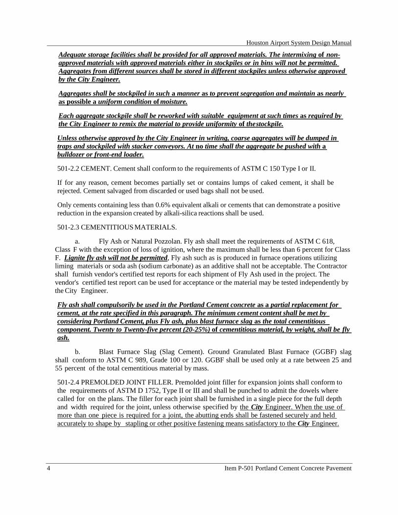
Houston Airport System Design Manual
4 Item P-501 Portland Cement Concrete Pavement
Adequate storage facilities shall be provided for all approved materials. The intermixing of non-approved materials with approved materials either in stockpiles or in bins will not be permitted. Aggregates from different sources shall be stored in different stockpiles unless otherwise approved by the City Engineer.
Aggregates shall be stockpiled in such a manner as to prevent segregation and maintain as nearly as possible a uniform condition of moisture.
Each aggregate stockpile shall be reworked with suitable equipment at such times as required by the City Engineer to remix the material to provide uniformity of the stockpile.
Unless otherwise approved by the City Engineer in writing, coarse aggregates will be dumped in traps and stockpiled with stacker conveyors. At no time shall the aggregate be pushed with a bulldozer or front-end loader.
501-2.2 CEMENT. Cement shall conform to the requirements of ASTM C 150 Type I or II.
If for any reason, cement becomes partially set or contains lumps of caked cement, it shall be rejected. Cement salvaged from discarded or used bags shall not be used.
Only cements containing less than 0.6% equivalent alkali or cements that can demonstrate a positive reduction in the expansion created by alkali-silica reactions shall be used.
501-2.3 CEMENTITIOUS MATERIALS.
a. Fly Ash or Natural Pozzolan. Fly ash shall meet the requirements of ASTM C 618, Class F with the exception of loss of ignition, where the maximum shall be less than 6 percent for Class F. Lignite fly ash will not be permitted, Fly ash such as is produced in furnace operations utilizing liming materials or soda ash (sodium carbonate) as an additive shall not be acceptable. The Contractor shall furnish vendor's certified test reports for each shipment of Fly Ash used in the project. The vendor's certified test report can be used for acceptance or the material may be tested independently by the City Engineer.
Fly ash shall compulsorily be used in the Portland Cement concrete as a partial replacement for cement, at the rate specified in this paragraph. The minimum cement content shall be met by considering Portland Cement, plus Fly ash, plus blast furnace slag as the total cementitious component. Twenty to Twenty-five percent (20-25%) of cementitious material, by weight, shall be fly ash.
b. Blast Furnace Slag (Slag Cement). Ground Granulated Blast Furnace (GGBF) slag shall conform to ASTM C 989, Grade 100 or 120. GGBF shall be used only at a rate between 25 and 55 percent of the total cementitious material by mass.
501-2.4 PREMOLDED JOINT FILLER. Premolded joint filler for expansion joints shall conform to the requirements of ASTM D 1752, Type II or III and shall be punched to admit the dowels where called for on the plans. The filler for each joint shall be furnished in a single piece for the full depth and width required for the joint, unless otherwise specified by the City Engineer. When the use of more than one piece is required for a joint, the abutting ends shall be fastened securely and held accurately to shape by stapling or other positive fastening means satisfactory to the City Engineer.

Houston Airport System Design Manual
Item P-501 Portland Cement Concrete Pavement 5
501-2.5 JOINT SEALER. The joint sealer for the joints in the concrete pavement shall meet the requirements of Item P-605 and shall be of the type(s) specified in the plans.
501-2.6 STEEL REINFORCEMENT. Reinforcing shall consist of welded steel wire fabric conforming to the requirements of ASTM A 185.
The steel shall be properly stored to protect it from mechanical injury and rust. The steel shall be free from dirt, rust, scale or other deleterious materials at the time of placement.
501-2.7 DOWEL AND TIE BARS. Tie bars shall be deformed steel bars and conform to the requirements of ASTM A 615 or ASTM A 996, except that rail steel bars, Grade 50 or 60, shall not be used for tie bars that are to be bent or re-straightened during construction.
Dowel bars shall be plain steel bars conforming to ASTM A 615 or ASTM A 966 and shall be free from burring or other deformation restricting slippage in the concrete. High strength dowel bars shall conform to ASTM A 714, Class 2, Type S, Grade I, II or III, Bare Finish. Before delivery to the construction site each dowel bar shall be painted with one coat of paint conforming to MIL-DTL- 24441/20A.SSPC Paint 5 or SSPC Paint 25.Metal or plastic collars shall be full circular device supporting the dowel until the epoxy hardens.
The sleeves for dowel bars used in expansion joints shall be metal or other type of an approved design to cover 2 to 3 inches (50 mm to 75 mm) of the dowel, with a closed end and with a suitable stop to hold the end of the bar at least 1 inch (25 mm) from the closed end of the sleeve. Sleeves shall be of such design that they will not collapse during construction.
501-2.8 WATER. Water used in mixing or curing shall be clean and free of oil, salt, acid, alkali, sugar, vegetable, or other substances injurious to the finished product. Water will be tested in accordance with the requirements of AASHTO T 26. Water known to be of potable quality may be used without testing.
501-2.9 COVER MATERIAL FOR CURING. Curing materials shall conform to one of the following specifications:
a. Liquid membrane-forming compounds for curing concrete shall conform to the requirements of ASTM C309, Type 2, Class B, or Class A if wax base only.
b. White polyethylene film for curing concrete shall conform to the requirements of ASTM C 171.
c. White burlap-polyethylene sheeting for curing concrete shall conform to the requirements of ASTM C
d. Waterproof paper for curing concrete shall conform to the requirements of ASTM C 171.
501-2.10 ADMIXTURES. The use of any material added to the concrete mix shall be approved by the City Engineer. The Contractor shall submit certificates indicating that the material to be furnished meets all of the requirements indicated below. In addition, the City Engineer may require the Contractor to submit complete test data from an approved laboratory showing that the material to be furnished meets all of the requirements of the cited specifications. Subsequent tests may be made of samples taken by the City Engineer from the supply of the material being furnished or proposed for use on the work to determine whether the admixture is uniform in quality with that approved.

Houston Airport System Design Manual
6 Item P-501 Portland Cement Concrete Pavement
a. Air-Entraining Admixtures. Air-entraining admixtures shall meet the requirements of ASTM C 260 and shall consistently entrain the air content in the specified ranges under field conditions. The air-entrainment agent and any water reducer admixture shall be compatible.
b. Chemical Admixtures. Water-reducing, set retaining and set-accelerating admixtures shall meet the requirements of ASTM C 494, including the flexural strength test. During hot weather concreting operations or normal operations in order to maintain specified slump and required workability, the City Engineer may allow use of a water-reducing admixture or a water-reducing and set-retarding mixture. The use of these admixtures shall be addressed and documented in development of the Mix Design.
The water-reducing admixture shall conform to requirements of AASHTO M 194. Type A and Type F and water- reducing and set-retarding admixtures shall conform to the requirements of AASHTO M 194. Type 0 and Type G. Water-reducing or water-reducing and retarding admixture shall be added at the mixer separately from the air-entraining admixtures according to manufacturers printed instructions.
501-2.11 EPOXY-RESIN. Epoxy-resin used to anchor dowels and tie bars in pavements shall conform to the requirements of ASTM C 881, Type I, Grade 3, Class C. Class A or B shall be used when the surface temperature of the hardened concrete is below 60 degrees F (16 degrees C).
501-2.12 MATERIAL ACCEPTANCE. Prior to use of materials, the Contractor shall submit certified test reports to the City Engineer for those materials proposed for use during construction. The certification shall show the appropriate ASTM test(s) for each material, the test results, and a statement that the material passed or failed.
The City Engineer may request samples for testing, prior to and during production, to verify the quality of the materials and to ensure conformance with the applicable specifications.
MIX DESIGN
501-3.1 PROPORTIONS. Concrete shall be designed to achieve a 28-day flexural strength that meets or exceeds the acceptance criteria contained in paragraph 501-5.2 for a flexural strength of 700 psi. The mix shall be designed using the procedures contained in Chapter 7 of the Portland Cement Association's manual, "Design and Control of Concrete Mixtures".
The Contractor shall note that to ensure that the concrete actually produced will meet or exceed the acceptance criteria for the specified strength; the mix design average strength must be higher than the specified strength. The amount of overdesign necessary to meet specification requirements depends on the producer's standard deviation of flexural test results and the accuracy that that value can be estimated from historic data for the same or similar materials.
The minimum cementitious material (cement plus fly ash) shall be 564 pounds per cubic yard (227 kg per cubic meter). The ratio of water to cementitious material, including free surface moisture on the aggregates but not including moisture absorbed by the aggregates shall not be more than 0.45 by weight.
Prior to the start of paving operations and after approval of all material to be used in the concrete, the Contractor shall submit a mix design showing the proportions and flexural strength

Houston Airport System Design Manual
Item P-501 Portland Cement Concrete Pavement 7
obtained from the concrete at 7 and 28 days. The mix design shall include copies of test reports, including test dates, and a complete list of materials including type, brand, source, and amount of cement, fly ash, ground slag, coarse aggregate, fine aggregate, water, and admixtures. The fineness modulus of the fine aggregate and the air content shall also be shown. The mix design shall be submitted to the City Engineer at least 15 business days prior to the start of operations. The submitted mix design shall not be more than 90 days old. Production shall not begin until the mix design is approved in writing by the City Engineer.
Should a change in sources be made, or admixtures added or deleted from the mix, a new mix design must be submitted to the City Engineer for approval.
Flexural strength test specimens shall be prepared in accordance with ASTM C 31 and tested in accordance with ASTM C 78. The mix determined shall be workable concrete having a slump for side- form concrete between 1 and 2 inches (25 mm and 50 mm) as determined by ASTM C 143. For vibrated slip-form concrete, the slump shall be between 1/2 inch (13 mm) and 1 1/2 inches (38 mm).
501-3.2 CEMENTITIOUS MATERIALS.
a. Fly Ash. Fly ash shall be used in the mix design. When fly ash is used as a partial replacement for cement, the minimum cement content may be met by considering Portland Cement plus fly ash as the total cementitious material. The replacement rate shall be determined from laboratory trial mixes, but shall be between 20 and 30 percent by weight of the total cementitious material. If fly ash is used in conjunction with ground granular blast furnace slag the maximum replacement rate shall not exceed 10 percent by weight of total cementitious material.
b. Ground Slag. Ground blast-furnace slag shall be used in a mix design containing Type I or Type" cement. The slag, or slag plus fly ash if both are used, may constitute between 25 to 55 percent of the total cementitious material by weight. If the concrete is to be used for slip forming operations and the air temperature is expected to be lower than 55 degrees F (13 degrees C) the percent slag shall not exceed 30 percent by weight.
501-3.3 ADMIXTURES.
a. Air-Entraining. Air-entraining admixture shall be added in such a manner that will insure uniform distribution of the agent throughout the batch. The air content of freshly mix air-entrained concrete shall be based upon trial mixes with the materials to be used in the work adjusted to produce concrete of the required plasticity and workability. The percentage of air in the mix shall be 4.0%. Air content shall be determined by testing in accordance with ASTM C 231 for gravel and stone coarse aggregate and ASTM C 173 for slag and other highly porous coarse aggregate.
b. Chemical. Water-reducing, set-controlling, and other approved admixtures shall be added to the mix in the manner recommended by the manufacturer and in the amount necessary to comply with the specification requirements. The use of any of these admixtures must be approved by the City Engineer prior to their use in project concrete. Tests shall be conducted on trial mixes, with the materials to be used in the work, in accordance with ASTM C 494.
501-3.4 TESTING LABORATORY. The laboratory used to develop the mix design shall meet the requirements of ASTM C 1077. The laboratory accreditation will include ASTM C 78. A certification that it meets these requirements shall be submitted to the City Engineer prior to the start of mix design. The certification shall include evidence that the laboratory is inspected/accredited for the test methods required herein by a nationally recognized laboratory inspection accreditation organization.

Houston Airport System Design Manual
8 Item P-501 Portland Cement Concrete Pavement
CONSTRUCTION METHODS
501-4.1 EQUIPMENT. Equipment necessary for handling materials and performing all parts of the work shall be approved by the City Engineer as to design, capacity, and mechanical conditions. The equipment shall be at the jobsite sufficiently ahead of the start of paving operations to be examined thoroughly and approved.
Batch Plant and Equipment. The batch plant and equipment shall conform to the requirements of ASTM C 94.
(1) General. The batching plant shall include bins, weighing hoppers, and scales for the fine aggregate and coarse aggregate. If bulk cement is used a bin, hopper and separate scale for cement shall be included. The weighing hoppers shall be properly sealed and vented to preclude dusting during operation.
(2) Bins and Hopper. Bins with adequate separate compartments for fine aggregate and coarse aggregate shall be provided in the batching plant. Each compartment shall discharge efficiently and freely into the weighing hopper. Means of control shall be provided so that as the quantity desired in the weighing hopper is approached the material may be added slowly and shut off with precision. A port or other opening for removing an overload of anyone of the several materials from the hopper shall be provided. Weighing hoppers shall be constructed to eliminate accumulations of materials and to discharge fully.
(3) Scales. The scales for weighing aggregates and cement shall be of either the beam or the springless dial type. They shall be accurate within 0.5 percent throughout their range of use. When beam-type scales are used, provisions such as a "telltale" dial shall be made for indicating to the operator that the required load in the weighing hopper is being approached. A device on the weighing beams shall clearly indicate critical position. Poises shall be designed to be locked in any position and to prevent unauthorized change. The weight beam and "telltale" device shall be in full view of the operator while charging the hopper and the operator shall have convenient access to all controls.
Scales shall be inspected and sealed as often as the City Engineer may deem necessary to assure their continued accuracy. The Contractor shall have on hand not less than ten 50pound (23 kg) weights for testing of all scales when directed by the City Engineer. Scales shall be equipped with an automatic recording device with printout capability to record the weight of each solid component of the batch. The device shall be sealed.
c. Mixers and Transportation Equipment.
(1) General. Concrete may be mixed at a central plant, or wholly or in part in truck mixers. Each mixer shall have attached in a prominent place a manufacturer's nameplate showing the capacity of the drum in terms of volume of mixed concrete and the speed of rotation of the mixing drum or blades.
A device accurate within 3 percent and satisfactory to the City Engineer shall be provided at the mixer for determining the amount of air-entraining agent or other admixture to be added to each batch requiring such admixtures.
Mixers shall be examined daily for the accumulation of hand concrete or mortar and the wear of blades.Accumulations greater than 1/8 inch shall be removed prior to resumption of concrete production.

Houston Airport System Design Manual
Item P-501 Portland Cement Concrete Pavement 9
Each mixer shall be equipped with a water measuring device so constructed that it will measure within one percent (1%) of the total amount required for each batch. Unless the Water is to be weighed, the water measuring equipment shall include an auxiliary tank with a capacity greater than that of the measuring tank, and from which the measuring tank will be filled by gravity flow. The measuring tank will be open to the atmosphere and shall be so placed and constructed that the water for a batch can be discharged into a calibrated tank or weighing device for checking the accuracy of water measurement without seriously delaying the paving operations. The Contractor shall have a calibrated tank or weighing device available at all times at a location satisfactory to the City Engineer.
(3) Central plant mixer. Central plant mixers shall conform to the requirements of ASTM C 94. Mixing shall be in an approved mixer capable of combining the aggregates, cementitious materials, and water into a thoroughly mixed and uniform mass within the specified mixing period and of discharging the mixture without segregation. Central plant mixers shall be equipped with an acceptable timing device that will not permit the batch to be discharged until the specified mixing time has elapsed. The water system for a central mixer shall be either a calibrated measuring tank or a meter and shall not necessarily be an integral part of the mixer.
The mixer shall be examined daily for changes in condition due to accumulation of hand concrete or mortar or wear of blades. The pickup and throw over blades shall be replaced when they have worn down 3/4 inch (19 mm) or more. The Contractor shall have a copy of the manufacturer’s design on hand showing dimensions and arrangement of blades in reference to original height and depth.
(4) Truck mixers and truck agitators. Truck mixers used for mixing and hauling concrete and truck agitators used for hauling central-mixed concrete shall conform to the requirements of ASTM C 94.
(5) Non-agitator trucks. Non-agitating hauling equipment shall conform to the requirements of ASTM C 94.
a. Finishing Equipment. The standard method of constructing concrete pavements on FAA projects shall be with an approved Slip-form paving equipment designed to spread, consolidate, screed, and float-finish the freshly placed concrete in one complete pass of the machine so a dense and homogeneous pavement is achieved with a minimum of hand finishing. The finishing machine shall be equipped with one or more oscillating-type transverse screed. The paver-finisher shall be a heavy duty, self-propelled machine designed specifically for paving and finishing high quality concrete pavements. It shall weigh at least 2200 Lbs. per foot of paving lane width and powered by an engine having at least 6.0 horsepower per foot of lane width.
On projects requiring less than 500 square yards of cement concrete pavement or requiring individual placement areas of less than 500 square yards, or irregular areas at locations inaccessible to slip-form paving equipment, cement concrete pavement may be placed with approved placement and finishing equipment utilizing stationary side forms. Hand screeding and float finishing may only be utilized on small irregular areas as allowed by the City Engineer.
b. Vibrators.
Vibrator shall be either internal type with multiple spuds, or surface type vibrating pan or screed.
For overlay pavements up to 8 inches (20 cm) nominal thickness, internal vibrators shall be used. Operating frequency for internal vibrators shall be between 7,000 and 12,000 vibrations per minute. Average amplitude for internal vibrators shall be 0.025-0.05 inches (0.06-0.13 cm).

Houston Airport System Design Manual
10 Item P-501 Portland Cement Concrete Pavement
The number, spacing, and frequency shall be as necessary to provide a dense and homogeneous pavement and meet the recommendations of ACI 309, Guide for Consolidation of Concrete. Adequate power to operate all vibrators shall be available on the paver. The vibrators shall be automatically controlled so that they shall be stopped as forward motion ceases. The contractor shall provide an electronic or mechanical means to monitor vibrator status. The checks on vibrator status shall occur a minimum of two times per day or when requested by the City Engineer.
Hand held vibrators may be used in irregular areas only, but shall meet the recommendations of ACI 309, Guide for Consolidation of Concrete.
c. Concrete Saws. The Contractor shall provide sawing equipment adequate in number of units and power to complete the sawing to the required dimensions. The Contractor shall provide at least one standby saw in good working order and a supply of saw blades at the site of the work at all times during sawing operations.
d. Side Forms. Straight side forms shall be made of steel and shall be furnished in sections not less than 10 feet (3 m) in length. Forms shall have a depth equal to the pavement thickness at the edge, and a base width equal to or greater than the depth. Flexible or curved forms of proper radius shall be used for curves of 100-foot (31 m) radius or less. Flexible or curved forms shall be of a design acceptable to the City Engineer. Forms shall be provided with adequate devices for secure settings so that when in place they will withstand, without visible spring or settlement, the impact and vibration of the consolidating and finishing equipment. Flange braces shall extend outward on the base not less than two-thirds the height of the form.
Forms with battered top surfaces and bent, twisted or broken forms shall not be used, and shall be removed from the work. Repaired forms shall not be used until inspected and approved. Built-up forms shall not be used, except as approved by the City Engineer. The top face of the form shall not vary from a true plane more than 1/8 inch (3 mm) in 10 feet (3 m), and the upstanding leg shall not vary more than 1/4 inch (6 mm). The forms shall contain provisions for locking the ends of abutting sections together tightly for secure setting. Wood forms may be used under special conditions, when approved by the City Engineer.
e. Pavers. The maximum allowable paving lane width for this project is to be 25 feet. The paver shall be fully energized, self-propelled, and designed for the specific purpose of placing, consolidating, and finishing the concrete pavement, true to grade, tolerances, and cross section. It shall be of sufficient weight and power to construct the maximum specified concrete paving lane width as shown in the plans, at adequate forward speed, without transverse, longitudinal or vertical instability or without displacement. The paver shall be equipped with electronic or hydraulic horizontal and vertical control devices.
Prior to the start of paving operations, the manufacturer’s representative is to certify that the slipform paver to be used by the Contractor on this project is in good operating condition and is capable of performing the work required by the drawings and specifications. The slipform paver shall be rechecked by the manufacturer’s representative for proper operation and condition at least once every 90 days during its use on this project, and as requested by the City Engineer. Cost of certification and rechecks shall be included in the Contract Unit Prices for work under this specification item. There will be no separate pay for certification and re-checks: costs to be subsidiary to the item(s) which it is a component.

Houston Airport System Design Manual
Item P-501 Portland Cement Concrete Pavement 11
501-4.2 FORM SETTING. Forms shall be set sufficiently in advance of the concrete placement to insure continuous paving operation. After the forms have been set to correct grade, the underlying surface shall be thoroughly tamped, either mechanically or by hand, at both the inside and outside edges of the base of the forms. Forms shall be staked into place sufficiently to maintain the form in position for the method of placement.
Form sections shall be tightly locked and shall be free from play or movement in any direction. The forms shall not deviate from true line by more than 1/8 inch (3 mm) at any joint. Forms shall be so set that they will withstand, without visible spring or settlement, the impact and vibration of the consolidating and finishing equipment. Forms shall be cleaned and oiled prior to the placing of concrete.
The alignment and grade elevations of the forms shall be checked and corrections made by the Contractor immediately before placing the concrete.
501-4.3 CONDITIONING OF UNDERLYING SURFACE. The compacted underlying surface on which the pavement will be placed shall be widened approximately 3 feet (1 m) to extend beyond the paving machine track to support the paver without any noticeable displacement. After the underlying surface has been placed and compacted to the required density, the areas that will support the paving machine and the area to be paved shall be trimmed or graded to the plan grade elevation and profile by means of a properly designed machine. The grade of the underlying surface shall be controlled by a positive grade control system using lasers, stringlines, or guide wires. If the density of the underlying surface is disturbed by the trimming operations, it shall be corrected by additional compaction and retested at the option of the City Engineer before the concrete is placed except when stabilized subbases are being constructed. If damage occurs on a stabilized subbase, it shall be corrected full depth by the Contractor. If traffic is allowed to use the prepared grade, the grade shall be checked and corrected immediately before the placement of concrete. The prepared grade shall be moistened with water, without saturating, immediately ahead of concrete placement to prevent rapid loss of moisture from concrete. The underlying surface shall be protected so that it will be entirely free of frost when concrete is placed.
501-4.4 CONDITIONING OF UNDERLYING SURFACE, SIDE-FORM AND FILL-IN LANE
CONSTRUCTION. The prepared underlying surface shall be moistened with water, without saturating, immediately ahead of concrete placement to prevent rapid loss of moisture from the concrete. Damage caused by hauling or usage of other equipment shall be corrected and retested at the option of the City Engineer. If damage occurs to a stabilized subbase, it shall be corrected full depth by the Contractor. A multiple-pin template weighing not less than 1.000 pounds per 20 feet or other approved template shall be provided and operated on the forms immediately in advance of the placing of all concrete. The template shall be propelled only by hand and not attached to a tractor or other power unit. Templates shall be adjustable so that they may be set and maintained at the correct contour of the underlying surface. The adjustment and operation of the templates shall be such as will provide an accurate retest of the grade before placing the concrete thereon. All excess material shall be removed and wasted. Low areas shall be filled and compacted to a condition similar to that of the surrounding grade. The underlying surface shall be protected so that it will be entirely free from frost when the concrete is placed. The use of chemicals to eliminate frost in the underlying surface shall not be permitted.
The template shall be maintained in accurate adjustment, at all times by the Contractor, and shall be checked daily.

Houston Airport System Design Manual
12 Item P-501 Portland Cement Concrete Pavement
501-4.5 HANDLING, MEASURING, AND BATCHING MATERIAL. The batch plant site, layout, equipment, and provisions for transporting material shall assure a continuous supply of material to the work. Stockpiles shall be constructed in such a manner that prevents segregation and intermixing of deleterious materials. Stockpiles shall be built up in layers of not more than 3 feet (90 cm) in thickness. Each layer shall be completely in place before beginning the next layer and shall not be allowed to "cone" down over the next lower layer. Aggregates from different sources and of different grading shall not be stockpiled together. Improperly placed stockpiles will not be accepted by the City Engineer.
Aggregates shall be handled from stockpiles or other sources to the batching plant in such manner to secure the specified grading of the material. Aggregates that have become segregated or mixed with earth or foreign material shall not be used. All aggregates produced or handled by hydraulic methods, and washed aggregates, shall be stockpiled or binned for draining at least 12 hours before being batched. Rail shipments requiring more than 12 hours will be accepted as adequate binning only if the car bodies permit free drainage. The fine aggregate and coarse aggregate shall be separately weighed into hoppers in the respective amounts set by the Engineer in the job mix. Cement shall be measured by weight Separate scales and hopper, with a device to positively indicate the complete discharge of the batch of cement into the batch box or container, shall be used for weighing the cement.
Batching plants shall be equipped to proportion aggregates and bulk cement, by weight, automatically using interlocked proportioning devices of an approved type. When bulk cement is used, the Contractor shall use a suitable method of handling the cement from weighing hopper to transporting container or into the batch itself for transportation to the mixer, such as a chute, boot, or other approved device, to prevent loss of cement. The device shall be arranged to provide positive assurance that the cement content specified is present in each batch.
Batches may be rejected unless mixed within 1-1/2 hours of initial contact of cement with the aggregates. Batching shall be conducted so that the results in the weights of each material required will be within a tolerance of 1 percent for cement and 2 percent for aggregates.
Water may be measured either by volume or by weight the accuracy of measuring the water shall be within plus or minus 1 percent of required amounts. Unless the water is to be weighed, the water- measuring equipment shall include an auxiliary tank from which the measuring tank shall be filled. The measuring tank shall be equipped with an outside tap and valve to provide for checking the setting unless other means are provided for readily and accurately determining the amount of water in the tank. The volume of the auxiliary tank shall be at least equal to that of the measuring tank.
Methods and equipment for adding air-entraining agent or other admixtures to the batch, when required, shall be approved by the City Engineer. All admixtures shall be measured into the mixer with an accuracy of plus or minus 3 percent.
501-4.6 MIXING CONCRETE. The concrete may be mixed at the work site, in a central mix plant or in truck mixers. The mixer shall be of an approved type and capacity. Mixing time shall be measured from the time all materials, except water, are emptied into the drum. All concrete shall be mixed and delivered to the site in accordance with the requirements of ASTM C 94 except that the minimum required revolutions of mixing for transit mixed concrete may be reduced to not less than that recommended by the mixer manufacturer. The number of revolutions recommended by the mixer manufacturer shall be indicated on the manufacturer's serial plate attached to the mixer. The Contractor shall furnish test data acceptable to the City Engineer verifying that the make and model of the mixer will produce uniform concrete conforming to the provisions of ASTM C 94 at the

Houston Airport System Design Manual
Item P-501 Portland Cement Concrete Pavement 13
reduced number of revolutions shown on the serial plate.
When mixed at the work site or in a central mixing plant the mixing time shall not be less than 50 seconds nor more than 90 seconds. Mixing time ends when the discharge chute opens. Transfer time in multiple drum mixers is included in mixing time. The contents of an individual mixer drum shall be removed before a succeeding batch is emptied therein.
The mixer shall be operated at the drum speed as shown on the manufacturer's nameplate on the approved mixer. Any concrete mixed less than the specified time shall be discarded at the Contractor's expense. The volume of concrete mixed per batch shall not exceed the mixer's nominal capacity in cubic feet (cubic yards), as shown on the manufacturer's standard rating plate on the mixer. An overload up to 10 percent above the mixer's nominal capacity may be permitted provided concrete test data for segregation and uniform consistency are satisfactory and provided no spillage of concrete takes place. The batch shall be charged into the drum so that a portion of the mixing water shall enter in advance of the cement and aggregates. The flow of water shall be uniform, and all water shall be in the drum by the end of the first 15 seconds of the mixing period. The throat of the drum shall be kept free of such accumulations as may restrict the free flow of materials into the drum.
Mixed concrete from the central mixing plant shall be transported in truck mixers, truck agitators, or non-agitating trucks. The elapsed time from the addition of cementitious material to the mix until the concrete is deposited in place at the work site shall not exceed 30 minutes when the concrete is hauled in non-agitating trucks, nor 90 minutes when the concrete is hauled in truck mixers or truck agitators.
Re-tempering concrete by adding water or by other means will not be permitted. With transit mixers additional water may be added to the batch materials and additional mixing performed to increase the slump to meet the specified requirements provided the addition of water is performed within 45 minutes after the initial mixing operations and provided the water/cementitious ratio specified in the approved mix design is not exceeded, and approved by the City Engineer.
Computerized batch tickets shall be supplied for all concrete.
501-4.7 LIMITATIONS ON MIXING AND PLACING. No concrete shall be mixed, placed, or finished when the natural light is insufficient, unless an adequate and approved artificial lighting system is operated.
a. Cold Weather. Unless authorized in writing by the City Engineer, mixing and concreting operations shall be discontinued when a descending air temperature in the shade and away from artificial heat reaches 40° F (4° C) and shall not be resumed until an ascending air temperature in the shade and away from artificial heat reaches 35° F (2° C).
The aggregate shall be free of ice, snow, and frozen lumps before entering the mixer. The temperature of the mixed concrete shall not be less than 50° F (10° C) at the time of placement. Concrete shall not be placed on frozen material nor shall frozen aggregates be used in the concrete.
When concreting is authorized during cold weather, water and/or the aggregates may be heated to not more than 150° F (66° C) prior to being placed in the mixer. The apparatus used shall heat the mass uniformly and shall be arranged to preclude the possible occurrence of overheated areas which might be detrimental to the materials.
b. Hot Weather. During periods of hot weather when the maximum daily air temperature

Houston Airport System Design Manual
14 Item P-501 Portland Cement Concrete Pavement
exceeds 85° F (30°C), the following precautions shall be taken.
The forms and/or the underlying surface shall be sprinkled with water immediately before placing the concrete. The concrete shall be placed at the coolest temperature practicable, and in no case shall the temperature of the concrete when placed exceed 90°F (35°C). The aggregates and/or mixing water shall be cooled as necessary to maintain the concrete temperature at or not more than the specified maximum.
The finished surfaces of the newly laid pavement shall be kept damp by applying a water-fog or mist with approved spraying equipment until the pavement is covered by the curing medium. If necessary, wind screens shall be provided to protect the concrete from an evaporation rate in excess of 0.2 psf per hour as determined in accordance with Figure 2.1.5 in ACI 305R, Hot Weather Concreting, which takes into consideration relative humidity, wind velocity, and air temperature.
When conditions are such that problems with plastic cracking can be expected, and particularly if any plastic cracking begins to occur, the Contractor shall immediately take such additional measures as necessary to protect the concrete surface. Such measures shall consist of wind screens, more effective fog sprays, and similar measures commencing immediately behind the paver. If these measures are not effective in preventing plastic cracking, paving operations shall be immediately stopped.
d. Temperature Management Program. Prior to the start of paving operation for each day of paving, the contractor shall provide the City Engineer with a Temperature Management Program for the concrete to be placed to assure that uncontrolled cracking is avoided. As a minimum the program shall address the following items:
(1) Anticipated tensile strains in the fresh concrete as related to heating and cooling of the concrete material. (2) Anticipated weather conditions such as ambient temperatures, wind velocity, and relative humidity. (3) Anticipated timing of initial sawing of joint.
501-4.8 PLACING CONCRETE. The Contractor has the option of placing the concrete with either side (fixed) forms or slip-forms. At any point in concrete conveyance, the free vertical drop of the concrete from one point to another or to the underlying surface shall not exceed 3 feet (1 m). Backhoes and grading equipment shall not be used to distribute the concrete in front of the paver. Front end loaders will not be used unless the contractor demonstrates that they can be used without contaminating the concrete and base course and it is approved by the City Engineer.
Hauling equipment or other mechanical equipment can be permitted on adjoining previously constructed pavement when the concrete strength reaches a flexural strength of 550 psi (3,792 kPa), based on the average of four field cured specimens per 2,000 cubic yards (1,530 cubic meters) of concrete placed.
Also, subgrade and subbase planers, concrete pavers, and concrete finishing equipment may be permitted to ride upon the edges of previously constructed pavement when the concrete has attained a minimum flexural strength of 400 psi.
a. Slip-Form Construction. The concrete shall be distributed uniformly into final position by a self-propelled slip-form paver without delay. The alignment and elevation of the paver shall be regulated from outside reference lines established for this purpose. The paver shall vibrate the concrete for the full width and depth of the strip of pavement being placed and the vibration shall be adequate to provide a consistency of concrete that will stand normal to the surface with sharp well

Houston Airport System Design Manual
Item P-501 Portland Cement Concrete Pavement 15
defined edges. The sliding forms shall be rigidly held together laterally to prevent spreading of the forms.
The plastic concrete shall be effectively consolidated by internal vibration with transverse vibrating units for the full width of the pavement and/or a series of equally placed longitudinal vibrating units. The space from the outer edge of the pavement to longitudinal unit shall not exceed 9 inches. The spacing of internal units shall be uniform and shall not exceed 18 inches.
The term internal vibration means vibrating units located within the specified thickness of pavement section.
The rate of vibration of each vibrating unit shall be within 8,000 to 12,000 cycles per minute and the amplitude of vibration shall be sufficient to be perceptible on the surface of the concrete along the entire length of the vibrating unit and for a distance of at least one foot. The frequency of vibration or amplitude shall vary proportionately with the rate of travel to result in a uniform density and air content. The paving machine shall be equipped with a tachometer or other suitable device for measuring and indicating the actual frequency of vibrations.
The concrete shall be held at a uniform consistency. The slip-form paver shall be operated with as nearly a continuous forward movement as possible. And all operations of mixing, delivering, and spreading concrete shall be coordinated to provide uniform progress with stopping and starting of the paver held to a minimum. If for any reason, it is necessary to stop the forward movement of the paver, the vibratory and tamping elements shall also be stopped immediately. No tractive force shall be applied to the machine, except that which is controlled from the machine.
When concrete is being placed adjacent to an existing pavement, that part of the equipment which is supported on the existing pavement shall be equipped with protective pads on crawler tracks or rubber- tired wheels on which the bearing surface is offset to run a sufficient distance from the edge of the pavement to avoid breaking the pavement edge.
Concrete constructed under this specification shall be placed on cement-stabilized crushed recycled concrete base, or other prepared surface as shown on the drawings. No concrete shall be placed before the stabilized base has attained the specified compressive strength, or 7 days, whichever occurs first.
b. Side-Form Construction. Side form sections shall be straight, free from warps, bends, indentations, or other defects. Defective forms shall be removed from the work. Metal side forms shall be used except at end closures and transverse construction joints where straight forms of other suitable material may be used.
Side forms may be built up by rigidly attaching a section to either top or bottom of forms. If such build-up is attached to the top of metal forms, the build-up shall also be metal. Width of the base of all forms shall be equal to at least 80 percent of the specified pavement thickness.
Side forms shall be of sufficient rigidity, both in the form and in the interlocking connection with adjoining forms, that springing will not occur under the weight of subgrading and paving equipment or from the pressure of the concrete. The Contractor shall provide sufficient forms so that there will be no delay in placing concrete due to lack of forms.
It is the intent of the specification to produce a high quality, dense, long lasting and smooth pavement suitable for the high speed operations of roughness-sensitive heavy jet aircraft. This requires that all joints and particularly all longitudinal joints meet the specified tolerance

Houston Airport System Design Manual
16 Item P-501 Portland Cement Concrete Pavement
throughout their length. The City Engineer will designate the paving lanes in an apron, taxiway or the outer runway paving lanes to be used for the initial paving operations.
Before placing side forms, the underlying material shall be at the proper grade. Side forms shall have full bearing upon the foundation throughout their length and width of base and shall be placed to the required grade and alignment of the finished pavement. They shall be firmly supported during the entire operation of placing, compacting, and finishing the pavement.
Forms shall be drilled in advance of being placed to line and grade to accommodate tie bars where these are specified.
Immediately in advance of placing concrete and after all subbase operations are completed, side forms shall be trued and maintained to the required line and· grade for a distance sufficient to prevent delay in placing.
Side forms shall remain in place at least 12 hours after the concrete has been placed and in all cases until the edge of the pavement no longer requires the protection of the forms. Curing compound shall be applied to the concrete immediately after the forms have been removed. Side forms shall be thoroughly cleaned and oiled each time they are used and before concrete is placed against them. Concrete shall be spread, screeded, shaped and consolidated by one or more self-propelled machines. These machines shall uniformly distribute and consolidate concrete without segregation so that the completed pavement will conform to the required cross section with a minimum of handwork.
The number and capacity of machines furnished shall be adequate to perform the work required at a rate equal to that of concrete delivery.
Concrete for the full paving width shall be effectively consolidated by internal vibrators without causing segregation. Internal type vibrators' rate of vibration shall be not less than 7,000 cycles per minute. Amplitude of vibration shall be sufficient to be perceptible on the surface of the concrete more than one foot from the vibrating element. The Contractor shall furnish a tachometer or other suitable device for measuring and indicating frequency of vibration.
Power to vibrators shall be connected so that vibration ceases when forward or backward motion of the machine is stopped.
The provisions relating to the frequency and amplitude of internal vibration shall be considered the minimum requirements and are intended to ensure adequate density in the hardened concrete.
c. Consolidation Testing. The provisions relating to the frequency and amplitude of internal vibration shall be considered the minimum requirements and are intended to ensure adequate density in the hardened concrete. If a lack of consolidation of the concrete is suspected by the City Engineer, additional referee testing may be required. Referee testing of hardened concrete will be performed by cutting cores from the finished pavement after a minimum of 24 hours curing. Density determinations will be made based on the water content of the core as taken. ASTM C 642 shall be used for the determination of core density in the saturated-surface dry condition. Referee cores will be taken at the minimum rate of one for each 500 cubic yards of pavement, or fraction thereof.
The average density of the cores shall be at least 97 percent of the original mix design density, with no cores having a density of less than 96 percent of the original mix design density.
Failure to meet the above requirements will be considered as evidence that the minimum requirements for vibration are inadequate for the job conditions and additional vibrating units or other means of

Houston Airport System Design Manual
Item P-501 Portland Cement Concrete Pavement 17
increasing the effect of vibration shall be employed so that the density of the hardened concrete as indicated by further referee testing shall conform to the above listed requirements.
501-4.9 STRIKE-OFF OF CONCRETE AND PLACEMENT OF REINFORCEMENT. Following the
placing of the concrete, it shall be struck off to conform to the cross section shown on the plans and to an elevation such that when the concrete is properly consolidated and finished, the surface of the pavement shall be at the elevation shown on the plans. When reinforced concrete pavement is placed in two layers, the bottom layer shall be struck off to such length and depth that the sheet of reinforcing steel fabric or bar mat may be laid full length on the concrete in its final position without further manipulation. The reinforcement shall then be placed directly upon the concrete, after which the top layer of the concrete shall be placed, struck off, and screeded. If any portion of the bottom layer of concrete has been placed more than 30 minutes without being covered with the top layer or if initial set has taken place, it shall be removed and replaced with freshly mixed concrete at the Contractor's expense. When reinforced concrete is placed in one layer, the reinforcement may be positioned in advance of concrete placement or it may be placed in plastic concrete by mechanical or vibratory means after spreading.
Reinforcing steel, at the time concrete is placed, shall be free of mud, oil, or other organic matter that may adversely affect or reduce bond. Reinforcing steel with rust, mill scale or a combination of both will be considered satisfactory, provided the minimum dimensions, weight, and tensile properties of a hand wire-brushed test specimen are not less than the applicable ASTM specification requirements.
501-4.10 JOINTS. Joints shall be constructed as shown on the plans and in accordance with these requirements. All joints shall be constructed with their faces perpendicular to the surface of the pavement and finished or edged as shown on the plans. Joints shall not vary more than 1/2 inch (13 mm) from their designated position and shall be true to line with not more than 1/4-inch (6 mm) variation in 10 feet (3 m). The surface across the joints shall be tested with a 10-foot (3 m) straightedge as the joints are finished and any irregularities in excess of 1/4 inch (6 mm) shall be corrected before the concrete has hardened. All joints shall be so prepared, finished, or cut to provide a groove of uniform width and depth as shown on the plans.
a. Construction. Longitudinal construction joints shall be slip-formed or formed against side forms with or without keyways, as shown in the plans. Transverse construction joints shall be installed at the end of each day's placing operations and at any other points within a paving lane when concrete placement is interrupted for more than 30 minutes or it appears that the concrete will obtain its initial set before fresh concrete arrives. The installation of the joint shall be located at a planned contraction or expansion joint. If placing of the concrete is stopped, the Contractor shall remove the excess concrete back to the previous planned joint.
b. Contraction. Contraction joints shall be installed at the locations and spacing as shown on the plans. Contraction joints shall be installed to the dimensions required by forming a groove or cleft in the top of the slab while the concrete is still plastic or by sawing a groove into the concrete surface after the concrete has hardened.
When the groove is formed in plastic concrete the sides of the grooves shall be finished even and smooth with an edging tool. If an insert material is used, the installation and edge finish shall be according to the manufacturer's instructions.
The groove shall be finished or cut clean so that spalling will be avoided at intersections with other joints. Grooving or sawing shall produce a slot at least 1/8 inch (3 mm) wide and to the depth shown on

Houston Airport System Design Manual
18 Item P-501 Portland Cement Concrete Pavement
the plans.
c. Expansion. Expansion joints shall be installed as shown on the plans. The premolded filler of the thickness as shown on the plans shall extend for the full depth and width of the slab at the joint, except for space for sealant at the top of the slab. The filler shall be securely staked or fastened into position perpendicular to the proposed finished surface. A cap shall be provided to protect the top edge of the filler and to permit the concrete to be placed and finished. All devices used for the installation of expansion joints shall be approved by the City Engineer. They shall be easily removable without disturbing the concrete and held in proper transverse and vertical alignment. After the concrete has been placed and struck off, the cap shall be carefully withdrawn leaving the space over the premolded filler. The edges of the joint shall be finished and tooled while the concrete is still plastic. Any concrete bridging the joint space shall be removed for the full width and depth of the joint sealant reservoir. Before the pavement is opened to traffic. This space shall be swept clean and filled with approved joint sealing material.
d. Tie bars. Tie bars shall consist of deformed bars installed in joints as shown on the plans. Tie bars shall be placed at right angles to the centerline of the concrete slab and shall be spaced at intervals shown on the plans. They shall be held in position parallel to the pavement surface and in the middle of the slab depth. When tie bars extend into an unpaved lane, they may be bent against the form at longitudinal construction joints, unless threaded bolt or other assembled tie bars are specified. These bars shall not be painted, greased, or enclosed in sleeves. When slip-form operations call for tie bars, two-piece hook bolts can be installed in the female side of the keyed joint provided the installation is made without distorting the keyed dimensions or causing edge slump. If a bent tie bar installation is used, the tie bars shall be inserted through the keyway liner only on the female side of the joint. In no case shall a bent tie bar installation for male keyways be permitted.
e. Dowel bars. Dowel bars or other load-transfer units of an approved type shall be placed across joints in the manner as shown on the plans. They shall be of the dimensions and spacing as shown and held rigidly in the middle of the slab depth in the proper horizontal and vertical alignment by an approved assembly device to be left permanently in place. The dowel or load-transfer and joint devices shall be rigid enough to permit complete assembly as a unit ready to be lifted and placed into position. A metal or other type, dowel expansion cap or sleeve shall be furnished for each dowel bar used with expansion joints. These caps shall be substantial enough to prevent collapse and shall be placed on the ends of the dowels as shown on the plans. The caps or sleeves shall fit the dowel bar tightly and the closed end shall be watertight. The portion of each dowel painted with rust preventative paint, as required under paragraph 501-2.7 and shown on the plans to receive a debonding lubricant, shall be thoroughly coated with asphalt Me-70, or an approved lubricant, to prevent the concrete from bonding to that portion of the dowel. If free-sliding plastic-coated or epoxy-coated steel dowels are used, a lubrication bond breaker shall be used except when approved pullout tests indicate it is not necessary. Where butt-type joints with dowels are designated, the exposed end of the dowel shall be oiled.
Dowel bars at contraction joints may be placed in the full thickness of pavement by a mechanical device approved by the City Engineer. The device shall be capable of installing dowel bars within the maximum permissible alignment tolerances. Dowels bars at longitudinal construction joints shall be bonded in drilled holes.
f. Installation. All devices used for the installation of expansion joints shall be approved by the City Engineer.

Houston Airport System Design Manual
Item P-501 Portland Cement Concrete Pavement 19
Transverse joints with dowels will require particular care to ensure the dowels are accurately placed and not disturbed during concrete placement. Transverse joint dowels will require use of an apparatus to firmly hold the dowels perpendicular to the joint and parallel to the slab surface. The most effective way to maintain proper alignment is with well-fabricated dowel baskets and dowel assemblies.
The top of an assembled joint device shall be set at the proper distance below the pavement surface and the elevation shall be checked. Such devices shall be set to the required position and line and shall be securely held in place by stakes or other means to the maximum permissible tolerances during the pouring and finishing of the concrete. The premolded joint material shall be placed and held in a vertical position; if constructed in sections, there shall be no offsets between adjacent units.
Dowel bars and assemblies shall be checked for position and alignment. The maximum permissible tolerances on dowel bar alignment shall be in accordance with paragraph 501-5.2e (6). During the concrete placement operation, it is advisable to place plastic concrete directly on dowel assemblies immediately prior to passage of the paver to help maintain dowel position and alignment within maximum permissible tolerances.
When concrete is placed using slip-form pavers, dowels and tie bars shall be placed in longitudinal construction joints by bonding the dowels or tie bars into holes drilled into the hardened concrete. Holes approximately 1/8-inch to 114-inch (3 to 6 mm) greater in diameter than the dowel or tie bar shall be drilled with rotary-type core drills that must be held securely in place to drill perpendicularly into the vertical face of the pavement slab. Rotary-type percussion drills may be used provided that spalling of concrete does not occur. Any damage of the concrete shall be repaired by the Contractor in a method approved by the City Engineer. Dowels or tie bars shall be bonded in the drilled holes using an epoxy resin material. Installation procedures shall be adequate to insure that the area around dowels is completely filled with epoxy grout. Epoxy shall be injected into the back of the hole and displaced by the insertion of the dowel bar. Bars shall be completely inserted into the hole and shall not be withdrawn and reinserted creating air pockets in the epoxy around the bar. The Contractor shall furnish a template for checking the position and alignment of the dowels. Dowel bars shall not be less than 10 inches (25 cm) from a transverse joint and shall not interfere with dowels in the transverse direction.
h. Sawing of Joints. Joints shall be cut as shown on the plans. Equipment shall be as described in paragraph 501-4.1. The circular cutter shall be capable of cutting a groove in a straight line and shall produce a slot at least 1/8 inch (3 mm) wide and to the depth shown on the plans. The top portion of the slot shall be widened by sawing to provide adequate space for joint sealers as shown on the plans. The initial sawcut for all sawed joints shall be made as soon as possible after the concrete pavement has hardened sufficiently to support equipment and render a clean sawcut without chipping, spalling, or creating other damage to the concrete surface, and before uncontrolled shrinkage cracking of the pavement occurs Sawing shall be carried on both during the day and night as required.
The joints shall be sawed at the required spacing, consecutively in sequence of the concrete placement. Curing compound, if being used as the cure type, shall be reapplied in the initial sawcut and maintained for the remaining cure period. Curing compound shall not be applied, and used as the cure method, to any final concrete face that is to receive a sealant. If, while sawing a faint. A crack develops ahead of the saw, immediately discontinue sawing that joint when the designed joint sealant reservoirs are sawed, "rout-out" the top of the crack to create a sealant reservoir of the same dimensions as for the planned joints. Then seal the crack as if it was a planned faint. To help assure that these accidental" joints match the corresponding Joints in adjacent slabs, a short

Houston Airport System Design Manual
20 Item P-501 Portland Cement Concrete Pavement
(approximately 1.5 ft) saw cut of the standard depth can be made on the opposite side of the slab before beginning sawing the complete joint from a given side.
501-4.11 FINAL STRIKE-OFF, CONSOLIDATION, AND FINISHING.
a. Sequence. The sequence of operations shall be the strike-off, floating and removal of laitance, straight edging, and final surface finish. The addition of superficial water to the surface of the concrete to assist in finishing operations will not be permitted.
b. Finishing at Joints. The concrete adjacent to joints shall be compacted or firmly placed without voids or segregation against the joint material; it shall be firmly placed without voids or segregation under and around all load-transfer devices, joint assembly units, and other features designed to extend into the pavement. Concrete adjacent to joints shall be mechanically vibrated as required in paragraph 501-4.8.a. After the concrete has been placed and vibrated adjacent to the joints, the finishing machine shall be operated in a manner to avoid damage or misalignment of joints. If uninterrupted operations of the finishing machine, to, over, and beyond the joints, cause segregation of concrete, damage to, or misalignment of the joints, the finishing machine shall be stopped when the screed is approximately 8 inches (20 cm) from the joint. Segregated concrete shall be removed from the front of and off the joint, the screed shall be lifted and set directly on top of the taint, and the forward motion of the finishing machine shall be resumed. Thereafter, the finishing machine may be run over the joint without lifting the screed, provided there is no segregated concrete immediately between the joint and the screed or on top of the joint.
c. Machine Finishing. The concrete shall be spread as soon as it is placed, and it shall be struck off and screeded by an approved finishing machine. The machine shall go over each area as many times and at such intervals as necessary to give to proper consolidation and to leave a surface of uniform texture. Excessive operation over a given area shall be avoided. When side forms are used, the tops of the forms shall be kept clean by an effective device attached to the machine, and the travel of the machine on the forms shall be maintained true without lift, wobbling, or other variation tending to affect the precision finish. During the first pass of the finishing machine, a uniform ridge of concrete shall be maintained ahead of the front screed for its entire length. When in operation, the screed shall be moved forward
with a combined longitudinal and transverse shearing motion, always moving in the direction in which the work is progressing, and so manipulated that neither end is raised from the side forms during the striking-off process. If necessary, this shall be repeated until the surface is of uniform texture, true to grade and cross section, and free from porous areas.
d. Hand Finishing. Hand finishing methods will not be permitted, except under the following conditions: in the event of breakdown of the mechanical equipment, hand methods may be used to finish the concrete already deposited on the grade; in areas of narrow widths or of irregular dimensions where operation of the mechanical equipment is impractical. Concrete, as soon as placed, shall be struck off and screeded. An approved portable screed shall be used. A second screed shall be provided for striking off the bottom layer of concrete when reinforcement is used.
e. The screed for the surface shall be a least 2 feet (0.6 m) longer than the maximum width of the slab to be struck off. It shall be of approved design, sufficiently rigid to retain its shape, and shall be constructed either of metal or of other suitable material covered with metal. Consolidation shall be attained by the use of suitable vibrators.
f. Floating. After the concrete has been struck off and consolidated, it shall be further smoothed and trued by means of a longitudinal float using one of the following methods:

Houston Airport System Design Manual
Item P-501 Portland Cement Concrete Pavement 21
(1) Hand Method. Long-handled floats shall not be less than 12 feet (3.6 m) in length and 6 inches (15 cm) in width, stiffened to prevent flexibility and warping. The float shall be operated from foot bridges spanning but not touching the concrete or from the edge of the pavement. Floating shall pass gradually from one side of the pavement to the other. Forward movement along the centerline of the pavement shall be in successive advances of not more than one-half the length of the float. Any excess water or laitance in excess of 1/8-inch (3 mm) thick shall be removed and wasted.
(2) Mechanical method. The Contractor may use a machine composed of a cutting and smoothing float(s), suspended from and guided by a rigid frame and constantly in contact with, the side forms or underlying surface. If necessary, long-handled floats having blades not less than 5 feet (1.5 m) in length and 6 inches (15 cm) in width may be used to smooth and fill in open-textured areas in the pavement. When the crown of the pavement will not permit the use of the mechanical float, the surface shall be floated transversely by means of a long-handled float. Care shall be taken not to work the crown out of the pavement during the operation. After floating, any excess water and laitance in excess of 1/8-inch (3 mm) thick shall be removed and wasted. Successive drags shall be lapped one-half the length of the blade.
g. Straight-edge Testing and Surface Correction. After the pavement has been struck off and while the concrete is still plastic, it shall be tested for trueness with a Contractor furnished 16-foot (5 m) straightedge swung from handles 3 feet (1 m) longer than one-half the width of the slab. The straightedge shall be held in contact with the surface in successive positions parallel to the centerline and the whole area gone over from one side of the slab to the other, as necessary.
Advancing shall be in successive stages of not more than one-half the length of the straightedge. Any excess water and laitance in excess of 1/8-inch (3 mm) thick shall be removed from the surface of the pavement and wasted. Any depressions shall be immediately filled with freshly mixed concrete, struck off, consolidated, and refinished. High areas shall be cut down and refinished. Special attention shall be given to assure that the surface across joints meets the smoothness requirements of paragraph 501-5.2e (3). Straightedge testing and surface corrections shall continue until the entire surface is found to be free from observable departures from the straightedge and until the slab conforms to the required grade and cross section. The use of long-handled wood floats shall be confined to a minimum; they may be used only in emergencies and in areas not accessible to finishing equipment.
h. Stationing Stencil. Furnish stencils to impress centerline stationing at 100 foot intervals into the fresh concrete along each edge, with numerals approximately 2 in. high by 1 in. wide by 114 in. deep. There will be no separate payment for stenciling.
501-4.12 SURFACE TEXTURE. The surface of the pavement shall be finished with either a brush or broom, burlap drag, or artificial turf finish for all newly constructed concrete pavements. It is important that the texturing equipment not tear or unduly roughen the pavement surface during the operation. Any imperfections resulting from the texturing operation shall be corrected
a. Brush or Broom Finish. If the pavement surface texture is to be a type of brush or broom finish, it shall be applied when the water sheen has practically disappeared. The equipment shall operate transversely across the pavement surface, providing corrugations that are uniform in appearance and approximately 1/16 of an inch (2 mm) in depth.
b. Burlap Drag Finish. If a burlap drag is used to texture the pavement surface, it shall be at least 15 ounces per square yard (555 grams per square meter). To obtain a textured surface, the transverse threads of the burlap shall be removed approximately 1 foot (0.3 m) from the trailing edge.

Houston Airport System Design Manual
22 Item P-501 Portland Cement Concrete Pavement
A heavy buildup of grout on the burlap threads produces the desired wide sweeping longitudinal striations on the pavement surface. The corrugations shall be uniform in appearance and approximately 1/16 of an inch (2 mm) in depth.
c. Artificial Turf Finish. If artificial turf is used to texture the surface, it shall be applied by dragging the surface of the pavement in the direction of concrete placement with an approved full width drag made with artificial turf. The leading transverse edge of the artificial turf drag will be securely fastened to a lightweight pole on a traveling bridge. At least 2 feet of the artificial turf shall be in contact with the concrete surface during dragging operations. A variety of different types of artificial turf are available and approval of anyone type will be done only after it has been demonstrated by the Contractor to provide a satisfactory texture. One type that has provided satisfactory texture consists of 7,200 approximately 0.85-inches-long polyethylene turf blades per square foot. The corrugations shall be uniform in appearance and approximately 1/16 of an inch (2 mm) in depth.
501-4.13 SKID-RESISTANT SURFACES. A skid-resistant surface shall be provided by construction of SAW-CUT GROOVES. For new concrete pavements that have hardened, transverse grooves shall be saw-cut in the pavement forming a 1/4 inch (6 mm) wide by 1/4 inch (6 mm) deep by 1-1/2 inches (37 mm) center to center configuration. The grooves shall be continuous for the entire runway length. They shall be saw-cut transversely in the runway pavement to within 10 feet (3 m) of the runway pavement edge to allow adequate space for equipment operation. The maximum transverse saw-cut grooves shall not exceed 130 feet (40 m). The tolerances for the saw-cut grooves shall meet the following:
• Alignment tolerance.
Plus or minus 1-1/2 inches (38 mm) in alignment for 75 feet (23 m).
• Groove tolerance
Minimum depth 3/16 inch (5 mm), except that not more than 60 percent of the grooves shall be less than 1/4 inch (6 mm).
Maximum depth 5/16 inch (8 mm). Minimum width 3/16 inch (5 mm). Maximum width 5/16 inch (8 mm).
• Center-to-center spacing
Minimum spacing 1-3/8 inches (35 mm) Maximum spacing 1-1/2 inches (38 mm).
Saw-cut grooves shall not be closer than 3 inches (76 mm) or more than 9 inches (229 mm) to transverse paving joints. Grooves shall not be closer than 6 inches (152 mm) and no more than 18 inches (457 mm) from in-pavement light fixtures. Grooves may be continued through longitudinal joints. Where neoprene compression seals have been installed grooves, shall not be closer than 3 inches (76 mm) or more than 5 inches (127 mm) from the longitudinal joints. Cleanup of waste material shall be continuous during the grooving operation. If flushing is used a temporary dam shall be constructed near the pavement edge to pond the waste slurry so that it can be picked up and disposed of. Water for cleanup shall be obtained by and at the Contractors expense. Waste material shall be disposed of in an approved manner. Waste material shall not be allowed to enter the airport storm or sanitary sewer system.

Houston Airport System Design Manual
Item P-501 Portland Cement Concrete Pavement 23
501-4.14 CURING. Immediately after finishing operations are completed and marring of the concrete will not occur, the entire surface of the newly placed concrete shall be cured for a 48-hour cure period or as specified by the City Engineer in accordance with one of the methods below. Failure to provide sufficient curing protection according to methods the Contractor elects to use shall be cause for immediate suspension of concreting operations. The concrete shall not be left exposed for more than 1/2 hour during the curing period.
When a two-saw cut method is used to construct the contraction joint, curing protection shall be applied to the sawcut immediately after the initial cut has been made. The sealant reservoir shall be sawed after sufficient strength has developed to prevent spalling or raveling. When the one cut method is used to construct the contraction joint, the joint shall be cured with wet rope, wet rags, or wet blankets. The rags, ropes, or blankets shall be kept moist for the duration of the curing period.
a. Curing Membrane Method. The entire surface of the pavement shall be sprayed uniformly with a white pigmented curing compound accepted by the City Engineer from a list of approved curing compounds immediately after the finishing of the surface and after surface bleeding is no longer evident The curing compound shall not be applied during rainfall. Curing compound shall be applied by mechanical sprayers under pressure at a rate specified by the City Engineer, but no less than 1 gallon (4 liters) to not more than 75 square feet (7 square meters).
The rate of application will be determined at a minimum for half day increments (morning and afternoon) during paving operations based upon expected weather conditions and the type of curing compound used. Expected morning and afternoon weather conditions will be assessed by the City Engineer according to wind speed, ambient relative humidity, and air temperature representative of a given half day increment.
The spraying equipment shall be of the fully atomizing type equipped with a tank agitator capable of keeping the compound stirred continuously by mechanical means during application. The spraying equipment shall be suitably instrumented to monitor the rate of travel which will be established based on the required rate of application and the flow rate. Alternatively, if approved by the City Engineer the spray equipment can be instrumented to monitor the rate of flow which would be established based upon the required rate of application and the rate of travel. In either case, the monitored rate of flow will be calibrated against weighted measurements at the nozzles prior to the initiation of paving operations and when required by the City Engineer. Spray nozzles will be cleaned on a daily basis.
Uniformity of the sprayed curing compound consists of a visually-observable even distribution of the curing compound with no visible streaks or isolated bare areas. The height and spacing of the spray nozzles should accommodate sufficient overlap to ensure and even distribution of curing compound on the surface of the concrete.
At the time of use, the compound shall be in a thoroughly mixed condition with the pigment uniformly dispersed throughout the vehicle. The curing compound shall be of such character that the film will harden within 30 minutes after application. Should the film become damaged from any cause, including sawing operations, within the required curing period the damaged portions shall be repaired immediately with additional compound or other approved means. Hand spraying of odd widths or shapes and concrete surfaces exposed by the removal of forms will be permitted. When hand spraying is approved by the City Engineer a double application rate shall be used to insure coverage.
Upon removal of side forms. The sides of the exposed slabs shall be protected immediately to

Houston Airport System Design Manual
24 Item P-501 Portland Cement Concrete Pavement
provide a curing treatment equal to that provided for the surface.
b. Polyethylene Films. The top surface and sides of the pavement shall be entirely covered with polyethylene sheeting. The units shall be lapped at least 18 inches (457 mm). The sheeting shall be placed and weighted to cause it to remain in contact with the surface and sides. The sheeting shall have dimensions that will extend at least twice the thickness of the pavement beyond the edges of the pavement. Unless otherwise specified, the sheeting shall be maintained in place for 7 days after the concrete has been placed.
c. Waterproof Paper. The top surface and sides of the pavement shall be entirely covered with waterproofed paper. The units shall be lapped at least 18 inches (457 mm). The paper shall be placed and weighted to cause it to remain in contact with the surface covered. The paper shall have dimensions that will extend at least twice the thickness of the pavement beyond the edges of the slab. The surface of the pavement shall be thoroughly saturated prior to placing of the paper. Unless otherwise specified, the paper shall be maintained in place for 7 days after the concrete has been placed.
d. White Burlap Polyethylene Sheets. The surface of the pavement shall be entirely covered with the sheeting. The sheeting used shall be such length (or width) that it will extend at least twice the thickness of the pavement beyond the edges of the slab. The sheeting shall be placed so that the entire surface and both edges of the slab are completely covered. The sheeting shall be placed and weighted to remain in contact with the surface covered, and the covering shall be maintained fully saturated and in position for 7 days after the concrete has been placed.
e. Water Method. The entire area shall be covered with burlap or other water absorbing material. The material shall be of sufficient thickness to retain water for adequate curing without excessive runoff. The material shall be kept wet at all times and maintained for 7 days. When the forms are stripped, the vertical walls shall also be keptmoist. It shall be the responsibility of the Contractor to prevent ponding of the curing water on the subbase.
f. Maintenance of Surface Moisture. Minimize surface drying of the pavement before application of the curing system. To this end, consider the use of evaporation retardant on the pavement surface. Apply evaporation retardant at the rate recommended by the manufacturer. Reapply the evaporation retardant as needed to maintain the concrete surface in a moist condition until curing system is applied. Do not use evaporation retardant as a finishing aid. Precautions to prevent surface drying of the pavement may be needed to prevent undesirable effects on pavement life.
g. Curing in Cold Weather. The concrete shall be maintained at a temperature of at least 50 degrees F (10 degrees CJ for a period of 72 hours after placing and at a temperature above freezing for the remainder of the curing time. The Contractor shall be responsible for the quality and strength of the concrete placed during cold weather and any concrete injured by frost action shall be removed and replaced at the Contractor's expense.
h. Curing Effectiveness Testing. Contractor shall cooperate with efforts to monitor the effectiveness of the curing operations by both surface relative and surface dielectric measurements to determine if the relative humidity and the free moisture levels in the surface of the concrete pavement are sufficient to sustain hydration and strength gain. These efforts are expected to have minimal impact on the contractors operations.

Houston Airport System Design Manual
Item P-501 Portland Cement Concrete Pavement 25
These measurements with be used ascertain the quality of the curing effort and determine the adequacy of the rate of application. It is anticipated that monitoring of this nature will initially be conducted at intervals of 500 linear feet of curing for up to 30 hours after placing in order to establish calibration procedures. Monitoring efforts may then focus on cured sections subjected to evaporation conditions exceeding the designated rate of curing in order to rate the impact on the quality of the concrete. Curing begins when the concrete curing system has been applied.
i. Measurement. Curing of concrete pavement will be measured by the gallon of curing compound in place.
501-4.15 REMOVING FORMS. Unless otherwise specified, forms shall not be removed from freshly placed concrete until it has hardened sufficiently to permit removal without chipping, spalling, or tearing. After the forms have been removed, the sides of the slab shall be cured as outlined in one of the methods indicated in paragraph 501-
4.14. Major honeycombed areas shall be considered as defective work and shall be removed and replaced in accordance with paragraph 501-5.2(f).
501-4.16 SEALING JOINTS. The joints in the pavement shall be sealed in accordance with Item P-605.
501-4.17 PROTECTION OF PAVEMENT. The Contractor shall protect the pavement and its appurtenances against both public traffic and traffic caused by the Contractors employees and agents. This shall include watchmen to direct traffic and the erection and maintenance of warning signs, lights, pavement bridges, crossovers, and protection of unsealed joints from intrusion of foreign material, etc.
Any damage to the pavement occurring prior to final acceptance shall be repaired or the pavement replaced at the Contractors expense. The Contractor shall have available at all times, materials for the protection of the edges and surface of the unhardened concrete. Such protective materials shall consist of rolled polyethylene sheeting at least 4 mils (0.1 mm) thick of sufficient length and width to cover the plastic concrete slab and any edges. The sheeting may be mounted on either the paver or a separate movable bridge from which it can be unrolled without dragging over the plastic concrete surface.
When rain appears imminent, all paving operations shall stop and all available personnel shall begin covering the surface of the unhardened concrete with the protective covering.
501-4.18 OPENING TO TRAFFIC. The pavement shall not be opened to traffic until test specimens molded and cured in accordance with ASTM C 31 have attained a flexural strength of 550 pounds per square inch (3,792 kPa) when tested in accordance with ASTM C 78. If such tests are not conducted, the pavement shall not be opened to traffic until 14 days after the concrete was placed. Prior to opening the pavement to construction traffic, all joints shall either be sealed or protected from damage to the joint edge and intrusion of foreign materials into the joint. As a minimum, backer rod or tape may be used to protect the joints from foreign matter intrusion. The pavement shall be cleaned before opening for normal operations.
501-4.19 REPAIR, REMOVAL, REPLACEMENT OF SLABS.
a. General. New pavement slabs that are broken or contain cracks shall be removed and replaced or repaired, as specified hereinafter at no cost to the owner. Spalls along joints shall be repaired as specified. Removal of partial slabs is not permitted. Removal and replacement shall be full depth,

Houston Airport System Design Manual
26 Item P-501 Portland Cement Concrete Pavement
shall be full width of the slab, and the limit of removal shall be normal to the paving lane and to each original transverse joint. The City Engineer will determine whether cracks extend full depth of the pavement and may require cores to be drilled on the crack to determine depth of cracking. Such cores shall be 4-inch
(100 mm) diameter, shall be drilled by the Contractor and shall be filled by the Contractor with a well consolidated concrete mixture bonded to the walls of the hole with epoxy resin, using approved procedures. Drilling of cores and refilling holes shall be at no expense to the owner. All epoxy resin used in this work shall conform to ASTM C 881, Type V.
b. Shrinkage Cracks. Shrinkage cracks, which do not exceed 4 inches in depth, shall be cleaned and then pressure injected with epoxy resin, Type IV, Grade 1, using procedures as approved. Care shall be taken to assure that the crack is not widened during epoxy resin injection. All epoxy resin injection shall take place in the presence of the City Engineer. Shrinkage cracks, which exceed 4 inches in depth, shall be treated as full depth cracks in accordance with paragraphs 4.19b and 4.19c.
c. Slabs with Cracks through Interior Areas. Interior area is defined as that area more than 6 inches (600 mm) from either adjacent original transverse joint. The full slab shall be removed and replaced at no cost to the owner, when there are any full depth cracks, or cracks greater than 4" in depth, that extend into the interior area.
d. Cracks Close To and Parallel to Transverse Joints. All cracks essentially parallel to original transverse joints, extending full depth of the slab, and lying wholly within 6 inches either side of the joint shall be treated as specified hereinafter. Any crack extending more than 6 inches (600 mm) from the transverse joint shall be treated as specified above in subparagraph "Slabs With Cracks Through Interior Area."
(1) Full Depth Cracks Present, Original Joint Not Opened. When the original uncracked transverse joint has not opened, the crack shall be sawed and sealed, and the original transverse joint filled with epoxy resin as specified below. The crack shall be sawed with equipment specially designed to follow random cracks. The reservoir for joint sealant in the crack shall be formed by sawing to a depth of 3/4 inch (19 mm), plus or minus 1/16 inch (1.6 mm), and to a width of 5/8 inch (16 mm), plus or minus 1/8 inch (3.2 mm). Any equipment or procedure which causes raveling or spalling along the crack shall be modified or replaced to prevent such raveling or spalling. The joint sealant shall be a liquid sealant as specified. Installation of joint seal shall be as specified for sealing joints or as directed. If the joint sealant reservoir has been sawed out, the reservoir and as much of the lower saw cut as possible shall be filled with epoxy resin, Type IV, Grade 2, thoroughly tooled into the void using approved procedures. If only the original narrow saw cut has been made, it shall be cleaned and pressure injected with epoxy resin, Type IV, Grade 1, using approved procedures. If filler type material has been used to form a weakened plane in the transverse joint, it shall be completely sawed out and the saw cut pressure injected with epoxy resin, Type IV, Grade 1, using approved procedures.
Where a parallel crack goes part way across paving lane and then intersects and follows the original transverse joint which is cracked only for the remained of the width, it shall be treated as specified above for a parallel crack, and the cracked original joint shall be prepared and sealed as originally designed.
(2) Full Depth Cracks Present, Original Transverse Joint Also Cracked. At a transverse joint, if there is any place in the lane width where a parallel crack and a cracked portion of the original joint overlap, the entire slab containing the crack shall be removed and replaced for the full lane width and length.

Houston Airport System Design Manual
Item P-501 Portland Cement Concrete Pavement 27
e. Removal and Replacement of Full Slabs. Where it is necessary to remove full slabs, unless there are keys or dowels present, all edges of the slab shall be cut full depth with a concrete saw. All saw cuts shall be perpendicular to the slab surface. If keys, dowels, or tie bars are present along any edges, these edges shall be sawed full depth 24 inches (150 mm) from the edge if only keys are present, or just beyond the end of the dowels or tie bars if they are present. These joints shall then be carefully sawed on the joint line to within 1 inch (25 mm) of the depth of the dowel or key.
The main slab shall be further divided by sawing full depth, at appropriate locations, and each piece lifted out and removed. Suitable equipment shall be used to provide a truly vertical lift, and approved safe lifting devices used for attachment to the slabs. The narrow strips along keyed or doweled edges shall be carefully broken up and removed using light, hand-held jackhammers, 30 LB (14 kg) or less, or other approved similar equipment.
Care shall be taken to prevent damage to the dowels, tie bars, or keys or to concrete to remain in place. The joint face below keys or dowels shall be suitably trimmed so that there is not abrupt offset in any direction greater than 1/2 inch (12 mm) and no gradual offset greater than 1 inch (25 mm) when tested in a horizontal direction with a 12- foot (3.6 m) straightedge.
No mechanical impact breakers, other than the above hand-held equipment shall be used for any removal of slabs. If underbreak between 1-1/2 and 4 inches (37 and 100 mm) deep occurs at any point along any edge, the area shall be repaired as directed before replacing the removed slab. Procedures directed will be similar to those specified for surface spalls, modified as necessary.
If underbreak over 4 inches (100 mm) deep occurs, the entire slab containing the underbreak shall be removed and replaced. Where there are no dowels, tie bars, or keys on an edge, or where they have been damaged, dowels of the size and spacing as specified for other joints in similar pavement shall be installed by epoxy grouting them into holes drilled into the existing concrete using procedures as specified. Original damaged dowels or tie bars shall be cut off flush with the joint face. Protruding portions of dowels shall be painted and lightly oiled. All 4 edges of the new slab shall thus contain dowels or original keys or original tie bars.
Placement of concrete shall be as specified for original construction. Prior to placement of new concrete, the underlying material (unless it is stabilized) shall be re-compacted and shaped as specified in the appropriate SECTION of these specifications. The surfaces of all four joint faces shall be cleaned of all loose material and contaminants and coated with a double application of membrane forming curing compound as bond breaker. Care shall be taken to prevent any curing compound from contacting dowels or tie bars. The resulting joints around the new slab shall be prepared and sealed as specified for original construction.
f. Repairing Spalls along Joints. Where directed, spalls along joints of new slabs, and along parallel cracks used as replacement joints, shall be repaired by first making a vertical saw cut at least 1 inch (25 mm) outside the spalled area and to a depth of at least 2 inches (50 mm). Saw cuts shall be straight lines forming rectangular areas. The concrete between the saw cut and the joint, or crack, shall be chipped out to remove all unsound concrete and at least 1/2 inch (12 mm) of visually sound concrete. The cavity thus formed shall be thoroughly cleaned with high-pressure water jets supplemented with compressed air to remove all loose material. Immediately before filling the cavity, a prime coat of epoxy resin, Type III, Grade I, shall be applied to the dry cleaned surface of all sides and bottom of the cavity, except any joint face. The prime coat shall be applied in a thin coating and scrubbed into the surface with a stiff-bristle brush. Pooling of epoxy resin shall be avoided. The cavity shall be filled with low slump Portland Cement concrete or mortar or with epoxy resin concrete or mortar. Concrete shall be used for larger spalls, generally those more than 1/2 cu. ft. (0.014 m3) in size

Houston Airport System Design Manual
28 Item P-501 Portland Cement Concrete Pavement
and mortar shall be used for the smaller ones.
a. Any spall less than 0.1 cu. ft. (0.003 m3) shall be repaired only with epoxy resin mortar or a Grade III epoxy resin. Portland Cement concrete and mortar mixtures shall be proportioned as directed and shall be mixed, placed, consolidated, and cured as directed. Epoxy resin mortars shall be made with Type III, Grade 1, epoxy resin, using proportions and mixing and placing procedures as recommended by the manufacturer and approved by the City Engineer The epoxy resin materials shall be placed in the cavity in layers not over 2 inches (50 mm) thick. The time interval between placement of additional layers shall be such that the temperature of the epoxy resin material does not exceed 140°F (60°C) at any time during hardening. Mechanical vibrators and hand tampers shall be used to consolidate the concrete or mortar. Any repair material on the surrounding surfaces of the existing concrete shall be removed before it hardens. Where the spalled area abuts a joint, an insert or other bond breaking medium shall be used to prevent bond at the joint face. A reservoir for the joint sealant shall be sawed to the dimensions required for other joints, or as required to be routed for cracks. The reservoir shall be thoroughly cleaned and sealed with the sealer specified for the joints. If any spall penetrates half the depth of the slab or more, the entire slab shall be removed and replaced as previously specified.
501-4.20 EXISTING CONCRETE PAVEMENT REMOVAL AND REPAIR.
All operations shall be carefully controlled to prevent damage to the concrete pavement and to the underlying material to remain in place. All saw cuts shall be made perpendicular to the slab surface.
a. Removal of Existing Pavement Slab.
When it is necessary to remove existing concrete pavement and leave adjacent concrete in place, unless there are dowels or keys present, the joint between the removal area and adjoining pavement to stay in place, including dowels, tie bars or keys, shall first be cut full depth with a standard diamond-type concrete saw. If keys or dowels are present at this joint, the saw cut shall be made full depth 6 inches (150 mm) from the joint if only keys are present, or just beyond the end of dowels if dowels are present. The edge shall then be carefully sawed on the joint line to within 1 inch (25 mm) of the top of the dowel or key. Next, a full depth saw cut shall be made parallel to the joint at least 24 inches (600 mm) from the joint and at least 12 inches (300 mm) from the end of any dowels. All pavement between this last saw cut and the joint line shall be carefully broken up and removed using hand-held jackhammers, 30 lb. (14 kg) or less, or the approved light-duty equipment which will not cause stress to propagate across the joint saw cut and cause distress in the pavement which is to remain in place. Where dowels or keys are present, care shall be taken to produce an even, vertical joint face below the dowels or keys. If the Contractor is unable to produce such a joint face, or if underbreak or other distress occurs, the Contractor shall saw the dowels or keys flush with the joint. The Contractor shall then install new dowels, of the size and spacing used for other similar joints, by epoxy resin bonding them in holes drilled in the joint face as specified in paragraph "Placing dowels and Tie-bars. All this shall be at no additional cost to the Owner. Dowels of the size and spacing indicated shall be installed as shown on the drawings by epoxy resin bonding them in holes drilled in the joint face as specified in paragraph "Placing Dowels and Tie Bars". The joint face shall be sawed or otherwise trimmed so that there is no abrupt offset in any direction greater than 1/2-inch (12 mm) and no gradual offset greater than 1 inch (25 mm) when tested in a horizontal direction with a 12 ft. (3.6 m) straightedge.
b. Edge Repair.
The edge of existing concrete pavement against which new pavement abuts shall be protected from

Houston Airport System Design Manual
Item P-501 Portland Cement Concrete Pavement 29
damage at all times. Areas that are damaged during construction shall be repaired at no cost to the Owner; repair of previously existing damage areas will be considered a subsidiary part of concrete pavement construction.
(1) Spall Repair. Spalls shall be repaired where indicated and where directed. Repair materials and procedures shall be as previously specified in subparagraph "Repairing Spalls along Joints.
(2) Underbreak Repair. All underbreak shall be repaired. First, all delaminated and loose material shall be carefully removed. Next, the underlying material shall be recompacted, without addition of any new material. Finally, the void shall be completely filled with paving concrete, thoroughly consolidated.
Care shall be taken to produce an even joint face from top to bottom. Prior to placing concrete, the underlying material shall be thoroughly moistened. After placement, the exposed surface shall be heavily coated with curing compound.
(3) Underlying Material. The underlying material adjacent to the edge of an under the existing pavement which is to remain in place shall be protected from damage or disturbance during removal operations and until placement of new concrete, and shall be shaped as shown on the drawings or as directed. Sufficient material shall be kept in place outside the joint line to prevent disturbance (or sloughing) of material under the pavement that is to remain in place. Any material under the portion of the concrete pavement to remain in place, which is disturbed or loses its compaction shall be carefully removed and replaced with concrete as specified in paragraph "Underbreak Repair." The underlying material outside the joint line shall be thoroughly compacted and moist when new concrete is placed.

Houston Airport System Design Manual
30 Item P-501 Portland Cement Concrete Pavement
MATERIAL ACCEPTANCE
501-5.1 ACCEPTANCE SAMPLING AND TESTING. The in-place concrete shall be homogeneous without segregation and honeycombing. The City Engineer reserves the right to take random cores to verify the quality of the in-place pavement These cores are In addition to those required. All acceptance sampling and testing, with the exception of coring for thickness determination, necessary to determine conformance with the requirements
specified in this section will be performed by the City Engineer. Concrete shall be accepted for strength and thickness on a lot basis.
If a core reveals segregations and/or honeycombing that is in the opinion of the City Engineer detrimental to the pavement structure, additional cores will be taken to define the area of deficiency. Areas so defined as containing segregated concrete and/or honeycombing shall be rejected, removed, and replaced at the Contractors expense. The City Engineer will be the sole judge as to the acceptability of the quality of the pavement.
A lot shall consist of: a day's production not to exceed 5,000 square yards (1,184 square meters)
Testing organizations performing these tests shall meet the requirements of ASTM C 1077, including accreditation. The accreditation will include ASTM C 78. The Contractor shall bear the cost of providing curing facilities for the strength specimens, per paragraph 501-5.1 a (3), and coring and filling operations, per paragraph 501-5.1 b (1).
a. Flexural Strength.
(1) Sampling. Each lot shall be divided into four equal sublots. One sample shall be taken for each sublot from the plastic concrete delivered to the job site. Sampling locations shall be determined by the City Engineer in accordance with random sampling procedures contained in ASTM D 3665. The concrete shall be sampled in accordance with ASTM C 172.
(2) Testing. Two (2) specimens shall be made from each sample. Specimens shall be made in accordance with ASTM C 31 and the flexural strength of each specimen shall be determined in accordance with ASTM C 78. The flexural strength for each sublot shall be computed by averaging the results of the two test specimens representing that sublot.
Immediately prior to testing for flexural strength, the beam shall be weighed and measured for determination of a sample unit weight. Measurements shall be made for each dimension; height, depth, and length, at the mid-point of the specimen and reported to the nearest tenth of an inch. The weight of the specimen shall be reported to the nearest 0.1 pound. The sample unit weight shall be calculated by dividing the sample weight by the calculated volume of the sample. This information shall be reported as companion information to the measured flexural strength for each specimen.
The samples will be transported while in the molds. The curing, except for the initial cure period, will be accomplished using the immersion in saturated lime water method.
Slump, air content, and temperature tests will also be conducted by the quality assurance laboratory for each set of strength test samples, per ASTM C 31.
(3) Curing. The Contractor shall provide adequate facilities for the initial curing of beams. During the 24 hours after molding, the temperature immediately adjacent to the specimens must be maintained in the range of 60 to 80 degrees F (16 to 27 degrees C), and loss of moisture from the specimens must be prevented. The specimens may be stored in tightly constructed wooden boxes; damp sand pits,

Houston Airport System Design Manual
Item P-501 Portland Cement Concrete Pavement 31
temporary buildings at construction sites, under wet burlap in favorable weather, or in heavyweight closed plastic bags, or using other suitable methods, provided the temperature and moisture loss requirements are met.
(3) Acceptance. Acceptance of pavement for flexural strength will be determined by the City Engineer in accordance with paragraph S01-S.2b.
b. Pavement Thickness
(1) Sampling. Each lot shall be divided into four equal sublots and one core shall be taken by the Contractor for each sublot. Sampling locations shall be determined by the City Engineer in accordance with random sampling procedures contained in ASTM D 366S. Areas, such as thickened edges, with planned variable thickness, shall be excluded from sample locations.
Cores shall be neatly cut with a core drill. The Contractor shall furnish all tools, labor, and materials for cutting samples and filling the cored hole. Core holes shall be filled by the Contractor with a non- shrink grout approved by the City Engineer within one day after sampling.
(2) Testing. The thickness of the cores shall be determined by the City Engineer by the average caliper measurement in accordance with ASTM C 174.
(3) Acceptance. Acceptance of pavement for thickness shall be determined by the City Engineer in accordance with paragraph S01-S.2c.
c. Partial Lots. When operational conditions cause a lot to be terminated before the specified number of tests have been made for the lot, or when the Contractor and the City Engineer agree in writing to allow overages or minor placements to be considered as partial lots, the following procedure will be used to adjust the lot size and the number of tests for the lot.
Where three sublots have been produced, they shall constitute a lot. Where one or two sublots have been produced, they shall be incorporated into the next lot or the previous lot and the total number of sublots shall be used in the acceptance criteria calculation, i.e., n=S or n=6.
d. Outliers. All individual flexural strength tests within a lot shall be checked for an outlier (test criterion) in accordance with ASTM E 178, at a significance level of 5 percent. Outliers shall be discarded, and the PWL shall be determined using the remaining test values.
501-5.2 ACCEPTANCE CRITERIA.
a. General. Acceptance will be based on the following characteristics of the completed pavement:
(1) Flexural strength (4) Grade (2) Thickness (5) Edge slump (3) Smoothness (6) Dowel bar alignment
Flexural strength and thickness shall be evaluated for acceptance on a lot basis using the method of estimating percentage of material within specification limits (PWL). Acceptance using PWL considers the variability (standard deviation) of the material and the testing procedures, as well as the average (mean) value of the test results to calculate the percentage of material that is above the lower specification tolerance limit (L).
Acceptance for flexural strength will be based on the criteria contained in accordance with paragraph 501-5.2e (1). Acceptance for thickness will be based on the criteria contained in paragraph 501-5.2e

Houston Airport System Design Manual
32 Item P-501 Portland Cement Concrete Pavement
(2). Acceptance for smoothness will be based on the criteria contained in paragraph 501-5.2e (3). Acceptance for grade will be based on the criteria contained in paragraph 501-5.2e (4).
The City Engineer may at any time, notwithstanding previous plant acceptance, reject and require the Contractor to dispose of any batch of concrete mixture which is rendered unfit for use due to contamination, segregation, or improper slump. Such rejection may be based on only visual inspection. In the event of such rejection, the Contractor may take a representative sample of the rejected material in the presence of the City Engineer, and if it can be demonstrated in the laboratory, in the presence of the City Engineer, that such material was erroneously rejected, payment will be made for the material at the contract unit price.
b. Flexural Strength. Acceptance of each lot of in-place pavement for flexural strength shall be based on PWL. The Contractor shall target production quality to achieve 90 PWL or higher.
c. Pavement Thickness. Acceptance of each lot of in-place pavement shall be based on PWL. The Contractor shall target production quality to achieve 90 PWL or higher.
d. Percentage of Material within Limits (PWL). The percentage of material within limits (PWL) shall be determined in accordance with procedures specified in Section 01457.
The lower specification tolerance limit (L) for flexural strength and thickness shall be: Lower Specification Tolerance Limit (L)
Flexural Strength 0.93 x strength specified in paragraph 501-3.1 Thickness Lot Plan Thickness in inches – 0.50 inches
e. Acceptance Criteria.
(1) Flexural Strength. If the PWL of the lot equals or exceeds 90 percent, the lot shall be acceptable. Acceptance and payment for the lot shall be determined in accordance with paragraph 501-8.1.
(2) Thickness. If the PWL of the lot equals or exceeds 90 percent, the lot shall be acceptable. Acceptance and payment for the lot shall be determined in accordance with paragraph 501-8.1.
(3) Smoothness. As soon as the concrete has hardened sufficiently, the pavement surface shall be tested in the transverse direction with a 16-foot straightedge or other specified device. Surface smoothness deviations shall not exceed 1/4 inch from a 16-foot straightedge at any location, including placement along and spanning any pavement joint or edge.
Areas in the slab showing high spots of more than 1/4 inch but not exceeding 1/2 inch in 16 feet shall be marked and immediately ground down with an approved grinding machine to an elevation that falls
within the tolerance of 1/4 inch or less. Where the departure from the correct cross section exceeds 1/2 inch, the pavement shall be removed and replaced at the expense of the Contractor when so directed by the City Engineer.
In addition to the 16-foot straight edge, the Contractor shall furnish a 25' wheel base California type profilograph and competent operator to be used to measure longitudinal pavement surface deviations. The profilograph shall be operated under the supervision of the City Engineer and in accordance with the manufacturer's instructions. The profilograph shall be operated at a speed no greater than a normal walk. Original profilograms for the appropriate locations interpreted in accordance with ASTM E 1274 shall be furnished to the City Engineer. The profilograms shall be recorded on a scale of one inch equal to 25 feet longitudinally and one inch equal to one inch or full scale vertically. Records

Houston Airport System Design Manual
Item P-501 Portland Cement Concrete Pavement 33
shall be maintained showing all smoothness measurements.
(a) The surface of Runway and Taxiway pavements of continuous placement of 50 feet or more shall be tested and evaluated as described herein. Two passes shall be made in each paving lane greater than 20 feet in width; each pass shall be six feet from and parallel with the centerline of the paving lane. The average of the two passes shall be considered as the profilograph result for the paving lane. For paving lanes less than 20 feet in width, one pass along the centerline shall be required. Tests shall be run the next working day following concrete placement. Each trace shall be completely labeled to show paving lane, wheel pass, and stationing.
(b) The Contractor shall furnish paving equipment and employ methods that produce a riding surface for each section of pavement having an average profile index meeting the requirements of paragraph B.1 c. A typical subsection will be considered to be the width of the paving lane and 1/10 mile long. The profile index will be determined in accordance with ASTM E 1274 using a 0.2-inch blanking band. Within each 1/10 mile subsection, all areas represented by high points having a deviation in excess of 0.4 inch in 25 feet or less shall be removed by the contractor using an approved grinding device or a device consisting of multiple diamond blades. The use of a bush hammer or other impact devices will not be permitted. After removing all individual deviations in excess of 0.4 inch, additional corrective work shall be performed if necessary to achieve the required ride quality. All corrective work shall be completed prior to determination of pavement thickness.
(c) On those pavement subsections where corrections were necessary, second profilograph runs will be performed to verify that the corrections have produced an average profile index of 15 inches per mile or less. If the initial average profile index was less than 15, only those areas representing greater than O.4-inch deviation will be re-profiled for correction verification.
(d) When the average profile index does not exceed Z inches per mile, payment will be made for that section at the contract unit price for the completed pavement. When the average profile index exceeds 15 inches per mile, but does not exceed fifteen inches per mile, the Contractor may elect to accept a contract unit price adjustment in lieu of reducing the profile index.
(e) Individual sections shorter than 50 feet and the last 15 feet of any section where the contractor is not responsible for the adjoining section, shall be straight edged in accordance with Section 501.5.2e(3).
(f) If there is a section of 250 feet or less, the profilogram for that section shall be included in the evaluation of the previous section. If there is an independently placed section of 50 to 250 feet in length, a profilogram shall be made for that section and the pay adjustment factors for short sections of paragraph 8.1 c shall apply.
(g) Any corrective work required shall be performed prior to joint sealing and grooving operations.
(h) All cost necessary to provide the profilograph and related to furnishing the appropriate profilograms as required in this provision are incidental to concrete pavement construction and no direct compensation will be made therefore.
(4) Grade. An evaluation of the surface grade shall be made by the City Engineer for compliance to the tolerances contained below. Records shall be maintained showing all grade measurements.
Lateral Deviation. Lateral deviation from established alignment of the pavement edge shall not exceed plus or minus 0.10 foot (30 mm) in any lane.

Houston Airport System Design Manual
34 Item P-501 Portland Cement Concrete Pavement
Vertical Deviation. Vertical deviation from established grade shall not exceed plus or minus 0.04 foot (12 mm) at any point.
(5) Edge Slump. When slip-form paving is used, not more than 15 percent of the total free edge of each 500 foot (150 m) segment of pavement, or fraction thereof, shall have an edge slump exceeding 1/4-inch (6 mm), and none of the free edge of the pavement shall have an edge slump exceeding 3/8-inch (10 mm). (The total free edge of 500 feet (150 m) of pavement will be considered the cumulative total linear measurement of pavement edge originally constructed as nonadjacent to any existing pavement; i.e., 500 feet (150 m) of paving lane originally constructed as a separate lane will have 1,000 feet (300 m) of free edge, 500 feet (150 m) of fill-in lane will have no free edge, etc.). The area affected by the downward movement of the concrete along the pavement edge shall be limited to not more than 18 inches (457 mm) from the edge. When excessive edge slump cannot be corrected before the concrete has hardened, the area with excessive edge slump shall be removed and replaced at the expense of the Contractor when so directed by the City Engineer.
(6) Dowel Bar Alignment. Dowel bars and assemblies shall be checked for position and alignment. The maximum permissible tolerance on dowel bar alignment in each plane, horizontal and vertical, shall not exceed 2 percent or 1/4 inch per foot (20 mm per meter) of a dowel bar. Vertical alignment of dowels shall be measured parallel to the designed top surface of the pavement, except for those across the crown or other grade change joints. Dowels across crowns and other joints at grade changes, shall be measured to a level surface. Horizontal alignment shall be checked perpendicular to the joint edge.
f. Removal and Replacement of Concrete. Any area or section of concrete that is removed and replaced shall be removed and replaced back to planned joints. The Contractor shall replace damaged dowels and the requirements for doweled longitudinal construction joints in paragraph 501-4.10 shall apply to all contraction joints exposed by concrete removal.
CONTRACTOR QUALITY CONTROL
501-6.1 QUALITY CONTROL PROGRAM. The Contractor shall develop a Quality Control Program in accordance with Section 01450-Contractors Quality Control. 100 of the General Provisions. The program shall address all elements that affect the quality of the pavement including but not limited to Management.
a. Mix Design
b Aggregate
e. Proportioning
f Mixing and
i. Dowel Placement and Alignment
j Flexural or Compressive
Gradation Transportation Strength
c. Quality of Materials g. Placing and Consolidation
k. Finishing and Curing
d. Stockpile h. Joints l. Surface Smoothness
501-6.2 QUALITY CONTROL TESTING. The Contractor shall perform all quality control tests necessary to control the production and construction processes applicable to this specification and as set forth in the Quality Control Program. The testing program shall include, but not necessarily be limited to, tests for aggregate gradation, aggregate moisture content, slump, and air content.
A Quality Control Testing Plan shall be developed as part of the Quality Control Program.

Houston Airport System Design Manual
Item P-501 Portland Cement Concrete Pavement 35
a. Fine Aggregate.
(1) Gradation. A sieve analysis shall be made at least twice daily in accordance with ASTM C 136 from randomly sampled material taken from the discharge gate of storage bins or from the conveyor belt.
(2) Moisture Content. If an electric moisture meter is used, at least two direct measurements of moisture content shall be made per week to check the calibration. If direct measurements are made in lieu of using an electric meter, two tests shall be made per day. Tests shall be made in accordance with ASTM C 70 or ASTM C 566.
b. Coarse Aggregate.
(1) Gradation. A sieve analysis shall be made at least twice daily for each size of aggregate. Tests shall be made in accordance with ASTM C 136 from randomly sampled material taken from the discharge gate of storage bins or from the conveyor belt.
(2) Moisture Content. If an electric moisture meter is used, at least two direct measurements of moisture content shall be made per week to check the calibration. If direct measurements are made in lieu of using an electric meter, two tests shall be made per day. Tests shall be made in accordance with ASTM C 566.
c. Slump. Four slump tests shall be performed for each lot of material produced in accordance with the lot size defined in Section 501-5.1. One test shall be made for each sublot. Slump tests shall be performed in accordance with ASTM C 143 from material randomly sampled from material discharged from trucks at the paving site. Material samples shall be taken in accordance with ASTMC 172.
d. Air Content. Four air content tests shall be performed for each lot of material produced in accordance with the lot size defined in Section 501-5.1. One test shall be made for each sublot. Air content tests shall be performed in accordance with ASTM C 231 for gravel and stone coarse aggregate and ASTM C 173 for slag or other porous coarse aggregate, from material randomly sampled from trucks at the paving site. Material samples shall be taken in accordance with ASTM C 172.
e. Four unit weight and yield tests shall be made in accordance with ASTM C 138. The samples shall be taken in accordance with ASTM C 172 and at the same time as the air content tests.
501-6.3 CONTROL CHARTS. The Contractor shall maintain linear control charts for fine and coarse aggregate gradation, slump, and air content.
Control charts shall be posted in a location satisfactory to the City Engineer and shall be kept up to date at all times. As a minimum, the control charts shall identify the project number, the contract item number, the test number, each test parameter, the Action and Suspension Limits, or Specification limits, applicable to each test parameter, and the Contractors test results. The Contractor shall use the control charts as part of a process control system for identifying potential problems and assignable causes before they occur. If the Contractors projected data during production indicates a potential problem and the Contractor is not taking satisfactory corrective action, the City Engineer may halt production or acceptance of the material.
a. Fine and Coarse Aggregate Gradation. The Contractor shall record the running average of the last

Houston Airport System Design Manual
36 Item P-501 Portland Cement Concrete Pavement
five gradation tests for each control sieve on linear control charts. Specification limits contained in Tables 1 and 2 shall be superimposed on the Control Chart for job control.
b. Slump and Air Content. The Contractor shall maintain linear control charts both for individual measurements and range (Le. difference between highest and lowest measurements) for slump and air content in accordance with the following Action and Suspension Limits.
CONTROL CHART LIMITS Control Parameter Individual Measurements
Range Suspension Limit Action Limit Suspension Limit Slip Form: Slump +0 to -1 inch (025mm) +0.5 to -1.5 inch (1338mm) +/-1.5 inch (38 mm) Air Content +/-1.2% +/-1.8% +/-2.5% Fixed Form Slump + 0.5 to -1 inch (1325mm) +1 to -1.5 inch (2538mm) +/-1.5 inch (38mm) Air Content +/-1.2% +/-1.8% +/-2.5%
The individual measurement control charts shall use the mix design target values as indicators of central tendency.
501-6.4 CORRECTIVE ACTION. The Contractor Quality Control Program shall indicate that appropriate action shall be taken when the process is believed to be out of control. The Contractor
Quality Control Program shall detail what action will be taken to bring the process into control and shall contain sets of rules to gauge when a process is out of control. As a minimum, a process shall be deemed out of control and corrective action taken if anyone of the following conditions exists.
a. Fine and Coarse Aggregate Gradation. When two consecutive averages of five tests are outside of the Tables 1 or 2 specification limits, immediate steps, including a halt to production, shall be taken to correct the grading.
b. Fine and Coarse Aggregate Moisture Content. Whenever the moisture content of the fine or coarse aggregate changes by more than 0.5 percent, the scale settings for the aggregate batcher(s) and water batcher shall be adjusted
c. Slump. The Contractor shall halt production and make appropriate adjustments whenever:
(1) one point falls outside the Suspension Limit line for individual measurements or range; or
(2) two points in a row fall outside the Action Limit line for individual measurements.
d. Air Content. The Contractor shall halt production and adjust the amount of air-entraining admixture whenever: (1) one point falls outside the Suspension Limit line for individual measurements or range; or
(2) two points in a row fall outside the Action Limit line for individual measurements.
Whenever a point falls outside the Action Limits line, the air-entraining admixture dispenser shall be calibrated to ensure that it is operating correctly and with good reproducibility.

Houston Airport System Design Manual
Item P-501 Portland Cement Concrete Pavement 37
METHOD OF MEASUREMENT
501-7.1 Portland Cement concrete pavement shall be measured by the number of square yards (square meters) of reinforced pavement as specified in-place, completed and accepted.
a. The area of new pavement to be paid for shall be the number of square yards of specified pavement thicknesses of Reinforced Concrete Pavement, as specified, in-place, complete and accepted, less any deduction(s), as hereinafter described for deficient thickness or strength.
b. Cementitious Materials. The quantity of cement, fly ash, and blast furnace slag used in the work will not be measured separately, but will be considered incidental to the items requiring PCC pavement.
c. Reinforcing Steel Dowels. and Tie Bars. The quantity of dowels, reinforcing steel, and tie bars used in the work will not be measured for payment, but will be considered Incidental to the items requiring PCC pavement.
d. Sawcutting and sealing joint. The quantity of saw cutting and sealing for all joint types will not be measured for payment, but will be considered incidental to the items requiring PCC pavement.
e. Thickened-Edge Joints. Concrete Thickened-Edges will not be measured separately for payment but will be considered incidental to the items requiring PCC pavement.
f. Curing compound shall be measured by the number of gallons completed and accepted.
g.
BASIS OF PAYMENT
501-8.1 PAYMENT. Payment for accepted concrete pavement shall be made at the contract unit price per square yard (square meter) adjusted in accordance with paragraph 501-8.1 a, subject to the limitation that:
The total project payment for concrete pavement shall not exceed 100 percent of the product of the contract unit price and the total number of square yards (square meters) of concrete pavement used in the accepted work (See Note 2 under Table 3).
Payment shall be full compensation for all labor, materials, tools, equipment, and incidentals required to complete the work as specified herein and on the drawings, except for saw-cut grooving.
This payment shall be full compensation for furnishing required temporary lighting and other equipment; furnishing and applying all water required; for furnishing, loading, unloading, storage, hauling, and handling all concrete ingredients, including Portland Cement, and all freight and royalty involved; for mixing, placing, finishing and texturing (except for saw-cut grooving) concrete; sawing, curing, cleaning, and sealing joints; dowel caps and load transfer devices required, wire and devices for placing, holding, and supporting the steel bars. load transfer devices, and any joint filler material in proper position; for coating steel bars when required by the drawings or specifications; and for all manipulations, appliances, tools, traffic provisions, impressioning Stationing on taxiway edges, and incidentals necessary to complete the work

Houston Airport System Design Manual
38 Item P-501 Portland Cement Concrete Pavement
a. Basis of Adjusted Payment. The pay factor for each individual lot shall be calculated in accordance with Table 3. A pay factor shall be calculated for both flexural strength and thickness. The lot pay factor shall be the higher of the two values when calculations for both flexural strength and thickness are 100 percent or higher. The lot pay factor shall be the product of the two values when only one of the calculations for either flexural strength or thickness is 100 percent or higher. The lot pay factor shall be the lower of the two values when calculations for both flexural strength and thickness are less than 100 percent.
TABLE 3. PRICE ADJUSTMENT SCHEDULE 1 Percentage of Material Within Specification
Limits (PWL) Lot Pay Factor (Percent of Contract
Unit Price)
96 – 100
106 90 – 95 PWL + 10 75 – 90 0.5PWL + 55 55 – 74 Below 55
1.4PWL - 12 Reject2
1 ALTHOUGH IT IS THEORETICALLY POSSIBLE TO ACHIEVE A PAY FACTOR OF 106 PERCENT FOR EACH LOT, ACTUAL PAYMENT IN EXCESS OF 100 PERCENT SHALL BE SUBJECT TO THE TOTAL PROJECT PAYMENT LIMITATION SPECIFIED IN PARAGRAPH 501-8.1.
2 The lot shall be removed and replaced. However, the City Engineer may decide to allow the rejected lot to remain. In that case, if the City Engineer and Contractor agree in writing that the lot shall not be removed, it shall be paid for at 50 percent of the contract unit price AND THE TOTAL PROJECT PAYMENT LIMITATION SHALL BE REDUCED BY THE AMOUNT WITHHELD FOR THE REJECTED LOT.
For each lot accepted, the adjusted contract unit price shall be the product of the lot pay factor for the lot and the contract unit price. Payment shall be subject to the total project payment limitation specified in paragraph 501-8.1. Payment in excess of 100 percent for accepted lots of concrete pavement shall be used to offset payment for accepted lots of concrete pavement that achieve a lot pay factor less than 100 percent.
b. Payment. Payment shall be made under:
18" Reinforced Portland Cement Concrete Pavement
Temporary 18" Reinforced Portland Cement Concrete Pavement
TESTING REQUIREMENTS
ASTM C 31 Making and Curing Concrete Test Specimens in the Field
ASTM C 39 Compressive Strength of Cylindrical Concrete Specimens
ASTM C 70 Surface Moisture in Fine Aggregate
ASTM C 78 Test for Flexural Strength of Concrete (Using Simple Beam with Third-Point Loading)
ASTM C 88 Test for Soundness of Aggregates by Use of Sodium Sulfate or Magnesium Sulfate
ASTM C 131 Test for Resistance to Abrasion of Small Size Coarse Aggregate by Use of the Los

Houston Airport System Design Manual
Item P-501 Portland Cement Concrete Pavement 39
Angeles Machine
ASTM C 136 Sieve Analysis of Fine and Coarse Aggregates
ASTM C 138 Test for Density (Unit Weight), Yield, and Air Content (Gravimetric) of Concrete
ASTM C 143 Test for Slump of Hydraulic Cement Concrete
ASTM C 172 Sampling Freshly Mixed Concrete
ASTM C 173 Test for Air Content of Freshly Mixed Concrete by the Volumetric Method
ASTM C 174 Measuring Thickness of Concrete Elements Using Drilled Concrete Cores
ASTM C 227 Potential Alkali Reactivity of Cement-Aggregate Combinations (Mortar-Bar Method)
ASTM C 231 Test for Air Content of Freshly Mixed Concrete by the Pressure Method
ASTM C 289 Potential Alkali-Silica Reactivity of Aggregates (Chemical Method)
ASTM C 295 Petrographic Examination of Aggregates for Concrete
ASTM C 114 Chemical Analysis of Hydraulic Cement
ASTM C 535 Test for Resistance to Degradation of Large-Size Coarse Aggregate by Abrasion and Impact in the Los Angeles Machine
ASTM C 566 Total Evaporable Moisture Content of Aggregates by Drying
ASTM C 642 Test for Density, Absorption, and Voids in Hardened Concrete
ASTM C 666 Resistance of Concrete to Rapid Freezing and Thawing
ASTM C 1077 Standard Practice for Laboratories Testing Concrete and Concrete Aggregates for Use in Construction and Criteria for Laboratory Evaluation
ASTM C 1260 Potential Alkali Reactivity of Aggregates (Mortar-Bar Method)
ASTM D 3665 Random Sampling of Paving Materials
ASTM D 4791 Test Method for Flat or Elongated Particles in Coarse Aggregate
ASTM E 178 Dealing With Outlying Observations
ASTM E 1274 Test for Measuring Pavement Roughness Using a Profilograph
AASHTO T 26 Quality of Water to be Used in Concrete
MATERIALREQUIREMENTS
ASTM A 184 Specification for Fabricated Deformed Steel Bar Mats for Concrete Reinforcement
ASTM A 185 Specification for Steel Welded Wire Fabric, Plain, for Concrete Reinforcement
ASTM A 497 Specification for Steel Welded Wire Fabric, Deformed, for Concrete Reinforcement

Houston Airport System Design Manual
40 Item P-501 Portland Cement Concrete Pavement
ASTM A 615 Specification for Deformed and Plain Billet-Steel Bars for Concrete Reinforcement
ASTM A 704 Specification for Welded Steel Plain Bar or Rod Mats for Concrete Reinforcement
ASTM A 714 Specification for High-Strength Low-Alloy Welded and Seamless Steel Pipe
ASTM A 996 Specification for Rail-Steel and Axle Steel Deformed Bars for Concrete Reinforcement
ASTM C 33 Specification for Concrete Aggregates
ASTM C 94 Specification for Ready-Mixed Concrete
ASTM C 150 Specification for Portland Cement
ASTM C 171 Specification for Sheet Materials for Curing Concrete
ASTM C 260 Specification for Air-Entraining Admixtures for Concrete
ASTM C 309 Specification for Liquid Membrane-Forming Compounds for Curing Concrete
ASTM C 494 Specification for Chemical Admixtures for Concrete
ASTM C 595 Specification for Blended Hydraulic Cements
ASTM C 618 Specification for Coal Fly Ash and Raw or Calcined Natural Pozzolan for Use as a Mineral Admixture in Concrete
ASTM C 881 Specification for Epoxy-Resin Base Bonding System for Concrete
ASTM C 989 Specification for Ground Granulated Blast-Furnace Slag for Use in Concrete and Mortars
ASTM D 1751 Specification for Preformed Expansion Joint Filler for Concrete Paving and Structural Construction (Nonextruding and Resilient Bituminous Types)
ASTM D 1752 Specification for Preformed Sponge Rubber and Cork Expansion Joint Fillers for Concrete Paving and Structural Construction
ACI 305R Hot Weather Concreting
ACI 306R Cold Weather Concreting
ACI 309 Guide for Consolidation of Concrete
MIL-DTL-24441/20a (1999) Paint, Epoxy-Polyamide, Green Primer, Formula 150, Type lll Department of Defense
END ITEM P-501

7/21/2014 AC 150/5370-10G
Item P-602 Bituminous Prime Coat 1
Item P-602 Bituminous Prime Coat
DESCRIPTION
602-1.1 This item shall consist of an application of bituminous material on the prepared base course in accordance with these specifications and in reasonably close conformity to the lines shown on the plans.
MATERIALS
602-2.1 Bituminous material. The bituminous material shall be an emulsified asphalt indicated in ASTM D3628 as a bituminous application for prime coat appropriate to local conditions or as designated by the Engineer.
CONSTRUCTION METHODS
602-3.1 Weather limitations. The prime coat shall be applied only when the existing surface is dry; the atmospheric temperature is 50°F (10°C) or above, and the temperature has not been below 35°F (2°C) for the 12 hours prior to application; and when the weather is not foggy or rainy. The temperature requirements may be waived when directed by the Engineer.
602-3.2 Equipment. The equipment shall include a self-powered pressure bituminous material distributor and equipment for heating bituminous material.
Provide a distributor with pneumatic tires of such size and number that the load produced on the base surface does not exceed 65.0 psi (4.5 kg/sq cm) of tire width to prevent rutting, shoving or otherwise damaging the base, surface or other layers in the pavement structure. Design and equip the distributor to spray the bituminous material in a uniform coverage at the specified temperature, at readily determined and controlled rates from 0.05 to 2.0 gallons per square yard (0.23 to 9.05 L/square meter), with a pressure range of 25 to 75 psi (172.4 to 517.1 kPa) and with an allowable variation from the specified rate of not more than ±5%, and at variable widths. Include with the distributor equipment a separate power unit for the bitumen pump, full-circulation spray bars, tachometer, pressure gauges, volume-measuring devices, adequate heaters for heating of materials to the proper application temperature, a thermometer for reading the temperature of tank contents, and a hand hose attachment suitable for applying bituminous material manually to areas inaccessible to the distributor. Equip the distributor to circulate and agitate the bituminous material during the heating process. If the distributor is not equipped with an operable quick shutoff valve, the prime operations shall be started and stopped on building paper. The Contractor shall remove blotting sand prior to asphalt concrete lay down operations at no additional expense to the Owner.
A power broom and power blower suitable for cleaning the surfaces to which the bituminous coat is to be applied shall be provided.
602-3.3 Application of bituminous material. Immediately before applying the prime coat, the full width of the surface to be primed shall be swept with a power broom to remove all loose dirt and other objectionable material.
The bituminous material shall be uniformly applied with a bituminous distributor at the rate of 0.15 to 0.30 gallons per square yard (0.68 to 1.36 liters per square meter) depending on the base course surface

AC 150/5370-10G 7/21/2014
2 Item P-602 Bituminous Prime Coat
texture. The type of bituminous material and application rate shall be approved by the Engineer prior to application.
Following application of the bituminous material and prior to application of the succeeding layer of pavement, allow the bituminous coat to cure and to obtain evaporation of any volatiles or moisture. Maintain the coated surface until the succeeding layer of pavement is placed, by protecting the surface against damage and by repairing and recoating deficient areas. Allow the prime coat to cure without being disturbed for a period of at least 48 hours or longer, as may be necessary to attain penetration into the treated course. Furnish and spread enough sand to effectively blot up and cure excess bituminous material. Keep traffic off surfaces freshly treated with bituminous material. Provide sufficient warning signs and barricades so that traffic will not travel over freshly treated surfaces.
602-3.4 Trial applications. Before providing the complete bituminous coat, the Contractor shall apply three lengths of at least 100 feet (30 m) for the full width of the distributor bar to evaluate the amount of bituminous material that can be satisfactorily applied with the equipment. Apply three different trial application rates of bituminous materials within the application range specified in paragraph 602-3.3. Other trial applications will be made using various amounts of material as deemed necessary by the Engineer.
602-3.5 Bituminous material Contractor’s responsibility. The Contractor shall provide a statement of source and character of the proposed bituminous material which must be submitted to and approved by the Engineer before any shipment of bituminous materials to the project. The Contractor shall furnish vendor’s certified test reports for each carload, or equivalent, of bituminous material shipped to the project. The test reports shall be provided to and approved by the Engineer before the bituminous material is applied. If the bituminous material does not meet the specifications, it shall be replaced at the Contractor’s expense. Furnishing the vendor’s certified test report for the bituminous material shall not be interpreted as basis for final acceptance.
602-3.6 Freight and weigh bills. The Contractor shall submit waybills and delivery tickets during the progress of the work. Before the final estimate is allowed, file with the Engineer certified waybills and certified delivery tickets for all bituminous materials used in the construction of the pavement covered by the contract. Do not remove bituminous material from storage until the initial outage and temperature measurements have been taken. The delivery or storage units will not be released until the final outage has been taken.
METHOD OF MEASUREMENT
602-4.1 The bituminous material for prime coat shall be measured by the gallon (liter). Volume shall be corrected to the volume at 60°F (16°C) in accordance with ASTM D1250. The bituminous material paid for will be the measured quantities used in the accepted work, provided that the measured quantities are not 10% over the specified application rate. Any amount of bituminous material more than 10% over the specified application rate for each application will be deducted from the measured quantities, except for irregular areas where hand spraying of the bituminous material is necessary. Water added to emulsified asphalt will not be measured for payment.
BASIS OF PAYMENT
602-5.1 Payment shall be made at the contract unit price per gallon (liter) for bituminous prime coat. This price shall be full compensation for furnishing all materials and for all preparation, delivering, and applying the materials, and for all labor, equipment, tools, and incidentals necessary to complete this item.

7/21/2014 AC 150/5370-10G
Item P-602 Bituminous Prime Coat 3
Payment will be made under:
Bituminous Prime Coat
TESTING REQUIREMENTS
ASTM D1250 Standard Guide for Use of the Petroleum Measurement Tables
MATERIAL REQUIREMENTS
ASTM D977 Standard Specification for Emulsified Asphalt
ASTM D2028 Standard Specification for Cutback Asphalt (Rapid-Curing Type)
ASTM D2397 Standard Specification for Cationic Emulsified Asphalt
ASTM D3628 Standard Practice for Selection and Use of Emulsified Asphalts
END OF ITEM P-602

AC 150/5370-10G 7/21/2014
4 Item P-602 Bituminous Prime Coat
Intentionally Left Blank

7/21/2014 AC 150/5370-10G
Item P-603 Bituminous Tack Coat 1
Item P-603 Bituminous Tack Coat
DESCRIPTION
603-1.1 This item shall consist of preparing and treating a bituminous or concrete surface with bituminous material in accordance with these specifications and in reasonably close conformity to the lines shown on the plans.
MATERIALS
603-2.1 Bituminous materials. The bituminous material shall be an emulsified asphalt indicated in ASTM D3628 as a bituminous application for tack coat appropriate to local conditions or as designated by the Engineer.
CONSTRUCTION METHODS
603-3.1 Weather limitations. The tack coat shall be applied only when the existing surface is dry and the atmospheric temperature is 50°F (10°C) or above; the temperature has not been below 35°F (2°C) for the 12 hours prior to application; and when the weather is not foggy or rainy. The temperature requirements may be waived when directed by the Engineer.
603-3.2 Equipment. The Contractor shall provide equipment for heating and applying the bituminous material.
Provide a distributor with pneumatic tires of such size and number that the load produced on the base surface does not exceed 65.0 psi (4.5 kg/sq cm) of tire width to prevent rutting, shoving or otherwise damaging the base, surface or other layers in the pavement structure. Design and equip the distributor to spray the bituminous material in a uniform coverage at the specified temperature, at readily determined and controlled rates from 0.05 to 2.0 gallons per square yard (0.23 to 9.05 L/square meter), with a pressure range of 25 to 75 psi (172.4 to 517.1 kPa) and with an allowable variation from the specified rate of not more than ±5%, and at variable widths. Include with the distributor equipment a separate power unit for the bitumen pump, full-circulation spray bars, tachometer, pressure gauges, volume-measuring devices, adequate heaters for heating of materials to the proper application temperature, a thermometer for reading the temperature of tank contents, and a hand hose attachment suitable for applying bituminous material manually to areas inaccessible to the distributor. Equip the distributor to circulate and agitate the bituminous material during the heating process. If the distributor is not equipped with an operable quick shutoff valve, the tack operations shall be started and stopped on building paper. The Contractor shall remove blotting sand prior to asphalt concrete lay down operations at no additional expense to the Owner.
A power broom and/or power blower suitable for cleaning the surfaces to which the bituminous tack coat is to be applied shall be provided.
603-3.3 Application of bituminous material. Immediately before applying the tack coat, the full width of surface to be treated shall be swept with a power broom and/or power blower to remove all loose dirt and other objectionable material.

AC 150/5370-10G 7/21/2014
2 Item P-603 Bituminous Tack Coat
Emulsified asphalt shall be diluted by the addition of water when directed by the Engineer and shall be applied a sufficient time in advance of the paver to ensure that all water has evaporated before the overlying mixture is placed on the tacked surface.
The bituminous material including vehicle shall be uniformly applied with a bituminous distributor at the rate of 0.05 to 0.10 gallons per square yard (0.20 to 0.50 liters per square meter) depending on the condition of the existing surface. The type of bituminous material and application rate shall be approved by the Engineer prior to application.
After application of the tack coat, the surface shall be allowed to cure without being disturbed for the period of time necessary to permit drying and setting of the tack coat. This period shall be determined by the Engineer. The Contractor shall protect the tack coat and maintain the surface until the next course has been placed.
603-3.4 Bituminous material Contractor’s responsibility. The Contractor shall provide a statement of source and character of the proposed bituminous material which must be submitted and approved by the Engineer before any shipment of bituminous materials to the project.
The Contractor shall furnish the vendor’s certified test reports for each carload, or equivalent, of bituminous material shipped to the project. The tests reports shall be provided to and approved by the Engineer before the bituminous material is applied. If the bituminous material does not meet the specifications, it shall be replaced at the Contractor’s expense. Furnishing the vendor’s certified test report for the bituminous material shall not be interpreted as a basis for final acceptance.
603-3.5 Freight and weigh bills The Contractor shall submit waybills and delivery tickets, during progress of the work. Before the final statement is allowed, file with the Engineer certified waybills and certified delivery tickets for all bituminous materials used in the construction of the pavement covered by the contract. Do not remove bituminous material from storage until the initial outage and temperature measurements have been taken. The delivery or storage units will not be released until the final outage has been taken.
METHOD OF MEASUREMENT
603-4.1 The bituminous material for tack coat shall be measured by the gallon (liter). Volume shall be corrected to the volume at 60°F (16°C) in accordance with ASTM D1250. The bituminous material paid for will be the measured quantities used in the accepted work, provided that the measured quantities are not 10% over the specified application rate. Any amount of bituminous material more than 10% over the specified application rate for each application will be deducted from the measured quantities, except for irregular areas where hand spraying of the bituminous material is necessary. Water added to emulsified asphalt will not be measured for payment.
BASIS OF PAYMENT
603.5-1 Payment shall be made at the contract unit price per gallon (liter) of bituminous material. This price shall be full compensation for furnishing all materials, for all preparation, delivery, and application of these materials, and for all labor, equipment, tools, and incidentals necessary to complete the item.
Payment will be made under:
Bituminous Tack Coat

7/21/2014 AC 150/5370-10G
Item P-603 Bituminous Tack Coat 3
MATERIAL REQUIREMENTS
ASTM D633 Standard Volume Correction Table for Road Tar
ASTM D977 Standard Specification for Emulsified Asphalt
ASTM D1250 Standard Guide for Use of the Petroleum Measurement Tables
ASTM D2028 Standard Specification for Cutback Asphalt (Rapid-Curing Type)
ASTM D2397 Standard Specification for Cationic Emulsified Asphalt
ASTM D3628 Standard Practice for Selection and Use of Emulsified Asphalts
END ITEM P-603

AC 150/5370-10G 7/21/2014
4 Item P-603 Bituminous Tack Coat
Intentionally Left Blank

7/21/2014 AC 150/5370-10G
Item P-605 Joint Sealants for Concrete Pavements 1
Item P-605 Joint Sealants for Concrete Pavements
DESCRIPTION
605-1.1 This item shall consist of providing and installing a resilient and adhesive joint sealing material capable of effectively sealing joints and cracks in rigid pavements.
MATERIALS
605-2.1 Joint sealants. Joint sealant materials shall meet the requirements of ASTM D5893 and ASTM D6690 as applicable.
Each lot or batch of sealant shall be delivered to the jobsite in the manufacturer’s original sealed container. Each container shall be marked with the manufacturer’s name, batch or lot number, the safe heating temperature, and shall be accompanied by the manufacturer’s certification stating that the sealant meets the requirements of this specification.
605-2.2 Backer rod. The material furnished shall be a compressible, non-shrinking, non-staining, non-absorbing material that is non-reactive with the joint sealant. The material shall have a water absorption of not more than 5% when tested in accordance with ASTM C509. The backer-rod material shall be 25% ± 5 % larger in diameter than the nominal width of the crack.
605-2.3 Backup materials. Not used.
605-2.4 Bond breaking tapes. Not used.
CONSTRUCTION METHODS
605-3.1 Time of application. Joints shall be sealed as soon after completion of the curing period as feasible and before the pavement is opened to traffic, including construction equipment. The pavement temperature shall be 50°F (10°C) and rising at the time of application of the sealant. Do not apply sealant if moisture is observed in the joint.
605-3.2 Equipment. Machines, tools, and equipment used in the performance of the work required by this section shall be approved before the work is started and maintained in satisfactory condition at all times. Submit a list of proposed equipment to be used in performance of construction work including descriptive data, 14 calendar days prior to use on the project.
a. Routing tool. Provide a routing tool, used for removing old sealant from the joints, of such shape and dimensions and so mounted that it will not damage the sides of the joints. The tool shall be designed so that it can be adjusted to remove the old material to varying depths as required. The use of V-shaped tools or rotary impact routing devices will not be permitted. Hand-operated spindle routing devices may be used to clean and enlarge random cracks.
b. Concrete saw. Provide a self-propelled power saw, with water-cooled diamond or abrasive saw blades, for cutting joints to the depths and widths specified or for refacing joints or cleaning sawed joints where sandblasting does not provide a clean joint.
c. Sandblasting equipment. Include with the sandblasting equipment an air compressor, hose, and long-wearing venturi-type nozzle of proper size, shape and opening. The maximum nozzle opening

AC 150/5370-10G 7/21/2014
2 Item P-605 Joint Sealants for Concrete Pavements
should not exceed 1/4 inch (6 mm). The air compressor shall be portable and capable of furnishing not less than 150 cfm (71 L/s) and maintaining a line pressure of not less than 90 psi (621 kPa) at the nozzle while in use. Demonstrate compressor capability, under job conditions, before approval. The compressor shall be equipped with traps that will maintain the compressed air free of oil and water. The nozzle shall have an adjustable guide that will hold the nozzle aligned with the joint approximately one inch (25 mm) above the pavement surface. Adjust the height, angle of inclination and the size of the nozzle as necessary to secure satisfactory results.
d. Waterblasting equipment. Not used.
e. Hand tools. Hand tools may be used, when approved, for removing defective sealant from a crack and repairing or cleaning the crack faces.
f. Hot-poured sealing equipment. The unit applicators used for heating and installing ASTM D6690 joint sealant materials shall be mobile and shall be equipped with a double-boiler, agitator-type kettle with an oil medium in the outer space for heat transfer; a direct-connected pressure-type extruding device with a nozzle shaped for inserting in the joint to be filled; positive temperature devices for controlling the temperature of the transfer oil and sealant; and a recording type thermometer for indicating the temperature of the sealant. The applicator unit shall be designed so that the sealant will circulate through the delivery hose and return to the inner kettle when not in use.
g. Two-component, cold-applied, machine mix sealing equipment. Not used.
h. Two-component, cold-applied, hand-mix sealing equipment. Not used.
i. Cold-applied, single-component sealing equipment. The equipment for installing ASTM D5893 single component joint sealants shall consist of an extrusion pump, air compressor, following plate, hoses, and nozzle for transferring the sealant from the storage container into the joint opening. The dimension of the nozzle shall be such that the tip of the nozzle will extend into the joint to allow sealing from the bottom of the joint to the top. Maintain the initially approved equipment in good working condition, serviced in accordance with the supplier’s instructions, and unaltered in any way without obtaining prior approval. Small hand-held air-powered equipment (i.e., caulking guns) may be used for small applications.
605-3.3 Preparation of joints.
a. Sawing. All joints shall be sawed in accordance with specifications and plan details. Immediately after sawing the joint, the resulting slurry shall be completely removed from joint and adjacent area by flushing with a jet of water, and by use of other tools as necessary.
b. Sealing. Immediately before sealing, the joints shall be thoroughly cleaned of all remaining laitance, curing compound, filler, protrusions of hardened concrete, old sealant and other foreign material from the sides and upper edges of the joint space to be sealed. Cleaning shall be accomplished as specified in paragraph 605-3.2. The newly exposed concrete joint faces and the pavement surface extending a minimum of 1/2 inch (12 mm) from the joint edge shall be sandblasted clean. Sandblasting shall be accomplished in a minimum of two passes. One pass per joint face with the nozzle held at an angle directly toward the joint face and not more than 3 inches (75 mm) from it. After final cleaning and immediately prior to sealing, blow out the joints with compressed air and leave them completely free of debris and water. The joint faces shall be surface dry when the seal is applied.
c. Backer rod. When the joint opening is of a greater depth than indicated for the sealant depth, plug or seal off the lower portion of the joint opening using backer rod to prevent the entrance of the sealant below the specified depth. Take care to ensure that the material is placed at the specified depth and is not stretched or twisted during installation.
d. Bond-breaking tape. Not used.

7/21/2014 AC 150/5370-10G
Item P-605 Joint Sealants for Concrete Pavements 3
605-3.4 Installation of sealants. Joints shall be inspected for proper width, depth, alignment, and preparation, and shall be approved by the Engineer before sealing is allowed. Sealants shall be installed in accordance with the following requirements:
Immediately preceding, but not more than 50 feet (15 m) ahead of the joint sealing operations, perform a final cleaning with compressed air. Fill the joints from the bottom up to 1/4 inch to 3/8 inch below the pavement surface. Remove and discard excess or spilled sealant from the pavement by approved methods. Install the sealant in such a manner as to prevent the formation of voids and entrapped air. In no case shall gravity methods or pouring pots be used to install the sealant material. Traffic shall not be permitted over newly sealed pavement until authorized by the Owner’s Authorized Representative. When a primer is recommended by the manufacturer, apply it evenly to the joint faces in accordance with the manufacturer’s instructions. Check the joints frequently to ensure that the newly installed sealant is cured to a tack-free condition within the time specified.
605-3.5 Inspection. The Contractor shall inspect the joint sealant for proper rate of cure and set, bonding to the joint walls, cohesive separation within the sealant, reversion to liquid, entrapped air and voids. Sealants exhibiting any of these deficiencies at any time prior to the final acceptance of the project shall be removed from the joint, wasted, and replaced as specified at no additional cost to the airport.
605-3.6 Clean-up. Upon completion of the project, remove all unused materials from the site and leave the pavement in a clean condition.
METHOD OF MEASUREMENT
605-4.1 No direct measurement for joint sealant shall be made. All work under this item shall be subsidiary to the bid items for P-501, “Portland Cement Concrete Pavement”.
BASIS OF PAYMENT
605-5.1 No separate payment will be made for joint sealant, including furnishing all materials, for all preparation, delivering, and placing of these materials, and for all labor, equipment, tools, and incidentals necessary to complete the item.
TESTING REQUIREMENTS
ASTM D412 Standard Test Methods for Vulcanized Rubber and Thermoplastic Elastomers – Tension
ASTM C509 Standard Specification for Elastomeric Cellular Preformed Gasket and Sealing Material
ASTM D1644 Standard Test Methods for Nonvolatile Content of Varnishes
MATERIAL REQUIREMENTS
AC 150/5340-30 Design and Installation Details for Airport Visual Aids
ASTM D789 Standard Test Method for Determination of Relative Viscosity of Polyamide (PA)
ASTM D5893 Standard Specification for Cold Applied, Single Component, Chemically Curing Silicone Joint Sealant for Portland Cement Concrete Pavements

AC 150/5370-10G 7/21/2014
4 Item P-605 Joint Sealants for Concrete Pavements
ASTM D6690 Standard Specification for Joint and Crack Sealants, Hot Applied, for Concrete and Asphalt Pavements
END ITEM P-605

7/21/2014 AC 150/5370-10G
Item P-620 Runway and Taxiway Marking 1
Item P-620 Runway and Taxiway Marking
DESCRIPTION
620-1.1 This item shall consist of the preparation and painting of numbers, markings, and stripes on the surface of runways, taxiways, and aprons, in accordance with these specifications and at the locations shown on the plans, or as directed by the Engineer. The terms “paint” and “marking material” as well as “painting” and “application of markings” are interchangeable throughout this specification.
MATERIALS
620-2.1 Materials acceptance. The Contractor shall furnish manufacturer’s certified test reports for materials shipped to the project. The certified test reports shall include a statement that the materials meet the specification requirements. The reports can be used for material acceptance or the Engineer may perform verification testing. The reports shall not be interpreted as a basis for payment. The Contractor shall notify the Engineer upon arrival of a shipment of materials to the site. All material shall arrive in sealed containers 55 gallons or smaller for inspection by the Engineer. Material shall not be loaded into the equipment until inspected by the Engineer.
620-2.2 Marking materials. Paint shall be waterborne or preformed thermoplastic in accordance with the requirements of paragraph 620-2.2 a and e. Paint shall be furnished in yellow, black, white, and red in accordance with Federal Standard No. 595.
a. Waterborne. Paint shall meet the requirements of Federal Specification TT-P-1952E, Type II. The non-volatile portion of the vehicle for all paint types shall be composed of a 100% acrylic polymer as determined by infrared spectral analysis.
b. Epoxy. Not used.
c. Methacrylate. Not used.
d. Solvent-Base. Not used.
e. Preformed Thermoplastic Airport Pavement Markings. Not used.
620-2.3 Reflective media. Glass beads shall meet the requirements for Federal Specification TT-B-1325D, Type III. Glass beads shall be treated with all compatible coupling agents recommended by the manufacturers of the paint and reflective media to ensure adhesion and embedment.
CONSTRUCTION METHODS
620-3.1 Weather limitations. The painting shall be performed only when the surface is dry and when the surface temperature is at least 45°F (7°C) and rising and the pavement surface temperature is at least 5°F (2.7°C) above the dew point or meets the manufacturer’s recommendations. Markings shall not be applied when the pavement temperature is greater than 130°F (55°C). Markings shall not be applied when the wind speed exceeds 10 mph unless windscreens are used to shroud the material guns.
620-3.2 Equipment. Equipment shall include the apparatus necessary to properly clean the existing surface, a mechanical marking machine, a bead dispensing machine, and such auxiliary hand-painting equipment as may be necessary to satisfactorily complete the job.

AC 150/5370-10G 7/21/2014
2 Item P-620 Runway and Taxiway Marking
The mechanical marker shall be an atomizing spray-type or airless-type marking machine suitable for application of traffic paint. It shall produce an even and uniform film thickness at the required coverage and shall apply markings of uniform cross-sections and clear-cut edges without running or spattering and without over spray.
620-3.3 Preparation of surface. Immediately before application of the paint, the surface shall be dry and free from dirt, grease, oil, laitance, or other foreign material that would reduce the bond between the paint and the pavement. The area to be painted shall be cleaned by sweeping, blowing, or rinsing with pressurized water or by other methods as approved to remove all contaminants minimizing damage to the pavement surface. Use of any chemicals or impact abrasives during surface preparation shall be approved in advance by the Engineer.
Paint shall not be applied to Portland cement concrete pavement until the areas to be painted are clean of curing material. Sandblasting or high-pressure water shall be used to remove curing materials.
At least 24 hours prior to remarking existing markings, existing markings must be removed such that 100% of the existing markings are removed. After removal, the surface shall be cleaned of all residue or debris either with sweeping or blowing with compressed air or both.
Prior to the application of any markings, the Contractor shall certify in writing that the surface has been prepared in accordance with the paint manufacturer’s requirements, that the application equipment is appropriate for the type of marking paint and that environmental conditions are appropriate for the material being applied. This certification along with a copy of the paint manufacturer’s surface preparation and application requirements must be submitted and approved by the Engineer prior to the initial application of markings.
620-3.4 Layout of markings. The proposed markings shall be laid out in advance of the paint application.
620-3.5 Application. Paint shall be applied at the locations and to the dimensions and spacing shown on the plans. Paint shall not be applied until the layout and condition of the surface has been approved by the Engineer. The edges of the markings shall not vary from a straight line more than 1/2 inch (12 mm) in 50 feet (15 m), and marking dimensions and spacings shall be within the following tolerances:
Dimension and Spacing Tolerance
36 inch (910 mm) or less ±1/2 inch (12 mm) greater than 36 inch to 6 feet (910 mm to 1.85 m) ±1 inch (25 mm) greater than 6 feet to 60 feet (1.85 m to 18.3 m) ±2 inch (50 mm)
greater than 60 feet (18.3 m) ±3 inch (76 mm)
The paint shall be mixed in accordance with the manufacturer’s instructions and applied to the pavement with a marking machine at the rate shown in Table 1. The addition of thinner will not be permitted. A period of 30 calendar days shall elapse between placement of a bituminous surface course or seal coat and application of the paint.
Prior to the initial application of markings, the Contractor shall certify in writing that the surface has been prepared in accordance with the paint manufacturer’s requirements, that the application equipment is appropriate for the marking paint and that environmental conditions are appropriate for the material being applied. This certification along with a copy of the paint manufactures application and surface preparation requirements must be submitted to the Engineer prior to the initial application of markings.
620-3.6 Test strip. Prior to the full application of airfield markings, the Contractor shall produce a test strip in the presence of the Engineer. The test strip shall include the application of a minimum of 5

7/21/2014 AC 150/5370-10G
Item P-620 Runway and Taxiway Marking 3
gallons (4 liters) of paint and application of 50 lbs (22.7 kg) of Type III glass beads. The test strip shall be used to establish thickness/darkness standard for all markings. The test strip shall cover no more than the maximum area prescribed in Table 1 (e.g., for 5 gallons (19 liters) of waterborne paint shall cover no more than 575 square feet (53.4 m2).
Table 1. Application Rates For Paint And Glass Beads
Paint Type Paint Glass Beads,
Type III
Waterborne, Type II Temporary
50 ft2/gal max 0
Waterborne, Type II Permanent
100 ft2/gal max 10 lb/gal min
(Yellow, White paint only)
Glass beads shall be distributed upon the marked areas at the locations shown on the plans to receive glass beads immediately after application of the paint. A dispenser shall be furnished that is properly designed for attachment to the marking machine and suitable for dispensing glass beads. Glass beads shall be applied at the rate shown in Table 1. Glass beads shall not be applied to black paint or red paint. Glass beads shall adhere to the cured paint or all marking operations shall cease until corrections are made. Different bead types shall not be mixed. Regular monitoring of glass bead embedment should be performed.
All emptied containers shall be returned to the paint storage area for checking by the Engineer. The containers shall not be removed from the airport or destroyed until authorized by the Engineer.
620-3.7 Application--preformed thermoplastic airport pavement markings.
a. Asphalt and Portland cement. To ensure minimum single-pass application time and optimum bond in the marking/substrate interface, the materials must be applied using a variable speed self-propelled mobile heater with an effective heating width of no less than 16 feet (5 m) and a free span between supporting wheels of no less than 18 feet (5.5 m). The heater must emit thermal radiation to the marking material in such a manner that the difference in temperature of 2 inches (50 mm) wide linear segments in the direction of heater travel must be within 5% of the overall average temperature of the heated thermoplastic material as it exits the heater. The material must be able to be applied at ambient and pavement temperatures down to 35°F (2°C) without any preheating of the pavement to a specific temperature. The material must be able to be applied without the use of a thermometer. The pavement shall be clean, dry, and free of debris. A non-volatile organic content (non-VOC) sealer with a maximum applied viscosity of 250 centiPoise must be applied to the pavement shortly before the markings are applied. The supplier must enclose application instructions with each box/package.
620-3.8 Protection and cleanup. After application of the markings, all markings shall be protected from damage until dry. All surfaces shall be protected from excess moisture and/or rain and from disfiguration by spatter, splashes, spillage, or drippings. The Contractor shall remove from the work area all debris, waste, loose or unadhered reflective media, and by-products generated by the surface preparation and application operations to the satisfaction of the Engineer. The Contractor shall dispose of these wastes in strict compliance with all applicable state, local, and Federal environmental statutes and regulations.

AC 150/5370-10G 7/21/2014
4 Item P-620 Runway and Taxiway Marking
METHOD OF MEASUREMENT
620-4.1 The quantity of runway and taxiway markings to be paid for shall be the number of square feet (square meters) of visible painting, i.e not covered by subsequent coat, for completed markings, performed in accordance with the specifications and accepted by the Engineer.
BASIS OF PAYMENT
620-5.1 Payment shall be made at the respective contract price per square foot (square meter) of visible, completed marking. This price shall be full compensation for furnishing all materials and for all labor, equipment, tools, and incidentals necessary to complete the item.
Payment will be made under the following pay items:
Yellow Pavement Marking (Temporary)
Black Pavement Marking (Temporary)
Surface Painted Runway Holding Position Marking (Temporary)
Yellow Pavement Marking with Glass Beads
White Pavement Marking with Glass Beads
Red Pavement Marking
Black Pavement Marking
TESTING REQUIREMENTS
ASTM C371 Standard Test Method for Wire-Cloth Sieve Analysis of Nonplastic Ceramic Powders
ASTM D92 Standard Test Method for Flash and Fire Points by Cleveland Open Cup Tester
ASTM D711 Standard Test Method for No-Pick-Up Time of Traffic Paint
ASTM D968 Standard Test Methods for Abrasion Resistance of Organic Coatings by Falling Abrasive
ASTM D1652 Standard Test Method for Epoxy Content of Epoxy Resins
ASTM D2074 Standard Test Method for Total, Primary, Secondary, and Tertiary Amine Values of Fatty Amines by Alternative Indicator Method
ASTM D2240 Standard Test Method for Rubber Property - Durometer Hardness
ASTM D7585 Standard Practice for Evaluating Retroreflective Pavement Markings Using Portable Hand-Operated Instruments
ASTM E1710 Standard Test Method for Measurement of Retroreflective Pavement Marking Materials with CEN-Prescribed Geometry Using a Portable Retroreflectometer
ASTM E2302 Standard Test Method for Measurement of the Luminance Coefficient Under Diffuse Illumination of Pavement Marking Materials Using a Portable Reflectometer
ASTM G154 Standard Practice for Operating Fluorescent Ultraviolet (UV) Lamp Apparatus for Exposure of Nonmetallic Materials

7/21/2014 AC 150/5370-10G
Item P-620 Runway and Taxiway Marking 5
MATERIAL REQUIREMENTS
ASTM D476 Standard Classification for Dry Pigmentary Titanium Dioxide Products
40 CFR Part 60, Appendix A-7, Method 24 Determination of volatile matter content, water content, density, volume solids, and weight solids of surface coatings
29 CFR Part 1910.1200 Hazard Communication
FED SPEC TT-B-1325D Beads (Glass Spheres) Retro-Reflective
American Association of State Highway and Transportation Officials (AASHTO) M247 Standard Specification for Glass Beads Used in Pavement Markings
FED SPEC TT-P-1952E Paint, Traffic and Airfield Marking, Waterborne
Commercial Item Description A-A-2886B Paint, Traffic, Solvent Based
FED STD 595 Colors used in Government Procurement
AC 150/5340-1 Standards for Airport Markings
END OF ITEM P-620

AC 150/5370-10G 7/21/2014
6 Item P-620 Runway and Taxiway Marking
Intentionally Left Blank

7/21/2014 AC 150/5370-10G
Item D-701 Pipe for Storm Drains and Culverts 1
Item D-701 Pipe for Storm Drains and Culverts
DESCRIPTION
701-1.1 This item shall consist of the construction of pipe culverts and storm drains in accordance with these specifications and in reasonably close conformity with the lines and grades shown on the plans.
MATERIALS
701-2.1 Materials shall meet the requirements shown on the plans and specified below.
All Storm Drain shall be Reinforced Concrete Pipe Class V ASTM C-76.
************************************************************************************
The Engineer should indicate the required class, schedule, standard dimension ratio (SDR), gauge, and/or strength of pipe desired.
************************************************************************************
701-2.2 Pipe. The pipe shall be of the type called for on the plans or in the proposal and shall be in accordance with the following appropriate requirements:
American Association of State Highway and Transportation Officials (AASHTO) M167 Standard Specification for Corrugated Steel Structural Plate, Zinc-Coated, for Field-Bolted Pipe, Pipe-Arches, and Arches
AASHTO M190 Standard Specification for Bituminous-Coated Corrugated Metal Culvert Pipe and Pipe Arches
AASHTO M196 Standard Specification for Corrugated Aluminum Pipe for Sewers and Drains
AASHTO M219 Standard Specification for Corrugated Aluminum Alloy Structural Plate for Field-Bolted Pipe, Pipe-Arches, and Arches
AASHTO M243 Standard Specification for Field-Applied Coating of Corrugated Metal Structural Plate for Pipe, Pipe-Arches, and Arches
AASHTO M252 Standard Specification for Corrugated Polyethylene Drainage Pipe
AASHTO M294 Standard Specification for Corrugated Polyethylene Pipe, 300- to 1500-mm (12- to 60-in.) Diameter
AASHTO M304 Standard Specification for Poly (Vinyl Chloride) (PVC) Profile Wall Drain Pipe and Fittings Based on Controlled Inside Diameter
AASHTO MP20 Standard Specification for Steel Reinforced Polyethylene (PE) Ribbed Pipe, 300- to 900-mm (12- to 36-in.) Diameter
ASTM A760 Standard Specification for Corrugated Steel Pipe, Metallic-Coated for Sewers and Drains

AC 150/5370-10G 7/21/2014
2 Item D-701 Pipe for Storm Drains and Culverts
ASTM A761 Standard Specification for Corrugated Structural Steel Plate, Zinc-Coated, for Field-Bolted Pipe, Pipe-Arches, and Arches
ASTM A762 Standard Specification for Corrugated Steel Pipe, Polymer Precoated for Sewers and Drains
ASTM A849 Standard Specification for Post Applied Coatings, Pavings, and Linings for Corrugated Steel Sewer and Drainage Pipe
ASTM B745 Standard Specification for Corrugated Aluminum Pipe for Sewers and Drains
ASTM C14 Standard Specification for Nonreinforced Concrete Sewer, Storm Drain, and Culvert Pipe
ASTM C76 Standard Specification for Reinforced Concrete Culvert, Storm Drain, and Sewer Pipe
ASTM C506 Standard Specification for Reinforced Concrete Arch Culvert, Storm Drain, and Sewer Pipe
ASTM C507 Standard Specification for Reinforced Concrete Elliptical Culvert, Storm Drain, and Sewer Pipe
ASTM C655 Standard Specification for Reinforced Concrete D-Load Culvert, Storm Drain, and Sewer Pipe
ASTM C1433 Standard Specification for Precast Reinforced Concrete Monolithic Box Sections for Culverts, Storm Drains, and Sewers
ASTM F667 Standard Specification for 3 through 24 in Corrugated Polyethylene Pipe and Fittings
ASTM F714 Standard Specification for Polyethylene (PE) Plastic Pipe (DR-PR) Based on Outside Diameter
ASTM F794 Standard Specification for Poly (Vinyl Chloride) (PVC) Profile Gravity Sewer Pipe and Fittings Based on Controlled Inside Diameter
ASTM F894 Standard Specification for Polyethylene (PE) Large Diameter Profile Wall Sewer and Drain Pipe
ASTM F949 Standard Specification for Poly (Vinyl Chloride) (PVC) Corrugated Sewer Pipe With a Smooth Interior and Fittings
ASTM F2435 Standard Specification for Steel Reinforced Polyethylene (PE) Corrugated Pipe
ASTM F2562 Specification for Steel Reinforced Thermoplastic Ribbed Pipe and Fittings for Non-Pressure Drainage and Sewerage
ASTM F2736 Standard Specification for 6 to 30 in. (152 to 762 mm) Polypropylene (PP) Corrugated Single Wall Pipe and Double Wall Pipe
ASTM F2764 Standard Specification for 30 to 60 in. (750 to 1500 mm) Polypropylene (PP) Triple Wall Pipe and Fittings for Non-Pressure Sanitary Sewer Applications
ASTM F2881 Standard Specification for 12 to 60 in. (300 to 1500 mm) Polypropylene (PP) Dual Wall Pipe and Fittings for Non-Pressure Storm Sewer Applications
ASTM D3034 Standard Specification for Type PSM Poly (Vinyl Chloride) (PVC) Sewer Pipe and Fittings

7/21/2014 AC 150/5370-10G
Item D-701 Pipe for Storm Drains and Culverts 3
************************************************************************************
The Engineer shall select the pipe used for the project and delete inappropriate requirements from paragraph 701-2.2 and from the list of material requirements. The Engineer shall include industry standard references (for example, ASTM and/or AASHTO) for installation if necessary.
************************************************************************************
701-2.3 Concrete. Concrete for pipe cradles shall have a minimum compressive strength of 2000 psi (13.8 MPa) at 28 days and conform to the requirements of ASTM C94.
701-2.4 Rubber gaskets. Rubber gaskets for rigid pipe shall conform to the requirements of ASTM C443. Rubber gaskets for PVC pipe, polyethylene, and polypropylene pipe shall conform to the requirements of ASTM F477. Rubber gaskets for zinc-coated steel pipe and precoated galvanized pipe shall conform to the requirements of ASTM D1056, for the “RE” closed cell grades. Rubber gaskets for steel reinforced thermoplastic ribbed pipe shall conform to the requirements of ASTM F477.
701-2.5 Joint mortar. Pipe joint mortar shall consist of one part Portland cement and two parts sand. The Portland cement shall conform to the requirements of ASTM C150, Type I. The sand shall conform to the requirements of ASTM C144.
701-2.6 Joint fillers. Poured filler for joints shall conform to the requirements of ASTM D6690.
701-2.7 Plastic gaskets. Plastic gaskets shall conform to the requirements of AASHTO M198 (Type B).
************************************************************************************
ASTM C1433 is primarily a manufacturing and purchasing specification. The box section dimensions, compressive strength of the concrete, and reinforcement details shown in the specifications have been designed for a combined earth dead load and AASHTO HS20 live load condition. A modified design will be necessary when aircraft loadings are greater than AASHTO HS20 live loads.
************************************************************************************
701-2.8. Controlled low-strength material (CLSM). [ CLSM is not allowed. ] [ Controlled low-strength material shall conform to the requirements of Item P-153. When CLSM is used all joints shall have gaskets. ]
************************************************************************************
The locations where CLSM is permitted shall be shown on the plans. This paragraph and paragraph 701-3.5 must agree.
************************************************************************************
CONSTRUCTION METHODS
701-3.1 Excavation. The width of the pipe trench shall be sufficient to permit satisfactory jointing of the pipe and thorough tamping of the bedding material under and around the pipe, but it shall not be less than as indicated on the plan details the external diameter of the pipe plus 6 inches (150 mm) on each side. The trench walls shall be approximately vertical.
The Contractor shall comply with all current Federal, state and local rules and regulations governing the safety of men and materials during the excavation, installation and backfilling operations. Specifically,

AC 150/5370-10G 7/21/2014
4 Item D-701 Pipe for Storm Drains and Culverts
the Contractor shall observe that all requirements of the Occupational Safety and Health Administration (OSHA) relating to excavations, trenching and shoring are strictly adhered to. The width of the trench shall be sufficient to permit satisfactorily jointing of the pipe and thorough compaction of the bedding material under the pipe and backfill material around the pipe, but it shall not be greater than the widths shown on the plans trench detail. The trench bottom shall be shaped to fully and uniformly support the bottom quadrant of the pipe.
Where rock, hardpan, or other unyielding material is encountered, the Contractor shall remove it from below the foundation grade for a depth of at least 8 inch (200 mm) or 1/2 inch (12 mm) for each foot of fill over the top of the pipe (whichever is greater) but for no more than three-quarters of the nominal diameter of the pipe. The excavation below grade shall be backfilled with selected fine compressible material, such as silty clay or loam, and lightly compacted in layers not over 6 inches (150 mm) in uncompacted depth to form a uniform but yielding foundation.
Where a firm foundation is not encountered at the grade established, due to soft, spongy, or other unstable soil, the unstable soil shall be removed and replaced with approved granular material for the full trench width. The Engineer shall determine the depth of removal necessary. The granular material shall be compacted to provide adequate support for the pipe.
The excavation for pipes placed in embankment fill shall not be made until the embankment has been completed to a height above the top of the pipe as shown on the plans.
701-3.2 Bedding. The pipe bedding shall conform to the class specified on the plans. The bedding surface for the pipe shall provide a firm foundation of uniform density throughout the entire length of the pipe. When no bedding class is specified or detailed on the plans, the requirements for Class C bedding shall apply.
a. Rigid pipe. Class A bedding shall consist of a continuous concrete cradle conforming comform to the plan details.
Class B bedding shall consist of a bed of granular material having a thickness of at least 6 inches (150 mm) below the bottom of the pipe and extending up around the pipe for a depth of not less than 30% of the pipe’s vertical outside diameter. The layer of bedding material shall be shaped to fit the pipe for at least 10% of the pipe’s vertical diameter and shall have recesses shaped to receive the bell of bell and spigot pipe. The bedding material shall be sand or select sandy soil with 100% passing a 3/8 inch (9 mm) sieve and not more than 10% passing a No. 200 (0.075 mm) sieve.
Class C bedding shall consist of bedding the pipe in its natural foundation material to a depth of not less than 10% of the pipe’s vertical outside diameter. The bed shall be shaped to fit the pipe and shall have recesses shaped to receive the bell of bell and spigot pipe.
b. Flexible pipe. For flexible pipe, the bed shall be roughly shaped to fit the pipe, and a bedding blanket of sand or fine granular material shall be provided as follows:
Pipe Corrugation Depth Minimum Bedding Depth
inch mm inch mm 1/2 12 1 25 1 25 2 50 2 50 3 75
2-1/2 60 3-1/2 90
c. PVC, polyethylene, and polypropylene pipe. For PVC, polyethylene, and polypropylene pipe, the bedding material shall consist of coarse sands and gravels with a maximum particle size of 3/4 inches (19

7/21/2014 AC 150/5370-10G
Item D-701 Pipe for Storm Drains and Culverts 5
mm). For pipes installed under paved areas, no more than 12% of the material shall pass the No. 200 (0.075 mm) sieve. For all other areas, no more than 50% of the material shall pass the No. 200 (0.075 mm) sieve. The bedding shall have a thickness of at least 6 inches (150 mm) below the bottom of the pipe and extend up around the pipe for a depth of not less than 50% of the pipe’s vertical outside diameter.
701-3.3 Laying pipe. The pipe laying shall begin at the lowest point of the trench and proceed upgrade. The lower segment of the pipe shall be in contact with the bedding throughout its full length. Bell or groove ends of rigid pipes and outside circumferential laps of flexible pipes shall be placed facing upgrade.
Paved or partially lined pipe shall be placed so that the longitudinal center line of the paved segment coincides with the flow line.
Elliptical and elliptically reinforced concrete pipes shall be placed with the manufacturer’s reference lines designating the top of the pipe within five degrees of a vertical plane through the longitudinal axis of the pipe.
701-3.4 Joining pipe. Joints shall be made with (1) Portland cement mortar, (2) Portland cement grout, (3) rubber gaskets, (4) plastic gaskets, or (5) coupling bands.
Mortar joints shall be made with an excess of mortar to form a continuous bead around the outside of the pipe and shall be finished smooth on the inside. Molds or runners shall be used for grouted joints to retain the poured grout. Rubber ring gaskets shall be installed to form a flexible watertight seal.
a. Concrete pipe. Concrete pipe may be either bell and spigot or tongue and groove. The method of joining pipe sections shall be so the ends are fully entered and the inner surfaces are reasonably flush and even. Joints shall be thoroughly wetted before applying mortar or grout.
b. Metal pipe. Metal pipe shall be firmly joined by form-fitting bands conforming to the requirements of ASTM A760 for steel pipe and AASHTO M196 for aluminum pipe.
c. PVC, polyethylene and polypropylene pipe. Joints for PVC, Polyethylene, and Polypropylene pipe shall conform to the requirements of ASTM D3212 when water tight joints are required. Joints for PVC and Polyethylene pipe shall conform to the requirements of AASHTO M304 when soil tight joints are required. Fittings for polyethylene pipe shall conform to the requirements of AASHTO M252 or ASTM M294. Fittings for polypropylene pipe shall conform to ASTM F2881, ASTM F2736, or ASTM F2764.
701-3.5 Backfilling. Pipes shall be inspected before any backfill is placed; any pipes found to be out of alignment, unduly settled, or damaged shall be removed and relaid or replaced at the Contractor’s expense.
Material for backfill shall be fine, readily compatible soil or granular material [ selected from the excavation or a source of the Contractor’s choosing ] [ shall meet the requirements of Item P-153 ]. It shall not contain frozen lumps, stones that would be retained on a 2-inch (50 mm) sieve, chunks of highly plastic clay, or other objectionable material. Granular backfill material shall have 95% or more passing the a 1/2 inch (12 mm) sieve, with 95% or more being retained on the No. 4 (4.75 mm) sieve.
When the top of the pipe is even with or below the top of the trench, the backfill shall be compacted in layers not exceeding 6 inches (150 mm) on each side of the pipe and shall be brought up one foot (30 cm) above the top of the pipe or to natural ground level, whichever is greater. Thoroughly compact the backfill material under the haunches of the pipe without displacing the pipe. Material shall be brought up evenly on each side of the pipe for the full length of the pipe.
When the top of the pipe is above the top of the trench, the backfill shall be compacted in layers not exceeding 6 inches (150 mm) and shall be brought up evenly on each side of the pipe to one foot (30 cm)

AC 150/5370-10G 7/21/2014
6 Item D-701 Pipe for Storm Drains and Culverts
above the top of the pipe. The width of backfill on each side of the pipe for the portion above the top of the trench shall be equal to twice the pipe’s diameter or 12 feet (3.7 m), whichever is less.
For PVC, polyethylene, and polypropylene pipe, the backfill shall be placed in two stages; first to the top of the pipe and then at least 12 inches (300 mm) over the top of the pipe. The backfill material shall meet the requirements of paragraph 701-3.2c.
All backfill shall be compacted to the density required under Item P-152.
It shall be the Contractor’s responsibility to protect installed pipes and culverts from damage due to construction equipment operations. The Contractor shall be responsible for installation of any extra strutting or backfill required to protect pipes from the construction equipment.
METHOD OF MEASUREMENT
701-4.1 The length of pipe shall be measured in linear feet (m) of pipe in place, completed, and approved. It shall be measured along the centerline of the pipe from end or inside face of structure to the end or inside face of structure, whichever is applicable. The several classes, types and size shall be measured separately. All fittings shall be included in the footage as typical pipe sections in the pipe being measured.
701-4.2 The volume of concrete for pipe cradles shall be the number of cubic yards (cubic meters) of concrete that is completed in place and accepted.
701-4.3 The volume of rock shall be the number of cubic yards (cubic meters) of rock excavated. No payment shall be made for the cushion material placed for the bed of the pipe.
BASIS OF PAYMENT
701-5.1 Payment will be made at the contract unit price per linear foot (meter) for each kind of pipe of the type and size designated; at the contract unit price per cubic yard (cubic meter) of concrete for pipe cradles; and at the contract unit price per cubic yard (cubic meter) for rock excavation.
These prices shall fully compensate the Contractor for furnishing all materials and for all preparation, excavation, and installation of these materials; and for all labor, equipment, tools, and incidentals necessary to complete the item.
Payment will be made under:
Item 701-5.1a [30] inch [Class V] per linear foot (meter)
[36] inch [Class V] per linear foot (meter)
[42] inch [Class V] per linear foot (meter)
[48] inch [Class V] per linear foot (meter)
Item 701-5.1b Concrete for pipe cradles - per cubic yard (cubic meter)
Item 701-5.1c Rock excavation - per cubic yard (cubic meter)

7/21/2014 AC 150/5370-10G
Item D-701 Pipe for Storm Drains and Culverts 7
************************************************************************************
The Engineer shall specify the size and type of pipe for each pipe size specified in the plans.
************************************************************************************
MATERIAL REQUIREMENTS
AASHTO M167 Standard Specification for Corrugated Steel Structural Plate, Zinc-Coated, for Field-Bolted Pipe, Pipe-Arches, and Arches
AASHTO M190 Standard Specification for Bituminous-Coated Corrugated Metal Culvert Pipe and Pipe Arches
AASHTO M196 Standard Specification for Corrugated Aluminum Pipe for Sewers and Drains
AASHTO M198 Standard Specification for Joints for Concrete Pipe, Manholes, and Precast Box Sections Using Preformed Flexible Joint Sealants
AASHTO M219 Standard Specification for Corrugated Aluminum Alloy Structural Plate for Field-Bolted Pipe, Pipe-Arches, and Arches
AASHTO M243 Standard Specification for Field Applied Coating of Corrugated Metal Structural Plate for Pipe, Pipe-Arches, and Arches
AASHTO M252 Standard Specification for Corrugated Polyethylene Drainage Pipe
AASHTO M294 Standard Specification for Corrugated Polyethylene Pipe, 300- to 1500-mm (12- to 60-in.) Diameter
AASHTO M304 Standard Specification for Poly (Vinyl Chloride) (PVC) Profile Wall Drain Pipe and Fittings Based on Controlled Inside Diameter
AASHTO MP20 Standard Specification for Steel Reinforced Polyethylene (PE) Ribbed Pipe, 300- to 900-mm (12- to 36-in.) Diameter
ASTM A760 Standard Specification for Corrugated Steel Pipe, Metallic Coated for Sewers and Drains
ASTM A761 Standard Specification for Corrugated Steel Structural Plate, Zinc Coated, for Field-Bolted Pipe, Pipe-Arches, and Arches
ASTM A762 Standard Specification for Corrugated Steel Pipe, Polymer Precoated for Sewers and Drains
ASTM A849 Standard Specification for Post-Applied Coatings, Pavings, and Linings for Corrugated Steel Sewer and Drainage Pipe
ASTM B745 Standard Specification for Corrugated Aluminum Pipe for Sewers and Drains
ASTM C14 Standard Specification for Nonreinforced Concrete Sewer, Storm Drain, and Culvert Pipe
ASTM C76 Standard Specification for Reinforced Concrete Culvert, Storm Drain, and Sewer Pipe
ASTM C94 Standard Specification for Ready Mixed Concrete
ASTM C144 Standard Specification for Aggregate for Masonry Mortar

AC 150/5370-10G 7/21/2014
8 Item D-701 Pipe for Storm Drains and Culverts
ASTM C150 Standard Specification for Portland Cement
ASTM C443 Standard Specification for Joints for Concrete Pipe and Manholes, Using Rubber Gaskets
ASTM C506 Standard Specification for Reinforced Concrete Arch Culvert, Storm Drain, and Sewer Pipe
ASTM C507 Standard Specification for Reinforced Concrete Elliptical Culvert, Storm Drain and Sewer Pipe
ASTM C655 Standard Specification for Reinforced Concrete D-Load Culvert, Storm Drain and Sewer Pipe
ASTM C1433 Standard Specification for Precast Reinforced Concrete Monolithic Box Sections for Culverts, Storm Drains, and Sewers
ASTM D1056 Standard Specification for Flexible Cellular Materials Sponge or Expanded Rubber
ASTM D3034 Standard Specification for Type PSM Poly (Vinyl Chloride) (PVC) Sewer Pipe and Fittings
ASTM D3212 Standard Specification for Joints for Drain and Sewer Plastic Pipes Using Flexible Elastomeric Seals
ASTM D6690 Standard Specification for Joint and Crack Sealants, Hot Applied, for Concrete and Asphalt Pavements
ASTM F477 Standard Specification for Elastomeric Seals (Gaskets) for Joining Plastic Pipe
ASTM F667 Standard Specification for 3 through 24 in. Corrugated Polyethylene Pipe and Fittings
ASTM F714 Standard Specification for Polyethylene (PE) Plastic Pipe (DR PR) Based on Outside Diameter
ASTM F794 Standard Specification for Poly (Vinyl Chloride) (PVC) Profile Gravity Sewer Pipe & Fittings Based on Controlled Inside Diameter
ASTM F894 Standard Specification for Polyethylene (PE) Large Diameter Profile Wall Sewer and Drain Pipe
ASTM F949 Standard Specification for Poly (Vinyl Chloride) (PVC) Corrugated Sewer Pipe With a Smooth Interior and Fittings
ASTM F2435 Standard Specification for Steel Reinforced Polyethylene (PE) Corrugated Pipe
ASTM F2562 Specification for Steel Reinforced Thermoplastic Ribbed Pipe and Fittings for Non-Pressure Drainage and Sewerage
ASTM F2736 Standard Specification for 6 to 30 in. (152 to 762 mm) Polypropylene (PP) Corrugated Single Wall Pipe and Double Wall Pipe
ASTM F2764 Standard Specification for 30 to 60 in. (750 to 1500 mm) Polypropylene (PP) Triple Wall Pipe and Fittings for Non-Pressure Sanitary Sewer Applications
ASTM F2881 Standard Specification for 12 to 60 in. (300 to 1500 mm) Polypropylene (PP) Dual Wall Pipe and Fittings for Non-Pressure Storm Sewer Applications

7/21/2014 AC 150/5370-10G
Item D-701 Pipe for Storm Drains and Culverts 9
END ITEM D-701

7/21/2014 AC 150/5370-10G
Item D-705 Pipe Underdrains for Airports 1
Item D-705 Pipe Underdrains for Airports
DESCRIPTION
705-1.1 This item shall consist of the construction of pipe drains in accordance with these specifications and in reasonably close conformity with the lines and grades shown on the plans.
MATERIALS
705-2.1 General. Materials shall meet the requirements shown on the plans and specified below.
705-2.2 Pipe. The pipe shall be of the type called for on the plans or in the proposal and shall be in accordance with the following appropriate requirements.
ASTM F758 Standard Specification for Smooth-Wall Poly (Vinyl Chloride) (PVC) Plastic Underdrain Systems for Highway, Airport, and Similar Drainage
705-2.3 Joint mortar. Not used.
705-2.4 Elastomeric seals. Elastomeric seals shall conform to the requirements of ASTM F477.
705-2.5 Porous backfill. Porous backfill shall be free of clay, humus, or other objectionable matter, and shall conform to the gradation in Table 1 when tested in accordance with ASTM C136.
Table 1. Gradation of Porous Backfill
Sieve Designation (square openings)
Percentage by Weight Passing Sieves
Porous Material No. 1 1-1/2 inch (38 mm)
1 inch (25 mm) 3/8 inch (9 mm) 100 No. 4 (4.75 mm) 95 – 100 No. 8 (2.36 mm)
No. 16 (1.18 mm) 45 – 80 No. 50 (0.30 mm) 10 – 30
No. 100 (0.15 mm) 0 – 10
705-2.6. Granular material. Granular material used for backfilling shall conform to the requirements of ASTM D2321 for Class IA, IB, or II materials, or shall meet the requirements of AASHTO Standard Specification for Highway Bridges Section 30.
705-2.7. Filter fabric. The filter fabric shall conform to the requirements of AASHTO M288 Class 2. Table 2
Fabric Property Test Method Test Requirement

AC 150/5370-10G 7/21/2014
2 Item D-705 Pipe Underdrains for Airports
Fabric Property Test Method Test Requirement
Grab Tensile Strength, lbs ASTM D4632 125 min
Grab Tensile Elongation % ASTM D4632 50 min
Burst Strength, psi ASTM D3785 125 min
Trapezoid Tear Strength, lbs ASTM D4533 55 min
Puncture Strength, lbs ASTM D4833 40 min
Abrasion, lbs ASTM D4886 15 max loss
Equivalent Opening Size ASTM D4751 70-100
Permittivity sec-1 ASTM D4491 0.80
Accelerated Weathering (UV Stability) (Strength Retained - %)
ASTM D4355 *(500 hrs exposure) 70
705-2.8. Controlled low-strength material (CLSM). Controlled low-strength material shall conform to the requirements of Item P-153. When CLSM is used all joints shall have elastomeric seals.
CONSTRUCTION METHODS
705-3.1 Equipment. All equipment required for the construction of pipe underdrains shall be on the project, in good working condition, and approved by the Engineer before construction is permitted to start.
705-3.2 Excavation. The width of the pipe trench shall be sufficient to permit satisfactory jointing of the pipe and thorough tamping of the bedding material under and around the pipe, but shall not be less than the external diameter of the pipe plus 6 inches (150 mm) on each side of the pipe. The trench walls shall be approximately vertical.
Where rock, hardpan, or other unyielding material is encountered, it shall be removed below the foundation grade for a depth of at least 4 inches (100 mm). The excavation below grade shall be backfilled with selected fine compressible material, such as silty clay or loam, and lightly compacted in layers not over 6 inches (150 mm) in uncompacted depth to form a uniform but yielding foundation.
Where a firm foundation is not encountered at the grade established, due to soft, spongy, or other unstable soil, the unstable soil shall be removed and replaced with approved granular material for the full trench width. The Engineer shall determine the depth of removal necessary. The granular material shall be compacted to provide adequate support for the pipe.
Excavated material not required or acceptable for backfill shall be disposed of by the Contractor as directed by the Engineer. The excavation shall not be carried below the required depth; if this occurs, the trench shall be backfilled at the Contractor’s expense with material approved by the Engineer and compacted to the density of the surrounding material.
The pipe bed shall be shaped so at least the lower quarter of the pipe shall be in continuous contact with the bottom of the trench. Spaces for the pipe bell shall be excavated to allow the pipe barrel to support the entire weight of the pipe.
The Contractor shall do trench bracing, sheathing, or shoring necessary to perform and protect the excavation as required for safety and conformance to Federal, state and local laws. Unless otherwise provided, the bracing, sheathing, or shoring shall be removed by the Contractor after the backfill has

7/21/2014 AC 150/5370-10G
Item D-705 Pipe Underdrains for Airports 3
reached at least 12 inches (300 mm) over the top of the pipe. The sheathing or shoring shall be pulled as the granular backfill is placed and compacted to avoid any unfilled spaces between the trench wall and the backfill material. The cost of bracing, sheathing, or shoring, and the removal of same, shall be included in the unit price bid per foot (meter) for the pipe.
705-3.3 Laying and installing pipe.
a. Concrete pipe. Not used.
b. Metal pipe. Not used.
c. PVC or polyethylene pipe. PVC or polyethylene pipe shall be installed in accordance with the requirements of ASTM D2321 or AASHTO Standard Specification for Highway Bridges Section 30. Perforations shall meet the requirements of AASHTO M252 or AASHTO M294 Class 2, unless otherwise indicated on the plans. The pipe shall be laid accurately to line and grade.
d. All types of pipe. The upgrade end of pipelines, not terminating in a structure, shall be plugged or capped as approved by the Engineer.
Unless otherwise shown on the plans, a 4 inch (100 mm) bed of granular backfill material shall be spread in the bottom of the trench throughout the entire length under all perforated pipe underdrains.
Pipe outlets for the underdrains shall be constructed when required or shown on the plans. The pipe shall be laid with tight-fitting joints. Porous backfill is not required around or over pipe outlets for underdrains. All connections to other drainage pipes or structures shall be made as required and in a satisfactory manner. If connections are not made to other pipes or structures, the outlets shall be protected and constructed as shown on the plans.
e. Filter fabric. The filter fabric shall be installed in accordance with the manufacturer’s recommendations, or in accordance with AASHTO M288 Appendix, unless otherwise shown on the plans.
705-3.4 Mortar. The mortar shall be of the desired consistency for caulking and filling the joints of the pipe and for making connections to other pipes or to structures. Mortar that is not used within 45 minutes after water has been added shall be discarded. Retempering of mortar shall not be permitted.
705-3.5 Joints in concrete pipe. Not used.
705-3.6 Backfilling.
a. Earth. All trenches and excavations shall be backfilled soon after the pipes are installed, unless additional protection of the pipe is directed. The backfill material shall be select material from excavation or borrow and shall be approved by the Engineer. The select material shall be placed on each side of the pipe out to a distance of the nominal pipe diameter and one foot (30 cm) over the top of the pipe and shall be readily compacted. It shall not contain stones 3 inches (75 mm) or larger in size, frozen lumps, chunks of highly plastic clay, or any other material that is objectionable to the Engineer. The material shall be moistened or dried, as required to aid compaction. Placement of the backfill shall not cause displacement of the pipe. Thorough compaction under the haunches and along the sides to the top of the pipe shall be obtained.
The backfill shall be placed in loose layers not exceeding 6 inches (150 mm) in depth under and around the pipe, and not exceeding 8 inches (200 mm) over the pipe. Successive layers shall be added and thoroughly compacted by hand and pneumatic tampers, approved by the Engineer, until the trench is completely filled and brought to the planned elevation. Backfilling shall be done to avoid damaging top or side pressures on the pipe.

AC 150/5370-10G 7/21/2014
4 Item D-705 Pipe Underdrains for Airports
In embankments and other unpaved areas, the backfill shall be compacted per Item P-152 to the density required for embankments in unpaved areas. Under paved areas, the subgrade and any backfill shall be compacted per Item P-152 to the density required for embankments for paved areas.
b. Granular backfill. When granular backfill is required, placement in the trench and about the pipe shall be as shown on the plans. The granular backfill shall not contain an excessive amount of foreign matter, nor shall soil from the sides of the trench or from the soil excavated from the trench be allowed to filter into the granular backfill. When required by the Engineer, a template shall be used to properly place and separate the two sizes of backfill. The backfill shall be placed in loose layers not exceeding 6 inches (150 mm) in depth. The granular backfill shall be compacted by hand and pneumatic tampers to the requirements as given for embankment. Backfilling shall be done to avoid damaging top or side pressure on the pipe. The granular backfill shall extend to the elevation of the trench or as shown on the plans.
When perforated pipe is specified, granular backfill material shall be placed along the full length of the pipe. The position of the granular material shall be as shown on the plans. If the original material excavated from the trench is pervious and suitable, it shall be used in lieu of porous backfill No. 1.
If porous backfill is placed in paved or adjacent to paved areas before grading or subgrade operations is completed, the backfill material shall be placed immediately after laying the pipe. The depth of the granular backfill shall be not less than 12 inches (300 mm), measured from the top of the underdrain. During subsequent construction operations, a minimum depth of 12 inches (300 mm) of backfill shall be maintained over the underdrains. When the underdrains are to be completed, any unsuitable material shall be removed exposing the porous backfill. Porous backfill containing objectionable material shall be removed and replaced with suitable material. The cost of removing and replacing any unsuitable material shall be at the Contractor’s expense.
If a granular subbase blanket course is used which extends several feet beyond the edge of paving to the outside edge of the underdrain trench, the granular backfill material over the underdrains shall be placed in the trench up to an elevation of 2 inches (50 mm) above the bottom surface of the granular subbase blanket course. Immediately prior to the placing of the granular subbase blanket course, the Contractor shall blade this excess trench backfill from the top of the trench onto the adjacent subgrade where it can be incorporated into the granular subbase blanket course. Any unsuitable material that remains over the underdrain trench shall be removed and replaced. The subbase material shall be placed to provide clean contact between the subbase material and the underdrain granular backfill material for the full width of the underdrain trench.
c. Controlled low-strength material (CLSM). Controlled low-strength material shall conform to the requirements of Item P-153.
d. Deflection testing. The Engineer may at any time, notwithstanding previous material acceptance, reject or require re-installation of pipe that exceeds 5% deflection when measured in accordance with ASTM D2321, including Appendices.
705-3.7 Connections. When the plans call for connections to existing or proposed pipe or structures, these connections shall be watertight and made to obtain a smooth uniform flow line throughout the drainage system.
705-3.8 Cleaning and restoration of site. After the backfill is completed, the Contractor shall dispose of all surplus material, soil, and rubbish from the site. Surplus soil may be deposited in embankments, shoulders, or as directed by the Engineer. Except for paved areas of the airport, the Contractor shall restore all disturbed areas to their original condition.

7/21/2014 AC 150/5370-10G
Item D-705 Pipe Underdrains for Airports 5
METHOD OF MEASUREMENT
705-4.1 The length of pipe shall be the number of linear feet (meters) of pipe underdrains in place, completed, and approved; measured along the centerline of the pipe from end or inside face of structure to the end or inside face of structure, whichever is applicable. The several pipe items identified shall be measured separately. All fittings shall be included in the footage as typical pipe sections in the pipeline being measured. All other associated items including, but not limited to, subgrade removal, bedding, filter fabric, porous backfill, backfill, cleanouts, connections to structures, and pavement removal/ replacement shall be incidental to the associated pipe length as applicable.
BASIS OF PAYMENT
705-5.1 Pipe underdrains, Complete. Pipe underdrains, complete (including, but not limited to, subgrade removal, bedding, filter fabric, porous backfill, backfill, cleanouts, connections to structures, and pavement removal/ replacement as applicable), shall be made at the contract unit price per linear foot (meter) COMPLETE.
These prices shall be full compensation for furnishing all materials and for all preparation, excavation, and installation of these materials, and for all labor, equipment, tools, and incidentals necessary to complete the item.
Payment will be made under:
6” Underdrain, Perforated PVC, complete (Proposed Pavement)
6” Underdrain, Perforated PVC, complete (Existing Pavement)
6” Underdrain, Non-perforated PVC, complete
MATERIAL REQUIREMENTS
ASTM A760 Standard Specification for Corrugated Steel Pipe, Metallic Coated for Sewers and Drains
ASTM A762 Standard Specification for Corrugated Steel Pipe, Polymer Precoated for Sewers and Drains
ASTM C136 Standard Test Method for Sieve or Screen Analysis of Fine and Coarse Aggregates
ASTM C144 Standard Specification for Aggregate for Masonry Mortar
ASTM C150 Standard Specification for Portland Cement
ASTM C444 Standard Specification for Perforated Concrete Pipe
ASTM C654 Standard Specification for Porous Concrete Pipe
ASTM D2321 Standard Practice for Underground Installation of Thermoplastic Pipe for Sewers and Other Gravity-Flow Applications
ASTM D3034 Standard Specification for Type PSM Poly(Vinyl Chloride) (PVC) Sewer Pipe and Fittings
ASTM F477 Standard Specification for Elastomeric Seals (Gaskets) for Joining Plastic Pipe
ASTM F758 Standard Specification for Smooth Wall Poly(Vinyl Chloride) (PVC) Plastic Underdrain Systems for Highway, Airport, and Similar Drainage

AC 150/5370-10G 7/21/2014
6 Item D-705 Pipe Underdrains for Airports
ASTM F794 Standard Specification for Poly (Vinyl Chloride) (PVC) Profile Gravity Sewer Pipe & Fittings Based on Controlled Inside Diameter
ASTM F949 Standard Specification for Poly (Vinyl Chloride) (PVC) Corrugated Sewer Pipe with a Smooth Interior and Fittings
ASTM F2562 Specification for Steel Reinforced Thermoplastic Ribbed Pipe and Fittings for Non-Pressure Drainage and Sewerage
AASHTO M190 Standard Specification for Bituminous - Coated Corrugated Metal Culvert Pipe and Pipe Arches
AASHTO M196 Standard Specification for Corrugated Aluminum Pipe for Sewers and Drains
AASHTO M252 Standard Specification for Corrugated Polyethylene Drainage Pipe
AASHTO M288 Standard Specification for Geotextile Specification for Highway Applications
AASHTO M294 Standard Specification for Corrugated Polyethylene Pipe, 300- to 1500- mm (12- to 60-in.) Diameter
AASHTO M304 Standard Specification for Poly (Vinyl Chloride) (PVC) Profile Wall Drain Pipe and Fittings Based on Controlled Inside Diameter
AASHTO MP20 Standard Specification for Steel-Reinforced Polyethylene (PE) Ribbed Pipe, 300- to 900-mm (12- to 36-in.) diameter
AASHTO Standard Specifications for Highway Bridges
END OF ITEM D-705

7/21/2014 AC 150/5370-10G
Item D-751 Manholes, Catch Basins, Inlets and Inspection Holes 1
Item D-751 Manholes, Catch Basins, Inlets and Inspection Holes
DESCRIPTION
751-1.1 This item shall consist of construction of manholes, catch basins, inlets, and inspection holes, in accordance with these specifications, at the specified locations and conforming to the lines, grades, and dimensions shown on the plans or required by the Engineer.
MATERIALS
751-2.1 Brick. The brick shall conform to the requirements of ASTM C32, Grade MS.
751-2.2 Mortar. Mortar shall consist of one part Portland cement and two parts sand. The Portland cement shall conform to the requirements of ASTM C150, Type I. The sand shall conform to the requirements of ASTM C144.
751-2.3 Concrete. Plain and reinforced concrete used in structures, connections of pipes with structures, and the support of structures or frames shall conform to the requirements of Item P-610.
751-2.4 Precast concrete pipe manhole rings. Precast concrete pipe manhole rings shall conform to the requirements of ASTM C478. Unless otherwise specified, the risers and offset cone sections shall have an inside diameter of not less than 36 inches (90 cm) nor more than 48 inches (120 cm). There shall be a gasket between individual sections and sections cemented together with mortar on the inside of the manhole.
751-2.5 Corrugated metal. Corrugated metal shall conform to the requirements of American Association of State Highway and Transportation Officials (AASHTO) M36.
751-2.6 Frames, covers, and grates. The castings shall conform to one of the following requirements:
a. ASTM A48, Class 35B: Gray iron castings
b. ASTM A47: Malleable iron castings
c. ASTM A27: Steel castings
d. ASTM A283, Grade D: Structural steel for grates and frames
e. ASTM A536, Grade 65-45-12: Ductile iron castings
f. ASTM A897:Austempered ductile iron castings
All castings or structural steel units shall conform to the dimensions shown on the plans and shall be designed to support the loadings, aircraft gear configuration and/or direct loading, specified.
Each frame and cover or grate unit shall be provided with fastening members to prevent it from being dislodged by traffic but which will allow easy removal for access to the structure.
All castings shall be thoroughly cleaned. After fabrication, structural steel units shall be galvanized to meet the requirements of ASTM A123.
751-2.7 Steps. The steps or ladder bars shall be gray or malleable cast iron or galvanized steel. The steps shall be the size, length, and shape shown on the plans and those steps that are not galvanized shall be given a coat of bituminous paint, when directed.

AC 150/5370-10G 7/21/2014
2 Item D-751 Manholes, Catch Basins, Inlets and Inspection Holes
751-2.8 Precast inlet structures. Manufactured in accordance with and conforming to ASTM C1433.
CONSTRUCTION METHODS
751-3.1 Unclassified excavation.
a. The Contractor shall excavate for structures and footings to the lines and grades or elevations, shown on the plans, or as staked by the Engineer. The excavation shall be of sufficient size to permit the placing of the full width and length of the structure or structure footings shown. The elevations of the bottoms of footings, as shown on the plans, shall be considered as approximately only; and the Engineer may direct, in writing, changes in dimensions or elevations of footings necessary for a satisfactory foundation.
b. Boulders, logs, or any other objectionable material encountered in excavation shall be removed. All rock or other hard foundation material shall be cleaned of all loose material and cut to a firm surface either level, stepped, or serrated, as directed by the Engineer. All seams or crevices shall be cleaned out and grouted. All loose and disintegrated rock and thin strata shall be removed. Where concrete will rest on a surface other than rock, the bottom of the excavation shall not be disturb and excavation to final grade shall not be made until immediately before the concrete or reinforcing is placed.
c. The Contractor shall do all bracing, sheathing, or shoring necessary to implement and protect the excavation and the structure as required for safety or conformance to governing laws. The cost of bracing, sheathing, or shoring shall be included in the unit price bid for the structure.
d. All bracing, sheathing, or shoring involved in the construction of this item shall be removed by the Contractor after the completion of the structure. Removal shall not disturb or damage finished masonry. The cost of removal shall be included in the unit price bid for the structure.
e. After excavation is completed for each structure, the Contractor shall notify the Engineer. No concrete or reinforcing steel shall be placed until the Engineer has approved the depth of the excavation and the character of the foundation material.
751-3.2 Brick structures.
a. Foundations. A prepared foundation shall be placed for all brick structures after the foundation excavation is completed and accepted. Unless otherwise specified, the base shall consist of reinforced concrete mixed, prepared, and placed in accordance with the requirements of Item P-610.
b. Laying brick. All brick shall be clean and thoroughly wet before laying so that they will not absorb any appreciable amount of additional water at the time they are laid. All brick shall be laid in freshly made mortar. Mortar not used within 45 minutes after water has been added shall be discarded. Retempering of mortar shall not be permitted. An ample layer of mortar shall be spread on the beds and a shallow furrow shall be made in it that can be readily closed by the laying of the brick. All bed and head joints shall be filled solid with mortar. End joints of stretchers and side or cross joints of headers shall be fully buttered with mortar and a shoved joint made to squeeze out mortar at the top of the joint. Any bricks that may be loosened after the mortar has taken its set, shall be removed, cleaned, and relaid with fresh mortar. No broken or chipped brick shall be used in the face, and no spalls or bats shall be used except where necessary to shape around irregular openings or edges; in which case, full bricks shall be placed at ends or corners where possible, and the bats shall be used in the interior of the course. In making closures, no piece of brick shorter than the width of a whole brick shall be used; and wherever practicable, whole brick shall be used and laid as headers.
c. Joints. All joints shall be filled with mortar at every course Exterior faces shall be laid up in advance of backing. Exterior faces shall be plastered or parged with a coat of mortar not less than 3/8 inch (9 mm) thick before the backing is laid up. Prior to parging, all joints on the back of face courses shall be

7/21/2014 AC 150/5370-10G
Item D-751 Manholes, Catch Basins, Inlets and Inspection Holes 3
cut flush. Unless otherwise noted, joints shall be not less than 1/4 inch (6 mm) nor more than 1/2 inch (12 mm) wide and the selected joint width shall be maintained uniform throughout the work.
d. Pointing. Face joints shall be neatly struck, using the weather-struck joint. All joints shall be finished properly as the laying of the brick progresses. When nails or line pins are used the holes shall be immediately plugged with mortar and pointed when the nail or pin is removed.
e. Cleaning. Upon completion of the work all exterior surfaces shall be thoroughly cleaned by scrubbing and washing with water. If necessary to produce satisfactory results, cleaning shall be done with a 5% solution of muriatic acid which shall then be rinsed off with liberal quantities of water.
f. Curing and cold weather protection. The brick masonry shall be protected and kept moist for at least 48 hours after laying the brick. Brick masonry work or pointing shall not be done when there is frost on the brick or when the air temperature is below 50°F (10°C) unless the Contractor has, on the project ready to use, suitable covering and artificial heating devices necessary to keep the atmosphere surrounding the masonry at a temperature of not less than 60°F (16°C) for the duration of the curing period.
751-3.3 Concrete structures. Concrete structures shall be built on prepared foundations, conforming to the dimensions and shape indicated on the plans. The construction shall conform to the requirements specified in Item P-610. Any reinforcement required shall be placed as indicated on the plans and shall be approved by the Engineer before the concrete is placed.
All invert channels shall be constructed and shaped accurately to be smooth, uniform, and cause minimum resistance to flowing water. The interior bottom shall be sloped to the outlet.
751-3.4 Precast concrete structures. Precast concrete structures shall conform to ASTM C478. Precast concrete structures shall be constructed on prepared or previously placed slab foundations conforming to the dimensions and locations shown on the plans. All precast concrete sections necessary to build a completed structure shall be furnished. The different sections shall fit together readily. Joints between precast concrete risers and tops shall be full-bedded in cement mortar and shall be smoothed to a uniform surface on both interior and exterior of the structure. The top of the upper precast concrete section shall be suitably formed and dimensioned to receive the metal frame and cover or grate, or other cap, as required. Provision shall be made for any connections for lateral pipe, including drops and leads that may be installed in the structure. The flow lines shall be smooth, uniform, and cause minimum resistance to flow. The metal steps that are embedded or built into the side walls shall be aligned and placed at vertical intervals of 12 inches (300 mm). When a metal ladder replaces the steps, it shall be securely fastened into position.
751-3.5 Corrugated metal structures. Corrugated metal structures shall be prefabricated. All standard or special fittings shall be furnished to provide pipe connections or branches with the correct dimensions and of sufficient length to accommodate connecting bands. The fittings shall be welded in place to the metal structures. The top of the metal structure shall be designed so that either a concrete slab or metal collar may be attached to allow the fastening of a standard metal frame and grate or cover. Steps or ladders shall be furnished as shown on the plans. Corrugated metal structures shall be constructed on prepared foundations, conforming to the dimensions and locations as shown on the plans. When indicated, the structures shall be placed on a reinforced concrete base.
751-3.6 Inlet and outlet pipes. Inlet and outlet pipes shall extend through the walls of the structures a sufficient distance beyond the outside surface to allow for connections. They shall be cut off flush with the wall on the inside surface of the structure, unless otherwise directed. For concrete or brick structures, mortar shall be placed around these pipes to form a tight, neat connection.
751-3.7 Placement and treatment of castings, frames, and fittings. All castings, frames, and fittings shall be placed in the positions indicated on the plans or as directed by the Engineer, and shall be set true

AC 150/5370-10G 7/21/2014
4 Item D-751 Manholes, Catch Basins, Inlets and Inspection Holes
to line and elevation. If frames or fittings are to be set in concrete or cement mortar, all anchors or bolts shall be in place before the concrete or mortar is placed. The unit shall not be disturbed until the mortar or concrete has set.
When frames or fittings are placed on previously constructed masonry, the bearing surface of the masonry shall be brought true to line and grade and shall present an even bearing surface so the entire face or back of the unit will come in contact with the masonry. The unit shall be set in mortar beds and anchored to the masonry as indicated on the plans or as directed by the Engineer. All units shall set firm and secure.
After the frames or fittings have been set in final position, the concrete or mortar shall be allowed to harden for seven (7) days before the grates or covers are placed and fastened down.
751-3.8 Installation of steps. The steps shall be installed as indicated on the plans or as directed by the Engineer. When the steps are to be set in concrete, they shall be placed and secured in position before the concrete is placed. When the steps are installed in brick masonry, they shall be placed as the masonry is being built. The steps shall not be disturbed or used until the concrete or mortar has hardened for at least seven (7) days. After seven (7) days, the steps shall be cleaned and painted, unless they have been galvanized.
When steps are required with precast concrete structures, they shall be cast into the side of the sections at the time the sections are manufactured or set in place after the structure is erected by drilling holes in the concrete and cementing the steps in place.
When steps are required with corrugated metal structures, they shall be welded into aligned position at a vertical spacing of 12 inches (300 mm).
Instead of steps, prefabricated ladders may be installed. For brick or concrete structures, the ladder shall be held in place by grouting the supports in drilled holes. For metal structures, the ladder shall be secured by welding the top support to the structure and grouting the bottom support into drilled holes in the foundation or as directed by the Engineer.
751-3.9 Backfilling.
a. After a structure has been completed, the area around it shall be backfilled with approved material, in horizontal layers not to exceed 8 inches (200 mm) in loose depth, and compacted to the density required in Item P-152. Each layer shall be deposited evenly around the structure to approximately the same elevation. The top of the fill shall meet the elevation shown on the plans or as directed by the Engineer.
b. Backfill shall not be placed against any structure until approved by the Engineer. For concrete structures, approval shall not be given until the concrete has been in place seven (7) days, or until tests establish that the concrete has attained sufficient strength to withstand any pressure created by the backfill and placing methods.
c. Backfill shall not be measured for direct payment. Performance of this work shall be considered an obligation of the Contractor covered under the contract unit price for the structure involved.
************************************************************************************
When structures are located within the runway safety area, POFA, RPZ, etc., the elevation of the structures shall be set to meet the grading requirements of these areas. Structures shall not exceed 3 inches (75 mm) above the elevation the surrounding areas.
************************************************************************************

7/21/2014 AC 150/5370-10G
Item D-751 Manholes, Catch Basins, Inlets and Inspection Holes 5
751-3.10 Cleaning and restoration of site. After the backfill is completed, the Contractor shall dispose of all surplus material, dirt, and rubbish from the site. Surplus dirt may be deposited in embankments, shoulders, or as approved by the Engineer. The Contractor shall restore all disturbed areas to their original condition. The Contractor shall remove all tools and equipment, leaving the entire site free, clear, and in good condition.
METHOD OF MEASUREMENT
751-4.1 Manholes, catch basins, inlets, and inspection holes shall be measured by the unit.
BASIS OF PAYMENT
751-5.1 The accepted quantities of manholes, catch basins, inlets, and inspection holes will be paid for at the contract unit price per each in place when completed. This price shall be full compensation for furnishing all materials and for all preparation, excavation, backfilling and placing of the materials; furnishing and installation of such specials and connections to pipes and other structures as may be required to complete the item as shown on the plans; and for all labor equipment, tools and incidentals necessary to complete the structure.
Payment will be made under:
Item D-751-5.1 Manholes - per each
Item D-751-5.2 Catch Basins - per each
Item D-751-5.3 Inlets - per each
Item D-751-5.4 Inspection Holes - per each
MATERIAL REQUIREMENT
ASTM A27 Standard Specification for Steel Castings, Carbon, for General Application
ASTM A47 Standard Specification for Ferritic Malleable Iron Castings
ASTM A48 Standard Specification for Gray Iron Castings
ASTM A123 Standard Specification for Zinc (Hot-Dip Galvanized) Coatings on Iron and Steel Products
ASTM A283 Standard Specification for Low and Intermediate Tensile Strength Carbon Steel Plates
ASTM A536 Standard Specification for Ductile Iron Castings
ASTM A897 Standard Specification for Austempered Ductile Iron Castings
ASTM C32 Standard Specification for Sewer and Manhole Brick (Made from Clay or Shale)
ASTM C144 Standard Specification for Aggregate for Masonry Mortar
ASTM C150 Standard Specification for Portland Cement
ASTM C478 Standard Specification for Precast Reinforced Concrete Manhole Sections
ASTM C1433 Standard Specification for Precast Reinforced Concrete Monolithic Box Sections for Culverts, Storm Drains, and Sewers

AC 150/5370-10G 7/21/2014
6 Item D-751 Manholes, Catch Basins, Inlets and Inspection Holes
AASHTO M36 Standard Specification for Corrugated Steel Pipe, Metallic-Coated, for Sewers and Drains
END OF ITEM D-751

7/21/2014 AC 150/5370-10G
Item D-752 Concrete Culverts, Headwalls, and Miscellaneous Drainage Structures 1
Item D-752 Concrete Culverts, Headwalls, and Miscellaneous Drainage Structures
DESCRIPTION
752-1.1 This item shall consist of [ plain ] [ reinforced ] concrete culverts, headwalls, and miscellaneous drainage structures constructed in accordance with these specifications, at the specified locations and conforming to the lines, grades, and dimensions shown on the plans or required by the Engineer.
MATERIALS
752-2.1 Concrete. [ Plain ] [ Reinforced ] concrete shall meet the requirements of Item P-610.
CONSTRUCTION METHODS
752-3.1 Unclassified excavation.
a. Trenches and foundation pits for structures or structure footings shall be excavated to the lines and grades and elevations shown on the plans. The excavation shall be of sufficient size to permit the placing of the full width and length of the structure or structure footings shown. The elevations of the bottoms of footings, as shown on the plans, shall be considered as approximate only; and the Engineer may approve, in writing, changes in dimensions or elevations of footings necessary to secure a satisfactory foundation.
b. Boulders, logs, or any other objectionable material encountered in excavation shall be removed. All rock or other hard foundation material shall be cleaned of all loose material and cut to a firm surface either level, stepped, or serrated, as directed by the Engineer. All seams or crevices shall be cleaned out and grouted. All loose and disintegrated rock and thin strata shall be removed. When concrete will rest on a surface other than rock, the bottom of the excavation shall not be disturbed and excavation to final grade shall not be made until immediately before the concrete or reinforcing steel is placed.
c. The Contractor shall do all bracing, sheathing, or shoring necessary to perform and protect the excavation and the structure as required for safety or conformance to governing laws. The cost of bracing, sheathing, or shoring shall be included in the unit price bid for excavation.
d. All bracing, sheathing, or shoring shall be removed by the Contractor after the completion of the structure. Removal shall be not disturb or damage the finished concrete. The cost of removal shall be included in the unit price bid for excavation.
e. After each excavation is completed, the Contractor shall notify the Engineer. No concrete or reinforcing steel shall be placed until the Engineer has approved the depth of the excavation and the character of the foundation material.
752-3.2 Backfilling.
a. After a structure has been completed, backfilling with approved material shall be accomplished by applying the fill in horizontal layers not to exceed 8 inches (200 mm) in loose depth, and compacted. The field density of the compacted material shall be at least 90% of the maximum density for cohesive soils and 95% of the maximum density for noncohesive soils. The maximum density shall be determined in accordance with ASTM D698. The field density shall be determined in accordance with ASTM D1556.

AC 150/5370-10G 7/21/2014
2 Item D-752 Concrete Culverts, Headwalls, and Miscellaneous Drainage Structures
b. No backfilling shall be placed against any structure until approved by the Engineer. For concrete, approval shall not be given until the concrete has been in place seven (7) days, or until tests establish that the concrete has attained sufficient strength to withstand any pressure created by the backfill or the placement methods.
c. Fill placed around concrete culverts shall be deposited on each side at the same time and to approximately the same elevation. All slopes bounding or within the areas to be backfilled shall be stepped or serrated to prevent wedge action against the structure.
d. Backfill will not be measured for direct payment. Performance of this work shall be considered as a subsidiary obligation of the Contractor, covered under the contract unit price for “unclassified excavation for structures.”
752-3.3 Weep holes. Weep holes shall be constructed as shown on the plans.
752-3.4 Cleaning and restoration of site. After the backfill is completed, the Contractor shall dispose of all surplus material, dirt, and rubbish from the site. Surplus dirt may be deposited in embankment, shoulders, or as approved by the Engineer. The Contractor shall restore all disturbed areas to their original condition. The Contractor shall remove all tools and equipment, leaving the entire site free, clear, and in good condition.
METHOD OF MEASUREMENT
752-4.1 The quantity of unclassified excavation for structures shall be the number of cubic yards (cubic meters), measured in original position, of material excavated in accordance with the plans, or as approved by the Engineer; but in no case shall any yardage be included in the measurement for payment which is outside of a volume bounded by vertical planes 18 inches (0.5 m) outside of and parallel to the neat lines of the footings.
752-4.2 Concrete shall be measured by the number of cubic yards (cubic meters) of concrete, complete in place and accepted. In computing the yardage of concrete for payment, the dimensions used shall be those shown on the plans or approved by the Engineer. No measurements or other allowances shall be made for forms, false work, cofferdams, pumping, bracing, expansion joints, or finishing of the concrete. No deductions in yardage shall be made for the volumes of reinforcing steel or embedded items.
752-4.3 The quantity of reinforcing steel shall be the calculated theoretical number of pounds (km) placed as shown on the plans, complete in place and accepted. The unit weight used for deformed bars shall be the weight of plain square or round bars, as the case may be, of equal nominal size.
BASIS OF PAYMENT
752-5.1 Payment will be made at the contract unit price per cubic yard (cubic meter) for unclassified excavation for structures; at the contract unit price per cubic yard (cubic meter) for concrete for the structures; and at the contract unit price per pound (km) for reinforcing steel. These prices shall be full compensation for furnishing all materials and for all preparation, excavation, and placing the materials, and for all labor, equipment, tools, and incidentals necessary to complete the structure.
Payment will be made under:
Item D-752-5.1 Unclassified Excavation for Structures - per cubic yard (cubic meter)
Item D-752-5.2 Structural Concrete - per cubic yard (cubic meter)
Item D-752-5.3 Reinforcing Steel - per pound (km)

7/21/2014 AC 150/5370-10G
Item D-752 Concrete Culverts, Headwalls, and Miscellaneous Drainage Structures 3
TESTING REQUIREMENTS
ASTM D698 Standard Test Methods for Laboratory Compaction Characteristics of Soil Using Standard Effort (12,400 ft-lb/ft3 (600 kN-m/m3))
ASTM D1556 Standard Test Method for Density and Unit Weight of Soil in Place by the Sand-Cone Method
END OF ITEM D-752

AC 150/5370-10G 7/21/2014
4 Item D-752 Concrete Culverts, Headwalls, and Miscellaneous Drainage Structures
Intentionally Left Blank

RS&H
7/21/2014 AC 150/5370-10G
Seeding 1
ITEM T-901 SEEDING
DESCRIPTION
901-1.1 This item shall consist of soil preparation, seeding and fertilizing the areas shown on the plans or
as directed by the Engineer in accordance with these specifications.
MATERIALS
901-2.1 SEED.
The species and application rates of grass, legume, and cover-crop seed furnished shall be those stipulated
herein. Seed shall conform to the requirements of Federal Specification JJJ-S-181, Federal Specification,
Seeds, Agricultural.
Seed shall be furnished separately or in mixtures in standard containers labeled in conformance with the
Agricultural Marketing Service (AMS) Seed Act and applicable state seed laws with the seed name, lot
number, net weight, percentages of purity and of germination and hard seed, and percentage of maximum
weed seed content clearly marked for each kind of seed. The Contractor shall furnish the Engineer
duplicate signed copies of a statement by the vendor certifying that each lot of seed has been tested by a
recognized laboratory for seed testing within six (6) months of date of delivery. This statement shall
include: name and address of laboratory, date of test, lot number for each kind of seed, and the results of
tests as to name, percentages of purity and of germination, and percentage of weed content for each kind
of seed furnished, and, in case of a mixture, the proportions of each kind of seed. Wet, moldy, or
otherwise damaged seed will be rejected.
Seeds shall be applied as follows:
Seed Minimum Seed
Purity
Minimum
Germination
Rate of Application,
lb/acre
* * * *
Seeding shall be performed during the period between [ ] and [ ] inclusive, unless otherwise
approved by the Engineer.
Conform to U.S. Department of Agriculture rules and regulations of Federal Seed Act and Texas Seed
Law. Seed shall be certified 90 percent pure and furnish 80 percent germination and meet following
requirements:
a. Rye: Fresh, clean, Italian rye grass seed (lollium multi-florum), mixed in labeled proportions.
b. Bermuda: Extra-fancy, treated, lawn type common bermuda (Cynodon dactylon).
c. Wet, moldy, or otherwise damaged seed will not be accepted.
d. Seed requirements, application rates, and planting dates are:

RS&H
AC 150/5370-10G 7/21/2014
2 Seeding
TYPE APPLICATION RATE
(LBS./ACRE) PLANTING DATE
Hulled Common Bermuda Grass 98/88
Unhulled Common Bermuda Grass 98/88
40
40 Jan. 1 to Mar. 31
Hulled Common Bermuda Grass 98/88 40 Apr. 1 to Sep. 30
Hulled Common Bermuda Grass 98/88
Unhulled Common Bermuda Grass 98/88
Annual Rye Grass (Gulf)
40
40
30
Oct. 1 to Dec. 31
901-2.2 LIME.
Lime shall be ground limestone containing not less than 85% of total carbonates, and shall be ground to
such fineness that 90% will pass through a No. 20 mesh sieve and 50% will pass through a No. 100 mesh
sieve. Coarser material will be acceptable, providing the rates of application are increased to provide not
less than the minimum quantities and depth specified in the special provisions on the basis of the two
sieve requirements above. Dolomitic lime or a high magnesium lime shall contain at least 10% of
magnesium oxide. Lime shall be applied at the rate of [ ]. All liming materials shall conform to the
requirements of ASTM C602.
901-2.3 FERTILIZER.
Fertilizer shall be standard commercial fertilizers supplied separately or in mixtures containing the
percentages of total nitrogen, available phosphoric acid, and water-soluble potash. They shall be applied
at the rate and to the depth specified, and shall meet the requirements of applicable state laws. They shall
be furnished in standard containers with name, weight, and guaranteed analysis of contents clearly
marked thereon. No cyanamide compounds or hydrated lime shall be permitted in mixed fertilizers.
The fertilizers may be supplied in one of the following forms:
a. A dry, free-flowing fertilizer suitable for application by a common fertilizer spreader;
b. A finely-ground fertilizer soluble in water, suitable for application by power sprayers; or
c. A granular or pellet form suitable for application by blower equipment.
Caked, damaged, or otherwise unsuitable fertilizer will not be accepted. Fertilizer shall contain minimum
percentages of following elements:
a. Nitrogen: 10 Percent
b. Phosphoric Acid: 20 Percent
c. Potash: 10 Percent
Fertilizers shall be [ ] commercial fertilizer and shall be spread at the rate of 500 pounds per acre,
minimum.
This item will not be measured for separate payment but shall instead be considered subsidiary to the cost
of seed application.

RS&H
7/21/2014 AC 150/5370-10G
Seeding 3
901-2.4 SOIL RETENTION BLANKET.
Provide and install soil retention blankets (SRB) on all seeded areas. Provide only SRB that meet the
requirements of the Texas Department of Transportation (TxDOT) DMS-6370, Soil Retention Blankets,
and are on the TxDOT Approved Products List, Erosion Control Approved Products:
http://www.txdot.gov/business/resources/erosion-control.html
Use material of the following class and type as shown on the plans and provide a copy of the
manufacturer’s label for the selected product.
a. Class 1: Slope Protection, Type A. Slopes 3:1 or flatter—clay soils.
b. Class 1: Slope Protection, Type B. Slopes 3:1 or flatter—sandy soils.
c. Class 1: Slope Protection, Type C. Slopes steeper than 3:1—clay soils.
d. Class 1: Slope Protection, Type D. Slopes steeper than 3:1—sandy soils.
Provide a copy of the manufacturer's installation instructions to the Engineer before placement of the
material. Place the SRB within 24 hours after the seeding operation, or when directed. Install and anchor
the SRB in strict accordance with the recommendations contained within the manufacturer's published
literature. Installation includes the repair of ruts, reseeding, and the removal of rocks, clods, and other
foreign materials which may prevent contact of the blanket with the soil.
This item will not be measured for separate payment but shall instead be considered subsidiary to the cost
of seed application.
901-2.5 SOIL FOR REPAIRS.
The soil for fill and topsoiling of areas to be repaired shall be at least of equal quality to that which exists
in areas adjacent to the area to be repaired. The soil shall be relatively free from large stones, roots,
stumps, or other materials that will interfere with subsequent sowing of seed, compacting, and
establishing turf, and shall be approved by the Engineer before being placed.
CONSTRUCTION METHODS
901-3.1 ADVANCE PREPARATION AND CLEANUP.
After grading of areas has been completed and before applying fertilizer and ground limestone, areas to
be seeded shall be raked or otherwise cleared of stones larger than 2 inches (50 mm) in any diameter,
sticks, stumps, and other debris that might interfere with sowing of seed, growth of grasses, or subsequent
maintenance of grass-covered areas. If any damage by erosion or other causes has occurred after the
completion of grading and before beginning the application of fertilizer and ground limestone, the
Contractor shall repair such damage include filling gullies, smoothing irregularities, and repairing other
incidental damage.
An area to be seeded shall be considered a satisfactory seedbed without additional treatment if it has
recently been thoroughly loosened and worked to a depth of not less than 5 inches (125 mm) as a result of
grading operations and, if immediately prior to seeding, the top 3 inches (75 mm) of soil is loose, friable,
reasonably free from large clods, rocks, large roots, or other undesirable matter, and if shaped to the
required grade.
When the area to be seeded is sparsely sodded, weedy, barren and unworked, or packed and hard, any
grass and weeds shall first be cut or otherwise satisfactorily disposed of, and the soil then scarified or
otherwise loosened to a depth not less than 5 inches (125 mm). Clods shall be broken and the top 3 inches

RS&H
AC 150/5370-10G 7/21/2014
4 Seeding
(75 mm) of soil shall be worked into a satisfactory seedbed by discing, or by use of cultipackers, rollers,
drags, harrows, or other appropriate means.
901-3.2 DRY APPLICATION METHOD.
a. Liming. Lime shall be applied separately and prior to the application of any fertilizer or seed and
only on seedbeds that have previously been prepared as described above. The lime shall then be
worked into the top 3 inches (75 mm) of soil after which the seedbed shall again be properly
graded and dressed to a smooth finish.
b. Fertilizing. Following advance preparations and cleanup fertilizer shall be uniformly spread at
the rate that will provide not less than the minimum quantity stated in paragraph 901-2.3.
c. Seeding. Grass seed shall be sown at the rate specified in paragraph 901-2.1 immediately after
fertilizing. The fertilizer and seed shall be raked within the depth range stated in the special
provisions. Seeds of legumes, either alone or in mixtures, shall be inoculated before mixing or
sowing, in accordance with the instructions of the manufacturer of the inoculant. When seeding
is required at other than the seasons shown on the plans or in the special provisions, a cover
crop shall be sown by the same methods required for grass and legume seeding.
d. Rolling. After the seed has been properly covered, the seedbed shall be immediately compacted
by means of an approved lawn roller, weighing 40 to 65 pounds per foot (60 to 97 kg per
meter) of width for clay soil (or any soil having a tendency to pack), and weighing 150 to 200
pounds per foot (223 to 298 kg per meter) of width for sandy or light soils.
901-3.3 WET APPLICATION METHOD.
a. General. The Contractor may elect to apply seed and fertilizer (and lime, if required) by spraying
them on the previously prepared seedbed in the form of an aqueous mixture and by using the
methods and equipment described herein. The rates of application shall be as specified in the
special provisions.
b. Spraying equipment. The spraying equipment shall have a container or water tank equipped
with a liquid level gauge calibrated to read in increments not larger than 50 gallons (190 liters)
over the entire range of the tank capacity, mounted so as to be visible to the nozzle operator.
The container or tank shall also be equipped with a mechanical power-driven agitator capable
of keeping all the solids in the mixture in complete suspension at all times until used.
The unit shall also be equipped with a pressure pump capable of delivering 100 gallons (380
liters) per minute at a pressure of 100 lb / sq inches (690 kPa). The pump shall be mounted in a
line that will recirculate the mixture through the tank whenever it is not being sprayed from the
nozzle. All pump passages and pipe lines shall be capable of providing clearance for 5/8 inch
(16 mm) solids. The power unit for the pump and agitator shall have controls mounted so as to
be accessible to the nozzle operator. There shall be an indicating pressure gauge connected and
mounted immediately at the back of the nozzle.
The nozzle pipe shall be mounted on an elevated supporting stand in such a manner that it can
be rotated through 360 degrees horizontally and inclined vertically from at least 20 degrees
below to at least 60 degrees above the horizontal. There shall be a quick-acting, three-way
control valve connecting the recirculating line to the nozzle pipe and mounted so that the nozzle
operator can control and regulate the amount of flow of mixture delivered to the nozzle. At
least three different types of nozzles shall be supplied so that mixtures may be properly sprayed
over distance varying from 20 to 100 feet (6 to 30 m). One shall be a close-range ribbon nozzle,
one a medium-range ribbon nozzle, and one a long-range jet nozzle. For case of removal and
cleaning, all nozzles shall be connected to the nozzle pipe by means of quick-release couplings.

RS&H
7/21/2014 AC 150/5370-10G
Seeding 5
In order to reach areas inaccessible to the regular equipment, an extension hose at least 50 feet
(15 m) in length shall be provided to which the nozzles may be connected.
c. Mixtures. Lime, if required, shall be applied separately, in the quantity specified, prior to the
fertilizing and seeding operations. Not more than 220 pounds (100 kg) of lime shall be added
to and mixed with each 100 gallons (380 liters) of water. Seed and fertilizer shall be mixed
together in the relative proportions specified, but not more than a total of 220 pounds (100 kg)
of these combined solids shall be added to and mixed with each 100 gallons (380 liters) of
water.
All water used shall be obtained from fresh water sources and shall be free from injurious
chemicals and other toxic substances harmful to plant life. Brackish water shall not be used at
any time. The Contractor shall identify to the Engineer all sources of water at least two (2)
weeks prior to use. The Engineer may take samples of the water at the source or from the tank
at any time and have a laboratory test the samples for chemical and saline content. The
Contractor shall not use any water from any source that is disapproved by the Engineer
following such tests.
All mixtures shall be constantly agitated from the time they are mixed until they are finally
applied to the seedbed. All such mixtures shall be used within two (2) hours from the time they
were mixed or they shall be wasted and disposed of at approved locations.
d. Spraying. Lime, if required, shall be sprayed only upon previously prepared seedbeds. After the
applied lime mixture has dried, the lime shall be worked into the top 3 inches (75 mm), after
which the seedbed shall again be properly graded and dressed to a smooth finish.
Mixtures of seed and fertilizer shall only be sprayed upon previously prepared seedbeds on
which the lime, if required, shall already have been worked in. The mixtures shall be applied by
means of a high-pressure spray that shall always be directed upward into the air so that the
mixtures will fall to the ground like rain in a uniform spray. Nozzles or sprays shall never be
directed toward the ground in such a manner as might produce erosion or runoff.
Particular care shall be exercised to ensure that the application is made uniformly and at the
prescribed rate and to guard against misses and overlapped areas. Proper predetermined
quantities of the mixture in accordance with specifications shall be used to cover specified
sections of known area.
Checks on the rate and uniformity of application may be made by observing the degree of
wetting of the ground or by distributing test sheets of paper or pans over the area at intervals
and observing the quantity of material deposited thereon.
On surfaces that are to be mulched as indicated by the plans or designated by the Engineer, seed
and fertilizer applied by the spray method need not be raked into the soil or rolled. However, on
surfaces on which mulch is not to be used, the raking and rolling operations will be required
after the soil has dried.
901-3.4 MAINTENANCE OF SEEDED AREAS.
The Contractor shall protect seeded areas against traffic or other use by warning signs or barricades, as
approved by the Engineer. Surfaces gullied or otherwise damaged following seeding shall be repaired by
regrading and reseeding as directed. The Contractor shall mow, water as directed, and otherwise maintain
seeded areas in a satisfactory condition until final inspection and acceptance of the work.
The Contractor shall mow installed vegetated areas so that the grass height is maintained between six (6)
and twelve (12) inches at no expense to the Owner.

RS&H
AC 150/5370-10G 7/21/2014
6 Seeding
When either the dry or wet application method outlined above is used for work done out of season, it will
be required that the Contractor establish a good stand of grass of uniform color and density to the
satisfaction of the Engineer. A grass stand shall be considered adequate when bare spots are one square
foot (0.01 sq m) or less, randomly dispersed, and do not exceed 3% of the area seeded.
METHOD OF MEASUREMENT
901-4.1 The quantity of seeding to be paid for shall be the number of acres of seed coverage, measured on
the ground surface, completed and accepted.
BASIS OF PAYMENT
901-5.1 Payment shall be made at the contract unit price per acre or fraction thereof, which price and
payment shall be full compensation for furnishing and placing all material and for all labor, equipment,
tools, and incidentals necessary to complete the work prescribed in this item.
Any areas disturbed by the Contractor's operations outside the grading limits shown on the plans (such as
access roads, haul routes, and staging areas) shall not be measured for payment, but shall be seeded in
accordance with this specification, at no additional cost to the Owner. Payment for this work along
access roads, haul routes, and/or staging areas shall be considered subsidiary to the various bid items
listed in the Bid Form.
Payment will be made under:
Item T-901-5.1 Seeding, Fertilizing, Soil Retention Blanket - per acre
MATERIAL REQUIREMENTS
ASTM C602 Standard Specification for Agricultural Liming Materials
ASTM D977 Standard Specification for Emulsified Asphalt
FED SPEC JJJ-S-181, Federal Specification, Seeds, Agricultural
END OF ITEM T-901

RS&H
7/21/2014 AC 150/5370-10G
Sodding 1
ITEM T-904 SODDING
DESCRIPTION
904-1.1 This item shall consist of furnishing, hauling, and placing approved live sod on prepared areas in
accordance with this specification at the locations shown on the plans or as directed by the Engineer.
MATERIALS
904-2.1 SOD. Sod furnished by the Contractor shall have a good cover of living or growing grass. This
shall be interpreted to include grass that is seasonally dormant during the cold or dry seasons and capable
of renewing growth after the dormant period. All sod shall be obtained from areas where the soil is
reasonably fertile and contains a high percentage of loamy topsoil. Sod shall be cut or stripped from
living, thickly matted turf relatively free of weeds or other undesirable foreign plants, large stones, roots,
or other materials that might be detrimental to the development of the sod or to future maintenance. At
least 70% of the plants in the cut sod shall be composed of the species stated in the special provisions, and
any vegetation more than six (6) inches (150 mm) in height shall be mowed to a height of three (3) inches
(75 mm) or less before sod is lifted. Sod, including the soil containing the roots and the plant growth
showing above, shall be cut uniformly to a thickness of two (2) inches not less than that stated in the
special provisions.
a. Species: Bermuda (Cynodon Dactylon), Buffalo (Buchloe Dactyloides), or St. Augustine
(Stenotaphrum Secundatum) Gulf Coast variety to match existing sod.
b. Contents: 95 percent permanent grass suitable to climate in which it is to be placed; not more than
5 percent weeds and undesirable grasses; good texture, free from obnoxious grasses, roots, stones
and foreign materials.
c. Sod is to be supplied and maintained in healthy condition as evidenced by grass being normal
green color.
904-2.2 LIME.
Lime shall be ground limestone containing not less than 85% of total carbonates, and shall be ground to
such fineness that 90% will pass through a No. 20 mesh sieve and 50% will pass through a No. 100 mesh
sieve. Coarser material will be acceptable, providing the rates of application are increased to provide not
less than the minimum quantities and depth specified in the special provisions on the basis of the two
sieve requirements above. Dolomitic lime or a high magnesium lime shall contain at least 10% of
magnesium oxide. Lime shall be applied at the rate of [ ]. All liming materials shall conform to the
requirements of ASTM C602.
904-2.3 FERTILIZER. Fertilizer shall be standard commercial fertilizers supplied separately or in
mixtures containing the percentages of total nitrogen, available phosphoric acid, and water-soluble
potash. They shall be applied at the rate and to the depth specified, and shall meet the requirements of
applicable state laws. They shall be furnished in standard containers with name, weight, and guaranteed
analysis of contents clearly marked thereon. No cyanamide compounds or hydrated lime shall be
permitted in mixed fertilizers.
The fertilizers may be supplied in one of the following forms:

RS&H
AC 150/5370-10G 7/21/2014
2 Sodding
a. A dry, free-flowing fertilizer suitable for application by a common fertilizer spreader;
b. A finely-ground fertilizer soluble in water, suitable for application by power sprayers; or
c. A granular or pellet form suitable for application by blower equipment.
Caked, damaged, or otherwise unsuitable fertilizer will not be accepted. Fertilizer shall contain minimum
percentages of following elements:
a. Nitrogen: 12 Percent
b. Phosphoric Acid: 4 Percent
c. Potash: 8 Percent
Fertilizers shall be [ ] commercial fertilizer and shall be spread at the rate of 25 pounds per 1,000
square feet, minimum.
This item will not be measured for separate payment but shall instead be considered subsidiary to the cost
of seed application.
904-2.4 WATER.
The water shall be sufficiently free from oil, acid, alkali, salt, or other harmful materials that would
inhibit the growth of grass. It shall be subject to the approval of the Engineer prior to use.
904-2.5 SOIL FOR REPAIRS.
The soil for fill and topsoiling of areas to be repaired shall be at least of equal quality to that which exists
in areas adjacent to the area to be repaired. The soil shall be relatively free from large stones, roots,
stumps, or other materials that will interfere with subsequent sowing of seed, compacting, and
establishing turf, and shall be approved by the Engineer before being placed.
CONSTRUCTION METHODS
904-3.1 GENERAL.
Areas to be solid, strip, or spot sodded shall be shown on the plans. Areas requiring special ground
surface preparation such as tilling and those areas in a satisfactory condition that are to remain
undisturbed shall also be shown on the plans.
Suitable equipment necessary for proper preparation of the ground surface and for the handling and
placing of all required materials shall be on hand, in good condition, and shall be approved by the
Engineer before the various operations are started. The Contractor shall demonstrate to the Engineer
before starting the various operations that the application of required materials will be made at the
specified rates.
904-3.2 PREPARING THE GROUND SURFACE.
After grading of areas has been completed and before applying fertilizer and limestone, areas to be
sodded shall be raked or otherwise cleared of stones larger than 2 inches (50 mm) in any diameter, sticks,
stumps, and other debris which might interfere with sodding, growth of grasses, or subsequent
maintenance of grass-covered areas. If any damage by erosion or other causes occurs after grading of
areas and before beginning the application of fertilizer and ground limestone, the Contractor shall repair
such damage. This may include filling gullies, smoothing irregularities, and repairing other incidental
damage.
904-3.3 APPLYING FERTILIZER AND GROUND LIMESTONE.

RS&H
7/21/2014 AC 150/5370-10G
Sodding 3
Following ground surface preparation, fertilizer shall be uniformly spread at a rate which will provide not
less than the minimum quantity of each fertilizer ingredient, as stated in the special provisions. If use of
ground limestone is required, it shall then be spread at a rate that will provide not less than the minimum
quantity stated in the special provisions. These materials shall be incorporated into the soil to a depth of
not less than 2 inches (50 mm) by discing, raking, or other suitable methods. Any stones larger than 2
inches (50 mm) in any diameter, large clods, roots, and other litter brought to the surface by this operation
shall be removed.
904-3.4 OBTAINING AND DELIVERING SOD.
After inspection and approval of the source of sod by the Engineer, the sod shall be cut with approved sod
cutters to such a thickness that after it has been transported and placed on the prepared bed, but before it
has been compacted, it shall have a uniform thickness of not less than 2 inches (50 mm). Sod sections or
strips shall be cut in uniform widths, not less than 10 inches (250 mm), and in lengths of not less than 18
inches (0.5 m), but of such length as may be readily lifted without breaking, tearing, or loss of soil. Where
strips are required, the sod must be rolled without damage with the grass folded inside. The Contractor
may be required to mow high grass before cutting sod.
The sod shall be transplanted within 24 hours from the time it is stripped, unless circumstances beyond
the Contractor’s control make storing necessary. In such cases, sod shall be stacked, kept moist, and
protected from exposure to the air and sun and shall be kept from freezing. Sod shall be cut and moved
only when the soil moisture conditions are such that favorable results can be expected. Where the soil is
too dry, permission to cut sod may be granted only after it has been watered sufficiently to moisten the
soil to the depth the sod is to be cut.
904-3.5 LAYING SOD.
Sodding shall be performed only during the seasons when satisfactory results can be expected. Frozen sod
shall not be used and sod shall not be placed upon frozen soil. Sod may be transplanted during periods of
drought with the approval of the Engineer, provided the sod bed is watered to moisten the soil to a depth
of at least 4 inches (100 mm) immediately prior to laying the sod.
The sod shall be moist and shall be placed on a moist earth bed. Pitch forks shall not be used to handle
sod, and dumping from vehicles shall not be permitted. The sod shall be carefully placed by hand, edge to
edge and with staggered joints, in rows at right angles to the slopes, commencing at the base of the area to
be sodded and working upward. The sod shall immediately be pressed firmly into contact with the sod
bed by tamping or rolling with approved equipment to provide a true and even surface, and ensure
knitting without displacement of the sod or deformation of the surfaces of sodded areas. Where the sod
may be displaced during sodding operations, the workmen, when replacing it, shall work from ladders or
treaded planks to prevent further displacement. Screened soil of good quality shall be used to fill all
cracks between sods. The quantity of the fill soil shall not cause smothering of the grass. Where the
grades are such that the flow of water will be from paved surfaces across sodded areas, the surface of the
soil in the sod after compaction shall be set approximately one inch (25 mm) below the pavement edge.
Where the flow will be over the sodded areas and onto the paved surfaces around manholes and inlets, the
surface of the soil in the sod after compaction shall be placed flush with pavement edges.
On slopes steeper than one (1) vertical to 2-1/2 horizontal and in v-shaped or flat-bottom ditches or
gutters, the sod shall be pegged with wooden pegs not less than 12 inches (300 mm) in length and have a
cross-sectional area of not less than 3/4 sq inch (18 sq mm). The pegs shall be driven flush with the
surface of the sod.
904-3.6 WATERING.
Adequate water and watering equipment must be on hand before sodding begins, and sod shall be kept
moist until it has become established and its continued growth assured. In all cases, watering shall be

RS&H
AC 150/5370-10G 7/21/2014
4 Sodding
done in a manner that will avoid erosion from the application of excessive quantities and will avoid
damage to the finished surface.
904-3.7 ESTABLISHING TURF.
a. General. The Contractor shall provide general care for the sodded areas as soon as the sod has
been laid and shall continue until final inspection and acceptance of the work.
b. Protection. All sodded areas shall be protected against traffic or other use by warning signs or
barricades approved by the Engineer.
c. Mowing. The Contractor shall mow the sodded areas with approved mowing equipment,
depending upon climatic and growth conditions and the needs for mowing specific areas. In the
event that weeds or other undesirable vegetation are permitted to grow to such an extent that,
either cut or uncut, they threaten to smother the sodded species, they shall be mowed and the
clippings raked and removed from the area.
904-3.8 REPAIRING.
When the surface has become gullied or otherwise damaged during the period covered by this contract,
the affected areas shall be repaired to re-establish the grade and the condition of the soil, as directed by
the Engineer, and shall then be sodded as specified in paragraph 904-3.5.
904-3.9 MAINTENANCE OF SODDED AREAS.
The Contractor shall protect sodded areas against traffic or other use by warning signs or barricades, as
approved by the Engineer. Surfaces gullied or otherwise damaged following sodding shall be repaired by
regrading and resodding as directed. The Contractor shall mow, water as directed, and otherwise maintain
sodded areas in a satisfactory condition until final inspection and acceptance of the work.
The Contractor shall mow installed vegetated areas so that the grass height is maintained between six (6)
and twelve (12) inches at no expense to the Owner.
METHOD OF MEASUREMENT
904-4.1 This item shall be measured on the basis of the area in square yards of the surface covered with
sod and accepted.
BASIS OF PAYMENT
T-904-5.1 This item will be paid for on the basis of the contract unit price per square yard for sodding,
which price shall be full compensation for all labor, equipment, material, staking, and incidentals
necessary to satisfactorily complete the items as specified.
Payment will be made under:
Item T-904-5.1 Sodding, Fertilizer - per square yard
MATERIAL REQUIREMENTS
ASTM C602 Standard Specification for Agricultural Liming Materials
END OF ITEM T-904

RS&H
7/21/2014 AC 150/5370-10G
Topsoiling 1
ITEM T-905 TOPSOILING
DESCRIPTION
905-1.1 This item shall consist of preparing the ground surface for topsoil application, removing topsoil
from designated stockpiles or areas to be stripped on the site or from approved sources off the site, and
placing and spreading the topsoil on prepared areas in accordance with this specification at the locations
shown on the plans or as directed by the Engineer.
MATERIALS
905-2.1 TOPSOIL.
Topsoil shall be the surface layer of soil with no admixture of refuse or any material toxic to plant growth,
and it shall be reasonably free from subsoil and stumps, roots, brush, stones (two (2) inches (50 mm) or
more in diameter), and clay lumps or similar objects. Brush and other vegetation that will not be
incorporated with the soil during handling operations shall be cut and removed. Ordinary sod and
herbaceous growth such as grass and weeds are not to be removed, but shall be thoroughly broken up and
intermixed with the soil during handling operations. Heavy sod or other cover, which cannot be
incorporated into the topsoil by discing or other means, shall be removed. The topsoil or soil mixture,
unless otherwise specified or approved, shall have a pH range of approximately 5.5 pH to 7.6 pH, when
tested in accordance with the methods of testing of the Association of Official Agricultural Chemists in
effect on the date of invitation of bids. The organic content shall be not less than 3% nor more than 20%
as determined by the wet-combustion method (chromic acid reduction). There shall be not less than 20%
nor more than 80% of the material passing the 200 mesh (0.075 mm) sieve as determined by the wash test
in accordance with ASTM C117.
Natural topsoil may be amended by the Contractor with approved materials and methods to meet the
above specifications.
905-2.2 INSPECTION AND TESTS.
Within 10 days following acceptance of the bid, the Engineer shall be notified of the source of topsoil to
be furnished by the Contractor. The topsoil shall be inspected to determine if the selected soil meets the
requirements specified and to determine the depth to which stripping will be permitted. At this time, the
Contractor may be required to take representative soil samples from several locations within the area
under consideration and to the proposed stripping depths, for testing purposes as specified in paragraph
905-2.1.
CONSTRUCTION METHODS
905-3.1 GENERAL.
Areas to be topsoiled shall be shown on the plans. All areas to be vegetated within the project shall
receive topsoil prior to vegetation installation. If topsoil is available on the site, the location of the
stockpiles or areas to be stripped of topsoil and the stripping depths shall be shown on the plans.

RS&H
AC 150/5370-10G 7/21/2014
2 Topsoiling
Suitable equipment necessary for proper preparation and treatment of the ground surface, stripping of
topsoil, and for the handling and placing of all required materials shall be on hand, in good condition, and
approved by the Engineer before the various operations are started.
905-3.2 PREPARING THE GROUND SURFACE.
Immediately prior to dumping and spreading the topsoil on any area, the surface shall be loosened by
discs or spike-tooth harrows, or by other means approved by the Engineer, to a minimum depth of 2
inches (50 mm) to facilitate bonding of the topsoil to the covered subgrade soil. The surface of the area to
be topsoiled shall be cleared of all stones larger than 2 inches (50 mm) in any diameter and all litter or
other material which may be detrimental to proper bonding, the rise of capillary moisture, or the proper
growth of the desired planting. Limited areas, as shown on the plans, which are too compact to respond to
these operations shall receive special scarification.
Grades on the area to be topsoiled, which have been established by others as shown on the plans, shall be
maintained in a true and even condition. Where grades have not been established, the areas shall be
smooth-graded and the surface left at the prescribed grades in an even and compacted condition to prevent
the formation of low places or pockets where water will stand.
905-3.3 OBTAINING TOPSOIL.
Prior to the stripping of topsoil from designated areas, any vegetation, briars, stumps and large roots,
rubbish or stones found on such areas, which may interfere with subsequent operations, shall be removed
using methods approved by the Engineer. Heavy sod or other cover, which cannot be incorporated into
the topsoil by discing or other means shall be removed.
When suitable topsoil is available on the site, the Contractor shall remove this material from the
designated areas and to the depth as directed by the Engineer. The topsoil shall be spread on areas already
tilled and smooth-graded, or stockpiled in areas approved by the Engineer. Any topsoil stockpiled by the
Contractor shall be rehandled and placed without additional compensation. Any topsoil that has been
stockpiled on the site by others, and is required for topsoiling purposes, shall be removed and placed by
the Contractor. The sites of all stockpiles and areas adjacent thereto which have been disturbed by the
Contractor shall be graded if required and put into a condition acceptable for seeding.
When suitable topsoil is secured off the airport site, the Contractor shall locate and obtain the supply,
subject to the approval of the Engineer. The Contractor shall notify the Engineer sufficiently in advance
of operations in order that necessary measurements and tests can be made. The Contractor shall remove
the topsoil from approved areas and to the depth as directed. The topsoil shall be hauled to the site of the
work and placed for spreading, or spread as required. Any topsoil hauled to the site of the work and
stockpiled shall be rehandled and placed without additional compensation.
905-3.4 PLACING TOPSOIL.
The topsoil shall be evenly spread on the prepared areas to a uniform depth of inches (50 mm) after
compaction, unless otherwise shown on the plans or stated in the special provisions. Spreading shall not
be done when the ground or topsoil is frozen, excessively wet, or otherwise in a condition detrimental to
the work. Spreading shall be carried on so that turfing operations can proceed with a minimum of soil
preparation or tilling.
After spreading, any large, stiff clods and hard lumps shall be broken with a pulverizer or by other
effective means, and all stones or rocks (2 inches (50 mm) or more in diameter), roots, litter, or any
foreign matter shall be raked up and disposed of by the Contractor. after spreading is completed, the
topsoil shall be satisfactorily compacted by rolling with a cultipacker or by other means approved by the
Engineer. The compacted topsoil surface shall conform to the required lines, grades, and cross-sections.
Any topsoil or other dirt falling upon pavements as a result of hauling or handling of topsoil shall be
promptly removed.

RS&H
7/21/2014 AC 150/5370-10G
Topsoiling 3
METHOD OF MEASUREMENT
905-4.1 Topsoil obtained on the site shall be measured by the number of cubic yards of topsoil measured
in its original position and stripped or excavated. Topsoil stockpiled by others and removed for topsoiling
by the Contractor shall be measured by the number of cubic yards of topsoil measured in the stockpile.
Topsoil shall be measured by volume in cubic yards computed by the method of end areas.
905-4.2 Topsoil obtained off the site shall be measured by the number of cubic yards of topsoil measured
in its original position and stripped or excavated. Topsoil shall be measured by volume in cubic yards
computed by the method of end areas.
BASIS OF PAYMENT
905-5.1 Payment will be made at the contract unit price per cubic yard for topsoiling (obtained on the
site). This price shall be full compensation for furnishing all materials and for all preparation, placing, and
spreading of the materials, and for all labor, equipment, tools, and incidentals necessary to complete the
item.
905-5.2 Payment will be made at the contract unit price per cubic yard for topsoiling (obtained off the
site). This price shall be full compensation for furnishing all materials and for all preparation, placing, and
spreading of the materials, and for all labor, equipment, tools, and incidentals necessary to complete the
item.
Payment will be made under:
Item T-905-5.1 Topsoiling (Obtained on Site or Removed from Stockpile) - per cubic yard
Item T-905-5.2 Topsoiling (Furnished from Off the Site) - per cubic yard
TESTING MATERIALS
ASTM C117 Materials Finer than 75 m (No. 200) Sieve in Mineral Aggregates by Washing
END OF ITEM T-905

RS&H
AC 150/5370-10G 7/21/2014
4 Topsoiling
Intentionally Left Blank

7/21/2014 AC 150/5370-10G
Item L-108 Underground Power Cable for Airports 1
Item L-108 Underground Power Cable for Airports
DESCRIPTION
108-1.1 This item shall consist of furnishing and installing power cables that are direct buried and furnishing and/or installing power cables within conduit or duct banks per these specifications at the locations shown on the plans. It includes excavation and backfill of trench for direct-buried cables only. Also included are the installation of counterpoise wires, ground wires, ground rods and connections, cable splicing, cable marking, cable testing, and all incidentals necessary to place the cable in operating condition as a completed unit to the satisfaction of the Engineer. This item shall not include the installation of duct banks or conduit, trenching and backfilling for duct banks or conduit, or furnishing or installation of cable for FAA owned/operated facilities. Requirements and payment for trenching and backfilling for the installation of underground conduit and duct banks is in Item L-110, Airport Underground Electrical Duct Banks and Conduits.
108-1.2 References. Additional information pertaining to the items covered in this section are contained in the Federal Aviation Administration (FAA) Advisory Circulars (AC's), latest edition, listed below:
150/5345-7 Specification for L-824 Underground Electrical Cable for Airport Lighting Circuits
150/5345-26 Specification for L-823 Plug and Receptacle, Cable Connectors
150/5345-53 Airport Lighting Equipment Certification Program
150/5370-2 Operational Safety on Airports During Construction
150/5370-10 Standard for Specifying Construction of Airports
The contractor is responsible for obtaining and using the latest edition of the referenced FAA Advisory Circulars. This list is not all inclusive but is offered as a convenience to the Contractor.
All new electrical systems should be tested to compare their compatibility to installed equipment. Operational tests shall be performed to ensure no increase in electromagnetic interference (EMI) occurs over the original findings.
EQUIPMENT AND MATERIALS
108-2.1 General.
a. Airport lighting equipment and materials covered by advisory circulars (AC) shall be approved under the Airport Lighting Equipment Certification Program per AC 150/5345-53, current version.
b. All other equipment and materials covered by other referenced specifications shall be subject to acceptance through manufacturer’s certification of compliance with the applicable specification, . The Contractor shall submit the manufacturer's certificate of compliance and the applicable specification

AC 150/5370-10G 7/21/2014
2 Item L-108 Underground Power Cable for Airports
sections to the Engineer for approval before the equipment and material are ordered., when requested by the Engineerwhen requested by the Engineer.
c. Manufacturer’s certifications shall not relieve the Contractor of the responsibility to provide materials per these specifications. Materials supplied and/or installed that do not comply with these specifications shall be removed (when directed by the Engineer) and replaced with materials that comply with these specifications at the Contractor’s cost.
d. All materials and equipment used to construct this item shall be submitted to the Engineer for approval prior to ordering the equipment. Submittals consisting of marked catalog sheets or shop drawings shall be provided. Submittal data shall be presented in a clear, precise and thorough manner. Original catalog sheets are preferred. Photocopies are acceptable provided they are as good a quality as the original. Clearly and boldly mark each copy to identify products or models applicable to this project. Indicate all optional equipment and delete any non-pertinent data. Submittals for components of electrical equipment and systems shall identify the equipment to which they apply on each submittal sheet. Markings shall be made bold and clear with arrows or circles (highlighting is not acceptable). The Contractor is solely responsible for delays in the project that may accrue directly or indirectly from late submissions or resubmissions of submittals. The Contractor's submittals shall be in accordance with Item L-106, Submittals, Record Documents and Maintenance Manuals.
e. The data submitted shall be sufficient, in the opinion of the Engineer, to determine compliance with the plans and specifications. The Engineer reserves the right to reject any and all equipment, materials, or procedures which, in the Engineer’s opinion, does not meet the system design and the standards and codes specified herein.that do not meet the system design and the standards and codes, specified in this document.
f. All equipment and materials furnished and installed under this section shall be guaranteed against defects in materials and workmanship for at least [ twelve (12) months ] from the date of final acceptance by the Owner. The defective materials and/or equipment shall be repaired or replaced, at the Owner’s discretion, with no additional cost to the Owner. The Contractor shall be responsible to maintain a minimum insulation resistance per AC 150/5340-26B, Maintenance Airport Visual aid Facilities, Table 5-1 and paragraph 5.1.3.1, with isolation transformers connected in new circuits and new segments of existing circuits through the end of the contract warranty period. A copy of the megger test results are required to be furnished to the engineer for review at the completion of the project. Results are required for all new circuits and modified circuits. The meggar results for all new circuits and all new portions of modified circuits must meet the FAA criteria. Any circuits that do not meet the FAA criteria will be required to be repaired at the contractors expense until acceptable meggar results are achieved.
108-2.2 Cable. Underground cable for airfield lighting facilities (runway and taxiway lights and signs) shall conform to the requirements of AC 150/5345-7, Specification for L-824 Underground Electrical Cable for Airport Lighting Circuits latest edition. Conductors for use on 6.6 ampere primary airfield lighting series circuits shall be single conductor, seven strand, #8 American wire gauge AWG), L-824, Type C, 5,000 volts, nonshielded, with cross-linked polyethylene insulation. Conductors for use on 20 ampere primary airfield lighting series circuits shall be single conductor, seven strand, #6 AWG, L-824 Type C, 5,000 volts, nonshielded, with cross-linked polyethylene insulation. L-824 conductors for use on the L-830 secondary of airfield lighting series circuits shall be sized in accordance with the manufacturer’s recommendations. All other conductors shall comply with FAA and National Electric Code (NEC) requirements. Conductor sizes noted above shall not apply to leads furnished by manufacturers on airfield lighting transformers and fixtures.
Wire for electrical circuits up to 600 volts shall comply with Specification L-824 and/or Federal Specification J-C-30 and shall be type THWN-2, 75°C. Conductors for parallel (voltage) circuits shall be sized and installed in accordance with NFPA-70, National Electrical Code.

7/21/2014 AC 150/5370-10G
Item L-108 Underground Power Cable for Airports 3
Unless noted otherwise, all 600-volt and less non-airfield lighting conductor sizes are based on a 75°C, THWN-2, 600 volt insulation, copper conductors, not more than three single insulated conductors, in raceway, in free air. The conduit/duct sizes are based on the use of THWN-2, 600 volt insulated conductors. The Contractor shall make the necessary increase in conduit/duct sizes for other types of wire insulation. In no case shall the conduit/duct size be reduced. The minimum power circuit wire size shall be #12 AWG.
Conductor sizes may have been adjusted due to voltage drop or other engineering considerations. Equipment provided by the Contractor shall be capable of accepting the quantity and sizes of conductors shown in the Contract Documents. All conductors, pigtails, cable step-down adapters, cable step-up adapters, terminal blocks and splicing materials necessary to complete the cable termination/splice shall be considered incidental to the respective pay items provided.
Cable type, size, number of conductors, strand and service voltage shall be as specified in the Contract Document.
108-2.3 Bare copper wire (counterpoise, bare copper wire ground and ground rods). Wire for counterpoise or ground installations for airfield lighting systems shall be No. 6 AWG bare solid copper wire for counterpoise and/or No. 6 AWG insulated stranded for ground wire per ASTM B3 and ASTM B8, and shall be bare copper wire per ASTM B33. See AC 150/5340-30 for additional details about counterpoise and ground wire types and installation. For voltage powered circuits, the equipment ground conductor shall be minimum No. 6 AWG, 600V rated, Type XHHW insulated, green color, stranded copper equipment ground conductor.
Ground rods shall be copper-clad steel. The ground rods shall be of the length and diameter specified on the plans, but in no case shall they be less than 10-feet (305 cm) long nor less than 3/4-inch (19 mm) in diameter.
108-2.4 Cable connections. In-line connections or splices of underground primary cables shall be of the type called for on the plans, and shall be one of the types listed below. No separate payment will be made for cable connections.
a. The cast splice. A cast splice, employing a plastic mold and using epoxy resin equivalent to that manufactured by 3MTM Company, “Scotchcast” Kit No. 82-B, or as manufactured by Hysol® Corporation, “Hyseal Epoxy Splice” Kit No. E1135, or an approved equivalent, used for potting the splice is acceptable.
b. The field-attached plug-in splice. Figure 3 of AC 150/5345-26, Specification for L-823 Plug and Receptacle, Cable Connectors, employing connector kits, is acceptable for field attachment to single conductor cable. It shall be the Contractor’s responsibility to determine the outside diameter of the cable to be spliced and to furnish appropriately sized connector kits and/or adapters and heat shrink tubing with integral sealant.
c. The factory-molded plug-in splice. Specification for L-823 Connectors, Factory-Molded to Individual Conductors, is acceptable.
d. The taped or heat-shrink splice. Taped splices employing field-applied rubber, or synthetic rubber tape covered with plastic tape is acceptable. The rubber tape should meet the requirements of ASTM D4388 and the plastic tape should comply with Military Specification MIL-I-24391 or Commercial Item Description A-A-55809. Heat shrinkable tubing shall be heavy-wall, self-sealing tubing rated for the voltage of the wire being spliced and suitable for direct-buried installations. The tubing shall be factory coated with a thermoplastic adhesive-sealant that will adhere to the insulation of the wire being spliced forming a moisture- and dirt-proof seal. Additionally, heat shrinkable tubing for multi-conductor cables, shielded cables, and armored cables shall be factory kits that are designed for the application. Heat

AC 150/5370-10G 7/21/2014
4 Item L-108 Underground Power Cable for Airports
shrinkable tubing and tubing kits shall be manufactured by Tyco Electronics/ Raychem Corporation, Energy Division, or approved equivalent.
In all the above cases, connections of cable conductors shall be made using crimp connectors using a crimping tool designed to make a complete crimp before the tool can be removed. All L-823/L-824 splices and terminations shall be made per the manufacturer’s recommendations and listings.
All connections of counterpoise, grounding conductors and ground rods shall be made by the exothermic process or approved equivalent, except that a light base ground clamp connector shall be used for attachment to the light base. See AC 150/5340-30 for additional information about methods of attaching a ground to a galvanized light base. All exothermic connections shall be made per the manufacturer’s recommendations and listings.
108-2.5 Splicer qualifications. Every airfield lighting cable splicer shall be qualified in making airport cable splices and terminations on cables rated at or above 5,000 volts AC. The Contractor shall submit to the Engineer proof of the qualifications of each proposed cable splicer for the airport cable type and voltage level to be worked on. Cable splicing/terminating personnel shall have a minimum of three (3) years continuous experience in terminating/splicing medium voltage cable.
108-2.6 Concrete. Concrete for cable markers shall be per Specification Item P-610, Structural Portland Cement Concrete.
108-2.7 Flowable backfill. Flowable material used to back fill conduit and duct bank trenches shall be designed utilizing a minimum of 5 lb cement (ASTM C150 – Type II) and 250 lb fly ash (ASTM C618, Class C or F) per cubic yard with remainder of volume consisting of sand, water and only approved admixtures to achieve a compressive strength of 100 to 200 psi when tested in accordance with ASTM D 4832 after 28 days. Flowable material used to backfill trenches for power cable trenches shall conform to the requirements of Item P-153, Controlled Low Strength Material.
108-2.8 Cable identification tags. Cable identification tags shall be made from a non-corrosive material with the circuit identification stamped or etched onto the tag. The tags shall be of the type as detailed on the plans.
In addition to a cable tag, all cables shall be further identified using color coded tape (Scotch 88, 1.5" wide, 8.5mil thick vinyl or equal). The tape shall be located on each cable end, including all connector kit and splice ends and in each pullcan, manhole or handhole. The contractor shall thoroughly swab, clean and dry the portion of cable to receive the tape. The tape shall include a minimum of 3 full wraps. Use separate color for all conductors. Where color coded conductors are installed, the additional of tape is not required.
108-2.9 Tape. Electrical tapes shall be ScotchTM Electrical Tapes –ScotchTM 88 (1-1/2 inch (38 mm) wide) and ScotchTM 130C® linerless rubber splicing tape (2-inch (50 mm) wide), as manufactured by the Minnesota Mining and Manufacturing Company (3MTM), or an approved equivalent.
108-2.10 Electrical coating. Electrical coating shall be Scotchkote™ as manufactured by 3MTM, or an approved equivalent.
108-2.11 Existing circuits. Whenever the scope of work requires connection to an existing circuit, the circuit’s insulation resistance shall be tested, in the presence of the Engineer. The test shall be performed per this item and prior to any activity that will affect the respective circuit. The Contractor shall record the results on forms acceptable to the Engineer. When the work affecting the circuit is complete, the circuit’s insulation resistance shall be checked again, in the presence of the Engineer. The Contractor shall record the results on forms acceptable to the Engineer. The second reading shall be equal to or greater than the first reading or the Contractor shall make the necessary repairs to the circuit to bring the second reading above the first reading. All repair costs including a complete replacement of the L-823 connectors, L-830

7/21/2014 AC 150/5370-10G
Item L-108 Underground Power Cable for Airports 5
transformers and L-824 cable, if necessary, shall be borne by the Contractor. All test results shall be submitted in the Operation and Maintenance (O&M) Manual.
108-2.12 Detectable warning tape. Plastic, detectable, American Wood Preservers Association (AWPA) Red (electrical power lines, cables, conduit and lighting cable) with continuous legend magnetic tape shall be polyethylene film with a metalized foil core and shall be 3-6 inches (75-150 mm) wide. Detectable tape is incidental to the respective bid item.
108.2.13 Temporary Circuiting and Electrical Provisions. Provide temporary circuiting and electrical provisions as required by the airport operations representative to maintain operational needs of the airport during construction. The temporary circuit may include new #8AWG L-824C conductors installed in new or existing ducts, taping or otherwise covering existing lighted fixtures to blank out and sign panel modifications (temporary blanking out all or portions of a legend). All outages of airfield nav-aid components shall be approved by the owner prior to construction of the area. The electrical contractor shall provide a phasing plan for review and approval prior to construction. The phasing plan shall show all temporary connections and associated outages broken out for each phase of the project.
CONSTRUCTION METHODS
108-3.1 General. The Contractor shall install the specified cable at the approximate locations indicated on the plans. Unless otherwise shown on the plans, all cable required to cross under pavements expected to carry aircraft loads shall be installed in concrete encased duct banks. Wherever possible, cable shall be run without splices, from connection to connection.
Cable connections between lights will be permitted only at the light locations for connecting the underground cable to the primary leads of the individual isolation transformers. The Contractor shall be responsible for providing cable in continuous lengths for home runs or other long cable runs without connections unless otherwise authorized in writing by the Engineer or shown on the plans.
In addition to connectors being installed at individual isolation transformers, L-823 cable connectors for maintenance and test points shall be installed at locations shown on the plans. Cable circuit identification markers shall be installed on both sides of the L-823 connectors installed or at least once in each access point where L-823 connectors are not installed.
Provide not less than 3 feet (1 m) of cable slack on each side of all connections, isolation transformers, light units, and at points where cable is connected to field equipment. Where provisions must be made for testing or for future above grade connections, provide enough slack to allow the cable to be extended at least one foot (30 cm) vertically above the top of the access structure. This requirement also applies where primary cable passes through empty light bases, junction boxes, and access structures to allow for future connections, or as designated by the Engineer.
Primary airfield lighting cables installed shall have cable circuit identification markers attached on both sides of each L-823 connector and on each airport lighting cable entering or leaving cable access points, such as manholes, hand holes, pull boxes, junction boxes, etc. Markers shall be of sufficient length for imprinting the cable circuit identification legend on one line, using letters not less than 1/4 inch (6 mm) in size. The cable circuit identification shall match the circuits noted on the construction plans.
108-3.2 Installation in duct banks or conduits. This item includes the installation of the cable in duct banks or conduit per the following paragraphs. The maximum number and voltage ratings of cables installed in each single duct or conduit, and the current-carrying capacity of each cable shall be per the latest version of the National Electric Code, or the code of the local agency or authority having jurisdiction.

AC 150/5370-10G 7/21/2014
6 Item L-108 Underground Power Cable for Airports
The Contractor shall make no connections or splices of any kind in cables installed in conduits or duct banks.
Unless otherwise designated in the plans, where ducts are in tiers, use the lowest ducts to receive the cable first, with spare ducts left in the upper levels. Check duct routes prior to construction to obtain assurance that the shortest routes are selected and that any potential interference is avoided.
Duct banks or conduits shall be installed as a separate item per Item L-110, Airport Underground Electrical Duct Banks and Conduit. The Contractor shall run a flexible mandrel 1/4-inch less than the conduit size, 2 wire brushes, and a rag through duct banks or conduit prior to installation of cable to ensure that the duct bank or conduit is open, continuous and clear of debris. The mandrel size shall be compatible with the conduit size. The Contractor shall swab out all conduits/ducts and clean light bases, manholes, etc., interiors immediately prior to pulling cable. Once cleaned and swabbed, the light bases and all accessible points of entry to the duct/conduit system shall be kept closed except when installing cables. Cleaning of ducts, light bases, manholes, etc., is incidental to the pay item of the item being cleaned. All raceway systems left open, after initial cleaning, for any reason shall be re-cleaned at the Contractor’s expense. All accessible points shall be kept closed when not installing cable. The Contractor shall verify existing ducts proposed for use in this project as clear and open. The Contractor shall notify the Engineer of any blockage in the existing ducts.
The cable shall be installed in a manner that prevents harmful stretching of the conductor, damage to the insulation, or damage to the outer protective covering. The ends of all cables shall be sealed with moisture-seal tape providing moisture-tight mechanical protection with minimum bulk, or alternately, heat shrinkable tubing before pulling into the conduit and it shall be left sealed until connections are made. Where more than one cable is to be installed in a conduit, all cable shall be pulled in the conduit at the same time. The pulling of a cable through duct banks or conduits may be accomplished by hand winch or power winch with the use of cable grips or pulling eyes. Maximum pulling tensions shall not exceed the cable manufacturer’s recommendations. A non-hardening cable-pulling lubricant recommended for the type of cable being installed shall be used where required.
The Contractor shall submit to the engineer, a cable installation plan for all cable pulls. Cable installation plan shall include:
1. Site layout drawing with cable pulls identified in numeric order of expected pulling sequence and direction of cable pull.
2. List of cable installation equipment. 3. Lubricant manufacturer's application instructions. 4. Procedure for resealing cable ends to prevent moisture from entering cable. 5. Cable pulling tension calculations of all cable pulls. 6. Cable percentage conduit fill. 7. Cable sidewall thrust pressure. 8. Cable minimum bend radius and minimum diameter of pulling wheels used. 9. Cable jam ratio. 10. Maximum allowable pulling tension on each different type and size of conductor.\
Maximum allowable pulling tension on pulling device.
The Contractor shall submit the recommended pulling tension values to the Engineer prior to any cable installation. If required by the Engineer, pPulling tension values for cable pulls shall be monitored by a dynamometer in the presence of the Engineer. Cable pull tensions shall be recorded by the Contractor and reviewed by the Engineer. Cables exceeding the maximum allowable pulling tension values shall be removed and replaced by the Contractor at the Contractor’s expense.

7/21/2014 AC 150/5370-10G
Item L-108 Underground Power Cable for Airports 7
The manufacturer’s minimum bend radius or NEC requirements (whichever is more restrictive) shall apply. Cable installation, handling and storage shall be per manufacturer’s recommendations. During cold weather, particular attention shall be paid to the manufacturer’s minimum installation temperature. Cable shall not be installed when the temperature is at or below the manufacturer’s minimum installation temperature. At the Contractor’s option, the Contractor may submit a plan, for review by the Engineer, for heated storage of the cable and maintenance of an acceptable cable temperature during installation when temperatures are below the manufacturer’s minimum cable installation temperature.
Cable shall not be dragged across base can or manhole edges, pavement or earth. When cable must be coiled, lay cable out on a canvas tarp or use other appropriate means to prevent abrasion to the cable jacket.
108-3.3 Installation of direct-buried cable in trenches. Unless otherwise specified, the Contractor shall not use a cable plow for installing the cable. Cable shall be unreeled uniformly in place alongside or in the trench and shall be carefully placed along the bottom of the trench. The cable shall not be unreeled and pulled into the trench from one end. Slack cable sufficient to provide strain relief shall be placed in the trench in a series of S curves. Sharp bends or kinks in the cable shall not be permitted.
Where cables must cross over each other, a minimum of 3 inches (75 mm) vertical displacement shall be provided with the topmost cable depth at or below the minimum required depth below finished grade.
a. Trenching. Where turf is well established and the sod can be removed, it shall be carefully stripped and properly stored. Trenches for cables may be excavated manually or with mechanical trenching equipment. Walls of trenches shall be essentially vertical so that a minimum of surface is disturbed. Graders shall not be used to excavate the trench with their blades. The bottom surface of trenches shall be essentially smooth and free from coarse aggregate. Unless otherwise specified, cable trenches shall be excavated to a minimum depth of 18 inches (0.5 m) below finished grade per NEC Table 300.5, except as follows:
(1) When off the airport or crossing under a roadway or driveway, the minimum depth shall be 36 inches (91 cm) unless otherwise specified.
(2) Minimum cable depth when crossing under a railroad track, shall be 42 inches (1 m) unless otherwise specified.
Dewatering necessary for cable installation, erosion and turbidity control, per Federal, state, and local requirements is incidental to its respective pay items as part of Item L-108. The cost of all excavation regardless of type of material encountered, shall be included in the unit price bid for the L-108 Item.
The Contractor shall excavate all cable trenches to a width not less than 6 inches (150 mm). Unless otherwise specified on the plans, all cables in the same location and running in the same general direction shall be installed in the same trench.
When rock is encountered, the rock shall be removed to a depth of at least 3 inches (75 mm) below the required cable depth and it shall be replaced with bedding material of earth or sand containing no mineral aggregate particles that would be retained on a 1/4 inch (6 mm) sieve. Flowable backfill material may alternatively be used. The Contractor shall ascertain the type of soil or rock to be excavated before bidding. All such rock removal shall be performed and paid for under Item P-152.
Duct bank or conduit markers temporarily removed for trench excavations shall be replaced as required.
It is the Contractor’s responsibility to locate existing utilities within the work area prior to excavation. Where existing active cables cross proposed installations, the Contractor shall ensure that these cables are adequately protected. Where crossings are unavoidable, no splices will be allowed in the existing cables, except as specified on the plans. Installation of new cable where such crossings must occur shall proceed as follows:

AC 150/5370-10G 7/21/2014
8 Item L-108 Underground Power Cable for Airports
(1) Existing cables shall be located manually. Unearthed cables shall be inspected to assure absolutely no damage has occurred.
(2) Trenching, etc., in cable areas shall then proceed, with approval of the Engineer, with care taken to minimize possible damage or disruption of existing cable, including careful backfilling in area of cable.
In the event that any previously identified cable is damaged during the course of construction, the Contractor shall be responsible for the complete repair or replacement.
b. Backfilling. After the cable has been installed, the trench shall be backfilled. The first layer of backfill in the trench shall be 3 inches (75 mm) deep, loose measurement, and shall be either earth or sand containing no mineral aggregate particles that would be retained on a 1/4 inch (6 mm) sieve. This layer shall not be compacted. The second layer shall be 5 inches (125 mm) deep, loose measurement, and shall contain no particles that would be retained on a one inch (25 mm) sieve. The remaining third and subsequent layers of backfill shall not exceed 8 inches (20 cm) of loose measurement and be excavated or imported material and shall not contain stone or aggregate larger than 4 inches (100 mm) maximum diameter.
The second and subsequent layers shall be thoroughly tamped and compacted to at least the density of the adjacent undisturbed soil, and to the satisfaction of the Engineer. If necessary to obtain the desired compaction, the backfill material shall be moistened or aerated as required.
If the cable is to be installed in locations or areas where other compaction requirements are specified (under pavements, embankments, etc.) the compaction requirements per Item P-152 for that area shall be followed.
Trenches shall not contain pools of water during backfilling operations. The trench shall be completely backfilled and tamped level with the adjacent surface, except that when turf is to be established over the trench, the backfilling shall be stopped at an appropriate depth consistent with the type of turfing operation to be accommodated. A proper allowance for settlement shall also be provided. Any excess excavated material shall be removed and disposed of per the plans and specifications.
Underground electrical warning (caution) tape shall be installed in the trench above all direct-buried cable. Contractor shall submit a sample of the proposed warning tape for acceptance by the Engineer. If not shown on the plans, the warning tape shall be located 6 inches (150 mm) above the direct-buried cable or the counterpoise wire if present. A 4-6 inch (100 - 150 mm) wide polyethylene film detectable tape, with a metalized foil core, shall be installed above all direct buried cable or counterpoise. The tape shall be of the color and have a continuous legend as indicated on the plans. The tape shall be installed 8 inch (200 mm) minimum below finished grade.
c. Restoration. Where soil and sod has been removed, it shall be replaced as soon as possible after the backfilling is completed. All areas disturbed by work shall be restored to its original condition. The restoration shall include the seeding, and topsoiling as shown on the plans. Refer to specifications T-901 Seeding, and T-905 TopSoiling. The Contractor shall be held responsible for maintaining all disturbed surfaces and replacements until final acceptance. When trenching is through paved areas, restoration shall be equal to existing conditions and compaction shall meet the requirements of Item P-152 Excavation and Embankment. Restoration shall be considered incidental to the pay item of which it is a component part. Following restoration of all trenching near airport movement surfaces, the Contractor shall visually inspect the area for foreign object debris (FOD) and remove any that is found. Where soil and sod has been removed, it shall be replaced as soon as possible after the backfilling is completed. All areas disturbed by work shall be restored to its original condition. The restoration shall include the [ sodding ] [ topsoiling ] [ fertilizing ] [ liming ] [ seeding ] [ sprigging ] [ mulching ] as shown on the plans. The Contractor shall be held responsible for maintaining all disturbed surfaces and replacements until final acceptance. When trenching is through paved areas, restoration shall be equal to

7/21/2014 AC 150/5370-10G
Item L-108 Underground Power Cable for Airports 9
existing conditions and compaction shall meet the requirements of Item P-152. Restoration shall be considered incidental to the pay item of which it is a component part.
108-3.4 Cable markers for direct-buried cable. The location of direct buried circuits shall be marked by a concrete slab marker, 2 feet (60 cm) square and 4-6 inch (10 - 15 cm) thick, extending approximately one inch (25 mm) above the surface. Each cable run from a line of lights and signs to the equipment vault shall be marked at approximately every 200 feet (61 m) along the cable run, with an additional marker at each change of direction of cable run. All other direct-buried cable shall be marked in the same manner. Cable markers shall be installed directly above the cable. The Contractor shall impress the word “CABLE” and directional arrows on each cable marking slab. The letters shall be approximately 4 inches (100 mm) high and 3 inches (75 mm) wide, with width of stroke 1/2 inch (12 mm) and 1/4 inch (6 mm) deep.
At the location of each underground cable connection, except at lighting units, or isolation transformers, or power a concrete marker slab must mark adapters placed above the connection. The Contractor shall impress the word “SPLICE” on each slab. The Contractor also shall impress additional circuit identification symbols on each slab as directed by the Engineer. All cable markers and splice markers shall be painted international orange. Paint shall be specifically manufactured for uncured exterior concrete. After placement, all cable or splice markers shall be given one coat of high-visibility aviation orange paint as approved by the Engineer. Furnishing and installation of cable markers is incidental to the respective cable pay item.
108-3.5 Splicing. Connections of the type shown on the plans shall be made by experienced personnel regularly engaged in this type of work and shall be made as follows:
a. Cast splices. These shall be made by using crimp connectors for jointing conductors. Molds shall be assembled, and the compound shall be mixed and poured per the manufacturer’s instructions and to the satisfaction of the Engineer.
b. Field-attached plug-in splices. These shall be assembled per the manufacturer’s instructions. These splices shall be made by plugging directly into mating connectors. In all cases the joint where the connectors come together shall be wrapped with at least one layer of rubber or synthetic rubber tape and one layer of plastic tape, one-half lapped, extending at least 1-1/2 inches (38 mm) on each side of the joint.
c. Factory-molded plug-in splices. These shall be made by plugging directly into mating connectors. In all cases, the joint where the connectors come together shall be wrapped with at least one layer of rubber or synthetic rubber tape and one layer of plastic tape, one-half lapped, extending at least 1-1/2 inches (38 mm) on each side of the joint.
d. Taped or heat-shrink splices. A taped splice shall be made in the following manner:
Bring the cables to their final position and cut so that the conductors will butt. Remove insulation and jacket allowing for bare conductor of proper length to fit compression sleeve connector with 1/4 inch (6 mm) of bare conductor on each side of the connector. Prior to splicing, the two ends of the cable insulation shall be penciled using a tool designed specifically for this purpose and for cable size and type. Do not use emery paper on splicing operation since it contains metallic particles. The copper conductors shall be thoroughly cleaned. Join the conductors by inserting them equidistant into the compression connection sleeve. Crimp conductors firmly in place with crimping tool that requires a complete crimp before tool can be removed. Test the crimped connection by pulling on the cable. Scrape the insulation to assure that the entire surface over which the tape will be applied (plus 3 inches (75 mm) on each end) is clean. After scraping wipe the entire area with a clean lint-free cloth. Do not use solvents.
Apply high-voltage rubber tape one-half lapped over bare conductor. This tape should be tensioned as recommended by the manufacturer. Voids in the connector area may be eliminated by highly elongating

AC 150/5370-10G 7/21/2014
10 Item L-108 Underground Power Cable for Airports
the tape, stretching it just short of its breaking point. Throughout the rest of the splice less tension should be used. Always attempt to exactly half-lap to produce a uniform buildup. Continue buildup to 1-1/2 times cable diameter over the body of the splice with ends tapered a distance of approximately one inch (25 mm) over the original jacket. Cover rubber tape with two layers of vinyl pressure-sensitive tape one-half lapped. Do not use glyptol or lacquer over vinyl tape as they react as solvents to the tape. No further cable covering or splice boxes are required.
Heat shrinkable tubing shall be installed following manufacturer’s instructions. Direct flame heating shall not be permitted unless recommended by the manufacturer. Cable surfaces within the limits of the heat-shrink application shall be clean and free of contaminates prior to application.
Surfaces of equipment or conductors being terminated or connected shall be prepared in accordance with industry standard practice and manufacturer’s recommendations. All surfaces to be connected shall be thoroughly cleaned to remove all dirt, grease, oxides, nonconductive films, or other foreign material. Paints and other nonconductive coatings shall be removed to expose base metal. Clean all surfaces at least 1/4 inch (6.4 mm) beyond all sides of the larger bonded area on all mating surfaces. Use a joint compound suitable for the materials used in the connection. Repair painted/coated surface to original condition after completing the connection.
108-3.6 Bare counterpoise wire installation for lightning protection and grounding. If shown on the plans or included in the job specifications, bare solid [ #6 AWG ] copper counterpoise wire shall be installed for lightning protection of the underground cables. Where the cable or duct/conduit trench runs parallel to the edge of pavement, the counterpoise shall be installed in a separate trench located half the distance between the pavement edge and the cable or duct/conduit trench. In trenches not parallel to pavement edges, counterpoise wire shall be installed continuously a minimum of 4-inches above the cable, conduit or duct bank, or as shown on the plans if greater. The Engineer shall select one of two methods of lightning protection for the airfield lighting circuit based on the frequency of local lightning:
The counterpoise wire shall be attached to the light fixture base grounding lug for light cans installed in pavement. More than one counterpoise may be needed for wider ductbanks. The counterpoise wire shall also be exothermic welded to copper or copper-clad ground rods installed not more than 500 feet apart around the entire circuit. The ground rods shall be of the length, diameter and type specified in the plans, but in no case shall they be less than 10 feet long nor less than ¾ inch in diameter.
Additionally, counterpoise wire shall be installed at least 8-inches below the top of subgrade in paved areas or 10-inches below finished grade in un-paved areas. This dimension may be less than 4-inches where conduit is to be embedded in existing pavement. Counterpoise wire shall not be installed in conduit.
Where hard or rocky earth is encountered during the ground rod installation, the contractor shall drill at least 18" down to break thru the layer for installation of the ground rod. If after drilling, the ground rod still cannot be driven into the ground, them the contractor shall submit the findings in writing to the engineer for review. The engineer may either require an additional 6" of drilling or allow the contractor to install UL Listed ground plates in lieu of ground rods. The ground plates must be Listed and at least 2 ft square and 0.032" deep copper flat plate installed at a depth of 18" below grade. The plate must be installed horizontally, thereby requiring an excavation area of at least 28x28x18"d.
The counterpoise system shall be continuous and terminate at one of the following locations: (1) the existing counterpoise system, (2) the transformer vault, or (3) the power source. It shall be securely attached to the vault or equipment external ground ring or other made electrode grounding system. The connections shall be made as shown on the plans and in the specifications.

7/21/2014 AC 150/5370-10G
Item L-108 Underground Power Cable for Airports 11
a. Equipotential. – may be used by the Engineer for areas that have high rates of lightning strikes. This is where the counterpoise is bonded to the light base (edge lights included) and counterpoise size is determined by the Engineer.
b. Isolation – used in areas where lightning strikes are not common. The counterpoise is not bonded to edge light fixtures, in-pavement fixtures are boned to the counterpoise. Counterpoise size is selected by the Engineer.
Counterpoise wire shall be installed in the same trench for the entire length of buried cable, conduits and duct banks that are installed to contain airfield cables.
The counterpoise wire shall also be exothermically welded to ground rods installed as shown on the plans but not more than 500 feet (150 m) apart around the entire circuit. The counterpoise system shall be continuous and terminate at the transformer vault or at the power source. It shall be securely attached to the vault or equipment external ground ring or other made electrode-grounding system. The connections shall be made as shown on the plans and in the specifications.
If shown on the plans or in the specifications, a separate equipment (safety) ground system shall be provided in addition to the counterpoise wire using one of the following methods:
c. A ground rod installed at and securely attached to each light fixture base, mounting stake, and to all metal surfaces at junction/access structures via #6 AWG wire.
d. For parallel voltage systems only, install a #6 AWG green insulated equipment ground conductor internal to the conduit system and securely attached it to each light fixture base internal grounding lug and to all metal surfaces at junction/access structures. Dedicated ground rods shall be installed and exothermically welded to the counterpoise wires at each end of a duct bank crossing under pavement.
Where an existing airfield lighting system is being extended or modified, the new counterpoise conductors shall be interconnected to existing counterpoise conductors at each intersection of the new and existing airfield lighting counterpoise systems.
108-3.7 Counterpoise installation above multiple conduits and duct banks. Counterpoise wires shall be installed above multiple conduits/duct banks for airfield lighting cables, with the intent being to provide a complete area of protection over the airfield lighting cables. When multiple conduits and/or duct banks for airfield cable are installed in the same trench, the number and location of counterpoise wires above the conduits shall be adequate to provide a complete cone of protection measured 22-1/2 degrees each side of vertical.
Where duct banks pass under pavement to be constructed in the project, the counterpoise shall be placed above the duct bank. Reference details on the construction plans.
108-3.8 Counterpoise installation at existing duct banks. When airfield lighting cables are indicated on the plans to be routed through existing duct banks, the new counterpoise wiring shall be terminated at ground rods at each end of the existing duct bank where the cables being protected enter and exit the duct bank. The new counterpoise conductor shall be bonded to the existing counterpoise system. The counterpoise conductor is bonded to ground rods that are located on each side of a duct crossing. Where conduit or duct runs continue beneath pavement (i.e., apron areas, etc.), install the counterpoise a minimum of 4 inches above conduits or ducts along the entire run.
108-3.9 Exothermic bonding. Bonding of counterpoise wire shall be by the exothermic welding process. Only personnel experienced in and regularly engaged in this type of work shall make these connections.
Contractor shall demonstrate to the satisfaction of the Engineer, the welding kits, materials and procedures to be used for welded connections prior to any installations in the field. The installations shall comply with the manufacturer’s recommendations and the following:

AC 150/5370-10G 7/21/2014
12 Item L-108 Underground Power Cable for Airports
a. All slag shall be removed from welds.
b. Using an exothermic weld to bond the counterpoise to a lug on a galvanized light base is not recommended unless the base has been specially modified. Consult the manufacturer’s installation directions for proper methods of bonding copper wire to the light base. See also AC 150/5340-30 for galvanized light base exception.
c. If called for in the plans, all buried copper and weld material at weld connections shall be thoroughly coated with 6 mm of 3MTM ScotchkoteTM, or approved equivalent, or coated with coal tar Bitumastic® material to prevent surface exposure to corrosive soil or moisture.
108-3.10 Testing. The Contractor shall furnish all necessary equipment and appliances for testing the airport electrical systems and underground cable circuits before and after installation. The Contractor shall perform all tests in the presence of the Engineer. The Contractor shall demonstrate the electrical characteristics to the satisfaction of the Engineer. All costs for testing are incidental to the respective item being tested. For phased projects, the tests must be completed by phase. The Contractor must maintain the test results throughout the entire project as well as during the warranty period that meet the following:
a. Earth resistance testing methods shall be submitted to the Engineer for approval. Earth resistance testing results shall be recorded on an approved form and testing shall be performed in the presence of the Engineer. All such testing shall be at the sole expense of the Contractor.
b. Should the counterpoise or ground grid conductors be damaged or suspected of being damaged by construction activities the Contractor shall test the conductors for continuity with a low resistance ohmmeter. The conductors shall be isolated such that no parallel path exists and tested for continuity. The Engineer shall approve of the test method selected. All such testing shall be at the sole expense of the Contractor.
After installation, the Contractor shall test and demonstrate to the satisfaction of the Engineer the following:
c. That all affected lighting power and control circuits (existing and new) are continuous and free from short circuits.
d. That all affected circuits (existing and new) are free from unspecified grounds.
e. That the insulation resistance to ground of all new non-grounded high voltage series circuits or cable segments is not less than 20 Giga-Ohms.
f. That the insulation resistance to ground of all new non-grounded conductors of new multiple circuits or circuit segments is not less than 100 1000 megohms.
g. That all affected circuits (existing and new) are properly connected per applicable wiring diagrams.
h. That all affected circuits (existing and new) are operable. Tests shall be conducted that include operating each control not less than 10 times and the continuous operation of each lighting and power circuit for not less than 1/2 hour.
i. That the impedance to ground of each ground rod does not exceed 25 ohms prior to establishing connections to other ground electrodes. The fall-of-potential ground impedance test shall be used, as described by American National Standards Institute/Institute of Electrical and Electronic Engineers (ANSI/IEEE) Standard 81, to verify this requirement. As an alternate, clamp-on style ground impedance test meters may be used to satisfy the impedance testing requirement. Test equipment and its calibration sheets shall be submitted for review and approval by the Engineer prior to performing the testing. Refer to Spec 26 0820 for additional testing requirements.

7/21/2014 AC 150/5370-10G
Item L-108 Underground Power Cable for Airports 13
Two copies of tabulated results of all cable tests performed shall be supplied by the Contractor to the Engineer. Where connecting new cable to existing cable, ground resistance tests shall be performed on the new cable prior to connection to the existing circuit.
There are no approved “repair” procedures for items that have failed testing other than complete replacement.
108-3.11 CABLE INSTALLATION REPORTS. Submit copies of the information described below in 8-1/2-inch by 11-inch binders having a minimum of 5 rings from which material may readily be removed and replaced, including a separate section for each cable pull. Sections shall be separated by heavy plastic dividers with tabs, with all data sheets signed and dated by the person supervising the pull.
a. Site layout drawing with all cable pulls numerically identified.
b. A list of all equipment used, with calibration certifications.
c. The manufacturer of and quantity of lubricant used on pull.
d. The cable manufacturer and type of cable. The dates of cable pulls, time of day, and ambient temperature.
e. The length of cable pulls and calculated cable pulling tensions.
f. The actual cable pulling tensions encountered during pull.
METHOD OF MEASUREMENT
108-4.Cable or counterpoise wire installed in trench, duct bank or conduit shall be measured by the number of linear feet of cable or counterpoise wire installed in trenches, duct bank or conduit, including trenching, ground rods with test reports and grounding connectors, and trench marking tape ready for operation, and accepted as satisfactory by the Engineer. Also included in this pay item is the associated trenching for counterpoise cable, including the excavation. backfill, and restoration, seeding, complete and accepted as satisfactory. Separate measurement shall be made for each cable or counterpoise wire installed in trench, duct bank or conduit. The measurement for this item shall include additional quantities required for slack. Measurement and payment for counterpoise cable installed at duct banks will be incidental to the item in which it is installed.
108-4.2 Temporary Circuitry and Electrical Provisions shall be measured on a lump sum basis and shall include all the proposed temporary cabling and electrical provisions required to coordinate with the contractors phasing plan. This item includes the temporary cables, associated installation, labels, trenching, terminations, splice kits and all incidentals and materials required for temporary cable requirements. In addition, this shall include blanking out existing lighted fixtures and/or sign panels as required by airport operations.
108-4.3 Electrical Circuit installed shall be measured by the number of linear feet of conductors for complete circuit, installed, and accepted. This item shall include all conductors noted for complete circuit, labels, testing, and terminations. The measurement for this item shall include additional quantities required for slack. Separate measurement shall be made for different end devices.

AC 150/5370-10G 7/21/2014
14 Item L-108 Underground Power Cable for Airports
BASIS OF PAYMENT
108-5.1 Payment will be made at the contract unit price for trenching, cable and bare counterpoise wire installed in trench (direct-buried), or cable and equipment ground installed in duct bank or conduit, in place by the Contractor and accepted by the Engineer. This price shall be full compensation for furnishing all materials and for all preparation and installation of these materials, and for all labor, equipment, tools, and incidentals, including ground rods and ground connectors and trench marking tape, necessary to complete this item.
108.5.2 Payment for conductors will be paid at the contract unit price for electrical circuits installed in duct bank or conduit, in place by the Contractor and accepted by the Engineer. This price shall be full compensation for furnishing all materials and for all preparation and installation of these materials, and for all labor, equipment, tools, and incidentals necessary to complete this item.
Payment will be made under:
Item L-108-5.1 No. 8 AWG, L824C cable in duct - per liner foot (meter)
Item L-108-5.2 No. 6 AWG Bare Counterpoise Wire, Installed in Conduit Trench, Including Ground Rods and Ground Connectors - per linear foot (meter)
Item L-108-5.3 No. 8 AWG, L-824C Cable, including 2” Conduit for Temporary Power - per Lump Sum
MATERIAL REQUIREMENTS
AC 150/5340-26 Maintenance of Airport Visual Aid Facilities
AC 150/5340-30 Design and Installation Details for Airport Visual Aids
AC 150/5345-7 Specification for L-824 Underground Electrical Cable for Airport Lighting Circuits
AC 150/5345-26 Specification for L-823 Plug and Receptacle, Cable Connectors
AC 150/5345-53 Airport Lighting Equipment Certification Program
Commercial Item Description A-A-59544 Cable and Wire, Electrical (Power, Fixed Installation)
Commercial Item Description A-A-55809 Insulation Tape, Electrical, Pressure-Sensitive Adhesive, Plastic
ASTM B3 Standard Specification for Soft or Annealed Copper Wire
ASTM B8 Standard Specification for Concentric-Lay-Stranded Copper Conductors, Hard, Medium-Hard, or Soft
ASTM B33 Standard Specification for Tin-Coated Soft or Annealed Copper Wire for Electrical Purposes
ASTM D4388 Standard Specification for Nonmetallic Semi-Conducting and Electrically Insulating Rubber Tapes
FED SPEC J-C-30 Cable and Wire, Electrical (Power, Fixed Installation)
MIL-I-24391 Insulation Tape, Electrical, Plastic, Pressure Sensitive

7/21/2014 AC 150/5370-10G
Item L-108 Underground Power Cable for Airports 15
REFERENCE DOCUMENTS
NFPA-70 National Electrical Code (NEC)
NFPA-780 Standard for the Installation of Lightning Protection Systems
MIL-S-23586F Performance Specification: Sealing Compound (with Accelerator), Silicone Rubber, Electrical
ANSI/IEEE STD 81 IEEE Guide for Measuring Earth Resistivity, Ground Impedance, and Earth Surface Potentials of a Ground System
END OF ITEM L-108

AC 150/5370-10G 7/21/2014
16 Item L-108 Underground Power Cable for Airports
Intentionally Left Blank

7/21/2014 AC 150/5370-10G
Item L-110 Airport Underground Electrical Duct Banks and Conduits 1
ITEM L-110 AIRPORT UNDERGROUND ELECTRICAL DUCT BANKS AND CONDUITS
DESCRIPTION
110-1.1 This item shall consist of underground electrical conduits and duct banks (single or multiple conduits encased in concrete or buried in sand) installed per this specification at the locations and per the dimensions, designs, and details shown on the plans. This item shall include furnishing and installing of all underground electrical duct banks and individual and multiple underground conduits. It shall also include all turfing trenching, backfilling, removal, and restoration of any paved or turfed areas; concrete encasement, mandrelling, pulling lines, duct markers, plugging of conduits, and the testing of the installation as a completed system ready for installation of cables per the plans and specifications. This item shall also include furnishing and installing conduits and all incidentals for providing positive drainage of the system. Verification of existing ducts is incidental to the pay items provided in this specification.
EQUIPMENT AND MATERIALS
110-2.1 General.
a. All equipment and materials covered by referenced specifications shall be subject to acceptance through manufacturer’s certification of compliance with the applicable specification when requested by the Engineer.
b. Manufacturer’s certifications shall not relieve the Contractor of the responsibility to provide materials per these specifications and acceptable to the Engineer. Materials supplied and/or installed that do not comply with these specifications shall be removed, when directed by the Engineer and replaced with materials, that comply with these specifications, at the Contractor’s cost.
c. All materials and equipment used to construct this item shall be submitted to the Engineer for approval prior to ordering the equipment. Submittals consisting of marked catalog sheets or shop drawings shall be provided. Submittal data shall be presented in a clear, precise and thorough manner. Original catalog sheets are preferred. Photocopies are acceptable provided they are as good a quality as the original. Clearly and boldly mark each copy to identify products or models applicable to this project. Indicate all optional equipment and delete non-pertinent data. Submittals for components of electrical equipment and systems shall identify the equipment for which they apply on each submittal sheet. Markings shall be made bold and clear with arrows or circles (highlighting is not acceptable). The Contractor is solely responsible for delays in project that accrue directly or indirectly from late submissions or resubmissions of submittals.
d. The data submitted shall be sufficient, in the opinion of the Engineer, to determine compliance with the plans and specifications. The Contractor’s submittals shall be submitted to the Engineer within fifteen (15) days of the notice to proceed. The contractor’s submittals shall follow requirements in Specification 01 33 00. The Engineer reserves the right to reject any and all equipment, materials or procedures that do not meet the system design and the standards and codes specified in this document.
e. All equipment and materials furnished and installed under this section shall be guaranteed against defects in materials and workmanship for a period of at least twelve (12) months from final acceptance by the Owner. The defective materials and/or equipment shall be repaired or replaced, at the Owner’s discretion, with no additional cost to the Owner.

AC 150/5370-10G 7/21/2014
2 Item L-110 Airport Underground Electrical Duct Banks and Conduits
110-2.2 Steel conduit. Rigid galvanized steel (RGS) conduit and fittings shall be hot dipped galvanized inside and out and conform to the requirements of Underwriters Laboratories Standards 6, 514B, and 1242. All RGS conduits or RGS elbows installed below grade, in concrete, permanently wet locations or other similar environments shall be painted with a 10 mil thick coat of asphaltum sealer or shall have a factory bonded polyvinyl chloride (PVC) cover. Any exposed galvanizing or steel shall be coated with 10 mil of asphaltum sealer. When using PVC coated RGS conduit, care shall be exercised not to damage the factory PVC coating. Damaged PVC coating shall be repaired per the manufacturer's written instructions.
110-2.3 Plastic conduit. Plastic conduit and fittings-shall conform to the following requirements:
• UL 514B covers W-C-1094-Conduit fittings all types, classes 1 thru 3 and 6 thru 10.
• UL 514C covers W-C-1094- all types, Class 5 junction box and cover in plastic (PVC).
• UL 651 covers W-C-1094-Rigid PVC Conduit, types I and II, Class 4.
• UL 651A covers W-C-1094-Rigid PVC Conduit and high density polyethylene (HDPE) Conduit type III and Class 4.
Underwriters Laboratories Standards UL-651 and Article 352 of the current National Electrical Code shall be one of the following, as shown on the plans:
a. Type I–Schedule 40 PVC suitable for underground use either direct-buried or encased in concrete.
b. Type II–Schedule 40 PVC suitable for either above ground or underground use.
c. Type III – Schedule 80 PVC suitable for either above ground or underground use either direct-buried or encased in concrete.
d. Type III –HDPE pipe, minimum standard dimensional ratio (SDR) 11, suitable for placement with directional boring under pavement.
The type of solvent cement shall be as recommended by the conduit/fitting manufacturer.
110-2.4 Split conduit. Split conduit shall be pre-manufactured for the intended purpose and shall be made of steel or plastic.
110-2.5 Conduit spacers. Conduit spacers shall be prefabricated interlocking units manufactured for the intended purpose. They shall be of double wall construction made of high grade, high density polyethylene complete with interlocking cap and base pads, They shall be designed to accept No. 4 reinforcing bars installed vertically.
110-2.6 Concrete. Concrete shall conform to Item P-610, Structural Portland Cement Concrete, using 1/8 inch maximum size coarse aggregate with a minimum 28-day compressive strength of 4000 psi. Where reinforced duct banks are specified, reinforcing steel shall conform to ASTM A615 Grade 60. Concrete and reinforcing steel are incidental to the respective pay item of which they are a component part.
110-2.7 Flowable backfill. Flowable material used to back fill conduit and duct bank trenches shall be designed utilizing a minimum of 5 lb cement (ASTM C150 – Type II) and 250 lb fly ash (ASTM C618, Class C or F) per cubic yard with remainder of volume consisting of sand, water and only approved admixtures to achieve a compressive strength of 100 to 200 psi when tested in accordance with ASTM D 4832 after 28 days.conform to the requirements of Item P-153, Controlled Low Strength Material. Fill shall be designed to achieve a 28-day compressive strength of 200 psi (1.4 MPa) under pavement.
110-2.8 Detectable warning tape. Plastic, detectable, American Wood Preservers Association (AWPA) Red (electrical power lines, cables, conduit and lighting cable) with continuous legend magnetic tape shall

7/21/2014 AC 150/5370-10G
Item L-110 Airport Underground Electrical Duct Banks and Conduits 3
be polyethylene film with a metallized foil core and shall be 3-6 inches (75-150 mm) wide. Detectable tape is incidental to the respective bid item.
110-2.9 Counterpoise Wire. Counterpoise wire shall be as specified in Item L-108 Underground Power Cable for Airports.
CONSTRUCTION METHODS
110-3.1 General. The Contractor shall install underground duct banks and conduits at the approximate locations indicated on the plans. The Engineer shall indicate specific locations as the work progresses, if required to differ from the plans. Duct banks and conduits shall be of the size, material, and type indicated on the plans or specifications. Where no size is indicated on the plans or in the specifications, conduits shall be not less than 2 inches (50 mm) inside diameter or comply with the National Electrical Code based on cable to be installed, whichever is larger. All duct bank and conduit lines shall be laid so as to grade toward access points and duct or conduit ends for drainage. Unless shown otherwise on the plans, grades shall be at least 3 inches (75 mm) per 100 feet (30 m). On runs where it is not practicable to maintain the grade all one way, the duct bank and conduit lines shall be graded from the center in both directions toward access points or conduit ends, with a drain into the storm drainage system. Pockets or traps where moisture may accumulate shall be avoided. No duct bank or underground conduit shall be less than 18 inches (0.5 m) below finished grade. Where under pavement, the top of the duct bank shall not be less than 18 inches (0.5 m) below the subgrade.
The Contractor shall mandrel each individual conduit whether the conduit is direct-buried or part of a duct bank. A flexible mandrel, not more than 1/4-inch (6 mm) smaller than the bore of the conduit shall be pulled or pushed through each conduit. An iron-shod mandrel, not more than 1/4 inch (6 mm) smaller than the bore of the conduit shall be pulled or pushed through each conduit. The mandrel shall have a leather or rubber gasket slightly larger than the conduit hole.
The Contractor shall swab out all conduits/ducts and clean base can, manhole, pull boxes, etc., interiors IMMEDIATELY prior to pulling cable. Once cleaned and swabbed the light bases, manholes, pull boxes, etc., and all accessible points of entry to the duct/conduit system shall be kept closed except when installing cables. Cleaning of ducts, base cans, manholes, etc., is incidental to the pay item of the item being cleaned. All raceway systems left open, after initial cleaning, for any reason shall be recleaned at the Contractor’s expense. All accessible points shall be kept closed when not installing cable. The Contractor shall verify existing ducts proposed for use in this project as clear and open. The Contractor shall notify the Engineer of any blockage in the existing ducts.
For pulling the permanent wiring, each individual conduit, whether the conduit is direct-buried or part of a duct bank, shall be provided with a 200 pound (90 kg) test polypropylene pull rope. The ends shall be secured and sufficient length shall be left in access points to prevent it from slipping back into the conduit. Where spare conduits are installed, as indicated on the plans, the open ends shall be plugged with removable tapered plugs, designed for this purpose.
All conduits shall be securely fastened in place during construction and shall be plugged to prevent contaminants from entering the conduits. Any conduit section having a defective joint shall not be installed. Ducts shall be supported and spaced apart using approved spacers at intervals not to exceed 5 feet (1.5 m).
Unless otherwise shown on the plans, concrete encased duct banks shall be used when crossing under pavements expected to carry aircraft loads, such as runways, taxiways, taxilanes, ramps and aprons. When under paved shoulders and other paved areas, conduit and duct banks shall be encased using flowable fill for protection.

AC 150/5370-10G 7/21/2014
4 Item L-110 Airport Underground Electrical Duct Banks and Conduits
All conduits within concrete encasement of the duct banks shall terminate with female ends for ease in current and future use. Install factory plugs in all unused ends. Do not cover the ends or plugs with concrete.
Where turf is well established and the sod can be removed, it shall be carefully stripped and properly stored.
Trenches for conduits and duct banks may be excavated manually or with mechanical trenching equipment unless in pavement, in which case they shall be excavated with mechanical trenching equipment. Walls of trenches shall be essentially vertical so that a minimum of shoulder surface is disturbed. Blades of graders shall not be used to excavate the trench.
When rock is encountered, the rock shall be removed to a depth of at least 3 inches (75 mm) below the required conduit or duct bank depth and it shall be replaced with bedding material of earth or sand containing no mineral aggregate particles that would be retained on a 1/4 inch (6 mm) sieve. Flowable backfill may alternatively be used The Contractor shall ascertain the type of soil or rock to be excavated before bidding. All such rock removal shall be performed and paid for under Item P-152.
Underground electrical warning (Caution) tape shall be installed in the trench above all underground duct banks and conduits in unpaved areas. Contractor shall submit a sample of the proposed warning tape for approval by the Engineer. If not shown on the plans, the warning tape shall be located 6 inches above the duct/conduit or the counterpoise wire if present.
Joints in plastic conduit shall be prepared per the manufacturer’s recommendations for the particular type of conduit. Plastic conduit shall be prepared by application of a plastic cleaner and brushing a plastic solvent on the outside of the conduit ends and on the inside of the couplings. The conduit fitting shall then be slipped together with a quick one-quarter turn twist to set the joint tightly. Where more than one conduit is placed in a single trench, or in duct banks, joints in the conduit shall be staggered a minimum of 2 feet (60 cm).
Changes in direction of runs exceeding 10 degrees, either vertical or horizontal, shall be accomplished using manufactured sweep bends.
Whether or not specifically indicated on the drawings, where the soil encountered at established duct bank grade is an unsuitable material, as determined by the Engineer, the unsuitable material shall be removed per Item P-152 and replaced with suitable material. Alternatively, additional duct bank supports that are adequate and stable shall be installed, as approved by the Engineer.
All excavation shall be unclassified and shall be considered incidental to the respective L-110 pay item of which it is a component part. Dewatering necessary for duct installation, erosion and turbidity control, per Federal, state, and local requirements is incidental to its respective pay item as a part of Item L-110. The cost of all excavation regardless of type of material encountered, shall be included in the unit price bid for the L-110 Item.
Unless otherwise specified, excavated materials that are deemed by the Engineer to be unsuitable for use in backfill or embankments shall be removed and disposed of offsite.
Any excess excavation shall be filled with suitable material approved by the Engineer and compacted per Item P-152.
It is the Contractor’s responsibility to locate existing utilities within the work area prior to excavation. Where existing active cables) cross proposed installations, the Contractor shall ensure that these cables are adequately protected. Where crossings are unavoidable, no splices will be allowed in the existing cables, except as specified on the plans. Installation of new cable where such crossings must occur shall proceed as follows:

7/21/2014 AC 150/5370-10G
Item L-110 Airport Underground Electrical Duct Banks and Conduits 5
a. Existing cables shall be located manually. Unearthed cables shall be inspected to assure absolutely no damage has occurred
b. Trenching, etc., in cable areas shall then proceed with approval of the Engineer, with care taken to minimize possible damage or disruption of existing cable, including careful backfilling in area of cable.
In the event that any previously identified cable is damaged during the course of construction, the Contractor shall be responsible for the complete repair.
110-3.2 Duct banks. Unless otherwise shown in the plans, duct banks shall be installed so that the top of the concrete envelope is not less than 18 inches (0.5 m) below the bottom of the base or stabilized base course layers where installed under runways, taxiways, aprons, or other paved areas, and not less than 18 inches (0.5 m) below finished grade where installed in unpaved areas.
Unless otherwise shown on the plans, duct banks under paved areas shall extend at least 3 5 feet (1 152 m) beyond the edges of the pavement or 3 5 feet (1 152 m) beyond any under drains that may be installed alongside the paved area. Trenches for duct banks shall be opened the complete length before concrete is placed so that if any obstructions are encountered, proper provisions can be made to avoid them. Unless otherwise shown on the plans, all duct banks shall be placed on a layer of concrete not less than 3 inches (75 mm) thick prior to its initial set. Where two or more conduits in the duct bank are intended to carry conductors of equivalent voltage insulation rating, tThe Contractor shall space the conduits not less than 3 1.5 inch (75 37 mm) apart (measured from outside wall to outside wall). Where two or more conduits in the duct bank are intended to carry conductors of differing voltage insulation rating, the Contractor shall space the conduits not less than 3-inches apart (measured from outside wall to outside wall). All such multiple conduits shall be placed using conduit spacers applicable to the type of conduit. As the conduit laying progresses, concrete shall be placed around and on top of the conduits not less than 3 inches (75 mm) thick unless otherwise shown on the plans. All conduits shall terminate with female ends for ease of access in current and future use. End bells or couplings shall be installed flush with the concrete encasement at access points.Install factory plugs in all unused ends. Do not cover the ends or plugs with concrete.
Conduits forming the duct bank shall be installed using conduit spacers. No. 4 reinforcing bars shall be driven vertically into the soil a minimum of 6 inches (150 mm) to anchor the assembly into the earth prior to placing the concrete encasement. For this purpose, the spacers shall be fastened down with locking collars attached to the vertical bars. Spacers shall be installed at 5-foot (1.5-m) intervals. Spacers shall be in the proper sizes and configurations to fit the conduits. Locking collars and spacers shall be submitted to the Engineer for review prior to use.
When specified, the Contractor shall reinforce the bottom side and top of encasements with steel reinforcing mesh or fabric or other approved metal reinforcement. When directed, the Contractor shall supply additional supports where the ground is soft and boggy, where ducts cross under roadways, or where shown on the plans. Under such conditions, the complete duct structure shall be supported on reinforced concrete footings, piers, or piles located at approximately 5-foot (1.5-m) intervals.
All pavement surfaces that are to have ducts installed therein shall be neatly saw cut to form a vertical face. All excavation shall be included in the contract with price for the duct.
Install a plastic, detectable, color as noted, 3 to 6 inches (75 to 150 mm) wide tape, 8 inches (200 mm) minimum below grade above all underground conduit or duct lines not installed under pavement. Utilize the 3-inch (75-mm) wide tape only for single conduit runs. Utilize the 6-inch (150-mm) wide tape for multiple conduits and duct banks. For duct banks equal to or greater than 24 inches (600 mm) in width, utilize more than one tape for sufficient coverage and identification of the duct bank as required.
When existing cables are to be placed in split duct, encased in concrete, the cable shall be carefully located and exposed by hand tools. Prior to being placed in duct, the Engineer shall be notified so that he

AC 150/5370-10G 7/21/2014
6 Item L-110 Airport Underground Electrical Duct Banks and Conduits
may inspect the cable and determine that it is in good condition. Where required, split duct shall be installed as shown on the drawings or as required by the Engineer.
110-3.3 Conduits without concrete encasement. Trenches for single-conduit lines shall be not less than 6 inches (150 mm) nor more than 12 inches (300 mm) wide. The trench for 2 or more conduits installed at the same level shall be proportionately wider. Trench bottoms for conduits without concrete encasement shall be made to conform accurately to grade so as to provide uniform support for the conduit along its entire length.
Unless otherwise shown on the plans, a layer of fine earth material, at least 4 inches (100 mm) thick (loose measurement) shall be placed in the bottom of the trench as bedding for the conduit. The bedding material shall consist of soft dirt, sand or other fine fill, and it shall contain no particles that would be retained on a 1/4 inch (6 mm) sieve. The bedding material shall be tamped until firm. Flowable backfill may alternatively be used.
Unless otherwise shown on plans, conduits shall be installed so that the tops of all conduits within the Airport’s secured area where trespassing is prohibited are at least 18 inches (0.5 m) below the finished grade. Conduits outside the Airport’s secured area shall be installed so that the tops of the conduits are at least 24 inches (60 cm) below the finished grade per National Electric Code (NEC), Table 300.5.
When two or more individual conduits intended to carry conductors of equivalent voltage insulation rating are installed in the same trench without concrete encasement, they shall be spaced not less than 3 inches (75 mm) apart (measured from outside wall to outside wall) in a horizontal direction and not less than 6 inches (150 mm) apart in a vertical direction. Where two or more individual conduits intended to carry conductors of differing voltage insulation rating are installed in the same trench without concrete encasement, they shall be placed not less than 3 inches (75 mm) apart (measured from outside wall to outside wall) in a horizontal direction and lot less than 6 inches (150 mm) apart in a vertical direction.
Trenches shall be opened the complete length between normal termination points before conduit is installed so that if any unforeseen obstructions are encountered, proper provisions can be made to avoid them.
Conduits shall be installed using conduit spacers. No. 4 reinforcing bars shall be driven vertically into the soil a minimum of 6 inches (150 mm) to anchor the assembly into the earth while backfilling. For this purpose, the spacers shall be fastened down with locking collars attached to the vertical bars. Spacers shall be installed at 5-foot (1.5-m) intervals. Spacers shall be in the proper sizes and configurations to fit the conduits. Locking collars and spacers shall be submitted to the Engineer for review prior to use.
110-3.4 Markers. The location of each end and of each change of direction of conduits and duct banks shall be marked by a concrete slab marker 2 feet (60 cm) square and 4 - 6 inches (100 - 150 mm) thick extending approximately one inch (25 mm) above the surface. The markers shall also be located directly above the ends of all conduits or duct banks, except where they terminate in a junction/access structure or building. Each cable or duct run from a line of lights and signs to the equipment vault must be marked at approximately every 200 feet (61 m) along the cable or duct run, with an additional marker at each change of direction of cable or duct run.
The Contractor shall impress the word “DUCT” or “CONDUIT” on each marker slab. Impression of letters shall be done in a manner, approved by the Engineer, for a neat, professional appearance. All letters and words must be neatly stenciled. After placement, all markers shall be given one coat of high-visibility orange paint, as approved by the Engineer. The Contractor shall also impress on the slab the number and size of conduits beneath the marker along with all other necessary information as determined by the Engineer. The letters shall be 4 inches (100 mm) high and 3 inches (75 mm) wide with width of stroke 1/2 inch (12 mm) and 1/4 inch (6 mm) deep or as large as the available space permits. Furnishing and installation of duct markers is incidental to the respective duct pay item.

7/21/2014 AC 150/5370-10G
Item L-110 Airport Underground Electrical Duct Banks and Conduits 7
110-3.5 Backfilling for conduits. For conduits, 8 inches (200 mm) of sand, soft earth, or other fine fill (loose measurement) shall be placed around the conduits ducts and carefully tamped around and over them with hand tampers. The remaining trench shall then be backfilled and compacted per Item P-152 “Excavation and Embankment” except that material used for back fill shall be select material not larger than 4 inches (100 mm) in diameter.
Flowable backfill may alternatively be used.
Trenches shall not contain pools of water during back filling operations.
The trench shall be completely backfilled and tamped level with the adjacent surface; except that, where sod is to be placed over the trench, the backfilling shall be stopped at a depth equal to the thickness of the sod to be used, with proper allowance for settlement.
Any excess excavated material shall be removed and disposed of per instructions issued by the Engineer.
110-3.6 Backfilling for duct banks. After the concrete has cured, the remaining trench shall be backfilled and compacted per Item P-152 “Excavation and Embankment” except that the material used for backfill shall be select material not larger than 4 inches (100 mm) in diameter. In addition to the requirements of P-152, where duct banks are installed under pavement, one moisture/density test per lift shall be made for each 250 linear feet (76 m) of duct bank or one work period’s construction, whichever is less.
Flowable backfill may alternatively be used.
Trenches shall not contain pools of water during backfilling operations.
The trench shall be completely backfilled and tamped level with the adjacent surface; except that, where sod is to be placed over the trench, the backfilling shall be stopped at a depth equal to the thickness of the sod to be used, with proper allowance for settlement.
Any excess excavated material shall be removed and disposed of per instructions issued by the Engineer.
110-3.7 Restoration. Where sod has been removed, it shall be replaced as soon as possible after the backfilling is completed. All areas disturbed by the work shall be restored to its original condition. The restoration shall include a minimum of 4" seeding and topsoiling.as shown on the plans. The Contractor shall be held responsible for maintaining all disturbed surfaces and replacements until final acceptance. All restoration shall be considered incidental to the respective L-110 pay item. Following restoration of all trenching near airport movement surfaces, the Contractor shall thoroughly visually inspect the area for foreign object debris (FOD), and remove any such FOD that is found. This FOD inspection and removal shall be considered incidental to the pay item of which it is a component part.
110-3.8 Bore Drill. The directional drilling equipment shall consist of a directional drilling rig of sufficient capacity to perform the bore and pullback the pipe, a drilling fluid mixing and delivery system of sufficient capacity to successfully complete the crossing, a guidance system to accurately guide boring operations and trained and competent personnel to operate the system. All equipment shall be in good, safe operating condition with sufficient supplies, materials and spare parts on hand to maintain the system in good working order for the duration of the project.
The guidance system shall be of a proven type and shall be setup and operated by personnel trained and experienced with this system. The operator shall be aware of any magnetic anomalies and shall consider such influences in the operation of the guidance system if using a magnetic system.
The conduit duct shall be Schedule 80 PVC conduit. Conduit shall be Carlon Plus 80 Rigid PVC nonmetallic conduit, or approved equivalent. The Contractor is responsible for selection of Schedule 80 PVC raceway that is compatible with the proposed directional bore method and equipment

AC 150/5370-10G 7/21/2014
8 Item L-110 Airport Underground Electrical Duct Banks and Conduits
110-3.9 Counterpoise Wire. Counterpoise wire shall be installed as specified in Item L-108.
METHOD OF MEASUREMENT
110-4.1 Underground conduits and duct banks shall be measured by the linear feet of conduits and duct banks installed, including encasement, locator tape, couplings, end bells, conduit transitions, conduit connection to existing light base, trenching and backfill with designated material, and for drain lines, the termination at the drainage structure, all measured in place, completed, and accepted. Also incidental to the ductbank item is modifications to existing manhole, handhole or pullbox to accept new ducts. Where multiple ducts are routed, this item includes a No. 6 counterpoise wire with ground rods and ground connections. Separate measurement shall be made for the various types and sizes.
110-4.2 Duct Markers shall be measured by each marker installed including marker, earth preparation and restoration all measured in place, completed and accepted.
110-4.3 Conduit transitions under pavement shall be measured by each transition installed, complete in place, including preparing existing conduit end and surrounding pavement, couplers, bonding materials and all tools and incidentals required all measured in place, completed and accepted.
110-4.4 Installation of Concrete Cap at Existing Ductbank is measured by the linear footage of concrete cap installed. This item shall include the location sevices for the existing ductbank and associated trenching and excavation, the new concrete cap and warning tape, backfill with designated material all measured in place, completed and accepted. There will not be separate measurement for existing duct back size.
BASIS OF PAYMENT
110-5.1 Payment will be made at the contract unit price per linear foot for each type and size of conduit and duct bank completed and accepted, including trench and backfill with the designated material, and, for drain lines, the termination at the drainage structure. This price shall be full compensation for furnishing all materials and for all preparation, assembly, and installation of these materials, and for all labor, equipment, tools, and incidentals necessary to complete this item per the provisions and intent of the plans and specifications.
Payment will be made under:
Item L-110-5.1 1-way, 2" PVC Conduit, Concrete Encased in New Shoulder Pavement – per Linear Foot
Item L-110-5.2 1-way, 2" PVC Conduit, Concrete Encased in New Full Strength Pavement – per Linear Foot
Item L-110-5.3 1-way, 2" PVC Conduit, Direct Earth Buried - per Linear Foot
Item L-110-5.4 4-way, 2" PVC Conduit, Concrete Encased including Ground Rods and Counterpoise Cable - per Linear Foot
Item L-110-5.5 4-way, 2" PVC Conduit, Directional Drilled including Ground Rods and Counterpoise Cable – per Linear Foot
Item L-110-5.6 4-way, 2" PVC Conduit, Bore Drill, 10" casing including Ground Rods and Counterpoise Cable – per Linear Foot

7/21/2014 AC 150/5370-10G
Item L-110 Airport Underground Electrical Duct Banks and Conduits 9
Item L-110-5.7 4-way, 4" PVC Conduit, Concrete Encased including Ground Rods and Counterpoise Cable – per Linear Foot
Item L-110-5.8 Conduit Transition under Pavement – Per Each
MATERIAL REQUIREMENTS
Advisory Circular (AC) 150/5340-30 Design and Installation Details for Airport Visual Aids
AC 150/5345-53 Airport Lighting Equipment Certification Program
ASTM A615 Standard Specification for Deformed and Plain Carbon-Steel Bars for Concrete Reinforcement
ASTM D1556 Standard Test Method for Density and Unit Weight of Soil in Place by the Sand-Cone Method
ASTM D1557 Standard Test Methods for Laboratory Compaction Characteristics of Soil Using Modified Effort (56,000 ft-lbf/ft3(2,700 kN-m/m3))
ASTM D2167 Standard Test Method for Density and Unit Weight of Soil in Place by the Rubber Balloon Method
ASTM D2922 Standard Test Methods for Density of Soil and Soil-Aggregate in Place by Nuclear Methods (Shallow Depth)
NFPA-70 National Electrical Code (NEC)
Underwriters Laboratories Standard 6 Electrical Rigid Metal Conduit - Steel
Underwriters Laboratories Standard 514B Conduit, Tubing, and Cable Fittings
Underwriters Laboratories Standard 514C Nonmetallic Outlet Boxes, Flush-Device Boxes, and Covers
Underwriters Laboratories Standard 1242 Electrical Intermediate Metal Conduit Steel
Underwriters Laboratories Standard 651 Schedule 40, 80, Type EB and A Rigid PVC Conduit and Fittings
Underwriters Laboratories Standard 651A Type EB and A Rigid PVC Conduit and HDPE Conduit
END OF ITEM L-110

AC 150/5370-10G 7/21/2014
10 Item L-110 Airport Underground Electrical Duct Banks and Conduits
Intentionally Left Blank

7/21/2014 AC 150/5370-10G
Item L-115 Electrical Manholes and Junction Structures 1
Item L-115 Electrical Manholes and Junction Structures
DESCRIPTION
115-1.1 This item shall consist of electrical manholes and junction structures (hand holes, pull boxes, junction cans, etc.) installed per this specification, at the indicated locations and conforming to the lines, grades and dimensions shown on the plans or as required by the Engineer. This item shall include the installation of each electrical manhole and/or junction structures with all associated excavation, backfilling, sheeting and bracing, concrete, reinforcing steel, ladders, appurtenances, testing, dewatering and restoration of surfaces to the satisfaction of the Engineer.
EQUIPMENT AND MATERIALS
115-2.1 General.
a. All equipment and materials covered by referenced specifications shall be subject to acceptance through manufacturer’s certification of compliance with the applicable specification when so requested by the Engineer.
b. Manufacturer’s certifications shall not relieve the Contractor of the responsibility to provide materials per these specifications. Materials supplied and/or installed that do not comply with these specifications shall be removed (when directed by the Engineer) and replaced with materials that comply with these specifications at the Contractor’s cost.
c. All materials and equipment used to construct this item shall be submitted to the Engineer for approval prior to ordering the equipment. Submittals consisting of marked catalog sheets or shop drawings shall be provided. Submittal data shall be presented in a clear, precise and thorough manner. Original catalog sheets are preferred. Photocopies are acceptable provided they are as good a quality as the original. Clearly and boldly mark each copy to identify products or models applicable to this project. Indicate all optional equipment and delete any non-pertinent data. Submittals for components of electrical equipment and systems shall identify the equipment to which they apply on each submittal sheet. Markings shall be made bold and clear with arrows or circles (highlighting is not acceptable). The Contractor is solely responsible for delays in the project that may accrue directly or indirectly from late submissions or resubmissions of submittals The Contractor's submittals shall be in accordance with Specification 01 3300.
d. The data submitted shall be sufficient, in the opinion of the Engineer, to determine compliance with the plans and specificationsThe Engineer reserves the right to reject any and all equipment, materials or procedures that do not meet the system design and the standards and codes, specified in this document.
e. All equipment and materials furnished and installed under this section shall be guaranteed against defects in materials and workmanship for a period of at least twelve (12) from the date of final acceptance by the Owner. The defective materials and/or equipment shall be repaired or replaced, at the Owner’s discretion, with no additional cost to the Owner.
115-2.2 Concrete structures. Cast-in-place concrete structures shall be per the details and dimensions shown on the plans.

AC 150/5370-10G 7/21/2014
2 Item L-115 Electrical Manholes and Junction Structures
Provide precast concrete structures where shown on the plans. Precast concrete structures shall be an approved standard design of the manufacturer. Precast units shall have mortar or bitumastic sealer placed between all joints to make them watertight. The structure shall be designed to withstand 100,000 loads, unless otherwise shown on the plans. Openings or knockouts shall be provided in the structure as detailed on the plans.
Threaded inserts and pulling eyes shall be cast in as shown.
If the Contractor chooses to propose a different structural design, signed and sealed shop drawings by a registered professional engineer within the state the project is being performed, along with all, design calculations, and other information requested by the Engineer shall be submitted by the Contractor to allow for a full evaluation by the Engineer. The Engineer shall review per the process defined in the General Provisions.
115-2.3 Junction boxes. Junction boxes shall be L-867 Class 1 (non-load bearing) or L-868 Class 1 (load bearing) airport light bases that are encased in concrete. The light bases shall have a galvanized steel blank cover, gasket, and stainless steel or coated steel hardware per FAA Engineering Brief (EB) #83. Covers shall be 3/8-inch (9-mm) thickness for L-867 and 3/4-inch (19-mm) thickness for L-868.
115-2.4 Mortar. The mortar shall be composed of one part of Portland cement and two parts of mortar sand, by volume. The Portland cement shall be per the requirements in ASTM C150, Type I. The sand shall be per the requirements in ASTM C144. Hydrated lime may be added to the mixture of sand and cement in an amount not to exceed 15% of the weight of cement used. The hydrated lime shall meet the requirements of ASTM C6. Water shall be potable, reasonably clean and free of oil, salt, acid, alkali, sugar, vegetable, or other substances injurious to the finished product.
115-2.5 Concrete. All concrete used in structures shall conform to the requirements of Item P-610, Structural Portland Cement Concrete and shall be 4,000 psi at 28-days..
115-2.6 Frames and covers. The frames shall conform to one of the following requirements:
a. ASTM A48 Gray iron castings
b. ASTM A47 Malleable iron castings
c. ASTM A27 Steel castings
d. ASTM A283, Grade D Structural steel for grates and frames
e. ASTM A536 Ductile iron castings
f. ASTM A897 Austempered ductile iron castings
All castings specified shall withstand a maximum tire pressure of [ ] psi and maximum load of200,000 lbs.
All castings or structural steel units shall conform to the dimensions shown on the plans and shall be designed to support the loadings specified.
Each frame and cover unit shall be provided with fastening members to prevent it from being dislodged by traffic, but which will allow easy removal for access to the structure.
All castings shall be thoroughly cleaned. After fabrication, structural steel units shall be galvanized to meet the requirements of ASTM A123.
Each cover shall have the word “ELECTRIC” or other approved designation cast on it. Each frame and cover shall be as shown on the plans or approved equivalent. No cable notches are required.

7/21/2014 AC 150/5370-10G
Item L-115 Electrical Manholes and Junction Structures 3
Each manhole shall be provided with a “DANGER -- PERMIT-REQUIRED CONFINED SPACE, DO NOT ENTER” safety warning sign as detailed in the Contract Documents and in accordance with OSHA 1910.146 (c)(2).
115-2.7 Ladders. Ladders, if specified, shall be galvanized steel or as shown on the plans.
115-2.8 Reinforcing steel. All reinforcing steel shall be deformed bars of new billet steel meeting the requirements of ASTM A615, Grade 60.
115-2.9 Bedding/special backfill. Bedding or special backfill shall be as shown on the plans.
115-2.10 Flowable backfill. Flowable material used to back fill conduit and duct bank trenches shall be designed utilizing a minimum of 5 lb cement (ASTM C150 – Type II) and 250 lb fly ash (ASTM C618, Class C or F) per cubic yard with remainder of volume consisting of sand, water and only approved admixtures to achieve a compressive strength of 100 to 200 psi when tested in accordance with ASTM D 4832 after 28 days.Flowable material used to backfill shall conform to the requirements of Item P-153, Controlled Low Strength Material.
115-2.11 Cable trays. Cable trays shall be of galvanized steel, plastic, or aluminum. Cable trays shall be located as shown on the plans.
115-2.12 Plastic conduit. Plastic conduit shall comply with Item L-110, Airport Underground Electrical Duct Banks and Conduits.
115-2.13 Conduit terminators. Conduit terminators shall be pre-manufactured for the specific purpose and sized as required or as shown on the plans.
115-2.14 Pulling-in irons. Pulling-in irons shall be manufactured with 7/8 inch (22 mm) diameter hot-dipped galvanized steel or stress-relieved carbon steel roping designed for concrete applications (7 strand, 1/2 inch (12 mm) diameter with an ultimate strength of 270,000 psi (1862 MPa)). Where stress-relieved carbon steel roping is used, a rustproof sleeve shall be installed at the hooking point and all exposed surfaces shall be encapsulated with a polyester coating to prevent corrosion.
115-2.15 Ground rods. Ground rods shall be one piece, copper clad. The ground rods shall be of the length and diameter specified on the plans, but in no case shall they be less than 8 10 feet (2.4304.8 cm m) long nor less than 5/83/4 inch (16 19.05 mm) in diameter.
CONSTRUCTION METHODS
115-3.1 Unclassified excavation. It is the Contractor’s responsibility to locate existing utilities within the work area prior to excavation. Damage to utility lines, through lack of care in excavating, shall be repaired or replaced to the satisfaction of the Engineer without additional expense to the Owner.
The Contractor shall perform excavation for structures and structure footings to the lines and grades or elevations shown on the plans or as staked by the Engineer. The excavation shall be of sufficient size to permit the placing of the full width and length of the structure or structure footings shown.
All excavation shall be unclassified and shall be considered incidental to the respective L-115 pay item of which it is a component part. Dewatering necessary for L-115 structure installation, erosion and turbidity control, per Federal, state, and local requirements is incidental to its respective pay item as a part of Item L-115. The cost of all excavation regardless of type of material encountered, shall be included in the unit price bid for the L-115 Item.
Boulders, logs and all other objectionable material encountered in excavation shall be removed. All rock and other hard foundation material shall be cleaned of all loose material and cut to a firm surface either level, stepped or serrated, as directed by the Engineer. All seams, crevices, disintegrated rock and thin

AC 150/5370-10G 7/21/2014
4 Item L-115 Electrical Manholes and Junction Structures
strata shall be removed. When concrete is to rest on a surface other than rock, special care shall be taken not to disturb the bottom of the excavation. Excavation to final grade shall not be made until just before the concrete or reinforcing is to be placed.
The Contractor shall provide all bracing, sheeting and shoring necessary to implement and protect the excavation and the structure as required for safety or conformance to governing laws. The cost of bracing, sheeting and shoring shall be included in the unit price bid for the structure.
Unless otherwise provided, bracing, sheeting and shoring involved in the construction of this item shall be removed by the Contractor after the completion of the structure. Removal shall be effected in a manner that will not disturb or mar finished masonry. The cost of removal shall be included in the unit price bid for the structure.
After each excavation is completed, the Contractor shall notify the Engineer. Structures shall be placed after the Engineer has approved the depth of the excavation and the suitability of the foundation material.
Prior to installation the Contractor shall provide a minimum of 6 inches (150 mm) of sand or a material approved by the Engineer as a suitable base to receive the structure. The base material shall be compacted and graded level and at proper elevation to receive the structure in proper relation to the conduit grade or ground cover requirements, as indicated on the plans.
115-3.2 Concrete structures. Concrete structures shall be built on prepared foundations conforming to the dimensions and form indicated on the plans. The concrete and construction methods shall conform to the requirements specified in Item P-610. Any reinforcement required shall be placed as indicated on the plans and shall be approved by the Engineer before the concrete is placed.
115-3.3 Precast unit installations. Precast units shall be installed plumb and true. Joints shall be made watertight by use of sealant at each tongue-and-groove joint and at roof of manhole. Excess sealant shall be removed and severe surface projections on exterior of neck shall be removed.
115-3.4 Placement and treatment of castings, frames and fittings. All castings, frames and fittings shall be placed in the positions indicated on the Plans or as directed by the Engineer and shall be set true to line and to correct elevation. If frames or fittings are to be set in concrete or cement mortar, all anchors or bolts shall be in place and position before the concrete or mortar is placed. The unit shall not be disturbed until the mortar or concrete has set.
Field connections shall be made with bolts, unless indicated otherwise. Welding will not be permitted unless shown otherwise on the approved shop drawings and written permission is granted by the casting manufacturer. Erection equipment shall be suitable and safe for the workman. Errors in shop fabrication or deformation resulting from handling and transportation that prevent the proper assembly and fitting of parts shall be reported immediately to the Engineer and approval of the method of correction shall be obtained. Approved corrections shall be made at Contractor’s expense.
Anchor bolts and anchors shall be properly located and built into connection work. Bolts and anchors shall be preset by the use of templates or such other methods as may be required to locate the anchors and anchor bolts accurately.
Pulling-in irons shall be located opposite all conduit entrances into structures to provide a strong, convenient attachment for pulling-in blocks when installing cables. Pulling-in irons shall be set directly into the concrete walls of the structure.
115-3.5 Installation of ladders. Ladders shall be installed such that they may be removed if necessary. Mounting brackets shall be supplied top and bottom and shall be cast in place during fabrication of the structure or drilled and grouted in place after erection of the structure.
115-3.6 Removal of sheeting and bracing. In general, all sheeting and bracing used to support the sides of trenches or other open excavations shall be withdrawn as the trenches or other open excavations are

7/21/2014 AC 150/5370-10G
Item L-115 Electrical Manholes and Junction Structures 5
being refilled. That portion of the sheeting extending below the top of a structure shall be withdrawn, unless otherwise directed, before more than 6 inches (150 mm) of material is placed above the top of the structure and before any bracing is removed. Voids left by the sheeting shall be carefully refilled with selected material and rammed tight with tools especially adapted for the purpose or otherwise as may be approved.
The Engineer may order the Contractor to delay the removal of sheeting and bracing if, in his judgment, the installed work has not attained the necessary strength to permit placing of backfill.
115-3.7 Backfilling. After a structure has been completed, the area around it shall be backfilled in horizontal layers not to exceed 6 inches (150 mm) in thickness measured after compaction to the density requirements in Item P-152. Each layer shall be deposited all around the structure to approximately the same elevation. The top of the fill shall meet the elevation shown on the plans or as directed by the Engineer.
Backfill shall not be placed against any structure until permission is given by the Engineer. In the case of concrete, such permission shall not be given until tests made by the laboratory under supervision of the Engineer establish that the concrete has attained sufficient strength to provide a factor of safety against damage or strain in withstanding any pressure created by the backfill or the methods used in placing it.
Where required, the Engineer may direct the Contractor to add, at his own expense, sufficient water during compaction to assure a complete consolidation of the backfill. The Contractor shall be responsible for all damage or injury done to conduits, duct banks, structures, property or persons due to improper placing or compacting of backfill.
115-3.8 Connection of duct banks. To relieve stress of joint between concrete-encased duct banks and structure walls, reinforcement rods shall be placed in the structure wall and shall be formed and tied into duct bank reinforcement at the time the duct bank is installed.
115-3.9 Grounding. A ground rod shall be installed in the floor of all concrete structures so that the top of rod extends 6 inches (150 mm) above the floor. The ground rod shall be installed within one foot (30 cm) of a corner of the concrete structure. Ground rods shall be installed prior to casting the bottom slab. Where the soil condition does not permit driving the ground rod into the earth without damage to the ground rod, the Contractor shall drill a 4 inch (100 mm) diameter hole into the earth to receive the ground rod. The hole around the ground rod shall be filled throughout its length, below slab, with Portland cement grout. Ground rods shall be installed in precast bottom slab of structures by drilling a hole through bottom slab and installing the ground rod. Bottom slab penetration shall be sealed watertight with Portland cement grout around the ground rod.
A grounding bus of 4/0 bare stranded copper shall be exothermically bonded to the ground rod and loop the concrete structure walls. The ground bus shall be a minimum of one foot (30 cm) above the floor of the structure and separate from other cables. No. 2 American wire gauge (AWG) bare copper pigtails shall bond the grounding bus to all cable trays and other metal hardware within the concrete structure. Connections to the grounding bus shall be exothermic. If an exothermic weld is not possible, connections to the grounding bus shall be made by using connectors approved for direct burial in soil or concrete per UL 467. Hardware connections may be mechanical, using a lug designed for that purpose.
115-3.10 Cleanup and repair. After erection of all galvanized items, damaged areas shall be repaired by applying a liquid cold-galvanizing compound per MIL-P-21035. Surfaces shall be prepared and compound applied per the manufacturer’s recommendations.
Prior to acceptance, the entire structure shall be cleaned of all dirt and debris.
115-3.11 Restoration. After the backfill is completed, the Contractor shall dispose of all surplus material, dirt and rubbish from the site. The Contractor shall restore all disturbed areas equivalent to or better than

AC 150/5370-10G 7/21/2014
6 Item L-115 Electrical Manholes and Junction Structures
their original condition. All sodding, grading and restoration shall be considered incidental to the respective L-115 pay item.
The Contractor shall grade around structures as required to provide positive drainage away from the structure.
Areas with special surface treatment, such as roads, sidewalks, or other paved areas shall have backfill compacted to match surrounding areas, and surfaces shall be repaired using materials comparable to original materials.
Following restoration of all trenching near airport movement surfaces, the Contractor shall thoroughly visually inspect the area for foreign object debris (FOD), and remove any such FOD that is found. This FOD inspection and removal shall be considered incidental to the pay item of which it is a component part.
After all work is completed, the Contractor shall remove all tools and other equipment, leaving the entire site free, clear and in good condition.
115-3.12 Inspection. Prior to final approval, the electrical structures shall be thoroughly inspected for conformance with the plans and this specification. Any indication of defects in materials or workmanship shall be further investigated and corrected. The earth resistance to ground of each ground rod shall not exceed 25 ohms. Each ground rod shall be tested using the fall-of-potential ground impedance test per American National Standards Institute / Institute of Electrical and Electronic Engineers (ANSI/IEEE) Standard 81. This test shall be performed prior to establishing connections to other ground electrodes.
115-3.13 Manhole elevation adjustments. The Contractor shall adjust the tops of existing manholes in areas designated in the Contract Documents to the new elevations shown. The Contractor shall be responsible for determining the exact height adjustment required to raise the top of each manhole to the new elevations. The existing top elevation of each manhole to be adjusted shall be determined in the field and subtracted/added from the proposed top elevation.
The Contractor shall remove/extend the existing top section or ring and cover on the manhole structure or manhole access. The Contractor shall then install precast concrete sections or grade rings of the required dimensions to adjust the manhole top to the new proposed elevation or shall cut the existing manhole walls to shorten the existing structure, as required by final grades. Finally, the Contractor shall reinstall the manhole top section or ring and cover on top and check the new top elevation.
The Contractor shall construct a concrete slab around the top of adjusted structures located in graded areas that are not to be paved. The concrete slab shall conform to the dimensions shown on the plans.
115-3.14 Duct extension to existing ducts. Where existing concrete encased ducts are to be extended, the duct extension shall be concrete encased plastic conduit. The fittings to connect the ducts together shall be standard manufactured connectors designed and approved for the purpose. The duct extensions shall be installed according to the concrete encased duct detail and as shown on the plans.
METHOD OF MEASUREMENT
115-4.1 Electrical manholes, handholes and pullboxes, shall be measured by each unit, completed in place and accepted. This shall include the manhole, handhole or pullbox structure, lid cover and ID tag, saddle racks, ducts plugs, labels, ground rod with test report and connections, sump drain and all required excavation, foundation, dewatering, backfilling, sheeting and bracing, restoration of disturbed areas, sodding, connections, and for drain lines and the termination at the drainage structure, and ground rod testing. Separate measurement shall be made for the various types and sizes.

7/21/2014 AC 150/5370-10G
Item L-115 Electrical Manholes and Junction Structures 7
115-4.2 Manhole elevation adjustment and Modification to Aircraft rated shall be measured by the completed units modified,. This item shall include all required materials, cutting of existing manhole top section, if required, new structural top sections, covers, labels, excavation, and sodding and incidentals necessary all measured in place, completed and accepted. Separate measurement shall not be made for the various types and sizes.
BASIS OF PAYMENT
115-5.1 The accepted quantity of electrical manholes and junction structures will be paid for at the Contract unit price per each, complete and in place. This price shall be full compensation for furnishing all materials and for all preparation, excavation, backfilling and placing of the materials, furnishing and installation of appurtenances and connections to duct banks and other structures as may be required to complete the item as shown on the plans and for all labor, equipment, tools and incidentals necessary to complete the structure.
115-5.2 Payment shall be made at the contract unit price for manhole elevation adjustments. This price shall be full compensation for furnishing all materials and for all preparation, assembly, and installation of these materials, and for all labor, equipment, tools, and incidentals necessary, including but not limited to, spacers, concrete, rebar, dewatering, excavating, backfill, topsoil, sodding and pavement restoration, where required, to complete this item as shown in the plans and to the satisfaction of the Engineer.
Payment will be made under:
Item L-115-5.1 L-867D Pullbox – Per Each
Item L-115-5.2 Adjust Elevation of existing Structure – Per Each
Item L-115-5.3 4-Way Junction Can Plaza with Apron - Per Each
Item L-115-5.4 Install new aircraft-rated handhole 4'x4'x4' – per Each
MATERIAL REQUIREMENTS
ANSI/IEEE STD 81 IEEE Guide for Measuring Earth Resistivity, Ground Impedance, and Earth Surface Potentials of a Ground System
Advisory Circular (AC) 150/5345-7 Specification for L-824 Underground Electrical Cable for Airport Lighting Circuits
AC 150/5345-26 Specification for L-823 Plug and Receptacle, Cable Connectors
AC 150/5345-42 Specification for Airport Light Bases, Transformer Housings, Junction Boxes, and Accessories
AC 150/5340-30 Design and Installation Details for Airport Visual Aids
AC 150/5345-53 Airport Lighting Equipment Certification Program
Commercial Item Description A-A 59544 Cable and Wire, Electrical (Power, Fixed Installation)
ASTM A27 Standard Specification for Steel Castings, Carbon, for General Application
ASTM A47 Standard Specification for Ferritic Malleable Iron Castings
ASTM A48 Standard Specification for Gray Iron Castings

AC 150/5370-10G 7/21/2014
8 Item L-115 Electrical Manholes and Junction Structures
ASTM A123 Standard Specification for Zinc (Hot Dip Galvanized) Coatings on Iron and Steel Products
ASTM A283 Standard Specification for Low and Intermediate Tensile Strength Carbon Steel Plates
ASTM A536 Standard Specification for Ductile Iron Castings
ASTM A615 Standard Specification for Deformed and Plain Carbon-Steel Bars for Concrete Reinforcement
ASTM A897 Standard Specification for Austempered Ductile Iron Castings
ASTM C144 Standard Specification for Aggregate for Masonry Mortar
ASTM C150 Standard Specification for Portland Cement
ASTM C206 Standard Specification for Finishing Hydrated Lime
FAA EB #83 In Pavement Light Fixture Bolts
MIL-P-21035 Paint High Zinc Dust Content, Galvanizing Repair
NFPA-70 National Electrical Code (NEC)
END OF ITEM L-115

Reconstruction of Taxiway NA Project No. 675 CIP No. A-000570 AIP No. 3-48-0111-TBD
01110-1 03-09-2005
Section 01110
SUMMARY OF WORK
PART 1 – GENERAL
1.01 SECTION INCLUDES
A. Project description.
B. Work description.
C. City occupancy.
D. Contractor-salvaged products (Not Used).
E. Separate contracts and work by City (Not Used).
F. Extra copies of Contract Documents.
G. Permits, fees and notices.
1.02 THE PROJECT
A. The Project is located at the George Bush Intercontinental Airport in Houston, Texas.
1.03 GENERAL DESCRIPTION OF THE WORK
A. Construct the Work under a single general construction contract, “Reconstruction of Taxiway NA”, Project Number 675, Capital Improvement Project Number A-000570.
B. Construct the Work in multiple phases following Section 01326 – Construction Sequencing
C. The Work is summarized as the reconstruction and widening of Taxiway NA from the west edge of Taxiway NE to the east edge of Taxiway NP; partial reconstruction and widening of connecting Taxiways NE, NR, NF, NG, NJ, NK, NN, and NP between Taxiway NA and Taxiway NB; reconstruction of connecting Taxiways NE, NR, and NP between Taxiway NA and Runway 8R-26L; and reconstruction of High Speed Exits NF, NH, NK, and NN between Taxiway NA and Runway 8R-26L.
1.04 CITY OCCUPANCY
A. The City will occupy all phase areas of the project not closed for construction for the conduct of normal operations.

Reconstruction of Taxiway NA Project No. 675 CIP No. A-000570 SUMMARY OF WORK AIP No. 3-48-0111-TBD
01110-2 03-09-2005
1. Cooperate with the City to reduce conflict, and to facilitate the City's operations. Coordinate Contractor's activities with City Operations or Maintenance personnel through City Engineer.
2. Schedule Work to fit these requirements.
1.05 CONTRACTOR-SALVAGED PRODUCTS (Not Used)
1.06 SEPARATE CONTRACTS AND WORK BY CITY (Not Used)
1.07 EXTRA COPIES OF CONTRACT DOCUMENTS
A. Use reproducible documents, furnished by City following Section 00700 – General Conditions, Paragraph 2.2.2, to make extra copies of Contract Documents as required by Contractor for construction operations, and for Contractor's records following Sections 01726 – Base Facility Survey and 01770 – Contract Closeout. Follow Section 00700 – General Conditions, Paragraph 1.3.
1.08 PERMITS, FEES AND NOTICES
A. Refer to Section 00700 – General Conditions, Paragraph 3.14. Reimburse City for City's payment of fines levied against City or its employees because of Contractor's failure to obtain proper permits, pay proper fees, and make proper notifications. Reimbursement will be by Change Order, deducting from the Contract Price the amount of fines imposed.
PART 2 – PRODUCTS (Not Used)
PART 3 – EXECUTION (Not Used)
END OF SECTION

Reconstruction of Taxiway NA Project No. 675 CIP No. A-000570 AIP No. 3-48-0111-TBD
01145-1 03-13-2006
Section 01145
CONTRACTOR'S USE OF PREMISES
PART 1 – GENERAL
1.01 SECTION INCLUDES
A. Rights-of-way and access to the Work.
B. Property and Base Facility outside contract limits.
C. General requirements for exterior work.
D. Work in AOA, including electrical lockout/tagout program.
E. Interior Work.
F. Control of access into security areas.
1.02 SUBMITTALS
A. Show start dates and duration of closures and impediments on construction schedule following Section 01325 – Construction Schedules.
B. Prepare written requests and submit requests at least 7 days before access is required, for following:
1. Roadway, street, driveway, curbside and building main entrance/exit closures or impediments. Do not close or impede emergency exits intended to remain.
2. Access to property outside contract limits, required to extend or connect work to utilities or environmental system controls in non-contract areas.
C. For work involving electrical energy or other hazardous energy sources, submit a Lockout/Tagout Program.
1.03 RIGHTS-OF-WAY AND ACCESS TO THE WORK
A. Confine access and operations and storage areas to contract limits and other areas provided by City, following Section 00700 – General Conditions. Do not trespass on non-City-owned property or on airport occupants' spaces.
B. Airport operates "around the clock." In cases of conflicts with construction operations, airport operations take precedence. Airport roads, streets, drives, curbsides and sidewalks, and ticketing, baggage claim, security check points, concessions, restrooms, aircraft gates and similar passenger-related areas are

Reconstruction of Taxiway NA Project No. 675 CIP No. A-000570 CONTRACTOR’S USE OF PREMISES AIP No. 3-48-0111-TBD
01145-2 03-13-2006
intended for year-round uninterrupted use and access by the public and airport operations. Maintain uninterrupted traffic movement.
1. Aircraft and emergency vehicles have right-of-way in AOA. 2. Private vehicles, public transportation and emergency vehicles have right-
of-way on roads, streets, driveways and curbsides. 3. Passengers have right-of-way in public spaces. Occupants have right-of-
way in other occupied areas.
C. Follow instructions of the City Engineer, Airport Manager and of ATCT. Follow FAA procedures.
D. FAA will review Contractor's submittals for compliance with FAA requirements. Attend meetings with FAA to assist the City Engineer in obtaining approvals.
E. Continued violations of or flagrant disregard for policies may be considered default, and individuals disregarding requirements may be determined as objectionable by the City Engineer, following provisions of Section 00700 – General Conditions.
1. Do not close or impede rights-of-way without City Engineer approval.
F. City Engineer may approve temporary storage of products, in addition to areas shown on Drawings, on other on-airport areas if storage piles do not interfere with airport operations.
1. No permission will be granted for this type of storage in Terminal roadway areas.
1.04 PROPERTY AND BASE FACILITY OUTSIDE CONTRACT LIMITS
A. Do not alter condition of property or Base Facility outside contract limits.
B. Means, methods, techniques, sequences, or procedures which may result in damage to property outside of contract limits are not permitted.
C. Repair or replace damage to property outside contract limits to condition existing at start of the Work, or better.
1.05 GENERAL REQUIREMENTS FOR EXTERIOR WORK
A. Obtain permits and City Engineer's approval prior to impeding or closing roadways, streets, driveways, Terminal curbsides and parking areas.
B. Maintain emergency vehicle access to the Work and to fire hydrants, following Section 01505 – Temporary Facilities.

Reconstruction of Taxiway NA Project No. 675 CIP No. A-000570 AIP No. 3-48-0111-TBD CONTRACTOR’S USE OF PREMISES
01145-3 03-13-2006
C. Do not obstruct drainage ditches or inlets. When obstruction is unavoidable due to requirements of the Work, provide grading and temporary drainage structures to maintain unimpeded flow.
D. Locate by Section 01726 – Base Facility Survey and protect by Section 01505 – Temporary Facilities underground utilities which may exist. Repair or replace damaged systems to condition existing at start of Work, or better.
E. Public, Temporary, and Construction Roads and Ramps:
1. Construct and maintain temporary detours, ramps, and roads to provide for normal public traffic flow when use of public roads or streets is closed by necessities of the Work.
2. Provide mats or other means to prevent overloading or damage to existing roadways from tracked equipment or exceptionally large or heavy trucks or equipment.
3. Construct and maintain access roads and parking areas following Section 01505 – Temporary Facilities.
F. Excavation in Streets and Driveways:
1. Do not hinder or needlessly impede public travel on roadways, streets or driveways for more than two blocks at any one time, except as approved by City Engineer.
2. Obtain the City Traffic Management and Maintenance Department and City Engineer's approval when the Work requires closing of off-airport roadways, streets or driveways. Do not unnecessarily impede abutting property.
3. Remove surplus materials and debris and open each block for public use as work in that block is complete. Acceptance of any portion of the Work will not be based on return of street to public use.
4. Provide temporary crossings, or complete work in one continuous operation. Minimize duration of obstructions and impediments at drives or entrances.
G. Provide barricades and signs following Sections 01505 – Temporary Facilities and 01507 – Temporary Signs.
H. Traffic Control: Follow Section 01555 – Traffic Control and Regulation.
I. Surface Restoration - Not Used.
1.06 WORK IN AOA
A. If construction requires closing of safety areas of runways, taxiways and aprons and those closings are not already indicated on the Drawings, then submit such

Reconstruction of Taxiway NA Project No. 675 CIP No. A-000570 CONTRACTOR’S USE OF PREMISES AIP No. 3-48-0111-TBD
01145-4 03-13-2006
request in writing on a separate document in the Safety Plan. Closings require NOTAMs (Section 01423 – References).
B. Open trenches are generally not permitted in areas of aircraft and GSE movement. Exceptions may be approved by the Airport Manager and by FAA.
1. Barricade, light and mark the edges of permitted open trenches and excavations as directed.
C. Flares are not permitted in the AOA.
D. Do not obliterate runway and taxiway markings, unless required as part of the Work. Repair or replace damaged markings with matching color, material and copy where resulting from work of this contract.
E. Open-flame welding and cutting in the AOA is discouraged. When unavoidable, obtain case-by-case approval. Provide proper fire control equipment, approved by Fire Department / Aviation Section.
F. Hearing protection is recommended for persons in the AOA.
G. Do not store products in safety or object free areas of runways, taxiways or aprons or in runway overruns and clear zones for more than then-active one-day operation. Provide large and long-term storage outside the AOA.
H. Follow lockout/tagout program below.
1. Electrical Lockout/Tagout for HAS Projects:
a. AOA has underground lighting and control cables. Known cables are shown (charted) on Drawings.
b. Survey area within contract limits following Section 01726 – Base Facility Survey, using proper equipment, to confirm location of charted cables and cables discovered during survey. Stake locations.
c. Notify City Engineer and Airport Manager in daily briefings (Section 01312 – Coordination and Meetings) before excavation in the vicinity of charted or discovered cables. Make written request for deactivation and reactivation of circuits.
d. Deactivation and reactivation of circuits is the responsibility of the Airport Manager.
e. Furnish proper personnel, cable locating instruments, tools, splice kits, cable and other products at the time excavation work is underway, for cable repair as required.
f. Excavate, make cable repairs, cover repairs, and backfill excavation at repaired cables and only in presence of City Engineer and Airport Manager.

Reconstruction of Taxiway NA Project No. 675 CIP No. A-000570 AIP No. 3-48-0111-TBD CONTRACTOR’S USE OF PREMISES
01145-5 03-13-2006
g. Immediately report discovered or detected outages to City Engineer and Airport Manager.
h. Follow repair details shown on Drawings. If details are not consistent with existing or discovered conditions, or if required repairs cannot be properly made, submit Section 00685 following Section 01255 – Modification Procedures.
i. Record repairs following Section 01770 – Contract Closeout. j. Test proper operation of circuits, in presence of City Engineer and Airport
Manager, before covering repairs. Follow Section 01450 – Contractor's Quality Control. Immediately correct failures.
k. Airport Manager will perform a daily check of circuits in vicinity of construction at 1500 hours to confirm proper operation. Immediately correct failures.
2. Electrical Lockout/Tagout: Follow OSHA 29 CFR 1910.331.
I. Construction near NAVAIDS and ARFF facilities:
1. Do not obstruct line of sight from ATCT or interfere with transmissions from NAVAIDS.
2. Do not obstruct exits or entrances to ARFF facilities.
1.07 GENERAL REQUIREMENTS FOR INTERIOR WORK (Electrical Vault)
A. Obtain City Engineer's approval prior to impeding or closing vault entrances and corridors.
B. Maintain emergency access to the Work and to fire hose and extinguisher cabinets, following Section 01505 – Temporary Facilities.
C. Do not obstruct fire exits. When obstruction is unavoidable due to requirements of the Work, provide fire-retardant enclosures to maintain unimpeded flow, following Section 01505 – Temporary Facilities.
D. Locate by Section 01726 – Base Facility Survey and protect by Section 01505 – Temporary Facilities, utility and communications or data systems which may exist. Repair or replace damaged systems to condition existing at start of Work, or better.
E. Provide temporary facilities and controls following Section 01505 – Temporary Facilities.
F. Provide signs following Section 01507 – Temporary Signs.

Reconstruction of Taxiway NA Project No. 675 CIP No. A-000570 CONTRACTOR’S USE OF PREMISES AIP No. 3-48-0111-TBD
01145-6 03-13-2006
1.08 CONTROL OF SECURITY AREA ACCESS
A. Install barricades and enclosures to prevent uncontrolled access into security areas, following Section 01505 – Temporary Facilities. Provide locked access points. Provide duplicate keys to City Engineer.
B. Post one gatekeeper, employed by the Contractor, at each point of access through barricades or enclosures into security areas, during times when access points are not locked. Ensure persons entering are properly badged.
C. Provide signs following Section 01507 – Temporary Signs.
PART 2 – PRODUCTS (Not Used)
PART 3 – EXECUTION (Not Used)
END OF SECTION

Reconstruction of Taxiway NA Project No. 675 CIP No. A-000570 AIP No. 3-48-0111-TBD
01210-1 10-31-2003
Section 01210
CASH ALLOWANCES
PART 1 – GENERAL
1.01 SECTION INCLUDES
A. City's allowances, allocated to the items of work listed or as directed.
B. See Section 00700 – General Conditions, Paragraph 3.11 for costs included and excluded from cash allowance values listed in 1.02 below.
C. Follow Section 01255 – Modification Procedures for processing allowance expenditures. Cash Allowance sums remaining at Final Completion belong to the City, creditable by Change Order.
1.02 SCHEDULE OF CASH ALLOWANCES (TOTAL $350,000.00)
A. Allowance Item 1 – Building Permit: Not Used.
B. Allowance Item 2 – Electrical Service: Not Used.
C. Allowance Item 3 –Telephone Service: Not Used.
D. Allowance Item 4 – Gas Service: Not Used.
E. Allowance Item 5 – Standing Contracts: Not Used.
F. Allowance Item 6 – Work for replacement of defective City-furnished products: Not Used.
G. Allowance Item 7 –Clean Air Incentive Bonus: For costs associated with contractor compliance with Clean Air Incentives, Section 00800, not to exceed $300,000.00.
H. Allowance Item 8 –TCEQ (Texas Commission on Environmental Quality) Regulations: For costs associated with implementing new 2017 TCEQ regulations during the project’s construction, not to exceed $50,000.00.
PART 2 – PRODUCTS (Not Used)
PART 3 – EXECUTION (Not Used)
END OF SECTION


Reconstruction of Taxiway NA Project No. 675 CIP No. A-000570 AIP No. 3-48-0111-TBD
01255-1 04-11-2005
Section 01255
MODIFICATION PROCEDURES
PART 1 – GENERAL
1.01 SECTION INCLUDES
A. Signatories on behalf of City and Contractor.
B. Contractor's documentation.
C. Change Orders and supplemental agreements for work funded by AIP grant.
D. Requests for Proposal.
E. Work Change Directives.
F. Execution of Modifications.
G. Resolving discrepancies.
H. Requests for Information or Clarification.
I. Correlation of submittals.
1.02 SIGNATORIES
A. Following are authorized to execute Section 00940 – Work Change Directive and Section 00941 – Change Order on behalf of City, within limits indicated:
1. Assistant Director of Infrastructure Construction Division: $0 to $10,000.00 or 3 percent of original Contract Price, whichever is less.
2. Deputy Director of Aviation, Infrastructure: $10,001.00 to $50,000.00 or 4 percent of original Contract Price, whichever is less.
3. Deputy Director of Aviation, Chief Operating Officer: $50,001.00 to $250,000.00 or 5 percent of original Contract Price, whichever is less.
4. Director of Department of Aviation: $250,001.00 and greater up to limit authorized by City Council. City Engineer may sign in absence of Director.
B. Submit at the Preconstruction Conference (Section 01312 – Coordination and Meetings) a letter indicating the name and address of Contractor's personnel authorized to execute Modifications, and with responsibility for informing others in Contractor's employ or Subcontractors of same.
1.03 REFERENCES
A. Blue Book: "Dataquest" Rental Rate Blue Book for Construction Equipment.

Reconstruction of Taxiway NA Project No. 675 CIP No. A-000570 MODIFICATION PROCEDURES AIP No. 3-48-0111-TBD
01255-2 04-11-2005
B. Rental Rate: The full unadjusted base rental rate for the applicable item of equipment.
1.04 CONTRACTOR'S DOCUMENTATION
A. Maintain detailed records of changes in the Work. Provide full information required for identification and evaluation of proposed changes, and to substantiate costs of changes in the Work.
B. Furnish sufficient data to allow City Engineer's evaluation of Contractor's responses to proposed changes.
C. Include with each proposal the following minimum information (as applicable to form of Contract Price):
1. Quantities of original Bid Schedule unit price work items (with additions, reductions, deletions, and substitutions).
2. When work items are not included in Section 00410 – Bid Tabulation Form, provide unit prices for the new items, with proper supporting information.
3. For Stipulated Price changes, furnish breakdown of labor, products, taxes, insurance, bonds, temporary facilities and controls as applicable, and overhead and profit.
4. Justification for change, if any, in Contract Time. 5. Additional data upon request.
D. Payment for rented equipment will be made to the Contractor by actual invoice cost for the duration of time required to complete additional work. If additional work comprises only a portion of the rental invoice where the equipment would otherwise be on the site, compute the hourly equipment rate by dividing the actual monthly invoice by 176. (One day equals 8 hours and one week equals 40 hours.) Operating costs shall not exceed the estimated operating costs given for the item of equipment in the Blue Book.
E. For changes in the Work performed on a time-and-materials basis using Contractor-owned equipment, compute rates with the Blue Book as follows:
1. Multiply the appropriate Rental Rate (the lowest cost combination of hourly, daily, weekly or monthly rates) by an adjustment factor of 70 percent plus the full rate shown for operating costs. Use 150 percent of the Rental Rate for double shifts (one extra shift per day) and 200 percent of the Rental Rate for more than two shifts per day. No other rate adjustments apply.
2. Standby Rates: 50 percent of the appropriate Rental Rate shown in the Blue Book. Operating costs are allowed.

Reconstruction of Taxiway NA Project No. 675 CIP No. A-000570 AIP No. 3-48-0111-TBD MODIFICATION PROCEDURES
01255-3 04-11-2005
1.05 CHANGE ORDERS
A. Changes to Contract Price or Time are made only by execution of Section 00941 – Change Order.
B. Stipulated Price Change Order: Stipulated Price Change Orders are based on an accepted Proposal/Contract Modification including the Contractor's lump sum price quotation.
C. Unit Price Change Order:
1. Where Unit Prices for the affected items of Work are included in Section 00410 – Bid Form, Unit Price Change Orders are based on unit prices as originally bid, subject to requirements in Articles 7 and 9 of Section 00700 – General Conditions.
2. Where unit prices of Work are not pre-determined in Section 00410 – Bid Form, Section 00932 – Request for Proposal or Section 00940 – Work Change Directive will state the unit prices to use.
D. Time-And-Material Change Order:
1. Provide an itemized account and supporting data after completion of change, within time limits indicated for claims in Section 00700 – General Conditions.
2. City Engineer will determine the change allowable in Contract Price and Contract Time following Section 00700 – General Conditions.
3. For changes in the Work performed on a time-and-material basis, furnish the following in addition to information specified in Paragraph 1.04.C:
a. Quantities and description of products and tools. b. Taxes, insurance and bonds. c. Overhead and profit, following Section 00700 – General Conditions
Paragraphs 7.3.2.2 or Section 00800 – Supplementary Conditions. d. Dates and times of work performance, and by whom. e. Time records and certified copies of applicable payrolls. f. Invoices and receipts for products, rented tools, and Subcontracts,
similarly documented.
E. Major Unit Price Change Order:
1. Definition: Work that would increase or decrease the total amount of the contract, or any major contract item, by more than 25 percent, such increased or decreased work being within the scope of the originally awarded contract; or Work not within the scope of the original contract.
2. Major Unit Price Change Orders will be processed the same as for "Unit Price Change Orders" above.

Reconstruction of Taxiway NA Project No. 675 CIP No. A-000570 MODIFICATION PROCEDURES AIP No. 3-48-0111-TBD
01255-4 04-11-2005
1.06 REQUEST FOR PROPOSAL (SECTION 00932 – REQUEST FOR PROPOSAL)
A. City Engineer may issue Section 00932 – Request for Proposal, including a detailed description of proposed changes, supported by revised Drawings and Specifications if applicable. Prepare and submit Contractor's response to Section 00932 – Request for Proposal within 7 days or as specified in the request.
B. This Section does not authorize work to proceed.
C. Follow instructions on back of Section 00932 – Request for Proposal.
1.07 WORK CHANGE DIRECTIVE (SECTION 00940 – WORK CHANGE DIRECTIVE)
A. City Engineer may issue Section 00940 – Work Change Directive instructing the Contractor to proceed with a change in the Work, for subsequent inclusion in a Change Order.
B. City Engineer may issue minor changes in the Work, not involving an adjustment to Contract Price or Time using Section 00940 – Work Change Directive.
C. The Section will describe changes in the Work and will designate a method of determining change, if any, in Contract Price or Time. When properly executed, this Section authorizes work to proceed. Follow instructions on back of Section 00940 – Work Change Directive.
D. Promptly execute changes in the Work following Section 00940 – Work Change Directive.
1.08 RESOLVING DISCREPANCIES
A. Complete Base Facility survey following Section 01726 – Base Facility Survey prior to preparation of submittal data and commencing main construction operations. Submit survey data of inaccessible concealed conditions as cutting and patching or demolition operations proceed.
B. Prepare and submit one Section 00931 – Request for Information for each separate condition with a written statement of substantive discrepancies, including specific scope, location and discrepancy discovered.
C. Based upon the Contractor's knowledge of Base Facility conditions "as-found" and the requirements for the Work, propose graphic or written alternatives to Drawings and Specifications to correct discrepancies. Include as supplementary data to Section 00931 – Request for Information.

Reconstruction of Taxiway NA Project No. 675 CIP No. A-000570 AIP No. 3-48-0111-TBD MODIFICATION PROCEDURES
01255-5 04-11-2005
D. Modifications due to concealed conditions are allowed only for conditions which are accessible only through cutting or demolition operations.
1. No changes in the Contract Sum or Time are permitted for sight-exposed conditions or conditions visible by entry into access doors or panels and above lay-in or concealed spline acoustical ceilings, or by conditions described in Sections 00320 – Geotechnical Information or 00330 – Existing Conditions.
1.09 REQUESTS FOR INFORMATION OR CLARIFICATION (SECTION 00931)
A. Section 00931 – Requests for Information or Clarification does not authorize work that changes the Contract Price or Time.
B. Request clarification of Contract Documents or other information by using Section 00931 – Requests for Information or Clarification.
1. If additional work is required, then response will be by City Engineer's issuance of Section 00932 – Request for Proposal or Section 00940 – Work Change Directive.
2. This Section does not authorize work to proceed.
C. Changes may be proposed by the Contractor only by submitting Section 00931 – Request for Information following Paragraph 1.08.
D. The City Engineer may issue minor changes in the Work, not involving an adjustment to Contract Price or Time using Section 00931 – Request for Information and following Section 00700 – General Conditions.
E. Follow directions on back of Section 00931 – Request for Information.
1.10 CORRELATION OF SUBMITTALS
A. For Stipulated Price Contracts, promptly revise Schedule of Values and Application for Payment forms to record each authorized Change Order as a separate line item and adjust the Contract Price, following Section 01290 – Payment Procedures.
B. For Unit Price Contracts, revise the next monthly estimate of work after acceptance of a Change Order to include new items not previously included and the appropriate unit rates.
C. Promptly revise progress schedules to reflect any change in Contract Time, revise schedules to adjust time for other items of work affected by the change, and resubmit for review following Section 01325 – Construction Schedules.

Reconstruction of Taxiway NA Project No. 675 CIP No. A-000570 MODIFICATION PROCEDURES AIP No. 3-48-0111-TBD
01255-6 04-11-2005
D. Promptly record changes on record documents following Section 01770 – Contract Closeout.
PART 2 – PRODUCTS (Not Used)
PART 3 – EXECUTION (Not Used)
END OF SECTION


Reconstruction of Taxiway NA Project No. 675 CIP No. A-000570 AIP No. 3-48-0111-TBD
01290-1 03-05-2014
Section 01290
PAYMENT PROCEDURES
PART 1 – GENERAL
1.01 SECTION INCLUDES
A. Schedule of Values.
B. Billing forecast.
C. Value / time log.
D. Expenditure of Cash Allowances.
E. Applications for Payment.
F. Payment for mobilization work.
G. Final payment.
1.02 DEFINITIONS
A. Schedule of Values: Itemized list, prepared by the Contractor, establishing the value of each part of the Work for a Stipulated Price contract, or for Major Stipulated Price items for a Unit Price contract. The Schedule of Values is the basis for preparing applications for payment. Quantities and unit prices may be included in the schedule when approved or required by City Engineer.
B. Major Stipulated Price Item: Item listed in Section 00410 – Bid Form which qualifies as Major Unit Price Work following Section 00700 – General Conditions Paragraph 9.1.5.
1.03 SUBMITTALS
A. The Contractor must utilize Microsoft SharePoint, a web-based system run by the Houston Airport System, to submit Invoices. Before doing so, the Contractor must attend a brief mandatory SharePoint training session, which will be conducted by a member of HAPMT. The Contractor must contact the designated HAPMT trainer prior to the start of construction to schedule a time for training. Access to SharePoint will not be given to the Contractor’s team until training is completed. All document collaboration will be done using SharePoint.
B. Submit electronic version in native format of preliminary Schedule of Values at the Preconstruction Conference (Section 01312 – Coordination and Meetings).

Reconstruction of Taxiway NA Project No. 675 CIP No. A-000570 PAYMENT PROCEDURES AIP No. 3-48-0111-TBD
01290-2 03-05-2014
Submit electronic copy in native format of final and updated Schedule of Values with each copy of Application for Payment.
C. Submit electronic version in native format of Billing Forecast and Value/Time Log at first Progress Meeting (Section 01312 – Coordination and Meetings). Obtain approval before making first application for payment. Coordinate this submittal with Master Schedule specified in Section 01325 – Construction Schedules.
D. Produce electronic document for Billing Forecast and Value / Time Log on 8-1/2 inch by 11 inch white bond paper.
1.04 SCHEDULE OF VALUES
A. Prepare Schedule of Values as follows:
1. Prior to the submission of the initial Application for Payment, Contractor shall obtain Project Manager approval for the format and content of the schedule of values for all invoices including the grouping of costs along the lines of specific equipment, asset or deliverable produced as a result of the work performed.
2. For Stipulated Price contracts, use the Table of Contents of the Project Manual as the outline for listing the value of work by Sections.
3. For Unit Price contracts, use Section 00410 – Bid Form as the outline. Include a proportional share of Contractor's overhead and profit in each Unit Price item so the sum of all items equals the Contract Price.
4. List mobilization, bonds, insurance, accepted Alternates and Cash Allowances as separate items.
B. Round off values for each item to the nearest $100.00, except for the value of one item of the Contractor's choice, if necessary, to make the total of all items in the Schedule of Values equal the Contract Price.
C. At direction of City Engineer revise the Schedule of Values and resubmit for items affected by Modifications, at least 10 days prior to submitting the next Application for Payment. List each Change Order as a separate item.
1.05 BILLING FORECAST
A. Prepare an electronic graphic or tabular Billing Forecast of estimated monthly applications for payment for the Work.
1. This information is not required in the monthly updates, unless significant changes in work require resubmittal of the schedule. Allocate the units indicated in the bid schedule or the schedule of values to Construction Schedule activities (weighted allocations are acceptable, where appropriate). Spread the dollar value associated with each allocated unit

Reconstruction of Taxiway NA Project No. 675 CIP No. A-000570 AIP No. 3-48-0111-TBD PAYMENT PROCEDURES
01290-3 03-05-2014
across the duration of the activity on a monthly basis. Indicate the total for each month and cumulative total.
2. Billing forecast is only for planning purposes of City Engineer. Monthly payments for actual work completed will be made by City Engineer following Section 00700 – General Conditions.
1.06 VALUE/ TIME LOG
A. Prepare an electronic Value / Time Log as a slope chart, showing:
1. Original Contract Time / Modified Contract Time: x coordinate, in weeks. 2. Original Contract Value / Modified Contract Value: y coordinate, in
thousands of dollars.
1.07 EXPENDITURE OF CASH ALLOWANCES
A. Verify with City Engineer that work and payment requested is covered by Cash Allowance.
B. Prepare electronic version of Section 00685 – Request for Information following Section 01726 – Base Facility Survey, include following minimum data to support Contractor's request for expenditure of Cash Allowances listed in Section 01210 – Cash Allowances, and process in a timely manner to allow detailed review by City Engineer:
1. Statement of fact indicating reason(s) expenditure is required. Include photographs or video following Section 01321 – Construction Photographs documenting existing conditions.
2. Quantity survey, made from on-site measurements, of quantity and type of work required to properly complete work.
3. Cost of work, including detailed proposals from trade(s) responsible. For work governed by unit prices, applying unit prices following this Section.
4. Trade(s) responsible for corrective work. 5. Change in Contract Time. 6. Administrative data, including contract name and number, and Contractor's
name.
C. Do not commence affected work without written authorization.
D. Process approved expenditures following Section 01255 – Modification Procedures and Application for Payment process below.
1.08 APPLICATIONS FOR PAYMENT
A. Submit each Application for Payment following Section 00700 – General Conditions and as directed via SharePoint which utilizes an electronic version

Reconstruction of Taxiway NA Project No. 675 CIP No. A-000570 PAYMENT PROCEDURES AIP No. 3-48-0111-TBD
01290-4 03-05-2014
of the American Institute of Architects Document G702 including G703 continuation sheets.
1.09 PAYMENT FOR MOBILIZATION WORK
A. Measurement for mobilization is on a lump sum basis if included as a unit price in Section 00410 – Bid Form.
B. Mobilization payments paid upon application by Contractor subject to:
1. Authorization for payment of 50 percent of the contract price for mobilization will be made upon receipt and approval by City Engineer of the following submittal items, as applicable:
a) Schedule of values. b) Trench safety program. c) Construction schedule. d) Photographs. e) Submit QC Program.
C. Authorization for payment of the remaining 50 percent of the Contract Price for mobilization will be made upon completion of Work amounting to 5 percent of the Contract Price less the mobilization unit price.
D. Mobilization payments are subject to retainage amounts stipulated in the Section 00700 – General Conditions.
1.10 FINAL PAYMENT
A. When Contractor considers the Work is complete, submit written certification that:
1. Work is fully inspected by the Contractor for compliance with Contract Documents.
2. Work follows the Contract Documents, and deficiencies noted on the Punch List are corrected.
3. Products are tested, demonstrated and operational. 4. Work is complete and ready for final inspection.
B. In addition to submittals required by Section 00700 – General Conditions and other Sections:
1. Furnish submittals required by governing authorities, such as Certificate of Occupancy and Certificates of Inspection.
2. Submit a final statement of accounting giving total adjusted Contract Price, previous payments, and sum remaining due (final Application for Payment).

Reconstruction of Taxiway NA Project No. 675 CIP No. A-000570 AIP No. 3-48-0111-TBD PAYMENT PROCEDURES
01290-5 03-05-2014
C. When the Work is accepted and final submittals are complete, a final Certificate for Payment will be issued.
PART 2 – PRODUCTS (Not Used)
PART 3 – EXECUTION (Not Used)
END OF SECTION


Reconstruction of Taxiway NA Project No. 675 CIP No. A-000570 AIP No. 3-48-0111-TBD
01312-1 10-05-2004
Section 01312
COORDINATION AND MEETINGS
PART 1 – GENERAL
1.01 SECTION INCLUDES
A. General coordination is required throughout the documents and the Work. Refer to all of the Contract Documents and coordinate as required to maintain communications between Contractor, City and Designer; Subcontractors and Suppliers. Assist City with communications between Contractor and City’s separate contractors.
B. Preconstruction conference.
C. Progress meetings.
D. Daily briefings.
1.02 SUBMITTALS
A. In addition to submittals related to meetings and described elsewhere in this Section, see following Sections for submittals prepared under those Sections, but submitted under this Section:
1. Section 01255 – Modification Procedures: Individual authorized to execute Modifications.
2. Section 01506 – Airport Temporary Controls: “Airport Construction Control Plans”, containing submittals prepared under Section 01506 – Airport Temporary Controls and other Sections referenced therein.
1.03 RESPONSIBILITIES FOR MEETINGS
A. City Engineer may act directly or through designated representatives identified by name at the Preconstruction Conference, and will schedule, chair, prepare agenda, record and distribute minutes and provide facilities for conferences and meetings.
B. Contractor:
1. Present status information and submittal data for applicable items. 2. Record and distribute Contractor’s corrections to meeting minutes. 3. Provide submittal data for attendees. Prepare, reproduce and issue
Contractor’s documents to support conferences and meetings. Issue typically as part of each session unless more frequent publication is necessary. Issue one copy to each conference attendee, and to others as directed by City Engineer and as required by Contractor.

Reconstruction of Taxiway NA Project No. 675 CIP No. A-000570 COORDINATION AND MEETINGS AIP No. 3-48-0111-TBD
01312-2 10-05-2004
a. Transmit documents requiring urgent action as directed by the City Engineer.
b. Provide project documentation as directed by the City Engineer. 4. Initiate and provide facilities for Coordination Meetings as required in
1.04.H.1. 5. Costs for documentation are the Contractor’s responsibility.
1.04 CONTRACTOR COORDINATION
A. Coordinate scheduling, submittals, and work of Sections to achieve efficient and orderly sequence of installation of interdependent construction elements.
B. Verify characteristics of products are compatible with existing or planned construction. Coordinate work of various Sections having interdependent responsibilities for installing, connecting to, and placing products in service.
C. Coordinate space requirements and installation of mechanical and electrical work which are indicated diagrammatically on Drawings. Follow routing shown for pipes, ducts, and conduit, as closely as practicable; place runs parallel with line of building as applicable. Utilize spaces efficiently to maximize accessibility for other installations, for maintenance, and for repairs.
D. Conceal pipes, ducts, wiring and fasteners in finished areas, except as otherwise indicated. Coordinate locations of fixtures and outlets with finish elements. Locate work requiring accessibility to coordinate with existing access panels and doors.
E. Coordinate completion and clean up of work for Substantial Completion and for portions of the Work designated for partial occupancy.
F. Coordinate access to site and within the work area(s) for correction of nonconforming work. Minimize disruption of occupants’ activities where work areas are occupied.
G. Do not proceed with affected work until discrepancies in contract requirements are resolved and unsatisfactory substrate and site conditions are corrected.
H. Vault Coordination Drawings: Before materials are fabricated or Work begun, prepare coordination Drawings including plans, elevations, sections, and other details as required to clearly define relationships between sleeves, piping, ductwork, conduit, ceiling grid, lighting, fire sprinkler, HVAC equipment and other mechanical, plumbing and electrical equipment with other components of the building such as beams, columns, ceilings, and walls.
1. Hold Coordination Meetings with trades providing the above Work, to coordinate Work of the trades for each floor and mechanical areas.
2. Prepare coordination Drawings for general layout, plans and sections in

Reconstruction of Taxiway NA Project No. 675 CIP No. A-000570 AIP No. 3-48-0111-TBD COORDINATION AND MEETINGS
01312-3 10-05-2004
congested areas such as equipment spaces as directed by the City Engineer.
3. Resolve conflicts between trades, prepare composite coordination Drawings and obtain signatures on original composite coordination Drawings as required by the City Engineer.
4. When conflicts cannot be resolved, Contractor shall request clarification prior to proceeding with that portion of the Work affected by such conflicts or discrepancies. Prepare interference Drawings to scale and include plans, elevations, sections, and other details as required to clearly define the conflict between the various systems and other components of the project and to indicate the Contractor's proposed solution.
5. Submit Drawings for approval whenever job measurements and an analysis of the Drawings and Specifications by the Contractor indicate that the various systems cannot be installed without significant deviation from the intent of the Contract. When such an interference is encountered, cease Work in the general areas of the conflict until a solution to the question has been approved by the City Engineer.
6. Submit original composite coordination Drawings as part of record document submittals specified in Section 01770 – Contract Closeout.
1.05 PRECONSTRUCTION CONFERENCE
A. Attendance Required: City Engineer’s representatives, Construction Manager (when so employed), Designer(s), Contractor, Contractor’s Superintendent, and major Subcontractors.
B. Submittals for review and discussion at this conference:
1. Draft Schedule of Values, following Section 01290 – Payment Procedures. 2. Bound draft of Airport Construction Plans, following Sections 01506 –
Temporary Controls and 01555 – Traffic Control and Regulation. 3. Draft construction schedule(s), following Section 01325 – Construction
Schedules. 4. Draft Submittal Schedule, following Sections 01325 – Construction
Schedules and 01340 – Shop Drawings, Product Data and Samples.
C. Agenda:
1. Status of governing agency permits. 2. Procedures and processing of:
a. Submittals (Section 01340 – Shop Drawings, Product Data and Samples).
b. Permitted substitutions (Section 01630 – Product Options and Substitutions).
c. Applications for payment (Section 01290 – Payment Procedures). d. Section 00685 – Request for Information.

Reconstruction of Taxiway NA Project No. 675 CIP No. A-000570 COORDINATION AND MEETINGS AIP No. 3-48-0111-TBD
01312-4 10-05-2004
e. Modifications Procedures (Section 01255 – Modification Procedures). f. Contract closeout (Section 01770 – Contract Closeout).
3. Scheduling of the Work and coordination with other contractors (Sections 01325 – Construction Schedules, 01326 – Construction Sequencing and this Section).
4. Agenda items for Site Mobilization Conference, if any, and Progress Meetings.
5. Procedures for Daily Briefings, when applicable. 6. Procedures for City’s acceptance testing (Sections 01450- Contractor’s
Quality Control, 01455- City’s Acceptance Testing). 7. Record documents procedures (Section 01770 – Contract Closeout). 8. Finalization of Contractor's field office and storage locations (Section 01505
– Temporary Facilities). 9. Use of premises by City and Contractor (Section 01145 – Use of Premises). 10. Status of surveys (Sections 01725 – Field Surveying and 01726 – Base
Facility Survey). 11. Review of temporary controls and traffic control (Sections 01506 –
Temporary Controls and 01555 – Traffic Control and Regulation). 12. Construction controls provided by City. 13. Temporary utilities and environmental systems (Section 01505 – Temporary
Facilities). 14. Housekeeping procedures (Section 01505 – Temporary Facilities).
1.06 PROGRESS MEETINGS
A. City Engineer will hold Progress Meetings weekly, or at other frequency determined by progress of the Work, at Department of Aviation office at 16930 JFK Boulevard (at George Bush Intercontinental Airport/ Houston), Houston, Texas 77032 (281/233-3000).
B. Attendance Required: Contractor's Superintendent, major Subcontractors’ and Suppliers’ superintendents, City Engineer representatives, and Designer(s), as appropriate to agenda topics for each meeting.
C. Submittals for review and discussion at this conference:
1. Project schedule (Section 01325 – Construction Schedules). 2. Submittal Log (Section 01340 – Shop Drawings, Product Data and
Samples). 3. Log of Section 00685 – Request for Information.
D. Agenda:
1. Review minutes of previous meetings to note corrections and to conclude unfinished topics.

Reconstruction of Taxiway NA Project No. 675 CIP No. A-000570 AIP No. 3-48-0111-TBD COORDINATION AND MEETINGS
01312-5 10-05-2004
2. Review of: progress schedule; coordination issues if any; corrective measures if any to regain planned progress; planned progress during succeeding work period; off-site fabrication and product delivery schedules.
3. Field observations, problems, and decisions. 4. Identification of problems which impede planned progress and Contractor’s
proposals for resolution. 5. Review of submittals schedule and status of submittals. 6. Review of RFI status. 7. Review of Request for Proposal, Work Change Directive and Change Order
status. 8. Closings and impediments (Section 01145 – Contractor’s Use of Premises). 9. Maintenance of quality and work standards (Sections 01450 – Contractor’s
Quality Control and 01455 – City’s Acceptance Testing). 10. Effect of proposed changes on progress schedule and coordination. 11. Other items affecting completion of the Work within contracted cost and
time.
1.07 DAILY BRIEFINGS
A. In addition to Progress Meetings, hold briefings as frequently as required, at place designated by the City Engineer, to coordinate details of construction and airport operations. Discuss specific requirements, procedures and schedule changes, and closures and impediments.
B. When required, hold briefing before start of work each day, to confirm that required activities are properly allocated and unchanged.
PART 2 – PRODUCTS (Not Used)
PART 3 – EXECUTION (Not Used)
END OF SECTION


Reconstruction of Taxiway NA Project No. 675 CIP No. A-000570 AIP No. 3-48-0111-TBD
01321-1 03-29-2005
Section 01321
CONSTRUCTION PHOTOGRAPHS PART 1 – GENERAL 1.01 SECTION INCLUDES
A. Progress photographs to supplement Applications for Payment.
B. Detail photographs and video to supplement Request for Information. 1.02 MEASUREMENT AND PAYMENT
A. Cost of photographs is incidental to the Contract Price. No additional costs will be paid for other than administrative costs of extra copies and photographs resulting from additional station points.
B. Following work will be paid on a Unit Price basis:
1. Extra Prints: Per print.
a. Extra prints provided direct from the photographer to parties authorized by
the City Engineer up to date of Substantial Completion, priced at prevailing local commercial rates. Include photographer's costs and Contractor's administrative costs only.
b. Extra prints provided direct from the photographer to the City Engineer up to 3 years after the date of Substantial Completion, priced at prevailing local commercial rates. Include photographer's costs but not Contractor's costs for this service.
2. Additional Station Points: Per station point, for photographs made during
same trips as Paragraph 2.01.
C. Emergencies: Per trip to site. Take additional photographs or video, as appropriate to conditions, within 24 hours of the City Engineer's request. This applies to professional photography required by conditions stated in Paragraph 8.2.1 in Section 00700 – General Conditions.
D. Following photography will be commissioned by Modification: Publicity
photographs; special events at site; photographs taken at fabrication locations off-site.

Reconstruction of Taxiway NA Project No. 675 CIP No. A-000570 CONSTRUCTION PHOTOGRAPHS AIP No. 3-48-0111-TBD
01321-2 03-29-2005
1.03 SUBMITTALS
A. Station point Plan: One copy of the Site Plan, marked to show plan, altitude and cone-of-view of each station point selected by the City Engineer or Designer. Submit at least 10 days prior to taking Preconstruction Photographs.
B. Preconstruction Photographs: Same as Paragraph C., except one-time only, and
marked as such.
C. Progress Photographs: 3 prints of each view. Submit 2 prints with each Application for Payment. Retain 1 print by the Contractor at the work site and available at all times for reference. Retain photographic negatives, at the photographer's office, for 3 years after Substantial Completion.
D. Photographs and Video Supporting RFI: Identify following with RFI number and
date of photographs:
1. Submit 1 copy of 3x5 inch prints on white card stock in clear plastic sleeves. 2. Submit videotapes in protector boxes. Include tape number, date of record,
approximate location on tape, and brief description of record.
E. Contract Closeout: Follow Section 01770 – Contract Closeout to:
1. Return negatives of RFI photographs in protective envelopes, identified by Project name, Contractor, and date photographs were taken.
2. Return videotapes in protective boxes, each box identified with contents, by RFI number, and each tape numbered sequentially and with "Date From/ To" on each tape.
F. Aerial Progress Photographs: Submit 5 prints and 1 CD ROM of 2 consistent
oblique views with each Application for Payment. Retain 1 print by the contractor at the work site and available at all times for reference. The photos shall be large format oblique angles taken from a height and viewpoint to be selected by the City Engineer.
1.04 QUALITY ASSURANCE
A. Timely take and produce photographs from proper station points, and provide proper image quality.
B. Cooperate with the photographer's work. Provide reasonable auxiliary services
as requested, including access and use of temporary facilities including temporary lighting.

Reconstruction of Taxiway NA Project No. 675 CIP No. A-000570 AIP No. 3-48-0111-TBD CONSTRUCTION PHOTOGRAPHS
01321-3 03-29-2005
C. Qualifications of Photographer for General Progress Photographs: A firm or individual of established reputation regularly engaged as a professional building or scene photographer for not less than 3 years.
D. Qualifications of Photographer for RFI Photographs and Video: An employee of
the Contractor knowledgeable in photography and videotaping technique, including proper use of video pan-zoom, close-ups, lighting, audio control, clear narrative, smooth transition between subjects, and steady camera support.
E. Qualifications of Aerial Photographer: A firm or individual of established
reputation, regularly engaged in aerial photography with prior experience at IAH. PART 2 – PRODUCTS 2.01 MEDIA
A. Fixed-film: 35mm color print film or color slide film, as determined by City Engineer; ASA 100 minimum, higher when required by lighting conditions.
B. Paper Prints:
1. For Progress Photographs: 8x10 inch matte-finish color, in clear plastic
envelop with reinforced 3-ring binding. 2. For RFI Photographs: 3x5 inch minimum size, matte-finish color, contact-
mounted on flexible white paper card stock in clear plastic envelop with reinforced 3-ring binding.
C. Video: Standard VHS format, T-120; record at slowest speed or speed capable
of freezing a clear image on "Pause"; date and time stamp as part of recording process. Use audio function for slate data below.
1. Provide color playback equipment at Contractor's site office, with minimum
13-inch (diagonal) screen size.
D. Bitmapped Images: MF2HD diskettes, BMP, TGA, or TIF format, maximum 1280x480 and minimum 480x480 pixels, made direct from photograph positives, digitally date and time stamped.
E. Slate for Fixed-film Photographs: Size as required to show Project number, date
and time of photographs, location of the photograph station point and photographer's name.
2.02 PRECONSTRUCTION, PROGRESS AND RFI PHOTOGRAPHS
A. Preconstruction Photographs: Prior to beginning on-site construction, take five sets of fixed-film photographs of the project area from approved station points.

Reconstruction of Taxiway NA Project No. 675 CIP No. A-000570 CONSTRUCTION PHOTOGRAPHS AIP No. 3-48-0111-TBD
01321-4 03-29-2005
Show condition of existing site area, and particular features as directed, within contract limits.
1. At exterior views, surrounding sites, showing streets, curbs, esplanades,
landscaping, runway, taxiway, and apron pavements. 2. At interior views, surrounding situs, showing floors, walls, ceilings and
architectural signs. 3. Take pan-view photographs as required to encompass existing conditions.
B. Progress Photographs for Applications for Payment: Take 3 fixed-film
photographs from each of 2 station-points (same station point each time to show a time-lapse sequence), coinciding with the cutoff date associated with each application for payment, and at Substantial Completion of each stage of the Work.
C. Photographs and Video for Request for Information: Take photographs and
video as required to support Section 00685 – Request for Information:
1. Details of existing conditions before construction begins. 2. Details of construction. 3. Details of damage or deficiencies in existing construction and work of
separate contractors. 4. Take number of images as required to fully show conditions.
PART 3 – EXECUTION 3.01 GENERAL A. Do not record over previous video records. B. Provide clear, sharp, vibration-less video data and clear audio without detrimental
background noise.
END OF SECTION

Reconstruction of Taxiway NA
Project No. 675 CIP No. A-000570
AIP No. 3-48-0111-TBD CONSTRUCTION SCHEDULES
01325-1
03-25-2014
Section 01325
CONSTRUCTION SCHEDULES PART 1 - GENERAL 1.01 SECTION INCLUDES
A. Definitions. B. Responsibility. C. Submittals. D. Scheduling personnel. E. Scheduling software. F. Master Schedule. G. Progress Schedule. H. Rolling Schedules. I. Submittal Data Schedules. J. Updating schedules. K. Narrative reports. L. Recovery.
1.02 DEFINITIONS
A. CPM: Critical Path Method. B. PDM: Precedence Diagramming Method.
1.03 RELATED SECTION
A. Section 01312 – Coordination and Meeting. 1.04 RESPONSIBILITY
A. Acceptance of Schedule Requirements by Contractor
1. By bidding this job, the Contractor accepts the responsibility to complete the
project on time as called for in the contract. Contractor will provide a schedule showing the necessary resources to complete the project within the time limit allowed by the contract.
B. Schedule
1. The Contractor is responsible for developing his own schedule logic with
appropriate durations, resource loading and cost data, however all information must be acceptable and compatible with the City Engineer’s Master Schedule, and all target, completion and milestone data generated

Reconstruction of Taxiway NA Project No. 675 CIP No. A-000570
CONSTRUCTION SEQUENCING AIP No. 3-48-0111-TBD must be acceptable to the City Engineer.
2. The City Engineer reserves the right to reject any schedule or report that
fails to reflect completion of the Project or any intermediate milestone on their required dates, does not provide a logical sequence of operation for each activity (predecessors and successors), or otherwise indicates unrealistic performance. Failure of the Contractor to deliver satisfactory schedules or reports as required in the Contract Documents may result in actions by the City Engineer as detailed in Paragraph 9.8 of Section 00700 – General Conditions.
1.05 SUBMITTALS
A. The Contractor shall utilize Microsoft SharePoint, a web-based application run by the Houston Airport System, to electronically submit RFIs, Submittals and Invoices. Access to the SharePoint portal and required training will be coordinated through the Project Manager. All submittals will be made at their required time and in the required format. The Contractor will provide the number of copies specified for each document. In addition to the hard copies specified, each submittal shall be accompanied by an electronic copy in its native format.
B. Master Schedule: Submit the preliminary version in its native format at least
one (1) week prior to the date of the pre-construction conference at Preconstruction Conference (Section 01325 – Construction Schedules). Submit the final version at first Progress Meeting (Section 01325 – Construction Schedules), and attached to each copy of first Application for Payment (Section 01290 – Payment Procedures).
C. Progress Schedules: Submit 1 copy for each attendee at Progress Meetings
and email 1 copy to the project manager (Section 01312 – Coordination and Meetings), and 1 copy attached to each Application for Payment (Section 01290 – Payment Procedures).
D. Submittal Schedule: Submit 1 copy for each attendee at Progress Meetings
and email 1 copy to the project manager (Section 01312 – Coordination and Meetings). See Section 01340 – Shop Drawings, Product Data and Samples for statement giving permission to include this schedule as part of the Master Schedule.
1.06 SCHEDULING PERSONNEL
The Contractor shall retain the services of a qualified scheduler to generate the submissions, or provide a qualified designated employee to be the Project Scheduler. In either case, that individual must have had previous scheduling responsibilities on major projects and be experienced with P6. The Contractor

Reconstruction of Taxiway NA
Project No. 675 CIP No. A-000570
AIP No. 3-48-0111-TBD CONSTRUCTION SCHEDULES
01325-3
03-25-2014
shall submit the resume of the designated scheduler for approval by City Engineer prior to the Notice to Proceed.
1.07 SCHEDULING SOFTWARE
A. The Network Diagramming Method to be utilized shall be the Precedence Diagram Method (PDM).
B. P6 version 7.0 is the required scheduling software for all Contractors & projects governed by these provisions. The Contractor shall make his own arrangements to produce his schedule using the same or approved compatible software.
C. Format Requirements
1. Activities
a. Activities shall include in addition to the construction activities, the
submittal, review and approval of samples, manufacturers’ data, and shop drawings, the procurement of materials and equipment, installation and testing. Any impact resulting from the operations of other Contractors or from operating restraints imposed by the City shall be identified in the network schedule. The selection and number of activities shall be subject to the City Engineer’s approval. The level of detail of each activity shall be such that the durations, in days, will range from one to five days. Schedule logic shall be derived such that activities do not have more than 30 days of total float. No more than 3% of the activities shall exceed these limits. Activity descriptions shall be concise and meaningful. Float belongs to the project, neither the City nor the Contractor will file a claim against the other for use of float. Both parties will be judicious in their use of float.
b. The general contractor is welcome to use the activity ID field to organize the activities within the schedule in addition to establishing a comprehensive and structured WBS in place. However, the activity ID structure is not a requirement in P6. 1.) RESOURCE CODES:
a.) Contractor will identify all resources required to complete the
project and will resource load the schedule. b.) Calendar ID’s:
1. Each contractor will be provided with a block of Calendar ID’s
sufficient to accommodate their varying holiday & other work calendar requirements. These Calendar ID’s will be reserved in advance by request to the City Engineer.

Reconstruction of Taxiway NA Project No. 675 CIP No. A-000570
CONSTRUCTION SEQUENCING AIP No. 3-48-0111-TBD
2.) COST LOADING
a.) An appropriate monetary value is to be assigned to each work activity or group activity by the Contractor and approved by the City Engineer. These costs will be presented in cost reports at each schedule update and cost loading shall be associated with materials (bid items) rather than labor or equipment so that production rates times the cost factor will equal progress payment amounts. These reports will be the basis for approving the Contractor’s application for payment.
3.) RESOURCE LOADING
a.) Each activity shall be resource loaded with manpower (by trade),
material, equipment, subcontractor(s) and all other resources required to complete each of the activities. The schedule will be leveled by available resources in order to verify the scheduled activity durations and total project duration. Each resource and the availability thereof shall be defined. The leveling of the schedule shall not be considered to take the place of appropriate schedule logic.
4.) PDM SCHEDULES: activity listings and bar charts with the following
information for each activity in the schedule:
a.) Activity ID. b.) Activity Description. c.) Estimated (Original) Duration. d.) Remaining Duration. e.) Actual Duration. f.) Early Start Date. g.) Late Start Date. h.) Early Finish Date. i.) Late Finish Date. j.) Free Float. k.) Total Float. l.) Activity Codes (such as Work Type).
1.08 MASTER SCHEDULE
A. Not later than 10 days after notice of contract award, prepare and submit the Preliminary Schedule confirming construction stages following Section 01326 – Construction Sequencing, and showing:

Reconstruction of Taxiway NA
Project No. 675 CIP No. A-000570
AIP No. 3-48-0111-TBD CONSTRUCTION SCHEDULES
01325-5
03-25-2014
1. Capability of software to produce required schedules in proper form and content.
2. Proposed date of Notice to Proceed (NTP). 3. Single-line bar for each stage including start dates (milestones), duration
of work by month, date (milestone) of Substantial Completion. 4. Activities affecting or affected by Separate Contractors. 5. No constraints will be used except for NTP, Project Milestones and
external relationships. 6. Major material purchase and delivery of long lead items must be shown on
the schedule 7. Duplicate activity descriptions must have an additional identifier (by
area/phase etc.) to distinguish between the activities when recording progress.
8. Use “task dependent” activities for all tasks, with the exception of milestones, and let the program summarize the schedule at a WBS level or activity codes level depending on the summarization requirements.
9. Confirm that all WBS levels are fully defined and not blank. CAUTION: missing WBS definitions will lead to confusion and possibly a failure to correctly account for work or costs properly.
10. All construction activities that are part of the capital costs must be completed prior to substantial completion milestone.
B. Designer and City Engineer will review the Proposed Schedule and will note
unacceptable deviations noted thereon and return comments to Contractor.
C. Correct Preliminary Schedule and resubmit until approved.
D. Not later than the date of the NTP prepare and submit Master Schedule based on applicable revisions to Preliminary Schedule showing the entire project:
1. Date of NTP. 2. Single-line bar for each activity in each Stage including start dates
(milestones), duration of work by week, date (milestone) of completion of each stage, and date (milestone) of Substantial Completion.
3. Single-line bar for acquisition and delivery of major projects. 4. Activities affecting or affected by Separate Contractors.
E. Baseline Data: Information shown on the Master Project Construction Schedule
is the baseline against which actual and forecasted progress is tracked.
F. Publish schedules monthly at minimum frequency with Monday-starts. Include calendar-specific dates based on date of NTP and contract duration. Number contract days.
1.09 PROGRESS SCHEDULES

Reconstruction of Taxiway NA Project No. 675 CIP No. A-000570
CONSTRUCTION SEQUENCING AIP No. 3-48-0111-TBD A. For each progress conference (Section 01312 – Coordination and Meetings)
and for each application for payment (Section 01290 – Payment Procedures), prepare and submit the Progress Schedule showing for the entire project:
1. Master Schedule data specified in Paragraph 1.06. 2. Immediately below each line of the Master Schedule:
a. Indicate actual progress (percent complete) not earlier than 2 days
prior to each progress conference. b. Indicate forecasted progress through completion of each activity.
3. Make and show revisions since previous submissions for changes in scope of work, sequencing and other identifiable changes, based on Modifications approved or then-in-process of approval.
4. The general contractor shall not reduce activity durations in an attempt to reduce negative float. If the general contractor intends to execute activities quicker than the original duration, this shall be mentioned in the float analysis and will be implemented on schedule revisions not schedule updates.
1.10 SUBMITTAL SCHEDULES
A. Prepare a Submittal Schedule showing: 1. Dates (milestones) for Contractor’s submittals to Designer. 2. Durations and dates (milestones) for processing by Designer and other
parties, at weekly or daily frequency as required. Indicate submittals requiring special processing such as short-duration reviews.
3. Dates (milestones) submittals are required from separate contractors and City (for work by City specified in Section 01110 – Summary of Work) for review by Contractor.
B. Submit a master Submittal Schedule showing all submittals required. If
required to adequately show processing requirements, provide schedules for each Stage.
C. List submittals following Section numbers and headings in the Project Manual.
If approved, submittal log data specified in Section 01340 – Shop Drawings, Product Data and Samples may be incorporated into this schedule.
D. At the Contractor’s option, Submittal Schedules may be prepared as an integral
part of construction schedules specified herein. 1.11 UPDATING SCHEDULES
A. Prepare updates to and issue updated Master Schedule and Progress Schedules to reflect changes in the Work or deviations from original schedule.

Reconstruction of Taxiway NA
Project No. 675 CIP No. A-000570
AIP No. 3-48-0111-TBD CONSTRUCTION SCHEDULES
01325-7
03-25-2014
B. Update to show actual start and finish dates, percent complete, and remaining
duration of each activity. Updating to reflect actual progress to date is not a revision to the contract schedule. Revise only with approval and when one or more of the following conditions occur:
1. When a change or delay significantly affects any specified intermediate
milestone dates or completion dates or the sequence of activities. 2. When the Contractor proposes to change sequence of activities affecting
the critical path or to significantly change the previously approved work plan.
3. When, in the opinion of the City Engineer, the status of the work is such that the schedule and supporting analysis are no longer representative for planning and evaluation of the Work.
C. Provide narrative reports as required to clarify information shown on schedules.
D. Instruct recipients to promptly notify Contractor of problems discovered or
anticipated in forecasts shown.
E. Participate with City, occupants, separate contractors, City Engineer and Designer in reviews and resolution of schedule conflicts.
1. 3 WEEK LOOKAHEAD – SORT BY WBS
a. A bar chart report sorted by WBS showing activities from previous
week and upcoming work for the next three (3) weeks.
2. CASH FLOW REPORT
a. Cash Flow Reports shall be based on agreed completions for each work activity and be formatted to be consistent with the approved schedule of values from the bid documents.
b. The original cash flow report is to display, either in tabular or graphic format, projections of weekly values of work-in-place. Each schedule of values line item is to be represented within the project. Updated reports are to record the original projection, and actual value of work-in-place, and adjusted projections required to accommodate completion of the project.
3. NARRATIVE REPORT
a. A narrative description of the Contractor’s management philosophy
and construction plan will be provided with each submittal. This description will define clearly each activity or group of activities so there is no doubt as to what is encompassed by an activity and what

Reconstruction of Taxiway NA Project No. 675 CIP No. A-000570
CONSTRUCTION SEQUENCING AIP No. 3-48-0111-TBD portion of the work is represents.
b. A written narrative will be supplied with each submittal: 1.) To describe or explain logic changes. 2.) To explain out of sequence progress. 3.) To detail procurement/delivery problems. 4.) To describe recovery plans whenever negative float is indicated. 5.) To explain clearly any new activities (the work they represent).
c. Schedule performance index shall be reported on monthly basis at CSI
spec. level.
4. OTHER REPORTS
a. Other reports may be required by the City Engineer. This will only be required if the Contractor fails to maintain all approved schedules.
1.12 RECOVERY
A. The City Engineer may require the Contractor to add to their plant, equipment, or construction forces, as well as increase the working hours, if operations fall behind schedule by 15 work calendar days or more at any time during the construction period. The cost of the above will be the responsibility of the Contractor.
B. If at any time during the project, any Contractor fails to complete any activity by
its latest completion date, he will be required, within fifteen (15) calendar days, to submit to the City Engineer a Recovery Schedule displayed in time scaled PDM format, at no additional cost to the City. The Recovery Schedule shall depict the Contractor’s plan for regaining the lost time including but not limited to the following actions:
1. Adjustment of work sequencing, as depicted on the accepted construction
schedule. 2. Increase resources as necessary. 3. Increase in the number of working hours per day, shifts per day, working days
per week, amount of equipment, or any combination thereof.
C. This work shall not be deemed to be acceleration demanded by the City but shall be recovery time by the Contractor.
D. Recovery Schedule Preparation
1. Within three (3) calendar days after being notified in writing of the late
completion of any activity, the Contractor shall prepare and submit a Recovery Schedule incorporating the best available information from subcontractors and others which shall permit return to the approved

Reconstruction of Taxiway NA
Project No. 675 CIP No. A-000570
AIP No. 3-48-0111-TBD CONSTRUCTION SCHEDULES
01325-9
03-25-2014
construction schedule at the earliest possible time, but not exceeding a total duration of seven (7) days from the date of written notification by the City Engineer. The Recovery Schedule shall be prepared to the same level of detail as the Approved Project Target.
E. Schedule Review
1. Within three (3) calendar days after above notifications the Contractor shall
participate in a conference with appropriate parties to review and evaluate the Recovery Schedule. The Contractor shall make revisions to his recovery plan as necessitated by this review. The Contractor shall use the accepted Recovery Schedule in his planning and execution of the work for the planned duration of the Recovery Schedule. The Contractor shall also continue to use as reference the Approved Project baseline Target and milestones completion dates (Original Baseline).
F. Schedule Assessment
1. During the planned duration of the Recovery Schedule, the Contractor shall
confer with the City Engineer every seven (7) days to assess the effectiveness of the Recovery Schedule. At the end of the recovery period, if the Contractor is:
a) Behind Schedule. If the Contractor is still behind schedule, the Contractor
shall prepare another Recovery Schedule. b) On Schedule. If the Contractor has recovered the delay, the Project shall
again be monitored using only the Approved Project Target Schedule. 1.13 MEASUREMENT AND PAYMENT
A. The acquisition of software and the development, updating, revising and submittal of schedules or progress reports will not be measured for payment.
No separate payment will be made for Construction Schedules. The cost of the work described in this item shall be considered incidental to the various other elements included in the project. Failure of the Contractor to provide all information, as specified herein, shall result in the disapproval of the entire construction schedule submission.
PART 2 – PRODUCTS (NOT USED) PART 3 – EXECUTION (NOT USED)
END OF SECTION


Reconstruction of Taxiway NA
Project No. 675 CIP No. A-000570
AIP No. 3-48-0111-TBD CONSTRUCTION SEQUENCING
01326-1
10-07-2004
Section 01326
CONSTRUCTION SEQUENCING PART 1 – GENERAL 1.01 SECTION INCLUDES
A. Work periods.
B. Mobilization and demobilization.
C. Construction sequence. 1.02 WORK PERIODS
A. No work is permitted Work schedules are restricted at IAH during the following
periods:
1. Beginning at 0600 hours on Tuesday prior to Thanksgiving Day and to 2000 hours the following Monday.
2. Beginning at 0600 hours one week prior to Christmas Day and to 2359 January 2 following.
3. Thanksgiving 2016 – Beginning at 6:00 a.m. CST (0600 hours) on November 20, 2016 and to 11:59 p.m. CST (2359 hours) November 29, 2016.
4. Christmas 2016 – Beginning at 6:00 a.m. CST (0600 hours) on December 18, 2016 and to 11:59 p.m. CST (2359 hours) January 3, 2017.
5. Superbowl LI 2017 – Beginning at 6:00 a.m. CST (0600 hours) on January 29, 2017 and to 11:59 p.m. CST (2359 hours) February 7, 2017.
6. Thanksgiving 2017 – Beginning at 6:00 a.m. CST (0600 hours) on November 19, 2017 and to 11:59 p.m. CST (2359 hours) November 28, 2017.
7. Christmas 2017 – Beginning at 6:00 a.m. CST (0600 hours) on December 17, 2017 and to 11:59 p.m. CST (2359 hours) January 2, 2018.
8. Thanksgiving 2018 – Beginning at 6:00 a.m. CST (0600 hours) on November 18, 2017 and to 11:59 p.m. CST (2359 hours) November 27, 2017.
9. Christmas 2018 – Beginning at 6:00 a.m. CST (0600 hours) on December 16, 2018 and to 11:59 p.m. CST (2359 hours) January 3, 2019.
No runway closures or removal of any NAVAIDS from service shall be allowed during these periods. No new pavement closures shall occur during these periods. No shifts of phasing will be permitted during these periods. No work that would require support from Airport Operations will be permitted during these periods. No construction traffic will be permitted on JFK Blvd., Will Clayton Parkway, or the Terminal Loop Roads during these periods. The Contractor shall prepare any closed runway pavements to be opened during these periods, including, but not limited to, removal of all barricades and

Reconstruction of Taxiway NA Project No. 675 CIP No. A-000570
CONSTRUCTION SEQUENCING AIP No. 3-48-0111-TBD
01326-2
10-07-2004
pavement closure devices, replacement of pavement markings, and return to service of any temporarily disabled NAVAIDs. The Contractor shall additionally prepare any other possible pavements to be opened during these periods. The Contractor shall anticipate increased aircraft traffic during these periods that may impact access routes and active pavement crossing points. The Contractor shall coordinate requirements with HAS Airport Operations. This work shall be considered subsidiary to the cost of the project and shall not be measured or paid for separately. HAS reserves the right to suspend construction operations for short periods of time (i.e. while an aircraft passes), daily, or between construction phases, and / or change the order of construction phasing during the project if it is determined to be in the best interest of Airport Operations or safety. The Contractor may be directed to move personnel, equipment, and materials to a safe location and / or evacuate the site in order to enable aircraft operations. Necessary extensions in contract time will be granted or a stop work order will be issued due to these delays. However, there will be no adjustments in contract price due to these delays, unless otherwise noted in the contract documents.
B. Reference the project phasing sheets of the plan set for details and required work
hours, by phase. The contractor is required to complete the work by phase and step within the calendar days noted in the project phasing sheets of the plan set.
C. For purposes of on-site construction operations for interior work, work may be accomplished in one or more of the following daily schedules (shifts) and as specified herein:
1. “Day (D) Shift”: For work fully confined behind dust-resistant enclosures and
where airborne or structure-borne noise is abatable by temporarily ceasing operations, work from 0000 hours through 2400 hours each day of the week, meaning a 24 hour shift is available whether or not all hours are used; however, deliver products and remove debris only during “N Shift.”
2. “Night (N) Shift”: For work that cannot, due to dust or noise-producing operations, be done during “D Shift”, work from 1900 hours through 0600 hours each day of the week (8-hour shift, one-hour lunch break), with the following restrictions on access:
a. Move products into and remove debris only during “N shift” period. b. Complete work of the shift and entirely evacuate the work area by 0600
of the next day, including rubbish removal, leaving enclosures or barricades in place.
c. Work at the car rental counters at the Baggage Level Public Lobby between 02300 hours to 0500 hours.
D. For purposes of on-site construction operations for exterior work within the AOA,
work shall conform to the following:

Reconstruction of Taxiway NA
Project No. 675 CIP No. A-000570
AIP No. 3-48-0111-TBD CONSTRUCTION SEQUENCING
01326-3
10-07-2004
1. The contractor shall not perform lane closures with the Terminal Roadways
unless approved in advance and in writing by HAS Airport Operations. 2. Fire station access must be maintained at all times. 3. Maintain access through work zone to terminal buildings and garages at all
times unless indicated on the plans. Temporary closures of any access must only be completed between the hours of 10:00 p.m. CST (2200 hours) to 6:00 a.m. CST (0600 hours) on weekend days unless indicated on the plans. Temporary closures of delivery entrances and exits may only occur from 8:00 p.m. CST (2000 hours) to 4:00 a.m. CST (0400 hours) on weekend days unless indicated on the plans.
4. The contractor shall coordinate staging areas for equipment with HAS Airport Operations.
5. See additional traffic control sequencing notes in the plans. 1.03 MOBILIZATION AND DEMOBILIZATION
A. Payment for mobilization is specified in Section 01290 – Payment Procedures and FAA General Provision 105, Mobilization.
B. General mobilization applicable to the Work, regardless of construction sequencing specified herein includes:
1. Construction and Submittal Schedule processing following Sections 01325 –
Construction Schedules and 01340 – Shop Drawings, Product Data and Samples.
2. Obtain and pay for permits. 3. Submittal of other documents following Section 01312 – Coordination and
Meetings. 4. Survey Base Building following Section 01726 – Base Facility Survey and
process related Section 00685 – Request for Information, including accessibility by cutting, following Section 01731 – Cutting and Patching, into concealed areas.
5. Security badging following Section 01506 – Temporary Controls and Section 01 35 13.14 – Safety and Security.
6. Approval of construction schedules following Section 01325 – Construction Schedules.
7. Product acquisition for other tasks; except products with short lead times may be acquired later as required to maintain schedule performance.
8. Acquisition of major construction equipment and set-up of on-site storage and office space.
9. Other activities necessary to maintain schedule performance. 10. Construction and/or use of exterior and interior barricades and enclosures
following Section 01505 – Temporary Facilities.
C. Demobilization:
1. Processing of closeout documents, following Section 01770 – Contract Closeout, and activities not otherwise completed at the end of previous tasks.

Reconstruction of Taxiway NA Project No. 675 CIP No. A-000570
CONSTRUCTION SEQUENCING AIP No. 3-48-0111-TBD
01326-4
10-07-2004
2. The cost of demobilization shall be considered subsidiary to the cost of mobilization.
1.04 CONSTRUCTION SEQUENCE
A. Sequence of work or tasks indicated in the included in the Drawings is intended only as a guide for Bidding.
B. Prepare and process Contractor’s construction schedule following Section 01325
– Construction Schedules. PART 2 – PRODUCTS (NOT USED) PART 3 – EXECUTION 3.01 CONSTRUCTION SEQUENCE
A. Construct the Work in sequence as shown on Drawings and as provided in the
Construction Safety and Phasing Plan (CSPP), included as an attachment to the Project Manual.
END OF SECTION

Reconstruction of Taxiway NA Project No. 675 CIP No. A-000570 AIP No. 3-48-0111-TBD
01330-1 03-05-2014
Section 01330
SUBMITTAL PROCEDURES
PART 1 GENERAL
1.01 SECTION INCLUDES
A. Submittal procedures for:
1. Construction Schedules and Cash Flow Curve (billing forecast). 2. Shop Drawings, Product Data and Samples 3. Manufacturer's Certificates 4. Construction Photographs 5. Project Record Documents and monthly certification. 6. Design Mixes
1.02 SUBMITTAL PROCEDURES
A. Scheduling and Handling:
1. The Contractor must utilize Microsoft SharePoint, a web-based system run by the Houston Airport System, to submit RFIs, Submittals and Invoices. Before doing so, the Contractor must attend a brief mandatory SharePoint training session, which will be conducted by a member of HAS. The Contractor must contact the designated HAS trainer prior to the start of construction to schedule a time for training. Access to SharePoint will not be given to the Contractor’s team until training is completed. All document collaboration will be done using SharePoint.
2. Submit Shop Drawings, data and Samples for related components as required by Specifications and Project Manager.
3. Schedule submittals well in advance of need for construction Products. Allow time for delivery of Products after submittal approval.
4. Develop submittal schedule that allows sufficient time for initial review, correction, resubmission and final review of all submittals. Allow a minimum of 30 days for initial review. Project Manager will review and return submittals to Contractor as expeditiously as possible but time required for review will vary depending on complexity and quantity of data submitted.
5. Project Manager’s review of submittals covers only general conformity to Drawings, Specifications and dimensions that affect layout. Contractor is responsible for quantity determination. No quantities will be verified by Project Manager. Contractor is responsible for errors, omissions or deviations from Contract requirements; review of submittals does not relieve Contractor from the obligation to furnish required items in accordance with Drawings and Specifications.
6. Submit five copies of documents unless otherwise specified. 7. Revise and resubmit submittals as required. Identify all changes made since

Reconstruction of Taxiway NA Project No. 675 CIP No. A-000570 SUBMITTAL PROCEDURES AIP No. 3-48-0111-TBD
01330-2 03-05-2014
previous submittal. 8. Assume risk for fabricated Products delivered prior to approval. Do not
incorporate Products into the Work, or include payment for Products in periodic progress payments, until approved by Project Manager.
B. Transmittal Form and Numbering:
1. Transmit each submittal to Project Manager with Transmittal letter which includes: a. Date and submittal number b. Project title and number c. Names of Contractor, Subcontractor, Supplier and manufacturer d. Identification of Product being supplied e. Location of where Product is to be installed f. Applicable Specification section number
2. Identify deviations from Contract documents clouding submittal drawings. Itemize and detail on separate 8-1/2-inch by 11-inch sheets entitled "DEVIATIONS FOR RECONSTRUCTION OF TAXIWAY NA". When no deviations exist, submit a sheet stating no deviations exist.
3. Have design deviations signed and sealed by an appropriate design professional, registered in the State of Texas.
4. Sequentially number transmittal letters beginning with number one. Use original number for resubmittals with an alphabetic suffix (i.e., 2A for the first resubmittal of submittal 2, or 15C for third resubmittal of submittal 15, etc.). Show only one type of work or Product on each submittal. Mixed submittals will not be accepted.
C. Contractor's Stamp:
1. Apply Contractor's Stamp certifying that the items have been reviewed in detail by Contractor and that they comply with Contract requirements, except as noted by requested variances.
2. As a minimum, Contractor's Stamp shall include: a. Contractor's name b. Job number c. Submittal number d. Certification statement Contractor has reviewed submittal and it is in
compliance with the Contract e. Signature line for Contractor
D. Submittals will be returned with one of the following Responses:
1. "REVIEWED AS SUBMITTED" when no response and resubmittal is required.
2. "NO EXCEPTION" when sufficient information has supplied to determine that item described is accepted and that no resubmittal is required.

Reconstruction of Taxiway NA Project No. 675 CIP No. A-000570 AIP No. 3-48-0111-TBD SUBMITTAL PROCEDURES
01330-3 03-05-2014
3. "MAKE CORRECTIONS AS NOTED WHEN EXCEPTIONS DO NOT REQUIRE FUTURE CHANGES" when sufficient information has been supplied to determine that item will be acceptable subject to changes, or exceptions, which will be clearly stated. When exceptions require additional changes, the changes must be submitted for approval. Resubmittal is not required when exceptions require no further changes.
4. "REVISE AND RESUBMIT" when submittal does not contain sufficient information, or when information provided does not meet Contract requirements. Additional data or details requested by Project Manager must be submitted to obtain approval.
1.03 MANUFACTURER'S CERTIFICATES
A. When required by Specification sections, submit manufacturers' certificate of compliance for review by Project Manager.
B. Place Contractor's Stamp on front of certification.
C. Submit supporting reference data, affidavits, and certifications as appropriate.
D. Product certificates may be recent or from previous test results, but must be acceptable to Project Manager
1.04 DESIGN MIXES
A. When required by Specification sections, submit design mixes for review.
B. Place Contractor's Stamp, as specified in this section, on the front of each design mix.
C. Mark each mix to identify proportions, gradations, and additives for each class and type of mix submitted. Include applicable test results from samples for each mix. Perform tests and certifications within 12 months of the date of the submittal.
D. Maintain copies of approved mixes at mixing plant.
1.05 CHANGES TO CONTRACT
A. Changes to Contract may be initiated by completing a Request for Information form. Project Manager will provide a response to Contractor by completing the form and returning it to Contractor.
1. If Contractor agrees that the response will result in no increase in cost or time, a Minor Change in the Work will be issued by City Engineer.
2. If Contractor and Project Manager agree that an increase in time or cost is warranted, Project Manager will forward the Request for Proposal for

Reconstruction of Taxiway NA Project No. 675 CIP No. A-000570 SUBMITTAL PROCEDURES AIP No. 3-48-0111-TBD
01330-4 03-05-2014
negotiation of a Change Order.
PART 2 – PRODUCTS (Not Used)
PART 3 – EXECUTION (Not Used)
END OF SECTION

Reconstruction of Taxiway NA Project No. 675 CIP No. A-000570 AIP No. 3-48-0111-TBD
01340-1 12-29-2003
Section 01340
SHOP DRAWINGS, PRODUCT DATA AND SAMPLES
PART 1 – GENERAL
1.01 SECTION INCLUDES
A. General procedural requirements for submittal data:
1. Shop drawings. 2. Product data. 3. Samples, including control samples. 4. Product certifications and compliance statements. 5. Submittal logging.
B. Submittal quantities specified in other Sections supersedes those specified herein.
C. Product interface control documents.
1.02 GENERAL PROCEDURES
A. Review submittal data and indicate results of review on documents submitted to Designer.
1. Obtain review and indicate results of Subcontractors' and applicable Separate Contractors' reviews before submittal to Designer.
2. Include on each shop drawing, sample or product data. Submit the following minimum language, signed (by individuals authorized to make binding agreements on behalf of their respective firms) and dated on behalf of each responsible party:
"The Subcontractor and the Contractor named below hereby certify this submittal has been checked prior to submission to Designer, and conforms to the requirements of the Contract Documents for work represented hereby. This submittal does not deviate from requirements of the Contract Documents. It has been checked for: field conditions; correlation of dimensions and quantities; safety precautions; construction means, methods, techniques, schedules, sequences, procedures and fabrication processes; for errors and omissions in this submittal; and for coordination of the work of the trades. __________________________________ (Subcontractor Firm) __________________________________ (Authorized Signature) __________________________________ (Date) ----------------------------------------------------------------------------------------------------

Reconstruction of Taxiway NA SHOP DRAWINGS, PRODUCT Project No. 675 CIP No. A-000570 DATA AND SAMPLES AIP No. 3-48-0111-TBD
01340-2 12-29-2003
This submittal has also been checked by the following Subcontractors and Separate Contractors for coordination of substrate/superstrate conditions and applicable product interfaces.
(List company names, place authorized signature and date for each.) ---------------------------------------------------------------------------------------------------- __________________________________ (Contractor) __________________________________ (Authorized Signature) __________________________________ (Date)"
B. Transmit submittals as specified in Section 01330 – Submittal Procedures. Number each submittal by specification number, for future reference.
1. Furnish number of copies specified herein or in other Sections, for Designer's and City Engineer's records, plus additional copies as the Contractor requires for construction operations and coordination of the Work.
2. Identify Project, Contractor, Subcontractor, Supplier, and generic name of component or system. Allow space on submittal data to accommodate required stamps by Contractor, applicable Subcontractors, applicable Separate Contractors, Designers, and other reviewers.
3. Indicate applicable Drawing detail and Section number. 4. For submittals using SI (metric) measure as the manufacturer's or fabricator's
standard, include corresponding Imperial measure conversions. Follow requirements in Section 01610 – Basic Product Requirements.
C. After Designer's review, revise and resubmit until resubmittal is no longer required; identify and log changes made to previous submittals.
D. Distribute copies of reviewed submittals to concerned parties, including Separate Contractors. Instruct recipients to promptly report inability to comply with requirements indicated therein.
E. Shop Drawings, Product Data and Samples: Follow Contractor's progress schedule for submittals related to work progress. Coordinate submittal of related items. Partial submittals will be returned un-reviewed.
F. Transmit submittals far enough in advance to provide time required for reviews, for securing necessary approvals, for revisions and resubmittals. Allow 14 days after receipt for Designer's review, except where shorter processing time is approved due to extraordinary conditions.
G. Do not submit data where no submittal requirements occur. Unsolicited submittals will be returned un-reviewed.
H. Incomplete, uncoordinated, inaccurate and illegible submittals, and submittals without evidence of review by Contractor, applicable Subcontractors and applicable Separate Contractors will be returned un-reviewed.

Reconstruction of Taxiway NA Project No. 675 CIP No. A-000570 SHOP DRAWINGS, PRODUCT AIP No. 3-48-0111-TBD DATA AND SAMPLES
01340-3 12-29-2003
I. Responsibility for costs of Designer's additional reviews resulting from improper submittal data remains with the Contractor, deductible from the Contract Sum or Time by Change Order.
1.03 SHOP DRAWINGS
A. Submit electronic copies and hard copies as required. After Designer's review, reproduce and distribute copies required for the Contractor's use. The Designer will reproduce copies for Designer and City Engineer.
B. Sheet Size: 8-1/2 x 11 inches minimum; 22 x 34 inches maximum.
C. If CAD is used, prepare documents readable, writable and printable using PC-compatible hardware and software, based on AutoCAD (13 or later versions) or software translated thereto. Provide AutoCAD data disks following Section 01770 – Contract Closeout.
D. Prepare shop drawings by qualified drafters, accurately and distinctly showing:
1. Field and erection dimensions clearly identified as such. 2. Arrangement and section views. 3. Relation to adjacent materials or structure including complete information for
making connections between work under this Contract and work under other contracts.
4. Kinds of materials and finishes. 5. Parts list and descriptions. 6. Assembly drawings of equipment components and accessories showing their
respective positions and relationships to the complete equipment package. 7. Where necessary for clarity, identify details by reference to drawing sheet and
detail numbers, schedule or room numbers as shown on the Contract Drawings.
E. Drawing to scale, and accurately represent specific products furnished.
1.04 PRODUCT DATA/MANUFACTURERS' LITERATURE
A. Submit electronic copy and 4 original hard copies plus additional copies required for Contractor's use. Designer will retain four copies for distribution to City. Distribute remaining copies.
B. Mark each copy to clearly identify applicable products, models, options, and other data; supplement manufacturers' standard data to provide information unique to the Work.
C. When available, submit "Spec Data" sheets.
D. Include manufacturers' installation instructions.

Reconstruction of Taxiway NA SHOP DRAWINGS, PRODUCT Project No. 675 CIP No. A-000570 DATA AND SAMPLES AIP No. 3-48-0111-TBD
01340-4 12-29-2003
E. For products specified only by reference standard, give manufacturer's name, product name, model or catalog number, copy of referenced standard, and manufacturer's descriptive technical literature.
1.05 CONTRACTOR-PREPARED SAMPLES
A. Submit 4 original sets of samples plus additional samples as required for Contractor's use. Designer will retain three samples for distribution to City. Distribute remaining samples.
B. Demonstrate functional and visual characteristics of products, complete with integral parts and attachment devices.
C. Submit a reasonable range of manufacturers' standard colors, textures, sheens, and patterns for selection where specific requirements are not specified, where deviations are proposed, and where the nature of the product may vary in color, vein or "grain," texture, sheen and other visible characteristics.
D. Sample characteristics are specified in individual Sections.
E. Size, unless otherwise specified:
1. Paint and Liquid Coated Products: 8-1/2 x 11 inches; tape edges of samples using gypsum board as the base or substrate.
2. Flat or Sheet Products: 8-1/2 x 11 inches. 3. Linear Products: 11 inches long. 4. Bulk Products: Copy of container label, only where label submittal is
specified.
F. Full size or on-site samples or mock-ups may be used in the Work if approved.
1.06 CONTROL SAMPLES
A. Certain Base Facility construction establishes performance, product, workmanship, or aesthetic quality requirements for this contract.
B. Required control samples include, but are not limited to, the following:
1. Paint and other applied coatings at sight-exposed surfaces in public spaces, regardless of substrate types; for matching compatibility, color, texture, sheen, reflectivity, and other visual and performance characteristics of analogous new work.
2. Reflective Media (Glass Bead), submitted prior to its use, to verify the quality of the materials and to ensure conformance with the applicable specifications. The submitted sample shall include documentation certifying that the material meets the requirements for TT-B-1325D, Type III, as detailed in Specification P-620. Glass beads shall be treated with all compatible coupling agents recommended by the manufacturers of the paint and reflective media to ensure adhesion and embedment, as required in Specification P-620.

Reconstruction of Taxiway NA Project No. 675 CIP No. A-000570 SHOP DRAWINGS, PRODUCT AIP No. 3-48-0111-TBD DATA AND SAMPLES
01340-5 12-29-2003
3. Asphalt binder, submitted prior to and during production, to verify the quality of the materials and ensure conformance with the applicable specifications. The submitted sample shall include certifications showing the appropriate ASTM testes, test results and a statement that the material meets the Specification P-401 requirements.
C. Include control samples with submittal to which they apply.
D. For items transmittable by mail or hand, remove one representative sample, following Section 01312 – Coordination and Meetings, and nondestructively label as "Control Sample." Process following Paragraph 1.06.
E. Obtain control samples following Section 01731 – Cutting and Patching. The control sample will be returned to the Contractor.
F. For items impractical to remove or mail, temporarily and non-destructively tag each item in place and maintain until submittal processing is complete. Request submittal evaluation to occur on-site. Include request with submittal to which it applies.
1. Provide temporary facilities following Section 01505 – Temporary Facilities to provide access to and protection of control samples.
2. Handle, store and protect control samples following Section 01610 – Basic Product Requirements.
G. Maintain control samples until applicable new work is completed or until directed.
1.07 PRODUCT INTERFACE CONTROL DOCUMENTS
A. Following requirements apply where specified in other Sections.
B. Prepare submittal data as required, to indicate proper interface between work of Subcontractors and Separate Contractors, for products of one Section or Contract required to be supported by, or affixed or connected to products of another Section or Contract. Follow Paragraph 1.02 for review and processing requirements.
1. Fully describe mating surfaces between products. 2. Fully describe predecessor and successor staging and sequencing of product
fabrications and installations.
C. Field corrections to mating surfaces are not permitted, unless field modification is specified in Sections.

Reconstruction of Taxiway NA SHOP DRAWINGS, PRODUCT Project No. 675 CIP No. A-000570 DATA AND SAMPLES AIP No. 3-48-0111-TBD
01340-6 12-29-2003
1.08 CERTIFICATIONS AND COMPLIANCE STATEMENTS
A. Submit 4 original copies plus additional copies required for Contractor's use. Designer will retain three copies for distribution to City. Distribute remaining copies. Include original signature and applicable original seal(s) on each copy.
B. Certifications may be in the form of recent test results, research reports, reference data, or affidavits, as applicable to certifications required.
1.9 SUBMITTAL LOG
A. If approved, submittal log may be incorporated into submittal schedules following Section 01325 – Construction Schedules.
B. Coordinate shop drawings, samples, product data and certifications schedule in Section 01325 – Construction Schedules. Log submittals showing proposed submittal number, and expected processing period for each.
C. Denote submittals requiring special attention, such as requested shorter review time due to extraordinary conditions. Indicate reasons for special attention.
D. Update and distribute following Sections 01312 – Coordination and Meetings and 01325 – Construction Schedules.
1.10 DESIGNER'S ACTIONS
A. Comments may be added by Designer to submittal data, to inform the Contractor of detected failure of submittal data to follow contract requirements and the design concept expressed therein.
B. Commencing work governed by submittal requirements without proper processing of required submittals is the risk of the Contractor.
1. Cost increases attributable thereto are the sole responsibility of the Contractor without increase in Contract Sum.
2. Time increases attributable thereto are the sole responsibility of the Contractor under provisions of Article 9.13 (Liquidated Damages) in Section 00700 – General Conditions.
C. Responsibility for Contractor's errors and omissions or construction of defective or deficient work remains with the Contractor and is not relieved by Designer's review.

Reconstruction of Taxiway NA Project No. 675 CIP No. A-000570 SHOP DRAWINGS, PRODUCT AIP No. 3-48-0111-TBD DATA AND SAMPLES
01340-7 12-29-2003
D. Following is Designer's submittal review statement, which may be affixed to Contractor's submittal by stamp, label or separate sheet:
END OF DESIGNER'S SUBMITTAL REVIEW STATEMENT
PART 2 – PRODUCTS (NOT USED)
PART 3 – EXECUTION
3.01 CONTROL SAMPLES
A. Reinstall control samples following Section 01731 – Cutting and Patching.
END OF SECTION

Reconstruction of Taxiway NA SHOP DRAWINGS, PRODUCT Project No. 675 CIP No. A-000570 DATA AND SAMPLES AIP No. 3-48-0111-TBD
01340-8 12-29-2003
END OF DESIGNER'S SUBMITTAL REVIEW STATEMENT

RS&H
01 35 13.14 – 1
Section 01 35 13.14
SAFETY AND SECURITY
DESCRIPTION
1.01 General. This work shall consist of complying with the provisions of this specification, the Construction Safety and Phasing Plan (CSPP), and other safety and security requirements of the contract documents. A complete understanding of all safety and security procedures and requirements contained in the contract documents is required to ensure safety during construction. The CSPP is a part of this contract and deviations from the requirements established herein will be sufficient cause for the Contract termination. The CSPP can be found as an attachment to the Project Manual.
Required reference material associated with this safety plan includes the current versions of the following documents:
FAA AC 150/5370-2, Operational Safety on Airports During Construction, current edition, latest change
FAA AC 150/5200-18, Airport Safety Self-Inspection, current edition, latest change
FAA AC 150/5210-5, Painting, Marking and Lighting of Vehicles Used on an Airport, current edition, latest change
FAA AC 150/5340-1, Standards for Airport Markings, current edition, latest change
FAA AC 150/5370-13, Offpeak Construction of Airports Using Hot-Mix Asphalt, current edition, latest change
Copies of these documents are available for download at www.faa.gov.
CONTRACTOR SAFETY AND SECURITY OFFICER
2.01 Contractor Safety and Security Officer (CSSO). The Contractor shall appoint its onsite construction superintendent or other qualified individual(s) as its duly authorized representative to serve as Contractor Safety and Security Officer (CSSO) for the duration of the project. The CSSO shall thoroughly understand the safety and security requirements of the project, the necessity for them and shall have sufficient authority to implement its provisions without significant deviation. The Contractor shall notify the Engineer in writing of the name of the individual(s) selected for the assignment.
The CSSO shall represent the Contractor on safety and security requirements compliance. The CSSO shall be especially knowledgeable regarding the requirements of AC 150/5200-18 and AC 150/5370-2.
2.02 Responsibilities of the Contractor Safety and Security Officer. Prior to the desired date for commencement of any work on the project, the CSSO shall accomplish the following:

RS&H
01 35 13.14 – 2
a. Develop and submit in writing a detailed work sequence schedule with dates and times specified for all milestone events. This sequence schedule shall conform, as a minimum, to the events specified in Section 3.1, Construction Sequence, and shall be subject to the approval of the Engineer. To assure adequate time for coordination, this document shall be submitted at least one (1) week prior to the date of the pre-construction conference.
b. Develop and submit in writing a Safety Plan Compliance Document (SPCD), See the Contract Documents for requirements and guidelines regarding the SPCD. The SPCD shall, as a minimum, be a detailed outline of the procedures to be followed showing how the Contractor will comply with the CSPP. The SPCD shall detail, but not be limited to, how the Contractor plans to maintain safety and security of both Contractor operations and the integrity of airport landside and airside operations during the prosecution of contract work and the procedures to be followed in the event of an emergency or accident. These procedures shall be subject to the approval of the Engineer and reflect any change as may be deemed necessary. To assure adequate time for coordination, this document shall be submitted at least one (1) week prior to the date of the pre-construction conference. The development of the required SPCD shall be considered incidental to the work of this specification.
c. Conduct at least one meeting of all Contractor supervisory personnel prior to the start of contract work. The purpose of this meeting is to review the approved Work sequence schedule and safety and security procedures. Attendance at this meeting by the CSSO, all Contractor supervisory personnel and the Engineer is mandatory. This meeting shall also be open to other employees of the Contractor and others as the Engineer may deem appropriate. Minutes of this meeting shall be taken by the CSSO, copies provided to each supervisor and kept on file in the Contractor’s construction office for periodic review and updating.
d. Develop a safety and security orientation program and provide a briefing for all employees of the Contractor and subcontractors that will be used on the project. A similar briefing will be given to new employees prior to their use on contract work. In addition, the CSSO shall be responsible for briefing, from time to time, all Contractor personnel on any changes to safety and security measures deemed necessary.
CONSTRUCTION SEQUENCING
3.01 Construction Sequence. The Contractor shall prepare a construction schedule and submit to the Engineer at least one week prior to the pre-construction conference.
3.02 Closing Surfaces. The Contractor shall acquaint his supervisors and employees with the sequence of construction and its relationship to airport activity and aircraft operations that are inherent to this airport. No runway, taxiway, apron or airport roadway shall be closed without the written approval of the Owner, to enable necessary NOTAMS and/or advisories to airport fixed based operators (FBOs), tenants and users.
The Contractor shall contact the Engineer a minimum of ten (10) days prior to any requested closing.
Any construction activity within 250 feet of the centerline of an active runway, 193 feet of

RS&H
01 35 13.14 – 3
the centerline of an active ADG VI taxiway, 160 feet of the centerline of an active ADG V taxiway, 129.5 feet of the centerline of an active ADG IV taxiway, 93 feet of the centerline of an active ADG III taxiway , 167 feet of the centerline of an active ADG VI Taxilane, 138 feet of the centerline of an active ADG V Taxilane, 112.5 feet of the centerline of an active ADG IV Taxilane, 81 feet of the centerline of an active ADG III taxilane, or apron requires closure of the impacted area. These safety and object free areas are shown on the phasing plans and are detailed in the CSPP.
The Engineer will arrange for an inspection, prior to return to service, of any facility that has been closed for work, on or adjacent thereto, or that has been used for a crossing point or haul route by the Contractor.
MARKING AND LIGHTING
4.01 Proper marking and lighting of areas on the airfield associated with the construction shall be the responsibility of the Contractor. This will include properly marking and lighting closed runways, taxiways, taxilanes, and aprons, the limits of construction, material storage areas, equipment storage areas, haul routes, parking areas and other areas defined as required for the Contractor's exclusive use. The Contractor shall erect and maintain around the perimeter of these areas suitable marking and warning devices visible for day and night use. Temporary barricades, flagging, and flashing warning lights shall be required at critical access points. The type and location of marking and warning devices will be as shown on the plans and approved by the Engineer.
Special emphasis shall be given to open trenches, excavations, heavy equipment marshalling areas, and stockpiled material located in the airport operations area, which shall be predominantly marked by the Contractor with flags and lighted by approved light units during hours of restricted visibility and darkness. All marking shall be in accordance with FAA AC 150/5340-1.
TRAFFIC CONTROL
5.01 Vehicle Identification. The Contractor shall establish and maintain a list of Contractor and subcontractor vehicles authorized to operate on the site. Contractor employee vehicles shall be restricted to the Contractor’s staging area and are not allowed in the Airport Operations Area (AOA) at any time. To be authorized to operate on the airport, each Contractor or subcontractor’s vehicle shall:
a. Display a flashing amber (yellow) dome-type light on top of the vehicle and of such
intensity to conform to local codes for maintenance and emergency vehicles. A 3 feet
x 3 feet or larger, orange and white checkerboard construction safety flag, each
checkerboard color being 1-foot, above the vehicle, may be used to supplement the
flashing light or for transient vehicles or those specifically onsite for the day to
complete a specific task during daytime operations only. Any vehicle operating in the
AOA during the hours of darkness shall be equipped with a flashing amber (yellow)
dome-type light.

RS&H
01 35 13.14 – 4
b. Be identified with the name and / or logo of the Contractor and be of sufficient size to be identified at a distance of 150 feet. Vehicles needing intermittent identification could be marked with tape or with commercially available magnetically attached markers. Vehicles that are not appropriately identified shall be escorted by a vehicle that conforms to this requirement. Vehicles requiring escort shall be identified on the list.
c. Be escorted under the control of a contractor escort monitoring ground control radio frequency.
d. Be operated in a manner that does not compromise the safety of either landside or airside airport operations. If, in the opinion of the Engineer, any vehicle is operated in a manner not fully consistent with this requirement, the Engineer has the right to restrict operation of the vehicle or prohibit its use on the airport.
5.02 Access to the Site of Construction. The Contractor’s access to the site shall be as shown in the plans. No other access points shall be allowed unless approved by the Engineer. All Contractor traffic authorized to enter the site shall be experienced in the route or guided by Contractor personnel. The Contractor shall be responsible for traffic control to and from the various construction areas on the site, and for the operation and security of the access gate to the site. A Contractor’s flagman or traffic control person shall monitor and coordinate all Contractor traffic at the access gate with Airport Security. The Contractor shall not permit any unauthorized construction personnel or traffic on the site. Access gates to the site shall be locked and secured at all times when not attended by the Contractor. If the Contractor chooses to leave any access gate open, it shall be attended by Contractor personnel who are familiar with the requirements of the Airport Security Program. The Contractor is responsible for the immediate cleanup of any debris deposited along the access route as a result of his construction traffic. Directional signing from the access gate along the delivery route to the storage area, plant site or work site shall be as directed by the Engineer. In addition, the following requirements are applicable:
a. All Contractor traffic authorized to travel on the airport shall have been briefed as part of the Contractor's construction safety and security orientation program, be thoroughly familiar with the access procedures and route for travel or be escorted by personnel authorized by the Contractor Safety and Security Officer (CSSO).
b. The Contractor shall install work site identification signs at the authorized access point(s). If, in the opinion of the Engineer, directional signs are needed for clarity, they shall be installed along the route authorized for access to each construction site.
c. Under no circumstance will Contractor personnel be permitted to drive their individually owned vehicles to any construction site on the airport. All vehicles must be parked in the area designated for employee parking and out of secured airport property.
d. In addition to the inspection and cleanup required at the end of each shift, the Contractor is responsible for the immediate cleanup of any debris generated along the construction site access route(s) as a result of construction related traffic or operations whether or not created by Contractor personnel.
5.03 Material Suppliers. All material suppliers, subcontractors and visitors to the

RS&H
01 35 13.14 – 5
work site are obligated to follow the same safety and security operating procedures as the Contractor. All material suppliers shall make their deliveries using the same access points and routes as the Contractor and shall be advised of the appropriate delivery procedures at the time the materials order is placed. The Contractor shall not use the Airport address for any delivery but shall use the street address appropriate to the location of the entrance to the work site. If it is not practical to conform to the vehicle identification requirements of Section 01 35 13.14-5.1 and the safety and security operations program requirements of Section 01 35 13.14-2.2, the Contractor shall be prepared to escort all suppliers, subcontractors and visitors while they are on the airport.
5.04 Personnel Identification. All employees, agents, vendors, invitees, etc., of the Contractor or subcontractors requiring access to the construction site shall, conform to the Security Program.
GENERAL SAFETY REQUIREMENTS
6.01 All Contractor vehicles that are authorized to operate on the airport outside of the designated construction area limits or haul routes as defined herein shall be vigilant for conflict with any aircraft and give way to any operating aircraft at all times.
All Contractor vehicles that are required to operate outside of the construction area limits as defined herein and cross active taxiways, aprons, or runway approach clear zones shall do so under the direct control of a flagman who is monitoring the Airport frequency. Flagmen and two-way radios shall be furnished by the Contractor. Flagmen shall be instructed in the use and operation of two-way radios on an active airfield prior to use. All aircraft traffic on taxiways and aprons shall have priority over Contractor's traffic. Any movement of the Contractor's vehicles and equipment on or across landing areas shall only be under escort by Airport Operations or when the runway is closed.
Construction vehicles not in use for extended periods during the work day, or during nights and weekends (nonwork periods) shall be parked away from active runways, taxiways, and aprons in designated vehicle marshalling areas.
6.02 In order to protect all aircraft traffic, aviation related businesses, terminal apron areas, etc. from potential damage caused by foreign object debris (FOD) generated by construction activities, the Contractor shall provide a vacuum truck as required at the startup of construction to daily vacuum all pavements affected by construction. The vacuum truck shall remain on-site for the duration of the project and shall be available at the discretion of the Owner to vacuum pavement areas adjacent to the construction areas to ensure no FOD is present on pavements within 500 feet of any construction area. Protecting the aircraft, airport tenants, users, public, etc. against FOD is a critical safety issue therefore the cost of the vacuum truck will be included in the cost established for this specification item.
CONSTRUCTION CONTROL
7.01 A primary and alternate responsible Contractor's representative shall be designated by the Contractor. The Contractor's representatives shall be available locally

RS&H
01 35 13.14 – 6
on a 24-hour basis. Names of the primary and alternate, including phone number, shall be made available to the Engineer by the Contractor. The Contractor shall insure that the names and phone numbers are kept current and made available to the Engineer.
CONSTRUCTION TECHNIQUES
8.01 Construction shall be planned and conducted throughout this project in such a manner as to maintain safe airport operations. Every effort shall be made to reduce the impact of construction activity on overall airport operations. To this end, the Contractor's activities shall be conducted in such a manner so as to preclude, except where absolutely required, open excavations, trenches, ditches and above ground obstacles such as booms on cranes. The primary responsibility for assuring that safe construction techniques are followed rests with the Contractor Safety and Security Officer (CSSO).
METHOD OF MEASUREMENT
9.01 The item of Safety and Security shall be measured as a lump sum item when required and furnished for the life of the Contract.
BASIS OF PAYMENT
10.01 Payment for safety and security measures for personnel, labor, equipment, materials and incidentals related to this specification item and required to satisfy the specified objectives will be paid at the contract lump sum price. In the event the contract completion date is extended, no additional payment will be made for Safety and Security. This compensation shall be full compensation for furnishing all materials and for all labor, equipment, tools, and incidentals necessary to complete the item.
No payment will be made under Safety and Security for each calendar day during which there are substantial deficiencies in compliance with the Specification requirements of any subsection of this Section as determined by the Engineer.
The amount of such calendar day non-payment will be determined by dividing the lump sum amount bid for Safety and Security by the number of calendar days between the date the Contractor commences work and the date of completion as designated in this proposal, without regard to any extension of time. If the Contractor fails to maintain and protect traffic adequately and safely for a period of 24 hours, the Owner shall correct the adverse conditions by any means it deems appropriate and shall deduct the cost of the corrective work from any monies due the Contractor. The cost of this work shall be in addition to any liquidated damages and non-payment for Safety and Security listed above.
However, where major non-conformance with the requirements of this Specification is noted by the Engineer and prompt Contractor compliance is deemed not to be obtainable, all contract work may be stopped by direct order of the Engineer regardless of whether corrections are made by the Owner as stated above.

RS&H
01 35 13.14 – 7
Partial payments will be made in accordance with the following schedule:
Percentage of Original Percent of the Lump
Contract Amount Earned Sum Price for the Item
5 15
15 20
25 25
50 50
75 75
100 (or Contract Completion) 100
Payment shall be made under:
Item 01 35 13.14-10.1 Safety and Security - Per Lump Sum
End of Section 01 35 13.14

RS&H
01 35 13.14 – 8
This page intentionally left blank.

Reconstruction of Taxiway NA Project No. 675 CIP No. A-000570 AIP No. 3-48-0111-TBD TPDES REQUIREMENTS
01410-1
11-10-2015
Section 01410
TPDES REQUIREMENTS
PART 1 – GENERAL
1.01 SECTION INCLUDES
A. Documentation to be prepared and signed by Contractor before conducting
construction operations, in accordance with the Texas Commission on Environmental Quality (TCEQ) Texas Pollutant Discharge Elimination System (TPDES) Construction General Permit Number TXR150000, latest issue (the Construction General Permit).
B. Review of the Storm Water Pollution Prevention Plan (SWPPP)
implementation in a meeting with Owner’s Representative prior to start of construction.
1.02 UNIT PRICES
A. Contractor will complete and submit a Notice of Intent (NOI), including
Certificate of Mailing and Proof of Payment on a lump sum basis. Contractor is responsible for pollution prevention implementation, including maintenance, inspections, and reporting for all pollution prevention measures.
1.03 DEFINITIONS
A. Commencement of Construction Activities: The exposure of soil resulting from
activities such as clearing, grading, and excavating.
B. Large Construction Activity: Project that:
1. Disturbs 5 acres or more, or 2. Disturbs less than 5 acres but is part of a larger common plan of
development that will disturb 5 acres or more of land.
C. Small Construction Activity: Project that:
1. Disturbs 1 or more acres but less than 5 acres, or 2. Disturbs less than 1 acre but is part of a larger common plan of
development that will ultimately disturb 1 or more acres but less than 5 acres.
D. TPDES Operator:
1. The person or persons who have day-to-day operational control of the
construction activities which are necessary to ensure compliance with

Reconstruction of Taxiway NA Project No. 675 CIP No. A-000570 TPDES REQUIREMENTS AIP No. 3-48-0111-TBD
01410-2 11-10-2015
the SWPPP for the site or other Construction General Permit conditions. PART 2 – PRODUCTS (NOT USED) PART 3 – EXECUTION
3.01 SITE SPECIFIC STORM WATER POLLUTION PREVENTION PLAN (SWPPP)
A. Prepare a SWPPP following Part III of the Construction General Permit and
the Storm Water Management Handbook for Construction Activities issued under City Ordinance Section 47-695(b). If conflicts exist between the Construction General Permit and the handbook, the more stringent requirements will apply.
B. The Storm Water Management Contractor, will be responsible for
implementation, maintenance inspection, and termination of storm water pollution prevention control measures including, erosion and sediment controls, and storm water management plans. Waste collection and disposal and off-site vehicle tracking, remain the responsibility of the Contractor.
C. The Storm Water Management Contractor will update or revise the SWPPP as
needed during the construction following Part III, Section E of the Construction General Permit.
3.02 NOTICE OF INTENT FOR LARGE CONSTRUCTION ACTIVITY
A. Fill out, sign, and date TCEQ Form 20022, Notice of Intent (NOI), for Storm
Water Discharges Associated with Construction Activity under the TPDES Construction General Permit (TXR150000), ATTACHMENT 1 of this Section 01410:
1. http://www.google.com/url?sa=t&rct=j&q=&esrc=s&source=web&cd=1
&cad=rja&uact=8&ved=0ahUKEwiIl9_R9u3JAhVLJiYKHTbNAbwQFggcMAA&url=http%3A%2F%2Fwww.tceq.state.tx.us%2Fassets%2Fpublic%2Fpermitting%2Fwaterquality%2Fforms%2F20022.pdf&usg=AFQjCNFLAdX7XHD5PNYS63cueBHMvjBHjQ&bvm=bv.110151844,d.eWE
B. Submit the Notice of Intent by one of the following methods:
1. Submit online at TCEQ ePermits (www6.tceq.state.tx.us/steers) and
pay the application fee. Transmit a copy of the electronic certificate provided by TCEQ to Owner’s Representative.
2. Send a $325 check and completed TCEQ Form 20022 and appropriate fees to the Texas Commission on Environmental Quality. Transmit a copy of the check and completed form to Owner’s Representative.

Reconstruction of Taxiway NA Project No. 675 CIP No. A-000570 AIP No. 3-48-0111-TBD TPDES REQUIREMENTS
01410-3
11-10-2015
C. Owner’s Representative will complete a separate Owner’s copy of TCEQ Form 20022 for NOI. Owner will submit Notice, along with application fee, to the TCEQ.
D. Submission of the Notice of Intent form by Contractor to TCEQ is required a
minimum of seven (7) days before Commencement of Construction Activities. 3.03 CONSTRUCTION SITE NOTICE FOR SMALL CONSTRUCTION ACTIVITY
A. Fill out, sign, and date the Construction Site Notice, Attachment 2 to TPDES General Permit TXR150000, “Construction Site Notice,” ATTACHMENT 2 of this Section 01410.
B. Transmit the signed Construction Site Notice to Owner’s Representative at
least seven (7) days prior to Commencement of Construction Activity. 3.04 CERTIFICATION REQUIREMENTS
A. Fill out TPDES Operator’s Information form, ATTACHMENT 3 of this Section
01410, including Contractor’s name, address, and telephone number and the names of persons or firms responsible for maintenance and inspection of erosion and sediment control measures. Use multiple copies as required to document full information.
B. Contractor and Subcontractors shall sign and date the Contactor’s /
Subcontractor’s Certification for TPDES Permitting, ATTACHMENT 4 of this Section 01410. Include this certification with other Project certification forms.
C. Submit properly completed certification forms to Owner’s Representative for
review before beginning construction operations.
D. Conduct inspections in accordance with TCEQ requirements. Ensure persons or firms responsible for maintenance and inspection of erosion and sediment control measures read, fill out, sign, and date the Erosion Control Contractor’s Certification for Inspection and Maintenance. Use the EPA NPDES Construction Inspection Form, ATTACHMENT 5 of this Section 01410; and the City of Houston Storm Water Pollution Prevention Plan Construction Site Inspection Report, ATTACHMENT 6 of this Section 01410 to record maintenance inspections and repairs.
3.05 RETENTION OF RECORDS
Keep a copy of this document and the SWPPP in a readily accessible location at the construction site from Commencement of Construction Activity until submission of the Notice of Termination (NOT) for Storm Water Discharges Associated with Construction Activity under TPDES Construction General Permit (TXR150000). Contractors with day-to-day operational control over

Reconstruction of Taxiway NA Project No. 675 CIP No. A-000570 TPDES REQUIREMENTS AIP No. 3-48-0111-TBD
01410-4 11-10-2015
SWPPP implementation shall have a copy of the SWPPP available at a central location, on-site, for the use of all operators and those identified as having responsibilities under the SWPPP. Upon submission of the NOT, submit all required forms and a copy of the SWPPP with all revisions to Project Manager.
3.06 REQUIRED NOTICES
Post the following notices from the effective date of the SWPPP until the date of final site stabilization as defined in the Construction General Permit:
1. Post the TPDES permit number for Large Construction Activity, or a
signed TCEQ Construction Site Notice for Small Construction Activity. Signed copies of the Contractor’s NOI must also be posted.
2. Post notices near the main entrance of the construction site in a prominent place for public viewing. Post name and telephone number of Contractor’s local contact person, brief project description and location of the SWPPP.
a. If posting near a main entrance is not feasible due to safety
concerns, coordinate posting of notice with Owner’s Representative to conform to requirements of the Construction General Permit.
b. If Project is a linear construction project (e.g., road, utilities, etc.), post notice in a publicly accessible location near active construction. Move notice as necessary.
3. Post a notice to equipment and vehicles operators, instructing them to
stop, check, and clean tires of debris and mud before driving onto traffic lanes. Post at each stabilized construction exit area.
4. Post a notice of waste disposal procedures in a readily visible location on site.
3.07 ON-SITE WASTE MATERIAL STORAGE
A. On-site waste material storage shall be self-contained and shall satisfy
appropriate local, state, and federal rules and regulations.
B. Prepare list of waste material to be stored on-site. Update list as necessary to include up-to-date information. Keep a copy of updated list with the SWPPP.
C. Prepare description of controls to reduce pollutants generate from on-site
storage. Include storage practices necessary to minimize exposure of materials to storm water, and spill prevention and response measures consistent with best management practices. Keep a copy of the description with the SWPPP.

Reconstruction of Taxiway NA Project No. 675 CIP No. A-000570 AIP No. 3-48-0111-TBD TPDES REQUIREMENTS
01410-5
11-10-2015
3.08 NOTICE OF TERMINATION
A. Submit a NOT, ATTACHMENT 7 of this Section 01410, to Project Manager within 30 days after:
1. Final stabilization has been achieved on all portions of the site that are
the responsibility of the Contractor; or 2. Another operator has assumed control over all areas of the site that
have not been stabilized; and 3. All silt fences and other temporary erosion controls have either been
removed scheduled to be removed as defined in the SWPPP, or transferred to a new operator, if the new operator has sought permit coverage.
4. http://www.google.com/url?sa=t&rct=j&q=&esrc=s&source=web&cd=1&cad=rja&uact=8&ved=0ahUKEwj87fnU-e3JAhXG2B4KHZwxDu0QFggcMAA&url=http%3A%2F%2Fwww.tceq.state.tx.us%2Fassets%2Fpublic%2Fpermitting%2Fwaterquality%2Fforms%2F20023.pdf&usg=AFQjCNEw3swKhMy7DdMzmz5SolDlU7UI9Q&bvm=bv.110151844,d.dmo
B. Contractor is responsible for Contractor’s notices to the TCEQ and MS4
entities.
C. Project Manager will complete City’s NOT and submit Contractor and City’s notices to the TCEQ and MS4 entities.
3.09 MEASUREMENT AND PAYMENT
A. Payment for TPDES Requirements shall be made at the contract lump sum price. This price shall include all labor, material, equipment, permitting, and incidentals necessary to complete this item. A prorated portion of the lump sum shall be paid on a monthly basis determined by the total lump sum amount divided by the number of months of actual contract duration.

Reconstruction of Taxiway NA Project No. 675 CIP No. A-000570 TPDES REQUIREMENTS AIP No. 3-48-0111-TBD
01410-6 11-10-2015
ATTACHMENT 1
http://www.google.com/url?sa=t&rct=j&q=&esrc=s&source=web&cd=1&cad=rja&uact=8&ved=0ahUKEwiIl9_R9u3JAhVLJiYKHTbNAbwQFggcMAA&url=http%3A%2F%2Fwww.tceq.state.tx.us%2Fassets%2Fpublic%2Fpermitting%2Fwaterquality%2Fforms%2F20022.pdf&usg=AFQjCNFLAdX7XHD5PNYS63cueBHMvjBHjQ&bvm=bv.110151844,d.eWE

Reconstruction of Taxiway NA Project No. 675 CIP No. A-000570 AIP No. 3-48-0111-TBD TPDES REQUIREMENTS
01410-7
11-10-2015
ATTACHMENT 2
CONSTRUCTION SITE NOTICE FOR THE
Texas Commission on Environmental Quality (TCEQ) Storm Water Program
TPDES GENERAL PERMIT TXR150000
The following information is posted in compliance with Part II.D.2 of the TCEQ General Permit Number TXR150000 for discharges of storm water runoff from construction sites. Additional information regarding the TCEQ storm water permit program may be found on the internet at:

Reconstruction of Taxiway NA Project No. 675 CIP No. A-000570 TPDES REQUIREMENTS AIP No. 3-48-0111-TBD
01410-8 11-10-2015
ATTACHMENT 3
TPDES OPERATOR’S INFORMATION
Owner’s Name and Address :
Telephone:
Contractor’s Names and Addresses:
General Contractor:
Telephone:
Site Superintendent:
Telephone:
Erosion Control and Maintenance Inspection:
Telephone:
Subcontractor’s Names and Addresses :
Phone: Phone:
Note: Insert name, address, and telephone number of persons or firms.

Reconstruction of Taxiway NA Project No. 675 CIP No. A-000570 TPDES REQUIREMENTS
01410-9 11-10-2015
ATTACHMENT 4
CONTRACTOR’S / SUBCONTRACTOR’S
CERTIFICATION FOR TPDES PERMITTING
I certify under penalty of law that I understand the terms and conditions of TPDES General Permit No. TXR150000 and the Storm Water Pollution Prevention Plan for the construction site identified as part of this certification.
Signature:
Name: (printed or typed)
Title:
Company:
Address:
Date:
Signature:
Name: (printed or typed)
Title:
Company:
Address:
Date:
Signature:
Name: (printed or typed)
Title:
Company:
Address:
Date:

Reconstruction of Taxiway NA Project No. 675 CIP No. A-000570 TPDES REQUIREMENTS AIP No. 3-48-0111-TBD
01410-10 11-10-2015
ATTACHMENT 5
Revision 4, March 1, 2000

Reconstruction of Taxiway NA Project No. 675 CIP No. A-000570 TPDES REQUIREMENTS
01410-11 11-10-2015
ATTACHMENT 5
Revision 4, March 1 , 2000

Reconstruction of Taxiway NA Project No. 675 CIP No. A-000570 TPDES REQUIREMENTS AIP No. 3-48-0111-TBD
01410-12 11-10-2015
ATTACHMENT 6
City of Houston Storm Water Pollution Prevention Plan Construction Site Inspection Report
TPDES/EPA Permit Number __________
COH Storm Water Quality Permit Number __________ DATE __________
No exceptions noted.
The following must be corrected prior to continuing work:
Public Notice improperly posted
Initial Construction Site Inspection Report information requires updating
Copy of NOI not on site
Storm water pollution prevention plan not on site
Erosion and sediment controls improperly installed
Erosion and sediment control devices improperly maintained
Fueling or washout areas not properly protected
Portocan or other sanitary facilities not properly protected
Self-inspection and maintenance records incomplete
Sediment from site outside area of construction
Other (see description below)
Please contact the Storm Water Quality Engineer at
611 Walker, RA-257, Houston TX 77002 713-837-7116 fax 713-837-0570
Once the above items have been corrected, call to arrange for reinspection. No further inspections for any construction related activity shall be made until the above items have been corrected.
Inspector's Signature Contractor’s Signature
Inspector's Name Contractor’s Name not present
Distribution Stormwater Quality Engineer, Code Enforcement, Inspector, Operator (Operator is Contractor) Form _________ (10-01-01)

Reconstruction of Taxiway NA Project No. 675 CIP No. A-000570 TPDES REQUIREMENTS
01410-13 11-10-2015
ATTACHMENT 7
http://www.google.com/url?sa=t&rct=j&q=&esrc=s&source=web&cd=1&cad=rja&uact=8&ved=0ahUKEwj87fnU-e3JAhXG2B4KHZwxDu0QFggcMAA&url=http%3A%2F%2Fwww.tceq.state.tx.us%2Fassets%2Fpublic%2Fpermitting%2Fwaterquality%2Fforms%2F20023.pdf&usg=AFQjCNEw3swKhMy7DdMzmz5SolDlU7UI9Q&bvm=bv.110151844,d.dmo


Reconstruction of Taxiway NA Project No. 675 CIP No. A-000570 AIP No. 3-48-0111-TBD
01423-1 10-10-2006
Section 01423
REFERENCES
PART 1 – GENERAL
1.01 SECTION INCLUDES
A. General quality assurance related to Reference Standards.
B. List of references.
C. List of definitions.
D. List of phrases.
1.02 QUALITY ASSURANCE
A. For work specified by association, trade, or Federal Standards, follow requirements of the standard, except when more rigid requirements are specified or are required by applicable codes or by Contract Documents.
B. Follow reference standard effective on the date stated in Section 00700 – General Conditions.
C. Submit Section 00685 – Request for Information before proceeding if specified reference standards conflict with Contract Documents, or if no standards apply.
1.03 PARTIAL LIST OF REFERENCES
AA Aluminum Association 900 19th St. N.W. Washington, DC 20006 Ph: 202-862-5100 AASHTO Amer. Assoc. of State Hwy. Officials
444 North Capitol Street, N.W. #249 Washington, DC 20001 Ph: 202-624-5800
ACI American Concrete Institute P.O. Box 9094 Farmington Hills, MI 48333-9094 Ph: 248-848-3700
AGC Associated General Contractors of America
333 John Carlyle St., #200 Alexandria, VA 22314 Ph: 703-548-3118
AI Asphalt Institute Research Park Dr. P.O. Box 14052 Lexington, KY 40512-4052 Ph: 859-288-4960 AITC American Institute of Timber Construction
7012 S. Revere Pkwy, #140 Englewood, CO 80112 Ph: 303-792-9559
AISC American Institute of Steel Construction 1 E. Wacher Dr., #3100 Chicago, IL 60601-2001 Ph: 312-670-2400
AISI American Iron & Steel Institute 1101 17th Street, N.W., #1300 Washington, DC 20036 Ph: 202-452-7100

Reconstruction of Taxiway NA Project No. 675 CIP No. A-000570 REFERENCES AIP No. 3-48-0111-TBD
01423-2 10-10-2006
ASME American Soc. of Mech. Engrs.
Three Park Ave. New York, NY 10016-5902 Ph: 212-591-7733
ANSI American Natl. Stds. Institute 25 W. 43rd St., 4 Floor New York, NY 10036 Ph: 212-642-4900
APA The Engineered Wood Assoc. 7011 So. 19th, Tacoma, WA 98466 Ph: 253-565-6600
API American Petroleum Institute 1220 L Street, N.W. Washington, DC 20005-4070 Ph: 202-682-8000
AREA Amer. Railway Engrg. Assoc. 8201 Corporate Dr., #1125 Landover, MD 20785 Ph: 301-459-3200
ASTM American Soc. for Testing & Materials 100 Barr Harbor Dr., PO Box C700 West Conshohocken, PA 19428-2959 Ph: 610-832-9585
AWPA American Wood-Preservers' Association PO Box 388 Selma, AL 36702-0388 Ph: 334-874-9800
AWS American Welding Society 550 N.W. LeJeune Rd. Miami, FL 33126 Ph: 800-443-9353
AWWA Amer. Water Works Assoc. 6666 West Quincy Avenue Denver, CO 80235 Ph: 303-794-7711
BICSI Bldg. Industry Consulting Svc. Intl. 8610 Hidden River Pkwy. Tampa, FL 33637-1000 Ph: 800-242-7405
COH City of Houston 900 Bagby Street (Box 1562) Houston, TX 77251-1562 Ph: 713-837-0311
CLFMI Chain Link Fence Mfgrs Inst. 10015 Old Columbia Rd., #B-215 Columbia, MD 21046 Ph: 301-596-2583
CRSI Conc. Reinf. Steel Institute 933 N. Plum Grove Road Schaumburg, IL 60173-4758
Ph: 847-517-1200 EJMA Expansion Joint Mfgrs. Assoc.
25 N. Broadway Tarrytown, NY 10591 Ph: 914-332-0040
FS Federal Standardization Documents Gen. Svcs. Admin. Specifictns. Unit
(WFSIS) 7th and D Streets, S.W. #6039 Washington, DC 20407 Ph: 202-472-2205
HAS (City of) Houston Airport System P.O. Box 60106 (16930 JFK Blvd., 77032) Houston, TX 77205-0106 Ph: 281-233-3000
HOU William P. Hobby Airport (Airport Manager) 7800 Airport Blvd. Houston, Texas 77061 Ph: 713-640-3000
IAH George Bush Intercontinental Airport Houston
(Airport Manager) 2800 N. Terminal Road Houston, TX 77032 Ph: 281-230-3100
ICEA Insulated Cable Engineer Association P.O. Box 1568 Carrollton, GA 30112
IEEE Institute of Electrical and Electronics Engineers
445 Hoes Lane, or P.O. Box 1331 Piscataway, NJ 08854-1331 Ph: 732-981-0060
MIL Military Specifications (see "FS" for address)
NACE National Association of Corrosion Engineers
440 1st St. N.W. Washington, DC 20001 Ph: 202-393-6226
NARTE National Association of Radio and Telecommunications Engineers, Inc.
167 Village Street P.O. Box 678 Medway, MA 02053 Ph: 508-533-8333, 800-896-2783
NEMA National Electrical Manufacturers' Association
1300 North 17th Street, Suite 1847 Rosslyn, VA 22209 Ph: 703-841-3200
NFPA National Fire Protection Association 1 Batterymarch Park, P.O. Box 9101

Reconstruction of Taxiway NA Project No. 675 CIP No. A-000570 AIP No. 3-48-0111-TBD REFERENCES
01423-3 10-10-2006
Quincy, MA 02169-7471 Ph: 617-770-3000
OSHA Occupational Safety Health Administration
200 Constitution Avenue, NW Washington, DC 20210 Ph: 866-487-2365
PCA Portland Cement Association 5420 Old Orchard Road
Skokie, IL 60077-1083 Ph: 847-966-6200 PCI Prestressed Concrete Institute
201 North Wacker Drive Chicago, IL 60606 Ph: 312-786-0300
SDI Steel Deck Institute P.O. Box 25 Fox River Grove, IL 60021
Ph: 847-458-4647 SSPC The Society for Protective Coatings
40 24th Street, 6th Floor Pittsburgh, PA 15222-4656 Ph: 412-281-2331
TAC Texas Admin. Code, Texas Water Development Board Box 13231, Capitol Station Austin, TX 78711-3231 Ph: 512-463-7926
UL Underwriters' Laboratories, Inc. 333 Pfingston Road Northbrook, IL 60062-2096 Ph: 877- 854-3577, 800-285-4476 UNI-BELL UNI-BELL Pipe Association
2655 Villa Creek Dr., Suite 155 Dallas, TX 75234 Ph: 972-243-3902
1.04 PARTIAL LIST OF DEFINITIONS
Airport: Area of land or water used or intended to be used for landing and takeoff of aircraft, and includes buildings and facilities. Airports under control of City are certificated by FAA under FAR Part 139, and operate under specific safety requirements applicable to maintenance and construction activities.
Airport Manager: Individual delegated by Director of Department of Aviation, with absolute responsibility and authority for overall airport operation and compliance with FAR Part 139. Airport Manager shall communicate with Contractor through City Engineer except in case of emergency when City Engineer is not present. The Airport Manager may delegate responsibilities to other persons, such as airport electricians to coordinate lockouts/tagouts.
Air Operations Area (AOA): Any area of Airport used or intended to be used for landing, takeoff, or surface maneuvering of aircraft, including paved or unpaved areas used or intended to be used for unobstructed movement of aircraft in addition to associated runway, taxiway, or apron. The AOA includes any adjacent areas (such as general aviation areas) that are not separated by adequate security systems, measures, or procedures.
Airport Security Officers: 1) Uniformed City of Houston Police (HPD) officers enforcing airport regulations and apprehension of unauthorized personnel in security areas; 2) Non-uniformed federal or local government personnel authorized to test for compliance with existing regulations.
Air Traffic Control Tower (ATCT): Person responsible for positive control of aircraft and vehicle traffic, including Contractor's, on and around runways, taxiways, and aprons.

Reconstruction of Taxiway NA Project No. 675 CIP No. A-000570 REFERENCES AIP No. 3-48-0111-TBD
01423-4 10-10-2006
Base Facility: Existing structure upon and within which the Work is constructed. "Existing construction" and "existing" mean the same as Base Facility.
1. By way of general description, Base Facility includes sidewalks and pavement; foundations; superstructure columns, beams and floors; exterior and interior walls, partitions and doors; mechanical and electrical systems; conveying systems; interior finish materials.
a. Underground structures include: sewer, water, gas, fuel and other piping, and manholes, chambers, electrical and signal conduits, ducts, tunnels, manholes and other means of access, foundations and below-ground extensions of surface structures and other existing subsurface Work located within or adjacent to the limits of the Work.
b. Surface structures include: existing buildings, tanks, masts and poles, navigational aids, walls, bridges, roads, dams, channels, open drainage, piping, wires, posts, signs, markers, curbs, walks, pavements and surfaces for wheeled vehicles (including aircraft), guard cables, fencing, lighting and similar constructs above the ground surface or visible without excavation, demolition or cutting.
DOT: Acronym for U.S. Department of Transportation.
Emergency Medical Service: Operational division of Houston Fire Department. Emergency Vehicles: ARFF, HPD and EMS vehicles operating in emergency mode
Federal Aviation Administration (FAA): Agency of U.S. Department of Transportation. FAA also means FAA's Administrator or Administrator's duly authorized representative.
Ground Support Equipment (GSE): Mobile and stationary vehicles and equipment for servicing aircraft.
Navigation Aids (NAVAIDS): Equipment used to locate aircraft and direct movement while airborne.
Public areas: Areas where no accessibility restrictions are imposed, generally including roadways, streets, parking lots and structures, and building interiors up to but not including baggage and passenger checkpoints at concourses.
Secured Area: Any portion of the airport where aircraft operators (and foreign air carriers that have a security program under part 1544 or 1546) enplane and deplane passengers, sort and load baggage, and any adjacent areas not separated by adequate security measures.
Security Areas, Security Identification Areas (SIDAs): 1.) AOA; 2) Secured Areas: Exterior or interior areas the access to which is controlled by authorized

Reconstruction of Taxiway NA Project No. 675 CIP No. A-000570 AIP No. 3-48-0111-TBD REFERENCES
01423-5 10-10-2006
security personnel or by keyed or electronic locks, and which may have posted notice of restricted access.
Traffic Activity: In-the-air or on-the-ground aircraft and emergency vehicle activity that, determined by ATCT, Airport Manager or City Engineer because of safety reasons, prohibits the start, continuation or completion of construction operations.
Transportation Security Administration (TSA): Agency of U.S. Department of Transportation charged with implementing and enforcing federal airport security rules and regulations. TSA also means TSA's Undersecretary or the Undersecretary 's duly authorized representative(s).
TSR: an acronym for Transportation Security Regulation.
1.05 PARTIAL LIST OF PHRASES
A. Read "includes" and "including" as having the phrase "but not necessarily limited to" immediately following the words, if not otherwise written out.
B. "Required" means products, labor and services provided by the Contractor to properly complete the Work following the Contract Documents and the design concept expressed therein, such required work being determined and governed by field or shop conditions.
1.06 PARTIAL LIST OF ABBREVIATIONS AND ACRONYMS
A. Following abbreviations and acronyms may appear on Drawings and in other Sections:
1. CFP: City-furnished product(s). 2. CSP: Contractor-salvaged product(s). 3. NIC or N.I.C.: Not in contract. 4. NOTAM: Notice to Airman. 5. PDC: Department of Aviation Planning Design Construction Group. 6. RFI: Request for Information/Clarification. 7. RFP: Request for Proposal. 8. WCD: Work Change Directive.
PART 2 – PRODUCTS (Not Used)
PART 3 – EXECUTION (Not Used)
END OF SECTION


Reconstruction of Taxiway NA Project No. 675 CIP No. A-000570 AIP No. 3-48-0111-TBD
01450-1 03-05-2014
Section 01450
CONTRACTOR'S QUALITY CONTROL
PART 1 – GENERAL
1.01 SECTION INCLUDES
A. General requirements for Contractor's quality control services.
B. Contractor's responsibilities related to City's testing are specified in Section 01455 – City's Acceptance Testing.
1.02 GENERAL
A. Maintain source and on-site quality control over suppliers, manufacturers, products, services, site conditions, quality assurance programs, and workmanship, to provide work of required quality at no additional cost to the City.
B. Follow manufacturers' installation instructions, including each step in sequence.
C. Request clarification from City Engineer before proceeding should manufacturers' instructions conflict with Contract Documents.
D. Follow specified standards as minimum requirements for the Work except when more stringent tolerances, codes, or specified requirements indicate higher standards or more precise workmanship.
E. Perform work by persons qualified to produce the specified level of workmanship.
F. Observe, inspect, collect samples and test samples of the Work as it progresses and as required for compliance with Section 00700 – General Conditions, Paragraph 3.2.
1. At Contractor's discretion, retain a testing laboratory to supplement manufacturers' own product testing programs, except do not retain the same testing laboratory retained by City under Section 01455 – City's Acceptance Testing.
2. Additional responsibilities of Contractor related to testing are specified in Section 01455 – City's Acceptance Testing.
1.03 CONTRACTOR'S QUALITY ASSURANCE PROGRAM (QAP)
A. Implement and maintain a QAP of inspection, sampling, testing, and observation and test results reporting for the Work, applicable to product source, fabrication, mixing, and through final installation, to provide proper work.

Reconstruction of Taxiway NA Project No. 675 CIP No. A-000570 CONTRACTOR’S QUALITY CONTROL AIP No. 3-48-0111-TBD
01450-2 03-05-2014
B. Submit required submittals and requests for information (RFIs) into the HAS’s web-based application, Microsoft SharePoint. Access to the SharePoint portal and required training will be coordinated through the Project Manager. Submit Contractor's Quality Assurance Program (QAP), following Section 01340 – Shop Drawings, Product Data and Samples, with following minimum information:
1. Organization chart indicating Contractor's QAP personnel. 2. Inspection, Sampling and Testing Matrix / Schedule: Overlaid with
requirements of Section 01325 – Construction Schedules and Section 01455 – City's Acceptance Testing.
3. Sample QAP reporting forms. 4. Procedures for action to correct defective work. 5. Procedures to implement and manage the QAP. 6. Submit one copy of Contractor's written QAP Inspection , Test, and Daily
Reports to City and one copy to ITL, on a daily basis, indicating: a. Project Name, Number, CIP Number. b. Date/time of inspection/sampling/test, and quantity of product involved. c. Product or installation batch, mill number, or production run number,
and method used to assure statistically based random sampling following ASTM D3665.
d. Environmental conditions where applicable to results. e. Name and signature of observer or tester, certifying as follows:
"The above work was inspected/sampled and tested in the manner described, and the result(s) are hereby certified by the undersigned as complete and accurate."
f. Product or installation inspected, by Section number, and location of inspection (such as product source, fabrication shop, or on site), and quantity of product tested.
g. Location in the Work, by Drawing/detail number, floor number, range/station number, or other specific identifier traceable to the Drawings.
h. Type of inspection or test (such as visual; non-destructive X-ray), and type of test by referenced standard test number.
i. Type of inspection, sample or test products used. j. Performance standard required. k. Factual evidence and results of inspections, measurements or tests
stated as "pass" or "fail." l. Factual evidence and record of observations and tests. Include nature
and type of failure, and comments as applicable.
C. Contractor's QAP Personnel for Sitework:
1. Quality Control Manager: Sole responsibility for management, implementation and control of the QAP; an employee of Contractor and specialist in type of applicable construction. If not an officer of firm, this person shall report to an officer.

Reconstruction of Taxiway NA Project No. 675 CIP No. A-000570 AIP No. 3-48-0111-TBD CONTRACTOR’S QUALITY CONTROL
01450-3 03-05-2014
a. Duties and Responsibilities: Plan, organize, staff, direct and control the QC Program; supervise QCTs (below); collate and review detail reports of QC activities for accuracy and completeness before publication, and prepare factual summary reports. The QCM may work projects other than this project, except QCM shall be present at times of sampling, testing or observation, within 2 hours of notice.
b. Demonstrated experience in parking garage paving construction and quality assurance compliance equivalent in scope and complexity to work of this contract, plus one of the following minimums: 1) Registered civil engineer, with 1 year above experience. 2) Engineer-in-Training, with 2 years above experience. 3) Graduate Bachelor of Science degree in Civil Engineering, Civil
Engineering Technology or Construction, with 3 years above experience.
4) National Institute for Certification in Engineering Technologies (NICET), Level III, certified Construction Materials Technician, Highway Materials Technician, or Highway Construction Technician, with 4 years above experience.
5) NICET-certified Civil Engineering Technician, with 5 years above experience, and approved by the City Engineer.
2. Quality Control Technicians (QCT): Responsibility for processing this QC Program; report to the QCM.
a. Duties and Responsibilities: Inspect work, collect samples, take measurements, test work, collate test and measurement data, and prepare factual, accurate and complete reports. Use as many QCTs as required. QCTs may be Contractor's employees or personnel of a qualified ITL subcontracted to the Contractor, except do not use City's ITL to fulfill Contractor's testing requirements.
b. Demonstrated experience in same construction as QCM, and quality assurance compliance equivalent in scope and complexity to work of this contract, plus one of the following minimums: 1) Engineer or Engineering Technician, with 1 year above
experience. 2) NICET Level II or higher certification as Construction Materials
Technician, Highway Materials Technician, or Highway Construction Technician, with 2 years above experience.
3. Equivalent certifications by authorities other than NICET may be substituted following Section 01630 – Product Options and Substitutions.
D. Contractor's QAP Personnel for Buildings:
1. Quality Control Manager: Sole responsibility for management, implementation and control of the QAP; an employee of the Contractor and

Reconstruction of Taxiway NA Project No. 675 CIP No. A-000570 CONTRACTOR’S QUALITY CONTROL AIP No. 3-48-0111-TBD
01450-4 03-05-2014
specialist in type of applicable construction. If not an officer of firm, this person shall report to an officer. a. Duties and Responsibilities: Plan, organize, staff, direct and control
the QC Program; supervise QCT staff (below); collate and review detail reports of QC activities for accuracy and completeness before publication, and prepare factual summary reports. The QCM may work projects other than this project, except QCM shall be present at times of sampling, testing or observation, within 2 hours of notice.
b. Demonstrated experience in building Structural construction and quality assurance compliance equivalent in scope and complexity to work of this contract, plus one of the following minimums: 1) Registered structural engineer, with 1 year above experience. 2) Engineer-in-Training, with 2 years above experience. 3) Graduate Bachelor of Science degree in structural engineering,
with 3 years above experience.
2. Quality Control Technicians (QCT): Responsibility for processing QAP; report to the QCM.
a. Duties and Responsibilities: Inspect work, collect samples, take measurements, test work, collate test and measurement data, and prepare factual, accurate and complete reports. Use as many QCTs as required. QCTs may be Contractor's employees or personnel of a qualified ITL subcontracted to the Contractor, except do not use City's ITL to fulfill Contractor's testing requirements.
b. Engineer or Engineering Technician, with minimum 1 year demonstrated experience in same construction as QCM, and quality assurance compliance equivalent in scope and complexity to work of this contract.
E. Contractor's QAP shall also meet the requirements of Section 00701 – FAA AC 150 5370-10G General Provisions. In the case of conflict, this Section 01450 shall govern.
1.04 REFERENCES
A. Obtain copies of referenced standards and maintain at site when required by other Sections.
1.04 MANUFACTURER'S FIELD SERVICES
A. When specified in other Sections or when conditions are required to maintain schedule, cost or quality control, provide services of properly qualified manufacturer's or supplier's technical representative(s) to observe field conditions, conditions of substrates and installation, quality of workmanship, startup, testing, adjusting, balancing, demonstration and City-personnel training as required.

Reconstruction of Taxiway NA Project No. 675 CIP No. A-000570 AIP No. 3-48-0111-TBD CONTRACTOR’S QUALITY CONTROL
01450-5 03-05-2014
B. Within 14 days of observation, submit a written report to City Engineer, prepared by manufacturer's representative, documenting their observations, supplementary instructions and instructions at variance with manufacturer's written instructions, and, where applicable, recommendations for corrective action. Costs and time for corrective action is Contractor's responsibility, without increase in Contract Sum or Time.
1.05 SUBCONTRACTS
A. Coordinate work of subcontractors. Inform subcontractors of relation of their work to that of other subcontractors and Separate Contractors and direct scheduling of work to prevent conflicts or interferences.
B. Employ subcontractors with documented proof of proper completion of two projects during the past 3 years of work similar in scope, type and quality as that required for this contract.
1.06 EXAMINATION AND PREPARATORY WORK
A. Carefully examine substrates whether Base Facility or provided as part of the Work before commencing work applied to or accommodated by substrates. Proceed after unsatisfactory conditions are corrected, and after substrate work is properly prepared and complete.
B. Take field dimension and establish and maintain lines, dimensions, and benchmarks as required to control proper fabrication and installation of work.
C. Do not proceed with affected work until unsatisfactory site conditions and substrates are correct.
1. Make written notification of scope and type of corrections required of separate contracts.
D. Repair remaining substrates following Section 01731 – Cutting and Patching.
1.07 CONTRACTOR'S TESTING
A. Follow Section 00700 – General Conditions, Paragraph 3.9.2, and this Section 01450.
PART 2 – PRODUCTS (Not Used)

Reconstruction of Taxiway NA Project No. 675 CIP No. A-000570 CONTRACTOR’S QUALITY CONTROL AIP No. 3-48-0111-TBD
01450-6 03-05-2014
PART 3 – EXECUTION
3.01 INSPECTIONS BY BUILDING OFFICIALS AND OTHER AGENCIES
A. Immediately notify City Engineer of the date of inspections by governing authorities, in order for City Engineer to attend.
END OF SECTION

Reconstruction of Taxiway NA Project No. 675 CIP No. A-000570 AIP No. 3-48-0111-TBD
01455-1 12-29-2003
Section 01455
CITY'S ACCEPTANCE TESTING
PART 1 – GENERAL
1.01 SECTION INCLUDES
A. City will retain an Independent Testing Laboratory (ITL) for following services:
1. Collect product samples at source, site of fabrication, or project site as required by referenced test procedure, as specified herein or in other Sections.
2. Test product samples at source, site of fabrication, project site or in ITL’s laboratory as required by referenced test procedure, as specified herein or in other Sections.
3. Inspect execution of work at source, site of fabrication, or project site, as applicable, as specified herein or in other Sections.
4. Record and distribute observations of work during inspections, indicating “pass” or “fail.”
5. Record and distribute results of tests, indicating “pass” or “fail.” 6. ITL does not have authority to:
a. Release, revoke, alter, or enlarge requirements of Contract Documents.
b. Approve or accept work. c. Assume duties of Contractor. d. Stop the Work or a part thereof.
B. Where requirements for acceptance testing appear in other Sections, without reference to this Section 01455, inspect and test that work following requirements in those Sections and this Section 01455.
1.02 CONTRACTOR'S RESPONSIBILITIES
A. Notify City Engineer, ITL and Designer minimum 24 hours prior to expected time for inspections or sample collections. Schedule ITL’s, City Engineer’s, and Designer’s presence for timely inspections, observations, and sample collection without delay to the Work.
B. Provide access to the Work and cooperate with ITL for inspection and sample collection.
C. Furnish samples of manufactured products to ITL for inspection and testing.
D. Provide incidental labor, products, services and facilities for sample collection and for transportation and handling of samples to ITL’s vehicle or to ITL’s on-site test facility.

Reconstruction of Taxiway NA Project No. 675 CIP No. A-000570 CITY’S ACCEPTANCE TESTING AIP No. 3-48-0111-TBD
01455-2 12-29-2003
E. Reimburse City by Modification (Section 01255 – Modification Procedures) for costs of retesting previously “failed” work, including time expended by City’s personnel related thereto.
F. Time delays and costs resulting from ill-timed QC work are the Contractor’s responsibility, without increase in Contract Time or Price.
G. Follow Section 00700 – General Conditions, Paragraph 3.2, and Section 01450 – Contractor’s Quality Control.
H. Perform work following requirements of Contract Documents.
I. Read reports of failed tests or measurements. Implement corrective actions to prevent defective work from proceeding farther.
J. Stop affected work when corrective action fails to bring work to required standards.
K. Remove defective work following Section 01731 – Cutting and Patching and replace with proper work.
L. Inspect, sample and test Base Facility (Section 01726 – Base Facility Survey) as required to determine and confirm acceptability of existing construction as substrate for new construction.
M. If Contractor employs a testing laboratory, follow ASTM D3740 and ASTM E329, plus other test standards specified in other Sections.
N. Provide QAP following Section 01450 – Contractor’s Quality Control.
O. Not Used.
P. Contractor shall not: 1. Employ for Contractor’s quality assurance testing the same ITL employed
by the City for this Project. 2. Retain possession of ITL’s samples.
1.03 SUBMITTALS BY ITL
A. Submit 3 copies of following to City:
1. Written certification of compliance with following: a. ASTM D3740 – Practice for Evaluation of Agencies Engaged in
Testing and/or Inspection of Soil and Rock as Used in Engineering Design and Construction.
b. ASTM E329 – Recommended Practice for Inspection and Testing Agencies for Concrete, Steel, and Bituminous Materials as Used in

Reconstruction of Taxiway NA Project No. 675 CIP No. A-000570 AIP No. 3-48-0111-TBD CITY’S ACCEPTANCE TESTING
01455-3 12-29-2003
Construction. 2. Copy of latest inspection report by Materials Reference Laboratory/
National Bureau of Standards (NBS) or inspection traceable thereto, with statement of remedies of deficiencies.
3. Invoice for retesting previously “failed” work.
B. Submit 5 copies of following, 3 to City, 2 to Contractor. Immediately transmit “fail” reports by facsimile directly to City and to Contractor.
1. Project Name, Number, CIP Number, AIP Number. 2. Identify ITL, Contractor, Subcontractor or Supplier, Section number and
name, generic and manufacturer's name of product, numerical sequence when more than one inspection, sample or test of the same product is made, date and time of each inspection, sample collection or test, and applicable Drawing detail number.
3. Date/time of inspection/sampling/test, and quantity of product involved. 4. Product or installation batch, mill number, or production run number, and
method used to assure statistically based random sampling following ASTM D3665.
5. Environmental conditions where applicable to results. 6. Name and signature of observer or tester, certifying as follows:
“The above work was inspected/sampled and tested in the manner described, and the result(s) are hereby certified by the undersigned as complete and accurate.”
7. Product or installation inspected, by Section number, and location of
inspection (such as product source, fabrication shop, or on site), and quantity of product tested.
8. Location in the Work, by Drawing/detail number, floor number, range/station number, or other specific identifier traceable to the Drawings.
9. Type of inspection or test (such as visual; non-destructive X-ray), and type of test by ASTM or other reference standard test number.
10. Type of inspection, sample or test equipment used. 11. Performance standard required 12. Factual evidence and results of inspections, measurements or tests stated
as “pass” or “fail.” 13. Factual evidence and record of observations and tests. Include nature
and type of failure, and comments as applicable. Furnish graphic or narrative data, or both, indicating nominal requirements and actual test values. Indicate type and numerical value of deviations from specified requirements.
14. For submittals using SI (metric) measure as the ITL’s standard, include corresponding Imperial measure conversions. Follow Section 01610 –

Reconstruction of Taxiway NA Project No. 675 CIP No. A-000570 CITY’S ACCEPTANCE TESTING AIP No. 3-48-0111-TBD
01455-4 12-29-2003
Basic Product Requirements.
C. Print and distribute copies of records.
D. Transmit reports within 7 days of observations, inspections or test completion, except where shorter processing time is required due to possibility of Contractor continuing installation of “failing” work.
E. For data in the form of drawings:
1. Submit electronic and hard copies, as required, to City Engineer. Submit electronic and hard copies, as required, to Contractor.
2. Sheet Size: 8-1/2 x 11 inches minimum; 22x 34 inches maximum. 3. If CAD is used, prepare documents readable, writable and printable using
PC-compatible hardware and software, based on AutoCAD (13 or later versions) or software translated thereto. Provide copy of AutoCAD data disks to City Engineer
4. Prepare drawings by qualified drafters. 5. Draw to scale, and accurately represent products.
F. For statistical records in the form of spreadsheets or graphs:
1. Submit electronic files and hard copies, as required. 2. Sheet Size: 8-1/2 x 11 inches minimum; 11 x 17 inches maximum. 3. Provide copy of data disks to City Engineer at completion of the Work.
PART 2 – PRODUCTS
2.01 SAMPLING AND TEST EQUIPMENT
A. Provide and maintain in proper function sampling and test equipment of type and quantity required, with calibration and accuracy traceable to NBS.
PART 3 – EXECUTION
3.01 GENERAL PROCEDURES
A. Follow requirements of individual Sections.
B. Not Used.
C. Coordinate inspections, sampling and testing with construction progress and Contractor’s schedule specified in Section 01325 – Construction Schedules.
D. At least once per shift inspect mixing, fabrication and installation of soil,

Reconstruction of Taxiway NA Project No. 675 CIP No. A-000570 AIP No. 3-48-0111-TBD CITY’S ACCEPTANCE TESTING
01455-5 12-29-2003
cementitious and petroleum-based products for proper operation or tolerances. Confirm installers and tool operators are qualified, and tools are properly functioning.
E. Sample at frequencies following requirements of applicable Sections or as specified herein, and test each sample.
F. Take quantity, linear, volume and bulk measurements as frequently as necessary to control mixing, fabrication and installation.
G. Properly calibrate test equipment and measuring tools before use.
H. Immediately report failed tests or measurements.
I. Test work for proper function and performance as specified herein and in other Sections.
3.02 INSPECTION AND OBSERVATION
A. Inspect work by properly experienced personnel. Observe mixing, fabrication and installation procedures. Record observations.
B. Inspect at frequency indicated, using visual observation and measuring tools appropriate to the work. If not otherwise required in other Sections, inspect product source at the site of origin.
3.03 SAMPLING
A. Unless otherwise indicated in Sections or otherwise required by test standard, randomly collect 3 samples and maintain possession until observation and testing is complete and results documented.
B. Collect and handle samples following test standard.
C. Coordinate operations with Contractor.
3.04 TESTING
A. Test products in situ as approved by City Engineer or in laboratory where destructive tests are required, test to product failure. Note factual observations, test results, and measuring equipment setup, typed or legibly handwritten. For graph illustrations, use computerized database or spreadsheets.
B. Store and cure samples following test standards or as required to maintain samples in pristine condition until tested.
C. Test samples for conformance with requirements.

Reconstruction of Taxiway NA Project No. 675 CIP No. A-000570 CITY’S ACCEPTANCE TESTING AIP No. 3-48-0111-TBD
01455-6 12-29-2003
D. Follow test standards specified herein and in other Sections.
E. Not Used.
3.05 SCHEDULE OF INSPECTIONS, SAMPLES AND TESTS
A. Observe mixing, fabrication and installation, and inspect, collect samples and test, as indicated in applicable Sections.
END OF SECTION

Reconstruction of Taxiway NA
Project No. 675 CIP No. A-000570
AIP No. 3-48-0111-TBD TEMPORARY FACILITIES
01505-1
11-17-2003
Section 01505
TEMPORARY FACILITIES PART 1 – GENERAL 1.01 SECTION INCLUDES
A. General temporary facilities: 1. Utilities and environmental systems. 2. Sanitary facilities. 3. Field office. 4. Storage sheds, buildings and lay-down areas. 5. General-purpose radios. 6. ATCT radios for monitoring ATCT communications. 7. Fire protection. 8. Protection of the Work and property. 9. Interim cleaning. 10. Disposal of trash and debris. 11. All other associated appurtenances and incidentals necessary for
completion of the project Work. 12. Also reference Section 01 59 01 – Temporary Construction Items.
B. Temporary facilities for exterior work:
1. Barricades. 2. Hazard lighting. 3. Access roads and parking. 4. Environmental controls. 5. Disposal of excavated material. 6. Control of erosion and water runoff.
C. Temporary facilities for interior work:
1. Barricades and enclosures, including those for accessways and
exitways. 2. Hazard lighting. 3. Environmental controls. 4. Existing electrical power, water, and HVAC are available at interior
construction projects for Contractor’s use at no charge by City Engineer.
D. Provide temporary product handling facilities and construction aids, such as scaffolds, staging, ladders and stairs, protective railings, hoists, chutes and other facilities, as required for construction operations and to protect persons, property and products. Follow governing agency requirements for scope, type and location if not otherwise specified.

Reconstruction of Taxiway NA Project No. 675 CIP No. A-000570 TEMPORARY FACILITIES AIP No. 3-48-0111-TBD
01505-2
11-17-2003
E. Follow Section 01326 – Construction Sequencing and FAA General Provision 105, Mobilization, for mobilization and demobilization requirements.
F. Temporary facilities specified herein are minimum standards. Provide
additional facilities as required for proper execution of the Work and to meet responsibilities for protection of persons and property.
G. Properly install temporary facilities.
H. Maintain in proper operating condition until use is no longer required or as
otherwise approved.
I. Modify and extend temporary facilities as required by Work progress.
J. Restore existing facilities used temporarily, to specified or original condition following Section 01731 – Cutting and Patching.
K. Provide weather protection and environmental controls as required to prevent
damage to remaining Base Facility, the Work, and to other property.
L. Follow Section 01___ for other temporary facilities for asbestos abatement and lead-based paint removal. Requirements of [that Section] [those Sections] govern in case of conflicts with requirements of this Section.
M. Follow regulatory agency requirements for required temporary facilities not
specified herein.
N. Where disposal of spoil and waste products, whether or not they are contaminated, is required under this or other Sections, make legal dispositions off site following governing authorities' requirements, unless on-site disposition is allowed under this or other Sections.
1.02 SUBMITTALS
A. Follow Section 01340 – Shop Drawings, Product Data and Samples. The Contractor shall be required to submit a Safety Plan Compliance Document (SPCD) to the airport describing how the Contractor will comply with the requirements set forth in the Construction Safety and Phasing Plan (CSPP). Reference Section 01506 – Airport Temporary Controls and the associated project CSPP for additional details and requirements.
B. Submit shop drawings and descriptive data showing:
1. Enclosure and barricade construction. 2. Enclosure and barricade layout if different from that shown on Drawings,
including for each stage if applicable.

Reconstruction of Taxiway NA
Project No. 675 CIP No. A-000570
AIP No. 3-48-0111-TBD TEMPORARY FACILITIES
01505-3
11-17-2003
C. Submit preliminary version of ATCT and general-purpose radio procedures with list of ATCT and general-purpose radio operators, general-purpose radio call signs and frequency following Section 01340 – Shop Drawings, Product Data, and Samples. Submit final version following Section 01312 – Coordination and Meetings.
1.03 GENERAL REQUIREMENTS FOR UTILITIES AND ENVIRONMENTAL
SYSTEMS
A. Make arrangements with utility service companies for temporary services.
B. Follow rules and regulations of utility service companies or authorities having jurisdiction.
C. Maintain utility service until Substantial Completion, including fuel, power,
light, heat, and other utility services necessary for execution, completion, testing, and initial operation of the Work.
D. Follow Section 01312 – Coordination and Meetings for advance notifications
and approvals of shutdowns of existing services and systems.
E. Water: Provide water for construction, at Contractor's sole cost and expense except as otherwise required below. Coordinate location and type of temporary water service with and obtain approval from City Engineer. 1. For water obtained direct from water mains or fire hydrants, obtain
permit or license from proper authorities, and install temporary meter if applicable.
2. For water obtained downstream from Department of Aviation meter, City will provide water without cost for construction operations. Obtain approval of tap types, locations, and pipe routing. Provide valves and pipe as required.
3. For drinking water for personnel, provide potable water in proper dispensing containers, except public drinking fountains close to interior construction projects are available as long as use by Contractor does not impede airport operations or increase airport maintenance.
F. Electrical Power: Provide power for lighting, operation of Contractor’s plant or
tools, or other uses by Contractor, at Contractor’s sole cost and expense, except as otherwise required below. Coordinate location and type of temporary power service with and obtain approval from City Engineer. 1. For power obtained direct from electric mains, obtain permit or license
from proper authorities, and install temporary meter if applicable. 2. For power obtained downstream from Department of Aviation meter, City
will provide power, without cost for construction operations, however,

Reconstruction of Taxiway NA Project No. 675 CIP No. A-000570 TEMPORARY FACILITIES AIP No. 3-48-0111-TBD
01505-4
11-17-2003
this shall be solely at the discretion of the City Engineer. Tap existing electrical panels and circuits at locations and ampacities approved by City Engineer. Obtain approval of tap types, locations, and conduit/wire routing. Provide switches as required.
3. Provide temporary power service or generators to power construction operations and to power existing facilities during main service shutdowns, and at locations where proper commercial power is not available.
G. Lighting: Provide lighting in construction areas, or other areas used by
Contractor, at Contractor’s sole cost and expense, except as otherwise required below. Coordinate location and type of temporary light fixtures with and obtain approval from City Engineer.
1. Provide explosion-resistant fixtures in areas where fuel is stored,
handled or dispensed. 2. Minimum Lighting Level: 5 foot-candles for open areas; 10-foot-candles
for exitways. Provide minimum of one 300W lamp per 20 square feet of work area.
H. Heat and Ventilation: Provide temporary heat and ventilation as required for
protection or completion of the Work and to control dust, odors and other environmental contaminants. Provide safe working conditions. Maintain enclosed work areas, including interior work areas, at minimum of 50 degrees F.
1.04 SANITARY FACILITIES
A. Provide one portable self-contained chemical toilet/urinal for each 25 workers for exterior construction projects or construction areas not close to existing public restrooms. Place at reasonably secluded locations outside object free areas conveniently accessible to workers. The Contractor shall provide portable sanitary facilities within the work area for each work period with anticipated or possible “in the box” operations. The Contractor’s employees shall not be allowed to cross active pavements during “in the box” operations to access sanitary facilities. Follow regulations of State and local departments of health.
1. Public restrooms close to interior construction projects are available as
long as use by Contractor does not impede airport operations or increase airport maintenance.
B. Enforce use of sanitary facilities.
C. Supply and service temporary sanitary units at least twice per week. Legally
dispose of waste off-site.

Reconstruction of Taxiway NA
Project No. 675 CIP No. A-000570
AIP No. 3-48-0111-TBD TEMPORARY FACILITIES
01505-5
11-17-2003
1.05 CONTRACTOR'S FIELD OFFICE
A. Furnish and maintain portable building(s) for Contractor’s field office, located on-site at the Contractor’s staging and storage area, as shown on Drawings, or in a place approved by City Engineer. Include furnishings and equipment as required by Contractor for proper construction operations and with following minimums when used by City Engineer or Designer: 1. Structurally sound foundation and superstructure. 2. Completely weathertight with insulated roof and walls. 3. Exterior finish acceptable to City Engineer. 4. Slip-resistant entry ramp sloped 1:12 maximum, with handrail platform
(5x5 feet) with mud scraper at door. Supplemental and railings and slip-resistant stairs as required. Follow requirements of Americans with Disabilities Act.
5. Interior finishes acceptable to City Engineer. 6. Screened windows sufficient for light, view, and ventilation. 7. Minimum Parking: 2 all weather hard surfaced parking spaces, all-
weather paving, for use by City Engineer and Designer, connected to office by walkway.
B. For projects where interior space becomes available as a result of
construction operations, Contractor may, if approved by City Engineer, install field office facilities inside the building, following Paragraphs C, D, E and F below, and then decommission and remove portable-type-building(s).
C. Field Office Using Existing Interior Facilities:
1. For interior projects where open unfinished space is available within the
contract limits, install non-combustible gypsum drywall and metal or noncombustible (noncom) wood stud partitions with noncom wood doors in metal or noncom wood frames. Provide services, furnishings and office equipment following Paragraphs C, D and E below.
1. For interior projects where existing built-out office space is available, use
such spaces without modification. Provide services, furnishings and office equipment following Paragraphs C, D and E below.
D. Minimum Services for Contractor’s Field Office:
1. Interior lighting of 50 foot-candles at desktop height. 2. Exterior light at entrance. 3. Automatic HVAC to maintain 65 degrees F in winter, 70 degrees F in
summer. 4. Electric power service. 5. Two telephone lines:

Reconstruction of Taxiway NA Project No. 675 CIP No. A-000570 TEMPORARY FACILITIES AIP No. 3-48-0111-TBD
01505-6
11-17-2003
a. One for voice, with telephone instrument. b. One for facsimile, with facsimile instrument. c. For use by Contractor's personnel and others performing work or
services. Pay for cost of local calls. Directly bill applicable parties for cost of long distance, without cost to the contract.
6. Minimum one cellular telephone, in possession of Superintendent at all times.
7. One digital pager per shift supervisor. 8. Base station for general-purpose radios, if radios are used. 9. Chilled drinking water.
a. Existing drinking fountains within the contract limits may be used.
10. Unisex restroom with plumbing facilities and sewers as required, one water closet, one urinal, one lavatory, one mirror. Protect from freezing. a. Existing toilet facilities within the contract limits may be used for
personal hygiene only.
11. Conference table and chairs to accommodate 16 persons.
E. Maintenance for Field Office: 1. Continuous maintenance of office, accessways, and services; clean not
less than once per week; 2. Provide soap, paper towels, cleansers, janitorial service and
appurtenances; 3. Immediately repair damage, leaks or defective service.
1.05a ENGINEER’S FIELD OFFICE
A. Reference and FAA General Provision 60, Control of Materials, Section 60-05, Engineer’s Field Office, for requirements.
1.06 STORAGE SHED, BUILDINGS AND LAY-DOWN AREAS
A. Store products neatly and orderly onsite, arranged to allow inspection, identification and inventory, at locations approved by City Engineer.
B. When lack of or ill-timed environmental control systems could damage
products, store in bonded off-site facilities approved by manufacturer, supplier or fabricator.
C. Provide suitable and substantial storage sheds, rooms, covers, or other
facilities, for storage of material subject to contamination or damage from other construction operations. Provide environmental control to maintain products within manufacturers’ required limits, when required. Storage of

Reconstruction of Taxiway NA
Project No. 675 CIP No. A-000570
AIP No. 3-48-0111-TBD TEMPORARY FACILITIES
01505-7
11-17-2003
materials not susceptible to weather damage may be on blocks off the ground.
D. Do not overload Base Facility structure. Provide temporary shoring or
bracing as required to prevent damage to structures. 1.07. GENERAL-PURPOSE RADIOS
A. Furnish type and number of radios as required by Contractor, for the dedicated purpose of monitoring ATCT communications. 1. The ATCT has sole positive authority over radio transmissions on aircraft
control frequencies. The Contractor shall under no circumstances communicate directly with the ATCT.
2. The Contractor shall keep ATCT radios turned on and with radio operators and maintain attention to ground control radio traffic while in the AOA. The Contractor shall keep radios in charging bases when not in use.
3. Obtain ATCT communications protocol and transmission training before preparation of submittal data. a. ATCT communication with aircraft takes precedence over other
Contractor communications. b. Train radio operators in proper procedures, frequently monitor radio
communication and counsel his personnel on correct procedures.
4. If communication is lost with ATCT, hold in place, or move to a safe area without crossing active runways, taxiways and aprons and reestablish contact.
B. Furnish type and number of radios as required by Contractor, for the limited
purpose of Contractor's internal communications, on FCC-approved frequencies provided those frequencies do not interfere with ATCT communications.
C. Provide proper FCC licenses for operators.
1.08 FIRE PROTECTION
A. Follow fire protection and prevention requirements specified herein and those established by Federal, State, or local governmental agencies.
B. Follow applicable provisions of NFPA Standard No. 241, Safeguarding
Building Construction and Demolition Operations.

Reconstruction of Taxiway NA Project No. 675 CIP No. A-000570 TEMPORARY FACILITIES AIP No. 3-48-0111-TBD
01505-8
11-17-2003
C. Provide portable fire extinguishers, rated not less than 2A or 5B following NFPA Standard No. 10, Portable Fire Extinguishers, for field office and for every 3000 square feet of floor area of facilities under construction, located within 50 feet maximum from any point in the protection area.
D. Prohibit smoking in hazardous areas. Post suitable warning signs in areas
which are continuously or intermittently hazardous. E. Use metal safety containers for storage and handling of flammable and
combustible liquids.
F. Do not store flammable or combustible products inside occupied buildings or near stairways or exits.
G. Maintain clear exits from all points in the Work.
1.09 PROTECTION OF THE WORK AND PROPERTY
A. Take precautions, provide programs, and take actions necessary to protect the Work and public and private property from damage.
B. Prevent damage to existing public and private utilities and systems during
construction. Utilities are shown on Drawings at approximate locations, but this information is not warranted as complete or accurate. Give City Engineer at least 48 hours notice before commencing work in the area, for locating the utilities during construction, and for making adjustments or relocation of the utilities when they conflict the Work.
1. Utilize the Utility Coordinating Committee One Call System, telephone
number, (713) 223-4567, called 48 hours in advance. The toll free telephone number is 1-800-245-4545, Texas One Call System.
2. Follow Section 01726 – Base Facility Survey, to determine existing utilities and systems.
3. Follow Section 01761 – Protection of Existing Services, to make coordination efforts for each existing Service that requires protection.
C. Provide safe barricades and guard rails around openings, for scaffolding, for
temporary stairs and ramps, around excavations, access ways, and hazardous areas. Reference Section 01506 – Airport Temporary Controls and the project Construction Safety and Phasing Plan (CSPP) for additional details and requirements.
D. Obtain written consent from proper parties, before entering or occupying with
workers, tools, or products on privately-owned land, except on easements required by the Contract Documents.
E. Assume full responsibility for preservation of public and private property on
or adjacent to the site. If direct or indirect damage is done by or on account

Reconstruction of Taxiway NA
Project No. 675 CIP No. A-000570
AIP No. 3-48-0111-TBD TEMPORARY FACILITIES
01505-9
11-17-2003
of any act, omission, neglect, or misconduct in execution of the Work by Contractor, restore by Contractor, at no cost or time increase, to a condition equivalent to or better than that existing before the damage was done.
F. Where work is performed on or adjacent to roadways, rights-of-way, or public
places, provide barricades, fences, lights, warning signs, and danger signals sufficient to prevent vehicles from being driven on or into Work under construction. 1. Paint barricades to be visible from sunset to sunrise 2. Install at least one flashing hazard light at each barricade section. 3. Furnish watchmen in sufficient numbers to protect the Work. 4. Other measures for protection of persons or property and protection of
the Work.
G. Protect existing trees, shrubs, and plants on or adjacent to the site against unnecessary cutting, breaking or skinning of branches, bark, or roots. 1. Do not store products or park vehicles within drip lines. 2. Install temporary fences or barricades in areas subject to damage from
traffic. 3. Water trees and plants to maintain their health during construction
operations. 4. Cover exposed roots with burlap and keep continuously wet. Cover
exposed roots with earth as soon as possible. Protect root systems from physical damage and damage by erosion, flooding, run-off, or noxious materials contamination.
5. Repair branches or trunks if damaged, prune branches immediately and protect the cut or damaged areas with emulsified asphalt compounded specifically for horticultural use in a manner approved by City Engineer.
6. Remove and replace damaged trees and plants that die or suffer permanent injury. Replace with product of equivalent size and in good health.
7. Coordinate this work with Division 2 requirements for clearing and landscaping.
H. Protection of Existing Structures:
1. Fully sustain and support in place and protect from direct or indirect
injury underground and surface structures located within or adjacent to the limits of the Work.
a. Before proceeding with sustaining and supporting work on property of
others, satisfy City Engineer that the owner of the property approves the methods and procedures proposed.

Reconstruction of Taxiway NA Project No. 675 CIP No. A-000570 TEMPORARY FACILITIES AIP No. 3-48-0111-TBD
01505-10
11-17-2003
2. Do not move or in any way change the property of public utilities or private service corporations without prior written consent of a responsible official of that service or public utility. Representatives of these utilities reserve the right to enter within the limits of the Work for the purpose of maintaining their properties, or of making changes or repairs to their property considered necessary by performance of the Work. a. Notify the owners and/or operators of utilities and pipelines of the
nature of construction operations proposed and the date or dates on which those operations will be performed. When construction operations are required in the immediate vicinity of existing structures, pipelines, or utilities, give minimum 5 working days advance notice. Probe and securely flag locations of underground utilities prior to beginning excavation.
3. Assume all risks attending presence or proximity of existing construction
within or adjacent to the limits to the Work including but not limited to damage and expense for direct or indirect injury caused by the Work to existing construction. Immediately repair damage caused, following Section 01731 – Cutting and Patching.
I. Protect installed products to prevent damage from subsequent operations.
Remove protection facilities when no longer needed. 1. Control traffic to prevent damage to products and surfaces. 2. Provide coverings to protect products from damage. Cover projections,
wall corners, jambs, sills, and off-site of openings in areas used for traffic and for passage of product in subsequent work.
1.10 ACCESS ROADS AND PARKING
A. Follow Section 01575 – Stabilized Construction Exit for construction exits.
B. Provide temporary stable construction roads, walks, and parking areas of a load bearing capacity required during construction connecting to public thoroughfares and for use of emergency vehicles. Design and maintain temporary roads and parking areas for full use in all weather conditions.
1. Locate temporary roads and parking areas as approved by City
Engineer. 2. Prevent interference with traffic, City and airport operations on existing
roads. Indemnify and save harmless the City from expense caused by Contractor’s operations over these roads.
3. Provide temporary parking areas to accommodate construction personnel. When site space is not adequate, provide additional off-site

Reconstruction of Taxiway NA
Project No. 675 CIP No. A-000570
AIP No. 3-48-0111-TBD TEMPORARY FACILITIES
01505-11
11-17-2003
parking. If not shown on the Drawings, locate as directed by City Engineer.
4. Minimize use of construction traffic on existing on-site streets and driveways. For tracked vehicles, use street plugs. Do not load paving beyond design capacity.
5. Do not allow heavy vehicles or construction equipment in existing parking areas.
6. Construction personnel may use designated areas of existing parking facilities.
7. Remove temporary roads, walks and parking areas prior to final acceptance. Return to its original condition, unless otherwise required by the Contract Documents.
C. Public, Temporary, and Construction Roads and Ramps:
1. Public Roads: Follow laws and regulations of governing authorities
when using public roads. If Contractor's work requires public roads be temporarily impeded or closed, obtain approvals from governing authorities and pay for permits before starting work. Coordinate activities with City Engineer following Section 01312 – Coordination and Meetings.
2. On-Site Roads: Prepare temporary roads, construction roads, ramps, and areas on the site to be accessible for trucking and equipment.
3. Construct temporary bridges and culverts to span low areas and allow unimpeded drainage. Extend and relocate as approved by City Engineer as Work progress requires, provide detours as necessary for unimpeded traffic flow. Maintain 12-foot width access road with turning space between and around combustible materials. Provide and maintain access for fire trucks to fire hydrants free of obstructions. a. Do not use limestone for paving.
4. Obtain approval of special requirements covering handling exceptionally
large or heavy trucks, cranes, or other heavy equipment. Provide mats or other means, so roadways are not overloaded or otherwise damaged.
D. Submit access road and parking locations to City Engineer for approval.
PART 2 – PRODUCTS 2.01 GENERAL
A. Provide products for temporary construction using equivalent type as required for permanent construction, except “construction grade” quality may be used (such as for wood framing, enclosures and barricades, and construction locks).

Reconstruction of Taxiway NA Project No. 675 CIP No. A-000570 TEMPORARY FACILITIES AIP No. 3-48-0111-TBD
01505-12
11-17-2003
B. Where materials for use in this Section are not specified or detailed, propose
products in writing and obtain approval from City Engineer before commencing work.
2.02 TEMPORARY EXTERIOR ENCLOSURES AND BARRICADES
A. Provide temporary fencing as required to enclose exterior storage/staging and demolition areas, during on-site operations, chain link fence at remote areas (away from Terminal buildings), and chain link fence with plywood overlay at on-site areas (adjacent to or near Terminal buildings and AOA).
1. Chain Link: Minimum 6 foot high commercial quality galvanized fabric,
galvanized steel or minimum 4 x 4 treated wood posts at 8 feet on center maximum, gate frames as required, with barbed wire at top if required by Contractor. For natural earth areas, provided minimum 8-inch diameter by 3-foot deep hole for posts. Fill annular space with pea gravel or crushed stone. For paved areas, provide welded base plate on each post and attach to paving with drill-in or powder actuated fasteners of size and quantity required to resist imposed loads. Provide corner bracing and struts as required to maintain erect fencing and taut fabric. Provide gate locks of Contractor's choice. Provide one set of keys to City Engineer.
2. Plywood Overlay: Exterior grade, minimum 3/4 inch thick, 8 feet high. Tie plywood with wire to public side of chain link fence and gates. Paint exterior (public) face with flat latex-based paint to match “Nevamar Pepperdust” plastic laminate.
B. Barricades In Safety Areas of Taxiways and Aprons at AOA: Preservative-
treated wood construction, maximum 3 feet high sawhorse legs at both ends of one 8 inch high top rail, with 45 degree-angled white and orange hashmarks, on 4 by 4 inch wood posts and struts bolted to 12 by 12 inch continuous timber base. Install hazard lights at maximum 6 feet centers and at each end and corners of the barricade. Sandbag wood frame to prevent overturning by jet blast or prop wash. Reference Section 01506 – Temporary Facilities, the project Safety and Phasing Plan (CSPP), Section 01 35 13.14 – Safety and Security and the project plans for details on barricades, barricade use, and requirements for use within the AOA.
C. Barricades at Roadways and Outside Safety Areas: Standard 13 foot 6 inch
long traffic guard rail type or precast concrete “Jersey” barriers, with 1 hazard light for each section.

Reconstruction of Taxiway NA
Project No. 675 CIP No. A-000570
AIP No. 3-48-0111-TBD TEMPORARY FACILITIES
01505-13
11-17-2003
2.03 TEMPORARY INTERIOR ENCLOSURES AND BARRICADES
A. Provide temporary partitions and ceilings or reuse existing partitions as required to separate work areas during on-site finishing operations, to prevent penetration of dust, odors, gases and moisture into occupied areas and to prevent damage to remaining Base Facility and to Contractor's work. Remove new and existing barricades upon completion of work or as directed by City.
B. Rigid Barricades and Enclosures: Provide wood or metal framing and
gypsum board or plywood sheet materials with closed joints; flame spread rating of 25 or less following ASTM E84.
1. Paint faces exposed to public areas to match “Nevamar Pepperdust”
plastic laminate, as required by City Engineer. 2. Sandbag or foam-tape floor track to existing terrazzo or tile flooring. Do
not fasten to existing finished walls or ceiling tiles.
C. Membrane Enclosures: Provide same framing as above. Cover with minimum 12 mil black plastic sheet, with taped joints and edges. Seal punctures as they occur.
D. Perimeter Tape: Manufactured plastic tape, with printed “Construction Area”
or equivalent message. Fasten to saw horses, “trees” or equivalent moveable posts. Repair breaks as they occur. Install around areas where quick changeability of barrier limits is required.
2.04 HAZARD LIGHTS
A. Provide battery-powered flashing yellow lights on barricades and enclosures around perimeter of exterior areas adjacent to AOA, roadways, and parking aisles or spaces. Install on posts set in striped barrels and anchored with sand, or attach to fencing, as applicable and as ground space permits where barricades or enclosures do not occur. . Reference Section 01506 – Temporary Facilities, the project Safety and Phasing Plan (CSPP), Section 01 35 13.14 – Safety and Security and the project plans for details on barricades, barricade use, and requirements for use within the AOA.
2.05 TEMPORARY UTILITY AND ENVIRONMENTAL SYSTEMS WORK
A. Furnish temporary HVAC, plumbing and electrical products as required to provide continued Base Facility operation, including systems by-pass dampers, ductwork, valves, pipe and fittings, conduit, wiring, junction boxes, and other items.

Reconstruction of Taxiway NA Project No. 675 CIP No. A-000570 TEMPORARY FACILITIES AIP No. 3-48-0111-TBD
01505-14
11-17-2003
B. Coordinate these products with products of Sections 01731 – Cutting and Patching and Divisions 2, 15 and 16 the project Technical Specifications.
PART 3 – EXECUTION 3.01 CONTRACTOR'S AND ENGINEER’S FIELD OFFICES
A. Install field offices ready for occupancy, 10 days after date fixed in Notice to Proceed, if required.
3.02 ENCLOSURE AND BARRICADE, SIGN, AND HAZARD LIGHT INSTALLATION
A. Fill and grade site for temporary structures to provide drainage away from buildings. Follow Section 01506 – Temporary Controls and 01572 – Erosion and Sedimentation Control FAA Specification P-156, Temporary Air and Water Pollution, Soil Erosion, And Siltation Control, for erosion and sedimentation control.
B. Follow Section 01507 – Temporary Signs.
C. Install and maintain enclosures and barricades, passageways, signs and
lights at locations shown on Drawings, or as directed by City Engineer, or as required to safely divert unauthorized parties away from or around construction operations.
1. Maintain minimum 3 foot candles of illumination at exitways, including
those remaining adjacent to permanent barricades. 2. Reinforce barricades at AOA as required to withstand jet blast loads.
3.03 TEMPORARY UTILITY AND ENVIRONMENTAL SYSTEMS
A. Install temporary HVAC, plumbing and electrical products as required to maintain adequate environmental conditions to facilitate progress of Work, to meet specified minimum conditions for installation of materials, to protect materials and finishes from damage due to temperature or humidity beyond specified or otherwise required ranges, and to maintain proper Base Facility systems operation outside contract limits.
B. Provide ventilation of enclosed areas for proper curing of installed products,
to disperse or control humidity, and to prevent hazardous accumulations of dust, fumes, vapors or gases inside or outside of enclosures.

Reconstruction of Taxiway NA
Project No. 675 CIP No. A-000570
AIP No. 3-48-0111-TBD TEMPORARY FACILITIES
01505-15
11-17-2003
3.04 CONSTRUCTION EQUIPMENT
A. See Section 00646 – Affidavit for FAA Form 7460-1 for filing of information related to height of construction equipment. When not in use, store equipment in designated location outside safety areas.
3.05 BRIDGING OF TRENCHES AND EXCAVATIONS AT ROADS
A. Install steel plates of thickness required to support TMUTCD H-20 loading, truck or lane, which produces maximum stress. Install with camber in direction proper to reduce tire impact noise.
B. Extend plates minimum 12 inches beyond all edges of trenches and
excavations. Install pre-mix pavement patch widely feathered out from edge of plate onto road surface.
C. Properly barricade around trenches or excavations and remove bridging
plates for access to trenches or excavations during construction operations. Properly install bridging and remove barricades during non-working periods. Maintain feathered pavement.
D. See also Section 01555 – Traffic Control and Regulation.
3.06 REMOVAL OF TEMPORARY FACILITIES
A. Maintain temporary facilities until Substantial Completion inspection, or when use is no longer required, or as directed by City Engineer.
B. Clean and repair damage caused by installation or use of temporary
facilities.
C. Restore existing facilities used during construction to specified or original condition following Section 01731 – Cutting and Patching.
3.07 DISPOSAL OF DEBRIS, EXCESS PRODUCTS AND EXCAVATED MATERIAL
A. Legally dispose of waste and excess products off site. Do not burn or bury on site.
1. Prepare and file with Texas Department of Health (TDH) “TDH
Demolition/ Renovation Notification” related to compliance with National Emissions Standards for Hazardous Air Pollutants. Obtain form from TDH, 10500 Forum Place Drive, Suite 300, Houston, TX 77036-8599, (713) 414-6125, or (800) 572-5548.

Reconstruction of Taxiway NA Project No. 675 CIP No. A-000570 TEMPORARY FACILITIES AIP No. 3-48-0111-TBD
01505-16
11-17-2003
B. Dispose of all excess excavated material off site. Do not make disposition within the City in an area designated as being within the 100-Year Flood Hazard Area unless a “Special Development Permit” as defined by City Ordinance No. 81-914 and Number 85-1705 has been issued. Verify the floodplain status of proposed disposal site.
1. For floodplain information, contact the City of Houston Storm Sewer
Engineering Section at (713) 837-0989. 2. Immediately remove and properly dispose of excavated material placed
in the 100-Year Flood Hazard Area without a ‘Special Development Permit” at no cost or time increase to the contract.
C. Do not dispose of debris in sewers. Repair sewer lines to proper function
within contract limits as a result of permitted use.
D. Remove and legally dispose of excess and other products not designated for salvage.
3.08 INTERIM CLEANING
A. Temporarily store debris in areas concealed from public, occupants’ and AOA view. Prevent migration of debris and dust following Section 01506 – Temporary Controls.
B. Clean-up dirt and debris in vicinity of construction entrances each day.
Clean up debris, scrap materials, and other disposable items before completion of each day's work. Keep streets, driveways, and sidewalks clean of dirt, debris and scrap materials.
1. Failure on the Contractor’s part to maintain a clean site is the basis for
City Engineer take action following Section 2.5 in Section 00700 – General Conditions.
C. Remove debris daily.
D. Prevent hazardous conditions due to product or debris storage in work areas
and storage areas.
E. Keep streets used for entering or leaving the job area free of excavated material, debris, and foreign material, including carryout dust and mud, resulting from construction operations. Follow Section 01575 – Stabilized Construction Exit for vehicle wash areas. Follow City of Houston Ordinance No. 5705, Construction or Demolishing Privileges.
F. As frequently as necessary, sweep and damp mop floors of spaces in public
spaces adjoining access points through barricades or enclosures.

Reconstruction of Taxiway NA
Project No. 675 CIP No. A-000570
AIP No. 3-48-0111-TBD TEMPORARY FACILITIES
01505-17
11-17-2003
3.09 ACCESS THROUGH JETWAYS OR EXTERIOR WALL
A. Obtain City Engineer’s approval to use City-owned jetways for bringing material into and out of flight station areas. Do not use privately owned or leased jetways.
B. Where approved by City Engineer, remove and salvage curtainwall glazing at
one light, provide temporary enclosure and building protection, and reinstall salvaged products upon completion of required accessibility.
3.10 MEASUREMENT AND PAYMENT
A. Payment shall be as specified in Section 01 59 01 – Temporary Construction Items.
END OF SECTION


Reconstruction of Taxiway NA
Project No. 675 CIP No. A-000570
AIP No. 3-48-0111-TBD AIRPORT TEMPORARY CONTROLS
01506-1 04-24-2014
Section 01506
AIRPORT TEMPORARY CONTROLS
PART 1 – GENERAL
1.01 SECTION INCLUDES
A. Dust control.
B. Noise control.
C. Pest and rodent control.
D. Pollution and environmental control.
E. Security controls, security plan and procedures. Work in AOA or the airport’s secured area is not intended as part of this Contract; however, TSA may be involved in reviews of Contractor’s construction plans to verify no TSA requirements or restrictions apply.
F. Safety requirements and safety plan Safety Plan Compliance Document (SPCD).
G. Emergency procedures.
H. Construction Safety and Phasing Plan (CSPP)
1.02 REFERENCES
A. U.S. Department of Transportation Federal Aviation Administration Advisory Circular AC 150/5370-2C, current edition, latest change.
1.03 SUBMITTALS
A. Make following submittals in 3-ring "D" binders, with clear spine and cover pockets and label "Airport Construction Control Plans Construction Safety and Phasing Plan (CSPP) / Safety Plan Compliance Document (SPCD)" on white card-stock inserts. Prepare submittals as work of this and other Sections, but submit following Section 01312 – Coordination and Meetings.
B. Preliminary "Airport Construction Control Plans Safety Plan Compliance Document (SPCD)": Submit, under provisions of Section 01325 – Construction Schedules, 3 copies in draft form of the following meeting the requirements of the SPCD as required in the CSPP which has been provided as a part of the Project Manual within this section 01506. The

Reconstruction of Taxiway NA Project No. 675 CIP No. A-000570
AIRPORT TEMPORARY CONTROLS AIP No. 3-48-0111-TBD
01506-2 04-24-2014
SPCD shall include, with section dividers labeled as and containing, at a minimum the following items:
1. Construction Traffic Control Plan, prepared under Section 01555 – Traffic Control and Regulation.
2. Emergency Response Plan listing Safety Officers (Paragraph 1.09) with names, positions, office and home telephone numbers, and pager and portable telephone numbers.
3. Safety Plan, including Trench Safety Plan prepared under Section 01561 – Trench Safety System.
4. Security Plan. 5. Dust Control Plan. 6. Ground Water and Surface Water Control Plan prepared under
Section 01578 – Control of Ground and Surface Water. 7. Revise as required and submit 5 final copies, in same form as
preliminary copies under Section 01312 – Coordination and Meetings.
C. Pesticides and Poisons: Submit following Section 01340 – Shop Drawings, Product Data and Samples. Include Material Safety Data Sheets and manufacturers' recommendations for use and application. Include copy of applicator's certification from manufacturer.
1.04 DUST CONTROL
A. Prevent uncontrolled dust creation and movement. Prevent airborne particulates from reaching receiving streams or storm water conveyance systems, building interiors and AOA.
B. Use spray-on adhesives or plastic covers on exposed soil piles.
C. Follow Section 01505 – Temporary Facilities for interior enclosures.
D. Implement dust control methods immediately whenever dust migration is observed.
1.05 NOISE CONTROL
A. Provide vehicles and tools with noise suppressors and use methods and products that minimize noise to the greatest degree practicable. Follow OSHA standards and City Ordinances regarding noise. Do not create noise levels which interfere with the Work, with work by City, with airport operations, or which create a nuisance in surrounding areas.
B. Do not use impact-type or powder-actuated-type tools adjacent to occupied office-type areas.

Reconstruction of Taxiway NA
Project No. 675 CIP No. A-000570
AIP No. 3-48-0111-TBD AIRPORT TEMPORARY CONTROLS
01506-3 04-24-2014
1.06 PEST AND RODENT CONTROL
A. Provide pest and rodent control as required to prevent infestation of construction or storage areas using legal chemicals applied by a licensed applicator.
B. Provide methods and products with no adverse effect on the Work or adjoining properties.
C. Use and store chemicals following manufacturers’ recommendations and with local, state, and federal regulations. Avoid overuse of pesticides that produce contaminated runoff. Prevent spillage. Do not wash pesticide containers in or near flowing streams or storm water conveyance systems, or inside buildings.
1.07 POLLUTION AND ENVIRONMENTAL CONTROL
A. Prevent contamination of soil, water or atmosphere by discharge of noxious substances from construction operations.
B. Contain spillage, and remove contaminated soils or liquids. Excavate and dispose of contaminated earth off-site, and replace with suitable compacted fill and topsoil.
C. Prevent harmful substances from entering public waters. Prevent disposal of wastes, effluents, chemicals, or other such substances adjacent to streams, or in sanitary or storm sewers.
D. Provide systems for control of atmospheric pollutants. Prevent toxic concentrations of chemicals. Prevent harmful dispersal of pollutants into the atmosphere.
E. Use equipment during construction following Federal, State, and local laws and regulations.
F. Follow statutes, regulations, and ordinances governing prevention of environmental pollution and preservation of natural resources, including but not limited to the National Environmental Policy Act of 1969, PL 91-190, Executive Order 11514.
G. Undeveloped areas on the airport site have considerable natural value. Do not cause unnecessary excavation or filling of terrain, unauthorized destruction of vegetation, air or stream pollution, nor harassment or destruction of wildlife.

Reconstruction of Taxiway NA Project No. 675 CIP No. A-000570
AIRPORT TEMPORARY CONTROLS AIP No. 3-48-0111-TBD
01506-4 04-24-2014
H. Follow environmental requirements. Limit disturbed areas to boundaries established by the Contract Documents. Do not pollute on-site streams, sewers, wells, or other water sources.
1.08 SECURITY CONTROLS, PLAN AND PROCEDURES
A. Reference the CSPP provided for project specific safety, security and phasing requirements. Additionally, the following general requirements shall apply and are required to be addressed in the Contractor’s submitted SPCD.
B. Protect products and property from loss, theft, damage, and vandalism. Protect City property and other private property from injury or loss in connection with the Work.
C. Employ watchmen as needed to provide required security and prevent unauthorized entry.
D. Repair damage or replace property vandalized.
E. If existing fencing or barriers are breached or removed for purposes of construction, provide an appropriate (as determined by the airport manager or designee) number of guards and/or maintain temporary security fencing equivalent to existing and approved by City Engineer.
F. Maintain security program through construction until City's acceptance and occupancy precludes need for Contractor's security program. The Contractor’s Security program shall follow the guidelines listed herein and those contained in the CSPP and will be implemented as a part of the SPCD. The security program implemented by the Contractor is a subsidiary obligation of Contractor compensated through Section 01 35 13.14 – Safety and Security.
G. Provide chain link fence Terminal area staging areas, following Section 01505 – Temporary Facilities.
H. Airport Security Requirements:
1. Airport Manager and TSA monitor effectiveness of airport security by attempting to gain unauthorized entry into security areas. When TSA gains unchallenged access to security areas, City and/or the responsible individual may be fined. When unauthorized entry into security areas is made through contract limits or other areas under the Contractor's control:
a. Reimburse the City, without increase in contract price, the amount of imposed fines levied against the City,

Reconstruction of Taxiway NA
Project No. 675 CIP No. A-000570
AIP No. 3-48-0111-TBD AIRPORT TEMPORARY CONTROLS
01506-5 04-24-2014
accomplished by Change Order following Section 01255 – Modification Procedures.
b. Cease work in breached areas until proper security measures are in place, without change in contract price or time.
2. Immediately notify HPD of discovered presence of unbadged or unknown persons, vehicles or animals in security areas. Dial (IAH) 281-231-3100.
3. Obtain permitted AOA gate and other security area access locations from Airport Manager. Assign personnel to control passage through entry points not staffed by airport personnel.
4. Badges:
a. After contract award and before preparation of the Safety Plan SPCD (Paragraph 1.09E) and construction schedule (Section 01325 – Construction Schedules), obtain permitted security badges.
b. Security identification badges are required for access into AOA/Secured areas. Badges are valid for one year or for the period of the contract, whichever is shorter.
c. TSA TSR Part 1542.209 applies to personnel engaged in work of this contract occurring within the AOA or secured area, and reads in part as follows: "…each airport operator must ensure that no individual is granted unescorted access authority unless the individual has undergone a fingerprint-based criminal history records check (CHRC) that does not disclose that he or she has a disqualifying criminal offense."
d. Obtain from City Engineer and fill out one security badge application package (application form and all associated paperwork) per person (including subcontractors' personnel) needing unescorted access in security areas.
e. Contact the airport ID badging office to arrange for collection and submittal of fingerprints. Prepare and maintain a file for each applicant, including a copy of the completed application. Keep in Contractor's main office until expiration of the warranty period.
(1) Short-term or temporary personnel are permitted in security areas but only under constant escort by a properly badged escort, who shall have no duty other than to escort short-term or temporary personnel.
(2) Badged and escorted personnel are limited to access to and from work areas and shall remain in the work area.

Reconstruction of Taxiway NA Project No. 675 CIP No. A-000570
AIRPORT TEMPORARY CONTROLS AIP No. 3-48-0111-TBD
01506-6 04-24-2014
(3) Personnel under constant escort shall be continuously observed by and in the immediate company of badged personnel.
(4) City Engineer may limit the number of badged personnel and personnel under constant escort.
f. Submit completed applications to City Engineer for further review.
g. Attend required security training sessions. h. Pick up completed badges and pay badging fees (as of
December 2000, $55.00 per badge for a 1-year period--verify fee and duration with Airport Manager).
5. Do not leave fence breaks unattended. Restore fence or erect equivalent secure temporary fencing before departing the work area.
6. Provide proper identification on Contractor’s vehicles permitted in AOA.
7. Submit draft SPCD at the Preconstruction Conference, following Section 01312 – Coordination and Meetings.
1.09 SAFETY REQUIREMENTS
A. Reference the CSPP provided for project specific safety, security and phasing requirements. Additionally, the following general requirements shall apply and are required to be addressed as a part of the Contractor’s submitted SPCD.
B. Contractor and not City, City Engineer or Designer is solely and without
qualification responsible for observation and compliance with safety regulations without reliance or superintendence of or direction by City, City Engineer or Designer.
C. Safety measures, including but not limited to safety of personnel, provision of first-aid equipment, installation, operation and removal of temporary ventilation and safety equipment, in the Contract Documents are a subsidiary obligation of Contractor compensated through various payment items.
D. Follow Section 00700 – General Conditions, Paragraph 10.1, and this Section for safety plan and procedures.
E. Prepare a written detailed Safety Plan SPCD for the Work describing:
1. Specific methods used to maintain airport safety procedures, based on requirements of the Contract Documents, airport procedures, FAA/TSA requirements and Contractor's own safety and security program.

Reconstruction of Taxiway NA
Project No. 675 CIP No. A-000570
AIP No. 3-48-0111-TBD AIRPORT TEMPORARY CONTROLS
01506-7 04-24-2014
2. Contractor's emergency procedures in event of following minimum set of circumstances: airport's, tenants', or Contractor's on-site property damage; accidents; fire emergency; medical emergency; Airport Manager's intervention in construction operations; detainment or arrest of unauthorized Contractor's employees and subcontractors in Security areas; discovery of hazardous materials.
3. Provisions for temporary removal of security fencing (including culvert and drainway grates). Include proposed actions to prevent entry of people or animals into security areas when security fence is breached. Do not breach fencing without approval.
4. Requirements for closing safety areas. 5. Submit draft Safety Plan SPCD at the Preconstruction Conference,
following Section 01312 – Coordination and Meetings.
F. City Engineer will review the safety program SPCD with FAA and ATCT, as applicable, for compliance with applicable regulations. If the plan fails to demonstrate compliance, modify it until approval is obtained.
G. Contractor's Safety Officers: Refer to Section 01550 – Public Safety & Contractor Safety Staffing, Paragraph 1.05, Contractor’s Safety Staffing Requirements.
H. Submit final Safety Plan SPCD at the first Progress Meeting following Section 01312 – Coordination and Meetings.
1. Include in the safety plan SPCD Contractor's response to trench safety requirements following Section 01561 – Trench Safety System.
I. Follow applicable Federal, State and local safety codes and statutes and with proper construction practice. Establish and maintain procedures for safety of work, personnel and products involved in the Work.
J. Follow Texas Occupational Safety Act (Art. 5182a, V.C.S.) and promulgations of Secretary of Labor under Section 107 of Contract Work Hours and Standards Act, published in 29 CFR Part 1926 and adopted by Secretary of Labor as occupational safety and health standards under the Williams-Steiger Occupational Safety and Health Act of 1970. Follow other legislation enacted for safety and health of Contractor employees. These safety and health standards apply to Contractor, Subcontractors and Suppliers and their respective employees.
K. Immediately notify City Engineer of investigation or inspection by Federal Safety and Health inspectors of the Work or place of work on the job site, and after such investigation or inspection inform City Engineer of results.

Reconstruction of Taxiway NA Project No. 675 CIP No. A-000570
AIRPORT TEMPORARY CONTROLS AIP No. 3-48-0111-TBD
01506-8 04-24-2014
Submit one (1) copy of accident reports to City Engineer within 10 days of date of inspection.
L. Protect areas occupied by workmen by the best available devices for detection of lethal and combustible gases. Frequently test devices to assure their functional capability. Monitor liquids and gases infiltrating into work areas for visual or odor evidences of contamination. Take immediate appropriate steps to seal off entry of contaminants into to the Work.
M. Maintain coordination with City's Police and Fire Departments during the Work.
1.10 EMERGENCY PROCEDURES
A. If an emergency situation occurs, including involvement in or witness to aircraft or motor vehicle emergencies and emergencies involving other parties or property regardless of fault, or a violation of requirements of this Section, or a violation of FAA/TSA regulations, take one or more of the following minimum actions as appropriate to the situation.
B. Immediately report to City Engineer accident or damage to pavement, build-ings, utilities, and vehicles involving or caused by Contractor, Subcontractors, Suppliers, personnel, equipment or others.
C. In general:
1. Immediately notify HFD or HPD (public areas) as appropriate and applicable to location of emergency.
2. Notify City Engineer by telephone or in person. 3. Stop work in the area. Secure site as required to prevent further
damage to property and persons. 4. Evacuate non-essential personnel from the scene. Keep involved
personnel and witnesses on-site until otherwise directed by City Engineer or security officers.
5. Impound involved vehicles in "as-is condition" until otherwise directed.
6. Do not resume work in the area until released by City Engineer.
D. For discovery of actual or suspected hazardous material contamination, proceed with Paragraph B above while simultaneously initiating Contractor's own hazardous material response program.
E. Follow City Engineer's instructions for emergencies affecting the Work but occurring outside the Contract Limits. Certain situations may require the Work or work to be temporarily stopped under provisions of Section 00700 – General Conditions.

Reconstruction of Taxiway NA
Project No. 675 CIP No. A-000570
AIP No. 3-48-0111-TBD AIRPORT TEMPORARY CONTROLS
01506-9 04-24-2014
1. Maintain a log documenting cost and time impact of the stop-work order.
2. Submit data to the City Engineer in form as instructed at that time.
1.11 CONSTRUCTION SAFETY AND PHASING PLAN (CSPP)
The Construction Safety and Phasing Plan (CSPP) sets forth guidelines and requirements for the project to help ensure the highest levels of safety, security and efficiency at the airport at the time of construction. Guidelines and requirements for the CSPP are developed from FAA Advisory Circular (AC) 150/5370-2F, Operational Safety on Airports During Construction, except as modified herein by those requirements listed above. The CSPP is a single document to be used by all personnel involved in the project. The CSPP covers the actions of not only the construction personnel and equipment, but also the action of inspection personnel and airport staff. Additionally, The Contractor shall develop and submit, for review and approval, a draft Safety Plan Compliance Document (SPCD), at the pre-construction meeting and the final SPCD at the first progress meeting following Section 01312 – Coordination and Meetings. The SPCD shall comply with the provisions and requirements required by the Airport, those requirements outlined in the CSPP and with those requirements outlined in FAA AC 150/5370-2F. The SPCD must also include a certified statement by the Contractor that indicates its understanding of those operational, safety and security requirements. The certified statement must also assert that the Contractor will not deviate from the approved CSPP and SPCD unless written approval is granted by the Airport. Implementation of the CSPP and SPCD will minimize interruptions to airport operations, reduce construction costs, and maximize the performance and safety of construction activity. Strict adherence to the provisions of the CSPP and SPCD by all personnel assigned to or visiting the construction site is mandatory. In the event Contractor activities are found in non-compliance with the provisions of the CSPP and/or the SPCD, the Airport or its duly authorized representative will direct the Contractor, in writing, to immediately cease operations in violation. In addition a safety meeting will be conducted for the purpose of reviewing those provisions in the CSPP and/or SPCD which were violated. The Contractor will not be allowed to resume any construction operations until the safety meeting has been conducted and the issue has been addressed and corrected or resolved. The CSPP is specifically made a part of this contract and has been included as an appendix to this document.

Reconstruction of Taxiway NA Project No. 675 CIP No. A-000570
AIRPORT TEMPORARY CONTROLS AIP No. 3-48-0111-TBD
01506-10 04-24-2014
1.12 MEASUREMENT AND PAYMENT
A. Payment shall be as specified in Section 01 59 01 – Temporary Construction Items.
PART 2 – PRODUCTS (NOT USED)
PART 3 – EXECUTION (NOT USED)
END OF SECTION

Reconstruction of Taxiway NA
Project No. 675 CIP No. A-000570
AIP No. 3-48-0111-TBD TEMPORARY SIGNS
01507-1
10-21-1997
Section 01507
TEMPORARY SIGNS PART 1 – GENERAL 1.01 SECTION INCLUDES
A. Temporary signs at construction access points.
B. Maintenance.
C. Removal.
D. Project and Contractor identity signs are not permitted. 1.02 QUALITY ASSURANCE
A. Design signs and supporting sign structure to remain in place and withstand 50 miles-per-hour wind velocity.
B. Sign Manufacturer/Maker/Painter: Experienced professional sign company.
C. Finishes, Painting: Withstand weathering, fading, and chipping for duration
of construction.
D. Appearance: Fresh, new-looking, legible and neat look during the entire period during which required.
1.03 SUBMITTALS
A. Follow Section 01340 – Shop Drawings, Product Data and Samples.
B. Submit shop drawings including:
1. Signboards and Copy: Show to-scale size, dimensions, content, layout, font style and size, and colors.
2. Location of each sign during each stage phase (Reference Section 01326 – Construction Sequencing, Construction Safety and Phasing Plan, and project plan sheets).
1.04 MEASUREMENT AND PAYMENT
A. Payment shall be as specified in Section 01 59 01 – Temporary Construction Items.

Reconstruction of Taxiway NA Project No. 675 CIP No. A-000570
TEMPORARY SIGNS AIP No. 3-48-0111-TBD
01507-2
10-21-1997
PART 2 – PRODUCTS 2.01 TEMPORARY SIGNS FOR ACCESS POINTS
A. Posts for Exterior Signs: New 4x4 inch moisture-resistant-treated wood or 2-1/2 inch diameter by 12-foot long galvanized steel. 1. [[Paint [black] [white] [________] [as scheduled or shown on
Drawings.]] *****OR***** [Unpainted.] 2. Fabricate to length required for 3-foot direct-bury plus aboveground
length required for proper height of signboard mounting. 3. Furnish number of posts as required for proper support of signboard
B. Signboards:
1. For Exterior Signs: 3/4 inch thick exterior grade medium density
overlay (MDO) plywood, or 3/16 inch sheet aluminum. Paint background [black] [white] [________] [as shown on Drawings]. a. Contractor's Option: Use colored vinyl film in lieu of paint for
aluminum.
2. For Interior Signs: 3/4 inch thick fire-retardant treated medium density overlay plywood, or colored plastic laminate cladding both faces and with painted edges, or 1/8 inch sheet aluminum. Paint background black. a. Contractor's Option: Use colored vinyl film in lieu of paint for
aluminum.
C. Color Coating for Signboards and Hashmarks: Flat ultraviolet inhibited acrylic polyurethane or matte vinyl, all visible surfaces.
D. Copy and Borders: Flat color (color as scheduled) vinyl die-cut, Helvetica
Medium typeface, size as shown or scheduled.
E. Rough Hardware: For wood, galvanized steel or brass for fasteners and other hardware. For aluminum, cadmium-plated steel or stainless steel.
F. Skid-mounted Signs: Allowed only when approved by the City Engineer.
Approval does not release Contractor from responsibility of maintaining temporary signs on site and does not make City responsible for security of temporary signs.
2.03 SIGN FABRICATION
A. Fabricate signboards and install copy in the shop.

Reconstruction of Taxiway NA
Project No. 675 CIP No. A-000570
AIP No. 3-48-0111-TBD TEMPORARY SIGNS
01507-3
10-21-1997
PART 3 – EXECUTION 3.01 INSTALLATION
A. Install temporary signs at construction area access points, including within security areas and AOA, at following location: 1. As scheduled below. 2. Where shown on Drawings. 3. Where required by City Engineer. 4. To denote Haul Routes. The Contractor shall use colored cones or
reflective tape, easily visible from 150 feet, to denote the limits of the haul route. The color shall match that of the project specific color assigned to the project, as described in the plans.
B. Install signs fully visible, legible, level and plumb.
3.02 MAINTENANCE
A. Maintain signs and supports and markings clean. Repair deterioration and damage.
B. Relocate signs as work progresses [at each site] [at each stage] [at both] as required at no additional cost to the City.
3.03 REMOVAL
A. Remove temporary sign work when control is no longer needed or as directed by City Engineer.
3.04 MESSAGE SCHEDULE
A. Construction Entrance Warning Sign: 3-foot by 2-foot signboard, white copy and border on black background. Surface-mount on access gates through fences and on doors through barricades or enclosures; at 50 feet on center unless otherwise required by governing agencies:
NO ENTRANCE (4 inch)
CONSTRUCTION AREA (4 inch) (45-degree hash marks, full width) (2 inch)
Hard Hat Required (2 inch) Security Badge Required (2 inch)
B. Emergency Egress Sign: One foot square signboard, white copy and border,
with directional arrow, on black background. Surface-mount on fences, barricades or enclosures, or freestanding, spaced 50 feet on center along path of egress, unless otherwise required by governing agencies.

Reconstruction of Taxiway NA Project No. 675 CIP No. A-000570
TEMPORARY SIGNS AIP No. 3-48-0111-TBD
01507-4
10-21-1997
EXIT (4 inch) (Arrow direction as appropriate to egress path) (6 inch)
C. No Entrance to Closed Parking Area: 8 by 4 foot signboard, white copy and
border on black background, free-standing; at each ramp access to floor on which work occurs:
NO ENTRANCE (6 inch)
CONSTRUCTION AREA (6 inch) (45-degree hash marks, full width) (4 inch)
This Parking Area Closed (4 inch) Until ______, 199_ (4 inch)
D. Notice of Intent to Close Parking Area: 8 by 4 foot signboard, white copy and
border on black background, free-standing; at each ramp access to floor on which work occurs:
WARNING (6 inch) THIS PARKING LEVEL (6 inch)
WILL BE CLOSED (6 inch) (45-degree hash marks, full width) (4 inch)
Do Not Park on This Level (4 inch) From ______, 199_ (4 inch) Until ______, 199_ (4 inch)
END OF SECTION

Reconstruction of Taxiway NA
Project No. 675 CIP No. A-000570 PUBLIC SAFETY AND CONTRACTOR’S
AIP No. 3-48-0111-TBD SAFETY STAFFING
01150-1 03-09-2005
Section 01550
PUBLIC SAFETY AND CONTRACTOR’S SAFETY STAFFING PART 1 – GENERAL 1.01 SECTION INCLUDES
A. Public Safety and Convenience. B. General Requirements. C. Street Markers and Traffic Control Signs. D. Contractor’s Safety Staffing Requirements.
1.02 RELATED SECTIONS
A. Section 00700 – General Conditions. B. Section 01506 – Airport Temporary Controls. C. Section 01555 – Traffic Control and Regulations. D. Section 01561 – Trench Safety System.
E. Section 01 35 13.14 – Safety and Security.
F. Construction Safety and Phasing Plan (CSPP).
1.03 PUBLIC SAFETY AND CONVENIENCE
A. The Work in this Project is to be performed [edit wording for scope of work and coord. w/other const. Projects going on in the immediate area]. within the Aircraft Operations Area (AOA) of the airport. Construction operations associated with this project have been broken into multiple phases of work. Due to the importance of maintaining airfield operations, safety, and security during construction, it is the Contractor’s responsibility to be apprised of and fully implement the guidelines established for each phase of construction as detailed in Section 01506 – Airport Temporary Controls, Section 01 35 13.14 – Safety and Security, the Construction Safety and Phasing Plan (CSPP), and the project plan set. The Contractor shall furnish and maintain appropriate barricades, and signage, and any other necessary equipment as well implementing all operational procedures required to maintain a safe work environment for the HAS employees, the public and construction staff working at the project site.

Reconstruction of Taxiway NA PUBLIC SAFETY AND CONTRACTOR’S Project No. 675 CIP No. A-000570 SAFETY STAFFING AIP No. 3-48-0111-TBD
01150-2 03-09-2005
B. Contractor shall plan and execute his operations in a manner that will
cause a minimum interference with other construction projects. This plan shall be detailed in the Contractor’s submitted Safety Plan Compliance Document (SPCD).
C. Signs, barricades and warning devices informing public of construction
features will be placed and maintained by Contractor, who shall be solely responsible for their maintenance.
D. Contractor shall perform the necessary cleanup and finishing immediately
after all or a portion of the Work is completed.
E. All fire hydrants and water control valves shall be kept free from obstruction and available for use at all times.
1.04 GENERAL REQUIREMENTS
A. The Contractor shall observe the rules and regulations of the State of Texas and agencies of the U.S. Government which prohibit the pollution of any lake, stream, river, or wetland by dumping of any refuse, rubbish, dredge material, or debris therein.
B. The Contractor is specifically cautioned that disposal of materials into any
water of the State must conform to the requirements of the Texas Natural Resource Conservation Commission (TNRCC), and any applicable permit from the US Army Corps of Engineers.
C. Waste material must be disposed of at sites approved by the Owner’s
Representative and permitted by the City. 1.05 CONTRACTOR’S SAFETY STAFFING REQUIREMENTS
A. Refer to Section 00700 – General Conditions, Article 10 – Safety
Precautions.
B. Refer to Section 01506 – Airport Temporary Controls.
C. Refer to Specification – Section 01 35 13.14 Safety and Security.
D. Refer to Construction Safety and Phasing Plan (CSPP). PART 2 – PRODUCTS (NOT USED) PART 3 – EXECUTION (NOT USED)
END OF SECTION

Reconstruction of Taxiway NA Project No. 675 CIP No. A-000570
AIP No. 3-48-0111-TBD TRAFFIC CONTROL AND REGULATION
01555-1 01-27-2004
Section 01555
TRAFFIC CONTROL AND REGULATION PART 1- GENERAL 1.01 SECTION INCLUDES
A. Signs, signals, lights and control devices.
B. Flagmen.
C. Construction parking control.
D. Designated haul routes.
E. Construction Traffic Control Plan.
F. See also Section 01145 – Use of Premises. G. See also Section 01506 – Airport Temporary Controls. I. See also Section 01 35 13.14 – Safety and Security. H. See also Construction Safety and Phasing Plan (CSPP).
1.02 DEFINITIONS
A. See Section 01312 – Coordination and Meetings for definition of terms related to Aircraft Operations Area (AOA).
B. Flagman: A person who has successfully fulfilled all airport required flagman
training and the “Certified Flagman” requirements set forth by the Texas Department of Transportation. Flagman certification may be achieved either through the Texas Department of Transportation, Texas Engineering Extension Services (TEEX), the City of Houston’s E.B Cape Training Center, or by a trained and certified flagman instructor, employed by the Contractor. The certified flagman must carry proof of certification while performing flagman duties. The certified flagman will be required to wear a distinctive, bright colored vest and be equipped with appropriate flagging and communication devices. He/she must be fluent in English (speaking, reading, and writing), with Spanish an advantageous, but not required, primary or secondary language. Flagmen must be badged and must have successfully completed the airport flagman training instructed by Airport Operations, in addition to the regular badge and movement training, prior to performing in that capacity on airport property. Gate guards and escorts shall

Reconstruction of Taxiway NA Project No. 675 CIP No. A-000570
TRAFFIC CONTROL AND REGULATION AIP No. 3-48-0111-TBD
01555-2 01-27-2004
be considered under the Flagmen classification and shall be subject to the same requirements as Flagmen.
C. Peace Officer: A licensed police officer actively employed in a full time
capacity as a peace officer, working on average, minimum 32 paid hours per week, at a rate not less than the prevailing minimum rate following the Federal Wage and Hour Act, and entitled to full benefits as a peace officer, and who receives compensation for private employment as an individual employee or independent contractor. Private employment may be either in employee-employer relationship or on an individual contractual basis. He/she must be fluent in English (speaking, reading, and writing) with Spanish an advantageous, but not required, primary or secondary language. The use of Peace Officers is not prohibited, but is not specifically required, for this project. The use of Peace Officers shall be at the Contractor’s discretion at no additional cost to the Owner.
D. Uniformed Flagman: A peace officer trained in traffic control and familiar
with George Bush Intercontinental Airport roadway traffic patterns and airport operation procedures. A uniformed flagman may not be a reserve peace officer. The use of Uniformed Flagmen is not prohibited, but is not specifically required, for this project. The use of Uniformed Flagmen shall be at the Contractor’s discretion at no additional cost to the Owner.
1.03 SUBMITTALS
A. For Contractor-proposed changes to Traffic Control and Regulation shown
on Drawings, permitted only in order to reduce construction time and cost through re-sequencing the Work, prepare plan drawings and supplement with product literature, narrative description, and construction schedule.
1.04 MEASUREMENT AND PAYMENT
A. Traffic Control and Regulation, excluding Flagmen: Measurement is on a lump sum basis, including submittal of Contractor-proposed changes. Payment will be made based on schedule of values and percent of work complete under Section 01 35 13.14 – Safety and Security.
B. Flagmen: Measurement is on a lump sum basis as required for the Work.
Payment will be made based on schedule of values and percent of work complete. For the purposes of payment, there shall be no separate distinction for Flagmen, Peace Officers, or Uniformed Flagmen. Payment for all of these titles shall be made under the umbrella term “flagmen”. Payment for flagmen shall be as specified under Section 01 59 01 – Temporary Construction Items.
C. Follow Section 01290 – Payment Procedures.

Reconstruction of Taxiway NA Project No. 675 CIP No. A-000570
AIP No. 3-48-0111-TBD TRAFFIC CONTROL AND REGULATION
01555-3 01-27-2004
1.05 CONSTRUCTION TRAFFIC CONTROL PLAN AND PROCEDURES
A. Develop a written and graphic detailed Construction Traffic Control plan. The Construction Traffic Control plan shall be considered incidental to the pay items described under Section 01 35 13.14 – Safety and Security. The plan shall at a minimum address and describe the following describing:
1. Rerouting of public roadway and AOA roadway traffic (outside safety
areas) showing route, duration, and methods for change over from one route to the other and return to normal.
2. Product Deliveries: Location, space required and duration for temporary off-loading along public roadways or curbsides and along AOA roadways and around buildings adjacent to aprons, and route through occupied building interiors.
3. Barricade locations and duration of installation. Submit barricade construction details following Section 01505 – Temporary Facilities.
4. Maintain, update and obtain approval for changes. PART 2 – PRODUCTS 2.01 SIGNS, SIGNALS, AND DEVICES
A. Furnish traffic cones, drums, barricades and traffic intersection lights, including control devices in AOA, following TMUTCD.
2.02 FLAGMEN AND OTHER PERSONNEL
A. Provide certified flagmen in number, at assigned, locations, and for durations as required to regulate even flow of vehicular and pedestrian traffic affected by construction activities.
B. Employ other personnel, i.e. uniformed peace officers, to take the additional
steps required to protect the Work and public, or when specifically requested by Airport Operations personnel through the City Engineer to assist flagmen in the regulating of airport roadway traffic. The uniformed peace officer will coordinate with City Engineer, contractor, and/or Airport Operations personnel, as appropriate, prior to beginning shift.
C. Use of flagmen or peace officers does not reduce responsibility for damage
for which the contractor would otherwise be liable. PART 3 – EXECUTION 3.01 GENERAL
A. Install traffic control devices, including flagmen, at approaches to site and on site, at crossroads, detours, parking areas, at AOA, at construction

Reconstruction of Taxiway NA Project No. 675 CIP No. A-000570
TRAFFIC CONTROL AND REGULATION AIP No. 3-48-0111-TBD
01555-4 01-27-2004
entrances, and elsewhere as required in the project plan set to direct construction and affected public traffic, aircraft and GSE, or where directed by City Engineer and/or Airport operations personnel.
B. As directed by appropriate authority, e.g. City Engineer, employ additional
uniformed peace officers to supplement the flagmen when performing a total terminal area road closure, detour, or overnight activity that affects existing traffic patterns. The uniformed peace officer will coordinate with City Engineer, contractor, and / or Airport Operations personnel, as appropriate, prior to beginning shift.
C. Install and operate traffic control signals to direct and maintain orderly flow of
traffic in areas under Contractor’s control, and areas affected by Contractor’s operations.
D. Install warning lights on traffic control devices for use during hours of low
visibility to delineate traffic lanes and to guide traffic. Do not use flares or flame pots.
E. Relocate traffic controls as Work progresses, to maintain effective traffic control.
3.02 HAUL ROUTES
A. Confine construction traffic to designated haul routes.
B. Regulate construction traffic along haul routes. Minimize interference with public traffic.
C. Follow Texas State Highway and Public Transportation load limits of
roadways. D. The Contractor shall use colored cones or reflective tape, easily visible from
150 feet, to denote the limits of the haul route. The color shall match that of the project specific color assigned to the project, as described in the plans.
3.03 PUBLIC ROADS AND TERMINAL AREA ROADS
A. Abide by laws and regulations of governing authorities when using roads. B. Maintain road lane use as follows, unless otherwise shown in the plans or
permitted by Airport Manager or Airport Operations personnel, as coordinated through City Engineer.
1. All Terminal area road lanes available from 5:00 a.m. CST (0500 hours) to 10:00 p.m. CST (2200 hours); minimum two lanes in each direction at all times.

Reconstruction of Taxiway NA Project No. 675 CIP No. A-000570
AIP No. 3-48-0111-TBD TRAFFIC CONTROL AND REGULATION
01555-5 01-27-2004
2. All on-airport road lanes (outside Terminal area) available from 5:00 a.m. CST (0500 hours) to 9:00 a.m. CST (0900 hours), and from 4:00 p.m. CST (1600 hours) to 7:00 p.m. CST (1900 hours); minimum two lanes in each direction at all times.
C. Maintain access at driveways. Do not block any vehicle or pedestrian traffic
area without obtaining prior approval from the Houston Airport. Any unusual or otherwise unforeseen activity will require forty-eight (48) hours of notification to the City Engineer as well as Airport Operations personnel. Traffic control meetings are held weekly, on Thursdays, at 2:00 p.m. CST (1400 hours) at a location to be identified during the pre-construction conference. Contractor shall attend these meetings to coordinate all roadway traffic impacts. Contractor must present detailed traffic control / coordination plan, including drawings, written narrative, etc., with dates, times, and durations of proposed activities. This plan must be presented a minimum of three (3) weeks prior to intended activity.
D. Maintain roads on airport property clean at all times. Broom or wash as
required. At Terminal area roads, follow behind haul vehicles and immediately clean up roads and debris and foreign material resulting from construction operations is deposited.
E. Follow City of Houston Ordinance 5705, Construction or Demolishing
Privileges. 3.04 CONSTRUCTION PARKING CONTROL
A. Control vehicular parking to prevent interference with public traffic and parking, access by emergency vehicles, and airport operations.
B. Prevent construction personnel's vehicles in revenue-producing facilities.
Maintain vehicular access to and through construction parking areas.
C. Do not park on or adjacent to roadways or curbsides. D. Comply with all security directives with regard to parking in the Terminal
area. 3.05 REMAINING EXISTING CONTROL AND REGULATION DEVICES
A. Leave existing control and regulation devices in place and properly operating and visible during construction, unless indicated for removal or otherwise permitted.
B. Repair damage resulting from construction operations.

Reconstruction of Taxiway NA Project No. 675 CIP No. A-000570
TRAFFIC CONTROL AND REGULATION AIP No. 3-48-0111-TBD
01555-6 01-27-2004
3.06 REMOVAL OF EXISTING CONTROL AND REGULATION DEVICES
A. Contact City of Houston Signal Shop Dispatcher at 713-803-3004 before removing or deactivating existing control and regulation devices.
B. Remove designated or permitted existing control and regulation devices
following Section 01731 – Cutting and Patching.
C. Unless otherwise indicated or directed, remove existing lane striping and reflective buttons in conflict with temporary control and regulation devices. Install matching temporary lane striping and reflective buttons, maintain during construction, remove after construction is complete, and install permanent matching lane striping and reflective buttons.
3.07 BRIDGING TRENCHES AND EXCAVATIONS IN ROADS
A. Follow Section 01505 – Temporary Facilities. 3.08 REMOVAL OF TEMPORARY CONTROL AND REGULATION
A. Remove controls and regulation when no longer required. Repair damage caused by installation.
B. Remove post settings to a depth of two (2) feet.
END OF SECTION

Reconstruction of Taxiway NA Project No. 675 CIP No. A-000570 AIP No. 3-48-0111-TBD
01561-1 03-10-2006
Section 01561
TRENCH SAFETY SYSTEM
PART 1 – GENERAL
1.01 SECTION INCLUDES
A. Trench safety system for construction of trench excavations.
B. Trench safety system for excavations governed by State and Federal trench safety laws.
1.02 MEASUREMENT AND PAYMENT
A. For Unit-Price-based Contact:
1. Measurement for trench safety systems used on trench excavations is on a linear foot basis measured along the trench centerline, including manholes and other line structures.
2. Measurement for Special Shoring – Not Used. 3. Payment for trench safety system is on a line-item basis. Include in Section
00410 – Bid Form the value for trench safety work as indicated.
1.03 DEFINITIONS
A. Trench: A narrow excavation (in relation to its depth) made below the surface of the ground. In general, the depth is greater than the width, but the width of a trench (measured at the bottom) is not greater than 15 feet.
B. Trench safety system requirements will apply to larger open excavations if erection of structures or other installations limits space between the excavation slope and the installation to dimensions equivalent of a trench, as defined.
C. Trench safety systems include both Protective Systems and Shoring Systems but are not limited to sloping, sheeting, trench boxes or trench shields, side rail systems, sheet piling, cribbing, bracing, dewatering or diversion of water to provide adequate drainage.
1. Protective System: A method of protecting employees from cave-ins, from material that could fall or roll from an excavation face or into an excavation, or from the collapse of an adjacent structure.
2. Shoring System: A structure that supports the sides of an excavation and which is designed to prevent cave-ins, or to prevent movement of ground affecting adjacent installations or improvements.
3. Special Shoring: A shoring system meeting Special Shoring requirements for locations shown on Drawings.

Reconstruction of Taxiway NA Project No. 675 CIP No. A-000570 TRENCH SAFETY SYSTEM AIP No. 3-48-0111-TBD
01561-2 03-10-2006
1.04 SUBMITTALS
A. Follow Section 01340 – Shop Drawings, Product Data and Samples.
B. Submit a safety program specifically for construction of trench excavation. Design the trench safety program following OSHA 29CFR standards governing presence and activities of individuals working in and around trench excavations, and following Special Shoring requirements shown on Drawings.
C. Have construction and shop drawings for trench safety systems sealed as required by OSHA by a licensed professional engineer retained and paid by Contractor.
D. Review of the safety program by City Engineer will only be in regard to compliance with this Section and will not constitute approval by City Engineer nor relieve Contractor of obligations under State and Federal trench safety laws.
1.05 REGULATORY REQUIREMENTS
A. Install and maintain trench safety systems following Excavations, Trenching, and Shoring, Federal Occupation Safety and Health Administration (OSHA) Standards, 29CFR, Part 1926, Subpart P, as amended, including Final Rule, published in Federal Register Vol. 54, No. 209 on Tuesday, October 31, 1989, including Sections 1926-650 through 1926-652, all of which is hereby incorporated, by reference, into this Section.
B. A reproduction of the OSHA standards included in "Subpart P - Excavations" from the Federal Register Vol. 54, No. 209 is available upon request of Bidders and Contractor. City assumes no responsibility for accuracy of the reproduction. Contractor is responsible for obtaining a copy of the referenced section of the Federal Register.
C. Legislation enacted by Texas Legislature regarding Trench Safety Systems, is hereby incorporated, by reference, into this Section. Refer to Texas Health and Safety Code Ann., 756.021 (Vernon 1991).
D. Reference materials, if developed for the Work, issued with Bid Documents, include:
1. Section 00830 – Trench Safety Geotechnical Information: Geotechnical information obtained for use in design of the trench safety system.
2. Section 00831 – Special Shoring Requirements: Not Used.
1.06 Indemnification
A. Indemnify and hold harmless City, its employees, and agents from any and all damages, costs (including, without limitation, legal fees, court costs, and the

Reconstruction of Taxiway NA Project No. 675 CIP No. A-000570 AIP No. 3-48-0111-TBD TRENCH SAFETY SYSTEM
01561-3 03-10-2006
cost of investigation), judgements or claims by anyone for injury or death of persons resulting from collapse or failure of trenches constructed under this Contract.
B. Contractor acknowledges and agrees this indemnity provision provides indemnity for City in case City is negligent either by act or omission in providing for trench safety, including, but not limited to safety program and design reviews, inspections, failure to issue stop work orders, and the hiring of Contractor.
PART 2 – PRODUCTS (Not Used)
PART 3 – EXECUTION
3.01 INSTALLATION
A. Install and maintain trench safety systems following provisions of OSHA 29CFR.
B. Install specially designed trench safety systems following Contractor's trench excavation safety program for locations and conditions identified in the program. Install Special Shoring at locations shown on Drawings.
C. Obtain verification from a competent person, as identified in Contractor's trench excavation safety program, trench boxes and other pre-manufactured systems are certified for actual installation conditions.
3.02 INSPECTION
A. Conduct daily inspections by Contractor or Contractor's independently retained consultant, of trench safety systems to ensure installed systems and operations meet OSHA 29CFR and other personnel protection regulations requirements.
B. If evidence of possible cave-ins or slides is apparent, immediately stop work in the trench and move personnel to safe locations until necessary precautions are taken by Contractor to safeguard personnel.
C. Maintain permanent record of daily inspections.
3.03 FIELD QUALITY CONTROL
A. Verify specific applicability of selected or specially designed trench safety systems to field conditions encountered at each trench.
END OF SECTION


Reconstruction of Taxiway NA
Project No. 675 CIP No. A-000570
AIP No. 3-48-0111-TBD STABILIZED CONSTRUCTION EXIT
01575-1
10-21-1997
Section 01575
STABILIZED CONSTRUCTION EXIT PART 1 – GENERAL 1.01 SECTION INCLUDES
A. Stabilized construction exits for erosion and sedimentation control. 1.02 SUBMITTALS
A. Manufacturer’s catalog sheets and other product data on geotextile fabric.
B. Sieve analysis of aggregates conforming to requirements of this Specification.
1.03 MEASUREMENT AND PAYMENT
A. Stabilized construction exit is incidental to the Work. Include costs for stabilized construction exit in the cost of work for which it is required. The quantity of Stabilized Construction Exits to be paid for shall be the number of exits installed and accepted by the Engineer in accordance with the plans and specifications. This price shall be full compensation for furnishing all materials and for all preparation, assembly, and installation and maintenance of these materials, and for all labor, equipment, tools, and incidentals necessary to complete this item.
1.04 REFERENCES
A. ASTM D4632 – Standard Test Method for Grab Breaking Load and Elongation of Geotextiles.
1.05 PERMITTED METHODS
A. Use only the following methods: 1. Cement-Stabilized Soil – Compacted cement-stabilized soil or other
fill material of minimum 8 inches thick. 2. Wood Mats/Mud Mats – Nominal 6-inch thick oak or other hardwood
timbers placed edge-to-edge across minimum 12 inch square wood beams placed on existing soil.
3. Steel Mats – Perforated mats placed across perpendicular support members.

Reconstruction of Taxiway NA Project No. 675 CIP No. A-000570
STABILIZED CONSTRUCTION EXIT AIP No. 3-48-0111-TBD
01575-2
10-21-1997
PART 2 – PRODUCTS 2.01 GEOTEXTILE FABRIC
A. Woven or Nonwoven Geotextile Fabric: Either polypropylene, polyethylene, ethylene, or polyamide material.
B. Minimum Grab Strength: 270 psi in any principal direction (ASTM D-4632),
and the equivalent opening size between 50 and 140.
C. Furnish geotextile and threads resistant to chemical attack, mildew, and rot and shall contain ultraviolet ray inhibitors and stabilizers to provide minimum of 6 months of expected usable life at a temperature range of 0 degrees F to 120 degrees F.
D. Representative Manufacturers: Mirafi, Inc., or equivalent; substitutions
following Section 01630 – Product Options and Substitutions. 2.02 COARSE AGGREGATES
A. Coarse Aggregate: Clean, hard, durable crushed stone, gravel, crushed blast furnace slag, or a combination of these materials, free from adherent coatings, salt, alkali, dirt, clay, loam, shale, soft or flaky materials, or organic and injurious matter.
B. Gradation: Sieve Size Percent Retained
(Square Mesh) (By Weight) 2-1/2 inches 0 2 inches 0 - 20 1-1/2 inches 15 - 50 3/4 inches 60 - 80 No. 4 95 - 100
PART 3 – EXECUTION 3.01 PREPARATION
A. Follow Section 01572 – Erosion and Sedimentation Control FAA Specification P-156, Temporary Air and Water Pollution, Soil Erosion, And Siltation Control.
B. Install stabilized construction roads and exits at construction, staging,
parking, storage, and disposal areas, as required to keep the street clean of mud carried by construction vehicles and equipment.
C. Remove stabilized construction roads and exits promptly when directed by
the City Engineer.

Reconstruction of Taxiway NA
Project No. 675 CIP No. A-000570
AIP No. 3-48-0111-TBD STABILIZED CONSTRUCTION EXIT
01575-3
10-21-1997
3.02 INSTALLATION
A. Provide stabilized access roads and parking areas, and other on-site vehicle transportation routes where shown on Drawings.
B. Provide stabilized construction exits, and truck washing areas when
approved by City Engineer, of the sizes and locations where shown on Drawings or as specified in this Section.
C. Clean tires of vehicles leaving construction areas to remove sediment prior to
entrance onto public right-of-way. Follow Section 01572 – Erosion and Sedimentation Control FAA Specification P-156, Temporary Air and Water Pollution, Soil Erosion, And Siltation Control, for requirements for washing area.
D. Construct stabilized construction exit, and other areas requiring temporary
stabilization, following the Drawings. 1. Roadway Width: 14 feet minimum for one-way traffic; 20 feet
minimum for two-way traffic, full width at ingress and egress. 2. Length: As shown on Drawings. 3. Stabilization Thickness: Minimum 8 inches.
E. Install geotextile fabric as a permeable separator to prevent mixing of coarse
aggregate with underlying soil. Expose geotextile fabric to the elements between laydown and cover a maximum of 14 days to minimize damage potential.
F. Grade roads and parking areas to provide sufficient drainage away from
stabilized areas. Use sandbags, gravel, boards, or similar methods to prevent sediment from entering public right-of-way, receiving stream or storm water conveyance system.
G. Inspect and maintain stabilized areas daily. Provide periodic top dressing
with additional coarse aggregates too maintain the required depth. Repair and clean out damaged control measures used to trap sediment. Immediately remove sediment spilled, dropped, washed, or tracked onto public right-of-way.
H. Stabilized area may be widened or lengthened to accommodate truck-
washing area when authorized by City Engineer.
END OF SECTION


Reconstruction of Taxiway NA
Project No. 675 CIP No. A-000570
AIP No. 3-48-0111-TBD WASTE MATERIAL DISPOSAL
01576-1
07-31-2003
Section 01576
WASTE MATERIAL DISPOSAL PART 1 – GENERAL
1.01 SECTION INCLUDES
A. Disposal of waste material and salvageable material.
B. Following Section 01505 – Temporary Facilities: for Disposal of Trash
and Debris, Excess Products, and Excavated Material. 1.02 SUBMITTALS
A. Conform to requirements of Section 01325 – Construction Schedules.
B. Submit copy of approved "Development Permit", as defined in Chapter 19 of Flood Plain Ordinance (City Ordinance Number 81-914 and Number 85-1705), prior to disposal of excess material in areas designated as being in "100-year Flood Hazard Area" within the City. Contact the City of Houston Flood Plain Manager, 3300 Main Street, at (713) 525-7605 for flood plain information.
C. Obtain and submit disposal permits for proposed disposal sites, if
required by local ordinances.
D. Submit copy of written permission from property owner, with description of property, prior to disposal of excess material adjacent to Project. Submit written and signed release from property owner upon completion of disposal work.
E. Describe waste materials expected to be stored on-site and a description
of controls to reduce Pollutants from these materials, including storage practices to minimize exposure of materials to storm water; and spill prevention and response measures in the Project’s Storm Water Pollution Prevention Plan (SWPPP). Refer to Section 01410 – TPDES Requirements.
PART 2 – PRODUCTS (Not Used) PART 3 – EXECUTION 3.01 SALVAGEABLE MATERIAL
A. Excavated Material: When indicated on Drawings, load, haul, and

Reconstruction of Taxiway NA Project No. 675 CIP No. A-000570
WASTE MATERIAL DISPOSAL AIP No. 675 3-48-0111-TBD
01576-2
07-31-2003
deposit excavated material at location or locations shown on Drawings outside limits of Project.
B. Base, Surface, and Bedding Material: Load shell, gravel, bituminous, or
other base and surfacing material designated for salvage into City trucks.
C. Pipe Culvert: Load culverts designated for salvage into City trucks.
D. Other Salvageable Materials: Conform to requirements of individual Specification Sections.
E. Coordinate loading of salvageable material on City trucks with Project
Manager.
3.02 EXCESS MATERIAL
A. Remove and legally dispose of vegetation, rubble, broken concrete,
debris, asphaltic concrete pavement, excess soil, and other materials not designated for salvage from job site. Do not burn or bury on site. Do not dispose of debris in sewers. Repair sewer lines to proper function within contract limits as a result of permitted use.
1. Prepare and file with Texas Department of Health (TDH) “TDH
Demolition/ Renovation Notification” related to compliance with National Emissions Standards for Hazardous Air Pollutants. Obtain form from TDH, 10500 Forum Place Drive, Suite 300, Houston, TX 77036-8599, (713) 414-6125, or (800) 572-5548.
B. Excess soil may be deposited on private property adjacent to Project
when written permission is obtained from property owner. See Paragraph 1.02 D above. Dispose of all excess excavated material off site.
C. Verify flood plain status of any proposed disposal site. Do not dispose of
excavated materials in area designated as within 100-year Flood Hazard Area unless “Development Permit” has been obtained. Remove excess material placed in "100-year Flood Hazard Area" within the City, without “Development Permit", at no additional cost to the City.
D. Remove waste materials from site daily, in order to maintain site in neat
and orderly condition.
END OF SECTION


Reconstruction of Taxiway NA
Project No. 675 CIP No. A-000570 TEMPORARY VEHICLE AND
AIP No. 675 3-48-0111-TBD EQUIPMENT FUELING AREA
01579-1
07-15-1997
Section 01579
TEMPORARY VEHICLE AND EQUIPMENT FUELING AREA PART 1 – GENERAL 1.01 SECTION INCLUDES
A. Installation of erosion and sediment control for a temporary vehicle and equipment fueling area for aboveground fuel storage tank, which will be on site for more than 48 hours.
1.02 SUBMITTALS
A. Follow Section 01340 – Shop Drawings, Product Data and Samples.
B. Submit manufacturer’s catalog sheets and other product data on dispensing equipment, pump, and aboveground fuel storage tanks, indicating the capacity and dimensions of the tank.
C. Submit drawings to show the location of tank protection area and driveway.
Indicate the nearest inlet or channelized flow area. Clearly dimension all distances and measurements.
D. Submit a copy of Contractor’s spill response and containment procedures to City
Engineer. In lieu of the above, the Contractor shall submit a written statement declaring that the Spill Containment Procedures contained in the Airport’s pollution prevention plan will be used in the event of a spill, and that a copy of the spill procedures will be located on-site.
E. Submit a list of significant materials to be used or stored at the airport
construction site. Submit statement that all significant materials and associated waste containers that are to be used or stored overnight at the airport construction site will be properly labeled.
F. Submit a list of spill containment equipment, and quantities thereof, located at the
fueling area.
G. Submit manufacturer’s catalog sheets and other product data on geotextile fabric.
H. Submit inspection reports after the fueling site has been returned to its original
condition or constructed in accordance with the Drawings.

Reconstruction of Taxiway NA
TEMPORARY VEHICLE Project No. 675 CIP No. A-000570
EQUIPMENT FUELING AREA AIP No. 3-48-0111-TBD
01579-2 07-15-1997
1.03 MEASUREMENT AND PAYMENT
A. Unless indicated in Section 00405 00410 – Bid Form, the Temporary Vehicle and Equipment Fueling Area is incidental to the Work. Include costs for Temporary Vehicle and Equipment Fueling Area in the cost of work for which it is required.
B. When indicated in Section 00405 00410 – Bid Form, measurement and payment
for Temporary Vehicle and Equipment Fueling Area will be on a lump sum basis. The Temporary Vehicle and Equipment Area measured as stated, will be paid for at the unit price bid for “Temporary Vehicle and Equipment Fueling Area, Complete in Place.”
1. Payment for Temporary Vehicle and Equipment Fueling area will include
and be full compensation for all labor, equipment, materials, supervision, and all incidental expenses for construction of these items, complete in place, including, but not limited to, embankment and excavation, concrete foundation and curbs, protection barrier, driveway, maintenance requirements, repair and replacement of damaged sections, removal of sediment deposits, redressing of aggregates and stones, and removal of erosion and sedimentation control systems at the end of construction.
1.04 QUALITY ASSURANCE
A. Person conducting visual examination for pollutant shall be fully knowledgeable about the NPDES TPDES Construction General Permit, detecting sources of storm water contaminants, inspection of aboveground storage tank and appurtenances for leakage, and the day to day operations that may cause unexpected pollutant releases.
PART 2 – PRODUCTS 2.01 ABOVEGROUND STORAGE TANK
A. Tank Assembly: Must be listed with UL 1709 and UL 2085.
B. Inner Steel Storage Tank: Follow UL 142, with minimum thickness of 1/8-inch all welded construction.
C. Tank Encasement: Either concrete or steel to provide a minimum of 110 percent
containment of the inner tank capacity. Provide 5-gallon overspill containment pan for tank refueling.
D. Dispenser Pump: For submersible pump, UL listed emergency shut-off valve to
be installed at each dispenser. For suction pump, UL listed vacuum-activated shut-off valve, with a shear section, is to be installed at each dispenser. Fuel may not be dispensed from a tank by gravity flow or by pressurization of the tank. Means must be provided to prevent release of fuel by siphon flow.
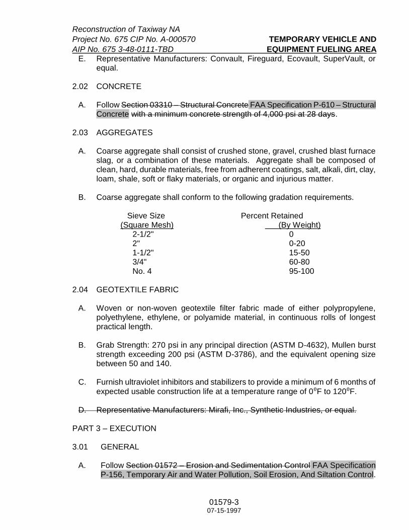
Reconstruction of Taxiway NA
Project No. 675 CIP No. A-000570 TEMPORARY VEHICLE AND
AIP No. 675 3-48-0111-TBD EQUIPMENT FUELING AREA
01579-3
07-15-1997
E. Representative Manufacturers: Convault, Fireguard, Ecovault, SuperVault, or equal.
2.02 CONCRETE
A. Follow Section 03310 – Structural Concrete FAA Specification P-610 – Structural Concrete with a minimum concrete strength of 4,000 psi at 28 days.
2.03 AGGREGATES
A. Coarse aggregate shall consist of crushed stone, gravel, crushed blast furnace slag, or a combination of these materials. Aggregate shall be composed of clean, hard, durable materials, free from adherent coatings, salt, alkali, dirt, clay, loam, shale, soft or flaky materials, or organic and injurious matter.
B. Coarse aggregate shall conform to the following gradation requirements.
Sieve Size Percent Retained (Square Mesh) (By Weight)
2-1/2" 0 2" 0-20 1-1/2" 15-50 3/4" 60-80 No. 4 95-100
2.04 GEOTEXTILE FABRIC
A. Woven or non-woven geotextile filter fabric made of either polypropylene, polyethylene, ethylene, or polyamide material, in continuous rolls of longest practical length.
B. Grab Strength: 270 psi in any principal direction (ASTM D-4632), Mullen burst
strength exceeding 200 psi (ASTM D-3786), and the equivalent opening size between 50 and 140.
C. Furnish ultraviolet inhibitors and stabilizers to provide a minimum of 6 months of
expected usable construction life at a temperature range of 0⁰F to 120⁰F.
D. Representative Manufacturers: Mirafi, Inc., Synthetic Industries, or equal.
PART 3 – EXECUTION 3.01 GENERAL
A. Follow Section 01572 – Erosion and Sedimentation Control FAA Specification P-156, Temporary Air and Water Pollution, Soil Erosion, And Siltation Control.

Reconstruction of Taxiway NA
TEMPORARY VEHICLE Project No. 675 CIP No. A-000570
EQUIPMENT FUELING AREA AIP No. 3-48-0111-TBD
01579-4 07-15-1997
B. Do not clear, grub, or rough cut until erosion and sedimentation control systems are in place, unless otherwise approved by City Engineer.
C. Maintain existing erosion and sedimentation control systems located within the
project site installed by others prior to start of construction under this contract until acceptance of the project or until directed by the City Engineer to remove and dispose the existing systems.
D. Inspect and repair or replace components of all erosion and sedimentation
control systems as specified for each type of system. Unless otherwise directed, maintain the erosion and sedimentation control systems until acceptance of the project. Remove erosion and sedimentation control systems promptly when directed by the City Engineer and dispose of removed materials offsite.
E. Remove and dispose of sediments deposits at the project spoil site. If a project
spoil site is not designated on Drawings, dispose sediment at an offsite location. Contractor assumes responsibility for offsite disposal location. Sediment shall be disposed of at an offsite location not in or adjacent to a stream or floodplain. Spread, compact, and stabilize sediment placed at the project site in accordance with the directions of the City Engineer. Do not allow sediment to flush into a stream or drainage way. If sediment is contaminated, dispose of sediment in accordance with federal, state and local regulations.
F. Do not maneuver equipment or vehicles on areas outside of dedicated rights-of-
way and easements for construction. Immediately repair damages caused by construction traffic to erosion and sedimentation control systems.
G. Employ protective measures to avoid damage to existing trees to be retained on
the project site. Conduct all construction operations under this Contract in conformance with the erosion control practices described in Section 01572 - Erosion and Sedimentation Control FAA Specification P-156, Temporary Air and Water Pollution, Soil Erosion, And Siltation Control.
H. Contractor to prepare spill response and containment procedures to be
implemented in the event of a significant materials spill. Significant materials include but are not limited to: raw materials; fuels; materials such as solvents, detergents, and plastic pellets; finished materials such as metallic products; raw materials used in food processing or production; hazardous substances designated under section 101(14) of CERCLA; any chemical required to be reported pursuant to Section 313 of Title III of SARA; fertilizers; pesticides; and waste products such as slag, ashes and sludge that have the potential to be released with storm water discharges. In lieu of developing procedures stated above, Spill Containment Procedures enclosed in the airport's pollution prevention plan may be used. Spill procedures shall be kept on-site at the airport construction site.

Reconstruction of Taxiway NA
Project No. 675 CIP No. A-000570 TEMPORARY VEHICLE AND
AIP No. 675 3-48-0111-TBD EQUIPMENT FUELING AREA
01579-5
07-15-1997
I. Spill containment equipment appropriate to the size of operation is to be located in close proximity to the fueling area. Such equipment includes, but not limited to, suitable waste containers for significant materials, drip pans, booms, inlet covers, or absorbent.
J. All significant materials or waste containers used for airport construction
activities and stored on-site at the airport overnight are to be properly labeled. 3.02 CONSTRUCTION METHODS
A. Provide fuel tank protection area and driveway as shown on the Drawings, or equivalent if prior written approval has been given by City Engineer.
B. Do not locate fueling area in or near a channelized flow area or close to a storm
sewer conveyance system. Sufficient space must be provided to allow installation of other erosion and sediment controls to protect those areas.
C. Clear and grub the fueling area to remove unsuitable materials. Place
geotextile fabric as permeable separator to prevent mixing of coarse aggregate with underlaying soil. Overlap fabric a minimum of 6 inches. Place coarse aggregate on top of the geotextile fabric to minimum depth of 8 inches.
D. Grade protection area and driveway to provide sufficient drainage away from
stabilized areas. Use sandbags, gravel, boards, or similar methods to prevent sediment from entering public right-of-way, receiving stream or storm water conveyance system. The driveway to the fuel tank area shall have a minimum width of 15 feet for one way traffic and 30 feet for two-way traffic.
E. Place the aboveground storage tank on top of the cast-in-place or pre-cast
foundation. The size and thickness of the foundation shall based on the size and weight of the tank to be used, with a minimum thickness of 6 inches. The concrete foundation shall be enclosed by a 5-inch by 5-inch concrete curb and shall extend a minimum of 1 foot beyond the tank and dispenser assemblies, so that leak and drip can be contained within the concrete foundation.
F. Slope the concrete foundation a minimum of 1 percent toward a 6-inch wide by
12-inch long by 4-inch deep sump pit. Install a minimum of 2-inch pipe inside the sump pit with a valve on the outside of the curb to allow draining of the concrete foundation.
G. Install a portable concrete jersey barrier around the concrete foundation.
Provide a minimum clearance of 2 feet from the edge of the foundation. In lieu of the jersey barrier, Contractor can install 4-inch diameter steel pipe bollards around the foundation. The bollards shall be buried a minimum of 3 feet deep, 3 feet aboveground, and 4 feet on center, encased in a 12-inch wide concrete foundation.

Reconstruction of Taxiway NA
TEMPORARY VEHICLE Project No. 675 CIP No. A-000570
EQUIPMENT FUELING AREA AIP No. 3-48-0111-TBD
01579-6 07-15-1997
3.03 MAINTENANCE
A. Inspect stabilized areas after every storm event and at least once a week. Provide periodic top dressing with additional coarse aggregate to maintain the required depth. Repair and clean out damaged control measures used to trap sediment.
B. Inspect fuel tank foundation’s bermed area after every storm event and at least
once a week. Visually examine storm water contained in the tank’s bermed foundation area for oil sheen or other obvious indicators of storm water pollution. Properly dispose of the storm water when significant amount of pollutant is present (as defined in Federal Register, Vol. 60, No. 189, Friday, September 29, 1995). Record visual examination of storm water discharge in a Report noting the date and time of examination, name of examiner, observations of water quality, and volume of storm water discharged from the bermed area. The Report shall be kept together with all other storm water pollution control inspection reports on the site, in a readily accessible location. The Report shall be maintained for the duration of the construction activity, and thereafter in accordance with the provisions of Section 01571 - NPDES Requirements Section 01410 – TPDES Requirements.
3.04 TEMPORARY FUELING AREA CLOSURE
A. The temporary vehicle and equipment fueling area shall be disposed of by removal of all sediment and erosion controls properly offsite. City Engineer will inspect the top soils in the fueling area and immediate vicinity for evidence of fuel leaks. If the City Engineer determines that sufficient pollutants have been released, the soil shall be removed and properly disposed offsite. Other remediation method may be required at no additional cost to the City.
END OF SECTION

RS&H
01 59 01 – 1
Section 01 59 01
TEMPORARY CONSTRUCTION ITEMS
DESCRIPTION
1.01 This item consists of furnishing all labor, materials and equipment for temporary construction items necessary for the safe and proper execution of work not otherwise included in other contract bid items. The Contractor will be expected to supply and utilize the temporary construction items listed below and other items contained in the plans and specifications. Temporary construction items to be provided may include, but are not limited to: flagmen; gate guards; escorts; portable lighting units; steel plates for temporary covering of excavations and structures; barricades; delineators; temporary haul roads; temporary safety area ramp downs; temporary signs; test pits; vacuum trucks and sweepers; portable sanitary facilities; temporary construction staging / storage areas, stockpile areas, disposal areas; waste disposal containers; runway / taxiway closure markers; temporary edge light coverings, centerline light masking, and sign coverings/modifications; temporary electrical cables, connections, and jumpering; and electrical lock-out and tag-out.
MATERIALS
2.01 Construction Barricades. Construction barricades shall be constructed in accordance with the details shown in the plans and shall be placed in accordance with the phasing plans and as directed by the Engineer. The term “barricade” shall be used throughout the plans and project manual to universally indicate barricades, signs, danger signals, hazard lighting, and / or any other safety measures to be installed by the Contractor prior to commencing work in an area. The Contractor shall be responsible for furnishing, installing, and maintaining the necessary barricades as required by the plans and specifications (FAA AC 150/5370-2, Operational Safety on Airports During Construction, current edition, latest change) for the protection of the work and the safety of the public for both land and air traffic.
2.02 Portable Lighting Units. Portable lighting units shall be provided, as required, for construction that must occur during nighttime operations. The Contractor shall provide sufficient units so that all work areas are illuminated to a level of five (5) horizontal footcandles. The lighting levels shall be calculated and measured in accordance with the current standards of the Illumination Engineering Society. Portable lighting units shall be positioned in such a way that they do not impact air traffic control operations and shall be approved by Airport Operations prior to use.
2.03 Steel Plates. Steel plates of adequate size and thickness shall be furnished as necessary to cover temporary excavations, unfinished structures or surfaces requiring protection or for safety purposes. Plates shall be securely fastened down and shall be adequate to safely support any anticipated loadings to be imposed.

RS&H
01 59 01 – 2
2.04 Lighted Runway Closure Markers and Unlit Taxiway Closure Markings. Lighted runway closure markers meeting the requirements of FAA AC 150/5370-2 shall be provided by the Contractor for each temporarily closed runway end. Unlit taxiway closure markers meeting the requirements of FAA AC 150/5370-2 shall be provided by the Contractor for each temporarily closed taxiway intersecting a runway at the entrance of the taxiway from the runway. The Contractor shall maintain the markers during construction, replace any worn parts, keep them fueled and maintain all oil levels, filters, etc. required to keep them running in good working order. The Contractor shall retain possession of the closure markers upon contract completion.
2.05 Haul Roads. The Contractor shall install, maintain, repair, and remove haul roads to be traversed by construction vehicles and equipment as indicated in the plans, or as required by the Contractor. Photos of the existing haul roads are attached to this specification.
The Contractor shall, in accordance with Section 01330 – Submittal Procedures, submit all proposed haul route improvements for review and approval prior to performing any proposed improvements.
2.06 Temporary Construction Staging / Storage Areas, Stockpile Areas, Disposal Areas, and Batch Plant Sites. The Contractor shall install, maintain, and repair temporary construction staging / storage areas, stockpile areas, disposal areas, and batch plant sites in accordance with the directives in the plans and project manual at the locations indicated in the plans, or as approved by the Engineer. At the completion of the project, these areas shall be removed and conditions of these areas and surrounding areas shall be as good as or better than the condition prior to starting work, including, at minimum, repair of existing facilities, regrading, and topsoiling and establishing vegetation, as applicable.
2.07 Sweepers, Vacuum Trucks, and Additional Cleaning Equipment. The Contractor shall provide an adequate number of sweepers, vacuum trucks, and additional cleaning equipment to keep all haul routes, active airfield pavements within the limits of work, and any other pavement areas traversed by the Contractor’s vehicles and equipment clean and free of mud, dirt, debris and other FOD. The Contractor shall provide a sweeper and vacuum truck at each active airfield pavement crossing, stationed outside the OFA. No less than two (2) sweepers and two (2) vacuum trucks shall be onsite for the duration of the project, regardless of the number of active airfield pavement crossings. The Contractor shall sweep and / or vacuum, as necessary, or as directed by the Owner's representative, immediately after each active airfield pavement crossing by the Contractor’s vehicles or equipment. The Contractor shall additionally ensure that all active airfield pavements affected by construction operations are kept free of any and all FOD deposited as the result of any source. The cost of all cleaning equipment, operation of said equipment, and labor and incidentals required for cleaning operations shall be included for payment under the item(s) of this specification.
2.08 Other Miscellaneous Items. Any other items not listed herein but which are associated directly or indirectly with temporary construction related work shall, by reference, be included in the requirements of this specification. No additional payment will be made for any related temporary construction item not specifically listed herein. The

RS&H
01 59 01 – 3
Contractor shall be responsible for providing any and all items necessary to ensure a safe, secure and functioning project construction site.
CONSTRUCTION METHODS
3.01 Construction Barricades. Barricades shall be placed around each phase of the work in accordance with the phasing plans and shall remain in place until completion of work in each phase.
3.02 Flagmen. Flagmen shall be provided, as necessary, to control the Contractor's traffic during the prosecution of work. All Contractor vehicles or equipment that are required to cross active airfield pavement or safety areas shall do so under the direct control of a competent flagman.
a. The contractor shall provide two (2) designated flagmen at any active airfield pavement crossing, as shown in the plans, or as directed by airport operations. The flagmen will be responsible for stopping any construction traffic that crosses the path of taxiing aircraft. Flagmen must be badged and must have successfully completed the airport flagman training, in addition to the regular badge and movement training.
b. Each flagman, supervisory individual, and Contractor lead / escort vehicle shall be equipped with an approved aviation band radio.
3.03 Portable Floodlighting. Portable floodlighting is required for construction during periods of limited visibility (i.e., nighttime). Illumination requirements shall be those contained in Paragraph 01 59 01-2.02.
METHOD OF MEASUREMENT
4.01 No direct measurement will be made for the items of this specification. Payment will be made on a lump sum basis.
BASIS OF PAYMENT
5.01 Payment will be made at the lump sum price for the items listed herein. Some items have been provided as independent bid items. For construction items required by this specification but not specifically provided as independent bid items (01 59 01-5.1 and 01 59 01-5.2), these items will collectively be bid as “Miscellaneous Temporary Construction Items”. “Miscellaneous Temporary Construction Items” shall include, but not be limited to construction flagmen, portable floodlighting, steel plates, barricades, temporary haul roads, test pits, vacuum trucks and sweepers, portable bathroom facilities, waste disposal containers, and runway / taxiway closure markers.
Payment for all items shall be full compensation for furnishing all materials and labor for placing, moving and removing barricades and steel plates, providing flagmen, furnishing portable floodlighting, test pitting, and for any other labor, materials, equipment, tools and incidentals necessary for temporary items required for construction of this work.

RS&H
01 59 01 – 4
Partial payments will be allowed as follows:
a. With first pay request, 25%.
b. When 25% or more of the original contract is earned, an additional 25%.
c. When 50% or more of the original contract is earned, an additional 40%.
d. After Final Inspection, Staging area clean-up and delivery of all Project Closeout materials as required by Section 90-11 of the FAA General Provisions, the final 10%.
* The Percent of Contract Amount Earned equals the work completed to date (including the total of all previous mobilization) plus or minus work completed associated with executed change orders, if any, divided by the Total Original Contract Amount plus or minus the Total Executed Change Order Amounts, if any.
Payment will be made under:
Item 01 59 01-5.1 Haul Roads - Per Lump Sum
Item 01 59 01-5.2 Flagmen - Per Lump Sum
Item 01 59 01-5.3 Miscellaneous Temporary Construction Items - Per Lump Sum

RS&H
01 59 01 – 5
PHOTO 1
PHOTO 2

RS&H
01 59 01 – 6
PHOTO 3
PHOTO 4

RS&H
01 59 01 – 7
PHOTO 5
PHOTO 6

RS&H
01 59 01 – 8
PHOTO 7
PHOTO 8

RS&H
01 59 01 – 9
PHOTO 9
PHOTO 10

RS&H
01 59 01 – 10
PHOTO 11
PHOTO 12

RS&H
01 59 01 – 11
PHOTO 13
PHOTO 14

RS&H
01 59 01 – 12
PHOTO 15
PHOTO 16

RS&H
01 59 01 – 13
PHOTO 17
PHOTO 18

RS&H
01 59 01 – 14
PHOTO 19
PHOTO 20
End of Section 01 59 01

Reconstruction of Taxiway NA Project No. 675 CIP No. A-000570 AIP No. 3-48-0111-TBD
01610-1 11-14-2007
Section 01610
BASIC PRODUCT REQUIREMENTS
PART 1 – GENERAL
1.01 SECTION INCLUDES
A. Transportation, delivery, handling, and storage of products.
1. Follow manufacturers' instructions for same. 2. Repair damage resulting from product transportation, delivery, handling and
storage to the satisfaction of the City Engineer. 3. Contractor salvaged products (CSP) are specified in Section 01110 –
Summary of Work.
B. Metric conversion.
C. Volatile organic compound (VOC)-producing products.
D. Contractor's responsibilities for product design.
1.02 PRODUCTS
A. “Products” is defined in Section 00700 – General Conditions. “Products” does not include machinery and equipment used for preparation, fabrication, conveying and erection of the Work. Products may also include existing construction designated for reuse.
B. Do not reuse existing products, except as permitted in Section 01110 – Summary of Work.
C. Provide products from the fewest number of manufacturers as practical, to simplify spare parts inventory and to allow for maximum interchangeability of components. For multiple components of the same size, type or application, use the same manufacturer and model of component throughout the Work.
1. Furnish products of latest proven design, new and in current production. Do not use obsolete components or components to be phased out of production.
D. Do not use new or existing products containing asbestos or other hazardous materials except as permitted by governing agencies.
E. When using chlorofluorocarbon (CFC) containing materials, follow regulations governing the release of CFCs into the atmosphere during fabrication or installation.

Reconstruction of Taxiway NA Project No. 675 CIP No. A-000570 BASIC PRODUCT REQUIREMENTS AIP No. 3-48-0111-TBD
01610-2 11-14-2007
1.03 TRANSPORTATION
A. Transport, deliver, and handle products as required for timely completion of the Work.
B. Consign and address shipping documents to the proper party giving name of Project, street number, and City. Deliver shipments to proper consignee.
1.04 DELIVERY
A. Deliver products in accord with construction schedule and in ample time for inspection prior to installation. Reduce lengthy storage or overburden of limited storage space due to excessively early deliveries.
B. Coordinate deliveries to avoid conflict with Work and conditions at the site and to accommodate the following:
1. Work of other contractors or City. 2. Limitations of storage space. 3. Availability of equipment and personnel for handling products. 4. City's use of premises.
C. Deliver products only after related submittal data are approved by City Engineer.
D. Deliver products when proper storage facilities are in place.
E. Deliver products to the site in manufacturer's original, unopened, labeled containers. Keep the City Engineer informed of delivery schedules for equipment to be incorporated in the Work.
F. Clearly mark partial deliveries of component parts of equipment to identify the equipment, to permit easy accumulation of parts, and to facilitate assembly.
G. Immediately upon delivery, including CSP, inspect shipment to assure:
1. Product complies with requirements of Contract Documents and reviewed submittals.
2. Quantities are correct. 3. Containers and packages are intact; labels are legible. 4. Products are properly protected and undamaged. 5. Process claims for damages and replacement.
1.05 PRODUCT HANDLING
A. Coordinate off-loading of products delivered to the site, including City-furnished products. If necessary to move stored products during construction, relocate products at no additional cost or time to the contract.

Reconstruction of Taxiway NA Project No. 675 CIP No. A-000570 AIP No. 3-48-0111-TBD BASIC PRODUCT REQUIREMENTS
01610-3 11-14-2007
B. Provide handling equipment, personnel and additional protection as required to:
1. Prevent soiling or damage to products, packaging or surrounding work and existing facilities.
2. Prevent bending or overstressing. 3. Lift heavy components only at designated lifting points. 4. Follow manufacturer's recommendations and specified requirements.
C. Do not drop, roll, or skid products off delivery vehicles. Hand carry or use suitable materials handling equipment.
1.06 PRODUCT STORAGE
A. Provide safe storage of products. Place salvaged products, excavated products, construction equipment, and other products to prevent damage to the Work or Base Facilities (Section 01726 – Base Facility Survey) and to maintain free access at all times to the Work and to City and applicable separate contractors with installations in the vicinity of the Work.
1. Keep products neatly and compactly stored in locations that with least inconvenience to other contractors, public travel, adjoining owners, tenants, and occupants.
2, Arrange storage to provide easy access for inspection.
B. Store products on airport property at location(s) shown on Drawings or approved by City Engineer.
C. Provide bonded off-site storage and protection when on-site storage is not adequate. Submit copy of storage facility bond following Section 01340 – Shop Drawings, Product Data and Samples procedures for certifications.
D. Do not use lawns, grass plots, private property, occupied areas, sidewalks or roadways for storage.
E. Protect stored products against loss or damage.
F. Store in manufacturers' unopened containers, placed on solid supports (sloped to drain at exterior conditions) and covered if subject to erosion or deterioration, except open for inspection and immediately repackage if products are scheduled for immediate installation.
1. Maintain stored products within manufacturer's required environmental range. Provide supplemental ventilation as required to prevent condensation.
2. Store products with clearly visible part numbers, carton numbers, packing lists and other identification markings.

Reconstruction of Taxiway NA Project No. 675 CIP No. A-000570 BASIC PRODUCT REQUIREMENTS AIP No. 3-48-0111-TBD
01610-4 11-14-2007
G. Neatly, safely, and compactly stack permitted excavation, fill, pavement and utility products stored along the line of paving and utility work to cause the least inconvenience and damage to Base Facility, occupants, airport operations and the general public, and:
1. No closer than 3 feet to fire hydrants. 2. Keep public and private drives and street crossings open. 3. Distribute evenly along the route of construction to maximum 1000 lineal feet,
unless otherwise approved in writing by the City Engineer.
1.07 METRIC CONVERSION
A. The Drawings and Specifications are typically prepared in Imperial (inch and feet) measure, to establish the basis for the contract.
B. Contractor may use SI (metric) measure when SI material, fabrication methods, tolerances and other dimension-controlled characteristics is in normal use by manufacturers and fabricators. Use meters or millimeters only, not centimeters, on submittals.
C. Follow ASTM E380 and ASTM/ANSI E621 for conversion protocol.
1.08 VOC-PRODUCING MATERIAL
A. Provide products and use installation methods producing the least practical amount of volatile organic compounds (VOCs).
B. Schedule and sequence work to allow maximum possible VOC release of products to occur off-site. Follow applicable laws and codes governing atmospheric release of VOCs.
C. For VOC-producing products which by nature must be fabricated or installed on-site, schedule and sequence work to allow initial VOC release as early as possible before Substantial Completion. Follow Section 01630 – Product Options and Substitutions for proposal of products with less VOC than specified products.
D. Contain odors following Section 01505 – Temporary Facilities.
1.09 CONTRACTOR’S RESPONSIBILITIES FOR PRODUCT DESIGN
A. Drawings and Specifications intend for the Contractor to provide product design expertise where actual conditions cannot be anticipated by the Drawings and Specifications or where the Contractor’s expertise or suggestions could substantially improve performance of the Work to the benefit of the Work without increase of Contract Sum or Time.

Reconstruction of Taxiway NA Project No. 675 CIP No. A-000570 AIP No. 3-48-0111-TBD BASIC PRODUCT REQUIREMENTS
01610-5 11-14-2007
B. The Drawings and Specifications establish the general design concept for the Work.
1. Drawings show “sight-line,” profile, units or modules, alignments and other visual characteristics of work.
2. Specifications state performance requirements including types of materials, fabrication and installation requirements, applicable performance criteria and other aspects of application of work.
C. Drawings and Specifications intentionally address performance and visual characteristics in order to employ Contractor's expertise and choice of fabrication processes and techniques, coordination of the trades and Separate Contracts, correlating and confirming dimensions and other aspects of construction control, or because concealed conditions are not known to Designer.
D. Product engineering design, design of details, and construction procedures within the general design concept is Contractor's responsibility. Supplement general designs with submittal data showing how general design requirements are fulfilled.
1. By accepting a contract for this work, Contractor agrees the requirements shown or specified for known conditions adequately establish the scope, location and other performance and visual requirements for the Work without additional cost or time.
2. If performance and visual requirements are unclear, obtain direction before expenditure of non-recoverable costs including preparation of submittal data, fabrication or acquisition of products and on-site preparatory work. When required, make subcontractors available for consultation at no additional cost.
3. Design, fabrication, erection, and installation of products shall be based on local applicable building codes and local environmental conditions: a. Normal Site Elevation, feet ASL: 98.0 (IAH) b. Seismic Zone: 0 c. Highest Wind Velocity, mph: 110 (IAH) d. Temperature: Coldest Winter Month High: 60 degrees F Low: 41 degrees F Warmest Summer Month High: 94 degrees F Low: 73 degrees F Lowest Expected: 11 degrees F Highest Expected: 107 degrees F e. Rainfall:
Annual: 45 Inches f. Design Relative Humidity: 98% g. Station Barometric Pressure: 29.5 Inches Hg Abs., average annual
E. When product engineering design is required, use designers licensed to practice the applicable discipline in the State of Texas.

Reconstruction of Taxiway NA Project No. 675 CIP No. A-000570 BASIC PRODUCT REQUIREMENTS AIP No. 3-48-0111-TBD
01610-6 11-14-2007
1. Seal design drawings, calculations and submittal data where specified, and process as submittal data.
2. Where seal is not required, provide letter of certification or statement of compliance signed by Subcontractor(s) and countersigned by Contractor stating products are fabricated and installed to meet or exceed requirements.
PART 2 – PRODUCTS (Not Used)
PART 3 – EXECUTION (Not Used)
END OF SECTION

Reconstruction of Taxiway NA Project No. 675 CIP No. A-000570 AIP No. 3-48-0111-TBD
01630-1 03-13-2006
Section 01630
PRODUCT OPTIONS AND SUBSTITUTIONS
PART 1 - GENERAL
1.01 SECTION INCLUDES
A. Procedure for requesting substitution of products in lieu of those specified. These requirements supplement Paragraph 3.10 of Sections 00700 – General Conditions and 00800 – Supplementary Conditions.
B. After submittal period expires, requests for substitutions will be considered only when a specified product becomes unavailable because of conditions beyond Contractor's control.
1.02 DEFINITIONS
A. Process: Any proprietary method for installing products that results in an integral, functioning part of the Work. For this Section, the word "product" includes "process."
1.03 SUBMITTALS
A. Submit 5 copies of each separate product substitution request, within time period stated in Section 00700 – General Conditions, including:
1. Full submittal data for specified products, following Section 01340 – Shop Drawings, Product Data and Samples.
2. Full data substantiating compliance of proposed substitutions with Contract Documents and substantiating equivalency with specified products: a. Product identification, including manufacturer's name and address. b. Manufacturer's literature with precise product description, and directly
applicable performance and test data and reference standards. c. Samples, as applicable. d. Name and address of projects on which proposed product was used in
similar or equivalent conditions within the last 3 years, and date of installation.
e. Name, address and telephone number of owner, designer, and installing contractor.
f. For process substitutions, detailed description of proposed method and drawings illustrating methods.
B. Detailed reason(s) for substitution, and tangible benefits accruing to City.
C. Itemized comparison of proposed substitutions with specified products and full description of deviations.

Reconstruction of Taxiway NA Project No. 675 CIP No. A-000570 PRODUCT OPTIONS AND SUBSTITUTIONS AIP No. 3-48-0111-TBD
01630-2 03-13-2006
D. Fully describe all effects of substitutions on the Work and on separate contracts and work by City. Include full cost data comparing proposed substitution with specified products and amount of change in Contract Sum. Indicate changes in construction schedule (Section 01325 – Construction Schedules).
E. Substitutions are not permitted when:
1. They are not processed following Section 00700 – General Conditions and this Section.
2. Acceptance will require revision of Contract Documents or will change the design concept.
3. Delay in construction will occur. 4. No provisions for substitutions are stated in the Contract Documents.
F. Burden of proof of merit of proposed substitution remains solely with Contractor.
1.02 CONTRACTOR'S OPTIONS
A. Options, stated as "Contractor's option(s)" in Contract Documents, are intended to benefit the Work through reduced cost, decreased construction time, or better performance within designated range of criteria.
B. Volunteer options are not permitted.
C. Notify in writing City Engineer of options chosen.
1.03 QUALITY ASSURANCE
A. To the maximum extent possible, provide products of the same type or function from a single manufacturer, make, or source. Where more than one choice is available, select the product which is compatible with other products already selected, specified, or which is in use by City.
1.04 DESIGNER'S ACTIONS
A. Decision to accept or deny proposed substitute products, or selection of one product instead of another, is solely the responsibility of Designer; such decisions and selections are final.
1.05 COSTS FOR REVIEW OF SUBSTITUTIONS
A. Pay costs related to Designer's review and examination of proposed substitutions. Assume liability for obtaining acceptance of substitutions.
B. Reimburse City for actual evaluation costs of Designer's(s') if proposed substitute does not meet requirements of Contract Documents, or acceptance of proposed substitute requires changes to the Work.

Reconstruction of Taxiway NA Project No. 675 CIP No. A-000570 AIP No. 3-48-0111-TBD PRODUCT OPTIONS AND SUBSTITUTIONS
01630-3 03-13-2006
C. Reimburse City for associated design costs, including redesign, additional submittal reviews, investigations, Designer's fees and revision of Contract Documents required because of the requested substitution. Design costs are the full price for additional work performed, paid at the rates established by Designer's contract with City for Design and Contract Documents phase of the Project.
D. Pay for laboratory testing required to obtain information upon which equivalency can be determined.
E. If Designer determines that proposed substitutions are not equivalent to specified products, furnish one of the specified products without delay in time or additional cost to City.
PART 2 – PRODUCTS (Not Used)
PART 3 – EXECUTION (Not Used)
END OF SECTION


Reconstruction of Taxiway NA Project No. 675 CIP No. A-000570 AIP No. 3-48-0111-TBD
01725-1 10-21-1997
Section 01725
FIELD SURVEYING
PART 1 – GENERAL
1.01 CONTRACTOR’S SURVEYOR
A. Contractor shall employ a State of Texas Registered Public Land Surveyor acceptable to City Engineer.
B. Responsibilities include, but are not limited to:
1. Recovering control points established by City; 2. Verifying benchmarks furnished by City; 3. Establishing temporary benchmarks and construction control points; 4. Recording location(s) and elevation(s) of temporary benchmarks and
construction control points; 5. Setting control for grading, cut and fill, and topsoil placement; 6. Establishing horizontal layout and vertical elevations for proposed
pavements, storm drainage, airfield lighting and signage, markings, and other project improvements.
1.02 SUBMITTALS
A. Submit to City Engineer the name, address, and telephone number of Surveyor before starting survey work.
B. On request, submit documentation verifying accuracy of survey work.
C. Submit 3 original copies of certificate, signed by surveyor and sealed, stating that horizontal and vertical control lines, elevations, and benchmarks follow Contract Documents.
1.03 PROJECT RECORD DOCUMENTS
A. Maintain a complete and accurate log of control and survey work as it progresses.
B. Prepare a certified survey setting forth dimensions, locations, angles, and elevations of construction and sitework upon completion of the Work.
C. Submit Record Documents following Section 01770 – Contract Closeout.
1.04 EXAMINATION
A. Establish benchmarks, control points, lines and elevations prior to starting work. Notify City Engineer immediately of discrepancies discovered between stated
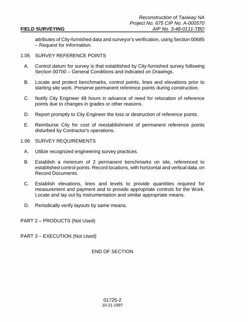
Reconstruction of Taxiway NA Project No. 675 CIP No. A-000570 FIELD SURVEYING AIP No. 3-48-0111-TBD
01725-2 10-21-1997
attributes of City-furnished data and surveyor's verification, using Section 00685 – Request for Information.
1.05 SURVEY REFERENCE POINTS
A. Control datum for survey is that established by City-furnished survey following Section 00700 – General Conditions and indicated on Drawings.
B. Locate and protect benchmarks, control points, lines and elevations prior to starting site work. Preserve permanent reference points during construction.
C. Notify City Engineer 48 hours in advance of need for relocation of reference points due to changes in grades or other reasons.
D. Report promptly to City Engineer the loss or destruction of reference points.
E. Reimburse City for cost of reestablishment of permanent reference points disturbed by Contractor's operations.
1.06 SURVEY REQUIREMENTS
A. Utilize recognized engineering survey practices.
B. Establish a minimum of 2 permanent benchmarks on site, referenced to established control points. Record locations, with horizontal and vertical data, on Record Documents.
C. Establish elevations, lines and levels to provide quantities required for measurement and payment and to provide appropriate controls for the Work. Locate and lay out by instrumentation and similar appropriate means.
D. Periodically verify layouts by same means.
PART 2 – PRODUCTS (Not Used)
PART 3 – EXECUTION (Not Used)
END OF SECTION

Reconstruction of Taxiway NA Project No. 675 CIP No. A-000570 AIP No. 3-48-0111-TBD
01726-1 10-21-1997
Section 01726
BASE FACILITY SURVEY
PART 1 – GENERAL
1.01 SECTION INCLUDES
A. “Base Facility” is defined in Section 01423 – References.
B. Survey of Base Facility and related existing conditions.
C. Notification of discoveries.
D. Contractor's survey of Base Facility is intended to identify and describe actual as-found conditions to supplement information contained in Base Facility documents and in the Drawings and Specifications.
E. Necessary changes in location of the Work may be made by City Engineer to avoid unanticipated concealed conditions, following Section 01255 – Modification Procedures.
F. If permanent relocation or reworking of existing conditions is required and not otherwise provided for in the Contract Documents, City Engineer will direct Contractor following Section 01255 – Modification Procedures.
1.02 BASE FACILITY DOCUMENTS
A. Drawing and Specifications for the Work are based on City-furnished Base Facility documents.
1. Contract Documents do not necessarily completely describe all details of Base Facility at interfaces with the Work.
B. Obtain available Base Facility documents from the City Engineer.
1.03 SEQUENCING AND SCHEDULING
A. Sequence and schedule survey to properly coordinate with other construction operations.
B. Complete survey work, process one or more Section 00685 – Request for Information, obtain responses, evaluate and submit cost or schedule impact of responses, and process accepted modifications before commencing work of affected Sections.
C. Obtain or designate and protect control samples of Base Facility work during survey and maintain until required submittals pertinent thereto are processed.

Reconstruction of Taxiway NA Project No. 675 CIP No. A-000570 BASE FACILITY SURVEY AIP No. 3-48-0111-TBD
01726-2 10-21-1997
1.04 BASE FACILITY CONDITIONS
A. Base Facility intended or required to remain takes precedence of fact and control over details and construction of interfaces, dimensions, clearances, openings, alignments, and substrate conditions between Base Facility and the Work.
B. Base Facility is intended to remain except as shown on Drawings or as specified.
1.05 DIMENSIONS
A. Control dimensions are indicated by nominal value on the Drawings within parenthesis. This designation means, in addition to other requirements, the Contractor is responsible for finding the actual dimension following this Section, and using actual dimensions to govern placement of work including relationship to and coordination with related work.
1. Follow Section 01255 – Modification Procedures to resolve discrepancies between existing conditions and Contract Documents.
PART 2 – PRODUCTS (Not Used)
PART 3 – EXECUTION
3.01 GENERAL
A. Survey Base Facility affecting or affected by the Work by on-site examination of existing conditions.
B. Explore ahead of trenching and excavation work to uncover obstructing underground structures sufficiently to determine location, to prevent damage and to prevent interruption of services. Restore to original condition damages to underground structure at no cost or time increase to the contract, following Section 01731 – Cutting and Patching.
C. Note discovered discrepancies between the Base Facility and Contract Documents.
1. Use one set of prints of Drawings and Specifications (made from reproducibles furnished following Section 01110 – Summary of Work) for the sole purpose of documenting discoveries. Designate as “SURVEY DOCUMENTS.”
2. Prepare and issue Section 00685 – Request for Information for each discrepancy, following Section 01255 – Modification Procedures.
3. Supplement data noted on survey documents with video or photographs following Section 01321 – Construction Photographs as required to clearly and fully describe conditions.

Reconstruction of Taxiway NA Project No. 675 CIP No. A-000570 AIP No. 3-48-0111-TBD BASE FACILITY SURVEY
01726-3 10-21-1997
D. Coordinate survey of semi-exposed and concealed conditions with proposed work.
END OF SECTION


Reconstruction of Taxiway NA Project No. 675 CIP No. A-000570 AIP No. 3-48-0111-TBD
01761-1 03-24-2010
Section 01761
PROTECTION OF EXISTING SERVICES
PART 1 – GENERAL
1.01 SECTION INCLUDES
A. Requirements to protect existing services and minimize impact of interruptions.
1.02 DEFINITIONS:
A. Service is defined to include utilities (natural gas, water, or power); lighting and emergency lighting; data and telecommunications; closed-circuit video, control and monitoring circuits, and air conditioning, heating, and ventilating. Service types include, but are not limited to:
1. Power. 2. Lighting, and emergency lighting. 3. Paging. 4. Telephone. 5. Video. 6. Data and computer networks. 7. Water. 8. Natural gas. 9. Heating, ventilating, and air conditioning
B. Data and Telecom Service is defined to include:
1. Wiring and cable used for the transmission of data, voice, or video information.
2. Wiring for low voltage monitoring and control of various types of devices.
C. Service interruption is defined to include any temporary or permanent inability
to provide the service as contracted or as intended and includes interference with or disruption to source, distribution, or terminal items of a service system.
D. Response time is defined to be the time elapsed between the time that a Service Interruption becomes known to the Contractor and the time that a person is at the site of the interruption or, if the site of the interruption is not immediately known, at the job site to diagnose and locate the service interruption.

Reconstruction of Taxiway NA Project No. 675 CIP No. A-000570 PROTECTION OF EXISTING SERVICES AIP No. 3-48-0111-TBD
01761-2 03-24-2010
1.03 PERFORMANCE REQUIREMENTS
A. Contractor is required to protect and maintain existing services to those operating areas of the Airport. 1. Where services are affected by construction activities and interruption
of service is required to complete the Work, schedule service interruption to minimize impact.
2. Where services cannot be interrupted, provide alternate services or circuits as required to maintain affected services. Design and implement service "cut-over" so that services are maintained without interruption.
B. Train employees and subcontractors to ensure that accidental service
interruptions are promptly recognized and appropriate responses can be initiated.
C. Maintain personnel, equipment, and parts at hand or on call to provide the response times indicated.
D. Interruptions to Existing Service are classified as follows:
1. Security Service Interruption:
a. Any service interruption of power, lighting, or data and telecom service that affects and compromises one of the following:
(1) FAA Security (2) Airline Security (3) Airport Security (4) Other government entity charged with enforcing security
at the Airport (Houston Police Department, FBI, Secret Service, etc.).
b. Security Services must be active at all times.
2. Life Safety Service Interruption:
a. Any service interruption of power, lighting, or data and telecom service affecting or compromising one or more of the following life safety systems. (1) Fire/smoke alarms. (2) Emergency lighting. (3) Elevator operations in "Fire" mode. (4) Emergency intercom systems.

Reconstruction of Taxiway NA Project No. 675 CIP No. A-000570 AIP No. 3-48-0111-TBD PROTECTION OF EXISTING SERVICES
01761-3 03-24-2010
b. Life Safety Services must be active at all times.
3. Business Service Interruption:
a. Any service interruption of utility service (power, lighting, natural gas, data and telecom, etc.) that affects and compromises the ability of a profit-seeking entity to earn revenue, including: (1) Airline: Includes FIDS network, reservation/confirmation
systems, paging systems. (2) Tenants Other Than Airlines: Point of sale systems,
reservation/confirmation systems, utilities for storing, cooking, or maintaining food for sale to the public.
b. Business Services must be active at all times in the areas of the
Airport served by Airlines or other tenants during hours of their operation.
4. Comfort / Convenience Service Interruption:
a. Any service interruption of power, lighting, or data and telecom
services affecting or compromising the comfort or convenience of those using the Airport (passengers, visitors, employees, concessionaires, etc.) including: (1) Lighting. (2) Air Conditioning. (3) Heating. (4) Public telephones. (5) Elevators.
b. Minimize Comfort/Convenience Service Interruptions except in construction areas.
1.04 SUBMITTALS
A. Schedule of service interruptions.
B. Emergency Response Plan.
1.05 QUALITY ASSURANCE
A. Develop emergency response plan for each class of service interruption
indicated. Notify other contractors responsible for services and obtain contact information. Where possible, obtain written instructions for emergency repairs

Reconstruction of Taxiway NA Project No. 675 CIP No. A-000570 PROTECTION OF EXISTING SERVICES AIP No. 3-48-0111-TBD
01761-4 03-24-2010
from the contractor responsible for each service. Where required, arrange for contractor personnel to be available to meet required response times.
1.06 COORDINATION AND SEQUENCING
A. Schedule and execute construction activities to prevent service interruption or, where service interruption is required to complete the Work, minimize service interruption.
1.07 SCHEDULING
A. Follow Section 01325 – Construction Schedules.
B. Develop a schedule of required service interruptions. Coordinate with the schedules required by Section 01325 – Construction Schedules and revise as required by the City or project conditions.
PART 2 – PRODUCTS (Not Used) PART 3 – EXECUTION 3.01 CONTRACTOR RESPONSIBILITIES:
A. Follow Section 01726.
B. Scheduled Service Interruptions: Notify the City Engineer in writing not less than 7 days in advance of a scheduled service interruption. Use the attached form and include the following information in addition to the information required on the form: 1. Type and classification of service. 2. Location. 3. Area(s) affected. 4. Entities affected. 5. Expected duration.
C. Unscheduled Service Interruptions to Data and Telecom Service:
1. Immediately notify IAH 24-Hour Emergency Dispatch Service at (281) 230-3024. Do not attempt to repair these lines. Include the following information:
a. Location. b. Area(s) affected.

Reconstruction of Taxiway NA Project No. 675 CIP No. A-000570 AIP No. 3-48-0111-TBD PROTECTION OF EXISTING SERVICES
01761-5 03-24-2010
c. Type and classification of service (if known). d. Entities affected (if known).
2. In addition to the notification requirements above, immediately notify the City Engineer of interruption.
D. Unscheduled Service Interruptions to Service Other Than Data and Telecom
Service:
1. When executing Work in an area known to have existing services, maintain on-site or on-call capability to initiate repairs to unscheduled service interruptions within the response times required.
2. Immediately notify the City Engineer of interruption.
a. Location. b. Area(s) affected. c. Type and classification of service (if known). d. Entities affected (if known).
3. Response Times to Interruptions to Existing Service:
a. Security Service Interruption: 15 minutes. b. Life Safety Service Interruption: 15 minutes. c. Business Service Interruption:
(1) Service Interruptions to Airlines: 15 minutes. (2) Service Interruptions to Tenants other than Airlines:
1 hour.
d. Comfort/Convenience Service Interruption: 1 hour.
END OF SECTION

Reconstruction of Taxiway NA Project No. 675 CIP No. A-000570 PROTECTION OF EXISTING SERVICES AIP No. 3-48-0111-TBD
01761-6 03-24-2010
SERVICE INTERRUPTION REQUEST/NOTIFICATION TO: IAH Operations
DATE RECEIVED:
ATT: REF:
(General Contractor to Complete this Block)
GENERAL CONTRACTOR:
PROJECT NUMBER:
PHONE NUMBER:
PAGER NUMBER: FAX NUMBER:
(Subcontractor to Complete this Block)
SUBCONTRACTOR: PHONE NUMBER: FAX NUMBER: PAGER NUMBER:
TYPE AND CLASSIFICATION OF SERVICE: LOCATION OF INTERRUPTION:
DATE OF INTERRUPTION
AREAS AFFECTED:
TIME OF INTERRUPTOIN
ENTITIES AFFECTED:
EXPECTED DURATION
SIGNATURE DATE:
Do not write below this line RESPONSE:

01761-7 03-24-2010
Construction Request IAH AIRPORT OPERATIONS - CONSTRUCTION
Once WAN is approved, this will change from a red “Construction Request” to a green WAN “Approval”.
TO: Airport Operations WAN #
ATT: Construction – IAH Operations
CONTRACTOR:
OFFICE NUMBER DATE:
FAX NUMBER: TIP PROJECT NUMBER:
E-MAIL: [email protected] [email protected] [email protected]
Onsite contact / phone #’s:
FROM:
OFFICE NUMBER:
MOBILE NUMBER:
FAX NUMBER:
LOCATION DESCRIPTION DATE OF
REQUEST TIME OF REQUEST
COMMENTS
Operations - Construction Response:


Reconstruction of Taxiway NA Project No. 675 CIP No. A-000570 AIP No. 3-48-0111-TBD
01770-1 07-18-2012
Section 01770
CONTRACT CLOSEOUT
PART 1 – GENERAL
1.01 SECTION INCLUDES
A. Submittal of Operation and Maintenance (O & M) manual, lien releases, record documents, badges, and keys.
B. O & M manual format and contents.
C. Final cleaning. Interim cleaning is specified in Section 01505 – Temporary Facilities.
D. Systems demonstrations and personnel training.
E. Notification of Substantial Completion.
F. Contractor's punch list.
G. Record of the Work.
1.02 SUBMITTALS
A. One month before Substantial Completion inspection, submit 2 sets of Preliminary O & M manual (Paragraph 1.03), 1 copy to Designer and 1 copy direct to City Engineer.
B. Subsequent to Preliminary O & M manual submittal and precedent to final Certificate for Payment, submit the following:
1. Five (5) sets of final O & M manual with one (1) original executed warranty plus four (4) copies, in same format as preliminary O & M manual.
2. Release or Waiver of Liens and consents of sureties following Sections 00700 – General Conditions and 00800 – Supplementary Conditions.
3. Record Documents following Section 00700 – General Conditions and Paragraph 1.08 below. a. Bind documents, material as directed by City Engineer, with metal folding
clasps (such as used for file folders) at top and bottom along binding edge. Collate into separate sets for Drawings, shop drawings, and other drawings.
b. Bind Project Manual, product data and similar page-type data in separate 3-ring “D” binders, contents marked on spine.
c. CADD diskettes in plastic file box. d. Videotapes and photographs following Section 01321 – Construction
Photographs.

Reconstruction of Taxiway NA Project No. 675 CIP No. A-000570 CONTRACT CLOSEOUT AIP No. 3-48-0111-TBD
01770-2 07-18-2012
e. Other data as directed. 4. Security identification badges. 5. Construction and other master keys.
1.03 O&M MANUAL CONTENTS AND FORMAT
A. Provide O & M Manual with full information to allow matching products under future contracts to products under this contract, and to allow City to operate, maintain and repair (for user-serviceable aspects) products, including trade names, model or type numbers, colors dimensions, and other physical characteristics.
B. Format:
1. Produce on 8-1/2-inch x 11-inch pages, and bind in 3-ring/D binders with durable plastic covers.
2. Label binder covers with printed title “OPERATION AND MAINTENANCE MANUAL”, title of project, and subject matter and “Number _ of _” of binder when multiple binders are required.
3. Separate each “Part” with substantial dividers tabbed and titled by Part number
C. Contents:
1. Table of Contents for each volume, naming each Part. 2. Part 1: Directory with name, address, and telephone number of Designer,
Contractor, and Subcontractors and Suppliers for each Project Manual Section.
3. Part 2: Operation and maintenance instructions, arranged by Project Manual Section number where practical, and where not, by system. Include: a. For finish materials, maintenance instructions prepared by manufacturers,
including recommended cleaning methods and materials and special precautions identifying detrimental agents.
b. Utility, door and window hardware, HVAC, plumbing and electrical products, prepared by product manufacturer, including: 1) Product design criteria, functions, normal operating characteristics,
and limiting conditions. 2) Assembly, installation, alignment, adjustment, checking instructions,
and troubleshooting guide. 3) Operating instructions for start-up, normal operation, regulation and
control, normal shutdown, and emergency shutdown. 4) Lubrication and detailed maintenance instructions; detailed drawings
giving location of each maintainable part and lubrication point and detailed instructions on disassembly and reassembly of products.
5) Spare parts list for operating products, prepared by manufacturers, including detailed drawings giving location of each maintainable part;

Reconstruction of Taxiway NA Project No. 675 CIP No. A-000570 AIP No. 3-48-0111-TBD CONTRACT CLOSEOUT
01770-3 07-18-2012
describe predicted life of parts subject to wear, lists of spares recommended for user-service inventory, and nearest source of in-stock spares.
6) Outline, cross-section, and assembly drawings; engineering data; wiring diagrams.
7) Test data and performance curves. 4. Part 3: Project documents and certificates, including:
a. Shop drawings, product data, and where practical, samples. b. Air and water balance reports. c. Certificates of occupancy or use. d. Product certifications and mix designs. e. Material Safety Data Sheets.
5. Part 4: Copy (not original) of each warranty form containing language of final warranty.
6. Part 5: Meeting notes from systems demonstrations. 7. Revise content and arrangement of preliminary Manual until approval by City
Engineer.
1.04 FINAL CLEANING
A. Execute final cleaning prior to Substantial Completion of each Phase.
B. Not Used.
C. Remove and legally dispose of waste and surplus products and rubbish from site.
D. Not Used.
E. Not Used.
F. Remove temporary facilities and controls.
G. Leave project site in such condition that no further cleaning of construction is required by City.
H. Adjust products to proper operating condition.
I. Correct defective function of products.
1.05 SYSTEMS DEMONSTRATIONS AND PERSONNEL TRAINING
A. Demonstrate proper operation and maintenance of each product to City’s maintenance personnel precedent to Substantial Completion inspection.
B. Precedent to submittal of O & M Manual, train City's maintenance personnel in proper operation, adjustment, and maintenance of products and systems, using

Reconstruction of Taxiway NA Project No. 675 CIP No. A-000570 CONTRACT CLOSEOUT AIP No. 3-48-0111-TBD
01770-4 07-18-2012
the preliminary O & M Manual as the basis of instruction. Continue training until City's personnel demonstrate proper knowledge and skills.
C. Take minutes of meetings, including sign-in sheet, and record subjects covered in each session. Bind minutes in O&M Manual.
1.06 NOTIFICATION OF SUBSTANTIAL COMPLETION
A. When Contractor considers the Work (or a designated portion or stage thereof identified in Section 01326 – Construction Sequencing) substantially complete, submit written notice and Punchlist (Paragraph 1.04) to City Engineer.
1. Do not claim Substantial Completion until authorities having jurisdiction issue certificates of occupancy or use and related inspections affirming compliance.
2. Attach copy of each certificate to Substantial Completion form.
B. Within a reasonable time after receipt of certificates, an inspection will be made by City Engineer and Designer to determine status of completion.
C. Should the Work be determined by City Engineer as not substantially complete as a result of any Substantial Completion inspection, Contractor will notified in writing.
1. Remedy deficiencies. 2. Send written notice of Substantial Completion as above. 3. City Engineer and Designer will re-inspect the Work. 4. Pay costs of Designer’s second and subsequent Substantial Completion
inspections, by Change Order.
D. When the Work is determined as substantially complete, the Certificate of Substantial Completion will be executed.
1.07 CONTRACTOR'S PUNCHLIST
A. Prior to and in connection with Substantial Completion procedures, prepare a written Punchlist for each Phase and as follows:
1. Designer will provide one reproducible copy of then-current contract plans. These drawings are the basis of Contractor’s Punchlist.
2. Inspect the Work and mark applicable comments on the contract plans. Prepare written notes as required to supplement notes made on drawings.
3. Continue completion of the Work including Punchlist items, marking off completed items.
4. Forward the annotated Drawings to City Engineer as directed, accompanied by notification that Substantial Completion Inspection is ready.

Reconstruction of Taxiway NA Project No. 675 CIP No. A-000570 AIP No. 3-48-0111-TBD CONTRACT CLOSEOUT
01770-5 07-18-2012
B. Schedule Punchlist Inspection and other closeout inspections through City Engineer.
C. Punchlist inspection will be attended by the following as a minimum:
1. Contractor, Contractor’s Superintendent, and applicable Subcontractors’ superintendents. Attend with Punchlist drawing.
2. City Engineer. 3. Designer. 4. Others of City Engineer’s choice.
D. Substantial Completion inspection will be made during one or more mutually agreed times to inspect the Work, to review and amend Contractor’s Punchlist. If the work is substantially complete, Section 00645 – Certificate of Substantial Completion will be executed.
1. Amendments to the Contractor’s Punchlist will be made on the reproducible. 2. Within 5 days of execution of Section 00645 – Certificate of Substantial
Completion, provide 4 copies of the amended Punch List and original Section 00645 – Certificate of Substantial Completion to City Engineer.
E. Expeditiously correct work.
F. Process each re-inspection as above and in Paragraph 1.04.
G. Punchlist items and corrections required after execution of Section 00650 – Certificate of Final Completion will be processed as warranty work following Section 00700 – General Conditions, Paragraph 3.12.
1.08 RECORD OF THE WORK
A. Following requirements expand Paragraph 3.16 of Sections 00700 – General Conditions and 00800 – Supplementary Conditions.
B. Record information concurrently with construction progress. Do not conceal work until required information is recorded.
C. Keep in a secure location in the contractor’s field office (Section 01505 – Temporary Facilities) and timely record the Work as actually built as the Work progresses.
1. Use one set of Drawings made from reproducibles and one set of Project Manual furnished under Section 01110 – Summary of Work. Use one set of submittal data, video and photographic data, and other record data as required by Contractor to support and supplement records made on Drawings and Project Manual.

Reconstruction of Taxiway NA Project No. 675 CIP No. A-000570 CONTRACT CLOSEOUT AIP No. 3-48-0111-TBD
01770-6 07-18-2012
2. Legibly note variations from Contract Documents on Drawings, Project Manual and submittal data, whichever most clearly shows the change.
3. Clearly mark each document in red ink “RECORD OF THE WORK. Use only for recording field deviations and actual constructed conditions and arrangements.”
D. Keep documents current and make available for inspection by City Engineer.
E. Show following minimum information, as applicable to type of work, marked in fine-point red ink:
1. Measured depths of foundation elements in relation to finish first floor datum. 2. Measured horizontal locations and elevations of underground utilities and
appurtenances, referenced to permanent surface improvements. 3. Elevations of underground utilities referenced to City’s benchmark utilized for
project. 4. Measured locations of internal utilities, environmental systems and
appurtenances concealed in construction, referenced to visible and accessible features of construction.
5. Field changes of dimension and detail. 6. Changes made by RFI (Section 00931 – Request for Information). 7. Changes made by Modifications. 8. Details not on original Contract Documents. 9. References to related shop drawings, product data, samples, RFIs and
Modifications.
F. Upon completion of the Work, collect marked-up Drawings, one single-sided copy of marked-up Project Manual, one set of shop drawings (including diskettes of CAD files prepared as part of the Contract, such as data required by Section 01340 – Shop Drawings, Product Data, and Samples), one original set of product data (Section 01340 – Shop Drawings, Product Data and Samples), one set of RFIs, one set of Modifications, one set of originals of video tapes and one copy of photographs (Section 01321 – Construction Photographs), and other required documents.
1. Clearly mark each document, immediately adjacent to the “RECORD OF THE WORK” mark, in red ink thus:
“CERTIFIED AS THE CORRECT AND COMPLETE RECORD OF WORK PERFORMED. ___________________________(Contractor Firm Name) ___________________________(Authorized Signature) ___________________________(Date)”
G. Transmit all records to City Engineer.

Reconstruction of Taxiway NA Project No. 675 CIP No. A-000570 AIP No. 3-48-0111-TBD CONTRACT CLOSEOUT
01770-7 07-18-2012
H. Transmit reproducible copies of Drawings (see Section 01110 – Summary of Work) to City Engineer.
I. Submit proper record of the Work, in addition to other requirements in the Contract Documents, precedent to City Engineer’s authorization for release of final payment.
1.09 FORWARDING CSP AND EXTRA PRODUCTS (Not Used)
PART 2 – PRODUCTS (Not Used)
PART 3 – EXECUTION (Not Used)
END OF SECTION


RS&H
02 41 13.14 – 1
Section 02 41 13.14
SAWCUTTING
DESCRIPTION
1.01 This work shall consist of sawcutting existing concrete and / or asphaltic concrete pavements to provide uniform joint alignments in sound material, as shown on the plans or as directed by the Engineer. Sawcutting of existing pavements may be required for the abutment of new pavement to existing pavement. This item shall include the furnishing of all labor, materials, equipment and incidentals necessary to perform the work to the satisfaction of the Engineer.
EQUIPMENT
2.01 Saws shall be power-driven, self-propelled, wheel or track-mounted, and capable of cutting to a depth of at least three (3) inches in one pass. The Contractor shall make the necessary number of passes to cut through the pavement. The use of a cutting wheel mounted on a roller, grader or similar equipment, or the use of pneumatically driven hand-held tools, will only be approved if the Contractor can demonstrate to the satisfaction of the Engineer that such equipment can consistently produce satisfactory results. Multi-blade arbor saws shall be used to construct sealant reservoirs.
CONSTRUCTION METHODS
3.01 The Contractor shall establish the line to be cut using chalkline or similar means. The face of any sawcut shall be sawed or otherwise trimmed so that there is no abrupt offset in any direction greater than 1/4 inch and no gradual offset greater than one (1) inch when tested in a horizontal direction with a 16-foot straightedge.
3.02 The sawcut depth shall be full depth so that spalling or other breakage of the existing pavement along the bottom of the pavement does not occur. If spalling or other breakage of the does occur, the Contractor shall relocate the sawcut line to a point deeper in the existing pavement to remove completely any spalled or broken pavement so that the underlying base and / or subbase layers is not damaged and the new pavement can be constructed up against the existing pavement without either the new or existing pavement strength and pavement section being compromised. Sawcutting depth may vary nominally and no extra payment will be allotted for varying depths.
3.03 A vacuum truck shall be required for use during all sawcutting operations in order to collect all dust, chips, slurry, or waste material as a result of sawcutting operations. All waste material shall be carefully collected and removed from the site in accordance with the general safety requirements of the Contract and disposed of legally off the airport property.

RS&H
02 41 13.14 – 2
METHOD OF MEASUREMENT
4.01 The quantity of sawcutting of existing pavement shall not be measured for payment.
BASIS OF PAYMENT
5.01 No separate payment will be made for sawcutting. The cost of the work described in this item shall be considered incidental to installation of the various other elements included in the project. The Contractor will still be responsible for furnishing all equipment and materials; for all preparation; and for all labor, tools and incidentals necessary to complete this item.
End of Section 02 41 13.14

Reconstruction of Taxiway NA Project No. 675 CIP No. A-000570 AIP No. 3-48-0111-TBD
26 05 00 - 1 03-21-2016
Section 26 05 00
COMMON WORK RESULTS FOR ELECTRICAL
PART 1 GENERAL
1.01 SECTION INCLUDES
A. This item is intended to supplement the specifications for the Airfield Electrical, Lighting and Lighting Control requirements of this contract. It is the intent and meaning of the Plans and Specifications that the Contractor shall provide an electrical installation that is operational and complete, including all items and appurtenances necessary, reasonably incidental or customarily included, even though each and every item is not specifically called out or shown.
B. Installations and construction under these provisions shall be coordinated with the Airport Construction Manager. Specification requirements for approvals, reviews, or other involvements of the Engineer shall be transmitted by the Contractor through the Construction Manager to the Engineer.
1.02 APPLICABLE CODES AND STANDARDS.
A. Codes. All electrical work shall conform with the requirements and recommendations of the latest edition of the National Electrical Code. In conflicts among drawings, specifications and codes, the most stringent requirements shall govern.
B. Standards. The specifications and standards of the following organizations are by reference made part of these specifications and all electrical work, unless otherwise indicated, shall comply with their requirements and recommendations wherever applicable.
1. Institute of Electrical and Electronic Engineers (IEEE) 2. American National Standards Institute (ANSI) 3. American Society for Testing and Materials (ASTM) 4. Insulated Power Cable Engineers Association (ICEA) 5. National Institute of Standards and Technology (NIST). 6. National Electrical Contractor's Association (NECA) 7. National Electrical Manufacturer's Association (NEMA) 8. National Fire Protection Association (NFPA) 9. Underwriter's Laboratories, Inc. (UL) 10. National Electrical Safety Code (NESC)

COMMON WORK RESULTS Reconstruction of Taxiway NA FOR ELECTRICAL Project No. 675 CIP No. A-000570 AIP No. 3-48-0111-TBD
26 05 00 - 2 03-21-2016
PART 2 QUALITY ASSURANCE
2.01 REQUIREMENTS OF REGULATORY AGENCIES
A. Airport lighting equipment and materials covered by FAA specifications shall be certified under the Airport Lighting Equipment Certification Program described in Advisory Circular (AC) 150/5345-53, current edition, and be listed in the current Addendum of the AC. All Advisory Circulars referenced in these specifications shall be the latest edition.
B. All other equipment and materials, covered by other referenced specifications shall be subject to acceptance through manufacturer's certification of compliance with the applicable specification, when requested by the Engineer.
C. The requirements and recommendations of the latest edition of the Occupational Safety and Health Act are by reference made a part of these specifications and all electrical work shall comply with their requirements and recommendations wherever applicable.
2.02 WORKMANSHIP AND PERSONNEL REQUIREMENTS
A. All electrical work shall be performed by workmen skilled in the electrical trade and licensed for the work either by the City of Houston or State of Texas. The Houston Airport System Airport Building Official will recognize the credentials of Master Electricians with valid current licenses from Houston. Credentials will be recognized of Journeyman Electricians with valid current licenses from Houston or other licensing entities having established reciprocal agreements with these municipalities.
B. A licensed Master Electrician will be required for the issuance of a building permit for constructing, installing, altering, maintaining, repairing or replacing any electrical wiring, apparatus, or equipment on any voltage level in the jurisdiction of the Airport.
C. A licensed Master Electrician or a licensed Journeyman Electrician is required to be on the job site whenever any electrical work is performed. Any airfield electrical work or associated electrical installations shall be accomplished under the direct supervision of a licensed Journeyman Electrician.
D. To insure compliance with Paragraph "c" above, only a documented Electrical work force with a ratio of a maximum ration of 3 licensed Apprentices for each licensed Journeyman Electrician shall be allowed to work on the airfield electrical systems.
E. Contractor shall prepare documentation associated with the electrical work force confirming adherence to the requirements of Paragraph "d" above.

Reconstruction of Taxiway NA COMMON WORK RESULTS Project No. 675 CIP No. A-000570 FOR ELECTRICAL AIP No. 3-48-0111-TBD
26 05 00 - 3 03-21-2016
These documents shall be submitted to the Construction Manager for approval. Also, any work force changes or revisions which affect compliance with paragraph "d" above shall also be submitted to the Construction Manager for approval.
F. All airfield circuits will be handled throughout the installation process by qualified licensed electrical personnel.
G. Every airfield lighting cable splicer shall be qualified in making airfield cable splices and terminations on cables rated above 1,000 volts A.C. The Contractor shall submit for approval of the Construction Manager proof of the qualifications of each proposed cable splicer for the cable type and voltage level to be worked on. Cable splicing/terminating personnel shall have a minimum of three (3) years continuous experience in terminating/splice medium voltage cable at airports.
H. At least thirty (30) days prior to performing any cable splicing/terminating, Contractor shall submit to the Construction Manager a written list of proposed cable splicing/terminating personnel, including written evidence that the proposed personnel have had a minimum of eight (8) hours of technical training by authorized splice/termination kit manufacturer personnel. Approved training shall include a thorough review of kit components and splicing/terminating techniques and procedures. Field splices shall only be installed by technicians approved by the Construction Manager and by HAS maintenance superintendent.
I. In addition, each trained cable splicer shall be required to install a splice and a connector on type and size of the cable to be used under this contract. Sample connections shall be accomplished in accordance with the manufacturer's instructions and in the presence of the Construction Manager.
J. All communications work shall be performed under the direct supervision of a Building Industry Consulting Service International, Inc. (BICSI) registered Cabling Installer/Technician level.
K. The Contractor performing construction on the airfield electrical and/or communication system shall have a minimum of 5 years of experience on construction of projects of similar type of work and of similar size and complexity. The owner will require all Electrical Contractors bidding on this project to submit proof of experience that they have successfully completed at least two projects of comparative size and complexity within the past 5 years.
L. Electrical contractor qualifications shall be based on previous work experience as follows:
1. Installed at least 500 L868 bases into existing facilities that were paved via a slipform method.

COMMON WORK RESULTS Reconstruction of Taxiway NA FOR ELECTRICAL Project No. 675 CIP No. A-000570 AIP No. 3-48-0111-TBD
26 05 00 - 4 03-21-2016
2. Modify existing airfield lighting control systems in at least two installations of the size and complexity of this project.
3. Installed semiflush and elevated runway guard light systems. 4. Perform construction activities within an active CAT II/III AOA.
2.03 EQUIPMENT, MATERIAL AND INSTALLATION REQUIREMENTS
A. The Contractor shall furnish and install all materials, equipment, accessories, connections and incidental items in accordance with the approved recommendations of the manufacturer and the best practices of the trade to provide a complete installation ready for use and operational by the Owner.
B. All equipment and materials shall be new, unless specifically noted otherwise, and shall bear the manufacturer's name, trademark and ASME, UL, and/or other labels in every case where a standard had been established for the particular item.
C. Where applicable, equipment shall be FAA approved design of a standard product of a manufacturer regularly engaged in the production of the required type of equipment, and shall be supported by a service organization reasonably convenient to the site, as determined by the Construction Manager.
D. The Contractor shall promptly notify the Construction Manager in writing of any conflict between any requirements of the Contract Documents and equipment manufacturer's directions and shall obtain written instructions from the Construction Manager before proceeding with the work. Should the Contractor perform any work that does not comply with the manufacturer's directions or such written instructions from the Construction Manager, Contractor shall bear all costs arising in correcting deficiencies.
E. After review of equipment submittals, and instructions by the Engineer to proceed, equipment installations may require arrangements or connections different from those shown on the drawings. It is the responsibility of the Contractor to install the equipment to operate properly. The Contractor shall provide any additional equipment and/or materials required for installations to operate in accordance with the intent of the drawings and specifications.
F. It is the responsibility of the Contractor to insure that items installed fit the space available with adequate room for proper equipment operation and maintenance. Contractor shall make field measurements to ascertain space requirements, including those for connections, and shall furnish and install such sizes and shapes of equipment that the final installation provides a complete and operational system that complies with the requirements of the drawings and specifications.

Reconstruction of Taxiway NA COMMON WORK RESULTS Project No. 675 CIP No. A-000570 FOR ELECTRICAL AIP No. 3-48-0111-TBD
26 05 00 - 5 03-21-2016
G. The Contractor shall be responsible for coordinating proper location of roughing in and connections by other trades. Changes associated with coordination requirements shall be made at no increase in the Contract amount or additional costs to other trades.
H. The Contractor shall support work and equipment plumb, rigid and true to line. The Contractor shall determine how equipment, fixtures, conduit, etc., are to be installed, as required by codes, drawings and specifications. Foundations, bolts, inserts, stands, hangers, brackets and accessories required for proper support shall be provided by the Contractor, whether or not specifically indicated on the drawings.
I. Uniform illumination levels for similar lighting systems throughout the airfield shall be installed. Contractor shall insure illumination levels for installed airfield edge or centerline lighting systems do not vary due to faulty installations from illumination levels of similar airfield lighting systems.
2.04 SUBMITTALS
A. Submit manufacturer's data or shop drawings of the following items giving full information as to the dimensions, materials, and other information required to define compliance with the specifications. Other items to be submitted are listed in the specification sections.
Handholes/Manholes/ Pull Boxes and Accessories
S-1 Plug Cutouts and Cabinet
Ductbanks Constant Current Regulator Conduit ALRCS Support Hardware Multi-hole Adapter Ring #8 5KV L-824C Cable Fixture Bases, and accessories #6 Stranded Counterpoise Wire L-823 Connectors Airfield Lighting Fixtures Splice Kits Airfield Fixture Lamps Identification Tags Isolation Transformers Ground Rods Cadweld Grounding Airfield Guidance Signs/ Panels Support Hardware Guidance Sign Foundation Shop Drawings 316 Stainless Steel Bolts Tape 3/8+ - Fixture Installation and Location
B. When requested by the Engineer, samples of these items shall be submitted for approval. Equipment/installation diagrams shall also be submitted for approval, as required by project specifications and/or requested by the Engineer.

COMMON WORK RESULTS Reconstruction of Taxiway NA FOR ELECTRICAL Project No. 675 CIP No. A-000570 AIP No. 3-48-0111-TBD
26 05 00 - 6 03-21-2016
C. Contractor submittal package shall include a typewritten list indicating each bid item, with a breakdown of all item components and all parts that are assembled or associated with bid item installation.
D. Submittal package list shall indicate: (1) Bid item number, (2) Part numbers of associated item components, as required and (3) Reference page number where item and components information is located in the submittal package. The contractor shall organize submittals so that common components to multiple bid items are not duplicated in the submittals.
E. Checking of submittals by the Engineer is done only as an aid to the Contractor and approval of submittals shall not relieve Contractor of responsibility for any errors or omissions in the submittals, nor shall it relieve the Contractor of total responsibility for proper and complete execution of the job.
2.05 INSPECTION AND TESTING
A. All work performed by the Contractor shall be subject to periodic inspections by the City Engineer, the Owner’s Representative, and the Owner's Construction Manager to verify that the installation is in compliance with the applicable requirements of these specifications.
B. System and component testing shall be performed as specified in Section 26 0820 - Airfield Electrical Installation Testing. Test results shall be evaluated by the Engineer, HAS PDC and the Construction Manager based upon the criteria indicated.
C. Any installation found which does not conform to the required technical provisions of these specifications or any specimen which does not meet the test criteria defined in Section 26 08 20 - Airfield Electrical Installation Testing, shall be immediately removed by the Contractor and then replaced at his expense. When required, testing shall be performed on the new specimen in place to verify compliance with the criteria defined in Section 26 0820 - Airfield Electrical Installation Testing.
PART 3 CONSTRUCTION PROVISIONS
3.01 AOA AREA INSTALLATION PROVISIONS
A. To enhance personnel safety and avoid contractual problems, the Contractor shall comply with the provisions indicated below.

Reconstruction of Taxiway NA COMMON WORK RESULTS Project No. 675 CIP No. A-000570 FOR ELECTRICAL AIP No. 3-48-0111-TBD
26 05 00 - 7 03-21-2016
3.02 ELECTRICAL WORK PROVISIONS.
A. Existing Underground Utilities. At least forty-eight (48) hours prior to beginning any excavation within the AOA, locations of all utility lines and FAA cables in the construction area will be identified and marked with surveyor flags by appropriate utility and/or FAA personnel. The Contractor shall be responsible for maintaining the location flags. Any flags displaced shall be replaced by the Contractor. The Contractor shall coordinate with Construction Manager any additional prior notification time required during weekend and/or holiday work periods.
B. Also at least forty-eight (48) hours prior to beginning any excavation within the AOA, the contractor shall request the HAS construction manager to have airport staff identify circuits in proposed excavation areas. The Contractor shall coordinate with Construction Manager any additional prior notification time required during weekend and/or holiday work periods.
C. The above noted line identification information shall not relieve the Contractor of the responsibility of pinpointing underground lines to avoid unplanned disruptions or disturbing of installation or operation of underground lines in construction areas. Contractor shall use cable tracing equipment or other methods approved by the Construction Manager at his disposal, to pinpoint line locations. Excavation shall not proceed until all underground lines have been identified to the satisfaction of the Construction Manager.
D. Contractor shall hand excavate in areas of Airport underground electrical lines to avoid disturbing circuits such as FAA, telecom and NAVAIDS.
E. Repair of underground lines damaged by the Contractor shall be the sole responsibility of the Contractor.
F. Lockout Procedure. Contractor shall adhere to requirements of latest edition of Section 26 08 10 - Recommended Lockout Procedure for Airfield Lighting Circuit.
3.03 TEMPORARY AND BYPASS CIRCUIT PROVISIONS
A. During construction, temporary or bypass wiring or cable installations may be required to maintain operation of certain equipment and/or airfield lighting circuits, as indicated in Construction Documents and/or as specified. Temporary/bypass circuit installations shall adhere to provisions indicated below.
1. General Requirements. Contractor shall review the requirements in the specifications and Construction Documents, including, but not restricted to: Phasing and Sequencing Plans, Demolition Plans and Wiring

COMMON WORK RESULTS Reconstruction of Taxiway NA FOR ELECTRICAL Project No. 675 CIP No. A-000570 AIP No. 3-48-0111-TBD
26 05 00 - 8 03-21-2016
Diagrams. Contractor shall determine locations, sizes and quantities of temporary/bypass wiring and conduits required for project construction.
2. At least 14 days prior to commencement of installation of temporary/bypass wiring, the Contractor shall submit a layout of proposed temporary/bypass conduits and circuits to the Construction Manager for review and approval, including proposed installation protection provisions.
3. Equipment and Materials. Temporary/bypass wiring shall meet the requirements of Section 26 0540 - Installation of Underground Cable for Airports (Item L-108), and shall also conform to the Construction Plans. Temporary/bypass wiring shall be identified at junction points with brass tags as approved by the Construction Manager.
4. Installation. Temporary/bypass circuits shall be installed with due consideration to personnel safety and circuit protection against physical damage. All damage to existing circuits as a result of Contractor action or inaction shall be corrected accordingly at the Contractor's expense and corrective action approved by the Owner.
5. Temporary/bypass, high voltage lighting system cables shall be protected from damage by vehicles with suitable fencing, barriers and/or adequately sized boards or timbers.
6. Temporary/bypass circuits shall be removed immediately upon completion of construction or purpose for which the wiring was installed. Upon removal of boards or timbers fastened to the pavement surface to protect temporary/bypass circuits, the Contractor shall repair the pavement with materials and methods approved by the Construction Manager. Temporary/bypass cable and counterpoise shall be removed and discarded off the Airport by the Contractor.
3.04 EXISTING ELECTRICAL EQUIPMENT AND MATERIALS
A. The Contractor shall remove all existing wiring and electrical equipment made unnecessary by the new installation. All materials removed shall become property of the Contractor and disposed of by the Contractor. The Contractor shall list materials according to type, class and/or size, and store or dispose of materials as directed by the Construction Manager.
3.05 POWER SERVICE CONTINUITY
A. Provide labor, materials and supervision required to maintain full capacity power service continuity when connection or modifications are made to existing systems and facilities. Do not interrupt service without prior consent of the Construction Manager, with a definite understanding of time and duration of outage. All outages will take place at a time for minimum disruption of facility activity. Coordinate with Owner.
3.06 AS-BUILT DRAWINGS

Reconstruction of Taxiway NA COMMON WORK RESULTS Project No. 675 CIP No. A-000570 FOR ELECTRICAL AIP No. 3-48-0111-TBD
26 05 00 - 9 03-21-2016
A. The Contractor shall maintain a set of as-built drawings on the job site as required the General Provisions of the Contract. Contractor shall mark on the as-built drawings all work details, alterations installed to meet site conditions and changes made by Change Notices. As-built drawings shall be kept available for inspection by the Construction Manager and/or the City Engineer at all times.
B. Airfield wiring verification diagrams shall be maintained throughout the project and later submitted to HAS Planning, Design, and Construction upon completion. These field wiring diagrams shall depict the exact routing and number of cables installed in each conduit originating from the airfield lighting vaults and extending to each manhole, handhole, pullbox, sign, and lighting fixture for each new circuit or circuit revision.
PART 4 MEASUREMENT AND PAYMENT
4.01 There will be no separate measurement or payment on the work discussed in this section. All work will be considered incidental for complete installation of the work to which it is related.
END OF SECTION

COMMON WORK RESULTS Reconstruction of Taxiway NA FOR ELECTRICAL Project No. 675 CIP No. A-000570 AIP No. 3-48-0111-TBD
26 05 00 - 10 03-21-2016
THIS PAGE INTENTIONALLY LEFT BLANK

Reconstruction of Taxiway NA Project No. 675 CIP No. A-000570 AIP No. 3-48-0111-TBD
26 05 05 - 1 03-21-2016
Section 26 05 05
ALTERATIONS, REMOVAL AND DEMOLITION
PART 1 DESCRIPTION
1.01 DEFINITIONS
A. Alterations shall mean any change or rearrangement in the component parts, including structural, mechanical, electrical systems, or internal or external arrangements of an existing structure.
B. Removal shall mean the dismantling of existing materials, components, equipment, and utilities. Removed items shall be handled, prepared for storage, transported to storage areas as specified.
C. Demolition shall mean the dismantling and disposal of existing materials, components, equipment, and utilities which cannot or will not be reused or which will have no salvage value, or which cannot be reused due to unrepairable damage caused by age, non-demolition related reasons, etc. All demolished items not designated to be turned over to the Owner shall be disposed of in a safe manner and at a location acceptable to the Owner.
D. All items to be turned over to the Owner shall be properly enclosed or boxed to protect the items from damage and transported by the Contractor to a location on the Owner’s property, designated by the Engineer and/or the Owner.
E. The installation and/or removal of lighting equipment may be critical to airport operations; therefore, the Contractor shall follow the work schedule established in the plans and specifications or as directed by the Engineer. The system shall be installed in accordance with the National Electrical Code and/or local code requirements.
F. The Contractor shall provide temporary wiring as required to reconnect existing circuits to provide guidance for aircraft to pass through the construction areas on those taxiways/runways which must remain open. The Contractor shall check all temporary circuits before dark each day to assure that they are operational. In the event of failure, the Contractor shall immediately take steps to restore operation. The cost of temporary and reconnected lighting shall be absorbed in the various work items.
1.02 CONDITION OF EXISTING FACILITIES
A. The Contractor shall verify the areas, conditions, and features necessary to

ALTERATIONS, REMOVAL Reconstruction of Taxiway NA AND DEMOLITION Project No. 675 CIP No. A-000570 AIP No. 3-48-0111-TBD
26 05 05 - 2 03-21-2016
tie into existing construction. This verification shall be done prior to submittal of shop drawings, fabrication or erection, construction or installation. The Contractor shall be responsible for the accurate tie-in of the new work to existing facilities.
B. Special attention is called to the fact that there may be piping, fixtures or other items in the existing systems which must be removed or relocated in order to perform the alteration work. All conduit, wiring, boxes, etc., that do not comply with these specifications shall be removed or corrected to comply with these specifications. All unused conduit not removed shall be identified and a pull line shall be installed. The work shall include all removal and relocation required for completion of the alterations and the new construction.
C. Whenever the scope of work requires connection to an existing circuit, the circuit’s insulation resistance shall be tested, in the presence of the Owner and Engineer. The Contractor shall record the results on the forms included in these specifications. When the circuit is returned to its final condition, the circuit’s insulation resistance shall be checked again in the presence of the Owner and Engineer. The Contractor shall record the results on the forms included in these specifications. The second reading shall be equal to or greater than the first reading or the Contractor shall make the necessary repairs to the circuit to bring the second reading above the first reading. All repair costs including a complete replacement of the cable, if necessary, shall be borne by the Contractor. All test results shall be submitted in the Operation and Maintenance Manuals as described in Section 16010 – General Provisions - Electrical.
1.03 OCCUPANCY AND USE OF EXISTING FACILITIES
A. The Owner will occupy and use the facilities within the areas of work during the entire construction period. The Contractor shall be required to plan and coordinate his activities in order to provide all necessary controls for the abatement of dust, noise, and inconvenience to the Owner personnel during all phases of the work.
1.04 VACATING OCCUPIED AREAS
A. The Owner will remove all portable items of furniture, equipment, and fixtures prior to the start of work.
1.05 SAFETY REQUIREMENTS
A. The Contractor shall conduct alterations and removal operations in a manner that will ensure the safety of persons in accordance with the requirements of CFR 29 PART 1926 and 1910.

Reconstruction of Taxiway NA ALTERATIONS, REMOVAL Project No. 675 CIP No. A-000570 AND DEMOLITION AIP No. 3-48-0111-TBD
26 05 05 - 3 03-21-2016
1.06 CLASSIFICATION OF REMOVED/DEMOLISHED ITEMS
A. Existing materials and equipment indicated to be removed will be classified as "salvageable" and shall remain the property of the Owner or will be classified as "debris" and shall be disposed of legally off the airport.
B. Salvageable Items
1. Reusable salvaged items: a. Salvaged materials and equipment shall be reused in the work as
described on the contract drawings, unless noted otherwise. 2. Retained salvaged items:
a. Salvaged materials and equipment to be retained by the Owner but not reused in the work shall be turned over to the Owner at a site at the facility to be determined by the Owner. Retained salvaged items shall be stored on Owner property where indicated by the Owner.
C. Debris Items
1. Items classified as debris shall be legally disposed of off the airport property. The cost of such disposal shall be included in the cost of other items of work.
1.07 TEMPORARY PROTECTION
A. The Contractor shall provide and maintain the following requirements.
1. Protection of persons and property shall be provided throughout the progress of the work in accordance with these specifications.
2. Provide temporary enclosures and partitions prior to starting alterations and removal of work. Such items shall protect existing materials, equipment, and other remaining building or system components from damage by weather and construction operations.
3. Provide temporary enclosures to isolate space utilized by equipment during construction, from dirt, dust, noise, and unauthorized entry.
4. Provide temporary exits, entrances, and protected passages where work prevents the use of existing facilities.
5. Provide weathertight temporary enclosures over and around openings to be made in existing exterior construction prior to the start of work. The Contractor shall maintain such temporary enclosures until new construction will protect the interior of existing facilities from the elements.
6. Provide temporary exterior wall construction which will be designed and fabricated to resist an applied horizontal wind pressure of not less than 130 mph.
7. Provide temporary exterior roof construction which will be capable of supporting an applied vertical live load of not less than 200 psf, uniformly distributed over the entire roof area.

ALTERATIONS, REMOVAL Reconstruction of Taxiway NA AND DEMOLITION Project No. 675 CIP No. A-000570 AIP No. 3-48-0111-TBD
26 05 05 - 4 03-21-2016
8. Design and fabricate temporary enclosures to maintain temperatures inside the existing facilities within a range of plus-or-minus 5 degrees F of normal operating conditions.
9. Provide temporary jet blast structures which will withstand the jet blast with a safety factor of 2.
PART 2 EXECUTION
2.01 DISCONNECTING UTILITIES
A. Prior to the start of work, the necessary utilities serving each area of alteration or removal will be shut off by the Owner and shall be disconnected and sealed by the Contractor, as required. Lockout/Tag/Try procedures shall be utilized in accordance with Section 26 0810 – Recommended Lockout Procedure for Airfield Lighting Circuit.
2.02 TEMPORARY UTILITY SERVICES
A. The Contractor shall install temporary utility services in satisfactory operating condition before disconnecting existing utilities. Such temporary services shall be maintained during the period of construction and removed only after new permanent services have been tested and are in operation.
2.03 REMOVAL WORK
A. The Contractor shall not disturb the existing construction beyond that indicated or necessary for installation of new work. Temporary shoring and bracing for support of building components to prevent settlement or other movement shall be as indicated and as required to protect the work.
B. The Contractor shall provide protective measures to control accumulation and migration of dust and dirt in all areas of work, particularly those adjacent to occupied areas. The Contractor shall remove dust, dirt, and debris from the areas of work daily.
2.04 SALVAGEABLE MATERIALS AND EQUIPMENT
A. The Contractor shall remove all salvageable materials and equipment in a manner that will cause the least possible damage thereto. Removed items which are to be retained by the Owner shall be carefully handled, stored, and protected.
B. The Contractor shall provide identification tags on all items boxed or placed in containers, indicating the type, size, and quantity of materials.

Reconstruction of Taxiway NA ALTERATIONS, REMOVAL Project No. 675 CIP No. A-000570 AND DEMOLITION AIP No. 3-48-0111-TBD
26 05 05 - 5 03-21-2016
2.05 BUILDINGS AND STRUCTURES
A. The Contractor shall perform removal operations in existing buildings as indicated and as otherwise required to complete the work.
B. Existing concrete shall be demolished, removed, and disposed of. Square, straight edges shall be provided where existing concrete adjoins new work and at other locations where indicated. Existing steel reinforcement shall be protected where indicated; otherwise, it shall be cut off flush with face of concrete.
C. The Contractor shall dismantle steel components at field connections and in a manner that will prevent bending or damage.
D. The use of flame-cutting torches will be permitted only when other methods of dismantling are not practical, and when approved in writing by the Owner and/or Engineer.
2.06 ELECTRICAL EQUIPMENT AND FIXTURES
A. Wiring systems and components shall be salvaged. Loose items shall be boxed and tagged for identification.
B. All unused conduit not removed shall have a pull string installed and shall be noted on the record drawings.
C. Primary, secondary, control, communication, and signal circuits shall be disconnected at the point of attachment to their distribution system.
D. The Contractor shall remove and salvage electrical fixtures. Incandescent lamps, mercury-vapor lamps, and fluorescent lamps shall be salvaged, boxed and tagged for identification, and protected from breakage.
E. The Contractor shall remove and salvage switches, receptacles, fixtures, transformers, constant current regulators, meters, instruments, plates, circuit breakers, panelboards, outlet boxes, and similar items. These items shall be boxed, and tagged for identification according to type and size.
F. The Contractor shall remove and dispose of conductors and conduits not used in the finished work and shown to be demolished on the plans.
PART 3 DEMOLITION, DISPOSAL, AND ALTERATION
3.01 DEMOLITION OPERATIONS
A. Demolition operations shall be conducted to ensure the safe passage of persons to and from facilities occupied and used by the Owner and to prevent

ALTERATIONS, REMOVAL Reconstruction of Taxiway NA AND DEMOLITION Project No. 675 CIP No. A-000570 AIP No. 3-48-0111-TBD
26 05 05 - 6 03-21-2016
damage by falling debris or other cause to adjacent buildings, structures, and other facilities.
B. The sequence of operations shall be such that maximum protection from inclement weather will be provided for materials and equipment located in partially dismantled structures.
3.02 MAINTAINING TRAFFIC
A. Demolition operations and removal of debris to disposal areas shall be conducted to ensure minimum interference with runways, taxiways, aprons, roads, streets, walks, and other facilities occupied and used by the Owner.
B. Streets, walks, runways, taxiways and other facilities occupied and used by the Owner shall not be closed or obstructed without written permission from the Owner.
3.03 REFERENCE STANDARDS REQUIREMENTS
A. Demolition operations shall be conducted to ensure the safety of persons in accordance with ANSI A 10.6 Safety Requirements for Demolition.
B. Demolition shall be conducted in accordance with OSHA, State and local requirements.
3.04 DISPOSAL OF DEMOLISHED MATERIALS
A. General
1. The Contractor shall dispose of debris, rubbish, scrap, and other non-salvageable materials resulting from demolition operations. Demolished materials shall not be stored or disposed of on Airport property.
B. Removal From Property Owner
1. Materials classified as debris shall be transported from Owner property and legally disposed of at no additional cost to the Owner. Permits and fees for disposal shall be paid by the Contractor.
3.05 ALTERATION WORK
A. General
1. Cutting, patching, repairing, and other alteration work shall be done by tradesman skilled in the particular trade or work required.
2. Where required to patch or extend existing construction, or both, such alteration work shall match existing exposed surface materials in finish,

Reconstruction of Taxiway NA ALTERATIONS, REMOVAL Project No. 675 CIP No. A-000570 AND DEMOLITION AIP No. 3-48-0111-TBD
26 05 05 - 7 03-21-2016
color, texture, and pattern.
3. Salvaged items for reuse shall be as approved by the Engineer and Owner.
PART 4 MEASUREMENT AND PAYMENT
4.01 METHOD OF MEASUREMENT
A. Remove and salvage light fixture, base can to remain in existing pavement areas with new blank steel cover. This item includes all materials, labor, transportation incidentals and services required for the fixture demolition as shown on the plans and shall be measured by each item removed. It is the intent of the demolition pay item that the light fixture is carefully removed and salvaged including base plate and frangible coupling. The existing base can will remain. The contractor shall install a blank cover on the base can (L-867B or L-868B as applicable). The salvaged lights will be turned over to the owner for use as spare parts. Removal of the item shall include the associated isolation transformer, disconnect of the wiring, etc for a complete removal of the light and abandonment and protection of the base can unless noted otherwise. There will be no separate measurement for Visual-Aid type.
B. Electrical Visual-Aid Demolition. This item includes all materials, labor, transportation incidentals and services required for the airfield Visual-Aid demolition as shown on the plans. It is the intent of the demolition pay item that all equipment, devices, fixtures, boxes, materials, systems and appurtenances, etc. which are no longer required as a result of the project to be removed shall be measured by each item removed. Removal of the item shall include the associated foundation, base can, concrete encasement, boxes, isolation transformers, structures, disconnect of the wiring, repair of the disturbed area to match surrounds, etc for a complete removal of the item and its components. Furthermore, this item shall include disposal or salvage as directed by owner or as noted on the contract drawings. Separate measurement will be made for each Visual-Aid type only. There is no separate measurement for installed location, Visual-Aid size variations, etc.
C. Electrical Infrastructure Demolition. This item includes all materials, labor, transportation incidentals and services required for the airfield electrical infrastructure demolition as shown on the plans. It is the intent of the demolition pay item that all equipment, devices, fixtures, wiring, materials, systems and appurtenances, etc. which are no longer required as a result of the project to be removed shall be measured by the lineal foot. Demolition of conduit and ductbanks are limited to areas requiring excavation for construction of pavement or new utilities or associated infrastructure. It is not the intent of this item to provide additional excavation for the sole purpose of electrical infrastructure removal. Incidental to this item are all associated duct

ALTERATIONS, REMOVAL Reconstruction of Taxiway NA AND DEMOLITION Project No. 675 CIP No. A-000570 AIP No. 3-48-0111-TBD
26 05 05 - 8 03-21-2016
markers, counterpoise cables and ground rods. Where a conductor is no longer in use but cannot be demolished, the cable ends shall be tagged and labeled at each end and at all accessible areas of the cable. Where wires are to be abandoned in each, this item includes the tagging and labeling at each end or accessible area of the cable. There is no separate measurement of conduit or ductbank size or type
D. Removal and disposal of runway guard light: “Y” connectors. This item includes all materials, labor, transportation incidentals and services required to remove an existing runway guard light “Y” connector, and associated secondary cables that are installed on each pair of in pavement runway guard lights. Some in pavement runway guard lights may not be associated with “Y” connectors. It is the intent of the demolition pay item that all equipment, devices, fixtures, wiring, materials, systems and appurtenances, etc. which are no longer required as a result of the project to be removed shall be measured per each “Y” connector and cable set removed.
4.02 BASIS OF PAYMENT
A. Payment will be made at the contract price for the required fixture demolition. This price shall be full compensation for furnishing all material, equipment and for all preparation, removal of the salvageable materials or debris and equipment and for all labor, equipment, tools and incidentals necessary to complete this item. This item includes any temporary wiring, fixtures, etc. required to maintain the existing airfield lighting systems to the satisfaction of the Owner and Engineer. Separate payment will be made for each Visual-Aid type.
B. Payment will be made at the contract price for required airfield electrical infrastructure demolition. This item includes all materials, labor, transportation, incidentals and services required for the demolition as shown on the plans. This item includes any temporary wiring, fixtures, etc. required to maintain the existing airfield lighting systems to the satisfaction of the Owner and Engineer. It is the intent of the demolition pay item that all conduit, conductors and counterpoise no longer required as a result of the project be removed.
Payment will be made under:
26 05 05 - 1 Remove and salvage elevated edge light, remove base can in modified pavement areas - Per Each
26 05 05 - 2 Remove and salvage in-pavement light, remove base can in modified pavement areas - Per Each
26 05 05 - 3 Remove and salvage elevated edge light, base can to remain in existing pavement areas - Per Each

Reconstruction of Taxiway NA ALTERATIONS, REMOVAL Project No. 675 CIP No. A-000570 AND DEMOLITION AIP No. 3-48-0111-TBD
26 05 05 - 9 03-21-2016
26 05 05 - 4 Remove and salvage in-pavement light, base can to remain in existing pavement areas - Per Each
26 05 05 - 5 Remove and salvage light, base can to remain and add new steel coverplate in existing pavement areas - Per Each
26 05 05 - 6 Remove sign including foundation – Per Each
26 05 05 - 7 Remove abandoned sign foundation – Per Each
26 05 05 - 8 Remove and Salvage Sign, Remove Sign Foundation – Per Each
26 05 05 - 9 Remove #8 AWG, L-824C in conduit or ductbank - Per Linear Foot
26 05 05 - 10 Remove conduit in modified pavement areas – Per Linear Foot
26 05 05 - 11 Remove conduit in earth – Per Linear Foot
26 05 05 - 12 Remove ductbank in modified pavement areas - Per Linear Foot
26 05 05 - 13 Remove ductbank in earth - Per Linear Foot
26 05 05 - 14 Remove L-867D Pullbox or Handhole (2'x2'x3' or smaller) – Per Each
26 05 05 - 15 Remove existing handhole 3'x3'x3' or larger – Per Each
26 05 05 - 16 Remove and dispose of existing “Y” connector and associated cables used on in pavement Runway Guard Lights. - Per Each
END OF SECTION

ALTERATIONS, REMOVAL Reconstruction of Taxiway NA AND DEMOLITION Project No. 675 CIP No. A-000570 AIP No. 3-48-0111-TBD
26 05 05 - 10 03-21-2016
THIS PAGE INTENTIONALLY LEFT BLANK

Reconstruction of Taxiway NA Project No. 675 CIP No. A-000570 AIP No. 3-48-0111-TBD
26 05 10 - 1 03-21-2016
Section 26 05 10
WORK IN EXISTING BUILDINGS - ELECTRICAL DEMOLITION
PART 1 GENERAL
1.01 SECTION INCLUDES
A. Relocate, rewire, or abandon electrical equipment and systems required in conjunction with work in existing building.
B. Temporary provisions for all existing and/or new circuits to maintain power to occupancies in adjacent areas.
C. Coordinate disposition of all removed equipment with the Owner.
1.02 DEFINITIONS
A. Abandoned: Refers to electrical equipment and systems which are no longer in use and are to be de-energized, disconnected and left in place.
B. Removal: Refers to electrical equipment and systems which are not to be reused and are to be removed from the job site and disposed of as directed by the Owner.
PART 2 PRODUCTS
2.01 MATERIALS
A. Provide materials to match existing construction unless specified elsewhere in these contract documents. Provide materials which comply to local codes and UL, and properly apply to their intended function.
PART 3 EXECUTION
3.01 PREPARATION
A. Visit and inspect the job site prior to bidding and become familiar with all existing conditions. Include the cost of the work required to accommodate the existing conditions in the bid proposal.
B. Provide a typed inventory (include pictures as necessary) of all equipment and facilities, which are damaged or not operating properly at the time construction commences. Any damage or inoperative equipment, which is

WORK IN EXISTING BUILDINGS - Reconstruction of Taxiway NA ELECTRICAL DEMOLITION Project No. 675 CIP No. A-000570 AIP No. 3-48-0111-TBD
26 05 10 - 2 03-21-2016
discovered during the course of construction and is not itemized on the written inventory will be assumed to have been caused by the contractor, and the contractor will be responsible for repair or replacement at no additional costs
3.02 RENOVATION
A. Relocate all existing material required to accommodate the new construction whether or not the existing material is shown on Drawings.
B. Removal of all equipment or systems identified on drawings to be removed, including all supports, appurtenances and accessories associated with equipment or systems.
C. Coordinate the work with other Divisions. Determine which items and equipment are to remain, to be relocated, or be removed.
D. Connect all loads, which are existing and are to remain to the new distribution system as required to maintain their proper operation.
3.03 EXISTING RACEWAYS
A. Reuse existing raceways where possible and where permitted by local codes. Remove old conductors from raceway. Clean raceway with mandrel followed by clean mop/pig. Rework existing raceways where required. Secure all existing raceways reused, which are loose or not properly connected. Paint existing raceways when exposed to view to match surroundings.
B. Fasten existing boxes securely.
3.04 NEW RACEWAYS
A. Provide new raceways where existing raceways cannot be reused or where raceways do not exist in order to provide a complete system as shown on the drawings.
B. Where raceways must be exposed to view, use surface metal raceway such as Wiremold, securely fastened, painted to match surroundings. Provide number of coats of paint as required to cover primer coat or original finish of wiremold or raceway.
3.05 EXISTING WIRING DEVICES
A. Remove foreign material from existing junction boxes to be reused.
3.06 EXISTING TELEPHONE OUTLETS
A. Remove foreign material from existing junction boxes to be reused.

Reconstruction of Taxiway NA WORK IN EXISTING BUILDINGS - Project No. 675 CIP No. A-000570 ELECTRICAL DEMOLITION AIP No. 3-48-0111-TBD
26 05 10 - 3 03-21-2016
B. Replace all telephone outlet coverplates with new coverplates.
3.07 EXISTING LIGHT FIXTURES
A. Existing light fixtures to be reused:
1. Clean reflective surfaces, lenses, and exposed surfaces. 2. Relamp with new lamps. 3. Repair or replace lampholders, ballasts, wiring, and door latching and
hinging mechanisms. 4. Reconnect to branch circuit wiring; tighten connections.
B. Existing light fixtures to be reused may be replaced with new fixtures to match existing, if in Contractor's opinion, costs to Owner would be lower.
3.08 EXISTING PANELBOARDS
A. Existing panelboards to be reused:
1. Clean interiors and exteriors. 2. Inspect for damage. Notify A/E if repairs or damaged components need
replacing. 3. Tighten conduit and wire terminations.
B. Verify panelboards and panelboard feeders are of adequate capacity for loads to be served.
1. Activate loads connected to panelboards to achieve full load condition. 2. Measure and record amperage readings of phase and neutral conductors
of panelboard's feeders. 3. Provide typewritten record of recorded measurements to the A/E for
review.
C. Provide new typewritten circuit directory.
D. Provide new nameplate for each panelboard.
3.09 EXISTING WIRING
A. Inspect existing wiring which is to be disturbed for damage. Repair or replace damaged wiring.
B. Assure integrity of existing wiring insulation:
1. Megger wiring phase to phase, phase to neutral, phase to ground, and neutral to ground.
2. Record megger results. Provide typewritten record of results to A/E for review.

WORK IN EXISTING BUILDINGS - Reconstruction of Taxiway NA ELECTRICAL DEMOLITION Project No. 675 CIP No. A-000570 AIP No. 3-48-0111-TBD
26 05 10 - 4 03-21-2016
3. Repair defective insulation to a dielectric value equal to that of wire of the same type and age.
C. Secure and label existing wiring, which is to be disturbed.
D. Tighten existing wiring terminations and connections.
3.10 SHUTDOWNS OF ELECTRICAL SERVICES
A. Establish a schedule of shutdown(s) complete with starting time and duration.
B. Present schedule to Owner for approval.
C. Revise schedule as necessary to coordinate with Owner.
D. Beyond any scheduled shutdowns, maintain continuity of electrical service to all existing facilities.
E. Provide all temporary power for both the North and South vaults during the construction activities as required to maintain full operational capabilities of the associated equipment.
3.11 PHASING
A. Provide temporary circuits as required to allow existing building functions to continue during day construction period. Comply with all schedules and phasing conditions as described in contract documents.
3.12 FINAL CLEANUP
A. Airfield lighting vault shall be cleaned upon final installations. Ceilings, walls and floors shall be painted in the construction area. Equipment shall be wiped clean of dust.
PART 4 METHOD OF MEASUREMENT AND PAYMENT
4.01 There will no separate measurement or payment on the work discussed in this section. All work will be considered incidental for the completion of the component of the work to which it is related.
END OF SECTION

Reconstruction of Taxiway NA Project No. 675 CIP No. A-000570 AIP No. 3-48-0111-TBD
26 05 33.13 - 1 03-21-2016
Section 26 05 33.13
CONDUIT
PART 1 GENERAL
1.01 SECTION INCLUDES
A. Raceway Systems:
1. Rigid metal conduit and fittings. 2. Electrical metallic tubing and fittings. 3. Liquidtight flexible metal conduit and fittings. 4. Nonmetallic conduit and fittings. 5. Innerduct.
1.02 REFERENCES
A. ANSI C80.1 - Rigid Steel Conduit, Zinc-Coated.
B. ANSI C80.3 - Electrical Metallic Tubing, Zinc-Coated.
C. ANSI/NEMA FB 1 - Fittings and Supports for Conduit and Cable Assemblies.
D. NEMA RN 1 - PVC Externally-Coated Galvanized Rigid Steel Conduit and Electrical Metallic Tubing.
E. NEMA TC 2 - Electrical Plastic Tubing (EPT) and Conduit (EPC-40 and EPC-80).
F. NEMA TC 3 - PVC Fittings for Use with Rigid PVC Conduit and Tubing.
1.03 RELATED SECTIONS
A. Section 26 05 53 - Electrical Identification
PART 2 PRODUCTS
2.01 ACCEPTABLE MANUFACTURERS
A. Rigid Metal Conduit, Electrical Metallic Tubing and Fittings:
1. Allied Tube and Conduit Corporation. 2. Triangle PWC, Inc.

CONDUIT Reconstruction of Taxiway NA Project No. 675 CIP No. A-000570 AIP No. 3-48-0111-TBD
26 05 33.13 - 2 03-21-2016
B. Flexible Conduit, Innerduct and Fittings:
1. Electri-Flex Co. 2. Anamet, Inc. 3. Triangle PWC, Inc.
C. Nonmetallic Conduit, Innerduct and Fittings:
1. Carlon. 2. Can-Tex Industries. 3. Certain-Teed.
2.02 PRODUCTS
A. Rigid Metal Conduit and Fittings:
1. Rigid Steel Conduit: ANSI C80.1; hot-dip galvanized. 2. PVC Externally Coated Conduit: NEMA RN 1; rigid steel conduit with
external PVC coating and internal galvanized surface. 3. Fittings and Conduit Bodies: ANSI/NEMA FB 1; threaded type, material to
match conduit.
B. Electrical Metallic Tubing (EMT) and Fittings:
1. EMT: ANSI C80.3; hot-dipped galvanized tubing. 2. Fittings and Conduit Bodies: ANSI/NEMA FB 1; steel set-screw, insulated
deep throat type.
C. Liquidtight Flexible Conduit and Fittings:
1. Conduit: Flexible metal conduit with PVC jacket and integral grounding conductor.
2. Fittings and Conduit Bodies: ANSI/NEMA FB 1; liquidtight, zinc coated steel.
D. Nonmetallic Conduit and Fittings:
1. Conduit: NEMA TC 2; Schedule 40 PVC. 2. Fittings and Conduit Bodies: NEMA TC 3.
E. Innerduct:
1. Conduit Systems: Solid-wall polyethylene. Extruded coilable tubing per Belcore performance criteria TR-TS4-000356, color coded

Reconstruction of Taxiway NA CONDUIT Project No. 675 CIP No. A-000570 AIP No. 3-48-0111-TBD
26 05 33.13 - 3 03-21-2016
PART 3 EXECUTION
3.01 CONDUIT SIZING, ARRANGEMENT AND SUPPORT
A. Minimum size of conduit is 3/4 inch. Minimum size of homerun and feeder conduits is 3/4 inch. Indicated sizes are minimum based on THW copper wire and larger sizes may be used for convenience of wire pulling.
B. Minimum size of innerduct is 1 ¼ inch.
C. Arrange conduit to maintain headroom and present a neat appearance.
D. Maintain minimum 6 inch clearance between conduit and piping. Maintain 12 inch clearance between conduit and heat sources such as flues, steam pipes, and heating appliances. Maintain minimum 6 inch clearance between innerduct and 240 volts or above power cabling.
E. Arrange conduit supports to prevent distortion of alignment by wire pulling operations. Fasten conduit securely to building structure using clamps, hangers and threaded rod.
3.02 GENERAL CONDUIT INSTALLATION
A. Cut conduit square using a saw or pipe cutter; de-burr cut ends before joining.
B. Bring conduit to the shoulder of fittings and couplings and fasten securely.
C. Install no more than the equivalent of three 90 degree bends between boxes.
D. Use conduit bodies to make sharp changes in direction, as around beams.
E. Avoid moisture traps where possible; where unavoidable, provide junction box with drain fitting at conduit low point. Seal conduit which crosses a boundary between areas of extreme temperature difference.
F. Use suitable conduit caps to protect installed conduit against entrance of dirt and moisture.
G. Drawings indicate intended circuiting and are not intended to be scaled for exact conduit location.
H. Install conduit such that it does not interfere with fire-proofing of steel.
I. Do not install conduit in floor slab of ground floor of building.

CONDUIT Reconstruction of Taxiway NA Project No. 675 CIP No. A-000570 AIP No. 3-48-0111-TBD
26 05 33.13 - 4 03-21-2016
3.03 NONMETALLIC CONDUIT INSTALLATION
A. Wipe nonmetallic conduit clean and dry before joining. Apply full even coat of cement to entire area that shall be inserted into fitting. Let joint cure for 20 minutes minimum.
3.04 METALLIC CONDUIT INSTALLATION
A. Make joints mechanically tight and all conduit electrically continuous.
B. Use conduit hubs for fastening conduit to sheet metal boxes in damp or wet locations. Use sealing locknuts and other approved techniques for moisture proofing raceway in wet areas.
C. Use hydraulic one-shot conduit bender or factory elbows for bends in conduit larger than 2 inch size.
D. Install expansion joints where conduit crosses building expansion joints and at 150 foot intervals in straight runs.
E. Provide fire-stop compound at all penetrations of floor slabs or fire walls such that fire rating integrity of barrier is not lessened.
3.05 UNDERGROUND
A. Follow Section 26 0543 – Installation of Airport Underground Electrical Duct Banks and Conduits for underground electrical ducts related to airfield lighting.
3.06 CONDUIT INSTALLATION SCHEDULE
A. Exterior:
1. Exposed a. Rigid metal conduit. b. PVC coated rigid metal conduit at all concrete slab penetrations.
2. Underground: a. Rigid nonmetallic conduit as described in Section 26 0543 –
Installation of Airport Underground Electrical Duct Banks and Conduits. b. PVC coated rigid metal factory elbows for all bends and for concrete
slab penetrations.
B. Interior:
1. Exposed: a. Rigid metal conduit in areas subject to moisture, corrosive agents, or
physical abuse.

Reconstruction of Taxiway NA CONDUIT Project No. 675 CIP No. A-000570 AIP No. 3-48-0111-TBD
26 05 33.13 - 5 03-21-2016
b. Electrical metallic tubing in areas not subject to moisture, corrosive agents or physical abuse.
2. Concealed: a. Rigid nonmetal conduit in areas subject to moisture or corrosive
agents. b. Electrical metallic tubing in areas not subject to moisture or corrosive
agents. 3. Connections to Product:
a. Liquidtight flexible metal conduit in areas subject to moisture, high humidity, or corrosive agents.
b. Flexible metal conduit in dry, noncorrosive areas. 4. Cast-In-Concrete; rigid nonmetallic conduit.
C. BX and MC cable are not acceptable for use on this project.
PART 4 METHOD OF MEASUREMENT AND PAYMENT
4.01 There will no separate measurement or payment on the work discussed in this section. All work will be considered incidental for the completion of the component of the work to which it is related.
END OF SECTION

CONDUIT Reconstruction of Taxiway NA Project No. 675 CIP No. A-000570 AIP No. 3-48-0111-TBD
26 05 33.13 - 6 03-21-2016
THIS PAGE INTENTIONALLY LEFT BLANK

Reconstruction of Taxiway NA Project No. 675 CIP No. A-000570 AIP No. 3-48-0111-TBD
26 05 33.16 - 1 03-21-2016
Section 26 05 33.16
BOXES
PART 1 GENERAL
1.01 DESCRIPTION
A. Furnish and install wall and ceiling outlet boxes, floor boxes, and pull and junction boxes.
1.02 RELATED SECTIONS
A. Section 26 05 53 - Electrical Identification.
B. Section 26 05 33.13 - Conduit.
1.03 REFERENCES
A. NEMA OS 1 - Sheet-Steel Outlet Boxes, Device Boxes, Covers and Box Supports.
B. NEMA 250 - Enclosures for Electrical Equipment (1000 Volts Maximum).
C. NFPA 70 - National Electrical Code.
PART 2 PRODUCTS
2.01 OUTLET BOXES
A. Provide galvanized steel outlet boxes suitable for the conditions of each outlet. Provide multi-gang outlets of single box design; sectional boxes will not be acceptable.
B. Provide deep type cast metal outlet boxes located in damp locations exposed to weather or exposed areas subject to damage, or where surface mounted below 8’ above finished floor, complete with gasketed cover and threaded hubs
C. Provide outlet boxes of sufficient volume to accommodate the number of conductors entering the box in accordance with the requirements of NFPA 70, and not less than 4 inches square and 1-1/2 inch deep unless shallower boxes are required by structural conditions and are specifically approved by A/E.

BOXES Reconstruction of Taxiway NA Project No. 675 CIP No. A-000570 AIP No. 3-48-0111-TBD
26 05 33.16 - 2 03-21-2016
D. Provide non-metallic type outlet boxes only in corrosive areas.
E. Provide 4-inch octagonal ceiling outlet boxes.
2.02 PULL AND JUNCTION BOXES
A. Provide galvanized sheet metal boxes conforming to NEMA OS 1. Provide hinged enclosures for any box larger than 12 inches in any dimension.
B. Provide cast metal boxes for outdoor and wet locations conforming to NEMA 250; Type 4 and Type 6, flat-flanged, surface-mounted junction box, UL listed as raintight with cover and ground flange, neoprene gasket, and stainless steel cover screws.
C. Provide precast concrete for underground installations.
D. Provide pre-cast reinforced concrete type pull/splice boxes with flush cover as manufactured by Oldcastle Precast, for underground circuits. Size boxes as indicated.
E. Provide separate pull boxes and junction boxes for electric power, control, and communication systems.
PART 3 EXECUTION
3.01 COORDINATION OF BOX LOCATIONS
A. Provide electrical boxes as shown on Drawings, and as required for splices, taps, wire pulling, equipment connections, and code compliance.
B. Electrical box locations shown on Drawings are approximate unless dimensioned. Verify with A/E the location of floor boxes and outlets in offices and work areas prior to rough-in.
C. Locate and install boxes to allow access. Provide access doors where installation is inaccessible. Coordinate locations and sizes of required access doors with those specified in Division 15 - Mechanical.
D. Locate and install to maintain headroom and to present a neat appearance.
3.02 OUTLET BOX INSTALLATION
A. Do not install boxes back-to-back in walls. Provide minimum 6 inch separation, except provide minimum 24-inch separation in acoustic-rated walls.

Reconstruction of Taxiway NA BOXES Project No. 675 CIP No. A-000570 AIP No. 3-48-0111-TBD
26 05 33.16 - 3 03-21-2016
B. Locate boxes in masonry walls to require cutting of masonry unit corner only. Coordinate masonry cutting to achieve neat openings for boxes.
C. Provide knockout closures for unused openings. Provide blank plates for all junction boxes.
D. Securely fasten boxes to the building structure using an approved bracket (i.e., “H” bracket), independent of the conduit, except for splice boxes that are connected to two metal conduits, both supported within 12 inches of box.
E. Provide access to all boxes.
F. Use multiple-gang boxes where more than one device are mounted together; do not use sectional boxes. Provide barriers to separate wiring of different voltage systems.
G. Install boxes in walls without damaging wall insulation.
H. Coordinate with A/E for mounting heights and locations of outlets mounted above counters, benches, and backsplashes.
I. Set boxes installed in concealed locations flush with the finish surfaces, and provide with the proper type extension rings and/or covers where required.
J. Position outlets to locate luminaires as shown on reflected ceiling plans.
K. In inaccessible ceiling areas, do not install junction boxes which are accessible only through luminaire ceiling opening.
L. Provide recessed outlet boxes in finished areas; secure boxes to interior wall and partition studs, accurately positioning to allow for surface finish thickness. Use adjustable steel channel fasteners for flush ceiling outlet boxes.
M. Align wall-mounted outlet boxes for switches, thermostats, and similar devices. Install all grouped device locations neat and symmetrical. Coordinate with A/E before rough-in.
3.03 PULL AND JUNCTION BOX INSTALLATION
A. Locate pull boxes and junction boxes above accessible ceilings or in unfinished areas.
B. Support pull and junction boxes independent of conduit.
C. Provide pull boxes in feeder circuits as required but at least every 150 feet in straight runs.

BOXES Reconstruction of Taxiway NA Project No. 675 CIP No. A-000570 AIP No. 3-48-0111-TBD
26 05 33.16 - 4 03-21-2016
D. Identify all junction boxes by circuit number on cover with legible permanent ink marker.
E. Duct Bank Pull Boxes
1. Refer to Item L-110 – Airport Underground Duct Banks and Conduits.
F. Provide weatherproof pull boxes or junction boxes when installed outdoors with watertight gasketed covers fastened by means of corrosion resistant screws.
PART 4 METHOD OF MEASUREMENT AND PAYMENT
4.01 There will no separate measurement or payment on the work discussed in this section. All work will be considered incidental for the completion of the component of the work to which it is related.
END OF SECTION

Reconstruction of Taxiway NA Project No. 675 CIP No. A-000570 AIP No. 3-48-0111-TBD
26 05 53-1 03-21-2016
Section 26 05 53
ELECTRICAL IDENTIFICATION
PART 1 GENERAL
1.01 SECTION INCLUDES
A. Furnish and install items for identification of electrical products installed under Divisions 16 where referenced.
1.02 SUBMITTALS
A. Submit product data.
PART 2 PRODUCTS
2.01 MANUFACTURERS
A. Manufacturers include but are not limited to those listed. All proposed components and materials are subject to the approval of the engineer.
B. W.H. Brady Co.
C. Carlton Industries, Inc.
D. Seton Nameplate Co.
2.02 MATERIALS
A. Nameplates: Provide engraved three-layer laminated plastic nameplates with white letters on a black background.
B. Wire and Cable Markers: Provide stainless steel, 2” round with ¼” letters in all manholes and light bases and provide with stainless steel ties.
C. Underground Warning Tape
1. Manufactured polyethylene material and unaffected by acids and alkalies. 2. 3.5 mils thick and 6 inches wide. 3. Tensile strength of 1,750 psi lengthwise. 4. Printing on tape shall include an identification note BURIED ELECTRIC
LINE, and a caution note CAUTION. Repeat identification and caution notes over full length of tape. Provide with black letters on a red background conforming to APWA recommendations.

ELECTRICAL IDENTIFICATION Reconstruction of Taxiway NA Project No. 675 CIP No. A-000570 AIP No. 3-48-0111-TBD
26 05 53-2 03-21-2016
D. Panelboard Directories: Provide a typed circuit directory for each panelboard. Mount circuit directory in a permanent, clear Lexan card holder located on inside of door on panelboard.
E. Conduit Markers: Flexible vinyl film with pressure sensitive adhesive backing and printed markings.
1. Electrical conduit markers shall include three identifying titles on an orange background except as noted. a. Typical.
1) Type Example - AC 60 Hertz 2) Load Example - Lighting and Power 3) Voltage Example - 480 VAC/3 Phase
2. Conduit that contains protective or communication systems shall have the exact content and title on blue background and installed and located as specified for conduit.
F. Conduit Markers and Letter Size
1. Dimensions:
Outside Diameter of Conduit in Inches
Width of Color Band in Inches
Height of Letter &
Numerals in Inches
1/2 to 1-1/4
8
1/2
1-1/2 to 2
8
3/4
2-1/4 to 3-1/4
10
1
3-1/2 & Larger
12
1-1/4
G. Wiring Device Circuit Identification: Provide for each receptacle and light switch:
1. Flexible vinyl film with pressure sensitive adhesive backing and printed markings. Black 1/8” high letters.
2. Indicate panelboard and circuit number.
PART 3 EXECUTION
3.01 INSTALLATION
A. Degrease and clean surfaces to receive nameplates.

Reconstruction of Taxiway NA ELECTRICAL IDENTIFICATION Project No. 675 CIP No. A-000570 AIP No. 3-48-0111-TBD
26 05 53-3 03-21-2016
B. Install nameplates parallel to equipment lines.
C. Secure nameplates to equipment fronts using screws or rivets. Secure nameplate to inside face of recessed panelboard doors in finished locations.
D. Embossed tape will not be accepted.
E. Provide underground tape at all electrical installations.
3.02 WIRE AND CABLE LABELING
A. Provide wire markers on each conductor in splice boxes, pull boxes, and at first load connection on homerun. Identify with branch circuit or feeder number for power and lighting circuits, and with control wire number as indicated on equipment manufacturer's shop drawings for control wiring.
B. Identify branch circuit or feeder number for power and lighting circuits on cover of pull and junction boxes with indelible marker.
3.03 EQUIPMENT LABELING
A. Provide nameplates to identify all electrical distribution and control equipment.
B. Engraved, Laminated Plastic Nameplates: 1/4-inch letters, equipment designation; 1/8-inch letters, source circuit number. Provide for:
1. Switchboards including each individual device or piece of equipment within a switchboard or switchgear.
2. Regulators. 3. Enclosed switches, starters, circuit breakers and contactors. Provide
neatly typed label inside each motor starter enclosure door identifying motor served, nameplate horsepower, full load amperes, design letter, service factor, and voltage/phase rating. Provide phenolic nameplate on cover exterior to indicate motor served.
4. ALRCS Cabinets 5. S1 Cutout Cabinets 6. Series Circuit Modem and Filter/ Transformer Cabinets
C. Identify all junction boxes by circuit number with legible permanent ink marker.
3.04 BOX COLOR CODING
A. Boxes and covers for fire alarm wiring shall be painted red.
B. Boxes and covers for emergency system wiring shall be painted yellow.

ELECTRICAL IDENTIFICATION Reconstruction of Taxiway NA Project No. 675 CIP No. A-000570 AIP No. 3-48-0111-TBD
26 05 53-4 03-21-2016
3.05 CONDUIT MARKERS
A. Location of Identifying Markers: At each end of conduit run and at intermediate points 50' on center maximum.
3.06 WIREWAY AND CABLE TRAY LABELING
A. Provide continuous label on outside edge of wireway or cabletray for all 5KV cables, 600V cables and low voltage cables. One on the outside edge of wireway and cabletray and one label shall be located on the bottom of the wireway. Cable tray labels to be on both outside edges.
B. Label shall be permanently attached to wireway and color coded. The label shall be a minimum of 3 mils thick and 4 inches wide and run the full length of the wireway. Label font shall be in bold letters 3 inches tall. Use the following color scheme:
1. Low voltage control cables light blue background and black letters 2. 600 Volt Conductors- Yellow background with black letters 3. Warning 5KV conductors- Red background and black letters
PART 4 METHOD OF MEASUREMENT AND PAYMENT
4.01 There will be no separate measurement or payment on the work discussed in this section. All work will be considered incidental for the completion of the component of the work to which it is related.
END OF SECTION

Reconstruction of Taxiway NA Project No. 675 CIP No. A-000570 AIP No. 3-48-0111-TBD
26 05 83-1 03-21-2016
Section 26 05 83
WIRE CONNECTIONS AND DEVICES
PART 1 GENERAL
1.01 SECTION INCLUDES
A. Furnish and install splicing and terminating devices.
PART 2 PRODUCTS
2.01 MANUFACTURERS
A. Manufacturers include but are not limited to those listed. All proposed components and materials are subject to the approval of the engineer
B. Burndy Corp.
C. Dossert Manufacturing Corp.
D. Ideal Industries, Inc.
E. Ilsco Corp.
F. Minnesota Mining and Manufacturing Co.
G. Thomas & Betts Co., Inc.
2.02 MATERIALS
A. Cable and wire connections for splicing or terminating shall be made with compression deforming type connectors. Connectors for cable sizes 250 kcmil and larger shall be the long barrel type for double indentation. Soldered connections will not be permitted. Twist-on insulated connectors may be used which are resistant to vibration and are used in the proper sizes.
B. Provide terminal connectors with hole sizes and spacing in accordance with NEMA standards. Provide terminal connectors with two holes in tongue for use on conductor sizes 250 kcmil and larger. Terminal connectors will not be required for connections to the circuit breakers in the lighting and/or receptacle panels.
C. Provide connections made with non-insulated connectors with three layers of plastic tape, each layer being half lapped. Provide No. 33+ plastic tape.

WIRE CONNECTIONS Reconstruction of Taxiway NA AND DEVICES Project No. 675 CIP No. A-000570
AIP No. 3-48-0111-TBD
26 05 83-2 03-21-2016
PART 3 EXECUTION
3.01 INSTALLATION
A. Provide electrical connections to equipment furnished under other contracts and furnish wiring, conduit, outlet boxes, and safety switches, as required. Verify locations, horsepower, and voltages of equipment prior to installation of feeders. If apparent conflict arises in power wiring, advise the project manager immediately for clarification.
B. Provide switches as required by national or local codes.
C. If the motor is integral to the equipment, isolate the entire piece of equipment with a short section of liquidtight flexible metal conduit to prevent vibration and/or noise amplification to be transferred to the building structure.
D. If the motor is adjustable, install an additional length of flexible metal conduit at the motor.
E. Connect a ground wire from the conduit termination to the motor frame on the inside of flexible conduit. Use approved grounding lugs or clamps or the conduit connection.
F. Major equipment furnished under mechanical and other sections of specifications may require different rough-in requirements than those indicated on Drawings. Secure detailed drawings from source furnishing equipment to determine actual rough-in locations, conduit and conductor requirements to assure proper installation.
G. Before connecting any piece of equipment, verify the name plate data corresponds with information shown on Drawings. Discrepancies shall be called to attention of the project manager.
H. Change any feeders installed incorrectly as a result of not verifying equipment requirements, of equipment provided by others, prior to feeder installation.
PART 4 METHOD OF MEASUREMENT AND PAYMENT
4.01 There will no separate measurement or payment on the work discussed in this section. All work will be considered incidental for the completion of the component of the work to which it is related.
END OF SECTION

Reconstruction of Taxiway NA Project No. 675 CIP No. A-000570 AIP No. 3-48-0111-TBD
26 08 10-1 03-21-2016
Section 26 08 10
RECOMMENDED LOCKOUT PROCEDURE FOR AIRFIELD LIGHTING CIRCUIT
PART 1 GENERAL
1.01 DESCRIPTION
A. The Contractor is required to lockout the power source feeding any airfield lighting circuit that he will come in contact with (either by hand or with equipment) during the course of the workday. Coordinate with the Construction Manager and IAH Electric Shop, Airfield lighting circuits can be locked out with the approval of the Owners representative. They must be returned to service the same day unless prior arrangements have been made. Cloudy or overcast days may delay or cancel a scheduled lockout.
B. In order to gain access to the circuit power source, the Contractor will contact his Construction Manager (CM) at least 48 hours prior to the day and hour when the circuit lockout is required. The Contractor will identify, in writing, his work area and the circuit to be locked out.
C. The CM will then contact the Owners Representative or Center Point at least 24 hours in advance, with all the pertinent information, so the work may be scheduled, and verify that the circuit can be turned off as requested. The Owners Representative or Center Point will determine if the circuit can remain de-energized outside of daylight hours. Request for lockouts that occur on recognized holidays, or Saturdays and Sundays, or after normal working hours, (0800 to 1600), will require special notice. In this case the Owners Representative or Center Point must be notified a minimum of two regular working days in advance of the lockout occurrence. The Contractor, the CM, and the Owners Representative, if required, will meet at the vault for the lockout. The Contractor shall provide a 5000-volt, direct current megger. The megger shall be a 120-volt A.C. device, as opposed to a hand crank type, and calibrated within the last three months. The Owners Representative will de-energize the circuit. *(See note at the end of the procedure). The Contractor will install his lock on the scissor clip, locking out the disconnect.
D. The Contractor will insulate between the field contact of the S-1 switch of all 6.6 AMP or 20 AMP series circuits to be locked out prior to megging. The insulating piece(s) will remain in place until all circuits are meggered for release of lockout. The Contractor will megger the circuit in the presence of the Owners Representative and the CM. The megger will be connected to the circuit and allowed to energize the circuit for a full three minutes at 1000 volts, before the reading is taken. The Contractor will record the reading by

RECOMMENDED LOCKOUT PROCEDURE Reconstruction of Taxiway NA FOR AIRFIELD LIGHTING CIRCUIT Project No. 675 CIP No. A-000570 AIP No. 3-48-0111-TBD
26 08 10-2 03-21-2016
completely filling out the lockout log form (example attached) on the tablet at the door of the regulator room. The CM will notify the Owners Representative to report the circuit lockout time and the megger reading.
E. The Contractor will install an appropriate Safety Tag on the locked out disconnect switch. The tag will show the name of the Contractor, and the date.
F. As soon as practical after the work is complete, but no later than the same day unless prior arrangements have been made, the Contractor will notify the CM, who will in turn notify the Owners Representative that the circuit is ready to be re-energized. The Contractor, the Owners Representative and the CM will meet at the vault to re-test the circuit.
G. The Contractor will megger the circuit for five minutes in the presence of the Owners Representative and the CM and record the reading on the form. He will also, at this time, megger across the field connections of the S-1 switch if present to insure continuity and correct field connections. If the readings are acceptable to the Owners Representative and the CM, then the Contractor will remove his safety tag and lock. If the readings are not acceptable, then the Contractor must correct the problem immediately or prove that the problem is not in his work area. An acceptable megger reading must be registered before the circuit can be released (acceptance of the circuit at this time does not relieve the Contractor of liability for damage discovered later which results from faulty workmanship). If the circuit is to be left off after dark, the CM must notify the Owners Representative with detailed information concerning the outage. Some outages will require continued work to re-energize circuits.
H. Under no circumstance will the Circuit Disconnect Switch be turned back on by anyone other than the Owners Representative or their Representative. The CM will notify the Owners Representative to report the time the circuit was released and the megger reading.
PART 2 PRODUCTS (NOT USED)
PART 3 EXECUTION (NOT USED)
PART 4 MEASUREMENT AND PAYMENT
4.01 There will be no separate measurement or payment of the work discussed in this section. All work will be considered incidental for the completion of the component of the work to which it is related.
END OF SECTION

Reconstruction of Taxiway NA Project No. 675 CIP No. A-000570 AIP No. 3-48-0111-TBD
26 08 20-1 03-21-2016
Section 26 08 20
AIRFIELD ELECTRICAL INSTALLATION TESTING
PART 1 DESCRIPTION
1.01 SECTION INCLUDES
A. This item shall consist of furnishing all equipment, materials and appliances necessary for testing of airfield lighting circuit installations and associated systems.
B. The Contractor shall provide testing to confirm installations are acceptable for ground rod testing and airfield lighting circuit testing.
C. Requirements under this item shall be coordinated with the Airport Construction Manager. Specification requirements for approvals, reviews or other involvement of the Engineer shall be transmitted by the Contractor through the Construction Manager to the Engineer.
1.02 RELATED SECTIONS
A. Section 26 08 10 - Recommended Lockout Procedures for Airfield Lighting Circuit
B. Section 26 05 40 - Installation of Underground Cable for Airports
C. Section 26 35 53 – Installation of Vault Equipment
D. Section 26 55 90 – Installation of Airport Lighting Systems
E. Section 26 55 95 - Airfield Lighting Remote Control System
PART 2 EQUIPMENT AND MATERIALS
2.01 GENERAL
A. Materials and equipment covered by this item shall be subject to acceptance through manufacturer's certification of compliance with the applicable specification, when requested by the Engineer.

AIRFIELD ELECTRICAL Reconstruction of Taxiway NA INSTALLATION TESTING Project No. 675 CIP No. A-000570 AIP No. 3-48-0111-TBD
26 08 20-2 03-21-2016
PART 3 CONSTRUCTION METHODS
3.01 GENERAL
A. The Contractor shall furnish all necessary equipment and appliances for testing installations as indicated below.
3.02 GROUND ROD TESTING.
A. Contractor shall provide equipment and personnel to measure the resistance to earth for all ground rods installed. Earth resistance measurement tests shall adhere to recommendations of IEEE Standard 142, latest edition. Contractor shall submit testing procedure, equipment and report form to the Construction Manager for approval.
B. As each rod is installed, tests shall be administered. Any rod that does not have a resistance to ground of 25 ohms or less shall be augmented by an additional rod not less than 10 feet away. No testing of the additional rod is required. Testing results, including confirmation of installation of augmenting ground rods, shall be submitted to the Engineer for approval.
3.03 AIRFIELD LIGHTING CIRCUITS TESTING.
A. The Contractor shall notify the CM and Facilities Maintenance 24-hours prior to cable testing. All testing shall be conducted in the presence of the CM and Airport Facilities Maintenance. All test results shall be simultaneously recorded by the Contractor and IAH Electrical Maintenance. Contractor shall provide test report information to the CM and IAH Electrical Maintenance for approval. Test procedures for the following required tests, including field test report forms, shall be submitted to the CM for approval prior to testing.
1. Testing Requirements. a. All Circuits. Prior to commencement of work on any circuit the Low
Voltage Tests shall be performed in accordance with procedures below. b. All Circuits. Upon completion of all rewiring of each circuit, the Low
Voltage Tests shall be performed on the completed circuit following paragraph 2 below, to determine if the circuits are free of grounds. Circuits tested shall meet the requirements of paragraph 3 below. Any faults indicated by these tests shall be corrected before proceeding with additional testing. All test results shall be submitted to the CM for approval.
2. Testing Procedures. a. Low Voltage Tests. Low Voltage Continuity and Insulation-Resistance
(Megger) Tests 1) Test Required. As noted in Part A above, circuits and portions of
circuits shall be subjected to a low voltage (1000 volt) continuity

Reconstruction of Taxiway NA AIRFIELD ELECTRICAL Project No. 675 CIP No. A-000570 INSTALLATION TESTING AIP No. 3-48-0111-TBD
26 08 20-3 03-21-2016
test and a low voltage (1000 volt) insulation-resistance (megger) test.
2) Test Products. Contractor shall provide a 5000-volt direct current Megger for low voltage testing. Megger tester shall be non-crank type, as manufactured by Associated Research Meg-Check, the James Biddle Megger, General Radio Mega-Ohmmeter or approved equivalent. The Contractor shall be responsible for providing any required 120V AC power source at testing locations remote from available power. Products calibration information shall be readily available for review by the CM, as requested.
3) Test Procedures. Refer to Section 26 0810 – Recommended Lockout Procedure for Airfield Lighting Circuit for lock-out procedure requirements. Test procedures for the required tests, including field test report forms, shall be submitted to the CM for approval prior to testing.
4) Test Results. Test values not meeting the requirements of paragraph 3 below shall be considered faulty and shall be corrected accordingly. Refer to paragraph D below for cables not meeting testing requirements.
3. Testing Results. a. New Circuits and New Portions of Existing Circuits.
1) Low Voltage Tests shall demonstrate to the satisfaction of the HAS the following:
2) All circuits are properly connected following the applicable wiring diagrams.
3) All lighting power and control circuits are continuous and free from short circuits.
4) All circuits are free from unspecified grounds. 5) The insulation-resistance to ground is equivalent to or greater than
100 mega-ohms for all new non-grounded series circuits. 4. Deficient Testing Results (Circuits Not Meeting Requirements).
a. New Circuits and New Portions of Existing Circuits. 1) Cables not meeting the requirements of sub-paragraph 3 above
shall be considered faulty. Faulty cables shall be corrected, if possible, and re-tested. If acceptable test values cannot be obtained, cables shall be removed from the conduit and replaced with new cable at Contractor's expense, as directed by the CM. Required testing of new cable in place shall then be implemented.
5. Submittal of Testing Data. a. Low Voltage Tests. Contractor shall submit 5 copies of tests reports for
approval by the HAS, IAH Airport Electrical Maintenance, and the Engineer-of-Record. Report shall include all measured data including applied voltage, time length of voltage application of cable within a circuit.

AIRFIELD ELECTRICAL Reconstruction of Taxiway NA INSTALLATION TESTING Project No. 675 CIP No. A-000570 AIP No. 3-48-0111-TBD
26 08 20-4 03-21-2016
DATE CABLE NUMBER START TIME OPERATING VOLTAGE END TIME MAX. TEST VOLTAGE CABLE B/M NO. FROM PRODUCTS DESCRIPTION TO PRODUCTS TEMP. MEASURE EQUIP. NO. HUMID. MEASURE EQUIP. NO. CALIBRATION DUE DATE RELATIVE HUMIDITY AMBIENT TEMPERATURE
3.04 SYSTEM TESTS
A. After the airfield lighting systems installation is complete and at such times as the Engineer may direct, the contractor shall conduct airfield lighting systems operating tests for approval.
B. The equipment shall be demonstrated to operate in accordance with the requirements of this specification. The test shall be performed in the presence of the Engineer or his authorized representative. The contractor shall furnish all equipment and personnel required for the test.
C. Each applicable switch in the control tower lighting panels shall be operated so that each switch position is engaged at least ten times. During this process, all lights and associated equipment shall be observed to determine that each control device properly commands the corresponding circuit. Radio communication between the operator and the observers shall be provided by the Contractor.
D. The above tests shall be repeated from the local control switches on the regulators. Each installed or revised lighting circuit shall be tested by operating the lamps throughout the range of applicable steps and shall be operated separately at Step 3 or Step 5 as appropriate for full intensity or as directed by the Engineer, for not less than 1 hour. Visual examination shall be made at the beginning and at the end of this test to determine that the installed airfield light fixtures are illuminating at full intensity.
E. If circuit regulators are installed under project construction, regulator output ampacity shall be adjusted for proper outputs following manufacturer's recommendations and requirements to insure proper circuit operation.
F. Systems tests shall confirm by demonstration in service that all lighting circuits are in good operating condition to the satisfaction of the Engineer if the tests are unsatisfactory, lighting systems installed shall be corrected and systems tests shall again be implemented.

Reconstruction of Taxiway NA AIRFIELD ELECTRICAL Project No. 675 CIP No. A-000570 INSTALLATION TESTING AIP No. 3-48-0111-TBD
26 08 20-5 03-21-2016
3.05 ALRCS SYSTEM
A. Following final installation and calibration of the ALRCS, the supplier shall perform a demonstration of system performance to the satisfaction of the Engineer. An acceptance test shall be conducted by an independent testing firm selected by the City to determine if the system meets the functional and performance requirements of the specification. Satisfactory performance of control functions, monitoring and display functions, alarming, and printout functions shall be demonstrated. All performance requirements in Section 26 5595 – Airfield Lighting Remote Control System are subject to testing and verification. If the system does not meet the performance requirements of this specification, the supplier shall make modifications so that the requirements can be met, and shall bear all associated costs including the cost of performing the test again. Any changes to the system as submitted shall be subject to the approval of the engineer.
3.06 CONSTANT CURRENT REGULATOR
A. Following final installation or modification and calibration of the CCRs, the supplier shall perform a demonstration of system performance to the satisfaction of the Engineer. An acceptance test shall be conducted by an independent testing firm selected by the City to determine if the CCR meets the functional and performance requirements of the specification. Satisfactory performance of the CCR power system, control functions, monitoring and display functions, alarming shall be demonstrated. All performance requirements in the CCR specification 26 3553 are subject to testing and verification. If the CCRs do not meet the performance requirements of this specification, the supplier shall make modifications so that the requirements can be met, and shall bear all associated costs including the cost of performing the test again. Any changes to the system as submitted shall be subject to the approval of the engineer.
PART 4 METHOD OF MEASUREMENT AND PAYMENT
4.01 There will no separate measurement or payment on the work discussed in this section. All work will be considered incidental for the completion of the component of the work to which it is related.
END OF SECTION

AIRFIELD ELECTRICAL Reconstruction of Taxiway NA INSTALLATION TESTING Project No. 675 CIP No. A-000570 AIP No. 3-48-0111-TBD
26 08 20-6 03-21-2016
THIS PAGE INTENTIONALLY LEFT BLANK

Reconstruction of Taxiway NA Project No. 675 CIP No. A-000570 AIP No. 3-48-0111-TBD
26 35 53-1 03-21-2016
Section 26 35 53
INSTALLATION OF VAULT EQUIPMENT
PART 1 DESCRIPTION
1.01 GENERAL
A. This item provides for modification and installation of equipment in the North Vault, including the following items:
1. Calibration of the CCRs in the North Vault for reconfigured loading.
2. Isolation of the 5KV Runway Guard Light circuit for 8R-26L in a separate conduit and new cables between the regulator and proposed isolated S-1 cutout enclosure and installation of a proposed filter/ transformer enclosure for the 8R-26L Runway Guard Lights circuit and associated conduits and new cables as shown on contract drawings
3. Isolation of the 5KV Land and Hold Short circuits as shown on contract drawings in a separate conduit and new cables between the power unit in the vault and proposed isolated S-1 cutout enclosure
B. Refer to contract drawings and documents for details on the electrical vault.
1.02 RELATED SECTIONS
A. Section 26 05 00 - General Provisions - Electrical
B. Section 26 55 95 - Airfield Lighting Remote Control System
1.03 QUALITY ASSURANCE
A. Codes and Standards
1. Comply with the provisions of the following specifications and standards, except where more stringent requirements are shown or specified.
2. AC 150/5345-10 – Specification for Constant Current Regulator and Regulator Monitors.
3. AC 150/5345-56 - Specification for L-890 Airport Lighting Control and Monitoring System (ALCMS)
4. AC 150/5347-7 - Specification for L-824 Underground Electrical Cable for Airport Lighting Circuits.

INSTALLATION OF Reconstruction of Taxiway NA VAULT EQUIPMENT Project No. 675 CIP No. A-000570 AIP No. 3-48-0111-TBD
26 35 53-2 03-21-2016
5. AC 150/5340-30 - Design and Installation Details for Airport Visual Aids
1.04 SUBMITTALS
A. Shop Drawings. Follow Section 26 05 00 – General Provisions - Electrical and other sections for product data, shop drawings and samples.
PART 2 PRODUCTS AND REQUIREMENTS
2.01 RECONFIGURATION AND RECALIBRATION OF CONSTANT CURRENT REGULATORS.
A. The existing stackable CCRs cell size includes 20KW and 30 KW CCRs with CCRs of both ratings in the same size enclosure, with a difference in internal components and circuit breaker.
B. The designated regulators for the modifications are indicated on contract drawings. The modification shall include but not be limited to:
1. Setting the CCRs designated to operate in a 5 step mode that are currently set for 1 or 3 step operation, or vice versa
2. Recalibration of the CCRs with changed loading or step designation. 3. Adjust CCR for stable and efficient operation at with new load levels based
on project circuit reconfiguration.
C. Salvaged Components
1. Return any salvageable components to HAS electrical maintenance.
D. Additional Performance Requirements
1. Regulator shall support proper stable operation of the regulator and connected load, on the entire population of series circuit components that is shown on contract drawings. The contractor shall follow manufacturer’s instructions and recommendations concerning the combinations of loads on each circuit, and coordinate the selection of regulators and lighting components for compatibility of operation. The compatibility must be ensured for the combinations of elements that include but are not limited to LED fixtures, and flashing loads. Refer to AC 150/5340-30, appendix 6 for application notes regarding these components.
2. Regulators shall support stable regulation when presented with non linear loads from Light Emitting Diode (LED) fixtures, or other electronic components that are required for this project.
3. Constant current regulators shall support stable regulation when presented with synchronous flashing loads.

Reconstruction of Taxiway NA INSTALLATION OF Project No. 675 CIP No. A-000570 VAULT EQUIPMENT AIP No. 3-48-0111-TBD
26 35 53-3 03-21-2016
4. Constant current regulators shall support stable regulation when presented with reactive loads that might be present on a circuit with a number of open secondary isolation transformers as described in the qualification test of AC 150-5345/10.
E. Control & Monitoring Requirements
1. The regulator shall be controlled and monitored with a Digital Control Unit (DCU). The DCU shall be door mounted, or in a protected enclosure and include an integrated display and keypad.
2. The DCU shall include a compact card cage mounted on the rear of the regulator door or in a protected enclosure in the regulator. The card cage shall include, but not be limited to, separate circuit boards for specific functions. All circuit boards shall be easily replaced without removing fasteners or disconnecting power or control wires. Circuit boards shall be provided on separate assemblies for the following functions. a. Power supply circuit board for card cage backplane. b. Processor circuit board with digital signal processor. c. Input circuit board for a minimum of 14 separately opto-isolated circuits
control inputs. d. Output relay circuit board for a minimum of 14 separate circuits.CCR
status. e. Analog to Digital circuit board and all electronics for a fully self-contained
Insulation Resistance Measuring System (IRMS). f. Dual Ethernet communication circuit board for connection to the ALRCS
vault network. g. The Dual Ethernet communications ports shall support redundant
operation with a failover mechanism that shall seamlessly switch from a failed network to the operational network, and continue normal operations with the ALRCS.
h. All control components that connect to the series circuit shall be electrically isolated from the digital and communications portionportions of the control interface.
i. All analog measured values shall be converted instantaneously to digital codes and processed using an optimized algorithm specifically designed for use in the regulators.
j. The display of the DCU shall be an alphanumeric type consisting of a minimum of 4 rows of 20 characters each. The DCU shall display, but not be limited to the following information. 1) Regulator On/Of 2) Regulator incoming power supply normal 3) Open circuit alarm 4) Overcurrent alarm 5) Status of regulator; OK/Failure, and cause of fault 6) Output current 7) Brightness step

INSTALLATION OF Reconstruction of Taxiway NA VAULT EQUIPMENT Project No. 675 CIP No. A-000570 AIP No. 3-48-0111-TBD
26 35 53-4 03-21-2016
8) Control source, Local/Remote k. All settings, adjustments, configuration and calibration shall be done
digitally using the integrated display and membrane function keys. l. Failsafe Control: In the event of communication/control system failure,
the CCRs shall enter the failsafe state. The CCR shall provide the failsafe function internally.
m. Each regulator failsafe function shall be independently programmable such that upon communication or system failure, the regulator shall automatically revert to either remain in the last state or switch to OFF, Brightness B1, B2, B3, B4 or B5.
n. If failsafe mode occurs, all regulators and circuits will set to their failsafe settings.
o. The failsafe settings shall be determined by the airport operations and maintenance staff and shall be field adjustable without changing the software.
p. A watchdog timer shall be installed to check the status of the control system and communications and the failsafe mode shall be entered if malfunction occurs.
q. When the control system returns to normal, control shall automatically be transferred back to the tower.
r. The DCU shall provide text messages and information on the display panel to guide a user through all menus by means of clear instructions on the display.
s. Configuration changes to the regulator for the number of brightness steps, brightness step current setting or any other configuration or calibration value shall be with a suitable access code that can be entered using the DCU function keys.
t. All configuration settings and calibration values shall be stored to a suitable non-volatile memory chip on the Processor circuit board.
u. The DCU shall be capable of being operation to the L-829 specification with a menu selection The L-829 monitoring shall include: 1) Lamp failure and alarm (two settings) 2) Number of failed lamps 3) Additional user configurable warning and alarm output relays 4) Display of input voltage, current and power measurement 5) Display of output voltage and power measurement
v. The DCU shall support insulation resistance monitoring system (IRMS) functionality with the following features. 1) Insulation measurement warning and alarm (two settings) 2) Insulation resistance value
w. The DCU shall be powered from 120 Volts AC supplied by the regulator electronics, and as a backup, from 24 Volts DC supplied externally as shown on contract drawings. Turning off the regulator shall cause the DCU to automatically select the 24 Volt DC power source.
x. The CCR shall be supplied with an insulation-monitoring unit, which shall be integral to the CCR. The insulation monitoring unit shall be capable of

Reconstruction of Taxiway NA INSTALLATION OF Project No. 675 CIP No. A-000570 VAULT EQUIPMENT AIP No. 3-48-0111-TBD
26 35 53-5 03-21-2016
automatically or manually monitoring and reporting the insulation value of the airport series lighting circuit cable. The insulation-monitoring unit shall also be capable of measuring the cable leakage current and display the actual insulation resistance in ohms, display the readings for view on the CCR control panel, and transfer all collected data to the ALRCS PLC via the dual Ethernet interface.
y. The keypad button functions shall be either labeled on each button or indicated based on the context, on the alphanumeric display
2.02 LABELS AND NAMEPLATES
A. CCR Labels and nameplates, and the labels and nameplates in the S-1 cutout cabinets shall reflect the proposed configuration of circuits and CCRs. The contractor shall verify that the circuit connected to the CCR is correct and that all labels are present and correct on the CCR and in the cutout cabinets, including circuit tags. Cable labels and S1 Cutout Nameplates in the S1 Cutout cabinets shall be added if missing to all North Vault Circuits. Separate nameplates shall be installed for the switchgear cell number and circuit name, so the circuit can be assigned to a CCR in a different cell without renumbering the cell number and simply moving the circuit nameplate.
B. Nameplates of laminated phenolic material with engraved letters shall be installed to designate the regulator cubicles, components, circuit descriptions and circuit numbers. Nameplates shall be white phenolic material with black engraved letters.
C. The minimum height of letters used shall be 3/16 inch. Main titles for circuit or cubicle designations shall be in letters 3/8 inch in height.
PART 3 EXECUTION
3.01 INSTALLATION OF PRODUCT IN VAULT
A. The Contractor shall furnish, install, and connect all equipment, equipment accessories, conduit, cables, wires, buses, grounds, and support necessary to insure a complete and operable electrical distribution center for the airport lighting system as specified herein and shown in the plans. When specified an emergency power supply and transfer switch shall be provided and installed.
B. The equipment installation and mounting shall comply with the requirements of the National Electrical Code and local code agency having jurisdiction.
C. Provide housekeeping pad beneath all regulators.
D. Provide and install an S1 cutout and associated wiring and labeling in the cutout cabinet as shown on drawings.

INSTALLATION OF Reconstruction of Taxiway NA VAULT EQUIPMENT Project No. 675 CIP No. A-000570 AIP No. 3-48-0111-TBD
26 35 53-6 03-21-2016
3.02 INSTALLATION AND COMMISSIONING
A. The contractor shall install the equipment according to the final review shop drawings and the equipment manufacturer's recommendations.
B. Final adjustments to the equipment shall include verification of the proper mechanical operation, verification of the regulator operation and review of the protective features and devices.
C. The equipment manufacturer shall provide a qualified factory trained service engineer to provide technical direction for the installation and final verification of the equipment.
D. The service engineer shall certify that the equipment has been installed according to the equipment manufacturer's recommendations.
E. A site acceptance test shall be completed according to additional requirements in Section 26 0820 – Airfield Electrical Installation Testing.
F. Following final installation and calibration of the CCRs, the supplier shall perform a demonstration of system performance to the satisfaction of the Engineer. An acceptance test shall be conducted to determine if the CCR meets the functional and performance requirements of the specification. Satisfactory performance of the CCR power system, control functions, monitoring and display functions, alarming shall be demonstrated. All performance requirements in the CCR specification 26 35 53 are subject to testing and verification. If the CCRs do not meet the performance requirements of this specification, the supplier shall make modifications so that the requirements can be met, and shall bear all associated costs including the cost of performing the test again.
3.03 TRAINING
A. Provide a qualified factory-trained service engineer to conduct on-site familiarization, operation, and maintenance training program for the CCRs. Training shall be conducted after the CCRs are fully commissioned.
B. Provide 8 hours of on-site training for maintenance personnel covering the changes reflected in any new configuration. Training session to be recorded onto DVD and turned over to IAH Electrical Section for future reference.
C. Provide updates to the operations and maintenance manuals two (2) weeks prior to formal training.
3.04 WIRING AND CONNECTIONS
A. The Contractor shall make all necessary electrical connections in the vault following the wiring diagrams furnished and as directed by the Engineer. In

Reconstruction of Taxiway NA INSTALLATION OF Project No. 675 CIP No. A-000570 VAULT EQUIPMENT AIP No. 3-48-0111-TBD
26 35 53-7 03-21-2016
wiring to the terminal blocks, the Contractor shall leave sufficient extra length on each control lead to make future changes in connections at the terminal block. This shall be accomplished by running each control lead the longest way around the box to the proper terminal. Leads shall be neatly laced in place.
3.05 MARKING AND LABELING
A. All equipment, control wires, terminal blocks, etc., shall be tagged, marked, or labeled as specified below:
B. Wire Identification: The Contractor shall furnish and install wire labels or identifying tags on all control wires at the point where they connect to the control equipment or to the terminal blocks.
3.06 WARRANTY
A. Products in this specification shall be warranted for a period of 1 year from acceptance. This includes any and all costs of repair and all spare parts shall be included in this 1 year warranty.
PART 4 MEASUREMENT AND PAYMENT
4.01 METHOD OF MEASUREMENT
A. The North Vault Upgrade for Circuit Modifications shall be measured per lump sum. This shall include reconfiguration of cables, S-1 Cutouts, Labels and Nameplates as required and adding of new conduits, enclosures, Labels and Nameplates to new or reconfigured S1 Cutouts and regulators; recalibration and reconfiguration of the regulators, as described in this specification and shall include all material, labor, installation, coordination, training and documentation updates, testing and commissioning and all incidentals required for a complete and working system.
4.02 METHOD OF PAYMENT
A. Payment for the North Vault Upgrades for Circuit Modifications covered in this section and subsidiary items shall be paid for per lump sum as shown below and shall be full compensation for furnishing all products and for preparation, assembly installation and testing of this item, and for all labor, equipment, tools, and incidentals necessary to complete the North vault Upgrades for Circuit Modifications in accordance with the provisions and intent of the plans and specifications.
Payment will be made under:
26 33 53 - 1 North Vault Upgrades for Circuit Modifications - Per Lump Sum.

INSTALLATION OF Reconstruction of Taxiway NA VAULT EQUIPMENT Project No. 675 CIP No. A-000570 AIP No. 3-48-0111-TBD
26 35 53-8 03-21-2016
END OF SECTION

Reconstruction of Taxiway NA Project No. 675 CIP No. A-000570 AIP No. 3-48-0111-TBD
26 55 90 - 1 03-21-2016
Section 26 55 90
INSTALLATION OF AIRPORT LIGHTING SYSTEMS
PART 1 DESCRIPTION
1.01 SECTION INCLUDES. This section shall consist of all lighting systems furnished and installed following the project plans and specifications and the applicable advisory circulars.
A. The systems shall be installed at the locations and following the dimensions, design and details shown on plans. It is the intent and meaning of the plans and specifications that the Contractor shall provide an electrical installation that is complete, including all items and appurtenances necessary, reasonably incidental or customarily included, even though each and every item is not specifically called out or shown.
B. Installations and construction under these provisions shall be coordinated with the Airport Construction Manager, hereby referred to as the CM. Specification requirements for approvals, reviews or other involvement of the City Engineer shall be transmitted by the Contractor through the CM to the City Engineer.
C. This item shall include the furnishing of all products, labor and incidentals necessary to place the systems in operation as completed units to the satisfaction of the CM. Refer to provisions of Section 26 05 00 – Common Work Results for Electrical.
D. Airport lighting and products covered by Federal Aviation Administration (FAA) specifications shall have the prior approval of the FAA and shall be listed in latest edition of Advisory Circular (AC) 150/5345-1, Airport Lighting Equipment.
E. All Advisory Circulars referenced in this specification shall be the edition indicated or the latest edition.
1.02 RELATED SECTIONS
A. Section 26 08 10 - Recommended Lockout Procedure for Airfield Lighting Circuit
B. Section 26 08 20 - Airfield Electrical Installation Testing
C. Section 26 05 53 - Electrical Identification
D. Section 26 05 40 - Installation of Underground Cable for Airports

INSTALLATION OF AIRPORT Reconstruction of Taxiway NA LIGHTING SYSTEMS Project No. 675 CIP No. A-000570 AIP No. 3-48-0111-TBD
26 55 90 - 2 03-21-2016
E. Section 26 05 43 – Installation of Airport Underground Electrical Duct Banks and Conduits
F. Section 26 35 53 – Installation of Vault Equipment
G. Section 26 55 95 - Airfield Lighting Remote Control System
1.03 RELATED DOCUMENTS
A. AC 150/5340-18 Standards for Airport Sign Systems
B. AC 150/5340-30 Design and Installation Details for Airport Visual Aids
C. EB-67 Light Sources Other Than Incandescent and Xenon For Airport and Obstruction Lighting Fixtures.
PART 2 PRODUCTS
2.01 GENERAL
A. All commercial items of electrical products not covered by Federal Aviation Administration specifications shall conform to the applicable rulings and standards of the National Electrical Code.
B. Some products shall be City Furnished for installation by the Contractor, as indicated in these specifications and/or on the construction plans and details.
2.02 APPROVAL PROCESS REQUIREMENTS
A. As part of the approval procedure, a sample of all proposed models and/or types of the following products, shall be submitted and become the property of the Airport.
1. Taxiway Centerline Light (LED) 2. Connector splice kit.
B. Submittal information shall include, but shall not be limited to, the following, where applicable.
1. Bolt pattern information for fixture bases. 2. Insulating transformer ratings 3. Sign legend, module information, and technical information.
C. Submittals shall comply with Section 26 05 00 – Common Work Results for Electrical on submittals.

Reconstruction of Taxiway NA INSTALLATION OF AIRPORT Project No. 675 CIP No. A-000570 LIGHTING SYSTEMS AIP No. 3-48-0111-TBD
26 55 90 - 3 03-21-2016
2.03 LIGHT FIXTURES.
A. Light fixtures and lamps specified shall be low wattage and energy efficient, unless noted otherwise.
B. The fixtures shall meet the latest edition of FAA Specifications in the applicable Advisory Circulars listed and shall be approved under the Airport Lighting Equipment Certification Program described in AC150/5345-53.
C. The lighting fixtures shall be ADB, Crouse-Hinds, or approved equivalent.
D. The guidance signs shall be ADB, quartz lamp, to match existing Siemens signs, or approved equivalent.
E. The guidance sign replacement panels shall be supplied by the manufacturer of the sign, to ensure continued photometric performance.
2.04 PRODUCTS COMMON TO ALL SYSTEMS
A. Primary Cable. Primary L-824 cable shall as specified in Section 26 05 40 – Installation of Underground Cable for Airports.
B. Counterpoise Wire. Counterpoise wire shall as specified in Section 26 05 40 – Installation of Underground Cable for Airports.
C. Isolation Transformers. Isolation transformers shall be of rating compatible with associated light fixture and conforming to requirements of AC 150/5345-47.
D. Fixture Bases. Provide L-868 and L-867, Class I bases that conform to the requirements of AC 150/5345-42 for all fixtures.
1. Certain applications shall require additional entrance hubs, as shown on the plans.
2. Provide drain coupling in base cans where noted on the contract documents.
3. All fixture mounting holes in base top shall be drilled completely through and then tapped.
4. Provide L-868, Class I, two-piece bases with factory installed anti-rotation tabs.
5. Coordinate bolt hole patterns for bases with fixtures to be installed. Stainless Steel Hardware to include nylon insert locking nuts. Reference bolt circle dimensions on fixture schedule noted on plans. In general, to match fixtures, bolt hole pattern for bases off concrete pavement shall be 10-1/4 inch diameter and bolt hole pattern for bases in concrete pavement, other than bases for runway edge lights, shall be 11-1/4 inch diameter.

INSTALLATION OF AIRPORT Reconstruction of Taxiway NA LIGHTING SYSTEMS Project No. 675 CIP No. A-000570 AIP No. 3-48-0111-TBD
26 55 90 - 4 03-21-2016
6. All bases to include internal and external ground lug.
E. Connectors. L-823 connectors used to splice the L-824 primary cables shall be as specified in Section 26 05 40 - Installation of Underground Cable for Airports. Fixtures shall be provided with a single connecting lead plug for connection to L-830 transformers.
F. Ducts and Conduits. Ducts and conduits shall be as specified in Section 26 0543 – Installation of Airport Underground Duct Banks and Conduits.
G. Tape and Heat Shrinkable Splices. Tapes and splices to be used on primary L-824 cable shall be as specified in Section 26 05 40 - Installation of Underground Cable for Airports.
H. Concrete. Concrete shall adhere to requirements of Structural Portland Cement Concrete Item P-610. Reinforcing steel shall conform to provisions of Item P-610.
I. Sealer Products. Products used shall conform to applicable requirements of Joint Sealing Filler Item P-605. Submit materials with satisfactory adhesive and waterproofing qualities for approval of the CM.
J. Joints. Use joint sealing material conforming to Section Item P-605 across concrete pavement joints. Where conduit is being installed in saw cut trench in existing pavement, OZ Gedney Type DX Expansion Fitting shall be installed at intersection of conduit installation and existing concrete pavement expansion joints.
K. Fixture Hold Down Bolts. Fixture hold down bolts and installations shall adhere to the following requirements.
1. Bolts shall be all-thread, 18-8, Type 304 stainless steel. 2. Bolts information shall be submitted for approval of the CM. Submittal
shall be specifically identify, as a minimum, the bolt material, dimensions and threading.
3. Bolt material shall be readily identifiable in the field by appropriate ASTM markings on the bolts or by having material identified on bolt packaging, as approved by the City Engineer.
4. Normally, bolts are supplied with the bases, not the fixtures. However, the usual bolts supplied with the bases are too short to extend into base can. The Contractor shall install bolts long enough to extend 1 inch inside the rim of the can after proper installation to hold down fixtures. Bolts of appropriate length shall be ordered accordingly.
5. Bolts shall receive anti-seize compound prior to the final turn. 6. Lock washers shall be installed on each bolt as per fixture base
manufacturer's recommendations. Appropriate lock washers are usually provided with bases.

Reconstruction of Taxiway NA INSTALLATION OF AIRPORT Project No. 675 CIP No. A-000570 LIGHTING SYSTEMS AIP No. 3-48-0111-TBD
26 55 90 - 5 03-21-2016
L. Spacer Rings. Light fixture spacer rings shall be used where shown and required for fixture adjustments. Only 1 spacer ring will be allowed per fixture base. City to retain additional spacers as spare parts.
2.05 PRODUCTS FOR TAXIWAY CENTERLINE LIGHTING
A. Light Fixtures. Fixtures shall be furnished complete, ready for installation on a base and shall comply with requirements of AC 150/5345-46. All fixtures shall be style 3. Drawings will indicate use of LED or Quartz Fixtures.
1. Taxiway centerline light fixtures shall be L-852C for straight sections and L-852D for curved sections as noted on the contract drawings. Fixtures shall be bi-directional with green/green or green/amber color lenses or uni-directional with green or amber lens, as indicated on construction plans and light fixture schedule. Fixture lamps shall be as shown on plans, or as manufacturer provides.
2. Taxiway centerline clearance bar fixtures shall be L-852C and shall have uni-directional yellow color lenses, unless indicated otherwise on construction plans and/or light fixture schedule. Fixture lamps shall be as shown on plans.
3. Fixtures shall be provided with connecting leads for power connections, optical system, lamp and mounting assembly.
B. Isolation Transformer. Transformers shall be L-830, isolation transformers complying with requirements of AC 150/5345-47 for 6.6 ampere series circuits. Transformer wattage rating shall be as shown on plans.
C. Light Base and Transformer Housing. Fixtures shall be installed on L-868 base complying with requirements of AC-150/5345-42.
1. Bases shall house isolation transformer and shall be 12” diameter, two -piece cylindrical body with a top flange having an 11-1/14 inch bolt circle.
2. Empty bases installed for future use shall be as specified above.
2.06 PRODUCTS FOR TAXIWAY EDGE LIGHTING SYSTEM
A. Light Fixtures. Fixtures shall be furnished complete, ready for installation on a base and shall comply with requirements of AC 150/5345-46.
1. Taxiway elevated edge light fixtures shall be L-861T. Fixtures shall be furnished with blue color omni-directional lens as indicated on construction plans and light fixture schedule. Fixture lamps shall be series lamp, LED, 6.6 ampere.
2. Taxiway semi-flush edge light fixtures shall be L-852T. LED. Fixtures shall be omni-directional with blue color lens, as indicated on construction plans and light fixture schedule. Fixture lamps shall be as shown on plans.

INSTALLATION OF AIRPORT Reconstruction of Taxiway NA LIGHTING SYSTEMS Project No. 675 CIP No. A-000570 AIP No. 3-48-0111-TBD
26 55 90 - 6 03-21-2016
3. Fixtures shall be provided with connecting leads for power connections, optical system, lamp and mounting assembly.
B. Isolation Transformer. Transformers shall be L-830, isolation transformers complying with requirements of AC 150/5345-47A for 6.6 ampere series circuits.
C. Light Base and Transformer Housing. Fixtures shall be installed on new or existing L-867 base (except L-852T, is on an L-868 2 piece base) complying with requirements of AC 150/5345-42. Furnish all elevated edge lights in new base cans installed in shoulder pavement with telescoping base cans. Furnish all elevated edge lights in new base cans installed in earth with one-piece base cans.
1. Bases shall house isolation transformer and are 12 inch diameter, cylindrical body with a top flange having an10-1/4 inch bolt circle. Base shall be provided with 1, 2 or more factory installed cable entrance hubs. Contractor to field verify entrances.
2.07 LED RUNWAY GUARD LIGHTS
A. Light Fixtures.
1. Fixtures shall be furnished complete, ready for installation on a new or existing base and shall comply with requirements of AC 150/5345-46, AC150/5340-30 and EB-67. See Section 26 55 92 for additional runway guard light requirements. The flashing of the in pavement RGLs and the monitoring of the light and flashing functionality shall be integrated in the fixture.
2. In-pavement runway light fixtures shall be LED L-852G (L). Fixtures shall be unidirectional yellow, as indicated on construction plans and light fixture schedule. Light fixture shall consist of an optical system as shown on plans, mounted in a suitable housing and mounting assembly.
3. Fixtures shall be provided with connecting leads for power connections.
B. Isolation Transformer. To facilitate RGL communication, transformers shall be low inductance L-830 isolation transformers complying with requirements of AC 150/5345-47 for 6.6 ampere series circuits. Leakage inductance shall not exceed 40 microhenries. Transformer wattage rating for runway guard light fixture, as shown on plans.
C. Light Base and Transformer Housing. Fixture light bases for the in-pavement guard lights shall be type L-868 base complying with requirements of AC 150/5345-42.
1. Bases shall house isolation transformer and and shall consist of a two-piece cylindrical body with a top flange having a bolt circle as indicated

Reconstruction of Taxiway NA INSTALLATION OF AIRPORT Project No. 675 CIP No. A-000570 LIGHTING SYSTEMS AIP No. 3-48-0111-TBD
26 55 90 - 7 03-21-2016
below. Base shall be provided with one, two or more factory installed cable entrance hubs, as indicated on the plans.
2. L-852G (L) Semi-flush guard light fixtures shall be mounted on an L-868 base with an 11-1/4 inch bolt circle.
2.08 ADDITIONAL REQUIREMENTS FOR LED FIXTURES OR SIGNS
A. LED fixtures shall comply to the FAA EB-67, Light Sources Other Than Incandescent and Xenon For Airport and Obstruction Lighting Fixtures latest version, and support the dimming curve as stated in EB-67.
B. Out of tolerance circuit current behavior. The fixture shall not fail or enter the failed or open circuit state automatically, when the input current is applied starting from zero amps RMS, and increasing linearly, to the maximum allowed by the constant current regulator. This shall include current levels that not at the correct nominal steps defined in AC 150/5345-10F for CCRs.
C. Light Output Dependency on Current waveform. The light output level of the fixture shall not depend on the duty cycle or crest factor of the input current. Light output shall operate at the nominal steps with full conduction sinusoidal current with a crest factor of 1.414 and partial conduction waveform up to and including a maximum crest factor as specified in AC 150/5345-10 for CCRs. If the RMS current is set for a given step, the fixture shall not change the light output anywhere within the full range of current crest factors.
D. Transient current behavior LED fixtures operating at a selected step, with the associated brightness output, and it encounters a transient in the circuit current, followed by a return to the same RMS current, it shall return to the correct selected step with the associated brightness output for the RMS current as was present before the transient event.
E. LED Fixture Dimming. LED Fixtures shall provide linear dimming as described in EB-67. The fixtures shall average the RMS input current to determine the brightness of the fixture, and not reflect momentary or transient current dips or surges in the light output. Discrete step fixtures are not acceptable.
F. Conducted emissions. The LED fixture and all LED fixtures on the circuits in the contract drawings shall not cause emissive currents in excess of minus 6dBmA at frequencies from 1 to 150 KHz, measured into a 50 ohm load
G. Fixture Step Support. The LED fixture shall support both 3 and 5 step brightness levels as specified in AC 150/5345-10.

INSTALLATION OF AIRPORT Reconstruction of Taxiway NA LIGHTING SYSTEMS Project No. 675 CIP No. A-000570 AIP No. 3-48-0111-TBD
26 55 90 - 8 03-21-2016
2.09 PRODUCTS FOR AIRFIELD GUIDANCE SIGNS SYSTEM
A. General. Signs shall be internally lighted by incandescent lamps and shall comply with requirements of AC 150/5345-44.
1. Signs shall be provided with the required transformers and regulators. 2. The signs shall be style 5 installed on a fixed 5.5 Ampere circuit and shall
be considered a part of the dedicated sign circuit system for electrical power supply.
3. All guidance signs shall be Size 3.
B. Isolation Transformers. Isolation transformers for signs shall be of wattage recommended by sign manufacturer for particular sign installation and shall comply with requirements of AC 150/5345-47.
C. Bases. Install one L-867, 16 inch base in sign support pads complying with requirements of AC 150/5345-42. Base cover shall be as indicated on plans. Furnish all bases with minimum 21” drain coupling.
D. Concrete Pads. Install reinforced concrete pad for signs and indicated on the plans and in accordance with sign manufacturer's recommendations. Pad construction shall conform to requirements of Item P-610.
E. New guidance signs shall match existing manufacturer.
PART 3 CONSTRUCTION METHODS
3.01 GENERAL
A. Install conduit, cables, counterpoise and supports necessary to insure a complete and operable electrical installation for lighting systems as specified and shown on the plans.
B. Install and mount the products to comply with the requirements of the National Electric Code, Section 26 08 20 – Airfield Electrical Installation Testing, and Section 26 05 40 – Installation of Airport Underground Cable for Airports.
C. General Light Fixture Base Installation Requirements.
1. Caution shall be exercised during light base installation to prevent the collection of foreign matter in products and on operating components. All installation residue shall be collected as installation progresses. As directed by CM, a cover shield shall be used to protect components from foreign matter during installation.

Reconstruction of Taxiway NA INSTALLATION OF AIRPORT Project No. 675 CIP No. A-000570 LIGHTING SYSTEMS AIP No. 3-48-0111-TBD
26 55 90 - 9 03-21-2016
2. Fixture base shall be installed in existing reinforced concrete or asphalt pavements with connecting conduit as shown on the plans.
3. Light bases shall be set level. Leveling jig shall be required as specified and as directed by the CM.
4. Flexible, seal tight steel conduit shall not be used unless specifically approved by the CM. If approved for use, a maximum length of two (2) feet of flexible, sealtight steel conduit can be installed at the connection point to fixture base cans, only where rigid conduit connections cannot be made. Any flexible, sealtight steel conduit bend radius shall meet the cable manufacturer's minimum bend radius requirements or shall meet bend radius requirements for rigid conduit. The more stringent requirement shall govern, as determined by the CM.
5. Light or bases shall have 1, 2 or more 2-inch threaded metallic hubs for all required conduit entrances, or as indicated on the plans. Grommeted conduit entrances are strictly prohibited. The cable entrance hubs shall be oriented in the proper direction so as to align with the connecting conduit.
6. Stub-in conduit connections into existing light bases shall be Meyers Hub installation, where required on the plans and as noted on plan details.
7. When existing light fixtures are removed for the purpose of installing new conductors, or cover plates are installed, new SS CEC lockwashers shall be installed using new 18-8, Type 304 stainless steel hold down bolts and bolts shall extend 1 inch below flange into base can. Submit bolts information for approval.
8. Breakage of fixture hold down bolts normally and regularly occurs in the field during fixture removal or fixture installation. When breakage occurs, the Contractor shall adhere to the following requirements: a. The Contractor shall submit a broken bolt removal process for approval
of the CM. b. Submittal shall include information about the planned broken bolt
removal process and jig required to effectively drill and tap broken bolts, when necessary.
c. Whenever encountered, broken bolts shall be removed. d. Where drilling and tapping is required, a jig approved for use by the
CM shall be used. Use Jaquith Industries L867B/L868B drill repair fixture or equivalent.
e. All broken bolts shall be replaced with 3/8”-16 stainless steel bolts. In the event that light fixture bases are permanently damaged in the course of removing broken bolts, the Contractor shall be held responsible for the immediate repair/replacement of the lighting base. Permanent damage includes drilling of holes which exceed the required 3/8” bolt diameter and/or any “off centered” impressions that penetrate the inner lip of the existing bolt holes.
f. Use of "helicoils" shall be strictly prohibited as a method of dealing with stripped bolt holes, unless specifically approved in extreme emergency conditions by the CM.

INSTALLATION OF AIRPORT Reconstruction of Taxiway NA LIGHTING SYSTEMS Project No. 675 CIP No. A-000570 AIP No. 3-48-0111-TBD
26 55 90 - 10 03-21-2016
g. Light fixture bases to be used as junction boxes shall be installed at the approximate locations indicated in the plans, or as directed by the CM.
D. General Cable Installation Requirements
1. The primary cable shall enter the light base and transformer housing as shown on the plans.
2. Primary cable slack shall be provided inside the light fixture base following Section 26 05 40 – Installation of Underground Cable for Airports. In general, enough slack shall be left in the cable to permit installation aboveground of the connections between the primary cable and the isolation transformer primary leads. A similar length of primary cable slack shall be provided for any unconnected cable installed in a fixture base can.
3. The transformer secondary leads shall be connected to the lamp leads with a disconnecting plug and receptacle. The secondary connection shall not be taped; the cable connections to the insulating transformer's leads shall be made following Item Section 26 05 40 – Installation of Underground Cable for Airports.
4. The connector joints in the primary circuit shall be wrapped with at least 1 layer of synthetic rubber tape and 2 layers of plastic tape, one-half lapped, extending at least 1-1/2 inches on each side of the joint.
5. Ends of cables shall be sealed with heat shrinkable tubing until the splice is made to prevent the entrance of moisture.
E. General Duct and Conduit Installation Requirements. Trenching, installation of ducts and conduits, concrete backfilling, trench backfilling, installation of duct markers and the type of material used shall conform to Section 26 05 43 – Installation of Airport Underground Electrical Duct Banks and Conduits.
F. Installing Light Fixtures at Existing Bases
1. At locations indicated on the plans, the Contractor shall install light fixtures at existing fixture bases. This shall include providing the following items, as required and directed by the CM. a. Remove and salvage existing base cover plates. b. Refurbish and prepare the base flange with flange rings or spacer
rings, as required and directed by the CM, in order to properly install the specified light fixture.
c. If no ground lug exists on the interior, provide new ground lug with ground strap following base manufacturer’s recommendations. Do not weld to galvanized base can.
d. Clean out and refurbish the interior of the bases, including conduits. e. Install primary airfield lighting circuit cable. f. Provide new 304 stainless steel bolts and CEC stainless lock washers

Reconstruction of Taxiway NA INSTALLATION OF AIRPORT Project No. 675 CIP No. A-000570 LIGHTING SYSTEMS AIP No. 3-48-0111-TBD
26 55 90 - 11 03-21-2016
g. Install fixture isolation transformers of proper specified rating and wattage.
h. Install specified fixtures.
G. Demolition and Salvage. At locations noted on plans, the following shall be required.
1. Existing light fixtures, bases, cables and other materials identified as salvageable by the CM shall be removed. Salvageable materials shall be delivered to City salvage area or disposed of as directed by the CM.
3.02 LIGHT FIXTURE INSTALLATIONS IN RIGID PAVEMENT AREAS
A. Toe-In Requirements. Taxiway centerline light fixture installations require that the base shall be angled from a straight set to provide toe-in.
1. Taxiway toe-in for curved taxiway centerline light fixture installations require that the base shall be angled from a straight set to provide toe-in. Taxiway centerline light toe-in shall be left or right, as required, 4 degrees from a line parallel to the centerline of the runway. The Contractor shall submit his written installation method to the CM for approval prior to installation, to provide the proper toe-in as the bases are being set.
B. Light Base Installation Requirements for Class I Bases. Install light fixture bases as per general requirements as noted below.
1. Conduit trench shall be filled with a concrete slurry of well graded aggregate mix with a top size aggregate of 3/8 inches. This concrete shall have a minimum cement content of six (6) sacks per cubic yard and a slump of 5 to 6 inches. The aggregate and other material shall meet the requirements of Item P-610. The level of the slurry fill shall remain 1 (1) inch below the bottom of the pavement slab as shown on the plans.
2. Concrete anchor block around the light base shall be constructed in accordance with Plan details.
3. Light base setting and leveling jig shall not be removed until concrete has set and sufficiently cured to allow stable installation for remainder of system.
4. Before the paving operation, the 1/8 inch mud plate shall be installed over the 5/8 inch construction ring and 3/4 inch plywood cover.
5. After placement of the overlay, the center of the light base is to be located. A properly sized core is to be centered over the base and the asphalt is to be cored and removed. Obtain measurement from the top of the L-868 bottom section to the top of the pavement and custom fabricate the L-868 top section, allow for installation of 1/8” spacer ring between top section and multi-hole adapter ring. Remove construction ring and cover plate and

INSTALLATION OF AIRPORT Reconstruction of Taxiway NA LIGHTING SYSTEMS Project No. 675 CIP No. A-000570 AIP No. 3-48-0111-TBD
26 55 90 - 12 03-21-2016
replace with custom made L-868 top section, spacer ring and fixture as shown in plan details.
6. After installation of the light fixture, the azimuth of the light beam shall not vary more than +1/2 degree from the required direction. The elevation of the light fixture outside edge shall be flush with the surrounding surface elevation such that the elevation of the fixture is not more than +0 inches higher than or -1/16 inch lower than the elevation of the pavement. If this tolerance is not met, the Contractor shall, at his expense, remove and replace the fixture to the satisfaction of the City.
7. In-concrete light bases shall have 1, 2 or more 2-inch threaded metallic hubs for all required conduit entrances, as indicated on the plans. Grommeted conduit entrances are strictly prohibited.
C. Light Fixtures. Assemble the light fixture following the manufacturer's instructions. Connect the secondary leads of the transformer to the fixture leads with a disconnecting plug and receptacle conforming to AC 150/5345-26A without taping the joint. Install a lamp of the proper rating in the fixture. Level each fixture as recommended by the manufacturer.
3.03 LIGHT FIXTURE INSTALLATION IN SHOULDER AREAS
A. Light Base Installation Requirements. Install light fixture bases as per general requirements noted in as noted below.
1. Approximately 4 inches of concrete shall be placed under and around the outside of the base. Reference detail drawings for fixture base installation requirements.
2. The top of the concrete shall be sloped away from the flange portion of the base so that a minimum amount of concrete is exposed above the shoulder. The bituminous surface shall not extend over the concrete surface.
3. Provide each fixture with an identification number following the plans by impressing numbers of a 1/4-inch minimum height on a 3 inch brass concrete marker disk imbedded in the concrete encasement.
4. For installation in surface shoulder areas the Contractor shall utilize the following method of installation: a. Prior to the bituminous base and surface courses, but after the
construction of the lime treated subgrade simultaneously install the edge light base and conduit. Set adjustable L-867 base in place using jig to keep alignment and elevation. Run conduit between bases, completing conduit installation. The conduit alignment shall be straight between bases.
b. Install counterpoise and make all connections. c. Backfill the trench with 3000 PSI concrete and encase L-867 base up
to top of lime stabilization. The steel shall extend 2 inch +1/4 inch above top of lime treated subgrade. The concrete and reinforcing steel

Reconstruction of Taxiway NA INSTALLATION OF AIRPORT Project No. 675 CIP No. A-000570 LIGHTING SYSTEMS AIP No. 3-48-0111-TBD
26 55 90 - 13 03-21-2016
shall not be separate bid items and will be considered subsidiary to the conduit, or of the L-867 base, as applicable.
d. Place a protective cover on the adjustable L-867 base, bond breaker on top of concrete, which will also prevent asphalt from getting on concrete, and a protective cover on the reinforcing steel.
e. After placement of bituminous base and surface course, drill 4 inch core to locate center of base. After determining center of base, core a 24 inch diameter hole down to top of L-867 base.
f. Remove bituminous plug, extend adjustable base up to 1/2 inch above finish surface of shoulder.
g. Clean off concrete and steel, place remainder of reinforcing steel, then apply a 2 component epoxy. Place 3000 PSI concrete into void, tapering off concrete back to shoulder surface as required.
h. Install the concrete marker disk. 5. The Contractor may use alternate methods of installations, only if
approved in writing by the City Engineer. The placement of conduit prior to liming operations and setting of bases after place of bituminous courses will not be allowed.
6. Submit planned installation process for approval of the CM.
B. Light Fixtures. Assemble the light fixture following the manufacturer's instructions.
1. Connect the secondary leads of the transformer to the fixture leads with a disconnecting plug and receptacle conforming to AC 150/5345-26 without taping the joint. Install a lamp of the proper rating in the fixture.
2. Do not extend the shearing groove of the breakable coupling more than 3-1/2 inches above finished grade. Level each fixture as recommended by the manufacturer to within 1 degree.
C. Cable, Duct and Conduit. Install as per general requirements noted in Section 26 05 40 – Installation of Underground Cable for Airports and Section 26 05 43 – Installation of Airport Underground Electrical Duct Banks and Conduits.
3.04 TAXIWAY CENTERLINE AND FLUSH MOUNTED EDGE LIGHTING SYSTEMS
A. Description. The taxiway centerline lighting system shall consist of single semiflush lights installed on a line parallel to the geometrical center of the taxiway.
1. Longitudinal Spacing. Light fixtures shall be spaced longitudinally as shown on the plans. A tolerance of plus or minus 10 percent of the longitudinal spacing specified to eliminate interferences shall be allowed and subject to the approval of the CM. Taxiway lights shall be displaced a

INSTALLATION OF AIRPORT Reconstruction of Taxiway NA LIGHTING SYSTEMS Project No. 675 CIP No. A-000570 AIP No. 3-48-0111-TBD
26 55 90 - 14 03-21-2016
maximum of 2 feet from the geometrical centerline of the taxiway. This lateral tolerance shall be applied consistently to avoid abrupt and noticeable changes in alignment, i.e., "zigzagging" from 1 side to the other side of the centerline.
2. Long Radius Taxi Exits Greater Than 1,200 Feet. The configuration shown on the plans shall be used to establish the starting point on the runway, spacing, and other details necessary to provide guidance to aircraft from the runway centerline into the "throat" of a long radius taxi exit.
3. Taxiway Crossing or Intersecting Another Taxiway. Taxiway centerline lighting shall continue across the intersection when a taxiway intersects or crosses another taxiway. An omni-directional, L-852F fixture shall be installed at the point of intersection of the 2 centerline light systems as shown in the details in the plans.
4. Taxiways Crossing a Runway. Taxiway centerline lighting shall normally stop where taxiways intersect or cross a runway. Lights shall not encroach within the confines of an intersecting runway except where shown on the plans.
5. Orientation of light beams shall adhere to the following requirements. a. On Straight Portions. On all straight portions of taxiway centerlines,
the axis of the light beam shall be parallel to the centerline of the taxiing path.
b. On Curved Portions. The axis of the 2 beams of bi-directional lights shall be oriented parallel to the tangent of the nearest point of the curve designated as the true centerline of the taxiway path. The axis of a unidirectional light beam shall be oriented so that it is "toed-in" to intersect the centerline of the light fixture path radius at a point approximately equivalent to 4 times the spacing of lights on the curved portion. This spacing shall be measured along the chord of the curve.
6. Flush mounted edge lights shall be located as indicated on the drawings and shall be a part of the taxiway edge lighting system.
B. Installation. Taxiway centerline and flush mounted edge lights shall be installed following details shown on the plans.
C. Testing and Inspection
1. General. Because certain components may be inaccessible after final installation, lighting shall be tested concurrently with installation.
2. Elevation and Alignment. Light unit installation procedures shall be checked during construction and after the system has been completed to determine that the recommended fixture elevation and alignment is following design and manufacturer's installation requirements.
3. Securing Screws or Bolts. All fixture securing screws or bolts shall be tightened following the manufacturer's recommendations.

Reconstruction of Taxiway NA INSTALLATION OF AIRPORT Project No. 675 CIP No. A-000570 LIGHTING SYSTEMS AIP No. 3-48-0111-TBD
26 55 90 - 15 03-21-2016
4. Light Channels and Lenses. Each light fixture shall be checked to determine that the lenses and the channels in front of the lenses are clean.
5. Cables, Wiring and Splices. All cables, wiring, and splices shall be tested following Item Section 26 05 40 – Installation of Underground Cable for Airports.
6. The airfield electrical installations shall be tested following the requirements of Section 26 08 20 – Airfield Electrical Installation Testing.
7. Systems Tests shall also be conducted following Item Section 26 08 20 – Airfield Electrical Installation Testing.
8. Any system installation errors or unacceptable discrepancies of installation shall be corrected, as directed by CM and to the satisfaction of the CM.
D. Phasing
1. Phase the centerline light installation separately from the paving schedule so that once the entire centerline circuit is completed and installed for the respective taxiway, the lights can be activated. IE: the centerline lights for the connector taxiways will be activated before the centerline lights on Taxiway NB. For all R/W 8R-26L centerline lead-on/lead-off lights, keep circuits active during construction using temporary cabling for as much of the circuit as possible and at a minimum the segment from the runway thru to the runway safety area hold bar.
3.05 TAXIWAY EDGE LIGHTING SYSTEM
A. Description. All taxiway edge lighting fixtures shall emit blue light. Light fixtures shall be located not more than 10 feet from the edge of the full strength pavement on each side of the taxiway and shall be spaced as indicated on the plans to define the lateral limits of the taxiing paths.
1. On a straight section, the lights on opposite sides of the taxiways are located on a line perpendicular to the taxiway centerline. Closer spacing of the lights at entrance to taxiways from runways or aprons may be required.
2. Taxiway edge lights are installed at runway/taxiway intersections to define the throat or entrance into the intersecting taxiing route. The taxiway edge lighting system shall be installed following the plans and these specifications.
B. Installation. Taxiway edge lights shall be installed following details shown on the plans and following the requirements AC 150/5340-30.

INSTALLATION OF AIRPORT Reconstruction of Taxiway NA LIGHTING SYSTEMS Project No. 675 CIP No. A-000570 AIP No. 3-48-0111-TBD
26 55 90 - 16 03-21-2016
C. Testing and Inspection
1. General. The installation and alignment of all lighting fixtures of the completed system shall be checked to determine if the products has been installed as designed.
2. Each light fixture shall be checked to determine that a lamp has been installed and that each light fixture using masked lamps is properly oriented following specifications.
3. Products covered by FAA specifications shall be checked to determine if the manufacturers are approved suppliers. The products shall be checked for conformance with specification requirements.
4. The airfield electrical installations shall be tested following the requirements of Section 26 08 20 – Airfield Electrical Installation Testing.
5. Systems Tests shall also be conducted following Item Section 26 08 20 – Airfield Electrical Installation Testing.
6. Any system installation errors or unacceptable discrepancies of installation shall be corrected, as directed by CM and to the satisfaction of the CM.
3.06 AIRFIELD GUIDANCE SIGNS SYSTEM
A. Description. The signs shall be located as indicated on the plans. The side of the sign closest to the taxiway or apron edge shall be 50 feet from the edge of full strength pavement, as shown on plans. Other locations will be as directed by the Construction Manager.
B. All signs shall be oriented so that the face of the sign is approximately 90 degrees to the direction of the taxiing paths from which it is viewed, unless otherwise shown on the plans or directed by the Construction Manager.
C. Installation. Installation shall be in accordance with AC 150/5340-18 and the plans.
1. Airfield guidance signs shall be furnished and installed, or relocated, as noted in these specifications. Signs shall also be installed in conformity with the details and locations shown on the plans.
2. Sign installations or relocations shall include signs, bases, transformers, mounting assemblies and concrete foundations (pads). Installation and relocation shall also include all cable connections, all lamps, regulators, all internal or external conduit and wiring and all incidentals necessary to place the signs in operation as completed units.
D. Sign Modifications. General sign modifications include the removal of existing signs and the installation of new signs on existing bases, modified as required for installation of the new signs.

Reconstruction of Taxiway NA INSTALLATION OF AIRPORT Project No. 675 CIP No. A-000570 LIGHTING SYSTEMS AIP No. 3-48-0111-TBD
26 55 90 - 17 03-21-2016
1. All panels that are removed shall be returned to the City at a location on the airport property directed by the Construction Manager. The contractor shall furnish all required or necessary materials.
E. Inspections and Tests. Each sign shall be inspected to insure that it is installed erect, level at the proper height, and at the location shown on the plans. Each sign identification number shall correspond to the number on the plans.
F. All cables, splices, and wiring shall be inspected to insure that the installation is in accordance with the plans and specifications. All wiring shall be continuous and free of shorts. All circuits shall be wired in accordance with the manufacturer's instructions. Insulation resistance to ground of all underground conductors shall meet the requirements of Section 26 08 20 – Airfield Electrical Installation Testing. All signs shall be tested by operating the complete system continuously for a minimum of one hour and operating each control ten times. Test signs in accordance with AC 150/5345-44. The airfield electrical installations shall be tested in accordance with the requirements of Section 26 08 20 – Airfield Electrical Installation Testing. Systems Tests shall also be conducted as specified in Section 26 08 20 – Airfield Electrical Installation Testing. Any system installation errors or unacceptable discrepancies of installation shall be corrected, as directed by Construction Manager and to the satisfaction of the City.
G. Concrete Pad. A concrete pad for sign installation shall be constructed at the approximate location shown on the plans. The exact location and orientation shall be as shown on the coordinate schedule of the plans unless otherwise
directed by the Construction Manager. The concrete pad shall be sized as shown on plans and shall be poured in place in undisturbed soil. Pad shall be reinforced as shown on the plans.
H. The surface of the concrete shall slope at 1/2 inch per foot, or 5% maximum. The exposed surface of the concrete shall be finished to a smooth finish with a steel trowel or by rubbing. Where required, place anchor bolts for additional flange supports in the concrete pad in accordance with the manufacturer's instructions. Anchors shall be drop in anchors manufactured by Hilti, or approved equivalent.
I. Leveling. The transformer base housing shall be firmly held in place during the construction of the concrete pad so that the machined upper surface of the base flange will be level within +2 degrees and not more than 1/4 inch above the surface of the pad. All other bearing areas for the additional flange supports shall be in the same horizontal plane as the transformer base flange, which shall be at the same elevation as the nearest edge of the taxiway shoulder. Provide grading of adjacent area, as directed by the Construction Manager.

INSTALLATION OF AIRPORT Reconstruction of Taxiway NA LIGHTING SYSTEMS Project No. 675 CIP No. A-000570 AIP No. 3-48-0111-TBD
26 55 90 - 18 03-21-2016
J. Cable Connections. Primary cable slack shall be left inside the base as required in Section 26 05 40 – Installation of Underground Cable for Airports to permit all cable connections to the taxiway sign to be made above the ground. A similar length primary cable slack shall be provided for any unconnected cable in sign base.
K. Type of Supply Circuit Connection. Sign transformer primary leads shall be connected to the primary cable using L-823 connectors specified in section 26 05 40 – Installation of Underground Cable for Airports.
L. Identification Numbers. An identification number shall be assigned to each sign in accordance with the plans and as directed by the Construction Manager.
M. Assembling Airfield Guidance Sign. The taxiway sign shall be assembled in accordance with the manufacturer's instructions. The sign shall be installed so that the distance from finished grade to the top of the sign is as indicated on the plans and in AC 150/5345-44. The secondary leads of the transformer shall connect to the sign leads with a disconnecting plug and a receptacle, conforming to AC 150/5345-26.
N. Location of Airfield Guidance Signs. Signs shall be installed in the locations as shown on the plans. Deviations/changes shall only be made with prior written approval by the Construction Manager.
O. Existing signs and bases to be removed shall have the removed sign salvaged to HAS. Base shall be disposed of according to specifications.
P. Existing signs and bases to be modified to accept larger signs shall have the removed sign salvaged to HAS. Install new Unistrut or extend existing Unistrut in concrete base as required for larger sign. Finished sign base shall follow detail sheet.
3.07 FIELD PHOTOMETRIC TESTING OF THE NEW LIGHTING SYSTEM
A. Field photometric testing of all new runway and taxiway lights shall be performed as part of the final acceptance testing. Testing shall be performed by a firm with a demonstrated capability for the field measurement of the photometric performance of airfield lighting fixtures. The firm shall have experience in evaluating the test results against FAA standards (FAA AC 150/5345-46) for each type of light fixture. The main beam axis readings for each light fixture evaluated shall be displayed simultaneously on a computer screen for operator and Airport representative review and evaluation, and shall be recorded automatically by the computer. A test report summarizing the photometric performance of each of the tested light fixtures, including conclusions and any recommendations for corrective actions shall be

Reconstruction of Taxiway NA INSTALLATION OF AIRPORT Project No. 675 CIP No. A-000570 LIGHTING SYSTEMS AIP No. 3-48-0111-TBD
26 55 90 - 19 03-21-2016
submitted. The testing firm shall re-test any fixtures that have deficient test results and require correction or replacement.
PART 4 MEASUREMENT AND PAYMENT
4.01 METHOD OF MEASUREMENT
A. The number of light fixtures with new base can installed to be paid for shall be measured per each per location, installed and accepted by the Engineer. This item will include the light unit, lenses, isolation transformer, L-868 Spacers, splice kits, heat shrinks, base can, base plate, multihole adapter ring, tag, concrete encasement collar, ground rods, ground rod terminations and all items necessary to complete installation and accepted by the Engineer. Separate measurement will be made for each fixture type.
B. The number of light fixtures installed on existing base can to be paid for shall be measured per each per location, installed and accepted by the Engineer. This item will include the light unit, base plate, multihole adapter ring, can modifications for internal ground lug with safety ground, lenses, isolation transformer, splice kits, heat shrinks, tag, connector kit, terminations, new stainless steel hardware and CEC Lock washers, and all items necessary to complete installation and accepted by the Engineer. Separate measurement will be made for each fixture type.
C. The re-installation of an existing fixture on a new base can shall be measured per each fixture reinstalled. This item will include the fixture installation including new isolation transformer, connectors, base can, ground rod, splice kits, heat shrinks, base plate, multihole adapter ring, tag, concrete encasement, terminations , new stainless steel hardware and CEC Lock washers, and all items necessary to re-install the existing fixture and accepted by the engineer. There will be no separate measurement for fixture type.
D. The number of airfield signs shall be measured per each per location, installed and accepted by the Engineer. This item will include the sign structure, panels, lamps, replacement lamps, concrete foundation with L-867D, 24" deep base can with galvanized steel cover plate with hub, gasket, L-830 isolation transformer, L-823 connector, stainless-steel bolting hardware, ground rod with test report, identification tag, tether and all incidentals required to provide a complete and operational system. Separate measurement will be made for the various sign module quantities and for single or double sided signs.
E. The number of airfield signs installed on existing sign pads shall be measured per each per location, installed and accepted by the Engineer. This item will include removal of the existing sign including isolation transformer and connectors and installation of the new sign on the existing concrete pad. The new sign will include the sign structure, panels, lamps, replacement lamps, L-

INSTALLATION OF AIRPORT Reconstruction of Taxiway NA LIGHTING SYSTEMS Project No. 675 CIP No. A-000570 AIP No. 3-48-0111-TBD
26 55 90 - 20 03-21-2016
830 isolation transformer, L-823 connector, tether, identification tag and all incidentals required to provide a complete and operational system. Modifications to the sign foundation to make longer due to manufacturer or new wider sign modules is incidental to this item. Separate measurement will be made for the various sign module quantities. There will be no separate measurement for single or double sided signs.
F. The number of airfield sign modules shall be measured per each per location, installed and accepted by the Engineer. This item will include removing the existing sign module and installation of a new module. Also included with this item is removal and replacement of the isolation transformer and connector kit.
G. The number of temporary sign modules needed for construction phases shall be measured per each per location, installed and accepted by the Engineer. This item will include all materials, labor, transportation and services required to provide a temporary operational system.
H. The Upgrade to LED sign will include only the cost difference to furnish and install an LED sign rather than an incandescent sign. There will be separate measurement for sign module quantity. There will be no separate measurement for single or double sided signs.
I. The number of airfield signs to reconnect shall be measured per each per location, complete in place. This item will include disconnect and removal of the existing connector kit, splice kit, lamps and isolation transformer and installation of new splice kit, connector kit, isolation transformer and lamps. There will be no separate measurement for sign module quantity.
J. The quantity of bolts and threads repaired or replaced on existing base can to be paid for under this item shall be the number of base cans repaired, complete and in place, ready for operation, and accepted by the Engineer. This item includes the labor and materials required for the bolt removal and repair to thread repair including multi-hole adapter plate, threaded inserts, stainless steel bolting hardware and all incidentals required to provide a complete and operational system. There is no separate measurement for can type.
K. The isolation transformers shall be measured complete in place. This item will include installation of new splice kit, connector kit and isolation transformer. There will be separate measurement for major equipment types only, not for different varieties or sizes of similar equipment.
L. The photometric testing of the airfield lighting shall be measured per lump sum and shall include all labor, equipment, and materials necessary to perform photometric testing as specified, including retesting of the fixtures

Reconstruction of Taxiway NA INSTALLATION OF AIRPORT Project No. 675 CIP No. A-000570 LIGHTING SYSTEMS AIP No. 3-48-0111-TBD
26 55 90 - 21 03-21-2016
deficient in the initial testing and corrected by the contractor, and the furnishing of the report to the construction manager.
M. For in pavement Runway Guard Lights, separate payment under section 26 55 92 will be made for system calibration, setup and provision for the modifications to the existing Runway Guard Light Control and Monitoring System.
4.02 METHOD OF PAYMENT
A. The light fixture or lighting base installation will be paid for at the contract unit price for each item completed in accordance with the plans and specifications that is installed by the contractor and accepted by the Engineer. This price shall be full compensation for furnishing all materials, labor, tools and incidentals necessary to install the light, complete in place in accordance with the plans and specifications.
B. The signage installation will be paid for at the contract unit price for each item completed in accordance with the plans and specifications that is installed by the contractor and accepted by the Engineer. This price shall be full compensation for furnishing all materials, labor, tools and incidentals necessary to install the light, complete in place in accordance with the plans and specifications.
C. Payment for Photometric testing will be paid per lump upon completion of the testing and the receipt of the report, in accordance with specifications. This price shall be full compensation for furnishing all materials, labor, tools and incidentals necessary to complete the testing and report.
Payment will be made under:
26 55 90 - 1 L-861T LED MITL with L-867B base can in new shoulder pavement – Per Each
26 55 90 - 2 L-861T LED MITL on existing L-867B base can – Per Each
26 55 90 - 3 L-852C LED Bi-Directional Taxiway Centerline light on new L-868B base can in new full strength pavement – Per Each
26 55 90 - 4 L-852K LED Bi-Directional Taxiway Centerline Light on new L-868B Base Can in New Full Strength Pavement – Per Each
26 55 90 - 5 L-852C LED Uni-Directional Taxiway Centerline Light on new L-868B Base Can in New Full Strength Pavement – Per Each
26 55 90 - 6 L-852K LED Uni-Directional Taxiway Centerline Light on new L-868B Base Can in New Full Strength Pavement – Per Each

INSTALLATION OF AIRPORT Reconstruction of Taxiway NA LIGHTING SYSTEMS Project No. 675 CIP No. A-000570 AIP No. 3-48-0111-TBD
26 55 90 - 22 03-21-2016
26 55 90 - 7 L-852C LED Bi-Directional Taxiway Centerline Light on existing L-868B Base Can – Per Each
26 55 90 - 8 L-852K LED Bi-Directional Taxiway Centerline Light on existing L-868B Base Can – Per Each
26 55 90 - 9 L-852C LED Uni-Directional Taxiway Centerline Light on existing L-868B Base Can – Per Each
26 55 90 - 10 L-852K LED Uni-Directional Taxiway Centerline Light on existing L-868B Base Can – Per Each
26 55 90 - 11 New L-868B Base Can with Blank Cover in New Full Strength pavement
26 55 90 - 12 Re-install existing fixture in new base can in new pavement - Per each
26 55 90 - 13 New guidance sign including foundation, 3-module, single face – Per Each
26 55 90 - 14 Install existing Sign on new Foundation – Per Each
26 55 90 - 15 Remove and replace Size 3 sign panel – Per Each
26 55 90 - 16 Provide temporary sign panels during construction for phasing – Per Each
26 55 90 - 17 Remove and repair bolts/threads on existing base can – Per Each
26 55 90 - 18 Install new isolation transformer, splice kit and fixture tag – Per Each
26 55 90 - 19 Additional fixture tags – Per Each
26 55 90 - 20 Reconnect Existing Sign - Per Each
26 55 90 - 21 Photometric testing of airfield lighting – Per Lump Sum
26 55 90 - 22 Furnish and install L-852G (L) LED Runway Guard Light with integral flashing and monitoring, mounted on a new L-868B two-piece base - Per Each
26 55 90 - 23 Furnish and install L-852G (L) LED Runway Guard Light with integral flashing and monitoring, mounted on an existing L-868B base - Per Each
END OF SECTION

Reconstruction of Taxiway NA Project No. 675 CIP No. A-000570 AIP No. 3-48-0111-TBD
26 55 92 - 1 03-21-2016
SECTION 26 55 92
RUNWAY GUARD LIGHTS CONTROL SYSTEM
PART 1 GENERAL
1.01 SECTION INCLUDES
A. Upgrade existing In Pavement Runway Guard Light System on Entrances to Runway 8R-26L be compliant with this specification
B. Remove existing Light Monitor and switch units in the base of each in pavement RGL fixture, replace with L852G fixture with integral flashing and flash monitoring capability in same location with new cable and low inductance isolation transformer and in some locations lighting base. Provide the removed light monitor and switch unit to IAH electrical maintenance.
C. Update the Existing RGLS programming unit to support LED fixture programming.
D. Any changes to RGL fixture quantities as a result of the construction shall include the reconfiguration as required of the RGLS and ALRCS. Any affected programming or configuration files shall be updated and provided to HAS.
E. Upon installation the RGLS shall be complete and functional. This system shall include the functionality to support operations at the airport during low visibility conditions, below 1200 feet and above 600 feet RVR. The quantities of components, location and installation details are per contract drawings
F. Provide an additional Series Circuit Modem for programming for the new RGL Fixtures and existing Light Monitor and Switch units, with all software and electronic files cables and hardware required for programming of all L852G (L) fixtures with integral flashing and flash monitoring, Light Monitor and Switch units, and Series Circuit Modems, at IAH
1.02 UNIT PRICES
A. Refer to Section 01 29 00, Payment Procedures for unit price procedures.
1.03 RELATED SECTIONS
A. Section 26 05 10 - Work in Existing Building
B. Section 26 05 53 - Electrical Identification

RUNWAY GUARD LIGHTS Reconstruction of Taxiway NA CONTROL SYSTEM Project No. 675 CIP No. A-000570 AIP No. 3-48-0111-TBD
26 55 92 - 2 03-21-2016
C. Section 26 08 20 - Airfield Electrical Installation Testing
D. Section 26 35 53 - Vault Equipment
E. Section 26 55 90 - Airport Lighting Systems
F. Section 26 55 95 - Airfield Lighting Remote Control System
1.04 RELATED DOCUMENTS
A. Drawings, Standard Contract Requirements, General Provisions, Special Provisions and other sections of Division II apply to this section.
B. FAA AC-120-57A Surface Movement Guidance and Control System.
C. FAA AC-150-5340-30 Design and Installation Details for Airport Visual Aids
D. FAA AC 150-5345-46 Specification for Runway and Taxiway Lighting Fixtures.
1.05 SUBMITTAL
A. Prior to start of project construction and within 30 days of Notice-to-Proceed, the supplier shall submit to the Airport for approval submittal containing complete dimensional and performance characteristics, system block diagram, theory of operation, wiring schematic diagrams and installation and operation instructions. The block diagram shall reflect the total integration of all new devices into the system. The diagram shall reference all interconnecting cabling requirements for digital components of the system including any data communications links.
B. All significant equipment to be supplied shall be listed followed by descriptive data sheets. The equipment list shall include each component name, supplier, model number, a description of the operation, quantity supplied and any special setup, operation and maintenance characteristics.
C. The submittal shall include a description, by specification paragraph number, of how each of the requirements in the RGLS specification will be met.
D. Arrange, identify and bind all submittals complete with suitable index.
E. Software submittals shall provide a complete description of the system on a functional level.
F. The loading calculation for IPRGL fixtures, including all losses from the transformer secondary, cabling with the transformer sizing requirements and margins shall be submitted with the shop drawings. This analysis shall indicate RMS as well as peak loading requirements of the isolation

Reconstruction of Taxiway NA RUNWAY GUARD LIGHTS Project No. 675 CIP No. A-000570 CONTROL SYSTEM AIP No. 3-48-0111-TBD
26 55 92 - 3 03-21-2016
transformer, to account for any wattage and peak demands on the transformer and series circuit, flashing of the fixture in the field. It is the responsibility of the system supplier to ensure proper operational conditions, accounting for all secondary losses and fixture loading.
G. Circuit or equipment modifications required by the IPRGL control system supplier to ensure specified level of performance shall be identified and detailed in the submittal. The costs of material and all labor shall be borne by the contractor.
H. Any requirement by the supplier of other equipment such as filters or other devices shall be completely described in the submittal, as to the functionality, location and how the a fault in the item is diagnosed, located and replaced.
I. The IPRGL system supplier shall identify in the submittal the minimum series circuit ground fault resistance the system can operate in, and meet all performance and functional requirements specified herein.
J. All submittal items shall be subject to approval of the Engineer-of-Record. Materials and methods identified and described not meeting the requirements of this specification or, in the opinion of the engineer, are not suitable for the intended application, may be rejected, in whole or in part. The supplier shall be required to modify the submittal including changes to materials and methods to the satisfaction of the Engineer.
K. Operations and Maintenance Manuals shall be submitted 2-weeks prior to any formal training.
1.06 GENERAL FUNCTIONAL DESCRIPTION
A. The RGLS shall support in pavement runway guard lights control and monitoring functionality. The system will be operated 24 hours a day/ 7 days a week in all visibility conditions. The lights designated for the RGLS require individual fixture monitoring to determine the operational state of the lighting at each hold point. In addition, the RGLS shall support precise and reliable RGL flashing functionality as specified in AC 150-5340-30. This control, monitoring and flashing functionality, requires the system controls to be addressable. Individual fixture status must be monitored by the system to determine the operability of the lighting system at the holding position. In addition, for in pavement RGLs in a specific hold bar, the evenly numbered fixtures as a group must flash in synchronism and opposite in state from odd numbered fixtures in the same bar as another group.
B. When the RGLS circuits are energized, the IPRGL fixtures shall commence the flashing functionality as specified. No additional action from the ALRCS shall be required.

RUNWAY GUARD LIGHTS Reconstruction of Taxiway NA CONTROL SYSTEM Project No. 675 CIP No. A-000570 AIP No. 3-48-0111-TBD
26 55 92 - 4 03-21-2016
C. The RGLS shall report the operational status of each designated fixture in each hold bar individually and as a group to the ALRCS.
D. RGLS maintenance screens on the ALRCS shall provide the functionality to display the system status, isolate and clear system faults, and view and manage system log files. It also can provide any system control functions required to operate the system for fault isolation and maintainability purposes. The RGLS shall provide the functionality to perform trouble shooting fault isolation and system monitoring.
E. Location of equipment (refer to drawings for location specifics).
F. Each hold bar includes the required number of in pavement RGL fixtures, as few as approximately 7 and shall support as many as approximately 32. The system shall meet functional and operational requirements with as many fixtures with stop bar/ hold bars requiring in excess of 50 fixtures.
G. Each new LED In Pavement RGL fixture includes addressable control and monitoring integral to the fixture. The monitoring shall include the monitoring of the fixture, so the in pavement RGL system detects and corrects any flashing synchronization that is not compliant to AC 150/5340-30
H. The RGLS shall include the necessary series circuit communications equipment in the airfield lighting vaults to control, collect status, and otherwise operate the RGLS system components in the airfield.
1.07 HOLD BAR OPERATIONAL CRITERIA
A. The RGLS shall determine and maintain the status of the RGLS designated lights at each holding position so equipped. The operational criteria of all lighting groups shall be easily programmable either from the maintenance workstation, or the RGLS vault computer, or through easy to understand plain text editing of a configuration file stored on the RGLS vault computer. The operational status of RGLS designated lights and components at each holding position is defined below. Failures shall be detected if the light is on off or flashing, while the circuit power is on. This is to provide an indication to the RGLS of a component failure, and in some cases may avoid a repair operation just at the time the system changes state.
B. Since the normal operation of the RGL bar is defined in 150/ 5340-30, includes fixture failure state and flash performance timing. The RGLS shall detect the operational status of each RGL bar, by fixture operational status and also by detecting the flashing timing of all lights in each bar. The RGLS communications equipment in the vault shall monitor the flash performance timing of the bar. If the RGLS detects flash timing errors of the devices in an RGL bar, and is not able to bring the flashing back to the normal operational criteria of flash rate, duty cycle, same set and opposite set group error, as

Reconstruction of Taxiway NA RUNWAY GUARD LIGHTS Project No. 675 CIP No. A-000570 CONTROL SYSTEM AIP No. 3-48-0111-TBD
26 55 92 - 5 03-21-2016
defined in this specification, the RGL bar is therefore out of compliance, and the RGLS shall declare the RGL bar non-operational with an appropriate indication on the tower screen, and maintenance system.
C. Operational. All fixtures on the in pavement RGL fixtures are operating properly.
D. Caution. Any of the following items is not operational:
1. One in pavement RGL fixture/ or flashing function. 2. Two non-adjacent in pavement RGL fixture flashing function.
E. Failed: Any of the following items is not operational:
1. Two adjacent in pavement RGL fixtures or flashing function. 2. Any three (or more) in pavement RGLs or flashing function. 3. The RGL bar does not meet flashing operational criteria
1.08 MAINTENANCE MODE
A. Provide maintenance mode functionality compliant with the existing RGLS:
1.09 LED IN-PAVEMENT RGL PERFORMANCE
A. Flash rate. The flash rate for In-pavement RGLs is defined as 30 to 32 flash cycles per minute. The flash cycle is defined as the period in which the light output is on and then an equal period of time that the light output is off during the flash cycle. The sequence of light on and light off, repeats between 30 and 32 times per minute.
B. Stability of flash rates. The flash rates shall be considered allowable static settings, not a limit of instability. Once selected, the flash rate must remain set.
C. Duty Cycle. During a flashing cycle, the length of time the light output of a given fixture is on must be equal to the length of time the light output is off, with a tolerance of +/- 0.5%. of the total cycle. At 30 flash cycles per minute, this is one second on followed by one second off. The allowable on or off time in this case is from 0.990 seconds to 1.010 seconds.
D. Stability of Duty Cycle. The duty cycle shall be considered allowable static settings, not a limit of instability. Once selected, the duty cycle must remain set.
E. Same set group error. During the normal flash functioning, when a group of in pavement RGL fixtures that operates in unison, change state (a group of odd numbered or a group of even numbered fixtures), it is required for all the

RUNWAY GUARD LIGHTS Reconstruction of Taxiway NA CONTROL SYSTEM Project No. 675 CIP No. A-000570 AIP No. 3-48-0111-TBD
26 55 92 - 6 03-21-2016
lights in the group to change state simultaneously. Same set group error is defined as the time light output turns on(or turns off) the first fixture in the group, until the light output turns on (or turns off) the last fixture in the same group. Under normal operating conditions no same set group error is allowed.
F. Even to odd group error. During the normal flash functioning, a group of in pavement RGL fixtures that operates in unison, change state, and as they extinguish, the opposing unison group change to the opposite state, it is required that these state changes occur simultaneously. Even to odd group error is measured from the time the light output turns on (or turns off) on the first fixture to change state in either unison group, until the time the light output turns on (or turns off) on the last fixture in the either group. Under normal operating conditions no even to odd group error is allowed.
G. SMGCS mode Change of state performance. When the RGLS changes state from above 1200 feet RVR to below 1200 feet RVR, or the reverse, in cases where the lights are not flashing all the time, the In pavement RGL lights shall commence (or stop) flashing. The maximum time for the all RGLS lights to switch (pushing the button the tower, to light output turning on or off in the fixture) shall not exceed 5 seconds. The maximum time for all back indications of status on the ALRCS shall not exceed 7 seconds.
H. RGLS Modes of failure
1. Any fixture failures shall not affect the functions or performance of any other elements in the system.
2. If an RLG fixture fails, it shall fail in the off state. If this results in any effects to the series circuit communications that prevent communications, loss of communications requirements shall apply in this specification.
I. RGLS Loss of communication behavior
1. Since changing series circuit conditions can impact communications, a loss in communication is defined as any communications related condition that impacts flashing or status reporting, to be unable to meet the performance requirements for normal operation. This loss of communication shall be considered an isolated, non-operational state and shall in no case be the normal operational mode.
2. If a fixture experiences a loss of communication, the flash functionality shall continue to operate normally.
3. Eight hours following a communications loss, the lights within a unison group shall continue to flash simultaneously with a maximum same set group error of 0.05 seconds. Even to odd set group error shall not exceed 0.13 seconds.

Reconstruction of Taxiway NA RUNWAY GUARD LIGHTS Project No. 675 CIP No. A-000570 CONTROL SYSTEM AIP No. 3-48-0111-TBD
26 55 92 - 7 03-21-2016
J. Light output failure or flashing related non operational behavior. In the event of the light output fails to meet its operational criteria, or if the fixture flash functions becomes non operational, the remaining lights in the bar shall continue to pulse normally. If a failure occurs in the fixture electronics, it becomes non operational, its light shall be turned off.
K. Fixture failure ALRCS reporting response time. If an RGLS fixture or interface is not operational, or is replaced and becomes operational, the resulting operational state of the holding position shall appear on the ALRCS within a maximum of 60 seconds.
L. Fixture failure maintenance screen response time. Individual fixture failure response times shall be correctly reported by fixture and location on the maintenance screen within 60 seconds.
M. Fixture communications failure reporting. A failure of communications to a fixture shall be a discrete reporting state on the maintenance screen and vault control panel.
N. Communications failure to the fixture ALRCS reporting response time. If an RGLS fixture loses communications on the circuit, the resulting operational state of the holding position shall appear on the ALRCS within a maximum of 60 seconds. If an RGLS fixture is replaced or restored to an operational state, the resulting status of the holding position shall be reflected on the ALRCS within 60 seconds, excluding any in circuit parametric downloading as a result of a replacement.
O. Flash Function monitoring (synchronization). The RGL functionality of each bar shall be monitored. The system shall be capable of determining if there is a loss of synchronization, and attempt to restore normal functionality. If the system cannot restore synchronization functionality the hold bar shall report a non operational condition. Addressable device failure reporting response times shall apply.
P. Programmability of flash behavior. The in pavement RGL components in the RGLS system shall be programmable to flash in the even and odd fashion as defined in FAA AC 150-5340-30, and also all fixtures in a bar, in unison, at the same rate.
Q. Above ground enclosures. The use of above ground enclosures on the airfield shall not be permitted.
R. Use of repeaters. Since a repeater represents a single point of failure, repeater devices are not permitted for series circuit communications on the RGLS.

RUNWAY GUARD LIGHTS Reconstruction of Taxiway NA CONTROL SYSTEM Project No. 675 CIP No. A-000570 AIP No. 3-48-0111-TBD
26 55 92 - 8 03-21-2016
S. Emissions. The RGLS system shall not create conducted or radiated noise in excess of FAA or FCC requirements for this type of equipment. Furthermore the RGLS shall not interfere with or be affected by emissions of existing equipment.
T. Flashing. The In Pavement RGL fixture flashing functions shall be programmatically capable of simulating the ramp up and ramp down photomectric behavior of a quartz in pavement RGL fixture. This capability shall be a parameter that canbe configured as part of programming on site or as shipped.
U. Maintainability
1. The RGLS shall include the capability to diagnose and locate system faults from the maintenance workstation and the vault control panel of the ALRCS. All system software on system computers that resides on hard disks shall be loaded by CDs or suitable mass storage media, provided by the supplier. The system shall not require any special configuration or file management by maintenance personnel to restore the system software. A restore of the hard disk image to the current system revision level, shall be accomplished by system restore CDs, and shall start an autorun or with a single restore command shall restore the entire system image. The system then shall be ready to operate.
2. Replacement of a although it is not recommended to access a fixture without turning the circuit off, RGLS fixture shall not require re-powering of the circuit to resume operation of flashing and monitoring of the fixture. The maintenance personnel shall be able to observe on the field without vault intervention that the fixture replacement resulted in proper observed operation.
V. Programming of Spares.
1. The RGLS shall be supplied with all tools, hardware and software necessary to configure spare addressable field devices and vault communications devices (if required for spare replacement).
2. “Plug and play” (in circuit, post replacement, component is downloaded its parameters) capability is also acceptable, as an alternative, as long as it meets the same maintainability requirements.
3. All operational and communications parameters shall be programmable so that spare components can be completely interchangeable with a like component. Programming shall provide the spare device with application and location specific parameters.
4. A spare replacement shall only require the use of a fixture number, or other single component identifier to be entered on the programming device. The maintenance personnel shall not be required to enter individual parameters.

Reconstruction of Taxiway NA RUNWAY GUARD LIGHTS Project No. 675 CIP No. A-000570 CONTROL SYSTEM AIP No. 3-48-0111-TBD
26 55 92 - 9 03-21-2016
5. Manufacturer updates to parameters shall be accommodated by simply replacing the appropriate file in the system or programming tools with the updated parameter file.
6. The RGLS device parametric programming functionality shall also include a confirmation capability. The system shall support a function to test a device’s installed parameter set against the parameter set maintained by the programming function of the system, to both ensure a proper parameter download, and also to ensure any given device has the proper parameters.
PART 2 PRODUCTS
2.01 MAJOR SYSTEM COMPONENTS
A. The main components of the RGLS to be supplied under this contract are as follows:
1. LED In pavement RGL fixture with Integral control and monitoring. 2. Update the Series circuit communication equipment for the 8R-26L Circuit 3. Update the In Pavement RGL programming system to be compatible with
the new LED fixtures and compatible with the existing in pavement RGL components with all software configuration file updates.
4. Provide an additional Series Circuit Modem for the In Pavement RGL programming, that is compatible with the LED In Pavement RGL fixtures and the existing In Pavement RGL components
2.02 SYSTEM FUNCTIONS
A. Each designated fixture is includes an integral addressable control and monitoring function that causes the fixture to flash, according to the requirements in this specification. The fixture is connected to each transformer using the 2-pole L823 plug. No other connections to the series circuit are permissible.
B. The integral addressable control also shall provide monitoring capability for the state of the fixture.
C. The integral addressable control shall communicate to associate interface equipment in the airfield lighting vault. The communications means shall be through the series circuit through the secondary of the isolation transformer.
2.03 VAULT EQUIPMENT
A. Series Circuit Communication Equipment

RUNWAY GUARD LIGHTS Reconstruction of Taxiway NA CONTROL SYSTEM Project No. 675 CIP No. A-000570 AIP No. 3-48-0111-TBD
26 55 92 - 10 03-21-2016
1. The series circuit communication equipment shall be 19” rack mountable and shall be capable of, but not limited to the following functions, and specifications:
2. Communications between the ALRCS and any number of addressable control and monitoring devices providing control and status of addressable control and monitoring devices or other addressable field components shall have lightning protection equal to that on the output of the CCR. The series circuit communications interface shall be provided with dual redundant Ethernet ports. These ports are interfaced to the Vault network and communicate with the ALRCS PLC’s supporting a redundant failover communications function. a. Operating temperature range -0°C to +55°C ambient. b. Relative Humidity, 10% to 90% non-condensing. c. Series circuit power (real or apparent) consumption not to exceed 200
watts. d. Shall provide indicators for determination of the status of the
equipment and to facilitate maintenance.
2.04 AIRFIELD EQUIPMENT
A. In-Pavement RGL Fixture Integral Control and Monitor Requirement. The integral control and monitoring elements of the fixture shall be capable of, but not limited to the following control and monitoring functions and specifications:
1. Communication between fixture and series circuit communication equipment on the secondary side of the isolation transformer.
2. On/Off switching and flashing of the fixture. 3. Monitoring of status of the fixture. 4. Detect failed fixtures. 5. Short-circuit the isolation transformer in case of a failed fixture. 6. Shall be waterproof and impervious to deicing fluids, IP 68 rating. 7. Operating temperature range -40°C to +65°C ambient.
B. Field equipment installation requirements.
1. Secondary cables with L-823 connectors as required to suit field conditions.
2. Current 2.8 to 6.6 amps, 60 Hz, crest factor max 2.9. 3. Lighting and surge protection compliant with FAA requirements for field
equipment.
C. Meets controllable and non-controllable stop bar, in pavement RGL requirements, and failure behavior specified in FAA AC 150-5340-30, and this specification.

Reconstruction of Taxiway NA RUNWAY GUARD LIGHTS Project No. 675 CIP No. A-000570 CONTROL SYSTEM AIP No. 3-48-0111-TBD
26 55 92 - 11 03-21-2016
2.05 VAULT EQUIPMENT FUNCTIONS
A. Interface Details. The interface between the RGL system and the ALRCS shall consist of dual Ethernet ports on the series circuit communications equipment. This interface shall support all of the specified functions and performance requirements and shall be provided with the necessary functionality to switch from a failed Ethernet connection to the other operational Ethernet connection seamlessly and automatically.
1. RGLS state definition. a. Operational. This state is valid when a hold bar group meets
operational criteria. b. Caution. This state is valid when a hold bar group meets caution
criteria. c. Failed. This state is valid when a hold bar group meets failed criteria. d. Maintenance. This state is valid when a hold bar group is placed of
service for maintenance.
B. Unknown. This state is valid when the operational of the components in the RGLS cannot be determined by the RGLS. Such would be the case if the RGLS was in the process of initialization of the addressable devices at start up, or the series circuit interface device. The purpose of this discreet state is to distinguish between a failed state of the components that the RGLS has determined are actually failed and a state where the system is unable to provide meaningful information to the ALRCS.
C. RGLS Health check signal. In addition to the items listed on a per-bar basis, RGLS shall provide health check support to the ALRCS, in the vault. The ALRCS will monitor the health check indication from the series circuit communications equipment, and if communications is lost, the ALRCS will declare the RGLS having failed. When the RGLS resumes the health check status, the ALRCS shall restore the normal RGLS processing.
2.06 SPARES
A. The RGLS shall include the following spare components:
1. 10% spares of the new RGL Fixtures. 2. One each of all other new replaceable components.
PART 3 EXECUTION
3.01 INSTALLATION
A. Calibration and update of the in pavement runway guard light system will follow contract drawings and details.

RUNWAY GUARD LIGHTS Reconstruction of Taxiway NA CONTROL SYSTEM Project No. 675 CIP No. A-000570 AIP No. 3-48-0111-TBD
26 55 92 - 12 03-21-2016
B. Cable routing and circuit design and labeling shall follow schematics in contract drawings
C. Return the removed existing flasher modules, to Airport Electrical Shop.
3.02 TESTING
A. See section 26 08 20 for acceptance testing requirements.
3.03 TRAINING
A. Provide a qualified factory-trained service engineer to conduct on-site familiarization, operation, and maintenance training program for the RGL system. Training will be for the Airport's Maintenance personnel shall be conducted after the system is fully commissioned.
B. Provide 8 hours of on-site training for maintenance personnel covering operational, maintenance and troubleshooting procedures.
C. If some of the topics of training for the RGL control system are provided by the ALRCS training, duplication is not required.
D. As a minimum, training shall include the following:
1. Familiarization with the Operation and Maintenance Manuals. 2. Review of schematic drawings - how to read them and how to use them to
troubleshoot system function and control problems. 3. Review of software documentation. 4. Physical check-over of equipment, noting device locations and
relationships to schematics. 5. Equipment functional tests and checks. 6. Equipment operating instructions. 7. Equipment routine service requirements. 8. Equipment troubleshooting instructions and procedures - review
equipment self-diagnostic features and indications, define most likely problems, symptoms and corrective actions.
9. Training shall be provided with specific emphasis and hands on training of the use and operation of the programming unit, components, and support software used to prepare a spare light monitor and switch device and series circuit modem. The programming of spares is one of the most critical items to be covered, and it is essential that all maintenance personnel are adequately trained to program spares. Programming files for all RGLS components at IAH shall be provided.
10. Trouble shooting shall include causing simulated faults throughout the system so that they can be diagnosed by maintenance personnel.

Reconstruction of Taxiway NA RUNWAY GUARD LIGHTS Project No. 675 CIP No. A-000570 CONTROL SYSTEM AIP No. 3-48-0111-TBD
26 55 92 - 13 03-21-2016
3.04 OPERATION AND MAINTENANCE MANUALS
A. Provide 7 copies of Operations and Maintenance Manuals.
B. Provide a detailed description of the RGL system operation principles and information on troubleshooting, servicing, and maintenance of the equipment, the actions required in the event of faults.
C. Manuals shall be in full color filly describing all equipment at site.
D. Provide a typical step-by-step procedure describing use and systematic troubleshooting of the system. Maintenance manuals shall describe in detail specifically how RGL system symptoms are diagnosed, isolated and repaired.
E. Provide individual manuals for specific equipment as appropriate. Provide identified tabs and sections in master manuals for individual equipment data/manuals.
F. Include schematics and detailed power and control/monitoring diagrams for all equipment supplied.
G. Include detailed material lists with parts numbers.
3.05 GUARANTEE
A. The complete system shall be guaranteed to meet or exceed the design and performance requirements stated in the project specification.
B. Installed equipment, software, and materials, which in the opinion of the Engineer do not meet the design requirements shall be replaced or modified by the supplier.
C. All equipment shall be warranted against defects in workmanship, hardware and software for a period of 1 year after system acceptance.
D. The RGLS consists of controls for in pavement runway guard lights fixtures, maintenance functionality on the ALRCS workstation in the maintenance office, and computer control panel in the vaults, and computer system with maintenance functionality.
E. The RGLS provides enhanced conspicuity at the entrances to runway 9-27 and at other designated locations on the airport. It is essential that the system be reliable and that the system be simple to maintain by airport personnel.

RUNWAY GUARD LIGHTS Reconstruction of Taxiway NA CONTROL SYSTEM Project No. 675 CIP No. A-000570 AIP No. 3-48-0111-TBD
26 55 92 - 14 03-21-2016
PART 4 MEASUREMENT AND PAYMENT
4.01 METHOD OF MEASUREMENT
A. Calibration and update of the In pavement RGL system shall include all work and materials required by this specification, plans and details, including programming of new fixtures, supply of all required vault equipment, preparation and modification to configuration files, site acceptance testing support, tuning of components and circuit related elements, training documentation, coordination. Removing of existing flashing modules and returning to the Electrical Shop, and supply of new fixtures, shall be measured in another section.
4.02 BASIS OF PAYMENT
A. Payment for the calibration and update of the RGLS shall include all work and materials required by this specification and plan details This price shall be full compensation for furnishing all materials and for all preparation, assembly, and installation of these materials, and for all labor, equipment, tools, and incidentals necessary to complete this item in accordance with the provisions and intent of the plans and specifications.
Payment will be made under:
26 55 92 - 1 Calibrate and update Runway Guard Light Monitoring and Control System - Per Lump Sum
END OF SECTION

Reconstruction of Taxiway NA Project No. 675 CIP No. A-000570 AIP No. 3-48-0111-TBD
26 55 95 - 1 03-21-2016
SECTION 26 55 95
AIRFIELD LIGHTING REMOTE CONTROL SYSTEM
PART 1 GENERAL
1.01 SUMMARY
A. It is the intention of this Section to describe the upgrade to the Airfield Lighting Remote Control System (ALRCS) that is required as a result of the changes for the project in airfield circuitry and reconfiguration of constant current regulators. This may include changing the CCR step configuration from 3 to 5 step or vice versa.
B. Provide all labor, materials, tools and equipment, whether or not directly specified in this Section or shown on the plans, required for the design, supply, installation, testing, training and commissioning of a complete, functioning ALRCS, unless it is specifically mentioned that the work or a portion thereof shall not be included or shall be by others.
C. Supply ALRCS components as shown on contract drawings including, but not limited to, cables, networking components, miscellaneous hardware, cabinets, and materials.
D. Supervise the installation of all components of the described above. Provide final connection of all communication cables to the ALRCS shown on drawing.
E. Work directly with Control Tower personnel to upgrade the existing operator control interface that is acceptable to the ATCT personnel.
F. Commission the upgrades to the ALRCS including systematic electrical and mechanical checkout and proving the systems under actual or simulated VFR and appropriate CAT I/II/III, operating conditions. Verify that all monitored and/or controlled points are accurately depicted and functional on all applicable tower and maintenance graphic screens. Verify that all alarm conditions are accurately displayed on the tower and maintenance graphic screens as required.
G. Provide training for personnel in the operation and maintenance of the upgraded ALRCS system including the provision of complete documentation, classroom instruction, and field training.
1.02 SECTION INCLUDES
A. Upgrades of the Airfield Lighting Remote Control System (ALRCS) for the North Vault.

AIRFIELD LIGHTING Reconstruction of Taxiway NA REMOTE CONTROL SYSTEM Project No. 675 CIP No. A-000570 AIP No. 3-48-0111-TBD
26 55 95 - 2 03-21-2016
B. Upgrades of the existing touchscreen at tower cab.
C. Training of maintenance operations and tower personnel in the operation and maintenance of the modified equipment.
1.03 RELATED SECTIONS
A. 26 08 20 - Airfield Electrical Installation Testing
B. 26 05 53 - Electrical Identification
C. 26 05 10 - Work in Existing Building – Electrical Demolition
D. 26 35 53 – Installation of Vault Equipment
E. 26 55 92 – Runway Guard Lights Control System
1.04 RELATED DOCUMENTS
A. AC 150/5340-30, Design and Installation Details for Airport Visual Aids
B. AC 150/5345-53, latest edition, Airport Lighting Equipment Certification Program.
C. AC 150/5345-56, latest edition, L-890 Airfield Lighting Control and Monitoring System
D. National Fire Protection Association (NFPA), NFPA 70, National Electrical Code.
E. National Electrical Manufacturer’s Association (NEMA), ICS-1-Industrial Control and Systems General Requirements.
1.05 DEFINITIONS
A. The following words and abbreviations have particular meaning and relevance to the work of this Section:
1. ALPC Airfield Lighting Power Center/Vault 2. ALRCS Airfield Lighting Remote Control System 3. APP Approach lighting 4. APU Automatic power units 5. ATC Air traffic control 6. ATCT Air traffic control tower 7. ATS Automatic Transfer System 8. CAT Category 9. CC Current Contactor 10. CCR Constant current regulator

Reconstruction of Taxiway NA AIRFIELD LIGHTING Project No. 675 CIP No. A-000570 REMOTE CONTROL SYSTEM AIP No. 3-48-0111-TBD
26 55 95 - 3 03-21-2016
11. CPU Central processing unit 12. CRT Cathode ray tube 13. EEPROM Electrical Erasable Programmable Read-Only Memory 14. FAA Federal Aviation Administration 15. HAS Houston Airport Systems, Owner 16. I/O Input/output 17. PCI PCI Expansion Slot on CPU 18. MTBF Mean Time between Failure 19. NEMA National Electrical Manufacturer’s Association 20. NFPA National Fire Protection Association 21. PC Personal computer, commercial grade computer 22. PLC Programmable logic controller 23. RAM Random access memory 24. RVR Runway visual range indicator 25. RWY Runway edge lighting 26. SAW Surface acoustic wave 27. TAXI Taxiway lighting 28. TFT Transition Film Technology 29. UPS Uninterruptible power supplies 30. VFR Visual flight regulator 31. VRAM Video rapid access memory
1.06 UPGRADES TO THE ALRCS
A. The ALRCS shall be upgraded to support the functionality associated with airfield lighting circuit reconfiguration identified on the contract drawings and specifications. All displays, preset functions, maintenance functions and CCR functions that are impacted by the reconfiguration shall comply with the specification performance and operational requirements. Any changes in circuitry from load rebalancing shall also include modifications to the remote control switches and legends on the ALRCS PLC cabinets.
1.07 EXISTING ALRCS SYSTEM DESCRIPTION
A. The ALRCS shall meet the requirements of FAA AC 150-5345-56, Specification for L-890, Airfield Lighting Control and Monitoring System. Type D and failsafe types A and B.
B. The requirements for L-890 shall be considered as general minimum requirements to be met. The ALRCS shall also fully comply with the requirements in this specification 26 55 95, which includes the specific requirements of this airport.

AIRFIELD LIGHTING Reconstruction of Taxiway NA REMOTE CONTROL SYSTEM Project No. 675 CIP No. A-000570 AIP No. 3-48-0111-TBD
26 55 95 - 4 03-21-2016
C. Existing ALRCS System Overview
1. The ALRCS architecture is specified to include a fully redundant design of critical system components. Refer to the drawings sheets to view the overall topology of the system. The primary function of the ALRCS is to provide the remote control and monitoring capability of the equipment in the airfield lighting vaults. The primary location for user interface to the system is at the cab of the air traffic control tower. Secondary control for the system, protected by an authentication process, is from each lighting vault and the tower equipment room.
2. The ALRCS is a state-of-the-art system, microprocessor based and software-controlled, able to operate as a stand-alone system and to be expandable to be connected as a subsystem to an integrated workstation. All hardware or software changes required in the future as a result of airport expansions or changes must be possible without contacting the original equipment manufacturer or supplier.
3. The ALRCS includes the functionality to fully support the addressable lighting control and monitoring system required for In Pavement Runway Guard Lights. The ALRCS system as supplied shall include the performance capability to support additional addressable lighting control monitoring applications including controllable stop bars, sectionalized taxiway routing control, and single lamp monitoring, without requiring system architectural changes
4. The system shall be configured and installed in such a manner as to facilitate and minimize impact to a future upgrade process. The ALRCS PLC Control engines are to be supplied with the processing capacity, memory and other resources to support the potential growth indicated in this specification.
1.08 EXISTING SYSTEM REQUIREMENTS
A. The ALRCS design criteria to meet the minimum general, operational, and equipment functional requirements are as follows.
B. General Requirements
1. The ALRCS shall provide remote control and monitoring of the designated airfield lighting equipment in the vault under VFR, and CAT I / II / III operating conditions, as applicable.
2. The ALRCS shall be based on an "open architecture" concept to allow simple integration and interfacing of all system components. All components shall be of industrial grade and extended temperature ranges and have high MTBF ratings.
3. Customized system and graphics software for control and maintenance operations.
4. The ALCRS supplier shall coordinate software and programming development with the control tower operations personnel and operations and

Reconstruction of Taxiway NA AIRFIELD LIGHTING Project No. 675 CIP No. A-000570 REMOTE CONTROL SYSTEM AIP No. 3-48-0111-TBD
26 55 95 - 5 03-21-2016
maintenance personnel to ensure that user-operated control and maintenance functional requirements are provided.
5. All other specifications and requirements in the design package shall be supported by the ALRCS. Functionality requirements from the RGLS and CCRs shall be integrated into the ALRCS, to meet the specified operational, functional and maintainability requirements.
6. All equipment indoors shall have an operating temperature range 0°C to +50°C ambient, with relative humidity, 10% to 90%, non-condensing.
C. Control Software
1. All upgraded software required to operate, maintain, analyze, and trouble-shoot the system, including source code, shall be provided as part of this contract. All control and monitoring software shall be off-the-shelf, non-proprietary and become the property of the owner.
2. All interlocking, monitoring and control logic shall be programmed in electrical ladder logic format and shall reside in the PLCs provided. A failure of a tower, vault or maintenance computer that displays the airfield graphics shall not affect the PLC operation and the operation of the rest of the system.
3. The software contained in the graphics computers shall consist solely of graphic generation, touch-screen operator input, configuration utilities and remote access software. All logic shall be performed in the ALRCS control engines.
4. System functions and display information shall be completely configurable on-line by maintenance personnel without the need to power down any device. This provides the ability to change the operation of the system without the need to make any program changes. These configuration changes shall be made simply by selecting a checkbox or by entering data into a configuration screen. The following features shall be provided: a. Enable control capability from each location including control tower,
equipment room and vault. b. Independently enable or disable circuits to allow monitoring and control of
the circuit. c. Independently enable or disable each monitoring feature for each circuit. d. Independently set the on-delay time, soft-start increment times for each
circuit. e. Independently set the warning and alarm thresholds for each individual
circuit and for each brightness level. It is acceptable to make these settings from the CCR keypad.
f. Independently enable or disable alarming of each monitoring function for viewing by tower, vault, and maintenance personnel. This allows the site to specify which alarms are viewable at each different location.
g. Enter or modify the circuit description / regulator information for each circuit.

AIRFIELD LIGHTING Reconstruction of Taxiway NA REMOTE CONTROL SYSTEM Project No. 675 CIP No. A-000570 AIP No. 3-48-0111-TBD
26 55 95 - 6 03-21-2016
h. Calibrate monitoring functions to match site true-RMS meters. It is acceptable to make these settings from the CCR keypad.
i. Configure all custom pushbuttons allowing the site to easily change how the system functions.
j. Enable ability to cancel user’s pushbutton’s selections after a pre-determined time of inactivity and the SEND button has not been pressed to initiate the commands. The time limit shall also be configurable by site.
k. Swap spare regulators into service by simply changing field cables and specifying the new regulator number.
5. Airport personnel shall be able to make most site adaptation change as may be required in the future without the need to contact the original manufacturer of the Airfield Lighting Control and Monitoring System. All original program files and source code necessary to make any changes must be provided as part of this contract.
6. Access to all software shall be provided with suitable security measures to prevent inadvertent access to advanced maintenance features, configuration screens and settings. Any ability to make changes to the software must be protected using appropriate passwords and security features. These passwords shall be provided to airport personnel to allow them to make future modifications and additions. Security features shall include the following: a. Site assignable usernames with different security levels, allowing
individuals access to different system capabilities (i.e. view only, lighting control only, control and monitoring, configuration, calibration).
b. Remote access protected by passwords and data encryption. c. Desktop lock feature prevents users from accessing any Windows
programs, functions, or preset keys.
1.09 MAINTENANCE REQUIREMENTS
A. The upgraded ALRCS shall include the capability to diagnose and locate system faults including all ALRCS network components, and connections to vault equipment, from any maintenance workstation, authorized PC and the vault PC of the ALRCS. All system software on system computers that resides on the SSD disk shall be loaded by CDs or suitable mass storage media, provided by the supplier. The system shall not require any special configuration or file management by maintenance personnel to restore the system software. A restore of the SSD disk image to the current system revision level, shall be accomplished by system restore CDs, and shall start an autorun or with a single restore command shall restore the entire system image. The system then shall be ready to operate.
B. It shall be possible for failed replaceable components to be diagnosed by maintenance personnel using the software tools training supplied

Reconstruction of Taxiway NA AIRFIELD LIGHTING Project No. 675 CIP No. A-000570 REMOTE CONTROL SYSTEM AIP No. 3-48-0111-TBD
26 55 95 - 7 03-21-2016
1.10 OPERATIONAL REQUIREMENTS
A. The following operational requirements define the operation of the control system as used by the Air Traffic Control Personnel. These items are subject to change and additional customization as required by the owner and FAA tower personnel. Any additions or changes shall be part of the scope of this contract.
B. Brightness Control
1. 3/5-step brightness level control. 2. Separate control for each system as required. 3. Provide individual brightness level pushbuttons.
C. Send Pushbutton
1. Must be pressed before any commands are sent to the control engine. 2. Allows entire airfield to be configured prior to initiating changes.
D. Cancel Pushbutton
1. Pressing this button will cancel the user’s inputs and revert all buttons to the current status of the airfield.
2. This allows the user to change their mind, as long as the SEND push-button has not been pressed.
3. The Cancel feature (if enabled) will also cancel any user inputs after a pre-determined time of inactivity without the SEND push-button being pressed.
E. Operating Mode Selection Pushbuttons
1. Provide one for each runway direction or Operating Mode. 2. Pre-programmed default settings for VFR, and CAT I, II, III Conditions. 3. Allows quick switching of runway direction or modes. 4. Lighting patterns to be maintained when switching direction. 5. Interlocking to be provided to prevent lights of opposite of runway directions
from being energized. Other interlocking to be provided as necessary for safe operations or regulator loading restrictions.
F. Runway and Taxiway Menus
1. Pop-up menus 2. SEND or CANCEL to automatically close menus 3. Provision to manually close menu
G. Runway Visual Range (RVR) Menu
1. Pop-up menu or permanent display 2. SEND or CANCEL to automatically close menu

AIRFIELD LIGHTING Reconstruction of Taxiway NA REMOTE CONTROL SYSTEM Project No. 675 CIP No. A-000570 AIP No. 3-48-0111-TBD
26 55 95 - 8 03-21-2016
3. Provision to manually close menu 4. Provision for Day / Night Operation 5. Provision for up to 5 visibility settings 6. SMGCS (less than 1200, above 600 feet RVR) 7. less than 1 mile 8. 1 to 2 miles 9. 2 to 3 miles 10. 3 to 5 miles 11. Greater than 5 miles
H. Runway Edge Lighting
1. Separate ON/OFF control for each runway 2. 5-step or 3-step brightness level control
I. Runway Centerline Lighting
1. Separate ON/OFF control for each runway 2. 5-step brightness level control
J. Touch Down Zone
1. Separate ON/OFF control for each runway 2. 5-step or 3-step brightness level control
K. Taxiway Lighting
1. Separate ON/OFF control 2. 3-step or 1-step brightness level control for edge lights 3. 5-step brightness level control for centerline lights
L. Runway Guard Lights
1. Separate ON/OFF control for in-pavement RGLs 2. 5-step brightness level control for in-pavement RGLs
M. Land and Hold Short Controls (LAHSO)
1. Separate ON/OFF control for LAHSOs 2. Monitor available status and display as required
1.11 ALRCS FUNCTIONAL REQUIREMENTS
A. Operator Control Panel

Reconstruction of Taxiway NA AIRFIELD LIGHTING Project No. 675 CIP No. A-000570 REMOTE CONTROL SYSTEM AIP No. 3-48-0111-TBD
26 55 95 - 9 03-21-2016
1. Each operator control panel shall be capable of independently controlling and displaying the entire airfield lighting installation or any predefined portion.
2. Operator Control panel functions shall include: a. Control and monitoring of runway lighting b. Control and monitoring of taxiway lighting c. Control and monitoring of the runway Guard Light System d. Control and monitoring of the generator, transfer switch, power e. Alarm indication of critical element failures including all battery low
indications, loss of power, generator fail, fiber optic, radio modem communication fail.
f. ALRCS or network failure g. Alarm indication of regulator or other circuit failures. h. Alarm of SMGCS lighting components i. Control and monitoring of the guidance sign circuits j. Control panels shall display a graphic representation of the airfield
lighting installation. k. Only circuits that are actually “ON” (current is flowing in circuit) shall be
indicated as being “ON” on the display. 3. Indication shall be as follows:
a. Runways Edge- white bar b. Runway Centerlines – Green bar c. Taxiways Edge- blue bar d. Taxiway Centerlines – Green bar e. Touchdown zones – red bar f. In pavement RGLs Yellow Bar g. Signs (to be agreed upon)
4. Circuits that are currently not under ATC control from the tower shall be indicated on the mimic display as “LOCAL”
5. Airfield lighting control commands shall be entered at the touch-screen monitors using touch-buttons on the displayed pages.
6. Separate control touch-buttons shall be provided for each controllable lighting element as detailed in Operational Requirements above.
7. Push-buttons shall change color according to the following status indications: a. Gray to indicate push-button is not selected and lighting circuit is OFF. b. Yellow to indicate push-button has been pressed to turn on the lighting
but no commands have been sent to the PLC. c. Green to indicate the command was initiated and acknowledged by the
PLC at the Vault. d. Dark green to indicate push-button has been pressed to turn off the
lighting but no commands have been sent to the PLC. e. Flashing red to indicate that the corresponding airfield circuit is not
operating as requested by the pushbutton. f. Each display page shall have touch-buttons for command selection,
SEND (acknowledge) and navigation to other display pages.

AIRFIELD LIGHTING Reconstruction of Taxiway NA REMOTE CONTROL SYSTEM Project No. 675 CIP No. A-000570 AIP No. 3-48-0111-TBD
26 55 95 - 10 03-21-2016
g. Provision shall be made to allow the tower personnel to calibrate the touch-screen simply by pressing a push-button on the screen.
h. Develop the displays and system/graphics software and coordinate this phase of the work with the ATC, maintenance and operations Personnel.
B. Air Traffic Control Tower (ATCT) Panels
1. The LCD panels shall include an embedded graphics engine that supports all of the required display and communications functions. This panel shall include an Ethernet interface to be connected to the network switch in the ATCT Equipment room. The ATCT panel shall perform the following functions: a. Generation of LCD graphics display. b. Receiving command signals from the touch-screen to control the airfield
lighting. c. Decoding and acknowledging receipt of command signals. d. Transmitting control command signals to the Tower PLC that are sent via
the dual Ethernet connection onto the fiber optic cable to the Vault PLC for execution.
e. Reception of data from the ALRCS network regarding the status of the airfield lighting and associated equipment. The Tower panels shall display only that information, which is has operational necessity for control and monitoring and situational awareness of the airfield lighting components and electrical power sources.
f. Provide real time status of the airfield lighting. g. Program for calibration of the touch-screen.
C. Remote Access
1. The software shall provide remote access capability to the Tower Computer using a dialup modem connection as follows: a. Maintenance electricians and other personnel as determined by the
Airport Authority shall have the ability to remotely connect to the tower computer using a dialup V.92 modem, which is part of the maintenance workstation.
b. Remote access shall be password protected and available only to those authorized by the Airport Authority.
c. All graphic screens, displays and information that are locally available shall also be available from the remote location.
d. Ability to view, control, maintain and troubleshoot the system shall be provided remotely, provided proper security passwords are provided.
e. Ability to perform file transfers and product updates from the manufacturer via modem shall be provided.

Reconstruction of Taxiway NA AIRFIELD LIGHTING Project No. 675 CIP No. A-000570 REMOTE CONTROL SYSTEM AIP No. 3-48-0111-TBD
26 55 95 - 11 03-21-2016
D. Tower Equipment
1. The equipment room under the tower cab shall include an interface to control and monitor the local I/O points as indicated, if required. This interface shall include redundant Ethernet network support. The network connection shall be interfaced to the ALRCS network switch in the equipment room.
E. Vault PLC. All vault I/O shall be via the dual vault Ethernet network and switches. The PLC Control engines shall be redundant including failover mechanism. The functions below are entirely supported on the network. These functions include but are not limited to:
1. Provide output signals to control the regulators: a. Regulator On (CC) b. Regulator Brightness Level B1 c. Regulator Brightness Level B2 d. Regulator Brightness Level B3 e. Regulator Brightness Level B4 f. Regulator Brightness Level B5
2. Provide regulator monitoring input signals: a. Analog output current b. Analog output voltage c. Regulator status d. Control Switch not in remote e. Input voltage present f. Output current sensor when necessary g. Analog Insulation Resistance h. CCR alarm Status
3. Provide monitoring input signals for the following: a. Generator ON b. Generator Low Fuel c. Automatic Transfer Switch-- Commercial power on line d. Automatic Transfer Switch--Generator Transfer e. ALRCS Equipment- 120VAC power failure f. Low PLC battery g. Low 24VDC UPS Battery
4. Provide Control output signals for the following: a. Generator Start b. Generator Stop
5. The PLC shall be provided with an EEPROM module providing non-volatile program backup. The program shall be reloaded directly from EEPROM simply by cycling the PLC power supply switch off and then on.

AIRFIELD LIGHTING Reconstruction of Taxiway NA REMOTE CONTROL SYSTEM Project No. 675 CIP No. A-000570 AIP No. 3-48-0111-TBD
26 55 95 - 12 03-21-2016
F. Communications Network
1. The ALRCS network shall use standard TCP/IP between the each location to pass data between all ALRCS elements..
2. Communication between locations shall be via a redundant fiber optic network using 2 strands each of single mode cable indicated in the drawings that connect between each of the locations. A backup radio modem connecting the locations where ALRCS equipment is present shall be supplied and shall switch on line in the event that fiber paths is failed
3. Communication shall automatically switch between the main and backup (redundant) fibers and backup radio modem as follows: a. Failure of one fiber optic transmit or receive line shall cause
communication to switch to the alternate transmit or receive fiber. b. Failure of both the transmit lines or the receive lines shall cause
automatic switch over to the backup radio modem. c. Repair or recovery of the fiber optic lines shall cause communication to
automatically switch back to the fiber optic cable. d. Communication switching shall be transparent to the control tower
personnel. All systems shall remain fully operational regardless of the mode of operation. Any failure shall be alarmed at the tower and all user panels and PC’s.
e. A watchdog timer shall be provided for both the copper Ethernet links and fiber optic lines and the backup radio link to ensure that both communication networks and the backup radio link are fully operational.
G. Runway Guard Light System Functionality
1. The ALRCS shall support all functions of the existing Runway Guard Lights System (RGL). The ARLCS shall support RGL system by providing status to airfield status screens that reflect the operational state of each RGL bar. For tower or overall situational awareness, only the state of the RGL bar is displayed. Alarms are conveyed based on those bar states. The performance requirements for the existing RGL system and the time of reporting status shall apply.
2. For Maintenance screens displayed anywhere in the ALRCS, the status of the bar as defined in the RGL specification, as well as individual fixture status shall be displayed in all modes of visibility. The existing performance requirements for the RGL system regarding reporting status shall apply.
3. The status of the series circuit communications interface shall also be reported as a component.
4. During a power up of the circuit, the status of the RGL controls is unknown, until they initialize and report. Subject to the reporting timing requirements, the ALRCS shall not report any failed components or states during power up or power down of the RGL circuits until it has been determined that an actual failure has occurred.

Reconstruction of Taxiway NA AIRFIELD LIGHTING Project No. 675 CIP No. A-000570 REMOTE CONTROL SYSTEM AIP No. 3-48-0111-TBD
26 55 95 - 13 03-21-2016
H. Failsafe Functions:
1. In the event of communication/control system failure, the CCRs shall enter the failsafe state. This function shall be present in the CCR, and is included here for clarity of the system functionality a. Each regulator failsafe function shall be independently programmable
such that upon communication or system failure, the regulator shall automatically revert to either remain in the last state or switch to OFF, Brightness B1, B2, B3, B4 or B5.
b. If failsafe mode occurs, all regulators and circuits will set to their failsafe settings.
c. The failsafe settings shall be determined by the airport operations and maintenance staff and shall be field adjustable without changing the software.
d. A watchdog timer shall be installed to check the status of the control system and communications and the failsafe mode shall be entered if malfunction occurs.
2. When the control system returns to normal, control shall automatically be transferred back to the tower.
1.12 MAINTENANCE DISPLAY
A. Maintenance displays with, printer, and software in the vault shall provide real time and historical information on the status of the ALRCS.
B. In the vault the maintenance display is installed in the PC equipment rack and visible through the door.
C. Airfield lighting systems status information shall be presented on display screens and accessed by means of graphical icons located at the bottom of each page.
D. Various screens shall be provided to display sections of the single line diagram for the airfield lighting power distribution. Single lines shall show the incoming power sources generators, regulators, circuit selectors and feeder circuits as seen physically in the ALRCS.
E. Single Line Diagrams
1. Regulators shown on the single line diagrams shall indicate the following conditions. Selecting the single line will bring up the corresponding regulator status screen.
Regulator Status Graphical Representation
Input voltage present Breaker - green Input voltage not present Breaker - Flashes red

AIRFIELD LIGHTING Reconstruction of Taxiway NA REMOTE CONTROL SYSTEM Project No. 675 CIP No. A-000570 AIP No. 3-48-0111-TBD
26 55 95 - 14 03-21-2016
Regulator Status Graphical Representation
Regulator off / not required Regulator single line - black Regulator energized and current is present
Regulator single line - green
Regulator energized and current is not present
Regulator single line - yellow
Regulator is in alarm Regulator single line -flashing red
2. The PLCs shown on the single line diagram shall indicate their operational state.
F. Regulator Status Displays. One Regulator Status Screen shall be provided for each regulator and shall include the following information:
1. Pictorial representation of the regulator 2. Regulator Cell Number 3. Field Circuit Number and Description 4. Local (manual) selection 5. Input voltage loss 6. Over-current, over-voltage or door inter-lock shut-down 7. CCR alarm 8. Selected brightness level (by ATCT) 9. Actual brightness level/series circuit output current 10. Output voltage 11. Output Current 12. Output KVA 13. Output KW 14. Elapsed time on each brightness level 15. Number of regulator operations 16. Insulation Resistance of field circuit 17. Current Sensor Status 18. Elapsed time on each brightness level 19. Number of operations 20. Selecting the regulator description shall automatically bring up the
corresponding regulator status screen. 21. Selecting a different circuit selector on the pictorial shall automatically bring
up the corresponding status .screen. 22. Reset capability shall be provided to reset the Elapsed Time meters and
operations counters.
G. Communications Status Displays. A communication Status Screen shall be provided and shall include:
1. Pictorial representation of the communication system

Reconstruction of Taxiway NA AIRFIELD LIGHTING Project No. 675 CIP No. A-000570 REMOTE CONTROL SYSTEM AIP No. 3-48-0111-TBD
26 55 95 - 15 03-21-2016
2. PLC Battery Status 3. 24VDC Battery Status at both Tower and vault 4. 120VAC Power Supply Status at both Tower and vault 5. Current Mode of Communication 6. Status of all network switches on the ALRCS network 7. Status of all network switches on the Vault networks 8. Status of all network links (between all switches and all devices) 9. Fiber Optic Channel A Receive Error (for each location) 10. Fiber Optic Channel B Receive Error (for each location) 11. Fiber Optic Channel A Impending Fault (for each location) 12. Fiber Optic Channel B Impending Fault (for each location) 13. Fiber Optic Watchdog Timer 14. Radio Modem Watchdog Timer 15. Push-buttons shall be provided for enhanced diagnostics and
troubleshooting by automatically forcing failures on any of the fiber optic lines and forcing the fiber optic modules to trap and hold intermittent errors.
H. Alarm Summary. Alarm Status Screen shall display a list of all current malfunctions and provide:
1. Date and time of the malfunction 2. Type of Failure or Alarm 3. Lighting system, CCR, circuit selector 4. Computer or PLC fault 5. Communications fault 6. Location, e.g. Control Tower, vault 7. Description of malfunction
I. Event Summary
1. Event Status Screen shall display a list of all events and provide: a. Date and time of the event b. Operator circuit switching / brightness changes c. Security information d. System event information provided by hardware e. Description of the event
J. Historical Reports
1. Menu selected screens shall be provided to display all the activities and malfunctions which occurred during a defined time period including. The reports shall have the capability of being sorted by any field listed for ease of maintenance. a. All lighting system operations b. All control system malfunctions (computers, PLCs, communication
systems, power supplies)

AIRFIELD LIGHTING Reconstruction of Taxiway NA REMOTE CONTROL SYSTEM Project No. 675 CIP No. A-000570 AIP No. 3-48-0111-TBD
26 55 95 - 16 03-21-2016
c. Elapsed time on each brightness level for each CCR/series lighting circuits
d. CCR activity, number of operations for each regulator, and malfunctions e. Generator operations and malfunctions f. Coordinate with and develop software, screen displays, and menus in
cooperation with Airport maintenance personnel, to fully incorporate user requirements.
K. Trending
1. The software shall provide simultaneous real-time trending, history logging and history replay of control system data. a. Trending shall be available in real-time, in the background, or from
historical data. b. The software shall be capable of displaying real time data and historical
data on the same trend, allowing full comparison of current and historical data.
c. The software shall be capable of trending any point or parameter of the control system that is either monitored or controlled.
d. Trending shall be configurable by the site maintenance electricians to aid in troubleshooting and analysis of airfield lighting circuit or equipment problems.
e. Coordinate with and develop software, screen displays, and menus in cooperation with Airport Authority engineering / maintenance personnel, to fully incorporate user requirements.
L. Control from Vault Computer
1. In normal operation, control of the airfield lighting shall not be permitted from the vault computer. Control shall be solely assigned from the control tower for maintenance of the system.
M. Remote Access
1. The software shall provide remote access capability to the Maintenance Computer using a dialup modem connection. a. Maintenance electricians and other personnel as determined by the
airport shall have the ability to remotely connect to the maintenance computer using a dialup V.92 modem.
b. Remote access shall be password protected and available only to the ALRCS system supplier or those authorized by the Airport.
c. All graphic screens, displays and information that are locally available shall also be available from the remote location.
d. The ability to view, control, maintain and troubleshoot the system shall be provided remotely, provided proper security passwords are provided.

Reconstruction of Taxiway NA AIRFIELD LIGHTING Project No. 675 CIP No. A-000570 REMOTE CONTROL SYSTEM AIP No. 3-48-0111-TBD
26 55 95 - 17 03-21-2016
e. The ability to perform file transfers and product updates from the manufacturer via modem shall be provided.
N. Event Data Related
1. The ALRCS shall include support for archiving log events, reports and other pertinent system events for the purposes of off line storage.
2. Archiving shall be supported to any storage volume connected to any workstation in the ALRCS. Events shall be stored for a predefined amount of time. Storage time shall be defined by the airport and shall be configurable from 1 day to 1 year
3. This includes but is not limited to CD R/W drives, removable flash storage devices and network storage appliances
4. Viewing events, including warnings and alarms, shall be able to be viewed via a user HMI interface.
5. Subset Viewing - Subset of events, including warnings and alarms, shall be able to be viewed via a subset HMI interface that allows the user to specify a date and time range to view. In addition, subsets of events shall be viewable based on configurable criteria, such as events involving a particular component, failure type, or any other searchable elements or combinations of elements, allowing the user to see the history of events with common characteristics.
6. Logging – All active and cleared events shall be stored to a database designed for optimal retrieval performance. These events shall be viewable as defined in d and e above.
7. Date/Time Stamp – Stored events shall be stamped with the date and time of occurrence.
8. Purging – The ALRCS shall provide a method (automatic or manual) for erasing the events database to allow for SSD disk space recovery
1.13 RESPONSE TIME PERFORMANCE REQUIREMENTS
A. Tower command on touch screen to CCR changing state, and actual back indication shall be less than two seconds
B. Vault or tower equipment room selection of any status screen until status of all elements is displayed shall be less than two seconds
C. Equipment on the any network fails until appropriate alarm or status is displayed shall be less than 30 seconds
D. Equipment on the any network is restored until appropriate alarm or status displayed is cleared shall be less than 30 seconds
E. Any event resulting in an automatic network failover shall be completed in less than 30 seconds. Any temporary loss of status or control beyond the failover

AIRFIELD LIGHTING Reconstruction of Taxiway NA REMOTE CONTROL SYSTEM Project No. 675 CIP No. A-000570 AIP No. 3-48-0111-TBD
26 55 95 - 18 03-21-2016
delay is not permitted. No control or status change of state as a result of a failover event is permitted.
F. Any event resulting in a restoration of an automatic network failover shall be completed in less than 30 seconds. Any temporary loss of status or control beyond the failover delay is not permitted. No control or status change of state as a result of a failover event is permitted
G. The PLC control engines shall keep system status synchronized between each other in order to meet the failover performance requirements
H. No false status or nuisance alarms are permitted.
1.14 SUBMITTALS
A. Design Submittal. All significant equipment to be supplied shall be listed followed by descriptive data sheets. The equipment list shall include each component name, supplier, model number, a description of the operation, quantity supplied and any special setup, operation and maintenance characteristics.
B. The submittal shall include a description, by specification paragraph number, of how each of the requirements in the specification will be met.
C. Software submittals shall provide a complete description of the system on a functional level.
D. All submittal items shall be subject to approval of the Engineer. Materials and methods identified and described not meeting the requirements of this specification or, in the opinion of the engineer, are not suitable for the intended application, may be rejected, in whole or in part. The supplier shall be required to modify the submittal including changes to materials and methods to the satisfaction of the engineer.
E. Shop Drawings and Product Data
1. For any new or modified wiring, provide drawings showing mounting details of Control Tower touch-screen video display monitors, general arrangement of control panels, identification and location of device and panel, "bill of materials." For control panels, provide as a minimum a plan view and a front view with doors removed. Show overall dimensions and component mounting details, cable routings, connections, and terminations.
2. For any modifications provide detailed power schematics of computer or PLC control cubicles, showing incoming power supplies, circuit breakers, cooling fan and control, battery charger and control.

Reconstruction of Taxiway NA AIRFIELD LIGHTING Project No. 675 CIP No. A-000570 REMOTE CONTROL SYSTEM AIP No. 3-48-0111-TBD
26 55 95 - 19 03-21-2016
3. For any modifications, provide detailed control schematic and wiring diagrams including all control, monitoring, and communications interconnections and terminations between PLC I/O and airfield lighting control and monitoring points and terminals; PLC and computer interconnections, fiber optic communication connections, computer to touch-screen video display monitor interconnections. Provide control and monitoring schematic diagrams in electrical ladder format.
4. Provide preliminary and final touch-screen video display monitor "page" layouts. Include graphic displays, touch, "pushbuttons," status displays (brightness level, on/off, alarm); graphic display representation for each field lighting element, and, for pushbuttons (back-indication from computer to acknowledge operator input; back-indication from computer or PLC to confirm action taken; alarm).
5. Submit 3 copies of all drawings and data to the Engineer for review.
F. Operation and Maintenance Manuals
1. Provide updates to the Operations and Maintenance Manuals.
1.15 PROJECT RECORD DOCUMENTS.
A. All drawings, materials lists, and software documentation shall be updated to as built condition to include any factory assembly modifications and field installation modifications.
1.16 QUALITY ASSURANCE
A. Airport lighting equipment and materials covered by FAA specifications shall have prior approval of the Federal Aviation Administration, Airports Service, Washington, D.C. 20591, and shall be listed in Advisory Circular 150/5345-53, latest edition, Airport Lighting Equipment Certification Program. All items that are FAA approved at the time of bidding that meet the project specifications are acceptable.
B. All hardware and software proposed must be commercially available off-the-shelf products and must be available from various suppliers.
C. Systems of the type and configuration proposed must have been operational at other airports for at least a period of five (5) years.
1.17 QUALIFICATIONS
A. Manufacturers must have a minimum of ten redundant PLC based airfield lighting control systems installed and fully operational.

AIRFIELD LIGHTING Reconstruction of Taxiway NA REMOTE CONTROL SYSTEM Project No. 675 CIP No. A-000570 AIP No. 3-48-0111-TBD
26 55 95 - 20 03-21-2016
B. The existing ALRCS software and system shall be upgraded, not replaced. Minimal changes to the existing system only are acceptable.
C. Submit a detailed experience list for approval by the owner including the following information: location, date of final acceptance, and a description of the hardware and software used in the control system.
1.18 REGULATORY REQUIREMENTS
A. Conform to requirements of NFPA 70.
B. Perform all work in conformance with guidelines established by the FAA for an ALRCS.
1.19 DELIVERY, STORAGE, AND HANDLING
A. Deliver, store, protect, and handle products to site under provisions of Section 26 05 00 – General Provisions - Electrical.
B. Accept products on site in factory containers. Inspect for damage.
1.20 WARRANTY
A. Provide written warranty that the ALRCS software upgrades and new equipment and components supplied and installed are warranted against defects and malfunction for a period of 12 months from date of completion of commissioning.
1.21 SPARE PARTS
A. If new hardware is required, provide a recommended spares kit for the ALRCS.
PART 2 PRODUCTS
2.01 UPGRADED COMPONENTS
A. Any new components required for the ALRCS upgrade shall exactly match existing ALRCS components, unless submitted and approved by the engineer.
B. All functionality and capability identified in this specification shall be included
C. Include and install any new components as required by this specification.
2.02 WIRING METHODS AND PRACTICES
A. All Ethernet cables shall be stranded, factory terminated Category 6 patchcords. No Horizontal cables are permitted.

Reconstruction of Taxiway NA AIRFIELD LIGHTING Project No. 675 CIP No. A-000570 REMOTE CONTROL SYSTEM AIP No. 3-48-0111-TBD
26 55 95 - 21 03-21-2016
B. Conductors: install copper conductors not smaller than #12 AWG for 120 V power circuits and #20 AWG for control wiring. Insulation: rated 600 V, 90ºC.
C. Color Code
1. AC power circuits: black 2. AC control circuits: red 3. DC control circuits: blue 4. Interlock circuits energized yellow
from an external source 5. Ground conductors: green 6. Current-carrying grounded white
conductors:
D. Terminal Blocks
1. Provide terminal blocks rated 600 V for both power and control wiring. 2. Locate terminal blocks so that connections are readily accessible. 3. Provide minimum 15% spare terminals for future use. 4. Group power and control terminals separately. Identify all terminals using
clear indelible markings.
E. Device Nameplates
1. Identify all power, control, and communications devices by means of labels or lamacoid nameplates. Label backplate mounted devices in a visible location adjacent to the device.
2. Lamacoid nameplates: 3-mm thick, white face, black lettering, 5-mm high letter, minimum.
3. All ALRCS cables must be labeled at both ends as to the signal name 4. Provide a network diagram laminated in plastic showing all network
connections. This should be placed in the each cabinet of the ALRCS for wiring at that location.
F. Panel Wiring
1. Contained in noncombustible plastic wiring duct with removable covers and filled to no more than 60% capacity.
2. Where the use of wiring ducts is impractical, wires shall be neatly bundled and mechanically supported.
3. All installed I/O points shall be wired to terminal blocks including points installed but left as spare.
G. Grounding
1. Ground controls enclosure and individual components.

AIRFIELD LIGHTING Reconstruction of Taxiway NA REMOTE CONTROL SYSTEM Project No. 675 CIP No. A-000570 AIP No. 3-48-0111-TBD
26 55 95 - 22 03-21-2016
2. Observe grounding procedures in accordance with the manufacturer's Assembly and Installation Manual.
3. Provide separate bond to ground for enclosure door with electrical devices mounted thereon.
4. Provide a bolted ground lug at the bottom of the enclosure and connect to building ground bus using insulated ground wire.
2.03 SOURCE QUALITY CONTROL
A. Tests of all equipment covered by these specifications shall be witnessed by a representative of the owner. The contractor shall provide advance notice of a minimum of two weeks prior to the schedule of factory testing. All costs associated with this testing shall be the contractor’s expense for two (2) personnel to attend all testing.
B. Perform a complete examination of the system to determine compliance with the specifications and drawings with respect to materials, workmanship, dimensions and marking.
C. Conduct a complete review of all graphic screens to determine compliance with air traffic control and maintenance requirements prior to shipment.
D. Verify sequence of operations to ensure complete functionality and performance of system. Perform complete testing of fiber optic and backup communication systems using cables of reduced length.
E. Perform any additional tests that the owner representative may require to satisfy themselves of the adequacy and satisfactory operation of the system.
PART 3 EXECUTION
3.01 INSTALLATION
A. The Upgrades to the ALRCS shall be coordinated with the Air Traffic Control personnel and the owner maintenance personnel as follows:
1. Existing control system shall remain operational until the modifications have been made and verified for correct operation. The changeover period shall be coordinated with the FAA and the owner and shall only occur during the windows agreed upon.
2. During the changeover, provision shall be made for local operation from the regulator vaults.
3. Refer to phasing plans for staging of ALRCS work. 4. Install and wire all regulator, circuit selector, and other monitoring kits.

Reconstruction of Taxiway NA AIRFIELD LIGHTING Project No. 675 CIP No. A-000570 REMOTE CONTROL SYSTEM AIP No. 3-48-0111-TBD
26 55 95 - 23 03-21-2016
5. Install and connect all control and monitoring wiring as required between the regulators and the computer or PLC controls cabinet.
6. Make grounding connections as previously outlined in this section.
3.02 TESTING AND COMMISSIONING
A. Prepare and submit a proposed testing and commissioning procedure for the ALRCS. Prepare documents listing the testing and commissioning procedures and expected test results. If applicable for new components, tests shall include the following:
1. Point-to-point wiring continuity tests for new components. 2. Insulation and grounding tests. 3. Fiber-optic network communications tests. 4. Verification of all remote control functions for each controllable element. 5. Touch-screen monitor operations, screen display sections, command select
acknowledgment, action confirmed representations, and alarm indications. 6. Maintenance Center computer tests.
B. Acceptance testing
1. Following final installation and calibration of the ALRCS, the supplier shall perform a demonstration of system performance to the satisfaction of the Engineer. An acceptance test shall be conducted to determine if the system meets the functional and performance requirements of the specification. Satisfactory performance of control functions, monitoring and display functions, alarming, and reporting functions shall be demonstrated. All performance requirements in this specification are subject to testing and verification. If the system does not meet the performance requirements of this specification, the supplier shall make modifications so that the requirements can be met, and shall bear all associated costs including the cost of performing the test again, and associated costs for additional time required by the engineer. Any changes to the system as submitted shall be subject to the approval of the engineer.
3.03 TRAINING
A. Provide a qualified factory-trained service engineer to conduct on-site familiarization, operation, and maintenance training program for the ALRCS. Training will be for the Airport's Control Tower and the Maintenance personnel and shall be conducted after the system is fully commissioned.
1. Provide 2 sets of 1 hour of on-site training for Air Traffic Control personnel covering operational procedures including allowance for shift work periods.
2. Provide 2 sets of 1 hours of on-site training for maintenance personnel covering operational, maintenance and troubleshooting procedures.

AIRFIELD LIGHTING Reconstruction of Taxiway NA REMOTE CONTROL SYSTEM Project No. 675 CIP No. A-000570 AIP No. 3-48-0111-TBD
26 55 95 - 24 03-21-2016
3. The training shall include a review of changes to the ALRCS and any hardware or functionality that has changed for the project :
PART 4 MEASUREMENT AND PAYMENT
4.01 METHOD OF MEASUREMENT
A. Measurement for the upgrades to the ALRCS System shall be per lump sum, and shall include modification of the configuration of the ALRCS for the vault equipment, modifications of the remote control switches and legends on the ALRCS cabinets in the north vault, modifications of the maintenance PCs and tower panels, all labor, equipment, training manual updates software, testing, commissioning as required by the specification and all incidentals to provide a complete and working system.
4.02 METHOD OF PAYMENT
A. Payment for items covered in this section and subsidiary items shall be paid for per lump sum as shown below and shall be full compensation for furnishing all products and for preparation, assembly installation and testing of this item, and for all labor, equipment, tools, and incidentals necessary to complete the ALRCS System upgrade in accordance with the provisions and intent of the plans and specifications.
Payment will be made under:
26 55 95 - 1 ALRCS System Upgrades - Per Lump Sum.
END OF SECTION

Reconstruction of Taxiway NA Project No. 675 CIP No. A-000570 AIP No. 3-48-0111-TBD
31 32 13.29-1
Section 31 32 13.29
CEMENT / FLY-ASH TREATED SUBGRADE PART 1 GENERAL 1.01 DESCRIPTION
A. Consists of spreading Portland Cement and fly ash upon subgrade, mixing, and compacting to required density, lines, grades, and cross-sections when required by soil conditions and approved by the Owner’s Representative.
PART 2 PRODUCTS 2.01 MATERIALS
A. Portland Cement to be Type I, standard brand, conforming to the requirements of ASTM C150, one sack (cubic foot) to weigh 94 pounds, one barrel to weigh 376 pounds. Bulk cement may be used provided weighing and handling is approved. Subgrade soils are to be free or organics or other deleterious materials. Total soluble sulfates shall not exceed 0.3%. All cement shall be placed in slurry form.
B. Fly ash shall meet the requirements of ASTM C-593, Section 3.2, when sampled
and tested in accordance with Section 4, 6, and 8. The loss on ignition shall not exceed 3%. The fly ash shall be Class C fly ash. Lignite fly ash will not be permitted. All fly ash shall be placed in slurry form.
PART 3 EXECUTION 3.01 PROPORTIONING
A. The percentages of cement and fly ash will be a minimum of 4% cement and 10% fly ash by dry soil weight.
3.02 CONSTRUCTION
A. Spreading and Mixing. The cement and fly ash in slurry form will be mixed in a concrete batch plant and transported and spread in ready-mix concrete trucks with some auxiliary equipment if necessary. Do not mix or place this cement/fly ash slurry if the air temperature is below 40°F.
B. Compaction. Compact stabilized subgrade to 95 percent of the maximum dry
density obtained from ASTM D698 (Standard Proctor) at a moisture content ranging from optimum to 3 percent above optimum using suitable self-propelled or towed rollers. The top surface of compacted subgrade is to be

Reconstruction of Taxiway NA Project No. 675 CIP No. A-000570 CEMENT / FLY ASH TREATED SUBGRADE AIP No. 3-48-0111-TBD
31 32 13.29-2
smooth, dense, and free of compaction ridges, cracks, or loose material, and is to conform to elevations, grades, and lines shown on the Plans.
A test section of 100 square yards will be installed prior to actual production. The Contractor will be paid for successful completion of this test section.
C. Curing. After compaction and finishing, wet cure the surface for a period of at
least 72 hours by sprinkling or prevent moisture loss by placing an approved asphaltic membrane. Adequate wet or membrane curing shall be maintained until placement of next lift of material. During curing, the Contractor is to protect the subgrade from construction and/or other traffic. If required, maintain moisture content during curing by sprinkling or other approved method.
PART 4 MEASUREMENT AND PAYMENT 4.01 METHODS OF MEASUREMENT
A. The area of cement and fly ash treated subgrade as approved by the Owner’s Representative will be measured by the square yard.
B. Cement will be measured by the ton (2,000 pounds dry weight).
C. Fly ash will be measured by the ton (2,000 pounds dry weight).
4.02 BASIS OF PAYMENT
A. Payment for manipulation of cement and fly ash for treated subgrade shall be made at the Contract unit price bid per square yard, complete in place and accepted. The price shall include the cost of all labor and equipment used for manipulating, pulverizing, and compaction.
B. Payment for cement shall be at the Contract unit price per ton, complete in place
and accepted.
C. Payment for fly ash shall be at the Contract unit price per ton, complete in place and accepted.
END OF SECTION

RS&H
32 01 90.34 – 1
Section 32 01 90.34
REMOVAL OF MARKINGS
DESCRIPTION
1.01 General. This item shall consist of furnishing all labor, materials and equipment required for the obliteration (complete removal) of existing pavement markings (paint and rubber) from asphalt and concrete surfaces, which are identified to be removed, including the obliteration of temporary painted pavement markings installed under this contract, as directed by the Engineer.
The existing paint may be thick, in areas, from many years of repainting activities. In other locations designated for marking removal, some of the paint marking may have deteriorated, leaving minimal paint to be removed. The Contractor shall inspect the conditions of the markings and provide a comprehensive plan to remove the markings without damaging the pavement, which may include multiple steps or processes to complete the removal.
This item also includes the cleanup and disposal of the markings and other materials used in the obliteration of the pavement markings. Areas of pavement marking obliteration have been estimated for bidding purposes. The actual locations of pavement marking obliteration will be as shown on the plans or directed by the Engineer.
EQUIPMENT
2.01 Equipment, tools and machines used in the performance of the removal operation shall be safe and in satisfactory working condition at all times. The Contractor shall provide satisfactory evidence that the Contractor's equipment has been used in the performance of similar work. This removal operation shall be accomplished with ultra-high pressure water blasting and / or grinding. Milling and sandblasting are prohibited for the obliteration of either temporary or permanent markings on finished pavement surfaces. The use of chemicals will also not be permitted.
2.02 General. The allowable methods for marking obliteration may include grinding and / or water blasting or a combination of multiple methods. The combination of equipment used may be different for asphalt vs. concrete surfaces and must not damage the pavement surface. The Contractor shall submit a description of the types and quantity of equipment proposed for this project. The Contractor shall submit a qualification statement indicating length of time the company has been performing marking obliteration on airfields and references from airports that a similar method was used. No pavement marking removal shall be started until the work has been laid out by the Contractor and approved by the Construction Manager.
2.03 Water Blasting. The water blasting equipment shall be truck mounted and shall be capable of water pressures of 2,000 to 40,000 psi. Operating pressures during pavement markings removal shall be above 20,000 psi to prevent a hydraulic effect from

RS&H
32 01 90.34 – 2
the force of the water on the pavement. The equipment shall be capable of adjusting the pressure to accomplish marking obliteration without damaging the paving surface. The equipment shall be capable of following a straight line and be maneuverable to accommodate various pavement markings. The spray width needs to be able to accommodate lines from four (4) inches to eigt (8) inches wide. If water blasting is used to remove lines on active airfield pavements, a vacuum system will be provided to allow for timely repainting and the prevention of any debris being ingested into propellers or turbine engines once the water blasting equipment has exited the active pavements. Water Blasting equipment similar to the Stripe Hog SH8000, manufactured by Waterblasting Technologies, is preferred for these operations. Water blasting equipment shall be limited to use on concrete pavements only. Water blasting may be permitted on asphalt pavements to remove the top layers of paint only if it can be demonstrated that the water jets will not damage the asphalt.
2.04 Grinding. The grinding equipment may be hand operated or mounted on a skid steer or other motorized vehicle. Adjustable skids or other means to control the depth of the grinding shall be used to prevent excessive grinding depths. Grinding equipment shall be subject to approval by the engineer. Grinding equipment to be used on concrete pavements shall be used to remove the top most layers of paint, with clean up by water blasting methods. Grinding may be acceptable for complete obliteration of pavement markings should a light grind texture be left behind. Test sections shall be performed for acceptance by the Engineer.
PERFORMANCE
3.01 Test Strip. The Contractor shall perform a test strip for each different pavement type and removal process used to demonstrate the ability of the equipment to do the work, ability of the operator to run the equipment and the degree of marking obliteration that will be satisfactory.
3.02 Cleanup and Restoration. Immediately upon completion of each work period’s removal operations, or more frequently if required by Airport Operations, the Contractor shall completely clean the work area of all debris, such as excess marking remnants, resulting from the pavement marking obliteration. Dust control is imperative during removal and cleanup operations. Methods to prevent dust generation will need to be employed.
Subsequent to water blasting, the pavement surface shall be flushed with high-pressure water (via water truck or similar) to remove the debris from the surface to be repainted. Subsequent to grinding, the surface shall be vacuumed, swept and blown with compressed air to adequately remove all dust particles left on the pavement surface. Cleaning with water may be required to remove residual grit if the compressed air cannot clean the surface adequately. Vacuum trucks alone are not sufficient means to remove all the debris and dust left after the removal process, however should be used to reduce the amount of dust generated.
All debris shall be disposed of off the airport property by the Contractor in a licensed landfill offsite in accordance with local laws and regulations, unless otherwise noted. No material shall be wasted on the airport site unless approved by the owner. This shall be

RS&H
32 01 90.34 – 3
considered subsidiary to the various bid items of the project. The Contractor shall not violate any local, state, or federal law or regulation in the disposal of the debris.
3.03 The Contractor shall furnish all equipment, water trucks and labor for delivery of water to the job site. The Contractor shall obtain all permits, pay all fees and provide to the Engineer the written approval of the authority having jurisdiction over the water source that all requirements for its use have been met.
3.04 The removal method applied to the surface shall not be damaging to concrete or asphalt surfaces, joint sealant material, or light fixtures. The Contractor shall prevent damage to existing joint sealant when removing pavement markings when the joint sealant is to remain in place. If it is deemed by the Engineer that damage to any existing facility is caused by an operational error, such as permitting a pressure water jet to dwell in one location for an extensive time, the Contractor shall repair said damage at no additional expense to the Owner. The Contractor shall cover or protect light fixtures within the removal area. Any damage to light fixtures or lenses shall be repaired at no additional expense to the Owner. The Contractor shall replace all damaged joints at no additional expense to the Owner.
The removal methods shall result in a scar of no more than 1/8-inch deep on asphalt pavements and no more than 1/16-inch deep on concrete pavements. Water removal shall not allow the jets to penetrate into the pavement structure, thereby dislodging fines around large aggregate.
The Contractor shall take precautions to protect the public from any damage due to his operations. Accumulation of sand, water, dust, or other residue resulting from the removal operation shall be removed as the work progresses and legally disposed of off airport property.
3.05 Pavement markings removal shall be defined as the removal of the existing markings at the degree specified in the table below. The degree of removal will be determined by the Engineer by visual inspection.
Type of Marking Removal Degree of Removal
Markings not to be Remarked 90% to 100%
Markings to be remarked in same location 85% to 95%
METHOD OF MEASUREMENT
4.01 The quantity of Pavement Marking Obliteration (removal) to be paid shall be the number of square feet of pavement marking obliteration (removal), regardless of the method or number of methods required to remove the markings and shall be in accordance with the specifications and accepted by the Engineer. Multiple operations to remove the same marking will not be measured separately.

RS&H
32 01 90.34 – 4
BASIS OF PAYMENT
5.01 Payment shall be at the contract unit price per square foot for Pavement Marking Obliteration. The price shall be full compensation for furnishing all materials and for all labor, equipment, tools and incidentals necessary to complete the item.
Payment will be made under:
Item 32 01 90.34-5.1 Pavement Marking Obliteration - Per Square Foot
End of Section 32 01 90.34