MUTILAZIONI GENITALI E SALUTE RIPRODUTTIVA della donna immigrata in Umbria

at SciVerse ScienceDirect
Journal of Structural Geology 37 (2012) 36e52
Contents lists available
Journal of Structural Geology
journal homepage: www.elsevier .com/locate/ jsg
Hot fluid pumping along shallow-level collisional thrusts: The Monte RentellaShear Zone, Umbria Apennine, Italy
F. Meneghini a,*, F. Botti a, L. Aldega b, C. Boschi c, S. Corrado d, M. Marroni a,c, L. Pandolfi a,c
aDipartimento di Scienze della Terra, Università di Pisa, Via S. Maria 53, 56126 Pisa, ItalybDipartimento di Scienze della Terra, Sapienza Università di Roma, P.le Aldo Moro 5, 00185 Roma, Italyc Istituto di Geoscienze e Georisorse, Centro Nazionale delle Ricerche, Via Moruzzi 1, 56124 Pisa, ItalydDipartimento di Scienze Geologiche, Università Roma TRE, Largo San L. Murialdo 1, 00146 Roma, Italy
a r t i c l e i n f o
Article history:Received 19 April 2011Received in revised form31 January 2012Accepted 2 February 2012Available online 19 February 2012
Keywords:Shallow level collisional thrustsFluid-driven fault-fracture meshVitrinite reflectanceC and O stable isotopesNorthern Apennines
* Corresponding author.E-mail addresses: [email protected] (F. M
(F. Botti), [email protected] (L. Aldega), [email protected] (S. Corrado), [email protected] (L. Pandolfi).
0191-8141/$ e see front matter � 2012 Elsevier Ltd.doi:10.1016/j.jsg.2012.02.004
a b s t r a c t
The characteristics of a shallow-level shear zone that is representative of the deformation in the externalsectors of the Northern Apennine fold-and-thrust belt are described. The characterization involved anintegrated approach using microstructural analysis of deformation fabrics, vitrinite reflectancemeasurements, XRD analysis on clay minerals and carbon and oxygen stable isotopes analyses. This dataset provides the evidence that the thrust was active at very shallow depths (ca. less than 3 km), withmaximum paleotemperatures ranging from 60� to 100e110 �C. The regime during fault activity evolvedthrough cycles of compaction and dilation linked to transient build up of fluid overpressure and injection.The alternating cycles of fluids supply generated a fault-fracture mesh with a complex network of blockyand striped veins that formed at temperatures ranging from 150� to 200 �C, not compatible with theconditions in the host rocks. This evidence implies that the shear zone was flooded by hot fluids comingupward from diagenetic and low-grade metamorphic dehydration of clay minerals active at deeperstructural levels. The fluids were thus highly channelled and focused where deformation also focused,producing a local pronounced isotopic difference between fluids and host rock.
� 2012 Elsevier Ltd. All rights reserved.
1. Introduction
The hydrogeologic characteristics of fault zones are matter ofdeep structural and economic geologic interest, particularly duringthe last half of the century, because of their crucial role in influ-encing heat and mass transport, healing processes, overall faultstrength, fault mechanical evolution and economic importance.After all, hydrothermal mineral deposits, as well as the productionof hydrocarbons and gas, rely on the availability of large volumes offluids that in many cases flowed along faults (e.g. Newhouse, 1942;Hubbert and Rubey, 1959; Fyfe et al., 1978; Hunt, 1990; Cox et al.,1991, 2001; Fournier, 1991; Sibson, 1990, 1994; 1996, 2001; Lawet al., 1998; Hillis, 2001; Leader et al., 2010 and referencestherein). In particular, starting from the work by Hubbert andRubey (1959), the feedbacks between cycling of stress and fluidpressure have interested many scientists, and the fluid migrations
eneghini), [email protected]@igg.cnr.it (C. Boschi),i.it (M. Marroni), pandolfi@
All rights reserved.
with pressures well in excess of hydrostatic, are considered to playa fundamental role in weakening low and high displacement faultzones, because of the efficiency of high pressure fluids for reducingthe effective normal stress prior to slip. The effects of fluid-rockinteraction along faults are also crucial at the tectonic scale, asfirst suggested by Davis et al. (1983), in the context of the dynamicsof accretionary prisms (e.g. Saffer and Bekins, 2002 and referencestherein).
Since Hubbert and Rubey’s contribution, many field, laboratory,and geophysical studies have worked to unravel the mechanicalinvolvement of fluids in the faulting process. Evidence of fluidcirculation along fault-related fracture systems have come from insitu measurements in active tectonic regions (thermal, chemicaland porosity anomalies, negative seismic reflectors: Shipley et al.,1995; Bangs et al., 1999, 2004; Brown et al., 2001), and from theoccurrence of mineral-infused vein systems in the faults of ancientorogenic belts (e.g. Labaume et al., 1991; Fisher and Brantley, 1992;Moore and Vrolijk, 1992; Chester et al., 1993; Fisher, 1996; Lewiset al., 2000; Collettini at al., 2006; Meneghini et al., 2007). Specialattention has been devoted to the relationships between fluids flowand pore fluid pressure with the seismic cycle (e.g. Hill, 1977;Ramsay, 1980; Sibson, 1987, 1996, 1990; Cox et al., 1991; Chester
F. Meneghini et al. / Journal of Structural Geology 37 (2012) 36e52 37
et al., 1993; Evans and Chester, 1995; Hickman et al., 1995; Faulknerand Rutter, 2001; Meneghini and Moore, 2007; Rowe et al., 2009).
The coupling of structural and geophysical analyses of fluid-infused faults with other laboratory-based techniques such asfluid inclusion studies, isotopic and geochemical characterization ofveins infillings, cathodoluminescence analyses, have confirmedthat fluids can circulate via intergranular flow or be highly chan-nelled; they can either have a local origin, or they can move overdistances of hundreds of kilometres along faults of regional extent(e.g. fluids released at depth by low-grade metamorphic reactionsin sedimentary rocks, see Moore and Saffer, 2001); and they caninteract differently with the surrounding rocks depending on thewater/rock volume ratio (Fyfe and Kerrich, 1985; Moore et al., 1990;Kastner et al., 1991; Kirschner et al., 1995; Conti et al., 2001; Brownet al., 2001; Goldstein et al., 2005; Hilgers et al., 2006; Vannucchiet al., 2010 and references therein). In line with these contribu-tions, we have conducted a multidisciplinary study on a well-exposed shallow shear zone that is responsible for thrust sheetdevelopment during the building of the Apennine collisional prism,and host to a complex system of calcite veins. To reconstruct thestructural and temperature fluid rock-interaction during shear zonedevelopment, we performed a detailed field and microstructuralanalysis of the Monte Rentella shear zone structure and deforma-tion fabrics, including vitrinite reflectance measurements, XRDanalysis on clay minerals (composition of mixed-layer illite-smec-tite) and carbon and oxygen stable isotopes analyses. The combineduse of vitrinite reflectance and mixed-layer illite-smectite, which isone of the best approaches for unravelling the maximum burial ofsedimentary basins in fold-and-thrust belt (Corrado et al., 2005;Aldega et al., 2007, 2011), was applied to regionally contextualizethis zone in the framework of the Apennine collisional belt, and toconstrain the depth and temperature conditions during faultactivity. Stable isotopes were used to identify fluid sources, esti-mate the temperatures of vein formation and unravel any fluid-rockinteraction. The comparison of d18O and d13C between vein fillingsand host rock, and its use with petrological, geological and struc-tural analyses, allowed us to speculate on the origin of the fluidsand their interaction with deformation.
2. Geologic setting
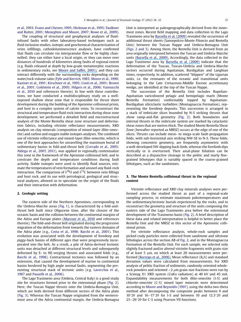
The eastern side of the Northern Apennines, corresponding tothe Umbria-Marche areas (Fig. 1), is characterized by a fold-and-thrust belt built since Oligocene time, after the closure of theoceanic basin and the collision between the continental margins ofthe Adria and Europe plates (Marroni et al., 2010 and referencestherein). The fold-and-thrust belt originated during the progressivemigration of the deformation front towards the eastern domains ofthe Adria plate (e.g., Costa et al., 1998; Barchi et al., 2001). Thisevolution was associated with the development of foredeep andpiggy-back basins of different ages that were progressively incor-porated into the belt. As a result, a pile of Adria-derived tectonicunits was detached at different structural levels and subsequentlydeformed by E- to NE-verging thrusts and associated folds (e.g.,Barchi et al., 1998). Contractional tectonics was followed by anextension, that caused the development of marine to continentalbasins bordered by high angle normal faults, segmenting the pre-existing structural stack of tectonic units (e.g. Lavecchia et al.,1987 and Pauselli et al., 2006).
The Lago Trasimeno area (Umbria, Central Italy) is a good studysite for structures formed prior to the extensional phase (Fig. 2).Here, the Tuscan Nappe thrusts onto the Umbria-Romagna Unit,which are both derived from different sectors of the Adria plate(Fig. 3). Whereas the Tuscan Nappe originated from the western-most area of the Adria continental margin, the Umbria-Romagna
Unit is interpreted as paleogeographically derived from the inner-most zones. Recent field mapping and data collection in the LagoTrasimeno area by Barsella et al. (2009) revealed the occurrence ofadditional thrust sheets (Sansepolcro-Monte Filoncio and RentellaUnis) between the Tuscan Nappe and Umbria-Romagna Unit(Figs. 2 and 3). Among them, the Rentella Unit is derived from anarea originally interposed between the Tuscan and Umbria-Marcheunits (Barsella et al., 2009). Accordingly, the data collected in theLago Trasimeno area by Barsella et al. (2009) indicate that thedeformation of the Tuscan, Tuscan-Umbria and Umbria-Marchesectors occurred during Aquitanian, Burdigalian and Langhiantimes, respectively. In addition, scattered “klippen” of the Ligurianunits, i.e. the remnants of the oceanic and transitional unitsbelonging to the Late Cretaceous-Middle Eocene accretionarywedge, are identified at the top of the Tuscan Nappe.
The succession of the Rentella Unit includes Rupelian-Aquitanian varicoloured pelagic and hemipelagic marls (MonteRentella Formation) conformably topped by Aquitanian-Burdigalian siliciclastic turbidites (Montagnaccia Formation), rep-resenting the foredeep deposits. This succession is arranged ina stack of imbricate slices bounded by N-S striking thrusts thatshow ramp-and-flat geometry (Fig. 2). Both boundaries andinternal thrusts in the imbricate system are marked by cataclasticshear zones that aremetres thick. The studiedMonte Rentella ShearZone (hereafter reported as MRSZ) occurs at the edge of one of theslices. Thrusts can include meso- to mega-scale fault-propagationfolds, with sub-horizontal axis striking NW-SE to N-S. These folds,showing concentric geometry, are frequently asymmetric withawell-developed SW-dipping back-limb, whereas the forelimb dipsvertically or is overturned. Their axial-plane foliation can bedescribed as a disjunctive cleavage in the pelitic and marly fine-grained lithotypes that is variably spaced in the coarse-grainedlithotypes, such as the sandstones.
3. The Monte Rentella collisional thrust in the regionalcontext
Vitrinite reflectance and XRD clay minerals analyses were per-formed across the studied thrust as part of a regional-scalesampling process, to estimate maximum paleotemperatures andthe sedimentary/tectonic burials experienced by the rocks, and toreconstruct the geometry and structure of the units composing theeastern side of the Lago Trasimento area before the extensionaldevelopment of the Trasimeno basin (Fig. 2). A brief description ofthese data and related interpretation is helpful to better place theRentella Unit and the MRSZ in this sector of the Apenninic colli-sional prism.
For vitrinite reflectance analysis, whole-rock samples andpicked coaly particles were collected from sandstone and siltstonelithologies across the section AB of Fig. 2, and in the MontagnacciaFormation of the Rentella Unit. For each sample, we selected onlyslightly fractured and/or altered vitrinite fragments with grain-sizeof at least 5 mm, on which at least 20 measurements were per-formed (Borrego et al., 2006). Mean reflectance (Ro%) and standarddeviation values were calculated from measurements. For XRDanalysis of pelitic fraction of sediments, randomly-oriented whole-rock powders and oriented <2 mm grain-size fractions were run bya Scintag X1 XRD system (CuKa radiation) at 40 kV and 45 mA.Expandability measurements for both illite-smectite (I-S) andchlorite-smectite (C-S) mixed layer minerals were determinedaccording to Moore and Reynolds (1997), using the delta two-thetamethod after decomposing the composite peaks between 9 and10�2q and 16e17�2q for I-S and between 10 and 12.3�2q and25e26�2q for C-S using Pearson VII functions.
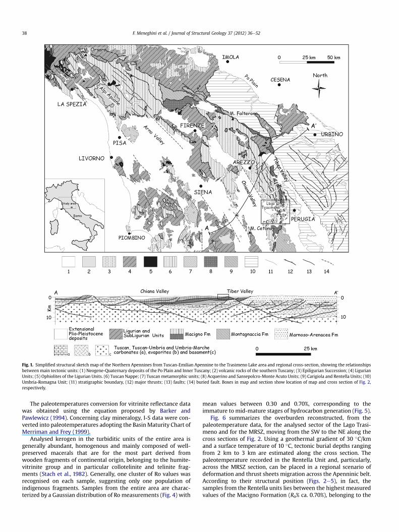
Fig. 1. Simplified structural sketch map of the Northern Apennines from Tuscan-Emilian Apennine to the Trasimeno Lake area and regional cross-section, showing the relationshipsbetween main tectonic units: (1) Neogene-Quaternary deposits of the Po Plain and Inner Tuscany; (2) volcanic rocks of the southern Tuscany; (3) Epiligurian Succession; (4) LigurianUnits; (5) Ophiolites of the Ligurian Units. (6) Tuscan Nappe; (7) Tuscan metamorphic units; (8) Acquerino and Sansepolcro-Monte Acuto Units; (9) Carigiola and Rentella Units; (10)Umbria-Romagna Unit; (11) stratigraphic boundary, (12) major thrusts; (13) faults; (14) buried fault. Boxes in map and section show location of map and cross section of Fig. 2,respectively.
F. Meneghini et al. / Journal of Structural Geology 37 (2012) 36e5238
The paleotemperatures conversion for vitrinite reflectance datawas obtained using the equation proposed by Barker andPawlewicz (1994). Concerning clay mineralogy, I-S data were con-verted into paleotemperatures adopting the BasinMaturity Chart ofMerriman and Frey (1999).
Analysed kerogen in the turbiditic units of the entire area isgenerally abundant, homogenous and mainly composed of well-preserved macerals that are for the most part derived fromwooden fragments of continental origin, belonging to the humite-vitrinite group and in particular collotelinite and telinite frag-ments (Stach et al., 1982). Generally, one cluster of Ro values wasrecognised on each sample, suggesting only one population ofindigenous fragments. Samples from the entire area are charac-terized by a Gaussian distribution of Ro measurements (Fig. 4) with
mean values between 0.30 and 0.70%, corresponding to theimmature to mid-mature stages of hydrocarbon generation (Fig. 5).
Fig. 6 summarizes the overburden reconstructed, from thepaleotemperature data, for the analysed sector of the Lago Trasi-meno and for the MRSZ, moving from the SW to the NE along thecross sections of Fig. 2. Using a geothermal gradient of 30 �C/kmand a surface temperature of 10 �C, tectonic burial depths rangingfrom 2 km to 3 km are estimated along the cross section. Thepaleotemperature recorded in the Rentella Unit and, particularly,across the MRSZ section, can be placed in a regional scenario ofdeformation and thrust sheets migration across the Apenninic belt.According to their structural position (Figs. 2e5), in fact, thesamples from the Rentella units lies between the highest measuredvalues of the Macigno Formation (Ro% ca. 0.70%), belonging to the
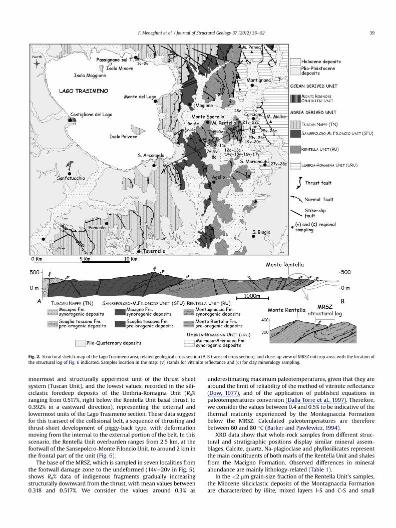
Fig. 2. Structural sketch-map of the Lago Trasimeno area, related geological cross section (A-B traces of cross section), and close-up view of MRSZ outcrop area, with the location ofthe structural log of Fig. 6 indicated. Samples location in the map: (v) stands for vitrinite reflectance and (c) for clay mineralogy sampling.
F. Meneghini et al. / Journal of Structural Geology 37 (2012) 36e52 39
innermost and structurally uppermost unit of the thrust sheetsystem (Tuscan Unit), and the lowest values, recorded in the sili-ciclastic foredeep deposits of the Umbria-Romagna Unit (Ro%ranging from 0.517%, right below the Rentella Unit basal thrust, to0.392% in a eastward direction), representing the external andlowermost units of the Lago Trasimeno section. These data suggestfor this transect of the collisional belt, a sequence of thrusting andthrust-sheet development of piggy-back type, with deformationmoving from the internal to the external portion of the belt. In thisscenario, the Rentella Unit overburden ranges from 2.5 km, at thefootwall of the Sansepolcro-Monte Filoncio Unit, to around 2 km inthe frontal part of the unit (Fig. 6).
The base of the MRSZ, which is sampled in seven localities fromthe footwall damage zone to the undeformed (14ve20v in Fig. 5),shows Ro% data of indigenous fragments gradually increasingstructurally downward from the thrust, with mean values between0.318 and 0.517%. We consider the values around 0.3% as
underestimating maximum paleotemperatures, given that they arearound the limit of reliability of the method of vitrinite reflectance(Dow, 1977), and of the application of published equations inpaleotemperatures conversion (Dalla Torre et al., 1997). Therefore,we consider the values between 0.4 and 0.5% to be indicative of thethermal maturity experienced by the Montagnaccia Formationbelow the MRSZ. Calculated paleotemperatures are thereforebetween 60 and 80 �C (Barker and Pawlewicz, 1994).
XRD data show that whole-rock samples from different struc-tural and stratigraphic positions display similar mineral assem-blages. Calcite, quartz, Na-plagioclase and phyllosilicates representthe main constituents of both marls of the Rentella Unit and shalesfrom the Macigno Formation. Observed differences in mineralabundance are mainly lithology-related (Table 1).
In the <2 mm grain-size fraction of the Rentella Unit’s samples,the Miocene siliciclastic deposits of the Montagnaccia Formationare characterized by illite, mixed layers I-S and C-S and small
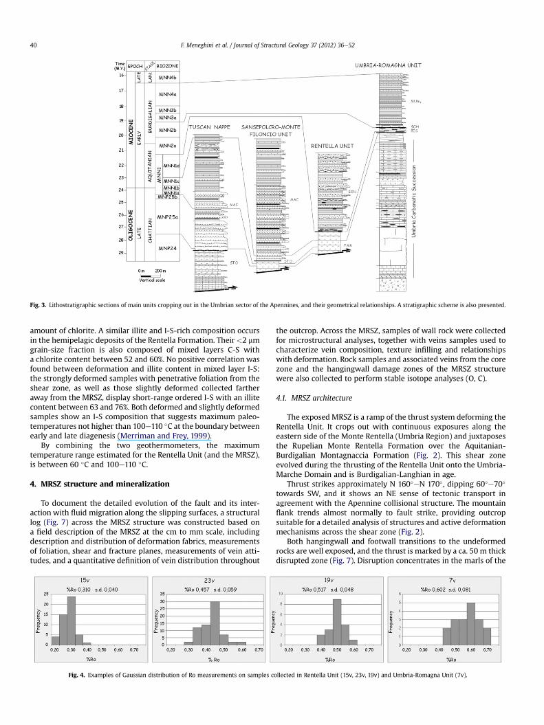
Fig. 3. Lithostratigraphic sections of main units cropping out in the Umbrian sector of the Apennines, and their geometrical relationships. A stratigraphic scheme is also presented.
F. Meneghini et al. / Journal of Structural Geology 37 (2012) 36e5240
amount of chlorite. A similar illite and I-S-rich composition occursin the hemipelagic deposits of the Rentella Formation. Their <2 mmgrain-size fraction is also composed of mixed layers C-S witha chlorite content between 52 and 60%. No positive correlation wasfound between deformation and illite content in mixed layer I-S:the strongly deformed samples with penetrative foliation from theshear zone, as well as those slightly deformed collected fartheraway from the MRSZ, display short-range ordered I-S with an illitecontent between 63 and 76%. Both deformed and slightly deformedsamples show an I-S composition that suggests maximum paleo-temperatures not higher than 100e110 �C at the boundary betweenearly and late diagenesis (Merriman and Frey, 1999).
By combining the two geothermometers, the maximumtemperature range estimated for the Rentella Unit (and the MRSZ),is between 60 �C and 100e110 �C.
4. MRSZ structure and mineralization
To document the detailed evolution of the fault and its inter-action with fluid migration along the slipping surfaces, a structurallog (Fig. 7) across the MRSZ structure was constructed based ona field description of the MRSZ at the cm to mm scale, includingdescription and distribution of deformation fabrics, measurementsof foliation, shear and fracture planes, measurements of vein atti-tudes, and a quantitative definition of vein distribution throughout
Fig. 4. Examples of Gaussian distribution of Ro measurements on samples c
the outcrop. Across the MRSZ, samples of wall rock were collectedfor microstructural analyses, together with veins samples used tocharacterize vein composition, texture infilling and relationshipswith deformation. Rock samples and associated veins from the corezone and the hangingwall damage zones of the MRSZ structurewere also collected to perform stable isotope analyses (O, C).
4.1. MRSZ architecture
The exposed MRSZ is a ramp of the thrust system deforming theRentella Unit. It crops out with continuous exposures along theeastern side of the Monte Rentella (Umbria Region) and juxtaposesthe Rupelian Monte Rentella Formation over the Aquitanian-Burdigalian Montagnaccia Formation (Fig. 2). This shear zoneevolved during the thrusting of the Rentella Unit onto the Umbria-Marche Domain and is Burdigalian-Langhian in age.
Thrust strikes approximately N 160�eN 170�, dipping 60�e70�
towards SW, and it shows an NE sense of tectonic transport inagreement with the Apennine collisional structure. The mountainflank trends almost normally to fault strike, providing outcropsuitable for a detailed analysis of structures and active deformationmechanisms across the shear zone (Fig. 2).
Both hangingwall and footwall transitions to the undeformedrocks are well exposed, and the thrust is marked by a ca. 50 m thickdisrupted zone (Fig. 7). Disruption concentrates in the marls of the
ollected in Rentella Unit (15v, 23v, 19v) and Umbria-Romagna Unit (7v).

Fig. 5. Illite content in mixed layer illite-smectite (black squares with error bars) and %Ro (grey blocks) values in analysed units (TN: Tuscan Nappe, SFU: San Sepolcro-M. Filoncio)and across the MRSZ (hangingwall (HDZ) and footwall (FDZ) damage zones and core zone (CO). Location of samples for vitrinite measurements (v) and X-ray diffraction of clayminerals (c) shown in Fig. 2.
F. Meneghini et al. / Journal of Structural Geology 37 (2012) 36e52 41
Monte Rentella Formation. Therefore, the intensity of deformationand meso-scale fabric development, as measured across the con-structed structural log (Fig. 7), are distributed asymmetrically forthe MRSZ, with an about 3.5 m thick core zone (COZ) bounded by
Fig. 6. eEstimated tectonic burial prior to the extension of the Rentella Unit using vitrinite reFig. 2, and scheme of Fig. 5): (1) Tuscan Units (1v, 2v); (2) San Sansepolcro-Monte Filoncio Un(4) Rentella Unit (10v); (5) base of MRSZ (14ve17v); (6), (7), (8) Umbria-Romagna Unit, fro
strikingly different footwall and hangingwall damage zones. Thecore is where most deformation is accommodated, featuring thegreatest density of deformation-related structures (Caine andForster, 1999).
flectance and mixed layer I-S data. Stars are vitrinite samples locations (see also map init (3v, 5v); (3) Rentella Unit at the footwall of the Sansepolcro-Monte Filoncio Unit (7v);m the internal to the external sectors (23v, 25v, 27v).

Table 1XRD quantitative analyses of the whole-rock composition and the <2 mm grain-size fraction. Note that non-clay minerals which have been identified in the <2 mm grain-sizefraction were not included in the quantitative analysis of the oriented aggregates and data refer to the phyllosilicates group only. The amounts of clay minerals were notrecalculated into percentages of bulk rocks, but represent the content of the separated phyllosilicates-size fraction.
Sample Formation Rock type Mineralogy of the whole-rock (%wt.) X-ray quantitative analysis of the<2 mm grain-size fraction (%wt.)
%I in I-S %C in C-S
Qtz Cal Dol Ab Phy Py I I/S C/S K Chl
24 MarnosoArenacea Fm
Marl 13 11 2 21 52 1 41 14 10 35 7526 Siltstone 12 23 4 15 46 65 18 14 3 73 608 Montagnaccia
FmMarl 7 64 3 26 58 22 19 1 76 55
22 Marl 4 57 2 37 57 29 12 1 76 5522(1) Marl 10 25 7 58 65 25 10 65 5511 Monte
Rentella FmMarl 4 55 1 40 62 29 6 3 68 55
11(1) Marl 4 69 1 26 69 18 10 1 2 68 6012 Marl 5 55 3 37 60 33 2 3 2 70 5212(1) Marl 5 57 4 34 58 22 14 2 4 70 6013 Marl 5 59 2 34 60 26 12 1 1 63 5513(1) Marl 5 59 2 34 60 21 6 6 7 70 5020 Marl 6 60 4 30 61 30 2 7 72 606 Macigno Fm Shale 3 1 1 95 41 59 744 Marl 9 22 12 57 65 27 7 1 70 60
F. Meneghini et al. / Journal of Structural Geology 37 (2012) 36e5242
The footwall damage zone (FDZ) developed in amalgamatedbeds of massive sandstones from the Montagnaccia Formation, fora thickness of about 28.5 m. Deformation is accommodated byawell-developed spaced dissolution foliationwith a spacing from 2to 5 cm. Fractures are arranged in 3 main sets of planes (Fig. 8): twoNE-dipping sets both striking N 150�eN 180�, with different incli-nation (30� and 75�) and a third set striking N 130�e160�, dipping20�e40� towards the SW. This last set is generally ornamented bya strong striation lineation striking N 40�e60� and showing a top-to-NE sense of shear, coherent with that inferred at map-scale forthe thrust (Fig. 8c). These sets are interpreted in terms of syntheticand antithetic Riedel shear planes, developed to accommodatestrain at the footwall, where the NE-dipping planes are R- and R0-Riedel planes associated with a main shear surface oriented as thecluster dipping towards the SW, and indicating a top-to-the-NEsense of shear. Deformation in the sandstones also features devel-opment of cataclastic shear zones (Fig. 9a), visible at all scales, andcharacterized by grain-size reduction at micro-scale (Fig. 9b).Scattered pressure solution seams are also associated with theshear zones.
The core zone in the Monte Rentella Formation marls showsextensive deformation with fabrics including many typicalfeatures of brittle shear zones in pelitic to marly lithotypes(Figs. 9e11), such as a strongly penetrative scaly foliation, Riedel-type sets of structures, shear-related asymmetric folds andextensive veining. Core zone boundaries are sharp, represented bytectonic surfaces.
Similar to S-C structures in the ductile regime, a P-type foliationis associated with Y-shear surfaces, visible at the meso- to themicro-scale, with Y-shear planes deforming and cutting the P-foliation surfaces (Fig. 11a). Y-shear surfaces are generally arrangedparallel to the mean shear zone boundaries, striking N 160�e170�
with a dipping of 40e50� towards SW (compare with geologicsection), and therefore fitting also with the SW-dipping surfacesdetected in the sandstones (Fig. 8). Average strike of the foliationranges N 110�eN 160� and foliation planes locally show polishedand striated surfaces. P-Y structures arrangement indicates a top-to-E-NE sense of shear, according with the main thrust vergence.Both P and Y surfaces are infused with calcite veins.
The scaly nature of the foliation in marls is defined by ananastomosing set of fracture planes, with spacing smaller than1 mm (Fig. 9c and Fig. 11a), marked by variably continuousmicroscopic pressure solution seams, also evidenced by partialdissolution of foraminifera along the seams. Also, foraminifera are
generally elongated along foliation or deform as delta-type objectstypical of ductile shear zones (Fig. 9d).
Foliation planes as well as veins are markedly folded in all expo-sures. The folds are strongly asymmetric and showvariable geometry,fromopen to tight to isoclinal,withoutanyvisibleaxial-plane foliation(Fig. 9c). Limbsare frequently neckedandboudinaged. Fold axes trendN 140�eN 170� with plunges clustered towards the NW and SE(Fig. 10a). Fold asymmetry is clearly related to the axes plunge: NW-plunging fold axes characterize NE-facing folds, whereas SE-plunging axes are connected with SW-facing folds. This foldarrangement is typical of shear zones with a large component ofsimple shear. Given this interpretation, the cylindrical best fit of thefold axes represents the plane of main shear to which the folds arerelated (Fig. 10b), and correspond approximately to both the averageattitude of the main fault and to the Y-planes (N 162� 45 NNE e
Fig. 10b).The HDZ developed in the central-upper portion of the Monte
Rentella Formation, also deforming marly lithologies. The transitionfromHDZ to both COZ and undeformedMonte Rentella Formation issharp, marked by thin (on the order of millimetres) gouges layersarranged along Y-shear surfaces, and confirmed also by biostrati-graphic data of calcareous nannofossil content. Sampling across thiszone indicates boundaries defined by low-angle reverse faults thateach juxtapose rock of different age: 1) from Biozone MNN1 (Chat-tian), at the top COZ, to Biozone MNP25b (Chattian), at the botton ofHDZ; 2) from Biozone MNN1, at the top of HDZ, to Biozone MNP24(Chattian) recorded at the bottom of undeformed zone (Fig. 7).
HDZ fabric is characterized by well-developed calcite-infusedsystems of P- and Y-surfaces that are similar to those observed inthe core, but distributedwith less frequency and intensity (Fig.11a).However, HDZ lacks the typical asymmetric folding observedpervasively in the core.
As mentioned, Y-planes are sharp, planar shear surfaces markedby thin gouges layers, ranging from N 150� to N 170�, and dippingroughly 40�e50� towards the SW (Fig. 10c). P-type foliation can bedescribed as a variably continuous, anastomosing to locally scalycleavage, with spacing everywhere greater than 2 mm. The P-planes strike N1 40�eN 180�, with a dipping ranging from 50�
towards SW to 80� towards the NE (Fig. 9c). Typically, the P-planesshow a change in attitude fromhigh angle to parallelismwith the Y-planes (Fig. 11a). As in the fault core, microscopic variably contin-uous pressure solution seams and elongate rigid grains define theP-foliation. The attitude of P- and Y-planes is interpreted as a top-to-ENE sense for shear of the MRSZ.

Fig. 7. Structural profile measured across the MRSZ parallel to zone dip direction showing major structural features at meso-scale, vein density, biostratigraphic data and isotopicvalues.
F. Meneghini et al. / Journal of Structural Geology 37 (2012) 36e52 43
Although marked by a sharp surface, the transition to the unde-formed Monte Rentella Formation is outlined also by a decrease indensity of P-Y structures. Moving from the bottom to the top of theHDZ, the spacing of Y-planes changes from 5 to 10 cm to 30e40 cm.An increase in spacing is also observed for the S-planes.
4.2. Mineralization along the MRSZ: mesoscopic and microscopicfeatures
All shear zone components are characterized by abundant veindevelopment, whose density strongly varies from the damage

Fig. 8. Lower hemisphere projection of most significant structural elements in the footwall damage-zone sandstones.
F. Meneghini et al. / Journal of Structural Geology 37 (2012) 36e5244
zones to the fault core. In addition, veins arrangement and texturealso change, depending on the host lithology.
Mineralization in the FDZ sandstones occurs along up to 2 cmthick, Mode I fractures sub-normal to bedding. Veinwalls are sharpand planar. The infillings show antitaxial texture, with straightfibres of calcite. The median line is highly discontinuous and, whenvisible, is marked by either small sandstones chips or simply by theboundary between different calcite crystals (Fig. 11b). Fibres vary
Fig. 9. Main deformation features in the MRSZ. Cataclastic shear zones developed in footw(indicated with white arrows) at micro-scale are defined by grain-size reduction associatehangingwall damage zones are characterized by penetrative scaly foliation, asymmetric foldsasymmetric clasts, all pointing towards a top-to-NE sense of shear.
greatly in thickness (0.2e0.5 mm) and length (1e4 mm). As it ispresent only in the damage zone of the footwall, this vein systemlacks any particular feature that enables us to relate it directly to thefault zone.
The marls of the core and hangingwall damage zones of theMRSZ are characterized by similar mineralization, but a dramaticdecrease in vein density is observed when moving from core toHDZ (Fig. 7), where veins are also less deformed.
all sandstones at a) field and b) micro-scale (crossed nicols). Cataclastic shear zonesd with pressure solution. Coin diameter is 2 cm c) Deformation of marls in core andand veins. Coin diameter is 2 cm. d) Shear sense indicator in marls: P-Y planes sets and

Fig. 10. Lower hemisphere projection of most significant structural elements in the marls of core zone (a and b) and hangingwall damage zone (c).
F. Meneghini et al. / Journal of Structural Geology 37 (2012) 36e52 45
The calcite veins along the P- and Y-planes in the deformedmarls range in thickness from 2 mm to 1 cm in the core and up to2 cm in the HDZ (Fig. 11a). Y-shear-parallel veins are thicker,planar and continuous, and show sharp boundaries. The
Fig. 11. a) Field-scale image of vein, running along Y-type shear planes (black dashed lines),Discontinuous white layers along Y-surfaces are calcite veins. b) Microphotograph of fibrousmarls at micro-scale (plane nicols). Veins are arranged along Y-shear planes and are charboundary define sense of vein opening and shear. White box is area of Fig. 11d. d) Close uboundaries and Y-shear surfaces. The centre of microphotograph (circled) shows inclusions ostructures. Top-to-the-NE sense of shear.
foliation-parallel vein system is less developed than the Y-shearparallel ones, especially in the damage zone, and it is lesscontinuous, probably as a result of folding and disruption duringshear.
in damage zone marls. White dashed line mimics foliation deflected by shear surfaceslayer-normal veins in footwall sandstones. c) Striped veins in damage and core zonesacterized by many crack-and-seal episodes. Staircase geometry visible at vein upperp view of vein system (crossed nicols). Different calcite stripes parallel the main veinf wall-rock marls accommodating further deformation through smaller dilatational jog

F. Meneghini et al. / Journal of Structural Geology 37 (2012) 36e5246
Although no particular texture is discernable in the veins at theoutcrop scale, vein walls along Y-shears bear a well-developedlineation on calcite crystals trending N 60�eN 110�. Along the Y-surfaces, a progressive change of the trend of the calcite fibres fromN 20� to N 90�, locally occurs.
Veins arranged along the Y-shear planes have morphologiesconsistent with experiencing many crack-and-seal episodes anda texture (Fig. 9d and Fig. 11c-d) comparable to that described forthe dilational jogs of Sibson (1987), or for the striped veins of Koehnand Passchier (2000). MRSZ veins show long, thin stripes of calcitecrystals, separated by crack-seal bands parallel to the jog wherefirst opening occurred (Fig. 11c). Jogs for different vein episodesshow a staircase shape that can be used as a shear sense indicator,and is always consistent with a top-to-the-NE shear sense (Fig. 11c).Grain boundaries of crystals do not track the opening of the veins,the displacement being sub-parallel to the boundaries betweendifferent calcite stripes (Fig. 11ced): these surfaces parallel themain vein boundaries, i.e. the Y-surfaces themselves, and therefore,according to Sibson (1987), Koehn and Passchier (2000), theyrepresent shear surfaces. Typically, along these dark shear surfaces,pressure solution seams also concentrate. Locally, trapped betweendifferent crack-seal episodes are inclusions of wall rock marls bigenough to be able to accommodate further deformation throughsmaller dilatational jog structures (Sibson, 1987), which are againconsistent with the main top-to-the-NE sense of shear (Fig. 11d).
Y-shear surfaces, and associated veins, are locally arranged insystems that can be fairly well related to specific Riedel shearplanes (Fig. 12a). The orientation of R, P and Y surfaces is alwayscompatible with a top-to-the-NE sense of shear.
Following Burkhard’s (1993) classification, calcite twins inMRSZare type II (Fig. 12b), suggesting a qualitative estimate for formationtemperature of 150�e300 �C for both vein systems (see also Ferrilet al., 2004).
Mineralization along the foliation surfaces (Fig. 12c) is charac-terized by calcite extension veins with a variable thickness that isup to twice as that of a single “striped episode” along the Y-surfaces.Infilling is fine, clear calcite blocky crystals. As with the foliationplanes, the veins are deformed by shear along the Y-planes to giverise to structures resembling S-C structures (Fig. 12c), consistentwith top-to-the-NE sense of shear.
Veins in the fault core are frequently deformed and disrupted byshear-related folding. As already described, fold vergence is alwaysconsistent with top-to-the-NE sense of shear (Fig. 12d). Locally,repeated folding and shear-related deformation allowed completedisruption of veins, and a brecciated structure (Fig. 12e).
Scanning electron microprobe (SEM) observations of samples ofhost rock marls from undeformed, damage and core zones suggestslocal fluid/rock interaction during fault activity and veins precipi-tation. The SEM images of core zone marl samples, in fact, showextensive precipitation of calcite and quartz, highlighted by a marlmicrofabric featuring the occurrence of triple junctions and straightboundaries between crystals (Fig. 12f). The amount of recrystalli-zation decreases away from the core zone towards the undeformedmarls with granular texture.
4.3. Fluid-rock interaction and temperature conditions of fluidsalong the MRSZ: the analysis of C and O stable isotopes
Stable isotope analyses allow us to characterize the fluid-rockinteraction along thrusts during their evolution, by determiningthe source of fluids involved and the diffuse or confined nature offluid flow. For these reasons, we sampled a representative numberof deformed marls and carbonate veins developed during MRSZactivity. Vein sampling was performed across the shear zone byselecting veins and adjacent wall rocks in the footwall damage
zone, core zone and hangingwall damage zone. Marl samples ofMonte Rentella Formation were collected from the undeformedzone up-section from the deformed hangingwall damage zone.
Selected veinsweremechanically drilled frompolished surfaces.Powdered rocks and veins were reacted with orthophosphoric acidat 25 �C under vacuum for 12 h (McCrea, 1950). The isotopiccompositions (13/12C and 18/16O ratios) of the resulting CO2 havebeen measured using Thermo-Finnigan Delta XP IRMS at the CNR-IGG of Pisa. Proper standardization for the O- and C-isotope anal-yses was verified by international carbonate standards, includingNBS-19 (calcite), and internal calcite standard. The internal stan-dard (Carrara marble) has uncertainty (expressed as 1s) less than0.10& for both d18O and d13C, and was regularly added to each runof measurement (i.e., 5 samples þ 1 internal standard).
The d18O values for the host rocks of the core and hangingwalldamage zone range approximately from 27 to 29&, (average valuefor both rock groups ¼ 27.7e27.8&) (Table 2, Figs. 7 and 13). d13C ofthe same samples is quite constant ranging from 0.5 to 1.3 for coresamples and from 0.8 to 1.5 for hangingwall host rocks. Additionalsamples were used to investigate the transition from deformedhangingwall damage zone to undeformed marls (see Fig. 7): d18Ovalues range from 27 to 30& (average value 28.8&) and d13C from0.4 to 1.5&. Importantly, the MR79(h) rock sample, representing anundeformed marl, shows the highest d18O value (30&). Carbonateveins selected and mechanically drilled from the core show d18Oand d13C values ranging from 24 to 27& (average value 26.0&) andfrom 0.4 to 1.5&, respectively. d18O and d13C values of hangingwalldamage zone carbonate veins (v-HDZ) range from 25 to 27&(average value 26.5&) and from 0.7 to 1.5&. Carbonate veins fromthe transitional zone to the undeformed marls show a quiteconstant d18O of around 27& and d13C values from 0.7 to 1.3&.
The rock samples and associated veins from the sandstones ofthe footwall all show similar d13C and d18O values, between0.1e0.2& and 24.7e25.3&, respectively (Table 2).
5. Discussion
5.1. Strain localization, hydrofracture opening/closure, and theirmutual feedback during MRSZ evolution
Deformation in MRSZ mainly concentrated in marls, creating anasymmetric geometry with awide hangingwall damage zone in theMonte Rentella Formation that progressively grades to the unde-formed protolith, whereas, down-section, it sharply passes intoa fault core where strain is concentrated and deformation is morepenetrative. The MRSZ is a tabular structure where competent rigidblocks of siltite are enclosed in amatrix ofmarl gouge. This block-in-matrix fabric, together with the occurrence of scaly fabric, systemsof P-foliation and Y-shear surfaces, and insoluble oxides seams inmarls all indicate that cataclastic flow and pressure solution werethe main deformation processes active during thrust evolution(Knipe, 1986, 1989; Lundberg and Moore, 1986; Labaume et al.,1997). The rheological heterogeneity of competent siltite layersalternating with incompetent marls in the Monte Rentella Forma-tion created a heterogeneous distribution of shear strain, andinvolved both continuous and discontinuous deformation. Webelieve that viscousflowoccurred duringdeformation in thematrix,so that the strain concentrated at the rigid siltite phacoids bound-aries by developing brittle, discrete slip planes, such as the Y-planes,that accommodated most of the displacement along the shear zone(Lister and Williams, 1983; Fagereng and Sibson, 2010). Similarfabrics are typically observed at different scale, in a wide range ofcrustal, metre-scale fault zones and shear-relatedmélanges (Sibson,1977, 1994; 1996; Lundberg and Moore, 1986; Aydin and Schultz,1990; Labaume et al., 1991; Chester et al., 1993; Antonellini and
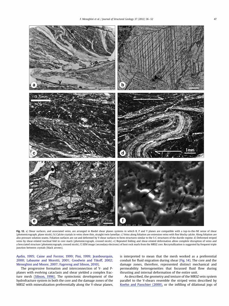
Fig. 12. a) Shear surfaces, and associated veins, are arranged in Riedel shear planes systems in which R, P and Y planes are compatible with a top-to-the-NE sense of shear(photomicrograph, plane nicols). b) Calcite crystals in veins show thin, straight twin lamellae. c) Veins along foliation are extension veins with fine blocky calcite. Along foliation arealso pressure solution seams. Foliation surfaces are cut and deformed by Y-shear surfaces to form structures similar to the S-C structures of the ductile regime. d) Deformed stripedveins by shear-related isoclinal fold in core marls (photomicrograph, crossed nicols). e) Repeated folding and shear-related deformation allow complete disruption of veins anda brecciated structure (photomicrograph, crossed nicols). f) SEM image (secondary electrons) of host rock marls from the MRSZ core. Recrystallization is suggested by frequent triplejunction between crystals (black arrows).
F. Meneghini et al. / Journal of Structural Geology 37 (2012) 36e52 47
Aydin, 1995; Caine and Forster, 1999; Pini, 1999; Jeanbourquin,2000; Labaume and Moretti, 2001; Goodwin and Tikoff, 2002;Meneghini and Moore, 2007; Fagereng and Sibson, 2010).
The progressive formation and interconnection of Y- and P-planes with evolving cataclasis and shear yielded a complex frac-ture mesh (Sibson, 1996). The syntectonic development of thehydrofracture system in both the core and the damage zones of theMRSZ with mineralization preferentially along the Y-shear planes,
is interpreted to mean that the mesh worked as a preferentialconduit for fluid migration during shear (Fig. 14). The core and thedamage zones, therefore, represented distinct mechanical andpermeability heterogeneities that focussed fluid flow duringthrusting and internal deformation of the entire unit.
As described, the geometry and texture of theMRSZ vein systemparallel to the Y-shears resemble the striped veins described byKoehn and Passchier (2000), or the infilling of dilational jogs of

Table 2Isotopic values of C and O in the host rocks and veins.
Sample no. Structural positiona Sample type d13CPDB (&) d18OPDB (&) d18OSMOW (&)
MR-5 (V) v-COZ Vein 0.79 �3.99 26.74MR8 (V) v-COZ Vein 1.39 �4.52 26.20MR9 (V) v-COZ Vein 0.44 �4.32 26.41MR15 (V) v-COZ Vein 0.83 �3.90 26.84MR17 (V) v-COZ Vein 1.41 �4.32 26.40MR19 (V) v-COZ Vein 1.17 �4.86 25.85MR20 (V) v-COZ Vein 1.24 �4.91 25.80MR23 (V) v-COZ Vein 0.54 �6.22 24.45MR26 (V) v-COZ Vein 1.13 �5.85 24.83MR29 (V) v-COZ Vein 1.22 �4.88 25.83MR37 (V) v-COZ Vein 0.77 �4.60 26.12MR38 (V) v-COZ Vein 1.40 �4.37 26.35MR41a (V) v-COZ Vein 0.91 �4.79 25.92MR41B (V) v-COZ Vein 1.19 �4.11 26.62MR43 (V) v-COZ Vein 1.52 �4.24 26.49MR5 (H) h-COZ Host rock 0.53 �3.31 27.45MR6 (H) h-COZ Host rock 0.56 �2.75 28.02MR13 (H) h-COZ Host rock 0.60 �3.54 27.21MR16 (H) h-COZ Host rock 0.74 �3.68 27.07MR18 (H) h-COZ Host rock 1.26 �2.80 27.97MR21 (H) h-COZ Host rock 1.09 �2.95 27.82MR22 (H) h-COZ Host rock 0.67 �3.53 27.22MR23 (H) h-COZ Host rock 0.90 �2.84 27.94MR27 (H) h-COZ Host rock 1.16 �1.76 29.05MR28 (H) h-COZ Host rock 0.99 �4.22 26.51MR36 (H) h-COZ Host rock 1.18 �2.85 27.93MR40 (H) h-COZ Host rock 1.01 �1.81 28.99MR42a (H) h-COZ Host rock 0.55 �3.58 27.17MR44 (H) h-COZ Host rock 1.18 �3.95 26.78MR46 (H) h-COZ Host rock 0.88 �2.68 28.10MR48 (V) v- COZ-HDZ Vein 0.87 �5.04 25.66MR49 (V) v - COZ-HDZ Vein 0.75 �3.71 27.03MR52 (V) v - COZ-HDZ Vein 0.86 �3.92 26.82MR-51 (V) v - COZ-HDZ Vein 1.40 �4.44 26.28MR53 (V) h- COZ-HDZ Host rock 0.85 �4.01 26.72MR54 (V) v-HDZ Vein 1.49 �3.88 26.86MR56 (V) v-HDZ Vein 1.38 �4.47 26.25MR57 (V) v-HDZ Vein 1.19 �4.23 26.50MR58 (V) v-HDZ Vein 1.29 �3.86 26.88MR60 (V) v-HDZ Vein 1.20 �4.44 26.28MR64 (V) v-HDZ Vein 1.23 �3.38 27.37MR65 (V) v-HDZ Vein 0.68 �5.28 25.42MR53 (H) h-HDZ Host rock 0.85 �4.01 26.72MR55 (H) h-HDZ Host rock 1.04 �1.91 28.89MR59 (H) h-HDZ Host rock 1.51 �2.56 28.22MR62 (H) h-HDZ Host rock 0.90 �4.00 26.73MR64 (H) h-HDZ Host rock 1.10 �2.30 28.49MR67 (V) v-HDZ-IND Vein 1.28 �3.51 27.24MR69 (V) v-HDZ-IND Vein 0.96 �3.68 27.06MR-73 (V) v-HDZ-IND Vein 0.95 �3.51 27.24MR71 (V) v-HDZ-IND Vein 0.71 �4.23 26.50MR75 (V) v-HDZ-IND Vein 0.70 �3.32 27.44MR-77 (V) v-HDZ-IND Vein 0.80 �3.54 27.21MR-70 (V) v-HDZ-IND Vein 0.98 �3.71 27.03MR67 (H) h-HDZ-UND Host rock 1.46 �2.3 28.46MR78 (H) h-HDZ-UND Host rock 0.91 �2.4 28.40MR74 (H) h-HDZ-UND Host rock 0.76 �2.5 28.29MR76 (H) h-HDZ-UND Host rock 0.88 �0.8 30.05MR79 (H) UND Host rock 0.9 �1.3 30MR34 (V) v-FDZ Vein 0.06 �5.47 25.23MR35 (V) v-FDZ Vein 0.15 �6.02 24.66MR34 (H)bis h-FDZ Host rock (sandstone) 0.22 �5.35 25.34MR35 (H)bis h-FDZ Host rock (sandstone) 0.19 �5.39 25.31
a v: vein; h: host rock; COZ: core zone, HDZ: hangingwall damage zone; FDZ: footwall damage zone; UND: undeformed; COZ-HDZ: core zone - hangingwall damage zonetransition; HDZ-UND: hangingwall damage zone - undeformed transition.
F. Meneghini et al. / Journal of Structural Geology 37 (2012) 36e5248
Sibson (1987). Both striped veins and dilational jogs typically formwhen a shear surface is not planar. The occurrence of jogs at highangles to a shear plane allows extension and the creation of voidsduring each shear event. If fluids infuse a shear zone, then the decayof pressure in the voids may cause precipitation and filling of thevoids themselves. The mineralization along the Y-planes in the
MRSZ shows multiple striped veins, suggesting multiple openingand closure events along the same fracture. Therefore, as suggestedby Ramsay (1980) for crack and seal veins, by Sibson (1981, 1987)for dilational jogs, and as presented in the model of Koehn andPasschier (2000), we believe that the formation of these veinsand the regularity of opening events occurred in response to cyclic
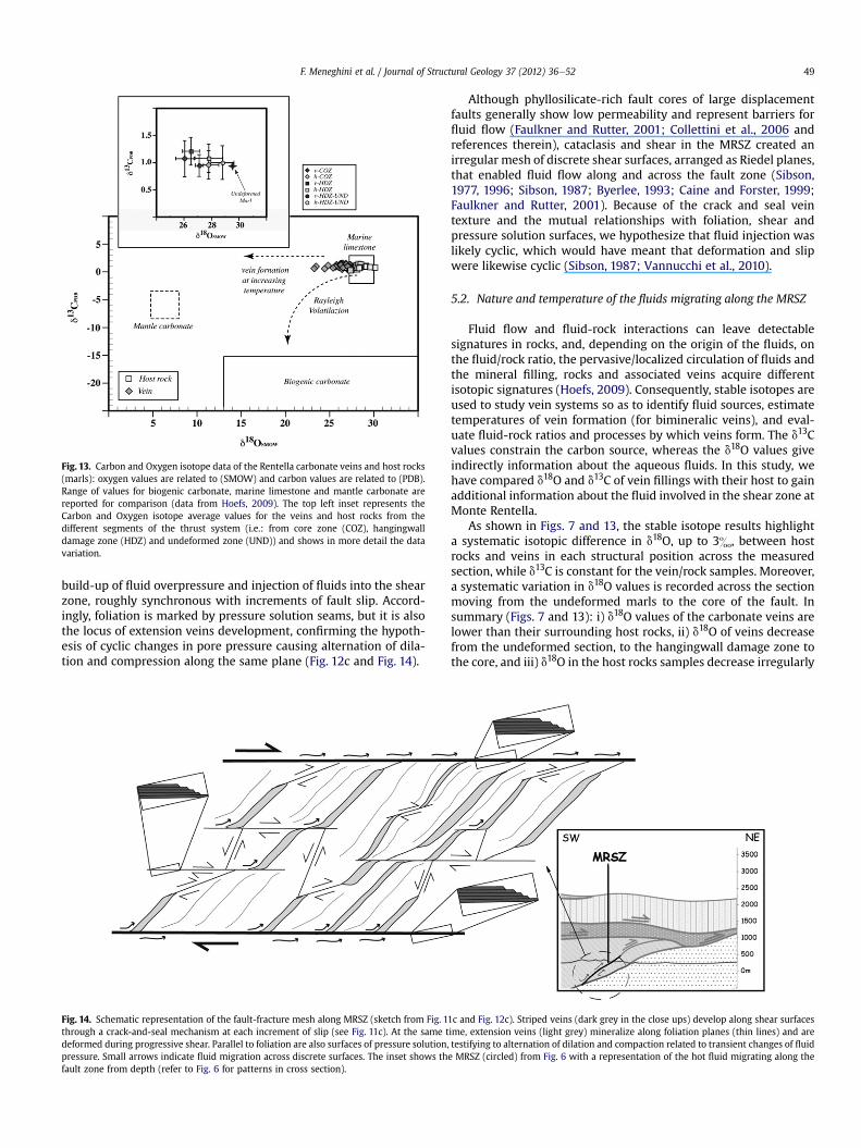
Fig. 13. Carbon and Oxygen isotope data of the Rentella carbonate veins and host rocks(marls): oxygen values are related to (SMOW) and carbon values are related to (PDB).Range of values for biogenic carbonate, marine limestone and mantle carbonate arereported for comparison (data from Hoefs, 2009). The top left inset represents theCarbon and Oxygen isotope average values for the veins and host rocks from thedifferent segments of the thrust system (i.e.: from core zone (COZ), hangingwalldamage zone (HDZ) and undeformed zone (UND)) and shows in more detail the datavariation.
F. Meneghini et al. / Journal of Structural Geology 37 (2012) 36e52 49
build-up of fluid overpressure and injection of fluids into the shearzone, roughly synchronous with increments of fault slip. Accord-ingly, foliation is marked by pressure solution seams, but it is alsothe locus of extension veins development, confirming the hypoth-esis of cyclic changes in pore pressure causing alternation of dila-tion and compression along the same plane (Fig. 12c and Fig. 14).
Fig. 14. Schematic representation of the fault-fracture mesh along MRSZ (sketch from Fig. 1through a crack-and-seal mechanism at each increment of slip (see Fig. 11c). At the same tdeformed during progressive shear. Parallel to foliation are also surfaces of pressure solution,pressure. Small arrows indicate fluid migration across discrete surfaces. The inset shows thfault zone from depth (refer to Fig. 6 for patterns in cross section).
Although phyllosilicate-rich fault cores of large displacementfaults generally show low permeability and represent barriers forfluid flow (Faulkner and Rutter, 2001; Collettini et al., 2006 andreferences therein), cataclasis and shear in the MRSZ created anirregular mesh of discrete shear surfaces, arranged as Riedel planes,that enabled fluid flow along and across the fault zone (Sibson,1977, 1996; Sibson, 1987; Byerlee, 1993; Caine and Forster, 1999;Faulkner and Rutter, 2001). Because of the crack and seal veintexture and the mutual relationships with foliation, shear andpressure solution surfaces, we hypothesize that fluid injection waslikely cyclic, which would have meant that deformation and slipwere likewise cyclic (Sibson, 1987; Vannucchi et al., 2010).
5.2. Nature and temperature of the fluids migrating along the MRSZ
Fluid flow and fluid-rock interactions can leave detectablesignatures in rocks, and, depending on the origin of the fluids, onthe fluid/rock ratio, the pervasive/localized circulation of fluids andthe mineral filling, rocks and associated veins acquire differentisotopic signatures (Hoefs, 2009). Consequently, stable isotopes areused to study vein systems so as to identify fluid sources, estimatetemperatures of vein formation (for bimineralic veins), and eval-uate fluid-rock ratios and processes by which veins form. The d13Cvalues constrain the carbon source, whereas the d18O values giveindirectly information about the aqueous fluids. In this study, wehave compared d18O and d13C of vein fillings with their host to gainadditional information about the fluid involved in the shear zone atMonte Rentella.
As shown in Figs. 7 and 13, the stable isotope results highlighta systematic isotopic difference in d18O, up to 3&, between hostrocks and veins in each structural position across the measuredsection, while d13C is constant for the vein/rock samples. Moreover,a systematic variation in d18O values is recorded across the sectionmoving from the undeformed marls to the core of the fault. Insummary (Figs. 7 and 13): i) d18O values of the carbonate veins arelower than their surrounding host rocks, ii) d18O of veins decreasefrom the undeformed section, to the hangingwall damage zone tothe core, and iii) d18O in the host rocks samples decrease irregularly
1c and Fig. 12c). Striped veins (dark grey in the close ups) develop along shear surfacesime, extension veins (light grey) mineralize along foliation planes (thin lines) and aretestifying to alternation of dilation and compaction related to transient changes of fluide MRSZ (circled) from Fig. 6 with a representation of the hot fluid migrating along the

F. Meneghini et al. / Journal of Structural Geology 37 (2012) 36e5250
from the undeformed section, to the hangingwall damage zone tothe core. The last two groups show similar d18O, 2& less than theundeformed end-member.
Concerning the last point, we have shown that the core zonerepresents a preferential locus for relatively large amount of fluids,as demonstrated by the abundance of carbonate veins. The hostrock in the core records the biggest depletion in 18O compared tothe same lithology away from the fault zone, suggesting that thecirculating fluid interacted strongly with the surrounding rock. Infact, the occurrence of a fossil hydrothermal conduit, channellinglarge fluxes of fluids, is indicated by a lowering of the d18O values ofthe host rocks surrounding the conduit as compared to the samerock far from the hydrothermal path (Hoefs, 2009). According toa diffusive and progressive fluid/rock interaction, the surroundingdamage zone reveals intermediate d18O values between the coreand the undeformed zone. Moreover, the SEM-scale microfabric ofthe marls hosting the veins, shows intense recrystallization withtriple junctions between crystals in the most deformed, intenselyveined fault core, demonstrating a localized interaction of rocksand an external fluid, with high fluid/rock ratio, able to change theisotopic signature and mineralogical characteristic.
d18Oveins values lower than those of the host rocks suggest thatfluids responsible for the veins precipitation were not isotopicallybuffered by surrounding host rocks and that the system was notclosed to external fluids input. Given the occurrence of a constantvein vs. rock O isotope shift, with nearly constant C-isotopecompositions, we propose that the external fluid was an oxygen-rich fluid such as H2O and not a CO2-rich fluid, and very little, ifany, carbonwas involved. If we assume a precipitation of CaCO3 andRentella veins (d18OSMOW ¼ 26e27&) in equilibriumwith the fluid,the oxygen isotope composition of the fluid, depending on thetemperature, would vary from w9e10& (at 100 �C) to w16e17&(at 200 �C; fractionation factors from O’Neil et al., 1969). Sucha fluid falls in the range of typical metamorphic isotope values,being very far from other hypothetical fluids, like trapped seawater(d18OSMOW ¼ 0&), or pore water (�3& seawater value; Hoefs,2009).
The oxygen isotope composition observed in the MRSZ samples(d18OSMOW ¼ 26e27&) could derive from a deep interactionbetween buried pore fluids (�3& seawater value; Hoefs, 2009) andthe Rentella marls, producing a partial dissolution of carbonate andgenerating heavier pore fluids responsible for the calcite veinsprecipitation at shallow levels. Because marine carbonates gener-ally have d18O values higher than any other mineral, virtually anyhydrothermal fluids in equilibrium with sedimentary carbonatewould show the heaviest d18O values. However, to producecarbonate veins with d18OSMOW ¼ 26& from an original sourcevalue of 30& (Fig. 13), the fluid would have to follow an increasingtemperature pathway, such as for example dissolution at lowertemperature and re-precipitation at higher temperature; followingfractionation factors from O’Neil et al. (1969). This inference is notin agreement with our geological and petrological evidence, andtherefore, this hypothesis can be rejected.
The calcite twins in the veins infilling enables a qualitativeestimate of temperature, which is 150 �Ce300 �C (Burkhard, 1993).Hydrocarbon maturation occurs roughly between 100 �C and150 �C and transforms solid organic matter to fluid, thus repre-senting another possible source of fluids (Moore and Saffer, 2001).However, the released fluids would be CO2-rich fluids, which doesnot fit our data about the carbon isotopes in the veins, which haveconstant or typically “inorganic” positive values (Fig. 13).
Metamorphic fluids are commonly released at depth, wheremetamorphic reactions produce mechanical expulsion of largequantities of fluids towards the surface. The geology of the MonteRentella suggests that the Monte Rentella thrust juxtaposes the
Rentella and Montagnaccia Formations (Figs. 2 and 6), bothcharacterized by illite and mixed layers I-S. The smectite to illitetransformation appears to be important at about 150 �C (Mooreand Vrolijk, 1992; Moore and Saffer, 2001). Since the oxygenisotope composition deduced from the veins lies in the field ofmetamorphic fluids (Fig. 13), and given this temperature for activetransformation, we regard the smectite to illite change as themost probable source of the metamorphic fluids responsible forvein formation along the MRSZ. The temperature of 150 �Cneeded for this reaction would fit with the qualitative tempera-ture range determined from the calcite twins in the veins, thusrepresenting a minimum estimate for the fluid temperature.Moreover, this interpretation is in accordance with observed andmodelled behaviour in ancient shallow-level thrusts and accre-tionary units involving similar lithologies (Vrolijk et al., 1990;Moore and Vrolijk, 1992; Moore and Saffer, 2001; Vannucchiet al., 2010).
In summary, all these observation point to an intenseinvolvement of externally-derived fluids, with temperature of150e200 �C and focused mainly in the core zone, that produceda precipitation of carbonate veins, a depletion in 18O of the hostrocks and a pervasive precipitation of calcite þ quartz in core host-rock samples. Diagenetic reactions such as the smectite to illitetransformation are proposed as the possible source of fluids atdepths.
The isotopic values of vein samples and adjacent host rocks fromthe sandstone footwall damage zone all fall into the same field andare not congruent with the data from the marls of the core andhangingwall damage zones. Similar isotopic values in host rock andveins suggest a local mechanism of dissolution-reprecipitation,with the fluids being isotopically buffered by the sandstones.Therefore, we consider the fluid circulation responsible for veinprecipitation in the sandstones as unrelated to the external fluidinput of fluids envisaged for the marls.
6. Conclusions
The new set of structural, isotopical and thermal maturity datapresented in this study provides a snapshot into fluid regime andevolution during fault activity in a collisional setting. While fluidrelease and circulation are universally recognized as dominatingthe shallow levels of subduction, their involvement in faultingduring the collisional phases is not very well documented inliterature.
Similarly to the behaviour along subduction margins, our thrustfault example evolved through cycles of compaction and dilationlinked to transient build-up of fluid overpressure and injection(Sibson, 1987; Koehn and Passchier, 2000; Vannucchi et al., 2010).Fluids mineralized with a crack-and-seal mechanism in shear veinswith the opening direction at a low angle with the main shearsurfaces (and Y-planes). Extension veins along foliation surfacesconnected shear surfaces to form a fault-fracturemesh that workedas a preferential fluid conduit during slip (Fig. 14).
While the thrust was active at very shallow depths, withmaximum paleotemperatures in the early diagenetic zone and inthe immature to early-mature stages of hydrocarbon generation(ca. less than 3 km), blocky and striped veins both formed fromfluids with warmer temperature conditions of 150�e200 �C. Weenvision the source area for hot fluids to be located at deeperstructural levels in the collisional prism, where diagenetic and low-grade metamorphic reactions could produce fluids by dehydrationof clayminerals. The hot fluids pumped from the deeper portions ofthe collisional prisms strongly interacted with the host rocks,modifying not only their isotopic character, but also their localtexture at micro-scale.

F. Meneghini et al. / Journal of Structural Geology 37 (2012) 36e52 51
Acknowledgements
This research was supported by M.I.U.R (Project PRIN). We arethankful to the Editor William Dunne, to Kotharo Ujiie and to theanonymous reviewer, for their thorough comments that helped toimprove the paper. Francesca Meneghini thanks J.C. Moore forcomments and suggestions. Chiara Boschi thanks L. Dallai forfruitful discussions and E. Calvi for assistance with carbonate lab.
References
Aldega, L., Botti, F., Corrado, S., 2007. Clay mineral assemblages and vitrinitereflectance in the Laga Basin (Central Apennines, Italy): what do they record?Clays and Clay Minerals 55, 504e518 October.
Aldega, L., Corrado, S., Di Paolo, L., Somma, R., Maniscalco, R., Balestrieri, M.L., 2011.Shallow burial and exhumation of the Peloritani Mts. (NE Sicily, Italy): insightfrom paleo-thermal and structural indicators. Geological Society of AmericaBulletin 123, 132e149.
Antonellini, M.A., Aydin, A., 1995. Effect of faulting on fluid flow in porous sand-stones: geometry and spatial distribution. American Association of PetroleumGeologists Bulletin 79, 642e671.
Aydin, A., Schultz, R.A., 1990. Effect of mechanical interaction on the development ofstrikeeslip faults with échelon patterns. Journal of Structural Geology 12,123e129.
Bangs, N.L.B., Shipley, T.H., Moore, J.C., Moore, G.F., 1999. Fluid accumulation andchanneling along the northern Barbados Ridge décollement thrust. Journal ofGeophysical Research 104, 20399e20414.
Bangs, N.L.B., Shipley, T.H., Gulick, S.P.S., Moore, G.F., Kuromoto, S., Nakamura, Y.,2004. Evolution of the Nankai Trough décollement from the trench into theseismogenic zone: inferences from three-dimensional seismic reflectionimaging. Geology 32, 273e276.
Barchi, M.R., De Fayter, A., Magnani, M.B., Minelli, G., Pialli, G., Sotera, B.M., 1998.The structural style of the Umbria-Marche fold and thrust belt. Memorie dellaSocietà Geologica Italiana 52, 557e578.
Barchi, M.R.,L., Landuzzi, A., Minelli, G., Pialli, G., 2001. Outer Northern Apennines.In: Vai, G.B., Martini, I.P. (Eds.), Anatomy of an Orogen: The Apennines andAdjacent Mediterranean Basin. Kluwer Academic Publishers, pp. 215e254.
Barker, C.E., Pawlewicz, M.J., 1994. Calculation of vitrinite reflectance from thermalhistories and peak temperatures. A comparison of methods. In:Mukhopadhyay, P.K., Dow, W.G. (Eds.), Vitrinite Reflectance as a MaturityParameter: Applications and Limitations. ACS Symposium Series, vol. 570,pp. 216e229.
Barsella, M., Boscherini, A., Botti, F., Marroni, M., Meneghini, F., Motti, A., Palandri, S.,Pandolfi, L., 2009. Oligocene-Miocene foredeep deposits in the Trasimeno Lakearea (Central Italy): insights in the evolution of the Northern Apennines. ItalianJournal of Geosciences 128, 341e352. doi:10.3301/IJG.2009.128.2.341.
Borrego, A.G., Araujo, C.V., Balke, A., Cardott, B., Cook, A.C., David, P., Flores, D., Hámor-Vidó,M., Hiltmann,W., Kalkreuth,W., Koch, J., Kommeren, C.J., Kusc, J., Ligouis, B.,Marques, M., Mendonça Filho, J.G., Misz, M., Oliveira, L., Pickel, W., Reimer, K.,Ranasinghe, P., Suárez-Ruiz, I., Vieth, A., 2006. Influence of particle and surfacequality on the vitrinite reflectance of dispersed organic matter: comparativeexercise using data from the qualifying system for reflectance analysis workinggroup of ICCP. International Journal of Coal Geology 68, 151e170.
Brown, K.M., Saffer, D.M., Bekins, B.A., 2001. Smectite diagenesis, pore-waterfreshening, and fluid flow at the toe of the Nankai wedge. Earth and Plane-tary Science Letters 194, 97e109. doi:10.1016/S0012-821X(01)00546-5.
Burkhard, M., 1993. Calcite twins, their geometry, appearance, and significance asstress-strain markers and indicators of tectonic regime: a review. Journal ofStructural Geology 15, 351e368.
Byerlee, J.D., 1993. Model for episodic flow of high-pressure water in fault zonesbefore earthquakes. Geology 21, 303e306.
Caine, J.S., Forster, C.B., 1999. Fault zone architecture and fluid flow: insights fromfield data and numerical modelling. In: Haneberg, W., et al. (Eds.), Faults andSub-surface Fluid Flow in the Shallow Crust: American Geophysical UnionGeophysical Monograph, vol. 113, pp. 101e127.
Chester, F.M., Evans, J.P., Biegel, R.L., 1993. Internal structure and weakeningmechanisms of the San Andreas fault. Journal of Geophysical Research 95,771e786.
Collettini, C., De Paola, N., Goulty, N.R., 2006. Switches in the minimum compressivestress direction induced by overpressure beneath a low-permeability fault zone.Terra Nova 18, 163e231.
Conti, A., Turpin, L., Polino, R., Mattei, M., Zuppi, G.M., 2001. The relationshipbetween evolution of fluid chemistry and the style of brittle deformation:examples from the Northern Apennines (Italy). Tectonophysics 330, 103e117.
Corrado, S., Aldega, L., Di Leo, P., Giampaolo, C., Invernizzi, C., Mazzoli, S., Zattin, M.,2005. Thermal maturity of the axial zone of the southern Apennines fold-and-thrust belt (Italy) from multiple organic and inorganic indicators. Terra Nova 17,56e65.
Costa, E., Pialli, G., Plesi, G., 1998. Foreland basins of the Northern Apennines:relationships with passive subduction of the Adriatic lithosphere. MemorieDella Società Geologica Italiana 52, 595e606.
Cox, S.F., Wall, V.J., Etheridge, M.,A., Potter, T.F., 1991. Deformational and meta-morphic processes in the formation of mesothermal vein-hosted gold deposits:examples from the Lachlan Fold Belt in central Victoria, Australia. Ore GeologyReview 6, 391e423.
Cox, S.F., Braun, J., Knackstedt, M.A., 2001. Principles of structural control onpermeability and fluid flow in hydrothermal systems. Reviews in EconomicGeology 14, 1e24.
Dalla Torre, M., Ferreiro Mählmann, R., Ernst, W.G., 1997. Experimental study on thepressure dependence of vitrinite maturation. Geochimica et Cosmochimica Acta61, 2921e2928.
Davis, D., Suppe, J., Dahlen, F.A., 1983. Mechanics of fold-and-thrust belts andaccretionary wedges. Journal of Geophysical Research 88 (B2), 1153e1172.
Dow, W.G., 1977. Kerogen studies and geological interpretation. Journal ofGeochemical Explorer 7, 79e99.
Evans, J.P., Chester, F.M., 1995. Fluid-rock interaction in faults of the San Andreassystem: inferences from San Gabriel fault rock geochemistry and microstruc-tures. Journal of Geophysical Research 100, 13,007e13,020. doi:10.1029/94JB02625.
Fagereng, A., Sibson, R.H., 2010. Mélange rheology and seismic style. Geology 38,751e754. doi:10.1130/G30868.1.
Faulkner, D.R., Rutter, E.H., 2001. Can maintenance of overpressured fluids in largestrike-slip fault zones explain their apparent weakness? Geology 29, 203e506.
Ferrill, D.A., Morris, A.P., Evans, M.A., Burkhard, M., Groshong, R.H., Onasch, C.M.,2004. Calcite twin morphology: a low temperature deformation geo-thermomenter. Journal of Structural Geology 26, 1521e1529.
Fisher, D.M., Brantley, S.L., 1992. Models of quartz overgrowth and vein formation:deformation and episodic fluid flow in an ancient subduction zone. Journal ofGeophysical Research 97, 20043e20061.
Fisher, D.M., 1996. Cyclic fluid flow in the forearc: evidence from fabrics and veins.In: Bebout, G., Scholl, D., Kirby, S. (Eds.), Subduction-Top to Bottom, vol. 96.American Geophysical Union Monograph, Washington, DC, pp. 75e90.
Fournier, R.O., 1991. The transition from hydrostatic to greater than hydrostatic fluidpressures in presently active hydrothermal systems in crystalline rock.Geophysical Research Letters 18, 955e958.
Fyfe, V.S., Price, N.J., Thompson, A.B., 1978. Fluids in the Earth’s Crust. Elsevier,Amsterdam, p. 383.
Fyfe, W.S., Kerrich, R., 1985. Fluids and thrusting. Chemical Geology 49, 353e362.Goldstein, A., Selleck, B., Valley, J.W., 2005. Pressure, temperature, and composition
history of syntectonic fluids in a low-grade metamorphic terrane. Geology 33,421e424. doi:10.1130/G21143.1.
Goodwin, L.B., Tikoff, B., 2002. Competency contrast, kinematics and the develop-ment of foliations and lineations in the crust. Journal of Structural Geology 24,1065e1085.
Hilgers, C., Kirschner, D.L., Breton, J.P., Urai, J.L., 2006. Fracture sealing and fluidoverpressures in limestones of the Jabal Akhdar dome, Oman mountains.Geofluids 6, 168e184.
Hill, D.P., 1977. A model for earthquake swarms. Journal of Geophysical Research 82,347e352.
Hillis, R.R., 2001. Coupled changes in pore pressure and stress in oil fields andsedimentary basins. Petroleum Geoscience 7, 419e425.
Hickman, S., Sibson, R.H., Bruhn, R., 1995. Mechanical involvement of fluids infaulting. Journal of Geophysical Research 100, 12,831e12,840.
Hoefs, J., 2009. Stable Isotope Geochemistry, sixth ed. Springer-Verlag, Berlin, p.285.
Hubbert, M.K., Rubey, W.W., 1959. Role of fluid pressure in mechanics of overthrustfaulting. Geological Society of America Billetin 70, 115e166.
Hunt, J.M., 1990. Generation and migration of petroleum from abnormally pres-sured fluid compartments. Bulletin of the American Association of PetroleumGeologists 74, 1e12.
Jeanbourquin, P., 2000. Chronology of deformation of a Franciscan mélange nearSan Francisco (California, U.S.A. Eclogae Geologicae Helvetiae 93, 363e378.
Kastner, M., Elderfield, H., Martin, J.B., 1991. Fluids in Convergent Margins e WhatDo We Know about Their Composition, Origin, Role in Diagenesis and Impor-tance for Oceanic Chemical Fluxes, vol. A335. Philosophical Transaction of theRoyal Society of London, pp. 243e259.
Kirschner, D.L., Sharp, Z.D., Masson, H., 1995. Oxygen isotope thermometry ofquartz-calcite veins: unraveling the thermal-tectonic history of the sub-greenschist facies Morcles nappe (Swiss Alps). Geological Society of AmericaBulletin 107, 1145e1156.
Knipe, R.J., 1986. Deformation mechanism path diagrams for sediments undergoinglithification. In: Moore, J.C. (Ed.), Structural Fabric in Deep Sea Drilling ProjectCores from Forearcs, vol. 166. Memoir of the Geological Society of America,pp. 151e160.
Knipe, R.J., 1989. Deformation mechanisms: recognition from natural tectonites.Journal of Structural Geology 11, 127e146.
Koehn, D., Passchier, C.W., 2000. Shear sense indicators in striped bedding veins.Journal of Structural Geology 22, 1141e1151.
Labaume, P., Berty, C., Laurent, Ph., 1991. Syn-diagenetic evolution of shear struc-tures in superficial nappes: an example from the Nothern Appennines (NWItaly). Journal of Structural Geology 13, 385e398.
Labaume, P., Moretti, I., 2001. Diagenesis-dependence of cataclastic thrust fault zonesealing in sandstones. Example from the Bolivian Sub-Andean Zone. Journal ofStructural Geology 23, 1659e1675.
Labaume, P., Maltman, A., Bolton, A., Tessier, D., Ogawa, Y., Takizawa, S., 1997. Scalyfabrics in sheared clays from the décollement zone of the Barbados accretionary

F. Meneghini et al. / Journal of Structural Geology 37 (2012) 36e5252
prism. In: Shipley, T.H., Ogawa, Y., Blum, P., Bahr, J.M. (Eds.), Proceedings of theOcean Drilling Program. Scientific Results, vol. 156, pp. 59e77.
Lavecchia, G., Minelli, G., Pialli, G., 1987. Contractional and extensional tectonicsalong the transect Lake Trasimeno-Pesaro (central Italy). In: Boriani, A.,Bonafede, M., Piccardo, G.B., Vai, G.B. (Eds.), The Lithosphere in Italy. Advancedin Earth Sciences Research, vol. 80. Accademia Nazionale dei Lincei,pp. 177e194.
Law, B.E., Ulmishek, G.F., Slavin, V.I., 1998. Abnormal Pressure in HydrocarbonEnvironments, vol. 70. AAPG Memoir, Tulsa, p. 264.
Leader, L.D., Robinson, J.A., Wilson, C.J.L., 2010. Role of faults and folding incontrolling gold mineralisation at Fosterville, Victoria. Australian Journal ofEarth Sciences 57 (2), 259e277.
Lewis, J.C., Byrne, T.B., Pasteris, J.D., London, D., Morgan, G.B., 2000. Early tertiaryfluid flow and pressure-temperature conditions in the Shimanto accretionarycomplex of southwest Japan: constraints from fluid inclusions. Journal ofMetamorphic Geology 18, 219e333.
Lister, G.S., Williams, P.F., 1983. The partitioning of deformation in flowing rockmasses. Tectonophysics 92, 1e33.
Lundberg, N., Moore, J.C., 1986. Macroscopic structural features in Deep Sea DrillingProject cores from forearc regions. In: Moore, J.C. (Ed.), Structural Fabric in DeepSea Drilling Project Cores from Forearcs, vol. 166. Geological Society of AmericaMemoir, pp. 13e44.
Marroni, M., Meneghini, F., Pandolfi, L., 2010. Anatomy of the Ligure-Piemontesesubduction system: evidence from Late Cretaceousemiddle Eocene conver-gent margin deposits in the Northern Apennines, Italy. International GeologyReview 1, 1e33.
McCrea, J.M., 1950. On the isotopic chemistry of carbonates and a paleotemperaturescale. Journal of Chemical Physics 18, 849e857.
Meneghini, F., Moore, J.C., 2007. Deformation and hydrofracture in a subductionthrust at seismogenic depths: the Rodeo Cove thrust zone, Marin Headlands,California. Geological Society of America Bulletin 119 (1), 174e183.
Meneghini, F., Marroni, M., Pandolfi, L., 2007. Fluid flow during accretion insediment-dominated margins: evidence of a high-permeability fossil fault zonefrom the Internal Ligurian accretionary units of the Northern Apennine, Italy.Journal of Structural Geology 29, 515e529.
Merriman, R.J., Frey, M., 1999. Patterns of very low-grade metamorphism in met-apelitic rocks. In: Frey, M., Robinson, D. (Eds.), Low-grade Metamorphism.Blackwell, Oxford, pp. 61e107.
Moore, D.M., Reynolds Jr., R.C., 1997. X-ray Diffraction and the Identification andAnalysis of Clay Minerals. Oxford University Press, New York, p. 378.
Moore, J.C., Vrolijk, P., 1992. Fluids in accretionary prisms. Reviews of Geophysics 30,113e135.
Moore, J.C., Saffer, D., 2001. Updip limit of the seismogenic zone beneath theaccretionary prism of southwest Japan: an effect of diagenetic to low-grademetamorphic processes and increasing effective stress. Geology 29,183e186.
Moore, J., Orange, D., Kulm, L., 1990. Interrelationship of fluid venting and structuralevolution: alvin observations from the frontal accretionary prism. Journal ofGeophysical Research 95, 8795e8808.
Newhouse, W.H., 1942. Ore Deposits as Related to Structural Features. PrincetonUniversity Press, Princeton, New Jersey.
O’Neil, J.R., Clayton, R.N., Mayeda, T.K., 1969. Oxygen isotopes fractionation indivalent carbonates. Journal of Chemical Physics 51, 5547e5558.
Pauselli, C., Barchi, M., Federico, C., Magnani, M.B., Minelli, G., 2006. The crustalstructure of the Northern Apennines (Central Italy): an insight by the Crop03seismic line. American Journal of Science 306, 428e450.
Pini, G.A. (Ed.), 1999. Tectosomes and Olistrostromes in the Argille Scagliose of theNorthernApennines, Italy. Geological SocietyofAmerica, Boulder, Colorado,p. 70.
Ramsay, J.G., 1980. The crack-seal mechanism of rock deformation. Nature 284,135e139.
Rowe, C.D., Meneghini, F., Moore, J.C., 2009. Fluid-rich damage zone of an ancientout-of-sequence thrust, Kodiak Islands, Alaska. Tectonics 28, TC1006.doi:10.1029/2007TC002126.
Saffer, D.M., Bekins, B.A., 2002. Hydrologic controls on the morphology andmechanics of accretionary wedges. Geology 30, 271e274.
Shipley, T.H., Ogawa, Y., Blum, P., The Shipboard Scientific Party, 1995. NorthernBarbados Ridge, Leg 156 of the cruises of the Drilling Vessel JOIDES Resolution,Sites 947e949. Proceedings of the ODP, Initial Reports, 156, College Station,Texas (Ocean Drilling Program).
Sibson, R.H., 1977. Fault rocks and fault mechanisms. Journal of the GeologicalSociety of London 133, 191e213.
Sibson, R.H., 1981. Fluid flow accompanying faulting: field evidence and models. In:Simpson, D.W., Williams, P.G. (Eds.), Earthquake Prediction: An InternationalReview. American Geophysical Union, Maurice Ewing Series, vol. 4,pp. 593e603.
Sibson, R.H., 1987. Earthquake rupturing as a mineralizing agent in hydrothermalsystems. Geology 15, 701e704.
Sibson, R.H., 1990. Conditions for fault-valve behaviour. In: Knipe, R.J., Rutter, E.H.(Eds.), Deformation Mechanisms, Rheology and Tectonics. Geological Society ofLondon, Special Publication, vol. 54, pp. 15e28.
Sibson, R., 1994. An assessment of field evidence for ‘‘Byerlee’’ friction. Pure andApplied Geophysics 142, 645e662.
Sibson, R.H., 1996. Structural permeability of fluid-driven fault-fracture meshes.Journal of Structural Geology 18, 1031e1042.
Sibson, R.H., 2001. Seismogenic framework for hydrothermal transport and oredeposition. Society of Economical Geology Review 14, 25e50.
Stach, E., Mackowsky, M.Th., Teichmüller, M., Taylor, G.H., Chandra, D.,Teichmüller, R., 1982. Stach’s Textbook of Coal Petrology. Gerbrüder Born-traeger, Berlin-Stuttgart, p. 535.
Vannucchi, P., Remitti, F., Bettelli, G., Boschi, C., Dallai, L., 2010. Fluid history relatedto the early Eocene-middle Miocene convergent system of the NorthernApennines (Italy): constraints from structural and isotopic studies. Journal ofGeophysical Research 115, B05405. doi:10.1029/2009JB006590.
Vrolijk, P., Chambers, S.R., Gieskes, J.M., O’Neil, J.R., 1990. Stable isotope ratios ofinterstitial fluids from the Northern Barbados accretionary prism, ODP Leg 110.In: Moore, J.C., Mascle, A. (Eds.), Proceedings of the Ocean Drilling Program,Scientific Results, vol. 110. Ocean Drilling Program, College Station, Tex,pp. 189e205.
Copyright © 2022 FDOKUMEN