Hints, Tips & Fault Codes - ATAG Heating
21
1 | Page Hints, Tips & Fault Codes Contents PCB no 105, just OK ............................................................................................................................... 2 Boiler: iR15 - Fault code 151 & 164 ........................................................................................................ 2 Diverter Valve Operation iC Combi Boilers ............................................................................................. 2 Fault Code 151 - Fan error (speed control is not achieved or is out of range) or control unit defective. 3 Fault Code 129 - Fan error (fan does not start up) ................................................................................. 3 Fault Code 78 .......................................................................................................................................... 3 Fault Code 154 ........................................................................................................................................ 3 Error code on ONE Controller: Code 002 / 003 .................................................................................... 4 Fault code 128 ........................................................................................................................................ 4 Nest with 3 port priority kit. ...................................................................................................................... 4 SE on LMU Display ................................................................................................................................. 4 Boiler heating up rads when not required. .............................................................................................. 4 Flow temp rising after 10 minutes on iS or iC boilers with weather compensation................................. 5 Extra expansion vessel on combi boiler with two zone valves – expansion problems ........................... 5 Older iC boiler with OpenTherm Honeywell T4R controller .................................................................... 5 Sticking Gradient Temperature Rise ....................................................................................................... 6 Parameter Service LMU and Fan Speeds .............................................................................................. 6 New Top HMI boiler ................................................................................................................................ 7 Fail to stay alight. .................................................................................................................................... 7 Ionisation current levels: ......................................................................................................................... 7 Heat Generation Lock function ............................................................................................................... 7 Fault code 117 (old boiler with new pressure sensor) ............................................................................ 7 Boiler stuck in initializing mode on start up ............................................................................................. 7 ‘AUTO’ under the heating temperature on the front screen .................................................................... 8 iS boiler 201 or 203 fault code ................................................................................................................ 8 ATAG ONE Zone - gateway serial number ............................................................................................ 8 Why does the display always sit on 80 and auto when I’ve set the ch point to 66? ............................... 9 Time program error ................................................................................................................................. 9 What Thermoregulation to choose and what control connections ........................................................ 11 iS boiler with 3 port diverter kit – Code 114 .......................................................................................... 11 iS boiler with – Code 114 ...................................................................................................................... 12 Boiler with error 411, 412, 413 .............................................................................................................. 12 Pump external (green) connector ......................................................................................................... 12 Nest not working on boiler in OpenTherm ............................................................................................ 12 New ATAG Upgraded Boiler Fault Codes v3 ........................................................................................ 12
-
Upload
khangminh22 -
Category
Documents
-
view
4 -
download
0
Transcript of Hints, Tips & Fault Codes - ATAG Heating

1 | P a g e
Hints, Tips & Fault Codes
Contents
PCB no 105, just OK ............................................................................................................................... 2
Boiler: iR15 - Fault code 151 & 164 ........................................................................................................ 2
Diverter Valve Operation iC Combi Boilers ............................................................................................. 2
Fault Code 151 - Fan error (speed control is not achieved or is out of range) or control unit defective. 3
Fault Code 129 - Fan error (fan does not start up) ................................................................................. 3
Fault Code 78 .......................................................................................................................................... 3
Fault Code 154 ........................................................................................................................................ 3
Error code on ONE Controller: Code 002 / 003 .................................................................................... 4
Fault code 128 ........................................................................................................................................ 4
Nest with 3 port priority kit. ...................................................................................................................... 4
SE on LMU Display ................................................................................................................................. 4
Boiler heating up rads when not required. .............................................................................................. 4
Flow temp rising after 10 minutes on iS or iC boilers with weather compensation. ................................ 5
Extra expansion vessel on combi boiler with two zone valves – expansion problems ........................... 5
Older iC boiler with OpenTherm Honeywell T4R controller .................................................................... 5
Sticking Gradient Temperature Rise ....................................................................................................... 6
Parameter Service LMU and Fan Speeds .............................................................................................. 6
New Top HMI boiler ................................................................................................................................ 7
Fail to stay alight. .................................................................................................................................... 7
Ionisation current levels: ......................................................................................................................... 7
Heat Generation Lock function ............................................................................................................... 7
Fault code 117 (old boiler with new pressure sensor) ............................................................................ 7
Boiler stuck in initializing mode on start up ............................................................................................. 7
‘AUTO’ under the heating temperature on the front screen .................................................................... 8
iS boiler 201 or 203 fault code ................................................................................................................ 8
ATAG ONE Zone - gateway serial number ............................................................................................ 8
Why does the display always sit on 80 and auto when I’ve set the ch point to 66? ............................... 9
Time program error ................................................................................................................................. 9
What Thermoregulation to choose and what control connections ........................................................ 11
iS boiler with 3 port diverter kit – Code 114 .......................................................................................... 11
iS boiler with – Code 114 ...................................................................................................................... 12
Boiler with error 411, 412, 413 .............................................................................................................. 12
Pump external (green) connector ......................................................................................................... 12
Nest not working on boiler in OpenTherm ............................................................................................ 12
New ATAG Upgraded Boiler Fault Codes v3 ........................................................................................ 12

2 | P a g e
ATAG ONE Zone Controller – Assigned to zone 6 ............................................................................... 15
Capacitor standard in iS & iR boiler boxes ........................................................................................... 15
CH Pump Overrun ................................................................................................................................. 15
Pump and Fan speeds TopHMI ............................................................................................................ 16
System Pressure Sensor readings ....................................................................................................... 17
ATAG ONE Zone factory reset from front screen menu ....................................................................... 18
ATAG Zone errors ................................................................................................................................. 20
PCB no 105, just OK Boiler starts up after power with no 105 de-aeration program, and just goes through to OK . The Boiler has not come out of test mode on the production line. Go into parameter 9 and make the selection of the boiler. For example iC 36 parameter P9 = 3.
Boiler: iR15 - Fault code 151 & 164 The fault code 151 can come up on an iR boiler and be caused by the flow switch. If the flow switch has an open connection during the operation of the boiler or before start up, you will get an error code 164. If the flow switch has an open connection during the ignition time of the boiler, you will get an error code 151. This means that a pump that starts up and has a flow large enough to operate the flow switch and then senses poor flow of water can cause this issue. This can be due to air in the system, pumping over or sucking in air through the open vent. A system that has TRV’s and the flow is restricted down to literally one rad still needs a route to flow round that is sufficient, otherwise where there is a demand for heat, but no flow around the system and an error code 164 flow switch not operating will come up. The switch point of the flow switch off is at 7 l/m, +/- 10% The switch on point of the flow switch is 5% to 10% above the switch off point. The flow rates of the boilers @∆T 20°C are 15 l/m and 20 l/m.
Diverter Valve Operation iC Combi Boilers
Call for hot water the valve will be pushed down and the motor will move outwards.
Call for heating the valve will move upwards and the motor will move inwards.
With the motor head taken off of the body the boiler is in heating mode.
With the motor head taken off of the body the diverter cartridge needs to be pushed and held
down to put it in hot water mode
The valve will stay in the last position until a change of demand is called for.

3 | P a g e
Fault Code 151 - Fan error (speed control is not achieved or is out of range) or control unit defective This fault code 151 comes from a tachometer signal from the fan. The LMU gives out a PWM (Pulse width modulation) to regulate the fan speed. LMU knows how fast the fan should be going e.g. 5,000 RPM. LMU checks the fan speed within a tolerance of 400 RPM for 25 seconds. 4,800 – 5,200 RPM If for 25 seconds the RPM is not within tolerance the fault code 151 will be given. This can be the fan speed, wiring, connectors or PCB at fault, but a very high proportion would be the PCB at fault.
Fault Code 129 - Fan error (fan does not start up) This fault code 129 comes from a tachometer signal from the fan. The fan is controlled by a PWM (Pulse width modulation) cable The fan is permanently supplied with 230v ac. For the fan to turn it needs a signal from the PWM cable to regulate the speed from off al the way through to high speed. If there is 230v ac at the fan, but the fan does not turn, the tachometer will not register a RPM figure and gives a fault code 129 If there is 230v ac at the fan, the fan may be stopped from turning by the PWM cable. Take off the PWM cable and if the fan runs (at full speed, no control) then it is the PWM that is stopping the fan from turning. The fault 129 code only comes up on initial start up after that it looks at the fan RPM and if there is a problem fault code 151 will come up.
Fault Code 78 Water pressure outside of range or not connected (Combi & System Boiler) Check water pressure on analogue gauge Check the sensor Check wiring harness not shorting to earth Check the connection plug on top of sensor and PCB If boiler does not see a pressure rise after 6 attempts (x 10min) 118 with spanner will go to 78 with bell IR boiler - If boiler has repeated 164 / 151 codes after 6 attempts (x 10min) it will go to 78 with bell
Fault Code 154
dT:
dT>25 = burner – 20% (80%)
dT>30K = burner minimum
dT>35K = burner off (C154 blocking)
After 10 times within 24 hours dT>35K: C154 lockout, has to be reset. Increase Tflow: When Tflow increases > 5K/second = burner off (C154 blocking)

4 | P a g e
After 10 times within 24 hours Tflow increases >5K/second: C154 lockout, has to be reset. Treturn > Tflow: When Treturn > Tflow + 15K = burner off (C154 blocking) for iC When Treturn > Tflow + 15K for more than 15 seconds = burner off (C154 blocking) for iS & iR After 50 times within 24 hours Treturn > Tflow + 15K: C154 lockout, has to be reset.
Error code on ONE Controller: Code 002 / 003 002 error will show during/after using chimney sweep function, same as 180 on the boiler. 003 error will show during/after using commissioning mode, same as 181 on the boiler.
Fault code 128 Ionisation level too low at max fan speed / RPM Poor ionisation current
Nest Switching on and off in reverse with OpenTherm
If the Nest is switching on and off in reverse with OpenTherm, then there is a setting on the Nest controller that needs to be set up as using OpenTherm.
Nest with 3 port priority kit. Heating and hot water can work with schedules and the low temp for hot water can be set to off. The tap symbol goes off.
SE on LMU Display Push the, minus button DHW, the Reset button and the minus button CH simultaneously
You will reset the time. and after the pre-set hours it will come up again.
Boiler heating up rads when not required.
Check if the boiler has a wireless controller as the receiver on the boiler may be in emergency mode.
Note: If the batteries are not replaced and no valid signal is received from the Transmitter, the Receiver’s neon light will flash every 0.5 seconds. After 1 hr the boiler will operate in ‘Emergency mode’ (heating on for 4 min. and off for 9 min.) until the batteries are replaced.

5 | P a g e
Note; always press the reset button after removing or replacing the batteries.
Another cause could be the diverter valve has not closed off the heating port completely when there is a request for hot water and a small amount of heat is going into the rads. If the boiler is in ‘Comfort mode’ then this will keep the boiler hot for quicker hot water, but a small amount of heat will go into the rads. This will need a new diverter valve motor.
Flow temp rising after 10 minutes on iS or iC boilers with weather compensation.
what happens is that when a heat demand by an On / Off switch ( Volt free or Switched Live) lasts without interruption for 10 minutes, the heating line setting will be increased by 10%. when the heat demand is interrupted during these 10 minutes this does not happen. when the heat demand is interrupted after these ten minutes and the increase of 10% has taken place then the heating line is decreased by 1% per minute
If the heat demand is permanent, then ultimately it will reach the max flow temperature.
For the Top HMI it is adjustable, factory setting is off but by adjusting parameter 475 (auto slope adaptation) you can alter this.
Extra expansion vessel on combi boiler with two zone valves – expansion problems
Symptom of expansion within the system can go high (displayed on boiler) due to a secondary heat exchanger being piped on the return where there are two or more zones valves on the system.
This creates no expansion when in hot water mode, as the return central heating pipe is closed off and the zone valves close off the other side (flow) of the heating pipework. Therefore, the expansion vessel is closed off from the boiler.
Pressure can be high within the boiler and when hot water is used the pressure can be drawn down and could be a negative pressure due to the incorrect positioning of the secondary expansion vessel in this situation of a combi boiler with zone valves.
Older iC boiler with OpenTherm Honeywell T4R controller
CH & HW Temp not saving on LCD display when end user requests a temp change.
This is because the O/T function isn’t compatible with older models. The controller would have to be wired as 230v in order to change the temp settings.
Alternatively, you can remove the O/T connections from the O/T bus, set the temp value then reconnect.

6 | P a g e
Sticking Gradient Temperature Rise If a boiler seems to ‘stick’ on the gradient rise try and renter the gradient P5 setting to 8. This has been found not to be stat related as it has been on OT, SWL, volt free and One controller. Resetting the board parameter p9 has also worked.
Parameter Service LMU and Fan Speeds
7 | P a g e
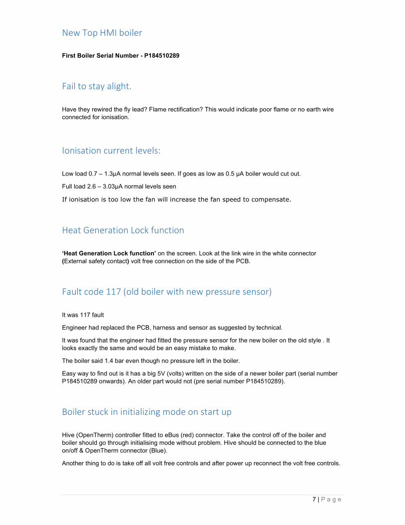
New Top HMI boiler
First Boiler Serial Number - P184510289
Fail to stay alight.
Have they rewired the fly lead? Flame rectification? This would indicate poor flame or no earth wire connected for ionisation.
Ionisation current levels:
Low load 0.7 – 1.3µA normal levels seen. If goes as low as 0.5 µA boiler would cut out.
Full load 2.6 – 3.03µA normal levels seen
If ionisation is too low the fan will increase the fan speed to compensate.
Heat Generation Lock function
‘Heat Generation Lock function’ on the screen. Look at the link wire in the white connector (External safety contact) volt free connection on the side of the PCB.
Fault code 117 (old boiler with new pressure sensor)
It was 117 fault
Engineer had replaced the PCB, harness and sensor as suggested by technical.
It was found that the engineer had fitted the pressure sensor for the new boiler on the old style . It looks exactly the same and would be an easy mistake to make.
The boiler said 1.4 bar even though no pressure left in the boiler.
Easy way to find out is it has a big 5V (volts) written on the side of a newer boiler part (serial number P184510289 onwards). An older part would not (pre serial number P184510289).
Boiler stuck in initializing mode on start up
Hive (OpenTherm) controller fitted to eBus (red) connector. Take the control off of the boiler and boiler should go through initialising mode without problem. Hive should be connected to the blue on/off & OpenTherm connector (Blue).
Another thing to do is take off all volt free controls and after power up reconnect the volt free controls.

8 | P a g e
‘AUTO’ under the heating temperature on the front screen
Parameter 2.2.4 Thermoregulation 0=absent 1= present (default no.1)
With Auto absent (off) the boiler just works as fixed flow temperatures (equivalent to thermoregulation No. 0)
With Auto present (on) the boiler looks at parameter 4.2.1. Thermoregulation No. 0 - 4
iS boiler 201 or 203 fault code
If a new boiler installed comes up with 202 or 203 fault code, then a parameter might be set wrong.
If the iS boiler does not have a sensor or cylinder stat connected to the hot water yellow volt free connection, then check the parameters.
Parameter 2.2.8 - Boiler version
Type of boiler selection
0 = Combi Fault code 201 comes up
1 = Storage with NTC Fault code 203 comes up
2 = Storage with thermostat Default (correct setting)
ATAG ONE Zone - gateway serial number
On the one controller go to connectivity, then connectivity info. If it has an IP address then it is connected to the internet. At the bottom of the screen it will show the one controller serial number (normally six numbers, one letter, five numbers) example 471828G56320. If the ONEZone smart controller has been connected to the Wi-Fi, but not connected to the account, then when going into the app next time it will ask at the bottom of the screen ‘if the product has already been connected to the internet or uses GPRS connection please click here’. You would then need to fill in the serial number at the top of the screen followed by address details, so in this case '471828G56320'. This will only work if the device is online. If it asks for a gateway serial number you are most likely on the portal. The one controller serial number can be entered here, but only if the one controller is connected to the internet. Otherwise you need to go back to the app to carry on.

9 | P a g e
Why does the display always sit on 80 and auto when I’ve set the ch point to 66?
In the customer screen, Complete menu, CH setting, CH Set point Temp. Most systems will be just 1 zone and here is where a customer (or you) could set the max temp for each zone. Let’s say 70 degrees for zone 1. Though zone 2 & 3 are not used, if they are still set to 80 degrees then this shows as the maximum the boiler could do for all zones on the front screen (highest number of the three zones). When you move the dial there is a number that comes up next to the rad symbol (normally No 1). This then shows the temperature for that zone, 70 degrees in this case. Then it reverts back to the normal front screen figures (highest number of the three zones). If within the customer screen, Complete menu, CH setting, CH Set point Temp. T Set Z1, T Set Z2 and TSet Z3 are set to the same or 2 & 3 are lower, then the temperature will show as the same or Z1 being the highest. Each zone can also have a maximum temperature set in engineers’ parameter 4.2.5 Z1 Max T. 20 to 80 degrees (for zone 1) (5.2.5 for zone 2 etc) If this is set to 70 degrees, then this is the maximum the customer can set on the front screen or within customer settings (for zone 1).
(Changes made to the soferware from P1938XXXXX to set zone 2 & 3 as 20°C)
Time program error
Time Program service type mismatch. Enter into Technical Menu and check it.
So, the boiler setting, and ONE zone are set up differently. Both should be set to Extended time program. On the boiler select ‘extended time program’ and ‘Advanced, schedule type’ on ONE Zone. Boiler User menu --> Complete menu --> Screen settings --> Time Program Service Type (Extended time program or time program)

10 | P a g e
One zone Menu --> SETTINGS --> ADVANCED --> SCHEDULE TYPE (Advanced or time program)
--> Select Advanced

11 | P a g e
What Thermoregulation to choose and what control connections
4.2.1 Thermoregulation
Within the parameters of the boiler (4.2.1) make a choice between:
No. Description Volt Free Connector
Colour Controls
0 = Fixed flow temperature (On/off or OpenTherm controller) (Factory setting)
Blue On / Off stat OpenTherm
1 = Do not use
2 = Room control with ATAG ONEZone controller (Room temp only / thermostat mode) Red (eBus)
ATAG ONEZone or Cube
3 = Weather Compensation (Outside sensor only or with On/off or OpenTherm controller) (4.7.0 & 4.7.2)
Salmon pink & Blue
Outside sensor with On / Off stat or OpenTherm
4 = Weather dependent control - with Room compensation (Only for ATAG ONEZone controllers) (ATAG ONEZone in weather dependent mode)
Red (eBus) ATAG ONEZone or Cube
If you are using the built-in programmer to control the heating times going On and Off then these are the settings to change
The built-in time program of the boiler display works in two different ways. There is a setting within the customer menu that need to change. Go to ‘Complete menu’, ‘Screen Settings’, then ‘Time Program service type’ and there the setting can be changed to either ‘Extended Time Program’ (default) or ‘Time Program’.
‘Extended Time Program’ (default) would be for the ATAG eBus connect products, like ATAG ONEZone & ATAG Cube (Thermoregulation setting no.2 & 4), which works with the built-in timer. These time settings are shown in the boiler and within the ATAG ONEZone app/portal
‘Time Program’ would be used where the front display built-in timer is used for the time setting element with the 230V SwL or Volt free On/Off contacts for a thermostat. (Thermoregulation setting no.0 & 3)
iS boiler with 3 port diverter kit – Code 114
In thermoregulation No. 4 it is the weather dependent mode, but it needs an outside temperature either from the internet or a weather compensator. So on a ONE Zone controller does the outside weather temp show up? If it does not have the outside temp yet or it has lost it, then it will come up with the code 114 Outdoor Sensor Damaged. Most people 98%+ use the ATAG eBus controls it thermoregulation setting No. 2, which was thermostat mode in the old ONE controller and gives lower flow temperatures due to load compensation.

12 | P a g e
iS boiler with – Code 114 If error 114 comes up with a description of ‘114 Outdoor Sensor Damaged’, then you might need to check that the boiler has the right thermoregulation setting. When it is using external Y-plan / S-plan the thermoregulation should be set to 0 (zero) Fixed flow temperature (On/off or OpenTherm controller) (Factory setting)
Boiler with error 411, 412, 413 (41z Room sensor not available)
A zone thermoregulation is incorrect. The last fault code digit gives the zone that is incorrect i.e. 412 is zone 2.
Go into thermoregulation parameter setting 4.2.1 for zone 1 and 5.2.1 for zone 2 etc.
You might find the parameter set to 2, 3 or 4 and if the zone is not used it should be set to parameter setting ‘0’ (zero).
Pump external (green) connector The pump external (green) connector on the combi boilers gives power out to an external pump during heating and hot water modes up to P1938XXXXX. After P1938XXXXX it only operate during heating mode. It also gives power out during the air purge mode as well.
On a system boiler with external valves (single call for heat, normally SwL) it is given, then it would send power out to the external pump connector when there is a call for heat.
On a system boiler with a hot water priority kit the external pump connector also gets power whilst in hot water mode up to P1938XXXXX. After P1938XXXXX it only operate during heating mode. This works the same as a combi.
Nest not working on boiler in OpenTherm
Check the Nest controller setting that is has been switched over to work on OpenTherm
New ATAG Upgraded Boiler Fault Codes v3
Fault Code Error Description Checks
101 Overheat Temperature rise too fast. Check correct circulation of the water and pump
102 Pressure Sensor Error
Check water pressure on analogue gauge Check the sensor Check wiring harness not shorting to earth Check the connection plug on top of sensor and PCB
103 Flow Check Failed 3 times (1 or 3 or 4, last 1)
Check pump is spinning via de-blocking centre screw

13 | P a g e
104 Flow Check Failed Check PWM pump connection pins, cable and PCB connection
105 Flow Check Failed 3 times (1 or 3 or 4, last 3)
106 Flow Check Failed 3 times (1 or 3 or 4, last 4)
107 Flow Check 5 Failed
108 Pressure < Pmin (< 0.5 bar), Filling needed
Check water pressure on analogue gauge
1P1 Flow Check 1 Failed Check pump is spinning via de-blocking centre screw Check PWM pump connection pins, cable and PCB connection
1P2 Flow Check 3 Failed
1P3 Flow Check 4 Failed
1P4 Pressure < Pmin (0.5 - 0.8 bar), Filling needed
Check water pressure on analogue gauge
1P9 Water pressure dynamic check
Check 230V to pump Check pump is spinning via de-blocking centre screw Check PWM pump connection pins, cable and PCB connection CN9
109 Pressure > Pmax
Check water pressure on analogue gauge Take any excess water out of the system Check expansion vessel air pressure with boiler drained of water
110 Send Probe Damaged
Check the sensor not short or open circuit Check wiring harness connections between sensor & PCB
112 Return Probe Damaged
Check the sensor not short or open circuit Check wiring harness connections between sensor & PCB
114 Outdoor Sensor Damaged
Look at parameter 4.2.1 & that the thermoregulation is set right Check the sensor Check the wiring harness for continuity Check wiring harness not shorting to earth Check no water leaks affecting wiring harness Check connection on PCB are connected properly
118 Send and Return probe plausibility checks failed

14 | P a g e
701 Zone 1 heating flow temperature sensor fault Check the connection of the sensor concerned. Check the continuity of the sensor. Replace the sensor if necessary.
702 Zone 2 heating flow temperature sensor fault 703 Zone 3 heating flow temperature sensor fault 711 Zone 1 heating return temperature sensor
fault 712 Zone 2 heating return temperature sensor
fault 713 Zone 3 heating return temperature sensor
fault 722 Zone 2 overheating Check the link and its connection to the "ST2"
terminal block on the module
140 Dynamic Pressure Check Failed (or no pump detection)
Check 230V to pump Check pump is spinning via de-blocking centre screw Check PWM pump connection pins, cable and PCB connection CN9
141 CH Flow Switch open (iR Boiler) Flow switch open circuit Check water flowing around system Check no air lock or air in the system
201 DHW Probe Damaged (Combi)
Check the sensor Check the wiring harness for continuity Check wiring harness not shorting to earth Check no water leaks affecting wiring harness Check connection on PCB are connected properly CN12 iS boilers should have parameter 2.2.8 - Boiler version, should be set to no.2 Storage with thermostat where no hot water sensor is used
203 Tank Probe Damaged (Solo)
Cylinder sensor faulty Check the wiring harness for continuity Check wiring harness not shorting to earth Check no water leaks affecting wiring harness Check connection on PCB are connected properly Yellow plug
303 PCB Fault Check PCB 304 Too many resets Too many (> 5) resets in 15 minutes 306 PCB Fault Check PCB 309 Gas Relay check Failed Check PCB 3P9 Scheduled Maintenance - Call Service Scheduled Maintenance - Call Service 41Z Room sensor z not available Check for C/htg Zone (X) sensor faulty 501 No flame detected Check gas supply and flue system
correct (in. condensate) Check connection between gas valve and PCB Check connection between spark generator and PCB Check connections between spark generator and electrode Check sensing lead connection between electrode and PCB
502 Flame detected with Gas Valve closed (False flame)
504 Flame lift 5P1 1stIgnit Failed 5P2 2ndIgnit Failed
5P3 Flame lift
612 Fan error (fan does not start up) Check fan and cable

15 | P a g e
OR Check the maximum heating temperature setting for Zone 2 (parameter 525). Check the connection of the safety thermostat to the "ST2" terminal block on the module.
723 Zone 3 overheating Check the link and its connection to the "ST3" terminal block on the module OR Check the maximum heating temperature setting for Zone 2 (parameter 625). Check the connection of the safety thermostat to the "ST3" terminal block on the module.
420 ATAG zone supply overload A "BUS supply overload" error may appear when three or more devices supplying power to the BUS are connected to the system. Example: boiler + hydraulic module, etc. To avoid this risk, the microswitch (1) on the electronic PCB of one of the connected devices (not the boiler) must be switched from ON to OFF.
ATAG ONE Zone Controller – Assigned to zone 6
Found One controller assigned to zone 6 which prevented any access via app on phones but some but not all access via customer portal. One controller connected to net OK but delivering Bus Access Errors in portal when you tried to do anything.
It’s Single zone Combi, One zone controller with no zone managers on it. Had to reset board in the end as once I reassigned One zone to zone one, it kept getting zone 6 ‘no room sensor available’ faults. Boiler was still configured fixed flow temp 4.2.1 to 0 too as it hadn’t recognised the One zone onto zone 1.
Capacitor standard in iS & iR boiler boxes
The capacitor was put into the iS & iR boiler boxes from serial number P1918XXXXX.
CH Pump Overrun
Excessive ‘CH Pump Overrun’ displayed on boiler. Possible causes: 1. This can happen with certain OpenTherm controllers that aren't compatible with our boiler. The
only way to get around this issue is to wire it a 230v

16 | P a g e
2. The PCB seems to be confused for some reason. A factory reset often sorts this issue. 3. Wireless stats will also do this if the signal strength is too weak. 4. If you remove all external controls and link the boiler out (Blue connector) and this continues to
happen after a factory reset, Replace the PCB. 5. If the set temp is too low, it could have reached temperature and not losing the heat quick
enough. Or heat is going high quickly and not going anywhere. So in that case It could be poor circulation or air in the system.
Pump and Fan speeds TopHMI

17 | P a g e
System Pressure Sensor readings

18 | P a g e
ATAG ONE Zone factory reset from front screen menu
Within the one zone controller you can go to the advanced page and select ‘factory reset’ on the screen.
This is the same as a hard reset where you hold down reset button down on the back of the control for 10 seconds until it beeps. A factory reset will reset all of the settings in the One Zone controller back to the original state out of the factory, but not the system choices that are stored in the boiler.
If you have problems during the setting up and connection process, then either go back a stage where a ‘back’ button is available or close down the app fully and carry out a factory reset on the ONE Zone controller.
Closing down of an app fully is carried out by double pressing the home button of your phone or selecting the menu icon and swiping the image of the app screen up off the screen of the phone. This will fully close down any app.
A factory reset will reset all of the settings in the One Zone controller back to the original state out of the factory, but not the system choices that are stored in the boiler.
From the front screen press the centre button and then press the right arrow until you find the setting screen. Press the centre button to enter settings.
1. Go to settings on controller 2. Select ‘Advanced’
Scroll down and select ‘Advanced’
19 | P a g e
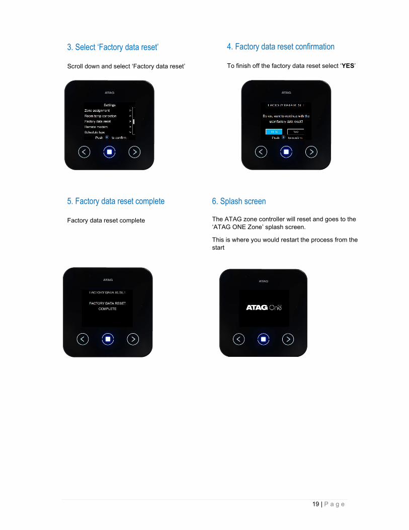
3. Select ‘Factory data reset’
Scroll down and select ‘Factory data reset’
4. Factory data reset confirmation
To finish off the factory data reset select ‘YES’
5. Factory data reset complete
Factory data reset complete
6. Splash screen
The ATAG zone controller will reset and goes to the ‘ATAG ONE Zone’ splash screen.
This is where you would restart the process from the start

20 | P a g e
ATAG Zone errors
DEVICE ERROR
In this case there is an acoustic alert with the blinking of central button. The interface shows a specific message depending on the type of error.
Error Zone Assignment
A control may not be assigned to the correct zone. The ‘X’ number is the zone that has a problem.
Gateway conflict
Room sensor error
Network configuration error

21 | P a g e
SYSTEM ERROR
In this case, as the previous one there is an acoustic alert with the blinking of central button. The interface shows a generic message. In order to verify which kind of issue is present on the system it is necessary to read on the boiler.