Plug-and-play microvalve and micropump for rapid integration with microfluidic chips
Upload
independentCategory
view
1download
0
RESEARCH PAPER
High-current density DC magenetohydrodynamics micropumpwith bubble isolation and release system
Bao Nguyen Æ Samuel Kinde Kassegne
Received: 8 October 2007 / Accepted: 8 December 2007 / Published online: 8 January 2008
� Springer-Verlag 2007
Abstract One of the major challenges for integrated Lab-
on-a-Chip (LOC) systems is the precise control of fluid
flow in a micro-flow cell. Magnetohydrodynamics (MHD)
micropumps which contain no moving parts and capable of
generating a continuous flow in any ionic fluid offer an
ideal solution for biological applications. MHD micro-
pumping has been demonstrated by using both AC and
direct current (DC) currents by a number of researchers
with varying degrees of success. However, current MHD
designs based on DC do not meet the flow rate require-
ments for fully automated LOC applications ([100 ll/
min). In this research, we introduce a novel DC-based
MHD micropump which effectively increases flow rate by
limiting the effects of electrolysis generated bubbles at the
electrode–electrolyte interface through isolation and a
mechanism for their release. Gas bubbles, particularly,
hydrogen generated by high current density at the elec-
trodes are the main culprit in low experimental flow rate
compared with theoretical values. These tiny bubbles
coalesce in the flow channel thus obstructing the flow of
fluid. Since hydrolysis is inevitable with DC excitation,
compartmentalized electrode channels with bubble isolat-
ing and coalescence retarding mechanisms and bubble
release systems are implemented to prevent the coales-
cence of these bubbles and minimize their effects on flow
rate. In this novel design called bubble isolation and release
system, flow rate of up to 325 ll/min is achieved using
1 M NaCl solution in DC mode with potentials of 5 V and
current density of about 5,000 A/m2 for a main channel of
800 lm 9 800 lm cross-section and 6.4 mm length.
Keywords DC current � Lab-on-a-chip � LOC �MHD � Microfluidics � Micropumping � Electrolysis �BioMEMS
1 Introduction
Magnetohydrodynamics (MHD) micropumps operate by
virtue of the body force generated by interaction between
electrical current and a perpendicular magnetic field pass-
ing through an electrolytic solution. This body force, called
Lorentz force, moves the charged ions and hence the bulk
fluid perpendicular to the plane formed by the orthogonal
magnetic and electric fields (Fig. 1a). This concept was
originally described in 1942 by Alfven (1942) as electro-
magnetic hydrodynamic wave.
The main reasons for the significant interest in MHD
micropumps for microfluidic applications are the absence
of moving parts, simple fabrication processes, lower actu-
ation voltages, reduced risk of clogging and damage to
molecular materials, reduced risk of mechanical fatigue
and a continuous fluid flow (Patel and Kassegne 2007). At
the macro-scale, MHD pumps are used in fusion reactors,
power plants, liquid metal processing, propulsion engines,
and many other applications (Strachan et al. 1987; Sutton
and Sherman 1965). At the micro-scale, on the other hand,
MHD pumps have found use in pumping biological fluid.
However, for microfluidic applications, few phenomena
that are negligible at the macro-level, such as electroos-
mosis, Joule heating and bubble formation, emerge as
major obstacles at the micro-level.
B. Nguyen � S. K. Kassegne (&)
MEMS Research Lab, Department of Mechanical Engineering,
College of Engineering, San Diego State University,
5500 Campanile Drive, San Diego, CA 92182-1323, USA
e-mail: [email protected]
123
Microfluid Nanofluid (2008) 5:383–393
DOI 10.1007/s10404-007-0255-3

MHD micropump feasibility has been demonstrated by
using both AC and direct current (DC) current by Lemoff
and Lee (2000), Jang and Lee (2000), Bao and Harrison
(2003), Jeong and Yang (2000), Homsy et al. (2005) with
varying success. However, current DC MHD designs do
not satisfy the flow rate requirement for fully automated
Lab on Chip (LOC) applications. Patel and Kassegne
(2007) provide a perspective to the range of MHD micro-
pumps developed so far. The sizes of the micropumps vary
from 2 mm deep (Wang et al. 2004) to 10 lm by 10 lm
(Bao and Harrison 2003). Current and magnetic flux den-
sities vary from a maximum of 4,000 A/m2 by Homsy et al.
(2005) and 2.2 Tesla (T) by Heng et al. (1999) to 1.8 mA
(Jang and Lee 2000) and 420 mT (Homsy et al. 2005). The
flow rates vary from 6,010 ll/min for the nozzle/diffuser
micropump of Heng et al. (1999) to 0.002 pl/min of Bao
and Harrison (2003). Both AC and DC sources have been
used (Bendib and Francais 1999; Heng et al. 2000; Heschel
et al. 1997; Huang et al. 1999, 2000). With regard to mi-
cromachining processes, bulk micromachining of silicon
using LIGA, inductively coupled plasma reactive ion
etching (ICP-RIE), and anisotropic wet etching together
with soft lithography have been used.
The first attempt in using high-current density MHD
micropumps and minimizing the effect of bubbling was
carried out by Homsy et al. (2005) who achieved pumping
at a high current density of 4,000 A/m2. The effect of
bubbles was reduced through an external channel system
located on the two longitudinal sides. The maximum flow
rate they reported was only 0.5 ll/min for a channel of
75 lm 9 150 lm cross-section. Further, their work does
not explicitly address the actual physical release system for
the bubbles, which for hermetically sealed LOC systems is
an important design constraint.
In this research, we introduce novelty by placing the
electrodes along the pumping length in supplementary
bubble isolation and electrode channels and introducing a
bubble release system on top of the flow cell which collects
these bubbles and releases them to the outside environment
at atmospheric pressure conditions (see Fig. 1b–d). The
full-length electrodes embedded in the peripheral channels
provide electric field to generate Lorentz force. Narrow
gaps at the bottom of the walls between the three chambers
ensure electrical continuity through out the whole pump. In
this manner, the electric field distribution, hence the Lor-
entz force, could be manipulated by varying the geometry
of the gaps. Further, the wall above the slits act as guiding
track for electrolyzed bubbles to escape to an air chamber
above the fluid level. The electric field and, hence, the
Lorentz force is maximized due to this geometric con-
striction between the two channels. Further, this
configuration provides a guided bubble release system to
Fig. 1 a Typical schematic
configuration of MHD
micropump with a rectangular
cross-section. b Front view of
BIRS micropump with bubble
isolation, collection (air vent)
and release chambers. Bubbles
are generated in the side
channels (800 lm wide) where
they develop positive pressure.
This chamber is connected to a
bubble collection channel or air
vent (6.4 mm long) that in turn
is connected to a bubble release
chamber that is at atmospheric
pressure. c Posterior view of
BIRS micropump showing the
bubble release system (2.4 mm
wide and 2 mm long) and
hermetic sealing at the back of
the air vent using gas permeable
membrane. d Cross-section of
manufactured BIRS micropump
384 Microfluid Nanofluid (2008) 5:383–393
123

the outside as shown in Fig. 1. For fast development time,
MHD micropumps presented here are fabricated from
polysulfone using computer numerical control (CNC)
techniques rather than conventional silicon or glass mi-
cromachining. Compartmentalized electrode channels in
conjunction with air traps allows for a maximum flow rate
325 ll/min in DC mode for 1 M NaCl solution at 5 V
excitation. This design could also accommodate AC mode
but it is beyond the scope of this research. The main design
that is presented in this research, hereafter known as,
bubble isolation and release system (BIRS) has the main
distinct features of compartmentalization for bubble iso-
lation, guided bubble release system, and a main fluid flow
channel. Bubbles are generated in the side channels where
they develop positive pressure. This chamber is connected
to a bubble collection channel (air vent) that in turn is
connected to a bubble release chamber that is at atmo-
spheric pressure. However, four more potential designs that
eventually led to BIRS are also discussed to establish the
intended functionality of the BIRS design. In integrated
LOC applications, an array of such micropumps could be
micromachined with all of them connected to a common
bubble release system at atmospheric pressure. If desired,
this chamber could contain hydrogel to act as a porous seal
as shown in Fig. 1c.
2 Theory
The theoretical basis for the physics of MHD micropumps
are now very well understood and have been presented
earlier by various researchers (Patel and Kassegne 2007;
Hughes et al. 1994, 1995; Ramos et al. 1998; Ramos and
Winowich 1990; Winowich and Hughes 1983; Winowich
et al. 1987). Recent research works have concentrated on
understanding and subsequently mitigating detrimental
effects commonly encountered in micropumps. For exam-
ple, Patel and Kassegne (2007) investigated the influence
of electroosmosis and Joule heating on flow rates. Homsy
et al. (2005) introduced a mechanism to reduce one of the
most challenging aspects of DC-based MHD micropum-
ping, i.e., bubbling. Their work pointed out that DC-based
MHD micropumps bubble formation due to electrolysis
interferes with the fluid flow necessitating a review of its
reaction chemistry to understand its effect on the perfor-
mance of such micropumps. In this section, we present a
theoretical investigation of electrolysis to gain a better
understanding of bubble formation and transportation.
Electrolysis of aqueous Sodium Chloride solution, used
in these experiments, occurs according to the reduction
oxidation equations given in Eqs. 1a–d. According to the
standard reduction table, this reaction has a potential of
approximately 3 V which corresponds to a current density
of 4 9 107 A/m2 for 2X platinum electrodes (100 lm in
diameter and 6 mm in length).
Cathode:
2H2Oþ 2e� ! 2OH� þ H2 gð Þ; Eoox ¼ �0:83 V ð1aÞ
Naþ þ e� ! Na, Eoox ¼ �2:71 V ð1bÞ
Anode:
2Cl� ! Cl2 gð Þ þ 2e�; Eoox ¼ �1:36 V ð1cÞ
2H2O! O2 gð Þ þ 4Hþ þ 4e�; Eoox ¼ �1:23 V ð1dÞ
In practical conditions, reduction does not occur for sodium
at the cathode due to higher energy of equilibrium required;
instead the sodium stays in the solution in aqueous form as
shown in Eq. 2. At the anode, chlorine’s concentration is
lower than water. Thus oxidation of water is unfavorable
even though its reduction potential is similar to chlorine.
The overvoltage required to produce oxygen also limits
oxygen production. This voltage depends on electrodes/
electrolytes chemistry. The overall electrolysis that occurs
in aqueous sodium chloride would give off primarily
hydrogen and chlorine gas.
2NaCl aqð Þ þ 2H2O lð Þ ! 2Naþ aqð Þ þ 2OH� aqð Þ þ H2 gð Þþ Cl2 gð Þ
ð2Þ
Since, the hydrostatic pressure within the pump is in order
of a few Pascals, it does not take many gas molecules to
create a gas pocket. Nonetheless, flow should be unaltered if
the occlusion’s volume is much smaller than the channel’s
internal volume. Gas bubbles generated by electrolysis will
try to reach equilibrium by either escaping to atmosphere or
aggregate with other bubbles to reduce their internal pres-
sure. However as more and more bubbles aggregate,
internal pressure would eventually burst the bubble aggre-
gate itself. The collapse of the bubble aggregate further
propels the fluid along the channel. In an open system, gas
bubbles escape to the atmosphere rather than travel along
with the fluid and aggregate along the walls due to ther-
mocapillary effects (Kasumi et al. 2000). Since the pump
has to be hermetically sealed to prevent contamination for
LOC application, a completely open micropump design is
not an option.
As a result, the most challenging problem in designing
DC MHD micropump is the dispatchment of these air
bubbles produced by electrolysis. The coalescence of the
bubbles to form larger air pockets which could occupy the
entire pump creates synergistically compounding prob-
lems. First, the higher internal pressure generated in gas
occlusions requires, in turn, a higher pressure head to move
them along the channel. Secondly, a Lorentz’s force cannot
be generated in areas lack of conductive fluid causing a
drop in the overall pressure and pumping efficiency.
Microfluid Nanofluid (2008) 5:383–393 385
123

While it is impossible to prevent the creation of bubbles
in high DC currents, it is clear, however, that controlling
air bubbles size, rate of accumulation and their location is
vital to improving a micropump’s performance. This con-
trol of bubble sizes and location could be achieved by
selecting optimal electrolyte that has the highest reduction
oxidation potential injunction with appropriate metal for
electrodes. In this research, platinum electrodes and aque-
ous sodium chloride are selected because they are the most
commonly used ones in biological applications. With a
better control of bubble location and sizes, the next chal-
lenge is to prevent the aggregation of bubbles and enhance
their dispersion.
In this research, the reduction and, possibly, the elimi-
nation of bubble coalescence is achieved by placing the
electrodes in compartments separate from the fluid flow
much like what is reported by Homsy et al. (2005). In the
approach described by this current research, conduits,
placed along the bottom of the walls separating the elec-
trodes and main chambers, serve as both current conductor
and bubbles trapping mechanisms. The geometry of these
conduits can be altered to vary the electric field distribution
and restricting bubbles’ entrance to the main pump. Fur-
ther, this research goes one more step by introducing a
guided bubble release system for the dispersion and release
of the bubbles whose generation could not be eliminated
(Fig. 1b–d).
3 Materials and methods
MHD micropumps are designed using CAD software and
machined from polysulfone on a Haas CNC machine (Haas
Automation Inc., Oxnard, California). The rapid prototyp-
ing offered by CNC is the main motivation for adopting
this milling process. In total, five unique MHD designs
with increasing sophistication in bubble isolating and dis-
charging capabilities are designed and fabricated. A
summary of the configuration and dimensions is given in
Table 1. Versions A–C are milled in one unit while Ver-
sion D and BIRS require milling two parts each that are
subsequently epoxy glued. During experiments, the bubble
release chamber was not plugged with hydrogel and
remained exposed to atmospheric pressure. The experi-
mental set-ups are shown in Fig. 2.
For the experiments involving all the five designs, pump
sections are sealed from the external environment by glu-
ing No. 1 glass cover-slips to polysulfone substrate.
Custom teflon insulated platinum electrodes (WPI, Sara-
tosa, Florida), 200 lm in diameter and 6.4 mm length
(running for the whole length of the main channel) are
powered using HP 6236B power supply (Hewlett Packard,
Palo Alto, California). The custom electrodes are made by
embedding Teflon coated platinum wire inside an epoxy
filled 22 gage hypodermic needle. Gold connector is then
soldered to the wire at the luer end of the needle for easy
connection to power supply. The entire electrode is then
coated with paraffin and epoxy to ensure proper insulation
leaving only the desired length exposed. To ensure proper
placement, electrodes are embedded into the channel using
micromanipulator and epoxy glue.
DC current was generated using GoldStar FG-2002C
(LG Precision, Seoul, South Korea) function generator
coupled with in-house amplifier. Permanent magnets, pur-
chased from Industrial Liquidator (San Diego, California),
were used to generate the required magnetic field for mi-
cropumps. The magnets have a magnetic flux density of
18 mT. Video recordings are done on Wesco stereoscope
(Western Scientific Company Inc., Valencia, California) at
59 magnification using a Zarbeco ZC105 camera (Zarbeco
LLC, Randolph, New Jersey). Data analysis is done using
Matlab (Mathworks, Natick, Massachusetts).
All experiments are performed using 1 M NaCl solution
at 20�C under identical configuration and settings. NaCl
solution is equilibrated in micropump for 10 min prior to
start of experiments to ensure proper priming with the help
of an external pipette. Pumps are activated for 2 min and
output volume measured using Pipetman� (Gilson Inc.,
Middleton, Wisconsin). Air bubbles are monitored and
velocities are measured using particle tracking algorithm.
Micro-beads of 2 lm size (Polysciences, Warrington, PA)
are used for velocity measurement. All measurements were
done in triplicates.
To assess the presence and potential magnitude of
contribution from electrokinetic flows, control experiments
are carried out with electric field only wherein the magnets
are removed. Our results show that there was no visible
electrokinetic flow in all the micropump designs consid-
ered here under the application of electric field. The rather
large size of the channels (800 lm 9 800 lm) is believed
to actually minimize the effect of electroosmotic flow as
demonstrated by Patel and Kassegne (2007).
4 Results and discussion
A. Conventional Single Channel/Compartment Micro-
pump: to demonstrate the feasibility of CNC MHD
micropump and the effect of unmitigated bubble for-
mation and transport on pumping, and more
specifically on flow rate, a simple conventional MHD
pump with electrodes along the side walls is machined
and tested. In this configuration, flow rates of 100 and
200 ll/min are obtained for 5 and 20 V, respectively
(cf. Fig. 3, Table 1). These results show that the flow
rate is not linearly proportional to the voltage as
386 Microfluid Nanofluid (2008) 5:383–393
123

expected. The chaotic and rapid bubbles generation as
well as the unpredictable dispersion at 20 V is con-
sidered to be the main reason for such major drop off
in observed flow rate. Other phenomena such as Joule
heating and electroosmotic flow, observed by other
researchers, are considered additional potential
Table 1 Summary of the five versions of bubble isolating and discharging MHD micropump designs
Design Front View Top View Isometric View Comments
A Traditional design with electrodes along sidewalls.
B Modified with electrodecompartments. Microfringes are 200 µm x 400 µm.
C Modified with electrodecompartments and raised main channel. Shaded part is solid.
D Modified with electrodecompartments and raised main channel and perforations for electrical continuity
E Modified with electrodecompartments and spacers for gas escape. Release chamber not shown for clarity.
d
d
2d
2d
1.5d
3w
3w
3w
3w
Electrode chamber
Main channel
Main channel
250 m perforations
Current conformer
wMain channel
Main channel
Note that all the drawings are to scale. Electrodes are noted as darkly shaded region. All main channels have a size of 800 lm 9 800 lm. Length
of pumping section = 6.4 mm. Version A—Conventional single channel/compartment micropump, version B—Compartmentalized micropump,
version C—Compartmentalized micropump with elevated main channel, version D—Compartmentalized micropump with buried electrodes,
version E—BIRS micropump. d = 800 lm, w = 800 lm
Fig. 2 Experimental set-up. a Schematics of the experimental set-up
consisting of power supply, micropump, microscope and camera as
well as data acquisition. b Location of inlet and outlet reservoirs,
pump section and the observation channel. Here, the pump sections
are sealed from the external through glass cover-slips. Custom teflon
insulated platinum electrodes 200 lm in diameter are powered using
HP 6236B power supply. AC current is generated using GoldStar FG-
2002C function generator coupled with in-house amplifier. Permanent
magnets are used to generate the required magnetic field for
micropumps. A video recording is done on Wesco stereoscope at
95 magnification using a Zarbeco ZC105 camera. Data analysis is
done using Matlab
Microfluid Nanofluid (2008) 5:383–393 387
123
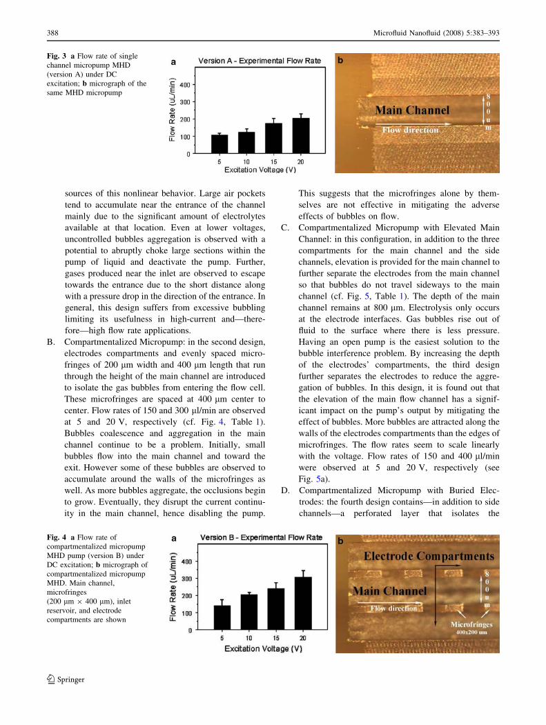
sources of this nonlinear behavior. Large air pockets
tend to accumulate near the entrance of the channel
mainly due to the significant amount of electrolytes
available at that location. Even at lower voltages,
uncontrolled bubbles aggregation is observed with a
potential to abruptly choke large sections within the
pump of liquid and deactivate the pump. Further,
gases produced near the inlet are observed to escape
towards the entrance due to the short distance along
with a pressure drop in the direction of the entrance. In
general, this design suffers from excessive bubbling
limiting its usefulness in high-current and—there-
fore—high flow rate applications.
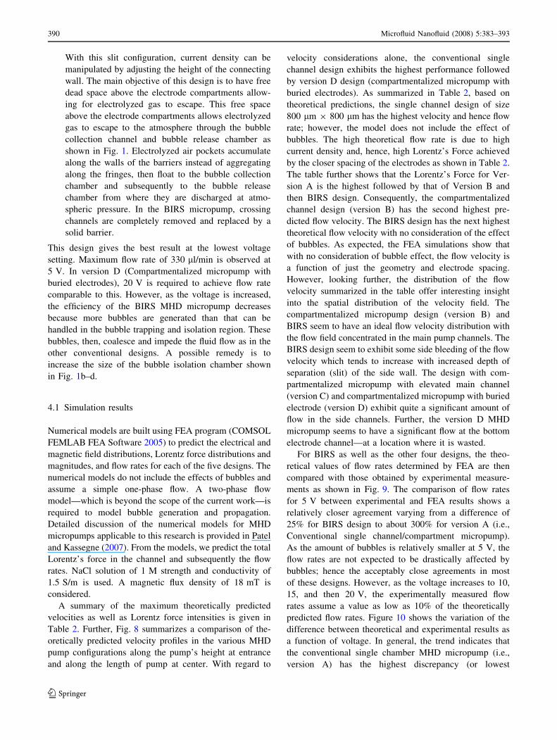
B. Compartmentalized Micropump: in the second design,
electrodes compartments and evenly spaced micro-
fringes of 200 lm width and 400 lm length that run
through the height of the main channel are introduced
to isolate the gas bubbles from entering the flow cell.
These microfringes are spaced at 400 lm center to
center. Flow rates of 150 and 300 ll/min are observed
at 5 and 20 V, respectively (cf. Fig. 4, Table 1).
Bubbles coalescence and aggregation in the main
channel continue to be a problem. Initially, small
bubbles flow into the main channel and toward the
exit. However some of these bubbles are observed to
accumulate around the walls of the microfringes as
well. As more bubbles aggregate, the occlusions begin
to grow. Eventually, they disrupt the current continu-
ity in the main channel, hence disabling the pump.
This suggests that the microfringes alone by them-
selves are not effective in mitigating the adverse
effects of bubbles on flow.
C. Compartmentalized Micropump with Elevated Main
Channel: in this configuration, in addition to the three
compartments for the main channel and the side
channels, elevation is provided for the main channel to
further separate the electrodes from the main channel
so that bubbles do not travel sideways to the main
channel (cf. Fig. 5, Table 1). The depth of the main
channel remains at 800 lm. Electrolysis only occurs
at the electrode interfaces. Gas bubbles rise out of
fluid to the surface where there is less pressure.
Having an open pump is the easiest solution to the
bubble interference problem. By increasing the depth
of the electrodes’ compartments, the third design
further separates the electrodes to reduce the aggre-
gation of bubbles. In this design, it is found out that
the elevation of the main flow channel has a signif-
icant impact on the pump’s output by mitigating the
effect of bubbles. More bubbles are attracted along the
walls of the electrodes compartments than the edges of
microfringes. The flow rates seem to scale linearly
with the voltage. Flow rates of 150 and 400 ll/min
were observed at 5 and 20 V, respectively (see
Fig. 5a).
D. Compartmentalized Micropump with Buried Elec-
trodes: the fourth design contains—in addition to side
channels—a perforated layer that isolates the
Fig. 3 a Flow rate of single
channel micropump MHD
(version A) under DC
excitation; b micrograph of the
same MHD micropump
Fig. 4 a Flow rate of
compartmentalized micropump
MHD pump (version B) under
DC excitation; b micrograph of
compartmentalized micropump
MHD. Main channel,
microfringes
(200 lm 9 400 lm), inlet
reservoir, and electrode
compartments are shown
388 Microfluid Nanofluid (2008) 5:383–393
123

electrolyzed bubbles from entering the main pump
channels while maintaining electrical conduction as
shown in Fig. 6 and Table 1. Essentially, this design is
similar to version C (compartmentalized micropump
with elevated main channel) except that there is a
physical separation layer that contains 250 lm diam-
eter perforation holes. The intent of introducing the
perforations is to arrest the transport of bubbles to the
main channel. There are four possible electrodes
placement configurations possible. With the anode in
the bottom electrode chamber and cathode on the
upper layer, a flow rate of 75 and 325 ll/min were
observed for 5 and 20 V excitation, respectively. For
this design, this electrodes configuration gives the best
results. The reason is that chlorine gas, produced at the
anode and slightly soluble in water, has an opportunity
to equilibrate with the surrounding and travel with the
liquid toward the exit without impeding flow. Mean-
while the more volatile and rapid forming hydrogen
can escape to the atmosphere faster since they are in
the upper layer. As expected, alternating the anode
and cathode location resulted in flow rate of 50 and
200 ll/min.
E. BIRS Micropump: in this design that forms the main
contribution of this research, instead of microfringes,
current continuity is achieved through open channels
at the bottom layer that connect the electrode
compartments and the main pumping channel (cf.
Fig. 7, Table 1). As seen by the other four previous
designs discussed here, microfringes are demonstrated
to actually promote bubble coalescing. As a result,
they are replaced with a solid connecting wall (that
divides the main channel from the electrode channels)
with a slit at the bottom to allow ionic fluid continuity.
Fig. 5 a Flow rate of
compartmentalized MHD
micropump with elevated
channel (ver03) under DC
excitation; b micrograph of the
MHD micropump. Elevated
main channel, microfringes
(200 lm 9 400 lm), inlet
reservoir, and electrode
compartments are shown
Fig. 6 a Flow rate of
compartmentalized MHD
micropump with buried
electrodes (version D) under DC
excitation; b micrograph of the
same MHD micropump.
Perforated layers, microfringes,
inlet reservoir, and electrode
compartments are shown
Fig. 7 a Flow rate of the BIRS
MHD micropump (version E)
under DC excitation; bmicrograph of BIRS MHD
micropump. Main channel and
electrode compartments are
shown
Microfluid Nanofluid (2008) 5:383–393 389
123
With this slit configuration, current density can be
manipulated by adjusting the height of the connecting
wall. The main objective of this design is to have free
dead space above the electrode compartments allow-
ing for electrolyzed gas to escape. This free space
above the electrode compartments allows electrolyzed
gas to escape to the atmosphere through the bubble
collection channel and bubble release chamber as
shown in Fig. 1. Electrolyzed air pockets accumulate
along the walls of the barriers instead of aggregating
along the fringes, then float to the bubble collection
chamber and subsequently to the bubble release
chamber from where they are discharged at atmo-
spheric pressure. In the BIRS micropump, crossing
channels are completely removed and replaced by a
solid barrier.
This design gives the best result at the lowest voltage
setting. Maximum flow rate of 330 ll/min is observed at
5 V. In version D (Compartmentalized micropump with
buried electrodes), 20 V is required to achieve flow rate
comparable to this. However, as the voltage is increased,
the efficiency of the BIRS MHD micropump decreases
because more bubbles are generated than that can be
handled in the bubble trapping and isolation region. These
bubbles, then, coalesce and impede the fluid flow as in the
other conventional designs. A possible remedy is to
increase the size of the bubble isolation chamber shown
in Fig. 1b–d.
4.1 Simulation results
Numerical models are built using FEA program (COMSOL
FEMLAB FEA Software 2005) to predict the electrical and
magnetic field distributions, Lorentz force distributions and
magnitudes, and flow rates for each of the five designs. The
numerical models do not include the effects of bubbles and
assume a simple one-phase flow. A two-phase flow
model—which is beyond the scope of the current work—is
required to model bubble generation and propagation.
Detailed discussion of the numerical models for MHD
micropumps applicable to this research is provided in Patel
and Kassegne (2007). From the models, we predict the total
Lorentz’s force in the channel and subsequently the flow
rates. NaCl solution of 1 M strength and conductivity of
1.5 S/m is used. A magnetic flux density of 18 mT is
considered.
A summary of the maximum theoretically predicted
velocities as well as Lorentz force intensities is given in
Table 2. Further, Fig. 8 summarizes a comparison of the-
oretically predicted velocity profiles in the various MHD
pump configurations along the pump’s height at entrance
and along the length of pump at center. With regard to
velocity considerations alone, the conventional single
channel design exhibits the highest performance followed
by version D design (compartmentalized micropump with
buried electrodes). As summarized in Table 2, based on
theoretical predictions, the single channel design of size
800 lm 9 800 lm has the highest velocity and hence flow
rate; however, the model does not include the effect of
bubbles. The high theoretical flow rate is due to high
current density and, hence, high Lorentz’s Force achieved
by the closer spacing of the electrodes as shown in Table 2.
The table further shows that the Lorentz’s Force for Ver-
sion A is the highest followed by that of Version B and
then BIRS design. Consequently, the compartmentalized
channel design (version B) has the second highest pre-
dicted flow velocity. The BIRS design has the next highest
theoretical flow velocity with no consideration of the effect
of bubbles. As expected, the FEA simulations show that
with no consideration of bubble effect, the flow velocity is
a function of just the geometry and electrode spacing.
However, looking further, the distribution of the flow
velocity summarized in the table offer interesting insight
into the spatial distribution of the velocity field. The
compartmentalized micropump design (version B) and
BIRS seem to have an ideal flow velocity distribution with
the flow field concentrated in the main pump channels. The
BIRS design seem to exhibit some side bleeding of the flow
velocity which tends to increase with increased depth of
separation (slit) of the side wall. The design with com-
partmentalized micropump with elevated main channel
(version C) and compartmentalized micropump with buried
electrode (version D) exhibit quite a significant amount of
flow in the side channels. Further, the version D MHD
micropump seems to have a significant flow at the bottom
electrode channel—at a location where it is wasted.
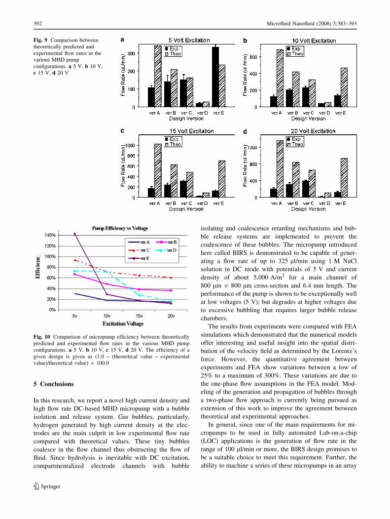
For BIRS as well as the other four designs, the theo-
retical values of flow rates determined by FEA are then
compared with those obtained by experimental measure-
ments as shown in Fig. 9. The comparison of flow rates
for 5 V between experimental and FEA results shows a
relatively closer agreement varying from a difference of
25% for BIRS design to about 300% for version A (i.e.,
Conventional single channel/compartment micropump).
As the amount of bubbles is relatively smaller at 5 V, the
flow rates are not expected to be drastically affected by
bubbles; hence the acceptably close agreements in most
of these designs. However, as the voltage increases to 10,
15, and then 20 V, the experimentally measured flow
rates assume a value as low as 10% of the theoretically
predicted flow rates. Figure 10 shows the variation of the
difference between theoretical and experimental results as
a function of voltage. In general, the trend indicates that
the conventional single chamber MHD micropump (i.e.,
version A) has the highest discrepancy (or lowest
390 Microfluid Nanofluid (2008) 5:383–393
123

efficiency). The introduction of bubble coalescence
retardation mechanisms in designs B–E, in general, tends
to improve the efficiencies with the BIRS design having
the best comparison.
The BIRS MHD micropump seems to degrade in per-
formance as measured by its flow rate when higher
voltages are used. As explained before, this is due to the
generation of excessive amount of bubble that cannot be
handled in the bubble trapping and isolation region. These
bubbles that coalesce tend to seriously impede the fluid
flow as in the other conventional designs. However, it
needs to be noted that a flow rate of 300 ll/min for the
main channel cross-section of 800 lm 9 800 lm is con-
sidered quite high for an operating voltage of 5 V;
therefore there is no pressing need for increasing the
voltage to higher values.
Table 2 Summary of theoretically predicted maximum velocities and Lorentz forces in the various MHD micropumps considered in this
research
Design Type Velocity Profile (Elevation) Velocity Profile (Top View) Max. Lorentz Force(N/m2)
MaximumVelocity (mm/s)
A – Conventional single channel/compartment micropump
1.27 7.11
B - Compartmentalized micropump
0.47 3.62
C - Compartmentalized micropump with Elevated Main Channel:
0.37 1.011
D - Compartmentalized micropump with Buried Electrodes:
0.18 1.858
E - BIRS micropump 0.43 2.196
Fig. 8 Comparison of
theoretically predicted velocity
profiles in the various MHD
pump configurations. a Along
pump’s height at entrance. bAlong length of pump at center
Microfluid Nanofluid (2008) 5:383–393 391
123
5 Conclusions
In this research, we report a novel high current density and
high flow rate DC-based MHD micropump with a bubble
isolation and release system. Gas bubbles, particularly,
hydrogen generated by high current density at the elec-
trodes are the main culprit in low experimental flow rate
compared with theoretical values. These tiny bubbles
coalesce in the flow channel thus obstructing the flow of
fluid. Since hydrolysis is inevitable with DC excitation,
compartmentalized electrode channels with bubble
isolating and coalescence retarding mechanisms and bub-
ble release systems are implemented to prevent the
coalescence of these bubbles. The micropump introduced
here called BIRS is demonstrated to be capable of gener-
ating a flow rate of up to 325 ll/min using 1 M NaCl
solution in DC mode with potentials of 5 V and current
density of about 5,000 A/m2 for a main channel of
800 lm 9 800 lm cross-section and 6.4 mm length. The
performance of the pump is shown to be exceptionally well
at low voltages (5 V); but degrades at higher voltages due
to excessive bubbling that requires larger bubble release
chambers.
The results from experiments were compared with FEA
simulations which demonstrated that the numerical models
offer interesting and useful insight into the spatial distri-
bution of the velocity field as determined by the Lorentz’s
force. However, the quantitative agreement between
experiments and FEA show variations between a low of
25% to a maximum of 300%. These variations are due to
the one-phase flow assumptions in the FEA model. Mod-
eling of the generation and propagation of bubbles through
a two-phase flow approach is currently being pursued as
extension of this work to improve the agreement between
theoretical and experimental approaches.
In general, since one of the main requirements for mi-
cropumps to be used in fully automated Lab-on-a-chip
(LOC) applications is the generation of flow rate in the
range of 100 ll/min or more, the BIRS design promises to
be a suitable choice to meet this requirement. Further, the
ability to machine a series of these micropumps in an array
Fig. 9 Comparison between
theoretically predicted and
experimental flow rates in the
various MHD pump
configurations. a 5 V, b 10 V,
c 15 V, d 20 V
Fig. 10 Comparison of micropump efficiency between theoretically
predicted and experimental flow rates in the various MHD pump
configurations. a 5 V, b 10 V, c 15 V, d 20 V. The efficiency of a
given design is given as (1.0 - (theoretical value - experimental
value)/theoretical value) 9 100.0
392 Microfluid Nanofluid (2008) 5:383–393
123

format where the BIRS pumps share a common bubble
release chamber could offer an efficient micropumping
system applicable to a variety of LOC and microTAS
systems under low voltage conditions.
References
Alfven H (1942) Existence of electromagnetic—hydrodynamic
waves. Nature 150:405
Bao JB, Harrison DJ (2003) Fabrication of microchips for running
liquid chromatography by magnetohydrodynamic flow. In:
Proceedings of the 7th international conference on miniaturized
chemical and biochemical analysts systems, Squaw Valley,
California, USA
Bendib S, Francais O (1999) Analytical study of microchannel and
passive microvalve application to micropump simulator. In:
Proceedings of the SPIE, pp 200–208
FEMLAB FEA Software (2005) Reference Manual, version 3.1,
COMSOL Inc
Heng KH, Huang L, Wang W, Murphy MC (1999) Development of a
diffuser/nozzle type micro-ump based on magnetohydrodynamic
(MHD) principle. Proc SPIE—Microfluidic Dev Syst II
3877:66–73
Heng KH, Wang W, Murphy MC, Lian K (2000) UV-LIGA
microfabrication and test of an ac-type micro-pump based on
the magnetohydrodynamic (MHD) principle. Proc SPIE—
Microfluidic Dev Syst III 4177:174–184
Heschel M, Mullenborn M, Bouwstr S (1997) Fabrication and
characterization of truly 3-D diffuser/nozzle microstructures in
silicon. J Microelectromech Syst 6(1):41–47
Homsy A, Koster S, Eijkel JCT, Berg A, Lucklum F, Verpoorte E, de
Rooij NF (2005) A high current density DC magnetohydrody-
namic (MHD) micropump. Lab Chip 5(4):466–471
Huang L, Wang W, Murphy MC (1999) A lumped-parameter model
for a micro-pump based on the magnetohydrodynamic (MHD)
principle. Proc SPIE–Des Test Microfabric MEMS MOEMS
3680:379–387
Huang L, Wang W, Murphy MC, Lian K, Ling ZG (2000) LIGA
fabrication and test of a DC type magneto-hydrodynamic (MHD)
micro-pump. Microsyst Technol 6:235–240
Hughes M, Pericleous KA, Cross M (1994) The CFD analysis of
simple parabolic and elliptic MHD flows. Appl Math Model
18:150–155
Hughes M, Pericleous KA, Cross M (1995) The numerical modeling
of DC electromagnetic pump and brake flow. Appl Math Model
19:713–723
Jang J, Lee SS (2000) Theoretical and experimental study of MHD
micro-pump. Sens Actuators A 80:84–89
Jeong OC, Yang SS (2000) Fabrication and test of a thermo-
pneumatic micro-pump with a corrugated p+ diaphragm. Sens
Actuators A 83:249–255
Kasumi H, Solomentsev YE, Guelcher SA, Anderson JL, Sides PJ
(2000) Thermocapillary flow and aggregation of bubbles on a
solid wall. J Colloid Interface Sci 232:111–120
Lemoff AV, Lee AP (2000) An AC magnetohydrodynamic micro-
pump. Sens Actuators B 63:178–185
Patel V, Kassegne SK (2007) Electroosmosis and thermal effects in
magnetohydrodynamic (MHD) micropumps using 3D MHD
equations. J Sens Actuators B 122:42–52
Ramos A, Morgan H, Green NG, Castellanos A (1998) AC
electronics: a review of forces in microelectrode structures. J
Phys D: Appl Phys 31:2338–2353
Ramos JI, Winowich NS (1990) Finite difference and finite element
methods for MHD flows. Int J Numer Methods Fluids 11:907–
934
Strachan JD, Bitter M et al (1987) High-temperature plasmas in a
tokamak fusion test reactor. Phys Rev Lett 58:1004–1007
Sutton GW, Sherman A (1965) Engineering magnetohydrodynamics.
McGraw-Hill Book Company, New York
Wang PJ, Chang CY, Chang ML (2004) Simulation of two-
dimensional fully developed laminar flow for a magneto-
hydrodynamic (MHD) pump. Biosens Bioelectron 20:115–121
Winowich NS, Hughes WF (1983) A finite element analysis of two-
dimensional MHD flow. AIAA Prog Astronaut Aeronaut 84:313
Winowich NS, Hughes WF, Ramos JI (1987) Numerical simulation of
electromagnetic pump flow. Numer Methods Laminar Turbulent
Flow 5(2):1228–1240
Microfluid Nanofluid (2008) 5:383–393 393
123
Copyright © 2022 FDOKUMEN