High-aspect-ratio microdrilling of polymers with UV laser ablation: experiment with analytical model
12
DOI: 10.1007/s00339-002-1511-8 Appl. Phys. A (2002) Invited paper Materials Science & Processing Applied Physics A v.n. tokarev 1,2 j. lopez 1 s. lazare 1, ✉ f. weisbuch 1 High-aspect-ratio microdrilling of polymers with UV laser ablation: experiment with analytical model 1 Laboratoire de Physicochimie Mol´ eculaire (LPCM), UMR 5803 du CNRS, Universit´ e de Bordeaux 1, 351 cours de la Lib´ eration, 33 405 Talence, France 2 General Physics Institute, ul. Vavilova 38, Moscow 117 942, Russia Received: 11 June 2002/Accepted: 12 June 2002 Published online: 28 October 2002 • © Springer-Verlag 2002 ABSTRACT Systematic experimental studies of KrF laser mi- crodrilling in polymers (PMMA, PET, PS, PC, PI, PEEK) have led to high-aspect-ratio microholes (up to 600) in a final sta- tionary profile. From these results, an original theory is derived, which gives an analytical modeling of the multi-pulse ablation process. In the experiments holes with diameters in the range of 10 to 100 µ m and from one to several tens of millimeters in depth, depending on fluence, are obtained for various polymers. The stationary depth increases with fluence and this dependence is well reproduced by the present model. The particular mech- anism of radiation propagation and absorption inside the deep laser keyhole is clarified, and does not suggest a significant channeling of the radiation in the forming hole. This mechan- ism alongside the angular divergence of the beam are important key factors for the mathematical description of high-aspect-ratio laser drilling. As a result (a) the controlling factors of drilling are outlined; (b) final keyhole profile and depth vs. incident fluence are calculated for the rectangular, Gaussian and other spatial distributions of the beam and the comparison with the experiment is given; and (c) the laser drilling is optimized, i.e. the matching conditions for the level and distribution of laser in- tensity, parameters of the optical focusing scheme and material parameters are derived in an explicit analytical form, allowing us to produce deep keyholes with practically parallel side walls and aspect ratios as high as 300–600. PACS 42.62.Cf; 61.80.Ba; 61.80.Az 1 Introduction Laser microdrilling of small-diameter holes [1, 2], with diameters from a few microns up to about one hundred microns, is one of the most widely used applications of laser materials processing. The wide scope of its practical applica- tions includes (a) microelectronics: drilling narrow holes in polymers used for microcircuit boards, texturing of magnetic hard disks, video heads [3] and diamond films; (b) aerospace and the advanced automotive industry [4]: drilling of precise hole patterns in hard refractory metals ✉ Fax: +33-556/846975, E-mail: [email protected] and alloys (e.g. holes in gas-turbine blades for cooling), drilling ultra-hard refractory ceramics [5, 6] (Al 2 O 3 , ZrO 2 , Si 3 N 4 , SiC, AlN [7]), e.g. in production fuel injection noz- zles in advanced ceramic engines; (c) micromechanics (watch industry, medical devices, jew- elry industry): drilling and microprocessing of dia- mond [8], ruby, gemstones and glasses. Studies and applications have been performed with quite different laser sources having radiation wavelengths in the IR, visible and the UV and pulse durations from cw, milli-, nano-, pico-, up to femtosecond pulses. UV nanosecond (ns) laser sources [9] attract special attention owing to their ver- satility. UV radiation is strongly absorbed by most materials and it is interesting for advanced technology materials such as polymers and ultra-hard refractory ceramics, as well as soft complex organic and inorganic solids. These lasers provide an excellent reproducibility of results from site to site on the treated surface in combination with a high spatial resolution, high precision and quality, unachievable for competitive IR and visible sources [10]. A relatively small ablation depth per pulse for ns pulses (about 1 µ m or less) can be compen- sated in large-scale industrial applications by a high repeti- tion rate of the pulses. For instance, copper-vapor lasers have 5–10-kHz rates, modern excimer lasers are up to 1 kHz and diode-pumped Nd-YAG lasers are multi-kHz with an output in the UV at 355 and 266 nm. There are two significant problems deteriorating the qual- ity of UV ns laser drilling: (i) laser keyholes as a rule are not cylindrical, but are convergent into the depth of a treated ma- terial and (ii) the aspect ratio of the obtained holes (i.e. the ratio of the hole depth to its diameter) is usually not high, e.g. for metals and ceramics it does not exceed about 10–16. In some applications these drawbacks make the drilling results unacceptable. A ‘blind’ empirical search for the optimum by a ‘probe and trial’ method in every particular situation is in many cases expensive, time-consuming and not efficient, due to an extremely large number of parameters influencing the result of drilling. These are material parameters (thermophys- ical and optical constants), radiation parameters (intensity and its spatial distribution, pulse duration, wavelength), geometri- cal parameters of focusing (angular divergence of radiation at the treated surface, irradiated spot size, mask demagnification factor and mask diameter, beam compression or decompres-
-
Upload
independent -
Category
Documents
-
view
0 -
download
0
Transcript of High-aspect-ratio microdrilling of polymers with UV laser ablation: experiment with analytical model
DOI: 10.1007/s00339-002-1511-8
Appl. Phys. A (2002)
Invi
ted
pape
rMaterials Science & ProcessingApplied Physics A
v.n. tokarev1,2
j. lopez1
s. lazare1,
f. weisbuch1
High-aspect-ratio microdrilling of polymerswith UV laser ablation: experiment withanalytical model1 Laboratoire de Physicochimie Moleculaire (LPCM), UMR 5803 du CNRS, Universite de Bordeaux 1,
351 cours de la Liberation, 33 405 Talence, France2 General Physics Institute, ul. Vavilova 38, Moscow 117 942, Russia
Received: 11 June 2002/Accepted: 12 June 2002Published online: 28 October 2002 • © Springer-Verlag 2002
ABSTRACT Systematic experimental studies of KrF laser mi-crodrilling in polymers (PMMA, PET, PS, PC, PI, PEEK) haveled to high-aspect-ratio microholes (up to 600) in a final sta-tionary profile. From these results, an original theory is derived,which gives an analytical modeling of the multi-pulse ablationprocess. In the experiments holes with diameters in the rangeof 10 to 100 µm and from one to several tens of millimeters indepth, depending on fluence, are obtained for various polymers.The stationary depth increases with fluence and this dependenceis well reproduced by the present model. The particular mech-anism of radiation propagation and absorption inside the deeplaser keyhole is clarified, and does not suggest a significantchanneling of the radiation in the forming hole. This mechan-ism alongside the angular divergence of the beam are importantkey factors for the mathematical description of high-aspect-ratiolaser drilling. As a result (a) the controlling factors of drillingare outlined; (b) final keyhole profile and depth vs. incidentfluence are calculated for the rectangular, Gaussian and otherspatial distributions of the beam and the comparison with theexperiment is given; and (c) the laser drilling is optimized, i.e.the matching conditions for the level and distribution of laser in-tensity, parameters of the optical focusing scheme and materialparameters are derived in an explicit analytical form, allowingus to produce deep keyholes with practically parallel side wallsand aspect ratios as high as 300–600.
PACS 42.62.Cf; 61.80.Ba; 61.80.Az
1 Introduction
Laser microdrilling of small-diameter holes [1, 2],with diameters from a few microns up to about one hundredmicrons, is one of the most widely used applications of lasermaterials processing. The wide scope of its practical applica-tions includes
(a) microelectronics: drilling narrow holes in polymers usedfor microcircuit boards, texturing of magnetic hard disks,video heads [3] and diamond films;
(b) aerospace and the advanced automotive industry [4]:drilling of precise hole patterns in hard refractory metals
Fax: +33-556/846975, E-mail: [email protected]
and alloys (e.g. holes in gas-turbine blades for cooling),drilling ultra-hard refractory ceramics [5, 6] (Al2O3, ZrO2,Si3N4, SiC, AlN [7]), e.g. in production fuel injection noz-zles in advanced ceramic engines;
(c) micromechanics (watch industry, medical devices, jew-elry industry): drilling and microprocessing of dia-mond [8], ruby, gemstones and glasses.
Studies and applications have been performed with quitedifferent laser sources having radiation wavelengths in theIR, visible and the UV and pulse durations from cw, milli-,nano-, pico-, up to femtosecond pulses. UV nanosecond (ns)laser sources [9] attract special attention owing to their ver-satility. UV radiation is strongly absorbed by most materialsand it is interesting for advanced technology materials suchas polymers and ultra-hard refractory ceramics, as well as softcomplex organic and inorganic solids. These lasers providean excellent reproducibility of results from site to site on thetreated surface in combination with a high spatial resolution,high precision and quality, unachievable for competitive IRand visible sources [10]. A relatively small ablation depthper pulse for ns pulses (about 1 µm or less) can be compen-sated in large-scale industrial applications by a high repeti-tion rate of the pulses. For instance, copper-vapor lasers have5–10-kHz rates, modern excimer lasers are up to 1 kHz anddiode-pumped Nd-YAG lasers are multi-kHz with an outputin the UV at 355 and 266 nm.
There are two significant problems deteriorating the qual-ity of UV ns laser drilling: (i) laser keyholes as a rule are notcylindrical, but are convergent into the depth of a treated ma-terial and (ii) the aspect ratio of the obtained holes (i.e. theratio of the hole depth to its diameter) is usually not high, e.g.for metals and ceramics it does not exceed about 10–16. Insome applications these drawbacks make the drilling resultsunacceptable. A ‘blind’ empirical search for the optimum bya ‘probe and trial’ method in every particular situation is inmany cases expensive, time-consuming and not efficient, dueto an extremely large number of parameters influencing theresult of drilling. These are material parameters (thermophys-ical and optical constants), radiation parameters (intensity andits spatial distribution, pulse duration, wavelength), geometri-cal parameters of focusing (angular divergence of radiation atthe treated surface, irradiated spot size, mask demagnificationfactor and mask diameter, beam compression or decompres-
Applied Physics A – Materials Science & Processing
Polymer γ 1/γ Ft Fte Dr Rm(µm−1) (µm) (mJ/cm2) (mJ/cm2) (µm/pulse)
PMMA 0.0063 150 250 6.6 2.5 255PI 22 0.045 54 3 0.4 360PC 1 1.0 40 2.2 0.8 390PET 16 0.065 30 1 0.7 565PS 0.61 1.6 40 5 − 315PEEK ∼ 10 ∼ 0.1 50 8.5 0.6 385
TABLE 1 Absorption coefficient γ , pene-tration depth 1/γ (low intensity), ablationthreshold Ft at 248 nm and drilling character-istics: extinction threshold Fte (given by themodel), drilling rate Dr and maximum aspectratio Rm for the studied polymers
sion factor, focal length, the distance between the beam waistand the treated surface, etc). Besides, the physical and chem-ical structure of the target, the mechanism of material removaland its energetic characteristics, the initial sample tempera-ture and the physical and chemical parameters of an ambientgas are important. Numerical modeling gives the result onlyfor a particular set of parameters [11–14], but unfortunatelydoes not allow us to see the general situation and to understandhow far we are from the optimum.
A general clear and effective guide for optimization, ap-propriate for a wide variety of material properties, radiationand focusing parameters, could be based on an analyticalmodel of drilling, appropriate for the description of high-aspect-ratio keyholes. Compared to numerical computer mod-eling, an analytical method has the advantage of giving theparameters of the final keyhole profile in an explicit form, al-lowing us to follow easily their variation for a wide varietyof materials, focusing and radiation parameters, to find outin transparent form the main controlling factors and, in par-ticular, to recognize the obstacles for obtaining keyholes withhigh aspect ratio (e.g. a few hundreds) and practically parallelside walls.
Despite a lot of papers on UV ns laser drilling (see for ex-ample [1–18]), such an analytical model of high-aspect-ratiolaser drilling has not been constructed up to now, as there isno clear understanding of the interaction of intense laser radi-ation with a deep laser keyhole.
The purpose of this paper is to develop such an analyticalmathematical model and to show that it is in good agreementwith the experimental results reviewed in the experimentalpart. A preliminary communication on such modeling ap-peared recently [19]. This paper describes in more detail theexperimental foundations of the model, its properties and itspredictability. For the high-aspect-ratio drilling the followingkey factors should be taken into account.
1. The particular mechanism of radiation propagation andabsorption inside the high-aspect-ratio laser keyhole.
This mechanism depends on the surface roughness in-side the keyhole. For example, at a small roughness ampli-tude the specular multiple reflections of the rays on the sidewalls can dominate, whereas at significant roughness diffusescattering is mostly occurring [11]. However the roughnessamplitude is a result of the effect of a great number of fac-tors (e.g. of repeated evaporation–redeposition cycles in theform of a vapor, droplets and tiny particles in the growinglaser keyhole; various types of surface-relief instabilities ofthe melt layer on the side walls in the presence of a strong laserplasma stream, a possible shrinkage at a cooling stage aftereach laser pulse, etc.). This complexity makes does not allow
a correct theoretical calculation of roughness in the model.Consequently, it appears also to be difficult to find out themechanism of radiation propagation and absorption inside thehigh-aspect-ratio hole in a theoretical way. It can only be donebased on the experimental results. However, such an approachhas never been realized in previous papers on modeling of UVns laser drilling [11–14]. Moreover, in a number of papersthis problem is not considered, but it is assumed that alreadyat the first strike of the laser beam rays with the side wallstotal (100%) absorption of the radiation takes place [13]. Sucha concept is approximate, since at highly oblique incidence ofthe radiation on the side walls the absorptivity, according tothe Fresnel formulas, is extremely small. In this paper, for thefirst time, the particular mechanism of radiation propagationand absorption inside the deep laser keyhole is establishedby a rigorous comparison of our systematic experimental re-sults of laser drilling obtained [15–17] for a wide number ofpolymers (Table 1) with the predictions made with the presentmodel.
2. Angular divergence of the focused laser beam.This factor has been considered previously in numerical
computer modeling of laser drilling of holes with small aspectratio (< 4) [14]. For the holes with high aspect ratio Rm (e.g.300–600 in Table 1) and in the framework of an analyticalmodel this factor is considered in this paper for the first time.Its taking into account, as will be shown below, will allowus to obtain a number of quite new results for laser drilling.For example, the angular distribution of the beam providingthe hole drilling with strictly parallel side walls and simultan-eously with very high aspect ratio will be predicted. It shouldbe noted, for comparison, that without taking into accountthe angular divergence, when the laser radiation is consid-ered for simplicity as a parallel beam, the model calculationsinevitably predict only conical, convergent into the materialdepth, keyholes [12, 13, 18].
2 Experiment
2.1 Laser set-up and polymers
A high-intensity microbeam with low numericalaperture α0 is obtained as in [16] and [19]. The excimer laseris a Lambda Physik LPX 220i (wavelength 248 nm, pulse du-ration 25 ns, energy 350 mJ/pulse and repetition rate up to200 Hz). The central part of the raw laser beam is eventuallyselected by means of a diaphragm if necessary. Figure 1 de-tails the ray model used to describe propagation of the laserbeam inside the keyhole. A point source O is considered de-livering a beam to the entrance of the keyhole and given bya function (top-hat or Gaussian) of angle α with respect to the
TOKAREV et al. High-aspect-ratio microdrilling of polymers with UV laser ablation: experiment with analytical model
FIGURE 1 Schematic of drilling a keyhole with a ray model of the incidentbeam inside the keyhole. All angles are strongly exaggerated for illustrationpurposes
main axis (see model in Sect. 3 below). The real experimentallaser profile is not Gaussian but more top-hat, slightly alteredwith diffraction patterns. It is usually evaluated by ablationof polycarbonate (PC) with a single pulse and measuring thecrater profile with scanning optical microscopy. At the ex-act position of the mask image it is in fact close to top-hatwith some fluctuations due to diffraction. In drilling, sincethe ablation front is moving ahead, the beam profile is in-deed substantially altered by this defocus and becomes moresmoothed.
The polymers studied are polyimide (PI), poly(ethyleneterephthalate) (PET, Mylar), polystyrene (PS), poly(etherether ketone) (PEEK), poly(methyl methacrylate) (PMMA)and bisphenol A polycarbonate (PC). Commercial names areKapton for PI, Mylar for PET, Stabar for PEEK. PS samplesare taken from a Petri dish and PC samples from polycar-bonate panels Axxis (DSM Engineering Products). As seenfrom Table 1, PI, PET and PEEK have high absorption coef-ficients, whereas PMMA, PS and PC are weak absorbers atroom temperature for the laser wavelength used. This givesthe possibility to study the effect of this important parameteron the results of drilling.
For the studied polymers the ablation thresholds Ft are lowenough (see Table 1) compared to metals and ceramics. It al-lows us to obtain in the experiment the laser keyholes witha high aspect ratio (e.g. around 600 for PET, see below) evenat low enough incident laser fluences (< 7 J/cm2), when thecomplications for the study and modeling the effect of thelaser plasma on the heating of the side walls and on the resultsof drilling are significantly minimized, allowing easier con-struction of the model. It should be noted that it is not so in thecase of drilling of metals and ceramics by laser radiation withthe same wavelength and pulse duration at fluences typical forthe drilling of deep holes in these materials (> 30 J/cm2); thementioned effect of the laser plasma is not negligibly small,thus essentially complicating the construction of the model.
2.2 High-aspect-ratio holes
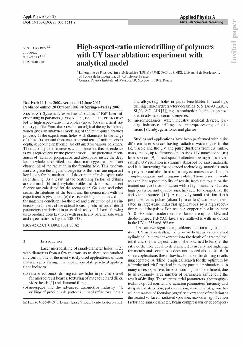
A high-aspect-ratio laser-drilled hole is shown inFig. 2a for PMMA (hole length 500 µm, diameter 8 µm).Figure 2b displays a series of holes in PC as a function of
FIGURE 2 High-aspect-ratio holes (stationary profile after many pulses)drilled at 248 nm in a PMMA (keyhole length 500 µm, diameter 8 µm) andb PC (series of holes) obtained at various starting fluences for the purposeof obtaining the aspect ratio vs. fluence curve of Fig. 6 (keyhole entrancediameter Φ = 35 µm, F = 1–20 J/cm2)
fluence as typical measurements leading to Fig. 6. It was ob-served that a high-intensity beam (F Ft, see Ft in Table 1)is necessary to obtain good-quality holes with a high aspectratio. But at some high value of the fluence (> 10 J/cm2), theaspect ratio does not increase more than a certain value, whichreveals a saturation phenomenon [16].
2.3 Keyhole branching and interpretation
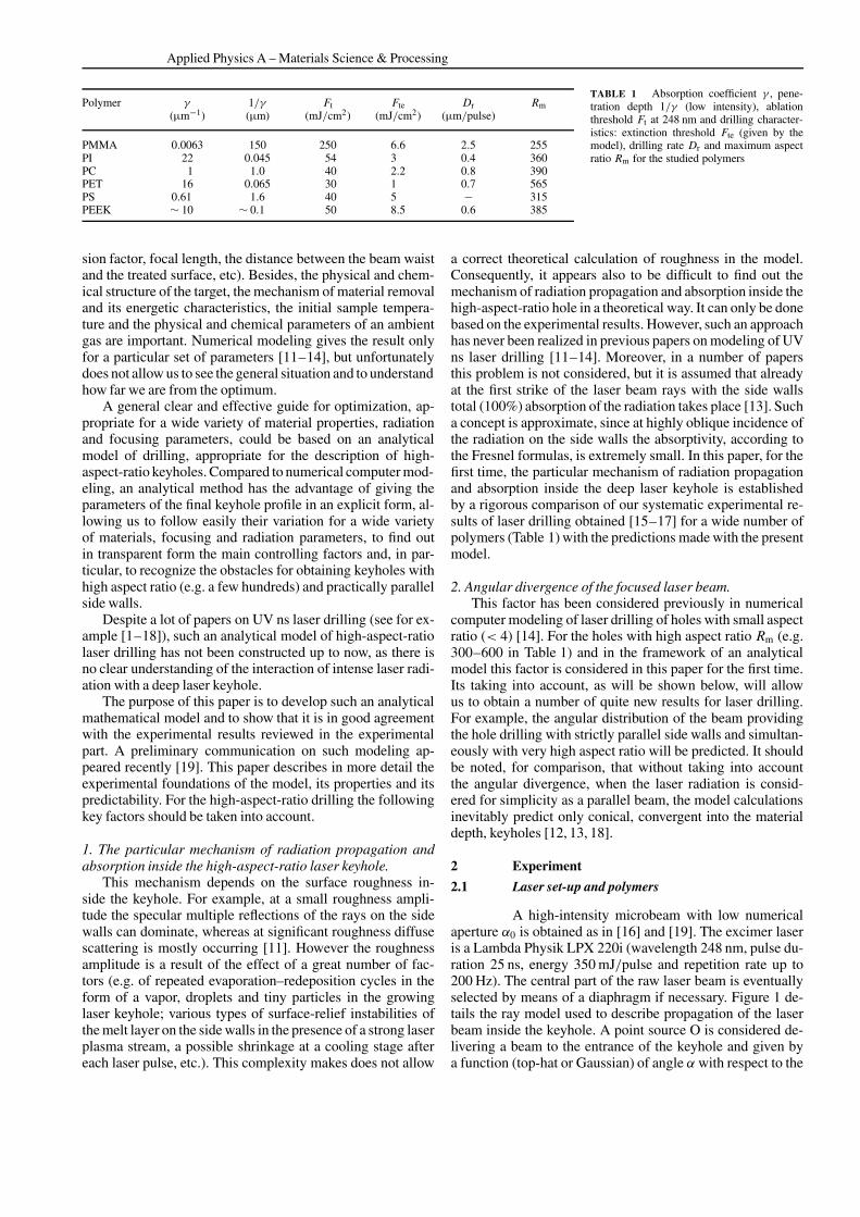
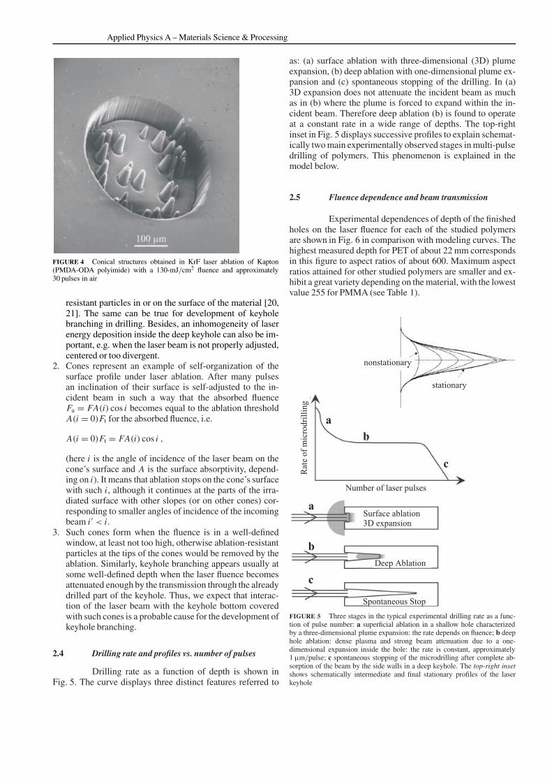
In well-defined conditions, it is observed (Fig. 3)that drilling propagation is not stable, so that side branches(Fig. 3a) develop along the main hole. Figure 3b proves that itcan be easily reproduced. This phenomenon is strongly simi-lar to the previously observed formation of cones on an ini-tially flat surface of some polymers and ceramics in shallowlaser ablation under multi-pulse irradiation. Indeed
1. Development of the cones (Fig. 4) is initiated by surfaceinstabilities in an intense laser–surface interaction in thepresence of an inhomogeneity of a polymer: ablation-
FIGURE 3 a Example of a laser-drilled hole in PC displaying branchingon the side of the main axis with an 8 angle, which occurs in the case ofa not properly adjusted beam. b Series of five holes with branching showingreproducibility of the phenomenon
Applied Physics A – Materials Science & Processing
FIGURE 4 Conical structures obtained in KrF laser ablation of Kapton(PMDA-ODA polyimide) with a 130-mJ/cm2 fluence and approximately30 pulses in air
resistant particles in or on the surface of the material [20,21]. The same can be true for development of keyholebranching in drilling. Besides, an inhomogeneity of laserenergy deposition inside the deep keyhole can also be im-portant, e.g. when the laser beam is not properly adjusted,centered or too divergent.
2. Cones represent an example of self-organization of thesurface profile under laser ablation. After many pulsesan inclination of their surface is self-adjusted to the in-cident beam in such a way that the absorbed fluenceFa = FA(i) cos i becomes equal to the ablation thresholdA(i = 0)Ft for the absorbed fluence, i.e.
A(i = 0)Ft = FA(i) cos i ,
(here i is the angle of incidence of the laser beam on thecone’s surface and A is the surface absorptivity, depend-ing on i). It means that ablation stops on the cone’s surfacewith such i, although it continues at the parts of the irra-diated surface with other slopes (or on other cones) cor-responding to smaller angles of incidence of the incomingbeam i ′ < i.
3. Such cones form when the fluence is in a well-definedwindow, at least not too high, otherwise ablation-resistantparticles at the tips of the cones would be removed by theablation. Similarly, keyhole branching appears usually atsome well-defined depth when the laser fluence becomesattenuated enough by the transmission through the alreadydrilled part of the keyhole. Thus, we expect that interac-tion of the laser beam with the keyhole bottom coveredwith such cones is a probable cause for the development ofkeyhole branching.
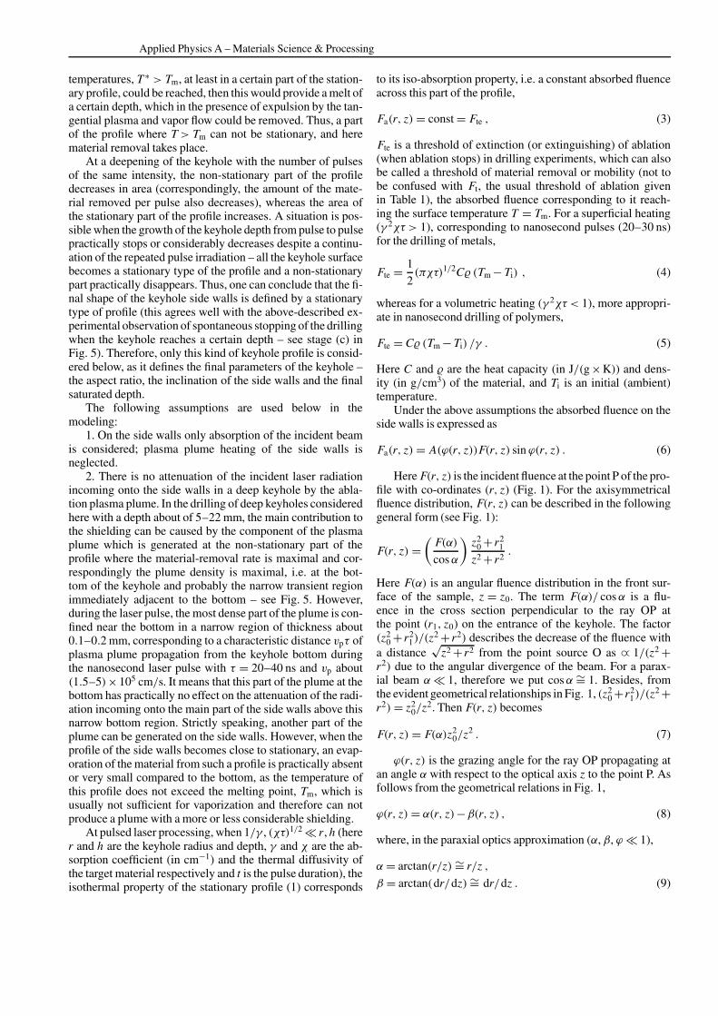
2.4 Drilling rate and profiles vs. number of pulses
Drilling rate as a function of depth is shown inFig. 5. The curve displays three distinct features referred to
as: (a) surface ablation with three-dimensional (3D) plumeexpansion, (b) deep ablation with one-dimensional plume ex-pansion and (c) spontaneous stopping of the drilling. In (a)3D expansion does not attenuate the incident beam as muchas in (b) where the plume is forced to expand within the in-cident beam. Therefore deep ablation (b) is found to operateat a constant rate in a wide range of depths. The top-rightinset in Fig. 5 displays successive profiles to explain schemat-ically two main experimentally observed stages in multi-pulsedrilling of polymers. This phenomenon is explained in themodel below.
2.5 Fluence dependence and beam transmission
Experimental dependences of depth of the finishedholes on the laser fluence for each of the studied polymersare shown in Fig. 6 in comparison with modeling curves. Thehighest measured depth for PET of about 22 mm correspondsin this figure to aspect ratios of about 600. Maximum aspectratios attained for other studied polymers are smaller and ex-hibit a great variety depending on the material, with the lowestvalue 255 for PMMA (see Table 1).
FIGURE 5 Three stages in the typical experimental drilling rate as a func-tion of pulse number: a superficial ablation in a shallow hole characterizedby a three-dimensional plume expansion: the rate depends on fluence; b deephole ablation: dense plasma and strong beam attenuation due to a one-dimensional expansion inside the hole: the rate is constant, approximately1 µm/pulse; c spontaneous stopping of the microdrilling after complete ab-sorption of the beam by the side walls in a deep keyhole. The top-right insetshows schematically intermediate and final stationary profiles of the laserkeyhole

TOKAREV et al. High-aspect-ratio microdrilling of polymers with UV laser ablation: experiment with analytical model
FIGURE 6 Experimental data (points) for the depth of finished keyholes vs.fluence in comparison with the top-hat model (solid curves given by (20a))for the studied polymers PET, PC, Kapton, PS, PMMA and PEEK. Thresh-olds of ablation extinction Fte obtained by fitting the model to the experimentare given in Table 1
FIGURE 7 Keyhole transmission of the beam energy (the ratio of the en-ergy transmitted through the via hole to the incident energy) vs. depth forPET (), PC ( ) and PMMA. The scheme of the corner-shape sample usedin the experiment. The model is given in Sect. 3.6
Beam transmission through the via hole vs. depth for PET,PC and PMMA is shown in Fig. 7. This experiment was doneto understand and characterize the propagation and absorptionof laser energy inside the keyhole. As one can see, in all cases(PET, PC or PMMA) the experimental data exhibit a behaviorclose to a linear dependence (as predicted by the model be-low) with a negative slope, whose absolute value depends onthe material and applied laser fluence. A study of the affectedzone around the keyhole profile in PMMA is possible by theconfocal microRaman technique, as already described [22].This can lead to the amount and the distribution of the scat-tered light absorbed around the keyhole.
3 Theoretical model
According to the mask projection scheme used inour experiment [16], the laser beam irradiating the target isconsidered in the model as a point source O (see Fig. 1) placed
at the distance z0 from the front surface of the workpiece andhaving an angular divergence, e.g. α0 = r0/z0 for a top-hatbeam profile, r0 being an irradiated spot radius on the en-trance plane of the treated sample. To describe the keyholeprofile for drilling with an axisymmetrical intensity distribu-tion a cylindrical co-ordinate system 0rz is introduced, withz = 0 corresponding to the position of the point source O(Fig. 1).
Previously, the laser drilling of deep keyholes has beenconsidered in a great number of papers for continuous-waveradiation, or for single-pulse drilling by long (millisecond)laser pulses – see for example [23–27]. Here, another regimeis considered – multi-pulse drilling by shorter (nanosecond)pulses, when deepening of the keyhole takes place gradually,by small steps from pulse to pulse. For example, for a mate-rial plate (metal, ceramics or polymer) with 1-mm thickness at0.2 µm/pulse or less (an ablation rate typical for a nanosecondpulse) about 5000 pulses or more are required to obtain a viahole. The laser drilling is controlled in this case by some self-regulated processes (similar to the above-considered situationwith the formation of cones), and the taking into account ofdifferent inclinations of different parts of the keyhole surfacewith respect to the incident beam becomes important [18].The full surface profile of the keyhole consists of two mainparts:
(i) Non-stationary profile, where significant material re-moval takes place. This kind of profile is characterized by thebottom of the keyhole (Fig. 5) and also by a certain transitionregion between the bottom and the inclined side walls of thekeyhole.
(ii) Stationary profile, where there is practically no mate-rial removal and whose slope therefore does not change frompulse to pulse. This profile is on the side walls of the deep key-hole (Fig. 5). Its slope is established after a certain number ofpulses as a result of self-regulated processes in such a way thata maximum vs. time local surface temperature T(r, z) attainedas a result of laser pulse action at each point of the surfaceprofile with co-ordinates (r, z) is constant across this profile,
T(r, z)= const = Tst . (1)
This theoretical statement is consistent with the above-described experimental observation of a constant depth of theaffected zone across the side walls.
Tst is the maximum temperature at which there is no ma-terial removal from the side walls in the presence of a strongexpulsion effect of a vapor plume propagating from the bot-tom to the orifice of the keyhole [18, 28].
For the processing in a chemically inert ambient consid-ered below we put
Tst = Tm , (2)
where Tm is a melting point. For drilling in a chemically ac-tive ambient medium Tst can be lower than Tm. Here the term‘melting’ is used independently of the nature of the material,although for polymers decomposition is often simultaneous.Rigorous use of the melting concept is only valid for a metalwithout any other reaction.
The last relation means that the melt depth is practicallyzero on the side walls [18, 29]. If we suppose that some higher
Applied Physics A – Materials Science & Processing
temperatures, T ∗ > Tm, at least in a certain part of the station-ary profile, could be reached, then this would provide a melt ofa certain depth, which in the presence of expulsion by the tan-gential plasma and vapor flow could be removed. Thus, a partof the profile where T> Tm can not be stationary, and herematerial removal takes place.
At a deepening of the keyhole with the number of pulsesof the same intensity, the non-stationary part of the profiledecreases in area (correspondingly, the amount of the mate-rial removed per pulse also decreases), whereas the area ofthe stationary part of the profile increases. A situation is pos-sible when the growth of the keyhole depth from pulse to pulsepractically stops or considerably decreases despite a continu-ation of the repeated pulse irradiation – all the keyhole surfacebecomes a stationary type of the profile and a non-stationarypart practically disappears. Thus, one can conclude that the fi-nal shape of the keyhole side walls is defined by a stationarytype of profile (this agrees well with the above-described ex-perimental observation of spontaneous stopping of the drillingwhen the keyhole reaches a certain depth – see stage (c) inFig. 5). Therefore, only this kind of keyhole profile is consid-ered below, as it defines the final parameters of the keyhole –the aspect ratio, the inclination of the side walls and the finalsaturated depth.
The following assumptions are used below in themodeling:
1. On the side walls only absorption of the incident beamis considered; plasma plume heating of the side walls isneglected.
2. There is no attenuation of the incident laser radiationincoming onto the side walls in a deep keyhole by the abla-tion plasma plume. In the drilling of deep keyholes consideredhere with a depth about of 5–22 mm, the main contribution tothe shielding can be caused by the component of the plasmaplume which is generated at the non-stationary part of theprofile where the material-removal rate is maximal and cor-respondingly the plume density is maximal, i.e. at the bot-tom of the keyhole and probably the narrow transient regionimmediately adjacent to the bottom – see Fig. 5. However,during the laser pulse, the most dense part of the plume is con-fined near the bottom in a narrow region of thickness about0.1–0.2 mm, corresponding to a characteristic distance vpτ ofplasma plume propagation from the keyhole bottom duringthe nanosecond laser pulse with τ = 20–40 ns and vp about(1.5–5)×105 cm/s. It means that this part of the plume at thebottom has practically no effect on the attenuation of the radi-ation incoming onto the main part of the side walls above thisnarrow bottom region. Strictly speaking, another part of theplume can be generated on the side walls. However, when theprofile of the side walls becomes close to stationary, an evap-oration of the material from such a profile is practically absentor very small compared to the bottom, as the temperature ofthis profile does not exceed the melting point, Tm, which isusually not sufficient for vaporization and therefore can notproduce a plume with a more or less considerable shielding.
At pulsed laser processing, when 1/γ , (χτ)1/2 r, h (herer and h are the keyhole radius and depth, γ and χ are the ab-sorption coefficient (in cm−1) and the thermal diffusivity ofthe target material respectively and t is the pulse duration), theisothermal property of the stationary profile (1) corresponds
to its iso-absorption property, i.e. a constant absorbed fluenceacross this part of the profile,
Fa(r, z)= const = Fte , (3)
Fte is a threshold of extinction (or extinguishing) of ablation(when ablation stops) in drilling experiments, which can alsobe called a threshold of material removal or mobility (not tobe confused with Ft, the usual threshold of ablation givenin Table 1), the absorbed fluence corresponding to it reach-ing the surface temperature T = Tm. For a superficial heating(γ 2χτ > 1), corresponding to nanosecond pulses (20–30 ns)for the drilling of metals,
Fte = 1
2(πχτ)1/2C (Tm − Ti) , (4)
whereas for a volumetric heating (γ 2χτ < 1), more appropri-ate in nanosecond drilling of polymers,
Fte = C (Tm − Ti) /γ . (5)
Here C and are the heat capacity (in J/(g ×K)) and dens-ity (in g/cm3) of the material, and Ti is an initial (ambient)temperature.
Under the above assumptions the absorbed fluence on theside walls is expressed as
Fa(r, z)= A(ϕ(r, z))F(r, z) sin ϕ(r, z) . (6)
Here F(r, z) is the incident fluence at the point P of the pro-file with co-ordinates (r, z) (Fig. 1). For the axisymmetricalfluence distribution, F(r, z) can be described in the followinggeneral form (see Fig. 1):
F(r, z) =(
F(α)
cosα
)z2
0 + r21
z2 + r2.
Here F(α) is an angular fluence distribution in the front sur-face of the sample, z = z0. The term F(α)/ cosα is a flu-ence in the cross section perpendicular to the ray OP atthe point (r1, z0) on the entrance of the keyhole. The factor(z2
0 + r21)/(z
2 + r2) describes the decrease of the fluence witha distance
√z2 + r2 from the point source O as ∝ 1/(z2 +
r2) due to the angular divergence of the beam. For a parax-ial beam α 1, therefore we put cosα ∼= 1. Besides, fromthe evident geometrical relationships in Fig. 1, (z2
0 +r21)/(z
2 +r2)= z2
0/z2. Then F(r, z) becomes
F(r, z) = F(α)z20/z
2 . (7)
ϕ(r, z) is the grazing angle for the ray OP propagating atan angle α with respect to the optical axis z to the point P. Asfollows from the geometrical relations in Fig. 1,
ϕ(r, z)= α(r, z)−β(r, z) , (8)
where, in the paraxial optics approximation (α, β, ϕ 1),
α= arctan(r/z)∼= r/z ,
β = arctan(dr/dz)∼= dr/dz . (9)

TOKAREV et al. High-aspect-ratio microdrilling of polymers with UV laser ablation: experiment with analytical model
β(r, z) is an angle of local inclination of the side walls of thekeyhole at the point (r, z). Taking into account that, accordingto (9), r = αz, the last relation takes the form
β ∼= d(αz)/dz = α+ z(dα/dz) . (10)
The substitution of (10) into (8) gives
sinϕ(r, z)∼= ϕ(r, z)∼= −z(dα/dz) . (11)
The value of the absorptivity A(ϕ(r, z)) in (6) depends on theparticular mechanism of propagation and absorption of laserradiation inside the keyhole. This mechanism depends in turnon the surface conditions on the keyhole side walls. Therefore,two extreme cases can be considered to estimate A(ϕ(r, z)):
1. In the specular reflection model, the side walls are ex-pected to be ideally smooth; the rays incoming from the pointsource O to the side walls are considered then as specularlyreflected. Further multiple reflections inside the keyhole areneglected. For the grazing angle ϕ of about 1/200–1/600(which corresponds to the holes considered here with aspectratios of about 100–300) the absorptivity according to theFresnel formulas is A(ϕ)= 2nϕ (n is the real part of the refrac-tive index) and appears to be very low for the considered ϕ:A = 0.015–0.005. As a result, the dependence of hole depthon fluence in the specular reflection model gives 10–30 timessmaller values compared to the experiment, while the cal-culations from the multiple-scattering model (see below), inwhich A = 1, agree well with the experiment. Therefore, thespecular reflection model is not considered any more.
2. In the multiple-scattering model the side walls are as-sumed to strongly scatter the incoming rays due to a surfaceroughness induced by (i) deposition of the vapor, clusters anddroplets expelled both from the bottom and from the sidewalls, and/or (ii) disturbances and rippling of the molten layeron the side walls due to its interaction with a strong flow of va-por and plasma propagating from the bottom to the orifice ofthe keyhole and/or (iii) keyhole profile shrinkage on coolingafter each pulse.
A(ϕ(r, z)) is in this case a local effective absorptivity fora high-aspect-ratio hole, taking into account multiple scatter-ing and absorption of the incoming ray OP (Fig. 1), incidenton the surface profile at the grazing angle ϕ. After the firststrike on the side wall the ray OP is scattered into a great num-ber of secondary rays in different directions. The main part ofthese rays strikes the opposite wall at not grazing, but not farfrom normal, incidence, for which the absorptivity A = 1− Rof polymers is high (about 95%). It means that just one or twofurther collisions and scatterings of these rays with the sidewalls are sufficient to provide a practically total absorption ofenergy of the original ray OP on the side walls in a small re-gion in the vicinity of the point (r, z). The length L of thisdiffused absorption region along the keyhole axis does not ex-ceed a few keyhole diameters near the point (r, z):
L = (2–4) d .
However, for high-aspect-ratio keyholes considered here thetotal depth is much higher:
h = (200–600) d ,
i.e. L h. The same can be concluded for any other neighbor-ing original rays or beamlets coming from the point source. Itmeans that such an effective total absorption can be consid-ered as taking place locally, at each point across the keyholedepth,
A(ϕ(r, z))= Aeff(ϕ(r, z))∼= 1 , (12)
and the absorbed fluence in (6) in each point of the side walls’profile is in such a case proportional to the local incident flu-ence F(r, z). Thus, in this model the keyhole totally traps thestray light, and to each point of the stationary profile scat-tered rays come from the left- and from the right-hand sidesat different incidence angles, providing finally the energy ab-sorption and heating at a particular point. The only excep-tions are small regions immediately adjacent to the keyholeentrance and bottom (tip), for which the scattered rays cancome only from one side. Therefore the local absorptivity inthese regions is expected to be about two times smaller than(12), but having in fact only a small contribution to the totalabsorptivity.
The substitution of (7), (11) and (12) into relation (6) andiso-absorption condition (3) gives rise to the following simpledifferential equation for the stationary keyhole profile:
zdz
dα= − z2
0
FteF(α) (13)
with the boundary condition z(α = α∞) = z0. Here α∞ isa certain limiting angle in a spatially concentrated angular dis-tribution of the incident laser beam, beyond which the beamintensity becomes negligibly small. The solution z(α) of (13)allows us to find the profile r(z) in a parametric form (with αas the parameter) and the final keyhole depth, h, vs. fluence:
r(α) = αz(α) , z(α)= z0
1 + 2
Ft
α∞∫α
F(α′)dα′
1/2
, (14)
(0 ≤ α ≤ α∞, z0 ≤ z ≤ h)
h(F)= z(α= 0)− z0 = z0
1 + 2
Fte
α∞∫0
F(α′)dα′
1/2
−1
(15)
Some particular cases are considered below.
3.1 Threshold fluence for obtaining parallel side wallsat the keyhole entrance
The parallel side walls, at least near the keyholeentrance, are provided when the fluence at the spot border(α = α0) in the entrance plane, F(α0), reaches a threshold,Fpar. The value Fpar follows after the substitution of (6), (7)and (8) into (3), taking into account that at z = z0, r = r0,α = α0 = r0/z0 and the walls’ inclination at the entranceβ = dr/dz(z = z0)= 0:
Fpar = Fte/α0 , (16)
Applied Physics A – Materials Science & Processing
At F(α0) < Fpar the keyhole walls at the entrance are conver-gent into the depth, whereas at F(α0) > Fpar the keyhole be-comes divergent at the orifice, although convergent in a deeperpart of the keyhole.
3.2 Fluence distribution providing strictly cylindricalside walls
The fluence profile at the keyhole entrance plane,F‖(α), providing strictly cylindrical side walls in drilling ofa via hole in a plate of thickness hs, follows from (13) afterthe substitutions r(z)= const = r0, z = r0/α, r0/z0 = α0 (seeFig. 8) and using (16):
F‖(α)= Fparα30/α
3 at α1 ≤ α≤ α0
F‖(α)= 0 at α ≥ α0 . (17)
Hereα1 = r0/(z0 +h) corresponds to the exit of the keyhole atz1 = z0 +hs. As seen in Fig. 8, F‖(α) should strongly increasewith a decrease of α as 1/α3, i.e. to be highly concentratedto the optical axis at least in the range of angles α0 ≥ α ≥ α1.Exact details of the F‖(α) behavior at α < α1 strictly speak-ing are not very important, as the rays with α < α1 propagatethrough the via keyhole at its final stationary state withoutstriking the walls.
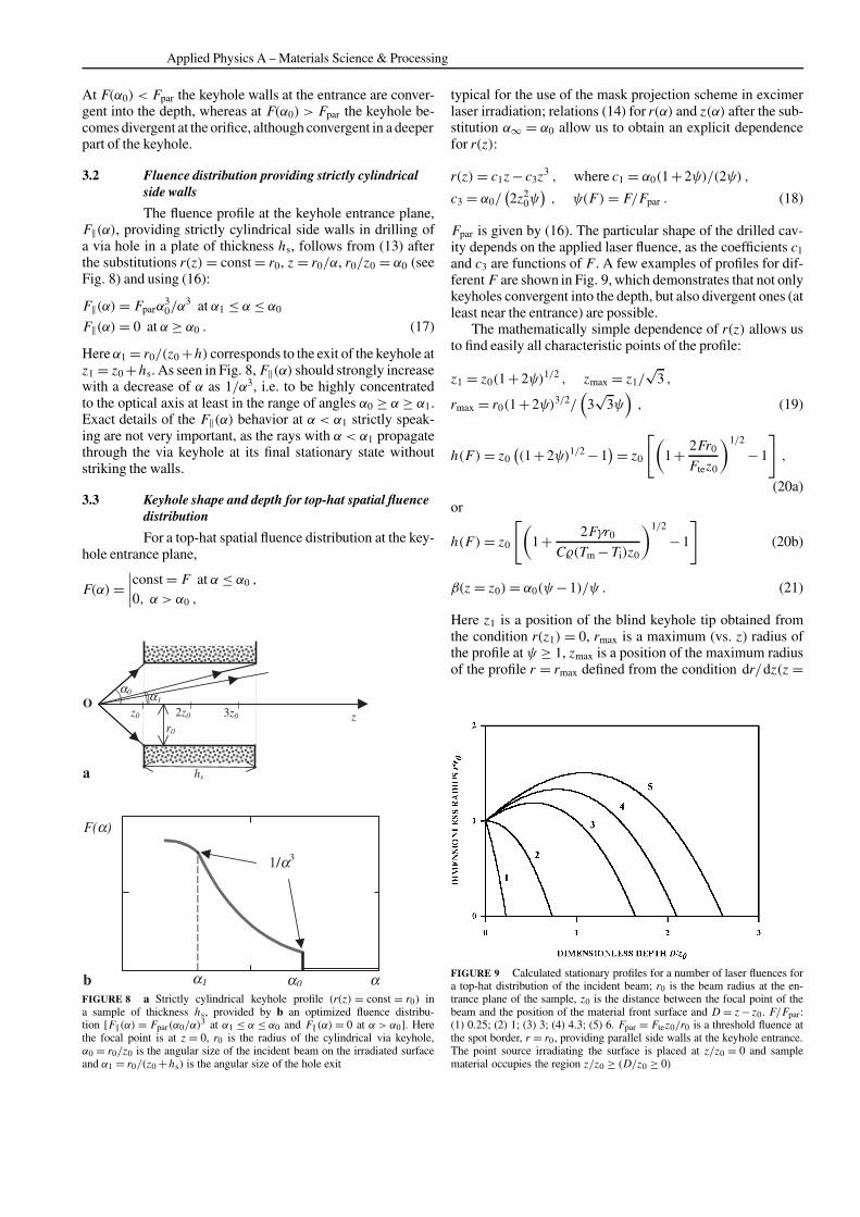
3.3 Keyhole shape and depth for top-hat spatial fluencedistribution
For a top-hat spatial fluence distribution at the key-hole entrance plane,
F(α)=∣∣∣∣const = F at α ≤ α0 ,
0, α > α0 ,
FIGURE 8 a Strictly cylindrical keyhole profile (r(z) = const = r0) ina sample of thickness hs, provided by b an optimized fluence distribu-tion [F‖(α)= Fpar(α0/α)
3 at α1 ≤ α ≤ α0 and F‖(α)= 0 at α > α0]. Herethe focal point is at z = 0, r0 is the radius of the cylindrical via keyhole,α0 = r0/z0 is the angular size of the incident beam on the irradiated surfaceand α1 = r0/(z0 +hs) is the angular size of the hole exit
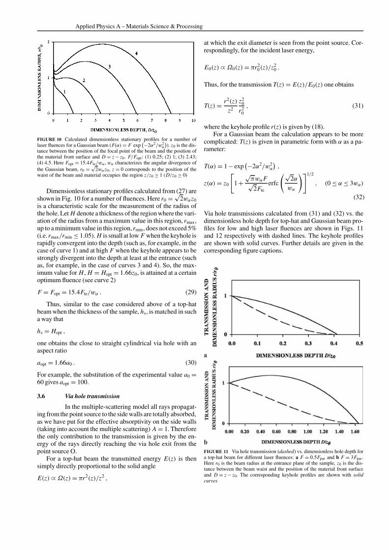
typical for the use of the mask projection scheme in excimerlaser irradiation; relations (14) for r(α) and z(α) after the sub-stitution α∞ = α0 allow us to obtain an explicit dependencefor r(z):
r(z)= c1z − c3z3 , where c1 = α0(1 +2ψ)/(2ψ) ,
c3 = α0/(2z2
0ψ), ψ(F)= F/Fpar . (18)
Fpar is given by (16). The particular shape of the drilled cav-ity depends on the applied laser fluence, as the coefficients c1and c3 are functions of F. A few examples of profiles for dif-ferent F are shown in Fig. 9, which demonstrates that not onlykeyholes convergent into the depth, but also divergent ones (atleast near the entrance) are possible.
The mathematically simple dependence of r(z) allows usto find easily all characteristic points of the profile:
z1 = z0(1 +2ψ)1/2 , zmax = z1/√
3 ,
rmax = r0(1 +2ψ)3/2/(
3√
3ψ), (19)
h(F)= z0((1 +2ψ)1/2 −1
)= z0
[(1 + 2Fr0
Ftez0
)1/2
−1
],
(20a)
or
h(F)= z0
[(1 + 2Fγr0
C(Tm − Ti)z0
)1/2
−1
](20b)
β(z = z0)= α0(ψ−1)/ψ . (21)
Here z1 is a position of the blind keyhole tip obtained fromthe condition r(z1) = 0, rmax is a maximum (vs. z) radius ofthe profile at ψ ≥ 1, zmax is a position of the maximum radiusof the profile r = rmax defined from the condition dr/dz(z =
FIGURE 9 Calculated stationary profiles for a number of laser fluences fora top-hat distribution of the incident beam; r0 is the beam radius at the en-trance plane of the sample, z0 is the distance between the focal point of thebeam and the position of the material front surface and D = z − z0. F/Fpar:(1) 0.25; (2) 1; (3) 3; (4) 4.3; (5) 6. Fpar = Ftez0/r0 is a threshold fluence atthe spot border, r = r0, providing parallel side walls at the keyhole entrance.The point source irradiating the surface is placed at z/z0 = 0 and samplematerial occupies the region z/z0 ≥ (D/z0 ≥ 0)

TOKAREV et al. High-aspect-ratio microdrilling of polymers with UV laser ablation: experiment with analytical model
zmax)= 0, h is a depth of the obtained blind keyhole, β(z = z0)
is a local inclination of the side walls at the entrance z = z0.These formulas (in particular (20b)) show in an explicit
way the controlling factors of drilling – material parameters(C, , Tm, γ ), geometrical focusing parameters (z0 and r0)and energetic parameters (F). Comparison of the analyticaldependence (20a) of the keyhole depth on the laser fluencewith experimental data (see Fig. 6) exhibits a good agree-ment for all studied polymers (PET, PC, PS, Kapton, PEEKand PMMA), when the values of Fte (in mJ/cm2) used in themodel calculations are: 1 for PET, 2.2 for PC, 3 for Kapton,5 for PS, 6.6 for PMMA and 8.5 for PEEK (Table 1). It is in-teresting to note that two remaining parameters in (20a), z0and r0, are taken in such a modeling description to be the samefor all polymers: z0 = 1.7 mm and r0 = 15 µm, which corres-ponds to the experiment.
Calculated keyhole shapes for different fluences for a top-hat beam demonstrate that not only keyholes convergent intothe depth, but also divergent ones, are possible (Fig. 9). Asseen from (21), β(z = z0)= 0 (side walls at the entrance areparallel) at ψ = 1, i.e. at F = Fpar – see curve 2 in Fig. 9. Atfluences below the threshold, F< Fpar, the keyhole is conver-gent into the depth across all its depth: β(z ≥ z0) < 0 (curve 1in Fig. 9), while fluences beyond the threshold, F> Fpar, givedivergent side walls at the entrance (β(z = z0) > 0), althoughthe slope decreases with z and becomes negative (i.e. the pro-file becomes convergent) for z > zmax (curves 3, 4 and 5 inFig. 9).
3.4 Drilling of long via holes with a small variation ofthe diameter across the length for a top-hat fluencedistribution
The obtained profiles, as one can see from Fig. 9,do not have strictly parallel walls, compared to the optimizedfluence distribution (17). With the increase of fluence the pos-ition z = zmax of the maximum radius of the profile rmax isshifted to greater z and at F ≥ Fpar is inside the material (seecurves 3, 4 and 5 in Fig. 9). In the vicinity of the maximum ra-dius position, z = zmax, the slope of the profile (and also thekeyhole diameter) changes with z to a smallest extent. Foreach value of the fluence one can find a region of a certaindepth inside the profile, across which the change of the key-hole radius r(z) from a maximal value in this region, rmax, upto a minimum value, rmin, in this region does not exceed, forexample, 33.3%, i.e. rmax/rmin ≤ 1.33. The length of such a re-gion H depends on the fluence; the maximum value of H(F)denoted as Hopt is attained, as calculations show, at F = Fopt,where
Fopt = 8.6a0Fte (22)
and is
Hopt = 1.48z0 . (23)
Here a0 = z0/(2r0)= 1/(2α0) is the aspect ratio of the beamitself, a parameter defined by beam focusing on the surface. Ithas a physical meaning of an inverse angular divergence of thebeam going out of the waist. Thus when the thickness of the
sample, hs, is matched in such a way that
hs = Hopt , (24)
one obtains the close to straight cylindrical via hole with anaspect ratio
aopt = 1.48a0 . (25)
The substitution of the experimental value a0 = 60 andFte ≈ 1 mJ/cm2 for PET (see Table 1) gives aopt = 89 atF = 0.52 J/cm2.
As one can see, the result for the aspect ratio aopt isproportional to the inverse angular divergence of the beam,a0 = 1/(2α0). As known from optics, 2a0 can be simply es-timated as 2a0 = λ/df, where df is the diameter of the beamwaist; hence a0 = df/λ. When the position of the entranceplane is chosen outside the waist so that, e.g., d = 2df, oneobtains that the parameter
a0 = d/(2λ)
increases with d and decreases with λ. For example, for theabove-described experiments d = 30 µm and λ = 248 nm,which gives a0 = 60. However for d = 150 µm and λ =193 nm one obtains a much greater value a0 = 390 (with thecorresponding aopt = 580).
3.5 Gaussian beam
Another important practical case is the drillingwith a Gaussian beam. Similar to the previous case we put inthe model below the angular distribution of the beam profile atthe entrance plane of the sample as
F(α) = F exp(−2α2/w2
α
), (26)
wherewα characterizes an angular divergence of the Gaussianbeam. z = 0 corresponds as previously to the position of thewaist of the beam, z = z0 is the position of the sample frontsurface, material occupies the region z ≥ z0, w0 is the radiusof the waist and zR = πw2
0/λ is the so-called Rayleigh length.In the model we take z0 > zR, which means that the position ofthe entrance plane of the sample is taken outside of the waist,in the region where the Gaussian beam can be considered asgoing out from the point source placed at z = 0. At such con-ditions a spatial distribution of the beam F(r, z), taking intoaccount an angular divergence, is described by the form (7).The substitution of (26) into the general formulas (14), (15)allows us to find the keyhole profile r(z) in a parametric formand the final depth h vs. fluence for a Gaussian beam:
r(α) = αz(α) , z(α)= z0
[1 +
√πwαF√2Fte
erfc
(√2α
wα
)]1/2
,
(0 ≤ α ≤ 3wα) , (27)
h(F)= z0
[(1 +
√πwαF√2Fte
)−1
]1/2
. (28)
The relation for h(F) is very similar to (20a) obtained previ-ously for a top-hat beam.
Applied Physics A – Materials Science & Processing
FIGURE 10 Calculated dimensionless stationary profiles for a number oflaser fluences for a Gaussian beam (F(α)= F exp
(−2α2/w2α
)). z0 is the dis-
tance between the position of the focal point of the beam and the position ofthe material front surface and D = z − z0. F/Fopt: (1) 0.25; (2) 1; (3) 2.43;(4) 4.5. Here Fopt = 15.4Fte/wα, wα characterizes the angular divergence ofthe Gaussian beam, r0 = √
2wαz0, z = 0 corresponds to the position of thewaist of the beam and material occupies the region z/z0 ≥ 1 (D/z0 ≥ 0)
Dimensionless stationary profiles calculated from (27) areshown in Fig. 10 for a number of fluences. Here r0 = √
2wαz0is a characteristic scale for the measurement of the radius ofthe hole. Let H denote a thickness of the region where the vari-ation of the radius from a maximum value in this region, rmax,up to a minimum value in this region, rmin, does not exceed 5%(i.e. rmax/rmin ≤ 1.05). H is small at low F when the keyhole israpidly convergent into the depth (such as, for example, in thecase of curve 1) and at high F when the keyhole appears to bestrongly divergent into the depth at least at the entrance (suchas, for example, in the case of curves 3 and 4). So, the max-imum value for H , H = Hopt = 1.66z0, is attained at a certainoptimum fluence (see curve 2)
F = Fopt = 15.4Fte/wα . (29)
Thus, similar to the case considered above of a top-hatbeam when the thickness of the sample, hs, is matched in sucha way that
hs = Hopt ,
one obtains the close to straight cylindrical via hole with anaspect ratio
aopt = 1.66a0 . (30)
For example, the substitution of the experimental value a0 =60 gives aopt = 100.
3.6 Via hole transmission
In the multiple-scattering model all rays propagat-ing from the point source to the side walls are totally absorbed,as we have put for the effective absorptivity on the side walls(taking into account the multiple scattering) A = 1. Thereforethe only contribution to the transmission is given by the en-ergy of the rays directly reaching the via hole exit from thepoint source O.
For a top-hat beam the transmitted energy E(z) is thensimply directly proportional to the solid angle
E(z)∝Ω(z)= πr2(z)/z2 ,
at which the exit diameter is seen from the point source. Cor-respondingly, for the incident laser energy,
E0(z)∝Ω0(z)= πr20(z)/z
20 .
Thus, for the transmission T(z)= E(z)/E0(z) one obtains
T(z)= r2(z)
z2
z20
r20
, (31)
where the keyhole profile r(z) is given by (18).For a Gaussian beam the calculation appears to be more
complicated: T(z) is given in parametric form with α as a pa-rameter:
T(α)= 1 − exp(−2α2/w2
α
),
z(α)= z0
[1 +
√πwαF√2Fte
erfc
(√2α
wα
)]1/2
, (0 ≤ α ≤ 3wα)
(32)
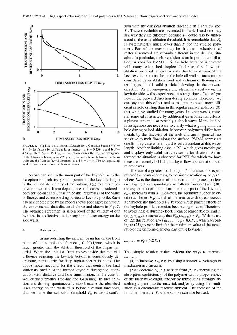
Via hole transmissions calculated from (31) and (32) vs. thedimensionless hole depth for top-hat and Gaussian beam pro-files for low and high laser fluences are shown in Figs. 11and 12 respectively with dashed lines. The keyhole profilesare shown with solid curves. Further details are given in thecorresponding figure captions.
FIGURE 11 Via hole transmission (dashed) vs. dimensionless hole depth fora top-hat beam for different laser fluences: a F = 0.5Fpar and b F = 3Fpar.Here r0 is the beam radius at the entrance plane of the sample, z0 is the dis-tance between the beam waist and the position of the material front surfaceand D = z − z0. The corresponding keyhole profiles are shown with solidcurves
TOKAREV et al. High-aspect-ratio microdrilling of polymers with UV laser ablation: experiment with analytical model
FIGURE 12 Via hole transmission (dashed) for a Gaussian beam(F(α)=
Fexp(−2α2/w2
α
) )for different laser fluences: a F = 0.25Fopt and b F =
4.5Fopt. Here Fopt = 15.4Fte/wα, wα characterizes the angular divergenceof the Gaussian beam, r0 = √
2wαz0, z0 is the distance between the beamwaist and the front surface of the material and D = z − z0. The correspondingkeyhole profiles are shown with solid curves
As one can see, in the main part of the keyhole, with theexception of a relatively small portion of the keyhole lengthin the immediate vicinity of the bottom, T(z) exhibits a be-havior close to the linear dependence in all cases considered –both for top-hat and Gaussian beams, regardless of the valueof fluence and corresponding particular keyhole profile. Sucha behavior predicted by the model shows good agreement withthe experimental data discussed above and shown in Fig. 7.The obtained agreement is also a proof of the validity of ourhypothesis of effective total absorption of laser energy on theside walls.
4 Discussion
In microdrilling the incident beam has on the frontplane of the sample the fluence (10–20) J/cm2, which ismuch greater than the ablation threshold of the virgin ma-terial. When the ablation front moves inside the materiala fluence reaching the keyhole bottom is continuously de-creasing, particularly for deep high-aspect-ratio holes. Theabove model accounts for the effects that control the finalstationary profile of the formed keyhole: divergence, atten-uation with distance and hole transmission, in the case ofwell-defined profiles (top-hat and Gaussian). In fact abla-tion and drilling spontaneously stop because the absorbedlaser energy on the walls falls below a certain threshold,that we name the extinction threshold Fte to avoid confu-
sion with the classical ablation threshold in a shallow spotFt. These thresholds are presented in Table 1 and one mayask why they are different, because Fte could also be under-stood as the usual ablation threshold. It is remarkable that Fteis systematically much lower than Ft for the studied poly-mers. Part of the reason may be that the mechanisms ofmaterial removal are strongly different in the drilling situ-ation. In particular, melt expulsion is an important contribu-tion: as seen for PMMA [16] the hole entrance is coveredwith many redeposited droplets. In the usual shallow-spotablation, material removal is only due to expansion of thelaser-excited volume. Inside the hole all wall surfaces can beconsidered as an ablation front and a stream of flowing ma-terial (gas, liquid, solid particles) develops in the outwarddirection. As a consequence any elementary surface on thekeyhole side walls experiences a strong drag effect of gasflow in the outward direction during ablation. Therefore, wecan say that this effect makes material removal more effi-cient in hole drilling than in the regular surface ablation [30]that we have studied for many years. In other words, mate-rial removal is assisted by additional environmental effects,a plasma stream, also possibly a shock wave. More detailedinvestigations are necessary to clarify what is going on in thehole during pulsed ablation. Moreover, polymers differ frommetals by the viscosity of the melt and are in general lesssensitive to melt flow along the surface. PMMA representsone limiting case where liquid is very abundant at this wave-length. Another limiting case is PC, which gives mostly gasand displays only solid particles seen after ablation. An in-termediate situation is observed for PET, for which we havemeasured recently [31] a liquid-layer flow upon ablation withmicrobeams.
The use of a greater focal length, f , increases the aspectratio of the beam according to the simple relation a0 ∝ f/D0,where D0 is the diameter of the beam on the projection lens(see Fig. 1). Correspondingly, as follows from (25) and (30),the aspect ratio of the uniform-diameter part of the keyhole,aopt, increases with a0. However, the optimum fluence to ob-tain such holes, Fopt, which also increases with a0, can exceeda characteristic threshold Fpl, beyond which plasma effects onthe keyhole profile extension become significant. Therefore,to avoid these disturbing effects it can be reasonable to limit a0
(a0 ≤ a0 max) in such a way that Fopt(a0 max)≈ Fpl. With the useof (22) this relation gives a0 max = Fpl/(8.6Fte), which accord-ing to (25) gives the limit for the maximum value of the aspectratio of the uniform-diameter part of the keyhole:
aopt max = Fpl/(5.8Fte) .
This simple relation makes evident the ways to increaseaopt max:
(a) to increase Fpl, e.g. by using a shorter wavelength orirradiation in a vacuum;
(b) to decrease Fte, e.g. as seen from (5), by increasing theabsorption coefficient γ of the polymer with a proper choiceof the laser wavelength, and/or by introducing strongly ab-sorbing dopant into the material, and/or by using the irradi-ation in a chemically reactive ambient. The increase of theinitial temperature, Ti, of the sample can also be used.
Applied Physics A – Materials Science & Processing
These optimized results for the aspect ratio are obtainedhere for a simple situation – a standing beam waist with re-spect to the material. They can be significantly (a few times)further improved when using a more complicated drilling‘strategy’, such as gradual translation of the beam waistalong the keyhole axis into the material depth. It allows usto increase the length of the uniform-diameter part of thekeyhole.
Finally, Podlesnik et al. [32] have put forward the pos-sibility of light channeling into the keyhole in order to ex-plain the high-aspect-ratio drilling. In our polymer case theabove multiple-scattering model, based on the approximationof 100% effective local absorptivity at the walls, does not con-firm such a phenomenon since it can satisfactorily explain thehigh aspect ratio (Fig. 6) of the laser keyholes.
5 Conclusions
Based on the results of systematic experimentalstudies, an analytical theoretical model of high-aspect-ratiodrilling of a number of polymers by multi-pulse UV radiationof an excimer KrF laser is developed in this paper. For the firsttime some particular aspects of the mechanism of the radia-tion propagation and absorption inside the deep laser keyholein polymers are established. As a result:
– controlling factors of the drilling are revealed, in particularthe obstacles for obtaining the holes with highly parallelside walls and a very high aspect ratio are suggested;
– final keyhole profile and depth vs. incident fluence arecalculated for the rectangular, Gaussian and other spatialdistributions of the beam and a comparison with the ex-periment is given;
– laser drilling is optimized, i.e. the matching conditions forthe level and spatial distribution of laser intensity, param-eters of the optical focusing scheme and material param-eters are derived in an explicit analytical form, allowingus to produce deep keyholes with practically parallel sidewalls and an aspect ratio as high as 300–600.
ACKNOWLEDGEMENTS The authors thank CNRS (CentreNational de Recherche Scientifique) of France for providing a visiting fellow-ship for VNT. Region Aquitaine and European Communities (FEDER) arethanked for complementary funding.
REFERENCES
1 B. Braren, R. Srinivasan: J. Vac. Sci. Technol. B 3, 913 (1985)2 D. Basting (Ed.): Lambda Highlights 7, 4 (1987)3 G. Liedl, K. Schröder, A.F.H. Kaplan: Appl. Surf. Sci. 106, 374 (1996)4 D. Basting (Ed.): Lambda Highlights 18, 2 (1989); I. Miyamoto, H.
Maruo: Proc. SPIE 1279, 66 (1990)5 I. Miyamoto, H. Maruo, T. Ooie: in Proc. LAMP’92, Nagaoka, Japan,
June (1992) [Lambda Highlights 34, 2 (1992)]6 H.K. Tönshoff, D. Hesse, O. Gedrat: Proc. SPIE 1810, 572 (1993)7 A. Tsetseku, T. Zambetakis, C.J. Stournaras: Proc. SPIE 1810, 615
(1993)8 T.V. Kononenko, S.V. Garnov, S.M. Pimenov, V.I. Konov, F. Dausinger:
Proc. SPIE 3343, 458 (1998)9 M. Wehner: in Werkstoffbearbeitung mit Laserstrahlung, ed. by
G. Herziger, P. Loosen (Hanser, München 1993) p. 18010 U. Sowada, P. Lokai, H.J. Kahlert, D. Basting: Laser Optoelektron. 21,
107 (1989); R. Poprawe, W. Schulze, M. Wehner: Opto Elektron. Mag. 6,70 (1990); E. Hontzopoulos, E. Damigos: Appl. Phys. A 52, 421 (1991)
11 G. Callies, H. Schittenhelm, P. Berger, H. Hügel: in Proc. 6th Eur.Conf. Laser Treat. Mater. (ECLAT’96), Stuttgart, Germany, Vol. 2, ed.by F. Dausinger, H.W. Bergmann, J. Sigel (1996) p. 613
12 T.W. Hodapp, P.R. Fleming: J. Appl. Phys. 84, 577 (1998)13 F. Wu, R.D. Pilkington: Proc. SPIE 3274, 306 (1998)14 C. Paterson, A.S. Holmes, R.W. Smith: J. Appl. Phys. 86, 6538 (1999)15 S. Lazare, D. Drilhole, J. Lopez, F. Weisbuch: Rev. Fr. Vac. Soc. 54, 265
(1998), in French16 S. Lazare, J. Lopez, F. Weisbuch: Appl. Phys. A 69, 1 (1999)17 J. Lopez, S. Lazare: J. Phys. IV Fr. 9, 153 (1999)18 V.N. Tokarev, A.F.H. Kaplan: Lasers Eng. 7, 295 (1998)19 V.N. Tokarev, J. Lopez, S. Lazare: Appl. Surf. Sci. 168, 75 (2000)20 P.E. Dyer, S.D. Jenkins, J. Sidhu: Appl. Phys. Lett. 49, 1059 (1986);
P.E. Dyer, S.D. Jenkins, J. Sidhu: Appl. Phys. Lett. 52, 1880 (1988)21 B. Hopp, Z. Bor, E. Homolya, E. Mihalik: Appl. Surf. Sci. 109–110, 232
(1997)22 S. Lazare, J. Lopez, J.M. Turlet, M. Kufner, S. Kufner, P. Chavel: Appl.
Opt. 35, 4471 (1996)23 S.I. Anisimov, Y.A. Imas, G.S. Romanov, Y.V. Khodyko: The Action of
High Power Radiation on Metals (Nauka, Moscow 1970) [in Russian]24 E. Armon, M. Hill, I.J. Spalding, Y. Zvirin: J. Appl. Phys. 65, 5003
(1989)25 A. Kar, J. Mazumder: J. Appl. Phys. 68, 3884 (1990)26 R.W. Olson, W.C. Swope: J. Appl. Phys. 72, 3686 (1992)27 P. Solana, P. Kapadia, J.M. Dowden, P.J. Marsden: J. Phys. D: Appl.
Phys. 32, 942 (1999)28 V.N. Tokarev, J.I.B. Wilson, M.G. Jubber, P. John, D.K. Milne: Diamond
Relat. Mater. 4, 169 (1995)29 V.N. Tokarev, A.F.H. Kaplan: J. Appl. Phys. 86, 2836 (1999)30 S. Lazare, V. Granier: J. Appl. Phys. 63, 2110 (1988)31 F. Weisbuch, V.N. Tokarev, S. Lazare, D. Debarre: Appl. Surf. Sci. 186,
95 (2002)32 D.V. Podlesnik, H.H. Gilgen, R.M. Osgood: Appl. Phys. Lett. 48, 496
(1986)


![[Revised] Revisiting Verb Aspect in T'boli](https://static.fdokumen.com/doc/165x107/631ef9e50ff042c6110c9f71/revised-revisiting-verb-aspect-in-tboli.jpg)