Adiabatic radio-frequency potentials for the coherent manipulation of matter waves

International Journal of Thermal Sciences 41 (2002) 1101–1111www.elsevier.com/locate/ijts
Heat and fluid flow resulting from the chimney effect in a symmetricallyheated vertical channel with adiabatic extensions
Antonio Auletta, Oronzio Manca∗
Dipartimento di Ingegneria Aerospaziale, Seconda Università degli studi di Napoli, Real casa dell’Annunziata,Via Roma 29, 81031 Aversa (CE), Italy
Received 4 May 2001; accepted 7 January 2002
Abstract
An experimental study on a channel-chimney system was carried out in order to elucidate the behavior of heat transfer and fluid flow.The results are presented in terms of local air temperature measurements inside the symmetrically heated channel and between the adiabaticextensions. Different fluid motion regions are observed inside the chimney. Inflows of air are detected in the lower extension ratio, particularlyfor large values of the ratio of the width of chimney to that of the heated channel. Some typical configurations show the presence of a vortexstructure for an expansion ratio greater than one close to the corner regions in the chimney. Some monomial correlation equations betweenthe local Nusselt number, the channel Rayleigh number and the geometric parameters are proposed. The dimensionless parameters are in thefollowing ranges: 102 � Ra∗(B/b) � 106; 1.5 � L/Lh � 4.0; 1.0 � B/b � 4.0, in whichL is the total height of the system,Lh is the heightof the heated channel,B is the width of the chimney andb is the width of the heated channel. A good agreement between the correlation andthe experimental data is observed. 2002 Éditions scientifiques et médicales Elsevier SAS. All rights reserved.
Keywords:Natural convection; Vertical channel; Experimental analysis; Enhancement of heat transfer; Uniform heat flux; Temperature measurements
1. Introduction
The use of adiabatic extensions downstream of a heatsink or a heated vertical channel enhances natural convec-tive transfer in the heated part of a system [1–6]. Optimalconfigurations can be obtained for heat sink-chimney sys-tems [1–4] and channel-chimney systems [4,5]. With ref-erence to heated vertical channel-chimney systems, theirthermal performance depends on the Elenbaas number (orchannel Rayleigh number) as well as two non-dimensionalgeometric parameters: the extension ratio (total height ofthe system / height of the channel) and the expansion ratio(chimney spacing / channel spacing).
Several studies have been carried out on the chimneyeffect both numerically and experimentally [1–3,5–12], asrecently reviewed in [6]. The experimental studies are brieflyreviewed in the following.
* Corresponding author.E-mail addresses:[email protected] (A. Auletta),
[email protected] (O. Manca).
The heat sink-chimney system was studied experimen-tally in [3,4]. In [3] a vertical parallel-plate finned heat sinkwith a chimney was investigated. Results obtained using airconfirmed to within 11% theoretical predictions of the over-all heat transfer and location of optima given in [1]. Flow-field measurements validated momentum transfer and coldinflow at the chimney exit. The measured average chimneyvelocity was found to be close to that predicted by the the-ory. Periodic cold inflow at the chimney exit was quantifiedby its frequency and found to reduce overall heat transfer byapproximately 4%. The experiments confirmed that a chim-ney, when combined with free convection heat sinks resultedin enhanced heat transfer, and therefore permitted the use ofsmaller geometric dimensions. In [4] the performance a ofa pin-fin heat sink with a chimney was obtained. Increasedchimney height was shown to reduce the heat-sink temper-ature by as much as 30%. The experiments were comparedwith theoretical predictions and reasonable agreement wasobserved for overall heat transfer, optimal heat-sink poros-ity and fluid velocity. Finally, the phenomenon of periodiccold inflow at the chimney exit was observed and quantified.Results confirmed the same conclusions obtained in [3].
1290-0729/02/$ – see front matter 2002 Éditions scientifiques et médicales Elsevier SAS. All rights reserved.PII: S1290-0729(02 )01396-0
1102 A. Auletta, O. Manca / International Journal of Thermal Sciences 41 (2002) 1101–1111
Nomenclature
b channel spacing . . . . . . . . . . . . . . . . . . . . . . . . . . mB extension spacing . . . . . . . . . . . . . . . . . . . . . . . . mg acceleration of gravity . . . . . . . . . . . . . . . . m·s−2
k thermal conductivity . . . . . . . . . . . . W·m−1·K−1
L total length,= Lh + Lext . . . . . . . . . . . . . . . . . . mLext extension length . . . . . . . . . . . . . . . . . . . . . . . . . . mLh channel length . . . . . . . . . . . . . . . . . . . . . . . . . . . mNux local Nusselt number, Eq. (7)Pr Prandtl numberq heat flux . . . . . . . . . . . . . . . . . . . . . . . . . . . . W·m−2
r2 regression coefficientRax local Rayleigh number, Eq. (3)Ra∗ channel Rayleigh number, Eq. (4)T temperature . . . . . . . . . . . . . . . . . . . . . . . . . . . . . . K�T ∗ dimensionless temperature, Eq. (6)
x, y coordinates . . . . . . . . . . . . . . . . . . . . . . . . . . . . . . mx∗, y∗ dimensionless coordinates, Eqs. (1) and (2)
Greek symbols
β volumetric coefficient of expansion . . . . . . K−1
ν kinematic viscosity . . . . . . . . . . . . . . . . . . m2·s−1
Subscripts
c convectivek conductivemax maximumr radiativeref referencew wall� Ohmic0 environmental air
The channel-chimney system was investigated experi-mentally in [5–7,11]. In [5] the experiments were performedwith air, using a Mach–Zehnder interferometer, providingverification of numerical results for both the local and globalchanges in heat transfer. The increase in heat transfer ratesvaried from 2.5 times at low Rayleigh numbers to 1.5 timesat high Rayleigh numbers. The authors proposed a singlecorrelation in terms of the channel Rayleigh number and allthe geometrical parameters (heated length ratio, expansionratio). The channel-chimney system with the channel heatedwas studied experimentally in [6,11] where results were de-rived in terms of geometric parameters and Rayleigh num-bers. The experiments focused for Rayleigh numbers greaterthan 1.8× 10² and wall temperature profiles as a function ofthe extension ratios were presented. Furthermore, the opti-mal channel configurations were derived, which yielded theminimum value of the maximum wall temperature. Correla-tions for both dimensionless maximum wall temperature andaverage channel Nusselt numbers were proposed.
In the case of asymmetrical heating, a cold inflow(downflow) is present, as observed in [3,4] for a heat sink-chimney system, or in [13] for the simple channel and in [7]for a channel-chimney system. Experimental investigationscan allow a better understanding of fluid motion inside thechimney as a result of temperature measurements.
It is necessary to have a better understanding of whathappens in the chimney in order to improve the heat transferin the heated part of the system. Experimental investigationsof air flow in the chimney provide descriptions of differentkinds of motion which take place in the chimney, and localevaluations against which computer codes can be validated.It seems that there is a lack of experimental results on thechannel-chimney system with symmetrical heating.
In this paper, an experimental study of a vertical channel-chimney system is carried out. The channel is symmetricallyheated with a uniform heat flux. Results in terms of local
temperature profiles inside the heated channel and betweenthe insulated walls are presented. Local Nusselt number pro-files along the channel height are shown and correlations be-tween local Nusselt and Rayleigh numbers and geometricaldimensionless parameters are proposed.
2. Experimental apparatus
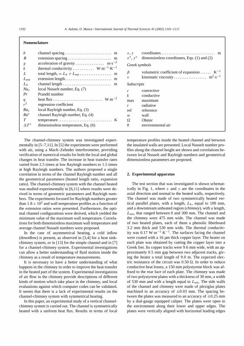
The test section that was investigated is shown schemat-ically in Fig. 1, wherex and y are the coordinates in theaxial direction and normal to the heated walls, respectively.The channel was made of two symmetrically heated ver-tical parallel plates, with a length,Lh, equal to 100 mm,and a downstream unheated region (chimney), with a length,Lext, that ranged between 0 and 300 mm. The channel andthe chimney were 475 mm wide. The channel was madeof two heated plates, each of them a phenolic fiberboard3.2 mm thick and 530 mm wide. The thermal conductiv-ity was 0.17 W·m−1·K−1. The surfaces facing the channelwere coated with a 16 µm thick copper layer. The heater oneach plate was obtained by cutting the copper layer into aGreek fret. Its copper tracks were 9.6 mm wide, with an ap-proximately 0.5 mm gap between two adjacent tracks, giv-ing the heater a total length of 9.0 m. The expected elec-tric resistance of the circuit was 0.50�. In order to reduceconductive heat losses, a 150 mm polystyrene block was af-fixed to the rear face of each plate. The chimney was madeof two polystyrene plates with a thickness of 30 mm, a widthof 530 mm and with a length equal toLext. The side wallsof the channel and chimney were made of plexiglas platesmachined to an accuracy of±0.03 mm. The spacing be-tween the plates was measured to an accuracy of±0.25 mmby a dial-gauge equipped caliper. The plates were open tothe environment along their lower and upper edges. Theplates were vertically aligned with horizontal leading edges
A. Auletta, O. Manca / International Journal of Thermal Sciences 41 (2002) 1101–1111 1103
Fig. 1. Sketch of the apparatus.
by screws using a plumb line and a level. The entire appa-ratus was located in an enclosed room that was carefullysealed in order to eliminate extraneous air currents and airdrafts were further reduced by vertical screens, 2.5 m high.In the lower part of the screens were some vents 0.20 mhigh. The plates were heated by passing a direct electricalcurrent through the copper tracks. This was accomplishedby using a Hewlett–Packard E3632A stabilized power sup-ply. The electrical power supplied by each heater was eval-uated by measuring the voltage drop across the plates andthe current flowing through them. A HP-3465A digital mul-timeter measured voltage drops in the circuit and across areference resistance to evaluate the current. To avoid elec-trical contact resistance, thick copper bars soldered both tothe electric supply wire and to the ends of each heater, werebolted together. The dissipated heat flux per board was eval-uated with an accuracy of±2%. Wall temperature measure-ments were carried out by ten equally spaced 0.50 mm ODcopper-constantan (type T) thermocouples, embedded andlocated in the centerline of each plate inside the fiberboardvery close to the back side of the copper layer and bondedwith a 3 M epoxy glue. They were run horizontally, paral-lel to the surfaces, thereby lying along isotherms in order tominimize conduction heat losses in the leads. The measureddifferences in the air ambient temperature in the proximityof the inlet and the exit sections of the apparatus were lessthan 0.8 K. A further two T-type thermocouples were usedto measure the environmental air temperature and the inletair temperature. A Tersid Isotech Ice Point was used as areference for the junctions of the thermocouple. A NationalInstruments SCXI 1000 module data acquisition system anda personal computer were used for the data collection and
reduction. The data acquisition was performed by means ofLabViewTM software. The temperature of the air flowing inthe channel and in the chimney was measured using a DAN-TEC 5600 hot wire system. A 55P15 special miniature probewith a wire of 1 µm diameter and a 56C01–56C20 constantcurrent bridge were used. The probe was calibrated in air,in the temperature range 15–80◦C, by comparison with a T-type thermocouple. The air temperature was measured with amaximum uncertainty of±0.1◦C. The probe could be man-ually positioned anywhere in the channel using a microme-ter traversing mechanism supported on the top of the frame(Fig. 1). It allowed positioning of the probe alongx andy
axes to an accuracy of not less than 0.03 mm. The typicaltime interval required to attain steady-state conditions aftermodifying the electric power supply was nearly 3 hours. Theprobe signal was automatically time averaged by the built-inintegrator voltmeter with an integration time of 100 seconds.The air temperature was evaluated on the average of foursuccessive integrated samples.
3. Data reduction
The dimensionless coordinate in the vertical direction isdefined by:
x∗ = x/Lh (1)
while the dimensionless coordinate in the horizontal direc-tion is given by:
y∗ = y/(b/2) (2)
1104 A. Auletta, O. Manca / International Journal of Thermal Sciences 41 (2002) 1101–1111
The local Rayleigh number is defined as:
Rax = gβqc(x)x4
ν2kPr (3)
whereqc(x) is the local convective heat flux, and the channelRayleigh number is:
Ra∗ = gβqcb5
ν2kLh
Pr (4)
whereqc is the mean value of the spatially-averaged convec-tive heat flux:
qc = 1
Lh
Lh∫0
qc(x)dx (5)
The dimensionless air temperature is given by:
�T ∗ = T − T0
qb/k(6)
The local Nusselt number is based on the differencebetween the wall and the inlet fluid temperatures, rather thanon that between the wall and the bulk fluid temperatures,since the latter cannot be easily established in practicalapplications and the ambient temperature,T0, is morereadily available:
Nux = qc(x)x
(Tw(x) − T0)k(7)
The properties of the air were evaluated at the referencetemperature:Tref = Tw+T0
2 .Local convective heat flux,qc(x), was not uniform
because of radiative and conductive losses. Experimentaldata was reduced by first introducing, in the equationspresented above, the local heat flux:
qc(x) = q� − qk(x) − qr(x) (8)
whereq� was the heat flux due to the Ohmic dissipation,which was assumed to be uniform along the plate;qk(x) de-notes the local conduction heat losses from the plates andqr(x) represents the local radiative heat flux from the plates.For each run, the termsqk(x) were calculated by a finite dif-ference numerical procedure, a two-dimensional distributionof the temperature being assumed in the polystyrene. Thepredicted temperatures in significant configurations of thesystem were previously compared to those measured by thethermocouples embedded in the polystyrene insulation andthe agreement was very good. In fact, the maximum devia-tion between calculated and measured temperatures referredto the measured temperature rise was±4%. Theqr(x) termswere calculated for each temperature distribution in the wallsand channel spacing by dividing each plate into ten equalsize strips along the channel, according to the procedure de-scribed by Webb and Hill [14].
In the following, with reference to Fig. 1, the expansionratio is expressed asB/b and the extension ratio isLh/L,whereL = Lh + Lext. In the experiments the length of thechimney,Lext varied in the range 0–300 mm. The channel
spacing,b, varied in the range 10–40 mm; that of thechimney,B, varied in the range 10–200 mm. With thesedimensions, the channel aspect ratio was in the 2.5–20 rangeand the expansion ratioB/b ranged between 1.0 and 8.0.
The uncertainty in the evaluated quantities is determinedaccording to the standard single sample analysis recom-mended in [15,16]. The uncertainty in the values of the airthermophysical properties can be assumed to be negligible.On the basis of Eqs. (3), (4) and (7) and of the maximumpercent uncertainties in the values ofRa∗ and Rax rangesbetween 5 and 8 percent while the maximum uncertainty inNux is 4 to 7 percent.
4. Results and discussion
4.1. Temperature profiles
In all the runs the heat flux was equal to 450 W·m−2 andthe temperature was referred to the ambient temperature.
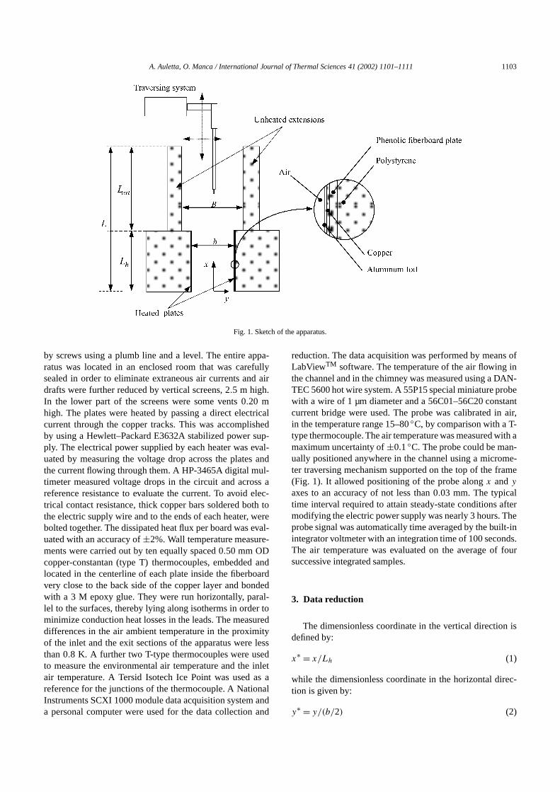
In Fig. 2 the temperature profiles of the air in the simplechannel (B/b → ∞) with an aspect ratio ofLh/b = 2.5 arereported. From the analysis of the figure a regular develop-ment of temperature profile is observed. The temperatures atx∗ = 0.50, near the wall (y∗ ≈ 0.80), exceed the correspond-ing temperatures atx∗ = 0.95 because of the edge effectsdue to the heat conduction in the solid wall, toward the insu-lated block, and with the ambient together with the radiativelosses from the heated surfaces.
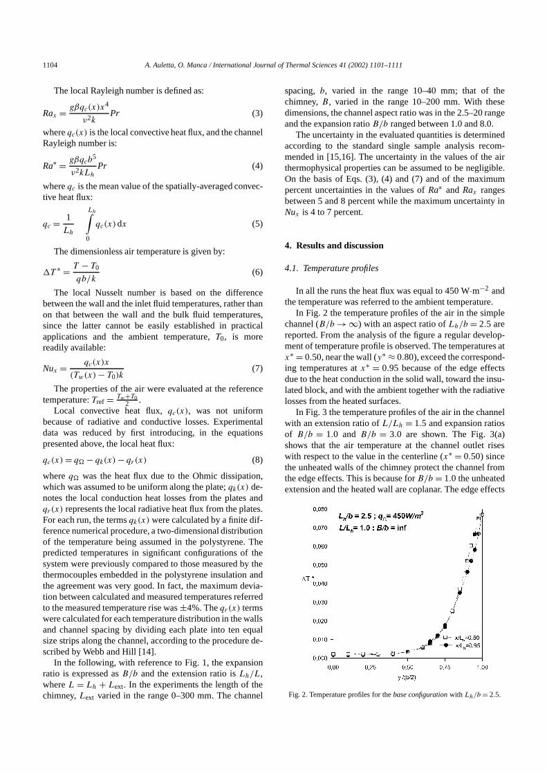
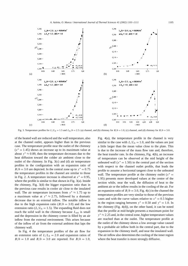
In Fig. 3 the temperature profiles of the air in the channelwith an extension ratio ofL/Lh = 1.5 and expansion ratiosof B/b = 1.0 and B/b = 3.0 are shown. The Fig. 3(a)shows that the air temperature at the channel outlet riseswith respect to the value in the centerline (x∗ = 0.50) sincethe unheated walls of the chimney protect the channel fromthe edge effects. This is because forB/b = 1.0 the unheatedextension and the heated wall are coplanar. The edge effects
Fig. 2. Temperature profiles for thebase configurationwith Lh/b = 2.5.
A. Auletta, O. Manca / International Journal of Thermal Sciences 41 (2002) 1101–1111 1105
(a) (b)
(c) (d)
Fig. 3. Temperature profiles forL/Lh = 1.5 andLh/b = 2.5: (a) channel, and (b) chimney forB/b = 1.0, (c) channel, and (d) chimney forB/b = 3.0.
of the heated wall are reduced and the wall temperature, alsoat the channel outlet, appears higher than in the previouscase. The temperature profile near the outlet of the chimney(x∗ = 1.45) shows an increase up to its maximum value atabouty∗ ≈ 0.89, then the temperature decreases due to theheat diffusion toward the colder air ambient close to theoutlet of the chimney. In Fig. 3(c) and (d) air temperatureprofiles in the configuration with an expansion ratio ofB/b = 3.0 are depicted. In the central zone up toy∗ = 0.75the temperature profiles in the channel are similar to thosein Fig. 2. A temperature increase is observed atx∗ = 0.95,where the profile is similar to that shown in Fig. 3(a). Insidethe chimney, Fig. 3(d) the bigger expansion ratio than inthe previous case results in cooler air close to the insulatedwall. The air temperature increases fromy∗ ≈ 1.75 up toa maximum value aty∗ ≈ 2.75, followed by a dramaticdecrease due to an external inflow. The notable inflow isdue to the high expansion ratio (B/b = 3.0) and the lowextension ratio (L/Lh = 1.5). The expanding fluid does notreach the solid wall in the chimney becauseLext is smalland the depression in the chimney corner is filled by an airinflow from the external environment. This arises becauseof the inflow of air from the external ambient that laps thechimney wall.
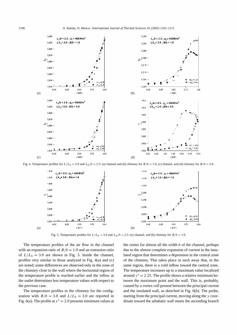
In Fig. 4 the temperature profiles of the air flow foran extension ratio ofL/Lh = 2.0 and expansion ratios ofB/b = 1.0 and B/b = 3.0 are reported. ForB/b = 1.0,
Fig. 4(a), the temperature profile in the channel is verysimilar to the case withL/Lh = 1.0, and the values are justa little larger than the mean value close to the plate. Thisis due to the increase of the mass flow rate and, therefore,the heat transfer rate. In the chimney, Fig. 4(b), an increaseof temperature can be observed at the mid height of theunheated wall (x∗ = 1.50) in the central part of the sectionwith respect to the channel outlet profile, that leads theprofile to assume a horizontal tangent close to the unheatedwall. The temperature profile at the chimney outlet (x∗ =1.95) presents more developed values at the centre of thesection while, near the wall, the diffusion of heat to theambient air or the inflow results in the cooling of the air. Foran expansion ratio ofB/b = 3.0, Fig. 4(c) in the channel thetemperature profiles are very similar to those of the previouscases and with the curve values relative tox∗ = 0.5 higherin the region ranging betweeny∗ = 0.50 andy∗ = 1.0. Inthe chimney (Fig. 4(d)), on the other hand, it can be notedthat the profile at mid-height presents a maximum point fory∗ ≈ 2.25 and, in the central zone, higher temperature valuesare reached than at the outlet. The temperature profile atthe outlet of the chimney shows a low average value causedby a probable air inflow both in the central part, due to theexpansion in the chimney itself, and near the insulated wall.The air inflow also determines the cooling of the inner regionwhere the heat transfer is more strongly diffusive.
1106 A. Auletta, O. Manca / International Journal of Thermal Sciences 41 (2002) 1101–1111
(a) (b)
(c) (d)
Fig. 4. Temperature profiles forL/Lh = 2.0 andLh/b = 2.5: (a) channel and (b) chimney forB/b = 1.0, (c) channel, and (d) chimney forB/b = 3.0.
(a) (b)
Fig. 5. Temperature profiles forL/Lh = 3.0 andLh/b = 2.5: (a) channel, and (b) chimney forB/b = 1.0.
The temperature profiles of the air flow in the channelwith an expansion ratio ofB/b = 1.0 and an extension ratioof L/Lh = 3.0 are shown in Fig. 5. Inside the channel,profiles very similar to those analyzed in Fig. 4(a) and (c)are noted; some differences are observed only in the zone ofthe chimney close to the wall where the horizontal region ofthe temperature profile is reached earlier and the inflow atthe outlet determines less temperature values with respect tothe previous case.
The temperature profiles in the chimney for the config-uration with B/b = 3.0 and L/Lh = 3.0 are reported inFig. 6(a). The profile atx∗ = 2.0 presents minimum values at
the center for almost all the widthb of the channel, perhapsdue to the almost complete expansion of current in the insu-lated region that determines a depression in the central zoneof the chimney. This takes place in such away that, in thesame region, there is a cold inflow toward the central zone.The temperature increases up to a maximum value localizedaroundy∗ = 2.25. The profile shows a relative minimum be-tween the maximum point and the wall. This is, probably,caused by a vortex cell present between the principal currentand the insulated wall, as sketched in Fig. 6(b). The probe,starting from the principal current, moving along they coor-dinate toward the adiabatic wall meets the ascending branch

A. Auletta, O. Manca / International Journal of Thermal Sciences 41 (2002) 1101–1111 1107
(a) (b)
Fig. 6. Temperature profiles forL/Lh = 3.0 Lh/b = 2.5: (a) chimney, and (b) sketch forB/b = 1.0.
Fig. 7. Temperature profiles for thebase configurationwith Lh/b = 5.0.
of the vortex in this region and has a temperature at a valueclose to that of the principal current. The temperature de-creases in the inner region of the vortex. Finally, close to theinsulated wall, the probe is surrounded by the descendingbranch of the vortex. Atx∗ = 2.95 it is noticeable that thetemperature profile is practically flat up toy∗ ≈ 2, whereasthe probe meets the principal flow. Then, the temperature in-creases toy∗ = 2.75 where a weak inflow determines a smalllowering as shown in Fig. 6(b).
The base configuration (B/b → ∞) with an aspect ra-tio of Lh/b = 5.0 is shown in Fig. 7. In this case, moredeveloped profiles are observed and, therefore, higher tem-perature values in the central zone, in contrast to the pre-vious case. An appreciable difference between the profilesat x∗ = 0.50 and atx∗ = 0.95 is apparent. This is a conse-quence of the lower value of Rayleigh number that deter-mines a higher diffusion in the inner layer of the channel.The profile atx∗ = 0.95 runs almost completely above the
profile at x∗ = 0.5 except near the heated wall where theedge effects invert this path.
Similar behavior is observed in the diagrams in Fig. 8,related to the configurations characterized by an expansionratio of B/b = 1.0 and B/b = 2.0 and by an extensionratio of L/Lh = 2.0. The temperature profiles of the innerzone are more developed than those relative to the caseof Lh/b = 2.5 and are similar to those observed in thebase case. However, it is noticeable that the profiles in themiddle part of the channel and at the exit are always veryclose to each other, particularly in the case ofB/b = 2.In Fig. 8(b), however, it is observed how both temperatureprofiles exhibit an internal maximum point. Furthermore,the temperature values of the air near the exit are almost allless than those relative tox∗ = 1.50. This could indicate amore efficient heat transfer with the external environmentcaused by a possible inflow in the chimney outlet. Theconfiguration in Fig. 8(d) shows that the internal layers arehotter than those at the exit of the channel. This is due to thetransfer of energy from the layers adjacent to the insulatedwalls of the chimney. The temperature profiles move slowlywith an horizontal tangent toward the wall. At the outlet,inthe internal zone, temperatures are higher than those in theprevious case and there is a cooling of the air probablycaused by a small inflow from outside the channel.
4.2. Local Nusselt numbers and correlations
In Figs. 9 and 10 the profiles of the local Nusseltnumbers are portrayed as functions of the dimensionlesscoordinatex∗, relative to the channel (the heated part ofthe analyzed system) for some values of heat fluxq , andof aspect ratio,Lh/b, expansion ratio,B/b, and extensionratio, L/Lh, investigated. First of all, the growing path ofNux should be observed: the presence of the local abscissain the definition of the Nusselt number clearly conditionsthis profile. Furthermore, it is noted how, in consonance withgeometrical conditions, the profiles are very similar to each

1108 A. Auletta, O. Manca / International Journal of Thermal Sciences 41 (2002) 1101–1111
(a) (b)
(c) (d)
Fig. 8. Temperature profiles forL/Lh = 2 andLh/b = 5.0: (a) channel, and (b) chimney forB/b = 1.0, (c) channel, and (d) chimney forB/b = 2.0.
(a) (b)
(c) (d)
Fig. 9. Local Nusselt number profiles forLh/b = 2.5 and for some values ofL/Lh andB/b.
A. Auletta, O. Manca / International Journal of Thermal Sciences 41 (2002) 1101–1111 1109
(a) (b)
(c) (d)
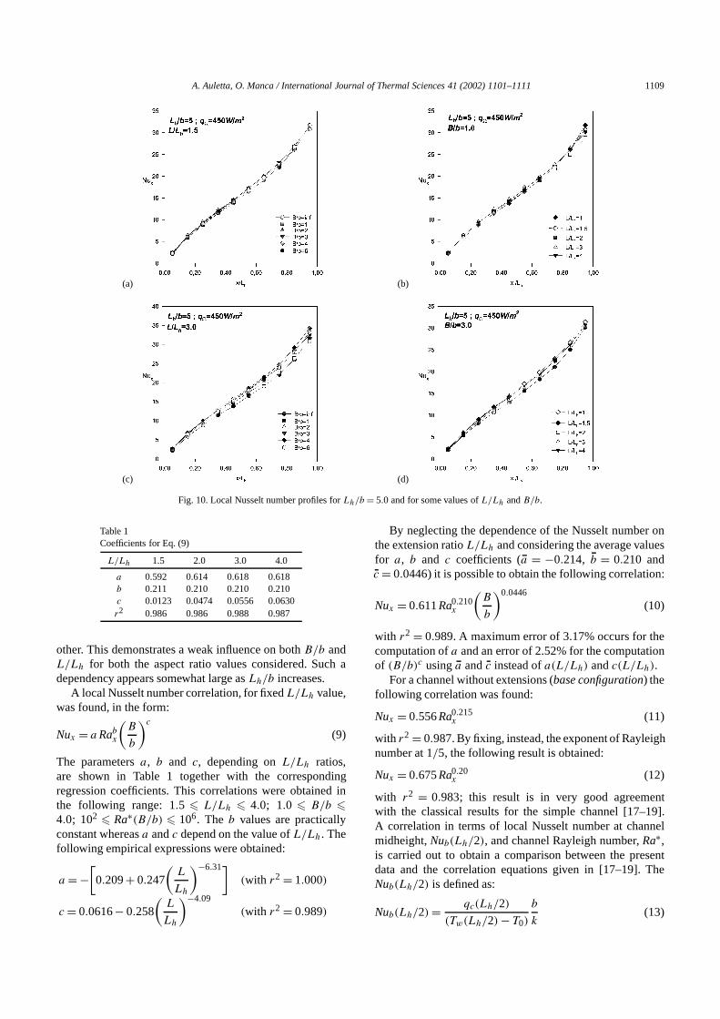
Fig. 10. Local Nusselt number profiles forLh/b = 5.0 and for some values ofL/Lh andB/b.
Table 1Coefficients for Eq. (9)
L/Lh 1.5 2.0 3.0 4.0
a 0.592 0.614 0.618 0.618b 0.211 0.210 0.210 0.210c 0.0123 0.0474 0.0556 0.0630r2 0.986 0.986 0.988 0.987
other. This demonstrates a weak influence on bothB/b andL/Lh for both the aspect ratio values considered. Such adependency appears somewhat large asLh/b increases.
A local Nusselt number correlation, for fixedL/Lh value,was found, in the form:
Nux = a Rabx
(B
b
)c
(9)
The parametersa, b and c, depending onL/Lh ratios,are shown in Table 1 together with the correspondingregression coefficients. This correlations were obtained inthe following range: 1.5 � L/Lh � 4.0; 1.0 � B/b �4.0; 102 � Ra∗(B/b) � 106. The b values are practicallyconstant whereasa andc depend on the value ofL/Lh. Thefollowing empirical expressions were obtained:
a = −[0.209+ 0.247
(L
Lh
)−6.31](with r2 = 1.000)
c = 0.0616− 0.258
(L
Lh
)−4.09
(with r2 = 0.989)
By neglecting the dependence of the Nusselt number onthe extension ratioL/Lh and considering the average valuesfor a, b and c coefficients (a = −0.214, b = 0.210 andc = 0.0446) it is possible to obtain the following correlation:
Nux = 0.611Ra0.210x
(B
b
)0.0446
(10)
with r2 = 0.989. A maximum error of 3.17% occurs for thecomputation ofa and an error of 2.52% for the computationof (B/b)c usinga andc instead ofa(L/Lh) andc(L/Lh).
For a channel without extensions (base configuration) thefollowing correlation was found:
Nux = 0.556Ra0.215x (11)
with r2 = 0.987. By fixing, instead, the exponent of Rayleighnumber at 1/5, the following result is obtained:
Nux = 0.675Ra0.20x (12)
with r2 = 0.983; this result is in very good agreementwith the classical results for the simple channel [17–19].A correlation in terms of local Nusselt number at channelmidheight,Nub(Lh/2), and channel Rayleigh number,Ra∗,is carried out to obtain a comparison between the presentdata and the correlation equations given in [17–19]. TheNub(Lh/2) is defined as:
Nub(Lh/2) = qc(Lh/2)
(Tw(Lh/2) − T0)
b
k(13)
1110 A. Auletta, O. Manca / International Journal of Thermal Sciences 41 (2002) 1101–1111
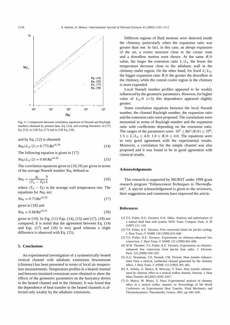
Fig. 11. Comparison between correlation equations of Nusselt and Rayleighnumbers obtained by present data, Eq. (14), and existing literature: in [17]Eq. (15), in [18] Eq. (17) and in [19] Eq. (18).
and by Eq. (12) is obtained:
Nub(Lh/2) = 0.775Ra∗0.20 (14)
The following equation is given in [17]:
Nub(Lh/2) = 0.60Ra∗0.20 (15)
The correlation equations given in [18,19] are given in termsof the average Nusselt numberNub defined as
Nub = qc
(Tw − T0)
b
k(16)
where(Tw − T0) is the average wall temperature rise. Theequations forNub are:
Nub = 0.73Ra∗0.20 (17)
given in [18] and
Nub = 0.68Ra∗0.21 (18)
given in [19]. In Fig. (11) Eqs. (14), (15) and (17), (18) arecompared. It is noted that the agreement between Eq. (14)and Eqs. (17) and (18) is very good whereas a slightdifference is observed with Eq. (15).
5. Conclusions
An experimental investigation of a symmetrically heatedvertical channel with adiabatic extensions downstream(chimney) has been presented in terms of local air tempera-ture measurements. Temperature profiles in a heated channeland between insulated extensions were obtained to show theeffects of the geometric parameters on the buoyancy drivenin the heated channel and in the chimney. It was found thatthe dependence of heat transfer in the heated channels is af-fected only weakly by the adiabatic extensions.
Different regions of fluid motions were detected insidethe chimney, particularly when the expansion ratio wasgreater than one. In fact, in this case, an abrupt expansionof the air, a vortex structure close to the corner zoneand a downflow motion were shown. At the sameB/b
value, the larger the extension ratioL/Lh the lesser thetemperature decrease close to the adiabatic wall in thechimney outlet region. On the other hand, for fixedL/Lh,the bigger expansion ratioB/b the greater the downflow inthe chimney, while the central cooler region in the chimneyis more expanded.
Local Nusselt number profiles appeared to be weaklyinfluenced by the geometric parameters. However, for highervalue of Lh/b (=5) this dependence appeared slightlygreater.
Some correlation equations between the local Nusseltnumber, the channel Rayleigh number, the expansion ratioand the extension ratio were proposed. The correlations weremonomial in terms of Rayleigh number and the expansionratio with coefficients depending on the extension ratio.The ranges of the parameters were: 102 � Ra∗(B/b) � 106;1.5 � L/Lh � 4.0; 1.0 � B/b � 4.0. The equations werein very good agreement with the experimental results.Moreover, a correlation for the simple channel was alsoproposed and it was found to be in good agreement withclassical results.
Acknowledgements
This research is supported by MURST under 1999 grantresearch program “Enhancement Techniques in Thermoflu-ids”. A special acknowledgement is given to the reviewers,their suggestions and comments have improved the article.
References
[1] T.S. Fisher, K.E. Torrance, K.K. Sikka, Analysis and optimization ofa natural draft heat sink system, IEEE Trans. Compon. Pack. A 20(1997) 111–119.
[2] T.S. Fisher, K.E. Torrance, Free convection limits for pin-fin cooling,J. Heat Trans.-T ASME 120 (1999) 633–640.
[3] T.S. Fisher, K.E. Torrance, Experiments on chimney-enhanced freeconvection, J. Heat Trans.-T ASME 121 (1999) 603–608.
[4] W.W. Thrasher, T.S. Fisher, K.E. Torrance, Experiments on chimney-enhanced free convection from pin-fin heat sinks, J. Electron.Pack. 122 (2000) 350–355.
[5] A.G. Straatman, J.D. Tarasuk, J.M. Floryan, Heat transfer enhance-ment from a vertical, isothermal channel generated by the chimneyeffect, J. Heat Trans.-T ASME 115 (1993) 395–402.
[6] A. Auletta, O. Manca, B. Morrone, V. Naso, Heat transfer enhance-ment by chimney effect in a vertical isoflux channel, Internat. J. HeatMass Transfer 44 (2001) 4345–4357.
[7] O. Manca, M. Musto, V. Naso, Experimental analysis of chimneyeffect in a vertical isoflux channel, in: Proceedings of 5th WorldConference on Experimental Heat Transfer, Fluid Mechanics andThermodynamics, Thessaloniki, Greece, 2001, pp. 645–650.
A. Auletta, O. Manca / International Journal of Thermal Sciences 41 (2002) 1101–1111 1111
[8] Y. Asako, H. Nakamura, M. Faghri, Natural convection in a verticalheated tube attached to thermally insulated chimney of a differentdiameter, J. Heat Trans.-T ASME 112 (1990) 790–793.
[9] K.T. Lee, Natural convection in vertical parallel plates with anunheated entry or unheated exit, Numer. Heat Trans. A Appl. 25 (1994)477–493.
[10] A. Campo, O. Manca, B. Morrone, Numerical analysis of partiallyheated vertical parallel plates in natural convective cooling, Numer.Heat Trans. A Appl. 36 (1999) 129–151.
[11] N. Bianco, O. Manca, B. Morrone, V. Naso, Experimental analysisof chimney effect for vertical isoflux symmetrically heated parallelplates, in: Proceedings of Thermal Management of Electronic SystemsIII (Eurotherm Seminar ’58), 1998, pp. 73–79.
[12] G.A. Shahin, J.M. Floryan, Heat transfer enhancement generated bythe chimney effect in systems of vertical channel, J. Heat Trans.-TASME 121 (1999) 230–232.
[13] E.M. Sparrow, G.M. Chrysler, L.F. Azedevo, Observed flow reversal
and measured-predicted Nusselt number convection in a one-sidedheated vertical channel, J. Heat Trans.-T ASME 106 (1984) 325–332.
[14] G.A. Webb, D.P. Hill, Rayleigh number laminar natural convection inan asymmetrical heated vertical channel, J. Heat Trans.-T ASME 111(1989) 649–656.
[15] S.G. Kline, F.A. McClintock, Describing uncertainty in single sampleexperiments, Mech. Engrg. 75 (1958) 3–12.
[16] R.J. Moffat, Describing the uncertainties in experimental results, Exp.Therm. Fluid Sci. 1 (1998) 3–17.
[17] W. Aung, L.S. Fletcher, V. Sernas, Developing laminar free convectionbetween vertical flat plates with asymmetric heating, Internat. J. HeatMass Transfer. 15 (1972) 2293–2308.
[18] A. Bar-Cohen, W.W. Rosenow, Thermally optimum spacing of ver-tical, natural convection cooled, parallel plates, J. Heat Trans.-TASME 106 (1984) 116–123.
[19] O. Manca, S. Nardini, Composite correlations for air natural convec-tion in tilted channels, Heat Transfer Engrg. 20 (1999) 64–70.
Copyright © 2022 FDOKUMEN