HEADWORKS SCREENING UPGRADE 7327 - WM LYLES
635
CONFORMED SET DECEMBER 2016 The conformed documents are prepared as a convenience for the use of inspectors, designers, construction managers, and contractors during the construction period. These documents have no contractual standing as the contract conditions and scope of work will remain formally defined by the bid documents, the addenda and any formal change orders. PROJECT DOCUMENTS FOR HEADWORKS SCREENING UPGRADE ____________________________ DISTRICT PROJECT 7327 ____________________________ VOLUME 2 of 3: PROJECT MANUAL PART 2 of 2 Contract Forms, Conditions, and Specifications
-
Upload
khangminh22 -
Category
Documents
-
view
2 -
download
0
Transcript of HEADWORKS SCREENING UPGRADE 7327 - WM LYLES

CONFORMED SET DECEMBER 2016
The conformed documents are prepared as a convenience for the use of inspectors, designers, construction managers, and contractors during the construction period. These documents have no contractual standing as the contract conditions and scope of work will remain formally defined by the bid documents, the addenda and any formal change orders.
PROJECT DOCUMENTS FOR
HEADWORKS SCREENING UPGRADE
____________________________
DISTRICT PROJECT
7327 ____________________________
VOLUME 2 of 3: PROJECT MANUAL PART 2 of 2
Contract Forms, Conditions, and Specifications

CENTRAL CONTRA COSTA SANITARY DISTRICT
5019 Imhoff Place Martinez, California
PROJECT DOCUMENTS
for construction of
DISTRICT PROJECT 7327
HEADWORKS SCREENING UPGRADE
VOLUME 2 OF 3: PROJECT MANUAL
including
Contract Forms, Conditions, and Specifications
Approved for Construction:
Roger S. Bailey
General Manager
September 2016

DP 7327 - Volume 2 - Page 3
TABLE OF CONTENTS
PROJECT DOCUMENTS: VOLUME 1 – BID DOCUMENTS
PART I NOTICE TO CONTRACTORS INVITING SEALED BIDS FOR CENTRAL CONTRA COSTA SANITARY DISTRICT PROJECT 7327
PART II INSTRUCTIONS TO BIDDERS PART III BID FORMS
PROJECT DOCUMENTS: VOLUME 2 – PROJECT MANUAL PART IV CONTRACT AND BOND FORMS PART V GENERAL CONDITIONS PART VI SPECIAL CONDITIONS PART VII TECHNICAL SPECIFICATIONS DIVISION 01 SUPPLEMENTAL PROJECT CONDITIONS
DIVISION 02 02 41 00 DEMOLITION, SALVAGE, RELOCATION, AND MODIFICATIONS DIVISION 03 03 11 00 CONCRETE FORMING 03 11 23 CONTROLLED DENSITY FILL 03 20 00 CONCRETE REINFORCING 03 30 00 CAST-IN-PLACE CONCRETE 03 60 00 GROUTING DIVISION 04 04 20 00 UNIT MASONRY DIVISION 05 05 05 13.13 ZINC COATINGS 05 05 20 ANCHOR BOLTS 05 10 00 STRUCTURAL METAL FRAMING 05 21 19 OPEN WEB STEEL JOIST FRAMING 05 31 23 STEEL ROOF DECKING 05 50 00 METAL FABRICATIONS 05 52 10 ALUMINUM RAILINGS 05 53 10 METAL GRATINGS 05 59 20.13 FLAT ALUMINUM COVERS DIVISION 06 06 70 13 FIBERGLASS REINFORCED PLASTIC (FRP) FABRICATIONS
IN ODOR TREATMENT EQUIPMENT

DP 7327 - Volume 2 - Page 4
DIVISION 07 07 19 00 WATER REPELLENTS 07 42 13 METAL WALL PANELS 07 52 16 STYRENE-BUTADIENE-STYRENE (SBS) MODIFIED
BITUMINOUS MEMBRANE ROOFING 07 62 00 SHEET METAL FLASHING AND TRIM 07 91 26 JOINT FILLERS 07 92 00 JOINT SEALANTS DIVISION 08 08 11 13.13 STANDARD HOLLOW METAL DOORS AND FRAMES 08 33 23 ALUMINUM ROLL-UP DOORS 08 62 00 UNIT SKYLIGHTS 08 71 00 DOOR HARDWARE 08 81 00 GLAZING DIVISION 09 09 97 25 MANHOLE REHABILITATION COATINGS [ADD. 2, Item 8] 09 90 00 PAINTING AND COATING DIVISION 10 10 14 00 SIGNAGE 10 44 00 FIRE PROTECTION SPECIALTIES 10 73 16 CANOPIES DIVISION 21 21 11 16 FACILITY FIRE HYDRANTS 22 13 19 SANITARY WASTE PIPING SPECIALTIES 22 13 19.43 HOSES AND NOZZLES DIVISION 23 23 05 93 HEATING, VENTILATING, AND AIR CONDITIONING SYSTEMS
TESTING, ADJUSTING, AND BALANCING 23 31 16.16 THERMOSET FIBERGLASS REINFORCED PLASTIC DUCTS 23 33 36.16 WATER HEATING SYSTEM 23 34 16.16 CENTRIFUGAL FRP FANS 23 37 13 GRILLES AND DAMPERS DIVISION 26 26 05 00 COMMON WORK RESULTS FOR ELECTRICAL 26 05 19 LOW VOLTAGE ELECTRICAL POWER CONDUCTORS AND
CABLES 26 05 26 GROUNDING AND BONDING FOR ELECTRICAL SYSTEMS 26 05 33 RACEWAYS AND BOXES FOR ELECTRICAL SYSTEMS 26 08 00 COMMISSIONING OF ELECTRICAL SYSTEMS 26 09 16 ELECTRICAL CONTROLS AND RELAYS 26 27 26 WIRING DEVICES 26 29 13 ENCLOSED CONTROLLERS 26 29 23 VARIABLE FREQUENCY MOTOR CONTROLLERS 26 50 00 LIGHTING

DP 7327 - Volume 2 - Page 5
DIVISION 28 28 31 12 ZONED (DC-LOOP) FIRE ALARM SYSTEMS DIVISION 31 31 10 00 SITE CLEARING 31 23 00 EXCAVATION AND FILL 31 41 00 SHORING DIVISION 32 32 12 16 ASPHALT PAVING 32 13 13 CONCRETE PAVING DIVISION 33 33 05 13 MANHOLES AND STRUCTURES 33 05 40 REINFORCED THERMOSETTING RESIN PIPE DIVISION 40 40 05 01 PIPING SYSTEMS 40 05 02 PIPING SYSTEM SCHEDULES 40 05 02.03 PROCESS AIR PIPING 40 05 02.23 POTABLE WATER AND HOT SERVICE WATER 40 05 02.29 MEDIUM PRESSURE PLANT UTILITY WATER 40 05 02.50 NATURAL GAS 40 05 02.81 ODOR CONTROL 40 05 02.89 BUILDING AND PROCESS DRAINAGE 40 05 06.16 MECHANICAL PIPE COUPLINGS 40 05 06.23 EXPANSION JOINTS AND FLEXIBLE HOSE 40 05 06.33 PIPING APPURTENANCES 40 05 07 HANGERS AND SUPPORTS FOR PROCESS PIPING 40 05 07.13 SEISMIC RESTRAINTS FOR PIPING 40 05 07.16 EXPANSION CONTROL FOR PIPING 40 05 17 COPPER PIPE 40 05 19 DUCTILE IRON PIPE 40 05 23 STAINLESS STEEL PIPE 40 05 24 STEEL PIPE 40 05 45 PIPING SYSTEM IDENTIFICATION 40 05 57.23 POWERED ACTUATORS 40 05 60 VALVES 40 05 62.01 AWWA C517 STANDARD PORT PLUG VALVE (PL01) 40 05 63.01 BRONZE OR BRASS BODY AND BALL VALVE (BV01) 40 05 63.03 SS THREADED BALL VALVE (BV03) 40 05 64.91 BUTTERFLY DAMPER (BD01) 40 05 65.01 SOLENOID VALVE (SOL01) 40 05 67.36 PRESSURE-REGULATING VALVES 40 05 72 SPECIALTY VALVES 40 06 20.13 POWER ACTUATED VALVE AND GATE SCHEDULE 40 42 00 PROCESS PIPING AND EQUIPMENT INSULATION 40 61 13 PROCESS CONTROL SYSTEM GENERAL PROVISIONS 40 61 21 PROCESS CONTROL SYSTEM TESTING 40 61 93 PROCESS CONTROL SYSTEM INPUT/OUTPUT LIST 40 70 93 INSTRUMENT SCHEDULE 40 72 00 LEVEL MEASUREMENT

DP 7327 - Volume 2 - Page 6
40 73 00 PRESSURE, STRAIN, AND FORCE MEASUREMENT 40 76 00 PROCESS GAS ANALYTICAL MEASUREMENT 40 79 00 MISCELLANEOUS INSTRUMENTS, CALIBRATION
EQUIPMENT, INSTRUMENT VALVES, AND FITTINGS DIVISION 41 41 24 53.14 ROLL OFF CONTAINER 41 24 80 HOT WATER PRESSURE WASHER DIVISION 43 43 05 11 GENERAL REQUIREMENTS FOR EQUIPMENT 43 05 13 RIGID EQUIPMENT MOUNTS 43 05 21 COMMON MOTOR REQUIREMENTS FOR EQUIPMENT DIVISION 46 46 21 11 MECHANICALLY CLEANED MULTIPLE RAKE BAR SCREENS 46 21 21 SCREENINGS SLUICE SYSTEM 46 21 31 SCREENINGS WASHER/COMPACTOR UNITS 46 21 41 SCREENINGS TIPPING TROUGHS
APPENDIX A - CENTRAL CONTRA COSTA SANITARY DISTRICT
DISTRICT SAFETY REQUIREMENTS FOR TREATMENT PLANT AND PUMPING STATION PROJECTS
APPENDIX B - FIELD MANAGEMENT PRACTICES FOR WATER QUALITY
PROTECTION
PROJECT DOCUMENTS: VOLUME 3 – PROJECT DRAWINGS PART VIII PROJECT DRAWINGS

CENTRAL CONTRA COSTA SANITARY DISTRICT PIPING SYSTEMS
HEADWORKS SCREENING UPGRADE PIPING SYSTEMSDISTRICT PROJECT 7327 40 05 01 - 1
SECTION 40 05 01
PIPING SYSTEMS
PART 1 GENERAL
1.01 SUMMARY
A. This section specifies the general requirements for design, selection, and supply of pipe materials, fittings, appurtenances, expansion control, supports, and seismic restraints for process, mechanical, plumbing, utility, odor control ducts, and HVAC piping systems. Installation, inspection, and testing are also specified in this Section.
B. Use the general requirements specified in this section with the more specific requirements listed in Section 40 05 02 and other referenced sections. Except where referenced specification sections specify alternate provisions, the requirements of this Section apply to all piping systems listed in Section 40 05 02.
C. Provide professional engineering services for a piping system design engineer (hereinafter and in all related and referenced sections the "Design Professional") for the design and inspection of piping systems work. For the scope of the work, defined herein as the “Design Professional’s Scope of Responsibility,” the Design Professional provides the design, final inspection, and certification for the piping supports, seismic restraints, and expansion control as specified in this Section and referenced sections.
1.02 RELATED SECTIONS
A. Section 01 33 00 – Submittal Procedures
B. Section 01 66 00 – Product Storage and Handling Requirements
C. Section 01 88 14 – Design Requirements for Non-Structural Components and Non-Building Structures
D. Section 03 30 00 – Cast-in-Place Concrete
E. Section 31 23 00 – Excavation and Fill
F. Section 40 05 02 – Piping System Schedules
G. Section 40 05 06.16 – Pipe Connections
H. Section 40 05 07 – Hangers and Supports for Process Piping
I. Section 40 05 07.13 – Seismic Restraints for Piping
J. Section 40 05 07.16 – Expansion Control for Piping
K. Section 40 05 45 – Piping System Identification
L. Section 40 42 00 – Process Piping and Equipment Insulation

CENTRAL CONTRA COSTA SANITARY DISTRICT PIPING SYSTEMS
HEADWORKS SCREENING UPGRADE PIPING SYSTEMSDISTRICT PROJECT 7327 40 05 01 - 2
1.03 REFERENCES
A. References: 1. This section contains references to the following documents. They are a part of this
section as specified and modified. Where a referenced document contains references to other standards, those documents are included as references under this section as if referenced directly. In the event of conflict between the requirements of this section and those of the listed documents, the requirements of this section shall prevail.
2. Unless otherwise specified, references to documents shall mean the documents in effect at the time of Advertisement for Bids or Invitation to Bid (or on the effective date of the Contract if there were no Bids). If referenced documents have been discontinued by the issuing organization, references to those documents shall mean the replacement documents issued or otherwise identified by that organization or, if there are no replacement documents, the last version of the document before it was discontinued. Where document dates are given in the following listing, references to those documents shall mean the specific document version associated with that date, regardless of whether the document has been superseded by a version with a later date, discontinued or replaced. Reference Title ANSI B16.21 Nonmetallic Flat Gaskets for Pipe Flanges
ANSI B31.1 Power Piping
ANSI B31.3 Process Piping
ANSI B31.9 Building Services Piping
ANSI Z223.1 National Fuel Gas Code
ANSI/ISA-S70.01 Quality Standard for Instrument Air
ASME B1.1 Unified Inch Screw Threads
ASME Section IX Boiler and Pressure Vessel Code; Welding and Brazing Requirements
ASTM F37 Sealability of Gasket Materials
ASTM F104 Nonmetallic Gasket Materials
ASTM F152 Tension Testing of Nonmetallic Gasket Materials
AWWA C651 Disinfecting Water Mains
CAN/CGA B149.6 Code for Digester Gas and Landfill Gas Installations
EJMA Expansion Joint Manufacturer’s Association
UPC Uniform Plumbing Code
1.04 DEFINITIONS
A. Terminology used in this Section conforms to the following definitions: 1. Maximum pressure: The greatest continual pressure at which the piping system is
designed to operate. 2. Test pressure: The hydrostatic, air, or gas pressure used to determine system
compliance. 3. Take down coupling: Pipe couplings that facilitate disassembly of piping systems
without damage or demolition of piping system components. 4. Embedded/Encased piping: Piping enveloped in reinforced concrete, typically under
structures and under roadways, where specified on the drawings.

CENTRAL CONTRA COSTA SANITARY DISTRICT PIPING SYSTEMS
HEADWORKS SCREENING UPGRADE PIPING SYSTEMSDISTRICT PROJECT 7327 40 05 01 - 3
5. Exposed: All area exposures other than buried, submerged, or encased/embedded.
B. Piping System Identification 1. Process, mechanical, plumbing, utility, odor control, and HVAC piping system piping is
identified by a two component alpha-numeric code, (Line Label) as follows: a. The first component of the code indicates the nominal line size. b. The second component of the code identifies the process Service or fluid being
conveyed in the Piping System. 2. Process Service identifiers are specified on the drawings and in Section 40 05 02. 3. Detailed specifications for each Process Service are scheduled in Section 40 05
02.00 through 40 05 02.99. 4. Mark and label Piping Systems as specified in Section 40 05 45.
1.05 SUBMITTALS
A. Action Submittals: 1. Procedures: Section 01 33 00. 2. Qualifications of the Design Professional charged with inspection and certification of
pipe hangers and supports and related scope of work; provide educational background, proof of registration, and proof of insurance and previous experience in performing this type of work. No further submittals under this or any related section will be considered until the Design Professional’s qualifications have been reviewed and accepted by the District.
3. A copy of this specification section, along with Sections 01 88 14, 40 05 07, 40 05 07.13 and 40 05 07.16, with addendum updates included, and all referenced and applicable sections, with addendum updates included, with each paragraph check-marked to indicate specification compliance or marked to indicate requested deviations from specification requirements. Check marks () shall denote full compliance with a paragraph as a whole. If deviations from the specifications are indicated and, therefore requested by the CONTRACTOR, each deviation shall be underlined and denoted by a number in the margin to the right of the identified paragraph, referenced to a detailed written explanation of the reasons for requesting the deviation. The District shall be the final authority for determining acceptability of requested deviations. The remaining portions of the paragraph not underlined will signify compliance on the part of the CONTRACTOR with the specifications. Failure to include a copy of the marked-up specification sections, along with justification(s) for any requested deviations to the specification requirements, with the submittal shall be sufficient cause for rejection of the entire submittal with no further consideration.
4. For each piping system (refer to Section 40 05 02), submit document listing pipe, fittings, linings, coatings, valves, flexible connectors, expansion joints, couplings, bolts, gaskets, restraints, and other items provided for each applicable pipe size and category.
5. Welding: Prior to commencing any welding of steel or stainless steel pipe, supports, and/or structural attachments, provide a written description of welding techniques, including, but not limited to, materials, methods, and quality control. Identify differences in shop and field techniques. Indicate in the submittal that the welding technique has been reviewed for each piping service and certify that the technique is acceptable for the intended service condition (piping service defined in Section 40 05 02 and area exposure designation). Written procedures to be stamped and

CENTRAL CONTRA COSTA SANITARY DISTRICT PIPING SYSTEMS
HEADWORKS SCREENING UPGRADE PIPING SYSTEMSDISTRICT PROJECT 7327 40 05 01 - 4
sealed by a Professional Engineer registered in the State of California and qualified for welding design.
B. Informational Submittals: 1. Procedures: Section 01 33 00 2. Pre-Construction Data:
a. Design drawings and calculations for pipe supports, anchorage, seismic restraints, and expansion control systems as specified in Sections 40 05 07, 40 05 07.13, and 40 05 07.16. Drawings and calculations sealed and submitted by the design professional specified in this Section. The Design Professional shall affirm that loads on structures are within any stipulated load limits that may be noted on the contract documents.
b. Submit piping layout drawings by plant area for all piping systems, including raceway, duct and other specified systems support. Indicate assembly details, location and placement of field welds, unions and flanges, fittings, valves, flushing connections, drains, sample taps, cathodic protection, seismic restraint system, expansion joints, guides, anchors, hangers, supports, and the provisions for thrust restraint, as well as any other pertinent details and appurtenances for all piping, including wall and floor penetrations, where applicable, in that area. Indicate location and clearances from structures and other utilities (ductwork, conduit, electrical tray, etc.). Include details of connections to new and existing equipment, piping and structures. Submit original layouts by the CONTRACTOR; photocopies of Contract Drawings are not acceptable. Identify the invert elevation of buried pipe at changes in slope, pipe crossings, and connections to structures on piping layout drawings in addition to providing coordinates for locating changes in horizontal alignment of buried pipe.
c. Product Samples: Where specified or when directed by the District, provide mill test results or product samples.
d. Prior to the commencement of welding, submit current and complete documentation of the welder's qualifications.
e. Safety plans for pneumatic pressure testing. 3. Post-Construction Data: Inspection reports, authored, sealed, and signed by the
Design Professional retained under the provisions of this Section submitted to the District. The Design Professional's final report shall be submitted to the District before beneficial occupancy by the District.
1.06 QUALITY ASSURANCE
A. Review the drawings prior to installation of piping, conduit services, and fixtures. Identify any conflicts and cooperate with the District to determine the adjustments necessary to resolve conflicts.
B. Confirm the routing of each section of pipeline with other services prior to commencement of installation. Advise the District of any conflicts with existing services or services yet to be installed. Where necessary, amend the routing of pipework to avoid conflict and confirm with the District.

CENTRAL CONTRA COSTA SANITARY DISTRICT PIPING SYSTEMS
HEADWORKS SCREENING UPGRADE PIPING SYSTEMSDISTRICT PROJECT 7327 40 05 01 - 5
1.07 DELIVERY, STORAGE, AND HANDLING
A. Procedures: Section 01 66 00 for Shipment and Storage.
B. Deliver pipe, fittings, and specials to site using loading methods which do not damage pipe or linings, or coatings.
C. Piping materials delivered to site will be clearly marked to indicate size, type, class/schedule and coatings.
D. Until ready for incorporation in the work, store on site as recommended by the piping materials manufacturer to prevent damage, undue stresses, or weathering.
E. Store materials at least 8 inches above ground. Provide sufficient supports to prevent undue bending.
F. Protect non-UV light inhibited plastic from sunlight.
G. Maintain refrigerant piping factory seals until ready for incorporation into the Work.
H. Cover openings in piping, and temporarily seal to protect from contamination.
I. Protect materials and equipment from damage due to environmental conditions. Use protective cover, and protect from surface water by elevating above floor or surrounding grade.
J. Protect unfinished work at end of each workday from damage, contamination and moisture by use of plugs, caps or covers.
K. Protect piping and valves from damage pending performance of system tests.
L. Use proper implements, tools, and facilities for the proper protection of the pipe. Exercise care in the installation so as to avoid damage to pipe, linings, and coatings.
M. Inspect each pipe and fitting prior to installation. Do not install damaged pipe or pipe with damaged protective coatings or linings.
N. Prevent entry of foreign matter during handling, assembling, and installation. Use compressed air, wire brush, solvent and other acceptable means to remove all foreign matter from inside of pipe prior to installation. Remove residual scale, dirt and other foreign matter from interior of piping before final connections are made.
1.08 PIPING SYSTEM DESIGN
A. Design Professional: 1. Provide professional engineering services (“Design Professional”) for the design and
inspection of piping systems work. The Design Professional must have not less than ten years experience in the type of piping support, seismic restraint, and expansion control design work required for this project.
2. The Design Professional shall be a professional engineer currently licensed to practice in the State of California.

CENTRAL CONTRA COSTA SANITARY DISTRICT PIPING SYSTEMS
HEADWORKS SCREENING UPGRADE PIPING SYSTEMSDISTRICT PROJECT 7327 40 05 01 - 6
3. The Design Professional must obtain and maintain professional liability insurance in the amount of $1,000,000 aggregate, to be in effect for the duration of this project plus one year.
4. The requirements for the Design Professional shall not be construed as relieving the CONTRACTOR of overall responsibility for this portion of the work.
B. Piping System Design and Inspection: 1. The Design Professional shall provide the design, inspection, and certification for
piping supports (hangers, guides, anchors, structural attachments, etc.), expansion control and seismic restraints as specified in this Section and referenced Sections.
2. The work of the Design Professional is complementary to the design elements specified in the Contract Documents and intended to provide complete piping system designs. The Design Professional’s inspection responsibilities also complement inspections by the District The division of responsibility for work is shown in the following table:
Piping System Element
(Specification) Design Professional’s
Scope of Responsibility Design Engineer’s
Responsibility
Pipe material and thickness, test pressures and other properties (Section 40 05 02.00 through 40 05 02.99)
(NA) All piping
Contractor layout drawings (Section 40 05 01)
All piping (NA)
Support design (Section 40 05 07 and Section 01 88 14, and related sections)
All piping Where shown on the drawings
Seismic bracing (Sections 40 05 07.13 and Section 01 88 14, and related sections)
All piping Where shown on the drawings
Expansion and Contraction Design (Section 40 05 07.16 and related sections)
All piping Where shown on the drawings
Inspection – General. For design and specification conformance (Section 40 05 01 and related sections)
All piping (NA)
C. Piping System Design Standards and Criteria
1. Comply with the following design standards. a. Process Piping, and piping not otherwise specified - ASME B31.3. b. Building Services Piping – ASME B31.9. c. Digester and other flammable, non-fuel gas piping – ASME B31.1. d. Fuel gas piping –NFPA 54 (ANSI Z223.1) National Fuel Gas Code and ASME
B31.1. e. Steel Pipe – ASME B31.3 f. Steel water pipe – A Guide for Design and Installation - AWWA M11. g. Other applicable standards as described in the detailed specifications.

CENTRAL CONTRA COSTA SANITARY DISTRICT PIPING SYSTEMS
HEADWORKS SCREENING UPGRADE PIPING SYSTEMSDISTRICT PROJECT 7327 40 05 01 - 7
2. Acceptable types of supports, guides, saddles, expansion joints, flexible couplings, hangers and structure attachments for general piping support are specified under Section 40 05 07. Seismic restraints are specified under Section 40 05 07.13. Pipe expansion control systems are specified under Section 40 05 07.16. Incorporate these specific elements in to the design prepared by the Design Professional.
3. Pipe support and seismic restraint placement is subordinate to the function of anchorage, flexibility, and expansion control provisions. Do not interfere with the function of anchorage, flexibility, and expansion control provisions specified on the drawings.
4. Where pipe anchors are specified, they have been designed for longitudinal seismic loading, in addition to other longitudinal forces associated with expansion control, and pipe thrust for the associated piping. Rely on the specified anchors for longitudinal seismic bracing of the pipe in these instances.
5. There may be situations where the Engineer wants to control where certain anchors are located, the level of forces that can be transmitted to structures, the direction that expansion growth is allowed, or requires use of particular piping elements. In such cases these elements will be shown on the drawings and shall be incorporated into the Design Professional’s design. Mandatory anchorage locations identified on the drawings and maximum limitations, if any, for structure loads from the anchor will be as indicated on the drawings, identifying location and force. Where structural load would be exceeded, provide piping flexibility or expansion joints to achieve the maximum loading.
6. For general understanding of intent and bidding purposes, general support locations, arrangements, types and means of attachment may be shown on the drawings. Some of the elements may be specifically designed and detailed. If a particular type of support, anchor, seismic restraint or expansion element is detailed on the drawings, then incorporate those elements into the CONTRACTOR’s design. Include all elements of the piping system in Piping submittals by the CONTRACTOR, including those portions directed by the District and complete piping runs.
7. The structural reaction loads for all fixed supports shall be calculated and shown on the submitted layout drawings. Notify the District if any Engineer -shown elements are incompatible with the overall piping system and its function.
8. Include consideration of and provisions for: a. Support and pipe restraint independent of equipment and without equipment
supported loads exceeding equipment manufacturer’s requirements. Obtain maximum nozzle loads from the equipment manufacturer.
b. Routing of pipe to provide access aisles free of obstruction and worker hazards. Unless otherwise specified or approved by the District, the minimum clear space between equipment is 36 inches horizontally. Minimum vertical clearance is 7 ft above the floor or local grade at pedestrian access aisles and egress paths. Minimum clearance for equipment access aisles in galleries, tunnels and utilidors is 10 ft by 10 ft.
c. Electrical bonding for all gas, fuel, and pneumatic conveyance systems. d. Dielectric separation, as specified.
9. Include all elements of piping systems required for fabrication and construction in the piping layout submittals. Depict couplings, support, restraint, anchorage, expansion control measures and other elements of the piping system.
10. Depict fitting angles and vertical and horizontal pipe locations, as determined by CONTRACTOR, on piping layout drawings.

CENTRAL CONTRA COSTA SANITARY DISTRICT PIPING SYSTEMS
HEADWORKS SCREENING UPGRADE PIPING SYSTEMSDISTRICT PROJECT 7327 40 05 01 - 8
11. Do not interfere with maintenance functions and access around equipment, including monorails and hoists.
1.09 COORDINATION
A. Refer to Section 40 05 45 for process piping identification requirements.
B. Pipe Sleeves: Coordinate placement of sleeves and penetrations in cast-in-place concrete with raceway, duct, and pipe penetrations prior to concrete placement. Coordinate placement of sleeves and wall penetration prior to construction of masonry building elements.
1.10 AREA EXPOSURES
A. Area exposures are defined as follows:
Area Exposures
Area Room Name/Description Exposure Type Headworks Area Screening Channels/below water Submerged
Screening Channels/above water Headspace Lower Screening Room Process Corrosive Pumping Wet Well Submerged Upper Screening Area (Deck Level) Outdoor Washer/Compactor Area Outdoor Screenings Building/floor and 12” above floor Indoor Wet Screenings Building Indoor Dry Electrical Room Indoor Dry Odor Control Area Outdoor Tunnel/floor and 12” above floor Indoor Wet Tunnel Indoor Dry
PART 2 PRODUCTS
2.01 PIPE MATERIALS - GENERAL
A. All pipe materials to be new, free from defects and conforming to the requirements and standards identified in Section 40 05 02 and related sections.
B. Select materials from those listed on the Piping System Schedule sheets (Section 40 05 02), including pipe, gaskets, fittings, connection and joint assemblies, linings and coatings.
C. New and existing piping is designated by process service rather than pipe material. Existing pipe material types may not be the same as material types specified for new piping. Investigate connections to existing piping and provide suitable connections, including electrical isolation, as necessary.

CENTRAL CONTRA COSTA SANITARY DISTRICT PIPING SYSTEMS
HEADWORKS SCREENING UPGRADE PIPING SYSTEMSDISTRICT PROJECT 7327 40 05 01 - 9
D. Fittings and Coupling Compatibility: To assure uniformity and compatibility of piping components, furnish fittings and couplings for grooved-end or shouldered-end piping systems from the same manufacturer.
E. Buried Piping: Size temporary and/or permanent thrust restraints. Design restraint systems to allow complete piping system disassembly without destructive measures.
2.02 MATERIAL FOR PIPING SUPPORT, SEISMIC RESTRAINTS AND PIPE ANCHORS
A. This paragraph specifies materials for pipe supports specified in Section 40 05 07, seismic restraints specified in Section 40 05 07.13, expansion control specified in Section 40 05 07.16, and all associated appurtenances. Pipe Support, Seismic Bracing, and Pipe Anchor materials are specified based on the specified environmental exposure. Provide Pipe Support, Seismic Bracing and Pipe Anchor components with materials as specified in the following table:
Environmental Exposure or Pipe Material
Materials a Nuts, bolts, washers, and fasteners
Outdoor Steel, hot dip galvanized after fabrication
Type 304/316 stainless steel
Indoor, Dry Steel, hot dip galvanized after fabrication
Steel, Zinc plated or hot-dip galvanized after fabrication
Indoor, Wet Type 316 stainless steel or FRP Type 316 stainless steel
Chemical Corrosive Fiberglass (FRP) Type 316 stainless steel
Head Space Type 316 stainless steel or FRP Type 316 stainless steel
Submerged Type 316 stainless steel or FRP Type 316 stainless steel
Undefined Type 316 stainless steel or FRP Type 316 stainless steel
Stainless steel piping Same type of stainless steel as the pipe or FRP
(per area as defined in this table)
a. Materials for specifically designed structural supports and rack frame work shall be as shown on the structural drawings. Supports cast integrally with cast iron fittings are specifically prohibited for use in any application where shear forces may be imposed on the support.
2.03 PIPE AND VALVE COMPATIBILITY
A. Coordinate the selection of pipe materials, linings, and end connections so that valves operate properly over their entire range (e.g., sufficient disk clearance for butterfly valves). Support wafer style valves or spectacle flanges between flanges of equal inside diameter.
2.04 BONDING JUMPERS
A. Provide plated, flexible copper braid jumpers with unplated copper ferrules for attachment to pipe flanges, rated for a 100 amp minimum. Provide Burndy Electrical, Type B series, or Approved Equal, and sufficient conductive, anti-oxidant compound (Burndy Electrical Penetrox series or Approved Equal) to protect ferrules.

CENTRAL CONTRA COSTA SANITARY DISTRICT PIPING SYSTEMS
HEADWORKS SCREENING UPGRADE PIPING SYSTEMSDISTRICT PROJECT 7327 40 05 01 - 10
2.05 JOINTS – GENERAL
A. Provide joints for disassembly within 3.0 ft of any connection to equipment, on both sides of structural penetrations, and within 2.0 ft of all threaded end valves. Unless otherwise specified on the drawings or in equipment specifications, adapt all equipment connections to a flanged connection compatible with the connected piping system.
B. Flexible Joints at Structural Joint Crossings: As specified, provide a flexible joint (or joints) on all piping crossing structural joints.
2.06 FLANGES AND OTHER COUPLINGS
A. Pipe connections are specified in the individual piping system schedules in Section 40 05 02.
B. General requirements for flanges are as follows: 1. Where raised-face and flat flanges are provided for connection, reface the raised-
face flanges. Flange face to be flush with flat-faced companion flanges on flat-faced valve or equipment flanges.
2. Provide flat-faced flanges on each side of butterfly valves. 3. For steel piping, provide weld neck flanges on both sides of wafer or lug body valves.
C. Slip-on flanges that are attached to a pipe by means of set screws and gaskets (uni-flange, etc.) are not acceptable.
2.07 FITTINGS – GENERAL
A. Fittings are specified with associated piping in the Piping System Schedules.
B. Provide eccentric reducers in horizontal lines with the flat side on top, unless specified otherwise on the drawings (e.g., flow meters in horizontal runs requiring submergence).
C. Provide concentric reducers in vertical lines, unless otherwise specified on the drawings.
D. Provide reducers upstream and downstream of flow measurement devices to adapt line size to the specified flow measurement device dimension. Coordinate with the specific instrument requirements.
E. Provide long radius (greater than or equal to 1.5 x nominal diameter) elbows unless otherwise specified on the drawings.
2.08 GASKET MATERIALS
A. For flat faced flanges, use full-face gaskets. For raised-face flanges, use ring type gaskets. Conform to ANSI B16.21.
B. Refer to the Piping System Schedule for the specified gasket material. Material designations used in the detailed pipe specification sheets are as follows: 1. EPDM: ethylene-propylene-diene-terpolymer 70 durometer 2. Neoprene: neoprene (black) 70 durometer 3. Nitrile: nitrile (Buna N)

CENTRAL CONTRA COSTA SANITARY DISTRICT PIPING SYSTEMS
HEADWORKS SCREENING UPGRADE PIPING SYSTEMSDISTRICT PROJECT 7327 40 05 01 - 11
4. SBR: Styrene-butadiene (red) 5. Natural rubber: natural rubber 6. Compressed synthetic fibers (Kevlar): ASTM F104 (F712400), and neoprene binder:
1.7 MPa (ASTM F152), 0.2 mL/h Leakage Fuel A (ASTM F37) 7. Compressed synthetic fibers (Kevlar): ASTM F104 (F712400) and SBR binder: 1.7
MPa (ASTM F152), 0.1 mL/h Leakage Fuel A (ASTM F37) 8. Gylon - Type 1: Garlock Style 3500: 1.35 MPa (ASTM F152), 0.22 mL/h Leakage Fuel A
(ASTM F37) 9. Gylon - Type 2: Garlock Style 3510: 1.35 MPa (ASTM F152), 0.04 mL/h Leakage Fuel A
(ASTM F37) 10. CPE - Chlorinated Polyethylene 11. Spiral-wound: Flexitallic SS316L, graphite impregnated per ASME B16.20 12. PTFE bonded EPDM, full-face gaskets 13. Viton/FKM – Fluoroelastomer, 75 Durometer
2.09 DISSIMILAR METAL CONNECTIONS
A. Where dissimilar metals are to be connected, provide dielectric fittings and/or isolating flanges, including bolt sleeves and washers, according to Section 40 05 06.16.
2.10 CATHODIC PROTECTION
A. Provide cathodic protection of piping, pipe fittings, and appurtenances where specified on the drawings.
2.11 STRUCTURAL ELEMENT PENETRATIONS
A. Penetrations through structural elements are referenced to a custom detail or Standard Detail. Where a penetration detail is not specified, conform to the Standard Detail relevant to the type of structure, exposure, and type of pipe.
B. Provide pipe sleeves capable of supporting the loads applied during placement of concrete or during block work erection.
2.12 PIPE MARKERS, DETECABLE WARNING TAPE, AND TRACER WIRE
A. Provide pipe marker, detectable warning tape, and tracer wire materials per Section 40 05 45.
PART 3 EXECUTION
3.01 PREPARATION
A. Prior to installation, inspect, and field measure to ensure that previous work is not prejudicial to the proper installation of piping.
B. Pothole existing pipe at connections to new pipe to confirm material and joints prior to submittal of pipe layout drawings.

CENTRAL CONTRA COSTA SANITARY DISTRICT PIPING SYSTEMS
HEADWORKS SCREENING UPGRADE PIPING SYSTEMSDISTRICT PROJECT 7327 40 05 01 - 12
C. The Drawings are, in part, diagrammatic, make all minor modifications to suit installed equipment and structural element locations and elevations and coordinate with electrical construction.
D. Provide details of connections to new and existing equipment, piping, and structures in piping layout drawing submittals. Unless otherwise specified on Drawings, piping fitting angles and vertical and horizontal pipe locations shall be determined by CONTRACTOR.
E. Piping arrangements indicated on the drawings have been estimated from the approximate configuration of the type of equipment listed in the equipment specifications. If the equipment to be provided does not have the same configuration, modify the piping arrangement as necessary. Include any piping modifications in shop drawings submitted prior to fabrication or installation.
3.02 PIPE SUPPORT, ANCHORAGE, AND SEISMIC BRACING
A. Support piping with anchor brackets, guides, saddles, or hangers. Pipe movement due to thermal expansion and internal pressure and dynamic forces shall be accommodated by pipe springing, anchors, expansion joints, and guides selected for the specific purpose by the Design Professional retained under the provisions of this Section. Provide supports on each run at each change of direction.
B. Acceptable types of supports, guides, saddles, expansion joints, flexible couplings, hangers and structure attachments for general piping support, expansion/contraction and for seismic bracing, as well as anchorage details, are referenced in Sections 40 05 07, 40 05 07.13 and 40 05 07.16 or shown on the drawings.
C. Provide seismic bracing as required to resist seismic loads.
D. Do not use existing pipes and supports to support new piping. Existing tunnel pipe support racks can be used for new pipe if the Design Professional determines that the existing rack components are adequate to support the additional load.
E. Install expansion loops, anchors, expansion joints, and guides where specified on the drawings.
3.03 PIPING CONNECTIONS TO MACHINES
A. Align piping at machine connections in all planes to permit insertion of bolts at bolted connections or coupling screwed connections without using jacks, come-a-longs or other mechanical means to align field piping with the connections at the machines.
B. Do not force bolts into mating flange bolt holes. Align flange bolt holes to permit insertion of bolts by hand (without tools, hammering, or prying).
C. Use of ‘dutchmen’ mitered sections or similar specials to achieve the required alignment with machine connections are strictly prohibited.
D. Provide equipment connection fittings per Section 40 05 06.16 as specified on the drawings.

CENTRAL CONTRA COSTA SANITARY DISTRICT PIPING SYSTEMS
HEADWORKS SCREENING UPGRADE PIPING SYSTEMSDISTRICT PROJECT 7327 40 05 01 - 13
3.04 JOINT AND FITTING OPTIONS
A. Provide pipe connection (joint and fitting) options as specified in the Piping System Schedule.
B. If a Piping System Schedule lists several connection options, then any of the listed options may be used for a particular pipe material, but the selected option shall be used consistently. For example, if flanged or grooved connections are specified and grooved are represented on the Drawings, then flanged may be installed in lieu of the grooved couplings specified on the drawings. Provide takedown couplings for all piping systems in accordance with Section 40 05 06.16.
C. Connecting straight runs of pipe by welding is acceptable only where the individual Piping System Schedule allows welding as a connection option.
D. Where connections other than those indicated on the Piping System Schedule are specified on the Drawings, locate the connection specified on the drawing at the specific location indicated on the drawing.
E. Provide rigid, non-rotating connections at all valves and equipment.
3.05 SMALL BORE UTILITY PIPING
A. Field route small bore (generally less than 3-inch) diameter branch piping for utility services.
B. In general, small bore utility branch piping is not specified on the Drawings unless a specific pipe routing or configuration is to be provided or where necessary to show valves or instrumentation requiring electrical connections.
C. Distribution lines for small bore utility piping are specified on the Drawings along with service connection routes to locations that require utility service piping.
D. Install small bore utility piping that must be drained to provide freeze protection with a continuous slope down to the drain.
3.06 BONDING
A. Bonding jumpers shall be per paragraph 2.04.
B. Bonding shall be provided for all gas, fuel, and pneumatic conveyance systems to control static electricity. Bonding jumpers shall, as a minimum, apply to the following piping systems: CAA, IA.
C. Construct electrically continuous piping for these process services and connect directly or indirectly to earth ground.
D. Provide bonding jumpers where sections of pipe are interrupted with non-conducting sections, fully lined valves that are not through-bolted or other interruption in continuity.

CENTRAL CONTRA COSTA SANITARY DISTRICT PIPING SYSTEMS
HEADWORKS SCREENING UPGRADE PIPING SYSTEMSDISTRICT PROJECT 7327 40 05 01 - 14
E. Remove any coatings, dirt, grease or other contaminants from flanges where jumpers are to be installed. Apply sufficient conductive, anti-oxidant compound to protect the entire ferrule from galvanic action and hydrogen sulfide attack.
3.07 SEWER AND DRAIN PIPING
A. Run horizontal drainage piping as straight as practicable and at uniform pitch.
B. Install pipe 3-inch or less in diameter with slope of not less than two percent, unless otherwise specified on the Drawings.
C. Install pipe larger than 3-inch diameter with slope of not less than one percent, unless otherwise specified on the Drawings or required by the Plumbing Code.
3.08 SLEEVES
A. Unless otherwise noted in the specified pipe penetration details or otherwise approved by the District, provide sleeves where piping passes through a wall, floor, or ceiling.
B. Locate and place sleeves prior to construction of cast-in-place elements and prior to the construction of concrete and masonry building elements.
3.09 PIPE JOINTS AND CONNECTIONS
A. Field cuts for glass-lined pipe are not permitted.
B. Cut pipe with appropriate tool and deburr.
C. Make joints tight. Test and remake leaking joints with new materials. Do not use thread cement or caulking to remake joints.
D. Do not use sharp toothed wrench in making up brass pipe, or chrome plated items.
E. Provide thread forms and length in accordance with ASME standards. Use lubricant or sealant on male threads suitable for proposed pipe service.
F. Clean joints before soldering. Use flux and alloy appropriate for specified operating temperature and pressure.
G. Unless otherwise specified welds shall be be made in accordance with the requirements of ASME B31.1 for Piping System Schedule 40 05 02.25 (Hydronic Systems), 40 05 02.91 (Boiler and Steam), and 40 05 02.95 (Jacket Water).
H. Unless otherwise specified welds for all other piping systems shall be be made in accordance with the requirements of ASME B31.3.
I. Welding procedures, welder certification/qualification, and weld testing per ASME Section IX, Boiler and Pressure Vessel Code. Make welds per the specified standard when ASME B31.1 or ASME B31.3 are specified for a Piping System in the Piping System Schedules (Sections 40 05 02.00 through 40 05 02.99).

CENTRAL CONTRA COSTA SANITARY DISTRICT PIPING SYSTEMS
HEADWORKS SCREENING UPGRADE PIPING SYSTEMSDISTRICT PROJECT 7327 40 05 01 - 15
J. Provide gasket coated with gasket manufacturer’s recommended lubricant between flange faces.
3.10 TAKEDOWN COUPLINGS
A. Takedown Couplings: Provide takedown couplings at the locations specified on the Drawings in accordance with this Section.
B. Provide takedown couplings at changes in piping direction and where specified in the Drawings on straight runs of pipe.
C. Provide screw unions, flanged or grooved end mechanical coupling type joints as takedown couplings.
D. Employ flanged or grooved end joints on pipelines 1.5-inch diameter and larger.
E. Where piping passes through walls provide takedown couplings within 40 inches of the wall.
F. Provide a union or flanged connection within 24 inches of each threaded end valve.
3.11 INSTALLATION OF BURIED PIPE AND PIPE BELOW STRUCTURES
A. Trenching and backfill for buried pipe: conform to Section 31 23 00.
B. Pipe laying and bedding: conform to Section 31 23 00.
C. Restrain all plugs, caps, tees and bends in buried pressure piping systems by means of restrained joints as specified in the respective Piping System Schedule. .
D. In accordance with Section 40 05 06.16, and where specified on the Drawings, provide flexibility per specified details where buried pipe passes under, through, or is connected to structures. Provide restrained joint connections or provide restraints across each un-restrained joints.
E. Install pipe in straight alignment. Do not exceed 3/8-inch variance over 30 ft from the true alignment in any direction.
F. Slope gravity lines uniformly from point of origin to discharge.
G. Ensure the pipe alignment stays true during and after placement of concrete encasement.
H. Ensure that the method used to prevent pipe uplift during placement of concrete encasement results in an invert and crown true to intended grade.
I. Maintain circular cross section of pipe.
J. Provide lean concrete below the underside of the slab or footing for backfill over pipe laid below structures when pipe is less than 6 inches below the underside of the slab or footing, unless specified otherwise. Place concrete in accordance with Section 03 30 00.

CENTRAL CONTRA COSTA SANITARY DISTRICT PIPING SYSTEMS
HEADWORKS SCREENING UPGRADE PIPING SYSTEMSDISTRICT PROJECT 7327 40 05 01 - 16
K. Provide Heat-Shrinkable Cross-Linked Polyolefin Coating coating on all flanged, grooved, and welded joints that are buried or below structures.
L. Provide Petrolatum Tape wrap on all valves and mechanical pipe couplings that are buried or below structures. Install per manufacturer’s recommendations. Candidate Manufacturers: 1. Denso Densyl Tape 2. #1 Wax Tape 3. Approved Equal
M. Use anti-seize compound with all stainless steel nuts and bolts.
N. Provide detectable warning tape for all buried pipe. Provide tracer (locate) wire as specified in Section 40 05 45.
3.12 EXPOSED INSTALLATION
A. Fabricate and install exposed pressure piping in accordance with the ASME pressure vessel code. Fabricate and install domestic hot and cold water piping, sanitary piping and storm drainage piping in accordance with the Plumbing Code.
B. Provide pipe system layout in accordance with the following criteria: 1. Drawings show general layout of piping. Exact dimensions shall be determined by
CONTRACTOR. 2. Maintain minimum clear areas through tunnels and principal access aisles as
specified in this Section. 3. Expanding or swaging of tubing to fit IPS (Iron Pipe Size) fitting sockets is not
permitted. 4. Use reducing fittings where change in pipe size occurs. 5. Use couplings only where pipe runs are longer than standard supplied pipe lengths. 6. Make exposed polished or enameled connections to fixtures or equipment with
special care to avoid damage to finished surfaces. 7. Make changes in direction only with fittings. 8. Install piping with not less than minimum slope to ensure adequate drainage and
venting. 9. Maintain clear areas around equipment to allow adequate access for maintenance
as specified in this Section. 10. Ensure valve operators are accessible from floor level. Provide chain wheel
operators for valves with centerline elevations of 7 feet or above. 11. Ensure piping ancillaries and in-pipe instrumentation is installed in accessible
locations which do not create problems for traffic in the clear areas.
C. Make adequate provision in piping and pipe support systems for expansion, contraction, slope, and anchorage.
D. Install pipe support system to adequately secure the pipe and to prevent undue vibration, sag or stress.

CENTRAL CONTRA COSTA SANITARY DISTRICT PIPING SYSTEMS
HEADWORKS SCREENING UPGRADE PIPING SYSTEMSDISTRICT PROJECT 7327 40 05 01 - 17
E. Install expansion joints where specified, or required by the Design Professional, to allow for piping expansion and contraction.
F. Install expansion loops or bends where specified, or required by the Design Professional, to allow for proper pipe expansion. Construct expansion loops with long radius welded bends.
G. Provide temporary supports as necessary during construction to prevent overstressing of equipment, valves or pipe.
H. Accurately cut all piping for fabrication to field measurements.
I. Install pipes in straight alignment and parallel to wall. Do not exceed 3/8-in variance over 30 ft from the true alignment, in any direction.
J. Fabricate and assemble pipe runs so that the pipework is not stressed to achieve the desired alignment and that no stresses are transferred to equipment or equipment flanges. Unless stipulated by the Design Professional to address significant thermal strain, and accepted by the District, the "springing" of pipe and fittings to ensure alignment is not permitted. Undo and subsequently remake all pipework connections where so instructed by the District to ensure that unintended springing does not occur. Take care not to damage equipment, valves, or flanges.
K. Slope instrument air piping to condensate traps.
L. Do not cut or weaken the building structure to facilitate installation of piping.
M. In parallel pipe runs, offset flanges and/or grooved joint fittings by a minimum of 8 inches longitudinally to allow for proper access.
N. In vertical pipe runs of pipe diameter greater than 10 inches, provide 8-inch long spool piece on lower side of each valve.
O. Do not install water piping over electric switchboards, transformers, cable tray or electric motor starters.
P. Provide pipe markers for all exposed pipe.
3.13 THREADED JOINTS
A. Conform to the requirement of ANSI B31.1.
B. Ream the end of all pipes to remove all burrs and cuttings when fabricating threaded joints.
C. Clean out pipe and repair linings and coatings prior to joining.
D. Apply Teflon tape to male threads and join pipe. Use both Teflon tape and Teflon sealing compound on stainless steel pipe threads. Do not apply extra tape to make up for slack in the joint.

CENTRAL CONTRA COSTA SANITARY DISTRICT PIPING SYSTEMS
HEADWORKS SCREENING UPGRADE PIPING SYSTEMSDISTRICT PROJECT 7327 40 05 01 - 18
3.14 FLANGED JOINTS
A. Maintain consistent flange bolt hole positions along the entire length or run of the pipe.
B. For pipe installed with a horizontal axis, position flange bolt holes so that the vertical centerline of the flange face bisects the arc between flange bolt holes (“Two-Holed”)..
C. For pipe installed with a vertical axis, position flange bolt holes so that the horizontal centerline of the flange face bisects the arc between flange bolt holes and is perpendicular to the closest structural wall.
D. Clean flanges and gaskets prior to connection.
E. Lubricate gaskets with gasket manufacturer’s recommended lubricant and apply anti-seize compound to all bolts.
F. Bring flanges into close parallel and lateral alignment.
G. Tighten bolts progressively. Proceed from side to side of the flange.
H. Use proper length bolts for each size flange on flanged connections. Washers may not be used to take up excess bolt length. Provide approximately two full threads bolt projection beyond nuts. Bolts with excessive length of exposed threads will not be permitted. All-thread rod is not acceptable for bolting flanges.
I. When joining steel to cast iron flanges, take care to avoid damage to the cast iron flange. Ensure both flanges are flat-faced and use full face gaskets.
J. Align flanges which connect piping to mechanical equipment to close parallel and lateral alignment prior to tightening bolts. Do not place strain on the equipment.
K. Allow a minimum of 6 inches clearance to face or 8 inches to edge of flange to wall, floor, or ceiling unless otherwise specified.
3.15 INSULATION
A. Insulate piping systems in accordance with Section 40 05 02 and Section 40 42 00.
3.16 FLEXIBLE HOSE CONNECTORS
A. Accurately align pipelines to receive flexible connectors before installing the connectors. Do not stretch, compress, misalign or offset the connectors.
B. Align and install each flexible connector in accordance with the manufacturer's instructions.
C. Support, anchor and guide the piping so that the flexible hose connectors are not required to absorb any axial compression or elongation of flexible hose.
D. Do not torque or twist the flexible connectors.

CENTRAL CONTRA COSTA SANITARY DISTRICT PIPING SYSTEMS
HEADWORKS SCREENING UPGRADE PIPING SYSTEMSDISTRICT PROJECT 7327 40 05 01 - 19
E. Check bolt tightness and tighten where necessary, a maximum of one week after commissioning and periodically thereafter.
3.17 EXPANSION JOINTS
A. Accurately align pipelines to receive expansion joints before installing the joint. Do not stretch, compress or offset the joint to fit the piping. Install expansion joints in accordance with manufacturer’s instructions prior to releasing preload.
B. Align and install each expansion joint in accordance with EJMA standards and with the manufacturer's written instruction; properly guide and anchor all expansion joints. No lateral movement is permitted on compensator type expansion joints.
C. On rubber expansion joints, check bolt tightness, and tighten where necessary one week after Commissioning is completed.
3.18 REPAIR/RESTORATION
A. Repair pipe with damaged shop-applied protective linings in accordance with specified standard (e.g. AWWA C210) or accordance with the lining manufacturer's directions, if no standard is cited.
B. Damaged glass lining cannot be repaired. Piping with damaged glass lining shall be replaced.
C. Patching inserts, overlays, or pounding out of dents shall not be permitted.
D. Repair pipe with damaged protective coatings and holdback areas for welding and other field fabrication, as follows: 1. For shop-applied coatings, not subject to Section 09 90 00 requirements, in
accordance with specified standard (e.g. AWWA C210) or accordance with the coating manufacturer's directions, if no standard is cited.
2. For coatings applied pursuant to Section 09 90 00 requirements, apply repair coatings in conformance with the applicable Section 09 90 00 coating system, including thickness and stipulated preparation of the lowest full thickness coating layer (i.e. exposed metal would require full profile preparation and specified multi-layer coating restoration).
3. Prepare areas to be repaired not less than 2-inches beyond damaged areas and feather repair coating into adjacent areas.
4. Resulting repair shall yield equivalent protection and a uniform appearance when judged from 4 feet away.
E. Other requirements may be stipulated in related piping sections.
3.19 FIELD QUALITY CONTROL
A. Inspections: 1. Inspect and provide reports as specified in Section 40 05 07, Section 40 05 07.13,
and Section 40 05 07.16.

CENTRAL CONTRA COSTA SANITARY DISTRICT PIPING SYSTEMS
HEADWORKS SCREENING UPGRADE PIPING SYSTEMSDISTRICT PROJECT 7327 40 05 01 - 20
2. Submit the Design Professional's final report before beneficial occupancy by the District
3.20 TESTING
A. Provide 24 hours notice prior to testing.
B. Do not insulate or conceal work until piping systems are tested and have met all required criteria.
C. Complete any required weld tests.
D. Supply all water, air, and inert gases required for pressure testing.
E. Supply all pumps, compressors, gauges, etc. required for testing.
F. Install air threadolets, air relief valves, and line fitting valves as necessary to complete testing. Remove after testing and plug threadolets.
G. Cap or plug all lines which are normally open ended. Remove on completion of testing.
H. Provide all temporary thrust restraints necessary for testing. Remove upon completion of testing.
I. Test all underground lines prior to backfilling. Do not place concrete encasement until lines are tested and have met all required criteria.
J. Test all existing piping where it connects to new piping to the first valve in the existing piping. Repair any failures in existing piping which occur as a result of the test after informing the District of such failure.
K. Isolate all pumps and low pressure equipment and appurtenances during testing so as not to place any excess pressure or thrust forces on the equipment.
L. Where defective material or equipment is identified, repair or replace using new material.
M. Flush and drain liquid pipes after pressure tests. Purge all gas pipes after pressure tests using inert gas.
N. Dispose of flushing water in manner approved by the District, which causes no damage to buildings or siteworks.
3.21 HYDROSTATIC PRESSURE TESTING OF LIQUID LINES
A. Hydrostatically test all lines normally used for the conveyance of liquids using water as the test medium, unless otherwise specified in this Section.
B. Test pressures and durations as specified in the Piping System Schedule.
C. Ensure all lines are filled with water. Bleed air from all high spots using the taps provided specifically for that purpose.

CENTRAL CONTRA COSTA SANITARY DISTRICT PIPING SYSTEMS
HEADWORKS SCREENING UPGRADE PIPING SYSTEMSDISTRICT PROJECT 7327 40 05 01 - 21
D. Lined pipelines: Allow filled pipeline or section thereof to stand under a slight pressure for at least 8 hours (24 hours for cement mortar lining) to allow the lining to absorb water and to allow the escape of air from air pockets.
E. Zero leakage is permitted throughout the specified test period for all exposed piping, buried insulated piping, and any liquid chemical lines.
F. Show evidence of leakage rates below 0.02 gal per hour per inch pipe diameter per 100 ft of pipe length for buried piping, unless otherwise specified.
G. Test drains in accordance with the Plumbing Code.
H. For hydraulic and lube oil systems, test using the medium of service. Provide zero loss of pressure through the specified test period.
3.22 PNEUMATIC PRESSURE TESTING
A. Use nitrogen gas or oil free dry air to test piping systems where nitrogen or air is the specified testing medium in the Piping System Schedule.
B. Submit a testing plan and a safety plan for each piping system that will be pressure tested with nitrogen gas or oil free dry air. Do not perform pressure testing with air or nitrogen until a favorable review of the safety plan and testing plan for the piping system has been returned from the District . Comply with all workplace safety and pressure vessel safety codes and guidelines.
C. Provide a separate pressure relief valve for pneumatic pressure testing.
D. Locate pressure relief valve within visual range of the test gauge and with exhaust to a safe location.
E. Set relief valve at not more than full test pressure plus 10 percent.
F. Continuously monitor and control testing to assure personnel safety and piping integrity.
G. Remove all personnel from areas where piping will be subjected to pressure tests and prevent entry into testing areas until pressure has been relieved and/or pressure testing is successfully completed.
H. Protect installed work from potential damage from pressure testing failures. The CONTRACTOR is responsible for any damage or injury resulting from failed pressure testing with air or nitrogen.
I. When using nitrogen or air to test steel or stainless steel pipelines, gradually introduce the test gas up to a pressure of 45 psig or 1/3 of specified test pressure, whichever is less.
J. While maintaining this pressure, test lines for leaks using soapy water.
K. When the line is free from leaks at this pressure, increase by increments of 50 psig or 1/3 of specified test pressure (whichever is less) to the specified test pressure.

CENTRAL CONTRA COSTA SANITARY DISTRICT PIPING SYSTEMS
HEADWORKS SCREENING UPGRADE PIPING SYSTEMSDISTRICT PROJECT 7327 40 05 01 - 22
L. After each increment, retest using soapy water; take corrective action as necessary.
M. When the system is free from leaks at the test pressure, depressurize the system slowly.
N. To prevent the entrance of water or moisture into the medium source, disconnect the test source from the system and cap.
O. Where specified, maintain nitrogen pad after testing until the line is put into service. Label any piping for which a pad is provided and maintained.
P. Provide high purity nitrogen gas used for testing, in cylinders fitted with pressure regulators for 0 to 300 psig and all necessary fittings and adaptors necessary to complete the connection between the source and the system header. Provide self-relieving type pressure regulator that vents to the atmosphere and include a throttling valve.
Q. Provide oil free air with a relative humidity of zero for testing. Provide all fittings, adaptors, accessories, and the pressure regulator and throttling valve that are suitable for pressure testing with air and rated for 300 psig service.
3.23 PRESSURE TESTING OF GAS, AIR, AND VAPOR LINES
A. Hydrostatically or pneumatically pressure test, as specified in the Piping System Schedules, all lines normally used for the conveyance of gas, air, and/or vapor in accordance with ASME procedures for testing pressure piping and CAN/CGA B149.6 for buried digester gas piping. Pneumatically test all instrument air lines in accordance with ISA-S7.0.01 and digester gas piping in accordance with CAN/CGA B149.6.
B. For gas and air lines to be hydrostatically tested, check support system to ensure it is capable of withstanding loads imparted by test method. Provide any additional supports necessary in a manner acceptable to the District. At the District’s request, provide calculations indicating design of temporary support system.
C. Test pressures are identified in the Piping System Schedule.
D. Zero leakage rate for insulated systems, and systems tested with water is required at the specified test pressure through the test period. Prior to commencing test using air, ensure air will be at ambient temperature and specified test pressure.
E. Do not exceed the maximum specified leakage rate during the test period for all other systems tested with air.
F. Remake all joints which display leakage and retest.
3.24 NOT USED
3.25 CLEANING AND FLUSHING
A. After installation and prior to testing, perform initial cleaning of process and utility lines. Clean piping greater than 6 inches and less than 24 inches by passing a tightly fitting cleaning ball or swab through the pipeline, unless specified otherwise. Lines greater

CENTRAL CONTRA COSTA SANITARY DISTRICT PIPING SYSTEMS
HEADWORKS SCREENING UPGRADE PIPING SYSTEMSDISTRICT PROJECT 7327 40 05 01 - 23
than 24 inches may be cleaned manually or with a cleaning ball or swab. Give lines smaller or equal to 6 inches an initial flush or purge.
B. After initial cleaning, connect the piping systems to related process and mechanical equipment. Insert temporary screens, provided with visible locator tabs, in the suction of pumps and compressors in accordance with the following table:
Suction size, in. Maximum screen opening, in. 0 – 1 1/16
1-1/4 – 3 1/4
3-1/2 – 6 1/2
Over 6 1
C. Maintain the screens during testing, flushing/purging, initial startup, and the initial operating phases of the commissioning process. In special cases and with the District's acceptance, screens may be removed for performance tests. Install screens for clear water testing and initial operation on liquid systems handling solids. Initial operation on solids systems following clear water testing may be without screens.
D. Unless specified otherwise, flush liquid systems after testing, with clean water and screens in place. Maintain flushing for a minimum period of 15 minutes and until no debris is collected in the screens.
E. Remove the screens and make the final connections after the screens have remained clean for a minimum of 24 consecutive hours of operation. Keep screens in place for 24 hours of clean water operation on solids handling systems; remove prior to placing the system into solids handling service.
F. In air or gas systems with pipe sizes less than or equal to 6 inches, purge with air and/or inert gases before testing. Upon completion of testing and cleaning, drain and dry the piping with a dry air stream. Satisfy ANSI/ISA-S7.0.01 standards for instrument air systems.
G. Purge digester gas, natural gas, and propane systems with nitrogen gas and provide a nitrogen pad maintained at 10 psig until put in service. Purge and dry digester gas systems in accordance with CGA B149.6.
H. For hazardous gas and liquid systems, clean interior of the pipelines by drawing a cloth or swab impregnated with an appropriate solvent (carbon tetrachloride or trichloroethylene) through the pipe. Do not clean interior of refrigerant lines. Dismantle valves and hand clean. Plug lines at the end of each day. Properly dispose of all waste solvents.
I. Clean and flush HVAC lines in accordance with Division 23.
3.26 DISINFECTION
A. Flush and disinfect lines intended for potable water service after testing in accordance with AWWA C651.
END OF SECTION

THIS PAGE INTENTIONALLY LEFT BLANK

CENTRAL CONTRA COSTA SANITARY DISTRICT PIPING SYSTEM SCHEDULES
HEADWORKS SCREENING UPGRADE PIPING SYSTEM SCHEDULESDISTRICT PROJECT 7327 40 05 02 - 1
SECTION 40 05 02
PIPING SYSTEM SCHEDULES
PART 1 GENERAL
1.01 SUMMARY
A. This section specifies a Piping System Schedule for each Process Service. Each Piping System Schedule specifies piping system materials for groups of similar process piping services.
B. The table in paragraph 1.01C lists process services and the corresponding Piping System Schedule that specifies piping system material requirements for the associated process piping service. See Part 4 for Piping System Schedules that define materials for piping services.
C. Piping System Schedule assignments are listed in the following table:
Process Service
Identifier Process Service
Piping System
Schedule Fluid Category
Pipe Marker Background
Color
CAA Channel Aeration Air 40 05 02.03 Compressed Air Blue
D Drain 40 05 02.89 Drain/Vent Green
FA Foul Air 40 05 02.81 Combustible Brown
HW Hot Water 40 05 02.23 Water Green
NG Natural Gas 40 05 02.50 Gas Yellow
IA Instrument Air 40 05 02.03 Compressed Air Blue
1W Potable Water (City water) 40 05 02.23 Water Green
2W No. 2 Water (Tertiary Plant Effluent) 40 05 02.29 Water Green
3WF No. 3 Water – Fire Service 40 05 02.29 Water N/A
3WLP No. 3 Water Low Pressure (Secondary Plant Effluent)
40 05 02.29 Water Green
3WHP No. 3 Water High Pressure (Secondary Plant Effluent)
40 05 02.29 Water Green
1.02 QUALITY ASSURANCE
A. References: 1. This section contains references to the following documents. They are a part of this
section as specified and modified. Where a referenced document contains references to other standards, those documents are included as references under this section as if referenced directly. In the event of conflict between the requirements of this section and those of the listed documents, the requirements of this section shall prevail.

CENTRAL CONTRA COSTA SANITARY DISTRICT PIPING SYSTEM SCHEDULES
HEADWORKS SCREENING UPGRADE PIPING SYSTEM SCHEDULESDISTRICT PROJECT 7327 40 05 02 - 2
2. Unless otherwise specified, references to documents shall mean the documents in effect at the time of Advertisement for Bids or Invitation to Bid (or on the effective date of the Contract if there were no Bids). If referenced documents have been discontinued by the issuing organization, references to those documents shall mean the replacement documents issued or otherwise identified by that organization or, if there are no replacement documents, the last version of the document before it was discontinued. Where document dates are given in the following listing, references to those documents shall mean the specific document version associated with that date, regardless of whether the document has been superseded by a version with a later date, discontinued or replaced.
Reference Title ASME B1.20.1 Pipe Threads, General Purpose
ASME B16.1 Cast Iron Pipe Flanges and Flanged Fittings, Class 25, 125, and 250
ASME B16.3 Malleable Iron Threaded Fittings Class 150 and 300
ASME B16.5 Pipe Flanges and Flanged Fittings
ASME B16.9 Factory-Made Wrought Steel Butt Welding Fittings
ASME B16.11 Forged Steel Fittings, Socket Welding and Threaded
ASME B16.12 Cast Iron Threaded Drainage Fittings
ASME B16.18 Cast Copper Alloy Solder Joint Pressure Fittings
ASME B16.22 Wrought Copper and Copper Alloy Solder Joint Pressure Fittings
ASME B16.26 Cast Copper Alloy Fittings for Flared Copper Tubes
ASME B31.1 Power Piping
ASME B31.3 Process Piping
ASME B31.9 Building Services Piping
ASME B32 Solder Metal
ASME B36.10 Welded and Seamless Wrought Steel Pipe
ASME B36.19 Stainless Steel Pipe
ASME B1.1 Unified Inch Screw Threads
ASME Section IX Boiler and Pressure Vessel Code; Welding and Brazing Requirements
ASTM A47 Malleable Iron Castings
ASTM A53 Pipe, Steel, Black and Hot Dipped, Zinc Coated Welded and Seamless
ASTM A74 Cast Iron Soil Pipe and Fittings
ASTM A105/A105M Forgings, Carbon Steel, for Piping Components
ASTM A106 Seamless Carbon Steel Pipe for High Temperature Service
ASTM A126 Grey-Iron Castings for Valves, Flanges, and Pipe Fittings
ASTM A135 Electric-Resistance-Welded Steel Pipe
ASTM A139 Electric-Fusion (ARC)-Welded Steel Pipe (NPS 4 and Over)
ASTM A167 Stainless Steel and Heat-Resisting Chromium-Nickel Steel Plate
ASTM A181/181M Forgings, Carbon Steel, for General Purpose Piping
ASTM A182/182M Forged or Alloy Steel Pipe Flanges, Forged Fittings, and Valves and Parts for High-Temperature Service
ASTM A193/193M Alloy Steel and Stainless Steel Bolting Materials for High Temperature Service High Pressure Service and Other Special Purpose Applications
ASTM A194/194M Carbon and Alloy Steel Nuts for Bolts for High Pressure and High Temperature Service or High Temperature Service, or Both
ASTM A197 Cupola Malleable Iron

CENTRAL CONTRA COSTA SANITARY DISTRICT PIPING SYSTEM SCHEDULES
HEADWORKS SCREENING UPGRADE PIPING SYSTEM SCHEDULESDISTRICT PROJECT 7327 40 05 02 - 3
Reference Title ASTM A234/A234M Pipe Fittings of Wrought Carbon Steel and Alloy Steel for Moderate and
Elevated Temperatures
ASTM A240 Heat-Resisting Chromium and Chromium-Nickel Stainless Steel Plate, Sheet and Strip for Pressure Vessels
ASTM A269 Seamless and Welded Austenitic Stainless Steel Tubing for General Service
ASTM A276 Stainless and Heat-Resisting Steel Bars and Shapes
ASTM A307 Carbon Steel Bolts and Studs, 60 000 psi Tensile Strength
ASTM A312/312M Seamless and Welded Austenitic Stainless Steel Pipe
ASTM A320/320M Alloy Steel Bolting Materials for Low-Temperature Service
ASTM A403/A403M Wrought Austenitic Stainless Steel Piping Fittings
ASTM A409/A409M Welded Large Diameter Austenitic Steel Pipe for Corrosive or High Temperature Service
ASTM A480/A480M General Requirements for Flat-Rolled Stainless and Heat-Resisting Steel Plate, Sheet, and Strip
ASTM A480/A480M General Requirements for Flat-Rolled Stainless and Heat-Resisting Steel Plate, Sheet, and Strip
ASTM A536 Ductile Iron Castings
ASTM A563 Carbon and Alloy Steel Nuts
ASTM A774/A774M As-Welded Wrought Austenitic Stainless Steel Fittings for General Corrosive Service at Low and Moderate Temperatures
ASTM A778 Welded, Unannealed Austenitic Stainless Steel Tubular Products
ASTM A1011/A1011M Standard Specification for Steel, Sheet and Strip, Hot-Rolled, Carbon, Structural, High- Strength Low-Alloy, High-Strength Low-Alloy with Improved Formability, and Ultra-High Strength
ASTM B75 Seamless Copper Tube
ASTM B88 Seamless Copper Water Tube
ASTM B584 Copper Alloy Sand Castings for General Applications
ASTM C76 Reinforced Concrete Culvert, Storm Drain, and Sewer Pipe
ASTM C564 Rubber Gaskets for Cast Iron Soil Pipe and Fittings
ASTM C361 Reinforced Concrete Low-Head Pressure Pipe
ASTM C443 Joints for Concrete Pipe and Manholes, Using Rubber Gaskets
ASTM C478 Circular Precast Reinforced Concrete Manhole Sections
ASTM D638 Test Method for Tensile Properties of Plastics
ASTM D792 Test Method for Specific Gravity and Density of Plastics by Displacement
ASTM D1248 Standard Specification for Polyethylene Plastics Extrusion Materials for Wire and Cable
ASTM D1784 Rigid Poly (Vinyl Chloride) (PVC) Compounds and Chlorinated Poly (Vinyl Chloride) (CPVC) Compounds
ASTM D1785 Poly (Vinyl Chloride) (PVC) Plastic Pipe, Schedules 40, 80, and 120
ASTM D2241 Poly (Vinyl Chloride) (PVC) Plastic Pipe (SDR-PR)
ASTM D2466 Poly (Vinyl Chloride) (PVC) Plastic Pipe Fittings, Schedule 40
ASTM D2467 Poly (Vinyl Chloride) (PVC) Plastic Pipe Fittings, Schedule 80
ASTM D2513 Thermoplastic Gas Pressure Pipe, Tubing, and Fittings
ASTM D2564 Solvent Cements for Poly (Vinyl Chloride) (PVC) Plastic Pipe and Fittings
ASTM D2665 Poly (Vinyl Chloride) (PVC) Plastic Drain, Waste, and Vent Pipe and Fittings
ASTM D2996 Filament-Wound Reinforced Thermosetting Resin Pipe
ASTM D3034 Type PSM Poly(Vinyl Chloride) (PVC) Sewer Pipe and Fittings
ASTM D3212 Joints for Drain and Sewer Plastic Pipes using Flexible Elastomeric Seals

CENTRAL CONTRA COSTA SANITARY DISTRICT PIPING SYSTEM SCHEDULES
HEADWORKS SCREENING UPGRADE PIPING SYSTEM SCHEDULESDISTRICT PROJECT 7327 40 05 02 - 4
Reference Title ASTM D3261 Butt Fusion Polyethylene (PE) Plastic Fittings for Polyethylene (PE) Plastic
Pipe and Fittings
ASTM D3350 Polyethylene Plastics Pipe and Fittings Materials
ASTM D4101 Propylene Plastic Injection and Extrusion Materials
ASTM D4174 Cleaning, Flushing, and Purification of Petroleum Fluid Hydraulic Systems
ASTM D4894 Standard Specification for Polytetrafluoroethylene (PTFE) Granular Molding and Ram Extrusion Materials
ASTM D4895 Standard Specification for Polytetrafluoroethylene (PTFE) Resin Produced From Dispersion
ASTM F441 Chlorinated Poly (Vinyl Chloride) (CPVC) Plastic Pipe, Schedules 40 and 80
ASTM F894 Standard Specification for Polyethylene (PE) Large Diameter Profile Wall Sewer and Drain Pipe
AWWA C104 Cement–Mortar Lining for Ductile-Iron Pipe and Fittings
AWWA C105 Polyethylene Encasement for Ductile-Iron Piping for Water and Other Liquids
AWWA C110 Ductile-Iron and Grey-Iron Fittings, 3 Inch Through 48 Inch, for Water and Other Liquids
AWWA C111 Rubber-Gasket Joints for Ductile-Iron and Grey-Iron Pipe and Fittings
AWWA C115 Flanged Ductile-Iron and Grey-Iron Pipe with Threaded Flanges
AWWA C150 Thickness Design of Ductile-Iron Pipe
AWWA C151 Ductile-Iron Pipe, Centrifugally Cast in Metal Molds or Sand-Lined Molds, for Water and Other Liquids
AWWA C153 Ductile-Iron Compact Fittings
AWWA C200 Steel Water Pipe, 6 Inches and Larger
AWWA C203 Coal Tar Protective Coatings and Linings for Steel Water Pipelines - Enamel and Tape - Hot Applied
AWWA C205 Cement-Mortar Protective Lining and Coating for Steel Water Pipe - 4 Inches through 144 Inches
AWWA C206 Field Welding of Steel Water Pipe
AWWA C207 Steel Pipe Flanges for Waterworks Services - Sizes 4 Inch Through 144 Inch
AWWA C208 Dimensions for Fabricated Steel Water Pipe Fittings
AWWA C209 Cold-Applied Tape Coating for Special Sections, Connections, and Fittings for Steel Water Pipelines
AWWA C210 Coal-Tar Epoxy Coating System for the Interior and Exterior of Steel Water Pipe
AWWA C214 Tape Coating Systems for the Exterior of Steel Water Pipelines
AWWA C222 Polyurethane Coatings for the Interior and Exterior of Steel Water Pipe and Fittings
AWWA C301 Coupling For Use In Connection With Hubless Cast Iron Soil Pipe And Fittings For Sanitary and Storm Drain, Waste, and Vent Piping Applications
AWWA C303 Reinforced Concrete Pressure Pipe - Steel Cylinder Type, Pretensioned, for Water and Other Liquids
AWWA C600 Installation of Ductile-Iron Water Mains and their Appurtenances
AWWA C606 Grooved and Shouldered Joints
AWWA C651 Disinfecting Water Mains
AWWA C900 Polyvinyl Chloride (PVC) Pressure Pipe, 4 Inches Through 12 Inches, for Water

CENTRAL CONTRA COSTA SANITARY DISTRICT PIPING SYSTEM SCHEDULES
HEADWORKS SCREENING UPGRADE PIPING SYSTEM SCHEDULESDISTRICT PROJECT 7327 40 05 02 - 5
Reference Title AWWA M11 Steel Pipe - A Guide for Design and Installation
CISPI 301 Specification Data for Hubless Cast Iron Sanitary System with No-Hub Pipe and Fittings
EJMA STDS Standards of Expansion Joint Manufacturers' Association, Edition No. 6
FSA Fluid Sealing Association Technical Handbook, Rubber Expansion Joint Division
FEDSPEC, L-C-530B(1) Coating, Pipe, Thermoplastic Resin or Thermosetting Epoxy
MIL-H-13528B Hydrochloric Acid, Inhibited, Rust Removing
MIL-S-8660C Silicone Compound
MIL-STD-810C Environmental Test Methods
MSS SP-25 Standard Marking System for Valves, Fittings, Flanges and Unions
MSS SP-43 Wrought Stainless Steel Butt Welding Fittings
MSS SP-97 Integrally Reinforced Forged Branch Outlet Fittings – Socket Welding, Threaded, and Buttwelding Ends
MSS SP-114 Corrosion Resistant Pipe Fittings Threaded and Socket Welding Class 150 and 1000
NSF/ANSI 61: Drinking Water System Components – Health Effects
SSPC Society for Protective Coatings
SAE J1227 Assessing Cleanliness of Hydraulic Fluid Power Components and Systems
CPC California Plumbing Code
1.03 DEFINITIONS
A. Terminology used in this Section conforms to the following definitions:
B. Pipe Connections and Joints: 1. BAS – Bell and Spigot 2. BFW – Butt Fusion Weld 3. BSS – Bolted Split Sleeve Coupling 4. BW – Butt Weld 5. BSW – Butt-Strap Weld 6. CGRV – Cut (or Cast) Groove Coupling 7. CPLG – Coupling 8. CPO – Compression Type Push-On 9. CPRSN – Compression 10. DLW – Double Lap Weld (Bell and Spigot) 11. EFSW - Electro-Fusion Socket Weld 12. FLG – Flanged 13. FLRD – Flared 14. FP – Full Penetration 15. FSW – Fusion Socket Weld 16. HAS – Hub and Spigot, Compression (Cast Iron Soil Pipe) 17. HBLS - Shielded Hubless (Cast Iron Soil Pipe) 18. HGRV – HDPE Groove Coupling

CENTRAL CONTRA COSTA SANITARY DISTRICT PIPING SYSTEM SCHEDULES
HEADWORKS SCREENING UPGRADE PIPING SYSTEM SCHEDULESDISTRICT PROJECT 7327 40 05 02 - 6
19. HLF CPLG – Half Coupling 20. HPEG – HDPE Plain End with Gripping Teeth 21. LR ELL – Long Radius Elbow 22. MJ – Mechanical Joint 23. PGRV - Proprietary Groove Coupling 24. PO – Push-on 25. RBAS – Restrained (Lap Welded) Bell and Spigot with O-ring rubber gasket 26. RGRV – Rolled Groove Coupling 27. RJC – Ring Joint Coupling 28. RMJ – Restrained Mechanical Joint 29. RPO – Restrained Push-On joint 30. SLV – Solvent Weld 31. SLDR – Solder or Brazing 32. SLW – Single Lap Weld (Bell and Spigot) 33. SR ELL – Short Radius Elbow 34. SW – Socket Weld 35. THD – Threaded 36. UN – Union
C. Flanges: 1. FF – Full Face 2. LF – Loose Flange 3. LJ – Lap Joint 4. LWN – Long Weld Neck 5. RF – Raised Face 6. SO – Slip-On 7. THD – Threaded 8. WN – Weld Neck
D. Materials: 1. DI – Ductile Iron 2. RCP – Reinforced Concrete Pipe 3. RCP-LHP – Reinforced Concrete Low Head Pressure Pipe 4. SS – Stainless Steel 5. SV – Service (Cast Iron Soil Pipe available with SV rating or XH, extra heavy, rating)
E. Welding: 1. FP – Full Penetration 2. SML – Seamless 3. WLD – Welded
F. Other: 1. CFT - Cured Film Thickness

CENTRAL CONTRA COSTA SANITARY DISTRICT PIPING SYSTEM SCHEDULES
HEADWORKS SCREENING UPGRADE PIPING SYSTEM SCHEDULESDISTRICT PROJECT 7327 40 05 02 - 7
2. DFT – Dry Film Thickness 3. Dim – Dimensions 4. M or E Pipe – Matches or exceeds rating of connecting pipe 5. Thk – Thickness 6. Sch – Schedule 7. Std – Standard 8. STD – Standard Weight or Standard
PART 2 PRODUCTS
2.01 MATERIALS
A. Pipe size (nominal diameter) and the Process Serivice Identifier for the contents of the pipeline are specified in pipe line labels on the drawings.
B. Provide piping system materials and components per the Piping System Schedule assigned for the specified process service and pipe size.
C. The Rating column in the Piping System Schedule specifies the minimum acceptable pressure rating or wall thickness for the component of the piping system.
PART 3 NOT USED
PART 4 SCHEDULES
4.01 PIPESPEC SYSTEM SHEETS/DETAILED PIPING SPECIFICATION SHEETS.
A. Piping System Schedules follow this Section. Piping System Schedules are assigned a Section number in the range from 40 05 02.00 through 40 05 02.99.
END OF SECTION

THIS PAGE INTENTIONALLY LEFT BLANK

SECTION 40 05 02.03
PROCESS AIR PIPING
Process Service Channel Aeration Air Instrument Air
Process Service Identifier CAA IA
HEADWORKS SCREENING UPGRADE PROCESS AIR PIPINGDISTRICT PROJECT 7327 40 05 02.03 - 1
Test Conditions
Pressure (psig)
Duration (min.)
Medium
20 120 Air
General Requirements
1. Full-Faced flanges mated with raised face flanges are not permitted.
2. Mating flanges for pipe shall be of the same Standard, Class, and Series. Mating flanges at valves and equipment shall have specified rating and matching drilling pattern.
3. Pipe Threads per ASME B1.20.1.
4. Match metal alloy/grade/type for any metal welded to pipe or fittings. (e.g. Do not weld carbon steel to stainless steel; weld Type 316L to Type 316L pipe material.)
Notes:
1. Bolt length per ASME B16.5 plus three additional threads. Hex head bolt dimensions per ASME B18.2.1. Class 2A standard coarse series threads per ASME B1.1, standard coarse thread series. Hex nut dimensions per ASME B18.2.2 (Heavy Hex). Class 2B standard coarse series threads per ASME B1.1.
2. Apply Anti-seize to stainless steel bolts before turning nut on flange bolts.
3. Provide Long Radius Elbows. Provide full flow fittings. Segmentally welded elbows are not acceptable.
4. Provide long radius five cut mitered elbows for segmentally welded fittings.
5. Stainless steel stub end per MSS SP-43 Type A or Type B for use with Lap Joint flanges. Stub end dimensions and materials to match pipe. Fillet radius of stub ends compatible with inner corner radius of backing flange bore.
6. For Headspace, Process Corrosive, and Submerged area exposures, use stainless steel flanges with stainless steel bolts and nuts.
7. Factory coat carbon steel/ductile iron backing ring flanges with Liquid Epoxy per AWWA C210, 16 mils DFT, minimum.
8. Provide stainless steel flange bolts, nuts, and washers with stainless steel flanges.
9. Insulation not required.
10. Provide weld neck flanges on both sides of wafer, lug body, or flanged valves.
11. All IA shall be stainless steel per Section 40 05 23. CAA shall be either stainless steel per Section 40 05 23 or steel per Section 40 05 24 as scheduled.

SECTION 40 05 02.03
PROCESS AIR PIPING
Process Service Channel Aeration Air Instrument Air
Process Service Identifier CAA IA
HEADWORKS SCREENING UPGRADE PROCESS AIR PIPINGDISTRICT PROJECT 7327 40 05 02.03 - 2
Indoor Dry, Outdoor – Exposed (CAA Only)
Component Line Size, in Rating Conn./Joints Material Spec Section Notes
Pipe 1/8 thru 2-1/2 Sch. 40 THD Steel: ASTM A53, Gr B, Type E or Type S, galvanized, Dim. Per ASME B36.10
40 05 24 11
3 thru 8 Sch. 40 CGRV, RGRV, FLG
Steel: ASTM A53, Gr B, Type E or Type S, Dim. Per ASME B36.10 40 05 24 11
Lining for Pipe & Fittings
1/8 thru 2-1/2 — — Unlined —
3 thru 72 — — Unlined 40 05 24
External Coating 1/8 thru 2-1/2 — — Epoxy 09 90 00 and 40 05 24
3 thru 72 Min. 15 mils DFT
— Epoxy 09 90 00 and 40 05 24
Valves — — Manufacturer’s Standard Primer or Primer and Finish Coating: Factory Applied
—
Fittings 1/8 thru 2-1/2 Class 150 THD Malleable Iron: ASTM A47 or ASTM A197, galvanized, Dim. per ASME B16.3
40 05 24 11
THD Forged Steel: ASTM A105, galvanized Dim. per ANSI B16.11 11
3 thru 8 Class 150 CGRV, RGRV Malleable Iron Grooved End: ASTM A47, Dim. per manufacturer’s standard
40 05 24 11
M or E Pipe CGRV, RGRV Ductile Iron Grooved End: ASTM A536-65/45/12, Dim. per manufacturer’s standard
11
Sch. 40 CGRV, RGRV Wrought Steel Grooved End: ASTM A234-WPB, r/D dim. per ANSI B16.9, ASTM A53 grooved tangents per manufacturer’s standard dim.
11
Sch. 40 CGRV, RGRV Fabricated Steel Grooved End: ASTM A53, Gr B, Type E or Type S, Dim. per manufacturer’s standard
3, 11
Sch 40 FLG Wrought Steel: ASTM A234-WPB, Dim. per ASME B16.9. 11

SECTION 40 05 02.03
PROCESS AIR PIPING
Process Service Channel Aeration Air Instrument Air
Process Service Identifier CAA IA
HEADWORKS SCREENING UPGRADE PROCESS AIR PIPINGDISTRICT PROJECT 7327 40 05 02.03 - 3
Indoor Dry, Outdoor – Exposed (CAA Only)
Component Line Size, in Rating Conn./Joints Material Spec Section Notes
Taps 1/8 thru 2-1/2 Class 150 THD Malleable Iron Tee: ASTM A47 or ASTM A197, galvanized, Dim. per ASME B16.3
40 05 24 11
Class 300 THD Forged Steel Tee: ASTM A105, galvanized, Dim. per ANSI B16.11 11
3 thru 72 Class 3000 FP Beveled Fillet Weld
Forged Steel Threadolet or Half Coupling: ASTM A105, Dim. per ANSI B16.11
40 05 24 11
Grooved Coupling 3 thru 24 M or E Pipe CGRV, RGRV Rigid Coupling: ASTM A536 Gr 65-45-12, Groove Dim. per AWWA C606 40 05 24 11
CGRV, RGRV Flexible Coupling: ASTM A536 Gr 65-45-12, Groove Dim. per AWWA C606
11
Flanges 3 thru 24 Class 150 LWN, WN, SO Forged Steel: ASTM A105, FF, Dim. per ANSI B16.5 40 05 24 11
FLG Bolts, nuts and hardware
All All — Carbon Steel Bolts: ASTM A307 Gr A. Carbon Steel Nuts: ASTM A563, 1/4" thru 1-1/2" use Gr A hex nuts, 1-5/8” thru 3” use Gr A heavy hex nuts.
— 1, 11
Flange gaskets 3 thru 10 1/16 in Thk. FLG Viton/FKM 40 05 01
Mechanical Coupling Gaskets
2-1/2 thru 30 — — Viton/FKM —
Compression and Push-On Gaskets
None — — None —
Valves 1/4 thru 3 — THD Ball: Bronze Body/Ball, 40 05 63.01 40 05 60
Insulation ½ thru 36 — — None — 9

SECTION 40 05 02.03
PROCESS AIR PIPING
Process Service Channel Aeration Air Instrument Air
Process Service Identifier CAA IA
HEADWORKS SCREENING UPGRADE PROCESS AIR PIPINGDISTRICT PROJECT 7327 40 05 02.03 - 4
Process Corrosive, Indoors Wet, Headspace, Inside Headworks Screen Rooms, Submerged, Wet Wells, Screen Channels – Exposed (IA and CAA)
Component Line Size, in Rating Conn./Joints Material Spec Section Notes
Pipe 1/8 thru 2-1/2 Sch. 40S BW, SW, THD, FLG
Stainless Steel: ASTM A312-TP316L, SML, Dim. Per ASME B36.19. 40 05 23 11
3 thru 8 Sch. 5S BW, FLG, BSS Stainless Steel: ASTM A312-TP316L, WLD or SML, Dim. Per ASME B36.19.
40 05 23 11
Lining for Pipe & Fittings
All — — None —
External Coating Pipe and Fittings
— — None — 7
Valves — — Manufacturer’s Standard Primer or Primer and Finish Coating: Shop or Factory Applied
—
Fittings 1/8 thru 2-1/2 Sch. 40S BW, FLG Wrought Stainless Steel: ASTM A403-WP316L, Dim. per ASME B16.9. 40 05 23 11
3 thru 24 Sch. 5S BW, FLG, BSS Wrought Stainless Steel: ASTM A403-WP316L, Dim. per ASME B16.9. 40 05 23 3, 11
Taps 1/8 thru 2-1/2 Sch. 40S THD, SW Wrought Stainless Steel Tee: ASTM A403-WP316L, Dim. per ASME B16.9.
40 05 23 11
3 thru 72 Class 3000 FP Beveled Fillet Weld
Forged Stainless Steel Half Coupling: ASTM A182-F316L, Dim. per ASME B16.11.
40 05 23 11
Class 3000 FP Beveled Fillet Weld
Forged Stainless Steel Olet: ASTM A182-F316L, Dim. per MSS SP-97
Grooved Coupling All — — None — 11
Flanges 1/2 thru 2-1/2 Class 150 WN,SO,THD Forged Stainless Steel: ASTM A182-F316L, FF, Dim. per ASME B16.5. 40 05 23 8, 11
3 thru 24 Class 150 LJ,LF Plate Steel Backing Ring: ASTM A36, bolt pattern per ASME B16.5 with stub end.
40 05 23 5, 7, 11
Class 150 WN, SO Welded Forged Stainless Steel: ASTM A182-F316L, FF, Dim. per ASME B16.5.
6, 8, 11
Class SD SO Welded Fabricated Stainless Steel: ASTM A240-316L, FF, Dim. per AWWA C228.
6, 8, 11
Class 150 LJ, LF Ductile Iron Backing Ring: ASTM A536, bolt pattern per ASME B16.5 with stub end.
5, 7, 11
FLG Bolts, nuts and hardware
Stainless Steel Bolts: ASTM A193 Gr B8M
Stainless Steel Nuts: ASTM A194 Gr 8M
1, 2, 6, 8

SECTION 40 05 02.03
PROCESS AIR PIPING
Process Service Channel Aeration Air Instrument Air
Process Service Identifier CAA IA
HEADWORKS SCREENING UPGRADE PROCESS AIR PIPINGDISTRICT PROJECT 7327 40 05 02.03 - 5
Process Corrosive, Indoors Wet, Headspace, Inside Headworks Screen Rooms, Submerged, Wet Wells, Screen Channels – Exposed (IA and CAA)
Component Line Size, in Rating Conn./Joints Material Spec Section Notes
Flange gaskets 3 thru 10 1/16 in Thk. FLG Viton/FKM 40 05 01
Mechanical Coupling Gaskets
All — — Viton/FKM —
Compression and Push-On Gaskets
All — — None —
Valves 1/4 thru 3 — THD Ball: Stainless Steel Body/Ball, 40 05 63.03 40 05 60 11
Insulation ½ thru 36 — — None — 9

SECTION 40 05 02.03
PROCESS AIR PIPING
Process Service Channel Aeration Air Instrument Air
Process Service Identifier CAA IA
HEADWORKS SCREENING UPGRADE PROCESS AIR PIPINGDISTRICT PROJECT 7327 40 05 02.03 - 6
Buried and Encased (CAA Only)
Component Line Size, in Rating Conn./Joints Material Spec Section Notes
Pipe 1/8 thru 2-1/2 Sch. 40 THD Steel: ASTM A53, Gr B, Type E or Type S, galvanized, Dim. Per ASME B36.10
40 05 24 11
Lining for Pipe & Fittings
1/8 thru 3 — — Unlined —
External Coating for Pipe, Fittings, and Valves
1/8 thru 3 — — Pipe Wrap Tape: PVC/bitumen tape for high temperature, Densopo 60 HT, or equal, installed per manufacturer recommendations.
09 90 00 and 40 05 24
8
Valves — — Manufacturer’s Standard Primer or Primer and Finish Coating: Factory Applied
—
Fittings 1/8 thru 2-1/2 Class 150 THD Malleable Iron: ASTM A47 or ASTM A197, galvanized, Dim. per ASME B16.3
40 05 24 11
THD Forged Steel: ASTM A105, galvanized Dim. per ANSI B16.11
Taps 1/8 thru 2-1/2 Class 150 THD Malleable Iron Tee: ASTM A47 or ASTM A197, galvanized, Dim. per ASME B16.3
40 05 24 11
Class 300 THD Forged Steel Tee: ASTM A105, galvanized, Dim. per ANSI B16.11
FLG Bolts, nuts and hardware
All All — Stainless Steel Bolts: ASTM A193 Gr B8M
Stainless Steel Nuts: ASTM A194 Gr 8M
— 1
Valves — — — None —
Insulation — — — None —
END OF SECTION

Schedule 40 05 02.23 – Potable Water and Hot Service Water
Process Service Hot Water Potable Water
Process Service Identifier HW 1W
HEADWORKS SCREENING UPGRADE POTABLE WATER AND HOT SERVICE WATERDISTRICT PROJECT 7327 40 05 02.23 - 1
Test conditions
Pressure (psig) Duration (min.) Medium
200 120 Water
General Requirements
1. Full-Faced flanges mated with raised face flanges are not permitted.
2. Mating flanges for pipe shall be of the same Standard, Class and Series. Mating flanges at valves and equipment shall have specified rating and matching drilling pattern.
3. Threads per ASME B1.20.1.
4. Match metal alloy/grade/type for any metal welded to pipe or fittings. (e.g. Do not weld carbon steel to stainless steel; weld Type 316L to Type 316L pipe material.)
5. Solvent welding of PVC piping performed with Weld-On 724 (ASTM F 493, NSF/ANSI 14, NSF/ANSI 61) or Approved Equal. Universal plastic pipe solvent is not acceptable. Prior to solvent welding, clean pipe joints to remove all loose debris and prime with a compatible primer. Primer shall stain piping.
Notes:
1. Flange bolt length per ASME B16.5 plus three additional threads. Hex head bolt dimensions per ASME B18.2.1. Class 2A standard coarse series threads per ASME B1.1, standard coarse thread series. Hex nut dimensions per ASME B18.2.2 (Heavy Hex). Class 2B standard coarse series threads per ASME B1.1.
2. Provide Long Radius Elbows. Provide full flow fittings. Segmentally welded fittings are not acceptable.
3. Provide long radius five cut mitered elbows for segmentally welded fittings.
4. Install lining and coating prior to welding Threadolet or Half Coupling.
5. Provide Concrete Surround for pipe buried below structures.
6. Except at flanged connections at valves, flanged connections/joints not permitted on buried Ductile Iron Pipe.
7. FNPT tap at factory installed tapping boss. Taps at other locations on pipe and fittings are not permitted.
8. No lining or coating for Concrete Cylinder Pipe.
9. Bolts and nuts with metallurgy specified in AWWA C111.
10. BW (butt weld) connections/joints not permitted for 14-inch through 24 inch pipe.
11. Provide square nut operator, extension stem, and valve box for buried valves.
12. Hard, drawn, furnished in straight lengths.
13. Provide annealed tube for flared fittings. Furnished in straight lengths or coils.
14. 3/8 inch thick wall required for installation of CGRV on 24-inch pipe.
15. Buried HW pipe shall be pre-insulated and jacketed per Section 40 05 17. Buried 1W piping shall not be insulated.

Schedule 40 05 02.23 – Potable Water and Hot Service Water
Process Service Hot Water Potable Water
Process Service Identifier HW 1W
HEADWORKS SCREENING UPGRADE POTABLE WATER AND HOT SERVICE WATERDISTRICT PROJECT 7327 40 05 02.23 - 2
Indoor Dry, Indoor Wet, Outdoor - Exposed
Component Line Size, in Rating Conn./Joints Material Spec Section Notes
Pipe 1/4 thru 1/2 Type K FLRD, CPRSN Copper Tube: ASTM B88, Drawn 40 05 17 13
5/8-thru 2-1/2 Type K SLDR Copper Tube: ASTM B88, Drawn 40 05 17 12
3 thru 12 Sch. 40 CGRV, RGRV, FLG
Steel: ASTM A53, Gr B, Type E or Type S, Dim. Per ASME B36.10. 40 05 24
Lining for Pipe & Fittings
1/4 thru 2-1/2 — — None —
Steel, 3 thru 48 16 mils DFT Liquid Epoxy: Factory Applied, AWWA C210, NSF 61 certified 40 05 24
12 mils CFT — Fusion-Bonded Epoxy: Factory Applied, AWWA C213, NSF 61 certified
Thk. per Std. — Polyurethane: Factory Applied, AWWA C222, NSF 61 certified
External Coating Steel, All 16 mils DFT — Liquid Epoxy: Factory Applied, AWWA C210 09 90 00 and 40 05 24
16 mils DFT — Three Coat Zinc/Epoxy/Urethane: Factory Applied, AWWA C218
12 mils CFT — Fusion-Bonded Epoxy: Factory Applied, AWWA C213, NSF 61 certified
Thk. per Std. — Polyurethane: Factory Applied, AWWA C222
Valves 16 mils DFT — Liquid Epoxy: Factory Applied, AWWA C210 40 05 24
Fittings Copper, 1/4 thru 1/2
Type K FLRD Cast Copper Alloy (Brass or Bronze): Material and dim. per ANSI B16.26. 40 05 17
CPRSN Copper or Bronze: Swagelok, Gyrolok, Hylok, or approved equal.
Copper, 5/8 thru 2-1/2
Type K SLDR Wrought Copper and Copper Alloy (Brass or Bronze): Materials and Dim. per ASME B16.22
40 05 17
SLDR Cast Copper Alloy (Brass or Bronze): Materials and Dim. per ASME B16.18
3 thru 24 Class 150 CGRV, RGRV Malleable Iron Grooved End: ASTM A47, Dim. per manufacturer’s standard
40 05 24 2
M or E Pipe CGRV, RGRV Ductile Iron Grooved End: ASTM A536-Gr 65/45/12, Dim. per manufacturer’s standard
Sch. 40 or Std. Wt.
CGRV, RGRV Wrought Steel Grooved End: ASTM A234-WPB, r/D dim. per ASME B16.9, ASTM A53 grooved tangents per manufacturer’s standard dim.
Sch. 40 or Std. Wt.
CGRV, RGRV Fabricated Steel Grooved End: ASTM A53, Gr B, Type E or Type S, Dim. per manufacturer’s standard
Sch 40 or Std. Wt.
FLG Wrought Steel: ASTM A234-WPB, Dim. per ASME B16.9.

Schedule 40 05 02.23 – Potable Water and Hot Service Water
Process Service Hot Water Potable Water
Process Service Identifier HW 1W
HEADWORKS SCREENING UPGRADE POTABLE WATER AND HOT SERVICE WATERDISTRICT PROJECT 7327 40 05 02.23 - 3
Indoor Dry, Indoor Wet, Outdoor - Exposed
Component Line Size, in Rating Conn./Joints Material Spec Section Notes Taps Copper, 1/4
thru 2-1/2 — FLRD Cast Copper Alloy Tee (Brass or Bronze): Materials and dim. per ANSI
B16.26. 40 05 17
CPRSN Copper or Bronze Tee: Swagelok, Gyrolok, Hylok, or approved equal.
3 thru 48 Class 3000 FP Beveled Fillet Weld
Forged Steel Threadolet or Half Coupling: ASTM A105, Dim. per ASME B16.11.
40 05 24 4
Grooved Coupling 3 thru 24 M or E Pipe CGRV, RGRV Rigid Coupling: ASTM A536-Gr 65/45/12, Groove Dim. per AWWA C606 Flexible Coupling: ASTM A536-Gr 65/45/12, Groove Dim. per AWWA C606
40 05 24
Flanges 4 thru 24 Class 150 LWN, WN, SO Forged Steel: ASTM A105, FF, Dim. per ASME B16.5 40 05 24
Class D SO Plate Steel: FF, Material and Dim. per AWWA C207
FLG Bolts, nuts and hardware
All All — Alloy Steel Bolts: ASTM A193-Gr B7 with Carbon Steel Nuts: ASTM A194-Gr 2H heavy hex
— 1
Flange gaskets 1/8 thru 10 1/16 in Thk. FLG Nitrile or Neoprene 40 05 01
Mechanical Coupling Gaskets
3 thru 48 — CGRV, RGRV,
PGRV EPDM 40 05 01
Compression and Push-On Gaskets
All — — None —
Valves 1/4 thru 2-1/2 THD Ball: Bronze Body/Ball, 40 05 63.01 40 05 60
3 thru 48 FLG Butterfly: AWWA C504, Class 150B, 40 05 64.05 40 05 60
Insulation 1/4 thru 8 1 in. Thk HW: Cellular Elastomeric: ASTM C534-Type I Grade 1, Low Temperature Range, Freeze Protection, PVC Jacket/Covers 1W: None
40 42 00

Schedule 40 05 02.23 – Potable Water and Hot Service Water
Process Service Hot Water Potable Water
Process Service Identifier HW 1W
HEADWORKS SCREENING UPGRADE POTABLE WATER AND HOT SERVICE WATERDISTRICT PROJECT 7327 40 05 02.23 - 4
Buried (Includes Embedded and Encased)
Component Line Size, in Rating Conn./Joints Material Spec Section Notes Pipe 1/2 thru 3 Type K SLDR Copper Tube: ASTM B88 40 05 17 12
4 thru 12 Pr. Class 350 RMJ, RPO, FLG
Ductile Iron: AWWA C151 40 05 19 5, 6
Lining for Pipe & Fittings
1/2 thru 3 — — None —
4 thru 48 — — Cement-Mortar: AWWA C104, NSF 61 certified 40 05 19
External Coating PVC, 1/2 thru 3 — — None —
Copper, 1/2 thru 3
2 wraps /layers
— Pipe Wrap Tape: Polyethylene or PVC tape, Shop or Field Applied —
4 thru 48 Thk. per Std —
— Asphaltic: Manufacturer’s Standard, AWWA C151, Factory Applied Polyethylene Encasement: AWWA C105, Field Installed
40 05 19
— —
Zinc Coating with Asphaltic Top Coat: Per Specification, Factory Applied V-Bio Enhanced Polyethylene Encasement: Per Specification, Field Installed
Valves — — Coating System M-1: Per specification, Field Applied 09 90 00
Fittings — SLDR Wrought Copper and Copper Alloy (Brass or Bronze): Materials and Dim.
per ASME B16.22 40 05 17
— SLDR Cast Copper Alloy (Brass or Bronze): Materials and Dim. per ASME B16.18 40 05 17
4 thru 12 350 psi CGRV Ductile Iron: ASTM A536-Gr 65/45/12, Dim. per AWWA C110 or AWWA C153
40 05 19 5
4 thru 24 350 psi RMJ, FLG, RPO
Ductile Iron: AWWA C110 or AWWA C153 40 05 19 5, 6
Taps — SLDR Wrought Copper and Copper Alloy (Brass or Bronze) Tee: Materials and
Dim. per ASME B16.22 40 05 17
— SLDR Cast Copper Alloy (Brass or Bronze) Tee: Materials and Dim. per ASME B16.18
40 05 17
4 thru 48 Sch. 40 THD Steel Short Nipple: ASTM A53, seamless-Gr B, Type E or Type S, galvanized, Dim. Per ASME B36.10
40 05 19 7
Grooved Coupling 4 thru 36 M or E Pipe CGRV Flexible Coupling: ASTM A536 Gr 65/45/12, Groove Dim. per AWWA C606 40 05 19
Flanges 1/2 thru 3 — — None —
4 thru 48 250 psig FLG Ductile iron: AWWA C115 for pipe, AWWA C110 for fittings, Dim. per ASME B16.1-Class 125
40 05 19 6

Schedule 40 05 02.23 – Potable Water and Hot Service Water
Process Service Hot Water Potable Water
Process Service Identifier HW 1W
HEADWORKS SCREENING UPGRADE POTABLE WATER AND HOT SERVICE WATERDISTRICT PROJECT 7327 40 05 02.23 - 5
Buried (Includes Embedded and Encased)
Component Line Size, in Rating Conn./Joints Material Spec Section Notes FLG Bolts, nuts and hardware
All — — Non Corrosive, High-Strength, Low-Alloy Steel Bolts: ASTM A 449- Gr 3, Class C or Class D with Carbon Steel Nuts: ASTM A563-Gr C3, Class C or Class D
— 1, 9 1
Flange gaskets 4 thru 10 1/16 in Thk FLG Nitrile or Neoprene 40 05 01
Mechanical Coupling Gaskets
4 thru 48 — CGRV EPDM 40 05 01
Compression and Push-On Gasket
4 thru 48 — RMJ, RPO, RBAS
Neoprene or Nitrile 40 05 01
Valves 1/2 thru 3 — THD Ball: Bronze Body/Ball, 40 05 63.01 40 05 60 11
Insulation All — — HW: Pre-insulated and jacketed per 40 05 17 1W: None
40 05 17 15

THIS PAGE INTENTIONALLY LEFT BLANK

Schedule 40 05 02.29 - Plant Utility Water, Medium Pressure
Process Service No. 2 Water No. 3 Water L.P. No. 3 Water H.P. No. 3 Water – Fire
Process Service Identifier 2W 3WLP 3WHP 3WF
HEADWORKS SCREENING UPGRADE PLANT UTILITY WATER, MEDIUM PRESSUREDISTRICT PROJECT 7327 40 05 02.29 - 1
Test conditions
Pressure (psig) Duration (min.) Medium
350 120 Water
General Requirements
1. Full-Faced flanges mated with raised face flanges are not permitted.
2. Mating flanges for pipe shall be of the same Standard, Class and Series. Mating flanges at valves and equipment shall have specified rating and matching drilling pattern.
3. Threads per ASME B1.20.1.
4. Match metal alloy/grade/type for any metal welded to pipe or fittings. (e.g. Do not weld carbon steel to stainless steel; weld Type 316L to Type 316L pipe material.)
Notes:
1. Flange bolt length per ASME B16.5 plus three additional threads. Hex head bolt dimensions per ASME B18.2.1. Class 2A standard coarse series threads per ASME B1.1, standard coarse thread series. Hex nut dimensions per ASME B18.2.2 (Heavy Hex). Class 2B standard coarse series threads per ASME B1.1.
2. Provide Long Radius Elbows. Provide full flow fittings. Segmentally welded fittings are not acceptable.
3. Provide long radius five cut mitered elbows for segmentally welded fittings.
4. Install lining and coating prior to welding Threadolet or Half Coupling.
5. Provide Concrete Surround for pipe buried below structures.
6. Except at flanged connections at valves, flanged connections/joints not permitted on buried Ductile Iron Pipe.
7. FNPT tap at factory installed tapping boss. Taps at other locations on pipe and fittings are not permitted.
8. No lining or coating for Concrete Cylinder Pipe.
9. Bolts and nuts with metallurgy specified in AWWA C111.
10. BW (butt weld) connections/joints not permitted for 14-inch through 24-inch pipe.
11. Apply multiple wraps as necessary to achieve the specified system thickness.
12. Provide square nut operator, extension stem, and valve box for buried valves.
13.13.13.13. Solvent welding of PVC piping shall be performed with Weld-On 711 (ASTM F 493, NSF 14, NSF 61) or equal. Universal plastic pipe solvent is not acceptable. Prior to solvent welding, pipe joints shall be cleaned of all loose debris, and shall be primed with a compatible primer. Primer shall stain piping. [ADD. 2, ITEM 13][ADD. 2, ITEM 13][ADD. 2, ITEM 13][ADD. 2, ITEM 13]
14. Fittings shall match or exceed material, ends and wall thickness of pipe. [ADD. 2, ITEM 13][ADD. 2, ITEM 13][ADD. 2, ITEM 13][ADD. 2, ITEM 13]

Schedule 40 05 02.29 - Plant Utility Water, Medium Pressure
Process Service No. 2 Water No. 3 Water L.P. No. 3 Water H.P. No. 3 Water – Fire
Process Service Identifier 2W 3WLP 3WHP 3WF
HEADWORKS SCREENING UPGRADE PLANT UTILITY WATER, MEDIUM PRESSUREDISTRICT PROJECT 7327 40 05 02.29 - 2
Indoor Dry, Indoor Wet, Outdoor, Process Corrosive, Headspace, Submerged – Exposed [ADD. 2, ITEM 13][ADD. 2, ITEM 13][ADD. 2, ITEM 13][ADD. 2, ITEM 13]
Component Line Size, in Rating Conn./Joints Material Spec Section Notes
Pipe 3/8 thru 6 Sch. 80 SLV, FLG PVC Pipe: ASTM D1784-Class 12454-B, NSF 61 certified, Dim. Per ASTM D1785
Lining for Pipe & Fittings
All — — None —
External Coatings for Pipe, Fittings, & Valves
All 3 mils DFT — PVC pipe exposed to sunlight shall be coated per coating system L-2 (Latex) 09 90 00
Valves — — PVC valves exposed to sunlight shall be coated per coating system L-2 (Latex) 09 90 00
Fittings 3/8 thru 2-1/2 Sch. 80 SLV PVC: ASTM D1784-Class 12454-B, Dim. Per ASTM D2665.
3 thru 6 Sch. 80 SLV, FLG PVC: ASTM D1784-Class 12454-B, Dim. Per ASTM D2665.
Taps 3/8 thru 6 Sch. 80 SLV PVC: ASTM A1784 Class 12454-B, TEE with reducer to 3/4” FNPT connection.
Grooved Coupling All — — None —
Flanges 3/8 thru 6 Class 150 SLV x FLG PVC: ASTM A1784-Class 12454-B, Dim. per ASME B16.5
FLG Bolts, nuts and hardware
All — — Carbon Steel Bolts: ASTM A307-Gr B with Xylan fluoropolymer coating, Tripac 2000 Blue, FluoroKote#1, or equal Carbon Steel Nuts: ASTM A563, 1/4" thru 1-1/2" use Gr A hex nuts, 1-5/8” thru 3” use Gr A heavy hex nuts with Xylan fluoropolymer coating, Tripac 2000 Blue, FluoroKote#1, or equal
— 13
Flange gaskets All 1/16 in FLG PTFE bonded EPDM, full-face gaskets, ASME B16.5. 40 05 01
Mechanical Coupling Gaskets
All — — None —
Compression and Push-On Gasket
All — — None —
Valves 1/4 thru 2-1/2 THD Ball: Bronze Body/Ball, 40 05 63.02 Globe: Bronze, 40 05 66.01 Swing Check: Bronze 40 05 65.18
40 05 60 13

Schedule 40 05 02.29 - Plant Utility Water, Medium Pressure
Process Service No. 2 Water No. 3 Water L.P. No. 3 Water H.P. No. 3 Water – Fire
Process Service Identifier 2W 3WLP 3WHP 3WF
HEADWORKS SCREENING UPGRADE PLANT UTILITY WATER, MEDIUM PRESSUREDISTRICT PROJECT 7327 40 05 02.29 - 3
Indoor Dry, Indoor Wet, Outdoor, Process Corrosive, Headspace, Submerged – Exposed [ADD. 2, ITEM 13][ADD. 2, ITEM 13][ADD. 2, ITEM 13][ADD. 2, ITEM 13]
Component Line Size, in Rating Conn./Joints Material Spec Section Notes
3 thru 48 FLG Butterfly: AWWA C504, Class 250B, 40 05 64.06 Swing Check: Lever Arm and Spring, Class 250, 40 05 65.17
40 05 60 13
Insulation — — — None —

Schedule 40 05 02.29 - Plant Utility Water, Medium Pressure
Process Service No. 2 Water No. 3 Water L.P. No. 3 Water H.P. No. 3 Water – Fire
Process Service Identifier 2W 3WLP 3WHP 3WF
HEADWORKS SCREENING UPGRADE PLANT UTILITY WATER, MEDIUM PRESSUREDISTRICT PROJECT 7327 40 05 02.29 - 4
Indoor Dry, Indoor Wet, Outdoor, Process Corrosive, Headspace, Submerged – Exposed [A[A[A[ADD. 2, ITEM 13]DD. 2, ITEM 13]DD. 2, ITEM 13]DD. 2, ITEM 13]
Component Line Size, in Rating Conn./Joints Material Spec Section Notes Pipe 1/8 thru 2-1/2 Sch. 40 THD Steel: ASTM A53, Gr B, Type E or Type S, galvanized, Dim. Per ASME
B36.10. 40 05 24
3 thru 10 Sch. 40 CGRV, RGRV, FLG
Steel: ASTM A53, Gr B, Type E or Type S, Dim. Per ASME B36.10. 40 05 24
Lining for Pipe & Fittings
1/8 thru 2-1/2 — — None —
3 thru 48 16 mils DFT — Liquid Epoxy: Factory Applied, AWWA C210, NSF 61 certified 09 90 00 and 40 05 24
12 mils CFT — Fusion-Bonded Epoxy: Factory Applied, AWWA C213, NSF 61 certified
Thk. per Std. — Polyurethane: Factory Applied, AWWA C222, NSF 61 certified
External Coating All 16 mils DFT — Liquid Epoxy: Factory Applied, AWWA C210 40 05 24 16 mils DFT — Three Coat Zinc/Epoxy/Urethane: Factory Applied, AWWA C218
Thk. per Std. — Polyurethane: Factory Applied, AWWA C222
Valves 16 mils DFT — Liquid Epoxy: Factory Applied, AWWA C210 40 05 24
Fittings 1/8 thru 2-1/2 Class 300 THD Malleable Iron: ASTM A47 or A197, galvanized, Dim. per ASME B16.3. 40 05 24 Class 300 THD Ductile Iron: ASTM A536-Gr 65/45/12, galvanized, Dim. per ASME B16.3
Class 3000 THD Forged Steel: ASTM A105, galvanized, Dim. per ASME B16.11
3 thru 24 Class 300 CGRV, RGRV Malleable Iron Grooved End: ASTM A47, Dim. per manufacturer’s standard
40 05 24 2
M or E Pipe CGRV, RGRV Ductile Iron Grooved End: ASTM A536-Gr 65/45/12, Dim. per manufacturer’s standard
Sch. 40 or Std. Wt.
CGRV, RGRV Wrought Steel Grooved End: ASTM A234-WPB, r/D dim. per ASME B16.9, ASTM A53 grooved tangents per manufacturer’s standard dim.
Sch. 40 or Std. Wt.
CGRV, RGRV Fabricated Steel Grooved End: ASTM A53, Gr B, Type E or Type S, Dim. per manufacturer’s standard
Sch 40 or Std. Wt.
FLG Wrought Steel: ASTM A234-WPB, Dim. per ASME B16.9.
Taps 1/2 thru 2-1/2 Class 3000 THD Forged Steel Tee: ASTM A105, galvanized, Dim. per ASME B16.11 40 05 24 Class 300 THD Ductile Iron Tee: ASTM A536-Gr 65/45/12, galvanized, Dim. per ASME
B16.3
Class 300 THD Malleable Iron Tee: ASTM A47 or ASTM A197, galvanized, Dim. per ASME B16.3
3 thru 48 Class 3000 FP Beveled Fillet Weld
Forged Steel Threadolet or Half Coupling: ASTM A105, Dim. per ASME B16.11.
40 05 24 4

Schedule 40 05 02.29 - Plant Utility Water, Medium Pressure
Process Service No. 2 Water No. 3 Water L.P. No. 3 Water H.P. No. 3 Water – Fire
Process Service Identifier 2W 3WLP 3WHP 3WF
HEADWORKS SCREENING UPGRADE PLANT UTILITY WATER, MEDIUM PRESSUREDISTRICT PROJECT 7327 40 05 02.29 - 5
Indoor Dry, Indoor Wet, Outdoor, Process Corrosive, Headspace, Submerged – Exposed [A[A[A[ADD. 2, ITEM 13]DD. 2, ITEM 13]DD. 2, ITEM 13]DD. 2, ITEM 13]
Component Line Size, in Rating Conn./Joints Material Spec Section Notes Grooved Coupling 3 thru 24 M or E Pipe CGRV, RGRV Rigid Coupling: ASTM A536-Gr 65/45/12, Groove Dim. per AWWA C606
Flexible Coupling: ASTM A536-Gr 65/45/12, Groove Dim. per AWWA C606 40 05 24
Flanges 4 thru 24 Class 300 LWN, WN, SO Forged Steel: ASTM A105, FF, Dim. per ASME B16.5 40 05 24
Class E SO Plate Steel: FF, Material and Dim. per AWWA C207
26 thru 48 Class E SO Plate Steel: FF, Material and Dim. per AWWA C207 40 05 24
FLG Bolts, nuts and hardware
All All — Alloy Steel Bolts: ASTM A193-Gr B7 with Carbon Steel Nuts: ASTM A194-Gr 2H heavy hex
— 1
Flange gaskets 1/8 thru 10 1/16 in Thk. FLG Compressed organic fibers (Kevlar) with neoprene binder 40 05 01
Mechanical Coupling Gaskets
3 thru 48 — CGRV, RGRV EPDM 40 05 01
Compression and Push-On Gaskets
All — — None —
Valves 1/4 thru 2-1/2 THD Ball: Bronze Body/Ball, 40 05 63.02 40 05 60 Globe: Bronze, 40 05 66.01 Swing Check: Bronze 40 05 65.18
3 thru 48 FLG Butterfly: AWWA C504, Class 250B, 40 05 64.06 Swing Check: Lever Arm and Spring, Class 250, 40 05 65.17
40 05 60
Insulation All None -

Schedule 40 05 02.29 - Plant Utility Water, Medium Pressure
Process Service No. 2 Water No. 3 Water L.P. No. 3 Water H.P. No. 3 Water – Fire
Process Service Identifier 2W 3WLP 3WHP 3WF
HEADWORKS SCREENING UPGRADE PLANT UTILITY WATER, MEDIUM PRESSUREDISTRICT PROJECT 7327 40 05 02.29 - 6
Buried (Includes Embedded and Encased)
Component Line Size, in Rating Conn./Joints Material Spec Section Notes Pipe 1/2 thru 3 Sch. 40 THD, FLG Steel: ASTM A53, Gr B, Type E or Type S, galvanized, Dim. Per ASME
B36.10. 40 05 24 5
4 thru 12 Pr. Class 350 RMJ, RPO, FLG
Ductile Iron: AWWA C151 40 05 19 5, 6
4 thru 36 Class 53 CGRV Ductile Iron: AWWA C151 40 05 19 5
Lining for Pipe & Fittings
1/2 thru 3 — — None — 7
4 thru 48 — — Cement-Mortar: AWWA C104, NSF 61 certified 40 05 19 8
External Coating 1/2 thru 3 50 mils — Polyethylene or PVC Adhesive Corrosion Protection Tape: Field Applied, — 11
4 thru 48 Thk. per Std —
— Asphaltic: Manufacturer’s Standard, AWWA C151, Factory Applied Polyethylene Encasement: AWWA C105, Field Installed
09 90 00 and 40 05 19
8
— —
Zinc Coating with Asphaltic Top Coat: Per Specification, Factory Applied V-Bio Enhanced Polyethylene Encasement: Per Specification, Field Installed
Valves — — Coating System M-1: Per specification, Field Applied 09 90 00
Fittings 1/2 thru 3 Class 300 THD Malleable Iron: ASTM A197, galvanized, Dim. per ASME B16.3 40 05 24 5
Class 3000 THD Forged Steel: ASTM A105, galvanized, Dim. per ASME B16.11
Class 300 THD Ductile Iron: ASTM A536-Gr 65/45/12, galvanized, Dim. per ASME B16.3
4 thru 12 350 psi CGRV Ductile Iron: ASTM A536-Gr 65/45/12, Dim. per AWWA C110 or AWWA C153
40 05 19 5
4 thru 24 350 psi RMJ, FLG, RPO
Ductile Iron: AWWA C110 or AWWA C153 40 05 19 5, 6
Taps 1/2 thru 3 Class 3000 THD Forged Steel Tee: ASTM A105, galvanized, Dim. per ASME B16.11 40 05 24 Class 300 THD Ductile Iron Tee: ASTM A536-Gr 65/45/12, galvanized, Dim. per ASME
B16.3
Class 300 THD Malleable Iron Tee: ASTM A47 or ASTM A197, galvanized, Dim. per ASME B16.3
4 thru 48 Sch. 40 THD Steel Short Nipple: ASTM A53, seamless-Gr B, Type E or Type S, galvanized, Dim. Per ASME B36.10
40 05 19 7
Grooved Coupling 4 thru 36 M or E Pipe CGRV Flexible Coupling: ASTM A536 Gr 65/45/12, Groove Dim. per AWWA C606 40 05 19
Flanges 1/2 thru 3 Class 300 THD x FLG Forged Steel: ASTM A105, FF, Dim. per ASME B16.5 40 05 24
4 thru 48 250 psig FLG Ductile iron: AWWA C115 for pipe, AWWA C110 for fittings, Dim. per ASME B16.1-Class 125
40 05 19 6
FLG Bolts, nuts and hardware
All — — Non Corrosive, High-Strength, Low-Alloy Steel Bolts: ASTM A 449- Gr 3, Class C or Class D with Carbon Steel Nuts: ASTM A563-Gr C3, Class C or Class D
— 1, 9 1

Schedule 40 05 02.29 - Plant Utility Water, Medium Pressure
Process Service No. 2 Water No. 3 Water L.P. No. 3 Water H.P. No. 3 Water – Fire
Process Service Identifier 2W 3WLP 3WHP 3WF
HEADWORKS SCREENING UPGRADE PLANT UTILITY WATER, MEDIUM PRESSUREDISTRICT PROJECT 7327 40 05 02.29 - 7
Buried (Includes Embedded and Encased)
Component Line Size, in Rating Conn./Joints Material Spec Section Notes Flange gaskets 1/2 thru 10 1/16 in Thk FLG Compressed organic fibers (Kevlar) with neoprene binder 40 05 01
Mechanical Coupling Gaskets
4 thru 48 — CGRV EPDM 40 05 01
Compression and Push-On Gasket
4 thru 48 — RMJ, RPO, RBAS
Neoprene or Nitrile 40 05 01
Valves 1/2 thru 3 — THD Ball: Bronze Body/Ball, 40 05 63.01 40 05 60 12
4 thru 48 — FLG Butterfly: AWWA C504, Class 250B, 40 05 64.06 40 05 60 6, 12
Insulation All — — None —

THIS PAGE LEFT INTENTIONALLY BLANK

Schedule 40 05 02.50 – Natural Gas
Process Service Natural Gas
Process Service Identifier NG
HEADWORKS SCREENING UPGRADE NATURAL GASDISTRICT PROJECT 7327 40 05 02.50 - 1
Test conditions
Pressure (psig) Duration (min.) Medium
30 120 Air
General Requirements
1. Full-Faced flanges mated with raised face flanges are not permitted.
2. Pipe mating flanges shall be of the same standard, class, and series. Compatible valves shall have specified rating and matching drilling pattern.
3. Threads per ASME B1.20.1.
4. Match metal alloy/grade/type for any metal welded to pipe or fittings. (i.e. do not weld carbon steel to stainless steel and only weld Type 316L to Type 316L pipe material).
5. Fittings shall match or exceed material, ends and wall thickness of pipe.
Notes:
1. Bolt length per ASME B16.5 plus three additional threads. Hex head bolt dimensions per ASME B18.2.1. Class 2A standard coarse series threads per ASME B1.1, standard coarse thread series. Hex nut dimensions per ASME B18.2.2 (Heavy Hex). Class 2B standard coarse series threads per ASME B1.1.
2. Provide weld neck flanges at flanged, lugged, and wafer valves.
3. Color: Standard ANSI yellow for natural gas services. Coating per 09 90 00.
4. Provide plastic tracer tape.
5. Coatings on encased pipe not required.
6. Provide extension stem and valve box.
Exposed
Component Line Size, in Rating Conn./Joints Material Spec Section Notes
Pipe 1/8 thru 2 Sch. 40 Taper THD Steel: ASTM A106, Grade B, SML, Dim. Per ASME B36.10. 40 05 24
2-1/2 thru 8 Sch. 40 BW, FLG Steel: ASTM A53, Grade B, SML, Dim. Per ASME B36.10. 40 05 24
Lining for Pipe & Fittings
1/8 thru 8 — — None —
External Coatings for Pipe, Fittings, & Valves
All — — Liquid Epoxy: AWWA C210, 16 mils DFT, including 3-4 mils primer. Factory Applied.
40 05 24 3

Schedule 40 05 02.50 – Natural Gas
Process Service Natural Gas
Process Service Identifier NG
HEADWORKS SCREENING UPGRADE NATURAL GASDISTRICT PROJECT 7327 40 05 02.50 - 2
Exposed
Component Line Size, in Rating Conn./Joints Material Spec Section Notes
Valves — — Liquid Epoxy: AWWA C210, 16 mils DFT, including 3-4 mils primer. Factory Applied.
40 05 24 3
Fittings 1/8 thru 2 Class 150 SW, THD Malleable Iron: ASTM A197, Dim. per ASME B16.3. Ends to match pipe. 40 05 24
2-1/2 thru 8 Sch. 40 BW, SW, FLG Steel: ASTM A234-WPB, Dim. per ASME B16.9. 40 05 24 2
Taps 1/2 thru 2 Class 3000 Sch. 40
THD, SW, BW Forged Steel: ASTM A105, Dim. per ASME B16.11 Wrought Steel: ASTM A234-WPB, Dim. per ASME B16.9. 3/4” FNPT branch
40 05 24
2-1/2 thru 8 Class 3000 Class 3000
FP Beveled Fillet Weld
Forged Steel Threadolet or Half Coupling: ASTM A105, Dim. per MSS SP-97 or ASME B16.11. 3/4” FNPT branch/ tap
40 05 24
Grooved Coupling — — — None —
Flanges 2-1/2 thru 8 Class 150
WN, SO Forged Steel: ASTM A105, FF, Dim. per ASTM B16.5 40 05 24 2
FLG Bolts, nuts and hardware
All All — Carbon Steel Bolts: ASTM A193 B7. Carbon Steel Nuts: ASTM A194 2H heavy hex nuts.
— 1
Flange gaskets 2-1/2 thru 8 1/16 in Thk. FLG Neoprene 40 05 01
Mechanical Coupling Gaskets
— — — None —
Compression and Push-On Gaskets
— — — None —
Valves 1/8 thru 2 — THD Ball: BV01
Lift Check: CV02
40 05 63.01
2-1/2 thru 4 — FLG Plug: PL06 40 06 51
Insulation — — — None —

Schedule 40 05 02.50 – Natural Gas
Process Service Natural Gas
Process Service Identifier NG
HEADWORKS SCREENING UPGRADE NATURAL GASDISTRICT PROJECT 7327 40 05 02.50 - 3
Buried
Component Line Size, in Rating Conn./Joints Material Spec Section Notes
Pipe 1/8 thru 2 Sch. 40 Taper THD Steel: ASTM A106, Grade B, SML, Dim. Per ASME B36.10. 40 05 24 4
2-1/2 thru 8 Sch. 40 BW, FLG Steel: ASTM A53, Grade B, SML, Dim. Per ASME B36.10. 40 05 24 4
Lining for Pipe & Fittings
All — — None — —
External Coatings for Pipe, Fittings, & Valves
All 50 mils — Polyethylene Tape: Factory Applied, AWWA C209 and AWWA C214 40 05 24 5
Valves — — Coating System M-1 09 90 00 5
Fittings 1/8 thru 2 Class 150 SW, THD Malleable Iron: ASTM A197, Dim. per ASME B16.3. Ends to match pipe. 40 05 24
2-1/2 thru 8 Sch. 40 BW, SW, FLG Steel: ASTM A234-WPB, Dim. per ASME B16.9. 40 05 24
Taps 1/8 thru 2 Sch. 40 THD Wrought Steel Tee; ASTM A234 Gr WPB or ASTM A105 per ASME B16.9/B16.11 and tap threaded FNPT per ASME B1.20.1
40 05 24
2-1/2 thru 8 Class 3000 HLF CPLG or Threadolet
Wrought Steel; ASTM A234 Gr WPB or ASTM A105 per ASME B16.9/B16.11 and tap threaded FNPT per ASME B1.20.1
40 05 24
Grooved Coupling — — — None —
Flanges 2-1/2 thru 8 Class 150 WN, SO Forged Steel: ASTM A105, FF, Dim. per ASTM B16.5 40 05 24 2
FLG Bolts, nuts and hardware
All — — Carbon Steel Bolts: ASTM A193 B7 Bolts with Xylan fluoropolymer coating, Tripac 2000 Blue, FluoroKote#1, or equal.
Carbon Steel Nuts: ASTM A194 2H heavy hex nuts with Xylan fluoropolymer coating, Tripac 2000 Blue, FluoroKote#1, or equal.
— 1
Flange gaskets 1/2 thru 8 1/16 in Thk FLG Neoprene 40 05 01
Mechanical Coupling Gaskets
— — — None —
Compression and Push-On Gasket
— — — None —
Valves 1/8 thru 2 — THD Ball: BV01 40 05 63.01 6
2-1/2 thru 4 — FLG Plug: PL06 40 06 51 6
Insulation — — — None —

THIS PAGE LEFT INTENTIONALLY BLANK

Schedule 40 05 02.81 – Odor Control
Piping Service Foul Air
Piping Service Abbreviation FA
HEADWORKS SCREENING UPGRADE ODOR CONTROLDISTRICT PROJECT 7327 40 05 02.81 - 1
Test Conditions Maximum Conditions
Pressure (psig)
Duration (min.)
Medium Pressure (psi)
Temp. (degrees, F)
15 60 Air -0.4 to 0.7 110
General Requirements
1. Line size based upon internal diameter. Provide pipe and or ductwork to ensure internal diameter meets or exceeds the specified line size.
2. Provide magnetic tracer tape for buried exposure.
Notes:
1. Install per ASTM 2321
2. Construct per SMACNA Round Industrial Duct Construction Standards.
3. Furnish flanged ends at transitions between pipe materials. Flange drilling pattern per ASME B16.5 Class 150 flange.
4. Bolt length per ASME B16.5 plus three additional threads. Hex head bolt dimensions per ASME B18.2.1. Class 2A standard coarse series threads per ASME B1.1. Hex nut dimensions per ASME B18.2.2 (Heavy Hex). Class 2B standard coarse series threads per ASME B1.1.
5. Apply anti-seize to bolt before turning.
6. Provide long radius elbows or five cut long radius mitered elbows.
7. Provide magnetic tracer tape.
8. Provide extension stem and valve box.
Indoor Dry, Indoor Wet, Outdoor, Process Corrosive
Component Line Size, in Rating Conn./Joints Material Spec Section Notes
Pipe 1 thru 16 Type 4 Bonded bell & spigot or FLG
Reinforced thermosetting resin (RTRP): ASTM D2310 and ASTM D2996 RTRP-12 EW1 or RTRP-11FW1 Type 4 resin
33 05 40 2,3
18 thru 60 — FLG Fiberglass reinforced plastic pipe for air and gas service 23 31 16.16 2
Lining for Pipe & Fittings
All — — None —
External Coating All — — None —
Valves — — None —
Fittings
1 thru 16 Class 150
Bonded bell & spigot or FLG
Glass Filament-wound reinforcing Reinforced thermosetting resin (RTRF): ASTM D5685, RTRF 52E4G.
33 05 40 6

Schedule 40 05 02.81 – Odor Control
Piping Service Foul Air
Piping Service Abbreviation FA
HEADWORKS SCREENING UPGRADE ODOR CONTROLDISTRICT PROJECT 7327 40 05 02.81 - 2
Indoor Dry, Indoor Wet, Outdoor, Process Corrosive
Component Line Size, in Rating Conn./Joints Material Spec Section Notes
18 thru 60 Class 150
FLG Fiberglass reinforced plastic pipe for air and gas service. 23 31 16.16 6
Taps All — — None
Grooved Coupling All — — None
Flanges 1 thru 16 Class 150 FLG Filament-wound construction, tapered socket type Reinforced thermosetting resin (RTR): ASTM D5421 CM-B4IF-46 or ASTM RTR-142E-EED
33 05 40 4,5
18 thru 60 FLG Fiberglass reinforced plastic pipe for air and gas service 23 31 16.16 4,5
Flange bolts, nuts and hardware
All All — Stainless Steel Bolts: ASTM A193, Gr B8M Stainless Steel Nuts: ASTM A194 Gr 8M
— 4
Flange gaskets 1 thru 16 FLG Gylon gasketing, Garlock Style 3504 40 05 01
18 thru 60 FLG EPOM, Viton or Buna-N 40 05 01
Mechanical Coupling Gaskets
All — — None —
Compression and Push-On Gaskets
All — — PTFE —
Valves 4 thru 36 See Spec Butterfly: 40 05 64.91 40 06 50
Insulation All — — None

Schedule 40 05 02.81 – Odor Control
Piping Service Foul Air
Piping Service Abbreviation FA
HEADWORKS SCREENING UPGRADE ODOR CONTROLDISTRICT PROJECT 7327 40 05 02.81 - 3
Headspace, Submerged, and Buried (includes Encased and Embedded)
Component Line Size, in Rating Conn./Joints Material Spec Section Notes
Pipe 1 thru 60 Type 4 Bonded bell & spigot or FLG
Reinforced thermosetting resin (RTRP); ASTM D2310 and ASTM D2996 RTRP-12EW1 or RTRP-11FW1, Type 4 resin
33 05 40 2,3,7
Lining for Pipe & Fittings
All — — None —
External Coating All — — None —
Valves — — Coating M-1 per spec Section 09 90 00
Fittings 1 thru 60 Class 150 Bonded bell & spigot or FLG
Glass Filament-wound reinforcing Reinforced thermosetting resin (RTRF): ASTM D5685, RTRF 52E4G.
33 05 40 6
Taps All — — None —
Grooved Coupling All — — None —
Flanges 1 thru 60 Class 150 Reinforced thermosetting resin (RTR): ASTM D5421 CM-B4IF-46 or ASTM RTR-142E-EED
33 05 40 3
Flange bolts, nuts and hardware
All — — Stainless Steel Bolts: ASTM A193 Gr B8M Stainless Steel Nuts: ASTM A194 Gr 8M Or Carbon Steel Bolts: ASTM A307 Gr A with Xlyan fluoropolymer coating, Tripac 2000 Blue or approved equal Carbon Steel Nuts: ASTM A563 Gr A hex nuts with Xlyan fluoropolymer coating, Tripac 2000 Blue or approved equal
— 4,5
Flange gaskets All — FLG Gylon gasketing, Garlock Style 3504 40 05 01
Mechanical Coupling Gaskets
All — — None —
Compression and Push-on Gaskets
All — — PTFE —
Valves 1 thru 60 — FLG Butterfly: 40 05 64.91 40 06 51 8
Insulation All — — None

THIS PAGE INTENTIONALLY LEFT BLANK

SSSSchedulechedulechedulechedule ––––40 05 02.89 40 05 02.89 40 05 02.89 40 05 02.89 –––– Building Building Building Building and Process and Process and Process and Process DrainageDrainageDrainageDrainage
Piping Service Drain
Piping Service Abbreviation D
HEADWORKS SCREENING UPGRADE BUILDING AND PROCESS DRAINAGEDISTRICT PROJECT 7327 40 05 02.89 - 1
Test Conditions
Pressure (psig) Duration (min.) Medium
5.0 15 Water
General Requirements 1. Minimum test conditions specified above. Comply with applicable local plumbing code.
2. Sleeve drain, waste and vent piping through structural concrete and masonry.
3. Piping under structures, concrete encased pipe from the structure, and piping extended from the structure through the interface between piped commodities common to process/mechanical and yard piping, shall be either CISP or DIP, as specified.
4. Refer to Section 22 40 00 for plumbing fixtures and trim.
5. Provide copper tube for Outdoor HVAC equipment condensate drains.
6. Pipe Threads per ASME B1.20.1.
Notes: 1. Provide cast iron soil pipe for buried pipe within 5 feet of building perimeter. Pipe materials transition to be at least 6 in above slab or 6 inches inside building
perimeter wall.
2. Provide long radius elbows.
3. Provide magnetic tracer tape,
4. Provide BAS joints with embedded steel joint rings for 30-inch and larger RCP.
5. Pipe Tape Wrap is not required for pipe installed in Indoor Dry, Indoor Wet, and Outdoor Area Exposures.
6. Flange bolt length per ASME B16.5 plus three additional threads. Hex head bolt dimensions per ASME B18.2.1. Class 2A standard coarse series threads per ASME
B1.1, standard coarse thread series. Hex nut dimensions per ASME B18.2.2 (Heavy Hex). Class 2B standard coarse series threads per ASME B1.1.
7. Provide Non Corrosive, High-Strength, Low-Alloy Steel Bolts or fluoropolymer coated Carbon Steel Bolts for flanges installed in Buried Area Exposure.
8. PVC lining is not required for D, RWP, and STD service.
9. Fabricated (miter cut pipe) PVC fittings are not acceptable.
10. Unreinforced Precast Concrete Manholes: 6-inch minimum wall thickness. Reinforced Precast Concrete Manholes: 4-inch minimum wall thickness. Provide Rubber
gasket joints or mastic sealant joints between Precast Concrete Manhole Sections.
11. Bolts and nuts with metallurgy specified in AWWA C111.
12. Install per Cast Iron Soil Pipe Institute recommended practice specified in Cast Iron Soil Pipe and Fittings Handbook.
13. Provide Polyethylene Encasement: per AWWA C105, Field Applied, for Buried pipe under buildings and within 5 feet of building perimeter.
14. Provide rigid couplings except for pipe installed on pipe racks in below pipe/utility tunnels or chases.
15. Provide long radius five cut mitered elbows for segmentally welded fittings.
16. Furnish RPO or RMJ connections/joints except at valves.

SSSSchedulechedulechedulechedule ––––40 05 02.89 40 05 02.89 40 05 02.89 40 05 02.89 –––– Building Building Building Building and Process and Process and Process and Process DrainageDrainageDrainageDrainage
Piping Service Drain
Piping Service Abbreviation D
HEADWORKS SCREENING UPGRADE BUILDING AND PROCESS DRAINAGEDISTRICT PROJECT 7327 40 05 02.89 - 2
17. Solvent welding of PVC piping shall be performed with Weld-On 711 (ASTM F 493, NSF 14, NSF 61) or equal. Universal plastic pipe solvent is not acceptable. Prior to solvent welding, pipe joints shall be cleaned of all loose debris, and shall be primed with a compatible primer. Primer shall stain piping. [ADD. 2, ITEM 14][ADD. 2, ITEM 14][ADD. 2, ITEM 14][ADD. 2, ITEM 14]
18. Fittings shall match or exceed material, ends and wall thickness of pipe. [ADD. 2, ITEM 14][ADD. 2, ITEM 14][ADD. 2, ITEM 14][ADD. 2, ITEM 14]

SSSSchedulechedulechedulechedule ––––40 05 02.89 40 05 02.89 40 05 02.89 40 05 02.89 –––– Building Building Building Building and Process and Process and Process and Process DrainageDrainageDrainageDrainage
Piping Service Drain
Piping Service Abbreviation D
HEADWORKS SCREENING UPGRADE BUILDING AND PROCESS DRAINAGEDISTRICT PROJECT 7327 40 05 02.89 - 3
Indoor Drain Piping in Screen Room and Wet Wells – Exposed [ADD. 2, ITEM 14][ADD. 2, ITEM 14][ADD. 2, ITEM 14][ADD. 2, ITEM 14]
Component Line Size, in Rating Conn./Joints Material Spec Section Notes
Pipe 3/8 thru 6 Sch. 80 SLV, FLG PVC Pipe: ASTM D1784-Class 12454-B, NSF 61 certified, Dim. Per ASTM D1785
Lining for Pipe & Fittings
All — — None —
External Coatings for Pipe, Fittings, & Valves
All 3 mils DFT — PVC pipe exposed to sunlight shall be coated per coating system L-2 (Latex) 09 90 00
Valves — — PVC valves exposed to sunlight shall be coated per coating system L-2 (Latex) 09 90 00
Fittings 3/8 thru 2-1/2 Sch. 80 SLV PVC: ASTM D1784-Class 12454-B, Dim. Per ASTM D2665.
3 thru 6 Sch. 80 SLV, FLG PVC: ASTM D1784-Class 12454-B, Dim. Per ASTM D2665.
Taps 3/8 thru 6 Sch. 80 SLV PVC: ASTM A1784 Class 12454-B, TEE with reducer to 3/4” FNPT connection.
Grooved Coupling All — — None —
Flanges 3/8 thru 6 Class 150 SLV x FLG PVC: ASTM A1784-Class 12454-B, Dim. per ASME B16.5
FLG Bolts, nuts and hardware
All — — Carbon Steel Bolts: ASTM A307-Gr B with Xylan fluoropolymer coating, Tripac 2000 Blue, FluoroKote#1, or equal Carbon Steel Nuts: ASTM A563, 1/4" thru 1-1/2" use Gr A hex nuts, 1-5/8” thru 3” use Gr A heavy hex nuts with Xylan fluoropolymer coating, Tripac 2000 Blue, FluoroKote#1, or equal
— 6
Flange gaskets All 1/16 in FLG PTFE bonded EPDM, full-face gaskets, ASME B16.5. 40 05 01
Mechanical Coupling Gaskets
All — — None —
Compression and Push-On Gasket
All — — None —
Valves 1/4 thru 2-1/2 THD Ball: Bronze Body/Ball, 40 05 63.02 Globe: Bronze, 40 05 66.01 Swing Check: Bronze 40 05 65.18
40 05 60 6

SSSSchedulechedulechedulechedule ––––40 05 02.89 40 05 02.89 40 05 02.89 40 05 02.89 –––– Building Building Building Building and Process and Process and Process and Process DrainageDrainageDrainageDrainage
Piping Service Drain
Piping Service Abbreviation D
HEADWORKS SCREENING UPGRADE BUILDING AND PROCESS DRAINAGEDISTRICT PROJECT 7327 40 05 02.89 - 4
Indoor Drain Piping in Screen Room and Wet Wells – Exposed [ADD. 2, ITEM 14][ADD. 2, ITEM 14][ADD. 2, ITEM 14][ADD. 2, ITEM 14]
Component Line Size, in Rating Conn./Joints Material Spec Section Notes
3 thru 48 FLG Butterfly: AWWA C504, Class 250B, 40 05 64.06 Swing Check: Lever Arm and Spring, Class 250, 40 05 65.17
40 05 60 6
Insulation — — — None —

SSSSchedulechedulechedulechedule ––––40 05 02.89 40 05 02.89 40 05 02.89 40 05 02.89 –––– Building Building Building Building and Process and Process and Process and Process DrainageDrainageDrainageDrainage
Piping Service Drain
Piping Service Abbreviation D
HEADWORKS SCREENING UPGRADE BUILDING AND PROCESS DRAINAGEDISTRICT PROJECT 7327 40 05 02.89 - 5
Indoor Dry, Indoor Wet, Outdoor, Process Corrosive, Headspace, Submerged, except drain piping in screen room and wet well – Exposed [ADD. 2, ITEM [ADD. 2, ITEM [ADD. 2, ITEM [ADD. 2, ITEM 14]14]14]14]
Component Line Size, in Rating Conn./Joints Material Spec Section Notes Pipe 1/8 thru 2-1/2 Sch. 40 THD Steel: ASTM A53, Gr B, Type E or Type S, galvanized, Dim. Per ASME
B36.10. 40 05 24
3 thru 12 Sch. 40 or STD CGRV, RGRV, FLG
Steel: ASTM A53, Gr B, Type E or Type S, Dim. Per ASME B36.10. 40 05 24
Lining for Pipe & Fittings
1/8 thru 2-1/2 — — None —
3 thru 72 16 mils DFT — Liquid Epoxy: Factory Applied, AWWA C210, NSF 61 certified 40 05 24
12 mils CFT — Fusion-Bonded Epoxy: Factory Applied, AWWA C213, NSF 61 certified
Thk. per Std. — Polyurethane: Factory Applied, AWWA C222, NSF 61 certified
External Coating All 16 mils DFT — Liquid Epoxy: Factory Applied, AWWA C210 09 90 00 and 40 05 24
16 mils DFT — Three Coat Zinc/Epoxy/Urethane: Factory Applied, AWWA C218
Thk. per Std. — Polyurethane: Factory Applied, AWWA C222
Valves 16 mils DFT — Liquid Epoxy: Factory Applied, AWWA C210 09 90 00 and 40 05 24
Fittings 1/8 thru 2-1/2 Class 150 THD Malleable Iron: ASTM A47 or A197, galvanized, Dim. per ASME B16.3. 40 05 24 Class 150 THD Ductile Iron: ASTM A536-Gr 65/45/12, galvanized, Dim. per ASME B16.3
Class 3000 THD Forged Steel: ASTM A105, galvanized, Dim. per ASME B16.11
3 thru 24 Class 150 CGRV Malleable Iron Grooved End: ASTM A47, Dim. per manufacturer’s standard
40 05 24
M or E Pipe CGRV Ductile Iron Grooved End: ASTM A536-Gr 65/45/12, Dim. per manufacturer’s standard
Sch. 40 or STD CGRV, RGRV Wrought Steel Grooved End: ASTM A234-WPB, r/D Dim. per ASME B16.9, ASTM A53 grooved tangents per manufacturer’s standard dim.
Sch. 40 or STD CGRV, RGRV Fabricated Steel Grooved End: ASTM A53, Gr B, Type E or Type S, Dim. per manufacturer’s standard
15
Sch 40 or STD FLG Wrought Steel: ASTM A234-WPB, Dim. per ASME B16.9.
Taps 1/2 thru 2-1/2 Class 3000 THD Forged Steel Tee: ASTM A105, galvanized, Dim. per ASME B16.11 40 05 24 Class 150 THD Ductile Iron Tee: ASTM A536-Gr 65/45/12, galvanized, Dim. per ASME
B16.3
Class 150 THD Malleable Iron Tee: ASTM A47 or ASTM A197, galvanized, Dim. per ASME B16.3

SSSSchedulechedulechedulechedule ––––40 05 02.89 40 05 02.89 40 05 02.89 40 05 02.89 –––– Building Building Building Building and Process and Process and Process and Process DrainageDrainageDrainageDrainage
Piping Service Drain
Piping Service Abbreviation D
HEADWORKS SCREENING UPGRADE BUILDING AND PROCESS DRAINAGEDISTRICT PROJECT 7327 40 05 02.89 - 6
Indoor Dry, Indoor Wet, Outdoor, Process Corrosive, Headspace, Submerged, except drain piping in screen room and wet well – Exposed [ADD. 2, ITEM [ADD. 2, ITEM [ADD. 2, ITEM [ADD. 2, ITEM 14]14]14]14]
Component Line Size, in Rating Conn./Joints Material Spec Section Notes Grooved Coupling 3 thru 12 M or E Pipe CGRV, RGRV Rigid Coupling: ASTM A536-Gr 65/45/12, Groove Dim. per AWWA C606
Flexible Coupling: ASTM A536-Gr 65/45/12, Groove Dim. per AWWA C606 40 05 24 14
Flanges 4 thru 24 Class 150 LWN, WN, SO Forged Steel: ASTM A105, FF, Dim. per ASME B16.5 40 05 24
Class D SO Plate Steel: FF, Material and Dim. per AWWA C207
FLG Bolts, nuts and hardware
All All — Alloy Steel Bolts: ASTM A193-Gr B7 with Carbon Steel Nuts: ASTM A194-Gr 2H heavy hex
— 6
Flange gaskets 1/8 thru 10 1/16 in Thk. FLG Nitrile or Neoprene 40 05 01
12 thru 72 1/8 in Thk. FLG Nitrile or Neoprene 40 05 01
Mechanical Coupling Gaskets
3 thru 72 — — Nitrile or Neoprene 40 05 01
Compression and Push-On Gaskets
All — — None —
Valves 1/4 thru 2-1/2 THD Ball: Bronze Body/Ball, 40 05 63.01 40 05 60
3 thru 60 FLG Plug: AWWA C517, Standard Port, 40 05 62.01 40 05 60 11

SSSSchedulechedulechedulechedule ––––40 05 02.89 40 05 02.89 40 05 02.89 40 05 02.89 –––– Building Building Building Building and Process and Process and Process and Process DrainageDrainageDrainageDrainage
Piping Service Drain
Piping Service Abbreviation D
HEADWORKS SCREENING UPGRADE BUILDING AND PROCESS DRAINAGEDISTRICT PROJECT 7327 40 05 02.89 - 7
Buried (Includes Encased and Embedded)
Component Line Size, in Rating Conn./Joints Material Spec Section Notes
Pipe 2 thru 48 Thk. Class 53 Pr. Class 350
FLG RPO, RMJ
Ductile Iron: AWWA C151, Dim. Per AWWA C150 Ductile Iron: AWWA C151, Dim. Per AWWA C150
40 05 19 40 05 19
16 16
Lining for Pipe and Fittings
2 thru 48 — — Cement-Mortar: AWWA C104 w/asphaltic seal coat 40 05 19
External Coatings for Pipe, Fittings, & Valves
2 thru 48 — — Polyethylene Encasement: AWWA C105, Linear low-density polyethylene film or High-density cross-laminated polyethylene film
40 05 19
Valves — — Coating M-1 09 90 00
Fittings 2 thru 48 350 psi RPO, RMJ, FLG [ADD. 2, [ADD. 2, [ADD. 2, [ADD. 2, ITEM 14]ITEM 14]ITEM 14]ITEM 14]
Ductile Iron: ASTM A536-65/45/12, Dim. per AWWA C110 40 05 19
Taps 4 thru 48 — THD Steel Short Nipple; ASTM A53, seamless, Grade B, black, no lining 3/4” FNPT tap in pipe wall.
40 05 24
Grooved Coupling All — — None —
Flanges 1/8 thru 3 — — None —
4 thru 48 — FLG Ductile Iron: ANSI/AWWA C115/A21.15 for pipe or ANSI/AWWA C110/A21.10 for fittings
40 05 19 8
FLG Bolts, nuts and hardware
2 thru 48 — — Carbon Steel Bolts: ASTM A307-Gr A with Xylan fluoropolymer coating, Tripac 2000 Blue, FluoroKote#1, or equal. Carbon Steel Nuts: ASTM A563, 1/4" thru 1-1/2" use Gr A hex nuts, 1-5/8” thru 3” use Gr A heavy hex nuts with Xylan fluoropolymer coating, Tripac 2000 Blue, FluoroKote#1, or equal.
— 6
Flange gaskets 2 thru 10 1/16” FLG Neoprene
40 05 01
12 thru 48 1/8” FLG Neoprene
40 05 01
Mechanical Coupling Gaskets
All — RMJ Nitrile or Neoprene 40 05 01
Compression and Push-On Gasket
All — RPO Nitrile or Neoprene 40 05 01

SSSSchedulechedulechedulechedule ––––40 05 02.89 40 05 02.89 40 05 02.89 40 05 02.89 –––– Building Building Building Building and Process and Process and Process and Process DrainageDrainageDrainageDrainage
Piping Service Drain
Piping Service Abbreviation D
HEADWORKS SCREENING UPGRADE BUILDING AND PROCESS DRAINAGEDISTRICT PROJECT 7327 40 05 02.89 - 8
Buried (Includes Encased and Embedded)
Component Line Size, in Rating Conn./Joints Material Spec Section Notes
Valves 2 thru 48 — FLG Eccentric Plug: PL01, 40 05 62.01 with extension stem and valve box
40 06 51
Insulation ———— — — None
—

CENTRAL CONTRA COSTA SANITARY DISTRICT MECHANICAL PIPE COUPLINGS
HEADWORKS SCREENING UPGRADE MECHANICAL PIPE COUPLINGSDISTRICT PROJECT 7327 40 05 06.16 - 1
SECTION 40 05 06.16
MECHANICAL PIPE COUPLINGS
PART 1 GENERAL
1.01 SUMMARY
A. This Section specifies mechanical pipe couplings and specialty pipe couplings.
B. Use the general requirements specified in this section integrally with the more specific requirements listed in Section 40 05 02 and other referenced sections. Except where referenced specification sections specify alternate provisions, the requirements of this Section apply to all piping systems listed in Section 40 05 02.
1.02 RELATED SECTIONS
A. Section 01 33 00 – Submittal Procedures
B. Section 01 60 00 – Product Requirements
C. Section 09 90 00 – Painting and Coating Systems
D. Section 40 05 01 – Piping Systems
E. Section 40 05 02 – Detailed Piping Specification Sheets
1.03 QUALITY ASSURANCE
A. References:
1. This section contains references to the following documents. They are a part of this section as specified and modified. Where a referenced document contains references to other standards, those documents are included as references under this section as if referenced directly. In the event of conflict between the requirements of this section and those of the listed documents, the requirements of this section shall prevail.
2. Unless otherwise specified, references to documents shall mean the documents in effect at the time of Advertisement for Bids or Invitation to Bid (or on the effective date of the Contract if there were no Bids). If referenced documents have been discontinued by the issuing organization, references to those documents shall mean the replacement documents issued or otherwise identified by that organization or, if there are no replacement documents, the last version of the document before it was discontinued. Where document dates are given in the following listing, references to those documents shall mean the specific document version associated with that date, regardless of whether the document has been superseded by a version with a later date, discontinued or replaced.
3.
Reference Title
ANSI B31.1 Power Piping
ASME Section IX Boiler and Pressure Vessel Code; Welding and Brazing Requirements
ASTM A36 Standard Specification for Carbon Structural Steel

CENTRAL CONTRA COSTA SANITARY DISTRICT MECHANICAL PIPE COUPLINGS
HEADWORKS SCREENING UPGRADE MECHANICAL PIPE COUPLINGSDISTRICT PROJECT 7327 40 05 06.16 - 2
Reference Title
ASTM A53 Standard Specification for Pipe, Steel, Black and Hot-Dipped, Zinc-Coated, Welded and Seamless
ASTM A193 Standard Specification for Alloy-Steel and Stainless Steel Bolting for High Temperature or High Pressure Service and Other Special Purpose Applications
ASTM A194 Standard Specification for Carbon and Alloy Steel Nuts for Bolts for High Pressure or High Temperature Service, or Both
ASTM A536 Standard Specification for Ductile Iron Castings
ASTM F593 Stainless Steel Bolts, Hex Cap Screws, and Studs
ASTM F594 Standard Specification for Stainless Steel Nuts
AWWA C105 Polyethylene Encasement for Ductile-Iron Pipe Systems
AWWA C111 Rubber-Gasket Joints for Ductile-Iron Pressure Pipe and Fittings
AWWA C116 Protective Fusion-Bonded Epoxy Coatings for the Interior and Exterior Surfaces of Ductile-Iron and Gray-Iron Fittings
AWWA C153 Ductile-Iron Compact Fittings
AWWA C206 Field Welding of Steel Water Pipe
AWWA C213 Fusion-Bonded Epoxy Coating for the Interior and Exterior of Steel Water Pipelines
AWWA C219 Bolted, Sleeve-Type Couplings for Plain-End Pipe
AWWA C550 Protective Epoxy Coatings for Valves and Hydrants
AWWA C606 Grooved and Shouldered Joints
AWWA M11 Steel Pipe-A Guide for Design and Installation
NSF 61 Drinking Water System Components - Health Effects
1.04 SUBMITTALS
A. The following information shall be provided in accordance with Section 01 33 00:
1. A copy of this specification section, with addendum updates included, and all referenced and applicable sections, with addendum updates included, with each paragraph check-marked to indicate specification compliance or marked to indicate requested deviations from specification requirements. Check marks (�) shall denote full compliance with a paragraph as a whole. If deviations from the specifications are indicated, and therefore requested by the Contractor, each deviation shall be underlined and denoted by a number in the margin to the right of the identified paragraph, referenced to a detailed written explanation of the reasons for requesting the deviation. The District shall be the final authority for determining acceptability of requested deviations. The remaining portions of the paragraph not underlined will signify compliance on the part of the Contractor with the specifications. Failure to include a copy of the marked-up specification sections, along with justification(s) for any requested deviations to the specification requirements, with the submittal shall be sufficient cause for rejection of the entire submittal with no further consideration.
2. Manufacturers’ product data, catalog cuts, typical installation details, and dimensions.
1.05 DELIVERY, STORAGE, AND HANDLING
A. Procedures: Section 01 60 00 for shipment and storage.

CENTRAL CONTRA COSTA SANITARY DISTRICT MECHANICAL PIPE COUPLINGS
HEADWORKS SCREENING UPGRADE MECHANICAL PIPE COUPLINGSDISTRICT PROJECT 7327 40 05 06.16 - 3
PART 2 PRODUCTS
2.01 GENERAL
A. Provide new pipe connections and couplings, free from defects and conforming to the requirements and standards identified in Section 40 05 02 and related sections.
2.02 MECHANICAL COUPLINGS
A. Sleeve-Type Couplings:
1. Acceptable manufacturer:
a. Sleeve-type mechanical pipe couplings:
1) Rockwell Type 411.
2) Dresser Style 38.
3) Approved equal, with the stop removed from the middle ring.
2. Reducing couplings:
a. Rockwell Type 415.
b. Dresser Style 62.
c. Approved equal.
3. Sleeve-type flanged coupling adapters:
a. Romac FCA 501.
b. Rockwell Type 913.
c. Dresser Style 128.
d. Approved equal.
4. Insulating couplings:
a. Rockwell Type 416.
b. Dresser Style 39.
c. Approved equal.
5. Bolts and nuts:
a. For submerged service: Made of Type 316 stainless steel in conformance with ASTM F593 and ASTM F594, markings F593F and F594F.
b. For buried service:
1) Carbon Steel Bolts and All-Thread Rods: ASTM A193 B7 with Xylan fluoropolymer coating, Tripac 2000 Blue, FluoroKote#1 or equal.
2) Carbon Steel Nuts: ASTM A194 2H heavy hex nuts with Xylan fluoropolymer coating, Tripac 2000 Blue , FluoroKote#1, or equal.
c. Where washers are required, they are to be of the same material as the associated bolts.
6. Gaskets: Unless otherwise specified in Section 40 05 02, as specified in this Section and AWWA C111.
B. Plain End Couplings:
1. Acceptable manufacturer:
a. Victaulic Style 99.
b. Approved equal.

CENTRAL CONTRA COSTA SANITARY DISTRICT MECHANICAL PIPE COUPLINGS
HEADWORKS SCREENING UPGRADE MECHANICAL PIPE COUPLINGSDISTRICT PROJECT 7327 40 05 06.16 - 4
2. Bolts and nuts: Unless otherwise specified, comply with AWWA C606.
3. Gaskets: Unless otherwise specified in Section 40 05 02, as specified in this Section and AWWA C606.
C. Grooved End Couplings:
1. Candidate manufacturers:
a. Flexible Grooved End Coupling:
1) Victaulic Style 77 or 177 for steel.
2) Victaulic Style 31 for ductile iron
3) Approved equal.
b. Rigid Grooved End Coupling:
1) Victaulic Style 07 or 107 Zero-Flex for steel.
2) Victaulic Style 31 for ductile iron
3) Approved equal.
c. Flanged Grooved End Coupling Adapter:
1) Victaulic Style 741 or 743 for steel.
2) Victaulic Style 341 for ductile iron.
3) Approved equal.
d. Snap-joint Grooved End Coupling:
1) Victaulic Style 78.
2) Approved equal.
e. Transition Coupling:
1) Victaulic Style 307.
2) Approved equal.
2. Bolts and nuts:
a. Unless otherwise specified, comply with AWWA C606.
b. For submerged service: Type 316 stainless steel in conformance with ASTM F593 and ASTM F594, markings F593F and F594F.
c. For buried service:
1) Carbon Steel Bolts and All-Thread Rods: ASTM A193 B7 with Xylan fluoropolymer coating, Tripac 2000 Blue, FluoroKote#1 or equal.
2) Carbon Steel Nuts: ASTM A194 2H heavy hex nuts with Xylan fluoropolymer coating, Tripac 2000 Blue , FluoroKote#1, or equal.
d. Where washers are required, they are to be of the same material as the associated bolts.
3. Gaskets: Unless otherwise specified in Section 40 05 02, as specified in this Section and AWWA C606.
D. Equipment Connection Fittings:
1. Equipment connection fittings provide both lateral and angular misalignment adjustment between equipment connection flanges and the connection to field piping systems by providing individually adjustable flexible joints at each connection. In addition, equipment connection fittings provide full pressure thrust restraint between the field piping connection and equipment connection flanges.

CENTRAL CONTRA COSTA SANITARY DISTRICT MECHANICAL PIPE COUPLINGS
HEADWORKS SCREENING UPGRADE MECHANICAL PIPE COUPLINGSDISTRICT PROJECT 7327 40 05 06.16 - 5
a. Equipment connection fittings consist of two flanged coupling adapters, a plain end section of pipe and thrust restraint rods and associated fittings designed to transmit thrust without transmitting shear to the thrust restraint rods and without compromising provisions for accommodating angular and parallel misalignment.
b. Materials and features are to conform to the requirements established in this Section. Standard “dismantling joints” incorporate only one flanged coupling adapter and are not acceptable substitutes.
c. Candidate manufacturers:
1) Romac ECF 400 Series
2) Baker Coupling Company, Los Angeles
3) Approved equal
2. Single sleeve of plain end piping conforming to the requirements of the specified piping system and of sufficient length to span the gap between the connection at the equipment and the connection at the field piping with gasketed flange adapters at each end.
3. Provide thrust restraint by means of all-thread rod spanning between flanges and male rod nuts and spherical washers to provide a ball-joint type self-aligning feature. Project the all-thread restraint rod through the flange and mating flange coupling adapter bolt holes or through holes in the restraint lug plates that extend above the flanges. Secure all-thread restraint rod to the flanges with a minimum of two flange bolts.
4. Where the all-thread rods project through the flange bolt holes, provide ball joint type nut and washer combinations with lock washers at each face and at each end. Where restraint lug plates are employed, provide ball joint type nuts and washers only on the outside faces of the plates with nuts that have a self-locking feature that prevents nut movement due to vibration or other operational or environmental causes. Double nutting with non-locking nuts is not an acceptable method of providing a self-locking feature.
5. Select thrust rod diameter and material to provide sufficient freedom of movement through all bolt holes to allow unrestricted maximum adjustment of equipment connection fittings to accommodate piping misalignment without transmitting any shear to the thrust rods and also to permit full development of thrust restraint at all thrust rod tension take-ups.
6. Design equipment connection fittings per the requirements of AWWA C219.
7. Select ASTM A193 grade B7, B8, or B8M thrust rods, ASTM A194 grade 2H, 8, or 8M nuts, with matching washers and lock washers to develop full rated piping system pressure thrust forces. For pump applications, select thrust rod quantities and diameters such that the thrust rod stretch under the piping system’s operating pressure does not exceed 50 microns (2 mils).
8. Factory apply dry film molybdenum disulfide anti-galling compound to ends of thrust rods, covering all threads subject to nut travel and tightening.
9. Gaskets:
a. Flange gaskets: nitrile full face.
b. Follower gaskets: nitrile compression wedge.
10. Provide schedule 40 ASTM A53 Grade B pipe sleeves with ductile iron ASTM A536 Grade 65-45-12 or carbon ASTM A36 or A576 flange bodies and end rings. The pressure ratings of the flange adapters are to meet or exceed the pressure rating of the mating flanges. All metal portions of equipment connection fittings, with the
CENTRAL CONTRA COSTA SANITARY DISTRICT MECHANICAL PIPE COUPLINGS
HEADWORKS SCREENING UPGRADE MECHANICAL PIPE COUPLINGSDISTRICT PROJECT 7327 40 05 06.16 - 6
exception of 316 stainless steel components, are to be coated and lined with fusion bonded epoxy conforming to AWWA C550 and NSF 61.
E. Dismantling Joints:
1. Dismantling joints may be used as takedown couplings in accordance with this Specification.
a. Dismantling joints: fully restrained double flange fittings consisting of a flange coupling adapter and flanged spool piece that allows for longitudinal adjustment.
b. Provide thrust restraint by means of all threaded rod spanning between flanges and secured to the flanges with a minimum of two flange bolts.
c. Design dismantling joint in accordance with AWWA C219.
d. Provide schedule 40 ASTM A53 Grade B pipe sleeves with ductile ASTM A536 Grade 65-45-12 or carbon steel ASTM A36 or A576 flange bodies and end rings. The pressure ratings of the flange adapters are to meet or exceed the pressure rating of the mating flanges. All metal portions of the fittings, with the exception of 316 stainless steel components, are to be coated and lined with fusion bonded epoxy conforming to AWWA C550 and NSF 61.
e. Candidate manufacturers:
1) Romac DJ-400
2) Smith Blair 975
3) Crane-Viking Johnson Dismantling Joint
4) Approved equal
F. Force Balanced Double Ball and Single Ball Expansion Joints
1. Install ball flexible expansion joints in the locations specified on the Drawings.
2. Provide foundry certification of material upon request. Materials are to be as follows:
a. Ductile iron joints conforming to the material requirements of ASTM A536 and ANSI/AWWA C153/A21.53.
b. Type 410 stainless steel lock rings.
c. EPDM molded watertight construction for ring gasket, casing, ball and cover.
3. Pressure test each expansion joint prior to shipment to a minimum of 250 PSI. Apply a minimum 2:1 safety factor, determined from the published pressure rating.
4. Each flexible expansion joint will consist of an expansion joint designed and cast as an integral part of a ball and socket type flexible joint, providing a minimum deflection of: 25 degrees per ball for 4-inch to 8-inch expansion joints; 20 degrees per ball for 10-inch to 12-inch expansion joints, and 15 degrees per ball for 14-inch and larger expansion joints.
5. Provide 6-inch minimum axial elongation with each ball expansion joint.
6. Provide force balance ball expansion joint fittings that do not expand or exert an axial thrust under internal water pressure.
7. Line all metal surfaces, including the stainless steel lock rings, with a minimum of 380 microns (15 mils) of fusion bonded epoxy conforming to the applicable requirements of ANSI/AWWA C213. Provide EPDM sealing gaskets. Provide ANSI/NSF 61 compliant coatings and gaskets.
8. Coat exterior surfaces with a minimum of 150 microns (6 mils) of fusion bonded epoxy conforming to the applicable requirements of ANSI/AWWA C116/A21.16.

CENTRAL CONTRA COSTA SANITARY DISTRICT MECHANICAL PIPE COUPLINGS
HEADWORKS SCREENING UPGRADE MECHANICAL PIPE COUPLINGSDISTRICT PROJECT 7327 40 05 06.16 - 7
9. For buried installations, install polyethylene sleeve, meeting per ANSI/AWWA C105/A21.5, in accordance with the manufacturer’s instructions.
10. Candidate manufacturers:
a. Romac FJ Restraint
b. Starflex Series 5000
c. EBAA Iron, Flex-Tend
d. Approved equal
2.03 UNIONS
A. 2-inch and smaller: Ground joint screwed pattern unions.
B. 2.5-inch and larger: Ground joint flange unions.
C. Dielectric Unions: Match the pipe material except bronze may be used with copper piping. Dielectric unions shall be EPCO, Capitol Manufacturing, or approved equal.
D. Hydraulic power and petroleum conveying piping shall use flat-faced O-ring style unions, for both regular and dielectric unions. O-ring material shall be suitable for piped fluid.
2.04 COATINGS
A. Unless otherwise specified, flange assemblies and mechanical type couplings for buried installation shall be field coated with System M-1 as specified in Section 09 90 00.
2.05 PRODUCT DATA
A. The following information shall be provided in accordance with Section 01 33 00:
1. Manufacturers’ product data with specific information on materials, dimensions and features cited and relevant to the work.
PART 3 EXECUTION
3.01 JOINT SELECTION
A. If several connection options are specified in Section 40 05 02, then any specified option may be used; e.g., if flanged or grooved connections are acceptable and grooved are shown, then flanged may be substituted. Maintain integrity of rigid, non-rotating connections at all valves and other equipment.
3.02 PIPE CUTTING, THREADING, AND JOINTING
A. Pipe cutting, threading and jointing shall conform to the requirements of ASME B31.1.
3.03 TAKEDOWN COUPLINGS
A. Takedown Couplings: Provide takedown couplings for all piping systems in accordance with this Section. Provide takedown couplings at changes in piping direction and where specified in the Drawings on straight runs of pipe.

CENTRAL CONTRA COSTA SANITARY DISTRICT MECHANICAL PIPE COUPLINGS
HEADWORKS SCREENING UPGRADE MECHANICAL PIPE COUPLINGSDISTRICT PROJECT 7327 40 05 06.16 - 8
B. Provide screw unions, flanged or grooved end mechanical coupling type joints as specified.
C. Employ flanged or grooved end joints on pipelines 2.5-inch in diameter and larger.
D. Where piping passes through walls, unless otherwise specified, provide takedown couplings within 40 inches of the wall.
E. Provide a union or flanged connection within 24 inches of each threaded end valve.
3.04 FLEXIBILITY
A. Unless otherwise specified, piping passing from concrete to earth shall be provided with two pipe couplings or flexible joints (or a single double ball expansion joint). Locate the closest pipe coupling or one end of the flexible joint within 6 inches of the structure for 2-inch through 6-inch diameter pipe; within 12 inches of the structure for 8-inch through 24-inch diameter pipe; and within one-half pipe diameter of the structure for larger pipe. The other pipe coupling or length of the flexible joints shall be located to accommodate the required differential settlement up to 2 inches. Where required for resistance to pressure, mechanical couplings shall be restrained in accordance with Chapter 13 of AWWA M11, including Tables 13-4, 13-5 and 13-5A, and Figure 13-20.
B. Restrain all flexible joints for pressurized ductile iron pipe. Lugs for restraint on ductile iron pipe shall be factory installed.
3.05 DIELECTRIC CONNECTIONS
A. Provide an insulating section of rubber or plastic pipe where a copper pipe is connected to steel, stainless steel, or cast/ductile iron pipe. The insulating section shall have a minimum length of 12 pipe diameters.
B. Dielectric unions as specified in this Section may be used instead of the specified insulating sections.
END OF SECTION

CENTRAL CONTRA COSTA SANITARY DISTRICT EXPANSION JOINTS AND FLEXIBLE HOSE
HEADWORKS SCREENING UPGRADE EXPANSION JOINTS AND FLEXIBLE HOSEDISTRICT PROJECT 7327 40 05 06.23 - 1
SECTION 40 05 06.23
EXPANSION JOINTS AND FLEXIBLE HOSE
PART 1 GENERAL
1.01 SUMMARY
Section includes: this Section specifies piping expansion joints and flexible hose.
1.02 RELATED SECTIONS
Section 01 33 00 – Submittal Procedures
Section 01 60 00 – Product Requirements
Section 40 05 01 – Piping Systems
Section 40 05 02 – Detailed Piping Specification Sheets
1.03 QUALITY ASSURANCE
References:
1. This section contains references to the following documents. They are a part of this section as specified and modified. Where a referenced document contains references to other standards, those documents are included as references under this section as if referenced directly. In the event of conflict between the requirements of this section and those of the listed documents, the requirements of this section shall prevail.
2. Unless otherwise specified, references to documents shall mean the documents in effect at the time of Advertisement for Bids or Invitation to Bid (or on the effective date of the Contract if there were no Bids). If referenced documents have been discontinued by the issuing organization, references to those documents shall mean the replacement documents issued or otherwise identified by that organization or, if there are no replacement documents, the last version of the document before it was discontinued. Where document dates are given in the following listing, references to those documents shall mean the specific document version associated with that date, regardless of whether the document has been superseded by a version with a later date, discontinued or replaced.
Reference Title
ASTM A276 Stainless and Heat-Resisting Steel Bars and Shapes
EJMA STDS Standards of Expansion Joint Manufacturers’ Association
Fluid Sealing Association - FSA 0012
Non-Metallic Expansion Joints and Flexible Pipe Connectors Technical Handbook
Selection Criteria:
1. The selection and installation of expansion joints and flexible metal hose shall be in conformance with the expansion control system designed by the Design Professional, retained under the requirements of Section 40 05 01, and the criteria specified herein. This requirement, however, shall not be construed as relieving the Contractor of responsibility for this portion of the work.

CENTRAL CONTRA COSTA SANITARY DISTRICT EXPANSION JOINTS AND FLEXIBLE HOSE
HEADWORKS SCREENING UPGRADE EXPANSION JOINTS AND FLEXIBLE HOSEDISTRICT PROJECT 7327 40 05 06.23 - 2
1.04 DEFINITIONS
Terminology used in this Section conforms to the following definitions:
1. Expansion Joint: A device designed to permit expansion and contraction of a pipe resulting from temperature changes
2. Pipe Section: the portion of pipe between two anchors.
3. Lateral Direction: Direction perpendicular to the pipe axis.
4. Longitudinal Direction: Direction parallel to the pipe axis.
1.05 SUBMITTALS
The following information shall be provided in accordance with Section 01 33 00:
1. A copy of this specification section, with addendum updates included, and all referenced and applicable sections, with addendum updates included, with each paragraph check-marked to indicate specification compliance or marked to indicate requested deviations from specification requirements. Check marks (�) shall denote full compliance with a paragraph as a whole. If deviations from the specifications are indicated, and therefore requested by the Contractor, each deviation shall be underlined and denoted by a number in the margin to the right of the identified paragraph, referenced to a detailed written explanation of the reasons for requesting the deviation. The District shall be the final authority for determining acceptability of requested deviations. The remaining portions of the paragraph not underlined will signify compliance on the part of the Contractor with the specifications. Failure to include a copy of the marked-up specification sections, along with justification(s) for any requested deviations to the specification requirements, with the submittal shall be sufficient cause for rejection of the entire submittal with no further consideration
2. Manufacturer's catalog data, including dimensions, materials of construction and allowable deflection.
3. Pressure thrust force and spring rate data for formed bellows expansion joints.
4. Details for installation of all expansion joints.
1.06 PRODUCT DATA.
The following information shall be provided in accordance with Section 01 33 00:
1. Percent elongation over range of design temperatures.
2. Design and construction details of formed metal bellows type expansion joints.
3. Schedule which identifies the type of expansion joint(s) or connector(s) required for each type of service or use.
1.07 PERFORMANCE REQUIREMENTS
Service Conditions
1. Provide expansion joints designed in accordance with EJMA Standards for pressure, temperature, and service as specified without crimping of corrugations.
2. Provide flexible metal hose suitable for a line pressure equal to the test pressure listed in Section 40 05 02.

CENTRAL CONTRA COSTA SANITARY DISTRICT EXPANSION JOINTS AND FLEXIBLE HOSE
HEADWORKS SCREENING UPGRADE EXPANSION JOINTS AND FLEXIBLE HOSEDISTRICT PROJECT 7327 40 05 06.23 - 3
Design Requirements
1. Base live lengths of flexible metal hose upon the service conditions listed in this Section and a design life of 50,000 full displacement cycles.
2. Supply corrugated type expansion joints suitable for a minimum of 10,000 pressure, temperature and deflection cycles (non-concurrent).
PART 2 PRODUCTS
2.01 GENERAL
All expansion joints and flexible hose materials to be new, free from defects and conforming to the requirements and standards specified in Section 40 05 02 and this Section.
Provide control units (restraints) to prevent excessive axial elongation and to accept the static pressure thrust in the piping system. Number and sizes of control rods or restraints shall be as determined by the manufacturer.
2.02 EXPANSION JOINTS
Metal Construction
1. Formed Bellows Type for service up to 800 degrees F
a. Determine expansion joint design by the amount and kind of movement specified (longitudinal, lateral, angular).
b. 300 series stainless steel multi-ply bellows
c. Ductwork expansion joints may be rated at less than 50psig but must be rated equal to the design pressure and, in no case, less than 2 psig.
d. Acceptable manufacturers: Senior Flexonics, Inc.; Hyspan Precision Products, Inc.; American BOA Inc.; Approved Equal.
2. Tied Universal Expansion Joint:
a. Determine expansion joint design by the amount and kind of movement specified.
b. 300 series stainless steel multi-ply bellows and flow liner
c. Schedule 40 pipe with carbon steel flanges. Stainless steel pipe and flanges where piping system is stainless.
d. Provide control rods to limit over extension. Bolt material to match piping system.
e. Acceptable manufacturers: Flexible Compensators, Inc.; Hyspan Series 1500; Senior Flexonics; Approved Equal.
3. Steel Expansion Compensator Type
a. Use 2-ply stainless steel bellows, with carbon steel shroud and end fittings.
b. Acceptable manufacturers: Unisource Series EP; Senior Flexonics Model H; Hyspan Series 8500; Approved Equal.
4. Bronze Expansion Compensator Type
a. Use multi-ply phosphor bronze or stainless steel bellows and copper tube end fittings.

CENTRAL CONTRA COSTA SANITARY DISTRICT EXPANSION JOINTS AND FLEXIBLE HOSE
HEADWORKS SCREENING UPGRADE EXPANSION JOINTS AND FLEXIBLE HOSEDISTRICT PROJECT 7327 40 05 06.23 - 4
b. Acceptable manufacturers: Senior Flexonics Model HB; Hyspan Series 8500; American BOA Inc.; Approved Equal.
5. Fabricated Steel Pipe Coupling
a. Use plain end coupling to allow for angular displacements.
b. Provide couplings that meet AWWA C219 and have a maximum working pressure equal to or greater than the test pressure listed in the applicable pipe system in Section 40 05 02, but no less than 150 psig.
c. Acceptable manufacturers: Romac Industries, Style “400” Steel Coupling; Approved Equal.
6. Slip Sleeve Linear Expansion Joint
a. Provide slip sleeve style linear expansion joint that allows 10 inches of linear movement and meets the requirements of AWWA C221.
b. A36 steel body with 304 stainless steel slip pipe.
c. Provide nitrile packing and limit rods.
d. Acceptable manufacturers: Romac Industries, EJ403 Expansion Joint; Approved Equal.
Elastomer and Fabric Construction
1. General requirements are as follows:
a. Standard spool arch type or the precision molded spherical design type as specified.
b. Single arch and sphere type expansion joints, unless otherwise indicated, have 6-inch face-to-face dimension for pipe up to 8 inches diameter and 8-inch face-to-face dimension for pipe 10-inch and 12-inch diameter. For use with larger diameters, Contractor must obtain approval from the District’s Representative.
c. Cover elastomer constructed of chlorobutyl, neoprene, or EPDM.
d. Tube elastomer constructed of chlorobutyl or EPDM for temperatures between 175 and 240 degrees F. Neoprene or Buna N liners are acceptable for temperatures up to 175 degrees F.
2. Spool Type requirements are as follows:
a. Resilient arch type and standard or tapered as specified. Unless otherwise specified, all tapered connectors shall be eccentric.
b. Constructed of multiple plies of woven fabric impregnated with elastomer and reinforced with steel rings or wire embedded in the body.
c. Provide retaining or backup rings for standard arch type expansion joints suitable for the specified temperature and pressure. Rings shall be 0.4-inch thick steel, split, either galvanized or zinc shield coated.
d. Use filled arch type expansion joints on all piping systems carrying fluids containing solids.
e. Acceptable manufacturers for single, multiple, or filled arch: Unisource Series 1200, Garlock Style 204, Mercer Style 500.
f. Acceptable manufacturers for high pressure couplings suitable for 240 degree F operating temperatures: Unisource Series 1500; Mercer Style 510; Garlock Style 204-HP; General Style 1015; Approved Equal.

CENTRAL CONTRA COSTA SANITARY DISTRICT EXPANSION JOINTS AND FLEXIBLE HOSE
HEADWORKS SCREENING UPGRADE EXPANSION JOINTS AND FLEXIBLE HOSEDISTRICT PROJECT 7327 40 05 06.23 - 5
3. Spherical Molded type requirements are as follows:
a. Precision molded of multiple plies of nylon tire cord fabric and elastomer suitable for specified temperature and pressure.
b. Have steel or ductile iron floating flanges, with no metal parts in contact with the fluid.
c. Acceptable manufacturer for single sphere molded connectors: Unisource Series 301, General Type 1010, Garlock Style 8100, Approved Equal.
d. Provide double sphere or triple sphere connectors where required to provide for the specified movement.
Polymer Expansion Joints
1. Provide expansion joints for PVC or CPVC piping that are EPDM elastomer flexible double-bellows. Attach expansion joints to pipe using union-type couplings.
2. PVC/CPVC acceptable manufacturers: Spears; Flexicraft; Approved Equal.
PTFE Expansion Joints
1. Provide PTFE expansion joint with external stainless steel reinforcing rings, limit rods, and flanges. Expansion joints shall be designed to the FSA 0012 design standard. Use polymer-coated tie rods or grommets between the tie rods and flanges; metal-to-metal contact between the rods and flanges are not acceptable. Flanges must be completely isolated from the chemical by the molded PTFE bellows.
2. Provide safety shields over PTFE joints and connections.
3. Molded PTFE expansion joints acceptable manufacturers: Garlock Style 214/215; Crane Resistoflex R-series; Flexicraft Teflex Series; Approved Equal.
2.03 FLEXIBLE METAL HOSE
Unless otherwise specified, corrugated type 321 stainless steel with stainless steel fittings and stainless steel single braid.
Attach end connections by helical crest welding.
Provide bronze flexible metal hose for copper and brass systems.
Acceptable Manufacturers: American BOA Series B; Unisource; Metraflex; Approved Equal.
2.04 FLEXIBLE TEFLON HOSE
Provide Teflon tube, supported by double steel wire helix.
Connections must be completely isolated from the chemical by PTFE.
Acceptable Manufacturers: Jackson Industrial; Crane Resistoflex; Approved Equal.

CENTRAL CONTRA COSTA SANITARY DISTRICT EXPANSION JOINTS AND FLEXIBLE HOSE
HEADWORKS SCREENING UPGRADE EXPANSION JOINTS AND FLEXIBLE HOSEDISTRICT PROJECT 7327 40 05 06.23 - 6
PART 3 EXECUTION
3.01 INSTALLATION
Locate expansion joints and anchors as specified. Location and number of guides shall be determined from EJMA Standards.
For piping services operating at less than 175 degrees F, do not install expansion joints during times of extreme temperature or in a fully compressed or fully expanded condition.
For piping services operating at over 175 degrees F, install expansion joints at percent elongation corresponding to installation temperature as a percent of maximum operating temperature.
Whenever possible, install the expansion joint close to an anchor. Locate the anchor or first pipe alignment guide no more than 4 pipe diameters from the expansion joint. The second guide should be located no more than 14 pipe diameters from the first guide. Additional pipe guides should be installed in accordance with the manufacturer's recommendations.
3.02 EXPANSION JOINTS
Accurately align pipelines to receive expansion joints before installing the joint. Do not stretch, compress, or offset the joint to fit the piping.
Align and install each expansion joint in accordance with EJMA standards and with the manufacturer's written instruction; properly guide and anchor all expansion joints. No lateral movement is permitted on compensator type expansion joints. Do not use expansion joints to correct piping misalignment during installations.
Install expansion joints in accordance with manufacturer’s instructions prior to releasing preload. Install expansion joints normally preset at the factory for rated axial compression and expansion in this preset condition.
On rubber expansion joints, check bolt tightness and tighten where necessary one week after commissioning has started.
3.03 FLEXIBLE HOSE CONNECTORS
Accurately align pipelines to receive flexible connectors before installing the connectors. Do not stretch, compress, misalign, or offset the connectors.
Align and install each flexible connector in accordance with the manufacturer's instructions.
Support, anchor, and guide the piping so that the flexible connectors are not required to absorb any axial compression or elongation of flexible hose.
Do not torque or twist the flexible connectors.

CENTRAL CONTRA COSTA SANITARY DISTRICT EXPANSION JOINTS AND FLEXIBLE HOSE
HEADWORKS SCREENING UPGRADE EXPANSION JOINTS AND FLEXIBLE HOSEDISTRICT PROJECT 7327 40 05 06.23 - 7
Check bolt tightness and tighten where necessary, a maximum of one week after commissioning.
3.04 EXPANSION JOINT AND CONNECTOR SCHEDULE
Expansion joints and/or flexible metal hose connectors provided for specific equipment items or piping systems are specified on the following schedule. Where specific expansion joints are required, the location of piping system expansion joints and design criteria, including temperature, pressure and movement for each joint, are specified and/or shown on the drawings.
Expansion Joint and Connector Schedule
Type of Expansion Joint/Connector Type of Service/Use
Formed metal bellows; medium temperature (2.02A1)
Boiler exhaust, hot water, high pressure air, and gas and steel lines subjected to ambient temperature differentials sufficient to require expansion joints.
Steel expansion compensator (2.02A3) Same type service/use as for "formed metal bellows type expansion joint" except size of piping is limited to 3 inch diameter or less.
Bronze expansion compensator (2.02A4) Copper piping.
Elastomer spool arch (2.02B2) Blower connectors and expansion joints for piping 14 inch diameter and larger.
Elastomer spherical molded (2.02B3) Blower connectors and expansion joints for piping 12 inch diameter and less1.
PVC (2.02C) PVC piping.
Teflon (2.02D Teflon Construction) RTRP (FRP) piping/ducts.
Stainless steel braided hose (2.03) Sludge, digester gas, and mixed service connections to digester and stand pipe.
Bronze braided hose (2.03) Air compressor discharge and pump connectors for copper lines.
Flexible Teflon hose (2.04) Connection of PVC piping to chemical storage tanks.
1. Excludes steam and chemical services.
3.05 TESTING
In addition to any testing herein, perform all testing for this product or system consistent with the applicable codes, and the manufacturers’ current quality assurance program.
END OF SECTION

THIS PAGE INTENTIONALLY LEFT BLANK

CENTRAL CONTRA COSTA SANITARY DISTRICT PIPING APPURTENANCES
HEADWORKS SCREENING UPGRADE PIPING APPURTENTANCESDISTRICT PROJECT 7327 40 05 06.33 - 1
SECTION 40 05 06.33
PIPING APPURTENANCES
PART 1 GENERAL
1.01 DESCRIPTION
A. Scope:
1. This section specifies pipeline thermometers, flow and level gages, pressure gages, strainers, steam traps, vents and drains.
B. Exclusions:
1. Temperature, pressure and flow measuring devices used for instrumentation are specified in Division 40. Instruments specified in Section 40 71 00 are identified in the instrument index in Section 40 70 93.
PART 2 PRODUCTS
2.01 PIPELINE THERMOMETERS
A. General:
1. Pipeline thermometers shall be suitable for the following temperature range:
Piping Service Temperature Range Degrees F
HW 0 to 200
2. Pipeline thermometers shall indicate fluid temperatures within the pipeline to an accuracy of plus or minus 2 percent of thermometer full scale.
3. Pipeline thermometers shall be provided with threaded thermowell mountings, designed to permit removal of the thermometer without depressurization or loss of process fluid. For insulated pipes a thermowell with a lagging extension shall be provided.
B. Thermometers:
1. Unless otherwise specified, provide bimetallic type thermometers of the adjustable angle type mounted for convenient viewing. Bimetallic thermometers shall have type 304 stainless steel case. Thermometer dials shall be a minimum of 5 inches in diameter and shall be equipped with an external adjustment mechanism for zero reset. Bimetallic thermometers shall be Ashcroft Type EH, Marsh Mastertherm, or equal.
2.02 FLOW AND LEVEL GAGES
A. Rotameters:
1. Unless otherwise specified, rotameters for purges and other low capacity services shall be Brooks Sho-Rate "50," Wallace & Tiernan 3-inch purge meter, Schutte & Koerting, or equal, with integral needle valve and flow controller. Meter tubes shall be glass, floats shall be stainless steel, and cases shall be aluminum or stainless steel. Unless otherwise specified, meter sizes shall be selected so that the flow rate recommended by the manufacturer of the purged equipment falls within the middle

CENTRAL CONTRA COSTA SANITARY DISTRICT PIPING APPURTENANCES
HEADWORKS SCREENING UPGRADE PIPING APPURTENTANCESDISTRICT PROJECT 7327 40 05 06.33 - 2
third of the meter scale. Units shall have a 3-inch minimum scale direct reading in the units of flow.
2. Rotameters for high capacity service shall be glass tube-type with a 5-inch scale and stainless steel frame. Flow range shall be as specified and scales shall indicate the units of flow. Rotameters shall be as manufactured by Brooks, Wallace & Tiernan, Schutte & Koerting, or equal.
B. Sight Gages:
1. Sight gages shall be 3/4-inch Penberthy 205 Series, Lunkenheimer Fig. 589, or equal, automatic water gage complete with pyrex gage glass and gage glass protector. Overall length of gages, type of mounting, and orientation of set shall be as specified.
C. Flow Indicators:
1. Flow indicators shall be provided where specified. Each indicator shall consist of a bronze body with threaded ends and a sight glass with rotary wheel. Pressure ratings for flow indicators shall match pipe pressure ratings. Indicators shall be as manufactured by Jacoby-Tarbox, Schutte & Koerting, Eugene Ernst Products, or equal.
2.03 PRESSURE DEVICES
A. Gage Cocks:
1. Unless otherwise specified, gage cocks shall be Robertshaw 1303, Ashcroft 1095, or equal. The exposed threads of each gage cock shall be protected by a brass plug.
B. Pressure Gages:
1. Unless otherwise specified, pressure gage scales shall be selected so that the normal operating pressure falls between 50 and 80 percent of full scale, shall be 4 1/2-inch, 270-degree movement, 1/2-percent accuracy, full-scale, and suitable for bottom stem mounting. Gages shall have a 316-SS bourdon tube. All gages shall have a 300 series stainless steel case, shatterproof glass, and a 1/2-inch NPT bottom connection.
2. Pressure gages for air, gas, and low pressure services (0-10 feet) shall be premium grade, heavy-duty bourdon-tube units (bellow type for vacuum) with Delrin bushings and pinion, and stainless steel sector.
3. Gages on liquid service shall be as noted above, except they shall be provided with an internal pulsation dampening system consisting of either a glycerin fill or a silicone fluid fill. Snubbers or orifices shall not be utilized. Gages shall be Ashcroft Duragauge Fig. 1279, Ametek 1981L, or equal.
2.04 REDUCED PRESSURE PRINCIPAL BACKFLOW PREVENTION ASSEMBLIES
A. Reduced pressure principal assemblies shall be installed at each potential health hazard location to prevent backflow due to backsiphonage and/or backpressure.
B. The assembly shall consist of a pressure differential relief valve located in a zone between two positive seating check valves. Seats and seat discs shall be replaceable in both check valves and the relief valve without the use of special tools. Service of all

CENTRAL CONTRA COSTA SANITARY DISTRICT PIPING APPURTENANCES
HEADWORKS SCREENING UPGRADE PIPING APPURTENTANCESDISTRICT PROJECT 7327 40 05 06.33 - 3
internal check valve components shall be through top mounted access covers threaded to the main valve body.
C. The check valve poppet assembly shall be guided via the use of a corrosion resistant plastic guide. The check valve and relief valve seats shall be push-in type. The relief valve cover shall be secured with stainless steel bolts and shall utilize a quarter-turn locking joint to capture the spring load of the relief valve. The relief valve shall have an internal sensing line to sense the inlet water supply.
D. All rubber elastomers shall be of chloramine resistant material. The assembly shall also include two resilient seated isolation valves, four top-mounted resilient seated test cocks and an air gap drain fitting.
E. Assemblies shall be lead free.
F. Manufacturer: Watts Series LF919; Apollo, or equal.
2.05 STRAINERS
A. Air and Gas Strainers:
1. Unless otherwise specified, air and gas line strainers shall be Y-pattern, cast iron body, with 40 mesh Monel screens packed with Everdur wool. Bronze bodies shall be provided with copper piping. Air line strainers shall be fitted with a brass blowoff cock. Strainers shall be Mueller, Armstrong, or equal.
B. Steam and Water Strainers:
1. Steam and water strainers shall be of Y-pattern, unless otherwise specified. Steam strainers shall have carbon steel body; water strainers shall have cast iron body. Bronze bodies shall be provided with copper piping. Strainers shall have 304 stainless steel screens and tapped and plugged blowoff connections. Screen perforations shall be 0.020 inch for steam service and 0.045 inch for water service. Strainers shall be Mueller, Armstrong, or equal.
2.06 PRODUCT DATA
A. Manufacturer's product data shall be provided in accordance with Section 01 33 00.
PART 3 EXECUTION
3.01 PIPELINE THERMOMETERS
A. Unless otherwise specified, filled thermometers shall be used on all water based services, and bimetallic thermometers shall be used for high temperature (300 degrees F or above) steam or gaseous services. Filled thermometers shall be installed where vibration or unstable mounting conditions exist. Thermometers shall be provided for all water and process stream inlets and outlets at each heat exchanger, heat extractor, and chiller; where shown, and adjacent to process taps for temperature sensing or transmitting instrumentation. Thermometers for sludge service shall be provided at elbows with the process sensor oriented in the direction of sludge flow.

CENTRAL CONTRA COSTA SANITARY DISTRICT PIPING APPURTENANCES
HEADWORKS SCREENING UPGRADE PIPING APPURTENTANCESDISTRICT PROJECT 7327 40 05 06.33 - 4
3.02 GAGE TAPS
A. Gage taps shall be provided on the suction and discharge of pumps, fans, compressors, vacuum pumps and blowers. Gage taps shall consist of a 1/4-inch gage cock attached by a threaded nipple to the pipeline, duct or equipment.
3.03 VENTS AND DRAINS
A. Manual air vents shall be provided at the high points of each reach of pipeline where specified. Air vents shall consist of bronze cock and copper tubing return. Air vents shall be taken to the nearest floor with cock mounted 4 feet above the floor. Vents in piping systems for fluids containing solids shall be 1-inch nonlubricated eccentric plug valves fitted with quick couplers.
B. Drains shall be piped to a sump, gutter, floor drain or other collection point with a valve mounted 4 feet above the floor. Drain valves shall be threaded end gate valves of the size specified. When drains cannot be run to collection points, they shall be routed to a point of easy access and shall have hose gate valves of the size specified.
END OF SECTION

CENTRAL CONTRA COSTA SANITARY DISTRICT HANGERS AND SUPPORTS FOR PROCESS PIIPING
HEADWORKS SCREENING UPGRADE HANGERS AND SUPPORTS FOR PROCESS PIPINGDISTRICT PROJECT 7327 40 05 07 - 1
SECTION 40 05 07
HANGERS AND SUPPORTS FOR PROCESS PIPING
PART 1 GENERAL
1.01 DESCRIPTION
A. Scope:
1. General: This section specifies hangers and supports for all exposed piping systems specified in Section 40 05 01. This section does not include pipe supports for fire sprinkler systems or seismic restraints.
2. Scope of Contractor Design: The Contractor shall provide the services of a “Design Professional” as specified in Section 40 05 01 to conduct all necessary piping and support design for exposed piping.
a. Whether a design or general arrangement is shown or not, Contractor’s Design Professional shall design all pipe supports, anchorage, restraints and expansion control within the scope described in Section 40 05 01. Where a conflict arises, Contractor’s Design Professional shall present any conflict to District for resolution.
b. As described in Section 40 05 01, the Design Professional’s work shall incorporate design criteria and other conditions as specified herein, in related sections, and as shown on the drawings.
c. Additional requirements are specified in related sections.
3. Scope of Work By Design Engineer: Design Engineer has undertaken design details for supports and anchors for as shown on the drawings. Contractor’s Design Professional shall incorporate these features into the Contractor’s design.
a. Where shown, Design Engineer has also provided guidance in the form of general arrangements that may include specific types of supports or anchorage details. In addition, allowable anchor points and load capacities for potential support structures are shown or otherwise described herein.
B. Operating Conditions:
1. For the purpose of pipe hanger and support selection, this section establishes pipe support classifications based on the operating temperatures of the piping contents. Pipe support classifications are as follows:
a. Hot Systems
1) A - 1. 120 degrees F to 450 degrees F
2) A - 2. 451 degrees F to 750 degrees F
3) A - 3. Over 750 degrees F
b. Ambient Systems
1) B. 60 degrees F to 119 degrees F

CENTRAL CONTRA COSTA SANITARY DISTRICT HANGERS AND SUPPORTS FOR PROCESS PIIPING
HEADWORKS SCREENING UPGRADE HANGERS AND SUPPORTS FOR PROCESS PIPINGDISTRICT PROJECT 7327 40 05 07 - 2
c. Cold Systems
1) C - 1. 33 degrees F to 59 degrees F
2) C - 2. -20 degrees F to 32 degrees F
C. Hanger And Support Selection:
1. The Contractor shall cause the pipe hangers and supports to be designed and selected by the Design Professional retained under the provisions of, and pursuant to the scope of work described in, Section 40 05 01. This provision, however, shall not relieve the Contractor of overall responsibility for this portion of the work. Hanger and support selection shall be based on the following:
a. The Contractor shall select pipe hangers and supports as specified in the project manual. Selections shall be based upon the pipe support classifications specified in MSS-SP 69, the piping insulation thickness specified in Section 40 42 00, and any special requirements which may be specified in the project manual.
b. The Contractor shall review the piping layout in relation to the surrounding structure and adjacent piping and equipment before selecting the type of support to be used at each hanger point.
c. Where a particular pipe support arrangement is shown, a design incorporating that arrangement shall be used.
d. Where a particular pipe support design is shown, that design shall be used.
e. Pipe supports shall be spaced such that pipe span deflections do not exceed 0.1-inch.
f. Pipe support design shall incorporate applicable criteria of standards stipulated in Section 40 05 01.
g. The pipe hanger and support system shall be coordinated with the seismic restraint system specified under Section 40 05 07.13 and the thermal expansion in Section 40 05 07.16.
h. Hangers and supports shall withstand all static and specified dynamic conditions of loading to which the piping and associated equipment may be subjected. As a minimum, consideration shall be given to the following conditions:
1) Weights of pipe, valves, fittings, insulating materials, suspended hanger components, and normal fluid contents.
2) Weight of hydrostatic test fluid or cleaning fluid if normal operating fluid contents are lighter.
3) Reaction forces due to test and operational conditions.
4) Reaction forces due to the operation of safety, relief, or other valves.
5) Wind, snow or ice loadings on outdoor piping (reference Section 01 88 14).
6) Supports shall be designed to prevent transfer of the weight of piping, valves and piping appurtenances to equipment piping connections. All supports adjacent at equipment connections to piping systems shall have provisions for vertical and horizontal adjustment. Flexible piping connections (two flexible piping connections not less than one pipe diameter apart or

CENTRAL CONTRA COSTA SANITARY DISTRICT HANGERS AND SUPPORTS FOR PROCESS PIIPING
HEADWORKS SCREENING UPGRADE HANGERS AND SUPPORTS FOR PROCESS PIPINGDISTRICT PROJECT 7327 40 05 07 - 3
equipment connection fittings) shall be provided between piping supports and any equipment piping connection.
i. Hangers and supports shall be sized to fit the outside diameter of pipe, tubing, or, where specified, the outside diameter of insulation.
j. Where negligible movement occurs at hanger locations, rod hangers shall be used for suspended lines, wherever practical. For piping supported from below, bases, brackets or structural cross members shall be used.
k. Hangers for the suspension of size 2 1/2 inches and larger pipe and tubing shall be capable of vertical hanger component adjustment under load.
l. The supporting systems shall provide for and control the free or intended movement of the piping including its movement in relation to that of connected equipment.
m. Where there is horizontal movement at a suspended type hanger location, hanger components shall be selected to allow for swing. The vertical angle of the hanger rod shall not, at any time, exceed 4 degrees.
n. There shall be no contact between a pipe and hanger or support component of dissimilar metals. Prevent contact between dissimilar metals when supporting copper tubing by use of copper-plated, rubber, plastic or vinyl coated, or stainless steel hanger and support components.
o. Stock hanger and support components shall be used wherever practical.
p. Fiberglass framing channel shall be provided where specified.
D. The following structural criteria shall also be applied:
1. Unless otherwise specified, existing pipes and supports shall not be used to support new piping.
2. Unless otherwise specified, pipe support components shall not be attached to pressure vessels.
3. Where critical support load requirements have been identified, limiting structural load requirements are shown.
4. Pipe support hangers, brackets etc. shall be of suitable capacity and shall be appropriate to the individual structural member that is used to support the pipe.
5. The structural integrity of existing and new members shall in no way be impacted by the placement of connections for pipe supports. For example, the tension reinforcement in reinforced concrete members shall not be impacted in any way by the placement of fasteners for pipe supports.
6. Spacing and arrangement of hangers supporting pipe shall be provided in such a manner that the loads from the pipes on existing and new structural members shall be quasi-uniform. These quasi-uniform loads shall not exceed the allowable design loads for mechanical equipment as shown on existing (not necessarily contract) drawings and as listed under Design Live Loads in the General Notes.
7. For new construction, unless otherwise shown, pipe may be supported from nearest structural element (floor, ceiling, or wall). The Design Loads for mechanical equipment, as listed in the General Notes sheet of the Structural drawings shall not be exceeded.

CENTRAL CONTRA COSTA SANITARY DISTRICT HANGERS AND SUPPORTS FOR PROCESS PIIPING
HEADWORKS SCREENING UPGRADE HANGERS AND SUPPORTS FOR PROCESS PIPINGDISTRICT PROJECT 7327 40 05 07 - 4
8. The loads and specific attachment requirements for pipe supports on new concrete Tees shall be coordinated with the Tee manufacturer and incorporated into the design of the Tees.
9. Unless otherwise specified, pipe supports from existing Tees or other roof types shall not be constructed without an evaluation of capacity and appropriate design from Contractor’s Design Professional.
1.02 QUALITY ASSURANCE
A. References
1. This section contains references to the following documents. They are a part of this section as specified and modified. Where a referenced document contains references to other standards, those documents are included as references under this section as if referenced directly. In the event of conflict between the requirements of this section and those of the listed documents, the requirements of this section shall prevail.
2. Unless otherwise specified, references to documents shall mean the documents in effect at the time of Advertisement for Bids or Invitation to Bid (or on the effective date of the Contract if there were no Bids). If referenced documents have been discontinued by the issuing organization, references to those documents shall mean the replacement documents issued or otherwise identified by that organization or, if there are no replacement documents, the last version of the document before it was discontinued. Where document dates are given in the following listing, references to those documents shall mean the specific document version associated with that date, regardless of whether the document has been superseded by a version with a later date, discontinued or replaced.
Reference Title AISC 360 Specification for Structural Steel Buildings (Allowable Stress Design)
FEDSPEC WW-H-171e-78 Hangers and Supports, Pipe
MFMA-4 Metal Framing Standards Publication
MFMA-102 Guideline for the Use of Metal Framing
MSS SP-58 Pipe Hangers and Supports - Materials, Design, Manufacture, Selection, Application, and Installation

CENTRAL CONTRA COSTA SANITARY DISTRICT HANGERS AND SUPPORTS FOR PROCESS PIIPING
HEADWORKS SCREENING UPGRADE HANGERS AND SUPPORTS FOR PROCESS PIPINGDISTRICT PROJECT 7327 40 05 07 - 5
B. Design:
1. The Contractor shall cause the design of pipe hanger and support systems to be developed in conjunction with preparation of the design seismic restraints and expansion control system by the Design Professional selected in accordance with Section 40 05 01. The pipe system drawings specified in Section 40 05 01 shall show the hanger and support locations as well as the details of the seismic restraints and expansion control systems. The pipe hanger and support design drawings and calculations shall be prepared and signed by the Design Professional and shall bear the Design Professional’s registration seal.
PART 2 PRODUCTS
2.01 ACCEPTABLE PRODUCTS
A. Standard pipe supports and components shall be manufactured by B-Line, Carpenter & Patterson, Grinnell, Michigan, Pipe Shields Incorporated, Superstrut, Unistrut, or equal. Pipe support components, materials, design, and manufacture shall conform to the requirements of MSS SP-58. Metal framing system components shall conform to the metal framing manufacturers' Association Standard MFMA-4 and MFMA-102.
2.02 MATERIALS
A. General:
1. Materials for pipe hangers, supports, structural attachments, fittings, and accessories shall be as specified in paragraph 40 05 01-2.02.
2. Where a specific material is described for a given attachment or support type, that material and figure or model number is intended to define a basis for use and strength of a particular element. Where a given type is specified or otherwise indicated, provide materials consistent with paragraph 40 05 01-2.02.
3. Pipe hangers and supports of dissimilar metals than pipe shall be insulated.
4. Pipe hangers and supports shall support pipe in the manner recommended by the pipe manufacturer and/or applicable building or piping codes.
B. Rack And Trapeze Supports:
1. Unless otherwise specified, trapeze and pipe rack components shall have a minimum steel thickness of 12 gage, with a maximum deflection 1/240 of the span.
2.03 THERMAL PIPE HANGER SHIELD
A. Thermal shields shall be provided at hanger, support and guide locations on pipe requiring insulation. The shield shall consist of an insulation layer encircling the entire circumference of the pipe and a steel jacket encircling the insulation layer. The thermal shield shall be the same thickness as the piping system insulation specified in Section 40 42 00. The standard shield shall be used for hot systems and the vapor barrier shield shall be used for cold systems. Stainless steel band clamps shall be used where specified to ensure against slippage between the pipe wall and the thermal shield.

CENTRAL CONTRA COSTA SANITARY DISTRICT HANGERS AND SUPPORTS FOR PROCESS PIIPING
HEADWORKS SCREENING UPGRADE HANGERS AND SUPPORTS FOR PROCESS PIPINGDISTRICT PROJECT 7327 40 05 07 - 6
B. Standard Shield:
1. Insulation:
a. Hydrous calcium silicate, high density, waterproof
b. Compressive strength: 100 psi average
c. Flexural strength: 75 psi average
d. K factor: 0.38 at 100 degrees F mean
e. Temperature range: 20 degrees F to 500 degrees F
2. Steel Jacket: Galvanized steel. Gage shall be the manufacturer's standard supplied for the given pipe size.
3. Connection: Shield shall have butt connection to pipe insulation. Steel jacket and insulation shall be flush with end.
C. Vapor Barrier Shield:
1. Insulation:
a. Hydrous calcium silicate, high density, waterproof
b. Compressive strength: 100 psi average
c. Flexural strength: 75 psi average
d. K factor: 0.38 at 100 degrees F mean
e. Temperature range: 20 degrees F to 500 degrees F
2. Steel Jacket: Galvanized steel. Gage shall be the manufacturer's standard supplied for the given pipe size.
3. Connection: Shield shall have butt connection to pipe insulation. Insulation shall extend 1 inch each side of steel jacket for vapor tight connection to pipe insulation vapor barrier.
D. Pipe Insulation Saddle:
1. Provide welded saddle where Standard or Vapor Barrier Shields lack sufficient strength for support reaction forces.
2. Steel or stainless steel per paragraph 40 05 01-2.02.
3. Flush fit insulation to saddle surfaces and seal.
2.04 PRODUCT DATA
A. The following information shall be provided in accordance with Section 01 33 00:
1. Hanger and support locations and components shall be indicated on the piping layout drawings required by Section 40 05 01.
2. Design Professional’s reports as specified in paragraph 3.05.

CENTRAL CONTRA COSTA SANITARY DISTRICT HANGERS AND SUPPORTS FOR PROCESS PIIPING
HEADWORKS SCREENING UPGRADE HANGERS AND SUPPORTS FOR PROCESS PIPINGDISTRICT PROJECT 7327 40 05 07 - 7
PART 3 EXECUTION
3.01 HANGER AND SUPPORT LOCATIONS
A. The Contractor shall locate hangers and supports as near as possible to concentrated loads such as valves, flanges, etc. Locate hangers, supports and accessories within the maximum span lengths specified in the project manual to support continuous pipeline runs unaffected by concentrated loads.
B. At least one hanger or support shall be located within 2 feet from a pipe change in direction.
C. The Contractor shall locate hangers and supports to ensure that connections to equipment, tanks, etc., are substantially free from loads transmitted by the piping.
D. Where piping is connected to equipment, a valve, piping assembly, etc., that will require removal for maintenance, the piping shall be supported in such a manner that temporary supports shall not be necessary for this procedure.
E. Pipe shall not have pockets formed in the span due to sagging of the pipe between supports caused by the weight of the pipe, medium in the pipe, insulation, valves and fittings.
3.02 INSTALLATION
A. Welded and bolted attachments to the building structural steel shall be in accordance with the requirements of the AISC 360 for ASD. Unless otherwise specified, there shall be no drilling or burning of holes in the building structural steel.
B. Hanger components shall not be used for purposes other than for which they were designed. They shall not be used for rigging and erection purposes.
C. The Contractor shall install items to be embedded before concrete is poured. Fasten embedded items securely to prevent movement when concrete is poured.
D. Embedded anchor bolts shall be used instead of concrete inserts for support installations in areas below water surface or normally subject to submerging.
E. The Contractor shall install thermal pipe hanger shields on insulated piping at required locations during hanger and support installation. Butt joint connections to pipe insulation shall be made at the time of insulation installation in accordance with the manufacturer's recommendations.
F. Hanger and support components in contact with plastic pipe shall be free of burrs and sharp edges.
G. Rollers shall roll freely without binding.
H. Finished floor beneath Type N structural attachments and framing channel post bases shall be roughed prior to grouting. Grout between base plate and floor shall be free of voids and foreign material.

CENTRAL CONTRA COSTA SANITARY DISTRICT HANGERS AND SUPPORTS FOR PROCESS PIIPING
HEADWORKS SCREENING UPGRADE HANGERS AND SUPPORTS FOR PROCESS PIPINGDISTRICT PROJECT 7327 40 05 07 - 8
I. Baseplates shall be cut and drilled to specified dimensions prior to welding stanchions or other attachments and prior to setting anchor bolts.
J. Plastic or rubber end caps shall be provided at the exposed ends of all framing channels that are located up to 7 feet above the floor.
3.03 ADJUSTMENTS
A. The Contractor shall adjust hangers and supports to obtain required pipe slope and elevation. Shims made of material that is compatible with the piping material may be used. Stanchions shall be adjusted prior to grouting their baseplates.
3.04 ANCHOR BOLTS
A. Anchor bolts in new concrete shall be cast in place. Refer to Section 05 05 23.
3.05 INSPECTION AND CERTIFICATION
A. The design professional retained by the Contractor under the provisions of Section 40 05 01 and paragraph 1.02 Design shall inspect the pipe hangers, support and restraint systems at not less than bi-weekly intervals during construction and furnish the District with monthly reports. The Design Professional shall inspect the completed pipe hanger, support and restraint system before the District assumes beneficial occupancy and provide written certification, without any qualification statements, that the installation conforms to the Design Professional’s design and the Contract Document requirements as may be described in other Sections or on the drawings. All reports shall bear the Design Professional's seal and signature in accordance with the laws, rules and regulations of the state.
END OF SECTION

CENTRAL CONTRA COSTA SANITARY DISTRICT SEISMIC RESTRAINTS FOR PIPING
HEADWORKS SCREENING UPGRADE SEISMIC RESTRAINTS FOR PIPINGDISTRICT PROJECT 7327 40 05 07.13 - 1
SECTION 40 05 07.13
SEISMIC RESTRAINTS FOR PIPING
PART 1 GENERAL
1.01 DESCRIPTION
A. Scope:
1. This section specifies seismic restraints for bracing all piping systems specified in Section 40 05 01 and the requirements specified in Section 01 88 14.
2. This section does not include seismic restraints for fire sprinkler systems.
B. Definitions:
1. Longitudinal direction--direction parallel to the pipe axis.
2. Lateral direction--direction perpendicular to the pipe axis.
C. Operating Conditions:
1. The seismic restraints specified in this section are provided to resist pipe movements and loads occurring as a result of an earthquake or other seismic event.
2. All piping systems shall be provided with seismic restraints conforming to governing state and local codes. Seismic restraints shall conform to the guidelines given in the SMACNA Seismic Restraint Manual for the Seismic Hazard Level consistent with the requirements of governing state and local codes. In case of conflict, the governing state or local code shall be followed.
D. Restraint Selection:
1. The Contractor shall select, locate and provide seismic restraints for piping in accordance with this section. As set forth in Section 40 05 01, this work shall be the product of a Design Professional retained by the Contractor.
2. The Contractor shall review the piping layout in relation to the surrounding structure and adjacent piping and equipment before selecting the restraint to be used at each point.
3. Seismic restraints may be omitted from the following installations:
a. Gas piping less than 1-inch inside diameter.
b. All other piping less than 2 1/2-inch inside diameter.
4. Piping systems shall not be braced to dissimilar parts of a building or to dissimilar building systems that may respond in a different mode during an earthquake. Examples: wall and a roof; solid concrete wall and a metal deck with lightweight concrete fill.
5. Restraints shall be sized to fit the outside diameter of the pipe, tubing, or, where specified, the outside diameter of insulation.
6. There shall be no contact between a pipe and restraint component of dissimilar metals. The Contractor shall prevent contact between dissimilar metals when restraining copper tubing by the use of copper-plated, rubber, plastic or vinyl coated, or stainless steel restraint components.
7. Branch lines shall not be used to brace main lines.
8. Seismic bracing shall not limit the expansion and contraction of the piping system.

CENTRAL CONTRA COSTA SANITARY DISTRICT SEISMIC RESTRAINTS FOR PIPING
HEADWORKS SCREENING UPGRADE SEISMIC RESTRAINTS FOR PIPINGDISTRICT PROJECT 7327 40 05 07.13 - 2
1.02 QUALITY ASSURANCE
A. References:
1. This section contains references to the following documents. They are a part of this section as specified and modified. In case of a conflict between the requirements of this section and those of the listed documents, the requirements of this section shall prevail.
2. Unless otherwise specified, references to documents shall mean the documents in effect at the time of Advertisement for Bids or Invitation to Bid (or on the effective date of the Contract if there were no Bids). If referenced documents have been discontinued by the issuing organization, references to those documents shall mean the replacement documents issued or otherwise identified by that organization or, if there are no replacement documents, the last version of the document before it was discontinued. Where document dates are given in the following listing, references to those documents shall mean the specific document version associated with that date, whether or not the document has been superseded by a version with a later date, discontinued or replaced.
Reference Title
AISC 360 Specification for Structural Steel Buildings (Allowable Stress Design)
MSS SP-127 Bracing for Piping Systems: Seismic-Wind-Dynamic Design, Selection, Application
B. Design:
1. The seismic restraint system shall be designed by the Design Professional retained under Section 40 05 01. Seismic restraint details shall be designed in conjunction with preparation of pipe system hangers and drawings specified in Section 40 05 01. All drawings and work product for the seismic restraint system shall bear the design professional’s registration seal and signature. The requirement, however, shall not be construed as relieving the Contractor of responsibility for this portion of the work.
PART 2 PRODUCTS
2.01 ACCEPTABLE PRODUCTS
A. Standard pipe restraints and components shall be manufactured by Carpenter & Patterson, B-Line, ITT Grinnell, Michigan, Pipe Shields Incorporated, Superstrut, Unistrut, or equal. Pipe restraint materials, design, manufacture, installation, and application shall conform to the requirements of MSS SP-127.
2.02 MATERIALS
A. Materials for seismic restraints, braces, structural attachments, fittings, and accessories shall be as specified in paragraph 40 05 01-2.02.
2.03 THERMAL PIPE HANGER SHIELD
A. Thermal shields shall be provided at seismic restraint locations on pipe requiring insulation. Thermal pipe hanger shields shall be as specified in Section 40 05 07.

CENTRAL CONTRA COSTA SANITARY DISTRICT SEISMIC RESTRAINTS FOR PIPING
HEADWORKS SCREENING UPGRADE SEISMIC RESTRAINTS FOR PIPINGDISTRICT PROJECT 7327 40 05 07.13 - 3
Stainless steel band clamps shall be provided on thermal shields at longitudinal pipe restraint locations.
2.04 PRODUCT DATA
A. The following information shall be provided in accordance with Section 01 33 00:
1. Seismic restraint system drawings and calculations as specified in paragraph 1.02 Design.
2. Seismic restraint locations and legend as specified in paragraph 3.01.
3. The Design Professional’s reports and certification of final installation as specified in Section 40 05 01 and paragraph 3.03.
PART 3 EXECUTION
3.01 PIPE RESTRAINT LOCATIONS
A. The first seismic restraint on a piping system shall be located not more than 10 feet from the main riser, entrance to a building or piece of equipment.
B. Ductile and cast iron pipe shall be braced on each side of a change in direction of 90 degrees or more. Joints in risers shall be braced or stabilized between floors.
C. No-hub and bell and spigot cast iron soil pipe shall be braced longitudinally every 20 feet and laterally every 10 feet.
D. Lateral bracing for one pipe section may also act as longitudinal bracing for the pipe section connected perpendicular to it, if the bracing is installed within 24 inches of the elbow or tee of the same size.
E. Seismic restraint locations and components shall be indicated on the piping layout drawings required by Section 40 05 01 . The drawings shall bear a legend giving load information and restraint component selection at each restraint location and shall be sealed and signed by the Design Professional retained by the Contractor for design of the pipe hanger and support system under the provisions of Section 40 05 01 and paragraph 1.02 Design.
3.02 INSTALLATION
A. Rod stiffener assemblies shall be used at seismic restraints for hanger rods over 6 inches in length. A minimum of two rod stiffener clamps shall be used on any rod stiffener assembly.
B. Lateral and longitudinal bracing shall be installed between 45 degrees above and 45 degrees below horizontal, inclusive, relative to the horizontal centerline of the pipe.
C. Welded and bolted attachments to the building structural steel shall be in accordance with the requirements of AISC M011. There shall be no drilling or burning of holes in the building structural steel without approval of the District.
D. Embedded anchor bolts shall be used instead of concrete inserts for seismic brace installations in new concrete areas below water surface or normally subject to

CENTRAL CONTRA COSTA SANITARY DISTRICT SEISMIC RESTRAINTS FOR PIPING
HEADWORKS SCREENING UPGRADE SEISMIC RESTRAINTS FOR PIPINGDISTRICT PROJECT 7327 40 05 07.13 - 4
submerging. Otherwise, anchor bolts shall be designed and provided in accordance with Section 05 05 20.
E. The Contractor shall install thermal pipe hanger shields on insulated piping at required locations during restraint installation. Butt joint connections to pipe insulation shall be made at the time of insulation installation in accordance with the manufacturer's recommendations.
F. Restraint components in contact with plastic pipe shall be free of burrs and sharp edges.
G. Rollers shall roll freely without binding.
H. Plastic or rubber end caps shall be provided at the exposed ends of all framing channels that are located up to 7 feet above the floor.
3.03 INSPECTION AND CERTIFICATION
A. The Design Professional retained by the Contractor under the provisions of Section 40 05 01 shall inspect the seismic restraint system at not less than bi-weekly intervals during construction and furnish the District with monthly reports. The Design Professional shall inspect the completed seismic control system before the District assumes beneficial occupancy and provide written certification in accordance with Section 40 05 07 requirements.
END OF SECTION

CENTRAL CONTRA COSTA SANITARY DISTRICT EXPANSION CONTROL FOR PIPING
HEADWORKS SCREENING UPGRADE EXPANSION CONTROL FOR PIPINGDISTRICT PROJECT 7327 40 05 07.16 - 1
SECTION 40 05 07.16
EXPANSION CONTROL FOR PIPING
PART 1 GENERAL
1.01 DESCRIPTION
A. Scope:
1. This section specifies expansion control for the piping systems specified in paragraph 1.01 Operating Conditions. This section addresses pipe anchorage, pipe guides, and expansion control by either expansion joints or pipe deflection.
B. Definitions:
Term Definition
Expansion joint A device designed to permit expansion and contraction of a pipe resulting from temperature changes
Main anchor An attachment between a structure and a pipe which must withstand the full pipeline thrust due to pressure, pipe bending, pipe compression, flow, spring forces, pipe and contents weight and other pipe forces.
Intermediate anchor An attachment between a structure and a pipe which withstands the same forces as a main anchor except the pressure forces.
Sliding anchor An attachment between a structure and a pipe which withstands forces in one direction while permitting motion in another. Also know as a limit stop
Pipe guide A device fastened to a structure, which permits the pipeline to move freely in only one direction, along the axis of the pipe.
Pipe section That portion of pipe between two anchors.
Planar pipe guide A device fastened to a structure, which permits transverse movement or bending of the pipeline in one plane.
Lateral direction Direction perpendicular to the pipe axis
Longitudinal direction Direction parallel to the pipe axis
C. Operating Conditions:
1. Expansion control as specified in this section shall be provided to control pipe movements and loads occurring as a result of pipeline temperature changes.
2. Those piping systems listed in the following table shall be provided with expansion control conforming to good engineering practice.
Piping system Minimum temperature, degrees F Maximum temperature, degrees F
CAA 20 300 (exterior 200)
HW 20 230
Unlisted Piping (exterior)
20 120
Unlisted Piping (interior)
20 120

CENTRAL CONTRA COSTA SANITARY DISTRICT EXPANSION CONTROL FOR PIPING
HEADWORKS SCREENING UPGRADE EXPANSION CONTROL FOR PIPINGDISTRICT PROJECT 7327 40 05 07.16 - 2
1.02 QUALITY ASSURANCE
A. References:
1. This section contains references to the following documents. They are a part of this section as specified and modified. In case of conflict between the requirements of this section and those of the listed documents, the requirements of this section shall prevail.
2. Unless otherwise specified, references to documents shall mean the documents in effect at the time of Advertisement for Bids or Invitation to Bid (or on the effective date of the Contract if there were no Bids). If referenced documents have been discontinued by the issuing organization, references to those documents shall mean the replacement documents issued or otherwise identified by that organization or, if there are no replacement documents, the last version of the document before it was discontinued. Where document dates are given in the following listing, references to those documents shall mean the specific document version associated with that date, whether or not the document has been superseded by a version with a later date, discontinued or replaced.
Reference Title
AISC 360 Specification for Structural Steel Buildings (Allowable Stress Design)
EJMA Standards of the Expansion Joint Manufacturers Association
B. Design:
1. The expansion control system shall be designed by the Contractor’s Design Professional selected under Section 40 05 01. Expansion control details shall be designed in conjunction with preparation of pipe system support and seismic restraint systems drawings specified in Section 40 05 01. The resulting drawings and work product for the expansion control system shall bear the Design Professional’s registration seal and signature. The requirement, however, shall not be construed as relieving the Contractor of responsibility for this portion of the work.
C. Design Guidelines:
1. The Design Professional shall use the following guidelines in preparation of the designs and calculations specified in paragraph 1.02 Design:
a. The difference between the minimum and maximum temperatures listed in the table in paragraph 1.01 Operating Conditions shall be used for calculating pipe expansion.
b. Published coefficients of thermal expansion for pipe materials shall be used for the listed temperature range. The source of the coefficients of expansion used in the calculations shall be included with the information provided as Product Data under Section 40 05 01.
c. Expansion control systems shall be designed for maximum reliability. Unless otherwise indicated on the Drawings, "L", "U", or "Z" bends shall be employed to control expansion in preference over expansion joints.
d. Expansion control systems using pipe bends shall be designed to limit bending stress in the pipe associated with deflection at the worst case temperature difference. The maximum allowable bending stress shall be 1/3 of the yield stress for the pipe material. If loading conditions or uncertainties warrant, a lower allowable stress value shall be used. A recognized pipe bending stress

CENTRAL CONTRA COSTA SANITARY DISTRICT EXPANSION CONTROL FOR PIPING
HEADWORKS SCREENING UPGRADE EXPANSION CONTROL FOR PIPINGDISTRICT PROJECT 7327 40 05 07.16 - 3
calculation method conforming to the requirements of Section 40 05 01 and documentation supporting its use shall be provided as Product Data under Section 40 05 01.
e. The requirements set forth in Section 40 05 06.23 shall prevail if expansion joints are used. Expansion control design for expansion joints shall conform to the guidelines given in the Standards of The Expansion Joint Manufacturers Association, Inc. (EJMA).
f. If the Design Professional chooses to use expansion control or pipe support methods that involve higher loadings on the structure than are specified and/or shown on the drawings, the District shall be notified in the submittal required in Section 40 05 01. The requested loads shall be listed and the District will redesign the structure as necessary at the Contractor’s expense.
g. The test pressures listed in the PIPESPEC sheets shall be used when calculating pressure forces.
h. Pipe guides or planar pipe guides shall be provided to control the movement of pipes when "L", "U", or "Z" bends are used for expansion control. The guides shall be located as indicated in EJMA standards. An alternative recognized standard may be used for this purpose only upon approval by the District.
i. For piping systems with potentially large loads, recommended main anchor locations are shown on the drawings. Intermediate anchors shall be provided as needed. Maximum forces that the structure can withstand at the main anchor points are noted on the drawings. Anchors shall be designed to attach to the structure and solidly to the pipe. Pipe clamps or U-bolts are not allowed unless they are designed to withstand the forces imposed upon the anchor and have stops welded to the pipe so that the pipe cannot slip in the anchor.
j. Anchors and guides shall be coordinated with the pipe support systems specified in Section 40 05 07 and seismic restraints specified in Section 40 05 07.13.
k. The design of the expansion control, pipe support and seismic restraints for the listed piping systems shall be integrated to provide maximum flexibility for maintenance access to equipment, appurtenances such as valves etc., and to the pipe itself.
l. The piping layout indicated shall be reviewed in relation to, surrounding structures, adjacent piping and equipment before selecting the anchors, guides, and expansion control method to be used at each point.
m. There shall be no metal-to-metal contact between a pipe and restraint component of dissimilar metals.
n. Branch lines shall not be used to anchor main lines.
o. For elevated pipe sections, fabricated support frames or other appropriate structures shall be designed to withstand the specified loads plus gravity and seismic loads. The supports shall be designed to provide access to equipment, walkways, gates, and other piping.
1.03 SUBMITTALS
A. The following information shall be provided in accordance with Section 01 33 00:
1. Expansion control schedules as specified in paragraph 3.01.

CENTRAL CONTRA COSTA SANITARY DISTRICT EXPANSION CONTROL FOR PIPING
HEADWORKS SCREENING UPGRADE EXPANSION CONTROL FOR PIPINGDISTRICT PROJECT 7327 40 05 07.16 - 4
PART 2 PRODUCTS
2.01 MATERIALS
A. Materials for anchors, guides, braces, structural attachments, and accessories shall be as specified in paragraph 40 05 01-2.02.
2.02 PRODUCT DATA
A. The following product data shall be provided as specified in Section 01 33 00:
1. Anchor bolt calculations in accordance with Section 05 05 23 requirements.
2. The Design Professional’s reports and final certification, as specified under paragraph 3.03.
PART 3 EXECUTION
3.01 EXPANSION CONTROL SCHEDULES
A. General: Anchor, guide, and expansion joint locations shall be indicated on the piping layout drawings required by Section 40 05 01 and paragraph 1.02 Design. In addition, schedules shall be prepared as specified below.
B. Anchors:
1. The anchor schedule shall list as a minimum:
a. Anchor Point Label
b. Pipe Size and Service
c. Contract Drawing No.
d. Layout Drawing No.
e. Forces
f. Load, pounds
g. Direction
h. Anchor Description
i. Remarks
C. Guides:
1. The guide schedule shall list as a minimum:
a. Guide Label
b. Pipe Size and Service
c. Contract Drawing No.
d. Layout Drawing No.
e. Guide Description
f. Remarks
D. Expansion Joints:
1. The expansion joint schedule shall list as a minimum:
a. Expansion Joint Label
b. Pipe Size and Service

CENTRAL CONTRA COSTA SANITARY DISTRICT EXPANSION CONTROL FOR PIPING
HEADWORKS SCREENING UPGRADE EXPANSION CONTROL FOR PIPINGDISTRICT PROJECT 7327 40 05 07.16 - 5
c. Contract Drawing No.
d. Layout Drawing No.
e. Movement, inches
1) Lateral movement
2) Compression movement
3) Extension movement
4) Angular movement
f. Maximum Spring Force, pounds
g. Test Pressure, PSIG
h. Pressure Force, pounds
i. Total Forces
j. Load, pounds
k. Direction
l. Expansion Joint Description
m. Special Features
n. Remarks
3.02 INSTALLATION
A. The Contractor shall install the expansion control system in accordance with the drawings required in paragraph 1.02 Design.
B. Welded and bolted attachments to the building structural steel shall be in accordance with the requirements of the AISC 360. There shall be no drilling or burning of holes in the building structural steel without approval of the District.
C. Unless otherwise specified, embedded anchor bolts shall be used instead of concrete inserts, wedge anchors, expansion anchors, adhesive, or other non-embedded type of anchor for expansion control installations in areas below water surface or normally subject to submerging.
D. The Contractor shall install thermal pipe hanger shields on insulated piping at required locations during guide installation. Butt joint connections to pipe insulation shall be made at the time of insulation installation in accordance with the manufacturer's recommendations. Anchors shall be directly connected to the pipe by welding or another acceptable, positive means.
E. Components in contact with plastic pipe shall be free of burrs and sharp edges.
F. Rollers shall roll freely without binding.
G. Plastic or rubber end caps shall be provided at the exposed ends of all framing channels that are located up to 7 feet above the floor.

CENTRAL CONTRA COSTA SANITARY DISTRICT EXPANSION CONTROL FOR PIPING
HEADWORKS SCREENING UPGRADE EXPANSION CONTROL FOR PIPINGDISTRICT PROJECT 7327 40 05 07.16 - 6
3.03 INSPECTION AND CERTIFICATION
A. The Design Professional retained by the Contractor under the provisions of Section 40 05 01 shall inspect the completed expansion control system at not less than bi-weekly intervals during construction and furnish the District with monthly reports. The Design Professional shall inspect the completed expansion control system before the District assumes beneficial occupancy and provide written certification in accordance with Section 40 05 07 requirements.
END OF SECTION

CENTRAL CONTRA COSTA SANITARY DISTRICT COPPER PIPING
HEADWORKS SCREENING UPGRADE COPPER PIPINGDISTRICT PROJECT 7327 40 05 17 - 1
SECTION 40 05 17
COPPER PIPE
PART 1 GENERAL
1.01 SUMMARY
A. This Section specifies un-insulated and pre-insulated copper pipe, tube, and fittings.
1.02 RELATED SECTIONS
A. This section contains specific references to the following related sections. Additional related sections may apply that are not specifically listed below. 1. Section 01 33 00 – Submittal Procedures 2. Section 01 66 00 – Product Storage and Handling Requirements 3. Section 40 05 01 – Piping Systems 4. Section 40 05 06.16 – Mechanical Pipe Couplings 5. Section 40 06 02 – Piping System Schedules
1.03 REFERENCES
A. This section contains references to the following documents. They are a part of this section as specified and modified. Where a referenced document contains references to other standards, those documents are included as references under this section as if referenced directly. In the event of conflict between the requirements of this section and those of the listed documents, the requirements of this section shall prevail.
Reference Title ASTM B32 Solder Metal
ASTM B88 Seamless Copper Water Tube
1.04 SUBMITTALS
A. Action Submittals:
B. Procedures: Section 01 33 00. 1. A copy of this specification section, with addendum updates included, and all
referenced and applicable sections, with addendum updates included, with each paragraph check-marked to indicate specification compliance or marked to indicate requested deviations from specification requirements. Check marks () denote full compliance with a paragraph as a whole. If deviations from the specifications are indicated, and therefore requested, each deviation shall be underlined and denoted by a number in the margin to the right of the identified paragraph, referenced to a detailed written explanation of the reasons for requesting the deviation. The Construction Manager is the final authority for determining acceptability of requested deviations. The remaining portions of the paragraph not underlined will signify compliance with the specifications. Failure to include a copy of the marked-up specification sections, along with justification(s) for any requested deviations to the

CENTRAL CONTRA COSTA SANITARY DISTRICT COPPER PIPING
HEADWORKS SCREENING UPGRADE COPPER PIPINGDISTRICT PROJECT 7327 40 05 17 - 2
specification requirements, with the submittal shall be sufficient cause for rejection of the entire submittal with no further consideration.
2. Manufacturers’ product data, catalog cuts, typical installation details, and dimensions demonstrating compliance with the requirements of this Section.
3. Indicate on the submittal each piping system where the product will be used.
1.05 DELIVERY, STORAGE, AND HANDLING
A. Procedures: Section 01 66 00 for Shipment and Storage.
PART 2 PRODUCTS
2.01 MANUFACTURERS
A. Candidate manufacturers are listed below for double ferrule compression fittings. 1. Swagelok. 2. Gyrolok. 3. Equal.
B. Candidate manufacturers are listed below for pre-insulated copper pipe. 1. Thermacor, Copper-Therm 2. Perma-Pipe, RICWIL Copper-Guard 3. Insul-Pipe Systems
2.02 MATERIALS
A. General 1. All pipe system materials to be new, free from defects and conforming to the
requirements and standards identified in the Piping System Schedules specified in Section 40 05 02 .00 through Section 40 05 02.99.
2. All copper piping shall be Type K per ASTM B88 unless otherwise specified. 3. Couplings and Fittings.
a. Double ferrule compression fittings capable of holding the full bursting strength of connected tubing.
b. Provide tapered piping reducers/enlargers. Bushing type adapters are not permitted.
4. Joint Solder a. Except where otherwise specified in the Piping System Schedules, use ASTM
B32, Alloy Grade Sn95 solder for general use in copper piping. b. ASTM B32 Alloy Grade E, or Silvabrite 100, for high pressure and high
temperature services, where specified. c. Brazing, for saturated steam, AWS Classification BCuP-5 (AWS A5.8/A5.8M) or
Sil-Fos® 15, where specified.
B. Pre-insulated Copper Pipe 1. Straight pipe shall be delivered in 20-ft lengths with insulation and jacketing pre-
installed at the factory with cutbacks to allow for brazing at field joints.

CENTRAL CONTRA COSTA SANITARY DISTRICT COPPER PIPING
HEADWORKS SCREENING UPGRADE COPPER PIPINGDISTRICT PROJECT 7327 40 05 17 - 3
2. Insulation shall be rigid 90 percent minimum closed-cell polyurethane with 2.0 pound per cubic foot nominal density and thermal conductivity K factor of not more than 0.16 BTU/(hr·ft⋅°F) at 75º F.
3. Jacket shall be Type 1 Grade 1 polyvinyl chloride (PVC) per ASTM D-1784 or high-density polyethylene with a minimum wall thickness of 0.060 inches.
4. Joints: a. Ends shall be square cut for socket brazing. Couplings may also be machine-
grooved for o-ring seals. Couplings shall be field insulated, jackected and seal in accordance with the manufacturer’s instructions.
b. Field joints shall be insulated with polyurethane fome to the same thickness as the pre-insulated pipe.
c. Fittings shall be jacketed with a moulded fitting cover or PVC cover and wrpped with polyethylene backed, pressure sensitive rubberized bitumen adhesive tape, 30 mils thick, mininimum.
PART 3 EXECUTION
3.01 INSTALLATION
A. Cleaning. 1. Remove foreign material from the pipe interior prior to assembly. Swab the pipe
interior. 2. Deburr pipe end and sand using fine emery cloth.
B. Dielectric protection. 1. Copper tubing or fittings in contact with dissimilar metal piping, reinforcing steel, or
other dissimilar metal at any location is not permitted. . 2. Make electrical checks to assure no contact is made between copper tubing and
ferrous elements. 3. Wherever electrical contact is demonstrated by such tests, provide dielectric
protection as specified in Section 40 05 06.16.
C. Pre-insulated pipe 1. Install and test in accordance with the manufacturer’s written instructions.
3.02 REPAIR/RESTORATION
A. Per Section 40 05 01.
3.03 COMPONENT TEST PHASE
A. Per Section 40 05 01.
END OF SECTION

THIS PAGE INTENTIONALLY LEFT BLANK.

CENTRAL CONTRA COSTA SANITARY DISTRICT DUCTILE IRON PIPE
HEADWORKS SCREENING UPGRADE DUCTILE IRON PIPEDISTRICT PROJECT 7327 40 05 19 - 1
SECTION 40 05 19
DUCTILE IRON PIPE
PART 1 GENERAL
1.01 SUMMARY
A. This Section specifies ductile iron pipe and fittings.
1.02 RELATED SECTIONS
A. Section 01 33 00 – Submittal Procedures
B. Section 01 66 00 – Product Storage and Handling Requirements
C. Section 40 05 01 – Piping Systems
D. Section 40 05 02 – Piping System Schedules
E. Section 40 05 06.16 – Mechanical Pipe Couplings
1.03 REFERENCES
A. This section contains references to the following documents. They are a part of this section as specified and modified. Where a referenced document contains references to other standards, those documents are included as references under this section as if referenced directly. In the event of conflict between the requirements of this section and those of the listed documents, the requirements of this section shall prevail.
Reference Title ASME B16.1 Cast Iron Pipe Flanges and Flanged Fittings Class 25, 125, and 250
ASME B16.5 Pipe Flanges and Flanged Fittings
ASTM C150 Portland Cement
ASTM A716 Standard Specification for Ductile Iron Culvert Pipe
AWWA C104 Cement-Mortar Lining for Ductile- Iron and Gray-Iron Pipe
AWWA C105 Polyethylene Encasement for Ductile-Iron Pipe Systems
AWWA C110 Ductile-Iron and Gray-Iron Fittings
AWWA C111 Rubber-Gasket Joints for Ductile- Iron and Gray-Iron Pressure Pipe and Fittings
AWWA C115 Flanged Ductile-Iron and Gray-Iron Pipe With Threaded Flanges
AWWA C116 Protective Fusion-Bonded-Epoxy Coating for the Interior and Exterior Surfaces fo Ductile-Iron and Gray-Iron Fittings.
AWWA C150 Thickness Design of Ductile-Iron Pipe
AWWA C151 Ductile-Iron Pipe, Centrifugally Cast
AWWA C153 Ductile-Iron Compact Fittings
AWWA C600 Installation of Ductile-Iron Water Mains and Their Appurtenances.
AWWA C606 Grooved and Shouldered Type Joints
ISO 8179-1 Ductile Iron Pipes – Externa Zinc-based Coating - Part 1: Metallic Zinc with Finishing Layer

CENTRAL CONTRA COSTA SANITARY DISTRICT DUCTILE IRON PIPE
HEADWORKS SCREENING UPGRADE DUCTILE IRON PIPEDISTRICT PROJECT 7327 40 05 19 - 2
1.04 SUBMITTALS
A. Action Submittals: 1. Procedures: Section 01 33 00: 2. A copy of this specification section, with addendum updates included, and all
referenced and applicable sections, with addendum updates included, with each paragraph check-marked to indicate specification compliance or marked to indicate requested deviations from specification requirements. Check marks () denote full compliance with a paragraph as a whole. If deviations from the specifications are indicated, each deviation shall be underlined and denoted by a number in the margin to the right of the identified paragraph, referenced to a detailed written explanation of the reasons for requesting the deviation. The Construction Manager is the final authority for determining acceptability of requested deviations. The remaining portions of the paragraph not underlined will signify compliance with the specifications. Failure to include a copy of the marked-up specification sections, along with justification(s) for any requested deviations to the specification requirements, with the submittal shall be sufficient cause for rejection of the entire submittal with no further consideration.
3. Manufacturer's product data, catalog cuts, dimensions and materials. Indicate each Piping System Schedule where the product will be used.
B. Informational Submittals: 1. Procedures: Section 01 33 00 2. Certifications indicated in the following documents:
a. ASTM A716, sworn statement of inspection and certification. b. AWWA C110, certification of inspection and testing. c. AWWA C111, record of specified tests. d. AWWA C115, affidavit of compliance. e. AWWA C151, manufacturer’s statement and affidavit of compliance. f. AWWA C606, affidavit of compliance.
1.05 DELIVERY, STORAGE, AND HANDLING
A. Procedures: Section 01 66 00 for shipment and storage.
PART 2 PRODUCTS
2.01 MATERIALS
A. All pipe system materials to be new, free from defects and conforming to the requirements and standards identified in Section 40 05 02 and related sections.
B. Pipe. 1. Provide increased wall thickness where specified on the Drawings.
2.02 PIPE LINING
A. Provide pipe and fittings with lining as specified in Piping System Schedules in Section 40 05 02.00 through 40 05 02.99. Requirements for each lining type are specified in this Section.

CENTRAL CONTRA COSTA SANITARY DISTRICT DUCTILE IRON PIPE
HEADWORKS SCREENING UPGRADE DUCTILE IRON PIPEDISTRICT PROJECT 7327 40 05 19 - 3
1. Cement Mortar Lining. a. Factory applied. b. Line pipe and fittings with cement mortar as specified in AWWA C104. c. Cement shall be ASTM C150, Type II or V, low alkali, containing less than 0.60
percent alkalis d. Patch field welds, cuts, connections, and damaged lining in accordance with
AWWA C104. 2. Glass Lining.
a. Factory or Shop applied. b. Line pipe and fittings with glass lining, 10 mils minimum thickness, using a dual
layer coating system of vitreous material. c. Provide continuous coverage glass lining as tested by a low voltage holiday
detector with only isolated voids permitted due to casting anomalies. Voids, other than isolated pinholes, shall be cause for rejection.
d. Pipe bored, machined, or grit blasted to remove any voids, protrusions or surface irregularities and to obtain a smooth continuous surface for glass lining. Fittings shall be ground or grit blasted to remove any voids, protrusions or surface irregularities.
e. Damaged glass lining cannot be repaired. Damaged glass lined pipe must be replaced.
f. Candidate manufacturers: 1) Ferrock, MEH 32. 2) Vitco SG 14. 3) Approved equal.
3. Ceramic Epoxy a. Factory applied. b. Line pipe and fittings with amine cured novolac epoxy containing at least 20
percent ceramic quartz pigment. c. 40 mils minimum thickness. d. Candidate Manufacturers:
1) Protecto 401 2) Approved Equal
4. Unlined a. Provide pipe and fittings with a bare metal (no coating) interior.
2.03 PIPE COATING
A. Provide pipe with coating as specified in Piping System Specification Sheets in Section 40 05 02. Requirements for each coating type are specified in this Section. 1. Asphaltic Coating
a. Factory applied. b. Coat pipe and fittings with 1 mil, minimum, of asphaltic material as specified in
AWWA C151. 2. Zinc Coating with Asphaltic Top Coat
a. Factory applied.

CENTRAL CONTRA COSTA SANITARY DISTRICT DUCTILE IRON PIPE
HEADWORKS SCREENING UPGRADE DUCTILE IRON PIPEDISTRICT PROJECT 7327 40 05 19 - 4
b. Coat pipe and fitings with a layer of arc-sprayed zinc per ISO 8179-1. Zinc applied at not less than 200 g/m2 of pipe surface area. Apply a finishing layer asphaltic topcoat per AWWA C151.
3. Polyethylene Encasement. a. Field installed. b. Encase pipe and fittings in polyethylene wrap as specified in AWWA C105. c. Polyethylene tubing shall be Anti-microbial, Low Density Polyethylene (LDPE) or High
Density Polyethylene (HDPE): 1) LDPE: 8-mil linear low density polyethylene film meeting the requirements of
AWWA C105, impregnated with ½ percent NM-100 anti-microbial compound. Fulton Enterprises Biofilm, or Approved Equal.
2) HDPE: 4-mil high-density, cross-laminated polyethylene film meeting the requirements of AWWA C105.
d. Seam/Joint Tape – Acceptable manufacturer: 1) Polyken No. 900 (polyethylene). 2) Scotchwrap No. 50 (polyvinyl). 3) Approved Equal.
4. V-Bio Enhanced Polyethylene Encasement a. Field installed b. Encase pipe and fittings in polyethylene tubing as specified in AWWA C105. c. Three layer, co-extruded, linear low density polyethylene wrap. d. 8 mils minimum wrap thickness e. Inner surface of polyethylene wrap infused with annti-microbial biocide and
corrosion inhibitor. f. Candidate Manufacturers:
1) V-Bio 2) Approved Equal
5. Expoxy Primer. a. Factory or shop applied. b. Coat pipe and fittitings with Amide or Polyamide cured epoxy, 4 to 6 mils DFT
5. Uncoated a. Provide pipe and fittings with a bare metal (no coating) exterior.
2.04 FUSION-BONDED EPOXY LINING AND COATING FOR FITTINGS
A. Factory or shop applied. B. Fusion Bonded Epoxy lining and coating per AWWA C116.
2.05 JOINTS AND COUPLINGS
A. Push-On Joint (Unrestrained) 1. Rubber ring compression gasket, push-on type joints conforming to AWWA C111. 2. 5 degree deflection at rated operating pressure for joints on 4-inch through 30-inch
pipe.

CENTRAL CONTRA COSTA SANITARY DISTRICT DUCTILE IRON PIPE
HEADWORKS SCREENING UPGRADE DUCTILE IRON PIPEDISTRICT PROJECT 7327 40 05 19 - 5
3. Candidate manufacturers: a. American Cast Iron Pipe Company Fastite b. U.S. Pipe Tyton Joint c. Approved Equal
B. Restrained Push-On Joint 1. Restrained, rubber ring compression gasket,push-on joints conforming to AWWA C111 2. Restrained by the interference of metallic rings, bolts, locking segments or other
interlocking components with flanges, lugs, beads, grooves or retainer rings that are integrally cast into or welded onto both ends of the joint. Restrained joints with gripping wedges, or gripping gaskets, radial pads, or other devices that penetrate, grip, or embed in the pipe material to resist axial thrust loads are not acceptable.
3. Candidate manufacturers: a. American Cast Iron Pipe Company, Flex-Ring or Lok-Ring b. U.S. Pipe, TR Flex or HP LOK c. Approved Equal
C. Mechanical Joint 1. Mechanical Joints per AWWA C110 and AWWA C111.
D. Restrained Mechanical Joint 1. Restrained by tie-rods/bolts tying the gasket gland to a second retainer/follower gland
behind a welded ring on the spigot end of the joint. Restrained joints with gripping wedges, or gripping gaskets, radial pads, or other devices that penetrate, grip, or embed in the pipe material to resist axial thrust loads are not acceptable.
2. Fully restrained mechanical joints for above or below ground service conforming to AWWA C110 and AWWA C111.
3. Candidate manufacturers: a. American Cast Iron Pipe Company, Mechanical Joint Coupled Joint b. U.S. Pipe, MJ HARNESS-LOK c. Approved Equal
E. Grooved couplings and fittings. 1. When pipe wall thickness does not meet the minimum requirements of AWWA C606
for rolled or cut groove joints, provide shouldered ends per the requirements of AWWA C606.
2. Candidate manufacturers. 1) Victaulic 2) Gruvlok 3) Approved equal.
3. Grooved end flanged coupling adapters candidate manufacturers: a. Victaulic Style 341 b. Approved Equal

CENTRAL CONTRA COSTA SANITARY DISTRICT DUCTILE IRON PIPE
HEADWORKS SCREENING UPGRADE DUCTILE IRON PIPEDISTRICT PROJECT 7327 40 05 19 - 6
4. Grooved end transition couplings to steel pipe candidate manufacturers: a. Victaulic Style 307 b. Approved Equal
F. Ball and Socket Flexible Joint. 1. Boltless type with retainer lock to prevent rotation after assembly 2. Up to 15 degrees of deflection at operating pressure 3. Candidate manufacturers.
a. Flex-Lok Joint by American Cast Iron Pipe b. USIFlex by US Pipe c. Approved equal.
G. Sleeve/Transition Coupling. 1. When connecting new ductile iron piping to existing piping, field verify outside
diameters of existing pipe prior to connection. See drawings for location and installation requirements.
2. Candidate Manufacturers. a. Romac, "501" b. JCM, "212" c. Smith-Blair, "461" d. Approved Equal
PART 3 EXECUTION
3.01 INSTALLATION
A. General: 1. Follow piping routes specified on the drawings as closely as possible. Submit proposed
deviations in accordance with Section 01 33 00. 2. Install pipe in accordance with AWWA C600. 3. Make connections to existing structures and manholes so that the finished work will
conform as nearly as practicable to the requirements specified for new manholes, including necessary concrete work, cutting and shaping. Shape concrete mortar within any structure and manhole as specified.
B. Insulating Sections: Where a metallic nonferrous pipe/appurtenance connects to ferrous pipe/appurtenance, provide an insulating section per Section 40 05 06.16.
C. Anchorage: Provide as specified on the Drawings.
3.02 REPAIR/RESTORATION
A. Per Section 40 05 01.

CENTRAL CONTRA COSTA SANITARY DISTRICT DUCTILE IRON PIPE
HEADWORKS SCREENING UPGRADE DUCTILE IRON PIPEDISTRICT PROJECT 7327 40 05 19 - 7
3.03 COMPONENT TEST PHASE
A. Buried Piping: Test hydrostatic pressure in accordance with Section 5 of AWWA C600, using the test pressures and allowable leakage specified in Section 40 05 01.
B. Exposed and Concrete Encased Piping: Conduct hydrostatic pressure tests in accordance with Section 40 05 01.
3.04 POLYETHYLENE ENCASEMENT
A. Install polyethylene as specified in AWWA C105 and within this Section.
B. Potable Water Pipe: Single wrap, 4-mil high density polyethylene.
C. Wrapping: 1. Wrap buried pipe, fittings, valves, and couplings. 2. Prior to the placing of concrete, wrap fittings that require concrete backing. 3. Wrap the polyethylene tube seams and overlaps and hold in place by means of a 2-inch-
wide plastic backed adhesive tape. 4. The tape shall be such that the adhesive shall bond securely to both metal surfaces and
polyethylene film. 5. Bedding and initial backfill for polyethylene wrapped pipe shall be a well-graded
granular material to avoid cutting or damaging the polyethylene tube during placement and backfilling.
END OF SECTION

THIS PAGE INTENTIONALLY LEFT BLANK

CENTRAL CONTRA COSTA SANITARY DISTRICT STAINLESS STEEL PIPE
HEADWORKS SCREENING UPGRADE STAINLESS STEEL PIPEDISTRICT PROJECT 7327 40 05 23 - 1
SECTION 40 05 23
STAINLESS STEEL PIPE
PART 1 GENERAL
1.01 SUMMARY
A. This Section specifies stainless steel pipe and fittings.
1.02 RELATED SECTIONS
A. Section 40 05 01 – Piping Systems
B. Section 40 05 02 –Piping System Scheudules
1.03 QUALITY ASSURANCE
A. References: 1. This section contains references to the following documents. They are a part of this
section as specified and modified. Where a referenced document contains references to other standards, those documents are included as references under this section as if referenced directly. In the event of conflict between the requirements of this section and those of the listed documents, the requirements of this section shall prevail.
2. Unless otherwise specified, references to documents shall mean the documents in effect at the time of Advertisement for Bids or Invitation to Bid (or on the effective date of the Contract if there were no Bids). If referenced documents have been discontinued by the issuing organization, references to those documents shall mean the replacement documents issued or otherwise identified by that organization or, if there are no replacement documents, the last version of the document before it was discontinued. Where document dates are given in the following listing, references to those documents shall mean the specific document version associated with that date, regardless of whether the document has been superseded by a version with a later date, discontinued or replaced. Reference Title ANSI B31.3 Process Piping
ASME Section IX Boiler and Pressure Vessel Code; Welding and Brazing Requirements
ASTM A480 General Requirements for Flat-Rolled Stainless and Heat-Resisting Steel Plate, Sheet, and Strip
AWWA M11 Steel Pipe-A Guide for Design and Installation
AWWA C227 Bolted, Split-Sleeve Restrained and Non-restrained Couplings for Plain-End Pipe
AWWA C606 Grooved And Shouldered Joints
CSA W48.3 Low Alloy Steel Covered Electrodes for Shielded Metal Arc Welding

CENTRAL CONTRA COSTA SANITARY DISTRICT STAINLESS STEEL PIPE
HEADWORKS SCREENING UPGRADE STAINLESS STEEL PIPEDISTRICT PROJECT 7327 40 05 23 - 2
1.04 SUBMITTALS
A. Action Submttals: 1. Procedures: Section 01 33 00. 2. A copy of this specification section, with addendum updates included, and all
referenced and applicable sections, with addendum updates included, with each paragraph check-marked to indicate specification compliance or marked to indicate requested deviations from specification requirements. Check marks () shall denote full compliance with a paragraph as a whole. If deviations from the specifications are indicated, and therefore requested by the CONTRACTOR, each deviation shall be underlined and denoted by a number in the margin to the right of the identified paragraph, referenced to a detailed written explanation of the reasons for requesting the deviation. The CITY shall be the final authority for determining acceptability of requested deviations. The remaining portions of the paragraph not underlined will signify compliance on the part of the CONTRACTOR with the specifications. Failure to include a copy of the marked-up specification sections, along with justification(s) for any requested deviations to the specification requirements, with the submittal shall be sufficient cause for rejection of the entire submittal with no further consideration.
3. Piping layout drawings as specified in Section 40 05 01. 4. Manufacturers’ product data, catalog cuts, typical installation details, and
dimensions. Indicate on the submittal each piping system where the product will be used.
5. Submit calculations for engineered flange face rings in accordance with Appendix D of ASME Section VIII Division 1.
B. Informational Submittals: 1. Procedures: Section 01 33 00. 2. Manufacturers’ certificates of compliance with specified industry standards.
1.05 DELIVERY, STORAGE, AND HANDLING
A. Procedures: Section 01 66 00 for Shipment and Storage.
B. Deliver pipe and fittings with end protectors in place. Do not remove protectors until materials are about to be installed.
C. Prevent carbon steel contamination of stainless steel pipe and fittings during storage, handling, fabrication, and installation.
PART 2 PRODUCTS
2.01 MATERIALS
A. All pipe system materials to be new, free from defects and conforming to the requirements and standards specified in Piping System Schedules (Section 40 05 02.00 through Section 40 05 02.99) and this Section.
B. Pipe. 1. Use pickled and annealed sheet or plate for manufacture of fabricated stainless steel
pipe.

CENTRAL CONTRA COSTA SANITARY DISTRICT STAINLESS STEEL PIPE
HEADWORKS SCREENING UPGRADE STAINLESS STEEL PIPEDISTRICT PROJECT 7327 40 05 23 - 3
2. Finish. a. 8-gage through 16-gage material: No. 1 or 2B per ASTM A480. b. 3/16-inch and heavier plate material: No. 1 mill finish per ASTM A480, “Hot-
Rolled or Cold-Rolled, and Annealed or Heat Treated, and Blast Cleaned or Pickled.”
C. Shop-fabricated stainless steel pipe and fittings. 1. Furnished by a single manufacturer who is experienced and qualified in the
manufacture and fabrication of the items to be provided. 2. Manufacture using Weld Procedure Specifications (WPS) that have been qualified
under ASME Section IX. Document qualifications in Procedure Qualification Reports (PQR). Use only certified welders who have successfully completed performance qualification tests per ASME Section IX for manufacture of stainless steel pipe.
D. Flanges. 1. Plate steel backing ring flanges, AWWA C207 Class D minimum thickness. 2. Ductile iron backing ring flanges with the following flange thicknesses.
Flange Size, in Flange Thickness, minimum, in. 3 1/2
4 9/16
6 thru 10 5/8
3. Stub ends. a. Wall thickness equal to or greater than pipe or fitting to which it is welded. b. Lap face/gasket mating surfaces clean, free of debris, with welds ground flush
and surface roughness between 3.18 and 12.7 microns RMS.
E. Fittings. 1. Double ferrule compression fittings capable of holding the full bursting pressure of
connected tubing. 2. Candidate manufacturers for double ferrule compression fittings.
a. Swagelok. b. Gyrolok. c. Approved Equal.
3. Provide straight tapered reducers. Flanged & flued reducers and bushing type adapters are not permitted.
4. Pressure rating and thickness of elbows, tees, crosses, and wyes equal to or greater than connecting pipe.
F. Grooved couplings and fittings. 1. Flexible and rigid coupling with pipe grooves compliant with AWWA C606. 2. When pipe wall thickness does not meet the minimum requirements of AWWA C606
for rolled or cut groove joints, provide shoulder ends per the requirements of AWWA C606.

CENTRAL CONTRA COSTA SANITARY DISTRICT STAINLESS STEEL PIPE
HEADWORKS SCREENING UPGRADE STAINLESS STEEL PIPEDISTRICT PROJECT 7327 40 05 23 - 4
3. Candidate manufacturers. a. Victaulic b. Gruvlok c. Approved equal.
G. Bolted split sleeve couplings. 1. AWWA C227 compliant sleeve with single or double arch cross section of the same
material as pipe. Body thickness equal to or greater than that of connecting pipe wall thickness.
2. Candidate manufacturers. a. Victaulic, Style 231S through 234S. b. Approved equal.
2.02 SHOP FABRICATION
A. Metal forming processes. 1. Use pinch rolls with a hard chrome finish to form cylinders. Thoroughly clean the rolls
using Avesta BlueOneTM 130 Pickling Paste or approved equal, prior to roll forming the pipe. Alternatively, provide a protective barrier between the stainless steel plate/sheet and the plate rolls during the forming process.
2. Provide a protective barrier between pipe welding rollers and the stainless steel pipe cylinder. Alternately, new rollers or rollers that have been turned down on a lathe to provide a new and clean working face may be used.
B. All saws, drills, files, wire brushes, grinding wheels, etc. will be free of carbon contamination and designated for stainless steel use only.
C. Provide nonferrous, stainless steel, or rubber-lined pipe storage and fabrication racks.
D. Use nylon slings or straps for handling stainless steel piping.
E. Preparation of surfaces to be welded. 1. Surfaces of joints to be welded are to be free from mill scale, slag, grease, oil, paint,
rust, and other foreign material. 2. Use only stainless wire wheels and grinding wheels that have not come into contact
with carbon steel. 3. Flame cutting or any use of oxy-acetylene gas cutting tools is prohibited. Use plasma
arc torch with a nitrogen or argon-hydrogen carrier gas, laser or waterjet processes for cutting and plate beveling.
4. Air arc and gas backgouging are prohibited. Use grinding and plasma gouging methods to achieve full penetration welds.
F. Welding. 1. Welding and production processes are to conform to ASME B31.3. 2. Use of Solar Flux is prohibited. 3. Use of FCAW welding is prohibited. 4. Pipe and fittings with wall thickness up to 11-gage (1/8-inch): weld using the GTAW
process.

CENTRAL CONTRA COSTA SANITARY DISTRICT STAINLESS STEEL PIPE
HEADWORKS SCREENING UPGRADE STAINLESS STEEL PIPEDISTRICT PROJECT 7327 40 05 23 - 5
5. Pipe and fittings with wall thicknesses greater than 1/4-inch may be welded using an automated SAW process.
6. Pipe and fittings with wall thickness greater than 11-gage (1/8-inch): Bevel and complete root pass using the GTAW process, followed by subsequent passes with the GTAW, GMAW, or Metallic Arc SMAW process.
7. Filler material: a. Add only ELC wire grades to provide a cross section at the weld equal to or
greater than the parent metal. b. SMAW electrodes to conform to CSA W48.3.
8. Make weld deposit smooth and evenly distributed and with a crown of no more than 1/16-inch on the I.D. and 3/32-inch on the O.D. of the piping. Concavity, undercut, cracks, or crevices are not permitted.
9. Full penetration butt welds: provide inert gas shielding to the interior and exterior of the joint.
10. Lap joints: provide full thickness seal welds on both joints.
G. Remove excessive weld deposits, slag, spatter, and projections by grinding. Grind welds smooth on gasket surfaces. Tack welds, clips, and other attachments. 1. Repair nicks, gouges, notches, and depressions in the base metal in the area before
the joint weld is made. 2. Remove tack welds, clips, and other attachments and repair defects, except where
the tack welds occur within the weld area and these tack welds do not exceed the size of the completed weld. Remove cracked tack welds.
3. Grind those areas to be repaired down to clean metal and then repair by building up with weld metal. Grind the repaired areas smooth to form a plane surface with the base metal.
H. Defects and repairs. 1. Remove welds with cracks, slag inclusions, porosity, undercutting, incomplete
penetration, or which are otherwise deficient in quality or made contrary to any provisions of these specifications, by chipping or grinding throughout their depth to clean base metal.
2. Do not perform calking or peening of welds to correct defects. 3. Enlarge welds found deficient in dimension but not in quality by additional welding
after thoroughly cleaning the surface of previously deposited metal and the adjoining plate.
4. Remove weld deposits, slag, weld spatter, and projections into the interior of the pipe by grinding.
I. Finish. 1. Treat all welded joints with Avesta BlueOneTM 130 Pickling Paste or approved equal
and rinse with clean water. 2. If rusting of embedded iron occurs, pickle the affected surface with Avesta BlueOneTM
130 Pickling Paste or approved equal. 3. Rinse clean using Avesta FinishOne Passivator 630 or approved equal.

CENTRAL CONTRA COSTA SANITARY DISTRICT STAINLESS STEEL PIPE
HEADWORKS SCREENING UPGRADE STAINLESS STEEL PIPEDISTRICT PROJECT 7327 40 05 23 - 6
PART 3 EXECUTION
3.01 GENERAL
A. Field Installation Weather conditions. 1. Perform welding only when the surfaces are clean and completely free of any
moisture or mineral deposits. Protect pipe and fittings from salt water spray or deposition or clean and protect pipe and fitting joints prior to welding.
2. Do not weld the pipe during periods of high winds or rain unless the areas being welded are properly shielded.
B. Field welding. 1. Use couplings and prefabrication of pipe systems at the factory to minimize field
welding to the greatest extent possible. Pipe butt welds may be performed at the job site, providing the butt welds are performed only with an inert gas shielded process and that the welding requirements of this Section are rigidly adhered to.
2. On the interior and exterior of the pipe, remove all residue, oxide, and heat stain from any type of field weld and the affected areas adjacent by the use of stainless steel wire brushes, followed by cleaning with an agent such as Avesta BlueOneTM 130 or approved equal, followed by complete removal of the agent.
C. Use wooden scaffolding and/or ladders if possible to gain access to work areas. If metal scaffolding and/or ladders must be used, tape or otherwise shield the contact points between scaffolding/ladders and the stainless steel.
D. After installation, wash and rinse all foreign matter from the piping surface. Adhere to the passivation manufacturer’s recommendations and local regulations for safety and disposal of any waste chemicals.
3.02 REPAIR/RESTORATION
A. Per Section 40 05 01 and as specified herein.
B. Paint all steel or iron flanges, couplings, and appurtenances in accordance with Section 09 90 00. Painting of the stainless steel pipe is not required.
C. Restore areas damaged or discolored by field welding or handling, iron contamination or soiled to a uniform surface finish and consistently clean surface with methods specified for shop fabrication.
D. Identifying spool piece marks shall be removed with paint thinner or solvents and the entire stainless steel surface shall be washed with detergent and hot water and rinsed clean.
3.03 COMPONENT TEST PHASE
A. Per Section 40 05 01.
END OF SECTION

CENTRAL CONTRA COSTA SANITARY DISTRICT STEEL PIPE
HEADWORKS SCREENING UPGRADE STEEL PIPEDISTRICT PROJECT 7327 40 05 24 - 1
SECTION 40 05 24
STEEL PIPE
PART 1 GENERAL
1.01 SUMMARY
A. Section includes: this Section specifies steel pipe and fittings.
1.02 RELATED SECTIONS
A. Section 01 33 00 – Submittal Procedures
B. Section 01 66 00 – Product Requirements
C. Section 40 05 01 – Piping Systems
D. Section 40 05 02 – Piping System Schedules
1.03 REFERENCES
A. This section contains references to the following documents. They are a part of this section as specified and modified. Where a referenced document contains references to other standards, those documents are included as references under this section as if referenced directly. In the event of conflict between the requirements of this section and those of the listed documents, the requirements of this section shall prevail.
Reference Title ASME B16.3 Malleable Iron Threaded Fittings, Class 150 and 300
ASME B16.9 Factory-Made Wrought Steel Buttwelding Fittings
ASME B16.11 Forged Steel Fittings, Socket-Welding and Threaded
ASME B31.1 Power Piping
ASME B31.3 Process Piping
ASTM A36/A36M Standard Specification for Carbon Structural Steel
ASTM A47 Ferritic Malleable Iron Castings
ASTM A53 Standard Specification for Pipe, Steel, Black and Hot-Dipped, Zinc-Coated, Welded and Seamless
ASTM A105/A105M Forgings, Carbon Steel, for Piping Components
ASTM A106 Seamless Carbon Steel Pipe for High-Temperature Service
ASTM A197 Cupola Malleable Iron
ASTM A234/A234M Pipe Fittings of Wrought Carbon Steel and Alloy Steel for Moderate and Elevated Temperatures
ASTM A283/A283M Low and Intermediate Tensile Strength Carbon Steel Plates, Shapes and Bars
ASTM A536 Standard Specification for Ductile Iron Castings
ASTM A1011/A1011M Steel, Sheet and Strip, Hot-Rolled, Carbon, Structural, High-
Strength Low-Alloy, High-Strength Low-Alloy with Improved
Formability, and Ultra-High Strength
ASTM A572/A572M High Strength Low Alloy Columbium-Vanadium Steels of Structural Quality
AWWA C200 Steel Water Pipe 6 Inches (150 mm) and Larger

CENTRAL CONTRA COSTA SANITARY DISTRICT STEEL PIPE
HEADWORKS SCREENING UPGRADE STEEL PIPEDISTRICT PROJECT 7327 40 05 24 - 2
Reference Title AWWA C205 Cement-Mortar Protective Lining and Coating for Steel Water Pipe,
DN100 mm and Larger, Shop Applied
AWWA C206 Field Welding of Steel Water Pipe
AWWA C207 Steel Pipe Flanges for Waterworks Services--Sizes 4 In. Through 144 In. (100 mm Through 3,600 mm)
AWWA C208 Dimensions for Fabricated Steel Water Pipe Fittings
AWWA C209 Cold-Applied Tape Coating for Special Sections, Connections, and Fittings for Steel Water Pipelines
AWWA C210 Liquid Epoxy Coating Systems for the Interior and Exterior of Steel Water Pipe
AWWA C214 Tape Coating Systems for the Exterior of Steel Water Pipelines
AWWA C218 Liquid Coating Systems for the Exterior of Aboveground Steel Water Pipelines and Fittings
AWWA C222 Polyurethane Coatings for the Interior and Exterior of Steel Water Pipe and Fittings
AWWA C606 Installation of Ductile-Iron Water Mains and Their Appurtenances
AWWA C606 Grooved and Shouldered Joints
AWWA M11 Steel Pipe, a Guide for Design and Installation
SSPC-SP10 Near-White Blast Cleaning.
1.04 SUBMITTALS
A. The following information shall be provided in accordance with Section 01 33 00: 1. A copy of this specification section, with addendum updates included, and all
referenced and applicable sections, with addendum updates included, with each paragraph check-marked to indicate specification compliance or marked to indicate requested deviations from specification requirements. Check marks () denote full compliance with a paragraph as a whole. If deviations from the specifications are indicated, each deviation shall be underlined and denoted by a number in the margin to the right of the identified paragraph, referenced to a detailed written explanation of the reasons for requesting the deviation. The District is the final authority for determining acceptability of requested deviations. The remaining portions of the paragraph not underlined will signify compliance with the specifications. Failure to include a copy of the marked-up specification sections, along with justification(s) for any requested deviations to the specification requirements, with the submittal shall be sufficient cause for rejection of the entire submittal with no further consideration.
2. Manufacturers’ product data, catalog cuts, installation details, and dimensions. Indicate each piping system that will use each steel pipe product or installation detail described in the Manufacturers’ product data, catalog cuts, and installation details .
1.05 DELIVERY, STORAGE, AND HANDLING
A. Procedures: Section 01 66 00 for Shipment and Storage.
B. Deliver pipe and fittings with end protectors in place. Do not remove protectors until materials are about to be installed.

CENTRAL CONTRA COSTA SANITARY DISTRICT STEEL PIPE
HEADWORKS SCREENING UPGRADE STEEL PIPEDISTRICT PROJECT 7327 40 05 24 - 3
PART 2 PRODUCTS
2.01 MATERIALS
A. All pipe system materials to be new, free from defects and conforming to the requirements and standards identified in the Piping System Schedules in Section 40 05 02.00 through 40 05 02.99.
2.02 PIPE LINING
A. Provide pipe with lining as specified in Piping System Scheduless in Sections 40 05 02.00 through 40 05 02.99. Requirements for each lining type are specified in this Section. Linings shall be factory or shop applied and repaired. 1. Epoxy Lining.
a. Line pipe and fittings with a liquid epoxy as specified in AWWA C210. b. Do not incorporate coal tar products into the liquid epoxy. c. Apply to a minimum thickness of 16 mils in not less than two coats. d. Patch field welds, connections and damaged lining in accordance with AWWA
C210. 2. Cement Mortar Lining.
a. Line pipe and fittings with cement mortar as specified in AWWA C205. b. Fittings and specials larger than24 inches, not fabricated from centrifugally lined
straight sections, require 2 inch by 4 inch by 13 gage self-furring wire mesh reinforcement for hand applied lining.
c. Patch field welds, connections and damaged lining in accordance with AWWA C205.
3. High Temperature Service Epoxy Lining. a. Steel pipe and fittings: epoxy lined with not less than 15 mils of epoxy suitable
for temperatures to 750 degrees F. b. Prepare surfaces in accordance with SSPC SP 10 Near White Blast Cleaning, and
apply lining as recommended by the manufacturer. c. Patch field welds, connections and damaged lining per coating manufacturer’s
recommendations. d. Candidate manufactures:
1) Dampney, Thurmalox 225 HD. 2) PPG, Hi Temp 1027. 3) Approved equal.
4. Glass Lining. a. Factory or Shop applied. b. Grind all internal welds smooth and grind out any voids or slag holes. Re-weld to
fill ground out voids and slag holes and grindsmooth. c. Line pipe and fittings with glass lining, 10 mils minimum thickness, using a dual
layer coating system of vitreous material. d. Provide continuous coverage glass lining as tested by a low voltage holiday
detector with only isolated voids permitted due to casting anomalies. Voids, other than isolated pinholes, shall be cause for rejection.

CENTRAL CONTRA COSTA SANITARY DISTRICT STEEL PIPE
HEADWORKS SCREENING UPGRADE STEEL PIPEDISTRICT PROJECT 7327 40 05 24 - 4
e. Damaged glass lining cannot be repaired. Damaged glass lined pipe must be replaced.
f. Candidate manufacturers: 1) Ferrock, MEH 32. 2) Vitco SG 14. 3) Approved equal.
5. Polyurethane Lining. a. Line pipe and fittings with polyurethane as specified in AWWA C222. b. Patch field welds, connections and damaged lining in accordance with AWWA
C222. c. Candidate manufacturers:
1) Lifelast Durashield 210. 2) Approved equal
2.03 PIPE COATING
A. Provide pipe with coating as specified in Piping System Schedules in Sections 40 05 02.00 through 4 05 02.99. Requirements for each coating type are specified in Section 09 90 00 and in this Section. 1. Epoxy Coating.
a. Coat pipe and fittings with a liquid epoxy as specified in AWWA C210. b. Do not incorporate coal tar products into the liquid epoxy. c. Apply coating to a minimum thickness of 16 mils in not less than two coats. d. Patch field welds, connections and damaged in accordance with AWWA C210.
2. Polyethylene Tape Coating. a. Coat and wrap pipe and fittings with prefabricated multilayer cold applied
polyethylene tape coating in accordance with AWWA C209 and AWWA C214. b. Apply coating in a continuous step operation in conformance with AWWA C214,
Section 3. c. The total coating thickness: not less than 50 mils for pipe 24-inch and smaller
and not less than 80 mils for pipe 30-inch and larger. d. Patch field welds, connections and damaged in accordance with AWWA C209
and AWWA C214. 3. Polyurethane Coating.
a. Coat pipe and fittings with polyurethane as specified in AWWA C222. b. Patch field welds, connections and damaged coating in accordance with AWWA
C222. c. Candidate manufacturers:
1) Lifelast Durashield 210. 2) Approved equal.
4. Three Coat/Zinc/Epoxy Urethane Coating. a. Coat pipe and fittings with a liquid epoxy as specified in AWWA C218. b. Patch field welds, connections and damaged coating in accordance with AWWA
C218.

CENTRAL CONTRA COSTA SANITARY DISTRICT STEEL PIPE
HEADWORKS SCREENING UPGRADE STEEL PIPEDISTRICT PROJECT 7327 40 05 24 - 5
5. Cement Mortar Coating. a. Coat pipe and fittings with cement mortar as specified in AWWA C205. b. Patch field welds, connections and damaged coating in accordance with AWWA
C205.
2.04 FUSION BONDED EPOXY COATING AND LINING.
1. Line and coat per AWWA C213. 2. NSF 61 certified for potable water applications. 3. Application Method: fluidized bed method, attaining 12 mils minimum dry film
thickness. 4. Surface Preparation: in accordance with SSPC SP 10 Near White Blast Cleaning. 5. Patch field welds, connections and damaged areas according to the manufacturer's
instructions with 3M Scotchkote 306 and AWWA C213. 6. Candidate manufacturers:
a. 3M Scotchkote 206N. b. Approved equal.
2.05 FITTINGS
A. Steel fittings. 1. Provide straight tapered reducers. Flanged and flued reducers and bushing type
adapters are not permitted.
2.06 COUPLINGS
A. Grooved Coupling, cut or cast groove and rolled groove (CGRV and RGRV): 1. Installed with rolled, cast, or cut groove dimensions per AWWA C606. 2. Flexible or Rigid Couplings as specified in the Piping System Schedules (Sections 40
05 02.00 through 40 05 02.99). 3. Candidate manufacturers.
a. Victaulic b. Gruvlok c. Approved equal.
B. Proprietary Grooved Coupling (PGRV): 1. Groove dimensions per coupling manufacturer’s requirements. 2. Flexible or Rigid Couplings as specified in the Piping System Schedules (Sections 40
05 02.00 through 40 05 02.99). 3. When pipe wall thickness does not meet the minimum requirements for the specified
groove joint(s), provide shoulder ends or ring adapters welded to pipe ends. 4. Candidate manufacturers.
a. Victaulic AGS b. Approved equal.

CENTRAL CONTRA COSTA SANITARY DISTRICT STEEL PIPE
HEADWORKS SCREENING UPGRADE STEEL PIPEDISTRICT PROJECT 7327 40 05 24 - 6
C. Ring Joint Coupling (RJC): 1. Circumfrential coupling segments bolted together to engage shouldered end or ring
adpapters. Groove dimensions per coupling manufacturer’s requirements. 2. Flexible or Rigid Couplings as specified in the Piping System Schedules (Sections 40
05 02.00 through 40 05 02.99). 3. When pipe wall thickness does not meet the minimum requirements for the specified
groove joint(s), provide shoulder ends or ring adapters welded to pipe ends. 4. Candidate manufacturers.
a. Victaulic Vic-Ring b. Approved equal.
D. Bolted split sleeve couplings (BSS): 1. AWWA C227 compliant sleeve with single or double arch cross section of the same
material with a body thickness equal to or greater than that of connecting pipe wall thickness.
2. Candidate manufacturers. a. Victaulic, Style 231 through 234. b. Approved equal.
PART 3 EXECUTION
3.01 INSTALLATION
A. General. 1. Use couplings and prefabrication of pipe systems at the factory to minimize field
welding to the greatest extent possible. Field welds shall conform to specified field welding requirements. .
2. Install pipe in accordance with AWWA M11, Chapter 16.
B. Weather conditions. 1. Perform welding only when the surfaces are completely free of any moisture. 2. Do not weld the pipe during periods of high winds or rain unless the areas to be
welded are properly shielded.
C. Field welding. 1. Except where the Piping System Schedule specifies compliance with ASME Pressure
Piping Codes (ASME B31.1, ASME B31.3, etc.) make field welds per AWWA C206 using using shielded metal arc, gas shielded arc, or submerged arc welding methods. Make welds per the specified Pressure Piping Code when these codes are specified for the Piping System in the Piping System Schedule.
2. Provide double-groove (double-vee) circumferential welds on 30 inch diameter and larger joints. Provide single-groove (single-vee) circumferential welds on joints less than 30 inch diameter. If backing rings are used, completely remove them after welding is complete and deburr, grind, and clean the area per AWWA C206.
3. Apply pipe lining and coatings at field joints as specified in this Section.

CENTRAL CONTRA COSTA SANITARY DISTRICT STEEL PIPE
HEADWORKS SCREENING UPGRADE STEEL PIPEDISTRICT PROJECT 7327 40 05 24 - 7
D. Coating. 1. Field coat buried mechanical couplings and valves as specified in Section 40 05 01.
E. Anchorage. 1. Provide concrete thrust blocks only where specified on the drawings. 2. Submit calculations and drawings for proposed alternative thrust restraint or pipe
anchorage.
F. Provide weld neck flanges on both sides of wafer, lug body, or flanged valves.
3.02 REPAIR/RESTORATION
A. Per Section 40 05 01.
3.03 COMPONENT TEST PHASE
A. Per Section 40 05 01.
END OF SECTION

THIS PAGE INTENTIONALLY LEFT BLANK

CENTRAL CONTRA COSTA SANITARY DISTRICT PIPING SYSTEM IDENTIFICATION
HEADWORKS SCREENING UPGRADE PIPING SYSTEM IDENTIFICATIONDISTRICT PROJECT 7327 40 05 45 - 1
SECTION 40 05 45
PIPING SYSTEM IDENTIFICATION
PART 1 GENERAL
1.01 SUMMARY
A. This section specifies the supply and installation of permanent identification labels and markers for piping systems.
B. Requirements for the supply and installation of permanent identification tags for valves are specified in Section 40 05 60.
1.02 RELATED SECTIONS
A. This section contains specific references to the following related sections. Additional related sections may apply that are not specifically listed below. 1. Section 01 33 00 – Submittal Procedures 2. Section 40 05 01 – Piping Systems 3. Section 40 05 02 – Piping System Schedules 4. Section 40 05 60 - Valves
1.03 REFERENCES
A. References: 1. This section contains references to the documents listed below. They are a part of
this section as specified and modified. Where a referenced document cites other standards, such standards are included as references under this section as if referenced directly. In the event of conflict between the requirements of this section and those of the listed documents, the requirements of this section shall prevail.
2. Unless otherwise specified, references to documents shall mean the documents in effect at the time of Advertisement for Bids or Invitation to Bid (or on the effective date of the Contract if there were no Bids). If referenced documents have been discontinued by the issuing organization, references to those documents shall mean the replacement documents issued or otherwise identified by that organization or, if there are no replacement documents, the last version of the document before it was discontinued. Where document dates are given in the following listing, references to those documents shall mean the specific document version associated with that date, regardless of whether the document has been superseded by a version with a later date, has been discontinued or has been replaced.
Reference Title ASME A13.1 Scheme for the Identification of Piping Systems
ANSI Z535.1 Safety Colors/APWA Uniform Color Code for Marking Underground Utilities

CENTRAL CONTRA COSTA SANITARY DISTRICT PIPING SYSTEM IDENTIFICATION
HEADWORKS SCREENING UPGRADE PIPING SYSTEM IDENTIFICATIONDISTRICT PROJECT 7327 40 05 45 - 2
1.04 DEFINITIONS
A. Terminology used in this Section conforms to the following definitions: 1. Embedded/Encased piping: Piping enveloped in concrete, typically under structures
or under roadways. 2. Exposed: All area exposures specified in Section 40 05 01 other than buried,
submerged, or encased/embedded. 3. Buried: Below grade walls or roofs; locations covered and in contact with earth/soil.
1.05 SUBMITTALS
A. Action Submittals: 1. Procedures: Section 01 33 00. 2. Provide a full line product brochure showing available Piping System Marker and
Detectable Warning Tape standard text and color options. Submit all text and colors proposed for use.
3. Provide manufacturer’s recommended installation instructions for Detectable Warning Tape.
4. Provide product brochures and data sheets for tracer wire and splice kits. Submit all wire insulation colors proposed for use.
5. Submit proposed tracer wire access box(es) for test leads. Submit electrical continuity test results upon completion.
6. A copy of this Section, addendum updates included, with each paragraph check-marked to indicate compliance or marked to indicate requested deviations from Section requirements.
B. Informational Submittals: 1. Procedures: Section 01 33 00 2. Electrical continuity test results. 3. Sample of each piping identification plastic marker used. 4. Sample of each detectable warning tape used.
PART 2 PRODUCTS
2.01 PIPING SYSTEM MARKERS FOR EXPOSED PIPE
A. Identify material contained in exposed piping systems using a colored plastic marker legend system conforming to ASME A13.1.
B. For exposed piping, provide pre-coiled mechanically attached type colored markers that are easily removable. Adhesive type markers are not acceptable. 1. Resistant to petroleum based oils and grease and meet criteria for humidity, solar
radiation, rain, salt, fog, leakage and fungus specified by MIL-STD-810. 2. Withstand a continuous operating temperature range of -40 to 250 degrees. 3. Manufactured and applied in one continuous length of plastic including directional
arrows. Markers comprised of letters and directional arrows individually applied to the maker are not acceptable. Legends and arrows printed on polyester subsurface and over laminated with Tedlar.

CENTRAL CONTRA COSTA SANITARY DISTRICT PIPING SYSTEM IDENTIFICATION
HEADWORKS SCREENING UPGRADE PIPING SYSTEM IDENTIFICATIONDISTRICT PROJECT 7327 40 05 45 - 3
4. Text size per ASME A13.1. 5. Marking Services Style MS-995, Brady Style B-689, or approved equal.
C. Each piping system marker to be color coded for identification and labelled with the Process Service Identifier and directional flow arrows indicating the direction of flow in the pipe. Piping System marker background colors are specified in Section 40 05 02 for each process service. Except for piping system markers with an orange, yellow or white background color, provide white text and directional arrows for all piping system markers. Provide black text and directional arrows for pipe markers with an orange, yellow or white background.
2.02 DETECTABLE WARNING TAPE AND TRACER WIRE FOR BURIED PIPE
A. Provide Detectable Warning Tape for all buried piping: 1. Detectable Warning Tape shall be 6 inches wide, colored per ANSI Z535.1 (APWA
Uniform Color Code for Marking Underground Utilities) and made of inert plastic material suitable for direct burial with solid aluminum foil core. Minimum 5 mil laminate thickness. Tin or nickel plated clips for joining sections of tape, as provided by the tape manufacturer.
2. Allen Systems, W. H. Brady Co., Seton Name Plate Corporation, Marking Services Inc., or approved equal.
3. Print two messages on buried Detectable Warning Tape. The first message reads "CAUTION CAUTION CAUTION ________ PIPE BURIED BELOW" with bold letters approximately 2 inches high. Fill the blank with the Process Service name. The second message reads "CALL____" with letters approximately 3/4 inch high. Both messages printed at maximum intervals of 2 feet. Fill the blank with phone number provided by the District.
B. Install tracer (locate) wire along the buried portion of pipe alignments for the following piping services: CAA, D 1. Direct burial rated, 12 gauge solid copper, 600-volt UF tracer wire with heavy-duty PVC
insulation. Tracer wire insulation color-coded to match each utility service as designated in ANSI Z535.1 (APWA Uniform Color Code for Marking Underground Utilities).
2. SPLICES: Silicone-filled UL-Listed product specifically designed for waterproof direct bury splicing of tracer wire. 3M DBR-6; or approve equal.
3. WIRE ACCESS BOXES: Cast iron valve box top piece frame and cover set within a concrete ring cast flush with grade, as appropriate for the location in which it will be installed and for the traffic loading it may be subject to, and in accordance with the applicable elements of the Standard Detail for valve box installations. Mark lids in raised or recessed lettering with the word “Test”. Submit all wire access boxes proposed for use to the District for review.
PART 3 EXECUTION
3.01 INSTALLATION OF PIPING SYSTEM MARKERS A. Provide piping system markers and direction arrows at locations conforming to ASME
A13.1 and at the following locations: 1. Apply intermittent markings on straight pipe runs, close to all valves, fittings, and
adjacent to all changes in direction. 2. Where pipes pass through walls, partitions, and floors, apply markings on both sides
of walls, partitions, and floors.

CENTRAL CONTRA COSTA SANITARY DISTRICT PIPING SYSTEM IDENTIFICATION
HEADWORKS SCREENING UPGRADE PIPING SYSTEM IDENTIFICATIONDISTRICT PROJECT 7327 40 05 45 - 4
3. At point of entry and leaving each pipe chase and/or confined space, and piping accessible at each access opening.
4. Adjacent to valves and where valves are in series at intervals of no more than 6 feet. 5. At least once in each room and at maximum spacing of 40 feet. Exception: gas piping
to be identified at 6-ft intervals in ceiling plenums. 6. Spacing for markings not less than 1 foot. 7. At the beginning and end points of each run; and, at each piece of equipment in each
run. B. Visibility
1. Place identification on the bottom of the piping system for pipe systems located near ceiling or above the normal line of sight.
2. Place identification on the side of the piping systems for pipe systems located at the normal line of sight or below.
3. Place identification at approximate line of sight for vertical pipe systems.
3.02 INSTALLATION OF DETECTABLE WARNING TAPE
A. Install a continuous ribbon of Detectable Warning Tape as specified for ALL buried piping.
B. Multiple pipes less than 4 inches in diameter installed in a common trench may be provided with a single ribbon of tape per trench. If the total width of such utilities within the common trench exceeds 3 feet, provide two parallel ribbons of tape spaced equally.
C. Provide a separate detectable warning tape for each pipe that is 4 inches or greater in size.
D. Install the tape in accordance with manufacturer recommendations.
E. At end-to-end and branch connections, provide electrical continuity connectors for detectable tape to mechanically and electrically connect ends together as recommended by the manufacturer.
F. Provide a single line of tape 2.5 feet above the centerline of buried pipe. For pipelines buried 8 feet or greater below finished grade, provide a second line of tape 12 inches below finished grade, above and parallel to each buried pipe. Spread tape flat with message side up before backfilling.
3.03 INSTALLATION OF TRACER WIRE
A. Tracer wire shall be a continuous, fully functioning, and tested system to include all appurtenances including splices and wire access boxes at grade.
B. Tracer wire laid along the top of the pipe prior to backfilling. Secure in place with tape every 20 feet. Where the pipe is encased or provided with concrete collars or cut-off walls, lay the wire on top of the encasement (do not encase the wire). Do not pull the wire taut; leave sufficient slack to allow for pipe movement and future repairs.
C. Splice tracer wire using the specified silicone-filled splice kits in accordance with manufacturer recommendations. Ensure the silicone fully encapsulates un-insulated wire ends and are made watertight.

CENTRAL CONTRA COSTA SANITARY DISTRICT PIPING SYSTEM IDENTIFICATION
HEADWORKS SCREENING UPGRADE PIPING SYSTEM IDENTIFICATIONDISTRICT PROJECT 7327 40 05 45 - 5
D. Pull tracer wire up into all valve boxes, cleanout access boxes, and into all utility cabinets and meter boxes installed on the pipeline. For each wire end, provide an 18-inch long length of extra wire (coiled and tucked out of the way in an accessible location) for connection to utility locating equipment.
E. Where the pipeline enters structures, vaults, tanks, or buildings, provide a wire access box at grade adjacent to the structure or building for termination of the tracer wire. Provide an 18-inch long length of extra wire (coiled and tucked into the box) for connection to utility locating equipment. Also provide boxes at each pipeline branch, cross or tee, and at intermediate spacing along the pipeline not to exceed 1,000 feet (except where pipeline valves with valve boxes provide the required wire access at those locations and intervals).
F. Upon completion and backfill of the pipeline, test and demonstrate electrical continuity of each segment of tracer wire. Submit test results to the District indicating the location of the tested segment. Use conductive testing method; inductive test methods are not acceptable. Repair all faulty work at no additional cost to the District until the system is functional and approved.
3.04 FIELD QUALITY CONTROL
A. Comply with manufacturer’s handling and installation instructions.
B. Provide continuity testing of tracer wire as specified herein.
END OF SECTION

THIS PAGE INTENTIONALLY LEFT BLANK

CENTRAL CONTRA COSTA SANITARY DISTRICT POWERED ACTUATORS
HEADWORKS SCREENING UPGRADE POWERED ACTUATORSDISTRICT PROJECT 7327 40 05 57.23 - 1
SECTION 40 05 57.23
POWERED ACTUATORS
PART 1 GENERAL
1.01 DESCRIPTION
A. Scope:
1. This section specifies powered actuators for valves and gates and actuator appurtenances.
B. Types:
1. For use in the control valve schedule in Section 40 06 20.13 and in this section, powered actuators are defined as follows:
Actuator Type (ACTUSPEC)
Service Definition
EMTI Isolating (Open-Close) Electric motor multi-turn
EQTI Isolating (Open-Close) Electric motor quarter-turn
1.02 REFERENCES
A. This section contains references to the following documents. They are a part of this section as specified and modified. Where a referenced document contains references to other standards, those documents are included as references under this section as if referenced directly. In the event of conflict between the requirements of this section and those of the listed documents, the requirements of this section shall prevail.
B. Unless otherwise specified, references to documents shall mean the documents in effect at the time of Advertisement for Bids or Invitation to Bid (or on the effective date of the Contract if there were no Bids). If referenced documents have been discontinued by the issuing organization, references to those documents shall mean the replacement documents issued or otherwise identified by that organization or, if there are no replacement documents, the last version of the document before it was discontinued. Where document dates are given in the following listing, references to those documents shall mean the specific document version associated with that date, regardless of whether the document has been superseded by a version with a later date, discontinued or replaced.
Reference Title
ASTM A519 Seamless Carbon and Alloy Steel Mechanical Tubing
ASTM B584 Copper Alloy Sand Castings for General Applications
JIC P-1 Pneumatic Standards for Industrial Equipment and General Purpose Machine Tools
NEMA ICS-2 Industrial Control Devices, Controllers and Assemblies

CENTRAL CONTRA COSTA SANITARY DISTRICT POWERED ACTUATORS
HEADWORKS SCREENING UPGRADE POWERED ACTUATORSDISTRICT PROJECT 7327 40 05 57.23 - 2
1.03 SUBMITTALS
A. The following information shall be provided in accordance with Section 01 33 00:
1. A copy of this specification section, with addendum updates included, and all referenced and applicable sections, with addendum updates included, with each paragraph check-marked to indicate specification compliance or marked to indicate requested deviations from specification requirements. Check marks shall denote full compliance with a paragraph as a whole. If deviations from the specifications are indicated, and therefore requested by the Contractor, each deviation shall be underlined and denoted by a number in the margin to the right of the identified paragraph, referenced to a detailed written explanation of the reasons for requesting the deviation. The Construction Manager shall be the final authority for determining acceptability of requested deviations. The remaining portions of the paragraph not underlined will signify compliance on the part of the Contractor with the specifications. Failure to include a copy of the marked-up specification sections, along with justification(s) for any requested deviations to the specification requirements, with the submittal shall be sufficient cause for rejection of the entire submittal with no further consideration.
2. A copy of the contract document control diagrams and process and instrumentation diagrams relating to the submitted equipment, with addendum updates that apply to the equipment in this section, marked to show specific changes necessary for the equipment proposed in the submittal. If no changes are required, the drawing or drawings shall be marked "no changes required". Failure to include copies of the relevant drawings with the submittal shall be cause for rejection of the entire submittal with no further review.
3. Manufacturer's catalog information and other data confirming conformance to design and material requirements.
4. Application sheets and schedules for each valve and actuator showing required mounting, operating torque for valve, torque capacity of actuator, and power or air pressure requirements. Valve identification (tag) number shall be clear for each application.
5. List of components being provided for each valve, actuator and positioner.
PART 2 PRODUCTS
2.01 GENERAL
A. Actuators shall be factory-mounted on the valve or gate and provided as a unit. Each valve body or actuator shall have cast thereon the word "OPEN," an arrow indicating the direction to open, and flow direction arrows.
2.02 POWERED ACTUATORS
A. General:
1. Actuators shall be sized to produce an operating torque equal to twice the maximum required valve operating torque under the specified flow conditions. Specific requirements for each type powered actuator are specified on the actuator specification sheets in paragraph 3.04.

CENTRAL CONTRA COSTA SANITARY DISTRICT POWERED ACTUATORS
HEADWORKS SCREENING UPGRADE POWERED ACTUATORSDISTRICT PROJECT 7327 40 05 57.23 - 3
B. Electric Actuators
1. General: Unless otherwise specified, electric actuators shall be provided in accordance with the actuator specification sheets and the following requirements.
2. Motor: Actuator motors shall be heavy duty, specifically designed for valve or gate actuator service. Motors shall be of totally-enclosed, non-ventilated construction. Motor shall have an internal space heater with nominal rating of 25-watts. Motors shall be rated as specified in Section 40 06 20.13 and shall be or shall incorporate:
a. Four-pole 1800 RPM or provide pole-speed as required for the application.
b. Suitable for use with 460 volt, 3-phase, 60-Hertz power with +/- 10% voltage fluctuation.
c. NEMA Class F insulation.
d. Thermistor for thermal protection embedded in the motor windings.
e. Automatic motor overload relay reset.
f. Four conduit openings.
3. Enclosure: Motor and electrical enclosures shall be rated for the application and location specified:
a. NEMA-4 Weatherproof
b. NEMA-6 Submersible [6-foot head for 30 minute]
c. NEMA-7 Explosion proof
4. Motor Starter: Actuator shall be provided with a three phase full voltage reversing starter rated at 30-amperes both mechanically and electrically interlocked with overload protection or elements in each of the three poles.
a. Control Transformer shall be epoxy encapsulated and impregnated and rated at a minimum of 75VA with 120Vac secondary and other required secondary voltages of 18 Vac and 12 Vac as required, with short-circuit and overload protection.
b. Provide lockable internal circuit breaker or internal disconnect switch where possible.
5. Disconnect Switch: Actuator shall be provided with a lockable, heavy-duty, nonfused-disconnect switch that is close-coupled to the motor actuator.
6. Gearing: Gearing shall be double-reduction, with a helical gear and pinion forming the first reduction and a worm and worm gear forming the second. The helical gear and pinion shall be fabricated from heat-treated alloy steel with hobbed and finished shaved teeth. The worm shall be fabricated from heat-treated alloy steel, ground, carburized and hardened. The worm gear shall be fabricated from high tensile strength bronze with hobbed teeth.
a. The stem nut shall be fabricated from high tensile strength bronze and shall be the two-piece type, when possible. It shall be possible to remove the stem nut from rising stem actuators from the top without removing the actuator from the valve or gate, disconnecting any electrical wiring, or disassembling any of the gearing. All gearing shall be designed to withstand a 100 percent overload.
7. Torque Switch: Electric actuators shall be provided with a double-torque switch set to disengage motor power at 75 percent of the shaft's design torque. The torque switch shall operate in both the opening and closing directions and shall operate during the complete cycle without the use of auxiliary relays, linkages, latches, or other devices.
a. Each side of the torque switch shall have a numbered dial for set point adjustment. A calibration tag shall be mounted near each switch for correlating the dial settings with output torque.

CENTRAL CONTRA COSTA SANITARY DISTRICT POWERED ACTUATORS
HEADWORKS SCREENING UPGRADE POWERED ACTUATORSDISTRICT PROJECT 7327 40 05 57.23 - 4
8. Manual Actuator: Electric actuators shall be provided with a handwheel for manual operation. The handwheel shall not rotate during motor operation nor shall a locked motor prevent manual operation. Motor or manual selection shall be accomplished by a positive declutching knob or lever which will disengage the motor and motor gearing mechanically but not electrically. Prohibit manual and motor simultaneously operation. Hand operation shall not require more than 100 pounds of rim effort at maximum torque.
9. Hammer Blow Device: Electric actuators shall be provided with a built-in lost-motion device that allows sufficient travel of the worm gear, prior to engaging the stem nut, for the motor to reach full speed. This action shall impart a "hammer blow" to start the valve or gate in motion in either direction. The load shall be shared equally by two lugs cast integrally on the drive sleeve.
10. Conduit Openings: Electric actuators shall be provided with the largest available: power conduit opening; control conduit opening; and instrument conduit opening.
C. NOT USED
D. NOT USED
2.03 ACTUATOR APPURTENANCES
A. Tubing:
1. Unless otherwise specified, tubing furnished with powered actuators shall be in accordance with Section 40 79 00-2.04 Copper Tubing.
B. Tube Fittings:
1. Unless otherwise specified, tube fittings furnished with powered actuators shall be in accordance with Section 40 79 00-2.04 Plastic Tubing.
C. NOT USED
D. Identification Tags:
1. Each powered actuator shall be provided with a 16-gage stainless steel identification tag that bear the equipment description and tag number of the actuator, as specified. Characters shall be 1/4 inch, die-stamped. Identification tags shall be securely attached to the actuator in a readily visible location using stainless steel screws or wire.
2.04 PRODUCT DATA
A. The following information, and technical data for all equipment specified in this section shall be provided in accordance with Section 01 33 00.
1. Testing procedures and forms specified in paragraph 3.02 General Requirements.
2. Training Certification Section 43 05 11-Form B specified in paragraph 3.03.
3. Operating and maintenance data in conformance with Section 01 78 23.

CENTRAL CONTRA COSTA SANITARY DISTRICT POWERED ACTUATORS
HEADWORKS SCREENING UPGRADE POWERED ACTUATORSDISTRICT PROJECT 7327 40 05 57.23 - 5
PART 3 EXECUTION
3.01 INSTALLATION
A. General:
1. Installation shall be as specified herein. Valve actuators shall be located so that they are readily accessible for operation and maintenance and mounted for unobstructed access.
a. Valve actuator mounting shall not obstruct walkways.
b. Valve actuator support systems shall not be attached to handrails, process piping, or mechanical equipment.
c. Valve actuators mounting shall not be located where shock or vibration will impair their operation.
B. Powered Actuators:
1. General: Powered actuators shall have their manual operating accessory, where possible, located between 48 inches and 60 inches above the floor or a permanent work platform
2. Identification Tags: Tags shall be located in a clearly visible location on the valves. If necessary, reposition and reattachment with stainless steel screws or wire.
3. Electrical Power Wiring: Electric power wiring and equipment shall be in compliance with Division 26.
4. Signal Wiring: Electrical signal wiring and equipment shall be in compliance with Division 26.
5. Instrument Supply And Signal Air Connections: Instrument supply and signal air connections shall comply with Section 40 79 00.
3.02 TESTING
A. General Requirements:
1. Testing shall be performed in accordance with Section 01 75 00 and Section 01 75 16, and this section. No required test shall be applied without prior notice to the Construction Manager to witness any test. At least 14 days before the commencement of any testing activity, a detailed step-by-step test procedure, complete with forms for the recording of test results shall be provided. All equipment necessary to perform the required tests shall be provided.
B. Piping Testing:
1. Pneumatic Piping Systems: Pneumatic piping systems shall be tested for leaks in compliance with Section 40 79 00.
2. Liquid Piping Systems: Liquid piping systems shall be tested for leaks in compliance with Section 40 05 01.
3.03 TRAINING
A. Operation and maintenance training for the equipment provided under this section shall be provided for the District's personnel in accordance with Section 01 79 00. Training shall be certified on Form 43 05 11-B specified in Section 01 99 90.

CENTRAL CONTRA COSTA SANITARY DISTRICT POWERED ACTUATORS
HEADWORKS SCREENING UPGRADE POWERED ACTUATORSDISTRICT PROJECT 7327 40 05 57.23 - 6
3.04 ACTUATOR SPECIFICATION (ACTUSPEC) SHEETS
A. The following ACTUSPEC sheets are included in this section: EQTI, EMTI

CENTRAL CONTRA COSTA SANITARY DISTRICT POWERED ACTUATORS
HEADWORKS SCREENING UPGRADE POWERED ACTUATORSDISTRICT PROJECT 7327 40 05 57.23 - 7
3.043.043.043.04 VALVE ACTUATOR SPECIFICATION SHEETS (ACTUSPEC)VALVE ACTUATOR SPECIFICATION SHEETS (ACTUSPEC)VALVE ACTUATOR SPECIFICATION SHEETS (ACTUSPEC)VALVE ACTUATOR SPECIFICATION SHEETS (ACTUSPEC)
Actuator Type: EQTI – 120 Vac, 1-Phase, 60-Hertz
Description: Electric Quarter-turn Isolation valve actuator
Construction: Actuators shall be Worcester Series 36, or equal; modified as necessary to provide the specified features and to meet the specified operating requirements.
Drive Motor: Non-reversing, brushless, shaded pole 120 Vac, single phase provided with a thermal overload protector to stop the motor if the temperature exceeds approximately 250 degrees F and reset automatically when the motor cools.
Enclosure: Actuator shall be housed in a NEMA 4 rated enclosure with a corrosion-resistant baked finish.
Gear Train: The valve shall be directly attached to the actuator with no external intermediate gearing or linkages.
Actuator shall drive the valve 90 degrees in approximately 5 seconds through a sealed, permanently lubricated gear train.
Position Signal: Separate momentary contact closure for open and close.
Position Switches: Actuator travel shall be controlled by an internal limit switch activated by positive detents located on the output gear. An additional SPDT position switch rated for 5 amps at 120 Vac shall be provided for remote indication.
Application/
Calibration: Application, sizing information, and actuator requirements are specified in Section 40 06 20.13.
Controller: The controller shall be an unfused disconnect type combination starter in compliance with NEMA ICS.

CENTRAL CONTRA COSTA SANITARY DISTRICT POWERED ACTUATORS
HEADWORKS SCREENING UPGRADE POWERED ACTUATORSDISTRICT PROJECT 7327 40 05 57.23 - 8
Actuator Type: EQTI – 120 Vac, 1-Phase , 60-Hertz (continued)
Actuators shall be provided with an integral control station that includes an "OPEN" pushbutton, a "CLOSE" pushbutton, and a "STOP" pushbutton.
Momentary operation of the "OPEN" or "CLOSE" pushbutton shall cause the actuator to drive the valve or gate to the appropriate limit.
Momentary operation of the "STOP" pushbutton shall cause the actuator to stop. Terminals for remote "OPEN" and "CLOSE" pushbuttons shall be provided.

CENTRAL CONTRA COSTA SANITARY DISTRICT POWERED ACTUATORS
HEADWORKS SCREENING UPGRADE POWERED ACTUATORSDISTRICT PROJECT 7327 40 05 57.23 - 9
3.04 VALVE ACTUATOR SPECIFICATION SHEETS (ACTUSPEC)
Actuator Type: EQTI - 460 Vac, 3-Phase, 60-Hertz
Description: Electric Quarter-turn Isolation valve actuator
Construction: Actuators shall be Limitorque Type L120, with "T" Series 90 degree gear actuator or Limitorque electronic model MXA; EIM Series 2000; Rotork IQT or Rotork IQ where a gear box is required due to high-torque applications; modified as necessary to provide the specified features and to meet the specified operating requirements.
Gear Box: 90-degree gear actuator.
Controller: An unfused disconnect type combination starter in compliance with NEMA ICS.
Controls: Control power shall be provided by an integral 120 volts AC, single-phase control transformer unless a separate power source is shown on the electrical drawings. The transformer shall be sized to operate at not more than 80 percent of rating with the connected load shown. The transformer shall have protective secondary fusing.
Actuators shall be provided with an integral control station that includes an "OPEN" pushbutton, a "CLOSE" pushbutton, and a "STOP" pushbutton.
Momentary operation of the "OPEN" or "CLOSE" pushbutton shall cause the actuator to drive the valve or gate to the appropriate limit.
Momentary operation of the "STOP" pushbutton shall cause the actuator to stop. Terminals for remote "OPEN" and "CLOSE" pushbuttons shall be provided.
Position Switches: Actuators shall be provided with a minimum of two rotor-type switch assemblies containing a minimum of 8 contacts. When shown on the electrical drawings, the actuator shall have 16 contacts, 4 on each of 4 rotors.
Position switches shall be heavy-duty, open-contact type, with rotary wiping action. Contacts shall be rated at 3

CENTRAL CONTRA COSTA SANITARY DISTRICT POWERED ACTUATORS
HEADWORKS SCREENING UPGRADE POWERED ACTUATORSDISTRICT PROJECT 7327 40 05 57.23 - 10
Actuator Type: EQTI 460 Vac, 3-Phase, 60-Hertz (continued)
amps at 120 volts AC. Position switches and gearing shall be an integral part of the actuator. Position switch gearing shall be of the intermittent type and shall allow switch set
points to be set at any point of travel between fully open and fully closed.
Switches shall not be subject to breakage or slippage due to over-travel. The position switch assembly shall be enclosed in its own housing.

CENTRAL CONTRA COSTA SANITARY DISTRICT POWERED ACTUATORS
HEADWORKS SCREENING UPGRADE POWERED ACTUATORSDISTRICT PROJECT 7327 40 05 57.23 - 11
3.04 VALVE ACTUATOR SPECIFICATION SHEETS (ACTUSPEC)
Actuator Type: EMTI – 460 Vac, 3-Phase, 60-Hertz
Description: Electric Multi-turn Isolation valve actuator
Construction: Actuators shall be Limitorque Type L120 or electronic model MXA; EIM Series 2000; or Rotork IQ; modified as necessary to provide the specified features and to meet the specified operating requirements.
Controller: Unfused disconnect type combination starter in compliance with NEMA ICS.
Controls: Control power shall be provided by an integral 120 volts AC, single-phase control transformer unless a separate power source is shown on the electrical drawings. The transformer shall be sized to operate at not more than 80 percent of rating with the connected load shown. The transformer shall have protective secondary fusing.
Actuators shall be provided with an integral control station that includes an "OPEN" pushbutton, a "CLOSE" pushbutton, and a "STOP" pushbutton.
Momentary operation of the "OPEN" or "CLOSE" pushbutton shall cause the actuator to drive the valve or gate to the appropriate limit.
Momentary operation of the "STOP" pushbutton shall cause the actuator to stop. Terminals for remote "OPEN" and "CLOSE" pushbuttons shall be provided.
Position Switches: Actuators shall be provided with a minimum of two rotor-type switch assemblies containing a minimum of 8 contacts.
When shown on the electrical drawings, the actuator shall have 16 contacts, 4 on each of 4 rotors. Position switches shall be heavy-duty, open-contact type, with rotary wiping action. Contacts shall be rated at 3 amps at 120 volts AC.
Actuator Type: EMTI – 460 Vac, 3-Phase, 60-Hertz (continued)
Position switches and gearing shall be an integral part of the actuator. Position switch gearing shall be of the intermittent type and allow switch set points to be set at any point of travel between fully open and fully closed. Switches shall not be subject to breakage or slippage due to over-travel. The position switch assembly shall be enclosed in its own housing.
END OF SECTION

THIS PAGE INTENTIONALLY LEFT BLANK

CENTRAL CONTRA COSTA SANITARY DISTRICT VALVES
HEADWORKS SCREENING VALVESDISTRICT PROJECT 7327 40 05 60 - 1
SECTION 40 05 60
VALVES
PART 1 GENERAL
1.01 SUMMARY
A. This Section specifies the supply, installation and testing of valves. Materials and performance requirements for valves are specified in Detailed Valve Specifications. Detailed Valve Specifications are provided in Sections 40 05 61.01 through 40 05 89.99. Additional Detailed Valve Specifications for some valves used for HVAC service are provided in Division 23.
B. Determining Valve Type: 1. Drawings specify valve types (gate, plug, butterfly, check, globe, etc.) used in each
pipeline. Process fluids that will be conveyed in pipelines are identified by the Process Service Identifiers shown on the Drawings.
2. Piping System Schedules (Sections 40 05 02.01 through 40 05 02.99) specify piping system materials and components, including valve requirements, based on the Process Service Identifier specified on the Drawings for the pipeline or piping system. Piping System Schedules reference Detailed Valve Specifications that specify requirements for each valve type used in the pipeline or piping system.
3. Provide valves conforming to the Detailed Valve Specifications listed in the Piping System Schedule for the valve/line size, process service, and valve type specified on the Drawings. Example: The Drawings specify a ball valve on a 1-inch line. The Piping System Schedule for the process service specified on the Drawings refers to Section 40 05 63.01 for 1/2 through 2 1/2 inch ball valves. For this example, provide the subject ball valve per the requirements specified in 40 05 63.01.
C. Section 40 06 20.13 specifies electric, pneumatic, and hydraulic powered control valves, complete with valve, actuator, and other ancillaries.
1.02 RELATED SECTIONS
A. This section contains specific references to the following related sections. Additional related sections may apply that are not specifically listed below. 1. Section 01 78 23 – Operation and Maintenance Manual 2. Section 40 05 02 – Detailed Piping Specification Sheets 3. Section 40 06 20.13 – Actuated Valve and Gate Schedules
1.03 REFERENCES
A. This section contains references to the following documents. They are a part of this section as specified and modified. Where a referenced document contains references to other standards, those documents are included as references under this section as if referenced directly. In the event of conflict between the requirements of this section and those of the listed documents, the requirements of this section shall prevail.
B. Unless otherwise specified, references to documents shall mean the documents in effect at the time of Advertisement for Bids or Invitation to Bid (or on the effective date of the

CENTRAL CONTRA COSTA SANITARY DISTRICT VALVES
HEADWORKS SCREENING VALVESDISTRICT PROJECT 7327 40 05 60 - 2
Contract if there were no Bids). If referenced documents have been discontinued by the issuing organization, references to those documents shall mean the replacement documents issued or otherwise identified by that organization or, if there are no replacement documents, the last version of the document before it was discontinued. Where document dates are given in the following listing, references to those documents shall mean the specific document version associated with that date, regardless of whether the document has been superseded by a version with a later date, discontinued or replaced.
Reference Title ANSI 16.10 Face-to-Face and End-to-End Dimensions of Valves
ANSI B1.20.1 Pipe Threads, General Purpose
ANSI B16.1 Cast Iron Pipe Flanges and Flanged Fittings Class 25, 125, and 250
ANSI B16.5 Pipe Flanges and Flanged Fittings
ANSI B16.34 Valves—Flanged, Threaded, and Welding End
API 607 Fire Test for Quarter-turn Valves and Valves Equipped with Nonmetallic Seats
ASTM A48 Gray Iron Castings
ASTM A108 Steel Bars, Carbon, Cold-Finished, Standard Quality
ASTM A126 Gray Iron Castings for Valves, Flanges, and Pipe Fittings
ASTM A216/A216M Steel Castings, Carbon, Suitable for Fusion Welding, for High Temperature Service
ASTM A276 Stainless and Heat Resisting Steel Bars and Shapes
ASTM A351 Castings, Austenitic, for Pressure-Containing Parts
ASTM A516 Pressure Vessel Plates, Carbon Steel, for Moderate- and Lower-Temperature Service
ASTM A536 Ductile Iron Castings
ASTM A571 Austinetic Ductile Iron Castings
ASTM A995/A995M-13 Castings, Austenitic-Ferritic (Duplex) Stainless Steel, for Pressure-Containing Parts
ASTM B124 Copper and Copper Alloy Forging Rod, Bar, and Shapes
ASTM B148 Aluminum-Bronze Sand Castings
ASTM C283 Resistance of Porcelain Enameled Utensils to Boiling Acid
ASTM D1784 Rigid Poly (Vinyl Chloride) (PVC) Compounds and Chlorinated Poly(Vinyl Chloride) (CPVC) Compounds
ASTM D5162 Discontinuity (Holiday) Testing of Nonconductive Protective Coating on Metallic Substrates
AWWA C500 Metal-Seated Gate Valves for Water Supply Service
AWWA C504 Rubber-Seated Butterfly Valves
AWWA C507 Standard for Ball Valves
AWWA C508 Swing Check Valves for Waterworks Service, 2 – 24 Inches NPS
AWWA C517 Resilient-Seated Cast Iron Eccentric Plug Valves
AWWA C550 Protective Interior Coatings for Valves and Hydrants
MSS SP-70 Gray Iron Gate Valves, Flanged and Threaded Ends
MSS SP-80 Bronze Gate, Globe, Angle and Check Valves
MSS SP-81 Stainless Steel, Bonnetless, Flanged, Knife Gate Valves
MSS SP-110 Ball Valves Threaded, Socket-Welding, Solder Joint, Grooved and Flared Ends

CENTRAL CONTRA COSTA SANITARY DISTRICT VALVES
HEADWORKS SCREENING VALVESDISTRICT PROJECT 7327 40 05 60 - 3
Reference Title NSF 61 Drinking Water System Components - Health Effects
UL 429 Electrically Operated Valves
UL 1002 Electrically Operated Valves for Use in Hazardous Locations, Class I, Groups A, B, C, and D, and Class II, Groups E, F, and G
1.04 SUBMITTALS
A. Action Submittals:
1. Procedures: Section 01 33 00 2. A copy of this Section, addendum updates included, with each paragraph
check-marked to indicate compliance or marked to indicate requested deviations from specification requirements. Check-marks () denote full compliance with a paragraph as a whole. Underline deviations and denote with a number in the margin to the right of the identified paragraph. The remaining portions of the paragraph not underlined signify compliance on the part of the Contractor with the specifications. Include a detailed, written justification for each deviation. Failure to include a copy of the marked-up specification sections, along with justification(s) for any requested deviations to the specification requirements, with the submittal will be sufficient cause for rejection of the entire submittal with no further consideration.
3. Catalog cuts and/or shop drawings for each type of valve indicating the valve type (Detailed Valve Specification Section Number), materials of construction, dimensions, operating torque, valve end connection configuration, pressure rating, and operating temperature range.
4. An amended Detailed Valve Specification for all valve types provided for this contract. Indicate with check marks where the valve supplied meets the requirements specified and with written amendments where the product differs from the specification.
5. Factory Acceptance Test results and/or Certified Statement of Proof-of-Design testing results when specified in Detailed Valve Specifications.
6. Action Submittal Items listed on Detailed Valve Specifications
B. Informational Submittals:
1. Affidavits and registration numbers as specified.
2. Operating and Maintenance data for incorporation in operation and maintenance manual, as specified in Section 01 78 23. Include complete description of operation together with detailed drawings, a complete list of replacement and repair parts, and parts manufacturer's identifying numbers.
3. Informational Submittal Items listed on Detailed Valve Specifications.
1.05 DELIVERY, STORAGE, AND HANDLING
A. Procedures: Section 01 66 00.
B. Deliver valves to site in accordance with Section 01 66 00 and using loading methods which do not damage any valve components or coatings.

CENTRAL CONTRA COSTA SANITARY DISTRICT VALVES
HEADWORKS SCREENING VALVESDISTRICT PROJECT 7327 40 05 60 - 4
C. Clearly tag valves stating size, type, coatings and mating parts shipped loose or separate.
D. Store on site until ready for incorporation in the work using methods recommended by the manufacturer to prevent damage, undue stresses, or weathering.
PART 2 PRODUCTS
2.01 VALVE CONFIGURATION REQUIREMENTS
A. General 1. Provide valves of the same type, size range and service from a single manufacturer. 2. Provide new, unused valves for the work. 3. Provide valve materials free from defects or flaws, with true alignment and bores. 4. Provide valves that open by turning the valve shaft to rotate counter-clockwise unless
otherwise specified in the Detailed Valve Specification Section.
B. Provide padlockable lockout feature on all valves.
C. Manual Operators 1. Provide valves with manual operators as specified in the Detailed Valve Specification,
unless specified otherwise in Section 40 06 20.13. 2. For hand wheels, clearly show the direction of opening in raised lettering and symbols. 3. The maximum rim pull on a hand wheel is not to exceed 65 lb when one side of the
valve is at test pressure and the other side is at atmospheric pressure. Where a shaft mounted hand wheel would require greater force to operate, provide a torque reduction gearbox operator. Unless different operators are scheduled or specified on the Drawings, conform to the following minimum requirements.
4. Provide 6 (total) eight-point operating wrenches for use on all valves with square nut operators.
5. Quarter turn lever operators are to be perpendicular to the pipe runs when the valves are closed.
6. Provide butterfly valves with 10 position latching levers except where used to balance air flows. Where used to balance air flows provide infinite position, screw down levers.
7. The maximum pull at the end of the lever arm is not to exceed 65 lb when one side of the valve is at test pressure and other side is at atmospheric pressure. Where greater force would be required to operate the valve with a lever, provide a torque reduction gearbox operator.
8. Provide grease lubricated, worm gear type operators for torque reduction gearbox operators. Gearbox operators equipped with a hand wheel and a visual indicator of the valve position. Provide gear operators with adjustable mechanical stop-limiting devices to prevent over travel of the disc/ball/plug in the open and closed positions and which are self-locking and designed to hold the valve in any intermediate position between full open and full closed. Where gearbox operators are intended for direct bury or submergence, seal units with long life lubricant.
9. For manual valves on lines 3 inches and greater, mounted over 7.0 feet above the operating floor, provide chain wheel gear operators. Design chain wheel operators so that a force of 30 lb is sufficient to open the valve when one side of the valve is at test pressure and the other side is at atmospheric pressure. Provide chain pulley that positively engages the chain links. The chain will extend from the valve operator to an

CENTRAL CONTRA COSTA SANITARY DISTRICT VALVES
HEADWORKS SCREENING VALVESDISTRICT PROJECT 7327 40 05 60 - 5
operating height of 4 feet above the floor or as directed by the District. The exact dimensions will be field determined. Provide approved chain hooks where required to prevent chain from hanging within traffic paths.
10. Where manual operators are installed over 7.0 ft above the operating floor and the Drawings specify a vertical valve shaft, revise the gear operator and/or chain wheel position to provide a horizontal chain wheel shaft. Retain the valve orientation specified on the Drawings.
11. Provide ductile iron chain wheels. Provide galvanized steel operating chains.
D. Valve Stem Extensions and Wrench Nuts 1. Provide valve stem extensions where additional clearance is required for pipe
insulation or where valve operation without the extension is difficult; and in manholes. 2. Where angle valve stem extensions are employed, they will be angle geared.
Universal joint types are not permitted. 3. Wrench nuts shall comply with AWWA C500. A minimum of two operating keys, but no
less than one key per every ten valves, shall be provided for operation of wrench nut operated valves.
E. Operator Appurtenances 1. Valve Boxes: Valve boxes shall be cast iron and shall have suitable base castings to fit
properly over the bonnets of their respective valves and heavy top sections with stay-put covers. Covers shall be hot-dip galvanized. Valve boxes extending to finished surfaces shall be provided for buried valves.
2. Floor Boxes: Floor boxes shall be hot-dip galvanized. Where the operating nut is in the concrete slab, the floor box shall be bronze bushed. Where the operating nut is below slab, the opening in the bottom of the box shall be sufficient for passage of the operating key. Floor boxes shall be provided for wrench operation of valves located below concrete slabs. Each floor box and cover shall be of the depth required for installation in the slab.
3. Adjustable Shaft Valve Boxes: Adjustable shaft valve boxes shall be concrete or cast iron Brooks No. 3RT, Christie G5, Empire 7-1/2 valve extension box, or equal. Box covers on water lines shall be impressed with the letter "W." Gas line covers shall be impressed with the letter "G."
2.02 VALVE IDENTIFICATION TAGS
A. Provide valve identification tags for all valves with an identification tag number on the drawings (Mechanical and PI&D drawings).
B. Match tag numbers shown on the drawings.
C. Type 316 stainless steel tags, minimum 2.5-inches x 0.75 inches, with 0.1875 inch numbers and letters. Complete tag number shall be embossed on the tag. Tags shall be attached using stainless steel wire.

CENTRAL CONTRA COSTA SANITARY DISTRICT VALVES
HEADWORKS SCREENING VALVESDISTRICT PROJECT 7327 40 05 60 - 6
PART 3 EXECUTION
3.01 PREPARATION
A. The valve and piping arrangement indicated on the Drawings is based on typical dimensions for valves of the specified type. Make the necessary modifications in the piping to allow for discrepancies between the valve dimensions shown and those supplied for the Work.
B. Prior to installation of valves, field measure and check all equipment locations, pipe alignments, and structural installations. Ensure that the valve location and orientation provides suitable access to manual operators and that sufficient space and accessibility is available for hydraulic, pneumatic, and electric power actuators.
C. Where conflicts are identified, inform the District.
3.02 INSTALLATION
A. Install valves in conjunction with the piping specified in the Piping System Schedules (Sections 40 05 02.01 through 40 05 02.99), and with control valves and their appurtenances specified in Section 40 06 20.13.
B. In horizontal pipe runs, other than in locations where space does not permit, install all valves (except for butterfly valves, eccentric plug valves, and trunnion ball valves) with a vertical operating shaft with the actuator at the top. In no case install a valve with the operator below the valve.
C. Unless otherwise specified on the drawings, install butterfly valves, eccentric plug valves, and trunnion ball valves with the shaft in a horizontal orientation. Install eccentric plug valves with the plug above the valve shaft centreline when the valve is full open.
D. When joining valves to pipe or fittings, do not over torque bolts to correct for misalignment.
E. Support valves in position using temporary supports until valves are fixed in place.
F. Permanently support valves to prevent transmission of loads to adjacent pipework and/or equipment.
G. Where valves are installed in plastic pipelines (PVC, CPVC, HDPE, polypropylene etc.) greater than 4-inch diameter, support valves independent of the piping and brace valves against operating loads and torque to prevent transmission of stresses to the adjacent pipework.
H. Install gate valves in the closed position.
I. Install valves which are bubble tight in one direction to provide bubble tight seal of flow in normal direction of flow unless otherwise noted or directed by the District.
J. Unless otherwise specified, install single seated valves with the seat downstream. Install valves at tank connections with seat away from tank. Install valves on pump discharge and suction lines with seat end towards the pump.

CENTRAL CONTRA COSTA SANITARY DISTRICT VALVES
HEADWORKS SCREENING VALVESDISTRICT PROJECT 7327 40 05 60 - 7
K. Install all valves in accordance with the manufacturer's recommendations.
L. Protect valves installed below grade with a shrink sleeve or polyethylene sheath attached to the pipe with tape wrap.
M. Wrench nuts shall be provided on buried valves, on valves which are to be operated through floor boxes, and where specified. Extended wrench nuts shall be provided if necessary so that the nut will be within 6 inches of the valve box cover.
3.03 FIELD QUALITY CONTROL
A. Field or Site Tests and Inspections per Detailed Valve Specifications.
B. Pressure test all valves in conjunction with the pipes in which the valves are installed at test pressures specified in the applicable Piping System Schedule.
END OF SECTION

THIS PAGE INTENTIONALLY LEFT BLANK

CENTRAL CONTRA COSTA SANITARY DISTRICT PLUG VALVE, AWWA C517
HEADWORKS SCREENING UPGRADE PLUG VALVE, AWWA C517DISTRICT PROJECT 7327 40 05 62.01 - 1
40 05 62.01 (40 05 62.01 (40 05 62.01 (40 05 62.01 (PL01PL01PL01PL01)))) –––– Plug Valve, AWWA C517 Standard Port
GENERALGENERALGENERALGENERAL
LINE SIZE (in)
RATED LIMITS
PRESSURE
(psi)
TEMP.
(°F)
3 through 12
175
125
VALVE MATERIALSVALVE MATERIALSVALVE MATERIALSVALVE MATERIALS VALVE CONFIGURATIONVALVE CONFIGURATIONVALVE CONFIGURATIONVALVE CONFIGURATION
ITEM MATERIAL NOTES ITEM CONFIGURATION NOTES
Body Cast Iron Valve
End/Connections
ANSI B16.1 Class 125# Flange
Plug Cast Iron or Ductile Iron Pattern One-Piece, Standard Port 1,2,3
Plug Facing Neoprene or Buna-N Reference Std. AWWA C517
Seatings Ni or Stainless Steel Installation See Note 4
Packing Buna V-flex or TFE Operator Handwheel
Bearings Stainless steel Special See Note 5,6
Grit Excluder PTFE or Buna-N
NOTESNOTESNOTESNOTES
1. Provide 100% minimum port area of adjacent pipe for valves 4 in and less.
2. Provide 80 to 85% port area of adjacent pipe for valves 6 to 24 in.
3. Provide 75% minimum port area of adjacent pipe for valves 30 in and larger.
4. Install with shaft in horizontal position, valve seat located upstream
5. Upper and lower journal bearings shall be replaceable, sleeve-type, corrosion resistant, and permanently
lubricated.
6. Packing shall be self-adjusting chevron type replaceable without disassembling the valve.
SUBMITTALS
Action Submittals:
1. Furnish three certified copies of a report from an independent testing laboratory certifying successful
completion of proof-of-design testing conducted in accordance with AWWA C517, Section 5.2. In lieu of
testing the valves at an independent testing laboratory, proof-of-design testing may be performed at the valve
manufacturer's laboratory, but must be witnessed by a representative of a qualified independent testing
laboratory, and all test reports must be certified by the laboratory representative. Proof-of-design testing shall
have been performed on not less than three 6-inch diameter valves, with all three test units demonstrating
full compliance with the test standards. Failure to satisfactorily complete the test shall be deemed sufficient
evidence to reject all valves of the proposed make or manufacturer's model number.
Information Submittals:
Closeout Submittals:
CANDIDATE MANUFACTURERS
Pratt Ballcentric DeZurik PEC Val-Matic Cam-Centric

THIS PAGE INTENTIONALLY LEFT BLANK

CENTRAL CONTRA COSTA SANITARY DISTRICT BALL VALVE, BRONZE/BRASS
HEADWORKS SCREENING UPGRADE BALL VALVE, BRONZE/BRASSDISTRICT PROJECT 7327 40 05 63.01 - 1
40 05 63.01 (40 05 63.01 (40 05 63.01 (40 05 63.01 (BV01BV01BV01BV01)))) –––– Ball Valve, Bronze/Brass
GENERALGENERALGENERALGENERAL
LINE SIZE (in)
RATED LIMITS
PRESSURE
(psi)
TEMP.
(°F)
1/4 to 3
4
600 psi (WOG)
400 psi (WOG)
100
100
VALVE MATERIALSVALVE MATERIALSVALVE MATERIALSVALVE MATERIALS VALVE VALVE VALVE VALVE CONFIGURATIONCONFIGURATIONCONFIGURATIONCONFIGURATION
ITEM MATERIAL NOTES ITEM CONFIGURATION NOTES
Body Bronze or Brass Valve
End/Connections
Threaded, Female 2
Ball Bronze or Chrome-Plated
Brass
Pattern 1 piece or 2 piece 3
Seats PTFE or RPTFE Ball Mount Floating
Shaft Bronze, Brass, or Stainless
Steel
1 Manual Operator Lever
Reference Std. MSS SP-110
NOTESNOTESNOTESNOTES
1. Blowout-proof stem.
2. Provide threaded end cap and chain in drain pipes.
3. Regular port.
SUBMITTALS
Action Submittals:
1. Technical product datasheet.
Information Submittals:
Closeout Submittals:
CANDIDATE MANUFACTURERS
Watts B6000 Apollo 77-100 Crane Figure 9201

THIS PAGE INTENTIONALLY LEFT BLANK

CENTRAL CONTRA COSTA SANITARY DISTRICT BALL VALVE, STAINLESS STEEL THREADED
HEADWORKS SCREENING UPGRADE BALL VALVE, STAINLESS STEEL THREADEDDISTRICT PROJECT 7327 40 05 63.03 - 1
40 05 63.03 (40 05 63.03 (40 05 63.03 (40 05 63.03 (BV0BV0BV0BV03333)))) –––– Ball Valve, Stainless Steel Threaded
GENERALGENERALGENERALGENERAL
LINE SIZE (in)
RATED LIMITS
PRESSURE
(psi)
TEMP.
(°F)
1/4 through 3 800 (WOG) 100
VALVE MATERIALSVALVE MATERIALSVALVE MATERIALSVALVE MATERIALS VALVE CONFIGURATIONVALVE CONFIGURATIONVALVE CONFIGURATIONVALVE CONFIGURATION
ITEM MATERIAL NOTES ITEM CONFIGURATION NOTES
Body Stainless Steel (316) Valve
End/Connections
Threaded, Female
Ball Stainless Steel (316) Pattern Compact, Regular Port
Seats PTFE Ball Mount Floating
Packing RPTFE Manual Operator Lever/Handwheel
Stem Stainless Steel (316) 1
NOTESNOTESNOTESNOTES
1. Blowout-proof stem.
SUBMITTALS
Action Submittals:
1. Technical product datasheet.
Information Submittals:
Closeout Submittals:
CANDIDATE MANUFACTURERS
Apollo 76J-100 Elite E1500 Nibco T-580

THIS PAGE INTENTIONALLY LEFT BLANK

CENTRAL CONTRA COSTA SANITARY DISTRICT BUTTERFLY DAMPER, FRP
HEADWORKS SCREENING UPGRADE BUTTERFLY DAMPER, FRPDISTRICT PROJECT 7327 40 05 64.01 - 1
40 05 64.01 (40 05 64.01 (40 05 64.01 (40 05 64.01 (BD01BD01BD01BD01)))) –––– Butterfly Damper, FRP
GENERALGENERALGENERALGENERAL
LINE SIZE (in)
RATED LIMITS
PRESSURE
(psi)
TEMP.
(°F)
4 through 72 1 200
VALVE MATERIALSVALVE MATERIALSVALVE MATERIALSVALVE MATERIALS VALVE CONFIGURATIONVALVE CONFIGURATIONVALVE CONFIGURATIONVALVE CONFIGURATION
ITEM MATERIAL NOTES ITEM CONFIGURATION NOTES
Body FRP 1,2,3 Valve
End/Connections
Flange 7
Blade FRP 1,2,4 Manual Operator Lever/handwheel 8,9
Shaft FRP or FRP-encapsulated
316 stainless steel
5,6
Shaft Seal FRP with Viton O-ring
Bearings PTFE
NOTESNOTESNOTESNOTES
1. Premium, corrosion resistant, flame retardant, vinyl ester resin: Derakane 510A or Hetron FR992.
2. Minimum 3mm corrosion barrier. FRP construction per ASTM D3982 and ASME/ANSI RTP-1.
3. Paraffinated gel coat with ultraviolet inhibitor.
4. L/360 blade deflection. Provide stiffeners as required; 316 stainless steel for any metal used in stiffener
construction.
5. Extend shaft full length of blade and 150 mm beyond frame.
6. Mount damper with shaft in horizontal plane.
7. Flange per ASTM D3982. Flange and corrosion barrier to be integral to body.
8. Diameter ≤ 20 in: crank levers with infinite screw down positioners (316 stainless steel for all metal components).
9. Diameter > 20 in: worm gear operator (316 stainless steel for metal components in contact with process fluid).
SUBMITTALS
Action Submittals:
1. Provide product datasheet.
2. Provide AMCA certification.
Information Submittals:
Closeout Submittals:
CANDIDATE MANUFACTURERS
Swartwout Model 914 Belco Model 203 Daniel Mechanical DanELAST 303

THIS PAGE INTENTIONALLY LEFT BLANK

CENTRAL CONTRA COSTA SANITARY DISTRICT SOLENOID VALVE, 2-WAY, 2-POSITION
HEADWORKS SCREENING UPGRADE SOLENDOID VALVE, 2-WAY, 2-POSITIONDISTRICT PROJECT 7327 40 05 65.01 - 1
40 05 40 05 40 05 40 05 65656565.01 (.01 (.01 (.01 (SOL01SOL01SOL01SOL01)))) –––– Solenoid Valve, 2-way, 2-position
GENERALGENERALGENERALGENERAL
LINE SIZE (in)
RATED LIMITS
PRESSURE
(psi)
TEMP.
(°F)
3/8 through 2-1/2 150 (air)
125 (water)
180
VALVE MATERIALSVALVE MATERIALSVALVE MATERIALSVALVE MATERIALS VALVE CONFIGURATIONVALVE CONFIGURATIONVALVE CONFIGURATIONVALVE CONFIGURATION
ITEM MATERIAL NOTES ITEM CONFIGURATION NOTES
Body Brass or Stainless Steel
(304)
Valve
End/Connections
Threaded
Seal Buna N or PTFE Operator Solenoid, Normally Closed
Disc Buna N or PTFE Lining None
Pattern 2-way/2 position, direct acting and
internal pilot type. 1,2,3, 4
Solenoid Coil Fully encapsulated Class F or Class
H coil.
5
NEMA Enclosure, type 4X/7 6
NOTESNOTESNOTESNOTES
1. Capable of sealing or unsealing the pressurized (supply) port when mounted in any position or orientation.
2. Furnish flow restriction on exhaust port to limit actuation speed to the “Open/Close Time” specified in Section 40
06 20.13.
3. Capable or opening or closing against the maximum differential pressure specified in Section 40 06 20.13.
4. Capable of opening or closing with a minimum operating pressure differential of 35 kPa, unless otherwise specified
in Section 40 06 20.13 “Remarks” column.
5. Continuous Duty Rating, 24 VDC or 120 VAC.
6. Explosion –Proof, Dual Rated unless otherwise specified in Section 40 06 20.13 “Remarks” column. UL 429 and
UL 1002 listed.
SUBMITTALS
Action Submittals:
1. Provide manufacturer's product data.
Information Submittals:
Closeout Submittals:
CANDIDATE MANUFACTURERS
Automatic Switch Company (ASCO) 8210 Honeywell Skinner

THIS PAGE INTENTIONALLY LEFT BLANK

CENTRAL CONTRA COSTA SANITARY DISTRICT PRESSURE-REGULATING VALVES
HEADWORKS SCREENING UPGRADE PRESSURE-REGULATING VALVESDISTRICT PROJECT 7327 40 05 67.36 - 1
SECTION 40 05 67.36
PRESSURE-REGULATING VALVES
PART 1 GENERAL
1.01 DESCRIPTION
A. This section specifies direct acting and pilot controlled pressure regulating valves for air, water and gas service.
1.02 QUALITY ASSURANCE
A. References:
1. This section contains references to the following documents. They are a part of this section as specified and modified. Where a referenced document contains references to other standards, those documents are included as references under this section as if referenced directly. In the event of conflict between the requirements of this section and those of the listed documents, the requirements of this section shall prevail.
2. Unless otherwise specified, references to documents shall mean the documents in effect at the time of Advertisement for Bids or Invitation to Bid (or on the effective date of the Contract if there were no Bids). If referenced documents have been discontinued by the issuing organization, references to those documents shall mean the replacement documents issued or otherwise identified by that organization or, if there are no replacement documents, the last version of the document before it was discontinued. Where document dates are given in the following listing, references to those documents shall mean the specific document version associated with that date, regardless of whether the document has been superseded by a version with a later date, discontinued or replaced.
Reference Title
ANSI B16.5 Pipe Flanges and Flanged Fittings
B. Performance:
1. Direct acting type pressure regulating valves shall control the discharge pressure within ±5 percent of set pressure.
2. Pilot controlled type pressure regulating valves shall maintain the set discharge pressure regardless of fluctuations in inlet pressure.
C. Testing:
1. Hydrostatic tests shall be conducted by the manufacturer for one valve of each type supplied for a particular service. Steel-bodied valves shall be hydrostatically tested in accordance with the requirements of ANSI B16.5. Aluminum-, bronze-, and brass-bodied valves shall be hydrostatically tested at double the MAX pressure specified. Leakage, sweating or visible deformation at any point on the valve shall be cause for rejection of valves of that type and manufacture.

CENTRAL CONTRA COSTA SANITARY DISTRICT PRESSURE-REGULATING VALVES
HEADWORKS SCREENING UPGRADE PRESSURE-REGULATING VALVESDISTRICT PROJECT 7327 40 05 67.36 - 2
1.03 SCHEDULE
Valve number Service Valve size, inches Maximum flow, SCFM or GPM Inlet pressure range, PSIG Outlet pressure, PSIG
PCV-24731A 2W 2 200 GPM 50-100 50
PCV-24731B 2W 2 200 GPM 50-100 15
PCV-24732A 3WHP 2 200 GPM 50-100 50
PCV-24732B 3WHP 2 200 GPM 50-100 15
PCV-24801 3WHP 1 1/2 50 GPM 50-100 40
PCV-24831 CAA 2 50 SCFM 0-50 10
PCV-24832 CAA 2 50 SCFM 0-50 10
PCV-24838 NG 2 20 SCFM 10-15 8 inches water column set point (5 to 10 inches water column range)
PART 2 PRODUCTS
2.01 ACCEPTABLE PRODUCTS
A. General:
1. Pressure regulating valves shall be flanged or threaded connections as specified. Moving parts requiring lubrication shall have means provided for lubrication and shall be lubricated prior to delivery.
B. Water Service:
1. Valves less than 1-1/4 inches shall be direct acting, spring-operated type. Valves less than 1-1/4 inches shall be Cash-Acme E-41 Series 3, Watts 223, or equal, with separate Y-pattern strainer.
2. Valves 1-1/4 inches and larger shall be pilot-controlled type, unless otherwise specified. Valves 1-1/4 inches and larger shall be diaphragm actuated type or differential piston pressure type and shall be Cla-Val Co. Clayton 90-01 Series, GA Industries, Inc., or equal.
C. Air Service:
1. Valves for air service shall be Cash-Acme E-41 Series 3, Watts 152A, or equal, with separate Y-pattern strainer.
D. Gas Service:
1. Valves for gas service shall conform to all AGA regulations and criteria. Valves shall be sized as recommended by the manufacturer for the intended use. Pressure regulating valves for gas shall be Fisher, Kieley and Mueller, or equal.
2. Pressure regulating valves for gas service shall be pilot operated.
2.02 PRODUCT DATA
A. The following information shall be provided in accordance with Section 01 33 00:

CENTRAL CONTRA COSTA SANITARY DISTRICT PRESSURE-REGULATING VALVES
HEADWORKS SCREENING UPGRADE PRESSURE-REGULATING VALVESDISTRICT PROJECT 7327 40 05 67.36 - 3
1. Manufacturer's product data.
2. Hydrostatic test results.
PART 3 EXECUTION
3.01 INSTALLATION
A. Pressure regulating valves shall be installed in accordance with the manufacturer's recommendations.
END OF SECTION

THIS PAGE INTENTIONALLY LEFT BLANK

CENTRAL CONTRA COSTA SANITARY DISTRICT SPECIALTY VALVES
HEADWORKS SCREENING UPGRADE SPECIALTY VALVESDISTRICT PROJECT 7327 40 05 72 - 1
SECTION 40 05 72
SPECIALTY VALVES
PART 1 GENERAL
1.01 DESCRIPTION
A. This section specifies specialty valves which are auxiliary to process piping systems.
1.02 REFERENCES
A. This section contains references to the following documents. They are a part of this section as specified and modified. Where a referenced document contains references to other standards, those documents are included as references under this section as if referenced directly. In the event of conflict between the requirements of this section and those of the listed documents, the requirements of this section shall prevail.
B. Unless otherwise specified, references to documents shall mean the documents in effect at the time of Advertisement for Bids or Invitation to Bid (or on the effective date of the Contract if there were no Bids). If referenced documents have been discontinued by the issuing organization, references to those documents shall mean the replacement documents issued or otherwise identified by that organization or, if there are no replacement documents, the last version of the document before it was discontinued. Where document dates are given in the following listing, references to those documents shall mean the specific document version associated with that date, regardless of whether the document has been superseded by a version with a later date, discontinued or replaced.
Reference Title ASME SEC VIII D2 Boiler and Pressure Vessel Code, Pressure Relief Devices
ASTM A126 Gray Iron Castings for Valves, Flanges, and Pipe Fittings
PART 2 PRODUCTS
2.01 HOSE VALVES
A. Unless specified otherwise, hose valves shall be a brass angle valve, composition disc, Crane 17, Lunkenheimer 214, Powell 151, or equal with threaded nipple adapter for hose connection.
2.02 FLUSHING COCKS
A. Flushing cocks shall consist of a DeZurik 159/118-S, Keystone Fig 541, or equal, neoprene-faced eccentric plug valve with a hose nipple adapter if required. Unless specified otherwise, flushing cocks shall be 1 inch in diameter.
2.03 QUICK DISCONNECTS
A. Quick disconnects shall not be disconnectable under pressure. Quick disconnects for air service shall be Swagelok, Tomco, or equal, and shall be 1/2 inch, unless otherwise

CENTRAL CONTRA COSTA SANITARY DISTRICT SPECIALTY VALVES
HEADWORKS SCREENING UPGRADE SPECIALTY VALVESDISTRICT PROJECT 7327 40 05 72 - 2
specified. Quick disconnects for water service shall be EverTite Part B, Gate Part B, or equal, and shall be 1 inch, unless specified otherwise.
2.04 STOP AND DRAIN VALVES
A. Stop and drain valves shall be Mueller H-10284, or equal.
2.05 PRODUCT DATA
A. Manufacturer's product data shall be provided in accordance with Section 01 33 00.
PART 3 EXECUTION
3.01 INSTALLATION
A. Specialty valves shall be installed in accordance with the manufacturer's recommendations.
END OF SECTION

CENTRAL CONTRA COSTA SANITARY DISTRICT POWER ACTUATED VALVE AND GATE SCHEDUILE
HEADWORKS SCREENING POWER ACTUATED VALVE AND GATE SCHEDULEDISTRICT PROJECT 7327 40 06 20.13 - 1
SECTION 40 06 20.13
POWER ACTUATED VALVE AND GATE SCHEDULE
1. GENERAL
A. DESCRIPTION
1. This section specifies requirements for actuators for valves and gates that are positioned or controlled by means other than manual actuation. For the purposes of this Section, actuated valves and gates include valves and/or gates that are operated and/or controlled using hydraulic, pneumatic, or electric power.
B. RELATED SECTIONS
1. Section 01 99 90 – Reference Forms
2. Section 43 05 11 – General Requirements for Equipment
3. Section 40 05 02 – Piping Systems Schedules
4. Section 40 05 57.23 – Powered Actuators
5. Section 40 06 50 – Valves
6. Section 40 06 51 – Detailed Valve Specification Sheets
C. REFERENCES
1. This section contains references to the following documents. They are a part of this section as specified and modified. Where a referenced document contains references to other standards, those documents are included as references under this section as if referenced directly. In the event of conflict between the requirements of this section and those of the listed documents, the requirements of this section shall prevail.
2. Unless otherwise specified, references to documents shall mean the documents in effect at the time of Advertisement for Bids or Invitation to Bid (or on the effective date of the Contract if there were no Bids). If referenced documents have been discontinued by the issuing organization, references to those documents shall mean the replacement documents issued or otherwise identified by that organization or, if there are no replacement documents, the last version of the document before it was discontinued. Where document dates are given in the following listing, references to those documents shall mean the specific document version associated with that date, regardless of whether the document has been superseded by a version with a later date, discontinued or replaced.
Reference Title
ISA-S75.02 Standard Control Valve Capacity Test Procedure.

CENTRAL CONTRA COSTA SANITARY DISTRICT POWER ACTUATED VALVE AND GATE SCHEDUILE
HEADWORKS SCREENING POWER ACTUATED VALVE AND GATE SCHEDULEDISTRICT PROJECT 7327 40 06 20.13 - 2
D. QUALITY ASSURANCE
1. Unit Responsibility:
a. Assign Unit Responsibility, as specified in Section 43 05 11, to the actuator manufacturer. The actuator manufacturer has Unit Responsibility, as defined in Section 43 05 11, for each valve or gate and the associated actuator. Assemble the valve/gate and actuator at the factory.
E. SUBMITTALS
2. Action Submittals:
a. A copy of this Section, addendum updates included, with each paragraph check-marked to indicate compliance or marked to indicate requested deviations from specification requirements. Check-marks (�) denote full compliance with a paragraph as a whole. Underline deviations and denote with a number in the margin to the right of the identified paragraph. The remaining portions of the paragraph not underlined signify compliance on the part of the Contractor with the specifications. Include a detailed, written justification for each deviation. Failure to include a copy of the marked-up specification sections, along with justification(s) for any requested deviations to the specification requirements, with the submittal will be sufficient cause for rejection of the entire submittal with no further consideration.
b. An amended Detailed Valve Specification Sheet for all valve types (Detailed Valve Specification Sheets in Sections 40 05 60 through 40 05 90). Indicate with check marks where the valve supplied meets the requirements specified and with written amendments where the product differs from the specification.
c. Catalog cuts and/or shop drawings for each valve type listed in the Actuated Valve and Gate Schedule. For each valve type (Detailed Valve Specification Sheets in Sections 40 05 60 through 40 05 90) indicate materials of construction, dimensions, operating torque, fail position, valve end connection configuration, pressure rating, and operating temperature range.
d. Cv information. Where Cv values are specified in the Actuated Valve and Gate Schedule, submit Cv documentation, including effect of line size reductions. Document functional control range.
e. Open/Close time. Where open/close times are specified in the Actuated Valve and Gate Schedule, submit information documenting valve operating speed. Include information on motor operating speed, gear ratio, exhaust port flow restriction, or other means of speed control.
f. For each solenoid valve type and size combination, submit manufacturer’s literature listing enclosure type, solenoid valve model number/type, maximum differential operating pressure, and minimum operating pressure.
g. List actuator type for each equipment number listed in the Actuated Valve and Gate Schedule.
h. Submittal information listed in actuator specification.
i. Certificate of Unit Responsibility attesting that the Contractor has assigned unit responsibility in accordance with the requirements of this section and Section 43 05 11.
3. Closeout Submittals:
a. Procedures: Section 01 78 23.
b. Operating and maintenance submittals: Section 01 78 23.

CENTRAL CONTRA COSTA SANITARY DISTRICT POWER ACTUATED VALVE AND GATE SCHEDUILE
HEADWORKS SCREENING POWER ACTUATED VALVE AND GATE SCHEDULEDISTRICT PROJECT 7327 40 06 20.13 - 3
F. ACTUATED VALVE AND GATE SCHEDULE
1. Furnish valves and gates conforming to the requirements specified in the Actuated Valve and Gate Schedule
2. Valve / Gate Type:
c. The Gate/Valve Type column identifies a Detailed Valve Specification or Gate Specification for each Valve/Gate and Actuator combination.
d. Refer to the listed specification for the required valve or gate characteristics (i.e. gate materials, dimensions, and configuration).
3. Valve Cv:
e. If a dash (-) is entered in this column, match valve size with the specified pipe connection size or match gate size with dimensions specified in the gate specification. Pipe sizes are specified on the drawings. Gate sizes are listed in the associated gate specification.
f. If a numerical value is listed in this column it specifies the required Cv value for the valve. Select valve size based on criteria listed in this column.
g. Cv refers to a flow coefficient that is defined as the flow rate of water (gpm) through a full open valve that results in a pressure drop of 1 psi through the valve. Furnish valve with a Cv value that is within +/- 10 percent of the specified Cv value.
h. When a Cv value is listed, the connection size for the valve is as required for the specified Cv value. Provide reducers to adapt valve size to adjacent pipe connection size as required.
i. Determine Cv values per ISA-SA 75.02.
j. Channel dimensions for gates are specified in the equipment specification for the gate and are not listed in this column.
4. Powered actuator types are specified in Section 40 05 57.23. Actuator types used in the valve and gate schedule are defined as follows:
Actuator Type (ACTUSPEC) Service Definition
EMTI Isolating (Open-Close) Electric motor multi-turn
EQTI Isolating (Open-Close) Electric motor quarter-turn
SOL Isolating (Open-Close) Solenoid
5. Actuator Enclosure, NEMA Type: Enclosure requirements for actuators are specified by NEMA enclosure type.
6. Maximum Pressure Differential: Pressure drop across each valve is specified for the purpose of actuator sizing. If no value is specified in this column, use the test pressure from the specified Piping System Schedule listed in Section 40 05 02 as the maximum pressure differential. Seating and unseating head requirements for gates are specified in the gate specification and are not included here.
7. Open/Close Time: The open/close time refers to the maximum allowable time required for the valve to travel from full closed to full open. Open/close times are based on continuous operation of the actuator. Entries in this column are minimum values. Configure the valve to provide an open/close time greater than the value listed in this column. Valve actuators that include programmed stops or steps are not acceptable.

CENTRAL CONTRA COSTA SANITARY DISTRICT POWER ACTUATED VALVE AND GATE SCHEDUILE
HEADWORKS SCREENING POWER ACTUATED VALVE AND GATE SCHEDULEDISTRICT PROJECT 7327 40 06 20.13 - 4
8. Fail Position: Fail position indicates the position that the valve will default to upon loss of electric, pneumatic, or hydraulic power supply for control of the actuator:
a. Closed. (Fail Closed) Configure valve to close upon loss of electric, pneumatic, or hydraulic power supply for control of the actuator.
b. Open. (Fail Open) Configure valve to open upon loss of electric, pneumatic, or hydraulic power supply for control of the actuator.
c. Last. (Fail Last Position) Configure valve to remain in the position last held by the actuator prior to loss of electric, pneumatic, or hydraulic power supply for control of the valve/actuator.
9. Voltage: This column specifies the supply power voltage and phase that will be available to power solenoids, electric motor actuators, and electro-hydraulic actuators. Provide actuators for operation with the specified power supply voltage and phase.
10. Horsepower: This column specifies the maximum actuator motor horsepower. Provide actuators with electric power requirements that do not exceed the specified horsepower value listed in this column.
2. NOT USED
3. NOT USED

CENTRAL CONTRA COSTA SANITARY DISTRICT POWER ACTUATED VALVE AND GATE SCHEDUILE
HEADWORKS SCREENING POWER ACTUATED VALVE AND GATE SCHEDULEDISTRICT PROJECT 7327 40 06 20.13 - 5
4. ACTUATED VALVE AND GATE SCHEDULE
Notes:
a. Provide actuators for washer/compactor drain valve if included with the supplied equiopment in accordance with Section 46 21 31.
b. Solenoid valves shall be provided by the washer/compactor equipment manufacturer per Section 46 21 31. The number of solenoid valves shall be as required by the equipment manufacturer and may differ from the number listed.
END OF SECTION
Equipment Number
Valv
e/G
ate
Sp
ecif
icat
ion
Flow
(gp
m)
Act
uato
r Typ
e
Act
uato
r Enc
losu
re,
NEM
A T
ype
Max
imum
Dif
fere
ntia
l P
ress
ure
(psi
)
Op
en/
Clo
se T
ime
(sec
ond
s)
Fail
Pos
itio
n
Volt
age
(Vot
age/
Pha
se)
Mot
or H
orse
pow
er
Notes
CV24733 46 21 21 200 EQTI 4X/7 75 20 Closed TBD Sluice flush valve
CV24806 46 21 21 250 EMTI 4X/7 5 30 Last 480/3 TBD Sluice diverter gate
CV24807 46 21 21 250 EMTI 4X/7 5 30 Last 480/3 TBD Sluice diverter gate
CV24831 40 05 60 and 40 05 63.01
50 scfm EQTI 4X 50 10 Closed 480/3 TBD Channel aeration air
CV24832 40 05 60 and 40 05 63.01
50 scfm EQTI 4X 50 10 Closed 480/3 TBD Channel aeration air
CV24814 (a) 40 05 60 and 40 05 62.01
250 EQTI 4X/7 25 20 Last 480/3 TBD Washer/compactor drain
CV24824 (a) 40 05 60 and 40 05 62.01
250 EQTI 4X/7 25 20 Last 480/3 TBD Washer/compactor drain
SV24812 (b) 40 05 60 and 40 05 65.01
20 SOL 4X/7 75 -- Closed 120 VAC or 24 VDC
-- Washer/compactor flush
SV24813 (b) 40 05 60 and 40 05 65.01
20 SOL 4X/7 75 -- Closed 120 VAC or 24 VDC
-- Washer/compactor flush
SV24822 (b) 40 05 60 and 40 05 65.01
20 SOL 4X/7 75 -- Closed 120 VAC or 24 VDC
-- Washer/compactor flush
SV24823 (b) 40 05 60 and 40 05 65.01
20 SOL 4X/7 75 -- Closed 120 VAC or 24 VDC
-- Washer/compactor flush

THIS PAGE INTENTIONALLY LEFT BLANK

CENTRAL CONTRA COSTA SANITARY DISTRICT PROCESS PIPING AND EQUIPMENT INSULATION
HEADWORKS SCREENING UPGRADE PROCESS PIPING AND EQUIPMENT INSULATIONDISTRICT PROJECT 7327 40 42 00 - 1
SECTION 40 42 00
PROCESS PIPING AND EQUIPMENT INSULATION
PART 1 GENERAL
1.01 DESCRIPTION
A. Scope: 1. This section specifies insulation for exposed piping and related equipment and
appurtenant surfaces.
B. Temperature Classes: 1. Insulation for exposed piping and equipment is classified for the following
temperature ranges: low and medium. 2. Low temperature class insulation shall be suitable for an operating temperature
range of minus 100 to plus 100 degrees F. 3. Medium temperature class insulation shall be suitable for an operating temperature
range of 100 to 800 degrees F.
1.02 REFERENCES
A. This section contains references to the following documents. They are a part of this section as specified and modified. Where a referenced document contains references to other standards, those documents are included as references under this section as if referenced directly. In the event of conflict between the requirements of this section and those of the listed documents, the requirements of this section shall prevail.
B. Unless otherwise specified, references to documents shall mean the documents in effect at the time of Advertisement for Bids or Invitation to Bid (or on the effective date of the Contract if there were no Bids). If referenced documents have been discontinued by the issuing organization, references to those documents shall mean the replacement documents issued or otherwise identified by that organization or, if there are no replacement documents, the last version of the document before it was discontinued. Where document dates are given in the following listing, references to those documents shall mean the specific document version associated with that date, regardless of whether the document has been superseded by a version with a later date, discontinued or replaced.
Reference Title ASTM B209 Aluminum and Aluminum-Alloy Sheet and Plate
ASTM C533 Calcium Silicate Block and Pipe Thermal Insulation
ASTM C534 Preformed Flexible Elastomeric Cellular Thermal Insulation in Sheet and Tubular Form
ASTM C552 Cellular Glass Thermal Insulation
ASTM E96 Water Vapor Transmission of Materials
FEDSPEC L-P-535E Plastic Sheet (Sheeting) “Plastic Strip” Poly (Vinyl Chloride) and Poly (Vinyl Chloride-Vinyl Acetate), Rigid
ASTM C547 Mineral Fiber Pipe Insulation

CENTRAL CONTRA COSTA SANITARY DISTRICT PROCESS PIPING AND EQUIPMENT INSULATION
HEADWORKS SCREENING UPGRADE PROCESS PIPING AND EQUIPMENT INSULATIONDISTRICT PROJECT 7327 40 42 00 - 2
PART 2 PRODUCTS
2.01 GENERAL
A. Piping insulation shall be tubular type or the flexible blanket type. Insulation for valves, strainers, fittings, expansion joints, flanges and other connections shall be segmented sections, molded, or blanket type coverings of the specified type and thickness of pipe insulation, or the flexible blanket type. Equipment insulation shall be flexible blanket type or rigid board type cut to fit the surface.
2.02 INSULATION
A. General: 1. Low temperature class insulation shall be of the unicellular elastomeric thermal,
cellular glass, or fiberglass type. 2. Medium temperature class insulation shall be of the cellular glass or fiberglass type.
B. Unicellular Elastomeric Thermal Type: 1. Unicellular elastomeric thermal type insulation shall conform to the requirements of
ASTM C534, Type I.
C. Cellular Glass Type: 1. Cellular glass type insulation shall conform to the requirements of ASTM C552, Type
II.
D. Fiberglass Type: 1. Fiberglass type insulation shall conform to the requirements of ASTM C547, Type I,
Grade A.
2.03 INSULATION JACKETS
A. Laminated Jackets: (Not Used)
B. Aluminum Jackets: 1. Aluminum jackets shall be constructed of smooth finish aluminum sheet conforming
to ASTM B209, alloy 5005, 3003, or 3105, temper H16, with integral vapor barrier. Jackets shall be 0.016 inch thick.
2. Sheet metal screws shall be aluminum or stainless steel. 3. Jackets shall be secured with 0.020 by 3/4 inch type 304 stainless steel expansion
bands.
2.04 INSULATION COVERS
A. Polyvinylchloride (PVC) Covers: 1. Polyvinylchloride covers shall be one piece, premolded polyvinylchloride conforming
to FEDSPEC L-P-535E, Composition A, Type II, Grade E4.

CENTRAL CONTRA COSTA SANITARY DISTRICT PROCESS PIPING AND EQUIPMENT INSULATION
HEADWORKS SCREENING UPGRADE PROCESS PIPING AND EQUIPMENT INSULATIONDISTRICT PROJECT 7327 40 42 00 - 3
B. Aluminum Covers: 1. Aluminum covers shall be constructed of smooth finish aluminum sheet conforming
to ASTM B209, alloy 5005, 3003, or 3105, temper H16, with integral vapor barrier. Covers shall be 0.016 inch thick.
2.05 SHIELDS
A. Unless otherwise specified, thermal pipe hanger shields shall be provided at pipe supports. Thermal hanger shields shall be as specified in Section 40 05 07.
2.06 FLASHING
A. Flashing shall include aluminum caps, sealant and reinforcing. Aluminum caps shall be 20 gage thick and shall be cut to completely cover the insulation. Sealants shall be as recommended by the insulation manufacturer.
B. Reinforcement in flashing heated up to 370 degrees F shall be nylon fabric. Reinforcement in flashing for hotter surfaces shall be wire mesh or as recommended by the insulation manufacturer.
2.07 PRODUCT DATA
A. The following information shall be provided in accordance with Section 01 33 00: 1. Manufacturer and manufacturer's type designation. 2. Samples, for each insulation material type, of typical jacket and closures for fittings,
valves and appurtenances. 3. Descriptive literature and catalog data for materials to be used showing methods of
installation. 4. Certification of ratings for water vapor transmission and puncture and stiffness as
specified in paragraph 2.03 Laminated Jackets.
PART 3 EXECUTION
3.01 INSTALLATION
A. General: 1. Insulation shall be applied over clean, dry surfaces. Double layer insulation, where
specified or required to achieve the specified surface temperature, shall be provided with staggered section joints.
B. Pipe Supports and Shields: 1. Unless otherwise specified, thermal pipe hanger shields shall be provided by the
Contractor and installed during pipe support installation. Where thermal pipe hanger shields are used, apply the following to all butt joints: a. On hot pipe systems, the Contractor shall apply 3-inch wide vapor barrier tape or
band over the butt joints. b. On cold water, chilled water, or refrigerant piping, the Contractor shall apply a wet
coat of vapor barrier lap cement on all butt joints and seal the joints with a minimum 3-inch wide vapor barrier tape or band.

CENTRAL CONTRA COSTA SANITARY DISTRICT PROCESS PIPING AND EQUIPMENT INSULATION
HEADWORKS SCREENING UPGRADE PROCESS PIPING AND EQUIPMENT INSULATIONDISTRICT PROJECT 7327 40 42 00 - 4
C. Protection: 1. Insulation and jackets shall be protected from crushing, denting, and similar damage
during construction. Vapor barriers shall not be penetrated or otherwise damaged. Insulation, jacket, and vapor barriers damaged during construction shall be removed and new material shall be installed.
D. Piping Insulation: 1. General:
a. Pipe: Piping shall be continuously insulated along its entire length including all in-line devices such as valves, fittings, flanges, couplings, strainers and other piping appurtenances. Unless otherwise specified, piping insulation shall be provided with aluminum jackets specified in paragraph 2.03 Aluminum Jackets. Insulation shall be butted firmly together and jacket laps and joint strips provided with lap adhesive. Jackets shall be provided with their seams located on the underside of pipe. 1) PVC covers specified in paragraph 2.04 Polyvinylchloride (PVC) Covers shall
not be used with medium- or high-temperature class insulation. Removable flexible blanket-type insulation need not be jacketed.
b. Fittings, Connections, Flanges and Valves: Fitting, connection, flange and valve insulation shall be provided with covers specified in paragraph 2.04. Insulation shall be secured in place with 20-gage wire and a coat of insulating cement. Covers shall overlap the adjoining pipe insulation and jackets. Covers shall be provided with their seams located on the underside of fittings and valves.
2. Low Temperature Class: a. Pipe: Insulation shall have ends sealed off with a vapor barrier coating. b. Fittings, Connections, Flanges and Valves: Except where soft covers are specified,
insulation for pipe sizes 2 inches and less, shall be provided with rigid PVC covers specified in paragraph 2.04 Polyvinylchloride (PVC) Covers. Covers shall be sealed at edges with vapor barrier adhesive. The ends of covers shall be secured with vinyl tape. The tape shall overlap the jacket and the cover at least 1 inch. Vapor barrier shall not be penetrated. 1) Except where soft covers are specified, insulation for pipes 2 1/2 inches and
larger shall be provided with rigid aluminum covers specified in paragraph 2.04 Aluminum Covers. Covers shall be mechanically secured by corrosion-resistant tacks pushed into the overlapping throat joint.
3. Medium Temperature Class: a. Pipe: Except for flexible blanket type, insulation shall have ends sealed with end
joint strips and held in place by waterproof adhesive. b. Fittings, Connections, Flanges and Valves: Except where soft covers are specified,
rigid insulation shall be provided with rigid aluminum covers specified in paragraph 2.04 Aluminum Covers. Covers shall be mechanically secured by corrosion-resistant tacks pushed into the overlapping throat joint.
4. Outdoor Piping: a. Pipe: Rigid insulation shall be provided with aluminum jackets specified in
paragraph 2.03 Aluminum Jackets. Flexible blanket-type insulation shall be designed for outdoor, weather-exposed service.

CENTRAL CONTRA COSTA SANITARY DISTRICT PROCESS PIPING AND EQUIPMENT INSULATION
HEADWORKS SCREENING UPGRADE PROCESS PIPING AND EQUIPMENT INSULATIONDISTRICT PROJECT 7327 40 42 00 - 5
b. Fittings, Connections, Flanges and Valves: Rigid insulation shall be provided with rigid aluminum covers specified in paragraph 2.04 Aluminum Covers. Flexible blanket type insulation shall be designed for outdoor, weather-exposed service.
E. Mechanical Equipment Insulation: 1. General: Unless otherwise specified, insulation shall fit the contours of equipment
and shall be secured with 1/2 by 0.015 inch galvanized steel bands. Weld pins or stick clips with washers may be used for flat surfaces and spaced a maximum 18 inches apart. Joints shall be staggered and voids filled with insulating cement. Unless otherwise specified, insulation shall be provided with aluminum jackets specified in paragraph 2.03 Aluminum Jackets. a. Unless specifically specified to be uninsulated, equipment connected to insulated
piping shall be insulated. 2. Outdoor Equipment: Insulation shall be provided with a coat of weatherproof mastic
and a layer of open-weave glass cloth embedded into a wet tack coat. Seams shall overlap at least 2 inches. A finish coat of weatherproof mastic shall be provided. The total coating thickness shall be a minimum of 1/8 inch.
3. Low Temperature Class: Insulation shall have joints, breaks, and punctures sealed in facing with fire-retardant vapor barrier adhesive reinforced with 4-inch tape.
4. Insulation shall be provided with a layer of open-weave glass cloth embedded into a wet coat of fire-retardant adhesive. Seams shall overlap at least 2 inches. A finish coat of fire-retardant adhesive shall be provided.
5. Medium Temperature Class: Joints shall be covered and cemented in place with 4-inch-wide strips of the same material as the laminated jackets specified in paragraph 2.03 Laminated Jackets.
F. Flashing: 1. Flashing shall be provided at jacket penetrations and terminations. Clearance for
flashing shall be provided between insulation system and piping supports. 2. A heavy tack coat of sealant shall be troweled over the insulation, extending over the
jacket edge 1 inch and over the pipe or protrusion 2 inches. Reinforcement shall be stretched over the tack coat after clipping to fit over pipe and jacket. Clipped reinforcing shall be strapped with a continuous band of reinforcing to prevent curling. Sealant shall then be troweled over the reinforcement to a minimum thickness of 1/8 inch.
3. Aluminum caps shall be formed to fit over the adjacent jacketing and to completely cover coated insulation. Cap shall be held in place with a jacket strap.
3.02 INSULATION THICKNESS SCHEDULE
A. The insulation dimensional tolerances shall comply with the specified standards. Equipment insulation shall match thickness of attached piping. The minimum insulation thicknesses, exclusive of jacket, shall be as follows:

CENTRAL CONTRA COSTA SANITARY DISTRICT PROCESS PIPING AND EQUIPMENT INSULATION
HEADWORKS SCREENING UPGRADE PROCESS PIPING AND EQUIPMENT INSULATIONDISTRICT PROJECT 7327 40 42 00 - 6
Piping Servicea Fluid Temperature Range, Degrees F
Insulation Thickness in Inches for Nominal Pipe Sizes
Runouts up to 2 inchesb
1 inch and less
1.25 to 2 inches
2.50 to 4 inches
5 and 6 inches
8 inches and larger
Plumbing:
• HW 100-150 1.0 1.0 1.0 1.0 1.0 1.5
aSee specification Section 40 05 01 and Section 40 06 01.
END OF SECTION

CENTRAL CONTRA COSTA SANITARY DISTRICT PROCESS CONTROL SYSTEM GENERAL PROVISIONS
HEADWORKS SCREENING UPGRADE PROCESS CONTROL SYSTEM GENERAL PROVISIONSDISTRICT PROJECT 7327 40 61 13 - 1
SECTION 40 61 13
PROCESS CONTROL SYSTEM GENERAL PROVISIONS
PART 1 GENERAL
1.01 SUMMARY
A. This section specifies general requirements applicable to Sections 40 60 00 through 40 79 99 of these specifications for the process control, instrumentation, communication, network, and signal systems. This work will be referenced as the Process and Instrumentation Control System (PICS) to be provided by a single Systems Integrator (SI) meeting the qualifications section of this specification.
B. System overview. Detailed requirements are in individual related specification sections. Work includes: 1. Field Instrumentation:
a. New and modified field instruments. 2. Process Control Hardware:
a. Integration/Expansion of an existing control system. b. Field controllers use programmable logic controllers (PLC). c. Redundant controllers in designated areas. d. New control panels. e. Modification of existing control panels
3. Process Control Software, Programming, and Integration: a. Integration/expansion of an existing control system. b. Integrated hardware and software across controllers and operator interface
systems from separate manufacturers. c. All programming and integration for screening equipment supplied under this
Contract done by supplier. d. Integration with packaged system controls in other sections. e. Integration with existing plant Plant Control System. f. All programming of the existing Plant Control System will be provided by the
District. 4. Communications and Networking
a. Interface to and expansion of existing District networks. b. Hardwired fiber-optic and copper communications systems. c. Device-level communications systems.
C. Related sections: 1. Section 40 70 93 – Schedules for Instrumentation of Process Systems.
1.02 REFERENCES
A. Abbreviations: 1. HMI: human-machine interface 2. OIT: operator interface terminal

CENTRAL CONTRA COSTA SANITARY DISTRICT PROCESS CONTROL SYSTEM GENERAL PROVISIONS
HEADWORKS SCREENING UPGRADE PROCESS CONTROL SYSTEM GENERAL PROVISIONSDISTRICT PROJECT 7327 40 61 13 - 2
3. PCS: Plant Control System 4. PICS: Process and Instrumentation Control System 5. PLC: programmable logic controller
B. Definitions General: 1. General: Definitions of terminology related to Instrumentation and Industrial
Electronic Systems used in the specifications as defined in IEEE 100, ISA S51.1, and NEMA ICS 1.
2. Data sheets: Data sheets refer to ISA S20 or ISA TR20.00.01, as referenced within ISA-20-1981 specification.
3. Two-wire transmitter: A transducer that derives operating power supply from the signal transmission circuit and requires no separate power supply connections. A two-wire transmitter produces a 4- to 20-milliampere current regulated signal in a series circuit with a 24-volt direct current (VDC) driving potential and a maximum circuit resistance of 600 ohms.
4. Four-wire transmitter: A transducer that derives operating power from separate power supply connections. A four-wire transmitter produces a 4- to 20-milliampere current regulated signal in a series circuit with a maximum circuit resistance of 600 ohms. Four-wire transmitters typically require 120-volt alternating current (VAC) or 24VDC input power supply.
5. Galvanic isolation: An electrical node having no direct current path to another electrical node. Galvanic isolation refers to a device with electrical inputs and/or outputs that are isolated from ground, the device case, the process fluid, and separate power supply terminals. Inputs and/or outputs may be externally grounded without affecting the characteristics of the devices or providing a path for circulation of ground currents.
6. Panel: An instrument support system that may be a flat surface, partial enclosure, or complete enclosure for instruments and other devices used in process control systems including consoles, cabinets, and racks. Panels provide mechanical protection, electrical isolation, and environmental protection from dust, dirt, moisture, and chemical contaminants that may be present in the atmosphere.
7. Systems Integrator: A firm engaged in the business of detailed control system design and engineering, instrumentation component purchase, system and panel assembly, control device programming, and implementing of the specified process control and industrial automation systems.
C. Definitions—Signal Types: 1. Analog, low level: Signal with full output level of 100 millivolts or less including
thermocouples and resistance temperature detectors. 2. Analog, high level: Signals with full output level greater than 100 millivolts but less
than 30 volts, including 4 to 20 mA transmission. 3. Audio signals, high level: Audio signals exceeding plus 4 dBm, including loudspeaker
circuits. 4. Digital code: Coded information from the output of an analog-to-digital converter or
digital transmission terminal. 5. Discrete control or events: Dry contact closures and signals monitored by solid-state
equipment, relays, or control circuits.

CENTRAL CONTRA COSTA SANITARY DISTRICT PROCESS CONTROL SYSTEM GENERAL PROVISIONS
HEADWORKS SCREENING UPGRADE PROCESS CONTROL SYSTEM GENERAL PROVISIONSDISTRICT PROJECT 7327 40 61 13 - 3
6. Discrete control or events, low voltage: Dry contact closures and signals monitored by solid-state equipment, relays, or control circuits operating at less than 30 volts and 250 milliamperes.
7. Modulated signals: Signals from modems or low-level audio signals. Normal signal level: plus 4 dBm to minus 22 dBm. Frequency range is 300 to 10,000 hertz.
8. Pulse frequency: Counting pulses emitted from speed or flow transmitters. 9. Radio frequency (RF) signals: Continuous wave alternating current signals with
fundamental frequency greater in a range of 310 kilohertz to 300 gigahertz.
D. Definition—Drawing Types: 1. Elementary or schematic diagram:
a. Use graphic symbols to indicate the electrical connections and functions of a specific circuit arrangement. The schematic diagram facilitates tracing of the circuit and its functions without regard to the actual physical size, shape, or location of the component devices or parts.
b. Indicate connections to internal and external components connected to the panel. Note which devices are external to the panel.
c. Depicted in ladder logic format. d. Indicates contact arrangement of internal and external devices such that circuits
are complete and match equipment furnished. e. Indicates equipment designations/tag numbers to match contract drawings and
P&IDs. 2. Block diagram: A diagram of a system, instrument, computer, or program in which
selected portions are represented by annotated boxes and interconnecting lines. 3. Network block diagram:
a. A diagram of the overall control system, containing annotated boxes showing the primary network components (controllers, hubs, routers, switches, computers, displays).
b. Include annotated interconnecting lines showing the system communication media and communication protocols.
c. Indicate manufacturer and model of the primary network components and software.
d. Indicates functions performed by each device (e.g., Historical Data Server, Field controller, Database Server, Operator workstation, etc.)
4. Connection diagram: a. Purpose is to show wiring requirements between internal panel components. b. Show components of a control panel in an arrangement similar to the actual
panel layout. c. Indicate internal wiring between components. d. Show terminal blocks used for internal wiring and field wiring, with identification
as such. e. Indicate insulation color code, signal polarities, wire numbers, and terminal block
numbers. 5. Interconnection diagram:
a. Purpose is to show wiring requirements between panels, standalone devices, components, and instruments.

CENTRAL CONTRA COSTA SANITARY DISTRICT PROCESS CONTROL SYSTEM GENERAL PROVISIONS
HEADWORKS SCREENING UPGRADE PROCESS CONTROL SYSTEM GENERAL PROVISIONSDISTRICT PROJECT 7327 40 61 13 - 4
b. Indicate wire numbers, cable numbers, raceway numbers, terminal box numbers, terminal block numbers, panel numbers, and field device tag numbers.
c. Show external connections between terminals of equipment and outside points, such as motors and auxiliary devices.
d. Indicate references to connection diagrams that interface to the interconnection diagrams.
e. Interconnection diagrams are to be of the continuous line type. Show bundled wires as a single line with the direction of entry/exit of the individual wires clearly shown. Wireless diagrams and wire lists are not acceptable.
f. Show termination of each cable. Clearly mark each termination point. Show each wire’s identification as actually installed. The wire identification for each end of the same wire shall be identical. Identify devices and equipment.
g. Depict terminal blocks as actually installed and identified in the equipment with individual terminal identification.
h. Indicate external jumpers, shielding, and grounding terminations. i. Indicate polarities for signal and DC circuit. j. Depict spare wires and cables installed or slated for installation.
6. Arrangement, layout, or outline drawings: a. Show the physical space and mounting requirements of a piece of equipment. b. Indicate ventilation requirements and space provided for connections or the
location to which connections are to be made. c. Indicate clearance requirements for ventilation and access. d. Show the dimensioned external and interior control panel views with components
and Bill of Material. 7. Loop diagrams:
a. Prepared per ISA S5.4. b. Show device element wiring of the system. Indicate device terminations, with
terminal numbers. c. Show circuits for hardwired device interlocks. d. Show circuit cable and wire cable numbers, signal polarities, and terminal block
numbers. e. Show connection to power supplies. Include alternating current (AC) and direct
current (DC) power supplies and circuit information for instruments furnished under this contract.
f. Indicate controller or I/O card address/node, rack, slot, and point wiring terminals.
g. Show power supplies for signal loops. Indicate in which panel components reside and power originates with circuit numbering/name. Where new/modified loops connect to an existing power supply, show the existing power supply name, location, and circuit.
h. Indicate surge protection type, manufacturer, and model number (i.e., types include floating ground reference or grounded reference).
i. Show new and modified terminal blocks with numbering in new and existing panels.
j. Indicate signal loop grounding terminations.

CENTRAL CONTRA COSTA SANITARY DISTRICT PROCESS CONTROL SYSTEM GENERAL PROVISIONS
HEADWORKS SCREENING UPGRADE PROCESS CONTROL SYSTEM GENERAL PROVISIONSDISTRICT PROJECT 7327 40 61 13 - 5
k. Indicate loop numbers, wire numbers, and cable numbers used in field wiring and panel wiring.
l. Indicate field element being controlled or monitored (i.e., normally open contact from relay CR17, or FIT 365).
E. Reference Standards: 1. This section contains references to the following documents. They are a part of this
section as specified and modified. Where a referenced document contains references to other standards, those documents are included as references under this section as if referenced directly. In the event of conflict between the requirements of this section and those of the listed documents, the requirements of this section prevail.
2. Unless otherwise specified, references to documents mean the documents in effect at the time of Advertisement for Bids or Invitation to Bid (or on the effective date of the Contract if there were no Bids).
3. If referenced documents have been discontinued by the issuing organization, references to those documents mean the replacement documents issued or otherwise identified by that organization or, if there are no replacement documents, the last version of the document before it was discontinued.
4. Where document dates are given in the following listing, references to those documents mean the specific document version associated with that date, regardless of whether the document has been superseded by a version with a later date, discontinued, or replaced.
Reference Title IEEE 100 Standard Dictionary of Electrical and Electronics Terms
ISA S5.4 Instrument Loop Diagrams
ISA S20 Specification Forms for Process Measurement and Control Instrumentation, Primary Elements, and Control Valves
ISA S51.1 Process Instrumentation Terminology
ISA TR20.00.01 Specification Forms for Process Measurement and Control Instruments Part 1: General Considerations
NEMA ICS 1 General Standards for Industrial Control and Systems
1.03 ADMINISTRATIVE REQUIREMENTS
A. Coordination: 1. Coordinate the process and instrumentation control system for proper operation with
related equipment and systems specified in other Divisions. 2. Integrate equipment in conformance with the drawings, specifications, and
recommendations of the equipment manufacturer and the related processes equipment manufacturers.
3. Obtain manufacturer’s technical information for items of equipment not provided with, but connected to, the control system. Provide the necessary coordination and components for correct signal interfaces between equipment and the control system.
4. Coordinate interface requirements and schedule with other project subcontractors and equipment suppliers.

CENTRAL CONTRA COSTA SANITARY DISTRICT PROCESS CONTROL SYSTEM GENERAL PROVISIONS
HEADWORKS SCREENING UPGRADE PROCESS CONTROL SYSTEM GENERAL PROVISIONSDISTRICT PROJECT 7327 40 61 13 - 6
5. Present to the Construction Manager conflicts between the plans, specifications, manufacturer/vendor drawings, and installation instructions, etc. for resolution before proceeding.
1.04 SUBMITTALS
A. Procedures: Section 01 33 00.
B. This article indicates general requirements applicable to all PICS submittals. Additional information to be submitted with each section will be listed under Action Submittals or Closeout Submittals in this and each related section.
C. Submit all information for sections covered by a submittal as a complete package in one submittal. Partial submittals of a section from multiple vendors showing contractor’s division of equipment, labor, or portions of the work are not acceptable.
D. Include a table of contents in each submittal divided by specification section and content of each section such as drawings and components. Clearly indicate the article or paragraph to which each table of content item applies.
E. Related sections indicate additional detail for each submittal.
F. Bookmark PDF submittals to match the table of contents of each submittal. Submitted information is to conform to the following: 1. Shop Drawings: Prepare drawings in AutoCAD version 2015 with borders and title
blocks identifying the project, system, revisions to the drawing, and type of drawing. Include a date and description for each revision of a drawing including the date and description of the revisions. Drawing prints shall be 11" by 17" with a minimum lettering size of 1/8".
2. Product Literature: Provide manufacturer’s specifications, data sheets, and catalog literature for the equipment and components that clearly and unambiguously show what is being provided and that it meets the requirements specified. Indicate provided and available options, materials of construction, environmental characteristics, electrical characteristics, and connection requirements. Include only applicable information.
G. Conformance with Contract Documents: 1. Provide a copy of sections applicable to the submittal group with addendum updates
included, with each paragraph check-marked to indicate specification compliance or marked to indicate requested deviations from specification requirements. .
2. Check-marks () denote full compliance with a paragraph as a whole. Underline deviations and denote them with a number in the margin to the right of the identified paragraph. Paragraph portions not underlined signify specification compliance. Include a detailed, written justification for each deviation. Show conformance with all paragraphs in a section. Failure to include a copy of the marked-up specification sections and justification(s) for requested deviations is cause for rejection of the entire submittal with no further consideration.
3. Mark a copy of the contract document control diagrams and process and instrumentation diagrams relating to the submitted equipment, with addendum updates that apply to the equipment in this section, to show specific changes necessary for the equipment proposed in the submittal. If no changes are required,

CENTRAL CONTRA COSTA SANITARY DISTRICT PROCESS CONTROL SYSTEM GENERAL PROVISIONS
HEADWORKS SCREENING UPGRADE PROCESS CONTROL SYSTEM GENERAL PROVISIONSDISTRICT PROJECT 7327 40 61 13 - 7
mark the drawing or drawings “no changes required.” Failure to include copies of the relevant drawings with the submittal is cause for rejection of the entire submittal with no further review. Contract drawings would include the following: a. Network system block diagrams b. Cabinet and panel arrangement drawings c. Control single-line diagrams d. Process and instrumentation diagrams e. Loop diagrams f. Equipment installation details
4. Show conformance across suppliers and vendors in one submittal. Partial submittals from multiple vendors showing contractor’s division of labor or portions of the work are not acceptable.
5. Provide a detailed written request and explanation for each deviation. Failure to include a copy of the marked-up specification sections and drawings, along with justification(s) for requested deviations to the contract requirements, with the submittal, is cause for rejection of the entire submittal with no further consideration.
H. Closeout submittal general requirements. 1. Procedures: Section 01 78 23. 2. Provide record drawing prints of drawings and schedules following project startup,
but prior to acceptance of the work, showing the final constructed state of the process instrumentation and control systems.
3. Include the following in each operation and maintenance manual: a. Final reviewed submittals, including revised as-built record drawings. b. Manufacturer’s operation and maintenance instructions, edited for this project. c. Written record of menu configuration, jumpers, switch settings, and other
configurable parameters for each instrument. d. Final application software configurations, in the software native format. Include a
comprehensive report print-out from each controller CPU in full color. Provide in Adobe PDF format on compact disc media.
e. Final network equipment software configurations. 4. Markup of existing O&M documentation that show modifications to existing panels,
communications, and loops/wiring. 5. Maintenance Material Submittals
a. Provide one listing of spare parts that is divided by specification section. b. Include list prices for spare parts, expendable supplies, and tools. c. Indicate spare parts packaging and storage methods. d. Indicate spare parts or components that could be deleted or reduced based on
manufacturer’s recommendations. e. Indicate where manufacturer’s recommendations exceed the spare parts
specified. f. Obtain spare parts from the equipment manufacturer. Do not provide third-party
equivalent replacements. g. Packaging, Testing, and Storage:
1) Provide protective toolboxes for special tools.

CENTRAL CONTRA COSTA SANITARY DISTRICT PROCESS CONTROL SYSTEM GENERAL PROVISIONS
HEADWORKS SCREENING UPGRADE PROCESS CONTROL SYSTEM GENERAL PROVISIONSDISTRICT PROJECT 7327 40 61 13 - 8
2) Test spare boards, circuit cards, power supplies, and similar spare electronic assemblies on site prior to acceptance.
3) Carefully repackage operable parts. Immediately remove inoperable parts from the site and order replacement parts. Test replacement parts prior to acceptance.
4) Package spare parts for protection against dirt and moisture. Label each package as to its contents with a description and part number.
5) Do not place spare parts for different equipment items in the same package.
1.05 ACTION SUBMITTALS
A. Quality Assurance (within 30 days of contract Notice to Proceed): 1. Systems Integrator qualifications per paragraph 1.07, Quality Assurance. 2. Project personnel qualifications per paragraph 1.07, Quality Assurance.
B. System Overview 1. Network block diagram 2. System description
1.06 CLOSEOUT SUBMITTALS
A. Provide record drawing prints of drawings and schedules following project startup, but prior to acceptance of the work, showing the final constructed state of the process instrumentation and control systems.
1.07 QUALITY ASSURANCE
A. All work covered by Sections 40 60 00 through 40 79 99 shall be the responsibility of a single Systems Integrator as defined within this article.
B. The instrumentation and control system functions are shown on the drawings and specified in subsequent sections of Division 40. The Systems Integrator drawings and integration practices shall be as defined in IEEE 100, ISA S51.1, and NEMA ICS 1.
C. Demonstrate the overall system performance to the District for acceptance.
D. Systems Integrator qualifications: 1. Evidence of Experience—Company specializing in the products and work of this
section and related sections: a. Minimum of 10 years of documented experience with the equipment specified as
well as overall systems responsibility for systems of similar size and complexity. b. Experience in performing three similar successful projects (equipment type,
software type, Systems Integrator responsibilities, complexity, and dollar value of work performed by Systems Integrator) in the last 5 years. At least one project currently in progress or completed within the last 2 years.
c. End-user satisfaction of projects in the past 3 to 5 years based on end-user interviews by the District or Engineer. Submit project descriptions of projects completed within the past 5 years with contact names, addresses, and telephone numbers from the project District, General Contractor, and Principal Design Firm.

CENTRAL CONTRA COSTA SANITARY DISTRICT PROCESS CONTROL SYSTEM GENERAL PROVISIONS
HEADWORKS SCREENING UPGRADE PROCESS CONTROL SYSTEM GENERAL PROVISIONSDISTRICT PROJECT 7327 40 61 13 - 9
d. Panel fabrication and staging facilities adequate to provide services for this project. Demonstrate by including the following: 1) Minimum 10,000 square feet of dedicated space for panel fabrication and
testing. 2) Panel shop shall be UL 508 recognized to produce panels to UL 508 and UL
698 standards and labeling. e. Financial resources available and projected for successful completion of this
project. Submit financial data for Systems Integrator division when subsidiary to a parent corporation. Include 2 years of financial data: 1) Financial statement. 2) Balance sheet. 3) Dun & Bradstreet Report.
E. Systems Integrator Personnel Qualifications: Provide qualified personnel to complete the work specified for this project. Demonstrate by including the following: 1. Organization chart and resumes for proposed project personnel showing experience
for the proposed roles on this project. 2. Training and certification information. Completion of the following training courses or
appropriate portions thereof or possession of the following certifications included with the Systems Integrator’s personnel experience requirements described above: a. Project manager: Control System Engineer (CSE) registration, Professional
Engineer (PE) registration, or Project Management Professional (PMP) certification.
b. Systems engineer: Control System Engineer (CSE) registration, Professional Engineer (PE) registration, or completion of the relevant core courses in the Engineering Skills Training program as certified by ISA.
c. Programmer: Certified by the software/hardware manufacturer for the software and hardware being used on the project, or Control System Engineer (CSE), or Professional Engineer (PE) registration.
d. Field instrument technician: Certified Control Systems Technician (CCST) registration or completion of the relevant core courses in the Technical Skills Training program as certified by ISA.
1.08 ENVIRONMENTAL CONDITIONS
A. Ambient conditions: Per Section 01 11 80
B. Corrosive locations: Per Division 26.
C. Hazardous (Classified) areas: Per Division 26 and on the contract drawings.
D. Seismic: 1. Brace equipment and supports per Section 01 88 14.
PART 2 PRODUCTS
2.01 CONTROL SYSTEM
A. Manufacturers:

CENTRAL CONTRA COSTA SANITARY DISTRICT PROCESS CONTROL SYSTEM GENERAL PROVISIONS
HEADWORKS SCREENING UPGRADE PROCESS CONTROL SYSTEM GENERAL PROVISIONSDISTRICT PROJECT 7327 40 61 13 - 10
1. Control system shall be as specified in Section 46 21 11.
2.02 EQUIPMENT/MATERIALS
A. General requirements: 1. New. 2. Free from defects. 3. Rated for the installed environment.
B. Similar control system components, instrument, instrument accessory, and devices used throughout the work shall be manufactured by one firm, where possible.
C. The components, modules, devices, and control system equipment shall be recognized industrial-quality products. Recognized commercial- or office-grade products are prohibited.
D. Use electronic equipment of solid-state construction with printed or etched circuit boards of glass epoxy of sufficient thickness to prevent warping.
E. Printed circuit boards in field-mounted equipment are to be coated with 2 mils of conformal coating in compliance with MILSPEC MIL-I-46058C.
F. Equipment supports: hot-dip galvanized after fabrication or shall be 316L stainless steel, as shown or specified.
2.03 SOFTWARE
A. Software packages are to be latest versions available or compatible with existing software currently in use.
2.04 ENCLOSURES
A. Table A specifies the instrument and control panel enclosure material and minimum NEMA rating for the location and application where not identified in other specification sections.
TABLE A Location Enclosure Material and NEMA Rating Indoor: architecturally finished area NEMA 12: mild steel
Indoor: electrical room NEMA 12: mild steel
Indoor: process areas NEMA 4X: 316 stainless steel
Indoor: corrosive area NEMA 4X: 316 stainless steel
Outdoor: corrosive area NEMA 4X: 316 stainless steel
Outdoor: non-corrosive areas NEMA 4X: 316 stainless steel
Corrosive area (hypochlorite) NEMA 4X: non-metallic
Hazardous area NEMA 7: galvanized malleable iron or aluminum or NEMA 4X and UL listed or FM approved for the hazardous area. Where no such enclosure is available, enclosure ratings shall be for the indoor or outdoor area and shall be made intrinsically safe.

CENTRAL CONTRA COSTA SANITARY DISTRICT PROCESS CONTROL SYSTEM GENERAL PROVISIONS
HEADWORKS SCREENING UPGRADE PROCESS CONTROL SYSTEM GENERAL PROVISIONSDISTRICT PROJECT 7327 40 61 13 - 11
Location Enclosure Material and NEMA Rating Hazardous and corrosive area NEMA 7: iron or aluminum with factory-applied corrosion-resistant
coating or NEMA 4X and UL listed or FM approved for the hazardous area. Where no such enclosure is available, enclosure ratings shall be for the indoor or outdoor area and shall be made intrinsically safe.
2.05 NAMEPLATES
A. Provide nameplates for field-mounted instrument, analyzer, or equipment covered by this section with the following requirements: 1. Include the equipment or instrument loop title and the instrument or equipment tag
number, where nameplate engraving is not specified or shown. 2. Machine engraved black phenolic with white 5/32-inch-high lettering, as minimum,
unless otherwise specified or shown.
B. Nameplate wording may be changed without additional cost or time, if changes are made prior to commencement of engraving.
C. Attach nameplates to support hardware with a minimum of two self-tapping type 316 stainless steel screws in a readily visible location so the nameplate will remain to identify the service when the device is removed. Attach field instrument nameplates with braided stainless steel straps where not stand-mounted.
PART 3 EXECUTION
3.01 EXAMINATION
A. Verify field measurements prior to fabrication.
3.02 INSTALLATION
A. General: 1. Install equipment in locations that are accessible for operation and maintenance
services. 2. Installation, calibration, settings, and testing procedures are specified in Section
40 61 13, Section 40 61 21, and subsequent sections of Divisions 26 and 40.
B. Field Equipment: 1. Space instruments and cabinets from concrete walls by 5/8 inch with framing
channel between instrument or cabinet and wall. Add supports to block wall to avoid damage to the wall.
2. Design support systems, including panels, in accordance with Section 01 88 14 to prevent deformation greater than 1/8 inch in any direction under the attached equipment load and under an external load of 200 pounds.
3. In wet or outdoor areas, make conduit penetrations into instrument housing or panels through the bottom (preferred) or side of enclosures to minimize water entry from around or from inside of conduits. Provide conduit hubs for connections and waterproof mastic for moisture sealant.

CENTRAL CONTRA COSTA SANITARY DISTRICT PROCESS CONTROL SYSTEM GENERAL PROVISIONS
HEADWORKS SCREENING UPGRADE PROCESS CONTROL SYSTEM GENERAL PROVISIONSDISTRICT PROJECT 7327 40 61 13 - 12
4. Provide nameplates for field-mounted equipment. Attach nameplates in a readily visible location, but such that if the field device is replaced, the nameplate will remain to identify the service.
3.03 INTEGRATION WITH OTHER SYSTEMS:
A. Integration of the control system provided under this Contract with the existing Plant Control System shall be included in this Contract. Integration of the control system shall include: 1. Connection of new PLCs provided under this Contract to the existing Plant Control
System newtork as shown in the Contract Documents. 2. Terminating of all PLC inputs and outputs to the existing PLC as shown in the
Contract Documents. 3. Coordination and testing of all new equipment provided under this Contract with the
District’s programmer, to ensure all points from the new system are properly integrated into the existing Plant Control System, including: a. Loop checking of all I/O from the equipment provided under this Contract to the
existing Plant Control System. Loop checks shall be done from the field equipment termination points up to the existing Plant Control System HMI screens.
b. Functional testing of all I/O from the equipment provided under this Contract for proper monitoring and manual and automatic control from the existing Plant Control System.
B. Programming of the existing Plant Control System, including existing PLCs and existing DYNAC system, will be furnished by the District.
3.04 FIELD QUALITY CONTROL
A. Delivery Inspection: 1. Notify the District’s Representative upon arrival of material or equipment to be
incorporated into the work. Remove protective covers or otherwise provide access in order that the District’s Representative may inspect such items.
B. Inspection and Installed Tests: 1. Refer to Section 40 61 21.
3.05 CLEANING
A. Execute final cleaning prior to final project assessment.
B. Clean surfaces exposed to view, remove temporary labels, stains, and foreign substances.
C. Replace filters of operating equipment.
D. Remove waste and surplus materials, rubbish, and construction facilities from site.
CENTRAL CONTRA COSTA SANITARY DISTRICT PROCESS CONTROL SYSTEM GENERAL PROVISIONS
HEADWORKS SCREENING UPGRADE PROCESS CONTROL SYSTEM GENERAL PROVISIONSDISTRICT PROJECT 7327 40 61 13 - 13
3.06 MAINTENANCE
A. Maintain and service all equipment provided under this contract from date of partial completion until substantial completion of complete system.
END OF SECTION

THIS PAGE INTENTIONALLY LEFT BLANK

CENTRAL CONTRA COSTA SANITARY DISTRICT PROCESS CONTROL SYSTEM TESTING
HEADWORKS SCREENING UPGRADE PROCESS CONTROL SYSTEM TESTINGDISTRICT PROJECT 7327 40 61 21 - 1
SECTION 40 61 21
PROCESS CONTROL SYSTEM TESTING
PART 1 GENERAL
1.01 SUMMARY
A. This section specifies testing requirements applicable to Sections 40 61 13 through 40 79 00 Sections 40 61 13 through 46 21 41 [ADD. 2, ITEM 15] of these specifications for the process control, instrumentation, communication, network, and signal systems. This work will be referenced as the Process and Instrumentation Control System (PICS) to be provided by a PICS Testing Manager meeting the Qualifications section of this specification. Section includes: 1. Testing documentation. 2. Testing organization and sequencing. 3. Factory Acceptance Testing (FAT) 4. Performance testing. 5. Loop testing. 6. Functional testing. 7. Operational testing.
B. Related sections: 1. Section 40 70 93 – Instrument Schedule 2. Section 40 61 13 – Process Control System General Provisions 3. Section 40 61 93 – Process Control System Input/Output List
1.02 REFERENCES
A. Definitions: 1. The term “instrumentation” covers field and panel instruments, analyzers, primary
sensing elements, transmitters, power supplies, and monitoring devices.
B. Reference Standards: 1. This section contains references to the following documents with additional
references listed in Section 40 61 13. a. References are part of this section as specified and modified. In case of conflict
between the requirements of this section and those of the referenced documents, the requirements of this section prevail.
b. Version: Latest documents in effect at the time of Advertisement for Bids or Invitation to Bid (or on the effective date of the Agreement if there were no bids) unless noted otherwise.
c. If referenced documents have been discontinued by the issuing organization, use the replacement documents issued or otherwise identified by that organization or, if there are no replacement documents, the last version of the document before it was discontinued.
d. Where document dates are given in the following listing, reference to those documents means the specific document version associated with that date,

CENTRAL CONTRA COSTA SANITARY DISTRICT PROCESS CONTROL SYSTEM TESTING
HEADWORKS SCREENING UPGRADE PROCESS CONTROL SYSTEM TESTINGDISTRICT PROJECT 7327 40 61 21 - 2
whether the document has been superseded by a version with a later date, discontinued, or replaced.
Reference Title ISA RP7.1 Pneumatic Control Circuit Pressure Test
ISA S51.1 Process Instrumentation Terminology
1.03 ADMINISTRATIVE REQUIREMENTS
A. Coordination: 1. Coordinate testing with Section 01 75 00 and Section 01 75 16. 2. Provide notice to the Construction Manager prior to conducting a test. 3. Provide a detailed step-by-step test procedure, between 60 and 70 days before the
commencement of testing activity, complete with forms for the recording of test results, testing equipment used, and a place for identification of the individuals performing and witnessing the test.
4. Equipment and System Performance and Operational Testing: Section 01 75 00 and Section 01 75 16 specify testing of the mechanical, electrical, instrumentation, and HVAC systems. Coordinate, manage, and supervise the work with the quality assurance program including: a. Testing plan with the sequence for the test work. b. Calibration program for instruments and analyzers. c. Documentation program that records tests results. d. Performance testing program systems.
1.04 SUBMITTALS
A. Procedures: Section 01 33 00.
B. PICS submittal requirements: Section 40 61 13. 1. Submit process and instrument control system instrumentation, hardware, and
software together as an integrated system in staged submittal groupings as defined in Section 40 61 13.
C. Action Submittals: 1. Quality Assurance submittal:
a. PICS Testing Manager Qualifications. b. Submit test procedures and sample forms for approval within 90 days from the
date of Notice to Proceed. 2. Testing submittal:
a. Submit detailed testing plan and proposed testing documentation after review of the Quality Assurance submittal showing conformance with Part 2 of this specification. Obtain approved submittal prior to testing. 1) Control descriptions. 2) I/O interface. 3) Testing status spreadsheets. 4) Test procedures.

CENTRAL CONTRA COSTA SANITARY DISTRICT PROCESS CONTROL SYSTEM TESTING
HEADWORKS SCREENING UPGRADE PROCESS CONTROL SYSTEM TESTINGDISTRICT PROJECT 7327 40 61 21 - 3
5) Proposed test forms per this section, detailed for each test for this project. b. Test equipment and test equipment calibration date. c. List of factory calibrated items and calibration certificates. d. Performance test results. e. Loop test results. f. Functional test results. g. Operational test results.
3. FAT: a. FAT schedule and location. b. FAT procedures and test forms.
D. Closeout Submittals 1. Final Test Report assembled in a three-ring binder and submitted at the completion
of the inspection and testing activities for a process area. a. Label the binder cover and spine to identify the project name and process area.
Include in the test report the applicable test procedures for the process area and the completed inspection and test report forms associated with the equipment and systems of that area.
b. Organize test results by equipment item or system with individual, labeled tab dividers to identify each. The responsible testing entity is to acknowledge system deficiencies and noncompliant test results identified in the final test report as corrected.
c. Documentation of network data communication nodes for network-type instruments, devices, and variable-frequency drives.
1.05 QUALITY ASSURANCE
A. Appoint a startup engineer or qualified specialist as PICS Testing Manager to manage, coordinate, and supervise the testing work.
B. The quality assurance program includes: 1. Definition of process areas and systems, with testing executed on an area-by-area
basis, based on the P&ID drawings. 2. Testing for each process area executed in sequential tasks. 3. Regularly updated testing status tracking by process area, system, and task. 4. Regularly updated separate testing documentation for each process system.
C. PICS Testing Manager Qualifications: 1. The PICS Testing Manager shall have at least 5 years of total experience, or
experience on at least five separate projects, in managing the testing and startup of similar electrical and instrumentation control systems.

CENTRAL CONTRA COSTA SANITARY DISTRICT PROCESS CONTROL SYSTEM TESTING
HEADWORKS SCREENING UPGRADE PROCESS CONTROL SYSTEM TESTINGDISTRICT PROJECT 7327 40 61 21 - 4
D. Testing Technician Qualifications: 1. Employ technicians who are qualified by completion and certification from training
courses offered by the International Society of Automation (ISA), the instrumentation and analyzer manufacturer’s training courses, or technician training courses at a recognized trade school that specializes in instrumentation calibration.
PART 2 PRODUCTS
2.01 GENERAL
A. Test forms: Conform to the requirements of Section 01 99 90. Develop additional or detailed forms as necessary to suit complex instrumentation. Use terms on test forms that comply with ISA S51.1.
B. Project Labeling: 1. The items specifying project labeling herein include the following as a minimum:
District’s name, facility name, project name, and project number.
2.02 TESTING DOCUMENTATION
A. Documentation Records: 1. Develop a record-keeping system to document progress and completion for each
task in each process area or system. Coordinate overall organization of areas and systems with overall testing required by Section 01 75 00 and Section 01 75 16.
2. Always keep documentation current and available for inspection on site in a location designated by the Construction Manager: a. PICS Testing Manager’s qualifications, project startup, and testing history,
including resume per paragraph 1.02 PICS Testing Manager. b. List of names of Contractor’s and System Integrator’s personnel associated with
final construction and testing, and normal and emergency contact telephone numbers
c. Testing Status spreadsheet with breakdown for each process area and process system, with percentage complete on each testing sequence task.
d. Testing status specific to pre-loop test and loop testing status spreadsheet to include the I/O list organized by area and system and loop number. Percent complete of the PICS system will be based on percentage of I/O points tested.
e. Test Report Volumes.
B. Test Report Volumes: 1. Develop and maintain testing documentation for each process area or system in
separate volumes. Always keep each volume current and available for inspection on site in a location designated by the Construction Manager. Include the following as a minimum: a. Three-ring binder with front cover and spine labeled: “Testing Documentation [for
(applicable) Process Area / Process System”] including project labeling. b. Table of Contents with same labeling as the volume cover with tabs for each
section: c. Section 1: Control Description

CENTRAL CONTRA COSTA SANITARY DISTRICT PROCESS CONTROL SYSTEM TESTING
HEADWORKS SCREENING UPGRADE PROCESS CONTROL SYSTEM TESTINGDISTRICT PROJECT 7327 40 61 21 - 5
d. Section 2: I/O Interface e. Section 3: Instrument Index f. Section 4: Test Procedures and Forms g. Section 5: Certified Factory Calibration Reports h. Section 6: Test Report
C. Control Description: 1. Provide a control description outlining operation for each process area’s system. The
Control Description Specification Section 40 61 96 may be used as a basis.
D. I/O Interface: 1. Provide I/O spreadsheets for each process area’s system. Spreadsheets are to
include the following for each I/O point: a. Information shown in Section 40 61 93. b. Signal number/tag. c. Annotation description that may be logically abbreviated and that is subject to
approval. d. Complete physical I/O channel designation and addressing or communication I/O
register designation. e. True/false status designations for digital I/O. f. Process range; engineering units and multipliers; and raw signal range count for
analog I/O. g. Signals: Fixed point and scaled at the controller with minimum four significant
implied digits of scaling; e.g., 0 to 1,400 at controller for a pH range of 0 to 14 at operator interface.
h. Provide operator interface scaling to display decimal digits required. i. Indicate pass/fail for each point for both pre-loop test and loop tests. j. Indicate date of tests and comment for failed points.
E. Instrument Index: 1. Provide a detailed Instrument Index. The Instrument Index from Section 40 70 93
may be used as a basis. Indicate actual calibration ranges, set points, and deadbands.
F. Field Test Procedure Documentation: 1. Organize and assemble test procedures for each analog and discrete loop in the
process control system in separate volumes for each process area or test group. Organize by I/O point. Submit final test records in electronic form by scanning and converting the records and files to Adobe PDF format, to preserve actual signatures and signoffs.
2. Include a detailed, step-by-step description of the required test procedure, panel and terminal block numbers for points of measurement, input test values, expected resultant values, test equipment required, process setup requirements, and safety precautions.
3. Include test report forms for each loop, including forms for wiring, piping, and individual component tests, with the test procedure documentation. Record the actual test results on these forms and assemble them into final test reports.

CENTRAL CONTRA COSTA SANITARY DISTRICT PROCESS CONTROL SYSTEM TESTING
HEADWORKS SCREENING UPGRADE PROCESS CONTROL SYSTEM TESTINGDISTRICT PROJECT 7327 40 61 21 - 6
4. Preprint and populate information in the test report forms to the extent possible prior to commencing testing.
5. Include on the test report forms: a. Project name. b. Process area associated with the equipment under test. c. Instrument loop description. d. Instrument loop identification number. e. Instrument nameplate data. f. Instrument setup and configuration parameters. g. Time and date of test. h. Inspection checklist and results. i. Reference to applicable test procedure. j. Expected and actual test results for each test point in the loop including
programmable controller data table or register values. k. Test equipment used. l. Space for remarks regarding test procedure or results, observations, etc. m. Name, date, and signature of testing personnel. n. Test witness’s name and signature.
2.03 SOURCE QUALITY CONTROL
A. Factory Acceptance Test (FAT): 1. Provide a Factory Acceptance Test with the factory acceptance tests and subsequent
retests witnessed by the Construction Manager and District. 2. Load software and configuration for control system panels, controllers, network
components, operator interfaces, servers, and the programming and graphic configuration application at the control system equipment supplier’s factory prior to the FAT.
3. Inspect equipment, panel instruments, panels, or cabinets with factory testing performed.
4. Provide written notice to the Construction Manager 30 working days before the commencement of the FAT activity and include: a. Schedule for the FAT. b. Location of the FAT. c. Testing equipment used. d. Detailed test procedure with forms for the recording of test results. e. Sign-off spaces for the individuals performing and witnessing the tests.
5. Network and interwire equipment and panels as applicable. Operate and check out equipment prior to the FAT. Submit certification indicating that the panels are ready for the FAT. Include the following: a. Visual inspection of equipment, instruments, control panels, and graphic
displays. b. Validation of each input loop and output loop by simulated signals for analog
inputs and by shorting discrete inputs.

CENTRAL CONTRA COSTA SANITARY DISTRICT PROCESS CONTROL SYSTEM TESTING
HEADWORKS SCREENING UPGRADE PROCESS CONTROL SYSTEM TESTINGDISTRICT PROJECT 7327 40 61 21 - 7
c. Validation includes: 1) Monitoring state changes on operator interface screens based on the inputs
state change. 2) Observation of online controller programming application software with the
associated outputs state change. 3) Outputs triggered by operator interface software devices (pushbuttons,
sliders, manually entered values, etc.) 4) Calibration and operation of instruments on or in the control panels.
d. Repair of loops that do not pass validation. e. Retest of the FAT at no additional cost.
PART 3 EXECUTION
3.01 GENERAL
A. General Requirements: 1. Provide the labor, tools, material, power, and services necessary to provide the
process instrumentation and control system inspection and testing specified herein. 2. Inspect materials, equipment, and construction included under this specification in
accordance with this section and subsequent sections of this division. Perform testing in accordance with this and subsequent sections of this division.
3. Have a certified instrument technician qualified to calibrate the instrumentation calibrate and set up field instruments and analyzers.
B. Test Equipment and Materials: 1. Provide test equipment to conduct the specified tests that simulate inputs and read
outputs with a rated accuracy at the point of measurement at least three times greater than the component under test.
2. Provide a calibration sticker on test instruments showing date of calibration, deviation from standard, name of calibration laboratory and technician, and date recalibration is required. Include certified calibration reports traceable to the National Institute of Standards and Technology with the final test report.
3. Provide a documenting calibration system to conduct process instrumentation calibration activities that consist of a documenting process calibrator and an instrumentation data management software system that captures the calibration results and electronically document instrument data, date of calibration, calibration procedures, and as-found and as-left instrument calibration data.
4. Provide an instrument calibration system such as Fluke 743B with Fluke DPC/Track Instrumentation Management software or similar system. Submit calibration files with the final test report in hard-copy and electronic formats that does not require specialized equipment or software to read and print the files.
5. Provide buffer solutions and reference fluids for tests of analytical equipment. 6. Provide a communications and software package to record final configuration
parameters and settings for variable-frequency drives with the parameters acquired by connection to the network that record the configuration settings without manual data entry or transcription of values.

CENTRAL CONTRA COSTA SANITARY DISTRICT PROCESS CONTROL SYSTEM TESTING
HEADWORKS SCREENING UPGRADE PROCESS CONTROL SYSTEM TESTINGDISTRICT PROJECT 7327 40 61 21 - 8
7. Vendor software tools may document the systems where a licensed copy of the identical software including connectors, cables, keys, interface cards, and devices required for operation is submitted with the final documentation files.
C. Performance Deviation Tolerances: 1. Tolerances are specified in individual sections. Where tolerances are not specified,
refer to the manufacturer’s published performance specifications. 2. Calculate overall accuracy requirements for loops consisting of two or more
components, by the root-summation-square (RSS) of the component accuracy specifications. Calculate and record tolerances for each required calibration point on the associated test report form.
D. Witnessing: 1. The Engineer and Construction Manager reserves the right to observe factory and
field instrumentation testing and calibration procedures. Notify the Construction Manager prior to testing, as specified herein.
3.02 TESTING SEQUENCE
A. Perform tests for each area or system in the following sequence: 1. Performance testing 2. Loop testing 3. Functional testing 4. Operational testing
B. Group equipment and I/O based on the relationship of the equipment to operate safely as specified, including full automatic and manual control and monitoring through the control system. Equipment and I/O in a given area or system shall pass testing prior to proceeding to the next set of tests in the sequence above.
3.03 PERFORMANCE TESTING
A. Perform tests in the order below.
B. Wiring Tests: 1. Verify that electrical power and signal cable ring-out and resistance testing has been
performed as specified in Sections 26 05 00 and 26 08 00. Conduct wiring tests after cables have been properly terminated, tagged, and inspected. a. Power and Control: Section 26 08 00. b. Signal: Section 40 61 13.
C. Network and Bus Cable Inspection and Testing: 1. Inspected and tested by independent industrial network testing firms. 2. Test proprietary bus systems by the manufacturer’s qualified field services
technician. Manufacturer’s sales personnel are not considered to be qualified technicians unless qualifications are documented and certified by the manufacturer.
3. Have a qualified independent network testing service test standardized networks and buses. The following types of cabling and networks shall be tested and certified by the independent industrial network testing firm:

CENTRAL CONTRA COSTA SANITARY DISTRICT PROCESS CONTROL SYSTEM TESTING
HEADWORKS SCREENING UPGRADE PROCESS CONTROL SYSTEM TESTINGDISTRICT PROJECT 7327 40 61 21 - 9
a. Ethernet system cabling. b. DeviceNet trunk and branch cabling. c. Other networks provided as a part of a packaged monitoring or control system.
4. Test and verify control and instrumentation bus cabling using the standards that apply to the specific cable and bus type as follows: a. Ethernet Category 5E and Category 6: per TIA/EIA-568B standards. b. DeviceNet: Open DeviceNet Vendors Association.
5. Pre-Active Testing: Inspect and test cables prior to energizing to verify the following: a. Media type and specifications. b. Physical routing and project-specific cable identification tagging. c. Correct termination installation and connection of conductors to pins at
terminations. d. Record cable run length and compare to the manufacturer or industry standards
to verify that lengths are within specifications. e. Locations and values of network termination resistance. f. Integrity and grounding of cable shields. g. Values of transient protection (surge) elements. h. Firmware revision level of network devices available prior to energization. i. Settings of dip switches and configuration parameters.
6. Active System Testing: After the cable or network system has been activated for testing, provide diagnostic monitoring and signal analysis for the bus network system to evaluate network and bus integrity and data transfer quality. Measure, verify, and record the following parameters: a. Node addressing. b. Signal attenuation before and after a repeater device and at the farthest point in
the network. c. Total network trunk voltage and current loading as applicable. d. Baud rate, message traffic rate, percent bandwidth used, error rate, and lost
packet count. e. Firmware revision level of the network devices. f. Pre-active and active testing: within the specified range of values established by
the referenced standards. g. Correct the functionality of networks and devices connected to the network.
D. Piping Tests: 1. Pneumatic Piping Systems: Tested for leaks in compliance with Section 40 79 00.
Test pneumatic piping systems for leaks in compliance with ISA RP7.1, except performed at 10 times the normal system operating pressure.
2. Liquid Piping Systems: Tested for leaks in compliance with Section 40 05 01.
E. Instrument and Component Inspection: 1. PICS components inspection activities include the following:
a. Compare and validate instrument type and nameplate data with the drawings, specifications, and data sheet.
b. Validate instrument identification tag.

CENTRAL CONTRA COSTA SANITARY DISTRICT PROCESS CONTROL SYSTEM TESTING
HEADWORKS SCREENING UPGRADE PROCESS CONTROL SYSTEM TESTINGDISTRICT PROJECT 7327 40 61 21 - 10
c. Confirm that instrument installation conforms to drawings, specifications, and manufacturer’s instructions.
d. Verify proper conductor termination and tagging. e. Visually check for physical damage, dirt accumulation, and corrosion. f. Verify that isolation amplifiers, surge protection, and safety barriers are properly
installed. g. Report deficiencies identified within 24 hours of discovery. No instrument or
system component shall be tested until deficiencies are addressed.]
F. Instrumentation Calibration: 1. Calibrate instruments and final elements in accordance with the manufacturer’s
recommended procedures and tested in accordance with the Contractor’s test procedure.
2. Complete and document instruments and component inspections to the satisfaction of the [Engineer][Construction Manager] prior to individual component calibration and testing.
3. Calibrate analog instrument at 0, 10, 50, 90, and 100 percent of the specified full-scale range. Adjust each signal sensing trip and process sensing switch to the required setting. Verify instrument readout matches loop signal. Test data recorded on test forms as specified herein.
4. Test and adjust final element alignment to verify that each final element operates smoothly over the full range in response to the specified process control signals.
5. Enter test data on the applicable test forms at the time of testing: set alarm trips, control trips, and switches to initial values specified in Section 40 70 93 Instrument Index at this time. Check final elements for range, deadband, and speed of response.
6. Have any component repaired or replaced by the manufacturer where the component fails to meet the required tolerances. Repeat the specified tests until the component is within tolerance.
7. Install a calibration sticker on each instrument following successful calibration that indicates the date of calibration, the name of the testing company, and personnel who calibrated the instrument.
8. Test forms.
G. Pre-Loop Testing: 1. Test every I/O point from the field device to the termination on the I/O card in the
panel. 2. Perform tests with loop wiring complete and terminated for each point being tested
between initial field device and I/O termination point. 3. For each discrete I/O point, verify and document contact status value for both the
open and closed positions of the contact. 4. For analog points, verify analog value matches local display. Confirm calibration at 0,
25, 75, and 100 percent of value.
3.04 LOOP TESTING
A. Provide a request to perform loop testing at least 2 weeks prior to the requested loop test date. Include the following with the request: 1. Area/system for which request is being made.

CENTRAL CONTRA COSTA SANITARY DISTRICT PROCESS CONTROL SYSTEM TESTING
HEADWORKS SCREENING UPGRADE PROCESS CONTROL SYSTEM TESTINGDISTRICT PROJECT 7327 40 61 21 - 11
2. Written certification that performance testing has been completed, documented, and passed for the area/system for which loop testing is being requested.
3. Submittal numbers that define the tests and data points for the I/O to be tested. Provide updates to the I/O list or instrument calibration as an outcome of the performance testing.
B. Commence loop testing after the performance testing has been completed and documented to the satisfaction of the Engineer or Construction Manager.
C. Test each instrument loop as an integrated system. Check operation from field instruments to transmitter to receiving components to the vendor panel or the Plant Control System Operator Interface Station. Inject test signals at the process impulse line connection where the measuring technique permits, and otherwise at the most primary signal access point.
D. For each discrete I/O point, verify and document field contact status value for both the open and closed position of the contact.
E. For analog points, verify that analog value matches local display. Confirm calibration at 0, 25, 50, 75, and 100 percent of value.
F. Where loops are interfaced to a controller, verify the controller input/output assignment and operation of the input/output system and processor. Inspect the data table or register in the PLC memory to verify proper operation.
G. If the output control or monitoring device fails to indicate properly, make corrections to the loop circuitry or device. Repeat the test until devices and instruments operate as required.
H. Correct loop circuitry and repeat the test until the instruments operate properly.
3.05 FUNCTIONAL TESTING
A. Process Control Strategy/Functional Testing: 1. Commence control strategy testing after loop testing has been completed and
documented to the satisfaction of the Engineer or Construction Manager. 2. Control strategy testing, performed by the Programmer, consists of installing and
debugging the PLC control logic program, verifying the interface points between the controller I/O cards and field devices and equipment, and exercising the control strategies. Perform control strategy testing on one PLC at a time.
3. Provide qualified personnel to immediately correct deficiencies in the work that may be encountered during control strategy testing. Failure of the Contractor to provide such personnel in a timely manner may prolong the time allotted to complete control strategy testing.
B. Control System Closed-Loop Testing: 1. Commence closed-loop commissioning after the control strategy testing has been
successfully completed and documented to the satisfaction of the Engineer or Construction Manager.

CENTRAL CONTRA COSTA SANITARY DISTRICT PROCESS CONTROL SYSTEM TESTING
HEADWORKS SCREENING UPGRADE PROCESS CONTROL SYSTEM TESTINGDISTRICT PROJECT 7327 40 61 21 - 12
2. Demonstrate stable operation of each loop under operating conditions. Adjust loop tuning parameters as part of the test.
3. Tuning parameters: gain (or proportional band), integral time constant, and derivative time constant for each control loop, adjusted to provide 1/4-amplitude damping, unless otherwise specified.
4. Provide the loop response to a step disturbance for each loop. Provide two graphs for cascaded control loops, one showing the secondary loop response with its set point in manual, and the second showing overall loop response.
5. Adjust control loops with “batch” features to provide optimum response following startup from an integral action saturation condition.
6. Provide graph recording showing the response at sufficient speed and amplitude to show 1/4 amplitude damping. Label to show loop number. loop title, settings of parameters and set point.
7. Where a loop is controlled under the direction of a PLC, the Programmer will perform the necessary adjustment of loop tuning parameters and set points, record the loop response, adjusting final elements, and ensure total integrated loop performance as specified.
C. Functional Checkout: 1. Conduct to verify the operation of discrete and hardwired control devices, refer to
Section 01 75 00 and Section 01 75 16. Exercise the operable devices and energize the control circuit. Operate control element, alarm device, and interlocks to verify that the specified action occurs.
3.06 OPERATIONAL TESTING
A. Perform the System Acceptance Test (SAT) after component and subsystem tests have been completed. Perform the test of the completed system in full operation and demonstrate that functional requirements of this specification have been met. Demonstrate the following: 1. Each component of the system operates correctly with other components of the
system. 2. Analog control loops operate in a stable manner. 3. Hard-wired and software equipment interlocks perform correctly. 4. Process control sequences perform correctly. 5. Application program performs monitoring and control functions correctly. 6. Operator interface graphics represent the monitoring and control functions correctly.
END OF SECTION

CENTRAL CONTRA COSTA SANITARY DISTRICT PROCESS CONTROL SYSTEM INPUT/OUTPUT LIST
HEADWORKS SCREENING UPGRADE PROCESS CONTROL SYSTEM INPUT/OUTPUT LISTDISTRICT PROJECT 7327 40 61 93 - 1
SECTION 40 61 93
PROCESS CONTROL SYSTEM INPUT/OUTPUT LIST
PART 1 GENERAL
1.01 SUMMARY
A. Section includes: 1. Input/output (I/O) list showing the following types of points that interface with the
control system: a. Points that are hardwired into the control system. b. Points that are interfaced to the control system over a communications link.
2. The I/O list does not include internal software points generated by the control system and used solely within the control system.
B. Related sections: 1. Refer to Section 40 61 13 – General Requirements for Instrumentation and Control. 2. Refer to Section 40 61 21 – Process Control System Testing.
1.02 SUBMITTALS
A. Procedures: Section 01 33 00.
B. Submittal grouping: Section 40 61 13. 1. Submit process and instrument control system instrumentation, hardware, and
software together as an integrated system in staged submittal groupings as defined in Section 40 61 13. What should be in each submittal grouping is clarified in the following paragraphs.
C. Action Submittal: 1. Panels and Consoles submittal group. Submit I/O information applicable to the
equipment and panels within the submittal group.
D. Informational Submittal: Provide a copy of the electronic version of the complete list to the District, at least monthly, when requested.
PART 2 NOT USED
PART 3 EXECUTION
3.01 FIELD QUALITY CONTROL
A. Refer to Section 40 61 21.
B. Maintain a copy of the complete Input/Output List with modifications during construction in Excel format.

CENTRAL CONTRA COSTA SANITARY DISTRICT PROCESS CONTROL SYSTEM INPUT/OUTPUT LIST
HEADWORKS SCREENING UPGRADE PROCESS CONTROL SYSTEM INPUT/OUTPUT LISTDISTRICT PROJECT 7327 40 61 93 - 2
3.02 ATTACHMENTS
A. 40 61 93 Appendix A: Input/Output (I/O) List 1. Description of headings in Input/Output (I/O) List.
Field or Heading Example Comment or Description
Tag Number LAHH-24122 See tagging on instrument legend sheets.
Description Channel Level High High Match contract drawings.
Type DI Match contract drawings.
Panel VCP24129 Number or tag to match contract documents
PLC or DCU PLC-14 Number or tag to match contract documents
Rack or IP Address 01
Match contract drawing, or if not shown, match to submittal information.
Slot or Segment 03
Match contract drawing, or if not shown, match to submittal information.
Point or Node 07
Match contract drawing, or if not shown, match to submittal information.
P&ID Number P-4 Contract P&ID drawing
Notes
END OF SECTION

CENTRAL CONTRA COSTA SANITARY DISTRICT APPENDIX A PROCESS CONTROL SYSTEM INPUT/OUTPUT LIST
TAG NUMBERTAG NUMBERTAG NUMBERTAG NUMBER DESCRIPTIONDESCRIPTIONDESCRIPTIONDESCRIPTION TYPETYPETYPETYPE PANELPANELPANELPANEL ADDRESSADDRESSADDRESSADDRESS RACKRACKRACKRACK SLOTSLOTSLOTSLOT POINTPOINTPOINTPOINT P&IDP&IDP&IDP&ID NOTESNOTESNOTESNOTES
LAHH-24122 CHANNEL 1/2 LEVEL HIGH HIGH DI LCP24129 P-4
HS-24120F SCREEN 1 LCS-A START FORWARD DI LCP24129 P-4
HS-24120G SCREEN 1 LCS-A START REVERSE DI LCP24129 P-4
YL-24120G SCREEN 1 LCS-A LOCAL CONTROL ENABLED DO LCP24129 P-4
YL-24120M SCREEN 1 READY DI LCP24129 P-4
HS-24120H SCREEN 1 HAND/OFF/AUTO DO LCP24129 P-4
HS-24120I SCREEN 1 START/STOP FWD DO LCP24129 P-4
HS-24120J SCREEN 1 START/STOP REV DO LCP24129 P-4
YL-24120H SCREEN 1 RUN FORWARD DI LCP24129 P-4
YL-24120I SCREEN 1 RUN REVERSE DI LCP24129 P-4
SK-24120 SCREEN 1 SPEED SETPOINT AO LCP24129 P-4
SI-24120 SCREEN 1 SPEED INDICATION AI LCP24129 P-4
UA-24120 SCREEN 1 VFD FAULT DI LCP24129 P-4
LDI-24119 SCREEN 1 DIFFERENTIAL LEVEL AI LCP24129 P-4
YL-24120K SCREEN 1 LCS-B START FORWARD DI LCP24129 P-4
YL-24120L SCREEN 1 LCS-B START REVERSE DI LCP24129 P-4
YL-24120J SCREEN 1 LCS-B LOCAL CONTROL ENABLED DO LCP24129 P-4
AI-24125A SCREENING ROOM 1/2 % LEL AI LCB-1 P-4
AI-24125B SCREENING ROOM 1/2 % OXYGEN AI LCB-1 P-4
AI-24125C SCREENING ROOM 1/2 % H2S AI LCB-1 P-4
AA-24125B SCREENING ROOM 1/2 TRI-GAS MONITORING SYSTEM ALARM DI LCB-1 P-4
YL-24220F SCREEN 2 LCS-A START FORWARD DI LCP24129 P-5
YL-24220G SCREEN 2 LCS-A START REVERSE DI LCP24129 P-5
YL-24220G SCREEN 2 LCS-A LOCAL CONTROL ENABLED DO LCP24129 P-5
YL-24220M SCREEN 2 READY DI LCP24129 P-5
HS-24220H SCREEN 2 HAND/OFF/AUTO DO LCP24129 P-5
HS-24220I SCREEN 2 START/STOP FWD DO LCP24129 P-5
HS-24220J SCREEN 2 START/STOP REV DO LCP24129 P-5
YL-24220H SCREEN 2 RUN FORWARD DI LCP24129 P-5
YL-24220I SCREEN 2 RUN REVERSE DI LCP24129 P-5
SK-24220 SCREEN 2 SPEED SETPOINT AO LCP24129 P-5
SI-24220 SCREEN 2 SPEED INDICATION AI LCP24129 P-5
UA-24220 SCREEN 2 VFD FAULT DI LCP24129 P-5
LDI-24219 SCREEN 2 DIFFERENTIAL LEVEL AI LCP24129 P-5
YL-24220K SCREEN 2 LCS-B START FORWARD DI LCP24129 P-5
YL-24220L SCREEN 2 LCS-B START REVERSE DI LCP24129 P-5
YL-24220J SCREEN 2 LCS-B LOCAL CONTROL ENABLED DO LCP24129 P-5
LAHH-24322 CHANNEL 3/4 LEVEL HIGH HIGH DI LCP24129 P-6
HS-24320F SCREEN 3 LCS-A START FORWARD DI LCP24129 P-6
HS-24320G SCREEN 3 LCS-A START REVERSE DI LCP24129 P-6
YL-24320G SCREEN 3 LCS-A LOCAL CONTROL ENABLED DO LCP24129 P-6
YL-24320M SCREEN 3 READY DI LCP24129 P-6
HS-24320H SCREEN 3 HAND/OFF/AUTO DO LCP24129 P-6
HS-24320I SCREEN 3 START/STOP FWD DO LCP24129 P-6
HEADWORKS SCREENING UPGRADE
DISTRICT PROJECT 7327
PROCESS CONTROL SYSTEM INPUT/OUTPUT LIST
40 61 93 APPENDIX A-1

CENTRAL CONTRA COSTA SANITARY DISTRICT APPENDIX A PROCESS CONTROL SYSTEM INPUT/OUTPUT LIST
TAG NUMBERTAG NUMBERTAG NUMBERTAG NUMBER DESCRIPTIONDESCRIPTIONDESCRIPTIONDESCRIPTION TYPETYPETYPETYPE PANELPANELPANELPANEL ADDRESSADDRESSADDRESSADDRESS RACKRACKRACKRACK SLOTSLOTSLOTSLOT POINTPOINTPOINTPOINT P&IDP&IDP&IDP&ID NOTESNOTESNOTESNOTES
HS-24320J SCREEN 3 START/STOP REV DO LCP24129 P-6
YL-24320H SCREEN 3 RUN FORWARD DI LCP24129 P-6
YL-24320I SCREEN 3 RUN REVERSE DI LCP24129 P-6
SK-24320 SCREEN 3 SPEED SETPOINT AO LCP24129 P-6
SI-24320 SCREEN 3 SPEED INDICATION AI LCP24129 P-6
UA-24320 SCREEN 3 VFD FAULT DI LCP24129 P-6
LDI-24319 SCREEN 3 DIFFERENTIAL LEVEL AI LCP24129 P-6
YL-24320K SCREEN 3 LCS-B START FORWARD DI LCP24129 P-6
YL-24320L SCREEN 3 LCS-B START REVERSE DI LCP24129 P-6
YL-24320J SCREEN 3 LCS-B LOCAL CONTROL ENABLED DO LCP24129 P-6
AI-24335A SCREENING ROOM 3/4 % LEL AI LCB-2 P-6
AI-24335B SCREENING ROOM 3/4 % OXYGEN AI LCB-2 P-6
AI-24335C SCREENING ROOM 3/4 % H2S AI LCB-2 P-6
AA-24335B SCREENING ROOM 3/4 TRI-GAS MONITORING SYSTEM ALARM DI LCB-2 P-6
HS-24730A SCREEN 4 OPEN SLUICE WATER VALVE DO LCP24129 P-7
LAH-24730B SCREEN SLUICE LEVEL HIGH DI LCP24129 P-7
YL-24420F SCREEN 4 LCS-A START FORWARD DI LCP24129 P-7
YL-24420G SCREEN 4 LCS-A START REVERSE DI LCP24129 P-7
YL-24420G SCREEN 4 LCS-A LOCAL CONTROL ENABLED DO LCP24129 P-7
YL-24420M SCREEN 4 READY DI LCP24129 P-7
HS-24420H SCREEN 4 HAND/OFF/AUTO DO LCP24129 P-7
HS-24420I SCREEN 4 START/STOP FWD DO LCP24129 P-7
HS-24420J SCREEN 4 START/STOP REV DO LCP24129 P-7
YL-24420H SCREEN 4 RUN FORWARD DI LCP24129 P-7
YL-24420I SCREEN 4 RUN REVERSE DI LCP24129 P-7
SK-24420 SCREEN 4 SPEED SETPOINT AO LCP24129 P-7
SI-24420 SCREEN 4 SPEED INDICATION AI LCP24129 P-7
UA-24420 SCREEN 4 VFD FAULT DI LCP24129 P-7
LDI-24419 SCREEN 4 DIFFERENTIAL LEVEL AI LCP24129 P-7
YL-24420K SCREEN 4 LCS-B START FORWARD DI LCP24129 P-7
YL-24420L SCREEN 4 LCS-B START REVERSE DI LCP24129 P-7
YL-24420J SCREEN 4 LCS-B LOCAL CONTROL ENABLED DO LCP24129 P-7
LAH-24732 SCREEN SLUICE LEVEL HIGH DI LCP24129 P-8
YL-24806 DIVERTER GATE 1 REMOTE DI LCP24129 P-8
HS-24806 DIVERTER GATE 1 CLOSE COMMAND DO LCP24129 P-8
HS-24806 DIVERTER GATE 1 OPEN COMMAND DO LCP24129 P-8
ZLO-24806 DIVERTER GATE 1 OPEN DI LCP24129 P-8
ZLC-24807 DIVERTER GATE 1 CLOSED DI LCP24129 P-8
YL-24807 DIVERTER GATE 2 REMOTE DI LCP24129 P-8
HS-24807 DIVERTER GATE 2 CLOSE COMMAND DO LCP24129 P-8
HS-24807 DIVERTER GATE 2 OPEN COMMAND DO LCP24129 P-8
ZLO-24807 DIVERTER GATE 2 OPEN DI LCP24129 P-8
ZLC-24807 DIVERTER GATE 2 CLOSED DI LCP24129 P-8
YL-24811 WASHER/COMPACTOR 1 LOCAL DI LCP24129 P-8
HEADWORKS SCREENING UPGRADE
DISTRICT PROJECT 7327
PROCESS CONTROL SYSTEM INPUT/OUTPUT LIST
40 61 93 APPENDIX A-2

CENTRAL CONTRA COSTA SANITARY DISTRICT APPENDIX A PROCESS CONTROL SYSTEM INPUT/OUTPUT LIST
TAG NUMBERTAG NUMBERTAG NUMBERTAG NUMBER DESCRIPTIONDESCRIPTIONDESCRIPTIONDESCRIPTION TYPETYPETYPETYPE PANELPANELPANELPANEL ADDRESSADDRESSADDRESSADDRESS RACKRACKRACKRACK SLOTSLOTSLOTSLOT POINTPOINTPOINTPOINT P&IDP&IDP&IDP&ID NOTESNOTESNOTESNOTES
YL-24811 WASHER/COMPACTOR 1 RUNNING FORWARD DI LCP24129 P-8
YL-24811 WASHER/COMPACTOR 1 RUNNING REVERSE DI LCP24129 P-8
HS-24813 WASHER/COMPACTOR 1 WATER VALVE 1 OPEN COMMAND DO LCP24129 P-8
HS-24812 WASHER/COMPACTOR 1 WATER VALVE 2 OPEN COMMAND DO LCP24129 P-8
YL-24811 WASHER/COMPACTOR 1 REMOTE DI LCP24129 P-8
HS-24811 WASHER/COMPACTOR 1 START DO LCP24129 P-8
HS-24811 WASHER/COMPACTOR 1 SCREW DRIVE START DO LCP24129 P-8
YL-24811 WASHER/COMPACTOR 1 RUNNING DI LCP24129 P-8
LAH-24816 WASHER/COMPACTOR 1 HIGH LEVEL DI LCP24129 P-8
PI-24815 WASHER/COMPACTOR 1 PRESSURE AI LCP24129 P-8
YL-24814 WASHER/COMPACTOR 1 DRAIN VALVE REMOTE DI LCP24129 P-8
HS-24814 WASHER/COMPACTOR 1 DRAIN VALVE CLOSE COMMAND DO LCP24129 P-8
HS-24814 WASHER/COMPACTOR 1 DRAIN VALVE OPEN COMMAND DO LCP24129 P-8
ZLO-24814 WASHER/COMPACTOR 1 DRAIN VALVE OPEN DI LCP24129 P-8
ZLC-24814 WASHER/COMPACTOR 1 DRAIN VALVE CLOSED DI LCP24129 P-8
HS-24811 WASHER/COMPACTOR 1 START RUNNING FORWARD DO LCP24129 P-8
HS-24811 WASHER/COMPACTOR 1 START RUNNING REVERSE DO LCP24129 P-8
YL-24821 WASHER/COMPACTOR 2 LOCAL DI LCP24129 P-9
YL-24821 WASHER/COMPACTOR 2 RUNNING FORWARD DI LCP24129 P-9
YL-24821 WASHER/COMPACTOR 2 RUNNING REVERSE DI LCP24129 P-9
HS-24823 WASHER/COMPACTOR 2 WATER VALVE 1 OPEN COMMAND DO LCP24129 P-9
HS-24822 WASHER/COMPACTOR 2 WATER VALVE 2 OPEN COMMAND DO LCP24129 P-9
YL-24821 WASHER/COMPACTOR 2 REMOTE DI LCP24129 P-9
YL-24821 WASHER/COMPACTOR 2 START DO LCP24129 P-9
HS-24821 WASHER/COMPACTOR 2 SCREW DRIVE START DO LCP24129 P-9
YL-24821 WASHER/COMPACTOR 2 RUNNING DI LCP24129 P-9
LAH-24826 WASHER/COMPACTOR 2 HIGH LEVEL DI LCP24129 P-9
PI-24825 WASHER/COMPACTOR 2 PRESSURE AI LCP24129 P-9
HS-24821 WASHER/COMPACTOR 2 START RUNNING FORWARD DO LCP24129 P-9
HS-24821 WASHER/COMPACTOR 2 START RUNNING REVERSE DO LCP24129 P-9
YL-24824 WASHER/COMPACTOR 2 DRAIN VALVE REMOTE DI LCP24129 P-9
HS-24824 WASHER/COMPACTOR 2 DRAIN VALVE CLOSE COMMAND DO LCP24129 P-9
HS-24824 WASHER/COMPACTOR 2 DRAIN VALVE OPEN COMMAND DO LCP24129 P-9
ZLO-24824 WASHER/COMPACTOR 2 DRAIN VALVE OPEN DI LCP24129 P-9
ZLC-24824 WASHER/COMPACTOR 2 DRAIN VALVE CLOSED DI LCP24129 P-9
HS-24808 TIPPING TROUGH 1 TILT LEFT DO LCP24129 P-9
HS-24808 TIPPING TROUGH 1 TILT RIGHT DO LCP24129 P-9
YL-24808 TIPPING TROUGH 1 TILT LEFT DI LCP24129 P-9
YL-24808 TIPPING TROUGH 1 TILT RIGHT DI LCP24129 P-9
YL-24808 TIPPING TROUGH 1 LOCAL DI LCP24129 P-9
YL-24808 TIPPING TROUGH 1 REMOTE DI LCP24129 P-9
YA-24808 TIPPING TROUGH 1 ESTOP DI LCP24129 P-9
HS-24809 TIPPING TROUGH 2 TILT LEFT DO LCP24129 P-9
HS-24809 TIPPING TROUGH 2 TILT RIGHT DO LCP24129 P-9
HEADWORKS SCREENING UPGRADE
DISTRICT PROJECT 7327
PROCESS CONTROL SYSTEM INPUT/OUTPUT LIST
40 61 93 APPENDIX A-3

CENTRAL CONTRA COSTA SANITARY DISTRICT APPENDIX A PROCESS CONTROL SYSTEM INPUT/OUTPUT LIST
TAG NUMBERTAG NUMBERTAG NUMBERTAG NUMBER DESCRIPTIONDESCRIPTIONDESCRIPTIONDESCRIPTION TYPETYPETYPETYPE PANELPANELPANELPANEL ADDRESSADDRESSADDRESSADDRESS RACKRACKRACKRACK SLOTSLOTSLOTSLOT POINTPOINTPOINTPOINT P&IDP&IDP&IDP&ID NOTESNOTESNOTESNOTES
YL-24809 TIPPING TROUGH 2 TILT LEFT DI LCP24129 P-9
YL-24809 TIPPING TROUGH 2 TILT RIGHT DI LCP24129 P-9
YL-24809 TIPPING TROUGH 2 REMOTE DI LCP24129 P-9
YA-24809 TIPPING TROUGH 2 ESTOP DI LCP24129 P-9
WAH-24808 TIPPING TROUGH 1 HIGH TORQUE DI LCP24129 P-9
WAH-24809 TIPPING TROUGH 2 HIGH TORQUE DI LCP24129 P-9
HS-24831 PLANT AIR VALVE TO SCREENS 3 AND 4 OPEN DO LCB-2 P-10
HS-24831 PLANT AIR VALVE TO SCREENS 3 AND 4 CLOSE DO LCB-2 P-10
YL-24831 PLANT AIR VALVE TO SCREENS 3 AND 4 REMOTE DI LCB-2 P-10
ZLO-24831 PLANT AIR VALVE TO SCREENS 3 AND 4 OPEN DI LCB-2 P-10
ZLC-24831 PLANT AIR VALVE TO SCREENS 3 AND 4 CLOSED DI LCB-2 P-10
HS-24832 PLANT AIR VALVE TO SCREENS 1 AND 2 OPEN DO LCB-2 P-10
HS-24832 PLANT AIR VALVE TO SCREENS 1 AND 2 CLOSE DO LCB-2 P-10
YL-24832 PLANT AIR VALVE TO SCREENS 1 AND 2 REMOTE DI LCB-2 P-10
ZLO-24832 PLANT AIR VALVE TO SCREENS 1 AND 2 OPEN DI LCB-2 P-10
ZLC-24832 PLANT AIR VALVE TO SCREENS 1 AND 2 CLOSED DI LCB-2 P-10
YL-24841 FRESH AIR SUPPLY FAN 1 READY DI LCB-2 P-12
YL-24841 FRESH AIR SUPPLY FAN 1 REMOTE DI LCB-2 P-12
YL-24841 FRESH AIR SUPPLY FAN 1 RUNNING DI LCB-2 P-12
HS-24841 FRESH AIR SUPPLY FAN 1 START/STOP DO LCB-2 P-12
YL-24841 FRESH AIR SUPPLY FAN 2 READY DI LCB-2 P-12
YL-24841 FRESH AIR SUPPLY FAN 2 REMOTE DI LCB-2 P-12
YL-24841 FRESH AIR SUPPLY FAN 2 RUNNING DI LCB-2 P-12
HS-24841 FRESH AIR SUPPLY FAN 2 START/STOP DO LCB-2 P-12
YL-24841 FRESH AIR SUPPLY FAN 3 READY DI LCB-2 P-12
YL-24841 FRESH AIR SUPPLY FAN 3 REMOTE DI LCB-2 P-12
YL-24841 FRESH AIR SUPPLY FAN 3 RUNNING DI LCB-2 P-12
HS-24841 FRESH AIR SUPPLY FAN 3 START/STOP DO LCB-2 P-12
LAHH-24522 CHANNEL 5/6 LEVEL HIGH HIGH DI LCB-1 P-13
HS-24520 BAR SCREEN 5 REMOTE DO LCB-1 P-13
YL-24520 BAR SCREEN 5 RUN FORWARD DI LCB-1 P-13
YL-24530 BAR SCREEN 5 READY DI LCB-1 P-13
YL-24520 BAR SCREEN 5 FAIL DI LCB-1 P-13
YL-24520 GRINDER 5 RUN DI LCB-1 P-13
YL-24530 GRINDER 5 READY DI LCB-1 P-13
YL-24520 GRINDER 5 FAIL DI LCB-1 P-13
HC-24520 GRINDER 5 START DO LCB-1 P-13
YL-24520 GRINDER 5 TEST DI LCB-1 P-13
AI-24555A SCREENING ROOM 5/6 % LEL AI LCB-3 P-13
AI-24555B SCREENING ROOM 5/6 % OXYGEN AI LCB-3 P-13
AI-24555C SCREENING ROOM 5/6 % H2S AI LCB-3 P-13AA-24335B SCREENING ROOM 5/6 TRI-GAS MONITORING SYSTEM ALARM DI LCB-3 P-13
HS-24520 BAR SCREEN 6 REMOTE DO LCB-1 P-13
YL-24520 BAR SCREEN 6 RUN FORWARD DI LCB-1 P-13
HEADWORKS SCREENING UPGRADE
DISTRICT PROJECT 7327
PROCESS CONTROL SYSTEM INPUT/OUTPUT LIST
40 61 93 APPENDIX A-4

CENTRAL CONTRA COSTA SANITARY DISTRICT APPENDIX A PROCESS CONTROL SYSTEM INPUT/OUTPUT LIST
TAG NUMBERTAG NUMBERTAG NUMBERTAG NUMBER DESCRIPTIONDESCRIPTIONDESCRIPTIONDESCRIPTION TYPETYPETYPETYPE PANELPANELPANELPANEL ADDRESSADDRESSADDRESSADDRESS RACKRACKRACKRACK SLOTSLOTSLOTSLOT POINTPOINTPOINTPOINT P&IDP&IDP&IDP&ID NOTESNOTESNOTESNOTES
YL-24530 BAR SCREEN 6 READY DI LCB-1 P-13
YL-24520 BAR SCREEN 6 FAIL DI LCB-1 P-13
YL-24520 GRINDER 6 RUN DI LCB-1 P-13
YL-24530 GRINDER 6 READY DI LCB-1 P-13
YL-24520 GRINDER 6 FAIL DI LCB-1 P-13
HC-24520 GRINDER 6 START DO LCB-1 P-13
YL-24520 GRINDER 6 TEST DI LCB-1 P-13
HEADWORKS SCREENING UPGRADE
DISTRICT PROJECT 7327
PROCESS CONTROL SYSTEM INPUT/OUTPUT LIST
40 61 93 APPENDIX A-5

CENTRAL CONTRA COSTA SANITARY DISTRICT APPENDIX A PROCESS CONTROL SYSTEM INPUT/OUTPUT LIST
TAG NUMBERTAG NUMBERTAG NUMBERTAG NUMBER DESCRIPTIONDESCRIPTIONDESCRIPTIONDESCRIPTION TYPETYPETYPETYPE PANELPANELPANELPANEL ADDRESSADDRESSADDRESSADDRESS RACKRACKRACKRACK SLOTSLOTSLOTSLOT POINTPOINTPOINTPOINT P&IDP&IDP&IDP&ID NOTESNOTESNOTESNOTES
END OF SECTION
HEADWORKS SCREENING UPGRADE
DISTRICT PROJECT 7327
PROCESS CONTROL SYSTEM INPUT/OUTPUT LIST
40 61 93 APPENDIX A-6

CENTRAL CONTRA COSTA SANITARY DISTRICT INSTRUMENT SCHEDULE
HEADWORKS SCREENING UPGRADE INSTRUMENT SCHEDULEDISTRICT PROJECT 7327 40 70 93-1
SECTION 40 70 93
INSTRUMENT SCHEDULE
PART 1 GENERAL
1.01 DESCRIPTION
A. Scope: 1. This section specifies the Instrument Index and general requirements applicable to
process instrumentation and analyzer systems consisting of process sensors, process indicators, signal conditioning module, control and monitoring devices, transmitters, and accessories.
2. The Contractor shall provide, calibrate, and test the complete process instrumentation and analyzer systems and place in operation and test the system. Testing includes tuning loops and making final adjustments to instruments and analyzers during facility start-up.
3. The Contactor shall provide the services of certified instrument technicians for testing and adjustment activities as specified in Section 40 61 13.
4. The Contractor shall examine the mechanical drawings and specifications to determine actual locations, sizes, materials and ratings of process connections. Process taps shall be indicated on pipe shop drawings as specified in Section 40 05 01-2.04.
1.02 REFERENCES
A. Refer to Section 40 61 13 – Process Control System General Provisions.
B. Refer to Section 40 61 21 – Process Control System Testing.
1.03 SUBMITTALS
A. Refer to Sections 40 61 13 and 40 61 21.
PART 2 PRODUCTS
2.01 INSTRUMENT INDEX
A. The Instrument Index, paragraph 3.03, lists instruments and analyzers required for the project. Instrument functions specified on this list shall be provided by the Contractor.
B. Additional instrumentation devices such as process taps, seals, and other items required to complete the instrument loops due to characteristics of the equipment selected by the Contractor and not specified in the instrument index or on the contract drawings shall be provided at no additional cost to provide a complete working system.
2.02 PRODUCT DATA
A. Test results as specified in paragraph 3.02 Installed Equipment – Tests and Inspection shall be provided in accordance with Section 01 33 00. Refer to Sections 40 61 13 and 40 61 21.

CENTRAL CONTRA COSTA SANITARY DISTRICT INSTRUMENT SCHEDULE
HEADWORKS SCREENING UPGRADE INSTRUMENT SCHEDULEDISTRICT PROJECT 7327 40 70 93-2
B. Standard instruments, analyzers, and devices shall be provided to meet the specified application requirements.
PART 3 EXECUTION
3.01 GENERAL REQUIREMENTS
A. Materials, equipment, and installation shall be tested and inspected per Sections 40 61 13, 40 61 21, and this section.
B. Provide buffer solutions and reference fluids for analytical equipment test procedures.
3.02 INSTALLED EQUIPMENT - TESTS AND INSPECTION
A. Refer to Section 40 61 21 – Process Control System Testing.
3.03 INSTRUMENT INDEX
A. The following is an index of the instrumentation equipment, analyzers, and devices.
B. Description of Headings: 1. Tag Number:
a. Tag Number appears as a heading (PREFIX and NUMBER) and consists of a two, three or four letter prefix indicating the instrument function followed by a number identifying the process loop with which the instrument is associated. Tag Number provides an identification of the instrument, analyzer, or device.
2. Description: a. Provides the functional description of the instrument, analyzer, or device.
3. P&ID Number: a. Lists the Process and Instrumentation Diagram on which the instrument,
analyzer, or device appears. 4. Specification:
a. Provides the specification reference and “INSTRUSPEC” designation for the instrument, analyzer, or device.
5. Size: a. Provides the application data relative to sizing the instrument; flow tube
diameter, probe length, associated pipe sizes, etc. 6. Range:
a. Provides the calibrated instrument range for each application. 7. Setpoint:
a. Provides the calibrated switch setpoint. 8. Comments:
a. Provides the features, interlocks, and information applicable to the instrument, analyzer, or device.

CENTRAL CONTRA COSTA SANITARY DISTRICT INSTRUMENT SCHEDULE
HEADWORKS SCREENING UPGRADE INSTRUMENT SCHEDULEDISTRICT PROJECT 7327 40 70 93-3
Instrument Index (Sorted By P&ID)
Tag No. Description P&Id Spec Size Range Setpoint Comments
LSHH-24122 CONDUCTANCE LEVEL SWITCH
P-4 40 72 00 -- -- 2 ft below top of channel
Set to alarm when level is 2 ft below top of channel
LDIT-24119 LEVEL DIFFERENTIAL TRANSMITTER
P-4 40 72 00 -- 0 to 25” H2O --
AIT-24125A
AIT-24125B
AIT-24125C
3-GAS ANALYZER PANEL P-4 40 76 00 -- O2: 0-25% H2S: 0-100 PPM
LEL: 0-100%
--
LDIT-24219 LEVEL DIFFERENTIAL TRANSMITTER
P-5 40 72 00 -- 0 to 25” H2O --
LSHH-24322 CONDUCTANCE LEVEL SWITCH
P-6 40 72 00 -- -- 2 ft below top of channel
Set to alarm when level is 2 ft below top of channel
LDIT-24319 LEVEL DIFFERENTIAL TRANSMITTER
P-6 40 72 00 -- 0 to 25” H2O --
AIT-24325A
AIT-24325B
AIT-24325C
3-GAS ANALYZER PANEL P-6 40 76 00 -- O2: 0-25% H2S: 0-100 ppm
LEL: 0-100%
--
LDIT-24419 LEVEL DIFFERENTIAL TRANSMITTER
P-7 40 72 00 -- 0 to 25” H2O --
LSH-24731 TUNING FORK P-7 40 72 00 and 46 21 21
-- Per Sluice Mfr Per Sluice Mfr
PI-24731 PRESSURE INDICATOR P-7 40 73 00 -- 0 to 50 psig --
PI-24732 PRESSURE INDICATOR P-7 40 73 00 -- 0 to 50 psig --
LSH-24732 TUNING FORK P-8 40 72 00 and 46 21 21
-- Per Sluice Mfr Per Sluice Mfr
LSHH-24816 LEVEL SWITCH HIGH P-8 40 72 00 and 43 21 31
-- Per Washer/ Compactor Mfr
Per Washer/ Compactor
Mfr
PIT-24815 PRESSURE TRANSMITTER P-8 40 73 00 and 43 21 31
-- Per Washer/ Compactor Mfr
Per Washer/ Compactor
Mfr
PI-24811 PRESSURE INDICATOR P-8 40 73 00 -- 0 to 100 psig --
LSH-24826 LEVEL SWITCH HIGH P-9 40 72 00 and 43 21 31
-- Per Washer/ Compactor Mfr
Per Washer/ Compactor
Mfr
PIT-24825 PRESSURE TRANSMITTER P-9 40 73 00 and 43 21 31
-- Per Washer/ Compactor Mfr
Per Washer/ Compactor
Mfr
WSH-24808 TORQUE SWITCH P-9 40 73 00 and 46 21 41
-- Per Trough Equipment Mfr
Per Trough Equipment
Mfr
WSH-24809 TORQUE SWITCH P-9 40 73 00 and 46 21 41
-- Per Trough Equipment Mfr
Per Trough Equipment
Mfr

CENTRAL CONTRA COSTA SANITARY DISTRICT INSTRUMENT SCHEDULE
HEADWORKS SCREENING UPGRADE INSTRUMENT SCHEDULEDISTRICT PROJECT 7327 40 70 93-4
Instrument Index (Sorted By P&ID)
Tag No. Description P&Id Spec Size Range Setpoint Comments
PI-24831 PRESSURE INDICATOR P-10 40 73 00 -- 0 to 50 psig --
PI-24832 PRESSURE INDICATOR P-10 40 73 00 -- 0 to 50 psig --
LSHH-24522 CONDUCTANCE LEVEL SWITCH
P-13 40 72 00 -- -- 2 ft below top of channel
Set to alarm when level is 2 ft below top of channel
AIT-24555A
AIT-24555B
AIT-24555C
3-GAS ANALYZER PANEL P-13 40 76 00 -- O2: 0-25% H2S: 0-100 PPM
LEL: 0-100%
--
END OF SECTION

CENTRAL CONTRA COSTA SANITARY DISTRICT LEVEL MEASUREMENT
HEADWORKS SCREENING UPGRADE LEVEL MEASUREMENTDISTRICT PROJECT 7327 40 72 00 - 1
SECTION 40 72 00
LEVEL MEASUREMENT
PART 1 GENERAL
1.01 DESCRIPTION
A. This section specifies requirements for instrumentation elements that quantitatively convert the measured variable energy into a form suitable for measurement and process measurement accessories. Application requirements are specified in Section 40 70 93.
B. This section specifies requirements for process parameter transmitters, associated indication devices, and accessories.
C. This section specifies requirements for process activated switches, devices, and accessories.
D. Scope:
1. This section specifies requirements for instrumentation elements which form a part of the process control systems specified in Section 40 61 13 and Section 40 70 93. Application requirements are specified in the instrument schedule, Section 40 70 93.
E. Operating Requirements:
1. The devices specified in this section quantitatively convert the measured variable energy into a form suitable for measurement and process measurement accessories.
1.02 REFERENCES
A. References are listed in Section 40 61 13. They are a part of this section as specified and modified.
1.03 QUALITY ASSURANCE
A. Manufacturer: Equipment furnished under this section shall be the products of firms regularly engaged in the design and manufacture of such equipment for a minimum of five years.
B. Installer: Installation, calibration and testing of equipment furnished under this section shall be performed by qualified, skilled, Certified Technicians specified in Section 40 61 13, who are regularly engaged in such activities involving systems of similar complexity.
C. References: References are listed in Section 40 61 13 and are a part of this section as specified and modified.
1.04 ENVIRONMENTAL CONDITIONS
A. Equipment provided under this section shall be suitable for operation under ambient conditions described in Section 40 61 13-1.08.

CENTRAL CONTRA COSTA SANITARY DISTRICT LEVEL MEASUREMENT
HEADWORKS SCREENING UPGRADE LEVEL MEASUREMENTDISTRICT PROJECT 7327 40 72 00 - 2
1.05 SUBMITTALS
A. Submittals shall be provided as specified in Section 40 61 13-1.04.
B. Submittals shall be provided as specified in Sections 01 33 00 and 40 61 13, including:
1. A copy of this specification section, with addendum updates included, and all referenced and applicable sections, with addendum updates included, with each paragraph check-marked to indicate specification compliance or marked to indicate requested deviations from specification requirements. Referenced and applicable sections to be marked up and submitted include:
a. Section 01 79 00 – Demonstration and Training
b. Section 01 78 23 – Operating and Maintenance Data
c. Section 40 61 13 - Process Control System General Provisions
d. Section 40 70 93 – Instrument Schedule
2. A check mark shall denote full compliance with a paragraph as a whole. If deviations from the specifications are indicated, and therefore requested by the Contractor, each deviation shall be underlined and denoted by a number in the margin to the right of the identified paragraph, referenced to a detailed written explanation of the reasons for requesting the deviation.
a. The Construction Manager shall be the final authority for determining acceptability of requested deviations. The remaining portions of the paragraph not underlined will signify compliance on the part of the Contractor with the specifications.
b. Failure to include a copy of the marked-up specification sections, along with justification(s) for any requested deviations to the specification requirements, with the submittal shall be sufficient cause for rejection of the entire submittal with no further consideration.
3. A copy of the contract document Control Diagrams and Process and Instrumentation Diagrams relating to the submitted equipment, with addendum updates that apply to the equipment in this section, marked to show specific changes necessary for the equipment proposed in the submittal. If no changes are required, the drawing or drawings shall be marked "no changes required". Failure to include copies of the relevant drawings with the submittal shall be cause for rejection of the entire submittal with no further review.
4. If no changes are required, the drawing or drawings shall be marked "no changes required". Failure to include copies of the relevant drawings with the submittal shall be cause for rejection of the entire submittal with no further review.
5. Marked Contract Document Mechanical and/or Electrical Plan drawings, sections, and details showing sensor installation locations and details. Failure to include copies of the relevant drawings with the submittal shall be cause for rejection of the entire submittal with no further review.
a. Marked product literature of all equipment and features to be provided.
b. Installation drawings for only the transmitters, sensors, and mounting accessories to be provided.
c. Electrical and signal connection drawings for only the transmitters and sensors to be provided.
d. List of miscellaneous items, cables, spare parts, that will be provided in accordance with INSTRUSPEC sheet requirements.

CENTRAL CONTRA COSTA SANITARY DISTRICT LEVEL MEASUREMENT
HEADWORKS SCREENING UPGRADE LEVEL MEASUREMENTDISTRICT PROJECT 7327 40 72 00 - 3
e. Marked product literature for surge protectors.
C. Marked product literature of all equipment and features.
D. Installation details for the process switches and mounting accessories.
E. Electrical and signal connection drawings for process switches and devices.
PART 2 PRODUCTS
2.01 INSTRUMENTATION SPECIFICATION SHEETS (INSTRUSPEC)
A. General requirements for instruments specified in this section are specified on the INSTRUSPEC sheets in the Appendix at the end of this section.
B. Application requirements are specified in the Instrument Index, and/or on the drawings.
2.02 PRODUCT DATA
A. General:
1. In accordance with Section 01 33 00, the General Conditions of the Contract Documents, drawings, information, and technical data for all equipment as, required in Section 40 61 13 and this section shall be provided. All required product data for this section shall be included in one complete package.
B. Process switches and devices shall comply with the following requirements:
1. Contact outputs used for alarm actuation shall be normally-opened as required by the process condition. Contact outputs shall close to initiate the alarm.
2. Contact outputs used to control equipment shall be normally-opened and shall close to start the equipment.
3. Contacts monitored by solid state equipment such as programmable controllers or annunciators shall be hermetically sealed and rated for switching currents from 20 to 100 mA at 24 volts DC.
4. Contacts, monitored by electromagnetic devices such as mechanical relays, shall be rated as NEMA ICS 2, designation B300.
5. Double barriers provided between switch elements and process fluids such that failure of one barrier will not permit process fluids into electrical enclosures.
6. Switch electrical enclosures rated as NEMA 250, Type 4 minimum.
7. Switch contacts located in Class I, Division 1 areas and monitored by solid-state circuits shall be made safe by intrinsic safety barriers.
8. Switch range shall be selected so that the specified set point is at least 30 percent but not more than 70 percent of the span, between the upper range limit and the lower range limit.
C. Measuring elements and transmitters shall comply with the following requirements:
1. Measured parameter output indicators shall be provided with any transmitter that does not include an integral indicator. Indicators, whether integral or separate, shall be calibrated in process units, and engraved on the indicator scale plate.

CENTRAL CONTRA COSTA SANITARY DISTRICT LEVEL MEASUREMENT
HEADWORKS SCREENING UPGRADE LEVEL MEASUREMENTDISTRICT PROJECT 7327 40 72 00 - 4
2. Transmitters shall meet specified performance requirements with load variations within the specified range with the power supply at a nominal 24 volts DC with the default range of 0 to 100% corresponding to 4 to 20 madc.
3. Transmitter output shall increase with increasing measurement.
4. Time constant shall be adjustable from 0.5 to 5.0 seconds for transmitters used for flow, level transmitters used for flow measurement, or pressure measurement.
5. Transmitter output shall be galvanically isolated via electro-mechanical or optical technology.
6. Transmitter enclosures shall be rated NEMA 250, Type 4, unless otherwise specified.
7. Transmitters located outdoors shall be provided with surge protectors:
a. Signal: Emerson/Rosemount Model 470 D, Emerson/EDCO SS64-036-2, CCI SPN-42 FS28 Series, or accepted equal.
b. AC Power: UL 1449, LED indicator, screw terminal connections, NEMA 4X. EDCO HSP121A or accepted equal.
8. Two-wire transmitter located in a facility area classified as hazardous per the NFPA and the NEC shall be rated for Class 1 Division 1 locations, or made safe by means of an intrinsic safety barrier as specified in paragraph 2.04.
9. Four-wire transmitters shall be isolated from the process and power or provided with a loop-powered signal current isolator as specified in paragraph 2.05 connected in the output signal circuit.
2.03 PROCESS PARAMETER OUTPUT INDICATOR
A. Provide digital LED or LCD indicators that integral to the instrument housing where available from the manufacturer. Displays shall be scaled in engineering units, over the calibrated range of the instrument. Calibrate the indicator scale in process units.
B. Analog output indicators shall be 2.5-inch milli-ammeter with 90-degree movement enclosed in a NEMA 7/9 rated meter case. Provide indicators with accuracy within two percent of span. Provide a diode to maintain loop continuity for indicator removal.
2.04 INTRINSIC SAFETY BARRIERS
A. Intrinsic safety barriers for two-wire transmitters shall be of the active, isolating, loop powered type. Barrier shall be Measurement Technology LTD Type MT3042, Stahl Series 9000, or Accepted equal.
2.05 SIGNAL CURRENT ISOLATOR
A. Isolator shall provide galvanic isolation of milliampere transmission signals from transmitters. Isolator shall be housed in a NEMA 250, Type 4/7 conduit body and derive operating power from the signal input circuit.
B. Input signals shall be 1-5 VDC and installed so that equipment can be removed without disprupting the transmitter 4-20m signal loop. Output signals shall be 4 to 20 milli-amperes, and error shall not exceed 0.1 percent of span. Input resistance shall not exceed 550 ohms with an output load of 250 ohms.
C. Isolator shall be Moore Industries SCX 4-20madc to 4-20madc / 5.5VPL / -RF DIN rail mounted, with maximum 250 ohm output impedance, or equal.

CENTRAL CONTRA COSTA SANITARY DISTRICT LEVEL MEASUREMENT
HEADWORKS SCREENING UPGRADE LEVEL MEASUREMENTDISTRICT PROJECT 7327 40 72 00 - 5
2.06 PRODUCT DATA
A. Additional Information: The following product data shall be provided:
1. Flow calculation for each differential-type flow element.
2. Record documentation shall include the data sheets specified in this section.
B. The following data provided in accordance with Section 01 33 00:
1. Operating and maintenance information as specified in Section 40 61 13-2.03. Include final reviewed submittal and separate record of all final configuration, jumper, and switch settings for each instrument.
2. Test results as specified in Section 40 61 21-2.02.
PART 3 EXECUTION
3.01 INSTALLATION
A. Process Connections:
1. Process taps shall comply with API RP551. Root valves shall be provided at taps, except temperature taps and pump discharge pressure taps. Process connections shall be arranged such that instruments may be readily removed for maintenance without disruption of process units or draining of large tanks or vessels.
2. Unions or flange connections shall be provided as necessary to permit removal without rotating equipment. Where process taps are not readily accessible from instrument locations, a block valve shall be provided at the instrument. Block valves shall also be provided for each instrument where multiple instruments are connected to one process tap.
B. Electrical Connections: Final connections between rigid raceway systems and instruments shall be made with jacketed flexible conduit with a maximum length of 2 feet.
3.02 INSTALLATION
A. General:
1. General requirements for the installation of primary elements specified in this section are listed on INSTRUSPEC sheets and the specific application specified in Section 40 06 70-3.03.
2. Installation requirements are specified in Section 40 61 13-3.01.
B. Process Connections:
1. General: Unless otherwise specified, process taps shall comply with Section 40 05 01. Process connections shall be arranged such that instruments may be readily removed for maintenance without disruption of process units or draining of large tanks or vessels. Unions or flange connections shall be provided as necessary to permit removal without rotating equipment.
a. Where process taps are not readily accessible from instrument locations, an isolation valve shall be provided at the instrument.
b. Isolation valves shall be provided for each instrument where multiple instruments are connected to one process tap.
CENTRAL CONTRA COSTA SANITARY DISTRICT LEVEL MEASUREMENT
HEADWORKS SCREENING UPGRADE LEVEL MEASUREMENTDISTRICT PROJECT 7327 40 72 00 - 6
c. Pipe between the process connection and instruments shall be 1/2-inch stainless steel with treatment material for easy removal, as specified herein.
2. Safety Instruments: No valves shall be installed at pressure taps for safety instruments. Safety instruments shall not be connected to the same process tap as instruments used for control, indication, or recording except when annular chemical seals are used.
3. Root Valves: Root valves shall be provided at all process taps, except as follows:
a. Temperature taps, where valves are unnecessary.
b. Pump discharge pressure taps where no instrument is permanently installed.
c. Isolation valves shall be provided.
d. Process taps for safety instruments.
e. Where gauge valves are provided.
f. Where chemical seals are used.
4. Gauge Valves: Gauge valves shall be provided for each pressure gauge tap except where chemical seals are used.
C. Tubing:
1. Tubing shall be installed on supports spaced not more than 3 feet apart and shall run parallel of perpendicular to walls structural members, or intersections of vertical planes and the ceiling. Unless otherwise shown, tubing shall follow building surfaces closely or shall be carried in trays or conduit.
2. Tubing shall not be supported from piping or equipment except at process taps or connections to the device served. Tubes supported directly on concrete surfaces shall be spaced at least 1/8 inch from the concrete. Tubing support shall be one-hole stainless steel clamps with clamp backs as required. Bends shall be formed to uniform radii without flattening.
3. Ends of tubing shall be square-cut and de-burred before installation in fittings. Fittings shall be used for splices, connections, and turns near final connections. Bulkhead fittings shall be used when tubing enters a panel.
D. Electrical Connections:
1. Final connections between rigid raceway systems and instruments shall be made with jacketed flexible conduit with a maximum length of 2 feet.
3.03 TESTING
A. Applicable testing requirements are specified in Section 40 06 70-3.02.
B. Testing requirements are specified in Section 40 61 21.

CENTRAL CONTRA COSTA SANITARY DISTRICT LEVEL MEASUREMENT
HEADWORKS SCREENING UPGRADE LEVEL MEASUREMENTDISTRICT PROJECT 7327 40 72 00 - 7
3.04 PROCESS CONNECTIONS
A. Process connection piping and tubing shall be tested in accordance with Section 40 05 01.
PART 4 APPENDIX - INSTRUSPECS
4.01 INSTRUSPECS
A. General requirements for instruments specified in this section are listed on INSTRUSPEC items in this section. Application requirements are specified in the Instrument Index, and/or on the drawings.
Table A
INSTRUSPEC Symbol Instrument description Instrument function
LBE Bubbler assembly Level Measurement
LCS Conductance Level Switch Level Measurement
LUS Ultrasonic Level Switch Level Measurement
4.02 INSTRUMENT IDENTIFICATION: LBE
A. Instrument Function: Differential level measurement
B. Instrument Description: Bubbler assembly
C. Power Supply: 24VDC loop power
D. Signal Input: N/A
E. Signal Output: 4-20 madc from Pressure/Current (I/P) transducer in complete assembly
F. Process Connection: Air or Gas; requires separate source supply
G. Purge Rotameter Assembly:
1. Air: Air purge rotameter assembly shall consist of a constant-differential relay, needle valve, check valve and 0.2 to 2.0 standard cubic feet per hour (scfh) rotameter. Assembly manufactures:
a. ABB / Fischer & Porter Air Purge Rotameter A0A3137N-53BR2110
b. SEMRAD products replaces Conoflow DH21-12
c. or equal.
H. High Pressure Purge:
1. Valve: Valve shall be a 3/8-inch, 3-way. 3-position ball valve with Type 316 stainless steel body and ball with Teflon seats. In the "normal" position, back pressure from the bubble pipe shall be passed to the pressure instruments. In the "bleed" position, all ports shall be sealed.
2. In the “purge” position, the instrument port shall be sealed and air shall be supplied directly from the air supply to the bubble pipe. Nameplates shall be provided to define each position.

CENTRAL CONTRA COSTA SANITARY DISTRICT LEVEL MEASUREMENT
HEADWORKS SCREENING UPGRADE LEVEL MEASUREMENTDISTRICT PROJECT 7327 40 72 00 - 8
I. Bubble Pipe: Bubble pipe shall be 3/4-inch, Schedule40, Type 316 stainless steel as indicated on the drawings.
J. Execution:
1. Installation: Mount and connect in a panel in accordance with manufacturer's instructions and as specified on the drawings.
2. Calibration: Top of notch in bubble pipe shall be set at specified elevation with an accuracy of 0.5 inch or better.
4.03 INSTRUMENT IDENTIFICATION: LCS
A. Instrument Function: Level Measurement
B. Instrument Description: Conductance Level Switch
C. Power Supply: 120 volts AC, 60-Hertz nominal
D. Signal Input: N/A
E. Signal Output: Contacts as specified in paragraph 2.02
F. Process Connection: Male NPT, 2-inch or 3-inch size depending on number of electrodes.
G. Product Requirements:
1. Switch shall be of the conductance type with PVC sheathed 1/4-inch stainless steel rod electrodes for lengths up through 6 feet. For lengths greater than 6 feet, provide wire suspension type with stainless steel shield electrodes.
2. Electrode fittings shall be an epoxy coated and gasketed cast aluminum housing of suitable configuration for the application.
3. Probes shall be B/W Controls Corporation, Charles F. Warrick Co., or equal.
4. Conductance relays shall be two winding type. Primary power supply shall be 120 volts, 60-Hertz. Secondary potential shall not exceed 300 volts AC and short circuit current shall not exceed 25 milliamperes.
H. Approved Manufacturers: B/W Type DH, Warrick Series lG, or equal.
I. Execution:
1. Installation: Install in accordance with manufacturer's instructions as shown on the drawings.
2. Switch set point and reset point adjusted as specified.
4.04 INSTRUMENT IDENTIFICATION: LUS
A. Instrument Type: Level Measurement
B. Instrument Description: Ultrasonic Level Switch
C. Power Supply: 120 Vac, 60-Hertz nominal
D. Signal Input: N/A

CENTRAL CONTRA COSTA SANITARY DISTRICT LEVEL MEASUREMENT
HEADWORKS SCREENING UPGRADE LEVEL MEASUREMENTDISTRICT PROJECT 7327 40 72 00 - 9
E. Signal Output: 24 VDC or two SPDT contact outputs rated at 5 amperes, 250 Vac as required.
F. Process Connection: N/A
G. Product Data:
1. The ultrasonic level switch system shall consist of a piezoelectric transducer and associated electronics in a single enclosure. The switch shall sense the level by measuring the echo-time of an ultrasonic pulse. The housing shall be suitable for operation in Class I Division 2 Hazardous areas and fabricated from polycarbonate. The sensor shall be coated with Tefzel.
2. The range shall be 1-16 feet from the face of the sensor. The switches shall be adjustable over the entire range in a high, low, high-high, high-low, or low-low configuration.
3. The switch shall have a three-digit, 9 mm LCD display and shall be key programmable. Repeatability shall be 0.25% of full range and the resolution 0.1-inch.
H. Execution:
1. Installation: In accordance with manufacturer's instructions, and the specified functional requirements.
2. The switch shall be rigidly mounted approximately 2 feet above maximum level and accurately leveled. The manufacturer shall provide all appropriate mounting hardware.
3. Test: In accordance with Section 40 61 21.
I. Application/Calibration: In accordance with Section 40 61 21. Switch set point and reset point adjusted as specified.
J. Approved Manufacturers: Siemens Pointek ULS, or equal.
END OF SECTION

THIS PAGE INTENTIONALLY LEFT BLANK

CENTRAL CONTRA COSTA SANITARY DISTRICT PRESSURE, STRAIN, AND FORCE MEASUREMENT
HEADWORKS SCREENING UPGRADE PRESSURE, STRAIN, AND FORCE MEASUREMENTDISTRICT PROJECT 7327 40 73 00 - 1
SECTION 40 73 00
PRESSURE, STRAIN, AND FORCE MEASUREMENT
PART 1 GENERAL
1.01 DESCRIPTION
A. This section specifies requirements for instrumentation elements that quantitatively convert the measured variable energy into a form suitable for measurement and process measurement accessories. Application requirements are specified in Section 40 70 93.
B. This section specifies requirements for process parameter transmitters, associated indication devices, and accessories.
C. This section specifies requirements for process activated switches, devices, and accessories.
D. This section specifies requirements for instrumentation elements which form a part of the process control systems specified in Section 40 61 13. Application requirements are specified in the instrument schedule, Section 40 70 93.
E. Operating Requirements: The devices specified in this section quantitatively convert the measured variable energy into a form suitable for measurement and process measurement accessories.
1.02 REFERENCES
A. References are listed in Section 40 61 13. They are a part of this section as specified and modified.
1.03 QUALITY ASSURANCE
A. Manufacturer: Equipment furnished under this section shall be the products of firms regularly engaged in the design and manufacture of such equipment for a minimum of five years.
B. Installer: Installation, calibration and testing of equipment furnished under this section shall be performed by qualified, skilled, Certified Technicians specified in Section 40 61 13, who are regularly engaged in such activities involving systems of similar complexity.
C. References: References are listed in Section 40 61 13 and are a part of this section as specified and modified.
1.04 ENVIRONMENTAL CONDITIONS
A. Equipment provided under this section shall be suitable for operation under ambient conditions described in Section 40 61 13.

CENTRAL CONTRA COSTA SANITARY DISTRICT PRESSURE, STRAIN, AND FORCE MEASUREMENT
HEADWORKS SCREENING UPGRADE PRESSURE, STRAIN, AND FORCE MEASUREMENTDISTRICT PROJECT 7327 40 73 00 - 2
1.05 SUBMITTALS
A. Submittals shall be provided as specified in Section 40 61 13.
B. Submittals shall be provided as specified in Sections 01 33 00 and 40 61 13, including: 1. A copy of this specification section, with addendum updates included, and all
referenced and applicable sections, with addendum updates included, with each paragraph check-marked to indicate specification compliance or marked to indicate requested deviations from specification requirements. Referenced and applicable sections to be marked up and submitted include: a. Section 01 79 00 – Demonstration and Training b. Section 01 78 23 – Operating and Maintenance Data c. Section 40 61 13 - Process Control System General Provisions d. Section 40 70 93 – Instrument Schedule
2. A check mark shall denote full compliance with a paragraph as a whole. If deviations from the specifications are indicated, and therefore requested by the Contractor, each deviation shall be underlined and denoted by a number in the margin to the right of the identified paragraph, referenced to a detailed written explanation of the reasons for requesting the deviation. a. The Construction Manager shall be the final authority for determining
acceptability of requested deviations. The remaining portions of the paragraph not underlined will signify compliance on the part of the Contractor with the specifications.
b. Failure to include a copy of the marked-up specification sections, along with justification(s) for any requested deviations to the specification requirements, with the submittal shall be sufficient cause for rejection of the entire submittal with no further consideration.
3. A copy of the contract document Control Diagrams and Process and Instrumentation Diagrams relating to the submitted equipment, with addendum updates that apply to the equipment in this section, marked to show specific changes necessary for the equipment proposed in the submittal. If no changes are required, the drawing or drawings shall be marked "no changes required". Failure to include copies of the relevant drawings with the submittal shall be cause for rejection of the entire submittal with no further review.
4. If no changes are required, the drawing or drawings shall be marked "no changes required". Failure to include copies of the relevant drawings with the submittal shall be cause for rejection of the entire submittal with no further review.
5. Marked Contract Document Mechanical and/or Electrical Plan drawings, sections, and details showing sensor installation locations and details. Failure to include copies of the relevant drawings with the submittal shall be cause for rejection of the entire submittal with no further review. a. Marked product literature of all equipment and features to be provided. b. Installation drawings for only the transmitters, sensors, and mounting
accessories to be provided. c. Electrical and signal connection drawings for only the transmitters and sensors to
be provided. d. List of miscellaneous items, cables, spare parts, that will be provided in
accordance with INSTRUSPEC sheet requirements.

CENTRAL CONTRA COSTA SANITARY DISTRICT PRESSURE, STRAIN, AND FORCE MEASUREMENT
HEADWORKS SCREENING UPGRADE PRESSURE, STRAIN, AND FORCE MEASUREMENTDISTRICT PROJECT 7327 40 73 00 - 3
e. Marked product literature for surge protectors.
C. Marked product literature of all equipment and features.
D. Installation details for the process switches and mounting accessories.
E. Electrical and signal connection drawings for process switches and devices.
PART 2 PRODUCTS
2.01 INSTRUMENTATION SPECIFICATION SHEETS (INSTRUSPEC)
A. General requirements for instruments specified in this section are specified on the INSTRUSPEC sheets in the Appendix at the end of this section.
B. Application requirements are specified in the Instrument Index, and/or on the drawings.
2.02 EQUIPMENT
A. General: 1. In accordance with Section 01 33 00 the General Conditions of the Contract
Documents, drawings, information, and technical data for all equipment as, required in Section 40 61 13 and this section shall be provided. All required product data for this section shall be included in one complete package.
B. Process switches and devices shall comply with the following requirements: 1. Contact outputs used for alarm actuation shall be normally-opened as required by
the process condition. Contact to close to initiate the alarm. 2. Contact outputs used to control equipment shall be normally-opened and shall close
to start the equipment. 3. Contacts monitored by solid state equipment such as programmable controllers or
annunciators shall be hermetically sealed and rated for switching currents from 20 to 100 mA at 24 volts DC.
4. Contacts, monitored by electromagnetic devices such as mechanical relays, shall be rated as NEMA ICS 2, designation B300.
5. Double barriers provided between switch elements and process fluids such that failure of one barrier will not permit process fluids into electrical enclosures.
6. Switch electrical enclosures rated as NEMA 250, Type 4 minimum. 7. Switch contacts located in Class I, Division 1 areas and monitored by solid-state
circuits shall be made safe by intrinsic safety barriers. 8. Switch range shall be selected so that the specified set point is at least 30 percent
but not more than 70 percent of the span, between the upper range limit and the lower range limit.
C. Measuring elements and transmitters shall comply with the following requirements: 1. Measured parameter output indicators complying with paragraph 2.02 shall be
provided with any transmitter that does not include an integral indicator. Indicators, whether integral or separate, shall be calibrated in process units, and engraved on the indicator scale plate.

CENTRAL CONTRA COSTA SANITARY DISTRICT PRESSURE, STRAIN, AND FORCE MEASUREMENT
HEADWORKS SCREENING UPGRADE PRESSURE, STRAIN, AND FORCE MEASUREMENTDISTRICT PROJECT 7327 40 73 00 - 4
2. The two-wire type transmitters shall have operating power derived from the signal transmission circuit.
3. Transmitters shall meet specified performance requirements with load variations within the specified range with the power supply at a nominal 24 volts DC with the default range of 0 to 100% corresponding to 4 to 20 madc.
4. Transmitter output shall increase with increasing measurement. 5. Time constant shall be adjustable from 0.5 to 5.0 seconds for transmitters used for
flow, level transmitters used for flow measurement, differential level, temperature or pressure measurement.
6. Transmitter output shall be galvanically isolated via electro-mechanical or optical technology.
7. Transmitter enclosures shall be rated NEMA 250, Type 4, minimum, unless otherwise specified.
8. Transmitters located outdoors shall be provided with surge protectors: a. Signal: Emerson/Rosemount Model 470 D, Emerson/EDCO SS64-036-2, CCI
SPN-42 FS28 Series, or accepted equal. b. AC Power: UL 1449, LED indicator, screw terminal connections, NEMA 4X. EDCO
HSP121A or accepted equal. 9. Four-wire transmitters shall be isolated from the process and power or provided with
a loop-powered signal current isolator as specified in paragraph 2.05 connected in the output signal circuit.
10. 316 stainless steel 3-valve manifolds shall be used for all differential pressure transmitters, including transmitters used for bubbler systems.
2.03 PROCESS PARAMETER OUTPUT INDICATOR
A. Provide digital LED or LCD indicators that integral to the instrument housing where available from the manufacturer. Displays shall be scaled in engineering units, over the calibrated range of the instrument. Calibrate the indicator scale in process units.
B. Analog output indicators shall be 2.5-inch milli-ammeter with 90-degree movement enclosed in a NEMA 7/9 rated meter case. Provide indicators with accuracy within two percent of span. Provide a diode to maintain loop continuity for indicator removal.
2.04 INTRINSIC SAFETY BARRIERS
A. Intrinsic safety barriers for two-wire transmitters shall be of the active, isolating, loop powered type. Barrier shall be Measurement Technology LTD Type MT3042, Stahl Series 9000, or Accepted equal.
B. Two-wire transmitter located in a facility area classified as hazardous per the NFPA and the NEC shall be made safe by means of an intrinsic safety barrier as specified in paragraph 2.04.
2.05 SIGNAL CURRENT ISOLATOR
A. Isolator shall provide galvanic isolation of milliampere transmission signals from transmitters. Isolator shall be housed in a NEMA 250, Type 4/7 conduit body and derive operating power from the signal input circuit.

CENTRAL CONTRA COSTA SANITARY DISTRICT PRESSURE, STRAIN, AND FORCE MEASUREMENT
HEADWORKS SCREENING UPGRADE PRESSURE, STRAIN, AND FORCE MEASUREMENTDISTRICT PROJECT 7327 40 73 00 - 5
B. Input and output signals shall be 1 to 5 volt and installed so that isolator can be removed without disrupting the transmitter 4-20 ma DC loop. Input resistance shall not exceed 550 ohms with an output load of 250 ohms.
C. Isolator shall be Moore Industries SCX 4-20madc to 4-20madc / 5.5VPL / -RF, DIN rail mounted, with maximum 250 ohm output impedance, or equal.
2.06 PRODUCT DATA
A. Additional Information: The following product data shall be provided: 1. Flow calculation for each differential-type flow element. 2. Record documentation shall include the data sheets specified in this section.
B. The following data provided in accordance with Section 01 33 00: 1. Operating and maintenance information as specified in Section 40 61 13. Include
final reviewed submittal and separate record of all final configuration, jumper, and switch settings for each instrument.
2. Test results as specified in Section 40 61 21.
PART 3 EXECUTION
3.01 INSTALLATION
A. Process Connections: 1. Process taps shall comply with API RP551. Root valves shall be provided at taps,
except temperature taps and pump discharge pressure taps. Process connections shall be arranged such that instruments may be readily removed for maintenance without disruption of process units or draining of large tanks or vessels.
2. Unions or flange connections shall be provided as necessary to permit removal without rotating equipment. Where process taps are not readily accessible from instrument locations, a block valve shall be provided at the instrument. Block valves shall also be provided for each instrument where multiple instruments are connected to one process tap.
B. Electrical Connections: Final connections between rigid raceway systems and instruments shall be made with jacketed flexible conduit with a maximum length of 2 feet.
3.02 INSTALLATION
A. General: 1. General requirements for the installation of primary elements specified in this section
are listed on INSTRUSPEC sheets and the specific application specified in Section 40 70 93.
B. Process Connections: 1. General: Unless otherwise specified, process taps shall comply with Section
40 05 01. Process connections shall be arranged such that instruments may be readily removed for maintenance without disruption of process units or draining of

CENTRAL CONTRA COSTA SANITARY DISTRICT PRESSURE, STRAIN, AND FORCE MEASUREMENT
HEADWORKS SCREENING UPGRADE PRESSURE, STRAIN, AND FORCE MEASUREMENTDISTRICT PROJECT 7327 40 73 00 - 6
large tanks or vessels. Unions or flange connections shall be provided as necessary to permit removal without rotating equipment. a. Where process taps are not readily accessible from instrument locations, an
isolation valve shall be provided at the instrument. b. Isolation valves shall be provided for each instrument where multiple instruments
are connected to one process tap. c. Pipe between the process connection and instruments shall be 1/2-inch
stainless steel with treatment material for easy removal, as specified herein. 2. Safety Instruments: No valves shall be installed at pressure taps for safety
instruments. Safety instruments shall not be connected to the same process tap as instruments used for control, indication, or recording except when annular chemical seals are used.
3. Root Valves: Root valves shall be provided at all process taps, except as follows: a. Temperature taps, where valves are unnecessary. b. Pump discharge pressure taps where no instrument is permanently c. installed. Isolation valves shall be provided. d. Process taps for safety instruments. e. Where gauge valves are provided. f. Where chemical seals are used.
4. Gauge Valves: Gauge valves shall be provided for each pressure gauge tap except where chemical seals are used.
C. Tubing: 1. Tubing shall be installed on supports spaced not more than 3 feet apart and shall run
parallel of perpendicular to walls structural members, or intersections of vertical planes and the ceiling. Unless otherwise shown, tubing shall follow building surfaces closely or shall be carried in trays or conduit.
2. Tubing shall not be supported from piping or equipment except at process taps or connections to the device served. Tubes supported directly on concrete surfaces shall be spaced at least 1/8 inch from the concrete. Tubing support shall be one-hole malleable iron clamps with clamp backs as required. Bends shall be formed to uniform radii without flattening.
3. Ends of tubing shall be square-cut and de-burred before installation in fittings. Fittings shall be used for splices, connections, and turns near final connections. Bulkhead fittings shall be used when tubing enters a panel.
D. Electrical Connections: 1. Final connections between rigid raceway systems and instruments shall be made
with jacketed flexible conduit with a maximum length of 2 feet.
3.03 TESTING
A. Applicable testing requirements are specified in Section 40 61 21.
3.04 PROCESS CONNECTIONS:
A. Process connection piping and tubing shall be tested in accordance with Section 40 05 01.

CENTRAL CONTRA COSTA SANITARY DISTRICT PRESSURE, STRAIN, AND FORCE MEASUREMENT
HEADWORKS SCREENING UPGRADE PRESSURE, STRAIN, AND FORCE MEASUREMENTDISTRICT PROJECT 7327 40 73 00 - 7
PART 4 APPENDIX - INSTRUSPECS
4.01 INSTRUSPECS
A. General requirements for instruments specified in this section are listed on INSTRUSPEC specification below. Application requirements are specified in the Instrument Index, and/or on the drawings.
Table A INSTRUSPEC Symbol Instrument description Instrument function PDT Differential Pressure Transmitter Pressure Measurement
PG Pressure gage Pressure measurement
PS Pressure Switch Pressure Measurement
4.02 INSTRUMENT IDENTIFICATION: PDT
A. Instrument Function: Differential Pressure Measurement
B. Instrument Description: Differential Pressure Transmitter
C. Power Supply: As specified and as shown on the drawings
D. Signal Input: Process
E. Signal Output: Analog transmission signal as specified in paragraph 2.02
F. Process Connection: Two 1/2-inch female NPT flange adapters
G. Product Requirements: 1. Differential Pressure Transmitter: Capacitance or piezoresistive type. 2. Wetted Parts: Type 316 stainless steel. 3. Range: 100:1. 4. HART standard data communication protocol. 5. Accuracy: 0.075 percent of calibrated span. 6. Static Pressure Rating: 2,000 psi 7. Indicator: LCD display. 8. Enclosure: panel mounted as indicated on the drawings 9. Acceptable Manufacturer:
a. Rosemount 3051S. b. No equal.
H. Execution: 1. Installation: Install in accordance with manufacturer's instructions and the Engineer’s
installation detail. 2. Root valves provided at all process pressure taps.

CENTRAL CONTRA COSTA SANITARY DISTRICT PRESSURE, STRAIN, AND FORCE MEASUREMENT
HEADWORKS SCREENING UPGRADE PRESSURE, STRAIN, AND FORCE MEASUREMENTDISTRICT PROJECT 7327 40 73 00 - 8
4.03 INSTRUMENT IDENTIFICATION: PG
A. Instrument Function: Pressure measurement
B. Instrument Description: Pressure gage
C. Power Supply: N/A
D. Signal Input: N/A
E. Signal Output: N/A
F. Process Connection: 1/2-inch male NPT
G. Product Requirements: Pressure gages shall be 4-1/2-inch premium grade, glycerin filled units with bourdon tube element, 270-degree milled stainless steel movement, phenolic case, and shatterproof glass window. Accuracy shall be 1 percent of span or better. All exposed metal parts shall be stainless steel. Pressure gage manufactures: 1. Ashcroft Duraguage Figure 1279 2. Ametek 1981L 3. or equal.
H. Execution: 1. Installation: Install in accordance with manufacturer's instructions and the
recommendations of API RP551. Root valves shall be provided at all process pressure taps except taps made for safety instruments. Gage valves shall be provided at the instrument where the instrument is not within sight of the root valve or where two or more instruments are connected to a single tap. Safety instruments shall not be connected to the same process tap as instruments used for control, indication, or recording. Unless otherwise specified, pressure instruments shall be located as close as practical to the process tap but shall be positioned to permit observation and maintenance. Pressure gages may be supported from the process tap if this location permits observation from the floor or a permanent work platform. Pressure instruments shall be installed in such a manner that blowout discs are not obstructed.
2. Application/Calibration: Application, calibration, and set points shall be as specified in Section 40 70 93.
4.04 INSTRUMENT IDENTIFICATION: PS
A. Instrument Function: Pressure Activation
B. Instrument Description: Pressure Switch
C. Signal Input: Process
D. Signal Output: Contact output contact as specified in paragraph 2.02
E. Process Connection: 1/2-inch female NPT

CENTRAL CONTRA COSTA SANITARY DISTRICT PRESSURE, STRAIN, AND FORCE MEASUREMENT
HEADWORKS SCREENING UPGRADE PRESSURE, STRAIN, AND FORCE MEASUREMENTDISTRICT PROJECT 7327 40 73 00 - 9
F. Product Requirements: 1. Device shall consist of a pressure transducer and a precision switch. Pressure
transducer shall be the diaphragm piston type with wetted materials as recommended by the switch manufacturer. Piston shall be backed by a cylinder disc to permit 10 times over-range pressure without affecting calibration.
2. Range spring and piston shall be isolated from process fluids by the diaphragm. Switch shall be provided with two 3/4-inch conduit connections. Switch assembly housing shall be cast aluminum rated types 3, 4, and 7D per NEMA ICS6. Contractor shall select pressure transducer so that set point falls between 30 and 70 percent of maximum range.
3. Approximate set point and, if applicable, reset point shall be indicated on calibrated scales. Repeatability and sensitivity shall be 1.0 percent of operating range. Unless otherwise specified, switches shall be nonadjustable deadband type.
G. Approved Manufacturers: SOR Inc. Static-O-Ring, Mercoid Series 1000, or equal.
H. Execution: 1. Installation: Install in accordance with manufacturer's instructions and to the
specified requirements. 2. Application/Calibration: Application, calibration, and set points as specified in
Section 40 70 93.
END OF SECTION

THIS PAGE INTENTIONALLY LEFT BLANK

CENTRAL CONTRA COSTA SANITARY DISTRICT PROCESS GAS ANALYTICAL MEASUREMENT
HEADWORKS SCREENING UPGRADE PROCESS GAS ANALYTICAL MEASUREMENTDISTRICT PROJECT 7327 40 76 00 - 1
SECTION 40 76 00
PROCESS GAS ANALYTICAL MEASUREMENT
PART 1 GENERAL
1.01 DESCRIPTION
A. This section specifies general requirements for air pollution monitoring systems which include field mounted sensing elements and monitoring assemblies which are field or panel mounted as specified.
1.02 GENERAL
A. Unless otherwise specified, air pollution monitoring systems shall comply with the following requirements: 1. Field elements shall be suitable for the atmospheric pollution monitored; i.e.,
combustible gas detectors shall be explosionproof as specified in Section 40 61 13, and chlorine, sulfur dioxide, and hydrogen sulfide detectors shall operate where exposed to dangerous concentrations of the monitored gas.
2. Power supplies shall be 120 volts, 60 hertz nominal with intregal backup sufficient for not less than 4 hours operation.
3. Concentration indication shall be provided on the monitoring assembly. 4. Two contact outputs with adjustable set points shall be provided for "warning" and
"danger" levels. 5. Contacts monitored by solid state equipment such as programmable controllers or
annunciators shall be hermetically sealed and rated for switching currents from 20 to 100 mA at 24 volts DC.
6. Contacts, monitored by electromagnetic devices such as mechanical relays, shall be rated as NEMA ICS 2, designation B300.
7. Double barriers provided between switch elements and process fluids such that failure of one barrier will not permit process fluids into electrical enclosures.
8. Electrical enclosures shall be rated NEMA 4X minimum, and rated for Class 1 Division 2 locations, unless otherwise noted.
9. Any switch contacts located in Class I, Division 1 areas and monitored by solid-state circuits shall be made safe by intrinsic safety barriers as specified herein in Section 2.04.
10. Switch range shall be selected so that the specified set point is at least 30 percent but not more than 70 percent of the span, between the upper range limit and the lower range limit.
11. A detailed wiring diagram for the equipment provided under this Section shall be submitted for approval. The wiring diagram shall detail the power, signal, and alarm connections from the equipment to the external control system and alarms. [ADD. 2, ITEM 16]
CENTRAL CONTRA COSTA SANITARY DISTRICT PROCESS GAS ANALYTICAL MEASUREMENT
HEADWORKS SCREENING UPGRADE PROCESS GAS ANALYTICAL MEASUREMENTDISTRICT PROJECT 7327 40 76 00 - 2
1.03 INSTRUMENTATION SPECIFICATION SHEETS (INSTRUSPEC)
A. General requirements for instruments specified in this section are given on INSTRUSPEC sheets in paragraph 3.03. Application requirements are specified in the instrument index, Section 40 70 93, and/or on the drawings.
1.04 BATTERY EQUIPMENT
A. Batteries shall be sealed lead-calcium type and shall be provided with a charger of sufficient capacity to return full charge within 24 hours of 4-hour discharge.
1.05 PRODUCT DATA
A. Product data shall be provided as specified in Section 40 61 13.
1.06 INSTALLATION
A. Install in accordance with manufacturer's instructions and as specified in Section 40 70 93
1.07 TESTING
A. Test with calibration gas ampules as recommended by the instrument manufacturer.
1.08 INSTRUSPEC (AIR POLLUTION MONITORING SYSTEMS)
A. Air pollution monitoring systems are specified on the following INSTRUSPECS. They are arranged alphabetically in Table A by system identification coding.
Table A, List of Air Pollution Monitoring Systems INSTRUSPEC symbol System description System function AG3 Tri-Gas Monitoring System H2S, LEL, O2 Analyzer
1.09 INSTRUMENT IDENTIFICATION: AG3
A. Instrument Function: Ambient Gas O2, LEL and H2S Measurement and alarm
B. Instrument Description: Tri-Gas Monitoring System
C. Power Supply: As specified
D. Signal Input: Ambient air sample
E. Signal Output: Three analog transmission signal as specified and alarm contat outputs
F. Process Connection: ¾ inch sample piping
G. Product Requirements:

CENTRAL CONTRA COSTA SANITARY DISTRICT PROCESS GAS ANALYTICAL MEASUREMENT
HEADWORKS SCREENING UPGRADE PROCESS GAS ANALYTICAL MEASUREMENTDISTRICT PROJECT 7327 40 76 00 - 3
1. Gas detection: O2, H2S, and IR LEL combustible gas 2. Range:
a. O2: 0-25% b. H2S: 0-100ppm c. LEL: 0-100%
3. Indicator: LCD display (3) 4. Fully enclosed sample system with sample and calibration inlet ports 5. Acceptable Manufacturer:
a. MSA TriGas Monitoring System 1) Ultima X gas detection analyzers 2) Ultima X sample pump 3) Red Strobe 4) 95db audible alarm 5) Nema 4X stainless steel enclosure 6) Inlet/outlet flashback arresters 7) 3-way pushbutton calibration 8) Panel internal heater 9) Dual-zone sample inlets 10) External alarm Reset and Silence pushbuttons
b. Accepted equal.
H. Execution: 1. Installation: Install in accordance with manufacturer's instructions and the Contract
documents. 2. Alarms from all gas systems provided in this Section shall be inter-connected so that
any O2, LEL, or H2S detector shall activate all 3 audible horns and 5 alarm beacons provided and installed under this Contract. Acknowledging the alarm on the analyzer panel of the analyzer in alarm condition shall silence all of the horns. The beacons shall de-activate when the alarm condition returns to normal. [ADD. 2, ITEM 16]
I. Seals: 1. NOT USED.
END OF SECTION

THIS PAGE INTENTIONALLY LEFT BLANK

CENTRAL CONTRA COSTA SANITARY DISTRICT MISCELLANEOUS INSTRUMENTS, CALIBRATION EQUIPMENT, INSTRUMENT VALVES, AND FITTINGS
HEADWORKS SCREENING UPGRADE MISCELLANEOUS INSTRUMENTS, CALIBRATION EQUIPMENT, INSTRUMENT VALVES, AND FITTINGS
DISTRICT PROJECT 7327 40 79 00 - 1
SECTION 40 79 00
MISCELLANEOUS INSTRUMENTS, CALIBRATION EQUIPMENT, INSTRUMENT VALVES, AND FITTINGS
PART 1 GENERAL
1.01 DESCRIPTION
A. This section specifies requirements for instrument air supply equipment and pneumatic signal transmission systems and accessories. Additional requirements for mechanical equipment and piping are specified in Divisions 23, 40, 41, 43, and 46.
1.02 REFERENCES
A. This section contains references to the following documents. They are a part of this section as specified and modified. Where a referenced document contains references to other standards, those documents are included as references under this section as if referenced directly. In the event of conflict between the requirements of this section and those of the listed documents, the requirements of this section shall prevail.
B. Unless otherwise specified, references to documents shall mean the documents in effect at the time of Advertisement for Bids or Invitation to Bid (or on the effective date of the Contract if there were no Bids). If referenced documents have been discontinued by the issuing organization, references to those documents shall mean the replacement documents issued or otherwise identified by that organization or, if there are no replacement documents, the last version of the document before it was discontinued. Where document dates are given in the following listing, references to those documents shall mean the specific document version associated with that date, regardless of whether the document has been superseded by a version with a later date, discontinued or replaced.
Reference Title ASME SECTION VIII Boiler and Pressure Code, Pressure Vessels
ASTM B68 Seamless Copper Tube, Bright Annealed
ASTM D883 Definition of Terms Relating to Plastics
ASTM D1248 Polyethylene Plastics Molding and Extrusion Materials
ISA S7.3 Quality Standard for Instrument Air
1.03 SUBMITTALS
A. The following information shall be submitted in accordance with Section 01 33 00: 1. Catalog and technical data for instrument air compressor system. 2. Outline dimensions, weight, and foundation requirements for instrument air
compressor system.
PART 2 PRODUCTS
2.01 INSTRUMENT AIR COMPRESSOR SYSTEM
1. NOT USED.

CENTRAL CONTRA COSTA SANITARY DISTRICT MISCELLANEOUS INSTRUMENTS, CALIBRATION EQUIPMENT, INSTRUMENT VALVES, AND FITTINGS
HEADWORKS SCREENING UPGRADE MISCELLANEOUS INSTRUMENTS, CALIBRATION EQUIPMENT, INSTRUMENT VALVES, AND FITTINGS
DISTRICT PROJECT 7327 40 79 00 - 2
2.02 AIR SETS
A. Air sets shall consist of service regulator and 10 micron filter of capacity to serve 200 percent of the connected instrument or final element load. Air sets for individual field mounted instruments shall be nonadjustable or otherwise sealed to prevent tampering, shall be provided with 2-inch gage, and shall be Conoflow, Fairchild-Hiller, or equal. Air sets for panels shall be adjustable with 3-1/2-inch or larger gage and shall be Conoflow, Fairchild-Hiller, or equal.
2.03 AIR SUPPLY PIPING, FITTINGS AND VALVES
A. Piping, fittings and valves shall comply with Section 40 05 02.03. Minimum pipe size shall be 3/8 inch for individual instrument supply connections and 1/2 inch for multiple instruments or panels with pneumatic instruments. Larger size piping shall be provided where specified.
2.04 SIGNAL PIPING, FITTINGS AND VALVES
A. Copper Tubing: 1. Signal tubing shall be ASTM B68 DHP soft annealed copper with an ASTM D883 PVC
jacket. Tubing shall be 1/4-inch O.D. by 0.03-inch wall or 3/8-inch O.D. by 0.032-inch wall as specified.
B. Stainless Steel Tubing: 1. Tubing shall be seamless annealed ASTM A269 Type 316 stainless steel. 1/2-inch
and 3/8-inch tubing shall have a wall thickness of 0.035 inches. 1/4-inch tubing shall have a wall thickness of 0.028 inches.
C. Tubing Fittings: 1. Tubing fittings shall be Type 316 stainless steel and shall be the double-ferrule
swage type. Flare, ball sleeve compression or single-ferrule swage type are not acceptable.
2. Fitting manufactures: Crawford "Swagelok", Hoke "Gyrolok", or equal.
D. Fittings: 1. Fittings shall be Type 316 stainless steel. Fittings shall be of the swage ferrule design
and shall have components (nut, body and ferrule system) interchangeable with those of at least one other manufacturer. Flare and ball sleeve compression type fittings are not acceptable. Fittings shall be Parker CPI, Crawford Swagelok, Hoke Gyrolok, or equal.
2.05 VALVES
A. Isolation Valves: 1. Valves shall be full port ball valves with ASTM A276, Type 316 stainless steel trim
and body and with Teflon seats and packing. Valves shall be Parker CPI, Whitey, Hoke, or equal.
B. Gage Valves:

CENTRAL CONTRA COSTA SANITARY DISTRICT MISCELLANEOUS INSTRUMENTS, CALIBRATION EQUIPMENT, INSTRUMENT VALVES, AND FITTINGS
HEADWORKS SCREENING UPGRADE MISCELLANEOUS INSTRUMENTS, CALIBRATION EQUIPMENT, INSTRUMENT VALVES, AND FITTINGS
DISTRICT PROJECT 7327 40 79 00 - 3
1. Gage valves shall be machined from ASTM A276, Type 316 stainless steel bar stock and shall be provided with 1/2-inch NPT connections and integral bleed plug. Valves shall be Anderson, Greenwood & Company M9 VIS-44, Hoke 6801L8Y, or equal.
C. Root Valves: 1. Root valves shall be ASTM A276, Type 316 stainless steel bar stock with 1/2-inch
NPT male process connection and 1/2-inch NPT female instrument connections. One instrument connection shall be provided with an ASTM A276, Type 316 stainless steel bleed valve. ASTM A276, Type 316 stainless steel plugs shall be provided for unused ports.
2. Lagging type units shall be provided for insulated vessels and pipes. 3. Root valve manufactures: Anderson, Greenwood & Company M5 VIS-44, Hoke
6802L8Y, or equal.
D. Manifolds: 1. Manifolds shall be three-valve bar-stock type. Manifold body shall be machined from
ASTM Type 316 stainless steel bar stock. Valves shall be globe configuration with 316 stainless steel ball seats and Teflon stem packing.
2. Manifolds shall be designed for direct mounting to differential pressure transmitters in place of the flanges normally furnished. Fabricated manifolds or manifolds employing needle or soft seat valves are not acceptable. Purge taps, 1/8-inch NPT shall be furnished on manifolds where water purge is specified.
3. Manifold manufacturers: Anderson Greenwood AX3T VIS-4, Hoke GP831211F8YL, or equal.
2.06 CHEMICAL SEALS
A. Not used.
2.07 PURGE ASSEMBLIES
A. Not used.
2.08 PRODUCT DATA
A. Applicable operating and maintenance information shall be provided in accordance with Section 01 33 00 as specified in Section 01 78 23.
PART 3 EXECUTION
3.01 INSTRUMENT AIR COMPRESSOR SYSTEM
A. Not used.
3.02 INSTRUMENT AIR PIPING
A. Instrument air piping shall be installed and tested as specified. Taps to instrument air headers shall be made on the top of the header and provided with an isolation valve. An additional isolation valve and air set shall be provided at each instrument or panel requiring instrument air.

CENTRAL CONTRA COSTA SANITARY DISTRICT MISCELLANEOUS INSTRUMENTS, CALIBRATION EQUIPMENT, INSTRUMENT VALVES, AND FITTINGS
HEADWORKS SCREENING UPGRADE MISCELLANEOUS INSTRUMENTS, CALIBRATION EQUIPMENT, INSTRUMENT VALVES, AND FITTINGS
DISTRICT PROJECT 7327 40 79 00 - 4
3.03 PNEUMATIC SIGNAL PIPING
A. Signal tubing internal to control panels shall be 1/4-inch thermoplastic tubing unless otherwise specified. Tubing for control air to pneumatic actuators shall be 3/8-inch copper. Copper tubing shall be supported at intervals not to exceed 3 feet. Plastic tubing shall be used only where specifically specified and shall be continuously supported in trays or conduits provided as specified in Division 26. Tubing shall be run parallel or perpendicular to walls and structural members. Signal tubing shall follow building surfaces closely unless carried in trays or conduit. Tubing supported directly from concrete or concrete block surfaces shall be spaced at least 1/8 inch from said surface by the use of suitable clamp backs.
B. Bends shall be formed to uniform radii without flattening the tube. Ends of tubing shall be square-cut and cleaned before being inserted into fittings. Compression fittings shall be used for splices, turns, and connections near instruments. Bulkhead assemblies shall be provided for termination of field tubing on panels.
END OF SECTION

CENTRAL CONTRA COSTA SANITARY DISTRICT ROLL OFF CONTAINER
HEADWORKS SCREENING UPGRADE ROLL OFF CONTAINERDISTRICT PROJECT 7327 41 24 53.14 - 1
SECTION 41 24 53.14
ROLL OFF CONTAINER
PART 1 GENERAL
1.01 DESCRIPTION
A. The CONTRACTOR shall furnish and install two roll off containers for storage and disposal of washed and compacted screenings, in accordance with the requirements of the Contract Documents.
1.02 QUALITY ASSURANCE
A. Qualifications:
1. Manufacturer shall be experienced in the production of similar containers and have been fabricating similar containers for the last 5 years.
B. References:
1. This section contains references to the following documents. They are a part of this section as specified and modified. Where a referenced document contains references to other standards, those documents are included as references under this section as if referenced directly. In the event of conflict between the requirements of this section and those of the listed documents, the requirements of this section shall prevail.
2. Unless otherwise specified, references to documents shall mean the documents in effect at the time of Advertisement for Bids or Invitation to Bid (or on the effective date of the Contract if there were no Bids). If referenced documents have been discontinued by the issuing organization, references to those documents shall mean the replacement documents issued or otherwise identified by that organization or, if there are no replacement documents, the last version of the document before it was discontinued. Where document dates are given in the following listing, references to those documents shall mean the specific document version associated with that date, regardless of whether the document has been superseded by a version with a later date, discontinued or replaced.
a. ANSI Z 245.3 Safety Requirements for the Stability of Refuse Bins
b. ASTM A36 Standard Specification for Carbon Structural Steel
c. ASTM A1011 Standard Specification for Steel, Sheet and Strip, Hot-Rolled, Carbon, Structural, High-Strength Low-Alloy and High-Strength Low-Alloy with Improved Formability
d. ASTM A500 Standard Specification for Cold-Formed Welded and Seamless Carbon Steel Structural Tubing in Rounds and Shapes
e. ASTM A53 Standard Specification for Pipe, Steel, Black and Hot-Dipped, Zinc-Coated, Welded and Seamless

CENTRAL CONTRA COSTA SANITARY DISTRICT ROLL OFF CONTAINER
HEADWORKS SCREENING UPGRADE ROLL OFF CONTAINERDISTRICT PROJECT 7327 41 24 53.14 - 2
1.03 CONTRACTOR SUBMITTALS
A. The following information shall be provided in accordance with Section 01 33 00:
1. A copy of this specification section, with addendum updates included, and all referenced and applicable sections, with addendum updates included, with each paragraph check-marked to indicate specification compliance or marked to indicate requested deviations from specification requirements. Check marks (�) shall denote full compliance with a paragraph as a whole. If deviations from the specifications are indicated, and therefore requested by the Contractor, each deviation shall be underlined and denoted by a number in the margin to the right of the identified paragraph, referenced to a detailed written explanation of the reasons for requesting the deviation. The District shall be the final authority for determining acceptability of requested deviations. The remaining portions of the paragraph not underlined will signify compliance on the part of the Contractor with the specifications. Failure to include a copy of the marked-up specification sections, along with justification(s) for any requested deviations to the specification requirements, with the submittal shall be sufficient cause for rejection of the entire submittal with no further consideration.
2. Complete shop drawings for the fabrication of the container. Include plans, sections, and details.
3. Provide catalog information showing material properties, structural properties, and dimensional characteristics of all structural shapes and manufactured products to be used.
B. O & M Manuals: Provide operation and maintenance data for all equipment furnished for the project in accordance with Section 01 78 23, Operation and Maintenance Data.
C. Tools: Special tools necessary for maintenance and repair of the equipment shall be furnished as a part of the WORK hereunder; such tools shall be suitably stored in metal tool boxes, and identified with the equipment number by means of stainless steel or solid plastic name tags attached to the box.
D. Quality Assurance: Contractor shall submit the following:
1. Factory performance test reports
2. Special shipping, storage and protection, and handling instructions
3. Manufacturer’s printed installation instructions
4. Suggested spare parts to maintain the equipment in service for a period of 5 years. Include a list of special tools required for checking, testing, parts replacement, and maintenance.
5. List of special tools, materials, and supplies furnished with equipment for use prior to and during startup.
PART 2 PRODUCTS
2.01 GENERAL
A. A radius-bottom type roll-off container shall be provided capable of storing the washed and compacted screenings before disposal. The container shall receive dewatered screenings logs dropped from the screenings tipping troughs located above the container. Container shall be watertight.

CENTRAL CONTRA COSTA SANITARY DISTRICT ROLL OFF CONTAINER
HEADWORKS SCREENING UPGRADE ROLL OFF CONTAINERDISTRICT PROJECT 7327 41 24 53.14 - 3
2.02 FEATURES
A. Dimensions shall not exceed 20’-0” L x 8”-0” W x 6’-0” H, and shall not be less than 18’-0” L x 7’-6” W x 4’-0” H. Container shall not weigh over 5,000 lb. Internal area shall yield a minimum of 20 cubic yards of screenings storage.
B. Container sides and bottom shall be constructed of 10 gauge A-36 carbon steel with 15-inch radius on sides. Floor cross members shall be structural channels, 3” minimum, spaced on maximum 20” centers.
C. Container shall have two 3” threaded drainage ports on each lower side at opposing ends for the floor. Each port shall have a 3” hose cam connection with cap and chain.
D. Main rails shall be constructed of 6” gusseted structural channel.
E. Top headers shall be 3” x 3” 10 ga structural tubing.
F. The Container shall be equipped with four (4) wheels located at the front and rear of the container, 8” diameter x 10” wide that include grease fittings.
G. Nose rollers shall be 4” diameter x 6” wide and include grease fittings.
H. Wall gussets shall be 7 gauge formed plate.
I. Container shall be equipped with a single rear gate to allow access to the inside of the container. Gate shall be constructed of 10 gauge steel and include lever style latch. Hinges shall be 8” x 8” x 1/2” steel plate with 1 1/2" cold rolled pin and grease fitting. Gait seal shall be watertight. Gate shall include safety chain with hooks for holding doors open.
J. Container shall be equipped with “dog house” style hook-up. CONTRACTOR shall coordinate with District to ensure that District’s preferred waste haulers can accept hook-up and slide rail configuration. Cable hook shall be 1 1/2” thick steel integrated and welded into the substructure. Bull nose shall be 1 ½” thick steel
K. OSHA-compliant gusseted ladder steps shall be provided on hook-up side to allow access and visibility inside container.
L. Tarp hooks shall be provided at approximately 4-foot centerlines. General fabrication of container shall include mitered corners to protect tarps.
M. One heavy duty polyethylene tarpaulin shall be provided, to be used for both containers. Tarp shall be minimum 14 x 14 mesh count, 12 mil thickness, 7 ounces per yard, and grommets every 18-inches.
N. Hot-rolled structural steel shapes and plates shall be ASTM A36.
O. Hot-rolled carbon steel sheet and strip structural quality shall conform to ASTM A1011 grades D & E.
P. Hot-formed welded and seamless steel tubing shall conform to ASTM A500 grade B.

CENTRAL CONTRA COSTA SANITARY DISTRICT ROLL OFF CONTAINER
HEADWORKS SCREENING UPGRADE ROLL OFF CONTAINERDISTRICT PROJECT 7327 41 24 53.14 - 4
Q. Welded and seamless steel pipe shall conform to ASTM A53 grade B.
R. Stainless steel fasteners shall conform to AISI grade 304/305.
S. Welding electrodes are E70S used in gas metal arc process conforming to the specifications for mild steel electrodes for gas metal ARL welding AWS A518.
T. All exposed welds shall be cleaned of welding slag and rounded. All exposed sharp edges and corners shall be rounded.
2.03 PROTECTIVE COATING
A. The interior and exterior surfaces shall receive 2 mil rust-inhibitive primer coating, All final surfaces shall receive 5 mils dry of industrial/marine enamel coating. The bottom of the container shall be coated with automotive underseal.
2.04 MANUFACTURERS
A. Manufacturer’s Experience: The manufacturer must be actively engaged in the manufacture of the type of equipment specified, who can show proof and document equipment of their own design and manufacture in actual service for a period of not less than 5 years.
B. Manufacturer’s or Equal:
1. Consolidated Fabricators Corp.
2. Bakers Waste Equipment, Inc.
PART 3 EXECUTION
3.01 DELIVERY AND STORAGE
A. A complete set of manufacturer’s instructions covering storage, installation, operation, lubrication, and maintenance shall be furnished to the DISTRICT no later than the date the equipment is shipped. Care during storage and procedures for installation, lubrication, and startup of the equipment and motors shall be in strict conformance with the manufacturer’s instructions.
3.02 INSTALLATION
A. Install in accordance with the manufacturer’s printed instructions.
3.03 TESTING
A. Factory Testing
1. Unit shall be water tested for complete water tightness.

CENTRAL CONTRA COSTA SANITARY DISTRICT ROLL OFF CONTAINER
HEADWORKS SCREENING UPGRADE ROLL OFF CONTAINERDISTRICT PROJECT 7327 41 24 53.14 - 5
3.04 WARRANTY
A. The manufacturer shall warrant that the work described herein shall be free from defects in workmanship and material. The manufacturer shall replace or repair any faulty workmanship or defective material provided within two years from the date of Beneficial Occupancy.
END OF SECTION

THIS PAGE INTENTIONALLY LEFT BLANK

CENTRAL CONTRA COSTA SANITARY DISTRICT HOT WATER PRESSURE WASHER
HEADWORKS SCREENING UPGRADE HOT WATER PRESSURE WASHERDISTRICT PROJECT 7327 41 24 80 - 1
SECTION 41 24 80
HOT WATER PRESSURE WASHER
PART 1 GENERAL
1.01 DESCRIPTION
A. The Contractor shall provide one hot water, high pressure, gas engine powered washer.
B. Machine shall be capable of operating on fresh water. Machine shall be manually operated with appropriate safety controls. Must be ETL, UL, CGA or CSA certified. Must be certified by a Nationally Recognized Testing Laboratory like ETL, UL, and/or CSA to the pressure washer industry safety standard UL1776 or CSA B140.11-M89. All equipment built in an ISO-9001; 2008 registered factory.
1.02 QUALITY ASSURANCE
A. Qualifications: 1. Manufacturer shall be experienced in the production of similar equipment and have
been fabricating similar equipment for the last 5 years.
1.03 CONTRACTOR SUBMITTALS
A. The following information shall be provided in accordance with Section 01 33 00: 1. A copy of this specification section, with addendum updates included, and all
referenced and applicable sections, with addendum updates included, with each paragraph check-marked to indicate specification compliance or marked to indicate requested deviations from specification requirements. Check marks () shall denote full compliance with a paragraph as a whole. If deviations from the specifications are indicated, and therefore requested by the Contractor, each deviation shall be underlined and denoted by a number in the margin to the right of the identified paragraph, referenced to a detailed written explanation of the reasons for requesting the deviation. The District shall be the final authority for determining acceptability of requested deviations. The remaining portions of the paragraph not underlined will signify compliance on the part of the Contractor with the specifications. Failure to include a copy of the marked-up specification sections, along with justification(s) for any requested deviations to the specification requirements, with the submittal shall be sufficient cause for rejection of the entire submittal with no further consideration.
2. Complete manufacturer’s technical literature for the equipment.
B. O & M Manuals: Provide operation and maintenance data for all equipment furnished for the project in accordance with Section 01 78 23, Operation and Maintenance Data.
PART 2 PRODUCTS
2.01 GENERAL
A. Equipment supplied under this section shall comply with the following operating criteria: 1. Hot Water Discharge Flow Rate: 4.0 gpm 2. Hot Water Discharge Pressure: 3,500 psi

CENTRAL CONTRA COSTA SANITARY DISTRICT HOT WATER PRESSURE WASHER
HEADWORKS SCREENING UPGRADE HOT WATER PRESSURE WASHERDISTRICT PROJECT 7327 41 24 80 - 2
3. Burner Fuel: Diesel 4. Heat Rating: 309,900 BTU/hour
2.02 FEATURES
A. Equipment supplied under this section shall have the following features: 1. Pressure Hose: All high pressure hoses shall be 3/8” ID double wire braid type with a
16000 PSI burst pressure, RMA class B cover with Continuous Impression Branding and Chemigum interior hose. Fittings shall be skive mounted swedge fittings, swivel on both ends and protected by bend restrictor guards. This hose shall have a 4 to 1 safety rating with an operating pressure of 4500 PSI at 250 Deg. F. and be 50’ in length.
2. Trigger Gun: Insulated pistol type shut off gun supplied shall be rated for 8 GPM at 3000 PSI and 300 Deg. F. Constructed of Zytel polymer with cast brass body, stainless steel seat and check ball. Trigger shall be equipped with operator safety lock out system and feature an easy pull trigger system for operator comfort.
3. Wand: A 48” Chrome plated wand with Zytel polymer insulated grip and side handle for operator safety and comfort. This wand shall use ¼” MNPT’s on both ends, and be quick coupled to the trigger gun for both ease of usage during operation and storage.
4. Nozzle: Appropriately sized color-coded high-pressure nozzle’s for single gun operation shall be supplied with ¼” quick coupler fittings for ease of changing nozzles. These nozzles shall be supplied in 0, 15 and 40 Deg. spray patterns for various cleaning needs.
5. Pump Drive: The pump drive system shall be direct drive. 6. High Pressure Pump: The high-pressure pump shall be a pump with an oil bath
crankcase, with ceramic plungers, Buna-N and cloth “U” seals, forged brass head and rated for pressures of up to 3000 PSI. This pump shall feature a 7-year crankcase warranty.
7. Unloader Valve: The pressure washer shall be equipped with a pressure actuated unloader valve set to maximum machine operating pressure. This unloader valve shall operate in conjunction with the single trigger gun to give safe operation of the equipment.
8. Chassis: The washer chassis shall be a heavy-gauge steel tubing welded frame with a bolt on coil tank. The polyethylene fuel tanks this frame work for added protection and the fuel tanks shall have a fuel level indicator built into the fuel caps. All chassis surfaces shall be covered with epoxy powder coat paint after all surfaces have been properly phosphatized to provide optimal adhesion properties for the paint. A storage hanger shall also be provided for the high-pressure hose, wand and trigger gun.
9. Portability: Portability shall be standard for this equipment and provided by 4, 12” pneumatic, ball bearing wheels mounted on axles. These shall be removable when needed to allow for the option of permanently mounting the equipment to a trailer or truck for added mobility.
10. Controls: All machine controls shall be mounted in a shock resistant control box, providing equipment control by the operator at a safe and comfortable position. These controls shall include a burner start/stop switch, interlocked with the engine alternator to prevent battery drain and an adjustable thermostat with a range of 32 to 240 Deg. F.

CENTRAL CONTRA COSTA SANITARY DISTRICT HOT WATER PRESSURE WASHER
HEADWORKS SCREENING UPGRADE HOT WATER PRESSURE WASHERDISTRICT PROJECT 7327 41 24 80 - 3
11. Burner System: The burner system shall be a 12 volt DC forced air type and capable of using home heating fuel, diesel fuel or kerosene. It shall be of the auto ignition type using a built in high voltage ignition source. It shall also use an air intake system capable of adjustments for different altitudes, thus providing a safe and clean burner exhaust with different amounts of air. An igniter control system shall be included to promote low amperage draw on the 12 volt charging system.
12. Burner Controls: These controls shall operate the burner system through the means of a pressure switch that will not allow the burner to ignite if water pressure of 450 PSI or greater is not present in the pump and coil system. This pressure switch shall operate a fuel solenoid only, allowing for the constant movement of combustion air and immediate availability of pressurized fuel for proper ignition when the fuel solenoid opens.
13. Heating Coil: The heating coil for the pressure washer shall be constructed from 88’ of schedule 80pipe. Sheathed in a fulllength, sheet metal wrap. This pipe shall have a burst pressure of 17,500 PSI. It shall be wound in an upright coil position, thus providing a combustion chamber and top layer pancake system adequate for the amount of BTU’s needed to heat the high pressure water up to 120 Deg. F. or more above inlet water temperature.
14. Safety Relief Valve: This device shall be located at the discharge port on the coil for over pressurization protection and safety of operator.
15. Detergent Applications: This equipment shall have the capability of applying detergent at a variable ratio determined by the operator. It shall be capable of applying the detergent at high pressure through means of an adjustable detergent valve mounted on the inlet of the water system, thus allowing the benefits of the coil cleaning additives of the detergent to be applied to the inside of the heating coil.
2.03 MANUFACTURERS
A. Manufacturer’s or Equal: 1. Hotsy, Model 1075SSE.
PART 3 EXECUTION
3.01 DELIVERY AND STORAGE
A. A complete set of manufacturer’s instructions covering storage, installation, operation, lubrication, and maintenance shall be furnished to the District no later than the date the equipment is shipped. Care during storage and procedures for installation, lubrication, and startup of the equipment and motors shall be in strict conformance with the manufacturer’s instructions.
3.02 TESTING
A. Demonstrate proper operation of the equipment to the District at the project site.

CENTRAL CONTRA COSTA SANITARY DISTRICT HOT WATER PRESSURE WASHER
HEADWORKS SCREENING UPGRADE HOT WATER PRESSURE WASHERDISTRICT PROJECT 7327 41 24 80 - 4
3.03 WARRANTY
A. The manufacturer shall warrant that the work described herein shall be free from defects in workmanship and material. The manufacturer shall replace or repair any faulty workmanship or defective material provided within one years from the date of delivery.
END OF SECTION
CENTRAL CONTRA COSTA SANITARY DISTRICT GENERAL REQUIREMENTS FOR EQUIPMENT
HEADWORKS SCREENING UPGRADE GENERAL REQUIREMENTS FOR EQUIPMENTDISTRICT PROJECT 7327 43 05 11 - 1
SECTION 43 05 11
GENERAL REQUIREMENTS FOR EQUIPMENT
PART 1 GENERAL
1.01 DESCRIPTION
A. Scope: 1. This section specifies general requirements which are applicable to all mechanical
equipment. The Contractor is responsible for ensuring that all mechanical equipment meets the requirements of this section in addition to the specific requirements of each individual equipment specification section.
B. Equipment Lists: 1. Equipment lists, presented in these specifications and as specified on the drawings,
are included for the convenience of the Construction Manager and Contractor and are not complete listings of all equipment, devices and material required to be provided under this contract. The Contractor shall prepare his own material and equipment takeoff lists as necessary to meet the requirements of this project manual.
1.02 QUALITY ASSURANCE
A. Arrangement: 1. The arrangement of equipment shown on the drawings is based upon information
available to the District at the time of design and is not intended to show exact dimensions conforming to a specific manufacturer. The drawings are, in part, diagrammatic, and some features of the illustrated equipment installation may require revision to meet actual submitted equipment installation requirements; these may vary significantly from manufacturer to manufacturer. The contractor shall, in determining the cost of installation, include these differences as part of his bid proposal. Structural supports, foundations, connected piping, valves, and electrical conduit specified may have to be altered to accommodate the equipment actually provided. No additional payment shall be made for such revisions and alterations.
B. References: 1. This section contains references to the documents listed below. They are a part of
this section as specified and modified. Where a referenced document cites other standards, such standards are included as references under this section as if referenced directly. In the event of conflict between the requirements of this section and those of the listed documents, the requirements of this section shall prevail.
2. Unless otherwise specified, references to documents shall mean the documents in effect at the time of Advertisement for Bids or Invitation to Bid (or on the effective date of the Contract if there were no Bids). If referenced documents have been discontinued by the issuing organization, references to those documents shall mean the replacement documents issued or otherwise identified by that organization or, if there are no replacement documents, the last version of the document before it was discontinued. Where document dates are given in the following listing, references to those documents shall mean the specific document version associated with that

CENTRAL CONTRA COSTA SANITARY DISTRICT GENERAL REQUIREMENTS FOR EQUIPMENT
HEADWORKS SCREENING UPGRADE GENERAL REQUIREMENTS FOR EQUIPMENTDISTRICT PROJECT 7327 43 05 11 - 2
date, regardless of whether the document has been superseded by a version with a later date, has been discontinued or has been replaced.
Reference Title ABMA Std 9 Load Ratings and Fatigue Life for Ball Bearings
ABMA Std 11 Load Ratings and Fatigue Life for Roller Bearings
ANSI B1.1 Unified Inch Screw Threads (UN and UNR Thread Form)
ANSI B1.20.1 Pipe Threads, General Purpose (Inch)
ANSI B16.1 Gray Iron Pipe Flanges and Flanged Fittings, (Classes 25, 125, and 250)
ANSI B18.2.1 Square and Hex Bolts and Screws (Inch Series)
ANSI B18.2.2 Square and Hex Nuts (Inch Series)
ANSI S2.19 Mechanical Vibration – Balance Quality Requirements of Rigid Rotors, Part 1: Determination of Permissible Unbalance, Including Marine Applications
C. Unit Responsibility: 1. The Contractor shall cause equipment assemblies made up of two or more
components to be provided as a working unit by the unit responsibility manufacturer, where specified. The unit responsibility manufacturer shall coordinate selection, coordinate design, and shall provide all mechanical equipment assembly components such that all equipment components furnished under the specification for the equipment assembly, and all equipment components specified elsewhere but referenced in the equipment assembly specification, is compatible and operates reliably and properly to achieve the specified performance requirements. Unless otherwise specified, the unit responsibility manufacturer shall be the manufacturer of the driven component equipment in the equipment assembly. The unit responsibility manufacturer is designated in the individual equipment specifications found elsewhere in this project manual. Agents, representatives or other entities that are not a direct division of the driven equipment manufacturing corporation shall not be accepted as a substitute for the driven equipment manufacturer in meeting this requirement. The requirement for unit responsibility shall in no way relieve the Contractor of his responsibility to the District for performance of all systems as provided in the General Conditions of the Contract Documents.
D. The Contractor shall ensure that all equipment assemblies provided for the project are products for which unit responsibility has been accepted by the unit responsibility manufacturer(s), where specified. Unit responsibility for related components in a mechanical equipment assembly does not require or obligate the unit responsibility manufacturer to warranty the workmanship or quality of component products not manufactured by them. Where an individual specification requires the Contractor to furnish a certificate from a unit responsibility manufacturer, such certificate shall conform to the content, form and style of Form 43 05 11-C specified in Section 01 99 90, shall be signed by an officer of the unit responsibility manufacturer's corporation and shall be notarized. No other submittal material will be processed until a Certificate of Unit Responsibility has been received and has been found to be satisfactory. Failure to provide acceptable proof that the unit responsibility requirement has been satisfied will result in withholding approval of progress payments for the subject equipment even though the equipment may have been installed in the work.

CENTRAL CONTRA COSTA SANITARY DISTRICT GENERAL REQUIREMENTS FOR EQUIPMENT
HEADWORKS SCREENING UPGRADE GENERAL REQUIREMENTS FOR EQUIPMENTDISTRICT PROJECT 7327 43 05 11 - 3
E. Balance: 1. Unless specified otherwise, for all machines 10 HP and greater, all rotating elements
in motors, pumps, blowers and centrifugal compressors shall be fully assembled, including coupling hubs, before being statically and dynamically balanced. All rotating elements shall be balanced to the following criteria:
a. N
GWU per
015.6
b. Where:
1) Uper = permissible imbalance, ounce-inches, maximum
2) G = Balance quality grade, millimeters per second 3) W = Weight of the balanced assembly, pounds mass 4) N = Maximum operational speed, rpm
2. Where specified, balancing reports, demonstrating compliance with this requirement, shall be submitted as product data. Equipment balance quality grade shall be G 2.5 (G = 2.5 mm/sec) or better in accordance with ANSI S2.19.
PART 2 PRODUCTS
2.01 FLANGES AND PIPE THREADS
A. Flanges on equipment and appurtenances provided under this section shall conform in dimensions and drilling to ANSI B16.1, Class 125. Pipe threads shall conform in dimension and limits of size to ANSI B1.1, coarse thread series, Class 2 fit.
B. Threaded flanges shall have a standard taper pipe thread conforming to ANSI B1.20.1. Unless otherwise specified, flanges shall be flat faced.
C. Flange assembly bolts shall be heavy pattern, hexagonal head, carbon steel machine bolts with heavy pattern, hot pressed, hexagonal nuts conforming to ANSI B18.2.1 and B18.2.2. Threads shall be Unified Screw Threads, Standard Coarse Thread Series, Class 2A and 2B, ANSI B1.1.
2.02 BEARINGS
A. Unless otherwise specified, equipment bearings shall be oil or grease lubricated, ball or roller type, designed to withstand the stresses of the service specified. Each bearing shall be rated in accordance with the latest revisions of ABMA Methods of Evaluating Load Ratings of Ball and Roller Bearings. Unless otherwise specified, equipment bearings shall have a minimum L-10 rating life of 50,000 hours. The rating life shall be determined using the maximum equipment operating speed.
B. Grease lubricated bearings, except those specified to be factory sealed and lubricated, shall be fitted with easily accessible grease supply, flush, drain and relief fittings. Extension tubes shall be used when necessary. Grease supply fittings shall be standard hydraulic alemite type.
C. Oil lubricated bearings shall be equipped with either a pressure lubricating system or a separate oil reservoir type system. Each oil lubrication system shall be of sufficient size to safely absorb the heat energy normally generated in the bearing under a maximum

CENTRAL CONTRA COSTA SANITARY DISTRICT GENERAL REQUIREMENTS FOR EQUIPMENT
HEADWORKS SCREENING UPGRADE GENERAL REQUIREMENTS FOR EQUIPMENTDISTRICT PROJECT 7327 43 05 11 - 4
ambient temperature of 60 degrees C and shall be equipped with a filler pipe and an external level indicator gage.
D. All bearings accessible to touch, and located within 7 feet measured vertically from floor or working level or within 15 inches measured horizontally from stairways, ramps, fixed ladders or other access structures, shall either incorporate bearing housings with sufficient cooling to maintain surface temperature at 65 degrees C or less for continuous operation at bearing rated load and a 50 degrees C ambient temperature or shall be provided with appropriate shielding shall be provided that will prevent inadvertent human contact.
2.03 V-BELT ASSEMBLIES
A. Unless otherwise specified, V-belt assemblies shall be Dodge Dyna-V belts with matching Dyna-V sheaves and Dodge Taper-lock bushings, Wood's Ultra V-belts with matching Ultra-V sheaves and Wood's Sure-Grip bushings, or equal.
B. Sheaves and bushings shall be statically balanced. Additionally, sheaves and bushings which operate at a peripheral speed of more than 5500 feet per minute shall be dynamically balanced. Sheaves shall be separately mounted on their bushings by means of three pull-up grub or cap tightening screws. Bushings shall be key seated to the drive shaft.
C. Belts shall be selected for not less than 150 percent of rated driver horsepower and, where two sheaves sizes are specified, shall be capable of operating with either set of sheaves. Belts shall be of the antistatic type where explosion proof equipment is specified.
2.04 NOT USED
2.05 COUPLINGS
A. Unless otherwise specified in the particular equipment sections, equipment with a driver greater than 1/2 HP, and where the input shaft of a driven unit is directly connected to the output shaft of the driver, shall have its two shafts connected by a flexible coupling which can accommodate angular misalignment, parallel misalignment and end float, and which cushions shock loads and dampens torsional vibrations. The flexible member shall consist of a tire with synthetic tension members bonded together in rubber. The flexible member shall be attached to flanges by means of clamping rings and cap screws, and the flanges shall be attached to the stub shaft by means of taper lock bushings which shall give the equivalent of a shrunk-on fit. There shall be no metal-to-metal contact between the driver and the driven unit. Each coupling shall be sized and provided as recommended by the coupling manufacturer for the specific application, considering horsepower, speed of rotation, and type of service.
B. Where torque or horsepower capacities of couplings of the foregoing type is exceeded, Thomas-Rex, Falk Steel Flex, or equal, couplings will be acceptable provided they are sized in accordance with the equipment manufacturer's recommendations and sizing data are submitted. They shall be installed in conformance to the coupling manufacturer's instructions.

CENTRAL CONTRA COSTA SANITARY DISTRICT GENERAL REQUIREMENTS FOR EQUIPMENT
HEADWORKS SCREENING UPGRADE GENERAL REQUIREMENTS FOR EQUIPMENTDISTRICT PROJECT 7327 43 05 11 - 5
2.06 GUARDS
A. Exposed moving parts shall be provided with guards which meet all applicable OSHA requirements. Guards shall be fabricated of 14-gage steel, 1/2-13-15 expanded metal screen to provide visual inspection of moving parts without removal of the guard. Guards shall be galvanized after fabrication and shall be designed to be readily removable to facilitate maintenance of moving parts. Reinforced holes shall be provided. Lube fittings shall be extended through guards.
2.07 CAUTION SIGNS
A. Equipment with guarded moving parts which operates automatically or by remote control shall be identified by signs reading "Caution - Automatic Equipment May Start At Any Time". Signs shall be constructed of fiberglass material, minimum 1/8 inch thick, rigid, suitable for post mounting. Letters shall be white on a red background. The sign size and pattern shall be as shown on the drawings. Signs shall be installed near guarded moving parts.
2.08 GAGE TAPS, TEST PLUGS AND GAGES
A. Gage taps shall be provided on the suction and discharge sides of pumps, blowers and compressors. Pressure and vacuum gages shall be provided where specified. Gage taps, test plugs, and gages shall be as specified in Division 40.
2.09 NAMEPLATES
A. Nameplates shall be provided on each item of equipment and shall contain the specified equipment name or abbreviation and equipment number. Equipment nameplates shall be engraved or stamped stainless steel and fastened to the equipment in an accessible and visible location with stainless steel screws or drive pins.
2.10 LUBRICANTS
A. The Contractor shall provide for each item of mechanical equipment a supply of the required lubricant adequate to last through the specified commissioning period. Lubricants shall be of the type recommended by the equipment manufacturer and shall be products of the District's current lubricant supplier. The Contractor shall limit the various types of lubricants by consolidating them, with the equipment manufacturer's approval, into the least number of different types. Not less than 90 days before the date shown in his construction schedule for starting, testing and adjusting equipment (Section 01 75 00 and Section 01 75 16), the Contractor shall provide the District with three copies of a list showing the required lubricants, after consolidation, for each item of mechanical equipment. The list shall show estimated quantity of lubricant needed for a full year's operation, assuming the equipment will be operating continuously.
2.11 ANCHOR BOLTS
A. Anchor bolts shall be designed for lateral forces for both pullout and shear in accordance with the provisions of Section 05 05 20. Unless otherwise stated in the individual equipment specifications, anchor bolt materials shall conform to the provisions of Section 05 05 20.

CENTRAL CONTRA COSTA SANITARY DISTRICT GENERAL REQUIREMENTS FOR EQUIPMENT
HEADWORKS SCREENING UPGRADE GENERAL REQUIREMENTS FOR EQUIPMENTDISTRICT PROJECT 7327 43 05 11 - 6
2.12 SPARE PARTS
A. Spare parts, wherever required by detailed specification sections, shall be stored in accordance with the provisions of this paragraph. Spare parts shall be tagged by project equipment number and identified by part number, equipment manufacturer, and subassembly component (if appropriate). Spare parts subject to deterioration, such as ferrous metal items and electrical components, shall be properly protected by lubricants or desiccants and encapsulated in hermetically sealed plastic wrapping. Spare parts with individual weights less than 50 pounds and dimensions less than 2 feet wide, or 18 inches high, or 3 feet in length shall be stored in a wooden box with a hinged wooden cover and locking hasp. Hinges shall be strap type. The box shall be painted and identi-fied with stenciled lettering stating the name of the equipment, equipment numbers, and the words "spare parts." A neatly typed inventory of spare parts shall be taped to the underside of the cover.
PART 3 EXECUTION
3.01 GENERAL
1. Installation of equipment accessories included in this section shall be as recommended by the equipment manufacturer unless otherwise specified in the individual equipment specification section.
END OF SECTION

CENTRAL CONTRA COSTA SANITARY DISTRICT RIGID EQUIPMENT MOUNTS
HEADWORKS SCREENING UPGRADE RIGID EQUIPMENT MOUNTSDISTRICT PROJECT 7327 43 05 13 - 1
SECTION 43 05 13
RIGID EQUIPMENT MOUNTS
PART 1 GENERAL
1.01 DESCRIPTION
A. Scope: 1. This section specifies minimum requirements for rigid equipment mounts
(baseplates, soleplates, and mounting blocks) and their installation on equipment pads. Completed equipment supports shall consist of equipment pads, equipment anchors, and rigid equipment mounts (baseplates, soleplates, or mounting blocks) set in grout.
2. Unless alternate requirements for equipment mounts are specified in the applicable equipment specification, the requirements of this section shall be applied to rigid mounts for all rotating or reciprocating equipment that is used to mix, convey, or pressurize fluids (gases and liquids). The requirements of this section shall also apply whenever referenced in specifications for other types of equipment. If conflict exists between this section and requirements of individual equipment manufacturers, the more restrictive requirements shall prevail.
B. Definitions: 1. Specific equipment mounting terminology used in this section conforms to the
following definitions: a. Baseplate:
1) Fabricated (welded structural steel elements), cast, or plate steel base providing a common mounting element on which the legs, feet, or mounting surfaces of equipment are mounted by means of bolted connections.
b. Soleplate: 1) A machined plate, spanning an opening in the floor or equipment pad,
providing a common mounting element on which the legs, feet, or mounting surfaces of equipment are mounted by means of bolted connections.
c. Mounting Blocks: 1) Multiple smaller baseplates on which individual legs, feet or equipment
supports are mounted when equipment or drivers are not fastened to a common baseplate or sole plate.
d. Equipment Pad: 1) Concrete foundation (block or slab) supporting and elevating equipment
mounts above the supporting structural floor slab or local grade. e. Mounting Pads:
1) Thickened or raised areas of baseplates and soleplates where the feet or mounting surfaces of mounted equipment and drivers are bolted and/or doweled to the baseplate or soleplate.

CENTRAL CONTRA COSTA SANITARY DISTRICT RIGID EQUIPMENT MOUNTS
HEADWORKS SCREENING UPGRADE RIGID EQUIPMENT MOUNTSDISTRICT PROJECT 7327 43 05 13 - 2
f. Leveling Blocks: 1) Temporary steel blocks placed under baseplates, soleplates, or a mounting
block at leveling positions (at equipment anchors) for the purpose of leveling baseplates, soleplates, or mounting blocks prior to grouting.
g. Shims: 1) Thin stainless steel plates of a uniform thickness installed on top of Leveling
Blocks for fine adjustment of level. Shims may also be used between equipment or drivers and baseplates, soleplates, or mounting blocks for equipment alignment purposes specified in Section 43 05 14.
h. Wedges: 1) Pairs of uniformly tapered metal blocks that are stacked with the tapered
surfaces reversed (relative to the other wedge) so that the top and bottom surfaces of the wedges are parallel. Wedges are used between equipment pads and baseplates, soleplates, or mounting blocks for the purpose of leveling baseplates, soleplates, or mounting blocks.
i. Mounting Stud: 1) Threaded rod or bolts anchored to baseplates, soleplates, or mounting blocks
for the purpose of mounting equipment or ancillary devices onto baseplates, soleplates, or mounting blocks.
j. Reinforcement Dowels: 1) Steel reinforcement rods embedded in concrete, across a cold joint, for the
purpose of transferring loads or force across the joint. k. Machine Alignment Dowels:
1) Tapered diameter rods inserted in tapered diameter holes for the purpose of aligning machinery. The practice of drilling tapered diameter holes through machinery and baseplates so that Machine Alignment Dowels may be inserted to facilitate alignment of machinery is known as Doweling.
l. Leveling Position: 1) A location on the top of a concrete equipment pad where leveling tools and
equipment will be temporarily installed or used for the purpose of leveling baseplates, soleplates, and mounting blocks prior to grouting.
m. Grout Manufacturer: 1) Refers to the manufacturer of the epoxy grout system used for installation of
rigid equipment mounts. n. Grout Manufacturer’s Technical Representative(s):
1) Refers to the technical representative(s) of the Grout Manufacturer.
C. Equipment Mounting Requirements: 1. Unless otherwise specified, equipment and drivers shall be rigidly mounted on a
common cast iron or fabricated steel baseplate or soleplate grouted into place on a concrete equipment pad. Under no circumstances shall baseplates, soleplates, or mounting blocks be grouted directly to concrete slabs or floors. Equipment that uses an interdependent equipment and driver mounting configuration (equipment that is bolted onto the driver frame and equipment that supports the driver entirely from the equipment frame) may be bolted directly on concrete or grout surfaces of equipment pads if the driver is less than five horsepower. Bolting equipment directly on concrete

CENTRAL CONTRA COSTA SANITARY DISTRICT RIGID EQUIPMENT MOUNTS
HEADWORKS SCREENING UPGRADE RIGID EQUIPMENT MOUNTSDISTRICT PROJECT 7327 43 05 13 - 3
or grout surfaces of equipment pads is not acceptable for equipment and drivers that do not have an interdependent equipment and driver mounting configuration.
1.02 QUALITY ASSURANCE
A. References: 1. This section contains references to the following documents. It is a part of this
section as specified and modified. In case of conflict between the requirements of this section and those of the listed document, the requirements of this section shall prevail.
2. Unless otherwise specified, references to documents shall mean the documents in effect at the time of Advertisement for Bids or Invitation to Bid. If referenced documents have been discontinued by the issuing organization, references to those documents shall mean the replacement documents issued or otherwise identified by that organization or, if there are no replacement documents, the last version of the document before it was discontinued. Where document dates are given in the following listing, references to those documents shall mean the specific document version associated with that date, whether or not the document has been superseded by a version with a later date, discontinued or replaced.
Reference Title ANSI/HI 1.4 Centrifugal Pumps – Installation, Operation and Maintenance
ANSI/HI 2.4 Vertical Pumps – Installation, Operation and Maintenance
API RECOMMENDED PRACTICE 686
Recommended Practices for Machinery Installation and Installation Design
ASTM E329 Inspection and Testing Agencies for Concrete, Steel, and Bituminous Materials as Used in Construction
MIL-PRF-907E Anti-Seize Thread Compound, High Temperature
SSPC Society for Protective Coatings Specifications, Vol. 2
IBC 2001 International Building Code (including local amendments)
B. Quality Control By Contractor: 1. To demonstrate conformance with the specified requirements for rigid equipment
mounts, the Contractor shall provide the services of an independent testing laboratory that complies with the requirements of ASTM E329. The testing laboratory shall sample and test equipment mount related materials as indicated in this section (43 05 13). Costs of testing laboratory services shall be borne by the Contractor.
2. For equipment with drivers 20 horsepower and greater, the Contractor shall furnish the services of a grout manufacturer’s technical representative that has been factory trained by the grout manufacturer. The grout manufacturer’s technical representative shall perform training and quality control of epoxy grout installation for rigid equipment mounts as indicated in this section (43 05 13).
1.03 SUBMITTALS
A. The following information shall be provided in accordance with the submittal requirements specified in Section 01 33 00.

CENTRAL CONTRA COSTA SANITARY DISTRICT RIGID EQUIPMENT MOUNTS
HEADWORKS SCREENING UPGRADE RIGID EQUIPMENT MOUNTSDISTRICT PROJECT 7327 43 05 13 - 4
1. A copy of this specification section, with addendum updates included, (referenced sections need not be included for Section 43 05 13) with each paragraph check-marked to indicate specification compliance or marked to indicate requested deviations from specification requirements. Check marks () shall denote full compliance with a paragraph as a whole. If deviations from the specifications are indicated, and therefore requested by the Contractor, each deviation shall be underlined and denoted by a number in the margin to the right of the identified paragraph, referenced to a detailed written explanation of the reasons for requesting the deviation. The District shall be the final authority for determining acceptability of requested deviations. The remaining portions of the paragraph not underlined will signify compliance on the part of the Contractor with the specifications. Failure to include a copy of the marked-up specification sections, along with justification(s) for any requested deviations to the specification requirements, with the submittal shall be sufficient cause for rejection of the entire submittal with no further consideration. Copies of this specification section shall be numbered and marked (specification number and eqiuipment number) for inclusion (filing) with the associated equipment submittal requirements.
2. Schedule of rigid equipment mount installations specified in paragraph 2.01. 3. Name, employer and certificates or other information documenting compliance with
the journeyman qualifications requirements for millwrights who will install rigid equipment mounts, as specified in paragraph 3.03 Leveling.
4. Certificates or other documentation issued by the epoxy grout manufacturer that demonstrates that the grout manufacturer’s technical representative has been factory trained on installation of epoxy grout for equipment mounts, as specified in paragraph 1.02 Quality Control by Contractor.
5. Shop drawings for all equipment pads, equipment anchors, and baseplate, soleplate or mounting block details. Shop drawings shall depict size and location of equipment pads and reinforcement; equipment drains; equipment anchor, size, location, and projection; expansion joint locations; elevation of top of grout and grout thickness; elevation of top of baseplate; soleplate; or mounting block; size and location of electrical conduits; and any other equipment mounting features embedded in equipment pads. Shop drawings for equipment pads, equipment anchors, and baseplate, soleplate, or mounting blocks shall be numbered and marked (specification number and equipment number) for inclusion (filing) with the associated equipment submittal requirements.
PART 2 PRODUCTS
2.01 GENERAL
A. Prior to initiating any installation efforts, the Contractor shall produce a rigid equipment mount installation schedule containing the expected dates for installing equipment anchors and preparation of equipment pads for leveling, grouting, and final equipment anchor clamping for each item of equipment. The schedule shall list the equipment, by equipment tag number, and shall list applicable equipment specification section, motor horsepower, and name of the Contractor’s representative responsible for quality control during installation of rigid equipment mounts. The schedule shall be accompanied by written verification of equipment anchor clamping torque from the manufacturer of each item of equipment to be installed with rigid equipment mounts.

CENTRAL CONTRA COSTA SANITARY DISTRICT RIGID EQUIPMENT MOUNTS
HEADWORKS SCREENING UPGRADE RIGID EQUIPMENT MOUNTSDISTRICT PROJECT 7327 43 05 13 - 5
2.02 CONCRETE EQUIPMENT PADS
A. Concrete equipment pads shall be as shown in the structural details for equipment pads and equipment anchors for rigid mounted equipment.
B. The Contractor shall submit equipment anchor calculations for all equipment with drivers 20 horsepower and greater. Equipment anchor calculations shall demonstrate that equipment anchor size, embedment, and edge distance comply with the current version of the California Building Code and are sufficient to resist the maximum lateral and vertical forces specified in Section 43 05 11-2.11. Equipment anchor calculations shall be sealed by a registered structural or civil engineer licensed in the State of California.
2.03 BASEPLATES, SOLEPLATES, AND MOUNTING BLOCKS
A. General: 1. Unless otherwise specified, Type I baseplates, soleplates, and mounting blocks shall
be a minimum of 1 inch thick for equipment with drivers 20 horsepower and larger. All Type I baseplates, soleplates, and mounting blocks shall have edges of surfaces bearing on grout rounded to a radius of not less than 0.25 inch. Horizontal corners of Type I baseplates, soleplates, or mounting blocks shall be rounded to a radius of not less than two inches to avoid producing stress risers on the grouted foundation. Grout pouring holes (minimum 4 inches in diameter for epoxy grout, minimum 2 ½ inches in diameter for cementitious nonshrink grout) shall be provided in all baseplates and soleplates and all baseplates and soleplates shall have grout release holes. Mounting blocks may be grouted without grout pouring holes provided that no dimension of the mounting block (width or length) exceeds 18 inches. Grout relief or vent holes (minimum 1 inch in diameter) shall be provided in all baseplates, soleplates, and mounting blocks. Internal stiffeners shall be provided on all cast and fabricated baseplates and shall be designed to allow free flow of grout from one section of the baseplate to another. The minimum acceptable opening in cross bracing and stiffeners shall be 2-inches high by 6-inches in width. All welds shall be continuous and free from skips, blowholes, laps and pockets.
2. Mounting holes for equipment anchors shall be drilled through baseplates, soleplates, and mounting blocks. Mounting holes for equipment anchors shall not be burned out and they shall not be open slots. All mounting studs shall be Type 316 stainless steel. An anti-seize or anti-galling compound, as specified in paragraph 2.06, shall be applied to all mounting stud threads prior to installing nuts on mounting studs. Terminations requiring connections to baseplates, soleplates, or mounting blocks shall be acorn nuts welded to the under side of the baseplate or nuts welded to the underside of the baseplate and plugged with cork, plastic plugs or grease. In no case shall the fastener terminate only into the metal base. Where baseplates, soleplates, or mounting blocks are leveled using jackscrews, jackscrew threads shall be tapped in thickened pads or otherwise in sufficient metal to provide ease in adjusting level.
3. Mounting pads for equipment shall be machined after all welding and stress relieving and shall be coplanar within 0.002 inch per foot in all directions. Mounting pads shall extend not less than 0.5 inch beyond the perimeter of the foot or mounting surface of the mounted equipment, in any direction.
4. Equipment baseplates shall provide common support for the equipment and driver (and flywheel, if one is specified). Baseplates for equipment with drivers 20 horsepower and greater shall be furnished with eight transverse alignment

CENTRAL CONTRA COSTA SANITARY DISTRICT RIGID EQUIPMENT MOUNTS
HEADWORKS SCREENING UPGRADE RIGID EQUIPMENT MOUNTSDISTRICT PROJECT 7327 43 05 13 - 6
(horizontal) positioning jackscrews for alignment of equipment drivers on horizontal surfaces of baseplates. Two of the eight transverse alignment/positioning jackscrews shall be installed in perpendicular directions in a horizontal plane at the mounting position for each corner or foot of the equipment driver. (Eight additional jackscrews shall be provided for transverse alignment of the flywheel, if flywheels are specified.)
B. Type I Baseplates: 1. Type I baseplates shall be plate or fabricated structural steel baseplates with
thickened steel mounting pads for doweling and bolting equipment to the baseplate. The baseplates shall be rectangular in shape for equipment other than centrifugal refrigeration machines and pump baseplates, which may be "T" or "L" shaped to accommodate the equipment drive and accessories. Baseplates for split case pumps shall include supports for suction and discharge elbows, if required by the specified configuration. Perimeter members shall be beams with a minimum depth equal to 1/10th of the longest dimension of the baseplate. Beam depth need not exceed 14 inches provided that the deflection and misalignment is kept within acceptable limits as determined by the manufacturer.
C. Type II/III Baseplates: 1. Type II and Type III Baseplates, which are applicable for vibration isolation mounting.
D. Type IV Baseplates: 1. Type IV Baseplates shall be cast iron with thickened mounting pads for doweling and
bolting equipment to the baseplate. Cast iron baseplates shall be sealed in accordance with the requirements for bleeding surfaces specified in Section 09 90 00 prior to grouting.
E. Soleplates: 1. Where soleplates are provided, the underside shall be scribed with the words “This
Side Down” using welding rod material prior to milling the mounting pad for each equipment foot or mounting surface. Mounting surfaces and mounting pads on soleplates shall be milled flat to a tolerance of not less than 0.002 inch per foot in all directions. Soleplates shall be machined for an indexed fit to the mounted equipment or driver.
F. Mounting Blocks: 1. Where equipment is fabricated or cast with feet or mounting surfaces that are not
fastened to a common baseplate or soleplate, as in dry-pit bottom suction pumps, the equipment may be supported on individual concrete piers or equipment pads in lieu of a common baseplate or soleplate and equipment pad. In such instances, the equipment shall be supported at the feet or mounting surfaces on individual mounting blocks, which shall be leveled and grouted into place on the individual piers or equipment pads as specified in this section. Vertical volute-type pumps weighing more than 2000 pounds shall be mounted on mounting blocks under each foot or mounting surface for the pump. All mounting blocks shall be furnished with jackscrew threads (three locations, minimum) tapped in the mounting block for the purpose of leveling mounting blocks with jackscrews.

CENTRAL CONTRA COSTA SANITARY DISTRICT RIGID EQUIPMENT MOUNTS
HEADWORKS SCREENING UPGRADE RIGID EQUIPMENT MOUNTSDISTRICT PROJECT 7327 43 05 13 - 7
2.04 GROUT FOR EQUIPMENT PADS
A. Epoxy Grout for Equipment Mounting: 1. Unless otherwise specified, grout for setting bearing surfaces of baseplates,
soleplates, and mounting blocks on equipment pads shall be Epoxy Grout for Equipment Mounting as specified in Section 03 60 00. Where the term epoxy grout is used in the context of details and specifications for equipment mounting it shall mean Epoxy Grout for Equipment Mounting.
B. Cementitious Nonshrink Grout: 1. Cementitious Nonshrink Grout, specified in Section 03 60 00, may be used for
setting bearing surfaces of baseplates, soleplates, or mounting blocks on equipment pads where equipment drivers are 20 horsepower and smaller and the combined weight of equipment and driver is less than 1000 pounds. Where the term nonshrink grout or cementitious grout is used in the context of details and specifications for equipment mounting it shall mean Cementitious Nonshrink Grout. Training and quality control by the grout manufacturer’s technical representative is not required for rigid equipment mounts installed with cementitious non-shrink grout.
2.05 EPOXY PRIMER
A. Epoxy primer shall be a lead free, chrome free, rust inhibitive, two-component epoxy primer specifically designed for use on metal substrates and in conjunction with epoxy grout. The epoxy primer shall be a product of the epoxy grout manufacturer.
2.06 ANTI-SEIZE/ANTI-GALLING COMPOUND
A. Anti-seize or anti-galling compound shall be a molybdenum disulfide and graphite combination in an aluminum complex base grease conforming to MIL-PRF-907E. Acceptable products include Jet Lube 550 by Jet Lube, Inc., E-Z Break by LA-CO, or equal.
2.07 PRODUCT DATA
A. The following information shall be provided in accordance with the product data requirements specified in Section 01 33 00: 1. Equipment anchor calculations specified in paragraph 2.02. 2. Results of grout strength tests, as specified in paragraph 3.03 Grouting. 3. Completed Rigid Equipment Mount Installation Inspection Checklist Forms (Form A),
as specified in paragraph 3.02 Epoxy Grout Quality Control. 4. List of Contractor’s equipment installation staff that has completed epoxy grout
manufacturer’s grout installation training specified in paragraph 3.02 Epoxy Grout Training.
PART 3 EXECUTION
3.01 GENERAL
A. Grouting for installation of equipment on equipment pads shall take place prior to connecting any field piping or electrical and instrumentation systems. Unless the District accepts an alternate installation procedure in writing, baseplates, soleplates, and

CENTRAL CONTRA COSTA SANITARY DISTRICT RIGID EQUIPMENT MOUNTS
HEADWORKS SCREENING UPGRADE RIGID EQUIPMENT MOUNTSDISTRICT PROJECT 7327 43 05 13 - 8
mounting blocks shall be leveled and grouted with the equipment removed. Pumps shall be installed in accordance with this section and ANSI/HI 1.4 or ANSI/HI 2.4, as appropriate for the type of pumping equipment installed.
B. Connecting piping with flexible connections and/or expansion joints shall be anchored such that the intended uses of these joints are maintained in the piping system without imposing strain on the equipment connections.
C. Where an equipment manufacturer’s installation requirements include a rigid connection between the machine and connecting piping systems, the Contractor shall delete any flexible coupling (including equipment connection fittings) shown on the drawings and install the equipment in the following manner, in lieu of installing the flexible coupling: 1. The equipment pad shall be prepared as shown on the details for rigid equipment
mounts 2. The baseplate, soleplate, or mounting blocks supporting the equipment shall be
installed, leveled, and grouted in place as specified in this section. 3. The equipment shall be installed, aligned and doweled in place as specified in
Section 43 05 14. 4. The piping shall be installed and aligned to the equipment connections and the field
piping connections without welding one of the joints for one section of pipe between the equipment connection and the field piping and all valving. All flanged joints shall be bolted up and pressure tested.
5. All piping shall be fully supported by supports designed to accept their full weight and thrust forces.
6. The final sections of piping shall be aligned with the equipment and field connections without the use of jacks, chain falls or other devices to force it into alignment.
7. The final piping joints shall be welded only after the previous steps have been completed and accepted by the District.
3.02 EPOXY GROUT TRAINING AND QUALITY CONTROL
A. Epoxy Grout Training: 1. Prior to commencing rigid equipment mount installation work on equipment pads,
the Contractor shall furnish the services of a grout manufacturer’s technical representative to conduct a training school for the workers that will be using the epoxy grout for rigid equipment mount installations. The school shall be not less than 4 hours in length and shall cover all aspects of using the products, from mixing to application. This requirement, however, shall not be construed as relieving the Contractor of overall responsibility for this portion of the work. The epoxy grout manufacturer shall furnish a list of school attendees that have been satisfactorily trained to perform epoxy grout installation for equipment mounting.

CENTRAL CONTRA COSTA SANITARY DISTRICT RIGID EQUIPMENT MOUNTS
HEADWORKS SCREENING UPGRADE RIGID EQUIPMENT MOUNTSDISTRICT PROJECT 7327 43 05 13 - 9
B. Epoxy Grout Quality Control: 1. For equipment with drivers 20 horsepower and greater, the epoxy grout
manufacturer’s technical representative shall provide quality control services for epoxy grout installation in rigid equipment mounts. The epoxy grout manufacturer’s technical representative shall be on site to inspect and verify that the application personnel have successfully performed surface preparation, epoxy grout application, and Quality Control Inspection in accordance with these specifications for a representative portion of the epoxy grout installation work. a. Specifically, the epoxy grout manufacturer’s technical representative shall
perform the following services for at least one rigid equipment mount installation for each equipment type and size: 1) Inspect ambient conditions during various phases of epoxy grouting
installation for conformance with the epoxy grout manufacturer’s requirements.
2) Inspect the surface preparation of concrete substrates onto which epoxy grout materials are to be applied, for conformance to the specified application criteria, including but not limited to substrate profile, degree of cleanliness, and moisture.
3) Inspect the surface preparation of the metallic substrates onto which the epoxy primer is to be applied.
4) Inspect the epoxy-primed metallic substrate for coverage and adhesion. 5) Inspect preparation and application of epoxy grout form work for
conformance to the specifications. 6) Inspect and record that the "pot life" of epoxy grout materials is not exceeded
during installation. 7) Inspect epoxy grout for cure. 8) Inspect and record that localized repairs made to grout voids are in
conformance with the specification requirements. 9) Conduct a final review of completed epoxy grout installation for conformance
to these specifications. 10) Attest to conformance of the Contractor’s work by signing appropriate entries
in the “Rigid Equipment Mount Inspection Checklist,” Form 43 05 13-A in Section 01 99 90.
3.03 INSTALLATION
A. Concrete Equipment Pad Preparation: 1. After the concrete is fully cured, the top of the equipment pad shall be roughened by
chipping the surface. Chipping shall remove all laitance and defective or weak concrete and result in a rough surface profile with a 0.25 inch minimum amplitude. Chipping shall expose broken aggregate without dislodging unbroken aggregate from the cement matrix and shall not cause fractures below the concrete surface. Leveling surfaces of the concrete that have been finished smooth and level for baseplate, soleplate, or mounting block leveling at equipment anchors shall be protected from damage during chipping. A light duty, hand held pneumatic chipper with a chisel type tool shall be used for chipping the equipment pad concrete surface. Abrasive blast, bush-hammer, jack hammers with sharp chisels, heavy chipping tools, or needle gun preparation of concrete surfaces to be grouted is not acceptable.

CENTRAL CONTRA COSTA SANITARY DISTRICT RIGID EQUIPMENT MOUNTS
HEADWORKS SCREENING UPGRADE RIGID EQUIPMENT MOUNTSDISTRICT PROJECT 7327 43 05 13 - 10
2. Prior to leveling activities, satisfactory removal of defective or weak concrete shall be demonstrated in the presence of the District by operating the chipper on the chipped concrete surface at locations identified by the District. The chipped surface of the concrete shall be such that the final baseplate, soleplate, or mounting block elevation results in the grout manufacturer’s recommended grout thickness between the surface of the equipment pad and the lower baseplate flange, underside of the soleplate or underside of mounting block.
3. All dust, dirt, chips, oil, water, and any other contaminants shall be removed and the surface protected with plastic sheeting until grout is installed.
4. Concrete equipment pad surfaces that have been finished smooth and level for use as leveling positions shall be protected from damage during chipping activities. Alternatively, leveling positions may be restored on chipped surfaces. Leveling positions shall be restored by installing leveling blocks or leveling plates for jackscrews on a high compressive strength epoxy putty (Philadelphia Resins, Phillybond Blue 6A, or equal). Leveling blocks and leveling plates shall be installed level on the epoxy putty.
B. Baseplates, Soleplates, and Mounting Blocks: 1. All surfaces of baseplates, soleplates, and mounting blocks to be in contact with
epoxy grout shall be cleaned to SSPC SP-6 and shall be primed with epoxy primer within 8 hours of cleaning.
C. Leveling: 1. All machinery shall be mounted and leveled by journeyman millwrights. Precision
surveying equipment shall be used for leveling. Machinists’ spirit levels will not be permitted for leveling purposes for any baseplate, soleplate, or mounting block with a plan dimension greater than 4 feet. Baseplates and mounting blocks shall be leveled to a maximum tolerance of 0.002 inch per foot or as otherwise required by the equipment manufacturer, if more stringent. Soleplates shall be leveled to 0.0005 inch per foot or as otherwise required by the equipment manufacturer, if more stringent. An anti-seize or anti-galling compound specified in paragraph 2.06 shall be applied to all equipment anchor threads prior to beginning baseplate, soleplate, or mounting block leveling.
2. All baseplates, soleplates, and mounting blocks shall be leveled against steel surfaces (jackscrew plates, leveling blocks, leveling nuts, support plates, or other steel surfaces). Use of other materials for leveling purposes is strictly and specifically prohibited. Unless otherwise specified, baseplates, mounting blocks, and soleplates shall be leveled as indicated in the leveling details. Leveling equipment and tools shall be stainless steel leveling blocks and shims, steel wedges, or jackscrews bearing on leveling plates. Leveling nuts may be used for leveling baseplates and soleplates weighing less than 200 pounds. The use of leveling nuts for leveling mounting blocks is not permitted.
3. After baseplates, soleplates, or mounting blocks have been leveled on the leveling equipment, the Contractor shall clamp the baseplates, soleplates, or mounting blocks in position by installing the equipment anchor nuts and washers. Clamping torque shall be less than the final clamping torque specified in paragraph 2.01, but sufficient to hold the baseplate, soleplate, or mounting block in position. The Contractor shall verify that the correct level and position of the baseplate, soleplate, or mounting block has been maintained after clamping on the leveling equipment.

CENTRAL CONTRA COSTA SANITARY DISTRICT RIGID EQUIPMENT MOUNTS
HEADWORKS SCREENING UPGRADE RIGID EQUIPMENT MOUNTSDISTRICT PROJECT 7327 43 05 13 - 11
4. Leveling blocks shall be stainless steel, four inches square and 1-1/2 inches thick with an open-ended slot terminating in the center for the equipment anchor. Leveling blocks shall be machined flat on all horizontal surfaces and placed under the baseplate or soleplate at each equipment anchor. Shims shall be pre-cut stainless steel, slotted for removal after grouting, and shall extend not less than three inches beyond the baseplate, soleplate or mounting block. Leveling blocks and shims shall be coated with a light oil just prior to beginning the leveling and grouting work. Shims shall be placed so the tabs on the shims are easily accessible.
D. Grouting: 1. Grout forms shall be built of minimum 0.75 inch thick waterproof plywood and shall
be securely braced (minimum brace size shall be two-by-four lumber). Forms shall be designed for a minimum of 6 inches hydrostatic head above the final elevation of the grout, to assist in flow during installation. Equipment mounting grout shall be furnished with expansion joints installed at four to six foot intervals, perpendicular to the centerline of baseplates.
2. Forms shall be coated with three coats of paste wax on all areas that will come in contact with the grout to prevent the grout from bonding to the forms. Forms shall be waxed before assembly to prevent accidental application of wax to surfaces where the grout is to bond. Before any forms are installed, all concrete surfaces that will contact epoxy grout shall be free from any foreign material, such as oil, sand, water, wax, grease, etc. Forms shall be liquid-tight. Any open spaces or cracks in forms, or at the joint between forms and the foundation, shall be sealed off, using sealant, putty, or caulking compound. All outside vertical and horizontal edges of the grout shall have 45-degree chamfers as indicated in the equipment anchor details for rigid equipment mounts. Match chamfers in concrete portions of the equipment pad. Block outs shall be provided at all shimming and leveling positions to allow removal of leveling equipment and tools after the grout has cured. Jackscrews shall be coated with a light oil or other acceptable bond-breaking compound prior to grouting.
3. The 45-degree perimeter chamfer strip shall be located at the final elevation of the grout. The final elevation of the grout on baseplates with exposed I-beam or C-channel supports shall be at the top of the lower support flange. The top of the grout, on all other baseplates soleplates, and mounting blocks, shall be at least 1.0 inch above the bottom or underside of the baseplate, soleplate, or mounting block and shall not be higher than the top of the baseplate, soleplate, or mounting block. The grout's final elevation shall not be so high as to bond the equipment anchor nut and washer.
4. The resin and hardener for epoxy grout for equipment mounting shall be mixed in accordance with the epoxy grout manufacturer's recommendations. Epoxy grout shall be placed at the center of one end of the baseplate or soleplate and worked toward the ends in such a manner as to force the air out from beneath the baseplate or soleplate and out the vent holes, to eliminate voids. Epoxy grout shall be placed in a manner that avoids air entrapment, using a head box to pour grout into the grout holes. When the head box is moved to the next grout hole, a 6-inch high standpipe shall be placed over the grout hole and filled with grout. Use of vibrating tools and/or jarring (rapping or tapping) forms to facilitate grout flow is not permitted during placement of epoxy grout.
5. The Contractor shall exercise care to never allow the grout to fall below the baseplate level once the grout has made contact with the baseplate. Grout placement shall be continuous until all portions of the space beneath the baseplate, soleplate, or

CENTRAL CONTRA COSTA SANITARY DISTRICT RIGID EQUIPMENT MOUNTS
HEADWORKS SCREENING UPGRADE RIGID EQUIPMENT MOUNTSDISTRICT PROJECT 7327 43 05 13 - 12
mounting block have been filled. Subsequent batches of grout shall be prepared so as to be ready when the preceding batch has been placed. Under no circumstances shall the grouting operation be halted because of lack of grout mix. After the entire baseplate is full, 6-inch high standpipes shall be maintained over each grout hole, to continue purging of air. When the grout has started to take an initial set (typically this is determined by a noticeable increase in temperature and no flow of grout at the vent holes) the standpipes shall be removed and excess grout cleaned from all surfaces.
6. Where the cavity under a baseplate or mounting block extends above the elevation of the top of the bolting flange for the baseplate or mounting block, grouting may be completed in two pours. Under these circumstances, the first grout pour shall be continuous until the lower face of the bolting flange for the baseplate or mounting block is submerged in grout a minimum of one inch. The second grout pour shall be completed with standpipes and air purges as specified in the previous paragraph.
7. Grout forms shall be checked for leaks throughout grout pours. Leaks shall be repaired immediately to prevent formation of voids. A final check of baseplate, soleplate, or mounting block level and elevation shall be performed before the grout sets.
8. A grout sample shall be taken for each equipment pad that has a baseplate, soleplate, or mounting block set in grout. The sample shall be placed in a cylinder of sufficient size to yield three two-inch cubes as test samples. The samples shall be tagged with project name, date, time, the equipment number and ambient temperature at the time of placement. Once the epoxy grout cylinder has been completely filled, it shall be placed next to the foundation of the equipment being grouted and allowed to cure for 48 hours. After 48 hours, the test cylinder shall be tested in accordance with the grout manufacturer’s recommendations by the independent testing laboratory specified in paragraph 1.02 Quality Control by Contractor. The results shall be reported directly to the District. Forms shall be removed only after the grout has cured sufficiently and upon specific permission from the District.
E. Completion: 1. Upon acceptance by the District and the equipment manufacturer’s representative
and after the grout has reached sufficient strength, grout forms and block outs at leveling positions shall be removed. Leveling blocks and shims or wedges and support plates shall be removed, leveling nuts and jack screws shall be backed off to allow the grout to fully support the baseplate, mounting block, or soleplate. Take care not to damage the grout during removal of extended shimming material or leveling equipment and tools.
2. The equipment anchor nuts shall be tightened, using calibrated indicating torque wrenches, to develop the full clamping force required by the equipment manufacturer.
3. Equipment anchor nuts shall be tightened in increments of not more than 25 percent of the final torque value in an alternating pattern to avoid stress concentration on the grout surface. After tightening equipment anchor nuts to final values, apply additional wax, grease, or mastic to all exposed portions of the equipment anchor beneath the baseplate, soleplate, or mounting block.
4. After applying additional wax or mastic to exposed portions of equipment anchors, block outs (pockets) for access to leveling nuts, leveling blocks and shims, or wedges shall be filled with the grout material installed under baseplates, soleplates, or

CENTRAL CONTRA COSTA SANITARY DISTRICT RIGID EQUIPMENT MOUNTS
HEADWORKS SCREENING UPGRADE RIGID EQUIPMENT MOUNTSDISTRICT PROJECT 7327 43 05 13 - 13
mounting blocks and pointed after the equipment anchor nuts have been tightened to final values. Jackscrews shall be removed and holes in the baseplate, soleplate, or mounting blocks filled with a flexible sealant (silicone rubber) or a short cap screw.
5. Check for baseplate, soleplate, or mounting block movement (soft foot) by individually loosening and re-tightening each equipment anchor. Vertical movement at each equipment anchor shall be measured and recorded during loosening and retightening and shall not exceed 20 micrometers (0.001 inch). Vertical movement shall be measured using a magnetic-based dial indicator on the baseplate, soleplate, or mounting block referenced to the epoxy grout surface of the equipment pad or other approved method. Soft foot conditions shall be sufficient cause for removal and reinstallation of grout and baseplates, soleplates, or mounting blocks.
6. Check for grout voids by tapping along the upper surfaces of the baseplate, soleplate, or mounting block. Grout voids shall be sufficient cause for removal and reinstallation of grout and baseplates, soleplates, or mounting blocks. Grout voids shall be marked. At the discretion of the District, grout voids may be repaired as specified in Chapter 5, Section 3.16 of API 686.
3.04 FINAL INSPECTION
A. The District will conduct a final inspection with the Contractor for conformance to requirements of the contract documents.
END OF SECTION

THIS PAGE INTENTIONALLY LEFT BLANK

CENTRAL CONTRA COSTA SANITARY DISTRICT COMMON MOTOR REQUIREMENTS FOR EQUIPMENT
HEADWORKS SCREENING UPGRADE COMMON MOTOR REQUIREMENTS FOR EQUIPMENTDISTRICT PROJECT 7327 43 05 21 - 1
SECTION 43 05 21
COMMON MOTOR REQUIREMENTS FOR EQUIPMENT
PART 1 GENERAL
1.01 SUMMARY
A. Section Includes: 1. Squirrel cage type, AC induction motors, up to 500 HP, for up to 4 poles (3600 or
1800 rpm nominal), or up to 250 HP for over 6 poles (1200 rpm or slower) shall be per NEMA MG1, Small or Medium.
2. Special purpose motors with features or ratings which are not specified herein, are specified in the particular equipment specifications.
1.02 RELATED SECTIONS
A. This section contains specific references to the following related sections. Additional related sections may apply that are not specifically listed below. 1. Section 26 29 23 Variable Frequency Motor Controllers
1.03 REFERENCES
A. This section contains references to the following documents. They are a part of this section as specified and modified. Where a referenced document contains references to other standards, those documents are included as references under this section as if referenced directly. In the event of conflict between the requirements of this section and those of the listed documents, the requirements of this section shall prevail.
Reference Title ABMA 9 Load Ratings and Fatigue Life for Ball Bearings
ABMA 11 Load Ratings and Fatigue Life for Roller Bearings
IEEE 112 Standard Test Procedures for Polyphase Induction Motors and Generators
IEEE 841 Standard for Petroleum and Chemical Industry- Premium-Efficiency, Severe Duty Totally Enclosed Fan-Cooled (TEFC) Squirrel Cage Induction Motors - Up to and Including 500 HP
NEMA ICS 2 Industrial Control and Systems Controllers, Contactors and Overload Relays Rated Not More Than 2000 Volts AC or 750 Volts DC
NEMA 250 Enclosures for Electrical Equipment (1000 volts maximum)
NEMA MG 1 Motors and Generators
Department of Energy Energy Policy and Conservation Act, Final Rules EERE-2010-BT-STD-0027-0117
UL 674 Electric Motors and Generators for Use in Division 1 Hazardous (Classified) Locations
UL 1004 Electric Motors

CENTRAL CONTRA COSTA SANITARY DISTRICT COMMON MOTOR REQUIREMENTS FOR EQUIPMENT
HEADWORKS SCREENING UPGRADE COMMON MOTOR REQUIREMENTS FOR EQUIPMENTDISTRICT PROJECT 7327 43 05 21 - 2
1.04 DEFINITIONS
A. Terminology used in this Section conforms with NEMA MG-1. Motors covered in this specification are those defined in NEMA MG1 as Small (Fractional) and Medium (Integral) AC induction motors.
1.05 ADMINISTRATIVE REQUIREMENTS
A. Unit Responsibility: Where Unit Responsibility is specified in the driven equipment sections of these specifications, the motor supplier shall coordinate with the provider of the driven equipment to verify that the motor provided under this section is fully compatible with and meets the specified performance requirements for that equipment.
1.06 SUBMITTALS
A. Action Submittals: 1. Procedures: Section 01 33 00.
a. Copy of this Section, with each paragraph check-marked to indicate specification compliance or marked to indicate requested deviations from specification requirements.
b. Check-marks () to denote full compliance with a paragraph as a whole. Underline deviations and denote by a number in the margin to the right of the identified paragraph. The remaining portions of the paragraph not underlined will signify compliance. Include a detailed, written justification for each deviation.
c. Failure to include a copy of the marked-up specification sections with justification(s) for any requested deviation will cause rejection of the entire submittal with no further consideration.
2. Motor Data Sheets specified in this Section and Division 01. a. Motors in conformance with IEEE 841: Manufacturers to complete IEEE Standard
841 Data Sheet for AC Induction Motors. b. Motors not in conformance with IEEE 841: Motor supplier to complete Form 43
05 21-A in Section 01 99 90 with required factory data. c. Motor Speed-Torque curve, where specified.
3. Routine Factory test data for polyphase motors. a. High-potential test.
4. Factory test data, from required dynamometer tests, where specified. 5. Vibration level when measured in accordance with NEMA MG 1, for all IEEE 841
motors, and where elsewhere specified. 6. Motor heating curve, where specified, 7. Motor mounting, outline, dimensions, and weight. 8. Motor bearing and winding RTDs (resistance temperature detector), where specified. 9. Motor winding thermostat or thermistor, where specified. 10. Motor winding space heaters, where specified. 11. Motor nameplate data.
B. Informational Submittals: 1. Procedures: Section 01 33 00 and 01 78 23.

CENTRAL CONTRA COSTA SANITARY DISTRICT COMMON MOTOR REQUIREMENTS FOR EQUIPMENT
HEADWORKS SCREENING UPGRADE COMMON MOTOR REQUIREMENTS FOR EQUIPMENTDISTRICT PROJECT 7327 43 05 21 - 3
2. Submittal requirements for operation and maintenance manuals as per requirements of Section 01 78 23.
1.07 QUALITY ASSURANCE
A. Factory Testing: 1. All polyphase motors shall be factory tested in conformance with routine tests per
NEMA MG1 and IEEE 112. Provide the following tests: a. Measurement of winding resistance. b. No-load readings of current and speed at normal voltage and frequency. c. Current input at rated frequency with rotor at standstill. d. High potential test.
B. Where specified for use in corrosive or hazardous locations, motor testing shall additionally be per IEEE 841. Test report shall be certified by the motor manufacturer’s test personnel and submitted to the Engineer. 1. For motors larger than 100 horsepower, test and submit results for the following:
a. Routine tests per NEMA MG1 and IEEE 112. Provide tests as noted in paragraph 1.07 Factory Testing. Test report shall be certified by the motor manufacturer's test personnel and submitted to the Engineer.
b. For motors larger than 200 horsepower, efficiency and power factor by Test Method B, IEEE 112. Submit Form B and B-2.
1.08 DELIVERY, STORAGE AND HANDLING
A. Procedures shall be in accordance with Section 01 66 00.
1.09 SPECIAL WARRANTY
A. Provide warranty in accordance with GC-10.
B. Submit warranties in writing to include 100 percent full payment coverage for parts and labor for repair or replacement of the motor (s) during the warranty period.
PART 2 PRODUCTS
2.01 MANUFACTURERS
A. The following candidate manufacturers are capable of producing equipment and/or products that will satisfy the requirements of this Section. The manufacturer’s standard product may require modification to conform to specified requirements: 1. Baldor 2. General Electric 3. Siemens 4. US Motors 5. WEG 6. Approved Equal

CENTRAL CONTRA COSTA SANITARY DISTRICT COMMON MOTOR REQUIREMENTS FOR EQUIPMENT
HEADWORKS SCREENING UPGRADE COMMON MOTOR REQUIREMENTS FOR EQUIPMENTDISTRICT PROJECT 7327 43 05 21 - 4
2.02 PERFORMANCE/DESIGN CRITERIA
A. Service Conditions: 1. Temperature: -25-degree C to +40 degree C. 2. Altitude: 0 to 3300 feet above sea level minimum. 3. Derate motors for higher ambient temperature and for higher altitude with motor size
based on brake-horsepower.
B. Design Requirements: 1. Operation: Continuous. 2. Compliance: Energy Policy Act of 1992 (EPAct), Final Rule 2014. 3. Tolerance: +/- 10-percent of rated voltage at rated frequency; +/- 5-percent of rated
frequency at rated voltage. 4. Standard design: NEMA Design B.
C. Service Factor (percent of additional horsepower): 1. 1.15 for Sine-wave motors. 2. Dual rating: 1.15 Sine-wave and 1.0 Inverter Duty for Inverter Duty motors.
D. Motor Efficiency: 1. NEMA Premium™ efficiency electric motor, single-speed, polyphase, 1-500
horsepower, 3600-rpm 2-pole, 1800-rpm 4-pole, and 1200-rpm 6-pole (1-250 HP), squirrel cage induction motors, NEMA Design B, continuous rated. NEMA Standards Publication MG 1 2011, in Table 12-12.
Table 12-12
Full-Load Efficiencies for 60 HZ Premium Efficiency Electric Motors
Rated 600 Volts or Less (Random Wound)
Open Motors
2 Pole 4 Pole 6 Pole 8 Pole
HP Nominal Efficiency
Minimum Efficiency
Nominal Efficiency
Minimum Efficiency
Nominal Efficiency
Minimum Efficiency
Nominal Efficiency
Minimum Efficiency
1 77.0 74.0 85.5 82.5 82.5 80.0 75.5 72.0
1.5 84 81.5 86.5 84.0 86.5 84.0 77.0 74.0
2 85.5 82.5 86.5 84.0 87.5 85.5 86.5 84.0
3 85.5 82.5 89.5 87.5 88.5 86.5 87.5 85.5
5 86.5 84.0 89.5 87.5 89.5 87.5 88.5 86.5
7.5 88.5 86.5 91.0 89.5 90.2 88.5 89.5 87.5
10 89.5 87.5 91.7 90.2 91.7 90.2 90.2 88.5
15 90.2 88.5 93.0 91.7 91.7 90.2 90.2 88.5
20 91.0 89.5 93.0 91.7 92.4 91.0 91.0 89.5
25 91.7 90.2 93.6 92.4 93.0 91.7 91.0 89.5
30 91.7 90.2 94.1 93.0 93.6 92.4 91.7 90.2
40 92.4 91.0 94.1 93.0 94.1 93.0 91.7 90.2
50 93.0 91.7 91.5 93.6 94.1 93.0 92.4 91.0

CENTRAL CONTRA COSTA SANITARY DISTRICT COMMON MOTOR REQUIREMENTS FOR EQUIPMENT
HEADWORKS SCREENING UPGRADE COMMON MOTOR REQUIREMENTS FOR EQUIPMENTDISTRICT PROJECT 7327 43 05 21 - 5
Table 12-12
Full-Load Efficiencies for 60 HZ Premium Efficiency Electric Motors
Rated 600 Volts or Less (Random Wound)
Open Motors
2 Pole 4 Pole 6 Pole 8 Pole
HP Nominal Efficiency
Minimum Efficiency
Nominal Efficiency
Minimum Efficiency
Nominal Efficiency
Minimum Efficiency
Nominal Efficiency
Minimum Efficiency
60 93.6 92.5 95.0 94.1 94.5 93.6 93.0 91.7
75 93.6 92.4 95.0 94.1 94.5 93.6 94.1 93.0
100 93.6 92.4 95.4 94.5 95.0 94.1 94.1 93.0
125 94.1 93.0 95.4 94.5 95.0 94.1 94.1 93.0
150 94.1 93.0 95.8 95.0 95.4 94.5 94.1 93.0
200 95.0 94.1 95.8 95.0 95.4 94.5 94.1 93.0
250 95.0 94.1 95.8 95.0 95.8 95.0 95.0 94.1
300 95.4 94.5 95.8 95.0
350 95.4 94.5 95.8 95.0
400 95.8 95.0 95.8 95.0
450 96.2 95.4 96.2 95.4
500 96.2 95.4 96.2 95.4
2.03 MATERIALS
A. Motor frames: 1. TEFC motors shall be cast iron. 2. Aluminum frame motors are not permitted.
B. Stator windings: 1. Shall be copper with Class F minimum insulation not to exceed Class B temperature
rise of 80-degree C at rated load and with Design B torque /current characteristics for all Medium (Integral) motors.
2. Small (fractional) motors shall be supplied with Class F insulation where available.
C. Rotor material shall be aluminum or copper.
D. Fans shall be non-sparking fan blades.
E. Motor leads shall be non-hygroscopic.
2.04 MOTOR TYPES
A. General Requirements for motors 1/2 horsepower through 500 horsepower: 1. Three phase, squirrel cage, with copper windings. 2. Rated for full voltage starting and continuous duty. 3. Rating shall be:
a. 460/ 230 volts, three-phase, 60-Hertz, as shown on the contract drawings.

CENTRAL CONTRA COSTA SANITARY DISTRICT COMMON MOTOR REQUIREMENTS FOR EQUIPMENT
HEADWORKS SCREENING UPGRADE COMMON MOTOR REQUIREMENTS FOR EQUIPMENTDISTRICT PROJECT 7327 43 05 21 - 6
4. General Purpose Type motors, which may also be called Type 1 per the project equipment specifications shall be: a. Open Drip Proof Motors, shall be as defined per NEMA MG1, self-cooled by
convection air. b. Weather-Protected Type I Motors (WP-I), shall be as defined per NEMA MG1,
similar to ODP construction with addition of screens to prevent entry of rain, snow, and particles, or objects into the motor. Suitable for clean indoor and protected outdoor installations.
c. Weather Protected Type II Motors (WP-II) shall be as defined per NEMA MG1, with maximum protection from entry of airborne particles, moisture and high velocity air. Suitable for unprotected outdoor installations.
5. Severe Duty Type Motors, which may also be called Type 2 per the project equipment specifications, shall be in accordance with IEEE 841. a. Totally Enclosed Fan-Cooled Motors (TEFC) shall be defined per NEMA MG1. b. Enclosure: totally enclosed, fan cooled, with external fan blowing air to the motor
frame cooling fins for cooling. c. Applications: severe duty and most outdoor installations.
6. Explosion Proof Type Motors, which may also be called Type 3 per the project equipment specifications. a. Enclosures: UL listed explosion proof b. Applications: hazardous locations including Class I and Class II (Division 1 and 2),
and Class III classified areas.
B. Motors Less Than 1/2 Horsepower: 1. Type shall be:
a. Squirrel cage, capacitor start with Class F insulation and copper windings. b. Fan motors rated 1/8 horsepower or less: split-phase or shaded-pole type.
2. Rating shall be: a. 115Volts, single phase, 60 Hz. b. 208 Volts, single phase, 60 Hz. c. 230 Volts, single phase, 60 Hz.
2.05 COMPONENTS
A. Inverter-Fed Polyphase Motors per NEMA MG1 Part 31: 1. Applications: variable torque or constant torque loads, for vertical or horizontal
motors with variable frequency drive controllers (VFD). 2. Features shall include:
a. Insulation design to meet 2000-Volt peak at a minimum of 0.1 micro-second rise time.
b. Built-in motor winding protection as specified. c. Electrically insulated bearings or, d. Provide Electro Static Technology's AEGIS Shaft Grounding Ring for Bearing
Protection or equal. The shaft grounding ring shall be solidly bonded per manufacturer's recommendations.

CENTRAL CONTRA COSTA SANITARY DISTRICT COMMON MOTOR REQUIREMENTS FOR EQUIPMENT
HEADWORKS SCREENING UPGRADE COMMON MOTOR REQUIREMENTS FOR EQUIPMENTDISTRICT PROJECT 7327 43 05 21 - 7
B. Vertical Motors: 1. Features: Inverter duty or non-inverter duty with solid shaft P-base and high thrust
bearing compatible with loads imposed by the driven equipment.
C. Thermal Protection: 1. Inverter duty motors:
a. Motors up to 50 horsepower: 1) Protection to be NEMA Type 2 bi-metallic thermal switch (Klixon) type. 2) Motor Nameplate: Marked "OVER TEMP PROT 2" in accordance with NEMA
MG 1 12.43. 2. Motors larger than 50 horsepower up to and including 250 horsepower:
a. Unless another form of thermal protection is specified in the driven equipment specification, provide a NEMA Type 1 temperature sensing device embedded in the motor winding which is sensitive to motor running over temperature.
b. Sensor: Wired to a temperature relay in a NEMA 4 box located near or on the motor, or to the variable frequency drive controller.
c. Motor Nameplate: Marked "OVER TEMP PROT 1" in accordance with NEMA MG 1 12.43.
3. Motors larger than 250 horsepower: a. Unless another form of thermal protection is specified in the driven equipment
specification, provide 100 ohm platinum RTDs, two per phase embedded in each winding phase.
b. RTDs shall be brought out to a separate control terminal box mounted on the motor.
c. Motor Nameplate: Marked "OVER TEMP PROT 1" in accordance with NEMA MG 1 12.43.
4. Explosion proof motors: a. Protection to be NEMA Type 2 bi-metallic thermal switch (Klixon) type:
1) Constant speed motors (non-explosion proof). b. Motors up to 50 horsepower:
1) Where thermal protection is specified in the driven equipment specifications, provide NEMA Type 2 bi-metallic thermal switch (Klixon) type.
2) Motor Nameplate: Marked "OVER TEMP PROT 2" in accordance with NEMA MG 1 12.43.
c. Motors larger than 50 horsepower up to 250 horsepower: 1) Where thermal protection is specified in the driven equipment specifications,
provide a NEMA Type 1 temperature sensing device embedded in the motor winding which is sensitive to both motor running over temperature and with fast response to rate of temperature rise for locked rotor protection.
2) Sensor: Wired to a NEMA 4 temperature monitor box located near or on the motor
3) Temperature Sensing System: Automatic reset, normally closed contact, rated 2A at 115 VAC.
4) Motor Nameplate: Marked "OVER TEMP PROT 1" in accordance with NEMA MG 1 12.43.

CENTRAL CONTRA COSTA SANITARY DISTRICT COMMON MOTOR REQUIREMENTS FOR EQUIPMENT
HEADWORKS SCREENING UPGRADE COMMON MOTOR REQUIREMENTS FOR EQUIPMENTDISTRICT PROJECT 7327 43 05 21 - 8
d. Motors larger than 250 horsepower: 1) Unless another form of thermal protection is specified in the driven
equipment specification, provide 100 ohm platinum RTDs, two per phase embedded in each winding phase.
2) RTDs shall be brought out to a separate control terminal box mounted on the motor.
3) Motor Nameplate: Marked "OVER TEMP PROT 1" in accordance with NEMA MG 1 12.43.
D. Motor Nameplates: 1. Materials: Engraved or stamped stainless steel. 2. Features shall be as follows:
a. NEMA Standard MG 1 motor data. b. Permanently fastened to the motor frame. c. ABMA bearing identification number for motors meeting IEEE 841. d. NEMA nominal efficiency for all motors. e. NEMA nominal and minimum efficiency for motors meeting IEEE 841. f. UL frame temperature limit code for explosion proof motors. g. Space heater data. h. Over Temperature Protection Type Number. i. Temperature device rating and alarm and shutdown setpoint. j. Provide motor nameplates for motors with space heaters located in Class I,
Division 2, Groups C, and D areas in accordance with NEC 501.125(B).
E. Conduit Boxes: 1. Provide oversized boxes, with split construction with threaded hubs and petroleum-
resistant gaskets. 2. Conduit boxes can be rotated in order to permit installation in any of four positions
90 degrees apart. 3. Provide grounding lug located within the conduit box for ground connection. 4. Provide separate conduit boxes for temperature devices and space heaters. 5. Separate terminal box for any signal leads (RTD, thermistor, vibration transmitter,
etc.).
F. Bearings: 1. Provide oil or grease lubricated ball bearings, angle contact roller bearings for axial
thrust loads, and cylindrical bearings for radial-only loads. 2. Rated for a minimum L-10 life of 50,000 hours for direct-connected loads. 3. Cartridge type bearings will not be accepted. 4. Fitted with lubricant fill and drain or relief fittings. 5. Belt loads not to exceed forces calculated from NEMA MG 1 Table 14-1 and 14-1A.
G. Bearing lubrication shall be either grease or oil as per the requirements in either 1 or 2: 1. Grease lubricated bearings:
a. Shall be for electric motor use only.

CENTRAL CONTRA COSTA SANITARY DISTRICT COMMON MOTOR REQUIREMENTS FOR EQUIPMENT
HEADWORKS SCREENING UPGRADE COMMON MOTOR REQUIREMENTS FOR EQUIPMENTDISTRICT PROJECT 7327 43 05 21 - 9
b. Grease shall be capable of higher temperatures associated with electric motors and shall be compatible with Polyurea-based greases.
c. Provide grease fittings, similar to Alemite™ type (or equivalent). d. Shielded bearings with regreasable provisions are permissible.
2. Provide oil lubricated bearings with externally visible sight glass to view oil level.
H. Lifting Eyes: 1. Provide lifting eyes with a safety factor of 5. 2. Provide one lifting eye for motors more than 50 pounds. 3. Provide two lifting eyes for motors over 150 pounds.
I. Winding Space Heaters when specified or shown: 1. Provide winding space heaters to prevent condensation. 2. Rating: 120 volts, single phase, 60 Hertz. 3. Motor nameplate to show space heater rating in watts and volts. 4. Provide terminal block in motor conduit box for heater leads termination.
2.06 FINISHES
A. Paint Finish: 1. Provide standard manufacturer paint finish. 2. Provide motors with semi-gloss finish, scratch and heat resistance electric motor
paint.
PART 3 EXECUTION
3.01 EXAMINATION
A. Delivery Inspection: 1. Inspect driven equipment-motor assembly and components immediately upon
delivery and unloading at the job site for damages. 2. Take photos of damage(s) if any, to substantiate the delivery inspection report.
3.02 INSTALLATION
A. Grounding of Motors: 1. Connect the motor feeder ground cable (green) to the grounding lug terminal in the
conduit terminal box.
B. Supplemental Grounding of Motors: Provide for motors fed from VFDs, all motors above 100 horsepower, and all motors in classified areas, where feasible. 1. Bond the motor frame to the grounding grid/electrode system to provide
supplemental grounding.
C. Field Coating of Motors: 1. Refer to the driven equipment specification section and Section 09 90 00 for coating
requirements.

CENTRAL CONTRA COSTA SANITARY DISTRICT COMMON MOTOR REQUIREMENTS FOR EQUIPMENT
HEADWORKS SCREENING UPGRADE COMMON MOTOR REQUIREMENTS FOR EQUIPMENTDISTRICT PROJECT 7327 43 05 21 - 10
3.03 FIELD QUALITY CONTROL
A. Field Testing: 1. Measure winding insulation resistance of motors to no less than 10-megohm with a
1000-Vac megohmmeter. 2. Perform motor phases current imbalance testing for motors 20 horsepower and
larger. 3. Test motors for proper rotation prior to connection to the driven equipment. 4. Perform thermographic survey per NETA ATS, for motors over 100 horsepower.
B. Field Inspection: 1. Compare equipment nameplate data with drawings and specifications. 2. Inspect physical and mechanical condition. 3. Inspect anchorage, alignment, and grounding. 4. Verify the installation of breather/drain fittings as specified herein. 5. Check for proper connections of space heaters, winding and RTDs and or
thermostats. 6. Visually check for correct phase and ground connections:
C. Manufacturer Services: Provide where specified or shown on the drawings. 1. Provide services to the driven equipment manufacturer for the inspection and
certification of the installation of the motor driven equipment. 2. Provide assistance in the start-up and operational testing of the motor driven
equipment.
3.04 SYSTEM START UP
A. Commissioning Test: Provide where specified or shown on the drawings. 1. Provide assistance during the commissioning test of the motor driven equipment.
3.05 CLOSEOUT ACTIVITIES
A. Operation and Maintenance: 1. Provide the operation and maintenance manual of the motor(s). Include testing
result information in the O&M manual.
END OF SECTION

CENTRAL CONTRA COSTA SANITARY DISTRICT MECHANICALLY CLEANED MULTIPLE RAKE BAR SCREENS
HEADWORKS SCREENING UPGRADE MECHANICALLY CLEANED MULTIPLE RAKE BAR SCREENSDISTRICT PROJECT 7327 46 21 11 - 1
SECTION 46 21 11
MECHANICALLY CLEANED MULTIPLE RAKE BAR SCREENS
PART 1 GENERAL
1.01 SUMMARY
A. Scope: 1. This section specifies the requirements for design, supply, programming, installation
and testing of a fully automatic mechanically cleaned multiple rake bar screens designed to remove solid debris from municipal wastewater (i.e., screenings).
2. Each screen shall consist of a frame, bar rack, dead plate, screening rake blades, scraper assembly, full enclosure shroud and skirt, removable access panels, an enclosed discharge chute, drive motor, gear reducer, sprockets and bearings, drive chains, mounting brackets, anchor bolts, main control panel, local control stations, and all necessary appurtenances to provide complete mechanical screening removal systems.
3. Each screen shall consist of a fixed bar rack cleaned by multiple chain-driven rake type assemblies designed to collect solid debris from a liquid municipal wastewater stream flowing in a concrete channel. The multiple rakes shall engage the upstream side of the bar rack from the bottom of the channel and clean the face of the rack while elevating collected solids for removal and disposal above the top of the channel.
4. The configuration of the screens shall be as specified in this section, as shown on the Drawings and as required for a complete and operating system.
B. Equipment List: The following is a partial listing of items are included in this section. Supply a complete and operating system as specified and shown on the Drawings.
Item Equipment No. Screen 1 ME-24120.1
Screen 2 ME-24220.1
Screen 3 ME-24320.1
Screen 4 ME-24420.1
Screen Channel 1 Level Differential LDIT-24119
Screen Channel 2 Level Differential LDIT-24219
Screen Channel 3 Level Differential LDIT-24319
Screen Channel 4 Level Differential LDIT-24419
Main Screening Control Panel LCP-24129
1.02 RELATED SECTIONS
A. This section contains specific references to the following related sections. Additional related sections may apply that are not specifically listed below. 1. Section 01 33 00 Submittal Procedures 2. Section 01 66 00 Product Storage and Handling Requirements 3. Section 01 75 00 Starting and Adjusting

CENTRAL CONTRA COSTA SANITARY DISTRICT MECHANICALLY CLEANED MULTIPLE RAKE BAR SCREENS
HEADWORKS SCREENING UPGRADE MECHANICALLY CLEANED MULTIPLE RAKE BAR SCREENSDISTRICT PROJECT 7327 46 21 11 - 2
4. Section 01 75 16 Initial Startup and Operation of Facilities 5. Section 01 78 23 Operation and Maintenance Data 6. Section 01 88 14 Design Requirements for Non-Structural Components and Non-
Building Structures 7. Section 01 99 90 Reference Forms 8. Section 26 29 23 Variable Frequency Motor Controllers 9. Section 40 61 13 Process Control Systems General Provisions 10. Section 40 70 93 Instrument Schedule 11. Section 43 05 11 General Requirements for Equipment 12. Section 46 21 21 Screenings Sluice System 13. Section 46 21 31 Screenings Washer/Compactor Units 14. Section 46 21 41 Screenings Tipping Troughs
1.03 REFERENCES
1. This section contains references to the documents listed below. They are a part of this section as specified and modified. Where a referenced document contains references to other standards, those documents are included as references under this section as if referenced directly. In the event of conflict between the requirements of this section and those of the listed documents, the requirements of this section shall prevail.
2. Unless otherwise specified, references to documents shall mean the documents in effect at the time of Advertisement for Bids or Invitation to Bid (or on the effective date of the Contract if there were no Bids). If referenced documents have been discontinued by the issuing organization, references to those documents shall mean the replacement documents issued or otherwise identified by that organization or, if there are no replacement documents, the last version of the document before it was discontinued. Where document dates are given in the following listing, references to those documents shall mean the specific document version associated with that date, regardless of whether the document has been superseded by a version with a later date, discontinued or replaced. Reference Title ABMA 9 Load Ratings and Fatigue Life for Ball Bearings
AFBMA Standard 9-90 Load Ratings and Fatigue Life for Ball Bearings
AFBMA Standard 11-90 Load Ratings and Fatigue Life for Roller Bearings
AGMA 6010 E Spur, Helical, Herringbone, and Bevel Enclosed Drives
AISC 8th Edition Manual of Steel Construction, Eighth Edition
AISI-85 Pocketbook of AISI Standard Steels
AISI C-1020 Carbon Steel
ASCE 7 Minimum Design Loads for Buildings and Other Structures
ASTM A36-87 Structural Steel
ASTM A 48 Specification for Cast Iron Castings.
ASTM A123 A Zinc (Hot-Dip Galvanized) Coatings on Iron and Steel Products
ASTM A153 Zinc Coating (Hot-Dip) on Iron and Steel Hardware
ASTM A276 Stainless Steel and Heat-Resisting Steel Bars and Shapes
ASTM 283-87 Low and Intermediate Tensile Strength Carbon Steel Plates, Shapes, and Bars
ASTM A320-85 Alloy-Steel Bolting Materials for Low-Temperature Service ASTM

CENTRAL CONTRA COSTA SANITARY DISTRICT MECHANICALLY CLEANED MULTIPLE RAKE BAR SCREENS
HEADWORKS SCREENING UPGRADE MECHANICALLY CLEANED MULTIPLE RAKE BAR SCREENSDISTRICT PROJECT 7327 46 21 11 - 3
Reference Title ASTM A666-87 Austenitic Stainless Steel, Sheet, Strip, Plate, and Flat Bar for Structural
Applications
ASTM A480/A480M General Requirements for Flat-Rolled Stainless and Heat-Resisting Steel Plate, Sheet, and Strip
ASTM B580-79 Anodic Oxide Coatings on Aluminum
ASTM D4020 Ultra-high Molecular Weight (UHMW) Polyethylene Molding and Extrusion Materials
AWS-B3.0-77 Welding Procedures and Performance Qualifications
AWS-D1.1 Structural Welding Code - Steel
CEMA Standard Number 300
JIC EMP-1-67 Electrical Standards for Mass Production Equipment
NEMA ICS 2 Industrial Control Devices, Controllers and Assemblies
NFPA 70 National Electrical Code (NEC)
RSWF Recommended Standards for Wastewater Facilities
CBC California Building Code,
UL Underwriter’s Laboratories, Inc.
Electrical Construction Materials Directory
UL-508 Industrial Control Equipment
1.04 SUBMITTALS
A. SHOP DRAWINGS: 1. The following information shall be provided in accordance with Section 01 33 00:
a. A copy of this specification section, with addendum updates included, and all referenced and applicable sections, with addendum updates included, with each paragraph check-marked to indicate specification compliance or marked to indicate requested deviations from specification requirements. Check marks () shall denote full compliance with a paragraph as a whole. If deviations from the specifications are indicated, and therefore requested by the Contractor, each deviation shall be underlined and denoted by a number in the margin to the right of the identified paragraph, referenced to a detailed written explanation of the reasons for requesting the deviation. The Construction Manager shall be the final authority for determining acceptability of requested deviations. The remaining portions of the paragraph not underlined will signify compliance on the part of the Contractor with the specifications. Failure to include a copy of the marked-up specification sections, along with justification(s) for any requested deviations to the specification requirements, with the submittal shall be sufficient cause for rejection of the entire submittal with no further consideration.
b. A copy of the contract document control diagrams and process and instrumentation diagrams relating to the submitted equipment, with addendum updates that apply to the equipment in this section, marked to show specific changes necessary for the equipment proposed in the submittal. If no changes are required, the drawing or drawings shall be marked "no changes required". Failure to include copies of the relevant drawings with the submittal shall be cause for rejection of the entire submittal with no further review.
c. A marked copy of each of the following specifications: 1) 26 27 16 Local Control Panels

CENTRAL CONTRA COSTA SANITARY DISTRICT MECHANICALLY CLEANED MULTIPLE RAKE BAR SCREENS
HEADWORKS SCREENING UPGRADE MECHANICALLY CLEANED MULTIPLE RAKE BAR SCREENSDISTRICT PROJECT 7327 46 21 11 - 4
2) 40 72 00 Level Measurement 3) 40 73 00 Pressure Strain and Force Measurement 4) 40 76 00 Process Gas Analytical Measurement 5) 43 05 21 Electric Motors
d. Certificate of Unit Responsibility. Failure to include the certificate with the submittal shall be cause for rejection of the entire submittal with no further review.
e. Manufacturer’s experience statement demonstrating compliance with the requirements of this section.
f. Manufacturer’s installation drawings and wiring schematic drawings. g. Control panel elevation drawings, including front door and rear panel equipment
arrangement and dimensions, showing fabrication and placement of operator interface devices and associated elements.
h. Parts list including materials of construction. i. Descriptive literature, brochures, catalogs, cut-sheets and other detailed
descriptive material regarding the equipment and components j. Motor characteristics and performance information k. Gear reduction unit catalog data indicating the unit's AGMA service classification,
service factor, efficiency, torque rating and materials. l. Gear output torque and rake weight lifting capacity calculations. m. Parts list, including a list of recommended spare parts. n. Equipment weights and lifting points. o. Support and restraint design drawings and calculations. p. HMI graphics (submit for review prior to PLC programming) q. PLC programming r. Power distribution drawing s. Nameplate schedule t. Wiring schematics with wire numbers and color u. Loop drawings v. Component submittals w. Communications and cable connection drawings x. List of communications registers/bits with descriptions [ADD. 2, ITEM 17]
2. OPERATIONS AND MAINTENANCE DATA:
a. Applicable operation and maintenance information shall be submitted as specified in Section 01 78 23.
b. Submit operation and maintenance information prior to equipment delivery. 3. TRAINING:
a. Provide vendor training submittals as specified in Section 01 79 00.

CENTRAL CONTRA COSTA SANITARY DISTRICT MECHANICALLY CLEANED MULTIPLE RAKE BAR SCREENS
HEADWORKS SCREENING UPGRADE MECHANICALLY CLEANED MULTIPLE RAKE BAR SCREENSDISTRICT PROJECT 7327 46 21 11 - 5
1.05 QUALITY ASSURANCE
A. Manufacturer's Experience: 1. The Manufacturer shall have at least five years’ experience producing equipment
substantially similar to that specified here. The Manufacturer shall also have a minimum of fifteen screens of this design installed and operating for at least five years worldwide. The manufacturer shall submit an experience statement with a list of at least ten installations in the United States in a similar wastewater influent screening application, including the correct name and telephone number of a contact person at each installation.
2. The manufacturer shall have a service headquarters and full parts storage in the United States.
B. Unit Responsibility: 1. The Contractor shall assign unit responsibility, as specified in Section 43 05 11-
1.02 Unit Responsibility, to the manufacturer of the screens provided under this Section and the equipment, systems and appurtenances specified in the following sections: a. Section 46 21 21 Screenings Sluice System b. Section 46 21 31 Screenings Washer/Compactor Units c. Section 46 21 41 Screenings Tipping Troughs
2. The manufacturer is the unit responsibility manufacturer and has unit responsibility, as specified in Section 43 05 11-1.02 Unit Responsibility, for both the equipment assembly specified in this section, Section 46 21 21, Section 46 31 21 and Section 46 21 41 and for integration of instrumentation and controls associated with the equipment specified in this section and in sections contained in Division 26 (Electrical) and Division 40 (Process Control Systems and Instrumentation).
3. A completed, signed, and notarized Certificate of Unit Responsibility (Section 01 99 90-Form 43 05 11-C) shall be provided.
1.06 DELIVERY, STORAGE AND HANDLING
A. Equipment shipment, protection, and storage shall conform to the requirements specified in Section 01 66 00.
B. The Contractor shall store and temporarily support equipment prior to installation in strict accordance with the Manufacturer’s recommendations and instructions. Protect all exposed surfaces. Keep records of the storage parameters and the dates that storage procedures were performed. The Contractor shall be responsible for work, equipment, and materials until inspected, tested and finally accepted.
C. Temporarily connect equipment with built in motor space heaters to a power source and keep heaters in operation. Rotate all shafts that have bearings on at least a monthly basis.

CENTRAL CONTRA COSTA SANITARY DISTRICT MECHANICALLY CLEANED MULTIPLE RAKE BAR SCREENS
HEADWORKS SCREENING UPGRADE MECHANICALLY CLEANED MULTIPLE RAKE BAR SCREENSDISTRICT PROJECT 7327 46 21 11 - 6
PART 2 PRODUCTS
2.01 MANUFACTURERS
A. The District and Engineer believe the following candidate manufacturers are capable of producing equipment and/or products that will satisfy the requirements of this Section. This statement, however, shall not be construed as an endorsement of a particular manufacturer’s products, nor shall it be construed that named manufacturers’ standard equipment or products will comply with the requirements of this section. Candidate manufacturers include: 1. Huber Technology, Inc. 2. Vulcan Industries, Inc. 3. Or equal. Requests for substitution shall be in strict accordance with GC-15,
Substitution of Equipment, Materials, and/or Products; Construction Methods; and Substitution.
2.02 PERFORMANCE/DESIGN CRITERIA
A. The Manufacturer shall design, select, locate and provide supports and seismic restraints for the screens in accordance with this section and Section 01 88 14. Structural elements required to be designed per this section and Section 01 88 14, drawings and design calculations shall be stamped by a California licensed professional engineer qualified to perform structural engineering.
B. All components shall be so designed such that screen blinding or jamming at any point will not result in structural failure, but will cause the drive motor to stall. All components, including the gear reducer, shall be designed to withstand, without damage or permanent distortion, the full stalling torque of the drive motor and/or the maximum differential head at any channel water depth.
C. The screens shall be suitable for continuous operation, 24 hours per day, 7 days per week, under the following conditions:
Parameter Value Peak wet weather flow per operating screen, mgd 68e
Peak hour dry weather flow per operating screen, mgd 35
Average dry weather flow per operating screen, mgd 21
Minimum flow per operating screen, mgd 9
Channel width, fta 6.5
Wet channel side wall depth, fta 12.9
Channel invert elevation, fta 89.0 to 89.1
Lower operating level elevation, fta 102.0
Upper main operating level elevation (not including curb or access sluice platform), fta
115.75
Maximum upstream water surface elevation, ft 101.0
Maximum downstream water surface elevation, ft 100.4
Elevation of screenings dischargeb As required per the configuration shown on the drawings

CENTRAL CONTRA COSTA SANITARY DISTRICT MECHANICALLY CLEANED MULTIPLE RAKE BAR SCREENS
HEADWORKS SCREENING UPGRADE MECHANICALLY CLEANED MULTIPLE RAKE BAR SCREENSDISTRICT PROJECT 7327 46 21 11 - 7
Parameter Value Elevation of discharge chuteb As required per the
configuration shown on the drawings
Inclination from horizontal, degrees 80
Clear spacing between bars, inches 1/4
Minimum Bar thickness, inchesc 5/16
Minimum bar width (parallel to flow), inchesd 1 1/2
Allowable rake travel velocity range, feet per minute 10 - 40
Maximum rake spacing, inches 72
Minimum motor horsepower rating 5.0
Average screenings removal capacity per operating screen, ft3/hr 10
Peak screenings removal capacity per operating screen, ft3/hr 62.5
Maximum differential head across bar rack at peak wet weather flow, ft when screen face is 40 percent blinded
0.6
a. Elevations and dimensions given are approximate; the Contractor shall field verify elevations and dimensions prior to fabrication.
b. The Contractor shall cause the bar screen manufacturer to coordinate the screenings discharge elevation and discharge chute with the screenings sluice specified in Section 46 21 21. The height of the screening discharge of each screen shall be the same, but the bottom elevations of the screen discharge chutes shall vary to match the slope of the sluiceway.
c. Bars to be tapered or tear-drop shaped in cross section. Thickness listed is at the leading edge (thickest point) of bar
d. Increased as required for structural integrity e. Listed peak flow is for all four screens in services. Peak flow may increase to 90 mgd per screen when
one screen is out of service. f. Listed elevations are based on NGVD 1929 + 100 feet.
2.03 MATERIALS
A. Equipment and all components furnished under this section shall be suitable for operation in corrosive atmospheric conditions and submergence in untreated wastewater typically found in municipal wastewater treatment plants. The wastewater will contain gross waste solids, rags, vegetable parts, small sections of lumber, rocks, sand, silt, petroleum products, industrial solvents, chloride, sulfate, animal fats, and oils. The wastewater will have a temperature of 60 degrees F to 80 degrees F and pH ranging from 6 to 10. The equipment will be exposed to variable concentrations of dissolved and gaseous sulfuric acid and hydrogen sulfide and ambient outdoor weather conditions.
B. Materials specified are considered the minimum acceptable for the purposes of durability, strength, and resistance to erosion and corrosion. The Contractor may propose alternative materials for the purpose of providing greater strength or to meet required stress limitations. However, alternative materials must provide at least the same qualities as those specified for the purpose.
C. Carbon steel tools (brushes, grinders, etc.) shall not be used on any stainless steel components.
D. Components of the screenings sluice system shall be as listed in the following table:

CENTRAL CONTRA COSTA SANITARY DISTRICT MECHANICALLY CLEANED MULTIPLE RAKE BAR SCREENS
HEADWORKS SCREENING UPGRADE MECHANICALLY CLEANED MULTIPLE RAKE BAR SCREENSDISTRICT PROJECT 7327 46 21 11 - 8
Component Minimum Size or Requirement Material Bar rack Per Paragraph 2.02 AISI, Type 316L stainless steel
Dead plate 3/16 inch thick plate AISI, Type 316L stainless steel
Discharge chute 14 gauge thickness AISI, Type 316L stainless steel
Rake Plates and Tines As specified AISI, Type 316L stainless steel
Rake Wiper Blade Main device: AISI, Type 316L stainless steel
Replaceable Blade: UHMWPE
Wear Strips ASTM D4020, UHMWPE
Side Frames 3/16 inch thick plate AISI, Type 316L stainless steel
Chain Guides AISI, Type 316L stainless steel
Foul air containment shroud, frame enclosure and skirt
14 gauge thickness AISI, Type 316L stainless steel
Support Structures, Fasteners, Anchor Bolts and Miscellaneous Hardware
As required AISI, Type 316L stainless steel
Gaskets, dielectric isolation pads and grommets
As required Neoprene
Upper Sprockets, End Castings and Shafts
AISI, Type 316L stainless steel
Lower Sprockets, End Castings and Shafts
AISI, Type 316L stainless steel
Rake Chain/Linkage System 1/4 inch thick plate AISI, Type 316L stainless steel
Drive Shaft 3 inch diameter, 13/64 inch wall thickness or solid stock
AISI, Type 316L stainless steel
Chain bushes and pins AISI, Hardened Type 420 or Type 17-4 PH stainless steel
Upper Bearings Antifriction, rolling element type, grease lubricated
Submerged Bearings Self-lubricating polyethylene
Shafting AISI, Type 316L stainless steel
2.04 CONFIGURATION, COMPONENTS, FEATURES
A. General: 1. The screens shall be installed in the existing Headworks structure as indicated on the
drawings. The screens will replace existing climber rake screens; therefore, the screens and screen structure may require custom modifications to support the screens and fit them into the existing channels and structures.
2. Screens shall be mechanically cleaned, front cleaned, multiple rake type. Each screen shall be cleaned by a raking unit that has scrapers attached to chains forming a loop. The rake drive chains shall be fixed by sprockets mounted to the tops and bottoms of the screen frames. Catenary screen designs are not acceptable.
3. The equipment furnished shall positively clean and remove debris from the incoming wastewater by means of a bar rack, installed in a concrete channel designed to retain debris. A traveling chain and raking mechanism shall remove and elevate the debris to a discharge scraper mechanism. The bar rack shall be cleaned by multiple rakes engaging the upstream side bar rack from the bottom of the channel and

CENTRAL CONTRA COSTA SANITARY DISTRICT MECHANICALLY CLEANED MULTIPLE RAKE BAR SCREENS
HEADWORKS SCREENING UPGRADE MECHANICALLY CLEANED MULTIPLE RAKE BAR SCREENSDISTRICT PROJECT 7327 46 21 11 - 9
removing the debris. The debris shall be lifted above the top of the channel and discharged through the downstream side to a sluice trough.
4. Designs employing the use, cables, threaded stems, or hydraulic cylinders to remove debris from the channel are not acceptable. The use of two or more motors to complete a screen cleaning cycle is not acceptable.
5. The design shall allow all manufacturer recommended preventive maintenance to be accomplished without ladders or temporary access platforms at the levels where operators normally stand as indicated on Drawings.
6. All welding shall be performed in accordance with American Welding Society (AWS) D1.1 Structural Welding Code.
7. All components shall be designed and installed for safe use in hazardous areas in accordance with the NFPA 70 and NFPA 820. Area classifications for components are as follows: a. Upper areas open to atmosphere: Class I, Division 2, Group D. b. Lower enclosed areas inside the Headworks structure: Class I, Division 1,
Group D
B. Frame Assembly 1. The side frames shall be formed from plate material with engineered bends and
provided with bracing to form a rigid assembly capable of withstanding all operating forces.
2. The frame of each screen shall have a minimum width of 23 inches and extend fully from the bottom of the channel to the top of the bar screen assembly.
3. Each side frame shall include chain guides attached to the frame to align the rake teeth into the screen bars and maintain engagement in the bar rack. The chain guides shall assist in deflecting flow and solids away from the chain and lower sprockets to minimize materials catching on the sprockets and chain.
C. Bar Rack 1. Each screen shall be provided with a removable bar rack. The bar rack shall consist
of equally spaced, parallel, straight bars with tapered or teardrop cross sectional shape.
2. The bottom of the bars shall be attached to a flush bottom, base plate. The bar rack shall extend from the base plate to the connection point on the dead plate.
3. The bottom of the bar rack shall be provided with extended curved parallel bars, which allow each raking mechanism to engage the bottom most portion of the bar rack prior to reaching the inclined section of the rack.
4. The inclined section of the bar rack shall consist of tear drop or trapezoidal bars that extend to the top of the channel.
D. Dead Plate 1. The bar screen shall be provided with a fixed dead plate extending from the upper
portion of the bar rack connection to the screenings discharge point. 2. The plate shall be flat without undulation so that the rake head teeth will ride no
closer than 1/16-inch from the dead plate and no further than 1/4-inch from the dead plate. The dead plate shall be securely fastened to the side frames.
3. Designs in which the dead plate does not extend to the point of discharge are not acceptable.

CENTRAL CONTRA COSTA SANITARY DISTRICT MECHANICALLY CLEANED MULTIPLE RAKE BAR SCREENS
HEADWORKS SCREENING UPGRADE MECHANICALLY CLEANED MULTIPLE RAKE BAR SCREENSDISTRICT PROJECT 7327 46 21 11 - 10
E. Rakes and Chain Assembly 1. The rake and chain assembly shall consist of multiple rakes attached to the roller
links of the drive chains. The drive chains shall engage onto adjustable upper sprockets and fixed lower sprockets on each side of the screen.
2. The upper sprockets shall be key mounted onto a drive shaft. The lower sprockets shall rotate on a stub shaft with a hardened steel sleeve attached to the frame. Lower sprocket bearings shall be manufactured from a self-lubricating, abrasion resistant polyethylene material.
3. Lower sprockets and bearings shall be replaceable without removing the screen from the channel. The sprockets shall have a pitch and width to match the roller chain.
4. Rake drive chains shall be roller type chain with 17-4PH hardened stainless steel or polyamide rollers, bushings and pins rated for a maximum of 24,000 lbs. operating force.
5. Drive chains, chain guides, sprockets and their bearings shall be replaceable without the need for removing the screen from the channel.
6. Each rake head assembly shall consist of a rake tooth plate and rake shelf. Rake head shall be precision cut from 1/2-inch thick plate (minimum) having a minimum depth of 6.5-inches. The rake head teeth shall be shaped to properly engage the clear space openings in the bar rack. The rake teeth shall engage into the bar rack a minimum of 50 percent of the bar depth. The rake tooth plate shall be replaceable and shall attach to a formed rake shelf. The formed rake shelf and integral end plates shall be manufactured from 1/4-inch thick plate.
F. Discharge Chutes 1. The rakes shall be designed to reach a discharge height as indicated on the
Drawings. 2. A directing (discharge) chute positioned 60 degrees from horizontal and located at
the top of the dead plate shall be a part of each bar screen. 3. A full discharge chute enclosure shall be provided. Each enclosure shall be shall be
provided with two hinged access doors with handles and latches to facilitate wiper replacement and sluice by-pass plate installation.
4. Each discharge chute shall be provided with a slide-in plate fabricated from minimum 14 gauge, 316 stainless steel to allow the screenings discharge to bypass the sluice trough. The system shall be capable of discharging to a temporary bin placed on the access platform directly adjacent to the sluice trough.
5. Tops of discharge chutes shall be equipped with connection points for foul air extraction duct. The connection points shall consist of 316 stainless steel pipe stubs in a vertical orientation with 6-inch nominal pipe flanges.
G. Wiper Assembly 1. A pivoting wiper mechanism shall be positioned at the point of discharge and shall
have a replaceable UHMWPE wiper blade. 2. During each cycle, the wiper blade shall contact the rake heads at its inner surface
during upward travel and shall scrape the debris off the end of the rake head and through the discharge chute. The entire wiper mechanism including the wiper arms shall be fully contained inside the framework of the bar screen.

CENTRAL CONTRA COSTA SANITARY DISTRICT MECHANICALLY CLEANED MULTIPLE RAKE BAR SCREENS
HEADWORKS SCREENING UPGRADE MECHANICALLY CLEANED MULTIPLE RAKE BAR SCREENSDISTRICT PROJECT 7327 46 21 11 - 11
3. The design shall be such that the rake repositions the wiper mechanism. The wiper mechanism design shall allow the rake assembly to be operated in reverse, through the wiper mechanism, without the need to manually lift the wiper assembly.
4. The Zerk grease fittings for the wiper arm bearings shall be extended and secured to the side frames in an area where they can be easily accessed by plant personnel.
5. Shock absorbers shall be provided to cushion the release of the wiper.
H. Frame Enclosures 1. All portions of frames above the wet channel shall be fully enclosed and provided
with removable enclosure panels on the upstream portions of the bar screen above the top of channel and at the upper operating deck.
2. The removable enclosure panels shall be provided with engineered bends. The panels shall be manufactured of 20-gauge 316 stainless steel held in place by latches. Each panel shall be provided with two handles for panel removal / replacement. All handles and latches shall be 316 stainless steel.
3. Removable channel cover panels shall be provided at the lower operating deck to fully enclose the channels and screens in accordance with Section 05 59 20.13. The panels shall be coordinated with existing FRP channel covers. The panels shall be designed to support all live and dead loads.
I. Drive Assembly 1. The bar screen shall be provided with an integrated drive assembly consisting of an
electric motor, variable frequency drive and gear reducer. The drive motor and gear reducer shall be mounted on the drive shaft on one frame side with the motor in a horizontal orientation facing the access platform to facilitate access and removal.
2. The drive shaft shall operate on two externally grease-able bearings mounted on the external sides of the frames. The entire drive assembly will be supported by adjustable jacking plates mounted on the exterior of the frames to provide rake alignment and proper chain tension. Fixed Zerk grease fittings and relief plugs shall be located at convenient points that are readily accessible by operators (less than 5 ft. above the operator level). AISI 316 stainless steel tubing shall be field routed from the Zerk grease fittings to the application points.
3. Motors a. The motor shall be Type 3 Explosion Proof Type as specified in Section 43 05 21.
The electric motor shall be close-coupled to the reducer. The motor shall have a minimum rating of 5 horsepower and be rated for inverter duty. Motors shall be designed for 230/460 volt, 3-phase, 60 Hertz, Class F/B rise insulation, 40 degree C Ambient.
b. Motors shall normally operate continuously in one direction during a complete raking cycle. The reverse operation of the motor shall be provided for maintenance and to automatically clear jams.
4. Variable Frequency Drives a. VFDs for bar screen motors shall be heavy-duty 6-pulse drives, minimum, and
shall include a method to access and change drive parameters if necessary, while the drive is in the field.
b. VFDs shall comply with the requirements specified in Section 26 29 23 (Electrical).

CENTRAL CONTRA COSTA SANITARY DISTRICT MECHANICALLY CLEANED MULTIPLE RAKE BAR SCREENS
HEADWORKS SCREENING UPGRADE MECHANICALLY CLEANED MULTIPLE RAKE BAR SCREENSDISTRICT PROJECT 7327 46 21 11 - 12
5. Gear Reducers a. Each gear reducer shall be of the helical worm gear type and shall be capable of
elevating the weight of the rake and chain assembly plus its maximum calculated debris load.
b. Gear reducers shall have ball or roller bearings throughout with all moving parts immersed in oil. Provide gear reducers with oil sample ports.
c. Worm gears shall be of alloy steel with threads precision ground and polished after casehardening.
d. The worm gear shall be high strength alloy bronze. e. Gear shafts shall be of high strength alloy steel ground to required tolerances. f. All ball or roller bearings shall be rated and manufactured by a member of the
Antifriction Bearing Manufacturer’s Association. At least one bearing on each shaft shall be of the combined radial and thrust type.
g. Gear reducer units shall meet the standards of the AGMA for such equipment under moderate shock, 24-hour service with a minimum service factor of 1.25. Bearings shall be anti-friction throughout, with a minimum L-10 rating of 100,000 hours under normal load conditions.
h. The output capacity of the gear reducer shall be equal to the motor horsepower less reducer losses at the rated service factor.
i. Fixed Zerk grease fittings and relief plugs shall be located at convenient points that are readily accessible by operators (less than 6 ft. above the operator level). AISI 316 stainless steel tubing shall be field routed from the Zerk grease fittings to the application points.
J. Fasteners and Anchor Bolts 1. All threaded fasteners shall be coated with a nickel based anti-seize thread lubricant
prior to assembly. 2. Provide anchor bolts sized to resist static and dynamic loads, including seismic loads
2.05 CONTROL
A. General 1. All control components, including control panels, local control stations and
instruments, shall be in accordance with the requirements specified in Division 26 (Electrical) and Division 40 (Process Integration).
B. Integration 1. The screens shall be fully integrated, including all required PLC and HMI
programming and interface development, into the screening control system and Main Screening Control Panel and equipment and systems supplied under Sections 46 21 21, 46 21 31 and 46 21 41.
2. Screens shall be fully integrated into the District’s PCS system. The screen supplier shall coordinate and perform testing from the equipment provided under this section to the District’s PCS system. Testing shall be in accordance with Section 40 61 21. [ADD. 2, ITEM 17]

CENTRAL CONTRA COSTA SANITARY DISTRICT MECHANICALLY CLEANED MULTIPLE RAKE BAR SCREENS
HEADWORKS SCREENING UPGRADE MECHANICALLY CLEANED MULTIPLE RAKE BAR SCREENSDISTRICT PROJECT 7327 46 21 11 - 13
C. General Requirements for Control Panels and Stations 1. All electrical equipment, devices and controls located near the screens and open
channels shall be rated for hazardous areas as indicated on the drawings and as specified herein.
2. Panels shall be UL698A labeled, with NEMA rated components. 3. Manufacturer-provided conduits shall be stainless rigid steel conduit per Section 26
05 33. Conduit and conduit seal installation above grade shall suitable for a Class 1, Division 2 hazardous area. Conduit and conduit seal installation below grade shall suitable for a Class 1, Division 1 hazardous area. Conduits or cords that hang above or within the screen housing are not permitted.
D. Local Control Stations 1. Two local control stations (LCS) shall be provided for each screen with the following
features: a. E-stop push button (red mushroom head. stops screen in all operating modes
and conditions) b. Local-Off-Remote selector switch c. Forward-Reverse selector switch
2. A selector switch shall be provided in the Main Control Panel for each screen that allows selection switching control between the two LCSs and the Main Control Panel.
3. The LCS at the lower level of the screen shall consist of a wall-mounted control station rated NEMA 7/4X, Type 316 cast stainless steel or cast aluminum, and with corrosion resistant coatings and external components rated for Class I, Division 1, Group D hazardous locations. The LCS located at the upper level (open to the atmosphere) shall be rated for Class I, Division 2, Group D hazardous locations.
E. Screen Channel Level Instruments:
1. Two bubbler level indicator/transmitter instruments shall be provided under this Section at each screen. One bubbler level indicator/transmitter instruments shall be provided under this Section at each screen, The bubblers instruments shall measure differential level across the screens in the screen channels. [ADD. 2, ITEM 17]
2. Bubbler level instruments shall be installed in a control panel. 3. The 4-20 mA DC analog output signals from each sensor shall be monitored by the
Main Screen Control Panel PLC and used for monitoring of differential level and for bar screen control as described herein.
4. The bubbler level transmitters shall be based on Rosemount Pressure Transmitters and shall be in accordance with Section 40 73 00 and other requirements in process control and instrumentation sections of Division 40. Installation shall be as shown in the Drawings, including replacement of all bubbler tubing and piping.
F. Main Screening Control Panel 1. A Main Screening Control Panel shall be provided for control of all four screens, the
screenings sluice trough system, the screenings washer/compactor units and the screenings tipping troughs.
2. The Main Screening Control Panel shall transmit status for all screening equipment, devices and systems to the existing Plant Control System and allow all control functions to be executed from the Plant Control System without use of the panel-mounted HMI.

CENTRAL CONTRA COSTA SANITARY DISTRICT MECHANICALLY CLEANED MULTIPLE RAKE BAR SCREENS
HEADWORKS SCREENING UPGRADE MECHANICALLY CLEANED MULTIPLE RAKE BAR SCREENSDISTRICT PROJECT 7327 46 21 11 - 14
3. All timers and set points shall be adjustable from the Main Screening Control Panel HMI.
4. The Main Screening Control Panel shall be provided with a GracePort interface incorporating a 120VAC GFCI receptacle and a RJ-45 port on the front of the control panel for connection to the panel interior PLC.
5. Enclosure a. The Main Screening Control Panel shall include a NEMA-12, steel free-standing
enclosure. b. Panel enclosures shall comply with the requirements of NEC Article 409 and
NEMA 250. c. Manufacturer:
1) Hoffmann Enclosures, Inc. 2) Rittal. 3) or equal.
6. Nameplates a. External door-mounted components and the panel description shall be identified
with plastic nameplates. Machine embossed metallic adhesive labels shall identify tag number of instruments inside panels. Nameplates shall be attached to panel surfaces, not to instruments.
b. The machine engraved laminated black phenolic nameplates with white lettering shall be provided for panel-mounted equipment. Nameplate engraving shall include the instrument tag number and description in 3/32-inch minimum size lettering.
c. The machine embossed metallic adhesive labels shall identify tag number of instruments inside panels. Nameplates shall be attached to panel surfaces, not to instruments.
d. The nameplates shall be attached to the panel with a minimum of two self-tapping 316 stainless steel screws. Provide RTV sealant for nameplates for NEMA-4X stainless steel panels.
e. The nameplate wording may be changed without additional cost or time prior to commencement of engraving. Submit nameplate legend with the panel submittal.
7. Power: a. The Main Screening Control Panel shall be powered from a 120VAC distribution
panel. The panel shall include a 120V control power transformer for all dedicated screen controls. All 120V instruments and the PLC shall be powered by a separate UPS-supplied 120V feed.
b. A separate 120VAC power shall be provided to the Main Screening Control Panel for fans, lights, heaters and receptacles.
c. A Utility Power Fail discrete input shall be provided to the PLC for alarming. d. An uninterruptible power supply (UPS) shall be provided inside the Main
Screening Control Panel for powering the PLCs and I/O and all instrumentation being powered from the control panel. The UPS shall provide a minimum of 45 minutes of backup power. NOT USED. [ADD. 2, ITEM 17]
e. Provide a surge suppressor for 120 VAC, and power distribution for the control panel, Ethernet switch panel, and two ultrasonic level transmitters. [ADD. 2, ITEM 17]

CENTRAL CONTRA COSTA SANITARY DISTRICT MECHANICALLY CLEANED MULTIPLE RAKE BAR SCREENS
HEADWORKS SCREENING UPGRADE MECHANICALLY CLEANED MULTIPLE RAKE BAR SCREENSDISTRICT PROJECT 7327 46 21 11 - 15
8. Heating, Ventilating and Cooling a. Forced air ventilation shall be provided. Ventilation for panel racks shall be
venturi fans provided on 5-1/2-inch high-notched panel. Ventilation for consoles shall be similar to that for panel racks except EIA RS-310 mounting is not required. Fans shall be equipped with UL-approved washable filters and provide at least 240 cubic feet per minute (CFM). Fans shall be thermostatically controlled. Noise level at 3 feet from exterior wall and 30 degrees off axis shall not exceed 60 NC units.
b. In heating calculation indicated that further heat control is require, provide panel air conditioning cooling system that does not exchange cabinet interior air with ambient air. The cooling system shall be either a closed glycol loop heat exchange system or a CFC-free refrigeration system as required for the specified equipment and instrument complement and ambient temperature conditions.
c. Panel air conditioner shall be NEMA rated based on the installed area environment and the coils shall be Heresite, or equal coated and protected from corrosion
9. Grounding: a. Each panel shall be provided with two copper ground bars.
1) One bar (NEC required) shall be bonded to the panel or panel frame or back-plate and to the facility grounding system.
2) Second (signal) ground bar shall be mounted on insulated stand-offs and shall be bonded to the panel ground bar only at one point.
b. Signal circuits, signal cable shields, and low-voltage DC power supply commons shall be bonded to the signal ground bar.
c. Field analog wiring shields shall only be grounded at the signal ground bar. Test to verify that single ground point at panel signal ground bar.
d. Surge protectors and separately derived AC power supplies shall be bonded to the frame ground bar.
a) Panels exceeding 36-inches width shall contain ground bars shall be 1/4- by 1-inch copper bars extending the entire length of the panel interior at the bottom of the panel
10. Redundant hot-standby programmable logic controllers (PLCs) shall be provided in the Main Screening Control Panel and programmed for monitoring and controlling the screens and other equipment and devices. PLCs and associated I/O shall be Schneider Modicon Quantum; no exceptions. Two power supplies shall be provided for each I/O rack. The PLCs shall also receive and transmit the signals indicated on the Drawings. The following shall be used as required for a complete system: a. PLC Processor: 140 CPU 672 60 b. Power Supply for PLC rack: 140 CPS 114 20 c. Remote I/O Head: 140 CRP 932 00 d. Modbus Plus Comm. Interface: 140 NOM 212 00 e. Ethernet Comm. Interface: 140 NOE 771 01 f. Power Supply for Remote I/O Rack: 140 CPS 124 20 g. Remote I/O Interface: 140 CRA 932 00 h. Analog Input Card: 140 ACI 030 00 i. Analog Output Card: 140 ACO 130 00

CENTRAL CONTRA COSTA SANITARY DISTRICT MECHANICALLY CLEANED MULTIPLE RAKE BAR SCREENS
HEADWORKS SCREENING UPGRADE MECHANICALLY CLEANED MULTIPLE RAKE BAR SCREENSDISTRICT PROJECT 7327 46 21 11 - 16
j. Discrete Input Card (24 VDC): 140 DDI 841 00 k. Discrete Input Card (120 VAC): 140 DAI 540 00 l. Discrete Output Card (Relay): 140 DRC 830 00 m. Quantum I/O racks shall be 10-slot for processors and 16-slot for I/O. n. PLC programming shall be done using Schneider Unity software using either LD
or LL984 with function blocks allowed for repetitive sequences. 11. The control panel shall be provided with a 15-inch Schneider Magelis HMIGTO5310
touch-screen HMI, or equal, mounted on the front of the control panel for interface to the PLC. The HMI shall provide access to all operator adjustable parameters, equipment status, and alarms, as described herein, including the following: a. Each Screen:
1) Start/Stop control 2) Forward/Reverse control and run status 3) Display of current fault 4) Alarm history 5) Motor Hour Meter 6) Operator access to user adjustable set points 7) Differential level 8) Channel high high level (2)
b. Each Washer/Compactor 1) Alarm history 2) Running status 3) Hand-Off-Auto Selector 4) Remote-Local Status 5) Start/Stop control
c. Each Tipping Trough 1) Alarm history 2) Remote-Local Status 3) Tipp/Return control 4) Tipp/Return status
d. Sluiceway 1) High high level alarm status (2) 2) Flushing water On-Off status 3) Service water control valve Local-Off-Remote status
12. All pilot indicated signals, auto status, alarms, differential level and VFD speed shall be connected to or generated by the PLC and available for monitoring at the control panel HMI and made available to monitor at the existing plant SCADA system via a future Ethernet connection. Panel pilot devices shall be Allen-Bradley Series 800H, or equal.
13. All PLC and HMI programming shall be provided by the Manufacturer. PLC program shall be submitted and reviewed by the District prior to testing and commissioning.
14. Surge suppressor for 120 VAC, and power distribution for the Control Panel, Ethernet Switch panel, and two ultrasonic level transmitters.

CENTRAL CONTRA COSTA SANITARY DISTRICT MECHANICALLY CLEANED MULTIPLE RAKE BAR SCREENS
HEADWORKS SCREENING UPGRADE MECHANICALLY CLEANED MULTIPLE RAKE BAR SCREENSDISTRICT PROJECT 7327 46 21 11 - 17
15. Alarm circuits shall be normally energized, “fail-safe.” Alarm circuits shall be normally de-energized and shall energize to close contacts for alarm. [ADD. 2, ITEM 17]
16. Provide indicators mounted on the panel face as follows: a. Indicator Colors
1) Running: red 2) Ready: green 3) Trouble/alarm: amber
b. Panel indicators: 1) SCREEN 1 READY 2) SCREEN 1 RUNNING 3) SCREEN 1 ALARM 4) SCREEN 2 READY 5) SCREEN 2 RUNNING 6) SCREEN 2 ALARM 7) SCREEN 3 READY 8) SCREEN 3 RUNNING 9) SCREEN 3 ALARM 10) SCREEN 4 READY 11) SCREEN 4 RUNNING 12) SCREEN 4 ALARM 13) CHANNEL 1/2 HIGH HIGH LEVEL ALARM 14) CHANNEL 3/4 HIGH HIGH LEVEL ALARM
17. All pilot indicated signals, auto status, alarms, differential level and VFD speed shall be connected to or generated by the PLC and available for monitoring at the control panel HMI and made available to monitor at the existing plant SCADA system via future Ethernet connection.
18. All PLC and HMI programming shall be provided by the Manufacturer. PLC program shall be submitted and reviewed by the District prior to testing and commissioning.
19. Alarm circuits shall be normally energized, “fail-safe.” NOT USED. [ADD. 2, ITEM 17]
G. Sequence of Operation 1. Screens
a. When in Remote, each bar screen shall be cycled on and off by control signals from the Main Screening Control Panel.
b. When in Remote at the LCS, the individual screen control is selected at Main Screening Control Panel using a HMI MANUAL/AUTO selector switch. In the AUTO position, the associated screen will operate automatically, responding to the level signals from the associated screen channel or a preset timer setting. The screens will vary the rake speed based on differential level. In MANUAL, the screen will operate continuously in the forward direction unless an alternate control is selected at the local control station.
c. Automatic level controls shall be field adjusted during startup. Initial settings are as follows: 1) Screen Start at standard speed: Differential level across screen of 2 inches.

CENTRAL CONTRA COSTA SANITARY DISTRICT MECHANICALLY CLEANED MULTIPLE RAKE BAR SCREENS
HEADWORKS SCREENING UPGRADE MECHANICALLY CLEANED MULTIPLE RAKE BAR SCREENSDISTRICT PROJECT 7327 46 21 11 - 18
2) High Level indicated and Screen Speed increase to high speed: Differential level across screen of 6 inches.
3) Timer settings: Provide timers that operate the screen at adjustable duration and frequency settings, regardless of channel levels.
4) Activation of high-high level switch will activate an alarm and cause screen to start and/or operate at high speed.
d. When a screen jam is detected, the PLC shall initiate a programmed jam clearing sequencing that reverse the screening direction. If after a set number of attempts the screen is still jammed, an alarm shall be indicated and the associate screen shall stop operating until it is reset manually.
2. Screenings Sluice Trough a. Controls described in Section 46 21 21 shall be integrated into the Main
Screening Control Panel. b. A signal shall be sent to the sluice water control valve and the washer/compactor
units to start whenever any of the bar screens are running. Only washer/compactor units that are in REMOTE-AUTO mode will run upon this command.
c. High level conditions in the sluice trough shall signal an alarm and close the sluice water control valve.
3. Screenings Washer/Compactor Units: a. Controls described in Section 46 21 31 shall be integrated into the Main
Screening Control Panel. 4. Screenings Tipping Troughs
a. Controls described in Section 46 21 41 shall be integrated into the Main Screening Control Panel.
2.06 FINISHES
A. Providing protective coatings in accordance with Section 09 90 00.
B. Stainless steel surfaces shall not be coated. The stainless steel components shall be passivated after fabrication to remove embedded iron, surface rust and weld burn. All other surfaces shall be blast cleaned to an SSPC-SP6 finish, removing all dirt, rust, scale and foreign materials prior to coating.
2.07 PRODUCT DATA
A. The following information shall be provided in accordance with Section 01 33 00: 1. Applicable operation and maintenance information specified in Section 01 78 23. 2. Manufacturer's Installation Certification Section 43 05 11-Form A as specified in
paragraph 3.01. 3. Manufacturer's instruction certification Section 43 05 11-Form B as specified in
paragraph 3.03. 4. Motor product data as specified in Section 43 05 21-2.05.

CENTRAL CONTRA COSTA SANITARY DISTRICT MECHANICALLY CLEANED MULTIPLE RAKE BAR SCREENS
HEADWORKS SCREENING UPGRADE MECHANICALLY CLEANED MULTIPLE RAKE BAR SCREENSDISTRICT PROJECT 7327 46 21 11 - 19
PART 3 EXECUTION
3.01 INSTALLATION, TESTING AND COMMISSIONING
A. The Contractor shall be responsible for verifying the accuracy of all dimensions in the field and to ensure compatibility with the specifications and equipment.
B. The equipment shall be installed and tested in accordance with the manufacturer’s written instructions and under the direction of the manufacturer’s trained personnel. The installation and trial operation shall be certified on Form 43 05 11-A as specified in Section 01 99 90.
C. Testing of equipment and systems shall be conducted in accordance with the requirements of Section 01 75 00 and Section 01 75 16.
3.02 SPARE PARTS
A. The following spare parts shall be provided: 1. 2 sets of rake plates 2. 2 lower bearing assemblies 3. 2 wipers for scraper 4. 2 proximity switches
3.03 TRAINING
A. The manufacturer shall provide two 8-hour training sessions for plant personnel in accordance with the requirements of Section 01 79 00. The manufacturer shall provide a completed Instruction Certification Form 43 05 11-B as specified in Section 01 99 90. Training specified in this section is separate from training specified in other sections.
END OF SECTION

THIS PAGE INTENTIONALLY LEFT BLANK

CENTRAL CONTRA COSTA SANITARY DISTRICT SCREENINGS SLUICE SYSTEM
HEADWORKS SCREENING UPGRADE SCREENINGS SLUICE SYSTEMDISTRICT PROJECT 7327 46 21 21 - 1
SECTION 46 21 21
SCREENINGS SLUICE SYSTEM
PART 1 GENERAL
1.01 SUMMARY
A. Scope: 1. This section specifies the requirements for design, supply, installation and testing of
a fully automatic screenings sluice system for receiving, conveying and distributing solid debris removed from municipal wastewater by bar screens (i.e., screenings). The screenings sluice system shall receive screenings from screen discharge chutes and distribute the screenings to washer/compactor units located at the end of the sluice trough.
2. The screenings sluice system shall be provided complete with all accessories, spare parts, supports, mounting hardware, anchor bolts and other appurtenances as specified and as may be required for a complete and operating installation.
3. The configuration of the screenings sluice system shall be as specified in this section and as shown on the Drawings.
B. Equipment List: The following is a partial listing of items are included in this section. Supply a complete and operating system as specified and shown on the Drawings:
Item Equipment No. Screenings Sluice Trough ME24730
Sluice Trough Flushing Valve CV24733
Sluice Trough Diverter Gate 1 CV24806
Sluice Trough Diverter Gate 2 CV24807
Sluice Trough High Level Switch 1 LSH24731
Sluice Trough High Level Switch 2 LSH24732
1.02 RELATED SECTIONS
A. This section contains specific references to the following related sections. Additional related sections may apply that are not specifically listed below. 1. Section 01 33 00 Submittal Procedures 2. Section 01 66 00 Product Storage and Handling Requirements 3. Section 01 75 00 Starting and Adjusting 4. Section 01 75 16 Initial Startup and Operation of Facilities 5. Section 01 78 23 Operation and Maintenance Data 6. Section 01 88 14 Design Requirements for Non-Structural Components and Non-
Building Structures 7. Section 01 99 90 Reference Forms 8. Section 26 05 00 1 Common Work Results for Electrical 9. Section 26 08 00 Commissioning of Electrical Systems

CENTRAL CONTRA COSTA SANITARY DISTRICT SCREENINGS SLUICE SYSTEM
HEADWORKS SCREENING UPGRADE SCREENINGS SLUICE SYSTEMDISTRICT PROJECT 7327 46 21 21 - 2
10. Section 43 05 11 General Requirements for Equipment 11. Section 46 21 11 Mechanically Cleaned Multiple Rake Bar Screens 12. Section 46 21 31 Screenings Washer/Compactor Units 13. Section 46 21 41 Screenings Tipping Troughs 14. Section 40 61 13 Process Control System General Provisions 15. Section 40 72 00 Level Measurement
1.03 REFERENCES
1. This section contains references to the documents listed below. They are a part of this section as specified and modified. Where a referenced document contains references to other standards, those documents are included as references under this section as if referenced directly. In the event of conflict between the requirements of this section and those of the listed documents, the requirements of this section shall prevail.
2. Unless otherwise specified, references to documents shall mean the documents in effect at the time of Advertisement for Bids or Invitation to Bid (or on the effective date of the Contract if there were no Bids). If referenced documents have been discontinued by the issuing organization, references to those documents shall mean the replacement documents issued or otherwise identified by that organization or, if there are no replacement documents, the last version of the document before it was discontinued. Where document dates are given in the following listing, references to those documents shall mean the specific document version associated with that date, regardless of whether the document has been superseded by a version with a later date, discontinued or replaced.
Reference Title AISI-85 Pocketbook of AISI Standard Steels
AISI-58.1 Minimum Design Loads for Buildings and Other Structures
AISI C-1020 Carbon Steel
ASTM A36 Structural Steel
ASTM A123 Zinc (Hot-Dip Galvanized) Castings on Iron and Steel Products
ASTM A153 Zinc Coating (Hot Dip) on Iron and Steel Hardware
ASTM A276 Stainless Steel and Heat-Resisting Steel Bars and Shapes
ASTM A480/A480M General Requirements for Flat-Rolled Stainless and Heat-Resisting Steel Plate, Sheet, and Strip
AWS-D1.1 Structural Welding Code - Steel
IBC International Building Code
NFPA 70 National Electric Code
NFPA 820 Standard for Fire Protection in Wastewater Treatment and Collection Facilities
NEMA ICS 2-88 Industrial Control Devices, Controllers and Assemblies
1.04 SUBMITTALS
A. SHOP DRAWINGS: 1. The following information shall be provided in accordance with Section 01 33 00:

CENTRAL CONTRA COSTA SANITARY DISTRICT SCREENINGS SLUICE SYSTEM
HEADWORKS SCREENING UPGRADE SCREENINGS SLUICE SYSTEMDISTRICT PROJECT 7327 46 21 21 - 3
a. A copy of this specification section, with addendum updates included, and all referenced and applicable sections, with addendum updates included, with each paragraph check-marked to indicate specification compliance or marked to indicate requested deviations from specification requirements. Check marks () shall denote full compliance with a paragraph as a whole. If deviations from the specifications are indicated, and therefore requested by the Contractor, each deviation shall be underlined and denoted by a number in the margin to the right of the identified paragraph, referenced to a detailed written explanation of the reasons for requesting the deviation. The Construction Manager shall be the final authority for determining acceptability of requested deviations. The remaining portions of the paragraph not underlined will signify compliance on the part of the Contractor with the specifications. Failure to include a copy of the marked-up specification sections, along with justification(s) for any requested deviations to the specification requirements, with the submittal shall be sufficient cause for rejection of the entire submittal with no further consideration.
b. A copy of the contract document control diagrams and process and instrumentation diagrams relating to the submitted equipment, with addendum updates that apply to the equipment in this section, marked to show specific changes necessary for the equipment proposed in the submittal. If no changes are required, the drawing or drawings shall be marked "no changes required". Failure to include copies of the relevant drawings with the submittal shall be cause for rejection of the entire submittal with no further review.
c. Certificate of Unit Responsibility. Failure to include the certificate with the submittal shall be cause for rejection of the entire submittal with no further review.
d. List of installations with phone numbers and contact names demonstrating compliance with paragraph 1.05 A Manufacturer’s Experience.
e. A marked copy of each of the following specifications: 1) 26 27 16 Local Control Panels 2) 40 72 00 Transmitters 3) 40 73 00 Process Switches
f. Manufacturer’s layout and installation drawings and wiring schematic drawings. g. Descriptive literature, brochures, catalogs, cut-sheets and other detailed
descriptive material regarding the equipment and components, including instruments, valves and actuators.
h. Parts list, including materials of construction and a list of recommended spare parts.
i. Equipment weights and lifting points. j. Support and restraint design drawings and calculations.
2. OPERATIONS AND MAINTENANCE DATA:
a. Applicable operation and maintenance information shall be submitted as specified in Section 01 78 23.
b. Submit operation and maintenance information prior to equipment delivery. 3. TRAINING:
a. Provide vendor training submittals as specified in Section 01 79 00.

CENTRAL CONTRA COSTA SANITARY DISTRICT SCREENINGS SLUICE SYSTEM
HEADWORKS SCREENING UPGRADE SCREENINGS SLUICE SYSTEMDISTRICT PROJECT 7327 46 21 21 - 4
1.05 QUALITY ASSURANCE
A. Manufacturer's Experience: 1. Equipment furnished under this section shall be the product of a single manufacturer
who shall have previously furnished similar equipment to at least three installations with a minimum of 4 years satisfactory operation at each installation.
B. Unit Responsibility: 1. The Contractor shall assign unit responsibility, as specified in Section 43 05 11-
1.02 Unit Responsibility, to the manufacturer of the screenings sluice system provided under this Section and the equipment, systems and appurtenances specified in the following sections: a. Section 46 21 11 Mechanically Cleaned Multiple Rake Bar Screens b. Section 46 21 31 Screenings Washer/Compactor Units c. Section 46 21 41 Screenings Tipping Troughs
2. The manufacturer is the unit responsibility manufacturer and has unit responsibility, as specified in Section 43 05 11-1.02 Unit Responsibility, for both the equipment assembly specified in this section, Section 46 21 11, Section 46 21 31 and Section 46 21 41 and for integration of instrumentation and controls associated with the equipment specified in this section and in sections contained in Division 26 (Electrical) and Division 40 (Process Control Systems and Instrumentation).
3. A completed, signed, and notarized Certificate of Unit Responsibility (Section 01 99 90-Form 43 05 11-C) shall be provided.
1.06 DELIVERY, STORAGE AND HANDLING
A. Equipment shipment, protection, and storage shall conform to the requirements specified in Section 01 66 00.
PART 2 PRODUCTS
2.01 MANUFACTURERS
A. Equipment and systems supplied in accordance with the requirements of this Section shall be supplied by the same manufacturer responsible for supplying equipment and systems specified in Section 46 21 11.
2.02 PERFORMANCE/DESIGN CRITERIA
A. The Manufacturer shall design, select, locate and provide supports and seismic restraints for the screenings sluice system in accordance with this section and Section 01 88 14. Structural elements required to be designed per this section and Section 01 88 14, drawings and design calculations shall be stamped by a California licensed professional engineer qualified to perform structural engineering.

CENTRAL CONTRA COSTA SANITARY DISTRICT SCREENINGS SLUICE SYSTEM
HEADWORKS SCREENING UPGRADE SCREENINGS SLUICE SYSTEMDISTRICT PROJECT 7327 46 21 21 - 5
B. The screenings sluice system shall be designed based on following requirements:
Parameter Value Average screenings production rate, ft3/hr 30
Maximum screenings production rate, ft3/hr 250
Wash water flow rate and pressure available at sluice 100 gpm at 75 psi
Sluice length, ft As shown on Drawings
Minimum sluice slope, percent 1%
Sluice channel inside width, inches 18
Sluice channel inside depth inches 24
Sluice channel cross section shape U-shaped
2.03 MATERIALS
A. Equipment and all components furnished under this section shall be suitable for operation in corrosive atmospheric conditions and submergence in untreated wastewater typically found in municipal wastewater treatment plants. The wastewater will contain gross waste solids, rags, vegetable parts, small sections of lumber, rocks, sand, silt, petroleum products, industrial solvents, chloride, animal fats, and oils. The wastewater will have a temperature of 60 degrees F to 80 degrees F and pH ranging from 6 to 10. The equipment will be exposed to variable concentrations of dissolved and gaseous sulfuric acid and hydrogen sulfide and ambient weather conditions outdoors.
B. Materials specified are considered the minimum acceptable for the purposes of durability, strength, and resistance to erosion and corrosion. The Contractor may propose alternative materials for the purpose of providing greater strength or to meet required stress limitations. However, alternative materials must provide at least the same qualities as those specified for the purpose.
C. Carbon steel tools (brushes, grinders, etc.) shall not be used on any stainless steel components.
D. Components of the screenings sluice system shall be as listed in the following table:
Component Minimum Size or Requirement Material Inlet Hoppers 12-gauge thickness AISI, Type 316L stainless steel
Sluice Trough 10-gauge thickness AISI, Type 316L stainless steel
Flow Splitter Assembly 10-gauge thickness AISI, Type 316L stainless steel
Sluice Trough Covers 20-gauge thickness AISI, Type 316L stainless steel
Service Water Connection 2-inch nominal diameter AISI, Type 316L stainless steel
Trough Head Plate 1/8-inch thick AISI, Type 316L stainless steel
Support Legs 1/4-inch thick shapes AISI, Type 316L stainless steel
Gaskets As required Neoprene
Anchor bolts As required AISI, Type 316 stainless steel
Hardware and fasteners All AISI, Type 316L stainless steel
Other metallic components As required AISI, Type 316 or 316L stainless steel

CENTRAL CONTRA COSTA SANITARY DISTRICT SCREENINGS SLUICE SYSTEM
HEADWORKS SCREENING UPGRADE SCREENINGS SLUICE SYSTEMDISTRICT PROJECT 7327 46 21 21 - 6
2.04 CONFIGURATION, COMPONENTS, FEATURES
A. General: 1. The sluice trough shall be designed to collect and convey debris received from the
bar screens into a pair of screenings washer/compactor units. The sluice trough shall be able to convey the entire hydraulic flow and screenings to the washer/compactor units.
2. The sluice trough system shall consist of a sluicing trough, removable cover panels, inlet hoppers, support legs, anchor bolts, sluice trough flow splitter assembly, floor stand mounted local Control station and sluice water valve manifold.
3. Bends: Provide bends in the sluice trough as shown on the drawings using mitered trough sections. Each miter section shall provide no more than 15 degrees of direction change.
4. The sluice trough shall have a segmental design that allows it to be constructed and commissioned in stages in accordance with the specified construction constraints and sequencing requirements. Trough joints shall be flanged and with gaskets between flanges. Provide temporary end plates as required to allow partial operation.
5. All components shall be designed and installed for safe use in a Class I, Division 2, Group D hazardous area in accordance with the NFPA 70 and NFPA 820.
6. All welding shall be performed in accordance with American Welding Society (AWS) D1.1 Structural Welding Code.
B. Inlet Hoppers: 1. A dedicated inlet hopper shall be provided at each screen. 2. The inlet hoppers shall be designed to direct wet screenings material into the sluice
trough from the bar screen discharge chutes. The inlet hoppers shall be flanged to match the flanges on the bar screen discharge chutes and completely shrouded to contain the screenings and odors.
C. Sluice Trough: 1. The sluice trough shall be U-shaped, and the inside of the sluice trough shall be
smooth and shall not allow any location for debris to collect while being conveyed. The trough shall have external flanges at the top to facilitate cover attachment.
2. The top of the trough shall be completely covered and furnished with removable cover panels that are no longer than 6 ft. each.
3. The trough shall be provided with flanged sections no longer than 25 feet each for field assembly. The flanged sections shall be fully gasketed and designed to not leak under any operational conditions.
4. The trough head plate shall be provided with a 2” NPT coupling for connection of the sluice water source.
5. The trough shall be provided with shop-fabricated support legs designed to support the weight of the trough when completely filled with water and to resist seismic loads. Supports shall be provided at each end, and support spacing shall not exceed 10 ft. The supports shall be designed to avoid interference with other equipment, equipment supports and operator access.

CENTRAL CONTRA COSTA SANITARY DISTRICT SCREENINGS SLUICE SYSTEM
HEADWORKS SCREENING UPGRADE SCREENINGS SLUICE SYSTEMDISTRICT PROJECT 7327 46 21 21 - 7
D. Sluice Trough Flow Splitter Assembly: 1. The sluice trough shall be connected to a flow splitter assembly as shown on the
Drawings. The flow splitter assembly shall consist of a shop-fabricated “T” fitting with flanged ends and two 18-inch sluice trough diverter knife gate valves with electric actuators and controls per Section 40 05 60 and Section 40 05 57.23. The splitter assembly shall consist of a welded 90 degree intersection of an 18-inch diameter pipe spool and the U-shaped trough. The invert of the trough shall be at least 2 inches higher than the invert of the pipe spool. a. Knife gate valves shall be as follows:
1) Compliant with AWWA C250. Compliant with AWWA C520. [ADD. 2, ITEM 18] 2) Full lug body drilled and tapped to ASME Class 150. 3) Designed for bi-directional shut-off 4) Resilient Viton or EPDM seats 5) Body: Cast AISI 316 stainless steel.
b. Knife gate valve actuators shall be as follows: 1) Actuator type: Isolating (open-close), electric motor, multi-turn in accordance
with Section 40 05 57.23. 2) Rated for Class I, Division 2, Group D hazardous areas in accordance with the
NFPA 70 and NFPA 820. 2. Flow entering the splitter assembly will be directed to one of two washing presses
based on which knife gate valve is called to be open. 3. The flow splitter assembly shall be provided with support legs designed to support
the weight of the assembly when completely filled with water. Ends of the flow splitter assembly shall be equipped with standard pipe flanges that are compatible with the sluice isolation knife gate valves.
E. Appurtenances: 1. A motorized ball-type sluice trough flushing control valve shall be provided in service
water piping connected to the head plate of the sluice trough. a. Ball valve:
1) Material: a) Body: Stainless steel, ASTM A351, CF8M b) Ball: Stainless steel, ASTM A351, CF8M or ASTM A276, Type 316. c) Seats: PTFE d) Packing: RPTFE e) Stem: Stainless steel, Type 304 or 316
2) Configuration: a) Ends: Flanged, ANSI 16.1 Class 150 b) Pattern: Full port
a. Ball valve actuator shall be as follows: 1) Actuator type: Isolating (open-close), electric motor, quarter-turn in
accordance with Section 40 05 57.23. 2) Rated for Class I, Division 2, Group D hazardous areas in accordance with the
NFPA 70 and NFPA 820.

CENTRAL CONTRA COSTA SANITARY DISTRICT SCREENINGS SLUICE SYSTEM
HEADWORKS SCREENING UPGRADE SCREENINGS SLUICE SYSTEMDISTRICT PROJECT 7327 46 21 21 - 8
2. All threaded fasteners shall be coated with a nickel based anti-seize thread lubricant prior to assembly.
3. Provide anchor bolts sized to resist static and dynamic loads, including seismic loads.
2.05 CONTROL
A. General 1. All control components, including control panels, local control stations and
instruments, shall be in accordance with the requirements specified in Division 26 (Electrical) and Division 40 (Process Integration).
B. Integration: 1. The service water control valve and sluice trough level switches shall be fully
integrated into the screening control system and Main Screening Control Panel as specified in Section 46 21 11.
C. Level Switches 1. The sluice trough shall be equipped with two level switches mounted in the sluice
trough cover at the head and toe ends as shown on the Drawings. The level switches shall be tuning fork type manufactured by Endress & Hauser Model Liquiphant FTL8x; Rosemount 2120, or equal.
2. Level switches shall be rated for Class I, Division 2, Group D hazardous areas in accordance with the NFPA 70 and NFPA 820.
D. Sequence of Operation: 1. The sluicing trough control valve shall be controlled by a signal from the Main
Screening Control Panel. Once a screen is called to operate, the sluice trough control valve will open for a preset/adjustable time to convey the collected screenings to the selected washer/compactor. As long as any screen is running, the valve shall remain open.
2. The duty or standby knife gate valve actuators shall be selected manually and operated automatically from the Main Screening Control Panel. Capability for local operation of the knife gate valves shall also be provided. The knife gate valve is opened and stays open when the downstream washer/compactor is selected to operate in automatic or hand mode.
2.06 FINISHES
A. Providing protective coatings in accordance with Section 09 90 00.
B. Stainless steel surfaces shall not be coated. The stainless steel components shall be passivated after fabrication to remove embedded iron, surface rust and weld burn. All other surfaces shall be blast cleaned to an SSPC-SP6 finish, removing all dirt, rust, scale and foreign materials prior to coating.
2.07 PRODUCT DATA
A. The following information shall be provided in accordance with Section 01 33 00: 1. Applicable operation and maintenance information specified in Section 01 78 23.

CENTRAL CONTRA COSTA SANITARY DISTRICT SCREENINGS SLUICE SYSTEM
HEADWORKS SCREENING UPGRADE SCREENINGS SLUICE SYSTEMDISTRICT PROJECT 7327 46 21 21 - 9
2. Manufacturer's Installation Certification Section 43 05 11-Form A as specified in paragraph 3.01.
3. Manufacturer's instruction certification Section 43 05 11-Form B as specified in paragraph 3.03.
4. Motor product data as specified in Section 43 05 21-2.05.
PART 3 EXECUTION
3.01 INSTALLATION, TESTING AND COMMISSIONING
A. The Contractor shall be responsible for verifying the accuracy of all dimensions in the field and to ensure compatibility with the specifications and equipment.
B. The equipment shall be installed and tested in accordance with the manufacturer’s written instructions and under the direction of the manufacturer’s trained personnel. The installation and trial operation shall be certified on Form 43 05 11-A as specified in Section 01 99 90.
C. Testing of equipment and systems shall be conducted in accordance with the requirements of Section 01 75 00 and Section 01 75 16.
3.02 TRAINING
A. The manufacturer shall provide two 4-hour training sessions for plant personnel in accordance with the requirements of Section 01 79 00. The manufacturer shall provide a completed Instruction Certification Form 43 05 11-B as specified in Section 01 99 90. Training specified in this section is separate from training specified in other sections.
END OF SECTION

THIS PAGE INTENTIONALLY LEFT BLANK

CENTRAL CONTRA COSTA SANITARY DISTRICT SCREENINGS WASHER/COMPACTOR UNITS
HEADWORKS SCREENING UPGRADE SCREENINGS WASHER COMPACTOR UNITSDISTRICT PROJECT 7327 46 21 31 - 1
SECTION 46 21 31
SCREENINGS WASHER/COMPACTOR UNITS
PART 1 GENERAL
1.01 SUMMARY
A. Scope: 1. This section specifies the requirements for design, supply, installation and testing of
fully automatic screenings washer/compactor units for reducing organic and water content in debris removed from municipal wastewater by bar screens (i.e., screenings). The washer/compactor units shall also reduce the volume of the screenings through mechanical compaction.
2. The screenings washer/compactor units shall receive untreated screenings and sluice water from the screenings sluice trough system, clean the screenings through mechanical agitation and flushing with service water, and compact the screenings to remove additional water. The washed and compacted screenings shall be discharged through pipes to the screenings tipping troughs.
3. Each washer/compactor unit shall consist of a covered inlet hopper with access panels, washer/compactor unit with a shafted screw auger and drainage system, an optional mechanical agitator driven by a separate drive unit, a discharge pipe, drive motor(s), motor starter(s), gear reducer(s), mounting brackets, anchor bolts, local control stations, and all necessary appurtenances to provide complete screenings washing and compacting systems.
4. The configuration of the screenings washer/compactor units shall be as specified in this section, as shown on the Drawings and as required for a complete and operating system.
B. Equipment List: The following is a partial listing of items are included in this section. Supply a complete and operating system as specified and shown on the Drawings: Item Equipment No. Washer/Compactor 1 ME24811
Washer/Compactor 2 ME24821
Washer/Compactor 1 Water Valve 11 CV24812
Washer/Compactor 1 Water Valve 21 CV24813
Washer/Compactor 2 Water Valve 11 CV24822
Washer/Compactor 2 Water Valve 21 CV24823
Washer/Compactor 1 Drain Valve2 CV24814
Washer/Compactor 2 Drain Valve2 CV24824
Washer/Compactor 1 Pressure Transmitter3 PT24815
Washer/Compactor 2 Pressure Transmitter3 PT24825
Washer/Compactor 1 Level Switch LS24816
Washer/Compactor 2 Level Switch LS24826 Notes: 1. Provide additional water valves as needed in accordance with manufacturer’s
requirements 2. Provide drain valves if required by manufacturer 3. Provide pressure transmitters if required by manufacturer

CENTRAL CONTRA COSTA SANITARY DISTRICT SCREENINGS WASHER/COMPACTOR UNITS
HEADWORKS SCREENING UPGRADE SCREENINGS WASHER COMPACTOR UNITSDISTRICT PROJECT 7327 46 21 31 - 2
1.02 RELATED SECTIONS
A. This section contains specific references to the following related sections. Additional related sections may apply that are not specifically listed below. 1. Section 01 33 00 Submittal Procedures 2. Section 01 66 00 Product Storage and Handling Requirements 3. Section 01 88 14 Design Requirements for Non-Structural Components and Non-
Building Structures 4. Section 01 75 00 Starting and Adjusting 5. Section 01 75 16 Initial Startup and Operation of Facilities 6. Section 01 78 23 Operation and Maintenance Data 7. Section 01 91 00 Commissioning 8. Section 01 99 90 Reference Forms 9. Section 26 29 13 Enclosed Controllers 10. Section 43 05 11 General Requirements for Equipment 11. Section 46 21 11 Mechanically Cleaned Multiple Rake Bar Screens 12. Section 46 21 21 Screenings Sluice System 13. Section 46 21 41 Screenings Tipping Troughs
1.03 REFERENCES
1. This section contains references to the documents listed below. They are a part of this section as specified and modified. Where a referenced document contains references to other standards, those documents are included as references under this section as if referenced directly. In the event of conflict between the requirements of this section and those of the listed documents, the requirements of this section shall prevail.
2. Unless otherwise specified, references to documents shall mean the documents in effect at the time of Advertisement for Bids or Invitation to Bid (or on the effective date of the Contract if there were no Bids). If referenced documents have been discontinued by the issuing organization, references to those documents shall mean the replacement documents issued or otherwise identified by that organization or, if there are no replacement documents, the last version of the document before it was discontinued. Where document dates are given in the following listing, references to those documents shall mean the specific document version associated with that date, regardless of whether the document has been superseded by a version with a later date, discontinued or replaced. Reference Title ABMA 9 Load Ratings and Fatigue Life for Ball Bearings
AFBMA Standard 9-90 Load Ratings and Fatigue Life for Ball Bearings
AFBMA Standard 11-90 Load Ratings and Fatigue Life for Roller Bearings
AGMA 6010 E Spur, Helical, Herringbone, and Bevel Enclosed Drives
AISC 8th Edition Manual of Steel Construction, Eighth Edition
AISI-85 Pocketbook of AISI Standard Steels
AISI C-1020 Carbon Steel
ASCE 7 Minimum Design Loads for Buildings and Other Structures
ASTM A36-87 Structural Steel

CENTRAL CONTRA COSTA SANITARY DISTRICT SCREENINGS WASHER/COMPACTOR UNITS
HEADWORKS SCREENING UPGRADE SCREENINGS WASHER COMPACTOR UNITSDISTRICT PROJECT 7327 46 21 31 - 3
Reference Title ASTM A 48 Specification for Cast Iron Castings.
ASTM A123 A Zinc (Hot-Dip Galvanized) Coatings on Iron and Steel Products
ASTM A153 Zinc Coating (Hot-Dip) on Iron and Steel Hardware
ASTM A276 Stainless Steel and Heat-Resisting Steel Bars and Shapes
ASTM 283-87 Low and Intermediate Tensile Strength Carbon Steel Plates, Shapes, and Bars
ASTM A320-85 Alloy-Steel Bolting Materials for Low-Temperature Service ASTM
ASTM A666-87 Austenitic Stainless Steel, Sheet, Strip, Plate, and Flat Bar for Structural Applications
ASTM A480/A480M General Requirements for Flat-Rolled Stainless and Heat-Resisting Steel Plate, Sheet, and Strip
ASTM B580-79 Anodic Oxide Coatings on Aluminum
ASTM D4020 Ultra-high Molecular Weight (UHMW) Polyethylene Molding and Extrusion Materials
AWS-B3.0-77 Welding Procedures and Performance Qualifications
AWS-D1.1 Structural Welding Code - Steel
CEMA Standard Number 300
JIC EMP-1-67 Electrical Standards for Mass Production Equipment
NEMA ICS 2 Industrial Control Devices, Controllers and Assemblies
NFPA 70 National Electrical Code (NEC)
RSWF Recommended Standards for Wastewater Facilities
CBC California Building Code,
UL Underwriter’s Laboratories, Inc.
Electrical Construction Materials Directory
UL-508 Industrial Control Equipment
1.04 SUBMITTALS
A. SHOP DRAWINGS: 1. The following information shall be provided in accordance with Section 01 33 00:
a. A copy of this specification section, with addendum updates included, and all referenced and applicable sections, with addendum updates included, with each paragraph check-marked to indicate specification compliance or marked to indicate requested deviations from specification requirements. Check marks () shall denote full compliance with a paragraph as a whole. If deviations from the specifications are indicated, and therefore requested by the Contractor, each deviation shall be underlined and denoted by a number in the margin to the right of the identified paragraph, referenced to a detailed written explanation of the reasons for requesting the deviation. The Construction Manager shall be the final authority for determining acceptability of requested deviations. The remaining portions of the paragraph not underlined will signify compliance on the part of the Contractor with the specifications. Failure to include a copy of the marked-up specification sections, along with justification(s) for any requested deviations to the specification requirements, with the submittal shall be sufficient cause for rejection of the entire submittal with no further consideration.
b. A copy of the contract document control diagrams and process and instrumentation diagrams relating to the submitted equipment, with addendum updates that apply to the equipment in this section, marked to show specific

CENTRAL CONTRA COSTA SANITARY DISTRICT SCREENINGS WASHER/COMPACTOR UNITS
HEADWORKS SCREENING UPGRADE SCREENINGS WASHER COMPACTOR UNITSDISTRICT PROJECT 7327 46 21 31 - 4
changes necessary for the equipment proposed in the submittal. If no changes are required, the drawing or drawings shall be marked "no changes required". Failure to include copies of the relevant drawings with the submittal shall be cause for rejection of the entire submittal with no further review.
c. A marked copy of each of the following specifications: 1) 26 27 16 Local Control Panels 2) 43 05 21 Electric Motors
d. Certificate of Unit Responsibility. Failure to include the certificate with the submittal shall be cause for rejection of the entire submittal with no further review.
e. Manufacturer’s experience statement demonstrating compliance with the requirements of this section.
f. Manufacturer’s installation drawings and wiring schematic drawings. g. Parts list including materials of construction. h. Descriptive literature, brochures, catalogs, cut-sheets and other detailed
descriptive material regarding the equipment and components. i. Motor characteristics and performance information. j. Gear reduction unit catalog data indicating the unit's AGMA service classification,
service factor, efficiency, torque rating and materials. k. Gear output torque and rake weight lifting capacity calculations. l. Parts list, including a list of recommended spare parts. m. Equipment weights and lifting points. n. Support and restraint design drawings and calculations.
2. OPERATIONS AND MAINTENANCE DATA: a. Applicable operation and maintenance information shall be submitted as
specified in Section 01 78 23. b. Submit operation and maintenance information prior to equipment delivery.
3. TRAINING: a. Provide vendor training submittals as specified in Section 01 79 00.
1.05 QUALITY ASSURANCE
A. Manufacturer's Experience: 1. The Manufacturer shall have at least five years’ experience producing equipment
substantially similar to that specified here. The Manufacturer shall also have a minimum of fifteen washer/compactor units of this design installed and operating for at least five years worldwide. The manufacturer shall submit an experience statement with a list of at least ten installations in the United States in a similar screenings washer/compactor application, including the correct name and telephone number of a contact person at each installation.
2. The manufacturer shall have a service headquarters and full parts storage in the United States.
B. Unit Responsibility: 1. The Contractor shall assign unit responsibility, as specified in Section 43 05 11-
1.02 Unit Responsibility, to the manufacturer of the screenings washer/compactor

CENTRAL CONTRA COSTA SANITARY DISTRICT SCREENINGS WASHER/COMPACTOR UNITS
HEADWORKS SCREENING UPGRADE SCREENINGS WASHER COMPACTOR UNITSDISTRICT PROJECT 7327 46 21 31 - 5
units provided under this Section and the equipment, systems and appurtenances specified in the following sections: a. Section 46 21 11 Mechanically Cleaned Multiple Rake Bar Screens b. Section 46 21 21 Screenings Sluice System c. Section 46 21 41 Screenings Tipping Troughs
2. The manufacturer is the unit responsibility manufacturer and has unit responsibility, as specified in Section 43 05 11-1.02 Unit Responsibility, for both the equipment assembly specified in this section, Section 46 21 11, Section 46 21 21 and Section 46 21 41 and for integration of instrumentation and controls associated with the equipment specified in this section and in sections contained in Division 26 (Electrical) and Division 40 (Process Control Systems and Instrumentation).
3. A completed, signed, and notarized Certificate of Unit Responsibility (Section 01 99 90-Form 43 05 11-C) shall be provided.
1.06 DELIVERY, STORAGE AND HANDLING
A. Equipment shipment, protection, and storage shall conform to the requirements specified in Section 01 66 00.
B. The Contractor shall store and temporarily support equipment prior to installation in strict accordance with the Manufacturer’s recommendations and instructions. Protect all exposed surfaces. Keep records of the storage parameters and the dates that storage procedures were performed. The Contractor shall be responsible for work, equipment, and materials until inspected, tested and finally accepted.
C. Temporarily connect equipment with built in motor space heaters to a power source and keep heaters in operation. Rotate all shafts that have bearings on at least a monthly basis.
PART 2 PRODUCTS
2.01 MANUFACTURERS
A. Equipment and systems supplied in accordance with the requirements of this Section shall be supplied by the same manufacturer responsible for supplying equipment and systems specified in Section 46 21 11.
2.02 PERFORMANCE/DESIGN CRITERIA
A. The Manufacturer shall design, select, locate and provide supports and seismic restraints for the screenings washer/compactor units in accordance with this section and Section 01 88 14. Structural elements required to be designed per this section and Section 01 88 14, drawings and design calculations shall be stamped by a California licensed professional engineer qualified to perform structural engineering.

CENTRAL CONTRA COSTA SANITARY DISTRICT SCREENINGS WASHER/COMPACTOR UNITS
HEADWORKS SCREENING UPGRADE SCREENINGS WASHER COMPACTOR UNITSDISTRICT PROJECT 7327 46 21 31 - 6
B. The screenings washer/compactor units shall be suitable for continuous operation, 24 hours per day, 7 days per week, under the following conditions and design criteria:
Parameter Value Minimum influent screenings processing capacity in batch operating mode, ft3/hr. 82
Minimum influent screenings processing capacity in continuous operating mode, ft3/hr.
247
Wash water consumption, gpm 20-30
Available wash water pressure, psig 30 to 75
Wash water temperature, degrees F 60 to 160
Organics removal >90%
Minimum volume reduction 50%
Minimum solids content of compacted screenings, % total solids 30%
Motor type Single speed
Minimum motor horsepower 7.5
Nominal motor speed, rpm 1800
Motor type Type 3
Motor space heaters required? Yes
C. The screening equipment shall produce dewatered screenings capable of passing the EPA Paint Filter Test as described in method 9095 of EPA Publication SW-486.
2.03 MATERIALS
A. Equipment and all components furnished under this section shall be suitable for operation in corrosive atmospheric conditions and exposure to untreated wastewater and screenings typically found in municipal wastewater treatment plants. The wastewater and screenings will contain gross waste solids, rags, vegetable parts, small sections of lumber, rocks, sand, silt, petroleum products, industrial solvents, chloride, sulfate, animal fats, and oils. The wastewater will have a temperature of 60 degrees F to 80 degrees F and pH ranging from 6 to 10. The equipment will be exposed to variable concentrations of dissolved and gaseous sulfuric acid and hydrogen sulfide and ambient outdoor weather conditions.
B. Materials specified are considered the minimum acceptable for the purposes of durability, strength, and resistance to erosion and corrosion. The Contractor may propose alternative materials for the purpose of providing greater strength or to meet required stress limitations. However, alternative materials must provide at least the same qualities as those specified for the purpose.
C. Carbon steel tools (brushes, grinders, etc.) shall not be used on any stainless steel components.
D. Components of the washer/compactor system shall be as listed in the following table:

CENTRAL CONTRA COSTA SANITARY DISTRICT SCREENINGS WASHER/COMPACTOR UNITS
HEADWORKS SCREENING UPGRADE SCREENINGS WASHER COMPACTOR UNITSDISTRICT PROJECT 7327 46 21 31 - 7
Component Minimum Size or Requirement Material Inlet Hopper 11 gauge thickness (hopper
body sheet metal) AISI, Type 316L stainless steel
Washer/Compactor Housing 9 gauge thickness AISI, Type 316L stainless steel
Shafted Screw As specified AISI, Type 316 or 316L stainless steel or Corrosion Resistant Alloy Steel
Drain Plates or Wedge Wire As specified AISI, Type 316L stainless steel
Discharge Pipe As required AISI, Type 316L stainless steel
Wash Water Piping Schedule 40 AISI, Type 316L stainless steel or braided polyethylene tubing
Other metallic components As required AISI, Type 316L stainless steel
Gaskets As required Neoprene or EPDM
Fasteners, Hardware and Anchor Bolts
As required AISI, Type 316 or 316L stainless steel coated with nickel based anti-seize lubricant before assembly
2.04 CONFIGURATION, COMPONENTS, FEATURES
A. General: 1. Each screenings washer/compactor unit shall be completely enclosed to contain
odors and splashing. Units shall also be leak free during operation. 2. Each screenings washer/compactor unit shall be comprised of two individual but
interconnected zones. The first zone shall receive, wash and drain screenings, and the second zone shall complete washing, dewatering and compaction of the screenings.
3. Each washer/compactor shall be shipped as a complete unit including the motor(s) and inlet hopper except that the discharge pipe may be shipped separately. Each unit shall include a local control station as an integral part of the service water solenoid valve manifold. The solenoid valves shall be pre-wired to a terminal strip inside the local control station. The number of solenoid valves provided shall be per the manufacturer’s standard design for the unit. Provide solenoid valves in accordance with Section 40 05 60 and Section 40 05 65.01.
4. All components shall be designed and installed for safe use in Class I, Division 2, Group D hazardous areas in accordance with the NFPA 70 and NFPA 820.
5. Each screenings washer/compactor unit shall be capable of utilizing cold service water derived from treated effluent produced at the plant or hot water (up to 160 degrees F) produces in the plant from potable water.
B. Inlet Hopper 1. Each washer/compactor unit shall be equipped with an inlet hopper with the
following features: a. Provide a sheet metal hopper mounted above the washer body and screw auger
designed to receive and direct screenings into the washer body. The sluice trough inlet shall be connected to the side wall of the hopper, and the receiving hopper shall extend above the height of the connection to the sluice trough as shown on the Drawings. The hopper shall also include a removable gasketed cover and a flanged and gasketed connection to the washer body.

CENTRAL CONTRA COSTA SANITARY DISTRICT SCREENINGS WASHER/COMPACTOR UNITS
HEADWORKS SCREENING UPGRADE SCREENINGS WASHER COMPACTOR UNITSDISTRICT PROJECT 7327 46 21 31 - 8
b. Provide ANSI/ASME 16.5 Class 150 or equivalent flanged pipe connections at interface with sluice trough system (on the side wall of the hopper) sized to match the sluice trough system knife gate valves.
c. Provide ANSI/ASME 16.5 Class 150 or equivalent flanged pipe connections for overflow piping from the hopper with a minimum nominal size of 12 inches.
d. Provide double-leaf, hinged and sealed access hatches with latches on the top, side and any other locations where maintenance access is required. Access hatches on tops of hoppers shall be readily accessible from the adjacent elevated access platform.
e. The inlet hopper may be equipped with a motorized agitator and hopper pressure/depth transmitter for use during the washing cycle if required as part of the manufacturer’s standard equipment. The agitator shall be connected to the hopper by an ANSI/ASME 16.5 Class 150 flanged pipe connection.
f. Level Switches: 1) Each washer/compactor hopper shall be equipped with a level switch
mounted in the cover to alarm high level conditions in the hopper via the Screening Main Control Panel. Each level switch shall be a tuning fork type manufactured by Endress & Hauser Model Liquiphant FTL8x; Rosemount 2120, or equal.
2) Level switches shall be rated for Class I, Division 2, Group D hazardous areas in accordance with the NFPA 70 and NFPA 820.
C. Washer/Compactor Housing 1. Provide washer/compacter units with a flanged inlet opening for connection to the
inlet hopper. 2. Each unit shall be provided with an integral drain pan in the wash zone. Provide
gasketed and removable plates or trays on the bottom of each unit to allow access for cleaning and maintenance.
3. Sluice and wash water shall be drained from the washer/compactor housing using one of the following options: a. Provide a wedge wire drain system with 2 mm linear openings and a screw
mounted replaceable nylon brush to help protect against blinding of the drain. b. Provide a perforated plate drain pan with 5 mm perforations at 10 mm spacing
and a screw mounted replaceable nylon brush to help protect against blinding of the drain.
4. The washer/compactor housing shall include ANSI/ASME 16.5 Class 150 or equivalent flanged pipe connections for drainage from the washer housing and discharge of screening to the screenings pipe.
5. The drain line may be equipped with an automated control valve if required as part of the manufacturer’s standard design. The control valve shall be an eccentric plug valve in accordance with Section 40 05 60 and Section 40 05 62.01 with an automated powered actuator in accordance with Section 40 05 57.23.
6. The dewatering section shall incorporate anti-rotational bars around the complete circumference to contain screenings and prevent rotation of the screenings.
7. Provide access panels with seals and latches at all points where maintenance access is required.
8. Provide wash water connection points in accordance with the manufacturer’s standard design. The number and location of the connection points shall be in

CENTRAL CONTRA COSTA SANITARY DISTRICT SCREENINGS WASHER/COMPACTOR UNITS
HEADWORKS SCREENING UPGRADE SCREENINGS WASHER COMPACTOR UNITSDISTRICT PROJECT 7327 46 21 31 - 9
accordance with the manufacturer’s requirements. Each wash water connection point shall be equipped with an automated solenoid valve and ball-type manual isolation valve. Valves shall be suitable for use in hazardous areas to deliver plant effluent service water and heated potable water. All solenoid valves shall be controlled through the Main Screening Control Panel.
D. Shafted Screw 1. Each washer/compactor unit shall be equipped with a shafted screw to agitate
screenings during wash cycles and/or transport screenings. 2. The screws and drive units shall be cable of discharging washed and compacted
screenings through the discharge tube and into the associated screenings tipping trough.
3. Minimum outside diameter of the screw flights shall be 14.5 inches. 4. Outside edges of screw flights shall have a minimum ASTM E10-14 Brinell hardness
of 200 for cantilevered shaft designs and 370 for designs where the flights come in contact with the screw housing.
5. Minimum screw flight thickness shall be 10 mm in the washing zone and 20 mm in the compaction/dewatering zone.
6. Flight spacing shall be as required to achieve the washing and compacting requirements.
E. Discharge Pipe 1. The discharge pipe on each unit shall be mounted to the pipe flange on the
washer/compactor body and designed to transport the washed, dewatered and compacted screenings to the screenings tipping troughs.
2. At a minimum, the first elbow on discharge pipe shall have flanged end connections. The pipe shall be configured and supported such that the first elbow can be removed without disassembling the remainder of the discharge pipe or washer/compactor unit.
F. Drive Assembly 1. Each washer/compactor unit shall be provided with an integrated drive assembly
consisting of a reversing electric motor and gear reducer to drive the shafted screw. The motor starter for each washer compactor shall be in the same enclosure as the associated trough motor starters (two enclosures, each with a set of washer/compactor/trough starters).
2. Each washer/compactor may also be equipped with a separate drive motor to drive the hopper agitator if included as part of the manufacturer’s standard design.
3. Motors a. Motors shall be reversing Type 3 Explosion Proof Type as specified in Section 43
05 21. The electric motors shall be close-coupled to the reducer. b. Motors for the auger shafts shall have a minimum rating of 7.5 horsepower and
be designed for 230/460 volt, 3-phase, 60 Hertz. c. If used, motors for the hopper agitators shall have a minimum rating of 7.5
horsepower and be designed for 230/460 volt, 3-phase, 60 Hertz. d. Motors shall be capable of reverse operation according to the manufacturer’s
standard operating sequences.

CENTRAL CONTRA COSTA SANITARY DISTRICT SCREENINGS WASHER/COMPACTOR UNITS
HEADWORKS SCREENING UPGRADE SCREENINGS WASHER COMPACTOR UNITSDISTRICT PROJECT 7327 46 21 31 - 10
e. Motor starters in enclosures shall meet the requirements listed in Section 26 29 13.
4. Gear Reducers a. Each gear reducer shall be of the helical worm gear type. b. Gear reducers shall have ball or roller bearings throughout with all moving parts
immersed in oil. External thrust bearings may also be used in accordance with manufacturer’s requirements.
c. Worm gears shall be of alloy steel with threads precision ground and polished after casehardening.
d. The worm gear shall be high strength alloy bronze. e. Gear shafts shall be of high strength alloy steel ground to required tolerances. f. All ball or roller bearings shall be rated and manufactured by a member of the
Antifriction Bearing Manufacturer’s Association. At least one bearing on each shaft shall be of the combined radial and thrust type.
g. Gear reducer units shall meet the standards of the AGMA for such equipment under moderate shock, 24-hour service with a minimum service factor of 1.25. Bearings shall be anti-friction throughout, with a minimum L-10 rating of 100,000 hours under normal load conditions.
h. The output capacity of the gear reducer shall be equal to the motor horsepower less reducer losses at the rated service factor.
i. Fixed Zerk grease fittings and relief plugs shall be located at convenient points that are readily accessible by operators (less than 6 ft. above the operator level). AISI 316 stainless steel tubing shall be field routed from the Zerk grease fittings to the application points.
5. Each screenings washer/compactor unit shall be provided with a reversing motor starter(s) as specified in Division 26. The motor starter(s) for each washer/compactor unit shall be in the same enclosure as the associated screening tipping trough motor starters (two enclosures, each with a set of washer/compactor/trough starters).
G. Fasteners and Anchor Bolts 1. All threaded fasteners shall be coated with a nickel based anti-seize thread lubricant
prior to assembly. 2. Provide anchor bolts sized to resist static and dynamic loads, including seismic loads
2.05 CONTROL
A. General 1. All control components, including control panels, local control stations and
instruments, shall be in accordance with the requirements specified in Division 26 (Electrical) and Division 40 (Process Integration).
B. Integration 1. The screening washer/compactor units shall be fully integrated into the screening
control system and Main Screening Control Panel and equipment and systems supplied under Sections 46 21 11, 46 21 21 and 46 21 41.

CENTRAL CONTRA COSTA SANITARY DISTRICT SCREENINGS WASHER/COMPACTOR UNITS
HEADWORKS SCREENING UPGRADE SCREENINGS WASHER COMPACTOR UNITSDISTRICT PROJECT 7327 46 21 31 - 11
C. General Requirements for Control Panels and Stations 1. All electrical equipment, devices and controls located near the screens and open
channels shall be rated for hazardous areas as indicated on the drawings and as specified herein.
2. Panels shall be UL508A labeled, with NEMA rated components. 3. Manufacturer-provided conduits shall be PVC-coated aluminum conduit suitable for
hazardous areas. Manufacturer-provided conduits shall be 316 stainless steel, suitable for hazardous areas. Conduits or cords that hang above or within the screen housing are not permitted. [ADD. 2, ITEM 19]
D. Local Control Stations 1. One local control station (LCS) shall be provided for each washer/compactor unit with
the following features: a. E-stop push button (red mushroom head. stops screen in all operating modes
and conditions) b. Hand-Off-Auto selector switch for the full washer/compactor system c. Forward-Reverse selector switch for screw shaft drive d. Open-Close selector switch for each wash water solenoid valve e. Start-Stop controls for the agitator motor if provided f. Other controls recommended by the manufacturer
2. The LCS shall be pedestal-mounted rated NEMA 7/4X cast stainless steel or cast aluminum, rated for Class I, Division 2, Group D hazardous locations.
E. Sequence of Operation 1. Washer/Compactor Units
a. Each washer/compactor unit shall cycle on and off by remote control signals from the Main Screening Control Panel based on a signal from a pressure transmitter or ultrasonic level transmitter mounted on the unit.
b. Washing, draining, and dewatering/compacting operations shall be programmed into the Main Screening Control Panel PLC and HMI.
c. Each washer/compactor unit shall have two modes of operation: 1) Batch operating mode: normal mode of operation. 2) Continuous operating mode: mode of operation triggered by high screenings
loading. d. Each unit shall an automated jam/blockage clearing sequence. e. When in Remote, each washer/compactor unit shall be cycled on and off by
control signals from the Main Screening Control Panel.
2.06 FINISHES
A. Providing protective coatings in accordance with Section 09 90 00.
B. Stainless steel surfaces shall not be coated. The stainless steel components shall be passivated after fabrication to remove embedded iron, surface rust and weld burn. All other surfaces shall be blast cleaned to an SSPC-SP6 finish, removing all dirt, rust, scale and foreign materials prior to coating.

CENTRAL CONTRA COSTA SANITARY DISTRICT SCREENINGS WASHER/COMPACTOR UNITS
HEADWORKS SCREENING UPGRADE SCREENINGS WASHER COMPACTOR UNITSDISTRICT PROJECT 7327 46 21 31 - 12
2.07 PRODUCT DATA
A. The following information shall be provided in accordance with Section 01 33 00: 1. Applicable operation and maintenance information specified in Section 01 78 23. 2. Manufacturer's Installation Certification Section 43 05 11-Form A as specified in
paragraph 3.01. 3. Manufacturer's instruction certification Section 43 05 11-Form B as specified in
paragraph 3.03. 4. Motor product data as specified in Section 43 05 21-2.05.
PART 3 EXECUTION
3.01 INSTALLATION, TESTING AND COMMISSIONING
A. The Contractor shall be responsible for verifying the accuracy of all dimensions in the field and to ensure compatibility with the specifications and equipment.
B. The equipment shall be installed and tested in accordance with the manufacturer’s written instructions and under the direction of the manufacturer’s trained personnel. The installation and trial operation shall be certified on Form 43 05 11-A as specified in Section 01 99 90.
C. Testing of equipment and systems shall be conducted in accordance with the requirements of Section 01 75 00 and Section 01 75 16.
3.02 SPARE PARTS
A. The following spare parts shall be provided: 1. Two solenoid valves 2. Two sets of all wear components, including brushes and wear/guide bars.
3.03 TRAINING
A. The manufacturer shall provide two 4-hour training sessions for plant personnel in accordance with the requirements of Section 01 79 00. The manufacturer shall provide a completed Instruction Certification Form 43 05 11-B as specified in Section 01 99 90. Training specified in this section is separate from training specified in other sections.
END OF SECTION

CENTRAL CONTRA COSTA SANITARY DISTRICT SCREENINGS TIPPING TROUGHS
HEADWORKS SCREENING UPGRADE SCREENINGS TIPPING TROUGHSDISTRICT PROJECT 7327 46 21 41 - 1
SECTION 46 21 41
SCREENINGS TIPPING TROUGHS
PART 1 GENERAL
1.01 SUMMARY
A. Scope: 1. This section specifies the requirements for design, supply, installation and testing of
fully automatic screenings tipping troughs for receiving and discharging washed and compacted solid debris removed from municipal wastewater by bar screens (i.e., screenings).
2. The tipping troughs shall receive washed and compacted screenings from discharge tubes of washer/compactor units and be mounted above a single 20 cubic yard drop box disposal bin. Screenings shall be discharged into the disposal bin by automated tipping action whenever instruments mounted on the troughs detect that they are full.
3. The screenings tipping troughs system shall be provided complete with all accessories, spare parts, supports, mounting hardware, anchor bolts, motor, motor starter, gear reducer and other appurtenances as specified and as may be required for a complete and operating installation.
4. The configuration of the screenings tipping trough shall be as specified in this section, as shown on the Drawings and as required for a complete and operating system.
B. Equipment List: The following is a partial listing of items are included in this section. Supply a complete and operating system as specified and shown on the Drawings:
Item Equipment No. Screenings Tipping Trough 1 ME24808
Screenings Tipping Trough 2 ME24809
1.02 RELATED SECTIONS
A. This section contains specific references to the following related sections. Additional related sections may apply that are not specifically listed below. 1. Section 01 33 00 Submittal Procedures 2. Section 01 66 00 Product Storage and Handling Requirements 3. Section 01 75 00 Starting and Adjusting 4. Section 01 75 16 Initial Startup and Operation of Facilities 5. Section 01 78 23 Operation and Maintenance Data 6. Section 01 88 14 Design Requirements for Non-Structural Components and Non-
Building Structures 7. Section 01 99 90 Reference Forms 8. Section 26 29 13 Enclosed Controllers

CENTRAL CONTRA COSTA SANITARY DISTRICT SCREENINGS TIPPING TROUGHS
HEADWORKS SCREENING UPGRADE SCREENINGS TIPPING TROUGHSDISTRICT PROJECT 7327 46 21 41 - 2
9. Section 43 05 11 General Requirements for Equipment 10. Section 46 21 11 Mechanically Cleaned Multiple Rake Bar Screens 11. Section 46 21 21 Screenings Sluice System 12. Section 46 21 31 Screenings Washer/Compactor Units
1.03 REFERENCES
1. This section contains references to the documents listed below. They are a part of this section as specified and modified. Where a referenced document contains references to other standards, those documents are included as references under this section as if referenced directly. In the event of conflict between the requirements of this section and those of the listed documents, the requirements of this section shall prevail.
2. Unless otherwise specified, references to documents shall mean the documents in effect at the time of Advertisement for Bids or Invitation to Bid (or on the effective date of the Contract if there were no Bids). If referenced documents have been discontinued by the issuing organization, references to those documents shall mean the replacement documents issued or otherwise identified by that organization or, if there are no replacement documents, the last version of the document before it was discontinued. Where document dates are given in the following listing, references to those documents shall mean the specific document version associated with that date, regardless of whether the document has been superseded by a version with a later date, discontinued or replaced.
Reference Title ABMA 9 Load Ratings and Fatigue Life for Ball Bearings
AFBMA Standard 9-90 Load Ratings and Fatigue Life for Ball Bearings
AFBMA Standard 11-90 Load Ratings and Fatigue Life for Roller Bearings
AGMA 6010 E Spur, Helical, Herringbone, and Bevel Enclosed Drives
AISC 8th Edition Manual of Steel Construction, Eighth Edition
AISI-85 Pocketbook of AISI Standard Steels
AISI C-1020 Carbon Steel
ASCE 7 Minimum Design Loads for Buildings and Other Structures
ASTM A36-87 Structural Steel
ASTM A 48 Specification for Cast Iron Castings.
ASTM A123 A Zinc (Hot-Dip Galvanized) Coatings on Iron and Steel Products
ASTM A153 Zinc Coating (Hot-Dip) on Iron and Steel Hardware
ASTM A276 Stainless Steel and Heat-Resisting Steel Bars and Shapes
ASTM 283-87 Low and Intermediate Tensile Strength Carbon Steel Plates, Shapes, and Bars
ASTM A320-85 Alloy-Steel Bolting Materials for Low-Temperature Service ASTM
ASTM A666-87 Austenitic Stainless Steel, Sheet, Strip, Plate, and Flat Bar for Structural Applications
ASTM A480/A480M General Requirements for Flat-Rolled Stainless and Heat-Resisting Steel Plate, Sheet, and Strip
ASTM B580-79 Anodic Oxide Coatings on Aluminum
ASTM D4020 Ultra-high Molecular Weight (UHMW) Polyethylene Molding and Extrusion Materials
AWS-B3.0-77 Welding Procedures and Performance Qualifications
AWS-D1.1 Structural Welding Code - Steel

CENTRAL CONTRA COSTA SANITARY DISTRICT SCREENINGS TIPPING TROUGHS
HEADWORKS SCREENING UPGRADE SCREENINGS TIPPING TROUGHSDISTRICT PROJECT 7327 46 21 41 - 3
Reference Title CEMA Standard Number 300
JIC EMP-1-67 Electrical Standards for Mass Production Equipment
NEMA ICS 2 Industrial Control Devices, Controllers and Assemblies
NFPA 70 National Electrical Code (NEC)
RSWF Recommended Standards for Wastewater Facilities
CBC California Building Code,
UL Underwriter’s Laboratories, Inc.
Electrical Construction Materials Directory
UL-508 Industrial Control Equipment
1.04 SUBMITTALS
A. SHOP DRAWINGS: 1. The following information shall be provided in accordance with Section 01 33 00:
a. A copy of this specification section, with addendum updates included, and all referenced and applicable sections, with addendum updates included, with each paragraph check-marked to indicate specification compliance or marked to indicate requested deviations from specification requirements. Check marks () shall denote full compliance with a paragraph as a whole. If deviations from the specifications are indicated, and therefore requested by the Contractor, each deviation shall be underlined and denoted by a number in the margin to the right of the identified paragraph, referenced to a detailed written explanation of the reasons for requesting the deviation. The Construction Manager shall be the final authority for determining acceptability of requested deviations. The remaining portions of the paragraph not underlined will signify compliance on the part of the Contractor with the specifications. Failure to include a copy of the marked-up specification sections, along with justification(s) for any requested deviations to the specification requirements, with the submittal shall be sufficient cause for rejection of the entire submittal with no further consideration.
b. A copy of the contract document control diagrams and process and instrumentation diagrams relating to the submitted equipment, with addendum updates that apply to the equipment in this section, marked to show specific changes necessary for the equipment proposed in the submittal. If no changes are required, the drawing or drawings shall be marked "no changes required". Failure to include copies of the relevant drawings with the submittal shall be cause for rejection of the entire submittal with no further review.
c. A marked copy of each of the following specifications: 1) 26 27 16 Local Control Panels 2) 40 72 00 Transmitters 3) 40 73 00 Process Switches 4) 43 05 21 Electric Motors
d. Certificate of Unit Responsibility. Failure to include the certificate with the submittal shall be cause for rejection of the entire submittal with no further review.
e. Manufacturer’s installation drawings and wiring schematic drawings.

CENTRAL CONTRA COSTA SANITARY DISTRICT SCREENINGS TIPPING TROUGHS
HEADWORKS SCREENING UPGRADE SCREENINGS TIPPING TROUGHSDISTRICT PROJECT 7327 46 21 41 - 4
f. Descriptive literature, brochures, catalogs, cut-sheets and other detailed descriptive material regarding the equipment and components.
g. Motor characteristics and performance information. h. Gear reduction unit catalog data indicating the unit's AGMA service classification,
service factor, efficiency, torque rating and materials. i. Parts list, including materials of construction and a list of recommended spare
parts. j. Equipment weights and lifting points. k. Support and restraint design drawings and calculations.
2. OPERATIONS AND MAINTENANCE DATA:
a. Applicable operation and maintenance information shall be submitted as specified in Section 01 78 23.
b. Submit operation and maintenance information prior to equipment delivery. 3. TRAINING:
a. Provide vendor training submittals as specified in Section 01 79 00.
1.05 QUALITY ASSURANCE
A. Manufacturer's Experience: The Manufacturer shall comply with one of the following requirements: 1. The Manufacturer shall have experience producing equipment substantially similar to
that specified here, including at least two tipping trough systems of this design installed and operating worldwide. The manufacturer shall submit an experience statement with a list installations in a similar wastewater influent screening application, including the correct name and telephone number of a contact person at each installation.
2. Provide an extended five-year warranty for the screenings tipping trough systems. The Manufacturer shall warrant satisfactory performance of the tipping trough systems to achieve the operational requirements. The warranty shall be in accordance with GC-10 except that the warranty period shall be for a period of five years after final acceptance.
3. If the Manufacturer does not meet the experience requirement stated above, the following requirement will be enforced as a substitute to guarantee performance: a. The District will retain 50% of the total installed cost of the Screenings Tipping
Troughs from the Contractor’s Progress Payment as specified in GC-40 until satisfactory completion of the Acceptance Tests for this equipment.
B. Unit Responsibility: 1. The Contractor shall assign unit responsibility, as specified in Section 43 05 11-
1.02 Unit Responsibility, to the manufacturer of the screenings tipping troughs provided under this Section and the equipment, systems and appurtenances specified in the following sections: a. Section 46 21 11 Mechanically Cleaned Multiple Rake Bar Screens b. Section 46 21 21 Screenings Sluice System c. Section 46 21 31 Screenings Washer/Compactor Units

CENTRAL CONTRA COSTA SANITARY DISTRICT SCREENINGS TIPPING TROUGHS
HEADWORKS SCREENING UPGRADE SCREENINGS TIPPING TROUGHSDISTRICT PROJECT 7327 46 21 41 - 5
2. The manufacturer is the unit responsibility manufacturer and has unit responsibility, as specified in Section 43 05 11-1.02 Unit Responsibility, for both the equipment assembly specified in this section, Section 46 21 11, Section 46 21 21 and Section 46 21 31 and for integration of instrumentation and controls associated with the equipment specified in this section and in sections contained in Division 26 (Electrical) and Division 40 (Process Control Systems and Instrumentation).
3. A completed, signed, and notarized Certificate of Unit Responsibility (Section 01 99 90-Form 43 05 11-C) shall be provided.
1.06 DELIVERY, STORAGE AND HANDLING
A. Equipment shipment, protection, and storage shall conform to the requirements specified in Section 01 66 00.
PART 2 PRODUCTS
2.01 MANUFACTURERS
A. Equipment and systems supplied in accordance with the requirements of this Section shall be supplied by the same manufacturer responsible for supplying equipment and systems specified in Section 46 21 11.
2.02 PERFORMANCE/DESIGN CRITERIA
A. The Manufacturer shall design, select, locate and provide supports and seismic restraints for the screenings tipping troughs in accordance with this section and Section 01 88 14. Structural elements required to be designed per this section and Section 01 88 14, drawings and design calculations shall be stamped by a California licensed professional engineer qualified to perform structural engineering.
B. The screenings tipping trough system shall be designed based on following requirements:
Parameter Value Average screenings production rate, ft3/hr Per Section 46 21 31
Maximum screenings production rate, ft3/hr Per Section 46 21 31
Nominal length, ft 18
Inside trough width, inches 18
Inside trough depth, inches 24
Trough cross section shape U-shaped
Mounting height and spacing Per Manufacturer
2.03 MATERIALS
A. Equipment and all components furnished under this section shall be suitable for operation in corrosive atmospheric conditions and submergence in untreated wastewater typically found in municipal wastewater treatment plants. The wastewater will contain gross waste solids, rags, vegetable parts, small sections of lumber, rocks, sand, silt, petroleum products, industrial solvents, chloride, animal fats, and oils. The wastewater will have a temperature of 60 degrees F to 80 degrees F and pH ranging from 6 to 10.

CENTRAL CONTRA COSTA SANITARY DISTRICT SCREENINGS TIPPING TROUGHS
HEADWORKS SCREENING UPGRADE SCREENINGS TIPPING TROUGHSDISTRICT PROJECT 7327 46 21 41 - 6
The equipment will be exposed to variable concentrations of dissolved and gaseous sulfuric acid and hydrogen sulfide and ambient weather conditions outdoors.
B. Materials specified are considered the minimum acceptable for the purposes of durability, strength, and resistance to erosion and corrosion. The Contractor may propose alternative materials for the purpose of providing greater strength or to meet required stress limitations. However, alternative materials must provide at least the same qualities as those specified for the purpose.
C. Carbon steel tools (brushes, grinders, etc.) shall not be used on any stainless steel components.
D. Components of the screenings tipping trough system shall be as listed in the following table:
Component Minimum Size or Requirement Material End Bearings Per Manufacturer ASTM D4020, UHMWPE
End Bearing Housings Per Manufacturer AISI, Type 316L stainless steel
Tipping Troughs 1/8-inch Thick Plate AISI, Type 316L stainless steel
Tipping Trough Stiffeners Per Manufacturer AISI, Type 316L stainless steel
Support Legs 1/4-inch thick shapes AISI, Type 316L stainless steel
Gaskets As required Neoprene
Anchor bolts As required AISI, Type 316 stainless steel
Hardware and fasteners All AISI, Type 316 stainless steel
Other metallic components As required AISI, Type 316 or 316L stainless steel
2.04 CONFIGURATION, COMPONENTS, FEATURES
A. General: 1. Each screenings tipping trough shall consist of a heavy-duty assembly capable of
withstanding all operating forces that may be imposed during operation without permanent warping or distortion. The principal of design shall include end bearing assemblies, a tipping trough, a drive assembly, structural supports and controls.
2. All welding shall be performed in accordance with American Welding Society (AWS) D1.1 Structural Welding Code.
3. The screenings tipping trough shall be shall be supported from horizontal beams as indicated on the drawings and in accordance with the Manufacturer’s requirements for proper operation. The height and spacing of the tipping troughs shall be in accordance with the Manufacturer’s requirements for proper operation.
B. End Bearing Assemblies 1. The tipping trough ends connected to the washer/compactor discharge tube and
drive shall have a slide bearing constructed of UHMWPE inside a cylindrical pipe. 2. End bearing assemblies shall be equipped with grease lubrication points. Fixed
grease Zerk fittings and relief plugs shall be located at convenient points that are readily accessible by operators (less than 6 ft. above the operator level). AISI 316

CENTRAL CONTRA COSTA SANITARY DISTRICT SCREENINGS TIPPING TROUGHS
HEADWORKS SCREENING UPGRADE SCREENINGS TIPPING TROUGHSDISTRICT PROJECT 7327 46 21 41 - 7
stainless steel tubing shall be field routed from the Zerk fittings to the application points.
C. Tipping Troughs 1. The screenings tipping troughs shall have a U-shaped cross section and longitudinal
stiffeners designed to resist all dead and live loads. The troughs shall be open at the top and connect to the end bearing assemblies at each end.
D. Drive Assemblies 1. Each screenings tipping trough shall be equipped with a mechanically actuated and
reversible rotating drive assembly. The drive assembly shall be complete with a TEFC electric motor close-coupled to a helical bevel gear reducer. Gear reducers shall have lubricant sampling ports.
2. Each screenings tipping trough shall be provided with a reversing motor starter as specified in Section 26 29 13. The motor starter for each tipping trough shall be in the same enclosure as the associated washer compactor motor starters (two enclosures, each with a set of washer/compactor/trough starters).
3. Motors shall be Type 2 Severe Duty Type Motors in accordance with the requirements of Section 43 05 21. Motors shall have a minimum rating of 3/4 horsepower, 230/460 volt, 3 phase, 60 Hertz with a service factor of 1.15. Motors shall be rated at 40°C ambient with Class F insulation and shall have a Class B temperature rise at full load. The nominal motor speed shall be 1800 rpm.
4. A sprocket/drive chain assembly or direct drive assembly shall enable positive rotation of the screenings tip trough in either direction.
5. The rotating operator shall allow 180-degree rotation of the tipping trough in both clockwise and counterclockwise directions.
E. Fasteners and Anchor Bolts 1. All threaded fasteners shall be coated with a nickel based anti-seize thread lubricant
prior to assembly. 2. Provide anchor bolts sized to resist static and dynamic loads, including seismic loads.
2.05 CONTROL
A. General 1. All control components, including control panels, local control stations and
instruments, shall be in accordance with the requirements specified in Division 26 (Electrical) and Division 40 (Process Integration).
B. Integration 1. The screenings tipping troughs shall be fully integrated into the screening control
system and Main Screening Control Panel as specified in Section 46 21 11. 2. The proximity switches, optical sensing devices and motor shall be factory wired to a
terminal strip located inside a NEMA 4X local control station mounted on the tipping trough frame work.
C. Switches 1. A non-contacting laser optical sensing device shall be installed in the end of each
tipping trough to detect full conditions.

CENTRAL CONTRA COSTA SANITARY DISTRICT SCREENINGS TIPPING TROUGHS
HEADWORKS SCREENING UPGRADE SCREENINGS TIPPING TROUGHSDISTRICT PROJECT 7327 46 21 41 - 8
2. Two NEMA 4X end-of-travel proximity switches shall stop rotation of the drive assembly in either direction at predetermined positions. Proximity switches shall be single pole, double throw (SPDT) and rated not less than 10 amps at 120VAC.
3. Each drive shall include a torque switch to shut down the equipment when high torque is detected.
D. Local control stations shall be provided for each tipping trough with the following features: 1. E-stop push button 2. Local-Off-Remote selector switch 3. Left-Middle-Right selector switch
E. Sequence of Operation 1. Local operation will allow local control of the associated tipping trough using the Left-
Middle-Right selector switch. 2. Remote operation will be under the complete control of the Main Screening Control
Panel. 3. In the rest position the open top of the trough shall face upwards (middle position). 4. The tipping trough shall rotate left or right according to signals from the local control
station or Main Screening Control Panel. The motor shall stop when the trough reaches its full travel position.
5. A maximum running timer shall start while the motor is running. If the time for a rotation is more than needed (adjustable time) the motor shall stop and fault signal indicated.
6. After 10 seconds waiting at the end position, the tipping through shall turn back to the rest position.
7. A maximum running time adjustable timer shall start when the motor starts in in either direction. If the time for a rotation is more than needed, the motor shall stop and fault signal indicated.
8. Only one tipping trough shall operate at any time. The other tipping trough shall be in the rest position.
9. The screenings tipping trough rotating drive shall be cycled on and off by remote control signals from the Main Screening Control Panel. A signal generated by an end of travel sensor for the screenings log discharged from the associated washer/compactor shall initiate the tipping trough drive. The tipping trough shall rotate 180 degrees to discharge the screenings log followed by a short delay and return to normal position (rotate 180 degrees in the reverse direction).
10. When in auto mode, the tipping direction (left or right) shall alternate automatically. The control system shall record the number of tipping cycles as a way to measure the volume of washed/compacted screenings produced.
2.06 FINISHES
A. Providing protective coatings in accordance with Section 09 90 00.
B. Stainless steel surfaces shall not be coated. The stainless steel components shall be passivated after fabrication to remove embedded iron, surface rust and weld burn. All

CENTRAL CONTRA COSTA SANITARY DISTRICT SCREENINGS TIPPING TROUGHS
HEADWORKS SCREENING UPGRADE SCREENINGS TIPPING TROUGHSDISTRICT PROJECT 7327 46 21 41 - 9
other surfaces shall be blast cleaned to an SSPC-SP6 finish, removing all dirt, rust, scale and foreign materials prior to coating.
2.07 PRODUCT DATA
A. The following information shall be provided in accordance with Section 01 33 00: 1. Applicable operation and maintenance information specified in Section 01 78 23. 2. Manufacturer's Installation Certification Section 43 05 11-Form A as specified in
paragraph 3.01. 3. Manufacturer's instruction certification Section 43 05 11-Form B as specified in
paragraph 3.03. 4. Motor product data as specified in Section 43 05 21-2.05.
PART 3 EXECUTION
3.01 INSTALLATION, TESTING AND COMMISSIONING
A. The equipment shall be installed and tested in accordance with the manufacturer’s written instructions and under the direction of the manufacturer’s trained personnel. The installation and trial operation shall be certified on Form 43 05 11-A as specified in Section 01 99 90.
B. Testing of equipment and systems shall be conducted in accordance with the requirements of Section 01 75 00 and Section 01 75 16.
3.02 TRAINING
A. The manufacturer shall provide two 4-hour training sessions for plant personnel in accordance with the requirements of Section 01 79 00. The manufacturer shall provide a completed Instruction Certification Form 43 05 11-B as specified in Section 01 99 90. Training specified in this section is separate from training specified in other sections.
END OF SECTION

THIS PAGE INTENTIONALLY LEFT BLANK

DISTRICT PROJECT NO. 7327
HEADWORKS SCREENING UPGRADE
VOLUME 2 APPENDIX A CENTRAL CONTRA COSTA SANITARY DISTRICT DISTRICT SAFETY REQUIREMENTS FOR TREATMENT PLANT AND PUMPING STATION PROJECTS
OR
SEWER CONSTRUCTION PROJECTS

CENTRAL CONTRA COSTA SANITARY DISTRICT
DISTRICT SAFETY REQUIREMENTS
FOR
TREATMENT PLANT AND PUMPING STATION PROJECTS
UPDATED MAY 2013

Page 1 of 10
TABLE OF CONTENTS Page No.
I. Contractor Duties 02
II. General Safety Requirements 02
A. Potential Hazards 02 B. Basic Rules 03 C. Power Tools 04 D. Traffic Control 04 E. Isolation of Work Areas 05 F. High Voltage Systems 05 G. Trenching/Excavations/Shoring 05 H. First Aid 06 I. Fire 06
Ill. Special Procedures and Unique Hazards 6
A. B. C. D.
E. F. G. H.
Lockout/Tagout Procedure 06 Confined Spaces Program 06 Fire Prevention Program – Hot Work 07 Natural Gas, Landfill Gas (Methane), and Liquid Petroleum 08 Gas Systems Hydrogen Peroxide Systems 08 Steam Lines and Steam-Operated Equipment 09 Dry Lime Systems 09 Ultraviolet (UV) Disinfection System 10
SAFETY DIRECTIVES 02.0 Lockout/Tagout – Control of Hazardous Energy Sources
03.0 Confined Spaces Program 06.0 Infection Control/Bloodborne Pathogens – not available yet 11.0 Asbestos – not available yet 12.0 Fire Prevention Program: Hot Work 13.0 Emergency Action Plan 19.0 Multiple Employer Worksite – not available yet 20.0 Electrical Safety Program and Energized Work Permit 25.0 Lead Compliance Program EXHIBIT
A. Treatment Plant Site Map

Page 2 of 10
I. CONTRACTOR DUTIES
The Contractor expressly assumes any and all duties to assure safety on the job site and all areas affected by the work-related activities. Contractor and its subcontractors shall comply with all applicable federal, state, and local safety rules, regulations, requirements, and orders in the performance of the contract work. In addition, Contractor and its subcontractors shall comply with all requirements and procedures in this manual. Contractor shall take any additional precautions necessary to prevent injury to all persons (District and contract employees, subcontractors, and the public), property (both public and private), or processes.
Contractor has the duty to inform all employees, subcontractors, suppliers, and invitees of Central Contra Costa Sanitary District (District) and of Contractor of the safety requirements on its job site and shall enforce these requirements Contractor shall not allow employees or subcontractors to begin work on District projects without a safety orientation specific to the potential hazards of the project.
II. GENERAL SAFETY REQUIREMENTS
A. POTENTIAL HAZARDS
1. Treatment Plant
a. Hazardous chemicals, such as dry and hydrated lime, sodium hydroxide, calcium thiosulfite, hydrogen peroxide, sodium hypochlorite, acids, caustics, and others, and volatile fuels, such as natural gas, propane, gasoline, methane (landfill gas), diesel fuel, steam and others are used for various prime movers and processes and are stored upon or piped to and around the premises.
b. The Contractor and all subcontractors bringing their
own chemicals on site shall post (and inform those working in the area) MSDS at the job site for as long as the chemical remains on the job.
c. Ultraviolet radiation is used as a part of the
treatment disinfection process.
d. Underground and exposed piping and duct systems in the project area may contain high and low pressure natural gas, methane (landfill gas), high voltage and low voltage energized electrical conductors, sewer gases (hydrogen sulfide and methane), and other hazardous substances.

Page 3 of 10
e. Within the treatment plant site are buried petroliferous materials generally classified as hazardous materials. There is an on-site management plan for this material.
f. Tank trucks deliver various treatment chemicals within
the treatment plant daily. Contractor personnel need to be alert to movements of large tank trunks while on the treatment plant site.
g. Contractor personnel need to be alert to movements of
carts and pedestrians while on the treatment plant site.
2. Pumping Stations
Caustic soda, hydrogen peroxide, sodium hypochlorite, diesel fuel, motor oil, anti-freeze, and various biological enzymes are routinely stored and handled at the pumping stations.
B. BASIC RULES
1. Work shall not begin until all Contractor personnel have been
informed in a meeting of potential hazards and the applicable safety procedures required at each job site.
2. The Contractor shall not operate any District equipment,
compressed air, switches, valves, or other controls. The Engineer or District representative shall be contacted should operation of District equipment be necessary.
3. Drinking water shall be supplied by Contractor.
a. Do not drink water from hose connections located
throughout the treatment plant. Most of these supply treated wastewater and are posted with signs reading "Do Not Drink."
b. Water from hose connections should not be used to
wash hands or equipment.
c. Water lines throughout the treatment plant are labeled as follows:
1W City water (Contra Costa Water District) is OK at a
few pumping stations 2W Wastewater (Filter Plant effluent) 3W Wastewater (Plant effluent)

Page 4 of 10
d. Never make any cross-connection to any water line without verifying with the Engineer that contamination of the city water supply will not occur.
4. Only tools designed for the task shall be used. Makeshift tools or tools in poor repair shall not be used.
5. Horseplay shall not be allowed.
6. Smoking is strictly prohibited inside and outside of all District
buildings, treatment plants, pumping stations, and facilities, except where "SMOKING AREA" signs are posted.
7. Use of alcoholic beverages and/or illegal drugs is strictly prohibited.
Workers who use prescription and non-prescription drugs that may interfere with the ability to work safely are prohibited from the work site.
8. The Contractor shall maintain all portions of the job site in a neat,
clean, and sanitary condition at all times.
9. On larger jobs, toilets shall be furnished by the Contractor for use of its employees.
10. The Contractor shall not make use of the District's sanitary and
shower facilities.
C. POWER TOOLS
1. Electric-powered hand tools shall be protected by approved ground fault circuit interrupters, or shall be double insulated.
2. Fixed electric power tools, such as table saws, pipe threaders, etc.,
shall be properly wired and grounded.
3. Pneumatically-driven power tools shall be disconnected from air lines when not in use. Air lines shall be properly clipped together.
4. Power-actuated tools (e.g., Hilti gun) shall be used only by certified
personnel who have a valid license in their possession.
D. TRAFFIC CONTROL
1. All contractors doing work on District projects shall:
a. Install and maintain required traffic control devices.

Page 5 of 10
b. Provide appropriately equipped and trained flagpersons when required.
c. Schedule and expedite the work to cause the least
inconvenience to District operations and activities.
d. Provide adequate safeguards for workers and District personnel.
e. Obey and observe all posted speed limits. f. Wear appropriately colored warning garments,
such as vests, jackets, or shirts outfitted with reflective material for nighttime work.
2. a. All work on streets, roadways, or similar thoroughfares
shall comply with the State of California Department of Transportation's Manual of Traffic Controls for Construction and Maintenance Work Zones and any local ordinances.
b. No work may be performed in any public right of way
without permission from the authorizing agency (i.e., local traffic engineering, public works department, and/or police).
E. ISOLATION OF WORK AREAS
Upon request by the Contractor to the Engineer, active construction areas may be restricted to only those persons engaged in the work and to District personnel who are required to have access to controls or equipment in the work area.
F. HIGH VOLTAGE SYSTEMS
All work on high voltage electrical systems shall be done in accordance with the State of California, Division of Industrial Safety, High Voltage Electrical Safety Orders and the National Electric Code (NEC). Work on high voltage electrical systems shall be coordinated with District electricians and t r e a t m e n t plant operations.
G. TRENCHING/EXCAVATIONS/SHORING
Contractor shall comply with CAL/OSHA Article 6, Excavation Construction Safety Orders. Contractor shall maintain a Competent Person on site during excavations.

Page 6 of 10
H. FIRST AID
The Contractor shall provide first aid and medical treatment for its employees and comply with the first aid requirements of the CAL/OSHA Construction Safety Orders. The Contractor shall make prior arrangements for emergency medical care and for transportation of injured Contractor or subcontractor personnel. If 9-1-1 (or 9 + 9-1-1 from a District telephone) is called directly and work is on the treatment plant site, contact the Plant Operations Control Room (Ext. 214) immediately afterward and report the incident. At a pumping station site, notify any available District personnel. The Contractor shall provide instruction in first aid.
I. FIRE
a. The Contractor shall have fire extinguishers on the job site. When work is being performed that generates sparks or open flame, appropriate fire extinguishers shall be available at the specific work site for use in case of fire. All employees shall be trained to use fire extinguishers. The Contractor and subcontractors shall use the District's "Hot Work Permit."
b. If a fire alarm pullbox is used, or 9-1-1 is called directly, a
follow-up call to the Plant Operations Control Room (Ext. 214) shall be made when work is on the treatment plant site.
On pumping stations sites, notify any District employee. Ill. SPECIAL PROCEDURES AND UNIQUE HAZARDS
A. LOCK OUT AND TAG OUT PROCEDURE (SAFETY DIRECTIVE 2.0) When the work of the Contractor involves tying into existing, live treatment plant or pumping station systems, the system shall be shut down prior to the commencement of work by the Contractor. The Contractor shall make a written request for a shutdown to the Engineer at least five (5) working days prior to the actual systems shutdown. The Engineer will indicate to the Contractor on the System Shutdown Request Form any special safety precautions for the Contractor to take. The Contractor shall acknowledge (in writing) receipt and understanding of the form and start the work at the date and time approved. An authorized Contractor representative shall sign the form.
B. CONFINED SPACES PROGRAM (SEE SAFETY DIRECTIVE 3.0)

Page 7 of 10
C. FIRE PREVENTION PROGRAM – HO T WO RK (SAFETY DIRECTIVE 12.0)
1. Purpose
To prevent injuries to personnel, damage to property and disruption to process that can be caused by ignition sources or fires.
2. Use of Hot Work Permits
Permits are required prior to welding, cutting, burning, soldering, grinding, use of an open flame, or when ignition sources are initiated anywhere within the treatment plant or pumping station fenced boundaries.
3. Procedure
a. A Hot Work Permit shall be issued to the Contractor or its designated representative by the Inspector. A Hot Work Permit form is shown following the District Safety Requirements in Exhibit C. Hot work on equipment or in areas controlled by the District shall not proceed without the permission of the Engineer. Contractor may request designation of special work areas and blanket Hot Work Permits for fabrication activities. However, a blanket permit may be issued for a designated period not to exceed thirty (30) days and restricted to the special work areas.
A daily Hot Work Permit is required when Contractor is working in an area that is hazardous by nature or in any area where District employees are working.
b. The Inspector issuing the Hot Work Permit shall indicate
on the permit which personal protective equipment is required and safety precautions to be followed by craftspersons. The Inspector, prior to issuing the Hot Work Permit, shall inspect the area for combustibles and verify there is no explosive atmosphere present.
c. Two copies of the Hot Work Permit shall be transmitted
to the Engineer, who will transmit a copy of the Hot Work Permit to the Superintendent of Operations or his designated representative at least one hour before the work is to commence.
d. The craftsperson assigned to hot work activities shall
perform all requirements, as indicated on the permit,

Page 8 of 10
prior to commencing work. Permit forms are available through the Engineer.
4. Firewatch
A firewatch shall be utilized when welding in pipe racks above combustible material, such as dry grass or near operating equipment, etc. Need for a firewatch will be specified on the Hot Work Permit written for the job. Contractor shall assign firewatch personnel and ensure that they are adequately instructed in their duties and responsibilities. An adequate number of filled fire extinguishers of the correct type for the specific use shall be made available.
D. NATURAL GAS AND LANDFILL GAS (METHANE)
When Contractor personnel are working on natural gas or landfill gas, the Contractor personnel shall be subject to and abide by the requirements contained in the Lock Out and Tag Out Procedure and the Blind Flanging/Capping of Designated Systems Procedure.
The systems shall be purged with nitrogen. (The Contractor shall test for gas until the testing shows that the level of gas is nonexplosive before any work will be allowed to proceed.)
E. HYDROGEN PEROXIDE SYSTEMS
1. Hydrogen Peroxide Procedures
The procedures listed below shall be followed by the Contractor when working with hydrogen peroxide. These are minimum requirements. The Contractor retains the duty to provide adequate protection for its employees. The person performing the work shall wear: Protective clothing suitable for chemical protection, and rubber gloves and boots, and chemical goggles and a face shield.
Workers are not to attempt to handle any hazardous chemicals alone, and shall have another person standing by. The second person shall be at least 20 feet from the person doing the work and dressed in protective clothing to be in a position to give aid in the case of an injury. A water hose with water running shall also be available.

Page 9 of 10
2. First Aid
In case of accident, immediately flush skin and clothing with hose or safety shower.
a. Do not remove goggles until having showered or
washed down. (By removing goggles, droplets of acid or caustic oxidizer could enter eyes.)
b. If the injured person has acid in the eyes, flush the eyes
with large amounts of water for at least fifteen (15) minutes, then see a physician immediately. Stand at the eye wash station for fifteen (15) minutes, irrigating eyes, while partner goes for help.
c. Keep eyes wet while en route to hospital. Continue
pouring water in eyes until relieved by physician or paramedic, not an ambulance attendant.
F. STEAM LINES AND STEAM-OPERATED EQUIPMENT
1. The Engineer shall be notified five (5) days in advance of any
work proposed to be done by the Contractor on any part of the steam system.
2. When Contractor personnel are working on steam lines and
steam-operated equipment, they shall comply with the requirements under the sections for Systems Shutdown Procedure, Lock Out and Tag Out Procedure, Blind Flanging/Capping, and Hot Work Permits.
G. DRY LIME SYSTEMS
1. Contractor personnel shall wear personal protective
equipment when doing the following work:
a. Mechanical repairs on the lime systems that involve opening the system that conveys and/or contains lime.
b. Cleanup work involving accumulated dust and/or spills.

Page 10 of 10
2. The equipment listed below shall be used by Contractor personnel while working on dry lime systems when lime dust may be present. These are minimum requirements. The Contractor retains the duty to provide adequate protection for its employees.
a. Chemical goggles and half-face respirator with particulate/HEPA filter, or
b. Full-face respirator with particulate/HEPA filter, or
c. Pressure demand, self-contained breathing apparatus (SCBA).
3. First Aid
a. If dry lime comes in contact with skin, brush the lime
from the skin and flush the area of contact with large amounts of water for at least fifteen (15) minutes, then see a physician immediately.
b. If dry lime is breathed or otherwise taken internally, see
that the injured worker is transported immediately to a hospital.
c. If lime slurry comes in contact with skin, flush the area
of contact with water. H. ULTRAVIOLET (UV) DISINFECTION SYSTEM
These are minimum requirements. The Contractor retains the duty to provide adequate protection for its employees.
1. Do not look directly into UV disinfection lamps while operating.
2. Do not expose unprotected skin to UV radiation.
3. Personnel working at the UV facility may also be exposed to
phosphoric acid, sodium hydroxide (caustic), ultraviolet radiation, electrical hazards, and glass and mercury from the breakage of UV glass lamps.
4. Working near these hazards may require personal protective
equipment, including heavy rubber boots, neoprene rubber gloves, chemical goggles, face shield, chemical resistive clothing, and hardhat.


SAFETY DIRECTIVE 3.0
CONFINED SPACES PROGRAM
Rev. 7/2009 Page 3-2
Table of Contents Section Page
1.0 PURPOSE ............................................................................................................ 4
Safety Requirement ................................................................................................... 4
3.3 SCOPE ................................................................................................................. 4
Contractors Performing Confined Space Entries on District Property ................. 5
4.0 DEFINITIONS ....................................................................................................... 5
5.0 GENERAL REQUIREMENTS (Application) ....................................................... 9
6.0 RESPONSIBILITIES .......................................................................................... 10
Safety and Risk Management ................................................................................ 10
Supervisors and Managers ..................................................................................... 10
Employees ................................................................................................................ 11
Entry Supervisor ...................................................................................................... 11
Prior to entry ............................................................................................................ 12
The Entry Supervisor .............................................................................................. 13
Attendant .................................................................................................................. 14
Pre-Entry Duties....................................................................................................... 15
Confined Space Entry ............................................................................................. 16
Authorized Entrant .................................................................................................. 18
Entrant Duties .......................................................................................................... 19
7.0 TRAINING .......................................................................................................... 20
8.0 ENTRY PROCEDURES ..................................................................................... 20
Entry Preparation ..................................................................................................... 20
Confined Space Entry Permit (Attachment C, CSE Form 2) ................................ 21
Permit-Required Confined Space (PRCS) Entry Procedures ............................... 22
Alternate Confined Space (ACS) Entry Procedures ............................................. 23
Non-Permit Confined Space (NPCS) Entry Procedures ....................................... 24
9.0 RESCUE PROCEDURES .................................................................................. 25
Rescuer Training And Equipment Requirements ................................................. 25
Rescue Plan ............................................................................................................. 25

SAFETY DIRECTIVE 3.0
CONFINED SPACES PROGRAM
Rev. 7/2009 Page 3-3
Table of Contents – Continued
Section ............................................................................................. Page
Attachments Attachment A Confined Space Classification Flowchart………………………….29
Attachment B Summary of Confined Space Entry Requirements……………….30
Attachment C Confined Space Entry Forms…………………………………………31
Confined Space Pre-Entry Hazard Assessment Checklist (CSE Form 1)...32
Permit-Required Confined Space Entry Permit (CSE Form 2)……………...34
Confined Space Entry Continuous Air Monitoring Log (CSE Form 3)…….35
Confined Space Entry Procedures Audit (CSE Form 4)……………………..36
Attachment D CCCSD Confined Space Assessments……………………………..38
Attachment E Confined Space Equipment Inventory…………………………….…52 Attachment F Program Review and Certification Log……………………………...53 Appendices
Appendix A Engineering Department: Opening and Closing Manholes 3A-1
Appendix B CSO Department Confined Space Entry Procedures to follow

SAFETY DIRECTIVE 3.0
CONFINED SPACES PROGRAM
Rev. 7/2009 Page 3-4
Update Effective: July 2009
1.0 PURPOSE 1.1 The purpose of this Safety Directive is to establish the policy, procedures,
and minimum requirements to protect the safety and health of all employees who work in or around Confined Spaces. This Safety Directive identifies what precautions must be in place prior to entry and the actions required throughout the entry. This program describes reasonable and necessary safe work practices as required by California and federal law and industry’s best management practices.
1.2 Success in all safety and health matters depends upon the cooperation among management, supervisors and all employees. Only through such cooperation can a safety program in the best interest of all be established and preserved.
1.3 The District’s Confined Space Assessments, originally published December 16, 1997 and updated in February 2009, identifies locations and/or equipment that meet the definition of a Confined Space (Attachment D). The initial survey was conducted by a consultant and serves as the District’s inventory to which additions and/or deletions shall be made to keep the document accurate.
Safety Requirement 1.4 Only qualified persons may enter a Confined Space.
1.5 All Confined Spaces shall be considered Permit-Required spaces until determined otherwise.
2.0 AUTHORITY 2.1 California Code of Regulations, Title 8, Chapter 4, Subchapter 7, General
Industry Safety Orders, Group 16, Article 108, Section 5155-5158.
3.3 SCOPE 3.1 This Safety Directive applies to all Central Contra Costa Sanitary District
employees including temporary, contract, seasonal and co-op employees. Contractors, vendors and their sub-contractors or agents, shall follow their own Confined Space Entry procedures unless a joint entry includes District personnel. In that case, the District’s procedure shall be followed.
3.2 Procedures governing the opening and closing of manholes for Engineering Department staff are detailed in Appendix A of this Safety Directive.

SAFETY DIRECTIVE 3.0
CONFINED SPACES PROGRAM
Rev. 7/2009 Page 3-5
3.3 Procedures governing Confined Space entries for Collections System Operations Department staff are detailed in Appendix B of this Safety Directive.
6.2 Contractors Performing Confined Space Entries on District Property
3.4 Contractors must comply with OSHA regulations as applied to employers engaged in construction work.
3.5 Contractor employees must complete a District safety orientation on the hazards specific to the Confined Space, the work being performed, and applicable communication protocols and emergency response procedures.
3.6 Contractors must advise District staff of any impacts their work could have on District employees working near the Confined Space entry area.
3.7 Contractor shall post their Permit-Required Confined Space Permits at the entry site and/or make the Permit immediately accessible to District employees upon request.
3.8 Contractor shall provide copies of any Confined Space Entry Permits to the Control Room before any entries begin.
3.9 If employees from multiple contractors enter a Confined Space, the controlling contractor must coordinate each entry to ensure all safety requirements have been met; that Entrants, Attendants, and support personnel duties have been identified; and that communication protocols and emergency response procedures are consistent.
3.10 If a separate entity is retained to provide rescue services, the controlling contractor and its employees will follow the emergency notification and response procedures established by that rescue services entity.
3.11 Upon completion of the contracted work, the controlling contractor and its employees shall participate in a debriefing with District staff (Project Manager and/or Safety Officer and/or designees) to discuss any hazards confronted or created in the Confined Space during the entry operations.
4.0 DEFINITIONS
Acceptable Entry Conditions – Conditions that must exist in a Confined Space to allow safe entry and to ensure that employees involved with a Confined Space entry can safely enter into and work within the space.
Alternate Confined Space (ACS) – Conditions that demonstrate the only hazard posed by the Permit Space is an actual or potentially hazardous atmosphere; that continuous forced air ventilation alone is sufficient to maintain the Permit Space safe for entry; and developed monitoring and inspection data supports the demonstrations required to control the actual or potential hazardous atmosphere.

SAFETY DIRECTIVE 3.0
CONFINED SPACES PROGRAM
Rev. 7/2009 Page 3-6
(see section 3.8.4).
Atmospheric Monitoring – Testing the atmosphere with a direct reading instrument (gas meter) that sounds an audible alarm and provides a visual readout.
Attendant – An individual stationed outside a Permit-Required Confined Space (PRCS) who monitors the Authorized Entrants and performs all Attendant duties as assigned by the Permit program.
Authorized Entrant – An employee who is authorized by the District to enter a Confined Space.
Blanking or Blinding - The closure of a pipe, line or duct by the fastening of a solid plate (such as a spectacle blind or skillet blind) that completely covers the bore, and that is capable of withstanding the maximum pressure of the pipe, line, or duct with no significant leakage beyond the plate.
Break the Plane – Whenever an Entrant crosses the physical boundary or if any part of their body passes through the entrance to a Confined Space, Cal OSHA will consider for the purpose of their investigation that an entry has occurred. For this reason, where there is any penetration into a Confined Space, the potential hazards and health risks must be considered. Therefore, any individual, whether considered an Entrant or not, must make a careful and thoughtful evaluation of the Confined Space before extending their hand, arm or other body part into the Confined Space.
Confined Space (CS) - Any space that has all three of the following characteristics; including but not limited to bins, boilers, centrifuges, furnaces, compartments, ducts, tunnels, manholes, pipelines, pits, sewers, tanks, tubs, vaults, and wet wells.
a) Is large enough and so configured that an employee can enter and perform assigned work; and
b) Has limited or restricted means for entry or exit; and
c) Is not designed for continuous human occupancy.
Double Block and Bleed –The closure of a line, duct, or pipe by closing and locking or tagging two in-line valves and by opening and locking or tagging a drain or vent valve in the line between the two closed valves.
Emergency – Any occurrence or event internal or external to the Permit Space that could endanger Entrants including any failure of hazard control or monitoring equipment.
Engulfment – The surrounding and effective capture of a person by a liquid or finely divided (flowable) solid substance that can be aspirated to cause death by filling or plugging the respiratory system or that can exert enough force on the body to cause death by strangulation, constriction, or crushing.

SAFETY DIRECTIVE 3.0
CONFINED SPACES PROGRAM
Rev. 7/2009 Page 3-7
Entrapment – A hazard caused by an internal configuration such that an Entrant could be trapped or asphyxiated by inwardly converging walls or by a floor which slopes downward and tapers to a smaller cross-section.
Entry – The action by which a person passes through an opening into a PRCS. Entry includes ensuing work activities in that space and is considered to have occurred as soon as any part of the Entrant’s body breaks the plane of an opening into the space.
Entry Permit (Permit) – The written or printed document provided by the employer allowing and controlling entry into a PRCS. The Permit shall identify specific hazards of the space and safety requirements to be implemented throughout the entry.
Entry Rescue - When a designated Rescue Person or Team retrieves employees in a PRCS by entering that space.
Entry Supervisor – The person trained and responsible for determining if acceptable entry conditions are present at a PRCS where an entry is planned, for assigning the Attendant and Entrants, and for authorizing the entry and overseeing entry operations, and for terminating the Permit as required by this Confined Spaces Program.
Hazard - An existing hazard or when there is a reasonable probability of a hazard occurring in or near a Confined Space.
Hazardous Atmosphere – An atmosphere that may expose employees to the risk of death, incapacitation, injury, or acute illness or impairment of their ability to Self-Rescue from one or more of the following causes:
a) Flammable gas, vapor, or mist in excess of 10% of its lower explosive limit (LEL);
b) Airborne combustible dust at a concentration that meets or exceeds its LEL (This concentration may be estimated by a condition where your vision is obscured by the dust particles at a distance of 5 feet or less.);
c) Atmospheric oxygen concentration below 19.5% or above 23.5%;
d) Any other atmospheric condition that is Immediately Dangerous to Life or Health.
Hot Work Permit – The employer’s written authorization to perform operations capable of providing a source of ignition (for example, riveting, welding, cutting, burning, and heating).
Immediately Dangerous to Life or Health (IDLH) – Any condition that poses an immediate or delayed threat to life, that would cause irreversible adverse health effects, or that would interfere with an individual’s ability to Self-Rescue.
Isolation – The process by which a Permit Space is removed from service and completely protected against the release of energy and material into the space by such means as: blanking or blinding; misaligning or removing sections of lines, pipes, or

SAFETY DIRECTIVE 3.0
CONFINED SPACES PROGRAM
Rev. 7/2009 Page 3-8
ducts; a double block and bleed system; lockout or tagout of all sources of energy; or blocking or disconnecting all mechanical linkages.
LEL or LFL – Lower Explosive Limit or Lower Flammable Limit means the minimum concentration of a substance in air needed for an ignition source to cause a flame or explosion.
Monitor or Monitoring – The process used to identify and evaluate the atmosphere in a Confined Space after an Authorized Entrant enters the space. This is the process of checking for changes in the atmospheric conditions within a Confined Space and is performed in a periodic or continuous manner after the completion of the initial testing of that space.
Non-Entry Rescue – When the attendant retrieves employees in a PRCS without entering that space.
Non-Permit Confined Space – A Confined Space that does not contain or, with respect to atmospheric hazards, does not have the potential to contain any hazard capable of causing death or serious physical harm.
OSHA Requirement – Means an OSHA standard or regulation that applies to CCR Title 8 General Industry Safety Orders, Construction Safety Orders, or the General Duty Clause of the Occupation Safety and Health Act of 1970 (paragraph (a)(1) of 29 U.S.C. 654).
Oxygen Deficient Atmosphere – Atmosphere containing less than 19.5% oxygen by volume.
Oxygen Enriched Atmosphere – Atmosphere containing more than 23.5% oxygen by volume.
Permissible Exposure Limit (PEL) - A legal limit for exposure of an employee to a chemical substance or physical agent; usually given as a time-weighted average (TWA).
Permit-Required Confined Space (PRCS) or Permit Space– A Confined Space that has one or more of the following characteristics:
a) Contains or has the potential to contain a hazardous atmosphere;
b) Contains a material that has the potential for engulfing an Entrant;
c) Has an internal configuration such that an Entrant could be trapped or asphyxiated by inwardly converging walls or by a floor which slopes downward and tapers to a smaller cross-section; or
d) Contains any other recognized serious safety or health hazard.
Pre-Entry Hazard Assessment – Evaluation of a Confined Space to determine if acceptable entry conditions exist.
Prohibited Condition – For Permit-Required Confined Spaces, any condition that is not allowed by the Permit during the period when entry is authorized. For Non-Permit

SAFETY DIRECTIVE 3.0
CONFINED SPACES PROGRAM
Rev. 7/2009 Page 3-9
Confined Spaces, any condition that would change the atmosphere or create a hazard to the health or safety of an Entrant.
Qualified Person – A District employee who has successfully completed the District’s annual Confined Space Entry training and demonstrates competency.
Rescue Person, Rescue Team or Rescue Service – The personnel designated to rescue employees from a Permit Space.
Retrieval System – The equipment (including a retrieval line, chest or full-body harness, wristlets, if applicable, and a lifting device or anchor) used for Non-Entry Rescue of Entrants from Permit Spaces.
Self-Rescue – An Entrant’s ability to escape from a Permit Space unaided.
Self-Retracting Lifeline (SRL) – A mechanical advantage self-retracting lifeline with a quick activating retrieval mechanism for emergency evacuation, ideal for Confined Space non-entry and Entry Rescue.
Toxicity - The degree to which a substance is able to damage an exposed organism.
a) Acute exposure - A single exposure to a toxic substance which may result in severe biological harm or death; acute exposures are usually characterized as lasting no longer than a day.
b) Chronic exposure - Continuous exposure to a toxic substance over an extended period of time, often measured in months or years that can cause irreversible side effects.
5.0 GENERAL REQUIREMENTS (Application)
5.1 A Confined Space is a space that exhibits all of the following characteristics.
Is large enough and so configured that an employee can bodily enter and perform assigned work; and
Has limited or restricted means for entry or exit; and
Is not designed for continuous employee occupancy.
5.2 If the space lacks any one of the characteristics defined above, the space is NOT a Confined Space. The presence of all three characteristics requires the space to be classified to determine methods used for accident prevention and protection. The Confined Space Classification Flowchart (Attachment A) can assist in the classification.
5.3 Whenever it is necessary to enter a Confined Space to eliminate hazards, the entry shall be performed as a Permit-Required Confined Space entry.
5.4 If testing and inspection during the entry demonstrate that the hazards within the Permit Space have been eliminated, the Permit Space may be reclassified as a NPCS for as long as the hazards remain eliminated.

SAFETY DIRECTIVE 3.0
CONFINED SPACES PROGRAM
Rev. 7/2009 Page 3-10
5.5 If the hazards cannot be eliminated but can be controlled through forced air ventilation, the entry may be performed following Alternate Confined Space (ACS) entry procedures.
5.6 A sign stating, "DANGER - CONFINED SPACE – ENTER BY PERMIT ONLY" or the equivalent, shall be posted at all Permit-Required Confined Spaces. In situations where posting is impractical, employees shall be trained to recognize those spaces as Permit-Required Confined Spaces. In the absence of a sign, the access points shall be covered and bolted or otherwise secured to prevent inadvertent entry. If at any time the cover is removed or unsecured, a Confined Space danger sign must be posted at the entry point.
5.7 Any references in this document to communications or contacting the control room are used in a generic tone and refer to either the Control Room or Shift Supervisor.
6.0 RESPONSIBILITIES
6.1 District employees who may be affected by this Safety Directive include Safety and Risk Management, Supervisors and Managers, Entry Supervisors, Authorized Entrants, Attendants, and Rescue Teams.
Safety and Risk Management shall:
6.2 Identify and evaluate the hazards of Confined Spaces, or assist supervisors in doing so;
6.3 Maintain the Confined Space Assessment inventory (Attachment D);
6.4 Assist in developing Confined Space entry procedures;
6.5 Provide Confined Space training to all designated District employees;
6.6 Review copies of completed Confined Space Entry Permits;
6.7 Annually inspect and test the mechanical ventilation systems installed in Confined Spaces for the purpose of providing a hazard-free atmosphere;
6.8 Maintain the training records.
Supervisors and Managers:
6.9 Supervisors and Managers of employees who may enter or perform work in a Confined Space shall:
6.10 Serve as, or designate, an Entry Supervisor who is adequately trained and proficient in Confined Space entry procedures;
6.11 Ensure employees have been adequately trained in Confined Space entry procedures and are physically capable of performing entry operations;

SAFETY DIRECTIVE 3.0
CONFINED SPACES PROGRAM
Rev. 7/2009 Page 3-11
6.12 Verify all Confined Spaces located on District-owned and -operated facilities and ensure those spaces are posted to warn employees of the Entry Permit requirements. In situations where posting is impractical, ensure employees are trained to recognize those spaces as Permit-Required Confined Spaces;
6.13 Stop any Confined Space activity that appears to be unsafe or not in compliance with this Safety Directive;
6.14 Direct questions or concerns about Confined Space policies and procedures to the District’s Safety Officer;
6.15 Provide all equipment necessary to implement the plans and procedures for entering into a Confined Space;
6.16 Audit their work group’s compliance with this Safety Directive at least annually (CSE Form 4).
Employees shall:
6.17 Follow all procedures outlined in this Safety Directive;
6.18 Only perform duties and activities associated with entry into a Confined Space for which they are trained and authorized;
6.19 Stop any activity or entry into a space that appears to be unsafe or is not in compliance with this Safety Directive;
6.20 Report to supervisors any operation or space with exposures related to Confined Space entry not formally identified and/or labeled as such. (A Report of Hazardous Condition of or Near-Miss IIPP Form 3 may be used for this purpose);
6.21 If entering a Confined Space, shall be provided an opportunity to observe the pre-entry atmospheric testing and any periodic testing to ensure that continuous forced air ventilation is maintaining safe atmospheric conditions;
6.22 Attend Confined Space training and tailgate safety meetings.
Entry Supervisor shall:
6.23 Be trained in the specific duties of the position and have the requisite knowledge to conduct a Confined Space activity;
6.24 Be aware of the general hazards that may be encountered during a Confined Space entry as well as the specific hazard(s) unique to each Confined Space;
6.25 Ensure that all safety equipment is in place to reduce to the greatest extent any health or safety risk to personnel performing work in a Confined Space;

SAFETY DIRECTIVE 3.0
CONFINED SPACES PROGRAM
Rev. 7/2009 Page 3-12
6.26 Identify the type of atmospheric tests required and determine if available monitoring equipment will provide enough warning to alert Entrants and Attendants to evacuate the Confined Space;
6.27 Provide pedestrian, vehicle, or other barriers as necessary to protect Entrants from external hazards;
6.28 Have a general understanding of the scope of the work that may affect the conditions in the space;
6.29 Verify that all Entrants are aware of any potential hazards and the measures in place to reduce, limit or mitigate their exposure. Review the rescue plan with each Entrant;
6.30 Verify that the Rescue Person, Team or Service is standing by and available for immediate response in the event of an emergency. For Confined Space entries involving District personnel, Rescue personnel will be District rescue-trained and qualified employees;
6.31 Ensure that communications are established between the Control Room and the Attendant;
6.32 Approve the method of communication to be used between the Attendant and all Entrants. For small spaces, verbal communication may be acceptable. If the space allows the Entrant(s) to move beyond the view of the Attendant or if the work may cause Entrants’ hearing to be impaired or compromised, a more definite and unquestionable communication method must be used. In some cases, a tag line may be required;
6.33 Coordinate a Confined Space pre-entry brief. The Entry Supervisor does not need to conduct the brief if someone more qualified is available to discuss the hazards associated with the entry and the work to be performed. The Attendant, and all planned Entrants must attend the pre-entry brief. Any on-site rescue personnel must also attend the brief;
6.34 Confirm acceptable entry conditions exist and sign the Confined Space Entry Permit authorizing entry.
Prior to entry, the Entry Supervisor shall:
6.29 Evaluate the Confined Space condition to determine if acceptable entry conditions exist. Entry Supervisors shall perform a hazard evaluation for each Confined Space entry using the attached Confined Space Pre-Entry Hazard Assessment Checklist (CSE Form 1).
6.30 Based upon the Pre-Entry Hazard Assessment findings, classify the Confined Space as a Permit-Required Confined Space (PRCS), Non-Permit Required Confined Space (NPCS), or Alternate Confined Space (ACS).

SAFETY DIRECTIVE 3.0
CONFINED SPACES PROGRAM
Rev. 7/2009 Page 3-13
6.31 If the space exhibits all of the characteristics of a Confined Space, it must be classified as either a Permit-Required Confined Space (PRCS) or a Non-Permit-Required Confined Space (NPCS).
6.32 A Non-Permit Confined Space (NPCS) does not contain or, with respect to atmospheric hazards, have the potential to contain, any hazards capable of causing death or serious physical harm.
6.33 A Permit-Required Confined Space (PRCS) has one or more of the following characteristics:
6.34 Contains or has a potential to contain a hazardous atmosphere;
6.35 Presents a potential for engulfing an Entrant;
6.36 Has an internal configuration such that an Entrant could be trapped or asphyxiated by inwardly converging walls or by a floor which slopes downward and tapers to a smaller cross-section; or
6.37 Contains any other recognized serious safety or health hazard.
6.38 The Entry Supervisor may use Alternate Confined Space (ACS) procedures provided the following conditions are met:
The Entry Supervisor can demonstrate that the only hazard posed by the Permit Space is an actual or potentially hazardous atmosphere;
The Entry Supervisor can demonstrate that continuous forced air ventilation alone is sufficient to maintain the Permit Space safe for entry;
The Entry Supervisor develops monitoring and inspection data that supports the demonstrations required to support items i and ii above;
The determinations and supporting data gathered from repeated entries are documented and made available to each employee, or employee’s authorized representative, who enters the Permit Space under the alternate conditions.
The Entry Supervisor, during an entry, shall:
6.39 Take no action or authorize any change of condition that would adversely alter or affect the Confined Space in any way;
6.40 Remain available to the Attendant to address any issues, questions or concerns that may develop. The Entry Supervisor is not required to remain at the entry site; however, some situations may warrant the added scrutiny and attentiveness of an on-site supervisor to ensure the safety of the Entrants;
6.41 Determine the number of Attendants required for a Confined Space entry after completing the pre-entry checklist. Several factors should be

SAFETY DIRECTIVE 3.0
CONFINED SPACES PROGRAM
Rev. 7/2009 Page 3-14
considered including the number of Entrants, the complexity of the job, the configuration of the space, the number of possible entry points, any communication difficulty or interference with the Entrants, and a full assessment of the hazards associated with the entry;
6.42 If the health or safety of the Entrant(s) is in question or of concern, the Entry Supervisor or the Attendant will instruct all Entrants to immediately exit the Confined Space and stand-by outside the space until the question or concern can be resolved;
6.43 The Entry Supervisor has the duty and the authority to terminate a Confined Space entry for any cause, but especially if the safety of any person involved with the entry is in jeopardy. The Entry Supervisor or the Attendant will direct all Entrants to exit the space;
6.44 Cancel the Entry Permit upon completion of the entry and/or in the event of emergency termination;
6.45 Be allowed to act as the Rescue Person if s/he has met the training requirements detailed in Section 3.9.1;
6.46 Be allowed to relieve the Attendant for short periods provided that all duties of the Attendant are continued and attention to the scene safety is not compromised.
Attendant shall:
6.47 Know the hazards that may be faced during entry, including information on the mode, signs or symptoms, and consequences of exposure to those hazards (e.g., MSDS);
6.48 Recognize possible behavioral effects of hazard exposure in Authorized Entrants;
6.49 Continuously maintains an accurate count of Authorized Entrants in the Permit Space;
6.50 Ensure that the means used to identify Authorized Entrants accurately identifies who is in the Permit Space;
6.51 Remain outside the Permit Space during entry operations until relieved by another Attendant;
6.52 Communicate with Authorized Entrants as necessary to monitor Entrant status and to alert Entrants of the need to evacuate the space;
6.53 Monitor activities inside and outside the space to determine if it is safe for Entrants to remain in the space;
6.54 Order the Entrants to evacuate the Permit Space immediately under any of the following conditions, if the Attendant:
6.55 Detects a prohibited condition;

SAFETY DIRECTIVE 3.0
CONFINED SPACES PROGRAM
Rev. 7/2009 Page 3-15
6.56 Detects the behavioral effects of hazards exposure in an Authorized Entrant;
6.57 Detects a situation outside the space that could endanger the Authorized Entrants; or
6.58 Cannot effectively and safely perform all the duties required as an Attendant.
6.55 Initiate Non-Entry Rescue procedures or perform Non-Entry Rescue as appropriate;
6.56 Summon additional rescue and other emergency services as soon as the Attendant determines that Authorized Entrants may need assistance to escape from Permit Space hazards;
6.57 Take the following actions when unauthorized persons approach or enter a Permit Space while an entry is underway:
6.55 Warn the unauthorized person(s) that they must stay away from the Permit Space;
6.56 Advise the unauthorized person(s) that they must exit immediately if they have entered the Permit Space; and
6.57 Inform the Authorized Entrants and the Entry Supervisor if unauthorized person(s) have entered the Permit Space;
6.58 Be allowed to serve as part of a District approved Entry Rescue Team if s/he has met the training requirements detailed in Section 3.9.1; and
6.59 Not perform any duties that might interfere with the Attendant’s primary duty to monitor and protect the Authorized Entrants.
6.60 The primary duty of the Attendant is to ensure the safety and wellbeing of the Entrants from all possible health or safety hazards. A technical knowledge of the work is not required but a general understanding of the scope of the work that may affect the conditions in the space is necessary.
Pre-Entry Duties
The Attendant’s duties shall include the following:
6.61 Set-up and test the air monitoring equipment.
Verify the instrument is in calibration and record the required information on the Confined Space Entry Permit.
Test the instrument with a clean, fresh air sample. The instrument should read between 20.8 – 21.0 % oxygen and the other three measurements (CO, H2S, LEL) should read zero. If the oxygen reading is outside the acceptable range, perform a zeroing procedure per the manufacturer’s operating manual. If the readings cannot be

SAFETY DIRECTIVE 3.0
CONFINED SPACES PROGRAM
Rev. 7/2009 Page 3-16
obtained, do not use the meter and tag the meter out of service. Report the out of service instrument to the appropriate technician.
6.62 Perform a pre-entry atmosphere profile of the Confined Space to be entered. Do not enter the space to conduct the profile. Allow two seconds per foot of sample hose before taking the meter reading. Never submerge the sample hose end as liquid may be siphoned into the meter damaging the delicate sensors.
For a vertical access space, lower the sample hose into the space and measure three locations; one towards the bottom of the space, one near the middle and a third measurement towards the top of the space. Record the meter readings on the Entry Permit.
For horizontal access spaces, extend the sample hose into the space as far as practical to get an air sample. A pole may be necessary to extend the sample hose far enough into the space to get a representative air sample. Attempt to measure in the vicinity of the work to be performed. Record the meter readings on the Entry Permit.
Compare the measured atmosphere values with the acceptable entry limits. Report to the Entry Supervisor the results of the comparison, noting in particular any value that exceeds the allowable standards and may present an atmosphere hazard.
6.63 Test communications with the control room and determine the most reliable method to communicate with the Entrants. Set up that communication method and test its effectiveness and reliability.
6.64 Attend the pre-entry brief conducted by the Entry Supervisor.
6.65 Position him/herself with respect to the entry point such that communication between the Entrants and the Attendant is never in question or compromised. The Attendant will remain in close proximity to the entry point to ensure access control but, as in the case of an open space, may relocate to better observe the Entrants. For a closed space, the Attendant will remain at or near the entry point.
Confined Space Entry, the Attendant shall:
6.66 Report to the Entry Supervisor any issue, question or concern that may develop or any action or change of condition that would adversely affect the Confined Space in any way.
6.67 Control access to the Confined Space and allow only Authorized Entrants to enter. Record on the Permit the entry and exit time of each Entrant.
6.68 Contact the Control Room when the entry conditions are acceptable and the Permit is authorized by the Entry Supervisor. Inform the Control Room when each Entrant enters the Confined Space and when they exit.

SAFETY DIRECTIVE 3.0
CONFINED SPACES PROGRAM
Rev. 7/2009 Page 3-17
Additionally, contact the Control Room at approximately 15-minute intervals throughout the entry to test communications and to provide a report of conditions.
6.69 Operate the air monitoring equipment and record readings on the Entry Permit at 15-minute intervals. If possible, position the sample hose for a representative atmosphere sample to where the Entrants are working but not directly in the discharge of a supply air blower. If at any time the meter alarms or if the instrument reading exceeds the allowed levels, evacuate all Entrants immediately and investigate the cause of the alarm or source of the contaminant.
6.70 Maintain a watchful contact with the Entrant(s). Be attentive to notice signs or symptoms of exposure to potential hazards and expected behavioral changes to that exposure. If at any time the health or safety of the Entrants is in question or doubt, immediately notify all Entrants to exit the Confined Space and stand-by outside the space until the concern can be resolved.
6.71 If the Attendant suspects an Entry Rescue may be necessary or the Entrant may require advanced medical treatment, contact the Control Room to initiate emergency procedures covered in Section 3.9 of this Safety Directive.
6.72 If the Attendant is also rescue-trained (per Section 3.9.1) and able to perform the rescue, it may be appropriate and expedient for the Attendant to take over the duties of the Rescue Person once another trained Attendant has relieved him of his duties.
6.73 If any Entrant suffers an injury or illness, whether as a result of a Confined Space hazard or not, the Attendant shall:
Notify all Entrants of the situation. If the injured or ill Entrant is capable of Self-Rescue, s/he should move towards the entrance and exit the Confined Space as quickly as possible. Other Entrants may assist in the rescue if possible but shall not place themselves at greater risk by doing so.
Begin Non-Entry Rescue through the retrieval system if applicable.
Do not under any circumstances enter the space to attempt a rescue. Contact the Control Room and report the situation. Ensure the Entry Supervisor is aware of the situation. Contact the Rescue Person to report to the scene or begin rescue procedures.
Note: For Permit-Required Confined Space entries involving District personnel, the Rescue Person will be available at the entry site at any time personnel are in the Confined Space.

SAFETY DIRECTIVE 3.0
CONFINED SPACES PROGRAM
Rev. 7/2009 Page 3-18
6.74 After all Entrants have evacuated the space, secure the entrance to prevent any additional entry until the space can be evaluated for re-entry.
6.75 At the completion of the work and after all Entrants are safely clear of the Confined Space, secure the access to prevent any inadvertent or unauthorized entry. Advise the Control Room that the entry is complete and the Entry Permit is cancelled. Return the Permit to the Entry Supervisor for proper routing and filing.
Authorized Entrant shall:
6.76 Know the hazards that may be faced during entry, including information on the mode, signs or symptoms, and consequences of the exposure to those hazards (e.g., MSDS).
6.77 Properly use equipment as required and identified for the entry, such as:
Testing and monitoring equipment;
Ventilating equipment;
Communications equipment;
Personal protective equipment;
Lighting;
Barriers and/or shields, as necessary;
Fall arrest systems, as needed;
Ladders or other equipment needed for safe entry and exit;
Rescue and emergency equipment;
Any other equipment necessary for safe entry and exit.
6.78 Communicate with the Attendant as necessary to enable the Attendant to monitor Entrant’s status and to enable the Attendant to alert Entrants of the need to evacuate the space;
6.79 Alert the Attendant whenever the Entrant:
Recognizes any warning sign or symptom of exposure to a dangerous situation,
Detects a prohibited condition.
6.80 Exit from the Permit Space as quickly as possible whenever:
An order to evacuate is given by the Attendant or the Entry Supervisor;
The Entrant recognizes any warning sign or symptom of exposure to a dangerous situation;
The Entrant detects a prohibited condition, or

SAFETY DIRECTIVE 3.0
CONFINED SPACES PROGRAM
Rev. 7/2009 Page 3-19
Any alarm is activated.
Entrant Duties
6.81 The primary duty of the Entrant is to perform work in a safe manner as quickly as possible and to minimize the exposure to all possible health or safety hazards. A technical knowledge of the work is required, and the Entrant must have a full understanding of how the work may affect the conditions in the space.
6.82 Before a Confined Space entry, the Entrant shall:
Have knowledge of the hazards associated with the Confined Space entry and review the Confined Space Entry procedures and the specific duties of the Entrant;
Understand the purpose of the entry and have a thorough knowledge of the work to be performed. Pre-stage the tools and equipment required for the job. Complete as much of the work as possible before entering the Confined Space;
Attend the pre-entry brief conducted by the Entry Supervisor.
Set-up and properly wear all the required personnel protective equipment (PPE). At a minimum, all Entrants will wear a properly fitted harness;
6.83 During a Confined Space entry, the Entrant shall:
For vertical entries, use a self-retracting lifeline for fall protection while climbing ladders. For short duration entries with only one Entrant, the lifeline may remain attached to the Entrant. If the lifeline is removed, ensure the cable is self-retracted under the control of the Attendant or another assistant to prevent damage to the device;
Carry no tools while climbing ladders. Use a bucket with a rope or individual lanyard to lower tools to other Entrants or for moving material to and from the space;
Never use the safety retrieval device for any purpose other than its intended use; to lower, raise or rescue personnel;
Immediately follow the instructions from the Attendant on any matters concerning safety. Quickly respond to any communication attempt from the Attendant. Failure to reply may result in a rescue attempt that unnecessarily places people at risk;
Report to the Attendant any change of conditions that may adversely affect the Confined Space;

SAFETY DIRECTIVE 3.0
CONFINED SPACES PROGRAM
Rev. 7/2009 Page 3-20
If the work is delayed, avoid any waiting or stand-by time in the Confined Space. Exit the space and stand-by out of the Confined Space;
If as an Entrant, you become injured or begin to feel ill, contact the Attendant and attempt a Self-Rescue. Warn any other Entrants of the situation and work together to exit the space as safely as possible;
In an emergency situation, exit the Confined Space as quickly as possible and stand-by to assist the Attendant or Rescue Person to retrieve any remaining Entrants.
7.0 TRAINING
7.1 All District employees will receive an overview of the District’s Confined Spaces Program during their New Employee Safety Orientation Training. Prior to initial involvement in a Confined Space entry, employees shall be trained in the District’s Confined Spaces Program. The employee’s immediate supervisor is responsible for ensuring this training is completed before assigning work that might involve entry into or near a Confined Space.
7.2 Training will also be given whenever there is a change in job assignments, equipment, or processes that would create a new hazard, or whenever a change occurs in the District’s Confined Spaces Program and/or this Safety Directive. Some of this training may be accomplished through work group tailgate training. Supervisors are responsible for ensuring that all employees under their supervision complete this training.
7.3 Employees will be trained to perform the specific duties for the position or task they are assigned. Any employee serving as the Rescue Person must also meet the training requirements detailed in Section 3.9.1.
7.4 The Safety & Risk Management Division will maintain training sign-up sheets. Names of persons trained will be entered and maintained on the District’s Training Database.
8.0 ENTRY PROCEDURES Entry Preparation
8.1 The Entry Supervisor may classify a Confined Space as either a Non-Permit Required Confined Space (NPCS) or a Permit-Required Confined Space (PRCS). Under certain conditions, a Permit-Required Confined Space may allow for Alternate Confined Space (ACS) Entry Procedures. See the flowchart on Attachment A for help in determining the classification and the procedure to use.

SAFETY DIRECTIVE 3.0
CONFINED SPACES PROGRAM
Rev. 7/2009 Page 3-21
8.2 See Attachment B for a Summary of the Confined Space Entry Requirements including staff, minimum equipment, documentation requirements and typical examples.
8.3 See Attachment D for a list of previously classified Confined Spaces. The classifications were based on normal and expected conditions supported by actual testing or past history of working within the space. If the purpose of the entry is not routine, the conditions are not as expected, the work to be performed will cause or create a health or safety hazard, or any issues or concerns arise then the space will be reevaluated and reclassified as appropriate.
8.4 For a Permit-Required Confined Space Entry or an Alternate Confined Space Entry, the Entry Supervisor will complete the Confined Space Pre-Entry Hazard Assessment Checklist. The checklist is a tool for the Entry Supervisor to review numerous areas of concern and thoughtfully consider the potential hazards. The Entry Supervisor will review the listed safety equipment, personal protective equipment (PPE) and rescue equipment, and check all items that will be required at the Confined Space entry point. The Entry Supervisor may use the Pre-Entry checklist as tool from which to conduct the pre-entry brief.
Confined Space Entry Permit (Attachment C, CSE Form 2)
8.5 If atmosphere readings are out of specification, continually ventilate the space with air from a clean source to eliminate or control a hazardous atmosphere.
8.6 Record the following information on the Permit:
The effective date and time when the Permit will be used;
The expected expiration time, usually not past the end of the shift;
Names of Attendant and the Rescue Standby person;
Location and the description of the entry space;
Purpose and description of the work to be performed;
Additional hazards that the Attendant and all Entrants must be made aware of;
Rescue equipment needed at entry site;
Applicable forms of communication;
Names of each Entrant and the time each Entrant entered the space, and the time each Entrant exited the space;
Air monitoring instruments, identification numbers, calibration data and location where each meter is sampling;

SAFETY DIRECTIVE 3.0
CONFINED SPACES PROGRAM
Rev. 7/2009 Page 3-22
Atmospheric monitoring results prior to entry.
8.7 When data entry is complete, the Entry Supervisor will review all data, conduct a pre-entry brief and sign the Permit authorizing the Entrants to enter the Confined Space and commence work.
8.8 At the completion of the job, the Entry Supervisor must cancel the Permit. File the completed Permit with the department and forward a copy to Safety & Risk Management Division. The Permit shall be retained on file for a minimum of one year.
8.9 A Confined Space Entry Permit is only good for one, 24-hour period. A new Permit must be issued each day that work is performed in a Confined Space.
Permit-Required Confined Space (PRCS) Entry Procedures
8.10 A Permit-Required Confined Space Entry will include three individuals at a minimum; the Attendant, the Entrant and the Entry Supervisor. If the Entry Supervisor is also certified as a Rescue Person and trained in Rescue procedures, then s/he may also fill that position. Otherwise a fourth person will be required as the Rescue Person. Once the Pre-Entry requirements are complete, the Confined Space entry may continue following this procedure:
8.11 Position the Attendant in the vicinity of the Confined Space access point to perform the required duties of Section 3.6.5.
8.12 Take measures to prevent entry by any unauthorized personnel.
8.13 Guard the opening with a railing or a temporary cover where applicable.
8.14 When possible, test the atmosphere in a manhole before removing the entrance cover. For solid covers, crack an opening to allow for the sample hose to test the air before the cover is fully removed.
8.15 Test the internal atmosphere with a functioning, calibrated, direct-reading instrument. Record the readings on the Permit. Continuously monitor the air in the space while any Entrant is in the space and record the readings at 15-minute intervals on the Permit. If the Confined Space is left for any reason and air testing is interrupted the atmosphere must be re-tested before anyone re-enters the space.
8.16 Test communications equipment between the Attendant and the Entrant.
8.17 Test communications equipment between the Attendant and the Control Room.
8.18 Inspect the rescue and retrieval equipment to ensure it is ready for use. Test the self-retracting lifeline by a quick tug on the line to make sure it locks in place.

SAFETY DIRECTIVE 3.0
CONFINED SPACES PROGRAM
Rev. 7/2009 Page 3-23
8.19 Once acceptable entry conditions exist, entry may commence.
8.20 If fall protection is necessary, use a self-retracting lifeline or similar device to enter the space.
8.21 Make contact with the Control Room or Shift Supervisor every 15 minutes. If the 15-minute contact is not made, the Shift Supervisor shall make an attempt to contact the Attendant. If contact is not made, the Shift Supervisor shall immediately call 911 and initiate rescue procedures.
8.22 Maintain available, identified, and operable means to summon additional rescue services.
8.23 If an emergency situation develops during a Confined Space entry, immediately initiate rescue procedures per Section 3.9 of this Safety Directive.
Alternate Confined Space (ACS) Entry Procedures
8.24 Alternate Confined Space entry procedures may be used for entering a Permit-Required Confined Space provided that:
The only hazard posed by the Permit Space is an actual or potentially hazardous atmosphere; and
Continuous forced air ventilation alone is sufficient to maintain a safe atmosphere; or
Documented monitoring and inspection data supports the demonstrations above.
8.25 Two individuals at a minimum are required for the alternate entry procedure; the Entrant and the Entry Supervisor. Test the internal atmosphere with a functioning, calibrated, direct-reading instrument. Record the readings on the Entry Permit.
8.26 The Entry Supervisor will complete the Confined Space Pre-Entry Hazard Assessment Checklist and review the atmosphere reading to determine if conditions are acceptable to authorize the Alternate Entry procedures. If available, data recorded during previous entries into that space should be considered in authorizing the Alternate Confined Space (ACS) Entry procedures.
8.27 If the Entry Supervisor concludes that conditions are acceptable, s/he may authorize the Alternate Entry procedures and indicate the authorization by checking the appropriate box on the Pre-Entry checklist and signing the Entry Permit.
8.28 If the Entry Supervisor has any doubt of the atmospheric conditions or any other safety concern for the Entrant, s/he shall not authorize the ACS procedures and the Permit-Required Confined Space entry procedures

SAFETY DIRECTIVE 3.0
CONFINED SPACES PROGRAM
Rev. 7/2009 Page 3-24
will be used. If, at a later time, the concerns can be addressed and verified to the satisfaction of the Entry Supervisor, s/he may at that time authorize the ACS procedures.
8.29 Once the Entry Supervisor authorizes the ACS procedures, the Confined Space entry may continue following this procedure:
The atmosphere in the space will be continuously monitored while any Entrant is in the space. Record the initial entry readings on the Permit. For an extended entry, record the air readings hourly and again when Entrants exit the space. If the Confined Space is left for any reason, and air testing is interrupted, the atmosphere must be re-tested before re-entering the space.
Maintain available, identified, and operable means to summon a Rescue person.
Test communications equipment between the Entrant and the Control Room. Contact with the Shift Supervisor shall be made when the space is initially entered and when Entrants exit the space.
If an emergency situation develops during an Alternate Confined Space entry, immediately initiate rescue procedures per section 3.9 of this Safety Directive.
Non-Permit Confined Space (NPCS) Entry Procedures
8.30 A Non-Permit Confined Space Entry will include only the Entrant. Once the Pre-Entry requirements are complete, the Confined Space entry may continue following this procedure:
For spaces designed with continuously operating ventilation fans or blowers, ensure the systems are operating to adequately exchange any foul air with fresh air.
Inspect the general area to identify and eliminate potential hazards such as automobile exhaust vapors, drifting chemical fumes or smoke.
Contact the Control Room to report that you are entering a Non-Permit Confined Space and identify the space.
Be aware of your of surroundings. If you detect a hazardous atmosphere or if conditions in the space change which create a hazard to your safety or health, leave the space immediately and notify your supervisor.
Contact the Control Room to report that your work is complete and you are no longer in a Non-Permit Confined Space.

SAFETY DIRECTIVE 3.0
CONFINED SPACES PROGRAM
Rev. 7/2009 Page 3-25
9.0 RESCUE PROCEDURES Rescuer Training And Equipment Requirements
9.1 Participants in the District’s Rescue Team shall meet the following minimum requirements:
Be trained on and equipped with personal protective equipment.
Maintain current certification in first aid, cardiopulmonary resuscitation (CPR) and the use of Automatic External Defibrillators (AEDs).
Be fully compliant with the District’s Respiratory Protection Program.
Wear a full body harness with a retrieval line attached to a mechanical device (e.g., tripod, davit arm, or other fixed point rated for fall protection) outside the space throughout the rescue effort.
9.2 A mechanical hoisting device shall be available to retrieve personnel from vertical type spaces more than 5 feet deep.
9.3 All rescue personnel shall be trained no less than annually in simulated rescue operations including, but not limited to, removing mannequins or persons from actual or representative Permit Spaces.
Rescue Plan
9.4 If an emergency develops and Non-Entry Rescue is necessary, take the following steps:
Summon emergency medical services via the Control Room.
Use radio, walkie-talkie, cellular telephone or other communications equipment to request assistance from the Shift Supervisor @ x214 (925-229-7214) or the Solids Building Control Room @ x219 (925-229-7219) or x299 (925-229-7299).
The Shift Supervisor shall call additional numbers as designated for further assistance.
For Non-Entry Rescue use retrieval equipment to remove the Entrant from the space.
9.5 For Entry Rescue in an emergency, take the following steps:
Notify the Control Room Shift Supervisor to contact emergency medical services personnel (911) as required.
Complete a Rescue Pre-Entry evaluation.
Station personnel at the front gate to direct outside emergency response teams (fire department, ambulance) to the rescue scene.

SAFETY DIRECTIVE 3.0
CONFINED SPACES PROGRAM
Rev. 7/2009 Page 3-26
If possible, place fresh air ventilation in the breathing zone of the person needing rescue. This may be done by repositioning or adding another blower.
The rescuer entering the space shall wear a self-contained breathing apparatus and full body harness with a retrieval line.
One person performing the duties of the Attendant shall remain outside the space at all times.
At least one rescue-trained standby person shall also be harnessed and ready to provide rescue support.

SAFETY DIRECTIVE 3.0
CONFINED SPACES PROGRAM
Rev. 7/2009 Page 3-27
ATTACHMENT A Confined Space Classification Flowchart
A Confined Space must have all three of the characteristics listed below.
Is it a Confined Space?
Is it large enough to enter and perform work AND
It has limited means of entry and exit AND
It is not designed for continuous human occupancy?
Are there any hazards present? - Atmospheric - Risk of Engulfment - Risk of Entrapment - Others
Confined Space Procedures are not
required.
YES NO
Can the hazards be controlled or eliminated?
Use Non-Permit Confined Space
Procedures (NPCS). YES NO
Use Permit-Required Confined Space Procedures (PRCS).
YES NO
Use Alternate Confined Space Entry
Procedures (ACS).

SAFETY DIRECTIVE 3.0
CONFINED SPACES PROGRAM
Rev. 7/2009 Page 3-28
Attachment B SUMMARY OF CONFINED SPACE ENTRY REQUIREMENTS
Non-Permit Entry
(Designated as Non-Permit space with no identified hazard)
Alternate Entry
(Designated as Permit-Required space; hazards are
controlled)
Permit-Required Entry
(Designated as Permit-Required space; hazards cannot be
controlled)
Staff: - Entrant
Staff: - Entrant - Entry Supervisor
Staff: - Entry Supervisor - Entrant(s) - Attendant1 - Rescue/Standby1
Equipment: - Air monitoring device - Communication w/Control Room - Operational mechanical ventilation system
Equipment: - Air monitoring device - Communication w/Control Room
Equipment: - Air monitoring device - Harnesses and lifelines - Tripod w/fall-protection for top- entries - Retrieval winch w/mechanical advantage - Communication devices - Barriers/Caution tape - Appropriate PPE - Rescue SABA/SCBA - 3 point Chin Strap Helmet
Hazard Control Measures: None required
Hazard Control Measures: (as appropriate) - Ventilation method - Lockout/Tagout devices - Lighting - Communication w/Control Room
Hazard Control Measures: (as appropriate) - Ventilation method - Lockout/Tagout devices - Lighting - Communication w/Control Room
Documentation: - Pre-Entry Hazard Assessment Checklist (CSE Form 1) - Air monitoring results shall be recorded and kept for Safety & Risk Management Review.
Documentation on site: - Pre-Entry Hazard Assessment Checklist (CSE Form 1) - Entry Procedures (Section 3.8)
Documentation on site: - Confined Space Entry Permit (CSE Form 2) - Entry Procedures (Section 3.8) - Rescue Procedures (Section 3.9) - Written Emergency Response Plan Documentation as appropriate: - Hot Work Permit - Material Safety Data Sheet(s)
1: Current First Aid/CPR/AED Training is required

SAFETY DIRECTIVE 3.0
CONFINED SPACES PROGRAM
Rev. 7/2009 Page 3-29
ATTACHMENT C
Confined Space Entry Forms Confined Space Pre-Entry Hazard Assessment Checklist CSE FORM 1 Permit-Required Confined Space Entry Permit CSE FORM 2 Confined Space Entry Continuous Air Monitoring Log CSE FORM 3 Confined Space Entry Procedures Audit CSE FORM 4

SAFETY DIRECTIVE 3.0
CONFINED SPACES PROGRAM
Rev. 7/2009 Page 3-30
ATTACHMENT C – CSE FORM 1
CONFINED SPACE PRE-ENTRY HAZARD ASSESSMENT CHECKLIST TO BE COMPLETED BY THE ENTRY SUPERVISOR
This checklist allows the Entry Supervisor to determine potential hazards within a Confined Space. The Entry Supervisor must review each section of the checklist, consider the potential hazards, and ensure that each identified hazard is eliminated or controlled. Any remaining hazards must be discussed at the pre-entry briefing to identify ways to minimize the hazard, level of possible exposure and emergency procedures.
Entry Location:
Purpose of Entry: IDENTIFIED HAZARDS MITIGATION/CONTROL METHODS
ATMOSPHERIC (Measured)
Initial Reading
Describe what has been done to reduce or control the atmospheric or physical hazard(s) (e.g., forced air
ventilation, etc).
Post-Mitigation Reading
Circle
Y/N
Oxygen Enriched > 23.5% Y / N
Oxygen Deficient <19.5% Y / N
Flammability > 10% LEL Y / N
Carbon Monoxide > 25 PPM Y / N
Hydrogen Sulfide > 10 PPM Y / N
Other – Not Listed Y / N
Fill in with resolution
INTERNAL CONFIGURATION Is Engulfment Material
Present? Entrapment
If wastewater flow cannot be eliminated, what safety measures will be utilized to protect Entrant(s)?
Y / N
Can Entrant easily manage Self-Rescue without interference from obstructions?
Y / N
On Site: First Aid Kit/AED Does top or side entry present access difficulty? Y / N
Overhead Hazards Measures taken to prevent tools from falling into top opening; placement of tripod, etc.
Y / N
Lighting (Darkness) Use intrinsically safe equipment Y / N
Lockout/Tagout - HECP
Pneumatic
Mechanical
Hydraulic
Y / N
Temperature (Heat/Cold) >=85° or <=32°
Use portable shade equipment; monitor pulse and recovery time
Y / N
Communication Plan Visual; verbal; hand signals; rope pulls
Y / N
Hot Work/Welding or Hazardous Materials See Hot Work Permit
Y / N
Traffic Pedestrian and vehicle interference Y / N
Depth of Entry Y / N
Falling Objects Construction work within Confined Space Y / N
Reference Materials On Site Written operating and rescue procedures are available at the job site
Y / N

SAFETY DIRECTIVE 3.0
CONFINED SPACES PROGRAM
Rev. 7/2009 Page 3-31
ATTACHMENT C - CSE FORM 1
CONFINED SPACE PRE-ENTRY HAZARD ASSESSMENT CHECKLIST Page 2 of 2
6.3 CHECK EQUIPMENT REQUIRED (refer to SD 3.0, Attachment B)
Inspected and/or Certified Safety Equipment
Personal Protective Equipment Rescue Equipment (PRCS)
Fall Protection Explosion Proof Lighting Hoist Rigging Device (Tripod) Fixed High Point (Crane, beam) Body Harness for Attendant Self-Retracting Lifeline Retrieval Winch Traffic Control Cones / Barriers
Other____________________
Body Harness for all Entrants Gloves Respirator Safety Glasses Tool Pouch with Rope Rubber Boots / Waders Personal Air Monitor Protective Clothing 3-Point Chin Strap Helmet
Other ___________________
Body Harness Gloves SCBA or Air Line Lanyard / Tag Line Fire Extinguisher Flash Light Area Lighting Rescue Rope Rescue Pole
Other_______________
CHECK APPROPRIATE BOX, SIGN AND
POST AT ENTRY SITE OR ATTACH TO CSE PERMIT
Non-Permit Required Confined Space
Alternate Confined Space Permit-Required Confined Space
Physical and atmospheric hazards have been eliminated or do not exist and this Permit-Required Confined Space is temporarily reclassified to a Non-Permit-Required Confined Space.
Atmospheric hazards have been controlled or eliminated with the use of continuous forced air ventilation. Entry will be conducted without a Permit, and Attendant or rescue team under Alternate procedures. Atmospheric conditions will be continuously monitored.
Physical and/or atmospheric hazards have not been eliminated or controlled and this Permit-Required Confined Space cannot be reclassified.
ENTRY SUPERVISOR SIGNATURE: Title: Date/Time:
Original: File in Equipment Room Filing Cabinet Copies: Plant Administration; Safety Office

SAFETY DIRECTIVE 3.0
CONFINED SPACES PROGRAM
Rev. 7/2009 Page 3-32
ATTACHMENT C - CSE FORM 2
PERMIT-REQUIRED CONFINED SPACE ENTRY PERMIT TO BE KEPT ON JOB SITE UNTIL ENTRY COMPLETED
Effective Date and Time: Duration of Entry: From: To:
Issued To: Attendant: Rescuer:
Project Title and Number:
Location & Description of Entry Space:
Purpose & Description of Work:
Additional Hazards to Consider:
Hot Work Permit:
Rescue Procedures & Equipment
Emergency Phone #: 911 Control Room Phone#: 214 or 229-7214
Location of Phone/Radio: Other:
Equipment Needed (see SD 3.0, Attachment B) Communications Full Body Harness / Lifeline Rescue Winch Wristlets
Personal Air Monitor Davit / Tripod Other
Verbal Rope Signals Radio Contact Visible Hand Signals
Authorized Entrants Time In Time Out ATTENDANT:
#1 Make condition reports every 15 minutes to the Control Room during entry and whenever Entrant(s) enter and exit the Permit-Required Entry Space.
#2
#3
Air Monitoring
AIR MONITORING INSTRUMENT NAME / TYPE: IDENTIFICATION # CALIBRATION DATE
BATTERY CHECK (<75% NO GO)
#1
#2
INITIAL ENTRY ATMOSPHERIC MONITORING Air monitoring shall be completed prior to any entry into a Permit-Required; Non-Permit-Required, or Alternate Confined Space. Monitoring shall be conducted continuously while inside any space where chemicals, gases, or liquids may form a flammable or toxic atmosphere, or cause oxygen deficiency. Periodic readings shall be recorded as determined by duration and complexity of hazards. The internal atmosphere shall be tested in the following order (left to right):
TIME OXYGEN (19.5% - 23.5%)
LEL (< 10%)
H2S (< 10 PPM)
CO (< 25 PPM)
Authorization and Acknowledgments
Entry Supervisor Name:
Entry Supervisor Signature:

SAFETY DIRECTIVE 3.0
CONFINED SPACES PROGRAM
Rev. 7/2009 Page 3-33
ATTACHMENT C – CSE FORM 3
CONFINED SPACE ENTRY – CONTINUOUS AIR MONITORING LOG TO BE KEPT ON JOB SITE UNTIL ENTRY COMPLETED
ATMOSPHERIC MONITORING Air monitoring shall be completed prior to any entry into a Permit-
Required; Non-Permit-Required, or Alternate Confined Space.
Monitoring shall be conducted continuously while inside any space
where chemicals, gases, or liquids may form a flammable or toxic
atmosphere, or cause oxygen deficiency.
Periodic readings shall be recorded as determined by duration and
complexity of hazards. The internal atmosphere shall be tested in
the following order (left to right):
ATTENDANT:
Make condition reports every 15 minutes to the Control Room during entry and whenever Entrant(s) enter and exit Permit Space.
TIME OXYGEN
(19.5% - 23.5%)
LEL
(< 10%)
H2S
(< 10 PPM)
CO
(< 25 PPM)
COMMENTS:
Notes or Sketches:

SAFETY DIRECTIVE 3.0
CONFINED SPACES PROGRAM
Rev. 7/2009 Page 3-34
ATTACHMENT C – CSE FORM 4
CONFINED SPACE ENTRY PROCEDURES AUDIT Page 1 of 2
Confined Space Entry Location:
Type of Entry: Non-Permit Permit-Required Alternate Entry
Entry Supervisor: Entry Date:
For auditing the actual entry, complete parts A and B. For a post-entry audit, skip to part B.
Part A – On-Site Audit Yes No Comments
Did the Entry Supervisor complete the Pre-Entry Checklist?
Was the Confined Spaces Safety Directive available at the entry site?
Did all participants attend the Pre-entry brief? (Attendant, Entrant(s), Rescue)
Were all hazards properly identified and reduced or eliminated?
Was all required equipment available?
Was safety equipment ready for use?
Was PPE appropriate for the job?
Was rescue equipment ready for use?
Was air monitoring performed correctly?
If required, was forced air ventilation appropriate for job?
Did Attendant understand his/her role and duties and perform those duties?
Did Entrant following all prescribed safety provisions?
Did the Entry Supervisor understand his/her role and duties and perform those duties?

SAFETY DIRECTIVE 3.0
CONFINED SPACES PROGRAM
Rev. 7/2009 Page 3-35
Did Rescuer understand his/her role and duties and perform those duties?
Yes No Comments
Were communications properly maintained?
Any other observed safety concerns?
Part B – Post-entry Review Yes No Comments
Was Entry Permit properly completed?
Were atmosphere readings as expected and within acceptable limits?
Was Entry Permit properly filed?
Was training record verified for Attendant?
Was training record verified for Entrant(s)?
Was training record verified for Entry Supervisor?
Was training record verified for Rescuer?
Remarks: Auditor: Date:

Rev. 7/2009 Page 3-36
ATTACHMENT D – CCCSD Confined Space Assessments
Issued 12/16/97 (Rev. 2/2009)
Map No. Description Location Purpose of entry
Recognized Hazards PRCS Posted Comments
Assessment Atmospheric Other Initial -
Date/Name Update -
Date/Name
1 Sump - South Head Works Building
Maintenance, Inspections, Cleaning of grit/sludge
Mechanical Ventilation‡; atmospheric monitoring
Slip from angled floor, waste water, organic sludge, sharps
Alt Yes Accessible by ladder, - 30' deep, mechanical ventilation 12/10/97-JM1 2/2009; dmh†
2 Sump - Center Head Works Building
Maintenance, Inspections, Cleaning of grit/sludge
Mechanical Ventilation‡; atmospheric monitoring
Slip from angled floor, waste water, organic sludge, sharps
Alt Yes Accessible by ladder, - 30' deep, mechanical ventilation 12/10/97-JM1 2/2009; dmh†
3 Sump - North Head Works Building
Maintenance, Inspections, Cleaning of grit/sludge
Mechanical Ventilation‡; atmospheric monitoring
Slip from angled floor, waste water, organic sludge, sharps
Alt Yes Accessible by ladder, - 30' deep, mechanical ventilation 12/10/97-JM1 2/2009; dmh†
4 Influent Channel - South
Head Works Building
Maintenance, Inspections, Cleaning of grit/sludge
Mechanical Ventilation‡; atmospheric monitoring
Waste water, mechanical (rake) Alt Yes Accessible by ladder, - 30' deep,
mechanical ventilation 12/10/97-JM1 2/2009; dmh†
5 Influent Channel -Center
Head Works Building
Maintenance, Inspections, Cleaning of grit/sludge
Mechanical Ventilation‡; atmospheric monitoring
Waste water, mechanical (rake) Alt Yes Accessible by ladder, - 30' deep,
mechanical ventilation 12/10/97-JM1 2/2009; dmh†
6 Influent Channel - North
Head Works Building
Maintenance, Inspections, Cleaning of grit/sludge
Mechanical Ventilation‡; atmospheric monitoring
Waste water, mechanical (rake) Alt Yes Accessible by ladder, -- 30'
deep, mechanical ventilation 12/10/97-JM1 2/2009; dmh†
7 Influent Structure North of Influent Diversion Building
Maintenance
Mechanical Ventilation‡; atmospheric monitoring
Waste water (no shut-down possible) Alt No Accessible by ladder
through 4 top panels 12/10/97-JM1 2/2009; dmh†
8 Furnace SCB Annual Maintenance, Inspection, Cleaning
Ash, gas2, mechanical (rabble arm)
Yes Some Multiple panels (-2'x2') 12/10/97-JM1 2/2009; dmh†
9 Furnace SCB Annual Maintenance, Inspection, Cleaning
Ash, gas2, mechanical (rabble arm), heat
Yes Some Multiple panels (-2'x2') 12/10/97-JM1 2/2009; dmh†
10 Boiler (waste heat) SCB Maintenance, Inspection,
Cleaning Gas2, heat Yes Some Multiple side and top access panels (-2'x2') 12/10/97-JM1 2/2009; dmh†
11 Boiler (waste heat) SCB- 3rd floor Maintenance, Inspection,
Cleaning Gas2, heat Yes Some Multiple side and top access panels (-2'x2') 12/10/97-JM1 2/2009; dmh†
12 Scum tank SCB - 3rd Floor Maintenance, Inspection, Cleaning Scum (oil and
grease) Alt Yes 6’ deep with top metal panels 12/10/97-JM1 2/2009;dmh†
13 Auxiliary Boiler SCB - 3rd Floor Maintenance, Inspection, Cleaning Gas2, heat Yes Yes Entry from ends, 2’ dia. & 4’ dia. 12/10/97-JM1 2/2009; dmh†
1 JM = James Martin, CIH of Martin Consulting - December 1997 Legend:
2 "gas" indicates natural gas, landfill gas, propane, or combinations throughout this assessment list unless stated otherwise PRCS

Rev. 7/2009 Page 3-37
†dmh = Diane M. Hinson, R.E.H.S., Safety Officer, CCCSD PRCS - To be Evaluated
‡ Mechanical air exchanges greater than 12 per hour; continuous combustible air monitoring Other PRCS - Not Martinez Site
ATTACHMENT D – CCCSD Confined Space Assessments Issued 12/16/97 (Rev. 2/2009)
Map No. Description Location Purpose of entry
Recognized Hazards PRCS Posted Comments
Assessment Atmospheric Other Initial -
Date/Name Update -
Date/Name
14 Auxiliary Boiler SCB - 3rd Floor Maintenance, Inspection, Cleaning Gas2, heat Yes Yes Entry from ends, 2 ft dia. & 4 dia. 12/10/97-JM1 2/2009;dmh†
15 Filters FR 74161 SCB - 3rd Floor Maintenance, Inspection, Cleaning Ash (lead, Cu) Not a Confined
Space * Not enterable, only 2 ft deep when panel is opened 12/10/97 - JM 2/2009;dmh†
16 Filters FR 74172 SCB - 3rd Floor Maintenance, Inspection, Cleaning Ash (lead, Cu) Not a Confined
Space * Not enterable, only 2 ft when panel is opened 12/10/97 - JM 2/2009;dmh†
17 Cogen (Ind. Turbine) SCB - 3rd Floor Maintenance, Inspection,
Cleaning Gas2, heat, steam, mechanical (engine) Yes No - 2'x2' port on side duct 12/10/97-JM1 2/2009;dmh†
18 Polymer mix tank SCB - 2nd Floor Maintenance, Inspection, Cleaning
Polymer chemicals, mechanical (mixer) waste water
Yes Yes Open top fiber composite tanks 12/10/97-JM1 2/2009;dmh†
19 Polymer mix tank SCB - 2nd Floor Maintenance, Inspection, Cleaning
Polymer chemicals, mechanical (mixer) waste water
Yes Yes Open top fiber composite tanks 12/10/97-JM1 2/2009;dmh†
20 Polymer mix tank SCB - 2nd Floor Maintenance, Inspection, Cleaning
Polymer chemicals, waste water Yes Yes Open top fiber composite tanks 12/10/97-JM1 2/2009;dmh†
21 Polymer mix tank SCB - 2nd Floor Maintenance, Inspection, Cleaning
Polymer chemicals, waste water Yes Yes Open top fiber composite tanks 12/10/97-JM1 2/2009;dmh†
22 No. 1 wet scrubber for furnace SCB - 2nd Floor Maintenance, Inspection,
Cleaning Ash, gas2, heat Yes Unk Multiple side panels 12/10/97-JM1 2/2009;dmh†
23 No.1 Emergency bypass stack SCB - 2nd Floor Inspection
Ash, gas2, heat Yes Unk Enterable through side opening
(2x2) 12/10/97-JM1 2/2009;dmh†
24 No. 1 Dry scrubber SCB - 2nd Floor Maintenance, Inspection, Cleaning Ash, gas2, heat Yes Unk Enterable through emergency
bypass stack 12/10/97-JM1 2/2009;dmh†
25 No. 2 wet scrubber for furnace SCB - 2nd Floor Maintenance, Inspection,
Cleaning Ash, gas2, heat Yes Unk Multiple side panels 12/10/97-JM1 2/2009;dmh†
26 No. 2 Emergency bypass stack SCB - 2nd Floor Inspection
Ash, gas2, heat Yes Unk Enterable through side opening
(2x2) 12/10/97-JM1 2/2009;dmh†
27 No. 2 Dry scrubber SCB - 2nd Floor Maintenance, Inspection, Cleaning Ash, gas2, heat Yes Unk Enterable through emergency
bypass stack 12/10/97-JM1 2/2009;dmh†
28 Centrate foam suppression tank SCB - 2nd Floor Maintenance, Inspection,
Cleaning Waste water, additive chemicals Yes Yes Side and top entry possible 12/10/97-JM1 2/2009;dmh†
1 JM = James Martin, CIH of Martin Consulting - December 1997 Legend:
2 "gas" indicates natural gas, landfill gas, propane, or combinations throughout this assessment list unless stated otherwise PRCS
†dmh = Diane M. Hinson, R.E.H.S., Safety Officer, CCCSD PRCS - To be Evaluated
Other PRCS - Not Martinez Site

Rev. 7/2009 Page 3-38
ATTACHMENT D – CCCSD Confined Space Assessments Issued 12/16/97 (Rev. 2/2009)
Map No. Description Location Purpose of entry Recognized Hazards PRCS Posted Comments Assessment
Atmospheric Other
29 Dissolved Air Flotation Tank East of SCB Maintenance, Inspection,
Cleaning Waste water, mechanical (scraper) Alt Yes Top entry - 2.5'x2.5' openings 12/10/97-JM1 2/2009; dmh†
30 Dissolved Air Flotation Tank East of SCB Maintenance, Inspection,
Cleaning Waste water, mechanical (scraper) Alt Yes Top entry - 2.5'x2.5' openings 12/10/97-JM1 2/2009; dmh†
31 Dissolved Air Flotation Tank East of SCB Maintenance, Inspection,
Cleaning Waste water, mechanical (scraper) Alt Yes Top entry - 2.5'x2.5' openings 12/10/97-JM1 2/2009; dmh†
32 Lime tank SCB Basement Maintenance, Inspection, Cleaning Waste water; lime Yes No Unable to access the top and
determine if there is an entryway. 12/10/97-JM1 2/2009; dmh†
33 Underground Lime Tank
NW Corner of SCB Cleaning
Lime, possible falling sections of lime build-up from walls, oxygen deficiency
Yes Yes Two 2x2 ft openings at top w/metal panels 12/10/97-JM1 2/2009; dmh†
34 Sumps (deeper than 4ft)
SCB Basement & throughout facility Maintenance, Inspection
Waste water, electrical, de-energize energy sources
Alt Yes Metal Panel Top 12/10/97-JM1 2/2009; dmh†
35 Water Channels (deeper than 4ft)
Throughout the Facility
Maintenance, Inspection, Cleaning Waste water; drain
prior to entry Alt No Top entry, usually without permanent ladders 12/10/97-JM1 2/2009; dmh†
36 Acid Cleaning Tank UV Building Cleaning, Repair 10% phosphoric acid Yes No Top entry, 8ft deep; 10x10 12/10/97-JM1 2/2009; dmh†
37 Rinse Tank UV Building Cleaning, Repair Water Only Yes No 8 ft deep; round, 20ft dia 12/10/97-JM1 2/2009; dmh†
38 Acid Neutralization Tank UV Building Cleaning, Repair Phosphoric Acid
(75%) Yes No Top panel entry; 6 ft deep 12/10/97-JM1 2/2009; dmh†
39 Electric Vault (MH-42) S of UV Building Maintenance, Inspection Electrical Alt No 3ft dia manhole >6 ft deep; not
able to open 12/10/97-JM1 2/2009; dmh†
40 High Voltage Electric Vault (MH40H)
S of UV Building Maintenance, Inspection High Voltage Electrical Alt No 3ft dia manhole >6ft deep; not
able to open 12/10/97-JM1 2/2009; dmh†
41 High Voltage Electric Vault
At Stop Sign NW of P&B Bldg Maintenance Electrical Alt No 6x3 ft top opening, fixed ladder;
≈20 ft deep 12/10/97-JM1 2/2009; dmh†
42 Media Beds (4) Filtration Plant Maintenance, Cleaning Charcoal; waste water; collected residues, fall hazards
Yes No Large open tops; 15-20 ft deep 12/10/97-JM1 2/2009; dmh†
43 Sodium Hypochlorite Tank (7500 gal)
E of Filtration Plant Maintenance, Cleaning oxygen
deficiency Sodium Hypochlorite; fall hazard; Yes No Top Entry 12/10/97-JM1 2/2009; dmh†
44 Sodium Hypochlorite Tank (7500 gal)
E of Filtration Plant Maintenance, Cleaning oxygen
deficiency Sodium Hypochlorite; fall hazard; Yes No Top Entry 12/10/97-JM1 2/2009; dmh†
1 JM = James Martin, CIH of Martin Consulting - December 1997 Legend:
†dmh = Diane M. Hinson, R.E.H.S., Safety Officer, CCCSD PRCS
PRCS - To be Evaluated
Other PRCS - Not Martinez Site

Rev. 7/2009 Page 3-39
ATTACHMENT D – CCCSD Confined Space Assessments Issued 12/16/97 (Rev. 2/2009)
Map No. Description Location Purpose of entry Recognized Hazards PRCS Posted Comments Assessment
Atmospheric Other
45 Sodium Hypochlorite Tank (7500 gal)
E of Filtration Plant Maintenance, Cleaning oxygen deficiency
Sodium Hypochlorite; fall hazard; Yes No Top Entry 12/10/97-JM1 2/2009; dmh†
46 Alum, Sulfate Tank (250 gal) E of Filtration Plant Maintenance, Cleaning oxygen
deficiency Alum, Sulfate; fall hazard Yes No Top entry; manhole bolted shut 12/10/97-JM1 2/2009; dmh†
47 Sump P&B Bldg; N end, 1st Floor Maintenance, Cleaning oxygen
deficiency Waste water; fall hazard Yes Yes Metal Cover; 25-30 ft deep; no
ladder 12/10/97-JM1 2/2009; dmh†
48 Final Effluent Valve Access Manhole
East of pump & blower building
Maintenance, Valve adjustment Waste water Yes No
Metal manhole cover, depth unknown (sign says to turn on fan before entry)
12/10/97-JM1 2/2009; dmh†
49 Final Effluent Sump
East of pump & blower building Maintenance, Cleaning Waste water, organic
debris Alt No Metal grill on top, -4' x 40', 20' deep 12/10/97-JM1 2/2009; dmh†
50 Final Effluent Sump
East of pump & blower building Maintenance, Cleaning Waste water, organic
debris Alt No Metal grill on top, -4" x 50', 20' deep 12/10/97-JM1 2/2009; dmh†
51 Sump Pump & blower building, lower level, center
Maintenance, Cleaning Waste water Alt Yes -1'x 2' top opening, depth unknown 12/10/97-JM1 2/2009; dmh†
52 Vault (3)V52PE09
Pump & blower building, east side
Maintenance, Cleaning, Valve adjustment None (just depth) Alt No Metal grill on top, -
20' deep, 6 x 10' top 12/10/97-JM1 2/2009; dmh†
53 Vault V52PE10 Pump & blower building, east side
Maintenance, Cleaning, Valve adjustment None (just depth) Alt No Metal grill on top, -
20' deep, 6 x 10' top 12/10/97-JM1 2/2009; dmh†
54 Vault V52FE07 Pump & blower building, east side
Maintenance, Cleaning, Valve adjustment None (just depth) Alt No Metal grill on top, -
20' deep, 6 x 10' top 12/10/97-JM1 2/2009; dmh†
55 Multiple flanged covers into large pipelines
Pump & blower building and throughout facility
Maintenance, Inspection, Cleaning Waste water, fall Yes No All currently bolted shut 12/10/97-JM1 2/2009; dmh†
56
Flanged covers for future connection to final effluent channel
Pump & blower building, lower level, center
Maintenance, Inspection, Cleaning Waste water, fall Yes No Covered by metal grills on floor,
bolted shut 12/10/97-JM1 2/2009; dmh†
1 JM = James Martin, CIH of Martin Consulting - December 1997 Legend:
†dmh = Diane M. Hinson, R.E.H.S., Safety Officer, CCCSD PRCS
PRCS - To be Evaluated
Other PRCS - Not Martinez Site

Rev. 7/2009 Page 3-40
ATTACHMENT D – CCCSD Confined Space Assessments Issued 12/16/97 (Rev. 2/2009)
Map No. Description Location Purpose of entry Recognized Hazards PRCS Posted Comments Assessment
Atmospheric Other
57 Lime Storage Bin Tunnel (T5 west) south of pump & blower building
Maintenance, Cleaning Tapered bottom, lime, entrapment, fall Yes No Side or top entry, inactive 12/10/97-JM1 2/2009; dmh†
58 Lime Storage Bin Tunnel (T5 west) south of pump & blower building
Maintenance, Cleaning Tapered bottom, lime, entrapment, fall Yes No Side or top entry, inactive 12/10/97-JM1 2/2009; dmh†
59 Lime Storage Bin Tunnel (T5 west) south of pump & blower building
Maintenance, Cleaning Tapered bottom, lime, entrapment, fall Yes No Side or top entry, inactive 12/10/97-JM1 2/2009; dmh†
60 Lime Storage Bin Tunnel (T5 west) south of pump & blower building
Maintenance, Cleaning Tapered bottom, lime, entrapment, fall Yes No Side or top entry, inactive 12/10/97-JM1 2/2009; dmh†
61 Receiving Area Vault #1
West of household waste facility
Maintenance, Inspection, Cleaning Waste stream
chemicals Yes No Metal lid -2'x5', -8' deep 12/10/97-JM1 2/2009; dmh†
62 Receiving Area Vault #2
West of household waste facility
Maintenance, Inspection, Cleaning Waste stream
chemicals Yes No Metal lid -2'x5', -8' deep 12/10/97-JM1 2/2009; dmh†
63 Receiving Area Vault #3
West of household waste facility
Maintenance, Inspection, Cleaning Waste stream
chemicals Yes No Metal lid -2'x5', -8' deep 12/10/97-JM1 2/2009; dmh†
64 Receiving Area Vault #4
West of household waste facility
Maintenance, Inspection, Cleaning Waste stream
chemicals Yes No Metal lid -2'x5', -8' deep 12/10/97-JM1 2/2009; dmh†
65 Receiving Area Vault #5
West of household waste facility
Maintenance, Inspection, Cleaning Waste stream
chemicals Yes No Metal lid -2'x5', -8' deep 12/10/97-JM1 2/2009; dmh†
66 Receiving Area Vault #6
West of household waste facility
Maintenance, Inspection, Cleaning Waste stream
chemicals Yes No Metal lid -2'x5', -8' deep 12/10/97-JM1 2/2009; dmh†
67 Receiving Area Vault #7
West of household waste facility
Maintenance, Inspection, Cleaning Waste stream
chemicals Yes No Metal lid -2'x5, -8' deep 12/10/97-JM1 2/2009; dmh†
66 Receiving Area Vault #8
West of household waste facility
Maintenance, Inspection, Cleaning Waste stream
chemicals Yes No Metal lid -2'x5', -8' deep 12/10/97-JM1 2/2009; dmh†
69 Fire water tank (10,000 gallon)
West of household waste facility Maintenance Water Yes No Currently bolted shut, manhole -
3' diameter 12/10/97-JM1 2/2009; dmh†
70 No. 2 fuel tank (100,000 gal)
Fuel oil storage area at SE perimeter
Maintenance, Cleaning Fuel oil, fall Yes No Entry access assumed at top, side manhole 12/10/97-JM1 2/2009; dmh†
71 No. 2 fuel; tank (100,000 gal)
Fuel oil storage area at SE perimeter
Maintenance, Cleaning Fuel oil, fall Yes No Entry access assumed at top, side manhole 12/10/97-JM1 2/2009; dmh†
1 JM = James Martin, CIH of Martin Consulting - December 1997 Legend:
†dmh = Diane M. Hinson, R.E.H.S., Safety Officer, CCCSD PRCS
PRCS - To be Evaluated
Other PRCS - Not Martinez Site

Rev. 7/2009 Page 3-41
ATTACHMENT D – CCCSD Confined Space Assessments Issued 12/16/97 (Rev. 2/2009)
Map No. Description Location Purpose of entry Recognized Hazards PRCS Posted Comments Assessment
Atmospheric Other
72 Backwash Tank SW of filter plant Maintenance, Cleaning None except water No No Large cement structure with ladder built into side 12/10/97-JM1 2/2009; dmh†
73 Inlet Structure South of filter plant clearwell Maintenance, Cleaning Waste water, fall Alt No Large cement, above ground,
outside ladder access only 12/10/97-JM1 2/2009; dmh†
74 MH-18 North perimeter Maintenance of meter Waste water, fall Alt No -25' deep, -2' diameter green manhole at top 12/10/97-JM1 2/2009; dmh†
75 Diffuser Structure North perimeter Maintenance, Addition of sulfur dioxide Sulfur Dioxide Waste water Yes No -2' diameter manhole at top, -25'
deep, with ladder 12/10/97-JM1 2/2009; dmh†
76 Dechlor Sump North perimeter Maintenance, Cleaning Waste water, electrical Alt Yes Metal panel on top, no ladder,
unknown depth 12/10/97-JM1 2/2009; dmh†
77 Basin B Sump Pump South of Basin B Maintenance, Cleaning Waste water,
electrical Alt No -2' x 4' top opening with hatch, unknown depth, no ladder 12/10/97-JM1 2/2009; dmh†
78 Drain Structure South of Basin B Maintenance, Inspection, Cleaning Alum sludge (clean
water with alum) Alt No Cement structure, partially under ground, with valve handle at top 12/10/97-JM1 2/2009; dmh†
79 Sump Inside room at bottom of tunnel Maintenance, Cleaning Waste water,
electrical Alt Yes -2' x 6' opening, unknown depth, with ladder 12/10/97-JM1 2/2009; dmh†
80 Sodium Hypochlorite Tank 1
NE corner outside pump/blower building
Maintenance, Inspection, Cleaning
Sodium Hypochlorite Yes No Top entry hatch 12/12/97-JM1 2/2009; dmh†
81 Sodium Hypochlorite Tank 2
NE corner outside pump/blower building
Maintenance, Inspection, Cleaning
Sodium Hypochlorite Yes No Top entry hatch 12/12/97-JM1 2/2009; dmh†
82 Signal Vault, PB 1752
NE corner outside pump/blower building
Maintenance, Inspection Electrical Yes No -8' deep, no ladder, 6" dia. Pipe in ground (drain?) 12/12/97-JM1 2/2009; dmh†
83 Secondary Electrical Vault, PB 17P2
NE corner outside pump/blower building
Maintenance, Inspection Electrical Yes No - 5-6' deep, unable to open 12/12/97-JM1 2/2009; dmh†
84 Valve Box
NE corner outside pump/blower building, in sidewalk
Maintenance, Turn valve Organic decay, unknown line type Alt No - 6' deep, no ladder, 2 metal
covers 12/12/97-JM1 2/2009; dmh†
85 Weir Gate NE corner outside pump/blower building
Maintenance, Inspection, Cleaning Waste water, fall Alt No Removable metal grates on top.
Different chambers, depth > 15' 12/12/97-JM1 2/2009; dmh†
86 North Clarifiers Central facility Maintenance, Inspection, Cleaning Waste water, fall Alt No - 20' deep 12/12/97-JM1 2/2009; dmh†
87 South Clarifiers Central facility Maintenance, Inspection, Cleaning Waste water, fall Alt No - 20' deep 12/12/97-JM1 2/2009; dmh†
1 JM = James Martin, CIH of Martin Consulting - December 1997 Legend:
†dmh = Diane M. Hinson, R.E.H.S., Safety Officer, CCCSD PRCS
PRCS - To be Evaluated
Other PRCS - Not Martinez Site

Rev. 7/2009 Page 3-42
ATTACHMENT D – CCCSD Confined Space Assessments Issued 12/16/97 (Rev. 2/2009)
Map No. Description Location Purpose of entry Recognized Hazards PRCS Posted Comments Assessment
Atmospheric Other
88 Valve vault and opening to channel
North side of south clarifiers
Maintenance, Inspection, Cleaning, Turn valve Waste water, fall Alt Yes
Vault side -20' deep Channel side -40' deep, no ladders
12/12/97-JM1 2/2009; dmh†
89
Utility panels for south clarifiers (- 16), access to clarifier mixed liquor channel
Center area of south clarifiers (RAS pump pit area)
Maintenance, Inspection, Cleaning Waste water, fall Alt No Metal hatches with handles or
metal grate tops, no ladders 12/12/97-JM1 2/2009; dmh†
90 Channel tank access vaults
South central side of south clarifiers
Maintenance, Inspection, Cleaning Waste water, fall Alt No
9 metal grate covered vaults, accesses to channel or holding tanks
12/12/97-JM1 2/2009; dmh†
91 (2) Channel access vaults
South central side of south clarifiers
Maintenance, Inspection, Cleaning Waste water, fall Alt No 2 large channels, - 25' deep, no
ladders 12/12/97-JM1 2/2009; dmh†
92 Channel access vault
SW side of south clarifiers
Maintenance, Inspection, Cleaning Waste water, fall Alt No Metal grates on top, 2 chambers,
no ladders, > 25' deep 12/12/97-JM1 2/2009; dmh†
93 Channel access vault
SE side of south clarifiers
Maintenance, Inspection, Cleaning Waste water, fall Alt No Metal grates on top, 2 chambers,
no ladders, > 25' deep 12/12/97-JM1 2/2009; dmh†
94 Channel access vault
SE side of south clarifiers
Maintenance, Inspection, Cleaning Waste water, fall Alt No Metal grates on top,> 25' deep,
no ladder 12/12/97-JM1 2/2009; dmh†
95 Aeration tank Central facility Maintenance, Inspection, Cleaning Waste water, fall Alt No Varying depths and
configurations 12/12/97-JM1 2/2009; dmh†
96 (4) Channel access vaults
East of Substation 32
Maintenance, Inspection, Cleaning Waste water, fall Alt No Metal grates on top, varying
depths 12/12/97-JM1 2/2009; dmh†
97 Instrument communication vault
South of north clarifiers Maintenance, Inspection Sewer Gases Electrical Alt No - 5.6' deep, unable to open 12/12/97-JM1 2/2009; dmh†
98 Electrical vault South of north clarifiers Maintenance, Inspection Sewer Gases Electrical Alt No - 5-6 deep, unable to open 12/12/97-JM1 2/2009; dmh†
99 High voltage manhole
South of north clarifiers Maintenance, Inspection Sewer Gases Electrical Alt No > 6' deep, unable to open 12/12/97-JM1 2/2009; dmh†
100 Valve vault and opening to channel
South side of north clarifiers
Maintenance, Inspection, Cleaning, Turn valve Wastewater, fall Alt Yes Vault side -20’ deep Channel
side -40' deep, no ladders 12/12/97-JM1 2/2009; dmh†
1 JM = James Martin, CIH of Martin Consulting - December 1997 Legend:
†dmh = Diane M. Hinson, R.E.H.S., Safety Officer, CCCSD PRCS
PRCS - To be Evaluated
Other PRCS - Not Martinez Site

Rev. 7/2009 Page 3-43
ATTACHMENT D – CCCSD Confined Space Assessments Issued 12/16/97 (Rev. 2/2009)
Map No. Description Location Purpose of entry Recognized Hazards PRCS Posted Comments Assessment
Atmospheric Other
101
Utility panels for north clarifiers (- 16), access to clarifier mixed liquor channel
Center area of north clarifiers (RAS pump pit area)
Maintenance, Inspection, Cleaning Waste water, fall Alt No Metal hatches with handles or
metal grate tops, no ladders 12/12/97-JM1 2/2009; dmh†
102 Channel tank access vaults
North of north clarifiers
Maintenance, Inspection, Cleaning Waste water fall Alt No
9 metal grates covered vaults, accesses to channel or holding tanks
12/12/97-JM1 2/2009; dmh†
103 High voltage manhole (MH 3)
NW of north clarifiers Maintenance, Inspection Electrical Alt No 5-6’ deep, unable to open 12/12/97-JM1 2/2009; dmh†
104 Instrument communication vault
NW of north clarifiers Maintenance, Inspection Electrical Alt No 5-6’ deep, unable to open 12/12/97-JM1 2/2009; dmh†
105 Instrument communication vault
NE of north clarifiers Maintenance, Inspection Electrical Alt No 5-6’ deep, unable to open 12/12/97-JM1 2/2009; dmh†
106 Instrument communication vault
SE of north clarifiers Maintenance, Inspection Electrical Alt No 5-6’ deep, unable to open 12/12/97-JM1 2/2009; dmh†
107 Electrical vault SE of north clarifiers Maintenance, Inspection Electrical Alt No 5-6' deep, unable to open 12/12/97-JM1 2/2009; dmh†
108 High voltage manhole
SE of north clarifiers Maintenance, Inspection Electrical Alt No >6’ deep, unable to open 12/12/97-JM1 2/2009; dmh†
109 NE Sump SE of north clarifiers
Maintenance, Inspection, Cleaning, Turn valves Waste water, fall Alt Yes Part open to valves, part open to
channel 12/12/97-JM1 2/2009; dmh†
110 Secondary electrical manhole (MH 41)
South of UV Building Maintenance, Inspection Electrical Yes No 5-6’ deep, unable to open 12/12/97-JM1 2/2009; dmh†
111 Signal vault (PB 17 51)
South of UV Building Maintenance, Inspection Electrical Yes No 5-6’ deep, unable to open 12/12/97-JM1 2/2009; dmh†
112 Waste oil tank South of south clarifiers Inspection, Cleaning Waste oil Yes Yes Top and side entry 12/12/97-JM1 2/2009; dmh†
112 Waste oil tank South of south clarifiers Inspection, Cleaning Waste oil Yes Yes Top and side entry 12/12/97-JM1 2/2009; dmh†
1 JM = James Martin, CIH of Martin Consulting - December 1997 Legend:
†dmh = Diane M. Hinson, R.E.H.S., Safety Officer, CCCSD PRCS
PRCS - To be Evaluated
Other PRCS - Not Martinez Site

Rev. 7/2009 Page 3-44
ATTACHMENT D – CCCSD Confined Space Assessments Issued 12/16/97 (Rev. 2/2009)
Map No. Description Location Purpose of entry Recognized Hazards PRCS Posted Comments Assessment
Atmospheric Other
113 Methanol tank South of south clarifiers Inspection, Cleaning Methanol Yes Yes Top and side entry 12/12/97-JM1 2/2009; dmh†
114 Ferric Chloride Tank
South of south clarifiers Inspection, Cleaning Ferric Chloride Yes Yes Top and side entry (currently
open) 12/12/97-JM1 2/2009; dmh†
115 Sodium Bisulfite Tank
South of south clarifiers Inspection, Cleaning Sodium Bisulfite Yes No Poly tank with top access 12/12/97-JM1 2/2009; dmh†
116 Digest Tank North of Building and Grounds
Maintenance, Inspection, Cleaning Waste water (Not
currently in use) Yes Yes Above ground, side and top entry, open top 12/12/97-JM1 2/2009; dmh†
117 Sludge Blending Tank
North of Building and Grounds
Maintenance, Inspection, Cleaning Blended sludge Yes Yes Above ground, side and top entry 12/12/97-JM1 2/2009; dmh†
118 Emergency Sludge Storage Tank
North of Building and Grounds
Maintenance, Inspection, Cleaning Blended sludge Yes Yes Above ground, side and top entry 12/12/97-JM1 2/2009; dmh†
119 Polymer Tank West side, outside SCB
Maintenance, Inspection, Cleaning Polymer chemicals Yes Yes Side and top openings 12/12/97-JM1 2/2009; dmh†
120 Polymer Tank West side, outside SCB
Maintenance, Inspection, Cleaning Polymer chemicals Yes Yes Side and top openings 12/12/97-JM1 2/2009; dmh†
121 Sodium Silicate Tank
West side, outside SCB Inspection, Cleaning Sodium silicate (out
of service) Yes No Yellow baker tank w/top opening 12/12/97-JM1 2/2009; dmh†
122 Baker Tank West side, outside SCB Inspection, Cleaning Chemical residues,
waste water Yes Yes Black baker tank w/top opening 12/12/97-JM1 2/2009; dmh†
123 Baker Tank SCB, NW Corner Maintenance, Inspection, Cleaning Chemical residues,
waste water Yes Yes Blue tank w/open top 12/12/97-JM1 2/2009; dmh†
124 Web Scrubber Seal Tank
SCB, 15' floor, west end
Maintenance, Inspection, Cleaning Scrubber water Yes No Top entry possible-difficult
access 12/12/97-JM1 2/2009; dmh†
125 Web Scrubber Seal Tank
SCB, 15' floor, west end
Maintenance, Inspection, Cleaning Scrubber water Yes No Top entry possible-difficult
access 12/12/97-JM1 2/2009; dmh†
126 Web Scrubber Seal Tank
SCB, 15' floor, west end
Maintenance, Inspection, Cleaning Scrubber water Yes No Top entry possible-difficult
access 12/12/97-JM1 2/2009; dmh†
127 Web Scrubber Seal Tank
SCB, 15' floor, west end
Maintenance, Inspection, Cleaning Scrubber water Yes No Top entry possible-difficult
access 12/12/97-JM1 2/2009; dmh†
128 Boiler feed tank for De-aerator 1
SCB, 15' floor, west end
Maintenance, Inspection, Cleaning Water, steam,
additive chemicals Yes Yes Large metal tanks w/small access openings on side 12/12/97-JM1 2/2009; dmh†
129 De-aerator 1 tank SCB, 15' floor, west end, above boiler feed tank
Maintenance, Inspection, Cleaning Water, steam,
additive chemicals Yes Yes Large metal tanks w/small access openings on side 12/12/97-JM1 2/2009; dmh†
1 JM = James Martin, CIH of Martin Consulting - December 1997 Legend:
†dmh = Diane M. Hinson, R.E.H.S., Safety Officer, CCCSD PRCS PRCS - To be Evaluated
Other PRCS - Not Martinez Site

Rev. 7/2009 Page 3-45
ATTACHMENT D – CCCSD Confined Space Assessments Issued 12/16/97 (Rev. 2/2009)
Map No. Description Location Purpose of entry Recognized Hazards PRCS Posted Comments Assessment
Atmospheric Other
130 Blow Down Tank SCB, 15' floor, west end
Maintenance, Inspection, Cleaning Water, steam,
chemical additives Yes No 6’ tall w/small side opening 12/12/97-JM1 2/2009; dmh†
131 Boiler Water Softener - 72117
SCB, 15' floor, west end
Maintenance, Inspection, Cleaning Water, chemical
additives Yes No Small access opening at top, 15’
high 12/12/97-JM1 2/2009; dmh†
132 Boiler water softener - 72118
SCB, 15' floor, west end
Maintenance, Inspection, Cleaning Water, chemical
additives Yes No Small access opening at top, 15’ high 12/12/97-JM1 2/2009; dmh†
133 Condensate Return Tank - 772104
SCB, 15' floor, west end
Maintenance, Inspection, Cleaning water Yes No Large metal tank w/top manhole
entry 12/12/97-JM1 2/2009; dmh†
134 Soot Conveyor System
SCB, 15’ floor, center
Maintenance, Inspection, Cleaning Ash, Converging
walls at bottom Yes Yes Large metal vessel w/entry port at bottom 12/12/97-JM1 2/2009; dmh†
135 Soot Conveyor System
SCB, 15’ floor, east
Maintenance, Inspection, Cleaning Ash, Converging
walls at bottom Yes Yes Large metal vessel w/entry port at bottom 12/12/97-JM1 2/2009; dmh†
136 Potassium Permanganate Tank (T77511)
North of SCB, outside Inspection, Cleaning Potassium
Permanganate Yes No Large black poly tank with top entry manhole 12/12/97-JM1 2/2009; dmh†
137 Sodium Hypochlorite
North of SCB, outside
Maintenance, Inspection, Cleaning Sodium Hypochlorite,
Fall Yes Yes Top manhole entry, - 25' tall tank 12/12/97-JM1 2/2009; dmh†
138 Foul Air Scrubber (75014)
North of SCB, outside
Maintenance, Inspection, Cleaning Emission Gases
/Contaminants Yes Yes - 40' tall tank, 4 manholes on side, 1 on top 12/12/97-JM1 2/2009; dmh†
139 Foul Air Scrubber (75015)
North of SCB, outside
Maintenance, Inspection, Cleaning Emission Gases
/Contaminants Yes Yes - 40' tall tank, 4 manholes on side, 1 on top 12/12/97-JM1 2/2009; dmh†
140 Porta Batch Lime Slaking System
NE corner outside SCB
Maintenance, Inspection, Cleaning Lime, Process
Chemicals Yes No Tanker size, white container with hatch at top on one end 12/12/97-JM1 2/2009; dmh†
141 Retention Tank (77107)
East of SCB, outside Inspection, Cleaning Waste water Yes No - 10' tall tank with 1 side
manhole entry 12/12/97-JM1 2/2009; dmh†
142 Retention Tank (77108)
East of SCB, outside Inspection, Cleaning Waste water Yes No - 10' tall tank with 1 side
manhole entry 12/12/97-JM1 2/2009; dmh†
1 JM = James Martin, CIH of Martin Consulting - December 1997 Legend:
2 "gas" indicates natural gas, landfill gas, propane, or combinations throughout this assessment list unless stated otherwise PRCS †dmh = Diane M. Hinson, R.E.H.S., Safety Officer, CCCSD PRCS - To be Evaluated
Other PRCS - Not Martinez Site

Rev. 7/2009 Page 3-46
ATTACHMENT D – CCCSD Confined Space Assessments Issued 12/16/97 (Rev. 2/2009)
Map No. Description Location Purpose of entry Recognized Hazards PRCS Posted Comments Assessment
Atmospheric Other
143 Retention tank (77109)
East of SCB, outside Inspection, Cleaning Waste water Yes No - 10' tall tank with 1 side
manhole entry 12/12/97-JM1 2/2009; dmh†
144 Sump East of SCB, outside, in sludge pump pit
Maintenance, Inspection, Cleaning Waste water,
electrical Alt Yes - 3'x3' with metal grate, no ladder 12/12/97-JM1 2/2009; dmh†
145 Vertical Vault South of DAF tanks
Maintenance, Inspection, Cleaning, Sampling Waste water,
process chemicals Alt No - 30' high with metal panels at top 12/12/97-JM1 2/2009; dmh†
146 Manholes (2) N and NE of Influent Diversion Building
Inspection, Cleaning Waste water assumed Yes No - 3' dia. Manhole cover in cement
square, could not open 12/12/97-JM1 2/2009; dmh†
147 Hydrogen Peroxide Tank
N of Influent Diversion Building
Maintenance, Inspection, Cleaning
50% Hydrogen Peroxide Yes Yes Poly tank, - 8' tall with top access 12/12/97-JM1 2/2009; dmh†
148 Wet Weather Flow Channel
NE of Influent Diversion Building
Maintenance, Inspection, Cleaning Waste water Alt No Metal panels and manholes in
cement structure 12/12/97-JM1 2/2009; dmh†
149 Channel Access Vault
S of Influent Diversion Building
Inspection, Cleaning Waste water, fall Alt No 2 pits in cement structure, one dry, one channel - 50' deep, no ladders
12/12/97-JM1 2/2009; dmh†
150 Manhole (0-1-C)
SW corner, outside Influent Diversion Building
Inspection, Cleaning Waste water, fall Yes No -2.5' diameter manhole, unable to open 12/15/97-JM1 2/2009; dmh†
151 Manhole (0-1-B)
SW of Influent Diversion Building
Inspection, Cleaning Waste water, fall Yes No -2.5' diameter manhole, unable to open 12/15/97-JM1 2/2009; dmh†
152 Manhole (E-2-D)
NW of Influent Diversion Building
Inspection, Cleaning Waste water, fall Yes No -2.5' diameter manhole, unable to open 12/15/97-JM1 2/2009; dmh†
153 Manhole (E-2-C)
NW of Influent Diversion Building
Inspection, Cleaning Waste water, fall Yes No -2.5' diameter manhole, unable to open 12/15/97-JM1 2/2009; dmh†
1 JM = James Martin, CIH of Martin Consulting - December 1997 Legend:
2 "gas" indicates natural gas, landfill gas, propane, or combinations throughout this assessment list unless stated otherwise PRCS
†dmh = Diane M. Hinson, R.E.H.S., Safety Officer, CCCSD PRCS - To be Evaluated ‡ Mechanical air exchanges greater than 12 per hour; continuous combustible air monitoring Other PRCS - Not Martinez Site

Rev. 7/2009 Page 3-47
ATTACHMENT D – CCCSD Confined Space Assessments Issued 12/16/97 (Rev. 2/2009)
Map No. Description Location Purpose of entry Recognized Hazards PRCS Posted Comments Assessment
Atmospheric Other
154 Secondary Electrical Manhole
NW of Influent Diversion Building
Maintenance, Inspection, Cleaning Electrical, Fall Yes No -2.5' diameter manhole,
unable to open 12/15/97-JM1 2/2009; dmh†
155 Manhole E-2-F 3
NE of Head Works Building Inspection, Cleaning Waste water, Fall Yes No - 2.5’ diameter manhole, unable
to open 12/15/97-JM1 2/2009; dmh†
156 Scrubber No. 2 Tank
NE of Head Works Building
Maintenance, Inspection, Cleaning
Waste water, Process Chemicals, Fall
Yes Yes Top and side entry -. 90' tall 12/15/97-JM1 2/2009; dmh†
157 Caustic Soda Tank NE of Head Works Building
Maintenance, Inspection, Cleaning Caustic Soda Yes Yes Top and side manholes, bolted
shut -12' tall 12/15/97-JM1 2/2009; dmh†
158 Hypochlorite Tank N of Head Works Building
Maintenance, Inspection, Cleaning Sodium Hypochlorita Yes Yes Top and side manholes, bolted
shut - 18' tall 12/15/97-JM1 2/2009; dmh†
159 Instrument Communication vault
S of Substation 81, outside
Maintenance, Inspection, Cleaning Electrical Alt No -5-6' deep, unable to open 12/15/97-JM1 2/2009; dmh†
160 (deleted) 12/15/97-JM1
161 Secondary Electrical Manhole
SW of Head Waters Building
Maintenance, Inspection, Cleaning Electrical Alt No -2.5' dia. manholes,
-5-6' deep, unable to open 12/15/97-JM1 2/2009; dmh†
162 High Voltage Electrical Manhole
S of Substation 16
Maintenance, Inspection, Cleaning Electrical Alt No -2.5' dia. manholes,
> 6' deep, unable to open 12/15/97-JM1 2/2009; dmh†
163 48" Pump Discharge Manholes (3)
W of Substation 16
Maintenance, Inspection, Cleaning Waste water Yes No -2.5' dia. manholes, unable to
open, unknown depth 12/15/97-JM1 2/2009; dmh†
164 Valve Vault W of Substation 16 ? ? Yes No
-3' x 3' metal panel In large cement footing, locked, unable to open
12/15/97-JM1 2/2009; dmh†
165 Primary Sedimentation Tanks
SW facility Maintenance, Inspection, Cleaning Waste water, Fall Alt Some 4
Varying configurations and depths, some covered, some not 12/15/97-JM1 2/2009; dmh†
166 Open Channel Ports
Chemical Feed Building
Maintenance, Inspection, Cleaning Waste water, Fall Alt No Numerous round and rectangular
panels 12/15/97-JM1 2/2009; dmh†
167 Lime Supply Vessel 1
Chemical Feed Building
Maintenance, Inspection, Cleaning Lime, Converging
/tapered base Yes No Manhole at top, not in service 12/15/97-JM1 2/2009; dmh†
168 Lime Supply Vessel 2
Chemical Feed Building
Maintenance, Inspection, Cleaning Lime, Converging
/tapered base Yes No Manhole at top, not In service 12/15/97-JM1 2/2009; dmh†
3 Detailed manhole inventory discontinued at this point due to the numerous manholes of the same type and configuration. Note that these manholes are present throughout the site, especially in roadways. 4 Most of the covered ones on the E side were posted. The uncovered areas and the covered accesses on W side were not posted. Legend:
1 JM = James Martin, CIH of Martin Consulting - December 1997 PRCS
†dmh = Diane M. Hinson, R.E.H.S., Safety Officer, CCCSD PRCS - To be Evaluated
Other PRCS - Not Martinez Site

Rev. 7/2009 Page 3-48
ATTACHMENT D – CCCSD Confined Space Assessments Issued 12/16/97 (Rev. 2/2009)
Map No. Description Location Purpose of entry Recognized Hazards PRCS Posted Comments Assessment
Atmospheric Other
169 Lime Supply Vessel 3
Chemical Feed Building
Maintenance, Inspection, Cleaning Lime, Converging
/tapered base Yes No Manhole at top, not In service 12/15/97-JM1 2/2009; dmh†
170 Foul Air Scrubber NW corner outside Chemical Feed Building
Maintenance, Inspection, Cleaning
Air emissions, Process Chemicals, Fall
Yes Yes 2 side manholes, one on top 12/15/97-JM1 2/2009; dmh†
171 Sodium Hydroxide Tank
NW corner outside Chemical Feed Building
Maintenance, Inspection, Cleaning
Sodium Hydroxide Yes Yes Side manhole, bolted shut, -14'
tall 12/15/97-JM1 2/2009; dmh†
172 Hypochlorite Tank NW corner outside Chemical Feed Building
Maintenance, Inspection, Cleaning
Sodium Hypochlorite Yes Yes -20' tall, top and side manholes,
bolted shut 12/15/97-JM1 2/2009; dmh†
173 Sump Vault
NW corner outside Chemical Feed Building, base of tank pit
Maintenance, Inspection, Cleaning
Waste water, electrical, chemical spillage from nearby tanks
Alt No -10' deep, -3x5" top opening 12/15/97-JM1 2/2009; dmh†
174 Lime Tanks E of HOB Maintenance, Inspection, Cleaning, Dismantling Lime, Fall Yes No
Assumed to be enterable from top of building, currently not in service
12/15/97-JM1 2/2009; dmh†
175 Air Shaft SE of Chemical Feed Building
Maintenance, Inspection, Cleaning None no No -4x4 metal panel on cement slab 12/15/97-JM1 2/2009; dmh†
The following spaces were selected by CCCSD as possibly representative of other CCCSD pump station Confined Spaces.
176 Wet Well Clyde Pump Station
Maintenance, Inspection, Cleaning Waste water,
Electrical, Fall Yes No - 20' deep 12/22/97-JM1 2/2009; dmh†
177 Valve Vault Clyde Pump Station
Maintenance, Inspection, Cleaning, Turning of valve
Sewer gases from drain Yes No - 20' deep, drain connected to
wet well 12/22/97-JM1 2/2009; dmh†
178 Dry Well Maltby Pump Station
Daily checks of pumps, Inspection Waste water,
Electrical, Fall Yes Yes 5
- 30' deep with manlift at 1 opening, ladder built into emergency opening, continuous ventilation
12/22/97-JM1 2/2009; dmh†
179 Wet Well Maltby Pump Station
Maintenance, Inspection, Cleaning Waste water, Fall Yes No - 2'x10' top metal grate, no
ladder 12/22/97-JM1 2/2009; dmh†
180 Discharge Piping Vaults
Maltby Pump Station Maintenance, Inspection Waste water, Fall Yes No - 16' deep with temporary wood
cover 12/22/97-JM1 2/2009; dmh†
5 Posted with a sign that read; Danger - If ventilation is not working follow Confined Space entry procedure 1 JM = James Martin, CIH of Martin Consulting - December 1997 †dmh = Diane M. Hinson, R.E.H.S., Safety Officer, CCCSD Legend:
PRCS
PRCS - To be Evaluated Other PRCS - Not Martinez Site

Rev. 7/2009 Page 3-49
ATTACHMENT D – CCCSD Confined Space Assessments Issued 12/16/97 (Rev. 2/2009)
Map No. Description Location Purpose of entry Recognized Hazards PRCS Posted Comments Assessment
Atmospheric Other
181 Sewer Manholes (2)
Maltby Pump Station
Maintenance, Inspection, Cleaning Waste water Yes No - 2' dia. manholes, -16' deep 12/22/97-JM1 2/2009; dmh†
182 No. 2 Water Hydroneumatic Tank
Martinez Pump Station Inspection No. 2 water Yes No Very small side entry port (- 1.5'
dia.) 12/22/97-JM1 2/2009; dmh†
183 Wet Well Martinez Pump Station
Maintenance, Inspection, Cleaning Waste water Yes Yes 5
Several channels with multiple accesses through grated floors, -20' deep
12/22/97-JM1 2/2009; dmh†
184 Influent access panels/manholes
Martinez Pump Station
Maintenance, Inspection, Cleaning Waste water Yes No Metal doors and Manholes 12/22/97-JM1 2/2009; dmh†
185 Equalization basin Martinez Pump Station Cleaning Wastewater, Fall Yes No -15' deep, large tank (used to be
clarifier), no ladder 12/22/97-JM1 2/2009; dmh†
5 Posted with a sign that read; Danger - If ventilation is not working follow Confined Space entry procedure 1 JM = James Martin, CIH of Martin Consulting - December 1997 †dmh = Diane M. Hinson, R.E.H.S., Safety Officer, CCCSD Legend:
PRCS
PRCS - To be Evaluated
Other PRCS - Not Martinez Site

PLANT GRID NORTH
CAL GRID NORTHF
F
22°17'26"
0
FEET
400
IMHOFF PLACE
IMH
OFF
DRIV
E
Grayso
n Creek
South
Holding Basin "A"
Clearwell
Plant
Filter
North
Holding Basin "A"
Operations Bldg.Filter Plant
Holding Basin "B"
Holding Basin "C"
Ponds
Sludge
Alum
Bldg.
Dechlorination
Walnut Cre
ek
SubStation 32
Structure
Drain
Sump PumpBasin "B"
Structure
Diffuser
N.E. Sump
U.V. Bldg.
Hypo Site 2
Influent Structure
Primary OCU
SubStation 16
RAS Pump Pits
Inlet Structure
ClarifiersClarifiers
Solids Conditioning Bldg.
Plant Operations Administration Area
Headquarters Office Building
Backwash Tank
Back Channel
Drain
North SouthAeration Tanks
UV Channel
Pump/Blower Bldg.
MH 18
Influent Diversion Bldg.S.C.B. Odor Control Unit
Collection Facility
Household Waste
Hazardous
Alum Sulfate
Filter Beds
Room in Tunnel
Fire Water Tank
Reveiving Tanks
Elec Vault
Fuel Oil Storage
Elec/Inst Vaults
Channel Vault
Valve Vaults
Air Shaft
Manholes
Headworks Bldg.
Elec. Manhole
Manholes
Channel Vault
Vertical Vault
Hydrogen Peroxide Tank
Wet Weather Flow Channel
Wet Weather Structure
Emergency Lime Slaker
TanksSedimentationPrimary
Feed Bldg.Chemical
Lime Tanks
Inst. Vault
Manhole/Tanks
Tanks & Sump
Tanks
Tanks
Channel Access Vaults
Hypo Site, Vaults, Valve Box, Weir Gate
Final Effluent Manhole & Sumps
Deeper Than 4 Feet
Sumps and Water Channels
Sludge Thickeners
Sanitary District
Central Contra Costa
Site Map
Confined Space Assessment
Turn on Ref file (logical name) tpsite, tproad, conf_spFor confined space site map - Levels: 1,5,6,7
Set "tproad" reference level symbology to color 10tpsite, tproad, fence & plant, tpbldgsTurn on Ref files (logical name) For COLOR standard site map - Levels: 1,3-5,8
Turn off Level Symbology in view attributesTurn off Ref file tpbldgstpsite, tproad, fence & plantTurn on Ref files (logical name) For B&W standard site map - Levels: 1,3-5,8
Turn on Ref file (logical name) tpsite, fence, plant, tptunnelFor shaded tunnel map -
Elec Vaults
March 23, 2005
1/14/2015 11:44:51 AM K:\Plant\tpproj\plant_2015.dgn
Rev. 5/2015 Page 3-50
PLANT GRID NORTH
CAL GRID NORTHF
F
22°17'26"
0
FEET
400
IMHOFF PLACE
IMH
OFF
DRIV
E
Grayso
n Creek
South
Holding Basin "A"
Clearwell
Plant
Filter
North
Holding Basin "A"
Operations Bldg.Filter Plant
Holding Basin "B"
Holding Basin "C"
Ponds
Sludge
Alum
Bldg.
Dechlorination
Walnut Cre
ek
SubStation 32
Structure
Drain
Sump PumpBasin "B"
Structure
Diffuser
N.E. Sump
U.V. Bldg.
Hypo Site 2
Influent Structure
Primary OCU
SubStation 16
RAS Pump Pits
Inlet Structure
ClarifiersClarifiers
Solids Conditioning Bldg.
Plant Operations Administration Area
Headquarters Office Building
Backwash Tank
Back Channel
Drain
North SouthAeration Tanks
UV Channel
Pump/Blower Bldg.
MH 18
Influent Diversion Bldg.S.C.B. Odor Control Unit
Collection Facility
Household Waste
Hazardous
(74)
(76)
(75)
(77)
(78)
(73)
(72)
Alum Sulfate
(46)
(43-45)
Filter Beds
(42)
(79)
Room in Tunnel
Fire Water Tank
(69)
(61-68)
Reveiving Tanks
(36-38)
(39,40,110,111)
Elec Vault
(41)
Fuel Oil Storage
(70,71)
(109)
Elec/Inst Vaults
51-60)
(47,
(29-31)
(96)
Channel Vault
(95)
(105)
(102)
(103)
(104)
(97-99,106-108)
(86)
(101)
(87)
(89)
Valve Vaults
(100) (88)
(165)
(170-173)
(166-169)
Air Shaft
(175)
Manholes
(162-164)
(161)
(7)
(1-6)
Headworks Bldg.
Elec. Manhole
Manholes
Channel Vault
(149)
Vertical Vault
(145)
(147)
Hydrogen Peroxide Tank
(148)
Wet Weather Flow Channel
(146,150-154)
Wet Weather Structure
(136-139)
(8-28,32,123-135)
Emergency Lime Slaker
(140)
TanksSedimentationPrimary
Feed Bldg.Chemical
Lime Tanks
(174)
(159)
Inst. Vault
Manhole/Tanks
(155-158)
Tanks & Sump
(141-144)
Tanks
Tanks
(112-115)
116
117118
(33,119-122)
Channel Access Vaults
(90-94)
Hypo Site, Vaults, Valve Box, Weir Gate
Final Effluent Manhole & Sumps
(80-85)
(48-50)
Deeper Than 4 Feet
Sumps and Water Channels
(34,35)
Sludge Thickeners
Sanitary District
Central Contra Costa
Site Map
Confined Space Assessment
Turn on Ref file (logical name) tpsite, tproad, conf_spFor confined space site map - Levels: 1,5,6,7
Set "tproad" reference level symbology to color 10tpsite, tproad, fence & plant, tpbldgsTurn on Ref files (logical name) For COLOR standard site map - Levels: 1,3-5,8
Turn off Level Symbology in view attributesTurn off Ref file tpbldgstpsite, tproad, fence & plantTurn on Ref files (logical name) For B&W standard site map - Levels: 1,3-5,8
Turn on Ref file (logical name) tpsite, fence, plant, tptunnelFor shaded tunnel map -
Elec Vaults
March 23, 2005
1/14/2015 11:44:51 AM K:\Plant\tpproj\plant_2015.dgn
Rev. 5/2015 Page 3-50

SAFETY DIRECTIVE 3.0
CONFINED SPACES PROGRAM
Rev. 7/2009 Page 3A-51
ATTACHMENT E CONFINED SPACE EQUIPMENT INVENTORY
QTY ITEM DESCRIPTION USE
These items may supplement the use of tripods for vertical entry and provide mechanical advantage for horizontal entry. This equipment shall be on site and ready for use during Permit entries.
2 Tripod w/Self-Retracting Lifeline w/Snap-Link Carabiner, winch and winch Adaptor (DBISala), and fall arrest device Personnel Retrieval (vertical rescue)
1 DBISala rated (or equivalent) winch with mechanical advantage attached to rated anchor point Personnel Retrieval (horizontal rescue)
2 1 Restraint lanyard w/sewn loop Personnel Retrieval (vertical rescue) 2 50 ft. 12.5mm (1/2”) Rescue Rope (White w/Black) Lifelines 2 Rescue Rope Bag (Blue) Lifeline Storage 1 Rescue Pole/Remote Hook Personnel Retrieval
4 Snap-Link Carabiners Steel Attachments for Lifeline Ropes and Emergency Retrieval
1 Rope Grab Rope Retrieval 1 Cable Grab Cable Retrieval 2 1-inch Kevlar or nylon webbing, 5 ft or more Securing device 2 Motorola Radios – HT1250-LS+ Communication Device 3 K2 Baseline ACS Helmets, 3 point chin strap PPE & Communication Device 3 Full Body Harnesses Fall Arrest Protection 1 Escape Pack w/mask 10-Minute Escape Respirator 1 100 ft Air Line w/quick-connect nipple Supplied Air Line
21 MSA Advantage 4000 Full Facepiece Respirators w/adaptors (push to talk; air line; cartridges)
Individually Assigned Full Facepieces for SCBA & Air Line
1 Portable Storage Vehicle – FUTURE ACQUISITION Stores all equipment The following equipment is available for usage, but not dedicated to the Confined Space equipment:
4 Industrial Scientific TMX 412 – 4 gas monitor Atmospheric Monitor 1 Ventilation Fan Forced Air Ventilation 1 25 ft ductwork Forced Air Ventilation 1 Ventilation Saddle Vent Forced Air Ventilation 3 MSA Passport 4-Gas Monitors Personal Air Monitors 1 GX 2001- 4-Gas Monitor Atmospheric Monitor
The following equipment is recommended for rescue services (purchase required**): 1 10 ft ventilation ductwork Forced Air Ventilation 1 Umbilical Air Respiratory Manifold (Air Systems Mack Series) Manifold air supply for rescuers 2 Escape Pack w/Mask 10-Minute Escape Respirator 4 100 ft Air Line w/quick-connect nipple Supplied Air Line 10 5 ft long, 1-inch Green Tubular Webbing Securing Device – Color Code 10 12 ft long, 1-inch Yellow Tubular Webbing Securing Device – Color Code 10 15 ft long, 1-inch Blue Tubular Webbing Securing Device – Color Code 10 20 ft long, 1-inch Orange Tubular Webbing Securing Device – Color Code 2 2-inch Double Pulleys Robe Rescue Device 3 2-inch Single Pulleys Robe Rescue Device
12 Large Steel Carabiners Steel Attachments for Lifeline Ropes and Emergency Retrieval
2 Steel Rigging Anchor Plates Patient Retrieval System 1 Steel Robe Edge Protector Protects Robe from Sharp Edges 4 ½-inch Static Kernmantle Lifelines (different colors) – 150 ft long Lifeline Safety Rope 1 Yates Spec Litter Patient Extraction System
Lifelines will not be used for purposes other than personnel location and retrieval.

SAFETY DIRECTIVE 3.0
CONFINED SPACES PROGRAM
Rev. 7/2009 Page 3A-52
ATTACHMENT F
Program Review and Certification Log
Document Owner: Safety Division Responsible Party: Safety Officer
Program Name Update Description Effective Date
Confined Spaces Program Attachment & TOC Updates
January 10, 2013

SAFETY DIRECTIVE 3.0
CONFINED SPACES PROGRAM
Rev. 7/2009 Page 3A-53
APPENDIX A Engineering Department
Opening and Closing Manholes
Table of Contents Section Page
3A.1 Application 3A-1
3A.2 Safety Requirement 3A-1
3A.3 Atmospheric Monitoring 3A-2
3A.4 Field Procedure 3A-2
3A.4.1 Lifting Manhole Covers & Atmospheric Monitoring 3A-3
3A.4.2 Opening and Ventilation of Manhole 3A-4
3A.4.3 Atmospheric Monitoring Results 3A-5
3A.4.4 Replacing Manhole Covers 3A-8
3A.5 Documentation 3A-9
Attachment A-1 Manhole Gas Monitoring Log 3A-10
3A.1 APPLICATION This procedure applies whenever a manhole is opened and/or accessed by incidental crossing of the horizontal plane for observation or to complete sampling or monitoring events. For the purposes of this Safety Directive, such access to manholes will not be considered a Permit-Required Confined Space entry only if the procedures outlined in this Appendix are followed along with any other guidelines established by Engineering Department work groups.
3A.2 SAFETY REQUIREMENT
Collection systems entry points differ from other confined space permit entries in the following ways:
Isolation of the space cannot be completely accomplished; and
The atmosphere may suddenly and unpredictably become immediately dangerous to life and health (IDLH).

SAFETY DIRECTIVE 3.0
CONFINED SPACES PROGRAM
Rev. 7/2009 Page 3A-54
Except as provided above for Source Control Section staff to perform their duties, no Engineering Department employee shall enter a confined space for any reason without prior approval from and coordination with the District’s Safety Officer. Entry means the action by which a person passes through an opening into a permit-required confined space.
3A.3 ATMOSPHERIC MONITORING Employees shall be trained to use and be equipped with atmospheric monitoring equipment that sounds an audible alarm, in addition to a visual readout, whenever one of the following conditions is encountered:
Oxygen concentration is less than 19.5%;
Flammable gas or vapor at 10% or more of the lower explosive limit (LEL);
Permissible exposure limits (PEL) measured as an 8-hour TWA are at or above 10 ppm for Hydrogen Sulfide or 35 ppm for Carbon Monoxide.
The gas monitoring procedures shall be followed for all manhole openings including locations on private property (e.g. grease interceptors at food service facilities and oil/water separators at vehicle service facilities). Responses to gas monitor readings may vary depending on the location of the manhole being monitored (e.g. District manhole, private manhole).
3A.4 FIELD PROCEDURE
The following equipment and/or supplies are required as needed:
Gloves (Leather recommended) Steel-toed shoes/boots Manhole pick Safety glasses Portable gas meter Sampling supplies (if applicable) Non-sparking hammer Traffic control equipment (site specific) Pry bar Manhole Gas Monitoring Log (Att. A1)
Traffic control measures shall be set according to approved procedures. Wear gloves, steel-toed shoes/boots, and use the proper tool. Do not use hands to remove a cover.

SAFETY DIRECTIVE 3.0
CONFINED SPACES PROGRAM
Rev. 7/2009 Page 3A-55
3A.4.1 Lifting Manhole Covers & Atmospheric Monitoring
Check if the manhole is secured with bolts (e.g. grease interceptor, pressure manhole).
Loosen all the bolts first to allow pressure to escape;
If a gasket is present around the ring when opening a grease interceptor manhole, be careful not to damage the gasket;
Remove the bolts.
If the manhole cover is equipped with a port opening:
Insert the gas monitoring probe into the opening;
Keep in place 30 seconds or as long as needed to get an initial reading.
NOTE: Monitor air LEAVING or ENTERING the manhole – See Section 3A.4.2 below for specific directions.
If the manhole cover is difficult to remove, strike it around the outer edge with a non-sparking hammer. This should loosen the seal and allow the manhole to be opened by conventional means. Use a pry bar to further loosen the manhole cover if necessary. Manhole covers not equipped with openings for use with lifting equipment, shall be opened using a long pry bar to prevent injury to hands and feet while lifting. If the cover has a pick hole, make sure the pick is securely set in the manhole cover, and use proper lifting and handling techniques to prevent injury.
Once the cover is lifted, open the manhole no more than 2 inches and:
Immediately put the probe for the portable gas meter in place right next to the opening;
Keep in place 30 seconds or as long as needed to get an initial reading.
NOTE: Monitor air LEAVING or ENTERING the manhole – See Section 3A.4.2 below for specific directions.
If no unusual readings occur lower the probe to its final depth (~18 inches) and take another reading. Be careful not to let the probe contact the water.
If the gas meter alarms, record the readings and any unusual conditions on the Manhole Gas Monitoring Log (Attachment A-1), and proceed as directed below.

SAFETY DIRECTIVE 3.0
CONFINED SPACES PROGRAM
Rev. 7/2009 Page 3A-56
3A.4.2 Opening and Ventilation of Manhole Air leaving manhole:
Carefully replace the manhole cover and call Collection System Operations (CSO) Department right away for assistance in ventilating the manhole.
Record the readings and any unusual conditions on the Manhole Gas Monitoring Log (Attachment A-1)
Evaluate the conditions upstream and downstream of the manhole to determine if explanation of source of air leaving manhole can be obtained.
Air entering manhole:
Leave the manhole cover partially open and allow the manhole to ventilate. To ensure that atmospheric conditions are stable, take another reading after 2 minutes.
Keep ventilating the manhole and taking readings in this manner until the reading for the parameter of concern drops below the alarm level or the action level identified below for the different gases.
Pull the manhole cover back some more and take another reading.
Continue to take readings as described above. Once the atmosphere inside the structure is determined to be within acceptable parameters for the work group (identified in section 3A.4.3) drag the manhole cover straight back and leave it in a position where it will not create a hazard to the public or crew.
Do not place the manhole cover on edge and do not roll the cover. Loss of balance when rolling might cause the cover to flip over. Uncontrolled manhole covers might roll into traffic or onto feet.
Proceed with fieldwork. The gas monitor should be left on continuously with the probe inside the manhole opening. Never leave open manholes unattended.
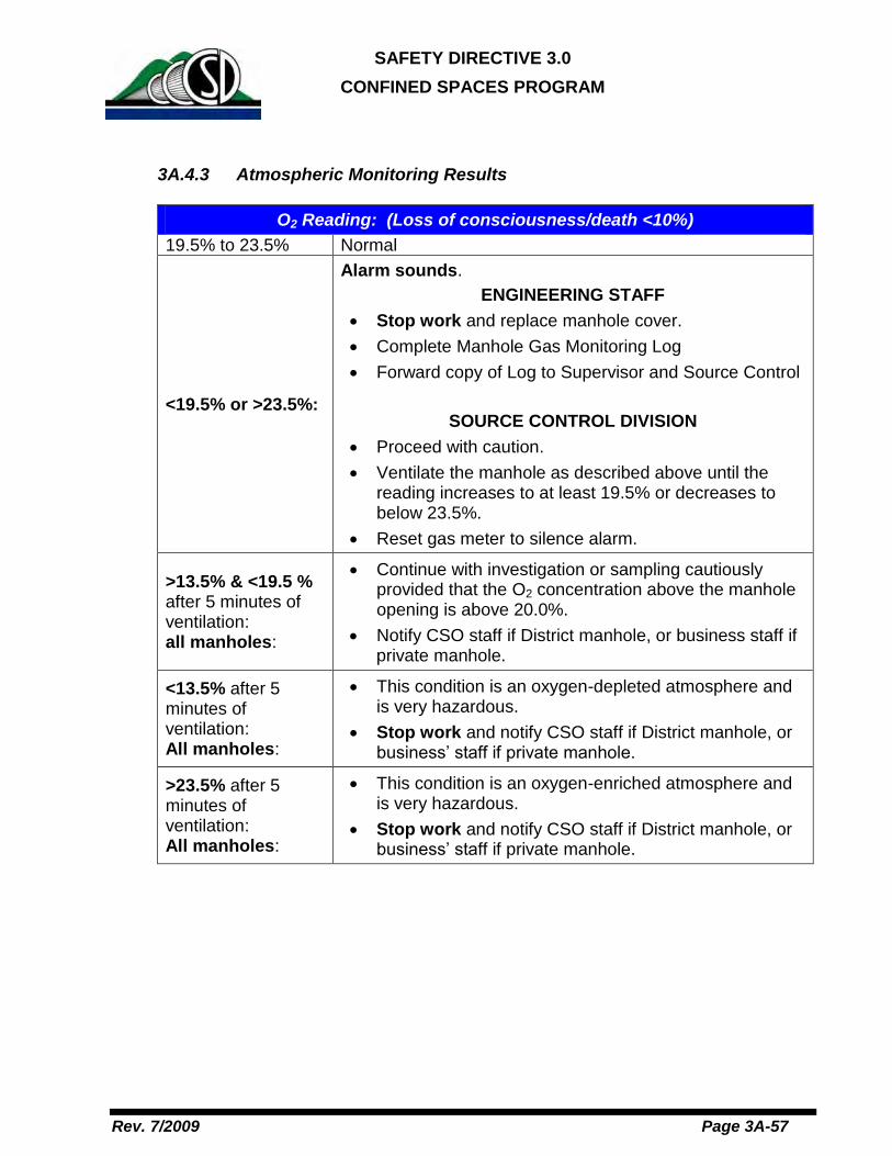
SAFETY DIRECTIVE 3.0
CONFINED SPACES PROGRAM
Rev. 7/2009 Page 3A-57
3A.4.3 Atmospheric Monitoring Results
O2 Reading: (Loss of consciousness/death <10%) 19.5% to 23.5% Normal
<19.5% or >23.5%:
Alarm sounds. ENGINEERING STAFF
Stop work and replace manhole cover. Complete Manhole Gas Monitoring Log Forward copy of Log to Supervisor and Source Control
SOURCE CONTROL DIVISION
Proceed with caution. Ventilate the manhole as described above until the
reading increases to at least 19.5% or decreases to below 23.5%.
Reset gas meter to silence alarm.
>13.5% & <19.5 % after 5 minutes of ventilation: all manholes:
Continue with investigation or sampling cautiously provided that the O2 concentration above the manhole opening is above 20.0%.
Notify CSO staff if District manhole, or business staff if private manhole.
<13.5% after 5 minutes of ventilation: All manholes:
This condition is an oxygen-depleted atmosphere and is very hazardous.
Stop work and notify CSO staff if District manhole, or business’ staff if private manhole.
>23.5% after 5 minutes of ventilation: All manholes:
This condition is an oxygen-enriched atmosphere and is very hazardous.
Stop work and notify CSO staff if District manhole, or business’ staff if private manhole.

SAFETY DIRECTIVE 3.0
CONFINED SPACES PROGRAM
Rev. 7/2009 Page 3A-58
LEL Reading
Up to 10% Normal
>10%
Alarm sounds. ENGINEERING STAFF
Stop work and replace manhole cover. Complete Manhole Gas Monitoring Log. Forward copy of Log to Supervisor and Source Control.
SOURCE CONTROL DIVISION
Proceed with caution. Reset gas meter to silence alarm. Ventilate the manhole as described above until the
concentration decreases to below 10%. If the reading is between 10% and 30 % LEL in District
manholes and between 10% and 80% in private manholes, investigation to identify potential sources of the LEL reading and grab sampling may be performed only if the work can be performed safely.
Reference Section 10.08.040 A. of Title 10 of the District Code for citable conditions related to measurements of LEL in a business’s discharge.
District Manholes: >30% after 5 minutes ventilation:
Stop work at manhole.
Call the Shift Supervisor to activate emergency response.
Locate upstream and downstream manhole locations to assess extent of LEL condition.
Private Manholes: Up to 15 ft. deep >80% after 5 minutes ventilation Deeper than 15 ft. >80% after 10 minutes ventilation
Stop work at manhole.
Locate downstream manhole to assess LEL level. If elevated above 10% LEL, instruct operator of business(es) discharging to private structure to cease discharge until elevated LEL condition is abated in the affected manholes.

SAFETY DIRECTIVE 3.0
CONFINED SPACES PROGRAM
Rev. 7/2009 Page 3A-59
H2S Reading (IDLH = 100 PPM)
Up to 10 ppm: Normal
>10 ppm:
Alarm sounds. ENGINEERING STAFF
Stop work and replace manhole cover. Complete Manhole Gas Monitoring Log. Forward copy of Log to Supervisor and Source
Control.
SOURCE CONTROL DIVISION
Proceed with caution. Ventilate the manhole as described above until the
concentration decreases to below 10 ppm. Reset gas meter to silence alarm.
>10 to <50 ppm after 5 minutes of ventilation: District Manholes:
Notify CSO and appropriate Engineering Department supervisor of condition.
Proceed with investigation and sampling only if H2S concentration above manhole opening is zero ppm.
>10 to <50 ppm after 5 minutes of ventilation: Private Manholes:
Notify business’ or property management’s staff of condition.
Proceed with investigation and sampling only if H2S concentration above manhole opening is zero ppm.
>50 ppm after 5 minutes of ventilation: All manholes:
Stop work at manhole. Notify CSO and appropriate Engineering Department
supervisor of condition for District manholes and business’ staff for private manholes.

SAFETY DIRECTIVE 3.0
CONFINED SPACES PROGRAM
Rev. 7/2009 Page 3A-60
CO Reading (IDLH = 300 PPM)
Up to 35 ppm Normal
>35 ppm:
Alarm sounds. ENGINEERING STAFF
Stop work and replace manhole cover. Complete Manhole Gas Monitoring Log. Forward copy of Log to Supervisor and Source
Control.
SOURCE CONTROL DIVISION
Proceed with caution. Ventilate the manhole as described above until the
concentration decreases to below 35 ppm. Reset gas meter to silence alarm.
>35 to <100 ppm after 5 minutes of ventilation – District manholes:
Notify CSO staff of condition. Proceed with investigation and sampling only if CO
concentration above manhole opening is less than 10 ppm.
>35 to <100 ppm after 5 minutes of ventilation - Private Manholes:
Notify business’ or property management’s staff of condition.
Proceed with investigation and sampling only if CO concentration above manhole opening is less than 10 ppm.
>100 ppm after 5 minutes of ventilation – All manholes:
Stop work at manhole. Notify CSO staff of condition for District manholes
and business’ staff for private manholes.
3A.4.4 REPLACING MANHOLE COVERS:
Clear the casting ring with a sharp tool to ensure good seating of cover. Generally, only one person should replace the cover. A tug from one person and a kick from another could lead to injury.

SAFETY DIRECTIVE 3.0
CONFINED SPACES PROGRAM
Rev. 7/2009 Page 3A-61
Since replacing the manhole cover is done at an angle over the open manhole, it is important to plan your move and use correct lifting procedures. Avoid twisting or turning as much as possible. When replacing the manhole cover, make sure your feet are out of the way. Use the pick to replace the cover most of the way and then push it into final position with your foot if needed. Once replaced, be sure the cover seats all the way around and does not rock. Replace bolts as necessary (grease interceptor, pressure manhole).
3A.5 DOCUMENTATION
The completed Manhole Gas Monitoring Log (Attachment A-1) should be circulated to the supervisor for review, comment, and signature. Completed forms will be kept on file as historical information for possible future investigations.

SAFETY DIRECTIVE 3.0
CONFINED SPACES PROGRAM
Rev. 7/2009 Page 3A-62
ATTACHMENT A-1
MANHOLE GAS MONITORING LOG
Field Staff Present: Date:
Location: (Street name, intersection, structure identification number, city, etc.)
Field Activity:
Gas Monitor Readings (See Procedure for testing order):
Peak Probe Location
O2 (%)
LEL%
H2S (ppm)
CO (ppm)
Other Observations:
Prepared by: (signature)
Supervisor’s Notes:
Supervisor’s Signature: Date:


SAFETY DIRECTIVE 12.0
FIRE PREVENTION PROGRAM: HOT WORK
Rev. August 2012 Page 12-2
TABLE OF CONTENTS
SECTION SUBJECT PAGE
.01 PROGRAM REVIEW AND CERTIFICATION……………………………………..3
.02 PURPOSE, POLICY AND SCOPE……………………………………….………...3
.03 DEFINITIONS..................................................................................................... 4
.04 RESPONSIBILITIES FOR HOT WORK…………………………………………….5
04.1 GENERAL MANAGER .................................................................................. 5
04.2 DIRECTORS AND MANAGERS: ..................................................................... 5
04.3 SUPERINTENDENTS AND SUPERVISORS ....................................................... 6
04.4 SAFETY DIVISION ....................................................................................... 7
04.5 PERMIT AUTHORIZING INDIVIDUAL (PAI)...................................................... 7
04.6 HOT WORK OPERATOR .............................................................................. 8
04.7 FIRE WATCH ............................................................................................. 9
04.8 CONTRACTORS.......................................................................................... 9
04.9 MUTUAL RESPONSIBILITY........................................................................... 9
.05 FIRE PREVENTION PRECAUTIONS.............................................................. 10
.06 HOT WORK PERMIT……………………………………………………………….11
.07 FIRE WATCH................................................................................................... 13
TABLE1 ……………………………………………………………………………………….15
ATTACHMENT A - PROGRAM REVIEW AND CERTIFICATION LOG…………...…...16
ATTACHMENT B- HW/Form 1...………………………………………………….………...17

SAFETY DIRECTIVE 12.0
FIRE PREVENTION PROGRAM: HOT WORK
Rev. August 2012 Page 12-3
CENTRAL CONTRA COSTA SANITARY DISTRICT
SAFETY DIRECTIVE 12.0
Update Effective: August 2012
.01 PROGRAM REVIEW AND CERTIFICATION
TheDistrict’sHot Work Program will be reviewed and revised as necessary toensure the program is current. All revisions are documented on the ProgramReview and Certification Log (Attachment A).
.02 PURPOSE, POLICY, SCOPE AND APPLICATION
02.1 Purpose. Establish the protocol for fire protection and preventionresponsibilities of persons and their supervisors (including outsidecontractors who manage, supervise and perform hot work).
02.2 Policy. The Hot Work Program sets the minimum requirements toprotect affected personnel and to mitigate the extent of damage from afire related incident. All welding, grinding, cutting, and brazing is to beperformed pursuant to the ANSI requirements, “Standard for Fire Prevention in Useof Cutting and Welding Processes”, NFPA Standard 51B (1962), CalOSHA and Federal OSHA.
02.3 Scope. This program applies to all District employees, includingtemporary, contract, seasonal, and co-op employees. Vendors,visitors, contractors and their sub-contractors or agents are alsosubject to this Directive.
02.4 Application. This Directive applies to the following hot workprocesses:
02.4.1 Welding and allied processes;
02.4.2 Heat treating;
02.4.3 Grinding;
02.4.4 Thawing pipe;
02.4.5 Hot riveting;

SAFETY DIRECTIVE 12.0
FIRE PREVENTION PROGRAM: HOT WORK
Rev. August 2012 Page 12-4
02.4.6 Any other application not specifically mentioned thatproduces or uses a spark, flame, or heat.
.03 DEFINITIONS
Designated Area–A permanent location designed or approved for hot workoperations (see Table 1 for locations).
Hot Work–Work involving burning, welding, or a similar operation that is capableof initiating fires or explosions.
Intrinsically Safe–The characteristic of a component to withstand heat andprotect the interior from the intrusion of flammable vapors (same as explosion-proof).
Permit Authorizing Individual (PAI)–The PAIs are the Plant MaintenanceSuperintendent, Collection System Field Operations Superintendent, LaboratorySuperintendent, or their designees.
Welding and Applied Processes–Processes such as arc welding, oxy-fuel gaswelding, open-flame soldering, brazing, thermal spraying, oxygen cutting, and arccutting.
Welding Blanket–A heat-resistant fabric designed to be placed in the vicinity ofa hot work operation. Designed to protect machinery and prevent ignition ofcombustibles, such as wood, that are located adjacent to the underside of theblanket.
Welding Curtain–A heat-resistant fabric designed to be placed in the vicinity of ahot work operation. Designed to prevent sparks from escaping the hot workarea.
Welding Pads–A heat-resistant fabric designed to be placed directly under a hotwork operation such as welding or cutting. Designed to prevent the ignition ofcombustibles that are located adjacent to the underside of the pad.

SAFETY DIRECTIVE 12.0
FIRE PREVENTION PROGRAM: HOT WORK
Rev. August 2012 Page 12-5
.04 RESPONSIBILITIES FOR HOT WORK
04.1 General Manager
04.3.1 Overall responsibility and authority for ensuring this programis fully implemented.
04.3.2 Ensure that the policy and program requirements areenforced.
04.3.3 Implement all relevant responsibilities as identified in theInjury Illness Prevention Program (IIPP).
04.2 Directors and Managers:04.2.1 Implementing all relevant responsibilities as identified in the
IIPP.
04.2.2 Recognizing responsibility for the safe operation of hot workactivity on District property and working with superintendentsand supervisors to implement the following criteria asnecessary:
04.2.2.1 Based on the fire potentials of District facilities,establish permissible areas for hot work.
04.2.2.2 Designate an individual responsible forauthorizing hot work operations in areas notspecifically designed for such processes.
04.2.2.3 Require cutters or welders and their supervisorsto provide documentation of their training in thesafe operation and use of their equipment andprocess.
04.2.2.4 Ensure inspection of equipment is documentedand equipment is only used when in safeoperating condition.
04.2.2.5 Only approved apparatuses such as torches,manifolds, regulators or pressure-reducingvalves, and acetylene generators shall be used.
04.2.2.6 Confirm with superintendents, supervisors, andthe Safety Officer that all individuals involved inhot work operations have been trained in thesafe operation of their equipment and in the safeuse of the process.

SAFETY DIRECTIVE 12.0
FIRE PREVENTION PROGRAM: HOT WORK
Rev. August 2012 Page 12-6
04.2.2.7 Confirm that individuals involved in hot workoperations shall have an awareness of theinherent risks involved and understand theemergency procedures in the event of a fire(refer to Safety Directive 13.0 Emergency ActionPlan).
04.3 Superintendents and Supervisors04.3.1 Recognizing responsibility for the safe operation of hot work
activity on District property and working with Management toimplement the following criteria as necessary:
04.3.1.1 Based on fire potentials of District facilities,establish permissible areas for hot work.
04.3.1.2 Designate an individual responsible forauthorizing hot work operations in areas notspecifically designed for such processes.
04.3.1.3 Require cutters or welders and their supervisorsto provide documentation of their training in thesafe operation of equipment and the safe use ofthe process.
04.3.1.4 Ensure inspection of equipment is documentedand equipment is only used when in safeoperating condition.
04.3.1.5 Only approved apparatuses such as torches,manifolds, regulators or pressure-reducingvalves, and acetylene generators shall be used.
04.3.1.6 Coordinate with the Safety Officer that allindividuals involved in hot work operations havebeen trained in the safe operation of theirequipment and in the safe use of the process.
04.3.1.7 Individuals involved in hot work operations shallhave an awareness of the inherent risks involvedand understand the emergency procedures inthe event of a fire (refer to Safety Directive 13.0Emergency Action Plan).
SAFETY DIRECTIVE 12.0
FIRE PREVENTION PROGRAM: HOT WORK
Rev. August 2012 Page 12-7
04.4 Safety Division
04.4.1 Providing training for employees to be familiar with thegeneral principles of fire extinguisher use and the hazardsinvolved with the onset of a fire.
04.4.2 Providing technical support to supervisors and employees inmeeting their responsibilities identified in this Directive.
04.4.3 Coordinating the inspection, testing and maintenance ofsystems, initiating devices and notification appliances asrequired in National Fire Protection Agency (NFPA) 72,Chapter 14.
04.4.4 Maintaining records of training provided to employees.
04.5 Permit Authorizing Individual (PAI)
04.5.1 The Permit Authorizing Individuals (PAIs) or their designee,in conjunction with Management, shall be responsible for thesafe operation of hot work activities.
04.5.2 Considering the safety of the hot work operator and FireWatch with respect to personal protective equipment (PPE)for special hazards beyond hot work.
04.5.3 Determining site-specific, flammable materials, hazardousprocesses or other potential fire hazards that are present orlikely to be present in the work location.
04.5.4 Ensuring the protection of combustibles from ignition by thefollowing criteria (if these criteria cannot be met, hot workshall not be performed):
04.5.4.1 Consider alternative methods to hot work;
04.5.4.2 Move the work to a location that is free fromcombustibles;

SAFETY DIRECTIVE 12.0
FIRE PREVENTION PROGRAM: HOT WORK
Rev. August 2012 Page 12-8
04.5.4.3 If the work cannot be moved, move thecombustibles to a safe distance or have thecombustibles properly shielded against ignition;
04.5.4.4 Hot work should be scheduled so thatoperations that could expose combustibles toignition are not initiated during hot workoperations.
04.5.4.5 Determine that fire protection and extinguishingequipment are properly located at the site
04.5.4.6 Where a Fire Watch is required (see Section12.07), ensure that a Fire Watch is at the site.
04.5.4.7 Where a Fire Watch is not required, make afinal check one half hour after the completionof hot work operations to extinguish anyremaining smoldering fires.
04.6 Hot Work Operator
04.6.1 Handling equipment safely and using it as follows so as notto endanger lives or property:
04.6.1.1 Obtain the PAI’s approval before starting hotwork operations;
04.6.1.2 All equipment shall be examined to ensure it isin a safe operating condition; if found to beincapable of reliable safe operation, theequipment shall be repaired by qualifiedpersonnel prior to its next use or withdrawnfrom service;
04.6.1.3 Cease hot work operations if unsafe conditionsdevelop and notify his/her supervisor, the PAIor Safety Officer for reassessment of thesituation.

SAFETY DIRECTIVE 12.0
FIRE PREVENTION PROGRAM: HOT WORK
Rev. August 2012 Page 12-9
04.7 Fire Watch
04.7.1 The Fire Watch shall be trained to understand the inherenthazards of the hot work and of the work site (e.g., tailgatebriefing before work begins).
04.7.2 Ensuring that safe conditions are maintained during hot workoperations (e.g., any change to the area conditions thatwould endanger the operator and/or other personnel).
04.7.3 Stopping hot work operations if unsafe conditions develop.
04.7.4 Having fire-extinguishing equipment readily available and istrained in its use.
04.7.5 Being familiar with the facilities and procedures for soundingan alarm in the event of a fire.
04.7.6 Watching for fires in all exposed areas and try to extinguishthem only when the fires are obviously within the capacity ofthe equipment available. If the Fire Watch determines thatthe fire is not within the capacity of the equipment, he/sheshall activate the Employee Emergency Action Plan ( SD13.0) immediately.
04.7.7 The Fire Watch shall be permitted to perform additionaltasks, but those tasks shall not distract from his/her FireWatch responsibilities.
04.8 ContractorsBefore starting any hot work, contractors, the District project managerand the affected department representative shall discuss the plannedproject completely, including the type of hot work to be conducted andthe hazards in the area.
04.9 Mutual Responsibility
Management, contractors, the PAI, the Fire Watch, and the operators shallrecognize their mutual responsibility for safety in hot work operations.

SAFETY DIRECTIVE 12.0
FIRE PREVENTION PROGRAM: HOT WORK
Rev. August 2012 Page 12-10
.05 FIRE PREVENTION PRECAUTIONS
05.1 Personal Protective ClothingClothing shall be selected to minimize the potential for ignition, burning,trapping hot sparks, and electric shock.
05.2 Permissible Areas
05.2.1 General. Hot work shall be permitted only in areas that are orhave been made fire safe.
05.2.2 Designated or Permit-Required Areas. Hot work shall beperformed in either designated areas or permit-required areas.
05.2.3 Designated Areas. A designated area shall be a specific areadesigned or approved for hot work, such as a maintenanceshop or a detached, outside location that is of noncombustibleor fire-resistive construction, essentially free of combustibleand flammable contents and is suitably segregated fromadjacent areas.
05.3 Permit-Required Areas
05.3.1 A permit-required area shall be an area that is made fire safeby removing or protecting combustibles from ignition sources.
05.3.2 Signs may be posted designating hot work areas as deemednecessary by the PAI.
05.4 Nonpermissible Areas
05.4.1 Hot work shall not be permitted in the following areas:
05.4.1.1 Areas not authorized by District management;
05.4.1.2 Buildings with impaired sprinkler fire suppressionsystems, unless the requirements of NFPA25,Standard for the Inspection, Testing, andMaintenance of Water-Based Fire ProtectionSystems, are met;

SAFETY DIRECTIVE 12.0
FIRE PREVENTION PROGRAM: HOT WORK
Rev. August 2012 Page 12-11
05.4.1.3 In the presence of explosive atmospheres (i.e.,where mixtures of flammable gases, vapors,liquids, or dusts with air exist);
05.4.1.4 In the presence of uncleaned or improperlyprepared equipment, drums, tanks, or othercontainers that have previously containedmaterials that could develop explosiveatmospheres;
05.4.1.5 In areas with an accumulation of combustibledusts that could develop explosive atmospheres.
.06 Hot Work Permit
06.1 Hot work in non-designated locations shall require the PAI’s approval and a written hot work permit may be required.
06.2 Before a hot work permit is issued, the following conditions shall beverified by the PAI:
06.2.1 The hot work equipment to be used shall be in satisfactoryoperating condition and in good repair.
06.2.2 Where combustible materials such as paper clippings, woodshavings or textile fibers are on the floor, the floor shall beswept clean for a radius of 35 ft (11 m) and the followingcriteria shall also be met:
06.2.1.1 Combustible floors shall be kept wet, coveredwith damp sand, or protected by a listed orapproved welding blanket, welding pad orequivalent.
06.2.1.2 Where floors have been wet down, personneloperating arc welding equipment or cuttingequipment shall be protected from potentialshock.
06.2.3 All combustibles shall be relocated at least 35 ft (11 m) awayin all directions from the work site and the following criteriashall also be met:
06.2.3.1 If relocation is impractical, combustibles shallbe protected by a listed or approved weldingcurtain, welding blanket, welding pad, orequivalent.

SAFETY DIRECTIVE 12.0
FIRE PREVENTION PROGRAM: HOT WORK
Rev. August 2012 Page 12-12
06.2.3.2 To prevent the entrance of sparks, the edgesof covers at the floor shall be tight, to the pointat which several covers overlap where a largeobject is being protected.
06.2.4 Openings or cracks in walls, floors or ducts within 35 ft (11m) of the site shall be covered or sealed with listed orapproved fire-rated or non-combustible material to preventthe passage of sparks into adjacent areas.
06.2.5 Ducts and conveyor systems that might carry sparks todistant combustibles shall be shielded, shut down or both.
06.2.6 If hot work is done near walls, partitions, ceilings, or roofs ofcombustible construction, they shall be protected by a listedor approved welding curtain, welding blanket, welding pad,or equivalent.
06.2.7 If hot work is done on one side of a wall, partition, ceiling, orroof, one of the following criteria shall be met:
06.2.7.1 Precautions shall be taken to prevent ignitionof combustibles on the other side by relocatingthe combustibles.
06.2.7.2 If it is impractical to relocate combustibles, aFire Watch shall be provided on the sideopposite to where the work is being performed.
06.2.8 Hot work shall not be attempted on a partition, wall, ceiling,or roof that has combustible insulation or coverings on wallsand partitions of combustible, sandwich-type panelconstruction.
06.2.9 Hot work that is performed on pipes or other metal that is incontact with combustible walls, partitions, ceilings, roofs, orother combustibles shall not be undertaken if the work isclose enough to cause ignition by conduction.
06.2.10 Fully charged and operable fire extinguishers that areappropriate for the type of potential fire shall be immediatelyavailable at the work site.
06.2.11 If existing hose lines (in cabinets) are located within the hotwork area defined by the permit, they shall be connectedand ready for service but are not required to be unrolled orcharged.
06.2.12 The following shall apply to hot work done in close proximityto a sprinkler head:

SAFETY DIRECTIVE 12.0
FIRE PREVENTION PROGRAM: HOT WORK
Rev. August 2012 Page 12-13
06.2.12.1 A wet rag shall be laid over the sprinkler headand then removed at the conclusion of theoperation.
06.2.12.2 During hot work, special precautions shall betaken to avoid accidental operation of automaticfire detection or suppression systems (e.g.,special extinguishing systems or sprinklers).
06.2.13 The operator and nearby personnel shall be suitablyprotected against dangers such as heat, sparks and slag.
06.2.14 In instances where the scope of work and tools used toconduct hot work result in potential travel of slag, sparks,spatter or similar mobile sources of ignition farther than 35 ft(11 m), the PAI shall be permitted to extend the distancesand areas addressed in 06.2.1 through 06.2.4.
06.2.15 In instances where the scope of work and tools used toconduct hot work are known to be incapable of generatingslag, sparks, spatter or similar mobile sources of ignitioncapable of leaving the immediate area of the applied hotwork, the PAI shall be permitted to do the following:
06.2.15.1 Reduce the distances and areas addressed in06.2.1 through 06.2.4 to distances and areasthat he or she considers fire safe for theintended operation;
06.2.15.2 Describe those distances and areas on the hotwork permit;
06.2.16 Based on local conditions, the PAI shall determine the lengthof the period for which the hot work permit is valid.
06.2.17 The area shall be inspected by the PAI at least once per daywhile the hot work permit is in effect to ensure that theconditions have not changed and the work site is safe.
.07 Fire Watch
07.1 A Fire Watch shall be required by the PAI when hot work isperformed in a location where other than a minor fire might developor where the following conditions exist:
07.1.1 Combustible materials are closer than 35 ft (11 m) to thepoint of operation;

SAFETY DIRECTIVE 12.0
FIRE PREVENTION PROGRAM: HOT WORK
Rev. August 2012 Page 12-14
07.1.2 Combustible materials are more than 35 ft (11 m) awayfrom the point of operation but are easily ignited by sparks;
07.1.3 Wall or floor openings within a 35 ft (11 m) radius exposecombustible materials in adjacent areas, includingconcealed spaces in walls or floors;
07.1.4 Combustible materials are adjacent to the opposite side ofpartitions, walls, ceilings, or roofs and are likely to beignited.
07.2 A Fire Watch shall be maintained for at least one half hour aftercompletion of hot work operations in order to extinguish anyremaining smoldering fires. The duration of the Fire Watch shall beextended if the PAI determines the fire hazards warrant extension.
07.3 More than one Fire Watch shall be required if combustible materialsthat could be ignited by the hot work operation cannot be directlyobserved by the initial Fire Watch.
07.4 Hot Tapping. Hot tapping or other cutting and welding on aflammable gas, liquid transmission or distribution utility pipelineshall be performed by a crew that is qualified to make hot taps.
07.5 Cylinders. Cylinder use and storage shall be in accordance withNFPA 55, Standard for the Storage, Use, and Handling ofCompressed Gases and Cryogenic Fluids in Portable andStationary Containers, Cylinders, and Tanks.

SAFETY DIRECTIVE 12.0
FIRE PREVENTION PROGRAM: HOT WORK
Rev. August 2012 Page 12-15
Table 1
Approved Hot Work Areas and Responsible Supervisor
Hot Work Areas Responsible SupervisorMachine Shop Machine Shop SupervisorWelding Room Machine Shop SupervisorMechanic Shop Mechanic Shop SupervisorInstrument Shop SolderingStation(s)
Instrument Shop Supervisor
Laboratory Fume Hood(s) Lab SuperintendentVehicle Maintenance Shop (CSO) Vehicle/Equipment Maintenance
SupervisorHHWCF Fume Hood HHW Supervisor

SAFETY DIRECTIVE 12.0
FIRE PREVENTION PROGRAM: HOT WORK
Rev. August 2012 Page 12-16
ATTACHMENT A
Program Review and Certification LogDocument Owner: Safety Division Responsible Party: Safety Officer
Program Name Update Description Effective Date

SAFETY DIRECTIVE 12.0
FIRE PREVENTION PROGRAM: HOT WORK
Rev. August 2012 Page 12-17
ATTACHMENT B
FIRE PREVENTION PROGRAM FORM - H/W FORM 1 HOT WORK PERMITDocument Owner: Safety Division Responsible Party: Safety Officer


SAFETY DIRECTIVE 13.0 EMERGENCY ACTION PLAN
Rev. 9/2011 Page 13-1
Table of Contents Section Page 1 Program Review and Certification 13-3 2 Purpose, Policy and Scope 13-3 3 Definitions 13-3 4 Responsibilities 13-4 4.1 Incident Commander 13-4 4.2 Area Safety Wardens 13-5 4.3 Safety & Risk Management Division 13-6 4.4 Supervisors and Managers 13-6 4.5 Employees 13-6 5 Emergency Notification Systems 13-7 6 Evacuations 13-7 7 Shelter in Place 13-8 8 Control Room Procedures – Other Emergencies 13-9 9 Training 13-11 ATTACHMENTS Attachment 1 Personnel Evacuation Log 13-12 Attachment 2 Evacuation Drill Evaluation 13-13 Attachment 3 Example of “Evacuated” Door Hanger 13-14 APPENDICES – EVACUATION PLANS Appendix A Headquarters Office Building (HOB) 13-15 Appendix B Plant Operations Building (POB) 13-17 Appendix C Laboratory (LAB) 13-19 Appendix D Maintenance Reliability Center (MRC) 13-21 Appendix E Mechanical Maintenance Building and Warehouse (MMB) 13-23

SAFETY DIRECTIVE 13.0 EMERGENCY ACTION PLAN
Rev. 9/2011 Page 13-2
Table of Contents - Continued Section Page Appendix F Solids Conditioning Building 13-25 Appendix G Household Hazardous Waste Collection Facility (HHWCF) 13-27 Appendix H 4737 Imhoff Place (Bays) 13-28 Appendix I CSO Pumping Stations (Annex) 13-30 Appendix J Filter Plant 13-32 Appendix K Influent Diversion Building (Headworks) 13-34 Appendix L Other Treatment Plant Areas 13-36

SAFETY DIRECTIVE 13.0 EMERGENCY ACTION PLAN
Rev. 9/2011 Page 13-3
Effective: October 5, 2011
1. PROGRAM REVIEW AND CERTIFICATION
This program will be reviewed and revised as necessary to ensure the program is current. All revisions are documented on the Program Review and Certification Log (See IIPP).
2 PURPOSE,POLICY AND SCOPE 2.1 Purpose. The purpose of an Emergency Action Plan is to reduce risk to
people and property and to mitigate the effect of hazards during an emergency situation. This Safety Directive and all site-specific Emergency Action Plans are intended to be used in conjunction with the District’s Illness and Injury Prevention Program (IIPP) and in accordance with California Code of Regulations, Title 8, Sections 3220 & 3221.
2.2 Policy. Every District facility shall have a site-specific Emergency Action Plan. These plans shall include emergency evacuation instructions for posting. All employees shall be trained in the elements of the plans and the proper response procedures under various emergency situations.
2.3 Scope. This Safety Directive and all site-specific Emergency Action Plans apply to all District employees as well as customers, contractors, and visitors and to all District worksites and locations.
3 DEFINITIONS Area Safety Warden –An volunteering employee designated and trained to perform certain collateral duties to ensure the safety of all personnel in emergency situations in a given area of responsibility. Assembly Area – A safe open space at some distance from the work area location and will not be in line of sight of the likely target or flying debris. The assembly area should also be a safe distance from nearby buildings to avoid the hazard of falling debris. Finally, the area should be at least 500 yards away or within about 5 minutes walking distance. Emergency – A serious situation or occurrence that happens unexpectedly and demands immediate action; a condition of urgent need for action or assistance. Evacuation – The act of withdrawing from or vacating a place or area, especially as a protective measure.

SAFETY DIRECTIVE 13.0 EMERGENCY ACTION PLAN
Rev. 9/2011 Page 13-4
Hostage – A person held by one party in a conflict as security that specified terms will be met by the opposing party. Incident Commander – The person responsible for all aspects of an emergency response including development of incident objectives; management of incident operations; application of resources; and responsibility for all persons involved. Suspicious – An act or object that is questionable or arouses suspicion.
4 RESPONSIBILITIES
4.1 Incident Commander
The following personnel serve as Incident Commanders:
• Primary Incident Commander: Safety & Risk Management Administrator
• Secondary Incident Commander: Safety Officer
• Backup Incident Commander: Supervisor; Manager; and/or General Manager
In the event of an evacuation the Incident Commander shall: • Confirm evacuation of the facility with Area Safety Wardens;
• Maintain contact with the Control Room to monitor the incident; advise Area Safety Wardens of developments and provide additional instructions to ensure the safety of evacuated personnel;
• Collect completed Personnel Evacuation Logs (Attachment 1) from Area Safety Wardens;
• Advise emergency responders of any missing personnel and ongoing medical needs;
• Surrender Incident Commander functions to outside emergency responders upon their arrival.
Once the building or area has been cleared for re-entry: • Authorize Area Safety Wardens to direct employees and other personnel
back inside the facility.
After an evacuation drill: • Distribute and collect Evacuation Drill Evaluations (Attachment 2);
• Maintain appropriate records for each drill;
• Present a summary to the Department Directors and propose modifications to the program as warranted.
4.2 Area Safety Wardens

SAFETY DIRECTIVE 13.0 EMERGENCY ACTION PLAN
Rev. 9/2011 Page 13-5
General Responsibilities
• Be familiar with the procedures in this Safety Directive and applicable Emergency Action Plans;
• Maintain the contents of the Emergency Response Team backpack;
• Attend Area Safety Warden training as required;
• Obtain a current roster of all personnel assigned to the area of responsibility in order to conduct accurate roll calls;
• Perform the required duties during an emergency evacuation or drill as detailed below.
In the event of an evacuation:
• Grab the Emergency Response Team Backpack;
• Walk through the area to ensure all personnel heard the evacuation notice and direct evacuees toward the designated assembly area;
• Inspect offices, work areas and conference rooms for occupants. Hang “EVACUATED” tag on door knob of inspected rooms and close door. DO NOT LOCK DOOR;
• Encourage occupants to evacuate the area or building quickly and in an orderly manner using the pre-designated evacuation routes. Be attentive for visiting personnel who may be unaware of the emergency procedures;
• At the assembly area conduct a roll call to account for all assigned personnel. Ask others about the location of any missing people. Determine if those missing from the roll call were on duty or on site at the time of the evacuation;
• Record the names and departments of those missing along with where they were last seen on the Personnel Evacuation Log (Attachment 1) and provide this information to the Incident Commander;
• Inquire if anyone requires medical attention and summon medical help and/or administer first aid;
• Record the names and types of injuries associated with any injured personnel reporting to the assembly area (Attachment 1) and provide this information to the Incident Commander;
• Instruct the group to stay calm, to remain assembled and to wait for further instructions from the Incident Commander.
Once the building or area has been cleared for reentry: • Inform your group and explain why the building or area is safe for re-entry;

SAFETY DIRECTIVE 13.0 EMERGENCY ACTION PLAN
Rev. 9/2011 Page 13-6
• Advise your group if there are any areas or rooms to avoid upon reentry into the building or area.
After an evacuation drill: • Attend a debrief meeting with the Incident Commander to discuss any
problems encountered during the drill, to identify lessons learned and to conduct a general review of the incident.
4.3 Safety & Risk Management Division • Provide District-wide training and support regarding all fire safety and
emergency-related issues; • Coordinate or perform fire hazard assessments through area safety audits
and routine monitoring inspections. Review area self-inspection reports and monitor implementation of corrective actions as appropriate;
• Coordinate inspections of fire equipment and alarm system testing including the required testing of fire protection devices;
• Administer fire and evacuation drills; • Provide training to employees in emergency action procedures; • Provide training to Area Safety Wardens in their duties and
responsibilities. 4.4 Supervisors and Managers
• Empower Area Safety Wardens under your supervision to perform their duties during an emergency evacuation or drill;
• Ensure that all employees under your supervision actively participate in emergency drills and exercises;
• Conduct tailgate sessions on the Emergency Action Plan(s) applicable to your worksite(s).
4.5 Employee • Periodically read and familiarize yourself with the Emergency Action
Plan(s) for your worksite(s);
• Know your work environment. Know the locations of emergency exits and evacuation routes (primary and secondary), fire extinguishers, fire alarms and methods of communication;
• Be familiar with the roles of the Incident Commander, Area Safety Wardens, and other emergency response personnel and acknowledge their authority;

SAFETY DIRECTIVE 13.0 EMERGENCY ACTION PLAN
Rev. 9/2011 Page 13-7
• Assist or get help to assist employees or visitors with special needs during an evacuation;
• Know your designated worksite assembly areas;
• Help to ensure that co-workers have been accounted for and report missing personnel to your supervisor;
• Attend training on the Emergency Action Plans.
5 EMERGENCY NOTIFICATION SYSTEMS District facilities have the following systems in place to alert occupants of an emergency:
• Fire Alarm Pull Stations • Public Address System • Panic Alarms • Area Safety Wardens on each floor or worksite • Verbal Order
Refer to the Appendices for additional or alternative emergency notification systems used at specific sites.
6 EVACUATIONS
6.1 Evacuation Initiation
• Evacuations will be communicated by verbal order and/or an audible alarm.
6.2 Buildings or areas shall be evacuated in the event of a: • Fire or Fire Alarm • Suspicious Package or Letter • Suspicious Substance within a Package or Letter • Bomb Threat • Hostage Incident • Any event that may cause injury to individuals within a building or
area.
6.3 Assembly Areas • The assembly area for each location is listed in each Appendix and
in the Employee Emergency Action Plan flipcharts.

SAFETY DIRECTIVE 13.0 EMERGENCY ACTION PLAN
Rev. 9/2011 Page 13-8
6.4 Evacuation of Disabled Employees or Visitors • Elevators shall not be used for evacuations. Wheelchair-bound
employees will have to be carried down the stairs. If the wheelchair cannot be taken, leave it behind, and get help to carry any disabled persons down the stairs.
• The District has developed a ‘buddy-system’ to evacuate hearing impaired employees. However, visitors with hearing impairments will need additional assistance during evacuations. Employees with hearing-impaired visitors and work groups that interact with the public on District property should be prepared to communicate an evacuation order through non-verbal methods.
6.5 Visitors Requiring Assistance with Evacuation • If there are visitors requiring assistance to evacuate the facility,
such assistance shall be provided by the hosting employee and workgroup. Visitors shall be escorted to the workgroup’s assembly area.
6.6 Contractors • Contractors shall evacuate and account for their own employees.
• Contractors shall brief their employees before entering District property, as part of the required contractor safety training. Upon notification of an evacuation, contractor employees will immediately follow the nearest evacuation route, report to the nearest assembly area and give their name to the Area Safety Warden.
7 SHELTER IN PLACE When the Control Room receives a Shelter in Place notification (either from the Contra Costa County Community Alert Network, a NOAA radio broadcast or by personal report) the shift supervisor shall verify the alert visually or by calling Contra Costa County Community Warning System Coordinator at 313-9296.
7.1 Notification Procedure • The Shift Supervisor will notify persons in the HOB, POD and the
Lab to Shelter in Place via an Emergency All Call announcement on the District’s public address system.
• The Shift Supervisor will notify all operations and maintenance employees to Shelter in Place via the plant’s VHF radio system.

SAFETY DIRECTIVE 13.0 EMERGENCY ACTION PLAN
Rev. 9/2011 Page 13-9
• The Shift Supervisor will notify persons outside these buildings or workgroups to Shelter in Place via Direct Connect or a group text on District cell phones.
• Shelter in Place notifications will include an explanation of the nature of the emergency and instructions for obtaining additional information.
7.2 Shelter in Place Locations Any room may serve as a shelter in place location as long as it has a door separating it from an exterior door.
8 CONTROL ROOM PROCEDURES – OTHER EMERGENCIES The Control Room is designated as an essential function of Plant Operations. It is equipped with fire-rated construction to enable the Operator to stay in the Control Room while emergency responders are summoned.
8.1 If an alarm is activated by District personnel, Control Room Operators shall: Call the Fire Department (9-933-1313) and report: - Exact location of the fire or triggering event - Type of fire (e.g., electrical, flammable liquid, or combustible
material) or triggering event - If fire is situated close to a critical system (e.g., major equipment,
fuel gas lines, steam lines, etc.) - If medical assistance is needed.
• Dispatch personnel to: - Direct emergency responders to the scene - Render any needed assistance

SAFETY DIRECTIVE 13.0 EMERGENCY ACTION PLAN
Rev. 9/2011 Page 13-10
• Notify: - Plant Operations Superintendent - Incident Commander - HOB Receptionist - Security Guard
• If it is a false alarm, notify the Fire Department as soon as possible.
8.2 If an alarm is activated by an automatic system, Control Room Operators shall:
• Dispatch personnel to confirm that an emergency exists and, if it is safe to do so, indentify any additional hazards;
• Notify: - Plant Operations Superintendent - Incident Commander - HOB Receptionist - Guard Shack
• Dispatch personnel to direct fire truck to fire location and to notify firefighters of any additional hazards involved.
• Make an announcement on the Public Address System (PA) for all personnel to stay clear of the area. Indicate any areas that should be evacuated.
Typical PA Announcement: Attention all personnel: There is a (type of emergency) at the (specify location). Stay clear of the area. Personnel in the (specify buildings) should evacuate and remain at designated assembly areas until further notice. Emergency responders are on the way.
• Dispatch personnel to assure that no one enters danger zone and/or set up barriers to prevent unauthorized entry.
• Repeat the announcement until emergency responders issue an all-clear notice.

SAFETY DIRECTIVE 13.0 EMERGENCY ACTION PLAN
Rev. 9/2011 Page 13-11
9 TRAINING
9.1 Drills • Emergency Drills shall be conducted at least annually for all
employees. The drills may include one or more of the following situations:
• Evacuation
• Shelter in Place
• Medical Emergency
• The Incident Commander shall maintain the following records for each drill:
• Date and type of drill,
• Roster of participants, • Analysis and report of the drill, including a summary of
evaluations received.
9.2 All Employees This Safety Directive and applicable site-specific Emergency Action Plans shall be reviewed with new employees during the Safety Orientation, whenever the employees’ responsibilities under the Plans change, whenever Plans are changed, and/or at least once a year.
9.3 Area Safety Wardens Training shall include, but not be limited to, the responsibilities for fire prevention awareness, methods and procedures for evacuation and shelter-in-place, first aid/CPR/AED, personnel accounting methods and protocols for reporting to the Incident Commander.
9.4 Documentation Training shall be properly documented and entered into the District’s training database.

SAFETY DIRECTIVE 13.0 EMERGENCY ACTION PLAN
Rev. 9/2011 Page 13-12
Attachment 1
Personnel Evacuation Log Date: Assembly Area Location:
Area Safety Warden Name: Missing Employees (Names) Area Last Seen 1.
2.
3.
4.
5.
6.
7.
Injured Employees (Names) Type of Injury 1.
2.
3.
4.
5.
6.
7.
Additional Employees or Guests (Names)
Issues / Concerns
1.
2.
3.
4.
5.
6.
7.

SAFETY DIRECTIVE 13.0 EMERGENCY ACTION PLAN
Rev. 9/2011 Page 13-13
Attachment 2
Evacuation Drill Evaluation
Date of Drill:
Facility/Site name:
Assembly Area:
Incident Commander Name:
Area Safety Warden Names:
Please take a moment to complete this evaluation form to allow us to correct any deficiencies or make improvements in our evacuation program. True False 1. I could hear the evacuation alarm or the instructions to evacuate: 2. I had been trained on the evacuation procedure: 3. I knew the evacuation route from my work area: 4. I took the shortest route to the nearest emergency exit: 5. I knew where my Assembly Area was located: 6. The Assembly Area was easy to find, get to, and occupy: 7. I did not stop or re-enter the building for any reason: 8. I believe my supervisor knew what to do: 9. The Area Safety Warden recorded evacuees and noted any absences: 10. I think the evacuation drill went well:
Did you encounter any difficulties during the drill and if so, how can those be issues be resolved?
Other Comments or Suggestions:
Evaluator’s Name (optional):
Return completed evaluations to the Safety & Risk Management Division

SAFETY DIRECTIVE 13.0 EMERGENCY ACTION PLAN
Rev. 9/2011 Page 13-14
Attachment 3
Sample ‘Evacuated’ Door Hanger

SAFETY DIRECTIVE 13.0 EMERGENCY ACTION PLAN
Rev. 9/2011 Page 13-15
APPENDIX A Headquarters Office Building (HOB) Evacuation Plan
The Headquarters Office Building (HOB) is used to provide public services, conduct office work and perform training. Each floor has several evacuation route maps posted, portable fire extinguishers installed, and smoke detectors and fire alarm pull boxes permanently mounted in strategic locations. It is the responsibility of all employees to be familiar with all evacuation routes and the locations of fire extinguishers and pull alarms.
13.A.1 Emergency Equipment 01 Evacuation Chairs are located on the second and third floors next to the
elevator to assist in moving injured or disabled persons up or down the stairs.
02 There are metal fire doors on the second and third floor that drop to further isolate these floors from the spread of fire. There is a 7 – 10 second delay from when the alarm sounds before the doors begin to ratchet down. The lowered doors will prevent egress through what might be a familiar route.
03 Perimeter doors on all the floors will also close automatically but can be used to facilitate evacuation. Consider these safety devices when planning your escape route.
13.A.2 Evacuation Procedure 01 When the fire alarm sounds or when you receive an evacuation order stop
work and immediately leave the building through the nearest exit or stairwell to the nearest exit, taking all persons encountered with you. Please refer to the posted evacuation route maps for each floor.
- If you are the last person to leave a room, hang the “EVACUATED” tag on the outside door knob and close the door. DO NOT LOCK THE DOOR.
- The stairwells, located on each end of the building, are fire rated for evacuation. DO NOT USE THE ELEVATOR. If possible, take your valuables with you; however, do not return to your workstation to retrieve anything.
- Before exiting from any stairwell door onto the first floor, touch the door to determine if it is hot. If the door is cool, slowly open it and check for smoke. If either the door is hot or smoke is observed, return to a higher floor and use the opposite stairwell for

SAFETY DIRECTIVE 13.0 EMERGENCY ACTION PLAN
Rev. 9/2011 Page 13-16
evacuation. If fire or smoke prevents exiting from either stairwell, use the EAST stairwell for access to the roof.
- The HOB Receptionist will take the employee rosters for each floor upon evacuation.
02 Report to the designated assembly area shown below and in the HOB Emergency Action Plan. The Incident Commander may direct people to an alternate assembly area if this location is unsafe.
03 Notify your Area Safety Warden upon arrival or acknowledge your presence during roll call at the assembly area.
04 Remain in the assembly area unless directed to another location by the Incident Commander or if staying at the assembly area would endanger personal safety.
05 Do not return to a building or an evacuated area unless the area or building has been cleared for re-entry by the Incident Commander.
13.A.3 Assembly Area

SAFETY DIRECTIVE 13.0 EMERGENCY ACTION PLAN
Rev. 9/2011 Page 13-17
APPENDIX B Plant Operations Building (POB) Evacuation Plan
The Plant Operations Building (POB) is used to provide administrative services, conduct office work and perform training in support of plant operations. Evacuation route maps are posted, portable fire extinguishers installed, and smoke detectors and fire alarm pull boxes are permanently mounted in strategic locations. It is the responsibility of all employees to be familiar with all evacuation routes and the locations of fire extinguishers and pull alarms.
13.B.1 Evacuation Procedure
01 When the fire alarm sounds or when you receive an evacuation order stop work and immediately leave the building through the nearest exit or stairwell to the nearest exit, taking all persons encountered with you. Please refer to the posted evacuation route maps for each area.
02 If you are the last person to leave a room, hang the “EVACUATED” tag on the outside door knob and close the door. DO NOT LOCK THE DOOR.
- Before exiting from the basement floor, touch the door to determine if it is hot. If the door is cool, slowly open it and check for smoke. If either the door is hot or smoke is observed, exit to another area for evacuation. If fire or smoke prevents exiting from either stairwell, use the Tunnel system to exit to the Pump and Blower Building’s first floor and exit through the EAST door. Walk through the Main Gate.
- Before exiting from any stairwell door onto the first floor, touch the door to determine if it is hot. If the door is cool, slowly open it and check for smoke. If either the door is hot or smoke is observed, return to a higher floor and use the opposite stairwell for evacuation. If fire or smoke prevents exiting from either stairwell, use the EAST stairwell for access to the roof.
- The Administrative Support Supervisor will take the employee roster for the POB upon evacuation.
03 Report to the designated assembly area shown below and in the POB Emergency Action Plan. The Incident Commander may direct people to an alternate assembly area if this location is unsafe.
04 Notify your Area Safety Warden upon arrival or acknowledge your presence during roll call at the assembly area.

SAFETY DIRECTIVE 13.0 EMERGENCY ACTION PLAN
Rev. 9/2011 Page 13-18
05 Remain in the assembly area unless directed to another location by the Incident Commander or if staying at the assembly area would endanger personal safety.
06 Do not return to a building or an evacuated area unless the area or building has been cleared for re-entry by the Incident Commander.
13.B.3 Assembly Area

SAFETY DIRECTIVE 13.0 EMERGENCY ACTION PLAN
Rev. 9/2011 Page 13-19
APPENDIX C Laboratory Evacuation Plan
The Laboratory provides sample collection and analytical services in support of plant operations. Evacuation route maps are posted, portable fire extinguishers installed, and smoke detectors and fire alarm pull boxes are permanently mounted in strategic locations. It is the responsibility of all employees to be familiar with all evacuation routes and the locations of fire extinguishers and pull alarms.
13.C.1 Evacuation Procedure
01 When the fire alarm sounds or when you receive an evacuation order stop work and immediately leave the building through the nearest exit or stairwell to the nearest exit, taking all persons encountered with you. Please refer to the posted evacuation route maps for each area.
02 If you are the last person to leave a room, hang the “EVACUATED” tag on the outside door knob and close the door. DO NOT LOCK THE DOOR.
03 Report to the designated assembly area shown below and in the Lab Emergency Action Plan. The Incident Commander may direct people to an alternate assembly area if this area is unsafe.
04 Notify your Area Safety Warden upon arrival or acknowledge your presence during roll call at the assembly area.
05 Remain in the assembly area unless directed to another location by the Incident Commander or if staying at the assembly area would endanger personal safety.
06 Do not return to a building or an evacuated area unless the area or building has been cleared for re-entry by the Incident Commander.

SAFETY DIRECTIVE 13.0 EMERGENCY ACTION PLAN
Rev. 9/2011 Page 13-20
Laboratory Evacuation Plan
13.C.2 Assembly Area

SAFETY DIRECTIVE 13.0 EMERGENCY ACTION PLAN
Rev. 9/2011 Page 13-21
APPENDIX D Maintenance Reliability Center (MRC) Evacuation Plan
The Maintenance Reliability Center (MRC) is staffed with maintenance administration, construction planning coordination, Building and Grounds, Instrumentation and Electrical workshops. Evacuation route maps are posted, portable fire extinguishers installed, and smoke detectors and fire alarm pull boxes are permanently mounted in strategic locations. It is the responsibility of all employees to be familiar with all evacuation routes and the locations of fire extinguishers and pull alarms.
13.D.1 Evacuation Procedure
01 When the fire alarm sounds or when you receive an evacuation order stop work and immediately leave the building through the nearest exit or stairwell to the nearest exit, taking all persons encountered with you. Please refer to the posted evacuation route maps for each area.
- If possible, take your valuables with you, however, do not return to your workstation to retrieve anything.
- If you are the last person to leave a room, hang the “EVACUATED” tag on the outside door knob and close the door. DO NOT LOCK THE DOOR.
02 Report to the designated assembly area shown below and in the MRC Emergency Action Plan. The Incident Commander may direct people to an alternate assembly area if this area is unsafe.
03 Notify your Area Safety Warden upon arrival or acknowledge your presence during roll call at the assembly area.
04 Remain in the assembly area unless directed to another location by the Incident Commander or if staying at the assembly area would endanger personal safety.
05 Do not return to a building or an evacuated area unless the area or building has been cleared for re-entry by the Incident Commander.

SAFETY DIRECTIVE 13.0 EMERGENCY ACTION PLAN
Rev. 9/2011 Page 13-22
Maintenance Reliability Center (MRC) Evacuation Plan
13.D.2 Assembly Area

SAFETY DIRECTIVE 13.0 EMERGENCY ACTION PLAN
Rev. 9/2011 Page 13-23
APPENDIX E Mechanical Maintenance Building (MMB) &
Materials Control Building (Warehouse) Evacuation Plan
The Mechanical Maintenance Building (MMB) is staffed with the mechanical maintenance workshop and offices and a lunchroom upstairs. The Materials Control Building (Warehouse) provides stored and delivered and shipped inventory in support of the District. The Warehouse contains administrative offices and a lunchroom, as well as a mezzanine and a fenced area outside of the building where surplus items are stored prior to removal from the Plant. Evacuation route maps are posted, portable fire extinguishers installed, and fire alarm pull boxes are permanently mounted in strategic locations. It is the responsibility of all employees to be familiar with all evacuation routes and the locations of fire extinguishers and pull alarms.
13.E.1 Evacuation Procedure
01 When the fire alarm sounds or when you receive an evacuation order stop work and immediately leave the building through the nearest exit or stairwell to the nearest exit, taking all persons encountered with you. Please refer to the posted evacuation route maps for each area.
- If possible take your valuables with you; however, do not return to your workstation to retrieve anything.
- If you are the last person to leave a room, hang the “EVACUATED” tag on the outside door knob and close the door. DO NOT LOCK THE DOOR.
02 Report to the designated assembly area shown below and in the MMB/Warehouse Emergency Action Plan. The Incident Commander may direct people to an alternate assembly area if this area is unsafe.
03 Notify your Area Safety Warden upon arrival or acknowledge your presence during roll call at the assembly area
04 Remain in the assembly area unless directed to another location by the Incident Commander or if staying at the assembly area would endanger personal safety.
05 Do not return to a building or an evacuated area unless the area or building has been cleared for re-entry by the Incident Commander.

SAFETY DIRECTIVE 13.0 EMERGENCY ACTION PLAN
Rev. 9/2011 Page 13-24
Mechanical Maintenance Building (MMB) & Materials Control Building (Warehouse) Evacuation Plan
13.E.2 Assembly Area

SAFETY DIRECTIVE 13.0 EMERGENCY ACTION PLAN
Rev. 9/2011 Page 13-25
APPENDIX F Solids Conditioning Building (SCB) Evacuation Plan
The Solids Conditioning Building (SCB) operates and contains furnaces, boilers, auxiliary boilers, scrubbers, centrifuges, cake pumps, steam system, ash hoppers, electrical and landfill and natural gas used to run the furnaces and auxiliary boilers. The SCB has three floors above the basement level that is connected to the Plant’s tunnel system. The Control Room 2 is located on the third floor of the SCB and supports the operational function of the SCB, dissolved air flotation (DAF) tanks, and the odor control system. The Control Room 2 contains the operations control room and a lunchroom. Evacuation route maps are posted, portable fire extinguishers installed, and fire alarm pull boxes are permanently mounted in strategic locations. It is the responsibility of all employees to be familiar with all evacuation routes and the locations of fire extinguishers and pull alarms.
13.F.1 Evacuation Procedure
01 When the fire alarm sounds or when you receive an evacuation order stop work and immediately leave the building through the nearest exit or stairwell to the nearest exit, taking all persons encountered with you. Please refer to the posted evacuation route maps for each area.
02 Report to the designated assembly area shown below and in the SCB Emergency Action Plan. The Incident Commander may direct people to an alternate assembly area if this location is unsafe.
03 Notify your Area Safety Warden upon arrival or acknowledge your presence during roll call at the assembly area.
04 Remain in the assembly area unless directed to another location by the Incident Commander or if staying at the assembly area would endanger personal safety.
05 Do not return to a building or an evacuated area unless the area or building has been cleared for re-entry by the Incident Commander.

SAFETY DIRECTIVE 13.0 EMERGENCY ACTION PLAN
Rev. 9/2011 Page 13-26
Solids Conditioning Building (SCB) Evacuation Plan
13.F.2 Assembly Area

SAFETY DIRECTIVE 13.0 EMERGENCY ACTION PLAN
Rev. 9/2011 Page 13-27
APPENDIX G Household Hazardous Waste Collection Facility
(HHWCF) Evacuation Plan The Household Hazardous Waste Collection Facility (HHWCF) accepts hazardous
wastes collected from central Contra Costa County households and small businesses. The HHWCF staff has completed specific hazardous waste handling training that includes emergency response to chemical spills and/or fires. Evacuation route maps are posted, portable fire extinguishers installed, and fire alarm pull boxes are permanently mounted in strategic locations. It is the responsibility of all employees to be familiar with all evacuation routes and the locations of fire extinguishers and pull alarms.
13.G.1 Evacuation Procedure
• Follow the procedures outlined in the AB2185/SARA Title III Emergency Response and Evacuation Plan.
• Notify the Control Room. 13.G.2 Assembly Area

SAFETY DIRECTIVE 13.0 EMERGENCY ACTION PLAN
Rev. 9/2011 Page 13-28
APPENDIX H 4737 Imhoff Place (Bays)
Collection System Operations (CSO) is located west from the Headquarters Office Building in Bays 1A, 2 and 11 while a permanent building is constructed at the Walnut Creek location. This temporary location serves as administrative offices for the, Collection System’s administrative staff and general crew quarters for the field staff. Other District workgroups including the Secretary of the District, Survey, and Source Control have office and/or storage space in Bays 2, 3, 6, 10 and 11. Evacuation route maps are posted, portable fire extinguishers are installed, and smoke detectors are permanently mounted in strategic locations. It is the responsibility of all employees to be familiar with all evacuation routes and the locations of fire extinguishers and smoke detectors.
13.H.1 Evacuation Procedure
01 When the fire alarm sounds or when you receive an evacuation order stop work and immediately leave the building through the nearest exit or stairwell to the nearest exit, taking all persons encountered with you. Please refer to the posted evacuation route maps for each area.
- If possible, take your valuables with you; however, do not return to your workstation to retrieve anything.
- If you are the last person to leave a room, hang the “EVACUATED” tag on the outside door knob and close the door. DO NOT LOCK THE DOOR.
02 Report to the designated assembly area shown below and in the Bays Emergency Action Plan. The Incident Commander may direct people to an alternate assembly area if this location is unsafe.
03 Notify your Area Safety Warden upon arrival or acknowledge your presence during roll call at the assembly area.
04 Remain in the assembly area unless directed to another location by the Incident Commander or if staying at the assembly area would endanger personal safety.
05 Do not return to a building or an evacuated area unless the area or building has been cleared for re-entry by the Incident Commander.

SAFETY DIRECTIVE 13.0 EMERGENCY ACTION PLAN
Rev. 9/2011 Page 13-29
4737 Imhoff Place (Bays)
13.H.2 Assembly Area

SAFETY DIRECTIVE 13.0 EMERGENCY ACTION PLAN
Rev. 9/2011 Page 13-30
APPENDIX I CSO Pumping Stations (Annex) Evacuation Plan
The Collection System Pumping Stations (ANNEX) is located west from the Headquarters Office Building. The Annex serves as administrative offices for the Pumping Stations personnel, Collection System’s Operations Safety Specialist, Technical Services, Engineering Support, and Information Systems Specialist. Pumping Stations personnel monitor the Collection System’s pumping stations at various locations throughout the District. Evacuation route maps are posted, portable fire extinguishers installed, and smoke detectors are permanently mounted in strategic locations. It is the responsibility of employees to be familiar with all evacuation routes and the locations of fire extinguishers and smoke detectors.
13.I.1 Evacuation Procedure
01 When the smoke alarm sounds or receiving an evacuation order, stop work and immediately leave the area or building through the nearest exit, taking all persons encountered. Please refer to posted evacuation route maps assigned to each area.
02 If possible, take your valuables with you; however, do not return to your workstation to retrieve anything. If you are the last person to leave a room, hang the “EVACUATED” tag on the outside door knob and close the door. DO NOT LOCK THE DOOR.
03 Report to the designated assembly area shown below and in the Annex Emergency Action Plan. The Incident Commander may direct people to an alternate assembly area if the assembly area is unsafe.
04 Notify your Area Safety Warden upon arrival or acknowledge your presence during roll call at the assembly area.
05 Remain in the assembly area unless directed to another location by the Incident Commander or if staying at the assembly area would endanger personal safety.
06 Do not return to a building or an evacuated area unless the area or building has been cleared for re-entry by the Incident Commander.
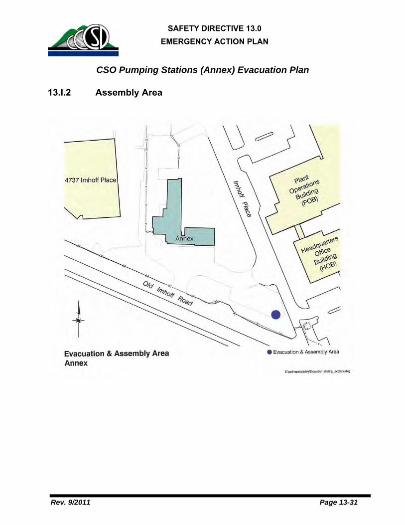
SAFETY DIRECTIVE 13.0 EMERGENCY ACTION PLAN
Rev. 9/2011 Page 13-31
CSO Pumping Stations (Annex) Evacuation Plan
13.I.2 Assembly Area

SAFETY DIRECTIVE 13.0 EMERGENCY ACTION PLAN
Rev. 9/2011 Page 13-32
APPENDIX J Filer Plant Evacuation Plan
The Filter Plant and associated structures were originally constructed in the mid-1970s with a design capacity of 36 MGD. The system can supply tertiary recycled water, the highest quality of treated recycled water, for landscape irrigation. Evacuation route maps are posted and portable fire extinguishers are permanently mounted in strategic locations. It is the responsibility of all employees to be familiar with all evacuation routes and the locations of fire extinguishers and pull alarms.
13.J.1 Evacuation Procedure
01 When the fire is not controllable by fire extinguisher or receiving an evacuation order, stop work and immediately leave the area or building through the nearest exit, taking all persons encountered. Please refer to posted evacuation route maps assigned to each area.
02 If possible, take your valuables with you; however, do not return to your workstation to retrieve anything. If you are the last person to leave a room, hang the “EVACUATED” tag on the outside door knob and close the door. DO NOT LOCK THE DOOR.
03 Report to the designated assembly area shown below or in the Filter Plant Emergency Action Plan. The Incident Commander/Incident Commander may direct people to an alternate assembly area if the assembly area is unsafe.
04 Notify your Area Safety Warden upon arrival or acknowledge your presence during roll call at the assembly area.
05 Remain in the assembly area unless directed to another location by the Incident Commander or if staying at the assembly area would endanger personal safety.
06 Do not return to a building or an evacuated area unless the area or building has been cleared for re-entry by the Incident Commander.

SAFETY DIRECTIVE 13.0 EMERGENCY ACTION PLAN
Rev. 9/2011 Page 13-33
Filer Plant Evacuation Plan
13.J.2 Assembly Area

SAFETY DIRECTIVE 13.0 EMERGENCY ACTION PLAN
Rev. 9/2011 Page 13-34
APPENDIX K Influent Diversion Building (Headworks) Evacuation Plan
The Influent Diversion Building (Headworks) is the area that the wastewater first enters the treatment plant from the collection system. Evacuation route maps are posted on the first and basement floors, portable fire extinguishers installed, and fire alarm pull boxes are permanently mounted in strategic locations. It is the responsibility of all employees to be familiar with evacuation routes and the locations of fire extinguishers and pull alarms.
13.K.1 Evacuation Procedure
01 When the fire alarm sounds or receiving an evacuation order, stop work and immediately leave the area or building through the nearest exit, taking all persons encountered. Please refer to posted evacuation route maps assigned to each area.
- If possible, take your valuables with you; however, do not return to your workstation to retrieve anything.
- If you are the last person to leave a room, hang the “EVACUATED” tag on the outside door knob and close the door. DO NOT LOCK THE DOOR.
02 Report to the designated assembly area shown below and in the Headworks Emergency Action Plan. The Incident Commander may direct people to an alternate assembly area if this location is unsafe.
03 Notify your Area Safety Warden upon arrival or acknowledge your presence during roll call at the assembly area.
04 Remain in the assembly area unless directed to another location by the Incident Commander or if staying at the assembly area would endanger personal safety.
05 Do not return to a building or an evacuated area unless the area or building has been cleared for re-entry by the Incident Commander.

SAFETY DIRECTIVE 13.0 EMERGENCY ACTION PLAN
Rev. 9/2011 Page 13-35
Influent Diversion Building (Headworks) Evacuation Plan
13.K.2 Assembly Area

SAFETY DIRECTIVE 13.0 EMERGENCY ACTION PLAN
Rev. 9/2011 Page 13-36
APPENDIX L Other Treatment Plant Areas Evacuation Plan
UV Building & Filter Banks Pump & Blower Building Chemical Feed Building Sludge Control Building Substations Filter Plant Forebay Filter Plant Clearwell Holding Basins A, B, C Fuel Oil Storage Area Primary & Secondary Sed Tanks Aeration/Nitrification Tanks Clarifiers Diffused Air Flotation (DAF) Tanks Diffuser Structure Former Dechlorination Building Tunnels Contractor Staging Area Gas Yard Influent Diversion Structure & Structures 1 & 1A Wet Weather Outfall
Drainback Channel & Wet Weather Structures
Influent Diversion Structure 9000 Odor Control Units Bioassay Trailer Portable fire extinguishers installed and fire alarm pull boxes are permanently mounted in strategic locations throughout the Treatment Plan. It is the responsibility of all employees to be familiar with evacuation routes and the locations of fire extinguishers and pull alarms.
13.L.1 Evacuation Procedure
01 When the fire alarm sounds or receiving an evacuation order, stop work and immediately leave the area or building through the nearest exit, taking all persons encountered. Please refer to posted evacuation route maps assigned to each area.
- If possible, take your valuables with you; however, do not return to your workstation to retrieve anything.
- If you are the last person to leave a room, hang the “EVACUATED” tag on the outside door knob and close the door. DO NOT LOCK THE DOOR.
02 Report to the nearest assembly area shown below. The Incident Commander may direct people to an alternate assembly area if these locations are unsafe.
03 If there are no Area Safety Wardens at the assembly area, contact your supervisor via Nextel to report your location and status.
04 Remain in the assembly area unless directed to another location by the Incident Commander or if staying at the assembly area would endanger personal safety.

SAFETY DIRECTIVE 13.0 EMERGENCY ACTION PLAN
Rev. 9/2011 Page 13-37
05 Do not return to a building or an evacuated area unless the area or building has been cleared for re-entry by the Incident Commander.
13.L.2 Assembly Areas


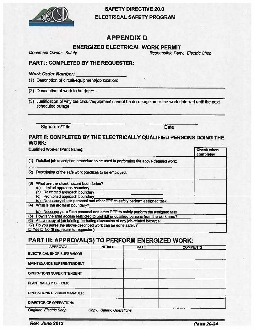


SAFETY DIRECTIVE 25.0LEAD COMPLIANCE PROGRAM
October 2012 Page 25-2
TABLE OF CONTENTS
.1 PROGRAM REVIEW AND CERTIFICATION.……………….……………………………....3
.2 PURPOSE, POLICY AND SCOPE.…………………………………….……………………..3
.3 RESPONSIBILITIES.……………………………………………………….…………………...4
.4 DEFINITIONS.……………………………………………………………….…………………..5
.5 GENERAL REQUIREMENTS……………………………………………….…………………6
.6 JOB CLASSIFICATION AND EXPOSURE CONTROL………………….…………………7
.7 BASIS OF INITIAL ASSESSMENT OF EMPLOYEE EXPOSURE………………….…….8
.8 FREQUENCY OF EXPOSURE ASSESSMENT…………………………………….……….8
.9 EMPLOYEE NOTIFICATION………………………………………………………….……….9
.10 METHODS OF COMPLIANCE………………………………………………………….……..9
.11 RESPIRATORY PROTECTION…………………………………………………….………..10
.12 PROTECTIVE WORK CLOTHING AND EQUIPMENT………………………….………...11
.13 HOUSEKEEPING…………………………………………………………………….………..12
.14 HYGIENE FACILITIES, PRACTICES AND REGULATED AREAS…………….………..12
.15 MEDICAL SURVEILLANCE…………………………………………………………….……13
.16 MEDICAL REMOVAL PROTECTION………………………………………………….……18
.17 EMPLOYEE INFORMATION, TRAINING AND CERTIFICATION……………….………22
.18 SIGNS…………………………………………………………………………………….……..24
.19 RECORDKEEPING…………………………………………………………………….………24
.20 OBSERVATION OFMONITORING………………………………………………….……….27
.21 LEAD WORK PRE-JOB NOTIFICATION……………………………………….…………..27
TABLE 1– TRIGGER TASKS……………………………………………………………..………….30
TABLE 2–SIGNS & SYMPTOMS OF LEAD POISENING, COMMON HEALTH DEFECTS OF
LEAD POISENING……………………………………………………………………………..31
TABLE 3–TRIGGER TASKS & RESPIRATOR PROTECTION FOR EMPLOYEES………….32
APPENDIX A– PROGRAM REVIEW AND CERTIFICATION LOG………………………..…….33
APPENDIX B– RESTRICTED WORK PERMIT (RWP)…………………………………..……….34
APPENDIX C–EMPLOYEE STANDARD SUMMARY SECTION V SUBSECTION G………..35
APPENDIX D–LEAD-WORK PRE-JOB NOTIFICATION FORM……………………………….37

SAFETY DIRECTIVE 25.0LEAD COMPLIANCE PROGRAM
October 2012 Page 25-3
CENTRAL CONTRA COSTA SANITARY DISTRICT
SAFETY DIRECTIVE 25.0
Update Effective: October 2012
.1 PROGRAM REVIEW AND CERTIFICATION
The District will review and evaluate this standard practice instruction at leastonce every 12 months or when changes occur that prompt revision of thisdocument or when facility operational changes occur that require a revision ofthis document, or should the procedures ever fail.
All revisions are documented on the Program Review and Certification Log(Appendix A).
.2 PURPOSE, POLICY AND SCOPE
2.1 Purpose: The primary purpose is to supplement the OSHA standard'sprimary mechanisms of disease and illness prevention, the elimination orreduction of airborne concentrations of lead and sources of ingestion.
2.2 Policy: District personnel are prohibited from performing any work thatmay expose employees to levels at or above PEL (Section 2.1) unless aRestricted Work Plan (RWP) [Appendix B] is first obtained from the SafetyOfficer.
2.3 Scope: This written program will be communicated to all personnel. Itencompasses the total workplace, regardless of number of workersemployed or the number of work shifts. It is designed to establish cleargoals and objectives. It includes but is not limited to:
2.3.1 Demolition or salvage of structures where lead or materialscontaining lead are present;
2.3.1.1 Removal or encapsulation of materials containing lead;
2.3.1.2 New construction, alteration, repair or renovation ofstructures, substrates or portions thereof that containlead or materials containing lead;
2.3.1.3 Installation of products containing lead;
2.3.1.4 Lead contamination/emergency cleanup;

SAFETY DIRECTIVE 25.0LEAD COMPLIANCE PROGRAM
October 2012 Page 25-4
2.3.1.5 Transportation, disposal, storage or containment of leador materials containing lead on the site or location atwhich construction activities are performed, and
2.3.1.6 Maintenance operations associated with theconstruction activities described in this Section.
.3 RESPONSIBILITIES
3.1 The General Manager is responsible for:
3.1.1 Ensuring this program is fully implemented.
3.1.2 Ensuring that adequate funding is made available for the successfulimplementation and continuation of this program.
3.2 Directors and Managers:
3.2.1 Implementing all other relevant responsibilities as identified in theInjury & Illness Prevention Program (IIPP).
3.2.2 Holding all personnel accountable for their responsibilities underthis program and implementing safe practices within their dailywork.
3.3 Superintendents and Supervisors
3.3.1 District superintendents and supervisors will develop and maintainthe following for each job where lead is emitted:
3.3.1.1 A description of each job.
3.3.1.2 A list of machinery used in the job.
3.3.1.3 Types of materials processed.
3.3.1.4 Exposure controls that are in place.
3.3.1.5 Crew size (if applicable).
3.3.1.6 Employee job responsibilities.
3.3.1.7 Operating procedures specific to the job.
3.3.1.8 Maintenance practices specific to the job.
3.4 Safety Officer
3.4.1 Coordinate and conduct initial and refresher awareness training forall employees.
3.4.2 Coordinate the initial and annual training program for eachemployee who is subject to lead exposure at or above the actionlevel (AL) 30 micrograms per cubic meter (μg/m3) on any given day.

SAFETY DIRECTIVE 25.0LEAD COMPLIANCE PROGRAM
October 2012 Page 25-5
3.4.3 Assist and provide technical support to supervisors and employeesin meeting their responsibilities identified in this directive.
3.4.4 Establish and implement a written compliance program to ensureno employee is exposed to lead concentrations greater than 50μg/m3 of air averaged over an 8-hour period.
3.4.5 Monitor employee’s use of respirators whenever exposure to the Permissible Exposure Limit (PEL) is exceeded (50 μg/m3) and asspecified in Safety Directive 7.0 Respiratory Protection Program.
3.5 All Employees
3.5.1 Employees using a respirator while working in potential lead-containing exposures shall be a participant in the District’s Respiratory Protection Program (Safety Directive 7.0).
3.5.2 If personal protective clothing becomes contaminated with lead-containing materials, clothing shall be left at work and not takenhome for laundering.
3.5.3 Contaminated clothing, shoes or equipment shall not be cleaned byblowing, shaking or any other means that disperses lead into theair.
.4 DEFINITIONS
Action Level (AL) means employee exposure, without regard to the use ofrespirators, to an airborne concentration of lead of 30 micrograms per cubicmeter of air (30μg/m3) calculated as an 8-hour time-weighted average (TWA).
Chelating is a medical practice administrating chelating agents to remove heavymetals from the body.
Exposure Assessment is an initial determination via air monitoring or previousmonitoring of a very similar job within the last 12 months.
Lead means metallic lead, all inorganic lead compounds and organic lead soaps.Excluded from this definition are all other organic lead compounds.
Lead Activities means abatement, lead hazard evaluation, lead-relatedconstruction work, or any activity which disturbs lead-based paint, presumedlead-based paint, or creates a lead hazard.
Lead-Based Paint means paint or other surface coatings that contain an amountof lead equal to, or in excess of:
(a) one milligram per square centimeter (1.0 mg/cm2); or(b) half of one percent (0.5%) by weight.

SAFETY DIRECTIVE 25.0LEAD COMPLIANCE PROGRAM
October 2012 Page 25-6
Lead Hazard means deteriorated lead-based paint, lead contaminated dust, leadcontaminated soil, disturbing lead-based paint or presumed lead-based paintwithout containment, or any other nuisance which may result in persistent andquantifiable leadexposure.
Lead-Contaminated Dust means dust that contains an amount of lead equal to,or in excess of:
(a) forty micrograms per square foot (40 μg/ft2) for interior floor surfaces;or(b) two hundred and fifty micrograms per square foot (250 μg/ft2) forinterior horizontal surfaces; or(c) four hundred micrograms per square foot (400 μg/ft2) for exterior floorand exterior horizontal surfaces.
Lead-Contaminated Soil means bare soil that contains an amount of lead equalto, or in excess of, four hundred parts per million (400 ppm) in children’s play areas and one thousand parts per million (1000 ppm) in all other areas.
Permissible Exposure Limit (PEL) is the maximum daily human exposure to aspecific substance allowed in a workroom's air over an 8-hour shift. It is basedeither on a time weighted average or the maximum exposure limit prescribed byregulation. For purposes in this Directive, no employee shall be exposed to leadat concentrationsgreater than fifty micrograms per cubic meter of air (50μg/m3) averaged over an8-hour period.
NIOSH means the National Institute of Occupational Safety and Health (NIOSH),U.S. Department of Health and Human Services or designee.
Supervisor means one who is capable of identifying existing and predictablelead hazards in the surroundings or working conditions and who hasauthorization to take prompt corrective measures to eliminate them. Supervisorsshall be trained as required.
Time-Weight Average (TWA) is the average exposure to a contaminant orcondition to which workers may be exposed without adverse effect over a periodsuch as an 8-hour day or 40-hour week.
.5 GENERAL REQUIREMENTS
OSHA guidelines require that each employer who has employee(s) with potentialoccupational exposure to lead prepares an exposure determination. This exposuredetermination shall contain the following:

SAFETY DIRECTIVE 25.0LEAD COMPLIANCE PROGRAM
October 2012 Page 25-7
5.1 A list of job classifications for all employees whose job classifications haveoccupational exposure.
5.2 A list of job classifications in which some employees have occupationalexposure.
5.3 A list of all tasks and procedures or groups of closely related tasks andprocedures in which occupational exposure occurs and that are performedby employees in job classifications listed in accordance with the provisionsof the this standard practice instruction (See Table 1 Trigger Tasks).
5.4 The schedule and method of implementation, methods of compliance,Communication of Hazards and record keeping required by 29 CFR1910.1025 and 8 CCR 1532.1.
5.5 The procedure for the evaluation of circumstances surrounding incidents(See Safety Directive 1.0).
5.6 Methods of compliance.
.6 JOB CLASSIFICATION AND EXPOSURE CONTROL
6.1 Job Classifications in Which All Employees in Those Classifications HaveOccupational Exposure:
6.1.1 Painter
6.1.2 Utility Worker
6.1.3 Mechanical Maintenance Tech I/II/III
6.1.4 Buildings & Grounds Supervisor
6.2 Job Classifications in Which Some Employees Have OccupationalExposure:
6.2.1 Plant Operator I/II/III
6.2.2 Instrument Technician
6.2.3 Maintenance Planner
6.2.4 Chemist I/II/III
6.2.5 Shift Supervisor
6.2.6 Senior Plant Operator
6.2.7 Electrical Supervisor
6.2.8 Electrical Technician
6.2.9 Mechanical Supervisor
6.2.10 Machinist
6.2.11 Senior Engineer

SAFETY DIRECTIVE 25.0LEAD COMPLIANCE PROGRAM
October 2012 Page 25-8
6.2.12 Associate Engineer
6.2.13 Assistant Engineer
6.2.14 Senior Chemist
6.2.15 Plant Maintenance Superintendent
.7 BASIS OF INITIAL ASSESSMENT OF EMPLOYEE EXPOSURE
7.1 The Safety Officer will monitor employee exposures and shall base initialassessments on the employee exposure monitoring results (airmonitoring) and any of the following relevant considerations:
7.1.1 Any information, observations, or calculations that would indicateemployee exposure to lead.
7.1.2 Any previous measurements of lead.
7.1.3 Any employee complaints of symptoms that may be attributable toexposure to lead (See Table 2 Signs & Symptoms of LeadPoisoning)
7.2 The District shall collect full-shift personal air monitoring samplesrepresentative of an employee’s regular, daily exposure to lead.
7.2.1 Monitoring shall include at least one sample for each jobclassification in each work area for each shift or for the shift with thehighest exposure level.
7.3 Monitoring results for similar work tasks that the District has obtainedwithin the past 12 months may be used to determine the level of employeeexposure.
7.4 If the District has objective data that demonstrates that a particularproduct or material containing lead or specific process, operation oractivity involving lead cannot result in an employee exposure of lead at orabove the PEL, the objective data may be used instead of conducting theinitial assessment.
7.4.1 Objective data shall not be used for exposure assessment inconnection with any of the trigger tasks listed in Table 1.
.8 FREQUENCY OF EXPOSURE ASSESSMENT
8.1 If the initial assessment shows that employee exposures are less than theAL (30μg/m3), no further assessment is needed.
8.1.1 Additional exposure assessment is required whenever there hasbeen a change of equipment, process, control, personnel or a newtask has been initiated.

SAFETY DIRECTIVE 25.0LEAD COMPLIANCE PROGRAM
October 2012 Page 25-9
8.2 If the initial assessment is at or above the AL but at or below the PEL,monitoring shall be done every 6 months.
8.3 If the initial assessment is above the PEL, monitoring shall be donequarterly.
.9 EMPLOYEE NOTIFICATION
9.1 The District shall notify each employee in writing the results whichrepresent the employee’s airborne lead exposure within five days aftercompletion of the exposure assessment
.10 METHODS OF COMPLIANCE
10.1 Engineering, Work Practice and Administrative Controls
10.1.1 The District will implement, to the extent feasible, engineeringand work practice controls to reduce and maintain employeeexposure to lead at or below the PEL.
10.1.2 If engineering and work practice controls are not sufficient toreduce and maintain employee exposure at or below the PEL,respiratory protection may be used to supplement the controls.
10.2 Where exposures are expected to reach the PEL, the Safety Officer andthe affected work group shall prepare a written compliance plan to includethe following:
10.2.1 A description of each activity in which lead is emitted (e.g.,equipment used, material involved, controls in place, crew size,employee job responsibilities, operating procedures andmaintenance practices).
10.2.2 A description of the specific means that will be used to achievecompliance (administrative and/or engineering controls).
10.2.3 Information on the technology considered to meet the PEL.
10.2.4 Air monitoring data that documents the source of lead emissions.
10.2.5 A detailed schedule for implementing the program, includingcopies of documentation (e.g., purchase orders for equipment,construction contracts).
10.2.6 A work practice program that includes guidelines for the use ofprotective work clothing, equipment, housekeeping and hygienefacility.
10.3 Where engineering controls are required, include the engineering plansand studies used to determine methods selected for controlling exposureto lead.

SAFETY DIRECTIVE 25.0LEAD COMPLIANCE PROGRAM
October 2012 Page 25-10
10.3.1 Where mechanical ventilation is used, the District shall evaluatethe performance as necessary to maintain the effectiveness ofthe system.
10.3.2 If administrative controls are used to reduce employees TWAexposure to lead, the employee’s supervisor shall establish andimplement a job rotation schedule that includes:
10.3.2.1 The name of each affected employee;
10.3.2.2 A control schedule for job rotation, if used;
10.3.2.3 Duration and exposure levels at each work site whereeach affected employee is located; and
10.3.2.4 Any other information that may be useful in assessingthe reliability of administrative controls to reduceexposure to lead.
10.4 The compliance program shall provide for frequent, regular inspections ofjob sites, regulated areas, materials and equipment to be made by thesupervisor.
10.5 A description of the communication methods to be used amongcontractors on multi-contractor sites to inform affected employees ofpotential exposure to lead and their responsibility to comply with thissafety directive.
10.6 Written compliance plans shall be available at the worksite forexamination.
10.6.1 Affected employees or authorized employee representatives willbe provided copies of the written compliance plan upon theirrequest.
10.6.2 If required, the compliance plan shall also be submitted to OSHAand NIOSH.
10.7 Written compliance plans shall be revised and updated any time there is achange of equipment, process, control, personnel or a new task has beeninitiated or least every 6 months, whichever is first.
.11 RESPIRATORY PROTECTION
11.1 Employees who use respirators shall select the District providedequipment based upon air monitoring results with the minimum level ofrespirator protection as indicated in Table 3.
11.2 The District will provide a powered, air-purifying respirator in lieu of therespirator specified in Table 1 whenever:
11.2.1 An employee chooses to use this type of respirator, and

SAFETY DIRECTIVE 25.0LEAD COMPLIANCE PROGRAM
October 2012 Page 25-11
11.2.2 This type of respirator will provide adequate protection to theemployee.
11.3 Employees wearing respirators shall be required to complete the District’s Respirator Program requirements as stipulated in Safety Directive 7.0Respiratory Protection Program.
11.4 Respirators must be used whenever:
11.4.1 An employee’s exposure to lead exceeds the PEL;
11.4.2 Work operations for which engineering controls and work practicesare not sufficient to reduce exposures at or below the PEL;
11.4.3 An employee requests a respirator;
11.4.4 Respirators are required to provide interim protection foremployees while they perform the operations specified in Table 1.
.12 PROTECTIVE WORK CLOTHING AND EQUIPMENT
12.1 The District shall provide and assure employees use appropriateprotective work clothing (e.g., coveralls or other full-body work clothing,gloves, hats, shoes or shoe coverings, and face shields, goggles or otherprotective equipment) as needed in the following circumstances:
12.1.1 Whenever an employee is exposed to lead above the PEL(regardless of whether a respirator is worn);
12.1.2 Whenever lead compounds may cause irritation;
12.1.3 When employees are exposed to lead above the PEL, workclothing shall be provided at least weekly;
12.1.4 Employees will be provided work clothing daily when exposuresexceed 200μg/m3; and
12.1.5 The District will maintain and replace protective work clothing andequipment.
12.1.5.1 Clothing to be laundered must be placed in a closedcontainer and labeled to indicate it contains leadcontaminated clothing.
12.1.5.2 Containers of contaminated protective clothingand/or equipment shall be labeled as follows:
12.1.5.2.1 Caution: Clothing contaminated withlead. Do not remove dust by blowing orshaking. Dispose of lead contaminatedwash water in accordance withapplicable local, state, or federalregulations.

SAFETY DIRECTIVE 25.0LEAD COMPLIANCE PROGRAM
October 2012 Page 25-12
12.1.6 The District will provide any person who launders protectiveclothing or cleans equipment a written notice of the potentiallyharmful effects of lead exposure.
12.1.7 No one shall remove lead particles from protective clothing orequipment by blowing, shaking, or any other means thatdisperses lead into the air.
.13 HOUSEKEEPING
13.1 All surfaces shall be maintained as free as practicable of accumulations oflead.
13.2 Vacuums shall be equipped with HEPA filters where vacuuming methodsare selected for cleaning surfaces.
13.3 Shoveling, dry or wet sweeping and brushing may be used only whereHEPA vacuuming has been tried and found ineffective.
13.4 The use of compressed air for cleaning is prohibited unless thecompressed air is in conjunction with a ventilation system designed tocapture airborne dust created by the compressed air.
.14 HYGIENE FACILITIES, PRACTICES AND REGULATED AREAS
14.1 Facilities
14.1.1 Hand washing facilities shall be provided for all employeesexposed to lead.
14.1.1.1 District shall ensure that employees wash their handsprior to eating, drinking, smoking or applyingcosmetics.
14.1.2 Employees exposed to lead above the PEL shall be providedwith clean changing areas with separate storage facilities forwork and street clothing.
14.1.3 Shower facilities, soap and towels shall be provided foremployees exposed to lead above the PEL. If shower facilitiescannot be provided, hand washing facilities will suffice.
14.2 Practices
14.2.1 The District shall assure that in areas where employees areexposed to lead above the PEL without regard to the use ofrespirators, food or beverages are not present or consumed,tobacco products are not present or used, and cosmetics arenot applied.

SAFETY DIRECTIVE 25.0LEAD COMPLIANCE PROGRAM
October 2012 Page 25-13
14.2.2 The District shall assure that employees do not leave theworkplace wearing any protective clothing that was worn orleave with equipment used during the work shift.
14.2.3 Lunchrooms and/or eating areas shall be kept free of leadaccumulation and employees shall not enter the lunchroomsand/or eating areas with protective work clothing or equipmentthat has not been cleaned by vacuuming or other method thatlimits dispersion of lead dust.
14.3 Regulated Areas
14.3.1 A regulated area shall be established in the following situations:
14.3.1.1 Whenever employees are exposed to lead above thePEL without regard to the use of respirators;
14.3.1.2 Whenever trigger tasks (see Table 1) are performed;
14.3.2 Warning signs shall be posted and access shall be restricted toauthorized employees.
14.3.3 Appropriate protective equipment shall be provided and wornby employees and other persons who enter the regulated area.
.15 MEDICAL SURVEILLANCE
15.1 General
15.1.1 The District shall initiate medical surveillance to employeesoccupationally exposed on any day to lead at or above the AL(30μg/m3 in an 8-hour TWA).
15.1.1.1 Initial medical surveillance consists of biologicalmonitoring in the form of blood sampling andanalysis for lead and zinc protoporphyrin (ZPP)levels.
15.1.2 The medical surveillance program shall include all employeeswho are or may be exposed by the employer at or above theAL for more than 30 days in any consecutive 12 months.
15.1.3 The lead medical program, including all medical examinationsand procedures performed, shall be under the supervision of alicensed physician.
15.1.4 Employees have the right to seek a second medical opinionregarding the lead medical evaluation at the expense of theDistrict.

SAFETY DIRECTIVE 25.0LEAD COMPLIANCE PROGRAM
October 2012 Page 25-14
15.1.4.1 If necessary, a third physician may be requested toresolve any disagreements between the first twoopinions.
15.2 Biological Monitoring
15.2.1 Initial blood lead and ZPP level sampling and analysis arerequired for employees performing any of the specified triggertasks (see Table 1) or for any employee exposed to anairborne lead level at or above the AL for at least one day.
15.2.2 Employees who are or may be exposed at or above the AL formore than 30 days in any consecutive 12 months must be inthe medical surveillance program.
15.2.2.1 Blood lead level and ZPP sampling shall beconducted at least every two months for the first 6months and every six months thereafter.
15.2.2.2 Any employee with a blood lead level above 40μg/dl (micrograms per deciliter) shall have a bloodlead level and ZPP every two months until twoconsecutive samples are less than 40μg/dl.
15.2.2.3 For employees temporarily removed from exposureto lead because of an elevated blood lead level, ablood lead level and ZPP must be provided everymonth during the removal period (See Section14.3).
15.2.3 Follow-up Blood Sampling Tests: Whenever the results of ablood lead level exceeds the numerical criterion for medicalremoval (greater than or equal to 30μg/dl) the District shallprovide a second (follow-up) blood sampling test within twoweeks after the District receives the results of the first bloodsampling test.
15.2.4 Accuracy Of Blood Lead Level Sampling And Analysis:Sampling provided pursuant to this Section shall have anaccuracy (to a confidence level of 95%) within plus or minus15% or 6μg/dl, whichever is greater, and shall be conductedby a laboratory approved by OSHA.
15.3 Employee Notification
15.3.1 Within 5 days after the receipt of biological monitoring results,the District shall notify each employee in writing of his/herblood lead level; and
15.3.2 The District shall notify each employee whose blood lead levelexceeds 40μg/dl that the standard requires the employee

SAFETY DIRECTIVE 25.0LEAD COMPLIANCE PROGRAM
October 2012 Page 25-15
undergo temporary medical removal with Medical RemovalProtection benefits.

SAFETY DIRECTIVE 25.0LEAD COMPLIANCE PROGRAM
October 2012 Page 25-16
15.4 Medical Examinations and Consultations
15.4.1 Frequency: The District shall make available medicalexaminations and consultations to each employee exposed to anairborne lead level at or above the AL for at least one day on thefollowing schedule:
15.4.1.1 At least annually for each employee for whom ablood-sampling test conducted at any time during thepreceding 12 months indicated a blood lead level at orabove 40μg/dl;
15.4.1.2 Upon notification by an employee that the employeehas developed signs or symptoms commonlyassociated with lead intoxication (See Table 2, Signs& Symptoms of Lead Poisoning & Some HealthEffects of Lead Poisoning ) or desires medical adviceconcerning the effects of current or past exposure tolead on theemployee’s ability to procreate a healthy child, the employee is pregnant, or the employee hasdemonstrated difficulty in breathing during a respiratorfitting test or during use; and
15.4.1.3 As medically appropriate for each employee eitherremoved from exposure to lead because a risk tosustaining material impairment to health, or otherwiselimited pursuant to a final medical determination.
15.5.1 Content: The content of medical examinations made availablewill be determined by an examining physician and, if requestedby an employee, will include pregnancy testing or laboratoryevaluation of male fertility. Medical examinations madeavailable, will include the following elements:
15.5.1.1 A detailed work history and medical history, withparticular attention to past lead exposure(occupational and non-occupational), personal habits(smoking, hygiene), and past gastrointestinal,hematological, renal, cardiovascular, reproductive andneurological problems.
15.5.1.2 A thorough physical examination with particularattention to teeth, gums, hematologic, gastrointestinal,renal, cardiovascular, and neurological systems.Pulmonary status should be evaluated if respiratoryprotection will be used.
15.5.1.3 A blood pressure measurement.

SAFETY DIRECTIVE 25.0LEAD COMPLIANCE PROGRAM
October 2012 Page 25-17
15.5.1.4 A blood sample and analysis that determines:
Blood lead level;
Hemoglobin and hematocrit determinations, redcell indices, and examination of peripheral smearmorphology;
Zinc protoporphyrin;
Blood urea nitrogen; and,
Serum creatinine;
15.5.1.5 A routine urinalysis with microscopic examination; and
15.5.1.6 Any laboratory or other test relevant to lead exposurewhich the examining physician deems necessary bysound medical practice.
15.6 Multiple Physician Review Mechanism
15.6.1 If the District selects the initial physician who conducts anymedical examination or consultation provided to an employeeunder this section, the employee may designate a secondphysician to:
15.6.1.1 Review any findings, determinations orrecommendations of the initial physician; and
15.6.1.2 Conduct such examinations, consultations andlaboratory tests as the second physician deemsnecessary to facilitate this review.
15.6.2 The District will promptly notify an employee of the right to seeka second medical opinion after each occasion that an initialphysician conducts a medical examination or consultationpursuant to this section. The District may condition itsparticipation in, and payment for, the multiple physician reviewmechanism upon the employee doing the following within 15days after receipt of the foregoing notification, or receipt of theinitial physician's written opinion, whichever is later:
15.6.2.1 The employee informs the District that he/she intendsto seek a second medical opinion, and
15.6.2.2 The employee initiates steps to make an appointmentwith a second physician.
15.6.3 If the findings, determinations or recommendations of thesecond physician differ from those of the initial physician, theDistrict and the employee shall assure that efforts are made forthe two physicians to resolve any disagreement.

SAFETY DIRECTIVE 25.0LEAD COMPLIANCE PROGRAM
October 2012 Page 25-18
15.6.4 If the two physicians have been unable to quickly resolve theirdisagreement, the District and the employee, through theirrespective physicians, will designate a third physician to:
15.6.4.1 Review any findings, determinations orrecommendations of the prior physicians; and
15.6.4.2 Conduct such examinations, consultations, laboratorytests and discussions with the prior physicians, as thethird physician deems necessary to resolve thedisagreement of the prior physicians.
15.6.5 The District will act consistently with the findings, determinationsand recommendations of the third physician, unless the Districtand the employee reach an agreement that is otherwiseconsistent with the recommendations of at least one of the threephysicians.
15.6.6 Information Provided To Examining And Consulting Physicians:The District will provide the initial physician conducting amedical examination or consultation with the followinginformation:
15.6.6.1 A copy of California Code of Regulations, Title 8,Section 1532.1, Lead including all Appendices;
15.6.6.2 A description of the affected employee's duties asthey relate to the employee's exposure;
15.6.6.3 The employee's exposure level or anticipatedexposure level to lead and any other toxic substance(if applicable);
15.6.6.4 A description of any personal protective equipmentused or to be used;
15.6.6.5 Prior blood lead determinations; and
15.6.6.6 All prior written medical opinions concerning theemployee in the employer's possession or control.
15.7 Written Medical Opinions
15.7.1 The District will provide the foregoing information to a second orthird physician conducting a medical examination orconsultation upon request either by the second or thirdphysician, or by the employee.
15.7.2 The District will obtain and furnish the employee with a copy of awritten medical opinion from each examining or consultingphysician that contains only the following information:

SAFETY DIRECTIVE 25.0LEAD COMPLIANCE PROGRAM
October 2012 Page 25-19
15.7.2.1 The physician's opinion as to whether the employeehas any detected medical condition that would placethe employee at increased risk of material impairmentof the employee's health from exposure to lead;
15.7.2.2 Any recommended special protective measures to beprovided to the employee or limitations to be placedupon the employee's exposure to lead;
15.7.2.3 Any recommended limitations upon the employee'suse of respirators, including a determination ofwhether the employee can wear a powered airpurifying respirator if the employee cannot wear anegative pressure respirator; and
15.7.2.4 The results of the blood lead determinations.
15.7.3 The District will instruct each examining and consultingphysician to:
15.7.3.1 Withhold the written opinion of findings, includinglaboratory results, or diagnoses unrelated to anemployee's occupational exposure to lead from theDistrict; and
15.7.3.2 Advise the employee of any medical condition,occupational or non-occupational, which dictatesfurther medical examination or treatment.
15.8 Alternate Physician Determination Mechanisms
15.8.1 The District and an employee or authorized employeerepresentative may agree upon the use of any alternatephysician determination mechanism in lieu of the multiplephysician review mechanism provided so long as the alternatemechanism is as expeditious and protective as therequirements contained in this Section.
15.9 Chelation
15.9.1 The District will assure that no employee engages inprophylactic chelation of any other District employee at anytime.
15.9.2 If therapeutic or diagnostic chelation is to be performed by anyperson in accordance with CCR Title 8, Section 1532.1, theDistrict shall assure that it be done under the supervision of alicensed physician in a clinical setting with thorough andappropriate medical monitoring and that the employee isnotified in writing prior to its occurrence.

SAFETY DIRECTIVE 25.0LEAD COMPLIANCE PROGRAM
October 2012 Page 25-20
.16 MEDICAL REMOVAL PROTECTION
16.1 Temporary Medical Removal And Return Of An Employee
16.1.1 Temporary Removal Because of Elevated Blood Lead Level:The District will remove an employee from work having anexposure to lead at or above the Action Level on each occasionthat a periodic and a follow-up blood sampling test indicates thatthe employee's blood lead level is at or above 50 μg/dl.
16.1.2 Temporary Removal Due To A Final Medical Determination: TheDistrict will remove an employee from work having an exposureto lead at or above the AL on each occasion that a final medicaldetermination results in a medical finding, determination, oropinion that the employee has a detected medical conditionwhich places the employee at increased risk of materialimpairment to health from exposure to lead.
16.1.2.1 For the purposes of this section, the phrase "finalmedical determination" means the written medicalopinion of the employees' health status by theexamining physician or, where relevant, the outcomeof the multiple physician review mechanism oralternate medical determination mechanism usedpursuant to the medical surveillance provisions asstated in CCR Title 8, Section 1532.1.
16.1.2.2 Where a final medical determination results in anyrecommended special protective measures for anemployee, or limitations on an employee's exposureto lead, the District shall implement and actconsistent with the recommendation.
16.1.3 Return of The Employee To Former Job Status: The District willreturn an employee to his/her former job status:
16.1.3.1 For an employee removed due to a blood lead levelat or above 50 μg/dl when twoconsecutive blood-sampling tests indicate that the employee's bloodlead level is at or below 40 μg/dl;
16.1.3.2 For an employee removed because of a finalmedical determination, when a subsequent finalmedical determination results in a medical finding,determination, or opinion that the employee nolonger has a detected medical condition whichplaces the employee at increased risk of materialimpairment to health from exposure to lead.

SAFETY DIRECTIVE 25.0LEAD COMPLIANCE PROGRAM
October 2012 Page 25-21
16.1.3.3 For the purposes of CCR Title 8, Section 1532.1 andthis Safety Directive, the requirement that the Districtreturn an employee to his/her former job status is notintended to expand upon or restrict any rights anemployee has or would have had, absent temporarymedical removal, to a specific job classification orposition under the terms of a collective bargainingagreement.
16.1.4 Removal of Other Special Protective Measure or Limitations:The District will remove any limitations placed on an employee orend any special protective measures provided to an employeepursuant to a final medical determination when a subsequentfinal medical determination indicates that the limitations orspecial protective measures are no longer necessary.
16.1.5 District Options Pending A Final Medical Determination: Wherethe multiple physician review mechanism or alternate medicaldetermination mechanism used pursuant to the medicalsurveillance provisions of this section has not yet resulted in afinal medical determination with respect to an employee, theDistrict may choose one of the following routes:
16.1.5.1 Removal: The District may remove the employeefrom exposure to lead, provide special protectivemeasures to the employee, or place limitations uponthe employee consistent with the medical findings,determinations, or recommendations of any of thephysicians who have reviewed the employee's healthstatus.
16.1.5.2 Return: The District may return the employee tohis/her former job status, end any special protectivemeasures provided to the employee, and removeany limitations placed upon the employee consistentwith the medical findings, determinations, orrecommendations of any of the physicians who havereviewed the employee's health status, with twoexceptions:
16.1.5.2.1. The initial removal, special protection orlimitation of the employee resulted froma final medical determination whichdiffered from the findings,determinations, or recommendations ofthe initial physician or;
SAFETY DIRECTIVE 25.0LEAD COMPLIANCE PROGRAM
October 2012 Page 25-22
16.1.5.2.1. If the employee has been on removalstatus for the preceding eighteenmonths due to an elevated blood leadlevel, then the District shall await a finalmedical determination.
16.2 Medical Removal Protection Benefits
16.2.1 Provision of Medical Removal Protection Benefits: The Districtwill provide an employee up to 18 months of medical removalprotection benefits on each occasion that an employee isremoved from exposure to lead or otherwise limited pursuant toCCR, Title 8, Section 1532.1.
16.2.2 Definition of Medical Removal Protection Benefits: Therequirement that the District provide medical removal protectionbenefits means that as long as the job the employee wasremoved from continues, the District will maintain the total normalearnings, seniority and other employment rights and benefits ofan employee, including the employee's right to his/her former jobstatus as though the employee had not been medically removedfrom the employee's job or otherwise medically limited.
16.2.3 Follow-Up Medical Surveillance During Period of EmployeeRemoval or Limitation: During the period of time that anemployee is medically removed from his/her job or otherwisemedically limited, the District may condition the provision ofmedical removal protection benefits upon the employee'sparticipation in follow-up medical surveillance made available.
16.2.4 Workers' Compensation Claims: If a removed employee files aclaim for workers' compensation payments for a lead-relateddisability, the District will continue to provide medical removalprotection benefits pending disposition of the claim. To theextent that an award is made to the employee for earnings lostduring the period of removal, the District’s medical removal protection obligation shall be reduced by such amount. TheDistrict will receive no credit for workers' compensation paymentsreceived by the employee for treatment-related expenses.
16.2.5 Other Credits: The District’s obligation to provide medical removal protection benefits to a removed employee will bereduced to the extent that the employee receives compensationfor earnings lost during the period of removal either from apublicly or employer-funded compensation program or if s/hereceives income from employment with another employer madepossible by virtue of the employee's removal.

SAFETY DIRECTIVE 25.0LEAD COMPLIANCE PROGRAM
October 2012 Page 25-23
16.2.6 Voluntary Removal or Restriction of An Employee: Where theDistrict, although not required to do so, removes an employeefrom exposure to lead or otherwise places limitations on anemployee because of the effects of lead exposure on theemployee's medical condition, the District will provide medicalremoval protection benefits to the employee equal to thatrequired by CCR, Title 8, Section 1532.1.
.17 EMPLOYEE INFORMATION, TRAINING AND CERTIFICATION
17.1 General
17.1.1 The District will communicate information concerning leadhazards according to the requirements of the California Code ofRegulations (CCR), Title 8, Section 5194, HazardCommunication Standard, including but not limited to therequirements concerning warning signs and labels, safety datasheets (SDS) employee information and training.
17.1.2 For all employees who are subject to exposure to lead at orabove the AL or who are subject to exposure to lead compoundswhich may cause skin or eye irritation (e.g. lead arsenate, leadazide), the District will provide a training program and assureemployee participation.
17.1.3 The District will provide the training program as initial trainingprior to the time of job assignment or to the start up date for thisrequirement, whichever comes last.
17.1.4 The District will also provide the training program at least once ayear for each employee who is subject to lead exposure at orabove the AL.
17.1.5 Where the certification of employee and supervisor training isrequired, the training shall be conducted by a training provideraccredited by the California Department of Health Services, inaccordance with CCR, Title 17, Division 1, Chapter 8.
17.2 Training Program
17.2.1 The District shall assure that each employee is trained in thefollowing:
17.2.1.1 The content of CCR, Title 8, Section 1532.1 and thisSafety Directive;
17.2.1.2 The specific nature of the operations that could resultin exposure to lead above the AL;
17.2.1.3 The purpose, proper selection, fitting, use, andlimitations of respirators;

SAFETY DIRECTIVE 25.0LEAD COMPLIANCE PROGRAM
October 2012 Page 25-24
17.2.1.4 The purpose and a description of the medicalsurveillance program and the medical removalprotection program, including information concerningthe adverse health effects associated with excessiveexposure to lead;
17.2.1.4.1. Particular attention will be made to theadverse reproductive effects on bothmales and females and hazards to thefetus and additional precautions foremployees who are pregnant;
17.2.2 The engineering controls and work practices associated with theemployee's job assignment including training of employees tofollow relevant good work practices described in Section V,subsection (g) in Appendix C;
17.2.3 The contents of any compliance plan and the location ofregulated areas in effect;
17.2.4 Instructions to employees that chelating agents should not beused routinely except under the direction of a licensed physician;and
17.2.5 The employee's right of access to records under CCR, Title 8,Section 3204, Access to Employee Exposure and MedicalRecords.
17.3 Certification of Training For Residential and Public Buildings
17.3.1 The District will ensure that all employees and supervisors whoare engaged in lead related construction work as defined in CCR,Title 17, § 35022, and have been exposed to lead at or above thePEL, meet the training requirements, are trained by an accreditedtraining provider and are certified by the California Department ofHealth Services.
17.3.2 Lead related construction work is defined in CCR, Title 17,§35022 to be any construction, alteration, painting, demolition,salvage, renovation, repair, or maintenance of any residential orpublic building, including preparation and cleanup, that, by usingor disturbing lead containing material or soil, may result insignificant exposure of adults or children to lead.
17.3.3 As used in the definition of lead related construction work, "publicbuilding" means a structure which is generally accessible to thepublic, including but not limited to schools, daycare centers,museums, airports, hospitals, stores, convention centers,government facilities, office buildings and any other buildingwhich is not an industrial building or a residential building.

SAFETY DIRECTIVE 25.0LEAD COMPLIANCE PROGRAM
October 2012 Page 25-25
17.3.4 Regulations for accreditation of training providers and for thecertification of employees and supervisors are found in CCR,Title 17, Division 1, Chapter 8.
17.4 Access To Information, Training And Certification Materials
17.4.1 The District will make readily available to all affected employeesa copy of CCR, Title 8, §1532.1 and its appendices.
17.4.2 The District will provide upon request, all materials relating to theemployee information training program and certification toaffected employees, their designated representatives, the Chiefand National Institute for Occupational Safety andHealth(NIOSH).
.18 SIGNS
18.1 General
18.1.1 The District may use signs required by other statutes, regulationsor ordinances in addition to, or in combination with, signsrequired by CCR, Title 8, §1532.1.
18.1.2 The District will assure that no statement appears on or near anysign that contradicts or detracts from the meaning of the requiredsign.
18.2 Signs
18.2.1 The District shall post the following warning signs in eachregulated area or work area where an employees exposure tolead is above the PEL:
WARNING
LEAD WORK AREA
POISON
NO SMOKING OR EATING
18.2.2 The District will assure that required signs are illuminated andcleaned as necessary so that it is readily visible.
.19 RECORDKEEPING
19.1 Exposure Assessment

SAFETY DIRECTIVE 25.0LEAD COMPLIANCE PROGRAM
October 2012 Page 25-26
19.1.1 The District will establish and maintain an accurate record of allmonitoring and other data used in conducting employeeexposure assessments.
19.1.2 Exposure monitoring records shall include:
19.1.2.1 The date(s), number, duration, location and results ofeach of the samples taken, including a description ofthe sampling procedure used to determinerepresentative employee exposure where applicable;
19.1.2.2 A description of the sampling and analytical methodsused and evidence of their accuracy;
19.1.2.3 The type of respiratory protective devices worn, if any;
19.1.2.4 The name, social security number and jobclassification of the employee monitored and of allother employees whose exposure is represented bythe measurement; and
19.1.2.5 The environmental variables that could affect themeasurement of employee exposure.
19.1.3 The District will maintain monitoring and other exposureassessment records.
19.2 Medical Surveillance
19.2.1 The District will establish and maintain an accurate record foreach employee subject to medical surveillance as required thisSafety Directive and CCR, Title 8, §1532.1.
19.2.2 This record will include:
19.2.2.1 The name, social security number, and description ofthe duties of the employee;
19.2.2.2 A copy of the physician's written opinions;
19.2.2.3 Results of any airborne exposure monitoring done onor for that employee and is provided to the physician;and
19.2.2.4 Any employee medical complaints related to exposureto lead.
19.2.3 The District will keep, or assure that the examining physiciankeeps, the following medical records:
19.2.3.1 A copy of the medical examination results, includingmedical and work history required under CCR, Title 8§1532.1;

SAFETY DIRECTIVE 25.0LEAD COMPLIANCE PROGRAM
October 2012 Page 25-27
19.2.3.2 A description of the laboratory procedures and a copyof any standards or guidelines used to interpret thetest results or references to that information;
19.2.3.3 A copy of the results of biological monitoring.
19.2.4 The District will maintain or assure that the physician maintainsmedical records in accordance with the provisions of CCR, Title8, §3204.
19.3 Medical Removals
19.3.1 The District shall establish and maintain an accurate record foreach employee removed from current exposure to lead.
19.3.2 Each record shall include:
19.3.2.1 The name and social security number of the employee;
19.3.2.2 The date of each occasion that the employee wasremoved from exposure to lead as well as thecorresponding date on which the employee wasreturned to his/her former job status;
19.3.2.3 A brief explanation of how each removal was or isbeing accomplished; and
19.3.2.4 Statements for each removal indicating whether or notthe reason for the removal was an elevated blood leadlevel.
19.3.3 The District will maintain each medical removal record for at leastthe duration of an employee's employment.
19.4 Objective Data For Exemption From Requirement For InitialMonitoring
19.4.1 For the purposes of this Safety Directive, objective data areinformation demonstrating that a particular product or materialcontaining lead or a specific process, operation, or activityinvolving lead cannot release dust or fumes in concentrations ator above the AL under any expected conditions of use.
19.4.2 Objective data can be obtained from any industry-wide study orfrom laboratory product test results from manufacturers of leadcontaining products, including surface coatings or othermaterials. The District may use data from an industry-widesurvey that must be obtained under workplace conditions closelyresembling the processes, types of material, control methods,work practices and environmental conditions in the employer'scurrent operations.

SAFETY DIRECTIVE 25.0LEAD COMPLIANCE PROGRAM
October 2012 Page 25-28
19.4.3 The District shall maintain the record of the objective data for atleast 30 years.
19.5 Availability
19.5.1 The District will make available upon request all records requiredto be maintained to affected employees, former employees, andtheir designated representatives, and to the Chief of the Divisionof Occupational Health and Safety and NIOSH for examinationand copying.
19.6 Transfer Of Records
19.6.1 Whenever the employer ceases to do business, the successoremployer shall receive and retain all records required to bemaintained by this Section.
19.6.2 Whenever the District ceases to do business and there is nosuccessor employer to receive and retain the records requiredthese records shall be transmitted to NIOSH.
19.6.3 At the expiration of the retention period for the records required tobe maintained by this section, the District will notify NIOSH at least3 months prior to the disposal of such records and shall transmitthose records to NIOSH if requested within the period.
19.6.4 The District will also comply with any additional requirementsinvolving transfer of records.
.20 OBSERVATION OF MONITORING
20.1 Employee Observation
20.1.1 The District will provide affected employees or their designatedrepresentatives an opportunity to observe any monitoring ofemployee exposure to lead.
20.2 Observation Procedures
20.2.1 Whenever observation of the monitoring of employee exposure tolead requires entry into an area where the use of respirators,protective clothing or equipment is required, the District willprovide the observer with and assure the use of such respirators,clothing and equipment, and shall require the observer to complywith all other applicable safety and health procedures.
20.2.2 Without interfering with the monitoring, observers shall be entitledto:
20.2.2.1 An explanation of the measurement procedures;

SAFETY DIRECTIVE 25.0LEAD COMPLIANCE PROGRAM
October 2012 Page 25-29
20.2.2.2 Observe all steps related to the monitoring of leadperformed at the place of exposure; and
20.2.2.3 A record of the results obtained or shall receive copiesof the results when returned by the laboratory.
.21 LEAD WORK PRE-JOB NOTIFICATION
21.1 The District will provide written notification to the nearest Cal OSHADivision District Office in the manner prescribed by this Section when workis planned that includes any of the following tasks:
21.1.1 Where lead containing coatings or paint is present:
21.1.1.1 Manual demolition of structures (e.g., dry wall),
21.1.1.2 Manual scraping,
21.1.1.3 Manual sanding,
21.1.1.4 Heat gun applications, and
21.1.1.5 Power tool cleaning with dust collection systems;
21.2.1 Spray painting with lead paint.
21.2.2 Exception No. 1: The District is not required to notify the Divisionif:
21.2.2.1 The amount of lead-containing materials to bedisturbed is less than 100 square feet or 100 linearfeet; or
21.2.2.2 The only Section 21.1 task to be performed consists oftorch cutting or welding, not to exceed duration of 1hour in any shift.
21.2.3 Exception No. 2: The District is not required to notify the Divisionif the percentage of lead in the material disturbed is less than0.5%, 5,000 parts per million (weight by weight), or 1.0 mg/cm2.
21.2.3.1 The District will ensure that the information required bysubsection 2290, is received by the nearest Cal OSHADivision District Office at least 24 hours prior to thecommencement of the work by the following means:
21.2.3.1.1 Letter; or
21.2.3.1.2 Telephone call, followed by writtennotification sent or mailed within 24hours of placing the call.
21.2.4 Exception No. 3: When the District intends to initiate unforeseenlead-work on an urgent basis within 24 hours, the notification

SAFETY DIRECTIVE 25.0LEAD COMPLIANCE PROGRAM
October 2012 Page 25-30
requirement may be met by giving telephone notice to theDivision at any time prior to commencement of the work, followedby written notification sent or mailed within 24 hours oftelephoning the Cal OSHA Division.
21.2.5 The written notification provided by the District will contain thefollowing:
21.2.5.1 The name, address and phone number of theemployer;
21.2.5.2 The address of the job or common name of the sitewith closest streets or roadways identified;
21.2.5.3 The precise physical location of the lead-related workat the job site;
21.2.5.4 The projected start date;
21.2.5.5 The expected completion date or approximateduration of the work in days;
21.2.5.6 The approximate number of workers planned to dothe lead-related work;
21.2.5.7 The type of structure(s) in which or on which the workis to be performed;
21.2.5.8 The amount of lead containing material to bedisturbed in square or linear feet;
21.2.5.9 A description of the type of lead-related work to beperformed and work practices that will be utilized;
21.2.5.10 The name of the supervisor who will be responsiblefor the lead-related work; and
21.2.5.11 The amount of lead in the disturbed materials(percent by weight, parts per million or milligrams persquare centimeter) if known.
21.2.6 The District will notify the Division and provide the currentinformation if changes are made to the starting date, the surfacearea to be disturbed, the type of lead-related work performed orwork practices to be utilized before or upon adoption of thatchange.
21.2.7 If the duration of work is more than one year, the District shallsubmit supplemental written notification updating all of theinformation required by this Section for each structure to theDivision, once a year.

SAFETY DIRECTIVE 25.0LEAD COMPLIANCE PROGRAM
October 2012 Page 25-31
21.2.8 Pre-job notification form is located in Appendix D and online athttp://www.dir.ca.gov/DOSH/leadnotification.pdf.

SAFETY DIRECTIVE 25.0LEAD COMPLIANCE PROGRAM
October 2012 Page 25-32
TABLE 1
Trigger Tasks - Protection of Employees During Assessment of Exposure
WHERE LEAD COATING OR PAINT IS PRESENT
Trigger Task - Class 1 Lowest Exposure Level
Manual Demolition of Structures
Manual Scraping
Heat Gun Applications
Power Tool Cleaning with Dust Collection System
Spray Painting with Lead
Any other task where employer has reason tobelieve employees may be exposed over the PEL
Greater than 50 and up to 500μg/m3
Trigger Task - Class 2 Medium Exposure Level
Use of Lead-Containing Mortar
Lead Burning
Rivet Busting
Power Tool Cleaning without Dust CollectionSystems
Cleanup of Dry Expendable Abrasives
Abrasive Blasting Enclosure Movement andRemoval
Greater than 500 and up to2,500μg/m3
Trigger Task - Class 3 Highest Exposure Level
Abrasive Blasting
Welding
Cutting
Torch Burning
Paint Removal with Heat Gun
Greater than 2,500μg/m3

SAFETY DIRECTIVE 25.0LEAD COMPLIANCE PROGRAM
October 2012 Page 25-33

SAFETY DIRECTIVE 25.0LEAD COMPLIANCE PROGRAM
October 2012 Page 25-34
TABLE 2
Signs & Symptoms of Lead Poisoning Tiredness (fatigue)
Sleep Problems
Dizziness
Irritability
Nervousness
Headaches
Difficulty Concentrating
Depression
Forgetfulness
Numbness
Wrist or Foot Drop
Weakness
Clumsiness
Joint and Muscle Pain
Vomiting
Loss of Appetite
Stomach Aches
Constipation
Metal Taste in the Mouth
Common Health Defects of Lead Poisoning
Anemia
High Blood Pressure
Damage to Blood Cell Formation
Kidney Disease
Brain Damage
Nerve Damage
Decreased Fertility
Premature Births
Miscarriages

SAFETY DIRECTIVE 25.0LEAD COMPLIANCE PROGRAM
October 2012 Page 25-35
TABLE 3
Highest ExposureLevel Required RespiratorNo greater than 50,000μg/m3 (up to 1,000 xPEL)
Half-mask supplied air incontinuous-flow (positive-pressure demand) mode
Type CE hood or helmet abrasiveblasting respirator in continuous-flow (positive-pressure demand)mode (with neck cuff or necksealing feature).
No greater than 100,000μg/m3 (up to 2,000 xPEL)
Full Face supplied air continuous-flow (positive-pressure demand)mode (e.g., Type CE abrasiveblasting respirator in positive-pressure mode)
Trigger Task - Class 3
Greater than 100,000μg/m3 (Greater Than2,000 x PEL)
Full Face SCBA in continuous-flow (positive-pressure demand)mode
Trigger Tasks & Respirator Protection for Employees
WHERE LEAD COATING OR PAINT IS PRESENT
Lowest ExposureLevel Required RespiratorNo greater than 500μg/m3(up to 10 x PEL)
Half-mask APR w/HEPA filters Half-mask supplied air in
demand (negative pressure)mode
Trigger Task - Class 1No greater than 1,250μg/m3 (up to 25 x PEL)
Loose-fitting hood or helmetPowered Air Purifying Respirator(PAPR) w/HEPA filters
Type C Hood or helmet suppliedair respirator in continuous-flow(positive-pressure demand)mode
(For Type CE abrasive blastingrespirator in continuous-flow modesee below)
Medium ExposureLevel Required Respirator
Trigger Task - Class 2
Greater than 2,500μg/m3(up to 50 x PEL)
Full face APR w/HEPA filters Tight-fitting PAPR w/HEPA filters Full face supplied air respirator in
demand (negative pressure)mode
Half-mask supplied air respiratorin continuous-flow (positive-pressure demand) mode

SAFETY DIRECTIVE 25.0LEAD COMPLIANCE PROGRAM
October 2012 Page 25-36

SAFETY DIRECTIVE 25.0LEAD COMPLIANCE PROGRAM
October 2012 Page 25-37
APPENDIX A
Program Review and Certification LogDocument Owner: Safety Division Responsible Party: Safety Division
Program Name Update Description Effective Date

SAFETY DIRECTIVE 25.0LEAD COMPLIANCE PROGRAM
October 2012 Page 25-38
APPENDIX B
CCCSD/Safety OfficerRESTRICTED WORK PERMIT –HAZARDOUS SUBSTANCES (RWP)
This RWP is invalid if restrictions and requirements are not included with this document.Authorization to Perform Work
Return Authorization to Safety Upon Completion of Work
q Asbestos q Lead q PCB q Other_______________
Project or Work Order #:__________________ Location of Work: _______________________________
Work Group Requesting Work:___________________ Work Group Affected:_____________________
Can Work Proceed on Basis of Negative Exposure Assessment? q Yes q No
Basis of Negative Exposure Assessment:q Approved Objective Data(Source:________________________________________________________________________)q Bulk Material Sampling(Lab Name/Report#_______________________________________________________________)q Previous Air Sampling(File #________________________________________________________________)
Is an Initial Exposure Assessment by Safety Required? q Yes q No(Establish breathing zone sampling parameters in Restrictions/Requirements below)
Based on the scope of work proposed, *qualified District employees may perform the work:q Yes q No
*Denotes workers who have received appropriate and relative training within the previous 12 months.
Are there any environmental compliance or security issues present on this project? q Yes q No
If District employees are assigned the work, they shall first be provided with copies of all analytical data,and a “tailgate” safety meeting that outlines the scope of work, site restrictions and task requirements. Ifemergency work was performed prior to the issuance of this Permit, affected workers shall be debriefedand provided with copies of any analytical data obtained. The Safety Division will retain a copy of thisproject’s pertinent documents for a minimum of 30 years. A copy of this Authorization must be posted atthe job-site until all work has been completed. This Authorization must be returned to Safety uponcompletion of the work.
_________________________________________ __________________________________Safety Signature Job Title
Restrictions/Requirements/Comments: (Attach additional sheets as necessary)
Authorization Date:Effective Period: toRWP/Sep12

SAFETY DIRECTIVE 25.0LEAD COMPLIANCE PROGRAM
October 2012 Page 25-39
APPENDIX C
EMPLOYEE STANDARD SUMMARY
Section V Protective Work Clothing and Equipment –subsection (g)
If you are exposed to lead above the PEL as an 8-hour TWA, without regard to your useof a respirator, or if you are exposed to lead compounds such as lead arsenate or leadazide which can cause skin and eye irritation, your employer must provide you withprotective work clothing and equipment appropriate for the hazard. If work clothing isprovided, it must be provided in a clean and dry condition at least weekly, and daily ifyour airborne exposure to lead is greater than 200 µg/m3. Appropriate protective workclothing and equipment can include coveralls or similar full-body work clothing, gloves,hats, shoes or disposable shoe coverlets, and face shields or vented goggles. Youremployer is required to provide all such equipment at no cost to you. In addition, youremployer is responsible for providing repairs and replacement as necessary, and also isresponsible for the cleaning, laundering or disposal of protective clothing andequipment.
The standard requires that your employer assure that you follow good work practiceswhen you are working in areas where your exposure to lead may exceed the PEL. Withrespect to protective clothing and equipment, where appropriate, the followingprocedures should be observed prior to beginning work 1. Change into work clothingand shoe covers in the clean section of the designated changing areas;
2. Use work garments of appropriate protective gear, including respirators beforeentering the work area; and
3. Store any clothing not worn under protective clothing in the designated changingarea.
Workers should follow these procedures upon leaving the work area:
1. HEPA vacuum heavily contaminated protective work clothing while it is still beingworn. At no time may lead be removed from protective clothing by any means whichresult in uncontrolled dispersal of lead into the air;
2. Remove shoe covers and leave them in the work area;
3. Remove protective clothing and gear in the dirty area of the designated changingarea. Remove protective coveralls by carefully rolling down the garment to reduceexposure to dust.
4. Remove respirators last; and

SAFETY DIRECTIVE 25.0LEAD COMPLIANCE PROGRAM
October 2012 Page 25-40
5. Wash hands and face.
Workers should follow these procedures upon finishing work for the day (in addition toprocedures described above):
1. Where applicable, place disposal coveralls and shoe covers with the abatementwaste;
2. Contaminated clothing which is to be cleaned, laundered or disposed of must beplaced in closed containers in the change room.
3. Clean protective gear, including respirators, according to standard procedures;
4. Wash hands and face again. If showers are available, take a shower and wash hair. Ifshower facilities are not available at the work site, shower immediately at home andwash hair.

SAFETY DIRECTIVE 25.0LEAD COMPLIANCE PROGRAM
October 2012 Page 25-41
APPENDIX D
LEAD-WORK PRE-JOB NOTIFICATION FORM

SAFETY DIRECTIVE 25.0LEAD COMPLIANCE PROGRAM
October 2012 Page 25-42

EXHIBIT A
TREATMENT PLANT SITE MAP

PLANT GRID NORTH
CAL GRID NORTHF
F
22°17'26"
0
FEET
Grayso
n Creek
400
SubStation 33
SubStation 34
South
Holding Basin "A"
MCC 81
ThickenersSludge
SubStation 81
ForebayFilter Plant
Clearwell
Plant
Filter
North
Holding Basin "A"
PlantNAX
Operations Bldg.Filter Plant
DAF Area
SubStation 73
Maintenance Bldg.Mechanical
Holding Basin "B"
Holding Basin "C"
Ponds
Sludge
Alum
Walnut Cre
ek
SubStation 32
Structure
Drain
Structure
Drain
Sump PumpBasin "B"
Sump PumpBasin "C"
Structure
Diffuser
MCC 42
N.E. Sump
Sludge Blending Tank
Storage Tank
Emergency Sludge
U.V. Bldg.
Substation 17
SubStation 40
Hypo Site 2 Diversion Structure
Influent Structure
Structure 1
Structure 1A
Hypo Site 1
Junction Structure "D"
Primary OCU
RAS Pump Pits
Trailer 1
"A South"
Structure
Wet Weather
Power Building
MCC 48
Pumps
Backwash
Water Pumps
Industrial
Fuel Pumps
Auto/Eq.
SubStation 82
Control BuildingMaterials
Pump Station
Emergency Lime Slaker
Solids Conditioning Bldg.
Plant Operations Administration Area
Headquarters Office Building
Chemical Feed Building
Backwash Tank
Sedimentation TanksPrimary
Standby Power Building
Junction Structure "J"
"A North"
Structure
Wet Weather
Sump Pump
Drain Back
Structure "B"
Wet Weather
Metering Yard
100 PSI
BuildingSulfur Dioxide
North South
UV Channel
Pump/Blower Bldg.
LEGEND:
Double Gate Single Gate Emergency Exit Gate Chainlink fence
DAF Biofilter
IMHOFF PLACE
IMH
OFF
DRIV
E
MH 18
Buildings & Grounds
Condenser Cooling Pumps
Wet Weather Structure
S.C.B. Odor Control Unit
Collection Facility
Hazardous Waste
Household
4737 Imhoff Place Warehouse
Fuel Oil Storage
Turn on Ref file (logical name) tpsite, tproad, conf_spFor confined space site map - Levels: 1,5,6,7
Bioassay Trailer
SubStation 16
Bypass Struct.
Odor Control
Gas Yard
Cogen. Gas Compressor
Applied Water Pumps (3)
Applied Water Pumps VFD Bldg.
Channel
Drain Back
Metering Yard
200 PSI
Dechlorination Bldg.
Metering MH
Center (MRC)Maintenance & Reliability
Set "tproad" reference level symbology to color 10tpsite, tproad, fence & plant, tpbldgsTurn on Ref files (logical name) For COLOR standard site map - Levels: 1,3-5,8
Laboratory
Electrical Switch Building
Turn off Level Symbology in view attributesTurn off Ref file tpbldgstpsite, tproad, fence & plantTurn on Ref files (logical name) For B&W standard site map - Levels: 1,3-5,8
Structure
Overflow
Clearwell
Tanks
Aeration
& Nitrification
(DAF Tanks)
Pond
Dolan's
Clarifiers(Secondary Sed Tanks)
Clarifiers(Final Sed Tanks)
Structure "JS1"
Junction
Turn on Ref file (logical name) tpsite, fence, plant, tptunnelFor shaded tunnel map -
Headquarters Office Building Annex
Influent Diversion Struct.
1/14/2015 11:44:51 AM K:\Plant\tpproj\plant_2015.dgn
PLANT GRID NORTH
CAL GRID NORTHF
F
22°17'26"
0
FEET
400
IMHOFF PLACE
IMH
OFF
DRIV
ETurn on Ref file (logical name) tpsite, tproad, conf_spFor confined space site map - Levels: 1,5,6,7
Set "tproad" reference level symbology to color 10tpsite, tproad, fence & plant, tpbldgsTurn on Ref files (logical name) For COLOR standard site map - Levels: 1,3-5,8
Turn off Level Symbology in view attributesTurn off Ref file tpbldgstpsite, tproad, fence & plantTurn on Ref files (logical name) For B&W standard site map - Levels: 1,3-5,8
Turn on Ref file (logical name) tpsite, fence, plant, tptunnelFor shaded tunnel map -
1/14/2015 11:44:51 AM K:\Plant\tpproj\plant_2015.dgn

DISTRICT PROJECT NO. 7327
HEADWORKS SCREENING UPGRADE VOLUME 2 APPENDIX B FIELD MANAGEMENT PRACTICES FOR WATER QUALITY PROTECTION


Page 2
TABLE OF CONTENTS
How to Use This Manual ............................................................................................ 3 Regulatory/Contractor Responsibility ......................................................................... 5 General Excavation Management .............................................................................. 7 Sewer Line and Water Main Breaks ........................................................................... 9 Drilling (tunneling) Operations .................................................................................. 10 Stockpiling Excavated Materials ............................................................................... 12 Dewatering ............................................................................................................... 14 Restabilization .......................................................................................................... 16 Erosion Control ........................................................................................................ 17 Erosion Control Blankets and Geotextiles ................................................................ 18 Inlet Protection and Energy Dissipation .................................................................... 20 Inlet Protection – Sand/Gravel Bag Barriers ............................................................. 22 Sediment Control/Energy Dissipation ....................................................................... 24 Fiber Roll Dikes ........................................................................................................ 25 Silt Fencing .............................................................................................................. 26 Stabilized Construction Entrance ............................................................................. 28 Storage/Maintenance Yard and Disposal Sites ........................................................ 29 Solid and Demolition Waste Management ............................................................... 30 Hazardous Waste and Materials Management ........................................................ 31 Pavement Management ........................................................................................... 34 Concrete Management ............................................................................................. 36 Vehicle and Equipment Services .............................................................................. 37 Secondary Containment ........................................................................................... 39 Paint Management ................................................................................................... 41 Resources ................................................................................................................ 43
A C K N O W L E D G E M E N T S
"Field Management Practices for Water Quality Protection – Sewer and Utility Improvement Projects" was prepared by Central Contra Costa Sanitary District with technical assistance provided by the San Francisco Estuary Projects, Friends of the San Francisco Estuary, and Hossain Kazemi and George Leyva of the Regional Water Quality Control Board San Francisco Bay Region. Research / Text / Layout – Marcie Adams Graphics – Gary Cribb

Page 3
HOW TO USE THIS MANUAL The purpose of this Manual is to acquaint the Contractor with the procedures and tools
to be used to control discharges resulting from the construction and maintenance of
sanitary sewer lines (and other utilities). Implemented correctly, these procedures will
reduce the transport of sediment, pollutants and/or toxic chemicals to waterways and
the San Francisco Bay.
The field management practices contained in this Manual detail pollution prevention
practices, commonly referred to as Best Management Practices (BMPs), which,
correctly implemented, will control wastewater discharges and assist the Contractor in
meeting the applicable regulatory requirements. Some of these controls can be
implemented by themselves while some will need to be implemented in combination
with other procedures to be effective.
Proper site management will require determining the best-suited combination of
practices dependent on site conditions, including:
• Surface conditions / paved areas or unpaved areas
• Season of year / wet weather or dry weather*
• Flow path / slope
• Proximity of jobsite to nearest storm drain
• Location of site if located down-gradient of a normal surface water drainage
• Sensitivity of receiving waters to change in storm water discharge*
*could affect expected flow volumes
It should not be assumed that all of the controls discussed in this Manual are necessary,
or even appropriate, for all construction sites. The relevance of each control will vary
from site to site, and from operation to operation. Contractor shall prepare a storm
water control plan that identifies the applicable BMPs for the project site. Each site plan
shall be discussed with, and approved by, the Engineer and then strictly adhered to.

Page 4
The Contractor shall be responsible for all requirements specified under GC-59, as well
as all other applicable requirements from the State Water Resources Control Board
(e.g., general permit requirements), Regional Water Quality Control Board, or any other
appropriate regulatory agency.

Page 5
REGULATORY/CONTRACTOR RESPONSIBILITY Applying the field management practices detailed in this Manual to the "maximum extent
practical" is a requirement of federal, state, and regional environmental protection
regulations.
Throughout construction, the Contractor shall:
• Maintain the site in a "neat and clean" condition.
• Not impair the operations of existing utilities (including storm drains and
channels).
• Implement controls to prevent the discharge of sediment and pollutants from
various sources to waterways.
• Maintain all storm water BMPs in operating condition.
The primary sources of pollutants from sewer improvement projects are:
• Groundwater, sediments and slurry water from excavation and backfill
operations;
• Paving materials from temporary and final paving operations.
• Fluids from construction equipment (such as oil, fuel).
• Waste from construction operations.
• Surface runoff.
• Staging yards/spoils.
The control practices described in this Manual are tools and methods which shall be
adapted and modified as dictated by site-specific conditions. Depending on site
conditions, an appropriate combination of erosion and sediment control practices, runoff
and wastewater control practices, and general site and materials management practices
shall be implemented to abate or minimize pollution to waters of the state.
Control measures shall be installed by the Contractor well in advance of anticipated rain
events, and shall be maintained for proper performance. There are many common
installation problems that can result in the failure of an erosion control, sediment control,

Page 6
or pollution prevention measure. Product manufacturer's guidelines shall be followed
precisely to avoid installation-related failures and costly fines and repairs.
A copy of this Manual and the site-specific storm water control plan shall be kept on site
and made accessible to field staff for reference and to ensure that repairs are
addressed in a timely and effective fashion. The Contractor shall be responsible for
training staff and subcontractors regarding the project's plans for storm water protection
and how to implement and maintain appropriate controls.

Page 7
GENERAL EXCAVATION MANAGEMENT Natural conditions can filter
sediment and pollutants and
regulate the volume of runoff from
land surfaces to adjacent storm
drains and/or streams.
Minimum-disturbance activities
(such as preservation of
vegetation) are preferred by the
Engineer as the most
cost-effective and efficient means
of preventing discharges.
Soils which are undisturbed and
covered with pavement, groundcover, or vegetation are generally not a high risk for
erosion.
Therefore, land disturbance should be minimized to the extent practical.
When the natural drainage system must be disrupted, structural controls mimicking or
reestablishing the functions of the natural drainage system/landscape may be used. If
excavation is to continue into the rainy season, then the length of time that soils are
exposed and the total area of exposed soil shall be minimized. Adequate control
materials shall be appropriately stored and made available at all times so that problems
and failures may be addressed immediately.
New excavation shall not be started within 24 hours prior to or during a rain event to
ensure that all controls are in place. In the event excavation must be conducted during
an anticipated rain event, special authorization shall be obtained from the Engineer. A
project involving excavation, where the excavation will remain open during a rain event,

Page 8
shall be managed to ensure that storm water does not come in contact with the
excavation or backfill material in the trench.
Contractor shall be responsible for cleaning the construction site routinely and
maintaining it in a neat and clean condition.

Page 9
SEWER LINE AND WATER MAIN BREAKS If the water main is ruptured in the course of the excavation, notify the Engineer and the
water district immediately.
If a sewer line is ruptured in the course of the excavation, notify the Engineer
immediately. Contractor shall record the following information so that it will be available
for subsequent follow-up reporting:
• Date
• Time starts
• Estimated amount of sewage spill (gallons)
• Time it was contained
• Estimated amount returned to sewer

Page 10
DRILLING (TUNNELING) OPERATIONS Regardless of whether construction activity occurs in wet or dry weather, Contractor
shall implement controls for the large quantities of water encountered in dewatering and
used in microtunneling operations to reduce sediment and associated pollutants
transported by splash, wind, and vehicle tracking. Contractor shall berm tunnel
equipment area to facilitate proper containment and cleanup of releases. Sediment
controls and pollution prevention measures shall be implemented regardless of
construction season and shall be maintained in operational condition.
Slurry from drilling and microtunneling operations which contain additives (such as
Bentonite or Polymer solution) is unsuitable for discharge from the site. The wastewater
shall be treated through a liquid/solid separation process and the clarified effluent
recycled back to the microtunneling operation.
Discharge of excess slurry to the sewer or storm drain is not allowed. All excess slurry
liquid from the microtunneling liquid/solid separation process tank shall be discharged
into a three-compartment Baker Tank prior to off-hauling by a tank truck for proper
disposal. An overflow line from the separation process tank and from the Baker Tank
shall be piped to the jacking pit to prevent overflow to the ground surface. Dewatered

Page 11
solids may be required to be managed as regulated waste and hauled to a designated
disposal site.
For construction activity during the wet-weather season, a more aggressive control
strategy will be necessary. Contractor shall stabilize disturbed areas at least 48 hours
before a forecasted rain event.

Page 12
STOCKPILING EXCAVATED MATERIALS Regardless of wet or dry weather
season, stockpiles of excavated
materials shall be contained in
bermed areas and covered with
tarps or erosion-control blankets
to prevent wind or splash erosion
and/or runoff.
Soils which are not contaminated
shall be contained with a berm of
sand/gravel bags, silt fencing or
staked-in fiber roll(s) provided
that they are placed a minimum of
2 feet from the base of the stockpiled materials.
Contractors shall immediately cease any and all work at the location upon the discovery
of contaminated soil or materials until further notice from the Engineer (see
Specifications GC-56, Contaminated Soil/Materials).
Stockpiled soils shall be protected from rain infiltration, erosion, and runoff.
Contaminated soils shall be contained to prevent contact with runoff by placing pile in a
debris box or on top of plastic and covering it with roofing, tarps, or erosion-control
blankets.
If flows come in contact with contaminated soils, that water shall be considered as a
regulated waste and managed as such. In such cases, the Contractor shall provide for
disposal in a manner acceptable to the San Francisco Bay RWQCB, or under a Special
Discharge Permit (SDP) issued by the District's Source Control Section, if applicable.

Page 13
The Contractor shall follow all applicable federal, state, and local regulations for
disposing of contaminated storm water, groundwater, and contaminated soils resulting
from or discovered during excavation.
In-trench reuse of contaminated soils may be allowed and shall be approved by
Engineer before any backfilling with contaminated material occurs.

Page 14
DEWATERING Dewatering operations shall be managed to prevent injury to the public health and
private property. The Contractor shall dewater the trench and provide a dry
construction site. Discharge of any material with the potential to degrade water quality
or adversely impact or threaten fish or wildlife is prohibited. In general, only clear,
uncontaminated water may be discharged from a project to a storm drain, waterway, or
sanitary sewer (if SDP issued from Source Control).
The amount of water to be discharged from dewatering operations will depend on
site-specific groundwater levels. Flows shall be considered at the onset of construction.
Discharging sediment-laden water from a dewatering site into any storm drain,
waterway, or sanitary sewer without proper settling and/or filtration is prohibited. As
such, dewatering controls shall be approved by the Engineer before construction
begins.
Dewatering controls shall be
implemented whenever sediment-laden
water is removed from an excavation
using a dewatering pump.
Dewatering facilities shall be sized to
allow water to flow through its structure
without overflowing the structure.
For fine particles, such as clay colloidal
suspensions, a more aggressive
dewatering strategy, including
secondary filtration, shall be necessary.
If work is conducted within an area of known groundwater contamination or if
contamination is found, water from dewatering operations shall be tested prior to

Page 15
discharge. If the water quality meets RWQCB standards and is approved by Engineer,
it may be discharged to a storm drain or creek, or to the sanitary sewer under an SDP.
If not, the water shall be hauled off site for proper disposal.
Dewatering facilities shall be inspected by Contractor daily during operation and
maintained, repaired, or replaced once sediment buildup decreases their efficiency.
The Contractor shall remove sediment and pollutants from dewatering flows prior to
discharge into storm drains or drainage channels. If the dewatering water becomes
polluted, the water shall not be discharged to storm drains or streams, or to the sanitary
sewer unless authorized under an SDP.

Page 16
RESTABILIZATION Backfill material around newly installed pipes shall include material as specified and
sand and structural backfill which shall be compacted to prevent settlement. The
Contractor shall cover the exposed soils with temporary pavement, final pavement,
gravel, topsoil, or hydromulch/seed as soon as backfilling is complete to prevent
erosion.
Paved Portions of the Site
Excavated material shall be replaced by native or imported backfill as specified.
Disturbed soils shall be stabilized by repaving. A temporary pavement, known as a
"cut-back," shall be placed over exposed soils to allow traffic to resume. Cut-back is
made from an asphalt which remains pliable in most situations but that may leach oil
when in contact with water. The use of cut-back shall be minimized during the rainy
season. Cut-back pavement shall be replaced by final pavement to match existing
pavement sections as soon as possible.
Unpaved Portions of the Site
Excavated material shall be replaced
by native or imported backfill as
specified. Disturbed soils shall be
stabilized using one of the following
controls unless specified otherwise:
hydroseeding, erosion-control
blankets, or mulch (straw/wood
chips/bark). Disturbed areas shall be
completely covered.

Page 17
EROSION CONTROL Disturbed soils shall be temporarily or permanently stabilized and protected against
erosion as necessary dependent on slope steepness, accessibility, weather conditions,
and desired longevity as follows, unless otherwise specified:
Stabilizing Materials
• Vegetable fibers (straw, hay)
• Wood bark chips
• Hydraulic mulches made from wood or recycled fiber
• Bonded fiber matrices
• Geotextile blankets (combinations of straw and/or coconut fiber in 6' x 50' rolls)
Installation Specifications
• Apply seed and fertilizer to the bare soil (optional)
• Apply loose hay or straw (preferred) over the top of the seed at a rate of 4,500
kg/ha (2 tons/ac) either by machine or by hand distribution until soil is completely
covered
• Anchor the mulch in place by using a tackifier (100 to 300 lbs/acre) such as
garden sprayed glue, netting, or crimp it into the soil mechanically (note:
crimping requires wet soils)

Page 18
EROSION CONTROL BLANKETS AND GEOTEXTILES Erosion control blankets and mats
protect disturbed soil from rain and
surface runoff impact and protect
seeds to facilitate the
reestablishment of vegetation.
Blankets are recommended to
protect slopes steeper than 2:1,
disturbed areas in sensitive areas
(such as streams, wetlands), and in
channels with flow velocities no
greater than 0.6 m/s.
Blankets shall be installed
according to manufacturer's recommendations, generally as follows:
• Begin at the top of the slope and anchor the blanket in a 6-inch deep by 6-inch
wide trench.
• Backfill trench and tamp earth firmly.
• Unroll blanket downslope in the direction of water flow, not horizontally.
• Lay blanket loosely to maintain direct contact with the soil. Do not stretch.
• If more than one blanket is required, overlap the edges of adjacent parallel rolls
50 mm (2 in) to 75 mm (3 in) and staple every 1 m (3 ft).
• Staple blankets as specified by manufacturer.
Contractor shall inspect blankets after installation and before and during significant rain
events. (What about overlap going downslope? (no distinction, i.e., same) If same,
drawing should show staples on these seams.) Contractor shall repair failures
immediately. If washout, mat undermining or breakages occur, Contractor shall
determine the source of failures, correct it, and repair damage to the slope or channel
(rills, gullies, etc.) before reinstalling and re-anchoring blankets.

Page 19
Plastic Sheeting
Plastic sheeting does not decrease runoff and, as such, shall be limited to covering
stockpiles or very small graded areas as a temporary measure and for only short
periods of time. Plastic sheeting shall be disposed of at a landfill.

Page 20
INLET PROTECTION AND ENERGY DISSIPATION To maintain the function of the storm drain, storm drain inlet grates shall not be covered
with filter fabric or with solid barriers, such as metal inlet covers. Storm drains shall be
protected using temporary sediment control and energy dissipation practices, as
allowed by local encroachment permit requirements, constructed along the flow path
and around storm drains to improve the quality of water being discharged to inlets or
catch basins. Inlet protection and energy dissipation devices shall be removed when no
longer required. The Contractor shall be cautious when utilizing any device which may
result in a public hazard.
To be effective, controls shall slow
water, pond sediment-laden runoff,
and increase settling time.
Ponding shall not encroach into
highway traffic or onto eroded
surfaces and/or slopes.
If high flow conditions are expected,
Contractor shall stabilize slopes and
treat disturbed areas with erosion
controls (such as geotextile
blankets, fiber rolls, mulch), in
addition to providing inlet protection.
The Contractor shall provide frequent maintenance of inlet protection devices to
minimize short-circuiting and to remove silt deposits and buildup. Sediment shall be
collected and usually can be deposited on site. Excess sediment, which could become
resuspended in a rain event, shall be removed immediately and disposed of offsite.

Page 21
Effectiveness of inlet protection devices should be inspected regularly in accordance
with the approved SWPPP. At a minimum, inspection shall occur within 48 hours prior
to and after a qualifying rain event.
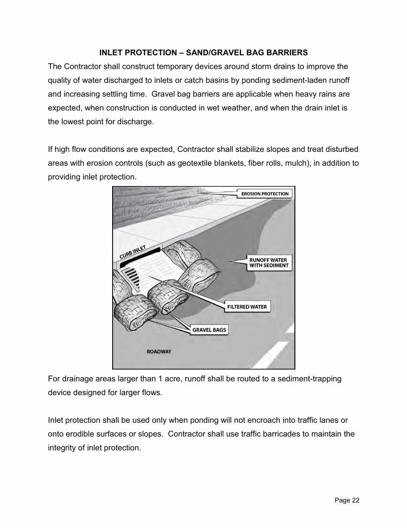
Page 22
INLET PROTECTION – SAND/GRAVEL BAG BARRIERS The Contractor shall construct temporary devices around storm drains to improve the
quality of water discharged to inlets or catch basins by ponding sediment-laden runoff
and increasing settling time. Gravel bag barriers are applicable when heavy rains are
expected, when construction is conducted in wet weather, and when the drain inlet is
the lowest point for discharge.
If high flow conditions are expected, Contractor shall stabilize slopes and treat disturbed
areas with erosion controls (such as geotextile blankets, fiber rolls, mulch), in addition to
providing inlet protection.
For drainage areas larger than 1 acre, runoff shall be routed to a sediment-trapping
device designed for larger flows.
Inlet protection shall be used only when ponding will not encroach into traffic lanes or
onto erodible surfaces or slopes. Contractor shall use traffic barricades to maintain the
integrity of inlet protection.

Page 23
Frequent Contractor maintenance shall be provided to remove silt deposits and buildup
and to minimize short-circuiting and overtopping.
(Recommended inspection text from previous page.)

Page 24
SEDIMENT CONTROL/ENERGY DISSIPATION In flow areas, implement controls to divert flow, slow flow velocity, and pond and filter
runoff.
Every attempt should be made to stabilize disturbed soils at the source. If sediment or
polluted water is making its way into the drain inlet, Contractor shall locate the source
and contain it using appropriate controls.
Check Dams
A check dam constructed of sand or gravel bags will slow flow velocity, pond water and
allow sediment to settle. Check dams are appropriate in small open channels draining
10 acres or less.
Contractor shall maintain check dams by removing trapped sediment to prevent its
resuspension in subsequent storms. Contractor shall inspect check dams after
significant rain events and replace loosed materials (rocks, gravel bags) as necessary.
Public safety is paramount. No controls shall be installed which present a hazard to the
public.

Page 25
FIBER ROLL DIKES Fiber rolls shall be entrenched and anchored according to the following installation
specifications:
Fiber rolls may be used for small areas or short slopes (3:1 or flatter) with low surface
flows not to exceed 1 cfs:
• Along the face of exposed and erodible slopes to shorten slope length.
• At grade breaks where slopes transition to a steeper slope.
• In drainage swales to slow flows.
• Along stream banks to assist stabilization and revegetation (wattles favorable for
plant establishment).
• Behind sidewalks or curbs.
Contractor shall inspect and maintain fiber rolls to maintain performance. Split, torn,
unraveling or slumping rolls shall be repaired or replaced as necessary.

Page 26
SILT FENCING Silt fencing is a permeable fabric designed to intercept and slow the flow of
sediment-laden runoff. Silt fencing ponds runoff, allows sediment to settle, and releases
the filtered water slowly. Silt fence must pond water to be effective.
Silt fencing may be used along the perimeter of the site, along (not across) streams and
channels, and around temporary stockpiles. Silt fence material shall be entrenched a
minimum of 4 inches to 6 inches. Contractor shall not anchor silt fencing without first
entrenching it.
Use of silt fence shall be limited to locations suitable for temporary ponding or
deposition of sediment. Silt fences shall not be used to divert flow and shall be placed
along the contour.
Silt fencing shall be routinely inspected by Contractor, and all undercutting, split, torn or
slumping material immediately repaired. Contractor shall remove silt fencing when no
longer necessary for sediment control.
If a small site has been
adequately protected from
erosion, silt fencing may be used
as a secondary control measure
or may not be necessary.

Page 27

Page 28
STABILIZED CONSTRUCTION ENTRANCE At an unpaved site (for example: an unpaved microtunneling or pump station site or
Contractor staging area), the point of ingress/egress shall be stabilized to minimize the
tracking of mud and dirt onto public roads by construction vehicles according to the
following specifications:
• Design the entrance to support the heaviest vehicles which will use it.
• Grade the entrance to prevent runoff from the construction site.
• The rock egress pad shall be 20-feet wide x 40-feet long x 8-feet deep consisting
of 6-inch to 8-inch diameter fractured stone aggregate placed over a geotextile
fabric.
• Mud grates and/or a tire wash shall be used at the intersection of paved
roadways and access roads for construction sites adjacent to creek areas, or
when BMPs not effective in keeping sediments from being tracked onto roadway.
• Contractor shall require that all employees, subcontractors, and suppliers utilize
the stabilized construction entrance.
• Contractor shall inspect for damage and remove and replace aggregate of
egress pad, as necessary, and repair the structure when needed.

Page 29
STORAGE/MAINTENANCE YARD AND DISPOSAL SITES If the Contractor enters into separate agreements with property owners for use of
parcels for a Contractor's yard for any of the purposes listed below – those sites will not
be under the control of the Engineer. However, the Contractor shall assure the
Engineer that there are no adverse environmental impacts related to use of parcels
where the Engineer has no control.
*Defined as any area to be used for:
• Loading or unloading
• Materials storage
• Vehicle and equipment maintenance
• Concrete truck washout
• Temporary storage of excess materials or debris
• Storage or disposal of spoil materials (such as excess construction material and
excavated material not suitable for use as backfill material).
The Contractor shall prepare a separate Storm Water Pollution Prevention Plan
(SWPPP) for the disposal site in accordance with the requirements of the California
State Water Resources Control Board and local agency ordinance, unless the site has a
separate SWPPP or a separate discharge permit from the California Regional Water
Quality Control Board. The SWPPP shall be signed by both the Contractor and the
property owner. A copy of the Contractor's SWPPP shall be submitted to the Engineer
prior to any activities in the site. If the Contractor's SWPPP is revised during work
progress, all revisions shall be submitted to the Engineer.
Permit application fees and costs incurred in preparing and/or amending the Storm
Water Pollution Prevention Plan developed for the site shall be at the expense of the
Contractor.

Page 30
SOLID AND DEMOLITION WASTE MANAGEMENT Only clean, uncontaminated water may be discharged to the storm drain, waterway, or
sanitary sewer with SDP. Non-hazardous, solid demolition wastes shall be managed
according to the following specifications:
• Waste collection areas shall be located away from streets, gutters, and storm
drains.
• Dumpsters shall be secured at night and during rain events.
• Leaky dumpsters shall be replaced/exchanged and returned for cleaning as
necessary.
• Arrangements for disposal shall be made to ensure dumpsters do not overflow.
Examples of Non-Hazardous Materials:
Drilling fluid additives
Wood, framing, etc.
Concrete, brick, cement mortar
Asphalt
Cleared vegetation, tree trimmings, plant material
Dry paint/non-hazardous paint chips/dust from stripping and sandblasting of
non-hazardous paint
Absorbent material (rags, mats) used to absorb non-hazardous spills (materials
used to absorb oil-based spills shall be disposed of as hazardous waste)
Steel and metal scraps
Pipe and electrical cuttings
Ground and/or broken paving materials
Domestic wastes (containers, cans, cups, etc.)

Page 31
HAZARDOUS WASTE AND MATERIALS MANAGEMENT Upon approval of Engineer, only clean, uncontaminated rainwater may be discharged to
a storm drain or waterway. Contractor shall manage hazardous wastes and materials
according to the following specifications:
• Chemical and/or hazardous materials storage and handling areas shall be
located away from watercourses and storm drains.
• Secondary containment shall have capacity to contain twice the contents of the
largest container, and large enough to capture any accidental releases.
• Leaks or spills shall be cleaned up immediately, including within the secondary
diked area.
• Contractor shall ensure that trailers carrying hazardous materials are covered
during transit (illegal transit of hazardous waste is a violation subject to fine
and/or jail time).
• Hazardous waste shall be disposed of only at authorized treatment, storage, and
disposal facilities (illegal dumping of hazardous waste is a violation subject to fine
and/or jail time).
• Contractor shall use only a licensed company to transport and dispose of
contaminated materials.
If storm water runoff enters the storage area or otherwise comes in contact with
construction material, the Contractor shall determine if the storm water has become
contaminated. Only clean, uncontaminated rainwater shall be discharged to a storm
drain, waterway, or the sanitary sewer under an SDP.
If the storm water runoff has come in contact with the construction materials, the
Contractor shall provide an appropriate collection system for disposal of the storm water
runoff in a manner acceptable to the San Francisco Bay RWQCB or under an SDP
issued by the District's Source Control Section. Contractor shall use only a licensed
hazardous waste handling company to clean up large spills.

Page 32
Major contamination, large spills, and other serious hazardous waste incidents will
require initial containment and immediate response from specialists. Spills of any
hazardous materials shall be reported immediately. Contractor shall notify the
Engineer, the Office of Emergency Service (OES) at 800-852-7550, the RWQCB at
510-622-2300, and the County Health Department 925-646-2286 when a hazardous
spill occurs. If there is indecision as to whether water quality will be impacted, the
Contractor shall contact the Regional Board to discuss the situation. If long-term
remedial action is necessary, the RWQCB may issue enforcement orders to assure
proper cleanup. Failure to report a spill resulting in discharge to a storm drain,
waterway, or sanitary sewer not by RWQCB, either pull out or reference follow-up by
the District, will result in greatly increased cleanup costs and enforcement action by the
RWQCB.
Example of Hazardous Wastes/Materials:
Drilling fluid additives
Petroleum products, such as oil, fuel, and grease
Asphalt products
Concrete curing compounds
Herbicides and pesticides
Chemical additives
Septic wastes
Paints, thinners, and solvents
Materials used to absorb hazardous spills
Acids, lime, glues, and curing compounds
Any material considered a hazardous waste by the State of California
The following preexisting site conditions may make contamination more likely:
• Areas of previous commercial or industrial activity.
• Sites with a history of illegal dumping on the site or on adjacent properties.
• Sites subject to Superfund, state or local cleanup order.

Page 33
• Ponded storm water, groundwater, or dewatering areas which exhibit an oily
sheen or smell of petroleum.
• Soils which appear discolored, smell of petroleum, or exhibit other unusual
properties.
• Sites where abandoned storage tanks, drums, or other buried debris are
encountered during construction activity.

Page 34
PAVEMENT MANAGEMENT Proper management of pavement construction materials and activities minimizes or
eliminates discharges to gutters, storm drains, and watercourses resulting from on-site
road paving, surfacing, and asphalt-removing activities.
Concrete, asphalt, and seal coat shall be applied during dry, appropriately-temperatured
weather to prevent contaminants from coming in contact with storm water runoff. Storm
drain inlets, catch basins, and manholes shall be covered while applying seal coat, tack
seal, slurry seal, fog seal, or similar materials. Paving machines (when not in use) shall
be placed over drip pans or absorbent materials since they tend to drip continuously.
Unless approved by the Engineer, during wet weather or when rain is forecast within 24
hours, the Contractor shall not pave or oil the street. If rain occurs during paving, the
Contractor shall arrange for a container to be delivered to the site to intercept rainwater
(see Specifications GC-59). Depending on site conditions, Contractor shall divert storm
water over the new pavement work to minimize water becoming contaminated.
The Contractor shall not sweep or wash down excess sand (placed as part of a sand
seal or to absorb excess oil) into gutters, storm drains, or creeks. The Contractor shall
either collect the sand and return it to the stockpile or dispose of it in a trash container.
Saw-Cutting
The Contractor shall prevent saw-cut slurry from entering catch basins and storm
drains. The slurry should be removed using a vacuum. The area over which the slurry
may spread should also be limited.
When making saw-cuts, Contractor shall not allow saw-cutting water to leave the work
site, enter a storm drain, waterway, or sanitary sewer under any conditions.
Toward this end, Contractor shall:
• Protect the drain inlet by covering it completely with filter fabric.

Page 35
• Use as little water as possible.
• Shovel, absorb, or vacuum the slurry residue from pavement or gutter, as
necessary, and remove from site at the end of the day/job.

Page 36
CONCRETE MANAGEMENT Contractor shall perform concrete washout in a designated area where the water will
flow into a temporary pit or bermed area in the dirt area from where it can be
pumped or dried before proper disposal. The wash water may not be discharged to
storm drain, waterway, or sanitary sewer.
Contractor's concrete wash water pit shall be located away from watercourses and
storm drains and shall be sized large enough to hold the maximum volume of waste
expected. Contractor shall drain wash water of exposed aggregate concrete to a dirt
area or onto stockpiles of aggregate base or sand. Water shall be allowed to
percolate into the soil and hardened concrete disposed of in a trash container. If a
suitable dirt area is not available, the Contractor shall collect the wastewater into a
steel, leakproof debris box. Contractor shall not discharge any wash water into
storm drain, waterway, or sanitary sewer.

Page 37
VEHICLE AND EQUIPMENT SERVICES The Contractor shall use secondary containment, such as a drip pan, to catch leaks
or spills any time that vehicle or equipment fluids are dispensed, changed, or
poured, and shall clean up leaks and spills of vehicle or equipment fluids
immediately and dispose of the waste and cleanup materials as a hazardous waste.
The Contractor shall inspect vehicles and equipment arriving on site for leaking
fluids and shall promptly repair leaking vehicles and equipment. Drip pans shall be
used to catch leaks until repairs are made. The Contractor shall perform
maintenance and fueling of vehicles or equipment in areas that will not allow run-on
of storm water or runoff of spills to storm drains and provide for confined cleanup.
The Contractor shall not contaminate the soils or groundwater with such
maintenance and fueling activities. Contractor shall encourage fueling and major
maintenance/repair and washing off site whenever possible.
Vehicle and Equipment Washing
Water from equipment washing
shall not be allowed to be
discharged to a storm drain,
waterway, or the sanitary sewer
unless authorized by an SDP.
The Contractor shall perform
vehicle or equipment cleaning
with water only in a designated,
bermed area that will not allow
rinse water to run off site into
streets, gutters, storm drains, or
creeks. Soaps, solvents,
degreasers, steam-cleaning

Page 38
equipment, or equivalent methods will not be allowed. Sumps associated with the
wash areas shall be serviced regularly and fully pumped dry by a permitted waste
hauler prior to closure of yard.

Page 39
SECONDARY CONTAINMENT Wet and dry building materials
with the potential to pollute
runoff shall be handled and
delivered with care and stored
under cover and/or surrounded
by berms to prevent contact with
runoff.
The Contractor shall also
include containment areas and
provide for proper disposal of
these materials, their
containers, and materials or soil
that may be contaminated with
these materials.
Perimeter controls, containment structures, and covers shall be repaired, as
necessary, to ensure their proper functioning.
The Contractor shall maintain the site in a neat and clean and well organized
condition.
Potential pollutants include:
Pesticides and herbicides
Fertilizers
Detergents
Asphalt and concrete compounds
Petroleum products, such as fuel, oil, and grease
Acids, lime glues, adhesives, curing compounds, etc.
Paints and solvents

Page 40
All hazardous materials shall be labeled and stored according to local, state, and
federal regulations and according to fire code requirements. Contractor shall keep
an inventory of hazardous material for use in emergency and shall post proper
storage instructions at all times in an open and conspicuous location. Contractor
shall use mats during transport and storage and shall not apply hazardous
chemicals outdoors during wet weather.
Contractor shall immediately clean up all spills, including:
Slurry from boring operations
Excess concrete and grout
Coatings
Controlled, low-strength material
Curing compounds
Lubricants
Paint

Page 41
PAINT MANAGEMENT Only clean rainwater shall be discharged to storm drains and/or waterways. The
Contractor shall remove as much excess paint as possible from brushes, rollers, and
equipment before starting cleanup.
Water-Based Paints
The Contractor may discharge very small amounts of cleaning wastes from brushes,
rollers, buckets, and tools contaminated with latex (water based) paints to the sanitary
sewer system provided they do not contain certain additives which are pollutants of
concern (mercury, tributyltin). Where not possible, clean with water, disperse wash
water over spoils, and spade in. Buckets containing leftover paints shall first be
recycled or properly disposed of.
Oil-Based Paints
For oil-based paints, paint out brushes to the extent possible; filter and reuse
thinner/solvents.
Dried latex paint, old brushes, rollers, etc., shall be disposed of as non-hazardous
waste. The Contractor shall dispose of thinner, solvent, sludge from cleaning
equipment and tools, and excess oil as a hazardous waste. Hazardous materials that
are not recyclable shall be disposed of by a licensed hazardous waste hauler.
Hazardous and non-hazardous paint-related materials, paint wastes, adhesives and
cleaning fluids shall be recycled when possible and disposed of properly to prevent
contact with storm water and discharge into storm drains/watercourses. Contractor
shall designate an area for cleaning of painting equipment and tools. Contractor shall
ensure that clean brushes or rinse containers are not washed into street gutters, storm
drains, or waterways.
Only clean rainwater shall be discharged to the storm drains and/or waterways.
Hazardous and non-hazardous paint-related materials, paint wastes, adhesives and

Page 42
cleaning fluids shall be recycled when possible and disposed of properly to prevent
contact with storm water and discharged into storm drains/watercourses. Contractor
shall designate an area for cleaning of paint equipment and tools. Contractor shall
ensure that wash water from cleaning of brushes, rollers, buckets, containers, and tools
is not discharged to the street, gutters, storm drains, or waterways.
Water-Based Paints
The Contractor shall remove as much excess paint as possible from brushes, rollers,
and equipment before starting cleanup. The Contractor may discharge small amounts
of cleaning wastes from brushes, rollers, buckets, and tools contaminated with latex
(water based) paints to the sanitary sewer system provided they do not contain certain
additives which are pollutants of concern (mercury, tributyltin). Where not possible,
wash water may be dispersed into spoils pile. Buckets containing leftover paints shall
be recycled or properly disposed of.
Oil-Based Paints
The Contractor shall remove as much excess paint as possible from brushes, rollers,
and equipment before starting cleanup. Thinner and solvents shall be filtered and
reused if appropriate. The Contractor shall dispose of thinner, solvent, sludge from
cleaning equipment and tools, and excess oil-based paint as hazardous waste.
Hazardous materials that are not recyclable shall be disposed of by a licensed
hazardous waste hauler.

Page 43
RESOURCES "Erosion and Sediment Control Field Manual" Regional Water Quality Control Board San Francisco Bay Region $35.00 Available from friends of the Estuary 510-622-2419 Guidelines for Construction Projects SFRWQCB $15 Available from Friends of the Estuary 510-622-2419 Storm Water Best Management Practice Handbook – Construction California Storm Water Quality Association $95.00 CSU Sacramento Office of Water Programs 916-278-6142 Videos: "Holds on to your Dirt: Preventing Erosion from Construction Projects" San Francisco Estuary Project $15.00 Available from Friends of the Estuary 510-622-2419 "Keep it Clean: Preventing Pollution from Construction Projects" San Francisco Estuary Project $15.00 Available from Friends of the Estuary 510-622-2419