
Hardwired and Microprogrammed Control For each instruction ...
21
1 Hardwired and Microprogrammed Control For each instruction, the control unit causes the CPU to execute a sequence of steps correctly. In reality, there must be control signals to assert lines on various digital components to make things happen. For example, when we perform an Add instruction in assembly language, we assume the addition takes place because the control signals for the ALU are set to "add" and the result is put into the AC. The ALU has various control lines that determine which operation to perform. The question we need to answer is, "How do these control lines actually become asserted?" We can take one of two approaches to ensure control lines are set properly. The first approach is to physically connect all of the control lines to the actual machine instructions. The instructions are divided up into fields, and different bits in the instruction are combined through various digital logic components to drive the control lines. This is called hardwired control, and is illustrated in figure (1) Instruction Register Instruction Decoder Input from clock Control Unit (Combinational Circuit) Input from system bus (such as interrupts) Input from status/ flag register Control Signals (These signals go to register) The bus and the ALU Hardwired Control Organization
-
Upload
khangminh22 -
Category
Documents
-
view
1 -
download
0
Transcript of Hardwired and Microprogrammed Control For each instruction ...

1
Hardwired and Microprogrammed Control
For each instruction, the control unit causes the CPU to execute a sequence of
steps correctly. In reality, there must be control signals to assert lines on various digital
components to make things happen. For example, when we perform an Add instruction in
assembly language, we assume the addition takes place because the control signals for the
ALU are set to "add" and the result is put into the AC. The ALU has various control lines
that determine which operation to perform. The question we need to answer is,
"How do these control lines actually become asserted?"
We can take one of two approaches to ensure control lines are set properly. The
first approach is to physically connect all of the control lines to the actual machine
instructions. The instructions are divided up into fields, and different bits in the
instruction are combined through various digital logic components to drive the control
lines. This is called hardwired control, and is illustrated in figure (1)
Instruction Register
Instruction Decoder
Input from clock
Control Unit
(Combinational Circuit)
Input from system bus
(such as interrupts) Input from status/
flag register
Control Signals
(These signals go to register)
The bus and the ALU
Hardwired Control Organization
2
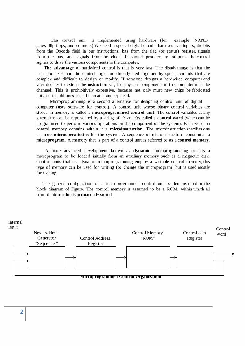
The control unit is implemented using hardware (for example: NAND
gates, flip-flops, and counters).We need a special digital circuit that uses , as inputs, the bits
from the Opcode field in our instructions, bits from the flag (or status) register, signals
from the bus, and signals from the clock. It should produce, as outputs, the control
signals to drive the various components in the computer.
The advantage of hardwired control is that is very fast. The disadvantage is that the
instruction set and the control logic are directly tied together by special circuits that are
complex and difficult to design or modify. If someone designs a hardwired computer and
later decides to extend the instruction set, the physical components in the computer must be
changed. This is prohibitively expensive, because not only must new chips be fabricated
but also the old ones must be located and replaced.
Microprogramming is a second alternative for designing control unit of digital
computer (uses software for control). A control unit whose binary control variables are
stored in memory is called a microprogrammed control unit. The control variables at any
given time can be represented by a string of 1's and 0's called a control word (which can be
programmed to perform various operations on the component of the system). Each word in
control memory contains within it a microinstruction. The microinstruction specifies one
or more microoperatiotins for the system. A sequence of microinstructions constitutes a
microprogram. A memory that is part of a control unit is referred to as a control memory.
A more advanced development known as dynamic microprogramming permits a
microprogram to be loaded initially from an auxiliary memory such as a magnetic disk.
Control units that use dynamic microprogramming employ a writable control memory; this
type of memory can be used for writing (to change the microprogram) but is used mostly
for reading.
The general configuration of a microprogrammed control unit is demonstrated in the
block diagram of Figure. The control memory is assumed to be a ROM, within which all
control information is permanently stored.
internal input
Next-Address
Generator
"Sequencer"
Control Address
Register
Control Memory
"ROM"
Control data
Register
Control
Word
Microprogrammed Control Organization

3
The control memory address register specifies the address of the microinstruction and
the control data register holds the microinstruction read from memory the
microinstruction contains a control word that specifies one or more microoperations for the
data processor. Once these operations are executed, the control must determine the
next address. The location of the next microinstruction may be the one next in sequence,
or it may be locate somewhere else in the control memory. For this reason it is necessary
to use some bits of the present microinstruction to control the generation of the address of the
next microinstruction. The next address may also be a function of external input
conditions. While the microoperations are being executed, the next address is computed
in the next address generator circuit and then transferred into the control address register
to read the next microinstruction.
The next address generator is sometimes called a microprogram sequencer,
as it determines the address sequence that is read from control memory, the address of the
next microinstruction can be specified several ways, depending on the sequencer
inputs. Typical functions of a microprogram sequencer are incrementing the control
address register by one, loading into the control address register an address from control
memory, transferring an external address or loading an initial address to start the control
operations.
The main advantages of the microprogrammed control are the fact that once the
hardware configuration is established; there should be no need for further hardware or wiring
changes. If we want to establish are different control sequence for the system, all we need to
do is specify different set microinstructions for control memory. The hardware
configuration should not be changed for different operations; the only thing that must be
changed is the microprogram residing in control memory.
Microinstructions are stored in control memory in groups, with each group specifying
routine. Each computer instruction has microprogram routine in control memory to
generate the microoperations that execute the instruction. The hardware that controls the
address sequencing of the control memory must be capable of sequencing the microinstructions
within a routine and be to branch from one routine to another. The
address sequencing capabilities required in a control memory are: 1. Incrementing of the control address register.
2. Unconditional branch or conditional branch, depending on status bit conditions.
3. A mapping process from the bits of the instruction to an address for control memory.
4. A facility for subroutine call and return.
Figure (3) shows a block diagram of control memory and the associated hardware
needed for selecting the next microinstruction address. The microinstruction in control
memory contains a set of bits to initiate microoperations in computer registers and other bits
to specify the method by which the address is obtained. The diagram shows four different
paths from which the control address register (CAR) receives the address. The incrementer
increments the content of the control address register by one, to select the next
microinstruction in sequence. Branching is achieved by specifying the branch address
in one of the fields of the microinstruction. Conditional branching is obtained by using part
of the microinstruction to select a specific status bit in order to determine its
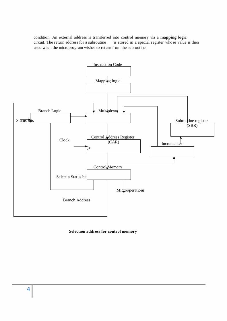
4
condition. An external address is transferred into control memory via a mapping logic
circuit. The return address for a subroutine is stored in a special register whose value is then
used when the microprogram wishes to return from the subroutine.
Instruction Code
Mapping logic
Branch Logic Multiplexer
Status bits Subroutine register
(SBR)
Clock Control Address Register
(CAR)
Incrementer
Control Memory
Select a Status bit
Microoperations
Branch Address
Selection address for control memory
5
Memory Organization
A memory unit is the collection of storage units or devices together. The memory unit stores the binary information
in the form of bits. Generally, memory/storage is classified into 2 categories:
Volatile Memory: This loses its data, when power is switched off.
Non-Volatile Memory: This is a permanent storage and does not lose any data when power is switched off.
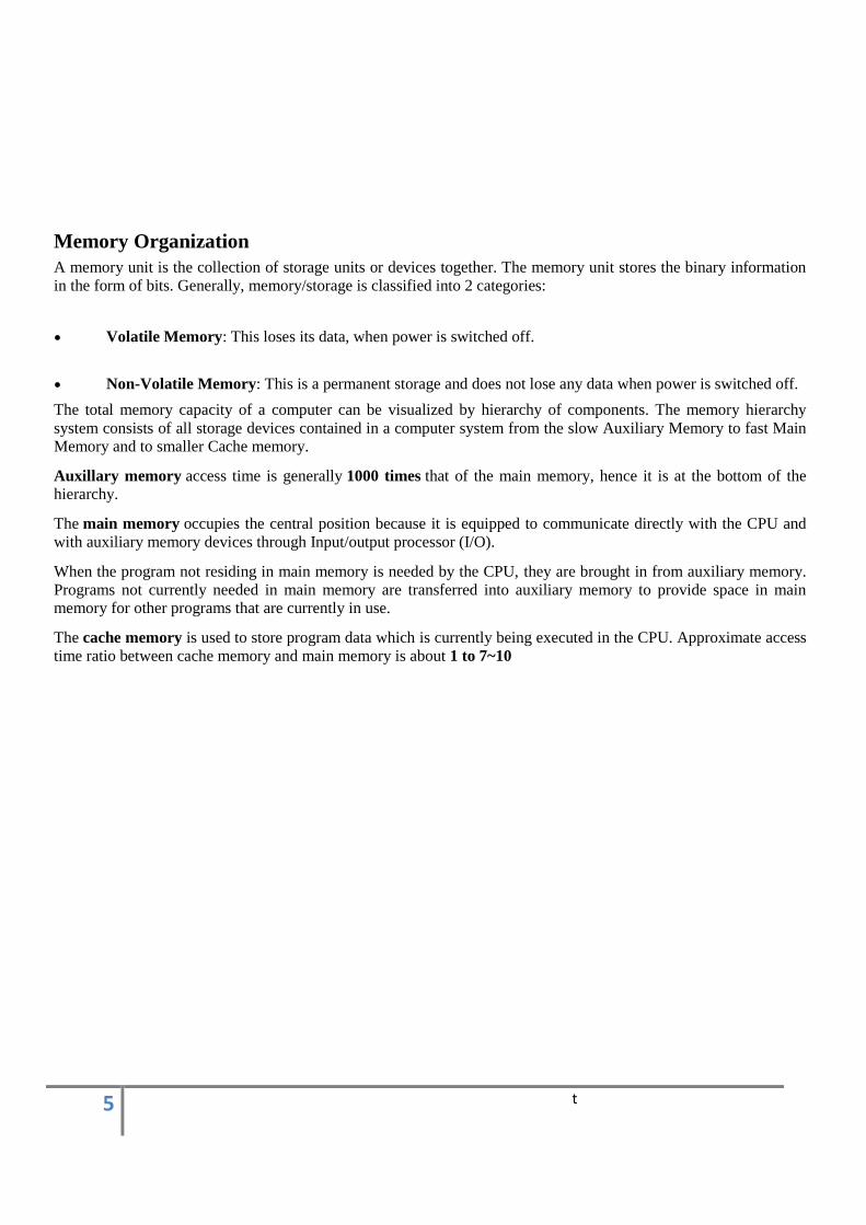
The total memory capacity of a computer can be visualized by hierarchy of components. The memory hierarchy
system consists of all storage devices contained in a computer system from the slow Auxiliary Memory to fast Main Memory and to smaller Cache memory.
Auxillary memory access time is generally 1000 times that of the main memory, hence it is at the bottom of the hierarchy.
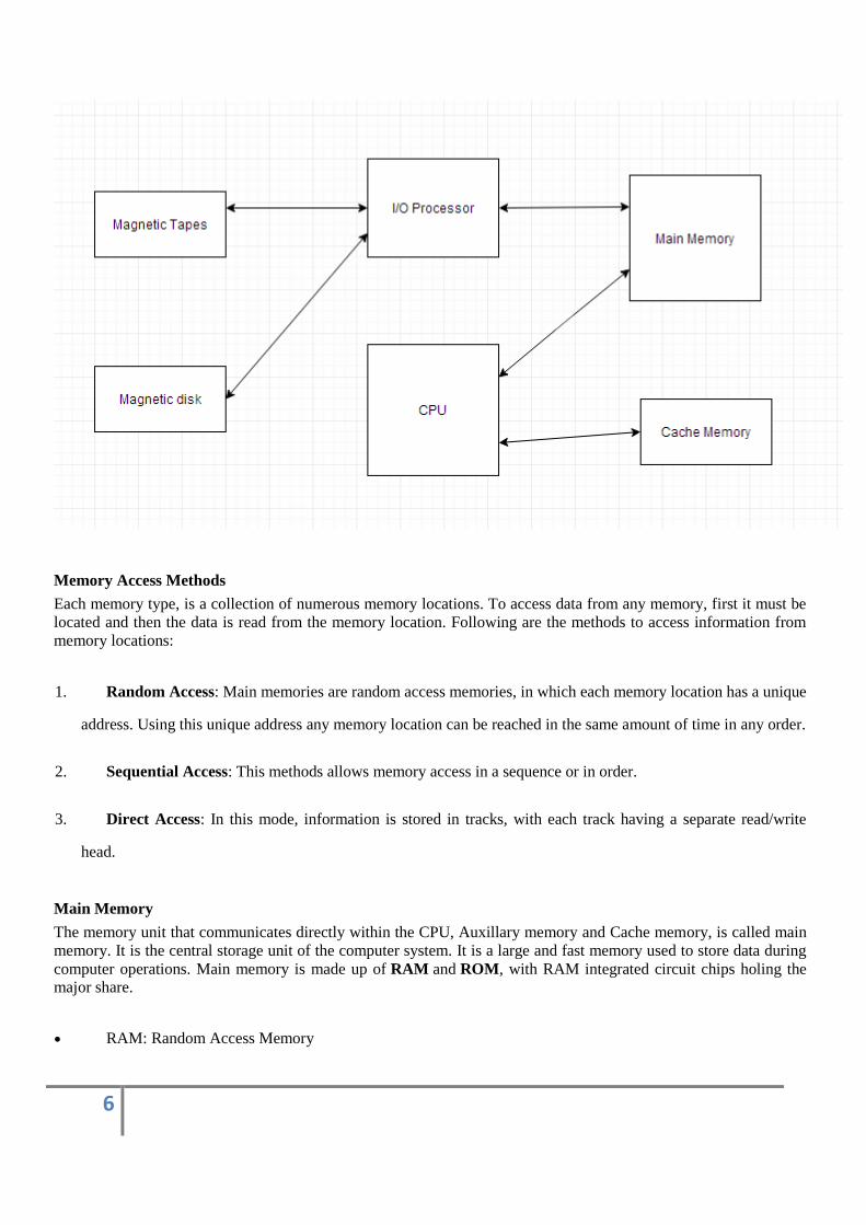
The main memory occupies the central position because it is equipped to communicate directly with the CPU and
with auxiliary memory devices through Input/output processor (I/O).
When the program not residing in main memory is needed by the CPU, they are brought in from auxiliary memory.
Programs not currently needed in main memory are transferred into auxiliary memory to provide space in main memory for other programs that are currently in use.
The cache memory is used to store program data which is currently being executed in the CPU. Approximate access
time ratio between cache memory and main memory is about 1 to 7~10
t
6
Memory Access Methods
Each memory type, is a collection of numerous memory locations. To access data from any memory, first it must be
located and then the data is read from the memory location. Following are the methods to access information from
memory locations:
1. Random Access: Main memories are random access memories, in which each memory location has a unique
address. Using this unique address any memory location can be reached in the same amount of time in any order.
2. Sequential Access: This methods allows memory access in a sequence or in order.
3. Direct Access: In this mode, information is stored in tracks, with each track having a separate read/write
head.
Main Memory
The memory unit that communicates directly within the CPU, Auxillary memory and Cache memory, is called main
memory. It is the central storage unit of the computer system. It is a large and fast memory used to store data during
computer operations. Main memory is made up of RAM and ROM, with RAM integrated circuit chips holing the major share.
RAM: Random Access Memory
7
o DRAM: Dynamic RAM, is made of capacitors and transistors, and must be refreshed every 10~100
ms. It is slower and cheaper than SRAM.
o SRAM: Static RAM, has a six transistor circuit in each cell and retains data, until powered off.
o NVRAM: Non-Volatile RAM, retains its data, even when turned off. Example: Flash memory.
ROM: Read Only Memory, is non-volatile and is more like a permanent storage for information. It also
stores the bootstrap loader program, to load and start the operating system when computer is turned
on. PROM(Programmable ROM), EPROM(Erasable PROM) and EEPROM(Electrically Erasable PROM) are
some commonly used ROMs.
Auxiliary Memory
Devices that provide backup storage are called auxiliary memory. For example: Magnetic disks and tapes are
commonly used auxiliary devices. Other devices used as auxiliary memory are magnetic drums, magnetic bubble memory and optical disks. It is not directly accessible to the CPU, and is accessed using the Input/Output channels.
Cache Memory
The data or contents of the main memory that are used again and again by CPU, are stored in the cache memory so that we can easily access that data in shorter time.
Whenever the CPU needs to access memory, it first checks the cache memory. If the data is not found in cache
memory then the CPU moves onto the main memory. It also transfers block of recent data into the cache and keeps
on deleting the old data in cache to accomodate the new one.
Hit Ratio
The performance of cache memory is measured in terms of a quantity called hit ratio. When the CPU refers to
memory and finds the word in cache it is said to produce a hit. If the word is not found in cache, it is in main memory then it counts as a miss.
The ratio of the number of hits to the total CPU references to memory is called hit ratio.
Hit Ratio = Hit/(Hit + Miss)
Associative Memory
It is also known as content addressable memory (CAM). It is a memory chip in which each bit position can be
compared. In this the content is compared in each bit cell which allows very fast table lookup. Since the entire chip
can be compared, contents are randomly stored without considering addressing scheme. These chips have less storage capacity than regular memory chips.
Mapping and Concept of Virtual Memory
8
The transformation of data from main memory to cache memory is called mapping. There are 3 main types of mapping:
Associative Mapping
Direct Mapping
Set Associative Mapping
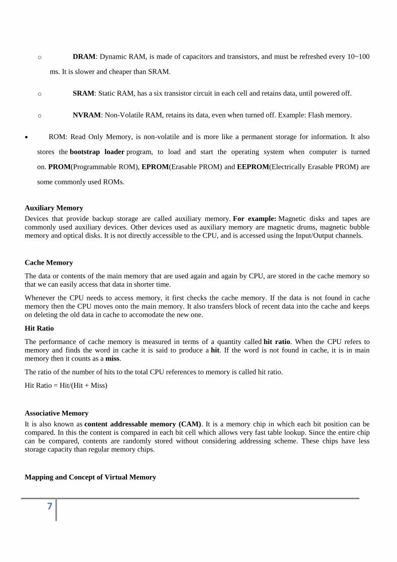
Associative Mapping
The associative memory stores both address and data. The address value of 15 bits is 5 digit octal numbers and data
is of 12 bits word in 4 digit octal number. A CPU address of 15 bits is placed in argument register and the
associative memory is searched for matching address.
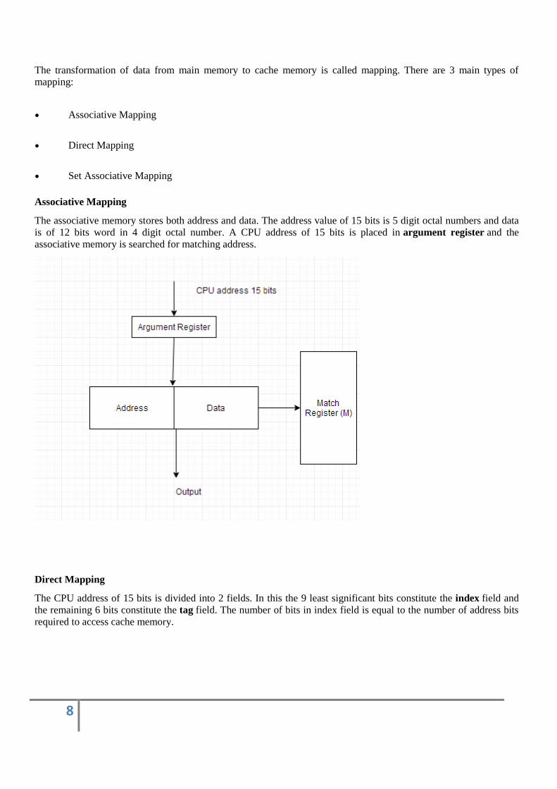
Direct Mapping
The CPU address of 15 bits is divided into 2 fields. In this the 9 least significant bits constitute the index field and
the remaining 6 bits constitute the tag field. The number of bits in index field is equal to the number of address bits
required to access cache memory.
9
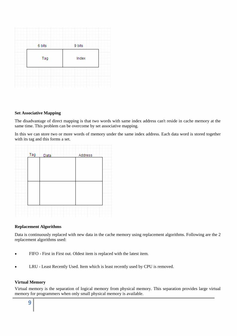
Set Associative Mapping
The disadvantage of direct mapping is that two words with same index address can't reside in cache memory at the same time. This problem can be overcome by set associative mapping.
In this we can store two or more words of memory under the same index address. Each data word is stored together
with its tag and this forms a set.
Replacement Algorithms
Data is continuously replaced with new data in the cache memory using replacement algorithms. Following are the 2
replacement algorithms used:
FIFO - First in First out. Oldest item is replaced with the latest item.
LRU - Least Recently Used. Item which is least recently used by CPU is removed.
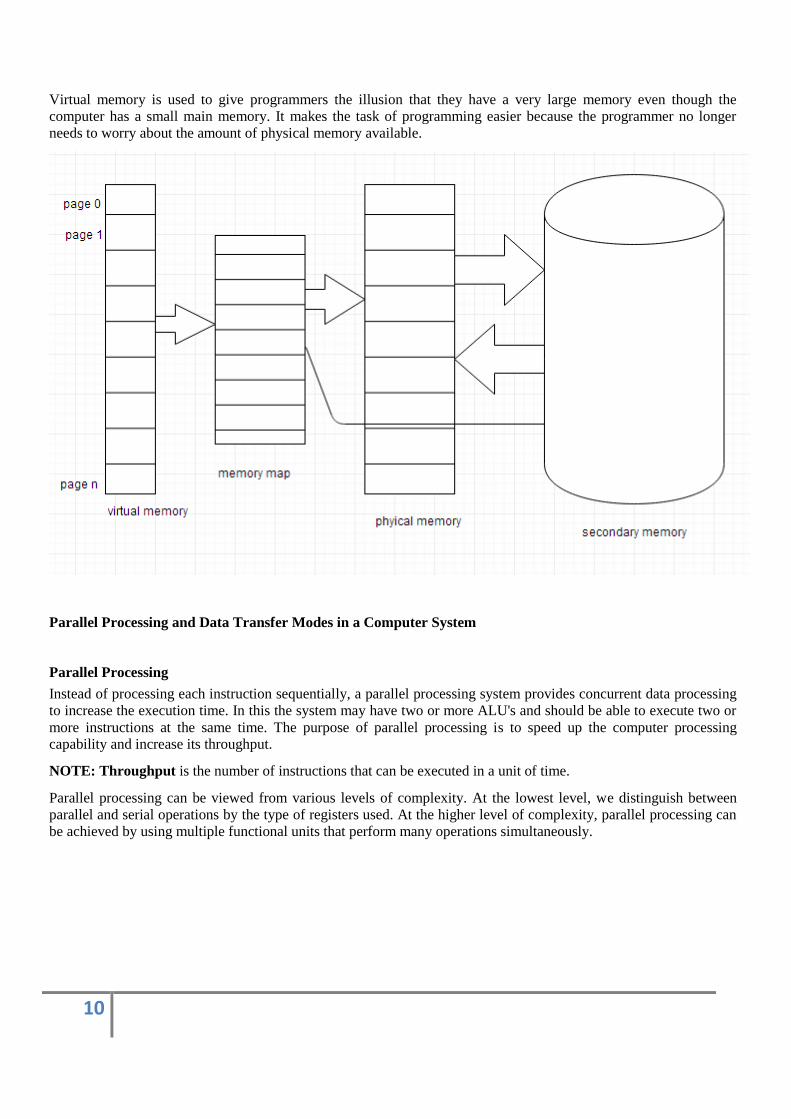
Virtual Memory
Virtual memory is the separation of logical memory from physical memory. This separation provides large virtual memory for programmers when only small physical memory is available.
10
Virtual memory is used to give programmers the illusion that they have a very large memory even though the
computer has a small main memory. It makes the task of programming easier because the programmer no longer
needs to worry about the amount of physical memory available.
Parallel Processing and Data Transfer Modes in a Computer System
Parallel Processing
Instead of processing each instruction sequentially, a parallel processing system provides concurrent data processing
to increase the execution time. In this the system may have two or more ALU's and should be able to execute two or
more instructions at the same time. The purpose of parallel processing is to speed up the computer processing capability and increase its throughput.
NOTE: Throughput is the number of instructions that can be executed in a unit of time.
Parallel processing can be viewed from various levels of complexity. At the lowest level, we distinguish between
parallel and serial operations by the type of registers used. At the higher level of complexity, parallel processing can
be achieved by using multiple functional units that perform many operations simultaneously.
11
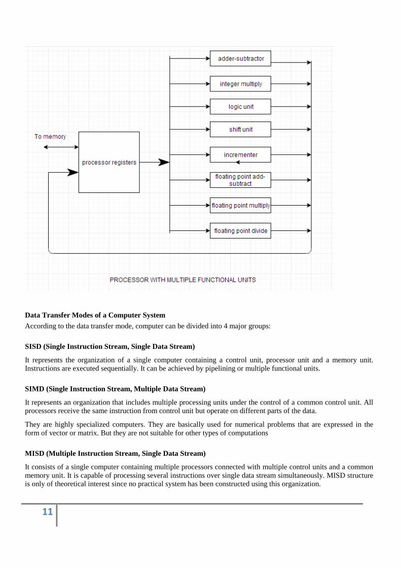
Data Transfer Modes of a Computer System
According to the data transfer mode, computer can be divided into 4 major groups:
SISD (Single Instruction Stream, Single Data Stream)
It represents the organization of a single computer containing a control unit, processor unit and a memory unit. Instructions are executed sequentially. It can be achieved by pipelining or multiple functional units.
SIMD (Single Instruction Stream, Multiple Data Stream)
It represents an organization that includes multiple processing units under the control of a common control unit. All processors receive the same instruction from control unit but operate on different parts of the data.
They are highly specialized computers. They are basically used for numerical problems that are expressed in the
form of vector or matrix. But they are not suitable for other types of computations
MISD (Multiple Instruction Stream, Single Data Stream)
It consists of a single computer containing multiple processors connected with multiple control units and a common
memory unit. It is capable of processing several instructions over single data stream simultaneously. MISD structure is only of theoretical interest since no practical system has been constructed using this organization.

12
MIMD (Multiple Instruction Stream, Multiple Data Stream
It represents the organization which is capable of processing several programs at same time. It is the organization of
a single computer containing multiple processors connected with multiple control units and a shared memory unit.
The shared memory unit contains multiple modules to communicate with all processors simultaneously.
Multiprocessors and multicomputer are the examples of MIMD. It fulfills the demand of large scale computations.
Pipelining
Pipelining is the process of accumulating instruction from the processor through a pipeline. It allows storing and
executing instructions in an orderly process. It is also known as pipeline processing.
Pipelining is a technique where multiple instructions are overlapped during execution. Pipeline is divided into stages
and these stages are connected with one another to form a pipe like structure. Instructions enter from one end and exit from another end.
Pipelining increases the overall instruction throughput.
In pipeline system, each segment consists of an input register followed by a combinational circuit. The register is
used to hold data and combinational circuit performs operations on it. The output of combinational circuit is applied
to the input register of the next segment.
Pipeline system is like the modern day assembly line setup in factories. For example in a car manufacturing industry,
huge assembly lines are setup and at each point, there are robotic arms to perform a certain task, and then the car moves on ahead to the next arm.
Types of Pipeline:
It is divided into 2 categories:
13
Arithmetic Pipeline
Arithmetic pipelines are usually found in most of the computers. They are used for floating point operations, multiplication of fixed point numbers etc.
Instruction Pipeline
In this a stream of instructions can be executed by overlapping fetch, decode and execute phases of an instruction cycle. This type of technique is used to increase the throughput of the computer system.
An instruction pipeline reads instruction from the memory while previous instructions are being executed in other
segments of the pipeline. Thus we can execute multiple instructions simultaneously. The pipeline will be more efficient if the instruction cycle is divided into segments of equal duration.
Pipeline Conflicts
There are some factors that cause the pipeline to deviate its normal performance. Some of these factors are given
below:
Timing Variations
All stages cannot take same amount of time. This problem generally occurs in instruction processing where different instructions have different operand requirements and thus different processing time.
Data Hazards
When several instructions are in partial execution, and if they reference same data then the problem arises. We must
ensure that next instruction does not attempt to access data before the current instruction, because this will lead to
incorrect results.
Branching
In order to fetch and execute the next instruction, we must know what that instruction is. If the present instruction is
a conditional branch, and its result will lead us to the next instruction, then the next instruction may not be known
until the current one is processed.
Interrupts
Interrupts set unwanted instruction into the instruction stream. Interrupts effect the execution of instruction.
Data Dependency
It arises when an instruction depends upon the result of a previous instruction but this result is not yet available.
Advantages of Pipelining
1. The cycle time of the processor is reduced.
2. It increases the throughput of the system
14
3. It makes the system reliable.
Disadvantages of Pipelining
1. The design of pipelined processor is complex and costly to manufacture.
2. The instruction latency is more.
Input/Output Subsystem
The I/O subsystem of a computer provides an efficient mode of communication between the central system and the
outside environment. It handles all the input-output operations of the computer system.
Peripheral Devices
Input or output devices that are connected to computer are called peripheral devices. These devices are designed to
read information into or out of the memory unit upon command from the CPU and are considered to be the part of
computer system. These devices are also called peripherals.
For example: Keyboards, display units and printers are common peripheral devices.
There are three types of peripherals:
1. Input peripherals : Allows user input, from the outside world to the computer. Example: Keyboard, Mouse
etc.
2. Output peripherals: Allows information output, from the computer to the outside world. Example: Printer,
Monitor etc
3. Input-Output peripherals: Allows both input(from outside world to computer) as well as, output(from
computer to the outside world). Example: Touch screen etc.
Interface
Interface is a shared boundary btween two separate components of the computer system which can be used to attach
two or more components to the system for communication purposes.
There are two types of interface:
1. CPU Inteface
2. I/O Interface
15
Input Output Interface
Peripherals connected to a computer need special communication links for interfacing with CPU. In computer
system, there are special hardware components between the CPU and peripherals to control or manage the input-
output transfers. These components are called input-output interface units because they provide communication
links between processor bus and peripherals. They provide a method for transferring information between internal
system and input-output devices.
Modes of Transfer
Data transfer between the central unit and I/O devices can be handled in generally three types of modes which are
given below:
Programmed I/O
Programmed I/O instructions are the result of I/O instructions written in computer program. Each data item transfer
is initiated by the instruction in the program. Usually the program controls data transfer to and from CPU and
peripheral. Transferring data under programmed I/O requires constant monitoring of the peripherals by the CPU.
Interrupt Initiated I/O
In the programmed I/O method the CPU stays in the program loop until the I/O unit indicates that it is ready for data
transfer. This is time consuming process because it keeps the processor busy needlessly. This problem can be
overcome by using interrupt initiated I/O. In this when the interface determines that the peripheral is ready for data
transfer, it generates an interrupt. After receiving the interrupt signal, the CPU stops the task which it is processing
and service the I/O transfer and then returns back to its previous processing task.
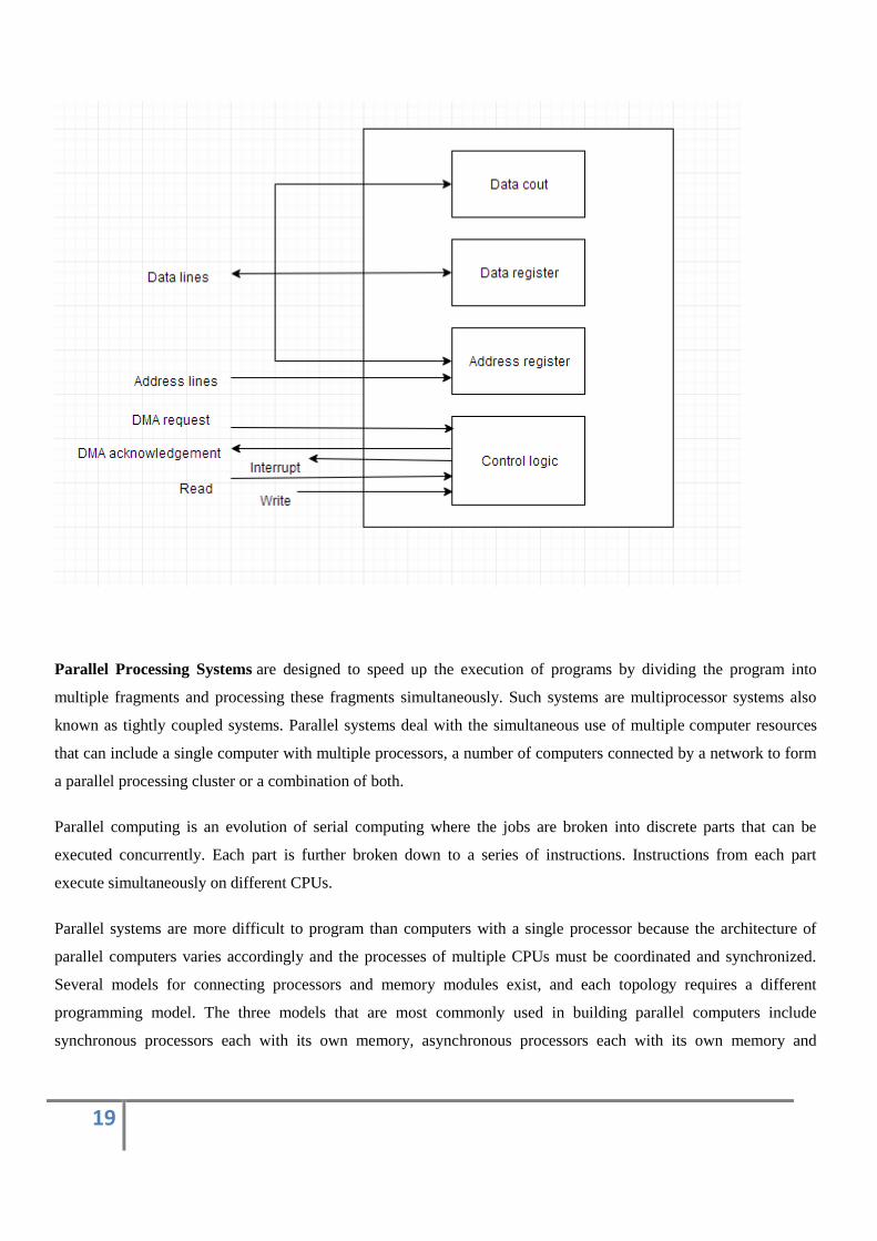
Direct Memory Access
Removing the CPU from the path and letting the peripheral device manage the memory buses directly would
improve the speed of transfer. This technique is known as DMA.
In this, the interface transfer data to and from the memory through memory bus. A DMA controller manages to
transfer data between peripherals and memory unit.
Many hardware systems use DMA such as disk drive controllers, graphic cards, network cards and sound cards etc.
It is also used for intra chip data transfer in multicore processors. In DMA, CPU would initiate the transfer, do other
operations while the transfer is in progress and receive an interrupt from the DMA controller when the transfer has
been completed.
16
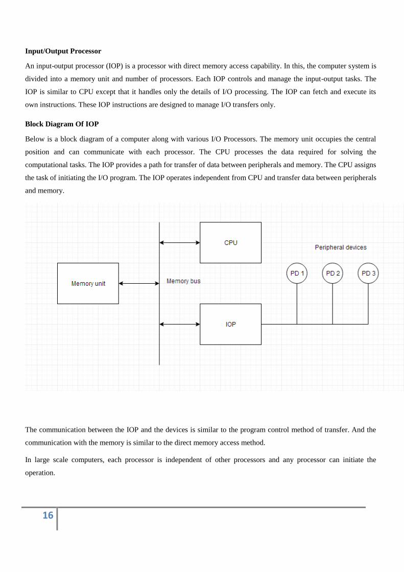
Input/Output Processor
An input-output processor (IOP) is a processor with direct memory access capability. In this, the computer system is
divided into a memory unit and number of processors. Each IOP controls and manage the input-output tasks. The
IOP is similar to CPU except that it handles only the details of I/O processing. The IOP can fetch and execute its
own instructions. These IOP instructions are designed to manage I/O transfers only.
Block Diagram Of IOP
Below is a block diagram of a computer along with various I/O Processors. The memory unit occupies the central
position and can communicate with each processor. The CPU processes the data required for solving the
computational tasks. The IOP provides a path for transfer of data between peripherals and memory. The CPU assigns
the task of initiating the I/O program. The IOP operates independent from CPU and transfer data between peripherals
and memory.
The communication between the IOP and the devices is similar to the program control method of transfer. And the
communication with the memory is similar to the direct memory access method.
In large scale computers, each processor is independent of other processors and any processor can initiate the
operation.
17
The CPU can act as master and the IOP act as slave processor. The CPU assigns the task of initiating operations but
it is the IOP, who executes the instructions, and not the CPU. CPU instructions provide operations to start an I/O
transfer. The IOP asks for CPU through interrupt.
Instructions that are read from memory by an IOP are also called commands to distinguish them from instructions
that are read by CPU. Commands are prepared by programmers and are stored in memory. Command words make
the program for IOP. CPU informs the IOP where to find the commands in memory.
Priority Interrupts
Interrupt
Data transfer between the CPU and the peripherals is initiated by the CPU. But the CPU cannot start the transfer
unless the peripheral is ready to communicate with the CPU. When a device is ready to communicate with the CPU,
it generates an interrupt signal. A number of input-output devices are attached to the computer and each device is
able to generate an interrupt request.
The main job of the interrupt system is to identify the source of the interrupt. There is also a possibility that several
devices will request simultaneously for CPU communication. Then, the interrupt system has to decide which device
is to be serviced first.
Priority Interrupt
A priority interrupt is a system which decides the priority at which various devices, which generates the interrupt
signal at the same time, will be serviced by the CPU. The system has authority to decide which conditions are
allowed to interrupt the CPU, while some other interrupt is being serviced. Generally, devices with high speed
transfer such as magnetic disks are given high priority and slow devices such as keyboards are given low priority.
When two or more devices interrupt the computer simultaneously, the computer services the device with the higher
priority first.
Types of Interrupts:
Hardware Interrupts
When the signal for the processor is from an external device or hardware then this interrupts is known as hardware
interrupt. Let us consider an example: when we press any key on our keyboard to do some action, then this pressing
of the key will generate an interrupt signal for the processor to perform certain action. Such an interrupt can be of
two types:
Maskable Interrupt
The hardware interrupts which can be delayed when a much high priority interrupt has occurred at the same time.
18
Non Maskable Interrupt
The hardware interrupts which cannot be delayed and should be processed by the processor immediately.
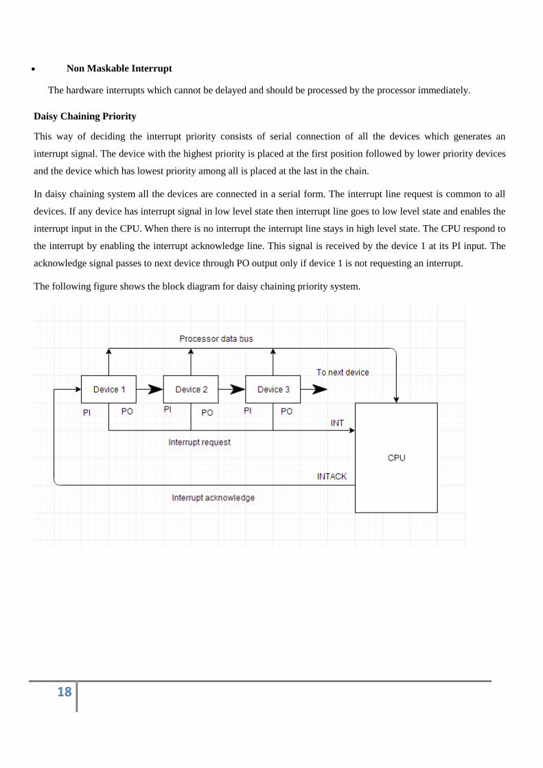
Daisy Chaining Priority
This way of deciding the interrupt priority consists of serial connection of all the devices which generates an
interrupt signal. The device with the highest priority is placed at the first position followed by lower priority devices
and the device which has lowest priority among all is placed at the last in the chain.
In daisy chaining system all the devices are connected in a serial form. The interrupt line request is common to all
devices. If any device has interrupt signal in low level state then interrupt line goes to low level state and enables the
interrupt input in the CPU. When there is no interrupt the interrupt line stays in high level state. The CPU respond to
the interrupt by enabling the interrupt acknowledge line. This signal is received by the device 1 at its PI input. The
acknowledge signal passes to next device through PO output only if device 1 is not requesting an interrupt.
The following figure shows the block diagram for daisy chaining priority system.
19
Parallel Processing Systems are designed to speed up the execution of programs by dividing the program into
multiple fragments and processing these fragments simultaneously. Such systems are multiprocessor systems also
known as tightly coupled systems. Parallel systems deal with the simultaneous use of multiple computer resources
that can include a single computer with multiple processors, a number of computers connected by a network to form
a parallel processing cluster or a combination of both.
Parallel computing is an evolution of serial computing where the jobs are broken into discrete parts that can be
executed concurrently. Each part is further broken down to a series of instructions. Instructions from each part
execute simultaneously on different CPUs.
Parallel systems are more difficult to program than computers with a single processor because the architecture of
parallel computers varies accordingly and the processes of multiple CPUs must be coordinated and synchronized.
Several models for connecting processors and memory modules exist, and each topology requires a different
programming model. The three models that are most commonly used in building parallel computers include
synchronous processors each with its own memory, asynchronous processors each with its own memory and
20
asynchronous processors with a common, shared memory. Flynn has classified the computer systems based on
parallelism in the instructions and in the data streams. These are:
1. Single instruction stream, single data stream (SISD).
2. Single instruction stream, multiple data stream (SIMD).
3. Multiple instruction streams, single data stream (MISD).
4. Multiple instruction stream, multiple data stream (MIMD).
The above classification of parallel computing system is focused in terms of two independent factors: the number of
data streams that can be simultaneously processed, and the number of instruction streams that can be simultaneously
processed. Here 'instruction stream' we mean an algorithm that instructs the computer what to do whereas 'data
stream' (i.e. input to an algorithm) we mean the data that are being operated upon.
Even though Flynn has classified the computer 'systems into four types based on parallelism but only two of them
are relevant to parallel computers. These are SIMD and MIMD computers.
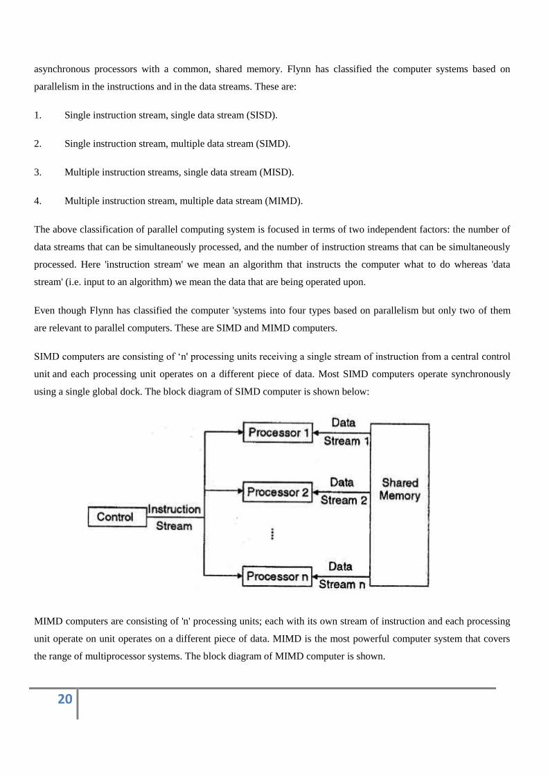
SIMD computers are consisting of ‘n' processing units receiving a single stream of instruction from a central control
unit and each processing unit operates on a different piece of data. Most SIMD computers operate synchronously
using a single global dock. The block diagram of SIMD computer is shown below:
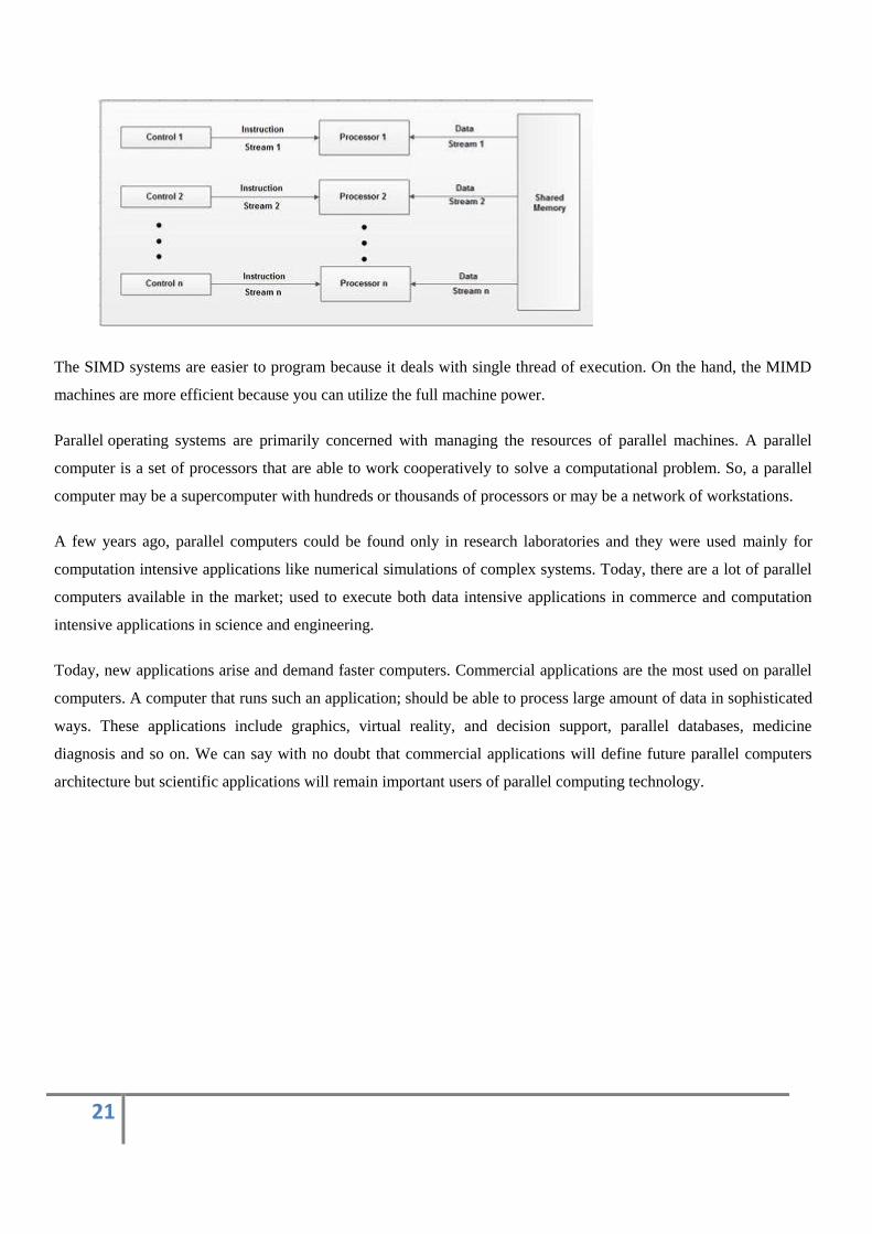
MIMD computers are consisting of 'n' processing units; each with its own stream of instruction and each processing
unit operate on unit operates on a different piece of data. MIMD is the most powerful computer system that covers
the range of multiprocessor systems. The block diagram of MIMD computer is shown.
21
The SIMD systems are easier to program because it deals with single thread of execution. On the hand, the MIMD
machines are more efficient because you can utilize the full machine power.
Parallel operating systems are primarily concerned with managing the resources of parallel machines. A parallel
computer is a set of processors that are able to work cooperatively to solve a computational problem. So, a parallel
computer may be a supercomputer with hundreds or thousands of processors or may be a network of workstations.
A few years ago, parallel computers could be found only in research laboratories and they were used mainly for
computation intensive applications like numerical simulations of complex systems. Today, there are a lot of parallel
computers available in the market; used to execute both data intensive applications in commerce and computation
intensive applications in science and engineering.
Today, new applications arise and demand faster computers. Commercial applications are the most used on parallel
computers. A computer that runs such an application; should be able to process large amount of data in sophisticated
ways. These applications include graphics, virtual reality, and decision support, parallel databases, medicine
diagnosis and so on. We can say with no doubt that commercial applications will define future parallel computers
architecture but scientific applications will remain important users of parallel computing technology.