H24-HERCULES-24V-Control-Board-Instruction-Manual ...
18
Stagnoli T.G. srl Via Mantova, trav. I, 105A/B +39.0309139511 +39.0309139580 [email protected] www.stagnoli.com H24 Centrale di comando per motori Hercules a 24V I GB F D E Control board for Hercules 24V motors Centrale de commande pour moteurs Hercules à 24V Steuerzentrale für Hercules-Motoren von 24V Central de mando para motores Hercules a 24V
-
Upload
khangminh22 -
Category
Documents
-
view
0 -
download
0
Transcript of H24-HERCULES-24V-Control-Board-Instruction-Manual ...

Stagnoli T.G. srlVia Mantova, trav. I, 105A/B
H24
Centrale di comando per motori Hercules a 24VI
GB
F
D
E
Control board for Hercules 24V motors
Centrale de commande pour moteurs Hercules à 24V
Steuerzentrale für Hercules-Motoren von 24V
Central de mando para motores Hercules a 24V

GB The Stagnoli H24 is the control board that has been studied for 24V Hercules automations.
Made using only prime quality materials, it has been designed for low absorption at rest allowing a low consumption of electricity.Particular attention has been paid to professionals in the sector making it easier to programme the control board by using a multi-language display.
• This manual has been created by Stagnoli for specifi c use by pro-fessional and qualifi ed staff.
• It is advisable to read the instruction manual completely before proceeding with installation.
• During wiring the system must not be live.
• Automatic gate systems must be installed by qualifi ed technical staff in compliance with legal requirements.
•DOUBLE SAFETY: The control board has two safety sensors: one with encoder and the other is amperometric.
•Before installing, check that the gate is fi rm, well fi xed and has measurements, dimensions and fi xings that are suitable for Hercu-les automation.
Inform the end user in detail of the method of use, residual dangers, the need for maintenance and the need to check safety devices at least once every six months.
18
GB
789
101112131415161718
Input/Control connectorsReceiver moduleSystem memory (removable)24V Terminal/fl asherFlasher relayMosfet motorMosfet open gate detector exitMotor connectorOpening relayRapid fuse 2,5A (card and accessories protection)Open gate detector terminal (SCA)Encoder connector
19 24V current card terminal20 PTC 0,9A open gate detector exit21 PTC 0,1A encoder exit22 Closing relay
1
654321
2
15
7
6a5 4
36b
6c
1413
121110
9
8
222120
191817
16
Setting keysRib entry terminal DisplayRadio aerial terminal Limit stop terminalJump resistive rib
19
GB
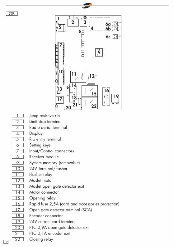
The current feed line (230V L,N, ) towards the automated device must be protected by a magnetometric switch or by a pair of 5A fuses. A differential switch is recommen-ded but not indispensable if it is already found at the top of the system.Feed the device with a 3x1,5mm2
cable (phase+neutral+earth). If the distance between the control board and the connection to the earthing system exceeds 30m, it is necessary to provide an earth plate near the control board.
Cabling must be done when the control board is switched off.Input of N.C. type contacts (normally closed), if they are not used, must be bridged with an ordinary terminal (+24V). If there are more N.C. contacts for the same input, they must be placed in series (example: ph1 and ph2 in the diagram).
Inputs of N.O. type contacts (normally open), if not used, must be left free. If there are more N.O. contacts for the same input, they must be placed in parallel (example: st1 and st2 in the diagram).
The rib input can be either the N.C. type or the resistive type 8k2., if it is the latter, then bridge the jump 8k2.
24 0
T1,25A
L N
common
0 230
stop
TRASFORMATOR
photocellsin closing
25w
5w
start
st1st2
ph1 ph2
ph3 ph4
redblackwhitegreenbrown
start
photocells in opening and
in closing
pedestrian
common
fl asher
open gate detector (SCA)
FUSE
LINE
accessory exit
20
GB Operating procedure at the fi rst start up
•Undertake the electric wiring for the plant and check when the card is switched off.
•Unblock the gate and check its movement (the rack must not be supported by the motor pinion). The stroke of the gate must not have any areas of stiffness during movement, it must be smooth.
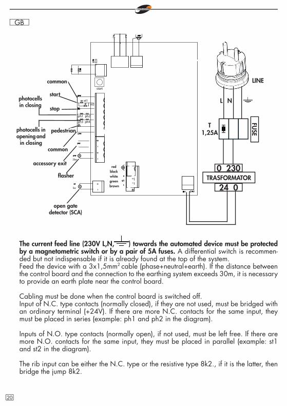
•Block the gate and supply current to the control board. At this point, the electric mains detection
E
led will light up and the display will show r|-00 or r-|00 where the horizontal line (-) indicates the opening direction of the gate. If the opening direction is not the required one, set the opening direction function da (see later). If this does not occur, check that the control board receives power and check the inputs activated (see the description of the display diagnostics).
•Activate the safety devices one at a time and check that the display shows the relative diagnostics wording. For example, activate the photocell and check that the message pho shows on the display.Enter the menu and select the item setup. The fi rst two manoeuvres help to identify the start and end of the stroke of the motor. The two that follow detect the peak of absorption of the motors when the gate is closing and opening. In this phase, monitor the values shown on the display.
•At the end of the learning phase, the display will show ok if programming was done correctly, or err if errors occurred. To exit the programme press the key ENTER.
•Correctly set the levels of anti-crushing force in opening and in closing, these must be greater than the maximum values viewed during learning (see later for regulating fm1a and fm1c).
WARNING: this regulation can infl uence the degree of safety of an automated device.During learning manoeuvres, the control board ignores the START and PEDE-STRIAN commands and works with the force parameters that have been set to maximum. Even if the safeties remain active, make sure that there are no objects or people in the pathway of the gate.
•Carry out some test cycles checking the correct operation of the entire system.
•Measure the force of impact of the gate according to the specifi cations of regu-lation EN12445.
display
LED indicator for power supply
21
GB
r|-00
add transmitter
1ch
adjustement
ttca
rlap
function
ca
ba
rlch
fm1a
fm1c
bp
cr
2p
pl
re
en
ss
it
cf
alte
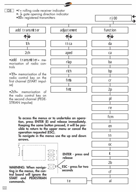
•add transmitter= me-morisation of radio con-trols
•1ch= memorisation of the radio control key on the fi rst channel (START impul-se)
•2ch= memorisation of the radio control key on the second channel (PEDE-STRIAN impulse)
To access the menus or to undertake an opera-tion, press ENTER (E) and release immediately. Keeping the same button pressed, it will be pos-sible to return to the upper menu or cancel the operation requested (ESC).To navigate in the menus use the up and down arrows.
E
•r= rolling code receiver indicator•-|= gate opening direction indicator •00= registered transmitters
WARNING: When naviga-ting in the menus, the con-trol board will ignore the START and PEDESTRIAN commands.
aped
da
fcm
oc
2b
2ch
ENTER - press and release
ESC - press for two seconds
22
GB
00 -
delete
default parameter
erase 1 transmitter
language
italiano
english
setup
read code
erase memory transmitters
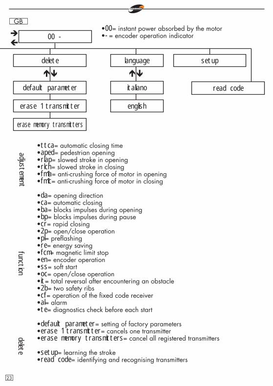
•ttca= automatic closing time•aped= pedestrian opening•rlap= slowed stroke in opening•rlch= slowed stroke in closing•fm1a= anti-crushing force of motor in opening•fm1c= anti-crushing force of motor in closing
•da= opening direction•ca= automatic closing•ba= blocks impulses during opening•bp= blocks impulses during pause•cr= rapid closing•2p= open/close operation•pl= prefl ashing•re= energy saving•fcm= magnetic limit stop•en= encoder operation•ss= soft start•oc= open/close operation•it= total reversal after encountering an obstacle•2b= two safety ribs•cf= operation of the fi xed code receiver•al= alarm•te= diagnostics check before each start
•default parameter= setting of factory parameters•erase 1 transmitter= cancels one transmitter•erase memory transmitters= cancel all registered transmitters
•setup= learning the stroke•read code= identifying and recognising transmitters
adjustementfunction
•00= instant power absorbed by the motor•-= encoder operation indicator
delete
23
GB Addition of radiocontrols•Before memorising a transmitter, make sure that it is compatible with the type of receiver that is integrated (the fi rst time the display shows r, if the receiver is in rolling code mode, or f if the receiver is in fi xed code mode). The receiver can memorise rolling codes type HCS300 STAGNOLI with billions of combinations or fi xed codes type HT53200 with 13 bits or the fi xed part of a rolling code (28 bit SN). It is possible to memorise up to 76 codes.
•Enter the menu add transmitter, move over the wording display 1ch or 2ch and select the channel that is to be added. Press ENTER, the wording premi (press) will appear. Press the key that must be memorised. At this point the display shows the wording ok if the operation has been carried out correctly, err if there are registration errors or full if the receiver memory is full.
•An external antenna installed far from the ground, increases the visibility betwe-en the transmitter and the receiver. The power of the receiver can be reduced if metal parts or reinforced concrete are placed next to it.
Regulating•ttca (automatic closing time)= this is the time from the when the gate is fully ope-ned to when it is closed automatically. If the photocell is engaged, the ttca viene conteggiato dal momento in cui la fotocellula si disimpegna. time is counted from the time when the photocell is freed. The default time set by Stagnoli is 10 secs and it can be regulated from 1 to 240secs.
•aped (pedestrian opening)= this is the length of the stroke stated in centimetres of the partial opening, namely the pedestrian mode. The default value set by Sta-gnoli is 70 secs and it can be regulated from 30 to 150.
•rlap (slowed stroke in opening)= the control board slows down the stroke of the motor in the end part of its opening phase. The default stroke set by Stagnoli is 20 cm and it can be regulated from 0 to 70 cm.
•rlch (slowed stroke in closing)= the control board slows down the stroke of the motor in the end part of its closing phase. The default stroke set by Stagnoli is 20cm and it can be regulated from 0 to 70cm.WARNING: before setting the slowing phase, check that the gate has been instal-led correctly. In this phase, the motor has less power and the way this parameter is set can infl uence the level of safety of the system itself. Once this phase has been carried out, check the force of impact of the gate.
•fm1a (anti-crushing force of the motor in opening)= is the anti-crushing force of the motor stated in percentage compared with the maximum force that the same can generate. The default value set by Stagnoli is 50 and it can be regulated from 20 to 99.
•fm1c (anti-crushing force of the motor in closing)= is the anti-crushing force of the motor stated in percentage compared with the maximum force that the same can generate. The default value set by Stagnoli is 50 and it can be regulated from 20
24

GB to 99.WARNING: the setting of these two parameters can infl uence the level of safety of the system itself. Stagnoli advises setting this parameter with a safety margin that is at least +10 compared with the maximum current consumed by the motor respectively in the opening and closing phases. This can be read on the display in the second main screen during the stroke of the motor.fm1a and fm1c with a low value indicate a greater anti-crushing sensitivity. At the end of installation, check that the forces of impact are in compliance with the regulation EN12453.
Functions•da (opening direction)= indicates the opening direction of the gate that is viewed on the main screen after indicating the type of receiver (r|-00 or r-|00).To change the gate opening direction go to da on the display and change the parameter from 0 to 1 or from 1 to 0 depending on the desired direction.
•ca (automatic closing)= automatic closing of the gate after it has opened com-pletely.ca=0 function not enabled.ca=1 function enabled.Set the ttca regulation to customise the time that must pass from the end of ope-ning and the start of automatic closing. N.B: If ca=1 and 2p=0, the command to START, activated while the gate is opening, will stop the gate and the ttca auto-matic closing time will be loaded.
•ba (impulse block during opening)= the control board ignores the START impul-ses during the opening phase.ba=0 function not enabled.ba=1 function enabled.
•bp (impulse block during pause)= the control board ignores the START impulses during the pause between opening and automatic closing (ca=1).bp=0 function not enabled.bp=1 function enabled.These functions are useful when there are various passages with different inputs through the same entry point.
•cr (rapid closing)= if there is a passage through the photocells during the ope-ning phase or with the gate open, the regulation time ttca (if activated and more than 3 secs) is automatically reduced to 3 secs.cr=0 function not enabled.cr=1 function enabled.
•2p (open/close operation)= 2p=1 function enabled: at each START impulse, the movement of the gate changes direction (OPENING - CLOSING).2p=0 function not enabled: the gate movement sequence becomes OPENING - CLOSING (ttca) - CLOSING - STOP.
•pl (prefl ashing)= after the opening command for the gate the fl asher or courtesy 25
GB light will activate for two seconds before the opening or closing phase begins.pl=0 function not enabled.pl=1 function enabled.
•re (energy saving)= keeps the photocells off while the system is not active per-mitting energy saving. The photocells therefore remain active only while the gate is in movement.re=0 function not enabled.re=1 function enabled.Connect the current feed +/-24V of both the transmitter and receiver of the photo-cells to the output set aside for the fl asher.
•fcm (magnetic limit stop)= activates the operation of the magnetic limit stop.fcm=0 function not enabled.fcm=1 function enabled.
•en (encoder operation)= runs the operation of the motor with encoder. In the case of encoder malfunction (the gate blocks after the start and the display shows ENC), it is possible to disable this function and allow the motor to carry out other manoeuvres.en=0 encoder not enabled.en=1 encoder enabled.WARNING: The operation of the system without encoder is to be seen as an emergency measure. In this mode any obstacle encountered by the motor will command the motor to stop movement without reversing it.
•ss (soft start)= allows the motor to undertake a soft start at a reduced speed to diminish stress of the mechanical parts of the system. Activating this function, the motor delivers less power in its starting phase.ss=0 function not enabled.ss=1 function enabled.
•oc (open/close operation)= the START terminal input becomes OPEN and the PEDESTRIAN terminal input becomes CLOSE. In this mode one control opens the gate and another closes it without intermediate stops. The PEDESTRIAN and START functions can be activated with the radio control on the fi rst and second channels respectively.oc=0 function not enabled.oc=1 function enabled.
•it (total reversal)= activating this function, if the motor encounters an obstacle in the opening or closing phase, it reverses the motion and reaches the limit stop. If the function has not been activated, when the motor encounters an obstacle in the opening or closing phase, it reverses the motion by 50cm before it stops.it=0 function not enabled.it=1 function enabled.
•2b (two safety ribs)= Operates with two safety ribs 8k2 connected in parallel.2b=0 function not enabled.2b=1 function enabled.
26
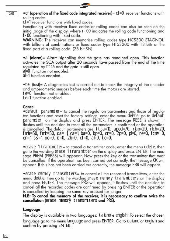
GB •cf (operation of the fi xed code integrated receiver)= cf=0 receiver functions with rolling codes.cf=1 receiver functions with fi xed codes.Functioning with receiver fi xed codes or rolling codes can also be seen on the initial page of the display, where r-00 indicates the rolling code functioning and f-00 functioning with fi xed code.WARNING: The receiver can memorise rolling codes type HCS300 STAGNOLI with billions of combinations or fi xed codes type HT53200 with 13 bits or the fi xed part of a rolling code (28 bit SN).
•al (alarm)= Alarm signalling that the gate has remained open. This function activates the SCA output after 20 seconds have passed from the end of the time regulated by ttca and the gate is still open.al=0 function not enabled.al=1 function enabled.
•te (test)= A diagnostics test is carried out to check the integrity of the encoder and amperometric sensors before each time the motors are started.te=0 function not enabled.te=1 function enabled.
Cancel•default parameter= to cancel the regulation parameters and those of regula-ted functions and reset the factory settings, enter the menu delete, go to default parameter on the display and press ENTER. The message RESE is shown, it fl ashes until the decision to reset all the parameters is confi rmed or the operation is cancelled. The default parameters are: ttca=10, aped=70, rlap=20, rlch=20, fm1a=50, fm1c=50, da= 1, ca=1, ba=0, bp=0, cr=0, 2p=0, pl=0, re=0, fcm= 0, en=1, ss=1, oc=0, it=0, 2b=0, cf=0, al=0, te=0.
•erase 1 transmitter= to cancel a transmitter code, enter the menu delete, then go to the wording erase 1 transmitter on the display and press ENTER. The mes-sage PREMI (PRESS) will apppear. Now press the key of the transmitter that must be cancelled. If the operation has been carried out correctly, the message OK will appear. If this has not been carried out correctly, the message ERR will appear.
•erase memory transmitters= to cancel all the recorded transmitters, enter the menu delete, then go to the wording erase memory transmitters on the display and press ENTER. The message PRG will appear, it fl ashes until the decision to cancel all the recorded codes are confi rmed by pressing ENTER or the operation is cancelled by keeping the same key pressed for longer.N.B: To cancel the memory of the receiver, it is neccessary to confi rm twice the cancellation (erase memory transmitters and PRG).
LanguageThe display is available in two languages: italiano e english. To select the chosen language go to the menu language and press ENTER. Go to italiano or english and confi rm by pressing ENTER.
27
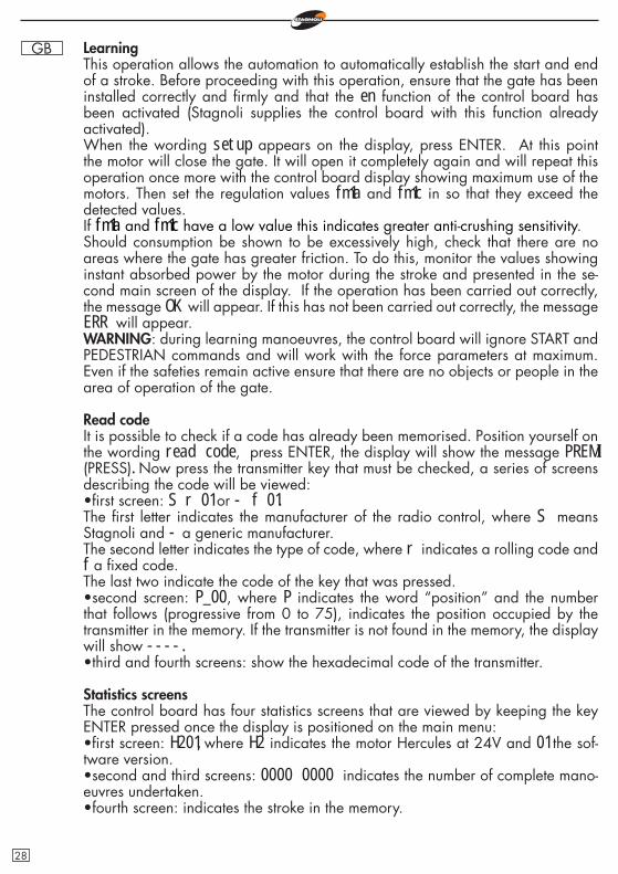
GB LearningThis operation allows the automation to automatically establish the start and end of a stroke. Before proceeding with this operation, ensure that the gate has been installed correctly and fi rmly and that the en function of the control board has been activated (Stagnoli supplies the control board with this function already activated).When the wording setup appears on the display, press ENTER. At this point the motor will close the gate. It will open it completely again and will repeat this operation once more with the control board display showing maximum use of the motors. Then set the regulation values fm1a and fm1c in so that they exceed the detected values.If fm1a and fm1c have a low value this indicates greater anti-crushing sensitivity.Should consumption be shown to be excessively high, check that there are no areas where the gate has greater friction. To do this, monitor the values showing instant absorbed power by the motor during the stroke and presented in the se-cond main screen of the display. If the operation has been carried out correctly, the message OK will appear. If this has not been carried out correctly, the message ERR will appear.WARNING: during learning manoeuvres, the control board will ignore START and PEDESTRIAN commands and will work with the force parameters at maximum. Even if the safeties remain active ensure that there are no objects or people in the area of operation of the gate.
Read codeIt is possible to check if a code has already been memorised. Position yourself on the wording read code, press ENTER, the display will show the message PREMI (PRESS). Now press the transmitter key that must be checked, a series of screens describing the code will be viewed:•fi rst screen: S r 01 or - f 01.The fi rst letter indicates the manufacturer of the radio control, where S means Stagnoli and - a generic manufacturer.The second letter indicates the type of code, where r indicates a rolling code and f a fi xed code.The last two indicate the code of the key that was pressed.•second screen: P_00, where P indicates the word “position” and the number that follows (progressive from 0 to 75), indicates the position occupied by the transmitter in the memory. If the transmitter is not found in the memory, the display will show ----.•third and fourth screens: show the hexadecimal code of the transmitter.
Statistics screensThe control board has four statistics screens that are viewed by keeping the key ENTER pressed once the display is positioned on the main menu:•fi rst screen: H201, where H2 indicates the motor Hercules at 24V and 01 the sof-tware version.•second and third screens: 0000 0000 indicates the number of complete mano-euvres undertaken.•fourth screen: indicates the stroke in the memory.
28

GB Diagnostics screensThe control board can recognise problems or alarms that can occur in the system therefore it can signal some messages on the main display to allow the problem to be identifi ed:•1 rf= activation of the START command on the fi rst radio frequency channel.•2 rf= activation of the PEDESTRIAN command on the second radio frequency channel.•sta= activation of the START command on the terminal board input.•ped= activation of the PEDESTRIAN input command.•stO= activation of the STOP command on the terminal board input.•phO= activation of the photocells input in closing on the terminal board.•phA= activation of photocells input in closing and in opening on the terminal board.•bar= activation of the safety rib input.•swo= activation of the limit stop input in opening.•swc= activation of the limit stop input in closing.•am 1= activation of the amperometric sensor on the fi rst motor.•enc1= activation of the encoder sensor on the fi rst motor.•prg= programming regulations or functions underway.•OK= successful outcome of operations.•ERR= unsuccessful outcome of operations.•full= radio control memory full.•attendi= pause time.•tout= pause time expired.
29
GB F.A.Q. - Frequently asked questions
Why choose a rolling code transmitter instead of a fi xed one?Rolling code transmitters are safer as they cannot be cloned and have over 200 mil-lion combinations that change with each transmission. Fixed code transmitters, inste-ad, have 1024 code combinations that do not change with each transmission.
Can the control board run the operation of the motor with emergency batteries?Yes. To use emergency batteries use the kit supplied by Stagnoli.
The control board does not recognise the transmitter. Why? Check that you are using the same type of control board and transmitter. It is possible to check the type of transmitter used by the control board from the main screen and change if necessary by setting the parameter cf.
Once the motor gets to the stop, it turns back instead of arresting. Why?One reason that can make the control board loose its parameters is that the motor has been working while unlocked. To be sure that the control board has found back its parameters, shut off the supply, make sure that the motor is locked and then put the supply back to the control board. At the fi rst START input, the control board will fi nd again its parameters.
Technical data•Automation supply: 230V - 50/60Hz.•Primary transformer protection fuse: T1,25A/230V.•24V Accessory output protection fuse: F2,5A.•Integrated receiver (433Mhz): maximum capacity 76 radio codes.•Operating temperature: -20° +55°•Maximum rated output of the motor: 80W•Maximum power of the fl asher output: 25W•Maximum power of the open gate detector light (SCA): 5W•Electronic anti-crushing device: amperometric and with encoder30

GB
31
Notes

GB
ANTENNA
CLOSIN
GCO
MM
ON
OPEN
ING
LIMIT STOP
SAFETY RIB
COMMON
START
STOP
COMMONPEDESTRIAN OPENING
+24V
-24V
FLASHERCOURTESY LIGHT
OPEN GATE DE-TECTOR LIGHT
MO
TOR
ENCO
DER
0
24V
MOTOR
SUPPLY
COMMANDS
32

GB
33
CLOSING PHOTOCELLS
OPENING PHOTOCELLS
CLOSING PHOTOCELLSOPENING AND CLOSING PHOTOCELLS
COMMON
+24V
-24V
TX
TX RX
RX
BATTERY-CHARGER BOARDWARNING: If a battery charger is used, the control board is supplied by the C24 charger board, linked to a trasnsformator. For the details of the connection, see the C24 instructions.
0 230
0 24TRAN
SFORM
ATOR
024
BATTERIES
0 24

82