
instruction manual of boiler control system - WordPress.com
149
E-l AUTOMATIC BOILER CONTROL SYSTEM
-
Upload
khangminh22 -
Category
Documents
-
view
0 -
download
0
Transcript of instruction manual of boiler control system - WordPress.com

E-l AUTOMATIC BOILER CONTROL SYSTEM

PLAN R E C O R D
(SO «*IC SCREW THREADS
CONFERRED
REVISIONS
NO. DESCRIPTION(OATE)
REVISEDFIM4L ,,„
137
F6&. IB. iff 4,
AP-PROVED!
CHECK-ED
A. INSTRUCTION MANUAL OF BOILER CONTROL SYSTEM
B. INSTRUCTION MANUAL OF BURNER CONTROL SYSTEM
C. INSTRUCTION MANUAL OF AUTOMATIC BOILER CONTROL SYSTEM
D. BMS CONTROLLER
E. APPENDED DRAWING OF BOILER CONTROL SYSTEM DIAGRAM
SHEETS WITH COVER
MARINE BOILER DESIGNING SEC.TUBBO & MARINE MACHlUESiG DEPT.APPROVED
CHECKIO
DRAWN
SCALE
S A M S U N G H. NO. 1139/40
INSTRUCTION MANUALOF AUTOMATIC BOILER
CONTROL SYSTEM
"K"K 1 4 5 8K 1 4 5 9
ITEM IRA WING NO.
N52-99K-N500m.m
1 MITSUBISHI HEAVY INDUSTRIES, LTD.NAGASAKI SHIPYARD & MACHINERY WORKS
7252 E DRAWN ISSUED

/ \M7, 8, /*, AS} 2f, 27, 28, 33,
-20-93'
/ICC
OINER
SHIP YARDat ft J5r
SHIP NO.
SHIP NAME
MITSUBISHI HEAVY INPUSTRIES.CO., LTD NAGASAKI SHIP YARD
SAMSUNG
H. NO. 1139/40/44
AUX. BOILER (MAC40B)
INSTRUCTION MANUAL OFBOILER CONTROL SYSTEM
AB S
* m
Asahi Mechatronic CorporationDATEB ft
PROD. NO.

TABL E OF CONTENT
A, INSTRUCTION MANUAL OF BOILER CONTROL SYSTEM
[ I ] CONFIGURATION OF CONTROL PANEL
[ n ] CHECK & OPERATION BEFORE RUNNING
B, INSTRUCTION MANUAL OF BURNER CONTROL SYSTEM
[ I ] SELECTION OF OPERATION MODES
[D] OPERATION OF BURNER
[I] AUTOMATIC RUNNING OF F.D. FAN, & F. 0. PUMP
[IV] SOOT BLOIER OPERATION
[V ] ALARMS
C, INSTRUCTION MANUAL OF AUTOMATIC BOILER CONTROL SYSTEM
[ I ] GENERAL DESCRIPTION
[H] OPERATING INSTRUCTION
[ 1 ] COMPONENTS
[IV] ALARM DISPLAY
D, BNS CONTROLLER
E, APPENDED DRAWING OF BOILER CONTROL SYSTEM DIAGRAM
SAMPAGE 1

A. INSTRUCTION MANUAL OF BOILER CONTROL SYSTEM
[ I ] CONF.IGULAT10N OF CONTROL PANEL
1 . BOILER CONTROL PANEL (BCP)
[ n ] CHECKS & OPERATION BEFORE RUNNING
a./.
rU,
xv.\ •. v o-
SAPAGE 2

A. INSTRUCTION MANUAL OF BOILER CONTROL SYSTEM
The Boiler Control Panel is provided with built-in operation, control andinterlock devices required for the running of the boiler.This control panel perforns the automatic and manual runnings of the
boiler,gives an alarm to tarn the operator if an abnormality occursduring running, and stops the boiler in an emergency mode by immediately
shutting down the fuel oil supply to the boiler if such an abnormalityshould be too serious to continue running any longer.
CAPTION
This manual has been prepared primarily for the instructions of remote-control running of the boilers.In running, the boiler, boiler auxiliary machines, oil burners, boilerautomatic control system, equipment attached to the boiler, and air flue,oust have always been adjusted in good order.
C I •] CONFIGURATION OF CONTROL PANEL
1. E.C. CONSOLE REMOTE INDICATION PANELThis indication panel is installed in the Engin Control roora.It contains following items.1) DRUM LEVEL INDICATOR2) STEAM DRUM INDICATOR3) SMOIE INDICATOR4) EMERGENCY STOP SWITCH5) BURNER BBRNN1NG LAMP6) LAMP TEST SfITCH
2. B/S BOILER CONTROL PANELThis control panel is installed at the boiler side.It contains the system power supply unit, the sequencerfor the burner control, the automatic boiler controller, and variousnecessary relay units.
SAMPAGE 3 ,
( f i

[D ] CHECKS AND OPERATION BEFORE RUNNING
1. Turn-on of Power SourceThe power switches of the boiler control panel are turned on,
and the action of each pilot la«p and buzzer is checked bythe *BZ. AND LAMP TEST" stitch on the control panel.
2. Actuation of Control DevicesEach control device is checked for having been supplied withnormal control air press, and also, for normal actuation whennanually operated.
3. Reset of Boiler start Interlock LampThe rese.t switches for the interlock alarm provided in the boilercontrol panel are turned on to check the interlock lamp forbeing turned off for normal operation.
1) AC SOURCE FAIL2) SEQUENCES ABNOR
3) MANUAL TRIP
4) P. D. FAN TRIP
5) DRBM LEVEL LOI-LOI
6) ATOMIZ PRESS LOI-LOI
7) IGNITION FAIL
8) FLAME FAIL
9) FLAME EYE ABNOK
10) IGNITION VALIDITY TIME OVER
11) BNR PI STOP V/V ABNOR
12) P. 0. PRESS LOI-LOI
13) CONTROL AIR PRESS LOI-LOI
14) F. 0. TEMP. LOI-LOI
> Alarm laips shall be "OFF"
CAUTION
(1) Ihile in operation, the indication lanps on the control panelshall be observed and the boiler checked periodically.
(2) By-pass operation must be carried out only by way of the"BY-PASS" switch.
SAMPAGE 4

B. INSTRUCTION MANUAL OFJUIRNER CONTROL SYSTEM
[ I ] SELECTION OF OPERATION MODES
A. BOILER SIDE OPERATION
B. SELECTION OF BOILER MODES
C. MASTER/SLAVE BOILERS OPERATION
[ n] OPERATION OF BURNER
A. MANUAL OPERATION OF BURNER START
B. MANUAL OPERATION OF BURNER STOP
C. AUTOMATIC RUNNING OF BOILER
D. OPERATION PANEL GRAPHIC FLOI CHART
E. INTERLOCK BY-PASS OPERATION
[E] AUTOMATIC RUNNING OF F.D. FAN, F. 0. PUMP
[IV] SOOT BLOIEH OPERATION
[ V] ALARMS
A. PATTERN OF ALARMS
B. BOILER SET POINT LIST
SAMPAGE 5

B. INSTRUCTION MANUAL OF BURNER CONTROL SYSTEM
In this control, the remote manual and automatic operations are availableon one single-throat burner provided at the ceiling of the boiler.Its control unit contains a programmable sequencer which can perform thesequential running of FURNACE PURGE and Pilot Burner and the automaticoperation of the burner piston valve by linking with the boiler Protective
System and the A.C. C.Also, it transmits the automatic adjustment commands of combustion air
quantity and fuel oil quantity to the A. C. C.at the siart/stop of theburner.In an emergency, this control system shuts off the fuel supply to theburner for the boiler protection.
SAMPAGE 6

C I ] SELECTION OF OPERATING MODES
A. BOILER SIDE OPERATION
During the initial start-up and under "INTERLOCK BY-PASS" mode, the boileris operated from this B/S BOILER CONTROL PANEL, froi which you can select*iie following modes.
1. SELECTION OF AUTO/MAN.
The operator can select his desired mode unless otherwise specified.
( a ) A. B. C. MAN.
If controller is under ABNOR, this controller is forced
to set A. B. C. to its manual mode.Also, the F. 0. & AIR controller is set to its manual mode .
in [ I ] A-2 (a), (c).
( b ) A. B. C. AUTO
( c ) BURNER MAN.INTERLOCK BY-PASS MODE, the Man Mode is forced to be selected.
( d ) BURNER AUTO
2. INTERLOCK BY-PASS MODE
fhile under this mode, the operation must be monitored at boiler side.
( a ) F. 0. TEMP. BY-PASS MODEThis mode must be selected when the F.0. heating steam isunavailable under the cold boiler start mode.
In this by-pass mode, the starting interlock for F.0. temp low
is by-passed.
See [ I ] B-1,2 Cold Mode.
See [ n ] E-l, F. 0. TEMP. By-pass Mode.
(b ) FLAME EYE BY-PASS MODE
This mode must be selected only when there is no choice butto select the flame eye by-pass mode during operation of theburner.
See [ n ] E-2 F. E. By-pass Mode.
( c ) EMERGENCY MODEThis mode must be selected when the burner sequencer is unavailable.See [ H ] E-3 Emergency Operating Mode.
SAMPAGE 7
PD

3. SELECTION OF BOILER MODE
(a) "IGS TOP UP' MODEThis node must be selected for the IGS operation,fhen this node be selected, burner operation becone MAN tode.The A. C. C. is limited to its min load within the allowable limit ofthe exh. gas oxygen content under this node.
C b ) "TANKER SERVICE* IODEThis node must be selected for the tanker service operation.In the Burner AUTO Bode, the burner is automatically started ata S. D. pressure of 12Ig/cn2 and automatically stopped at a S. 0. pressureof 16.3lg/cn2.
4. IGS OPERATION
fhen in the IGS mode, the burner is normally kept »in operation.The IGS lode cannot be selected while sootblower is operated.The sootblower cannot be operated while in the IGS mode, either.
1) IGS Mode SelectionIGS mode can be selected with BOtLEI MODE SELECT, switch of boiler controlpanel.
2) IGS Load SettingIhen in the IGS lode. ACC raises the nininuB burner load overapprox. 30$ of boiler load.
SAMPAGE 8

B. SELECTION OF BOILER START MODE
One of the following start lodes is selected, depending on the boilercondition.
1 . BOILER COLD START
This mode is selected to start from the cold boiler with the burneratomizing steam and the F. 0. heating steam not provided.( 1 ) Fuel oil used : A HEAVY OIL
( 2 ) Burner tip used :
In use of compress air.
( 3 ) Mode switch• "F.O. TEMP. BY-PASS"SIITCH ON
• BURNER OPERATION \MODE "MAN"
• A.C.C. OPERATIONMODE "MAN"
• F. 0. temp, low sequenceinterlock is by-passed.
Automatically set to "MAN"•then selected byF. 0. temp, byrpass switches.
CAUTION
(1) In use of "A" heavy oil. atomizing air is to be used.This is because the use of steam causes the oil spray quantity toincrease (approx. 20 percent), resulting in an unstable combustion.
(2) For fuel oil used at normal temp., fuel oil with viscosity exceeding150 sec. RI No. 1 at normal temp, must not be used.
(3) Compressed air may be used instead of the burner atomiz. steam.In this case, compressed air exceeding 5 Kg/cm2 must be suppliedupstream of the burner atomiz. control valve.
(4) In any case. "ATOMISING STEAM PRESS. LOf-LOf TRIP INTERLOCK" mustnot be by-passed.
SAMPAGE 9

2 . CHANGE-OVER OPERATION FROM BOILER COLD MODE TO ITS HOT MODE
This mode is selected to start from the hot boiler with theburner atomiz. steal provided and A-oil used.
( 1 ) Fuel oil used A HEAVY OIL
( 2 ) Burner tip used :
* Atomizer steam use
( 3 ) Mode switch• "P.O. TEMP. BY-PASS"SIITCH ON
• BURNER OPERATIONMODE "MAN"
• A.C.C. OPERATIONMODE "MAN"
(2 ) attention
F. 0. Temp, low sequenceinterlock is by-passed.
Automatically set to "MAN'when selected by F. 0. temp,by-pass switches.
CAUTION
(1) This mode is to be used at the change-over of A-Oil to C-oil only,and watching at the boiler side must not be neglected at thischange-over.After completion of this cohge-over, the Normal Mode or theCold Mode must be selected without delay.
(2) To burn A-Oil by Steal Jet Atomizer, the air/fuel ration mustbe sufficiently adjusted.
(3) In any case. "ATOMIZING STEAM PRESS. LOf-LOf TRIP INTERLOCK"must not be by-passed.
SAMPAGE 10

3. BOILER HOT START MODE
This mode is selected to start froi the hot boiler with the burner
atoiiz. steam provided and C-oil used.
( 1 ) Fuel oil used C-HEAVY OIL
( 2) Burner tip used
( 3 ) Mode switch• BURNER OPERATIONMODE "MAN"
The first start is set to "MAN'After the start. "AUTO" can beselected.
A.C.C. OPERATION then the drum press, has exceeded5 Kg/cm2 "AUTO" can be selected:However being less than 5 Kg/ci2,"AUTO" cannot be selected.
CAUTION
(1) fhen the boiler is operated with C-OIL and F. 0. PUMP is put under"AUTO" node, F. 0. temperature is set automatically and the following
operations can be done..a) The F. 0. pump automatically starts or stops according to
the temp, of fuel oil before the burner.F. 0. temp, low (Rf. NO. 1 120SEC. or more)-••-STARTF. 0. temp. high(RI. NO. 1 80SEC. or less)-•••STOP
(b) In the A. C. C. auto mode, the F. 0. control valve slightly
opens. And, in the MAN mode, the temperature rises timecan be controlled by adjusting the opening of the F. 0.control valve.
SAMPAGE 11

C. MASTER/SLAVE BOILERS OPERATION
(a ) MASTER/SLAVE BOILER OUTLINE OPERATING PRINCIPLEThe master boiler operates singly or in coibination with the slaveboiler, with the slave unit started and stopped automaticallydepending on the master boiler load: as the master boiler loadexceeds 60X the slave boiler automatically starts operating fordual steam generation; as the master boiler load goes down tobelow 2Q& the slave unit automatically stops its operation leavingthe master boiler alone in service.
(b ) MASTER BOILER FUNCTIONS(1) Selection of master boiler
Either boiler may be selected as the master unit if itsinterlock system is in the normal setting (no trip), bydepressing the designated "MASTER" push button.
(2) Change to steai drum set pressureThe master boiler drum pressure setting can be changed by themaster boiler manual adjuster alone. And the slave boilerdrum pressure setting will be kept t® the same level as thatof the master unit.
(3) Master Boiler automatic start/stopwith the master boiler burner in the "AUTO" mode, the masterboiler A. C. C. signal (S.D. press. ) cause the burner to automaticallystart and stop firing (B— [ D ] — C to be referred to).
Automatic startThe master boiler automatically starts up as the S. D. pressurereaches 12 Kg/cm2.
Automatic stopThe master boiler automatically stops operating as the S. D.pressure reaches 16. 3 Kg/cm2.
SAMPAGE 12
/if

(4) Slave boiler autoiatic start/stop
Once the master/slave boilers operation is established, theslave unit is automatically started and stopped according to
the change in master boiler load ( B - [ I ] - C (c) to bereferred to) .
AutomaticstartAs the master boiler load increases and F. 0. pressure
reaches 10 Kg/ci2 (60X load), the slave boiler automaticallystart its operation
Autoiatic stop
As the master boiler load decreases and the P.O. pressure gose
down to 4.0 Kg/cm2 (20& load), the slave boiler automaticallystop its operation
NOTE :Even when the slave-boiler burner was manually ignited and thesteam pressure reached the setfpoint,thereafter thereby placingthe slave boiler in the "AUTO RUN" mode and then only when theslave-boiler burner "AUTO" is selected, the slave boiler doesnot stop automatically unless the slave boiler steam pressurereaches 16.3 Kg/cm2 even if the master boiler's load goes downunder 20&
SAMPAGE 13

(c ) SLAVE BOILER FUNCTIONS
The slave boiler fuctions may be classified as follows by the
state of the "SLAVE" lamp.
(1) "SLAVE" Lamp off#The slave boiler is not in the "AUTO" lode (A. C. C. andburner "AUTO")
*The slave boiler is operated by its own A. C. C. signal (S. D.press. ). Iith the "BURNER AUTO" node, the burner automaticallystarts and stops firing controlled by the A. C. C. signal, asfollows.Automatic startThe burner automatically starts firing as the S.D. pressurereaches 12 Kg/cn2
Automatic stopThe burner automatically stops firing as the S.D, pressurereaches 16. 3 Kg/cm2.
(2) "SLAVE" Lamp flickering*The slave boiler is in the "AUTO" mode (A. C. C. and burner "AUTO"),fhereas the master boiler is not in the "AUTO" mode(A.C.C.and burner "AUTO").
*The slave boiler is operated by its own A. C. C. signal (S. D.PRESS. ). Iith the "BURNER AUTO" mode, the burner automaticallystarts and stops firing as per ( [ I ] — C(c)(l))
(3) "SLAVE" lamp on*The condition ( [ I ] - C(d)(D) for master/slave boilersoperation has been established.
The slave boiler is automatically started and stopped(automatic steaming operation *1) by its own A.C. C. signal(S. D. press. ) and also automatically started and stopped(loading operation *2) by the master boiler A. C. C. signal.
Automatic startthen the slave boiler S. D, pressure has reached 13 Kg/cm2 orwhen the master boiler F.0.pressure has reached 10 Kg/cm2.
Automatic stopthen the slave boiler S. D. pressure has reached to.master setpressure or when the master boiler F. 0. pressure has gone downto 4. 0 Kg/cm2 and below.
SAMPAGE 14

( d ) MASTER/SLAVE BOILER OPERATION
laster/slave boiler operation1) then both the master and slave boilers have gone into the
"AUTO" operation while in the A. C. C. (P.O.) and"BURNER AUTO" mode ( [ I ] - C (d)(2) to be referred to)
The laster/slave boilers operation is initiated when either 1)above is established.
(2) Master/slave boilers operation in TANKER SERVICE modeIn the laster/slave boilers operation, the two boilers areoperated in parallel by the laster boiler A. C. C. signal.
(3) Master/slave boilers operation in IGS lode.In the IGS lode, the burner switches to the "MAN" lode anddoes not perform automatic start/stop operations.fith both the master and slave boilers in automatic running,they are controlled for parallel operation by the masterboiler A. C. C. signal.Also, 3GX load limit is applied to both boilers and the minimumcombustion rate is limited tto 3Q5K of rated boiler load.
Notes : *1) "automatic steaming operation" - operation to maintainthe slave boiler to be stand-by condition by automaticstart at 12 Kg/cm2 and stop at master set press.
*2) "loading operation" - operation to supply steam to the plant.
SAMPAGE 15

[ H ] OPERATION OF BURNER
A. MANUAL OPERATION OF BURNER START
Burner Ignition.By turning on the "BNR ON" Button, the following burner ignitionsequence starts to ignite the burner.Also, the interlock conditions (nark O) of the ignition sequenceare established by automatic operation in A. C. C. Auto Mode.but in Man. mode, the manual operation (| |) according tothe sequence step is needed.
1. Burner Ignition
(1) Boiler start conditionestablishedO See [ V ] - B
(2) Boiler run mode selectedO See [ I ]
(3) "BNR ON" BUTTONO ON
(4) F. D. FAN AUTO START
F. 0. PUMP AUTO START
O P. D.FAN RUN
(5) Furnace purge condition set
O F. D. fan vane opensFULLY
•Burner atomiz. steam valvefull opens
'BOILER TRIP" LAMP OFF'BNR OFF" LAMP ON 1L
PILOT LAMP TO RUNNING MODE ON
"BNR ON" LAMP FLICKER »-"lL"
'F. D. FAN RUN" LAMP ON
T.O. PUMP RUN" LAMP ON
"PRE-PURGE START"
LAMP FLICKERS--XEstablished at burnerdifferential pressabove 150 mmAq
" ATM. STM. V. OPEN" LAMP ON
GL
'IL'
SAMPAGE 16

(6) Furnace purge conditionestablished
"PRE-PURGE START'LAMP ON IL
Maintained to furnace purge condition for more than one linute.
(7) Burner ign. conditionestablished
"PRE-PURGE START" LAMP OFF"PRE-PURGE FINISH" LAMP ON
00
0
: "IGNITION F. 0. RATE" LAMP FLICKER: "IGNITION AIR RATE" LAMP FLICKER--: "IGNITION READY" LAMP FLICKER
Furnace purge completedF. 0. teip. is equal to or lore than 150 sec. R. I. Nolin viscosity or A-Oil use node (F. 0. temp, by-pass)
IL
'IL'
F. 0. recirculating valvefull close
"F.O.RECIRC.V.OPEN" LAMP OFF"F.O.RECIRC.V. SHUT" LAMP ON' IL
0 F. 0. press, at burner header ^ 10 Kg/cm20 F. 0. puip run
0 F.0.control V. to specified opening
Established at valve opening20 ~ 40*
—•-Established at F. 0. header press.—above 10 Kg/cm2
"IGNITION F. 0. RATE'LAMP ON
IL
0 F.D. fan inlet vane to specified opening
Established at burner —differential air pressure20 - 40 imAq
OR -* "PRE-PURGE FINISH"LAMP OFF
"IGNITION AIR RATE"—ffLLAMP ON
(8) Pilot ign. conditionestablished
"IGNITION READY'LA|P ON
-IL
< 5 sec. > 0 Maintained to pilot ignition condition for 5 sec.
SAMPAGE 17

(9) Pilot ignition
PILOT BNR PUMP START
PILOT BNR IGNITOR SPARKPILOT BNR FLAME EYE "ON"PILOT BNR SOL. VALVE OPEN
O Flame eye malfunctiondetected
MAX
'PILOT PUMP START'
LAMP ON
'PILOT BNR ON'LAMP ON
GL
WL
8sec.
O IGNITION VALIDITY TERM OVERTRIP INTERLOCK CANCEL
Trip interlock for normal stateat F.E.OFF is changed to interlockfor normal state at F. E. ON.
Cancelled if ignition followswithin 5 minutes afterthe burner start.
"IGNITION VALIDITY \R L "TIME OVER" LAMP FLICKER
"IGNITION FAIL" " RL"LAMP FLICKER
"BOILER TRIP" " RL"LAMP FLICKER
"BNR OFF" " WL"LAMP FLICKER
(10) Pilot ign. check(F.E. detects flame within 8 sec. after pilot ign. start)
O
O
ON" signal is output.
OFF" signal is output.
\/
: "FLAME ON" LAMP ON G Lr
: BOILER TRIP AT IGNITION FAIL
"IGNITION FAIL" " RLLAMP FLICKER
3sec.
'BOILER TRIP"
LAMP FLICKER
'BNR OFF"LAMP FLICKER
R L
WL
SAMPAGE 18

(11) Burner ignition
(The following motion is made 3 sec. after check of the pilot burnerignition. )
F. 0. valve full open
(12)
(13)
: "BNR.F.O. V.OPEN" LAMP ON: "BNR.BURN ING" LAMP ON: "IGNITION F. 0. RATE"
LAMP OFF: "IGNITION AIR RATE"
LAMP OFF
PILOT BNR IGNITOR SPARK STOP(F. 0. valve opening must have been confirmed or 8 sec.lust have passed after pilot BNR ign. start.)
Pilot stop(The following motion is lade 15 sec. after pilot BNRignition start)
WLWL
PILOT BNR PUMP STOPPILOT BNR SOL. VALVE CLOSE
: "PILOT PUMP START" LAMP OFF: "PILOT BNR.ON" LAMP OFF: "IGNITION READY" LAMP OFF
4) Cancel of ignition mode and completion of burner ignition(Ignition lode cancel and burner run signals are output to A.C. C.)
O F.E.detecters flamefail and outputs OFF signal
Boiler is made to trip at flame fail.: "FLAME FAIL" " R L"
LAMP FLICKER: "BOILER TRIP" " R L"
LAMP FLICKER: "BNR OFF" " RL"
LAMP FLICKER
SAMPAGE 19, r>

B. MANUAL OPERATION OF BURNER STOP
By selecting the Burner Run Mode to "MAN" and turning on the "BNR OFF"Button, the burner shut-down sequence starts to stop the burner.The interlock conditions (O) of the shut-down sequence are establishedby ATOMIZER autoiatic operation, under A. C. C. Auto Mode, but under A. C. C.Man. Mode, the manual operation ([ H) according to the sequence step isnecessary.
(1) Burner run lode'BNR MANU." LAMP ON WL
(2) Min. firing rate set.(The firing rate is set to burner ignition condition to pre-establishthe burner purge condition. )
F.O. CONTROL VALVE TO SPECIFIED OPENING
F.D. FAN INLET VANE TO SPECIFIED OPENING
(3) "BNR OFF" BUTTON'BNR OFF" LAMP FLICKER WL
START THE BURNER STOP SEQUENCE
(4) Pilot ignitionPILOT BNR. PUMP START
v2sec.
PILOT BNR IGNITOR SPARKPILOT BNR FLAME EYE "ON-PILOT BNR SOL. VALVE OPEN
(5) Burner extinguishNol,2, F.O. VALVE FULL CLOSE
(6) F. 0. RECRC. modeF.O. RECIRC. VALVE OPEN
'PILOT PUMP START'LAMP ON
'PILOT BNR ON"LAMP ON
'BNR F.O. V. OPEN" LAMP OFF'BNR BURNING" LAMP OFF
'F.O. REC IRC V. SHUT'LAMP OFF'F.O. REC IRC V. OPENLAMP ON
G L
WL
WL
F. 0. PUMP AUTO ON-OFFSAM
PAGE 20

(7) Pilot burner check(F. E. detects flai within 6 sec. after the pilot ign. start.)
O "ON" signal is output.
O "OFF" signal is output
: "FLAME ON" LAMP ON G L
: (12) START AT IGNITION FAIL
: IGNITION FAIL" " R LLAMP FLICKER
: BNR OFF" " R LLAMP FLICKER
(8) Burner purge start(F. 0. valve is closed and the residual oil within the burnersprayer body is incinerated. )BURNER PURGE VALVE FULL OPEN : "BNR. PURGE V." - WL
LAMP ON
(9) Pilot burner ignitor spark stop(6 or lore sec. must have passed after pilot burner IgnitionStart)
(10) Completion of burner purge
O Burner purge to be held more than 30 sec. or flame is failed.BUR PURGE VALVE FULL CLOSE : "BNR. PURGE V." LAMP OFFBUR ATOMIZ. STM. VALVE FULL CLOSE : "ATM.STM V OPEN" LAMP OFFPILOT BNR. PUMP STOP : "PILOT PUMP START" LAMP OFFPILOT BNR. SOL. VALVE CLOSE : "PILOT BNR. ON" LAMP OFF
v(11) Furnace after-purge start 'PRE-PURGE START'
LAMP FLICKER•" WL
O F. D. FAN VANE FULL OPEN BNR. differential air press.above ISOmmAq
v(12) Furnace after-purge condition : "PRE-PURGE START'
established LAMP ONWL
O Maintained to furnace after purge conditions for 30 or more sec.
SAMPAGE 21

(13) Completion of furnace after-purge : "PRE-PURGE START" LAMP OFFF. D. FAN AUTO STOP
(14) Boiler stop : "BNR OFF" LAMP ON-- -* WL
COMPLETION OF BURNER STOP SEQUENCE
SAMPAGE 22
/J-

2, AUTOMATIC RUNNING IN MASTER/SLAVE MODE
By selecting master and slave boiler "AUTO RUNNING",master/slave automatic running can be carried out.
The running condition and operation are detailed below.
(1) MASTER/SLAVE CONDITION ESTABLISHED
AUTOMATIC RUNNING OF BOTHBOILER ONLY ESTABLISHED
JT AUTOMATIC RUNNING OFMASTER BOILER ONLY ESTABLISHED
J, AUTOMATIC RUNNING OF
SLAVE BOILER ONLY ESTABLISHED
O SELECT TANKER SERVICE MODE
'SLAVE" LAMP ON-
"SLAVE" LAMP OFF
'SLAVE" LAMP FLICKER-
'TANKER SERVICE'
LAMP ON
"MASTER/SLAVE" MODE Automatic Operation Start
WL
WL"
WL
(a) Master boiler automatic operation
The sane autoiatic operation that is described in the precedingparagraph "1. Boiler Independent Automatic Operation" is performed.
(b) Slave boiler automatic operationThe slave boiler autoiatic operation takes place as follows.
(2) STEAMING UP MODE : "STEAMING UP" LAMP 0N- WL
The steam pressure is raised automatically with the combustionrate controlled in response to the steam drum pressure.
v(3) BOILER AUTO STOP
•& The master boiler load has reached 20X and slave steampressure also has reached the level of master set pressure.
The steam pressure has reached 16. 3kg/cm2-The burner extinguishing completed.
v
SAMPAGE 25 /jf

c. AUTOMATIC RUNNING OF BOILER
BOILER INDEPENDENT AUTOMATIC OPERATION
By selecting the A. C. C.and the Burner Run Mode to "AUTO". BoilerAutomatic Running can be carried out.The running conditions and operation are detailed below.
(1) Boiler start conditionestablished
O See [V] -B
BOILER TRIP" LAMP OFF
'BNR OFF" LAMP ON' W L
(2) Boiler lode selected
O See [ I ] - B
O STEAM DRUM PRESS. 5 K g / c m 2 AND UPPER
: PILOT LAMP TO RUNNING MODE ON
(3) A. C. C. run modeAuto selectedF. 0. FLOf CONTROL F. 0. FLO! CONTROL
'AUTO" INDICATE---
AIR FLO! CONTROL'AUTO" INDICATE-•'
AUTO
AUTO
(then Stm. Drum Press.is below 5kg/cm2 F.0. FLOW Control is selected toMANU. and then to AUTO after BNR Ignition start. )
START BOILER AUTO OPERATION
(4) Burner starti
Completion of burner ignition
v
: See [ H
(5) Burner auto node: BNR "AUTO" LAMP ON- WL
SAMPAGE 23

(6) Stealing up mode "STEAMING UP" LAMP ON WL
Pressure is raTsed automatically by limiting combusion load
, in proportion to steam drum Dressure. _ . ' -STEAM 0RUM PRESS LOAD LIMITER
(Kg/cm2) •5-10 6 0 9 6 L O A D
1 0~ 1 0 0 %L 0AD
(7) Auto run lode : "AUTO RUN" LAMP ON ••-> WL
O STM. Drui press, has reached Master Set Press.
(8) Boiler auto stop See [ I ] B
O Under TANKER SERVICE MODE STM. Drui Press, has reached 1"6. 3 kg/ci2.
(9) Boiler auto stand-by : "STAND-BY" LAMP ON--- » WL(Stand-by state until STM. Drum Press, reaches BOILER Re-StartPress. )
(10) Boiler auto start :$ee [ n ] A
O Under TANKER SERVICE MODE. STM. Drui Press, has reached 12 kg/cn2/
v(11) BURNER ignition completed
v
BOILER AUTOMATIC OPERATION
SAMPAGE 24

(4) BOILER AUTO STAND-BY 'STAND-BY" LAMP ON- WL
(The stand-by state waiting for the "SLAVE" steam pressure or"MASTER" P.O. pressure to the restart level.)
(5) BOILER AUTO START
The "MASTER" boiler loadhas reached 6 OXorThe "SLAVE" steal pressurehas reached 13 kg/cm2
Automatic operation to continue
See [ n ] - C
The slave boiler load-sustainingoperation
The slave boiler steaiing-upoperation
CAUTION
1 SELECTION OF I.G. S. MODEThis selection is used to run the Inert Gas System.J,G.S. MODE ON(1) Burner auto Stop is by-passed.(2) The boiler minimum load is limited to the larger value of 301(3) The soot blower steam valve is fully closed.
2 MASTER/SLAVE MODE SELECTION
To be used when selecting either starboard boiler or port boiler asthe master boiler.(1) The master/slave boiler automatic operation is performed only
wfen the condition for the automatic operation has beenestablished.
(2) In the master/slave boilers automatic operation, the A. C. C.targets the master boiler steam drum pressure in performingits control function.
3 LOADED OPERATION
After the pressure rise is completed and steam drum pressurereaches the set pressure (AUTO RUN/LAMP ON), perform loadedoperation of boiler.
SAMPAGE 26

D, OPERATION PANEL GRAPHIC FLOW CHART
This is an operation panel fitted on "B/S BOILER CONTROL PANEL".
"BOILER" mode and "F.O.TEMP BY-PASS" switch, which are commonly operated,
can be found on "STBD" Boiler Operation Panel.
The operations (A-l ~~ B-6) described below show how to start and stop the
boiler by way of "BNR ON" / "BNR OFF" switch, when the boiler is in the
conditions 1 ~ 7 specified as follows.
1. It is Master Boiler.
2. Boiler is in "TANKER SERVICE" mode.
3. Burner is in "MAN" mode.
4. Each station of ACC is in "AUTO" mode.
5. F. D. fan is in "AUTO" mode.
6. F. 0. pump is in "AUTO" mode.
7. Boiler is in normal condition (not in alarm condition).
* If the burner is in "AUTO" mode, tlie boiler is started and stopped
automatically based on the boiler load. Thus, it is unnecessary to
operate "BNR ON" and "BNR OFF" switch. SAMPAGE 27
SAMSUNG (STBD BLR SIDE)

1, LAMP INDICATION FOR BURNER IGNITION(A- 1)
STU'urn
(A-2) -o- "BNR.ON" SI. ON
(A-3)after 20 sec.
(1) .Boiler stop condition
Fig. (A-l) is the operation panel
for the boiler prior to operation.
If "BNR ON" is pressed here, the
operation panel will be changed
as follows.
,(2) F.D.FAN TRING CONDITION, "BNR OFF" lamp is off.
"BNR ON" lamp starts to flicker(keeps flickering until P.O. valve
is open. )
"P.O. P. RUNNING" lamp is on
"F.D.FAN RUNNING" lamp is on
If F. D. fan and F. 0. pump are in
"AUTO" mode, they start running
automatically.
Atoiiz piston valve open order.
"ATM. STM. V. OPEN" lamp M> on.
See ( * a )
:3) FURNACE PURGE ORDER START
"PRE-PURGE START" lamp flickers.
20 seconds after F. D. fan starts,
the mode is switched to "FURNACE
PURGE" mode, and furnace purge
order is sent from the burner
sequencer to ACC.
If "AIR FLO! STATION" is in "AUTO'
mode, F. D. fan vane will be opened
to the specified degree, and
furnace will be purged.
LAMP ON, LAMP FLICKER - Q .- LAMP OFF,SAM
PAGE 28

(FROM A- 3)
( A - 4 )
( A - 5 )after 45 sec.
( A - 6 )froi(A-4)after 60sec.
n
L A M P O M V LAMP FLICKER,V
(41 FURNACE PURGE CONDITION . -
"PRE-PURGE START" lamp is on.
fhen F. D. fan vane is opened to the
specified degree and air draft rea-
ches at the purge rate, "PRE-PURGE
START" lamp is switched "ON" (and
') starts to count furnace purge
time. )
60sec. purge will start.
If the purge rate is not establis-
hed, the operation will result
in ( * b )
(50 P.O. REC IRC. STOP CONDI DION
"F. 0. REC IRC. V. OPEN" lamp is off
"F. 0. REC IRC. V. SHUT" lamp is on
P.O. REC IRC. PISTON VALVE CLOSE order!
If "F. O.TEMP. INTERLOCK NORMAL"
lamp is not on, P.O. REC IRC VALVE
CLOSE order will be cancelled with
the operation resulting in (* b ).
Confirm that the lamp is on before
starting the boiler,
(refer to * a )
(6') SWITCHING TO IGNITION MODE
Ignition order is sent from the
burner sequencer to ACC.
"PRE-PURGE START" lamp is off
"PRE-PURGE FINISH" lamp is on
"IGNITION P.O. RATE" lamp is flicker
"IGNITION AIR RATE" lamp is flicker
"IGNITION READY" lamp is flicker
If the each rate (P.O. & AIR) is
not established, the operation wil
result in (* b ).
• • LAMP OFFN
PAGE 29

(A- 7)
(A- 8)
(A- 9)
(FROM A- 6)
smiUK
n
(7) ESTABLISED F. 0. RATE. CONDITION
"PRE-PURGE FINISH" lamp is off.
"FINISH" lamp is switched off
when F. 0. or AIR rate is reached.
"IGNITION P.O. RATE" lamp is on.
when F. 0. pressure and F. 0. control
valve reach the specified rates.
If not, the operation will result
in (* b ).
(8> IGNITION AIR RATE REACHED TOGETHER
IITH F. 0. AND AIR RATES.
"IGNITION AIR RATE" lamp is on
when air draft reaches the speci-
fied rate for ignition.
If not, the operation will result
in (* b ).
"IGNITION READY" lanp is on when
F. 0. and AIR rates are reached.
If either F. 0. or AIR rate is not
reached, lamp starts to flicker and
the operation will result in (* b ).
OR) PILOT PUMP START CONDITION
"PILOT PUMP START" lamp is on
when ignition rate is reached and
the pilot puip is started.
LAMP ONNf
- • • LAMP FLICKED I |- • • LAMP OFF,SAM
PAGE 30

(FROM A- 9)
(A- 1 0)
(A- 1 1)
ATI.sru.Lilt
(A- 1 2)
(10) IGNITOR SPARK CONDITION
"PILOT BNR,ON" lamp is on
PILOT SOL. V. OPEN order.
The lamp is switched on when
ignitor sparks and pilot flame
is given out.
Cll) F.O. PISTON VALVE OPEN IN IGNITION
MODE.
"BNR. ON" lamp is on.
"BNR. F.O. V. OPEN" lamp is on.
"BNR. BURNING" lamp is on.
The F. 0. V. open is made 3 sec.
after check of the pilot burner
ignition.
"IGNITION F.O. RATE" lamp is off
"IGNITION AIR RATE" lamp is off.
(12) COMPLETION OF BNR.IGNITION
SEQUENCE
"IGNITION READY" lamp is off.
"PILOT PUMP START" lamp is off.
PILOT PUMP STOP order.
"PILOT BNR. ON" lamp is off.
PILOT SOL. V. CLOSE order.
LAMP ON, LAMP FLICKER, LAMP OFF,SAM
PAGE 31

2, LAMP INDICATE FOR BURNER EXTINGUISHMENT(B- 1)
0=0
( B - 2 )"BNR OFF" SI. ON
ATI.STIUCU«
rn
( B - 3 )2 sec.
ATI.STWIlire O
n
LAMP ON,LAMP OFF,
LAMP FLICKER,
(D/BOILER FIRING CONDITION j
Fig(B-l) is the operation panel j
for the boiler firing condition.
If "BNR OFF" is pressed here,
the operation panel will be
changed as follows.
(2) BURNER STOP PROCEDURES.
"BNR ON" lamp is off.
"BUR OFF" lamp starts to flicker
(keeps flickering until the burner
is extinguished. )
"IGNITION READY" lamp is on.
Ignition order to A. C. C.
"PILOT PUMP START" lamp is on.
PILOT PUMP START order.
"PILOT BNR ON" lamp is on.
PILOT SOL.V. OPEN order.
Start of burner purge initial step
(3) START OF BURNER GUN PURGE.
"BNR. BURNING" lamp is off.
"BNR. F.O.V. OPEN" lamp is off.
F. 0. PISTON VALVE CLOSE order.
"P.O. P. RUNNING" lamp is off.
F. 0. PUMP STOP order.
T.O.RECIRC.V. SHUT" lamp is off.
"F. O.REC IRC. V. OPEN" lamp is on.
F. O.REC IRC MODE order.
"BNR. PURGE. V" lamp is on.
BNR. PURGE. VALVE OPEN order.
If a feedback signal contrary to
the order is returned, the opera-
tio.n will result in * a ." . S A M

(B-4)
(FROM BHi
- 3)"FLAME ON" continuesfor max, 15 sec.
(B-5)\7
(4) START OF FURNACE PURGE.
"BNR. PURGE V." lamp is off.
BNR PURGE PISTON VALVE CLOSE order.
"IGNITION READY" lamp is off.
The mode is changed to "FURNACE
PURGE" from "IGNITION."
"PILOT BNR. ON" lamp is off.
PILOT SOL. V. CLOSE order.
"PILOT PUMP START".lamp is off.
PILOT PUMP STOP order.
"ATM. STM. V. OPEN" lamp is off.
ATOM IZ PISTON VALVE CLOSE order.
If a feedback signal contrary to the
order is returned, the operation will
result in * a.
"PRE-PURGE START" lamp is flicker.
The lamp keeps flickering until F. D.
fan vane is opened to the specified
degree and air draft reaches to the
purge rate.
(S) FURNACE PURGE CONDITION
"PRE-PURGE START" lamp is on.
Air draft has reached at the purge
rate (Purge time counting starts.)
Purge for 30 seconds.
I- • • LAMPON, H\ • LAMP FLICKER, Hi* - * LAMP OFF,SAM
PAGE 33

(FROM B - 5 )
(B- 6)(6)-PURGE COMPLETED AND BOILER NOT IN
OPERATION.
"BNR OFF" lamp is on.
Burner is extinguished.
"PRE-PURGE START" lamp is off.
Furnace purge node ended.
"F. D.FAN RUNNING" lamp is off.
F. D. FAN STOP order.
* F. D. fan is automatically stopped
if 15 minutes have passed since
the start of boiler (A-l).
Otherwise, it keeps operating
until after the 15 minutes.BOILER START-UP (A- 1 )
CAUTION
* a If a feed-back signal contrary to the burner sequence order signal
is returned, the corresponding lamp flickers and an alarm is given.
If something is wrong with "BOILER INTERLOCK", the boiler is stopped
immediately.
* b If the specified rate is not reached and the lamp keeps flickering,
the boiler is tripped by "IGNITION VALIDITY TIME OVER" after 5 minutes.
LAMP ON, LAMP FLICKER, LAMP OFF,SAM
PAGE 34

E. INTERLOCK BY-PASS OPERATION
This mode is selected when the boiler run condition or the burnercontrol system can not be used.
The running mode is selected according to its purpose as follows.
1 , F. 0. TEMP. BY-PASS MODEMode with Steam Jet Atomizer used an A-oil used.
By-pass operation
(1) "F. 0. T. BY-PASS" SI. ->: "F.O.T. BY-PASS"-- ->" Y LLAMP FLICKER
(See [ I ] -B>
F. E. BY-PASS MODEThis mode is selected when the boiler can not be stopped thoughthe cleaning and check of the flame eyes are headed during running of theboiler, or when it is desired to avoid the boiler trip due to the keensensitivity of the flame eyes under sharp changes of the boiler loadIn this case, the flame must always be watched at the boiler side.
By-pass operation
During normal running(1) One of the flame eyes > BOILER TRIP
detects flaie failV'F.E.BY-PASS" SIITH > : "F. E. BY-PASS" ->" YL
LAMP FLICKER
(1) One of the flame eyes > FLAME FAIL ALARMCBOILER NOT TRIP)detectors flame fail
(2) Both of F.L's detect AFLAME FAIL BOILER TRIPflame fail
CAUTION
During F. E. By-pass Run. watching must always take place at the boiler side.
SAMPAGE 35
/

3 s EMERGENCY RUN MODEThis mode is selected when the Burner Sequencer cannot be used.The burner start in this lode follows the operating procedure below.
EMERG. IGNITE OPERATION START
(1) OPERATION MODE SI "EMERG. -> : "EMERGENCY MODE" LAMP ON— R L
(2) Established of start condition
O The operator directly checks and confirms the conditions in [V] B
(3) Select of boiler run mode
O The operator directly checks and selects the running mode in [ I ] B
(4) Furnace purge
O The F. D. Fan is started, the F. D. Fan Inlet Vane is full opened, andthe furnace purge is maintained for 3 minutes.
(5) Main burner ignition condition set
O
O
F. 0. CONTROL VALVETO SPECIFIED OPENINGF. D. FAN INLET VANETO SPECIFIED OPENING
Opening 5 ~ 1585
BNR. differential air press.20 ~ 40 mmAq
(6) Pilot burner ignition
'PILOT BNR PUMP" SIITH "PILOT BNR'LAMP ON
WL
O PILOT BURNER IGNITION- 'FLAME ON'LAMP ON
GL
SAMPAGE 36
(/r\

CAUTION
1, Tine to try ignition of the pilot burner is to be 15 sec. atmaximum.If the pilot burner fails to be ignited within 15 sec.the pilot BNR IGN. Sf is to be turnedCheck of Ignition Fail.
2, If the ignition fails, ignition is to be re-attempted from (4)Furnace Purge.
Burner ignition(Ignition of the pilot BNR is checked. F. 0.Piston Valve is opened,and ignition is tried. )
F. 0. V/V SELECT Sf. BNR. F. 0. V. OPEN"LAMP ON
WL
CAUTION
1, Time to try ignition of the main burner is to be 10 sec.at maximum.Pilot Burner Ign. Sw and P.O. Valve Open Sf are to be set to"Intermediate Position" (spring-return with hand off) within10 sec.
2, If Ignition fails, ignition is to be re-attempted from (4)Furnace Purge.
EMERG. IGNITION OPERATION COMPLETION
CAUTION
1, During the emergency running, the machine-side manual operation andwatching at the machine side must always take place. The boiler tripinterlock conditions are to be checked and confirmed by directwatching.
SAMPAGE 37

2, Interlock nor. condition of eiergency run lode(1) F.D. FAN RUNNING(2) NOT DRUM IATER LEVEL LOf-LOf(3) FLAME ON (F.O. VALVE OPEN CONDITION)(4) EMERG. STOP (MAN.TRIP)
The boiler start conditions in [V] B, except the above, areto be checked and confirmed directly by the operator.
PAGE 38

(7
CAUTION
1, Time to try ignition of the pilot burner is to be 15 sec. atmaximum.If the pilot burner fails to be ignited within 15 sec.the pilot BNR IGN. SI is to be turnedCheck of Ignition Fail.
2, If the ignition fails, ignition is to be re-atteipted from (4)Furnace Purge.
) Burner ignition(Ignition of the pilot BNR is checked. F. 0. Piston Valve is opened,and ignition is tried. )
F.O. V/Y SELECT SI. BNR. F. 0. V. OPEN'LAMP ON
WL
CAUTION
1, Time to try ignition of the main burner is to be 10 sec.at maximum.Pilot Burner Ign. Sw and F. 0. Valve Open Sf are to be set to"Intermediate Position" (spring-return with hand off) within10 sec.
2, If Ignition fails, ignition is to be re-attempted from (4)Furnace Purge.
EMERG. IGNITION OPERATION COMPLETION
CAUTION
1, During the emergency running, the machine-side manual operation andwatching at the machine side must always take place. The boiler tripinterlock conditions are to be checked and confirmed by directwatching.
SAMPAGE 37

2, Interlock nor. condition of emergency run lode(1) F.D. FAN RUNNING(2) NOT DRUM IATER LEVEL LOf-LOf(3) FLAME ON (F.O. VALVE OPEN CONDITION)(4) EMERG. STOP (MAN.TRIP)
The boiler start conditions in [V] B, except the above, areto be checked and confined directly by the operator.
SAMPAGE 38
c-v

[ f f l ] A U T O M A T I C R U N N I N G OF F. D. FAN, F . 0 . P U M P
1. F. D. FAN
(1) 2 F. D. fans in total (1 unit/1 boiler) are provided.Operate the F. D. fan for each boiler.
(2) F. D. fan with its mode switch in "AUTO", automatically starts and stopsrunning -with burner star.t/stop commands.However. F. D. fan continues running for 15 minutes after starting to runautomatically.In the case of boiler trip. F. D. fan continues its operation for 10 minuteand stops running...
(3) Th% Fan speed is operated by its own Blr. Load(F. 0. Press.). fith the"F. D. FAN AUTO" mode, the fan speed automatically high and low runningcontrolled by the F. 0. P. signal, as follows.
F. 0. P.4KF.D. FAN HIGH SPEED
F. D. FAN LOf SPEEDF. 0. P.10K
2 . F. 0. PUMP
(1) 2 F. 0. pumps are provided per ship1 F. 0. pump is used normally as the working unit.
(2) F. 0. pump with its mode switch in "AUTO", automatically starts and stopsrunning with burner start/stop commands.F.0. RECIC is carried out by automatically starting F. 0.pump so thatF.0.temperature of burner header does not fall too much while the burneri-s in operation.
SAMPAGE 39

[ I V ] SOOT BLOWER O P E R A T I O N
SOOT BLOfER OPERATION START
vDRAIN VALV FULL OPEN(1)
(2) "S.B.STM. INLET V/V" SELECT SI.
O UP TAKE VALVE CLOSE : "UP TAKE VALVE OPEN" LAMP OFF
O TANKER SERVICE MODE : "TANKER SERVICE" LAMP ON-^ WL
(3) SOOT BLOfER STEAM VALVE OPEN
< 3nin > IARMING OF PIPING LINE
(4)
V
(5)
DRAIN VALVE FULL CLOSE
No. 1 SOOT BLOfER START/STOP
No. 1 SOOT BLOfER BLOfING
No. 2 SOOT BLOfER START/STOP
v(7)
v(8)
No. 2 SOOT BLOfER BLOfING
"S.B.STM INLET V/V" SELECT Sf. : "SOOT BLOfER PISTON V.OPEN" LAMP OFF
SOOT BLOfER OPERATION FINISH
CAUTION1, RELATION SOOT BLOEING AND BOILER LOAD
The soot blower shall be operated, as a rule, during a boiler loadexceeding 50X
2, INTERLOCK BETfEEN SOOT BLOfER AND IGSThe soot blower and the IGS are interlocked each other.During running of any soot blower, IGS can not be operated.And during the IGS is operated, any soot blower can not be run.
SAMPAGE 40

[V] ALARMS
A, PATTERNS OF ALARM
If an abnormality should occur during running of the boiler.
an alarm is given to alert the operator.The pattern of alarms is described below.
The operation of these alarms must follow the sequential order.
NOTE
ABNORMAL
ALARM LAMP
BUZZER
"BZ. STOP"BUTTON
"LAMP RESET"BUTTON
AMUn
flFF
AM \
OFF
AN N
AFP
ON
OFF
ON
npp
f
j
1
I
\
\
-i
/^
'
* 1
Refer to bottom ofthis page
WITH "BZ. STOP"BUTTON ON.BUZZER STOPS.
* 1 ; fith "BZ. STOP" Button ON. flicker stops and continuousillumination follows.
Lamp is disillulinated by turning on "LAMP RESET" Button after nonal
state is restored.
The alarm lamp does not disilluminate, even after normal state has been
restored, unless "LAMP RESET" Button is turned on after the turn-on of"BZ STOP" Button. Also, the alarm lamp can not be turned off before
noioal state has been restored.
SAMPAGE 41

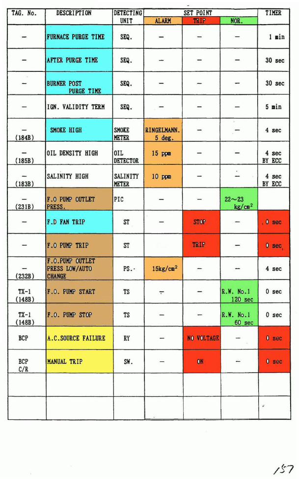
B . B O I L E R S E T P O I N T L I S T
SAMPAGE 42
•re

B O I L E B S E T P O I N T L I S T ECC.; ENGINE CONT.CONSOLMS. ; MONITOR SW.PS. ; PRESS. SW.TS. ; TEMP. SENSORF.E.; FLAME EYEPT. ; PRESS. TRANS.LS. ; LIMIT SW.SEQ.; SEQUENCER
TAG. No.
LM-1(157B)
1LM--
157B2
LM-(156B.159B)
PS-1(153B)
PS-2(154B)
PS-3(152B)
PS-4(151B)
PS-5(172B)
PT(123B)
PT(123B)
TX-1(148B)
TX-1(148B)
DESCRIPTION
DRUM LEVEL HIGH
DRUM LEVEL LOW
DRUM LEVEL LOW-LOW
FUEL OIL PRESS. LOW
FUEL OIL PRESS.LOW-LOW
ATOMIZ. STEAM PRESS.LOW
ATOMIZ. STEAM PRESS.LOW-LOW
CONTROL AIR PRESS.LOW-LOW
STEAM DRUM PRESS.HIGH
STEAM DRUM PRESS.LOW
FUEL OIL TEMP. LOW
FUEL OIL TEMP. HIGH
DETECTINGUNIT
MS
MS
. MS.
PS.
PS.
PS.
PS.
PS.
PT
PT
TS
TS
ALARM
+200 no
-200 no
—
2 kg/cm2
—
3.5 kg/en2
—
_
17.0kg/cm2
9.0kg/cm2
—
R.W.NO.l50 sec
SET POINT___ | _""
—
-240 «n
-
1 . 5 kg/on2
_
3 kg/cm2
4 kg/cm2
-
R.W.NO.l150 sec
-
—
—
—
—
_
—
——
—
—
TIMER
10 sec
10 sec
0 sec
4 sec
0 sec
4 sec
0 sec
0 sec
4 sec
4 sec
10 sec
10 sec
TAG. No.
_
—
—
—
(184B)
(185B)
(183B)
(231B)
—
—
(232B)
TX-1(148B)
TX-1(148B)
BCP
BCPC/R
DESCRIPTION
FURNACE PURGE TIME
AFTER PURGE TIME
BURNER POSTPURGE TIME
l&. VALIDITY TERM
SMOKE HIGH
OIL DENSITY HIGH
SALINITY HIGH
F.O PUMP OUTLETPRESS.
P.D FAN TRIP
F.O PUMP TRIP
F.O.PUMP OUTLETPRESS LOW/AUTOCHANGE
F.O. PUMP START
F.O. PUMP STOP
A. C. SOURCE FAILURE
MANUAL TRIP
DETECTINGUNIT
SEQ.
SEQ.
SEQ.
SEQ.
SMOKEMETER
OILDETECTOR
SALINITYMETER
PIC
ST
ST
PS.-
TS
TS
RY
SW.
ALARM
—
_
—
—
RINGELMANN.5 deg.
15 ppo
10 ppm
—
—
ISkg/cm2
—
—
—
—
SET POINTTRIP_
—
—
—
—
—
—
—
STOP
TRIP
_
—
—
NO VOLTAGE
ON
NOR.
—
—
—
_
—
—
_
22-23kg/ on2
_
__
R.W. No.l120 sec
R.W. No.l60 sec
—
_
TIMER
1 nin
30 sec
30 sec
5 nin
4 sec
4 secBY ECC
4 secBY ECC
, 0 sec
0 sec(
4 sec
0 sec
0 sec
0 sec
0 sec
*

TAG. No.
FDX-1,2(HOB)
FDX-1,2(HOB)
FDX-1,2(HOB)
PX-1
PX-1
FX-1
FX-1
FX-1
PX-2
DESCRIPTION
PILOT BURNERIGNITION FAIL
MAIN BURNERIGNITION FAIL
FLAME FAIL
BOILER AUTO START(AT 16K MODE)
BOILER AUTO STOP(AT 16K MODE)
FURNACE PURGEAIR RATE
AFTER PURGE AIR RATE
IGNITION AIR RATE
IGNITION F.O. RATE
WIND BOX TEMP. HIGH
DETECTINGUNIT
F.E.
F.E.
F.E.
MS.
MS.
FT.
PT.
PT.
PT.
TS.
SET POINTALARM
—
._
_
—
—
—
—
—
200°C
TRIP
NO FLAME
NO FLAME
NO FLAME
—
—
—
—
-
—
-
,.
NOR.
—
—
—
12 kg/cm2
16.3k g/cin2
150 nnAq
150 nmAq
ab.35 ranAq
ab.3 kg/cm2
—
TIMER
6 sec
7 sec
1 sec
_
—
(
1 oin
30 sec
10 sec
10 sec
4 sec

C, INSTRUCTION MANUAL OF AUTOMATIC BOILER CONTROL SYSTEM
[ I ] GENERAL DESCRIPTION OF AUTOMATIC BOILER CONTROL SYSTEM
1. AUTOMATIC COMBUSTION CONTROL
2 . AUTOMATIC FEED IATER CONTROL
[ n ] OPERATING INSTRUCTIONS OF AUTOMATIC BOILER CONTROL SYSTEM
1 . MASTER STATION
2 . AIR FLOf STATION
3. DRUM LEVEL STATION
[m] CONFIGURATION OF AUTOMATIC BOILER CONTROL SYSTEM
1 . NOMENCLATURE AND FUNCTION
2. FUNCTION OF KEYS
3. CHANGE METHOD OF DATA
[IV] ALARM DISPLAY
SAMACC 1 f
I

[ I ] GENERAL DESCRIPTION OF AUTOMATIC BOILER CONTROL SYSTEM
rThis system (A. B. C. ) is coiposed of the. automatic coibustion controlsystem (A. C. C. ) and the automatic feed water control systei (F. I. R. ).
Composition of Control Systemr- MASTER CONTROLLER
r- A. C. C.—
A. B. C. —
L AIR FLOI CONTROLLER
I—F. W. C. F. I. CONTROL
1 . AUTOMATIC COMBUSTION CONTROLIn this system, the fuel oil injection, and the coibustion air quantityfor injection of fuel oil required for coibustion are controlled atoptiiui in order to maintain steam pressure to a given point for therequired steam flow rate.The control loops and functions of the A. C. C. are detailed below.
(1) MASTER CONTROL(a) MASTER CONTROL LOOP
This loop detects the steal drum pressure (master press.). comparesthis pressure with a preset pressure (master set press.). performsthe "PiI" operation, and outputs the F. 0. flow control signal (mastersignal) so as to set the deviation to *0".Also, the master control comprises the following sub-loops.
(b) F. 0.FLO! CASCADE CONTROL SUB-LOOPThe fuel oil flow control signal (Master Signal) and the oilpressure before the burner are compared with the signal (feedback) converted to fuel oil flow rate. "P-fl" operation isperformed, and the operating signal to F. 0. Cont. V. iscontrolled so as to set the deviation to zero.
(c) HOT START & STEAMING UP CONTROL SUB-LOOPThe Master Set Press, is controlled so as to obtain press, rise rate,
from steam drum press, of 5kg/cm2 to normal press. (16kg/cm2).
(d) BURNER ON-OFF CONTROL SUB-LOOPSteam drum press. (Master Press. ) is detected, and the burner isautomatically ignited and shut-down. The set points for ignitionand shout-down are automatically selected by Boiler Mode.
SAMACC
Перевод при помощи PROMT Plug-In for Acrobat
АВТОМАТИЧЕСКОЕ УПРАВЛЕНИЕ СГОРАНИЯ В этой системе, впрыск топлива , и coibustion воздушном количестве для инжекции топливной нефти, заданной для coibustion управляется в optiiui, чтобы сохранить давление пара к данной точке для заданного коэффициента расхода пара. Контуры управления и функции A. C. C. детализированы ниже. (1)ОБРАЗЦОВОЕ УПРАВЛЕНИЕ (a) ОБРАЗЦОВЫЙ КОНТУР УПРАВЛЕНИЯ Эта петля обнаруживает(выпрямляет) давление барабана кражи (образцовый пресс.). сравнивает это давление с заданным давлением (образцовый пресс набора.). исполняет "PiI" действие, и выводит F. 0. сигнал регулирования потока (овладевает сигнал), чтобы установить девиацию на *0". Также, образцовое управление включает следующие подпетли. (b) F. 0. ФЛО! ПОДПЕТЛЯ СТУПЕНЧАТОГО УПРАВЛЕНИЯ, которой сигнал регулирования потока топливной нефти (Образцовый Сигнал) и нефтяное давление перед горелкой является по сравнению с сигналом (отводит назад) преобразованный к расходу топливной нефти. " P-fl" действие выполнен, и операционный сигнал к F. 0. Продолжение следует. V. управляется, чтобы установить девиацию, чтобы обнулить. (c) ПУСК ИЗ ГОРЯЧЕГО СОСТОЯНИЯ и РАЗОЗЛИВШИЙ ПОДПЕТЛЮ УПРАВЛЕНИЯ Образцовый Пресс Набора, управляется, чтобы получить пресс, коэффициент возвышения, от пресса парового коллектора, 5kg/cm2 к нормальному прессу. (16kg/cm2). (d) ГОРЕЛКА ДВУХПОЗИЗИОННЫЙ пресс Парового коллектора ПОДПЕТЛИ УПРАВЛЕНИЯ. (Образцовый Пресс.) выпрямлен(обнаружен), и горелка автоматически зажжена и остановка. Заданные значения для воспламенения и крика вниз автоматически отобраны Модой Котла.

(e) STEAM DUMP CONTROL SUB-LOOPThe signal during activation of I.G. S. adds a limiter to the fuel oilflow rate (Master Cont. Signal).
(f) LOAD LIMITTER CIRCUITThis circuit liiits the increment of master signal, using the air flowsignal
(g) BURNER IGNITION SET CIRCUITThis circuit sets the F. 0. control valve to an opening according to theburner ignition sequence.The "OPEN" signal is detected to range withis the ignition rate, andoutput to the outside.
(h) MASTER STATIONThe set point of the steam drum press, (master press. ) is set anddisplayed, and the processed point is indicated.The F.0. Control Valve Open Order is changed over to Auto/Man, withthis change-over displayed, and the manual operation and output displayand output display are perfomed.
(2) AIR FLO! CONTROL(a) AIR FLO! CONTROL LOOP
This loop compares the demand windbox differential pressure asdetermined by the F.0. Flow control signal (master signal) withthe windbox differential pressure as measured, performs the "P-l-I"operation, and controls the operating signal of the No. 1 F. D. fan inletvane control drive so as to set the deviation to "0". This is intendedto maintain constantly the best combustion by controlling the air flowfor an optimum ratio of air/fuel corresponding to a boiler load. Also,the air flow controls are composed of the following sub loops.
(b) OPERATION CIRCUIT OF DEMANDED IINDBOX DIFFERENTIAL PRESSUREThis circuit calculates the demanded windbox differential pressureby ^compensating the windbox differential press, as determind by the F. 0flow (F.0.Burning Press.) for the boiler characteristics and performingthe variation addition (air, priority circuit) of the master signal
* This compensation to be carried out at the combustion test of the boiler
(c) SETTING OF F. 0. /AIR EXCESS AIR RATIOThe demanded windbox differential press, can be raised or reduced, usingthe fuel/air ratio adjuster.The excess air ratio is adjustable over a range of 0.5 to 1.5 andnormally set to 1. 0
SAMACC 3 ,
fbl

(d) BURNER IGNITION MODEThe F.D. Fan Inlet Vane is set to opening according to the burnerignition sequence.The air flow signal is detected to range within the Furnace Purge,and output to the outside.The air flow signal is detected to range within the Ign.Mode and outputto the outside.
(e) AIR FLOW STATIONThe ratio value of fuel oil/air flow is normally set and displayed,using this adjuster.The Air Flow Control Drive Open Order is changed over to Auto/Man,with this change-over displayed, and the manual operation and outputdisplay are performed.
2. AUTOMATIC FEED IATER CONTROL(a) F. I. CONTROL LOOP
The steam drum water level is detected and compared with the presetwater level, and two-element control is performed for the control ofthe feed water quantity so as to zero the deviation, and steam flowsignal is supplied as feed-forward signal when load change.The "P-H" operation is performed in comparison between the abovewater level set and the detected water level of the steam drum, andthe operating signal of the feed water control valve is controlled soas to zero the deviation.Also, the F. I. C. comprises the functions below.
(b) DRUM LEVEL STATIONThe set point of the drum level is set and displayed, and the processpoint is indicated.The F.I. Control Valve Open Order is changed over to Auto/Man, with
this change-over displayed, and the manual operation and output displayare performed.
SAMACC 4

n ] OPERATINGJNSTRUCTIONS OF AUTOMATIC BOILER CONTROL SYSTEM
This section explains the instructions and indications on thegraphic panel (GP) of ABC system.
The following screen is displayed once GP is started.Please refer to the instruction manual of "Boiler Control Panel" forhow to operate GP while the boiler is working.
J.VLSP. LVLPV S.-FLI
FEED CONT.VOUTPUT i 0.
THE COMPOSITION OF A PICTURE (PORT BOILER)
SAMACC

1. -MASTER STATION'
0> MASTER SET
POINT RAISE
& LOWER SI.
F. 0. CONTROL
VALVE AUTO/
MAN. SELECTOR
Sf.
S3 F. 0. CONTROL
VALVE OPEN
ORDF.R 1 NOT CAT
F. 0. CONTROL
VALVE RAISE
& LOTER SW.
<S> F. 0. CONTROL
VALVE AUTO/
MAN.INDICATE
MSTSP MSTPV F. 0 Pr 25.00 r 25.00 r 15.00
F. 0. CONT. VOUTPUT F~0.
The set and display of the set point andprocess of the steam drum press.The change-over and display of Auto/Manof F. 0. Control Valve Order, as well asthe manual operation and output diaplay,are perfoned.
(1) MASTER SET RAISE & LOffER SI.This is the switch for manual setting ofthe Master Set Point.The master set pressure can, only be seton the master boiler alone.Also the initial set at power-on is madeto 15 kg/cm2
(2) BAR GRAPH OF MASTER SET POINT INDICATOR.The »lef£-hand bar graph shows Masterpressure set point.
(3) BAR GRAPH OF MASTER PROCESS INDICATORThe senter bar graph shows MasterProcess point(Pr,ess)
(4) BAR GRAPH OF F. 0. FLO! INDICATOR.The right-hand bar graph shows P.O.burning pressure.
(5) f. 0. CONTROL MAN. /AUTO SELECTOR Sf.Switches for selecting MAN or AUTO mode for the operation of F.0.controlvalve.
(6) P.O.CONTROL VALVE RAISE & LOIER Sf.The P.O. Control Valve Open Order can be manually operated in theMan Mode.
CAUTION
In EMERGENCY MODE or F. 0. TEMP. BY-PASS MODE, the Man Mode isforced to be selected.
SAMACC 6

2. " A I R FLO!" STATION"
CD FUEL/AIR
RATIO RAISE
& LOIER SI.
© F. D. FAN
CONTROL DRIVE
AUTO/MAN.
SELECTOR Sf
® F.D.FAN CONT.
DEIVE OPEN
ORDER INDICATE
F. D. FAN
CONTROL DEIVE
RAISE & LOIER
Sf.
® F.D.FAN
CONTROL DRIVE
RATIO AIRSP AIRPVr K5Q «=
- 1.00
r 400.D
- 200.0
r 400.0
8SI1
CD
BS22
CD
• IM.O
DSK3
CDBSI4
CD
A U T O[
M A N U
F. D. F VANEOUTPUT 1+ 0. OIX
The change-over and display of Auto/Han, of
the F.D.FAN INLET VANE CONTROL DRIVE OPEN
ORDER, as well as the manual operation andoutput display, are perfomed.The manual set and indication of the Fuel/AirRatio (Excess Air Ratio) are perfomed.
(1) FUEL/AIR RATIO RAISE & LOWER Sf.This switch is used for the manual set ofthe Fuel/Air Ratio.The initial set at power-on is made to 0.
CAUTION
The fuel/air ratio is tested and adjustedat the actual combustion adjustment test,so that the optimum combustion air ratecanbe obtained at the set point of 0 under
normal running mode.
(2) BAR GHAB1 OF FUEL/AIR RATIO INDICATORThe left-hand bar graph indicates thescale tactof (-50&~~*5030 to the combustionair quantity established at the combustion*adjustment test.Also, the initial set at power-on is made
to 0.
(3) BAR GRAPH OF AIR FLOf SET POINTThe center bar graph shows Air Flow set point.
(4) m GRAPH OF AIR FLO!(BURNER DRAFT LOSS).The right-hand bar graph shows AIR FLOf(0-10030.
(5) F. D. FAN MAN. /AUTO SELECTOR SI.This switch is used to select the operation of the F. D. Fan InletVane Control Drive to Man. or Auto.
CAUTIONIn EMERGENCY MODE or F. O.TEMP. BY-PASS MODE, the Man. Mode is forcedto be selected.
(6) F.D.FAN CONTROL DRIVE RAISE & LOIER SfThe F. D. Fan Inlet Vane Control Drive Open Order can be manually
operated in the Man Mode.SA
ACC

3, "DRUM LEVEL" STATION'
© DRUM LEVEL
SET POINT
RAISE & LOfER
St.
F. I. CONTROL V
VALVE AUTO/
MAN.SELECTOR
Sf.
F. f. CONTROL
VALVE OPEN
ORDER INDTCATl
F. I. CONTROL
VALVE
fflLVLSP LVLPV S. FLW
r 40.00
© F.f.CONTROL
VALVE
AUTO/MAN. INDICATE
The set and display of the steam drum water
level, as well as the iidication of the
process value, are performed.
The change-over and display of Auto/Man ofthe F. f. CONTROL VALVE OPEN ORDER, as wellas the manual operation and output display,are performed.
(1) DRUM LEVEL SET POINT RAISE & LOfER Sf.
This is the switch for the manual set ofthe drum level set point.At the time of power-on, the initial setpoint is made to ± 0 (Nor.).
(2) BAR GRAPH OF DRUM LEVEL SET POINTThe left-hand bar graph shows Druilevel set point.
(3) BAR GRAPH OF LEVEL PROCESSThe senter baf graph shows Drumlevel process point.
(4) BAR .GRAPH OF STEAM FLOf
The right-hand bar graph shows
Steam Flow.
(5) F.I. CONTROL AUTO/MAN. SELECTOR Sf.This switch is for selecting the operation of F.f. control valveto Man or Auto Mode.
(6) F. f. CONTROL VALVE RAISE & LOfER Sf.The Feed fater Control Valve Open Order can be manually operated inthe Man Mode.
SAMACC

[ffl] CONFIGURATION OF AUTOMATIC BOILER CONTROL SYSTEM
1 , NOMENCLATURE AND FUNCTION
TO GP
COMMUNICATION
CONNECTOR
TO ACS10
COMMUNICATION
CONNECTOR
O
o
A M C O
r-RS-485-A-,
o
Q
caasoCQ
Oeu
o
a
oeao•«cCu
OasO
a.
O
•0) PAC ID
ROTATIONAL
SIITCH
(D LED LAMP
N O NAME FUNCTION
PAC ID
Rotational switch
to set ID numbers for communication
between PAC and GP.
* Setting is unnecessary once outfitted.
SAMACC 9

N O
©
•NAME
L E D L A M P
D D D D D D D DI D D D D D D D
D D D D D D D DD I D D D D D D
D D D D D D D DD D I D D D D D
D D D D D D D DD D D I D D D D
D D D D D D D DD D D D I D D D
D D D D D D D DD D D D D I D D
D D D D D D D DD D D D D D I D
D D DD D D
D D D D DD D D D I
_ _ „,... !
FUNCTION
LED indication of Self-Diagnosis
(Please see (IV)Alari display (2).
Digital Input No. 1
Input status is display
LED lamp "ON" -» DI Nol. ON
LED lamp "OFF" -* DI Nol. OFF
Digital Input No. 2
Input status is display
LED lamp "ON" - DI No2. ON
LED lamp "OFF" -* DI No2. OFF
Digital Input No. 3
Input status is display
LED lamp "ON" - DI No3. ON
LED lamp "OFF" — DI No3. OFF
Digital Input No. 4
Input status is display
LED lamp "ON" -» DI No4. ON
LED lamp "OFF" -» DI No4. OFF
Digital Input No. 5
Input status is display
LED lamp "ON" — DI No5. ON
LED lamp "OFF" -> DI No5. OFF
Digital Input No. 6
Input status is display
LED lamp "ON" -» DI No6. ON
LED lamp "OFF" -* DI No6. OFF
Digital Input No. 7
Input status is display
LED lamp "ON" -» DI No7. ON
LED lamp "OFF" -> DI No7. OFF
SAMACC 10

N O
©
NAME
L E D L A M P
O I D D D D D DD D D D D D D D
D D I D D D D DD D D D D D D D
D D D I D D D D
D D D D I D D DD D D D D D D D
D D D D D I D DD D D D D D D D
D D D D D D I DD D D D D D D D
D D D D D D D ID D D D D D D D
I D D D D D D DD D D D D D D D
FUNCTION
Digital Output No. 1
Output status is display
LED lamp "ON" - DO Nol. ON
LED lamp "OFF" -» DO Nol. OFF
Digital Output No. 2
Output status is display
LED lamp "ON" -* DO No2. ON
LED lamp "OFF" -» DO No2. OFF
Digital Output No. 3
Output status is display
LED lamp "ON" - DO No3. ON
LED lamp "OFF" — DO No3. OFF
Digital Output No. 4
Output status is display
LED lamp "ON" - DO No4. ON
LED lamp "OFF" - DO No4. OFF
Digital Output No. 5
Output status is display
LED lamp "ON" -» DO No5. ON
LED lamp "OFF" -* DO No5. OFF
Digital Output No. 6
Output status is display
LED lamp "ON" -» DO No6. ON
LED lamp "OFF" — DO No6. OFF
Digital Output No. 7
Output status is display
LED lamp "ON" - DO No7. ON
LED lamp "OFF" -* DO No7. OFF,x""\
Digital Output No. 8 output status is display
LED lamp "ON" -* DO No8. ON (CPU Run)
'LED lamp "OFF" — DO No8. OFF (CPU Stop)
* This lamp is "ON" whi le CPU is running
SAMACC 11

2, FUNCTION OF KEYS (Fig 1)
D TEN KEY dJ DATA ENTRY KEY
As you press the D key, MENU is display.
The menu switches function as follows.
[P I D ] : to display parameters and change set values on
PID parameter screen
[% P] : to display parameters and change set values on
l-type parameter screen.
[T P] : to display parameters and change set values on
time parameter screen.
[T B L] : to display parameters and change set values on
broken-line table screen.
[A I 0] : to display AI/AO data screen.
[D I 0] : to display DI/DO data screen.
[S W] : to display SI screen.
[ERR] : to display error screen.
LEND] : to end menu screen.
SAMACC 12

The switch screen (Fig. 2) will be displayed for data setting on
every screen called throught menu (Fig. 1)
(Fig 2)
t
END
CLR
[CLR]
Cursor Up
Cursor Down
Cursor Left
Cursor Right
To next page
Data Cancellation
The set data can be cheanged by using the above keys(fig 2)and
ten keys(fig 1 -©).
The set data can only be changed for "PID", "% P", "T P", and "TBL",
(If a manu is selected for those other that stated above, cursor key
and data cancellation key will not work. )
SAMACC 13

P I D
When
T P
Ihen
(Fig 3-1)
pressed,
mm nPID Parameter
PID 1PC % ) 999.9I (min) 99.99D(oin) 99. 99
IloC X ) +999. 9IhiC % ) +999. 9
^ -<• *
^ ->• CLR
|END|
(Fig 3-3)
pressed^
mm nTime ParameterNo No1 99.99 11 99.992 99. 99 12 99. 993 99. 99 13 99. 994 99.99 14 99.995 99.99 15 99.996 99.99 16 99.997 99.99 17 99. 998 99. 99 18 99. 999 99. 99 19 99. 9910 99. 99 20 99. 99
^ I •<• *
^ I •> CLR
END
X P
then
IB!-
When
(Fig 3-2)
pressed^
am%No12345678910
DParameter
No
+ 999. 9 11 +999. 9+ 999. 9 12 +999. 9+ 999. 9 13 +999. 9+ 999. 9 14 +999. 9+ 999. 9 15 +999. 9+ 999. 9 16 +999. 9+ 999. 9 17 +999. 9+ 999. 9 18 +999. 9+ 999. 9 19 +999. 9+ 999. 9 20 +999. 9
71
a*
^END
*
CL8
(Fig 3-4)
pressed^
mm DConvertNo X1 999. 92 999. 93 999. 94 999. 95 999. 96 999. 97 999. 98 999. 99 999. 910 999, 9
Table 1Y
999. 9999. 9999. 9999. 9999.9999.9999. 9999. 9999. 9QQQ Q
TIa^
END
#
CLR
SAMACC 14

(Fig 3-5)
AID
then pressed^
[y jj| 1 1
Analog In/Out
; All +999. 9 A01 +999. 9
AI2 +999. 9 A02 +999. 9
AI3 +999. 9 A03 +999. 9
AI4 +999. 9 A04 +999. 9
AI5 +999. 9 A05 +999. 9
AI6 +999. 9 A06 +999.9
AIT +999. 9 A07 +999. 9
AI8 +999. 9 A08 +999. 9
1
t
<•
-END 1
*
CLR
(Fig 3-7)
S I
then pressed^
When pressed.
(Fig 3-6)
D
Digital In/Out
-DI1 0
DI2 0
DI3 0
DI4 0
DJ5 0
DI6 0
DI7 0
DI8 0
D01
D02D03
D04DOS
D06DOT
DOS
0
0
0
0
0
00
0
±j CLR
(Fig 3-8)
ERE
theft pressed.
DError Infoaation
Com 9 9999
Cycle 9
Calc 9 99
AI 9 9
CLR
SAMACC 15

(Fig 4) 3, CHANGE METHOD OF DATA
X P
Press Key
mm nX ParameterNo12345678910
Nn
+ 000. 0 11+ 005. 0 12+ 010. 0 13+ 003. 0 14-020. 0 15+000.+ 010.+075.+ 100.-050.
0 16
0 170 180 190 20
+050. 0+ 001.0+030. 0-010. 0+ 100. 0+500. 0-500. 0+000. 0+000. 0+ 100.0
7]
a**
<**
END
* lCLRI
(Fig 5)% Parameter
No No
1 +000. 0 11
^2 +005.0
! 3 +010. 0 [13
+050.0
4 +003.0 14
5 -Q20. 0 15
6 +000. 0 16
7 +010. 0 17
8 +075.0 18
9 +100. 0 19
10 -050. 0 20
+030 .0-010 .0+ 1 0 0 . 0+500 .0-500.0+ 0 0 0 . 0+000 .0+ 1 0 0 . 0
This explains how to change % parameter
set point.
(Example) to change No.3 parameter from
10* to 25X
(1) Press key on the station screen
of the controller you wish to change,
and the menu screen [2-(Fig- l ) ]
will be displayed..
(2) Press the %P key,
and (Fig 4) will be displayed.
(3) Press the IT] key of (Fig 4)twice to move the cursor to No. 3,
and (Fig 5)will be displayed.
(4>Press
3 -h 0 1 0. 0
key of Fig. 4
twice to move the cursor
to the second place of the
value.
0 2 0 . 0(5) Press 2 key and then
3 -f 0 2 5. 0
of the ten keys below GP.
(see 2-Fig 1-®)
key(2-Figl -
after confirming that the
number has been changed.
CAUTIONPlease contact the boiler maker(Mitsubishi Heavy Ind.)
before changing invariable numbers such as parameters.
* Invariable numbers other than %? can also be changed in the
same way on the respective screen.
SAMACC 16

[IV] ALARM DISPLAY
GP displays reversible and communication errors.
The abnormality are displayed with GP. as follows.
(Fig 6)
F 1
mm
HE
Vcz
F 2 F 3
D
. 5g
OUTPUT
3D
9
'' CZ
.
— i
zmAUTO
V
0.
?
%
1 2 3
Q
9 « '
• 11!•»
ISKD
- S5.8
1na
OS14D
=?| RUN |
| M A N U |
MANU
A
4 5
F
mm
ESP
V
4 F 5
D
C O M
D OWN
CZL-7SI
••Aq
'i
091
KBp
• 50.0
OSBD
BSWa
loAq *
OUTPUT |_
3D
AUTO
V
6 7
ZJ«| RUN |
| MANU |
MANU
A
5 9 0
F 6 F 7
mm
|LSP|
Vc
- 5$
OUTPUT
T|D]
i
•' c
- 56
LJL~T
: • NAUTO
V
F 8
D
0
3° C
mi
miD
-50.11
BSi3D
JSI4D
JJ
1 RUN 1| M A N U |
M A N U
A
Warn DDDDDDDD
4-
i
IBOST!
B S E N T R
(2) (A) (i)(1) Reversible errors
then the following errors occur in ACC CONTROLLER(ACSIQQ),it will be
indicated on GP as (1).
Reversible errors item as follows.
1) Analog input range over
2) Arithmetic overflow
3) Arithmetic overload
There are 8 LEDs after "farm", and the location of lighted LEDs
indicates the kind of error.
ffhen a reversible error occurs under "AUTO" node, the mode is
automatically switched to manual.
Only after the reversible error is corrected, the mode can be changed
back to "AUTO" by pressing (A) (reset)key.SAM
ACC 17

(2) Irreversible errors (Communication down)
If GP detects 10 communication errors in a row from a controller,
it displays an error indication such as Fig. 6 (2) and stops communicating
with the controller.
If an irreversible error is detected by self-diagnosis function,
all the arithmetic functions will be ceased.
Thus, a communication error is displayed on GP and an irreversible
error can be confirmed.
then an irreversible error occurs, "Errors"LED blinks. ( [Iff] — 1 —(D)
The number of blinks, which repeats itself in every certain period of
time, indicate the kind of the error.
1 Blink Abnormal Program ROM
2 Blinks Abnormal Data ROM
3 II Abnormal Data RAM
4 II Abnormal Sampling Time
5 II Abnormal Output Line Connection (A01)
6 II Abnormal Analog output
7 II Abnormal Communication (not transmissible)
8 II Abnormal Analog input (hardware error)
9 II Abnormal Program
10 II Abnormal Parameter
11 (I PID arithmetic overflow
12 I Abnormal Output Line Connection (A02)
* After the error is corrected, press [F 5] key (Fig 6 ~
and check connection, and GP can be resumed.
SAMACC 18

D. BMS C O N T R O L L E RTABLE OF C O N T E N T S
S E C T I O N
D-[l] SYSTEM C O N F I G U R A T I O N
C2] CPU U N I T
[ 3] I/O R A C K
[ 4] P OWE R S U P P L Y
[5] S P E C I F I C A T I O N S
[6] R E A D I N G AND C L E A R I N G E R R O R S
AND M E S S A G E S
[7] I N S P E C T I O N AND M A I N T E N A N C E
[8] P R O G R A M M I N G C O N S O L E O P E R A T I O N
/77

SECTION 2System Configuration and Unit Description
This section provides information about the Racks and individual Units that make up a C200HS PC S ystem. The names of allthe parts of a Unit are given, followed by any details thai apply 10 that Unit alone. For a description of how the Units fit togetherto become a PC, refer to Section 3 Assembly Instructions. For information about the model numbers of any of the parts de-scribed in this section, refer to Appendix A Standard Models. For specifications, refer to Appendix B Specifications.
2-1 System Configuration 162-1-1 CPU Racks 162-1-2 Expansion I/O Racks 172-1-3 Slave Racks 17
2-2 CPUs 182-2-1 CPU Components 182-2-2 CPU Indicators 192-2-3 DIP Switch 202-2-4 Peripheral Device Connector 202-2-5 Operation Modes t.. 202-2-6 Memory Cassettes 21
2-3 Expansion I/O Racks 212-4 Power Supply 222-5 yO Units 23
•2-5-1 Standard I/O Units 242-5-2 Group-2 High-density I/O Units 252-5-3 High-density I/O Units Classified as Special I/O Units 26

System Configuration Section 2-1
2-1 System Configuration
2-1-1 CPU Racks
A variety of system configurations can be achieved by using different combina-tions of Racks and Units. Before ordering specific Units, carefully consider whichsystem configuration will best meet your control requirements. In a C200HS PCSystem, a maximum of two Expansion I/O Racks and five Remote I/O SlaveRacks can be connected to a CPU Rack.
(10) (9) (6). (7) (5)
1. BackplaneThere are backplanes available with 3, 5, 8, or 10 slots. The same back-planes can be used for CPU Racks, Expansion I/O Racks, or Slave Racks.
2. CPUThere are six CPU models available: CPU01-E, CPU03-E, CPU21-E,CPU23-E, CPU31-E, and CPU33-E.
3. Memory CassetteEPROM and EEPROM are both available.
4. Standard I/O UnitThe Units can have 5,8,12, or 16 points. In this illustration the I/O Un'rt coveris mounted. This is the terminal block cover for Units with 10P terminalblocks.
5. Interrupt Input UnitOne Interrupt Input Unit can be used at the CPU Rack.
6. SYSMAC NET Llnk/SYSMAC LINK Unit, Host Link Unit, or PC Link Unit
7. Remote I/O Master UnitA maximum of two Units can be used, either on the CPU Rack or on an Ex-pansion I/O Rack.
8. Terminal BlockTerminal blocks have either 10 or 19 terminals. This is a 19P Terminal Block.
9. High-density I/O Unit (Group 2)A maximum of ten Units can be used if they are all 32-point Units, and five ifthey are all 64-point Units. They cannot be used on Slave Racks.
10. Special I/O UnitUp to ten Special I/O Units can be used (including PC Link), They can beused on any Rack.
11. I/O Connection CableThere are five types of cable, from 30 cm to 10 m. A maximum total of 12 mcan be used.
16

System Configuration Section 2-1
2-1-2 Expansion I/O Racks
2-1-3 Slave Racks
A maximum of two Expansion I/O Racks can be connected.
1. I/O Power Supply Unit2. Backplane
There are backplanes available with 3, 5, 8, or 10 slots. The same back-planes can be used for CPU Racks, Expansion I/O Racks, or Slave Racks.
A maximum of five Slave Racks can be connected.
(2)
1. Slave UnitEither Optical or Wired Slaves can be used.
2. Fiber-optic Cable
2/?-\ I L
^/&>

CPUs Section 2-2
2-2 CPUsThere are two groups of CPUs available, one that uses an AC power supply, andone that uses a DC power supply. Select one of the models shown betow accord-ing to requirements of your control system.
CPU model
C200HS-CPU01-E/CPU21-E/CPU31-E
C200HS-CPU03-E/CPU23-E/CPU33-E
Power supply voltage
100 to 1 20 VAC or 200 to 240 VAC(voltage selector)
24 VDC
The CPU21-E, CPU23-E, CPU31-E, and CPU33-E CPUs have an RS-232Cconnector. The CPU31-E and CPU33-E CPUs support the SYSMAC NET LinkUnit and SYSMAC LINK Unit.
Caution Be sure to check the power supply used by the CPU. Absolutely do not apply anAC power supply to a DC-type CPU.
2-2-1 CPU ComponentsC200HS-CPU01-E/CPU03-E
Power fuse (MF51NR, 5.2 dia. x 20 mm):C200HS-CPU01-E: 2 A, 250 VC200HS-CPU03-E: 5 A, 125 V
Removable terminal block
Battery/Switch compartment:The backup lithium battery (C200H-BAT09)and the DIP switch for setting C200HS opera-tions are contained. An optional Memory Cas-sette can also be mounted.
L- Cable connector for peripheral devices(Peripheral device connector)
18

CPUs Section 2-2
C200HS-CPU21-E/CPU23-E/CPU31-E/CPU33-E
Memory Casette compartment
Bus connector:Available only with the CPU31-Eand CPU33-E. Use this connectorwhen SYSMAC NET Link Unit orSYSMAC LINK Unit is used.
Power fuse (MF51NR, 5.2 dia. x 20 mm):C2COHS-CPU21-E/CPU31-E: 2 A, 250 VC20CHS-CPU23-E/CPU33-E: 5 A, 125 V
Removable terminal block
RS-232Cconnector
Cable connector forperipheral devices
Battery/Switch compartment
2-2-2 CPU IndicatorsThe following figure shows the indicators that are located on the front panel ofCPU models.
•RUN (green):Lights when the PC isoperating normally.
I— COMM1 (orange):Lights when a peripheral device is in operatbn.COMM2 (orange):Available only with the CPU21-E. CPU23-E. CPU31-E,and CPU33-E. Lights whe.n the CPU is communicatingvia the RS-232C connector. POWER (green):
Lights when power issupplied to the CPU.
RUN11 AIMK ERR
COMMOUTINHIBIT
POWiB FUSE250l'AC
ALM (blinking red):Blinks if an error occurs thatdoes not stop the CPU.
•OUT INHIBIT (red):Lights when the Load OFFflag (SR bit 25215) turns ON,at which time all the outputsare turned OFF.
• ERR (solid red):Lights if an error occurs that stops theCPU, at which time the RUN indicatorturns OFF and the outputs are turnedOFF.
19

CPUs Section 2-2
2-2-3 DIP SwitchPin no.
1
2
3
4
5
6
Item
Memory protect
Automatic transfer of MemoryCassette contents
Message language
Expansion instruction setting
Communications conditions
Expansbn TERMINAL modesetting
Setting
ON
OFF
ON
OFF
ON
OFF
ON
OFF
ON
OFF
ON
OFF
Function
Program Memory and read-only DM (DM 6144 to DM 6655)data cannot be overwritten from a Peripheral Device.Program Memory and read-only DM (DM 6144 to DM 6655)data can be overwritten from a Peripheral Device.
The contents of the Memory Cassette will be automaticallytransferred to the internal RAM at start-up.The contents will not be automatically transferred.
Programming Console messages will be displayed in English.
Programming Console messages will be displayed in thelanguage stored in system ROM. (Messages will be displayedin Japanese with the Japanese version of system ROM.)
Expansion instructions set by user. Normally ON when using ahost computer for programming/monitoring.
Expansion instructions set to defaults.RS-232C communications conditions are set as follows.Start bit: 1 ; data length: 7 bits; parity: even; stop bit: 1 ; baudrate: 2.400 bpsRS-232C communications conditions are canceled.
Expansion TERMINAL mode; AR 071 2: ONNormal mode; AR 071 2: OFF
2-2-4 Peripheral Device ConnectorA Programming Console (C200H-PRO27-E or CQM1-PRO01-E) or IBM PC/ATrunning LSS can be used to program and monitor the C200HS PCs. They can beconnected by opening the cover and connecting a cable to the peripheral deviceconnector.Use the following cables to connect the respective Peripheral Devices.
Programming Console: C200H-CN222/422IBM PC/AT: COM 1 -CIF02
(The cable is included with the CQM1-PRO01-E Programming Console.)
Note Peripheral Devices can be mounted directly to C200H PCs, but not to C200HSPCs.
2-2-5 Operation ModesThe operation modes when the C200HS is powered up are shown in the tablebelow. If a Peripheral Device is connected when the C200HS power is alreadyon, the mode status prior to connecting the Peripheral Device will be retained.
PC Setup (DM 6600} status
Mode according to status ofProgramming Console keys(DM 6600 - 0000)
Mode retained from before powerinterruption(DM 6600- 01 00)
Mode according to PC SetupDM 6600 « 0200: PROGRAMDM 6600 - 0201 : MONITORDM 6600 - 0202: RUN
Peripheral Device connected
NoneProgramming Console
Device other than ProgrammingConsole
None
Programming Console
Device other than ProgrammingConsoleNone
Programming Console
Device other than ProgrammingConsole
C200HS mode at power up
Automatically goes into RUN mode.
Goes into mode set by ProgrammingConsole selector switch.Automatically goes into PROGRAMmode.Goes into mode that was in effectprior to power interruption.
Goes into mode set by PC Setup (bits00 to 07 of DM 6600).
20

Expansion I/O Racks Section 2-3
2-2-6 Memory Cassettes
C200HS-ME16K (EEPROM)
The C200HS comes equipped with a built-in RAM for the user's program, so anormal program be created even without installing a Memory Cassette. An op-tional Memory Cassette, however, can provide greater speed and flexibility.There are two types of Memory Cassette available, each with a capacity of 16Kwords. For instructions on installing Memory Cassettes, refer to Section 3 Instal-lation.The following table shows the Memory Cassettes which can be used with theC200HS PCs. These Memory Cassettes cannot be used in C200H PCs.
Memory
EEPROM
EPROM
Capacity
1 6K words
1 6K words
Model number
C2QOHS-ME16K
C200HS-MP16K
Comments...
The ROM chip is not included withthe Memory Cassette; it must bepurchased separately.
Note Memory Cassettes for the C200HS cannot be used with the C200H, andMemory Units for the C200H cannot be used with the C200HS.
When a Memory Cassette is installed in the CPU. reading and writing of theuser memory (UM) and I/O data is made possible. There is.no need for abackup power supply. The Memory Cassette can be removed from the CPUand used for storing data.
C200HS-MP16K (EPROM) The program is written using a PROM Writer. The ROM is mounted to theMemory Casette and then installed in the CPU. I/O data cannot be stored.
Oompon caooHs-MpisK
oooooO /T*v
oMol
Notch
r01
2-3 Expansion I/O RacksThe Backplane used to construct a CPU Rack is also used to construct an Ex-pansion I/O Rack. An Expansion I/O Rack is identical to a CPU Rack, except theCPU is replaced with a Power Supply. Two Expansion I/O Racks can be con-nected to a CPU Rack. The number of I/O Units and Special I/O Units that can beconnected to an Expansion I/O Rack is determined by the number of slots on theRack.
21

Power Supply Section 2-4
The parts of an Expansion I/O Rack are shown in the following diagram.
I/O Connecting Cable Connector:Connects Expansbn I/O Rack to pre-ceding Expansion I/O Rack or to CPU.
Backplane Power Supply
I/O Connecting Cable Connector:Connects Expansbn I/O Rack tonext Expansion I/O Rack.When not used, cover with a cap.
I/O Units
Backplane mounting screws(four, with 4-mm dia. heads)
2-4 Power SupplyThe Power Supply used for Expansion I/O Racks is available in two models. Oneruns on 100 to 120 or 200 to 240 VAC, and the other runs on 24 VDC. Be verycareful not to provide an AC power supply to a DC-type Unit.
AC Power Supply
POWER indicator (green): —Lights when power issupplied to Power Supply
C200H onwonPROGRAMMABLE CONTROLLER
Power fuse:2 A, 250 V(5.2-dia. x20)MF51NR
Terminalsfor exter-nal con-nectbns
±r~TL_
(x)M^MMM
(x)
(x)
(x)
(x)
(x)
(x)
(x)
(x)
(x)
^© AC Input
Short: 100 to 120Open: 200 to 240
"Th LG
"© GR
"~~** ® 24 VDC, 0.3,_ 0 A output
NC
NC
srminalsVACVAC
22

IIO Units Section 2-5
DC Power Supply
DWER indicator (green): —ghts when power isapplied to Power Supply
PS211
— i — i —
POWER jf
fe
C2QOH oowonPROGRAMMABLE CONTROLLER
•
Power fuse:5 A, 125V(5.2-dia.x20)MF51NR
2r* -
""L
*
•*.
^5d£
SisSB
ill
— i
Terminalsfor exter-nal con-nections
(x)
(x)
©
©
©
©
©
©
©
,»"*Tr 24 VDC
aNC
NC
m LG
NC
NC
NC
NC
2-5 I/O UnitsI/O Units are divided into three groups based on the way that I/O words they useare allocated. Standard I/O Units are allocated I/O words according to the Unit'slocation on the CPU or Expansion I/O Rack. Group-2 High-density I/O Units areallocated I/O words according to I/O number set on each Unit. High-density I/OUnits classified as Special I/O Unit are allocated I/O words according to the unitnumber set on each Unit.
23

HO Units Section 2-5
2-5-1 Standard I/O UnitsStandard I/O Units come in two shapes; A-shape and B-shape. Refer to Appen-dix B Specifications for the dimensions of each Unit.
A-shape I/O Unit (10-termlna! Terminal Block)
I/O Unit locking notch
Nameplate
I/O indicators:Indicate ON/OFF sta-tus of points
10-terminal terminal block
B-shape I/O Untt (19-terminal Terminal Block)
I/O Unit locking notch
Nameplate
~" I/O indicators:Indicate ON/OFF sta-tus of points
— 19-terminal terminal block
24

HO Units Section 2-5
2-5-2 Group-2 High-density I/O UnitsGroup-2 High-density I/O Units come in two varieties; C-shape and D-shape.The shape of the two varieties is the same, but C-shape Units have only one con-nector, while the D-shape Units have two. C-shape Units have 32 I/O points andD-shape Units have 64 I/O points.
Unit
DC Input Unit
Transistor Output Unit
Specifications
24 VDC; 32 pts
24 VDC; 64 pts
4.5 VDC, 16 mA to26.4 VDC, 100 mA; 32 pts
4.5VDC.16mAto26.4 VDC, 100 mA; 64 pts
Shape
C
D
C
D
Mode!
C200H-ID216
C200H-ID217
C200H-OD218
C200H-OD219
Note Refer to Optional Products, Appendix A Standard Models for a list of externalconnectors.
Group-2 High-density I/O Units are allocated I/O words in the IR Area (IR 030 toIR 049} by setting the I/O number switch on the front of each Unit. C-shape Unitsare allocated 2 words and D-shape Units are allocated 4 words beginning withm, where m = IR 030 + 2 x I/O number.
For C-shape Units the 16 I/O bits in m are allocated to the A side of the connector,and the I/O bits in rm-1 are allocated to the B side of the connector. For D-shapeUnits the I/O bits in m are allocated to the A side of connector 1, the I/O bits inm+1 are allocated to the B side of connector 1. the I/Obits in m+2 are allocated tothe A side of connector 2, the I/O bits in m+3 are allocated to the B side of con-nector 2. Refer to the C200HS Operation Manual (W235) for more details on I/Oword allocation.Always turn the PC power off before changing a Unit's I/O number. The new I/Onumber will not be recognized unless the PC has been turned off. Do not setmore than one Unit to the same I/O number or set I/O numbers so that the sameI/O word is allocated to more than one Unit, e.g., if you set a 64-point Unit to I/Onumber 0, you cannot use I/O number 1 for any Unit.
Refer to Appendix B Specifications for the specifications and dimensions of theUnits.
C-shape Units (32-point Units)
I/O Unit locking notch
Nameplate
~ I/O indicators:Indicate ON/OFF status of points
I/O number setting switch
40-pin connector
25

IIO Units Section 2-5
D-shape Units (64-point Units)
I/O Unit locking notch
Nameplate
I/O indicators:Indicate ON/OFF status of I/O pointsI/O number setting switch
Indicator switch:Determines whether the status ofconnector 1 or connector 2 I/O pointsare indicated by the I/O indicators.
40-pin connectors
2-5-3 High-density I/O Units Classified as Special I/O Units
Some High-density I/O Units are classified as Special I/O Units. Up to 10 SpecialI/O Units can be connected to a PC. The Units have two 24-pin connectors. Ingeneral, these Units control 32 I/O points, although some Units can control 128I/O points when set for dynamic operation.
Refer to Appendix B Specifications tor detailed specifications and dimensions ofthe Units.
UnitTO. Input UnitDC Input Unit
TTL Output UnitTransistor Output UnitTTL I/O UnitDC Input/TransistorOutput Unit
Specifications5 VDC. 32 inputs24 VDC; 32 inputs
5 VDC, 32 outputs24 VDC; 32 outputs5 VDC, 16 inputs, 16 outputs12 VDC; 16 inputs, 16 outputs24 VDC; 16 inputs, 16 outputs
Model NumberC200H-ID501C200H-ID215
C200H-OD501C200H-OD215C200H-MD501C200H-MD115C200H-MD215
Remarks8 pts can be set as high-speed inputs.
Can be set for 128 dynamic outputs.
8 pts can be set as high-speed inputs.
Can be set for 128 dynamic inputs.
Note Refer to Optional Products, Appendix A Standard Models for a list of externalconnectors.
Setting the Unit Number High-density I/O Units are each allocated 10 I/O words in the IR Area (IR 100 toIR 199) by setting the unit number switch on the front of each Unit. The 10 wordsbegin with n, where n = IRlOO + 10x unit number. For example, a Special I/OUnit with a unit number of 3 would be allocated IR 130 to IR 139.
Always turn the PC power off before changing a Unit's unit number. The new unitnumber (0 to 9) will not be recognized unless the PC has been turned off.
26

HO Units Section 2-5
Setting the DIP Switch The operation of High-density I/O Units is controlled by setting the pins of theDIP switch on the back panel. The following table shows the function of each pinand applicable Units.
Pin
1
2
3
4
5
6
Function
Operating mode
High-speed input1
High-speed inputminimum pulse width2
Input response time3
Data output mode4
Not used.
Applicable Units
C200H-OD501/OD215
C200H-M0501/MD1 1 5/MD21 S
C200H-I0501/ID215
C200H-MD501/MD115/MD215
C200H-1D501/ID215C200H-MD501/MD1 1 S/MD215C200H-ID501/ID215C200H-M0501/MD1 1 5/MD21 5
C200H-OD501/OD215._
Setting
ON
128 dynamic outputs
1 28 dynamic inputs
Inputs 08 to 15 of CN2are high-speed inputs.Inputs 08 to 15 of CN2are high-speed inputs.
4ms
15ms max.
Positive logic...
OFF
32 outputs
16 inputs, 16 outputs
Normal inputs
Normal inputs
1 ms
2.5 ms max.
Negative logic...
Note 1. Used in the C200H-MD501/MD115/MD215 only when pin 1 is OFF, settingthe Unit to static mode.
2. Used in the C200H-ID501/215, C200H-MD501/MD215/MD115/MD215only when pin 2 is ON, setting the Unit to High-speed input mode.
3. Sets the input response time for normal inputs. When pin 2 is ON, CN2 08 to15 are pulse-catch inputs. Other inputs can be used as normal inputs.
4. Used when pin 1 is ON, setting the C200H-OD501/OD215 to dynamic out-put mode.
I/O Unit locking notch
Nameplate
I/O indicators:Indicate ON/OFF status of points
Unit number setting switch
24-pin connectors

Appendix BSpecifications
The following figures and tables provide specifications for each Unit of the C200HS. I/O Units may take on one oftwo different shapes and are sometimes referred to as A-shape Units or B-shape Units. Group-2 High-density I/OUnits take on one of two different shapes and are sometimes referred to as C-shape Units or D-shape Units. Referto the figures at the end of the I/O Unit specifications for the exact dimensions of these two shapes of I/O Unit.
CPUs and Power SuppliesGeneral Specifications
item
Supply Voltage
Operating Voltage Range
Power Consumption
Surge Current
Output Capacity
Fuse
24 VDC Output
Insulation Resistance(See note 1 .)
Dielectric Strength(See note 1 .)
Noise Immunity
Vibration
Shock
Ambient Temperature
Humidity
Atmosphere
Grounding
Enclosure Rating
Weight
C200HS-CPU01-E/CPU21-E/CPU31-E,C200H-PS221
100 to 120/200 to 240 VAC selectable50/60 Hz
85 to 1 32/1 70 to 264 VAC
120 VA max.
30 A max.
C200HS-CPU03-E/CPU23-E/CPU33-E,C200H-PS211
24 VDC
20.4 to 26.4 VDC
40 W max.
30 A max.
CPU01-E/CPU21-E/CPU31-E; 4.6 A, 5 VDC (3.9 A supplied to I/O Units)CPU03-E/CPU23-E/CPU33-E: 3 A, 5 VDC (2.3 A supplied to I/O Units)Expansion UO Rack: 3 A, 5 VDC (2.7 A supplied to I/O Units)
2 A 250 V 5.2 dia. x 20 (MF51NR)
0.3 A. 24 VDC *10%/_2o%
20 MQ between AC terminals and the GRterminal at 500 VDC
2,300 VAC at 50/60 Hz for 1 minutebetween AC terminals and housing; 1,000VAC at 50/60 Hz for 1 minute between DCterminate and housing. Leakage current: 10mA max.
2 A 1 25 V 5.2 dia. x 20 (MF5 1 NR)
None
(See note 2.)
(See note 2.)
1 ,500 Vp-p. pulse width: 100 ns to 1 u.s, rise time: 1 ns pulse (by noise simulator)
JIS C0911 conforming, 10 to 57 Hz; 0.075 mm amplitude, 57 to 150 Hz; acceleration: 1 G(see note 3), in X, Y, and Z directions, for 80 minutes each (sweep time 8 min x 10sweeps - 80 min); (When mounted on DIN track, 2 to 55 Hz, 0.3 G, in X, Y, and Zdirections, for 20 minutes each)
JIS C0912 conforming. 15 G (147 m/S2) in X, Y. and Z directions, 3 times each
Operating: 0*to 55°C; storage: -20°to 75°C (without battery)
1 0% to 90% (without condensation)
Must be free of the following:« Corrosive gases• Abrupt temperature changes• Direct sunlight• Dust, salt, or metal filings* Water, oil, or chemicals
Class 3 ground
IEC IP-30 (mounted in a panel)
6 kilograms max.
Note 1. Internal components might be damaged rf insulation resistance or dielectric strength tests are con-ducted with the LG and GR terminals connected.
2. Do not conduct a dielectric strength test on the C200HS-CPU03-E/CPU23-E/CPU33-E, PS211,RT002-P, or RT202 Units. The power supply input line and internal circuit of the 24 VDC Power Supplyare not isolated from each other. If a dielectric strength test is conducted at 50 VDC or higher, internalcomponents such as capacitors will be damaged. If a short-circuit test must be conducted, use a devicesuch as a tester.
93

Specifications Appendix B
3.Acceleration (G)
Amplitude0.075 mm
10 57 150Frequency (Hz)
C200HS Dimensions
M4
30 1
II
6.
*
5 —
0nufc
a a a a a a
A
a a
— >~~ '
Q 2
B*"_ ... J, 7.5
Backplane
C200H-BC031-V2
C200H-BC051-V2
C200H-BC081-V2
C200H-BC101-V2
A
246
316
421
491
W
260
330
435
505
D
CPU01-E/CPU03-E
118
CPU21-E/CPU23-E/CPU31-E/CPU33-E143
Note 1. AH units are in millimeters.
2. For dimensions of individual units and Backplane, refer to page 160 onward.
94

Specifications Appendix B
CPU SpecificationsControl Method
I/O ControlMethodProgrammingMethod
Instruction Length
Number ofInstructionsExecution Time
Program Capacity
IX) bits
IRbits
SRbits
TRbits
HRbits
ARbrts
LR bits
Timers/Counters
DM words
RUN Output
Power FailureBackup Function
Clock Function
Memory BackupTime
Self-diagnosticFunction
Program CheckFunction
Stored program
Cyclic scan and immediate processing are both possible.
Ladder diagram
1 address/instruction, 1 to 4 words/instruction
239 (14 basic instructions + 225 special instructions)
Basic instructions: 0.375 to 1 .313 u,s Special instructions: Approx. 10 us
1 5.2K words max.
480 IX) relay of I/O Units mounted to Special I/O Optical I/O(00000 through 02915) High-density Remote IX) Slave Units 1,500 Units 512
I/O Unit 320 Racks 800 (05000 (1 0000 through (20000 through6i688 (group 2) through 09915) 19915) 23115)(03000 through 2351 5, C03000
30000 through 51115) through
1 ,016 (23600 through 25507 and 25600 through 29915)
8 (TR 0 through 7)
1 ,600 (HR 0000 through 991 5)
448 (AR 0000 through 271 5)
1 ,024 (LR 0000 through 6315)
5 1 2 (TIM/CNT 000 through 511) TIMs: 0 through 999.9 sTIMHs: 0 through 99.99 s CNT: 0 through 9999 counts
Read/write: 6,144 (DM 0000 through 6143)Read only: 512 (DM 6144 through 6655)
3.000 words max. (DM 7000 through 9999)
Contacts are dosed while PC is in RUN mode and operating.Max. switching capacity: 2A 250 VAC (resistive load)
0.5 A 250 VAC (inductive load, cos$ - 0.4)2 A 24 VDC
Holds HR. AR, CNT, and DM, and clock (RTC) contents.
Standard
The battery service life is five years at 25°C. The service life will be shortened if the battery is usedat higher temperatures.Replace the battery within one week after the battery alarm indicator starts blinking. Whenreplacing the battery, install the new battery within five minutes after removing the old one.
CPU errors (watchdog t mer), I/O verification errors, host link errors, memory errors, battery errors,I/O bus errors, remote I/O errors, etc.
Carries out program checks at the beginning of operation for items such as no END instruction,instruction errors, and so on.
95

Specifications Appendix B
Group-2 High-density I/O UnitsIn the following diagrams, "m" is the first word allocated to the Unit in PC memory.
DC Input Unit C200H-ID216 (32 Points)Rated Input Voltage
Operating Input Voltage
Input impedance
Input Current
ON VoltageOFF Voltage
ON Response Time
OFF Response Time
No. of Circuits
Internal Current ConsumptionWeight
Dimensions
24 VDC
20.4 to 26.4 VDC
5.6 kQ4.1 mA (at 24 VDC)
14.4 VDC min.
5.0 VDC max.
1.0ms max.
1.0ms max.
1 (32 points/common)
All 32 points cannot be turned ON simultaneouslyat high temperatures. Refer to the following graph.
100 mA 5 VDC max.
180 grams max.
C-shape
CIrcuft Configuration and Simuttaneousiy Usable Points
J2-
30"
25-
20"
15"
10-
5"
0
,
Vinput
/
Input Vtoftag*: 26.4 VDC
10 20 30 40 505560
Ambient Temperature (°C)
124

Specifications Appendix B
Terminal ConnectionsI/O word *m* I/O word *m+r
24 VDC
24 VDC
24 VDC
24 VDC
Note 1. I/O word *m" is determined by the I/O number setting {m = IR 030 + 2 x I/O number).
2. The power can be supplied in either polarity, but the same polarity must be used for all COM terminals.Connect power supply wiring to every COM terminal, even though the COM terminals are connected
internally.
DC Input Unit C200H-ID217 (64 Points) £ PrsRated Input Voltage
Operating input Voltage
Input Impedance
Input Current
ON Voltage
OFF Vottage
ON Response Time
OFF Response Time
No. of Circuits
Internal Current Consumption
Weight
Dimensions
24 VDC
20.4 to 26.4 VDC
5.6 W24.1 mA (at 24 VDC)
14.4 VDC min.
5.0 VDC max.
1.0 ms max.
1.0 ms max.2 (32 points/common)
All 64 points cannot be turned ON simultaneouslyat high temperatures. Refer to the following graph.
120 mA 5 VDC max.
250 grams max.
D-shape
125

Specifications Appendix B
Circuit Configuration and Simultaneously Usable Points
<5^
CN1
A -
B <
fNOO
IN07 6COMO-oIN08 O
IIN15O
Input Voftapt:
54 -
60
tn 50~c'0Q.
^40-
1«30-
|
~ 203E
CO10~
0
\\
K\/
/\
/
input26.4 V/
10 20 30 40 50 55 60Ambient Temperature (°C)
N15 <L_. ..JTerminal Connections
I/O word *m+r
CN1 CN2
I/O word *m" I/O word "m+2" IAD word *m*3"
24 V6C , >-K~B
24 VDC
24 V6C
24 VDC
Note 1. I/O word "m" is determined by the I/O number setting (m = IR 030 4-2x1/0 number).
126

Specifications Appendix B
2. The power can be supplied in either polarity, but the same polarity must be used for all COM terminals ineach connector. Connect power supply wiring to every COM terminal, even though the COM terminals ineach connector are connected internally.
Transistor Output Unit C200H-OD218 (32 Points)Max. Switching Capacity
Min. Switching Capacity
Leakage Current
Residual Voltage
ON Response Time
OFF Response Time
No. of Circuits
Internal Current Consumption
Fuse Rating
Power for External Supply
Weight
Dimensions
16 mA 4.5 VDC to 100 mA 26.4 VDC (see below)
None
0. 1 mA max.
0.8 V max.
0.1 ms max.
0.4 ms max.
1 (32 points/common)
180 mA 5 VDC max.
3.5 A (The fuse is not user-replacable.)
110 mA 5 to 24 VDC±10% min.(3.4 mA x number of ON pts)
180 grams max.
C-shape
Circuit Configuration and Maximum Switching Capacity
M-u
COM4.5 to26.4 VDCOUTGO
IO OUT07
COM4,5 to26.4 VDCOUT08
IOUT 15COM
100-
"50 H
CO
x 16fa
I4.5 10 20.4 26.4
Power Supply Voltage (V)
127

Specifications Appendix B
Terminal Connections
I/O word "m" I/O word
4,5 to26.4 VDC
Note 1. I/O word "m" is determined by the I/O number setting (m = IR 030 + 2 x I/O number).
2. When the fuse blows, the F indicator lights and the error flag in AR 02 corresponding to the I/O number isturned ON. I/O numbers 0 to 9 correspond to AR 0205 to AR 0214.
3. The interruption of power from the external power supply is treated the same as a fuse blowout.
4. Connect power supply wiring to every COM terminal, even though the COM terminals are connectedinternally.
Transistor Output Unit C200H-OD219 (64 Points) 5
Max. Switching Capacity
Min. Switching Capacity
Leakage Current
Residual Voltage
ON Response Time
OFF Response Time
No. of Circuits
Internal Current Consumption
Fuses
Power for External Supply
Weight
Dimensions
16 mA 4.5 VDC to 1 00 mA 26.4 VDC (see below)
None
0.1 mA max.
0.8 V max.
0.1 ms max.
0.4 ms max.
2 (32 points/common)
270 mA 5 VDC max.
Two 3.5 A fuses (1 fuse/common)The fuses are not user-replacable.
220 mA 5 to 24 VDC±1 0% min.(3.4 mA x number of ON pts)
250 grams max.
D-shape
128

Specifications Appendix B
Circuit Configuration
rr-~InternalCircuit
Indicatorswitch/fuseblowout
y *f Output indicator
F indicator
oCN2
IO 4.5 to
26.4 VDCOUTOO
IOUT07
L-.Maximum Switching Capacity
CN2
4.5 10 20.4 26.4
Power Supply Voltage (V)
-- -"2
I
COOOJc£aW
3
6.0-
5.0-
4.0-
3.0-
2.0-
1.0-
0
V.""
0 10 20 30 40 505560
Ambient Temperature (°C)
129
,99

Specifications Appendix B
Terminal Connections
CN1
I/O word *m+1" I/O word •m"
CN2
I/O word "m+2" I/O word "m+3"
4.5to26.4 VDC
Note 1. I/O word "m" is determined by the I/O number setting (m = IR 030 + 2 x I/O number).2. When either fuse blows, the F indicator lights and the error flag in AR 02 corresponding to the I/O number
is turned ON. I/O numbers 0 to 9 correspond to AR 0205 to AR 0214.3. The interruption of power from the external power supply is treated the same as a fuse blowout.4. Connect power supply wiring to every COM terminal, even though the COM terminals in each connector
are connected internally.
130

Specifications Appendix B
DC input Unit C200H-ID215 (32 Points)Rated Input Voltage
Operating Input Voltage
Input Impedance
Input Current
ON Voltage
OFF Voltage
ON Response Time
OFF Response Time
No. of Circuits
High-speed Inputs
Internal Current Consumption
Weight
Dimensions
24 VDC
20.4 to 26.4 VDC
5.6 kQ
4.1 mA (at 24 VDC)
14.4 VDC min.
5.0 VDC max.
2.5 rns/15 ms max. (swrtchable; at 24 VDC, 25°C)
2.5 ms/15 ms max. (switchable; at 24 VDC, 25°C)
4 (8 points/common)
8 points (connector 2 terminals 8 to 15, when set)Pulse width: 1 ms/4 ms min. (switchable)
130 mA 5 VDC max.
300 grams max.
130x34.5x100.5 (HxWxD, in millimeters)
132A/

Specifications Appendix B
Circuit Configuration
CN1
CN2
Terminal Connections
CN2
UQ word *n
A B
24
COW2
NC
NC
NC
10
11
12
1
10
11
12
COM3
NC
NC
NC
24 VDC+•
Note 1. I/O word "n" is determined by the unit number setting (n » IR 100 -t-10 x unit number).2. When pin 2 of the Unit's DIP switch is ON, input points 08 to 15 in connector 2 are high-speed inputs.3. At high temperatures, the number of inputs that can be turned ON simultaneously is limited. Refer to the
graphs on page 149 for details.
133

Specifications Appendix B
5. Each output terminal has an output resistance of 4.7 RH
Transistor Output Unit C200H-OD215 (Used as 32-point Output Unit)Max. Switching Capacity
Min. Switching Capacity
Leakage Current
Residual Voltage
ON Response Time
OFF Response Time
No. of Circuits
Internal Current Consumption
Fuses
Power for External Supply
Weight
Dimensions
1 6 mA 4.5 VDC to 1 00 mA 26.4 VDC (see below)800 mA/common, 3.2 A/Unit
None
0.1 mA max.
0.7 V max.
0.2 ms max.
0.6 ms max.
4 (8 points/common)
220 mA 5 VDC max.
4 (1 fuse/common; fuses are not user-repiacable.)
90 mA 5 to 24 VDC±10% min.(2.8 mA x number of ON outputs)
300 grams max.
130x34.5x100.5 (HxWxD, in millimeters)
Circuit Configuration
r1
1
1I
11111I
1
InternalCircuit
— vw—/~Ivj
— vw—/ ,vj
!___
4-5 *°I 26.4 VDC
OUTGO
OUT07
COMO4.5 to26.4 VDCOUT08
OUT15COM14.5 to26.4 VDC
OUTGO
OUT07
COM24.5 to26.4 VDCOUT08
OUT15COM3
CN1
CN2
137

Specifications
Terminal Connections
Appendix B
5 to 24VDC
CN2
I/O word "n+1"
A B
5 to 24VDC
5 to 24
Note 1. I/O word "n" is determined by the unit number setting (n = IR 100 + 10 x unit number).2. The Unit will have 32 static output points when pin 1 of it's DIP switch is OFF.
138 2.0 ¥>

SECTION 6Troubleshooting
The C200HS provides self-diagnostic functions to identify many types of abnormal system conditions. These functions mini-mize downtime and enable quick, smooth error correction.
This section provides information on hardware and software errors that occur during PC operation. It also provides trouble-shooting charts for CPU Racks. Expansion I/O Racks, Input Units, and Output Units.
6-1 Alarm Indicators 706-2 Programmed Alarms and Error Messages 706-3 Reading and Clearing Errors and Messages 706-4 Error Messages 716-5 CPU Racks and Expansion I/O Racks 746-6 Input Units 756-7 Output Units 76
69

Reading and Clearing Errors and Messages Section 6-3
6-1 Alarm IndicatorsThe ALM/ERR indicator on the front of the CPU provides visual indication of anabnormality in the PC. When the indicator is ON (ERROR), a fatal error (i.e.,ones that will stop PC operation) has occurred; when the indicator is flashing(ALARM), a nonfatal error has occurred.
Caution The PC will turn ON the ALM/ERR indicator, stop program execution, and turnOFF all outputs from the PC for most hardware errors, for certain fata! softwareerrors, or when FALS(07) is executed in the program (see tables on followingpages). PC operation will continue for all other errors. It is the user's responsibil-ity to take adequate measures to ensure that a hazardous situation will not resultfrom automatic system shutdown for fatal errors and to ensure that proper ac-tions are taken for errors for which the system is not automatically shut down.System flags and other system and/or user-programmed error indications canbe used to program proper actions.
6-2 Programmed Alarms and Error MessagesFAL(06), FALS(07), and MSG(46) can be used in the program to provideuser-programmed information on error conditions. With these three instructions,the user can tailor error diagnosis to aid in troubleshooting.
FAL(06) is used with a FAL number other than 00, which is output to the SR areawhen FAL(06) is executed. Executing FAL(06) will not stop PC operation or di-rectly affect any outputs from the PC.
FALS(07) is also used with a FAL number, which is output to the same location inthe SR area when FALS(07) is executed. Executing FALS(07) will stop PC op-eration and will cause all outputs from the PC to be turned OFF.
When FAL(06) is executed with a function number of 00, the current FAL numbercontained in the SR area is cleared and replaced by another, if more have beenstored in memory by the system.
When MSG(46) is used a message containing specified data area words is dis-played onto the Programming Console or another Programming Device.
The use of these instructions is described in detail in the C200HS OperationManual (W235),
6-3 Reading and Clearing Errors and MessagesSystem error messages can be displayed onto the Programming Console orother Programming Device.
On the Programming Console, press the CLR, FUN, and MONTR keys. If thereare multiple error messages stored by the system, the MONTR key can bepressed again to access the next message. If the system is in PROGRAM mode,pressing the MONTR key will clear the error message, so be sure to write downall message errors as you read them. (It is not possible to clear an erroror a mes-sage while in RUN or MONITOR mode; the PC must be in PROGRAM mode.)When all messages have been cleared, "ERR CHK OK" will be displayed.
Details on accessing error messages from the Programming Console are pro-vided inthe C200HS Operation Manual(W235). Procedures forthe LSS are pro-vided in the LSS Operation Manual (W237).
70

Error Messages Section 6-4
6-4 Error Messages
initialization Errors
There are basically three types of errors for which messages are displayed: in-itialization errors, non-fatal operating errors, and fatal operating errors. Most ofthese are also indicated by FAL number being transferred to the PAL area of theSR area.
The type of error can be quickly determined from the indicators on the CPU, asdescribed below for the three types of errors. If the status of an indicator is notmentioned in the description, it makes no difference whether it is lit or not.
After eliminating the cause of an error, clear the error message from memorybefore resuming operation.
Asterisks in the error messages in the following tables indicate variable numericdata. An actual number would appear on the display.
The following error messages appear before program execution has beenstarted. The POWER indicator will be lit and the RUN indicator will not be lit foreither of these. The RUN output will be OFF for each of these errors.
Error and massageWaiting for Special I/Oor Interrupt Input Units
CPUUflIT 8
Waiting for Remote I/O
cpuufiii a
FAL no.None
None
Probable cause
A Special I/O Unit orInterrupt Input Unit has notinitialized.
Power to Remote I/O Unit isoff or terminator cannot befound. %
Possible correction
Perform the I/O Table Readoperatbn to check unitnumbers. Replace Unit if 1is indicated by "$" only inthe I/O table.
(High-density I/O Units willnot appear on I/O TableRead display for ailperipheral devices.)
Check power supply toRemote I/O Units,connections betweenRemote I/O Units, andterminator setting.
Non-fatal Operating Errors The following error messages appear for errors that occur after program execu-tion has been started. PC operation and program execution will continue afterone or more of these errors have occurred. For each of these errors, thePOWER and RUN indicators will be lit and the ALM/ERR indicator will be flash-ing. The RUN output will be ON.
Error and message
FAL error
SVS FRIL FfiL**
Interrupt Input Unit error
SVS FRIL FflLSfl
FAL no.01 to 99
8A
Probable cause
FAL(06) has been executedin program. Check the FALnumber to determineconditions that would causeexecution (set by user).
An error occurred in datatransfer between theInterrupt Input Unit and theCPU.
Possible correction
Correct according to causeindicated by FAL number(set by user).
Replace the Interrupt InputUnit.
71

Error Messages Section 6-4
Error and message FAL no. Probable cause Possible correction
interrupt subroutine error8B
SVS FfllL FflLSB
Interrupt subroutinecontaining Special IAD Unitrefresh was too long.
Cyclic Special I/O Unitrefreshing was not disabledfor interrupt subroutinerefresh.
Check the interruptsubroutine and PC Setup.
High-density I/O Unit error9A
SVS FfllL FflL9fi
An error occurred in datatransfer between aHigh-density I/O Unit andthe CPU.
Check AR 0205 to AR 0214to identify the Unit with aproblem, replace the Unit,and restart the PC.
9BPC Setup error
SVS FfllL FflL9B
An error has been detectedin the PC Setup. This errorwill be generated when thesetting is read or used forthe first time.
Check an correct PC Setupsettings.
Memory Cassette Transfer error9D
SVS FfllL FflL9D
An error has occurredduring data transmissionbetween UM and a MemoryCassette because:
Not in PROGRAM Mode.
UM or Memory Cassette isread-only.
Insufficient capacity in UMor Memory Cassette.
A checksum error occurredin the Memory Cassette
Make sure that the PC is inPROGRAM mode.
Make sure that the MemoryCassette is notwrite-protected.
Make sure that the UM andMemory Cassette capacityis sufficient.Transfer the data again.
Cycle time overrun F8
CVCLE TIME OVERWatchdog timer hasexceeded 100 ms.
Program cycle time islonger than recommended.Reduce cycle time "rfpossible.
I/O table verification error E7
I/O UER ERRUnit has been removed orreplaced by a different kindof Unit, making I/O tableincorrect.
Use I/O Table VerifyOperation to check I/O tableand either connect dummyUnits or register the I/Otable again.
Remote I/O error BO or B1
REMOTE ERR>I/O >
Master Un* nurrtoer
Error occurred intransmissions betweenRemote IAD Units.
Check transmission linebetween PC and Masterand between Remote I/OUnits.
Special I/O Unit error DO
SIOU ERR
Error has occurred in PCLink Unit, Remote I/OMaster Unit, between aHost Link, SYSMAC LINK,or SYSMAC NET Link Unitand the CPU, or in refreshbetween Special I/O Unitand the CPU.
Determine the unit numberof the Unit which caused theerror (AR 00), correct theerror, and toggle theappropriate Restart Bit inAR01.SR250, orSR252.If the Unit does not restart,replace it.
Battery error F7
BflTT LOU
Backup battery is missing orits voltage has dropped.
Check battery, and replaceif necessary.
72

Error Messages Section 6-4
Fatal Operating Errors The following error messages appear for errors that occur after program execu-tion has been started. PC operation and program execution will stop and all out-puts from the PC will be turned OFF when any of the following errors occur. NoCPU indicators wrH be lit for the power interruption error. For all other fatal oper-ating errors, the POWER and ALM/ERR indicators will be lit. The RUN output willbe OFF.
Error and messagePower interruption
No message.
CPU error
No message.
Memory error
MEMORV ERR
No END(01) instruction
HO END INST
I/O bus error
I/O BUS ERRRack no.
FAL no.None
None
F1
FO
CO to C2
Probable causePower has beeninterrupted for at least10ms.
Watchdog timer hasexceeded maximumsetting (default setting:130ms).
SR27211 ON:A checksum error hasoccurred in the PCSetup (DM 6600 toDM 6655).SR 2721 2 ON:
A checksum error hasoccurred in the program,indicating an incorrectinstruction.SR 2721 3 ON
A checksum error hasoccurred in anexpansion instructionchange.SR 2721 4 ON:
Memory Cassette wasinstalled or removedwith the power on.SR 2721 5 ON:
Autoboot error.
END(01) is not writtenanywhere in program.
Error has occurred inthe bus line between theCPU and I/O Units.
Possible correctionCheck power supply voltageand power lines. Try topower-up again.
Restart system in PROGRAMmode and check program.Reduce cycle time or resetwatchdog timer if longer timerequired. (Consider effects oflonger cycle time beforeresetting.)
Check the PC Setup.
Check the program.
Install the Memory Cassettecorrectly.
Check whether the CPUmemory is protected or achecksum error occurred in theMemory Cassette.Write END(01) at the finaladdress of the program.
The rightmost digit of the FALnumber will indicate the numberof the Rack where the error wasdetected. Check cableconnections between the I/OUnits and Racks.
73

CPU Racks and Expansion I/O Racks Section 6-5
Error and massage
Too many Units
I/O UNIT OUER
Input-output I/O table error
I/O SET ERROR
FALS error
SVS FOIL FfiLS**
&
FAL no.
E1
EO
01 to 99or 9F
Probable cause
Two or more Special I/OUnits are set to thesame unit number
Two or more Group-2High-density I/O Unitsare set to the same I/Onumber or I/O word.
The I/O number of a64-pt Group-2High-density I/O Unit isset to 9.
More than one InterruptUnit is mounted.
Input and output worddesignations registeredin I/O table do no agreewith input/output wordsrequired by Unitsactually mounted.
FALS has beenexecuted by theprogram. Check the FALnumber to determineconditions that wouldcause execution (Set byuser or by system).
Possible correction
Perform the I/O Table Readoperation to check unitnumbers, and eliminateduplications. (High-density I/OUnits other than Group-2 areSpecial I/O Units, too.)
Set unit numbers of 64-ptGroup-2 High-density I/O Unitsto numbers other than 9.
Mount only one Interrupt Unit.
Check the I/O table with I/OTable Verification operation andcheck all Units to see that theyare in correct configuration.When the system has beenconfirmed, register the I/O tableagain.
Correct according to causeindicated by FAL number. If FALnumber is 9F, check watchdogtimer and cyde time, which maybe to long. 9F will be outputwhen FALS(07) is executed andthe cycle time is between 120and 130 ms.
Other Error Messages A number of other error messages are detailed within this manual. Errors in pro-gram input and debugging and errors in cassette tape operation are detailed inthe C200HS Operation Manual (W235). Information on error flags is also con-tained in the C200HS Operation Manual (W235).
6-5 CPU Racks and Expansion I/O RacksError
POWER indicator does not light.
Fuses are frequently blown.
RUN indicator does not light.
RUN indicator is lit, but RUN outputdoes not turn on.Relays do not operate from aparticular number onwards.
Outputs (or inputs) turn ON forparticular relay numbers.All the bits from a particular Unit turnON.
Probable cause
The voltage selector terminal setting iswrong.
A fuse is blown.
The voltage selector terminal setting iswrong.
Pattern short-circuiting or damagefrom fire
The program has an error (no ENDinstruction).
A power supply line is defective.Special I/O Units are assignedoverlapping unit numbers.
A Slave Unit's power supply is turnedoff, or no Unit is set as the terminator.The power circuit is defective.
The I/O bus is defective.
Possible correction
Correct the voltage selector terminalsetting.Replace the fuse.
Correct the voltage selector terminalsetting.Replace the CPU or Power SupplyUnit.Correct the program.
Replace the CPU.Correct the unit number assignments.
Turn on the power to the Slave Unit,or set a Unit as the terminator.
Replace the CPU.
Replace the Backplane.
74

Input Units Section 6-6
6-6 Input UnitsError
Indicator lights are turned off, and noinputs turn ON.
Indicator lights are turned ON, but noinputs turn ON.
All inputs remain ON, and will not turnOFF.Inputs do not turn ON for particularrelay numbers.
Inputs do not turn OFF for particularrelay numbers.
Inputs are turning ON and OFFirregularly.
Malfunctioning relays are in groups ofeight.
Operation is normal, but the inputindicator does not light.
Probable cause
No external input power supply isprovided.The external input voltage is low.
Terminal screws are loose.
Terminal block connectors are makingpoor contact.The input circuit is defective.
The input circuit is defective.
An input device is defective.Input wiring is disconnected.
Terminal screws are loose.Terminal block connectors are makingpoor contact.
The ON time for external inputs is tooshort.The input circuit is defective.
An input bit address is used for anOUT instruction in the program.The input circuit is defective.
An input bit address is used for anOUT instruction in the program.The external input voltage is low.
There is malfunctioning due to noise.
Terminal screws are loose.
Terminal block connectors are makingpoor contact.
Common terminal screws are loose.
Terminal block connectors are makingpoor contact.The CPU is defective.
The LED is defective.
Possible correction
Provide a power supply.
Supply the rated voltage.
Tighten the terminal screws.
Securely lock the connectors, orreplace them if necessary.
Replace the Unit.
Replace the Unit.
Replace the input device.
Check the input wiring.
Tighten the terminal screws.Securely lock the connectors, orreplace them if necessary.Adjust the input device.
Replace the Unit.
Correct the program.
Replace the Unit.
Correct the program.
Supply the rated voltage.Apply noise countermeasures such asinstalling a surge suppressor,installing an isolation transformer, andusing shielded cables.Tighten the terminal screws.
Securely lock the connectors, orreplace them if necessary.Tighten the terminal screws.
Securely lock the connectors, orreplace them if necessary.Replace the CPU.
Replace the Unit.
75
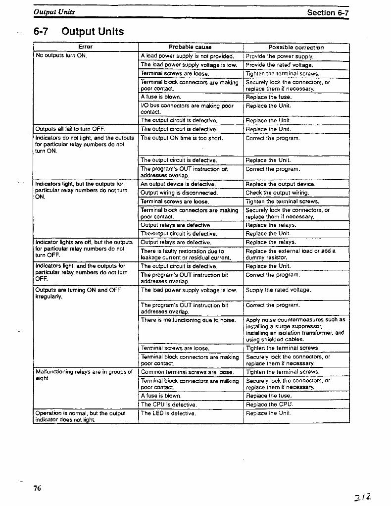
Output Units Section 6-7
6-7 Output UnitsError
No outputs turn ON.
Outputs all fail to turn OFF.
Indicators do not light, and the outputsfor particular relay numbers do notturn ON.
Indicators light, but the outputs forparticular relay numbers do not turnON.
Indicator lights are off, but the outputsfor particular relay numbers do notturn OFF.
Indicators light, and the outputs forparticular relay numbers do not turnOFF.
Outputs are turning ON and OFFirregularly.
Malfunctioning relays are in groups ofeight.
Operation is normal, but the outputindicator does not light.
Probable cause
A bad power supply is not provided.
The toad power supply voltage is tow.
Terminal screws are loose.
Terminal block connectors are makingpoor contact.A fuse is blown.
I/O bus connectors are making poorcontact.The output circuit is defective.
The output circuit is defective.
The output ON time is too short.
The output circuit is defective.
The program's OUT instruction bitaddresses overlap.An output device is defective.
Output wiring is disconnected.Terminal screws are loose.
Terminal block connectors are makingpoor contact.Output relays are defective.The-output circuit is defective.Output relays are defective.
There is faulty restoration due toleakage current or residual current.The output circuit is defective.
The program's OUT instruction bitaddresses overlap.
The load power supply voltage is tow.
The program's OUT instruction bitaddresses overlap.There is malfunctioning due to noise.
Terminal screws are loose.
Terminal block connectors are makingpoor contact.
Common terminal screws are loose.
Terminal block connectors are mikingpoor contact.A fuse is blown.
The CPU is defective.
The LED is defective.
Possible correctionProvide the power supply.
Provide the rated voltage.Tighten the terminal screws.Securely lock the connectors, orreplace them if necessary.Replace the fuse.Replace the Unit.
Replace the Unit.Replace the Unit.
Correct the program.
Replace the Unit.
Correct the program.
Replace the output device.Check the output wiring.
Tighten the terminal screws.
Securely lock the connectors, orreplace them if necessary.Replace the relays.Replace the Unit.Replace the relays.
Replace the external load or add adummy resistor.
Replace the Unit.Correct the program.
Supply the rated voltage.
Correct the program.
Apply noise countermeasures such asinstalling a surge suppressor,installing an isolation transformer, andusing shielded cables.Tighten the terminal screws.Securely lock the connectors, orreplace them if necessary.Tighten the terminal screws.
Securely lock the connectors, orreplace them if necessary.Replace the fuse.
Replace the CPU.Replace the Unit.
76

SECTION 7Inspection and Maintenance
Certain consumable items in a PC (such as fuses, relays, and batteries) need occasional replacement. This section explainshow to replace these items. Always keep spare items on hand so that they can be used as immediate replacements when heed-ed
7-1 CPU and Power Supply Fuses 787-2 Output Unit Fuses 787-3 Output Unit Relays 797-4 Batteries 81
77

Output Unit Fuses Section 7-2
7-1 CPU and Power Supply Fuses
Turn counterclockwiseto remove, clockwise toattach
Standard _screwdriver
To replace a fuse, follow the steps below. Use only UUCSA certified replace-ment fuses.
1, 2, 3... 1. Turn OFF the power to the PC.2. Remove the fuse holder by turning it approximately 50°counterclockwise
with a standard screwdriver.3. Remove the fuse from the holder.4. Insert a new fuse.5. Reattach the fuse holder by turning H approximately 50°clockwise with a
standard screwdriver.
7-2 Output Unit FusesTo replace a fuse, follow the steps below. Use only UL/CSA certified replace-ment fuses.
f, 2, 3... 1. Turn OFF the power to the PC.2. Detach the terminal block by unlocking the lock levers at the top and bottom
of the terminal block.3. While pushing down the lock lever on the Backplane with a screwdriver as
shown below, remove the Output Unit.
78

Output Unit Relays Section 7-3
4. Detach the case from the Unit.
5. Pull out the printed circuit board.
6. Insert a new fuse. A spare fuse is provided inside the rear of the case whenthe Unit is delivered.
7. Reassemble in reverse order of assembly.
Note 1. In North America, use UL or CSA approved fuses.
2. Fuses in High-density I/O Units cannot be replaced by the user. Refer toyour OMRON dealer for service.
7-3 Output Unit Relays *To replace a Relay (G6B-1174P-FD-US, 24 VDC), follow the steps below:
1,2,3... 1. Turn OFF the power to the PC.
2. Detach the terminal block by unlocking the tack levers at the top and bottomof the terminal block.
3. While pushing down the lock lever on the Backplane with a screwdriver asshown below, remove the Output Unit.
79

Output Unit Relays Section 7-3
4. Detach the case from the Unit.
5. Pull out the printed circuit board. The Relays are placed on the PC boards ofindividual Units as shown in the figures below.
OC221/OC224
OC222
OC223
I
2
LLffl
^
.-C
T
CEIrarn
m
Ii
Si
X
p
>
OC225
.15 14
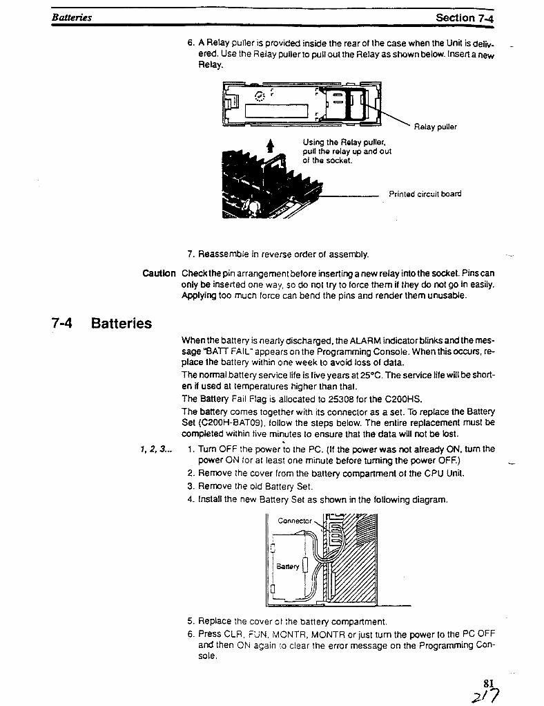
Batteries Section 7-4
6. A Relay puller is provided inside the rear of the case when the Unit is deliv-ered. Use the Relay puller to pull out the Relay as shown below. Insert a newRelay.
Relay puller
Using the Relay puller,pull the relay up and outof the socket.
_ Printed circuit board
7. Reassemble in reverse order of assembly.
Caution Check the pin arrangement before inserting a new relay into the socket. Pins canonly be inserted one way, so do not try to force them if they do not go in easily.Applying too much force can bend the pins and render them unusable.
7-4 Batteries
1, 2, 3...
When the battery is nearly discharged, the ALARM indicator blinks and the mes-sage "BATT FAIL" appears on the Programming Console. When this occurs, re-place the battery within one week to avoid loss of data.The normal battery service life is five years at 25°C. The service life will be short-en if used at temperatures higher than that.The Battery Fail Flag is allocated to 25308 for the C200HS.The battery comes together with its connector as a set. To replace the BatterySet (C200H-BATQ9), follow the steps below. The entire replacement must becompleted within five minutes to ensure that the data will not be tost.
%
1. Turn OFF the power to the PC. (If the power was not already ON, turn thepower ON for at least one minute before turning the power OFF.)
2. Remove the cover from the battery compartment of the CPU Unit.3. Remove the old Battery Set.4. Install the new Batter/ Set as shown in the following diagram.
Connector
5. Replace the cover of the battery compartment.6. Press CLR, FUN, MONTR, MONTR or just turn the power to the PC OFF
and then ON again to ciear the error message on the Programming Con-sole.

Batteries Section 7-4
DANGER! Batteries can bum, exptode, or leak. Absolutely do not short-circuit across theterminals, attempt to recharge batteries, or take them apart, heat them, or ex-pose them to fire.
82

4-5 The Programming ConsoleThis and the next section describe the Programming Console and the opera-tions necessary to prepare for program input. 4-7 Inputting, Modifying, andChecking the Program describes actual procedures for inputting the programinto memory.Although the Programming Console can be used to write ladder programs, it isprimarily used to support LSS operations and is very useful for on-site editingand maintenance. The main Programming Console functions are listed below.
1, 2, 3... 1. Displaying operating messages and the results of diagnostic checks.2. Writing and reading ladder programs, inserting and deleting instructions,
searching for data or instructions, and monitoring I/O bit status.3. Monitoring I/O status, force-setting/resetting bits.4. The Programming Console can be connected to or disconnected from the
PC with the power on.5. The Programming Console can be used with C-series PCs.6. Supports TERMINAL mode, which allows the display of a 32-character
message, as well as operation of the keyboard mapping function. Refer to5-25-5 TERMINAL MODE- TERM(-) for details.
Note The Programming Console does not support all of the LSS operations, onlythose required for on-srte edHing and maintenance.
4-5-1 The Keyboard
White: Numeric Keys
Red: CLR Key
Yellow: Operation Keys
Gray: Instruction and DataArea Keys
The keyboard of the Programming Console is functionally divided by key colorinto the following four areas:
The ten white keys are used to input numeric program data such as programaddresses, data area addresses, and operand values. The numeric keys arealso used in combination with the function key (FUN) to enter instructions withfunction codes.
The CLR key clears the display and cancels current Programming Console op-erations. It is also used when you key in the password at the beginning of pro-gramming operations. Any Programming Console operation can be cancelledby pressing the CLR key, although the CLR key may have to be pressed two orthree times to cancel the operation and clear the display.
The yellow keys are used for writing and correcting programs. Detailed explana-tions of their functions are given later in this section.
Except for the SHIFT key on the upper right, the gray keys are used to input in-structions and designate data area prefixes when inputting or changing a pro-
74

The Programming Console Section 4-5
gram. The SHIFT key is similar to the shift key of a typewriter, and is used to alterthe function of the next key pressed. (It is not necessary to hold the SHIFT keydown; just press it once and then press the key to be used with it.)
The gray keys other than the SHIFT key have either the mnemonic name of theinstruction or the abbreviatkDn of the data area written on them. The functions ofthese keys are described below.
TH
Pressed before the function code when inputting an instructionvia its function code.
Pressed to enter SFT (the Shift Register instruction).
Input either after a function code to designate the differentiatedform of an instruction or after a ladder instruction to designatean inverse condition.
Pressed to enter AND (the AND instruction) or used with NOTto enter AND NOT.
Pressed to enter OR (the OR instruction) or used with NOT toenter OR NOT.
Pressed to enter CNT (the Counter instruction) or to designatea TC number that has already been defined as a counter.
Pressed to enter ID (the Load instruction) or used with NOT toenter ID NOT. Also pressed to indicate an input bit.
Pressed to enter OUT (the Output instruction) or used withNOT to enter OUT NOT. Also pressed to indicate an output bit.
Pressed to enter TIM (the Timer instruction) or to designate aTC number that has already been defined as a timer.
Pressed before designating an address in the TR area.
Pressed before designating an address in the LR area.
Pressed before designating an address in the HR area.
Pressed before designating an address in the AR area.
Pressed before designating an address in the DM area.
Pressed before designating an indirect DM address.
Pressed before designating a word address.
Pressed before designating an operand as a constant.
Pressed before designating a bit address.
Pressed before function codes for biock programming instruc-tions, i.e., those placed between potnted parentheses <>.
75

Preparation for Operation Section 4-6
4-5-2 PC ModesThe Programming Console is equipped with a switch to control the PC mode. Toselect one of the three operating modes—RUN, MONITOR, or PROGRAM—use the mode switch. The mode that you select will determine PC operation aswell as the procedures that are possible from the Programming Console.RUN mode is the mode used for normal program execution. When the switch isset to RUN and the START input on the CPU Power Supply Unit is ON, the CPUwill begin executing the program according to the program written in its ProgramMemory. Although monitoring PC operation from the Programming Console ispossible in RUN mode, no data in any of the memory areas can be input orchanged.MONITOR mode allows you to visually monitor in-progress program executionwhile controlling I/O status, changing PV (present values) or SV (set values),etc. In MONITOR mode, I/O processing is handled in the same way as in RUNmode. MONITOR mode is generally used for trial system operation and final pro-gram adjustments.In PROGRAM mode, the PC does not execute the program. PROGRAM modeis for creating and changing programs, clearing memory areas, and registeringand changing the I/O table. A special Debug operation is also available withinPROGRAM mode that enables checking a program for correct execution beforetrial operation of the system.
DANGER! Do not leave the Programming Console connected to the PC by an extensioncable when in RUN mode. Noise picked up by the extension cable can enter thePC, affecting the program and thus the controlled system.
4-5-3 The Display Message SwitchPin 3 of the CPU's DIP switch determines whether Japanese or English lan-guage messages will be displayed on the Programming Console. It is factory setto ON, which causes English language messages to be displayed.
4-6 Preparation for OperationThis section describes the procedures retired to begin Programming Consoleoperation. These include password entry, clearing memory, error messageclearing, and I/O table operations. I/O table operations are also necessary atother times, e.g., when changes are to be made in Units used in the PC configu-ration.
DANGER! Always confirm that the Programming Console is in PROGRAM mode whenturning on the PC with a Programming Console connected unless another modeis desired for a specific purpose, if the Programming Console is in RUN modewhen PC power is turned on, any program in Program Memory will be executed,possibly causing a PC-controlled system to begin operation.
The following sequence of operations must be performed before beginning in-itial program input.
1, 2, 3... 1. Insert the mode key into the Programming Console.2. Set the mode switch to PROGRAM mode. (The mode key cannot be re-
moved while set to PROGRAM mode.)3. Turn on PC power.
Note When I/O Units are installed, turn on those Units also. The Program-ming Console will not operate if these Units are not turned on.
76 /~>2-f

Preparation for Operation Section 4-6
4. Confirm that the CPU's POWER LED is lit and the following display appearson the Programming Console screen. (If the ALM/ERR LED is lit or flashingor an error message is displayed, clear the error that has occurred.)
<PROGRflM>PflSSUORD!
5. Enter the password. See 4-6-1 Entering the Password tor details.6. Clear memory. Skip this step if the program does not need to be cleared.
See 4-6-3 Clearing Memory for details.
4-6-1 Entering the PasswordTo gain access to the PC's programming functions, you must first enter the pass-word. The password prevents unauthorized access to the program.The PC prompts you for a password when PC power is turned on or, if PC poweris already on, after the Programming Console has been connected to the PC. Togain access to the system when the "Password!" message appears, press CLRand then MONTR. Then press CLR to clear the display.If the Programming Console is connected to the PC when PC power is alreadyon, the first display below will indicate the mode the PC was in before the Pro-gramming Console was connected. Ensure that the PC Is In PROGRAM modebefore you enter the password. When the password is entered, the PC willshift to the mode set on the mode switch, causing PC operation to begin if themode is set to RUN or MONITOR. The mode can be changed to RUN or MONI-TOR with the mode switch after entering the password.
4-6-2 Buzzer
<PROGRfiM>PflSSUORD!
<PRO<3RRM> BZ
Indicates the mode set by the mode selector switch.
Immediately after the password is input or anytime immediately after the modehas been changed, SHIFT and then the 1 key can be pressed to turn on and offthe buzzer that sounds when Programming Console keys are pressed. If BZ isdisplayed in the upper right corner, the buzzer is operative. If BZ is not displayed,the buzzer is not operative.This buzzer also will also sound whenever an error occurs during PC operation.Buzzer operation for errors is not affected by the above setting.

4-6-4 Registering the I/O TableThe I/O Table Registration operation records the types of I/O Units controlled bythe PC and the Rack locations of the I/O Units. It also clears all I/O bits.
l!o r°K»abKSOlUtely neoessary to register the I/O table with the C200HS When the^O table has not been registered, the PC will operate according to the I/O Unitsmounted when power is applied. The I/O verification/setting error will not occur.
80

Preparation for Operation Section 4-6
Key Sequence
initial I/O Tabte Registration
It is necessary to register the I/O table if I/O Units are changed, otherwise an I/Overification error message, "I/O VER ERR" or -I/O SET ERROR", will appearwhen starting programming operations.
I/O Table Registration can be performed only in PROGRAM mode with the write-protection switch (pin 1 of the CPU's DIP switch) set to OFF (OFF="WRlTE").
Group-2 High-density I/O Units will not be displayed in the I/O table when it isdisplayed using a host computer. Four asterisks (****}, indicating no Unit, will bedisplayed instead.
9 7 *1 °3
•MFTCH
*
CHQ 7 '! °3 WMJTX
06000
00000
FUN <??)
00000IOTBL?-?u=
00000IOTBL URIT
00000IOTBL URIT9713
00000IOTBLOK
URIT
- Register I/O table
4-6-5 Clearing Error MessagesAfter the I/O table has been registered, any error messages recorded in memoryshould be cleared. It is assumed here that the causes of any of the errors forwhich error messages appear have already been taken care of. If the beepersounds when an attempt is made to clear an error message, eliminate the causeof the error, and then clear the error message (refer to Section 9 Troubleshoot-ing).
To display any recorded error messages, press CLR, FUN, and then MONTR.The first message will appear. Pressing MONTR again will clear the presentmessage and display the next error message. Continue pressing MONTR untilall messages have been cleared.
Although error messages can be accessed in any mode, they can be clearedonly in PROGRAM mode.
Key Sequence
CLR - FUN-
iUOMTR
4-6-6 Verifying the 1/0 TableThe I/O Table Verification operation is used to check the I/O table registered inmemory to see if rt matches the actual sequence of I/O Units mounted. The first

Preparation for Operation Section 4-6
Key Sequence
inconsistency discovered will be displayed as shown below. Every subsequentpressing of VER displays the next inconsistency.
Note This operation can be executed only when the I/O table has been registered.
cm f\jn SMVTCM
*VBK
Example
cm
PUN
•MtTT f **
MM
vex
00000
00000
FUN <??)
00000IOTBL ?
00000IOTBLOK
CHK
00000IOTBL0- 1 U=Q*#*
CHK
(No errors)
(An error occurred)
Actual IAD words
Registered I/O table words
I/O slot number
Rack number
Meaning of Displays The following display indicates a G500, C1000H, or C2000H and C200H orC200HS have the same unrt number on a Remote I/O Slave Rack.
00000I/OTBL CHK
The following display indicates a duplication in Optical I/O Unit unit numbers.
09000I/OTBL CHK2**HU=R*-I
Indicates duplication
4-6-7 Reading the I/O TableThe I/O Table Read operation is used to access the I/O table that is currentlyregistered in the CPU memory. This operation can be performed in any PCmode.
82

Preparation for Operation Section 4-6
Key Sequence
cm PUM •MPTCM
*
EXT.
Rack Unitnumber number
1 JLT
Press the EXT key to select RemoteI/O Slave Racks or Optical I/O Units.
Example 00000
00000
FUN < ??)
00000
?-?
IOTBL ?U =
(Slave Rack Units)
00000IOTBL
R??-?U=(Optical I/O Unit)
00000IOTBL ?
2??LU=
00000 IOTBL
(PC Unit)
(PC Unit)
00000!OTBL0-?U =
00000IOTBL0-5U =
00000IOTBL0~5U=i***
00000IOTBL@ - 4 |J = Q -4: +• *
00000 I OTBL8-51j=i***
?
7
READ005
REftD004
•REflD005
83

Preparation for Operation Section 4-6
Meaning of DisplaysI/O UnK Designations for Displays(see I/O Units Mounted in Remote Slave Racks, page 85)
C500,1000H/C2000H I/O UnitsNo. of points
16
32
64
Input Unit
I # * *
I I * *
I I I I
Output Unit0 # # #
0 0 * *
8 0 0 0
C200H I/O UnitsNo. of point*
8
16
input Unft
i ( * ) * *i i * *
Output Unft
o * # *
o o * *Note: (») is i tor non-fatal errors or F_
I/O Units 00000IOTBL REftDsfc — * (J = * * * * #:*#
T n=— WD word number
I/O type: i: (input), o: (output)
Unit number (0 to 9}
Rack number (0 to 2)
Interrupt Input Units 000Q0IOTBLs*c — sfc (J =
REflD
INTO: Mounted to CPU Rack.IN**: Mounted to Expansion IAD Rack.(Treated as an 8-point Input Unit)
Special I/O Units 00000 I OTBL REflD5f! — >T^|_| — 5'Sft'T-!T!
I Blank:W:
Specsunit 15
inff eat
Unit 1 exclusivelyUnit 2 exclusively
C: High-speed CounterN: Host Link UnitA: Otherto 9)
Indicates Special I/O Unit
Remote I/O Master Units 00000IOTBL REflD
Remote I/OMaster no. (0 or
84

Preparation for Operation Section 4-6
Remote I/O Slave Racks 00000IOTBL REflD
I/O word number
I/O type: I.Oi, o (see tables on previous page)
Unit number (0 to 9}
Remote I/O Slave Unit number (0 to 4)
Remote I/O Master Unit number (0 or 1)
Indicates a Remote I/O Rack
Group-2 High-density I/OUnits
00000IOTBL REflD
2:4:
I:O:
2 words (32 pis)4 words (64 pts)
Input UnitOutput Unit
Unit number {0 to 9}
Indicates Group-2 High-density I/O Unit
Note Group-2 High-density I/O Units will not be displayed in the I/O table when it isdisplayed using LSS (host computer). Four asterisks (****). indicating no Unit,will be displayed instead.
Optical I/O Units andRemote Terminals 00000IOTBL REflD
I/O type: 1 (input), O (output), orW (input/output)
Remote I/O Master Unit number (0 to I)
Word (H: leftmost 8 bits: L: rightmost 8 bits)
I/O word number (200 to 231)

7-1-4 Hexadecimal/BCD Data ModificationWhen the Bit/Digit Monitor ope ration is being performed and a BC D or hexadeci-mal value is leftmost on the display, CHG can be input to change the value. SRwords cannot be changed.If a timer or counter is leftmost on the display, the PV will be displayed and will bethe value changed. See 7-1-13 Changing Timer/CounterSVtor the procedure tochange SV. PV can be changed in MONITOR mode onry when the timer orcounter is operating.To change contents of the leftmost word address, press CHG, input the desiredvalue, and press WRITE
Key SequenceWord currentlymonitored onleft of display.
Data
336

Monitoring Operation and Modifying Data Section 7-1
Example The following example shows the effects of changing the PV of a timer.
Thit example * h MONITOR mode
80800
00000TIM 000
T0000122
PRE5 URL?T000 0119 ????
PRES URL?T000 0100 0200
T0000199
Monitor slams of timer PVthat will be changed.
Timing
Timing
PV decrementing
Timing
PV changed. Timer/counter PVscan be changed even when thetimer/counter is operating.
Timing
337

7-1-13 Changing Timer/Counter SVThere are two ways to change the SV of a timer or counter. It can be done eitherby inputting a new value; or by incrementing or decrementing the current SV.Either method can be used only in MONITOR or PROGRAM mode. In MONI-TOR mode, the SV can be changed while the program is being executed. Incre-menting and decrementing the SV is possible only when the SV has been en-tered as a constant.To use either method, first display the address of the timer or counter whose SVis to be changed, presses the down key, and then press CHG. The new valuecan then be input numerically and WRITE pressed to change the SV or EXT canbe pressed followed by the up and down keys to increment and decrement thecurrent SV. When the SV is incremented and/or decremented, CLR can bepressed once to change the SV to the incremented or decremented value butremaining in the display that appeared when EXT was pressed or CLR can bepressed twice to return to the original display with the new SV.This operation can be used to change a SV from designation as a constant to aword address designation and visa verse.
346

Monitoring Operation and Modifying Data Section 7-1
Key Sequence
TTrrw/Countwcurmntty deployed. * oa !
— - [N«wSV]
*4
Example
Inputting New SV andChanging to WordDesignation
The following examples show inputting a new constant, changing from a con-stant to an address, and incrementing to a new constant.
00080
00000
TIM 000
002015RCHTIM 000
00201 TIM DflTfl#0123
00201 TIM DfiTfiT000 #0123 #????
00201 TIM DflTflT000 #0123 #0124
00201 TIM DflTfl#0124
00201 DftTfl?T000 #0123 c???
00201 DflTfl?T000 #0123 C010
00"201 TIM DflTfl010
InputtingrwwSV.
Changing toword designation.
3472.

Monitoring Operation and Modifying Data Section 7-1
Incrementing andDecrementing cm
t
m
I
•WON
}
fiT
CHQ
f
•XT
i 1
4|t
.._
*fcm
t
0*
00000
00000
TIM 000
00201SRCHTIM 000
00201 TIM
00201 TIMT000 #0123
DflTfl#0123
DflTfl#7777
00201DflTflT000 #0123
? U/D#0123
< Current SV (duringchange operation)
SV before the change
00201DflTfl
T090 #0123 #0122
00201DflTflT000 #0123 #0123
00201DflTflT000 #0123 #0124
00201DRTflT000 #0124
7#7777
00201 TIM DflTfl#0124
Returns to original displaywit) new SV
348

BO
ILE
R
CO
fTR
OL
P
AN
EL
SA
MS
UN
GR
-

m m
^ ££
O w
UALIP
X T
j Z
QH
P
1 5
C
D
I
JQNITORSOURCE S
3o m
TJ
HO
TJ
H
F.aAB
CH
633
TI
m—
.
lo |3 TJ
SCOTBLOAERISTON V.OPEN
w o
Qr
^
cn O rnCD
>
BOITR
m m
C -°
en TI
w r GNIT
SOUR I > S
, -0 I
m rr
AM
MS
AM
SU
NG
1^
PecT'0
4D
RAW
ING
ffl

SSI
SLAVE11 201 P)
A
MASTER
(1 200P)
160
SA
MS
UN
G
ltN5P
KT1<>)|

(14115) (1409S) (1410S)
o o oF.O.
LINE
ATM
A-IS)
HGET
\1/
4S)
1U94
v-
_^__(1212S)
PW-KWEFINISH
/~XI 1v«/
(121BS)
-F\J=\J=}(1301S) (1302S)
WV®
/""\I )V-/
(1 3035)
(1400S) (1402S) (14055) (14055) OICMTICN PIUJT
im CH•A
MMU0 (14065
(1300S)
{1401S) (1404S)
a
6(1407S)
M4ST1R
(12(WS)
200
ISONLY
STBD SIDE BLR PANEL

o
. .

BOILER CONTROL PANEL

BOILER CONTROL
*> *

-B l—
•
b'.HiER CONTROL PANEL
• 0 J mm •

-
jp^^TrO^ -•*=<> -Iiin^m
• s.

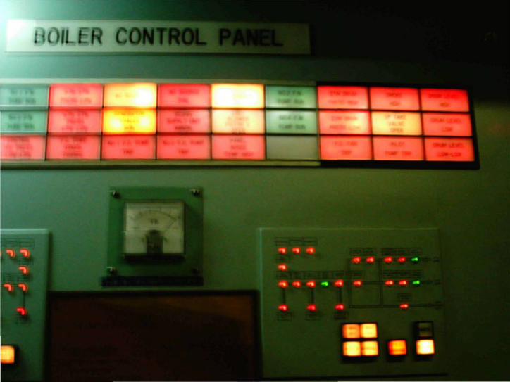
. ill tR CONTROL PAN L

l<
•. ;


? MI
Ml 1
• M
,' 1 ,
I M
V W
V .
a;^!^^
1,
t^^


! »3 * 1 *, * *jp *1*_J *3 *i ' k
I t •*
, jp 1_J 3 '
I t ? ! t • . I fjri'l * i * *; * t *^ *J_r' *ji * V* i * ' '


1