Hard Macrocellular Silica Si(HIPE) Foams Templating Micro/Macroporous Carbonaceous Monoliths:...
10
Hard Macrocellular Silica Si(HIPE) Foams Templating Micro/Macroporous Carbonaceous Monoliths: Applications as Lithium Ion Battery Negative Electrodes and Electrochemical Capacitors By Nicolas Brun, Savari R. S. Prabaharan, Mathieu Morcrette,* Cle ´ment Sanchez, Gilles Pe ´castaings, Alain Derre ´, Alain Soum, Herve ´ Deleuze, Marc Birot, and Re ´nal Backov* 1 Introduction Porous carbon materials are outstanding candidates for a range of applications ranging from water and air purification, adsorption or catalysis, to electrodes and energy storage, as a result of their high surface area, large pore volume, chemical inertness, and excellent mechanical stabi- lity. [1,2] To reach such porous carbonaceous materials, hard and soft templating meth- ods offer versatility towards pore morpho- logies, pore sizes, and size distributions. The hard-template methodology, also known as exotemplating, [3] makes use of prefor- matted, hard, porous templates impregnated with a carbon source that is subse- quently carbonized under a non-oxidative atmosphere. After dissolution of the hard template, a negative, carbonaceous replica is finally obtained. Thus, ordered mesopor- ous carbons (OMCs) have been reported through insertion of carbon precursors within the mesoporous silica particles. [4] Hard templates are varied, both in nature, considering alumina membranes [5] or FULL PAPER www.afm-journal.de [*] N. Brun, A. Derre ´, R. Backov Universite ´ de Bordeaux, Centre de Recherche Paul Pascal, UPR 8641- CNRS 115 Avenue Albert Schweitzer, 33600 Pessac (France) E-mail: [email protected] S. R. S. Prabaharan, M. Morcrette Laboratoire de Re ´activite ´ et Chimie des Solides, UMR CNRS 6007 Universite ´ de Picardie Jules Verne 33 Rue Saint Leu, 80039 Amiens CEDEX (France) E-mail: [email protected] S. R. S. Prabaharan Faculty of Engineering and Computer Science, The University of Nottingham, Malaysia Campus Jalan Broga, Semenyih, Selangor (Malaysia) C. Sanchez Laboratoire de Chimie de la Matie `re Condense ´e de Paris, UMR-7574 CNRS, UPMC Universite ´ Paris 06, Colle `ge de France, 11 Place Marcelin Berthelot, 75231 Paris (France) G. Pe ´castaings, A. Soum Laboratoire de Chimie des Polyme `res Organiques UMR 5629 CNRS, Universite ´ Bordeaux-1, ENSCPB 16 avenue Pey Berland, BP 108 33607 Pessac (France) N. Brun, H. Deleuze, M. Birot Universite ´ de Bordeaux, Institut des Sciences Mole ´culaires CNRS-UMR 5255 351 cours de la Libe ´ration, F-33405 Talence (France) DOI: 10.1002/adfm.200900749 By using Si(HIPEs) as hard, exotemplating matrices, interconnected macro-/ microporous carbon monolith-type materials with a surface area of around 600 m 2 g 1 are synthesized and shaped. The carbonaceous foams exhibit a conductivity of 20 S cm 1 , addressed with excellent mechanical properties (Young’s modulus of 0.2 GPa and toughness of 13 J g 1 , when the carbon core is optimized). The above-mentioned specificities, combined with the fact that the external shape and size can be easily designed on demand, are of primary importance for applications. The functionality of these carbonaceous monoliths is tested as both an electrochemical capacitor and a lithium ion negative electrode. The electrochemical capacitors’ voltage–current profiles exhibit a non-ideal rectangular response, confirming the double-layer behavior of the carbon studied, while the charge-discharge current profile of the electric double-layer capacitor is directly proportional to the scan where the current response during charge and discharge exhibits high reversibility. When acting as a lithium ion negative electrode, after initial irreversibility, a good cyclability is obtained, associated with a stable capacity of 200 mA h g 1 during the first 50 cycles at a reasonable current density (C/10). 3136 ß 2009 WILEY-VCH Verlag GmbH & Co. KGaA, Weinheim Adv. Funct. Mater. 2009, 19, 3136–3145
-
Upload
independent -
Category
Documents
-
view
0 -
download
0
Transcript of Hard Macrocellular Silica Si(HIPE) Foams Templating Micro/Macroporous Carbonaceous Monoliths:...
FULLPAPER
www.afm-journal.de
3136
Hard Macrocellular Silica Si(HIPE) Foams TemplatingMicro/Macroporous Carbonaceous Monoliths:Applications as Lithium Ion Battery Negative Electrodesand Electrochemical Capacitors
By Nicolas Brun, Savari R. S. Prabaharan, Mathieu Morcrette,*
Clement Sanchez, Gilles Pecastaings, Alain Derre, Alain Soum,
Herve Deleuze, Marc Birot, and Renal Backov*
[*] N. Brun, A. Derre, R. BackovUniversite de Bordeaux, Centre de Recherche Paul Pascal, UPR 8641-CNRS115 Avenue Albert Schweitzer, 33600 Pessac (France)E-mail: [email protected]
S. R. S. Prabaharan, M. MorcretteLaboratoire de Reactivite et Chimie des Solides, UMR CNRS 6007Universite de Picardie Jules Verne33 Rue Saint Leu, 80039 Amiens CEDEX (France)E-mail: [email protected]
S. R. S. PrabaharanFaculty of Engineering and Computer Science, The University ofNottingham, Malaysia CampusJalan Broga, Semenyih, Selangor (Malaysia)
C. SanchezLaboratoire de ChCNRS, UPMCUniversite Paris 075231 Paris (Fran
G. Pecastaings, A.Laboratoire de ChUniversite Bordea16 avenue Pey Be
N. Brun, H. DeleuUniversite de BordCNRS-UMR 5255351 cours de la Li
DOI: 10.1002/adfm.200900749
By using Si(HIPEs) as hard, exotemplating matrices, interconnected macro-/
microporous carbon monolith-type materials with a surface area of around
600m2 g�1 are synthesized and shaped. The carbonaceous foams exhibit a
conductivity of 20 S cm�1, addressed with excellent mechanical properties
(Young’s modulus of 0.2GPa and toughness of 13 J g�1, when the carbon
core is optimized). The above-mentioned specificities, combined with the fact
that the external shape and size can be easily designed on demand, are of
primary importance for applications. The functionality of these carbonaceous
monoliths is tested as both an electrochemical capacitor and a lithium ion
negative electrode. The electrochemical capacitors’ voltage–current profiles
exhibit a non-ideal rectangular response, confirming the double-layer
behavior of the carbon studied, while the charge-discharge current profile of
the electric double-layer capacitor is directly proportional to the scan where
the current response during charge and discharge exhibits high reversibility.
When acting as a lithium ion negative electrode, after initial irreversibility, a
good cyclability is obtained, associated with a stable capacity of 200mA h g�1
during the first 50 cycles at a reasonable current density (C/10).
� 2009 WILEY-VCH Verlag GmbH & Co. KGaA, Weinheim
1 Introduction
Porous carbon materials are outstandingcandidates for a range of applicationsranging from water and air purification,adsorption or catalysis, to electrodes andenergy storage, as a result of their highsurface area, large pore volume, chemicalinertness, and excellent mechanical stabi-lity.[1,2] To reach such porous carbonaceousmaterials, hard and soft templating meth-ods offer versatility towards pore morpho-logies, pore sizes, and size distributions. Thehard-template methodology, also known asexotemplating,[3] makes use of prefor-matted, hard, porous templates impregnatedwith a carbon source that is subse-quently carbonized under a non-oxidativeatmosphere. After dissolution of the hardtemplate, a negative, carbonaceous replicais finally obtained. Thus, ordered mesopor-ous carbons (OMCs) have been reportedthrough insertion of carbon precursors
within the mesoporous silica particles.[4] Hard templates arevaried, both in nature, considering alumina membranes[5] or
imie de la Matiere Condensee de Paris, UMR-7574
6, College de France, 11 Place Marcelin Berthelot,ce)
Soumimie des Polymeres Organiques UMR 5629 CNRS,ux-1, ENSCPBrland, BP 108 33607 Pessac (France)
ze, M. Biroteaux, Institut des Sciences Moleculaires
beration, F-33405 Talence (France)
Adv. Funct. Mater. 2009, 19, 3136–3145
FULLPAPER
www.afm-journal.de
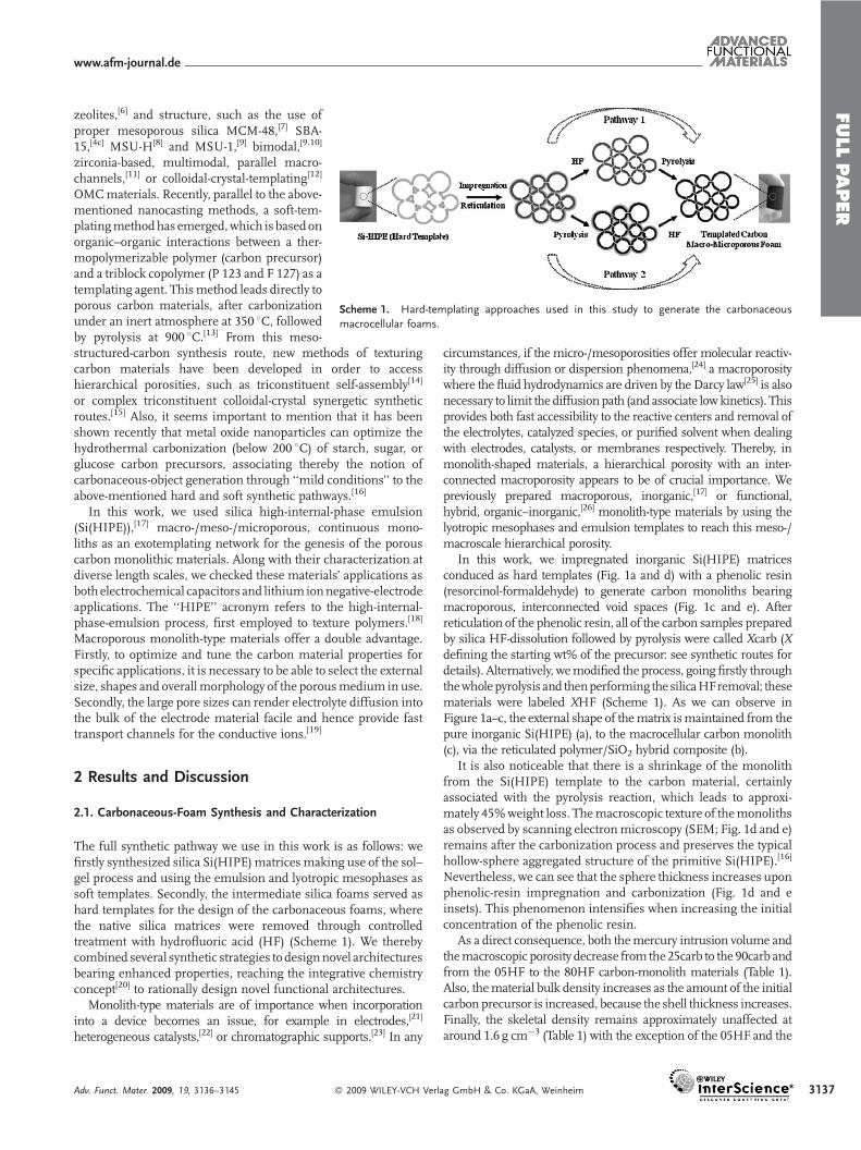
Scheme 1. Hard-templating approaches used in this study to generate the carbonaceous
macrocellular foams.
zeolites,[6] and structure, such as the use ofproper mesoporous silica MCM-48,[7] SBA-15,[4c] MSU-H[8] and MSU-1,[9] bimodal,[9,10]
zirconia-based, multimodal, parallel macro-channels,[11] or colloidal-crystal-templating[12]
OMCmaterials. Recently, parallel to the above-mentioned nanocasting methods, a soft-tem-platingmethodhas emerged,which is basedonorganic–organic interactions between a ther-mopolymerizable polymer (carbon precursor)and a triblock copolymer (P 123 and F 127) as atemplating agent. Thismethod leads directly toporous carbon materials, after carbonizationunder an inert atmosphere at 350 8C, followedby pyrolysis at 900 8C.[13] From this meso-
structured-carbon synthesis route, new methods of texturingcarbon materials have been developed in order to accesshierarchical porosities, such as triconstituent self-assembly[14]or complex triconstituent colloidal-crystal synergetic syntheticroutes.[15] Also, it seems important to mention that it has beenshown recently that metal oxide nanoparticles can optimize thehydrothermal carbonization (below 200 8C) of starch, sugar, orglucose carbon precursors, associating thereby the notion ofcarbonaceous-object generation through ‘‘mild conditions’’ to theabove-mentioned hard and soft synthetic pathways.[16]
In this work, we used silica high-internal-phase emulsion(Si(HIPE)),[17] macro-/meso-/microporous, continuous mono-liths as an exotemplating network for the genesis of the porouscarbon monolithic materials. Along with their characterization atdiverse length scales, we checked these materials’ applications asboth electrochemical capacitors and lithium ionnegative-electrodeapplications. The ‘‘HIPE’’ acronym refers to the high-internal-phase-emulsion process, first employed to texture polymers.[18]
Macroporous monolith-type materials offer a double advantage.Firstly, to optimize and tune the carbon material properties forspecific applications, it is necessary to be able to select the externalsize, shapes and overallmorphology of the porousmedium in use.Secondly, the large pore sizes can render electrolyte diffusion intothe bulk of the electrode material facile and hence provide fasttransport channels for the conductive ions.[19]
2 Results and Discussion
2.1. Carbonaceous-Foam Synthesis and Characterization
The full synthetic pathway we use in this work is as follows: wefirstly synthesized silica Si(HIPE)matrices making use of the sol–gel process and using the emulsion and lyotropic mesophases assoft templates. Secondly, the intermediate silica foams served ashard templates for the design of the carbonaceous foams, wherethe native silica matrices were removed through controlledtreatment with hydrofluoric acid (HF) (Scheme 1). We therebycombined several synthetic strategies to designnovel architecturesbearing enhanced properties, reaching the integrative chemistryconcept[20] to rationally design novel functional architectures.
Monolith-type materials are of importance when incorporationinto a device becomes an issue, for example in electrodes,[21]
heterogeneous catalysts,[22] or chromatographic supports.[23] In any
Adv. Funct. Mater. 2009, 19, 3136–3145 � 2009 WILEY-VCH Verl
circumstances, if the micro-/mesoporosities offer molecular reactiv-ity through diffusion or dispersion phenomena,[24] a macroporositywhere the fluid hydrodynamics are driven by the Darcy law[25] is alsonecessary to limit the diffusionpath (and associate lowkinetics). Thisprovides both fast accessibility to the reactive centers and removal ofthe electrolytes, catalyzed species, or purified solvent when dealingwith electrodes, catalysts, or membranes respectively. Thereby, inmonolith-shaped materials, a hierarchical porosity with an inter-connected macroporosity appears to be of crucial importance. Wepreviously prepared macroporous, inorganic,[17] or functional,hybrid, organic–inorganic,[26] monolith-type materials by using thelyotropic mesophases and emulsion templates to reach this meso-/macroscale hierarchical porosity.
In this work, we impregnated inorganic Si(HIPE) matricesconduced as hard templates (Fig. 1a and d) with a phenolic resin(resorcinol-formaldehyde) to generate carbon monoliths bearingmacroporous, interconnected void spaces (Fig. 1c and e). Afterreticulation of the phenolic resin, all of the carbon samples preparedby silica HF-dissolution followed by pyrolysis were called Xcarb (Xdefining the starting wt% of the precursor: see synthetic routes fordetails). Alternatively, wemodified the process, going firstly throughthewholepyrolysis and thenperforming the silicaHFremoval; thesematerials were labeled XHF (Scheme 1). As we can observe inFigure 1a–c, the external shape of thematrix ismaintained from thepure inorganic Si(HIPE) (a), to the macrocellular carbon monolith(c), via the reticulated polymer/SiO2 hybrid composite (b).
It is also noticeable that there is a shrinkage of the monolithfrom the Si(HIPE) template to the carbon material, certainlyassociated with the pyrolysis reaction, which leads to approxi-mately 45%weight loss. Themacroscopic texture of themonolithsas observed by scanning electronmicroscopy (SEM; Fig. 1d and e)remains after the carbonization process and preserves the typicalhollow-sphere aggregated structure of the primitive Si(HIPE).[16]
Nevertheless, we can see that the sphere thickness increases uponphenolic-resin impregnation and carbonization (Fig. 1d and einsets). This phenomenon intensifies when increasing the initialconcentration of the phenolic resin.
As a direct consequence, both themercury intrusion volume andthemacroscopic porosity decrease from the25carb to the 90carb andfrom the 05HF to the 80HF carbon-monolith materials (Table 1).Also, thematerial bulk density increases as the amount of the initialcarbon precursor is increased, because the shell thickness increases.Finally, the skeletal density remains approximately unaffected ataround 1.6 g cm�3 (Table 1) with the exception of the 05HF and the
ag GmbH & Co. KGaA, Weinheim 3137
FULLPAPER
www.afm-journal.de
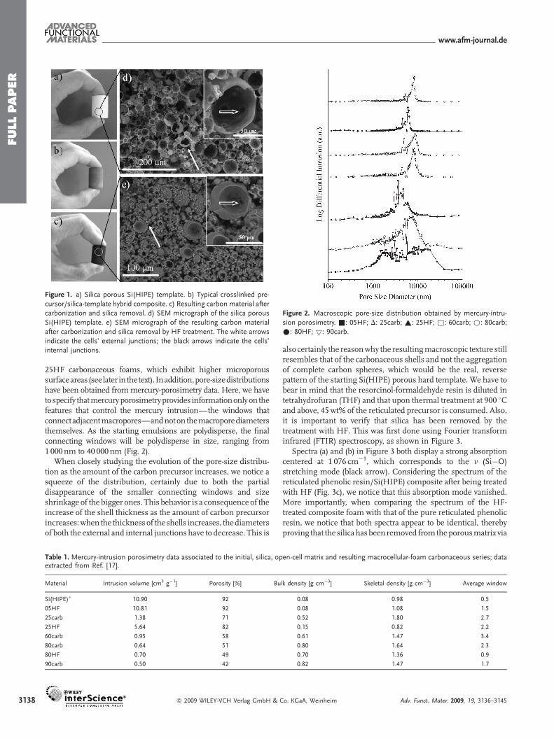
Figure 1. a) Silica porous Si(HIPE) template. b) Typical crosslinked pre-
cursor/silica-template hybrid composite. c) Resulting carbon material after
carbonization and silica removal. d) SEM micrograph of the silica porous
Si(HIPE) template. e) SEM micrograph of the resulting carbon material
after carbonization and silica removal by HF treatment. The white arrows
indicate the cells’ external junctions; the black arrows indicate the cells’
internal junctions.
Figure 2. Macroscopic pore-size distribution obtained by mercury-intru-
sion porosimetry. &: 05HF; D: 25carb; ~: 25HF; &: 60carb; *: 80carb;
�: 80HF; 5: 90carb.
3138
25HF carbonaceous foams, which exhibit higher microporoussurfaceareas (seelater in thetext). Inaddition,pore-sizedistributionshave been obtained frommercury-porosimetry data. Here, we havetospecify thatmercuryporosimetryprovides informationonlyon thefeatures that control the mercury intrusion—the windows thatconnectadjacentmacropores—andnoton themacroporediametersthemselves. As the starting emulsions are polydisperse, the finalconnecting windows will be polydisperse in size, ranging from1000nm to 40 000nm (Fig. 2).
When closely studying the evolution of the pore-size distribu-tion as the amount of the carbon precursor increases, we notice asqueeze of the distribution, certainly due to both the partialdisappearance of the smaller connecting windows and sizeshrinkage of the bigger ones. This behavior is a consequence of theincrease of the shell thickness as the amount of carbon precursorincreases:when the thicknessof theshells increases, thediametersof both the external and internal junctions have to decrease. This is
Table 1. Mercury-intrusion porosimetry data associated to the initial, silica, opextracted from Ref. [17].
Material Intrusion volume [cm3 g�1] Porosity [%] Bu
Si(HIPE)� 10.90 92
05HF 10.81 92
25carb 1.38 71
25HF 5.64 82
60carb 0.95 58
80carb 0.64 51
80HF 0.70 49
90carb 0.50 42
� 2009 WILEY-VCH Verlag GmbH &
also certainly the reasonwhy the resultingmacroscopic texture stillresembles that of the carbonaceous shells and not the aggregationof complete carbon spheres, which would be the real, reversepattern of the starting Si(HIPE) porous hard template. We have tobear in mind that the resorcinol-formaldehyde resin is diluted intetrahydrofuran (THF) and that upon thermal treatment at 900 8Cand above, 45wt% of the reticulated precursor is consumed. Also,it is important to verify that silica has been removed by thetreatment with HF. This was first done using Fourier transforminfrared (FTIR) spectroscopy, as shown in Figure 3.
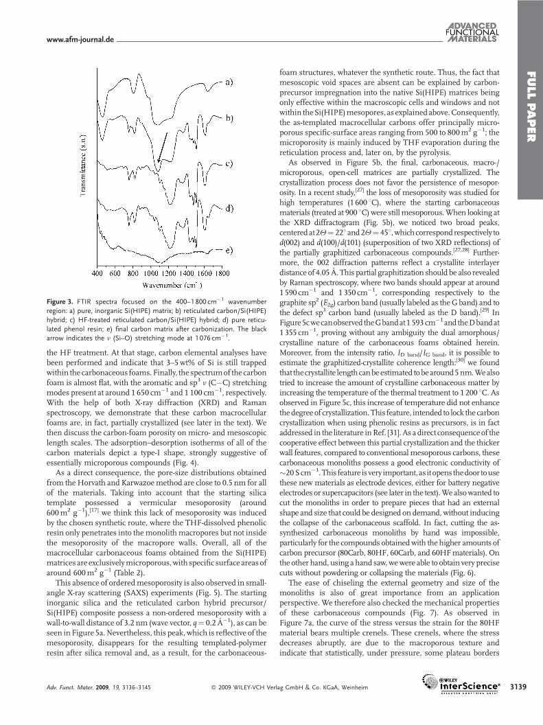
Spectra (a) and (b) in Figure 3 both display a strong absorptioncentered at 1 076 cm�1, which corresponds to the n (Si�O)stretching mode (black arrow). Considering the spectrum of thereticulated phenolic resin/Si(HIPE) composite after being treatedwith HF (Fig. 3c), we notice that this absorption mode vanished.More importantly, when comparing the spectrum of the HF-treated composite foam with that of the pure reticulated phenolicresin, we notice that both spectra appear to be identical, therebyproving that the silicahasbeenremoved fromtheporousmatrix via
en-cell matrix and resulting macrocellular-foam carbonaceous series; data
lk density [g cm�3] Skeletal density [g cm�3] Average window
0.08 0.98 0.5
0.08 1.08 1.5
0.52 1.80 2.7
0.15 0.82 2.2
0.61 1.47 3.4
0.80 1.64 2.3
0.70 1.36 0.9
0.82 1.47 1.7
Co. KGaA, Weinheim Adv. Funct. Mater. 2009, 19, 3136–3145
FULLPAPER
www.afm-journal.de
Figure 3. FTIR spectra focused on the 400–1 800 cm�1 wavenumber
region: a) pure, inorganic Si(HIPE) matrix; b) reticulated carbon/Si(HIPE)
hybrid; c) HF-treated reticulated carbon/Si(HIPE) hybrid; d) pure reticu-
lated phenol resin; e) final carbon matrix after carbonization. The black
arrow indicates the n (Si–O) stretching mode at 1 076 cm�1.
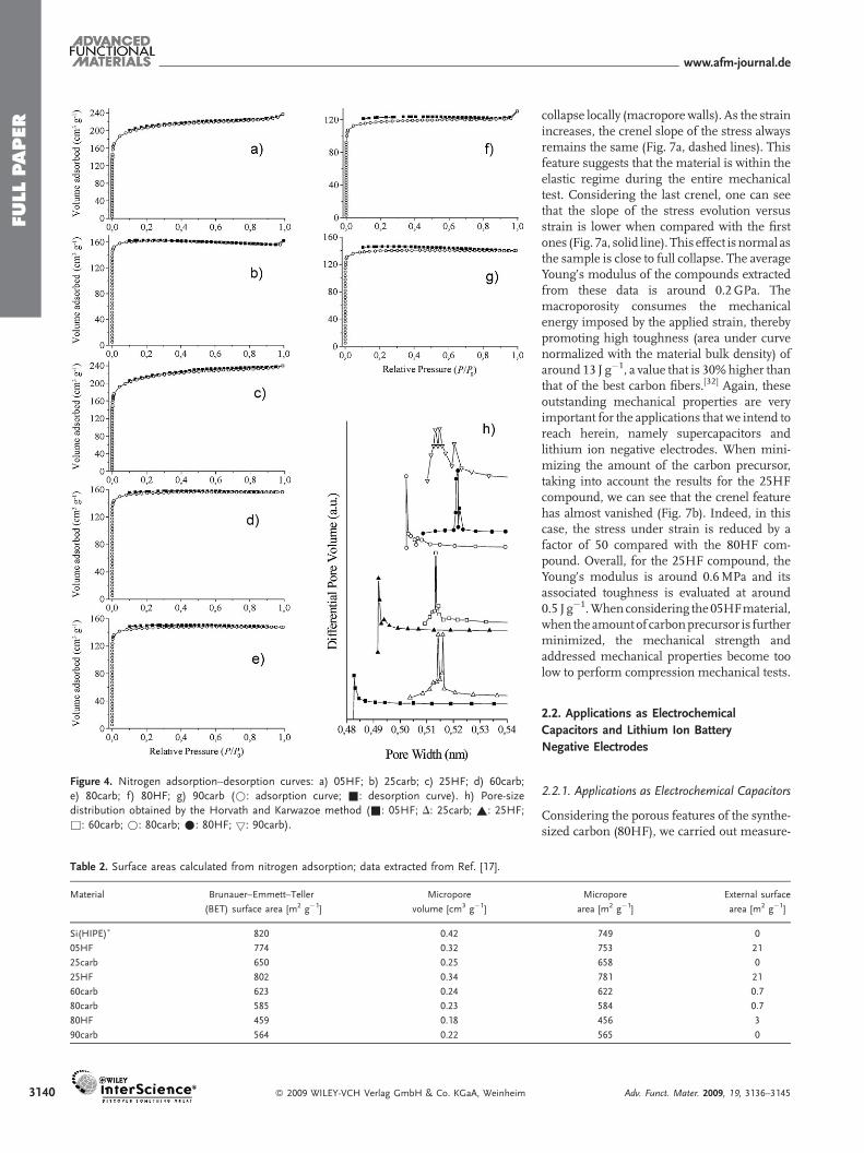
the HF treatment. At that stage, carbon elemental analyses havebeen performed and indicate that 3–5wt% of Si is still trappedwithin the carbonaceous foams.Finally, the spectrumof thecarbonfoam is almost flat, with the aromatic and sp3 n (C�C) stretchingmodes present at around 1 650 cm�1 and 1 100 cm�1, respectively.With the help of both X-ray diffraction (XRD) and Ramanspectroscopy, we demonstrate that these carbon macrocellularfoams are, in fact, partially crystallized (see later in the text). Wethen discuss the carbon-foam porosity on micro- and mesoscopiclength scales. The adsorption–desorption isotherms of all of thecarbon materials depict a type-I shape, strongly suggestive ofessentially microporous compounds (Fig. 4).
As a direct consequence, the pore-size distributions obtainedfrom theHorvath and Karwazoemethod are close to 0.5 nm for allof the materials. Taking into account that the starting silicatemplate possessed a vermicular mesoporosity (around600m2 g�1),[17] we think this lack of mesoporosity was inducedby the chosen synthetic route, where the THF-dissolved phenolicresin only penetrates into themonolithmacropores but not insidethe mesoporosity of the macropore walls. Overall, all of themacrocellular carbonaceous foams obtained from the Si(HIPE)matrices are exclusivelymicroporous,with specific surface areas ofaround 600m2 g�1 (Table 2).
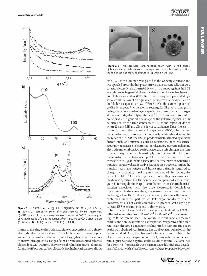
This absence of orderedmesoporosity is also observed in small-angle X-ray scattering (SAXS) experiments (Fig. 5). The startinginorganic silica and the reticulated carbon hybrid precursor/Si(HIPE) composite possess a non-ordered mesoporosity with awall-to-wall distance of 3.2 nm (wave vector, q¼ 0.2 A�1), as can beseen in Figure 5a.Nevertheless, this peak, which is reflective of themesoporosity, disappears for the resulting templated-polymerresin after silica removal and, as a result, for the carbonaceous-
Adv. Funct. Mater. 2009, 19, 3136–3145 � 2009 WILEY-VCH Verl
foam structures, whatever the synthetic route. Thus, the fact thatmesoscopic void spaces are absent can be explained by carbon-precursor impregnation into the native Si(HIPE) matrices beingonly effective within the macroscopic cells and windows and notwithin theSi(HIPE)mesopores, as explainedabove.Consequently,the as-templated macrocellular carbons offer principally micro-porous specific-surface areas ranging from 500 to 800m2 g�1; themicroporosity is mainly induced by THF evaporation during thereticulation process and, later on, by the pyrolysis.
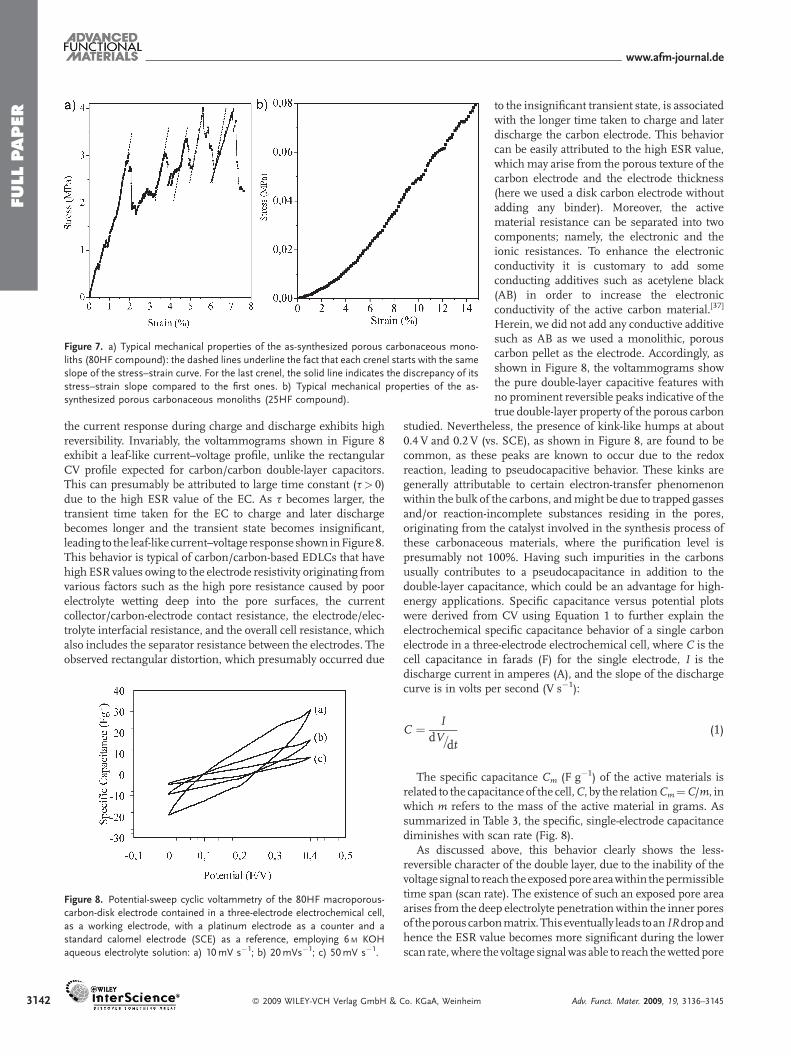
As observed in Figure 5b, the final, carbonaceous, macro-/microporous, open-cell matrices are partially crystallized. Thecrystallization process does not favor the persistence of mesopor-osity. In a recent study,[27] the loss of mesoporosity was studied forhigh temperatures (1 600 8C), where the starting carbonaceousmaterials (treated at 900 8C)were stillmesoporous.When looking atthe XRD diffractogram (Fig. 5b), we noticed two broad peaks,centeredat2Q¼ 228and2Q¼ 458,whichcorrespondrespectively tod(002) and d(100)/d(101) (superposition of two XRD reflections) ofthe partially graphitized carbonaceous compounds.[27,28] Further-more, the 002 diffraction patterns reflect a crystallite interlayerdistance of 4.05 A. This partial graphitization should be also revealedby Raman spectroscopy, where two bands should appear at around1590 cm�1 and 1 350 cm�1, corresponding respectively to thegraphite sp2 (E2g) carbon band (usually labeled as theGband) and tothe defect sp3 carbon band (usually labeled as the D band).[29] InFigure5cwecanobserved theGbandat1 593 cm�1andtheDbandat1 355 cm�1, proving without any ambiguity the dual amorphous/crystalline nature of the carbonaceous foams obtained herein.Moreover, from the intensity ratio, ID band/IG band, it is possible toestimate the graphitized-crystallite coherence length:[30] we foundthat thecrystallite lengthcanbeestimated tobearound5nm.Wealsotried to increase the amount of crystalline carbonaceous matter byincreasing the temperature of the thermal treatment to 1 200 8C. Asobserved in Figure 5c, this increase of temperature did not enhancethedegreeof crystallization.This feature, intended to lock the carboncrystallization when using phenolic resins as precursors, is in factaddressed in the literature inRef. [31]. As a direct consequenceof thecooperative effect between this partial crystallization and the thickerwall features, compared to conventionalmesoporous carbons, thesecarbonaceous monoliths possess a good electronic conductivity of�20Scm�1.This feature isvery important, as itopens thedoor tousethese new materials as electrode devices, either for battery negativeelectrodes or supercapacitors (see later in the text).We alsowanted tocut the monoliths in order to prepare pieces that had an externalshape and size that could be designed on demand, without inducingthe collapse of the carbonaceous scaffold. In fact, cutting the as-synthesized carbonaceous monoliths by hand was impossible,particularly for the compounds obtainedwith thehigher amounts ofcarbon precursor (80Carb, 80HF, 60Carb, and 60HFmaterials). Onthe other hand, using a hand saw,wewere able to obtain very precisecuts without powdering or collapsing the materials (Fig. 6).
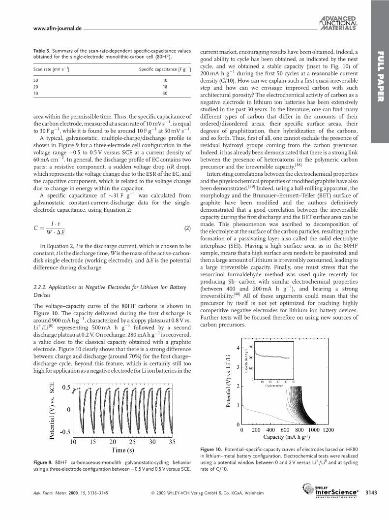
The ease of chiseling the external geometry and size of themonoliths is also of great importance from an applicationperspective. We therefore also checked the mechanical propertiesof these carbonaceous compounds (Fig. 7). As observed inFigure 7a, the curve of the stress versus the strain for the 80HFmaterial bears multiple crenels. These crenels, where the stressdecreases abruptly, are due to the macroporous texture andindicate that statistically, under pressure, some plateau borders
ag GmbH & Co. KGaA, Weinheim 3139
FULLPAPER
www.afm-journal.de
Figure 4. Nitrogen adsorption–desorption curves: a) 05HF; b) 25carb; c) 25HF; d) 60carb;
e) 80carb; f) 80HF; g) 90carb (*: adsorption curve; &: desorption curve). h) Pore-size
distribution obtained by the Horvath and Karwazoe method (&: 05HF; D: 25carb; ~: 25HF;
&: 60carb; *: 80carb; �: 80HF; 5: 90carb).
Table 2. Surface areas calculated from nitrogen adsorption; data extracted from Ref. [17].
Material Brunauer–Emmett–Teller
(BET) surface area [m2 g�1]
Micropore
volume [cm3 g�1]
Si(HIPE)� 820 0.42
05HF 774 0.32
25carb 650 0.25
25HF 802 0.34
60carb 623 0.24
80carb 585 0.23
80HF 459 0.18
90carb 564 0.22
3140 � 2009 WILEY-VCH Verlag GmbH & Co. KGaA, Weinheim
collapse locally (macropore walls). As the strainincreases, the crenel slope of the stress alwaysremains the same (Fig. 7a, dashed lines). Thisfeature suggests that the material is within theelastic regime during the entire mechanicaltest. Considering the last crenel, one can seethat the slope of the stress evolution versusstrain is lower when compared with the firstones (Fig. 7a, solid line). This effect is normal asthe sample is close to full collapse. The averageYoung’s modulus of the compounds extractedfrom these data is around 0.2GPa. Themacroporosity consumes the mechanicalenergy imposed by the applied strain, therebypromoting high toughness (area under curvenormalized with the material bulk density) ofaround 13 J g�1, a value that is 30%higher thanthat of the best carbon fibers.[32] Again, theseoutstanding mechanical properties are veryimportant for the applications that we intend toreach herein, namely supercapacitors andlithium ion negative electrodes. When mini-mizing the amount of the carbon precursor,taking into account the results for the 25HFcompound, we can see that the crenel featurehas almost vanished (Fig. 7b). Indeed, in thiscase, the stress under strain is reduced by afactor of 50 compared with the 80HF com-pound. Overall, for the 25HF compound, theYoung’s modulus is around 0.6MPa and itsassociated toughness is evaluated at around0.5 J g�1.Whenconsidering the05HFmaterial,when theamountof carbonprecursor is furtherminimized, the mechanical strength andaddressed mechanical properties become toolow to perform compression mechanical tests.
2.2. Applications as Electrochemical
Capacitors and Lithium Ion Battery
Negative Electrodes
2.2.1. Applications as Electrochemical Capacitors
Considering the porous features of the synthe-sized carbon (80HF), we carried out measure-
Micropore
area [m2 g�1]
External surface
area [m2 g�1]
749 0
753 21
658 0
781 21
622 0.7
584 0.7
456 3
565 0
Adv. Funct. Mater. 2009, 19, 3136–3145
FULLPAPER
www.afm-journal.de
Figure 5. a) SAXS spectra (&: initial Si(HIPE); !: 80reti; D: 80carb;
�: 80HF; *: composite 80reti after silica removal by HF treatment).
b) XRD pattern of the carbonaceous foams treated at 900 8C under argon.
c) Raman spectra of the carbonaceous foams treated at 9008C under argon
(D: 80carb; �: 80HF), and at 1200 8C (&: 80HF).
Figure 6. a) Macrocellular carbonaceous foam with a rod shape.
b) Macrocellular carbonaceous macroporous disks, obtained by cutting
the rod-shaped compound shown in (a) with a hand saw.
ments of the single-electrode capacitive characteristics in a three-electrode electrochemical cell using both potential-sweep cyclicvoltammetry and constant-current charge/discharge measure-ments within a potential range of 0–0.4 V versus saturated calomelelectrode (SCE). Figure 8 shows typical voltammograms obtainedfor the80HFporouscarbonelectrode inwhicha carbonmonolithic
Adv. Funct. Mater. 2009, 19, 3136–3145 � 2009 WILEY-VCH Verl
disk (�20-mm diameter) was placed as the working electrode andwas spiraled arounda thinplatinumwire as a current collector.As acounter electrode,platinumfoil (�4 cm2)wasusedagainst theSCEasa reference. Ingeneral, theequivalent circuit for electrochemicaldouble-layer capacitive (EDLC) electrodesmay be represented by aserial combination of an equivalent series resistance (ESR) and adouble-layer capacitance (Cdl).
[33]In EDLCs, the current–potentialprofile is expected to render a rectangular-like voltammogramowing to thepuredouble-layer capacitance causedby static chargesat the electrode/electrolyte interface.[34] This renders a nonredox,cyclic profile. In general, the shape of the voltammogram is dulydetermined by the time constant, t(RC) of the capacitor devicewhereR is theESRandC is thedevice capacitance.Nevertheless, incarbon/carbon electrochemical capacitors (ECs), the perfectrectangular voltammogram is not easily achievable due to thepresence of the ESR (the ESR is predominantly affected by variousfactors such as intrinsic electrode resistance, pore resistance,separator resistance, electrolyte conductivity, current collector/electrode-material contact resistance, etc.) as this changes the timeconstant significantly. Accordingly, in Figure 8, the non-rectangular current–voltage profile reveals a nonzero timeconstant [t(RC) 6¼ 0], which indicates that the current contains atransient part as well as a steady-state part. As t becomes larger, thetransient part lasts longer and hence more time is required tocharge the capacitor, resulting in a collapse of the rectangularcurrent profile.[35] Considering the current–voltage response of anideal carbon/carbon EC, the double-layer response of a voltammo-gram is rectangular in shape due to the nonredox electrochemicalreaction associated with the pure electrostatic double-layercapacitance. At the same time, the reason for the time constantnot being within the ideal case, that is t¼ 0, is because the currentcontains a transient part, which falls exponentially with t.[36]
However, this is not easily achievable in practical cells owing tovarious ESR elements present in the system.
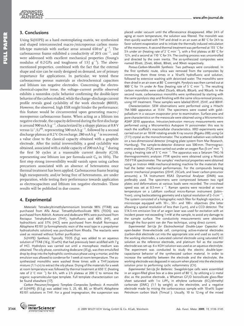
In this work, the typical voltammograms obtained for 80HF atdifferent scan rates from 10mV s�1 to 50mV s�1 are shown inFigure 8. As can be seen, the voltage–current profile observedexhibits thenon-ideal rectangular response irrespective of the scanrate, even though a consistent cycling profile without any redoxpeaks was obtained, confirming the double-layer behavior of thecarbon studied. Also, the charge–discharge current profile of theelectric double-layer capacitor is directly proportional to the scanrate. Figure 8 shows a typical cyclic voltammogram (CV) obtainedfor a 10mVs�1 potential sweep (scan rate), exhibiting true double-layer behavior with a leaf-like current–voltage response. However,
ag GmbH & Co. KGaA, Weinheim 3141
FULLPAPER
www.afm-journal.de
Figure 7. a) Typical mechanical properties of the as-synthesized porous carbonaceous mono-
liths (80HF compound): the dashed lines underline the fact that each crenel starts with the same
slope of the stress–strain curve. For the last crenel, the solid line indicates the discrepancy of its
stress–strain slope compared to the first ones. b) Typical mechanical properties of the as-
synthesized porous carbonaceous monoliths (25HF compound).
3142
the current response during charge and discharge exhibits highreversibility. Invariably, the voltammograms shown in Figure 8exhibit a leaf-like current–voltage profile, unlike the rectangularCV profile expected for carbon/carbon double-layer capacitors.This can presumably be attributed to large time constant (t> 0)due to the high ESR value of the EC. As t becomes larger, thetransient time taken for the EC to charge and later dischargebecomes longer and the transient state becomes insignificant,leading to the leaf-like current–voltage response shown inFigure8.This behavior is typical of carbon/carbon-based EDLCs that havehigh ESR values owing to the electrode resistivity originating fromvarious factors such as the high pore resistance caused by poorelectrolyte wetting deep into the pore surfaces, the currentcollector/carbon-electrode contact resistance, the electrode/elec-trolyte interfacial resistance, and the overall cell resistance, whichalso includes the separator resistance between the electrodes. Theobserved rectangular distortion, which presumably occurred due
Figure 8. Potential-sweep cyclic voltammetry of the 80HF macroporous-
carbon-disk electrode contained in a three-electrode electrochemical cell,
as a working electrode, with a platinum electrode as a counter and a
standard calomel electrode (SCE) as a reference, employing 6M KOH
aqueous electrolyte solution: a) 10mV s�1; b) 20mVs�1; c) 50mV s�1.
� 2009 WILEY-VCH Verlag GmbH & Co. KGaA, Weinheim
to the insignificant transient state, is associatedwith the longer time taken to charge and laterdischarge the carbon electrode. This behaviorcan be easily attributed to the high ESR value,which may arise from the porous texture of thecarbon electrode and the electrode thickness(here we used a disk carbon electrode withoutadding any binder). Moreover, the activematerial resistance can be separated into twocomponents; namely, the electronic and theionic resistances. To enhance the electronicconductivity it is customary to add someconducting additives such as acetylene black(AB) in order to increase the electronicconductivity of the active carbon material.[37]
Herein, we did not add any conductive additivesuch as AB as we used a monolithic, porouscarbon pellet as the electrode. Accordingly, asshown in Figure 8, the voltammograms showthe pure double-layer capacitive features withno prominent reversible peaks indicative of thetrue double-layer property of the porous carbon
studied. Nevertheless, the presence of kink-like humps at about0.4 V and 0.2 V (vs. SCE), as shown in Figure 8, are found to becommon, as these peaks are known to occur due to the redoxreaction, leading to pseudocapacitive behavior. These kinks aregenerally attributable to certain electron-transfer phenomenonwithin the bulk of the carbons, andmight be due to trapped gassesand/or reaction-incomplete substances residing in the pores,originating from the catalyst involved in the synthesis process ofthese carbonaceous materials, where the purification level ispresumably not 100%. Having such impurities in the carbonsusually contributes to a pseudocapacitance in addition to thedouble-layer capacitance, which could be an advantage for high-energy applications. Specific capacitance versus potential plotswere derived from CV using Equation 1 to further explain theelectrochemical specific capacitance behavior of a single carbonelectrode in a three-electrode electrochemical cell, where C is thecell capacitance in farads (F) for the single electrode, I is thedischarge current in amperes (A), and the slope of the dischargecurve is in volts per second (V s�1):
C ¼ IdV=dt
(1)
The specific capacitance Cm (F g�1) of the active materials isrelated to the capacitance of the cell,C, by the relationCm¼C/m, inwhich m refers to the mass of the active material in grams. Assummarized in Table 3, the specific, single-electrode capacitancediminishes with scan rate (Fig. 8).
As discussed above, this behavior clearly shows the less-reversible character of the double layer, due to the inability of thevoltage signal to reach theexposedporeareawithin thepermissibletime span (scan rate). The existence of such an exposed pore areaarises from the deep electrolyte penetrationwithin the inner poresof theporouscarbonmatrix.Thiseventually leads toan IRdropandhence the ESR value becomes more significant during the lowerscan rate,where the voltage signalwas able to reach thewettedpore
Adv. Funct. Mater. 2009, 19, 3136–3145
FULLPAPER
www.afm-journal.de
Table 3. Summary of the scan-rate-dependent specific-capacitance valuesobtained for the single-electrode monolithic-carbon cell (80HF).
Scan rate [mV s�1] Specific capacitance [F g�1]
50 10
20 18
10 30
area within the permissible time. Thus, the specific capacitance ofthe carbon electrode,measured at a scan rate of 10mVs�1, is equalto 30 F g�1, while it is found to be around 10 F g�1 at 50mV s�1.
A typical, galvanostatic, multiple-charge/discharge profile isshown in Figure 9 for a three-electrode cell configuration in thevoltage range �0.5 to 0.5 V versus SCE at a current density of60mA cm�2. In general, the discharge profile of EC contains twoparts: a resistive component, a sudden voltage drop (iR drop),which represents the voltage change due to the ESR of the EC, andthe capacitive component, which is related to the voltage changedue to change in energy within the capacitor.
A specific capacitance of �31 F g�1 was calculated fromgalvanostatic constant-current-discharge data for the single-electrode capacitance, using Equation 2:
C ¼ I � tW � DE (2)
In Equation 2, I is the discharge current, which is chosen to beconstant, t is thedischarge time,W is themassof the active-carbon-disk single electrode (working electrode), and DE is the potentialdifference during discharge.
2.2.2. Applications as Negative Electrodes for Lithium Ion Battery
Devices
The voltage–capacity curve of the 80HF carbons is shown inFigure 10. The capacity delivered during the first discharge isaround 900mAhg�1, characterized by a sloppy plateau at 0.8 V vs.Liþ/Li(0) representing 500mA h g�1 followed by a seconddischarge plateau at 0.2 V.On recharge, 280mAhg�1 is recovered,a value close to the classical capacity obtained with a graphiteelectrode. Figure 10 clearly shows that there is a strong differencebetween charge and discharge (around 70%) for the first charge–discharge cycle. Beyond this feature, which is certainly still toohigh for application as anegative electrode forLi ionbatteries in the
Figure 9. 80HF carbonaceous-monolith galvanostatic-cycling behavior
using a three-electrode configuration between�0.5 Vand 0.5 V versus SCE.
Adv. Funct. Mater. 2009, 19, 3136–3145 � 2009 WILEY-VCH Verl
currentmarket, encouraging results have been obtained. Indeed, agood ability to cycle has been obtained, as indicated by the nextcycle, and we obtained a stable capacity (inset to Fig. 10) of200mA h g�1 during the first 50 cycles at a reasonable currentdensity (C/10). How can we explain such a first quasi-irreversiblestep and how can we envisage improved carbon with sucharchitectural porosity? The electrochemical activity of carbon as anegative electrode in lithium ion batteries has been extensivelystudied in the past 30 years. In the literature, one can find manydifferent types of carbon that differ in the amounts of theirordered/disordered areas, their specific surface areas, theirdegrees of graphitization, their hybridization of the carbons,and so forth. Thus, first of all, one cannot exclude the presence ofresidual hydroxyl groups coming from the carbon precursor.Indeed, it has already been demonstrated that there is a strong linkbetween the presence of heteroatoms in the polymeric carbonprecursor and the irreversible capacity.[38]
Interesting correlations between the electrochemical propertiesand the physicochemical properties ofmodified graphite have alsobeen demonstrated.[39] Indeed, using a ball-milling apparatus, themorphology and the Brunauer–Emmett–Teller (BET) surface ofgraphite have been modified and the authors definitivelydemonstrated that a good correlation between the irreversiblecapacity during the first discharge and the BETsurface area can bemade. This phenomenon was ascribed to decomposition ofthe electrolyte at the surface of the carbonparticles, resulting in theformation of a passivating layer also called the solid electrolyteinterphase (SEI). Having a high surface area, as in the 80HFsample,means that a high surface area needs to be passivated, andthen a large amount of lithium is irreversibly consumed, leading toa large irreversible capacity. Finally, one must stress that theresorcinol formaldehyde method was used quite recently forproducing Sb�carbon with similar electrochemical properties(between 400 and 200mA h g�1), and bearing a strongirreversibility.[40] All of these arguments could mean that theprecursor by itself is not yet optimized for reaching highlycompetitive negative electrodes for lithium ion battery devices.Further tests will be focused therefore on using new sources ofcarbon precursors.
Figure 10. Potential–specific-capacity curves of electrodes based on HF80
in lithium–metal battery configuration. Electrochemical tests were realized
using a potential window between 0 and 2V versus Liþ/Li0 and at cycling
rate of C/10.
ag GmbH & Co. KGaA, Weinheim 3143
FULLPAPER
www.afm-journal.de
3144
3. Conclusions
Using Si(HIPE) as a hard exotemplating matrix, we synthesizedand shaped interconnected macro-/microporous carbon mono-lith-type materials with surface areas around 650m2 g�1. Thecarbonaceous foams exhibited a conductivity of 20 S cm�1, andwere addressed with excellent mechanical properties (Young’smodulus of 0.2GPa and toughness of 13 J g�1). The above-mentioned properties, combined with the fact that the externalshape and size can be easily designed on demand, are of primaryimportance for applications. In particular, we tested thesecarbonaceous porous materials as electrochemical capacitorsand lithium ion negative electrodes. Concerning the electro-chemical-capacitor issue, the voltage–current profile observedexhibits a nonredox cyclic behavior confirming the double-layerbehavior of the carbonstudied,while the charge–discharge currentprofile reveals good cyclability of the work electrode (80HF).However, the observed, high ESR might hinder the performance;this feature would be circumvented upon generating macro-/mesoporous carbonaceous foams. When acting as a lithium ionnegative electrode, the capacity delivered during the first dischargeis around 900mA h g�1, characterized by a sloppy plateau at 0.8 Vversus Liþ/Li(0), representing 500mA h g�1, followed by a seconddischarge plateau at 0.2 V.On recharge, 280mAhg�1 is recovered,a value close to the classical capacity obtained with a graphiteelectrode. After the initial irreversibility, a good cyclability wasobtained, associated with a stable capacity of 200mA h g�1 duringthe first 50 cycles at a reasonable current density (C/10,representing one lithium ion per formula-unit C6 in 10 h). Thefirst step strong irreversibility would vanish upon using carbonprecursors associated with an absence of heteroatoms oncethermal treatment has been applied. Carbonaceous foams bearinghigh mesoporosity, and/or being free of heteroatoms, are underpreparation, while testing their performance towards applicationas electrocapacitors and lithium ion negative electrodes. Thoseresults will be published in due course.
4. Experimental
Materials: Tetradecyltrimethylammonium bromide 98% (TTAB) waspurchased from Alfa Aesar. Tetraethylorthosilicate 98% (TEOS) waspurchased from Aldrich. Acetone and dodecane 99% were purchased fromRectapur. Tetrahydrofuran (THF), hydrofluoric acid 48% (HF), andhydrochloric acid 37% (HCl) were purchased from AnalaR Normapur.Ablaphene RS101 (a formophenolic resin of the resol type in a prepolymerhydroalcoholic solution) was purchased from Rhodia. The reactants wereused as received without further purification.
Si(HIPE) Synthesis: Typically, TEOS (5 g) was added to an aqueoussolution of TTAB (16 g, 35wt%) that had previously been acidified with 7 gof HCl. Hydrolysis was carried out until a monophasic medium wasobtained. The oily phase, constituting dodecane (35 g), was then emulsifieddrop by drop into the hydrophilic continuous phase using a mortar, and theemulsion was allowed to condense for 1 week at room temperature. The as-synthesized monoliths were washed three times with a THF/acetonemixture (1:1 v/v) to extract the oily phase. Drying of thematerials for a weekat room temperature was followed by thermal treatment at 650 8C (heatingrate of 2 8C min�1) for 6 h, with a 2 h plateau at 200 8C to remove theorganic supramolecular-type template. Full template characterization canbe found elsewhere [17].
Carbon Precursor/Inorganic Template Composites Synthesis: A monolithof Si(HIPE) (0.5 g) was added into 5, 25, 60, 80, or 90wt% AblapheneRS101 solutions in THF. For a good impregnation, the suspension was
� 2009 WILEY-VCH Verlag GmbH &
placed under vacuum until the effervescence disappeared. After 24 h ofaging at room temperature, the solution was filtered. The monolith wasthen quickly washed with THF and dried in an air oven at 80 8C for 24 h tofavor solvent evaporation and to initiate the thermally induced reticulationof themonomers. A second thermal treatment was performed at 155 8C for5 h under air (heating rate of 2 8C min�1), with a first plateau at 80 8C for12 h, and a second at 110 8C for 3 h. The cooling process was uncontrolledand directed by the oven inertia. The as-synthesized composites werenamed 05reti, 25reti, 60reti, 80reti, and 90reti respectively.
Porous-Carbon-Monolith Synthesis: Two pathways were considered. Inthe first synthetic route, silica was removed from the composites byimmersing them three times in a 10wt% hydrofluoric acid solution,followed by extensive washing with deionised water. The monoliths werethen dried in an air oven at 80 8C overnight. Pyrolysis was then carried out at900 8C for 1 h under Ar flow (heating rate of 5 8C min�1). The resultingcarbon monoliths were called 25carb, 60carb, 80carb, and 90carb. In thesecond route, carbonaceous monoliths were synthesized by starting withthe same pyrolysis step and finishing with the same silica-removal process,using HF treatment. These samples were labeled 05HF, 25HF, and 80HF.
Characterization: SEM observations were performed using a HitachiTM-1000 apparatus at 15 kV. The specimens were coated with gold–palladium in a vacuum evaporator prior to examination. Surface-area andpore characteristics on the mesoscale were obtained using a MicromeriticsASAP 2010 apparatus. Intrusion/extrusion mercury measurements wereperformed using a Micromeritics Autopore IV porosimeter: this was toreach the scaffold’s macrocellular characteristics. XRD experiments werecarried out on an 18 kW rotating-anode X-ray source (Rigaku-200) using Ge(111) crystal as the monochromator. The scattered radiation was collectedon a two-dimensional detector (imaging plate system from Mar Research,Hamburg). The sample-to-detector distance was 500mm. Thermogravi-metric analyses (TGA) were carried out under an oxygen flux (5 cm3 min�1)using a heating rate of 5 8C min�1. The apparatus was a Setaram TAG-16thermogravimetric analyzer. FTIR spectra were obtained using a Nicolet750 FTIR spectrometer. The samples’ mechanical properties were obtainedusing an Instron 4466 mechanical-testing machine for the materials thathad the better mechanical performances. For the compounds bearingpoorer mechanical properties (25HF, 25Carb, and lower carbon-precursoramounts) a TA Instrument RSA3 Dynamical Analyser (DMA) waspreferably used. The specimens were compressed between two rigidplates and deformations at various loads were recorded. The crossheadspeed was set at 0.5mm s�1. Raman spectra were recorded at roomtemperature on a LabRam confocal micro-Raman instrument (Jobin–Yvon), using backscattering geometry and a typical resolution of 2–3 cm�1.The system consisted of a holographic notch filter for Rayleigh rejection, amicroscope equipped with 10�, 50� and 100� objectives (the latterallowing a spatial resolution of less than 2mm), and a CCD detector. The514.5-nm emission line of an argon laser was used for excitation with anincident power not exceeding 1mW at the sample, to avoid any damage tothe sample surface. The conductivity measurements were obtainedthrough the four-point van der Paw technique, using direct current.
Experimental Set-Up for Electrochemical Double-Layer Capacitor: Anopen-beaker three-electrode cell, comprising active-material electrodes(carbon-disk electrode cut into the appropriate size and used as such) asthe working electrodes, a saturated calomel electrode using saturated KClsolution as the reference electrode, and platinum foil as the counterelectrode was set-up. 6 M KOH solution was used as an aqueous electrolyte.The experiment was conducted to study the electric double-layer-capacitance behavior of the synthesized carbon material. In order toincrease the wettability between the electrode and the electrolyte, theworking electrode was degassed in vacuumwhen placed into the electrolytesolution prior to performing cyclic voltammetry (CV).
Experimental Set-Up for Batteries: Swagelok-type cells were assembledin an argon-filled glove box at a dew point of 80 8C, by utilizing a Li metaldisc as the positive electrode, a Whatman GF/D borosilicate glass-fibersheet saturated with 1M LiPF6 in ethylene carbonate (EC)/dimethylcarbonate (DMC) (1:1 by weight) as the electrolyte, and a negativeelectrode made by mixing the carbonaceous sample with 10wt% SuperPetroleum carbon black (Timcal ). Usually, 10 to 12mg of the mixed
Co. KGaA, Weinheim Adv. Funct. Mater. 2009, 19, 3136–3145
FULLPA
www.afm-journal.de
powders was placed on top of the Swagelok plunger. The lithium reactivitywas monitored with a ‘‘VMP’’ potentiostat/galvanostat (Biologic SA, Claix,France). Electrochemical tests were realized using a potential windowbetween 0 and 2 V versus Liþ/Li0 and at cycling rate of C/10 (i.e., onelithium per formula unit C6 in 10 h).
PER
AcknowledgementsWe wish to thank Dr. Michel Couzi (ISM, University Bordeaux 1) for theRaman spectroscopy data and Dr. Pierre Delhaes for helpful discussion.
Received: April 30, 2009
Published online: August 25, 2009
[1] H. C. Foley, Microporous Mater. 1995, 4, 407.
[2] T. Kyotani, Carbon 2000, 38, 269.
[3] F. Schuth, Angew. Chem. Int. Ed. 2003, 42, 3604.
[4] a) R. Ryoo, H. S. Joo, S. Jun, J. Phys. Chem. B 1999, 103, 7743; b) J. Lee,
S. Yoon, T. Hyeon, S. M. Oh, K. B. Kim, Chem. Commun. 1999, 2177;
c) S. Jun, H. S. Joo, R. Ryoo, M. Kruk, M. Jaroniec, Z. Liu, T. Ohsuna,
O. Terasaki, J. Am. Chem. Soc. 2000, 122, 10712; d) S. B. Yoon, J. Y. Kim,
J.-S. Yu, Chem. Commun. 2001, 559.
[5] a) G. Che, B. B. Lakshmi, E. R. Fisher, C. R. Martin, Nature 1998, 393, 346;
b) T. Kyotani, L. Tsai, A. Tomita, Chem. Mater. 1995, 7, 1427.
[6] a) T. Kyotani, L. Tsai, S. Inoue, A. Tomita, Chem. Mater. 1997, 9, 609;
b) Z. Ma, T. Kyotani, A. Tomita, Chem. Commun. 2000, 2365; c) Z. Ma,
T. Kyotani, A. Tomita, Chem. Mater. 2001, 13, 4413.
[7] a) M. Kruk, M. Jaroniec, R. Ryoo, S. H. Joo, J. Phys. Chem. B 2000, 104,
7960; b) S. H. Joo, S. Jun, R. Ryoo, Microporous Mesoporous Mater. 2001,
44–45, 153; c) S. H. Joo, S. J. Choi, I. Oh, J. Kwak, Z. Liu, O. Terasaki,
R. Ryoo, Nature, 2001, 412, 169.
[8] S. S. Kim, T. S. Pinnavaia, Chem. Commun. 2001, 2418.
[9] S. Alvarez, A. B. Fuertes, Carbon 2004, 42, 433.
[10] a) A.-H. Lu, W. Schmidt, B. Spliethoff, F. Schuth, Adv. Mater. 2003, 15,
1602; b) A.-H. Lu, A. Kiefer, W. Schmidt, F. Schuth, Chem. Mater. 2004, 16,
100; c) A.-H. Lu, C. W. Li, W. Schmidt, W. Kiefer, F. Schuth, Carbon 2004, 42,
2939; d) J. Lee, J. Kim, T. Yheon, Chem. Commun. 2003, 1138; e) T. Miyake,
M. Hanaya, J. Mater. Sci. 2002, 37, 907; f) H. I. Lee, C. Pak, C.-H. Shin,
H. Chang, D. Seung, J. A. Yie, J. M. Kim, Chem. Commun. 2005,
6035.
[11] B.-L. Su, A. Vantomme, L. Surahy, R. Pirard, J.-P. Pirard, Chem. Mater. 2007,
19, 3325.
[12] B. T. Holland, C. F. Blanford, A. Stein, Science 1998, 281, 538.
[13] a) Y. Meng, D. Gu, F. Zhang, Y. Shi, H. Yang, Z. Li, C. Yu, B. Tu, D. Zhao,
Angew. Chem. Int. Ed. 2005, 44, 7053; b) D. Zhao, Y. Yan, B. Tu, H. F. Yang,
Small 2007, 3, 198; c) Y. Huang, H. Q. Cai, T. Yu, F. Q. Zhang, F. Zhang,
Y. Meng, D. Gu, Y. Wan, X. L. Sun, B. Tu, D. Zhao, Angew. Chem. Int. Ed.
2007, 46, 1089; d) Y. Meng, D. Gu, F. Q. Zhang, Y. F. Shi, L. Cheng, D. Feng,
Z. X. Wu, Z. X. Chen, Y. Wan, A. Stein, D. Zhao, Chem. Mater. 2006, 18,
4447.
[14] R. Liu, Y. F. Shi, Y. Wan, Y. Meng, F. Q. Zhang, D. Gu, Z. X. Chen, B. Tu,
D. Zhao, J. Am. Chem. Soc. 2006, 128, 11652.
[15] Z. Wang, A. Stein, Chem. Mater. 2008, 20, 1029.
[16] a) Q. Wang, H. Li, L. Q. Chen, X. J. Huang, Carbon 2001, 39, 2211;
b) X. M. Sun, Y. D. Li, Angew. Chem. Int. Ed. 2004, 116, 607; c) X. Cui,
M. Antonietti, S.-H. Yu, Small 2006, 2, 756.
[17] F. Carn, A. Colin, M.-F. Achard, H. Deleuze, M. Birot, R. Backov, J. Mater.
Chem. 2004, 14, 1370.
[18] a) D. Barby, Z. Haq, Eur. Pat. 0060138 1982; b) N. R. Cameron,
D. C. Sherrington, Biopolymers – Liquid Crystalline Polymers – Phase Emul-
sion, Advances in Polymer Science, Vol. 126, Springer, Berlin/Heidelberg
Adv. Funct. Mater. 2009, 19, 3136–3145 � 2009 WILEY-VCH Verl
1996, p. 163; c) N. R. Cameron, Polymer, 2005, 46, 1439; d) H. Zhang,
A. I. Cooper, Soft Matter, 2005, 2, 107.
[19] a) Y.-S. Hu, P. Adelhelm, B. M. Smarsly, S. Hore, M. Antonietti, J. Maier,
Adv. Funct. Mater. 2007, 17, 1873; b) L.-Z. Fan, Y.-S. Hu, J. Maier,
P. Adelhelm, B. Smarsly, M. Antonietti, Adv. Funct. Mater. 2007, 17,
3083; c) C. M. Leroy, F. Carn, M. Trinquecost, R. Backov, P. Delhaes,
Carbon 2007, 45, 2176.
[20] a) R. Backov, Soft Matter 2006, 2, 452; b) E. Prouzet, Z. Khani, M. Bertrand,
M. Tokumoto, V. Gyuot-Ferreol, J.-F. Tranchant, Microporous Mesoporous
Mater. 2006, 96, 369; c) C. Sanchez, C. Boissiere, D. Grosso, C. Laberty,
L. Nicole, Chem. Mater. 2008, 3, 682; d) E. Prouzet, S. Ravaine, C. Sanchez,
R. Backov, New J. Chem. 2008, 32, 1284; e) R. Backov, L’Actualite Chimique
2009, 329, III.
[21] a) K. Y. Lee, J. C. Lytle, N. S. Ergang, S. M. Oh, A. Stein, Adv. Funct. Mater.
2005, 15, 547; b) C.-Z. Lai, M. A. Fierke, P. Buhlmann, Anal. Chem. 2007, 79,
4621.
[22] a) A. Kirschning, C. Altwicker, G. Drager, J. Harders, N. Hoffmann,
U. Hoffmann, H. Schondfeld, W. Solodenko, U. Kuns, Angew. Chem.
Int. Ed. 2001, 40, 3995; b) J. C. Ganley, K. L. Riechmann,
E. G. Seebauer, R. I. Mazel, J. Catal. 2004, 227, 26.
[23] K. Hosoya, T. Ogata, Y. Watabe, T. Kubo, T. Ikegani, M. Tanaka,
H. Minakuchi, K. Nakanishi, J. Chromatogr. 2005, 1073, 123.
[24] E. Guyon, J. P. Hulin, L. Petit, C. D. Mitescu, Physical Hydrodynamics,
Oxford University Press, Oxford 2001.
[25] a) K. H. Coats, B. D. Smith, Soc. Petroleum Engineers J, Trans. AIME 1964,
131, 73; b) P. Levitz, in:Handbook of Porous Media, (Eds: F, Schuth, K, Sing,
J. Weitkamp), Wiley-VCH, Weinheim 2002, p. 37.
[26] a) S. Ungureanu, M. Birot, G. Laurent, H. Deleuze, O. Babot, B. Julian-
Lopez, M.-F. Achard, M. I. Popa, C. Sanchez, R. Backov, Chem. Mater. 2007,
19, 5786; b) S. Ungureanu, H. Deleuze, M. I. Popa, C. Sanchez, R. Backov,
Chem. Mater. 2008, 20, 6494; c) N. Brun, B. Julian-Lopez, P. Hesemann,
L. Guillaume, M.-F. Achard, H. Deleuze, C. Sanchez, R. Backov, Chem.
Mater. 2008, 20, 7117.
[27] K. P Gierszal, M. Jaroniec, T.-W. Kim, J. Kim, R. Ryoo, New J. Chem. 2008,
32, 981.
[28] H. Yang, Y. Yan, Y. Liu, F. Zhang, R. Zhang, Y. Meng, M. Li, S. Xie, B. Tu,
D. Zhao, J. Phys. Chem. B 2004, 108, 17320.
[29] G. Marcolongo, G. Ruaro, M. Gobbo, M. Meneghetti, Chem. Commun.
2007, 4925.
[30] a) F. Tuinstra, J. L. Koenig, J. Chem. Phys. 1970, 53, 1126; b) A. Gerald,
G. A. Zickler, B. Smarsly, N. Gierlinger, H. Peterlik, O. Paris, Carbon 2006,
44, 3239.
[31] a) N. Kasahara, S. Shiraishi, A. Oya, Carbon 2003, 41, 1654; b) K. Okabe,
S. Shiraishi, A. Oya, Carbon 2004, 42, 667.
[32] F. Fourne, Synthetic Fibers: Machines and Equipment, Manufacture, Proper-
ties, Carl Hanser Verlag, Munich 1999.
[33] A. J. Bard, L. R. Faulkner, Electrochemical Methods Fundamentals and
Applications, Wiley, NY 1980, pp. 11–15.
[34] B. E. Convey, Electrochemical Supercapacitors, Kluwer-Plenum Publishing
Co, New York 1999.
[35] E. G. Gagnon, J. Electrochem. Soc. 1973, 120, 1052.
[36] S. R. S. Prabaharan, R. Vimala, Z. Zainal, J. Power Sources 2006, 161,
730.
[37] M. Michael, S. R. S. Prabaharan, J. Power Sources 2004, 136,
250.
[38] D. Larcher, C. Mudalige, A. E. George, V. Porter, M. Gharghouri, J. R. Dahn,
Solid State Ionics 1999, 93, 71.
[39] F. Disma, L. Aymard, L. Dupont, J.-M. Tarascon, J. Electrochem. Soc. 1996,
143, 3959.
[40] J. Hassoun, G. Derrien, S. Panero, B. Scrosati, J. Power Sources 2008, 183,
339.
ag GmbH & Co. KGaA, Weinheim 3145