H)ALL: a DSVL for designing user interfaces for Control Systems
14
(H)ALL: a DSVL for designing user interfaces for Control Systems. Bruno Barroca Universidade Nova de Lisboa [email protected] and Vasco Amaral Universidade Nova da Lisboa [email protected] Abstract. This paper presents the methodology used to design a Do- main Specific Visual Language (DSVL), named HALL (Human Assisted Logic Language), for the purpose of deriving automatically or semi- automatically user interfaces for critical control systems. We will de- scribe our approach to design this language’s abstract syntax and the process to describe its semantics by using formal framework based on an algebraic Petri-nets formalism: Concurrent Object-Oriented Petri Nets (CO-OPN). Keywords: Coordination-engine, Queries-Views-Transformations (QVT), interface model components, petri-net, CO-OPN, control systems, finite state machine, message model. 1 Introduction Control systems are hierarchical systems composed by several subsystems and components. On the leafs of the hierarchy, typically are the sensors and controls which may deal with continuous and discrete values at various refresh rates in a synchronous and asynchronous fashion. Control Systems used to be centralised in a single operational control centre (OCC), nowadays they tend to be dis- tributed. The control interfaces can be deployed on several machines on each level of a control system. Lower level interfaces are usually more specialised and perform control and monitoring with a great level of resolution and accuracy. Top level interfaces are usually less specialised, but presents statistical informa- tion providing a comprehensive global view of the overall performance of the system. Typically, the development of user interfaces for critical control systems con- sists of a complex and slow process. The problem tends to scale with the increas- ing complexity of the systems involved. For instance in the high energy physics domain, a detector machine is composed by thousands of different components which have to be controlled and exposed to the operators in a intuitive and usable way. To develop individually the graphical user interfaces (GUIs) is not viable in time. In order to tackle this problem, the GUI development process should be more systematic by allowing the domain expert to start at the requirements and
Transcript of H)ALL: a DSVL for designing user interfaces for Control Systems

(H)ALL: a DSVL for designing user interfacesfor Control Systems.
Bruno BarrocaUniversidade Nova de [email protected]
and Vasco AmaralUniversidade Nova da [email protected]
Abstract. This paper presents the methodology used to design a Do-main Specific Visual Language (DSVL), named HALL (Human AssistedLogic Language), for the purpose of deriving automatically or semi-automatically user interfaces for critical control systems. We will de-scribe our approach to design this language’s abstract syntax and theprocess to describe its semantics by using formal framework based on analgebraic Petri-nets formalism: Concurrent Object-Oriented Petri Nets(CO-OPN).Keywords: Coordination-engine, Queries-Views-Transformations (QVT),interface model components, petri-net, CO-OPN, control systems, finitestate machine, message model.
1 Introduction
Control systems are hierarchical systems composed by several subsystems andcomponents. On the leafs of the hierarchy, typically are the sensors and controlswhich may deal with continuous and discrete values at various refresh rates in asynchronous and asynchronous fashion. Control Systems used to be centralisedin a single operational control centre (OCC), nowadays they tend to be dis-tributed. The control interfaces can be deployed on several machines on eachlevel of a control system. Lower level interfaces are usually more specialised andperform control and monitoring with a great level of resolution and accuracy.Top level interfaces are usually less specialised, but presents statistical informa-tion providing a comprehensive global view of the overall performance of thesystem.
Typically, the development of user interfaces for critical control systems con-sists of a complex and slow process. The problem tends to scale with the increas-ing complexity of the systems involved. For instance in the high energy physicsdomain, a detector machine is composed by thousands of different componentswhich have to be controlled and exposed to the operators in a intuitive andusable way. To develop individually the graphical user interfaces (GUIs) is notviable in time.
In order to tackle this problem, the GUI development process should bemore systematic by allowing the domain expert to start at the requirements and

interface specification levels, and afterwards deploy the artifacts in a automaticor semi-automatic way. Together with this approach, several extra benefits willcome, such as verification (model correction), and validation (assuring that themodel covers completely the initial requirements).
The BATIC3S[1, 8, 9] project aims to build a comprehensive methodology forsemi-automated, formal model-based generation of effective, reliable and adap-tive 3D GUIs for diagnosing control systems. Within this context, there was theneed to define a domain specific visual language (DSVL) with which we couldsupport interface modeling and integrate with the framework, based on a formalsemantics ground by using Petri-Nets, for fast prototype generation.The (H)ALL is an approach to that problem. It uses the Finite State Machine(FSM) formalism to express behaviour of both system and GUIs. Current FSMmodels are limited since they lack a hierarchical structure and they do not possessany formal mechanism of synchronisation between several FSM’s. To effectivelyexpress some problem in a specific domain, one usually decompose the problem(divide) into several logical components which may seem independent in one ofmore aspects (dimensions). Each component can again be decomposed into sev-eral levels of abstraction. Finally all the components and subcomponents need tobe synchronised and updated to compose a behaviour model required to expressthe solution to the initial problem (conquer). Hierarchical FSM’s achieve FSMcomposition. In (H)ALL, FSM’s are synchronised using a message broadcastingmechanism. Furthermore, (H)ALL is subdivided into two components.The first one is exclusively dedicated to model the structure and behaviour ofthe system itself. It can be used to simulate and verify the lower level interfaceswith the real system (drivers). Although it can also be used to aid the verydefinition of a user interface model, and simulate the generated GUI artifactswithout requiring to plug-in to the real control system. The connection with thereal system is not really tackled on this work. Here we assume that it will be as-sured by platform-dependent drivers which will interface with our coordinationengine.The second one represents the users and their profiles. For each profile, we willmodel the view that each user will have over the control system. Here it is possi-ble to define their specific GUIs, specific tasks and specific user permissions androles on each level of the control system.
This paper focuses on the approach and methodology to derive a DSVLnamed HALL (Human Assisted Logic Language), as well as on its formal def-inition. We have chosen the drink vending machine (DVM) [4] as a case studyto verify and validate the current work. Some of samples presented along thispaper are based on the DVM case study analysis.
In the rest of the paper, we will have a look at related work in section 2,then we will focus on the language design issues in section 3 and finally we willdiscuss future developments of our ongoing work in section 4 .

2 Related Work
The research area of user interface prototyping is vast and broad. However, to ourknowledge, there is a lack of bibliographic references presenting a comprehensivesurvey in this specific area of control systems applications.
As shown in Table 1, in what concerns to GUI prototyping, there is a plethoraof work done: TRIDENT[10], MOBI-D[6], ERGOCONCEPTOR[5], ENVIR-3D[11], to name a few. The underneath concept is a powerful mechanism tospeed up the design process by automatically generating a user interface basedon a formal specification of some kind. We will next summarise the mentionedprojects under the dimensions we found relevant for this work: prototype gener-ation and modeling capabilities.
Project Domain Application
TRIDENT 2D GUIs General scopeMOBI-D 2D GUIs Business applicationsERGOCONCEPTOR 2D GUIs Process control applicationsEnvir3D 3D GUIs Control systems
Table 1. Researched projects on the domain of GUI prototyping.
Prototype generation - Prototype generation is achieved by means ofmechanisms built to ease and fasten the production of GUIs based on somesort of specification (it may not be a formal one). TRIDENT presents full GUIprototype generation in several aspects: it uses configurable production rulesto guide the designer, and automatically take some options on the interfacedesign. The positioning of the widgets on the dialogues is automatically donegiven the desired layout strategy, effectively reducing the design time of a userinterface. Clearly, it is shown that there must be a balance in a Rapid UserInterface Prototyping (RUIP) system between flexibility and the design timespent on specifying all the details of the user interface’s design. MOBI-D uses atool (TIMM) to assist the designers in their design choices, not limiting however,the artistic options that the designer may take. ERGOCONCEPTOR balancesthe capability of rapidly generate a first version of the GUI formed by abstractuser controls (and with several design options left open) to the flexibility ofinstantiating those abstract user controls in an external design editor - this wayjoining the best of two worlds. Finally, Envir3D can also generate a user interface(VRML code) based on a XIML specification. Their Abstract Interface Objects(AIO) library can effectively speed up the design process in a considerable way.
Modeling - A GUI design framework is said to be model-based if it imple-ments some of these interface model components: presentation model (dialogueand geometric model are usually included here), task model, user profile model,domain specific model. Some also include a design model which resembles in-terface model components composition issues MOBI-D seems to be the most

general-purpose of all the studied model-based systems, as it is the one whichimplements all the components of the interface model. Both TRIDENT (busi-ness oriented) and ERGOCONCEPTOR (process control oriented) imposes aspecific design order which also guides the designer through all the design pro-cess. MOBI-D also drives the design process from abstract models to concreteones, but it uses a specific model (design model) to glue link all models and anassistant (TIMM) to help the designer pruning the space of choices. This way oforganising the mappings can be interesting if we are to support iterative designdue to the fact that all modeling components are intrinsically independent fromeach other. Finally in Envir3D, they have limited their work to presentationand dialogue models, but they left doors open to the other interface model com-ponents by adopting the XIML format on their model-based engine. Envir3Dpresents a unified model to coordinate all aspects of the interface model, how-ever they do not give a clear answer from how do they deal with the aspectsof concurrency and parallelism, nor give an architectural view of all involvedmodules of their prototyping solution.
Final Remarks - From all the work that we have researched on the fieldsof GUI prototyping and GUI modeling, only Envir3D has presented an unifiedmodel for GUI specification specifically in the domain of control systems. How-ever, we require a methodology based on a complete and strong formal basis, todeal will all aspects of prototyping a GUI in a uniform and intuitive way.
3 (H)ALL Design
The purpose of designing a new domain specific visual language (DSVL) is toenable designers and system engineers to think and develop using the very ownterms and sentences of the problem’s domain instead of solution’s domain. Onthe other hand, general purpose languages (GPL) available nowadays, use termsand sentences that usually concerns to software engineering concepts like reuse,modularity, etc.
The (H)ALL design framework will attempt to give to designers an inte-grated design view, centring on each object/component. In each design step, thelanguage below automatically separates aspects and concerns like user profiles,graphical objects and tasks.
We ought to create both kinds of 2D and 3D interfaces to control systems.These interfaces are composed by commonly known widgets like combo-boxes,radio-buttons, push buttons, context menus, and others with drag and dropcapabilities, auto-resizing, auto-placing and other interaction behaviour.
In the Figure 1, it is shown an example of a generated GUI running on agraphics engine which was developed specifically in the context of BATIC3Sproject.
The (H)ALL is intended to feed this particular engine with data containingthe geometrical information about the interface objects and their visual/interactionproperties. The particular behaviour of each widget can be either fully modeledin (H)ALL, or just left has a property/parameter for the designer to configure.

Fig. 1. Prototype of GUI for a Control System.
The (H)ALL visual model only reaches the notion of the building of a logicalGUI. The specified widgets (it’s structure and behaviour - states and events)are abstract, and can be instantiated in any graphics engine you choose to im-plement. Therefore, the concrete interfaces generated by (H)ALL are stronglydependent on the final implementation of the graphics engine in a particularplatform.
3.1 Language Syntax Specification
The (H)ALL syntax specification is divided into a ”hidden” textual formalismand a visual formalism, which are both closely connected on the design process.In this paper, due to space concerns, we only describe the (H)ALL’s abstractsyntax, excluding a description of the concrete visual syntax that is described in[2].
The (H)ALL abstract syntax is divided into two parts: the kernel structuresand the domain structures, which can be considered as sub-languages. Domainstructures attempt to model the different aspects of building a GUI (see Figure2).
When specifying a GUI for a control system the designer has to take intoconsideration several aspects like: who will use the GUI (defining it in the usersmodel), the GUI requirements (defining it in the task model), the GUI structure(dialogues, widgets, etc..) and behaviour (dynamism and properties, defined inthe visual model). Last and not least, we include a system model which enablesthe designer to model a simulator of the real control system for simulation,
Fig. 2. (H)ALL’s top level meta-model.
testing and verification purposes. All these models are designed using the statemachine abstraction. State machines are synchronised using a messaging model.
The hierarchical state machines and messaging model forms what we namethe Kernel. Sub-domain specific behaviour is defined on external machines whichare connected with the Kernel by the respective domain structures. For instance,the GUI objects geometrical specifications defined in the visual model will feedthe graphics engine (built on some platform) which implements the graphicalobject rendering. In Figure 3 it is shown the (H)ALL structures used to specifyGUI objects.
The same for user profiling specific data that will feed the User Interfacedatabase management engine (IUD). As shown in Figure 4, (H)ALL is used todefine the structure and behaviour of the coordination between all the compo-nents which compose the interface model. It achieves that by both modeling andsimulating the internal states of each engine, and by synchronising all enginesusing messages.
The Kernel The (H)ALL, as many other languages, has a core level/layer,which is named the Kernel. It resembles most of the common properties on thedesign process of each sub-language.
In Fig. 5 it is shown the component’s meta-model, which is here referred asthe Kernel. The Kernel can be divided into two parts. The first one is the FiniteState Machine (FSM), and the second is the messaging. In each hierarchy of

Fig. 3. (H)ALL’s visual meta-model.
components among all sub-domains, each one (each node) will have a model ofits behaviour described as a state machine. The state machine is a graph-likemodel specification of the behaviour of common systems. It is composed by statesand transitions, which will be given values in each sub-domain specification. Atransition is a relation between states. It can be defined as a tuple of two states(source state, target state). Here we simplify to simple graphs, but we can alwayspower-up (by composition) to an equivalent semantic of hyperbolic state graphs.
On the FSM model editor, states are connected each other by named tran-sitions. Each transition includes a trigger, a precondition, a postcondition andan action. The trigger activates the transition. Triggers can be either eventsfrom the domain, or message notifications. After the transition is activated by atrigger, the transition’s precondition is evaluated as a boolean expression. If theprecondition evaluates to ”true”, the transition is fired and the active state ischanged from the origin state to the target state. After this, the postcondition isevaluated (setting internal values). After postconditions are evaluated, actionsare then executed. In actions, it is possible, for instance, to set domain propertiesor send messages to other components. These messages don’t have a particulardestination: a message is broadcast along the hierarchy, and can be handled byany component which implements a handler for it.

Fig. 4. GUI development process using (H)ALL.
Messaging - The messaging model is one of the most important facets of thedesign process, since it implements the communication between all sub-domains.
A message is an entity which is able to be cloned over the system’s structure.A message has it’s internal data structures and it’s own FSM. The message FSMwill only run at the time the message is being handled. This FSM is thereforecontextual to the message being handled, and will provide direct access to ma-nipulate not only component data, but message parameters and data as well.However, there are predefined states which enable the designer to control themessage routing over the domain hierarchy. The propagation mechanism shouldbe (on designers view) an implementation detail. For now let’s consider it willrun like the virtual table mechanism on C++. By default, a message is passedto children or to parents till some component handles it.
The messages are passed between engines, thus it is natural that the messagedefinitions have to be placed on a global area, to be accessed by all sub-domains.In the message definition area is where the designer defines messages signaturesand its internal data structures and types. It is also on this area where thedesigner specifies the message data initialisation behaviour. A signature is the

Fig. 5. Component Model in (H)ALL
name of the message and its parameters. It is then used by message handlerswhich implement the receiving behaviour of that message of that specific signa-ture. Messages from one engine can be fired an handled by other engine, simplyby using the MessageInvocation expression. Message handlers of a certaincomponent can be all disabled using the Enable expression or one can specifyexactly what handler is to be enabled/disabled.
On a component hierarchy, each node will have defined several message han-dlers. These message handlers have themselves internal state machines whichexpress the behaviour of receiving a message. Typically, while specifying a mes-sage handler, the designer specifies the processing of the message data, mergingthat information with the internal components data or its FSM, and will thendecide about if the message was well received. If so, it can be signalled to thecomponent inner FSM (unblocking all MessageNotification and consequentlytriggering state transitions). When a message is sent, the message state is au-tomatically set to ”continue”. The state of a message is automatically set to”stop” whenever it reaches a component which implements an handler to thatmessage. Otherwise, the message stays in the ”continue” state. If no component

implements an handler for it, the message will be silently lost. At this pointthe designer is also able to reset the routing direction ”children to parents” or”parents to children”, by setting the message state with the property ”topdown”.
Since the message handler’s FSM is activated whenever the message arrivesto the component, there is no trigger to be defined on the message handler’sFSM transitions. Also, a message handler cannot expect message notificationsfrom another message, because it is not possible (by design) to send a messageto a message handler. Note that in a message handler it is possible to access tomessage’s data and parameters, as well as component’s data.
3.2 Language semantics specification
The (H)ALL semantics has just been informally described. Here we will describethe methodology used to formally specify the its semantics.
The specification of the semantics was defined [2] by model transformation toa known semantics language: CO-OPN [3](which stands for Coordinated Object-Oriented Petri-Nets). The CO-OPN language is already a graph-like language,so one could think to use it instead. However, CO-OPN is a General PurposeLanguage (GPL), so writing a user interface would be a lot more complicatedand error prone. Here we express (H)ALL in terms of CO-OPN constructs whichcould rather be directly implemented in CO-OPN.
The translation focuses on the Kernel constructs and was made only forsemantic specification purposes, which means that it is not an optimised trans-lation, and the resulting CO-OPN code is not efficient. Note that performancerequirements are an issue while designing user interfaces to critical and complexcontrol systems. Thus, performance is an issue that we must deal afterwards.Here we just want to formally specify the semantics of (H)ALL.
To demonstrate the transformation methodology, we will show how an (H)ALLsystem component - DVM - is transformed into a CO-OPN context (see Figure6). Note that, for simplicity, the proposed visual syntax do not show all contentsin detail [2]. The system component DVM is composed by two subcomponents:Money Unit and Container. Also, DVM has its own FSM (including three states)and it implements a message handler FSM to message Shutdown.
The transformation specification expressed in QVT (Query-View Transfor-mation)[7] rules uses the meta-model definition of the (H)ALL as source modeland the meta-model definition of the CO-OPN language as target model. There-fore, the resulting model will be a CO-OPN specification of a GUI.
Top-level The transformation rules in QVT (Query-View Transformation) startsto flat (H)ALL components hierarchy into CO-OPN contexts. Thus, componentcompositions is mapped into CO-OPN context-use compositions. All top-levelcomponents in a (H)ALL model are mapped into CO-OPN contexts and context-
used in a default CO-OPN context named ”SpaceModelCTX”. For every de-fined message in (H)ALL, all CO-OPN context translated from (H)ALL com-ponents will have a method (MessageInPort) and a gate (MessageOutPort) to
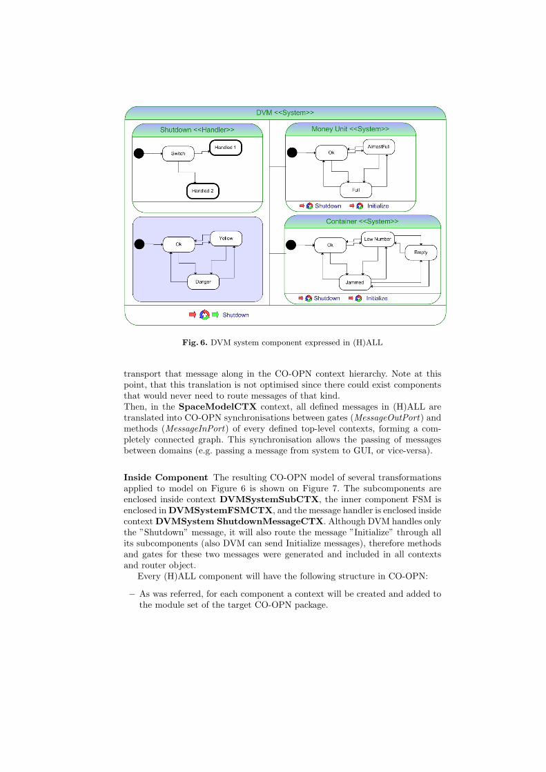
Fig. 6. DVM system component expressed in (H)ALL
transport that message along in the CO-OPN context hierarchy. Note at thispoint, that this translation is not optimised since there could exist componentsthat would never need to route messages of that kind.Then, in the SpaceModelCTX context, all defined messages in (H)ALL aretranslated into CO-OPN synchronisations between gates (MessageOutPort) andmethods (MessageInPort) of every defined top-level contexts, forming a com-pletely connected graph. This synchronisation allows the passing of messagesbetween domains (e.g. passing a message from system to GUI, or vice-versa).
Inside Component The resulting CO-OPN model of several transformationsapplied to model on Figure 6 is shown on Figure 7. The subcomponents areenclosed inside context DVMSystemSubCTX, the inner component FSM isenclosed in DVMSystemFSMCTX, and the message handler is enclosed insidecontext DVMSystem ShutdownMessageCTX. Although DVM handles onlythe ”Shutdown” message, it will also route the message ”Initialize” through allits subcomponents (also DVM can send Initialize messages), therefore methodsand gates for these two messages were generated and included in all contextsand router object.
Every (H)ALL component will have the following structure in CO-OPN:
– As was referred, for each component a context will be created and added tothe module set of the target CO-OPN package.
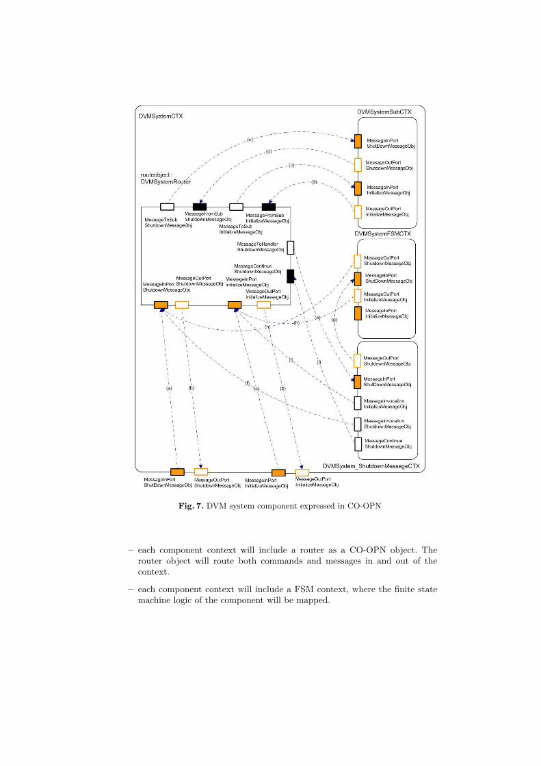
Fig. 7. DVM system component expressed in CO-OPN
– each component context will include a router as a CO-OPN object. Therouter object will route both commands and messages in and out of thecontext.
– each component context will include a FSM context, where the finite statemachine logic of the component will be mapped.

– each component context will include (context-use) a SubComponents con-text. This context only encapsulates all subcomponents contexts and passesmessages and commands in and out from them.
– each component context will include several message handler contexts. Thesecontexts will have the finite state machine logic of the message handlersdefined on (H)ALL’s component.
The router object is implemented with a CO-OPN class. A pair of placesRouterEnabled and RouterDisabled are added to class Route. Command Enable
can also take effect on message handlers, thus for each component message han-dler, another pair of places (”Enabled” and ”Disabled”) are added to the Routeclass. All Enabled places are marked with ”@” on Initial. Then some axiomsswitches the tokens between Enabled and Disabled places according to the valueon the Enable command. Message routing to and from subcomponents context,as well as message routing from messages which were handled in some messagehandler are also implemented using axioms. The route object also routes com-mands. Axioms route commands from parents, returns from children to parents,and commands and returns to its inner component context.
4 Conclusions
We have described the syntax and the semantics of a language named (H)ALL forinterface modeling. It was introduced under the scope of the project BATIC3Swhich will derive a comprehensive methodology for semi-automated, formalmodel-based generation of effective, reliable and adaptive 3D GUIs for diag-nosing Control Systems. Although initially meant for 3D GUIs, (H)ALL hassupport for the definition of both 2D and 3D abstract widgets to compose either2D or 3D GUIs. Similarly, the domain of application is not confined to controlsystems, but also for other application domains as long as they do share the sameconceptual properties: hierarchical, event based, etc. Since the GUI library willbe composed by graphical objects which are dependent from the used graphics-engine, and we did not wanted to bound our solution to a specific set of widgets,we have chosen not to include any other syntatic facility (meta-model) to enablethe expression of anything more than their structure (hierarchical compositionand data structures) and behaviour (state machines).
The next step of this project is to implement (H)ALL. This will be achievedby using meta-modeling tools and the corresponding transformation rules as de-fined in [2]. From the point of view of the architecture design, there will be twomain modules: the graphical interface editor (to design and build the GUI proto-types) and the execution engine (to run and simulate the GUI prototypes). Thenext step will be to build an editor’s prototype based on (H)ALL’s definitionsand its mapping rules to CO-OPN.
Another relevant issue to be tackled will be the need for optimising themapping rules. Not only we will want to reduce redundant structures but alsoto improve the running speed of the coordination engine as well as the otherengines.
This work represents a step forward closer to design a design framework witha visual edition pragmatics, which would allow for instance, free-hand editions ofboth structure and behaviour of remote user interfaces, without requiring all theinterface system to be reset and rebuilt. With (H)ALL, we believe to be in theright direction to derive a proper design framework with a novel methodologythat makes use of formal methods, languages and tools to express any model ofa GUI.
References
1. Batic3s. URL: http://smv.unige.ch/tiki-index.php?page=BATICS.2. B. Barroca. (h)all: a dsl for rapid prototyping of user interfaces for control systems.
Msc. thesis, Universidade Nova de Lisboa, 2007.3. D. Buchs and N. Guelfi. A formal specification framework for object-oriented
distributed systems. IEEE Trans. Software Eng., 26(7):635–652, 2000.4. B. collaboration. Batic3s project - document collection 2005-2006. URL:
http://smv.unige.ch/tiki-download file.php?fileId=728.5. F. Moussa, C. Kolski, and M. Riahi. A model based approach to semi-automated
user interface generation for process control interactive applications. Interactingwith Computers, 12(3):245–279, January 2000.
6. A. Puerta and J. Eisenstein. Towards a general computational framework formodel-based interface development systems. In IUI ’99: Proceedings of the 4thinternational conference on Intelligent user interfaces, pages 171–178, New York,NY, USA, 1999. ACM Press.
7. QVT-Partners. Qvt-partners. URL: http://qvtp.org.8. M. Risoldi and V. Amaral. Towards a formal, model-based framework for control
systems interaction prototyping. In to be published at Springer Verlag LectureNotes in Computer Science (LNCS) Series 2007, 2007.
9. M. Risoldi and D. Buchs. A domain specific language and methodology for controlsystems gui specification, verification and prototyping. In Proceedings of the 2007IEEE Symposium on Visual Languages and Human Centric Computing, IEEE (toappear), 2007.
10. J. Vanderdonckt. Knowledge-based systems for automated user interface genera-tion: the trident experience, 1995.
11. J. Vanderdonckt, C. Chieu, L. Bouillon, and D. Trevisan. Model-based design,generation, and evaluation of virtual user interfaces. In Web3D Symposium Pro-ceedings, pages 51–60, 2004.