Eco-friendly electric outboard motor - FLOVER Trolling Motor
Upload
khangminh22Category
view
0download
0
Foreword
Thank you for choosing the vehicle from GAC MOTOR. To better enjoy the driving pleasure provided by your vehicle, please carefully read this User's Manual. The use instructions on the vehicle provided in this Manual will allow you to fully understand its operations and important notes. The proper use of the car will improve driving safety and increase service life.
The on-board Warranty Manual describes the warranty services provided by GAC MOTOR which you can enjoy, as well as regular maintenance of your vehicle. Read the manual thoroughly so you can understand your rights and responsibilities.
Please keep this Manual in your car for your reference.
Your dealer is dedicated to your satisfaction and will be pleased to answer any questions and concerns.
If you have any advice or comments, welcome to call GAC MOTOR customer service hotline: +86-400-158-9999.
Thank you for your support and great kindness to GAC MOTOR. Wish you a happy driving!
Instructions About Safety
Your safety and the safety of passengers are very important. Therefore, operating this vehicle safely is an important responsibility.
To help you be familiar with relevant safety notes, we have provided operating steps and other instructions on signboards of the car and in this manual. These instructions alert you to warn potential hazards that could hurt you or passengers.
Of course, it is not practical or possible to list all the hazards associated with operating or maintaining your vehicle. You must use your own good judgment.
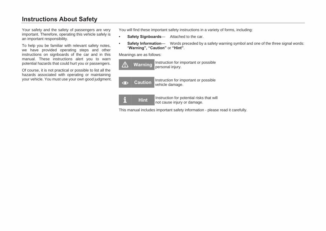
You will find these important safety instructions in a variety of forms, including:
• Safety Signboards— Attached to the car.
• Safety Information— Words preceded by a safety warning symbol and one of the three signal words: “Warning”, “Caution” or “Hint”.
Meanings are as follows:
Warning Instruction for important or possible personal injury.
Caution Instruction for important or possible vehicle damage.
Hint Instruction for potential risks that will not cause injury or damage.
This manual includes important safety information - please read it carefully.

Key Safety Precautions The following safety precautions describe the safety features and correct use of the vehicle. We think all of them are very important.
♦ Be sure to wear the seat beltIn all types of crashes, seat belts are protective devices that perform best. Air bags are designed to enhance safety provided by seat belts rather than take the place of seat belts. Thus even if the vehicle is equipped with air bags, make sure that you and other occupants always correctly wear seat belts.
♦ Protect all childrenChildren 12 years old and under must never ride in the front seat. They shall be correctly restrained in the second-row seats. For infants and babies, child safety seats shall be used. For older children, both child safety seats and three-point seat belts shall be used.
♦ Note that air bag may cause dangerAir bags can save lives. However, deployment of air bags could result in serious or fatal injury to the occupant too close to them or improperly restrained. Air bags present greatest threats to infants, babies, and short adults. Therefore, be sure to observe all instructions and warnings contained in this Manual.
♦ Never drive after drinking alcoholNever drive after drinking alcohol. Even drinking a little alcohol can suppress capability of dealing with changing situations. Besides, it takes longer time for doing so. Never drive after drinking alcohol. Do not let your friends drive after drinking alcohol either.
♦ Observe road traffic safety regulations and be polite while driving.
♦ Pay due attention to driving safetyMaking calls or doing other things while driving could cause you to pay no attention to road conditions, other vehicles and pedestrians. This could result in accidents. Keep in mind to avoid distraction while driving.
♦ Control the speedToo fast speed is one of the main causes for injury and death in crashes. Generally, the faster the speed, the greater the risk. Nonetheless, sometimes accidents with relatively slow speeds can also lead to serious injury or death. Regardless of the highest speed permitted by the regulation, never drive faster than the permission by actual road conditions for safety purpose.
♦ Keep the vehicle at a safe statusTire burst or mechanical fault can be very dangerous. To reduce possibility of these problems, check tire pressures and conditions from time to time, and have the vehicle serviced periodically according to the Warranty Manual.


Contents
I
PICTORIAL REFERENCES ......................................................................... 1
INTERIOR ............................................................................................................................. 1
EXTERIOR ........................................................................................................................... 7
ENGINE COMPARTMENT ............................................................................................... 10
1. SAFETY OPERATING INSTRUCTIONS ............................................. 11
1.1 SAFETY DRIVING ............................................................................................. 11
1.1.1 General Instructions ............................................................ 11
1.1.2 Correct Sitting Position of Passengers ............................... 12
1.1.3 Pedal Area .......................................................................... 14
1.2 SEAT BELT SYSTEM ........................................................................................ 16
1.2.1 General Instructions ............................................................ 16
1.2.2 Why Wear Seat Belts .......................................................... 19
1.2.3 Seat Belt ............................................................................. 21
1.3 SRS SYSTEM ................................................................................................... 26
1.3.1 General Instructions ............................................................ 27
1.3.2 Front Seat Frontal SRS ...................................................... 30
1.3.3 Front Seat Side SRSs (Apply to Certain Models) ............... 31
1.3.4 Side Curtain SRS (Apply to Certain Models) ...................... 32
1.3.5 Cases When SRSs Could Deploy ...................................... 33
1.3.6 Cases When SRSs Could Not Deploy ................................ 34
1.4 SAFETY RULES FOR CHILDREN .................................................................... 36
1.4.1 General Instructions ............................................................ 36
1.4.2 Child Safety Seat ................................................................ 37
1.4.3 Install a Child Seat Properly ................................................ 40
1.5 DANGEROUS EXHAUST GASES ..................................................................... 45
1.6 SAFETY LABELS ............................................................................................... 46
2. OPERATING SYSTEM AND EQUIPMENT .......................................... 47
2.1 CAB ..................................................................................................................... 47
2.1.1 Instrument Cluster ............................................................... 47
2.1.2 Indicator Light ...................................................................... 61
2.1.3 Steering Wheel .................................................................... 66
2.2 DOOR OPENING AND CLOSING ..................................................................... 69
2.2.1 Smart Key ............................................................................ 69
2.2.2 Emergency Mechanical Key (Apply to Certain Models) ...... 76
2.2.3 Central Locking System ...................................................... 77
2.2.4 Door ..................................................................................... 82
2.2.5 Hatchback Door ................................................................... 83
2.2.6 Electric Windows ................................................................. 84
2.2.7 Electric Sunroof (Apply to Certain Models) ......................... 87
2.2.8 Engine Hood ........................................................................ 91
2.2.9 Basic Operations of Anti-Theft on Vehicle Body ................. 93
2.3 LIGHTS AND VISUAL FIELD ............................................................................. 94
2.3.1 Exterior Lights ..................................................................... 94
2.3.2 Interior Lights ..................................................................... 100
2.3.3 Windshield Wiper. ............................................................. 102
2.3.4 Windshields ....................................................................... 104
Contents
II
2.3.5 Rear-view Mirror ............................................................... 105
2.3.6 Sun Visor .......................................................................... 109
2.4 SEATS AND STORAGE DEVICES ................................................................. 110
2.4.1 Importance of Adjusting Seats Properly ........................... 110
2.4.2 Headrest ........................................................................... 111
2.4.3 Front Seats ....................................................................... 113
2.4.4 Rear Seats ........................................................................ 115
2.4.5 Storage Devices ............................................................... 116
2.4.6 Cigarette Lighter/Power Outlet ......................................... 123
2.4.7 Trunk ................................................................................. 125
2.4.8 Luggage Rack (Apply to Certain Models) ......................... 128
2.4.9 Accessories and Modifications ......................................... 129
2.5 A/C SYSTEM .................................................................................................. 131
2.5.1 General Instructions .......................................................... 131
2.5.2 Control Panel .................................................................... 132
2.5.3 A/C Air Outlets .................................................................. 139
2.6 AUDIO SYSTEM (RADIO) (APPLY TO CERTAIN MODELS) ................ 140
2.6.1 Basic Operation ................................................................ 142
2.6.2 Radio................................................................................. 148
2.6.3 USB Play .......................................................................... 152
2.6.4 IPod Play .......................................................................... 155
2.6.5 Precautions ....................................................................... 156
2.6.6 Supported Formats ........................................................... 158
2.6.7 Characteristic Specification ............................................... 159
2.6.8 Pre-maintenance Inspection ............................................. 160
2.7 AUDIO SYSTEM (AVN) (APPLY TO CERTAIN MODELS) ................... 162
2.7.1 Control Panel ..................................................................... 162
2.7.2 Control Buttons on the Steering Wheel ............................. 164
2.7.3 Basic Operation ................................................................. 166
2.7.4 Radio ................................................................................. 170
2.7.5 USB Play ........................................................................... 174
2.7.6 iPod Play ........................................................................... 180
2.7.7 Bluetooth ........................................................................... 181
2.7.8 System Setting .................................................................. 186
2.7.9 Car Setting ........................................................................ 193
2.7.10 Supported Formats............................................................ 197
2.7.11 Precautions for Use of USB .............................................. 200
2.7.12 Precautions for Product Use ............................................. 202
3. DRIVING GUIDE ................................................................................. 203
3.1 STARTING AND DRIVING .............................................................................. 203
3.1.1 Ignition Switch (Applicable to Certain Vehicle Models) ..... 203
3.1.2 Start Switch (Applicable to Certain Vehicle Models) ......... 204
3.1.3 Engine Start ....................................................................... 206
3.1.4 Engine Shutdown .............................................................. 208
3.1.5 Gear and Driving Instructions ............................................ 210
Contents
III
3.1.6 Electrical Park Brake (EPB) (applicable to certain models) ........................................... 217
3.1.7 Mechanical Parking Brake System (applicable to certain models) ............................................................................. 222
3.2 SERVICE ELECTRONIC BRAKE SYSTEM ................................................... 223
3.2.1 Anti-lock Braking System (ABS) ....................................... 223
3.2.2 Electronic Brakeforce Distribution System (EBD) ............ 225
3.2.3 Electronic Stability Program (ESP) ................................... 226
3.2.4 Traction Control System (TCS) ........................................ 229
3.2.5 Hydraulic Brake Assist (HBA) ........................................... 230
3.2.6 Hill Hold Control (HHC)..................................................... 231
3.2.7 Hill Descent Control (HDC) ............................................... 232
3.3 DRIVING ASSIST SYSTEM ............................................................................ 234
3.3.1 Cruise Control System (Apply to certain models) ............. 234
3.3.2 Tire pressure monitoring system (TPMS) (apply to certain models) ............................................................................. 237
3.4 REVERSING ASSIST SYSTEM ...................................................................... 239
3.4.1 Reversing Radar System .................................................. 239
3.4.2 Reversing rear-view system (Apply to certain models) .... 242
3.5 ELECTRIC POWER STEERING (EPS) SYSTEM ....................................... 244
3.6 DRIVING SKILLS ............................................................................................. 245
3.6.1 Safety Check for Driving ................................................... 245
3.6.2 Driving during Running-in Period ...................................... 246
3.6.3 Important Tips for Driving under Different Conditions ...... 248
3.6.4 Efficient Use of the Car ..................................................... 250
3.6.5 Fire Prevention .................................................................. 251
4. USAGE AND MAINTENANCE ........................................................... 252
4.1 MAINTENANCE INSTRUCTIONS ................................................................... 252
4.2 INTERIOR MAINTENANCE ............................................................................. 253
4.3 EXTERIOR MAINTENANCE ........................................................................... 255
4.4 CHECKING AND ADDING FLUIDS ................................................................ 260
4.4.1 Fuel Oil .............................................................................. 260
4.4.2 Engine Oil .......................................................................... 262
4.4.3 Coolant .............................................................................. 267
4.4.4 Windshield Washing Liquid and Wiper Blade ................... 271
4.4.5 Brake Fluid ........................................................................ 273
4.4.6 Battery ............................................................................... 276
4.5 A/C FILTER..................................................................................................... 279
4.6 REPLACING BULBS ....................................................................................... 282
4.7 WHEELS .......................................................................................................... 299
4.8 TIRE CHAIN ..................................................................................................... 305
4.9 MAINTENANCE INSTRUCTIONS FOR CAR BODY ANTI-THEFT .............. 306
5. TECHNICAL DATA ............................................................................. 307
5.1 VEHICLE IDENTIFICATION NUMBERS ......................................................... 307
5.2 VEHICLE PARAMETERS ................................................................................ 309
6. HANDLING OF ACCIDENT ................................................................ 319
6.1 VEHICLE TOOLS AND SPARE TIRE ............................................................ 319
Contents
IV
6.2 USAGE OF WARNING TRIANGLE................................................................. 321
6.3 REPLACING THE FLAT TIRE ......................................................................... 322
6.4 FUSE ................................................................................................................ 325
6.4.1 Fuses in the Instrument Panel Fuse Box .......................... 327
6.4.2 Fuse in the Fuse Box of Engine Compartment ................ 330
6.5 EMERGENCY START ..................................................................................... 333
6.6 EMERGENCY TOWING .................................................................................. 335
7. TYPE APPROVAL INFORMATION ................................................... 341
7.1 TYPE APPROVAL NUMBER .......................................................................... 341
7.2 TYPE APPROVAL INFORMATION ................................................................. 342


Pictorial References
1
Pictorial References
Interior 1. Sun visor(Please refer to Page 110)2. Front ceiling lights(Please refer to Page 101)– Electric sunroof switch (Please refer to Page 88)– Glass case(Please refer to Page 120)3. Manual anti-glare interior rear-view mirror (Please refer
to Page 107)– Automatic anti-glare interior rear-view mirror (Please
refer to Page 106)
Pictorial References
2
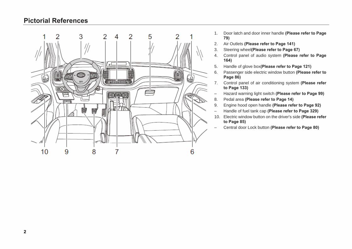
1. Door latch and door inner handle (Please refer to Page79)
2. Air Outlets (Please refer to Page 141)3. Steering wheel(Please refer to Page 67)4. Control panel of audio system (Please refer to Page
164)5. Handle of glove box(Please refer to Page 121)6. Passenger side electric window button (Please refer to
Page 86)7. Control panel of air conditioning system (Please refer
to Page 133)– Hazard warning light switch (Please refer to Page 99)8. Pedal area (Please refer to Page 14)9. Engine hood open handle (Please refer to Page 92)– Handle of fuel tank cap (Please refer to Page 329)10. Electric window button on the driver's side (Please refer
to Page 85)– Central door Lock button (Please refer to Page 80)
Pictorial References
3
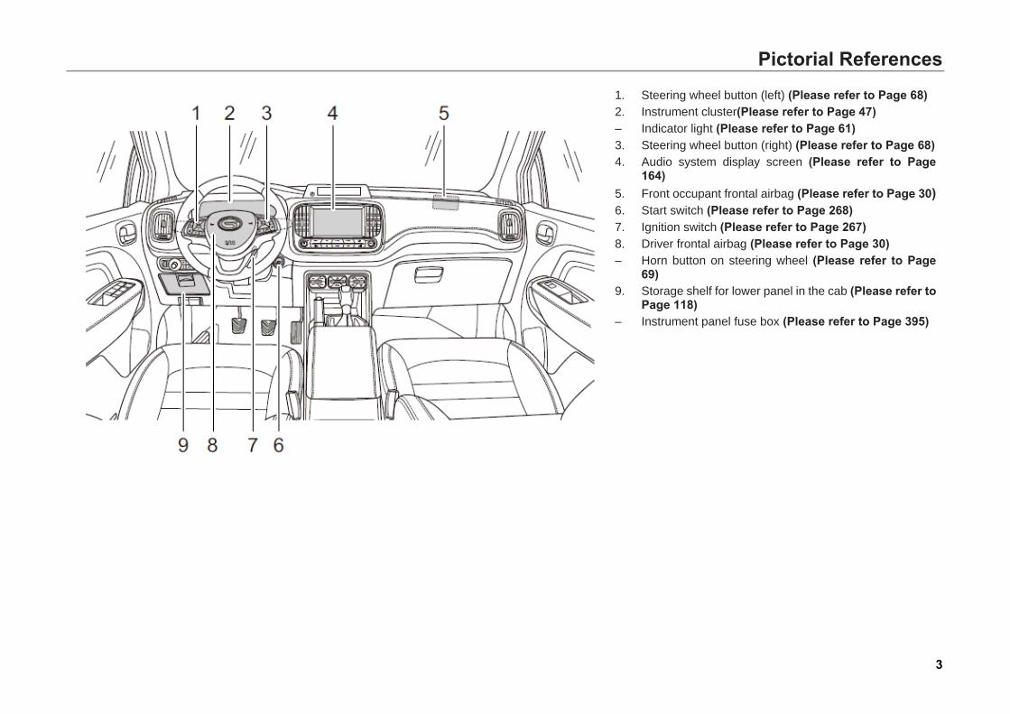
1. Steering wheel button (left) (Please refer to Page 68)2. Instrument cluster(Please refer to Page 47)– Indicator light (Please refer to Page 61)3. Steering wheel button (right) (Please refer to Page 68)4. Audio system display screen (Please refer to Page
164)5. Front occupant frontal airbag (Please refer to Page 30)6. Start switch (Please refer to Page 268)7. Ignition switch (Please refer to Page 267)8. Driver frontal airbag (Please refer to Page 30)– Horn button on steering wheel (Please refer to Page
69)9. Storage shelf for lower panel in the cab (Please refer to
Page 118)– Instrument panel fuse box (Please refer to Page 395)
Pictorial References
4
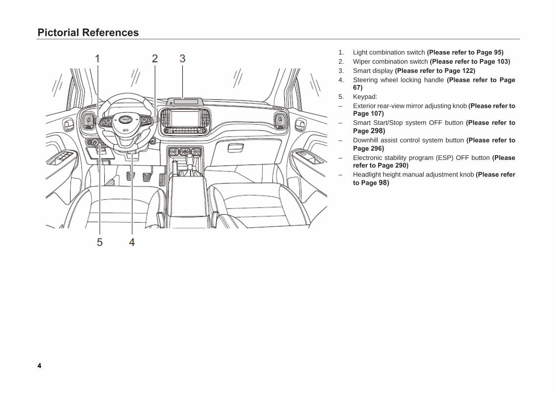
1. Light combination switch (Please refer to Page 95)2. Wiper combination switch (Please refer to Page 103)3. Smart display (Please refer to Page 122)4. Steering wheel locking handle (Please refer to Page
67)5. Keypad:– Exterior rear-view mirror adjusting knob (Please refer to
Page 107)– Smart Start/Stop system OFF button (Please refer to
Page 298)– Downhill assist control system button (Please refer to
Page 296)– Electronic stability program (ESP) OFF button (Please
refer to Page 290)– Headlight height manual adjustment knob (Please refer
to Page 98)
Pictorial References
5
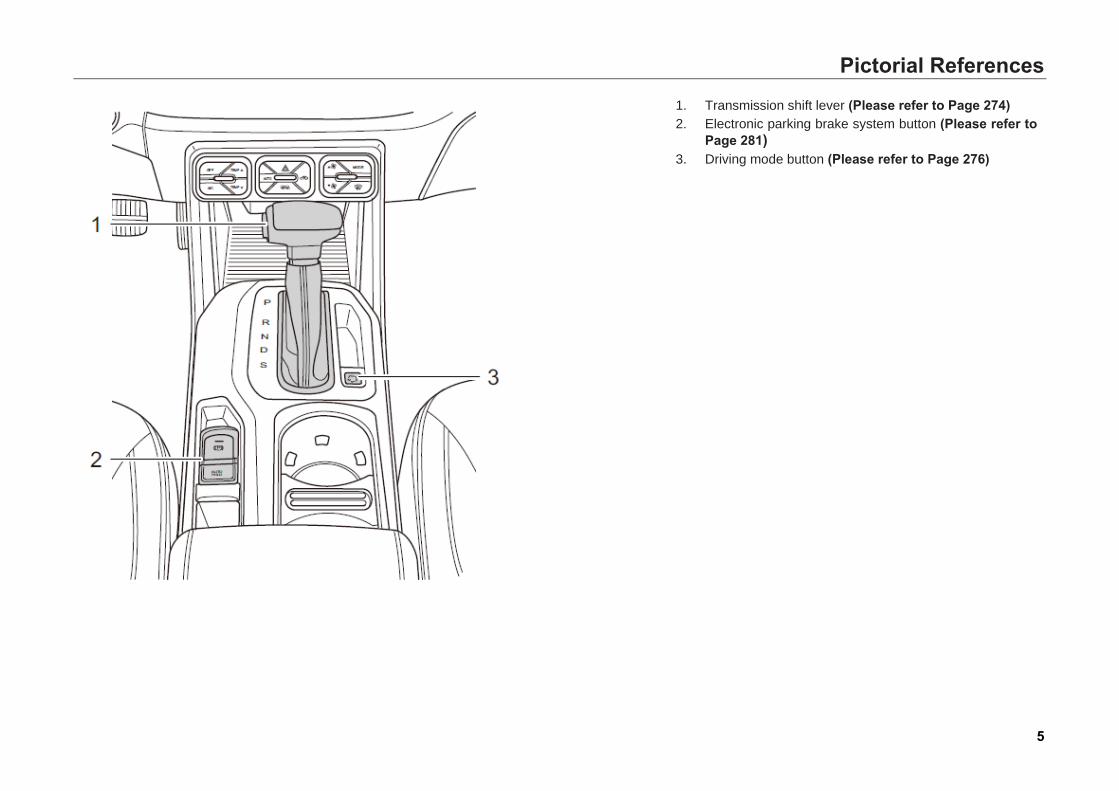
1. Transmission shift lever (Please refer to Page 274)2. Electronic parking brake system button (Please refer to
Page 281)3. Driving mode button (Please refer to Page 276)
Pictorial References
6
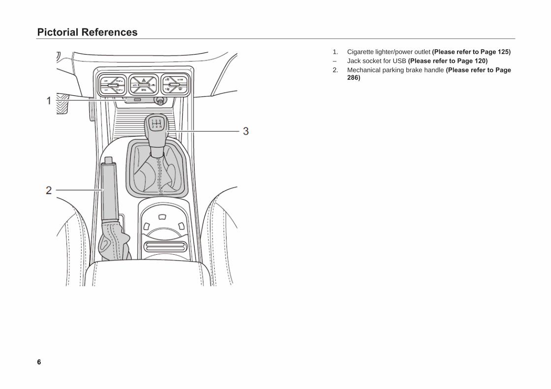
1. Cigarette lighter/power outlet (Please refer to Page 125)– Jack socket for USB (Please refer to Page 120)2. Mechanical parking brake handle (Please refer to Page
286)
Pictorial References
7
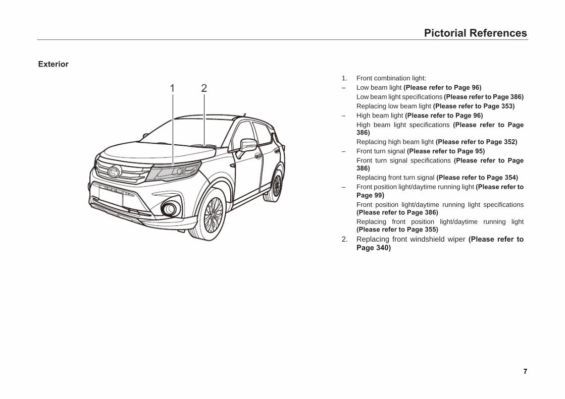
Exterior 1. Front combination light:– Low beam light (Please refer to Page 96)
Low beam light specifications (Please refer to Page 386)Replacing low beam light (Please refer to Page 353)
– High beam light (Please refer to Page 96)High beam light specifications (Please refer to Page386)Replacing high beam light (Please refer to Page 352)
– Front turn signal (Please refer to Page 95)Front turn signal specifications (Please refer to Page386)Replacing front turn signal (Please refer to Page 354)
– Front position light/daytime running light (Please refer toPage 99)Front position light/daytime running light specifications(Please refer to Page 386)Replacing front position light/daytime running light(Please refer to Page 355)
2. Replacing front windshield wiper (Please refer toPage 340)
Pictorial References
8
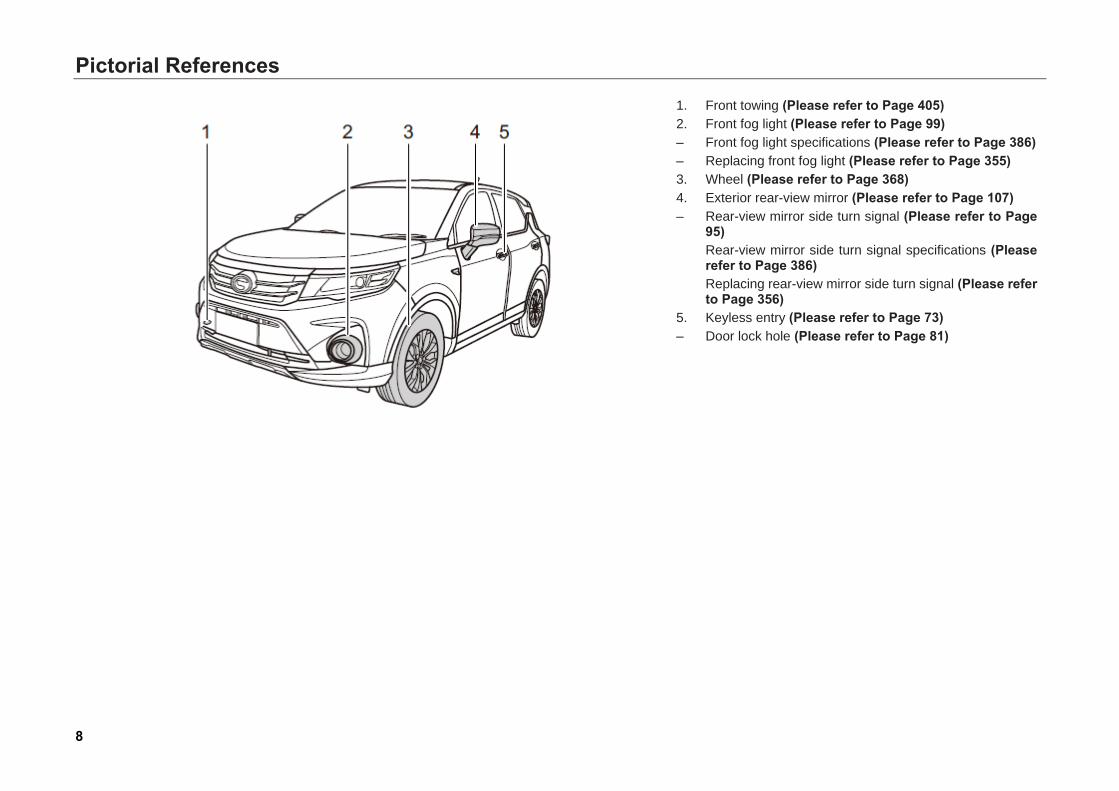
1. Front towing (Please refer to Page 405) 2. Front fog light (Please refer to Page 99) – Front fog light specifications (Please refer to Page 386) – Replacing front fog light (Please refer to Page 355) 3. Wheel (Please refer to Page 368) 4. Exterior rear-view mirror (Please refer to Page 107) – Rear-view mirror side turn signal (Please refer to Page
95) Rear-view mirror side turn signal specifications (Please refer to Page 386) Replacing rear-view mirror side turn signal (Please refer to Page 356)
5. Keyless entry (Please refer to Page 73) – Door lock hole (Please refer to Page 81)
Pictorial References
9
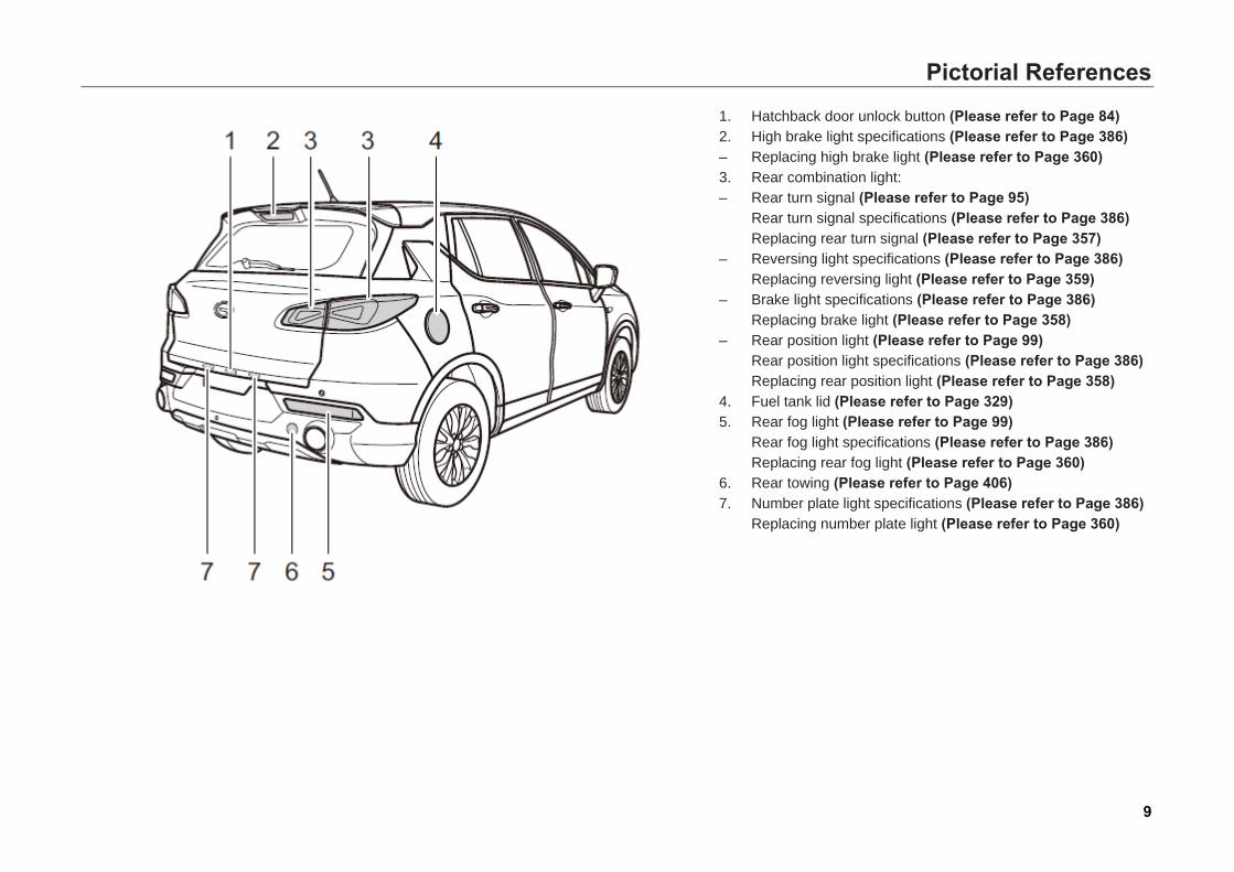
1. Hatchback door unlock button (Please refer to Page 84) 2. High brake light specifications (Please refer to Page 386) – Replacing high brake light (Please refer to Page 360) 3. Rear combination light: – Rear turn signal (Please refer to Page 95)
Rear turn signal specifications (Please refer to Page 386) Replacing rear turn signal (Please refer to Page 357)
– Reversing light specifications (Please refer to Page 386) Replacing reversing light (Please refer to Page 359)
– Brake light specifications (Please refer to Page 386) Replacing brake light (Please refer to Page 358)
– Rear position light (Please refer to Page 99) Rear position light specifications (Please refer to Page 386) Replacing rear position light (Please refer to Page 358)
4. Fuel tank lid (Please refer to Page 329) 5. Rear fog light (Please refer to Page 99)
Rear fog light specifications (Please refer to Page 386) Replacing rear fog light (Please refer to Page 360)
6. Rear towing (Please refer to Page 406) 7. Number plate light specifications (Please refer to Page 386)
Replacing number plate light (Please refer to Page 360)
Pictorial References
10
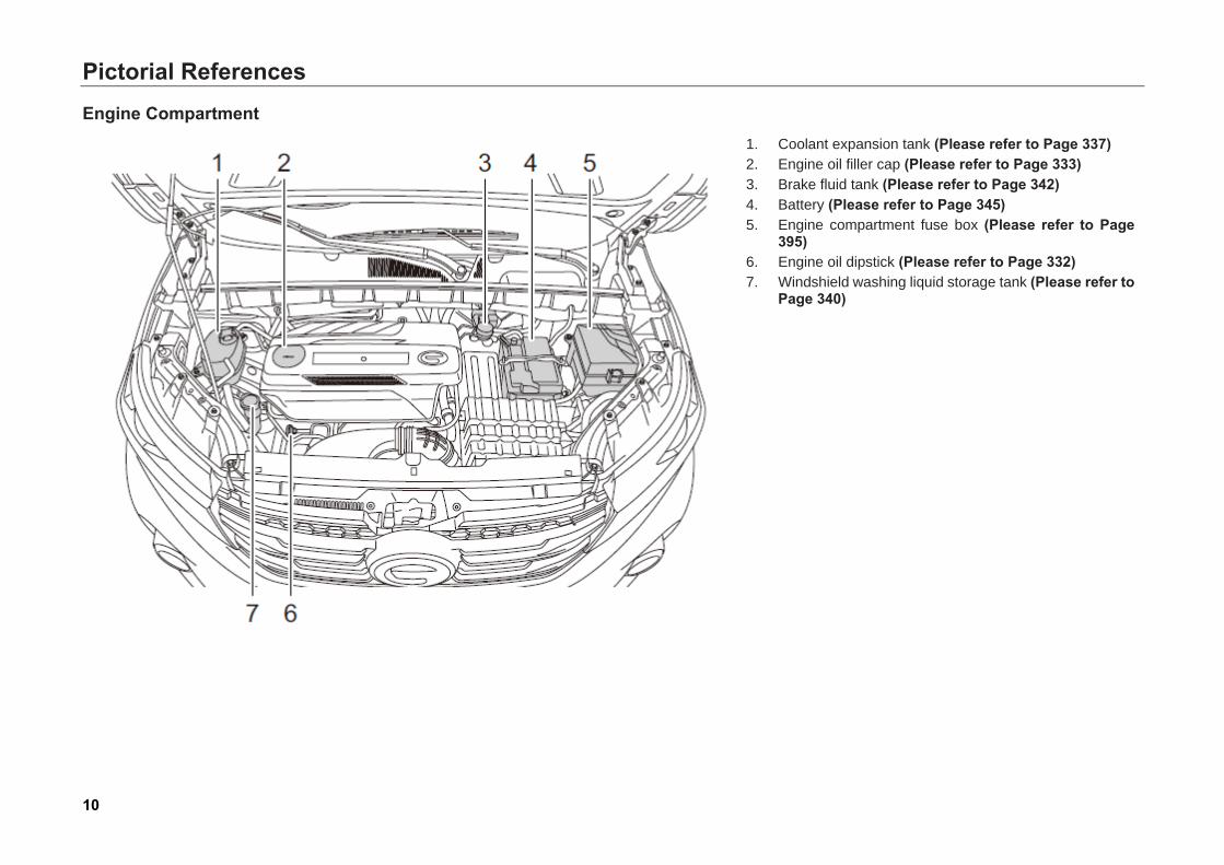
Engine Compartment
1. Coolant expansion tank (Please refer to Page 337) 2. Engine oil filler cap (Please refer to Page 333) 3. Brake fluid tank (Please refer to Page 342) 4. Battery (Please refer to Page 345) 5. Engine compartment fuse box (Please refer to Page
395) 6. Engine oil dipstick (Please refer to Page 332) 7. Windshield washing liquid storage tank (Please refer to
Page 340)
1. Safety Operating Instructions
11
1. Safety Operating Instructions
1.1 Safety Driving 1.1.1 General Instructions This section describes important information, operating essentials, recommendations and safety precautions for safety driving. For your safety and the safety of your passengers, please read it carefully and observe the relevant regulations.
Warning
Keep this User’s Manual in your car. Please make sure the Manual stays with the vehicle if you lend or sell it to the next owner. It is an integral part of the vehicle.
You should do the following inspections before driving your vehicle:
– Make sure that all car lights are under normal working condition.
– Ensure sufficient fuel level.
– Ensure sufficient coolant level.
– Ensure sufficient brake fluid level.
– Ensure sufficient windshield washer fluid level.
– Make sure that tire pressure is under normal condition.
– Make sure all windows are clean and unobstructed.
– Make sure that no items obstruct the pedal movement in the footwell.
– Adjust the seats, headrest and rear view mirrors according to height and body type.
– Make sure the child is protected with suitable child seat and properly worn the seat belt.
– Wear your seat belt correctly. Check that your passengers have fastened their seat belts.
Caution • Do not let yourself be distracted from
driving because of external factors. • Do not drive your vehicle when your
reaction capacity weakens. Medicines, alcohol, drugs and other will impair your reaction capacity.
• Follow the traffic laws and speed limits strictly.
1. Safety Operating Instructions
12
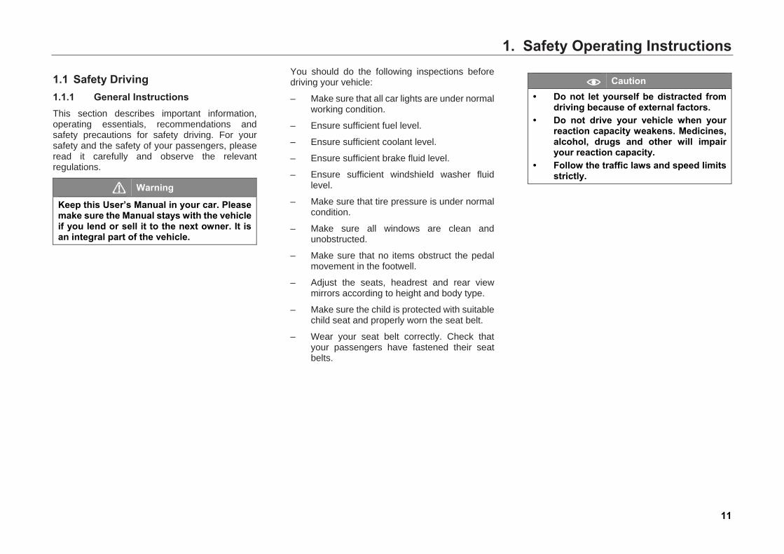
1.1.2 Correct Sitting Position of Passengers Correct Sitting Position of the Driver Correct driving position has a direct influence on driving safety and fatigue.
For the safety of yourself and the passengers, to reduce the risk of accidental injuries and deaths, the driver is recommended to do the following operation:
– Adjust the driver's seat forward or backward,
so that you can effectively operate all pedals with legs bent slightly.
– Adjust the seat backrest to proper position, so that your back can fully contact with the seat backrest.
– Adjust the headrest properly (Please refer to Page 112).
– Adjust steering wheel to ensure that the distance between steering wheel and your chest should not be less than 25cm.
– Wear seat belts properly (Please refer to Page 21).
Warning
• Adjusting the steering wheel until it faces your chest, which can effectively reduce the injury caused by an inflating frontal airbag.
• If your chest is too close to the steering wheel, you cannot get effective protection from airbags, and can be seriously injured by an inflating frontal airbag.
• Your hands should always hold the steering wheel outside edge (at the 9 o'clock and 3 o'clock positions) to ensure you can see all instruments and indicator lights on the instrument cluster.
• While driving, do not recline the backrest too far. Wear the seat belt correctly and keep correct sitting position to avoid injury caused by emergency braking.

1. Safety Operating Instructions
13
Correct Sitting Position of Front Seat Passenger To ensure the safety of front seat passenger and reduce the risk of accidental injury and death, front seat passenger should do the following operations:
– The front seat passenger should adjust the seat as far as possible, leave suitable distance between his/her chest and the instrument panel, so as to get the most safety protection when airbag is triggered.
– Adjust the headrest properly (Please refer to Page 112).
– Adjust the seat backrest to proper position, so that your back can fully contact with the seat backrest.
– Wear seat belts properly (Please refer to Page 21).
– Keep feet in the footwell in front of the front seat.
Warning
• If the front passenger sits too close to the instrument panel, he/she cannot get effective protection from airbags.
• While driving, do not allow the front seat passenger to put his/her feet on the instrument panel, outside the window or on the seat. But always keep his/her feet in the footwell. Otherwise, he/she can be injured easily during emergency braking or in a crash.
• While driving, do not recline the backrest too far. Wear the seat belt correctly and keep correct sitting position to avoid injury caused by emergency braking.
Correct Sitting Position of Rear Seat Passengers To ensure the safety of rear seat passengers and reduce the risk of accidental injuries and deaths, rear seat passengers should do the following matters:
– Adjust the headrest properly (Please refer to Page 112).
– Sit upright and make sure the back contacts with seat back as much as possible.
– Keep feet in the footwell in front of the rear seat.
– Wear seat belts properly (Please refer to Page 21).
– Whenever an infant or child rides in your car, take appropriate measures in accordance with the relevant provisions, e.g., using a suitable child seat to restrain the infant or child (Please refer to Page 37).
Warning
Sitting improperly or wearing the seat belts improperly can increase the chance of injury during an accident.

1. Safety Operating Instructions
14
1.1.3 Pedal Area Pedal for Models with Automatic Transmission
1. Brake pedal
2. Accelerator pedal
Pedal for Models with Manual Transmission
1. Clutch pedal
2. Brake pedal
3. Accelerator pedal
– Before driving, make sure all the pedals can be depressed to their extreme position all the way.
– Make sure all the pedals can return to the original position without obstruction.
When there is a fault in the brake circuit, the brake pedal needs a larger travel to stop the vehicle.
Warning
The pedal being obstructed may cause serious accidents and even damage to people. • Do not place anything in the driver's
footwell. Otherwise, the objects may slide into pedal area and hinder the driver's operation to the pedals. When there is an emergency brake or urgent cases occur, the driver can't operate the pedals, which may cause accidents.
1. Safety Operating Instructions
15
Wear Proper Shoes The driver must wear a pair of fit shoes to feel the pedal movement sensitively.
Foot Mat on the Driver’s Side The foot mat should be fixed in the footwell, and cannot interfere with the pedal movement.
Warning
• Make sure the foot mat is fixed in the driver’s footwell securely.
• Do not lay other mat or covering on the foot mat installed in place. Doing so can shrink the pedal travel, hindering the pedal movement.
• After cleaning the foot mat removed from the vehicle, be sure to re-fix it during re-installation.
1. Safety Operating Instructions
16
1.2 Seat Belt System 1.2.1 General Instructions
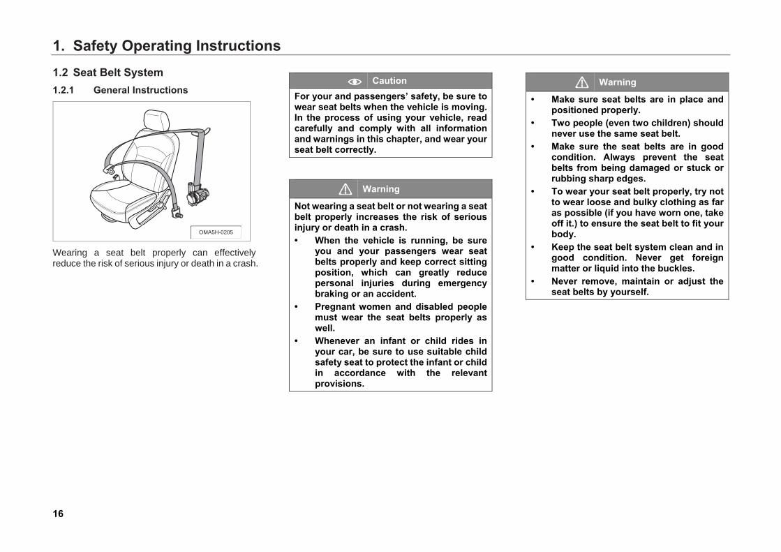
Wearing a seat belt properly can effectively reduce the risk of serious injury or death in a crash.
Caution For your and passengers’ safety, be sure to wear seat belts when the vehicle is moving. In the process of using your vehicle, read carefully and comply with all information and warnings in this chapter, and wear your seat belt correctly.
Warning
Not wearing a seat belt or not wearing a seat belt properly increases the risk of serious injury or death in a crash. • When the vehicle is running, be sure
you and your passengers wear seatbelts properly and keep correct sittingposition, which can greatly reducepersonal injuries during emergencybraking or an accident.
• Pregnant women and disabled peoplemust wear the seat belts properly aswell.
• Whenever an infant or child rides inyour car, be sure to use suitable childsafety seat to protect the infant or childin accordance with the relevantprovisions.
Warning
• Make sure seat belts are in place andpositioned properly.
• Two people (even two children) shouldnever use the same seat belt.
• Make sure the seat belts are in goodcondition. Always prevent the seatbelts from being damaged or stuck orrubbing sharp edges.
• To wear your seat belt properly, try notto wear loose and bulky clothing as faras possible (if you have worn one, takeoff it.) to ensure the seat belt to fit yourbody.
• Keep the seat belt system clean and ingood condition. Never get foreignmatter or liquid into the buckles.
• Never remove, maintain or adjust theseat belts by yourself.
OMA5H-0205
1. Safety Operating Instructions
17
Seat Belt System Components Seat belt system in the vehicle consists of three-point seat belts and seat belt indicator light on the instrument cluster (all the seats).
Seat Belt Indicator Light
Driver seat belt indicator light ( )
If the driver has not fastened the seat belt with the Start switch or ignition switch at “ON” position, the driver seat belt indicator light on the instrument cluster illuminates and the audible alarm (“Please fasten your seat-belt”) appears to remind the driver to wear the seat belt.
Front passenger seat belt indicator light ( )
If the front passenger has not fastened the seat belt with the Start switch or ignition switch at “ON” position, the indicator light on the instrument cluster illuminates and the audible alarm (“Please fasten your seat-belt”) appears to remind the front passenger to wear the seat belt.
Caution Before starting driving, check the front seat and make sure there is no heavy on the seat to prevent the system from mistaking that there is occupant on it and giving a false alarm.
When the Start switch or ignition switch is at "ON" position and the speed is less than 20km/h, if the driver or front passenger does not fasten his/her seat belt, the corresponding indicator light on the instrument cluster will flash about 6 seconds and then stay on.
Caution When the seat belt device fails, the indicator light will also flash about 6s and then stay on. In this case, please go to the authorized GAC MOTOR dealer timely to have your vehicle checked and repaired.
When the Start switch or ignition switch is at "ON" position and the speed is not lower than 20km/h, if the driver or the front passenger does not fasten the seat belt, the corresponding indicator light on the instrument cluster will flash about 20 seconds and then stay on, and the beeper also sounds until the seal belt is fastened.
Caution When the seat belt device fails, the indicator light will also flash about 20 seconds and then stay on, and the beeper also sounds. In this case, please go to the authorized GAC MOTOR dealer timely to have your vehicle checked and repaired.
1. Safety Operating Instructions
18
Seat Belt Pretensioner Equipment
The configuration of seat belt pretensioner equipment may vary with different vehicle models.
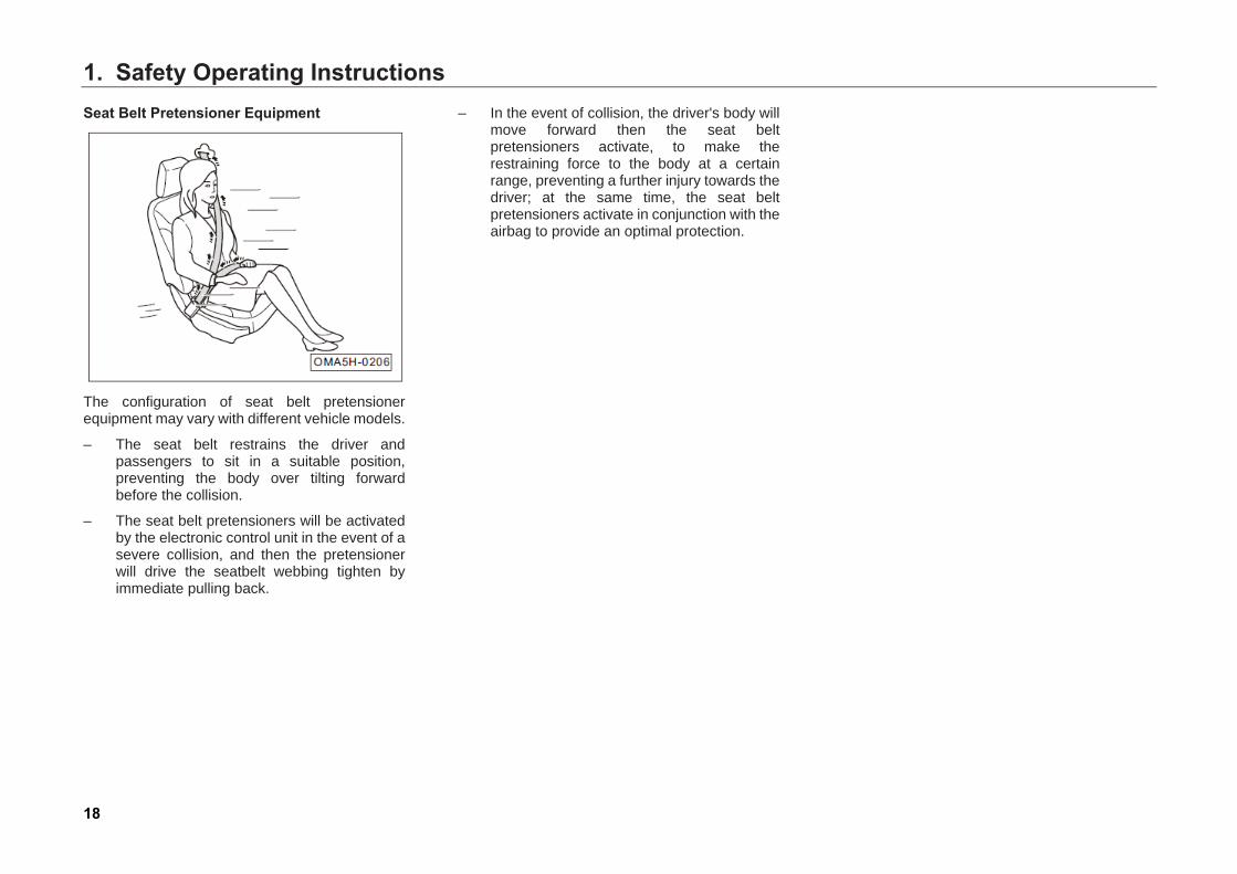
– The seat belt restrains the driver and passengers to sit in a suitable position, preventing the body over tilting forward before the collision.
– The seat belt pretensioners will be activated by the electronic control unit in the event of a severe collision, and then the pretensioner will drive the seatbelt webbing tighten by immediate pulling back.
– In the event of collision, the driver's body will move forward then the seat belt pretensioners activate, to make the restraining force to the body at a certain range, preventing a further injury towards the driver; at the same time, the seat belt pretensioners activate in conjunction with the airbag to provide an optimal protection.
1. Safety Operating Instructions
19
1.2.2 Why Wear Seat Belts Protection from Seat belts In case of crash, correctly wearing seat belts can restrict the driver and passengers at proper positions, reducing inertia of forward motion, to prevent loss of control of motion and being ejected out of the vehicle, and minimize injury due to impact.
The seat belts can absorb most of the kinetic energy resulting from a collision. In addition, the crumple zones and other passive safety systems can absorb the energy at the same time to reduce the risk of injury further together with the seat belts.
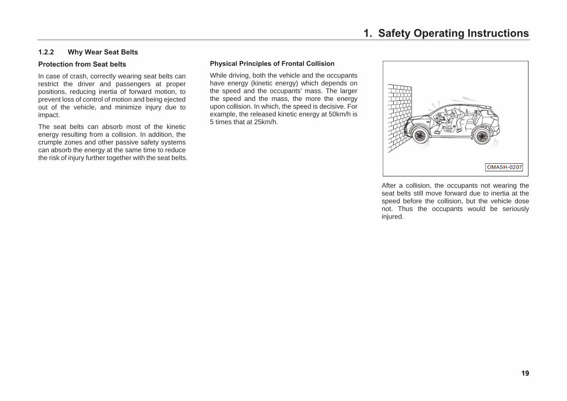
Physical Principles of Frontal Collision While driving, both the vehicle and the occupants have energy (kinetic energy) which depends on the speed and the occupants' mass. The larger the speed and the mass, the more the energy upon collision. In which, the speed is decisive. For example, the released kinetic energy at 50km/h is 5 times that at 25km/h.
After a collision, the occupants not wearing the seat belts still move forward due to inertia at the speed before the collision, but the vehicle dose not. Thus the occupants would be seriously injured.
1. Safety Operating Instructions
20
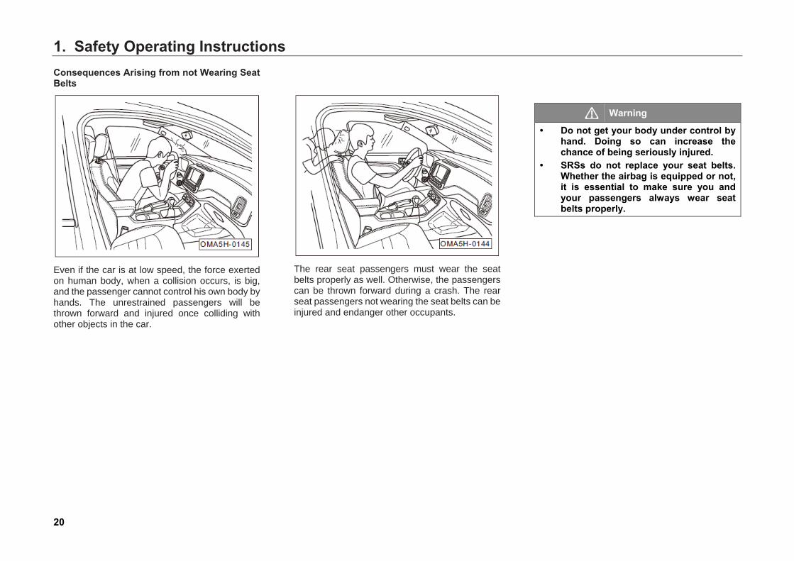
Consequences Arising from not Wearing Seat Belts
Even if the car is at low speed, the force exerted on human body, when a collision occurs, is big, and the passenger cannot control his own body by hands. The unrestrained passengers will be thrown forward and injured once colliding with other objects in the car.
The rear seat passengers must wear the seat belts properly as well. Otherwise, the passengers can be thrown forward during a crash. The rear seat passengers not wearing the seat belts can be injured and endanger other occupants.
Warning
• Do not get your body under control by hand. Doing so can increase the chance of being seriously injured.
• SRSs do not replace your seat belts. Whether the airbag is equipped or not, it is essential to make sure you and your passengers always wear seat belts properly.
1. Safety Operating Instructions
21
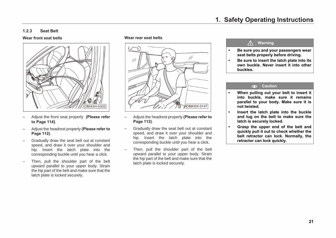
1.2.3 Seat Belt Wear front seat belts
– Adjust the front seat properly (Please referto Page 114).
– Adjust the headrest properly (Please refer toPage 112).
– Gradually draw the seat belt out at constantspeed, and draw it over your shoulder andhip. Insert the latch plate into thecorresponding buckle until you hear a click.
– Then, pull the shoulder part of the beltupward parallel to your upper body. Strainthe hip part of the belt and make sure that thelatch plate is locked securely.
Wear rear seat belts
– Adjust the headrest properly (Please refer toPage 112).
– Gradually draw the seat belt out at constantspeed, and draw it over your shoulder andhip. Insert the latch plate into thecorresponding buckle until you hear a click.
– Then, pull the shoulder part of the beltupward parallel to your upper body. Strainthe hip part of the belt and make sure that thelatch plate is locked securely.
Warning
• Be sure you and your passengers wearseat belts properly before driving.
• Be sure to insert the latch plate into itsown buckle. Never insert it into otherbuckles.
Caution • When pulling out your belt to insert it
into buckle, make sure it remainsparallel to your body. Make sure it isnot twisted.
• Insert the latch plate into the buckleand tug on the belt to make sure thelatch is securely locked.
• Grasp the upper end of the belt andquickly pull it out to check whether thebelt retractor can lock. Normally, theretractor can lock quickly.
1. Safety Operating Instructions
22
Warning
The seat belt not fastened properly cannot provide good protection during a crash, resulting in serious personal injury. • To let the seat belt play a full role, make
sure the seat back is upright and the occupant sits well back in the seat and wears the seat belt properly.
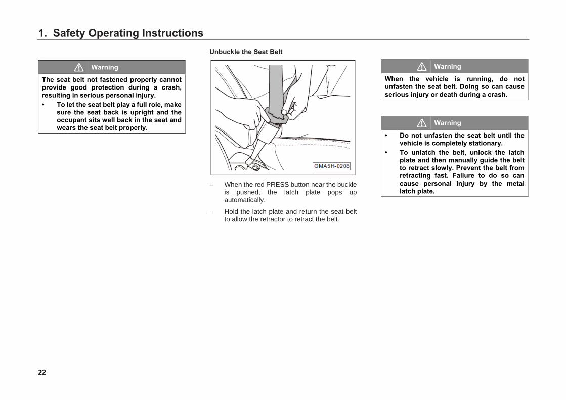
Unbuckle the Seat Belt
– When the red PRESS button near the buckle
is pushed, the latch plate pops up automatically.
– Hold the latch plate and return the seat belt to allow the retractor to retract the belt.
Warning
When the vehicle is running, do not unfasten the seat belt. Doing so can cause serious injury or death during a crash.
Warning
• Do not unfasten the seat belt until the vehicle is completely stationary.
• To unlatch the belt, unlock the latch plate and then manually guide the belt to retract slowly. Prevent the belt from retracting fast. Failure to do so can cause personal injury by the metal latch plate.
1. Safety Operating Instructions
23
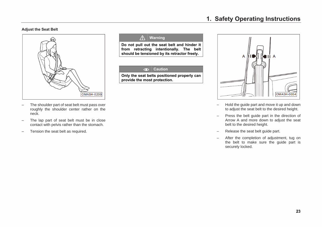
Adjust the Seat Belt
– The shoulder part of seat belt must pass over
roughly the shoulder center rather on the neck.
– The lap part of seat belt must be in close contact with pelvis rather than the stomach.
– Tension the seat belt as required.
Warning
Do not pull out the seat belt and hinder it from retracting intentionally. The belt should be tensioned by its retractor freely.
Caution Only the seat belts positioned properly can provide the most protection.
– Hold the guide part and move it up and down
to adjust the seat belt to the desired height.
– Press the belt guide part in the direction of Arrow A and more down to adjust the seat belt to the desired height.
– Release the seat belt guide part.
– After the completion of adjustment, tug on the belt to make sure the guide part is securely locked.
1. Safety Operating Instructions
24
Warning
• Make sure the shoulder part of the seat belt rests across the center of your shoulder. Do not let the seat belt cross your neck.
• Make sure the seat belt is flat and fits over your upper body.
• Make sure the waist part of the belt goes across your pelvic bones tightly without twisting.
• The belt cannot be too loose.
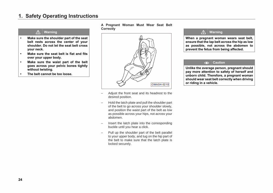
A Pregnant Woman Must Wear Seat Belt Correctly
– Adjust the front seat and its headrest to the
desired position.
– Hold the latch plate and pull the shoulder part of the belt to go across your shoulder slowly, and position the waist part of the belt as low as possible across your hips, not across your abdomen.
– Insert the latch plate into the corresponding buckle until you hear a click.
– Pull up the shoulder part of the belt parallel to your upper body, and tug on the hip part of the belt to make sure that the latch plate is locked securely.
Warning
When a pregnant woman wears seat belt, ensure that the lap belt across the hip as low as possible, not across the abdomen to prevent the fetus from being affected.
Caution Unlike the average person, pregnant should pay more attention to safety of herself and unborn child. Therefore, a pregnant woman should wear seat belt correctly when driving or riding in a vehicle.
1. Safety Operating Instructions
25
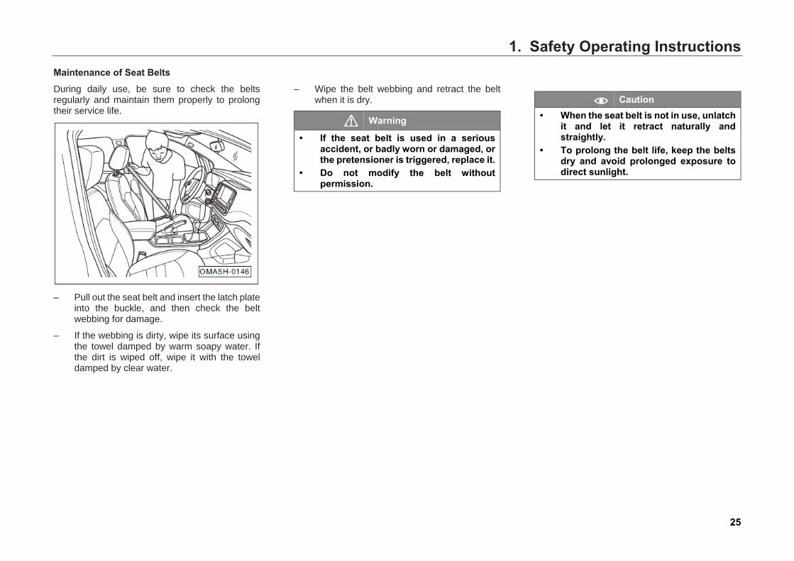
Maintenance of Seat Belts During daily use, be sure to check the belts regularly and maintain them properly to prolong their service life.
– Pull out the seat belt and insert the latch plate
into the buckle, and then check the belt webbing for damage.
– If the webbing is dirty, wipe its surface using the towel damped by warm soapy water. If the dirt is wiped off, wipe it with the towel damped by clear water.
– Wipe the belt webbing and retract the belt when it is dry.
Warning
• If the seat belt is used in a serious accident, or badly worn or damaged, or the pretensioner is triggered, replace it.
• Do not modify the belt without permission.
Caution • When the seat belt is not in use, unlatch
it and let it retract naturally and straightly.
• To prolong the belt life, keep the belts dry and avoid prolonged exposure to direct sunlight.
1. Safety Operating Instructions
26
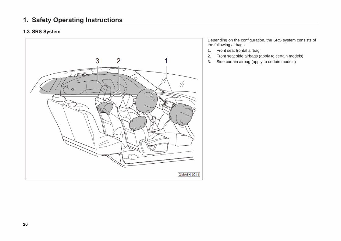
1.3 SRS System Depending on the configuration, the SRS system consists of the following airbags: 1. Front seat frontal airbag 2. Front seat side airbags (apply to certain models) 3. Side curtain airbag (apply to certain models)
1. Safety Operating Instructions
27
1.3.1 General Instructions To allow the triggered SRS system to play a full role in protection, before starting driving, the driver and passengers should wear the seat belts properly, adjust the seat and the steering wheel properly, adjust the headrests properly and restrain the child in the vehicle in a suitable child seat.
Warning
Not wearing a seat belt properly or wrong sitting position can cause serious injury or even death during a crash. • Before starting driving, make sure you
and your passengers wear seat belts properly and sit in correct position.
• While driving, do not let other occupant (child), pet or object occupy the space between the front seat passenger and the frontal airbag. Do not put anything on or attach anything to the steering wheel and instrument panel surfaces.
Caution The airbags do not replace your seat belts. Seat belt must be fastened all the time during traveling.
Hint
When the airbags inflate, you may see what looks like smoke. This is a normal phenomenon. Do not worry about it.
Function of SRSs When the vehicle has a serious collision with barriers and the trigger condition is reached, the airbag will quickly open an air pad filled with air, to buffer impact force when occupants move forward due to inertia and absorb impact energy, reducing injury degree of occupants.
When the vehicle has a serious collision and the trigger condition is reached, the airbag inflates at a high speed shortly. Therefore, the driver shall keep an appropriate sitting position, the front driver passenger and frontal airbag should be kept at a further distance to protect them effectively and avoid a severe injury when airbag activated and inflated.
If the vehicle had a serious collision, occupants unfastened seat belt may be thrown away to airbag inflation area, the inflating airbag may cause serious injuries and deaths of occupants, especially the children.

1. Safety Operating Instructions
28
Factors of SRS Inflating Whether the airbags inflate or not depends on the collision energy during a collision. If the control unit detects that the collision energy is less than the ignition requirement of control unit when a collision occurs, the system won’t trigger airbag. Therefore, even serious damage of the vehicle can't indicate that the airbag should be triggered.
Caution During a collision, whether the airbags inflate or not depends on the collision energy. This relates to the accident type, impact angle, barrier and speed.
Maintenance and Scrapping of SRSs Any operation on the SRS system and removal and installation of the SRS system components for repairing other vehicle parts must be carried out by an authorized GAC MOTOR dealer. Failure to do so may cause damage to the SRS system components. As a result, during a crash, the airbags may be triggered abnormally or not be triggered.
When scrapping an entire vehicle or its airbag components, be sure to follow the relevant safety regulations, and get consulting service from a GAC MOTOR dealer.
Warning
• Do not repair, adjust or modify any components of the airbags by yourself without authorization.
• An airbag inflates only once. If the airbag ever inflates during a crash, it must be replaced by a GAC MOTOR dealer.
• If the SRS system fails, go to your authorized GAC MOTOR dealer immediately to have the system checked/repaired. Otherwise, the control unit system may not trigger the airbags or trigger the airbags abnormally during a collision.
1. Safety Operating Instructions
29
SRS System Components The SRS system mainly consists of three parts:
• Electric control and monitoring device.
• SRSs with gas generator.
• Indicator lights in the instrument cluster ( )(Please refer to Page 65).
The airbag is monitored by electric monitoring system located in airbag control unit. Switch the Start switch or ignition switch to the "ON" position, the indicator light illuminates for a few seconds then extinguishes after self-checking.
The SRS indicator light indicates a fault developing in the system in one of the following conditions:
1. After the Start switch or ignition switch isswitched to "ON" position, the indicator lightdoes not illuminate.
2. After the Start switch or ignition switch isswitched to "ON" position, the indicator lightstays illuminated.
3. After the Start switch or ignition switch isswitched to "ON" position, the indicator lightilluminates again after turning off.
4. When the vehicle is running, the indicatorlight illuminates or flashes.
1. Safety Operating Instructions
30
1.3.2 Front Seat Frontal SRS
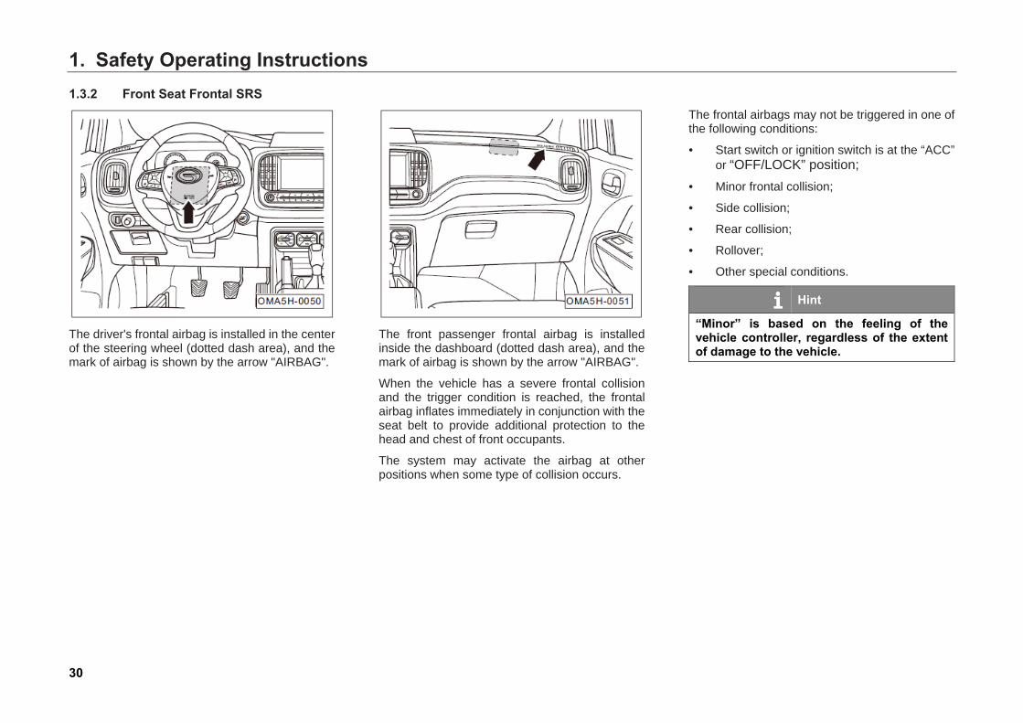
The driver's frontal airbag is installed in the center of the steering wheel (dotted dash area), and the mark of airbag is shown by the arrow "AIRBAG".
The front passenger frontal airbag is installed inside the dashboard (dotted dash area), and the mark of airbag is shown by the arrow "AIRBAG".
When the vehicle has a severe frontal collision and the trigger condition is reached, the frontal airbag inflates immediately in conjunction with the seat belt to provide additional protection to the head and chest of front occupants.
The system may activate the airbag at other positions when some type of collision occurs.
The frontal airbags may not be triggered in one of the following conditions:
• Start switch or ignition switch is at the “ACC” or “OFF/LOCK” position;
• Minor frontal collision;
• Side collision;
• Rear collision;
• Rollover;
• Other special conditions.
Hint
“Minor” is based on the feeling of the vehicle controller, regardless of the extent of damage to the vehicle.

1. Safety Operating Instructions
31
1.3.3 Front Seat Side SRSs (Apply to Certain Models)
The front side airbag is installed inside the driver’s seat and front passenger's seat back against the door (dotted dash area), the mark of the airbag is shown by the arrow "AIRBAG".
When the vehicle has a severe side collision and the trigger condition is reached, the side airbag inflates immediately in conjunction with the seat belt to provide additional protection to the upper body of front occupants.
The system may activate the airbag at other positions when some type of collision occurs.
Warning
Never for the outer seat use the covering that could impede deployment of the side airbag.
The side airbags may not be triggered in one of the following conditions:
• Start switch or ignition switch is at the “ACC” or “OFF/LOCK” position;
• Frontal collision;
• Minor side collision;
• Rear collision;
• Other special conditions.
Hint
“Minor” is based on the feeling of the vehicle controller, regardless of the extent of damage to the vehicle.
Warning
Please notice the warnings on the door side. Do not lean on the door side, where installed with side airbag during driving.
1. Safety Operating Instructions
32
1.3.4 Side Curtain SRS (Apply to Certain Models)
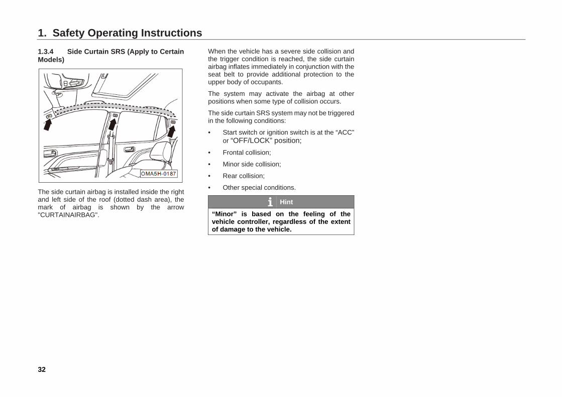
The side curtain airbag is installed inside the right and left side of the roof (dotted dash area), the mark of airbag is shown by the arrow "CURTAINAIRBAG".
When the vehicle has a severe side collision and the trigger condition is reached, the side curtain airbag inflates immediately in conjunction with the seat belt to provide additional protection to the upper body of occupants.
The system may activate the airbag at other positions when some type of collision occurs.
The side curtain SRS system may not be triggered in the following conditions:
• Start switch or ignition switch is at the “ACC” or “OFF/LOCK” position;
• Frontal collision;
• Minor side collision;
• Rear collision;
• Other special conditions.
Hint
“Minor” is based on the feeling of the vehicle controller, regardless of the extent of damage to the vehicle.
1. Safety Operating Instructions
33
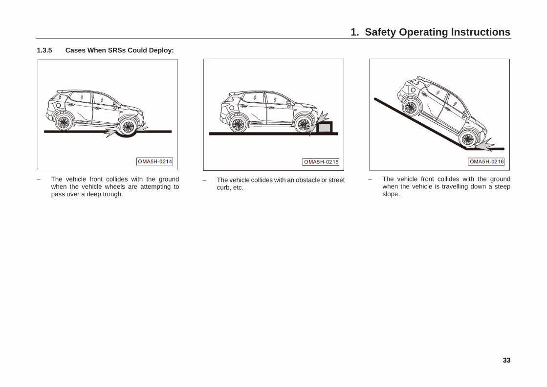
1.3.5 Cases When SRSs Could Deploy:
– The vehicle front collides with the ground
when the vehicle wheels are attempting to pass over a deep trough.
– The vehicle collides with an obstacle or street
curb, etc.
– The vehicle front collides with the ground
when the vehicle is travelling down a steep slope.
1. Safety Operating Instructions
34
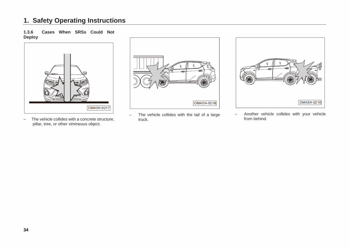
1.3.6 Cases When SRSs Could Not Deploy
– The vehicle collides with a concrete structure,
pillar, tree, or other vimineous object.
– The vehicle collides with the tail of a large
truck.
– Another vehicle collides with your vehicle
from behind.

1. Safety Operating Instructions
35
– The vehicle laterally rolls over.
– The corner of the vehicle collides with the
wall or another vehicle.
1. Safety Operating Instructions
36
1.4 Safety Rules for Children 1.4.1 General Instructions For children under 12 years, appropriate child safety seats or child seat belts shall be selected according to their heights and weights.
To properly wear a seat belt through a child seat, follow the seat manufacturer’s instructions. Keep the child seat instructions together with the vehicle documents in your car so you can refer to it at any time.
Warning
• Don’t install child seat with its back toward driving direction on the front passenger’s seat. Or it can result in serious injury or death during a crash. Children must be placed on the second- row seats.
• Proper wear of a seat belt can let it play its protective role fully.
• Never hold a baby or child on your lap when riding in a car. Otherwise, the baby or child could be seriously hurt or killed when accident happens.
• Only a child seat of right size can provide effective protection to the child.
• Do not leave children alone in a car. Because of huge climate difference from place to place, the in-car temperature may become extremely low or high. A child left alone in a car could be hurt fatally.
• Without a child safety seat, do not let a child with a height below 1.5m use the preinstalled seat belt in the car. Doing so can cause the child’s abdomen or neck be injured during emergency braking or in a crash.
• Never let two children use the same child seat.
• Be sure to read and follow the child seat manufacturer’s instructions and precautions.
• Follow the relevant laws and regulations to install and use a child seat. The national laws and regulations shall prevail.
1. Safety Operating Instructions
37
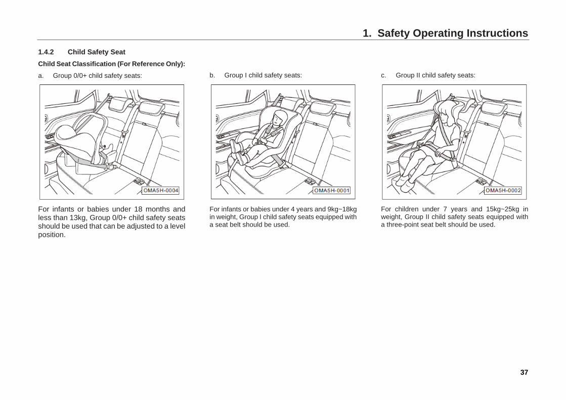
1.4.2 Child Safety Seat Child Seat Classification (For Reference Only): a. Group 0/0+ child safety seats:
For infants or babies under 18 months and less than 13kg, Group 0/0+ child safety seats should be used that can be adjusted to a level position.
b. Group I child safety seats:
For infants or babies under 4 years and 9kg~18kg in weight, Group I child safety seats equipped with a seat belt should be used.
c. Group II child safety seats:
For children under 7 years and 15kg~25kg in weight, Group II child safety seats equipped with a three-point seat belt should be used.

1. Safety Operating Instructions
38
d. Group III child safety seats:
For children above 7 years, 22kg~36kg in weight and less than 1.50m, Group III child safety seats equipped with a three-point seat belt should be used.
Applicability of different riding positions to child restraint system:
Mass group Position to fix the system
Front passenger seat Second-row seats on both sides
Second-row central seat
Group 0: <10kg X U X
Group 0+: <13kg X U X
Group I: 9~18kg X U/UF X
Group ll:15~25kg X UF X
Group III: 22~36kg X UF X
Note: Meanings of the letters in the table: U= Permitting use of type “General” of child safety seats in this mass group UF= Permitting use of type “General” of front-facing child safety seats in this mass group X= Not applicable for use of child safety seats
Dimension ranges may be specified for some child safety seats. Find the dimension range from the manufacturer's instructions, packaging, or child safety seats. For how to correctly install the child safety seats, refer to their use instructions.
1. Safety Operating Instructions
39
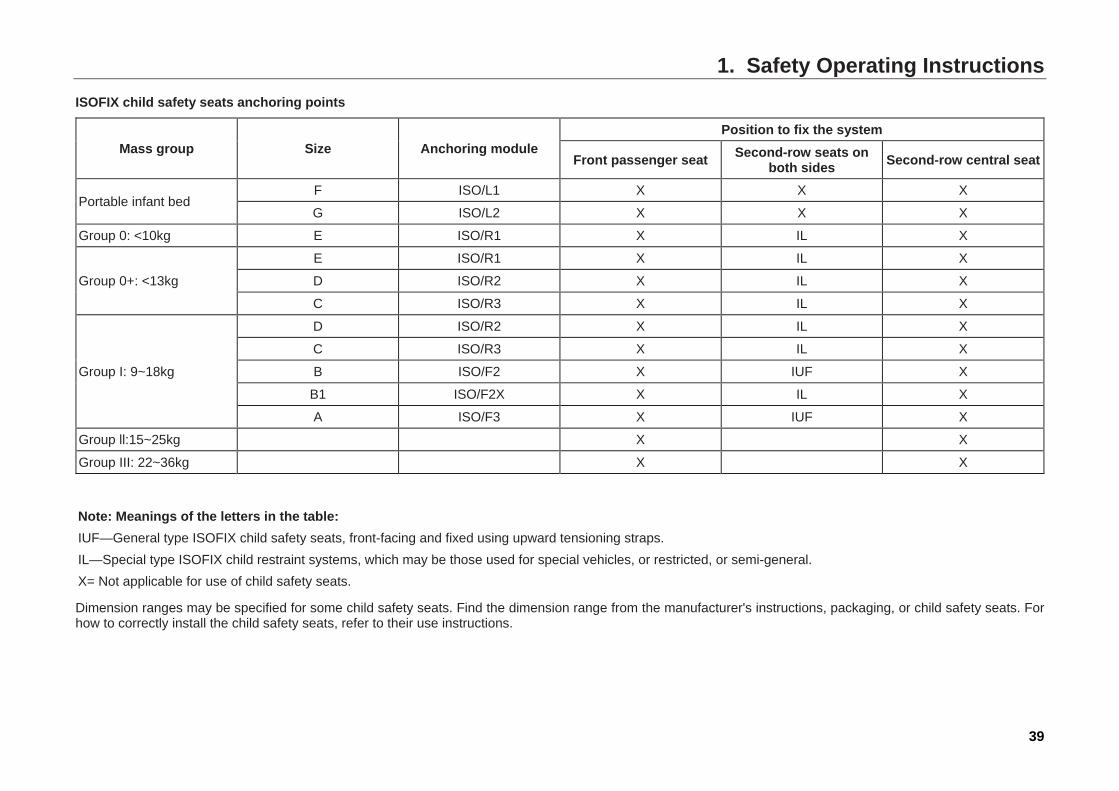
ISOFIX child safety seats anchoring points
Mass group Size Anchoring module Position to fix the system
Front passenger seat Second-row seats on both sides Second-row central seat
Portable infant bed F ISO/L1 X X X
G ISO/L2 X X X
Group 0: <10kg E ISO/R1 X IL X
Group 0+: <13kg
E ISO/R1 X IL X
D ISO/R2 X IL X
C ISO/R3 X IL X
Group I: 9~18kg
D ISO/R2 X IL X
C ISO/R3 X IL X
B ISO/F2 X IUF X
B1 ISO/F2X X IL X
A ISO/F3 X IUF X
Group ll:15~25kg X X
Group III: 22~36kg X X
Note: Meanings of the letters in the table: IUF—General type ISOFIX child safety seats, front-facing and fixed using upward tensioning straps. IL—Special type ISOFIX child restraint systems, which may be those used for special vehicles, or restricted, or semi-general. X= Not applicable for use of child safety seats.
Dimension ranges may be specified for some child safety seats. Find the dimension range from the manufacturer's instructions, packaging, or child safety seats. For how to correctly install the child safety seats, refer to their use instructions.
1. Safety Operating Instructions
40
1.4.3 Install a Child Seat Properly Before installing the child safety seat in the second row, adjust the front seat to the desired position according to the child seat size and the child’s body type. This will help keep the child restrained in the second row from striking the interior sharp objects of the car during a crash or emergency braking. Moreover, this will also prevent the child from being injured due to the airbags inflating. Never hold an infant or child on your lap!
Child seat generally has three types of installations, i.e. three-point seat belt, ISOFIX system, and LATCH system. The installation of three-point seat belt is that using its own seat belts to tighten the child seat, as shown in the figure "Child Seat Classifications". Installation of ISOFIX and LATCH system is that using the child seat fixing device to fasten and lock with the remaining anchor points in the car.
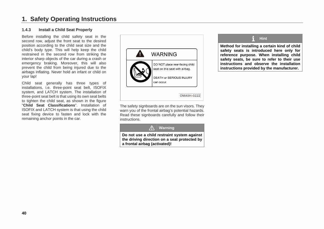
The safety signboards are on the sun visors. They warn you of the frontal airbag’s potential hazards. Read these signboards carefully and follow their instructions.
Warning
Do not use a child restraint system against the driving direction on a seat protected by a frontal airbag (activated)!
Hint
Method for installing a certain kind of child safety seats is introduced here only for reference purpose. When installing child safety seats, be sure to refer to their use instructions and observe the installation instructions provided by the manufacturer.
1. Safety Operating Instructions
41
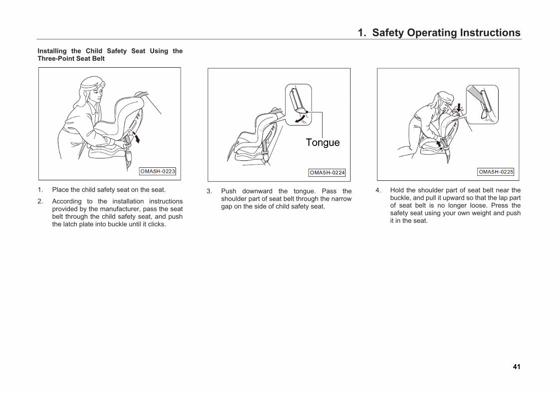
Installing the Child Safety Seat Using the Three-Point Seat Belt
1. Place the child safety seat on the seat.
2. According to the installation instructions provided by the manufacturer, pass the seat belt through the child safety seat, and push the latch plate into buckle until it clicks.
3. Push downward the tongue. Pass the
shoulder part of seat belt through the narrow gap on the side of child safety seat.
4. Hold the shoulder part of seat belt near the
buckle, and pull it upward so that the lap part of seat belt is no longer loose. Press the safety seat using your own weight and push it in the seat.
1. Safety Operating Instructions
42
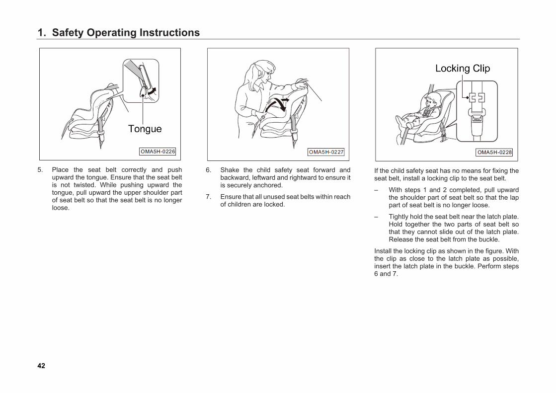
5. Place the seat belt correctly and pushupward the tongue. Ensure that the seat beltis not twisted. While pushing upward thetongue, pull upward the upper shoulder partof seat belt so that the seat belt is no longerloose.
6. Shake the child safety seat forward andbackward, leftward and rightward to ensure itis securely anchored.
7. Ensure that all unused seat belts within reachof children are locked.
If the child safety seat has no means for fixing the seat belt, install a locking clip to the seat belt.
– With steps 1 and 2 completed, pull upwardthe shoulder part of seat belt so that the lappart of seat belt is no longer loose.
– Tightly hold the seat belt near the latch plate.Hold together the two parts of seat belt sothat they cannot slide out of the latch plate.Release the seat belt from the buckle.
Install the locking clip as shown in the figure. With the clip as close to the latch plate as possible, insert the latch plate in the buckle. Perform steps 6 and 7.

1. Safety Operating Instructions
43
Installing the ISOFIX system or LATCH system The installing methods for both ISOFIX system and LATCH system are similar, LATCH system has one more anchor point than ISOFIX system, but the lower anchor point for both systems can be interchangeable. The two sides of seats in second row for this car are equipped with LATCH system. Therefore, both LATCH and ISOFIX system child seat can be installed.
Warning
When driving, be sure to restrain the child in the child seat suitable for the child's weight and body type. • The anchoring device for child seat of
this car can only be used to fix the child seat.
• Do not connect any other things like fastening belt, hard or sharp objects or other things other than child seat items to the anchoring device, and otherwise, it may endanger the child’s life when accident occurs.
Hint
Front anchor points (1) at both sides of the rear seats are hidden inside the gaps between the backrest and cushion, you may see it by breaking off with hands.
Hint
Rear anchor points (2) at both sides of the rear seats are hidden inside the gaps between the backrest and cushion, you may see it by breaking off with hands.
1. Safety Operating Instructions
44
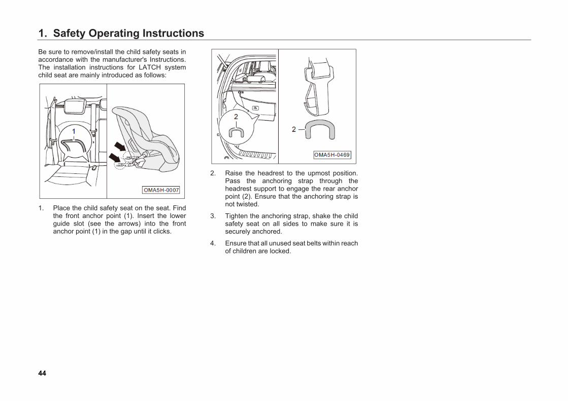
Be sure to remove/install the child safety seats in accordance with the manufacturer's Instructions. The installation instructions for LATCH system child seat are mainly introduced as follows:
1. Place the child safety seat on the seat. Find
the front anchor point (1). Insert the lower guide slot (see the arrows) into the front anchor point (1) in the gap until it clicks.
2. Raise the headrest to the upmost position.
Pass the anchoring strap through the headrest support to engage the rear anchor point (2). Ensure that the anchoring strap is not twisted.
3. Tighten the anchoring strap, shake the child safety seat on all sides to make sure it is securely anchored.
4. Ensure that all unused seat belts within reach of children are locked.

1. Safety Operating Instructions
45
1.5 Dangerous Exhaust Gases Carbon Monoxide Exhaust gases from the engine of this car contains carbon monoxide, a colorless odorless very toxic gas. As long as you can correctly maintain and use the car, carbon monoxide will not enter the interior of car.
In the following cases, the exhaust system must be checked for leakage:
– Abnormal noise coming out of exhaustsystem
– Abnormal color of exhaust gases coming outof exhaust system
Driving with the trunk open can cause exhaust gases entering the car resulting in danger. If you have to drive with the trunk open, open all windows and turn on the air conditioning system.
1. Select the external air circulation mode.
2. Select the mode.
3. Set the fan speed to maximum.
If you sit in the car with the engine running, operate the air conditioning system in the same manner.
Warning
• Carbon monoxide is very toxic.Inhaling it can causeunconsciousness, even death.
• Do not run the engine in confinedareas, which will result in high contentof carbon monoxide inside the car.
• Running the engine in confined areas (such as garage) can cause rapid buildup of carbon monoxide Never start the engine with the garage door closed. Even if the garage door is open, drive away immediately.
1. Safety Operating Instructions
46
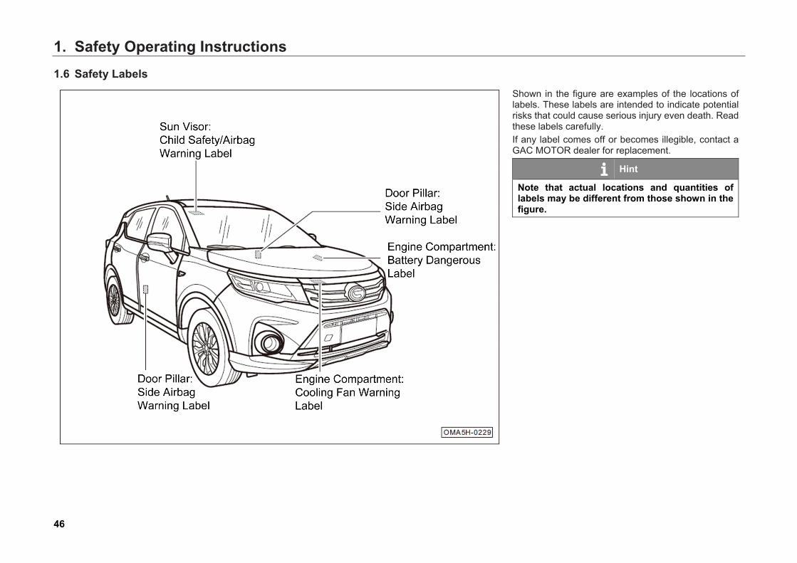
1.6 Safety Labels Shown in the figure are examples of the locations of labels. These labels are intended to indicate potential risks that could cause serious injury even death. Read these labels carefully. If any label comes off or becomes illegible, contact a GAC MOTOR dealer for replacement.
Hint
Note that actual locations and quantities of labels may be different from those shown in the figure.
2. Operating System and Equipment
47
2. Operating System and Equipment
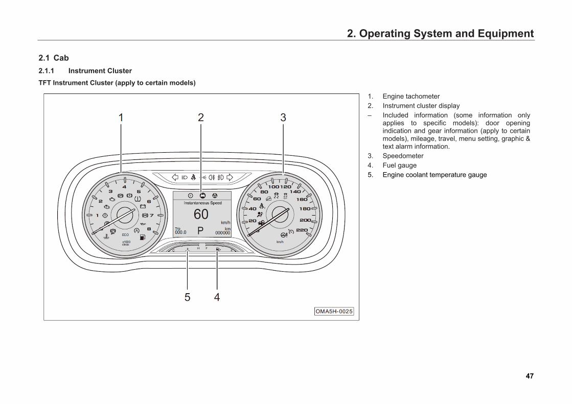
2.1 Cab 2.1.1 Instrument Cluster TFT Instrument Cluster (apply to certain models)
1. Engine tachometer 2. Instrument cluster display – Included information (some information only
applies to specific models): door opening indication and gear information (apply to certain models), mileage, travel, menu setting, graphic & text alarm information.
3. Speedometer 4. Fuel gauge 5. Engine coolant temperature gauge
2. Operating System and Equipment
48
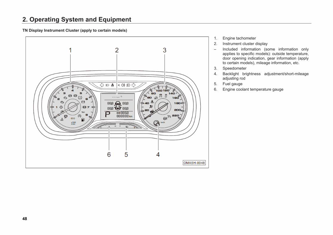
TN Display Instrument Cluster (apply to certain models)
1. Engine tachometer 2. Instrument cluster display – Included information (some information only
applies to specific models): outside temperature, door opening indication, gear information (apply to certain models), mileage information, etc.
3. Speedometer 4. Backlight brightness adjustment/short-mileage
adjusting rod 5. Fuel gauge 6. Engine coolant temperature gauge

2. Operating System and Equipment
49
Engine tachometer
The engine tachometer is used to indicate the current engine speed, in x1000 r/min, minimum scale 500 r/min, ranging from 0 r/min to 8000 r/min.
Caution • The red warning area (7000 r/min ~ 8000
r/min) on the speed dial means the heavy-duty area of the car. Do not let the car operate in this area. Doing so can cause fuel cut-off due to engine self-protection.
• Damage to the engine probably occurs if the tachometer reading is in the red zone while the running-in period of the car does not expire.
• Even if the running-in period has expired, damage to the engine probably occurs if the tachometer reading is in the red zone.
Hint
Shifting into a higher gear timely helps save fuel and reduce the engine running noise.
Instrument Cluster Display (TFT)
Displayed information includes: door opening indication and gear information (apply to certain models), mileage and travel information (Please refer to Page 50), menu setting information (Please refer to Page 54), and graphic & text alarm information (Please refer to Page 57).
2. Operating System and Equipment
50
Door opening indication information
– Display icon hint information when any door,engine hood or hatchback door is open.
Gear information (apply to certain models)
– The “P” location is used to indicate currentgear, for example, display P, R, N, D, or Sbased on received signal.
Mileage information
(Short-mileage Trip)
– Range from 0 km to 999.9 km. When a short-mileage trip exceeds 999.9 km, it will be resetand then continue to accumulate.
– Short-mileage Trip, may be reset by the totalmileage in the settings of menu on display(Please refer to Page 55).
(Total mileage)
– Display range: 0 km to 999999 km.
Travel information
Press / button on the right side of the steering wheel to enter the travel information interface when the Start switch or ignition switch is at "ON" position; and then press ▲ / button to switch between the following travel information interface:
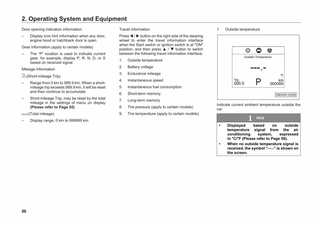
1. Outside temperature
2. Battery voltage
3. Endurance mileage
4. Instantaneous speed
5. Instantaneous fuel consumption
6. Short-term memory
7. Long-term memory
8. Tire pressure (apply to certain models)
9. Tire temperature (apply to certain models)
1. Outside temperature
Indicate current ambient temperature outside the car
Hint
• Displayed based on outsidetemperature signal from the airconditioning system, expressedin °C/°F (Please refer to Page 56).
• When no outside temperature signal isreceived, the symbol “---.-” is shown onthe screen.
2. Operating System and Equipment
51
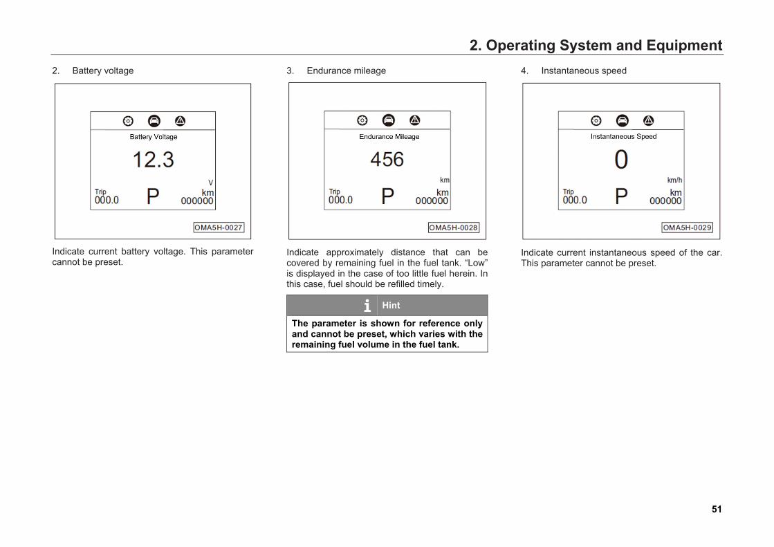
2. Battery voltage
Indicate current battery voltage. This parameter cannot be preset.
3. Endurance mileage
Indicate approximately distance that can be covered by remaining fuel in the fuel tank. “Low” is displayed in the case of too little fuel herein. In this case, fuel should be refilled timely.
Hint
The parameter is shown for reference only and cannot be preset, which varies with the remaining fuel volume in the fuel tank.
4. Instantaneous speed
Indicate current instantaneous speed of the car. This parameter cannot be preset.
2. Operating System and Equipment
52
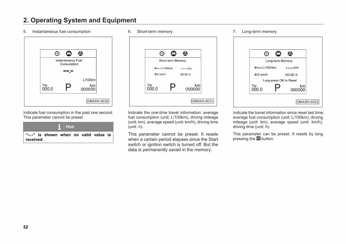
5. Instantaneous fuel consumption
Indicate fuel consumption in the past one second. This parameter cannot be preset.
Hint
“--.-” is shown when no valid value is received.
6. Short-term memory
Indicate the one-time travel information: average fuel consumption (unit: L/100km), driving mileage (unit: km), average speed (unit: km/h), driving time (unit: h).
This parameter cannot be preset. It resets when a certain period elapses since the Start switch or ignition switch is turned off. But the data is permanently saved in the memory.
7. Long-term memory
Indicate the travel information since reset last time: average fuel consumption (unit: L/100km), driving mileage (unit: km), average speed (unit: km/h), driving time (unit: h).
This parameter can be preset. It resets by long pressing the button.
2. Operating System and Equipment
53
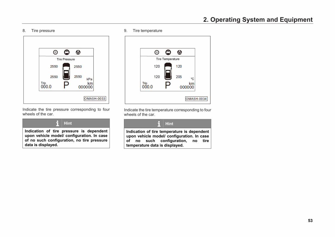
8. Tire pressure
Indicate the tire pressure corresponding to four wheels of the car.
Hint
Indication of tire pressure is dependent upon vehicle model/ configuration. In case of no such configuration, no tire pressure data is displayed.
9. Tire temperature
Indicate the tire temperature corresponding to four wheels of the car.
Hint
Indication of tire temperature is dependent upon vehicle model/ configuration. In case of no such configuration, no tire temperature data is displayed.
2. Operating System and Equipment
54
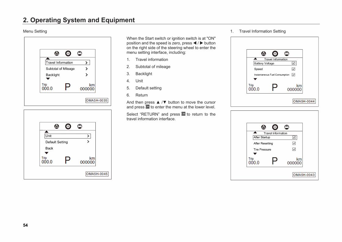
Menu Setting
When the Start switch or ignition switch is at "ON" position and the speed is zero, press / button on the right side of the steering wheel to enter the menu setting interface, including:
1. Travel information
2. Subtotal of mileage
3. Backlight
4. Unit
5. Default setting
6. Return
And then press ▲ /▼ button to move the cursor and press to enter the menu at the lower level.
Select “RETURN” and press to return to the travel information interface.
1. Travel Information Setting
2. Operating System and Equipment
55
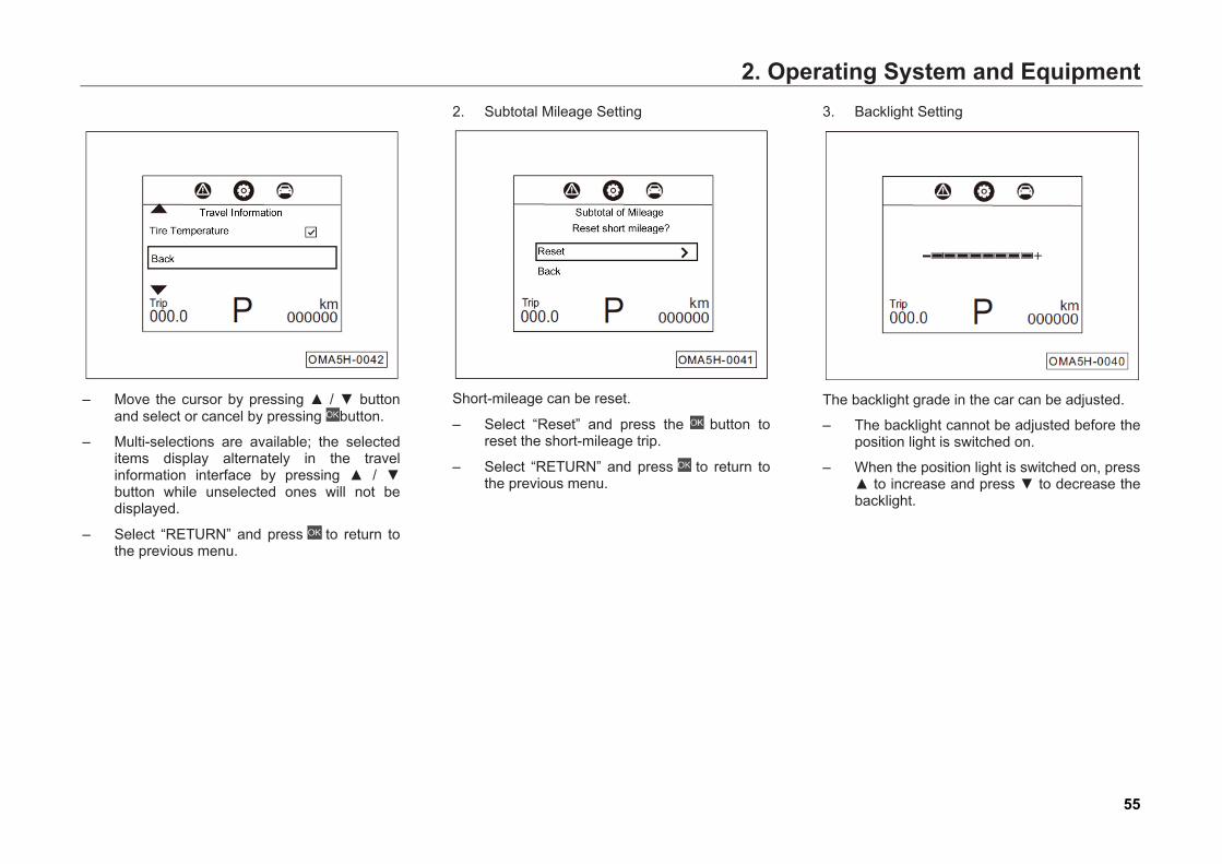
– Move the cursor by pressing ▲ / ▼ button
and select or cancel by pressing button.
– Multi-selections are available; the selected items display alternately in the travel information interface by pressing ▲ / ▼ button while unselected ones will not be displayed.
– Select “RETURN” and press to return to the previous menu.
2. Subtotal Mileage Setting
Short-mileage can be reset.
– Select “Reset” and press the button to reset the short-mileage trip.
– Select “RETURN” and press to return to the previous menu.
3. Backlight Setting
The backlight grade in the car can be adjusted.
– The backlight cannot be adjusted before the position light is switched on.
– When the position light is switched on, press ▲ to increase and press ▼ to decrease the backlight.
2. Operating System and Equipment
56
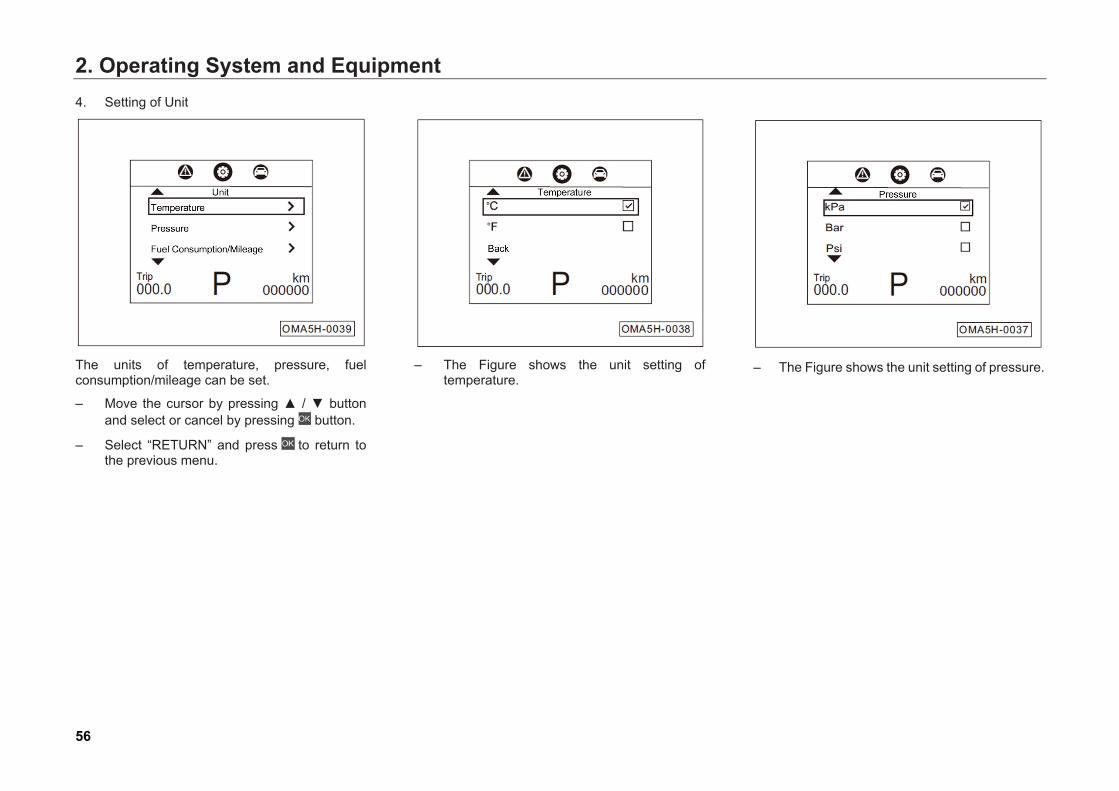
4. Setting of Unit
The units of temperature, pressure, fuel consumption/mileage can be set.
– Move the cursor by pressing ▲ / ▼ buttonand select or cancel by pressing button.
– Select “RETURN” and press to return tothe previous menu.
– The Figure shows the unit setting oftemperature.
– The Figure shows the unit setting of pressure.
2. Operating System and Equipment
57
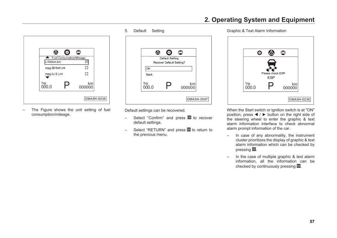
– The Figure shows the unit setting of fuelconsumption/mileage.
5. Default Setting
Default settings can be recovered.
– Select “Confirm” and press to recoverdefault settings.
– Select “RETURN” and press to return tothe previous menu.
Graphic & Text Alarm Information
When the Start switch or ignition switch is at "ON" position, press / ► button on the right side of the steering wheel to enter the graphic & text alarm information interface to check abnormal alarm prompt information of the car.
– In case of any abnormality, the instrumentcluster prioritizes the display of graphic & textalarm information which can be checked bypressing .
– In the case of multiple graphic & text alarminformation, all the information can bechecked by continuously pressing .
2. Operating System and Equipment
58
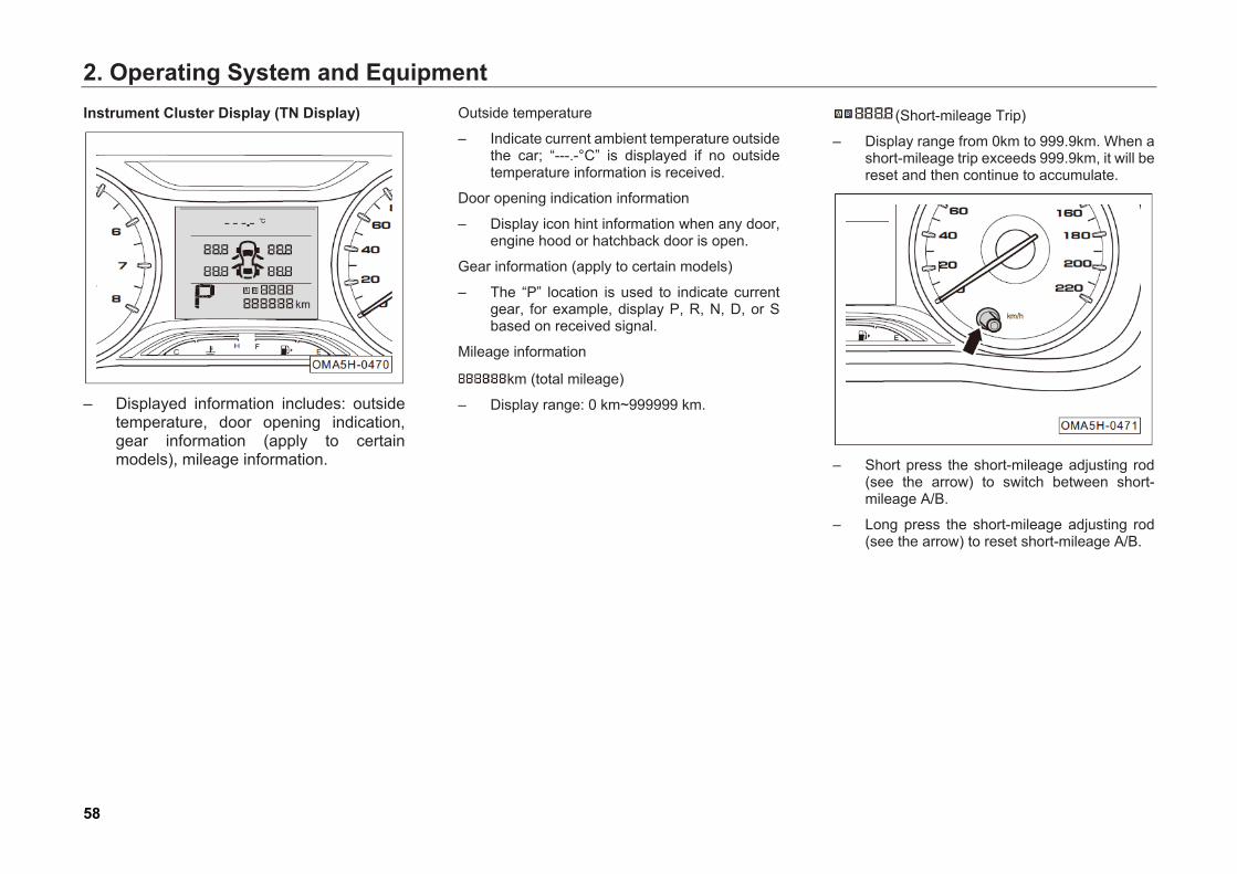
Instrument Cluster Display (TN Display)
– Displayed information includes: outsidetemperature, door opening indication,gear information (apply to certainmodels), mileage information.
Outside temperature
– Indicate current ambient temperature outsidethe car; “---.-°C” is displayed if no outsidetemperature information is received.
Door opening indication information
– Display icon hint information when any door,engine hood or hatchback door is open.
Gear information (apply to certain models)
– The “P” location is used to indicate currentgear, for example, display P, R, N, D, or Sbased on received signal.
Mileage information
km (total mileage)
– Display range: 0 km~999999 km.
(Short-mileage Trip)
– Display range from 0km to 999.9km. When ashort-mileage trip exceeds 999.9km, it will bereset and then continue to accumulate.
– Short press the short-mileage adjusting rod(see the arrow) to switch between short-mileage A/B.
– Long press the short-mileage adjusting rod(see the arrow) to reset short-mileage A/B.

2. Operating System and Equipment
59
Backlight Brightness Adjustment
– When the position light is switched on,
anticlockwise rotate the backlight brightness adjusting rod to decrease the backlight and clockwise rotate it to increase the backlight.
Speedometer
Speedometer is used for indicating the current speed, in km/h, minimum scale of 10km/h, ranging from 0km/h to 220km/h.
Caution • 200 km/h ~ 220 km/h represents the
heavy-load range. To protect your car, avoid prolonged driving in this range.
• Strictly abide by traffic rules. Do not overspeed at will.
Fuel gauge
Fuel gauge (1) is used to indicate the current fuel remaining in the tank.
– There is a total of 8 major sections, indicating the range of E~F, in which, "E" represents the fuel tank is empty, and "F" represents the fuel tank is full. An appropriate number of sections are illuminated depending on the residual fuel.
– It indicates insufficient fuel in the fuel tank when only the first bar or no bar is on and the low level yellow indicator light ( ) in the instrument cluster flickers. In this case, the fuel should be refilled as soon as possible.
2. Operating System and Equipment
60
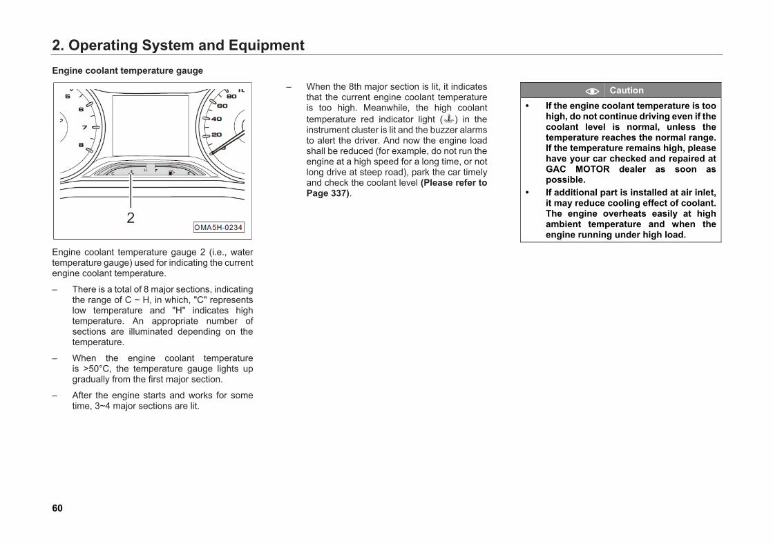
Engine coolant temperature gauge
Engine coolant temperature gauge 2 (i.e., water temperature gauge) used for indicating the current engine coolant temperature.
– There is a total of 8 major sections, indicatingthe range of C ~ H, in which, "C" representslow temperature and "H" indicates hightemperature. An appropriate number ofsections are illuminated depending on thetemperature.
– When the engine coolant temperatureis >50°C, the temperature gauge lights upgradually from the first major section.
– After the engine starts and works for sometime, 3~4 major sections are lit.
– When the 8th major section is lit, it indicatesthat the current engine coolant temperatureis too high. Meanwhile, the high coolanttemperature red indicator light ( ) in theinstrument cluster is lit and the buzzer alarmsto alert the driver. And now the engine loadshall be reduced (for example, do not run theengine at a high speed for a long time, or notlong drive at steep road), park the car timelyand check the coolant level (Please refer toPage 337).
Caution • If the engine coolant temperature is too
high, do not continue driving even if thecoolant level is normal, unless thetemperature reaches the normal range.If the temperature remains high, pleasehave your car checked and repaired atGAC MOTOR dealer as soon aspossible.
• If additional part is installed at air inlet,it may reduce cooling effect of coolant.The engine overheats easily at highambient temperature and when theengine running under high load.
2. Operating System and Equipment
61
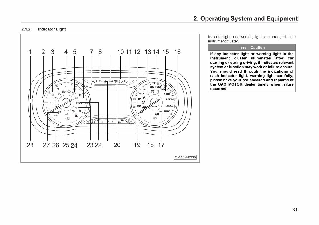
2.1.2 Indicator Light
Indicator lights and warning lights are arranged in the instrument cluster.
Caution If any indicator light or warning light in the instrument cluster illuminates after car starting or during driving, it indicates relevant system or function may work or failure occurs. You should read through the indications of each indicator light, warning light carefully; please have your car checked and repaired at the GAC MOTOR dealer timely when failure occurred.
CH F
E
km/h
ECO
x1000r/min
2 3 4 6 7 11
19 1828 27 24 23 22
1 5 8 9 10 13 14 15 16
21 20 1726 25
12
OMA5H-0235
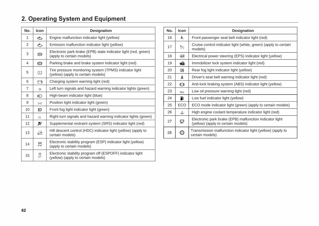
2. Operating System and Equipment
62
No. Icon Designation
1 Engine malfunction indicator light (yellow)
2 Emission malfunction indicator light (yellow)
3 Electronic park brake (EPB) state indicator light (red, green) (apply to certain models)
4 Parking brake and brake system indicator light (red)
5 Tire pressure monitoring system (TPMS) indicator light (yellow) (apply to certain models)
6 Charging system warning light (red)
7 Left turn signals and hazard warning indicator lights (green)
8 High-beam indicator light (blue)
9 Position light indicator light (green)
10 Front fog light indicator light (green)
11 Right turn signals and hazard warning indicator lights (green)
12 Supplemental restraint system (SRS) indicator light (red)
13 Hill descent control (HDC) indicator light (yellow) (apply to certain models)
14 Electronic stability program (ESP) indicator light (yellow) (apply to certain models)
15 Electronic stability program off (ESPOFF) indicator light (yellow) (apply to certain models)
No. Icon Designation
16 Front passenger seat belt indicator light (red)
17 Cruise control indicator light (white, green) (apply to certain models)
18 Electrical power steering (EPS) indicator light (yellow)
19 Immobilizer lock system indicator light (red)
20 Rear fog light indicator light (yellow)
21 Driver's seat belt warning indicator light (red)
22 Anti-lock braking system (ABS) indicator light (yellow)
23 Low oil pressure warning light (red)
24 Low fuel indicator light (yellow)
25 ECO ECO mode indicator light (green) (apply to certain models)
26 High engine coolant temperature indicator light (red)
27 Electronic park brake (EPB) malfunction indicator light (yellow) (apply to certain models)
28 Transmission malfunction indicator light (yellow) (apply to certain models)
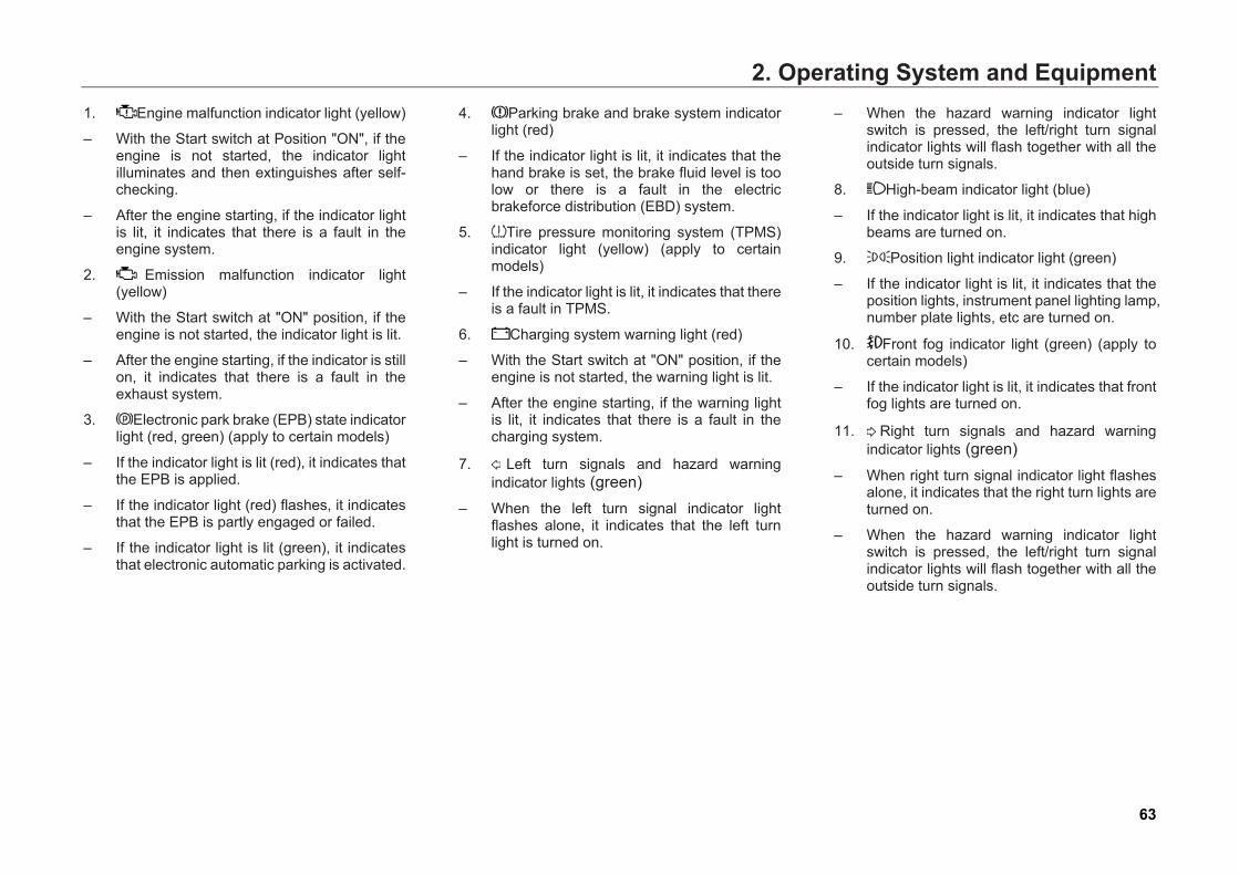
2. Operating System and Equipment
63
1. Engine malfunction indicator light (yellow)
– With the Start switch at Position "ON", if theengine is not started, the indicator lightilluminates and then extinguishes after self-checking.
– After the engine starting, if the indicator lightis lit, it indicates that there is a fault in theengine system.
2. Emission malfunction indicator light(yellow)
– With the Start switch at "ON" position, if theengine is not started, the indicator light is lit.
– After the engine starting, if the indicator is stillon, it indicates that there is a fault in theexhaust system.
3. Electronic park brake (EPB) state indicatorlight (red, green) (apply to certain models)
– If the indicator light is lit (red), it indicates thatthe EPB is applied.
– If the indicator light (red) flashes, it indicatesthat the EPB is partly engaged or failed.
– If the indicator light is lit (green), it indicatesthat electronic automatic parking is activated.
4. Parking brake and brake system indicatorlight (red)
– If the indicator light is lit, it indicates that thehand brake is set, the brake fluid level is toolow or there is a fault in the electricbrakeforce distribution (EBD) system.
5. Tire pressure monitoring system (TPMS)indicator light (yellow) (apply to certainmodels)
– If the indicator light is lit, it indicates that thereis a fault in TPMS.
6. Charging system warning light (red)
– With the Start switch at "ON" position, if theengine is not started, the warning light is lit.
– After the engine starting, if the warning lightis lit, it indicates that there is a fault in thecharging system.
7. Left turn signals and hazard warningindicator lights (green)
– When the left turn signal indicator lightflashes alone, it indicates that the left turnlight is turned on.
– When the hazard warning indicator lightswitch is pressed, the left/right turn signalindicator lights will flash together with all theoutside turn signals.
8. High-beam indicator light (blue)
– If the indicator light is lit, it indicates that highbeams are turned on.
9. Position light indicator light (green)
– If the indicator light is lit, it indicates that theposition lights, instrument panel lighting lamp,number plate lights, etc are turned on.
10. Front fog indicator light (green) (apply tocertain models)
– If the indicator light is lit, it indicates that frontfog lights are turned on.
11. Right turn signals and hazard warningindicator lights (green)
– When right turn signal indicator light flashesalone, it indicates that the right turn lights areturned on.
– When the hazard warning indicator lightswitch is pressed, the left/right turn signalindicator lights will flash together with all theoutside turn signals.
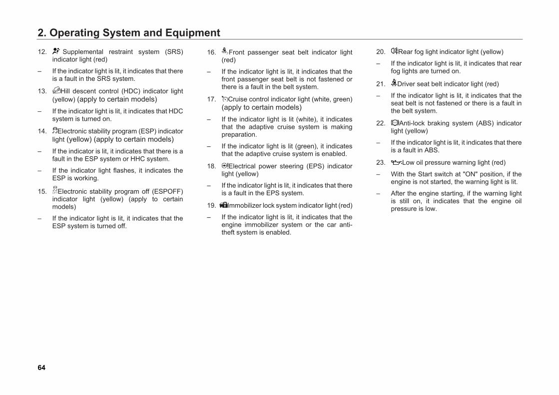
2. Operating System and Equipment
64
12. Supplemental restraint system (SRS)indicator light (red)
– If the indicator light is lit, it indicates that thereis a fault in the SRS system.
13. Hill descent control (HDC) indicator light(yellow) (apply to certain models)
– If the indicator light is lit, it indicates that HDCsystem is turned on.
14. Electronic stability program (ESP) indicatorlight (yellow) (apply to certain models)
– If the indicator is lit, it indicates that there is afault in the ESP system or HHC system.
– If the indicator light flashes, it indicates theESP is working.
15. Electronic stability program off (ESPOFF)indicator light (yellow) (apply to certainmodels)
– If the indicator light is lit, it indicates that theESP system is turned off.
16. Front passenger seat belt indicator light(red)
– If the indicator light is lit, it indicates that thefront passenger seat belt is not fastened orthere is a fault in the belt system.
17. Cruise control indicator light (white, green)(apply to certain models)
– If the indicator light is lit (white), it indicatesthat the adaptive cruise system is makingpreparation.
– If the indicator light is lit (green), it indicatesthat the adaptive cruise system is enabled.
18. Electrical power steering (EPS) indicatorlight (yellow)
– If the indicator light is lit, it indicates that thereis a fault in the EPS system.
19. Immobilizer lock system indicator light (red)
– If the indicator light is lit, it indicates that theengine immobilizer system or the car anti-theft system is enabled.
20. Rear fog light indicator light (yellow)
– If the indicator light is lit, it indicates that rearfog lights are turned on.
21. Driver seat belt indicator light (red)
– If the indicator light is lit, it indicates that theseat belt is not fastened or there is a fault inthe belt system.
22. Anti-lock braking system (ABS) indicatorlight (yellow)
– If the indicator light is lit, it indicates that thereis a fault in ABS.
23. Low oil pressure warning light (red)
– With the Start switch at "ON" position, if theengine is not started, the warning light is lit.
– After the engine starting, if the warning lightis still on, it indicates that the engine oilpressure is low.
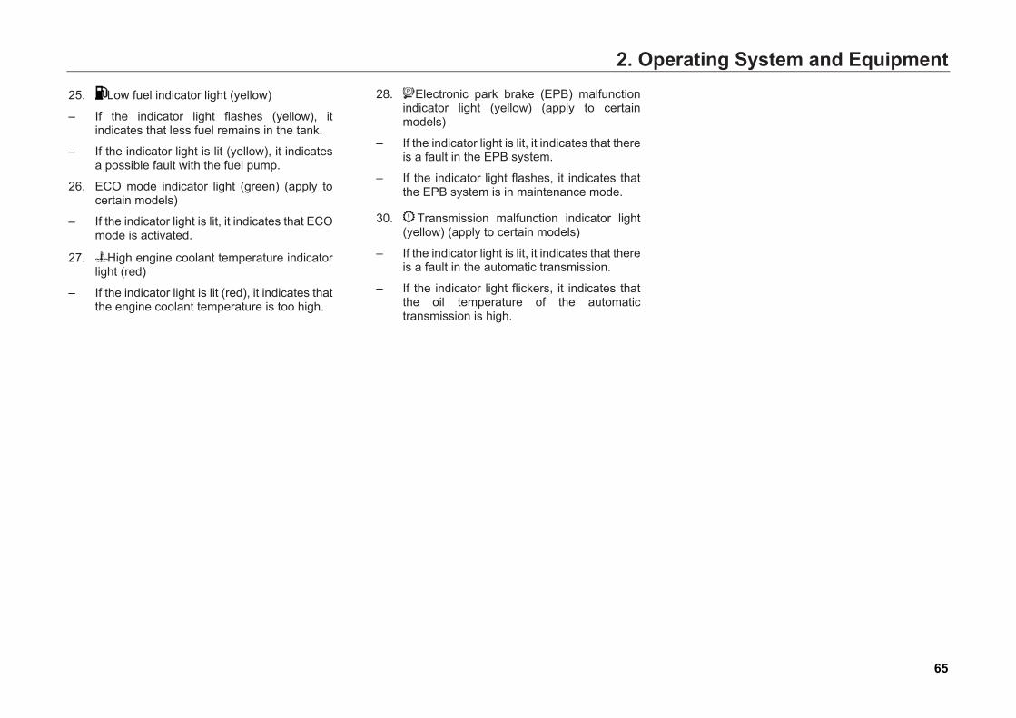
2. Operating System and Equipment
65
25. Low fuel indicator light (yellow)
– If the indicator light flashes (yellow), itindicates that less fuel remains in the tank.
– If the indicator light is lit (yellow), it indicatesa possible fault with the fuel pump.
26. ECO mode indicator light (green) (apply tocertain models)
– If the indicator light is lit, it indicates that ECOmode is activated.
27. High engine coolant temperature indicatorlight (red)
– If the indicator light is lit (red), it indicates thatthe engine coolant temperature is too high.
28. Electronic park brake (EPB) malfunctionindicator light (yellow) (apply to certainmodels)
– If the indicator light is lit, it indicates that thereis a fault in the EPB system.
– If the indicator light flashes, it indicates thatthe EPB system is in maintenance mode.
30. Transmission malfunction indicator light(yellow) (apply to certain models)
– If the indicator light is lit, it indicates that thereis a fault in the automatic transmission.
– If the indicator light flickers, it indicates thatthe oil temperature of the automatictransmission is high.
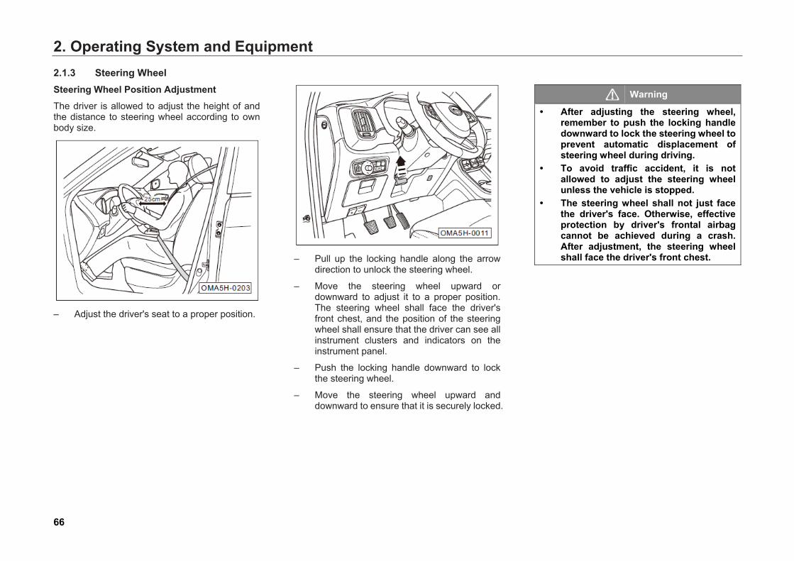
2. Operating System and Equipment
66
2.1.3 Steering Wheel Steering Wheel Position Adjustment The driver is allowed to adjust the height of and the distance to steering wheel according to own body size.
– Adjust the driver's seat to a proper position.
– Pull up the locking handle along the arrow
direction to unlock the steering wheel.
– Move the steering wheel upward or downward to adjust it to a proper position. The steering wheel shall face the driver's front chest, and the position of the steering wheel shall ensure that the driver can see all instrument clusters and indicators on the instrument panel.
– Push the locking handle downward to lock the steering wheel.
– Move the steering wheel upward and downward to ensure that it is securely locked.
Warning
• After adjusting the steering wheel, remember to push the locking handle downward to lock the steering wheel to prevent automatic displacement of steering wheel during driving.
• To avoid traffic accident, it is not allowed to adjust the steering wheel unless the vehicle is stopped.
• The steering wheel shall not just face the driver's face. Otherwise, effective protection by driver's frontal airbag cannot be achieved during a crash. After adjustment, the steering wheel shall face the driver's front chest.
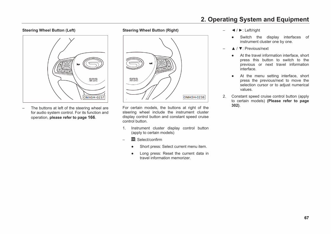
2. Operating System and Equipment
67
Steering Wheel Button (Left)
– The buttons at left of the steering wheel are
for audio system control. For its function and operation, please refer to page 166.
Steering Wheel Button (Right)
For certain models, the buttons at right of the steering wheel include the instrument cluster display control button and constant speed cruise control button.
1. Instrument cluster display control button (apply to certain models)
– : Select/confirm
● Short press: Select current menu item.
● Long press: Reset the current data in travel information memorizer.
– ◄ / ►: Left/right
● Switch the display interfaces of instrument cluster one by one.
– ▲ / ▼: Previous/next
● At the travel information interface, short press this button to switch to the previous or next travel information interface.
● At the menu setting interface, short press the previous/next to move the selection cursor or to adjust numerical values.
2. Constant speed cruise control button (apply to certain models) (Please refer to page 302).
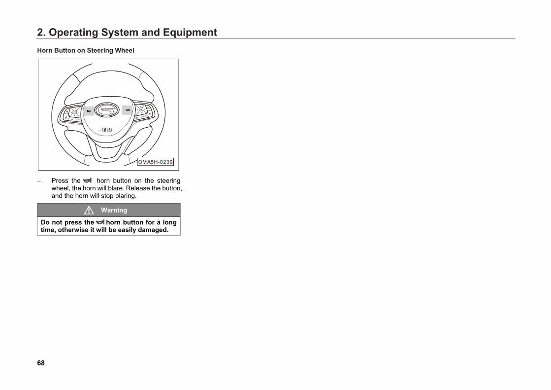
2. Operating System and Equipment
68
Horn Button on Steering Wheel
– Press the horn button on the steering
wheel, the horn will blare. Release the button, and the horn will stop blaring.
Warning
Do not press the horn button for a long time, otherwise it will be easily damaged.
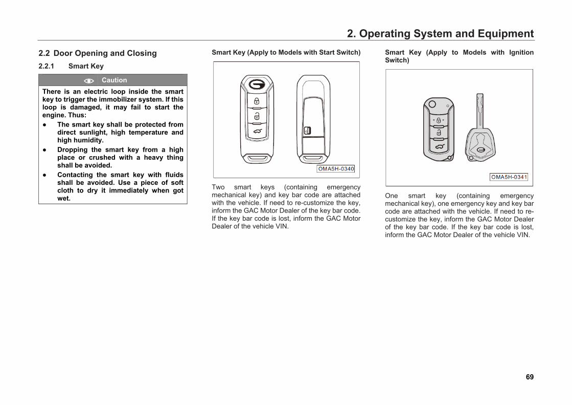
2. Operating System and Equipment
69
2.2 Door Opening and Closing 2.2.1 Smart Key
Caution There is an electric loop inside the smart key to trigger the immobilizer system. If this loop is damaged, it may fail to start the engine. Thus: ● The smart key shall be protected from
direct sunlight, high temperature and high humidity.
● Dropping the smart key from a high place or crushed with a heavy thing shall be avoided.
● Contacting the smart key with fluids shall be avoided. Use a piece of soft cloth to dry it immediately when got wet.
Smart Key (Apply to Models with Start Switch)
Two smart keys (containing emergency mechanical key) and key bar code are attached with the vehicle. If need to re-customize the key, inform the GAC Motor Dealer of the key bar code. If the key bar code is lost, inform the GAC Motor Dealer of the vehicle VIN.
Smart Key (Apply to Models with Ignition Switch)
One smart key (containing emergency mechanical key), one emergency key and key bar code are attached with the vehicle. If need to re-customize the key, inform the GAC Motor Dealer of the key bar code. If the key bar code is lost, inform the GAC Motor Dealer of the vehicle VIN.
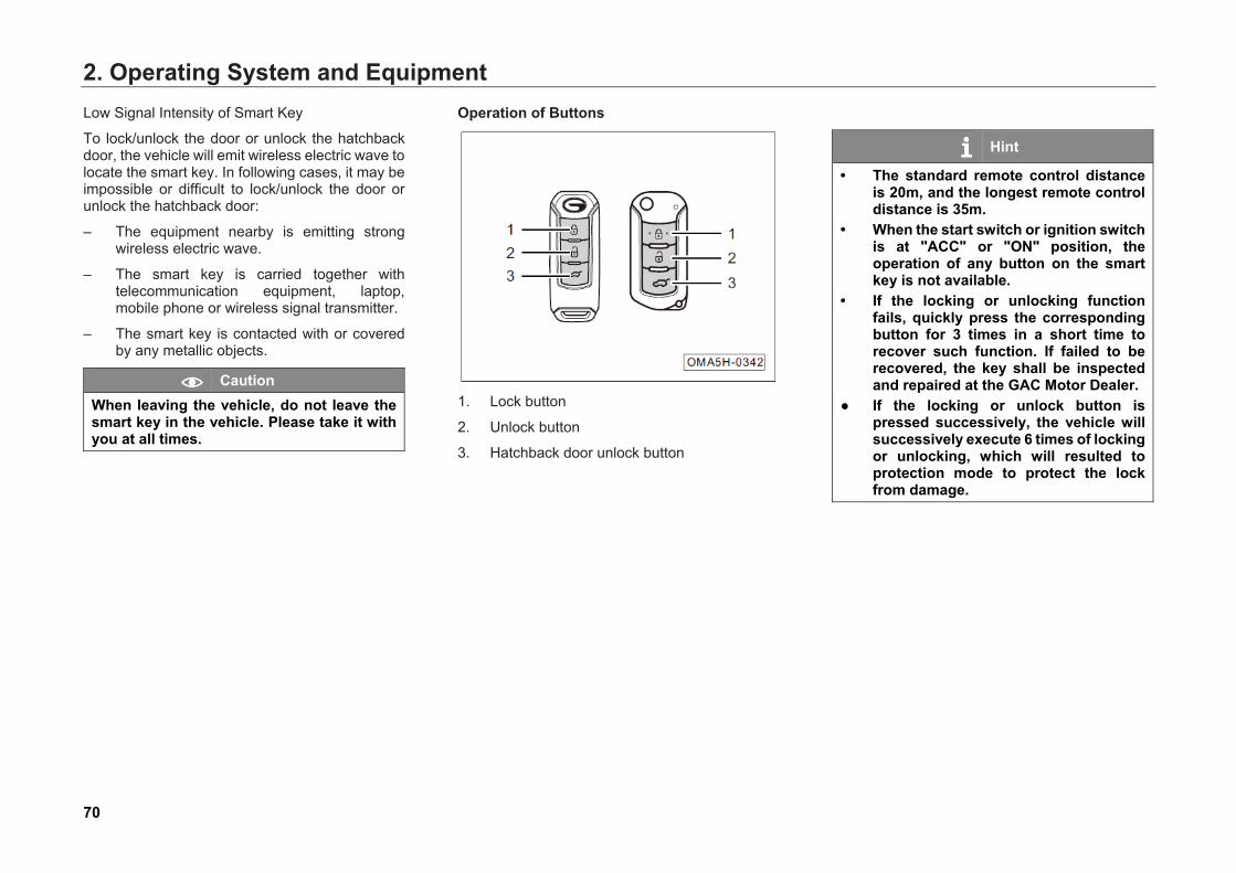
2. Operating System and Equipment
70
Low Signal Intensity of Smart Key
To lock/unlock the door or unlock the hatchback door, the vehicle will emit wireless electric wave to locate the smart key. In following cases, it may be impossible or difficult to lock/unlock the door or unlock the hatchback door:
– The equipment nearby is emitting strong wireless electric wave.
– The smart key is carried together with telecommunication equipment, laptop, mobile phone or wireless signal transmitter.
– The smart key is contacted with or covered by any metallic objects.
Caution When leaving the vehicle, do not leave the smart key in the vehicle. Please take it with you at all times.
Operation of Buttons
1. Lock button
2. Unlock button
3. Hatchback door unlock button
Hint
• The standard remote control distance is 20m, and the longest remote control distance is 35m.
• When the start switch or ignition switch is at "ACC" or "ON" position, the operation of any button on the smart key is not available.
• If the locking or unlocking function fails, quickly press the corresponding button for 3 times in a short time to recover such function. If failed to be recovered, the key shall be inspected and repaired at the GAC Motor Dealer.
● If the locking or unlock button is pressed successively, the vehicle will successively execute 6 times of locking or unlocking, which will resulted to protection mode to protect the lock from damage.
2. Operating System and Equipment
71
The wireless remote function of the smart key is able to lock/unlock all doors, lift/down window at driver side (apply to certain models), open/close sunroof (apply to certain models) and unlock the hatchback door.
The intelligent sensing function of smart key is able to achieve PEPS to operate the start switch to start or shut down the engine (apply to models with start switch).
Hint
There is transceiver chip inside the smart key. This chip is equipped with electronic code that will be sent to the vehicle. The smart key can be used to operate the vehicle only when the chip electronic code is consistent with the registered vehicle ID code.
1. Lock button Operation
– Short pressing this button once within the effective range, all doors will be locked; pressing this button and hold for 2s, the window at driver side will close automatically (apply to certain models); pressing this button and hold for 3s, the sunroof will close automatically (apply to certain models). If this button is released while the window or sunroof is closing automatically, the closing will be stopped.
– Pressing this button twice within 0.5s, the vehicle locating function can be activated, and the turn signal will flash quickly for 3 times.
Hint
When the door is locked, the turn signal will flash once.
Caution In case one door is not closed and the Lock button is pressed, the four doors will be locked and then be unlocked immediately. In case the engine hood or hatchback door is not closed and the Lock button is pressed, then system will alarm.

2. Operating System and Equipment
72
2. Unlock button Operation
– Short pressing this button once within the effective range, all doors will be unlocked; pressing this button and hold for 2s, the window at driver side will open automatically (apply to certain models); pressing this button and hold for 3s, the sunroof will open automatically (apply to certain models). If this button is released while the window or sunroof is opening automatically, the opening will be stopped.
Hint
When the door is unlocked, the turn signal will flash twice.
Caution After pressing the unlock button to unlock the door, the system will lock the door again if it is not opened within 30s.
3. Hatchback Door Unlock button Operation
– Within effective range, long pressing this button (≥2s), the hatchback door can be unlocked.
Caution Once the speed exceeds 1.5km/ h, it is forbidden to unlock the hatchback door.
PEPS (Apply to Certain Models)
– When the start switch or ignition switch is at
"OFF/LOCK" position, if the user approaches to the door with smart key and presses the button on the handle of front door, all doors will be unlocked.
– When the start switch or ignition switch is at "OFF/LOCK" position, if the user presses the button on the handle of front door with smart key after closing all doors, all doors will be locked.
2. Operating System and Equipment
73
– When the start switch or ignition switch is at "OFF/LOCK" position, if the user approaches to the hatchback door with smart key and presses the unlock button of hatchback, the hatchback door can be unlocked and opened.
– If the vehicle is unlocked and stationary, then you may open the hatchback door without carrying the smart key.
Caution Once the speed exceeds 1.5km/ h, it is forbidden to unlock the hatchback door.
Immobilizer System The vehicle is provided with the immobilizer function to prevent the vehicle from being stolen. If an improperly-coded key (or other tool) is used to start the engine, the fuel system will not work and the vehicle cannot be started normally.
Caution If matched smart key is used, the immobilizer system will be deactivated automatically.
"Sound" and "Light" Alarm Switching The "light" alarm indicates the vehicle warns the driver only with light, while the "sound and flash" alarm mode indicates the vehicle warns the driver both with light and horn sound.
When the start switch or ignition switch is at "OFF/LOCK" position, press the button and button at the same time for 2s, the "sound" alarm mode and "sound and flash" alarm mode can be switched. If the switching is successful, the left and right turn signals will flash at the same time for 3 times.
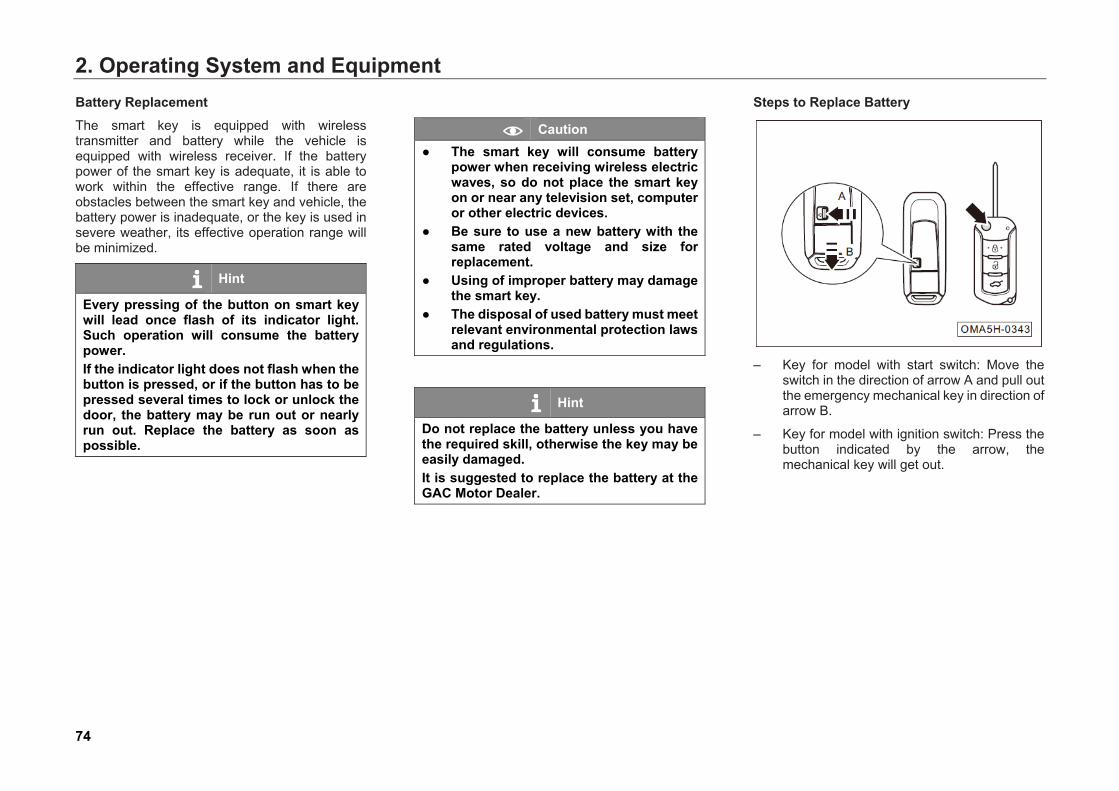
2. Operating System and Equipment
74
Battery Replacement The smart key is equipped with wireless transmitter and battery while the vehicle is equipped with wireless receiver. If the battery power of the smart key is adequate, it is able to work within the effective range. If there are obstacles between the smart key and vehicle, the battery power is inadequate, or the key is used in severe weather, its effective operation range will be minimized.
Hint
Every pressing of the button on smart key will lead once flash of its indicator light. Such operation will consume the battery power. If the indicator light does not flash when the button is pressed, or if the button has to be pressed several times to lock or unlock the door, the battery may be run out or nearly run out. Replace the battery as soon as possible.
Caution ● The smart key will consume battery
power when receiving wireless electric waves, so do not place the smart key on or near any television set, computer or other electric devices.
● Be sure to use a new battery with the same rated voltage and size for replacement.
● Using of improper battery may damage the smart key.
● The disposal of used battery must meet relevant environmental protection laws and regulations.
Hint
Do not replace the battery unless you have the required skill, otherwise the key may be easily damaged. It is suggested to replace the battery at the GAC Motor Dealer.
Steps to Replace Battery
– Key for model with start switch: Move the
switch in the direction of arrow A and pull out the emergency mechanical key in direction of arrow B.
– Key for model with ignition switch: Press the button indicated by the arrow, the mechanical key will get out.
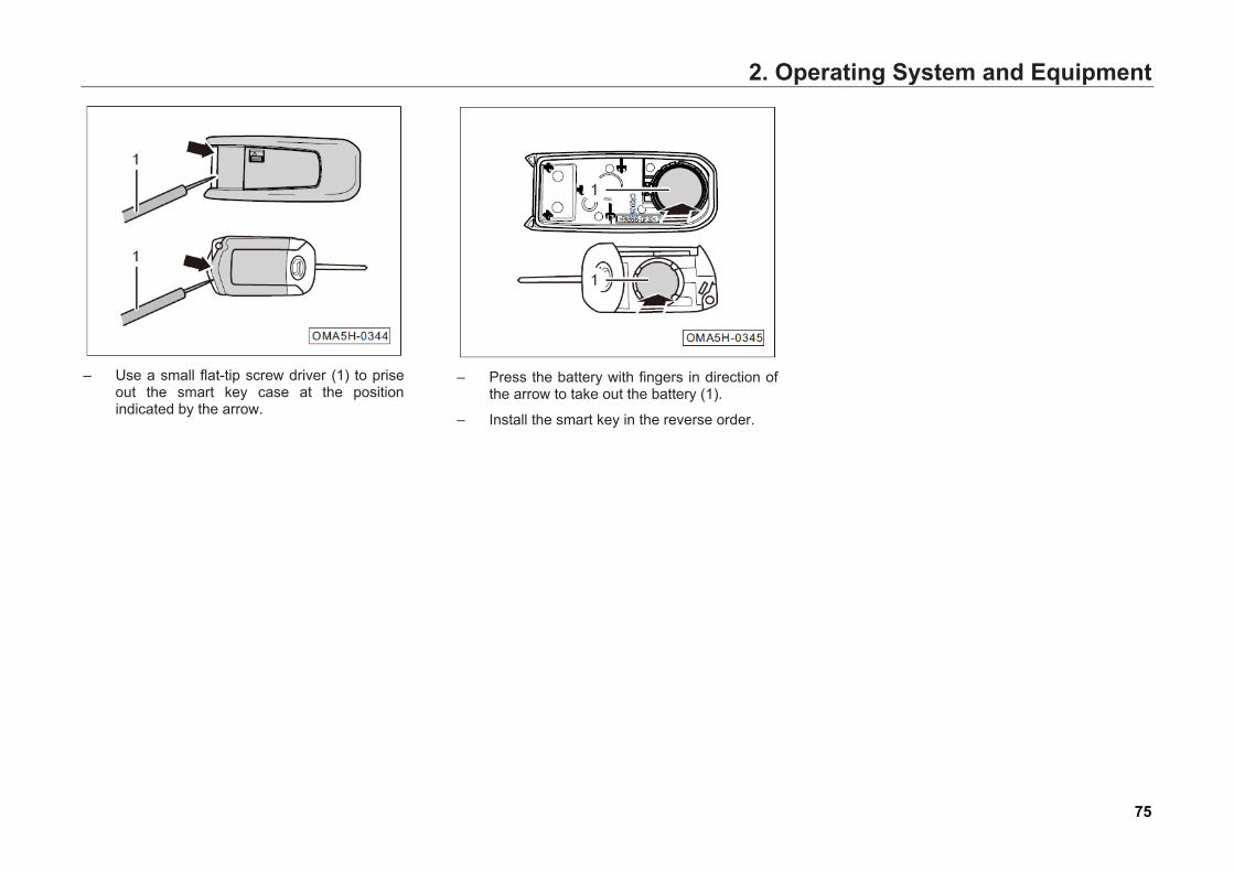
2. Operating System and Equipment
75
– Use a small flat-tip screw driver (1) to prise
out the smart key case at the position indicated by the arrow.
– Press the battery with fingers in direction of
the arrow to take out the battery (1).
– Install the smart key in the reverse order.
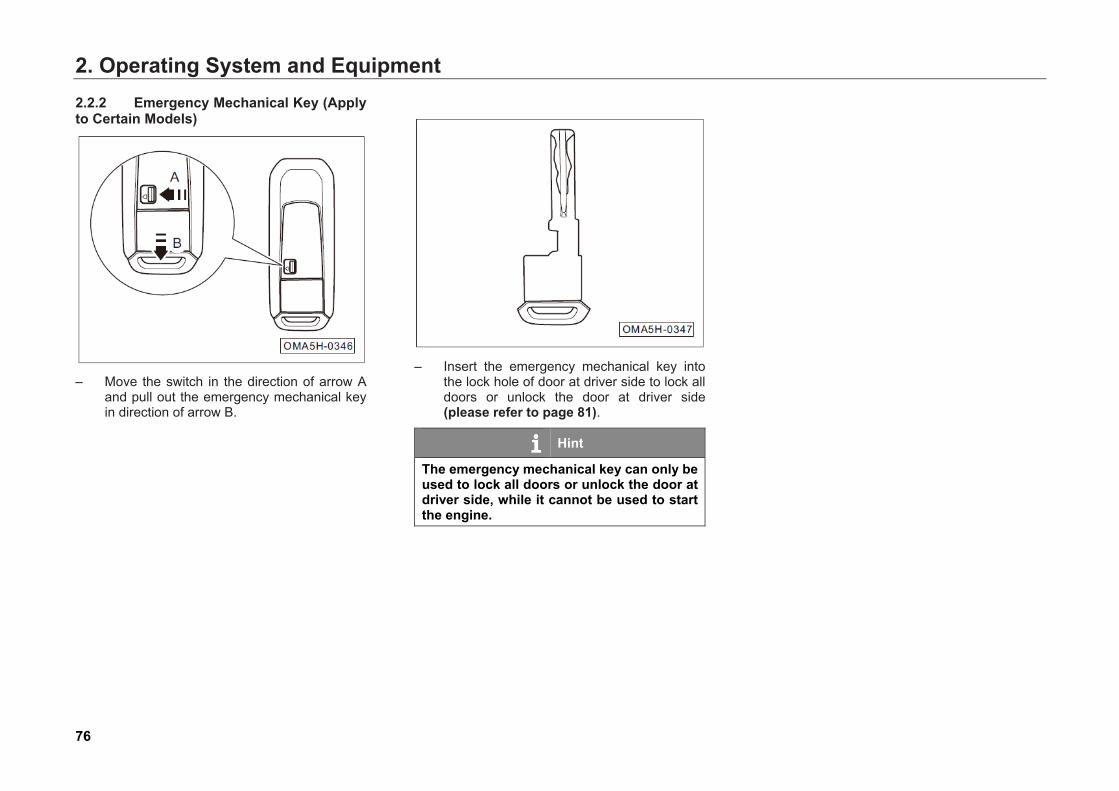
2. Operating System and Equipment
76
2.2.2 Emergency Mechanical Key (Apply to Certain Models)
– Move the switch in the direction of arrow A
and pull out the emergency mechanical key in direction of arrow B.
– Insert the emergency mechanical key into
the lock hole of door at driver side to lock all doors or unlock the door at driver side (please refer to page 81).
Hint
The emergency mechanical key can only be used to lock all doors or unlock the door at driver side, while it cannot be used to start the engine.
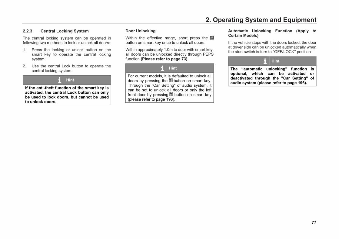
2. Operating System and Equipment
77
2.2.3 Central Locking System The central locking system can be operated in following two methods to lock or unlock all doors:
1. Press the locking or unlock button on the smart key to operate the central locking system.
2. Use the central Lock button to operate the central locking system.
Hint
If the anti-theft function of the smart key is activated, the central Lock button can only be used to lock doors, but cannot be used to unlock doors.
Door Unlocking
Within the effective range, short press the button on smart key once to unlock all doors.
Within approximately 1.0m to door with smart key, all doors can be unlocked directly through PEPS function (Please refer to page 73).
Hint
For current models, it is defaulted to unlock all doors by pressing the button on smart key. Through the "Car Setting" of audio system, it can be set to unlock all doors or only the left front door by pressing button on smart key (please refer to page 196).
Automatic Unlocking Function (Apply to Certain Models) If the vehicle stops with the doors locked, the door at driver side can be unlocked automatically when the start switch is turn to "OFF/LOCK" position
Hint
The “automatic unlocking” function is optional, which can be activated or deactivated through the "Car Setting" of audio system (please refer to page 196).
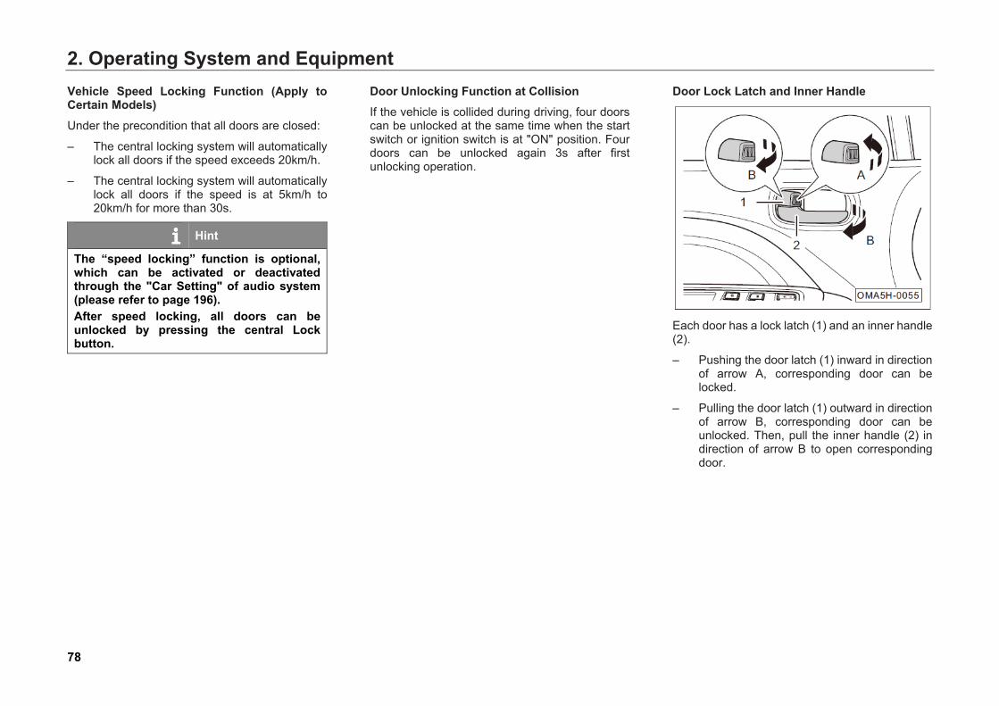
2. Operating System and Equipment
78
Vehicle Speed Locking Function (Apply to Certain Models) Under the precondition that all doors are closed:
– The central locking system will automatically lock all doors if the speed exceeds 20km/h.
– The central locking system will automatically lock all doors if the speed is at 5km/h to 20km/h for more than 30s.
Hint
The “speed locking” function is optional, which can be activated or deactivated through the "Car Setting" of audio system (please refer to page 196). After speed locking, all doors can be unlocked by pressing the central Lock button.
Door Unlocking Function at Collision If the vehicle is collided during driving, four doors can be unlocked at the same time when the start switch or ignition switch is at "ON" position. Four doors can be unlocked again 3s after first unlocking operation.
Door Lock Latch and Inner Handle
Each door has a lock latch (1) and an inner handle (2).
– Pushing the door latch (1) inward in direction of arrow A, corresponding door can be locked.
– Pulling the door latch (1) outward in direction of arrow B, corresponding door can be unlocked. Then, pull the inner handle (2) in direction of arrow B to open corresponding door.
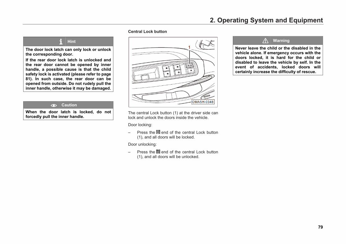
2. Operating System and Equipment
79
Hint
The door lock latch can only lock or unlock the corresponding door. If the rear door lock latch is unlocked and the rear door cannot be opened by inner handle, a possible cause is that the child safety lock is activated (please refer to page 81). In such case, the rear door can be opened from outside. Do not rudely pull the inner handle, otherwise it may be damaged.
Caution When the door latch is locked, do not forcedly pull the inner handle.
Central Lock button
The central Lock button (1) at the driver side can lock and unlock the doors inside the vehicle.
Door locking:
– Press the end of the central Lock button (1), and all doors will be locked.
Door unlocking:
– Press the end of the central Lock button (1), and all doors will be unlocked.
Warning
Never leave the child or the disabled in the vehicle alone. If emergency occurs with the doors locked, it is hard for the child or disabled to leave the vehicle by self. In the event of accidents, locked doors will certainly increase the difficulty of rescue.
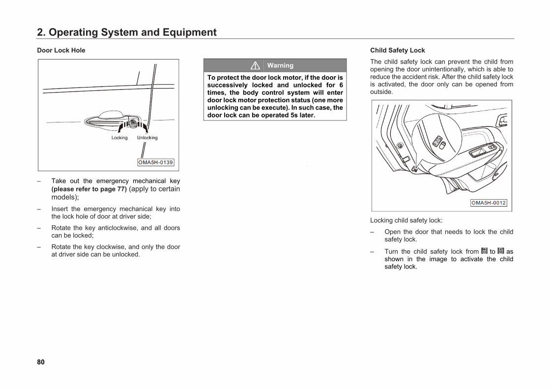
2. Operating System and Equipment
80
Door Lock Hole
– Take out the emergency mechanical key
(please refer to page 77) (apply to certain models);
– Insert the emergency mechanical key into the lock hole of door at driver side;
– Rotate the key anticlockwise, and all doors can be locked;
– Rotate the key clockwise, and only the door at driver side can be unlocked.
Warning
To protect the door lock motor, if the door is successively locked and unlocked for 6 times, the body control system will enter door lock motor protection status (one more unlocking can be execute). In such case, the door lock can be operated 5s later.
Child Safety Lock The child safety lock can prevent the child from opening the door unintentionally, which is able to reduce the accident risk. After the child safety lock is activated, the door only can be opened from outside.
Locking child safety lock:
– Open the door that needs to lock the child safety lock.
– Turn the child safety lock from to as shown in the image to activate the child safety lock.
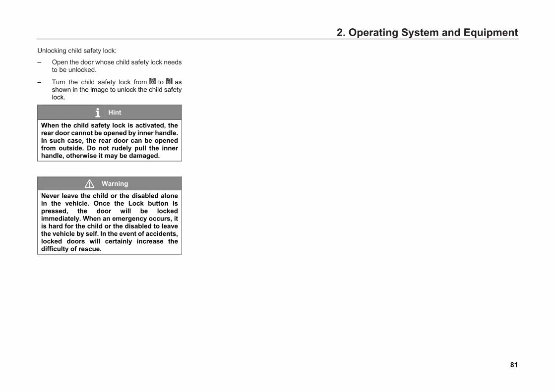
2. Operating System and Equipment
81
Unlocking child safety lock:
– Open the door whose child safety lock needs to be unlocked.
– Turn the child safety lock from to as shown in the image to unlock the child safety lock.
Hint
When the child safety lock is activated, the rear door cannot be opened by inner handle. In such case, the rear door can be opened from outside. Do not rudely pull the inner handle, otherwise it may be damaged.
Warning
Never leave the child or the disabled alone in the vehicle. Once the Lock button is pressed, the door will be locked immediately. When an emergency occurs, it is hard for the child or the disabled to leave the vehicle by self. In the event of accidents, locked doors will certainly increase the difficulty of rescue.
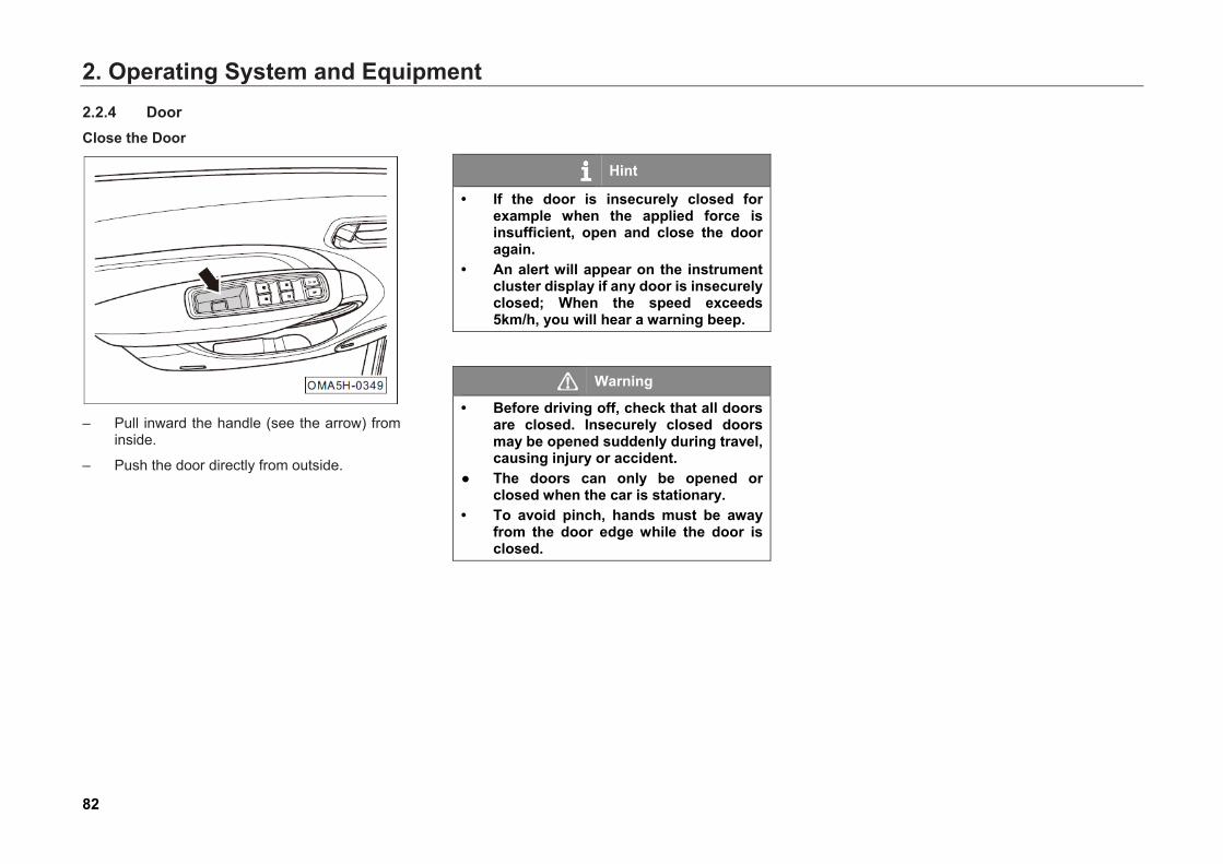
2. Operating System and Equipment
82
2.2.4 Door Close the Door
– Pull inward the handle (see the arrow) from
inside.
– Push the door directly from outside.
Hint
• If the door is insecurely closed for example when the applied force is insufficient, open and close the door again.
• An alert will appear on the instrument cluster display if any door is insecurely closed; When the speed exceeds 5km/h, you will hear a warning beep.
Warning
• Before driving off, check that all doors are closed. Insecurely closed doors may be opened suddenly during travel, causing injury or accident.
● The doors can only be opened or closed when the car is stationary.
• To avoid pinch, hands must be away from the door edge while the door is closed.
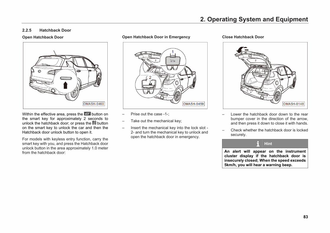
2. Operating System and Equipment
83
2.2.5 Hatchback Door Open Hatchback Door
Within the effective area, press the button on the smart key for approximately 2 seconds to unlock the hatchback door; or press the button on the smart key to unlock the car and then the Hatchback door unlock button to open it.
For models with keyless entry function, carry the smart key with you, and press the Hatchback door unlock button in the area approximately 1.0 meter from the hatchback door:
Open Hatchback Door in Emergency
– Prise out the case -1-;
– Take out the mechanical key;
– Insert the mechanical key into the lock slot -2- and turn the mechanical key to unlock and open the hatchback door in emergency.
Close Hatchback Door
– Lower the hatchback door down to the rear
bumper cover in the direction of the arrow, and then press it down to close it with hands.
– Check whether the hatchback door is locked securely.
Hint
An alert will appear on the instrument cluster display if the hatchback door is insecurely closed; When the speed exceeds 5km/h, you will hear a warning beep.
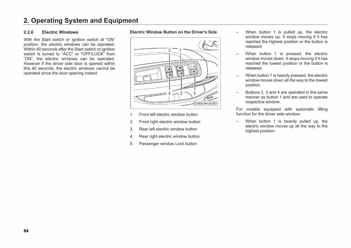
2. Operating System and Equipment
84
2.2.6 Electric Windows With the Start switch or ignition switch at “ON” position, the electric windows can be operated. Within 40 seconds after the Start switch or ignition switch is turned to “ACC” or "OFF/LOCK” from “ON”, the electric windows can be operated. However if the driver side door is opened within this 40 seconds, the electric windows cannot be operated since the door opening instant.
Electric Window Button on the Driver's Side
1. Front left electric window button
2. Front right electric window button
3. Rear left electric window button
4. Rear right electric window button
5. Passenger window Lock button
– When button 1 is pulled up, the electric window moves up. It stops moving if it has reached the highest position or the button is released.
– When button 1 is pressed, the electric window moves down. It stops moving if it has reached the lowest position or the button is released.
– When button 1 is heavily pressed, the electric window moves down all the way to the lowest position.
– Buttons 2, 3 and 4 are operated in the same manner as button 1 and are used to operate respective window.
For models equipped with automatic lifting function for the driver side window:
– When button 1 is heavily pulled up, the electric window moves up all the way to the highest position.
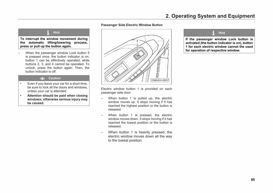
2. Operating System and Equipment
85
Hint
To interrupt the window movement during the automatic lifting/lowering process, press or pull up the button again.
– When the passenger window Lock button 5 is pressed once, the button indicator is on, button 1 can be effectively operated, while buttons 2, 3, and 4 cannot be operated. To unlock, press the button again. Then, the button indicator is off.
Caution • Even if you leave your car for a short time,
be sure to lock all the doors and windows, unless your car is attended.
• Attention should be paid when closing windows; otherwise serious injury may be caused.
Passenger Side Electric Window Button
Electric window button 1 is provided on each passenger side door:
– When button 1 is pulled up, the electric window moves up. It stops moving if it has reached the highest position or the button is released.
– When button 1 is pressed, the electric window moves down. It stops moving if it has reached the lowest position or the button is released.
– When button 1 is heavily pressed, the electric window moves down all the way to the lowest position.
Hint
If the passenger window Lock button is activated (the button indicator is on), button 1 for each electric window cannot the used for operation of respective window.
2. Operating System and Equipment
86
Anti-Pinch Function (Apply to Certain Models) The driver side electric window is equipped with anti-pinch function. If the window encounters an obstacle when it moves up in the anti-pinch area (4~200mm), it stops there and moves down immediately. If the above situation occurs, check out the reason before closing the window again.
If the anti-pinch function has been activated for quite a few times in a short period, the initialization data of anti-pinch is automatically erased to protect the window movement system. In this case, check carefully for obstacle again. Remove the obstacle if any. Perform the initialization learning to recover the anti-pinch function.
Caution • In spite of the anti-pinch function, it is
necessary to check for obstacle before closing windows. In some cases (for example, thin or flexible obstacles), anti-pinch function may not be triggered.
• Do not install any accessories within window movement range. Otherwise anti-pinch function could be affected or accidentally triggered thus the windows cannot be closed normally.
Anti-Pinch Initialization (Apply to Certain Models) Initialization must be performed again if the driver side electric window cannot move up automatically due to anti-pinch function failure, or if initialization data of anti-pinch has been automatically erased due to the anti-pinch function being activated for quite a few times in a short period.
When the button of the driver side electric window is pulled up, the window moves up step by step. Repeat the process several times until the window reaches the highest position. Then continue to pull up and hold the button for 2 to 3 seconds. The initialization is thus completed.
Caution During initialization learning, the window has no anti-pinch function, so do not use any part of the body or other articles to obstruct the window movement, otherwise injury may be caused and the initialization affected. If the electric window system fails, please contact your GAC MOTOR dealer for inspection.

2. Operating System and Equipment
87
2.2.7 Electric Sunroof (Apply to Certain Models) With the Start switch or ignition switch at “ON” position, the electric sunroof can be operated. Within 40 seconds after the Start switch or ignition switch is turned to “ACC” or "OFF/LOCK” from “ON”, the electric windows can be operated. However if the driver side door is opened within this 40 seconds, the electric sunroof cannot be operated since the door opening instant.
Open and Close the Sunroof Visor
Hold the groove:
– Pull backward to open the sunroof visor;
– Pull forward to open the sunroof visor.
Hint
When the electric sunroof slides to open, the sunroof visor will be opened together with the electric sunroof.
Caution ● To avoid damage to the sunroof visor
due to possible effect of air flow generated during car driving on the sunroof visor, the sunroof visor can be closed only when the electric sunroof is completely closed.
• Close the electric sunroof before closing the sunroof visor. If the sunroof visor is closed but the sunroof is not, rainwater can enter the vehicle when it rains.
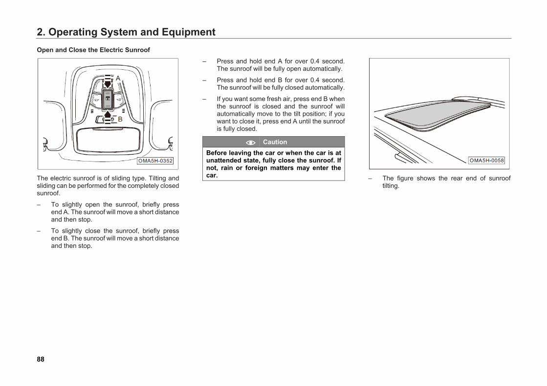
2. Operating System and Equipment
88
Open and Close the Electric Sunroof
The electric sunroof is of sliding type. Tilting and sliding can be performed for the completely closed sunroof.
– To slightly open the sunroof, briefly press end A. The sunroof will move a short distance and then stop.
– To slightly close the sunroof, briefly press end B. The sunroof will move a short distance and then stop.
– Press and hold end A for over 0.4 second. The sunroof will be fully open automatically.
– Press and hold end B for over 0.4 second. The sunroof will be fully closed automatically.
– If you want some fresh air, press end B when the sunroof is closed and the sunroof will automatically move to the tilt position; if you want to close it, press end A until the sunroof is fully closed.
Caution Before leaving the car or when the car is at unattended state, fully close the sunroof. If not, rain or foreign matters may enter the car.
– The figure shows the rear end of sunroof
tilting.
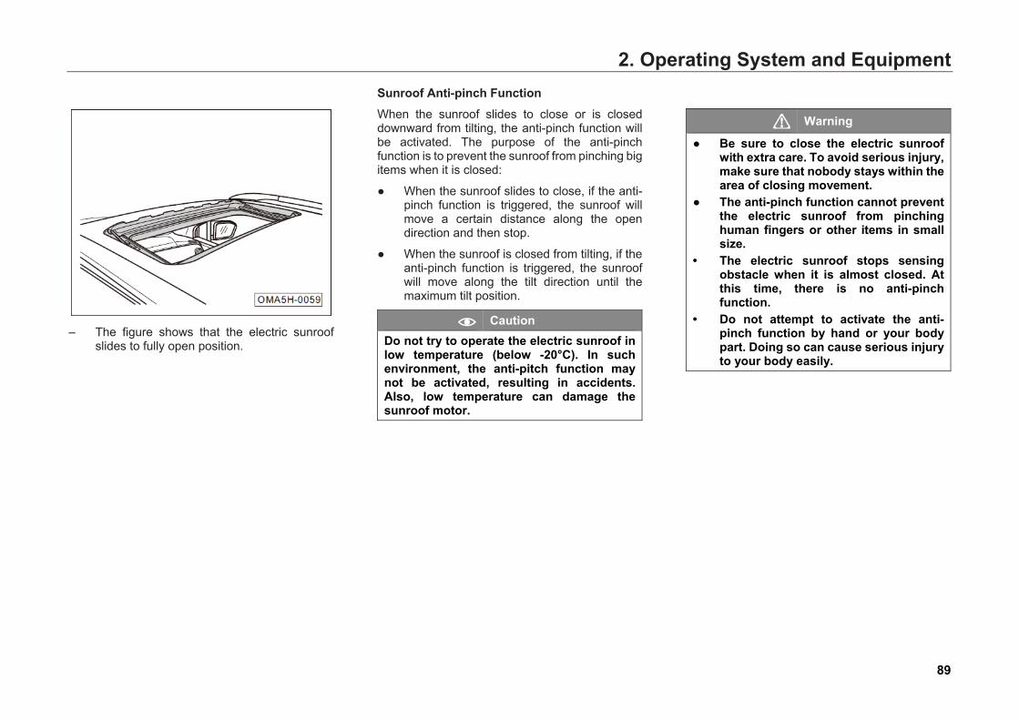
2. Operating System and Equipment
89
– The figure shows that the electric sunroof
slides to fully open position.
Sunroof Anti-pinch Function When the sunroof slides to close or is closed downward from tilting, the anti-pinch function will be activated. The purpose of the anti-pinch function is to prevent the sunroof from pinching big items when it is closed:
● When the sunroof slides to close, if the anti-pinch function is triggered, the sunroof will move a certain distance along the open direction and then stop.
● When the sunroof is closed from tilting, if the anti-pinch function is triggered, the sunroof will move along the tilt direction until the maximum tilt position.
Caution Do not try to operate the electric sunroof in low temperature (below -20°C). In such environment, the anti-pitch function may not be activated, resulting in accidents. Also, low temperature can damage the sunroof motor.
Warning
● Be sure to close the electric sunroof with extra care. To avoid serious injury, make sure that nobody stays within the area of closing movement.
● The anti-pinch function cannot prevent the electric sunroof from pinching human fingers or other items in small size.
• The electric sunroof stops sensing obstacle when it is almost closed. At this time, there is no anti-pinch function.
• Do not attempt to activate the anti-pinch function by hand or your body part. Doing so can cause serious injury to your body easily.
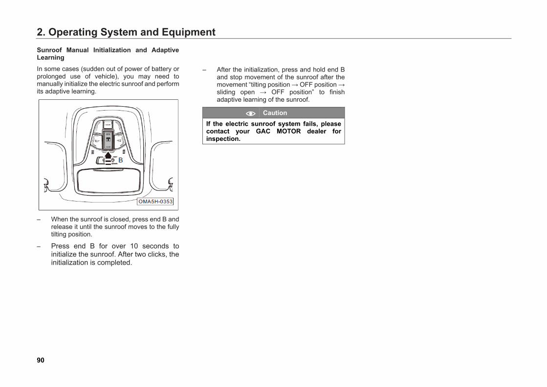
2. Operating System and Equipment
90
Sunroof Manual Initialization and Adaptive Learning In some cases (sudden out of power of battery or prolonged use of vehicle), you may need to manually initialize the electric sunroof and perform its adaptive learning.
– When the sunroof is closed, press end B and
release it until the sunroof moves to the fully tilting position.
– Press end B for over 10 seconds to initialize the sunroof. After two clicks, the initialization is completed.
– After the initialization, press and hold end B and stop movement of the sunroof after the movement “tilting position → OFF position → sliding open → OFF position” to finish adaptive learning of the sunroof.
Caution If the electric sunroof system fails, please contact your GAC MOTOR dealer for inspection.
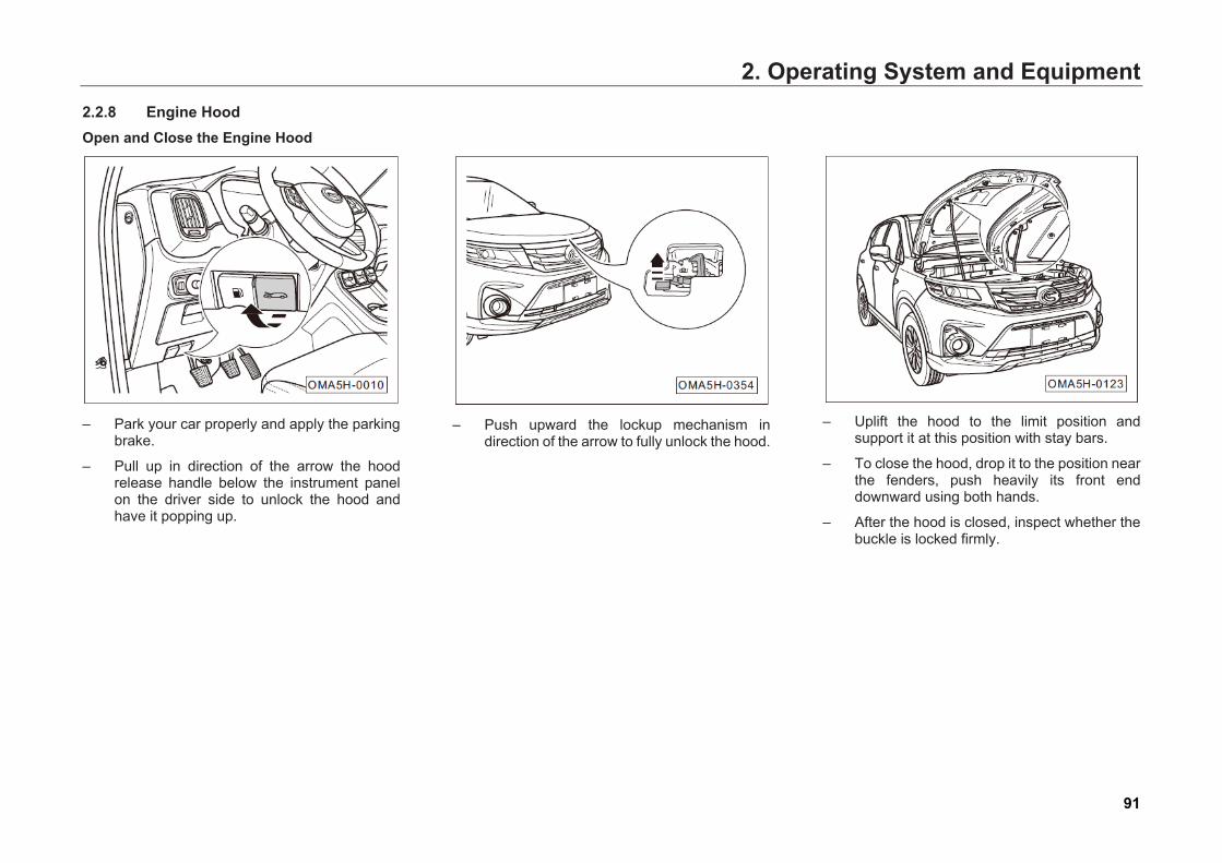
2. Operating System and Equipment
91
2.2.8 Engine Hood Open and Close the Engine Hood
– Park your car properly and apply the parking
brake.
– Pull up in direction of the arrow the hood release handle below the instrument panel on the driver side to unlock the hood and have it popping up.
– Push upward the lockup mechanism in
direction of the arrow to fully unlock the hood.
– Uplift the hood to the limit position and
support it at this position with stay bars.
– To close the hood, drop it to the position near the fenders, push heavily its front end downward using both hands.
– After the hood is closed, inspect whether the buckle is locked firmly.
2. Operating System and Equipment
92
Hint
• Lubricate the moving part of the lockup mechanism of the engine hood properly to help open or close the engine hood.
• An alert will appear on the instrument cluster display if the hood is insecurely closed; When the speed exceeds 5km/h, you will hear a warning beep.
Warning
Engine compartment is a hazard area where improper operation may cause serious injuries or deaths. • If you see vapor or coolant overflowing
from the engine compartment, do not open the hood. Doing so can seriously scald you.
• When the engine is hot, do not touch it. Doing so can seriously scald you.
• Never open the coolant expansion tank cover when the engine is in hot condition. At this moment, the cooling system is in high temperature and pressure condition.
• When the engine works, do not touch the drive belt, alternator, radiator fan and other rotating components, the high-voltage ignition system and high-temperature exhaust system.

2. Operating System and Equipment
93
2.2.9 Basic Operations of Anti-Theft on Vehicle Body Anti-Theft on Vehicle Body - Unlock: With the Start switch or ignition switch at “OFF” position, the car is locked. If the user carries the smart key to approach the front door and presses once the button in the handle of the front door or the unlock button on the smart key, the anti-theft system unlocks the door and the instrument panel and turn signals flash twice.
Anti-Theft on Vehicle Body - Lock: With the Start switch or ignition switch at “OFF” position, four doors, engine hood and hatchback door of the car are closed. If the smart key is not in the car, after pressing once the button in the handle of the front door or the lock button on the smart key, the anti-theft system locks the door and the instrument panel and turn signals flash once.
1. If the engine hood or the hatchback door is not securely closed, press on the smart key to start alarm: left and right turn signals flash and the anti-theft horn gives short beep.
Hint
During an alarm, if the unclosed door is closed, the car will enter anti-theft state; or if on the smart key is pressed, the alarm stops and the car is unlocked.
2. If any door is not closed, after on the smart key is pressed, the four doors will be locked and then immediately unlocked without any alarm.
Activate the Anti - Theft on car body: With the Start switch or ignition switch at “OFF/LOCK” position, the car is locked. If any door, engine hood, or hatchback door is unlocked forcibly or using an illegal key, the anti-theft system will trigger the horn beep and flashing of turn signals for about 28 seconds.
Hint
During an alarm, if on the smart key is pressed or the Start switch or the ignition switch is switched to “ON” position, the alarm stops and the car is unlocked.
Anti-Theft on Engine: With the Start switch or ignition switch at "OFF" position, the anti-theft function of car body enabled and the smart key being inside the car, when the vehicle owner starts the engine twice, if the anti-theft system considers this operation to be legal, it activates fuel injection and ignition; otherwise, it does not activate fuel injection and ignition, and activates the horn to beep and the turn signals to flash twice.

2. Operating System and Equipment
94
2.3 Lights and Visual Field 2.3.1 Exterior Lights Light Combination Switch
1. Turn signal
2. Lane change flashlight
3. Headlight high beam
4. Headlight low beam
5. High beam flashing
6. Lights off
7. Auto lighting (apply to certain models)
8. Position light (manual open)
9. Low beam (manual open)
10. Fog lights off
11. Front fog light (apply to certain models)
12. Rear fog light
Turn signal – By pushing the light combination switch lever
up or down to position 1, the right or left turn signal is turned on and or in the instrument cluster flashes.
Caution If any turn signal on the front end or rear end fails, flashing frequency of the turn signal indicators in the instrument cluster will be doubled.
2. Operating System and Equipment
95
Lane Change Flashlight
– Switch the Start switch or ignition switch to “ON” position
– By pushing quickly (within 0.1 to 0.7 seconds) the light combination switch lever up or down to position 2, and then releasing it to let it return to the original position, the corresponding turn signal flashes three times, and the turn signal indicator in the instrument cluster also flashes three times.
– By pushing the light combination switch lever up or down to position 2 and keeping it at this position, the corresponding turn signal and also the turn signal indicator in the instrument cluster flash continuously. If the lever is released to let it return to the original position, the flashing stops.
Headlight High Beam
– Switch the Start switch or ignition switch to “ON” position
– Turn the light switch to position.
– By pushing forward (forward direction of the car) the light combination switch lever to position 3, headlight high beams are turned on and in the instrument cluster flashes.
– By pulling back (backward direction of the car) the light combination switch lever to position 4, headlight high beams are turned off, in the instrument cluster is off, but headlight low beams are still on.
– By turning the light switch to position, all lights are turned off.
Warning
Headlight high beams may dazzle the drivers of other cars nearby and result in accidents. Please use them properly.
Headlight Low Beam
– Switch the Start switch or ignition switch to “ON” position
– When the light combination switch lever is at position 4, turn the light switch to position to turn on headlight low beams.
– By turning the light switch to position, all lights are turned off.
2. Operating System and Equipment
96
High Beam Flashing
– Switch the Start switch or ignition switch to “ON” position
– Pull back (backward direction of the car) the light combination switch lever to position 5 to turn on headlight high beams.
– Release the light combination switch lever to let it return to position 4 to turn off the headlight flashers.
Hint
Even if no light is turned on, high beams remain on and in the instrument cluster remains on if the light combination switch lever is pulled back (backward direction of the car).
Auto Lighting (Apply to Certain Models) – Switch the Start switch to “ON” position.
- Turn the light switch to position to enable auto lighting.
Hint
● With auto lighting enabled, lights of the car will be turned on or off depending on the environmental light. When the environmental light outside the car dims gradually, the position lights are turned on firstly, and then the low beams. When the environmental light outside the car brightens gradually, the low beams go out firstly, and then the position lights. When entering or exiting a tunnel or garage or other dark environment, the position lights and low beams will be automatically turned on or off at the same time.
• You can adjust auto lighting sensitivity via the "Car Setting" under audio system (please refer to Page 197). The higher the sensitivity, the brighter the lights.
Caution • If the instrument cluster display
prompts "The sensor fails, please control the lighting manually", and for the sake of safety, the system will keep low beams turned on. In this case, you can choose to control the lighting manually, and go to the authorized GAC MOTOR dealer timely to have your car checked and repaired.
• Auto lighting may fail in heavily foggy or misty weather. Manually turn on the lights then.
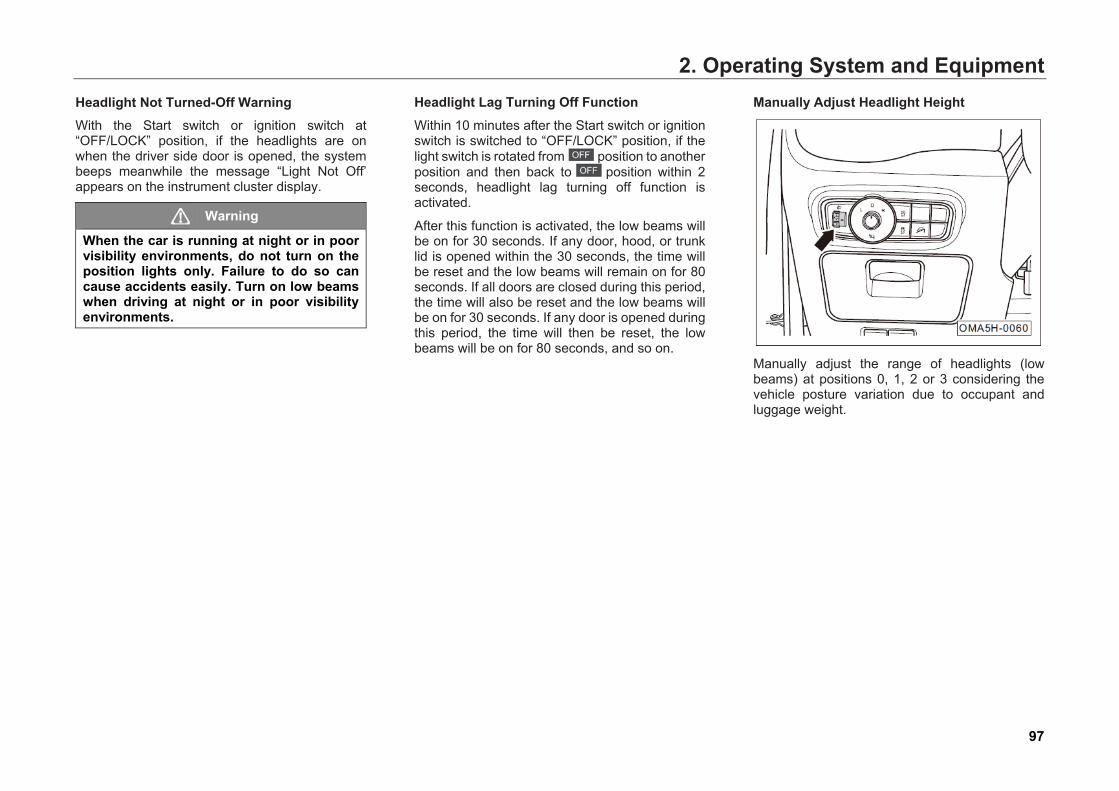
2. Operating System and Equipment
97
Headlight Not Turned-Off Warning With the Start switch or ignition switch at “OFF/LOCK” position, if the headlights are on when the driver side door is opened, the system beeps meanwhile the message “Light Not Off’ appears on the instrument cluster display.
Warning
When the car is running at night or in poor visibility environments, do not turn on the position lights only. Failure to do so can cause accidents easily. Turn on low beams when driving at night or in poor visibility environments.
Headlight Lag Turning Off Function Within 10 minutes after the Start switch or ignition switch is switched to “OFF/LOCK” position, if the light switch is rotated from position to another position and then back to position within 2 seconds, headlight lag turning off function is activated.
After this function is activated, the low beams will be on for 30 seconds. If any door, hood, or trunk lid is opened within the 30 seconds, the time will be reset and the low beams will remain on for 80 seconds. If all doors are closed during this period, the time will also be reset and the low beams will be on for 30 seconds. If any door is opened during this period, the time will then be reset, the low beams will be on for 80 seconds, and so on.
Manually Adjust Headlight Height
Manually adjust the range of headlights (low beams) at positions 0, 1, 2 or 3 considering the vehicle posture variation due to occupant and luggage weight.
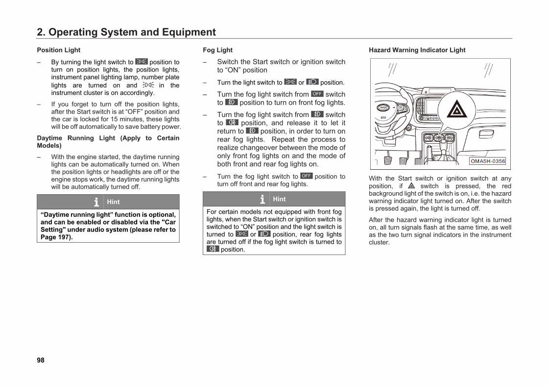
2. Operating System and Equipment
98
Position Light
– By turning the light switch to position to turn on position lights, the position lights, instrument panel lighting lamp, number plate lights are turned on and in the instrument cluster is on accordingly.
– If you forget to turn off the position lights, after the Start switch is at “OFF” position and the car is locked for 15 minutes, these lights will be off automatically to save battery power.
Daytime Running Light (Apply to Certain Models) – With the engine started, the daytime running
lights can be automatically turned on. When the position lights or headlights are off or the engine stops work, the daytime running lights will be automatically turned off.
Hint
“Daytime running light” function is optional, and can be enabled or disabled via the "Car Setting" under audio system (please refer to Page 197).
Fog Light
– Switch the Start switch or ignition switch to “ON” position
– Turn the light switch to or position.
– Turn the fog light switch from switch to position to turn on front fog lights.
– Turn the fog light switch from switch to position, and release it to let it return to position, in order to turn on rear fog lights. Repeat the process to realize changeover between the mode of only front fog lights on and the mode of both front and rear fog lights on.
– Turn the fog light switch to position to turn off front and rear fog lights.
Hint
For certain models not equipped with front fog lights, when the Start switch or ignition switch is switched to “ON” position and the light switch is turned to or position, rear fog lights are turned off if the fog light switch is turned to
position.
Hazard Warning Indicator Light
With the Start switch or ignition switch at any position, if switch is pressed, the red background light of the switch is on, i.e. the hazard warning indicator light turned on. After the switch is pressed again, the light is turned off.
After the hazard warning indicator light is turned on, all turn signals flash at the same time, as well as the two turn signal indicators in the instrument cluster.
2. Operating System and Equipment
99
In case of emergency, use the hazard warning indicator light to attract the attention of other people on the road, so as to reduce the risk of accidents. Turn it on in one of the following conditions:
• Vehicle breakdown due to technical failure.
• At the end of traffic flow during traffic jam.
• Towing another vehicle or being towed.
Caution • The hazard warning indicator light will
consume battery. Turn them off if permitted.
• Follow the relevant laws and regulations when using the hazard warning indicator light.
● If the hazard warning indicator light fails in emergency, other warning means must be taken to attract attention of other people on the road provided that these means are safe and comply with relevant traffic regulations.
Collision Warning Light In case of collision, left and right turn signals flash.
Lighting for Getting on the Car
– By pressing on the smart key when you get close to the car, the position lights will be on for 25 seconds as auxiliary lighting so that you can see clearly obstacles if any. If on the smart key is pressed again, the position lights will be on for another 25 seconds.
- If the Start switch or ignition switch is switch to “ON” position after getting on the car, the position lights go out.
Lighting for Locating the Car
– If on the smart key is pressed twice successively, the position lights will be on for 8 seconds and left and right turn signals will flash 3 times so that the car can be located easily.
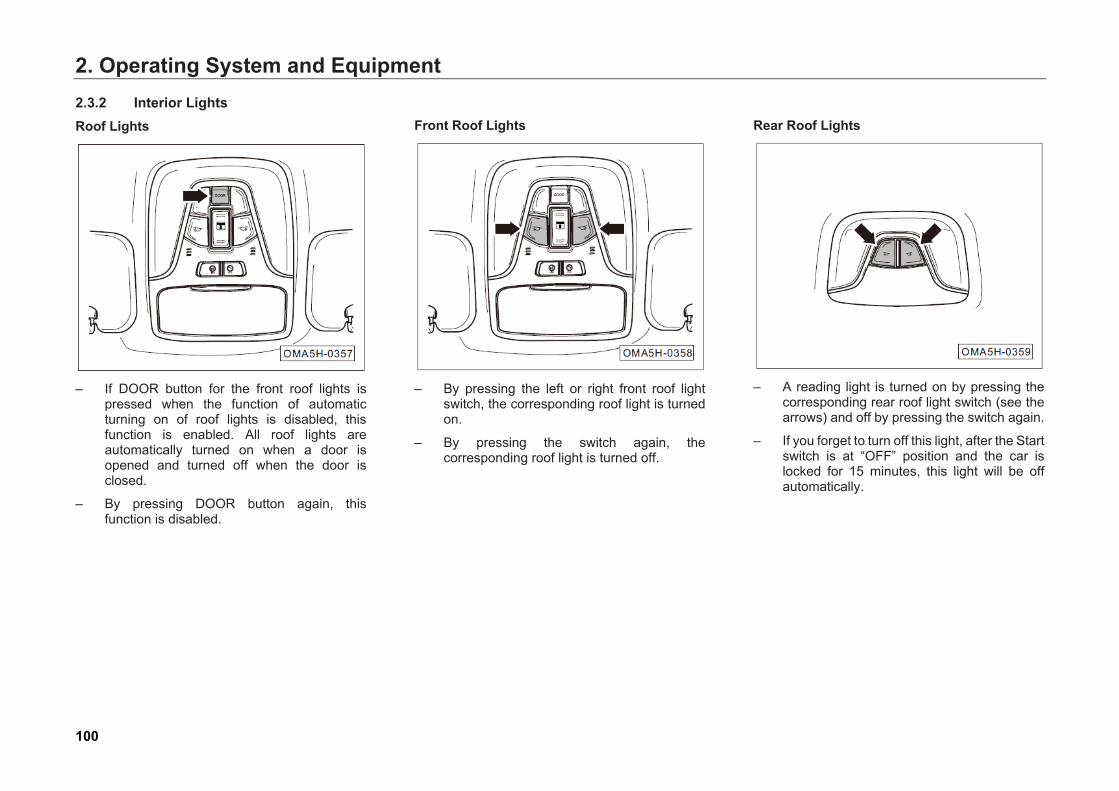
2. Operating System and Equipment
100
2.3.2 Interior Lights Roof Lights
– If DOOR button for the front roof lights is
pressed when the function of automatic turning on of roof lights is disabled, this function is enabled. All roof lights are automatically turned on when a door is opened and turned off when the door is closed.
– By pressing DOOR button again, this function is disabled.
Front Roof Lights
– By pressing the left or right front roof light
switch, the corresponding roof light is turned on.
– By pressing the switch again, the corresponding roof light is turned off.
Rear Roof Lights
– A reading light is turned on by pressing the
corresponding rear roof light switch (see the arrows) and off by pressing the switch again.
– If you forget to turn off this light, after the Start switch is at “OFF” position and the car is locked for 15 minutes, this light will be off automatically.
2. Operating System and Equipment
101
Glove Box Light (Apply to Certain Models) – By opening the front passenger side glove
box, the glove box light will be on automatically.
– By closing the front passenger side glove box, the glove box light will be off automatically.
Trunk Light – By opening the hatchback door, the trunk
light goes on automatically.
– By closing the hatchback door, the trunk light goes off automatically.
Hint
With the Start switch or ignition switch at "OFF" position, interior lights automatically goes off if the doors remain locked for a period of time.
Courtesy Lights (Apply to Certain Models) – When the door is opened, the courtesy lights
go on automatically.
– When the door is closed, the courtesy lights go off automatically.

2. Operating System and Equipment
102
2.3.3 Windshield Wiper Wiper Combination Switch
1. : continuous wiping
2. : wiping off
3. : intermittent wiping (apply to certain models)
– : auto wiping (apply to certain models)
4. : low-speed wiping
5. : high-speed wiping
6. Turning on front windshield washer system
7. Adjusting wiping frequency (apply to certain models)
– Adjusting wiper sensitivity (apply to certain models)
8. : rear windshield washer system on
9. : rear wiper on
10. : rear windshield washer system or rear wiper off
: continuous wiping – If the wiper combination switch lever is
pushed up to position 1 , the front wipers will work continuously.
– If the lever is released to let it return to position 2 , the front wipers will stop work.
: wiping off – If the wiper combination switch lever is
pushed to position 2 , the front wipers will stop work.
: intermittent wiping (apply to certain models) – – If the wiper combination switch lever is
pushed to position 3 , the front wipers will work intermittently at a certain frequency. The wiping frequency can be adjusted via the wiping frequency adjustment knob 7.
– The wiping frequency can be adjusted via 7. The time interval between wiping increases from up to down when the knob 7 is turned up-down.
2. Operating System and Equipment
103
: low-speed wiping – If the wiper combination switch lever is
pushed to position 4 , the front wipers will work at a low speed.
: high-speed wiping – If the wiper combination switch lever is
pushed to position 5 , the front wipers will work at a high speed.
Turning on Front Windshield Washer System - If the wiper combination switch lever is pulled
back (backward direction of the car) to position 6, the front windshield washer system is started, the washer jets water and a little later the front wipers begin to work.
- If the wiper combination switch lever is released to let it return to the original position, the front washer system is off and the front wipers continue to work for about 4 seconds.
– After a pause of 6 seconds, the front wipers operate once to remove residual water stains on the glass.
: auto wiping (apply to certain models) – If the wiper combination switch lever is
pushed to position 3 , the front wipers will work automatically, and the wiper system will adjust the wiping speed based on the current rainfall and real-time speed.
– The wiper sensitivity can be adjusted by turning up-down the knob 7 and the time interval between wiping increases from up to down.
Hint
• When the instrument cluster display prompts "The sensor fails, please control the wipers manually", for the sake of safety, the wipers will keep operating at a low speed. In this case, you can choose to control the wipers manually based on actual situation, and go to the authorized GAC MOTOR dealer timely to have your car checked and repaired.
● Before auto wiping in winter, make sure the wiper blades are not frozen.
Rear windshield washer system on
– If the rear wiper knob is turned up-down to position 8 , the rear windshield washer system is started, the washer jets water and a little later the rear wipers begin to work.
: rear wiper on
– If the rear wiper knob is turned to position 9 , the rear wipers begin to work. : rear windshield washer system or rear
wiper off – If the rear wiper knob is turned to position 10
, the rear windshield washer system will be closed, or the rear wipers will stop work.
Winter Maintenance Positions (Apply to Certain Models)
– Within 10 minutes after the Start switch or ignition switch is switched to “OFF/LOCK” position, if the wiper combination switch lever is pushed to
and then pulled back rapidly, the front wipers will move to the highest positions and then stop.
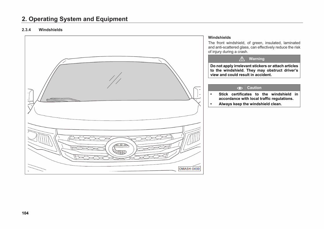
2. Operating System and Equipment
104
2.3.4 Windshields
Windshields The front windshield, of green, insulated, laminated and anti-scattered glass, can effectively reduce the risk of injury during a crash.
Warning
Do not apply irrelevant stickers or attach articles to the windshield. They may obstruct driver’s view and could result in accident.
Caution
• Stick certificates to the windshield in accordance with local traffic regulations.
• Always keep the windshield clean.
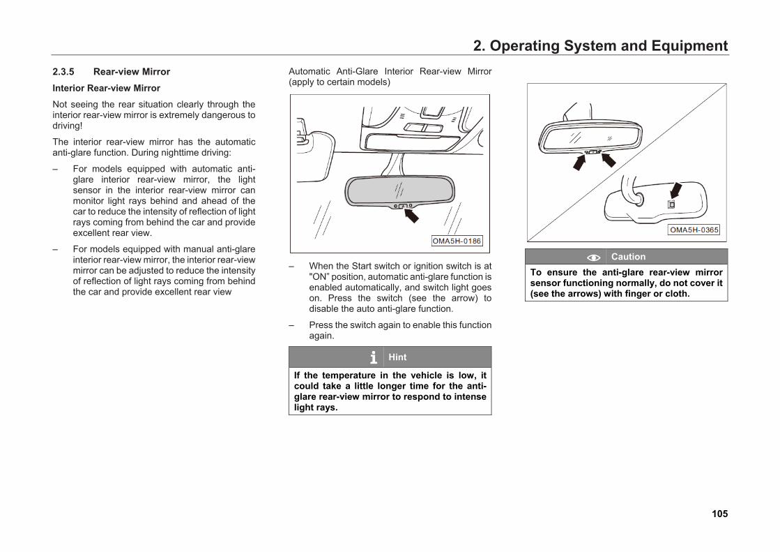
2. Operating System and Equipment
105
2.3.5 Rear-view Mirror Interior Rear-view Mirror Not seeing the rear situation clearly through the interior rear-view mirror is extremely dangerous to driving!
The interior rear-view mirror has the automatic anti-glare function. During nighttime driving:
– For models equipped with automatic anti-glare interior rear-view mirror, the light sensor in the interior rear-view mirror can monitor light rays behind and ahead of the car to reduce the intensity of reflection of light rays coming from behind the car and provide excellent rear view.
– For models equipped with manual anti-glare interior rear-view mirror, the interior rear-view mirror can be adjusted to reduce the intensity of reflection of light rays coming from behind the car and provide excellent rear view
Automatic Anti-Glare Interior Rear-view Mirror (apply to certain models)
– When the Start switch or ignition switch is at
"ON” position, automatic anti-glare function is enabled automatically, and switch light goes on. Press the switch (see the arrow) to disable the auto anti-glare function.
– Press the switch again to enable this function again.
Hint
If the temperature in the vehicle is low, it could take a little longer time for the anti-glare rear-view mirror to respond to intense light rays.
Caution To ensure the anti-glare rear-view mirror sensor functioning normally, do not cover it (see the arrows) with finger or cloth.
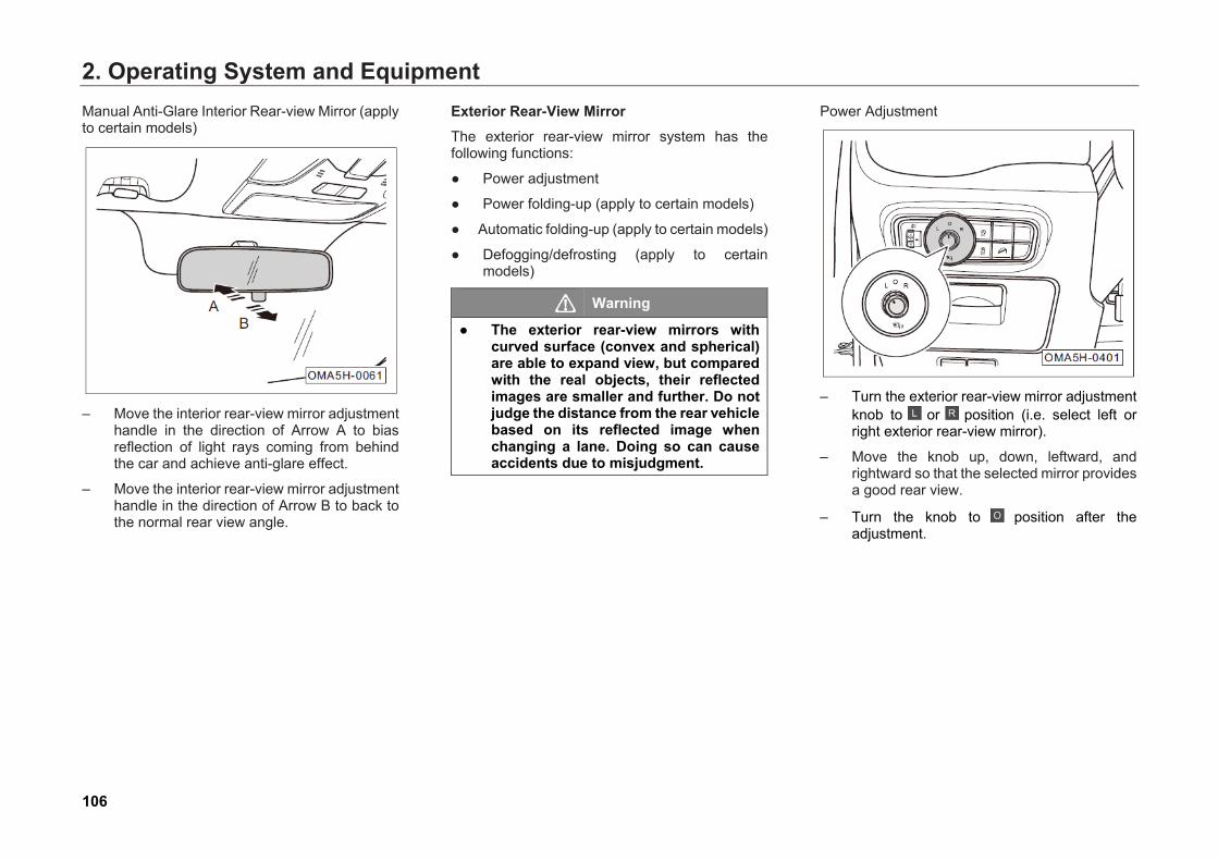
2. Operating System and Equipment
106
Manual Anti-Glare Interior Rear-view Mirror (apply to certain models)
– Move the interior rear-view mirror adjustmenthandle in the direction of Arrow A to biasreflection of light rays coming from behindthe car and achieve anti-glare effect.
– Move the interior rear-view mirror adjustmenthandle in the direction of Arrow B to back tothe normal rear view angle.
Exterior Rear-View Mirror The exterior rear-view mirror system has the following functions:
● Power adjustment
● Power folding-up (apply to certain models)
● Automatic folding-up (apply to certain models)
● Defogging/defrosting (apply to certainmodels)
Warning
● The exterior rear-view mirrors withcurved surface (convex and spherical)are able to expand view, but comparedwith the real objects, their reflectedimages are smaller and further. Do notjudge the distance from the rear vehiclebased on its reflected image whenchanging a lane. Doing so can causeaccidents due to misjudgment.
Power Adjustment
– Turn the exterior rear-view mirror adjustmentknob to or position (i.e. select left orright exterior rear-view mirror).
– Move the knob up, down, leftward, andrightward so that the selected mirror providesa good rear view.
– Turn the knob to position after the adjustment.
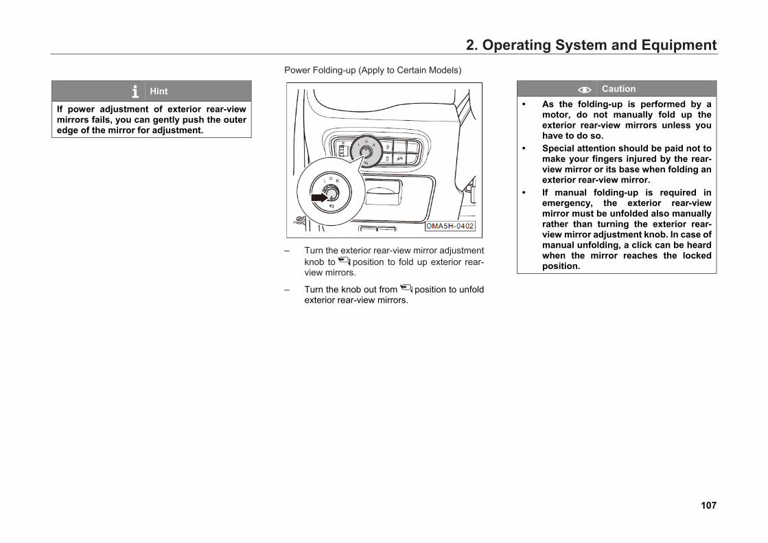
2. Operating System and Equipment
107
Hint
If power adjustment of exterior rear-view mirrors fails, you can gently push the outer edge of the mirror for adjustment.
Power Folding-up (Apply to Certain Models)
– Turn the exterior rear-view mirror adjustmentknob to position to fold up exterior rear-view mirrors.
– Turn the knob out from position to unfold exterior rear-view mirrors.
Caution • As the folding-up is performed by a
motor, do not manually fold up theexterior rear-view mirrors unless youhave to do so.
• Special attention should be paid not tomake your fingers injured by the rear-view mirror or its base when folding anexterior rear-view mirror.
• If manual folding-up is required inemergency, the exterior rear-viewmirror must be unfolded also manuallyrather than turning the exterior rear-view mirror adjustment knob. In case ofmanual unfolding, a click can be heardwhen the mirror reaches the lockedposition.
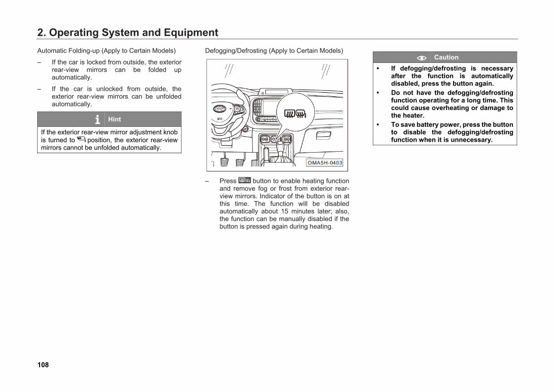
2. Operating System and Equipment
108
Automatic Folding-up (Apply to Certain Models)
– If the car is locked from outside, the exterior rear-view mirrors can be folded up automatically.
– If the car is unlocked from outside, the exterior rear-view mirrors can be unfolded automatically.
Hint
If the exterior rear-view mirror adjustment knob is turned to position, the exterior rear-view mirrors cannot be unfolded automatically.
Defogging/Defrosting (Apply to Certain Models)
– Press button to enable heating function
and remove fog or frost from exterior rear-view mirrors. Indicator of the button is on at this time. The function will be disabled automatically about 15 minutes later; also, the function can be manually disabled if the button is pressed again during heating.
Caution • If defogging/defrosting is necessary
after the function is automatically disabled, press the button again.
• Do not have the defogging/defrosting function operating for a long time. This could cause overheating or damage to the heater.
• To save battery power, press the button to disable the defogging/defrosting function when it is unnecessary.
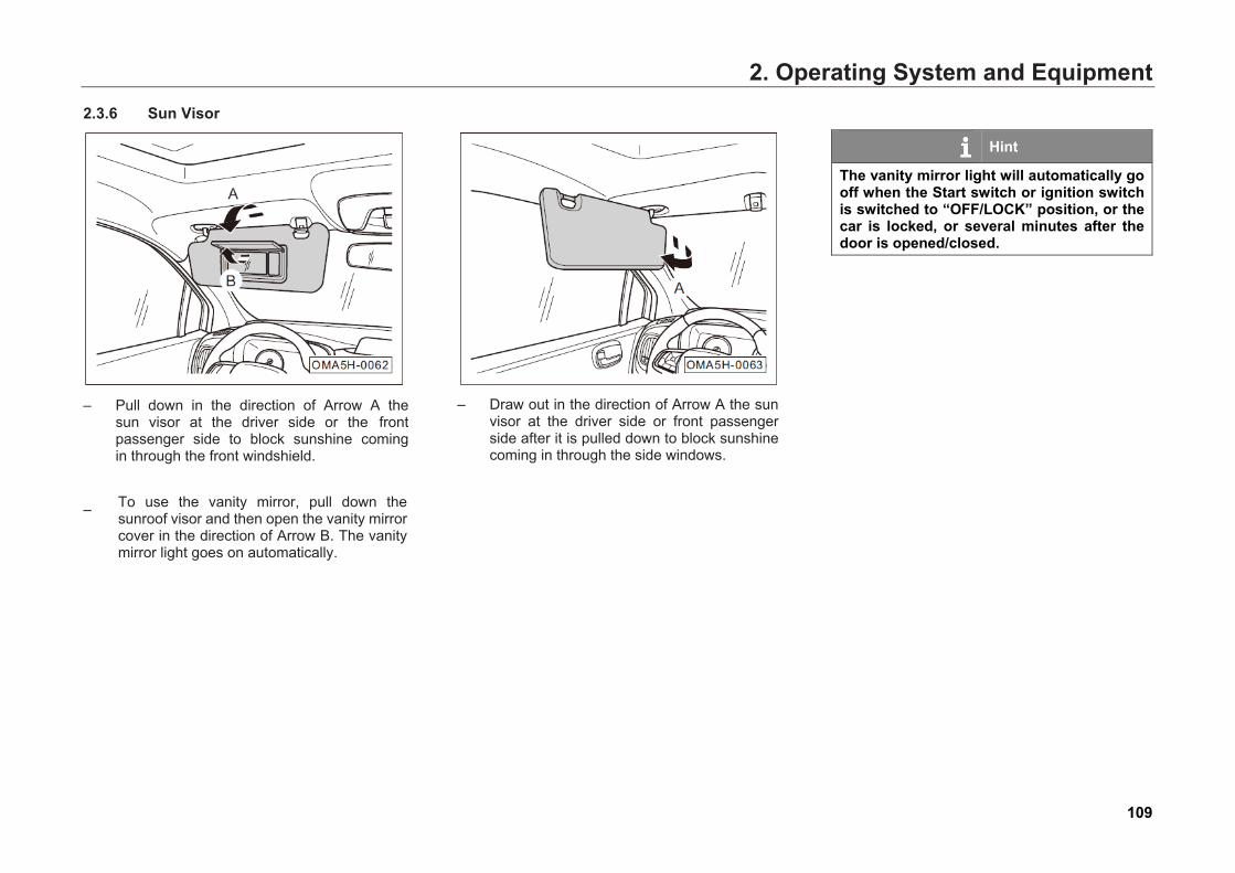
2. Operating System and Equipment
109
2.3.6 Sun Visor
– Pull down in the direction of Arrow A thesun visor at the driver side or the frontpassenger side to block sunshine comingin through the front windshield.
– To use the vanity mirror, pull down thesunroof visor and then open the vanity mirrorcover in the direction of Arrow B. The vanitymirror light goes on automatically.
– Draw out in the direction of Arrow A the sunvisor at the driver side or front passengerside after it is pulled down to block sunshinecoming in through the side windows.
Hint
The vanity mirror light will automatically go off when the Start switch or ignition switch is switched to “OFF/LOCK” position, or the car is locked, or several minutes after the door is opened/closed.
2. Operating System and Equipment
110
2.4 Seats and Storage Devices 2.4.1 Importance of Adjusting Seats Properly To maximize the protection from the seat belts and airbags, adjust the seats property.
Driver's seat or front passenger's seat can be adjusted according to the body shape.
Before the car moves off, seats shall be adjusted properly, so that the driver or passenger:
• can operate all mechanisms on theinstrument panel in an accurate, effectiveand safe manner;
• has a correct sitting posture and does not getfatigued easily.
• can be fully protected by seat belts andairbags.
Warning
Incorrect sitting posture will cause serious injury. • Any passenger should sit upright and
well back in the seat.• Be sure you and your passengers wear
the seat belts properly.• Make sure the child is restrained in the
child safety seat properly.• All the headrests must be adjusted
properly according to the height of thedriver and passengers and be sure thedriver and passengers wear the seatbelts all the time to get the bestprotection.
• During traveling, the front passengershould place the feet in the footwell.Never put the feet on the instrumentpanel/seat or stretching out of thewindow. Incorrect sitting posture willcause serious injury when the airbagsinflating.
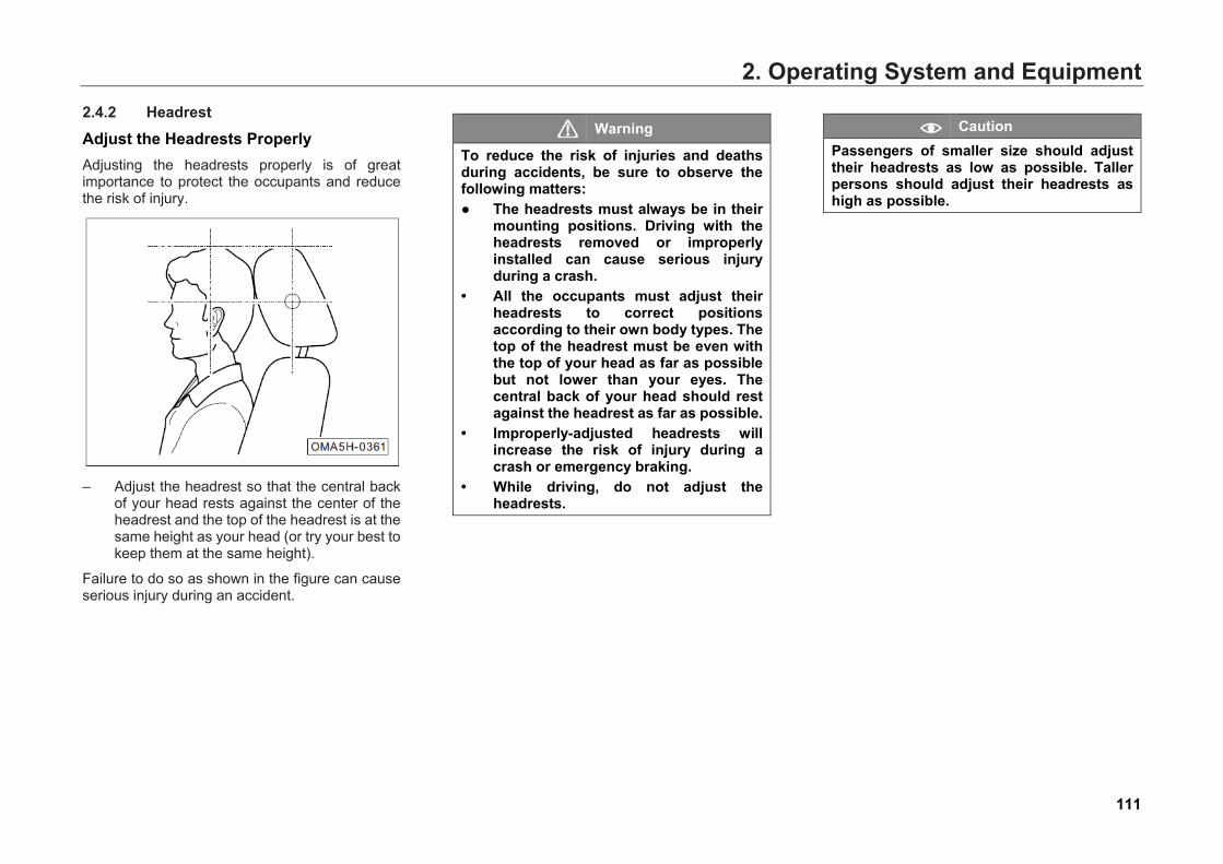
2. Operating System and Equipment
111
2.4.2 Headrest
Adjust the Headrests Properly Adjusting the headrests properly is of great importance to protect the occupants and reduce the risk of injury.
– Adjust the headrest so that the central backof your head rests against the center of theheadrest and the top of the headrest is at thesame height as your head (or try your best tokeep them at the same height).
Failure to do so as shown in the figure can cause serious injury during an accident.
Warning
To reduce the risk of injuries and deaths during accidents, be sure to observe the following matters: ● The headrests must always be in their
mounting positions. Driving with theheadrests removed or improperlyinstalled can cause serious injuryduring a crash.
• All the occupants must adjust theirheadrests to correct positionsaccording to their own body types. Thetop of the headrest must be even withthe top of your head as far as possiblebut not lower than your eyes. Thecentral back of your head should restagainst the headrest as far as possible.
• Improperly-adjusted headrests willincrease the risk of injury during acrash or emergency braking.
• While driving, do not adjust theheadrests.
Caution Passengers of smaller size should adjust their headrests as low as possible. Taller persons should adjust their headrests as high as possible.
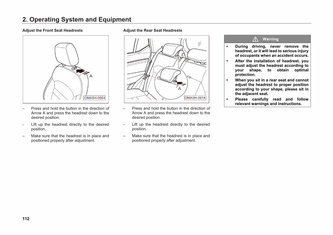
2. Operating System and Equipment
112
Adjust the Front Seat Headrests
– Press and hold the button in the direction ofArrow A and press the headrest down to thedesired position.
- Lift up the headrest directly to the desiredposition.
– Make sure that the headrest is in place andpositioned properly after adjustment.
Adjust the Rear Seat Headrests
– Press and hold the button in the direction ofArrow A and press the headrest down to thedesired position.
- Lift up the headrest directly to the desiredposition.
– Make sure that the headrest is in place andpositioned properly after adjustment.
Warning
• During driving, never remove theheadrest, or it will lead to serious injuryof occupants when an accident occurs.
• After the installation of headrest, youmust adjust the headrest according toyour shape, to obtain optimalprotection.
• When you sit in a rear seat and cannotadjust the headrest to proper positionaccording to your shape, please sit inthe adjacent seat.
• Please carefully read and followrelevant warnings and instructions.
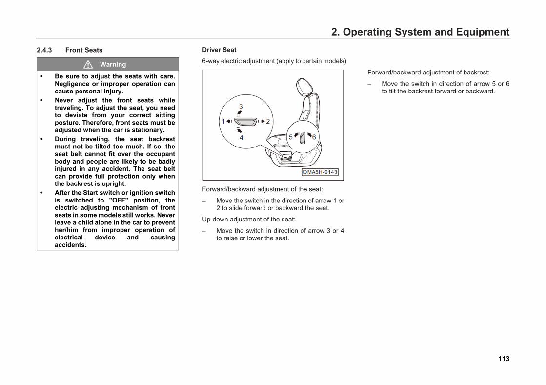
2. Operating System and Equipment2.4.3 Front Seats
Warning
• Be sure to adjust the seats with care.Negligence or improper operation cancause personal injury.
• Never adjust the front seats whiletraveling. To adjust the seat, you needto deviate from your correct sittingposture. Therefore, front seats must beadjusted when the car is stationary.
• During traveling, the seat backrestmust not be tilted too much. If so, theseat belt cannot fit over the occupantbody and people are likely to be badlyinjured in any accident. The seat beltcan provide full protection only whenthe backrest is upright.
• After the Start switch or ignition switchis switched to "OFF" position, theelectric adjusting mechanism of frontseats in some models still works. Neverleave a child alone in the car to preventher/him from improper operation ofelectrical device and causingaccidents.
Driver Seat 6-way electric adjustment (apply to certain models)
Forward/backward adjustment of the seat:
– Move the switch in the direction of arrow 1 or2 to slide forward or backward the seat.
Up-down adjustment of the seat:
– Move the switch in direction of arrow 3 or 4to raise or lower the seat.
Forward/backward adjustment of backrest:
– Move the switch in direction of arrow 5 or 6to tilt the backrest forward or backward.
113
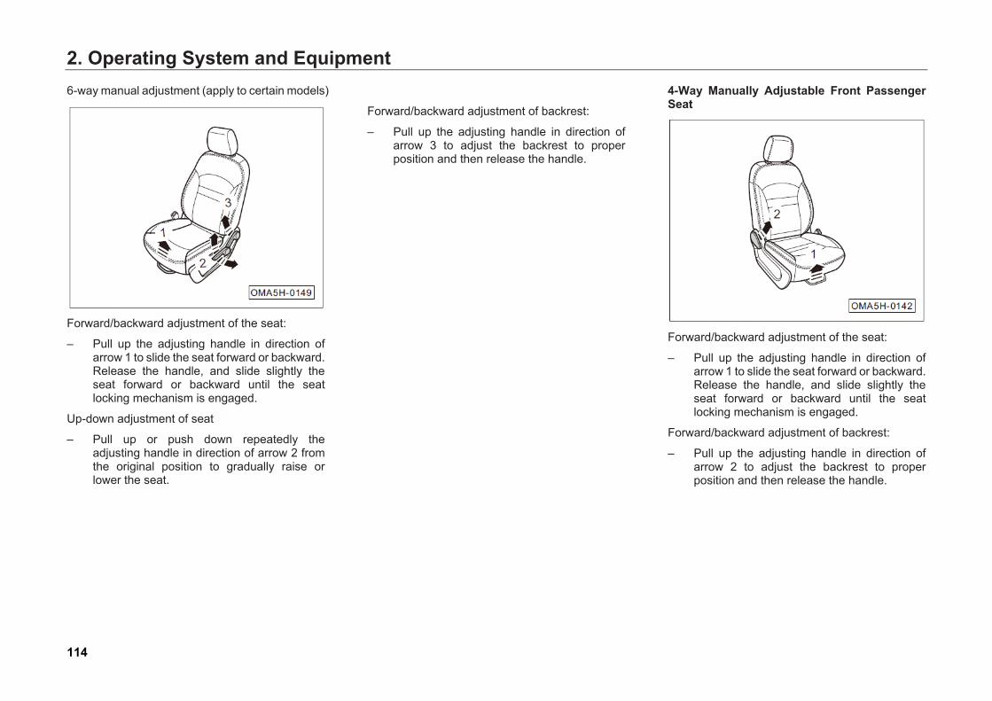
2. Operating System and Equipment6-way manual adjustment (apply to certain models)
Forward/backward adjustment of the seat:
– Pull up the adjusting handle in direction ofarrow 1 to slide the seat forward or backward. Release the handle, and slide slightly the seat forward or backward until the seat locking mechanism is engaged.
Up-down adjustment of seat
– Pull up or push down repeatedly theadjusting handle in direction of arrow 2 from the original position to gradually raise or lower the seat.
Forward/backward adjustment of backrest:
– Pull up the adjusting handle in direction ofarrow 3 to adjust the backrest to properposition and then release the handle.
4-Way Manually Adjustable Front PassengerSeat
Forward/backward adjustment of the seat:
– Pull up the adjusting handle in direction ofarrow 1 to slide the seat forward or backward.Release the handle, and slide slightly theseat forward or backward until the seatlocking mechanism is engaged.
Forward/backward adjustment of backrest:
– Pull up the adjusting handle in direction ofarrow 2 to adjust the backrest to properposition and then release the handle.
114
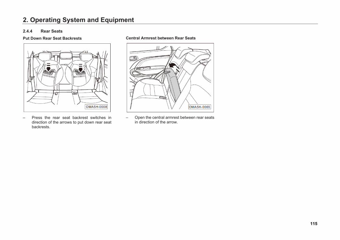
2. Operating System and Equipment2.4.4 Rear Seats Put Down Rear Seat Backrests
– Press the rear seat backrest switches indirection of the arrows to put down rear seatbackrests.
Central Armrest between Rear Seats
– Open the central armrest between rear seatsin direction of the arrow.
115
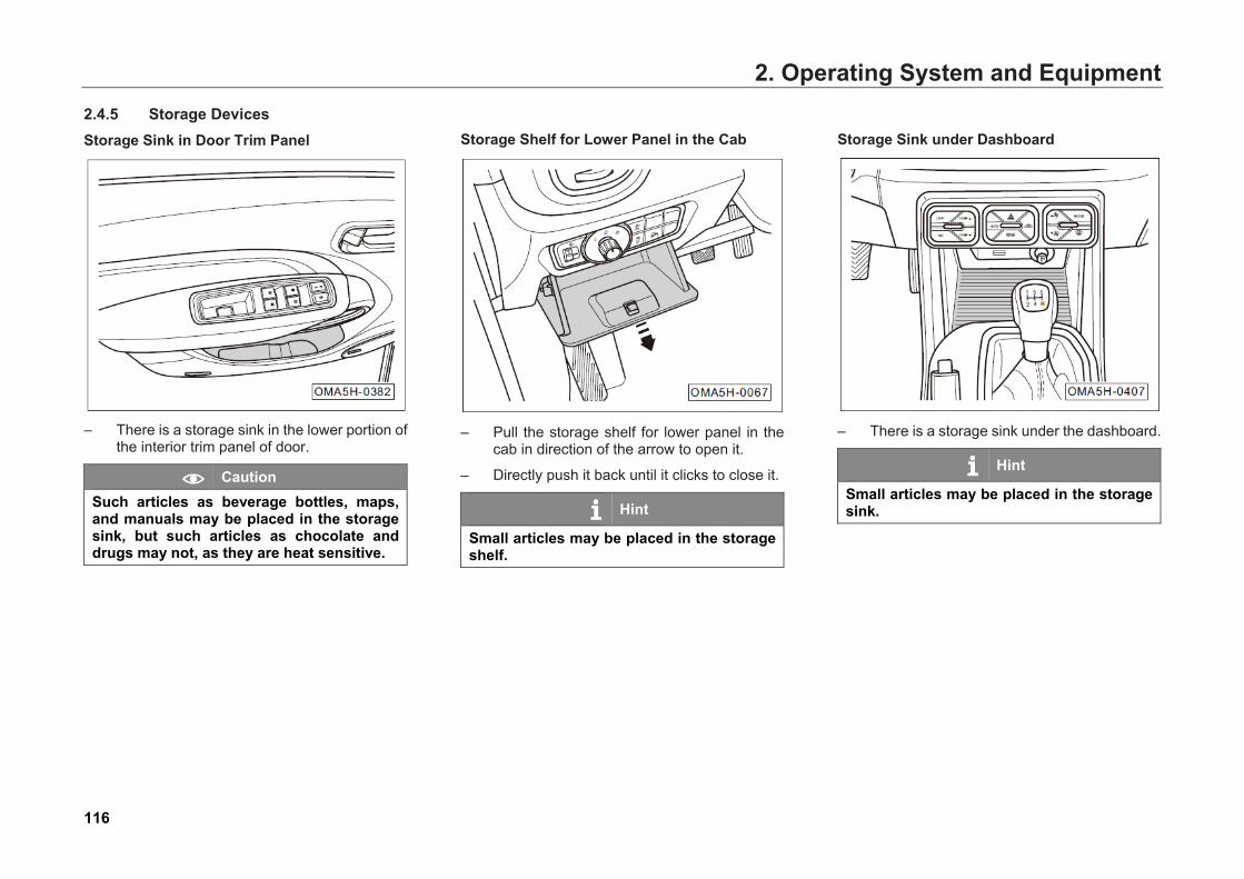
2. Operating System and Equipment2.4.5 Storage Devices Storage Sink in Door Trim Panel
– There is a storage sink in the lower portion ofthe interior trim panel of door.
Caution Such articles as beverage bottles, maps, and manuals may be placed in the storage sink, but such articles as chocolate and drugs may not, as they are heat sensitive.
Storage Shelf for Lower Panel in the Cab
– Pull the storage shelf for lower panel in thecab in direction of the arrow to open it.
– Directly push it back until it clicks to close it.
Hint
Small articles may be placed in the storage shelf.
Storage Sink under Dashboard
– There is a storage sink under the dashboard.
Hint
Small articles may be placed in the storage sink.
116
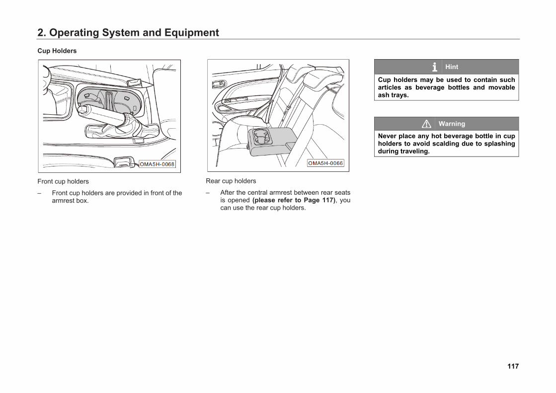
2. Operating System and EquipmentCup Holders
Front cup holders
– Front cup holders are provided in front of thearmrest box.
Rear cup holders
– After the central armrest between rear seatsis opened (please refer to Page 117), youcan use the rear cup holders.
Hint
Cup holders may be used to contain such articles as beverage bottles and movable ash trays.
Warning
Never place any hot beverage bottle in cup holders to avoid scalding due to splashing during traveling.
117
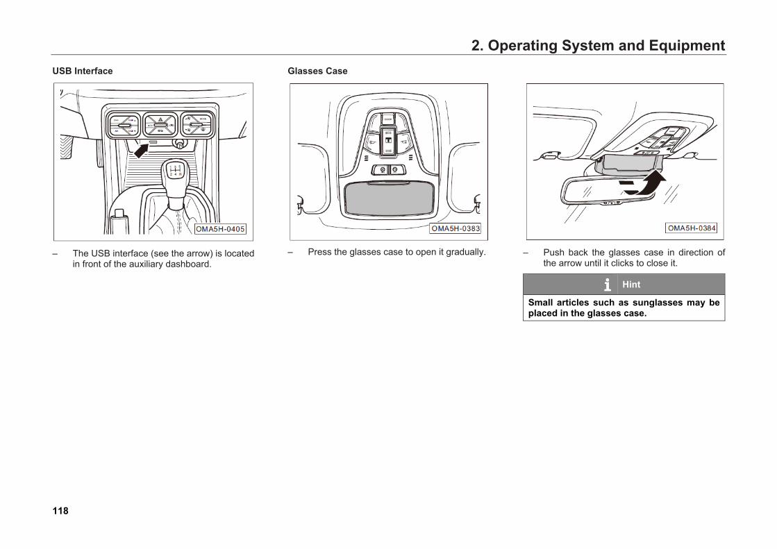
2. Operating System and EquipmentUSB Interface
– The USB interface (see the arrow) is locatedin front of the auxiliary dashboard.
Glasses Case
– Press the glasses case to open it gradually. – Push back the glasses case in direction ofthe arrow until it clicks to close it.
Hint
Small articles such as sunglasses may be placed in the glasses case.
118
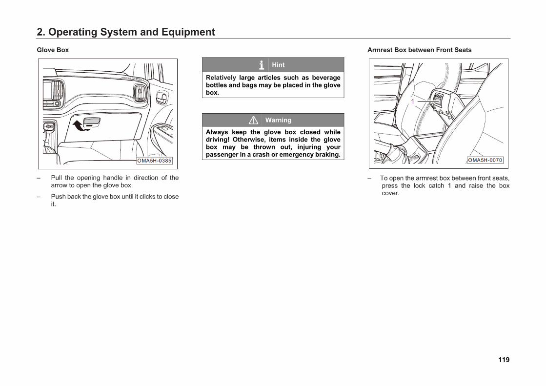
2. Operating System and EquipmentGlove Box
– Pull the opening handle in direction of thearrow to open the glove box.
– Push back the glove box until it clicks to closeit.
Hint
Relatively large articles such as beverage bottles and bags may be placed in the glove box.
Warning
Always keep the glove box closed while driving! Otherwise, items inside the glove box may be thrown out, injuring your passenger in a crash or emergency braking.
Armrest Box between Front Seats
– To open the armrest box between front seats,press the lock catch 1 and raise the boxcover.
119
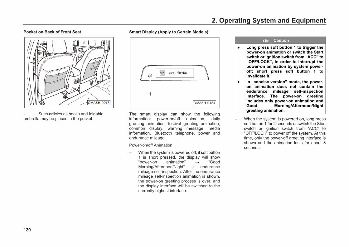
2. Operating System and EquipmentPocket on Back of Front Seat
- Such articles as books and foldableumbrella may be placed in the pocket.
Smart Display (Apply to Certain Models)
The smart display can show the following information: power-on/off animation, daily greeting animation, festival greeting animation, common display, warning message, media information, Bluetooth telephone, power and endurance mileage.
Power-on/off Animation
– When the system is powered off, if soft button1 is short pressed, the display will show“power-on animation” → “GoodMorning/Afternoon/Night” → endurancemileage self-inspection. After the endurancemileage self-inspection animation is shown,the power-on greeting process is over, andthe display interface will be switched to thecurrently highest interface.
Caution ● Long press soft button 1 to trigger the
power-on animation or switch the Startswitch or ignition switch from “ACC” to“OFF/LOCK”, in order to interrupt thepower-on animation by system power-off; short press soft button 1 toinvalidate it.
● In “concise version” mode, the power-on animation does not contain theendurance mileage self-inspectioninterface. The power-on greetingincludes only power-on animation andGood Morning/Afternoon/Nightgreeting animation.
– When the system is powered on, long presssoft button 1 for 2 seconds or switch the Startswitch or ignition switch from “ACC” to“OFF/LOCK” to power off the system. At thistime, only the power-off greeting interface isshown and the animation lasts for about 8seconds.
120
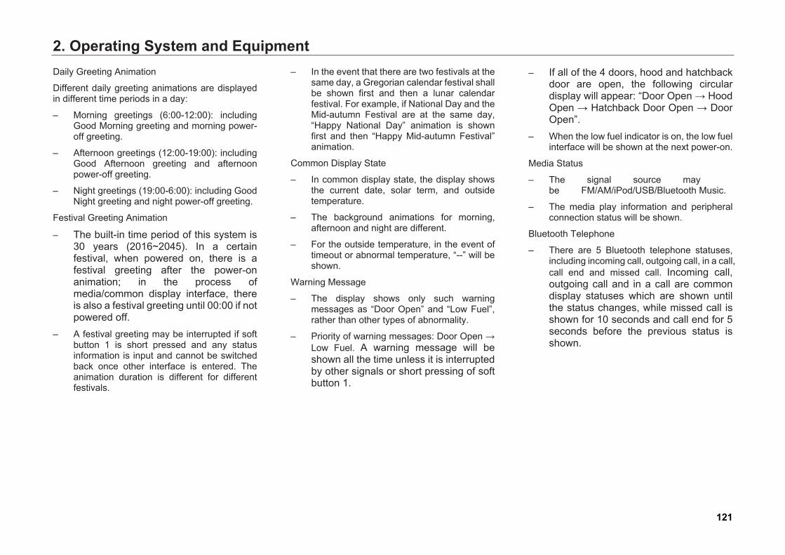
2. Operating System and EquipmentDaily Greeting Animation
Different daily greeting animations are displayed in different time periods in a day:
– Morning greetings (6:00-12:00): includingGood Morning greeting and morning power-off greeting.
– Afternoon greetings (12:00-19:00): includingGood Afternoon greeting and afternoonpower-off greeting.
– Night greetings (19:00-6:00): including GoodNight greeting and night power-off greeting.
Festival Greeting Animation
– The built-in time period of this system is30 years (2016~2045). In a certainfestival, when powered on, there is afestival greeting after the power-onanimation; in the process ofmedia/common display interface, thereis also a festival greeting until 00:00 if notpowered off.
– A festival greeting may be interrupted if softbutton 1 is short pressed and any statusinformation is input and cannot be switchedback once other interface is entered. Theanimation duration is different for differentfestivals.
– In the event that there are two festivals at thesame day, a Gregorian calendar festival shallbe shown first and then a lunar calendarfestival. For example, if National Day and theMid-autumn Festival are at the same day,“Happy National Day” animation is shownfirst and then “Happy Mid-autumn Festival”animation.
Common Display State
– In common display state, the display showsthe current date, solar term, and outsidetemperature.
– The background animations for morning,afternoon and night are different.
– For the outside temperature, in the event oftimeout or abnormal temperature, “--” will beshown.
Warning Message
– The display shows only such warningmessages as “Door Open” and “Low Fuel”,rather than other types of abnormality.
– Priority of warning messages: Door Open →Low Fuel. A warning message will beshown all the time unless it is interruptedby other signals or short pressing of softbutton 1.
– If all of the 4 doors, hood and hatchbackdoor are open, the following circulardisplay will appear: “Door Open → HoodOpen → Hatchback Door Open → DoorOpen”.
– When the low fuel indicator is on, the low fuelinterface will be shown at the next power-on.
Media Status
– The signal source may be FM/AM/iPod/USB/Bluetooth Music.
– The media play information and peripheralconnection status will be shown.
Bluetooth Telephone
– There are 5 Bluetooth telephone statuses,including incoming call, outgoing call, in a call,call end and missed call. Incoming call,outgoing call and in a call are commondisplay statuses which are shown untilthe status changes, while missed call isshown for 10 seconds and call end for 5seconds before the previous status isshown.
121
2. Operating System and EquipmentEndurance Mileage
– After the power-on greeting animation, theendurance mileage will be shown for 6seconds.
– Endurance mileage: 0 represents for lowmileage, and in this case, the display willshow “Low Mileage” warning.
Hint
● If the system has not received any validdata, the display shows “--” for thecorresponding data.
● When the Start switch or ignitionswitch is at "ACC" position, the displayshows “--”.
● When the Start switch or ignitionswitch is switched from “ACC” to“ON”, the display shows “--” within thefirst 3 seconds. If valid data is receivedafter 3 seconds, it shows the validvalue of endurance mileage.
Interface Switching
– When the system is powered on, switch theinterface such as power-on/off animationinterface, festival greeting animationinterface and Bluetooth incoming callinterface according to built-in settings of thesystem.
– Short press soft button 1 to switch the displayinterface.
Operating Mode
– The operating mode may be “concise version”or “full version” mode:
● Concise version: Only power-on/off interface,festival greeting and common displayanimation interfaces are displayed. Thedisplay update will not be triggered even ifthere is relevant input signal.
● Full version: All interfaces are displayed.
– When switching from “concise version” to“full version” mode, if the current displayinterface is not a festival greeting interface,the current interface will be switched tocommon display interface, and timing echofunction of the previous Bluetooth andwarning will stop.
– When switching from “full version” to“concise version” mode, the interface for thevalid signal of the top priority among all of thesignals will be displayed, and timing echofunction of the previous Bluetooth andwarning will be recovered. The display ofperipheral connection status and festivalgreeting will not continuous, and will not berecovered when switching from “conciseversion” to “full version” mode.
Hint
The display mode of the smart display can be set as “concise version” to “full version” via “Guang Xiaoqi Smart Display” function in “Smart Body” of “Car Setting” under audio system (please refer to Page 196).
122

2. Operating System and Equipment2.4.6 Cigarette Lighter/Power Outlet Central Console Cigarette Lighter/Power Outlet
– With the Start switch or ignition switch at"ON" or "ACC” position, when thecigarette lighter is pressed down, youcan pull it out after it pops upautomatically.
– You can use the power outlet after pulling outthe cigarette lighter.
Rear Seat USB Power (Apply to Certain Models)
– A USB power interface is provided behindthe central armrest box for direct connectionof USB wire.
Trunk Power Supply Socket (Apply to Certain Models)
– You can use the power supply socket afterpulling up the power supply socket cover.
Warning
● Improper use of power outlet can causefire. Do not leave a child alone in thecar.
● To prevent fire hazards, never usepower outlet when nobody is in the car.
123
2. Operating System and Equipment
Caution ● To avoid damage to the electrical
system, do not connect any generatingequipment to the power outlet.
● Use only electrical equipment in linewith the national electromagneticcompatibility norms.
● To avoid damage to electricalequipment connected to power outletdue to voltage fluctuation, be sure toturn off the electrical equipment whenthe Start switch is turned on/off.
124
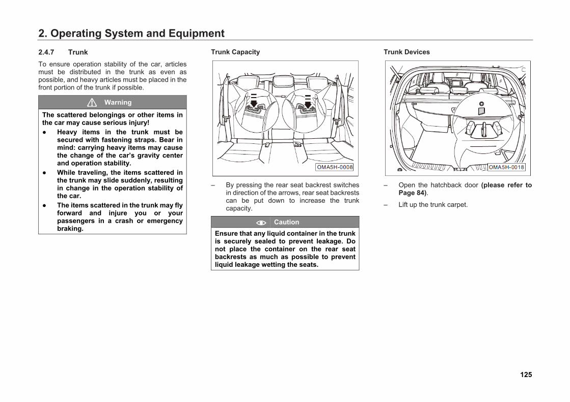
2. Operating System and Equipment2.4.7 Trunk To ensure operation stability of the car, articles must be distributed in the trunk as even as possible, and heavy articles must be placed in the front portion of the trunk if possible.
Warning
The scattered belongings or other items in the car may cause serious injury! ● Heavy items in the trunk must be
secured with fastening straps. Bear inmind: carrying heavy items may causethe change of the car’s gravity centerand operation stability.
● While traveling, the items scattered inthe trunk may slide suddenly, resultingin change in the operation stability ofthe car.
● The items scattered in the trunk may flyforward and injure you or yourpassengers in a crash or emergencybraking.
Trunk Capacity
– By pressing the rear seat backrest switchesin direction of the arrows, rear seat backrestscan be put down to increase the trunkcapacity.
Caution Ensure that any liquid container in the trunk is securely sealed to prevent leakage. Do not place the container on the rear seat backrests as much as possible to prevent liquid leakage wetting the seats.
Trunk Devices
– Open the hatchback door (please refer toPage 84).
– Lift up the trunk carpet.
125
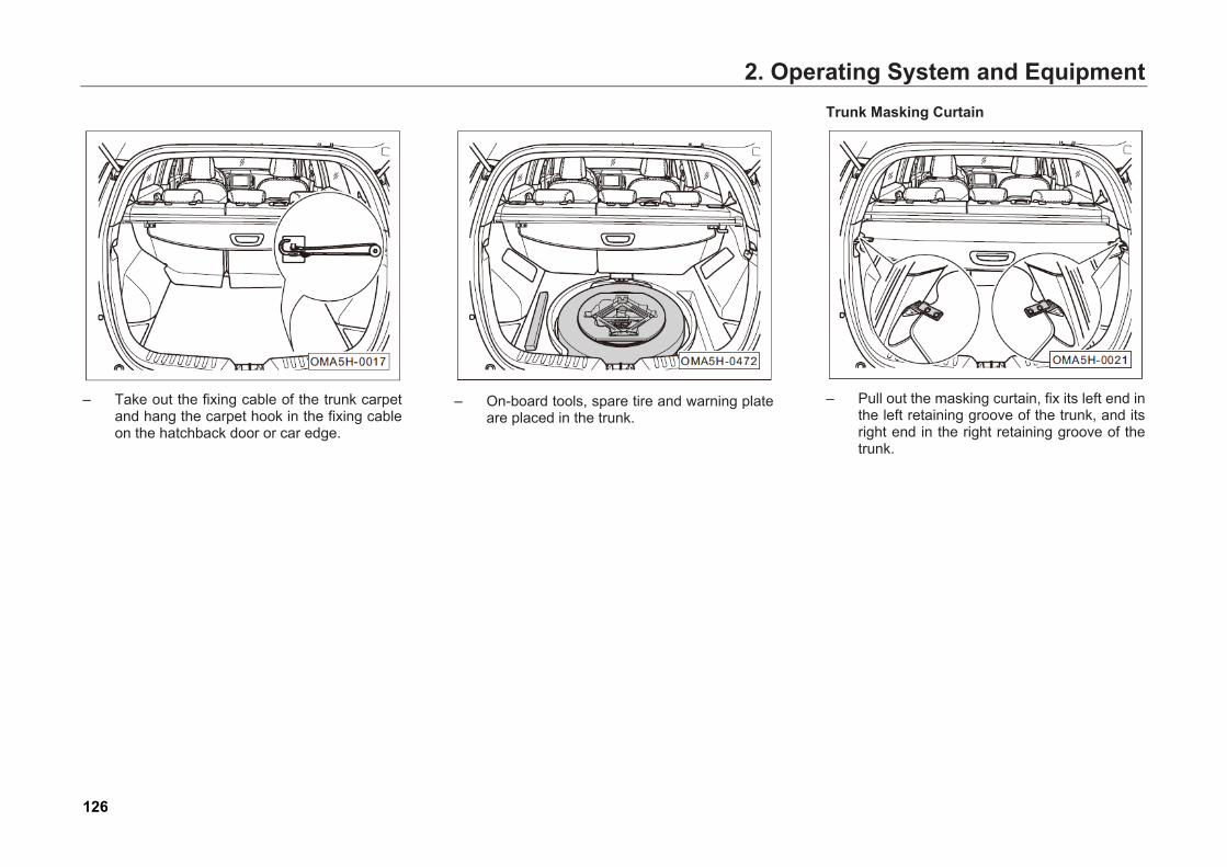
2. Operating System and Equipment
– Take out the fixing cable of the trunk carpetand hang the carpet hook in the fixing cableon the hatchback door or car edge.
– On-board tools, spare tire and warning plateare placed in the trunk.
Trunk Masking Curtain
– Pull out the masking curtain, fix its left end inthe left retaining groove of the trunk, and itsright end in the right retaining groove of thetrunk.
126
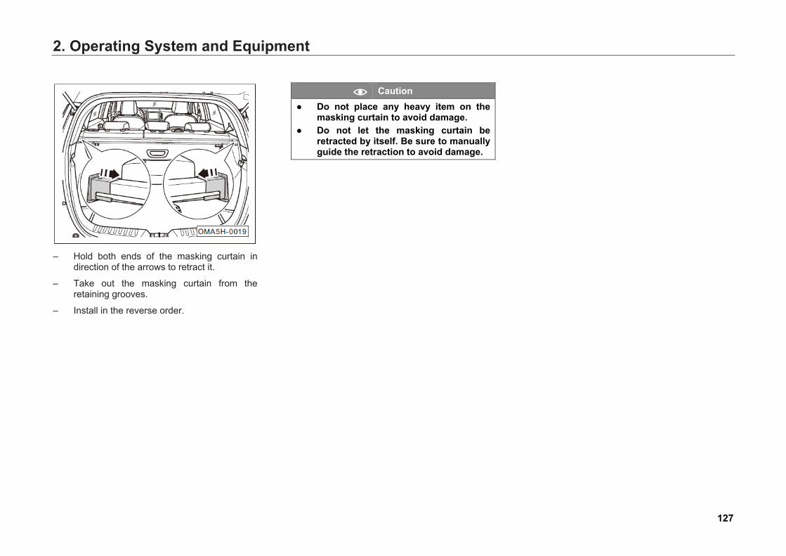
2. Operating System and Equipment
– Hold both ends of the masking curtain indirection of the arrows to retract it.
– Take out the masking curtain from theretaining grooves.
– Install in the reverse order.
Caution ● Do not place any heavy item on the
masking curtain to avoid damage.● Do not let the masking curtain be
retracted by itself. Be sure to manuallyguide the retraction to avoid damage.
127
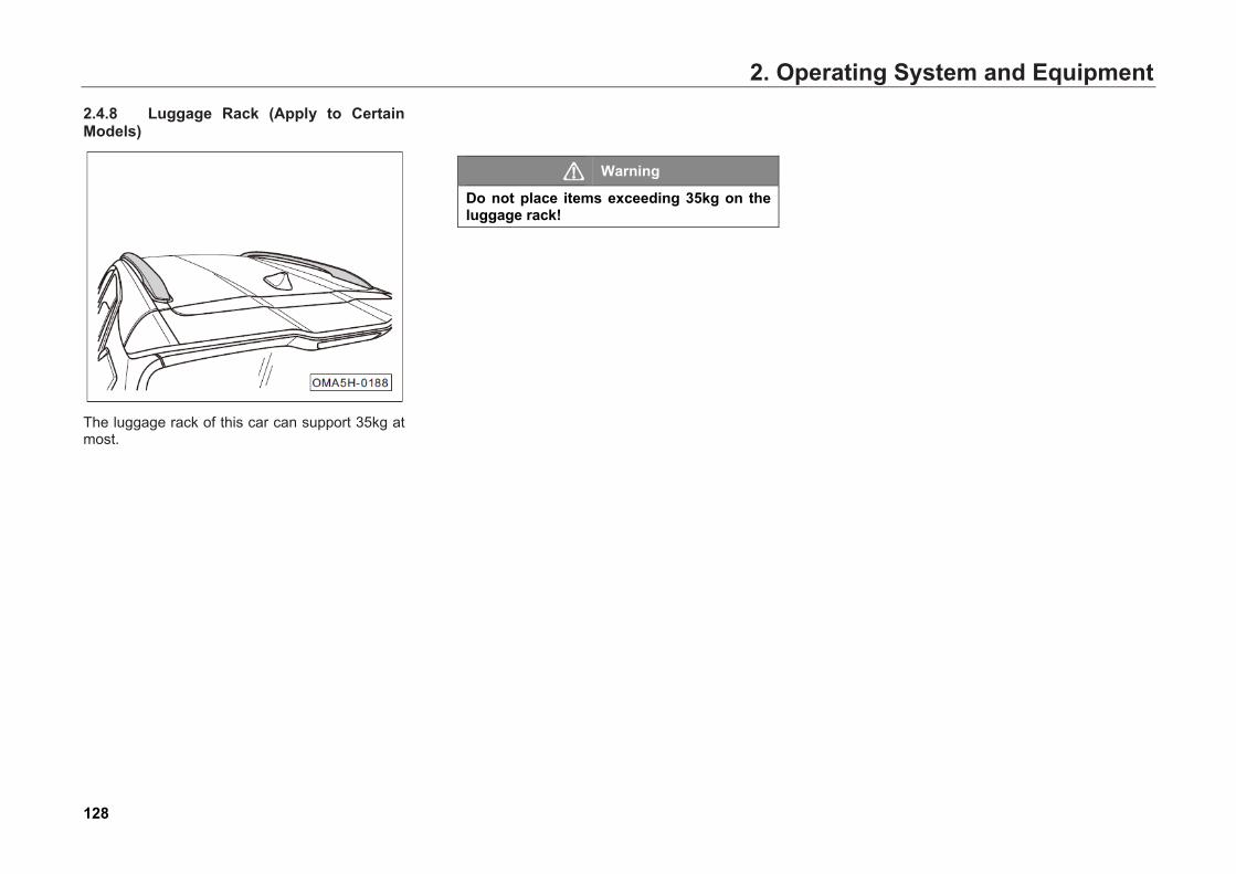
2. Operating System and Equipment2.4.8 Luggage Rack (Apply to Certain Models)
The luggage rack of this car can support 35kg at most.
Warning
Do not place items exceeding 35kg on the luggage rack!
128
2. Operating System and Equipment2.4.9 Accessories and Modifications The data labels and signboards attached to the fuel tank cap, engine hood lock rack and other auto components of the car, when delivered, contain important data and information on car operation. Do not remove or damage such labels and signboards. Always keep the data and information on the labels and signboards clear and readable.
This car is designed with the latest safety technique to ensure excellent active safety and passive safety. Therefore, to maintain the car's excellent features, before installing accessories and replacing components, be sure to consult GAC MOTOR dealer.
We recommend you always use the accessories and components which have been designed and approved for your car. We are not responsible for any component not manufactured by us.
Warning
Improper accessories or modifications may affect your car's operation stability and other performance, and may lead to severe injury or death.
If car phone, alarm device, two-way radio equipment, and low-power audio system need to be installed, they should not interfere with your car's computer control system, such as Anti-lock Brake System (ABS).
Before installing any accessory:
1. Make sure that the accessory does not dimany light, or affect proper operation orperformance of the car.
2. Do not install accessories on the B-pillar oracross the rear windows for cars equippedwith side curtain airbags. Accessoriesinstalled in these areas may interfere withproper operation of side curtain airbags.
129
2. Operating System and EquipmentModifying Your Car Removing components from your car, or replacing components with non-GAC MOTOR model components could seriously affect your car's operation stability and reliability. For example:
● Installing larger or smaller wheels and tirescan interfere with proper operation of ABSand other systems.
● Modifying the steering wheel or any othersafety facility may lead to system failure.
Warning
● Improper accessories or modificationscan easily cause faults and accidents.We recommend you always use theapproved accessories andcomponents with strictly-verifiedadaptability, reliability and safety byGAC MOTOR.
● Improper maintenance ormodifications can weaken theprotection from airbags, and causesystem failure and fatal accidents. Donot install or connect the beverage cupholder, phone holder and otheraccessories onto the cover of airbagassembly or in the range of action ofairbags.
● Improper operation or modifications(modification of the engine, brakesystem, running system orcomponents affecting the performanceof the wheels and tires) can affect thefunction of the SRS system, resulting inserious injury or death.
● Do not install wheels and tires notapproved by GAC MOTOR.
● Modifying the front part of the car andthe engine compartment candeteriorate pedestrian protectionperformance of the car and violates theroad regulations.
130
2. Operating System and Equipment2.5 A/C System 2.5.1 General Instructions The A/C filter can remove the pollen and dust brought in by the heating and cooling system from the outside.
Be sure to replace the A/C filter at scheduled maintenance.
See the Maintenance Schedule in the Warranty Manual.
Shorten the replacement interval of the A/C filter if you often drive in the urban area with heavy smoke caused by factories and diesel-powered cars. Replace the A/C filter as soon as possible if the air flow from the heating and cooling system is not smooth as usual.
Warning
● Activate the Recirculation Mode asneeded. Deactivate it when there is noneed.
• Blurred windows easily increase therisk of accidents and casualties. Forthe sake of safety, all the windows mustbe free of ice, snow and fog to ensureclear vision.
● Turbid air in the car will make the driverfatigued, depressed and distracted,resulting in accidents and casualtieseasily.
Caution ● The expertise and special tools are
essential to the diagnosis and repair ofA/C system. Therefore, if your A/Csystem fails or is suspected to fail, goto the authorized GAC MOTOR dealerto have it checked and repaired.
Hint
● When the outside temperature andhumidity are high, moisture in the airwill condense on the evaporator of therefrigeration system, resulting in waterdroplets dripping from the evaporatorto form water under the car. This isnormal, and there is no need to worry.
● The air inlet in front of the frontwindshield should be unblocked, andmake sure it is not clogged by snow,ice and leaves to ensure normalheating and cooling and prevent thefront windshield from fogging up.
● All the windows and the sunroof mustbe closed for the A/C system to play amaximum effect. If the car has beenexposed to the burning sun and it isvery hot in the car, you should brieflyopen the windows to dissipate the heatand accelerate cooling.
131
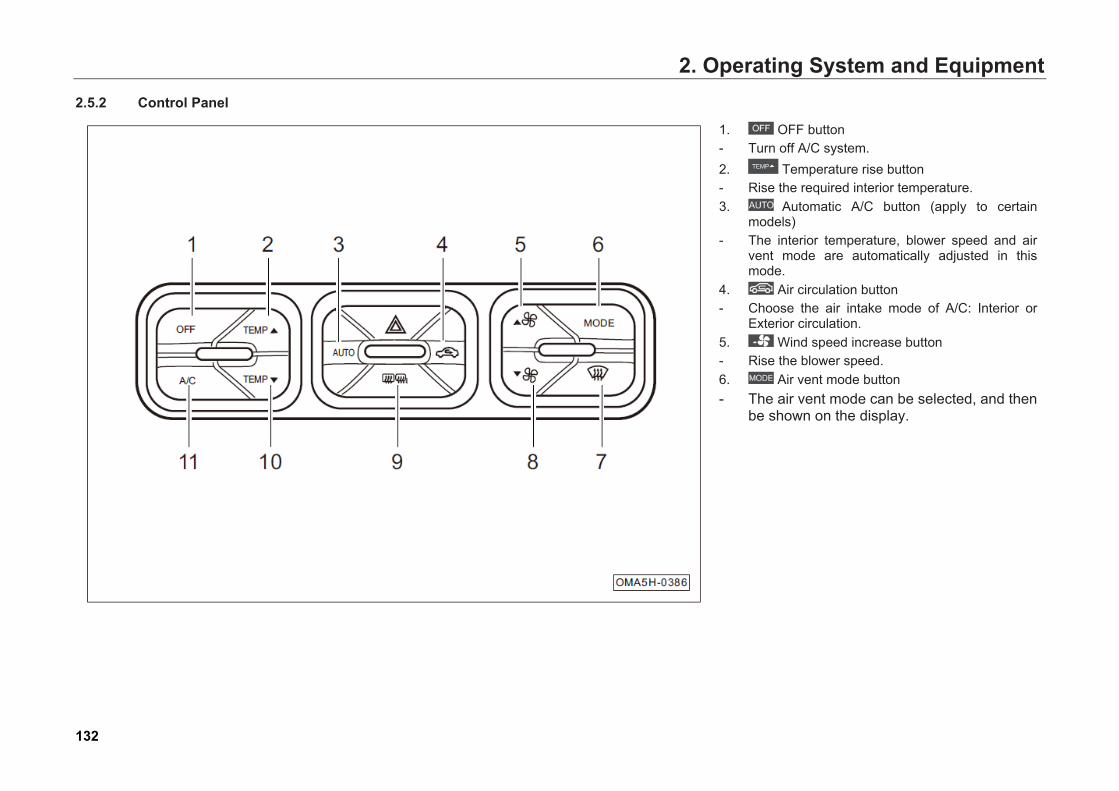
2. Operating System and Equipment2.5.2 Control Panel
1. OFF button- Turn off A/C system.2. Temperature rise button- Rise the required interior temperature.3. Automatic A/C button (apply to certain
models)- The interior temperature, blower speed and air
vent mode are automatically adjusted in thismode.
4. Air circulation button- Choose the air intake mode of A/C: Interior or
Exterior circulation.5. Wind speed increase button- Rise the blower speed.6. Air vent mode button- The air vent mode can be selected, and then
be shown on the display.
132
2. Operating System and Equipment7. Front windshield defrosting/defogging
button
- Remove the surface snow, frost or fog withthe air flow from A/C system.
8. Wind speed decrease button
- Decrease the blower speed.
9. Rear windshield and exterior rear-viewmirror defrosting/defogging button (apply tocertain models)
- Heat electrically the rear windshield andexterior rear-view mirrors to remove thesurface snow, frost or fog.
10. Temperature drop button
- Down the required interior temperature.
11. A/C button
- Turn on/off the A/C system.
Hint
A/C system of certain models can be controlled through the audio system as well (Please refer to Page 198).
133
2. Operating System and EquipmentA/C Off
Press button to turn off A/C system. After A/C system is off, the air condition compressor is turned off and the wind speed at the air outlet is 0.
After A/C system is off, , , and buttons can be operated effectively, without turning on A/C system. and buttons are unavailable. If any button of (apply to certain models), and is operated, the A/C system will be on.
Temperature Setting The interior temperature can be set through temperature rise button ( ) and temperature drop button ( ). When the interior temperature is set:
● The adjusted temperature value is shown onthe audio system display. The temperature isadjustable within 18.5℃~31.5℃.
● Each step for temperature adjustment is0.5℃.
● When the set temperature is lower than18.5℃, LO is shown on the display; when the
set temperature is greater than 31.5℃, HI isshown on the display.
Temperature setting will not change the operation mode of the A/C system.
In "AUTO" mode, when LO/HI is reached, the system will keep operating in a large amount of air ventilation state (apply to certain models).
In "AUTO" mode, in order to obtain the most ideal interior temperature, we recommend that the set temperature is 25.0 ℃ . If necessary, you can adjust the temperature by yourself (apply to certain models).
Hint
The temperature value on the display is the target value of the set temperature, instead of the measured value of the interior temperature.
134
2. Operating System and EquipmentAUTO Mode (Apply to Certain Models)
Press button to light on the button light. A/C system enters full automatic operation mode. Auto control will be performed for the following items in accordance with the setting:
● Air vent temperature.
● Air volume at the air outlet.
● Air vent mode.
● Air circulation mode.
● Working conditions of A/C system (A/C).
Press button to light off the button light. A/Csystem exits full automatic operation mode.
Air Circulation
Press button continuously to make air circulation mode switch between interior circulation and exterior circulation.
- Interior air circulation: Press button to light on the button light. Air circulation enters interior air circulation mode. When this mode is available:
● It can prevent the outside air fromentering the car to make the interior aircirculate.
● It can prevent the exhaust of othervehicles or other dirty air from enteringthe car.
● In auto control mode in summer, thesystem will strengthen the refrigerationeffect with interior air circulation mode.
- Exterior air circulation: Press button tolight off the button light. Air circulation entersexterior air circulation mode. When this modeis available:
● This function will introduce the outsideair into the car to keep fresh interior air.
Caution ● Prolonged interior air circulation will
cause accumulation of carbon dioxidein the car, and it is not conducive tokeep the driver awake.
● Using the interior air circulation modein cold or rainy weather is easy tocause fogging of window, to affect thedriver’s vision.
135
2. Operating System and EquipmentWind Speed Setting Manual control and auto control can be performed for the wind speed setting (apply to certain models).
Press or button to control the wind speed at the air outlet manually. The wind speed scale is within 1~7. The corresponding wind speed scale will be shown on the display:
: Pressing each, the wind speed at the air outlet decreases a scale.
: Pressing each, the wind speed at the air outlet increases a scale.
In "AUTO" mode, the system will control the wind speed at the air outlet automatically. The wind speed at the air outlet is not limited to 7-scale regulation in manual state, but there are only 7-scale indicating bar on the display, so the number of the indicating bars shown is the proximate one. To achieve the target value of the interior temperature, the wind speed will be adjusted automatically (apply to certain models).
In "AUTO" mode, if or button is pressed, the system will be switched to "Manual" mode from "AUTO" mode, and the "AUTO" identification will disappear (apply to certain models).
Air Vent Mode Manual control and auto control can be performed for the air vent mode (apply to certain models).
Press button continuously to control the air vent mode at the air outlet manually. The circulation switching sequences of the air vent mode are listed as follows:
: Face blowing mode. Air is blown out from the air outlet of the instrument panel.
: Face and foot blowing mode. Air is blown out from the air outlets of the instrument panel and the footwell.
: Foot blowing mode. Air is blown out from the air outlet of the footwell.
: Foot and front windshield blowing mode. Air is blown out from the defrosting air outlet of the front windshield and the air outlet of the footwell.
In "AUTO" mode, the system will control the air vent mode automatically. The basic factor to affect the air vent mode is the air vent temperature (apply to certain models):
● When the air vent temperature is hotter, theair flow will be blown towards the feet;
● When the air vent temperature is cooler, theair flow will be blown towards the face.
When A/C system is in "AUTO" mode, if button is pressed, the system will be switched to "Manual" mode from "AUTO" mode, and the "AUTO" identification will disappear (apply to certain models).
Hint
● To ensure that A/C system caneffectively control all the air ventmodes automatically, please open allthe air outlets.
● Under cold start in winter, the blowingmode will be switched over from thefront windshield blowing mode in"AUTO" mode.
136
2. Operating System and EquipmentFront Windshield Defrosting
Press button to light on the button light and enable the front windshield defrosting function. The system will perform the following settings automatically:
● Increase the wind speed of air vent.
● Turn on the A/C system (A/C).
● The air vent mode is the front windshieldblowing mode.
● Air circulation is the exterior circulation mode.
Press button again to light off the button light, disable the front windshield defrosting function, and return to the state before the defrosting action; or press button to directly enter the auto control state to stop the front windshield defrosting function (apply to certain models).
Caution When the coldest temperature is set, using the defrosting function may cause fog on the outside of the windshield to affect the driver’s vision. When the defrosting function is used, the temperature is suggested to be set at hot or warm position.When the defrosting function is used at an ambient temperature of greater than 0℃, if the A/C function (A/C) is off manually, it may cause the fog on the front windshield to affect the driver’s vision, and even lead to traffic accidents.
Rear Windshield Defrosting
Press button to light on the button light and enable the rear windshield defrosting function to heat the rear windshield and the rear-view mirrors electrically (apply to certain models).
During the rear windshield defrosting, you can press button again to light off the button light and disable the rear windshield defrosting function. If the rear windshield defrosting function is not off, this function will be off automatically after the continuous working for 15 minutes.
Caution Prolonged rear windshield defrosting function may make low battery voltage to lead to be unable to start the car without starting the engine.
137

2. Operating System and EquipmentA/C Button
Press button to light on the button light. A/C system will enable the refrigeration function. When the refrigeration function is on:
● This means the refrigeration/dehumidification is needed, but the air condition compressor is not necessary to run.
● When the temperature outside is lower than0℃, if the refrigeration function of A/C is on,the button light will be on, but the air conditioncompressor may not work.
Press button again to light off the button light. The A/C system will disable the refrigeration function.
Sunlight Sensor The full automatic A/C control system can measure the interior and exterior sunlight intensity. Pay attention to not cover the sensor in the driving process.
Caution Due to different environment areas and vehicle conditions, the ambient temperature shown may be different from the actual value.
138
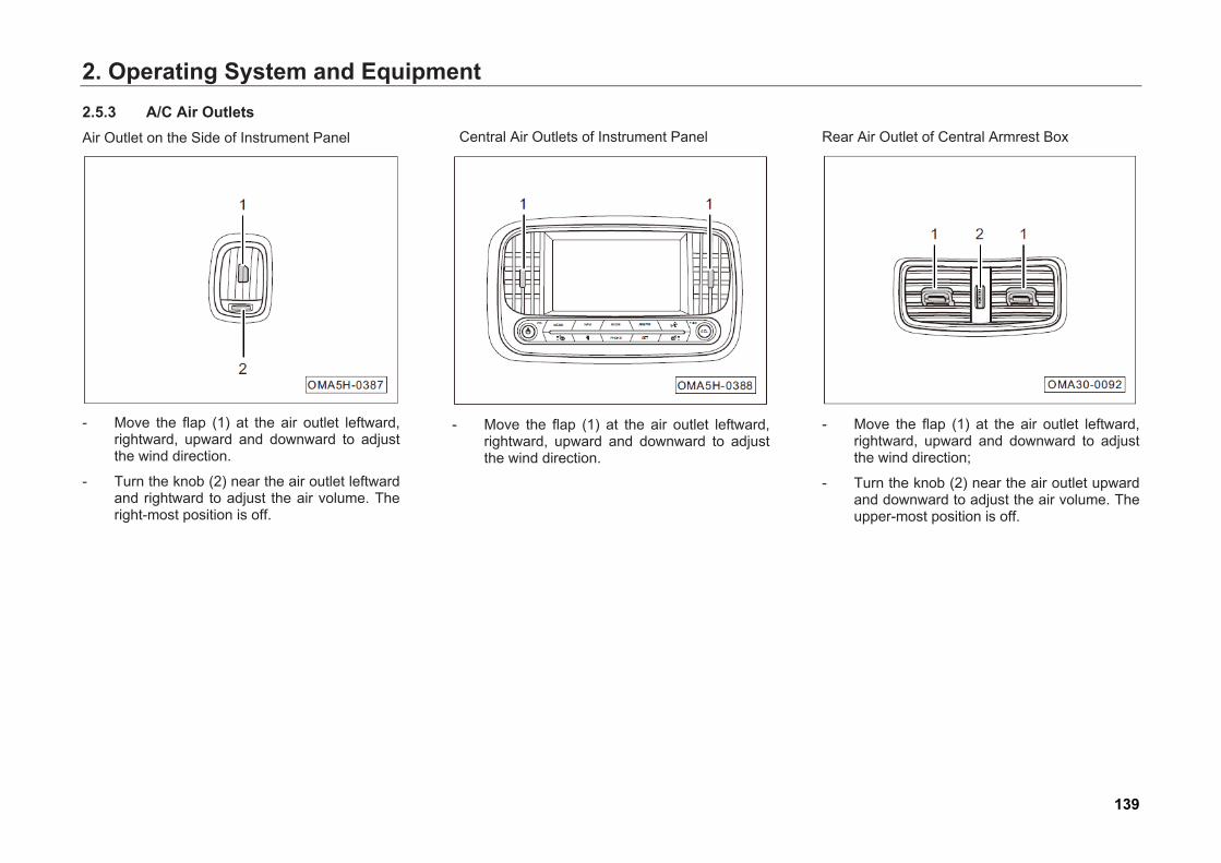
2. Operating System and Equipment2.5.3 A/C Air Outlets Air Outlet on the Side of Instrument Panel
- Move the flap (1) at the air outlet leftward,rightward, upward and downward to adjustthe wind direction.
- Turn the knob (2) near the air outlet leftwardand rightward to adjust the air volume. Theright-most position is off.
Central Air Outlets of Instrument Panel
- Move the flap (1) at the air outlet leftward,rightward, upward and downward to adjustthe wind direction.
Rear Air Outlet of Central Armrest Box
- Move the flap (1) at the air outlet leftward,rightward, upward and downward to adjustthe wind direction;
- Turn the knob (2) near the air outlet upwardand downward to adjust the air volume. Theupper-most position is off.
139
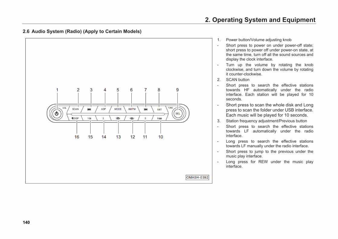
2. Operating System and Equipment2.6 Audio System (Radio) (Apply to Certain Models)
1. Power button/Volume adjusting knob- Short press to power on under power-off state;
short press to power off under power-on state, atthe same time, turn off all the sound sources anddisplay the clock interface.
- Turn up the volume by rotating the knobclockwise, and turn down the volume by rotatingit counter-clockwise.
2. SCAN button- Short press to search the effective stations
towards HF automatically under the radiointerface. Each station will be played for 10seconds.
- Short press to scan the whole disk and Longpress to scan the folder under USB interface.Each music will be played for 10 seconds.
3. Station frequency adjustment/Previous button- Short press to search the effective stations
towards LF automatically under the radiointerface.
- Long press to search the effective stationstowards LF manually under the radio interface.
- Short press to jump to the previous under themusic play interface.
- Long press for REW under the music playinterface.
140
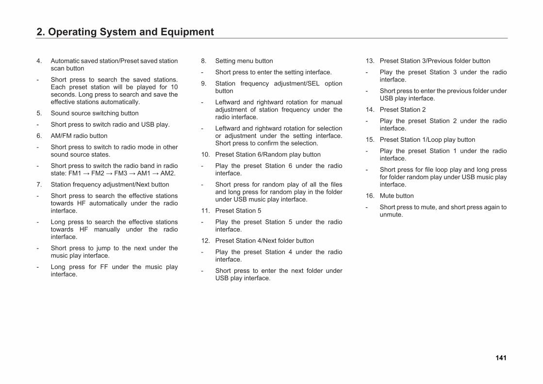
2. Operating System and Equipment
4. Automatic saved station/Preset saved stationscan button
- Short press to search the saved stations.Each preset station will be played for 10seconds. Long press to search and save theeffective stations automatically.
5. Sound source switching button
- Short press to switch radio and USB play.
6. AM/FM radio button
- Short press to switch to radio mode in othersound source states.
- Short press to switch the radio band in radiostate: FM1 → FM2 → FM3 → AM1 → AM2.
7. Station frequency adjustment/Next button
- Short press to search the effective stationstowards HF automatically under the radiointerface.
- Long press to search the effective stationstowards HF manually under the radiointerface.
- Short press to jump to the next under themusic play interface.
- Long press for FF under the music playinterface.
8. Setting menu button
- Short press to enter the setting interface.
9. Station frequency adjustment/SEL optionbutton
- Leftward and rightward rotation for manualadjustment of station frequency under theradio interface.
- Leftward and rightward rotation for selectionor adjustment under the setting interface.Short press to confirm the selection.
10. Preset Station 6/Random play button
- Play the preset Station 6 under the radiointerface.
- Short press for random play of all the filesand long press for random play in the folderunder USB music play interface.
11. Preset Station 5
- Play the preset Station 5 under the radiointerface.
12. Preset Station 4/Next folder button
- Play the preset Station 4 under the radiointerface.
- Short press to enter the next folder underUSB play interface.
13. Preset Station 3/Previous folder button
- Play the preset Station 3 under the radiointerface.
- Short press to enter the previous folder underUSB play interface.
14. Preset Station 2
- Play the preset Station 2 under the radiointerface.
15. Preset Station 1/Loop play button
- Play the preset Station 1 under the radiointerface.
- Short press for file loop play and long pressfor folder random play under USB music playinterface.
16. Mute button
- Short press to mute, and short press again tounmute.
141
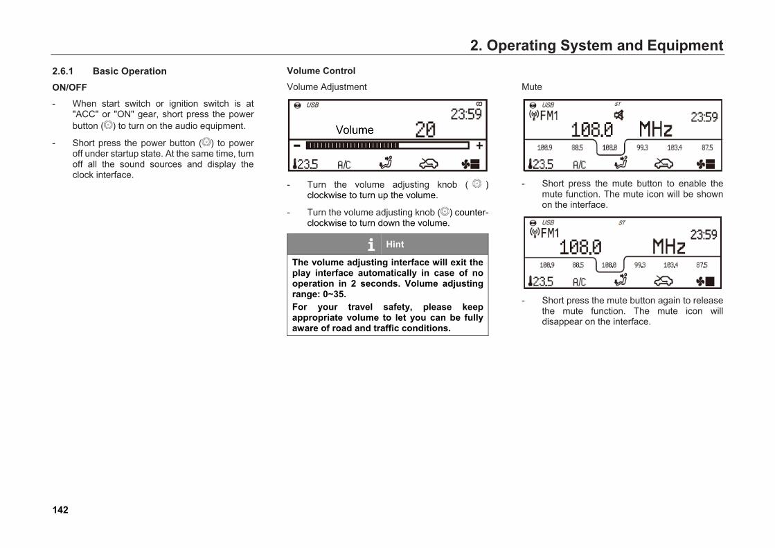
2. Operating System and Equipment2.6.1 Basic Operation ON/OFF - When start switch or ignition switch is at
"ACC" or "ON" gear, short press the powerbutton ( ) to turn on the audio equipment.
- Short press the power button ( ) to poweroff under startup state. At the same time, turnoff all the sound sources and display theclock interface.
Volume Control Volume Adjustment
- Turn the volume adjusting knob ( ) clockwise to turn up the volume.
- Turn the volume adjusting knob ( ) counter-clockwise to turn down the volume.
Hint
The volume adjusting interface will exit the play interface automatically in case of no operation in 2 seconds. Volume adjusting range: 0~35. For your travel safety, please keep appropriate volume to let you can be fully aware of road and traffic conditions.
Mute
- Short press the mute button to enable themute function. The mute icon will be shownon the interface.
- Short press the mute button again to releasethe mute function. The mute icon willdisappear on the interface.
142
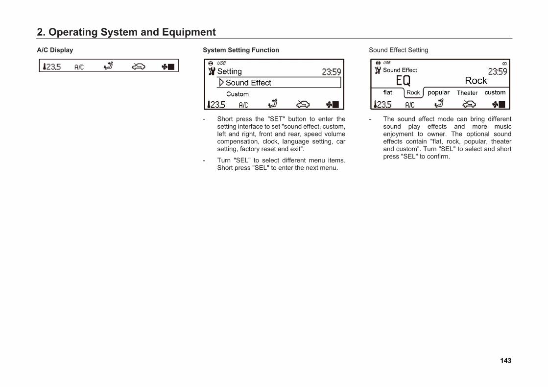
2. Operating System and EquipmentA/C Display System Setting Function
- Short press the "SET" button to enter thesetting interface to set "sound effect, custom,left and right, front and rear, speed volumecompensation, clock, language setting, carsetting, factory reset and exit".
- Turn "SEL" to select different menu items.Short press "SEL" to enter the next menu.
Sound Effect Setting
- The sound effect mode can bring differentsound play effects and more musicenjoyment to owner. The optional soundeffects contain "flat, rock, popular, theaterand custom". Turn "SEL" to select and shortpress "SEL" to confirm.
143
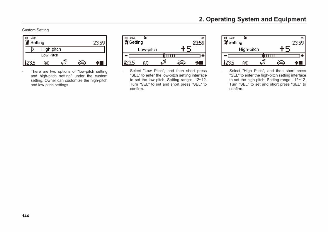
2. Operating System and EquipmentCustom Setting
- There are two options of "low-pitch settingand high-pitch setting" under the customsetting. Owner can customize the high-pitchand low-pitch settings.
- Select "Low Pitch", and then short press"SEL" to enter the low-pitch setting interfaceto set the low pitch. Setting range: -12~12.Turn "SEL" to set and short press "SEL" toconfirm.
- Select "High Pitch", and then short press"SEL" to enter the high-pitch setting interfaceto set the high pitch. Setting range: -12~12.Turn "SEL" to set and short press "SEL" toconfirm.
144
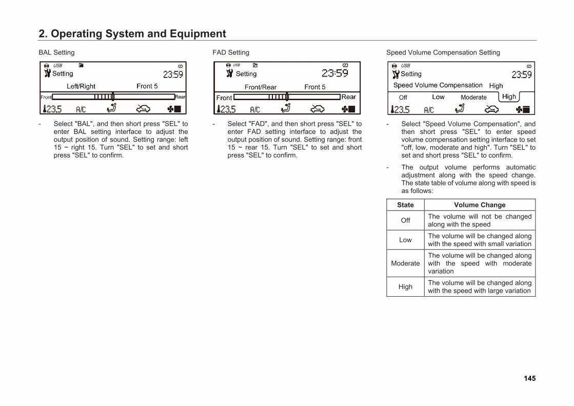
2. Operating System and EquipmentBAL Setting
- Select "BAL", and then short press "SEL" toenter BAL setting interface to adjust theoutput position of sound. Setting range: left15 ~ right 15. Turn "SEL" to set and shortpress "SEL" to confirm.
FAD Setting
- Select "FAD", and then short press "SEL" toenter FAD setting interface to adjust theoutput position of sound. Setting range: front15 ~ rear 15. Turn "SEL" to set and shortpress "SEL" to confirm.
Speed Volume Compensation Setting
- Select "Speed Volume Compensation", andthen short press "SEL" to enter speedvolume compensation setting interface to set"off, low, moderate and high". Turn "SEL" toset and short press "SEL" to confirm.
- The output volume performs automaticadjustment along with the speed change.The state table of volume along with speed isas follows:
State Volume Change
Off The volume will not be changed along with the speed
Low The volume will be changed along with the speed with small variation
ModerateThe volume will be changed along with the speed with moderate variation
High The volume will be changed along with the speed with large variation
145
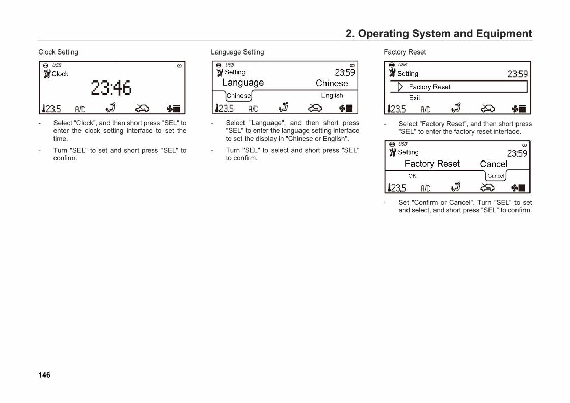
2. Operating System and EquipmentClock Setting
- Select "Clock", and then short press "SEL" toenter the clock setting interface to set thetime.
- Turn "SEL" to set and short press "SEL" toconfirm.
Language Setting
- Select "Language", and then short press"SEL" to enter the language setting interfaceto set the display in "Chinese or English".
- Turn "SEL" to select and short press "SEL"to confirm.
Factory Reset
- Select "Factory Reset", and then short press"SEL" to enter the factory reset interface.
- Set "Confirm or Cancel". Turn "SEL" to setand select, and short press "SEL" to confirm.
146
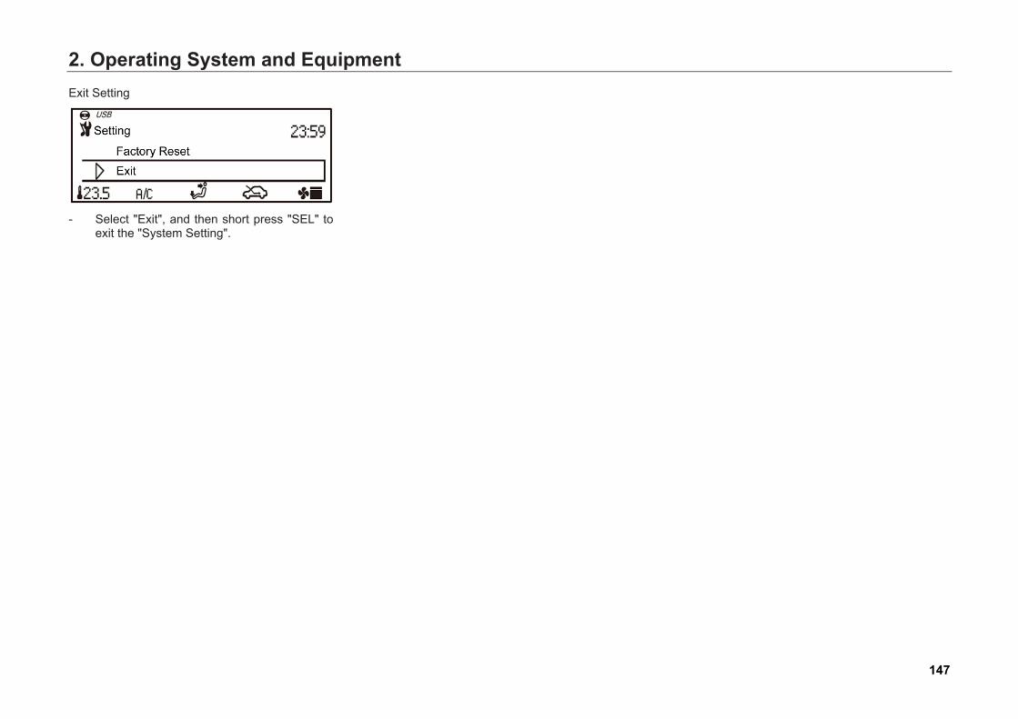
2. Operating System and EquipmentExit Setting
- Select "Exit", and then short press "SEL" toexit the "System Setting".
147

2. Operating System and Equipment2.6.2 Radio Band Selection Enter the radio play interface through the following ways:
- Short press button on the control panel to enter the radio mode;
- Short press button on the control panel to enter the radio mode;
- Under the radio play interface, short pressbutton continuously to switch the bands
among FM1 → FM2 → FM3 → AM1 → AM2.
- FM interface is as shown in the figure.
- AM interface is as shown in the figure.
Station Search Function Tune stations in manual or auto mode.
Manual search
- Long press button to search towards HF direction.
- Long press button to search towards LF direction.
Auto Search
- Short press button to search stationtowards HF automatically. If an effectivestation is met, auto search stops and thestation starts playing.
- Short press button to search stationtowards LF automatically. If an effectivestation is met, auto search stops and thestation starts playing.
148
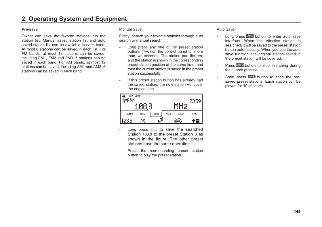
2. Operating System and EquipmentPre-save Owner can save the favorite stations into the station list. Manual saved station list and auto saved station list can be available in each band. At most 6 stations can be saved in each list. For FM bands, at most 18 stations can be saved, including FM1, FM2 and FM3. 6 stations can be saved in each band. For AM bands, at most 12 stations can be saved, including AM1 and AM2. 6 stations can be saved in each band.
Manual Save
Firstly, search your favorite stations through auto search or manual search.
- Long press any one of the preset stationbuttons (1~6) on the control panel for morethan two seconds. The station part flickers,and the station is shown in the correspondingpreset station position at the same time, andthen the current station is saved in the presetstation successfully.
- If this preset station button has already hadthe saved station, the new station will coverthe original one.
- Long press 3 to save the searchedStation 108.0 to the preset Station 3 asshown in the figure. The other presetstations have the same operation.
- Press the corresponding preset stationbutton to play the preset station.
Auto Save
- Long press button to enter auto save interface. When the effective station is searched, it will be saved to the preset station button automatically. When you use the auto save function, the original station saved in the preset station will be covered.
- Press button to stop searching during the search process.
- Short press button to scan the pre-saved preset stations. Each station can be played for 10 seconds.
149
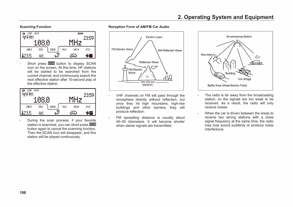
2. Operating System and EquipmentScanning Function
- Short press button to display SCANicon on the screen. At this time, HF stationswill be started to be searched from thecurrent channel, and continuously search thenext effective station after 10-second play ofthe effective station.
- During the scan process, if your favoritestation is searched, you can short pressbutton again to cancel the scanning function.Then the SCAN icon will disappear, and thisstation will be played continuously.
Reception Form of AM/FM Car Audio
- VHF channels on FM will pass through theionosphere directly without reflection, butonce they hit high mountains, high-risebuildings and other barriers, they willproduce reflection.
- FM spreading distance is usually about40~50 kilometers. It will become shorterwhen stereo signals are transmitted.
- The radio is far away from the broadcastingstation, so the signals are too weak to bereceived. As a result, the radio will onlyreceive noises.
- When the car is driven between the areas toreceive two strong stations with a closesignal frequency at the same time, the radiomay lose sound suddenly or produce noiseinterference.
150
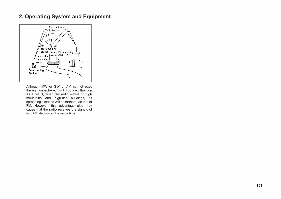
2. Operating System and Equipment
- Although MW or SW of AM cannot passthrough ionosphere, it will produce diffraction.As a result, when the radio waves hit highmountains and high-rise buildings, itsspreading distance will be farther than that ofFM. However, this advantage also maycause that the radio receives the signals oftwo AM stations at the same time.
151
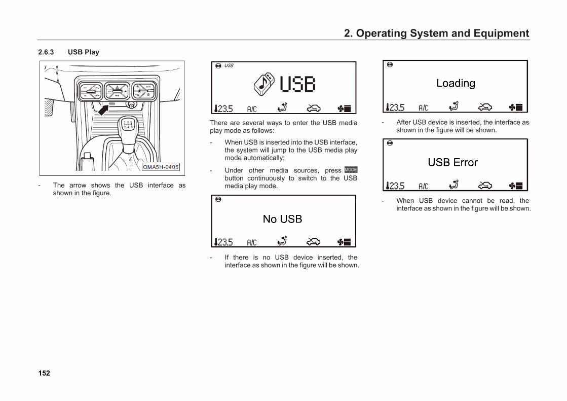
2. Operating System and Equipment2.6.3 USB Play
- The arrow shows the USB interface asshown in the figure.
There are several ways to enter the USB media play mode as follows:
- When USB is inserted into the USB interface,the system will jump to the USB media playmode automatically;
- Under other media sources, pressbutton continuously to switch to the USBmedia play mode.
- If there is no USB device inserted, theinterface as shown in the figure will be shown.
- After USB device is inserted, the interface asshown in the figure will be shown.
- When USB device cannot be read, theinterface as shown in the figure will be shown.
152
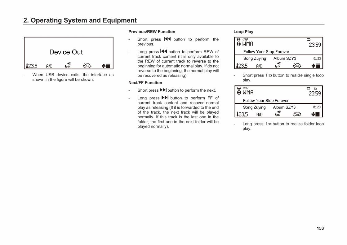
2. Operating System and Equipment
- When USB device exits, the interface asshown in the figure will be shown.
Previous/REW Function
- Short press button to perform the previous.
- Long press button to perform REW ofcurrent track content (It is only available tothe REW of current track to reverse to thebeginning for automatic normal play. If do notreverse to the beginning, the normal play willbe recovered as releasing).
Next/FF Function
- Short press button to perform the next.
- Long press button to perform FF of current track content and recover normal play as releasing (If it is forwarded to the end of the track, the next track will be played normally. If this track is the last one in the folder, the first one in the next folder will be played normally).
Loop Play
- Short press 1 button to realize single loopplay.
- Long press 1 button to realize folder loopplay.
153
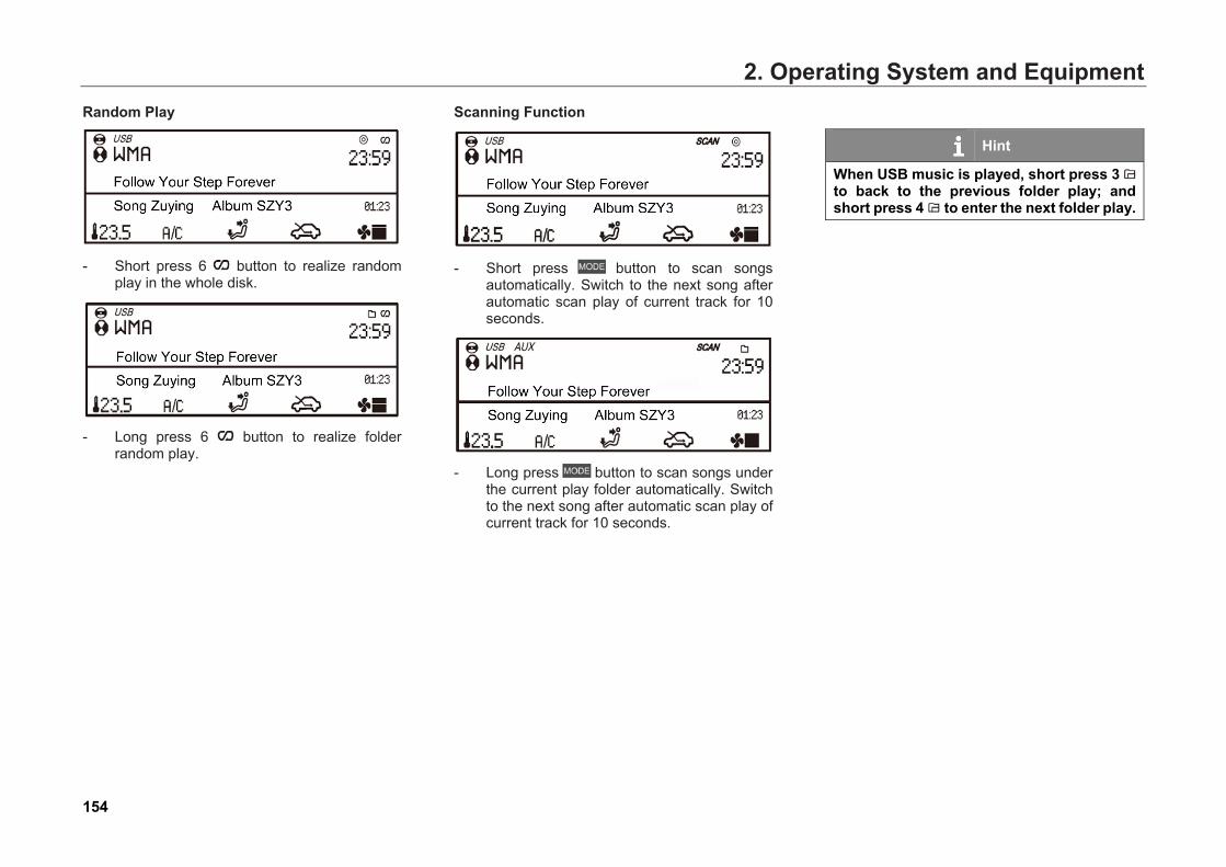
2. Operating System and EquipmentRandom Play
- Short press 6 button to realize random play in the whole disk.
- Long press 6 button to realize folder random play.
Scanning Function
- Short press button to scan songsautomatically. Switch to the next song afterautomatic scan play of current track for 10seconds.
- Long press button to scan songs underthe current play folder automatically. Switchto the next song after automatic scan play ofcurrent track for 10 seconds.
Hint
When USB music is played, short press 3 to back to the previous folder play; and short press 4 to enter the next folder play.
154

2. Operating System and Equipment2.6.4 IPod Play This product has been certified by the Apple iPod, supporting iPod and iPhone professional equipment to play iPod and iPhone music. IPod and iPhone professional equipment is connected to the audio head unit with USB line.
Selection of IPod Sound Source
There are several ways to enter the main interface of the iPod media source as follows:
- When iPod is inserted in the USB interfacewith USB line, the system will jump to theiPod media play mode automatically;
- Under other media sources, pressbutton continuously to switch to the iPodmedia play mode.
Hint
When iPod plays music, the function and the operation method are same to that of the USB play. Please refer to the operation method of the USB play.
155
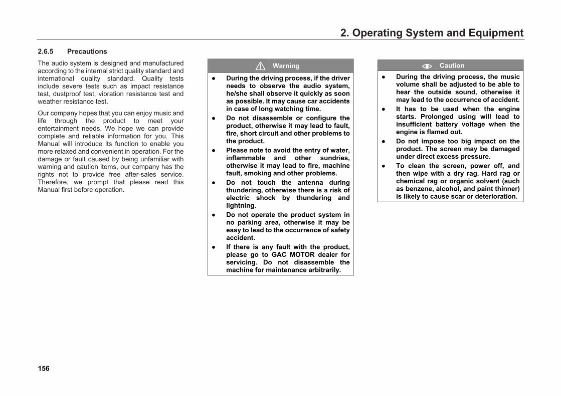
2. Operating System and Equipment2.6.5 Precautions The audio system is designed and manufactured according to the internal strict quality standard and international quality standard. Quality tests include severe tests such as impact resistance test, dustproof test, vibration resistance test and weather resistance test.
Our company hopes that you can enjoy music and life through the product to meet your entertainment needs. We hope we can provide complete and reliable information for you. This Manual will introduce its function to enable you more relaxed and convenient in operation. For the damage or fault caused by being unfamiliar with warning and caution items, our company has the rights not to provide free after-sales service. Therefore, we prompt that please read this Manual first before operation.
Warning
● During the driving process, if the driverneeds to observe the audio system,he/she shall observe it quickly as soonas possible. It may cause car accidentsin case of long watching time.
● Do not disassemble or configure theproduct, otherwise it may lead to fault,fire, short circuit and other problems tothe product.
● Please note to avoid the entry of water,inflammable and other sundries,otherwise it may lead to fire, machinefault, smoking and other problems.
● Do not touch the antenna duringthundering, otherwise there is a risk ofelectric shock by thundering andlightning.
● Do not operate the product system inno parking area, otherwise it may beeasy to lead to the occurrence of safetyaccident.
● If there is any fault with the product,please go to GAC MOTOR dealer forservicing. Do not disassemble themachine for maintenance arbitrarily.
Caution ● During the driving process, the music
volume shall be adjusted to be able tohear the outside sound, otherwise itmay lead to the occurrence of accident.
● It has to be used when the enginestarts. Prolonged using will lead toinsufficient battery voltage when theengine is flamed out.
● Do not impose too big impact on theproduct. The screen may be damagedunder direct excess pressure.
● To clean the screen, power off, andthen wipe with a dry rag. Hard rag orchemical rag or organic solvent (suchas benzene, alcohol, and paint thinner)is likely to cause scar or deterioration.
156

2. Operating System and Equipment
Caution ● If there is any problem with the product
and it cannot be used normally, pleasestop operation and contact customerservice center.
● Continuous operation in abnormalstate may cause more seriousproblems. If the product isdisassembled or configured at will, freewarranty service cannot be enjoyed.
Hint
● "Short press" herein means that thebutton-hold time does not exceed twoseconds, and "long press" means thatthe button-hold time exceeds morethan two seconds. They are called as"short press" and "long press" forshort herein.
157
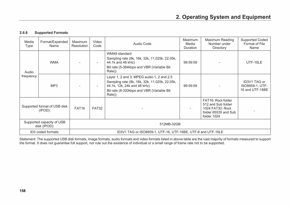
2. Operating System and Equipment
2.6.6 Supported Formats
Media Type
Format/Expanded Name
Maximum Resolution
Video Code Audio Code
Maximum Media
Duration
Maximum Reading Number under
Directory
Supported Coded Format of File
Name
Audio frequency
WMA - -
WMA9 standard Sampling rate (8k, 16k, 32k, 11.025k, 22.05k, 44.1k and 48 kHz) Bit rate (5-384kbps and VBR (Variable Bit Rate))
99:59:59 - UTF-16LE
MP3 - -
Layer 1, 2 and 3; MPEG audio 1, 2 and 2.5 Sampling rate (8k, 16k, 32k, 11.025k, 22.05k, 44.1k, 12k, 24k and 48 kHz) Bit rate (8-320kbps and VBR (Variable Bit Rate))
99:59:59 - ID3V1 TAG or
ISO8859-1, UTF-16 and UTF-16BE
Supported format of USB disk (IPOD): FAT16 FAT32 - -
FAT16: Root folder 512 and Sub folder 1024 FAT32: Root folder 65535 and Sub folder 1024
-
Supported capacity of USB disk (IPOD): 512MB-32GB
ID3 coded formats: ID3V1 TAG or ISO8859-1, UTF-16, UTF-16BE, UTF-8 and UTF-16LE
Statement: The supported USB disk formats, image formats, audio formats and video formats listed in above table are the vast majority of formats measured to support the format. It does not guarantee full support, nor rule out the existence of individual or a small range of frame rate not to be supported.
158
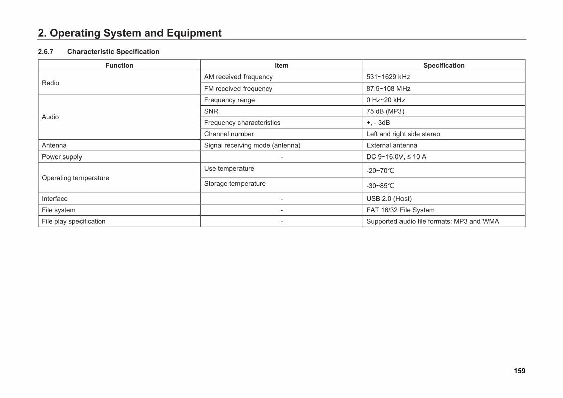
2. Operating System and Equipment2.6.7 Characteristic Specification
Function Item Specification
Radio AM received frequency 531~1629 kHz
FM received frequency 87.5~108 MHz
Audio
Frequency range 0 Hz~20 kHz
SNR 75 dB (MP3)
Frequency characteristics +, - 3dB
Channel number Left and right side stereo
Antenna Signal receiving mode (antenna) External antenna
Power supply - DC 9~16.0V, ≤ 10 A
Operating temperature Use temperature -20~70℃
Storage temperature -30~85℃
Interface - USB 2.0 (Host)
File system - FAT 16/32 File System
File play specification - Supported audio file formats: MP3 and WMA
159
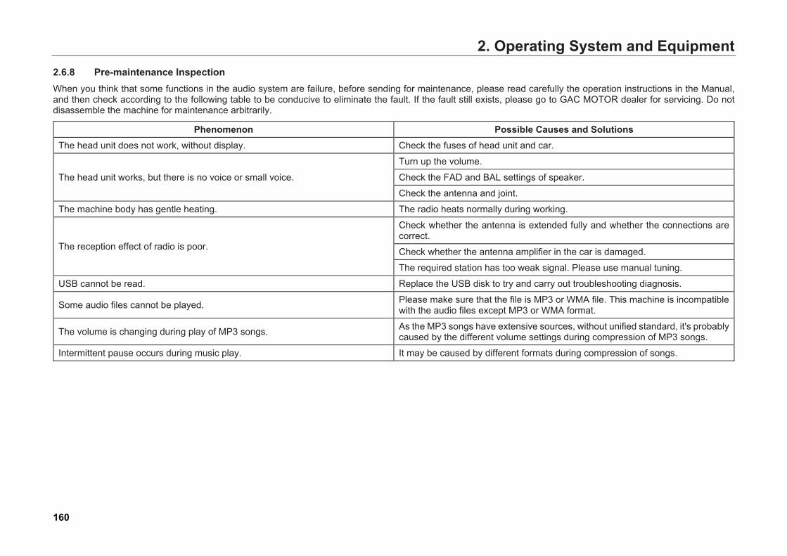
2. Operating System and Equipment2.6.8 Pre-maintenance Inspection When you think that some functions in the audio system are failure, before sending for maintenance, please read carefully the operation instructions in the Manual, and then check according to the following table to be conducive to eliminate the fault. If the fault still exists, please go to GAC MOTOR dealer for servicing. Do not disassemble the machine for maintenance arbitrarily.
Phenomenon Possible Causes and Solutions The head unit does not work, without display. Check the fuses of head unit and car.
The head unit works, but there is no voice or small voice.
Turn up the volume.
Check the FAD and BAL settings of speaker.
Check the antenna and joint.
The machine body has gentle heating. The radio heats normally during working.
The reception effect of radio is poor.
Check whether the antenna is extended fully and whether the connections are correct.
Check whether the antenna amplifier in the car is damaged.
The required station has too weak signal. Please use manual tuning.
USB cannot be read. Replace the USB disk to try and carry out troubleshooting diagnosis.
Some audio files cannot be played. Please make sure that the file is MP3 or WMA file. This machine is incompatible with the audio files except MP3 or WMA format.
The volume is changing during play of MP3 songs. As the MP3 songs have extensive sources, without unified standard, it's probably caused by the different volume settings during compression of MP3 songs.
Intermittent pause occurs during music play. It may be caused by different formats during compression of songs.
160
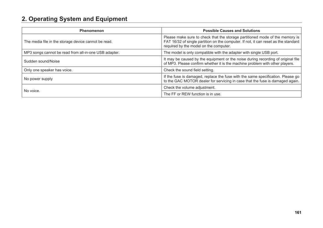
2. Operating System and Equipment
Phenomenon Possible Causes and Solutions
The media file in the storage device cannot be read. Please make sure to check that the storage partitioned mode of the memory is FAT 16/32 of single partition on the computer. If not, it can reset as the standard required by the model on the computer.
MP3 songs cannot be read from all-in-one USB adapter. The model is only compatible with the adapter with single USB port.
Sudden sound/Noise It may be caused by the equipment or the noise during recording of original file of MP3. Please confirm whether it is the machine problem with other players.
Only one speaker has voice. Check the sound field setting.
No power supply If the fuse is damaged, replace the fuse with the same specification. Please go to the GAC MOTOR dealer for servicing in case that the fuse is damaged again.
No voice. Check the volume adjustment.
The FF or REW function is in use.
161
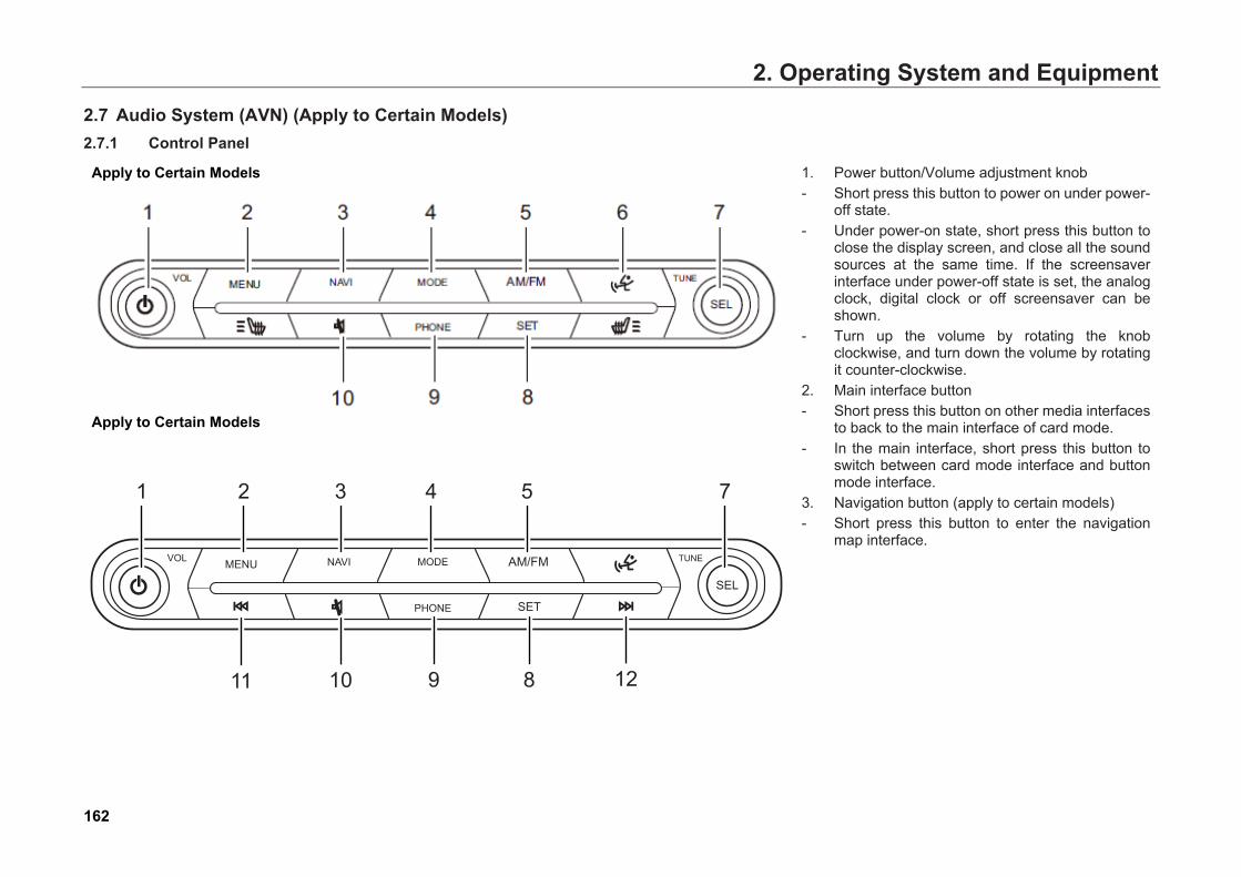
2. Operating System and Equipment2.7 Audio System (AVN) (Apply to Certain Models) 2.7.1 Control Panel
Apply to Certain Models
Apply to Certain Models
1. Power button/Volume adjustment knob- Short press this button to power on under power-
off state.- Under power-on state, short press this button to
close the display screen, and close all the soundsources at the same time. If the screensaverinterface under power-off state is set, the analogclock, digital clock or off screensaver can beshown.
- Turn up the volume by rotating the knobclockwise, and turn down the volume by rotatingit counter-clockwise.
2. Main interface button- Short press this button on other media interfaces
to back to the main interface of card mode. - In the main interface, short press this button to
switch between card mode interface and buttonmode interface.
3. Navigation button (apply to certain models)- Short press this button to enter the navigation
map interface.
162
VOL MENU MODE
PHONE
NAVI AM/FM
SET
SEL
TUNE
8 1291011
2 3 4 5 71
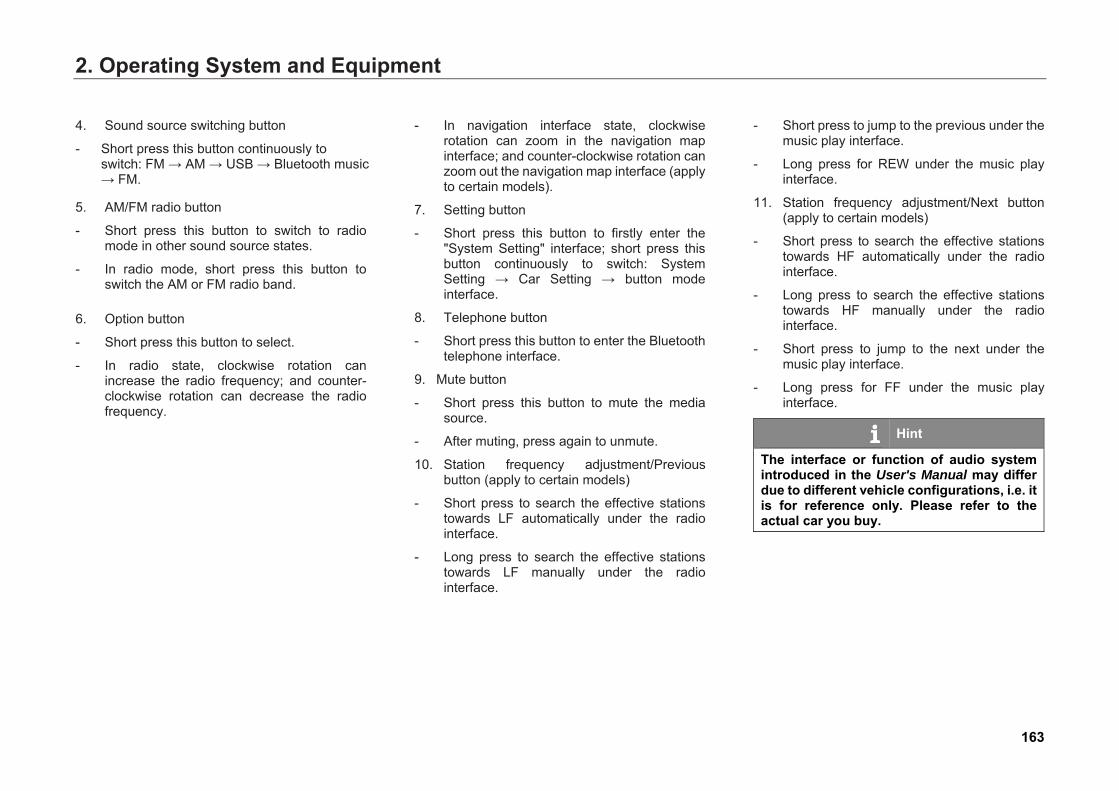
2. Operating System and Equipment
4. Sound source switching button
- Short press this button continuously toswitch: FM → AM → USB → Bluetooth music→ FM.
5. AM/FM radio button
- Short press this button to switch to radiomode in other sound source states.
- In radio mode, short press this button toswitch the AM or FM radio band.
6. Option button
- Short press this button to select.
- In radio state, clockwise rotation canincrease the radio frequency; and counter-clockwise rotation can decrease the radiofrequency.
- In navigation interface state, clockwiserotation can zoom in the navigation mapinterface; and counter-clockwise rotation canzoom out the navigation map interface (applyto certain models).
7. Setting button
- Short press this button to firstly enter the"System Setting" interface; short press thisbutton continuously to switch: SystemSetting → Car Setting → button modeinterface.
8. Telephone button
- Short press this button to enter the Bluetoothtelephone interface.
9. Mute button
- Short press this button to mute the mediasource.
- After muting, press again to unmute.
10. Station frequency adjustment/Previousbutton (apply to certain models)
- Short press to search the effective stationstowards LF automatically under the radiointerface.
- Long press to search the effective stationstowards LF manually under the radiointerface.
- Short press to jump to the previous under themusic play interface.
- Long press for REW under the music playinterface.
11. Station frequency adjustment/Next button(apply to certain models)
- Short press to search the effective stationstowards HF automatically under the radiointerface.
- Long press to search the effective stationstowards HF manually under the radiointerface.
- Short press to jump to the next under themusic play interface.
- Long press for FF under the music playinterface.
Hint
The interface or function of audio system introduced in the User's Manual may differ due to different vehicle configurations, i.e. it is for reference only. Please refer to the actual car you buy.
163
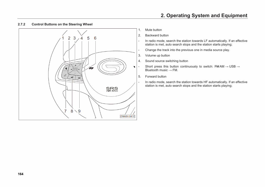
2. Operating System and Equipment2.7.2 Control Buttons on the Steering Wheel
1. Mute button
2. Backward button
- In radio mode, search the station towards LF automatically. If an effectivestation is met, auto search stops and the station starts playing;
- Change the track into the previous one in media source play.
3. Volume up button
4. Sound source switching button
- Short press this button continuously to switch: FM → AM → USB → Bluetooth music → FM.
5. Forward button
- In radio mode, search the station towards HF automatically. If an effectivestation is met, auto search stops and the station starts playing;
164

2. Operating System and Equipment
- Change the track into the next one in media source play.
6. Volume down button
7. Answer Call button
- When an incoming call is in the Bluetooth phone system, you can press this button to answer.
- When there is no incoming call in the Bluetooth phone system, you can press this button to enter the "Bluetooth Setting" interface.
8. Hanging up button
- When an incoming call is in the Bluetooth phone system, you can press this button to reject;
- Press this button to end the current call in the call process.
165
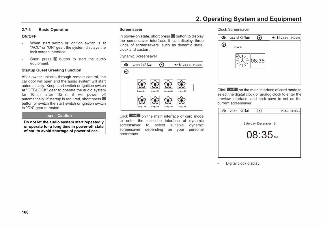
2. Operating System and Equipment2.7.3 Basic Operation ON/OFF - When start switch or ignition switch is at
"ACC" or "ON" gear, the system displays thelock screen interface.
- Short press button to start the audio equipment.
Startup Guest Greeting Function After owner unlocks through remote control, the car door will open and the audio system will start automatically. Keep start switch or ignition switch at "OFF/LOCK" gear to operate the audio system for 10min, after 10min, it will power off automatically. If startup is required, short press button or switch the start switch or ignition switch to "ON" gear to restart.
Caution Do not let the audio system start repeatedly or operate for a long time in power-off state of car, to avoid shortage of power of car.
Screensaver
In power-on state, short press button to display the screensaver interface. It can display three kinds of screensavers, such as dynamic state, clock and custom.
Dynamic Screensaver
Click on the main interface of card mode to enter the selection interface of dynamic screensaver to select suitable dynamic screensaver depending on your personal preference.
Clock Screensaver
Click on the main interface of card mode to select the digital clock or analog clock to enter the preview interface, and click save to set as the current screensaver.
- Digital clock display.
166
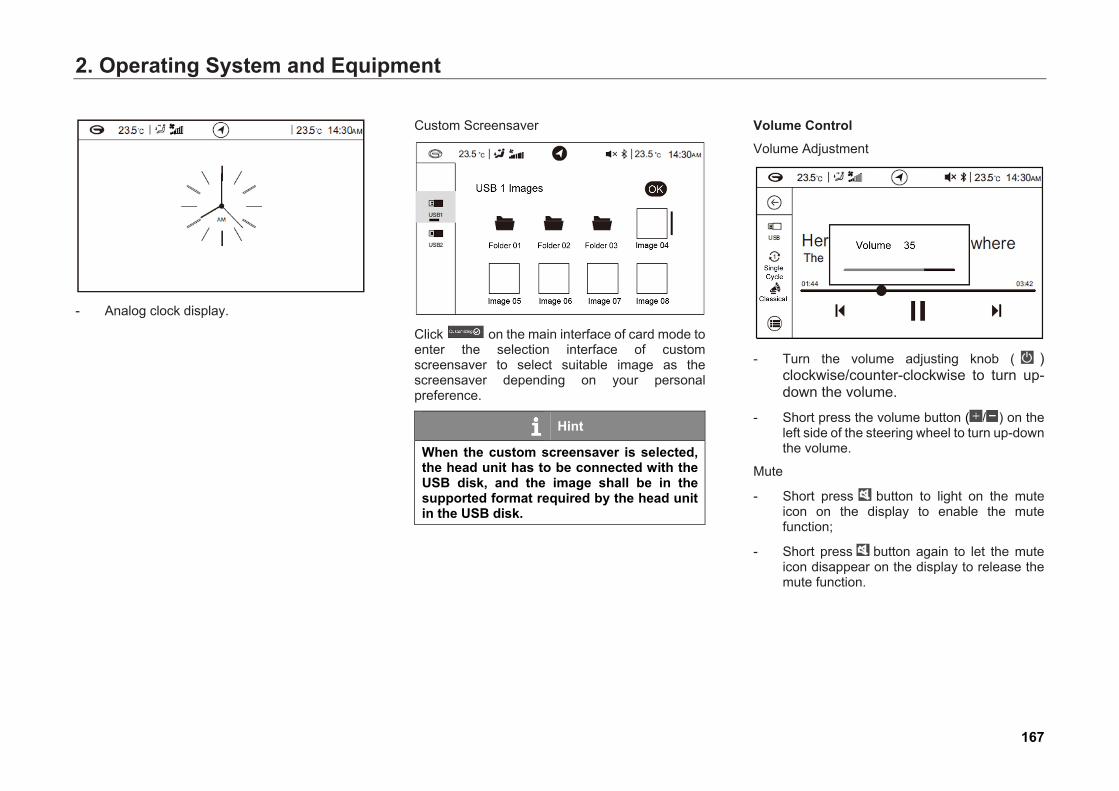
2. Operating System and Equipment
- Analog clock display.
Custom Screensaver
Click on the main interface of card mode to enter the selection interface of custom screensaver to select suitable image as the screensaver depending on your personal preference.
Hint
When the custom screensaver is selected, the head unit has to be connected with the USB disk, and the image shall be in the supported format required by the head unit in the USB disk.
Volume Control Volume Adjustment
- Turn the volume adjusting knob ( )clockwise/counter-clockwise to turn up-down the volume.
- Short press the volume button ( / ) on theleft side of the steering wheel to turn up-downthe volume.
Mute
- Short press button to light on the muteicon on the display to enable the mutefunction;
- Short press button again to let the muteicon disappear on the display to release themute function.
167
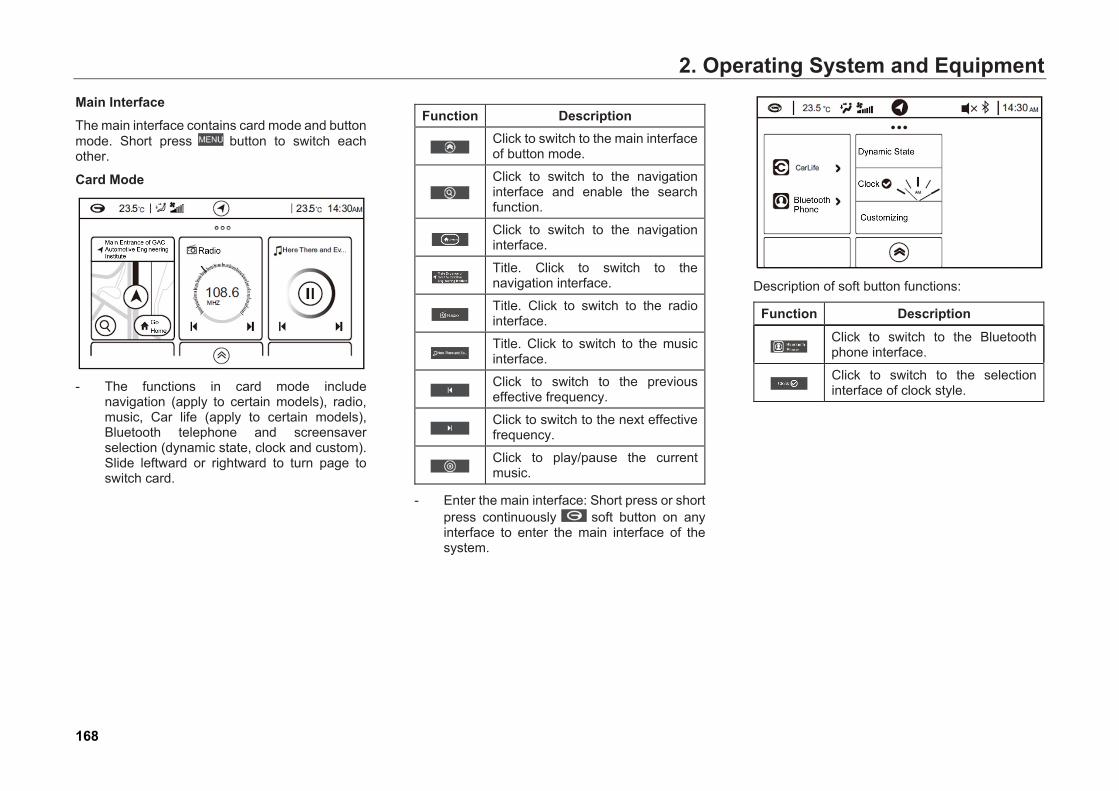
2. Operating System and EquipmentMain Interface The main interface contains card mode and button mode. Short press button to switch each other.
Card Mode
- The functions in card mode includenavigation (apply to certain models), radio,music, Car life (apply to certain models),Bluetooth telephone and screensaverselection (dynamic state, clock and custom).Slide leftward or rightward to turn page toswitch card.
Function Description Click to switch to the main interface of button mode.
Click to switch to the navigation interface and enable the search function.
Click to switch to the navigation interface.
Title. Click to switch to the navigation interface.
Title. Click to switch to the radio interface.
Title. Click to switch to the music interface.
Click to switch to the previous effective frequency.
Click to switch to the next effective frequency.
Click to play/pause the current music.
- Enter the main interface: Short press or shortpress continuously soft button on anyinterface to enter the main interface of thesystem.
Description of soft button functions:
Function Description Click to switch to the Bluetooth phone interface.
Click to switch to the selection interface of clock style.
168
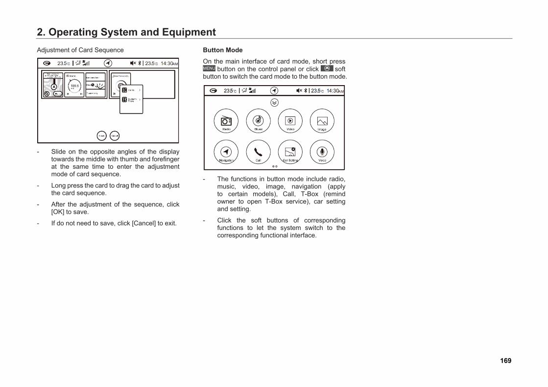
2. Operating System and EquipmentAdjustment of Card Sequence
- Slide on the opposite angles of the displaytowards the middle with thumb and forefingerat the same time to enter the adjustmentmode of card sequence.
- Long press the card to drag the card to adjustthe card sequence.
- After the adjustment of the sequence, click[OK] to save.
- If do not need to save, click [Cancel] to exit.
Button Mode On the main interface of card mode, short press
button on the control panel or click soft button to switch the card mode to the button mode.
- The functions in button mode include radio,music, video, image, navigation (applyto certain models), Call, T-Box (remindowner to open T-Box service), car settingand setting.
- Click the soft buttons of correspondingfunctions to let the system switch to thecorresponding functional interface.
169
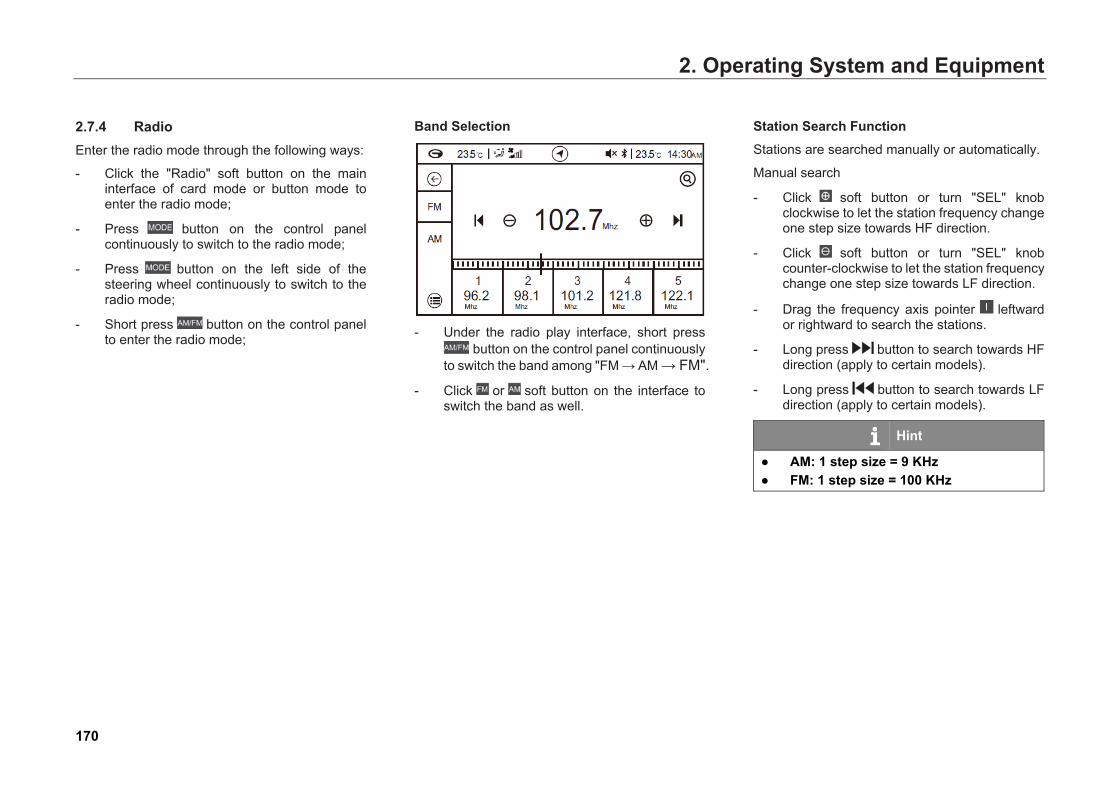
2. Operating System and Equipment
2.7.4 Radio Enter the radio mode through the following ways:
- Click the "Radio" soft button on the maininterface of card mode or button mode toenter the radio mode;
- Press button on the control panel continuously to switch to the radio mode;
- Press button on the left side of thesteering wheel continuously to switch to theradio mode;
- Short press button on the control panel to enter the radio mode;
Band Selection
- Under the radio play interface, short pressbutton on the control panel continuously
to switch the band among "FM → AM → FM".
- Click or soft button on the interface toswitch the band as well.
Station Search FunctionStations are searched manually or automatically.
Manual search
- Click soft button or turn "SEL" knobclockwise to let the station frequency changeone step size towards HF direction.
- Click soft button or turn "SEL" knob counter-clockwise to let the station frequency change one step size towards LF direction.
- Drag the frequency axis pointer leftwardor rightward to search the stations.
- Long press button to search towards HF direction (apply to certain models).
- Long press button to search towards LF direction (apply to certain models).
Hint
● AM: 1 step size = 9 KHz● FM: 1 step size = 100 KHz
170

2. Operating System and EquipmentAuto Search
- Short press soft button or the ► button onthe left side of the steering wheel to searchthe station towards HF automatically. If aneffective station is met, auto search stopsand the station starts playing.
- Short press soft button or button on theleft side of the steering wheel to search thestation towards LF automatically. If aneffective station is met, auto search stopsand the station starts playing.
- Short press button to search station towards HF automatically. If an effective station is met, auto search stops and the station starts playing (apply to certain models).
- Short press button to search station towards HF automatically. If an effective station is met, auto search stops and the station starts playing (apply to certain models).
Manually Input the Station Frequency
1. Click on the upper right corner to open theinput keyboard.
2. Input the station frequency manually.
Pre-save
- Long press soft buttons (1~5) on the lowerpart of the interface to pre-save the currentplaying station to the corresponding positions(1~5).
- Short press soft buttons (1~5) to play thecorresponding pre-saved stations.
171
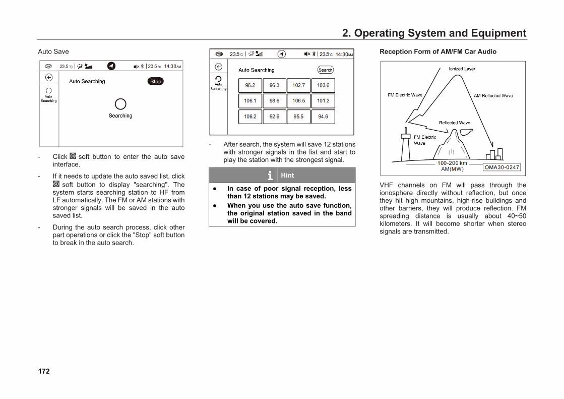
2. Operating System and EquipmentAuto Save
- Click soft button to enter the auto saveinterface.
- If it needs to update the auto saved list, click soft button to display "searching". The
system starts searching station to HF fromLF automatically. The FM or AM stations withstronger signals will be saved in the autosaved list.
- During the auto search process, click otherpart operations or click the "Stop" soft buttonto break in the auto search.
- After search, the system will save 12 stationswith stronger signals in the list and start toplay the station with the strongest signal.
Hint
● In case of poor signal reception, lessthan 12 stations may be saved.
● When you use the auto save function,the original station saved in the bandwill be covered.
Reception Form of AM/FM Car Audio
VHF channels on FM will pass through the ionosphere directly without reflection, but once they hit high mountains, high-rise buildings and other barriers, they will produce reflection. FM spreading distance is usually about 40~50 kilometers. It will become shorter when stereo signals are transmitted.
172

2. Operating System and Equipment
The radio is far away from the broadcasting station, so the signals are too weak to be received. As a result, the radio will only receive noises. When the car is driven between the areas to receive two strong stations with a close signal frequency at the same time, the radio may lose sound suddenly or produce noise interference.
Although MW or SW of AM cannot pass through ionosphere, it will produce diffraction. As a result, when the radio waves hit high mountains and high-rise buildings, its spreading distance will be farther than that of FM. Therefore, it is likely to simultaneously receive the signals from two AM stations.
173
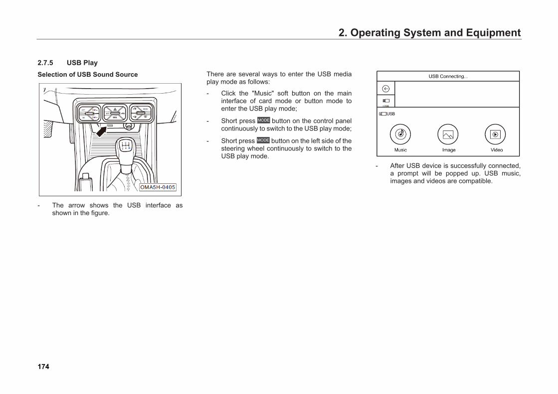
2. Operating System and Equipment
2.7.5 USB Play Selection of USB Sound Source
- The arrow shows the USB interface asshown in the figure.
There are several ways to enter the USB media play mode as follows:
- Click the "Music" soft button on the maininterface of card mode or button mode toenter the USB play mode;
- Short press button on the control panelcontinuously to switch to the USB play mode;
- Short press button on the left side of thesteering wheel continuously to switch to theUSB play mode.
- After USB device is successfully connected,a prompt will be popped up. USB music,images and videos are compatible.
174
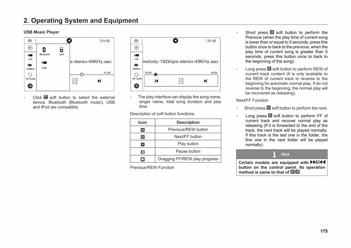
2. Operating System and EquipmentUSB Music Player
- Click soft button to select the externaldevice. Bluetooth (Bluetooth music), USBand iPod are compatible.
- The play interface can display the song name,singer name, total song duration and playtime.
Description of soft button functions:
Icon Description Previous/REW button
Next/FF button
Play button
Pause button
Dragging FF/REW play progress
Previous/REW Function
- Short press soft button to perform thePrevious (when the play time of current songis lower than or equal to 5 seconds, press thisbutton once to back to the previous; when theplay time of current song is greater than 5seconds, press this button once to back tothe beginning of the song).
- Long press soft button to perform REW ofcurrent track content (It is only available tothe REW of current track to reverse to thebeginning for automatic normal play. If do notreverse to the beginning, the normal play willbe recovered as releasing).
Next/FF Function
- Short press soft button to perform the next.
- Long press soft button to perform FF ofcurrent track and recover normal play asreleasing (If it is forwarded to the end of thetrack, the next track will be played normally.If this track is the last one in the folder, thefirst one in the next folder will be playednormally).
Hint
Certain models are equipped with / button on the control panel. Its operation method is same to that of / .
175
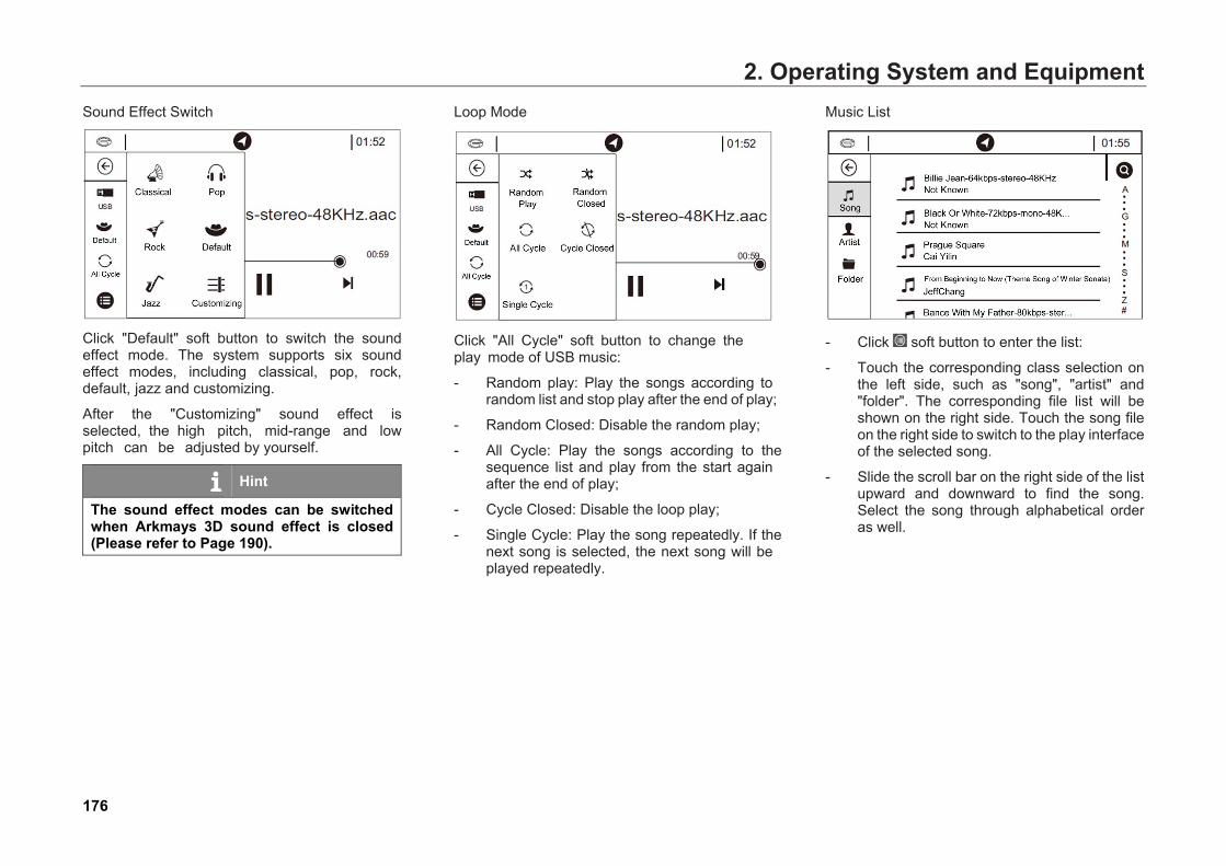
2. Operating System and EquipmentSound Effect Switch
Click "Default" soft button to switch the sound effect mode. The system supports six sound effect modes, including classical, pop, rock, default, jazz and customizing.
After the "Customizing" sound effect is selected, the high pitch, mid-range and low pitch can be adjusted by yourself.
Hint
The sound effect modes can be switched when Arkmays 3D sound effect is closed (Please refer to Page 190).
Loop Mode
Click "All Cycle" soft button to change the play mode of USB music:
- Random play: Play the songs according torandom list and stop play after the end of play;
- Random Closed: Disable the random play;
- All Cycle: Play the songs according to thesequence list and play from the start againafter the end of play;
- Cycle Closed: Disable the loop play;
- Single Cycle: Play the song repeatedly. If thenext song is selected, the next song will beplayed repeatedly.
Music List
- Click soft button to enter the list:
- Touch the corresponding class selection onthe left side, such as "song", "artist" and"folder". The corresponding file list will beshown on the right side. Touch the song fileon the right side to switch to the play interfaceof the selected song.
- Slide the scroll bar on the right side of the listupward and downward to find the song.Select the song through alphabetical orderas well.
176
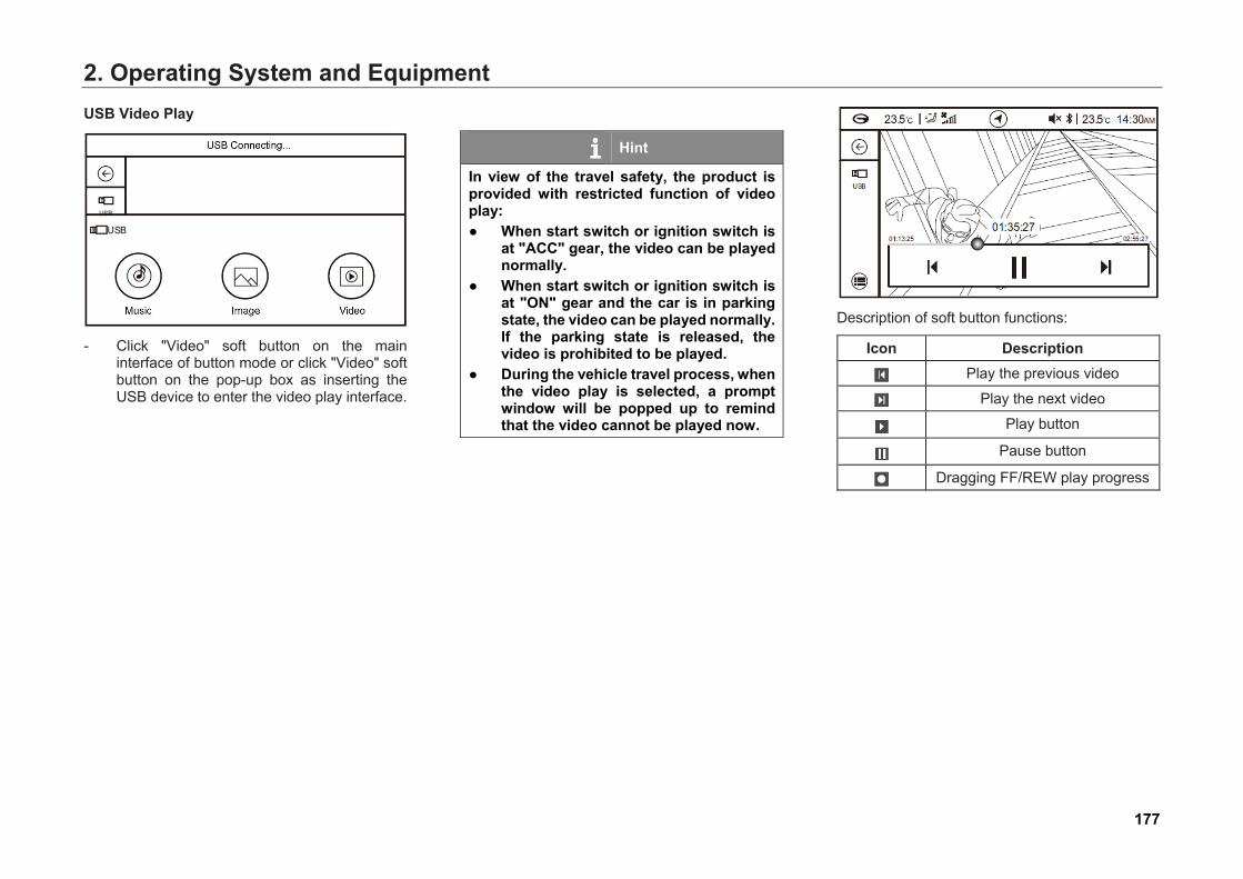
2. Operating System and EquipmentUSB Video Play
- Click "Video" soft button on the maininterface of button mode or click "Video" softbutton on the pop-up box as inserting theUSB device to enter the video play interface.
Hint
In view of the travel safety, the product is provided with restricted function of video play: ● When start switch or ignition switch is
at "ACC" gear, the video can be playednormally.
● When start switch or ignition switch isat "ON" gear and the car is in parkingstate, the video can be played normally.If the parking state is released, thevideo is prohibited to be played.
● During the vehicle travel process, whenthe video play is selected, a promptwindow will be popped up to remindthat the video cannot be played now.
Description of soft button functions:
Icon Description Play the previous video
Play the next video
Play button
Pause button
Dragging FF/REW play progress
177
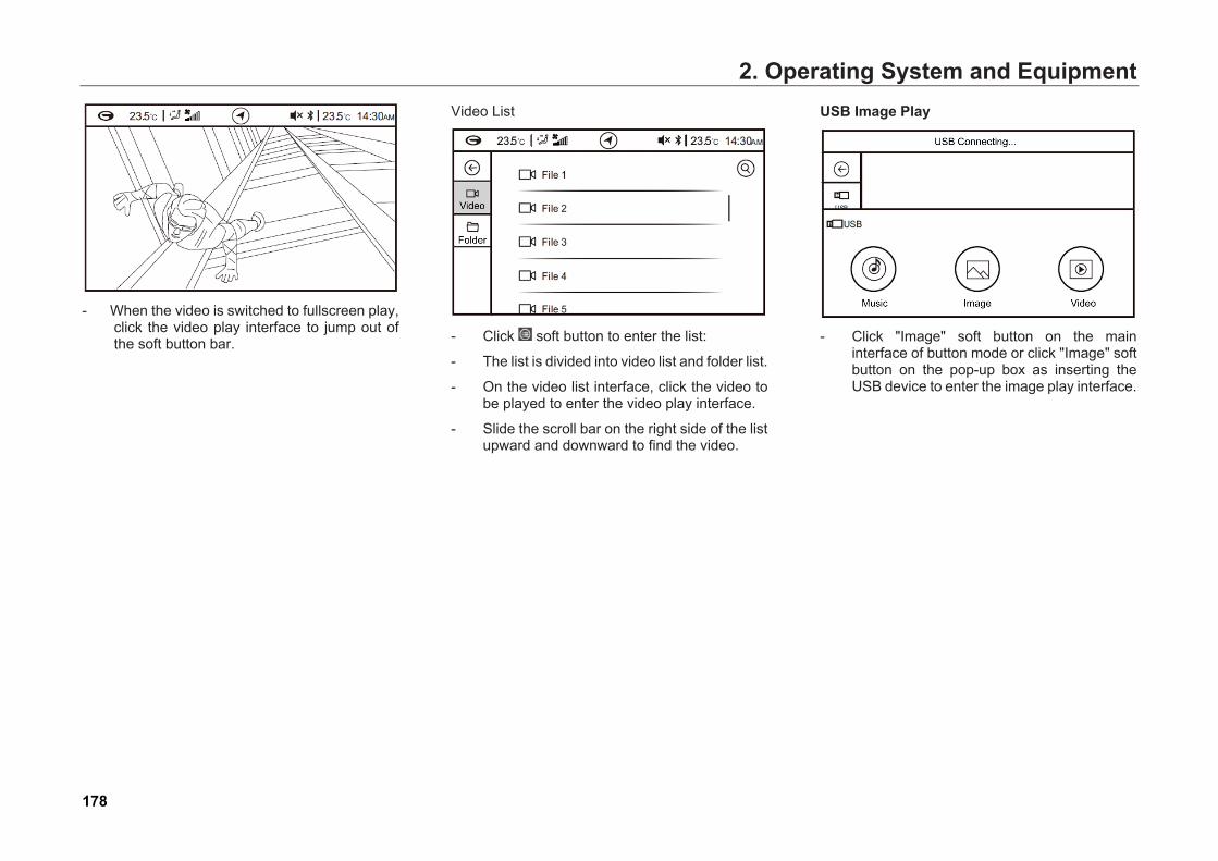
2. Operating System and Equipment
- When the video is switched to fullscreen play,click the video play interface to jump out ofthe soft button bar.
Video List
- Click soft button to enter the list:
- The list is divided into video list and folder list.
- On the video list interface, click the video tobe played to enter the video play interface.
- Slide the scroll bar on the right side of the listupward and downward to find the video.
USB Image Play
- Click "Image" soft button on the maininterface of button mode or click "Image" softbutton on the pop-up box as inserting theUSB device to enter the image play interface.
178
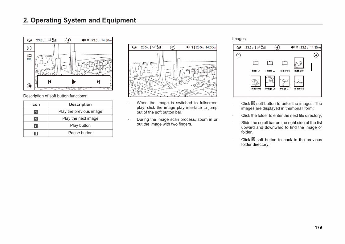
2. Operating System and Equipment
Description of soft button functions:
Icon Description Play the previous image
Play the next image
Play button
Pause button
- When the image is switched to fullscreenplay, click the image play interface to jumpout of the soft button bar.
- During the image scan process, zoom in orout the image with two fingers.
Images
- Click soft button to enter the images. Theimages are displayed in thumbnail form:
- Click the folder to enter the next file directory;
- Slide the scroll bar on the right side of the listupward and downward to find the image orfolder.
- Click soft button to back to the previousfolder directory.
179

2. Operating System and Equipment2.7.6 iPod Play This product has been certified by iPod. After iPod or iPhone is connected to audio host through USB harness, music in iPod or iPhone can be played. If iPod or iPhone is not connected to audio host, it will prompt that there is no iPod when clicking “iPod” soft button.
System Setting Open the general interface for host setting, and select iPod for the item “phone priority connection”.
Phone priority connection
- Phone priority connection can select that thesystem gives priority to connect iPod.
Hint
● Refer to USB Play for procedure of iPodplaying.
● In terms of USB harness connectingiPod equipment to audio host, be sureto use genuine harness; otherwise,failure of normal play may be caused.
● If iPod certification failure or failure ofnormal reading takes place, it issuggested to pull and plug USBharness again that connects audiohost.
● If it prompts that iPod is in stop state, itis suggested to pull out iPod andreplug it after clicking “play music”.
180
2. Operating System and Equipment2.7.7 Bluetooth Description Bluetooth is a short-distance wireless communication technology. Without any physical connection, it can exchange information within 5 m. You can use the Bluetooth of the system toestablish a wireless connection with yourBluetooth phone to achieve hands-free answer.
Instructions: • Turn on Bluetooth connection function: Turn
on your phone’ s Bluetooth and the hostBluetooth of the system when using theBluetooth function, and make sure yourBluetooth phone is at a distance within 5maway from the host of the system.
• The Bluetooth function of this system haspassed the relevant certification. If your cellphone in use cannot be paired to the hostBluetooth of this system properly, or theBluetooth functions abnormally afterconnection, check whether your phonemeets the design requirements of theinternational Bluetooth standards or not.
• The Bluetooth function of this systemonly supports that one device isconnected at a time, and generally, theBluetooth phone also only supports thatone device is connected. If your phonehas searched the Bluetooth of thissystem, but it cannot be connected,check whether your phone has beenconnected to any other Bluetooth devicearound. If so, try to cut off the Bluetoothconnection to your phone, or try to poweroff your phone, and then re-power on itand turn on the Bluetooth connection.Meanwhile, try to cut off all the Bluetoothconnection to the system, and then turnon the Bluetooth connection function ofthe system.
• Just like using a mobile phone to answercalls, prolonged Bluetooth conversation byconnecting the system with your phone cando harm to your health due toelectromagnetic radiation.
181
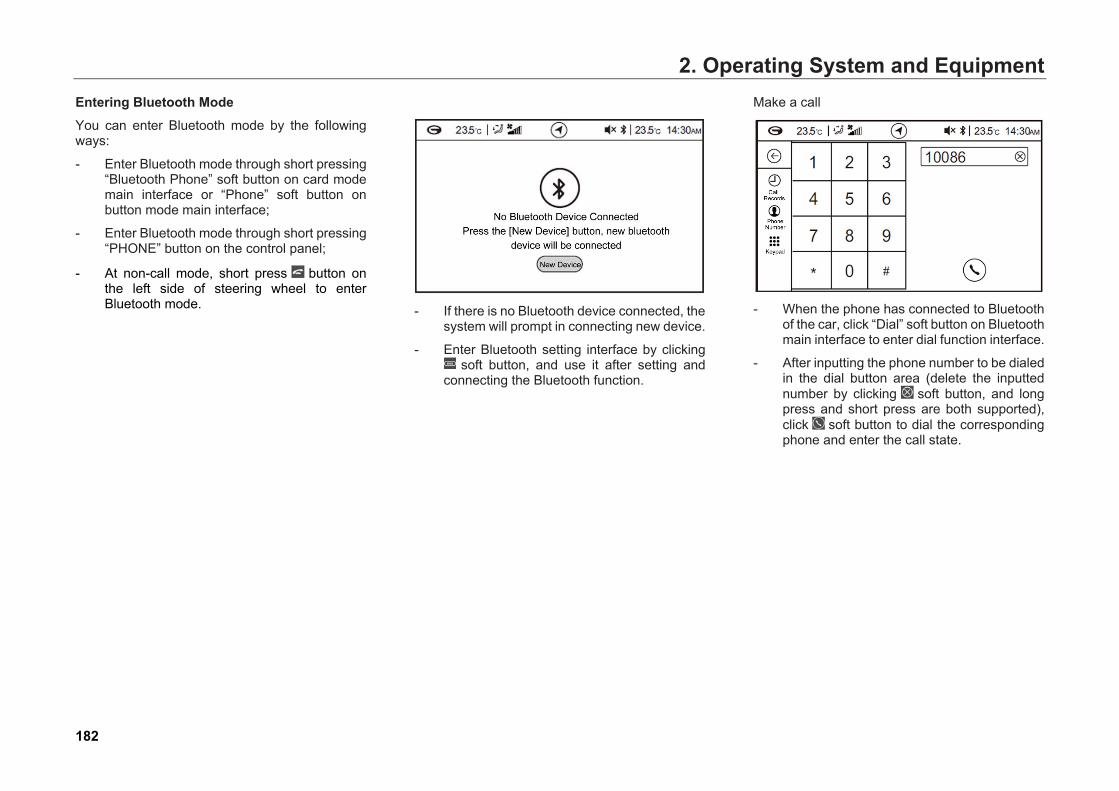
2. Operating System and EquipmentEntering Bluetooth Mode You can enter Bluetooth mode by the following ways:
- Enter Bluetooth mode through short pressing“Bluetooth Phone” soft button on card modemain interface or “Phone” soft button onbutton mode main interface;
- Enter Bluetooth mode through short pressing“PHONE” button on the control panel;
- At non-call mode, short press button onthe left side of steering wheel to enterBluetooth mode. - If there is no Bluetooth device connected, the
system will prompt in connecting new device.
- Enter Bluetooth setting interface by clicking soft button, and use it after setting and
connecting the Bluetooth function.
Make a call
- When the phone has connected to Bluetoothof the car, click “Dial” soft button on Bluetoothmain interface to enter dial function interface.
- After inputting the phone number to be dialedin the dial button area (delete the inputtednumber by clicking soft button, and longpress and short press are both supported),click soft button to dial the correspondingphone and enter the call state.
182

2. Operating System and Equipment
- If the contact is saved in the phone, the dialinterface will display the contact name anddefault image; if the contact is not saved, itwill display the number and default image.
- When the call is connecting, it will display“call connecting”.
During the call, clicking soft buttons on the call interface can realize:
- Click soft button to cut off the call;
- Click soft button to switch Hands Free andPrivate mode (when the call is connected,the default mode is Hands Free);
- Click soft button, realize mute and unmute;
- When the call is connected, short press toinput number.
Answer Calls
When Bluetooth is connected and it does not enable automatic answer, clicking soft buttons on the incoming call interface can realize:
- Click soft button to answer the call;
- Click soft button to reject the call.
Hint
In addition, press the Answer button on the steering wheel to answer the call; press the Hangup button on the steering wheel to reject the call.
183

2. Operating System and EquipmentCall Records
- The call records after Bluetooth is connectedare saved in “Call Records” of the system. OnBluetooth main interface, click the call recordsoft button to enter call records interface.
- If the call records are not synchronized, thesystem will display that call records are notsynchronized. Click “Synchronize” softbutton to synchronize the call records.
- The call records include received calls,missed calls and dialed calls.
- Pull down the scroll bar on the right side tobrowse the call records.
Phone Number
- After Bluetooth is connected successfully,click “Phone Number” soft button onBluetooth main interface to enter phone bookinterface.
Hint
The phone number function requires that the mobile phone supports the phonebook download function.
- If the phonebook is not synchronized, thesystem will display that phonebook is notsynchronized. Click “Synchronize” softbutton to synchronize the phonebook.
Hint
It is required to confirm on the phone whether you agree to synchronize the phonebook.
- After the synchronization is completed, thesystem will display the contacts inalphabetical order. Pull down the scroll baron the right to browse the contact, or pulldown the alphabet on the right to list all thecontacts with the initial.
- Click the contact required for dialing.
- Click soft button on the top right corner toopen the keyboard, and input initials andEnglish letters to find the contact number.
184
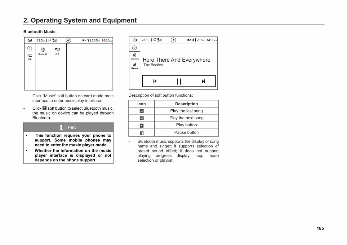
2. Operating System and EquipmentBluetooth Music
- Click “Music” soft button on card mode maininterface to enter music play interface.
- Click soft button to select Bluetooth music,the music on device can be played throughBluetooth.
Hint
• This function requires your phone tosupport. Some mobile phones mayneed to enter the music player mode.
• Whether the information on the musicplayer interface is displayed or notdepends on the phone support.
Description of soft button functions:
Icon Description Play the last song
Play the next song
Play button
Pause button
- Bluetooth music supports the display of songname and singer; it supports selection ofpreset sound effect; it does not supportplaying progress display, loop modeselection or playlist.
185
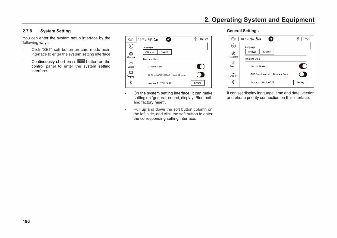
2. Operating System and Equipment2.7.8 System Setting You can enter the system setup interface by the following ways:
- Click “SET” soft button on card mode maininterface to enter the system setting interface.
- Continuously short press button on thecontrol panel to enter the system settinginterface.
- On the system setting interface, it can makesetting on “general, sound, display, Bluetoothand factory reset”.
- Pull up and down the soft button column onthe left side, and click the soft button to enterthe corresponding setting interface.
General Settings
It can set display language, time and date, version and phone priority connection on this interface.
186
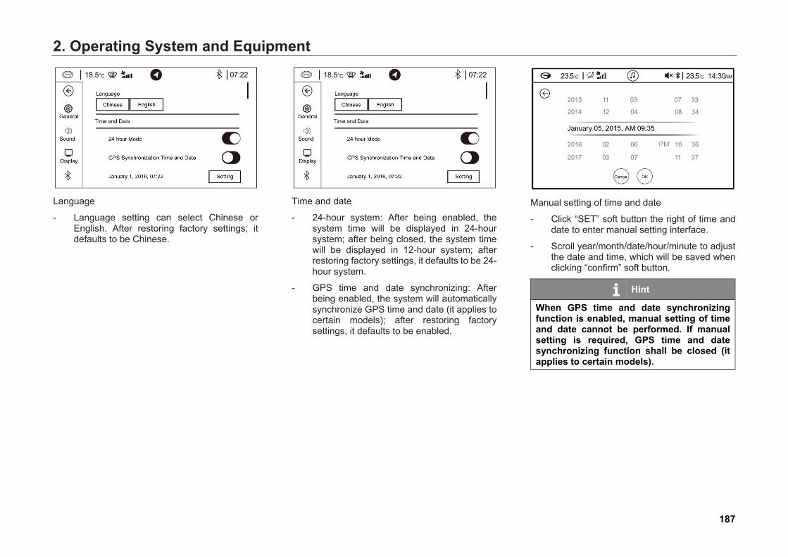
2. Operating System and Equipment
Language
- Language setting can select Chinese orEnglish. After restoring factory settings, itdefaults to be Chinese.
Time and date
- 24-hour system: After being enabled, thesystem time will be displayed in 24-hoursystem; after being closed, the system timewill be displayed in 12-hour system; afterrestoring factory settings, it defaults to be 24-hour system.
- GPS time and date synchronizing: Afterbeing enabled, the system will automaticallysynchronize GPS time and date (it applies tocertain models); after restoring factorysettings, it defaults to be enabled.
Manual setting of time and date
- Click “SET” soft button the right of time anddate to enter manual setting interface.
- Scroll year/month/date/hour/minute to adjustthe date and time, which will be saved whenclicking “confirm” soft button.
Hint
When GPS time and date synchronizing function is enabled, manual setting of time and date cannot be performed. If manual setting is required, GPS time and date synchronizing function shall be closed (it applies to certain models).
187
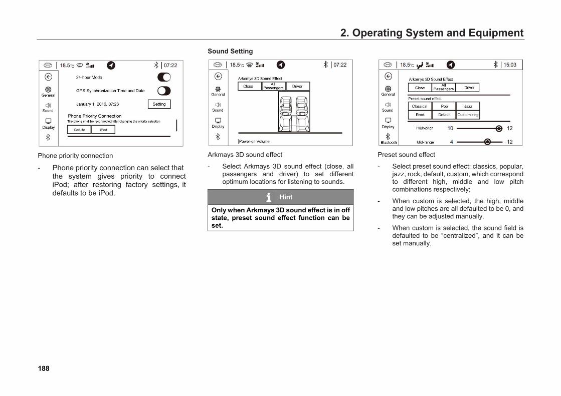
2. Operating System and Equipment
Phone priority connection
- Phone priority connection can select thatthe system gives priority to connect iPod; after restoring factory settings, it defaults to be iPod.
Sound Setting
Arkmays 3D sound effect
- Select Arkmays 3D sound effect (close, allpassengers and driver) to set differentoptimum locations for listening to sounds.
Hint
Only when Arkmays 3D sound effect is in off state, preset sound effect function can be set.
Preset sound effect
- Select preset sound effect: classics, popular,jazz, rock, default, custom, which correspondto different high, middle and low pitchcombinations respectively;
- When custom is selected, the high, middleand low pitches are all defaulted to be 0, andthey can be adjusted manually.
- When custom is selected, the sound field isdefaulted to be “centralized”, and it can beset manually.
188
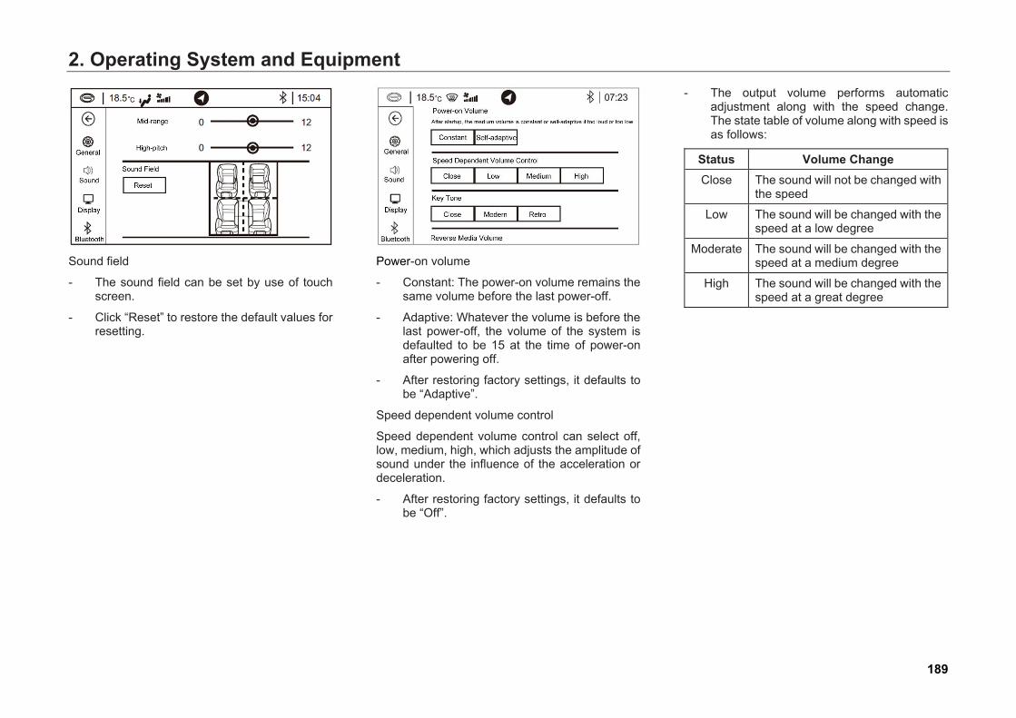
2. Operating System and Equipment
Sound field
- The sound field can be set by use of touchscreen.
- Click “Reset” to restore the default values forresetting.
Power-on volume
- Constant: The power-on volume remains thesame volume before the last power-off.
- Adaptive: Whatever the volume is before thelast power-off, the volume of the system isdefaulted to be 15 at the time of power-onafter powering off.
- After restoring factory settings, it defaults tobe “Adaptive”.
Speed dependent volume control
Speed dependent volume control can select off, low, medium, high, which adjusts the amplitude of sound under the influence of the acceleration or deceleration.
- After restoring factory settings, it defaults tobe “Off”.
- The output volume performs automaticadjustment along with the speed change.The state table of volume along with speed isas follows:
Status Volume Change Close The sound will not be changed with
the speed
Low The sound will be changed with the speed at a low degree
Moderate The sound will be changed with the speed at a medium degree
High The sound will be changed with the speed at a great degree
189
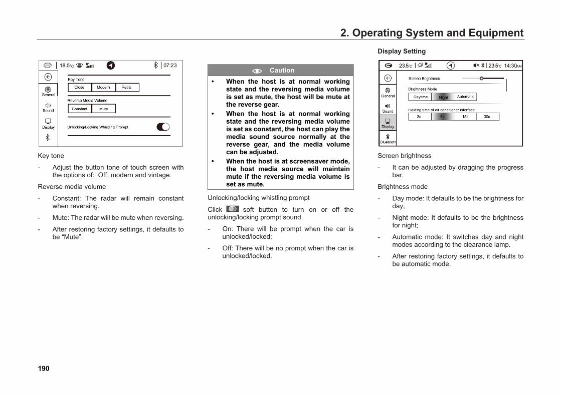
2. Operating System and Equipment
Key tone
- Adjust the button tone of touch screen withthe options of: Off, modern and vintage.
Reverse media volume
- Constant: The radar will remain constantwhen reversing.
- Mute: The radar will be mute when reversing.
- After restoring factory settings, it defaults tobe “Mute”.
Caution • When the host is at normal working
state and the reversing media volumeis set as mute, the host will be mute atthe reverse gear.
• When the host is at normal workingstate and the reversing media volumeis set as constant, the host can play themedia sound source normally at thereverse gear, and the media volumecan be adjusted.
• When the host is at screensaver mode,the host media source will maintainmute if the reversing media volume isset as mute.
Unlocking/locking whistling prompt
Click soft button to turn on or off the unlocking/locking prompt sound.
- On: There will be prompt when the car isunlocked/locked;
- Off: There will be no prompt when the car isunlocked/locked.
Display Setting
Screen brightness
- It can be adjusted by dragging the progressbar.
Brightness mode
- Day mode: It defaults to be the brightness forday;
- Night mode: It defaults to be the brightnessfor night;
- Automatic mode: It switches day and nightmodes according to the clearance lamp.
- After restoring factory settings, it defaults tobe automatic mode.
190
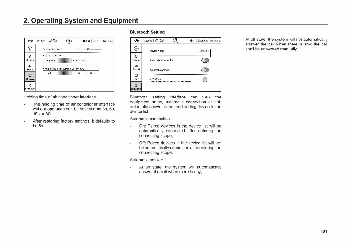
2. Operating System and Equipment
Holding time of air conditioner interface
- The holding time of air conditioner interfacewithout operation can be selected as 3s, 5s,15s or 30s.
- After restoring factory settings, it defaults tobe 5s.
Bluetooth Setting
Bluetooth setting interface can view the equipment name, automatic connection or not, automatic answer or not and adding device to the device list.
Automatic connection
- On: Paired devices in the device list will beautomatically connected after entering theconnecting scope;
- Off: Paired devices in the device list will notbe automatically connected after entering theconnecting scope.
Automatic answer
- At on state, the system will automaticallyanswer the call when there is any;
- At off state, the system will not automaticallyanswer the call when there is any; the callshall be answered manually.
191

2. Operating System and EquipmentDevice list
- Click soft button to pop up the prompt box.
Caution Whether to input the PIN code or not shall be judged according to different phone models.
- Search the prompted device name withmobile phone and input PIN code in theprompt box to connect the car Bluetooth. Itwill display in the device list after beingconnected successfully.
- The device list will display the pairedBluetooth device, and if the device issuccessfully connected, it will display“connected” ■
Factory reset
- Click “Reset” soft button on the factory resetinterface, and the system will pop up a dialogbox. Click “Confirm” to restore the systemsetting as the factory settings.
192
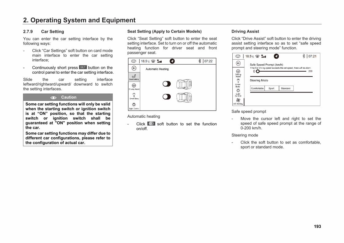
2. Operating System and Equipment2.7.9 Car Setting You can enter the car setting interface by the following ways:
- Click “Car Settings” soft button on card modemain interface to enter the car settinginterface;
- Continuously short press button on the control panel to enter the car setting interface.
Slide the car setting interface leftward/rightward/upward/ downward to switch the setting interfaces.
Caution Some car setting functions will only be valid when the starting switch or ignition switch is at “ON” position, so that the starting switch or ignition switch shall be guaranteed at "ON" position when setting the car. Some car setting functions may differ due to different car configurations, please refer to the configuration of actual car.
Seat Setting (Apply to Certain Models) Click “Seat Setting” soft button to enter the seat setting interface. Set to turn on or off the automatic heating function for driver seat and front passenger seat.
Automatic heating
- Click soft button to set the function on/off.
Driving Assist Click “Drive Assist” soft button to enter the driving assist setting interface so as to set “safe speed prompt and steering mode” function.
Safe speed prompt
- Move the cursor left and right to set thespeed of safe speed prompt at the range of0-200 km/h.
Steering mode
- Click the soft button to set as comfortable,sport or standard mode.
193
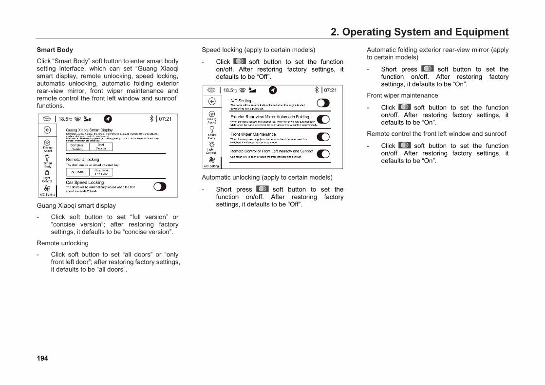
2. Operating System and EquipmentSmart Body Click “Smart Body” soft button to enter smart body setting interface, which can set “Guang Xiaoqi smart display, remote unlocking, speed locking, automatic unlocking, automatic folding exterior rear-view mirror, front wiper maintenance and remote control the front left window and sunroof” functions.
Guang Xiaoqi smart display
- Click soft button to set “full version” or“concise version”; after restoring factorysettings, it defaults to be “concise version”.
Remote unlocking
- Click soft button to set “all doors” or “onlyfront left door”; after restoring factory settings,it defaults to be “all doors”.
Speed locking (apply to certain models)
- Click soft button to set the functionon/off. After restoring factory settings, itdefaults to be “Off”.
Automatic unlocking (apply to certain models)
- Short press soft button to set thefunction on/off. After restoring factorysettings, it defaults to be “Off”.
Automatic folding exterior rear-view mirror (apply to certain models)
- Short press soft button to set thefunction on/off. After restoring factorysettings, it defaults to be “On”.
Front wiper maintenance
- Click soft button to set the function on/off. After restoring factory settings, it defaults to be “On”.
Remote control the front left window and sunroof
- Click soft button to set the function on/off. After restoring factory settings, it defaults to be “On”.
194
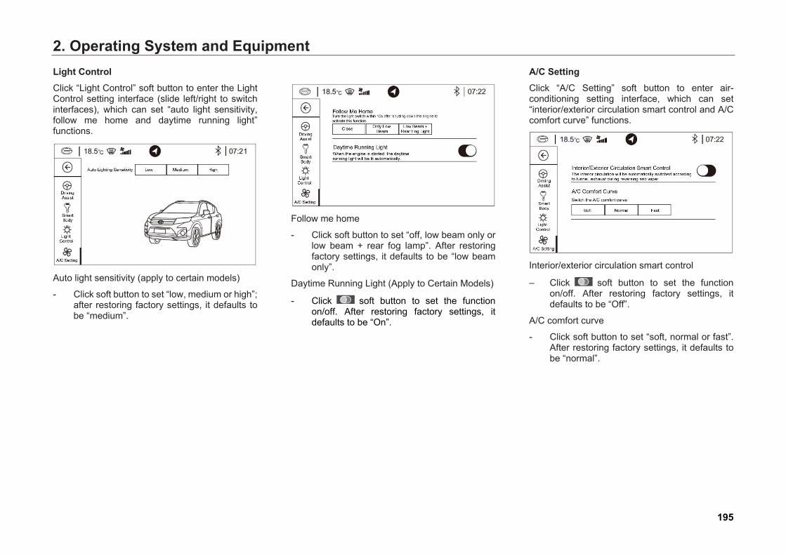
2. Operating System and EquipmentLight Control Click “Light Control” soft button to enter the Light Control setting interface (slide left/right to switch interfaces), which can set “auto light sensitivity, follow me home and daytime running light” functions.
Auto light sensitivity (apply to certain models)
- Click soft button to set “low, medium or high”;after restoring factory settings, it defaults tobe “medium”.
Follow me home
- Click soft button to set “off, low beam only orlow beam + rear fog lamp”. After restoringfactory settings, it defaults to be “low beamonly”.
Daytime Running Light (Apply to Certain Models)
- Click soft button to set the function on/off. After restoring factory settings, it defaults to be “On”.
A/C Setting Click “A/C Setting” soft button to enter air-conditioning setting interface, which can set “interior/exterior circulation smart control and A/C comfort curve” functions.
Interior/exterior circulation smart control
– Click soft button to set the function on/off. After restoring factory settings, it defaults to be “Off”.
A/C comfort curve
- Click soft button to set “soft, normal or fast”.After restoring factory settings, it defaults tobe “normal”.
195
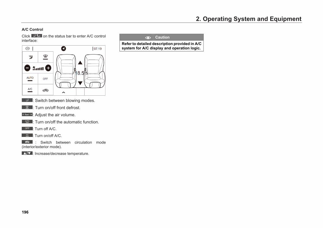
2. Operating System and EquipmentA/C Control Click on the status bar to enter A/C control interface:
: Switch between blowing modes.
: Turn on/off front defrost.
: Adjust the air volume.
: Turn on/off the automatic function. : Turn off A/C.
: Turn on/off A/C.
: Switch between circulation mode (interior/exterior mode).
: Increase/decrease temperature.
Caution Refer to detailed description provided in A/C system for A/C display and operation logic.
196
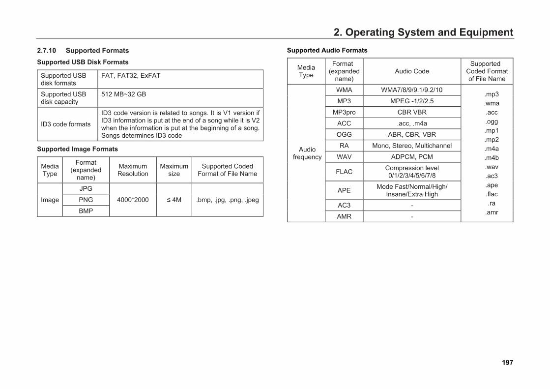
2. Operating System and Equipment2.7.10 Supported FormatsSupported USB Disk Formats
Supported USB disk formats
FAT, FAT32, ExFAT
Supported USB disk capacity
512 MB~32 GB
ID3 code formats
ID3 code version is related to songs. It is V1 version if ID3 information is put at the end of a song while it is V2 when the information is put at the beginning of a song. Songs determines ID3 code
Supported Image Formats
Media Type
Format (expanded
name)
Maximum Resolution
Maximum size
Supported Coded Format of File Name
Image
JPG
4000*2000 ≤ 4M .bmp, .jpg, .png, .jpegPNG
BMP
Supported Audio Formats
Media Type
Format (expanded
name) Audio Code
Supported Coded Format of File Name
Audio frequency
WMA WMA7/8/9/9.1/9.2/10 .mp3 .wma .acc .ogg .mp1 .mp2 .m4a .m4b .wav .ac3 .ape .flac .ra
.amr
MP3 MPEG -1/2/2.5
MP3pro CBR VBR
ACC .acc, .m4a
OGG ABR, CBR, VBR
RA Mono, Stereo, Multichannel
WAV ADPCM, PCM
FLAC Compression level 0/1/2/3/4/5/6/7/8
APE Mode Fast/Normal/High/ Insane/Extra High
AC3 -
AMR -
197
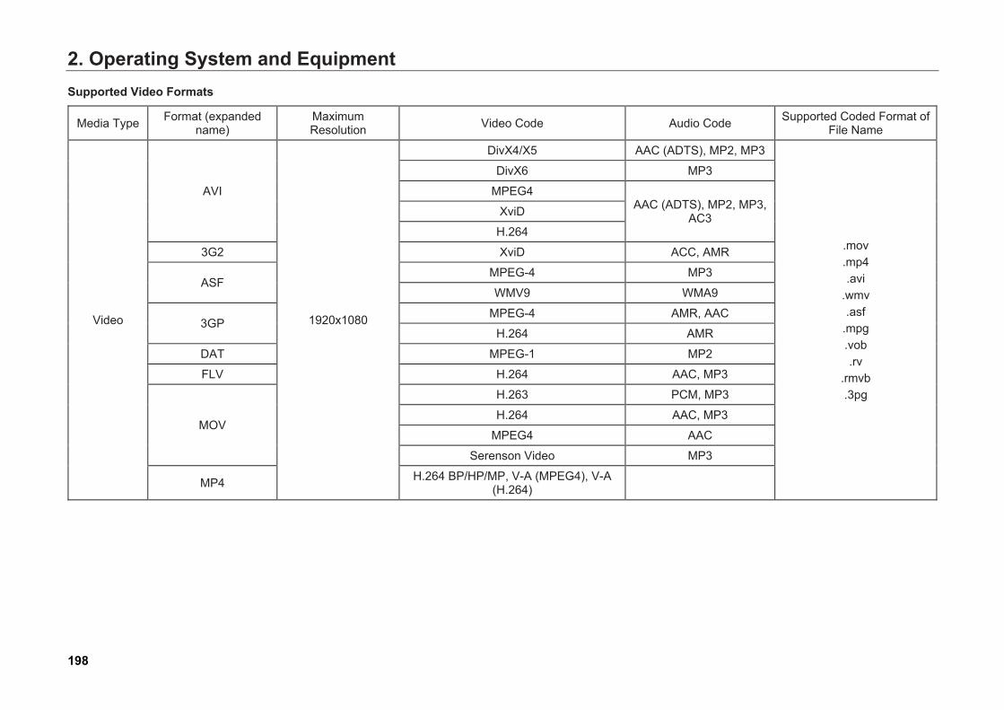
2. Operating System and EquipmentSupported Video Formats
Media Type Format (expanded name)
Maximum Resolution Video Code Audio Code Supported Coded Format of
File Name
Video
AVI
1920x1080
DivX4/X5 AAC (ADTS), MP2, MP3
.mov
.mp4 .avi
.wmv .asf
.mpg .vob .rv
.rmvb .3pg
DivX6 MP3
MPEG4 AAC (ADTS), MP2, MP3,
AC3 XviD
H.264
3G2 XviD ACC, AMR
ASF MPEG-4 MP3
WMV9 WMA9
3GP MPEG-4 AMR, AAC
H.264 AMR
DAT MPEG-1 MP2
FLV H.264 AAC, MP3
MOV
H.263 PCM, MP3
H.264 AAC, MP3
MPEG4 AAC
Serenson Video MP3
MP4 H.264 BP/HP/MP, V-A (MPEG4), V-A(H.264)
198
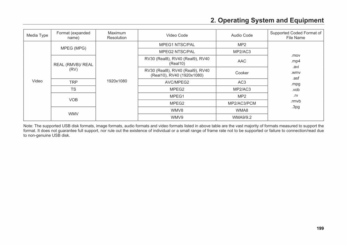
2. Operating System and Equipment
Media Type Format (expanded name)
Maximum Resolution Video Code Audio Code Supported Coded Format of
File Name
Video
MPEG (MPG)
1920x1080
MPEG1 NTSC/PAL MP2
.mov
.mp4 .avi
.wmv .asf
.mpg .vob .rv
.rmvb .3pg
MPEG2 NTSC/PAL MP2/AC3
REAL (RMVB)/ REAL (RV)
RV30 (Real8), RV40 (Real9), RV40 (Real10) AAC
RV30 (Real8), RV40 (Real9), RV40 (Real10), RV40 (1920x1080) Cooker
TRP AVC/MPEG2 AC3
TS MPEG2 MP2/AC3
VOB MPEG1 MP2
MPEG2 MP2/AC3/PCM
WMV WMV8 WMA8
WMV9 WMA9/9.2
Note: The supported USB disk formats, image formats, audio formats and video formats listed in above table are the vast majority of formats measured to support the format. It does not guarantee full support, nor rule out the existence of individual or a small range of frame rate not to be supported or failure to connection/read due to non-genuine USB disk.
199
2. Operating System and Equipment
2.7.11 Precautions for Use of USB Please carefully read the following precautions before USB play:
1. If the engine has been started, maintain USBdevice connected. Starting the engine underthe connection of USB device may damagethe USB device.
2. When the engine is started or shut downunder the connection of USB device, theUSB device may not react.
3. Files not in standard formats such as MP3and WMA probably cannot be played.
4. MP3 file can be played only when thecompression ratio is 8 Kbps ~ 320Kbps andWMA file can be played only when thecompression ratio is 32 Kbps ~ 320 Kbps.
5. The connection of USB device may be notidentified due to the status of the USB deviceoccasionally.
6. USB device in the format of FAT16/32 onlycan be read.
7. USB device may not work because ofcompatibility, so please confirm the USBdevice can work before use.
8. Do not let your body or other things touch thejoint of USB device.
9. USB device may be damaged by repeatedplugging in a short time.
10. Suddenly unplugging USB device during fileplaying may damage USB device or causeabnormal conditions. So, please turn offaudio system or switch to other play modesbefore unplugging USB device.
11. The duration for identifying the connection ofUSB device varies with the type of USBdevice, memory or format of file saved.
12. Do not use USB interface for charging,because this may reduce the productperformance or result in fault.
13. USB device may be not identified whenordinary USB or extended cable is used, soplease directly connect USB device to USBinterface.
14. If MP3 PLAYER, mobile phone or digitalcamera connected cannot be identified, thehead unit may not work properly.
15. SD Type USB memory stick or CF type USBmemory stick and other USB devices forconnecting Adapter may be not identified.
16. USB device may be poorly connected due tocar vibration.
17. Do not unplug USB device immediatelyduring the playing of USB video, otherwise,USB device may be damaged.
18. The more files, the longer time for openingand playing USB; for rapid read, make filescopied to USB as few as possible and try notto place irrelevant files (e.g. APPs, maps).
200

2. Operating System and Equipment19. For playing USB, the opening time may vary
with different music, video or image files (forexample, longer time is required for openingimage files occupying large memory space,high-definition video and audio); too longopening time may result in restart.
20. Fast forward and fast backward of videoplaying is subject to addressing by frame; theconverted video data may be not in standardformat, and irregular fast forward and fastbackward may occur during the playing ofUSB video, causing blocking; or some keyframes are lost after conversion, blockingmay occur, causing restart.
201

2. Operating System and Equipment2.7.12 Precautions for Product Use
Warning
● When navigation system is used forroute navigation, please driveaccording to the actual traffic rules. Ifthe driver only follows the routenavigation of the navigation systemwhen driving, sometimes he will breaktraffic regulations or even cause trafficaccident.
● During the driving process, the drivershall check the images within theshortest possible time. Watching theimage for a too long time may causetraffic accident.
● During the driving process, the drivershall not execute address login, facilitysearch or other operations, which mustbe operated after parking. Inattention toobserve the front situations may causetraffic accident.
● Do not privately disassemble ortransform this product, which maycause traffic accident, fire or electricshock, etc.
Warning
● It should be noted that water or otherforeign matters shall not intrude intothe product, which may causesmoking, fire or failure, etc. In casesmoking or other abnormal conditionsoccur due to foreign matter intrusion orwater soaking, immediately stop using,and contact your GAC MOTOR dealer.Any continued use may cause failure.
● Do not use at failure state, including noimage display or no sound, which maycause accident, fire, electric shock, orcritical failure, etc.
● Turn off the touch screen beforewiping, for which soft dry cloth shall beused. Do not use coarse cleaning cloth,chemical cleaning cloth or organicreagent (alcohol, benzene, disinfectant,etc.), which will damage or deterioratethe panel.
Warning
● During a thunderstorm, do not touchantenna or other circuits, which maycause electric shock due to lightningstroke.
● Do not operate this product in an areawhere parking is prohibited, which maycause traffic accident.
Caution ● Please drive according to the traffic
conditions. During the navigationprocess, the driver may drive the carinto an area of no entry due to changeof rules.
● During the driving process, the volumeshall be adjusted in such a manner thatthe driver can hear the conditionsoutside the car. If the volume is toohigh and the driver cannot hear theconditions outside the car, accidentmay occur.
202
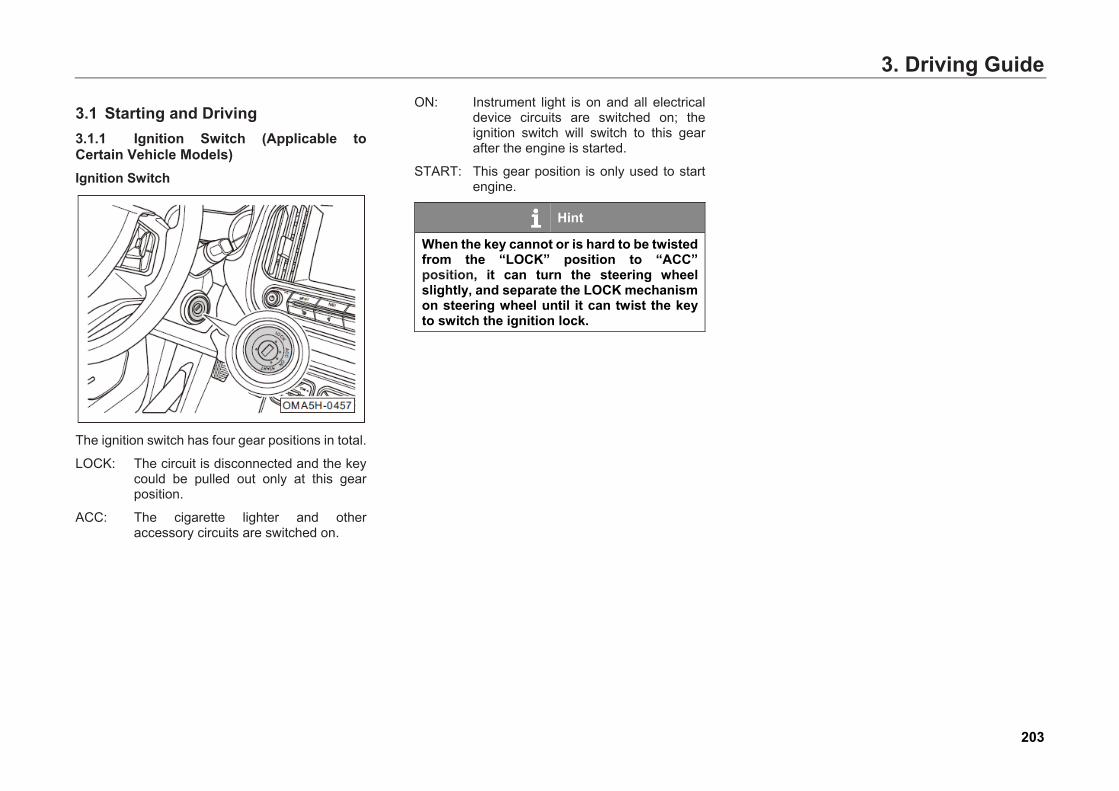
3. Driving Guide3. Driving Guide
3.1 Starting and Driving 3.1.1 Ignition Switch (Applicable to Certain Vehicle Models) Ignition Switch
The ignition switch has four gear positions in total.
LOCK: The circuit is disconnected and the key could be pulled out only at this gear position.
ACC: The cigarette lighter and other accessory circuits are switched on.
ON: Instrument light is on and all electrical device circuits are switched on; the ignition switch will switch to this gear after the engine is started.
START: This gear position is only used to start engine.
Hint
When the key cannot or is hard to be twisted from the “LOCK” position to “ACC” position, it can turn the steering wheel slightly, and separate the LOCK mechanism on steering wheel until it can twist the key to switch the ignition lock.
203
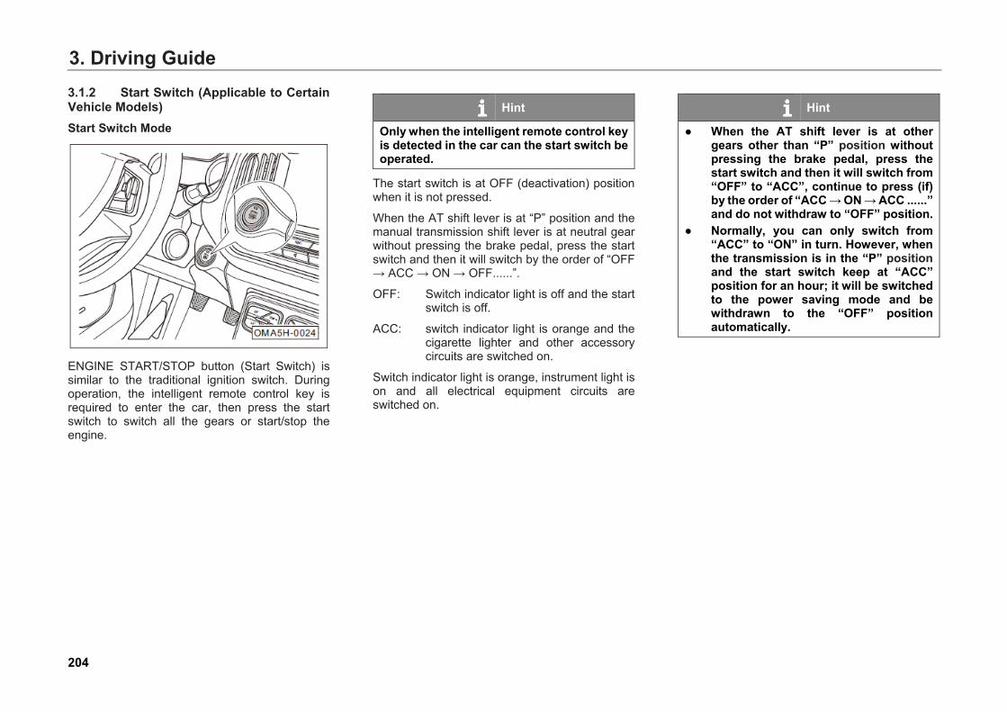
3. Driving Guide3.1.2 Start Switch (Applicable to Certain Vehicle Models) Start Switch Mode
ENGINE START/STOP button (Start Switch) is similar to the traditional ignition switch. During operation, the intelligent remote control key is required to enter the car, then press the start switch to switch all the gears or start/stop the engine.
Hint
Only when the intelligent remote control key is detected in the car can the start switch be operated.
The start switch is at OFF (deactivation) position when it is not pressed.
When the AT shift lever is at “P” position and the manual transmission shift lever is at neutral gear without pressing the brake pedal, press the start switch and then it will switch by the order of “OFF → ACC → ON → OFF......”.
OFF: Switch indicator light is off and the start switch is off.
ACC: switch indicator light is orange and the cigarette lighter and other accessory circuits are switched on.
Switch indicator light is orange, instrument light is on and all electrical equipment circuits are switched on.
Hint
● When the AT shift lever is at othergears other than “P” position withoutpressing the brake pedal, press thestart switch and then it will switch from“OFF” to “ACC”, continue to press (if)by the order of “ACC → ON → ACC ......”and do not withdraw to “OFF” position.
● Normally, you can only switch from“ACC” to “ON” in turn. However, whenthe transmission is in the “P” positionand the start switch keep at “ACC”position for an hour; it will be switchedto the power saving mode and bewithdrawn to the “OFF” positionautomatically.
204
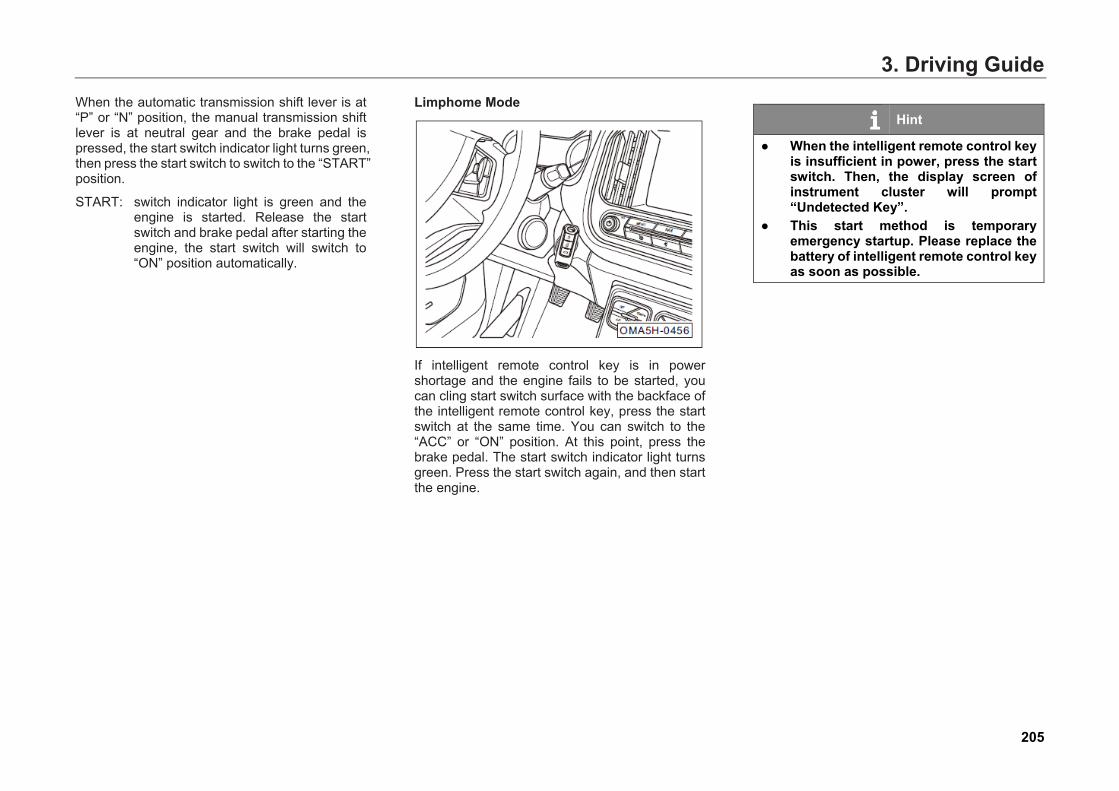
3. Driving GuideWhen the automatic transmission shift lever is at “P” or “N” position, the manual transmission shift lever is at neutral gear and the brake pedal is pressed, the start switch indicator light turns green, then press the start switch to switch to the “START” position.
START: switch indicator light is green and the engine is started. Release the start switch and brake pedal after starting the engine, the start switch will switch to “ON” position automatically.
Limphome Mode
If intelligent remote control key is in power shortage and the engine fails to be started, you can cling start switch surface with the backface of the intelligent remote control key, press the start switch at the same time. You can switch to the “ACC” or “ON” position. At this point, press the brake pedal. The start switch indicator light turns green. Press the start switch again, and then start the engine.
Hint
● When the intelligent remote control keyis insufficient in power, press the startswitch. Then, the display screen ofinstrument cluster will prompt“Undetected Key”.
● This start method is temporaryemergency startup. Please replace thebattery of intelligent remote control keyas soon as possible.
205
3. Driving Guide3.1.3 Engine Start Vehicle Models with Manual Transmission Vehicle Models with Ignition Switch
– Insert the mechanical key into the ignitionswitch.
– Depress the brake pedal and clutch pedal toand maintain it at the full range, and makesure the shift lever is at neutral gear.
– Turn the mechanical key to switch theignition switch to “START” position, thus theengine is started.
Vehicle Models with Start Switch
– Carry the intelligent remote control key toenter the car with you.
– Depress the brake pedal and clutch pedal toand maintain it at the full range, and makesure the shift lever is at neutral gear and thestart switch indicator light is green.
– Depress the start switch to start the engine.
Vehicle Models with Automatic Transmission Vehicle Models with Ignition Switch
– Insert the mechanical key into the ignitionswitch.
– Depress the brake pedal and maintain it atthe full range, and make sure the shift leveris at “P” or “N” position.
– Turn the mechanical key to switch theignition switch to “START” position, thus theengine is started.
Vehicle Models with Start Switch
– Carry the intelligent remote control key toenter the car with you.
– Depress the brake pedal and maintain it atthe full range, and make sure the shift leveris at “P” or “N” position and the start switchindicator light is green.
– Depress the start switch to start the engine.
Hint
● If the engine is of cold start, it needsidle running to let it warm up beforedriving. At the same time, becausevalve lifter takes a few seconds toreach normal working pressure, it canproduce running noise, which isnormal phenomenon, requiring noworry.
● If models with start switch cannot startthe engine normally caused by brakesignal, speed failure, or lowtemperature in winter and otherreasons, it can try to switch the startswitch to the “ACC” position, ensurethe transmission shift lever in “P” or“N” position, and press start switch for15 seconds, and then start the engineforcefully.
206
3. Driving Guide
Caution ● After the engine has successfully
started, release the start switch ormechanical key immediately.
● Engine startup time cannot exceed 15seconds. If engine fails to startsuccessfully, wait about 30 seconds totry again.
● Do not push the accelerator pedal torun the engine in high speed or in anoverload way. Otherwise, the enginecan be easily damaged.
● If the battery is short of power and youcan't start the engine, try to perform theemergency start by connecting thecable. (Please refer to Page 403).
● Do not start a vehicle engine bypushing or pulling it.
Warning
● Do not start the engine in a poorlyventilated or enclosed room for a longtime. Because engine off-gas containsharmful gas, it can cause coma andeven suffocation death.
● Do not leave the engine in unattendedmode when the engine is running.
● Do not start the engine by startingauxiliary device. Otherwise, it mayexplode or cause the engine to run athigh speed, causing casualties.
207
3. Driving Guide3.1.4 Engine Shutdown Vehicle Models with Manual Transmission – Depress the brake pedal and clutch pedal to
stop the vehicle steadily, and apply parkingbrake.
– Switch the shift lever to neutral gear.
– Loosen the brake pedal and the clutch pedal,twist the mechanical key to switch the ignitionswitch to “LOCK” or press the start switch toshut down the engine.
– Turn the steering wheel back and forth, andmesh the steering wheel lock mechanism.
Hint
The radiator fan may still run for some time after the engine is shut down.
Vehicle Models with Automatic Transmission – Push the brake pedal, stop the vehicle, and
apply the parking brake.
– Put the shift lever at “P” position.
– Loosen the brake pedal, twist the mechanicalkey to switch the ignition switch to “LOCK” orpress the start switch to shut down theengine.
Hint
The radiator fan may still run for some time after the engine is shut down.
Caution ● In the process of vehicle driving, in
case of emergency which requiresshutting down the engine, press startswitch for long time or press startswitch three times continuously. Thestart switch will be withdrawn from“ON” to “ACC” position. Shut down theengine. Then, emergency flameout iscompleted. The engine can be restarteda few seconds later after emergencyflameout.
● In the process of vehicle driving, incase of automatic engine shutdown orafter emergency flameout, simply putthe transmission at “N” position andpress the start switch again to restartthe engine.
● If brake signal failure occurs to theengine during the startup process, itmust first switch to the “ACC” positionand then press the start switch to startthe engine. In the startup process, theautomatic transmission shift levermust be at “P” or “N” position.
208
3. Driving Guide
Warning
● When the engine stops working andwhen the brake booster does not work,the brake pedal requires more force topush the brake pedal to stop thevehicle. If the steering booster does notwork, a greater force must be applied toturn the steering wheel.
● When driving, do not turn off the enginein case of emergency. Otherwise, theairbag will not work.
Precautions for Parking When parking, put the shift lever to the “P” position or the neutral gear and pay attention to the following matters:
● Pay attention to the vehicle parking directionand do not make the exhaust discharged tothe plant to damage the green belt.
● Try to park on a straight road and avoid asteep slope.
● When parking, no matter the vehicle is facingthe top or the bottom of the slope, the frontwheels should be directed to the curb.
● The vehicle should be applied with theelectronic parking brake. Turn off all lightsand other electrical equipment, and shutdown the engine.
● When leaving the vehicle, be sure to bringyour valuables and vehicle keys with you,and confirm that the skylight, window, doorand hatchback door are closed or locked.
● Check the anti-theft start locking systemindicator on the instrument cluster, andconfirm that the anti-theft system has beenactivated.
Warning
● Even if you leave the vehicletemporarily, you must shut down theengine, apply the electronic parkingbrake, and carry the car keys with you.Otherwise, the person left in the carmay accidentally start the engine orelectrical equipment, causing seriousinjuries and deaths.
● After the driver stops to leave thevehicle, do not leave the person in thecar, especially the child. Otherwise, it iseasy to cause suffocating, coma andeven death sealed car.
● Do not park vehicles near flammableand explosive items.
209
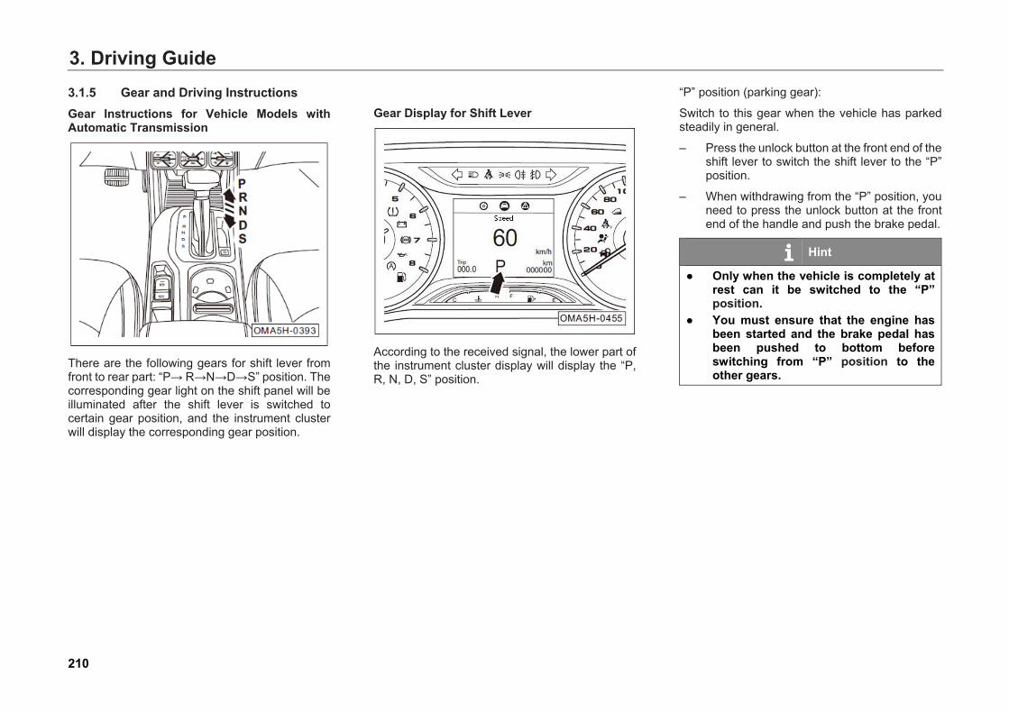
3. Driving Guide3.1.5 Gear and Driving Instructions Gear Instructions for Vehicle Models with Automatic Transmission
There are the following gears for shift lever from front to rear part: “P→ R→N→D→S” position. The corresponding gear light on the shift panel will be illuminated after the shift lever is switched to certain gear position, and the instrument cluster will display the corresponding gear position.
Gear Display for Shift Lever
According to the received signal, the lower part of the instrument cluster display will display the “P, R, N, D, S” position.
“P” position (parking gear):
Switch to this gear when the vehicle has parked steadily in general.
– Press the unlock button at the front end of theshift lever to switch the shift lever to the “P”position.
– When withdrawing from the “P” position, youneed to press the unlock button at the frontend of the handle and push the brake pedal.
Hint
● Only when the vehicle is completely atrest can it be switched to the “P”position.
● You must ensure that the engine hasbeen started and the brake pedal hasbeen pushed to bottom beforeswitching from “P” position to theother gears.
210

3. Driving Guide“R” position (reverse gear):
Switch to this gear when reversing:
– Depress the brake pedal and stop the vehiclesteadily.
– Press the unlock button at the front of theshift lever, put the shift lever to “R” position.At this time, the reversing light willautomatically light up, and automatically turnon the reversing system (if any) (Pleaserefer to Page 310).
– Release the brake pedal and depress theaccelerator pedal slowly. The vehicle willmove reversely.
Caution Please depress the brake pedal and do not depress the accelerator before withdrawing the shift lever out from “N” position.
“N” position (neutral gear):
You can directly put the shift lever from “R” or “D” to “N” position.
Caution Please depress the brake pedal and do not depress the accelerator before withdrawing the shift lever out from “N” position.
Warning
When driving a vehicle, do not switch to “N” position to slide. Otherwise, it can easily cause driving hazards.
“D” position (driving gear):
Switch to this gear when the vehicle drives forward.
– Directly put the shift lever from “N” or “S” to“D” position. At this gear, the system will beautomatically raised or lowered the gearaccording to engine load and speed.
211
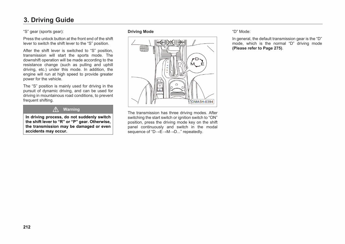
3. Driving Guide“S” gear (sports gear):
Press the unlock button at the front end of the shift lever to switch the shift lever to the “S” position.
After the shift lever is switched to “S” position, transmission will start the sports mode. The downshift operation will be made according to the resistance change (such as pulling and uphill driving, etc.) under this mode. In addition, the engine will run at high speed to provide greater power for the vehicle.
The “S” position is mainly used for driving in the pursuit of dynamic driving, and can be used for driving in mountainous road conditions, to prevent frequent shifting.
Warning
In driving process, do not suddenly switch the shift lever to “R” or “P” gear. Otherwise, the transmission may be damaged or even accidents may occur.
Driving Mode
The transmission has three driving modes. After switching the start switch or ignition switch to “ON” position, press the driving mode key on the shift panel continuously and switch in the modal sequence of “D→E→M→D...” repeatedly.
“D” Mode:
In general, the default transmission gear is the “D” mode, which is the normal “D” driving mode (Please refer to Page 275).
212
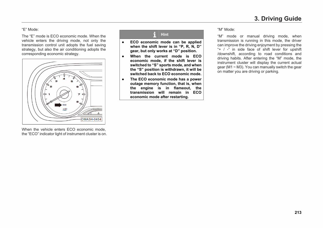
3. Driving Guide“E” Mode:
The “E” mode is ECO economic mode. When the vehicle enters the driving mode, not only the transmission control unit adopts the fuel saving strategy, but also the air conditioning adopts the corresponding economic strategy.
When the vehicle enters ECO economic mode, the “ECO” indicator light of instrument cluster is on.
Hint
● ECO economic mode can be appliedwhen the shift lever is in “P, R, N, D”gear, but only works at “D” position.
● When the current mode is ECOeconomic mode, if the shift lever isswitched to “S” sports mode, and whenthe “S” position is withdrawn, it will beswitched back to ECO economic mode.
● The ECO economic mode has a poweroutage memory function, that is, whenthe engine is in flameout, thetransmission will remain in ECOeconomic mode after restarting.
“M” Mode:
“M” mode or manual driving mode, when transmission is running in this mode, the driver can improve the driving enjoyment by pressing the “+ / -” in side face of shift lever for upshift /downshift, according to road conditions and driving habits. After entering the “M” mode, the instrument cluster will display the current actual gear (M1 ~ M3). You can manually switch the gear on matter you are driving or parking.
213
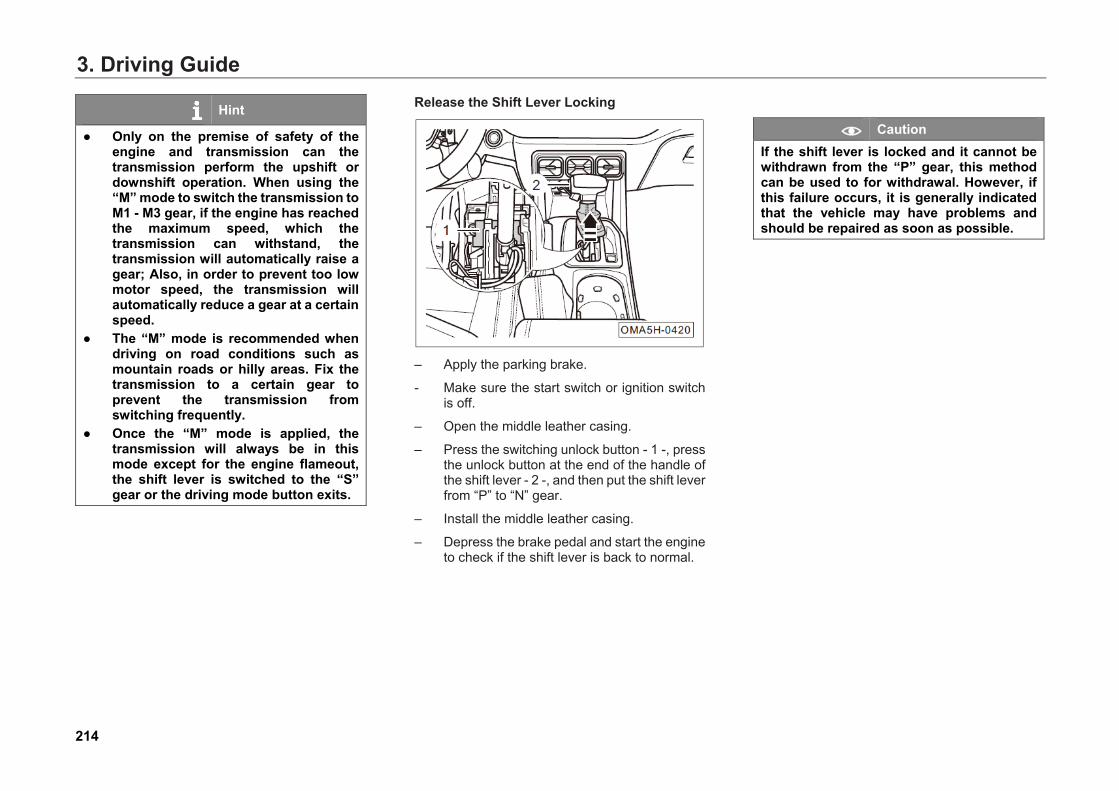
3. Driving Guide
Hint
● Only on the premise of safety of theengine and transmission can thetransmission perform the upshift ordownshift operation. When using the“M” mode to switch the transmission toM1 - M3 gear, if the engine has reachedthe maximum speed, which thetransmission can withstand, thetransmission will automatically raise agear; Also, in order to prevent too lowmotor speed, the transmission willautomatically reduce a gear at a certainspeed.
● The “M” mode is recommended whendriving on road conditions such asmountain roads or hilly areas. Fix thetransmission to a certain gear toprevent the transmission fromswitching frequently.
● Once the “M” mode is applied, thetransmission will always be in thismode except for the engine flameout,the shift lever is switched to the “S”gear or the driving mode button exits.
Release the Shift Lever Locking
– Apply the parking brake.
- Make sure the start switch or ignition switchis off.
– Open the middle leather casing.
– Press the switching unlock button - 1 -, pressthe unlock button at the end of the handle ofthe shift lever - 2 -, and then put the shift leverfrom “P” to “N” gear.
– Install the middle leather casing.
– Depress the brake pedal and start the engineto check if the shift lever is back to normal.
Caution If the shift lever is locked and it cannot be withdrawn from the “P” gear, this method can be used to for withdrawal. However, if this failure occurs, it is generally indicated that the vehicle may have problems and should be repaired as soon as possible.
214
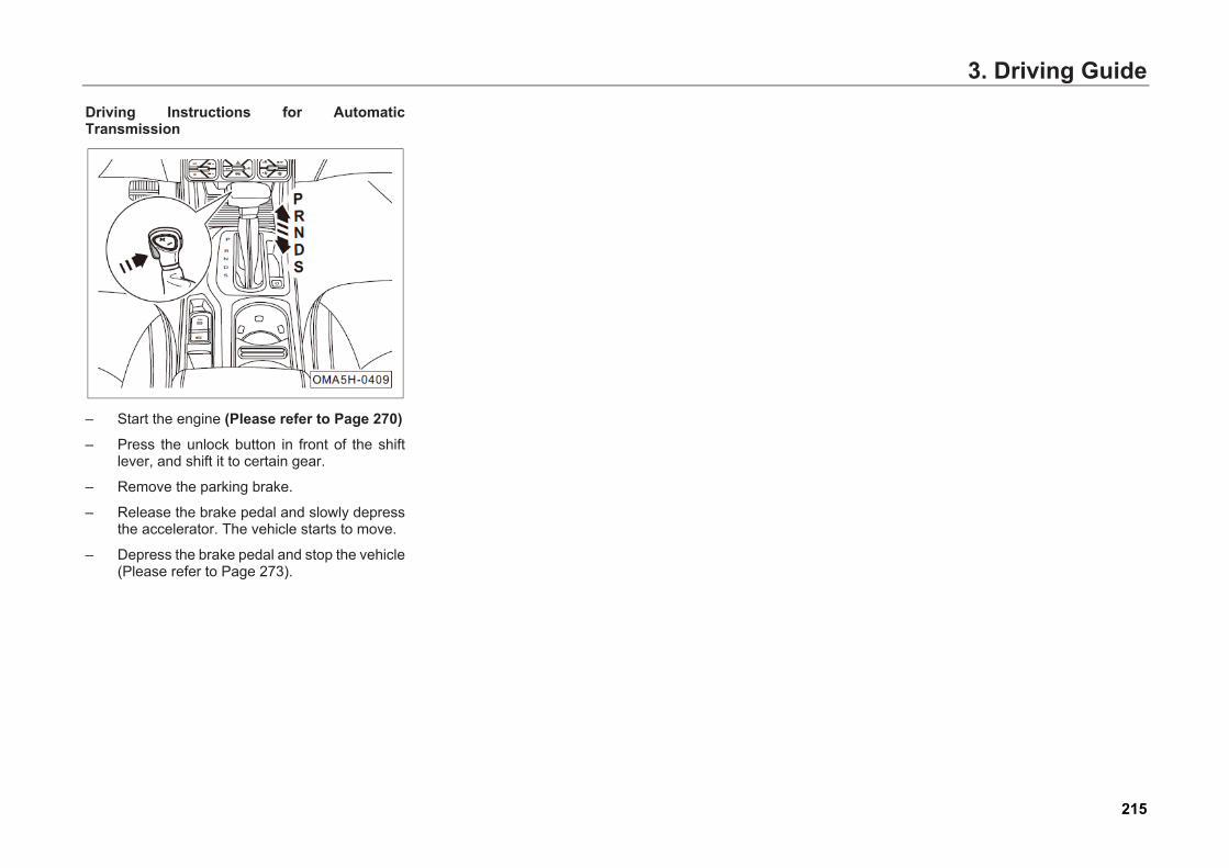
3. Driving GuideDriving Instructions for Automatic Transmission
– Start the engine (Please refer to Page 270)
– Press the unlock button in front of the shiftlever, and shift it to certain gear.
– Remove the parking brake.
– Release the brake pedal and slowly depressthe accelerator. The vehicle starts to move.
– Depress the brake pedal and stop the vehicle(Please refer to Page 273).
215
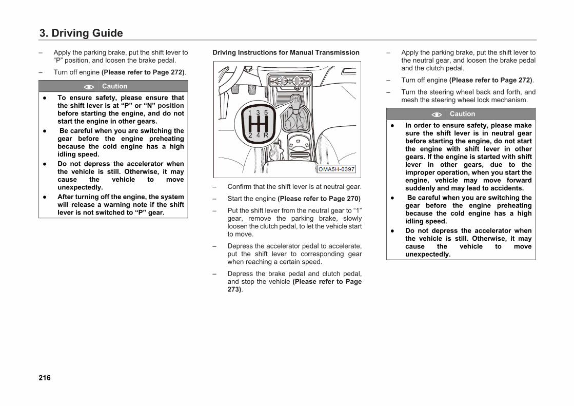
3. Driving Guide– Apply the parking brake, put the shift lever to
“P” position, and loosen the brake pedal.
– Turn off engine (Please refer to Page 272).
Caution ● To ensure safety, please ensure that
the shift lever is at “P” or “N” positionbefore starting the engine, and do notstart the engine in other gears.
● Be careful when you are switching thegear before the engine preheatingbecause the cold engine has a highidling speed.
● Do not depress the accelerator whenthe vehicle is still. Otherwise, it maycause the vehicle to moveunexpectedly.
● After turning off the engine, the systemwill release a warning note if the shiftlever is not switched to “P” gear.
Driving Instructions for Manual Transmission
– Confirm that the shift lever is at neutral gear.
– Start the engine (Please refer to Page 270)
– Put the shift lever from the neutral gear to “1”gear, remove the parking brake, slowlyloosen the clutch pedal, to let the vehicle startto move.
– Depress the accelerator pedal to accelerate,put the shift lever to corresponding gearwhen reaching a certain speed.
– Depress the brake pedal and clutch pedal,and stop the vehicle (Please refer to Page273).
– Apply the parking brake, put the shift lever tothe neutral gear, and loosen the brake pedaland the clutch pedal.
– Turn off engine (Please refer to Page 272).– Turn the steering wheel back and forth, and
mesh the steering wheel lock mechanism.
Caution ● In order to ensure safety, please make
sure the shift lever is in neutral gearbefore starting the engine, do not startthe engine with shift lever in othergears. If the engine is started with shiftlever in other gears, due to theimproper operation, when you start theengine, vehicle may move forwardsuddenly and may lead to accidents.
● Be careful when you are switching thegear before the engine preheatingbecause the cold engine has a highidling speed.
● Do not depress the accelerator whenthe vehicle is still. Otherwise, it maycause the vehicle to moveunexpectedly.
216
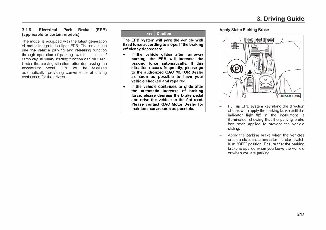
3. Driving Guide3.1.6 Electrical Park Brake (EPB) (applicable to certain models) The model is equipped with the latest generation of motor integrated caliper EPB. The driver can use the vehicle parking and releasing function through operation of parking switch. In case of rampway, auxiliary starting function can be used. Under the parking situation, after depressing the accelerator pedal, EPB will be released automatically, providing convenience of driving assistance for the drivers.
Caution The EPB system will park the vehicle with fixed force according to slope. If the braking efficiency decreases: ● If the vehicle glides after rampway
parking, the EPB will increase thebraking force automatically. If thissituation occurs frequently, please goto the authorized GAC MOTOR Dealeras soon as possible to have yourvehicle checked and repaired.
● If the vehicle continues to glide afterthe automatic increase of brakingforce, please depress the brake pedaland drive the vehicle to the flat road.Please contact GAC Motor Dealer formaintenance as soon as possible.
Apply Static Parking Brake
– Pull up EPB system key along the directionof -arrow- to apply the parking brake until theindicator light in the instrument isilluminated, showing that the parking brakehas been applied to prevent the vehiclesliding.
– Apply the parking brake when the vehiclesare in a static state and after the start switchis at “OFF” position. Ensure that the parkingbrake is applied when you leave the vehicleor when you are parking.
217
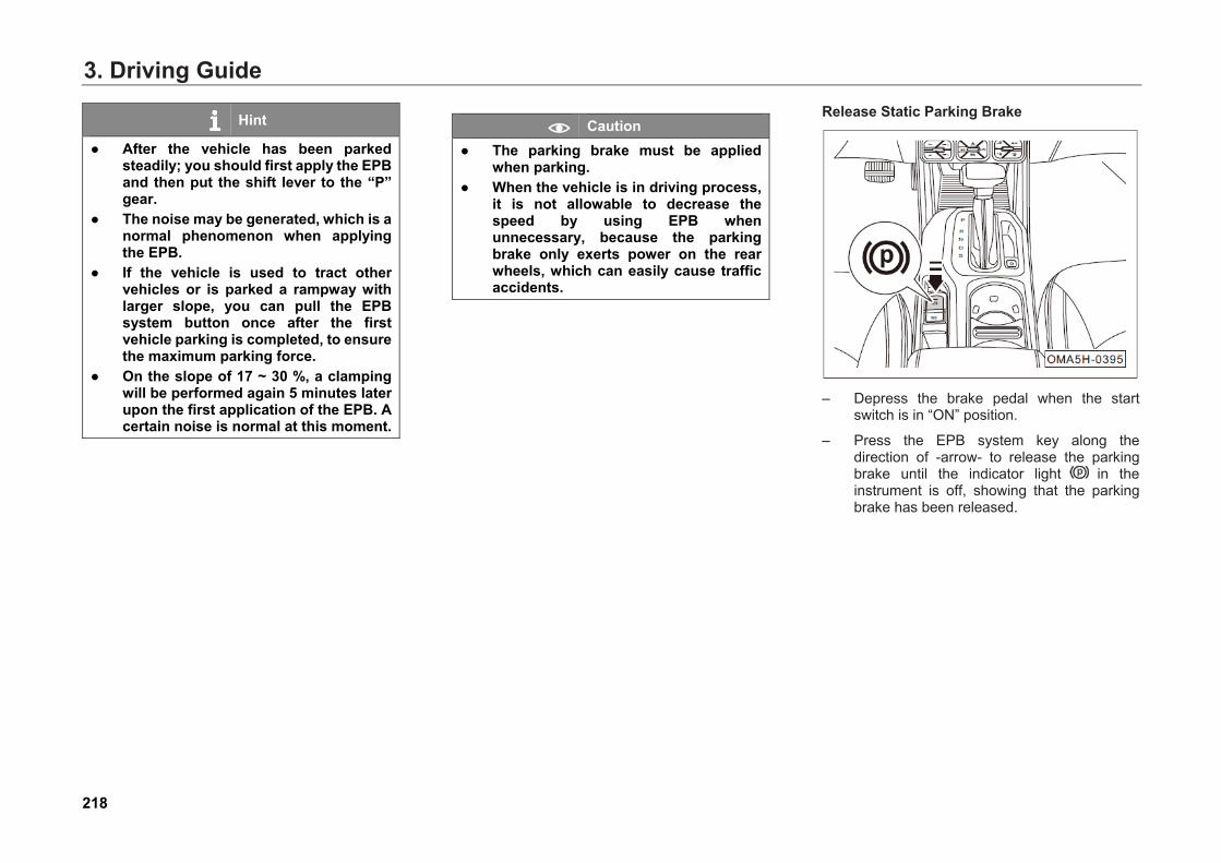
3. Driving Guide
Hint
● After the vehicle has been parkedsteadily; you should first apply the EPBand then put the shift lever to the “P”gear.
● The noise may be generated, which is anormal phenomenon when applyingthe EPB.
● If the vehicle is used to tract othervehicles or is parked a rampway withlarger slope, you can pull the EPBsystem button once after the firstvehicle parking is completed, to ensurethe maximum parking force.
● On the slope of 17 ~ 30 %, a clampingwill be performed again 5 minutes laterupon the first application of the EPB. Acertain noise is normal at this moment.
Caution ● The parking brake must be applied
when parking.● When the vehicle is in driving process,
it is not allowable to decrease thespeed by using EPB whenunnecessary, because the parkingbrake only exerts power on the rearwheels, which can easily cause trafficaccidents.
Release Static Parking Brake
– Depress the brake pedal when the startswitch is in “ON” position.
– Press the EPB system key along thedirection of -arrow- to release the parkingbrake until the indicator light in theinstrument is off, showing that the parkingbrake has been released.
218
3. Driving Guide
Hint
● If the brake pedal is not depressed,press the EPB system button to releasethe parking brake. The buzzer willalarm, and the instrument clusterdisplay will show “please depress thebrake and release the EPB”.
● The noise may be produced, which is anormal phenomenon when releasingthe EPB.
● When the vehicle battery has no power,the system cannot remove the EPB.Please contact GAC Motor Dealer forhandling, if the condition allows for thecable emergency activation (Pleaserefer to Page 403) and the parkingbrake is removed under this condition.
● If the EPB is not applied for a long time,the system will detect the conditionsautomatically with audible noise.
Automatic Driving Release When the door is closed and the driver has
fastened his seat belt, the EPB will be released automatically when the accelerator pedal is depressed.
Caution ● When the vehicle is in the parking state,
do not depress the accelerator pedalquickly. Otherwise, it will accelerate toshorten the service life of EPB.
● The utilization of the automatic drivingrelease function will shorten theservice life of the EPB, and it isrecommended to be used only in caseof rampway starting.
Warning
Do not depress the accelerator pedal when the driver is operating in front/rear or bottom of the vehicle, such as in the engine running state with the transmission in driving gear, even if the EPB is applied. Otherwise, the vehicle will move and cause accidents and even casualties.
Uphill Start Assist When the vehicle has been parked on the
slope, fasten the seat belt, start the engine, put the shift lever to the corresponding gear and depress the accelerator pedal to assist uphill start and avoid the vehicle sliding. The EPB will be automatically removed after a smooth start.
Caution The EPB cannot be automatically removed if the safety belt is not fastened.
219

3. Driving GuideApply Dynamic Emergency Brake
– The dynamic emergency braking can berealized by pulling up the EPB system buttoncontinuously in the direction of -ARROW- inthe driving process. If the accelerator pedalis depressed in emergency braking process,the system will exit from the braking. If theemergency braking is not caused by driveroperation, please depress the acceleratorpedal repeatedly to exit from the braking.
Hint
Switch the start switch to “ON” position. The corresponding indicator light in the instrument cluster will be illuminated in red when the EPB is applied. The red light will be off when the EPB is removed. In case of any of the following phenomena, please re-apply and re-remove the EPB. If the fault is still not eliminated, please contact the GAC Motor Dealer for maintenance. ● If the indicator light flashes in red
continuously, it indicates that the EPBis in partial combination/removal stateor there is a fault in the system.
● If the indicator light is illuminated in theabsence of the EPB, the system isabnormal.
● If the indicator light is illuminated inyellow, it indicates that a fault isdetected in the EPB system and theelectric parking efficiency decreases.
Caution ● Do not apply the dynamic emergency
braking when unnecessary, becausethe parking brake only exerts power onthe rear wheels, which can easily causetraffic accidents. The braking distanceis longer than that of brake pedal, andit can shorten the service life of theparking brake system.
● When the vehicle is in driving process,the EPB switch will be pulled up, thebuzzer will alarm and the instrumentcluster display will prompt the“Release the EPB switch”.
● In the process of dynamic emergencybraking, the removing state can berecovered for parking brake byreleasing the EPB and depressing theaccelerator pedal. If the EPB system iscontinuously pulled up until the vehicleis stopped, the parking brake willremain in combination state.
220
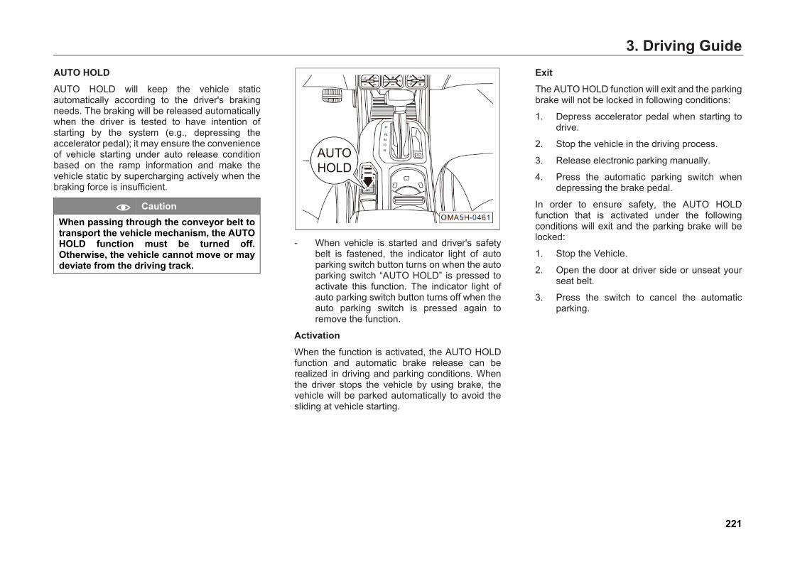
3. Driving GuideAUTO HOLD AUTO HOLD will keep the vehicle static automatically according to the driver's braking needs. The braking will be released automatically when the driver is tested to have intention of starting by the system (e.g., depressing the accelerator pedal); it may ensure the convenience of vehicle starting under auto release condition based on the ramp information and make the vehicle static by supercharging actively when the braking force is insufficient.
Caution When passing through the conveyor belt to transport the vehicle mechanism, the AUTO HOLD function must be turned off. Otherwise, the vehicle cannot move or may deviate from the driving track.
- When vehicle is started and driver's safetybelt is fastened, the indicator light of autoparking switch button turns on when the autoparking switch “AUTO HOLD” is pressed toactivate this function. The indicator light ofauto parking switch button turns off when theauto parking switch is pressed again toremove the function.
Activation When the function is activated, the AUTO HOLD function and automatic brake release can be realized in driving and parking conditions. When the driver stops the vehicle by using brake, the vehicle will be parked automatically to avoid the sliding at vehicle starting.
Exit The AUTO HOLD function will exit and the parking brake will not be locked in following conditions:
1. Depress accelerator pedal when starting todrive.
2. Stop the vehicle in the driving process.
3. Release electronic parking manually.
4. Press the automatic parking switch whendepressing the brake pedal.
In order to ensure safety, the AUTO HOLD function that is activated under the following conditions will exit and the parking brake will be locked:
1. Stop the Vehicle.
2. Open the door at driver side or unseat yourseat belt.
3. Press the switch to cancel the automaticparking.
221
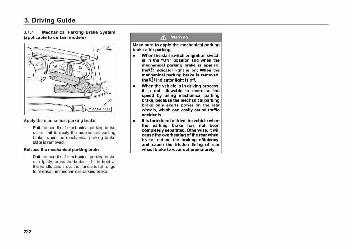
3. Driving Guide3.1.7 Mechanical Parking Brake System (applicable to certain models)
Apply the mechanical parking brake - Pull the handle of mechanical parking brake
up to limit to apply the mechanical parkingbrake, when the mechanical parking brakestate is removed.
Release the mechanical parking brake - Pull the handle of mechanical parking brake
up slightly, press the button - 1 - in front ofthe handle, and press the handle to full rangeto release the mechanical parking brake.
Warning
Make sure to apply the mechanical parking brake after parking. ● When the start switch or ignition switch
is in the “ON” position and when themechanical parking brake is applied,the indicator light is on; When themechanical parking brake is removed,the indicator light is off.
● When the vehicle is in driving process,it is not allowable to decrease thespeed by using mechanical parkingbrake, because the mechanical parkingbrake only exerts power on the rearwheels, which can easily cause trafficaccidents.
● It is forbidden to drive the vehicle whenthe parking brake has not beencompletely separated. Otherwise, it willcause the overheating of the rear wheelbrake, reduce the braking efficiency,and cause the friction lining of rearwheel brake to wear out prematurely.
222

3. Driving Guide
3.2 Service Electronic Brake System 3.2.1 Anti-lock Braking System (ABS) Anti-lock braking system (ABS) is an important part of vehicle active safety system.
When ABS works, the friction between the wheel and the road belongs to rolling friction and it is favorable for braking by making use of maximum adhesion between the wheel and road, thereby improving the braking deceleration, shortening the braking distance, and ensuring the direction stability in the process of vehicle braking.
When ABS works, it is equivalent to snubbing at high frequency. The driver will feel the vibration of brake pedal accompanied by the “tick” sound produced by brake master cylinder operation when depressing the brake pedal in case of emergency. At this point, the ABS is in normal working state. Since the brake master cylinder adjusts the brake pressure constantly, a force will be fed back to the brake pedal continuously. Therefore, in this case, it is required to depress the brake pedal to the end, and it is forbidden to depress the brake pedal repeatedly.
As ABS is only the safety assistant system, its function is very limited. For example, when making a brake on sand and stone road or snowy road, it may have a longer braking distance compared with braking on concrete road or dry road. It shall not consider that ABS can achieve the ideal braking performance in any situation. Therefore, don not rely on these systems too much. Only safe driving is the most important.
Under the following conditions, light depress the brake pedal to activate ABS. It is normal to feel vibration:
● When shifting gears.
● During emergency braking.
● When turning at high speed.
● When driving on slippery road.
● When driving on projected or pit road.
● When making sudden start after the vehicleis started.
223
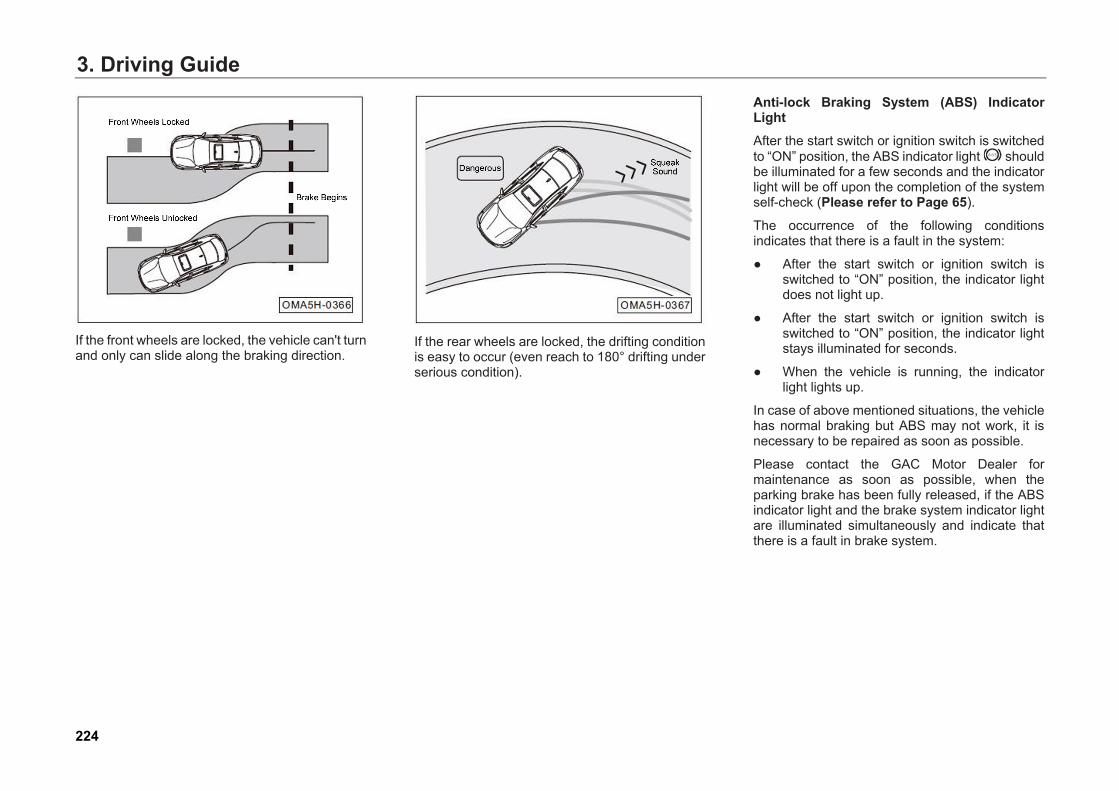
3. Driving Guide
If the front wheels are locked, the vehicle can't turn and only can slide along the braking direction.
If the rear wheels are locked, the drifting condition is easy to occur (even reach to 180° drifting under serious condition).
Anti-lock Braking System (ABS) Indicator Light After the start switch or ignition switch is switched to “ON” position, the ABS indicator light should be illuminated for a few seconds and the indicator light will be off upon the completion of the system self-check (Please refer to Page 65).
The occurrence of the following conditions indicates that there is a fault in the system:
● After the start switch or ignition switch isswitched to “ON” position, the indicator lightdoes not light up.
● After the start switch or ignition switch isswitched to “ON” position, the indicator lightstays illuminated for seconds.
● When the vehicle is running, the indicatorlight lights up.
In case of above mentioned situations, the vehicle has normal braking but ABS may not work, it is necessary to be repaired as soon as possible.
Please contact the GAC Motor Dealer for maintenance as soon as possible, when the parking brake has been fully released, if the ABS indicator light and the brake system indicator light are illuminated simultaneously and indicate that there is a fault in brake system.
224

3. Driving Guide
Warning
You must adjust your speed according to the weather, road and traffic conditions at any moment. To avoid traffic accident, do not take a risk to drive your vehicle just depending on limited safety functions provided by the systems. ● The ABS cannot go beyond the
kinematic law. It is still dangerous for avehicle with ABS to drive on slipperyroad. While driving, if the ABS isadjusting the brake pressure,immediately slow down to adapt to theroad and traffic conditions.
● Improper operation or modification(such as modification of parts ofbraking system, or wheels and tires)may affect the functions of ABS, EBDand ESP.
● Specified size of tires must be used. Ifthe vehicle is installed with tires inimproper size or non-uniform size, ABScannot work normally.
Warning
● If the indicator lights of ABS andbraking system light up, stop thevehicle immediately and check thebrake fluid level in the tank (Pleaserefer to Page 342).
● If the brake fluid level is normal, thefailure of the braking system may becaused by the malfunction of the ABScontrol function. In this case, the rearwheel may skid soon, resulting in tailsliding and side sliding of the vehicle.You must go to the GAC Motor Dealerfor maintenance.
3.2.2 Electronic Brakeforce Distribution System (EBD) EBD is short for Electronic Brakeforce Distribution System and is a part of ABS. When a vehicle takes normal brake, EBD can uniformly distribute brakeforce to front and rear wheels based on vehicle's loading condition.
EBD exerts more brake pressure on the rear wheel through adjusting slip rate, to obtain the shortest braking distance under the premise of braking stability. In particular, the stability and maneuverability of vehicle braking are improved when driving on a poor or slippery road.
225
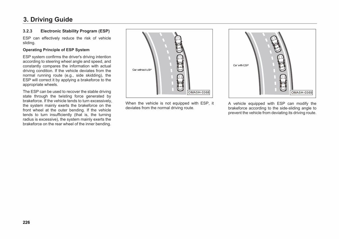
3. Driving Guide3.2.3 Electronic Stability Program (ESP) ESP can effectively reduce the risk of vehicle sliding.
Operating Principle of ESP System ESP system confirms the driver's driving intention according to steering wheel angle and speed, and constantly compares the information with actual driving condition. If the vehicle deviates from the normal running route (e.g., side skidding), the ESP will correct it by applying a brakeforce to the appropriate wheels.
The ESP can be used to recover the stable driving state through the twisting force generated by brakeforce. If the vehicle tends to turn excessively, the system mainly exerts the brakeforce on the front wheel at the outer bending. If the vehicle tends to turn insufficiently (that is, the turning radius is excessive), the system mainly exerts the brakeforce on the rear wheel of the inner bending.
When the vehicle is not equipped with ESP, it deviates from the normal driving route.
A vehicle equipped with ESP can modify the brakeforce according to the side-sliding angle to prevent the vehicle from deviating its driving route.
226
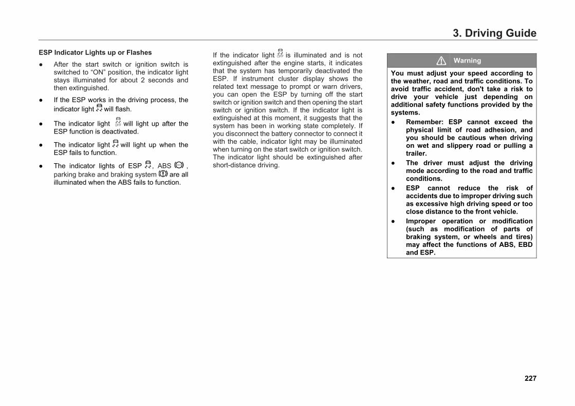
3. Driving GuideESP Indicator Lights up or Flashes ● After the start switch or ignition switch is
switched to “ON” position, the indicator lightstays illuminated for about 2 seconds andthen extinguished.
● If the ESP works in the driving process, theindicator light will flash.
● The indicator light will light up after the ESP function is deactivated.
● The indicator light will light up when theESP fails to function.
● The indicator lights of ESP , ABS , parking brake and braking system are all illuminated when the ABS fails to function.
If the indicator light is illuminated and is not extinguished after the engine starts, it indicates that the system has temporarily deactivated the ESP. If instrument cluster display shows the related text message to prompt or warn drivers, you can open the ESP by turning off the start switch or ignition switch and then opening the start switch or ignition switch. If the indicator light is extinguished at this moment, it suggests that the system has been in working state completely. If you disconnect the battery connector to connect it with the cable, indicator light may be illuminated when turning on the start switch or ignition switch. The indicator light should be extinguished after short-distance driving.
Warning
You must adjust your speed according to the weather, road and traffic conditions. To avoid traffic accident, don't take a risk to drive your vehicle just depending on additional safety functions provided by the systems. ● Remember: ESP cannot exceed the
physical limit of road adhesion, andyou should be cautious when drivingon wet and slippery road or pulling atrailer.
● The driver must adjust the drivingmode according to the road and trafficconditions.
● ESP cannot reduce the risk ofaccidents due to improper driving suchas excessive high driving speed or tooclose distance to the front vehicle.
● Improper operation or modification(such as modification of parts ofbraking system, or wheels and tires)may affect the functions of ABS, EBDand ESP.
227
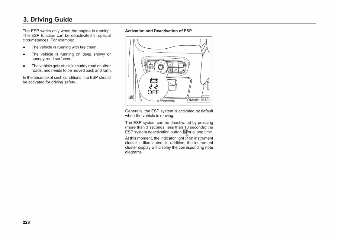
3. Driving GuideThe ESP works only when the engine is running. The ESP function can be deactivated in special circumstances. For example:
● The vehicle is running with tire chain.
● The vehicle is running on deep snowy orspongy road surfaces.
● The vehicle gets stuck in muddy road or otherroads, and needs to be moved back and forth.
In the absence of such conditions, the ESP should be activated for driving safety.
Activation and Deactivation of ESP
Generally, the ESP system is activated by default when the vehicle is moving.
The ESP system can be deactivated by pressing (more than 3 seconds, less than 10 seconds) the ESP system deactivation button for a long time. At this moment, the indicator light on instrument cluster is illuminated. In addition, the instrument cluster display will display the corresponding note diagrams.
228
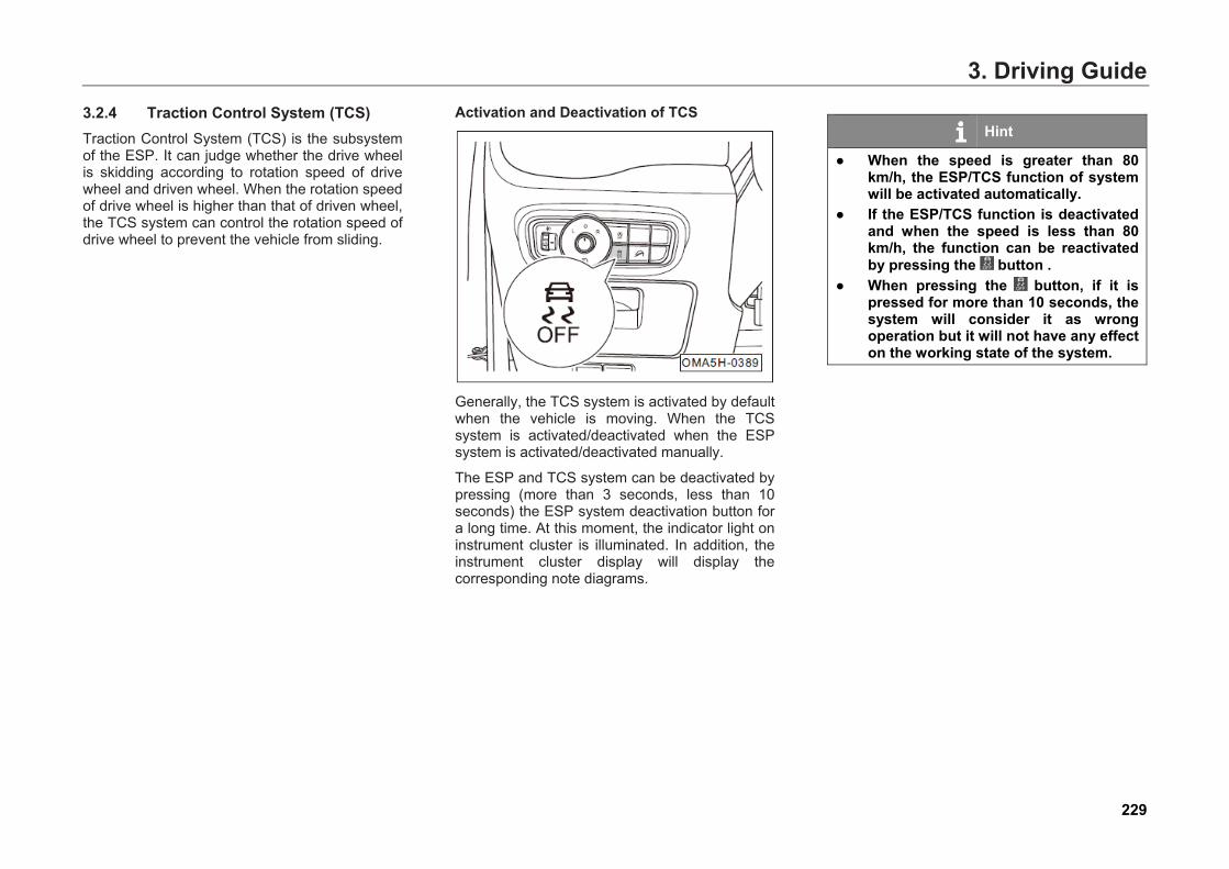
3. Driving Guide3.2.4 Traction Control System (TCS) Traction Control System (TCS) is the subsystem of the ESP. It can judge whether the drive wheel is skidding according to rotation speed of drive wheel and driven wheel. When the rotation speed of drive wheel is higher than that of driven wheel, the TCS system can control the rotation speed of drive wheel to prevent the vehicle from sliding.
Activation and Deactivation of TCS
Generally, the TCS system is activated by default when the vehicle is moving. When the TCS system is activated/deactivated when the ESP system is activated/deactivated manually.
The ESP and TCS system can be deactivated by pressing (more than 3 seconds, less than 10 seconds) the ESP system deactivation button for a long time. At this moment, the indicator light on instrument cluster is illuminated. In addition, the instrument cluster display will display the corresponding note diagrams.
Hint
● When the speed is greater than 80km/h, the ESP/TCS function of systemwill be activated automatically.
● If the ESP/TCS function is deactivatedand when the speed is less than 80km/h, the function can be reactivatedby pressing the button .
● When pressing the button, if it ispressed for more than 10 seconds, thesystem will consider it as wrongoperation but it will not have any effecton the working state of the system.
229
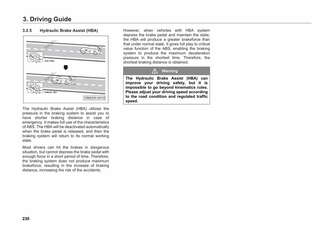
3. Driving Guide3.2.5 Hydraulic Brake Assist (HBA)
The Hydraulic Brake Assist (HBA) utilizes the pressure in the braking system to assist you to have shorter braking distance in case of emergency. It makes full use of the characteristics of ABS. The HBA will be deactivated automatically when the brake pedal is released, and then the braking system will return to its normal working state.
Most drivers can hit the brakes in dangerous situation, but cannot depress the brake pedal with enough force in a short period of time. Therefore, the braking system does not produce maximum brakeforce, resulting in the increase of braking distance, increasing the risk of the accidents.
However, when vehicles with HBA system depress the brake pedal and maintain the state, the HBA will produce a greater brakeforce than that under normal state. It gives full play to critical value function of the ABS, enabling the braking system to produce the maximum deceleration pressure in the shortest time. Therefore, the shortest braking distance is obtained.
Warning
The Hydraulic Brake Assist (HBA) can improve your driving safety, but it is impossible to go beyond kinematics rules. Please adjust your driving speed according to the road condition and regulated traffic speed.
230
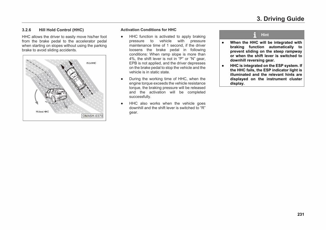
3. Driving Guide3.2.6 Hill Hold Control (HHC) HHC allows the driver to easily move his/her foot from the brake pedal to the accelerator pedal when starting on slopes without using the parking brake to avoid sliding accidents.
Activation Conditions for HHC ● HHC function is activated to apply braking
pressure to vehicle with pressuremaintenance time of 1 second, if the driverloosens the brake pedal in followingconditions: When ramp slope is more than4%, the shift lever is not in “P” or “N” gear,EPB is not applied, and the driver depresseson the brake pedal to stop the vehicle and thevehicle is in static state.
● During the working time of HHC, when theengine torque exceeds the vehicle resistancetorque, the braking pressure will be releasedand the activation will be completedsuccessfully.
● HHC also works when the vehicle goesdownhill and the shift lever is switched to “R”gear.
Hint
● When the HHC will be integrated withbraking function automatically toprevent sliding on the steep rampwayor when the shift lever is switched todownhill reversing gear.
● HHC is integrated on the ESP system. Ifthe HHC fails, the ESP indicator light isilluminated and the relevant hints aredisplayed on the instrument clusterdisplay.
231
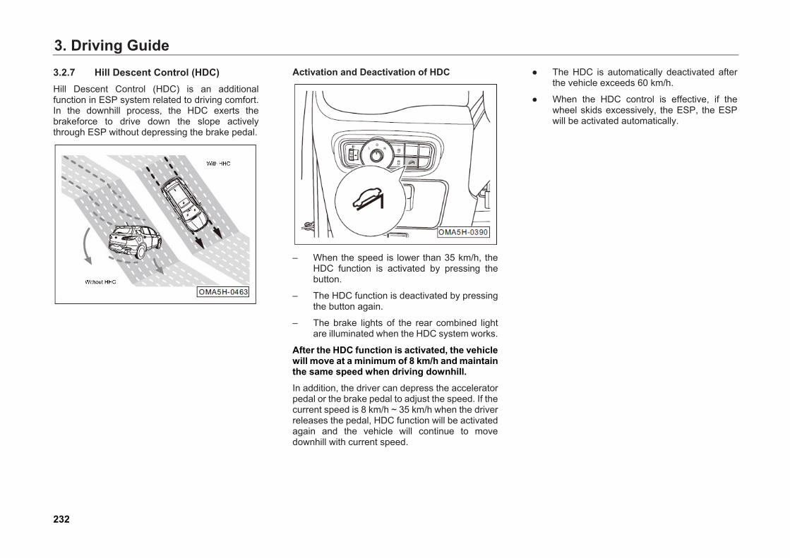
3. Driving Guide3.2.7 Hill Descent Control (HDC) Hill Descent Control (HDC) is an additional function in ESP system related to driving comfort. In the downhill process, the HDC exerts the brakeforce to drive down the slope actively through ESP without depressing the brake pedal.
Activation and Deactivation of HDC
– When the speed is lower than 35 km/h, theHDC function is activated by pressing thebutton.
– The HDC function is deactivated by pressingthe button again.
– The brake lights of the rear combined lightare illuminated when the HDC system works.
After the HDC function is activated, the vehicle will move at a minimum of 8 km/h and maintain the same speed when driving downhill. In addition, the driver can depress the accelerator pedal or the brake pedal to adjust the speed. If the current speed is 8 km/h ~ 35 km/h when the driver releases the pedal, HDC function will be activated again and the vehicle will continue to move downhill with current speed.
● The HDC is automatically deactivated afterthe vehicle exceeds 60 km/h.
● When the HDC control is effective, if thewheel skids excessively, the ESP, the ESPwill be activated automatically.
232

3. Driving Guide
Hint
When the HDC system fails, the function shall be deactivated, and the instrument cluster display will show “please check HDC”, and there will be a sound alarm for about 5 seconds. At this point, the HDC system will not work properly. The driver should not use the system for downhill driving forcefully, but shall depress the brake pedal, and go to GAC Motor Dealer as soon as possible. Under some special circumstances, HDC system will be in thermal protection mode due to high braking temperature. For example, when the environmental temperature is high and the system is used for a long time, the braking system temperature increases continuously because of friction. When the limit value is reached, the HDC function will be in thermal protection mode: The function is activated, but does not work. The HDC system will lose its function temporarily. The vehicle shows the sign of acceleration, and the HDC will work again when the braking system temperature drops to the effective working temperature.
233
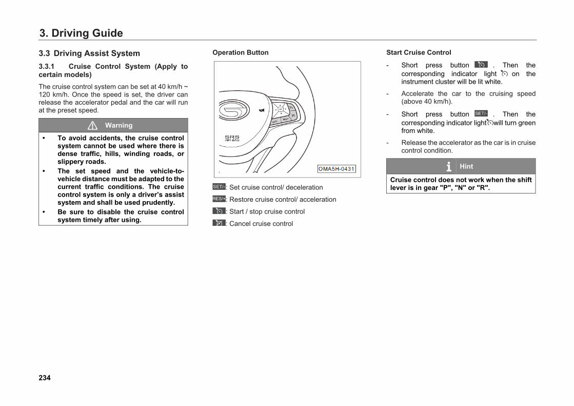
3. Driving Guide
3.3.1 Cruise Control System (Apply to certain models) The cruise control system can be set at 40 km/h ~ 120 km/h. Once the speed is set, the driver can release the accelerator pedal and the car will run at the preset speed.
Warning
• To avoid accidents, the cruise controlsystem cannot be used where there isdense traffic, hills, winding roads, orslippery roads.
• The set speed and the vehicle-to-vehicle distance must be adapted to thecurrent traffic conditions. The cruisecontrol system is only a driver’s assistsystem and shall be used prudently.
• Be sure to disable the cruise controlsystem timely after using.
Operation Button
: Set cruise control/ deceleration
: Restore cruise control/ acceleration
: Start / stop cruise control
: Cancel cruise control
Start Cruise Control
- Short press button . Then the corresponding indicator light on the instrument cluster will be lit white.
- Accelerate the car to the cruising speed(above 40 km/h).
- Short press button . Then thecorresponding indicator light will turn greenfrom white.
- Release the accelerator as the car is in cruisecontrol condition.
Hint
Cruise control does not work when the shift lever is in gear "P", "N" or "R".
3.3 Driving Assist System
234
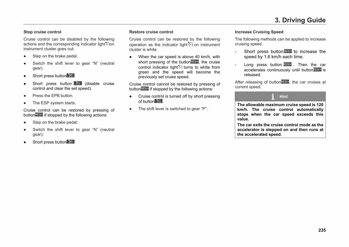
3. Driving GuideStop cruise control Cruise control can be disabled by the following actions and the corresponding indicator light on instrument cluster goes out:
● Step on the brake pedal.
● Switch the shift lever to gear “N” (neutralgear).
● Short press button
● Short press button (disable cruise control and clear the set speed).
● Press the EPB button.
● The ESP system starts.
Cruise control can be restored by pressing of button if stopped by the following actions:
● Step on the brake pedal;
● Switch the shift lever to gear “N” (neutralgear);
● Short press button
Restore cruise control Cruise control can be restored by the following operation as the indicator light on instrument cluster is white:
● When the car speed is above 40 km/h, withshort pressing of the button , the cruise control indicator light turns to white from green and the speed will become the previously set cruise speed.
Cruise control cannot be restored by pressing of button if stopped by the following actions:
● Cruise control is turned off by short pressingof button .
● The shift lever is switched to gear “P”.
Increase Cruising Speed The following methods can be applied to increase cruising speed.
- Short press button to increase the speed by 1.6 km/h each time.
- Long press button . Then the car accelerates continuously until button is released.
After releasing of button , the car cruises at current speed.
Hint
The allowable maximum cruise speed is 120 km/h. The cruise control automatically stops when the car speed exceeds this value. The car exits the cruise control mode as the accelerator is stepped on and then runs at the accelerated speed.
235
3. Driving GuideDecrease cruising speed The following methods can be applied to decrease cruising speed.
- Short press button to decrease the speed by 1.6 km/h each time.
- Long press button and the speed decreases continuously.
The car runs at lower speed after button is released.
Hint
The cruise control automatically stops when the car speed is lower than 40 km/h.
236
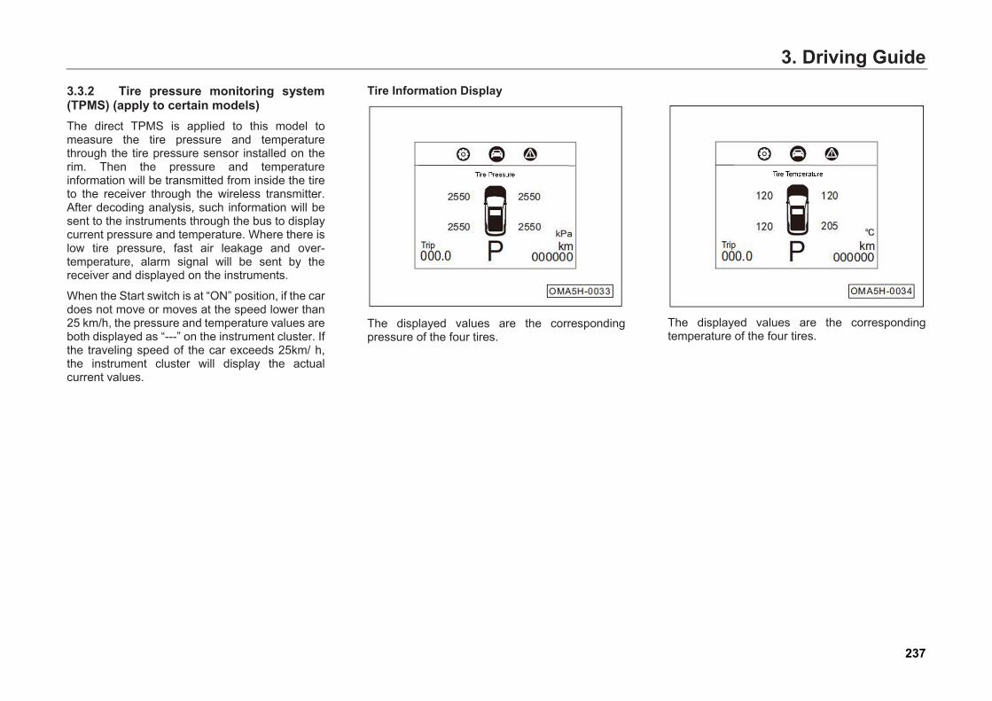
3. Driving Guide3.3.2 Tire pressure monitoring system (TPMS) (apply to certain models) The direct TPMS is applied to this model to measure the tire pressure and temperature through the tire pressure sensor installed on the rim. Then the pressure and temperature information will be transmitted from inside the tire to the receiver through the wireless transmitter. After decoding analysis, such information will be sent to the instruments through the bus to display current pressure and temperature. Where there is low tire pressure, fast air leakage and over-temperature, alarm signal will be sent by the receiver and displayed on the instruments.
When the Start switch is at “ON” position, if the car does not move or moves at the speed lower than 25 km/h, the pressure and temperature values are both displayed as “---” on the instrument cluster. If the traveling speed of the car exceeds 25km/ h, the instrument cluster will display the actual current values.
Tire Information Display
The displayed values are the corresponding pressure of the four tires.
The displayed values are the corresponding temperature of the four tires.
237
3. Driving GuideWhen the speed exceeds 25 km/h, the tire pressure sensor will send the data to the receiver. After decoding analysis, such information will be sent to the instruments through the bus to display current pressure and temperature.
● If the tire pressure is higher than 150% of thenormal set value, the TPMS indicator lightwill be on, and the text alarm on theinstrument cluster display screen will showhigh tire pressure.
● If the tire pressure is lower than 75% of thenormal set value, the TPMS indicator lightwill be on, and the text alarm on theinstrument cluster display screen will showlow tire pressure.
● If the tire pressure changing exceeds acertain speed, the TPMS indicator light willbe on, and the text alarm on the instrumentcluster display screen will show flat tire.
● If the tire temperature exceeds 85°C, theTPMS indicator light will be on, and the textalarm on the instrument cluster displayscreen will show over-temperature.
Caution If the tire pressure sensor inside the tire needs to be replaced, the tire needs to be replaced, or the tire position needs to be adjusted, one should learn the matching of sensors and four tires again. Please go to your GAC MOTOR dealer for replacement.
Hint
● After replacing with a spare tire or witha new tire in some other place, becauseof the missing tire sensor, the low tirepressure alarm lasts. Do not mistakethis as abnormal tire pressure signal.
Hint
● If the tire suffers high temperature, highpressure, low pressure, or rapid airleakage, the instrument cluster willgive early warning, with position of thecorresponding failed tire displayed incircular manner. If the system fails, theinstrument cluster will give earlywarning, with “system failure, pleasecheck” in circular manner.
● Where there is high temperature alarm,it is recommended to stop the car andwait until the tires cool.
● The traveling alarm not handled untilthe car stops will remain when the carstarts again, with pressure andtemperature displayed as “---”. Butwhen the car speed exceeds 25 km/h,the receiver will receive updated dataand then the alarm stops.
238
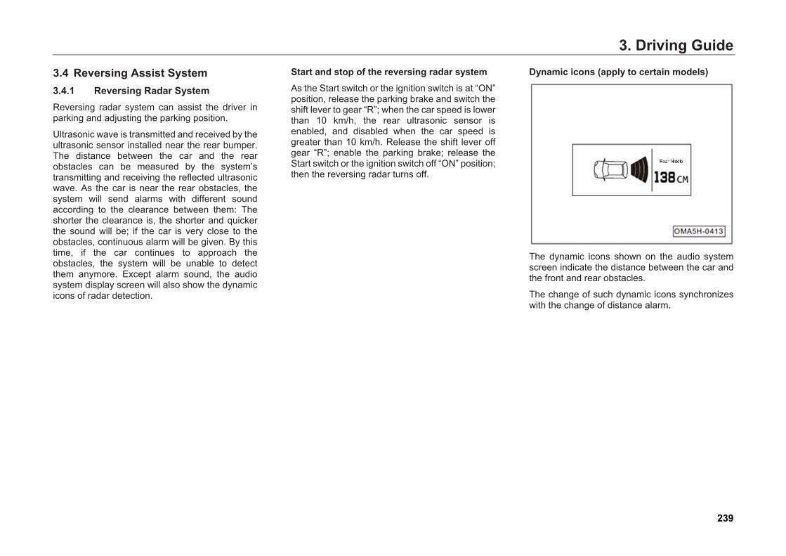
3. Driving Guide
3.4 Reversing Assist System 3.4.1 Reversing Radar System Reversing radar system can assist the driver in parking and adjusting the parking position.
Ultrasonic wave is transmitted and received by the ultrasonic sensor installed near the rear bumper. The distance between the car and the rear obstacles can be measured by the system’s transmitting and receiving the reflected ultrasonic wave. As the car is near the rear obstacles, the system will send alarms with different sound according to the clearance between them: The shorter the clearance is, the shorter and quicker the sound will be; if the car is very close to the obstacles, continuous alarm will be given. By this time, if the car continues to approach the obstacles, the system will be unable to detect them anymore. Except alarm sound, the audio system display screen will also show the dynamic icons of radar detection.
Start and stop of the reversing radar system As the Start switch or the ignition switch is at “ON” position, release the parking brake and switch the shift lever to gear “R”; when the car speed is lower than 10 km/h, the rear ultrasonic sensor is enabled, and disabled when the car speed is greater than 10 km/h. Release the shift lever off gear “R”; enable the parking brake; release the Start switch or the ignition switch off “ON” position; then the reversing radar turns off.
Dynamic icons (apply to certain models)
The dynamic icons shown on the audio system screen indicate the distance between the car and the front and rear obstacles.
The change of such dynamic icons synchronizes with the change of distance alarm.
239
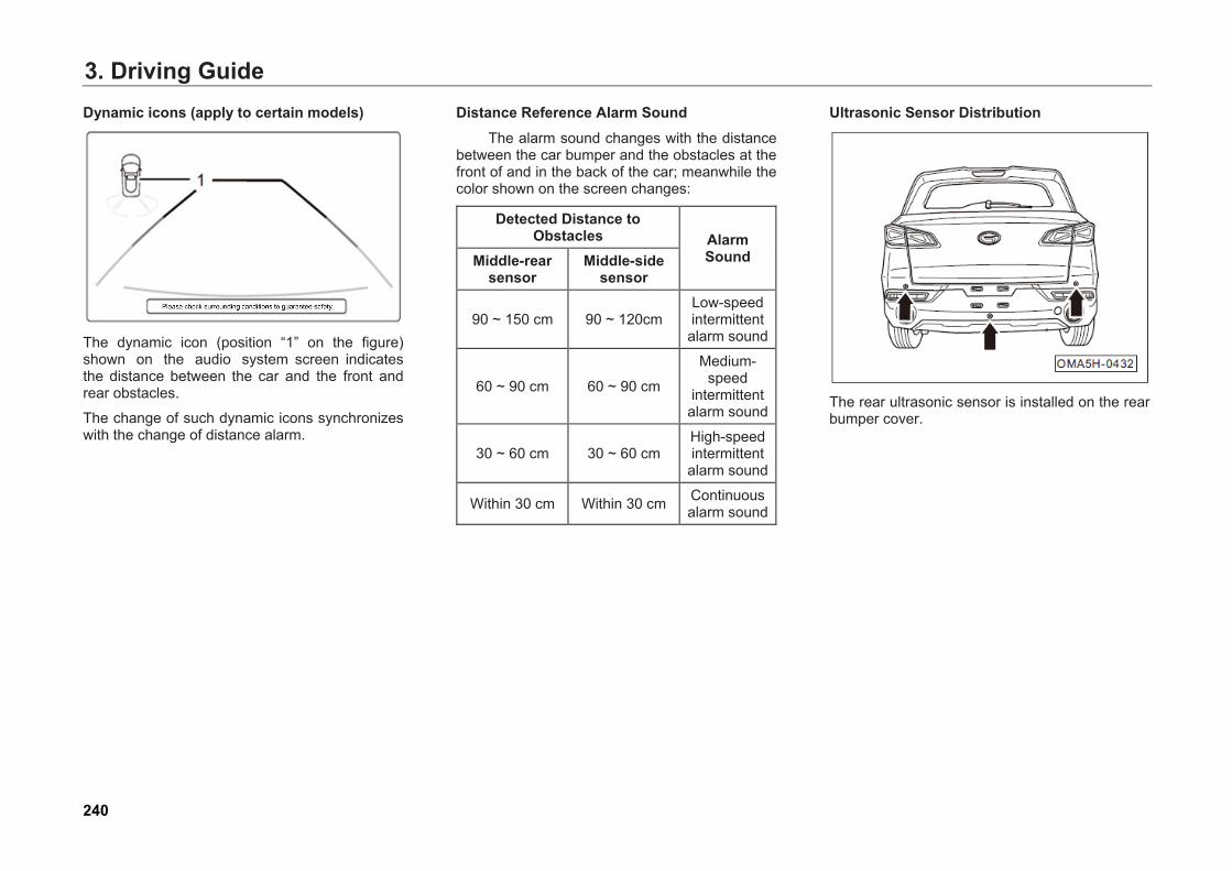
3. Driving GuideDynamic icons (apply to certain models)
The dynamic icon (position “1” on the figure) shown on the audio system screen indicates the distance between the car and the front and rear obstacles.
The change of such dynamic icons synchronizes with the change of distance alarm.
Distance Reference Alarm Sound The alarm sound changes with the distance
between the car bumper and the obstacles at the front of and in the back of the car; meanwhile the color shown on the screen changes:
Detected Distance to Obstacles Alarm
Sound Middle-rear sensor
Middle-side sensor
90 ~ 150 cm 90 ~ 120cm Low-speed intermittent alarm sound
60 ~ 90 cm 60 ~ 90 cm
Medium- speed
intermittent alarm sound
30 ~ 60 cm 30 ~ 60 cm High-speed intermittent alarm sound
Within 30 cm Within 30 cm Continuousalarm sound
Ultrasonic Sensor Distribution
The rear ultrasonic sensor is installed on the rear bumper cover.
240
3. Driving Guide
Caution ● Always keep the ultrasonic sensor
surface clean, and do not cover it.● It must keep the ultrasonic sensor
clean and avoid icing to make sure thebumper ultrasonic sensor works.
● When cleaning the ultrasonic sensorsurface, use soft wet cloth to avoidsurface scratching.
Warning
● The reversing radar system does nottake the place of the driver’sobservation to the surroundingenvironment, so that the driver shallpay attention, park and adjust parkingpositions according to actualconditions.
● Blind zone exists when the ultrasonicsensor is detecting the obstacles, sothat the driver must observe carefullyto avoid scraping or collision.
● During reversing in a narrow space oruphill, the ultrasonic sensor may detectrailings, trees or slope, which isconsidered normal.
● At fast reversing speed, the detectionof the ultrasonic sensor may not be asaccurate. It is suggested that therevising speed does not exceed 15km/h. The continuous alarm soundfrom the revising radar systemindicates that the car is very close tothe obstacles. The driver shall stoprevising immediately to avoid accident.
Warning
● Clean the ultrasonic sensor with highpressure cleaning device in a shorttime and in gentle manner; keep at least10 cm between the nozzle and thesensor.
● Water drops on the ultrasonic sensorsurface of the rear bumper caninfluence sensitivity of the sensor. Torestore sensitivity, wipe off the waterdrops.
● Surfaces of certain items cannot reflectthe signals from the ultrasonicsensors, so that the sensor cannotdetect such items or persons wearingsuch clothes.
● The ultrasonic sensor may not detectthe objects if interfered by outdoornoise.
● The ultrasonic sensors are precisionparts. Do not dismantle or repair one byyourself. Damage caused by suchdismantling or repairing is not coveredin the warranty of GAC MOTOR.
241
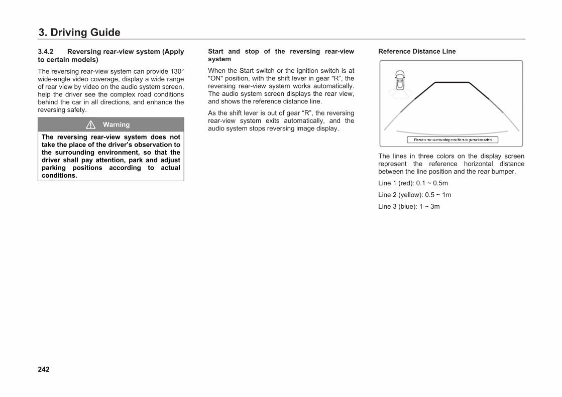
3. Driving Guide3.4.2 Reversing rear-view system (Apply to certain models) The reversing rear-view system can provide 130° wide-angle video coverage, display a wide range of rear view by video on the audio system screen, help the driver see the complex road conditions behind the car in all directions, and enhance the reversing safety.
Warning
The reversing rear-view system does not take the place of the driver’s observation to the surrounding environment, so that the driver shall pay attention, park and adjust parking positions according to actual conditions.
Start and stop of the reversing rear-view system When the Start switch or the ignition switch is at "ON" position, with the shift lever in gear "R”, the reversing rear-view system works automatically. The audio system screen displays the rear view, and shows the reference distance line.
As the shift lever is out of gear “R”, the reversing rear-view system exits automatically, and the audio system stops reversing image display.
Reference Distance Line
The lines in three colors on the display screen represent the reference horizontal distance between the line position and the rear bumper.
Line 1 (red): 0.1 ~ 0.5m
Line 2 (yellow): 0.5 ~ 1m
Line 3 (blue): 1 ~ 3m
242

3. Driving Guide
Caution The above distance is measured on flat ground and is only taken as a reference value of view distance. If it is on a slope, the above distance is not correct.
Hint
● The longitudinal lines on both sides ofthe reference distance line can be usedas the reference lines for determinationof the required space for reversing orparking.
● The reference distance lines adjustwith turning of the steering wheel.
Rear-view camera
Rear-view camera is installed under the panel of hatchback door.
Warning
● Blind zone exists in detecting scope ofthe rear-view camera, because thecamera may be unable to detect youngchildren or small animals. Pay specialattention to young children or smallanimals around when reversing.
● Upright objects with higher elevation,such as protruding wall edges, mayalso not be detected by the rear-viewcamera.
Caution ● Always keep the rear-view camera
surface clean. When cleaning the rear-view camera, use soft wet cloth toavoid scratching.
● Do not use high pressure cleaningdevice to clean the rear-view camerafor a long time, and keep a distance ofat least 30 cm from the camera whencleaning.
● Do not cover the rear-view camera.
243
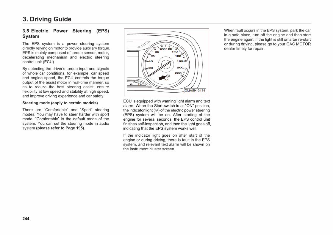
3. Driving Guide
3.5 Electric Power Steering (EPS) System The EPS system is a power steering system directly relying on motor to provide auxiliary torque. EPS is mainly composed of torque sensor, motor, decelerating mechanism and electric steering control unit (ECU).
By detecting the driver’s torque input and signals of whole car conditions, for example, car speed and engine speed, the ECU controls the torque output of the assist motor in real-time manner, so as to realize the best steering assist, ensure flexibility at low speed and stability at high speed, and improve driving experience and car safety.
Steering mode (apply to certain models) There are “Comfortable” and “Sport” steering modes. You may have to steer harder with sport mode. “Comfortable” is the default mode of the system. You can set the steering mode in audio system (please refer to Page 195).
ECU is equipped with warning light alarm and text alarm. When the Start switch is at "ON" position, the indicator light ( ) of the electric power steering (EPS) system will be on. After starting of the engine for several seconds, the EPS control unit finishes self-inspection, and then the light goes off, indicating that the EPS system works well.
If the indicator light goes on after start of the engine or during driving, there is fault in the EPS system, and relevant text alarm will be shown on the instrument cluster screen.
When fault occurs in the EPS system, park the car in a safe place, turn off the engine and then start the engine again. If the light is still on after re-start or during driving, please go to your GAC MOTOR dealer timely for repair.
244
3. Driving Guide
3.6 Driving Skills 3.6.1 Safety Check for Driving It is better to do safety check before driving. Checking your car for a few minutes helps safe and enjoyable driving.
Before Starting the Engine 1. External check
● Check the tires for normal tire pressure andno incision, bulge, damage or excessivewear.
● Check there is no tire bolts lost or loose.
● Make sure that the headlight, brake light,taillight, steering signal and other lights workwell. Check headlight lighting direction.
2. Internal check
● Check and confirm the seat belt has beenfastened securely. The seat belts are freefrom wear or damage.
● Check the instruments and controllers, andespecially make sure the instrument indicatorlights and defroster work well.
● Make sure the pedal has enough freeclearance.
● Ensure sufficient coolant level (please referto Page 337).
● Check the condition of 12V battery. Checkwhether there is corrosion or loosening onterminal and cracks on the shell. Check if thecable connection is good.
After Starting the Engine ● Check whether there is leakage of fuel,
engine oil, water or other liquid from the carbottom. Water drops from the use of AC isnormal.
● Park the car on flat ground; turn off theengine; then check the engine oil level afterthe engine is cool (please refer to Page 332).
During driving ● Make sure the instruments work well.
● For checking and confirming the brake onsafe road, the car shall not deviate to anyside.
● For other abnormalities: check for no loosecomponents or leakage; listen whether thereis any abnormal noise.
245

3. Driving Guide3.6.2 Driving during Running-in Period To ensure your car’s service life, you have to run it in at the initial stage before putting it into normal use. When your car is in running-in period, please observe the following requirements:
● The mileage of running-in period is 1500 km.
● Drive on good roads under reduced load atlimited speed.
● Avoid full-accelerator starting or rapidacceleration.
● Avoid emergency braking for the first 300 km.
● Strictly follow the operating instructions andkeep the normal operating temperature of theengine. Do not change the engine oil beforethe regular maintenance.
● Carefully do routine maintenance; frequentlycheck and fasten the external bolts and nuts;pay attention to the changes of sounds andtemperature of each assembly duringrunning, and adjust timely.
Running-in of the Engine You have to run a new engine in for 1500 km. Within 1000 km of traveling mileage of the car:
● The car speed shall not exceed 3/4 of themaximum speed.
● Avoid full-accelerator driving.
● Avoid high engine speed.
● Do not tow a trailer.
When the traveling mileage is within 1000 km-1500 km, the engine speed and car speed can be gradually increased to the maximum allowable range.
At the early stage of running-in period, the internal frictional resistance of the engine is much greater than that after the running- in. All the moving components of the engine coordinate well only after running in.
Full running-in of the engine can increase the service life and reduce fuel consumption.
Running-in of Tires and Braking Pads Drive at moderate speed within the first 500 km to properly run the new tires in.
Within the first 200 km ~ 300 km of traveling mileage, the new braking pad cannot realize the optimal friction status, so that drive at medium or low speed and avoid emergency braking as much as possible.
246
3. Driving Guide
Warning
● The best adhesion and friction cannotbe realized for mew tires and brakingpad without running-in. Therefore,drive carefully for the first 500 km torun in the tires well and avoidaccidents.
● After replacement, the new braking padshall also go through running- in periodin accordance with the aboverequirements.
● Keep an appropriate distance withother cars during driving to preventemergency braking, because at thattime, both the new tires and brakingpad are not fully run-in, and emergencybraking may cause traffic accident.
● If the brake is damped or frozen, or thecar is running on salt spreading road,the braking effect weakens.
Warning
● Heavy work load of the brake duringrunning downhill makes it prone tooverheat. It is recommended to slowdown by shifting to a lower gear andfully use engine braking to reduce itswork load.
● Always brake the car according to theroad and traffic conditions. Avoidunnecessary press of brake pedal.Doing so can make the brakeoverheating, resulting in a longerbraking distance and excessive wear.
● Do not let your car coast with theengine off, because as the brakebooster is disabled, the brakingdistance will be much longer, makingthe situation accident-pron.
● Do not use the brake fluid for too long.Be sure to replace the brake fluidaccording to the maintenance intervalsin the Warranty Manual.
247
3. Driving Guide3.6.3 Important Tips for Driving under Different Conditions
● Drive slowly with wind blowing laterally, soas to control your car easily.
● Keep the right driving angle and avoidpassing through high or sharp objects orother road barriers, or otherwise it may causetire burst or serious damage.
● Slow down during driving on very bumpy oruneven roads. Otherwise, the car will beseriously damaged by impact and chassisscratching.
● After car washing or driving through road withdeep ponding, since the braking pads andbrake disc is soaked, the braking effectweakens. At this time, drive at slow speedand slightly press down the brake pedal forseveral times to eliminate left water drops inthe brakes, and then drive normally as thebraking effect resumes.
Warning
● Before driving, make sure the parkingbrake is released fully and its indicatorlight is out.
● Do not rest your foot on the brake pedalduring driving. Or otherwise it can leadto dangerous overheating,unnecessary wear and fuel wasting.
● When driving downward on a longslope, decelerate and down-shift.Remember that using the brakesfrequently can make them toooverheated to work.
● Be careful during acceleration, up-shifting, down-shifting or braking onslippery road surfaces. Suddenacceleration or engine braking cancause wheel slipping or spinning.
● Stop driving when the brake is wet. Ifthe brake gets wet, braking distancewill be longer than usual and the carmay deviate during braking. Theparking brake cannot stop the carfirmly, either.
Precautions for Driving through Ponding Road: 1. Before driving into a ponding road, find out
the ponding depth which shall not exceed thelower edge of car body.
2. In case of driving through water, turn off theair conditioner before starting; drive slowly;slightly step on the accelerator pedal and donot release; drive through this pondingsection at a stable and low speed.
3. Do not park your car in water, nor reverse orturn off the engine.
4. After passing the ponding area, slightly stepon the brake pedal for several times toevaporate water on the braking disc, so as torecover braking performance as soon aspossible.
248
3. Driving GuideImportant Tips for Driving in Winter 1. Make sure the anti-freezing solution works
well.
● Use the anti-freezing solution of thesame model as the one originally used,and select suitable anti-freezingsolution according to the environmenttemperature and add it to the coolingsystem.
● The engine can be damaged byunsuitable anti-freezing solution
2. Check the conditions of battery and cable.
● Battery energy may decrease in coldweather, so that sufficient energy shallbe reserved for starting in winter.
3. Prevent the door lock from being frozen byice and snow.
4. Spray deicing agent or glycerinum intokeyhole to avoid freezing.
5. Use detergent containing anti-freezing agent.
● These products are available in GACMOTOR dealers and all auto parts shop.
● The mixing ratio between water andanti-freezing agent shall be based onthe manufacturer’s instruments.
6. There shall be no ice or snow accumulatedunder the fender.
● Accumulated ice or snow under thefender causes hard steering. In winter,stop the car now and again to check ifthere is accumulated ice or snow underthe fender.
7. Based on different road conditions, it isrecommended that necessary emergencytools or articles should be carried.
● Tire chain, window scraper, a bag ofsand or salt, signal flasher, scoop,connecting cable and other necessaryarticles are better to be placed on thecar.
249
3. Driving Guide3.6.4 Efficient Use of the Car ● Maintain sufficient tire pressure because
insufficient pressure leads to wear of tire andwaste of fuel. Please refer to Page 384 fortire pressure parameters.
● Make sure wheels are accurately positioned.Inaccurate positioning makes the tires wearout faster, increases engine load and wastesfuel.
● Do not make your car under over-load.Excessive weight increases engine load,wasting fuel.
● Accelerate slowly and steadily. Avoidemergency starting. It is better to use thehigh gears during driving.
● Avoid areas with dense traffic or traffic jamas much as possible to prevent continuousacceleration and deceleration, because stop-and-go driving mode wastes fuel.
● Avoid unnecessary parking and braking andkeep a stable speed. Driving according totraffic signals help avoid frequent stop. Orchoose thoroughfares without traffic lights.Keep appropriate distances with other cars toavoid emergency braking. This helps reducebrake wear.
● Do not rest your foot on the brake pedal. Thiscauses early wear or overheating of brakingpad and fuel waste.
● Avoid hitting road shoulder while driving.Slow down when driving on uneven roads.
● Avoiding mud or other foreign matters stuckon chassis helps reduce car weight andprevent corrosion.
● Regularly maintain your car to keep it in itsbest working condition. Dirty air filter,unclean spark plugs, polluted engine oil andgrease will weaken engine performance andwaste fuel. To extend the service life of allcomponents and reduce operating costs, besure to perform regular maintenance.Maintain your car more frequently if you oftendrive under bad conditions.
Fuel-saving Driving Fuel-saving driving can not only save fuel but also protect environment.
● Drive slowly for several minutes after startingat low temperature, and then accelerate afterthe engine warms.
● Unload unnecessary items before driving.
● Keep proper tire pressure.
● Try to drive on good roads.
● Avoid rapid acceleration. Step on theaccelerator pedal gently. Do not step onpedals hard for start or stop.
● Do not open windows when driving at highspeed.
● Use the AC, audio system and other devicesproperly.
● Turn off all unnecessary electric appliances.
● Shut off the engine for long-time parking andprevent it from long-time running at idlespeed.
● Drive on flat roads at economic speed.
● Always drive in an appropriate gear based onthe running speed. Do not drive at high speed in low gear.
● Perform regular maintenance according toinstructions.
250
3. Driving Guide3.6.5 Fire Prevention In order to prevent car fire, the following notices shall be kept in mind:
1. Flammables and explosives shall not bestored in your car;
● In hot summer, the internal temperatureof car parking in the sun can reachhigher than 70 °C. If there is lighter,detergent, perfume, and otherflammables and explosives in your car,it is very easy to cause fire or evenexplosion.
2. After smoking, make the cigarette is put outcompletely;
● Cigarette not put out completely maycause fire.
3. It is recommended to go to your GACMOTOR dealer for regular check;
● Regularly check the circuits of the wholecar to make sure connectors, insulationand fixing positions of all electricappliances and harness are in goodcondition. Once problems are found,troubleshoot timely.
4. Refitting the car circuits or adding electricalcomponents is prohibited.
● Adding other electric appliances (e.g.high-power audio device and xenonheadlights) will overload the circuit, andthe harness will be prone to heat andcause fire.
● It is strictly prohibited to use fuse out ofthe rated specifications of electricappliance, or use other metal wire tosubstitute fuse.
5. Precautions for driving;
● For parking, especially in summer, besure to check whether flammables existunder your car, such as hay, deadwood,leaves, or wheat straw, because thetemperature of engine or othercomponents increase after long-timerunning, and flammables under the carmay cause fire.
● When driving, try to avoid the road withstacking leaves, wheat straw, weed orother flammables, or timely stop andcheck whether such inflammables arecaught on car bottom after passingthrough. Avoid parking in placesexposed to direct sunlight.
6. Portable fire extinguisher shall always bekept on your car, and you should know howto use it;
● In order to guarantee safety, fire extinguishershall be kept on your car and also bechecked and replaced periodically. Youshould know how to use a fire extinguisher,so as to be prepared for accident.
7. During maintenance, disconnect thenegative wire of battery;
8. Please use the cigarette lighter provided onthis car. Do not use inverter to take electricityfrom cigarette lighter.
251

4. Usage and Maintenance4. Usage and Maintenance
4.1 Maintenance Instructions Safety Precautions To avoid potential hazards, read this chapter before your operation, and make sure you have the tools and skills required.
● Make sure your car is parked on level ground,the engine is off, and the parking brake isapplied.
● To clean components, use a commerciallyavailable degreaser or components cleaner,not gasoline.
● To reduce the possibility of fire or explosion,keep cigarettes, sparks, and flames awayfrom the battery and all fuel-related parts.
● Wear goggles and protective clothing whenworking with the battery or compressed air.
Warning
Driving after incorrect maintenance or before solving safety related failures may cause traffic accidents and lead to severe injury or death.
Potential Car Hazards ● Carbon monoxide: Carbon monoxide from
engine exhaust is poisonous. Be sure thereis adequate ventilation whenever youoperate the engine.
● Scald: the engine and exhaust system willproduce high temperature when working,which is very easy to cause scald. Therefore,do not touch any components until theengine has been stopped for at least 30minutes and the engine and exhaust systemhave cooled down.
Caution Some of the most important safety precautions are given in this chapter. However, we cannot warn you of every conceivable hazard that can be raised in maintenance.
252
4. Usage and Maintenance
4.2 Interior Maintenance Cleaning and Maintaining the Instrument and Plastic Parts Clean the surfaces of the instrument and plastic parts with a clean soft cloth and fresh water.
Otherwise, use a special solvent-free plastic cleaning agent to clean them.
Caution Cleaning agents with solvent may damage the plastic parts.
Warning
Do not use any driver's compartment spray or cleaning agent with solvent to clean the surfaces of the instrument panel and airbag module. Doing so could loosen the surfaces and trigger the airbags, resulting in serious personal injury.
Cleaning and Maintaining the Carpet Remove dust on the carpet with a vacuum cleaner regularly.
Clean and brush the carpet with detergent regularly to keep it clean.
Caution Follow the instructions of the detergent to do the cleaning work.
Warning
It is strictly forbidden to add water into foam-type cleaner. Make sure that the carpet is dry.
Cleaning and Maintaining the Leather (Apply to Certain Models) - Vacuum dirt and dust from the leather
frequently.
- Clean the leather with a soft cloth dampenedwith clear water.
- Then, buff it with a clean, dry cloth.
- If further cleaning is needed, use specialsaddle soap or detergent to clean it.
Caution After you wipe the leather using the special detergent, wipe it dry as soon as possible with a soft, dry cloth.
Warning
Do not place soft cloth soaked with detergent on any interior parts for a long time, to avoid discoloration or breakage to the resin or fiber of the interior braided fabrics.
253
4. Usage and MaintenanceCleaning and Maintaining the Seat Belts - Pull out each belt slowly and hold it there.
- Use a soft brush and neutral soap water toclean dirt.
- Let the seat belts dry completely beforeretracting them.
Caution ● Do not retract the seat belts until they
are completely dry. Otherwise, the seatbelt retractor may be damaged.
● Check all seat belts in the car regularlyand keep them clean to ensure theirproper operation.
Warning
● Please contact GAC MOTOR dealer forreplacement in case of any damage tothe base, connection unit, retractor orbuckle of the seat belt.
● Whether damaged or not, be sure toreplace the seat belts after a collision.
● When replacing the belt, be sure to usea new belt of the same model andstructure.
● Prevent foreign matters or liquids fromentering the seat belt buckles. Failureto do so can cause the buckles and thebelts to function abnormally.
● Do not remove or transform the belts inany case by yourself.
● Do not use chemical cleaning agents toclean the seat belts to avoid damagingthe seat belt base, thus affecting itsfunction.
Cleaning and Replacing Filters The car is equipped with air filter, air conditioner filter, oil filter and fuel filter, which play a role in filtering gas or oil. If the filter is too dirty or blocked, the normal work of the corresponding system will be influenced, so it is recommended that the user should go to GAC MOTOR dealer periodically to clean or replace the filter according to the provisions of the Warranty Manual.
254
4. Usage and Maintenance
4.3 Exterior Maintenance Car Washing Frequent washing helps preserve your car’s appearance.
Wash your car in a shady area, not in direct sunlight. If your car is exposed to the sun for a long time, wait until the exterior cools down before washing.
Follow the instructions of the operator when using an automatic car washer.
Warning
Switch the Start switch off before washing the car.
Caution • Although the body paint is strong
enough to withstand the flushing fromthe automatic car washer, pay attentionto its impact on the paint. The washerstructure, used cleaner, filtration stateof fresh water, and type of wax solventwhich do not meet the specifiedrequirements are likely to damage thepaint.
• After washing, due to dampened oreven frozen brakes, the brakingefficiency will be reduced to someextent. After washing, try to avoidsudden brake to prevent trafficaccidents.
Manual Washing - Rinse the car thoroughly with clean water to
remove floating dust.
- Prepare a bucket of clear water and mix thewater with special washing cleaner.
- Wash the car gently with soft cloth, spongeor a bristle brush and rinse it from top tobottom frequently.
- Finally, rinse the wheels, doorsills and others.Remember to replace the sponge or softcloth during washing.
- Then rinse the car thoroughly with a plenty ofwater.
- Finally, dry it with a soft towel.
Caution If there is asphalt or other dirt on the car’s body, special cleaner needs to be used. Then rinse the body with water to avoid damage to the finish. As drying the car, check it for chips and scratches. In case of any, go to GAC MOTOR dealer for repair.
255
4. Usage and MaintenanceBe careful when washing the car with a steam washer or a high pressure washer. Follow the instructions and requirements of the steam washer or the high-pressure washer when doing so and pay attention to operation pressure, temperature and washing distance.
● When washing the car with a steam washeror a high-pressure washer, keep enoughspraying distance with the car and keep thetemperature not greater than 60℃.
● Keep a spraying distance of more than 80 cmwhen washing the car with an electricsunroof. Short distance between the high-pressure washer and the car or excessivehigh temperature or pressure may damageyour car.
● Do not face the high-pressure washer to theradar sensor or the parking camera for a longtime when washing the car. When washingthe radar sensor or the parking camera, keepa spraying distance of more than 30 cm.
Warning
Water, ice and anti-skid salt in the brake system can cause reaction retardation of the brakes, resulting in a longer braking distance which is likely to lead to accidents.● If the car has just been washed, try to
avoid emergency brake.● Press the brake pedal gently to test the
brake before driving.• Try to avoid braking before removing
the ice or antiskid salt attached to thebrake. Apply the brake with extra careto avoid traffic accidents.
Warning
● Make sure that you have carefully readand followed relevant instructions andwarnings before operation.
● Pay attention to personal safety andavoid being scratched by angular partsunder the bottom of the car duringmanual washing.
● Pay special attention to the bottom ofthe car and the inside part of the wheelcover during washing and prevent yourhand and arm from being hurt by sharpparts.
● Do not directly spray water into theengine compartment when washing thecar. Otherwise, the service life of partsin the engine compartment may beaffected.
256

4. Usage and Maintenance
Waxing Regular waxing helps protect car body’s paint and keep the body bright and clean. In order to protect body paint surface, it is suggested to apply high quality hard wax every year to protect the paint surface from being corroded due to poor environment and withstand light mechanical scratch.
The waxing operation must be executed after the surface of the whole car is wiped dry. High quality paint protective wax shall be used. In general, there are two types of products:
• Body wax: A wax coats the finish andprotects it from the damage by exposure tosunlight, air pollution, and other poor externalenvironment. It always applies to newvehicles.
• Polishing wax: Polishing wax can restore theluster of oxidized paint or the paint withoutgloss. It is mainly used to restore the luster topaint.
Caution Do not polish your car in a dusty environment.
Cleaning and Maintaining the External Plastic Parts In general, clean the external plastic parts with fresh water, soft cloth and bristle brush. If further cleaning is needed, use the special solvent-free plastic cleaning agent recommended by GAC MOTOR.
Caution Do not use any cleaning agent with solvent to clean the plastic parts. Doing so can cause damage to the plastic parts.
Cleaning the Windows and Exterior Rear-View Mirror Clean the window glass and rear-view mirrors with alcoholic glass cleaner, and then dry glass surface with a clean, lint-free, soft cloth.
Caution ● Do not wipe off the glass of the
windows and rear-view mirrors with thesoft cloth which has been used to cleanthe paint. The residual wax on the softcloth may blur the glass surface.
● If there is any residual rubber, greaseor silicone on the glass, remove it witha special window cleaner or siliconecleaner.
257
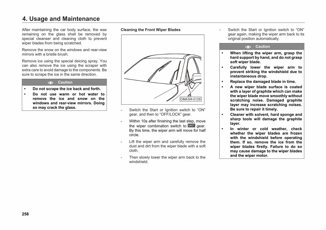
4. Usage and MaintenanceAfter maintaining the car body surface, the wax remaining on the glass shall be removed by special cleanser and cleaning cloth to prevent wiper blades from being scratched.
Remove the snow on the windows and rear-view mirrors with a bristle brush.
Remove ice using the special deicing spray. You can also remove the ice using the scraper with extra care to avoid damage to the components. Be sure to scrape the ice in the same direction.
Caution • Do not scrape the ice back and forth.• Do not use warm or hot water to
remove the ice and snow on thewindows and rear-view mirrors. Doingso may crack the glass.
Cleaning the Front Wiper Blades
- Switch the Start or Ignition switch to “ON”gear, and then to “OFF/LOCK” gear.
- Within 10s after finishing the last step, movethe wiper combination switch to gear.By this time, the wiper arm will move for halfcircle.
- Lift the wiper arm and carefully remove thedust and dirt from the wiper blade with a softcloth.
- Then slowly lower the wiper arm back to thewindshield.
- Switch the Start or Ignition switch to “ON”gear again, making the wiper arm back to itsoriginal position automatically.
Caution • When lifting the wiper arm, grasp the
hard support by hand, and do not graspsoft wiper blade.
• Carefully lower the wiper arm toprevent striking the windshield due toinstantaneous drop.
• Replace the damaged blade in time.• A new wiper blade surface is coated
with a layer of graphite which can makethe wiper blade move smoothly withoutscratching noise. Damaged graphitelayer may increase scratching noises.Be sure to repair it timely.
• Cleaner with solvent, hard sponge andsharp tools will damage the graphitelayer.
• In winter or cold weather, checkwhether the wiper blades are frozenwith the windshield before operatingthem. If so, remove the ice from thewiper blades firstly. Failure to do somay cause damage to the wiper bladesand the wiper motor.
258
4. Usage and Maintenance
Maintaining the Sealing Strips Frequent and appropriate protection of the rubber sealing strips for the doors, windows and other parts can maintain their flexibility, prolong their service life. Such action can improve the leakproofness, making the doors easier to open and reducing the closing sound and making it harder to get frozen in winter.
When maintaining the sealing strip, use soft cloth to remove the surface dust and dirt. Apply the special protective agent to the rubber sealing strips regularly.
Cleaning and Maintaining the Wheels Regular wheel maintenance can keep the wheel artistic, and periodically removing the antiskid salt and brake lining abrasive dust on the wheel can maintain the surface smoothness of the wheel and increase the service life. In order to protect your car, it is suggested that the following operations should be executed periodically:
• Use acid-free cleanser to remove the antiskidsalt and brake lining abrasive dust on thewheel every two weeks.
• Wax the alloy wheels with high-quality hardwax every three months.
Caution ● Be sure to clean the alloy wheels with
acid-free cleaner.● Do not clean the wheels surface with
the vehicle polishing agent or othergrinding agents.
● If the protective layer of the wheels isdamaged, be sure to repair it in time.
● The high-pressure washer may causepermanent visible or invisible damageto the wheels, resulting serious injuryor death.
● Never spray the tires with the clusternozzles. Even a short-time long-distance cleaning may cause damageto the tires, causing traffic accidents.
259
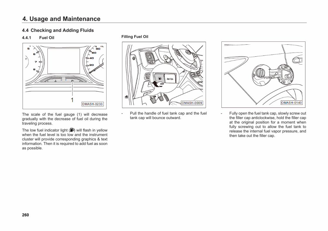
4. Usage and Maintenance
4.4 Checking and Adding Fluids 4.4.1 Fuel Oil
The scale of the fuel gauge (1) will decrease gradually with the decrease of fuel oil during the traveling process.
The low fuel indicator light ( ) will flash in yellow when the fuel level is too low and the instrument cluster will provide corresponding graphics & text information. Then it is required to add fuel as soon as possible.
Filling Fuel Oil
- Pull the handle of fuel tank cap and the fueltank cap will bounce outward.
- Fully open the fuel tank cap, slowly screw outthe filler cap anticlockwise, hold the filler capat the original position for a moment whenfully screwing out to allow the fuel tank torelease the internal fuel vapor pressure, andthen take out the filler cap.
260
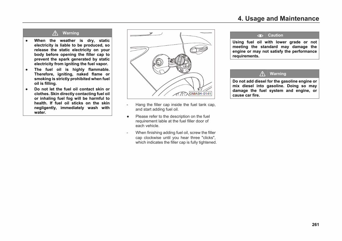
4. Usage and Maintenance
Warning
● When the weather is dry, staticelectricity is liable to be produced, sorelease the static electricity on yourbody before opening the filler cap toprevent the spark generated by staticelectricity from igniting the fuel vapor.
● The fuel oil is highly flammable.Therefore, igniting, naked flame orsmoking is strictly prohibited when fueloil is filling.
● Do not let the fuel oil contact skin orclothes. Skin directly contacting fuel oilor inhaling fuel fog will be harmful tohealth. If fuel oil sticks on the skinnegligently, immediately wash withwater.
- Hang the filler cap inside the fuel tank cap,and start adding fuel oil.
● Please refer to the description on the fuelrequirement lable at the fuel filler door ofeach vehicle.
- When finishing adding fuel oil, screw the fillercap clockwise until you hear three "clicks",which indicates the filler cap is fully tightened.
Caution Using fuel oil with lower grade or not meeting the standard may damage the engine or may not satisfy the performance requirements.
Warning
Do not add diesel for the gasoline engine or mix diesel into gasoline. Doing so may damage the fuel system and engine, or cause car fire.
261
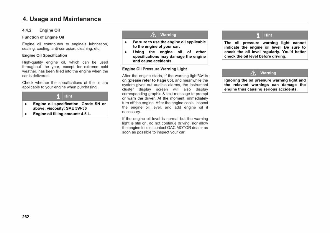
4. Usage and Maintenance4.4.2 Engine Oil Function of Engine Oil Engine oil contributes to engine’s lubrication, sealing, cooling, anti-corrosion, cleaning, etc.
Engine Oil Specification High-quality engine oil, which can be used throughout the year, except for extreme cold weather, has been filled into the engine when the car is delivered.
Check whether the specifications of the oil are applicable to your engine when purchasing.
Hint
● Engine oil specification: Grade SN orabove; viscosity: SAE 5W-30
● Engine oil filling amount: 4.5 L.
Warning
● Be sure to use the engine oil applicableto the engine of your car.
● Using the engine oil of otherspecifications may damage the engineand cause accidents.
Engine Oil Pressure Warning Light After the engine starts, if the warning light is on (please refer to Page 65), and meanwhile the system gives out audible alarms, the instrument cluster display screen will also display corresponding graphic & text message to prompt or warn the driver. At the moment, immediately turn off the engine. After the engine cools, inspect the engine oil level, and add engine oil if necessary.
If the engine oil level is normal but the warning light is still on, do not continue driving, nor allow the engine to idle; contact GAC MOTOR dealer as soon as possible to inspect your car.
Hint
The oil pressure warning light cannot indicate the engine oil level. Be sure to check the oil level regularly. You'd better check the oil level before driving.
Warning
Ignoring the oil pressure warning light and the relevant warnings can damage the engine thus causing serious accidents.
262
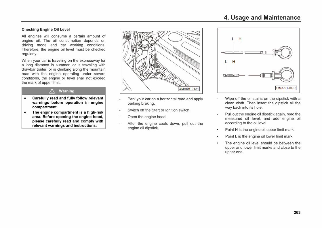
4. Usage and Maintenance
Checking Engine Oil Level All engines will consume a certain amount of engine oil. The oil consumption depends on driving mode and car working conditions. Therefore, the engine oil level must be checked regularly.
When your car is traveling on the expressway for a long distance in summer, or is traveling with drawbar trailer, or is climbing along the mountain road with the engine operating under severe conditions, the engine oil level shall not exceed the mark of upper limit.
Warning
● Carefully read and fully follow relevantwarnings before operation in enginecompartment.
● The engine compartment is a high-riskarea. Before opening the engine hood,please carefully read and comply withrelevant warnings and instructions.
- Park your car on a horizontal road and applyparking braking.
- Switch off the Start or Ignition switch.
- Open the engine hood.
- After the engine cools down, pull out theengine oil dipstick.
- Wipe off the oil stains on the dipstick with aclean cloth. Then insert the dipstick all theway back into its hole.
- Pull out the engine oil dipstick again, read themeasured oil level, and add engine oilaccording to the oil level.
• Point H is the engine oil upper limit mark.
Point L is the engine oil lower limit mark.
• The engine oil level should be between theupper and lower limit marks and close to theupper one.
•
263

4. Usage and Maintenance
Warning
If the engine oil level should be inspected when the engine is hot, firstly turn off the engine and wait for several minutes until the engine oil fully flows back to the oil sump, and then inspect the engine oil level. The engine oil level can be checked when the engine is in cold state.
Caution If the engine oil is insufficient, please timely add a proper amount of engine oil. Otherwise, the engine may be damaged.
Hint
The shape and color of engine oil dipstick for the car you purchase may be different with those of the engine oil dipstick shown in the figure, but the oil level mark on the engine oil dipstick as shown in the figure applies to the engine oil dipstick of all vehicle models.
Adding Engine Oil
- Park your car on a horizontal road and applyparking braking.
- Switch off the Start or Ignition switch.
- Open the engine hood.
- After the engine cools down, press theengine oil filler cap cover along the directionof arrow to open it.
- Screw out the engine oil filler capanticlockwise.
- Fill engine oil into the filler repeatedly bysmall amount, and check the engine oil levelafter each filling.
- When the oil level is close to the upper limitmark, i.e. the engine oil is sufficient, stopadding oil, assemble the filler cap and tightenclockwise.
264

4. Usage and Maintenance
Warning
● Engine oil is a type of highlycombustible material. Be careful to addthe engine oil and do not sprinkle theengine oil onto the scorching hotengine parts or exhaust system piping.
● If too much engine oil is filled, pleasedo not start the engine, and contactGAC MOTOR dealer for treatment.Otherwise, the three-way catalyticconverter may be damaged.
● After completing the filling, the engineoil filler cap must always be tightened,so as to prevent the engine oil fromspilling when the engine is operatingand avoid fire.
Replacing Engine Oil Replace the engine oil as per the intervals specified in the Warranty Manual at GAC MOTOR dealer.
If the car is used under severe conditions, or fuel oil with higher sulfur content is used, or short-distance traveling frequently occurs, or the car will idle for a long time (e.g. taxi), or the car will travel in high dust area, or the car will frequently travel with drawbar trailer, or the car will be used in high and cold area, increase the number of maintenance times or reduce the maintenance period of several maintenance items between periodic maintenances.
Warning
Never replace the engine oil by yourself unless you have relevant expertise. ● Be sure to operate after the engine
cools down, so as to prevent scald byhigh temperature engine oil.
● To prevent engine oil from getting intoyour eyes, be sure to wear goggleswhen replacing the engine oil.
● When unscrewing the oil drain plug, besure to place your arm horizontally toprevent the oil from flowing along it.
● If the engine oil splashes on the skin,rinse it thoroughly.
● Put the used oil into a special containerwhich is large enough to contain allused oil.
● Do not store the used oil in a foodcontainer or any other non-originalcontainer to avoid confusing, resultingin poisoning.
● As engine oil is toxic, please first put iton a safe place to prevent children fromtouching it before disposing it.
265
4. Usage and Maintenance
Caution ● Add no lubricant into engine oil;
otherwise, the engine may bedamaged. Any fault caused by additionof lubricant isn't included in qualityguarantee.
• Disposing the used engine oil is ahighly specialized work, requiringrelevant expertise and necessary tools.Therefore, it is suggested to disposethe used engine oil by GAC MOTORdealer.
• Improper disposal of engine oil can beharmful to the environment and watersource, so do not discard it in a sewerline or dump it on the ground. Inaddition, the cost for treating the soilabsorbing the waste engine oil is veryhigh.
266
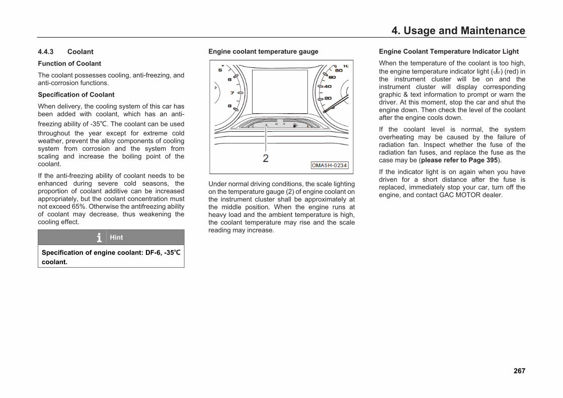
4. Usage and Maintenance
4.4.3 Coolant Function of Coolant The coolant possesses cooling, anti-freezing, and anti-corrosion functions.
Specification of Coolant When delivery, the cooling system of this car has been added with coolant, which has an anti-freezing ability of -35℃. The coolant can be used throughout the year except for extreme cold weather, prevent the alloy components of cooling system from corrosion and the system from scaling and increase the boiling point of the coolant.
If the anti-freezing ability of coolant needs to be enhanced during severe cold seasons, the proportion of coolant additive can be increased appropriately, but the coolant concentration must not exceed 65%. Otherwise the antifreezing ability of coolant may decrease, thus weakening the cooling effect.
Hint
Specification of engine coolant: DF-6, -35℃ coolant.
Engine coolant temperature gauge
Under normal driving conditions, the scale lighting on the temperature gauge (2) of engine coolant on the instrument cluster shall be approximately at the middle position. When the engine runs at heavy load and the ambient temperature is high, the coolant temperature may rise and the scale reading may increase.
Engine Coolant Temperature Indicator Light When the temperature of the coolant is too high, the engine temperature indicator light ( ) (red) in the instrument cluster will be on and the instrument cluster will display corresponding graphic & text information to prompt or warn the driver. At this moment, stop the car and shut the engine down. Then check the level of the coolant after the engine cools down.
If the coolant level is normal, the system overheating may be caused by the failure of radiation fan. Inspect whether the fuse of the radiation fan fuses, and replace the fuse as the case may be (please refer to Page 395).
If the indicator light is on again when you have driven for a short distance after the fuse is replaced, immediately stop your car, turn off the engine, and contact GAC MOTOR dealer.
267
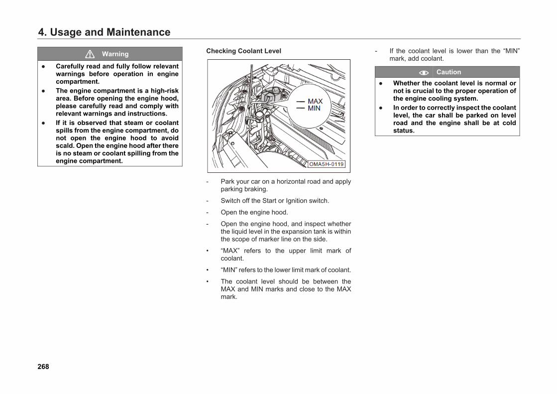
4. Usage and Maintenance
Warning
● Carefully read and fully follow relevantwarnings before operation in enginecompartment.
● The engine compartment is a high-riskarea. Before opening the engine hood,please carefully read and comply withrelevant warnings and instructions.
● If it is observed that steam or coolantspills from the engine compartment, donot open the engine hood to avoidscald. Open the engine hood after thereis no steam or coolant spilling from theengine compartment.
Checking Coolant Level
- Park your car on a horizontal road and applyparking braking.
- Switch off the Start or Ignition switch.
- Open the engine hood.
- Open the engine hood, and inspect whetherthe liquid level in the expansion tank is withinthe scope of marker line on the side.
• “MAX” refers to the upper limit mark ofcoolant.
• “MIN” refers to the lower limit mark of coolant.
• The coolant level should be between theMAX and MIN marks and close to the MAXmark.
- If the coolant level is lower than the “MIN”mark, add coolant.
Caution ● Whether the coolant level is normal or
not is crucial to the proper operation ofthe engine cooling system.
● In order to correctly inspect the coolantlevel, the car shall be parked on levelroad and the engine shall be at coldstatus.
268

4. Usage and Maintenance
Adding Coolant
After inspecting the coolant level, add coolant if necessary in the following steps:
- Wrap the expansion tank cover with a largeand thick cloth and carefully screw it outanticlockwise.
- Slowly add coolant to make the coolant levelreach the scope of marker line on the side ofexpansion tank.
- Install and tighten the expansion tank coverclockwise.
Caution ● Please firstly inspect the level before
adding coolant, and get readyaccording to the inspectionrequirements.
● When the engine is in warm or hotcondition, the cooling system is underhigh pressure. At this moment, neveropen the coolant expansion tank cover.Otherwise, you may be scalded by thesteam.
● Each time when screwing theexpansion tank cover, use cloth towrap the cover to avoid scald.
● Add new coolant only and thedischarged coolant cannot be reused.
Hint
When the engine is hot, the coolant level may exceed the MAX mark slightly.
Warning
● Store both the used and unusedcoolant in their original containersrespectively and keep them out thereach of children.
● Do not store the coolant in a foodcontainer or other non-originalcontainer to avoid confusing, resultingin poisoning.
● Make sure the anti-freezing capabilityof the coolant is sufficient in coldweather. Add enough DF-6 coolantbased on the environment temperature.Otherwise, the coolant may be frozen,resulting in breakdown of the car. Inaddition, the driver and passengers willbe exposed to severe cold due to thedisabled heating system.
269
4. Usage and Maintenance
Caution ● Do not mix the original coolant with
other unrecognized coolant.Otherwise, the engine may be damagedseriously.
● If the coolant is needed to be added,only add new coolant. The coolantmust meet the provisions of thisManual; do not add other types ofcoolant even if no DF-6 coolant can bepurchased temporarily. If necessary,add pure water temporarily. But, torestore the normal concentration, youmust add the recommended coolant asrequired as soon as possible.
● If the coolant in the coolant expansiontank discolors, and no coolant of othercolor mixes, replace the coolantperiodically according to therequirements of the Warranty Manual.
Caution ● Do not add coolant until the engine
cools down. After adding coolant, makesure the coolant level is at or below theMAX mark. Otherwise, the excessivecoolant will spill out of the coolingsystem when the engine becomes hot.
● If a large amount of coolant isconsumed, add cold coolant after theengine cools down; otherwise, theengine may be damaged. Great loss ofcoolant implies a leakage failure in thecooling system. Go to GAC MOTORdealer to inspect the cooling system assoon as possible, so as to avoiddamaging the engine.
● Collect and dispose the used coolant inaccordance with environmentalprotection laws and regulations.
270
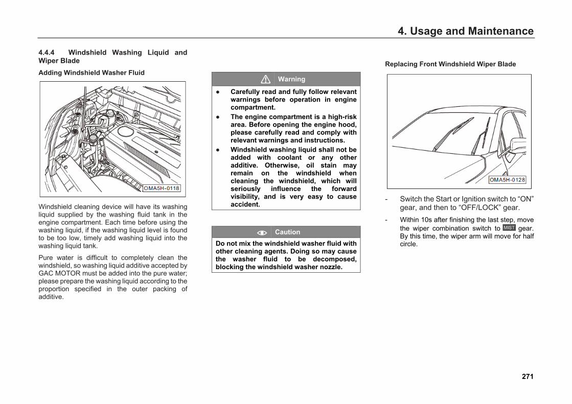
4. Usage and Maintenance
4.4.4 Windshield Washing Liquid and Wiper Blade Adding Windshield Washer Fluid
Windshield cleaning device will have its washing liquid supplied by the washing fluid tank in the engine compartment. Each time before using the washing liquid, if the washing liquid level is found to be too low, timely add washing liquid into the washing liquid tank.
Pure water is difficult to completely clean the windshield, so washing liquid additive accepted by GAC MOTOR must be added into the pure water; please prepare the washing liquid according to the proportion specified in the outer packing of additive.
Warning
● Carefully read and fully follow relevantwarnings before operation in enginecompartment.
● The engine compartment is a high-riskarea. Before opening the engine hood,please carefully read and comply withrelevant warnings and instructions.
● Windshield washing liquid shall not beadded with coolant or any otheradditive. Otherwise, oil stain mayremain on the windshield whencleaning the windshield, which willseriously influence the forwardvisibility, and is very easy to causeaccident.
Caution Do not mix the windshield washer fluid with other cleaning agents. Doing so may cause the washer fluid to be decomposed, blocking the windshield washer nozzle.
Replacing Front Windshield Wiper Blade
- Switch the Start or Ignition switch to “ON”gear, and then to “OFF/LOCK” gear.
- Within 10s after finishing the last step, movethe wiper combination switch to gear.By this time, the wiper arm will move for halfcircle.
271
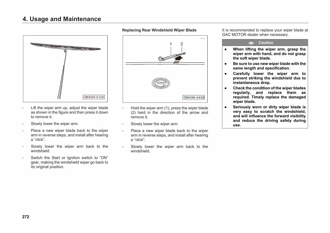
4. Usage and Maintenance
- Lift the wiper arm up, adjust the wiper bladeas shown in the figure and then press it downto remove it.
- Slowly lower the wiper arm.
- Place a new wiper blade back to the wiperarm in reverse steps, and install after hearinga “click”.
- Slowly lower the wiper arm back to thewindshield.
- Switch the Start or Ignition switch to “ON”gear, making the windshield wiper go back toits original position.
Replacing Rear Windshield Wiper Blade
- Hold the wiper arm (1), press the wiper blade(2) hard in the direction of the arrow andremove it.
- Slowly lower the wiper arm.
- Place a new wiper blade back to the wiperarm in reverse steps, and install after hearinga “click”.
- Slowly lower the wiper arm back to thewindshield.
It is recommended to replace your wiper blade at GAC MOTOR dealer when necessary.
Caution ● When lifting the wiper arm, grasp the
wiper arm with hand, and do not graspthe soft wiper blade.
● Be sure to use new wiper blade with thesame length and specification.
● Carefully lower the wiper arm toprevent striking the windshield due toinstantaneous drop.
● Check the condition of the wiper bladesregularly, and replace them asrequired. Timely replace the damagedwiper blade.
● Seriously worn or dirty wiper blade isvery easy to scratch the windshield,and will influence the forward visibilityand reduce the driving safety duringuse.
272
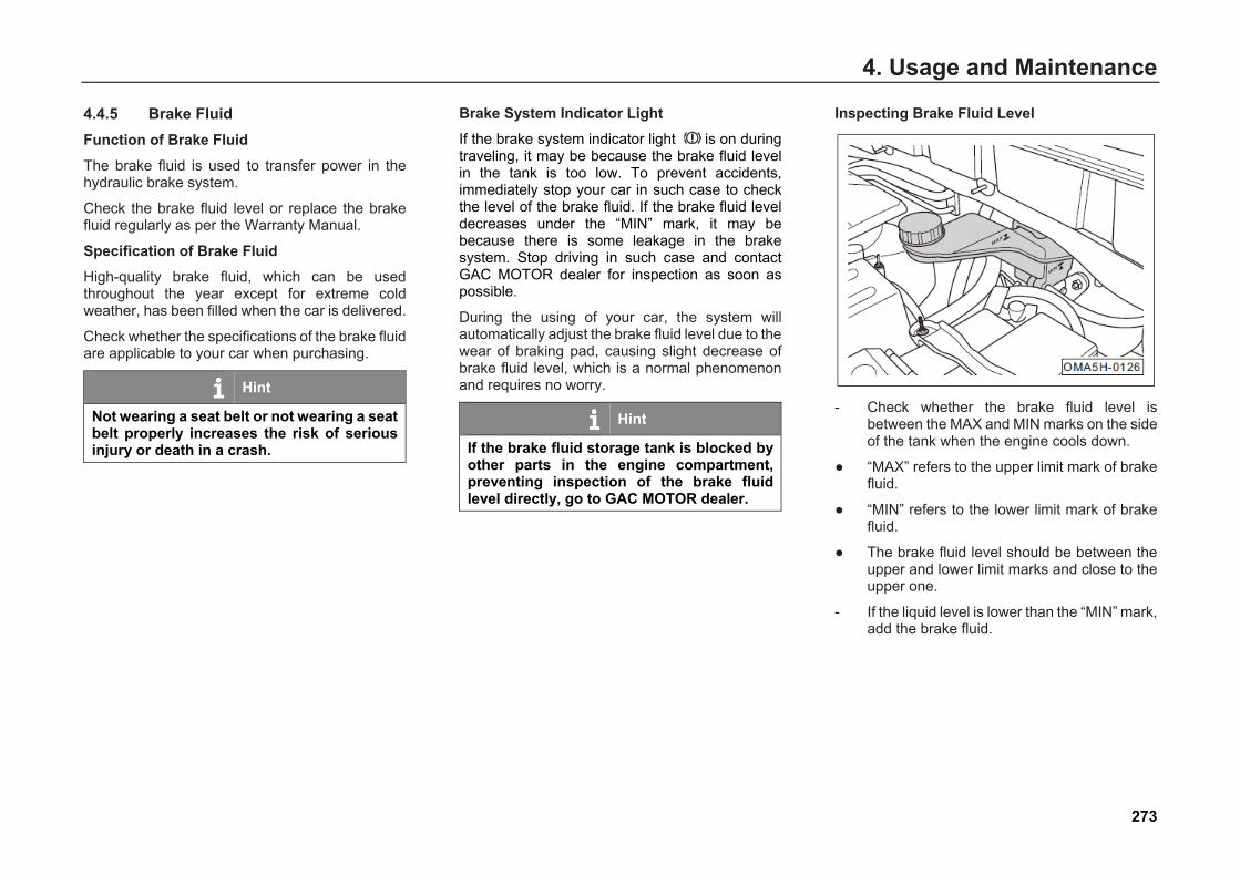
4. Usage and Maintenance
4.4.5 Brake Fluid Function of Brake Fluid The brake fluid is used to transfer power in the hydraulic brake system.
Check the brake fluid level or replace the brake fluid regularly as per the Warranty Manual.
Specification of Brake Fluid High-quality brake fluid, which can be used throughout the year except for extreme cold weather, has been filled when the car is delivered.
Check whether the specifications of the brake fluid are applicable to your car when purchasing.
Hint
Not wearing a seat belt or not wearing a seat belt properly increases the risk of serious injury or death in a crash.
Brake System Indicator Light If the brake system indicator light is on during traveling, it may be because the brake fluid level in the tank is too low. To prevent accidents, immediately stop your car in such case to check the level of the brake fluid. If the brake fluid level decreases under the “MIN” mark, it may be because there is some leakage in the brake system. Stop driving in such case and contact GAC MOTOR dealer for inspection as soon as possible.
During the using of your car, the system will automatically adjust the brake fluid level due to the wear of braking pad, causing slight decrease of brake fluid level, which is a normal phenomenon and requires no worry.
Hint
If the brake fluid storage tank is blocked by other parts in the engine compartment, preventing inspection of the brake fluid level directly, go to GAC MOTOR dealer.
Inspecting Brake Fluid Level
- Check whether the brake fluid level isbetween the MAX and MIN marks on the sideof the tank when the engine cools down.
● “MAX” refers to the upper limit mark of brakefluid.
● “MIN” refers to the lower limit mark of brakefluid.
● The brake fluid level should be between theupper and lower limit marks and close to theupper one.
- If the liquid level is lower than the “MIN” mark,add the brake fluid.
273
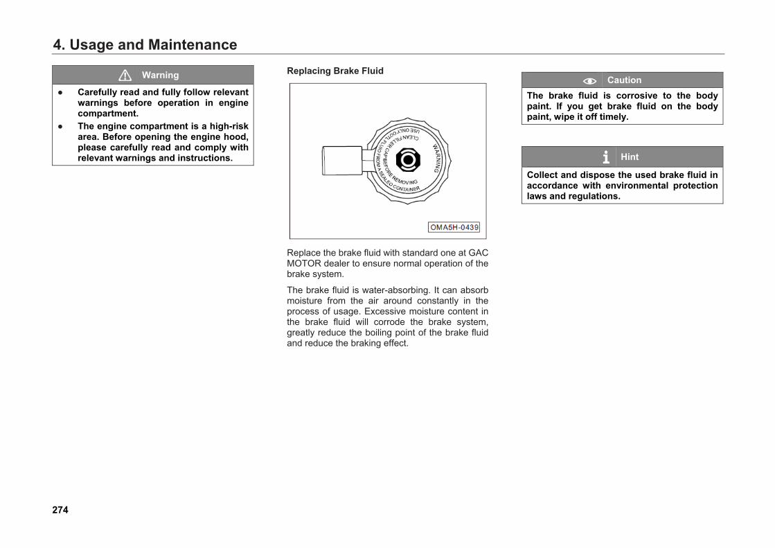
4. Usage and Maintenance
Warning
● Carefully read and fully follow relevantwarnings before operation in enginecompartment.
● The engine compartment is a high-riskarea. Before opening the engine hood,please carefully read and comply withrelevant warnings and instructions.
Replacing Brake Fluid
Replace the brake fluid with standard one at GAC MOTOR dealer to ensure normal operation of the brake system.
The brake fluid is water-absorbing. It can absorb moisture from the air around constantly in the process of usage. Excessive moisture content in the brake fluid will corrode the brake system, greatly reduce the boiling point of the brake fluid and reduce the braking effect.
Caution The brake fluid is corrosive to the body paint. If you get brake fluid on the body paint, wipe it off timely.
Hint
Collect and dispose the used brake fluid in accordance with environmental protection laws and regulations.
274
4. Usage and Maintenance
Warning
Using waste brake fluid or brake fluid not suitable for this car will greatly decrease the braking effect, or even cause failure of the brake system. ● The brake fluid container is labeled
with the specifications. Always use thebrake fluid with correct specifications.
● The brake fluid is toxic.● Do not store the brake fluid in a food
container or any other non-originalcontainer to avoid confusing, resultingin poisoning. Store the brake fluid in itsoriginal sealed container and put it in asafe place. Keep the container awayfrom children to avoid poisoningaccidents
● Brake fluid must be replaced accordingto the schedule specified in theWarranty Manual, because if the brakefluid stays inside the system for a longtime, air lock will be produced insidethe pipeline of braking system. In thiscase, it will reduce brake effect anddriving safety, and even causecomplete failure of the braking systemand accidents.
275
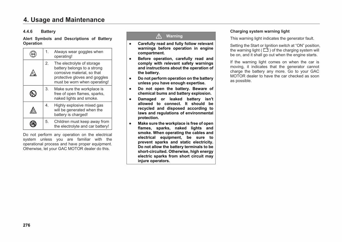
4. Usage and Maintenance4.4.6 Battery Alert Symbols and Descriptions of Battery Operation
1. Always wear goggles whenoperating!
2. The electrolyte of storagebattery belongs to a strongcorrosive material, so thatprotective gloves and gogglesmust be worn when operating!
3. Make sure the workplace isfree of open flames, sparks,naked lights and smoke.
4. Highly explosive mixed gaswill be generated when thebattery is charged!
5. Children must keep away fromthe electrolyte and car battery!
Do not perform any operation on the electrical system unless you are familiar with the operational process and have proper equipment. Otherwise, let your GAC MOTOR dealer do this.
Warning
● Carefully read and fully follow relevantwarnings before operation in enginecompartment.
● Before operation, carefully read andcomply with relevant safety warningsand instructions about the operation ofthe battery.
● Do not perform operation on the batteryunless you have enough expertise.
● Do not open the battery. Beware ofchemical bums and battery explosion.
● Damaged or leaked battery isn'tallowed to connect. It should berecycled and disposed according tolaws and regulations of environmentalprotection.
● Make sure the workplace is free of openflames, sparks, naked lights andsmoke. When operating the cables andelectrical equipment, be sure toprevent sparks and static electricity.Do not allow the battery terminals to beshort-circuited. Otherwise, high energyelectric sparks from short circuit mayinjure operators.
Charging system warning light This warning light indicates the generator fault.
Setting the Start or Ignition switch at “ON” position, the warning light ( ) of the charging system will be on, and it shall go out when the engine starts.
If the warning light comes on when the car is moving, it indicates that the generator cannot charge the battery any more. Go to your GAC MOTOR dealer to have the car checked as soon as possible.
276

4. Usage and Maintenance
Checking Battery Please regularly check the battery capacity when driving for a long distance or in hot areas or using the battery for a long time.
- Turn over the battery positive pole cover inthe direction of the arrow.
- Check the battery connection for corrosion orloosing and check the battery appearance forcracks and expansion. - In any casementioned above, go to your GAC MOTORdealer for troubleshooting.
Charging and Replacing Battery If your car is always driven for short distances or stored for a long time, perform more frequent checks for the battery than the specified maintenance intervals.
If the battery is damaged, its capacity will be insufficient, making it difficult to start the car. In this case, we recommend you to have your GAC MOTOR dealer charge or replace the battery.
Charging Battery Battery charging requires relevant expertise and must be done in controllable environment, so it should be done by your GAC MOTOR dealer.
If the Start or Ignition switch fails to turn off after the engine is closed, the battery will discharge rapidly when any electric device on the car is used.
1. Do not use any electrical equipment for anextended period after the engine is shutdown.
2. When leaving the car, be sure to close thedoors tightly and turn off all the electricalequipment (e.g., lights, etc.)
3. If the engine cannot be started afterelectric equipment is used, do notcontinuously start the engine, restart theengine after 5~10min. If the engine stillcannot be started, please contact yourGAC MOTOR dealer for maintenance.
277

4. Usage and MaintenanceReplacing Battery Your battery is installed properly and safely.
The battery can meet the car maintenance, performance and safety requirements.
Caution ● Battery shall be replaced with the one
of the specified type (please refer toPage 386), or otherwise it will affect thenormal operation of the Start/Stopsystem (applicable to certain models).Please go to your GAC MOTOR dealerfor replacement.
● To avoid damaging your car’s electricalsystem, do not connect the solarpanels or battery charger and otherpower generation equipment to the 12Vpower outlet or cigarette lighter.
● As the battery contains toxic materialssuch as sulfuric acid and lead, disposeit carefully and don’t take it just as acommon household waste.
Hint
● Reconnect the battery to the electricalsystem of the finished automobile, andthen the indicator light of electronicstability program (ESP) will light.
● The indicator light shall go out after thecar travels at a speed of 15~20km/h fora short distance.
Caution As to the car model with the Start/Stop system, whenever the battery is disconnected and re-connected, operation needs to be performed on self-learning of the Start/Stop system: 1. Turn off the Start or Ignition switch and
all in-car electrical equipment, and letthe car sit for over 4h.
2. Start the car for 3 times, and let itoperate continuously for at least 1minute each time.
278
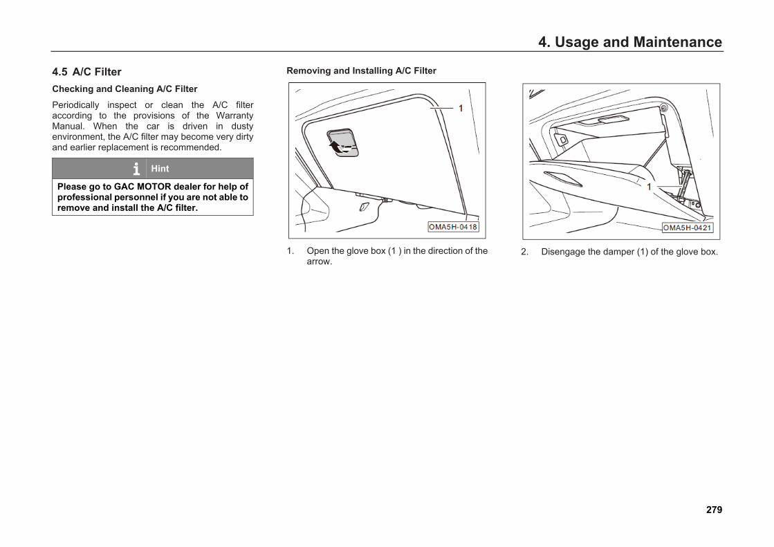
4. Usage and Maintenance
4.5 A/C Filter Checking and Cleaning A/C Filter Periodically inspect or clean the A/C filter according to the provisions of the Warranty Manual. When the car is driven in dusty environment, the A/C filter may become very dirty and earlier replacement is recommended.
Hint
Please go to GAC MOTOR dealer for help of professional personnel if you are not able to remove and install the A/C filter.
Removing and Installing A/C Filter
1. Open the glove box (1 ) in the direction of thearrow.
2. Disengage the damper (1) of the glove box.
279
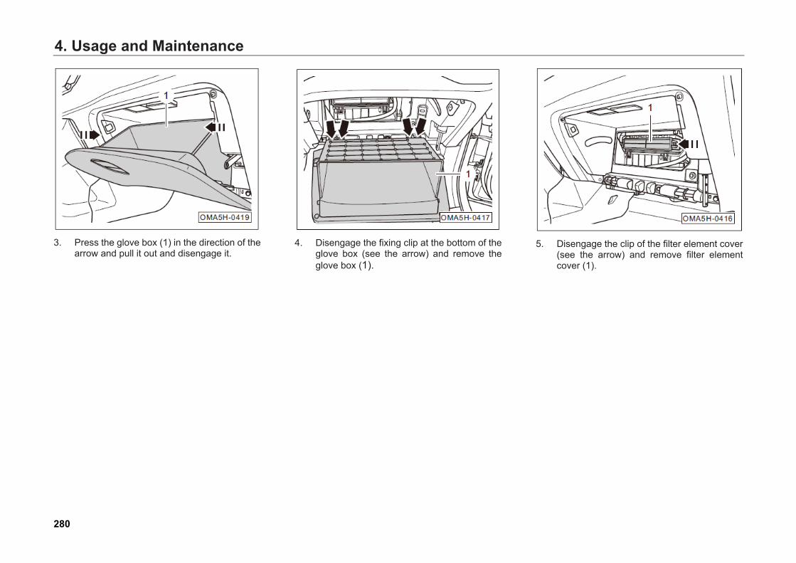
4. Usage and Maintenance
3. Press the glove box (1) in the direction of thearrow and pull it out and disengage it.
4. Disengage the fixing clip at the bottom of theglove box (see the arrow) and remove theglove box (1).
5. Disengage the clip of the filter element cover(see the arrow) and remove filter elementcover (1).
280

4. Usage and Maintenance
6. Remove the A/C filter (1). 7. Clean the A/C filter with compressed air orflap it.
Hint
The A/C filter cannot be cleaned with water as it is made of special materials and cannot contact moisture.
8. Install the A/C filter in opposite steps aftercleaning.
Hint
Install the A/C filter according to the “UP” mark (see the arrow) on it.
281
4. Usage and Maintenance
4.6 Replacing Bulbs Safe Operation Instructions for Replacing Bulbs Check the following lights:
1. Headlight (low beam and high beam)
2. Front/rear position lights
3. Daytime running light (apply to certainmodels)
4. Brake light
5. Turn signal
6. Reversing light
7. Hazard warning indicator light
8. Number plate light
9. High brake light
10. Front/rear fog light
11. Interior lights
If you find any bulbs are burned out, replace them as soon as possible. Before replacing the bulb, be sure to check the relevant fuse. The blown fuse can cause the light failure. In addition, do the following:
1. Turn the relevant light switch to the OFFposition.
2. Move the light combination switch controllever to the middle position.
3. Switch the Start or Ignition switch to“OFF/LOCK” position.
Caution Only replace the burned-out bulb with a new one of the same rating. The bulb specification is marked on the bulb glass or the socket. As to the bulb specification in this car, please refer to Page 386.
For example:
LL = long-lasting bulbs, with life longer than that of standard bulbs.
Blue = blue/white bulbs, matching with the color of gas discharge lights (Xenon).
282
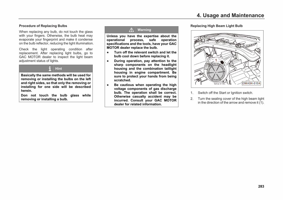
4. Usage and Maintenance
Procedure of Replacing Bulbs When replacing any bulb, do not touch the glass with your fingers. Otherwise, the bulb heat may evaporate your fingerprint and make it condense on the bulb reflector, reducing the light illumination.
Check the light operating condition after replacement. After replacing light bulbs, go to GAC MOTOR dealer to inspect the light beam adjustment status of lights.
Hint
Basically the same methods will be used for removing or installing the bulbs on the left and right sides, so that only the removing or installing for one side will be described herein. Don not touch the bulb glass while removing or installing a bulb.
Warning
Unless you have the expertise about the operational process, safe operation specifications and the tools, have your GAC MOTOR dealer replace the bulb. ● Turn off the relevant switch and let the
bulb cool down before replacing it.● During operation, pay attention to the
sharp components on the headlighthousing and the combination taillighthousing in engine compartment. Besure to protect your hands from beingscratched.
● Be cautious when operating the highvoltage components of gas dischargebulb. The operation shall be correct.Otherwise casualty accident may beincurred. Consult your GAC MOTORdealer for related information.
Replacing High Beam Light Bulb
1. Switch off the Start or Ignition switch.
2. Turn the sealing cover of the high beam lightin the direction of the arrow and remove it (1).
283
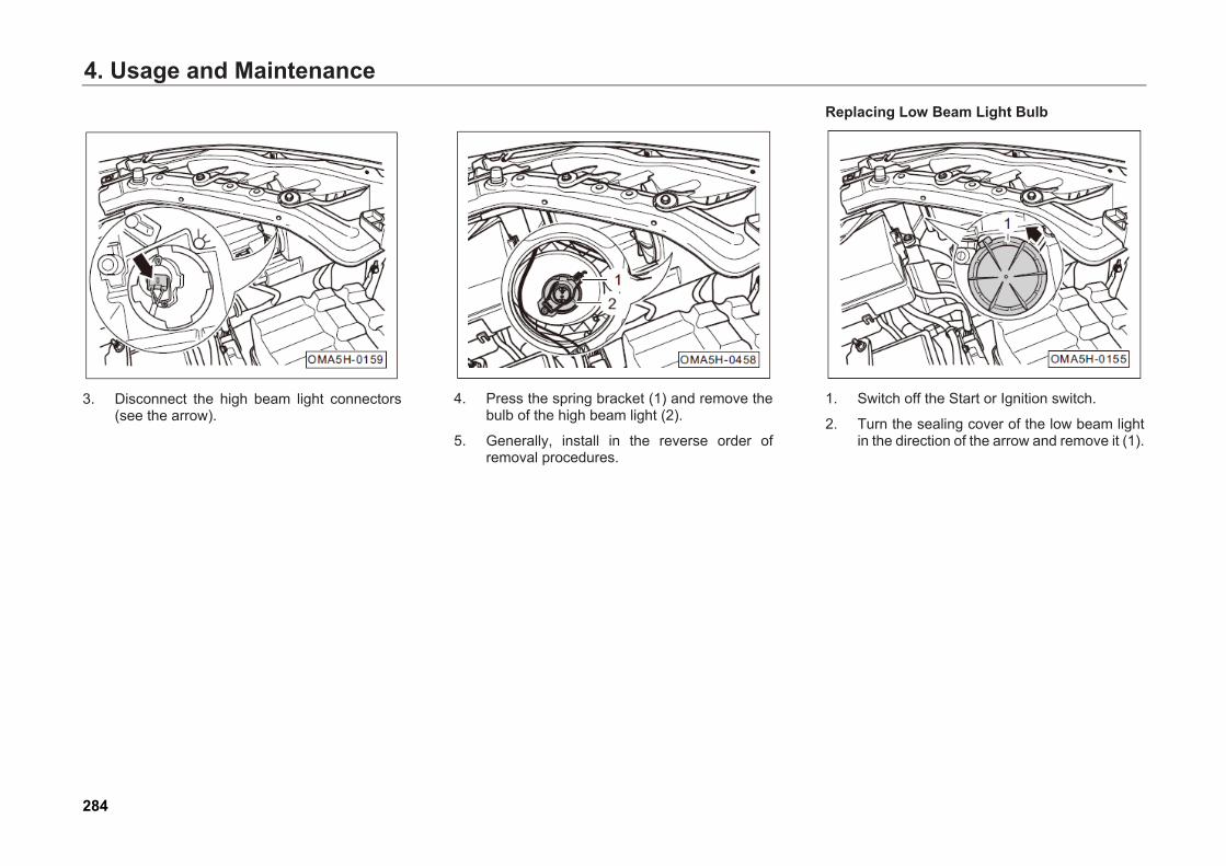
4. Usage and Maintenance
3. Disconnect the high beam light connectors(see the arrow).
4. Press the spring bracket (1) and remove thebulb of the high beam light (2).
5. Generally, install in the reverse order ofremoval procedures.
Replacing Low Beam Light Bulb
1. Switch off the Start or Ignition switch.
2. Turn the sealing cover of the low beam lightin the direction of the arrow and remove it (1).
284
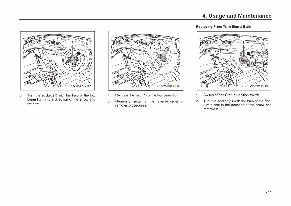
4. Usage and Maintenance
3. Turn the socket (1) with the bulb of the lowbeam light in the direction of the arrow andremove it.
4. Remove the bulb (1) of the low beam light.
5. Generally, install in the reverse order ofremoval procedures.
Replacing Front Turn Signal Bulb
1. Switch off the Start or Ignition switch.
2. Turn the socket (1) with the bulb of the frontturn signal in the direction of the arrow andremove it.
285
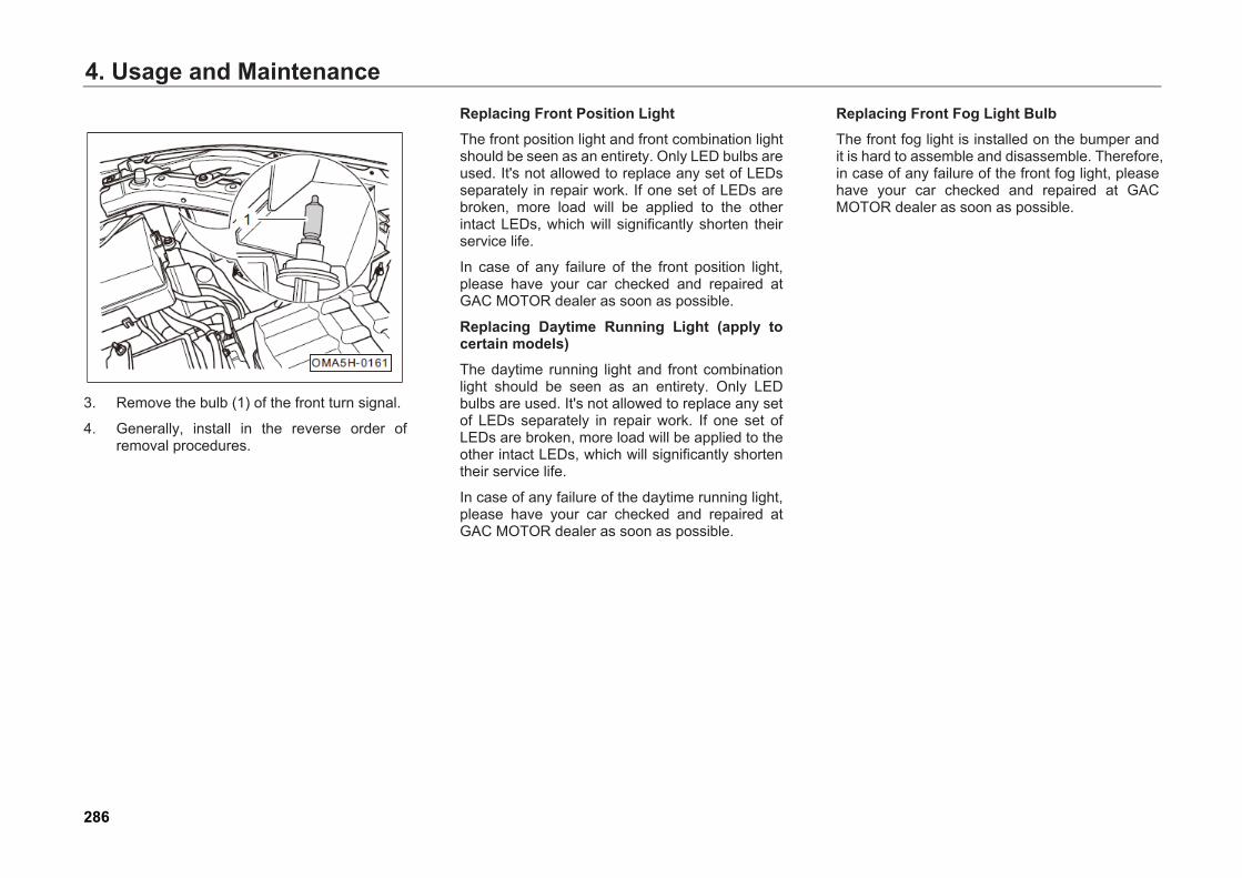
4. Usage and Maintenance
3. Remove the bulb (1) of the front turn signal.
4. Generally, install in the reverse order ofremoval procedures.
Replacing Front Position Light The front position light and front combination light should be seen as an entirety. Only LED bulbs are used. It's not allowed to replace any set of LEDs separately in repair work. If one set of LEDs are broken, more load will be applied to the other intact LEDs, which will significantly shorten their service life.
In case of any failure of the front position light, please have your car checked and repaired at GAC MOTOR dealer as soon as possible.
Replacing Daytime Running Light (apply to certain models) The daytime running light and front combination light should be seen as an entirety. Only LED bulbs are used. It's not allowed to replace any set of LEDs separately in repair work. If one set of LEDs are broken, more load will be applied to the other intact LEDs, which will significantly shorten their service life.
In case of any failure of the daytime running light, please have your car checked and repaired at GAC MOTOR dealer as soon as possible.
Replacing Front Fog Light Bulb The front fog light is installed on the bumper and it is hard to assemble and disassemble. Therefore, in case of any failure of the front fog light, please have your car checked and repaired at GAC MOTOR dealer as soon as possible.
286

4. Usage and Maintenance
Replacing Side Turn signal on Rear- View Mirror The side turn signal on rear-view mirror uses LED bulb, the side turn signal assembly on rear-view mirror shall be replaced as a whole and replacing a single LED bulb is not allowed.
In case of any failure of the side turn signal on rear-view mirror, please have your car checked and repaired at GAC MOTOR dealer as soon as possible.
Removing Rear Combination Light
1. Switch off the Start or Ignition switch.
2. Pry the small trim panel out (1).
3. Disconnect the connector (see arrow A) ofthe rear combination light.
4. Unscrew the fixing nuts (see arrow B) of therear combination light.
287
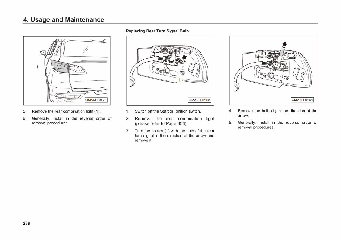
4. Usage and Maintenance
5. Remove the rear combination light (1).
6. Generally, install in the reverse order ofremoval procedures.
Replacing Rear Turn Signal Bulb
1. Switch off the Start or Ignition switch.
2. Remove the rear combination light(please refer to Page 356).
3. Turn the socket (1) with the bulb of the rearturn signal in the direction of the arrow andremove it.
4. Remove the bulb (1) in the direction of thearrow.
5. Generally, install in the reverse order ofremoval procedures.
288
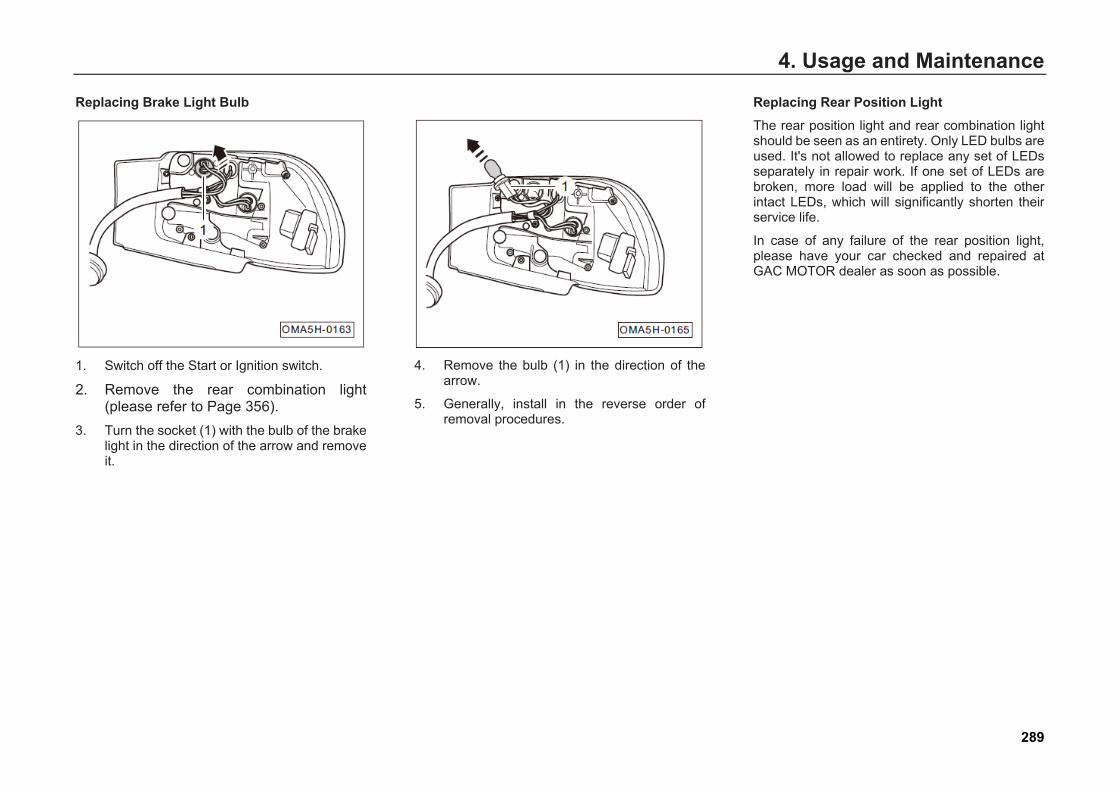
4. Usage and Maintenance
Replacing Brake Light Bulb
1. Switch off the Start or Ignition switch.
2. Remove the rear combination light(please refer to Page 356).
3. Turn the socket (1) with the bulb of the brakelight in the direction of the arrow and removeit.
4. Remove the bulb (1) in the direction of thearrow.
5. Generally, install in the reverse order ofremoval procedures.
Replacing Rear Position Light The rear position light and rear combination light should be seen as an entirety. Only LED bulbs are used. It's not allowed to replace any set of LEDs separately in repair work. If one set of LEDs are broken, more load will be applied to the other intact LEDs, which will significantly shorten their service life.
In case of any failure of the rear position light, please have your car checked and repaired at GAC MOTOR dealer as soon as possible.
289
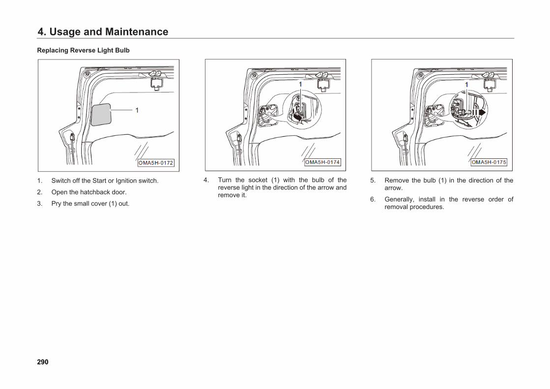
4. Usage and MaintenanceReplacing Reverse Light Bulb
1. Switch off the Start or Ignition switch.
2. Open the hatchback door.
3. Pry the small cover (1) out.
4. Turn the socket (1) with the bulb of thereverse light in the direction of the arrow andremove it.
5. Remove the bulb (1) in the direction of thearrow.
6. Generally, install in the reverse order ofremoval procedures.
290
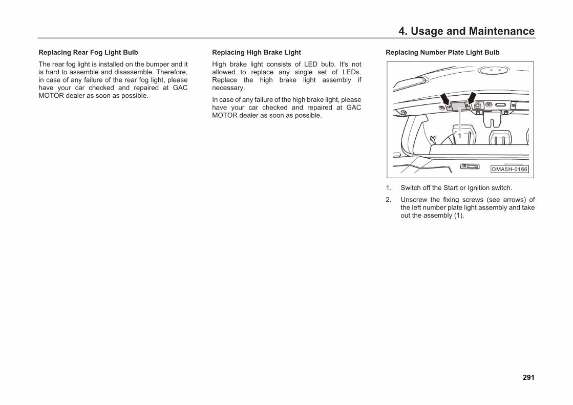
4. Usage and Maintenance
Replacing Rear Fog Light Bulb The rear fog light is installed on the bumper and it is hard to assemble and disassemble. Therefore, in case of any failure of the rear fog light, please have your car checked and repaired at GAC MOTOR dealer as soon as possible.
Replacing High Brake Light High brake light consists of LED bulb. It's not allowed to replace any single set of LEDs. Replace the high brake light assembly if necessary.
In case of any failure of the high brake light, please have your car checked and repaired at GAC MOTOR dealer as soon as possible.
Replacing Number Plate Light Bulb
1. Switch off the Start or Ignition switch.
2. Unscrew the fixing screws (see arrows) ofthe left number plate light assembly and takeout the assembly (1).
291
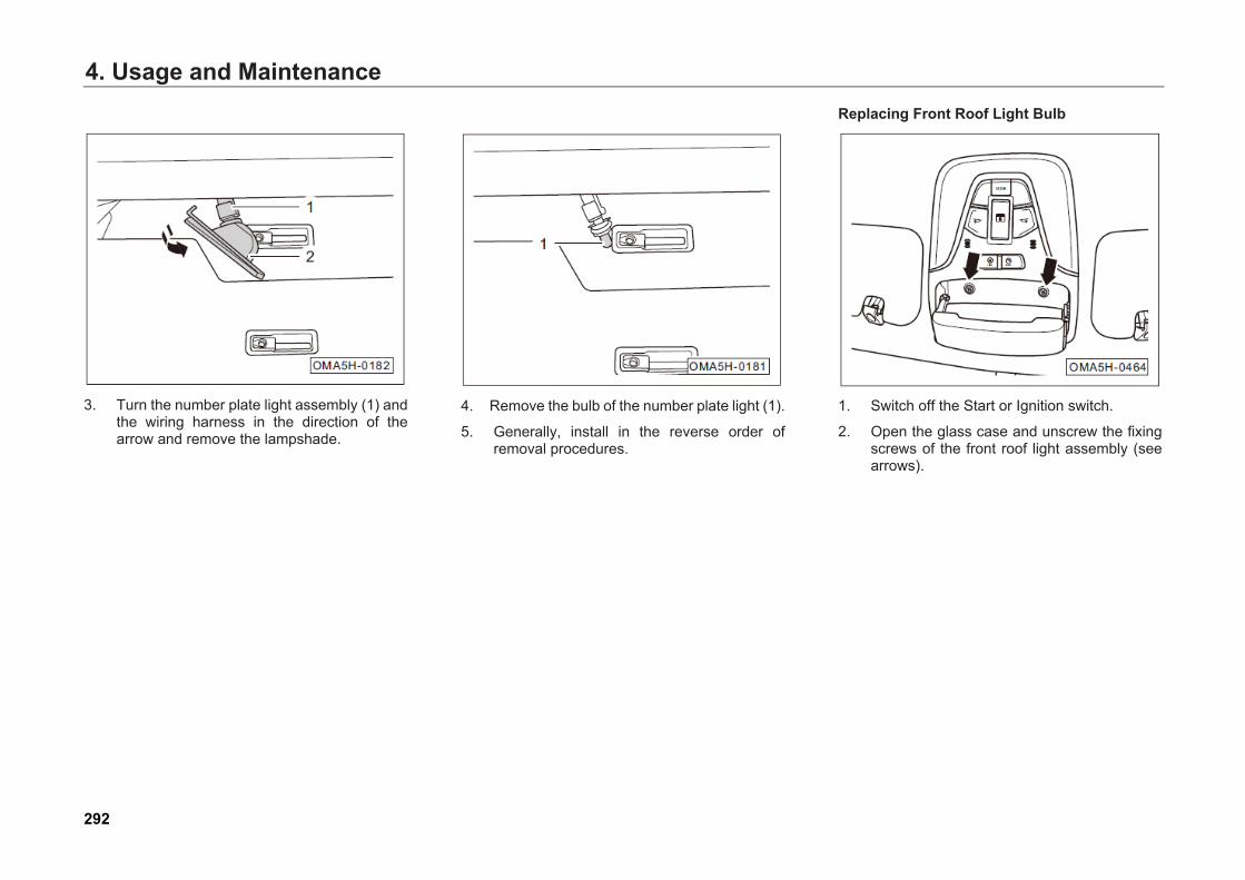
4. Usage and Maintenance
3. Turn the number plate light assembly (1) andthe wiring harness in the direction of thearrow and remove the lampshade.
4. Remove the bulb of the number plate light (1).
5. Generally, install in the reverse order ofremoval procedures.
Replacing Front Roof Light Bulb
1. Switch off the Start or Ignition switch.
2. Open the glass case and unscrew the fixingscrews of the front roof light assembly (seearrows).
292
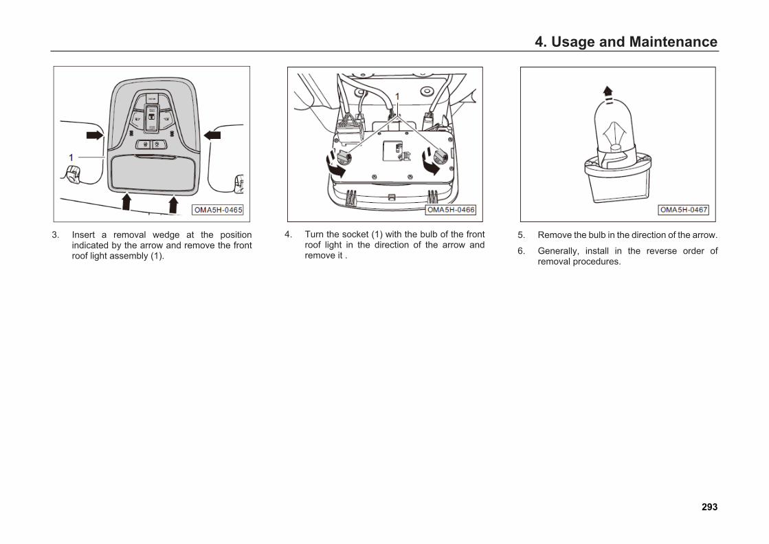
4. Usage and Maintenance
3. Insert a removal wedge at the positionindicated by the arrow and remove the frontroof light assembly (1).
4. Turn the socket (1) with the bulb of the frontroof light in the direction of the arrow andremove it .
5. Remove the bulb in the direction of the arrow.
6. Generally, install in the reverse order ofremoval procedures.
293
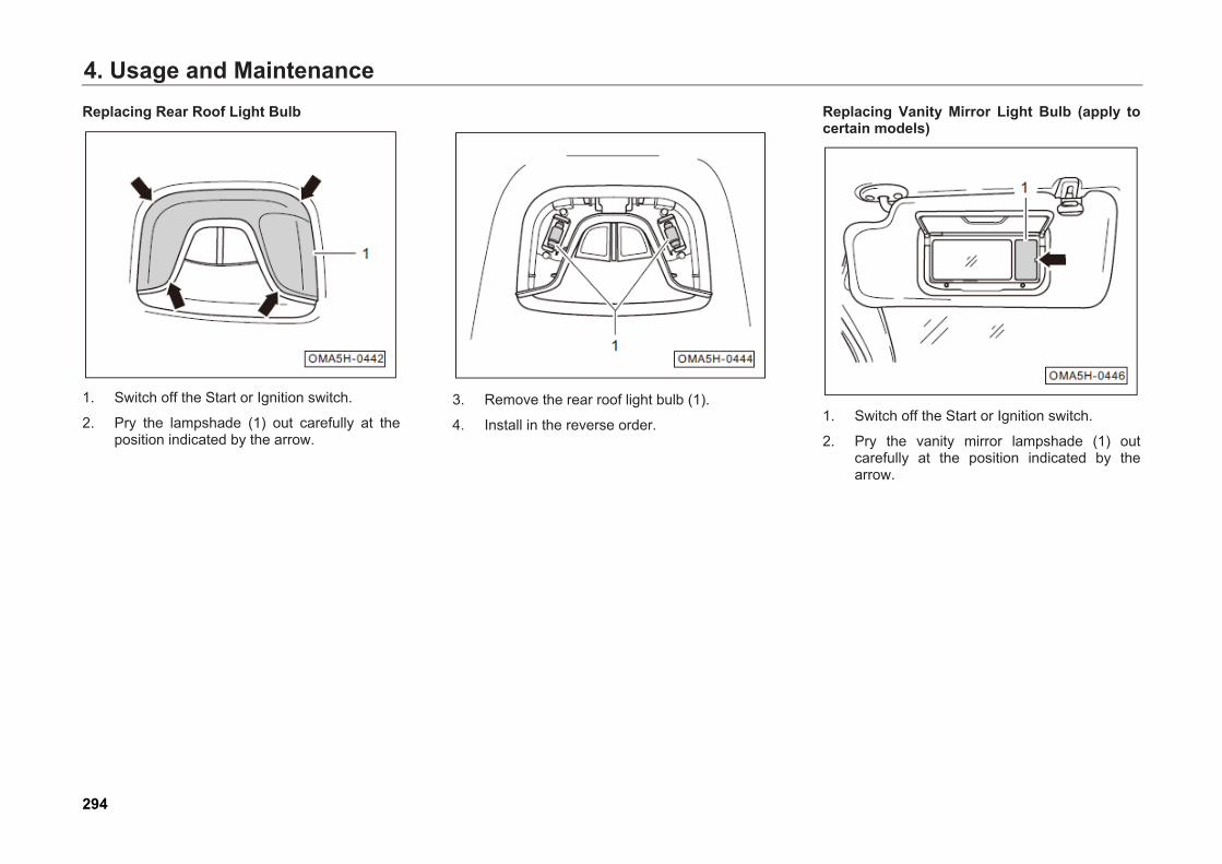
4. Usage and MaintenanceReplacing Rear Roof Light Bulb
1. Switch off the Start or Ignition switch.
2. Pry the lampshade (1) out carefully at theposition indicated by the arrow.
3. Remove the rear roof light bulb (1).
4. Install in the reverse order.
Replacing Vanity Mirror Light Bulb (apply to certain models)
1. Switch off the Start or Ignition switch.
2. Pry the vanity mirror lampshade (1) outcarefully at the position indicated by thearrow.
294

4. Usage and Maintenance
3. Remove the vanity mirror light bulb (1).
4. Generally, install in the reverse order ofremoval procedures.
Replacing Glove Box Light
1. Switch off the Start or Ignition switch.
2. Open the glove box.
3. Pry the fixing clip of the glove box (see thearrow) and remove the glove box light (1).
4. Disconnect the connector of the glove boxlight (see the arrow).
5. Remove the glove box light (1).
295
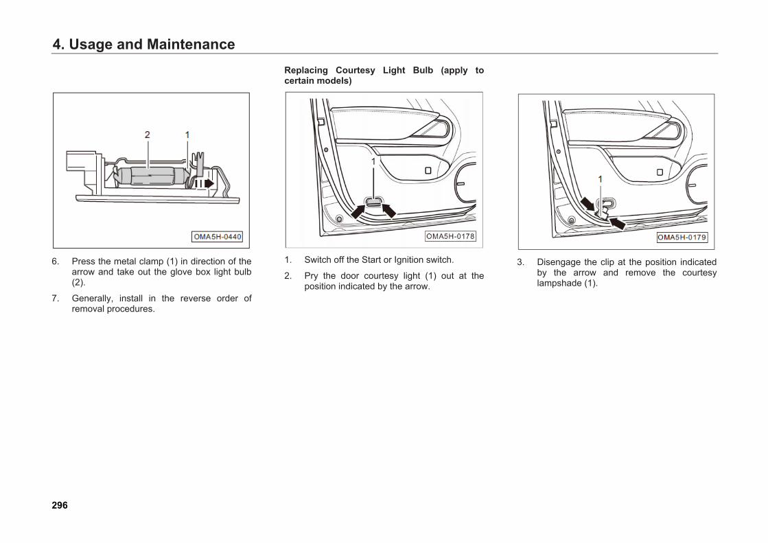
4. Usage and Maintenance
6. Press the metal clamp (1) in direction of thearrow and take out the glove box light bulb(2).
7. Generally, install in the reverse order ofremoval procedures.
Replacing Courtesy Light Bulb (apply to certain models)
1. Switch off the Start or Ignition switch.
2. Pry the door courtesy light (1) out at theposition indicated by the arrow.
3. Disengage the clip at the position indicatedby the arrow and remove the courtesylampshade (1).
296
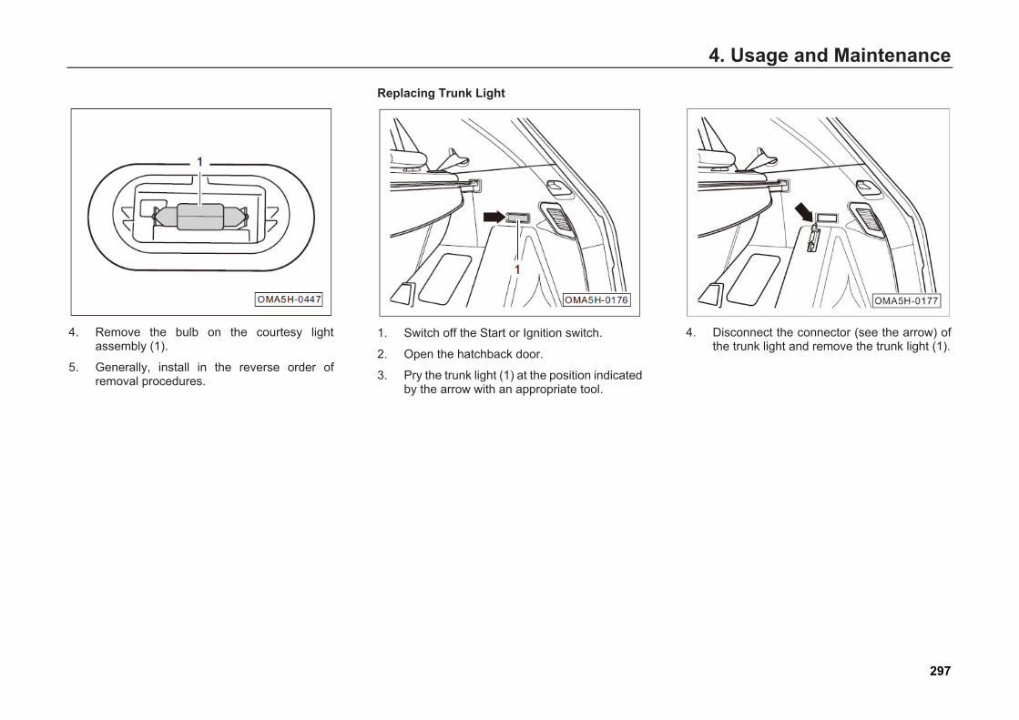
4. Usage and Maintenance
4. Remove the bulb on the courtesy lightassembly (1).
5. Generally, install in the reverse order ofremoval procedures.
Replacing Trunk Light
1. Switch off the Start or Ignition switch.
2. Open the hatchback door.
3. Pry the trunk light (1) at the position indicatedby the arrow with an appropriate tool.
4. Disconnect the connector (see the arrow) ofthe trunk light and remove the trunk light (1).
297
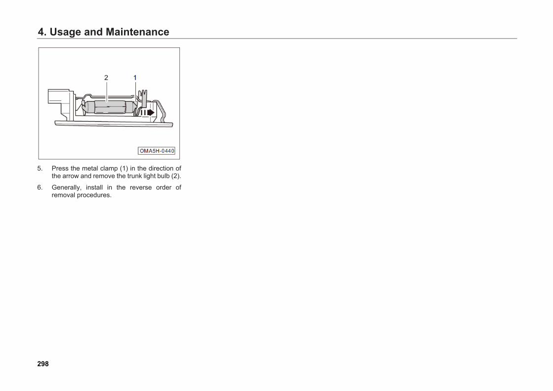
4. Usage and Maintenance
5. Press the metal clamp (1) in the direction ofthe arrow and remove the trunk light bulb (2).
6. Generally, install in the reverse order ofremoval procedures.
298
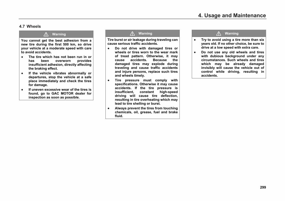
4. Usage and Maintenance
4.7 Wheels
Warning
You cannot get the best adhesion from a new tire during the first 500 km, so drive your vehicle at a moderate speed with care to avoid accidents. ● The tire which has not been run in or
has been overworn providesinsufficient adhesion, directly affectingthe braking effect.
● If the vehicle vibrates abnormally ordepartures, stop the vehicle at a safeplace immediately and check the tiresfor damage.
● If uneven excessive wear of the tires isfound, go to GAC MOTOR dealer forinspection as soon as possible.
Warning
Tire burst or air leakage during traveling can cause serious traffic accidents. ● Do not drive with damaged tires or
wheels or tires worn to the wear markof tread pattern. Otherwise, it maycause accidents. Because thedamaged tires may explode duringtraveling and cause traffic accidentsand injure persons, replace such tiresand wheels timely.
● Tire pressure must comply withspecifications. Otherwise it may causeaccidents. If the tire pressure isinsufficient, constant high-speeddriving will cause tire deflection,resulting in tire overheating which maylead to tire shelling or burst.
● Always prevent the tires from touchingchemicals, oil, grease, fuel and brakefluid.
Warning
● Try to avoid using a tire more than sixyears old. If no other choice, be sure todrive at a low speed with extra care.
● Do not use any old wheels and tireswith dubious background under anycircumstances. Such wheels and tireswhich may be already damagedinvisibly will cause the vehicle out ofcontrol while driving, resulting inaccidents.
299
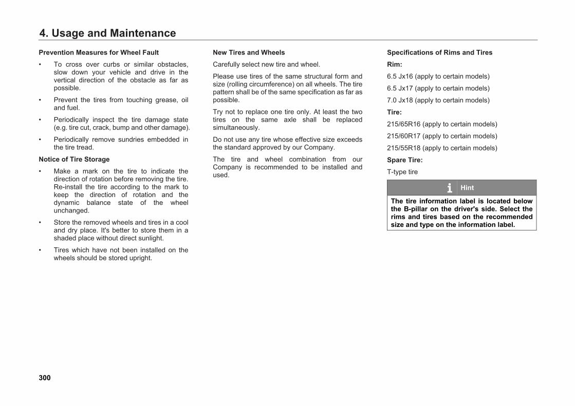
4. Usage and MaintenancePrevention Measures for Wheel Fault • To cross over curbs or similar obstacles,
slow down your vehicle and drive in thevertical direction of the obstacle as far aspossible.
• Prevent the tires from touching grease, oiland fuel.
• Periodically inspect the tire damage state(e.g. tire cut, crack, bump and other damage).
• Periodically remove sundries embedded inthe tire tread.
Notice of Tire Storage • Make a mark on the tire to indicate the
direction of rotation before removing the tire.Re-install the tire according to the mark tokeep the direction of rotation and thedynamic balance state of the wheelunchanged.
• Store the removed wheels and tires in a cooland dry place. It's better to store them in ashaded place without direct sunlight.
• Tires which have not been installed on thewheels should be stored upright.
New Tires and Wheels Carefully select new tire and wheel.
Please use tires of the same structural form and size (rolling circumference) on all wheels. The tire pattern shall be of the same specification as far as possible.
Try not to replace one tire only. At least the two tires on the same axle shall be replaced simultaneously.
Do not use any tire whose effective size exceeds the standard approved by our Company.
The tire and wheel combination from our Company is recommended to be installed and used.
Specifications of Rims and Tires Rim: 6.5 Jx16 (apply to certain models)
6.5 Jx17 (apply to certain models)
7.0 Jx18 (apply to certain models)
Tire: 215/65R16 (apply to certain models)
215/60R17 (apply to certain models)
215/55R18 (apply to certain models)
Spare Tire: T-type tire
Hint
The tire information label is located below the B-pillar on the driver's side. Select the rims and tires based on the recommended size and type on the information label.
300
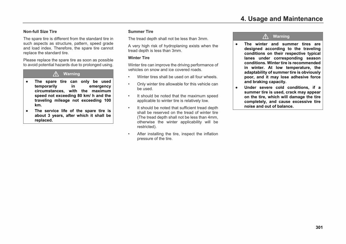
4. Usage and Maintenance
Non-full Size Tire The spare tire is different from the standard tire in such aspects as structure, pattern, speed grade and load index. Therefore, the spare tire cannot replace the standard tire.
Please replace the spare tire as soon as possible to avoid potential hazards due to prolonged using.
Warning
● The spare tire can only be usedtemporarily in emergencycircumstances, with the maximumspeed not exceeding 80 km/ h and thetraveling mileage not exceeding 100km.
● The service life of the spare tire isabout 3 years, after which it shall bereplaced.
Summer Tire The tread depth shall not be less than 3mm.
A very high risk of hydroplaning exists when the tread depth is less than 3mm.
Winter Tire Winter tire can improve the driving performance of vehicles on snow and ice covered roads.
• Winter tires shall be used on all four wheels.
• Only winter tire allowable for this vehicle canbe used.
• It should be noted that the maximum speedapplicable to winter tire is relatively low.
• It should be noted that sufficient tread depthshall be reserved on the tread of winter tire(The tread depth shall not be less than 4mm,otherwise the winter applicability will berestricted).
• After installing the tire, inspect the inflationpressure of the tire.
Warning
● The winter and summer tires aredesigned according to the travelingconditions on their respective typicallanes under corresponding seasonconditions. Winter tire is recommendedin winter. At low temperature, theadaptability of summer tire is obviouslypoor, and it may lose adhesive forceand braking capacity.
● Under severe cold conditions, if asummer tire is used, crack may appearon the tire, which will damage the tirecompletely, and cause excessive tirenoise and out of balance.
301
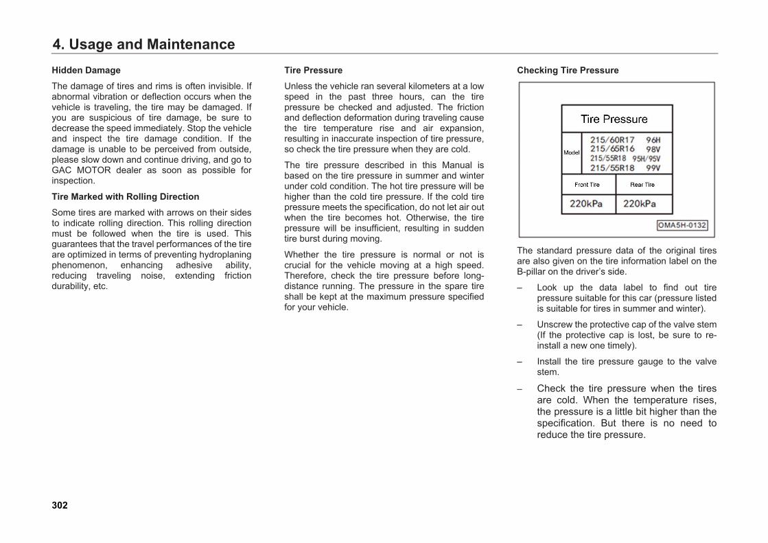
4. Usage and MaintenanceHidden Damage The damage of tires and rims is often invisible. If abnormal vibration or deflection occurs when the vehicle is traveling, the tire may be damaged. If you are suspicious of tire damage, be sure to decrease the speed immediately. Stop the vehicle and inspect the tire damage condition. If the damage is unable to be perceived from outside, please slow down and continue driving, and go to GAC MOTOR dealer as soon as possible for inspection.
Tire Marked with Rolling Direction Some tires are marked with arrows on their sides to indicate rolling direction. This rolling direction must be followed when the tire is used. This guarantees that the travel performances of the tire are optimized in terms of preventing hydroplaning phenomenon, enhancing adhesive ability, reducing traveling noise, extending friction durability, etc.
Tire Pressure Unless the vehicle ran several kilometers at a low speed in the past three hours, can the tire pressure be checked and adjusted. The friction and deflection deformation during traveling cause the tire temperature rise and air expansion, resulting in inaccurate inspection of tire pressure, so check the tire pressure when they are cold.
The tire pressure described in this Manual is based on the tire pressure in summer and winter under cold condition. The hot tire pressure will be higher than the cold tire pressure. If the cold tire pressure meets the specification, do not let air out when the tire becomes hot. Otherwise, the tire pressure will be insufficient, resulting in sudden tire burst during moving.
Whether the tire pressure is normal or not is crucial for the vehicle moving at a high speed. Therefore, check the tire pressure before long-distance running. The pressure in the spare tire shall be kept at the maximum pressure specified for your vehicle.
Checking Tire Pressure
The standard pressure data of the original tires are also given on the tire information label on the B-pillar on the driver’s side.
– Look up the data label to find out tirepressure suitable for this car (pressure listedis suitable for tires in summer and winter).
– Unscrew the protective cap of the valve stem(If the protective cap is lost, be sure to re-install a new one timely).
– Install the tire pressure gauge to the valvestem.
– Check the tire pressure when the tiresare cold. When the temperature rises,the pressure is a little bit higher than thespecification. But there is no need toreduce the tire pressure.
302
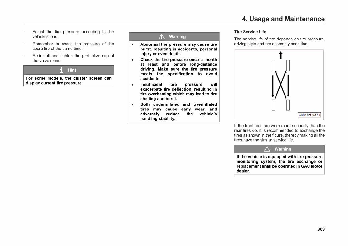
4. Usage and Maintenance
- Adjust the tire pressure according to thevehicle’s load.
– Remember to check the pressure of thespare tire at the same time.
- Re-install and tighten the protective cap ofthe valve stem.
Hint
For some models, the cluster screen can display current tire pressure.
Warning
● Abnormal tire pressure may cause tireburst, resulting in accidents, personalinjury or even death.
● Check the tire pressure once a monthat least and before long-distancedriving. Make sure the tire pressuremeets the specification to avoidaccidents.
● Insufficient tire pressure willexacerbate tire deflection, resulting intire overheating which may lead to tireshelling and burst.
● Both underinflated and overinflatedtires may cause early wear, andadversely reduce the vehicle’shandling stability.
Tire Service Life The service life of tire depends on tire pressure, driving style and tire assembly condition.
If the front tires are worn more seriously than the rear tires do, it is recommended to exchange the tires as shown in the figure, thereby making all the tires have the similar service life.
Warning
If the vehicle is equipped with tire pressure monitoring system, the tire exchange or replacement shall be operated in GAC Motor dealer.
303
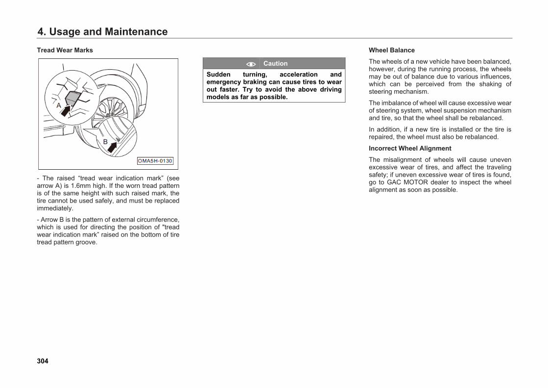
4. Usage and MaintenanceTread Wear Marks
- The raised “tread wear indication mark” (seearrow A) is 1.6mm high. If the worn tread patternis of the same height with such raised mark, thetire cannot be used safely, and must be replacedimmediately.
- Arrow B is the pattern of external circumference,which is used for directing the position of "treadwear indication mark” raised on the bottom of tiretread pattern groove.
Caution Sudden turning, acceleration and emergency braking can cause tires to wear out faster. Try to avoid the above driving models as far as possible.
Wheel Balance The wheels of a new vehicle have been balanced, however, during the running process, the wheels may be out of balance due to various influences, which can be perceived from the shaking of steering mechanism.
The imbalance of wheel will cause excessive wear of steering system, wheel suspension mechanism and tire, so that the wheel shall be rebalanced.
In addition, if a new tire is installed or the tire is repaired, the wheel must also be rebalanced.
Incorrect Wheel Alignment The misalignment of wheels will cause uneven excessive wear of tires, and affect the traveling safety; if uneven excessive wear of tires is found, go to GAC MOTOR dealer to inspect the wheel alignment as soon as possible.
304
4. Usage and Maintenance
4.8 Tire Chain When driving on snow or ice road or in other severe environments in winter, the tire wear degree may increase or other failure may occur. The following suggestions must be observed in order to reduce the failure in winter:
• When driving in deep snow, it is necessary toinstall tire chain. If a tire chain is to beinstalled, an equivalent product with its sizeand type conforming to the tire specificationmust be selected. Otherwise, the vehicleperformance and safety will be adverselyaffected. High risk exists for such operationsas speeding, emergency acceleration,emergency braking and emergency steering.
• When decelerating, make the best of thebraking function of the engine. Emergencybraking on roads with snow or ice will causevehicle drifting or slipping. Keep a safedistance with the front vehicle, slightly treadthe brake pedal, and note that the tire chaininstalled can provide certain force of frictionbut cannot prevent the occurrence of sideslip.
Hint
Different countries and regions have different laws and regulations on tire chain, which shall be referenced before a tire chain is assembled. Do not install a tire chain without understanding the laws and regulations of a country or region, which may restrict the use of tire chain.
Caution If a tire chain is to be installed, make sure that the size and type of the tire chain are consistent with those of the standard tire. Otherwise, the driving safety and maneuverability of the vehicle will be adversely affected. Installing tire chain on all tires shall guarantee the balanced driving under various weather conditions. Keep in mind that the vehicle may be short of power after being installed with tire chain. Drive with care even if the road condition is good. The driving speed shall not exceed the specified speed for tire chain, nor exceed 50km/h, whichever is smaller.
305

4. Usage and Maintenance
4.9 Maintenance Instructions for Car Body Anti-Theft Normal use requires no maintenance. Contact GAC MOTOR dealer when a problem occurs.
306
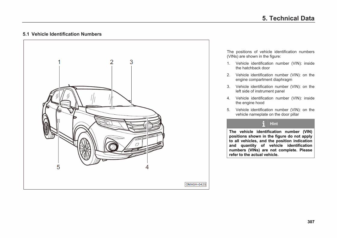
5. Technical Data5. Technical Data
5.1 Vehicle Identification Numbers
The positions of vehicle identification numbers (VINs) are shown in the figure:
1. Vehicle identification number (VIN): insidethe hatchback door
2. Vehicle identification number (VIN): on theengine compartment diaphragm
3. Vehicle identification number (VIN): on theleft side of instrument panel
4. Vehicle identification number (VIN): insidethe engine hood
5. Vehicle identification number (VIN): on thevehicle nameplate on the door pillar
Hint
The vehicle identification number (VIN) positions shown in the figure do not apply to all vehicles, and the position indication and quantity of vehicle identification numbers (VINs) are not complete. Please refer to the actual vehicle.
307

5. Technical DataVehicle Nameplate
1. VIN, model
2. Brand, engine model
3. Engine displacement, rated power
4. Total mass, occupant capacity
5. Manufacturing date and place
Engine number
Engine number - arrow - located in the engine cylinder block (behind the engine)
308
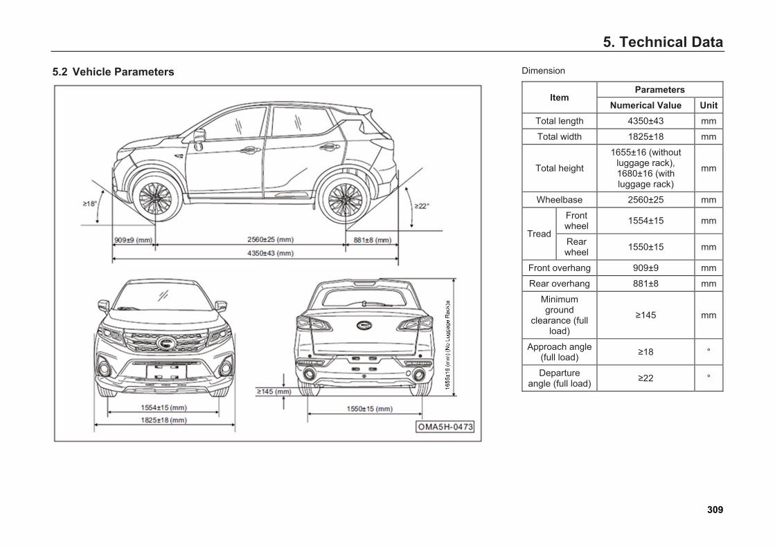
5. Technical Data
5.2 Vehicle Parameters Dimension
Item Parameters
Numerical Value Unit Total length 4350±43 mm
Total width 1825±18 mm
Total height
1655±16 (without luggage rack), 1680±16 (with luggage rack)
mm
Wheelbase 2560±25 mm
Tread
Front wheel 1554±15 mm
Rear wheel 1550±15 mm
Front overhang 909±9 mm
Rear overhang 881±8 mm
Minimum ground
clearance (full load)
≥145 mm
Approach angle (full load) ≥18 °
Departure angle (full load) ≥22 °
309
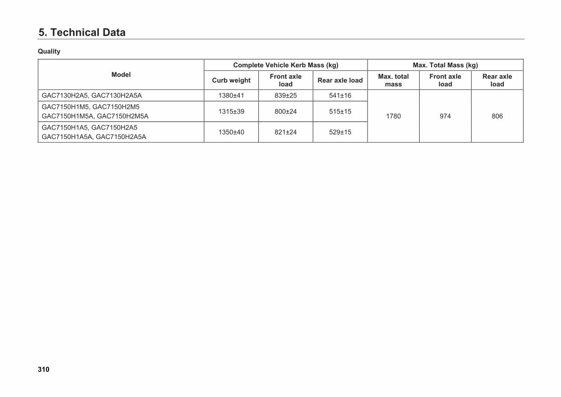
5. Technical DataQuality
Model Complete Vehicle Kerb Mass (kg) Max. Total Mass (kg)
Curb weight Front axle load Rear axle load Max. total
mass Front axle
load Rear axle
load GAC7130H2A5, GAC7130H2A5A 1380±41 839±25 541±16
1780 974 806 GAC7150H1M5, GAC7150H2M5 GAC7150H1M5A, GAC7150H2M5A
1315±39 800±24 515±15
GAC7150H1A5, GAC7150H2A5 GAC7150H1A5A, GAC7150H2A5A
1350±40 821±24 529±15
310
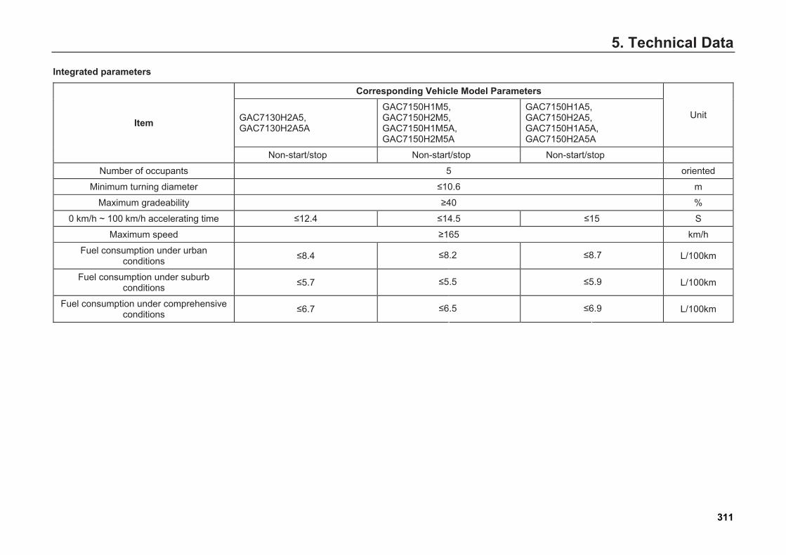
5. Technical Data
Integrated parameters
Item
Corresponding Vehicle Model Parameters
Unit GAC7130H2A5, GAC7130H2A5A
GAC7150H1M5, GAC7150H2M5, GAC7150H1M5A, GAC7150H2M5A
GAC7150H1A5, GAC7150H2A5, GAC7150H1A5A, GAC7150H2A5A
Non-start/stop Non-start/stop Non-start/stop
Number of occupants 5 oriented
Minimum turning diameter ≤10.6 m
Maximum gradeability ≥40 %
0 km/h ~ 100 km/h accelerating time ≤12.4 ≤14.5 ≤15 S
Maximum speed ≥165 km/h
Fuel consumption under urban conditions ≤8.4 ≤8.2 ≤8.7 L/100km
Fuel consumption under suburb conditions ≤5.7 ≤5.5 ≤5.9 L/100km
Fuel consumption under comprehensive conditions ≤6.7 ≤6.5 ≤6.9 L/100km
311
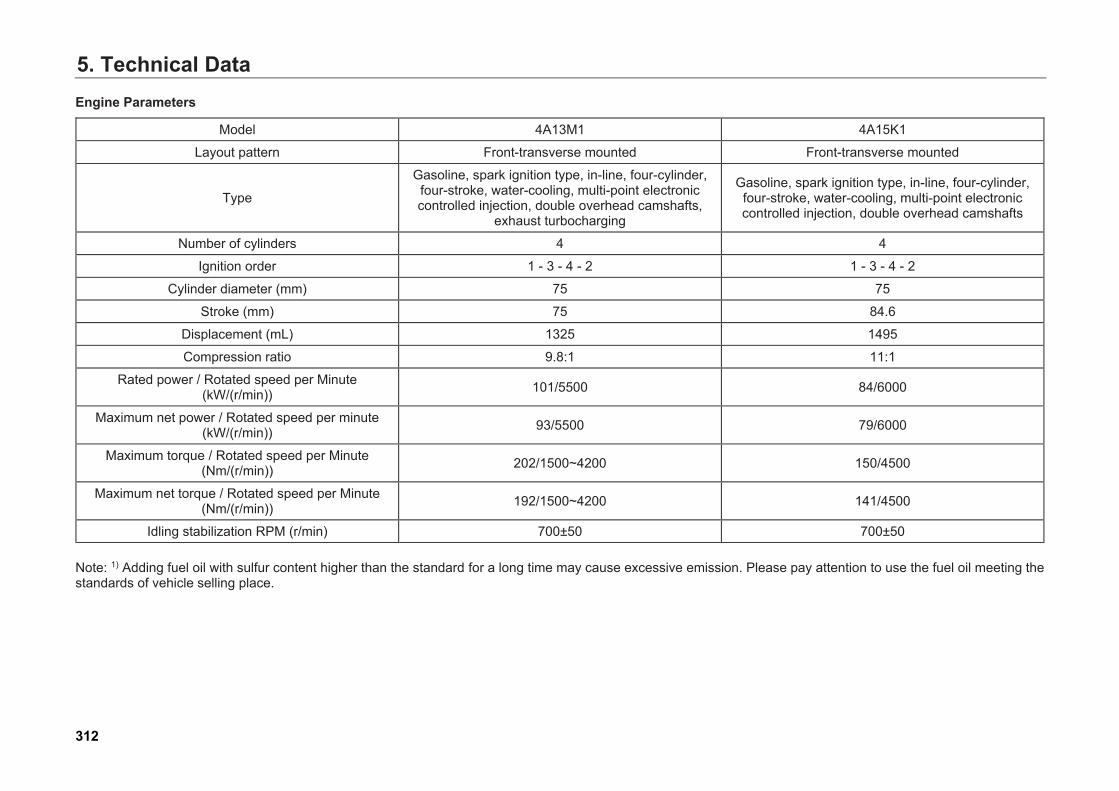
5. Technical DataEngine Parameters
Model 4A13M1 4A15K1
Layout pattern Front-transverse mounted Front-transverse mounted
Type
Gasoline, spark ignition type, in-line, four-cylinder, four-stroke, water-cooling, multi-point electronic controlled injection, double overhead camshafts,
exhaust turbocharging
Gasoline, spark ignition type, in-line, four-cylinder, four-stroke, water-cooling, multi-point electronic controlled injection, double overhead camshafts
Number of cylinders 4 4
Ignition order 1 - 3 - 4 - 2 1 - 3 - 4 - 2
Cylinder diameter (mm) 75 75
Stroke (mm) 75 84.6
Displacement (mL) 1325 1495
Compression ratio 9.8:1 11:1
Rated power / Rotated speed per Minute (kW/(r/min)) 101/5500 84/6000
Maximum net power / Rotated speed per minute (kW/(r/min)) 93/5500 79/6000
Maximum torque / Rotated speed per Minute (Nm/(r/min)) 202/1500~4200 150/4500
Maximum net torque / Rotated speed per Minute (Nm/(r/min)) 192/1500~4200 141/4500
Idling stabilization RPM (r/min) 700±50 700±50
Note: 1) Adding fuel oil with sulfur content higher than the standard for a long time may cause excessive emission. Please pay attention to use the fuel oil meeting the standards of vehicle selling place.
312
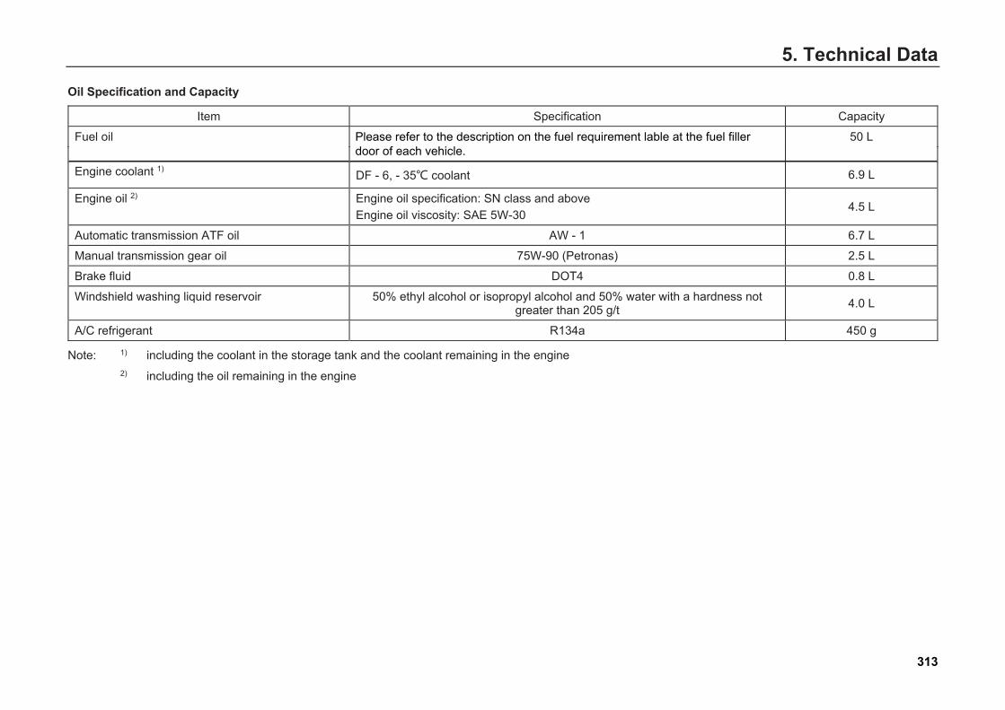
5. Technical Data
Oil Specification and Capacity
Item Specification Capacity
Fuel oil Please refer to the description on the fuel requirement lable at the fuel filler door of each vehicle.
50 L
Engine coolant 1) DF - 6, - 35℃ coolant 6.9 L
Engine oil 2) Engine oil specification: SN class and above Engine oil viscosity: SAE 5W-30
4.5 L
Automatic transmission ATF oil AW - 1 6.7 L
Manual transmission gear oil 75W-90 (Petronas) 2.5 L
Brake fluid DOT4 0.8 L
Windshield washing liquid reservoir 50% ethyl alcohol or isopropyl alcohol and 50% water with a hardness not greater than 205 g/t 4.0 L
A/C refrigerant R134a 450 g
Note: 1) including the coolant in the storage tank and the coolant remaining in the engine2) including the oil remaining in the engine
313
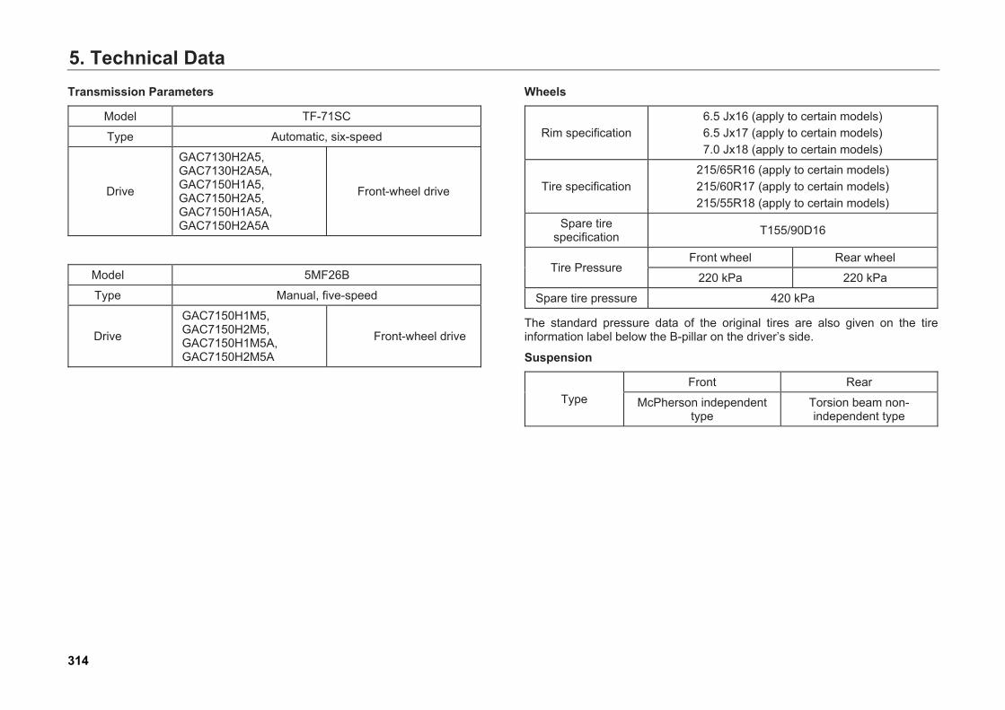
5. Technical DataTransmission Parameters
Model TF-71SC
Type Automatic, six-speed
Drive
GAC7130H2A5, GAC7130H2A5A, GAC7150H1A5, GAC7150H2A5, GAC7150H1A5A, GAC7150H2A5A
Front-wheel drive
Model 5MF26B
Type Manual, five-speed
Drive
GAC7150H1M5, GAC7150H2M5, GAC7150H1M5A, GAC7150H2M5A
Front-wheel drive
Wheels
Rim specification 6.5 Jx16 (apply to certain models) 6.5 Jx17 (apply to certain models) 7.0 Jx18 (apply to certain models)
Tire specification 215/65R16 (apply to certain models) 215/60R17 (apply to certain models) 215/55R18 (apply to certain models)
Spare tire specification T155/90D16
Tire Pressure Front wheel Rear wheel
220 kPa 220 kPa
Spare tire pressure 420 kPa
The standard pressure data of the original tires are also given on the tire information label below the B-pillar on the driver’s side.
Suspension
Type Front Rear
McPherson independent type
Torsion beam non-independent type
314
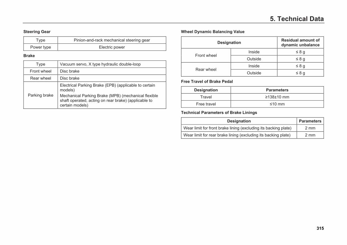
5. Technical Data
Steering Gear
Type Pinion-and-rack mechanical steering gear
Power type Electric power
Brake
Type Vacuum servo, X type hydraulic double-loop
Front wheel Disc brake
Rear wheel Disc brake
Parking brake
Electrical Parking Brake (EPB) (applicable to certain models) Mechanical Parking Brake (MPB) (mechanical flexible shaft operated, acting on rear brake) (applicable to certain models)
Wheel Dynamic Balancing Value
Designation Residual amount of dynamic unbalance
Front wheel Inside ≤ 8 g
Outside ≤ 8 g
Rear wheel Inside ≤ 8 g
Outside ≤ 8 g
Free Travel of Brake Pedal
Designation Parameters Travel ≥138±10 mm
Free travel ≤10 mm
Technical Parameters of Brake Linings
Designation Parameters Wear limit for front brake lining (excluding its backing plate) 2 mm
Wear limit for rear brake lining (excluding its backing plate) 2 mm
315
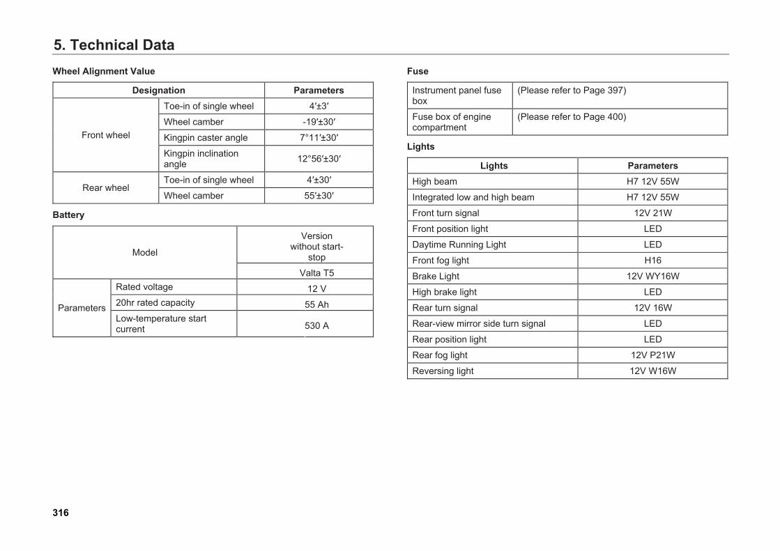
5. Technical DataWheel Alignment Value
Designation Parameters
Front wheel
Toe-in of single wheel 4′±3′
Wheel camber -19′±30′
Kingpin caster angle 7°11′±30′
Kingpin inclination angle 12°56′±30′
Rear wheel Toe-in of single wheel 4′±30′
Wheel camber 55′±30′
Battery
Model
Version without start-
stop
Valta T5
Parameters
Rated voltage 12 V 20hr rated capacity 55 Ah Low-temperature start current 530 A
Fuse
Instrument panel fuse box
(Please refer to Page 397)
Fuse box of engine compartment
(Please refer to Page 400)
Lights
Lights Parameters High beam H7 12V 55W
Integrated low and high beam H7 12V 55W
Front turn signal 12V 21W
Front position light LED
Daytime Running Light LED
Front fog light H16
Brake Light 12V WY16W
High brake light LED
Rear turn signal 12V 16W
Rear-view mirror side turn signal LED
Rear position light LED
Rear fog light 12V P21W
Reversing light 12V W16W
316
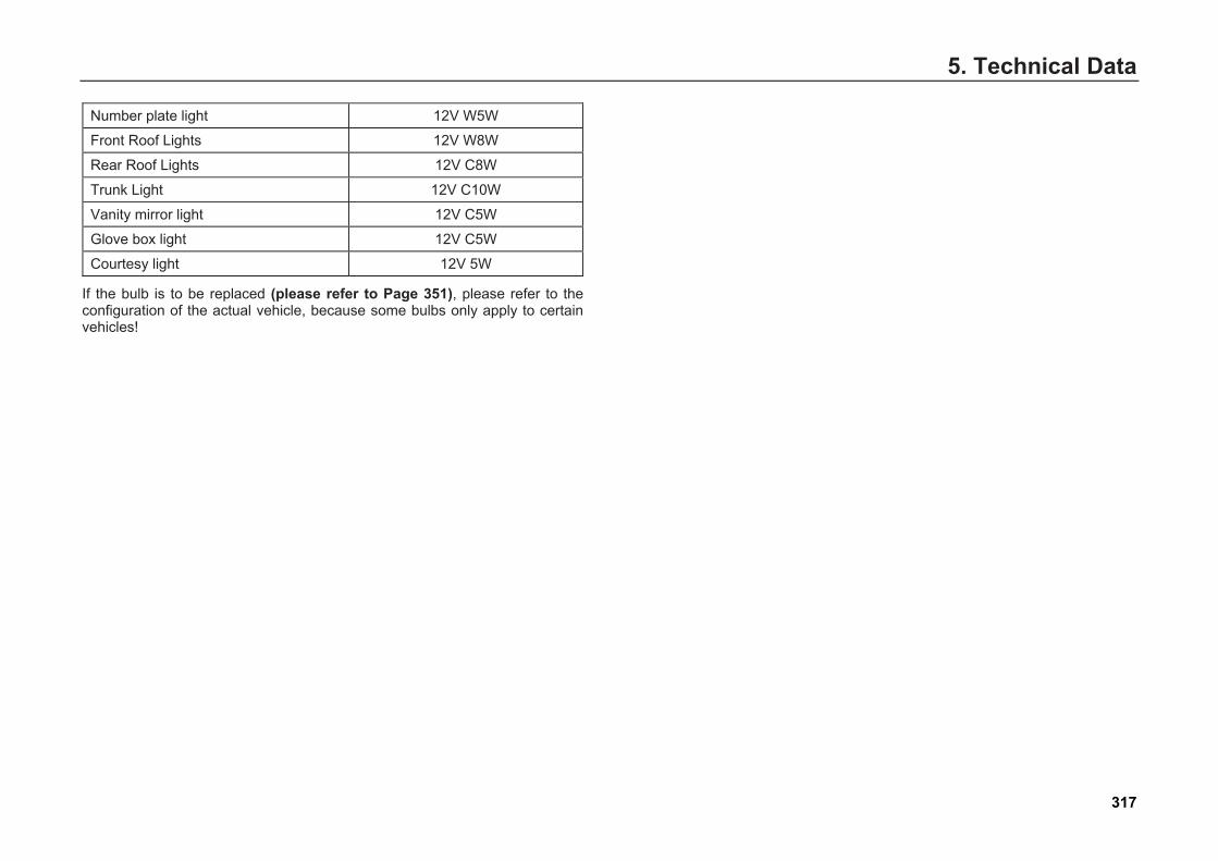
5. Technical Data
Number plate light 12V W5W
Front Roof Lights 12V W8W
Rear Roof Lights 12V C8W
Trunk Light 12V C10W
Vanity mirror light 12V C5W
Glove box light 12V C5W
Courtesy light 12V 5W
If the bulb is to be replaced (please refer to Page 351), please refer to the configuration of the actual vehicle, because some bulbs only apply to certain vehicles!
317


6. Handling of Accident6. Handling of Accident
6.1 Vehicle Tools and Spare Tire Vehicle Tools
The vehicle tools include the following:
1. Jack
2. Warning triangle
3. Towing hook
4. Removal wrench for wheel bolts
5. Special wrench for jack
Caution After using a jack, recover it to the state before use, and then place the special spanner for jack and the jack into the accompanied foam tool box.
Warning
● Tighten the wheel bolts according tothe specified torque correctly. Failureto do so may make the bolts becomeloose when the vehicle is moving,resulting in accidents.
● Be sure to tighten the wheel bolts withthe special wrench provided on thevehicle.
Warning
Improper use of the jack may cause serious damage. ● Only use the jack on solid and level
ground.● Only use your jack to jack up your
vehicle. Do not use your jack to jack upother weights or vehicles.
● Do not start the engine when using thejack. Doing so can cause accidents.
● To avoid the risk of personal injury, donot put any part of your body under thevehicle when the vehicle is on the jack.
● Place appropriate protective supportunder the vehicle if the operation has tobe done under the vehicle.
319
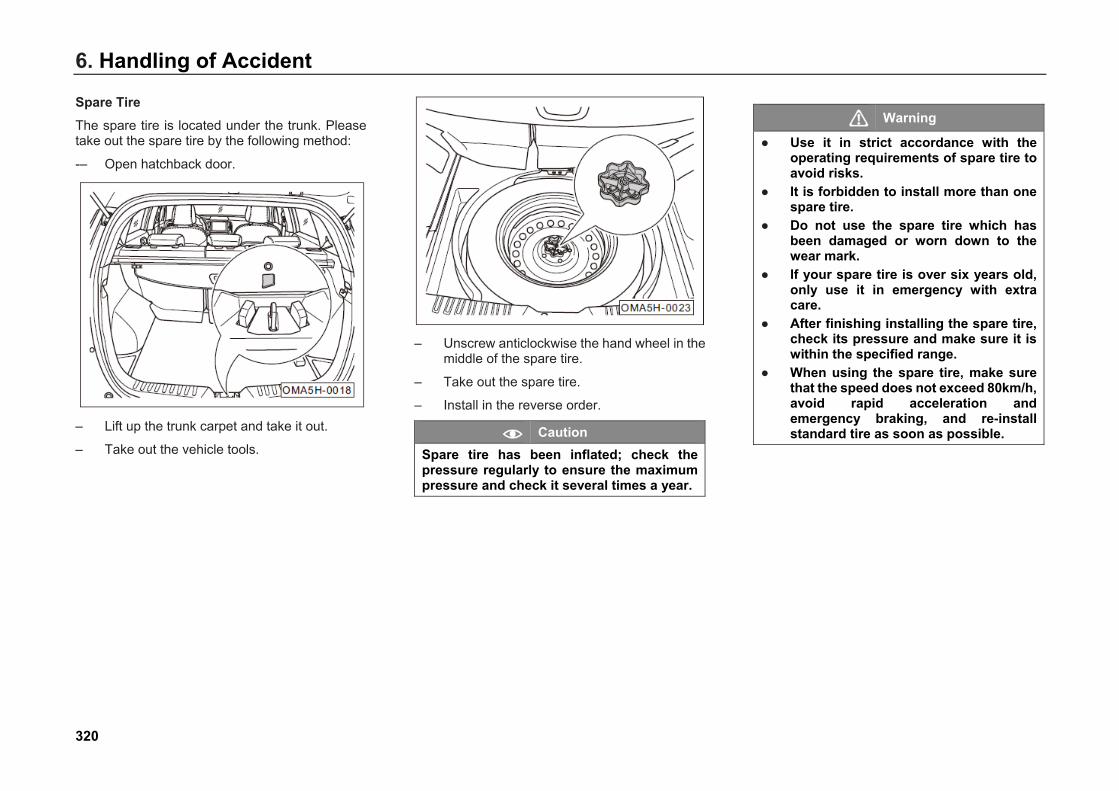
6. Handling of Accident
Spare Tire The spare tire is located under the trunk. Please take out the spare tire by the following method:
-– Open hatchback door.
– Lift up the trunk carpet and take it out.
– Take out the vehicle tools.
– Unscrew anticlockwise the hand wheel in themiddle of the spare tire.
– Take out the spare tire.
– Install in the reverse order.
Caution Spare tire has been inflated; check the pressure regularly to ensure the maximum pressure and check it several times a year.
Warning
● Use it in strict accordance with theoperating requirements of spare tire toavoid risks.
● It is forbidden to install more than onespare tire.
● Do not use the spare tire which hasbeen damaged or worn down to thewear mark.
● If your spare tire is over six years old,only use it in emergency with extracare.
● After finishing installing the spare tire,check its pressure and make sure it iswithin the specified range.
● When using the spare tire, make surethat the speed does not exceed 80km/h,avoid rapid acceleration andemergency braking, and re-installstandard tire as soon as possible.
320
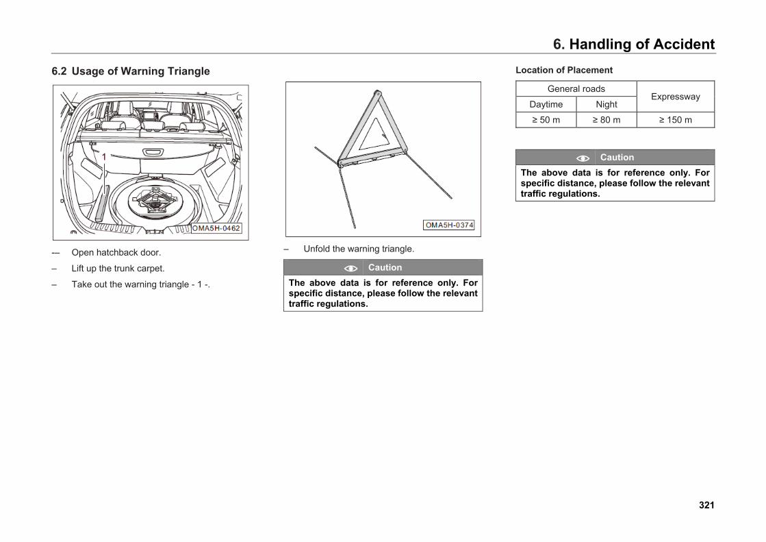
6. Handling of Accident
6.2 Usage of Warning Triangle
-– Open hatchback door.
– Lift up the trunk carpet.
– Take out the warning triangle - 1 -.
– Unfold the warning triangle.
Caution The above data is for reference only. For specific distance, please follow the relevant traffic regulations.
Location of Placement
General roads Expressway
Daytime Night
≥ 50 m ≥ 80 m ≥ 150 m
Caution The above data is for reference only. For specific distance, please follow the relevant traffic regulations.
321
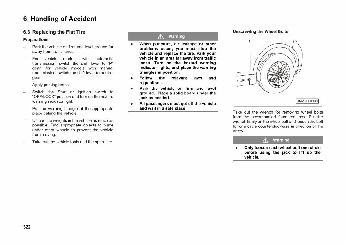
6. Handling of Accident
6.3 Replacing the Flat Tire Preparations – Park the vehicle on firm and level ground far
away from traffic lanes.
– For vehicle models with automatictransmission, switch the shift lever to “P”gear; for vehicle models with manualtransmission, switch the shift lever to neutralgear.
– Apply parking brake.
– Switch the Start or Ignition switch to“OFF/LOCK” position and turn on the hazardwarning indicator light.
– Put the warning triangle at the appropriateplace behind the vehicle.
– Unload the weights in the vehicle as much aspossible. Find appropriate objects to placeunder other wheels to prevent the vehiclefrom moving.
– Take out the vehicle tools and the spare tire.
Warning
● When puncture, air leakage or otherproblems occur, you must stop thevehicle and replace the tire. Park yourvehicle in an area far away from trafficlanes. Turn on the hazard warningindicator lights, and place the warningtriangles in position.
● Follow the relevant laws andregulations.
● Park the vehicle on firm and levelground. Place a solid board under thejack as needed.
● All passengers must get off the vehicleand wait in a safe place.
Unscrewing the Wheel Bolts
Take out the wrench for removing wheel bolts from the accompanied foam tool box. Put the wrench firmly on the wheel bolt and loosen the bolt for one circle counterclockwise in direction of the arrow.
Warning
● Only loosen each wheel bolt one circlebefore using the jack to lift up thevehicle.
322
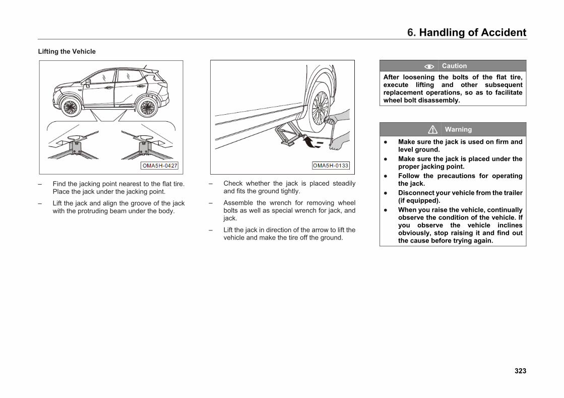
6. Handling of AccidentLifting the Vehicle
– Find the jacking point nearest to the flat tire.Place the jack under the jacking point.
– Lift the jack and align the groove of the jackwith the protruding beam under the body.
– Check whether the jack is placed steadilyand fits the ground tightly.
– Assemble the wrench for removing wheelbolts as well as special wrench for jack, andjack.
– Lift the jack in direction of the arrow to lift thevehicle and make the tire off the ground.
Caution After loosening the bolts of the flat tire, execute lifting and other subsequent replacement operations, so as to facilitate wheel bolt disassembly.
Warning
● Make sure the jack is used on firm andlevel ground.
● Make sure the jack is placed under theproper jacking point.
● Follow the precautions for operatingthe jack.
● Disconnect your vehicle from the trailer(if equipped).
● When you raise the vehicle, continuallyobserve the condition of the vehicle. Ifyou observe the vehicle inclinesobviously, stop raising it and find outthe cause before trying again.
323
6. Handling of Accident
Removing the Flat Tire – Remove the wheel bolts with the wrench with
the tire off the ground.
– Remove the flat tire.
Installing the Spare Tire– Mount the spare tire on the vehicle.
– Put all wheel bolts back, and pre-tightenthem with the wrench.
– Lower the vehicle.
– Tighten all wheel bolts with the wrench.
Caution ● Tighten them in diagonal sequence.● After installing the wheel, go to GAC
MOTOR dealer to inspect the tighteningtorque of wheel bolts as soon aspossible (which is 120±10 N·m).
Warning
Keep the threads of the wheel bolts and hub clean, and make sure the bolts can be screwed easily. No grease or other attachment is permitted.
Notification of Tire Replacement ● The replaced tire shall be timely and correctly
placed into the spare tire installation position.
● Clean the tools and put them to the originalposition after use.
● Check the tightening torque of the wheelbolts as soon as possible.
● Change the damaged tire as soon aspossible.
● When a tire is replaced, if any bolt is corrodedor difficult to screw, replace it and clean thethreaded hole before checking the wheelbolt’s tightening torque.
Caution The spare tire/replaced tire must be securely fixed on the spare tire installation position.
324
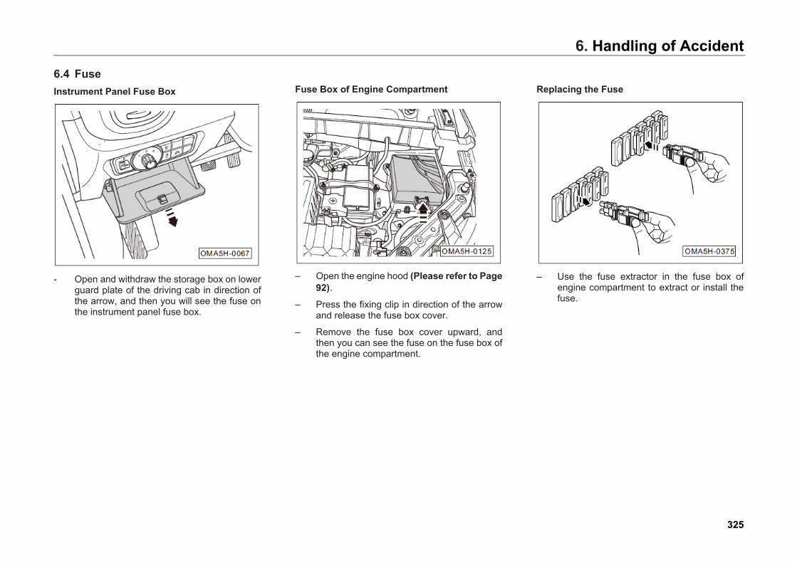
6. Handling of Accident
6.4 Fuse Instrument Panel Fuse Box
- Open and withdraw the storage box on lowerguard plate of the driving cab in direction ofthe arrow, and then you will see the fuse onthe instrument panel fuse box.
Fuse Box of Engine Compartment
– Open the engine hood (Please refer to Page92).
– Press the fixing clip in direction of the arrowand release the fuse box cover.
– Remove the fuse box cover upward, andthen you can see the fuse on the fuse box ofthe engine compartment.
Replacing the Fuse
– Use the fuse extractor in the fuse box ofengine compartment to extract or install thefuse.
325
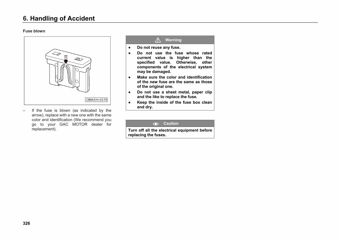
6. Handling of Accident
Fuse blown
– If the fuse is blown (as indicated by thearrow), replace with a new one with the samecolor and identification (We recommend yougo to your GAC MOTOR dealer forreplacement).
Warning
● Do not reuse any fuse.● Do not use the fuse whose rated
current value is higher than thespecified value. Otherwise, othercomponents of the electrical systemmay be damaged.
● Make sure the color and identificationof the new fuse are the same as thoseof the original one.
● Do not use a sheet metal, paper clipand the like to replace the fuse.
● Keep the inside of the fuse box cleanand dry.
Caution Turn off all the electrical equipment before replacing the fuses.
326
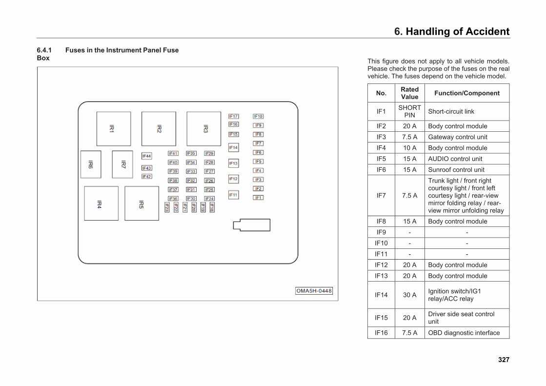
6. Handling of Accident6.4.1 Fuses in the Instrument Panel Fuse Box This figure does not apply to all vehicle models.
Please check the purpose of the fuses on the real vehicle. The fuses depend on the vehicle model.
No. Rated Value Function/Component
IF1 SHORT PIN Short-circuit link
IF2 20 A Body control module
IF3 7.5 A Gateway control unit
IF4 10 A Body control module
IF5 15 A AUDIO control unit
IF6 15 A Sunroof control unit
IF7 7.5 A
Trunk light / front right courtesy light / front left courtesy light / rear-view mirror folding relay / rear-view mirror unfolding relay
IF8 15 A Body control module
IF9 - -
IF10 - -
IF11 - -
IF12 20 A Body control module
IF13 20 A Body control module
IF14 30 A Ignition switch/IG1 relay/ACC relay
IF15 20 A Driver side seat control unit
IF16 7.5 A OBD diagnostic interface
327
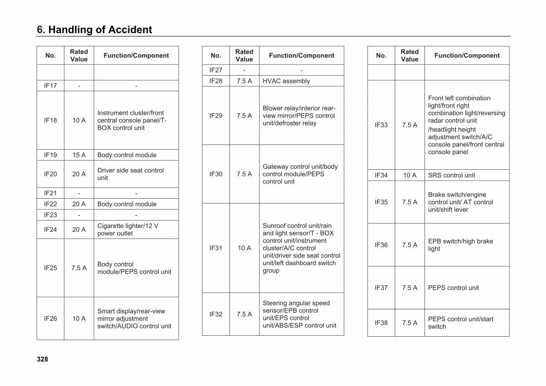
6. Handling of Accident
No. Rated Value Function/Component
IF17 - -
IF18 10 A Instrument cluster/front central console panel/T-BOX control unit
IF19 15 A Body control module
IF20 20 A Driver side seat control unit
IF21 - -
IF22 20 A Body control module
IF23 - -
IF24 20 A Cigarette lighter/12 V power outlet
IF25 7.5 A Body control module/PEPS control unit
IF26 10 A Smart display/rear-view mirror adjustment switch/AUDIO control unit
No. Rated Value Function/Component
IF27 - -
IF28 7.5 A HVAC assembly
IF29 7.5 A Blower relay/interior rear-view mirror/PEPS control unit/defroster relay
IF30 7.5 A Gateway control unit/body control module/PEPS control unit
IF31 10 A
Sunroof control unit/rain and light sensor/T - BOX control unit/instrument cluster/A/C control unit/driver side seat control unit/left dashboard switch group
IF32 7.5 A
Steering angular speed sensor/EPB control unit/EPS control unit/ABS/ESP control unit
No. Rated Value Function/Component
IF33 7.5 A
Front left combination light/front right combination light/reversing radar control unit /headlight height adjustment switch/A/C console panel/front central console panel
IF34 10 A SRS control unit
IF35 7.5 A Brake switch/engine control unit/ AT control unit/shift lever
IF36 7.5 A EPB switch/high brake light
IF37 7.5 A PEPS control unit
IF38 7.5 A PEPS control unit/start switch
328
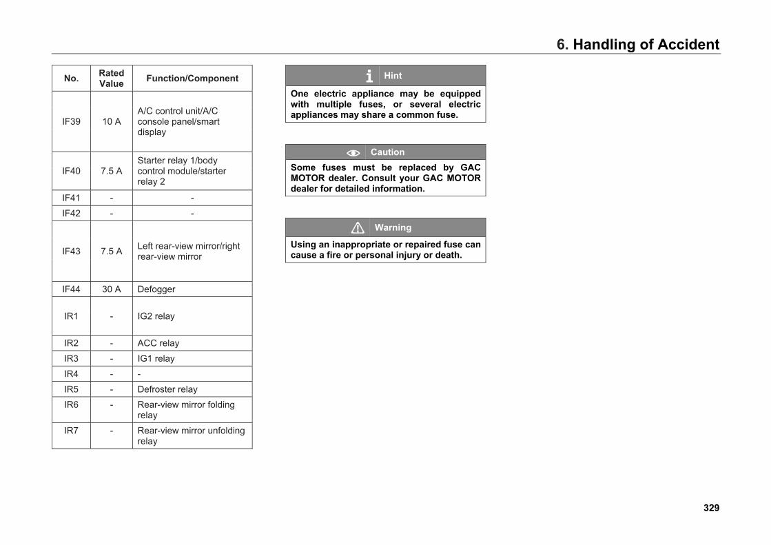
6. Handling of Accident
No. Rated Value Function/Component
IF39 10 A A/C control unit/A/C console panel/smart display
IF40 7.5 A Starter relay 1/body control module/starter relay 2
IF41 - -
IF42 - -
IF43 7.5 A Left rear-view mirror/right rear-view mirror
IF44 30 A Defogger
IR1 - IG2 relay
IR2 - ACC relay
IR3 - IG1 relay
IR4 - -
IR5 - Defroster relay
IR6 - Rear-view mirror folding relay
IR7 - Rear-view mirror unfolding relay
Hint
One electric appliance may be equipped with multiple fuses, or several electric appliances may share a common fuse.
Caution Some fuses must be replaced by GAC MOTOR dealer. Consult your GAC MOTOR dealer for detailed information.
Warning
Using an inappropriate or repaired fuse can cause a fire or personal injury or death.
329
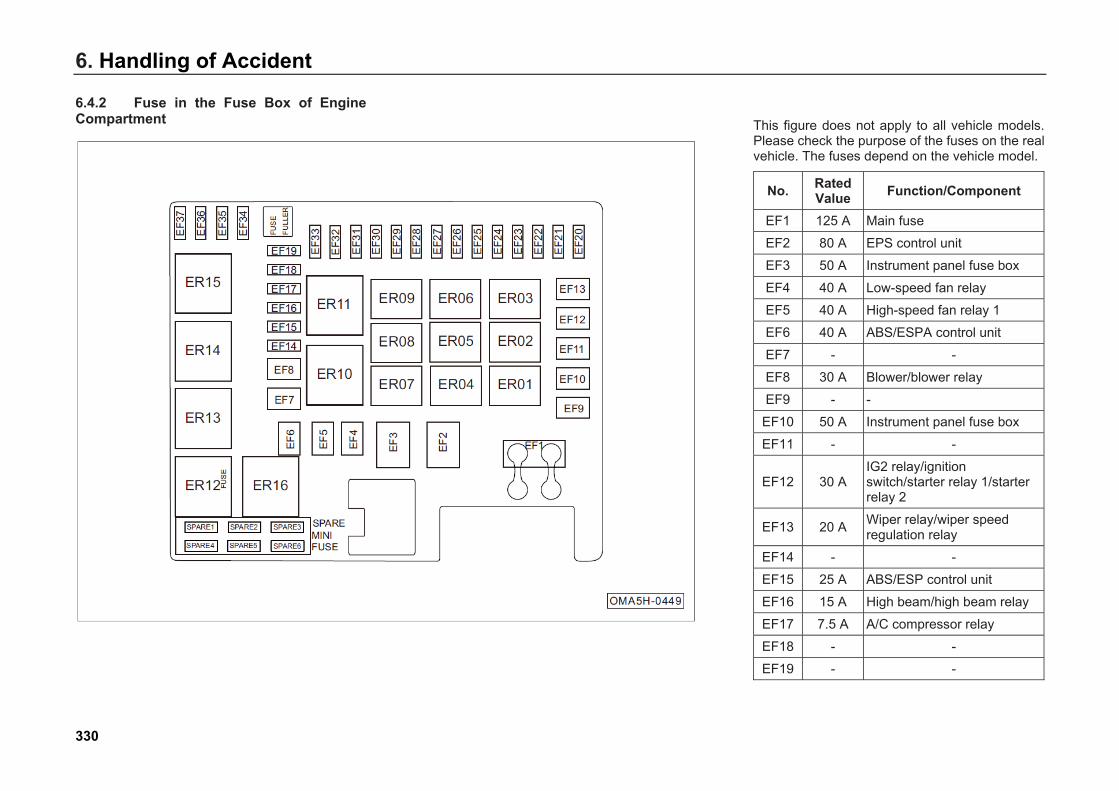
6. Handling of Accident
6.4.2 Fuse in the Fuse Box of Engine Compartment This figure does not apply to all vehicle models.
Please check the purpose of the fuses on the real vehicle. The fuses depend on the vehicle model.
No. Rated Value Function/Component
EF1 125 A Main fuse
EF2 80 A EPS control unit
EF3 50 A Instrument panel fuse box
EF4 40 A Low-speed fan relay
EF5 40 A High-speed fan relay 1
EF6 40 A ABS/ESPA control unit
EF7 - -
EF8 30 A Blower/blower relay
EF9 - -
EF10 50 A Instrument panel fuse box
EF11 - -
EF12 30 A IG2 relay/ignition switch/starter relay 1/starter relay 2
EF13 20 A Wiper relay/wiper speed regulation relay
EF14 - -
EF15 25 A ABS/ESP control unit
EF16 15 A High beam/high beam relay
EF17 7.5 A A/C compressor relay
EF18 - -
EF19 - -
330
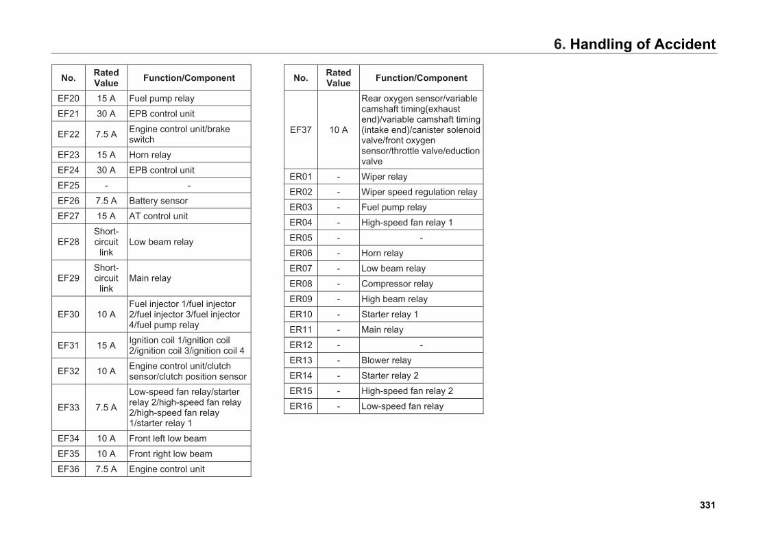
6. Handling of Accident
No. Rated Value Function/Component
EF20 15 A Fuel pump relay
EF21 30 A EPB control unit
EF22 7.5 A Engine control unit/brake switch
EF23 15 A Horn relay
EF24 30 A EPB control unit
EF25 - -
EF26 7.5 A Battery sensor
EF27 15 A AT control unit
EF28 Short-circuit
link Low beam relay
EF29 Short-circuit
link Main relay
EF30 10 A Fuel injector 1/fuel injector 2/fuel injector 3/fuel injector 4/fuel pump relay
EF31 15 A Ignition coil 1/ignition coil 2/ignition coil 3/ignition coil 4
EF32 10 A Engine control unit/clutch sensor/clutch position sensor
EF33 7.5 A
Low-speed fan relay/starter relay 2/high-speed fan relay 2/high-speed fan relay 1/starter relay 1
EF34 10 A Front left low beam
EF35 10 A Front right low beam
EF36 7.5 A Engine control unit
No. Rated Value Function/Component
EF37 10 A
Rear oxygen sensor/variable camshaft timing(exhaust end)/variable camshaft timing (intake end)/canister solenoid valve/front oxygen sensor/throttle valve/eduction valve
ER01 - Wiper relay
ER02 - Wiper speed regulation relay
ER03 - Fuel pump relay
ER04 - High-speed fan relay 1
ER05 - -
ER06 - Horn relay
ER07 - Low beam relay
ER08 - Compressor relay
ER09 - High beam relay
ER10 - Starter relay 1
ER11 - Main relay
ER12 - -
ER13 - Blower relay
ER14 - Starter relay 2
ER15 - High-speed fan relay 2
ER16 - Low-speed fan relay
331
6. Handling of Accident
Hint
One electric appliance may be equipped with multiple fuses, or several electric appliances may share a common fuse.
Caution Some fuses must be replaced by GAC MOTOR dealer. Consult your GAC MOTOR dealer for detailed information.
Warning
Using an inappropriate or repaired fuse can cause a fire or personal injury or death.
332

6. Handling of Accident
6.5 Emergency Start Jumper Cable If you cannot start the engine because of low battery energy, you can use the jumper cable to connect with another vehicle’s battery to start the engine.
Caution When jump starting, two cars cannot contact with each other. Otherwise, once the positive terminals of the two batteries are connected, the current is turned on immediately.
Warning
● Engine compartment is a dangerousarea. Improper operation may causeinjuries or deaths.
● Before the operation of storage battery,be sure to carefully read and observethe safety warning descriptions relatedto storage battery operation.
Connect the positive terminals of the batteries before connecting the negative ones.
– Switch the Start or Ignition switch to“OFF/LOCK” position.
– Connect one end (-1-) of the red cable to thepositive electrode (+) of flat battery “A”, andconnect the other end (-2-) to the positiveelectrode (+) of booster battery “B”.
– Connect one end (-3-) of the black cable tothe negative electrode (-) of booster battery“B”, and connect the other end (-4-) to theengine cylinder block or the metalcomponent securely connecting with theengine cylinder block of the vehicle with flatbattery “A”.
Caution Place the jumper cables in position to prevent them from touching the moving parts of the engine.
– Start the engine of the vehicle with boosterbattery and let it idle, and then start theengine of the vehicle with flat battery until theengine runs smoothly.
Warning
● Do not remove the jumper cables untilthe headlights have been turned off.
● Turn on the air blower and rearwindshield heater in the vehicle withflat battery to reduce the voltage peakresulting from removing the cables.
● Once your engine is running,disconnect the jumper cable in reversesequence.
333
6. Handling of Accident
Warning
A battery can explode if you cannot use the jumper cable properly, seriously injuring anyone nearby. ● Make sure the voltage of the booster
battery is equal to that of the flatbattery, and the capacity of the boosterbattery is similar to that of the flatbattery. Otherwise, it may causeexplosion.
● Keep open flames away from thebattery to avoid explosion.
● Do not connect the negative cable tothe negative electrode of the flat batterydirectly. Make sure there is no staticnear the battery. Otherwise,combustible gas produced by thebattery can be ignited by sparks,causing explosion.
● Do not connect the negative cable tothe fuel system component or brakepipe. During operation, do not face thebattery to avoid acid burns.
334
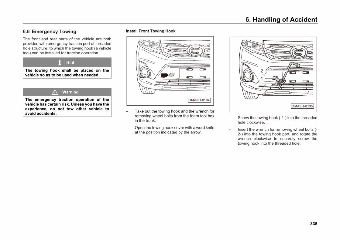
6. Handling of Accident
6.6 Emergency Towing The front and rear parts of the vehicle are both provided with emergency traction port of threaded hole structure, to which the towing hook (a vehicle tool) can be installed for traction operation.
Hint
The towing hook shall be placed on the vehicle so as to be used when needed.
Warning
The emergency traction operation of the vehicle has certain risk. Unless you have the experience, do not tow other vehicle to avoid accidents.
Install Front Towing Hook
– Take out the towing hook and the wrench forremoving wheel bolts from the foam tool boxin the trunk.
– Open the towing hook cover with a word knifeat the position indicated by the arrow.
– Screw the towing hook (-1-) into the threadedhole clockwise.
– Insert the wrench for removing wheel bolts (-2-) into the towing hook port, and rotate thewrench clockwise to securely screw thetowing hook into the threaded hole.
335
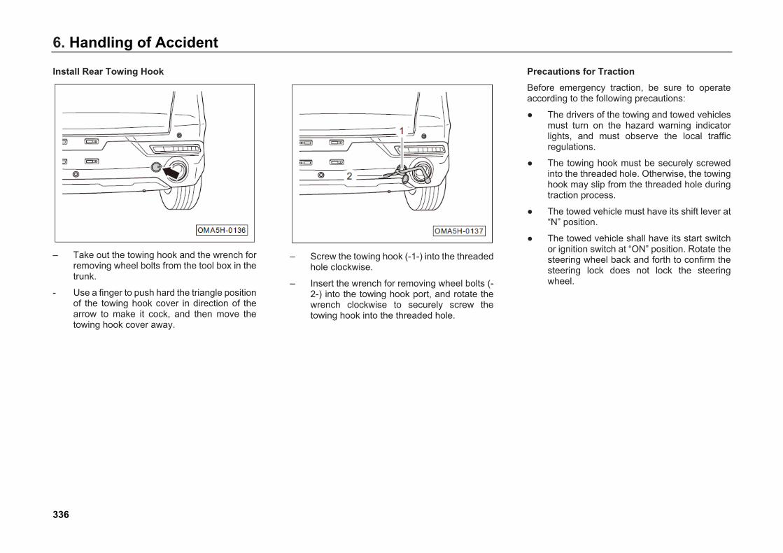
6. Handling of Accident
Install Rear Towing Hook
– Take out the towing hook and the wrench forremoving wheel bolts from the tool box in thetrunk.
- Use a finger to push hard the triangle positionof the towing hook cover in direction of thearrow to make it cock, and then move thetowing hook cover away.
– Screw the towing hook (-1-) into the threadedhole clockwise.
– Insert the wrench for removing wheel bolts (-2-) into the towing hook port, and rotate thewrench clockwise to securely screw thetowing hook into the threaded hole.
Precautions for Traction Before emergency traction, be sure to operate according to the following precautions:
● The drivers of the towing and towed vehiclesmust turn on the hazard warning indicatorlights, and must observe the local trafficregulations.
● The towing hook must be securely screwedinto the threaded hole. Otherwise, the towinghook may slip from the threaded hole duringtraction process.
● The towed vehicle must have its shift lever at“N” position.
● The towed vehicle shall have its start switchor ignition switch at “ON” position. Rotate thesteering wheel back and forth to confirm thesteering lock does not lock the steeringwheel.
336
6. Handling of AccidentDuring emergency traction process, be sure to operate according to the following precautions:
● Start and move slowly until the tow ropestrains, and then accelerate gradually.
● Drive smoothly, and do not accelerate,decelerate or turn sharply.
● Always remember that the brake booster andsteering booster of the towed vehicle will notwork. Normally, press the brake pedal inadvance but press it slightly.
● During the traction operation, the tow ropemust always be strained.
If the vehicle transmission suffers oil leakage, during the emergency traction, only the driving wheel of the vehicle can be lifted for traction, and:
● The towing speed shall not be greater than50 km/h.
● The maximum towing distance shall be 50km.
Warning
● The oil pump of the transmissioncannot work when the engine is off. Ifthe driving wheel rotates on theground, the transmission will be at aworking condition of poor lubricationwhen the vehicle is towed at a highspeed and for a long distance, whichwill damage the transmission.
● Please do not lift the rear traction of thevehicle, otherwise the wheel will rotatebackwards, and the gear intransmission will reach a very highrotating speed, causing seriousdamage to the transmission within ashort time.
Towing If your car has an accident and requires to be towed, we suggest using a platform truck to tow your car. If it is not available, you can also use a wheeled truck to tow your car if necessary.
Select proper towing method according to the configuration and fault condition of your car. But the following precautions must be noted:
● Contact your GAC MOTOR dealer or theprofessional towing company for towing, anddo not tow the vehicle by yourself without fullconfidence, otherwise the vehicle is veryeasy to be damaged.
● All towing methods require the use of safetychain system and shall comply with relevanttraffic laws.
● You must tow your car according to thespecification; otherwise it may cause thedamage to your car and threaten trafficsafety.
337

6. Handling of Accident
Tow the Car by Using a Platform Truck
This towing method is applicable to all models of fault cars. We suggest using this method as much as possible.
Caution Pay attention to apply parking brake and fix four wheels, to prevent the vehicle from moving during emergency braking of the trailer.
Tow the Car from the Front by Using a Wheeled Truck
If your vehicle’s rear wheels and rear axle are damaged, the towing platform must be placed beneath your vehicle’s rear wheels.
Caution ● For cars equipped with electronic
parking brake (EPB) or four-wheel drivecars, when they are towed, towingplatform must be placed under the rearwheels. Otherwise, components likethe brake, tires and four-wheeltransmission system are easilydamaged.
● When lifting the front part of thevehicle, guarantee that appropriateground clearance shall be reserved forthe rear part, otherwise the outer coverof rear bumper or underbody of thetowed vehicle may be damaged.
338
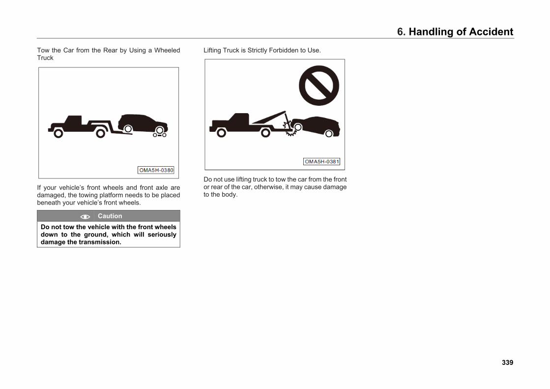
6. Handling of AccidentTow the Car from the Rear by Using a Wheeled Truck
If your vehicle’s front wheels and front axle are damaged, the towing platform needs to be placed beneath your vehicle’s front wheels.
Caution Do not tow the vehicle with the front wheels down to the ground, which will seriously damage the transmission.
Lifting Truck is Strictly Forbidden to Use.
Do not use lifting truck to tow the car from the front or rear of the car, otherwise, it may cause damage to the body.
339

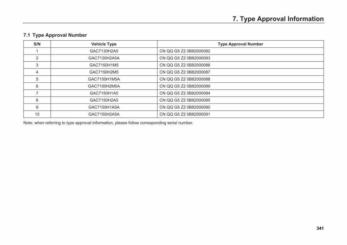
7. Type Approval Information7. Type Approval Information
7.1 Type Approval Number
S/N Vehicle Type Type Approval Number 1 GAC7130H2A5 CN QQ G5 Z2 0B82000082
2 GAC7130H2A5A CN QQ G5 Z2 0B82000083
3 GAC7150H1M5 CN QQ G5 Z2 0B82000086
4 GAC7150H2M5 CN QQ G5 Z2 0B82000087
5 GAC7150H1M5A CN QQ G5 Z2 0B82000088
6 GAC7150H2M5A CN QQ G5 Z2 0B82000089
7 GAC7150H1A5 CN QQ G5 Z2 0B82000084
8 GAC7150H2A5 CN QQ G5 Z2 0B82000085
9 GAC7150H1A5A CN QQ G5 Z2 0B82000090
10 GAC7150H2A5A CN QQ G5 Z2 0B82000091
Note: when referring to type approval information, please follow corresponding serial number.
341
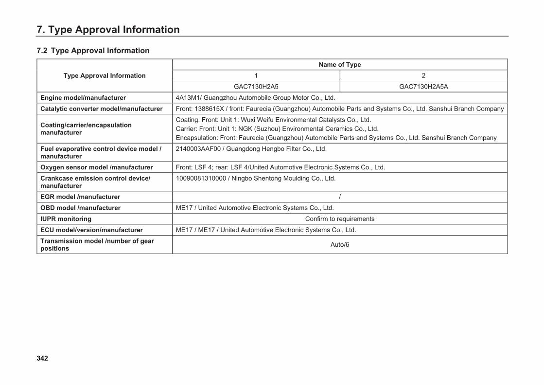
7. Type Approval Information
7.2 Type Approval Information
Type Approval Information Name of Type
1 2
GAC7130H2A5 GAC7130H2A5A
Engine model/manufacturer 4A13M1/ Guangzhou Automobile Group Motor Co., Ltd.
Catalytic converter model/manufacturer Front: 1388615X / front: Faurecia (Guangzhou) Automobile Parts and Systems Co., Ltd. Sanshui Branch Company
Coating/carrier/encapsulation manufacturer
Coating: Front: Unit 1: Wuxi Weifu Environmental Catalysts Co., Ltd. Carrier: Front: Unit 1: NGK (Suzhou) Environmental Ceramics Co., Ltd. Encapsulation: Front: Faurecia (Guangzhou) Automobile Parts and Systems Co., Ltd. Sanshui Branch Company
Fuel evaporative control device model / manufacturer
2140003AAF00 / Guangdong Hengbo Filter Co., Ltd.
Oxygen sensor model /manufacturer Front: LSF 4; rear: LSF 4/United Automotive Electronic Systems Co., Ltd.
Crankcase emission control device/ manufacturer
10090081310000 / Ningbo Shentong Moulding Co., Ltd.
EGR model /manufacturer /
OBD model /manufacturer ME17 / United Automotive Electronic Systems Co., Ltd.
IUPR monitoring Confirm to requirements
ECU model/version/manufacturer ME17 / ME17 / United Automotive Electronic Systems Co., Ltd.
Transmission model /number of gear positions Auto/6
342
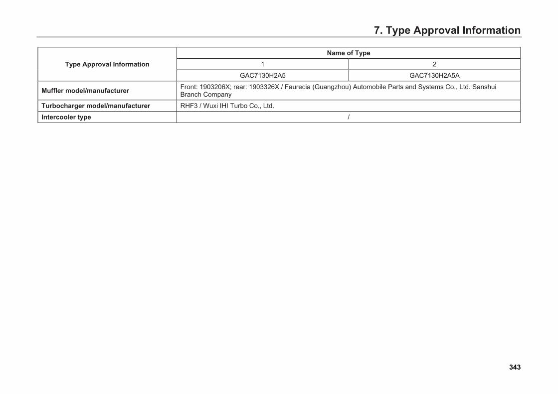
7. Type Approval Information
Type Approval Information Name of Type
1 2
GAC7130H2A5 GAC7130H2A5A
Muffler model/manufacturer Front: 1903206X; rear: 1903326X / Faurecia (Guangzhou) Automobile Parts and Systems Co., Ltd. Sanshui Branch Company
Turbocharger model/manufacturer RHF3 / Wuxi IHI Turbo Co., Ltd.
Intercooler type /
343
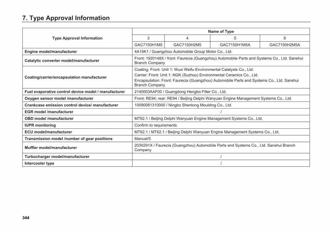
7. Type Approval Information
Type Approval Information Name of Type
3 4 5 6
GAC7150H1M5 GAC7150H2M5 GAC7150H1M5A GAC7150H2M5A
Engine model/manufacturer 4A15K1 / Guangzhou Automobile Group Motor Co., Ltd.
Catalytic converter model/manufacturer Front: 1920148X / front: Faurecia (Guangzhou) Automobile Parts and Systems Co., Ltd. Sanshui Branch Company
Coating/carrier/encapsulation manufacturer
Coating: Front: Unit 1: Wuxi Weifu Environmental Catalysts Co., Ltd. Carrier: Front: Unit 1: NGK (Suzhou) Environmental Ceramics Co., Ltd. Encapsulation: Front: Faurecia (Guangzhou) Automobile Parts and Systems Co., Ltd. Sanshui Branch Company
Fuel evaporative control device model / manufacturer 2140003AAF00 / Guangdong Hengbo Filter Co., Ltd.
Oxygen sensor model /manufacturer Front: RE94; rear: RE94 / Beijing Delphi Wanyuan Engine Management Systems Co., Ltd.
Crankcase emission control device/ manufacturer 10090081310000 / Ningbo Shentong Moulding Co., Ltd.
EGR model /manufacturer /
OBD model /manufacturer MT62.1 / Beijing Delphi Wanyuan Engine Management Systems Co., Ltd.
IUPR monitoring Confirm to requirements
ECU model/manufacturer MT62.1 / MT62.1 / Beijing Delphi Wanyuan Engine Management Systems Co., Ltd.
Transmission model /number of gear positions Manual/5
Muffler model/manufacturer 2030291X / Faurecia (Guangzhou) Automobile Parts and Systems Co., Ltd. Sanshui Branch Company
Turbocharger model/manufacturer /
Intercooler type /
344
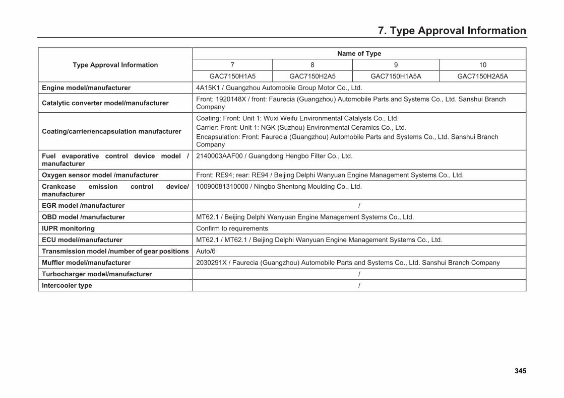
7. Type Approval Information
Type Approval Information Name of Type
7 8 9 10
GAC7150H1A5 GAC7150H2A5 GAC7150H1A5A GAC7150H2A5A
Engine model/manufacturer 4A15K1 / Guangzhou Automobile Group Motor Co., Ltd.
Catalytic converter model/manufacturer Front: 1920148X / front: Faurecia (Guangzhou) Automobile Parts and Systems Co., Ltd. Sanshui Branch Company
Coating/carrier/encapsulation manufacturer
Coating: Front: Unit 1: Wuxi Weifu Environmental Catalysts Co., Ltd. Carrier: Front: Unit 1: NGK (Suzhou) Environmental Ceramics Co., Ltd. Encapsulation: Front: Faurecia (Guangzhou) Automobile Parts and Systems Co., Ltd. Sanshui Branch Company
Fuel evaporative control device model / manufacturer
2140003AAF00 / Guangdong Hengbo Filter Co., Ltd.
Oxygen sensor model /manufacturer Front: RE94; rear: RE94 / Beijing Delphi Wanyuan Engine Management Systems Co., Ltd.
Crankcase emission control device/ manufacturer
10090081310000 / Ningbo Shentong Moulding Co., Ltd.
EGR model /manufacturer /
OBD model /manufacturer MT62.1 / Beijing Delphi Wanyuan Engine Management Systems Co., Ltd.
IUPR monitoring Confirm to requirements
ECU model/manufacturer MT62.1 / MT62.1 / Beijing Delphi Wanyuan Engine Management Systems Co., Ltd.
Transmission model /number of gear positions Auto/6
Muffler model/manufacturer 2030291X / Faurecia (Guangzhou) Automobile Parts and Systems Co., Ltd. Sanshui Branch Company
Turbocharger model/manufacturer /
Intercooler type /
345
This Manual describes information related to configurations, functions, performance parameters and product schematic drawings of vehicles from GAC MOTOR. Its contents are effective when printing is allowed. But actual car configurations and functions are subject to actually delivered cars. If there is any difference between the product schematic drawing and actual car, the actual one should prevail.
GAC MOTOR reserves the right to alter, supplement or terminate the contents or technical specifications in this Manual without further notification.
All copyright is reserved by GAC MOTOR. Without written permission by GAC MOTOR, no printing and extracting of all or part contents of this Manual is allowed.
Copyright © 2022 FDOKUMEN