Growth saturation of unstable thin films on transverse-striped hydrophilic-hydrophobic micropatterns
11
arXiv:1110.5496v1 [cond-mat.soft] 25 Oct 2011 Growth saturation of unstable thin films on transverse-striped hydrophilic-hydrophobic micropatterns R. Ledesma-Aguilar, 1, 2 A.Hern´andez-Machado, 1 and I. Pagonabarraga 3 1 Departament d’Estructura i Constituents de la Mat` eria. Universitat de Barcelona, Avinguda Diagonal 647, E-08028 Barcelona, Spain 2 The Rudolf Peierls Centre for Theoretical Physics, University of Oxford, 1 Keble Road, Oxford OX1 2HQ, United Kingdom 3 Departament de F´ ısica Fonamental. Universitat de Barcelona, Avinguda Diagonal 647, E-08028 Barcelona, Spain (Dated: June 27, 2013) Using three-dimensional numerical simulations, we demonstrate the growth saturation of an un- stable thin liquid film on micropatterned hydrophilic-hydrophobic substrates. We consider different transverse-striped micropatterns, characterized by the total fraction of hydrophilic coverage and the width of the hydrophilic stripes. We compare the growth of the film on the micropatterns to the steady states observed on homogeneous substrates, which correspond to a saturated sawtooth and growing finger configurations for hydrophilic and hydrophobic substrates, respectively. The proposed micropatterns trigger an alternating fingering-spreading dynamics of the film, which leads to a complete suppression of the contact line growth above a critical fraction of hydrophilic stripes. Furthermore, we find that increasing the width of the hydrophilic stripes slows down the advancing front, giving smaller critical fractions the wider the hydrophilic stripes are. Using analytical approx- imations, we quantitatively predict the growth rate of the contact line as a function of the covering fraction, and predict the threshold fraction for saturation as a function of the stripe width. I. INTRODUCTION The growth of patterns in forced thin liquid films on solid substrates is an ubiquitous process of both bio- logical and technological relevance which has attracted the attention of the scientific community over the last decades [1, 2]. The manipulation of thin films is impor- tant in microfluidics, where the increasing miniaturiza- tion of fluidic devices demands the development of new and simple ways to handle small volumes of liquid. Due to their smaller internal hydrodynamic resistance and increased surface area, thin films can be used to over- come problems associated to other geometries, such as microchannels [3]. Both experimental and theoretical studies indicate the possibility of using clever structur- ing of microfluidic devices to orient the growth of films [4–9] or to control the motion of interfaces in confined microfluidic chambers [10]. Still, a remaining challenge is how to control the intrin- sic growth of thin liquid films in the microscale. When a thin film of liquid is forced to spread on a dry solid substrate, there is a net accumulation of fluid close to the contact line, which corresponds to the apparent posi- tion where the liquid, the solid, and the surrounding gas meet. As a result, the film profile bulges near its leading edge, generating a capillary ridge. For films driven by a body force, such as a constant pressure gradient, vari- ations in the size of the ridge along the leading edge of the film have the effect of increasing the hydrostatic pres- sure locally. This introduces a driving mechanism that amplifies small perturbations to the contact line, which are relaxed by the surface tension [11]. Such competition of driving and restoring forces gives rise to a linear in- stability [12–14], which, far from a flat advancing front, leads to the formation of non-linear structures, such as the familiar water rivulets observed in the shower. Given the strong interaction with the solid, it is un- surprising that the instability is affected by the wetting properties of the liquid [15–18]. Wetting interactions de- termine the equilibrium contact angle of the fluid-fluid interface with the solid. As a consequence, the size and shape of the capillary ridge, which control the driving destabilizing force, depend on wetting. For hydrophilic substrates, the contact angle of the interface profile is small, making the capillary ridge relatively thin. The instability is thus weakened [9]. Remarkably, if the size of the ridge is sufficiently small, the restoring capillary pressure is strong enough to balance the driving force af- ter the early stages of growth. The interface thus stops growing, but still retains a curved saturated shape rem- iniscent of a sawtooth pattern [16]. In contrast, for hy- drophobic substrates the net accumulation of mass at the ridge is large enough to outweigh the effect of surface ten- sion, and the emerging film patterns grow steadily, with a shape that resembles that of fingers [17, 18]. Crucially, the lateral lengthscale of the patterns, Λ max , is of the order of the thickness of the thin film. Therefore, in a microfluidic device one expects that the lengthscale of emerging patterns is also of the order of microns. Our aim in this paper is to demonstrate the exploita- tion substrate heterogeneity to control the growth of the contact line, up to complete growth saturation. This is appealing to many situations in which fingering is unde- sirable, for example in coating processes and in ‘chemi- cal channeling’ [3], where the desired lateral lengthscale of the film needs not to be constrained by the intrin- sic lengthscale of the instability. We shall thus analyze the effect of a simple, yet effective, substrate pattern
-
Upload
independent -
Category
Documents
-
view
0 -
download
0
Transcript of Growth saturation of unstable thin films on transverse-striped hydrophilic-hydrophobic micropatterns

arX
iv:1
110.
5496
v1 [
cond
-mat
.sof
t] 2
5 O
ct 2
011
Growth saturation of unstable thin films on transverse-striped
hydrophilic-hydrophobic micropatterns
R. Ledesma-Aguilar,1, 2 A. Hernandez-Machado,1 and I. Pagonabarraga3
1Departament d’Estructura i Constituents de la Materia. Universitat de Barcelona,
Avinguda Diagonal 647, E-08028 Barcelona, Spain2The Rudolf Peierls Centre for Theoretical Physics,
University of Oxford, 1 Keble Road, Oxford OX1 2HQ, United Kingdom3Departament de Fısica Fonamental. Universitat de Barcelona,
Avinguda Diagonal 647, E-08028 Barcelona, Spain
(Dated: June 27, 2013)
Using three-dimensional numerical simulations, we demonstrate the growth saturation of an un-stable thin liquid film on micropatterned hydrophilic-hydrophobic substrates. We consider differenttransverse-striped micropatterns, characterized by the total fraction of hydrophilic coverage andthe width of the hydrophilic stripes. We compare the growth of the film on the micropatterns tothe steady states observed on homogeneous substrates, which correspond to a saturated sawtoothand growing finger configurations for hydrophilic and hydrophobic substrates, respectively. Theproposed micropatterns trigger an alternating fingering-spreading dynamics of the film, which leadsto a complete suppression of the contact line growth above a critical fraction of hydrophilic stripes.Furthermore, we find that increasing the width of the hydrophilic stripes slows down the advancingfront, giving smaller critical fractions the wider the hydrophilic stripes are. Using analytical approx-imations, we quantitatively predict the growth rate of the contact line as a function of the coveringfraction, and predict the threshold fraction for saturation as a function of the stripe width.
I. INTRODUCTION
The growth of patterns in forced thin liquid films onsolid substrates is an ubiquitous process of both bio-logical and technological relevance which has attractedthe attention of the scientific community over the lastdecades [1, 2]. The manipulation of thin films is impor-tant in microfluidics, where the increasing miniaturiza-tion of fluidic devices demands the development of newand simple ways to handle small volumes of liquid. Dueto their smaller internal hydrodynamic resistance andincreased surface area, thin films can be used to over-come problems associated to other geometries, such asmicrochannels [3]. Both experimental and theoreticalstudies indicate the possibility of using clever structur-ing of microfluidic devices to orient the growth of films[4–9] or to control the motion of interfaces in confinedmicrofluidic chambers [10].
Still, a remaining challenge is how to control the intrin-sic growth of thin liquid films in the microscale. Whena thin film of liquid is forced to spread on a dry solidsubstrate, there is a net accumulation of fluid close tothe contact line, which corresponds to the apparent posi-tion where the liquid, the solid, and the surrounding gasmeet. As a result, the film profile bulges near its leadingedge, generating a capillary ridge. For films driven bya body force, such as a constant pressure gradient, vari-ations in the size of the ridge along the leading edge ofthe film have the effect of increasing the hydrostatic pres-sure locally. This introduces a driving mechanism thatamplifies small perturbations to the contact line, whichare relaxed by the surface tension [11]. Such competitionof driving and restoring forces gives rise to a linear in-stability [12–14], which, far from a flat advancing front,
leads to the formation of non-linear structures, such asthe familiar water rivulets observed in the shower.
Given the strong interaction with the solid, it is un-surprising that the instability is affected by the wettingproperties of the liquid [15–18]. Wetting interactions de-termine the equilibrium contact angle of the fluid-fluidinterface with the solid. As a consequence, the size andshape of the capillary ridge, which control the drivingdestabilizing force, depend on wetting. For hydrophilicsubstrates, the contact angle of the interface profile issmall, making the capillary ridge relatively thin. Theinstability is thus weakened [9]. Remarkably, if the sizeof the ridge is sufficiently small, the restoring capillarypressure is strong enough to balance the driving force af-ter the early stages of growth. The interface thus stopsgrowing, but still retains a curved saturated shape rem-iniscent of a sawtooth pattern [16]. In contrast, for hy-drophobic substrates the net accumulation of mass at theridge is large enough to outweigh the effect of surface ten-sion, and the emerging film patterns grow steadily, witha shape that resembles that of fingers [17, 18]. Crucially,the lateral lengthscale of the patterns, Λmax, is of theorder of the thickness of the thin film. Therefore, in amicrofluidic device one expects that the lengthscale ofemerging patterns is also of the order of microns.
Our aim in this paper is to demonstrate the exploita-tion substrate heterogeneity to control the growth of thecontact line, up to complete growth saturation. This isappealing to many situations in which fingering is unde-sirable, for example in coating processes and in ‘chemi-cal channeling’ [3], where the desired lateral lengthscaleof the film needs not to be constrained by the intrin-sic lengthscale of the instability. We shall thus analyzethe effect of a simple, yet effective, substrate pattern

2
that consists of hydrophilic-hydrophobic stripes orientedtransversely to the direction of flow, as shown in Fig. 1.As we shall see below, the lengthscale of the micropat-tern is important, and has a significant impact already atscales comparable to the micron-sized films. Still, and de-spite its simplicity, such a pattern has not yet been stud-ied. In a previous study [9], we have demonstrated thatthe growth of the thin film can be tuned by patterning thesolid substrate with transverse or checkerboard arrange-ments of hydrophilic-hydrophobic domains. Previous ex-perimental and numerical studies of flow patterning [4–7]have mainly focused on the effect longitudinal tracks ofvarying flow resistance [4] or wetting angle [5–7]. Theoverall experiments and numerical simulations evidenceis that substrate heterogeneity can be used to handle thinfilms, through preferential orientation over hydrophilicor low-resistance domains in the substrate, or to par-tially control its growth using checkerboard hydrophilic-hydrophobic patterns. As we shall show in the following,the proposed transverse pattern introduces new physicalmechanisms, particularly the transverse spreading of thefilm, which lead to the desired saturation of the contactline.
Our approach to this problem will be to performLattice-Boltzmann (LB) simulations [19] of Navier-Stokes hydrodynamics coupled to a phase-field binaryfluid model [20] to account for the interface dynam-ics. Previous theoretical approaches to model forced thinfilms on chemically heterogeneous substrates have mainlyconsisted of sharp-interface formulations based on theStokes equations [5–8]. Most of these studies use theso-called thin-film equations, which are appropriate tomodel the fluid dynamics in the limit of small interfaceslopes. Within this framework, a common procedure toregularize the viscous dissipation singularity is to replacethe contact line by a thin precursor film that extends be-yond the leading front. The effect of the heterogeneitycan then be included by choosing a particular model forthe precursor. For example, an heterogeneous disjoiningpressure model that couples to the precursor film [7] hasbeen used to study the motion of the film on longitudinal-striped and disordered substrates, as well as on orderedand disordered isolated spots [8]. Alternatively, a sim-ilar model consisting of a spatially-varying thickness ofthe precursor film to study the motion of the film overchemical patterns has also been used [5, 6].
Our aim in this work is to study the effect of a sharpcontrast between hydrophilic and hydrophobic domainsin the proposed micropatterns. This corresponds to sit-uations in which the static and dynamic contact anglesneed not to be small. Such regime falls beyond the limitof applicability of the thin-film equations, demanding theresolution of the full three-dimensional dynamics. Thisis a complicated problem from the classical point of view,as it involves the motion of two free boundaries: the filmsurface and the contact line. Within sharp-interface for-mulations, boundary integral methods could be used toaddress this problem, as has been done to model the effect
of chemical heterogeneities on two-dimensional fluid nan-odrops [21]. However, the mesoscopic approach that wetake here constitutes a reliable three-dimensional Navier-Stokes solver that allows for both small and large contactangles, necessary to model hydrophilic and hydrophobicinteractions. Because of the diffuse approximation to de-scribe the fluid interface, the method circumvents thefree-boundary problem, regularizes the viscous dissipa-tion singularity at the contact line, and deals naturallywith merging and pinch-off events, which otherwise needa specific rule in sharp interface approximations. Wehave carried out a validation of our model in a previousstudy, for the case of driven thin films on homogeneoussolid substrates [22].
The rest of this work is organized as follows. InSection II we introduce the mesoscopic model and theLattice-Boltzmann algorithm to perform the numericalsimulations. We will complement our numerical resultswith kinematical calculations for the propagation of theinterface. As we shall see from our numerical results,presented in Section IV, the main effect of the transversehydrophilic stripes on the forced film is to favor its lateralspreading on hydrophilic domains, thus slowing down theleading edge of the film. The same lateral spreading ul-timately leads to a speed-up of the trailing edge of thefilm. The net result is that the growth rate of the filmdecreases with increasing fraction of hydrophilic stripesin the substrate, until the film saturates above a criticalvalue of this fraction. As we detail in the discussion andconclusions of this work, presented in Section V, we pre-dict that a relatively small fraction of hydrophilic stripesis sufficient to suppress the growth of the contact line inexperimental realizations. Our results thus constitute apromising step towards the control of interface growth inmicrofluidic systems.
II. MODEL
In this paper we shall perform numerical simulation ofNavier-Stokes level hydrodynamics coupled to a phase-field representation of the viscous fluid film and surround-ing low-viscosity phase. Such modeling is very useful toaddress the dynamics of immiscible fluids, as it has theadvantage of circumventing the free-boundary problemassociated to sharp-interface representations, as for ex-ample in boundary integral methods. Furthermore, thephase-field model regularizes the viscous dissipation sin-gularity at the contact line through a diffusive mecha-nism acting at small scales (of the order of the size ofthe interface). One thus does not need to specify addi-tional boundary conditions at the contact line. In orderto integrate the model equations, we will use a Lattice-Boltzmann algorithm.

3
FIG. 1: Schematic representation of the system. A thin film ofinitial thickness h is forced along the x direction by the action
of a constant body force, ~f , on a solid substrate composed ofhydrophilic and hydrophobic transverse stripes. The scale ofthe thin film thickness and of the width of the stripes is ofthe order of microns.
A. Hydrodynamics and Phase-Field Model
A schematic depiction of the forced thin-film geometryis presented in Fig. 1. We consider two immiscible New-tonian fluids of viscosities η1 and η2 and densities ρ1 andρ2, respectively. The thin film, corresponding to fluid 1,is forced on a solid substrate composed of hydrophilic andhydrophobic regions. In order to distinguish between thetwo liquids, we introduce a phase field characterized by aconcentration variable, or order parameter, φ. The localvalue of the order parameter thus describes each phase,and varies between two volume values across a diffuseinterfacial region.
In equilibrium, the free energy of the system can bewritten as a functional of the order parameter field, φ(~r)and the local density field, ρ(~r),
F{ρ, φ} =
∫
V
dV(
U(φ, ρ) +κ
2(~∇φ)2
)
+
∫
S
dSfS(φS).
(1)
The first integral in Eq. (1) is composed by the vol-ume contributions to the free energy. These consist of adouble-well potential with an ideal gas term, U(φ, ρ) =Aφ2/2+Bφ4/4+(1/3)ρ lnρ, and a square-gradient termthat penalizes variations of the order parameter, thusallowing for the formation of a diffuse interface. The pa-rameters A, B and κ control the equilibrium values ofthe order parameter ±φeq = ±
√
−A/B, the size of the
interface, ξ =√
−κ/2A and the fluid-fluid surface ten-
sion, γ =√
−8κA3/9B2. The second integral in the freeenergy corresponds to the contribution of fluid-solid in-teractions. Here we chose a Chan model, fS(φS) = CφS ,which assigns the free surface energy fS according to thelocal value of the order parameter at the boundary, φS .The parameter C controls the equilibrium contact angle,θe, of the fluid-fluid interface in contact with a flat solid
wall through the relation
cos θe =1
2
[
−(
1− C(−κA)−1
2
)3
2
+(
1 + C(−κA)−1
2
)3
2
]
.
(2)The order parameter and density fields contribute to
the chemical potential, µ, and pressure tensor, Pαβ , of thesystem. These are obtained by taking functional deriva-tives of the free energy [23] and have the following ex-pressions,
µ = Aφ+Bφ3 − κ∇2φ, (3)
Pαβ =(
13ρ+ 1
2Aφ2 + 3
4Bφ4 − κφ∇2φ− 1
2κ|~∇φ|2
)
δαβ
+κ(∂αφ)(∂βφ).(4)
Out of equilibrium, the dynamics of the density, ρ,velocity, ~v, and order parameter, φ, fields are givenby the continuity and Navier-Stokes equations, plus aconvection-diffusion equation for the phase field, i.e.,
∂ρ
∂t+ ~∇ · (ρ~v) = 0, (5)
∂~v
∂t+ (~v · ~∇)~v = −~∇P − φ~∇µ+ η∇2~v + ~f, (6)
and
∂φ
∂t+ ~v · ~∇φ = M∇2µ, (7)
respectively.The φ−dependent term in the Navier-Stokes equations
arises from the concentration dependence of the pressure
tensor in Eq. (4), giving a ‘chemical’ force density, −φ~∇µ,which plays a similar role as the pressure gradient termin the volume of each phase. The remaining terms inthe Navier-Stokes equations are the viscous friction term,whose strength is controlled by the local viscosity, η, and
to the body force term, ~f .The evolution of the order parameter is dictated by
Eq. (7), which contains an advective term caused bythe underlying velocity field and a diffusive term, whosestrength is controlled by the mobility parameter M .
B. System Geometry and Boundary Conditions
In order to ensure the formation of steady patterns,we choose a constant flux configuration for the geome-try of the system. We set a rectangular simulation do-main of linear dimensions L × W × H , in the x, y andz directions, respectively. The solid-fluid interface, S,is parallel to the x − y plane and located at z = 0 asshown in Fig. 1. The thin film is initially at rest andoccupies the volume V0 = L0 × W × hc. We fix the

4
force term as ~f = 12fx(φ + 1)x, so fluid 1 is forced uni-
formly while fluid 2 is left to evolve passively. This setsup a flow of mean velocity u = h2
cfx/3η1 within the film.At x = 0, a constant flux in the x direction is thus en-sured as long as there is a reservoir of fluid availableto compensate for the downstream motion of the film.This is achieved by imposing ∂xρ(x = {0, L}, y, z) = 0,
∂x~v(x = {0, L}, y, z) = ~0 and ∂xφ(x = {0, L}, y, z) = 0.Using this approach, we do not find any appreciable vari-ations of the mean velocity of the film or the film thick-ness close to the boundary.We fix periodic boundary conditions in the y direction,
i.e., ρ(x, y = W, z) = ρ(x, y = 0, z), ~v(x, y = W, z) =~v(x, y = 0, z), φ(x, y = W, z) = φ(x, y = 0, z). Atthe upper boundary, a shear-free boundary condition isimposed by fixing ∂z~v(x, y, z = H) = ~0, while vanish-ing density and concentration gradients normal to theboundary are fixed by imposing ∂zρ(x, y, z = H) = 0and ∂zφ(x, y, z = H) = 0.The velocity profile is subject to stick boundary and
impenetrability conditions at the solid-fluid surface, i.e.,
~v|S = 0. (8)
In macroscopic representations, imposing the stickboundary condition for a moving interface in contact witha solid causes a spurious divergence of the viscous stressas one approaches the contact line [24]. This paradoxis readily avoided by the phase-field model, through thediffusive term in Eq. (7), which allows for a slip veloc-ity that increases as one approaches the contact line [25],even when Eq. (8) is enforced. Diffusion is driven byvariations of the chemical potential profile close to thecontact line, over a typical lengthscale ld, which scales asld ∼ (η1ξM/∆φ2)1/4 [26].An evolution equation for the order parameter should
be specified at the solid-fluid interface (see [25] for a de-tailed derivation). In this paper we shall impose the nat-ural boundary condition
n · ~∇φ|S =1
κ
dfSdφS
. (9)
This gives an instantaneous relaxation of the order pa-rameter gradient to its surface value at the wall, whichcorresponds to quasi-equilibrium dynamics for the inter-face slope at lengthscales comparable to the size of theinterface [27]. By choosing the wetting parameter C inEq. (2), we specify the local value of the equilibrium con-tact angle and hence the desired hydrophilic-hydrophobicpattern.The phi−dependent term in Eq. (6) is most important
at the fluid-fluid interface, where it plays the role of aLaplace pressure. This behavior can be verified by in-tegration of Eq. (6) over the length of the interface (c.f.[28]) whence one recovers a jump in the normal stress
∆µ ∼γ
R. (10)
Eq. (10) corresponds to the Young-Laplace conditionwith R being the local radius of curvature of the interface.Thus, the concentration dependent term in the Navier-Stokes equation eliminates the need of using Eq. (10)explicitly. Accordingly, the continuity of the tangentialstress is recovered in the sharp interface limit.
In order to present our results in a natural scale, wechoose units according to the classical thin-film theory inthe lubrication limit [1, 2]. For microscales inertial effectsare negligible, and the relevant control parameter is thecapillary number, Ca = η1u/γ, which measures the ratioof viscous to capillary forces. A suitable unit system is
x∗ =x
xc, y∗ =
y
xc, (z∗, h∗) =
(
z
hc,h
hc
)
,
〈~v〉∗ =〈~v〉
u, and
t
tc, (11)
where xc = hc(3Ca)−1
3 , and tc = xc/u.
C. Parameter values
The model presented in the previous section is specifiedby a set of parameters, ρ1, ρ2, η1, η2, φeq, γ, ξ and M .Additionally, the fluid wetting properties are specified bythe static contact angle, θe, which depends on C. In thefollowing, we specify the values of these parameters usedin our simulations (all in lattice units).
The equilibrium values of the order parameter are fixedto φ∗ = ±1 by choosingA = −B. To specify the viscosityof each fluid we fix the mean viscosity 〈η〉 = 0.1 and theviscosity contrast, δη = 0.9. The local viscosity, η(~r),is then set as η1 = 〈η〉(1 + δη) if φ > 0 (viscous film)and η2 = 〈η〉(1 + δη) if φ < 0 (surrounding low-viscosityphase). The density is set to the same mean value in eachphase, ρ1 = ρ2 = 1. The fluid-fluid surface tension isfixed to γ = 2.3×10⁻³. The interface width is set to ξ =0.57, which corresponds to an effective transition zoneof ∼ 5 lattice spacings for the order parameter profilebetween the volume values in equilibrium.
In order to ensure that the contact line propagates witha velocity comparable to the velocity of the film [22], wefix the mobility to M = 10.0.
The equilibrium contact angles used throughout thisstudy correspond to θe = 0◦ for the hydrophilic substrateand θe = 90◦ for the hydrophobic substrate, which corre-sponds to C = 0 and C = 1.7× 10⁻³, respectively.
The capillary number is set to Ca = 0.41, which followsfrom choosing the forcing fx to give a mean velocity valuefor the film, u = 0.005. This value ensures the stabilityof the LB scheme and a small compressibility (densityvariations of the order of ∼ 1%.)

5
III. LATTICE BOLTZMANN METHOD
We use the Lattice-Boltzmann (LB) implementationintroduced in detail in Ref. [23, 29] in the context of spin-odal decomposition of binary fluid mixtures, and whichwe have used in a previous work [9], where we have fo-cused on the dynamics of unstable thin films in homo-geneous solid substrates. In LB, the dynamics are intro-duced by two sets of velocity distribution functions, fiand gi, which evolve in time according to the discretizedBoltzmann equations,
fi(~r + ~ci, t+ 1)− fi(~r, t) = −1
τf(fi − feq
i ) + F fi , (12)
and
gi(~r + ~ci, t+ 1)− gi(~r, t) = −1
τg(gi − geqi ), (13)
Space is discretized as a cubic lattice where nodes arejoined by velocity vectors, ~ci. Here we use the D3Q19model, which consists of a set of 19 velocity vectors inthree dimensions [23]. Hence, fi and gi are proportionalto the number of particles moving in the direction of ~ci.Eqs. (12) and (13) are composed of two steps. First,the distribution functions are relaxed to their equilib-rium values, represented by feq
i and geqi , with relaxation
timescales τf and τg. The term F fi is related to the ex-
ternal forcing. Following this collision stage, distributionfunctions are propagated to neighboring sites.The mapping between LB scheme and the hydrody-
namic phase-field model is done by defining the hydro-dynamic variables through moments of the fi and gi.The local density and order parameter are given by∑
i fi = ρ and∑
i gi = φ, while the fluid momentumand order parameter current are defined as
∑
i fi~ci = ρ~vand
∑
i gi~ci = φ~v.Local conservation of mass and momentum is enforced
through the conditions∑
i fi =∑
i feqi = ρ,
∑
i gi =∑
i geqi = φ,
∑
i fi~ci =∑
i feqi ~ci = ρ~v and
∑
i gi~ci =∑
i geqi ~ci = φ~v. In equilibrium, the pressure tensor and
chemical potential are defined as∑
i feqi ~ci~ci = ρ~v~v+ ¯PT
and∑
i geqi ~ci~ci = Mµ¯δ + φ~v~v.
To recover the equilibrium behavior of the phase-fieldmodel, the equilibrium distribution functions and theforcing term are expanded in powers of ~v[30], i.e.,
feqi = ρων
(
Afν + 3~v · ~ci +
9
2~v~v : ~ci~ci −
3
2v2 + ¯G
f: ~ci~ci
)
,
geqi = ρων
(
Agν + 3~v · ~ci +
9
2~v~v : ~ci~ci −
3
2v2 + ¯G
g: ~ci~ci
)
and
F fi = 4ων
(
1−1
2τf
)
[
~f · ~ci(1 + ~v · ~ci)− ~v · ~f]
.
FIG. 2: Geometry of the transverse stripe pattern. The pat-tern is composed of alternated hydrophilic (grey) and hy-drophobic (white) stripes of lengths lh and lφ, respectively.The panel shows a schematic representation of the contactline (solid line), which spreads on the hydrophilic stripes upto a width whW before advancing on the next hydrophobicstripe. Spreading causes that a series of dry spots are left onthe hydrophobic stripes, which are eventually covered by thetrailing edge of the film. The dotted lines depict the thin filmprofile, which has a typical thickness h0
t on a wet hydrophilicstripe, and a maximum thickness ht at the trailing edge on ahydrophobic stripe. At the grey zones θe = 0◦ while at thewhite zones θe = 90◦.
Here, ν stands for the three possible magnitudes of the~ci set. The values of the coefficents are then fixed bythe definition of the moments of feq
i and geqi , and by thesymmetry of the lattice. Coefficient values for the D3Q19LB scheme are ω0 = 2/9, ω1 = 1/9 and ω√
3 = 1/72;
Af0 = 9/2 − 7/2Tr ¯P, Af
1 = Af√3= 1/ρTr ¯P and ¯Gf =
9/(2ρ) ¯P − 3¯δTr ¯P ; Ag0 = 9/2 − 21/2Mµ, Ag
1 = Ag√3=
3Mµ/ρ and ¯Gg = 9/(2ρ)Mµ(¯1 − ¯δ), where ¯1 is the unitmatrix.The hydrodynamic phase-field model, given by
Eqs. (5), (6) and (7), up to second order corrections inthe velocity, can be recovered by performing a Chapman-Enskog expansion of Eqs. (12) and (13)[30]. The LBscheme maps to the hydrodynamic model through therelaxation timescales, i.e., η = (2τf − 1)/6 and M =
(τg − 1/2)M, and through the body force ~f = ρ~g.Solid boundaries in the Lattice-Boltzmann method are
implemented by means of the well known bounce-backrules[30, 31]. In the lattice nodes that touch the solid,the propagation scheme is modified so the distributionfunctions are reflected to the fluid rather than absorbedby the solid. As a consequence, a stick condition forthe velocity is recovered approximately halfway from thefluid node to the solid node.
IV. RESULTS
We want to assess if a small fraction of hydrophilic do-mains can induce a significant reduction of the growthof the contact line. We thus characterize the trans-

6
(a)
(b)
FIG. 3: Contact line evolution on transverse stripe patternsfor hydrophilic stripes of length lh/xc = 1.3 at different cover-ing fraction, f . The first panel in each figure shows the initialperturbation at t/tc = 0, while the subsequent two panelsshow the contact line at time intervals of ∆t/tc = 67. Forcomparison, the last panel in (a) and (b) shows the fingerthat grows on a homogeneous hydrophobic substrate (f=0)at t = 2∆t/tc. For both values of f , the contact line grows asa finger on the hydrophobic stripes, and spreads transverselyon the hydrophilic domains. (a) For a small fraction of hy-drophilic stripes, f = 0.11, the contact line grows at a smallerrate than the one measured on a homogeneous substrate. (b)Increasing the fraction to f = 0.55 has the effect of decreas-ing the growth rate dramatically, making the length of thecontact line substantially smaller than the length of the un-perturbed finger. As seen by comparing the position of thecontact line in third panel of (a) and (b), the reduction of thegrowth rate arises both from a slow down of the leading edgeand a speed up of the trailing edge of the contact line.
verse stripe arrangement by the width of the hydrophilicstripes, lh, and the fraction of the substrate that is cov-ered by them, f = lh/(lh + lφ), where lφ is the length ofthe hydrophobic stripes, as depicted in Fig. 2.
In a previous study [9], we have considered the mo-tion of thin films on homogeneous substrates. We havefound that the front develops as a finger if the substrateis hydrophobic (θe = 90◦), with an inter-finger spacinggiven by Λmax(θe = 90◦) ≃ 8xc. In contrast, for a hy-drophilic substrate the front develops as a sawtooth witha typical lateral lengthscale of Λmax(θe = 0◦) ≃ 14xc.Due to the periodicity of the emerging structures, itis sufficient to consider simulation domains of widthW = Λmax(θe = 90◦) ≃ 8xc. Larger system sizes obey-ing W = nΛmax(θe = 90◦), with n being an integer,only give rise to additional identical fingers, whose effectis already taken into account by the periodic boundaryconditions in our simulations. For non-integer n we ex-pect a non-linear competition of emerging fingers, whichwe have observed previously [9]. However, this compe-
tition should not modify significantly the main effect ofthe transverse-stripe pattern.
In the following, we will explore the dynamics of thefront when varying lh and f . We study the effect of theoccupation fraction in the range 0 ≤ f ≤ 1, while for thelength of the stripes we choose the values lh/xc = 1.3,lh/xc = 4.0, and lh/xc = 6.7. As before, we considerthe evolution of a single mode in systems whose widthis chosen to be close to the most unstable wavelengthpredicted for the hydrophobic substrate.
Figures 3(a) and 3(b) show the evolution of the contactline for f = 0.11 and f = 0.55 respectively, for a stripewidth lh/xc = 1.3 at three subsequent times, t0/tc = 0,t1/tc = 67 and t2/tc = 134. For comparison, the lastpanel at the bottom of (a) and (b) shows the interfaceprofile for a homogeneous hydrophobic substrate (f=0)at t2/tc = 134. The main feature in these patterns is thatthe growth rate of the contact line decreases strongly asthe fraction of hydrophilic stripes is increased. For thevalue of lh considered in Fig. 3, the growth rate actuallyvanishes at a critical fraction fc ≃ 0.59. We first noticethat for both patterns shown in Fig. 3, the leading edgeof the contact line grows as a finger when it is in con-tact with a hydrophobic stripe. The finger grows untilit touches a hydrophilic stripe, where it starts to spreadtransversely. As spreading takes place, the leading edgecontinues advancing over the hydrophilic domain, untilit reaches the next hydrophobic stripe, where it devel-ops as a finger again. A closer inspection of Fig. 3(a)shows that a series of spots are left uncovered momen-tarily on the hydrophobic stripes after the leading edgehas passed by. This is a consequence of the transversespreading process that occurs every time the leading edgepasses over a hydrophilic stripe. The second and thirdpanels in Fig. 3(a) show that the trailing spot is eventu-ally covered by the film, and that only after the trailingspot has disappeared, the following spot starts to be cov-ered. This mechanism holds for larger f , as can bee seenin Fig. 3(b). The global result is that the transversepattern induces a slow down of the leading edge, as canbe seen by comparing the contact line with the fingerthat grows on a homogeneous substrate. This effect isstronger for f = 0.55 than for f = 0.11. Additionally,the transverse pattern induces a speed up of the trailingedge, and effect that can also clearly be seen in Fig. 3.Again, this effect is stronger the larger f is.
The combination of the speed up of the trailing edgeand the slow down of the leading edge causes the contactline growth rate, L, to decrease with increasing fraction ofhydrophilic stripes. Figure 4 shows a plot of L as a func-tion of f . The limits in this plot correspond to the finger(f = 0) and sawtooth (f = 1) solutions on homogeneoussubstrates. For small f , the growth rate converges to thegrowth rate of the unperturbed finger, while increasing fhas the effect of decreasing the growth rate as explainedabove. We find that L vanishes at a critical fraction,fc(lh), which is considerably smaller than unity. Thismeans that the transverse pattern induces the saturation

7
FIG. 4: Global contact line growth rate as a function of thefraction of hydrophilic stripes for different hydrophilic stripelengths on transverse striped patterns. The growth rate L,decreases as the fraction of hydrophilic stripes, f , increases.For fixed f , increasing the length of the hydrophilic stripes,lh, has the effect of decreasing the growth rate. Continuouslines correspond to the kinematical theoretical prediction, forwhich the dependence on lh is contained in the parameter wh,which we measure from simulations. The plot shows that thegrowth rate vanishes at a fraction that is smaller than unity.
of the contact line by caused by transverse spreading ofthe film on hydrophilic domains.To analyze the effect of the length of the stripes, lh, we
have carried out additional simulations at fixed f whilevarying lh and have measured the corresponding growthrate. We plot these results in Fig. 4, where we observethat the growth rate decreases systematically as lh is in-creased. Accordingly, the critical fraction fc(lh) is a de-creasing function of lh.
Analytical model for growth on transverse stripe patterns
In order to gain insight into the growth of the contactline on transverse patterns, we will analyze the inter-play between hydrophilic and hydrophobic stripes usinga kinematical argument.Let us denote ∆tl and ∆tt the time intervals in which
the leading and trailing edges sweep a distance ∆l =lφ + lh, respectively. For a mean steady growth of theinterface, each of these intervals can be decomposed asthe sum of the time that the interface spends on a hy-drophilic and a hydrophobic stripe. We thus write
∆tl = ∆thl +∆tφl and ∆tt = ∆tht +∆tφt , (14)
where superscripts h and φ correspond to the hydrophilicand hydrophobic domains, respectively.For sufficiently long hydrophobic stripes, the thin film
should grow as an unperturbed finger, with leading andtrailing edge velocities vl and vt, respectively. Disregard-ing the transient relaxation to these values, it is reason-
able to assume that the contact line changes its velocityinstantaneously to vl and vt as soon as it comes into con-tact with a hydrophobic stripe. From this assumption, itfollows that the residence time of the leading and trailingedges of the film in a hydrophobic stripe are
∆tφl =lφvl
and ∆tφt =lφvt.
For the hydrophilic stripes, we can write similar ex-pressions for the residence times of the leading and trail-ing edges of the interface in a hydrophilic stripe,
∆thl =lh
vhland ∆tht =
lh
vht.
The velocity vhl corresponds to the mean velocity of theleading edge on a hydrophilic stripe, while vht is definedas the velocity of the jump that the trailing interfaceundergoes on a prewet hydrophilic stripe.To estimate vhl , we first approximate the volumetric
flux supplied by the finger to the hydrophilic stripe asql ∼ hfλWvl, where hf and λW are the thickness andwidth of the finger in the hydrophobic stripe, respectively(see Fig. 2). The flow rate ql sustains the spreading ofthe leading edge, which covers a volume Vl ≃ hf lhwhWof the hydrophilic stripe before it moves over the next hy-drophobic stripe. The volume Vl depends on wh, whichis the lateral fraction of the stripe that the film covers be-fore the leading edge advances over the next hydrophobicdomain. In writing the expression for Vl we have assumedthat the film thickness does not vary significantly duringspreading. The residence time of the spreading processis therefore ∆tl
h = Vl/ql, which gives a mean spreadingvelocity
vlh ≃
lh
∆tlh=
λ
whvl. (15)
We next estimate the jumping velocity of the trailingedge, vht . This velocity corresponds to the ratio betweenthe length of the hydrophilic stripe, lh, and the waitingtime to observe the jump in the contact line position,∆tt
h. Let ht be the thickness of the trailing edge ofthe film when it touches the hydrophilic stripe, which isalready wet and has a local thickness h = ht
0, as shownin Fig. 2. After contact, the cross section of the film inthe x − z plane will evolve as At
h ≃ hlh = ht0lh + qtt,
where the flow rate per unit length in the y direction,qt, obeys qt ∼ vtht. We expect that At
h grows until thethickness of the film is h = ht, from which it follows thatthe corresponding waiting time is
∆tth =
(ht − ht0)lh
vtht. (16)
We thus obtain an estimate for the jumping velocity ofthe trailing edge,
vht =vt
1− ht
, (17)

8
where ht = ht0/ht.
We now return to Eq. (14), which we write in terms ofthe mean velocities of the leading and trailing edges, vland vt, i.e.,
lφ + lhvl
=lhvlh
+lφvl
andlφ + lh
vt=
lhvth
+lφvt. (18)
From Eq. (18) we obtain the mean velocities of the inter-face as a function of the local velocities and the fractionof hydrophilic stripes,
vl =vl
1 + f(
vlvlh
− 1) and vt =
vt
1 + f(
vtvth
− 1) ,
(19)where vl and vt can be measured from the single fingersolution, while vhl and vht follow from Eqs. (15) and (17).For the leading edge velocity we obtain
vl =vl
1 + f(
wh
λ − 1) , (20)
which is proportional to the leading edge velocity of thefinger and depends on the fraction of hydrophilic stripes,as well as on the degree of transverse spreading, which iscontained in the dependence on wh.For the trailing edge velocity we find
vt =vt
1− htf, (21)
which is controlled by the local thickness of the film onthe prewet hydrophilic stripe.Equations (20) and (21) can be used to obtain the
growth rate of the contact line,
L = vl − vt =vl
1 + f(
wh
λ − 1) −
vt
1− htf. (22)
In order to verify the validity of Eq. (22), values of λ, vf ,
vt, wh, and ht have to be provided. The finger width,λ, and the finger velocities of the leading and trailingedges, vf , and vt, are known from the finger growth on ahomogeneous hydrophobic substrate. For our simulationparameters, vl = 1.1, vt = 0.6, and λ ≃ 0.3 as measured
from the finger solution (f = 0). On the other hand, ht
and wh are geometrical parameters that can be measured
from simulations. We find that ht does not depend onthe length or on the fraction of hydrophilic domains and
we measure ht = 0.33. In contrast, wh shows a depen-dence on lh, which is essentially controlled by the compe-tition between the forward motion of the film the lateralspreading caused by the hydrophobic covering. For longhydrophilic domains, the film spreads to a larger extentbefore the leading edge arrives to the next hydrophobicdomain. Therefore, wh increases with lh. This introducesthe dependence of the growth rate on lh. We do not havea prediction for wh as a function of lh. Instead, we mea-sure these values from our simulations. For the runs per-formed we find wh = 0.58 for lh/xc = 1.3, wh = 0.60 forlh/xc = 4.0, and wh = 0.64 for lh/xc = 6.7.
FIG. 5: Critical fraction, fc, as a function of the fraction of thehydrophilic stripe covered by the leading edge, wh. The frac-tion wh increases with the length of the hydrophilic stripes,lh. Lattice-Boltzmann simulations (solid symbols) show thatthe critical fraction decreases substantially with increasingwh, i.e., with increasing lh. This behavior is captured by akinematical model for large wh, depicted by the solid line (seetext).
In Figure 4 we show a comparison of Eq. (22) with sim-ulation results. As depicted in the figure, the theoreticalprediction captures the main dependence of the growthrate of the contact line, L, both on f and, through wh, onlh. For a fixed hydrophilic domain length, lh, L decreaseswith increasing f due both to a decrease of the leadingedge velocity, as shown by Eq. (20), and by an increaseof the trailing edge velocity, as predicted by Eq. (21). Onthe other hand, for fixed f , increasing lh has the effectof decreasing the growth rate. This effect can be tracedback to Eq. (15), which shows that increasing wh has theeffect of slowing down the leading edge on a hydrophilicdomain.The theoretical result given by Eq. (22) predicts a crit-
ical fraction of hydrophilic stripes, fc < 1, above whichthe growth rate, L, vanishes. Such a saturation emergesboth from the decrease of the leading edge velocity andthe increase of the trailing edge velocity, an effect thatis intimately linked to the fraction of hydrophilic stripesimposed to the substrate. The critical fraction followsfrom setting L = 0 in Eq. (22), and reads
fc = (vl − vt)
[
vlht + vt
(
wh
λ− 1
)]−1
. (23)
Here, the relevant dependence is fc(wh), given that wh
can be controlled by choosing the length of the hy-drophilic domains lh.In Fig. 5 we show a plot of fc as a function of lh and wh.
We have included fc data for four additional values of lh;lh/xc = 0.4, lh/xc = 0.7, lh/xc = 10.1 and lh = 13.4.Corresponding values of wh are wh = 0.33, wh = 0.45,wh = 0.80 and wh = 0.95, respectively. We also show the

9
theoretical prediction given by Eq. (23), which accuratelycaptures the decrease of fc as wh increases for large wh.An interesting limit corresponds to short hydrophilic
domains, which we can include in our theory. As shown inthe figure, the critical fraction reaches a saturation value,which originates from a weaker lateral spreading. In thislimit the lateral size of the film in a hydrophilic domainremains close to the width of the finger, i.e., wh ≃ λ.Still, the hydrophilic interaction causes a decrease in thelocal contact angle. As the leading edge encounters thenext hydrophobic boundary, the capillary ridge grows,until the contact angle reaches the advancing contact an-gle of the hydrophobic stripe. The relevant timescale isgiven by the filling of the capillary ridge, which we ap-proximate as a spherical cap of radius R ≃ hf/2 and vol-ume Vl = 2π(hf/2)
3/3. The volumetric flow coming intothe sphere still obeys ql = hfλWvl. Adding this contri-bution to the residence time, we find the spreading-fillingvelocity,
vhl (wh → λ) =vl
πh2
f
6πλWlh+ wh
λ
. (24)
Eq. (24) can be used to obtain the critical fraction inthis limit, which reads
fc(wh → λ) = (vl − vt)
[
vlht + vt
(
πh2f
6πλWl∗h
)]−1
,
(25)where l∗h is the crossover hydrophilic stripe length belowwhich filling dominates over spreading. The dotted line inFig. 5 shows the value predicted by Eq. (25) for l∗h/xc ≈0.4, which is a typical stripe length for which no lateralspreading is observed. As depicted in the figure, thislimiting value reasonably captures the saturation of thecritical fraction for small wh. It is important to remarkthat the estimate of the leading edge velocity given byEq. (24) is expected to be valid only as wh → λ; forlarger wh, the shape of the leading ridge is expected todepend on wh. Still, the filling timescale is subdominant,as shown by the good agreement of simulation data withEq. (23), and we thus disregard it.The opposite case, corresponding to wh → 1, is an
interesting regime, as in this case the imposed patternhas the smallest critical fraction of hydrophilic stripesfor which saturation is expected. In this limit the leadingedge spreads completely in the transverse direction on ahydrophilic stripe, a situation favored by long hydrophilicdomains. In Eq. (23), this is equivalent to to settingwh = 1, from which it follows that the minimum possiblecritical fraction is
f∞c = (vl − vt)
[
vlht +
(
1
λ− 1
)
vt
]−1
. (26)
For the simulation values used in this work we findf∞c ≃ 0.3. In Fig. 5(b) we plot this value, which is a goodestimate of the limiting critical fraction as suggested by
Lattice-Boltzmann results. While both simulation andtheory predict a slow final decay towards the limitingcritical fraction, there is a rapid variation for intermedi-ate stripe lengths, as shown in Fig. 5. For example, forlh/xc = 13.4 we obtain fc ≃ 0.4. This value of the stripelength should be compared to the the typical finger spac-ing, which for our simulations is Λmax/xc = 8. There-fore, one expects critical fractions significantly smallerthan unity for stripes whose length is comparable to thelengthscale of the unstable film.
V. CONCLUSIONS
By means of Lattice-Boltzmann simulations and ana-lytic approximations, we have studied the effect of hetero-geneous hydrophilic-hydrophobic substrates composed oftransverse striped patterns on the dynamics of forced thinliquid films, and have demonstrated that the film growthcan be controlled by the interaction of the film with aprescribed hydrophilic-hydrophobic pattern.We have focused on a scenario where the unstable
contact line gives rise to sawtooth and finger structureson homogeneous hydrophilic and hydrophobic substrates,respectively, and have examined how the growth of thecontact line is altered by the chemical pattern. Tothis end, we have considered patterns where the typi-cal lengthscale is comparable to the most unstable wave-length of the contact line, Λmax.For the transverse striped patterns considered, we have
shown that above a critical fraction of hydrophilic stripes,fc, the saturation of the film is achieved. The mechanismthat causes such a saturation originates from transversespreading of the leading edge of the contact line on thehydrophilic domains and from the growth of the film atthe hydrophilic-hydrophobic boundary so as to reach theadvancing contact angle. These processes contribute toa reduction of the velocity of the leading edge. As thisoccurs, a film of fluid is left on the hydrophilic domains,thus increasing the velocity of the trailing edge as soonas it comes into contact with a hydrophilic stripe, whichalready has been wet. The trailing edge jumps everytime it finds a wet domain, with the corresponding gainin the trailing edge velocity. The global outcome is thatfor sufficiently large fractions of hydrophilic stripes, thenet growth rate of contact line vanishes, independentlyof the details of the dynamics of the contact line.We have captured this effect with a kinematical model,
assuming local relaxation of the leading and trailing edgevelocities to ‘hydrophilic’ and ‘hydrophobic’ values. Hy-drophobic values have been approximated as the veloci-ties of the leading and trailing edges of an unperturbedfinger, while the hydrophilic velocity values have beenestimated by mass conservation. The global growth rateof the contact line, L, has been determined by the dif-ference of the mean velocities of the leading and trailingedges of the contact line. By estimating these velocitieson kinematical grounds, we have obtained a prediction
10
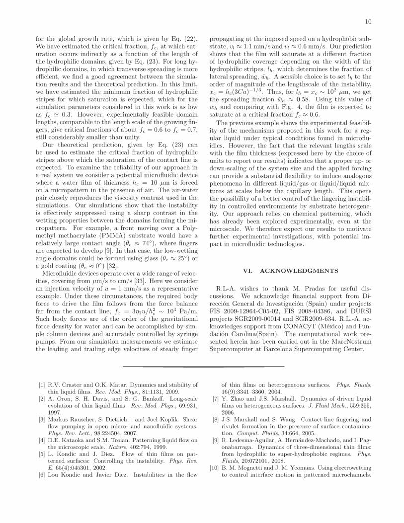
for the global growth rate, which is given by Eq. (22).We have estimated the critical fraction, fc, at which sat-uration occurs indirectly as a function of the length ofthe hydrophilic domains, given by Eq. (23). For long hy-drophilic domains, in which transverse spreading is moreefficient, we find a good agreement between the simula-tion results and the theoretical prediction. In this limit,we have estimated the minimum fraction of hydrophilicstripes for which saturation is expected, which for thesimulation parameters considered in this work is as lowas fc ≃ 0.3. However, experimentally feasible domainlengths, comparable to the length scale of the growing fin-gers, give critical fractions of about fc = 0.6 to fc = 0.7,still considerably smaller than unity.Our theoretical prediction, given by Eq. (23) can
be used to estimate the critical fraction of hydrophilicstripes above which the saturation of the contact line isexpected. To examine the reliability of our approach ina real system we consider a potential microfluidic devicewhere a water film of thickness hc = 10 µm is forcedon a micropattern in the presence of air. The air-waterpair closely reproduces the viscosity contrast used in thesimulations. Our simulations show that the instabilityis effectively suppressed using a sharp contrast in thewetting properties between the domains forming the mi-cropattern. For example, a front moving over a Poly-methyl methacrylate (PMMA) substrate would have arelatively large contact angle (θe ≈ 74◦), where fingersare expected to develop [9]. In that case, the low-wettingangle domains could be formed using glass (θe ≈ 25◦) ora gold coating (θe ≈ 0◦) [32].Microfluidic devices operate over a wide range of veloc-
ities, covering from µm/s to cm/s [33]. Here we consideran injection velocity of u = 1 mm/s as a representativeexample. Under these circumstances, the required bodyforce to drive the film follows from the force balancefar from the contact line, fx = 3η1u/h
2c ∼ 104 Pa/m.
Such body forces are of the order of the gravitationalforce density for water and can be accomplished by sim-ple column devices and accurately controlled by syringepumps. From our simulation measurements we estimatethe leading and trailing edge velocities of steady finger
propagating at the imposed speed on a hydrophobic sub-strate, vl ≈ 1.1 mm/s and vl ≈ 0.6 mm/s. Our predictionshows that the film will saturate at a different fractionof hydrophilic coverage depending on the width of thehydrophilic stripes, lh, which determines the fraction oflateral spreading, wh. A sensible choice is to set lh to theorder of magnitude of the lengthscale of the instability,xc = hc(3Ca)−1/3. Thus, for lh = xc ∼ 102 µm, we getthe spreading fraction wh ≈ 0.58. Using this value ofwh and comparing with Fig. 4, the film is expected tosaturate at a critical fraction fc ≈ 0.6.
The previous example shows the experimental feasibil-ity of the mechanisms proposed in this work for a reg-ular liquid under typical conditions found in microflu-idics. However, the fact that the relevant lengths scalewith the film thickness (expressed here by the choice ofunits to report our results) indicates that a proper up- ordown-scaling of the system size and the applied forcingcan provide a substantial flexibility to induce analogousphenomena in different liquid/gas or liquid/liquid mix-tures at scales below the capillary length. This opensthe possibility of a better control of the fingering instabil-ity in controlled environments by substrate heterogene-ity. Our approach relies on chemical patterning, whichhas already been explored experimentally, even at themicroscale. We therefore expect our results to motivatefurther experimental investigations, with potential im-pact in microfluidic technologies.
VI. ACKNOWLEDGMENTS
R.L-A. wishes to thank M. Pradas for useful dis-cussions. We acknowledge financial support from Di-reccion General de Investigacion (Spain) under projectsFIS 2009-12964-C05-02, FIS 2008-04386, and DURSIprojects SGR2009-00014 and SGR2009-634. R.L.-A. ac-knowledges support from CONACyT (Mexico) and Fun-dacion Carolina(Spain). The computational work pre-sented herein has been carried out in the MareNostrumSupercomputer at Barcelona Supercomputing Center.
[1] R.V. Craster and O.K. Matar. Dynamics and stability ofthin liquid films. Rev. Mod. Phys., 81:1131, 2009.
[2] A. Oron, S. H. Davis, and S. G. Bankoff. Long-scaleevolution of thin liquid films. Rev. Mod. Phys., 69:931,1997.
[3] Markus Rauscher, S. Dietrich, , and Joel Koplik. Shearflow pumping in open micro- and nanofluidic systems.Phys. Rev. Lett., 98:224504, 2007.
[4] D.E. Kataoka and S.M. Troian. Patterning liquid flow onthe microscopic scale. Nature, 402:794, 1999.
[5] L. Kondic and J. Diez. Flow of thin films on pat-terned surfaces: Controlling the instability. Phys. Rev.
E, 65(4):045301, 2002.[6] Lou Kondic and Javier Diez. Instabilities in the flow
of thin films on heterogeneous surfaces. Phys. Fluids,16(9):3341–3360, 2004.
[7] Y. Zhao and J.S. Marshall. Dynamics of driven liquidfilms on heterogeneous surfaces. J. Fluid Mech., 559:355,2006.
[8] J.S. Marshall and S. Wang. Contact-line fingering andrivulet formation in the presence of surface contamina-tion. Comput. Fluids, 34:664, 2005.
[9] R. Ledesma-Aguilar, A. Hernandez-Machado, and I. Pag-onabarraga. Dynamics of three-dimensional thin films:from hydrophilic to super-hydrophobic regimes. Phys.
Fluids, 20:072101, 2008.[10] B. M. Mognetti and J. M. Yeomans. Using electrowetting
to control interface motion in patterned microchannels.

11
Soft Matter, 6:2400, 2010.[11] M. P. Brenner. Instability mechanism at driven contact
lines. Phys. Rev. E, 47:4597, 1993.[12] S. M. Troian, X. L. Wu, and S. A. Safran. Fingering in-
stability in thin wetting films. Phys. Rev. Lett., 62:1496–1499, 1989.
[13] J.M. Davis and S.M. Troian. On a generalized approachto the linear stability of spatially non-uniform thin filmflows. Phys. Fluids, 15:1344, 2003.
[14] S. M. Troian, E. Herbolzheimer, S. A. Safran, and J.F.Joanny. Fingering instabilities in driven spreading films.Europhys. Lett., 10:25–30, 1989.
[15] H.E. Huppert. The flow and instability of viscous gravitycurrents down a slope. Nature, 300:427, 1982.
[16] N. Silvi and E.B. Dussan. On the rewetting of an inclinedsolid surface by a liquid. Phys. Fluids, 28:5–7, 1985.
[17] J.R. de Bruyn. Growth of fingers at a driven three-phasecontact line. Phys. Rev. A, 46:R4500, 1992.
[18] K.E. Holloway, P. Habdas, N. Semsarillar, K. Burfitt, andJ.R. de Bruyn. Spreading and fingering in spin coating.Phys. Rev. E, 75:046308, 2006.
[19] F.J. Higuera, S. Succi, and R. Benzi. Lattice gas-dynamics with enhanced collisions. Europhys. Lett.,9:345, 1989.
[20] M.R. Swift, E. Orlandini, W.R. Osborn, and J. Yeomans.Lattice boltzmann simulation of liquid-gas and binaryfluid systems. Phys. Rev. E, 54:5041, 1996.
[21] A. Moosavi, M. Rauscher, and S. Detrich. Motion ofnanodroplets near chemical heterogeneities. Langmuir,24:734, 2008.
[22] R. Ledesma-Aguilar, A. Hernandez-Machado, and I. Pag-onabarraga. Three-dimensional aspects of fluid flows inchannels: I. Meniscus and thin film regimes. Phys. Flu-
ids, 19:102112, 2007.
[23] V. M. Kendon, M. E. Cates, I. Pagonabarraga, J. C. De-splat, and P. Bladon. Inertial effects in three-dimensionalspinodal decomposition of a symmetric binary mixture:a Lattice-Boltzmann study. J. Fluid Mech., 440:147–203,2001.
[24] C. Huh and L.E. Scriven. Hydrodynamic model of steadymovement of a solid/liquid/fluid contact line. J. ColloidInterface Sci., 35:85, 1971.
[25] T. Qian, X.-P. Wang, and P. Sheng. A variational ap-proach to moving contact line hydrodynamics. J. Fluid
Mech., 564:333, 2006.[26] A.J. Briant and J.M. Yeomans. Lattice Boltzmann sim-
ulations of contact line motion. II. Binary fluids. Phys.
Rev. E, 69:031603, 2004.[27] D. Bonn, J. Eggers, J. Indekeu, J. Meunier, and E. Rolley.
Wetting and spreading. Rev. Mod. Phys., 81:739, 2009.[28] A.J. Bray. Theory of phase ordering-kinetics. Adv. Phys.,
43:357–459, 1994.[29] M.E. Cates, J.-C. Desplat, P. Stansell, A.J. Wagner,
K. Stratford, R. Adhikari, and I Pagonabarraga. Phys-ical and computational scaling issues in lattice Boltz-mann simulations of binary fluid mixtures. J. Stat. Phys.,363:1917, 2005.
[30] A.C.J. Ladd and R. Verberg. Lattice-Boltzmann sim-ulations of particle-fluid suspensions. J. Stat. Phys.,104:1191–1251, 2001.
[31] J. C. Desplat, I. Pagonabarraga, and P. Bladon. Lud-wig: A parallel Lattice-Boltzmann code for complex flu-ids. Comp. Phys. Comm., 134:273–290, 2001.
[32] H. Bruus. Theoretical Microfluidics. Oxford UniversityPress, 2008.
[33] T.M. Squires and S.R. Quake. Microfluidics: Fluidphysics at the nanoliter scale. Rev. Mod. Phys., 77:3,2005.


![Water-soluble aminocalix[4]arene receptors with hydrophobic and hydrophilic mouths](https://static.fdokumen.com/doc/165x107/63133b5cc32ab5e46f0c535e/water-soluble-aminocalix4arene-receptors-with-hydrophobic-and-hydrophilic-mouths.jpg)