
GRAVITY DAM Part 2: Stability Analysis Load Combinations
14
1 GRAVITY DAM Part 2: Stability Analysis Load Combinations Gravity dam design should be based on the most adverse load combination A, B, C, D, E, F or G given below using the safety factors prescribed. Depending on the scope and details of the various project components, site conditions and construction programme one or more of the following loading combinations may not be applicable ipso-facto and may need suitable modifications: • Load Combination A (Construction Condition) - Dam completed but no water in reservoir and no tailwater. • Load Combination B (Normal Operating Condition) - Full reservoir elevation, normal dry weather tailwater, normal uplift; ice and silt (if applicable). • Load Combination C (Flood Discharge Condition) - Reservoir at maximum flood pool elevation, all gates open, tailwater at flood elevation, normal uplift, and silt (if applicable ). • Load Combination D - Combination A, with earthquake. • Load Combination E - Combination B, with earthquake but no ice. • Load Combination F - Combination C, but with extreme uplift (drains inoperative). • Load Combination G - Combination E, but with extreme uplift (drains inoperative). Requirements for Stability Following are the modes of failure of a gravity dam: 1. Overturning 2. Sliding 3. Compression or Crushing 4. Tension. Therefore, the design shall satisfy the hollowing requirements of stability: 1. The dam shall be safe against sliding on any plane or combination of planes within the dam, at the foundation or within the foundation; 2. The dam shall be safe against overturning at any plane within the dam, at the base, or at any plane below the base; and 3. The safe unit stresses in the concrete or masonry of the dam or in the foundation material shall not be exceeded. The shape of a dam and curvature in its layout are pertinent in regard to the stability and more favourable stress conditions. Wherever possible dam and foundation designs should take advantage of the favourable conditions accruing from curved shapes, gradual transitions and fillets. For consideration of stability the following assumptions are made: 1. That the dam is composed of individual transverse vertical elements each of which carries its load to the foundation without transfer of load from or to adjacent elements. (NOTE - However. in the stability analysis of a gravity dam, it becomes frequently necessary to make an analysis of the whole block, wherever special features of foundation and large openings so indicate); and
-
Upload
independent -
Category
Documents
-
view
9 -
download
0
Transcript of GRAVITY DAM Part 2: Stability Analysis Load Combinations
1
GRAVITY DAM Part 2: Stability Analysis
Load Combinations
Gravity dam design should be based on the most adverse load combination A, B, C, D, E, F
or G given below using the safety factors prescribed. Depending on the scope and details of
the various project components, site conditions and construction programme one or more of
the following loading combinations may not be applicable ipso-facto and may need suitable
modifications:
• Load Combination A (Construction Condition) - Dam completed but no water in
reservoir and no tailwater.
• Load Combination B (Normal Operating Condition) - Full reservoir elevation, normal
dry weather tailwater, normal uplift; ice and silt (if applicable).
• Load Combination C (Flood Discharge Condition) - Reservoir at maximum flood
pool elevation, all gates open, tailwater at flood elevation, normal uplift, and silt (if
applicable ).
• Load Combination D - Combination A, with earthquake.
• Load Combination E - Combination B, with earthquake but no ice.
• Load Combination F - Combination C, but with extreme uplift (drains inoperative).
• Load Combination G - Combination E, but with extreme uplift (drains inoperative).
Requirements for Stability
Following are the modes of failure of a gravity dam:
1. Overturning
2. Sliding
3. Compression or Crushing
4. Tension.
Therefore, the design shall satisfy the hollowing requirements of stability:
1. The dam shall be safe against sliding on any plane or combination of planes within
the dam, at the foundation or within the foundation;
2. The dam shall be safe against overturning at any plane within the dam, at the base, or
at any plane below the base; and
3. The safe unit stresses in the concrete or masonry of the dam or in the foundation
material shall not be exceeded.
The shape of a dam and curvature in its layout are pertinent in regard to the stability
and more favourable stress conditions. Wherever possible dam and foundation designs should
take advantage of the favourable conditions accruing from curved shapes, gradual transitions
and fillets. For consideration of stability the following assumptions are made:
1. That the dam is composed of individual transverse vertical elements each of which
carries its load to the foundation without transfer of load from or to adjacent elements.
(NOTE - However. in the stability analysis of a gravity dam, it becomes frequently
necessary to make an analysis of the whole block, wherever special features of
foundation and large openings so indicate); and

2
2. That the vertical stress varies linearly from upstream face to downstream face on any
horizontal section.
Reaction of Foundations
The resultant of all horizontal and vertical forces including uplift should be balanced by an
equal and opposite reaction at the foundation consisting of the total vertical reaction and the
total horizontal shear and friction at the base and the resisting shear and friction of the passive
wedge, if any. For the dam to be in static equilibrium the location of this force is such that the
summation of moments is equal to zero. The distribution of the vertical reaction is assumed
as trapezoidal for convenience only, with knowledge that the elastic and plastic properties of
both the foundation material and the concrete do affect the actual distribution. The problem
of determining the actual distribution is complicated by the horizontal reaction, internal stress
relations and other theoretical considerations. Moreover, variations of foundation materials
with depth, cracks, and fissures which affect the resistance of the foundation also make the
problem more complex. For overflow sections, the base width is generally determined by
projecting the spillway slope to the foundation line and all concrete downstream from this
line is disregarded. If a vertical longitudinal joint is not provided at this point, the mass of
concrete downstream from the theoretical toe must be investigated for internal stresses.
Internal stresses and foundation pressures should be computed both with and without uplift to
determine the worst condition.
Overturning
The overturning of the dam section takes place when the resultant force at any section cuts
the base of the dam downstream of the toe. In that case the resultant moment at the toe
becomes clockwise (or -ve). On the other hand, if the resultant cuts the base within the body
of the dam, there will be no overturning. For stability requirements, the dam must be safe
against overturning. The factor of safety against overturning is defined as the ratio of the
righting moment (+ ve MR) to the overturning moments (- ve M0) about the toe
0M
M
MomentsgOverturnin
MomentsRightingFS R
Σ
Σ=
ΣΣ
=
The factor of safety against overturning should not be less than 1.5.
IS Code Recommendation - Before a gravity dam overturns bodily, other types of failures
may occur, such as cracking of the upstream material due to tension, increase in uplift,
crushing of toe material and sliding. A gravity dam is, therefore, considered safe against
overturning if the criteria of no tension on the upstream face, the resistance against sliding as
well as the quality and strength of concrete/masonry of the dam and its foundation is satisfied
assuming the dam and foundation as a continuous body.
Sliding Resistance
Many of the loads on the dam are horizontal or have horizontal components which are
resisted by frictional or shearing forces along horizontal or nearly horizontal planes in the
body of the dam, on the foundation or on horizontal or nearly horizontal seams in the
foundation. A dam will fail in sliding at its base, or at any other level, if the horizontal forces
causing sliding are more than the resistance available to it at that level. The resistance against
sliding may be due to friction alone, or due to friction and shear strength of the joint. Shear
strength develops at the base if benched foundations are provided and at other joints if the
joints are carefully laid so that a good bond develops. Shear strength also comes into play
because of the interlocking of stone in masonry dams.

3
The stability of a dam against sliding is evaluated by comparing the minimum total
available resistance along the critical path of sliding (that is, along that plane or combination
of planes which mobilizes the least resistance to sliding) to the total magnitude of the forces
tending to induce sliding. Sliding resistance is a function of the cohesion inherent in the
materials and at their contact and the angle of internal friction of the material at the surface of
sliding. The junction plane between the dam and rock is rarely smooth. In fact, special efforts
are made to avoid this condition. There may, however, be some lower plane in the foundation
where sliding is resisted by friction alone especially if the rock is markedly stratified and
horizontally bedded.
The factor of safety against sliding shall be computed from the following equation
and shall not be less than 1.0.
( )H
ccU
F
FAFPWFS
Σ
+Σ−Σ=
τµ φ
where FS = factor of safety against sliding, ΣW = dead load of the dam, ΣPU = total uplift
force, µ = tan φ = coefficient of internal friction of the material (varies from 0.65 to 0.75 for
concrete), τc = cohesion of the material or permissible shear stress at the plane considered
(=1.4 N/mm2
for concrete), A = area under consideration for cohesion, Fφ = partial factor of
safety in respect of friction, Fc = partial factor of safety in respect of cohesion, and ΣFH =
total horizontal force. The partial factor of safety in respect of friction and partial factor of
safety in respect of cohesion are given in Table 1.
The value of cohesion and internal friction may be estimated for the purpose of preliminary
designs on the basis of available data on similar or comparable materials. For final designs,
however, the value of cohesion and internal friction shall be determined by actual laboratory
and field tests.
Compression or Crushing
In order to calculate the normal stress distribution at the base, or at any section, let ΣFH be the
total horizontal force, ΣFV be the total vertical force and R be the resultant force cutting the
base at an eccentricity e from the centre of the base of width b (Fig.), which is equal to
xb −2 wherex is the distance of the resultant force R from the toe given by
( ) VoR FMMx ∑∑−∑=
The normal stress at any point on the base will be the sum of the direct stress and the bending
stress. Thus, direct stress σcc is

4
1×
Σ=
b
FV
ccσ
and bending stress σcbc at any fibre at distance y from Neutral Axis is
I
yMcbc
Σ±=σ
Since eFM VΣ=Σ ; 121 3bI ×= for
rectangular section of 1 m wide and b m deep;
and 2by = for extreme fibre at toe or heel,
hence the total normal stress pn is given by
±Σ
=Σ
±×
Σ=+=
b
e
b
F
b
eF
b
Fp VVV
cbcccn
61
6
1 2σσ
The positive sign will be used for calculating
normal stress at the toe, since the bending stress
will be compressive there, and negative sign
will be used for calculating normal stress at the
heel. Thus, the normal stress at the toe is
+Σ
=b
e
b
Fp V
toen
61,
and the normal stress at the heel is
−Σ
=b
e
b
Fp V
heeln
61,
Fig. shows the normal stress distributions for a general case when the pressure at both toe and
heel are compressive. Evidently, the maximum compressive stress occurs at the toe and for
safety, this should not be greater than the allowable compressive stresses both for the dam
and foundation materials. When the eccentricity e is equal to b/6 we get
0;2
,, =Σ
= heeln
V
toen pb
Fp
Fig. shows the pressure distribution for this case as well.
Tension
From equation for the normal stress at the heel it is evident that if e > b/6, the normal stress at
the heel will be -ve or tensile as shown in Fig. When the eccentricity e is greater than b/6 a
crack of length lc will develop due to tension which can be calculated as
−Σ
=×
Σ⇒
Σ=
×
Σ⇒= c
VVV
cbccc lb
b
eF
b
F
I
yM
b
F
2
12
11 3σσ
−=e
bblc
61
2
No tension should be permitted at any point of the dam under any circumstance for
Heel ∑Fv
∑FH
R
e b/2 b/2
Toe
e < b/6 pn,Toe
pn,heel
e = b/6 pn,Toe
pn,heel = 0
e > b/6 pn,Toe
pn,heel = - ve
x
lc

5
moderately high dams. For no tension to
develop, the eccentricity should be less
than b/6. In other words, the resultant
should always lie within the middle third.
However, in case of extra high dams, 230
to 260 m, small tension within the
permissible limit is generally permitted for
comparatively small periods of loading
such as heavy flood or earthquake as listed
in Table 2.
Effect of Tension Cracks: Since
concrete cannot resist the tension, a crack
develops at the heel, which modifies the
uplift pressure diagram, as illustrated in
Fig. Due to tension crack, the uplift pressure increases in magnitude and net downward
vertical force or the stabilizing force reduces. The resultant force thereby gets further shifted
towards the toe and this leads to further lengthening of the crack. The base width thus goes on
reducing and the compressive stresses on toe goes on increasing, till the toe fails in
compression or sliding.
Quality and Strength of Concrete/Masonry
The strength of concrete/masonry shall exceed the stresses anticipated in the structure by a
safe margin. The maximum compressive stresses occur at the heel or toe and on planes
normal to the faces of the dam. The strength of concrete and masonry varies with age, the
kind of cement and other ingredients and their proportions in the work can be determined
only by experiment. Mix proportions are determined from the results of laboratory tests made
with the materials that will be used in the structures. The proportions are selected to produce
concrete/masonry of sufficient strength to meet the design requirements multiplied by an
appropriate safety factor. In addition to meeting the requirements of strength the
concrete/masonry/mortar should be adequate in regard to placing characteristics, weathering
resistance, impermeability and resistance to alkali-aggregate attack.
The compressive strength of concrete should satisfy early load and construction
requirements and at the age of one year it should be four times the maximum computed stress
in the dam or 14 N/mm2, whichever is more. The allowable working stress in any part of the
structure shall not also exceed 7 N/mm2. The compressive strength of masonry should satisfy
early load and construction requirements and at one year it should be five times the maximum
computed stress on the dam or 12.5 N/mm2 whichever is more.
No tensile stress shall be permitted at the upstream face of the clam for load

6
combination B. Nominal tensile stresses, however, may be permitted in other load
combinations and their permissible values shall not exceed the values given in Table 2. Small
values of tension on the downstream face may be permitted since it is very improbable that a
fully constructed dam is kept empty and downstream cracks which are not extensive and for
limited depths from the surface may not be detrimental to the safety of the structure.
Principal and Shear Stresses
Principal Stress: Consider an elementary triangular section at either the heel or the toe of the
dam section such that stress intensities may be assumed to be uniform on its faces. The face
of the dam will be a principal
plane as water pressure acts on
it in the perpendicular direction,
with no accompanying shear
stress. Since the principal
planes are mutually at right
angle, the plane AB, considered
at right angles to the face AC,
well also have only a normal
stress on it, and will be the
other principal plane. The
forces acting on the elementary
section are shown in Fig.
Let ds, dr and dy be the lengths
of AC, AB and BC; p = intensity of water pressure; σ1 = principal stress on plane AB; τ =
shear stress; and pn = normal stress. Considering unit length of the dam, the normal forces on
the planes AB, BC and CA are respectively σ1 dr, pn dy and p ds. Resolving all the forces in
the vertical direction, we get
φσφ cossin 1drpdsdypn +=
But φcosdydr = and φsindyds = , therefore
φσφφσφ 2
1
22
1
2 cossincossin +=⇒+= ppdypdydyp nn
Hence
( ) φφσφφσ 22
1
22
1 tanseccossin pppp nn −=⇒−=
If pe is the intensity of hydrodynamic pressure due to an earthquake, then the principal stress
is given by
( ) φφσ 22
1 tansec en ppp +−=
This equation is known as the principal stress relationship, and is applicable to both upstream
and downstream faces. It should be noted, however, that for the upstream face σ1 will always
be less than p. Hence σ1 is the minor principal stress and p is the major principal stress for the
upstream face. For the downstream face σ1 will always be greater than p, so σ1 is the major
principal stress and p is the minor principal stress. However, for the downstream side, the
worst condition will be when there is no tailwater, and hence p will be zero and σ1 will be
maximum. If pe’ is the intensity of hydrodynamic pressure of tailwater due to an earthquake
the principal stress at the downstream becomes

7
( ) φφσ 2'2
1 tansec en ppp −−=
Shear Stress: Resolving all the forces in the horizontal direction, we get
φφφφστφφστ cossinsincoscossin 11 pdydydypdsdrdy −=⇒−=
Substituting the value of σ1 we get
( ) ( ) φτφφφφτ tansincostansec 22 ppppp nn −=⇒−−=
The above equation is applicable for downstream side only. For the upstream side, the
magnitude of τ will be the same but its direction will be reversed. If tailwater is neglected (p
= zero), the shear stress at the downstream side will be maximum. Considering the
hydrodynamic pressure due to earthquake, the shear stress at downstream is given by
( )( ) φτ tan'
en ppp −−=
Similarly, the shear stress for the upstream side is given by
( )( ) φτ tan'
en ppp +−−=
Elementary Profile of a Gravity Dam
In the absence of any force other than the forces due
to water, an elementary profile will be triangular in
section, having zero width at the water level, where
water pressure is zero, and a maximum base width b,
where the maximum water pressure acts. Thus, the
section of the elementary profile is of the same shape
as the hydrostatic pressure distribution diagram. For
reservoir empty condition, a right angled triangular
profile as shown in Fig., will provide the maximum
possible stabilising force against overturning, without
causing tension in the base. This is so because the
weight of the dam acts at distance b/3 from the
upstream face and is closer to it. If any triangular
profile, other than the right angled one, is provided,
its weight will act still closer to the upstream face to
provide a higher stabilising force, but tension will be
developed at the toe when the dam is empty.
We shall consider main three forces (weight
of the dam, water pressure, and uplift pressure) acting
on the elementary profile of a gravity dam viz
2;2;2 2
wUwHc CbHPHPbHW γγγ ===
where C = uplift pressure intensity factor.
Base width of the elementary profile
The base width of the elementary profile can be found under two criteria: (1) No Tensile
Stress Criterion, and (2) No Sliding Criterion.
No Tensile Stress Criterion: We have already seen that when reservoir is empty, for no
tension to develop, the resultant should act at the inner third point. For the reservoir full
8
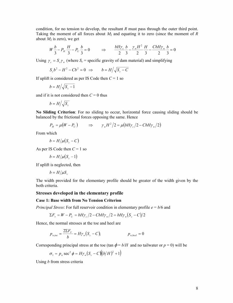
condition, for no tension to develop, the resultant R must pass through the outer third point.
Taking the moment of all forces about M2 and equating it to zero (since the moment of R
about M2 is zero), we get
0323232
0333
2
=−−⇒=−−bCbHHHbbHb
PH
Pb
W wwcUH
γγγ
Using wcc S γγ = (where Sc = specific gravity of dam material) and simplifying
CSHbCbHbS cc −=⇒=−− 0222
If uplift is considered as per IS Code then C = 1 so
1−= cSHb
and if it is not considered then C = 0 thus
cSHb =
No Sliding Criterion: For no sliding to occur, horizontal force causing sliding should be
balanced by the frictional forces opposing the same. Hence
( ) ( )2222
wcwUH CbHbHHPWP γγµγµ −=⇒−=
From which
( )CSHb c −= µ
As per IS Code then C = 1 so
( )1−= cSHb µ
If uplift is neglected, then
cSHb µ=
The width provided for the elementary profile should be greater of the width given by the
both criteria.
Stresses developed in the elementary profile
Case 1: Base width from No Tension Criterion
Principal Stress: For full reservoir condition in elementary profile e = b/6 and
( ) 222 CSbHCbHbHPWF cwwcUv −=−=−=Σ γγγ
Hence, the normal stresses at the toe and heel are
( ) 0;2
,, =−=Σ
= heelncw
V
toen pCSHb
Fp γ
Corresponding principal stress at the toe (tan φ = b/H and no tailwater or p = 0) will be
( ) ( )( )1sec22
1 +−== HbCSHp cwn γφσ
Using b from stress criteria
9
( ) ( )111
1 +−=
+
−−= CSH
CSCSH cw
c
cw γγσ
Shear Stress: Following similar procedure, shear stress at the toe will be
( ) ( ) HbCSHpp cwn −=−= γφτ tan
Using b from stress criteria
( ) CSHCSCSH cwccw −=−−= γγτ
Since the normal stress at the heel is zero, the principal stress and shear stress will be zero at
heel.
Case 2: Base width from No Sliding Criterion
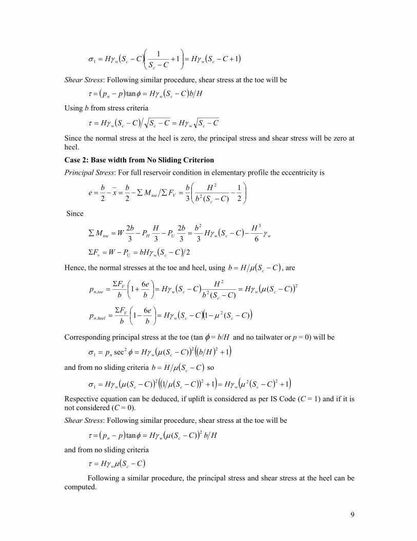
Principal Stress: For full reservoir condition in elementary profile the eccentricity is
−
−=∑∑−=−=
2
1
)(322 2
2
CSb
HbFM
bx
be
c
Vtoe
Since
( ) wcwUHtoe
HCSH
bbP
HP
bWM γγ
633
2
33
2 32
−−=−−=∑
( ) 2CSbHPWF cwUv −=−=Σ γ
Hence, the normal stresses at the toe and heel, using ( )CSHb c −= µ , are
( ) ( )22
2
, )()(
61 CSH
CSb
HCSH
b
e
b
Fp cw
c
cw
V
toen −=−
−=
+Σ
= µγγ
( )( ))(16
12
, CSCSHb
e
b
Fp ccw
Vheeln −−−=
−Σ
= µγ
Corresponding principal stress at the toe (tan φ = b/H and no tailwater or p = 0) will be
( ) ( )( )1)(sec222
1 +−== HbCSHp cwn µγφσ
and from no sliding criteria ( )CSHb c −= µ so
( ) ( )( )( ) ( )( )111)(2222
1 +−=+−−= CSHCSCSH cwccw µγµµγσ
Respective equation can be deduced, if uplift is considered as per IS Code (C = 1) and if it is
not considered (C = 0).
Shear Stress: Following similar procedure, shear stress at the toe will be
( ) ( ) HbCSHpp cwn
2)(tan −=−= µγφτ
and from no sliding criteria
( )CSH cw −= µγτ
Following a similar procedure, the principal stress and shear stress at the heel can be
computed.
10
Reservoir empty condition: When the reservoir is empty, the only force acting on the
elementary profile will be its weight, acting through the first third point M1. Hence, ΣFV = W,
and e = -b/6 so shear stress is zero and the maximum compressive normal stress equal to
principal stress at the heel or toe thus
0;2
;0 1,1, ======= heeltoewcheelntoen HSb
Wpp ττγσσ
Limiting Height of a Gravity Dam
The only variable in the expression for the principal stress σ1 at the toe is H. The maximum
value of this principal stress should not exceed the allowable stress σper for the material ie σ1
≤ σper. In the limiting case
( ) percw CSH σγσ =+−= 11
From which, the limiting height Hlim is given by
( )1lim +−= CSH cwper γσ
For finding the limiting height Hlim, it is usual not to
consider the uplift. Hence, putting C = 0, we get,
( )1lim += cwper SH γσ
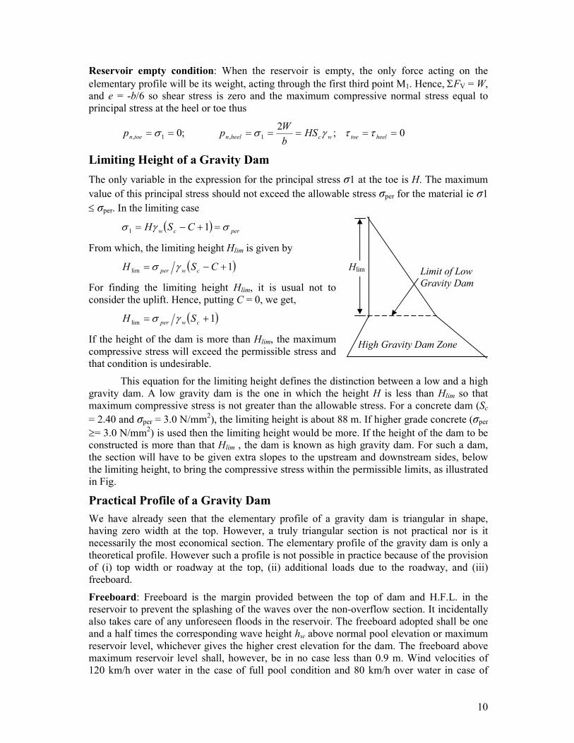
If the height of the dam is more than Hlim, the maximum
compressive stress will exceed the permissible stress and
that condition is undesirable.
This equation for the limiting height defines the distinction between a low and a high
gravity dam. A low gravity dam is the one in which the height H is less than Hlim so that
maximum compressive stress is not greater than the allowable stress. For a concrete dam (Sc
= 2.40 and σper = 3.0 N/mm2), the limiting height is about 88 m. If higher grade concrete (σper
≥= 3.0 N/mm2) is used then the limiting height would be more. If the height of the dam to be
constructed is more than that Hlim , the dam is known as high gravity dam. For such a dam,
the section will have to be given extra slopes to the upstream and downstream sides, below
the limiting height, to bring the compressive stress within the permissible limits, as illustrated
in Fig.
Practical Profile of a Gravity Dam
We have already seen that the elementary profile of a gravity dam is triangular in shape,
having zero width at the top. However, a truly triangular section is not practical nor is it
necessarily the most economical section. The elementary profile of the gravity dam is only a
theoretical profile. However such a profile is not possible in practice because of the provision
of (i) top width or roadway at the top, (ii) additional loads due to the roadway, and (iii)
freeboard.
Freeboard: Freeboard is the margin provided between the top of dam and H.F.L. in the
reservoir to prevent the splashing of the waves over the non-overflow section. It incidentally
also takes care of any unforeseen floods in the reservoir. The freeboard adopted shall be one
and a half times the corresponding wave height hw above normal pool elevation or maximum
reservoir level, whichever gives the higher crest elevation for the dam. The freeboard above
maximum reservoir level shall, however, be in no case less than 0.9 m. Wind velocities of
120 km/h over water in the case of full pool condition and 80 km/h over water in case of
High Gravity Dam Zone
Hlim Limit of Low
Gravity Dam

11
maximum reservoir condition are generally assumed for calculation of wave heights.
However, modern practice is to provide a maximum free board equal to 3 to 4 % of the dam
height, though free board equal to 5 % or more might prove economical.
Top width: If some top width T = AD is provided for the elementary section ABC, the
resultant of the dam section will be shifted to the u/s when the reservoir is empty. AM1 is the
inner third point line, and MI is the line passing
through the centroid of the added triangle ADE.
Both these lines intersect at point H. For all
sections below plane FHG, the resultant will,
therefore, be shifted to the left of line AM1,
causing tension at the down stream face when the
reservoir is empty. This will, therefore, require the
provision of u/s batter FC1 below the plane FHG.
In order to find the depth h' of the plane FHG
below which u/s batter is required, we have
TFHFGTAMFH 233
2==⇒==
But
CSTCSFGAFh cc −=−== 2'
Thus for heights greater than h’, u/s batter will
have to be provided. The centroidal line MIJ
intersects with the outer-third point line AM2 at J.
Hence, when the reservoir is full, the resultant of
all sections below the plane KJE is shifted to the u/s side. In order to bring the resultant back
to the outer third point line, for the sake of economy, the slope of d/s face may be flattened,
bringing it from EB to position EB1. Thus, due
to the provision of some top width T, the net
economical section will be ADEB1C1F as
shown in Fig. It can be seen that as the top
width is increased, the u/s batter is increased
while the d/s slope is decreased. The increase
in masonry volume due to provision of top
width is counter-balanced by the reduction in
the d/s slope at lower levels. It can be shown,
that within limits, the masonry added for the
provision of top width decreases, rather than
increases, the total masonry volume in the dam.
However, the most economical top width is the
function of height of dam. Creager has shown
that the most economical top width, without,
considering earthquake effects, is found to be
about 14 % of the height of dam. However, for
dams of low height, the top width provided on
the basis of economy (ie.14 % of height) may
have to be increased from other practical considerations, such as provision of roadway on the
top etc.
Thus due to provisions of freeboard and top width, some masonry is to be provided to

12
the upstream side and some masonry is removed from the downstream side to eliminate
tension and/or to economize. Fig. shows the dimensions of the practical profile of a gravity
dam.
Construction Issues
Construction Joints: Construction joints, usually called horizontal joints are necessary since
the entire work of concreting the whole dam cannot be completed in one stretch. The
concreting is, therefore, done in various stages. In solid gravity dams, the height between
horizontal joints is usually limited to about 1.5 m. This height between two successive
construction joints or horizontal joints is known as lift. Evidently, this height is· limited to the
necessity of providing sufficient cooling between pours. For the first layer immediately on
the rock, half this amount, i.e. 0.75 m height is adopted as the lift. Modern treatment of the
surface and good concrete create automatic water-tight horizontal joints, and as such no
provisions, such as water stops or keyways etc., are made in the horizontal joints. The
contraction joints, though provided for different purpose, also serve as construction joints
Contraction Joints: Contraction joints are mainly provided to avoid cracks caused due to
shrinkage of concrete due to temperature. A contraction joint is formed vertical or inclined
surface between masses of concrete/ masonry placed at different times. They divide the dam
into convenient sized monoliths to permit convenient and systematic construction and to
prevent the formation, owing to volume changes that cannot be prevented, of haphazard
ragged cracks.
One of the measures used to control cracks parallel to the length of the dam in the
case of relatively high dams is to subdivide the monolith into several blocks by longitudinal
contraction joints and subsequently grout these joints to ensure monolithic action. The
spacing of the joints is largely dictated by convenience of construction and the foundation
conditions. A spacing of 20-30 m is generally adopted. There is also now a school of thought
which believes that the longitudinal joints need to be at very close spacing (about 15 m) if
they are to achieve their purpose. However, it is recognized that the practice of dividing a
monolith into two or more blocks buy introducing joints parallel to the axis is basically
unsound unless a high degree of perfection is accomplished in ensuring monolithicity by
provision of suitable shear keys and successfully grouting at the appropriate time. It is now
being increasingly accepted that better alternative is to achieve necessary temperature control
by precooling of the concrete supplemented where necessary, by post-cooling and avoid
longitudinal contraction joints altogether, :even in case of high dams. No longitudinal joints
are considered necessary in dams built of rubble masonry with the construction methods in
vogue in India, as of now.
The spacing of transverse contraction joints shall be such as to suit the methods of
construction materials of the dam, the foundation conditions and the convenience of the
location of control gates outlet, etc. A spacing of -15 to 25 m may be adopted for concrete
dams; larger spacing may be adopted for masonry dams. The general requirement is that each
joint extends entirely through the
structure.
The characteristics of a dam
and its profile determine the
magnitude of the load transferred
horizontally through the joints to the
abutments. If the stream bed is wide
and flat, the vertical cantilever blocks from the centre of the dam towards end canyon walls

13
are approximately of the same length. Under load each will deflect downstream very nearly
the same amount and the load transferred horizontally across the joints (provided it is capable
of transferring the load) to the abutments will, therefore, be negligible except near the
abutment. In a narrow canyon with steep sloping walls, each cantilever block from the centre
of the dam towards the canyon wall will be shorter than the preceding one. In this case the
load will cause each succeeding block to deflect less than the preceding one and more than
the succeeding one. If the transverse joints are keyed and grouted, or keyed and ungrouted the
intervening cantilever block will be affected by adjacent ones. This interaction between
blocks causes torsional moments, or twist in the blocks, which materially affect the way in
which the loads are distributed to the foundation and abutments. If the joints are keyed and
grouted, part of the load will be transferred horizontally to the abutments by both bending and
shear in the horizontal beam elements. If the joints are keyed but ungrouted, the load will be
transferred horizontally to the abutments by shear across the keys. If the joints are neither
keyed nor grouted, the -entire load on the dam is transferred to the foundation independently
by each block.
Keys are invariably provided in longitudinal joints to permit the transfer of shearing
stresses from one block to the other. However, their provision in the transverse joints in
optional. The adjoining surfaces of each side of the joint are given such a shape as to be
interlocked together for the transfer of stresses. Keyways give a measure of shearing strength
required at times when the dam is only partly full and the lines of first principal stress are not
parallel to the joints. Water stops are provided in both the types of joints, to prevent leakage
of water. Water stops are also sometimes known as water bars. Water stops may be either of
metal, such as annealed copper, steel, monel, metal or sheet lead, or of natural or synthetic
rubbers and plastics such as polyvinyl chloride. Metal water stops are provided only in the
case of non-yielding foundations. For other cases of yielding foundation, rubber water bars
are preferred.
Galleries: A gallery is a formed opening left in a dam. This may run in transverse or
longitudinal direction and may run horizontally or on a slope. The shape and size varies from
dam to dam and is generally governed by the functions it has to perform. Following are the
purposes for which a gallery is formed in the dams.
1. To provide drainage' of the dam section. Some amount of water constantly seeps
through the upstream face of the dam which is drained off through galleries.
2. To provide facilities for drilling and grouting operations for foundations etc. Drillings
for drain is generally resorted to clean them if they are clogged. High pressure
grouting and required drilling for it is generally carried out after the completion of
dam. This can be best done through galleries.
3. To provide space for header and return pipes for post cooling of concrete and grouting
the longitudinal joints after completion of dam.
4. To provide access to observe and
measure the behaviour of the structure
after its completion by fixing thermo-
couples and examining development of
cracks etc.
5. To provide an access of mechanical
contrivances needed for the operation of
outlet gates and spillway gates.
Fig. shows two typical shapes of galleries. In

14
the rectangular gallery, all the corners should be rounded so that stress concentration is
minimum. Where drainage trough is required, a rectangular trough such as at c is necessary,
though shape d is preferred. In oval shaped gallery to provide walkway, the semi-circular
bottom is filled in with an unbounded slab.
Shafts: Vertical openings in the dam are called shafts. Shafts are provided to connect
galleries a (various levels. Plumber shaft is provided to measure the deflections of dam by
suspending a plumb bob in it.
Control of Cracking in Concrete Dams: If proper temperature control is not exercised, the
large concrete block between the joints may crack due to high temperature gradient between
the interior and the surface. These large blocks of concrete are subject to deep as well as
surface cracking. The cracks in the interior of the blocks are produced due to beat of
hydration liberated by cement thus giving rise to high temperature gradient. The surface
cracks may appear due to daily variations of the temperature at surface. The surface cracks
are more harmful, since the disintegration starts through them by wedge action. Water enters
these surface cracks, accumulates there and then solidifies. The ice so formed begins to
expand at 4°C, resulting in widening and deepening of cracks. Following are some of the
methods employed to check or minimize the development of the cracks in mass concrete:
1. Pre-cooling of concrete: The concrete is precooled before it is placed in the dam. This
is accomplished by cooling the aggregate by refrigerated water, blowing air through
them, cooling of sand and using refrigerated water for the manufacture of concrete.
All this involves high cost of preparing the concrete.
2. Post cooling of concrete: The post cooling is achieved by circulating refrigerated
water through pipes embedded in concrete in each lift. The cooling is begun
immediately after a block is laid and is continued till the mass temperature falls to the
mean annual temperature of the locality. For the purposes of circulating cool water,
thin walled tubings are placed in the middle of each lift. The horizontal spacing of
these tubings may be between 0.5 to 2 m and the velocity of flow is kept more than 60
cm per second. Resistance thermometers are embedded in the concrete to ascertain the
temperature.
3. Using low heat cement in the concrete.
4. Using lower percentage of cement in the concrete for the interior of the blocks, say
about 80 % of that for the exterior.
5. Restricting the height of lift, to say 1.5 m
6. Allowing considerable time between laying of two successive vertical lifts. The usual
time is about 4 days.
7. Providing contraction joints at suitable spacings.