Dam Rating Curves, Fort Loudoun.
402
Attachment 02.04.03-08J TVA letter dated February 2, 2010 RAI Response ASSOCIATED ATTACHMENTS/ENCLOSURES: Attachment 02.04.03-8J: Dam Rating Curves, Fort Loudoun (402 Pages including Cover Sheet)
-
Upload
khangminh22 -
Category
Documents
-
view
5 -
download
0
Transcript of Dam Rating Curves, Fort Loudoun.
Attachment 02.04.03-08JTVA letter dated February 2, 2010RAI Response
ASSOCIATED ATTACHMENTS/ENCLOSURES:
Attachment 02.04.03-8J: Dam Rating Curves, Fort Loudoun
(402 Pages including Cover Sheet)
NPG, CALCULATION COVERSHEETICCRIS UPDATEPage 1
TVA 40532 [I0G2008a NEDP,-24. [10-2.042008].
NPG CALCULATIONCOVERSHEET/CCRIS UPDATE
Page laREV. 0.EDMS/RIMS NO. .EDMS'TYPE: EOMSACCESSION NO (N/A for REV. 01L 5 8 0 9 0 3 0 4 0 0 Calculations (nuuear) N/ACalc Title:, Dam Rating Curves, Fort Loudoun
CALCJ ID YPE M PLANT BRANCH ;NUMBER ;CUR R NEV RIYd EV IJ~EAPPLICABILnICURRENT CN NUC
Entire calc [-'1Selected pages 0
NEW CN NUC GEN CEB CDQ000020080009 NfA 0..... ;1:
No CCRIS Changes ['TACTION NEW DELETE. El SUPERSEDE Li CCRIS UPDATEONLY E] (For caic revision, CCRISREVISION r RENAME DUPLICATE'. (VeriflaeApproval Signatures Not been reviewed and no.1 Required) CCRISSchanges required)UINITS SYSEMS UNIDS,000 N/A NIA.DCN.EDC.NIA APPLICABLEDESIGN DOCUMENTtS) ,.L1'ICIIN'N/A N/A
EQAIY SAFETY RELATED? .UVEFE SPECIAL REUIREMENTS -DESINUUT A S and/orISFSIEA(Ifyes, QR-yes) 0UMPTIO :ANDiO LIMIG CONDITIONS?; ATTACHMENT? CSARICaC FECTEQYest No 17 Yeso No.l I Yes12 No Yes[L] No0E Yesa[ No.0 Yesl NoPREPARER ID PREPARERPHONENO " PREPARING ORG fRANCHi vERIFICATION METHOD' GNEWMETHODOF ANALYSIS,attina [86,5-2204418 CES Deslgn Review 0]Yes 0 NoPREP R 3 RE 'DAT CHECK j)SIGNAT-EDTVERIFIER SIGNATUF• " ", DATE APPROVAL 1 UREDATE0,,;U10of2~
.. TATEMENT F -ROBLEMIABSTRACT
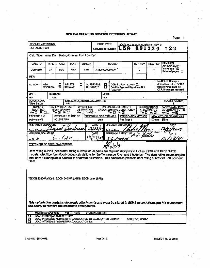
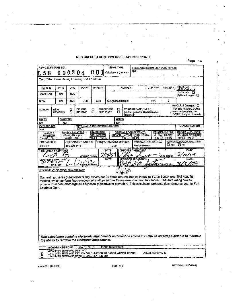
Dam rating curves (headwaterrating curves)-for 20 dams ar'erequired as inputs toTVA's SOCH and TR3ROUTEmodels, which perform flood-routing calculations for the Tennessee River and tributaries. The dam rating curvesprovide total dam discharge as a function of:headwater elevation. This calculation presents dam-rating curves for FortLoudoun Dam,
rThis calculation contains electronic attachments and must be storedin EDMS asan Adobe ;pdffile to maintainthe ability to retrieve the electronic attachments.
MICROFICHIEEFICHE Yes 0 No Q FICHE NUMBER(S)[3 LOAD IWTO EDMS AND DEbSTROY1 LOAD INTO EDMS AND RETURNMCALCULATION TO CALCULATION LIBRARY. ADDRESS: "LP4D-CQ1 LOAD INTO EDMS AND RETURN CALCULATION TO:
[VA 40S32 10-20051 Page-I ofT
NEDP-2-i [10-20-ZOOS]
TVA 40532 [1I0-2008]Page]I of 3 NEDP44[00-20-2008]
NPG CALCULATION COVERSHEET/CCRIS UPDATEPage 2
CALC ID ITYPE ORG I PLANT I BRANCH I Mll I4A RI:: I i ::\/ INUMBER EV I
..
CN NUC GEN CEB CDQ000020080009 1 1 -ALTERNATE CALCULATION IDENTIFICATION
BLDG ROOM ELEV COORD/AZIM FIRM Print Report Yes ElBWSC
CATEGORIES NA
KEY NOUNS (A-add, D-delete)
ACTION KEY NOUN A/D KEY NOUN
(N/D
CROSS-REFERENCES (A-add, C-change, D-delete)
ACTION XREF XREF XREF XREF XREF XREF(A/C/D' CODE TYPE PLANT BRANCH NUMBER REV
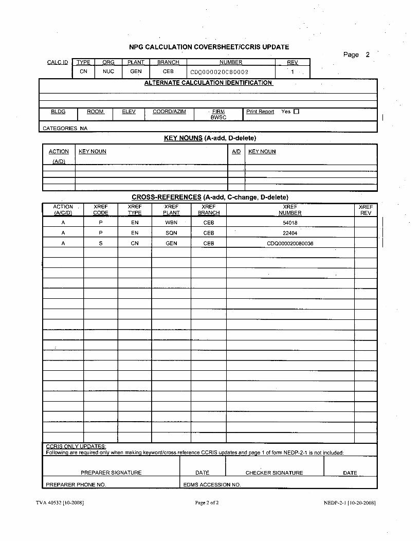
A P EN WBN CEB 54018
A P EN SQN CEB 22404
A S CN GEN CEB CDQ000020080036
I _I I _ _ _ II _ _ _ I _ _ _ _ _ _ I _
4 4 4 4 4 .1.
4 4 4 4 4 +
1 1 4 1 4 +
1 1 4 1 4 +
4 4 4 4 4 .4.
j a a aCCRIS ONLY UPDATES:Following are required only when making keyword/cross reference CCRIS updates and page 1 of form NEDP-2-1 is not included:
PREPARER SIGNATURE DATE CHECKER SIGNATURE DATE
PREPARER PHONE NO. EDMS ACCESSION NO.
TVA 40532 [10-2008] Page 2 of 2 NEDP-2-1 [10-20-2008]
NPG CALCULATION COVERSHEET/CCRIS UPDATE
Page 3
NPG CALCULATION RECORD OF REVISION
CALCULATION IDENTIFIER CDQ000020080009 ITitle Initial Dam Rating Curves, Fort Loudoun Dam
Revision DESCRIPTION OF REVISIONNo.
0 Initial Issue of Calculation, Total Pages - 158 Total PagesAppendix A - 37 Pages including Attachments
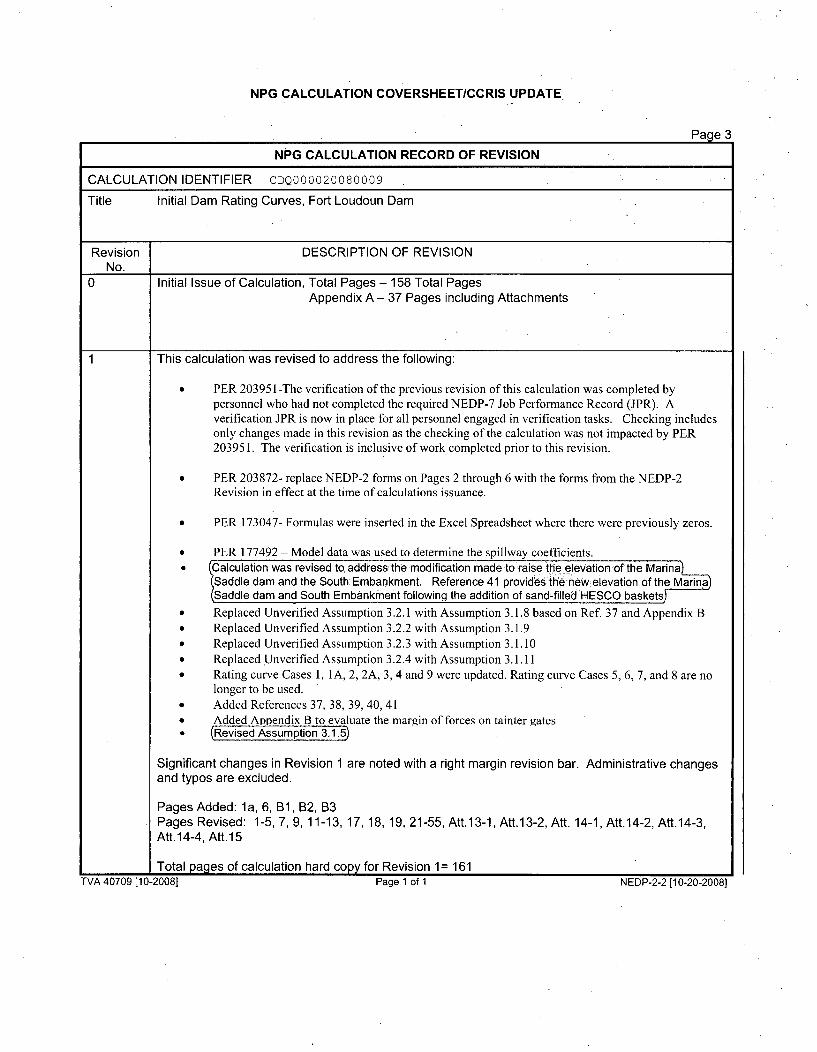
This calculation was revised to address the following:
" PER 20395 1-The verification of the previous revision of this calculation was completed bypersonnel who had not completed the required NEDP-7 Job Performance Record (JPR). Averification JPR is now in place for all personnel engaged in verification tasks. Checking includesonly changes made in this revision as the checking of the calculation was not impacted by PER203951. The verification is inclusive of work completed prior to this revision.
* PER 203872- replace NEDP-2 forms on Pages 2 through 6 with the forms from the NEDP-2Revision in effect at the time of calculations issuance.
" PER 173047- Formulas were inserted in the Excel Spreadsheet where there were previously zeros.
" PER 177492 - Model data was used to determine the spillway coefficients.* Calculation was revised to address the modification made to raise the elevation of the Marina
Saddle dam and the South Embankment. Reference 41 provides the new elevation of the MarinaýSaddle dam and South Embankment following the addition of sand-filled HESCO baskets.
* Replaced Unverified Assumption 3.2.1 with Assumption 3.1.8 based on Ref 37 and Appendix B* Replaced Unverified Assumption 3.2.2 with Assumption 3.1.9* Replaced Unverified Assumption 3.2.3 with Assumption 3.1.10* Replaced Unverified Assumption 3.2.4 with Assumption 3.1.11* Rating curve Cases 1, IA, 2, 2A, 3, 4 and 9 were updated. Rating curve Cases 5, 6, 7, and 8 are no
longer to be used.* Added References 37, 38, 39, 40, 41* Added Appendix B to evaluate the margin of forces on tainter gatesS lRevised Assumption 3.1.5)
Significant changes in Revision 1 are noted with a right margin revision bar. Administrative changesand typos are excluded.
Pages Added: la, 6, B1, B2, B3Pages Revised: 1-5, 7, 9, 11-13, 17, 18, 19, 21-55, Att.13-1, Att.13-2, Att. 14-1, Att.14-2, Att.14-3,Att. 14-4, Aft. 15
Total pages of calculation hard copy for Revision 1 = 161TVA 40709 [10-20081 Page 1 at 1 NEDP-2-2 110-20-2008]
TVA 40709 [10-2008] Page 1 of 1 NEDP-2-2 (10-20-20081
Paqe 4
NPG CALCULATION TABLE OF CONTENTS
Calculation Identifier: CDQ000020080009 Revision: 1
TABLE OF CONTENTS
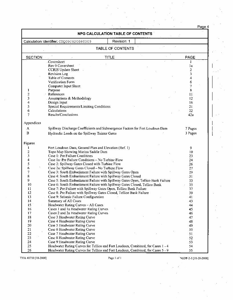
SECTION TITLE PAGECoversheet 1Rev 0 Coversheet laCCRIS Update Sheet 2Revision Log 3Table of Contents 4Verification Form 6Computer Input Sheet 7
1 Purpose 82 References 113 Assumptions & Methodology 124 .Design Input 165 Special Requirements/Limiting Conditions 216 Calculations 227 Results/Conclusions 42a
Appendices
A Spillway Discharge Coefficients and Submergence Factors for Fort Loudoun Dam 7 PagesB Hydraulic Loads on the Spillway Tainter Gates 3 Pages
Figures1 Fort Loudoun Dam, General Plan and Elevation (Ref. 1) 92 Topo Map Showing Marina Saddle Dam 103 Case 1: Pre Failure Conditions 234 Case la: Pre Failure Conditions-No Turbine Flow 245 Case 2: Spillway Gates Closed with Turbine Flow 266 Case 2a: Spillway Gates Closed - No Turbine Flow 277 Case 3: South Embankment Failure with Spillway Gates Open 298 Case 4: South Embankment Failure with Spillway Gates Closed 319 Case 5: South Embankment Failure with Spillway Gates Open, Tellico Bank Failure 3310 Case 6: South Embankment Failure with Spillway Gates Closed, Tellico Bank 3511 Case 7: Pre Failure with Spillway Gates Open, Tellico Bank Failure 3712 Case 8: Pre Failure with Spillway Gates Closed, Tellico Bank Failure 3913 Case 9: Seismic Failure Configuration 4114 Summary of All Cases 4315 Headwater Rating Curves - All Cases 4416 Cases 1 and I a Headwater Rating Curves 4517 Cases 2 and 2a Headwater Rating Curves 4618 Case 3 Headwater Rating Curve 4719 Case 4 Headwater Rating Curve 4820 Case 5 Headwater Rating Curve 4921 Case 6 Headwater Rating Curve 5022 Case 7 Headwater Rating Curve 5123 Case 8 Headwater Rating Curve 5224 Case 9 Headwater Rating Curve 5325 Headwater Rating Curves for Tellico and Fort Loudoun, Combined, for Cases 1 - 4 5426 Headwater Rating Curves for Tellico and Fort Loudoun, Combined, for Cases 5 - 9 55
TVA 40710 [10-2008] Page I of I NEDP-2-3 [ 10-20-2008]
Page 5
NPG CALCULATION TABLE OF CONTENTS (CONTINUED)
Calculation Identifier: CDQ000020080009 Revision: 1
TABLE OF CONTENTS
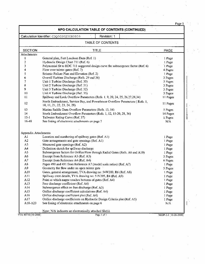
SECTION TITLE PAGEAttachments
1
234567891011
12
131415-116-48
General plan, Fort Loudoun Dam (Ref. 1)Hydraulic Design Chart 711 (Ref. 6)Polynomial fit to HDC 711 suggested design curve for submergence factor (Ref. 6)Flow over tainter gates (Ref. 7)Seismic Failure Plan and Elevation (Ref. 2)Overall Turbine Discharge (Refs. 29 and 36)Unit 1 Turbine Discharge (Ref. 30)Unit 2 Turbine Discharge (Ref. 31)Unit 3 Turbine Discharge (Ref. 32)Unit 4 Turbine Discharge (Ref. 33)Spillway and Lock Overflow Parameters (Refs. 1, 9, 20, 24, 25, 26,27,28,34)
North Embankment, Service Bay, and Powerhouse Overflow Parameters ( Refs. 1,10,11,21,22,23,24,28)
Marina Saddle Dam Overflow Parameters (Refs. 13, 14)South Embankment Overflow Parameters (Refs. 1, 12, 15-20, 28, 36)Tailwater Rating Curve (Ref. 37)See listing of electronic attachments on page 7
1 Page1 Page1 Page
4 Pages1 Page
3 Pages3 Pages3 Pages3 Pages3 Pages
11 Pages
11 Pages
5 Pages14 Pages1 Pages
N/A
Appendix AttachmentsAl Location and numbering of spillway gates (Ref. Al)A2 Gate arrangements and gate openings (Ref. Al)A3 Measured gate openings (Ref. A2)A4 Definition sketch for spillway dischargeA5 Submergence factors for Orifice Flow through Radial Gates (Refs. A6 and A10)A6 Excerpt from Reference A3 (Ref. A3)A7 Excerpt from Reference A4 (Ref. A4)A8 Pages 490 and 491 from Reference A7 (model scale ratios) (Ref. A7)A9 Geometry for flow under an open tainter gateA10 Gates, general arrangement, TVA drawing no: 54W200, R6 (Ref. A8)All Spillway crest details, TVA drawing no: 51N205, R4 (Ref. A9)A 12 Point at which nappe touches bottoms of gates (Ref. A4)A13 Free discharge coefficient (Ref. A4)A 14 Submergence effect on free discharge (Ref. A3)A 15 Orifice discharge coefficient calculations (Ref. A4)A 16 Orifice discharge coefficient plot (Ref. A4)A 17 Orifice discharge coefficients on Hydraulic Design Criteria plot (Ref. A5)A 18-A23 See listing of electronic attachments on page 6
I Page1 Page1 PageI Page1 Page5 Pages6 Pages1 Page
5 Pages1 PageI Page1 Page1 Page1 Page1 Page1 Page1 PageN/A I.
Note: N/A indicates an electronically attached file(s).I ?VA 40710 [10-2008] Page I of I NEDP-2-3 [10-20-2008]
Page-6
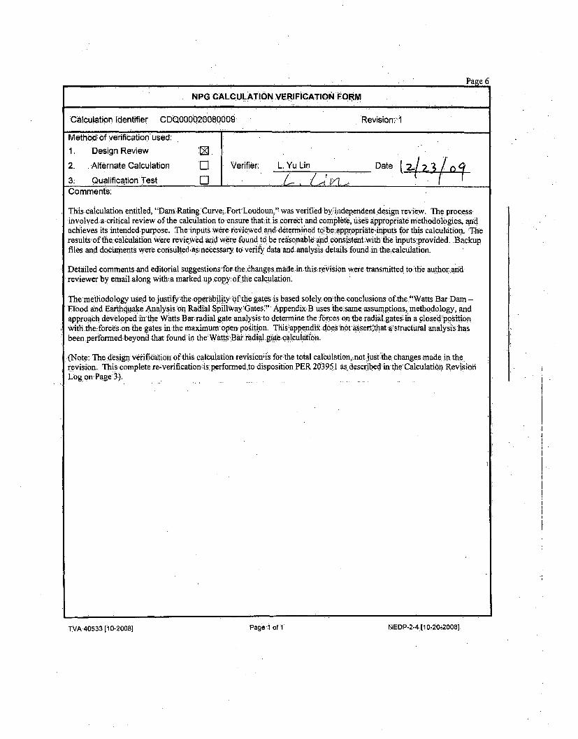
NPG CALCULATION VERIFICATION FORM
'Calculation Identifier 0DQ000020080009, Revision:. I
-Method: of Verification'used:
1. 'Design Review [
2. Alternate Calculation 'r-I Verifier: L.'Yu Lin Date ( 2./
3ý Qualification Test E]-j•/•/.
Comments:
Thiscalculation entitled, "DamRating Curve, FortLoudoun,"-was verified by independent design review. The process-
involved alcritical review of the.calctilation to ensure thatit~is.correct and complete,,USes appropriate methodologies, and
achieves its intended purpose. The inputs were reViewed and ddtermined tabe appropriateinputs for this calculation. ;The
,results ofthe.calculation Were reviewed anid were found;to be reisonabledand consistent withý the inputs provided. "Backup
files and docurents were.constilted;bsnecessaxy to verif data andanalysis details found in the~calculation.
Detailed comments and editorial suggestions for.the dhanges made.in.thisrevision were transmitted to the authorland
reviewer-by emailalong with a marked up copy.-of the calc ulatirn.
The methodology used to justifythe operabilityrbf the gates is based solely on~the-conclusions of thej"Watts Bar Dam -
Fibodand Emrth, qiakae Analysis oonRadial Spillway'Gates:" AppendixB uses the same assumptions, methodology, and
approach developed in'the Watts Barradial gate:analysis-to determine-the forces on the radial gateshin a closed'positionwith the-.forces on the gates inthe maximum open position. This§appendii does'notassert.that a'structutral analysishasbeen performedbeyond-that found in the'Watts Bai radial gatecalculhition.
(Note: The design ve-ification of this calculationrevisionis for the total calculation, not just the changes-made in the
revision. This complete re-verification isperformed to disposition PER 203951 as described in'the Calculation Revision
Log on Page 3).
TVA 40533 El 0-2008) Page-I ofi NEDP-2-4 [10-20-2008]
TVA 40533 [10-20081 Pagel' of 1 NEDP-2-4 [1 040-20081
Paae 7
NPG COMPUTER INPUT FILESTORAGE INFORMATION SHEET
Document CDQ000020080009 Rev. 1 Plant: GEN
Subject:Initial Dam Rating Curves, Fort Loudoun Dam
L] Electronic storage of the input files for this calculation is not required. Comments:There is no electronic input or output files associated with this calculation.
Z Input files for this calculation have been stored electronically and sufficient identifying information is providedbelow for each input file. (Any retrieved file requires re-verification of its contents before use.)
These files are electronically attached to the parent ADOBE.pdf calculation file. All files are therefore stored in an
unalterable medium and are retrievable through the EDMS number for this calculation.
Attachment 16: 16 - Fort Loudoun DRCRevl.xlsSpreadsheet for dam rating curve calculations
Attachment 17: Fort Loudoun Area Topo.pdf
A high-resolution PDF file of the topo map portion in Figure 2.
Attachment 18: Complete PDF copy of Reference 2Attachment 19: Complete PDF copy of Reference 3 (also referenced as Al)Attachment 20: Complete PDF copy of Reference 7
Attachment 21: Complete PDF copy of Reference 36
Attachments 22 through 48: Large resolution PDF files of References 1 and 9-34
Attachment A18: Watts Bar Model Data for Dam Ratings.xls
Spreadsheet for model data calculations
Attachment Al 9: Complete PDF copy of Reference A3
Attachment A20: Complete PDF copy of Reference A4Attachment A21: Large resolution PDF file of Reference A8
Attachment A22: Large resolution PDF file of Reference A9
Attachment A23: Combined Submergence Factors for Watts Bar and Fort Lo.xls
Spreadsheet for model data calculations
F- Microfiche/eFiche
TVA 40535 [10-2008] Page I of I NEDP-2-6 [ 10-20-2008]
TVACalculation No. CDQ000020080009 Rev: 0 Plant: GEN Page: 8
Subject: Initial Dam Rating Curves, Fort Loudoun Prepd: A.T. Tinsley
Checked: J.C. Triplett
1. Purpose
Dam rating curves (headwater rating curves) for twenty dams geographically located on the Tennessee River and its tributariesabove the existing Bellefonte Nuclear facility are required as inputs to TVA's SOCH and TRBROUTE models, which performflood-routing calculations. The dam rating curves for each dam provide total dam discharge as a function of headwater elevation.This calculation presents dam rating curves for Fort Loudoun Dam.
TVA developed methods of analysis, procedures, and computer programs for determining design basis flood levels for nuclearplant sites in the 1970's. Determination of maximum flood levels included consideration of the most severe flood conditions thatmay be reasonably predicted to occur at a site as a result of both severe hydrometerological conditions and seismic activity. Thisprocess was followed to meet Nuclear Regulatory Guide 1.59. At that time, there were no computer programs available thatwould handle unsteady flow and dam failure analysis. As a result of this early work and method development TVA developed arunoff and stream course modeling process for the TVA reservoir system. This process provided a basis for currently licensedplants (Sequoyah Nuclear Plant, Watts Bar Nuclear Plant, and Browns Ferry Nuclear Plant). The Bellefonte Nuclear Plant (BLN)Units 1 & 2 Final Safety Analysis Report (FSAR) was also based on this process.
BLN Unit 3 & 4 Combined Operating License Application (COLA) was submitted using data and analysis that was determinedfor the original BLN FSAR (Unit 1 and Unit 2) and was documented in a 1998 reassessment. In 1998, the analysis process anddocumentation was brought under the nuclear quality assurance process for the first time. A quality assurance audit conducted byNRC staff in early 2007 raised several questions related to the documentation of past work regarding design basis flood leveldeterminations. This calculation supports a portion of the effort to improve this designbasis documentation.
Preparation of all calculations supporting nuclear development and licensing are subject to TVA Standard Department ProcedureNEDP-2. This standard dictates the process in which calculations are prepared, checked, verified, stored, and cross referenced ina goal to provide the highest quality nuclear design input and output possible.
As required by NRC Regulatory Guide 1.59, the most severe seismically induced floods reasonably possible should beconsidered for each site in addition to the floods produced by the severe hydrometeorological conditions. Also, theconsideration of seismically induced floods should include the same range of seismic events as is postulated for the design ofthe nuclear plant. The seismic design basis for the plant requires consideration of an Operating Basis Earthquake (OBE) or 0.5Safe Shutdown Earthquake (SSE) and a full SSE.
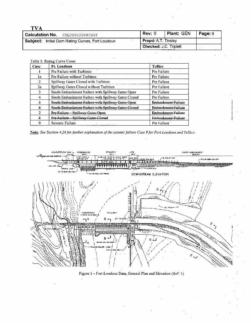
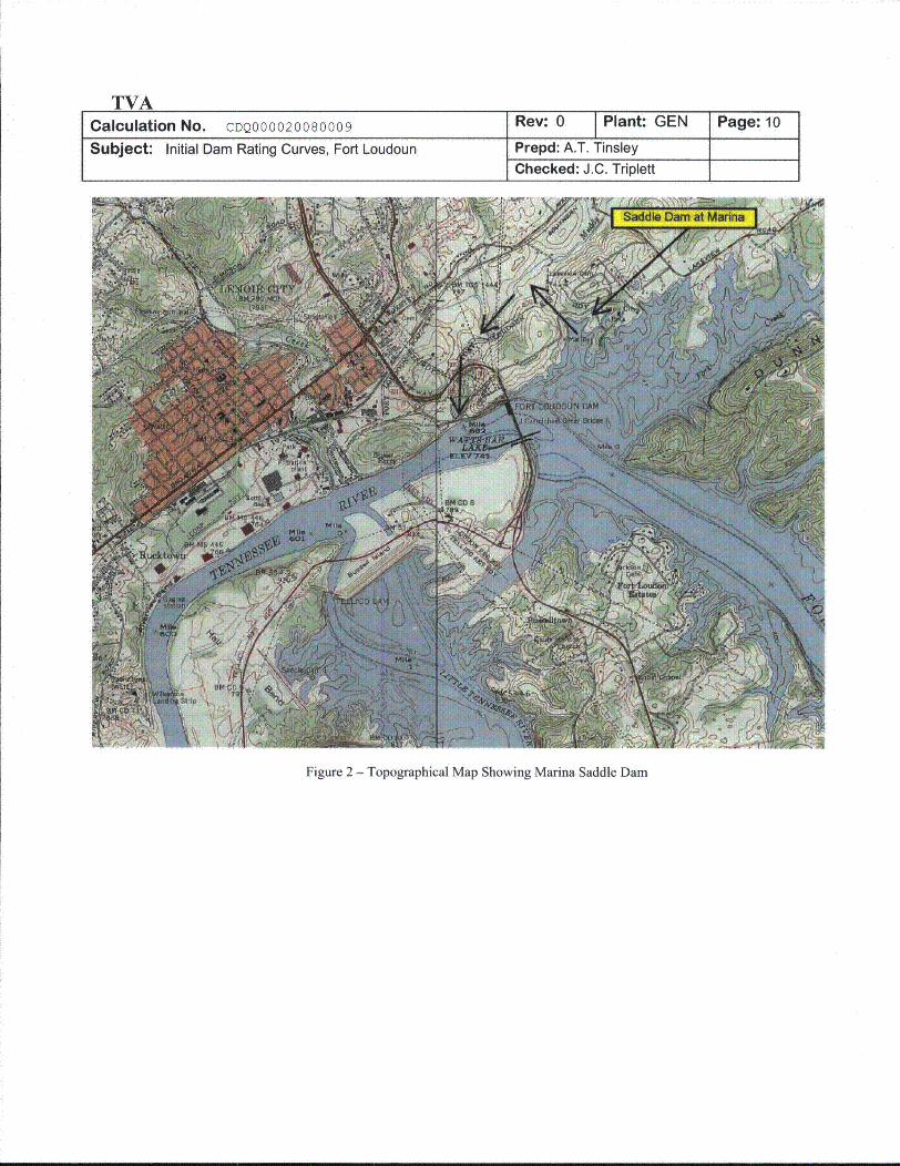
Figure 1 is a plan and elevation view of Fort Loudoun Dam (a portion of Reference 1). For headwaters in the normal operatingrange, discharge is passed through the turbines or over the spillway. The spillway consists of fourteen spillway bays, each with aradial, or tainter gate, to control discharge. If, as during a probable maximum flood (PMF) event, headwater rises above thenormal operating range, discharge may pass also over the nonoverflow section, the navigation lock, the tops of the open spillwaygates, the tops of the spillway piers, and the north and south embankments. In addition, as indicated in Figure 2, discharge mayalso pass over the Marina Saddle Dam that closes a low point in the reservoir rim. The purpose of this calculation does notevaluate the design loading conditions of the dam. Rating curves are provided for several cases as listed in Table 1.
TVACalculation No. CDQ000020080009 Rev: 0 Plant: GEN Page: 9
Subject: Initial Dam Rating Curves, Fort Loudoun Prepd: A.T. TinsleyChecked: J.C. Triplett
Table 1: Rating Curve Cases
Case Ft. Loudoun Tellico1 Pre Failure with Turbines Pre Failurela Pre Failure without Turbines Pre Failure2. Spillway Gates Closed with Turbines Pre Failure
2a Spillway Gates Closed without Turbines Pre Failure3 South Embankment Failure with Spillway Gates Open Pre Failure4 South Embankment Failure with Spillway Gates Closed Pre Failure
5 South Embankment Failure with Spiliway-Gates Ope Emfbankmnent Failurfe6 Setuth Emibanikmfent Failtrc v.ith SpilkwyGatý6es Closed- Emnbankmfent Failur-e7 Pre Failute Spillway G.tes Ope l . Embanfkment Failure
g Pre Failuire Spillway Gates Closed- Emfbaadfent F-ailure9 Seismic Failure Pre Failure"
Note: See Section 4.26for further explanation of the seismic failure Case 9for Fort Loudoun and Tellico
NONOvERFLOW DAM POWERHOUSE
th\I ] gVt •
SPILLWAY LOCK
S•~ CS-[ ý •L '77tO7 S t B. E L %25 -It6L 57. _0,, 7S 5 .-cf ' _1rr
EARTN EMBANKMENT
DOWNSTREAM ELE
_ 0. . ... .. .
VATION
Figure 1 - Fort Loudoun Dam, General Plan and Elevation (Ref 1).
TVACalculation No. CDQ000020080009
Subject: Initial Dam Rating Curves, Fort Loudoun
P•'L %
SadeDam at Maia I ý
Figure 2 - Topographical Map Showing Marina Saddle Dam
TVACalculation No. CDQ000020080009 Rev: 1 Plant: GEN Page: 11
Subject: Initial Dam Rating Curves, Fort Loudoun Prepd: WBBChecked: ACM
2. References
1. TVA drawing no: 10W200, R 11 (Attachments 1, 11-4, 12-4, 14-11, and 22)2. TVA Calculation. "Ft. Loudoun - Concrete Stability Analysis for SSE and ½2 SSE + ½ PMF." RIMS 880525E0010. Accession
Number B66880520302. Revision 1 (Attachments 5 and 18).3. "Fort Loudoun Dam Spillway Discharge Tables", River Operations, Tennessee Valley Authority, 2004. RIMS Acc.:No. L58
081212 809 (Attachment 19).4. "Hydraulic Design Criteria," USACE (U. S. Army Engineer Waterways Experiment Station), Eighteenth issue, Vicksburg, MS,
1988.5. Handbook of Hydraulics, E. F. Brater and H. W. King, Sixth Ed., McGraw Hill, 1976.6. Hydraulic Design Chart 711 (HDC 711) from Reference 3 (Attachment 2).7. "Rating Curves for Flow over Drum Gates," Joseph N. Bradley, Paper No. 2677, Transactions of the American Society of Civil
Engineers, vol. 119, pp. 403-433, 1954 (Attachment 20).8. Reference Deleted9. TVA drawing no: 21/2.2 (Attachments 11-6 and 23)10. TVA drawing no: 22W200, RIO (Attachments 12-6 and 24)11. TVA drawing no: 22W214, R9 (Attachments 12-8 and 25)12. TVA drawing no: 23W200, R 1I (Attachments 14-14 and 26)13. TVA drawing no: 23W220-1, R2 (Attachments 13-4 and 27)14. TVA drawing no: 23W220-2, R2 (Attachments 13-5 and 28)15. TVA drawing no: 23W230-1, R3 (Attachments 14-5 and 29)16. TVA drawing no: 23W230-2, R2 (Attachments 14-6 and 30)17. TVA drawing no: 23W230-3, R2 (Attachments 14-7 and 31)18. TVA drawing no: 23W230-4, R2 (Attachments 14-8 and 32)19. TVA drawing no: 23W230-5, R3 (Attachments 14-9 and 33)20. TVA drawing no: 23W230-7, Ri (Attachments 14-10 and 34)21. TVA drawing no: 41N508, R4 (Attachments 12-5 and 35)22. TVA drawing no: 41N615, RI (Attachments 12-7 and 36)23. TVA drawing no: 46N402, R6 (Attachments 12-9 and 37)24. TVA drawing no: 51N200, R2 (Attachments 11-7, 12-10, and 38)25. TVA drawing no: 61W220-1, RO (Attachments 11-5 and 39)26. TVA drawing no: 61W804-1, R1 (Attachments 11-10 and 40)27. TVA drawing no: 66N201, R7 (Attachments 11-9 and 41)28. TVA drawing no.: 80H3401, R3 (Attachments 11-8, 12-11, 14-12, and 42)29. TVA drawing no.: 41N600, R5 (Attachments 6-2 and 43)30. TVA drawing no.: 47B901, RO (Attachments 7-3 and 44)31. TVA drawing no.: 47B904, RO (Attachments 8-3 and 45)32. TVA drawing no.: 47B908, RO (Attachments 9-3 and 46)33. TVA drawing no.: 47B912, RI (Attachments 10-3 and 47)34. TVA drawing no.: 64W204. RO (Attachment 11-1 land 48)35. Open Channel Flow, Sec. 2.7, F. M. Henderson, Macmillan, New York, 1966.36. TVA Water Control Project Blue Book. Fort Loudoun Dam. July 1998. (Attachment 6, 14-13, and 21)37. "Basis for Dam Spillway Gate/Outlet Open Configuration for Flood Analyses," Tennessee Valley Authority, May 29, 2009
(EDMS No. L58 090529 800)38. "SOCH Model Calibration, Ft. Loudoun - Tellico," CDQ000020080036 (EDMS L58 090814 003).39. "Dam Lock Gate Technical Evaluation for the PMF," Tennessee Valley Authority, 2009, (EDMS No. L58 090908 001).40. "SOCH Model Calibration, Watts Bar," CDQ000020080037 (EDMS L58 090814 002)41. "Bellefonte Units 3 and 4 Hydrology Project Request for Information (RFI) Response Information Continuation Sheet," RFI
Number BWSC_75578_2009054 (EDMS L58 091216 801)
TVACalculation No. CDQ000020080009 Rev: 1 Plant: GEN Page: 12
Subject: Initial Dam Rating Curves, Fort Loudoun Prepd: WBBChecked: ACM
3. Assumptions & Methodology
The initial dam rating curves developed in these calculations will be used in simulations of probable maximum flood events.Consequently, the rating curves have been calculated well above the normal operating range and several feet above the top ofthe dam.
3.1 Assumptions
3.1.1 Assumption: Power generation will continue until valid reason to shut off turbines is demonstrated.Technical Justification: Turbine flow will contribute to flow through the dam in the event of a PMF occurrence. Thehead differential will be less than optimal since the tailwaters will almost certainly be elevated during such an event.Reference 29 (Attachment 6-2) shows that turbine flows can logically be included for headwater ranges between 790'and 815' and tailwater ranges below 797'. The turbine flow will be based on the equation developed in Attachments 6thru 10 and a gross head of 15' (See Attachment 6) will be considered the minimum amount of head to operate theturbines. The flow through all four turbines will not exceed 32,200 cfs (see Attachment 6) under any circumstances.
3.1.2 Assumption: The North Embankment will fail at the same headwater elevation of the nonoverflow section and will failto the overflow elevation of the core wall.Technical Justification: Since the North Embankment and the nonoverflow section of the dam are located next to eachother, they will be assumed to fail at the same elevation of 826.5' (Reference 21, Attachment 12-5). This assumptionis valid since the embankment will not be overtopped until that elevation. The failure length and depth will beconsistent with the length of the core wall that extends beneath the North Embankment as outlined in Attachment 12 ofthis calculation. Since the length of this failed section is relatively minimal when compared to the rest of the dam,failure will be assumed at any elevation greater than the overtopping height of 826.5' and no separate failure case willbe computed. The assumption has minimal effects on the final rating curves produced by this calculation.
3.1.3 Assumption: For calculating overflow discharge at the Marina Saddle Dam, the reservoir water elevation may beassumed to equal the headwater elevation at Fort Loudoun Dam.Technical Justification: The Marina Saddle Dam is located less than one mile from Fort Loudoun Dam (see Figure 2).The calculation of overflow at the Marina Saddle Dam, both before and after failure, is approximate in nature and willnot be made more uncertain by neglecting differences between the water level at the Marina Saddle Dam and the FortLoudoun headwater during a PMF.
3.1.4 Assumption: The total discharge used to determine tailwater from the rating curve includes discharge from the MarinaSaddle Dam.Technical Justification: Discharge from the Marina Saddle Dam will enter the tailwater about one half miledownstream from the Fort Loudoun Dam (see Figure 2) and will have an effect on the tailwater levels.
3.1.5 Assumption: The PMF headwaters at Ft. Loudoun and Tellico will be the same until the elevation reaches 830.0. ForPMF headwaters above 830.0, it is assumed that the PMF headwater at Tellico linearly increases from 830.0 to 834.0as the PMF headwater at Ft. Loudoun increases from 830.0 to 837.0.Technical Justification: Development of initial rating curves requires an assumption about the relationship betweenheadwater elevations at Ft. Loudoun and Tellico. The assumed relationship was based on preliminary SOCH analysis.Since this assumption affects only the initial curves and has no effect on rating curves determined from future iterativeanalyses, this assumption is acceptable.
3.1.6 Assumption: The South embankment and Marina Saddle Dam will fail to the approximate original ground elevation.Technical Justification: Original ground elevation represents the most probable extent to which the Marina SaddleDam and South embankment would fail. They may erode less than this but would not be expected to erode further.While no documentation regarding the failure elevation of these sections exists, this is a similar approach taken onother dams in the Bellefonte FSAR. Since the original ground elevation is not clearly stated on the drawings,estimates of the original ground elevation are utilized. Slight variances from the original ground elevation haveminimal effect on the final curves.
TVACalculation No. CDQ000020080009 Rev: 1 Plant: GEN Page: 13
Subject: Initial Dam Rating Curves, Fort Loudoun Prepd: WBBChecked: ACM
3.1.7 Assumption: Elevations of the top of the Marina Saddle Dam and South Embankment have been raised to elevation837.(Ref. 41).Technical Justification: TVA has made physical modifications to both the Marina Saddle Dam and SouthEmbankment.
3.1.8 Assumption: All spillway gates will remain operable and will be set to the maximum openings specified in thespillway discharge tables.Technical Justification: For technical justification, see Reference 37, "Basis for Dam Spillway Gate/Outlet OpenConfiguration for Flood Anaylses", and Appendix B. The radial gates will remain operable in the maximum openedposition based on the findings of the "Watts Bar Dam - Flood and Earthquake Analysis on Radial Spillway Gates"(Reference B 1). Appendix B uses the same assumptions, methodology, and approach as the Watts Bar radial gateanalysis to compare forces on the gates in a closed position with forces on the gates in the maximum open positionto provide technical justification for the gates to remain operable in the maximum open position during a PMF.
3.1.9 Assumption: The upper gate of the navigation lock will not fail when overflowed.Technical Justification: For technical justification, see Reference 39, "Dam Lock Gate Technical Evaluation for thePMF".
3.1.10 Assumption: The tailwater rating curve included as Attachment 15 is used in the initial dam rating curvecalculations.Technical Justification: The final tailwater curve was verified in the unsteady SOCH Model Calibration, Ft.Loudoun - Tellico (Reference 38).
3.1.11 Assumption: Steady-state tailwater rating is sufficient for computing submergence effects on the initial dam ratingcurves.Technical Justification: The final tailwater curve is validated in the unsteady SOCH PMF calculation (Reference 38)by ensuring consistency with the headwater-tailwater relationship across the modeled dam configuration. Thiscalculation provides the initial dam rating curve for the SOCH PMF calculation.
3.2 Unverified Assumptions (UVA)
None
3.3 Methodology - Discharge Equations
Discharges past the dam are computed as either "free" discharge or "orifice" discharge. Free discharge refers to free surfaceoverflow and is computed using a weir-type equation as follows (Reference 4 shows weir flow equations for overflow discharges):
Q = CfLHC15 (1)
in which Qf = free discharge (cfs), Cf = free discharge coefficient ((ft°5/s -- may vary with HW), L = length ofoverflowing section (ft), H, = head on crest (ft) = HW - Zc, HW = headwater elevation (ft), and Z. = top, or crest,elevation of overflowing section (ft).
This equation is modified to account for tailwater submergence as follows:
Qfs =QfSf (2)
in which Qfs "corrected" free discharge (cfs) and Sf = tailwater submergence factor (dimensionless -- varies between0 and 1). Sf varies with d/Hrt where d = TW - Z. (ft) and TW = tailwater elevation (ft).
Flows over the nonoverflow section, the navigation lock, the tops of the open spillway gates, the tops of the spillway piers, thenonoverflow dam, the powerhouse, the south embankment, the north embankment, and the Marina Saddle Dam are treated as
TVACalculation No. CDQ000020080009 Rev: 0 Plant: GEN Page: 14
Subject: Dam Rating Curves, Fort Loudoun Prepd: A.T. TinsleyChecked: J.C. Triplett
free discharge. Flow over the spillway crest is treated as free discharge for headwater elevations below H, = HLmin, the head atwhich the overflowing nappe first touches the bottoms of the open gates (see Attachments A4 and A12). HLmin varies withgate opening, V, defined as the vertical distance between the bottom of the gate and the spillway crest.
For headwater elevations above H. = HLmin flow through the spillway gates is treated as orifice discharge. Orifice dischargerefers to flow passing through a contracted opening and is computed using an orifice-type equation as follows (e.g., Reference4, Hydraulic Design Chart 311-1):
Qg =CgGnL 2gHc-mp (3)
in which Qg = orifice discharge (cfs), Cg = orifice discharge coefficient (varies with gate opening and He), G, =
effective gate opening = minimum distance between the gate lip and the crest (ft), g = acceleration of gravity, andHmp = vertical distance between the mid-point of G, and the crest.
This equation is modified to account for tailwater submergence as follows:
Qgs = SgQg (4)
in which Qgs = "corrected" orifice discharge (cfs) and Sg = tailwater submergence factor (dimensionless -- varieswith d/H, and gate opening, G.).
3.4 Methodology - Spillway Discharge Calculations
The discharge coefficient, Cf, for free discharge over a spillway crest varies with head, Hc (References 4 and 5 both providethis kind of data). For the Watts Bar spillway crest, the relationships HLmin (V), CK(HC), and Sf(d/HJ) are available from modeltest data (Appendix A). This data is used for Fort Loudoun calculations since the spillway crest and gates are of identicaldesign and construction. The relationship between orifice discharge coefficient, Cg, and head, H., for various gate openings, V(up to V = 23.83 feet), is also available from the model test data. The crest length, L, and crest elevation, Z., are shown onTVA drawings (e.g., Reference 1). The parameters Gn and Hmp are determined from geometry (Appendix A). Model data forNickajack and Tellico Dams are used to estimate Sg (d/Hc, GO) for Fort Loudoun Dam (Appendix A, References A6 and A 10).
The physical model used to measure spillway discharge included several bays and the piers between them. Consequently, piercontraction effects are implicitly included in the discharge coefficients derived from the model test data.
Under the assumption that all spillway gates are fully open, the two end bays (first and last) are the only spillway bays subjectto end contraction effects. These effects, which may reduce discharge through these two bays by a few percent, are neglectedin this calculation. Neglecting this minor effect has negligible impact on the overall rating curve.
3.5 Methodology -- Discharge Coefficients and Submergence Factors for Overflow Sections
Values of the discharge coefficient, Cf, and the submergence factor, Sf, for flows over the nonoverflow section, the navigationlock, the tops of the open spillway gates, the tops of the spillway piers, the north embankment, the south embankment, theMarina Saddle Dam, the failed Marina Saddle Dam, and the failed south embankment are estimated using Hydraulic DesignChart 711 (Reference 6) which is included as Attachment 2. Length, L, and crest elevation, Zc, in each case is determinedfrom TVA drawings (all relevant drawings are listed as References).
The upper plot of HDC 711 (Reference 6) shows that Cf is about 2.65 for very broad crests (HI/B < 0.4 where H, = H, and B =
streamwise length of the crest) and gradually increases to 3.3, the maximum value for a "broad-crested" weir, as H1/Bincreases to about 1.2. As H1/B increases above 1.2, Cf continues to increase as the weir transitions from broad-crested tosharp-crested at about H1/B = 2.0. Since the estimation of discharge over the top of various sections of a dam and itsembankments is an approximation, small variations in Cf with Hc are not modeled and the effects of end contractions areneglected. A single representative value for Cf within the range of its variation is used for all headwater elevations included inthe rating. Neglecting minor variations in Cf values and end contractions has negligible impact on the dam rating curve.
TVACalculation No. CDQ000020080009 Rev: 0 Plant: GEN Page: 15
Subject: Initial Dam Rating Curves, Fort Loudoun Prepd: A.T. TinsleyChecked: J.C. Triplett
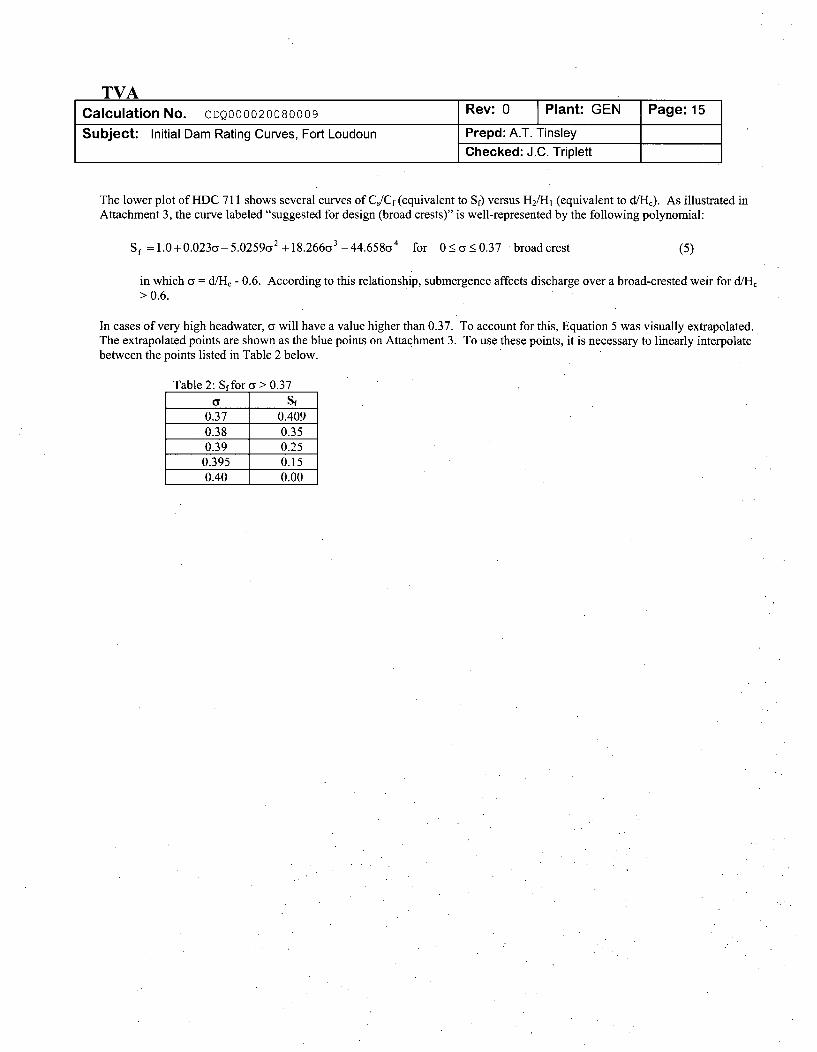
The lower plot of HDC 711 shows several curves of Cs/Cf (equivalent to Sf) versus H2/H1 (equivalent to d/Hc). As illustrated inAttachment 3, the curve labeled "suggested for design (broad crests)" is well-represented by the following polynomial:
S= 1.0 +0.023o- 5.02592 + 18.266C3 -44.658&4 for 0•<a_•0.37 broadcrest (5)
in which a = d/H, - 0.6. According to this relationship, submergence affects discharge over a broad-crested weir for d/H,> 0.6.
In cases of very high headwater, a will have a value higher than 0.37. To account for this, Equation 5 was visually extrapolated.The extrapolated points are shown as the blue points on Attachment 3. To use these points, it is necessary to linearly interpolatebetween the points listed in Table 2 below.
TVACalculation No. CDQ000020080009 Rev: 0 Plant: GEN Page: 16
Subject: Initial Dam Rating Curves, Fort Loudoun Prepd: A.T. TinsleyChecked: J.C. Triplett
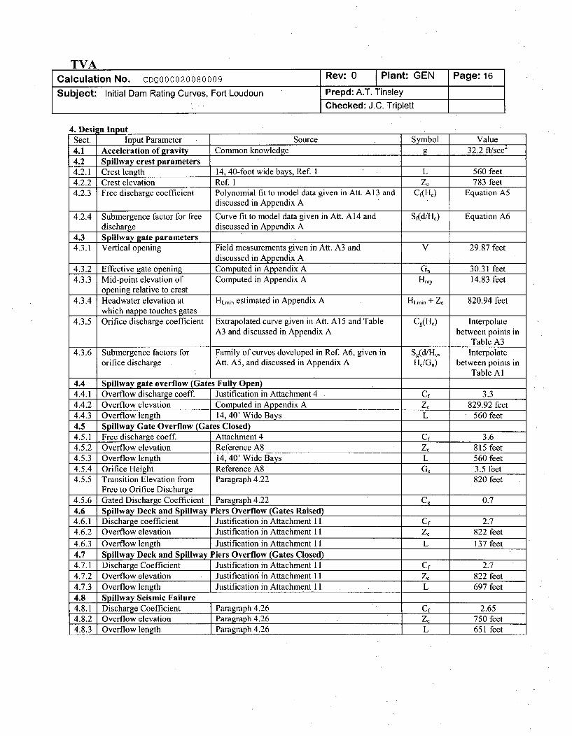
4. Design InputSect. Input Parameter Source Symbol Value4.1 Acceleration of gravity Common knowledge g 32.2 ft/sec2
4.2 Spillway crest parameters4.2.1 Crest length 14, 40-foot wide bays, Ref. 1 L 560 feet4.2.2 Crest elevation Ref. 1 Z' 783 feet4.2.3 Free discharge coefficient Polynomial fit to model data given in Att. A13 and Cf(HJ) Equation A5
discussed in Appendix A
4.2.4 Submergence factor for free Curve fit to model data given in Att. A14 and Sf(d!H,) Equation A6discharge discussed in Appendix A
4.3 Spillway gate parameters4.3.1 Vertical opening Field measurements given in Att. A3 and V 29.87 feet
discussed in Appendix A4.3.2 Effective gate opening Computed in Appendix A Gn 30.31 feet4.3.3 Mid-point elevation of Computed in Appendix A Hmp 14.83 feet
opening relative to crest4.3.4 Headwater elevation at HLmin estimated in Appendix A HLmin + Zc 820.94 feet
which nappe touches gates4.3.5 Orifice discharge coefficient Extrapolated curve given in Att. A15 and Table Cg(Hc) Interpolate
A3 and discussed in Appendix A between points inTable A3
4.3.6 Submergence factors for Family of curves developed in Ref. A6, given in Sg(d/Hc, Interpolateorifice discharge Att. A5, and discussed in Appendix A H,/Gn) between points in
Table Al4.4 1 Spillway gate overflow (Gates Fully Open)4.4.1 Overflow discharge coeff. Justification in Attachment 4 Cf 3.34.4.2 Overflow elevation Computed in Appendix A Zý 829.92 feet4.4.3 Overflow length 14, 40' Wide Bays L 560 feet4.5 Spillway Gate Overflow (Gates Closed)4.5.1 Free discharge coeff. Attachment 4 Cf 3.64.5.2 Overflow elevation Reference A8 Z' 815 feet4.5.3 Overflow length 14, 40' Wide Bays L 560 feet4.5.4 Orifice Height Reference A8 Gs 3.5 feet4.5.5 Transition Elevation from Paragraph 4.22 820 feet
Free to Orifice Discharge4.5.6 Gated Discharge Coefficient Paragraph 4.22 C9 0.74.6 Spillway Deck and Spillway Piers Overflow (Gates Raised)4.6.1 Discharge coefficient I Justification in Attachment 11 Cf 2.74.6.2 Overflow elevation Justification in Attachment 11 ZC 822 feet
4.6.3 Overflow length I Justification in Attachment 11 L 137 feet4.7 Spillway Deck and Spillway Piers Overflow (Gates Closed)4.7.1 Discharge Coefficient Justification in Attachment 11 Cf 2.74.7.2 Overflow elevation Justification in Attachment 11 Zý 822 feet4.7.3 Overflow length Justification in Attachment 11 L 697 feet4.8 Spillway Seismic Failure4.8.1 Discharge Coefficient Paragraph 4.26 Cf 2.654.8.2 Overflow elevation Paragraph 4.26 Zc 750 feet4.8.3 Overflow length Paragraph 4.26 L 651 feet
TVACalculation No. CDQ000020080009 Rev: 1 Plant: GEN Page: 17
Subject: Initial Dam Rating Curves, Fort Loudoun Prepd: WBBChecked: ACM
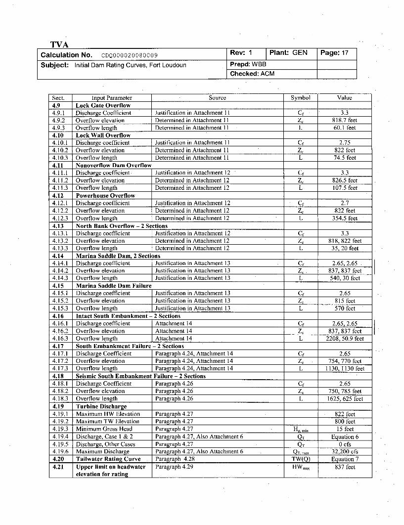
Sect. Input Parameter Source Symbol Value4.9 Lock Gate Overflow4.9.1 Discharge Coefficient Justification in Attachment 11 Cf 3.34.9.2 Overflow elevation Determined in Attachment 11 Zc 818.7 feet4.9.3 Overflow length Determined in Attachment 11 L 60.1 feet4.10 Lock Wall Overflow4.10.1 Discharge coefficient Justification in Attachment 11 Cf 2.754.10.2 Overflow elevation Determined in Attachment I I Zc 822 feet4.10.3 Overflow length Determined in Attachment 11 L 74.5 feet4.11 Nonoverflow Dam Overflow4.11.1 Discharge coefficient Justification in Attachment 12 Cf 3.34.11.2 Overflow elevation Determined in Attachment 12 Zc 826.5 feet4.11.3 Overflow length Determined in Attachment 12 L 107.5 feet4.12 Powerhouse Overflow4.12.1 Discharge coefficient Justification in Attachment 12 Cf 2.74.12.2 Overflow elevation Determined in Attachment 12 Zc 822 feet4.12.3 Overflow length Determined in Attachment 12 L 354.5 feet4.13 North Bank Overflow - 2 Sections4.13.1 Discharge coefficient Justification in Attachment 12 Cf 3.34.13.2 Overflow elevation Determined in Attachment 12 ZC 818, 822 feet4.13.3 Overflow length Determined in Attachment 12 L 35, 20 feet4.14 Marina Saddle Dam, 2 Sections4.14.1 Discharge coefficient Justification in Attachment 13 Cf 2.65, 2.654.14.2 Overflow elevation Justification in Attachment 13 Zc 837, 837 feet4.14.3 Overflow length Justification in Attachment 13 L 540, 30 feet4.15 Marina Saddle Dam Failure4.15.1 Discharge coefficient Justification in Attachment 13 Cf 2.654.15.2 Overflow elevation Justification in Attachment 13 Zc 815 feet4.15.3 Overflow length Justification in Attachment 13 L 570 feet4.16 Intact South Embankment - 2 Sections4.16.1 Discharge coefficient Attachment 14 Cf 2.65, 2.654.16.2 Overflow elevation Attachment 14 Z' 837, 837 feet4.16.3 Overflow length Attachment 14 L 2208, 50.9 feet4.17 South Embankment Failure - 2 Sections4.17.1 Discharge Coefficient Paragraph 4.24, Attachment 14 Cf 2.654.17.2 Overflow elevation Paragraph 4.24, Attachment 14 Zc 754, 770 feet4.17.3 Overflow length Paragraph 4.24, Attachment 14 L 1130, 1130 feet4.18 Seismic South Embankment Failure - 2 Sections4.18.1 Discharge Coefficient Paragraph 4.26 Cf 2.654.18.2 Overflow elevation Paragraph 4.26 Z' 750, 785 feet4.18.3 Overflow length Paragraph 4.26 L 1625, 625 feet
4.19 Turbine Discharge4.19.1 Maximum HW Elevation Paragraph 4.27 822 feet4.19.2 Maximum TW Elevation Paragraph 4.27 800 feet4.19.3 Minimum Gross Head Paragraph 4.27 Hg, min 15 feet4.19.4 Discharge, Case 1 & 2 Paragraph 4.27, Also Attachment 6 QT Equation 64.19.5 Discharge, Other Cases Paragraph 4.27 QT 0 cfs4.19.6 Maximum Discharge Paragraph 4.27, Also Attachment 6 QT, max 32,200 cfs4.20 Tailwater Rating Curve Paragraph 4.28 TW(Q) Equation 74.21 Upper limit on headwater Paragraph 4.29 HWmx 837 feet
elevation for rating
TVACalculation No. CDQ000020080009 Rev: 1 Plant: GEN Page: 18
Subject: Initial Dam Rating Curves, Fort Loudoun Prepd: WBBChecked: ACM
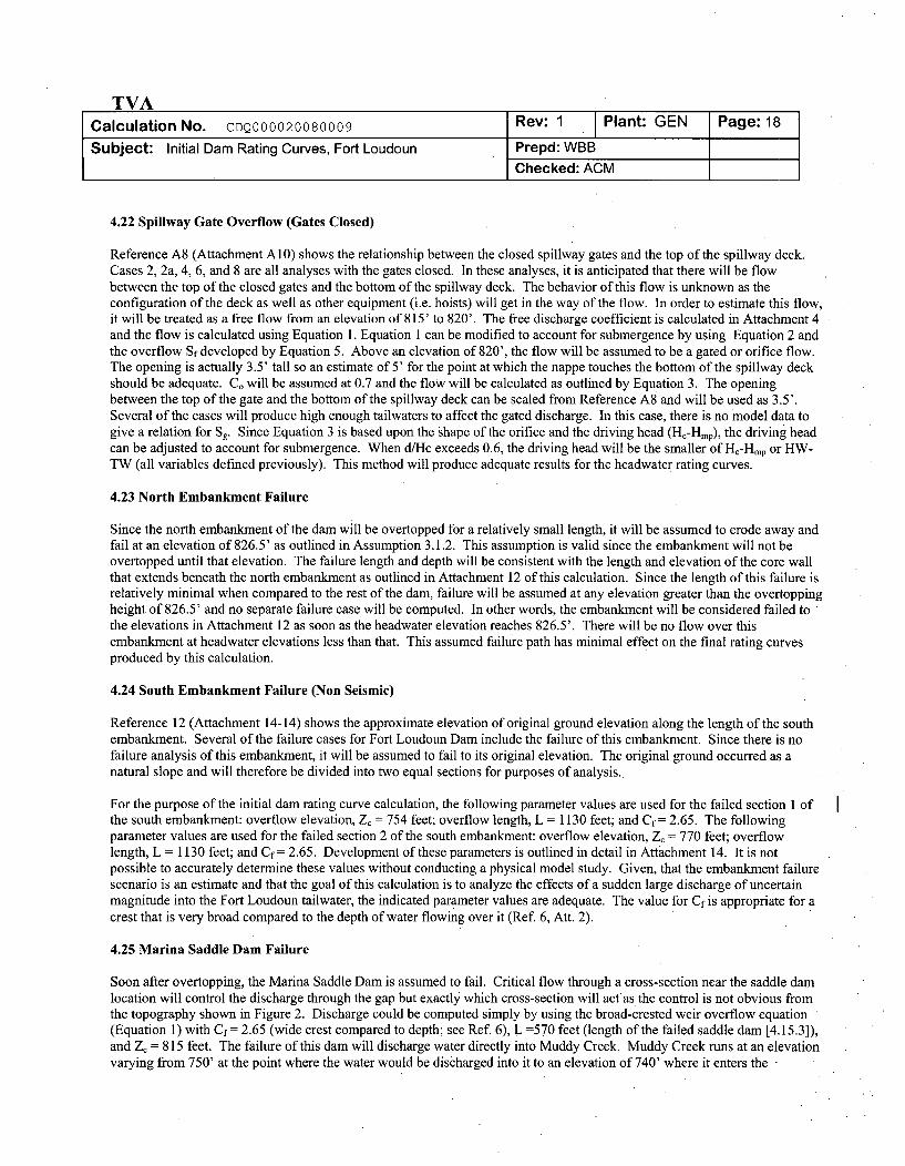
4.22 Spillway Gate Overflow (Gates Closed)
Reference A8 (Attachment A10) shows the relationship between the closed spillway gates and the top of the spillway deck.Cases 2, 2a, 4, 6, and 8 are all analyses with the gates closed. In these analyses, it is anticipated that there will be flowbetween the top of the closed gates and the bottom of the spillway deck. The behavior of this flow is unknown as theconfiguration of the deck as well as other equipment (i.e. hoists) will get in the way of the flow. In order to estimate this flow,it will be treated as a free flow from an elevation of 815' to 820'. The free discharge coefficient is calculated in Attachment 4and the flow is calculated using Equation 1. Equation 1 can be modified to account for submergence by using Equation 2 andthe overflow Sf developed by Equation 5. Above an elevation of 820', the flow will be assumed to be a gated or orifice flow.The opening is actually 3.5' tall so an estimate of 5' for the point at which the nappe touches the bottom of the spillway deckshould be adequate. Co will be assumed at 0.7 and the flow will be calculated as outlined by Equation 3. The openingbetween the top of the gate and the bottom of the spillway deck can be scaled from Reference A8 and will be used as 3.5'.Several of the cases will produce high enough tailwaters to affect the gated discharge. In this case, there is no model data togive a relation for Sg. Since Equation 3 is based upon the shape of the orifice and the driving head (Hc-Hmp), the driving headcan be adjusted to account for submergence. When d/Hc exceeds 0.6, the driving head will be the smaller of Hc-Hmp or HW-TW (all variables defined previously). This method will produce adequate results for the headwater rating curves.
4.23 North Embankment Failure
Since the north embankment of the dam will be overtopped for a relatively small length, it will be assumed to erode away andfail at an elevation of 826.5' as outlined in Assumption 3.1.2. This assumption is valid since the embankment will not beovertopped until that elevation. The failure length and depth will be consistent with the length and elevation of the core wallthat extends beneath the north embankment as outlined in Attachment 12 of this calculation. Since the length of this failure isrelatively minimal when compared to the rest of the dam, failure will be assumed at any elevation greater than the overtoppingheight of 826.5' and no separate failure case will be computed. In other words, the embankment will be considered failed tothe elevations in Attachment 12 as soon as the headwater elevation reaches 826.5'. There will be no flow over thisembankment at headwater elevations less than that. This assumed failure path has minimal effect on the final rating curvesproduced by this calculation.
4.24 South Embankment Failure (Non Seismic)
Reference 12 (Attachment 14-14) shows the approximate elevation of original ground elevation along the length of the southembankment. Several of the failure cases for Fort Loudoun Dam include the failure of this embankment. Since there is nofailure analysis of this embankment, it will be assumed to fail to its original elevation. The original ground occurred as anatural slope and will therefore be divided into two equal sections for purposes of analysis.
For the purpose of the initial dam rating curve calculation, the following parameter values are used for the failed section 1 ofthe south embankment: overflow elevation, Z, = 754 feet; overflow length, L = 1130 feet; and Cf = 2.65. The followingparameter values are used for the failed section 2 of the south embankment: overflow elevation, Z, = 770 feet; overflowlength, L = 1130 feet; and Cf = 2.65. Development of these parameters is outlined in detail in Attachment 14. It is notpossible to accurately determine these values without conducting a physical model study. Given, that the embankment failurescenario is an estimate and that the goal of this calculation is to analyze the effects of a sudden large discharge of uncertainmagnitude into the Fort Loudoun tailwater, the indicated parameter values are adequate. The value for Cf is appropriate for acrest that is very broad compared to the depth of water flowing over it (Ref. 6, Att. 2).
4.25 Marina Saddle Dam Failure
Soon after overtopping, the Marina Saddle Dam is assumed to fail. Critical flow through a cross-section near the saddle damlocation will control the discharge through the gap but exactly which cross-section will actas the control is not obvious fromthe topography shown in Figure 2. Discharge could be computed simply by using the broad-crested weir overflow equation(Equation 1) with Cf = 2.65 (wide crest compared to depth; see Ref. 6), L =570 feet (length of the failed saddle dam [4.15.3]),and Z, = 815 feet. The failure of this dam will discharge water directly into Muddy Creek. Muddy Creek runs at an elevationvarying from 750' at the point where the water would be discharged into it to an elevation of 740' where it enters the -
TVACalculation No. CDQ000020080009 Rev: 1 Plant: GEN Page: 19
Subject: Initial Dam Rating Curves, Fort Loudoun Prepd: WBBChecked: ACM
Tennessee River after Fort Loudoun Dam. With the large elevation difference between the failed saddle dam and MuddyCreek, it is assumed that the flow through the saddle dam will control the flow. The topography and postulated flow pathshown in Figure 2 confirms this assumption.
The failure of the Marina Saddle Dam is not expected to provide any relief to the overtopping of Fort Loudoun Dam and anyeffects on such will therefore be ignored.
4.26 Seismic Failure
As required in the TVA nuclear plant design basis, the impact of the following combined seismic and flooding cases must beconsidered in the plant design:
Condition 1 - Plant flood level due to postulated upstream dam failures due to an Operating Basis Earthquake (OBE) during a0.5 PMF.
Condition 2 - Plant flood levels due to postulated upstream dam failures due to a Safe Shutdown Earthquake (SSE) during a25-year flood.
A review of the current PMF design basis for the TVA nuclear plants indicates that the critical OBE seismic case is coincidentfailure of the Fontana, Hiwassee, Apalachia and Blue Ridge Dams due to an OBE during a 0.5 PMF. The critical SSE seismiccase is coincident failure of the Norris, Cherokee and Douglas dams due to a SSE during a 25-year flood.
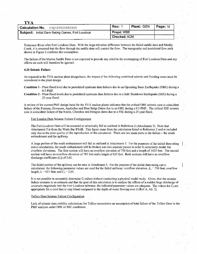
Fort Loudon Dam Seismic Failure Configuration
The Fort Loudoun Dam will be assumed to seismically fail as outlined in Reference 2 (Attachment 5). Note thatAttachment 5 is from the Watts Bar FSAR. This figure came from the calculation listed in Reference 2 and is includedonly due to the poor quality of the reproduction of the calculation. There are two main parts to the failure - the southembankment and the spillway.
A large portion of the south embankment will fail as outlined in Attachment 5. For the purposes of the initial dam ratingcurve calculations, the south embankment will be broken into two separate pieces in order to accurately model theoverflow'elevations. The first section will have an overflow elevation of 750 feet and a length of 1625 feet. The secondsection will have an overflow elevation of 785 feet and a length of 625 feet. Both sections will have an overflowdischarge coefficient (Cf) of 2.65.
The failed portion of the spillway can be seen in Attachment 5. For the purpose of the initial dam rating curvecalculation, the following parameter values are used for the failed spillway: overflow elevation, Z, = 750 feet; overflowlength, L = 651 feet; and Cf = 2.65.
It is not possible to accurately determine Cf values without conducting a physical model study. Given, that the seismicfailure scenario is an estimate and that the goal of this calculation is to analyze the effects of a sudden large discharge ofuncertain magnitude into the Fort Loudoun tailwater, the indicated parameter values are adequate. The values for Cf areappropriate for a crest that is very broad compared to the depth of water flowing over it (Ref. 6, An. 2).
Tellico Dam Seismic Failure Configuration
Lack of seismic dam stability calculations for Tellico necessitates an assumption of total failure of the Tellico Dam in thePMF analysis under OBE or SSE conditions.
TVACalculation No. CDQ000020080009 Rev: 0 Plant: GEN Page:20
Subject: Initial Dam Rating Curves, Fort Loudoun Prepd: A.T. TinsleyChecked: J.C. Triplett
Dam Rating Curve Conditions
The seismic dam rating curve provided in this calculation in Section 6.9 (Case 9) assumes the above described FortLoudon Seismic failure configuration coincident with a Tellico Dam intact configuration. An intact Tellico Damconfiguration is used because Fort Loudon Dam tailwater characteristics have not been determined for a seismicallyfailed Tellico condition. Since an intact Tellico Dam will reduce the Fort Loudon Dam tailwater and will result in anincreased PMF flow (and water level) downstream, Case 9 (intact Tellico) is considered a conservative representation ofthe Fort Loudon Dam in modeling for the Condition 1 and Condition 2 analysis combinations.
Tellico Dam will be assumed to be completely failed in the SOCH PMF-seismic analysis cases. Following this analysisand to support removing the tailwater curve unverified assumption in Section 3, the Fort Loudon tailwater and the damrating will either (1) be revised to reflect the more accurate tailwater characteristics which can then be used in a revisedPMF-seismic analysis or (2) a technical justification provided for retaining the tailwater curve provided in Attachment15.
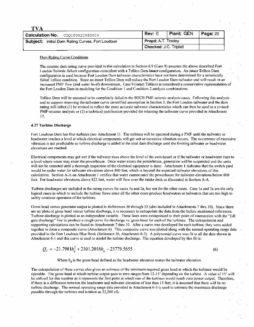
4.27 Turbine Discharge
Fort Loudoun Dam has four turbines (see Attachment 1). The turbines will be operated during a PMF until the tailwater orheadwater reaches a level at which electrical components will get wet or excessive vibration occurs. The occurrence of excessivevibration is not predictable so turbine discharge is added to the total dam discharge until the limiting tailwater or headwaterelevations are reached.
Electrical components may get wet if the tailwater rises above the level of the switchyard or if the tailwater or headwater rises toa level where water may enter the powerhouse. Once water enters the powerhouse, generation will be suspended and the unitswill not be restarted until a thorough inspection of the electrical equipment is done. Attachment 1 indicates that the switch yardwould be under water for tailwater elevations above 860 feet, which is beyond the expected tailwater elevations of thiscalculation. Section A-A on Attachment 1 verifies that water cannot enter the powerhouse for tailwater elevations below 800feet. For headwater elevations above 822 feet, water will flow over the intake deck as illustrated in Section A-A.
Turbine discharges are included in the rating curves for cases la and 2a, but not for the other cases. Case la and 2a are the onlylogical cases in which to include the turbine flows since all the other cases produce headwaters or tailwaters that are too high tosafely continue operation of the turbines.
Gross head versus generator output is plotted in References 30 through 33 (also included in Attachments 7 thru 10). Since thereare no plots of gross head versus turbine discharge, it is necessary to extrapolate the data from the before mentioned references.Turbine discharge is plotted as an independent variable. These lines were extrapolated to their point of intersection with the "fullgate discharge" line to produce a rough curve for discharge vs. gross head for each of the turbines. The extrapolation andsupporting calculations can be found in Attachments 7 thru 10. After a curve was developed for each turbine, they were addedtogether to form a composite curve (Attachment 6). This composite curve was plotted along with the normal operating range dataprovided in the Fort Loudoun Blue Book (Reference 36, Attachment 6-3). A polynomial curve was fit to all the data shown inAttachment 6-1 and this curve is used to model the turbine discharge. The equation developed by this fit is:
QT = -21.798 1h 2 + 2301.2018hg - 23779.5655 (6)
Where hg is the gross head defined as the headwater elevation minus the tailwater elevation.
The extrapolation of these curves also gives an estimate of the minimum required gross head at which the turbines would beoperable. The gross head at which turbine output goes to zero ranges from 12-15' depending on the turbine. A value of 15' willbe utilized for this number as it represents the first point at which one of the turbines would reach zero power output. Therefore,if there is a difference between the headwater and tailwater elevation of less than 15 feet, it is assumed that there will be noturbine discharge. The normal operating range data provided in Attachment 6-3 is used to estimate the maximum dischargepossible through the turbines and is taken as 32,200 cfs.
TVACalculation No. CDQ000020080009 Rev: 1 Plant: GEN Page: 21
Subject: Initial Dam Rating Curves, Fort Loudoun Prepd: WBBChecked: ACM
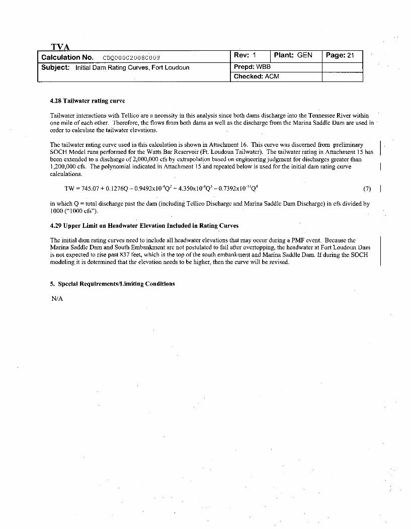
4.28 Tailwater rating curve
Tailwater interactions with Tellico are a necessity in this analysis since both dams discharge into the Tennessee River withinone mile of each other. Therefore, the flows from both dams as well as the discharge from the Marina Saddle Dam are used inorder to calculate the tailwater elevations.
The tailwater rating curve used in this calculation is shown in Attachment 16. This curve was discerned from preliminarySOCH Model runs performed for the Watts Bar Reservoir (Ft. Loudoun Tailwater). The tailwater rating in Attachment 15 hasbeen extended to a discharge of 2,000,000 cfs by extrapolation based on engineering judgment for discharges greater than1,200,000 cfs. The polynomial indicated in Attachment 15 and repeated below is used for the initial dam rating curvecalculations.
TW = 745.07 + 0.1276Q - 0.9492xl0- 4Q2 + 4.350xl0SQ 3 - 0.7392x10lIQ 4 (7)
in which Q = total discharge past the dam (including Tellico Discharge and Marina Saddle Dam Discharge) in cfs divided by1000 ("1000 cfs").
4.29 Upper Limit on Headwater Elevation Included in Rating Curves
The initial dam rating curves need to include all headwater elevations that may occur during a PMF event. Because theMarina Saddle Dam and South Embankment are not postulated to fail after overtopping, the headwater at Fort Loudoun Damis not expected to rise past 837 feet, which is the top of the south embankment and Marina Saddle Dam. If during the SOCHmodeling it is determined that the elevation needs to be higher, then the curve will be revised.
5. Special Requirements/Limiting Conditions
N/A
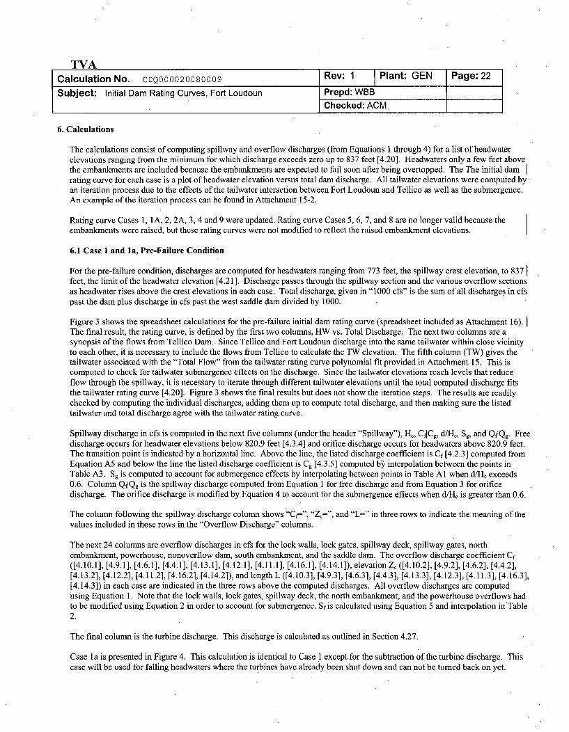
6. Calculations
The calculations consist of computing spillway and overflow discharges (from Equations 1 through 4) for a list of headwaterelevations ranging from the minimum for which discharge exceeds zero up to 837 feet [4.20]. Headwaters only a few feet abovethe embankments are included because the embankments are expected to fail soon after being overtopped. The The initial damrating curve for each case is a plot of headwater elevation versus total dam discharge. All tailwater elevations were computed byan iteration process due to the effects of the tailwater interaction between Fort Loudoun and Tellico as well as the submergence.An example of the iteration process can be found in Attachment 15-2.
Rating curve Cases 1, IA, 2, 2A, 3, 4 and 9 were updated. Rating curve Cases 5, 6, 7, and 8 are no longer valid because theembankments were raised, but these rating curves were not modified to reflect the raised embankment elevations.
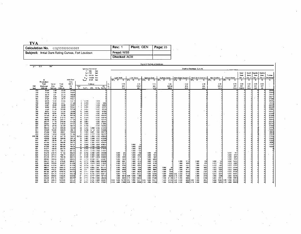
6.1 Case 1 and la, Pre-Failure Condition
For the pre-failure condition, discharges are computed for headwaters.ranging from 773 feet, the spillway crest elevation, to 837 Ifeet, the limit of the headwater elevation [4.21 ]. Discharge passes through the spillway section and the various overflow sectionsas headwater rises above the crest elevations in each case. Total discharge, given in "1000 cfs" is the sum of all discharges in cfspast the dam plus discharge in cfs past the west saddle dam divided by 1000.
Figure 3 shows the spreadsheet calculations for the pre-failure initial dam rating curve (spreadsheet included as Attachment 16).The final result, the rating curve, is defined by the first two columns, HW vs. Total Discharge. The next two columns are asynopsis of the flows from Tellico Dam. Since Tellico and Fort Loudoun discharge into the same tailwater within close vicinityto each other, it is necessary to include the flows from Tellico to calculate the TW elevation. The fifth column (TW) gives thetailwater associated with the "Total Flow" from the tailwater rating curve polynomial fit provided in Attachment 15. This iscomputed to check for tailwater submergence effects on the discharge. Since the tailwater elevations reach levels that reduceflow through the spillway, it is necessary to iterate through different tailwater elevations until the total computed discharge fitsthe tailwater rating curve [4.20]. Figure 3 shows the final results but does not show the iteration steps. The results are readilychecked by computing the individual discharges, adding them up to compute total discharge, and then making sure the listedtailwater and total discharge agree with the tailwater rating curve.
Spillway discharge in cfs is computed in the next five columns (under the header "Spillway"), He, CdCg, d/Hc, Sg, and QdQg. Freedischarge occurs for headwater elevations below 820.9 feet [4.3.4] and orifice discharge occurs for headwaters above 820.9 feet.The transition point is indicated by a horizontal line. Above the line, the listed discharge coefficient is Cf [4.2.3] computed fromEquation A5 and below the line the listed discharge coefficient is Cg [4.3.5] computed by interpolation between the points inTable A3. Sg is computed to account for submergence effects by interpolating between points in Table Al when d/Hc exceeds0.6. Column QdQg is the spillway discharge computed from Equation 1 for free discharge and from Equation 3 for orificedischarge. The orifice discharge is modified by Equation 4 to account for the submergence effects when d/Hc is greater than 0.6.
The column following the spillway discharge column shows "Cf=", "Zr="', and "L=" in three rows to indicate the meaning of thevalues included in those rows in the "Overflow Discharge" columns.
The next 24 columns are overflow discharges in cfs for the lock walls, lock gates, spillway deck, spillway gates, northembankment, powerhouse, nonoverflow dam, south embankment, and the saddle dam. The overflow discharge coefficient Cf([4.10.1], [4.9.1], [4.6.1], [4.4.1], [4.13.1], [4.12.1], [4.11.1], [4.16.1], [4.14.1]), elevation Z, ([4.10.2], [4.9.2], [4.6.2], [4.4.2],[4.13.2], [4.12.2], [4.11.2], [4.16.2], [4.14.2]), and length L ([4.10.3], [4.9.3], [4.6.3], [4.4.3], [4.13.3], [4.12.3], [4.11.3], [4.16.3],[4.14.3]) in each case are indicated in the three rows above the computed discharges. All overflow discharges are computedusing Equation 1. Note that the lock walls, lock gates, spillway deck, the north embankment, and the powerhouse overflows hadto be modified using Equation 2 in order to account for submergence. Sf is calculated using Equation 5 and interpolation in Table2.
The final column is the turbine discharge. This discharge is calculated as outlined in Section 4.27.
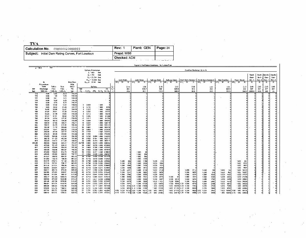
Case 1 a is presented in Figure 4. This calculation is identical to Case 1 except for the subtraction of the turbine discharge. Thiscase will be used for falling headwaters where the turbines have already been shut down and can not be turned back on yet.
TVACalculation No. CDQ000020080009 Rev: 1 Plant: GEN Page:23
Subject: Initial Dam Rating Curves, Fort Loudoun Prepd: WBBChecked: ACM
g= 32.2 fits'
Spillay Paramters Overlw Disharge 0, in efsL 560 feet
Z0= 783 ftet Sou"t Snt Saddle Saddle
Gn = 30.314 feet Bank Bank Dam Dam Toutine
H, =14M28 teet Lock Wallsa Loc G.ato St~alra Deck I Spiftwy Gates N"r Bank SeotUIon Noott Bank Seodow 2 1 Noo Gnto J Pooe noos Sa..1 Se-.2 Sec. tI Sen. 2 Olsocargea Main Dam H,.= 37894 feet CtHt Sf Q d St G H 0 St ld/t St ý d/H Sf 0 laHe Sf I d/ S Sf Q ]CdHr St G
1dH, Stf 0 0 0 - Q
Toral Tellio Total 602.3 51 C = 2.75 3.38 2.7 338 3.30 3.30 3.30 2.70 2.65 2.85 2.85 2.85
HW Discharge Floe, Flow TW tent tcs 0, = 822 81887 822 829.82 818 822 828.5 822 837 827 827 837feer 1000 I f 1000 cfc 1000 dos ftt d, s, e S. Q, = 74.5 60.1 137.0 58W.0 35.0 20.0 107.5 354.5 2208.0 5B.8 580 30
T35
785
777779781
783785787789791793
Bil801
823
805837
8113
81815
516817Big819:20821822a26824825826827828
:29830931
032833
835836837
22.44 1.06 23.50 748.02
24.14 3.01 27.15 748.4625.67 5.58 31.25 748.97
27.87 8.70 35.77 749.5128.33 12.32 40.65 750.1034.09 16.42 50051 751.2843.97 20.99 64.96 752.8756.82 26.01 82.83 755.0172.23 31.46 103.68 757.33
89.91 37.31 127.22 759.86109,70 43.54 153.24 76255
131.45 50.13 181.58 765.3M155.07 57.08 212.12 788.27
188.52 64.25 244.77 771.23207.17 71.72 279.49 774.22
236.82 79.40 316.22 777.23267.70 87.23 354.92 780.23380.43 95.13 395.56 783.20
335.05 103.04 438.09 786.14371.58 110.94 482.51 788.03
418.02 118.8 528.82 791.88425.84 121.82 547.76 792.79
43.088 120.88 550.96 793.1545M.77 120.30 571.15 716.30
471.53 125.41 5W6.95 795.73482.46 135.20 627.65 787.37513.69 150.12 663.88 799.23515.17 169.55 684.72 800.28
513.62 182.73 706.34 801.33512.79 218.74 731.52 802.53512.16 247.01 759.17 803.81511.16 277.21 788.39 805.13
520.83 30864 829.47 886.93534.11 341.15 875,26 808,87543.85 375.82 919.67 810.69552.48 412.64 965.12 812.58
558.17 451.56 1009.73 814.235688.6 474.20 1043.06 815.51
581.48 497.58 1079.05 816.87594.01 521.74 1115.76 818.24
605.35 546.93 1152.28 819.58616.35 572.16 1188.51 820.92627.10 598.79 1223.88 822.22638.13 621.10 1259.23 623.51
0 3.090 i. 0oo
2 3.191 1.00 50514 3.277 1 000 146886 3.350 1.000 2757c 3.412 1.000 43231
10 3.465 1.080 6136112 3512 100 8175f
14 3.554 1.088 10424:16 3591 1.000 12871118 3,627 1tOO 15511'20 3.661 1.000 18337,c
22 3.695 1.000 21350(24 31728 . 1.000 24545;26 3.763 0.888 1.08I 279350
28 3.798 0.112 1.880 31509(30 3,833 0,201 1.000 35271132 3869 0277 1.000 392211
32.796 3.883 0.304 1.000 408452
33 3.887 0.308 1.000 41265134 3.885 0.332 1.000 433541
35 3.923 0.364 1.000 45487136 3.940 0.399 1.000 476631
37 3.958 0.439 0.=85 4987813M 0.793 0.455 0.989 514471
3 0.77 0.470 0.988 51242ý
40 0.756 0.488 0.985 500848
41 0.738 0.508 0.982 50540142 0.720 0.527 0.978 WONO;43 0 719 0.556 0.971 5M4661
44 0717 O.588 0.963 58825t
45 0.716 0.615 0.853 51044(48 0.714 0.641 0.940 510712
47 0.713 0.665 0.921 50731048 0.711 0.877 0.908 50628(
4 0.711 0.691 0.892 505155W1 0.711 0.705 0.875 502412
51 0,711 0.717 0.853 497152
52 0.711 0.72: 0.828 45035153 0.711 0.740 0.8O6 48220154 0.711 0.750 0.781 473321
C
o
1I0O 2051.00 578
I
1'008 1,638a1.00O 22811.08 301 1t100 37941.000 46361.000 55321000 6879
1.080 33
1.800 17681.880 2420
1.080 50131.800 85561.800 475421.000 8558
1.000 8820
1M 85C1A 6C
C
CCC
1.00 3701000 1048
1.000 18221000 2855
1 .000 41381.000 5438
1.000 8881
1.000 116811.00 13455
1.000 401.000 28741.000 554
1.008 3110100 3652
1.000 48014
1.000 5414
0.02 t.000 87100.10 1.088 7392017 1088 80980.23 1.000 88200.29 1.080 9568
1.000 1251.000 0521.000 1402
100 0 2323108 3388108 45781588 58751 000 7288
0
1.00 85
100 207
o00000000
1.0 47
00aaa
1.0 75
00000
1.000 10701
1.000 140870
1000 177271.000 2186581.000 258431.000 302881.000 348201.000 39788
0a
000000000
000000
000000000000000a
0a
256712708E2833
221
25252
27842720E2835t254t I243812331t2220421071
1788
1 74181 722188615782t488E
1.0o0 73E1.000 97(1.000 1220
1.000 14981.080 1780
1.000 20001.000 2401
1.000 27441.000 3094
0.02 1.000 34570.10 1.0MO 3834
1.000 74741 1.000 107251.000 85161 0.06 1.000 118891 1.000 1537E
t000 8803 0 14 1.000 13052 1.000 173380.02 108 10732 020 1000 14271 0.02 1.000 19377
050 1,08 11902 026 1000 15526 0.10 1.000 21488
1.000 8E1.000 1523015000 211581,000 27701
1.000 34814
1.000 8781 1.000 44864
1.000 12070 0.10 1.800 55885
TVACalculation No. CDQ000020080009 Rev: 1 Plant: GEN Page: 24
Subject: Initial Dam Rating Curves, Fort Loudoun Prepd: WBBChecked: ACM
Fiour 4: Pre-Failure Conditions - No Turbine Flow
= 32.2 fts'
Spillway Parameters Overflow Discharge. Q, in cfsL = 56o feet
S7183 feet b outh baddle Saddle
G= 30.314 feet Bonk Book Doo Doo
H= 14.828 feet Look Wolls Look Gaton. I Spilway Dook I piliwa-y bton North Book Section 1 North Book boo.oo.. 2 . oo. boor1w Poer Houe bo 1 bec. 2 Sec. 1 Sec. 20 Main Dam H-n= 37.94 feet d/fHl Sf Q d/P Sf Q /H
0 Sf Q0 d/H, Sf 0 dlHý Sf 0 41K SI 0 dll SI 0 d1K Of 0 0
FtLoudeounTTRM feet 60.1___ _ __ A3. 35.0_ 20.0_ A0. 3545 208Total Tellioo Total 602.3 Silway 7 3.30 2.70 3.30 3.30 3.30 3.30 2.70 2.65 2.65 2.65 2.65Telc oa t 2 818.7 822 829.9 818 822 82%. 822 837 83 87 87
HW Dischrge Flow Flow T eer cfs 4 = 622 6837 ]837 837
feet 1806. 1000o f s b t CrIC d S n L= 74.5 666.0 3 2 0 0 22080 50.9 540 30
775777779
781763785787789791793795787789888
803885
807809811813
815815.80
816817818819820821822823824825828827828829838831832833834835838837
080. 1.06 1.06 745.2M
8.85 3.01 3.01 745.41
8.88 5.58 5.50 745.78
8.08 8.70 8.70 746.11
0.80 12.32 12.32 746.6'
5.05 16.42 21.48 747.7714.68 20.99 35.67 749.50
27.57 26.01 53.58 751.64
43.24 31.46 74.69 754.06
81.37 37.31 98.68 756.78
81.76 43.54 125.30 .759.68
154.24 50.13 154.38 762.68
128.72 57.05 185.77 765.71
155.11 84.25 219.36 788.54
183.38 71.72 255.09 772.12
213.51 79.41 292.92 775.34
245.49 87.28 332.77 778.52
279.35 95.20 374.60 781.61315.89 103.25 418.34 784.8'
352.72 11123 463.54 787.84
39522 110.17 511.38 790.81
488.45 122.32 530.77 791.91
412.66 121.49 534.15 792.17
433.55 120.99 554.54 793.38
454.88 126.09 580.97 794.81
476.66 136.09 612.75 796.58
459.08 150.96 650.04 798.53
515.17 169.50 684.72 800.28
513.82 192.73- 706.34. 801.33
512.75 218.74 731.52 . 802.53
512.16 247.01 759.17 803.81
511.18 277.21 788.39 8 805.13
520.83 308.64 829.47 806.92534.11 341.15 875.26 808.87
543.85 375.82 919.67 810.60
552.48 412.64 965.12 812.50
558.17 451.56 1009.73 814123
068.86 474.20 1043.06 . 815.51
58148 497.58 1079.05 816.87
594.01 521.74 1115.76 818.24
805.35 546.93 1152.28 819.59
186.35 572.16 1188.51 826.92
627.10 596.79 1223.88 822.22
638.13 621.10 1259.23 823.51
u0
00
0 3.090 1.000 0
2 3.151 . 1.000 5655
4 3.277 1.000 14682
6 3.350 1.000 27571
8 3.412 1.000 4323510 3.465 1.000 61368
12 3.512 1.000 81756
14 3.554 1.000 10424316 3.591 1.r00 128718
18 3.627 1.000 155111
20 3.661 1.000 183379
22 3.695 - 1.000 213506
24 3.728 1.000 245492
28 3.763 1.000 279350
28 3.798 0.064 1.000 315090
30 3.833 0.161 1.000 352717
32 3.869 0124 1.000 392217
32.796 3.883 06274 1.000 408452
33 3.887 0.278 1.000 412658
34 3.905 0.305 1.000 433549
35 3.923 0.339 1.000 454878
36 3.940 0.377 1.000 476631
37 3.958 0.420 1.000 498787
38 0.793 0.455 0.989 514478
39 0.775 0.470 0.958 512427
40 0.756 0.488 0.985 509486
41 0.738 0.508 0.982 505405
42 0.720 0.527 0.078 58008243 0.719 0.556 0.971 504661
44 0.717 0.588 0.963 508256
45 0.716 0.615 0.953 510440
46 0.714 0.641 0.940 510713
47 0.713 0.665 0.921 507310
48 0.711 0.677 0.908 506286
49 0.711 0.691 0.892 505157
50 0,711 0.705 0.875 50241351 0.711 0.717 0.853 497153
52 0.711 0,729 0.830 490306
53 0.711 0.740 0.806 482207
54 0.711 0.750 0.781 473321
0.00
00
0
00000O0O00O00000000
1.000 2051.000 5791.000 10651.000 16391.000 22911.000 30111.000 37941.000 46361.000 55321.000 64791.000 74741.000 85161.000 9603
0.02 1.000 107320.10 1.000 11902
u00o0000
00o0000o000
0
00
1.000 33
1.000 6921.000 11891.000 17681.000 24201.000 31361.000 39121.000 47421.000 56251.000 65561.000 75341,000 85561.000 96201,000 10725
0.06 1,000 118690.14 1.000 130520.20 1.000 142710.26 1.000 15526
00
0
00
0
1.000 0
1.000 1046
1.000 102211.000 2050i
1.000 41361
1.000 54361
1.000 68511
1.000 83701
1.000 00871
1.000 116071
1.000 134951
1.840 153761
1.000 173201
0.02 1.000 103770.10 1.000 214001
00000000000
0
100 00 00 0
0
00
0
1 01 00
00n0
0
1.000 27705
1.000 34814
1.0 31
1.0 30
1.0 411.0 401.0 51
1.000 6000t0.2 1.000 36712
0.0 1.000 7302
0.17 1.000 80060.23 1.00 882C0.25 1.00 0566
0000000000000000000000000000
1.000 1251.000 8521.000 14021.000 23231.000 33861.000 45781,000 58781.000 72861,000 87011.000 103871.000 12070
00000000000000000
1.00 55
oo
000
1.00M 27071.000 49731.000 76571.0130 107011.000 140671.000 177271.000 216581.000 25831.000 3026881.000 349201.000 3975881.000 44884
0.02 1.000 001300.10 1.000 55605
1.0001.0001.0001.0001.0001.0001.0001.0001.000
0.02 1.0000.10 1.000
TVACalculation No. CDQ000020080009 Rev: 1 Plant: GEN Page: 25
Subject: Initial Dam Rating Curves, Fort Loudoun Prepd: WBB
Checked: ACM
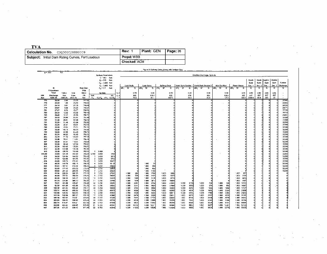
6.2 Cases 2 and 2a - Spillway Gates Closed
For the spillway gates closed condition, discharges are computed for headwaters ranging from 773 feet, an arbitrary startingpoint for turbine discharge, to 837 feet, the limit of the headwater elevation [4.21]. This case is similar to case 1 except for thereis no discharge through the spillway until the gates themselves are overtopped. Discharge passes through the various overflowsections as headwater rises above the crest elevations in each case. Total discharge, given in "1000 cfs" is the sum of all dischargesin cfs past the dam plus discharge in cfs past the west saddle dam divided by 1000.
Figure 5 shows the spreadsheet calculations for the spillway gates closed initial dam rating curve (spreadsheet included asAttachment 16). The final result, the rating curve, is defined by the first two columns, HW vs. Total Discharge. The next twocolumns are a synopsis of the flows from Tellico Dam. Since Tellico and Fort Loudoun discharge into the same tailwater withinclose vicinity to each other, it is necessary to include the flows from Tellico to calculate the TW rating curve. The fifth column(TW) gives the tailwater associated with the "Total Flow" from the tailwater rating curve polynomial fit [4.20]. This is computedto check for tailwater submergence effects on the discharge. Since the tailwater elevations reach levels that reduce flow throughthe spillway (mainly at Tellico in this calculation), it is necessary to iterate through different tailwater elevations until the totalcomputed discharge fits the tailwater rating curve [4.20]. Figure 5 shows the final results but does not show the iteration steps.The results are readily checked by computing the individual discharges, adding them up to compute total discharge, and thenmaking sure the listed tailwater and total discharge agree with the tailwater rating curve.
Spillway discharge in cfs is computed in the next four columns (under the header "Spillway"), He, CftCg, d/H-, and QdQg asoutlined in section 4.22. Free discharge occurs for headwater elevations below 820 feet [4.5.5] and orifice discharge occurs forheadwaters above 820 feet. The transition point is indicated by a horizontal line. Above the line, the listed discharge coefficientis Cf [4.5.1 ] computed in Attachment 4 and below the line the listed discharge coefficient is Cg [4.5.6] as discussed in Section4.22. Column QdQg is the spillway discharge computed from Equation 1 for free discharge and from Equation 3 for orificedischarge.
The column following the spillway discharge column shows "Cf=', "Z=", and "L=" in three rows to indicate the meaning of thevalues included in those rows in the "Overflow Discharge" columns.
The next eleven columns are overflow discharges in cfs for the lock walls, lock gates, spillway deck, north embankment,powerhouse, nonoverflow dam, south embankment, and the saddle dam. The overflow discharge coefficient Cf ([4.10.1], [4.9.1],[4.7.1], [4.13.1], [4.12.1], [4.11.1], [4.16.1], [4.14.1]), elevation Zc ([4.10.2], [4.9.2], [4.7.2], [4.13.2], [4.12.2], [4.11.2], [4.16.1],[4.14.2]), and length L ([4.10.3], [4.9.3], [4.7.3], [4.13.3], [4.12.3], [4.11.3], [4.16.1], [4.14.3]) in each case are indicated in thethree rows above the computed discharges. All overflow discharges are computed using Equation 1.
The final column is the turbine discharge. This discharge is calculated as outlined in Section 4.27.
Case 2a is presented in Figure 6. This calculation is identical to Case 2 except for the subtraction of the turbine discharge. Thiscase will be used for falling headwaters where the turbines have already been shut down and can not be turned back on yet.
TVACalculation No. CDQ000020080009 Rev: 1 Plant GEN Page: 26
Subject: Initial Dam Rating Curves, Fort Loudoun Prepd: WBBChecked: ACM
Fioure 5: Spilwav Gatos dosed with Tlatine Flow
g= 32.2 f/s'
SpIlway Poraeters Overflow Discharge. Q, in cfsL =560 feel
4= 815 feet South South Saddle Saddle
G, = 3.500 feet Bank Bank Dam Damn Turbine
C= 3600 feet Lock Watls Lock Gates [oSpily Desk Ntt Bank Son 1 Sorth Bank Section 2 Non Orfoow 3Powe Houso So. 1 Sos. 2 Sm. 1 So. 2 Discrge
Main Dam C, 0.7 toot dO-l, St 0 di/I St 0 d/H-` Sf Q d/I, St 0 dIl, St 0 dll, Sf
Q 0 C' Q Q
Total Tellico Total 602.3 Spillwy C, = 2.75 3.30 2.70 3.30 3.30 3.30 2.70 2.65 2.65 2.65 2.65 -
HW Discharge Flow Flow TW feet dse 4 = 822 8t1.7 822 818 822 826.5 822 837 837 837 837
feet 1000 tcs 1000 sfs 1000 sfs feet Hc C' I C, d/H, 0, i 0d L = 74.5 80. 697.0 35.0 20.0 1075 [ 354.5 2208.0 50.9 540 30
773
775
777
779
781783
785
787
789
791
793
795
797
799801
803
805
8078O9
811813"815
815.80819
817
818819
828
821
822
823
824
825
826
827
828
829
838
831
832
833
834
835
838837
20.55 0.00 20.55 747.65
22.44 1.06 23.50 748.02
24.14 3.01 27.15 748.46
25.67 5.58 31.25 748.9727.07 8.70 35.77 749.51
28.33 12.32 40.65 750.10
29.48 16.42 45.90 750.73
30.52 20.99 51.51 751.40
31.46 26.01 57.46 752.10
32.20 - 31.46 63.66 752.82
32.20 37.31 69.51 753.50
32.20 43.54 75.74 754.21
32.20 50.13 82.33 754.96
32.20 57.05 89.25 755.73
32.20 64.25 96.45 756.53
32.20 71.72 103.92 757.35
32.20 79.41 111.61 . 758.19
32.20 87.31 119.51 759.04
32.20 95.40 127.60 759.89
32.20 103.66 135.86 760.76
32.20 112.09 144.29 761.63
32.20 120.70 152.90 762.51
33.63 124.19 157.82 763.01
34.22 124.05 158.28 763.0537.90 123.98 161.88 763.42
42.68 129.73 172.41 764.46
48.36 140.79 189.15 766.09
55.03 , 157.31 212.34 768.2959.59 177.43 233.02 770.18
98.82 201.33 259.95 772.56
32.34 228.25 260.58 772.61
40.68 257.91 298.59 775.81
50.58 290.19 340.77 779.15
81.75 324.95 388.70 782.07
78.01 361.86 439.87 786.26
92.56 401.00 493.56 789.72
108.30 441.94 550.24 793.11
125.11 484.85 609.96 796.43
142.89 510.16 653.05 708.69181.59 535.00 697.07 800.91
181.18- 562.45 743.61 803.09
291.59 589.38 790.93 805.24
222.74 616.47 839.21 807.35
244.69 643.96 888.65 809.42
267.38 671.05 938.43 811.44
0
0
0 3.6O0.
0.796 3.600 1432
1 3.600 2016
2 3.600 5702
3 3.600 15475
4 3.600 16128
O 3.600 22540
6 0.700 22696
7 0.700 25228
6 0.700 27026
9 . 0.700 2964610 0.700 31625
11 0.700 33486
12 0.70;0 35250
f3 0.700 36929
14 0.700 36936
iS 0.700 40078
16 0.700 41003
17 0.700 42996
18 0.700 44384
19 0.700 46729
20 0.700 47036
21 0.700 48307
22 0.700 49546
1.000 0
1.000 579
1.000 1060
1.000 1639
1.000 2291
1.000 3010
1.000 3754
1.000 4636
1.500 0532
1.5O0 5479
1.000 7474
1.000 6516
1.000 9603
1.000 10732
1.000 11902
1.000 3:1.000 29'
1.000 69;1.000 11811.000 17611.000 242(
1.000 313(1.000 391;
1.000 474;
1.000 56211.000 655(1.000 753'
1.000 855f1.000 962(1.000 10721
1.000 118611.000 1305;1.000 14271
1.000 1552(
1.000 1682
1.000 6323
1.000 9779
1.000 15055
1.000 21040
1.000 27650
1.000 34003
1.000 42053
1.000 50811
1.000 599011
1,000 00657
1,000 78229
1,000 88209
1.000 98500
1".000 109329
1.0 311.0 351.0 411.0 401.0 511.0 601.0 611.0 791.0 69
1.0 C021.0 90
~0
100 100.0 9
100 1020.0 220.0 36
1.0 071. 0071 00 76100 07910 038100 1070
.0
1.000 9571.000 27071.000 4973
1.000 76571.000 107011.000 140671.000 17727
1.000 21658
1.000 20843
1.000 30268
1.000 34920
1.000 39788
1.000 44854
1.000 50139
1.000 55605
000o
000o00
0
000ao000000o0a000
oa00000.o
2054622443
24136
2567127006
28332
29481
30520
31450
32200
3220E
32200
32200
32200
32200
32200
32200
3220C
32200
32200
32200
32200
32200
3220C
32200
322G0
32200
32200
32200
3220C
.
1.0001.0001.0001.0001.0001.0001.0001.0001.0001.OO1.000
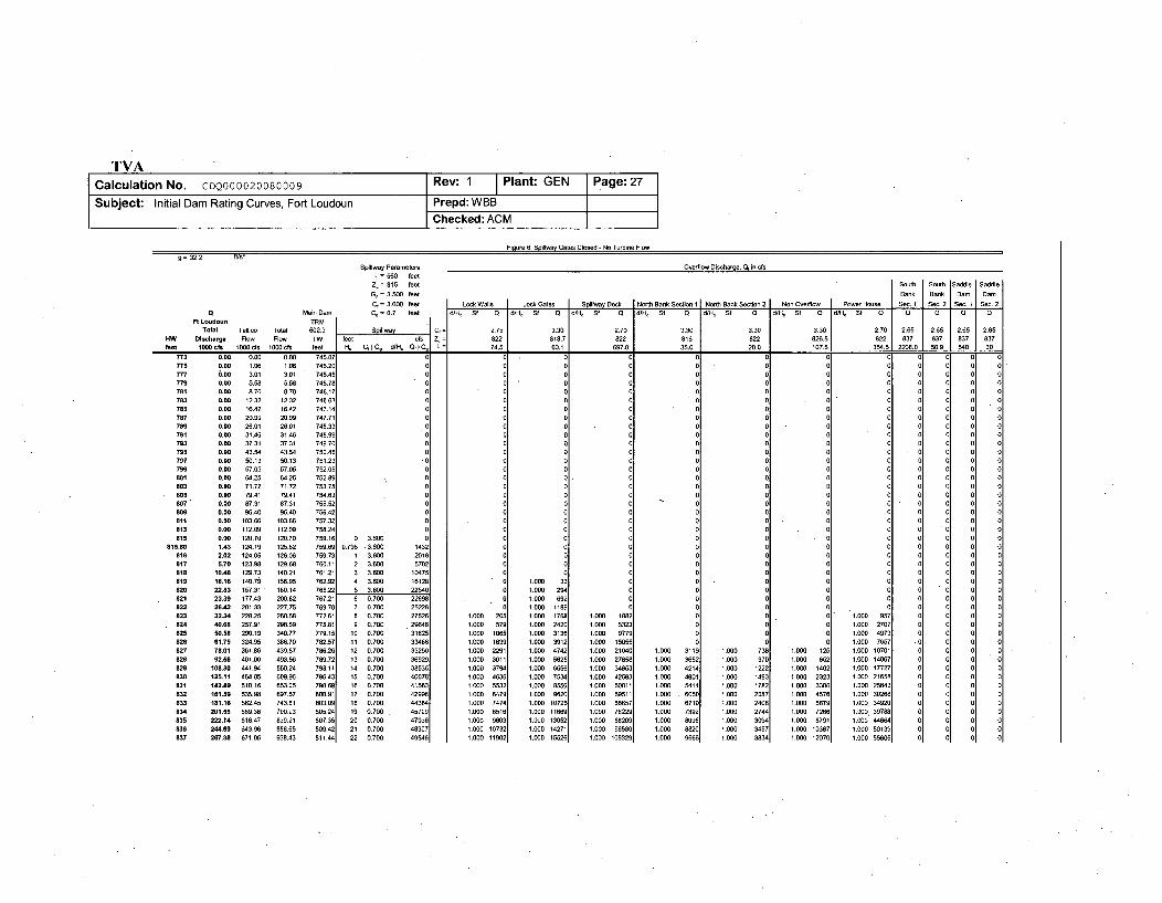
TVACalculation No. CDQ000020080009 Rev: 1 Plant: GEN Page: 27
Subject: Initial Dam Rating Curves, Fort Loudoun Prepd: WBBChecked: ACM
Fioure 6: Soltswa- Gates Closed - No Turbine Flowg=32.2 /s
Spillway Parameters Overflow Discharge, Qfin cfs
L = 560 feet
Zj = 815 feet South South JSaddle ISddl
G, = 3.500 feet Bank Bank Dam Damt
C, = 3.600 feet Look Walls Lock Gates Splltway Deck North Bank Section 1 North Bank Section 2 1 Non Ovef- Power House S-11 Sec. 2 S I Sec. 2a Main Dam C. = 0.7 feet d/H, Sf 0 I-f, Sf Q d/H-f Sf Q d/H, Sf Q d/Hl Sf Q d/H, Sf G d/Hf Sf Q 0 0 1
FtLoudoun TRM .
Total Tellio Total 602.3 Splltway C,= 2.75 3.30 270 3.30 3.30 3.30 2.70 2.65 2.65 j 2.65 2.65EW Discharge Flow Flow TW feet cfs 7- - 822 818.7 822 818 822 026.5 022 037 037 037 037
feet 10800 s 1000os 1000 cfs feet H. C, I CG d/H, G, 106 L= 74.5 60.1 607.0 35.0 20.0 107.5 350.6 2200.0 50.0 540 20
773775777778781783785707789781783795787789881883
B05807809811813815
810.0
817
1t9020821822823824825026827828628830831832833834835836837
0.00 0.00 0.00 745.07
0.00 1.06 1.06 745.20
0.00 3.01 3.01 745.45
0.00 5.58 5.58 745.78
0.00 8.70 8.70 746.17
0.0O 12.32 12.32 746.63
0.00 16842 16042 747.14
0.00 20.99 20.99 747.71
0.00 20.01 26.01 748.33
0.00 31.46 31.46 748.99
0.0O 37.31 37.31 749.70
0.00 43.54 43.54 750.45
0.00 50.13 50.13 751.23
0.80 57.05 57.05 752.05
0.00 64.25 64.25 752.89
0.00 71.72 71.72 753.75
0.00 79.41 70.41 754.03
0.00 87.31 87.31 755.52
0.00 5.40 95.40 756.42
0.00 103.66 103.66 757.32
0.08 112.01 112.09 758.24
0.00 120.70 120.70 759.16
1.43 124.19 125.62 759.69
2.02 124.05 126.06 759.73
5.70 123.98 129.68 760.11
10.40 129.73 140.21 761.21
10.16 140.79 156.95 762.9222.83 157.31 180,14 765.22
23.39 177.43 200.82 767.2128.42 201.33 227.75 769.70
32.34 228.25 260.58 772.61
40.68 257.91 298.59 775.81
50.58 290.19 340.77 779.15
61.75 324.95 386.70 782.57
78.01 361.86 439.87 786.26
92.56 401.00 493.56 789.72
108.30 441.94 550.24 793.11
125.11 484.A5 609.96 796.43
142.89 510.16 653.05 79806.
181.59 535.90 697.57 800.91
181.16 562.45 743.61 803.00201.50 509.38 790093 005.24
222.74 616.47 839.21 807.35
284.69 643.96 888.65 809.42
267.38 671.05 938.43 811.44
0
0"0
0 3.600 00.796 .3.600 1432
1 3.600 2016
2 3.600 5702
3 3.600 10475
4 3.600 16128
5 3.600 22540
0 0.700 22608
7 0.700 25228
8 0.700 27526
9 0.700 .29640
10 0.700 31625
11 0.700 33406
12 0.700 35250
13 0.700 36929
14 0.700 38536
15 0.700 40078
16 0.700 41563
17 0.700 42996
18 0.700 44384
19 0.700 45729
20 0.700 47036
21 0,700 48307
22 0.700 49546
CC
IC00 31.0 5
1.00 08
1.0 Cf01.0 101.0 22
1.000 3011.000 24741.000 00251.000 66601.000 17561.000 05501.000 01621.000 310251.000 ff060
1.000 135261.000 154271.000 15520
1.0 101.0 351.0 41
1.0 00
1.0 0511.0 001.0 70100 702100 000100 002100 050 1.000 731
1.000 9711.000 122Z1.000 14901.000 178;
1.000 20811.000 24011.000 274&
1.000 30901.000 345S
1.000 3834
.0
.0
0 1
CI
C0
1 1
1 210 3
1 41 50
1.000 1207
1.0 C51 c0 1o1,o 221 c0 38
1.000 12O7
1.000 20!
1.000 571.000 106!
1.000 10311.000 22911.000 30111.000 379'1,000 46311.000 55311.000 647i1,000 747'
1.1300 107311.000 1100:
1.000 18821.000 53231.000 9770
1.000 150551.000 21540
1.000 27656
1.000 34853
1.000 42583
1.000 50811
1.000 59511
1.000 60657
1.000 78229
1.000 88209
1.000 985801.000 109329
00
0
0
0
1.000 957
1.000 2707
1.000 4973
1.000 7657
1.000 10701
1.000 14067
1.000 17727
1.000 21658
1.000 25843
1.000 30268
1.000. 34920
1.5000 39788
1.000 44864
1.000 50139
1.000 55605
TVACalculation No. CDQ000020080009 Rev: 1 Plant: GEN Page: 28
Subject: Initial Dam Rating Curves, Fort Loudoun Prepd: WBBChecked: ACM
6.3 Case 3 - South Embankment Failure, Fort Loudoun Spillway Gates Open - Tellico Intact
For the South Embankment Failure condition, discharges are computed for headwaters ranging from 773 feet to 837 feet, thelimit of the headwater elevation [4.21]. Discharge passes through the spillway section and the various overflow sections asheadwater rises above the crest elevations in each case. Total discharge, given in "1000 cfs" is the sum of all discharges incfs past the dam plus discharge in cfs past the west saddle dam divided by 1000.
Figure 7 shows the spreadsheet calculations for the pre-failure initial dam rating curve (spreadsheet included as Attachment 16). IThe final result, the rating curve, is defined by the first two columns, HW vs. Total Discharge. The next two columns are asynopsis of the flows from Tellico Dam. Since Tellico and Fort Loudoun discharge into the same tailwater within close vicinityto each other, it is necessary to include the flows from Tellico to calculate the TW elevation. The fifth column (TW) gives thetailwater associated with the "Total Flow" from the tailwater rating curve polynomial fit provided in Attachment 15. This iscomputed to check for tailwater submergence effects on the discharge. Since the tailwater elevations reach levels that reduceflow through the spillway, it is necessary to iterate through different tailwater elevations until the total computed discharge fitsthe tailwater rating curve [4.20]. Figure 7 shows the final results but does not show the iteration steps. The results are readilychecked by computing the individual discharges, adding them up to compute total discharge, and then making sure the listedtailwater and total discharge agree with the tailwater rating curve.
Spillway discharge in cfs is computed in the next five columns (under the header "Spillway"), H., CdCg, d/H,, Sd•Sg,. and QdQg.Free discharge occurs for headwater elevations below 820.9 feet [4.3.4] and orifice discharge occurs for headwaters above 820.9feet. The transition point is indicated by a horizontal line. Above the line, the listed discharge coefficient is Cf [4.2.3] computedfrom Equation A5 and below the line the listed discharge coefficient is Cg [4.3.5] computed by interpolation between the points inTable A3. Sf is computed to account for submergence effects using Equation A6 when d/H, exceeds 0.6. Sg is calculated byinterpolating between values in Table Al. Column QdQg is the spillway discharge computed from Equation 1 for free dischargeand from Equation 3 for orifice discharge. The free and orifice discharges are modified by Equations 2 and 4, respectively, toaccount for the submergence effects when d/Hc is greater than 0.6.
The column following the spillway discharge column shows "Cf="', "Z,=", and "L=" in three rows to indicate the meaning of thevalues included in those rows in the "Overflow Discharge" columns.
The next 33 columns are overflow discharges in cfs for the lock walls, lock gates, spillway deck, spillway gates, northembankment, nonoverflow, powerhouse, south embankment, and saddle dam. The overflow discharge coefficient Cf ([4.10.1],[4.9.1], [4.6.11, [4.4.1], [4.13.1], [4.11.1], [4.12.1], [4.17.1], [4.15.1]), elevation Z ([4.10.2], [4.9.2], [4.6.2], [4.4.2], [4.13.2],[4.11.2], [4.12.2], [4.17.2], [4.15.2]), and length L ([4.10.3], [4.9.3], [4.6.3], [4.4.3], [4.13.3], [4.11.3], [4.12.3], [4.17.3], [4.15.3])in each case are indicated in the three rows above the computed discharges. All overflow discharges are computed usingEquation 1. Note that all overflows had to be modified using Equation 2 in order to account for submergence. Sf is calculatedusing Equation 5 and interpolation in Table 2.
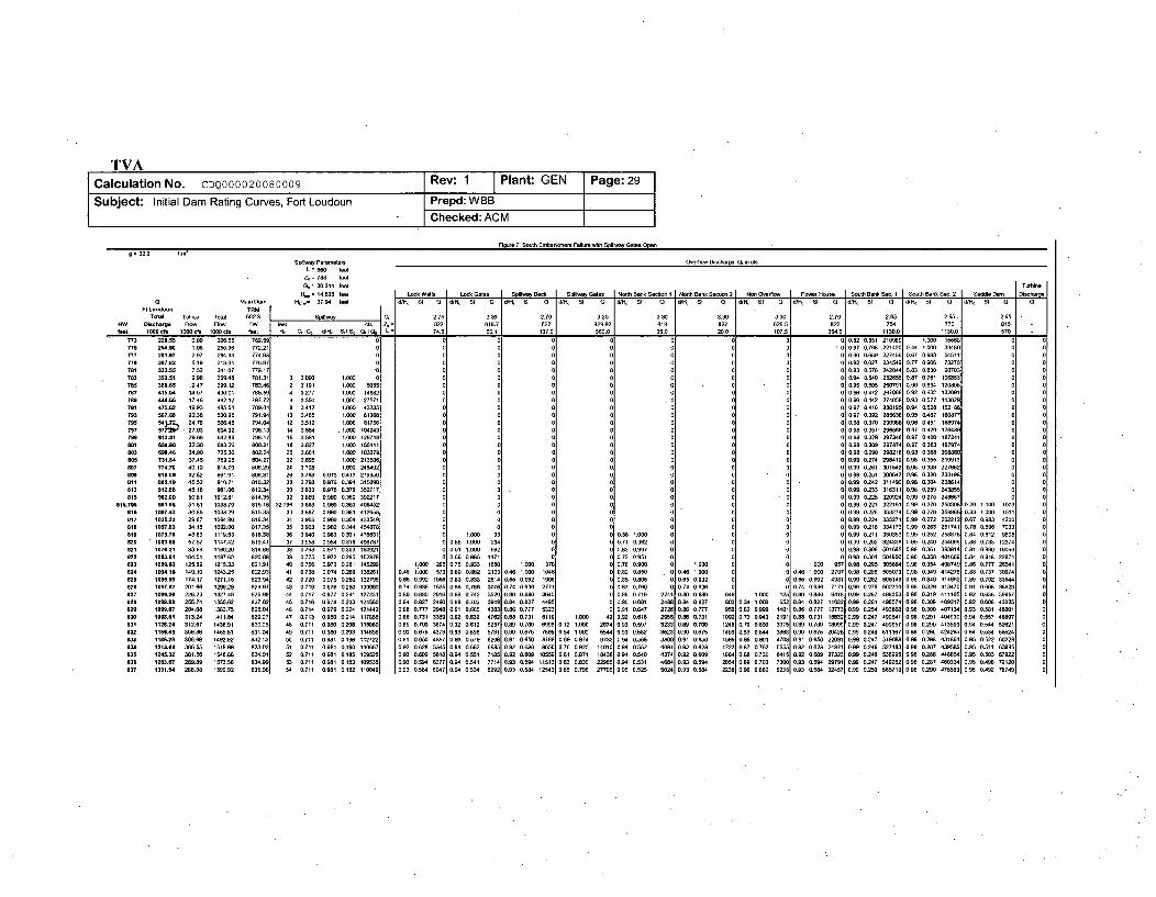
g 32.2 vt
s pioay P.temee. Overflow Qrsoharge. Or ir cfsL 560 feat
74 783 1-e
C, 30.314 leer5 354,5 1130.0 1130. j TaiooH= 14.828 le r I Look Wa [ Look Gates I Spinevay Beok Spiltvy Gates Notdh Bwk Secoo 1 NBoroh Bank S-oooo 2 NB OveNlow Por Haven Sou0 Benk Sen. 1 Soout Bono Soo. 2 Saddle DeSchrge
d Maine Dm . H_= 37.B4 le WKH. St 0 0%H SI 0 ] d/ f d St 0 rant SI 0 401 Sf a &4t St 0 [attt. Q d0 , J f t dS SI 0 at Sf O WK Sf 0 a
Tota Tellit Total 602.3 Stiloney = 2.75 3.30 2.70 330 3.30 3.30 3.30 3 2.70 2.652 2.65 2.65 -
mW DBlsharge Flow Flow TW Zeel ocf = 822 818.7 822 829.92 818 822 826.5 822 754 770 815 -feel 1800 ole 1060 os 1000 ole l eert t. Crl. Ic dtt Sti Se 1 L= 74.5 60.1 137.0 560.0 35.0 20.0 107.5 35.5 13.0 1130.5
773 228.85 0.00 226.55 78.5 0 0 0 0 0 0 0 0 0 0.82 00o1s 210068 1..00 1550 0 0775 250.80 1.30 255.96 772.21 00 0 0 0 0 0.87 0.78 221420 0.44 1.000 33480 0 0777 281.87 2.97 280.94 774.8 0 0 0 0 0.68 2274560 0 .87 03 54511 0 0779 387.82 r19 313.01 776.97 0 0 0 0 0 0.92 0.827 23459 0.77 068 73276 0 0781 M38.55 7.52 Sat.07 779.17 0 0 0 0 0 0 0 0 0.93 0.578 242844 083 830 90703 0783 488.51 9.98 39.48 781.31 0 3.090 1000 0 0 0 0 0 0 0 0 0.04 0.540 25268 1 0.87 0.761 106853 0 0785 388.85 12.47 389.12 783.46 2 3.191 t.000 055 0 0 0 0 0 1 0 0 0.85 0.105 260791 0.0 069 12008 0 0787 415.04 14.87 430.01 785.59 4 33277 1.030 1462 0 9 0 0 0 0 0 0W9 0472 267668 0.92 0.632 132691 0789 444.88 17.46 462.12 787.72 6 3.35 1000 21571 0 0 00 0 0.98 0.442 274059 0.93 0.577 143029 0 0781 475.62 19.93 495.50 789.84 8 3.412 1,000 03250 0 0 0 0 0 0 0 280195 0.9.4 0.528 152186 0793 5W7.88 22.3M 530.26 791.84 10 3.415 1000 8136 0 0 0 0 0 01 0 097 0,392 285634 0.95 0,487 160877 0 0795 U4lJ2. 24.19 576 .48 784.84 12 3.512 1800 81751 0 0 0 0 0 0 0 0.098 0.370 290988 0*90 0.451 160974 0797 s7ll"' 27.03 604.32 7961.3 14 3.55 1.000 184243 0 0 0 0 0 0.N 09.351 296%64 0.97 0.420 176486 0 0788 613.31 29.66 642.96 798.17 16 3.591 1000 128718 0 0 0 0 0 0 0 094 0,329 207346 0.97 0.400 187241 0 0
e01 650.96 32.30 683.26 800.21 18 3.627 1000 155111 0 00 0 0 09 0.309 297874 0.97 0.303 197974 08DO M98.88 34.90 725.36 802.24 2a 3.661 1.000 183379 0 0( 0 0 0.98 0.290 298214 0.98 0.360 204060 0 0805 731.84 37.45 769.28 804,27 22 3,695 1.000 21350 0 0 0 0 0 0 0 0. 0274 298419 0.98 0.355 21"013 0 0808 7n.70 40.10 014.79 W06.29 24 3.728 1.000 245092 0 0 0 0 0 0 0 0 0.0 0:261 001502 0.98 0.330 2276.2 0 0808 818.04 42.82 861.91 808.31 26 3.78 0.973 0413 279350 0 0 0 0 n 0 0 8 0.00 09251 00503 0.6 0.320 233198 0 0811 ee5.19 45.52 910.71 810.32 21 3.798 0.976 0.384 315090 0 0 0 0 0 0 . 0 0.8 0.242 311400 0.60 0.304 230614 0813 912.88 48.18 961.06 812.34 30 3.834 0.878 0.378 352717 0 0 0 0 8 0 0 0 0.60 0.233 318311 0.90 0.289 243855 0 0815 982.00 50.81 1012.81 014.35 30 3.89 0.80 0.W00 39U17 0 0 0 8 0 0 0 0.0 0225 320024 0.99 0.275 248857 0 0
815.79% 981.98 51.81 1033.79 815.16 32.798 3.883 0.900 0.353 406052 0 0 0 0 0 0 0 0 0.00 0221 3221511 0.60 0.270 250308 0.20 1.000 1013 0818 1987.43 30.86 103829 815.33 33 3.887 0.830 0.001 1284 0 0 0 0 0 0 0 0 0. 0.228 33274 0.00 0278 26v8 0.33 1.000 1511 0817 1035.23 29.67 1064.90 816.34 3 3 .90 0.90o 0.354 4334 0 .0 0a 0 0 0 0 0.9 0.224 305271 0.60 0.272 262212 0.67 0.983 4200 0818 1057.88 34.18 1092.00 811.35 M5 3.923 0.982 0.34 034078 0 0 0 0 0 0 0 0.99 0.218 334173 0.00 0.263 261741 0.78 0.896 7033819 1075.70 43.83 1119.53 818.38 36 3.840 0.963 0.31 476B31 0 1.000 33 0 0 0.38 1.000 0 0 0 0 0.99 0.211 330353 0.09 0.252 258878 084 0.812 006 0ON0 Joe.8 57.5 1147.42 MAI.4 37 3958 0.9N4 0 318 498781 0 0.55 1.000 204 0 0.71 0.962 0• 1 0.99 0,202 324W61 0,9 0.240 N,40661 0.88 0.733 12374
821 1078.21 03.99 1160.20 819.88 3M 0.793 0.971 0.309 100821 0 0.51 1.000 602 0 0 0.63 0.997 0 0 0 0 0.98 0300 501685 0.98 0261 396014 0.81 0.860 19096 0822 1083.1 104.01 1107.02 028.09 39 0.775 0.972 0.285 152970 0 0.60 0.98 1171 0 0 0.72 0.651 00 0 0.98 0.301 504B00 0.98 0234 401689 0.84 0.818 22871 0823 1084.83 125.69 1215.33 821.91 40 0.750 0.973 0.281 105299 1.000 205 0.75 0.933 1650 1.000 370 0 0.78 0.900 0 1.00 0 0 1.000 957 0.98 0.295 50504 0.98 0.354 408749 0.86 0.777 26541 0824 109I.16 148.10 1243.25 802.93 41 0.730 0.974 0.269 100261 0.46 1.000 579 0.90 0.882 2133 0.46 1.000 1040 0 0.82 0.050 0 0.40 1.000 0 0 0.40 1.030 2707 0.90 0260 505079 0.98 0.349 414270 0.88 0.737 3074 0835 1888.30 174.17 1271.15 822.94 42 0.720 0.975 0N20 132795 0.65 0.992 1010 0.83 0.13 26146 060 0.:92 1890 0.85 0805 0 9.65 0.892 00 065 0.092 4931 039 0.282 505149 0.98 0.340 410992 0 0.702 3844 0026 1097.82 201.88 129.28 024.97 43 0,719 0.976 0.250 13000 0.74 0.936 1535 0.00 0.786 3076 070 0.936 2771 0 0.87 0.76 0 0.74 0.936 0 0 0.74 0.93 7171 060 0.275 602710 0.9 0.329 413470 0.91 0.668 3682 0827 1888.28 226.23 1324 825.60 44 0717 0.877 0.241 127291 0.60 0.800 2916 0.40 0.742 3520 0.80 0.880 3840 0 0.49 0719 224 8.80 0.828 1.000 125 0.60 0.74 0 8418 009 0.267 4993533 0.60 0.319 411105 0.92 0.636 39957 0828 1898.88 255.74 1355.62 827.02 45 0716 0.974 0.233 124560 0.84 02827 2400 0.88 0.702 3948 0.84 0.827 4495 0 0.96 0601 2488 0.8 0.827 800 0.34 1.000652 0. 0. 0.027 11832 0099 0.2l1 496574 1.O 0.309 409217 0.92 0.60 4302: 0829 1898.67 284.00 1303.75 820.04 46 0.714 0.879 0.224 121442 0.6 0.777 29.8 0.81 8.60 4363 0.86 0.777 5323 0 0.91 0.847 2126 0.30 0.777 050 0.62 0.960 1401 0.00 0.777 13773098 09254 483608 0.60 0.300 407134 0.93 0581 46001 0898 188.81 31324 1411.84 829.07 47 0.713 0.80 0.214 117856 0.M 0 .731 3389 0.92 0.632 4782 0.88 0.731 6118 1.900 42 0.92 0.616 2955 0.60 0.731 1092 0.73 0.843 2181 0.80 0.731 15832 0.99 0.247 460541 0.98 0.21 4.4930 0.04 0.557 4897 0131 1128.24 312.07 1438.91 830.05 40 0.711 0.980 0.284 116000 0.09 0.798 3M74 0.92 0.612 5237 0.09 0.78 89951 0.12 1.900 2074 0.93 0.501 323 0.69 0.700 1248 0.79 0.890 3015 0.89 0.700 18099 0.0 27 490957 0.6 0.290 413809 0.9 0.544 52621 0830 1158.45 306.30 1465.81 831.04 48 0.711 0.60 0M23 114890 0.90 0.675 8373 0.83 0.596 5731 0.60 0.675 7951 0.50 1.800 5544 0.502 3023 0.60 0.075 1409 03.844 3031 0.1 0.675 2842B 0.99 0.248 511107 0.88 0.290 424295 0.84 0.534 56020823 118828 3046.0 1492.92 032.83 00 0.711 0.606 n8.198 112722 0.01 0.650 4857 0.00 0.579 62 0 .81 0.10 8769 0.609 0.974 9733 0.94 0566 3800 0.91 0.650 6565 0.80 0.801 4709 0.91 0.610 22691 0.09 0.247 51960 0.68 0.288 431861 0.95 0.522 60229884 1213.44 300.55 1518.88 833.02 51 0711 0.941 0.1 0 110667 0.92 0.628 5•35 0.94 0.563 66850 0.:2 0 %5010 0.70 0.928 14010, 0.98 0.52 4061 0.82 0.628 1722 0.87 0.762 55 0.03 0.628 24971 0.99 0.246 5271831 8.8 0.907 435 .85 0.511 6 5M5825 1205.32 301.30 154U.60 830.91 53 0711 0981 0.185 109525 0.82 0.609 5848 0.04 0.501 7185 0.82 0.608 10550 0.8 0.871 19030 0.94 0.540 4374 0.82 0.609 180 0.88 0.730 6415 0.92 0.609 27323 0.99 0.240 538895 0.98 0286 488541 0.0 0.503 6792 0
826 12138,7 289.88 1573.51 834.98 53 0.711 0.981 0.103 1.9535 0.60 0594 0377 0.94 0.341 77141 0.93 0.594 15131 0 .830 22985 0.94 0.531 4104 0.83 0.584 2854 0.88 0.703 73O1 0.03 0.594 2971 9 0.247 549262 0.98 0.287 4o3341 0.30 0.4w 72129 0837 1 u31.50 268.38 1599.92 835.96 54 0.711 0.891 0.182 110049 0.93 0584 6847 0.94 0.534 42021 0.83 0.5%4 12543 0.85 0.796 27705 0.95 0.525 5024 0.93 0.584 2238 0.00 0.682 8235 0.93 0.584 32457 0.99 0.20 505713 0.88 0.290 475589 0.95 0.492 76749 0
TVACalculation No. CDQ000020080009 Rev: 1 Plant: GEN Page: 30
Subject: Initial Dam Rating Curves, Fort Loudoun Prepd: WBB
Checked: ACM
6.4 Case 4 - South Embankment Failure, Fort Loudoun Spillway Gates Closed - Tellico Intact
For the South Embankment Failure with spillway gates closed condition, discharges are computed for headwaters ranging from773 feet to 837 feet, the limit of the headwater elevation [4.21]. This case is similar to case 3 except for there is no dischargethrough the spillway until the gates themselves are overtopped. Discharge passes through the various overflow sections asheadwater rises above the crest elevations in each case. Total discharge, given in "1000 cfs" is the sum of all discharges in cfspast the dam plus discharge in cfs past the west saddle dam divided by 1000.
Figure 8 shows the spreadsheet calculations for the spillway gates closed initial dam rating curve (spreadsheet included asAttachment 16). The final result, the rating curve, is defined by the first two columns, HW vs. Total Discharge. The next twocolumns are a synopsis of the flows from Tellico Dam. Since Tellico and Fort Loudoun discharge into the same tailwater withinclose vicinity to each other, it is necessary to include the flows from Tellico to calculate the TW rating curve. The fifth column(TW) gives the tailwater associated with the "Total Flow" from the tailwater rating curve polynomial fit [4.20]. This is computedto check for tailwater submergence effects on the discharge. Since the tailwater elevations reach levels that reduce flow throughthe spillway (mainly at Tellico in this calculation), it is necessary to iterate through different tailwater elevations until the totalcomputed discharge fits the tailwater rating curve [4.20]. Figure 8 shows the final results but does not show the iteration steps.The results are readily checked by computing the individual discharges, adding them up to compute total discharge, and thenmaking sure the listed tailwater and total discharge agree with the tailwater rating curve.
Spillway discharge in cfs is computed in the next five columns (under the header "Spillway"), He, CdCg, d/Hc, Sf, and QfQg asoutlined in section 4.22. Free discharge occurs for headwater elevations below 820 feet [4.5.5] and orifice discharge occurs forheadwaters above 820 feet. The transition point is indicated by a horizontal line. Above the line, the listed discharge coefficientis Cf [4.5.1] computed from Equation A5 and below the line the listed discharge coefficient is Cg [4.5.6]. Column Qf]Qg is thespillway discharge computed from Equation 1 for free discharge and from Equation 3 for orifice discharge. Free discharge ismodified by Equation 2 using the Sf calculated from Equation 5. Orifice discharge is modified as outlined in Section 4.22.
The column following the spillway discharge column shows "Cf=", "Zc=", and "L=" in three rows to indicate the meaning of thevalues included in those rows in the "Overflow Discharge" columns.
The next 33 columns are overflow discharges in cfs for the lock walls, lock gates, spillway deck, north embankment, powerhouse,nonoverflow dam, south embankment, and the saddle dam. The overflow discharge coefficient Cf ([4.10.1], [4.9.1], [4.7.1],[4.13.1], [4.12.1], [4.11.1], [4.17.1], [4.15.1 ]), elevation Z, ([4.10.2], [4.9.2], [4.7.2], [4.13.2], [4.12.2], [4.11.2], [4.17.2],[4.15.2]), and length L ([4.10.3], [4.9.3], [4.7.3], [4.13.3], [4.12.3], [4.11.3], [4.17.3], [4.15.3]) in each case are indicated in thethree rows above the computed discharges. All overflow discharges are computed using Equation 1. Note that all overflows hadto be modified using Equation 2 in order to account for submergence. Sf is calculated using Equation 5 and interpolation in Table2.
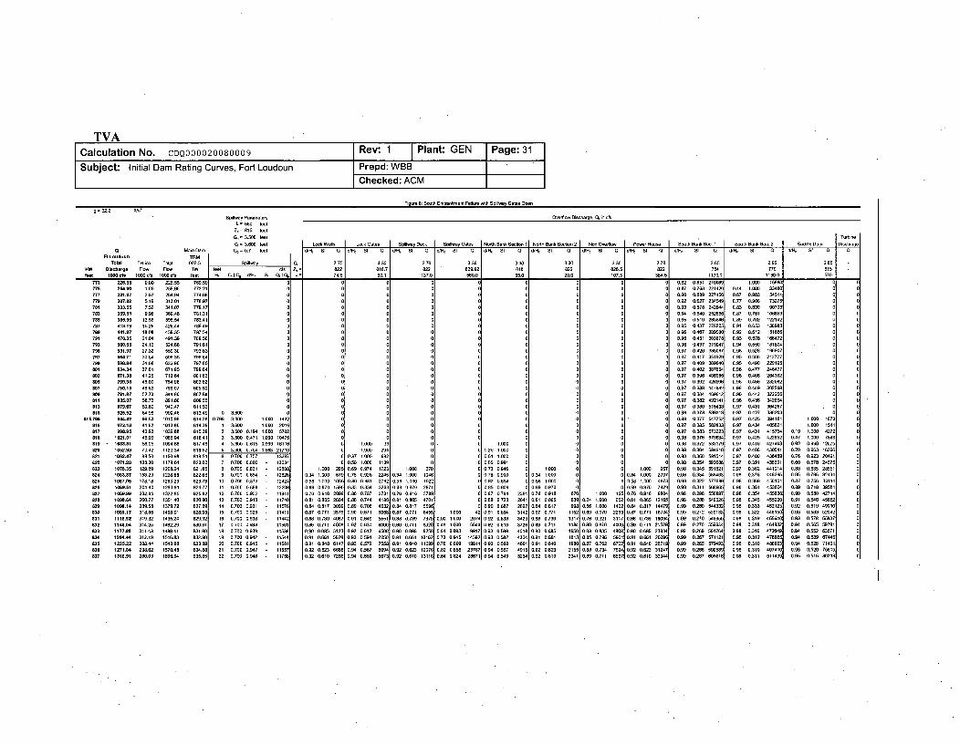
TVACalculation No. CDQ000020080009 Rev: 1 Plant GEN Page: 31
Subject: Initial Dam Rating Curves, Fort Loudoun Prepd: WBBChecked: ACM
g=32.2 MI WSp'Ihay Patameter Sca O l Dischag. , in cte
.- 560 eatZ== 816 f~t
C, = 3.500 feet Turing3. = 3 Io0 Bet Lok WWlIs LOCk Gate Spillwa Dck I /Spioly Gates Noth Bank Section 1 Nonh Bank Sectin 2 Non Oereft ton HC-Jo Soth Bank Sac. 1 J uh Bae Sac. 2 SaI ,e Dan D-lchag
M a ln D . .m = 0.7 ft a t W/Ho S f 0 / S S u S /Ho S f a oditt o S 0 S f 0 1 /S S f Q 0 /Ho S f Q 0 /It St Q d0 /t St Q H ' St 5 0Ft L oo un TRMIIIIIIII
Total T98ico Total 602.3 Spiwany 2.75 3.30 2.70 3.30 n3.3 3.30 3.3O 2.70 2.65 2.620 "lghane Rote fatt o j = 822 818.7 822 0 629.92 81i 822 828.5 822 754 770 t15 -fae ee a1Ocoo l c00 It 030 s t e tot lI H C I C3 dunt $% QoiQ• L-= 74. 60.1 137.0 550.0 35,0 20.0 0 17.5 5. 5730o
773 2M6.55 0.00 218.55 789.59 0 0 0 0 0 0 0.82 I.B5t 2t080 1.65 550775 1.agO ,06 255.86 772,21 00 0 0 0 0 0 0.87 0.760 22t820 0,4 1.50 33080777 281.97 2.97 280.6 770,68 0 0 0 , 0 0 0 0 .80 0.680 0 .67 0.983 451t 0 077M 3V7.82 5.t9 313.01 778.97 0 0 0 0 0 0.82 0.627 230548 0.77 0,906 73275 0781 =33.55 7.52 30t.07 77B1.7 0 0 0 0 0 0 0.83 0.578 24284W 0.83 0.830 90703 0 0783 359.51 9.98 36%,48 781t30 0 0 0 0 0 0 0 0,94 0.540 252630 0.87 0,761 1t0685 0 0785 385.99 12.55 398.54 783.4t 0 0 0 0 0 0.95 01t1 263846 089 0.702 12242 0787 41 .19 3,25 428.80 785.49 0 0 o 0 0 095 0.487 276205 0,1 0.653 31 3 0 0789 801.27 18.08 459.35 787.5 0 0 0 0 0 0 0 0 0.3 0,487 209680 0.92 0,612 56860e91 4703.5 21.00 491.39 769.58 0 0 0 0 0 0 0.96 0.451 30387 0.93 0.576 158872 0
743 500.95 24.12 524.68 791.61 0 0 0 0 0 0 0 0 0 0.96 0.437 319047 0.94 0.550 11t 0'7985 31.97 27.32 55930 79363 0 0 o 0 0 0'0 0.87 0.426 335067 0.95 0.526 19907 .0707 64.71 30.64 595.35 790 00 0 0 . 0 0 0.97 0.417 351929 0.95 0506 212777705 598.84 38.30 632.90 787.85 0 0 0 0 0 0,, 0 0 0.B7 0409 309640 0.95 0.490 229t9 00801 824.34 37.61 671t95 79964 0 0 0 0 0 0 0 0 0.97 0002 307086 0.96 0.477 246477 0 0803 17:.38 80.26 712.64 1 . 0 0 0 00 0 0 0.97 0.396 406980 0.96 0.483 26432 0805 70.9 45.00 7549t 603.62 0 0 0 0 0 0 0 1 0.B7 0.392 426891 0.96 0.456 2828 0807 758.15 48.83 79697 "856" .,0 0 0 0 0 0 0 0 0.97 0.388 807882 0.96 0.809 302268 0808 7"1.87 52.73 844.60 607.50 0 0 0 0 0 0 0 0 0 0.97 0.384 4696"2 0.9 0.002 322250911 835.87 58.73 B91.68 68.55 00 0 0 0 0 0 . 0 0 0.97 0.382 492t40 0.96 0.430 382838813 879.07 60.80 940.47 811t52 0 0 0 0 0 0 0 0 0 0.97 0.300 515403 0.97 0.43t 3842 6815 925.52 64.96 990.48 6 t349 0 3,610 0 0 0 0 0 0 0 0 0 0.68 0.374 533113 4.97 0.427 36828
81&.7M8 944.42 68.59 1010.95 814.28 0.796 3.600 1.000 1432 0 0 0 0 0 0 0 0 0.8 0.377 547752 0.97 0.425 3941t 1.000 M07816 972.18 41.62 1013.80 814.39 1 3.80 1.000 2016 0 0 0 . 00 0 0 0 0.67 0.305 612633 9.97 0.43 40512 1.0 111t 0817 998.95 40.93 103n. 815.39 2 3.60M 0.194 .000 5702 0 0 0 00 0 0 0 0.87 0.303 57522 0.97 0.431 415751 0.1t 0.030 427 0998 1021.01 45.93 1966.94 816.41 3 3.600 0,471 1.000 0475 0 0 0 0 0 0 0 0 98 0.378 579820 0.97 0,425 422852 0.47 1.000 7849 0819 1038.81 56.05 $094.48 817.46 4 3.600 0.615 0.999 16116 0 1.000 33 0 . 0 1.000 0,, 0 0.68 3.372 583179 0.97 0.416 427403 3.82 0,999 1207582 1983.82 70.42 1123.3M 818t52 5 3.600 0.704 0.963 21710 0 .000 290 0 01 26 1.00 0 0 0 0 0.68 0.380 588618 0.97 0.406 43004t 0.70 3.963 8260821 1862.47 88.50 t160.98 8t9.50 0.700 0.757 03287 0 3.37 .000 692 0 0 0.1 01.00 0 0 0 0.88 3.368 591514 0.97 0.400 436489 0.76 0.923 2091 0822 187128 M00.30 t179.64 820.60 7 J75. 0.600 03030 0.59 1000 1t69 0 0a 0,65 0.991 0 0 0 0.68 0.354 593068 0.97 0.391 43880t 0.60 0.878 24575 0823 1078.35 129.9 1208.24 821t.5 8 0.700 0.631 12204 1.000 205 0.69 0.974 1723 1000 370 0 0.73 .,946 0 1.000 0 0 1.000 957 0.98 0.305 591821 0.97 0,382 44191t 0.63 0835 2551 0824 1983.37 53.29 230.8 8226 9 3.700 0.654 12826 0.3 1 .00 579: 0.75 0.826 2205 3.30 000 1040 0 0.76 0.900 0 .30 1.000 0 0 0.30 t.000 2707 0.98 0.334 59503 0.98 ).376 446265 0.85 0.795 3243 08u5 1087.05 1 1t 1265.23 82313 t10 o.zoo 3873 42024 0 058 .050 065 080 0.80 2702 0.58 tO00 1922 0 0.82 0854 0 0.59 .000 0 0 0.58 1000 0973 098 0.322 5776 0.90 0.369 45010t 087 0.756 36t11 0826 1089.51 209.40 1293.91 824.77 11 0.700 0.888 12208 6 69 0.970 1590 3.82 0.830 3863 0.9 0.970 207t 0 0.65 409 0 09 70 0 0 0.69 0,970 7429 0.98 0,311 568965 0.98 030t 435380 8 3.49 0.76 3951 0827 1089.95 232.65 1322.85 825.82 12 0.700 0,902 11t94 0.76 0.901 2099 0.80 0.787 3731 0.76 0.916 3789 0 0.97 0764 2381 0.78 0,918 67 00 125 076 0,91t 9800 396 0.298 5089 0.98 0.350 450830 0.90 0.6B0 42714 0839 189.64 260.77 1381,40 8.68 3 0.700 0.9t3 11740 0,1. 0.065 2600 0.8 0,744 4188 0.81 0.865 4701 0 0.89 0.723 2641t 0S8t 065 839 024 32 .000 652 0.81 08565 12165 0.99 0.288 549326 0.99 0.305 455928 0.80 0.648 5482829 1090.14 249.58 379.72 62n.69 to 0.780 0.92t 1t578 0.64 0.0t7 30991 0.9 0.796 0632 0.84 ,8t7 0590 01 0.90 0,687 2897 0 0,8t7 998 38 0. 1.0 002 1 0 0.8 t7 8079 0.99 0S20 584332 .0.8 0.332 452123 0.92 0619 49010 0834 1084.17 318.02 t49,o.t 628.93 5l 0.700 592 o t 0.' t 0.87 t.77t 37 0.90 0.628 11411 08056 1.008 42 0.91 0.650 3t42 3.87 0.770 1152 0.09 0.970 2253 3.67 0,77 16704 0.99 0.272 529t83 0.98 0.322 868150 0.93 0.593 52002 0831 1115.92 319.32 1038.24 829.92 16 0.700 0.933 01802 3.44 0.739 0487 091 0.649 555 0.84 3.739 7379 0.96 1.008 20740 0.0633 329 0.68 0.739 t317 0.76 0,921 3171 0.68 0.738 1993 0.88 0.270 306850 3.96 0.3t9 05944 0.93 0.579 5537 0832 11M8."4 314.25 1462.29 830t91 17 0.700 0936 11501 0.88 0.701 4688 0.9 0."30 60 .6 0.8 lt 8320 0.48 1.900 550 4 0.92 0.616 3726 0.• 0.71 144 0M .80 76 4005 0 .6 1t 2t528 0.99 0270 5N8634 3.98 0.3t8 494832 0.68 3.565 59791834 1173.68 311.43 1489.41 831.9W 10 0.700 0.939 10530 3.90 0495 5423 0.92 0.612 6500 0.96 0.685 8250 3,64 0.o93 9617 0.93 0.599 48 B.685 650 0.83 0.835 490• 0.90 0.080 23830 0.9 3.269 564764 0.98 0.316 472649 0.94 0.552 63671 0834 1284.44 312.19 1516.03 832.00 ta 3.700 0.942 OB54o 0.90 3.680 5629 0.83 0.568 7050 .1 0.661 10162 0.73 0.9485 14392 0.93 0.582 434 0.91 0.6t1 1813 0.95 0.796 5801 0.91 0.661 2629 0,99 0.267 571121 0.68 0.312 47085S 0.94 0.5n9 676 0835 1245.20 308. 54388 83.99 28 0.700 0.645 11581 0.9t 0.646 8 .65 8.579 75581 1.9 0.640 110961 0.78 0.899 10141 0.93 0,568 401t 0.91 0.640 1980 0.87 0.762 6702 Sot 0.640 28719 0.99 0.265 579493 3.9 .310 48t6923 4.6 0.526 71401836 1231.84 288.62 1570.46 934.88 201 0700 0.947 t1667 0.82 0.823 6800 0.94 0,567 8088 3.92 0.823 2876 0.82 5,54 33767 4.90 3,557 49t5 3.92 3.623 2t59 3.99 0.730 7620 3.92 023 31247 3.96 0.268 500589 3.94 0.300 097400 0.6 0.520 7005 0837 1316.68 283.03 1596. 4 38.65 22 0.700 0.48 11768 0.2 0.0610 726 6 0.559 - 673 0.92 0.610 13118 0.84 0-824 28671 0.04 0.549 5254 0,92 0.610 23 0.89 0.7311 847 0.92 0.t10 3394 0.99 0.267 6M56t6 3.96 -.311 511439 0.95 0.515 4013

TVACalculation No. CDQ000020080009 Rev: 1 Plant: GEN Page: 32
Subject: Initial Dam Rating Curves, Fort Loudoun Prepd: WBBChecked: ACM
6.5 Case 5 - South Embankment Failure, Fort Loudoun Spillway Gates Open - Tellico Embankment Failure
For the South Embankment Failure condition, discharges are computed for headwaters ranging from 750 feet to 837 elimit of the headwater elevation [4.21]. Discharge passes through the spillway section and the various overfly' se oheadwater rises above the crest elevations in each case. Total discharge, given in "1000 cfs" is the sum of1 di si spast the dam plus discharge in cfs past the west saddle dam divided by 1000. Note that this case is coupledembankment failure from Tellico which produces elevated tailwaters.
Figure 9 shows the spreadsheet calculations for the pre-failure initial dam rating curve (spreadsh in a tachment16). The final result, the rating curve, is defined by the first two columns, HW vs. Total Discharg Te wo columns area synopsis of the flows from Tellico Dam. Since Tellico and Fort Loudoun discharge int me lwater within closevicinity to each other, it is necessary to include the flows from Tellico to calculate the TW elev fifth colur (TW)gives the tailwater associated with the "Total Flow" from the tailwater rating curve polomial fit provided in Attachment 15.This is computed to check for tailwater submergence effects on the discharge. Since tailwater elevations reach levels thatreduce flow through the spillway, it is necessary to iterate through different tailw 11Le tions until the total computeddischarge fits the tailwater rating curve [4.20]. Figure 9 shows the final resuts .n how the iteration steps. Theresults are readily checked by computing the individual discharges, adding tie 0mpute total discharge, and thenmaking sure the listed tailwater and total discharge agree with the tailwat.
Spillway discharge in cfs is computed in the next five columns (un h ad illway"), Hc, CdCg, d/Hc, Sf, and QdQg.Free discharge occurs for headwater elevations below 820.9 feet . ischarge occurs for headwaters above820.9 feet. The transition point is indicated by a horizontal line. ove li , e listed discharge coefficient is Cf [4.2.3]computed from Equation A5 and below the line the listed * e fficient is Cg [4.3.5] computed by interpolationbetween the points in Table A3. Sf is computed to accou or su ergence effects using Equation A6 when d/Hc exceeds 0.6.Column QdQg is the spillway discharge comput from Eq *o for free discharge and from Equation 3 for orificedischarge. The free and orifice discharges are by E ions 2 and 4, respectively, to account for the submergenceeffects when d/Hc is greater than 0.6.
The column following the spillway disch elumn w"C='=", "Z,"=', and "L=" in three rows to indicate the meaning ofthe values included in those rows *the ver Discharge" columns.
The next 33 columns are ov wdis• cfs for the lock walls, lock gates, spillway deck, spillway gates, northembankment, nonoverflow, lu th embankment, and saddle dam. The overflow discharge coefficient Cf ([4.10.1],[4.9.1], [4.6.1], [4.4.1], [4.13.1 ,] 11.1], [4.12.1], [4.17.1], [4.15.1]), elevation Zc ([4.10.2], [4.9.2], [4.6.2], [4.4.2], [4.13.2],[4.11.2], [4.12.2], [4.17.2], [4.15.2 nd length L ([4.10.3], [4.9.3], [4.6.3], [4.4.3], [4.13.3], [4.11.3], [4.12.3], [4.17.3],[4.15.3]) in each case icated in the three rows above the computed discharges. All overflow discharges are computedusing Equation 1. N e 11 overflows had to be modified using Equation 2 in order to account for submergence. Sf iscalculated usingiu1Jj id interpolation in Table 2.
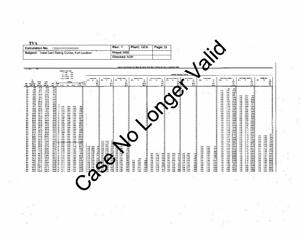
TVACalculation No. CDQ000020080009 Rev: 1 Plant: GEN Page: 33
Subject: Initial Dam Rating Curves, Fort Loudoun Prepd: WBBChecked: ACM
Z= 7M2 fa
0. = 303M 75et
84 033 00 210$ 70 9 i, 03 ,3 01. L 0 j 0. 0. 330 04330 1 0T7t0l T.8• T074 S =I 215 " 3 2#&j 30 2.7 2ss 2.0 2.65
3 . I " ..7 8
"To
.r3
.5
ow62."
43.Wo
76."
11-,4
t37-
4-O14,219901l
.2.7.17
173.7111-5
211A22315
2.0
-3mr
44$.7
4-6
521.03
-6293
0856
140.M8
870,43
081.72t021.11
.93
'.413482.5
77.W012U32
17-5
2t6
25.2
.240
391.4a
44I8..
47' 400.73.
574.8
Sit..7
6-.13
1-621.7445
11006l
1127.14
1235.671262,2.1n1.o9
137-•13-o.114-.l
7.9
7 ,1
77U67-e
7 l8
7-4
-7o
-7g
7.8-8-o
02 3-19 0-7 0.75
4 32.77 -.98 0.6
6 -.• 0.M6 0.48: 3,412 0.974 a4Q
12 3ý512 0 .2 0.3314 3-S5 0.- 0.3•1. 35.1 0.M 02
t8 3-2 ...•7 02M 36W1 0.M8 .2
22 3.5 0.-9 0.224 3.- 0.-0 0Z
28 3.798 0.-9 2WO 3S3M 0.-9 0.32 -6 0.-9 0.•M4 3.W75 Owl 0235 392 " 991 '2338 30 M • 01237 3-5 0,9 022. 0-9 0,92 0123M 0775 099 O0ll4Q 0,757 0 92 01041 -.3 .9M3 0.1042 0.M2 09M3 0 M
4• 0,719 0.-° 0-4 0.717 -.9 00
4 0..-1 0-• 0-049 0,714 0-• 0,0
o .7 o-e Ow
53 0ý7 t1 0, 0O
54 0.711 -.9 o
52 3o
07 17- 0
13 .26i9
71 4- 1?.
142 2 162-1. o~e
73 10-31
23 11-14 0 7.7 'J 12 21
27 o6C 08 77 A3
18 013 0.90 0,672 7R
09 %n'2 D 6 0973 o 3 05o - 105
oo 11212 o.M o 09M4l o 53 13o93 4732 0. 0.-6 71 0.95 ill 15
79 4182 0 W5 1 0.97 073 3.15 08 09 • •o0 35 o,47 1 .0.97;
63 .481 0.97 t 0- o.998 763 -8342 0W...5 1 0. 8 .. w353 3 1.: 0.371 21 it :
30 01. 3791
oooo
oooooo
ooo
ooo
\7o7
o_o.o o7. o. , 7o.lo o-
oWO2
o.
0O
IQi
0,77
U97 ý3241
5.
1.4
112!
.7
.321.
4.
14.
0.20'.0•0•
0.9
o.59oi
o 21
0.1.
0.-30.142
O.le•
0.-6
0.1420.1410.141
0.140..13.
0.12
0.41
0741
0076
0.1070
273164.80
-79172-5
-457
1o3•
1331.13-14a521
1.21•
1.97
20;'2"
21-o
23'23.1'2.8
21•
4..
0'.9o.e60.980.980.9
090.9
0.89o..o..
0.•
0.90..9
0.090.99
09ý70,97
0.80'.90.9
0.4 17
0.-7
03410'-90-9
0.2560Z3,
0.940950.960970.970.980.980.980.980.990.99
0-530 -70.104Q1
0.3710.•20.3270-O02.802Z9
0407
02-
0271
0 -
0 M0•02
0,Z
0".0.-
0 77
0.1170.17.0,175
713
0,173
o17
oil.. 141
0.143
o.1;0-11
0., 1.070.e 0,7W
Owe 070-
0,9; 0-30.9 03.3
ow 03.'W
17V72164
06.8
0..3
OA3e097
097;
.W3
05.-
0.421
0.3W
U.•
175
225e72721177,
0.- .10- -0 - 71
0.- 11440AW0.4 15U0ý:ý 1711
O.M 21410.- 2-
0- 2-
OUI 270i0 2.
W 3w,.2. 31.
51U31 M5U12 =1
0,.5
0920%4090.9;
0978097
0.9809
0.9W

TVACalculation No. CDQ000020080009 Rev: 1 Plant: GEN Page: 34
Subject: Initial Dam Rating Curves, Fort Loudoun Prepd: WBBChecked: ACM
6.6 Case 6 - South Embankment Failure, Fort Loudoun Spillway Gates Closed - Tellico Embankment Failure
For the South Embankment Failure with spillway gates closed condition, discharges are computed for headwaters rafrom 750 feet to 837 feet, the limit of the headwater elevation [4.21]. This case is similar to case 5 except foKere nodischarge through the spillway until the gates themselves are overtopped. Discharge passes through the v*sections as headwater rises above the crest elevations in each case. Total discharge, given in "1000 cfs" is t udischarges in cfs past the dam plus discharge in cfs past the west saddle dam divided by 1000. Note that pledwith an embankment failure from Tellico which produces elevated tailwaters.
Figure 10 shows the spreadsheet calculations for the spillway gates closed initial dam rating curve pre t included asAttachment 16). The final result, the rating curve, is defined by the first two columns, H ota ischarge. The next twocolumns are a synopsis of the flows from Tellico Dam. Since Tellico and Fort Loudoun discha the same tailwaterwithin close vicinity to each other, it is necessary to include the flows from Tellico to cjulate theT rating curve. The fifthcolumn (TW) gives the tailwater associated with the "Total Flow" from the tailwater 4ng curve polynomial fit [4.20]. Thisis computed to check for tailwater submergence effects on the discharge. Since ths' fj1r elevations reach levels that reduceflow through the spillway (mainly at Tellico in this calculation), it is necessary "te-etl~ ugh different tailwater elevationsuntil the total computed discharge fits the tailwater rating curve [4.20]. Fig e VIV04the final results but does not show theiteration steps. The results are readily checked by computing the individ adding them up to compute totaldischarge, and then making sure the listed tailwater and total discharge ree the tailwater rating curve.
Spillway discharge in cfs is computed in the next five columns ( -e a e' pillway")' H,, CdCg, d/Hc, Sf, and QdQg asoutlined in section 4.22. Free discharge occurs for headwater el ons 0o 0 feet [4.5.5] and orifice discharge occursfor headwaters above 820 feet. The transition point is ddi rizontal line. Above the line, the listed dischargecoefficient is Cf [4.5.1] computed from Equation A5 and w t lin the listed discharge coefficient is Cg [4.5.6]. ColumnQdQg is the spillway discharge computed from ,quation ischarge and from Equation 3 for orifice discharge. Freedischarge is modified by Equation 2 using the S culated r quation 5. Orifice discharge is modified as outlined inSection 4.22.
The column following the spillway disch lumn" shows "Cf=", "Z.='', and "L=" in three rows to indicate the meaning ofthe values included in those rows the (verf. Discharge" columns.
The next 30 columns are ov w ds cfs for the lock walls, lock gates, spillway deck, north embankment,powerhouse, nonoverflow d !n km ent, and the saddle dam. The overflow discharge coefficient Cf ([4.10.1],[4.9.1], [4.7.1], [4.13.1], [4.12.. . 11.1], [4.17.1], [4.15.1]), elevation Z, ([4.10.2], [4.9.2], [4.7.2], [4.13.2], [4.12.2],[4.11.2], [4.17.2], [4.15.2]), and le')i L ([4.10.3], [4.9.3], [4.7.3], [4.13.3], [4.12.3], [4.11.3], [4.17.3], [4.15.3]) in each caseare indicated in the thovhs above the computed discharges. All overflow discharges are computed using Equation 1. Notethat all overflows ha to dified using Equation 2 in order to account for submergence. Sf is calculated using Equation 5and intervolatio-aii Ve I
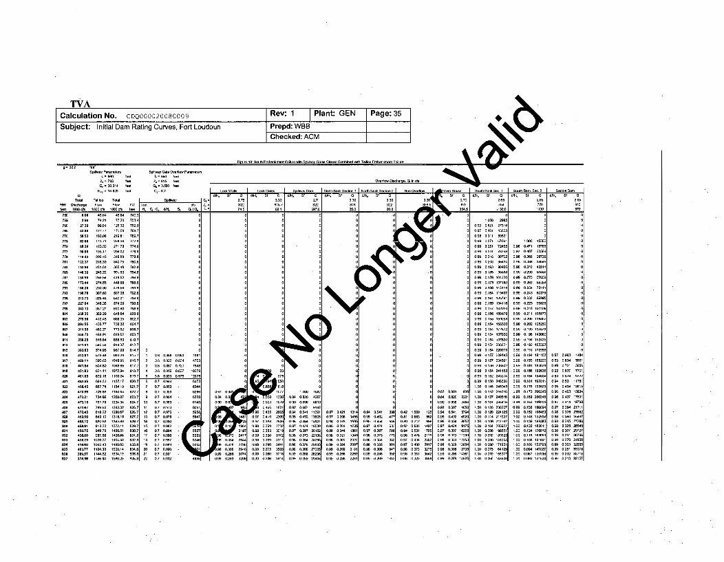
TVACalculation No. CDQ000020080009 Rev: 1 Plant: GEN Page: 35Subject: Initial Dam Rating Curves, Fort Loudoun Prepd: WBB
Checked: ACM 4Fur 10: Sooth Embankmest Failure -~l So4ao Cares Closed Combined rare T-lko Errabankmert - 1 -
g =322 Ps•
Spialery P-met Spay Gate so" ePrear. e
1=500 fear L500 fear4-=783 feer 4=815 fae Overoargeeo , 5 in ds
Cl ] 0-=ClC0031f4 04ffee00tC GF L-="""3.5w 1 0 Clf104 f
fatal Tello Tal S ' 2.7•5 j30 2 3 300 2.75 2,65
HW 1hre r FI fe 0 822 81s87 82 8 1fee I00f 100cf L0of 7- IC0 350• -%. Q,5 Iwo 1.
27.32-3.0
U,65
U.24
110.43
12.37
'".632
172.4
213.73
275.90293.55311,55-3072
350.25
371.01
3-3.0413.81
42,1 1
4.1-8
451.83
461.05
-•2546.-S
470.59
M7321
M-.1
47-.747Z.45469,0040512458.914W0.754M680-2.23
414.60M0.77
389.57374.M4
4-6742199 01
1 27.7
1 73.711 83 5s1 95.17
2O4521.39
2311.512452n
259,54274 55
367 27- 2s
:12 45436.774.227488 91
5749557948
66.32687.74
76,.79
913209`9 76987.8W
1026271O06543
114462
7720
219 11
271.78
31688340.75
30,49
41892
47s.•
574,29
610,40
6M,35730.32
773.82
916.37
967.9999329
1072-9
11-024
115419
18045
12208.07
1262.321290,67
131 10
1 372.1114DO511426.66145ý.501480.03
:50.ý14
1560,20
0 0, , : .0ý'ý 19 1
, on 475ý
3 3.6 OW Oý121 14 36 0916 0 637 10270
s - 09ý Os76 1.7.6 0.7 0- W73
7 0.7 -M8 17 0ý9 UN9 07 O.ý M1
10 0.7 O.o69 61.
11 0.7 0- GO 112 , so.13 Oý; 'ý9'78' 5s4714 OJ OýWIs OJ O'W216 OJ 0,9B4 552717 0.; OISM 53Mis 0. 0 .7 5_is 0.; DON W9320 . O'm 121 07 0,991U 0.7 D.W2 4658
~4c
4
00
0
0fi
*4 o
0
oB
or
0
067 0,
0'" 0.ON 0,
092 0,0.94 0,0.0 00 96 00 1;
00, 0.09. ..
0:: 0,0.98 0,ON 0.Oýý 0ý
0.92 0.621 273110.9ý7 O4Ol 4180
0.99 0.27 1 709'
.. • 0.2 7245ON9 D,231 7.25,
... -216 W070;OS9 0 203 s542,
O.9 0.1598
OM• 0, 17 101321
O.90173 10780.9 0.168 1131
0.9 0.164 113 19
0.99 0-11 12o74'
0. % 0.15g 13411'ON9 o-15 142021
O.9 0.15% 1547•
0 .9 9 0 ,1 5 4 1 5 9 0 9 'O.99 0'154 11830:
so. 054 1875
029 0,154 20862
09N 01.4 _270.99 0.157 221118!
0.9N 0.157 23M59'
0O99 .156 23860:
0.99 0.154 24118&
09N 0.152 M427,
1.00 0.142 24011
1.00 .. 137 24011
1IM 0.131 23511
4.00 0.126 23020i
1.00 0.120 22412!00o o.114 21792;
1.00 o.109 21239:1.oo0.0 A 20597
1.oo 0-M2 18M,2:1lDO 0.086 18125S
1.00oo 0080 17195'100 075 12412
1.00 007V 155-71.o 0O5 145-
0.960.97
0.980.990.9N0.99
O.99O.99
0.99
O.9
O990.99
O9N
O.9O.90.99
.Oo0.990.99
0.990.99
0,99
ýO99
009
1.00
0471 157&J0407 2258-
0,368 2972.
0.M9 50ý0275 5765-0,263 6526,
0 254 7314
0243 8027
0223 9382•
0216 10110•
0211 -T87
0206 118O
0,202 12529•0,199 13387
019% 1430
0194 15241!
0192 10239:
0.191 172950'194 18116:
0,193 18620(0.191 19001
0.188 19263(
0.181 19781'
0.17. 1995!0.173 20034
0.163 M2.•
0-5 1NO0%0.152 19660146 19ný0.139 188380.132 18301'0.124 17681:0.-1 169050108 161w6OAlOO 15379•0.094 14702•0.087 1393NOO8O 13162,
0
00
00
o 070+8 18
0,308435
0.67 046 14.,P0.8 0.847 -17
0s97 07342175&%0 92 06376 238
0.98 0 357 -79
0'% 0325 28550,98 0,437 1-12097 04214 1907
ON9 0,276 31850N ,9 0 264 387
0.9 0,25.2-097
0 .9 0.276 37185
0,9. 0.213 3n157
0,67 O
04
80 32 2179
80,30 2'40
0ý286 3740o9 o269 32M6
046 18210435 .04
.0.7 041. 2"0.0.9 0:318 2-4o 98 .+3Ms 27.2o N8o0353 30150,98 0.330 31720o9 N o309 33110. .9 0.2W0 3W0.99 0.275 358
0.9 024 3-1
1.oo.54 1139
095 0492 13W0.
097 0424 18031.0.97 0.397 201&•0.90 0373 2219N0.98 0354 2428N
0.9 -.0 2700.'O.9 0.286 2823(ON9 0,269 24
ý4&SV.1 73, w1941202209218
0.97 0.4210 97 0,398oN• 0-70.98 on,6oN 0.340,98 0.321098 0.301
O0 O.284Oý99 O.2".099 0 2w6
0.5 .2
09 0.37
098 0,373
ON8 0.328O.9 0."OO.9 0186
7.18590
10
0a000000
125W2
7.2176
2W3278ý2nos
981 9a
607 6541 579,4%2 692Z
424 917•397 1261M7 11029
541235:MB• 1306306 13712W6 1436M6 14971
0 42 1.NOoD0.1 0.W•30.89 0.712D02 O6'0 94 0O5309 0.4760,97 0,$40,97 0 4000.9 0373
0'.8 .,no
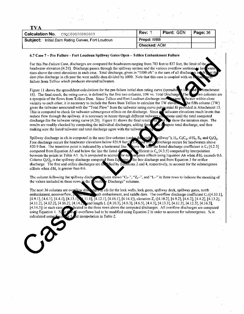
TVACalculation No. CDQ000020080009 Rev: 1 Plant: GEN Page: 36
Subject: Initial Dam Rating Curves, Fort Loudoun Prepd: WBBChecked: ACM
6.7 Case 7 - Pre Failure - Fort Loudoun Spillway Gates Open - Tellico Embankment Failure
For this Pre-Failure Case, discharges are computed for headwaters ranging from 783 feet to 837 feet, the limit of theheadwater elevation [4.21 ]. Discharge passes through the spillway section and the various overflow sections* he aterises above the crest elevations in each case. Total discharge, given in "1000 cfs" is the sum of all dischar s s\I S ttdam plus discharge in cfs past the west saddle dam divided by 1000. Note that this case is coupled with an aeefailure from Tellico which produces elevated tailwaters.
Figure 11 shows the spreadsheet calculations for the pre-failure initial dam rating curve (spreads t ii d ttachment16). The final result, the rating curve, is defined by the first two columns, HW vs. Total Discharg le w columns area synopsis of the flows from Tellico Dam. Since Tellico and Fort Loudoun discharge int me lwater within closevicinity to each other, it is necessary to include the flows from Tellico to calculate the T1 eleva he fifth column (TW)gives the tailwater associated with the "Total Flow" from the tailwater rating curve pol omial fit provided in Attachment 15.This is computed to check for tailwater submergence effects on the discharge. Since tailwater elevations reach levels thatreduce flow through the spillway, it is necessary to iterate through different tailwa~ • e tions until the total computeddischarge fits the tailwater rating curve [4.20]. Figure 11 shows the final resultl show the iteration steps. Theresults are readily checked by computing the individual discharges, addingt ei 0f'o mpute total discharge, and thenmaking sure the listed tailwater and total discharge agree with the tailwat
Spillway discharge in cfs is computed in the next five columns (un a illway"), H,, CidCg, d/Hc, Sf, and Qf]Qg.Free discharge occurs for headwater elevations below 820.9 feet scharge occurs for headwaters above820.9 feet. The transition point is indicated by a horizontal line. l , e listed discharge coefficient is Cf [4.2.3]computed from Equation A5 and below the line the listed * e fficient is Cg [4.3.5] computed by interpolationbetween the points in Table A3. Si is computed to accou or su ergence effects using Equation A6 when d/H. exceeds 0.6.Column QdQg is the spillway discharge coputý' from Eq 'o for free discharge and from Equation 3 for orificedischarge. The free and orifice discharges are rby E ions 2 and 4, respectively, to account for the submergenceeffects when d/Hc is greater than 0.6.
Thecol mnfolowi g he pil wa di h I mnshows" f= ,
The column following the spillway disch elumn "ZC=", and "L=" in three rows to indicate the meaning ofthe values included in those rows *the ver Discharge" columns.
The next 36 columns are ov w gis cfs for the lock walls, lock gates, spillway deck, spillway gates, northembankment, nonoverflow, • •u th embankment, and saddle dam. The overflow discharge coefficient Cf ([4.10.1],[4.9.1], [4.6.1], [4.4.1], [4.13.1 , 1.1], [4.12.1], [4.16.1], [4.14.1]), elevation Z, ([4.10.2], [4.9.2], [4.6.2], [4.4.2], [4.13.2],[4.11.2], [4.12.2], [4.16.2], [4.14.2 nd length L ([4.10.3], [4.9.3], [4.6.3], [4.4.3], [4.13.3], [4.11.3], [4.12.3], [4.16.3],[4.14.3]) in each case IP icated in the three rows above the computed discharges. All overflow discharges are computedusing Equation 1. Ne Ie.til overflows had to be modified using Equation 2 in order to account for submergence. Sf iscalculated usingju~ L 5upd interpolation in Table 2.
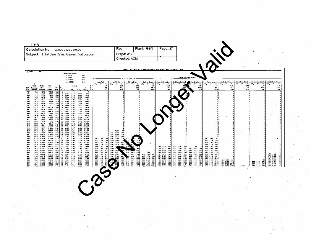
TVACalculation No. CDQ000020080009 Rev: 1 Plant: GEN Page: 37
Subject: Initial Dam Rating Curves, Fort Loudoun Prepd: WBBChecked: ACM 4
Flge 11: Pre Fai1lur Int spillwy -te ope - -- Mbi fne I~ -M~i -1bank1ent 11Failue• j
g= 322 fs'Spillway Paaetes
Z, 783 tG, = 30314 ftt
t = 14828 tot LOW Watts Lock Ga Spiwa Deck Si-/ay ates o Se o N2Pk e I S 2 P Stnt S- 1 S[ ut, Bank Sec. 2 S le Wam S0. Sad .e .amSac. 2
Wt00 GO. St dls St Qj feet Sf 4 St St t -1 , St 0 St Q -t St 0 S Q
T "O O Tsoa Ro T /. 3W ttCO Z.22I 08tI22 292 2 I 82- -5 833. 2.7 93/883
793III797
W79
8019820
821
9112
013
.37
11.0217.56
30.8637.6945~os2.660.62
77.50
MUr
113.14
107M1
1"6.33
-1,47
111238I07.41-m.3
383.9404N
4.9,47473,83499,5526.28S54.47SS4.18-1.47
;18 V75257-W-3476
V9l1. 11
1087.65111-01148,041180,891213.41124.1274,95
1I5=.13
140M. m14aw6
415.71
473M6
571.33(307.15
W.3724.37725.a2
81497
911M5W2.15
1013MO1O4OO
1173,5512O0.--28.121255,4912eM 221312.87
13-813
1423MO145122
147-6
1 533 W
7981
7802
810,.!812.!=814,!
818A819,8201821,822
8234
82a.
827..US8.
ME
8W.J
o2 3,191 0.7914 3,277 0,8976 3,35W 0,9338 3.412 0-5
1O 34M5 096012 35ý12 0.96714 3,5S4 0.97116 3,591 0.974118 3627 0.976
22 695 0,979-4378 0.,98
263763 0.58128 37,M 0.923M -83 0.-832 3869 0.9833 388 0.M8
34 3.5 0983w5 ,923 0984.7 -90 09N'i
38 0794 09843n 0.77 0-840 0.75 0 So41 0-3 0=•
43 0;719 0,987
450.716 098So`,6 0.714 0.-847 0713 0990,$8 03711 0.99149 0.711 0.92SO 0311 0.9251 0a11l 0.99352 .111 0,99453 03711 0.10%4M4 0,711 0995
0,919 a64I0.750 1 10180637 1 75o50.559 241M a0 503 308570.461 37-19a"0.432 450,1710.409 526790.391 6O20(
0.4 N147
0.325 127354I0,327 - S 010.325 1409 1D322 1464 10,318 151,16130.313 1560W• 0 ,5 1000 294
022 1 18141 0 ,074 038M 164E0221 IW31 O o ' 053 10140 21: 11154W 0.41 1000 2 0 8 0.78 137`028 175 1.71 -9. 08 07. 172•1
018 10 6 0.81 0-8 918 0.654al 205o.18" 9558 a8W 015 27 0,93 G06"4 23
.. 147 7861 0 .92 192. G,-0.131 713 1 0.93 0. n o 4 40,119) -53 0.9 o-• 2517 046 M7a0.0 5871' 0.9 o 5 W2 9 2"6 .440 o0.03 U%76 0.Mt 0A5 Wi 0..7 0.414 3.810.08 477251 0.7 0.:4 3. O..3 4183
006 3 1{ S 0.9 031 46730400.53320• o•0.4W72
0I
00
000000100
001
0 137.7741 06.22
a-3 4-OW2 W130. .31
7,97 0,4n W50
.97 - -30 W 0361 7002am a 3. IM
0
0
0a
00
a
o91 oo . 4:-
0,80ý 0,870 85
,9 0 45M 1 595.
I
-9 0.5.2(395 0.5100 96 0.4mla9 N 0.4550 97 0.430.97 0.4060,97 OM8
09 1.21
(a(m(0
21&9
202i218
2951
28028i2285'
7U97(
12Z
147:ýýM7ME27.WI)ý 712R
1-c 12!)980 7 652
OW 2 20
0,3 0W N
1ý .544 31o5
0.48 0496 361301 0 4513
1V0421 43710,7139 4713
04ý 1000 950.7• 09a 259081 08.2 4289
0,8 077 5934o90,701 750,1
0.9 0,640 9OOO0.M 0,5,87 10407-.9 0543 117P
0.95 0,502 I191
0%9 0 465 1406097 0433 151M8-. 7 -.0 16250.97 0-8 1718
0.9 0 118119
0-9 0338 18-•
0
00
01
00
00a
0I
01
0.49 1.000 4M142N
ON ý 72 MWa W a 610 31ý
45(ý71 0ý1 ý
a a (ý 5(. M 0
0 8N 0,7010,92 0.W4
oam 04650 97 0.43
0 A7 O0W3309M owl6
M.9 03318
O .5w 1ý0o01 .79 08 5
[ 087 0.757- .1 0-550.93 0 57
.0.95 0 511
SO.9m 40-

TVACalculation No. CDQ000020080009 Rev: 1 Plant: GEN Page: 38
Subject: Initial Dam Rating Curves, Fort Loudoun Prepd: WBBChecked: ACM
6.8 Case 8 - Pre Failure - Fort Loudoun Spillway Gates Closed - Tellico Embankment Failure
For the South Embankment Failure with spillway gates closed condition, discharges are computed for headwaters rafrom 750 feet to 837 feet, the limit of the headwater elevation [4.21]. This case is similar to case 7 except folere nodischarge through the spillway until the gates themselves are overtopped. Discharge passes through the v * u wsections as headwater rises above the crest elevations in each case. Total discharge, given in "1000 cfs" is tdischarges in cfs past the dam plus discharge in cfs past the west saddle dam divided by 1000. Note that 3 s- pledwith an embankment failure from Tellico which produces elevated tailwaters.
Figure 12 shows the spreadsheet calculations for the spillway gates closed initial dam ratinA curve 1ra included asAttachment 16). The final result, the rating curve, is defined by the first two columns, H ota ischarge. The next twocolumns are a synopsis of the flows from Tellico Dam. Since Tellico and Fort Loudoun discha the same tailwaterwithin close vicinity to each other, it is necessary to include the flows from Tellico to c ulate the TW rating curve The fifthcolumn (TW) gives the tailwater associated with the "Total Flow" from the tailwater ng curve polynomial fit [4.20]. Thisis computed to check for tailwater submergence effects on the discharge. Since th il r elevations reach levels that reduceflow through the spillway, it is necessary to iterate through different tailwater e the total computed discharge fitsthe tailwater rating curve [4.20]. Figure 12 shows the final results but does jot t iteration steps. The results arereadily checked by computing the individual discharges, adding them up 1 discharge, and then making sure thelisted tailwater and total discharge agree with the tailwater rating curve.
Spillway discharge in cfs is computed in the next five columns ( er er' pillway"), H,, CdCg, d/He, Sf, and QdQg asoutlined in section 4.22. Free discharge occurs for headwater el ~ons 0 0 feet [4.5.5] and orifice discharge occursfor headwaters above 820 feet. The transition point is mdi ' rizontal line. Above the line, the listed dischargecoefficient is Cf [4.5.1] computed from Equation A5 and wt lin'• the listed discharge coefficient is Cg [4.5.6]. ColumnQlQg is the spillway discharge computed from Fuation Iischarge and from Equation 3 for orifice discharge. Freedischarge is modified by Equation 2 using the S culatedfr quation 5. Orifice discharge is modified as outlined inSection 4.22.
The column following the spillway disch lumn" shows ",C='', "ZZ=", and "L=" in three rows to indicate the meaning of
the values included in those rows* the tverfl. Discharge" columns.
The next 33 columns are ov wi. cfs for the lock walls, lock gates, spillway deck, north embankment,powerhouse, nonoverfiow d nkm ent, and the saddle dam. The overflow discharge coefficient Cf ([4.10.1],[4.9.1], [4.7.1], [4.13.1], [4.12.• .11.1], [4.16.1], [4.14.1]), elevation Zc ([4.10.2], [4.9.2], [4.7.2], [4.13.2], [4.12.2],[4.11.2], [4.16.2], [4.14.2]), and le'h L ([4.10.3], [4.9.3], [4.7.3], [4.13.3], [4.12.3], [4.11.3], [4.16.3], [4.14.3]) in each caseare indicated in the ttAO s above the computed discharges. All overflow discharges are computed using Equation 1. Notethat all overflows ha to dified using Equation 2 in order to account for submergence. Sf is calculated using Equation 5and interpolatioa.m Tie I
I
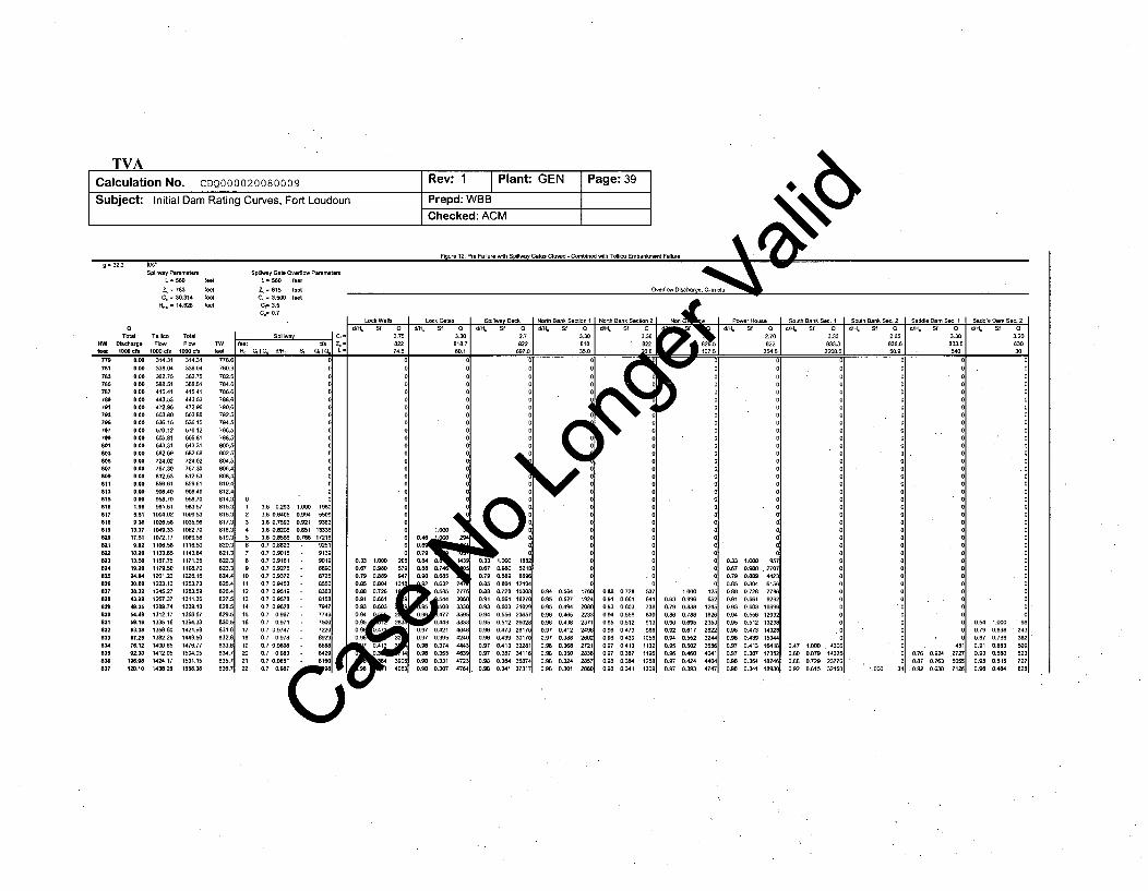
-P41880 -ates 410ose - l -omOlOO wltn I ec .- -= 32.2 we/-
Spilpi Po te Spllway Gate Ocetfloe PatmettL NO feet L =560 feet
Z,= 783 feet 4ý= 815 feeatOeflo Discharge. Q, in f,0"= 30.314 teet 0 = 3.500 feet
H = 14.82 tot cC= 3.5
Lock Walls Lock Gt Sptiwy Deck NodS Back Section 1 North Baok PSo Hos e Scot Bank Se. I South Back Sec. 2 Saddle Dam Sea 1 Sade Soo Soc. 2
tQe ati
SdC
Std0 1 dB St 0]d H,• t 0 1
d//
St
% 0 d/Bc St 0 H, Stf Q
JBH, Sf 0 jB 3H.. H, St
Tota T ealico Total .Spill wa ./ 275 3.3 2.7 3.30 3.30 2.70 3.33 2.65 3.3 3.20KW Rishtge F Fla O oto 823 St a7 822 8t2 I 822 833.3 836.6 833.6 3f DOt 000 cs t ct to 8/c S1 cfL 74.5 67 350 -. j 354.00A2N750.5082-0
788781
78378579778979179379579779t801803605807
818818815816
182
817a8l$19620
83t832
823824
827
828829830831632833834635636837
888O850.00.00.000.00
0.000.000.00
0.000.00
0.00
0.00
8880.000.00
0.008,58
5.81
9,38
13.3717.519.92
54.40
13.5019.20
78.1282.80
Ma.3243.9949.3551.49591663.3867.2576.12
102.10120010
314.31388.04
415.41
443.53472.86583.80
570.12605.61643.31682.69724.02767.38612.53
S00.40958.70
1026.581049.331072.17
1706.58lf57,75
1201.221223.13
1245.271267.371289.741312.1710338.16
1358.6013B2.25t4906.6
1412.05t424.171438.28
314.3133.0 N
3U2.753" .51415.41
443.53472.,•
503.80
570.128095,1
643.31
N82.8724.02767.30
96.40
958.7098357
1035.9610962701089.681 116.50
1143.841171.251182.701226.1612U373
128W.59
1ý3111313E).10
1366.671394.331421.38144.95D1476.77
1504.051531.151558.38
778.6780.6782.678,1.6
7M6.6788.6790.6
;92.5
796.5798.5882.5802.5
804.5806.4008.4
812.4814.3812.3
16.3
817.3818.3819.3820.3821.3822,3623.3824.4825.4826.4
829.582B.5
83M.58460.5
831.6832.8833.6;
834.7835.7836.7
0090
0 3
6 3
60 90 00 00 00 0
0 00
10 1
9 .097 80 0.7 .98 6710 0.0972 82 0. 0.8 4
I 3.5 0.293 t.860 1960 02 3.6 0.4059 8 3.94 5509 13 3.8 067593 8.921 9382
04 3. 0.8208 8.821 13338 05 3.5 08 06 .786 17216 0.
15 6.7 0.88237 8241016 0.7 0,7 75;
07 .7 0,614 9139
8 6.7 0.918 :: 965 N 06733.980 5to 8.7 0.5372 . 8729 6.79 0.889 84tt 5.7 0.8492 M5 038 .82 0.884 131ý12 6.7 0.9519 . 836 8.50 0.7ý28 1'13 0.7 0.895758 81N58 1a
14 0.7 0.9628 . 87W .. 0616 0.7 0.967 75460 0916 0.7 0.971 7746 095 2:
17 0.7 0.9778 722 69284
19 0.7 0.9836 6648 04 1
21 0.7 6.9891 6168 39022 0.7 0.987 10 4063
%.m
046 OD 9
0.79
0.84 O. 430.N80.7Om 0.6850.
/7E
!591 0 333¢0.96 B477359E
0.97 0.421 4"'0.97 0.395 424C
0.980 37403. 44
0.98a 0.331 4720.98 0.307 4764
N00
0.3 1.0 :882
6.67 0.980 521t8.79 6.888 5696
6.88 0.726 193880.91 6.681 182706.93 0.683 210290.8406.558236970.9950.512260280.96 0.473 281700.5560.439 381700.97 0.413 323010.97 0.357 341160.985 0.384 39874
.0.88 0.341 37317;
•
000
0
C0QI4
170
060
203
237124962602
2836
2880
537
738830913988
10581132
t291309
1.696 950.980 . 2700.889 442:0.804 615N0.728 771N0.661 929:O.603; 10691
0.5.3 1203:0.512 132310.473 143210.438 1934'
0.413 164110.387 1735:0.364 182410.341 18981
t.0800 4333
6.87 143210.729 2377106.15 32195 1.0960 3
0.78 0.924 20727
0.87 0.763 90980.9 0.838 7113
0.94 0.5640.95 0.5270.96 0.4940.96 0,4650.96 0.4380.97 0.4120.97 0.3880.96 0.3680.96 0.3500.96 0.3240.98 0.301
0.88 0.7280.91 0.6610.93 0.6036.84 0.5560.95 0.5120.09 0.473096 0.4390.97 0.4130.97 0.387
0.98 0.3640.98 0.341
1.0o00.63 0.99m0.79 0.880.86 0786
0.90 0.6950.92 0.6170.94 0.5520.95 0.5020.98 0.4600.97 0.4240.97 0.393
0.330.67
0.790.85
0.910.930.940.950.96
0.970.970.980.98
0.470.80
0.96
0.54
0.870.910.930.950.96
0.789
0.6630.5800.515
0.464
TVACalculation No. CDQ000020080009 Rev: 1 Plant: GEN Page:40
Subject: Initial Dam Rating Curves, Fort Loudoun Prepd: WBB
Checked: ACM
6.9 Case 9 - Fort Loudoun Seismic Failure
For the seismic failure case, discharges are computed for headwaters ranging from 750 feet to 837 feet, the limit of the headwaterelevation [4.21]. Discharge passes through the spillway section and the various overflow sections as headwater rises above thecrest elevations in each case. Total discharge, given in "1000 cfs" is the sum of all discharges in cfs past the dam plus dischargein cfs past the west saddle dam divided by 1000.
Figure 13 shows the spreadsheet calculations for the seismic failure initial dam rating curve (spreadsheet included as Attachmentl16). The final result, the rating curve, is defined by the first two columns, HW vs. Total Discharge. The next two columns are asynopsis of the flows from Tellico Dam. Since Tellico and Fort Loudoun discharge into the same tailwater within close vicinityto each other, it is necessary to include the flows from Tellico to calculate the TW elevation. The fifth column (TW) gives thetailwater associated with the "Total Flow" from the tailwater rating curve polynomial fit provided in Attachment 15. This iscomputed to check for tailwater submergence effects on the discharge. Since the tailwater elevations reach levels that reduceflow through the spillway, it is necessary to iterate through different tailwater elevations until the total computed discharge fitsthe tailwater rating curve [4.20]. Figure 13 shows the final results but does not show the iteration steps. The results are readilychecked by computing the individual discharges, adding them up to compute total discharge, and then making sure the listedtailwater and total discharge agree with the tailwater rating curve.
Spillway discharge in cfs is computed in the next four columns (under the header "Spillway"). Since the spillway has failed fromseismic loading, it will fail as shown in Attachment 5 and outlined in Section 4.26. It is treated as a standard weir overflow and iscomputed using Equation 1 and the parameters listed in Section 4.8. The flows are modified by Equation 2 to account forsubmergence effects. Sf is calculated using Equation 5 and interpolation in Table 2.
The column following the spillway discharge column shows "Cf='', "Zc='", and "L=" in three rows to indicate the meaning of thevalues included in those rows in the "Overflow Discharge" columns.
The next 27 columns are overflow discharges in cfs for the lock walls, lock gates, north embankment, nonoverflow, powerhouse,south embankment, and saddle dam. The overflow discharge coefficient Cf ([4.10.1], [4.9.1], [4.13.1], [4.11.1], [4.12.1], [4.18.1],[4.14.1]), elevation Zc ([4.10.2], [4.9.2], [4.13.2], [4.11.2], [4.12.2], [4.18.2], [4.14.2]), and length L ([4.10.3], [4.9.3], [4.13.3],[4.11.3], [4.12.3], [4.18.3], [4.14.3]) in each case are indicated in the three rows above the computed discharges. All overflowdischarges are computed using Equation 1. Note that all overflows had to be modified using Equation 2 in order to account forsubmergence. Sf is calculated using Equation 5 and interpolation in Table 2.
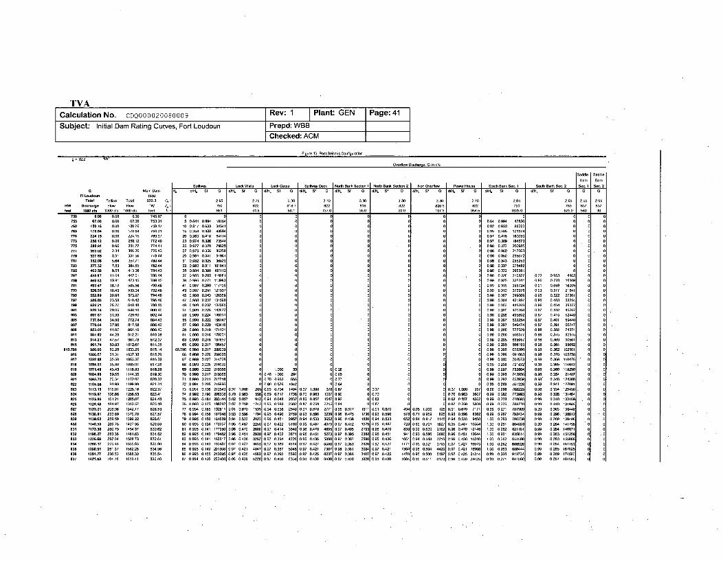
g =32.2 fs
Oerfleo Dischrg, Q, in cfs
Saddle Saddle
Dam I Dam
S Ilo LekWalls I Lek Gatee Spiflay S•ek NeSh Bank Sectn II Nanh Bank Se-t 2 N OOenle[ PowetHsee Scn Bank Se 1 SeS Bank Se. 2 Se1 Se. 2M Main Dam H= d/H
5 Sf 0 . SIM Q 0 dHl f / Sf 0 dH 8He Sf0t S Sf 0 dtlH Sf 0 d/HH Sf 0 fdlO Sf 0 d70, Sf Q d/H, Sf a 0 0
FtLomdou TRM
Total Telleo Toeal 602.3 ,25 2.75 3.30 2.70 3.30 3.30 3.30 270 2.65 2.65 2.65 205tw Dischare Flew Fl T1W 4 750 U22 818.7 822 18 22 8265 U22 750 785 037 837feet 14 10 s 1000 de ee 5 74S 60.1 1370 350 20.0 1075 355 16250 625.0 50 3
758 .00 0.00 00 74507 0 0 0 0 0,5 0 0 00 0753 670 .006 67.00 753.21 5 041 0994 f1164 0 0 0 5 0 0 0 064 0994 4783" 0 0760 120.76 000 120.76 759.17 10 0.917 0633 34541 0 0 0 0 0 0 0 0.92 0,633 86220 0 0 06w 170.84 0.00 17004 764.31 15 0.954 0488 40064 0 0 0 0 0 0 0 0.95 0488 121974 0 0a
7ne 224.15 0.00 224.15 769.37 20 0,969 0,416 64114 0 0 0 0 0 0 0 0.97 0.416 160039 0 0 0773 258.12 000 258.12 77240 23 0.974 0.386 73544 0 0 0 0 0 0 0 0.97 0.389 1684573 0 0 0
775 280.81 0.96 281.77 774.41 25 0.977 0370 79025 0 0 0 0 0 0. 0 098 0373 200985 0 0 0707 303.92 2.34 30626 77643 27 0,979 0.356 0259 0 0 0 0 0 0 0 098 0360 217663 0 0 0779 327.65 3.91 331,56 77844 29 0,981 0341 9198f 0 0 0 0 0 0 0 098 0350 235672 0 0 0781 352.06 5.64 35771 78044 31 0.982 0.325 9'009 0 0 0 0 0 0 0 0.98 0343 255253 0 0 0793 377.32 7,53 304.5 702.44 33 0.003 03ff 101641 0 0 0 0 0 0 0 0.00 0337 275482 0 0 0
785 403.00 055 413.0 764.43 35 0.984 0.300 107112 0 0 0 0 0 0 0 0.98 0.332 296391 0 0 0787 438.97 11.64 442.61 786.44 37 0.985 0.285 110681 0 0 0 0 0 0 0.0 0.98 0326 315827 0.72 0.953 4403 0 0789 459.63 13.1 47345 788.45 39 0.06 0271 113%83 0 0 0 0 0 0,0 0.99 0.320 335341 086 0.778 10300 0 0791 489Z4 16.10 505.56 790.46 41 0987 0.260 117736 0 0 0 0 0 0 0 06 0.315 355724 001 0.658 16005 0 0793 V2e.55 1849 53904 792.46 43 0.987 0.251 121937 0 0 0 0 0 0 7 0099 0.310 376976 093 0.577 21644 0 0
795 00299 2098 573.97 794.46 45 0908 0.243 126509 0 00 0 0 0 0099 0.307 399069 095 0.522 27304 0 0
797 998.80 23.50 61042 79646 47 0.908 0237 131598 0 0 0 0 0 0 0 099 0.304 421997 0.95 0.43 33254 0 0799 622.21 2627 640.48 798.45 49 0.989 0.232 137005 0 0 0 0 0 0 0 0. 0.302 445769 0.0 0.454 39377 0 0801 659.14 2905 688.19 800.45 51 0.99 0.220 142972 0 0 0 0 0 0 0 0 0.300 470398 0.97 0.432 45767 0 0803 697.67 31.93 72960 802.44 53 0.98 0224 149331 0 0 0 0 0 0 0.99 0298 495892 0.97 0.415 52449 0 0e05 737.64 34.0 772.74 004.43 55 0.900 0,222 150147 0 0 0 0 0 0 0 0.99 0297 522254 0.97 044 59040 0827 779.64 37.95 817.58 80642 57 0.990 0.220 163416 0 0 0 0 0 0 0.00 0297 540074 0.97 0.391 66747 0 0111 823.02 41.07 864.fO 00840 59 0.990 0.219 171121 0 0 0 0 0 0 0 0.99 0.296 577529 0.90 0.382 74374 0 0
811 867.92 4428 91221 810.38 61 0.990 0218 179231 0 0 0 0 0 0 0 0.99 0296 606377 0.98 0.375 82315 0 0813 914.21 4757 961.78 812.37 63 0.990 0.218 187697 0 0 0 0 0 0 0 099 0.295 635957 0.98 0.369 90561 0 0815 "91.74 50.93 1012.67 014.35 00 9O 0217 196457 0 00 0 0 0 0 0.99 0205 006193 098 0.364 90092 0 0
8015.796 OW0.N0 5229 103325 815.14 65.796 0.990 0.217 200300 0 0 0 0 0 0 0 0.99 0.295 670390 0.90 0.362 102561 0 0
816 l026.07 31.31 1037.38 915.29 66 0.089 0226 209235 0 0 0 0 0 0 0 0.99 0.299 6913 0.98 0370 105750 0 0817 1832.88 3050 1063.37 01628 67 0.989 0227 214720 0 0 0 0 0 0 0 .90 0300 707673 .0.98 0.300 110476 5 0
818 1204.51 3540 109.91 817.28 68 0.989 0.225 218032 0 0 0 0 0 0 0 0.99 0.299 721832 090 0365 114643 0 0819 1071.49 45.43 1116.93 918.28 69 0.990 0.222 21930M 0 1.00 33 0 028 0 0 0 0 09 0.297 733804 0.98 0.360 118290 0 082a 1084,80 59.55 114435 01930 70 0.990 0217 21966 0 0.46 7.006 294 0 065 0 0 0 9 099 0.295 743956 0.98 0.354 12147 0821 1195.73 76.34 117207 820332 71 0.990 0211 217710 0 0.70 0,903 06 . 0 0.77 8 0 0 0 099 0.292 752959 0.98 0348 124388 0 0
822 1105.00 54.93 ff0099 821.34 72 0.991 02O5 210906 0 0.80 0876 1042 0 084 0 0 0 0 0 90 0289 761228 098 0341 127091 0 0823 1113.15 11501 122016 822.37 73 0.991 0.198 212543 037 1.000 205 0.85 0794 1441 0.37 1.000 370 087 0 0,37 0 027 1000 957 099 0286 768225 0.0 0334 129050 . 0 0824 1019.67 130086 1256053 823.41 74 0.992 0.190 206308 0.70 0903 55080.9 0.717 .1730 0.70 0963 1007 090 0 0.70 000.70 0.903 2607 0.99 0282 ,773993 0.00 0.326 131404 0 0825 1123.86 16121 1285007 824.45 75 0.993 0.181 203744 082 0.457 912 091 0 0.92 0 0.0 0 0.03 0857 4202 0.90 0278 770693 0.99 031 133169 . 0 0
826 1128.90 14.97 1313.57 82549 76 0.993 0.173 190203 087 0.759 1243 093 0.599 2302 0.87 0.759 2245 0.94 0 0.87 0 0 0.87 0759 5809 0.00 0275 783770 0.99 0310 134505 0 0827 1133.21 20096 1342.17 826.53 77 0.894 0.165 192611 0.670 1535 064 0530 2340 0.94 0.67a 27711 00 0.517 16ff 0.91 0.670 44 0.00 1.000 125 0.91 0670 7171 0.99 0271 787909 0.99 0303 135440 0 082 ff00.81 23389 1370.70 827.57 78 0.894 0.100 10724 0.93 0.596 1794 0.95 0.40 2759 0.93 0.596 3239 0.96 0475 1736 0.93 0.596 578 0.71 0959 625 0.93 0.596 8382 0.90 0267 792434 099 0.290. 130012 0 0829 1199.62 25059 130622 38.61 79 0.995 0.150 181659 004 0533 2023 0.96 0451 2957 0.94 0.533 3652 0.96 0439 1850 0.94 0.533 650 0.64 0.17 1145 0.94 0.533 9450 1.00 0263 796739 0.99 0.289 139490 0 0
830 1140.59 286.76 1427.35 829.63 S0 0.995 0.138 170357 009 0.487 22591 0.97 0,422 3100 0.00 0.447 40791 0.97 0412 19791 0.95 0.487 720 089 0.701 16271 0.95 0.487 10554 1.00 0261 004033 0.99 0.284 141790 01 083e 1173.98 28079 145437 83062 81 0.995 0141 177350 0.96 0.470 2600 097 0414 3540 00 0.470 4695 0.97 0405 21091 0.6 0.470 030 092 0.639 21621 0.96 0.470 12148 1.00 0262 821181 0.90 0284 140071 0 0832 1198.27 23.36 1481.63 83162 82 0.995 0.140 179482 0.96 0.451 29201 0.97 0402 3871 0.6 0.451 5273 0.87 0395 23881 096 0.451 941 0.93 0.5N0 260 O9 0,451 13644 1.50 0261 835814 0.99 0.283 151256 01 .0833 1226,9 20204 1508.73 832.61 83 0.905 0141 103617 0.96 0.436 32621 0.97 0.394 4226 0.96 0.436 5890 0.97 0387 25981 096 0436 1051 9 0.544 32191 0.96 0436 15240 1.00 0.262 851599 099 0.283 155988 01 0894 1280.17 275.46 1535A3 833.60 N4 0.995 0143 190484 0.97 0.427 3331 0.97 03N9 4614 0.97 0427 6560 0.97 0.383 23281 0.97 0427 1171 095 0.521 37951 0.97 0.427 16975 1.00 0.262 868928 090 0.2M3 161181 0 0833 1300291 261.37 1502.2 034.58 85 0.995 0149 201300 0.97 0.421 40471 0.97 0.387 5048 0.97 0421 7307 0.9 0.381 30841 097 0421 .304 0.95 0.504 4291 0.97 0,421 189001 100 0263 888444 099 0.285 167026 0 0800 1351.77 230.53 1508.30 035.54 00 0995 0.155 213695 0.87 0.425 4521 0.97 0392 5593 0.97 0425 8237 097 0386 34071 0.7 0425 1470 0.95 0500 5971 0.97 0.425 21314 0.99 0.266 913734 0.99 0289 174560 - 0837 1421.63 191.78 161341 836.46 87 0.994 0.166 232403 096 0439 52281 0.97 0.406 6304 0.96 0439 9439 097 0.400 3829 0.96 0439 1684 0.95 0.511 6173 0.90 0.439 24425 0.99 0.271 947560 0.99 0.297 18459 0 0
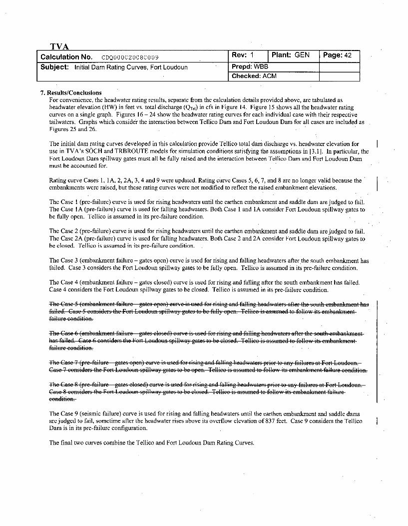
TVACalculation No. CDQ000020080009 Rev: 1 Plant: GEN Page: 42
Subject: Initial Dam Rating Curves, Fort Loudoun Prepd: WBBChecked: ACM
7. Results/ConclusionsFor convenience, the headwater rating results, separate from the calculation details provided above, are tabulated asheadwater elevation (HW) in feet vs. total discharge (QTe) in cfs in Figure 14. Figure 15 shows all the headwater ratingcurves on a single graph. Figures 16 - 24 show the headwater rating curves for each individual case with their respectivetailwaters. Graphs which consider the interaction between Tellico Dam and Fort Loudoun Dam for all cases are included asFigures 25 and 26.
The initial dam rating curves developed in this calculation provide Tellico total dam discharge vs. headwater elevation foruse in TVA's SOCH and TRBROUTE models for simulation conditions satisfying the assumptions in [3.1]. In particular, theFort Loudoun Dam spillway gates must all be fully raised and the interaction between Tellico Dam and Fort Loudoun Dammust be accounted for.
Rating curve Cases 1, 1A, 2, 2A, 3, 4 and 9 were updated. Rating curve Cases 5, 6, 7, and 8 are no longer valid because theembankments were raised, but these rating curves were not modified to reflect the raised embankment elevations.
The Case 1 (pre-failure) curve is used for rising headwaters until the earthen embankment and saddle dam are judged to fail.The Case IA (pre-failure) curve is used for falling headwaters. Both Case 1 and 1A consider Fort Loudoun spillway gates tobe fully open. Tellico is assumed in its pre-failure condition.
The Case 2 (pre-failure) curve is used for rising headwaters until the earthen embankment and saddle dam are judged to fail.The Case 2A (pre-failure) curve is used for falling headwaters. Both Case 2 and 2A consider Fort Loudoun spillway gates tobe closed. Tellico is assumed in its pre-failure condition.
The Case 3 (embankment failure - gates open) curve is used for rising and falling headwaters after the south embankment has.failed. Case 3 considers the Fort Loudoun spillway gates to be fully open. Tellico is assumed in its pre-failure condition.
The Case 4 (embankment failure - gates closed) curve is used for rising and falling after the south embankment has failed.Case 4 considers the Fort Loudoun spillway gates to be closed. Tellico is assumed in its pre-failure condition.
The Case 5 (embafflmnent failur-e gates open) eur.'c, is used for- rising and falling headwaeres after the gouth emfbafflanent hagfailed, Case 5 contsider-s the Fort Loudoun spillway gates to be fully open. Tellico is assumed to follow its embafflment-failtue condition.
The Case 6 (embankment failure e gates closed) cunc is used for rising and falling headwaters after the sobth embaddleneathag failed. Case 6 otnsiderg the Feor Luduten spillway gates to be elogwd. Tellieo is asgumed to fClaoe9 itg emsbaesteentfailure congdition.
The Cage 7 (pre failuire gates open) eurye ig uised for- rising and falling headwatergs pr-ior to any failures at Fort Loudoun.Cage 7 consider-s the Fort Louidoun spillway gates to be open. Tellico is assumed to follow its embaduanenit failure conditionl.
The Case 8 (tre failurfe gates elosed) eur.~e is used for rising and falling headvwaters prior to any' failures at Fort Loudoun.Case S eonsiders the Fort Louidoun spillway gates to be closed. Tellico is assumned to follow its embafdflnont failurceefiditieer
The Case 9 (seismic failure) curve is used for rising and falling headwaters until the ear-then embankment and saddle damsare judged to fail, sometime after the headwater rises above its overflow elevation of 837 feet. Case 9 considers the TellicoDam is in its pre-failure configuration.
The final two curves combine the Tellico and Fort Loudoun Dam Rating Curves.
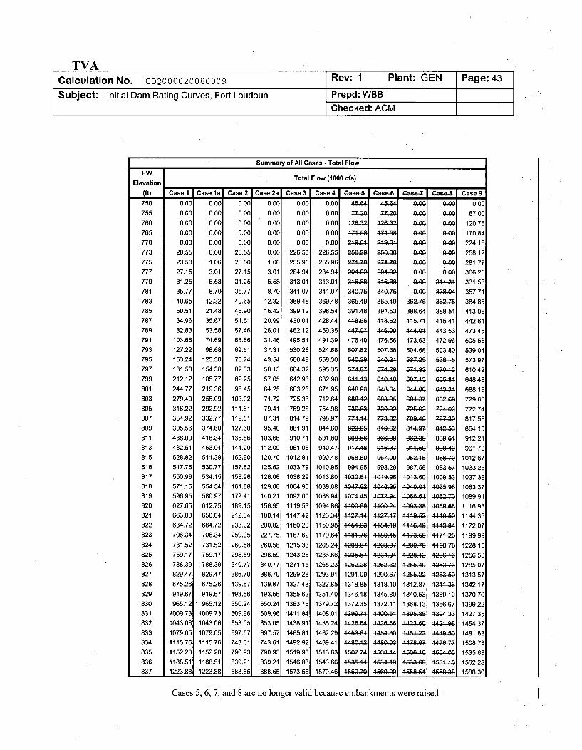
TVACalculation No. CDQ000020080009 Rev: 1 Plant: GEN Page:43
Subject: Initial Dam Rating Curves, Fort Loudoun Prepd: WBBChecked: ACM
Summary of All Cases - Total FlowHW Total Flow (1000 cfs)
Elevation
(ft) I Case 1i Case la Case 21 Case 2a1 Case 31 Case4 Case I Gase-6 1 CRAPe7 Case-8I Case9
750
755
760
765
770
773
775777
779
781
783785
787
789
791
793
795
797
799
801
803
805
807
809
811
813
815
816
817
818
819
820821
822
823
824
825
826
827
828
829
830
831
832
833
834
835
836
837
0.00
0.00
0.00
0.00
0.00
20.55
23.50
27.15
31.25
35.77
40.65
50.51
64.96
82.83
103.68
127.22
153.24
181.58
212.12
244.77
279.49
316.22
354.92
395.56
438.09
482.51
528.82
547.76
550.96
571.15
596.95
627.65
663.80
684.72
706.34
731.52
759.17
788.39
829.47
875.26
919.67
965.12
1009.73
1043.06
1079.05
1115.76
1152.28
1188.51
1223.88
0.00
0.00
0.00
0.00
0.00
0.001.06
3.01
5.58
8.70
12.32
21.48
35.67
53.58
74.69
98.68
125.30
154.38
185.77
219.36
255.09
292.92
332.77
374.60
418.34
463.94
511.38
530.77
534.15
554.54
580.97
612.75
650.04
684.72
706.34
731.52
759.17
788.39
829.47
875.26
919.67
965.121009.73
1043.06
1079.05
1115.76
1152.28
1188.51
1223.88
0.00
0.00
0.00
0.00
0.00
20.55
23.50
27.15
31.25
35.77
40.65
45.90
51.51
57.46
63.66
69.51
75.74
82.33
89.25
96.45
103.92
111.61
119.51
127.60
135.86
144.29
152.90
157.82
158.26
161.88
172.41
189.15
212.34
233.02
259.95
260.58
298.59
340.77
386.70
439.87
493.56
550.24
609.96
653.05
697.57
743.61
790.93
839.21
888.65
0.00
0.00
0.00
0.000.00
0.00
1.06
3.01
5.58
8.70
12.32
16.42
20.99
26.01
31.46
37.31
43.54
50.13
57.05
64.25
71.72
79.41
87.31
95.40
103.66
112.09
120.70
125.62
126.06
129.68
140.21
156.95
180.14
200.82
227.75
260.58
298.59
340.77
386.70
439.87
493.56
550.24
609.96
653.05
697.57
743.61
790.93
839.21
888.65
0.00
0.00
0.00
0.00
0.00
226.55
255.96
284.94
313.01
341.07
369.48
399.12
430o.1
462.12
495.54
530.26
566.48
604.32
642.96
683.26
725.36
769.28
814.79
861.91
910.71
961.06
1012.81
1033.79
1038.29
1064.901092.00
1119.53
1147.42
1160.20
1187.62
1215.33
1243.25
1271.15
1299.28
1327.48
1355.62
1383.75
1411.84
1438.91
1465.81
1492.92
1519.98
1546.88
1573.56
0.00
0.00
0.00
0.00
0.00
226.55
255.96
284.94
313.01
341.07
369.48
398.54
428.44
459.35
491.39
524.68
559.30
595.35
632.90
671.95
712.64
754.98
798.97
844.60
891.80
940.47
990.48
1010.95
1013.80
1039.88
1066.94
1094.86
1123.34
1150.98
1179.64
1208.24
1236.66
1265.23
1293.91
1322.85
1351.40
1379.72
1408.01
1435.24
1462.29
1489.41
1516.63
1543.66
1570.46
7-7720
219.61
291029
507.482840.05
868A66
968.80
-001.056
101-7.62
:t2914-9
44-R 66,1
1141.42
6480Q2
1208.87
1:201,00
1318.85
1300.71
41123.61
1180.12
4150767
1560-.70...---
7720126.32
171.58
271.78201.02
316.88
391.53
176.566
5714.20
649 6
730322773.82
866899016.37
067.00003.20
1010.06
1016.65107-2.91
1100.211127.171151.19
1180.15
1 208.07
12231.911262.32p
1200.67
:1318.10
1315.80137:2.11
1100.51
1126.661151.50
118O020
1508.114
1531.191560.o20
0.009090
0,090,00
0009
0-00o0•0
0-00
0•00
362.75
115718
501.68
571.332
607.
760.64
862.36
062.15
0817.5
41110.52
1116.10
1473.55
1 200.701228.1:2
1255.101285.22
13405.81123.604
11785.6715026.114533.60
0=QO
9-.G9-Q"
9-GG0,90
72.402
503804
7-6730
812.59
-006.1
058.70
1000.53
UP ,6461908.701080.681116.50
1171.25
1:226.16
1283.50
1311.36
1366.67
44848
0.0c
67.OC
120.7E
170.84
224.15
258.12
281.77
306.26
331.56
357.71
384.85
413.06
442.61
473.45
505.56
539.04
573.97
610.42
648.46
688.19
729.6C
772.74
817.58
864.1C
912.21
961.7E
1012.67
1033.25
1037.3E
1063.37
1089.91
1116.93
1144.35
1172.07
1199.9E
1228.16
1256.53
1285.07
1313.57
1342.17
1370.70
1399.22
1427.35
1454.37
1481.63
1508.73
1535.63
1562.28
1588.30
Cases 5, 6, 7, and 8 are no longer valid because embankments were raised.
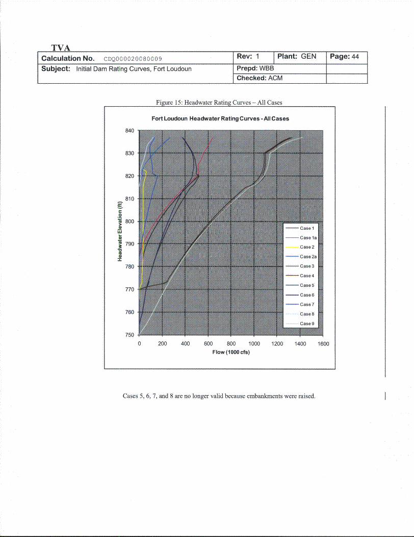
TVACalculation No. CDQ000020080009
Subject: Initial Dam Rating Curves, Fort Loudoun
Figure 15: Headwater Rating Curves - All Cases
Fort Loudoun Headwater Rating Curves -Al Cases
840
830
820
810
._o800
LU1
S7900w
780
770
760
750
0 200 400 600 800 1000 1200 1400 1600
Flow (1000 cfs)
Cases 5, 6, 7, and 8 are no longer valid because embankments were raised.
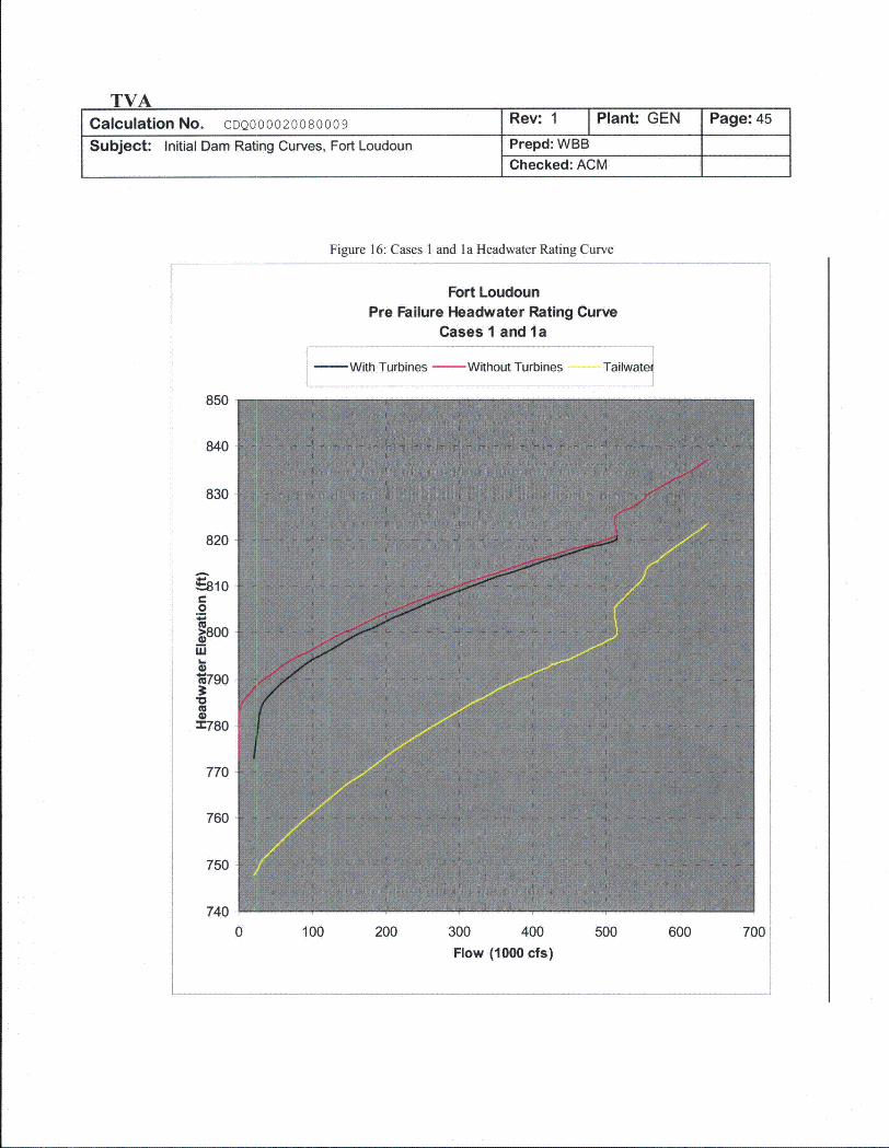
Figure 16: Cases 1 and la Headwater Rating Curve
Fort LoudounPre Failure Headwater Rating Curve
Cases I and la
- With Turbines -Without Turbines Tailwatem
850
840
830
820
E-8100
.2
iii
'*790
M780
770
760
750
7400 100 200 300 400 500 600 700
Flow (1000 cfs)
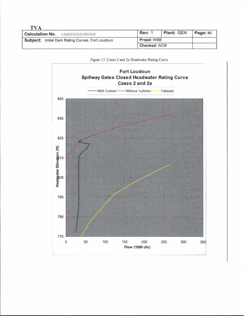
TVACalculation No. CDQ000020080009 Rev: 1 Plant- GEN Page: 46
Subject: Initial Dam Rating Curves, Fort Loudoun Prepd: WBB
Checked: ACM
Figure 17: Cases 2 and 2a Headwater Rating Curve
Fort LoudounSpillway Gates Closed Headwater Rating Curve
Cases 2 and 2a- With Turbine- Without Turbines Tailwatei
845
835
825
0f~159
795
785
775
0 50 100 150 200 250 300 350Flow (1000 cfs)
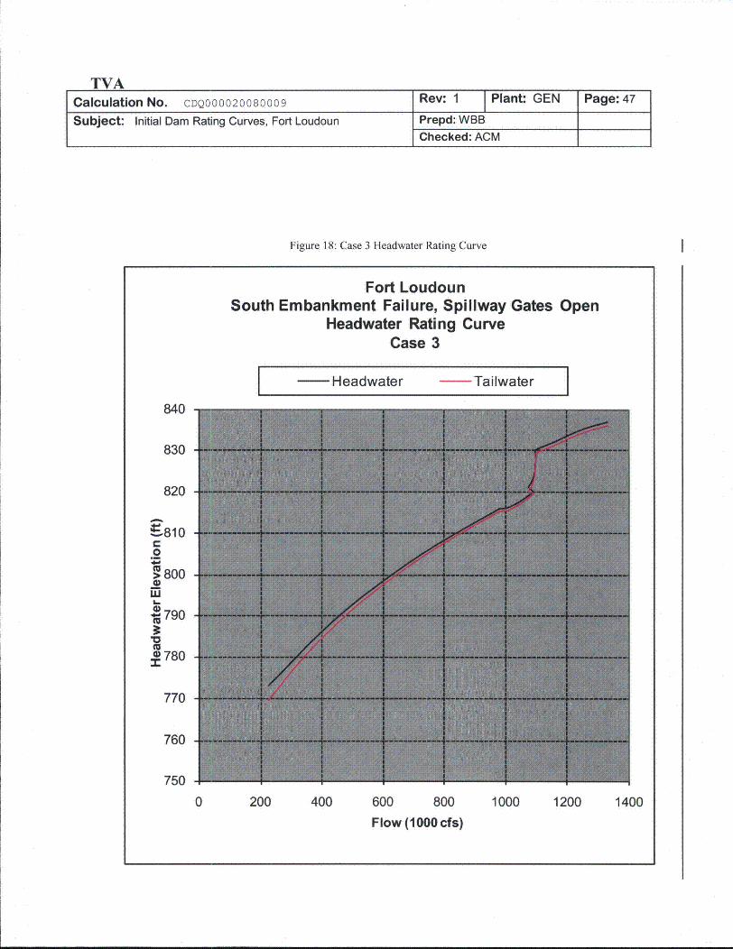
TVACalculation No. CDQ000020080009
Subject: Initial Dam Rating Curves, Fort Loudoun
Figure 18: Case 3 Headwater Rating Curve
Fort LoudounSouth Embankment Failure, Spillway Gates Open
Headwater Rating CurveCase 3
Headwater - Tailwater
840
830
820
•810E.8o0
800
L.
790
780
770
760
750
0 200 400 600 800
Flow (1000 cfs)
1000 1200 1400
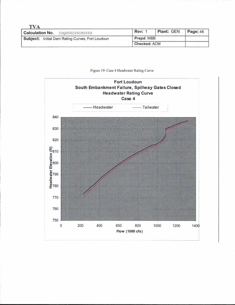
TVACalculation No. CDQ000020080009
Subject: Initial Dam Rating Curves, Fort Loudoun
Rev: 1 Plant: GEN
Prepd: WBBChecked: ACM
Page: 48
Figure 19: Case 4 Headwater Rating Curve
Fort LoudounSouth Embankment Failure, Spillway Gates Closed
Headwater Rating CurveCase 4
Headwater Tailwater
840
830
820
r-0
4 800
m790
0 780
770
760
7500 200 400 600 800 1000 1200
Flow (1000 cfs)140Q
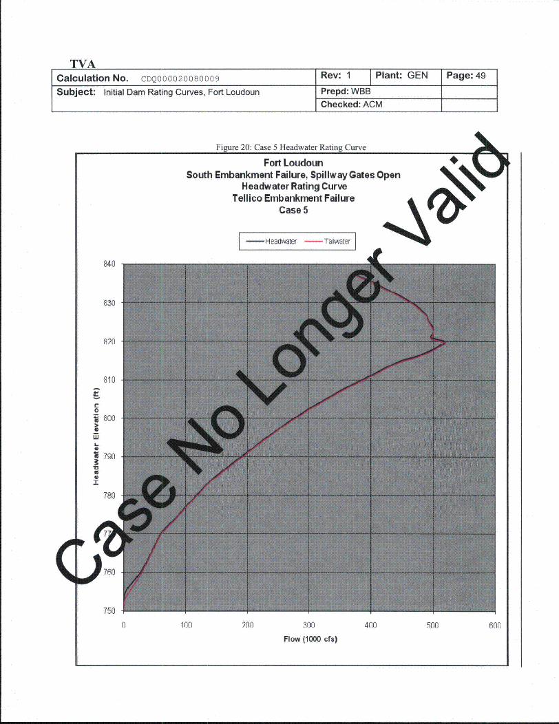
TVACalculation No. CDQ000020080009 Rev: 1 Plant: GEN Page: 49
Subject: Initial Dam Rating Curves, Fort Loudoun Prepd: WBBChecked: ACM
5
Fort LoudounSouth Embankment Failure, Spillway Gates Open
Headwater Rating CurveTellico Embankment Failure
Case 5
I-Headwater -Tailwater I
840
830
820
810
r-0
8006
7o 790
U6-1
780
760
750
0 100 200 300
Flow (1000 cfs)
400 500 600
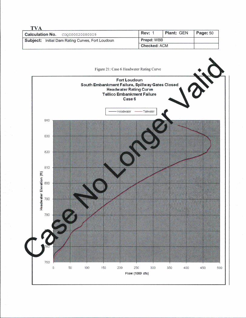
TVACalculation No. CDQ000020080009 Rev: 1 Plant: GEN Page: 50
Subject: Initial Dam Rating Curves, Fort Loudoun Prepd: WBBChecked: ACM
Fort LoudounSouth Embankment Failure, Spillway Gates
Headwater Rating CurveTellico Embankment Failure
Case 6
I - Headwater - Taiwater I
840
030
820
810
0800
W
790
UI
780
V
750
0 50 100 150 200 250
Flow (1000 cfs)
300 350 400 450 500
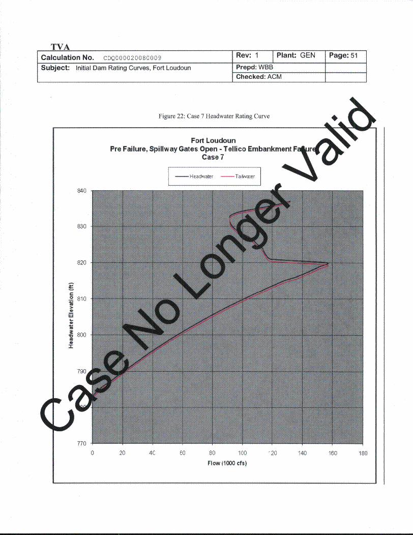
TVACalculation No. CDQ000020080009
Subject: Initial Dam Rating Curves, Fort Loudoun
Rev: 1 Plant: GEN
Prepd: WBBChecked: ACM
Page: 51
Fort LoudounPre Failure,
- HEadwater - TaiKlra:er
840
830
820
C
o 810
w 0
S800U0.-
790
I
770
0 20 4C 60 80 100
Flow 11000 cfs)
'20 140 160 180
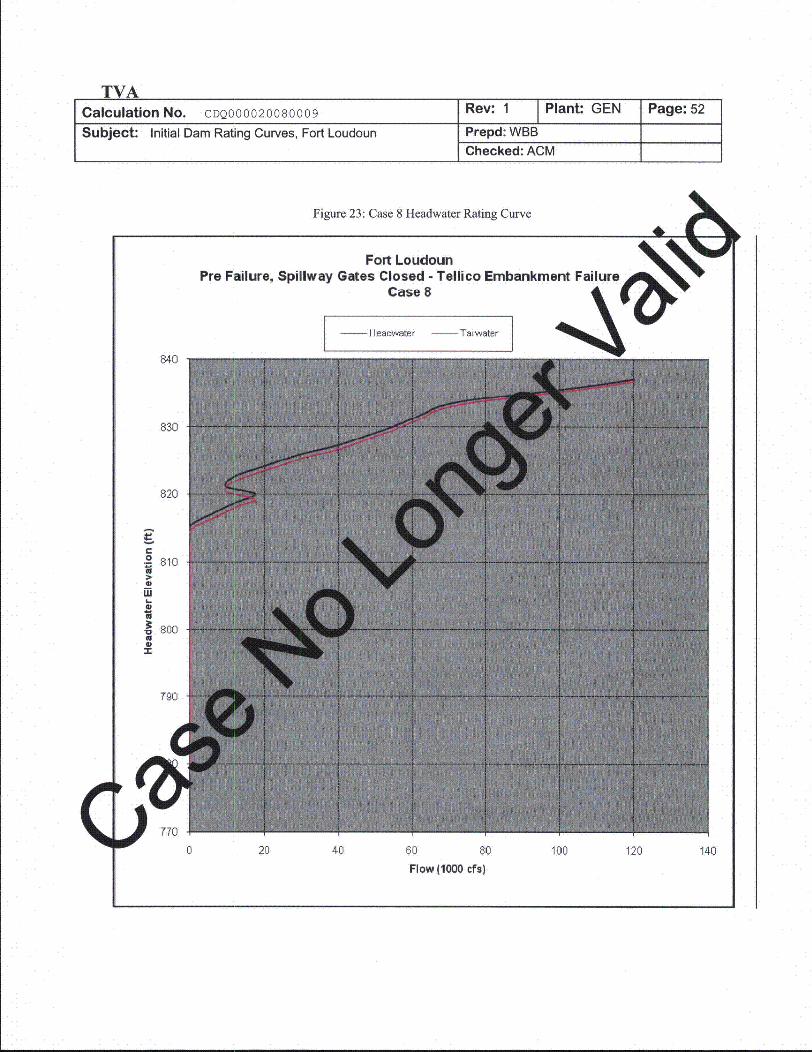
TVACalculation No. CDQ000020080009 Rev: 1 Plant: GEN Page: 52
Subject: Initial Dam Rating Curves, Fort Loudoun Prepd: WBBChecked: ACM
Figure 23: Case 8 Headwater Rating Curve
Fort LoudounPre Failure, Spillway Gates Closed - Tellico Embankment
Case 8
I - I leadwater - Tiwater
840
830
820
0 810
WS
-• 800U"r
790
,d
0 20 40 60 80
Flow (1000 cfs)
100 120 140
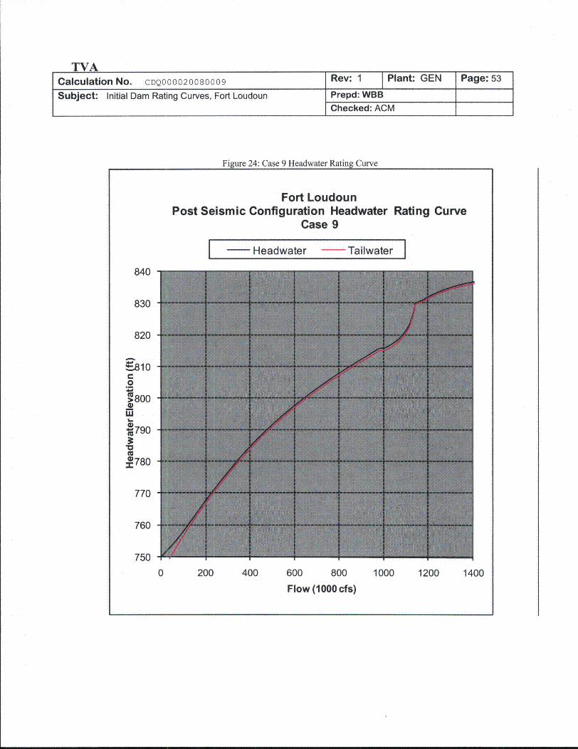
TVACalculation No. CDQ000020080009
Subject: Initial Dam Rating Curves, Fort Loudoun
Figure 24: Case 9 Headwater Rating Curve
Fort LoudounPost Seismic Configuration Headwater Rating Curve
Case 9
I -Headwater - Tailwater I
840
830
820
E810a
> 800
w,7 9 0
: 780
770
760
750
0 200 400 600 800 1000 1200 1400
Flow (1000 cfs)
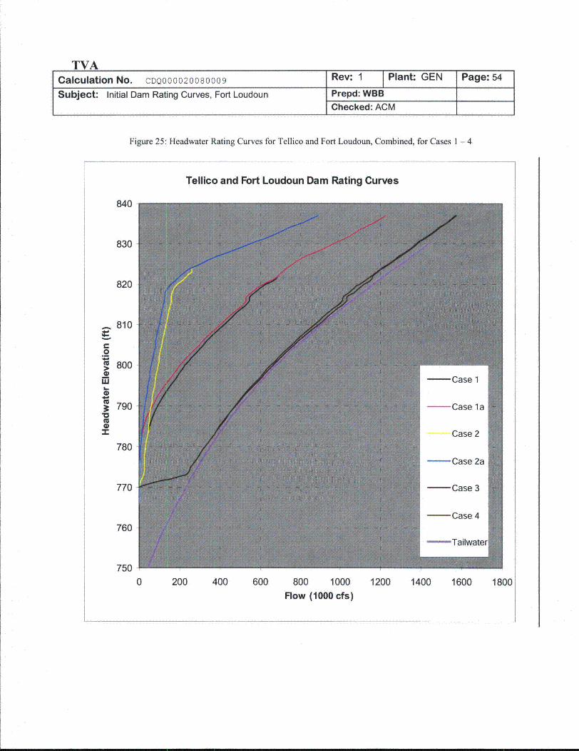
TVACalculation No. CDQ000020080009 Rev: 1 Plant GEN Page: 54
Subject: Initial Dam Rating Curves, Fort Loudoun Prepd: WBBChecked: ACM
Figure 25: Headwater Rating Curves for Tellico and Fort Loudoun, Combined, for Cases 1 - 4
Tellico and Fort Loudoun Dam Rating Curves
0
4-
V
uJ4--
(U
"U0-r
840
830
820
810
800
790
780
770
760
750
0 200 400 600 800 1000Flow (1000 cfs)
1200 1400 1600 1800
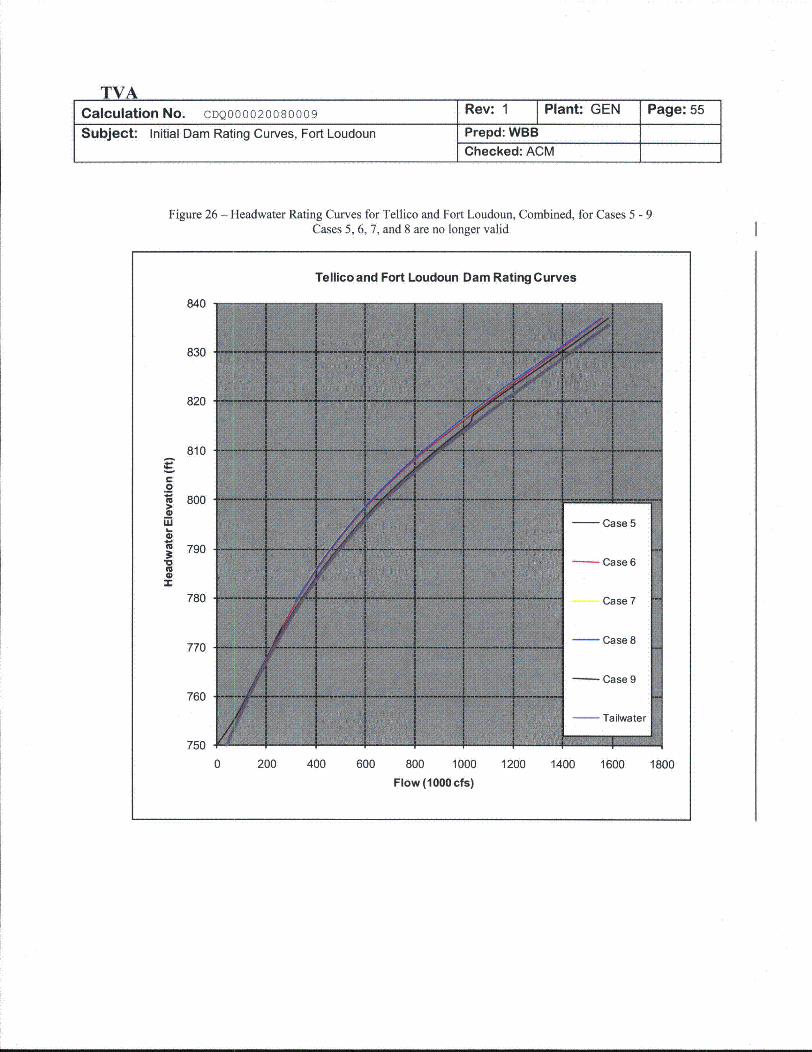
TVACalculation No. CDQ000020080009 Rev: 1 Plant: GEN Page: 55
Subject: Initial Dam Rating Curves, Fort Loudoun Prepd: WBBChecked: ACM
Figure 26 - Headwater Rating Curves for Tellico and Fort Loudoun, Combined, for Cases 5 - 9Cases 5, 6, 7, and 8 are no longer valid
Tellicoand Fort Loudoun Dam Rating Curves
0
'U
0
0'U
(U0
840
830
820
810
800
790
780
770
760
750
0 200 400 600 800 1000 1200 1400 1600 1800
Flow (1000 cfs)
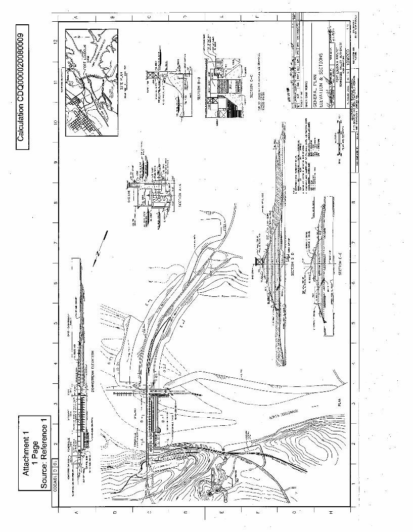
o)CCCcoCC
C)CC
0CDC)c-0
Cu
0
<o•
/
U-
o0
A
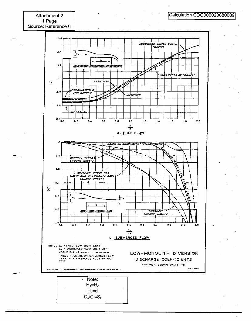
Attachment 21 Page
Source: Reference 6
Calculation CDQ0000200800091
3.5- 1 1 1
SUGGESTED DESIGN CURVE-.I I II I (AZIN.)
3.2 oo
• r \ "USGS TESTS A4T CORNELLI
3.0
2. :DECRING$SeIELD
2.8 AND BARKER - EUTNER
-- •ODRQN-
Cf
2.4 L_0.0 0.2 0.4 0.6 0.8 f.0 1.2 1.4 1.8 1.8 2.0
a i-a. FREE FLOW
CsC;r
0.1 0.2 0.3 0.4 0.5 0.6 0,7 0.8 0.9 1.0
Hz
b. SUBMERGED FLOW
NOTE" Cr = FREE-FLOW COEFFICIENTC3 = SUBMERGED-FLOW COEFFICIENT
NEGLIGIBLE VELOCITY OF APPROACH
RAISED NUMBERS ON SUBMERGED FLOWCHART ARE REFERENCE NUMBERS FROMTEXT.
.RE •O .. V. .. .* .....U ..* ... V.. l... C..V.. .. . V.C...u.. .• .l ..,
LOW-MONOLITH DIVERSION
DISCHARGE COEFFICIENTSHYDRAULIC DESIGN CHART 711
wS _-66
Note:H 2=HcH2=d
C,;Cf=Sf
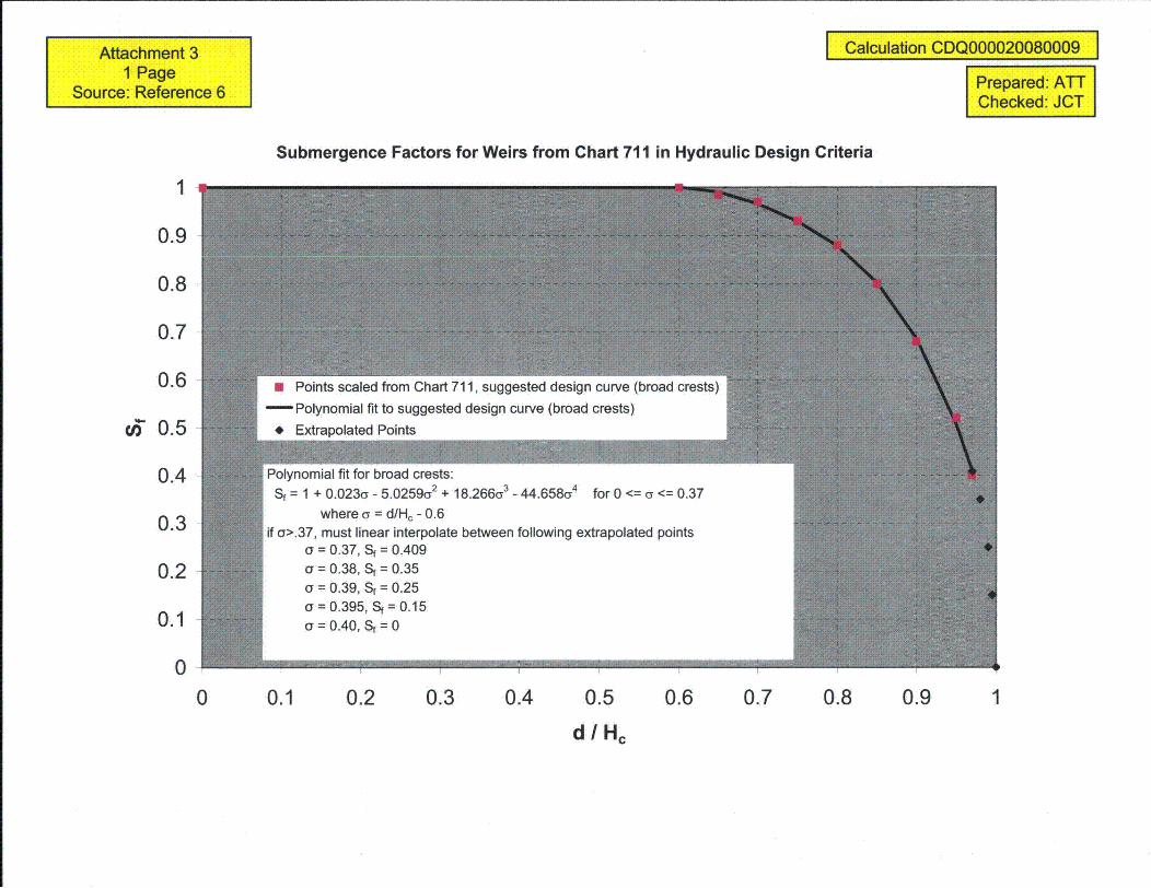
Attachment 31 Page
Source: Reference 6
I Calculation CDQ000020080009 I
Prepared: ATTChecked: JCT
Submergence Factors for Weirs from Chart 711 in Hydraulic Design Criteria
1
0.9
0.8
0.7
0.6
c 0.5
0.4
0.3
0.2
0.1
00 0.1 0.2 0.3 0.4 0.5 0.6 0.7 0.8 0.9 1
dlHc
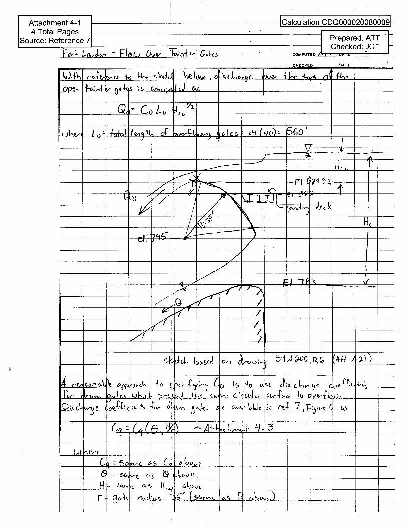
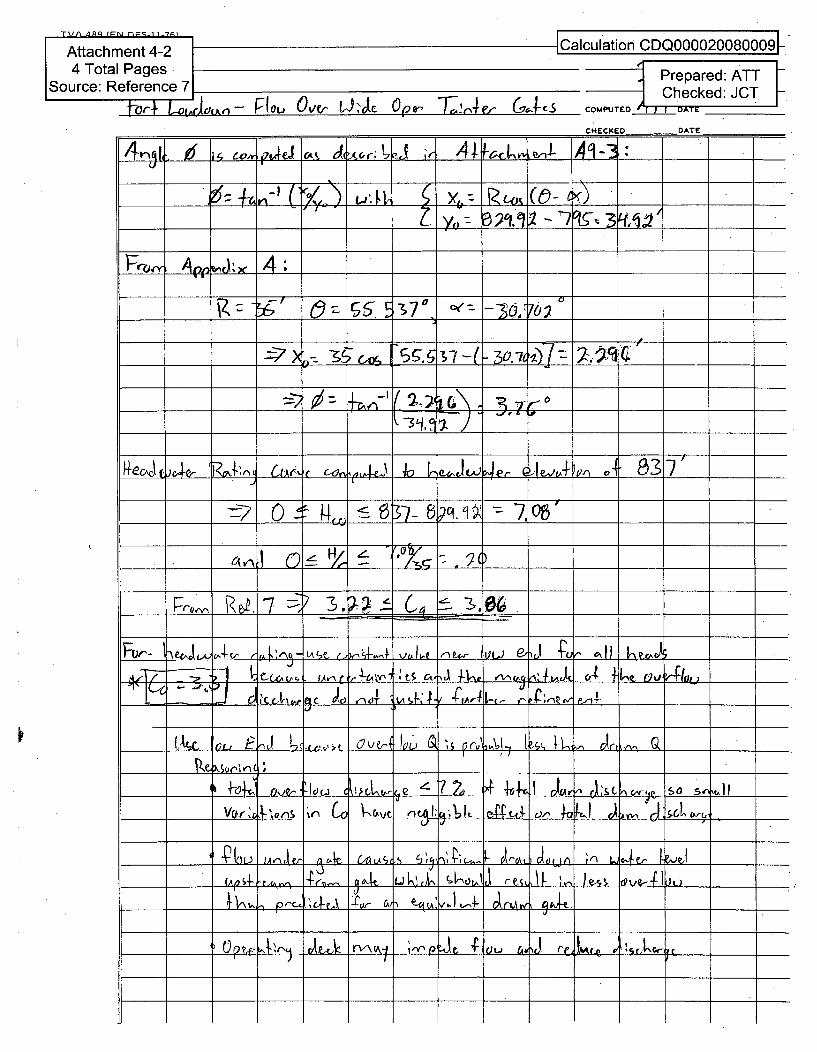
DA
17 lei _ _ _ _ _
_ _ Ii K
_-- _ S 5• +eJ7i V,70) 7
_ 7 _- 30
Pix' ~~631 baLI '=-U '7 ~ ~ __ _
Fi~r' I'efl- ,J "flONA-.,.,,. ný o V- 1- I t-u I a n,,v 01 ;1s•k.firo.'" tS a' e 0' I
4. CO
1'6.! IA,-jf A,:ý, _g- ___u down ___
OL kyJ OA'-sjL __
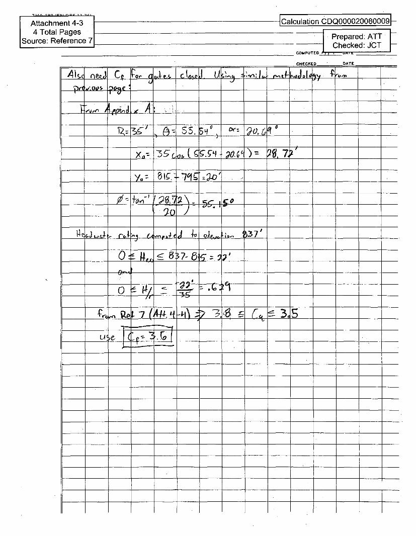
Attachment 4-34 Total Pages
Source: Reference 7
ICalculation CDQ0000200800091-
Prepared: ATTChecked: JCT
COMPUTED 4___7_1______.
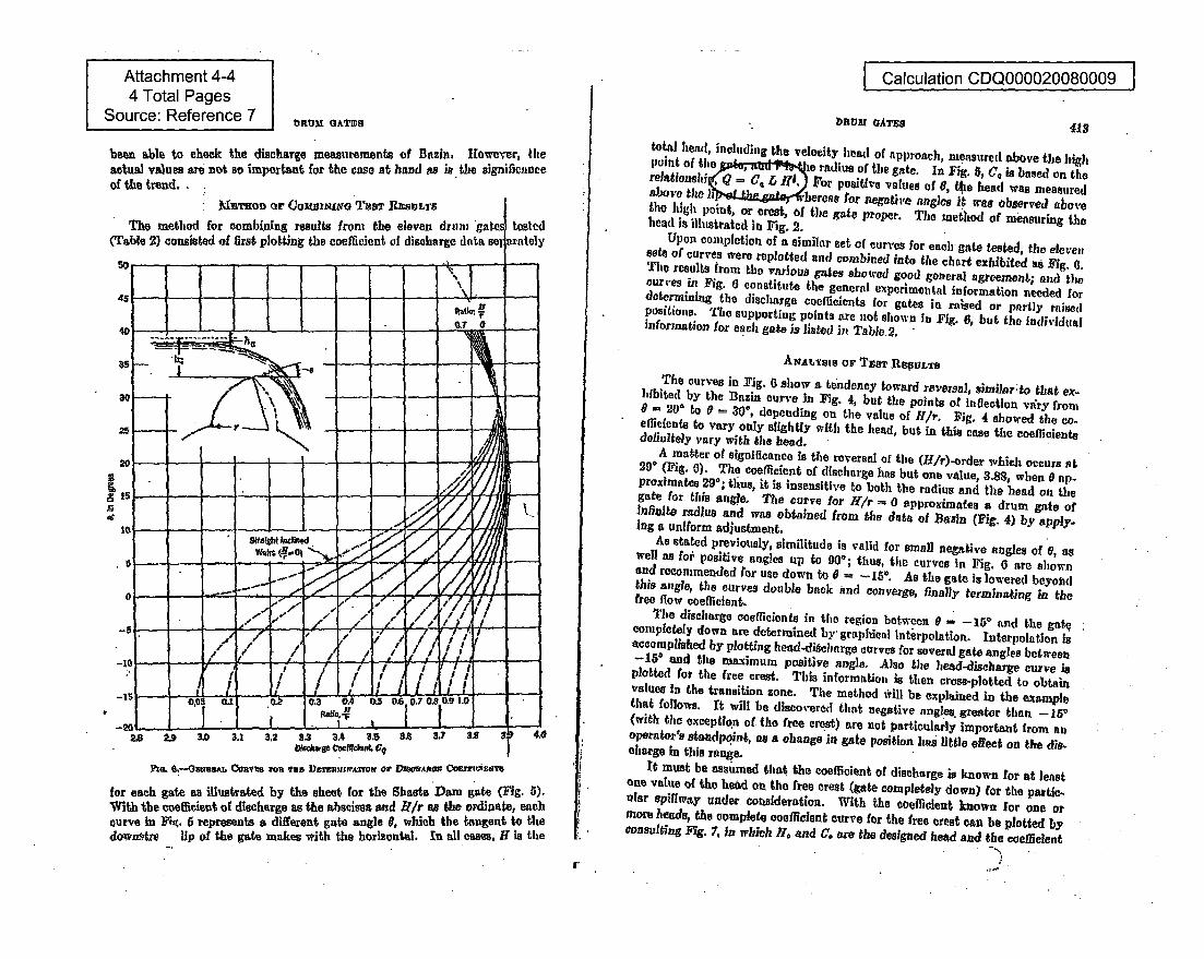
Attachment 4-44 Total Pages
Source: Reference 7
been able to check the discharge measurements of Bazin, HIowever, theactual values are not so important for the case at hand as in the significanceof the trend.
I Calculation CDQ000020080009 I
bRVM GATES 418
The method for combining results fron, the eleven drum 'gii(Table 2) consisted of first plotting the coefficient of discharge data
Z4r
total head, including the velocity Ileadl of approach, measured above the high* pohint of the e~.gldT-m~ri radius of the gate. In Fig. 5, Ce is based on therelationaii ~C.ff r or positive values of 0, the head was measuredabove te I vlereas tor negative angles tr wie observed above* the1high point, or crest, of the gate proper. The method of mensuring thehead is illustrated in Fig. 2.
Upon completion of a similar set of curves for each gate tested, the elevensete of curves were replotted and combined into the chart exhibited as Fig. 0.The results from theo various gates showed good general agreement; and the.curves in Fig. 6 constitute the general experimental information needed fordetermining the discharge coefficients for gates in ralsed or partly raiaedpositions. The supporting points are not shown in Fig. 6, but the individualinformation for each gate is listed in Table 2.
AortAsie or Tsna Res lurs
The curves in Fig. 0 show a tendency toward reversal, similar to that ex-hibited by the Basin curve in Fig. 4, but the points of inflection vary from0 = 20* to 6 - 30', depending on the value of H/r. Fig, 4 showed the co-effidients to vary only slightly with the head, but in this case the coeflicientsdefinitely vary with the head.A matter of significance is the reversal of the (H/r)-order which occurs at29* (Fig. 0). The coefficient of discharge has but one value, 3.88, when 0 ap-proximates 29*; tirus, it is insensitive to both the radius and the bead on thegate for this angle. The curve for 111/r 0 approximates a drum gate ofInfinite radius and was obtained from the data of Basin (Fig. 4) by apply-ing a uniform adjustment.As stated previously, similitude is valid for small negative angles of 6, aswell as for positive angles up to 900; thus, tlhe curves in Mig. 6 are shownand recommended for use down to 0 -- -15. As the gate is lowered beyondthis angle, the curves double back and converge, finally terminating in thefree flow coefficient.Tile discharge coefficients in the region between 0 -150 and the gatecompletely down are determined by- graphical Interpolation. Interpolation isaccomplished by plotting head-diselarge curves for several gate angles between-156 and the maximum positive angle. Also the head-discharge curve isplotted for the free crest. This information is then cruss-plotted to obtainvalues In the transition zone. The method will be explained in the examplethat follows. ft will be discover6d that negative angles greater than -- 150
(with the exception of tile free crest) are not particularly important from anoperator's standpolint, as a change in gate position hies little effect on the dis-charge in this range.It must be assumed that the coefficient of discharge is known for at leastone value of the heed on the free crest (gate completely down) for the pattic-ular spillway under cotsideration. With the coefficient known for one ormore heads, the complete coefficient curve for the free crest can be plotted byconsulting Mg. 7, In which 11, and C. are the designed head and the coefficient
n4L O.--,Ostw. Comms ionv ma DEM-rE•,imrato or mteM•sz•m •O a4s
for each gate as illustrated by the sheet for the Shasta Dam gate (Fig. 5).With the coeflicient of discharge as the abscissa aid H/r as the ordinate, eachcurve in Fit. 6 represents a different gate angle 0, which the tangent to thedosvn.tre lip of the gate makes with the horizontal. In all cases, H is the
r
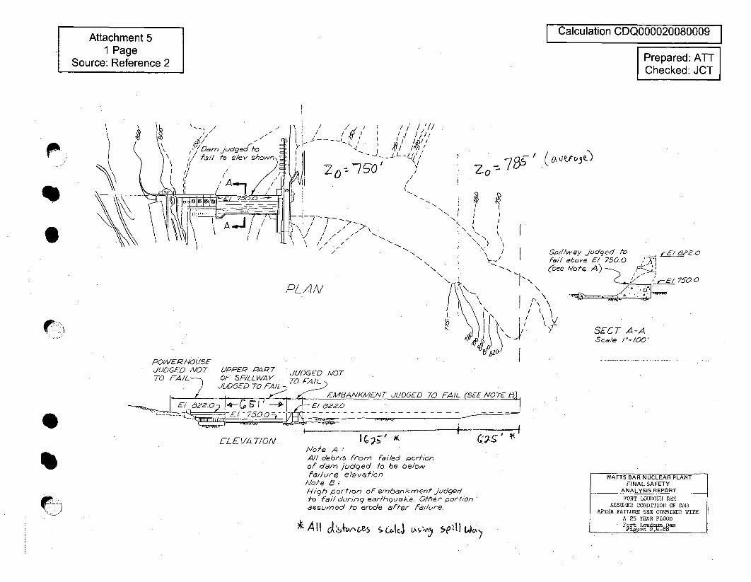
Attachment 51 Page
Source: Reference 2
I Calculation CDQ000020080009 I
Prepared: ATTChecked: JCT
( 6k J V.Fce')20
0 0
0 f
N
PLAN
Si//lway judged AofI/7 "6ove El 750.0(s&ee Mote A)
SET \\
I SECT -z
7/22.0
F E1 750.0
-AI' Sca/e /"=/00'
POWER HOUSEJUDGED NOT UPPER PART JUDGED MOT
ELEVA T/ON./o.'e A
All debrl-s from failed portionof ofam judged to be be/owfailure elevcthbn
/Note 3 :High portion of em6a1nkment judgedto fail during earfhgu•ke. Other or'tionassumed to erode after failure.
, All otcer-,cL• cl, tJ v) 5ez!t) wCA'
<,+•.:,;,
WATTS BAR NUCLEAR PLANTFINAL SAFETY
ANALYSIS REPORTFORT LOIJ/OI2 DAM,
ASSU•IE)D COOTYTION OF DAJMAFTER FAILURE SSE COMBINED WITH
A 25 YEAR FLOODFort LoudownjamFieare 2.-8
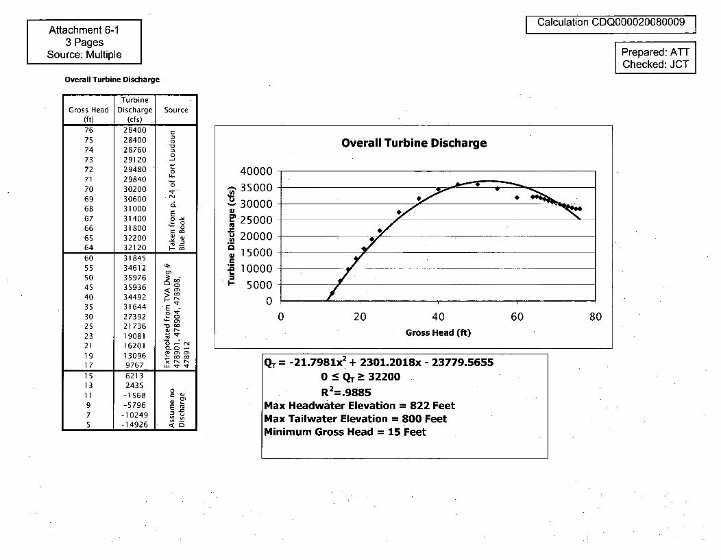
Attachment 6-13 Pages
Source: Multiple
I Calculation CDQ000020080009 IPrepared: ATTChecked: JCT
Overall Turbine Discharge
TurbineGross Head Discharge Source
(ft) (cfs)
76 2840075 28400 o74 28760 073 2912072 2948071 2984070 30200 -169 30600 r
68 31000 2E
67 31400 o -e
66 31800 065 3220064 32120 ca
60 3184555 3461250 35976 3 -
45 35936 <40 34492 P35 31644 E30 27392 2 825 21736 c23 1908121 1620119 13096 o
17 9767 _ __
15 621313 2435
011 -1568 C9 -5796 E7 -10249 .5 -14926 _
Overall Turbine Discharge
400003500030000 "
6 25000
20000
" 15000
50000
0 20 40 60 80Gross Head (ft)
QT = -21.7981x2 + 2301.2018x - 23779.56550 : QT-- 32200
R2 =.9885Max Headwater Elevation = 822 FeetMax Tailwater Elevation = 800 FeetMinimum Gross Head = 15 Feet
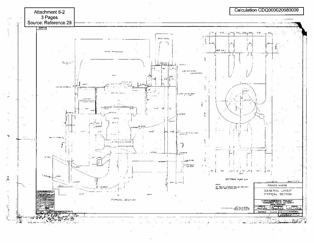
Calculation CDQ000020080009 I
r
,Sl.Z0~. 47<0147
1'?ý
r,.,. Iw t 1 1-o
,]
A'
Z0 4V>1
-i7i
- -,o~-
8"-3" -
1.
'i i
U, 3o' ,,UIc~~~, ,, Sa tg
"~ 273 OX ' :~ 4
20 t
3:ý:d
TYPICAL 5ECT,2IN
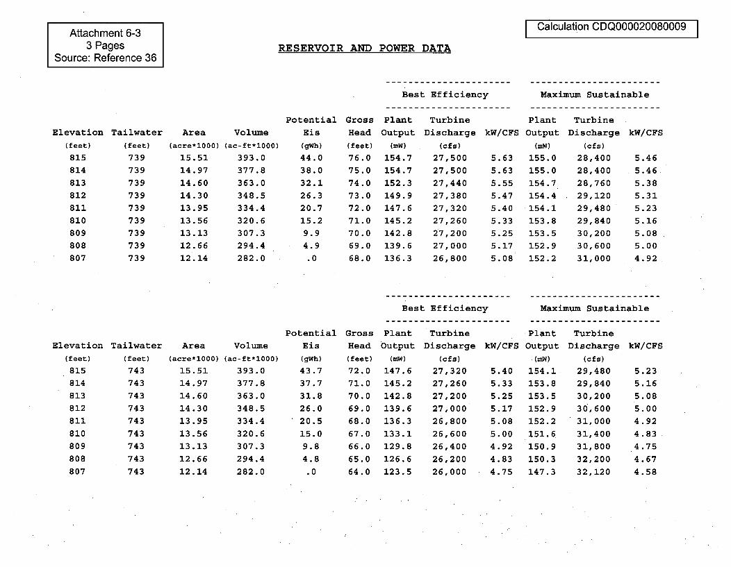
Attachment 6-33 Pages
Source: Reference 36
Calculation CDQ000020080009
RESERVOIR AND POWER DATA
Best Efficiency Maximum Sustainable
Elevation Tailwater Area Volume
(feet)
815814813812811810809808807
(feet)
739739739739739739739739739
(acre*1000) (ac-ft*1000)
15.51 393.014.97 377.814.60 363.014.30 348.513.95 334.413.56 320.613.13 307.312.66 294.412.14 282.0
PotentialEis
(gWh)
44.038.032.126.320.715.29.94.9.0
Gross Plant Turbine Plant TurbineHead Output Discharge kW/CFS Output Discharge kW/CFS(feet)
76.075.074 .0
73.072.071.070.069.068.0
(mW)
154.7154.7152.3149.9147.6145.2142.8139.6136.3
(cfS)
27,50027,50027,44027,38027,32027,26027,20027,00026,800
5.635.63
5.555.475.405.335.255.17
5.08
(mW)
155.0155.0154.7154.4154.1
153.8
153.5152.9
152.2
(cfs)
28,40028,40028,76029,12029,48029,84030,20030,60031,000
5.465.46
5.385.315.235.165.085.004.92
Best Efficiency Maximum Sustainable
Elevation Tailwater(feet) (feet)
815 743814 743813 743812 743811 743810 743809 743808 743807 743
Area(acre*1000)
15.5114.9714.6014.3013.9513.5613.13
12.66
12.14
Volume(ac-ft*1000)
393.0377.8
363.0348.5334.4320.6
307.3294.4282.0
PotentialEis
(gWh)
43.737.731.826.020.515.09.84.8.0
GrossHead(feet)
72.071.070.069.0
68.0
67.0
66.0
65.0
64.0
Plant TurbineOutput Discharge kW/CFS
(mW) (cfs)
147.6 27,320 5.40145.2 27,260 5.33142.8 27,200 5.25139.6 27,000 5.17136.3 26,800 5.08
133.1 26,600 5.00129.8 26,400 4.92126.6 26,200 4.83123.5 26,000 4.75
Plant Turbine
Output Discharge kW/CFS(mW) (cfs)
154.1 29,480 5.23153.8 29,840 5.16
153.5 30,200 5.08152.9 30,600 5.00152.2 31,000 4.92151.6 31,400 4.83150.9 31,800 4.75150.3 32,200 4.67147.3 32,120 4.58
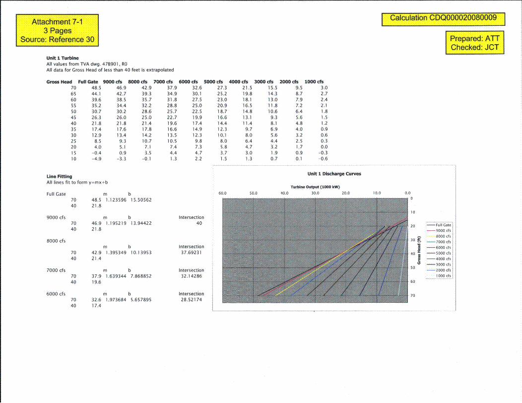
Attachment 7-13 Pages
Source: Reference 30
Calculation CDQ000020080009
Prepared: ATTChecked: JCT
Unit 1 TurbineAll values from TVA dwg. 47B901, ROAll data for Gross Head of less than 40 feet is extrapolated
Gross Head Full Gate 9000 cfs 8000 cis 7000 cis 6000 cis 5000 cis 4000 cis 3000 cis 2000 cis 1000 cis70 48.5 46.9 42.9 37.9 32.6 27.3 21.5 15.5 9.5 3.065 44.1 42.7 39.3 34.9 30.1 25.2 19.8 14.3 8.7 2.760 39.6 38.5 35.7 31.8 27.5 23.0 18.1 13.0 7.9 2.455 35.2 34.4 32.2 28.8 25.0 20.9 16.5 11.8 7.2 2.150 30.7 30.2 28.6 25.7 22.5 18.7 14.8 10.6 6.4 1.845 26.3 26.0 25.0 22.7 19.9 16.6 13.1 9.3 5.6 1.540 21.8 21.8 21.4 19.6 17.4 14.4 11.4 8.1 4.8 1.235 17.4 17.6 17.8 16.6 14.9 12.3 9.7 6.9 4.0 0.930 12.9 13.4 14.2 13.5 12.3 10.1 8.0 5.6 3.2 0.625 8.5 9.3 10.7 10.5 9.8 8.0 6.4 4.4 2.5 0.320 4.0 5.1 7.1 7.4 7.3 5.8 4.7 3.2 1.7 0.015 -0.4 0.9 3.5 4.4 4.7 3.7 3.0 1.9 0.9 -0.310 -4.9 -3.3 -0.1 1.3 2.2 1.5 1.3 0.7 0.1 -0.6
Unit 1 Discharge CurvesUne FittingAll lines fit to form y=mx+b
Full Gate m b70 48.5 1.123596 15.5056240 21.8
Turbine Output (1000 kW)
60.0 50.0 40.0 30.0 20.0 10.0 0.0
9000 cfs
8000 cfs
7000 cfs
6000 cfs
m b70 46.9 1.195219 13.9442240 21.8
m b70 42.9 1.395349 10.1395340 21.4
m b70 37.9 1.639344 7.86885240 19.6
m b70 32.6 1.973684 5.65789540 17.4
Intersection40
Intersection37.69231
Intersection32.14286
Intersection28.52174
to
20 1-Full Gate9000 cfs
8000 cfs
30 •. -7000 cfs-- 6000 cfs
40 -5000 cfs-- 4000 cfs
-3000 cfs
o - 2000 cfs
1000 0fs60
70
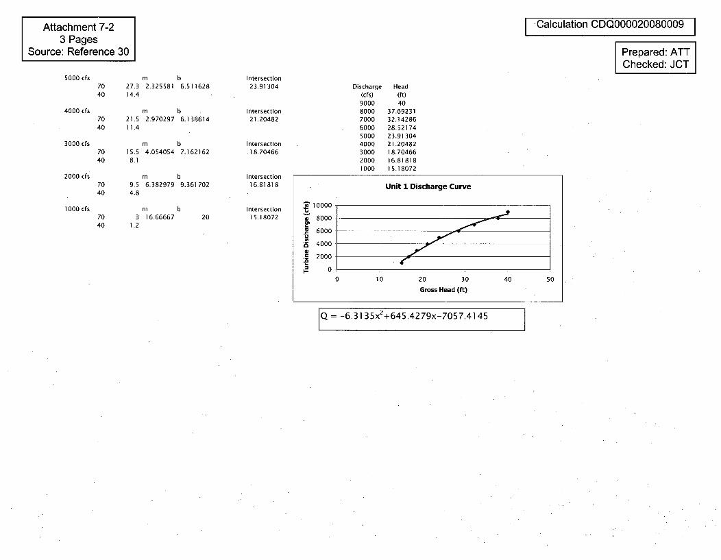
Attachment 7-23 Pages
Source: Reference 30
I Calculation CDQ000020080009 IPrepared: ATTChecked: JCT
5000 cfs
4000 cfs
3000 cfs
2000 cfs
1000 cfs
7040
m b27.3 2.325581 6.51162814.4
m b70 21.5 2.970297 6.13861440 11.4
m b70 15.5 4.054054 7.16216240 8.1
m b70 9.5 6.382979 9.36170240 4.8
Intersection23.91304
Intersection21.20482
Intersection.18.70466
Intersection16.81818
Intersection15.18072
Discharge(cfs)900080007000600050004000300020001000
Head(ft)40
37.6923132.1428628.5217423.9130421.2048218.7046616.8181815.18072
m b70 3 16.6666740 1.2
20
Unit I Discharge Curve
10000 8
w8000
6000
4000
0.5 2000
0 10 20 30 40 50
Gross Head (ft)
Q = -6.3135x 2+645.4279x-7057.4145
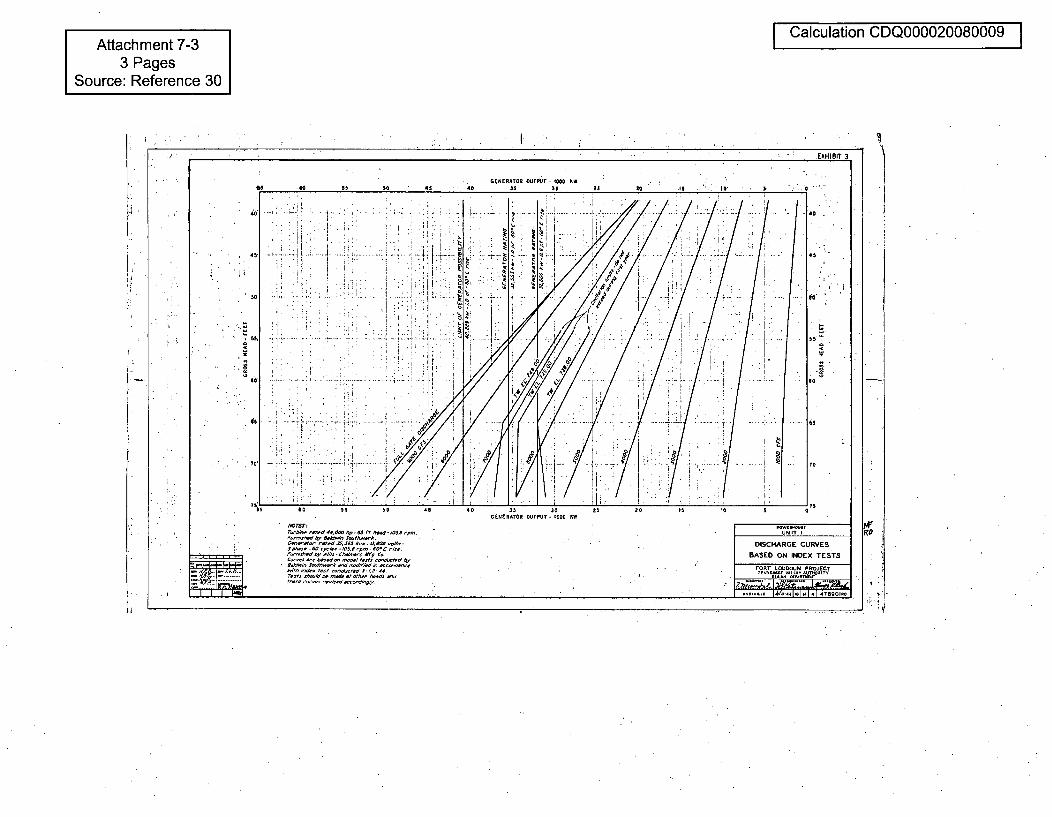
I Calculation CDQ000020080009 IAttachment 7-33 Pages
Source: Reference 30
I.
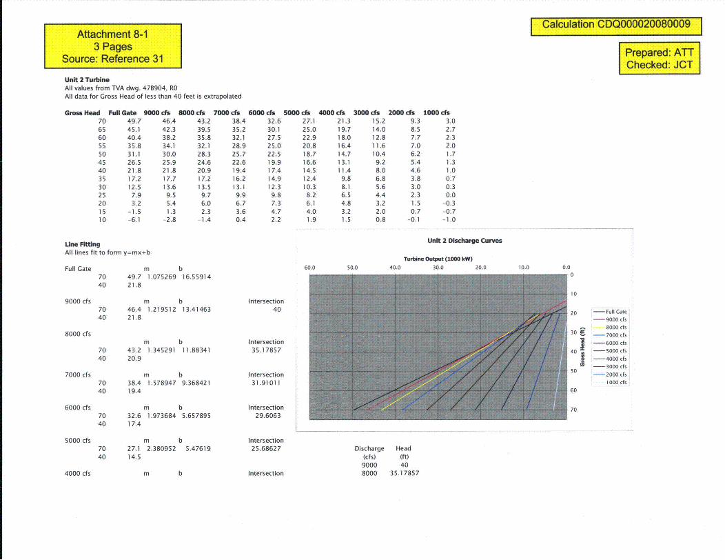
Attachment 8-13 Pages
Source: Reference 31
Unit 2 TurbineAll values from TVA dwg. 47B904, ROAll data for Gross Head of less than 40 feet is extrapolated
I Calculation CDQ000020080009 I
Prepared: ATTChecked: JOT
Gross Head Full Gate 9000 cfs 8000 cis 7000 cfs 6000 cfs 5000 cfs 4000 cfs 3000 cfs 2000 ds 1000 cs70 49.7 46.4 43.2 38.4 32.6 27.1 21.3 15.2 9.3 3.065 45.1 42.3 39.5 35.2 30.1 25.0 19.7 14.0 8.5 2.760 40.4 38.2 35.8 32.1 27.5 22.9 18.0 12.8 7.7 2.355 35.8 34.1 32.1 28.9 25.0 20.8 16.4 11.6 7.0 2.050 31.1 30.0 28.3 25.7 22.5 18.7 14.7 10.4 6.2 1.745 26.5 25.9 24.6 22.6 19.9 16.6 13.1 9.2 5.4 1.340 21.8 21.8 20.9 19.4 17.4 14.5 11.4 8.0 4.6 1.035 17.2 17.7 17.2 16.2 14.9 12.4 9.8 6.8 3.8 0.730 12.5 13.6 13.5 13.1 12.3 10.3 8.1 5.6 3.0 0.325 7.9 9.5 9.7 9.9 9.8 8.2 6.5 4.4 2.3 0.020 3.2 5.4 6.0 6.7 7.3 6.1 4.8 3.2 1.5 -0.315 -1.5 1.3 2.3 3.6 4.7 4.0 3.2 2.0 0.7 -0.710 -6.1 -2.8 -1.4 0.4 2.2 1.9 1.5 0.8 -0.1 -1.0
Une FittingAll lines fit to form y=mx+b
Full Gate m b70 49.7 1.075269 16.55914
Unit 2 Discharge Curves
Turbine Output (1000 kW)60.0 50.0 40.0 30.0 20.0 10.0 0.0
9000 cfs
8000 cfs
7000 cfs
6000 cfs
5000 cfs
40 21.8
m b70 46.4 1.219512 13.4146340 21.8
m b70 43.2 1.345291 11.8834140 20.9
m b70 38.4 1.578947 9.36842140 19.4
m b70 32.6 1.973684 5.65789540 17.4
m b70 27.1 2.380952 5.4761940 14.5
Intersection40
Intersection35.17857
Intersection31.91011
Intersection29.6063
Intersection25.68627
Intersection
10
20 -- Full Gate- 9000 cfs
- ' 8000 cfs
30 7000 cfs
-- 6000 cfs
40 - 5000 cfsI - 4000 cfs- 3000 cfs
50 -- 2000 cfs
1000 cfs
60
70
Discharge Head(cfs) (ft)9000 408000 35.178574000 cfs m b
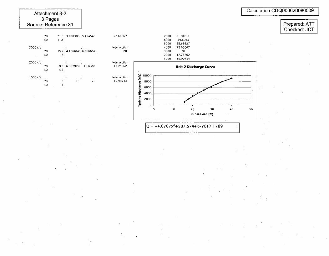
Attachment 8-23 Pages
Source: Reference 31
Calculation CDQ000020080009
Prepared: ATTChecked: JCT
3000 cfs
2000 cfs
1000 cfs
70 21.3 3.030303 5.45454540 11.4
m b70 15.2 4.166667 6.66666740 8
m b70 9.3 6.382979 10.638340 4.6
22.66667
Intersection20
Intersection17.75862
Intersection15.90734
7000600050004000300020001000
31.9101129.6063
25.6862722.66667
2017.7586215.90734
m b15 2570 3
40 1
Unit 2 Discharge Curve
10000
S8000
6000 -
~54000.5 2000
0 10 20 30 40 50
Gross Head (ft)
Q = -4.6707x 2 +587.5744x-701 7.1 789
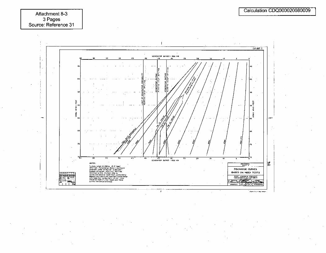
Attachment 8-33 Pages
Source: Reference 31
I Calculation CDQ000020080009
Af
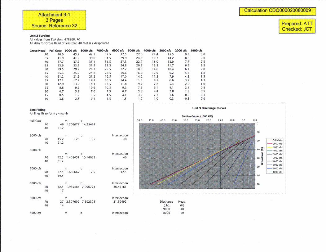
Attachment 9-13 Pages
Source: Reference 32
Unit 3 TurbineAll values from TVA dwg. 47B908, ROAll data for Gross Head of less than 40 feet is extrapolated
Calculation CDQ000020080009
Prepared: ATTChecked: JCT
Gross Head Full Gate 9000 cts 8000 cfs 7000 cfs 6000 cfs 5000 cfs 4000 cfs 3000 cfs 2000 cis 1000 cfs70 46.0 45.2 42.5 37.5 32.5 27.0 21.4 15.5 9.3 3.065 41.9 41.2 39.0 34.5 29.9 24.8 19.7 14.2 8.5 2.860 37.7 37.2 35.4 31.5 27.3 22.7 18.0 13.0 7.7 2.555 33.6 33.2 31.9 28.5 24.8 20.5 16.3 11.7 6.9 2.350 29.5 29.2 28.3 25.5 22.2 18.3 14.6 10.4 6.1 2.045 25.3 25.2 24.8 22.5 19.6 16.2 12.9 9.2 5.3 1.840 21.2 21.2 21.2 19.5 17.0 14.0 11.2 7.9 4.5 1.535 17.1 17.2 17.7 16.5 14.4 11.8 9.5 6.6 3.7 1.3
30 12.9 13.2 14.1 13.5 11.8 9.7 7.8 5.4 2.9 1.025 8.8 9.2 10.6 10.5 9.3 7.5 6.1 4.1 2.1 0.820 4.7 5.2 7.0 7.5 6.7 5.3 4.4 2.8 1.3 0.515 0.5 1.2 3.5 4.5 4.1 3.2 2.7 1.6 0.5 0.310 -3.6 -2.8 -0.1 1.5 1.5 1.0 1.0 0.3 -0.3 0.0
Unit 3 Discharge CurvesLine FittingAll lines fit to form y=mx+b
Full Gate
9000 cfs
8000 cfs
7000 cfs
6000 cfs
5000 cfs
m b70 46 1.209677 14.3548440 21.2
m b70 45.2 1.25 13.540 21.2
m b70 42.5 1.408451 10.1408540 21.2
m70 37.5 1.66666740 19.5
b7.5
Intersection40
Intersection40
Intersection32.5
Intersection26.45161
Intersection21.69492
Intersection
Turbine Output (1000 kW)50.0 45.0 40.0 35.0 30.0 25.0 20.0 1 5.0 10.0 5.0 0.0
0
20 i-Full Gateii--9000 cfs
- ~8000 cfs30 • -_ 7000 cfs
--6000 cfs40 , -5000 cfs
--4000 cfs
-•3000 cf's
5 -- 2000 cf's
1 000 cf's
60
70m b70 32.5 1.935484 7.09677440 17
m b70 27 2.307692 7.69230840 14
Discharge Head(cfs) (ft)9000 408000 404000 cfs m b
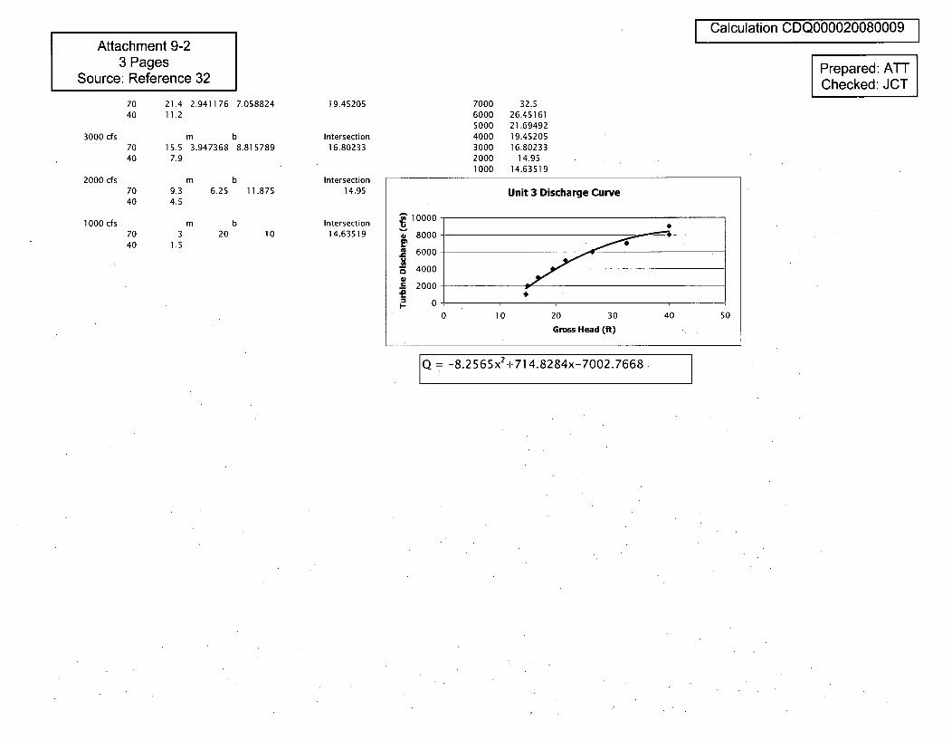
Attachment 9-23 Pages
Source: Reference 32
70 21.4 2.941176 7.05882440 11.2
m b70 15.5 3.947368 8.81578940 7.9
3000 cfs
2000 cfs
1000 cfs
19.45205
Intersection16.80233
Intersection14.95
Intersection14.63519
7040
7040
m b9.3 6.25 11.8754.5
m b3 20 10
1.5
Calculation CDQ000020080009
Prepared: ATTChecked: JCT
7000 32.56000 26.451615000 21.694924000 19.452053000 16.802332000 14.951000 14.63519
Unit 3 Discharge Curve
10000-
8000
6000
4000
.S 2000
0 10 20 30 40 50
Gross Head (ft)
Q = -8.2565x2 +714.8284x-7002.7668
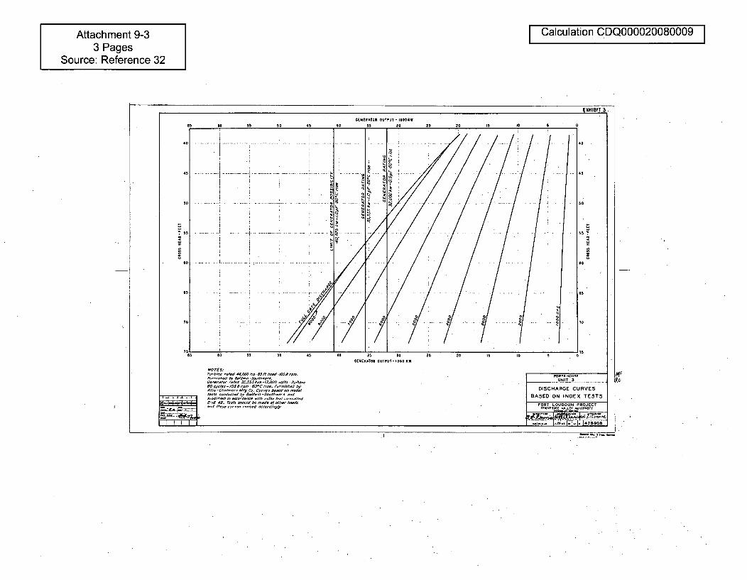
Attachment 9-33 Pages
Source: Reference 32
I Calculation CDQ000020080009 I
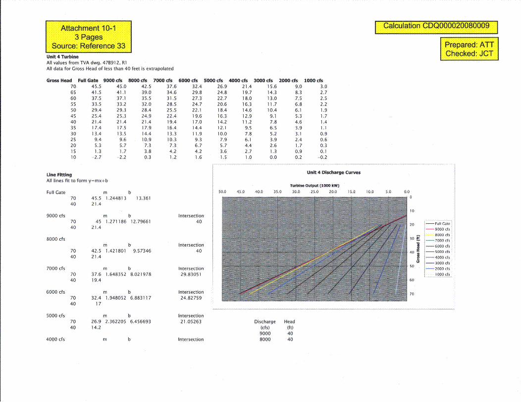
Attachment 10-13 Pages
Source: Reference 33Unit 4 TurbineAll values from TVA dwg. 478912, R1All data for Gross Head of less than 40 feet is extrapolated
Gross Head Full Gate 9000 cfs 8000 cfs 7000 cfs 6000 cfs 5000 cfs 4000 cfs 3000 cis 2000 cfs 1000 cfs70 45.5 45.0 42.5 37.6 32.4 26.9 21.4 15.6 9.0 3.065 41.5 41.1 39.0 34.6 29.8 24.8 19.7 14.3 8.3 2.760 37.5 37.1 35.5 31.5 27.3 22.7 18.0 13.0 7.5 2.555 33.5 33.2 32.0 28.5 24.7 20.6 16.3 11.7 6.8 2.250 29.4 29.3 28.4 25.5 22.1 18.4 14.6 10.4 6.1 1.945 25.4 25.3 24.9 22.4 19.6 16.3 12.9 9.1 5.3 1.740 21.4 21.4 21.4 19.4 17.0 14.2 11.2 7.8 4.6 1.435 17.4 17.5 17.9 16.4 14.4 12.1 9.5 6.5 3.9 1.130 13.4 13.5 14.4 13.3 11.9 10.0 7.8 5.2 3.1 0.925 9.4 9.6 10.9 10.3 9.3 7.9 6.1 3.9 2.4 0.620 5.3 5.7 7.3 7.3 6.7 5.7 4.4 2.6 1.7 0.315 1.3 1.7 3.8 4.2 4.2 3.6 2.7 1.3 0.9 0.110 -2.7 -2.2 0.3 1.2 1.6 1.5 1.0 0.0 0.2 -0.2
Calculation CDQ000020080009
Prepared: ATTChecked: JCT
Unit 4 Discharge CurvesLine FittingAll lines fit to form y=mx+b
Full Gate m b70 45.5 1,244813 13.36140 21.4
Turbine Output (1000 kW)50.0 45.0 40.0 35.0 30.0 25.0 20.0 15.0 10.0 5.0 0.0
9000 cfs
8000 cfs
7000 cfs
6000 cfs
5000 cfs
m b70 45 1.271186 12.7966140 21.4
m b70 42.5 1.421801 9.5734640 21.4
m b70 37.6 1.648352 8.02197840 19.4
m b70 32.4 1.948052 6.88311740 17
m b70 26.9 2.362205 6.45669340 14.2
Intersection40
Intersection40
Intersection29.83051
Intersection24.82759
Intersection21.05263
Intersection
10
20 !- Full Gate- 9000 cfs
8000 cfs30 •. -7000 cfs
1 - 6000 cfs
40 -5000 Efs
[- 4000 efsI- 3000 efs
50-2000 cis
12000 cfs
60
70
Discharge Head(cfs) (ft)9000 408000 404000 cfs m b
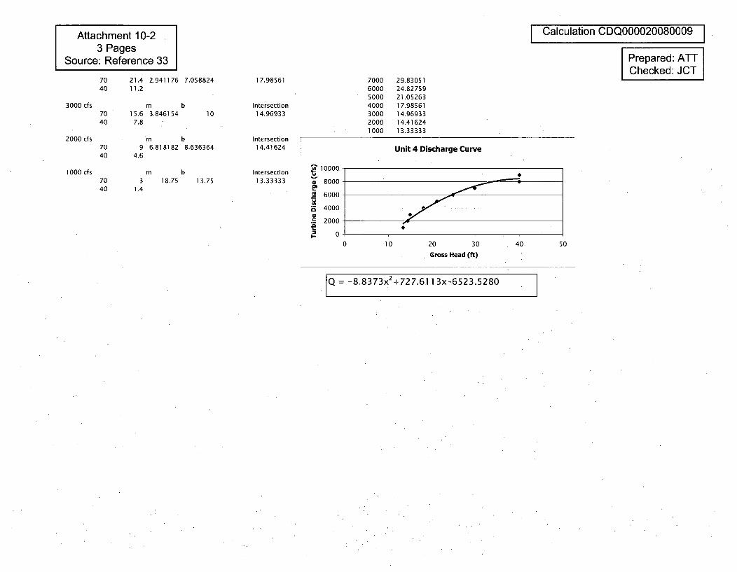
Attachment 10-23 Pages
Source: Reference 33
I Calculation CDQ000020080009 I
Prepared: ATTChecked: JCT
70 21.4 2.941176 7.05882440 11.2
3000 cfs
2000 cfs
1000 cfs
m b70 15.6 3.84615440 7.8
10
17.98561
Intersection14.96933
Intersection14.41624
Intersection13.33333
7000600050004000300020001000
29.8305124.8275921.0526317.9856114.9693314.4162413.33333
7040
7040
m b9 6.818182 8.636364
4.6
m b3 18.75 13.75
1.4
Unit 4 Discharge Curve
S10000 -
8000-
6000
4000
.5 2000
0 10 20 30 40 50
Gross Head (ft)
Q = -8.8373x 2+727.6.11 3x-6523.5280
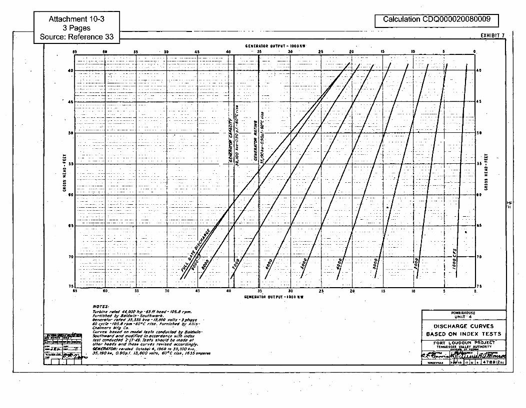
Attachment 10-33 Pages
Source: Reference 33
F Calculation CDQ000020080009EXHIBIT 7
GENERAToR OUTPUT- 1000KWSO 50 45 40 *.35 - 30 25 20 IS I0 560 so 45 40 25 20 5
.7/ I. I†. i :. = ; i
I
L...... ............. ..
4; 1l•: i U :i - j;.. 1: :i-i I :.. .
So
a - -- - 7
I',.
38
.1
001 /Ii/ /1
3.,S
lbI-..'Z L*~~___ .~
03
0
I.,
30'.3
/
- ------- • + - 145I
3.,
F.
/ / I It/S1
I: . .. I..I - 11
'S ~4-
0
1
w - .. ... ( /~1 / / •.1. L* -l .1
C
- 7 L
........ ..__ _ _ _- ... ..... .. ..- -/ - . I.-/ ...i . .. , . ... . -
--.-- .. . . --. 1 1•: • I: . : . . . .. . - - ,77.0 77 -7
;5- 60 55 50 45 40 3530 25 20 15 10 5 0.GENERATOR OUTPUT-I000 KW
NOrESjTurbine reted 44,000 hp -•65 f/ heed- /05.8 rpm.Furnished by aIdwin - &outhwerk.6enerwlor risfed 3w.i,35 kva - IO0 vo/Is - Iphese60 cycle -i05.0 rpm -60*C rise. Furnished by Allis-Chelmers Mfg Co. .Curves based on model tests conducted by 8alowi,-Southward end modified in accordance with indextest conducted 2-17-"4. rests should be made atot/her heeds end These curves revised accordingly.&MERfATOR: reroted Otoebe 4, 1968 to 39,4.00 *,a,.35,190 Ac, 0. 90p.f. 13,5 00 volts, 60.C else, 1635 amperes
POWERHOUSEUNIT"4
DISCHARGE CURVES
BASED ON INDEX TESTS
FORT LOUDOUN PROJECTTENNESSEE VALLEY AUTHORITY
= .- l---- -1- F--.-,-; . ..• 1K~ ex, , 7-& 40 1,o 1U I14 1 4 7 8 9 12 R,
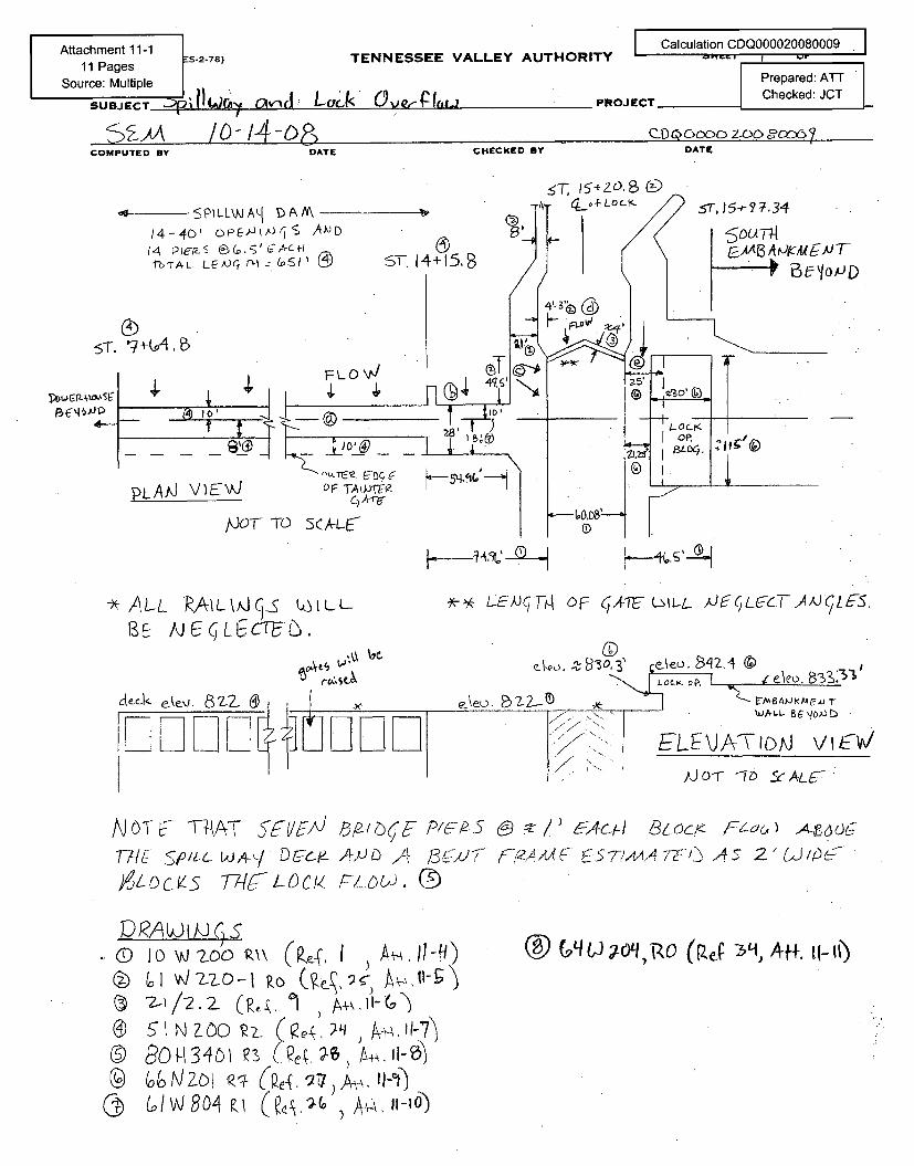
Attachment 11-111 Pages S-2-78) TENNESSEE VALLEY AUTHORI
Source: Multiple
SUBJECT ., - L, ,),f
/o-14-oR
TYCalculation CDQ000020080009
Prepared: A-T
OJECT Checked: JCT
DATECOMPUTED BY DATE CHECKED BY
• PILL\A/AAI 1A-
14-40' oP[-ý&Ax <rJS AJD14 PIEF-S a,' C.-
hrTAL. LEA)• mr :O!S I ST. 14+15,3
5T. •+(A. B
4, I FLO Nd
II 4.64
ST.) 5- ? 7.3"4
E•/IOPD
PLAAJ VIEWJ OF TAtJF-(ZC , A --
h- ~'-~~~""
/dOCT TO 5CA-L6
S
- ALL PA•/utA__v Lt0LLBE •/J•LGCrEL.,
-Yz-Y L-EWJqT4 OF GATE UL-L- A)J6L&7YJ,)ILFS.
\'eo. &ns:31Jed<CI e-ke'j. 82-
WALL -
ELE\JATiDoJ vi•v-.Jo-r -i- ofeA.L&- "
T7t-/ •, A-,./ D V Aý A5711R4 137 . A- (S77AAA '•Z '1 57 2- GU'-5Atc~ds• 77-(g-L-D_/. f7_OUiJ, (•
0 1 too tA\ (P,' I w ,.w1-9)
® gI N zoo I eý_ 4 A•• , - 11-7"7)
Cy @ / 80W 4 AJZOI, 11-10
(0 Cý',. ,-04 1g0q) (Ref -3q Aft, (1- 11
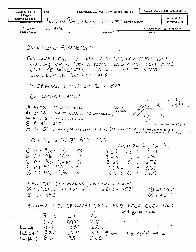
TENNESSEE VALLEY AUTHORITY Calculation CDQ000020080009 '
,- URLLO~PROJICT Prepared: ATT
_________________E____ K_______D __ Checked: JCT
CHECKED BY DATE
S EAI LC-f4-(28COMPUTED BY DATE
OVER• FLUO PAeMAAUT-E-S
FDR .S(APLICTLI•) -THE-. Pc) •- VOF o \ t--ý A-c}s" K1-\\c•Uk JbO, tcoc• FLOCJ A-(,,b0E ELEU, 8SOS'
L- E- ECL-E rCTF0. (-LEAJý7D A M-C•L,
OtU?.FLGU• CL&-AT-O}J 3L- p22)
C ý -b C-- 7-FP1tA i /J A Tý D)J,'
6. If' •.
C ±
o - IAc/ I3
O•_ k-I,.5
o £ ,- c/ :-
?(),J ST. 1-445, S TD 1-14C-
Wt LOC-KPJAL4ATF
/' PA 1B9Lý
0o), 3Lý (,A TfLOW B-6 56"-Q(-AL-Th T" LIJ-Tý4 op f-ýlAeL-cr-. op. aLokicL-a7As5A~4e-)
•
-vu ;5%
~.5
V .3
2-G
Z,G
1 0/&r-12010) A-,ý. :2_L-- 42,7?-/
5~ 6 k ~3,33_5 C'± 2• Co-
L ECc 7)-lS (RACMEW BP-bC)C- 2,2p- BLOc~CAt,4ljH
()L; (O I® Lz•s'
~~AA4AAAP1~~04 6(4§HL.A1ýbmLc C-1FLOLd
tooxk t40t I"
Lu~k. G;,t&s'I" b~difi
T 18.7'
Bt
G9, 7,4 5, 5'
2-51-AN V&
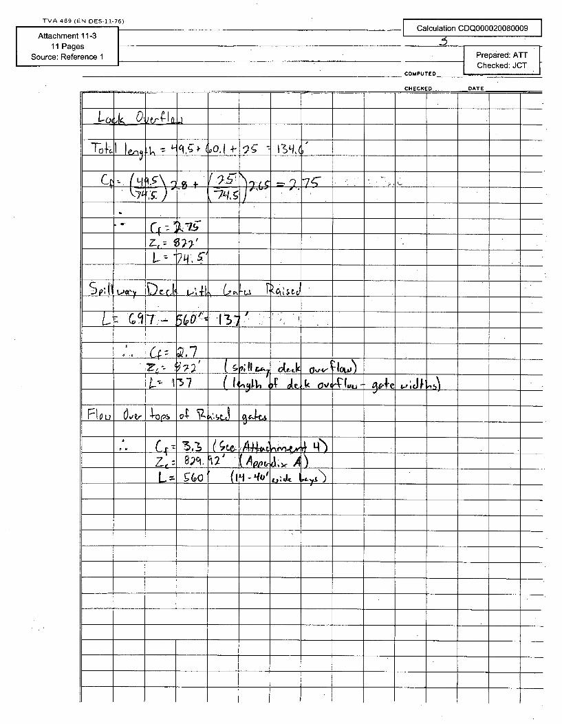
nATFDlATE
•-7,r:• ) '" -' -/,•. 5 " "
L. 9 71ff"l- 1 (o••,13 ' '"
1QL2 _ Vu
F~loe~k oH-'2 rýL)s 0
Z,,.
____~~1 ;-___ _ _
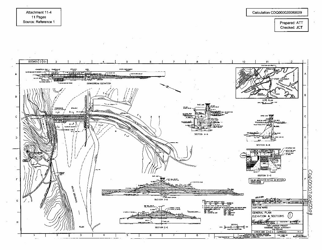
Attachment 11-411 Pages
Source: Reference 1
Calculation CDQ000020080009
Prepared: ATTChecked: JCT
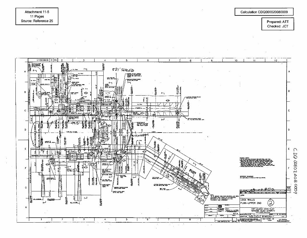
Attachment 11-511 Pages
Source: Reference 25
I Calculation CDQ000020080009 IPrepared: A'-Checked: JCT
12
A
8
c
E
t•
F Q
C,
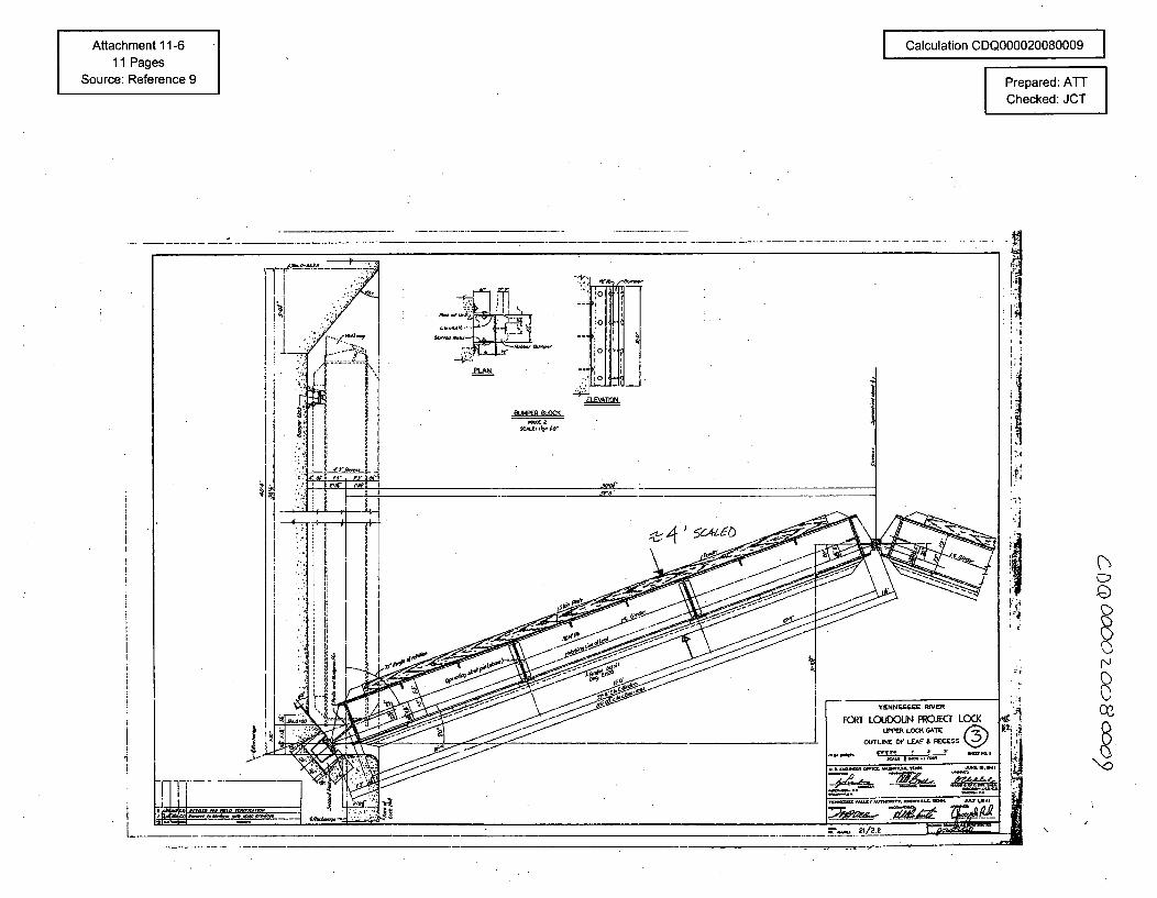
Attachment 11-611 Pages
Source: Reference 9
I Calculation CDQ000020080009 I
Prepared: ATT
Checked: JCT
-c
!Qi
,j71.
!.N
*1:
8
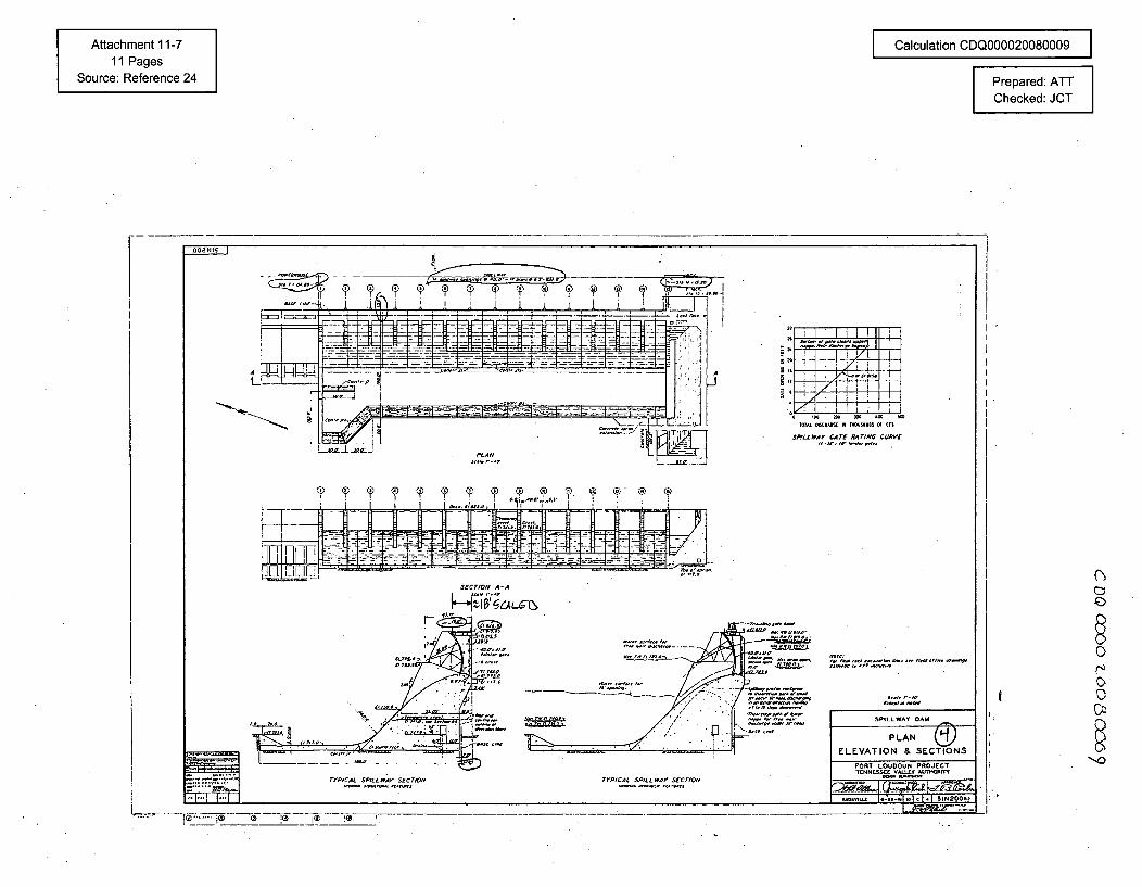
Attachment 11-711 Pages
Source: Reference 24
Calculation CDQ000020080009
Prepared: ATTChecked: JOT
O00Z.15
L
1014 40 ... q)i ., ... C 7 . .. 13 - - ______ i
]j I•=,-'-•'-•: ••••. ..- T .- _-. - --.- _..
PL--A
t
SPfLLWAY CATE RATING CURAVE
P q, 9 . T , T
' -'- - F= : • ••-'iT - T ; -: =" k h 7 ' "" -
JL~iLJ.,L,, ,,.0-.
SECTION A-A
r "TIAL$lLA ECION 7r01C,4, kIfLlf soTIO
SPtLLWAY DAM
PLAN
ELEVATION & SECTIONS
FORT LOUOOUN PROJECT0T7001SS5E V=LL 00Nýf
i 00,o0010J *1- o-,, ,T c L 51N200o
..44- !i~fW7~20 iE I~)
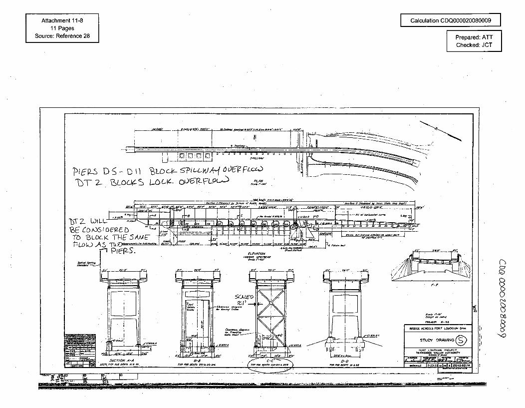
Attachment 11-811 Pages
Source: Reference 28
Calculation CDQ000020080009
Prepared: ATTChecked: JCT
NO
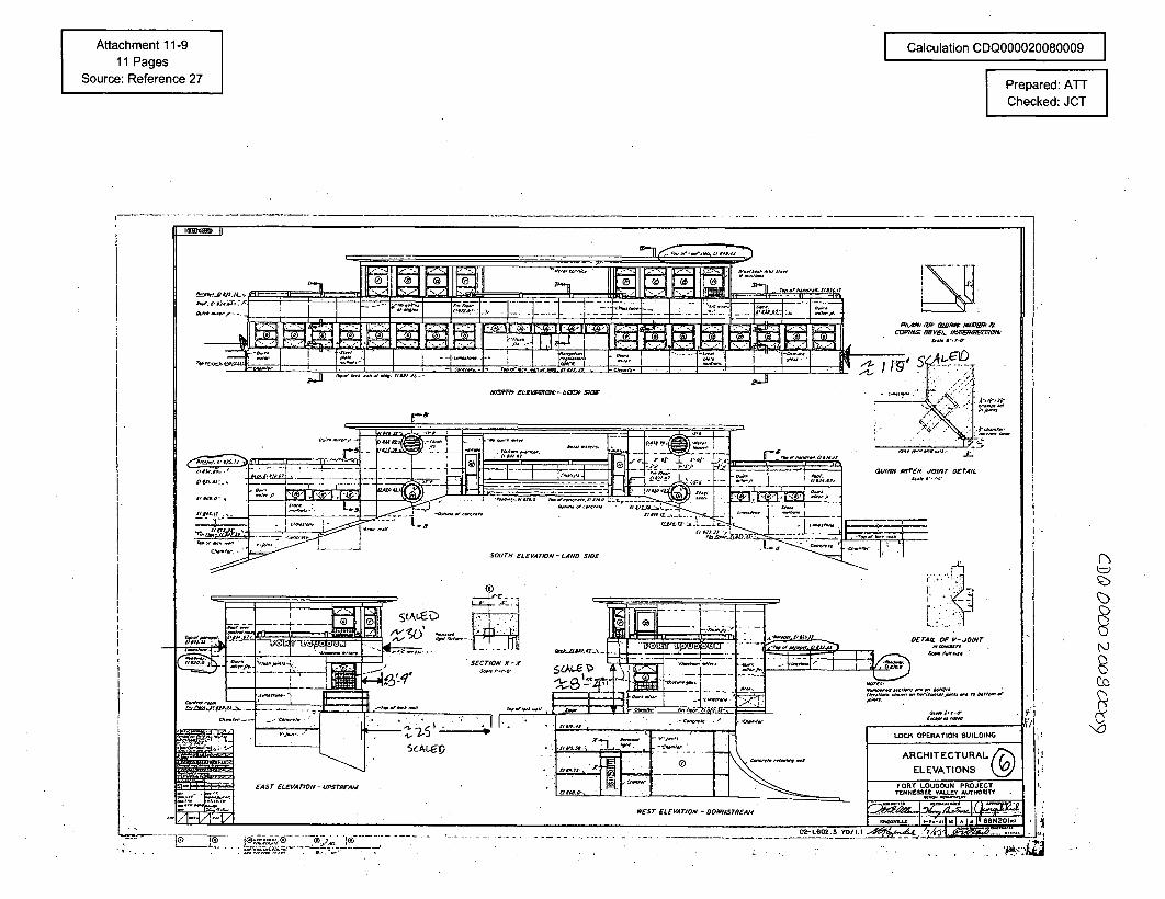
Attachment 11-911 Pages
Source: Reference 27
Calculation CDQ000020080009
Prepared: ATChecked:CJ
**~® ®~-.:® j0-L602.3 70/1.1
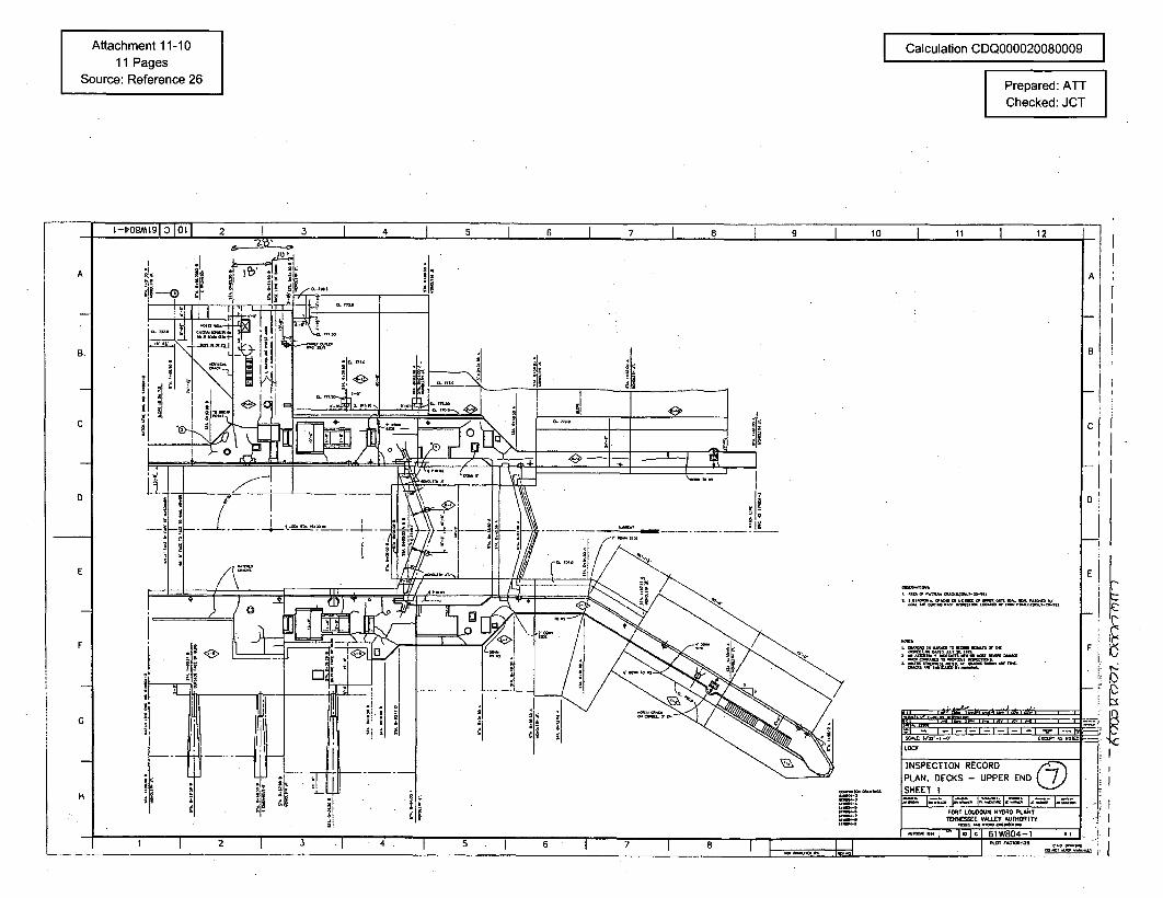
Attachment 11-1011 Pages
Source: Reference 26
Calculation CDQ000020080009
Prepared: ATTChecked: JCT
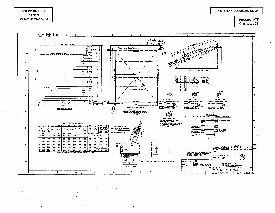
Attachment 11-1111 Pages
Source: Reference 34
Calculation CDQ000020080009
Prepared: ATTChecked: JCT
- - - /
\ /
--- - -------/
R! FORCES ACTING ON GIRDER
FINTIO
4-D1PN-D I3*-R~PAN~-R 3*-R~P~FI-II
* law
4-N PAN~
- .YR.-S -AORIZONTAt GrRDER DESIGN
ii:
ALORABlO STRFSý FOR EXTREME CONDITIONS
IT r
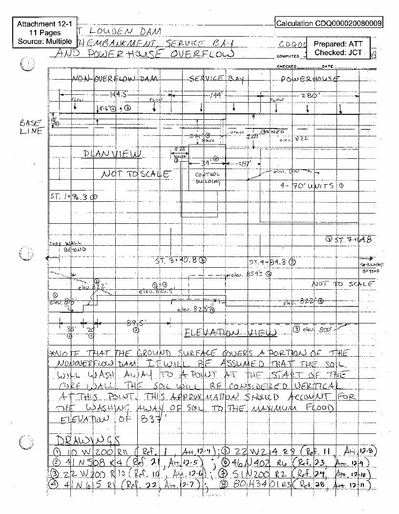
Attachment 12-1 -
11 Pages T LOUt•&/J DA-/Aj __
Source: Multiple g C-4, , Ui 4tjT, 'A-p Cq-. 14
[Calculation CDQ0000200800091
Ctooc Prepared: ATTCOMPUTEO Checked: JCT.
POWEP-A4 P-.FLQQf~I.4FCK~fl OATF
CEK PATEI !
L-14 -
FLo0(
--------------*-~-
A -~
I NG_
SA4t_•lo U " 22- -t
P _ • V •- -•
c1(~~3 C
1A'SAL co) ITR.OL
- 'u UL) L *--
4- L7D tAL________ _________ -- 4- -- I 4-
-1 -44- -- -- 4 -4
(-; ..-D
'10 )-~ c~
4
C?~t
S
-1.ID787C2.5--
A-P leo
5T.~1-4-
351: c~)
\JO -
~-r. ~7-+l
-~ Sc-. rf---z--- ! ["~-- -4 -I -- ,
I eLH~_________ + -4------- 4- -4-~------~--F~---4~,i/---------4 -- 4 4- 4- -4----4 -4 --
---- 4d--- - -b4d- -4, ~ - 4 ---- 4~4-~ + ~ 4- -~r--- 4 4- - -= - -- - H~ -4.- ~- 4I ~ r• 4, AI=T'Ir &), I ~ elo -
-~----=-- I. .4 4 -a- b -
~J()
L1)
EE U
- .f$ J,.f; 4
N
1•TI_ ,9 o
A4tTA1, Tj
irn (-,DL4I
Iý_L
SLL A-
'u.ZA-(c C-) P_ ý10ýj i7
._-. __\
x, W i
_ E
v ~A-P
SSU
for
(E71_1_ jA
~ ~il4
T-ý- ".k
,- a, C.
-0-EY,
A.Fi
~- E7
__AS
_,00ý)
L._T ....
L SO IL mI-mr
-- • . . . "V ___"••-- ___ ' - . . .. . ..... $ - -_ ___ ... . .. U - -I -
C-3)I
~~~A{LAL~S(4 IC -4-4-
- -4-. -4 - 4 ~ 4 ---- +--~ 4- -~ -. - 4- -1--/
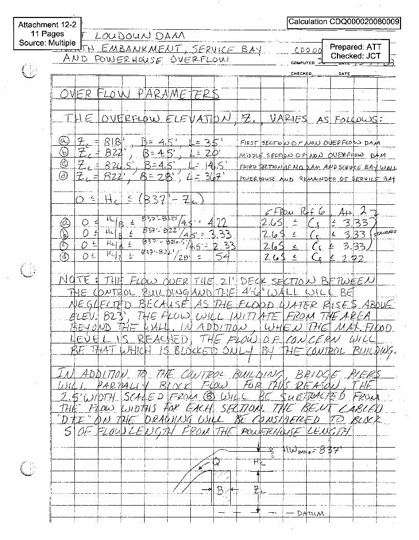
Attachment 12-2. Calculation CDQ000028OO0911 Pages F LQ(_1.tOL•/J DAM,.A_
Source: Multiple . CP.... E/ \ - )A4• /J _k• !,_ ?J(-' €- C D• Prepared: ATT I
AJ PC)©4O& ]US OV "@..FT Checked: JCTA. 1 V. ' 1D r COMPUTE D - ,-
-oI
©
1<2'--ii-j
72
L
jT)
64 2I2
0 S 21
I&F0czU, l
_Lt A): IL .
F" I~11
AL-) / 77j,
-72'
49
-- I---00A
FA :TII -5-
CL T-1 L M IVý
L21 U A
Li__P L I Li-H_---- T - -i~-- - ~-~-~--~z + -~-~- { --
-_ 5 -r
AA- 1i. DL• _
k 2 (.),)
0 A.) 0 C
,IFLQ
R
- . , DA-
A- - 77-
7-m .iP-- , -- I i
54 z.uq
E.L. ~Fl LL ,)(L _
7dzi1 L L4 7L!£
--- -- -- , -"
5,,.
fr L~IW4i2Z~/7L(~4~2
1- 4ij3~J~-1
owL11I f -
bmfi ~'t4LVI'7 ,b ,/ •,i' -_/ .• _ .. _•FL -_tc _,•djFU
_)ALJ.•.,y) y-.). ;t ..•.,
~4LL~L½½LK
(~±LDY~Sj~f~
- f~/Af_2A7AS~,i .
?WuLc.. ~~?65~6Q76~•
L A¶'()'7-7
:_____
LIfZ 'I LI
~74 _
I
I
~iL5/14
,~,f
(}I'-
I~I
- I. -I- - --- -
I-- t:+
1 - 4 -
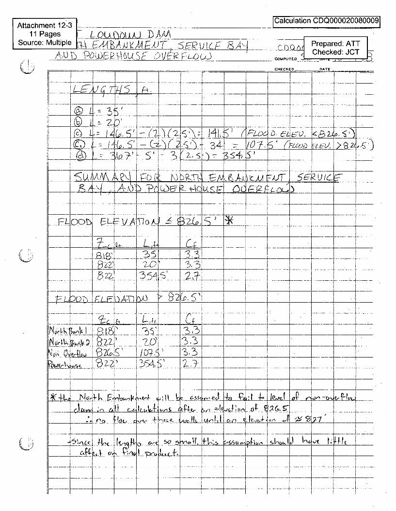
Attachment 12-3 _ . '11 Pages M-LUA(.J, -A _____ _.
Source: Multiple , >F.i )' ;4:S,4 __
.... .f, R . 0... . .P6) __0_ fRtb 1-6)"'
lCalculation CDQ0000200800091
S•Prepared: ATTCOMUTE ~Checked: JCT -
CHECKED DATEK; - DATE
4~ 4 4 4 + --- 4
7-I
-=3, -4, - .-- ii'
-3-4
'F b
b 91•2
-72zi 35+LrLI
5=57A AA~)L~ L~ AJL~s~r.
I
.. . .... • .J ? I I
FLi _o0_
2---
XIoi 4
IA_
zL0< )
• •-- "b"-•'•-• I :-a------------•--------t•--
I -4- -- + -l -4 4 4 -
221
£iL~
~LI
1ATh1
1~
___l~7~4L* ~2
.4-
1L~] - 4-- - 4 .-- ---- 4
~~1~-U- P
-1~~AjLI 2i~K
N tl, •.o'!Qq~
2333
A
ý3LV_ 3 I ..
0 ......2-6~
..... i
-- - ' •- + -+ a 4 - -'
_________ 4 4 ~
A i26•~ £4
-(J-•J ,eel 4A &'
5 ~ Lc kiaW- 1-----
,'~ c~~j $0 5 IV
~A41
- ~ 4 4 . - -4
Ct~4
. .1- o .. 4-.
~~~1
-1
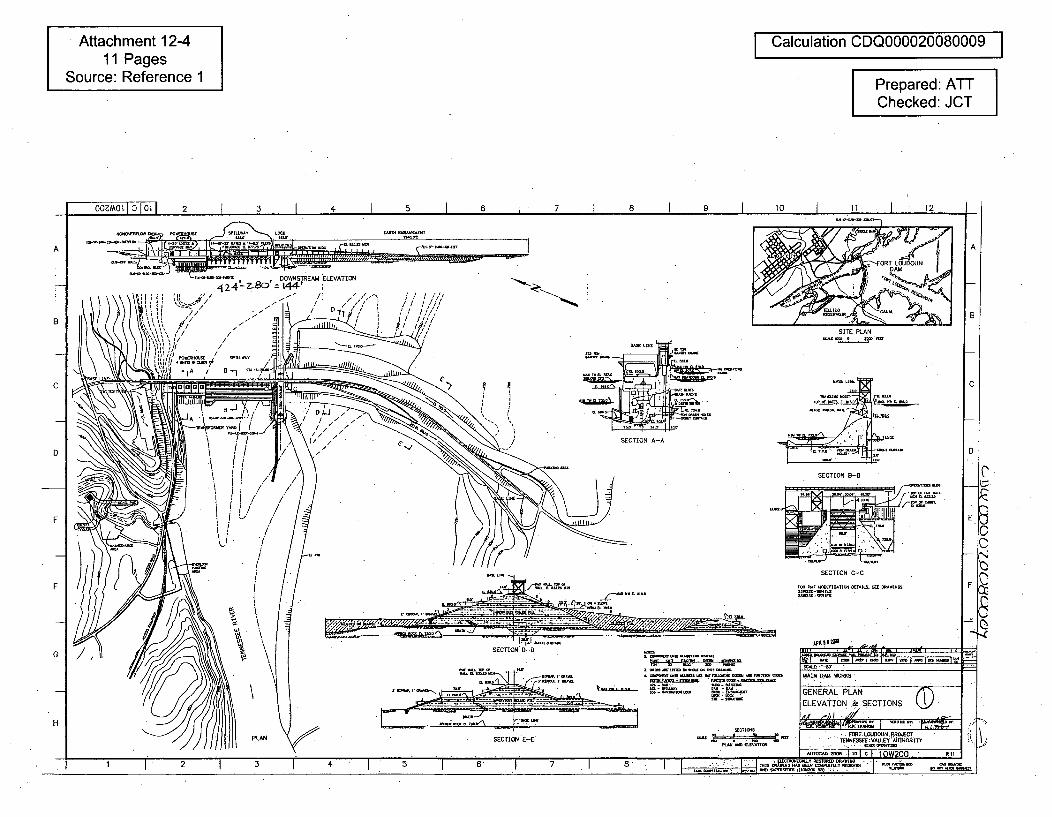
Attachment 12-411 Pages
Source: Reference 1
Calculation CDQ000020080009
Prepared: ATTChecked: JCT
........ i 3-- G-- i I 3 I 4 I 5 1 6 I 7 I 8 I 9 1 10 1 11 I 1200zmO L 10 1 a Ll 2
NOEO'LMM oM.~povoAasE M~awAY OCX
A A
2_ OW-NSTREAM ELEVATION
TI ' i A / - / / 0',/
B
SITE PLAN
C
SECTION A-A
SECTION B-8
SECTION C-C
C
D
E E
C
C
F - ----- - -- F
- - /
'0S110
-1
G
- afinrun Ow z
mii-- E&W:n "mbl-,arM InaIImIwoInrInRImaI~~.~-
I-MAIN DAM WORKS
GENERAL PLAN ('jELEVATION & SECTIONS k}
,, w g ; , I /// . .
FORT.LOUDOUN ,A5•.ETENNE.TE E VAULEY 'AIOORITY
H
- 2-M 1-,o c I 10W200 R%1
I 1 -"2 3 II 6 1.N1jH••5 7 a
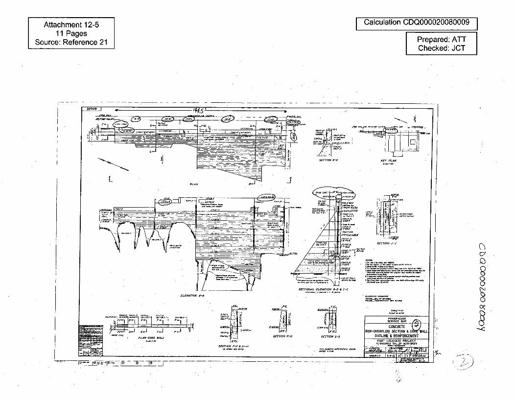
Attachment 12-511 Pages
Source: Reference 21
I Calculation CDQ000020080009 IPrepared: ATTChecked: JCT
0
0Oý
PLAN-CORE WALL SEC
SECTION F-F A 17-Fl
I.., I
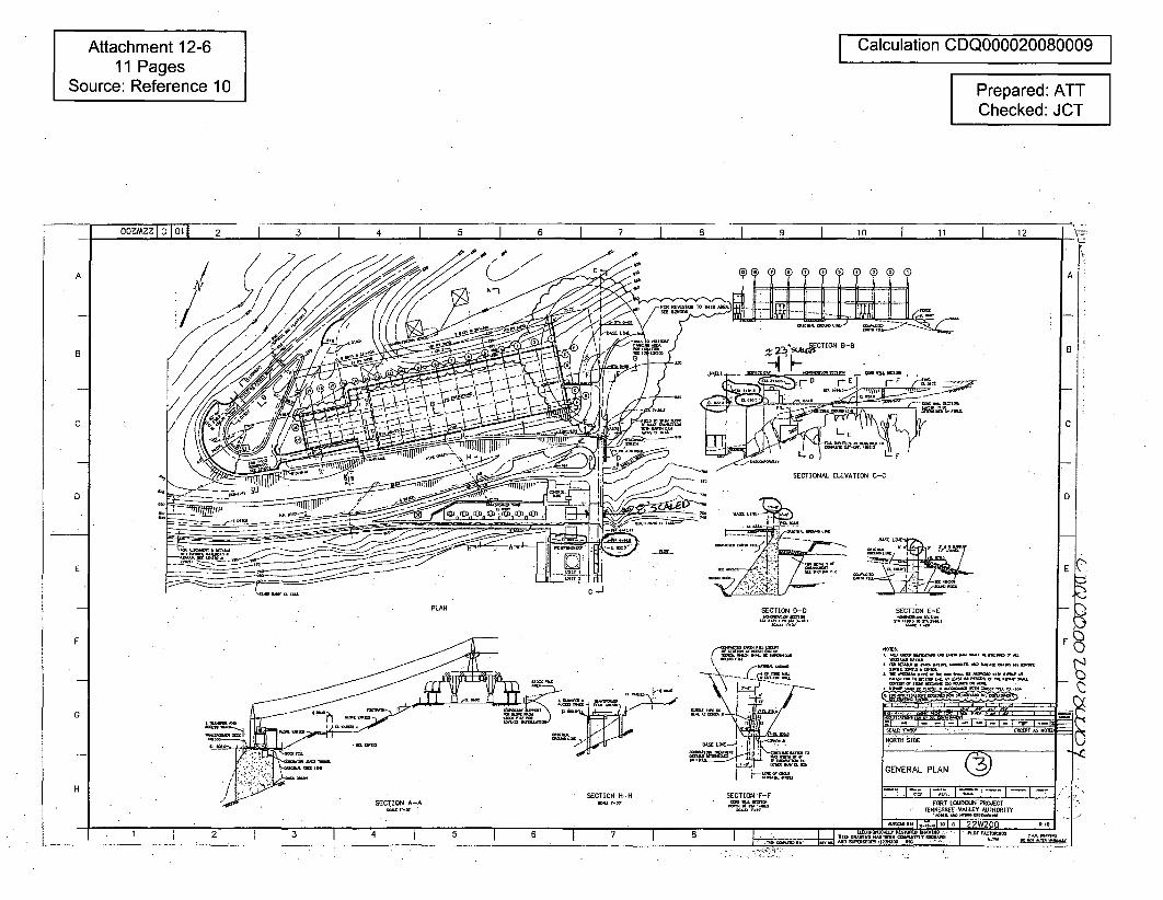
Attachment 12-611 Pages
Source: Reference 10
Calculation CDQ000020080009
Prepared: ATTChecked: JCT
OzMzz 10 10I f 3 4 1 5 1 7 I 8 1 9 I 10 I 11 1 12
C
5 - lins ~ ~ S WCTIDN B B
- ..
SECTIONAL ELEVATION C-C
- 9T -_
_ _ _ _ 1ý;C
B
A
D D
E E
PLAN SECTION S-S SECTION E-C
F F C00
G
SECTION F-F
ý, ,. ,,
Bins? ism .iES is s~Fm This(o jiisikistii~T l~ kktinTist FA. miIuiNd
TFs
o5iscsoooTpsknqcm~slis9sT
inTiflr-m SkwTOsssOTTj~~~%
GENERAL PLAN
7-7 j.7,. I-1 • I-"I-' "FORT LOUDOUN PROECT
TENNESSEE VALLEY AUTHORITY
-kfisk-
HSECTION H-H
SECTION A-A.w "n
-~~~ I li
, 12 3 4 i i i i8---~---..---i---.Ti OTTO55S0 UFOTTfiTsr
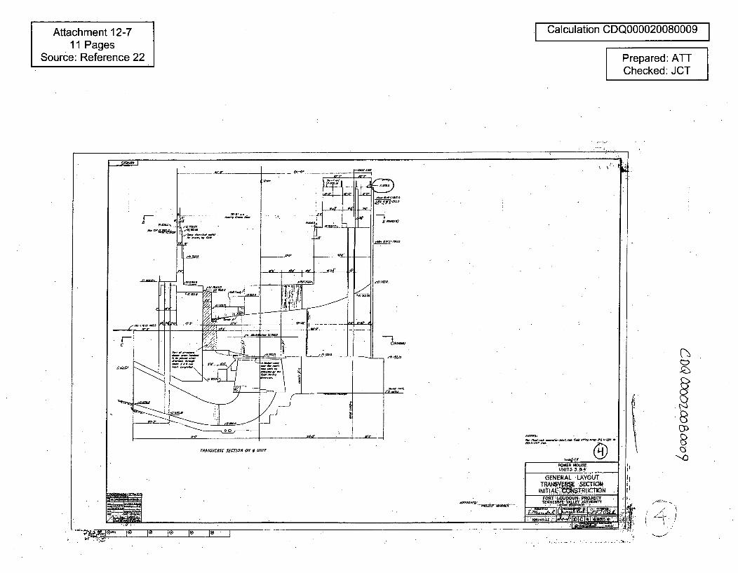
Attachment 12-711 Pages
Source: Reference 22
I Calculation CDQ000020080009 I
Prepared: ATTChecked: JCT
h'-4
•-'.z
_ Ni4 I)
"-,0I
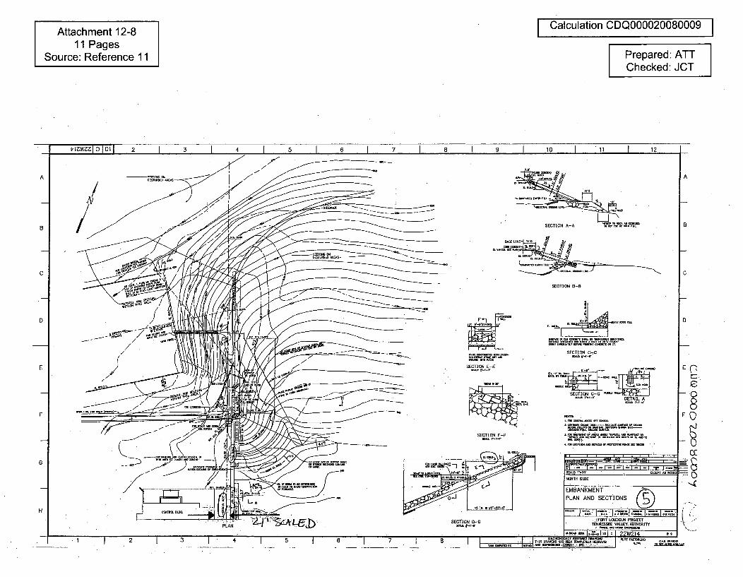
Attachment 12-811 Pages
Source: Reference 11
Calculation CDQ000020080009
Prepared: ATTChecked: JCT
I 12
ZA o•,iL• - (
HF
* • As.,i
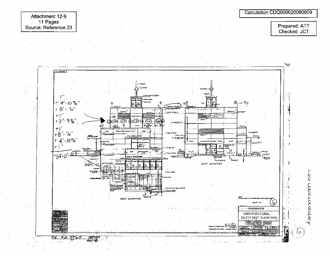
Attachment 12-911 Pages
Source: Reference 23
I Calculation CDQ000020080009 I
Prepared: ATTChecked: JCT
S.OtN.*
FI-"-9
4- 0 4"a, 0I-'
1- '- --
T/4"
, -_ d - • _ "' 4.'-• .-- ,-,
Oil ;'• - , - = • -
•~ ~~~~ a-......:•• •
- _:-. -_• -. 7 7, 7 1 .¢
,I
I- ' •"-3Flll•-] J i:EZ"I:- a
EAST ELEVATION
•m -- I -
WEST ELEVATION
ARCI-IITECTUR.ALEfST & WEST ELEVATIONS
""FORT LOUDOUN PROJECT
RsoCs~t -I i A 4 402 0
!I-
iIj ,
I4-l. lI 'V 1r2.- Ia 1anr.s1-i•, I f,,i,-
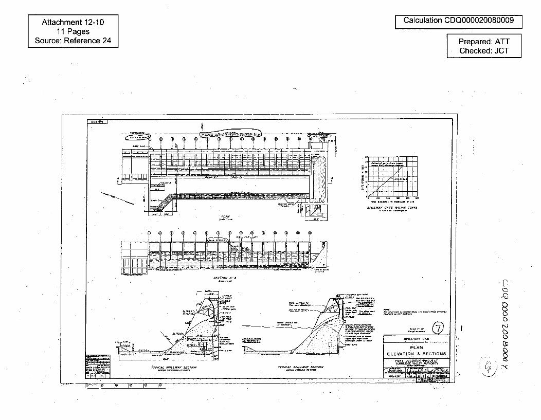
Attachment 12-1011 Pages
Source: Reference 24
Calculation CDQ000020080009I
Prepared: ATTChecked: JCT
JQ
K".
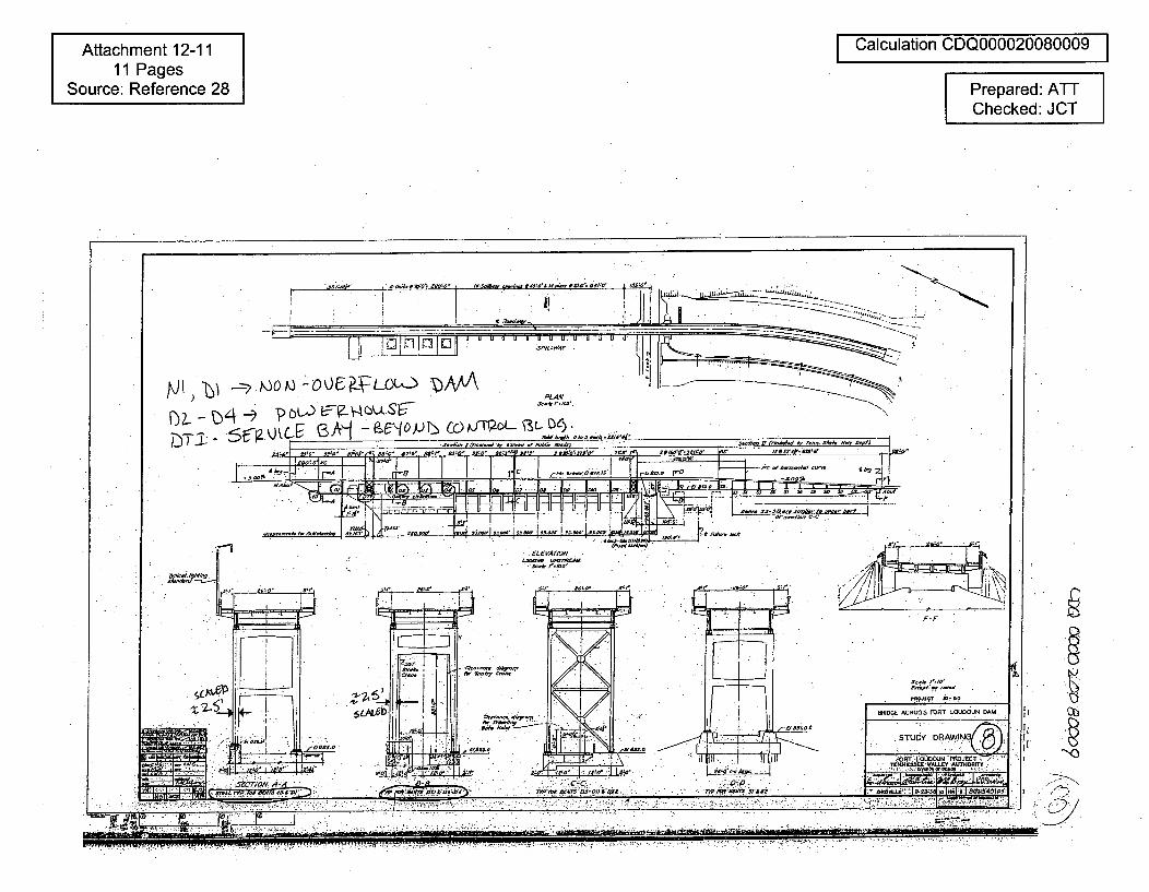
Attachment 12-1111 Pages
Source: Reference 28
Calculation CDQ000020080009
Prepared: ATTChecked: JCT
PLAN
D2. - 'b-4 LtU b---j_ o I t2 .. " t" -,
-- ~ ~ ~ N zmýo1. I1 0~--• IAM R II "f "" -- I
.. .. ~~ ~. .: . . . .,,,,:• .
CoatiVstAM&
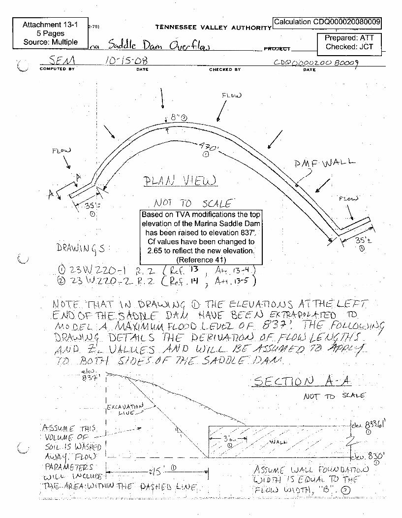
Attachment 13-15 Pages
Source: Multiple. S .J I )
S/FAA D SD
Calculation CDQ0000200800091TENNESSEE VALLEY AUTHORITY1 D•
Prepared: ATTI e,41-1, c •,<Cx4IO- Checked: JCT
G~Uc zj•oo 7_o0aoo •
(f-l)ýn6oozoo Booo9COMPUTED BY DATE CHECKED BY DATE I
8' /
T-J\) A\JWA
Based on TVA modifications the topelevation of the Marina Saddle Damhas been raised to elevation 837'.
.AW.. ( _ Cf values have been changed to2.65 to reflect the new elevation.
(Reference 41)
(@ -_ I'-L02 R.2- 13 4 t 13-5,
I~~~i07EIM ThA\T U~ A&Jk-n~ o~j 17L~U.p S AkTh(E._L LPTY
... A ..AA W... ...- F -0 L C T 7 - ,
0 ,4 S 704- 0}P,' c 2 U. , P1V) 6F 4,
~ ~ <~I~ ./41/ 8,< C,4 -Qjg I-4, 4
.ejpo . ,
.S~CTThfJ ,4-ANOT IbTT SokL&C
. L_ • A •
-...--. F-7 I0 0"
PA.... A, M. TcA,0 7~P :Lýý
(D)
A~~L'AA6 u J-7 T.H~L*U~rj
... ..... ....... .... >JL
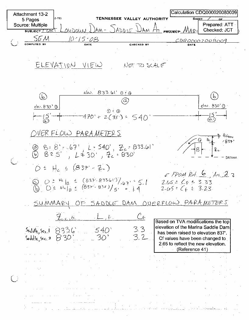
Attachmer5 Pag
Source: MSu8J
it 13-2 ICalculation CDQ0000200800091es 2-78) TENNESSEE VALLEY AUTHORITY SHEET / F
ECA Checked: JCT
J cl-/v /V I"j / D "O,• 0(1-5 D Cn 7 0 o ,Co oo9COMPUTED BY DATE CHECKED BY DATE
. f
EL: VA-7\% 0 J 0(71T '77-' ZCA
cko,
•tJi•FLOU)~ PA-eA/P CJ-",/LP. S
]c
€\eJ. 52o> 3b
'-- -- DATLAW\.0 S
@~t
(~r~jt 40, ~c~: S3.3'LOI
(9) IA~j
(9 ~ A-YJ~L (57:'- 3z.(•")/ •
,
r 15-ý (O- .- (0•
Re-
3
5U /\AAAr 4Lu~A~DL~L&- P-A5
E., c,- -i..
W61-(r.kC7'ýQ 3D'
3.3Based on TVA modifications the topelevation of the Marina Saddle Damhas been raised to elevation 837'.Cf values have been changed to2.65 to reflect the new elevation.
(Reference 41)
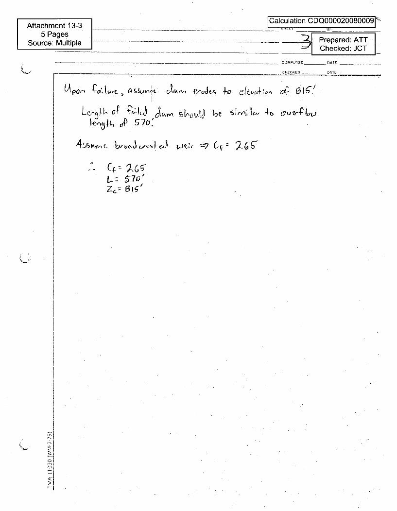
Attachment 13-35 Pages
Source: Multiple
ICalculation CDQ0000200800091
-___ Prepared: ATT..__ Checked: JCT
COMPUTED _ DATE
CHECKED DATE
.'. C•z U).Gc
LV 570'z&" 6Ig'
In
5.
C
a

Attachment 13-45 Pages
Source: Reference 13
Calculation CDQ000020080009
Prepared: ATTChecked: JCT
I-OEzmc Ij IOL 1 2 1 3 I 4 I 5 I 6 1 7 I B 10 I 11 I 12-I
L = -150' •~o'-t - 1-'•A
B
#/)a orE DK-{A77qW6 Tb P L
A)DIrCA-f7AJj T74A '
,C0T~,_ SLLk pe
- K~Ey PLAI
n 5l
B
A
C
D
=4 mnnn1 prn"-
E
F
C
G
HDI~CIl-El
SALIjO ~IAIIAT14Eg111 SInE
Al-Al at-B1
No.m sIE .. .SADI ADAM AT MJARINA
CONCRETEINCREASINGIHEIGHT OF DAM (jJPLAN, I AND ELEVATIONS.
FORT L=OUN PROJKET
, . 0-0 23W220-1
H
-4. UI 1 I 2 3 40 6 7 8 (000n0
/1
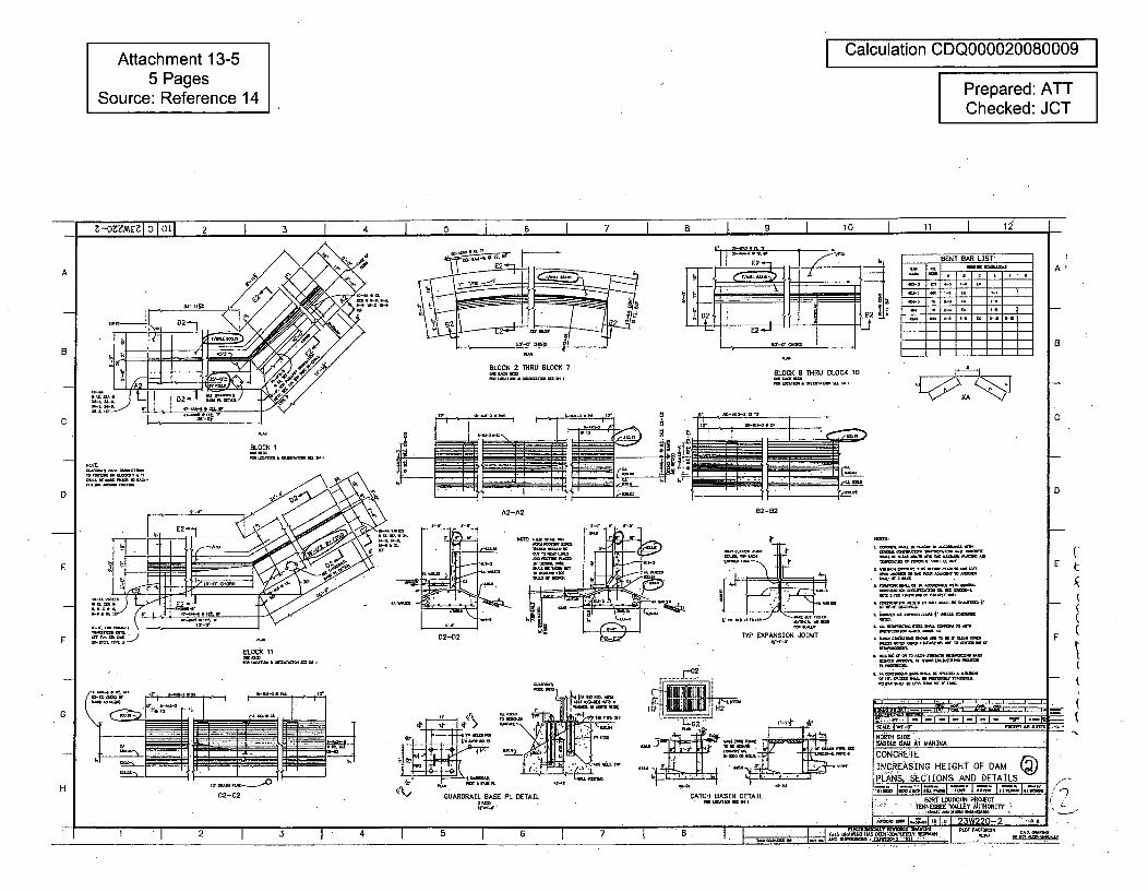
Attachment 13-55 Pages
Source: Reference 14
I Calculation CDQ000020080009I
Prepared: ATTChecked: JCT
7 I A I U I 10 I 11 I 12"Z-n'z'ztmc 0 01 1 •tI I I +t I i
-I-,'--- I I~ I~ I I - I-
A
5L0.2( 2 THRU BLOCK 7
BENT BAR LIST
- ar 7 -7
A
a
BLOCK 8 IHRU BLOCK 10
C ,r 12~z' C
BLOCK If
D D
A2 B2-B2
E
FBLOCK 11
r-7I
D2-D2 ~TYP EXPNSIN JOINT
----. -J--- - -
Al GUARDRAIL BASE PL DERAIL CATCH BASIN DETAIL
* mS..SSS.SSSrSIISSS.uSSeinI
E
F
- N
G
C2-C2
• +
SADDI.E DAl AT MARINIAj
CONCRETEINCREASING HEIGHT OF DAMPLANS, SECTIONS AND DETAILS
FORT LOUDON pROECTTENNESSM VALL.Y AU4DO'lY
H
SE-S-i
I +-zl•WrJ'•l'•__• + +.o e_____________ 6-6~
5
1- 2-m 31 4 8 C
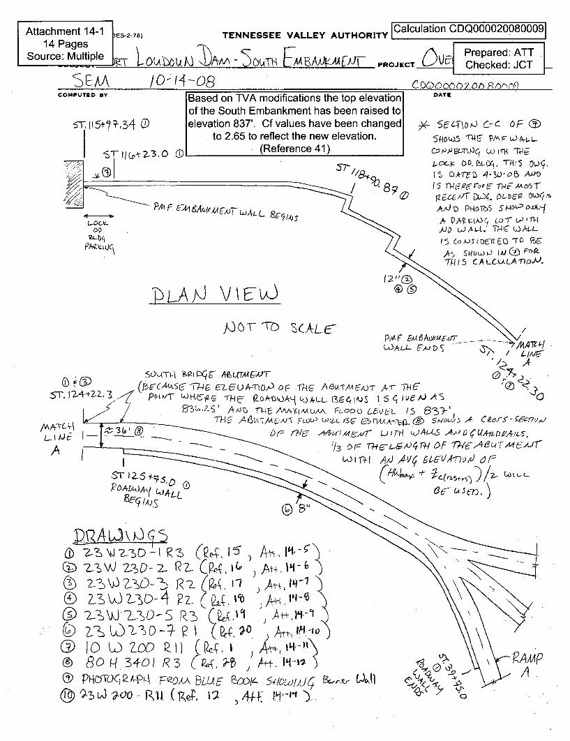
TENNESSEE VALLEY AUTHORITY lCalculation CDQ0000200800091Prepared: ATT
PROJECT O C Checked: JCT
35CAmDATECOMPUTED BY Based on TVA modificat
of the South Embankme5T 115+,34 (D elevation 837'. Cf
to 2.65 to reti
'C1T/c 0t2-3.O (D (Re
o7
ThLAJJ V\iJ
valueect thferen
ions the top elevationnt has been raised tos have been changede new elevation.ce 41)
DATIE
)v_ 5 Ci , -c F (a)
co/jJIug-Ru.q WinR 7m4&Loc--4' O, .L yI, T-h5 1 O
18' D.T-CD -4-30-0e) A-•S-7
0 PE661fF lUoq. -D m-36O1--, ,-.,aD PROTh5 5WL-0AoX•q
AAJ PT? S9rOt ,) c 0 1 d j-APA? LýAALI THC w A-L.f-
./D U)AL-t 1 ThuA) DF0
Th.?5 CALCu'LAfn(lJ-
PAAF EmAvr~c--AJr_WIAL1L F- /D
€4
,%
ý))-A ý,J E7 ýA2
13 0 T-7
'iýL>.[-v'. AD. t rri J r-1)-t-
L
ST.~?4 2-ZZ.4(cA&E~-r LEuA-MTO6) or- ThýG /CJ- A31-AA1-A)- 4-mcST.P 'j TI WR T(5RE tO)A-e JAL fJ,4AJS I IC4 ~~ J
~3(o,-~~ g~ -m A A~jbXFL-OOD LeVC-t 15S3-MC-- /4&AA-U-v5 FLOU'L - ,AAA-yF>,(A Fsoi0 c•Fl - , C
7& (7-T A 7,mo 16f6I, LJ,-I( 4-A•) - D-- ---- -
1/ o~r- O~A~l F flI->"L-M J-r
R)ADL.JA,( CK41LýCCLc
L 80 U 342- R3 ( , At + .--2-ý) V3 J -L:ý)0 S• R I L9. , •,- h "o PnOT) krý4 n1o/J -10 ~~ ~
........I
,J
U 5 -
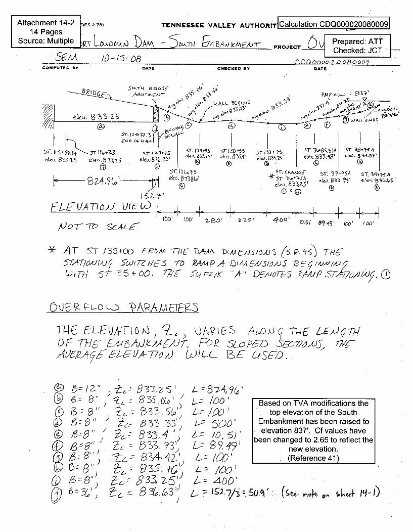
Attachment 14-2 ES.2-78)
14 PagesSource: Multiple ~ ~~bA
TENNESSEE VALLEY AUTHORIT Calculation CDQ000020080009
'5L-( &Lq S~i B,4Ej PF/
ID-fPROJECT Prepared: ATT
Checked: JCT
CD~6ooo 2xoo00DoTDATEICOMPUTED BY DATE CHECKED BY
SILI-FH 1321CCuA&vr(ýM RV
Yr. s 3 . 1 " t•-2 3 U) A
ST Im St~ 12'#S.R3,1 z ' ' e8e4 833,2S'
e~c• 33. -5 0o, g 3,•5 leo.8 eo p338W
r13D 4-55 5-r 13It +-5 s5 3(MM,$1A ST 3a3-5 Aeko. 8'3,A' eo.2,33.'•€ eo. •333,41• eo33, '
, CRAAJ,•K ST. 3-t'SA ST, S47 5A
ekeo. P33.75'
EL EiLATTJo vU1
•.?'ý
.L-- -I- -I- I , - L . i I. I _ I II- W i I,- -2-o B 2-0' -r '- 7z0, "T- , o I -1I I- -Ir4 0 o,1' ' 994' Jo0 /,%)'
J I
/00T- -72-) ScAtL4-
*AT 'T Iý)/3 54cxc F~MT-96 LAAA Dim E,51AY3/O (5IPJ' S 77/65-1;47?o01U A) 5WI77ZAA--5 7-D R4/MP, LW•xa51Lzt,/ )S • ,.JJ
0ioc 7/ E~7 'A-' D~~T+ ARAAi JF276Pdj
TN C 5LEVAThO6) 2C) ODMAFk-S ( Th /-&(7DF THEs AJcS3JF, LOP&/I- )~62
A 2-a',4-7(7ý --- A7o), WILL- E7 (C()
C9CI
~5z /
,)
,1 567
• ,33 ,
ý? 3 , >5'6g.3-, -S))
3Y (o 3'I)
3Based on TVA modifications the
. /60 Basedontop elevation of the South
. '_ Embankment has been raised toelevation 837'. Cf values have
been changed to 2.65 to reflect thenew elevation.
Z /---) ' (Reference 41)
Z= l400'20.= 4qO'
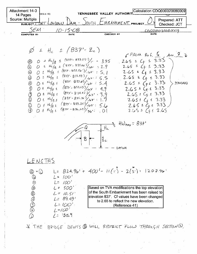
Attachment 14-3 Calcu AUTHORIT ulation CDQ00002008000914 Pages ES-2-78) TENNESSEE VALLEY AT_
Source: Multiple - V T- Prepared: ATTSUBJECrT -LI•XA 0 A-- ,OOTM.1 PROJCT- Checked: JCT P-
(A4 SCQT-&)A EM 64)Ol ChckedS9C-- f -- " -- •. . .. I
COMPUTED BY DATE CHECKED BY DATE
g ~3?'- If)
0
0
D0
L
L
L
t
L
I
L
C (,37-- 8.. &)/,/ -,,
ý ( 3~ 3 3, /Di' -
(34,/ ( &3ý'- 83 4 v) 7 3,
(8 3( ,(& SY
-7/5./
ol
2,45 • Cf--
Z,4 S . C '
2,(sA - C_Z.1 f2-, 6 f (i-A~2 G5D~~c~~
3,'333. 3:5133
'3333.J33
(R.?/t F12o G, ( - 3,3%
z~u¢C-F •!i '3,33
)
-L -
- - DP~UM
L.-. T h S
0
Cj)
L= 82-4%'L= 1b-C)'L= /00'L- 5,00'
t7 89,/91
6-l. !-I0O
+- 400r_ ]• (,") - ( '
Based on TVA modifications the. top elevationof the South Embankment has been raised toelevation 837'. Cf values have been changed
to 2.65 to reflect the new elevation.(Reference 41)
TH ' &QE T-5•-j-.Si ( WILu t2&L1aSur • c M 774-oc/-/ ý-77,,I--.
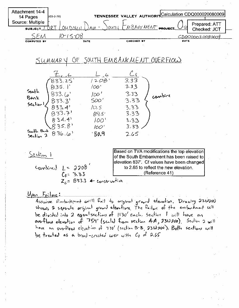
Attachment 14-4 _____________________________14 Pages ES-2-78) TENNESSEE VALLEY AUTHORICalculation CDQ000020080009I
Source: Multiple - Prepared: ATTSUBJECT I 0ET ) QU,•O, bA - •OUTh{ -/FSJ(e)A{{/,T ' Checked: JCT
E AAecked: JCT .
COMPUTED BY DATE CHECKED DY DATE
~d~AA~APOFE,ý 0 UTH A6A AV /Q ý kF OuR E1ocJ
ý35. I3( 33, 3o'rS3,• %, 3'.
82,4,41•
I), S
3,33
3,33313
3,233
3, 22
"2, 6,S
Based on TVA modifications the top elevationof the South Embankment has been raised toelevation 837'. Cf values have been changed
to 2.65 to reflect the new elevation.(Reference 41)
~OfA Elk
c 7 IZ6.= 0S33 A,+%, \10
6C, :2 eQ~ej -1,'0e13 'It 1130/ e-,"CL, %eJIh1 11 kav an( -&~, ~-
cvv~j-c' (9ScK3 ýr 5cj,.v 4-A.) 93U;0)PO), %'~2~
ýc~~reAC' " q c ov-crce3W eJ j ~ft, Cp o-ý g,6•
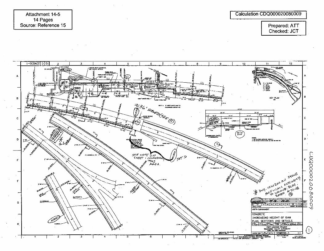
Attachment 14-514 Pages
Source: Reference 15
I Calculation CDQ000020080009 IPrepared: ATTChecked: JCT
L-OsMi D I OL] 2 1 3 1 4 I 5 1 6 1 7 1 a 1 9 10 1 11 12-I
A
a
C
D
_ 7
- 4----- .------- ----S-..-4--- .I-- m
74 4
tcr E8N
CONRETCNRAI
PLAN SE
KEY P
C
B
A
E
F
EC)
0F
7-
G -I-I-I-I-I-I "U" I--i'
PENT
NG HEIGHT OF DAM
TIONS AND DETAILS
FORT LOUDOUN PROJCTENNESSý VALEY AUT1OSITY
H
[-I c 1 23W230-1 R3
L
2t 3550 4 5 6A 7: 0
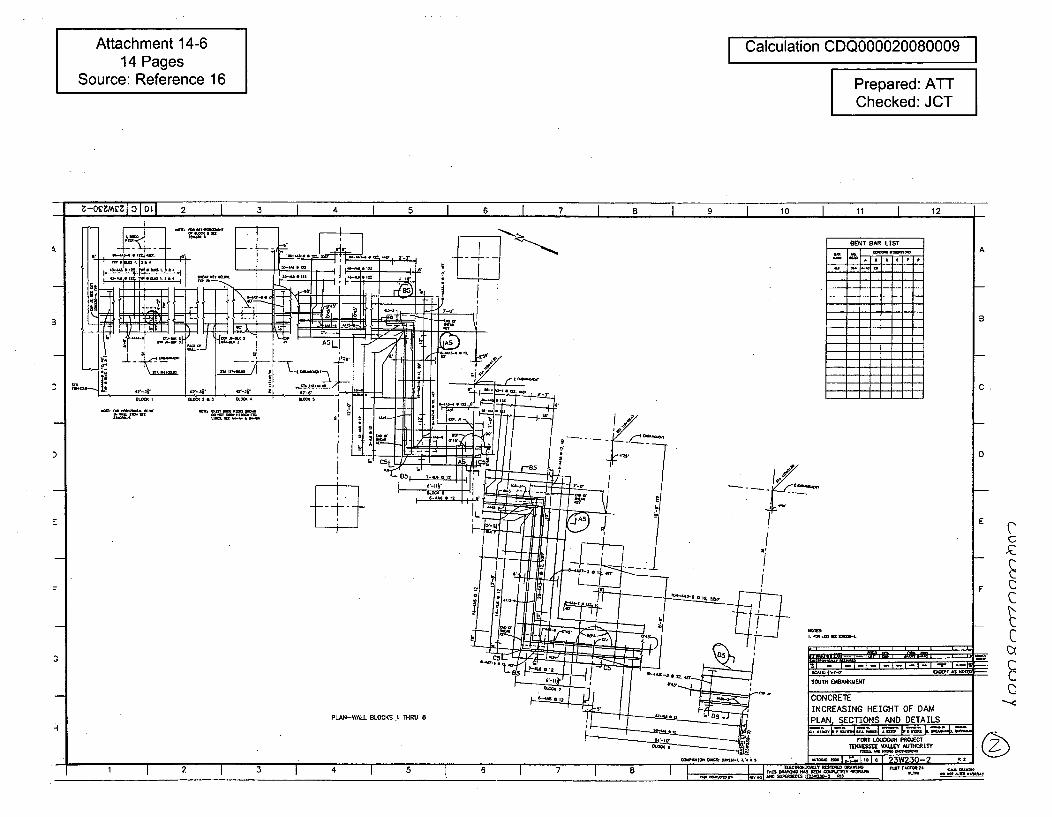
Attachment 14-614 Pages
Source: Reference 16
Calculation CDQ000020080009
Prepared: ATTChecked: JCT
J Z-o0VCZI 0-1 2 3 5 6 7 8 9 10 11 12
V
,-t n~
SE:NT BAR LIST
/ -
B
C
A
D
E
C
C
SOUT EMBARKMENI -
SOUTH EMBM4UWENT
D
CCCONCRETEINCREASING HEIGHT OF DAMPLAN. SECTIONS AND DETAILSPLAN-WALL BLOCKS .1 THRU 8
-1 Z =11- I _-Y, 6 mi4FORT LOUDOIJN PROJECT
7EtU0Sj1VALLEY AIDhRITY
I "rJ "4 IM "J •lt•l I •7 R•
1. 2 3 8 5_7_ _2
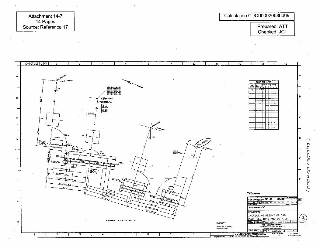
Attachment 14-714 Pages
Source: Reference 17
Calculation CDQ000020080009
Prepared: ATTChecked: JCT
C-O M IoCZ LI 2 I 3 I 4 I I I 7 I 8 1 9 I 10 I 11 1 12
AA
B
SENT BAR LIST
7I,€l' ,I
B
C C
D
E I
D
E
FF
- ,...,..I.1..I I--I,GSCSI. I - -c CXCuT AS SAS =SOUTH ElaBMOIENT
CONCRETEINCREASING HEIGHT OF DAMPLAN. SECTIONS AND DETAILS
HFORT ICUDOUN PROJECT
TENNES!IE VALLEY AU110RITY
rnonsaIa.~IzIcI 95W2~fl-3 liz1 4 ..... 3~..
1 2 3 4 5 6 7 8 - 21Oi. . . ..
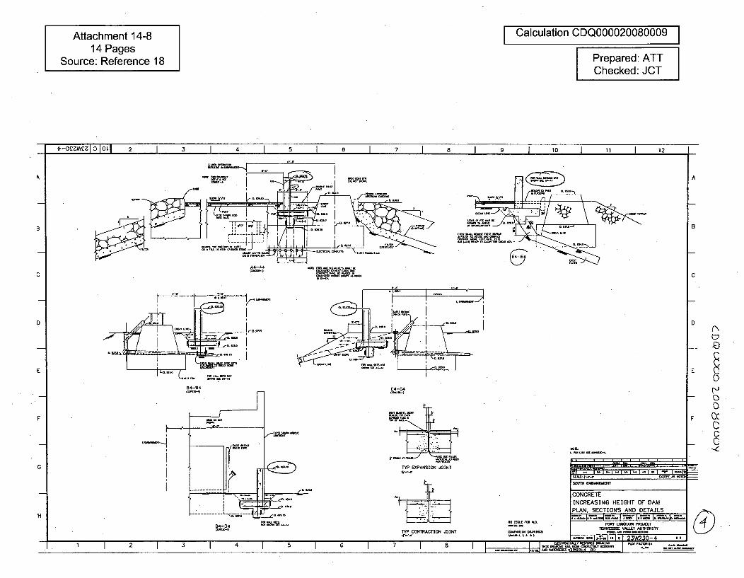
Attachment 14-814 Pages
Source: Reference 18
Calculation CDQ000020080009
Prepared: ATTChecked: JCT
t-oMel 0 I ot1 2 1 3 I 4 I 5 I 6 I 7 I 8 I 9 I 10 1 11 I 12~1 .4.-
A
B
A4-A4 ,
D
84-84 C4-C4•b•- -1
E
C
EI(N
F ccCC
- C
F
TYP EXPANSION JOINT'P.-I
L u•
G
SOUTiH MBANKMENT
CONCRETE
INCREASING HEIGHT OF DAMPLAN. SECTIONS AND DETAILS
H
04-04P-c-,)
FORT LOUDULM PROJECT10800500VMJE U49
,ayni,~0l~o~I 93~3fl4 R2TYP CONTRACTION JOINTW-.,--
-41 I 2 I 3 4 5 6 7 a I , ,
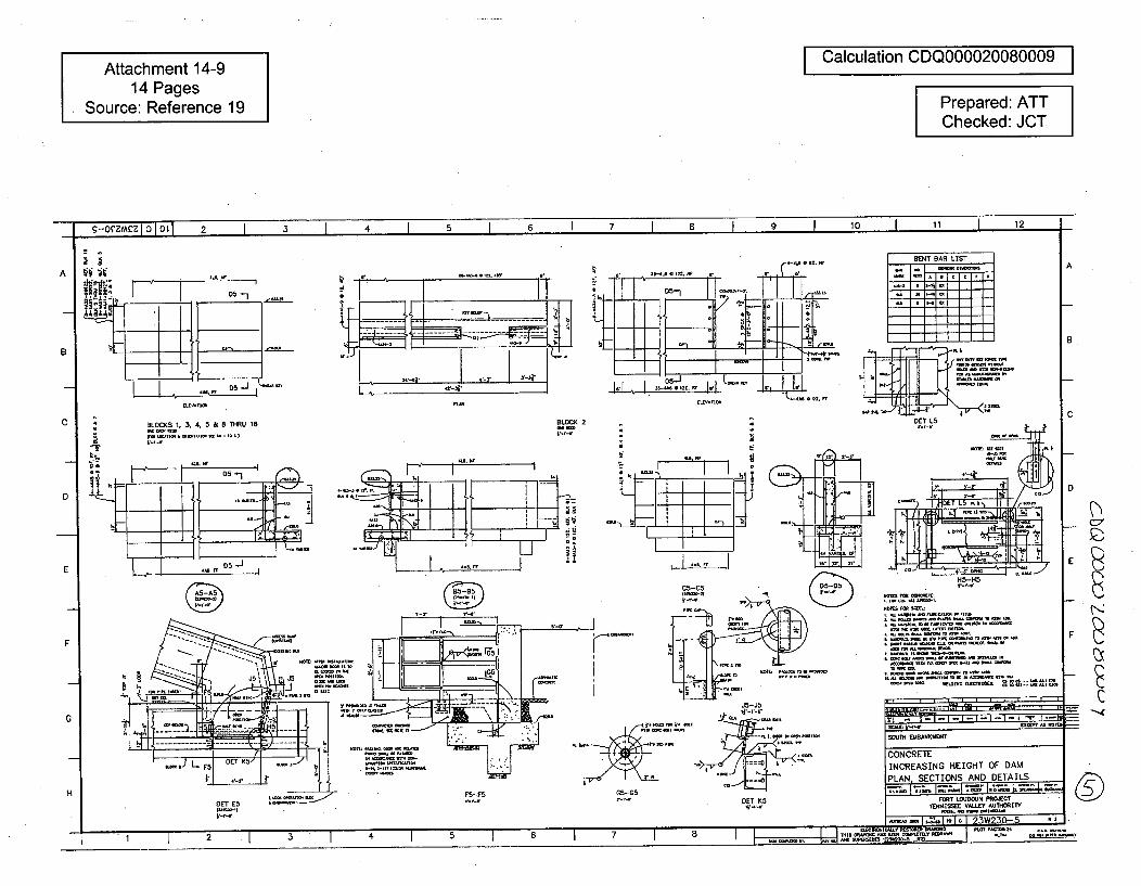
Attachment 14-914 Pages
Source: Reference 19
Calculation CDQ000020080009
Prepared: ATTChecked: JCT
I - I I I I I II "1 I •[ I I
b~MM1.M1IMIj L I I I -, I . I -
AA
B
C-4S.
0*
BLOCKS 1. 3, 4, 5 & B THRU 16
(IM C- OIMI' M TM
BLOCK 2
iI.. 14
-, b=•
" +"' 8f
EI.•ATI•'I
C
D
E
F
G
G5 GS i°s=p
JA-j5
DET K5l*r,-,,
I MM~MC MIC ic rMOm P01 DMSM 10MM t
- it M ,M M ] Pi SW i i i i
S =,T8E•ANKM'ENT
CONCRETEINCREASING HEIGHT OF DAM
P MLAN. MECTIIIO AND. DETAILS
FORT LOUDOUJN PROJECT"OU rh EMBXI1EV TRIM"Y
MIMMI IMM,,I 23W230,5 M IMO
DEiFL -
HDET E5
2 2 3 4 5 6 7 8 .J .. hSoorol~ MMIMMMTIVoo . C-
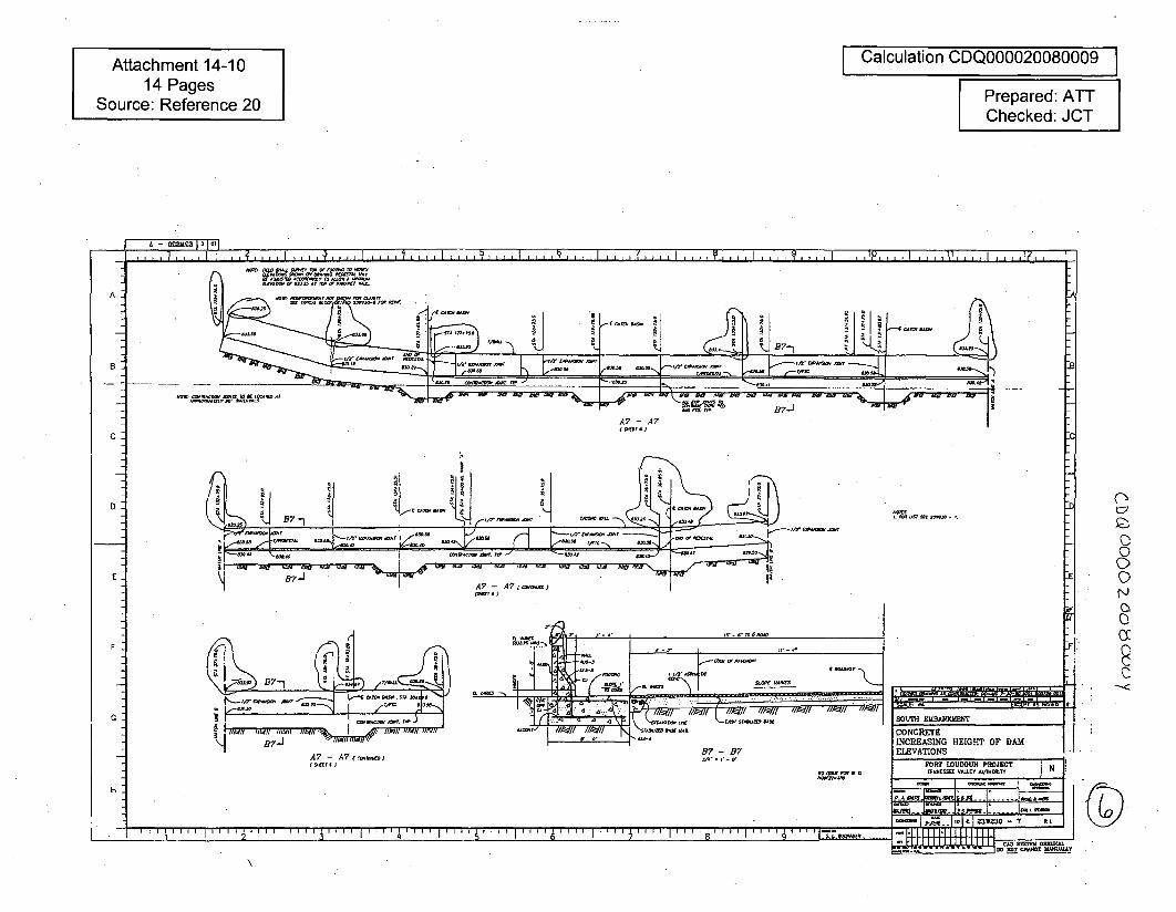
Attachment 14-1014 Pages
Source: Reference 20
Calculation CDQ000020080009 I
Prepared: ATTChecked: JCT
I I, I I V . , , 1 1 ,
ýA
D:D
0
0
N
0
SOUTH EMBANKMWENT
CONCRETEINCREASING HEIGHT OF DAMELEVATIONS
FORT tOUDOUN PROJECT
......0
0~OQ I C5W30 -7 RD
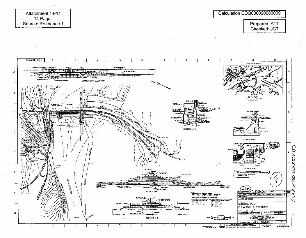
Attachment 14-1114 Pages
Source: Reference 1
Calculation CDQ000020080009
Prepared: ATTChecked: JCT
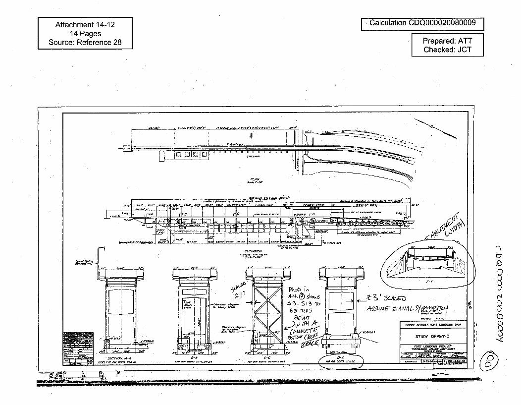
Attachment 14-1214 Pages
Source: Reference 28
Calculation CDQ000020080009
Prepared: ATTChecked: JCT
N
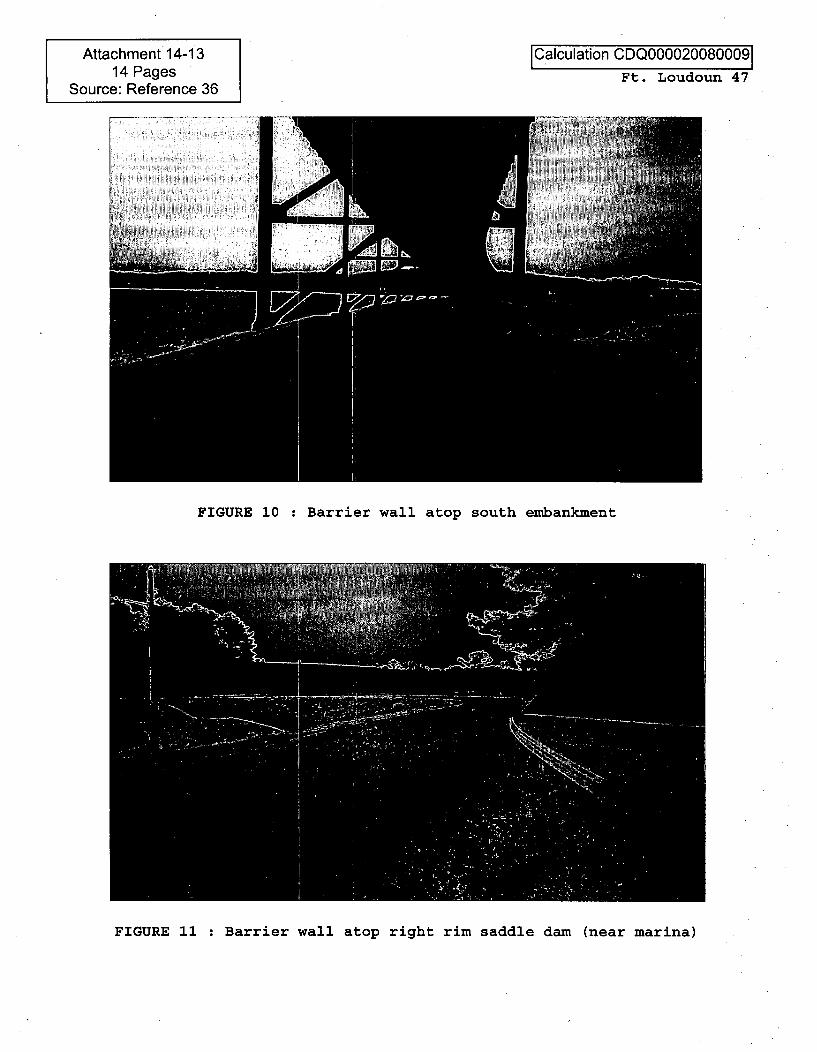
Attachment 14-1314 Pages
Source: Reference 36
ICalculation CDQ000020080009Ft. Loudoun 47
FIGURE 10 : Barrier wall atop south embankment
FIGURE 11 : Barrier wall atop right rim saddle dam (near marina)

Attachment 14-1414 Pages
Source: Reference 12
Calculation CDQ000020080009
Prepared: ATTChecked: JCT
OOZt.Wi1L 1OLI1 2 3 I 4 1 5 I 6 I 7 I a 1 9 1 10 I 11 I 12-I 0~
A
DETAIL X DETAIL C
P .LA N , LAN
• - - ,s~- SECTION H-H PLAN
A
BB
C C
0)
DETAIL H
EPROFILE On TOE DRAIN
SECTOR 0-0DETAE
EI. Di. DIOADA OR TilOsit STICTA&T MACCAL STIlL Di
flOS CDI TIE DAT5TIJ. mAID atat 550 DC &CAIDTEDRITO CUt STaiws is PLATO gUSTO DL
t DC IsCATIOS C TM MD P DID-CT COLDS AT SD'. SIAMMAY Di CAJAUD gist isi i5 DAT ALDAA. CUICTOID CASTODmA OCUTTOTO V DIE WIElD ID CDW.
tim SIDLE. K am DIDIE DC TM M ATAWs C. CT 2555 TCCIJ wan-at Ma at #5055AS ACTATC CT DC CC5A CMI C STOITTOAC
* AT LEAST TOPS CUT N DIE CADS? SIAM. TCISSE sI STICtS
A. LPTTTDAA Dat - NA TUACS ES* osatisCa Sm BassO, in-as PASTIES UT mATIATIE #555504 Data ASSIst
A. TO? MDI OTTOASAE. TACCID AAD Alt ADDS TM TOTAlSCE CADDIE 5)1251. Ci, STAt CD
S ECO 5DM LAID DC spa, ant a DLIEI ART TM iCECTEDT ST*DCD AM TTWE MEADAITD aCID BADE LINE.
2SSIADa.DLL V DATiwEL
GSilaD -I i TrmA. AS. ..
SOUTH! UMA IIIMDIT
PLAN, SECTIONS & DETAILS
FORT LOUGU HDERJ aC PROJECT1OTENNEE VALLEY AUTHORIUTY
H
-4 I I -I 2 .I ,1 1 4 I 5 1 6 1 8 I 1= TD* Di 55 .. ,I AID MAEAU ESAIIADI TIlT)
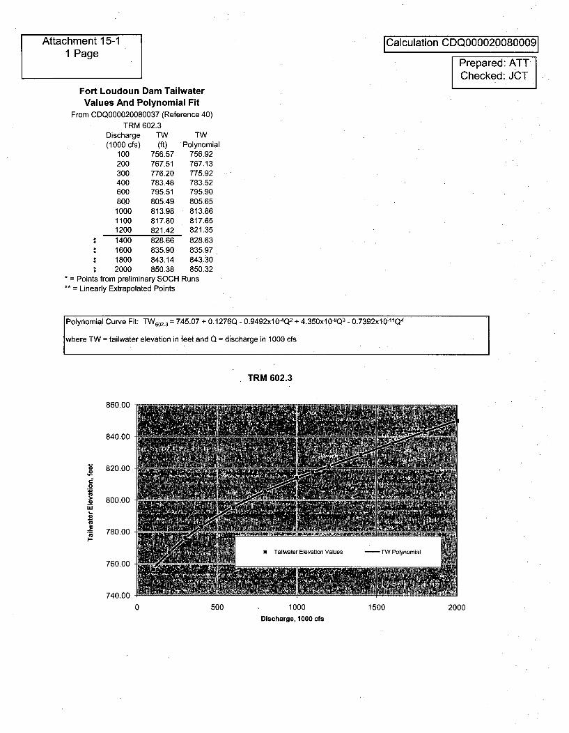
ýchment 15-1 ICalculation CDQ00002008000911 Page Prepared: ATT
Checked: JCT
Fort Loudoun Dam TaliwaterValues And Polynomial Fit
From CDQ000020080037 (Reference 40)
TRM 602.3Discharge TW TW(1000 cfs) (ft) Polynomial
100 756.57 756.92200 767.51 767.13300 776.20 775.92400 783.48 783.52600 795.51 795.90800 805.49 805.651000 813.98 813.861100 817.80 817.651200 821.42 821.35
• 1400 828.66 828.63• 1600 835.90 835.97; 1800 843.14 843.30• 2000 850.38 850.32
= Points from preliminary SOCH Runs•* = Linearly Extrapolated Points
Polynomial Curve Fit: TW 602.3 = 745.07 + 0.1276Q - 0.9492x10⁴Q2 + 4.350x10⁻⁸ Q3 - 0.7392x10- 11 Q 4
where TW = tailwater elevation in feet and Q = discharge in 1000 cfs
TRM 602.3
860.00
840.00 P
820.00
.2 j "
> 800.00
'U
. 780.00I--
-6 Tailwater Elevation Values TW Polynomial
760.00
740.00 5101000 500 1000 1500 2000
Discharge, 1000 cfs
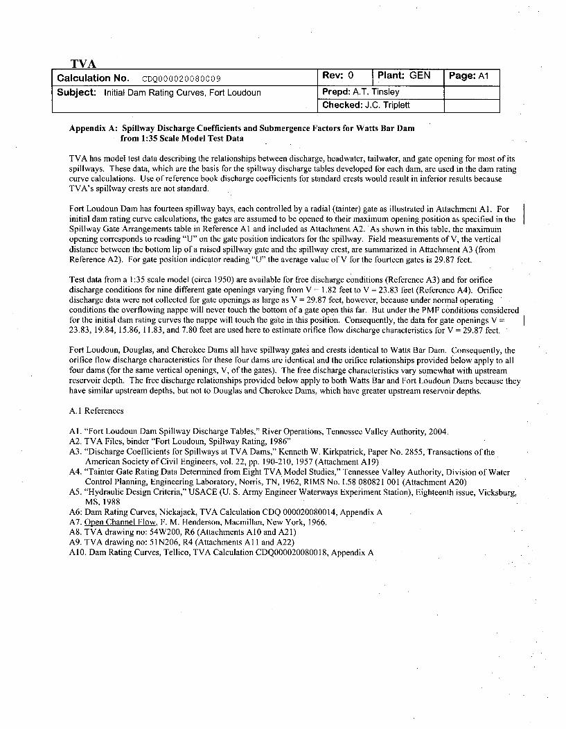
TVACalculation No. CDQ000020080009 Rev: 0 Plant: GEN Page: AlSubject: Initial Dam Rating Curves, Fort Loudoun Prepd: A.T. Tinsley
Checked: J.C. Triplett
Appendix A: Spillway Discharge Coefficients and Submergence Factors for Watts Bar Damfrom 1:35 Scale Model Test Data
TVA has model test data describing the relationships between discharge, headwater, tailwater, and gate opening for most of itsspillways. These data, which are the basis for the spillway discharge tables developed for each dam, are used in the dam ratingcurve calculations. Use of reference book discharge coefficients for standard crests would result in inferior results becauseTVA's spillway crests are not standard.
Fort Loudoun Dam has fourteen spillway bays, each controlled by a radial (tainter) gate as illustrated in Attachment Al. Forinitial dam rating curve calculations, the gates are assumed to be opened to their maximum opening position as specified in theSpillway Gate Arrangements table in Reference Al and included as Attachment A2. As shown in this table, the maximumopening corresponds to reading "U" on the gate position indicators for the spillway. Field measurements of V, the verticaldistance between the bottom lip of a raised spillway gate and the spillway crest, are summarized in Attachment A3 (fromReference A2). For gate position indicator reading "U" the average value of V for the fourteen gates is 29.87 feet.
Test data from a 1:35 scale model (circa 1950) are available for free discharge conditions (Reference A3) and for orificedischarge conditions for nine different gate openings varying from V =1.82 feet to V = 23.83 feet (Reference A4). Orificedischarge data were not collected for gate openings as large as V = 29.87 feet, however, because under normal operatingconditions the overflowing nappe will never touch the bottom of a gate open this far. But under the PMF conditions consideredfor the initial dam rating curves the nappe will touch the gate in this position. Consequently, the data for gate openings V =23.83, 19.84, 15.86, 11.83, and 7.80 feet are used here to estimate orifice flow discharge characteristics for V = 29.87 feet. '
Fort Loudoun, Douglas, and Cherokee Dams all have spillway gates and crests identical to Watts Bar Dam. Consequently, theorifice flow discharge characteristics for these four dams are identical and the orifice relationships provided below apply to allfour dams (for the same vertical openings, V, of the gates). The free discharge characteristics vary somewhat with upstream.reservoir depth. The free discharge relationships provided below apply to both Watts Bar and Fort Loudoun Dams because theyhave similar upstream depths, but not to Douglas and Cherokee Dams, which have greater upstream reservoir depths.
A. 1 References
Al. "Fort Loudoun Dam Spillway Discharge Tables," River Operations, Tennessee Valley Authority, 2004.A2. TVA Files, binder "Fort Loudoun, Spillway Rating, 1986"A3. "Discharge Coefficients for Spillways at TVA Dams," Kenneth W. Kirkpatrick, Paper No. 2855, Transactions of the
American Society of Civil Engineers, vol. 22, pp. 190-210, 1957 (Attachment A19)A4. "Tainter Gate Rating Data Determined from Eight TVA Model Studies," Tennessee Valley Authority, Division of Water
Control Planning, Engineering Laboratory, Norris, TN, 1962, RIMS No. L58 080821 001 (Attachment A20)A5. "Hydraulic Design Criteria," USACE (U. S. Army Engineer Waterways Experiment Station), Eighteenth issue, Vicksburg,
MS, 1988A6: Dam Rating Curves, Nickajack, TVA Calculation CDQ 000020080014, Appendix AA7. Open Channel Flow, F. M. Henderson, Macmillan, New York, 1966.A8. TVA drawing no: 54W200, R6 (Attachments A10 and A21)A9. TVA drawing no: 51N206, R4 (Attachments A11 and A22)A10. Dam Rating Curves, Tellico, TVA Calculation CDQ000020080018, Appendix A
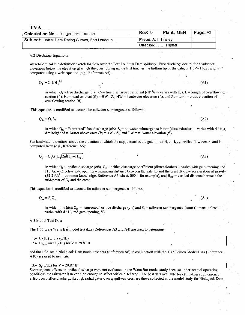
TVACalculation No. CDQ000020080009 Rev: 0 Plant: GEN Page: A2
Subject: Initial Dam Rating Curves, Fort Loudoun Prepd: A.T. TinsleyChecked: J.C. Triplett
A.2 Discharge Equations
Attachment A4 is a definition sketch for flow over the Fort Loudoun Dam spillway. Free discharge occurs for headwaterelevations below the elevation at which the overflowing nappe first touches the bottom lip of the gate, or H. <= HLmin, and iscomputed using a weir equation (e.g., Reference A5):
Qf =CfLHC15 (Al)
in which Qf= free discharge (cfs), Cf = free discharge coefficient ((ft° 51s -- varies with He), L = length of overflowingsection (ft), H, = head on crest (ft) = HW - Zý, HW = headwater elevation (ft), and Z = top, or crest, elevation ofoverflowing section (ft).
This equation is modified to account for tailwater submergence as follows:
QfS =OfSf (A2)
in which Q&. = "corrected" free discharge (cfs), Sf= tailwater submergence factor (dimensionless -- varies with d / HJ),d = height of tailwater above crest (f1) = TW - Z., and TW = tailwater elevation (f1).
For headwater elevations above the elevation at which the nappe touches the gate lip, or H, > HLmin, orifice flow occurs and iscomputed from (e.g., Reference A5):
Qg =CgGnL 2gc-Hmp (A3)
in which Qg = orifice discharge (cfs), Cg = orifice discharge coefficient (dimensionless -- varies with gate opening andHJ), Gn = effective gate opening = minimum distance between the gate lip and the crest (ft), g = acceleration of gravity(32.2 ft/s 2 -- common knowledge, Reference A5, sheet. 000-1 for example), and Hmp = vertical distance between themid-point of Gn and the crest.
This equation is modified to account for tailwater submergence as follows:
Qgs = SgQg (A4)
in which in which Qgs = "corrected" orifice discharge (cfs) and S,= tailwater submergence factor (dimensionless --
varies with d H, and gate opening, V).
A.3 Model Test Data
The 1:35 scale Watts Bar model test data (References A3 and A4) are used to determine
1. CK(HJ) and Sf(d/Hc)2.e HLmin and Cg(Hc) for V = 29.87 ft.
and the 1:35 scale Nickajack Dam model test data (Reference A6) in conjunction with the 1:72 Tellico Model Data (ReferenceA10) are used to estimate
3.0 Sg(d/Hc) for V = 29.87 ftSubmergence effects on orifice discharge were not evaluated in the Watts Bar model study because under normal operatingconditions the tailwater is never high enough to affect orifice, discharge. The best data available for estimating submergenceeffects on orifice discharge through radial gates over a spillway crest are those collected in the model study for Nickajack Dam
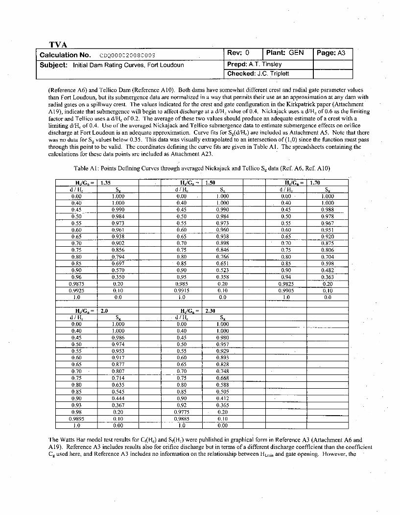
TVACalculation No. CDQ000020080009 Rev: 0 Plant: GEN
Subject: Initial Dam Rating Curves, Fort Loudoun Prepd: A.T. Tinsley
Checked: J.C. Triplett
(Reference A6) and Tellico Dam (Reference A10). Both dams have somewhat different crest and radial gate parameter valuesthan Fort Loudoun, but its submergence data are normalized in a way that permits their use as an approximation at any dam withradial gates on a spillway crest. The values indicated for the crest and gate configuration in the Kirkpatrick paper (AttachmentA 19), indicate that submergence will begin to affect discharge at a d/He value of 0.4. Nickajack uses a d/H, of 0.6 as the limitingfactor and Tellico uses a d/H, of 0.2. The average of these two values should produce an adequate estimate of a crest with alimiting d/H, of 0.4. Use of the averaged Nickajack and Tellico submergence data to estimate submergence effects on orificedischarge at Fort Loudoun is an adequate approximation. Curve fits for Sg(d/Hc) are included as Attachment A5. Note that therewas no data for Sg values below 0.35. This data was visually extrapolated to an intersection of(1,0) since the function must passthrough this point to be valid. The coordinates defining the curve fits are given in Table Al. The spreadsheets containing thecalculations for these data points are included as Attachment A23.
Table Al: Points Defining Curves through averaged Nickajack and Tellico Sg data (Ref. A6, Ref. A10)
H =G,= 1.35 H/G,= 1.50 H =G,= 1.70d / Hc S, d / Hý S, d / H, Sg0.00 1.000 0.00 1.000 0.00 1.0000.40 1.000 0.40 1.000 0.40 1.0000.45 0.990 0.45 0.990 0.45 0.9880.50 0.984 0.50 0.984 0.50 0.9780.55 0.973 0.55 0.973 0.55 0.9670.60 0.961 0.60 0.960 0.60 0.9510.65 0.938 0.65 0.938 0.65 0.9200.70 0.902 0.70 0.898 0.70 0.8750.75 0.856 0.75 0.846 0.75 0.8060.80 0.794 0.80 0.766 0.80 0.7040.85 0.697 0.85 0.651 0.85 0.5980.90 0.570 0.90 0.523 0.90 0.4820.96 0.350 0.95 0.358 0.94 0.363
0.9875 0.20 0.985 0.20 0.9825 0.200.9925 0.10 0.9915 0.10 0.9905 0.10
1.0 0.0 1.0 0.0 1.0 0.0
H,/G= 2.0 H/Gn= 2.30d/H. S, d/Hc S,0.00 1.000 0.00 1.0000.40 1.000 0.40 1.0000.45 0.986 0.45 0.9800.50 0.974 0.50 0.9570.55 0.953 0.55 0.9290.60 0.917 0.60 0.8930.65 0.877 0.65 0.8280.70 0.807 0.70 0.7480.75 0.714 0.75 0.6680.80 0.635 0.80 0.5880.85 0.545 0.85 0.5050.90 0.444 0.90 0.4120.93 0.367 0.92 0.3650.98 0.20 0.9775 0.20
0.9895 0.10 0.9885 0.101.0 0.00 1.0 0.00
The Watts Bar model test results for CK(HC) and Sf(HC) were published in graphical form in Reference A3 (Attachment A6 andA 19). Reference A3 includes results also for orifice discharge but in terms of a different discharge coefficient than the coefficientCg used here, and Reference A3 includes no information on the relationship between Hlrmin and gate opening. However, the
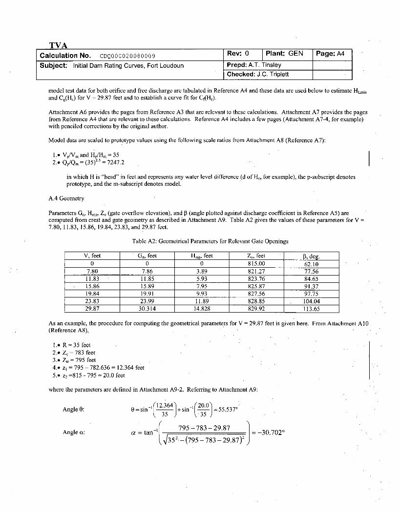
TVACalculation No. CDQ000020080009 Rev: 0 Plant: GEN Page:A4
Subject: Initial Dam Rating Curves, Fort Loudoun Prepd: A.T. TinsleyChecked: J.C. Triplett
model test data for both orifice and free discharge are tabulated in Reference A4 and these data are used below to estimate HLmin
and Cg(Hc) for V = 29.87 feet and to establish a curve fit for Cf(HJ).
Attachment A6 provides the pages from Reference A3 that are relevant to these calculations. Attachment A7 provides the pagesfrom Reference A4 that are relevant to these calculations. Reference A4 includes a few pages (Attachment A7-4, for example)with penciled corrections by the original author.
Model data are scaled to prototype values using the following scale ratios from Attachment A8 (Reference A7):
1.9 VpIVm and Hp/Hm 352.. Qp/Qm = (35)2.5 = 7247.2
in which H is "head" in feet and represents any water level difference (d of H,, for example), the p-subscript denotesprototype, and the m-subscript denotes model.
A.4 Geometry
Parameters Gr, Hmp, Z. (gate overflow elevation), and P3 (angle plotted against discharge coefficient in Reference A5) arecomputed from crest and gate geometry as described in Attachment A9. Table A2 gives the values of these parameters for V =
7.80, 11.83, 15.86, 19.84, 23.83, and 29.87 feet.
Table A2: Geometrical Parameters for Relevant Gate Openings
V, feet Gn, feet Hmp, feet Z0, feet de0 0 0 815.00 62.10
7.80 7.86 3.89 821.27 77.5611.83 11.85 5.93 823.76 84.6515.86 15.89 7.95 825.87 91.3719.84 19.91 9.93 827.56 97.7523.83 23.99 11.89 828.85 104.0429.87 30.314 14.828 829.92 113.65
As an example, the procedure for computing the geometrical parameters for V = 29.87 feet is given here. From Attachment A10(Reference A8),
1.. R= 35 feet2.. Z, = 783 feet3.' Ztr = 795 feet4.. z, = 795 - 782.636 = 12.364 feet5.. z2 =815 - 795 = 20.0 feet
where the parameters are defined in Attachment A9-2. Referring to Attachment A9:
Angle 0: 0=sin-' 12.364 +sin-1 230.= 55.5370
Angle a: a tan-' 795-783-29.87 j =-30.7020
435. 2 -(795 - 783 - 29.87)2
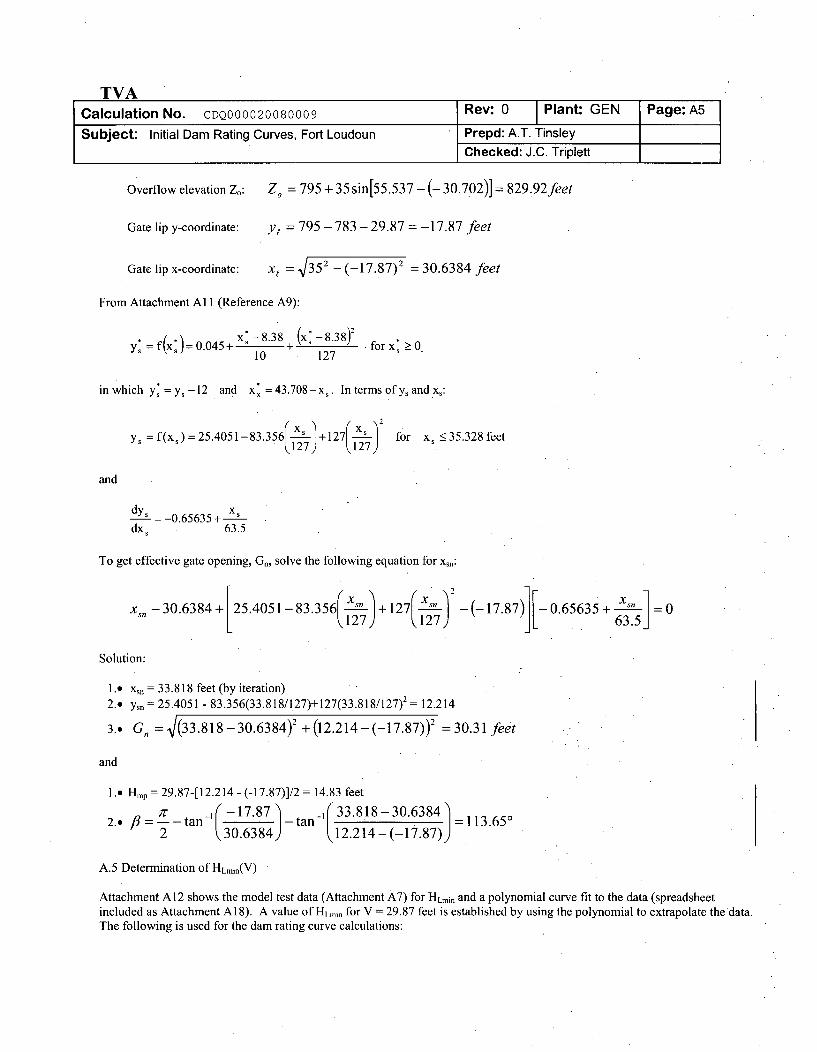
TVACalculation No. CDQ000020080009 Rev: 0 Plant: GEN Page:A5
Subject: Initial Dam Rating Curves, Fort Loudoun Prepd: A.T. TinsleyChecked: J.C. Triplett
Overflow elevation Z.: Zo = 795 + 35 sin[55.537 -(- 30.702)] =829.92feet
Gate lip y-coordinate: Ye = 795 - 783 - 29.87 = -17.87 feet
Gate lip x-coordinate: Xe = 352 - (-17.87)2 =30.6384 feet
From Attachment A 11 (Reference A9):
y: _- f(x:) 0045+ x:-8.38 + (x: -8.38)2 forx:>010 127
inwhich Y*=Y,- 12 and x =43.708- x,. In terms ofy, and x,:
y, =f(x,)=25.4051-83.356 - +127 for x <35.328feetk~127) 127)
and
dys 0.65635+ xdx, 63.5
To get effective gate opening, Gn, solve the following equation for xsn:
xs -30.6384+ 25.4051-83.356 +127 -(-17.87) 0.65635+ x6 3 5 j=0127 k27 63.51
Solution:
1.. x, = 33.818 feet (by iteration)2.. Ysn = 25.4051 - 83.356(33.818/127)+127(33.818/127)2 = 12.214
3.. GQ =V(33.818-30.6384)2 + (12.214 - (-17.87))2 = 30.31 feet
and
1. Hmp = 29.87-[12.214 - (-17.87)]/2 = 14.83 feet
2 ... 7'- 17"87 33.818- 30.6384 =113.6502 (30.6384) 12.214 (-17.87))
A.5 Determination of HLmin(V)
Attachment A12 shows the model test data (Attachment A7) for HLmin and a polynomial curve fit to the data (spreadsheetincluded as Attachment A18). A value of HuLmn for V = 29.87 feet is established by using the polynomial to extrapolate the data.The following is used for the dam rating curve calculations:
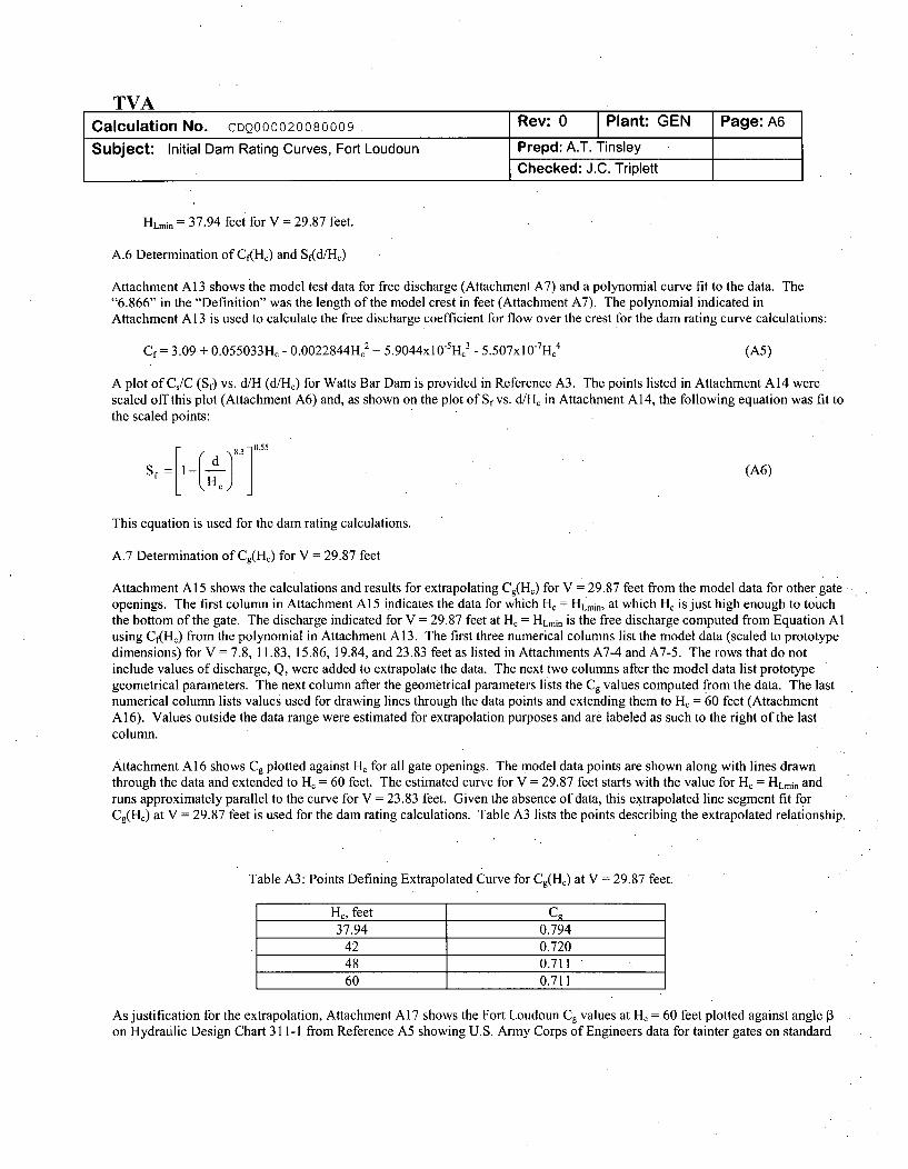
TVACalculation No. CDQ000020080009 Rev: 0 Plant: GEN Page: A6
Subject: Initial Dam Rating Curves, Fort Loudoun Prepd: A.T. TinsleyChecked: J.C. Triplett
HLmini 37.94 feet for V = 29.87 feet.
A.6 Determination of Cf(HC) and Sf(d/HC)
Attachment A13 shows the model test data for free discharge (Attachment A7) and a polynomial curve fit to the data. The"6.866" in the "Definition" was the length of the model crest in feet (Attachment A7). The polynomial indicated inAttachment A13 is used to calculate the free discharge coefficient for flow over the crest for the dam rating curve calculations:
Cf= 3.09 + 0.055033HC - 0.0022844Hc2 + 5.9044x1O5 H,3 - 5.507x10THC4 (AM)
A plot of Cs/C (Sf) vs. d/H (d/HJ) for Watts Bar Dam is provided in Reference A3. The points listed in Attachment A14 werescaled off this plot (Attachment A6) and, as shown on the plot of Sf vs. d/H, in Attachment A14, the following equation was fit tothe scaled points:
-, [1 ( d 18.3 0-55 (A6)
This equation is used for the dam rating calculations.
A.7 Determination of Cg(HJ) for V = 29.87 feet
Attachment A15 shows the calculations and results for extrapolating Cg(Hc) for V - 29.87 feet from the model data for other gateopenings. The first column in Attachment A15 indicates the data for which H, = HLmin, at which Hc is just high enough to touchthe bottom of the gate. The discharge indicated for V = 29.87 feet at H, = HLmin is the free discharge computed from Equation Alusing Cf(Hc) from the polynomial in Attachment A13. The first three numerical columns list the model data (scaled to prototypedimensions) for V = 7.8, 11.83, 15.86, 19.84, and 23.83 feet as listed in Attachments A7-4 and A7-5. The rows that do notinclude values of discharge, Q, were added to extrapolate the data. The next two columns after the model data list prototypegeometrical parameters. The next column after the geometrical parameters lists the Cg values computed from the data. The lastnumerical column lists values used for drawing lines through the data points and extending them to Hc = 60 feet (AttachmentA16). Values outside the data range were estimated for extrapolation purposes and are labeled as such to the right of the lastcolumn.
Attachment A16 shows Cg plotted against H. for all gate openings. The model data points are shown along with lines drawnthrough the data and extended to H2 = 60 feet. The estimated curve for V = 29.87 feet starts with the value for Hc = HLmin andruns approximately parallel to the curve for V = 23.83 feet. Given the absence of data, this extrapolated line segment fit forCg(Hc) at V = 29.87 feet is used for the dam rating calculations. Table A3 lists the points describing the extrapolated relationship.
Table A3: Points Defining Extrapolated Curve for Cg(Hc) at V = 29.87 feet.
H•, feet C,37.94 0.794
42 0.72048 0.71160 0.711
As justification for the extrapolation, Attachment A17 shows the Fort Loudoun Cg values at H, = 60 feet plotted against angle 13on Hydraulic Design Chart 311-1 from Reference A5 showing U.S. Army Corps of Engineers data for tainter gates on standard
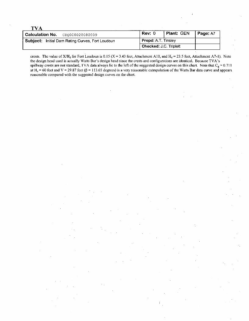
TVACalculation No. CDQ000020080009
Subject: Initial Dam Rating Curves, Fort Loudoun
Rev: 0 Plant: GEN
Prepd: A.T. Tinsley
Checked: J.C. Triplett
crests. The value of X/Hd for Fort Loudoun is 0.15 (X = 3.43 feet, Attachment A10, and Hd = 23.5 feet, Attachment A7-1). Notethe design head used is actually Watts Bar's design head since the crests and configurations are identical. Because TVA'sspillway crests are not standard, TVA data always lie to the left of the suggested design curves on this chart. Note that Cg = 0.711at H, = 60 feet and V = 29.87 feet (P = 113.65 degrees) is a very reasonable extrapolation of the Watts Bar data curve and appearsreasonable compared with the suggested design curves on the chart.
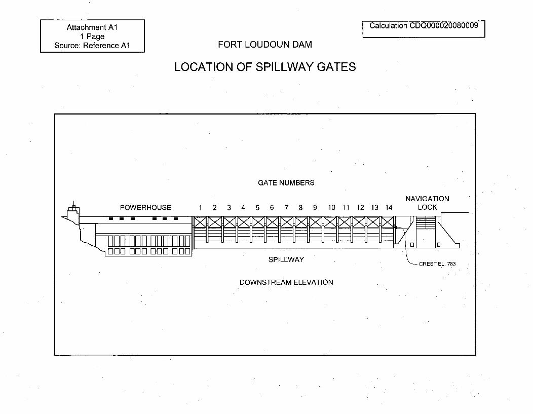
Attachment Al1 Page
Source: Reference AlCalculation CDQ000020080009 I
FORT LOUDOUN DAM
LOCATION OF SPILLWAY GATES
GATE NUMBERS
NAVIGATION5 6 7 8 9 10 11 12 13 14 LOCKPOWERHOUSE 1 2 3 4
SPILLWAY CREST EL. 783
DOWNSTREAM ELEVATION
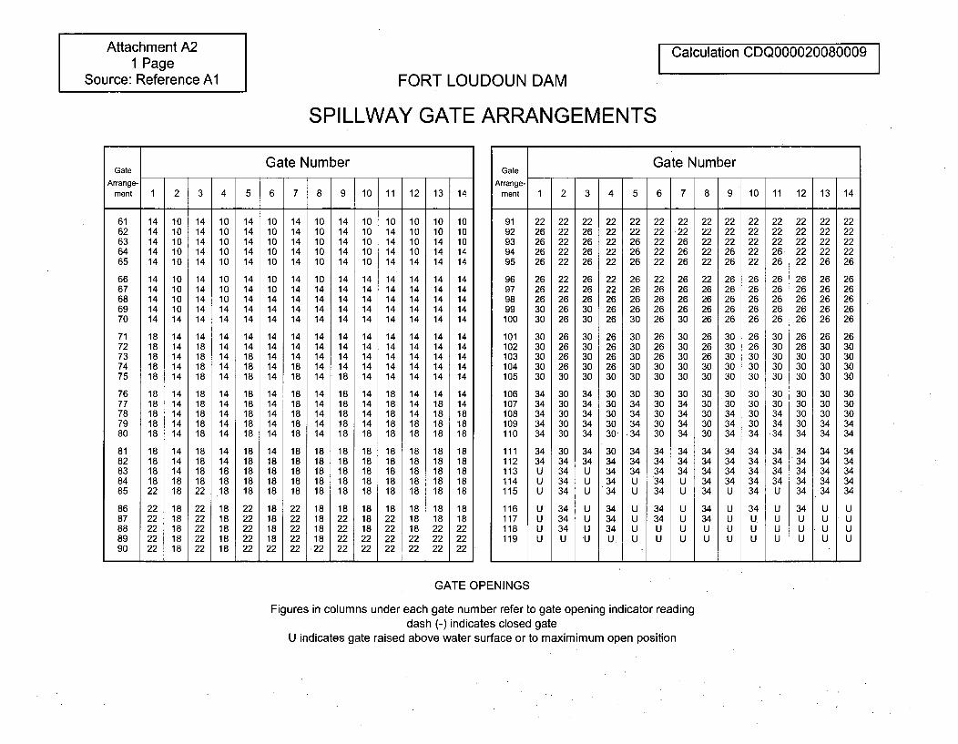
Attachment A21 Page
Source: Reference AlI Calculation CDQ000020080009 I
FORT LOUDOUN DAM
SPILLWAY GATE ARRANGEMENTS
Gate NumberGate
Arrange-ment 1 2 3 4 5 6 7 8 9 10 11 12 13 14
61 14 10 14 10 14 10 14 10 14 10 10 10 10 1062 14 10 14 10 14 10 14 10 14 10 14 10 10 1063 14 10 14 10 14 10 14 10 14 10 14 10 14 1064 14 10 14 10 14 10 14 10 14 10 14 10 14 1465 14 10 14 10 14 10 14 10 14 10 14 14 14 14
66 14 10 14 10 14 10 14 10 14 14 14 14 14 1467 14 10 14 10 14 10 14 14 14 14 14 14 14 1468 14 10 14 10 14 14 14 14 14 14 14 14 14 1469 14 10 14 14 14 14 14 14 14 14 14 14 14 1470 14 14 14 14 14 14 14 14 14 14 14 14 14 14
71 18 14 14 14 14 14 14 14 14 14 14 14 14 1472 18 14 18 14 14 14 14 14 14 14 14 14 14 1473 18 14 18 14 18 14 14 14 14 14 14 14 14 1474 18 14 18 14 18 14 18 14 14 14 14 14 14 1475 18 14 18 14 18 14 18 14 18 14 14 14 14 14
76 18 14 18 14 18 14 18 14 18 14 18 14 14 1477 18 14 18 14 18 14 18 14 18 14 18 14 18 1478 18 14 18 14 18 14 18 14 18 14 18 14 18 1879 18 14 18 14 18 14 18 14 18 14 18 18 18 1880 18 14 18 14 18 14 18 14 18 18 18 18 18 18
81 18 14 18 14 18 14 18 18 18 18 18 18 18 1882 18 14 18 14 18 18 18 18 18 18 18 18 18 1883 18 14 18 18 18 18 18 18 18 18 18 18 18 1884 18 18 18 18 18 18 18 18 18 18 18 18 18 1885 22 18 22 .18 18 18 18 18 18 18 18 18. 18 18
86 22 18 22 18 22 18 22 18 18 18 18 18 18 1887 22 18 22 18 22 18 22 18 22 18 22 18 18 1888 22 18 22 18 22 18 22 18 22 18 22 18 22 2289 22 18 22 18 22 18 22 18 22 22 22 22 22 2290 22 18 22 18 22 22 22 22 22 22 22 22 22
Gate NumberGate
Arrange-ment 1 2 3 4 5 6 7 8 9 10 11 12 13 14
91 22 22 22 22 22 22 22 22 22 22 22 22 22 2292 26 22 26 22 22 22 22 22 22 22 22 22 22 2293 26 22 26 22 26 22 26 22 22 22 22 22 22 2294 26 22 26 22 26 22 26 22 26 22 26 22 22 2295 26 22 26 22 26 22 26 22 26 22 26 22 26 26
96 26 22 26 22 26 22 26 22 26 26 26 26 26 2697 26 22 26 22 26 26 26 26 26 26 26 26 26 2698 26 26 26 26 26 26 26 26 26 26 26 26 26 2699 30 26 30 26 26 26 26 26 26 26 26 26 26 26100 30 26 30 26 30 26 30 26 26 26 26 .26 26 26
101 30 26 30 26 30 26 30 26 30 26 30 26 26 26102 30 26 30 26 30 26 30 26 30 26 30 26 30 30103 30 26 30 26 30 26 30 26 30 30 30 30 30 30104 30 26 30 26 30 30 30 30 30 30 30 30 30 30105 30 30 30 30 30 30 30 30 30 30 30 30 30 30
106 34 30 34 30 30 30 30 30 30 30 30 30 30 30107 34 30 34 30 34 30 34 30 30 30 30 30 30 30108 34 30 34 30 34 30 34 30 34 30 34 30 30 30109 34 30 34 30 34 30 34 30 34 30 34 30 34 34110 34 30 34 30- .34 30 34 30 34 34 34 34 34 34
111 34 30 34 30 34 34 34 34 34 34 34 34 34 34112 34 34 34 34 34 34 34 34 34 34 34 34 34 34113 U 34 U 34 34 34 34 34 34 34 34 34 34 34114 U 34 U 34 U 34 U 34 34 34 34 34 34 34115 U 34 U 34 U 34 U 34 U 34 U 34 -34 34
116 U 34 U 34 U 34 U 34 U 34 U 34 U U117 U 34 U 34 U 34 U 34 U U. U U U U118 U 34 U 34 U U U U U U U U U U119 U U
U ý U'' U-ý u ý U ý U I u . U . U U U U
GATE OPENINGS
Figures in columns under each gate number refer to gate opening indicator readingdash (-) indicates closed gate
U indicates gate raised above water surface or to maximimum open position
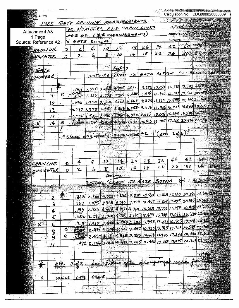
ES17 Calculation No: CDQ000020080009
Attachment A3 ,C
Source: Reference A2 7 '/qT• C.T'oT v CECKET
T, Lw c3 a ~ ~ 28 Z4' 3• 42- ~ ~
~ c. •,,,
t) 75#.. a. 306 -U O 7# 162 /9 0.5S 7 B' 'Z-
.4, :,..
JO 0~ /7503.b041416 2b 7-In7 /3,170 (, 745
'.. T0:7 9 78 if 2-z 3 /956 Z3, O
0 7 ..,
00 z. 3,6 44- 5:z
2- 30.
)A-709 0 - i / .3
I I z.•O_ +%3 7Z.7 ,Z,,4~ /3.74j1024 3:i -. e 7--
-i• -: - - - - - "-
E 17 5 . a?7- 7-190.
A'.•..:J -g :v . " "w A ,.
;.z~ 7,' 3. 1 715 i.7 .7 o8 a.
A v g03-. 51.3 ~~SIZ Z
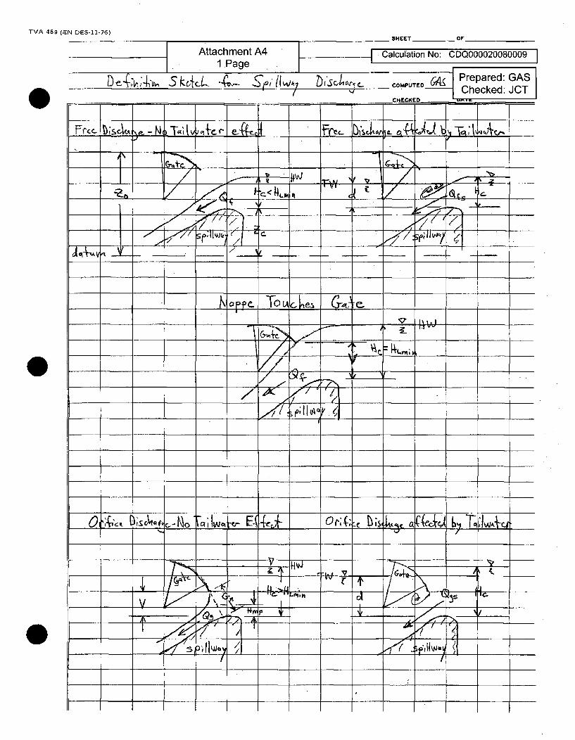
TVA 489 (EN DES-11-76)
Attachment A41 .Page
_ SHEET _ OF
t "Calculation No: CDQ000020080009It'~sc, €..v COPUTEO D Prepared: GAS
Checked: JCTDe4iýk4-v, S kcici- -ý- Ep,, I(wý,
I
0
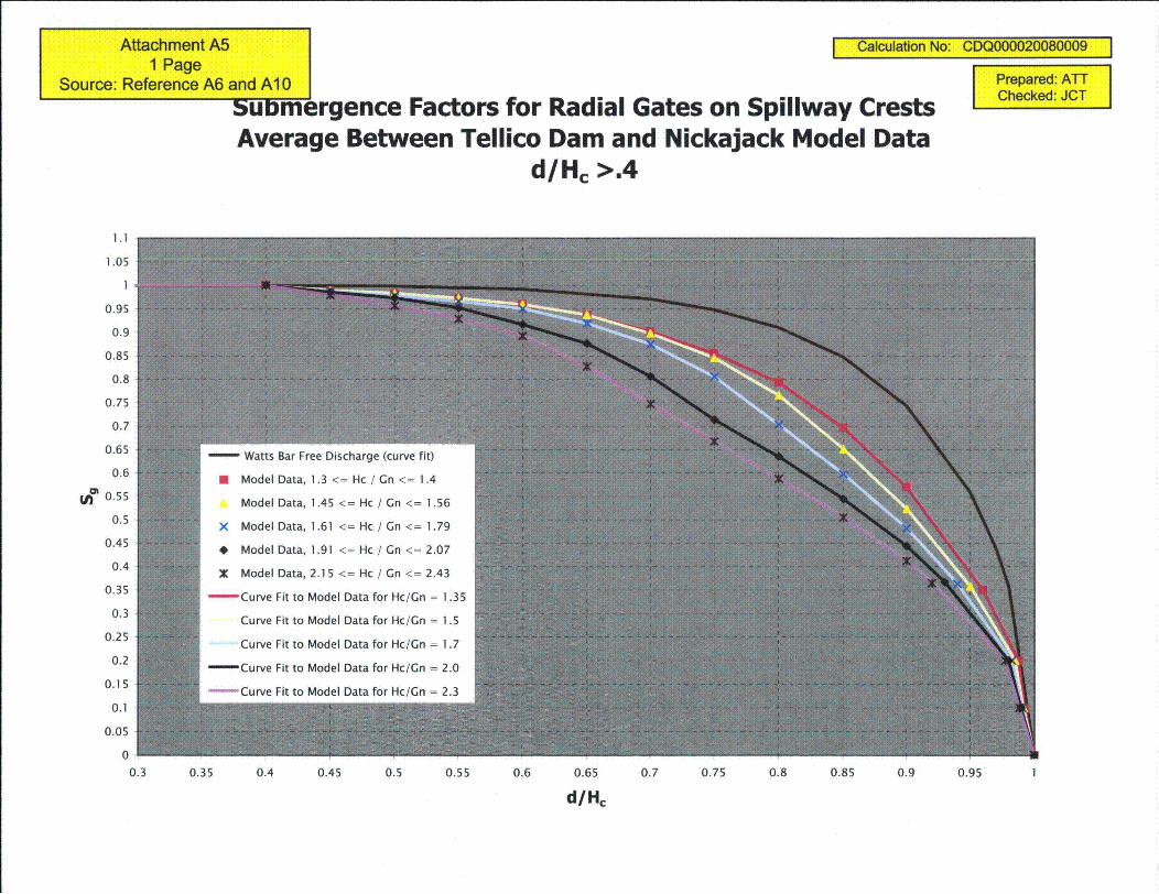
Attachment A51 Page
Source: Reference A6 and Al10
I Calculation No: CDQ000020080009
Prepared: ATTChecked: JCT
buDmergence Factors for Radial Gates on Spillway CrestsAverage Between Tellico Dam and Nickajack Model Data
d/Hc >.4
1.1
1.05
1
0.95
0.9
0.85
0.8
0.75
0.7
0.65
0.6
U) 0.55
0.5
0.45
0.4
0.35
0.3
0.25
0.2
0.15
0.1
0.05
0
0.3 0.35 0.4 0.45 0.5 0.55 0.6 0.65 0.7 0.75 0.8 0.85 0.9 0.95
d/Hc
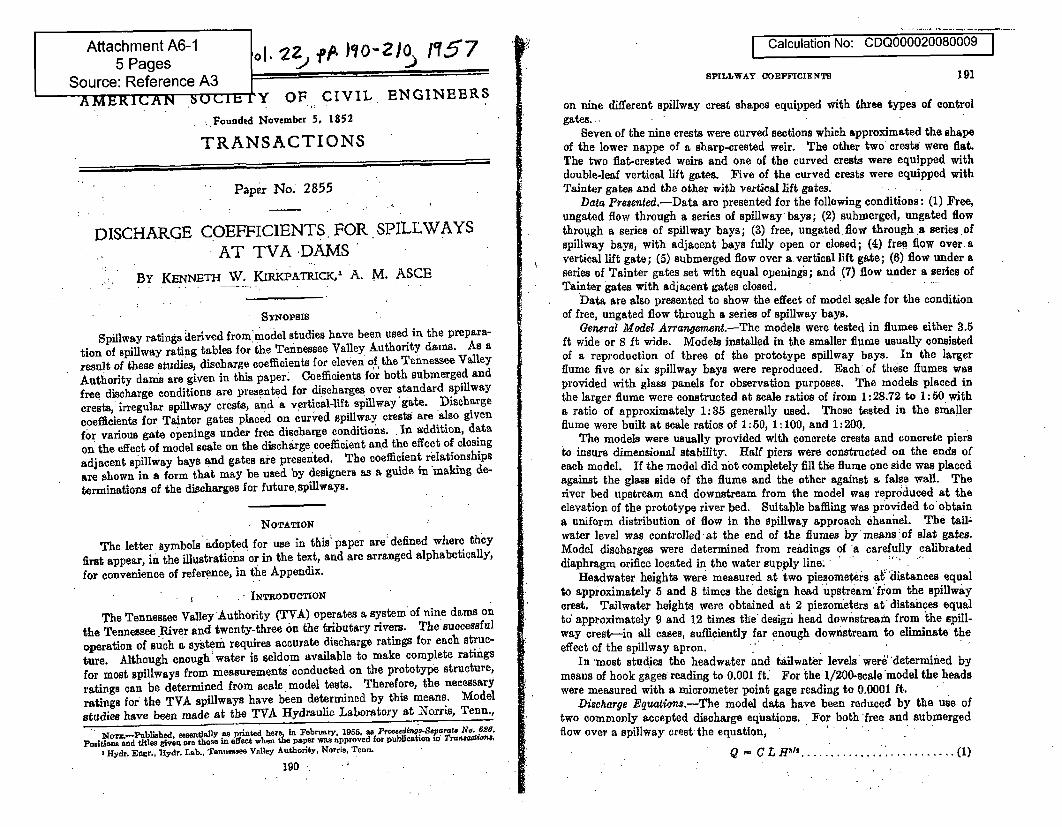
|
Attachment A6-15 Pages
Source: Reference A3
2ol fjP*.)¶o-2i% 1Y57 ti rCalculation No: CDQ000020080009
SPILLWAY COEFFICIENTS 191
AMERICAN bouCIbly OF CIVIL ENGINEERS
.. Foundel November 5, 1852
TRANSACTIONS
Paper No. 2855
DISCHARGE COEFFICIENTS, FOR SPILLWAYSAT TVA DAMS
BY KENNETH W. KIRKPATRICK,' A. M. ASCE
SYNopsiS '
Spillway ratings derived fromrmodel studies have been used in the prepara-
tion of spillway rating tables for the Tennessee Valley Authority dams. As aresult of these studies, discharge coefficients for eleven of the Tennessee ValleyAuthority dam's are given in this paper; Coefficients for both submerged and
free discharge conditions are presented for discharges over standard spillwaycrests, irregular spillway crests, and a vertical-lift spillway'gate. Discharge
coefficients for Tainter gates placed on curved spillway crests are also givenfor various gate openings under free discharge condition's. In addition, data
on the effect of model scale on the'discharge coefficient and the effect of closing
adjacent spillway bays and gates are presented. The coefficient relationshipsare shown in a form that may be used by designers as a guide in making de-
terminations of the discharges for future, spillways.
NOTATION
The letter symbols adopted for use in this paper are: defined where they
first appear, in the illustrations or in the text, and are arranged alphabetically,for convenience of reference, in the Appendix.
- INTRODUCTION
The Tennessee Valley 'Authority (TVA) operates a system of nine dams on
the Tennessee River and twenty-three on the tributary rivers. The successful
operation of such a system requires accurate discharge ratings for each struc-
ture. Although enough water is seldom available to make complete ratings
for most spillways from measurements'conducted on the prototype structure,
ratings can be determined from scale, model tests. Therefore, the necessary
ratings for the TVA spillways have been determined by this means. Modelstudies have been made at the TVA Hydraulic Laboratory at Norris, Tenn.,
Noa.-Published. essentially as printed here• in Yebruary. 1955, as ProeedinosSeporate No. 828.positions and titles given are those in effect when the paper was approved for publication id Trannatont,
3 Hydr. Engr., iydr. Lab.. Tennessee Valley Authority, Norris, Tenn.
1 9 0 •
on nine different spillway crest shapes equipped with three types of controlgates..
Seven of the nine crests were curved sections which approximated the shapeof the lower nappe of a sharp-crested weir. The other two crests were flat.The two flat-crested weirs and one of the curved crests were equipped withdouble-leaf vertical lift gates. Five of the curved crests were equipped withTainter gates and the other with vertical lift gates.i
Data Presented.-Data are presented for the following conditions: (1) Free,ungated flow through a series of spillway bays; (2) submerged, ungated flowthrough a series of spillway bays; (3) free, ungated. flow through a series ofspillway bays, with adjacent bays fully open or closed; (4) free flow over avertical lift gate; (5) submerged flow over a vertical lift gate; (6) flow under aseries of Tainter gates set with equal opening's; and (7) flow under a series ofTainter gates with adjacent gates closed;.
Data are also presented to show the effect of model scale for the conditionof free, ungated flow through a series of spillway bays.
General Model Arrangerment.-The models were tested in flumes either 3.5ft wide or 8 ft wide. Models installed in the smaller flume usually consistedof a reproduction of three of the prototype spillway bays. In the largerflume five or six spillway bays were reproduced. Each of these flumes wasprovided with glass panels for observation purposes. The models placed inthe larger flume were constructed at scale ratios of from 1:28.72 to 1: 50 witha ratio of approximately 1:35 generally used. Those tested in the smallerflume were built at scale ratios of 1:50, 1:100, and 1:200.
The models were usually provided with concrete crests and concrete piersto insure dimensional stability. Half piers were constructed on the ends ofeach model. If the model did not completely fill the flume one side was placedagainst the glass side of the flume and the other against a false wall. Theriver bed upstream and downstream from the model was reproduced at theelevation of the prototype river bed. Suitable baffling was provided to obtaina uniform distribution of flow in the spillway approach chanhel. The taillwater level was controlled-at the end of the flumes by means:of slat gates.Model discharges were determined from readings of 'a carefully calibrateddiaphragm orifice located in the water supply line; -
Headwater heights were measured at two piezometers ali distances equalto approximately 5 and 8 times the design head upstream from the spillwaycrest. Tailwater heights were obtained at 2 piezometers at distances equalto' approximately 9 and 12 times the design head downstream from the spill-way crest-in all cases, sufficiently far enough downstream to eliminate theeffect of the spillway apron.
In -most studies the headwater and tailwater levels wer6 'determined bymeans of hook gages reading to 0.001 ft. For the 1/200-scale model the headswere measured with a micrometer point gage reading to 0.0001 ft.
Discharge Equations,-The model data have been reduced by the use oftwo commonly accepted discharge eqiations. For both 'free and submergedflow over a spillway crest the equation,
Q= C L H1m..... ........ (1)
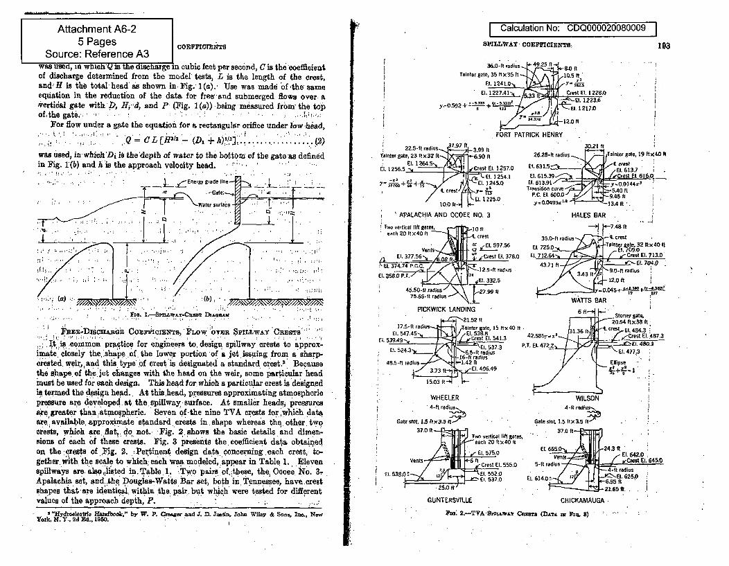
Aftachment A6-25 Pages -IC IZNTs
Source: Reference A3was used, in whlch is the discharge in cubic feet per sec6nd, C is the coefficientof discharge determined from the model tests, L is the length of the crest,and; H is the total head as shown. in, Fig.i1(a).' -Use was made bf 'the sameequation in the reduction of the data for free- and submerged flows over, a,výertidal gate with ', ./1-,d, and P (Fig. 1 (q)) .being measured frbuo the topo f ,th e g a t e . . ' . , . . " .
For flow under a gate the equation for a rectangular orifice under low -head,
Q C CL[H-11 (ZN +h)'? ........... 2was used, in which'Di is the'depth of water to the bottom of the gate -as definedin Fig. 1(b) and A is the approach velocity head.
. " ... "'. .. -[ .. ":••
* . j~jEnrergy grade line I-~ -Gate:
Waler suriac ' T
- .: 1 . ... / - ..'
Fie. l.---r ,wAx-Cazn DiLea ,m
Fnsm-flxSicnano Cozrk0IcXTw, 'LOW O'VER SPmLiwAY 'OansT&ý
It is common practice for engineers to, design, spillway crests.to approx-imnate, closely the, shape' of. the lower portion of a jet, issuing from a. sharp-created. wei,, and this type of crest is designated a standard crest." Becausethe shape, of the. jet changes with the head on the weir, some particular headmust be used for each design. This head for which a particular crest is designedis termed the design head. At this head, pressures approximating atmosphericpressure are developed, at. the, spillway. surface. At smaller heads. pressuresare greater than atmopheric. Seven of -the nine TVA crests for ,which dataaxe available, approximate standard , crests in, shape whereas 'the, other twocrests, which are fisat, do not.. Fig. 2.shows the basic details and dimen-sions of each of these crests. Fig. 3 presents the, coefficient data obtainedon the qrests, of ,.Fig. :2. :Pertinent design data concerning each crest, to-gether, with the scale to which; each was modeled,. appear in Table 1. Elevenspillways are. also listed in. Table. 1. tTwo pairs* of,;these, the: Ocoee. No. 3.-Apalachia. set, and,.thq Douglas-Watts Bar set, both in Tennessee, have crestshapes that are identieal, within the pair.. but which were tested for differentvalues of the approach depth, P. . ,
Calculation No: CDQ000020080009 I
SPILLWAY, COEFFICIENTS;
36.0-ft radius 49.25 -l t 80 i"
Tainter gate, 35 ftl)35 It ý,10.5 f tEl. 241.0, 3 s
Ell.122.414 5331 Crest El. 1228,0
,.0.5 ,2 + "l 2 2 7A+ - 5Q : Et . 1 2 2 3 , 6
C +iEl. 1217.0FOiRT PATRICK( HENRY
193
I
22.5-ft radius -.• , 9--'-L -. 93 0Tainter gate, 23 ftx32 ftf 6.90 •t
El. 1264 .5,IEl. 1256.5 -1 • jiCrest El. 1257.0
E. 1254.1
El. 1 225.0
APALACHIA AND OCOEE NO. 3
Two vertical lift gates, 10 fteach 20 ftx40 it -q. crest
g Ventsl5.
E 3 Crest El . 378.0
45.0-f rias 127.5-I raiu
75.65-ft radius - 2, _
PICKWICK LANDING
21.52 I117.5-1t radius Tainser gate, 15 ttx40 ft
El. 547.45 / El 5388fl. 539.49. - . restl , 541.3
U. 54.3 El 537.3l5"6.5-ft radius
16-ft radius"48.5-ft radius -1.42 ft
3.73 It El. 496.49
15,03 It
WHEELER' 4-ft radius
Gate slot, 1.5 ItX3.5 '!
37.0 IftTwo vertical lift gait
each 20 Itx40 It
El. 575.0
Vents . 6 It Crest Et. 555.0E. 538,0: Et. 552.0
GUNTERSVILLE
3021 ift
26.25-It radius Tainter gate, 19 ttX40 It
.....63.5 cr-. ff /est63,
EL 615.39 r--Crest El. 6t6.c0Transition curve-'ly/ Y--S0f
Y=-0.0495x 13.4 it-
HALES BAR
35.0-ft radius rt 1"'. crest
El. 725... -Tanter te, 32 ftx 40 itE. 1... ..4-•.___ ! " /I , Ces El. 13.00
43.71 •t .. C' tEl. 7?04. '
WATTS 2AR
6 1'f Stonrey gate,313t L crs El 484x.3
42.585y-x1 CrestEl 4B7.3
•//• ' " ' •Ellipse '
WILSON4- ft radius
Gate slot. 1.5 ttX3.5 ft.. , 37.0 ,ft-'-BEj!I
El. 65.0 243, IVents El. 64 -2.0
5-ft radius Cres El. 64504-it radius
EI. 614.o0 . 6 -95 El. 625,06-95 -t
CHICKAMAUGA
'"Hydroelectric Handbook," by W. P. .7fresir and J. D. Justin, John Wiley & Sons, Inc., NewYork. N. Y.. 2 Ed.,. 1950.Fu:. 2..-TVA-rzLLw&-z Cairnz (D)ATA sac FuLs 82') . ..
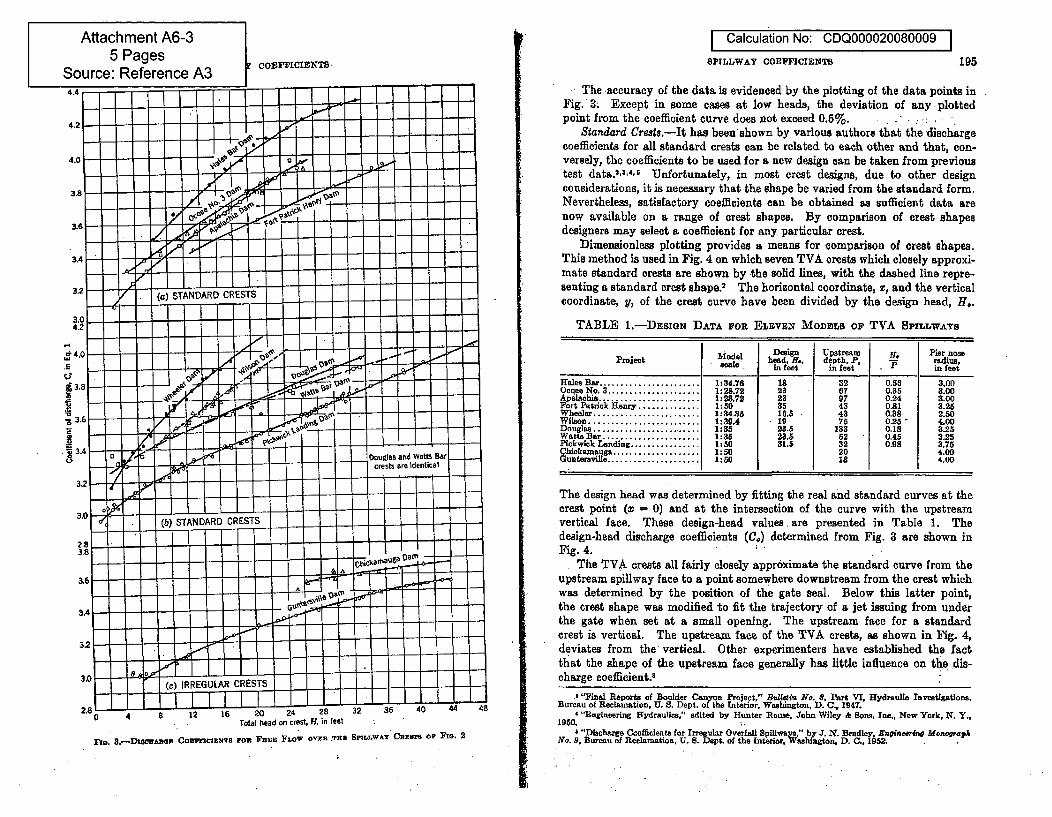
Calculation No: CDQ000020080009 ISPILLWAY COEFFICIENTS 195
The accuracy of the data is evidenced by the plotting of the data points inFig. 3; Except in some cases at low heads, the deviation of any plottedpoint from the coefficient curve does not exceed 0.5%. . -' . :. .
Standard Crests.-It has been'shown by various authors that the dischargecoefficients for all standard crests can be related to each other and that, con-versely, the coefficients to be used for a new design can be taken from previoustest data."3 "45, Unfortunately, in most crest designs, due to other designconsiderations, it is necessary that the shape be varied from the standard form.Nevertheless, satisfactory coefficients can be obtained as sufficient data arenow available on a range of crest shapes. By comparison of crest shapesdesigners may select a coefficient for any particular crest.
Dimensionless plotting provides a means for comparison of crest shapes.This method is used in Fig. 4 on which seven TVA crests which closely approxi-mate standard crests are shown by -the solid lines, with the dashed line repre-senting a standard crest shape.2 The horizontal coordinate, z, and the verticalcoordinate, y, of the crest curve have been divided by the design head, H,.
TABLE 1.-DESIGN DATA FOR ELEVEN MODELS OF TVA SPILTWATS
model Design Upstream F, ier noseProject head, . depth, P, - radius,s" in feet in fet in feet
Hales Bar ...................... 1:34.76 is 32 0.58 3.00Ocoee No. 3 .................... 1228.72 23 67 0.35 8.00
palac| a ............ 1:28.72 23 97 0.24 3.00Fort Patrick Henry .... . 1:50 35 43 0.81 3.25Wheeler ....................... 1:34.35 16.5 43 0.38 2.50Wilson ........................ 1:394 - 19 75 0.25- 4.00Dougla ................... .... 1:85 23.5 133 0.18 8.25Watts Bar................. 1:35 23.5 52 0.45 3.25Pickwick Landing ................ 1:50 31.3 32 0.98 3.75Chiokanauga ................... 1:50 20 4.00Gu.tersyille.................... 1:0 1i 4.00
The design head was determined by fitting the real and standard curves at thecrest point (m = 0) and at the intersection of the curve with the upstreamvertical face. These design-head values, are presented in Table 1. Thedesign-head discharge coefficients (C.) determined from Fig. 3 are shown inFig. 4. . '
The TVA crests all fairly closely approximate the standard curve from theupstream spillway face to a point somewhere downstream from the crest whichwas determined by the position of the gate seal. Below this latter point,the crest shape was modified to fit the trajectory of a jet issuing from underthe gate when set at a small opening. The upstream face for a standardcrest is vertical. The upstream face of the TVA crests, as shown in Fig. 4,deviates from the vertical. Other experimenters have established the factthat the shape of the upstream face generally has little influence on the dis-charge coefficient.8
.3 "Tinal Reports of Boulder Canyon ProSect," Blletin No. 8, Part VI, Hydraulic Investigationa,Bureau of Reclamation, U. S. Dept. of the tnterior. Washington, D. C-, 1947.
4 "Engineering Hydraulics." edited by Hunter Rouse. John Wiley & Sons, Inc., New York, N. Y.,
1950. i.4 "Discharge Coefficients for Irregular Overfall Spiliway," by J. N. Bradley, Engieerin Monograph
No. 9, Bureau of Reclamation, U. S. Dept, of the Interior. washington, D. C., 1952.
(c) IRREGULAR CRESTS I I I zl I .i...
8 12 16 20 24 28 32 36 40 44 48
Total head on crest, H, in feet l :2.8
0 4
PRo. 3.--DTSAsaOe COErrrcIaTa ro F zRIE FPOW OVER 7.HZ SPILLWAY CREma or Po. 2
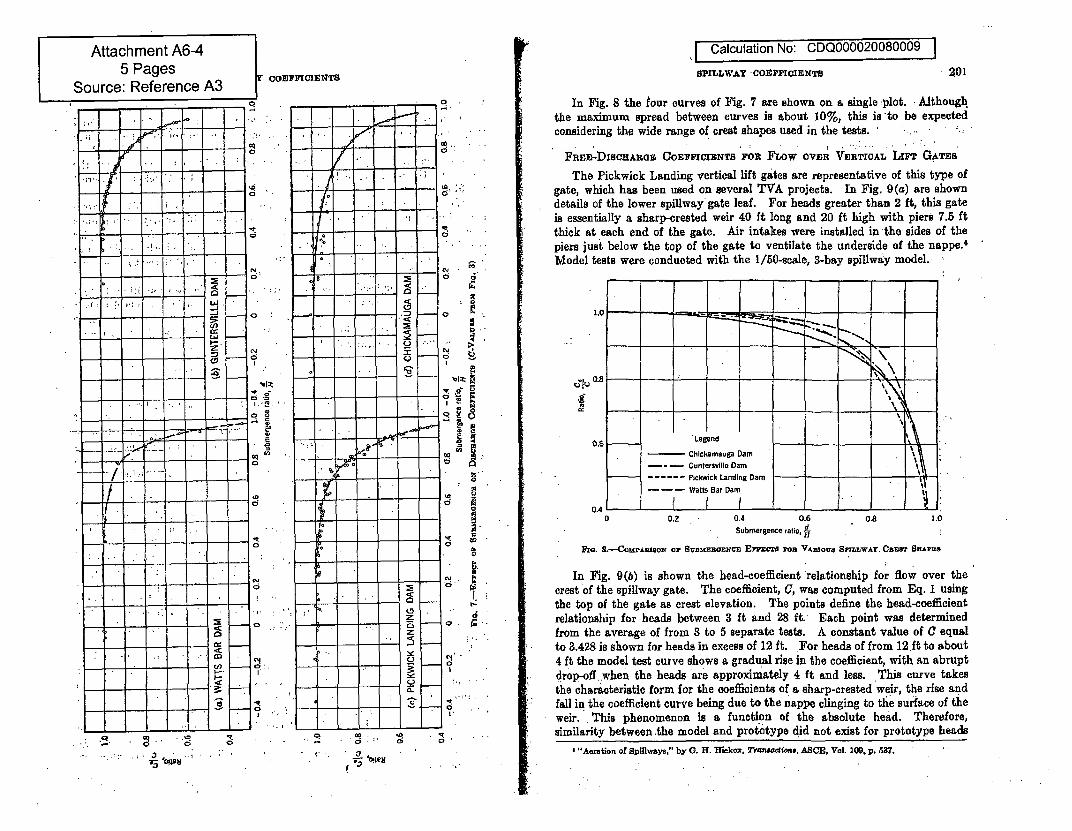
Calculation No: CDQ000020080009
SPILLWAY -COEFICIOENT• 201
In Fig. 8 the tour curves of Fig. 7 are shown on a single ýplot. : Althonghthe maximum spread between curves is about 10%, this is to be expectedconsidering the wide range of crest shapes used in the tests.
F• DxSc•ARGs COE"FCrENTS Fou FLow ovwn VERTICAL Lrnr GATESThe Pickwick Landing vertical lift gates are representative of this type of
gate, which has been used on several TVA projects. In Fig. 9(a) are showndetails of the lower spillway gate leaf. For heads greater than 2 ft, this gateis essentially a sharp-crested weir 40 ft long and 20 ft high with piers 7.5 ftthick at each end of the gate. Air intakes were installed in-the sides of thepiers just below the top of the gate to ventilate the underside of the nappe.'Model tests were conducted with the 1/50-scale, 3-bay spillway model.-
LIl
0.6 Legend
Chickamauga Dam IGuntersville Dam
-.. Pickwick Landing Damr- - Watts Bar Dam
-0 0.2 0.4 0.6 0.8 1.0•" ~Submergence ratio, d
a. S*-"-OMPAuisOm oIp Svamnsazw• cm Er"7o'E aOa VARZOVU SXLLWAT. CSEES SHaAC9
In Fig. 9(b) is shown the head-coefficient relationship for flow over the. !crest of the spillway gate. The coefficient, C, was computed from Eq. 1 using
the top of the gate as crest elevation. The points define the head-coefficientrelationship for heads between 3 ft and 28 ft. Each point was determinedfrom the average of from 3 to 5 separate tests. A-constant value of C equalto 3.428 is shown for heads in excess of 12 ft. For heads of from 12 ft to about4 ft the model test curve shows a gradual rise in the coefficient, with an abruptdrop-off when the heads are approximately 4 ft and less. This curve takesthe characteristic form for the coefficients of a sharp-crested weir, the rise andfall in the coefficient curve being due to the nappe clinging to the surface of theweir. This phenomenon is a function of the absolute head. Therefore,similarity between the model and prototype did not exist for prototype heads
I"Aeration of Spillwaya," by G. H. Hielcox, 7Tr4oewim, ASCE, Val. 109, p. 537..:*...3 , .... ..-" R " R- -5 '

I Calculation No: CDQ000020080009 I
SPnXLWAT COEFICENTSI 205
discharge over the gate was thus increased, with a consequent -lowering .of theheadwater level.
The flow conditions of plunging nappe and flowing nappe, previouslydescribed, also occurred in this type of flow. In this case the chAnge .fromone to the other is apparent in the data. The dashed line in Fig. 10 indicatesthe approximate location of the change. At these points the curves show -adefinite discontinuity in shape. The data of Fig. 10 can be reduced in coeffi-
4.2
I18 12 16 20 24 28 32
Total head on spillway creit, kL in feet
nIo. 1&.-TA•n•%-QAT SpmrLLAY DICKAmOg O Comwahwrs(DiMmosIONs ox Cuxvea Amc GATn OpxNwBs)
36
cient form to the single-curve representation shown in Fig. 11. In this illustra-tion, a constant, value of C, equal to 3.428, was used in computing the ratio of
DisOHAIGn COEFFICIENT15 roR FoW UNDmt. TAj'TBR, GATzS
The flow under Tainter gates mounted on curved crests is .controlled bythe geometry of three interrelated variables-the crest shape, 'the gate, andthe gate setting. The major factors which influence the discharge relation-
";'3.0 " t I0* 4 8- 12 16 20 2
- .. Total head an spillway crest. H, in feet
P,, . 12.-TA1eL1TEIGATE SPIL-WAY DIscEunoE Coarrn•ca ..(DexznezaO oz? CuOVEs Apu GATn iPB'uNO8)
28
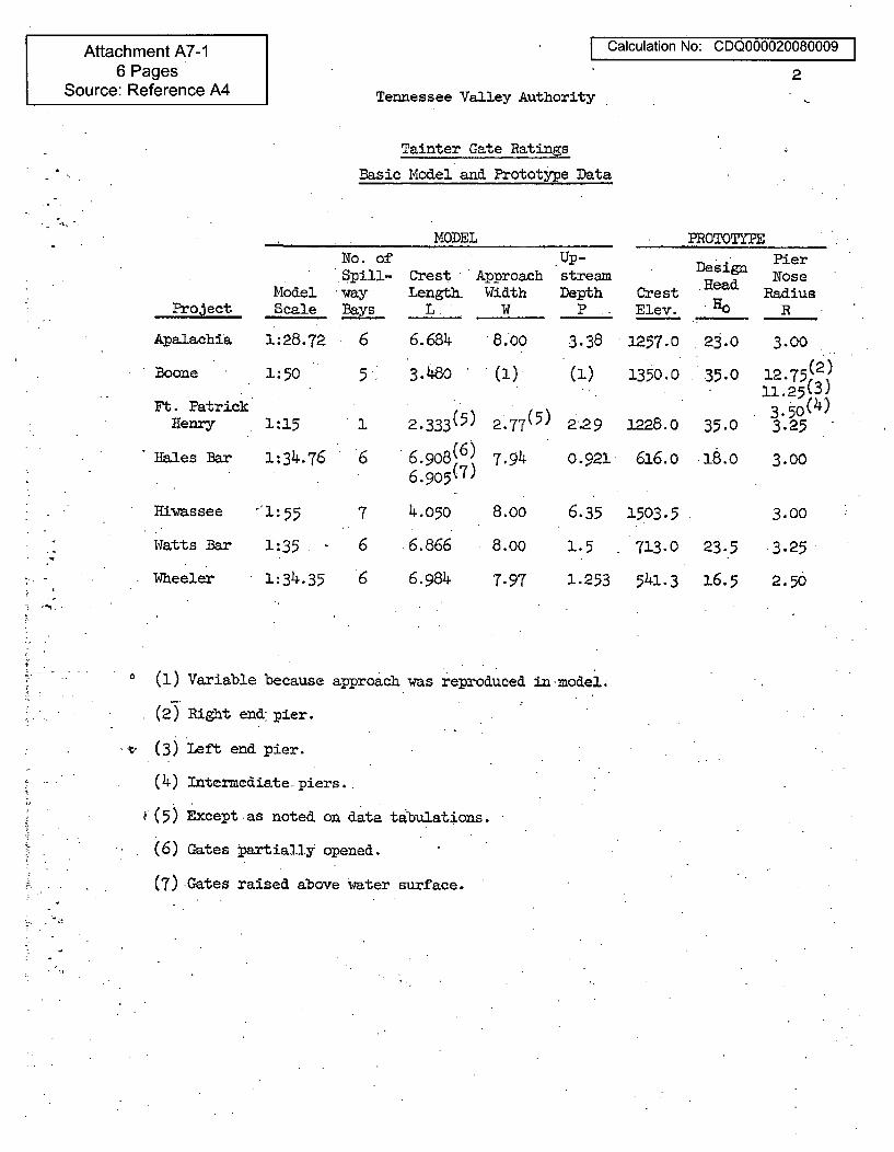
Attachment A7-16 Pages
Source: Reference A4
I Calculation No: CDQ000020080009 I
2
Tennessee Valley Authority
Tainter Gate Ratings
Basic Model and Prototype Data
.. .•. :,, •
MODEL PROTOTYPE
ModelProject Scale
Apalachia 1:28.72
Boone 1:50
Ft. PatrickHenry 1:15
Hales Bar 1:34.76
Hivtassee -'1:55
Watts Bar 1:35
Wheeler 1:34.35
No. ofSpill-.Way
Bays-
6
5,
1
6
7
6
6
CrestLength.
L
6.6843.48o
2.333(5)
6. 908(6 )6.905(7)
4.050
6.866
6.984
Up-Approach streamWidth Depth
W P
.8.00 3.38
(1)• (1)
2*77(5) 229
7.94 0.921
8.00 6.35
8.00 1.5
7.97 1.253
CrestElev.
1257.0
1350.0
1228.0
616.o
1503.5
713.0
541.3
DesignRead
HO
23.0
35.0
35.0
23.5
16.5
PierNose
RadiusR
3.00
12.75 (2)11.25(3)
3.5o(4)3.25
3.00
3.00
3.25
2.50
(1) Variable because approach was reproduced in model.
(2) Right end pier.
'•" (3) Left end pier.
(4) Intermediate piers..
(5) Except as noted on data tabulations.
(6) Gates jartially opened.
(7) Gates raised above water surface.
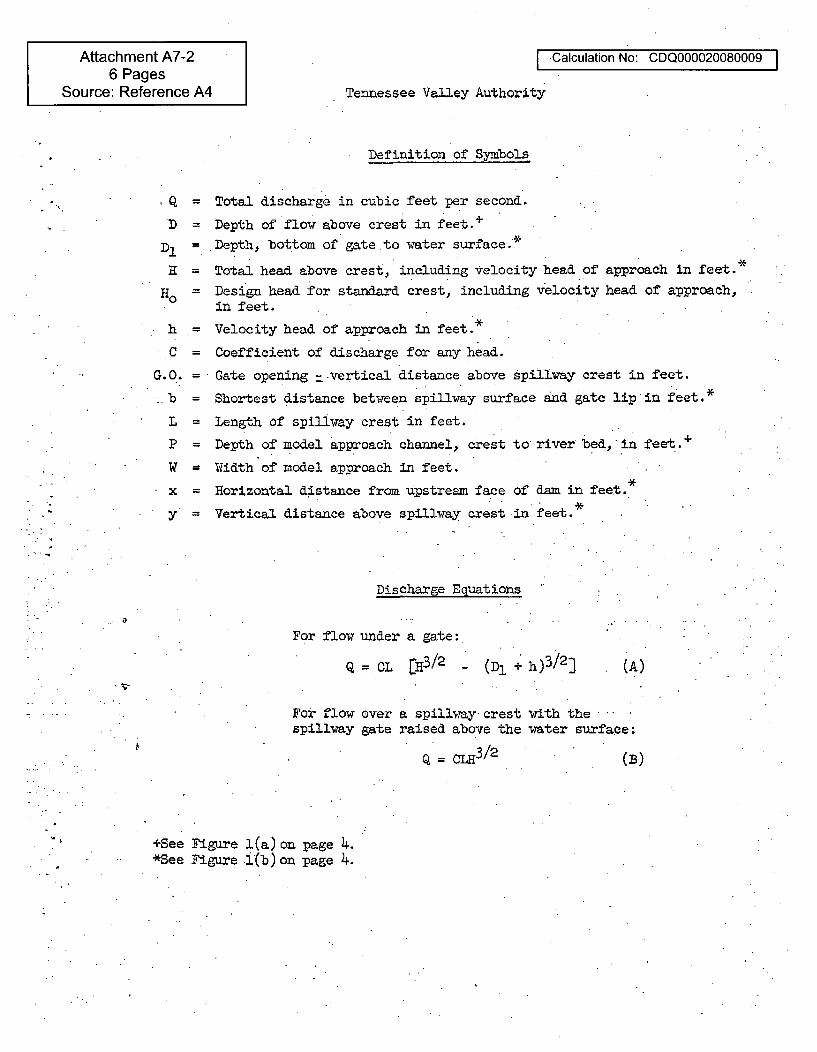
Attachment A7-26 Pages
Source: Reference A4
-Calculation No: CDQ000020080009
Tennessee Valley Authority
Definition of Symbols
,Q = Total discharge in cubic feet per second.
D Depth of flow above crest in feet.+
D = Depth, bottom of gate to vater surface.*
K = Total head above crest, including velocity head of approach in feet.*
= Design head for standard crest, including velocity head of approach,in feet.
h Velocity head of approach in feet.*
C = Coefficient of discharge for any head.
G.O. = Gate opening =-vertical distance above spillway crest in feet.
b = Shortest distance beti.een spillway surface and gate lip in feet.*
L = Length of spillway crest in feet.
P = Depth of model approach channel,, crest to river bed, in feet.+
W Width of model approach in feet.
x = Horizontal distance from upstream face of dam in feet..
y' Vertical distance above spillway crest in feet.*
Discharge Equations
For flow under a gate:
Q = CL [EH3/2 - (D + h)3/23 (A)
For flow over a spillwaycrest ith thespillvay gate raised above the water surface:
Q L3/12 (B)
+See Figure l(a) on page 4.*See Figure f(b)on page 4.
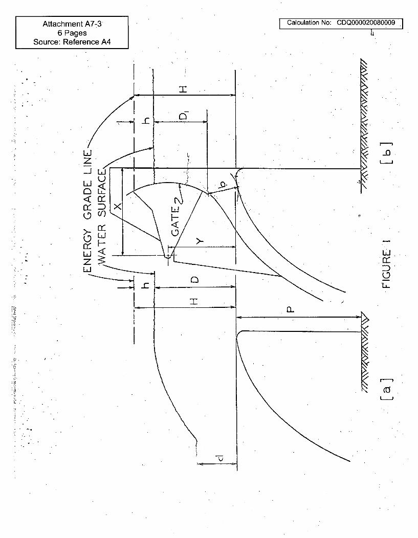
Attachment A7-36 Pages
Source: Reference A4
Calculation No: CDQ000020080009 I4
bLJ
L•
LJ <7zu-
Ii
-o
uJ..
D(-9LL
LJ
i -
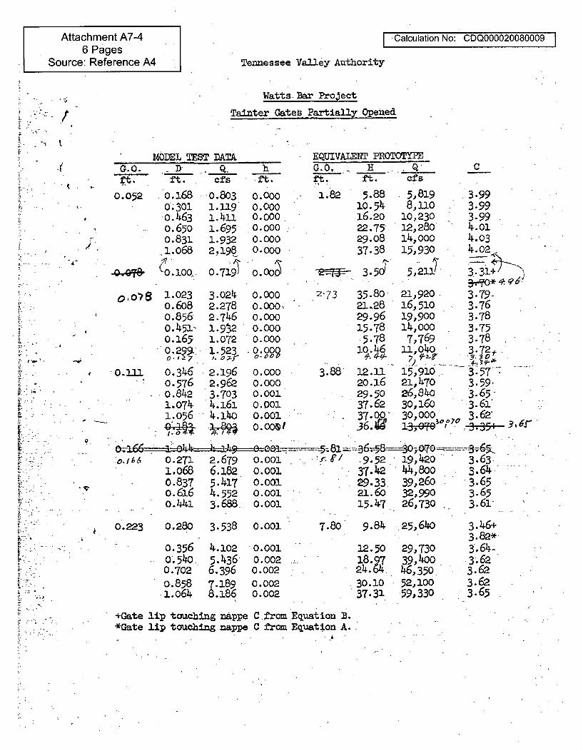
Attachment A7-46 Pages
Source: Reference A4
I Calculation No: CDQ000020080009 I
I
Tennessee Valley Authority
Watts.Bar ProjectTainter Gates3 Partially 0pene
MODEL TEST DATAG.O. - D . Q. hft. ft. cfs -ft.
EQUIVALENT PROTOTYPEG.0,. H -. Qft. ft. cfs
C
0.052 o.1680-301o. 463S.6500.831l.o68
" •o~100
p.. -
"4
--wI
o,oB8 1.0230.6080.8560.451-o.1650.299..
0.011. 0.3460.5760.8421.0741.056
0.8031.1191. 4u1.6951.9322,198
0 .719'1
3.0242.2782.7461.9321.072.1.523
/. a -.r2.1962,9623.7034.1614.14ho
0.0000.0000.000..0.0000.0000.000o.0oooo.ooo
0.000
0.000%0.0000.000
0.000
0.000
0.000<
0.0010.0010.0010. 0O1 I
1.82 5.8810.5416.2022.75.29.0837.38
3.5d
2-73 35.8021.2829.9615.78
5.78
3.88 12.1120.1629.5037-6237.00.36.,
5,8198, 11O
10,23012,280'14,00015,930
5,21J)
21,92016,51019,90014,0007,769
11,040
15,91021,47o26,84030,160" 30,0001 ,7
3.993.993.994.014.034.402
3i31
3.79-3.763.783.753.783.72,
3.57 '3.59.3.65-3.61*3.62"3.335+ i3- F
6,r 1 269F .9.52 19,420 3.63.i.o68 6.182 0.00.1 37.42 44,8oo 3.640.837 5.417 0.001 -29.33 39,260 3.65o.616 4.552 0.001 21.60 32,990 3.65o. ,4 3.688. O.OOl 15.47 26,730 3.61.
0.223 0.280 3.538 0.001 7.80 9.84 25,640
0.3560 *540.0.7020.8581.o64
4.1025.4366.396z.189.186
0.0010.0020.0020.0020.002
12.50
24.6
30.1037.31
29,73039,40046,35052,10059,330
3.46+3.82*3.64..
.3-.623.623.623.65
+Gate lip touching nappe C from Equation B.*Gate lip touching nappe C from Equation A..
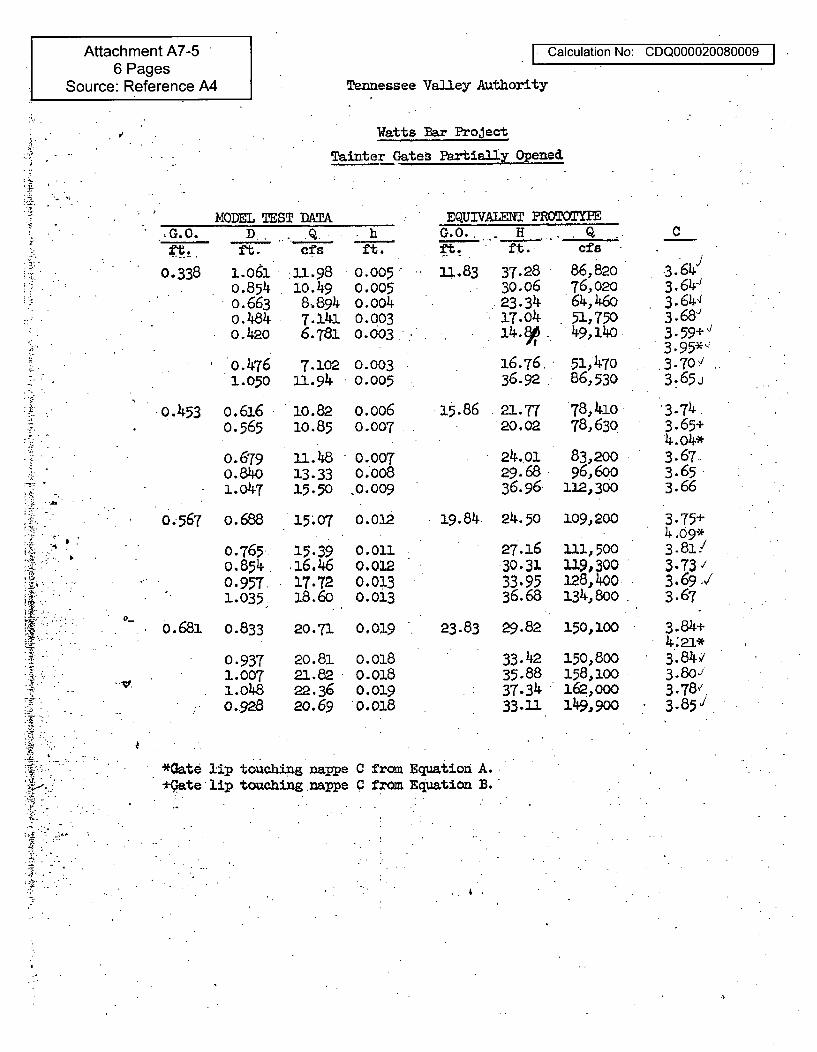
Attachment A7-56 Pages
Source: Reference A4
I Calculation No: CDQ000020080009 I
Tennessee Valley Authority
Watts Bar Project
Tainter Gates PartiallyOpened
U1.
.7.
,G.0.
0.338
MODEL TEST DATAD.. .Qft. cfs
1.o61 .:11.980.854 lO. 490.663 8-89Wo.484 7.14Jo.42O 6.7-8
I-
•hft.
0.005-0.0050.0040.0030.003
u.83 37.2830.0623.3417.0414.8 ,ye
16.76.36.92
86,82o76,02064,46051,75049,40
51'47086,530
EQUIVALENT PROTOYPEG.0. H. .. Q -
ft. ft. cfs
0.476 7.102 0.0031.050 11.94 0.005
o.453 o.6160.565
0.6790.84o1.047
1o.82 o.oo610.85 0.007
15.86 21.77 78,41o20.02 78,63P
1a.4813.3315.50
* 0.0070.008
10.009
24.0129.6836.96
83,20096,600
112,300
C
3.64J!3.644
3.68'3.59+3.95*`3.7013.65
3.743.65+4. o4*3.67--3.653.66
3.75+4 .09*3.81/3-73 /3.69 -V3.67
3.84+4.;2a*3.84,/3.80-/3.78',3.85,,
0.567 0.688 15.07 o.o12 19.84. 24.50 109,200
0.765o.851.0.9571.035
15.3916.4617.7218.60
0.0110.0120.0130.013
27.1630.3133.9536.68
111,500119,300128,400134,800
0O
o.681 0.833
0.9371.0071.0480.928
20.71 0.019 23.83 29.82 150,100
20.8121.8222.3620.69
o.0180.0180.019
33.4235.8837.3433.11
150,800158,100162,00010e9,900
*1
*Gate lip touching nappelip touching nappe
C fromC from
Equation A.Equation B.
. 4 .
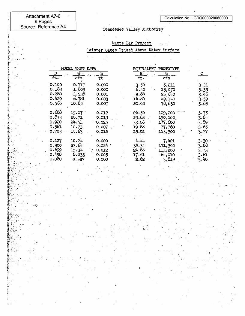
Attachment A7-66 Pages
Source: Reference A4
I Calculation No: CDQ000020080009 I
Tennessee Valley Authority
w.
IN
Watts Bar Project
Tainter Gates Raised Above Water Surface
MODEL TESTD.• _. q_____
DAT,
0.1000.1830.2800.420o.565
o. 6880.8330.920o.5610.703
0.1270.9000.699o.4980.080
0.717
3.5386.781
10.85
15.0720.7124.5110.73.15.63
10. 2423.6415.3348.833.0; 527
h
0.0000.0000.0010.0030.007
0.0120.O0l90.0250.0070.012
0.000
0.0240.0120.0050.000
EQUIVALET PROT0T=PEH . Q .
cfs
3.506.409.84
14.8020.02
24. 5029.8233.0819.8825.02
4.4432-. 3424.8817.61ý.82
5,21113,07025,64049,14078, 630"
109,200150. 100177,60077,760
113,300
7,)el.171,300111,200
64,0103,819
C
3.313.353.463.593.65
3.753.84,3.893.653.77
3.303.883.733.61"3.4o
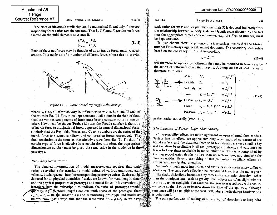
Attachment A81 Page
Source: Reference A7
I Calculation No: CDQ000020080009
SIMILITUDE AND MODELS [Ch. 11 Sec. 11.2] BASIC PRINCIPLES 491
The state of kinematic similarity can be maintained if, and only if, the cor-responding force ratios remain constant. That is, if F. and Fb are the net forcesexerted on the fluid elements at A and B,
(Fa)p = (Fb)P (11-3)(F.a). (Fb)m
Each of these net forces may be thought of as an inertia force, mass x accel-eration. It is made up of a number of different forces (those due to gravity,
a '""
Vb
Figure 1l-1. Basic Model-Prototype Relationships
viscosity, etc.), all of-which vary in different ways with v, L, p, etc. If each ofthe ratios in Eq. (11-3) is to be kept constant at all points in the field of flow,then the various components of force must bear a constant ratio to one an-other. Now it can be shown (Prob. 11.1) that the Froude number is the ratioof inertia force to gravitational force, expressed in general dimensional form;similarly that the Reynolds, Weber, and Cauchy numbers are the ratios of the,inertia force to viscous, capillary, and compression forces respectively. The ifinal conclusion is the same as that already drawn from Eq. (11-1): that if acertain type of force is effective in a certain flow situation, the appropriatedimensionless number must be given the same value in the model as in the -prototype.
Secondary Scale Ratios
scale ratios for mass and length. The time scale T, is deduced indirectly fromthe relationship between velocity scale and length scale dictated by the factthat the appropriate dimensionless number, e.g., the Froude number, mustbe kept constant.
In open channel flow the presence of a free surface means that the FroudenumberFr is always significant, indeed dominant. The secondary scale ratiosbased on the constancy of Fr and its corollary
vr =LrW12 (11-4)
will therefore be applicable, although they may be modified in some case bythe action of influences other than gravity. A complete list of scale ratios istherefore as follows
Mass M,VF _r -J, 'Length, 4V•,. , Velocity v, L L1/2
Time T = LVr-1 LrI/2
Discharge Qr = VrL. 2 - Lr
2 -
Force F, = MrLrTr- 2 = prLr I(11-5)
Pressure .p, FLr - = =pL,.
as the reader can verify (Prob. 11.2).
The Influence of Forces Other Than Gravity
The detailed interpretation of model measurements requires that scaleratios be available for translating model Values of various quantities, e.g.,;..velocity, discharge, etc., into the corresponding prototype values. Scales can be-ideduced for all physical quantities if scales are known for mass, length, time,and the physical properties of prototype and model fluids. It is convenient tointroduce here the subscript r to indicate the ratio of prototype: model
Zyodel lengths are one-tenth those of the protoype, then Ne subscripts p and m indicating prototype and model a
before. Now it.Wg always true that the mass ratio M,. =p,L,.3 , so we have
Compressibility effects are never significant in open channel flow models.Surface tension effects are appreciable only when radii of curvature of theliquid surface, and the distances from solid boundaries, are very small. Theywill therefore be negligible in all real prototype situations, and care must betaken to keep them negligible in model situations. This is accomplished bykeeping. model water depths no less than an inch or two, and similarly forchannel widths. Beyond the taking of this precaution, capillary effects donot warrant any further attention.
Viscosity is much more important, and exerts its influence in many different.situations. The term scale effect can be introduced here; it is the name givento the slight distortions introduced by forces-for example, viscosity-otherthan the dominant one, such as gravity. Such effects are often slight withoutbeing altogether negligible. For example, the flow over a spillway will encoun-ter some slight viscous resistance down the face of the spillway, althoughresistance will be negligible at the crest itself, where the discharge-head relationis determined.
The only perfect way of dealing with the effect of viscosity is to keep both
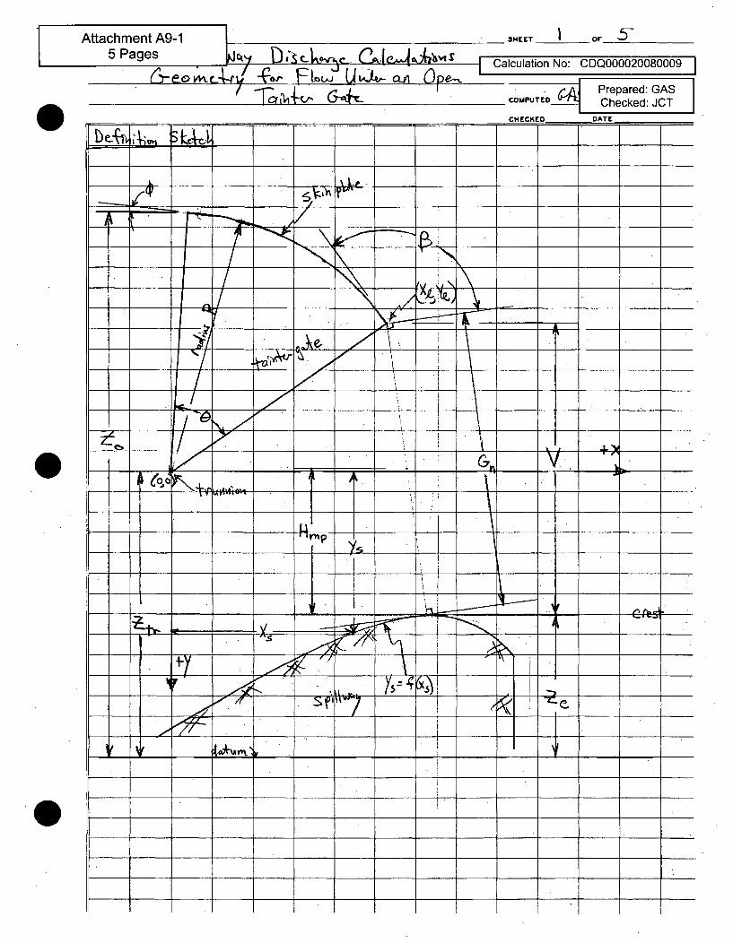
I
1 Attachment A9-15 Pages lc4\1 D-c-i",e _l Cas
E w U G -c-a- p.
SHEET I OF 5-
Iculation No: CDQ000020080009
.Aj _Prepared: GASCOMPUTE"O2"_ Checked: JCT
0
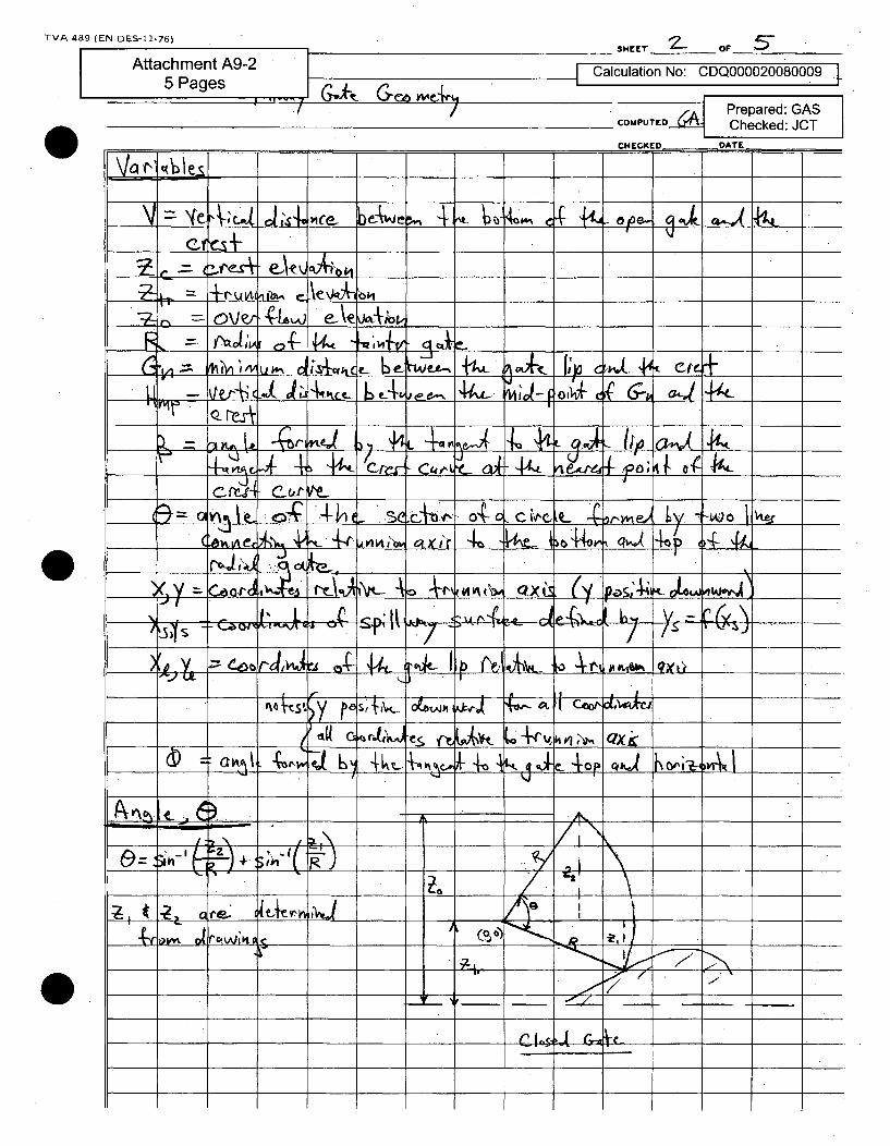
TVA 489 (EN DES-11-76)SHEET or O _ 5"
Attachment A9-25 Pages I~4-~ (Z~~ i
, __,,__ .__ , co,•t '.J-_.1 /
I Calculation No: CDQ000020080009 -
Prepared: GASCOPUTEDA Checked: JCT
r•uIr n DATF
0
iI~iI I'sie 14 .1 -M a _ _ _ _
_~~~_ _: '4,e we-Ir_
__ ~ O~r __ A.1 eV ?9 _ _ _ _ __ __
4, - v /4v-
I•Y "7 J~ I'", .L l" At (I l 04 a k
L~ @11L G4___C. 4___I cfý.X ___, L_ o; li• -~' 4__ -
1. - A LI~ 44 x _
:•, L&-•_ oj I,,••
\G___ a___ Sc AX±1 I__ __W *0 a ,( Coot-
_ _ v~J _ __ __ _ __I
a o v r-{ V4,___ ~~~ ~ ~ ( 0)~ _ _ _ _ _
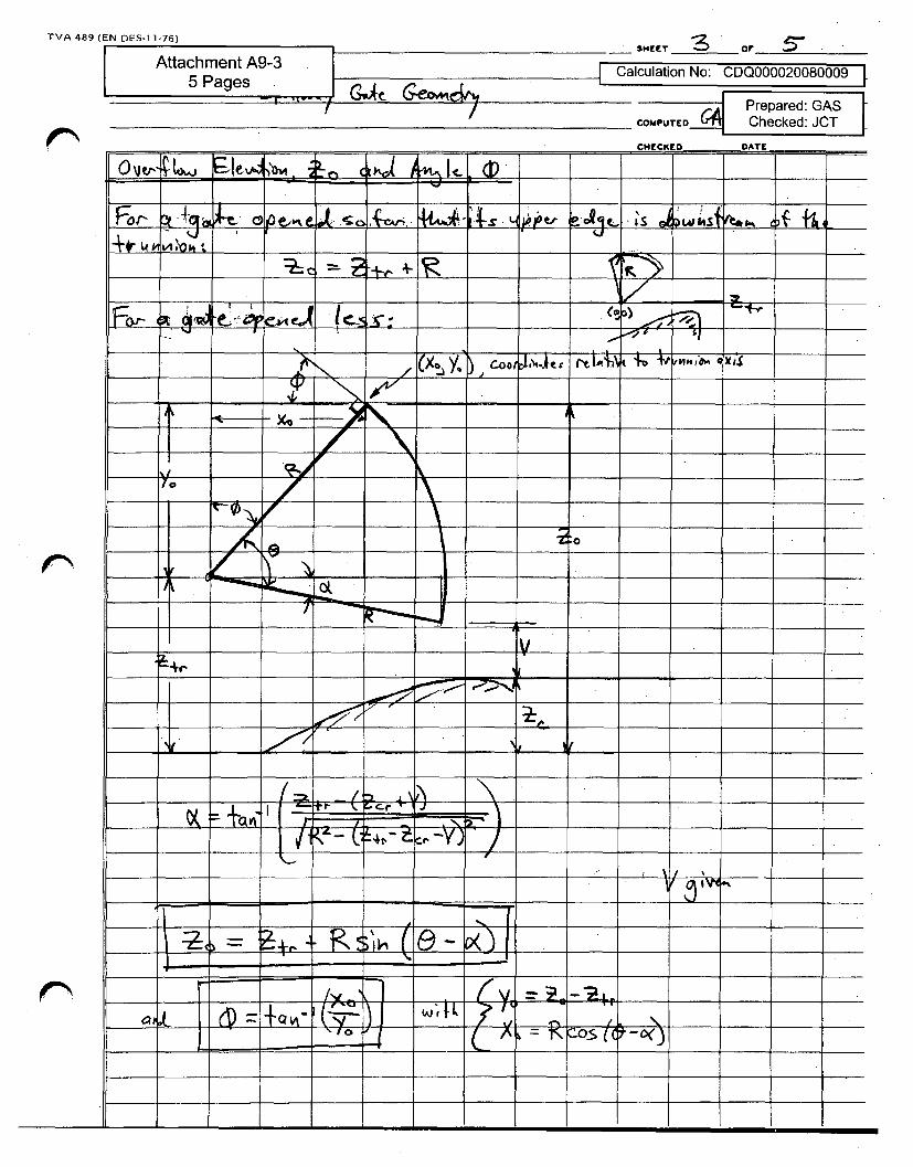
TVA 489 (EN DES-11-76)
Attachment A9-35 Pages r- I, f
4-.- A.
SHEET or_________
Calculation No: CDQ000020080009
,-AI Prepared: GASCOhPUTErO2 Checked: JCT
• -•.-.-I - -/ %r -.A1V
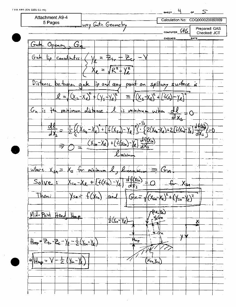
TVA 489 (EN DES-11-76)SHEET OF -O
Calculation No: CDQ000020080009 I
AC • Prepared: GASChecked: JCT
P~rwrnr n~rr
A _, =
_- V . .. .. . .
L IM h IVII* LA ne I• V -KIWý,\ h. ItC 1
If . - '%
J CAAS(x,~ ~ ~ --x (L-V•) •-
IA
- - . .0
j4 ,+ _ -•
0
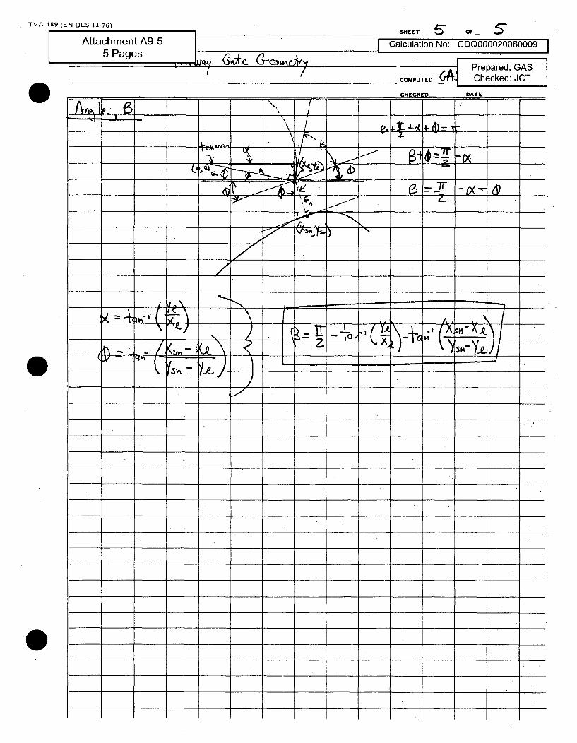
TVA 489 (EN DES-11-76)SHEET ý" OF
iýA Prepared: GASCOMPUTED Checked: JCT
0
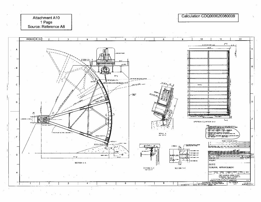
Attachment AlO Calculation CDQ000020080009
1 PageSource: Reference A8
oo0mgI 10Lo1 2 I 3 I I 5 1 6 I 7 I a I 9 I 10 I 11 I 12-I - I-
rA , I
20"-'
A AI
- - - -- - - - - - - - - - - - - - - - - - - - - - -
liii m i'Ifl
11 - --- - ------
1----- ------- BB
i
15-- - -
- - - - - --
C--.------------
-------- ------ -
--.----- --------
---------------- :S- - - J L------
- - - - - - - - - - - - - - - - - - - - - ---------- 11---------
---------------------------------------------------------"E-----------------I. .
--- -- - -- -
C
D D
L-AEUPSTREAM ELEVATION B-B
it-m• LIT - T. mmsDETAIL- A
F F
G
SECTION Y-Y
=1 -- I--I - I - I- I - I - I E-I As I.-I,- 'm . ',-, . . . . . . ý(••• NoP I
SP
ILWVAY
SECTION A-
SECTION C-C
GATES
GENERAL ARRANGEMENT
FORT LOUDOUN HYDR0 PLANTTENNESSEE VALLEY AU1HORITY
HI
- R1' I :7..1to I mo I r,4W900~1. __________________________
1 2 3 I 4~ I ~. I 6 7 I I I I VOS WIN OVNPHE1EL0E000AINH _______
1 I 2 1 3 1 4 1 5 1 6 1 7 1 8 11115.... OR.o .... 0RI
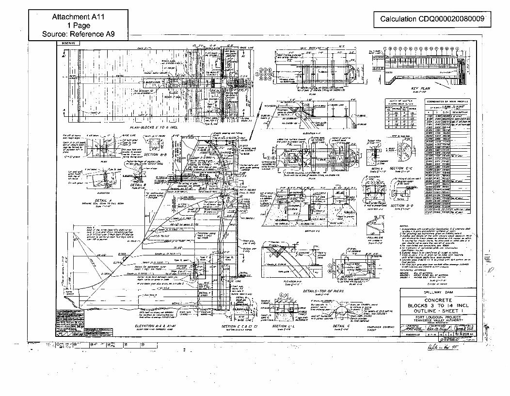
Attachment Al11 Page
Source: Reference A9
I Calculation CDQ000020080009 II
90ENIS IlL.4oooo~s .~j9o, ~ 00Sf 0/SfC•tt ## -•-;
, I
I , 0004.70507/9799/ CN7~
K 9990900 1
L IN
A.J_ ___
IF " .', -- ,
1 I I.. .a tI . I •' " " -
k1ADk tt V I CM
- ý,- I-A-t. MhV,-
i I I I, I ' II e, i '#•- lil + qi l~ I ,, JrI-____ 70 SAE 9/
A "L A/ S("'.. 90/90/99 C52 J-' 1
L-s I0~ IF -----
9C_ D4599 1 -. PLA
DETAIL ~ D~AI AB9-C O - ~ 79S
- A IX -
-4
o9,929N oSECT/ION C-C
5750 / ,SECT/ON D-0CC/,S/C tA-SCO j/oo
COO - 3 OF -R -F1
W144 9 /50t /
9A000 I/400 00.000
M79* 7- 90 95 ___
0002 009*95* q
•d- d'e" "•________i 4
4/2/21 - 004fl01/~j ______ 000 7A. CSC5N O/LA~~09
w20-C
9/090 0'~~A009, . IAN N-1
.00,0/C "A/" DfTAILS-TOP OP PIERS
A A SECTION L- ANAI C /4/ 06/CON -
/ 0NC//CNOC-C,0014
0/9 006//S 70/049
CC09CCO//00S7S.C///0799 0-.' 000C/.// S05C/
AC-CCCO/0,6 rS.C 00 S/020A,/C505 7.
0 /.~9 00 5/96/099 A-A. 69909900O 0/7004./C, 040/500/000,905900/0/SSC-./O.CN..///07C5/CCCS'.
S/09L50/0./0/550200CC009990060 .9000SCO-/,55/0/57/ 07 ,0~C/.SC/C00~OL7S. - /00/90/9,9ASC,///C0000 0/00.
O 9,905.0 00900004 CO.60/C90 //* 50705/00/0//SO./0/0099.9,0/C /5565/7 COC SO rd/SO 009.50/964
CC//CC 57/SC /750/96 40400 0505 50.59709675/5/90/054700 57*090 070049900700/CC 70./C
9405C1*0 CCC
/04/0007/00.0709900/99050C0/0/00505CCCC50970/000/CCS 0900090522/709075090*0/0/4050922/709000970.90*
0.5404/,/,p94/o0/02
SPILLWAY DAM
CONCRETEBLOCKS 3 TO 14 INCL
OUTLINE - SHEET IFORT LOUDOUN PROJECT
TENNESSEE VALLEY AUTHORITY
z
.7-
S....... I-.
I ~I~*; e_ 9C~ :.__ -0C I&; ® -j
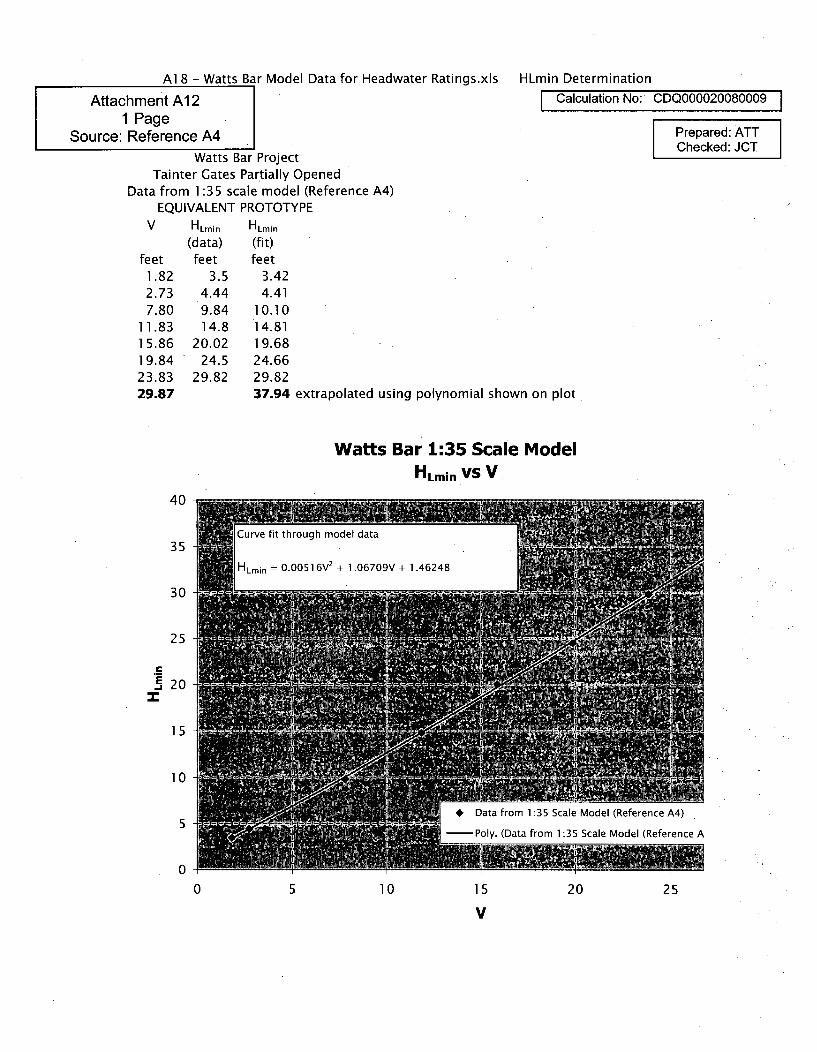
Al 8 - Watts Bar Model Data for Headwater Ratings.xls HLmin Determination
Attachment Al 2 Calculation No: CDQ000020080009
1 PageSource: Reference A4 Prepared: AT
ICheckedJWatts Bar Project
Tainter Gates Partially OpenedData from 1:35 scale model (Reference A4)
EQUIVALENT PROTOTYPEV HLmin HLmin
(data) (fit)feet feet feet
1.82 3.5 3.422.73 4.44 4.417.80 9.84 10.10
11.83 14.8 14.8115.86 20.02 19.6819.84 24.5 24.6623.83 29.82 29.8229.87 37.94 extrapolated using polynomial shown on plot
Watts Bar 1:35 Scale ModelHLmin VS V
40
35
30
25
., 20
15
10
5
00 5 10 15 20 25
V
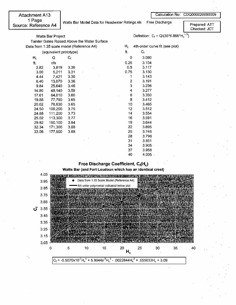
Attachment A13 Calculatior1 Page Watts Bar Model Data for Headwater Ratings.xls Free Discharge
Source: Reference A4
No: CDQ000020080009 I
Prepared: ATTChecked: JCT
Watts Bar ProjectTainter Gates Raised Above the Water Surface
Data from 1:35 scale model (Reference A4)
(equivalent prototype)
Hc Q Cf
ft. cfs2.82 3,8193.50 5,2114.44 7,4216.40 13,0709.84 25,640
14.80 49,14017.61 64,01019.88 77,76020.02 78,63024.50 109,20024.88 111,20025.02 113,30029.82 150,10032.34 171,30033.08 177,600
3.363.31
3.303.363.463.593.603.653.653.753.733.773.843.883.88
Definition: Cf = Q/(35*6.866*Hc1. 5)
Hc 4th-order curve fit (see plot)
ft. Cf
0 3.0900.25 3.104
0.5 3.1170.75 3.130
1 3.1432 3.1913 3.2364 3.2776 3.3508 3.412
10 3.46512 3.51214 3.55416 3.59119 3.64422 3.69525 3.74628 3.79831 3.85134 3.90537 3.95840 4.005
Free Discharge Coefficient, Cf(Hc)Watts Bar (and Fort Loudoun which has an identical crest)
4.05
3.95
3.85
3.75
3.65
t3 3.55
3.45
3.35
3.25
3.15
3.05
0 5 10 15 20 25 30 35 40
Cf = -5.5070xl0- Hc4 + 5.9044x'5 Hc - .0022844Hc2 + .055033Hc + 3.09
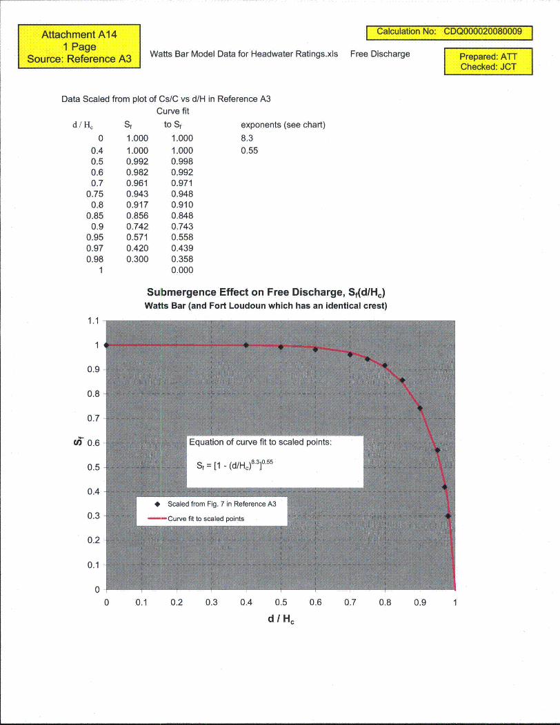
Attachment A141 PageSo e R e A Watts Bar Model Data for Headwater Ratings.xlsSource: Reference A3
I Calculation No: CDQ000020080009 1
Free Discharge Prepared: ATChecked:JCT
Data Scaled from plot of Cs/C vs d/H in Reference A3Curve fit
d/Hc
00.40.50.60.7
0.750.8
0.850.9
0.950.970.98
1
Sf to Sf
1.0001.0000.9920.9820.9610.9430.9170.8560.7420.5710.4200.300
1.0001.0000.9980.9920.9710.9480.9100.8480.7430.5580.4390.3580.000
exponents (see chart)
8.30.55
Submergence Effect on Free Discharge, Sf(d/Hc)Watts Bar (and Fort Loudoun which has an identical crest)
1.1
0.9
0.8
0.7
W 0.6
0.5
0.4
0.3
0.2
0.1
00 0.1 0.2 0.3 0.4 0.5 0.6 0.7 0.8 0.9
d / Hc
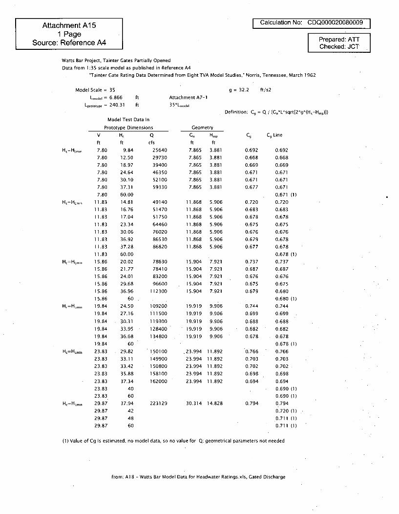
Attachment A 151 Page
Source: Reference A4
Calculation No: CDQ000020080009
Prepared: ATTChecked: JCT
Watts Bar Project, Tainter Gates Partially Opened
Data from 1:35 scale model as published in Reference A4
"Tainter Gate Rating Data Determined from Eight TVA Model Studies," Norris, Tennessee, March 1962
Model Scale = 35
Lmodel = 6.866
Lprototype = 240.31
g = 32.2 ft/s2
ftft
Attachment A7-135*Lm.ode
Definition: C. = Q / {Gn*L*sqrt[2*g*(HcHmp)]}
Model Test Data In
Prototype Dimensions Geometry
Gn HmpV
ft
HC=HLfLmin 7.80
7.80
7.80
7.80
7.80
7.80
7.80
Hc=HLmmi 11.83
11.83
11.83
11.83
11.83
11.83
11.83
11.83
Hc=HLmin 15.86
15.86
15.86
15.86
15.86
15.86
HC=HLfLmin 19.8419.84
19.84
19.84
19.84
19.84
Hc=HLmin 23.83
23.83
23.83
23.83
23.83
23.83
23.83
Hc=HLmmi 29.87
29.87
29.87
29.87
Hc
ft
9.84
12.50
18.97
24.64
30.1037.31
60.00
14.81
16.76
17.04
23.34
30.06
36.92
37.28
60.00
20.02
21.77
24.01
29.68
36.96
60
24.50
27.16
30.31
33.95
36.68
60
29.82
33.11
33.42
35.88
37.34
40
60
37.94
42
48
60
Qcfs
25640
29730
39400
46350
52100
59330
49140
51470
51750
64460
76020
86530
86820
78630
78410
83200
96600
112300
109200
111500
119300
128400
134800
150100
149900
150800
158100
162000
223129
ft7.865
7.865
7.865
7.865
7.8657.865
ft
3.881
3.881
3.881
3.881
3.881
3.881
11.868
11.868
11.868
11.868
11.868
11.868
11.868
15.904
15.904
15.904
15.904
15.904
19.919
19.919
19.919
19.919
19.919
23.994
23.99423.994
23.9942 3.994
5.906
5.906
5.906
5.906
5.906
5.906
5.906
7.921
7.921
7.921
7.921
7.921
9.906
9.906
9.906
9.906
9.906
11.892
11.89211.892
11.892
11.892
C9 C9 Line
0.692 0.692
0.668 0.668
0.669 0.669
0.671 0.671
0.671 0.6710.677 0.671
0.671 (1)0.720 0.720
0.683 0.683
0.678 0.678
0.675 0.675
0.676 0.676
0.679 0.678
0.677 0.678
0.678 (1)
0.737 0.737
0.687 0.687
0.676 0.676
0.675 0.675
0.679 0.680
0.680 (1)
0.744 0.744
0.699 0.699
0.688 0.688
0.682 0.682
0.678 0.678
0.678 (1)
0.766 0.766
0.703 0.703
0.702 0.702
0.698 0.698
0.694 0.694
0.690 (1)0.690 (1)
0.794 0.794
0.720 (1)
0.711 (1)
0.711 (1)
30.314 14.828
(1) Value of Cg is estimated; no model data, so no value for Q; geometrical parameters not needed
from: Al 8 - Watts Bar Model Data for Headwater Ratings.xls, Gated Discharge
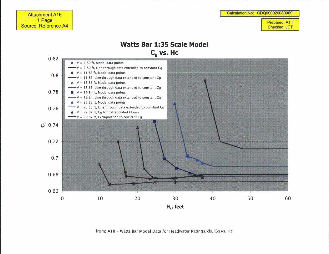
Attachment A161 Page
Source: Reference A4
Calculation No: CDQ000020080009
Prepared: ATTChecked: JCT
Watts Bar 1:35 Scale ModelCg vs. Hc
0.82X V = 7.80 ft, Model data points
V = 7.80 ft, Line through data extended to constant Cg
0.8 0 V - 11.83 ft, Model data pointsV = 11.83, Line through data extended to constant Cg
A V = 1 5.86 ft, Model data points
V = 1 5.86, Line through data extended to constant Cg
0.78 E V = 1 9.84 ft, Model data pointsV = 19.84, Line through data extended to constant Cg
A V = 23.83 ft, Model data points
0.76 -V = 23.83 ft, Line through data extended to constant Cg
A V = 29.87 ft, Cg for Extrapolated HLminV = 2QR7 ft Fytrannintinn tn rnnrtant Cn
U0T 0.74
0.72
0.7
0.68
0.66
0 10 20 30 40 50
Hc, feet
60
from: Al 8 - Watts Bar Model Data for Headwater Ratings.xls, Cg vs. Hc
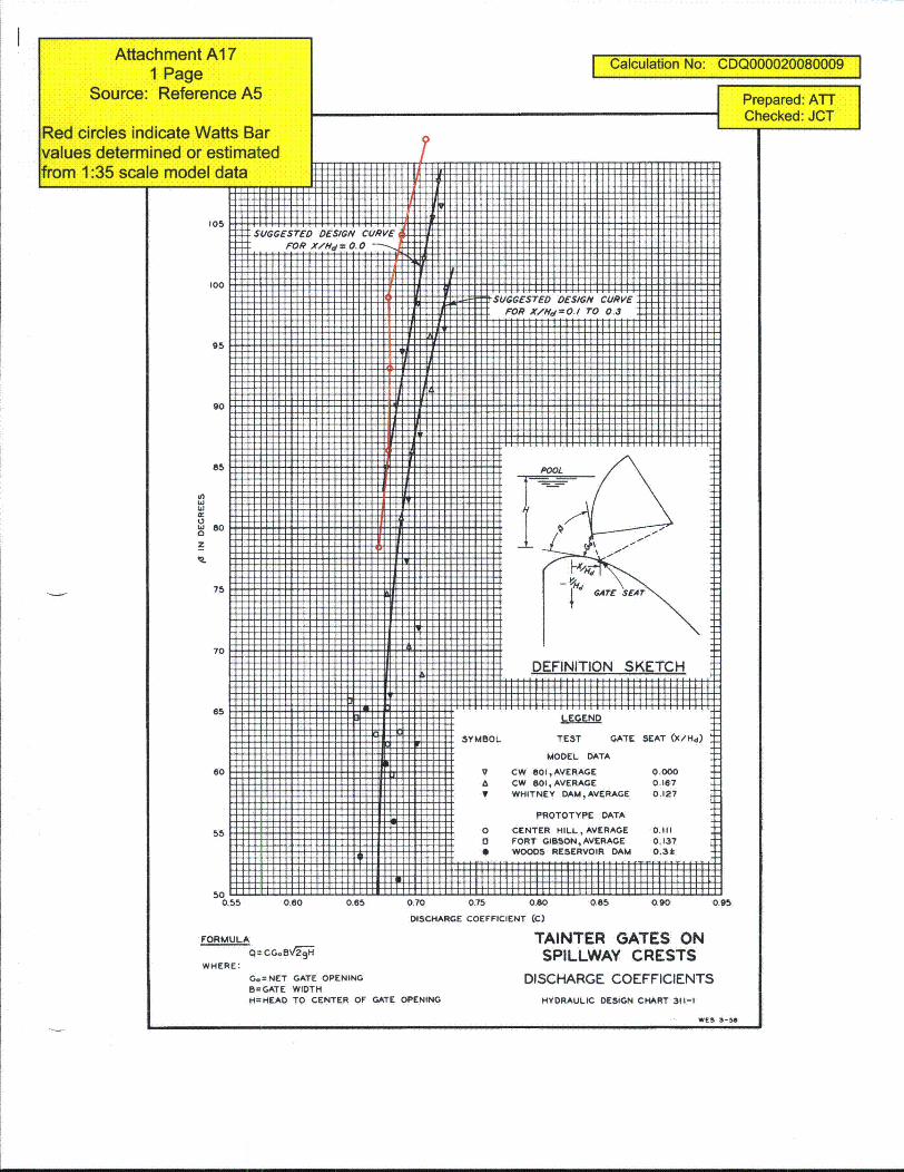
Attachment A171 Page
Source: Reference A5
Red circles indicate Watts Barvalues determined or estimatedfrom 1:35 scale model data
Calculation No: CDQ000020080009
Prepared: ATTChecked: JCT
7
105
95
90
85
0.5
I5
6d 0
75
500.55 0.65 0.70 0.75 0.80 0.85 0.90 0.95
DISCHARGE COEFFICIENT (C)
FORMULA
Q-CG.BV2i9H
WHERE:
G.=NET GATE OPENINGB=GATE WIDTHH=HEAD TO CENTER OF GATE OPENING
TAINTER GATES ONSPILLWAY CRESTS
DISCHARGE COEFFICIENTSHYDRAULIC DESIGN CHART 311-1
WES 3-50

TVACalculation No. CDQ000020080009 Appendix B Rev: I Plant: GEN Page: BI
Subject: Initial Dam Rating Curves, Fort Loudoun Prepped WBB
Checked ACM
Appendix B: Hydrostatic Loads on the Spillway Tainter Gates
The Hydrostatic loads on the spillway tainter-gates for Fort Loudoun Dam can be found in the following calculations.
BI References
B 1. "Watts Bar Dam - Flood and Earthquake Analysis on Radial Spillway Gates, pages 76-100" Tennessee ValleyAuthority, HEPE3WBHSQN-WBNBLNBFN.
B2 Calculations
Reference B 1 evaluates the structural capacity of the radial spillway gates at Watts Bar Dam. This reference wasused as a basis for evaluating the margin between the forces on the closed gates (FRIloSd) when the headwaterelevation is at the top of the gate (815.00 feet) and when the gates are completely open (FRopen) and the headwaterelevation is at 837.00 feet. The margin is defined at the ratio of FRepen to FRclosd. The calculation of these forcesand the results of this comparison are shown in Figure B 1.
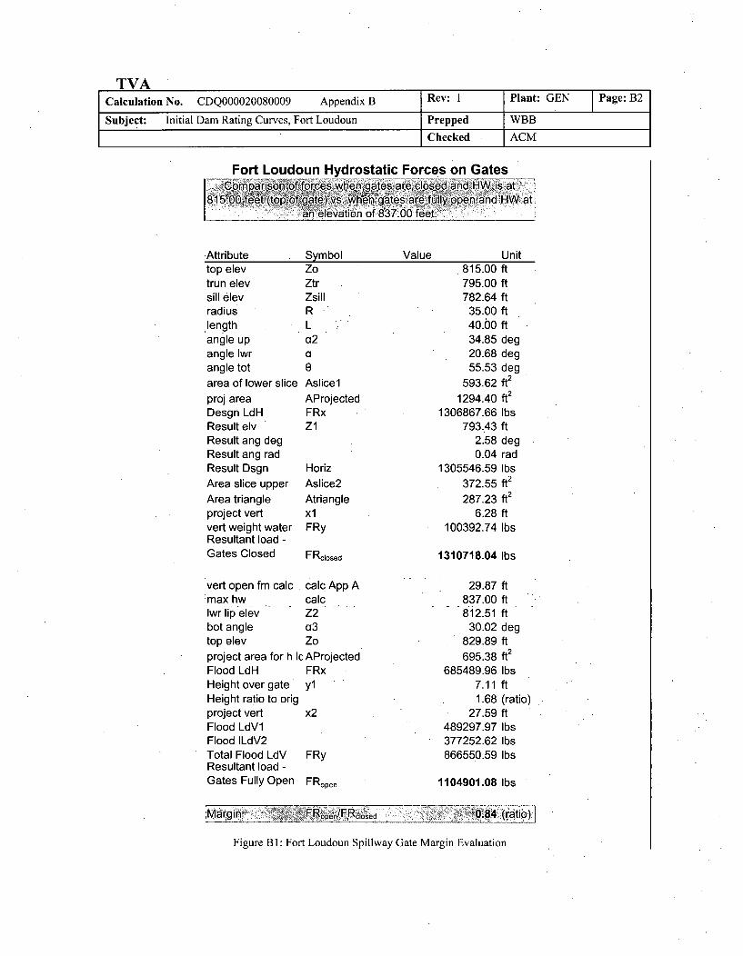
TVACalculation No. CDQ000020080009 Appendix B Rev: 1 Plant: GEN Page: B2
Subject: Initial Dam Rating Curves, Fort Loudoun Prepped WBB
Checked ACM
Fort Loudoun Hydrostatic Forces on Gatesoprnparison of forces when g~ates ar~e closed and]1 isat
8185.00,•feet topof gatel)vsa.n of8:a00tes are fulle open: ..... an elevation of 837.00 feet.
Attributetop elevtrun elevsill elevradiuslengthangle upangle lwrangle tot
area of lower slice
proj areaDesgn LdHResult elvResult ang degResult ang radResult Dsgn
Area slice upper
Area triangleproject vertvert weight waterResultant load -Gates Closed
SymbolZoZtrZsillR
Value
La2a
AslicelAProjectedFRxZI
Horiz
Aslice2
AtrianglexlFRy
FRciosed
Unit815.00 ft795.00 ft782.64 ft
35.00 ft40.00 ft34.85 deg20.68 deg55.53 deg
593.62 ft2
1294.40 ft2
1306867.66 lbs793.43 ft
2.58 deg0.04 rad
1305546.59 lbs372.55 ft
2
287.23 ft2
6.28 ft100392.74 lbs
1310718.04 lbs
vert open fm calc calc App A:max hw calclwr lip elev Z2bot angle a3top elev Zoproject area for h Ic AProjectedFlood LdH FRxHeight over gate ylHeight ratio to origproject vert x2Flood LdV1Flood ILdV2Total Flood LdV FRyResultant load -Gates Fully Open FRopen
29.87 ft837.00 ft812.51 ft
30.02 deg829.89 ft
695.38 ft2
685489.96 lbs7.11 ft1.68 (ratio)
27.59 ft489297.97 lbs377252.62 lbs866550.59 lbs
1104901.08 lbs
Magin .- pen/cose..... ,0'84 (ratio)r
Figure B 1: Fort Loudoun Spillway Gate Margin Evaluation
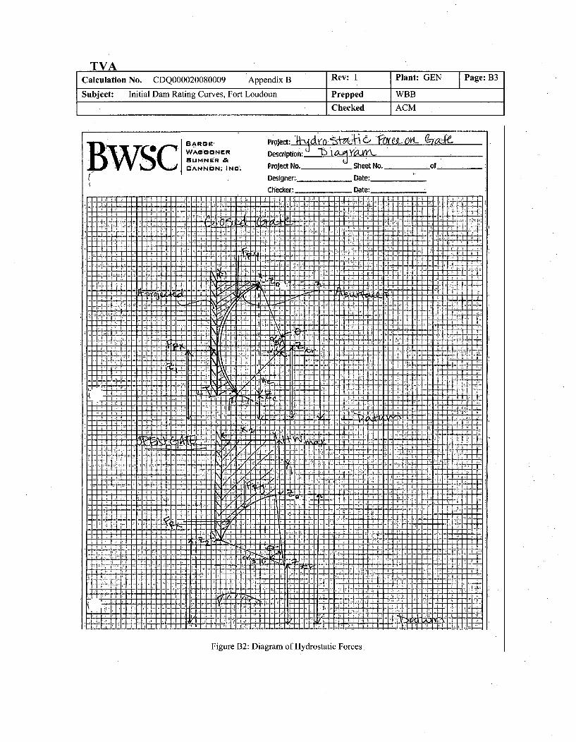
TVACalculation No. CDQ000020080009 Appendix B Rev: I Plant: GEN Page: 133
Subject: Initial Dam Rating Curves, Fort Loudoun Prepped WBB
Checked ACM
' WAGGON[UNER Description;-W. Li .b
B W v! ANNONi INM• Project No.- . Sheet No. of.
(• Designer:. Date:
Checker: Date:
- -. P r - 1 4
.1 ..'..7
17 7.
:lF
Figure B2: Diagram of Hydrostatic Forces
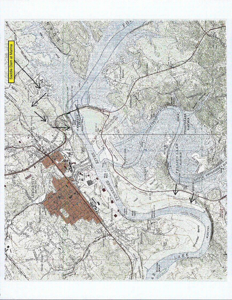
CU
WN'
'K>V4
\~ \~ ~ ~' -
404
(4 0ifi
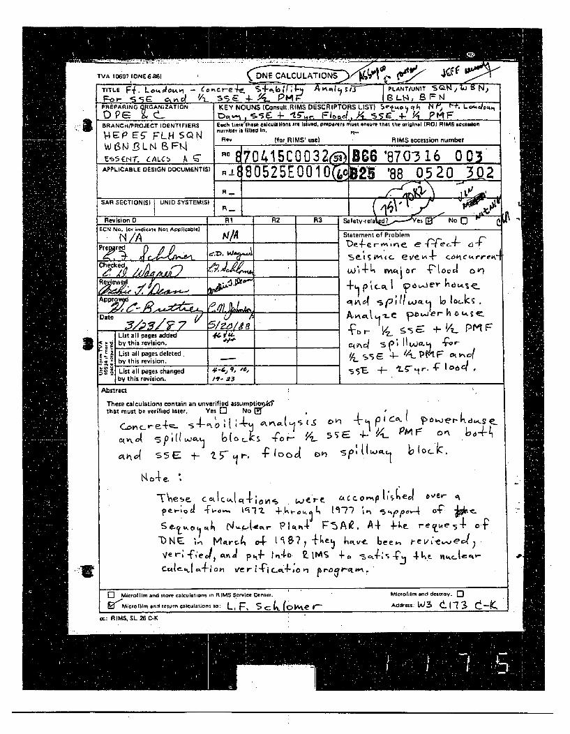
TVA 10697 lONE4,B61I
TVA 10697(DNE& 861DNE CALCULATIONS ~~% "' 4 j~~TITLE FR . LA~vdýi -- Ceij-e'• S4-.{( !/kL A-r6ttC ;IJ PLANT/UNIT SGIN,/".J 1 No
-- ,g , r' SSE 4-9- PMF' 1 BLt4, 8FS
3
S
PREP•RING G.ANIZATION KEY NOUNS fConsultRIMS DESCRIPTORS LIST) S"-oz.q. w('l h+' L.otdae%,.m0 96: t 'cvt , iiE 4- Fic.. )/l s, 5r, !-L PM
BRANCH/PROJECT IDENTIFIERS Each lima theae tass•latong 4r itiuad. preparersnuit ensure that the original (RO RIMS acceslon
VI4 S P E5 FL - SQ N number is filTled In.II., E5- FLH Rev (for.RIMS' usel RIMS accession numberWB IS 5L N 9 FtA0
E-55EN-r.CALC A~ RE 0415C0032rs) 06 '870-316 0 03APPLIC EDESIGN DOCUMENTISI R' 80525E 0010LA '25 '88 05 2 03 02
R __. ,/JI'.
SAR SECTION(S) UINID SYSTEMISI
Revision 0 R1 R2 R3 Safety-reia d?a' No QECN No. (Or indicate Not Applicable)
.'N /Al t1• •Statement of Problem
Prered De4--e r- tsr't e- e -e -- f 64~-,sets.c, eve--. cacrreK
Approv q 0
Date powe zo..ee
List all pages added 4 .- ,e' +V.. PMF-d{ by this revision. _'______;_I__-_,____-
List all pages deleted. 4- PM F14 r 01,.; by this revision. "-
3 List all pages changed 444,,9, '-a, 5s .- t.-r. 4
by this revision. 17 -23
Absiract
These calculations contain an unverified assumptio5Kthat must be verified later. Yes 0 No U
P N wc , I,.(.L4,,o- V9 5, 4- PM F4i, , .,,
S 5S:,e 4- ,1,,. p5Do4 D --
] Microltlr -and store calculaions n RIMS Service Center. ' Microfllmr aren delrov. q
2ýMicoofilm anti return ccuatios L,F Sc .e- Address:WL3 t("73 t-K,c: AIMS, SL 26 C-K
9 ..
. EPE5FLHS QN-WBN.BLNBF 8.
-~'-5--,6' 1 '{ A I REVISION LOG
[Till" Fla, SE& 5E ~ 4. fmr!
Revision O E NateNo. DESCRIPTION OF REVISION Approved
/ 4u*mE4 Av~ 444s
TVA 1034 WIN Oi-.4711
HEPE5FLHSQN-WB NBLN BFN
CALCULATION DESIGN VERIFICATION (INDEPENDENT REVIEW) FORM
O ,,Li 5A 1-k•uAa 8o MAA/Calculation N~o.
/Revision
If-
Method of design verification (independent review) used (check method used):
1. Design Review __
2. Alternate Calculation3. Qualification Test
Justification (explain below):
Method 1: In the design review method, justify the technical adequacy of thecalculation and explain how the adequacy was verified (calculation issimilar to another, based on accepted handbook methods, appropriatesensitivity studies included for confidence, etc.).
Method 2: In the alternate calculation method, identify the pages where thealternate calculation has been included in the calculation packageand explain why this method is adequate.
Method 3: In the qualification test method, identify the QA documentedsource(s) where testing adequately demonstrates the adequacy of thiscalculation and explain.
0~r rZ- S ,r re -?ereneg 4twv C r- "'T cea '
Li -,
Idespen d ertfReviewer)(Independent Reviewer )
S
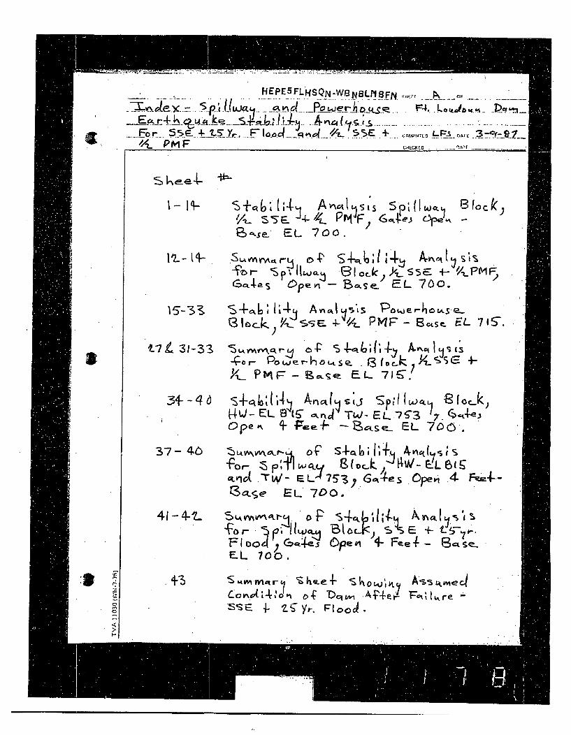
HEPESFLHSQN'.WBNBLNBFN
E76,r- 5 5E -~t57Yr. >~o4q~o L E +. .•/pm F
z;iu* rOF
F O(4J J4Iii-
£ubfCaLCrC .-fl,7 -- -
s ke-e4-
I- H-
e--se_ EL 700.
I c k,
IzL- t4-%F r- 3p,.o..k,
GCLp-I S Openi - ThCLSP')cS5E +- '/_.PMFEL 700.
& S- I4-sk- A, fl.RILs ?ue,•,-6 L4.se-L03 l•C._.. Y-/: S- . 4-4_ P MF" - 13cs,. EL. 7 1 S-.
V7 4~ 31 -3-32S A-for- Pog..erla-tse~ f3 (oc-k I zLS S G +
XL. P MFP- 9c, s 4 E L 71 S-
3-46-L S-ki't 1A4ý Arnctt~stJ SpiA IOL S 0 Jk,4/-ELL•w ,.•jr TW-EL.7-'3 7.G.,•3
Ope% 1 ,e- c-se. EL 700.
37- 4c ZWAVAV\G-r- of' -. 6 , VR7
9tv.d .'riA- EL 76y .Gt:ýtes Opei .4 F-ý-.-13,o.e EL 700.
41 - 4-t_ S,.w, .'U . " "
E.L 700.
S44 E I+- k aI
I-
+3Cov•.a( 4,'o-i D-C .A-'--e ',ilre -SS-e 4- ?-ýyr-. Flood,

HEPE5FLHSQN-WBNBLNBF. ,,•SE _OF
. F.o~r. ....... 5..E....- 2 5-Y F• .v, o and _S5 4 coIE LF• o.rr 3FS WE
2.PMvF HCE DA.
s WEET *44 SL~tcr OP S~aijd;4-ý Av,ýs
{'o r Pc..,wer-~~ rv~~ o - cAOLksý
'/-L- S -5 e-P M F'.-
fýOr- IE14ql VAC Loe%4-;I4 A(eJ~Y-L S 5 E //t-p T
a
* .
•'/..•
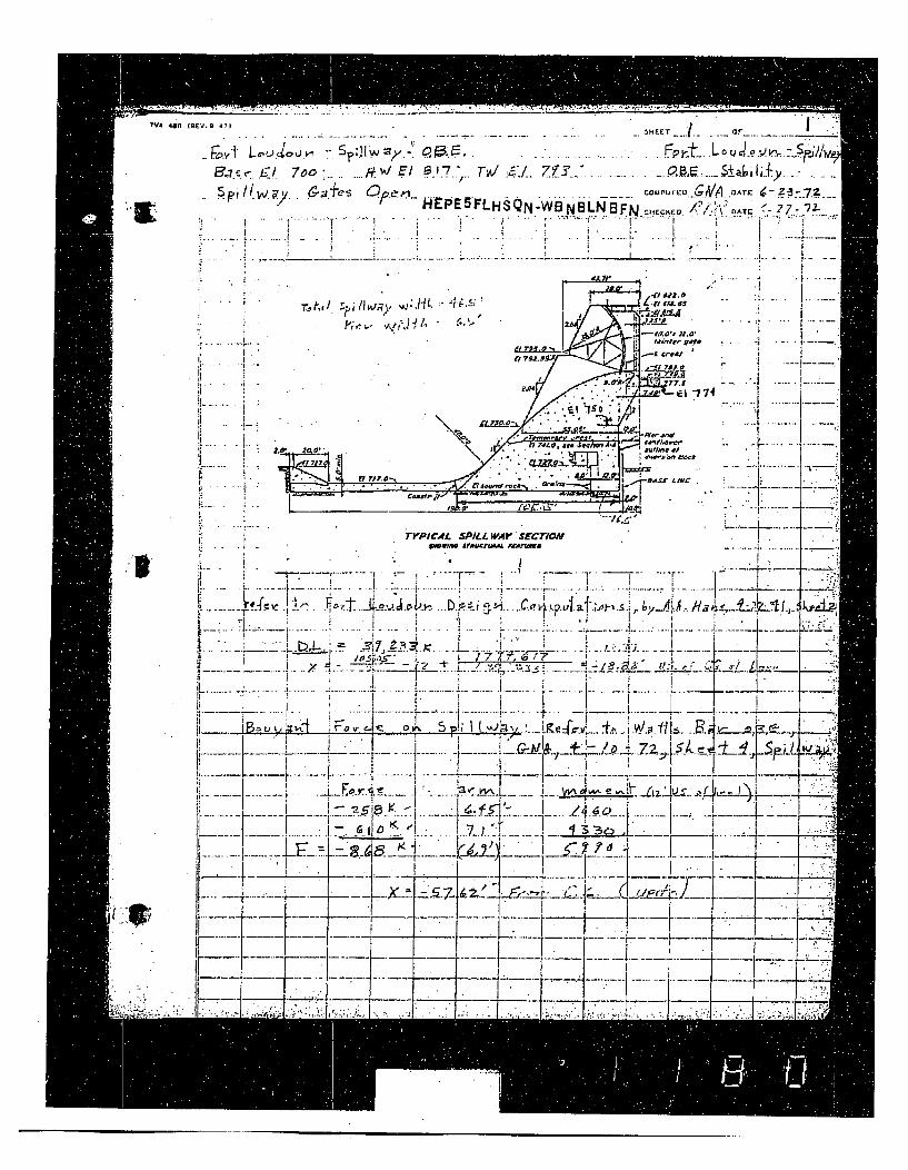
NVA 480
I
(Rev. .4.?1,1 ,- .. . ' T( o . . .
Ba•i• gl 7oo .... ,.7',' El B I'7" Tv!' a•.7W. .a ±&+~
T:1. tj• f/s. ,f , ,s • il. -
S.pi/t.W ,, C.a,% Ooe•l - o.,+: COJPfE •/A oDAT-E r..z... ...... /........ .... U4 9 EPE5 FLHSQN 'W NBNBi-•FNII:,(,. /.'/].\" '. ?7.-<7-2T
:+ t .+ -77- .f -- ------
4 .e 1-77. I.. . . 5" 1 " .. ax~
01?
a _
-0__O ... C ...... cu .. .
... " I -' , I . I I,• •
• . ~- ---.. • -,1.. .,.-".------'-.....-----
I•i : . .. . ." ."---; "Z- .";,7,. I
I--' " . . "" •• "
F7 ii. Y.
I"" • ; '¢',,-,+'+'+/ T2.+' ++'' "'lz~of . ""I ••1+ " .- •t ,I•?-
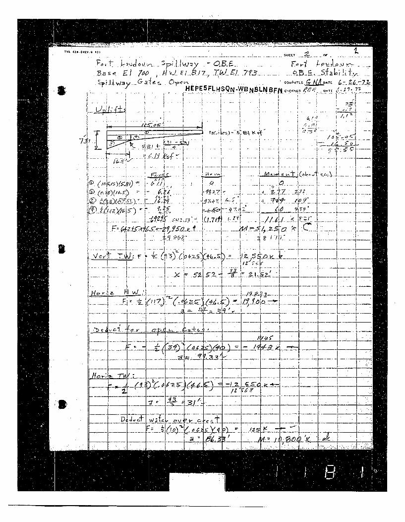
TvA 4oo
I
• I /~ HEPE 5 FLHSQN-WBNBLNB.Fp: CH) ,A' 6 , ?. .... ... . .. ' . . . .
%I Y. 5_ _ _ .. . .._ 1 "
±...-,.I?, -. •+ j., ::.,.. ... .. - .+" i
.1 .- -- I
..... .. ...
: • - I . I _ _•.... : . .• - S • \• s• i , . .. " II1 7 IIf
-v---T4 I _ 6 *~K~
, ... . .• . . . . . ... . ..D® ( f .• ( / -: i :- z i i .. - •!.. ... .•.. . .. . .. ..• ..... .. . .. i: ... .i . ... . ..
I..-
I...--
K
---------.. -
... .• ... .. ... • • •.L_'-VT-------•: _ ( - -. -- --•.. -- .. .. F - '
H---
-41-'? '-,•/. ......... 12--V : -h~ ~
.1~' -4--I
J / Z ".....................
I!-J~, c.i~
.7
w ~.2~
/ I
2y ~.
0 2
-.:.t.2Yffi
i - .• i I
~6 7
4
~zrf .
K f~-j
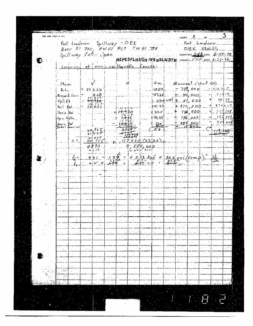
!VA A99 S II •v. 41 .. .. •r.'r... or "
- oT* : L.• ,L 'J.•• -p.l .• " ) E•.. . . .• .. . .. . .Fo -t... • .... ,. . .......
Bv.-,c F -1 ýO- rn•." ' " .7 " ro,,,~ A• -• -
PEPESFLHS.QN,..WBNBL.NBFN . .CH•.•!A..L /1 AT.,
,B. . . -j-.. . ., I ..... .
IL S" P-1~ 'O' ~. . _ -• . . . .
ii,! : i .• - .. . .. . 4, ......i..•7 .''• k ... -3 $• L5. Q. • .. ' I ""~
b. ,W-i .i JI• A .
" .i i -
3.) 77i A 3- 7.// 5 A 1 , .i .?
,,i4 70.. ' .... . . . . e• : .• 4-,r,; . , :o ,I ' i f. .""•€ g
I: u-' • g •• .• 0 I.j-•.. . . .t, -*..' . . . .: . . ....- . i ... -. . .. • .. . .
-, ,-• ..".-.-" --.- ...~...i ......l•• .. .... •!'• • . ...... .. ... . ..+ • -; . -,.• " '- "...... • , ••... . . ... _ ., - .. •-. , .. ....•. .. .. •' .• ' ,•
: ' '~ ~* 1 ,• -- 1 •:., ~ - - _•, . ..,• • %...;:;__. _
"-- - "--4 .. _K7 r ..r •1 _... .. _ :: -•- ... .. -,V...+ " ' ....
....... " 7 -r " { -
... :. ... .. . _ _ __ .1_ • ........i
01
~77I~
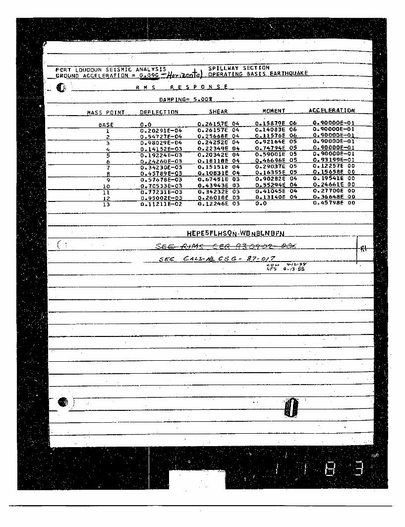
FURT LOUDOUN SEISMIC ANALYSIS ÷ SPILLWAY SECTION
.GROUND ACCELERATION = O.09G_--o c'*24n.a- OPERATING-BASIS EARTHQUAKE
R M S R E S PO N S E
DAMPING= 5.002 .....
MASS POINT DEFLECTION SHEAR MOMENT ACCELERATION
BASE 0.0 0.2615,7E 04 0.15879E 06 O.90000E-O1
1 O.2O291E-04 0.26157E 04 0.14083E 06 0.90000E-01
2 0.54727E-04 0.25668E 04 0.11576E 06 0.900OOE-01
3 0.98029E-04 0.24Z52E 04 0,92164E 05 0.90000E-01
4 O.14L52E-03 0.22349E 04 0.74794E 05 O.90000E-O1
5 O.19224E-03 O.Z0342E 04 0.59001E 05 O.90000E-Ol
6 0.24260E-03 0.1811SE 04 0,46696E 05 0.93199E-01
7 0.34230E-03 0.15151E 04 0.29037E 05 0.12257E 00
8 0.45789E-03 010031E 04 0.16355E 05 0.15658E 00
9 0.57678E-03 0.67451E 03 0.90282E 04 0.19541E 00
10 0.70533E-03 0.43943E 03 0.55294E 04 0.24661E 00
11 0.77231E-03 0.34232E 03 0.41045E 04 0.27700E 00
12 0.9500ZE-03 0.26018E 03 0.13140E 04 0o.36648E 00
13 0.11211E-02 0.12246E 03 0.0 0.45798E 00
HEPE5FLHSQN-WB N13L__N B__
________s _ S-, C6G- _7-o/7
evL
i69
i" S
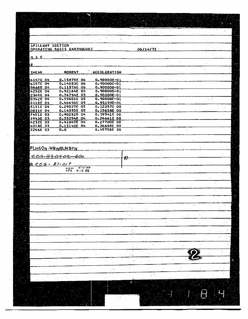
SPILLWAY SECTION
OPERATING BASIS EARTHQUAKE 06/14/72
N SE
SHEAR MOMENT ACCELERATION
615-7E 04 0.15879E 06 0.q0O0OE-o0 JL6157E 04 0.14083E 06 0.90000E-01566SE 04 0.11576E 06 0.90000E-01.4252E 04 0.gz164E .05 0.,90000E-012349E 04 0.74794E 05 0.900OOE-01.0342E 04 0.59001E 05 0.90000E-OL8118E 04 0.46696E 05 0.93199E-015151E 04 0.29037E 05 0.12257E 00
0831E 04 0,16355E 05 0,15658E 00._,,_,_,,_ _._,
7451E 03 0.90282E 04 0.19541E O03943E 03 0.55294E 04 0.24661E 004232E 03 0.41045E 04 0.2T700E 006018E 03 0.13140E 04 0.36648E 002246E 03 0.0. 0.45798E 00
FLHSQN-WBNBLNBFN
LCS$S- 97-ol7________ ______
LF$ "_0• D ,.,a -• z. •'a
- ~-.. _Mwoes.-
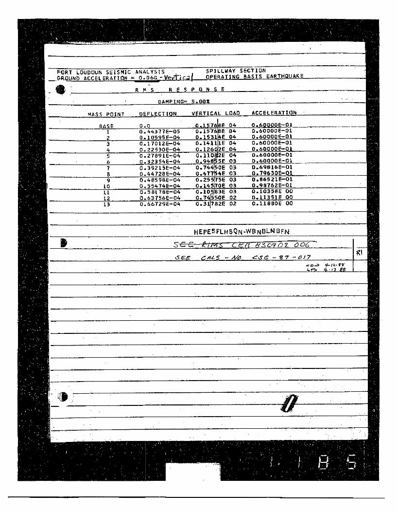
FORT LOUDOUN SEISMIC ANALYSIS SPILLWAY SECTION
_GROUND ACCELERATION = 0.06G ti OPERATING BASIS EARTHQUAKE
R M S R E S P N S E
DAMPING= 5.00%
MASS POINT DEFLECTION VERTICAL LOAD ACCELERATION
BASE 0.0 0.15768E 04 0.60000E-O1I 0.'44377E-05 0.15768E 04 0.60000E-012 0.10595E-04 0.15314E 04 O.60000E--OI3 O.17012E-04 0.14111E 04 O.60000E-01
4 O.22530E-04 0.12602E 04 0.60000E-01.5 o.27891E-04 0O110 2E 04 0.60000E-01
O.32354E-04 0.94855E 03 0.60000E-017 O.39215E-04 0.744 OE 03 0.69016E-01B G.44728E-04 0.477 4E 03 0,7963QE-Q0L9 0.4859SE-04 0.255 5E 03 0.86521E-01
10 0.55474E-04 0.1.45 OE 03 0.98762E-01it 0.58L78E-04 0.105•3E 03 0.10358E 00
12 0.63756E-04 0.7 550E 02 0.11351E 0013 0.66729E-04 0.38T2E 02 0.1188OE 00
HEPE5FLHSQN-WBNBLN BFN
___________,__ 02- 0__06 _
!!-Vl. I•O.-,, ,CSG - 7 -e1/7
5 L
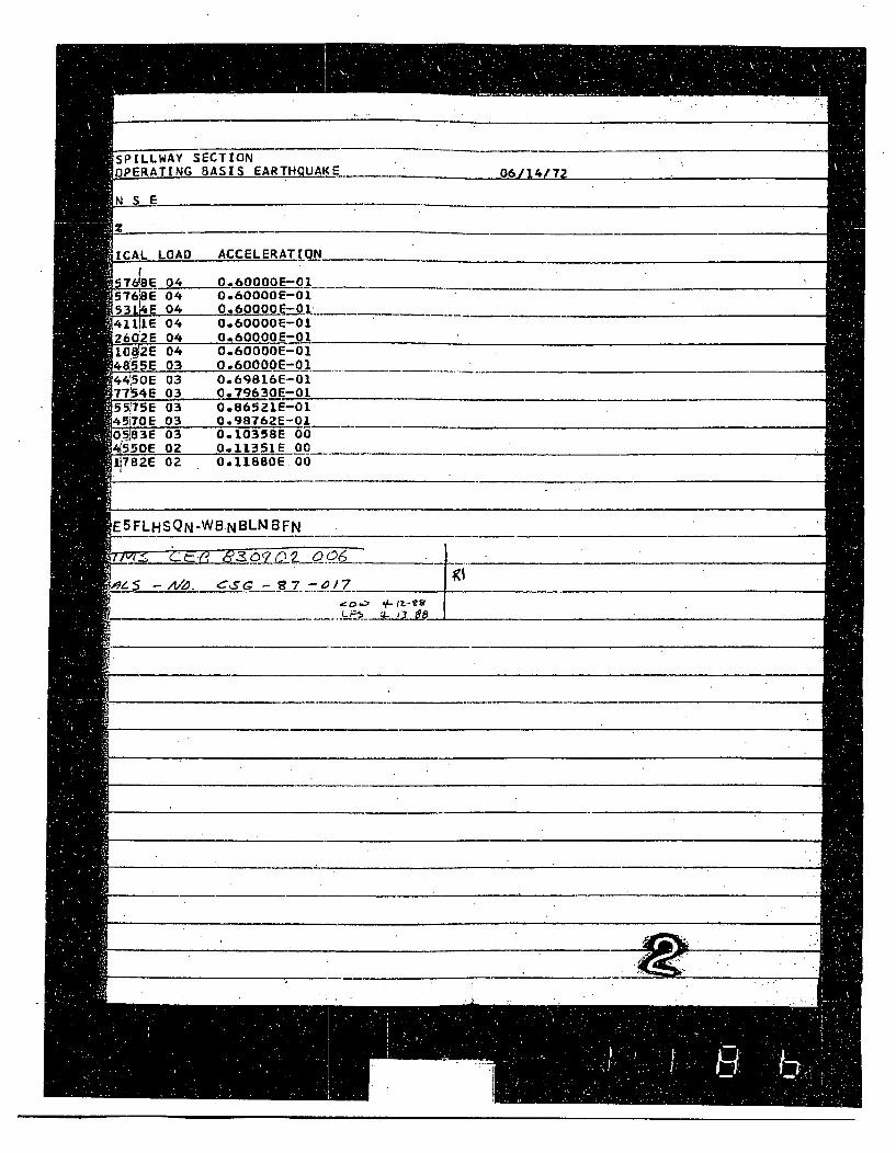
SPILLWAY SECTIONOPERATING BASIS EARTHQUAKE. 06/1472
N S E _ _ _ _ _ _ _ _ _ _ _ _ _ _ _ _ _ _ _ _ _ _
[CAL LOAD ACCELERATION
576j 04 0.60OOE-ol5768E 04 0.600OOE-a053_.4_E 04 0.60oooE-0100
4 iLIE 04 0.600OOE-0126a2E 04 0.60000E-01L0f2E 04 0.60000E-014855E 03 0.60000E-01'44,50E 03 0.69816E-0177ý54E 03 0.79630E-01_5507SE 03 0.8652LE-0145170E 03 0.98762E-0105•183E 03 0.1035SE 00!550E 02 0.11351E 00
782E 02 0.11880E.00
E5FLHSQN-WB.NBLNBFN " _
95 AMo. cs--S g7-.0/7 __________
___.Co.> __.__-_____
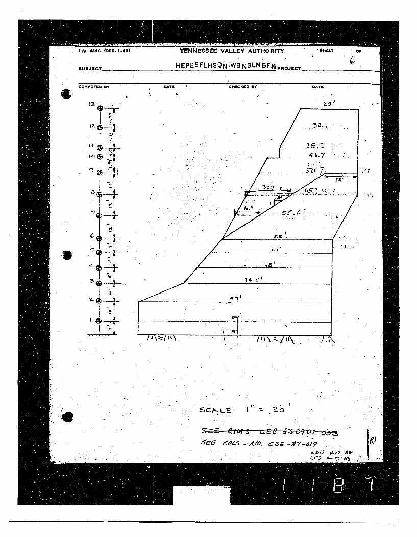
TVA 4g5G
SUBJECT
COMPU3tE
-'3
II
10
9
a
"7
(O:S.1.63) TENNESSEE VALLEY AUTHORITY SHEZE orF
HEPE5FLHSQN-WBNBLN BFN PROJECT _------
NY DATE CHECKED BY DATE
'4
) -- 4-
in
I-M
, r~
'I
IC
SCIFL.. Zo' '
-S ,C ,L•o. E -z 5-L &c•z,
5c- 9SAO c---~/
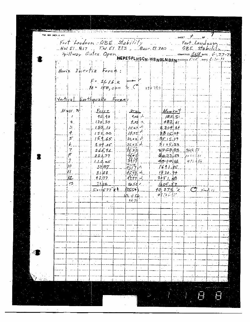
rVA 401 (erCV-e 47) ,Ec ' _ _.
7 :,,< l o o<,.< -o .,• .7 a-B ..-$/IiI 7 S 7 , U Cfi3," .. .8; •.oc •.,' .,...1._ L<:_+ <.., K....
''-" rDP5LH OMU5TCD ~ATIt{ 77"P5FLHSQ.WBN8LNF. ,O / / c -V. .. i .. . . .. .. . P . N
e, . . ... . ..
• t • .q ; . ;. . . . ! . . . .. . . . . . .. . . . .
T 7-
i!2. ,2i'!
:73
S- --- --- -- 1 •.-. .
_ I .ti,+
- I I ih4" ;. '
r" 1 * "... .. I-+ .. .. .• ¢ ,r .......... il. I71+_ • . /.i. iJ.1.-i-, -. . _
IL. , ' ._,_ __-"_ __._.,+
"-] '• / il
L~~~~~~~~~ ...... .......-......... .,.-.+i,• ,+ L •
t _ .. . --_ i .. .LT L__ -,.I I ~ .. 1•7
• I •I..
.... ..... -+..... 'K t.
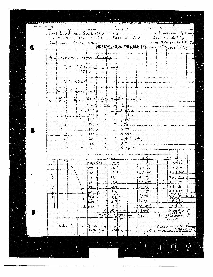
tYA 48~ IRUV QSHEE~T ~
A , ,v-J... !31. SJ7:-
£ flPrLFLHSN-vyI.NBLIN.BFN CAMPUTEO ` DATE.4I I,
v il....................... ............ i...... i......... !............ i............ !......." ",...... :............!ILIi . . ...I. - I , . ! . . -. . ..
. I , " . . . . . ... . . . . . .
( .' 7... . . -I ... .I
I--0 . , p 7
... ..... .... -
,.r (.... -. "r. .it,. .•'J oJ • • ., ,L, ; .. . . . ._f ~, 7. -... ... .... .".. ....... .
. 1 L.
7~~ -j Oa
, ? 0 I.j I t
i I • , I
-. .. I ,. ...L<l ,
', -- I. l iT 7 1 ."~
-- - " , _.--- _P __1 --.
i*_.... ..... . i. 7"• "' F 1 ,. i k ' _
S .... .1 . 1 1 - i-- -•, • -vi• 'A .~< . ,_ ; ..._ -.- 4-..]_ - -,, * ... . .. H . ..-. . .,..... . .. ; . . . .r. . .. .... I [ . " " i .- '- "-'. ' - ,
, \ I I , . L i I - : t..... __.1 1_-- -
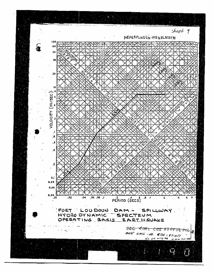
ýAeeI- 1J-dEPE5FLHSQ N-WB NBLNB FN
rI00
80Y
6
4
2
4-,LaJCt)Nz
4-)0-jIiJ
:- tN
40
I0
V4
0
6
4
S"4
.4
.1
0.0
0.06
I-_'X~vt•/I/ %.\ > Y, r\ I,>.,I ",N2Y,;•.!,x,,,">~( A' AN lXl l \.-I/'A/
A•. ~ A-...A - Y V7, N ,X ..0.04 '-
.01 .02 .04 .06 .08 .1 .2 4 .6 .8 IPERIOD (SECS)
4 6 a ,
9I-F OR.T " LO L 1ou " - S,1k 4 ip-- o y t -AC",hS.. ....... G PF C .-rp • mo m p P A . -I -1 N 6 . -• t . "i . P• _....'r /.• _ 0. 4 0. G
C'_- 01
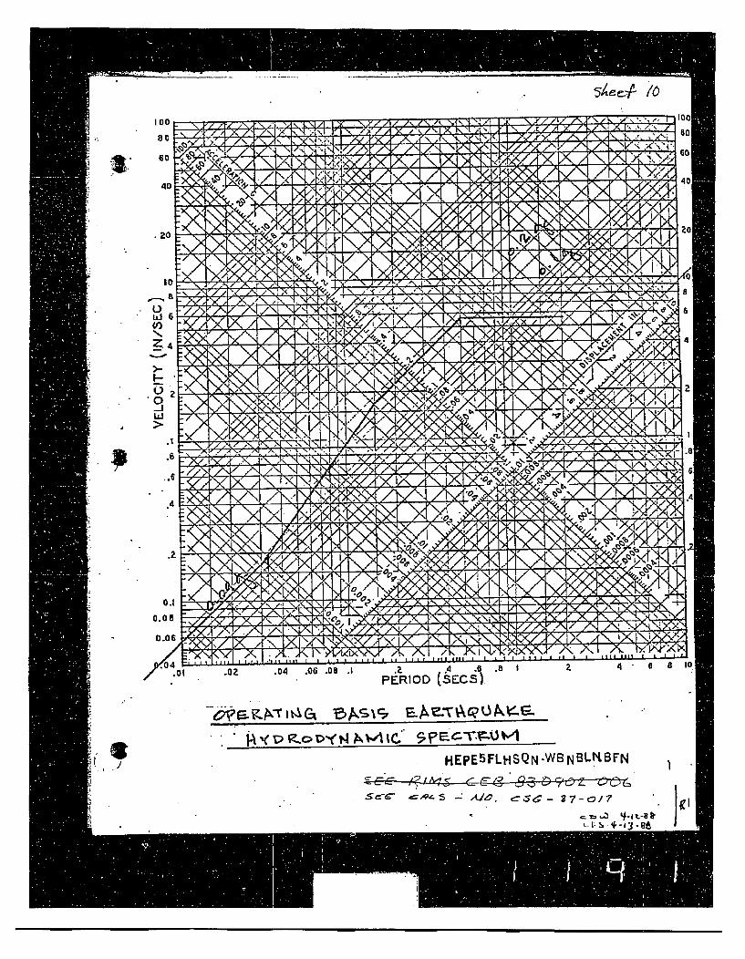
54 eej!. /6
100
80
6c
I ~ ~ ~ ~ -X"Wuu \- /X
1~'* 60
4':
20
* Id
F-.
0-JId
-/-
0
C
6
.1 G
.4
.lei
J-Z7wxB
X N , " .
.. . . y x A X" AN N A rl
0
4
2
I
00.0
0.o
0,01 .OZ .04 .06 .05 .1
PERIOD (sEcs)
--0aKPCTIt4GIi 15AS19
p~o~(NMA~ ~?ECT~~\~A
J HEPE5FLHSQN -WB N BLKBFN I" • - - Ale,
I fl-- = •,z• •1-
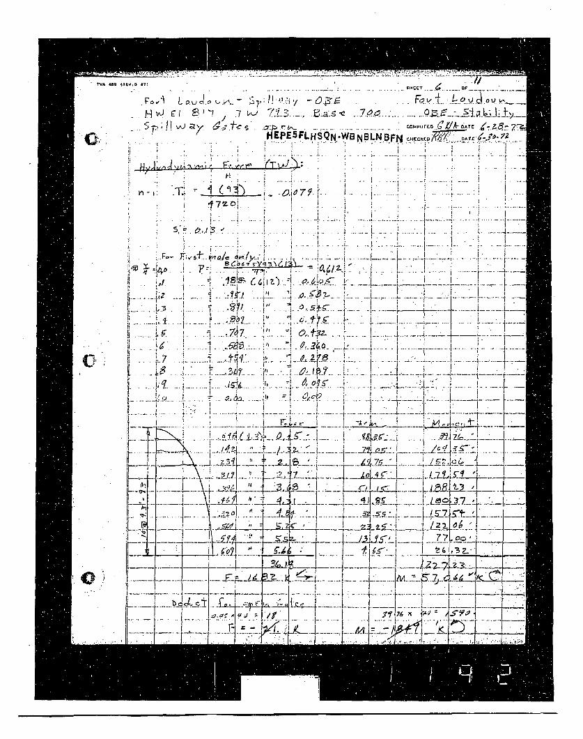
TVA .48
" 40-1-.
* i•~ L . i o . . ..- ... . . ; . ... .- C r . i '. , .5. . . . . . • . . .. . . . ... F • {.. ~ ... . . . . . . a t . .. . . . .IA V' •7 .m/ .
,r 0 r- "
-i f.... ; ( 3 S .. . .......... .. I ... .. . 6 A ....... • . .... .
IIEPE FLHSQN WBNB3LNBF ,7
16m . . :, -!. . . . .,. .. .. ..... . .. .......
* -R -I' A4L
• 4 .. .. . I ,
~~~. . . . . . . . . . . ...... : ...... ........... ....... ................ :........ '. ... . : - . .... ........
OF3 e2 .18
h L
.4 7h.
4, .. i -•:.... .. ..... c i3 7 ' 1 -
-U, IL
-q ,i a ý.f 5 " i.
i "~~~~~~~~~ ! .. .. .. . i .. ......... .". ....r-.. . '. ..:-!.... ..iF......... .. I .--.....t; , . • -. ___ A; I -*-*-K" .i~ 2 ' 7$,z • , a, : L.. .. . .,.o . .. •.. ...!. . . ....... I-- _.:.:.*l ..... L ..... z• _ _
,• . . .. .1 .. . . . ' '" ., ! ..j -. • L .L• /.. " I ., 1.f - 1 • ' l
: b.- ;r ' , -i - -
7L ~LJ --1..--• I .~ l.U... , =L .t•K,• _.I1, 77... 'Tj..... -
I-i" I " - -.......... ..... "4 . ..... .. ........... .... ..+ ......... ... ..... .............
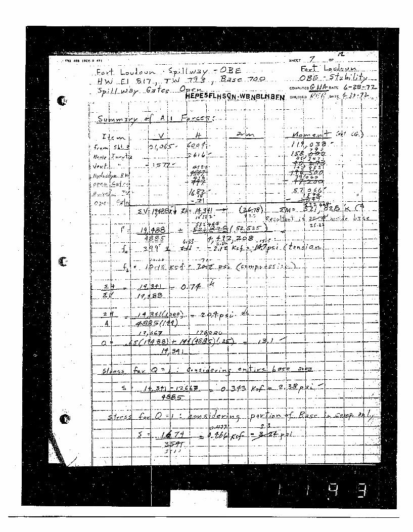
SV7A.409 1PCV.0 471 SHEECT O F.
.. . .. . .. . . • A l A _ .. .. .. .. .. .........
_____. 6, AU Fcc~' .
Pr.: s• ,H. SCW' __•, .... _ • ,_ L0.
S , " . . . . ." 1 . .. Z "r ; . .- ,- ii
.1. . . . . . . . . . . . . - .I . . -- .... . ..
_ _!_... ... .. .!i. U ,: v • :.' ' .• .. I /' • .• - ' ... .. 4 -? " ! z. . .5... . . - ' ..
: 2- 4.-- ig , .
,: ~ - 3 ; , X .- j.. .4•.. :-2d K V .. .. . ..... I .. :- I '
',..! : - •
Ap.9
:•e' ,,• • i#.. -. L..." ... .. • . . • , • ' . . . • , • .
-" ~- 2__,•L:jD ,C ' - i '4" , .~ ....... Z.,.• J- ... I ' I". .• ... ' ""
0. . .-' , . _,_ _•i .• " - i . .. I . • : : . . . . . . .4.. .. .
',_. ._ _-4 -I __ _ _ -- . _ __-Tf._/_ o .... -. . .. ...
L!.... ... • I ' L 1' 1
-- ' ;' ""':.. . . i -J ...... . . ." "" i ib.+• •
-h, "- - ' - :• I --- - -,, . . .. . . . . .
I •--t. .-- ---.. . . . . .. . I .... I . . .. . . . ... 1 .. . ..
• .)' -I ._ -. .,I,
It ... . I ... ],. -.. • :, • ... F.•.. •. • .•- -:--¢.r•' • .:" ' ° ... . ...t ..... Ii......
li ' ! r • i" o: ." ' ' "'
.• , , : L-... ..• ..... .,...
.. . . . . . . .t.' . z- ,..... . .. 7 . . •... . . . ..... . ... i ._£ . .. p ..:/.•. - -.r. .-. . .. . ( .• .,.>.. . : -'.•-7.. ..tr- ' ' i, , . .• "l. .. ... i - ' r
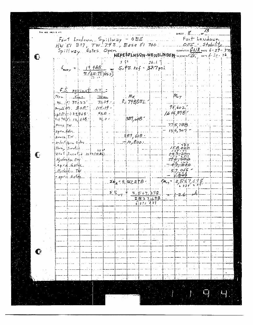
~~. . .... ...... . . ........ ... ... ....... . ... ..... ....... ...... . .. ... . -Lo uc- o u-.h/h i.E 47•.. T/...' ., •'as~e •/ 7oe . . .......... :.e _. ... ' f ,/... HA'o ........ . - -z '- 7.Fc I L•" ".. . "r r • J-
HEPE5FLHSQN-WBNBLN-BifN-,.,,L.,.D.'•(, PA& '
g~ go
; _ _- i .- 4.. .l . .. . .7
-....... .... .........
S ....!../,1 e , •., • I . ..., ..
/I~J~i".' 2iT
. . . . . ,• ,•.• '..i .. .........I : i - i. -~f /I 6 • '( •i
! •: '/€'''•' 1'#- •. . .. ! " .. .... . . . ........ f ..... .r .......... .... I.. ... " ". . .! ' ' .. ..... ;.. . .. r.. .
I -.-.---.---.---2 _ --------..--,~,- -- ..-.-.- j --•-- ...........
.r ..... .. i.... ... . ; .. L . ... . t- . -. .. ....- -. ."- I ,
:, .. /,•1 .•.. ... .. ..L .. ~.....!if/<,-.,•:L f-•,,! ..., • .• . . . i... .. . '• ," < . .. . . • ,
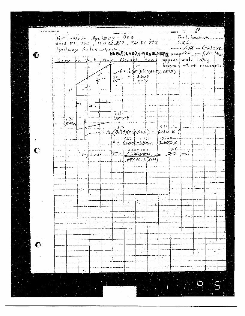
T-V W)9 10
CL
tV.9 47 - MIEFrT Or
F~ t t.u ou " ' ';, •, -., O E . ... .. F' t . ~L• ,> &..,,_......
. _ 7 . ,e 1-/ ,e TO F/ 7ýy .
~~~~' S- ..ep~---- *27 -2-
'JEPESFLHSQ N -WB.NOLN BFN ,:,,Dt•I'. DATE
- v • / 1 .. .- . l•.0. . .
I3•I
," ......... ! " : ~L 41:) ..... ... I. . . . . . .... i . .
-..... .... .
-fj.4) 1..... -. .... . .. .
. .... .. ..... - -..... ....
S. .. . I...
. .. .. . I .... .- K.. .. .. .. ..---- ,. .. . .. . .. ..:! . ..- - ..... . F . . .t. . . . .. ..r.. .I,•• I A/ -. L ..-*- ..
,__.. .. _ • . • , ' •_i " I .4 j "i"
'I .. . .. . . . . . . . .. .' 3 -I . • " ' .. . . . .. . .. . . ..-1 - "1" " 1.. .. 1: . . . . . . } ..
• •_- X: • , ;• • i• '$•, .--.'f'-] O -- .ti .........., ........ !--
.. ... .. ..•• ;.. .. e .z. ...,.. 2 .... i7... ti...... .... . ... .. .. .." ... I .... .i.. .. .... , i ' •- * ! • ;" : 1
... . .... . !• -.-. • -,• :-.s_•: o : • - !• •<. . .... ... ... .. ....* .......•~ ~~ .. .- ' " ........ ..1...
0
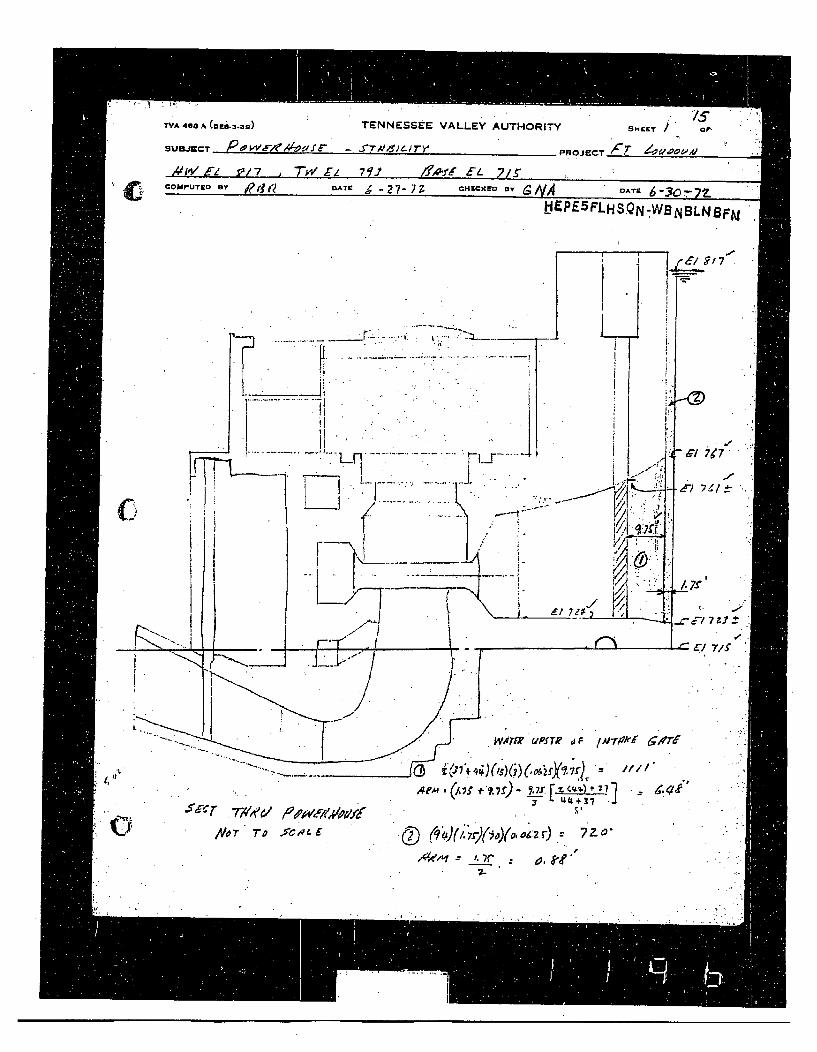
TVA 408 A (Dti-3-30 TENNESSEE VALLEY AUTHORITY SHCET OF .
SUBJECT - PROJECT Ct4; d'.ooVA9W
Ad IW 9/7 1"" 77 .. ,! E. 7f. ,COMPUTo- BY DATE , •27- 7z CHECKEO 13Y a. IVA A-T -HEPE 5 FLHS.QN-WBNBLN8FNJ
4Li.
morfe u~Pf Te j A;-rkf axdT6
(. 8 (1,7 ) - Lr &Z."410 1' 1
Nor T T i dc ,"E § , --( ,()__ - •, o -•'"
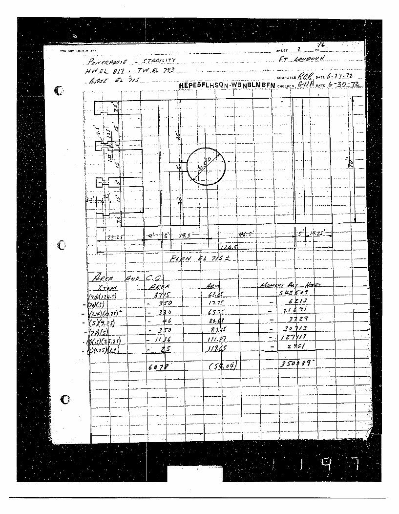
TVA 441 4•tV S T . 2 .. F .
OUP.C, D.. .- AT?...: 2.7__..- 7Z- HEPE5FLHSQN-W BNNBLNBFN ( ;-Al 11:1"AT..
S' -'I - . I ' I . •i.ina.
.......... I
1z~'. K -..1 .. ...
"; ' I - I '- - -
'.• , i . I- . . . , . . . .. ., .. . t . . .. . . . -.. .. .. . . .
-.. . ... . . ................ .
I S .... .. ...._
r.5 I .. ,.-.4L - ~
10 1 1 4 -ii ...• < !. .. r .. ' " . . ...i ... ............ i._
t .. . .. Ii. ..1 . . . . .. . . . -. -... . . . ..I
"I I C .--- 1 ---.. ,--
!• __ '. I I ! / I' . . - -l " -
_ _ •-'- i• - -'-i"
__1 - _ L/. _< -.]=.- -- - i- Il...... - . .. ...- .... ..... .. .. .... _ I
' " ~........ .. 1.............. ... ....- t......... ...... 1...... -....!...... ....
•__r_-a -._-•..-_•• .... ~ ; •_ ......... ----
--. .-.- . . . . . ... -.... . . -...... ..
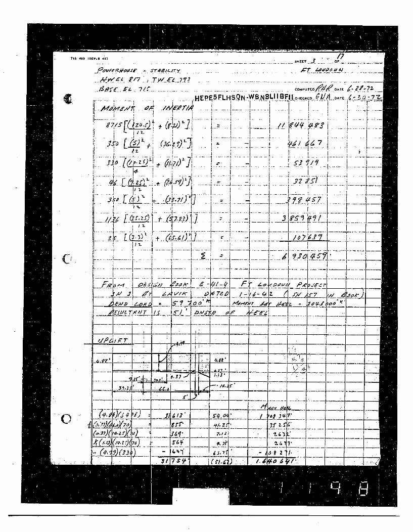
T'iA 4•, (R,..m 47T '. " I1
_• w•.• -,•..•- .•. Tr•:.• Y . .... ..... ",•-•._. .o..•_•...... ..............
C./7/
1 "-
.I.. . . . ...
7f3 .L s).
-.. ,V. .
j" ... . t.....I......
I t
i I2i L
Fi. . . .i ! . ...
•HEPEBFLHrSQN .WB NBLII BFfIc cuk.-o -•V, 1 ^ .O-T *.. -'73 •-
./I• .. . .... .... . . .. . . .... . <i. . . iiV-.. !j. I I - "
* ( i z 9 J I . . . . . . ... .
ýr7
•. -. .... 4......... .. j.. i."..... l....- . . .. . . ...
I • . I
-e-L. A ,•. ...
II...s Dmrri. ...• k •-~ I ---... .......... .i1 _•... ... i. .. ... ...... . . ; . . .... ...f ... -. -. -...1. . ..]. ..... .-
ti ' j: 2I I2E{?.•.. ....
... .. ... .. ... ..
•. . I_ ___,_ . ...... f . --_
II I I • • F r T..........................
-ii - .- -- ----- ~--.)_ -- -
Li..,.4 _____
T4F __ _I _
j Kr?-' H l.13 ,. I3~.Z4 ~ ~ . I------II- 1--
I
7~TL-: -*I-L ..... I:*-
F----7-7•;0) IL1/1ýl
(,:?) 76
6Q. I r)ý
_0
......iI-Av
T 117 .C4A
7-4•. --
-, /<a.t 2' *i/
CLA CI T
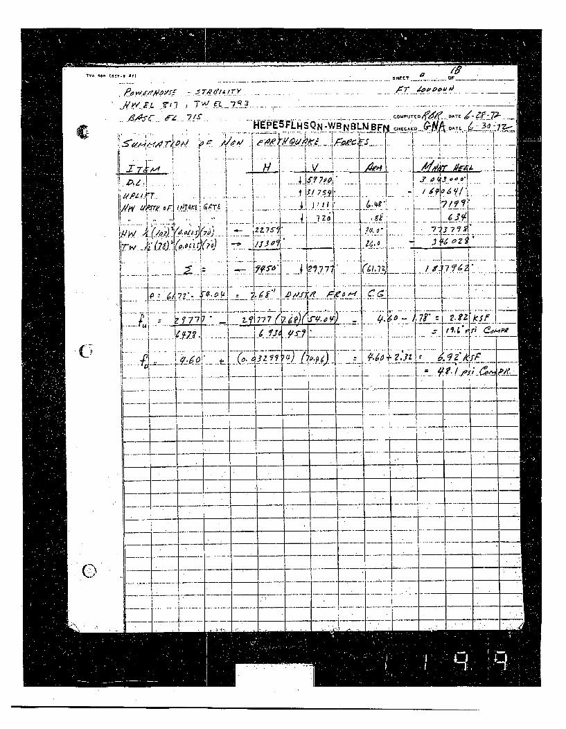
'TVA 489 t"EV.% All1S41Kr IJ F
*J' .P,..t / 7 - -..-?n..t.Lr•. ... ... ..........--....... ....- .. /• -- '-u. .. ...... ..... .
C U, TA EE h i EZQ 4 w ,A.T
AlH -W1 NLN BFN tCE.*N AL3JZ
* T ,,. ..i • ... i ..... • *... . .. * I // -,,, .... __,, I/ • | I.•'
ii , • I !: , tI f I -",
- f3/7511 71 S.Y.I-¢ Z /*T. . . . .. . .. . .. .. * ...... . . . ... . . . .. . .. !-A .. ... . . ..
1N I/rr I.2. dT *. j... .. .. .-..•--- -
j. !?1"'. ,77 .. ,, .7 -. .+ - i . ... . ,I . I. -.---.. .-. .
i , ,- .- ---- -r ir. .. . . . . _ ...... .. . .
I K z I s, 1" , ----. '' 5 •
• ,... ........ --, -- ... .... - -,I ,-- -. .. ... .+ --...... .. - .
_L__ _1_ -' - .-- "-
- -... -_-- -- ____I --- - - --- -.----- - ----- - .
--- -.-.- - -___ ___--- - -- --I--- _-.. -- - -- -. ___
..- --- _ :•.---. . - - - .-- -
1©--- : - -
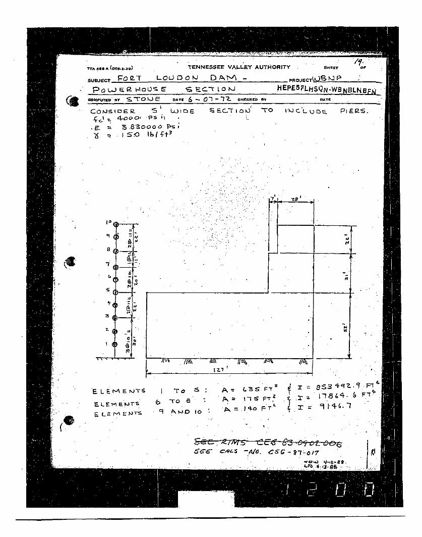
?VA 46 0(oE8.3.3O) TENNESSEE VALLEY AUTHORITY
SUEUcr Po2PT LOUDOWJ D AM -,
Po W 1- 9- HOUS E S. ý-z.C-T L O 'J HEPcOMPUr ,, y S_. TOLJ M ,ATt 6 m• c"-"K. r ov
Go~iD~E. S •,mi carioJ "TO t-t
.3. •8ZoooO D•,,= IS•.O 1I(1 -:'I
SHErr OP
ROJECTLk)S tIJ pE5 FLHSQN-WBNBLNBFNj_
DAYK"
Pi E P--.
10
q (
(6N
(J!
0 00
F. L E M• E JTS
E L E• E
F- LE M'A r •S9
'To
"Ta
G~ ( 1 3 S Fr!S% FsT~
+, I
,1
8gs3 IqZ.C Z + F.T 4
1-91*3 '. . FT9 1+4-.l
$ C- C Gst~ AO C G-~7 -,b1 7
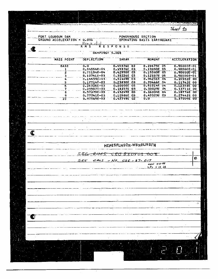
FORT LOUDOUN DAM POWERHOUSE SECTIONGROUND ACCELERATLON = 0.090- ----- .- O- PER-TING- BAS-I-S"EARTH*QUA-KE"-- ------
_• •R M S R E S P 0 N S E
DAMPING=5o00 -
MASS POINT DEFLECTION SHEAR MOMENT ACCELERATION
BASE 0.0 0o.45376E 03 0.23475E 05 0.90000E-O1I.. . . 0.34554E-04 O.45376E 03 _0.19350E 05 0.900001E-01Z OoTE154E-0. Q.4.2950E 03 0.15580E 05 0 *g 0 0 ~0 0E- 0 1 *3 0.10741E-03 0.38226E 03 0.12337E 05 0.90000E-01
.1.i4459E-o3 O.3169E 03 0.94.251E 0•04 0.10552E 005 0.17714E-03 0.23830E 03 0.70466E 04 O.IL762E 006 0.26306E-03 0.20000E 03 0.51014E 04 O.12358E 007 0o.39507E-03 0.13237E 03 0.33029E 04 0,1371LE 008 o.57379E-03 0.15249E 03 " 0.16334E 04 0.187T6E 009 O.77741E-03 O.10586E 03 0.47023E 03 0.27442E 00- 1 ....- 0.975S69E-03 . ... ;- -•E" '02 0... ............... . ... .......... 0-0--
.... ..... .. - - - --..... . ....-- - ----.-- . - -... - --...... .0- .- 3709.
HEPE5FLHSQN .WB NBLH BFN
S~=0, A19, CS C,!7 -0 1e.o- -
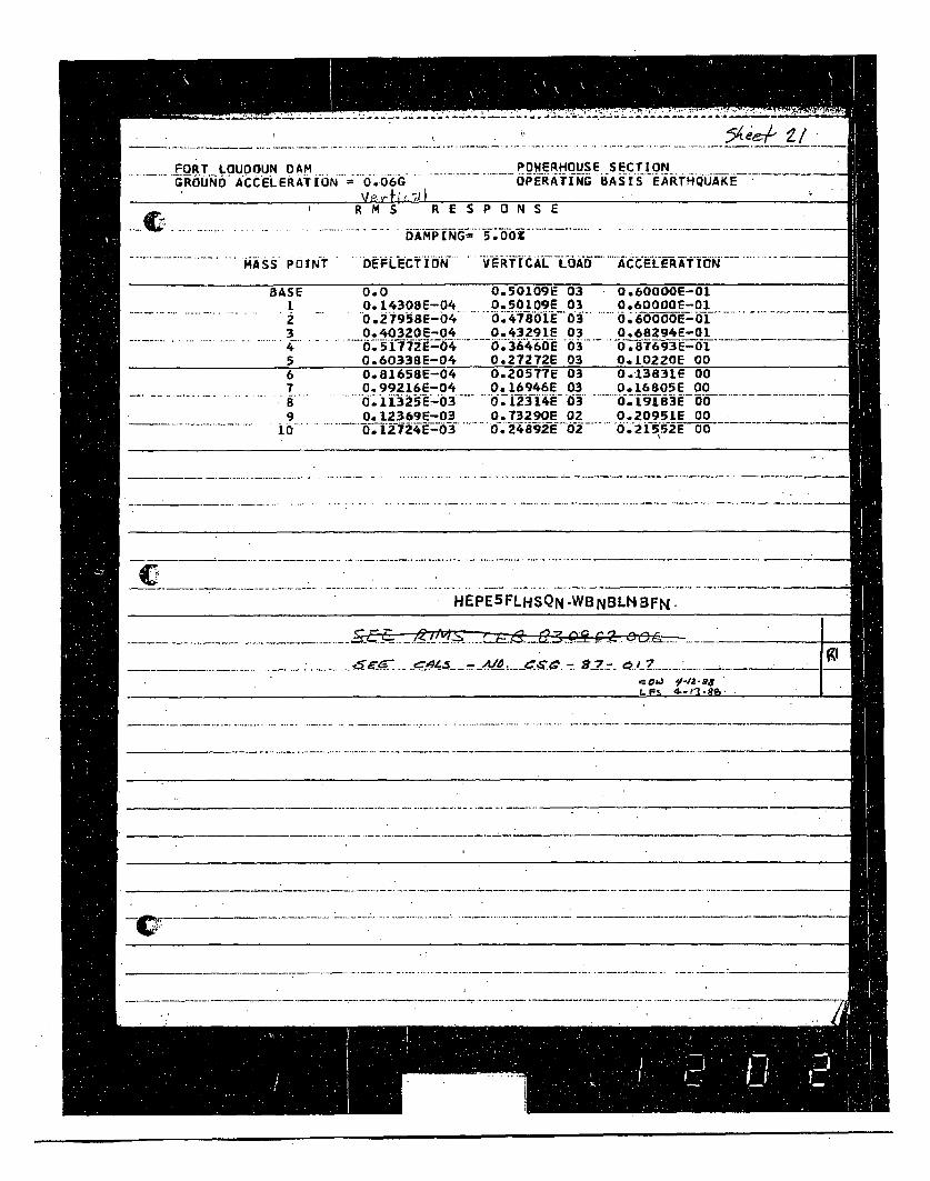
FORT... ... .... . . POWERHOUSE SECTIONGROUND ACCELERATION =00GOPERATING BASIS EARTHQUAKE
- R MS" RESPONSE
DAMPING= 5.00O
. . MASS POINT DEFLECTION VERTICAL LOAD ACCELERATION
BASE 0.0 0.5O009E 03 Oe60000E-011. 0.I4308E-04 0.501.09E 03 0.60000E-Ol2 0.27958E-04 0.47801E 03 0.600ooE-013 0.40320E-04 0.43291E 03 0o68294E-014 '.17E0 .6 6i- 03 0.87693E-015 0.6033BE-04 0:27272E 03 0.1OZZOE 006 0.8165SE-04 0.20577E 03 O.13831E 007 0.99216E-04 0O.16946E 03 O.L6805E 00
. 1 . 13 25E 3 ... ... 2s '4 E 3• 0 . -.19183E -009 O.12369E-03 0.T3290E 02 0.20951E 00
10 .L2-724E-03 . -. 2.24892E'-'- ... Oa552E 00
HEPE 5 FLHSQN .WBNBLt BFN.
S .-.-- - ... ~. ..... .•.'.•.....4.tS _-....•.. •.• -AlO _•.Zz .-. ' ___........... .
.0a-" •-/Z-ar "t- F% . B R•
. ..........
cr ------------ *--~~~---**--....-......---...
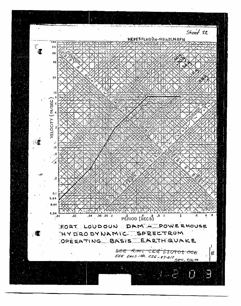
SAee/ It
-.... LHEPEFLHSN-WB NBLBFN
-o60
40
* vi\4
s11'
r~A5 1,_ -I r ! N
-111ANN,1
to
LI 6oS
Z 4
U 2
w
- . - - IN~.
,'.,%,
r". .a% i
I
/.4
/X
b;s ?,*
i/ '.' / A
I~ I A./
N-~~~~b *gjY>-< .* /
..2
0.1
0.0 B
0.06
0.04oI .oz .04 .06 .08 ,J PE IO .6 .8 1PERIOD (S4_.C.S }
A 6
_FO Lou 0U , DOW E.-'.O uE.
i-W1t M C Np-.' .P'ttE
b'
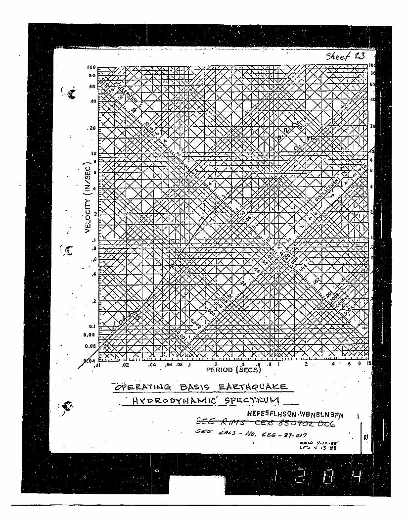
54 ee~l W10I
4
2'
L)
>-
' 0
_1
D
0
0
6
4
a
-\I Ne
4
I \A
'4
4
o.0~
.01 .OZ .04 .06 .08 1 .2 .4 .6 .81 24.6 81(PERIOD (SECS)
HEPE 5 FLHSQN .WB NBLNBnFN
--,. •CS - 97-0.•-7
c'o-,.3 Y//-I.sd,';
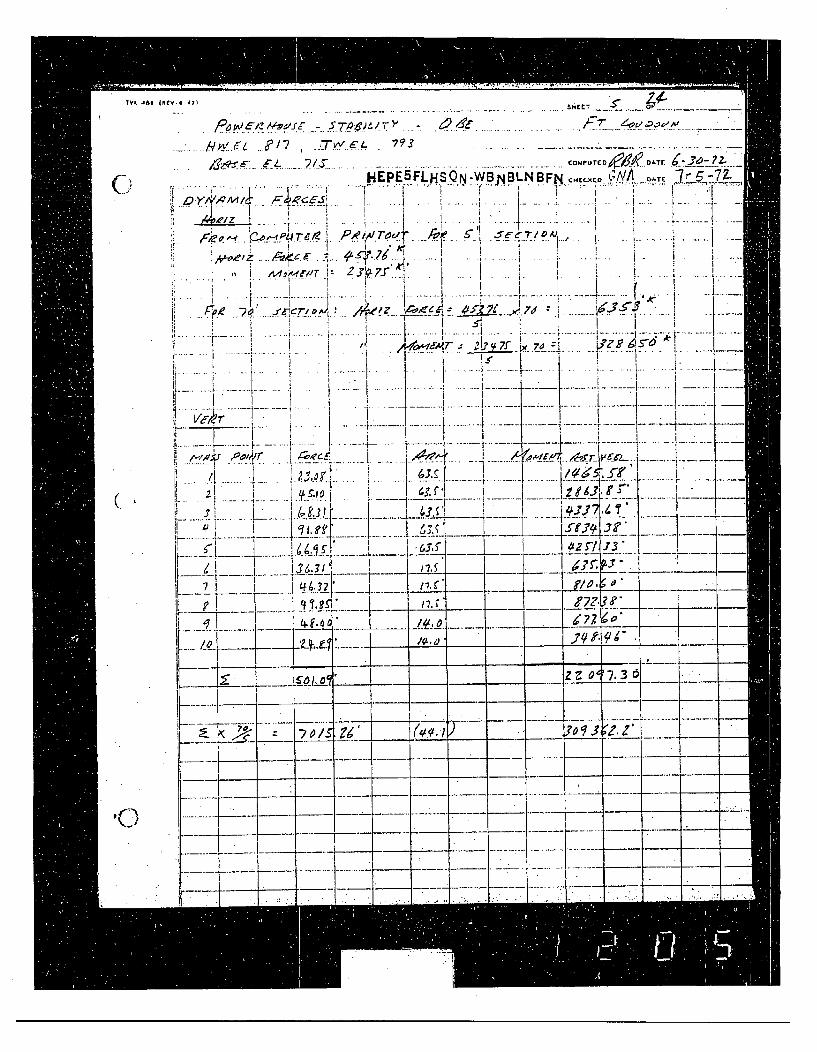
TVA, 442 iFR
(.
.©)
E 0- 47) Sh~t-
* /i~' 197 , . 4y ... ....... ... coupurb " .Tr .
HEPE5FLHSQN-WB NBLN BFN C A/AT,,,_Co A TE - 77-Dji i.k~4_ _... . - . ._ _ . .. _.. . i * - - . , ..L
-,/z ~ ~ a I.
e i..A a. -Td.?
T/i'rs 2l?v7f 70 5-
" I j.9, t i i -
": : 1 i i " I I I ' I "
f.. oo... r . . ....e .A
i !•,,Z , • .• ••Z7•. •...... ............ i....... . i.........
. *. . .-.. . . ... . ..... ... . . . ... .' I 1Is', 1 8 I ... ..-. ....1 .- .. ..../
___ -I. --- _ _- -_
I I __ _ _
.. .. . .. . ... . . . .. . . . ' . .. . I . . . . . . . . . . .. . _... ... .. . _ _. .. . . .. . -. . .. . .
Li.......... -.~
._`7.. 3 -
.. . . . . .el , - - . . . . . ..
1~-
i-i.---~1
"- .
~j7j-- .- ~. -i
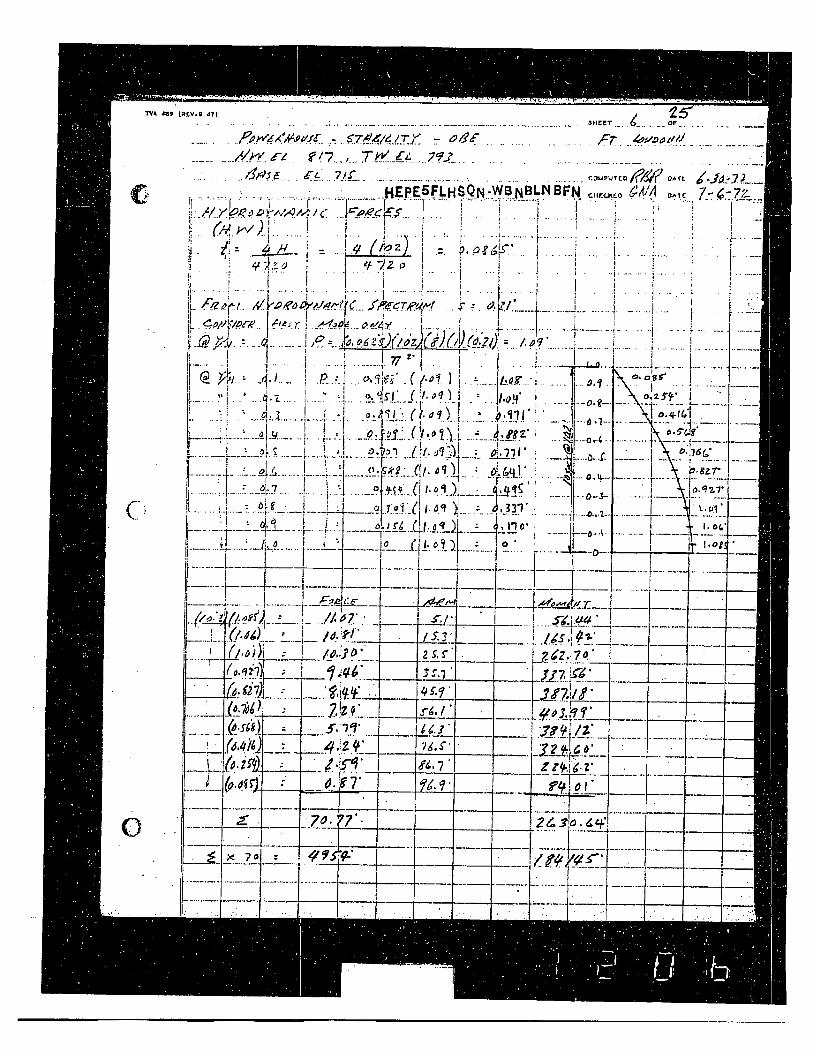
TVA .- L.. - x.......... .. •..'
E:.• .• -r- 7 , : - . D Af t p' .4 0 7' 2 L
. , , . . HEPE5FLHSQN.WBNBLNBFN D,,r.o U•O 6!A-7 0--
1'12I i I 2 1.7
, i. IF) ... A. I j F
~~'7 1
• . [ ! i r
!i i • I I I I I , I Z ,
'- ', i i 'y 0 1
&qiDd SZ7
" - -- .. . . ..
......... -- F - -•fF ,-.9 •.<, (i;,,. . ... ... ....
*,l-' : -_F , ..... 'Oi)....i. . ... . .... . .%. ~ I Ii... .. .. .. ..... .....
IJ..12.! - .
-- I. .. .. *.'...' "--- .- ..- .....- - . .i ........ • ."..............
- - _ __ _••2••• I..
-- _4,7 ~ ... ___• ,•. __-
.... .- - ----
.. .._'_,_ _' _L . . l, -. _ . _,___,___/,-'_ _ ....._ z..:.... ..-' • .i• .,7 " .
A, 7" I ____ .r.
(0,,'9 7'
70.01o-. -t- -___I --.. .- o_ i - - .-t-....... .. ____ -
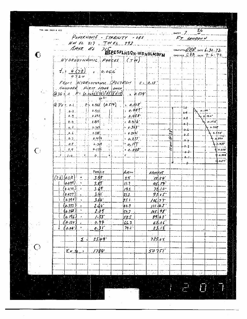
N ~LwHSENW-NB4BFH CH fi"/"jA DTE 7/;7i,,-
,! • 'i . ............. . ..... ... 1 •.. . . . ... .. :I!......J............. .. . . . . .• I'
".. . . . . . . . . . . . . .. . .. . ....
f Z. ' 4, / • z , ,. W ~ A C . 1 f'6 T , ',. I . . ... .• .. ... . . . ..r .. .. . .i.. . .
.....•,W. ATE, , ,I " ..
7. 1 i D N A I C. ........ R .. ....MN I ! 7 ...... 4.. ......r ... . ....
~04__.- ....... .....
0-4/
.. ... ' .... . ........... .. .
31..
C, 3•. : •. , ;. • • : .. i j...... . -•.... .. 0 3 .
i ! I "~ ~ I v;6•• •'
___ PI.... .If..,, i o ! ', [ .3 !L _ _ o , r i,,..' .......K .. ..
t[ ' •I. .91]• i4/, 77 -.
F" I _____ I7 I7__t:-- i • I , - -, z............ ---- - - - v - .......... j
:- :•.!-- --3' • I-.__ ~______ . 4 I5, O_ _•
I----I "
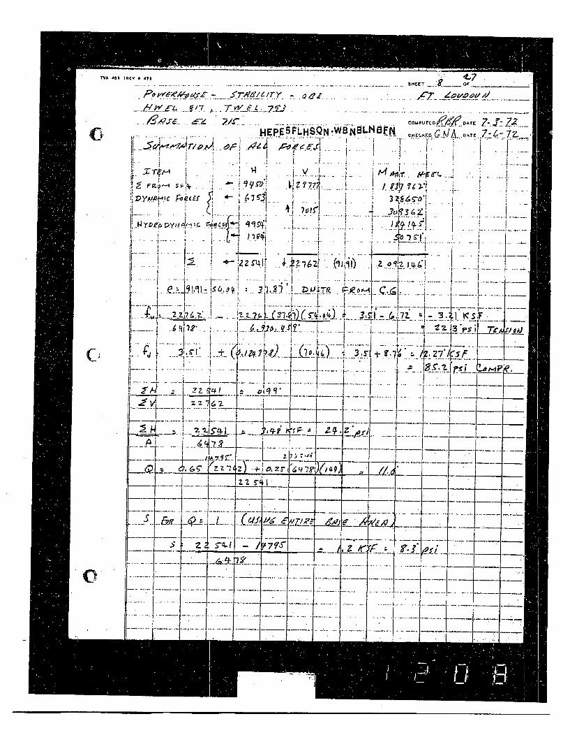
TVA d4 IlREYe 473 .---- 3HEET a* or _ __
....~~ ~~~~~~~ ~~~~~ • +••... z .i.z'. .. •• -. _..o~•Z. -... .....
-C ..I& " " C" P U..... T r D 7 . .
HEF5LHSQN-WBNBL Sff cIlftcG.0 /A nArr74.Z
~~AT AAt-cEjecE.F a --Ii F 'Of
Ei I:'ajC" j+ " . . ... .. I '- -. •; -
'" !i2. Z ' _.
I .... q 3! , . ,,1 Z,,,)V. ., ,,.,.- ... ....... ..... .......... + +.........-......+
II ' I
...... .I ...... .i~ i.+ 'I • ' I ".. . . i... .. t.1 ..-...
~..•~-•.----,7. .,-..- .. .. {.....-t ... .. ... . ... .... ....... I .... I........ -- . .... +. . . ........
-:I5r7 '7- I
.1 -------- -- - -
...... ...........
I+" '~ I-... . .. . .. .. . . ...- - . .. - " - . .... ..... ..-.. .-. . . .."- . . ..t . ....• . ._ ... . .
,, + i ' " .-- +- " '.... ..'1 ~~~ + ..............................,r_- v+ r r • • 12.111 il il ...
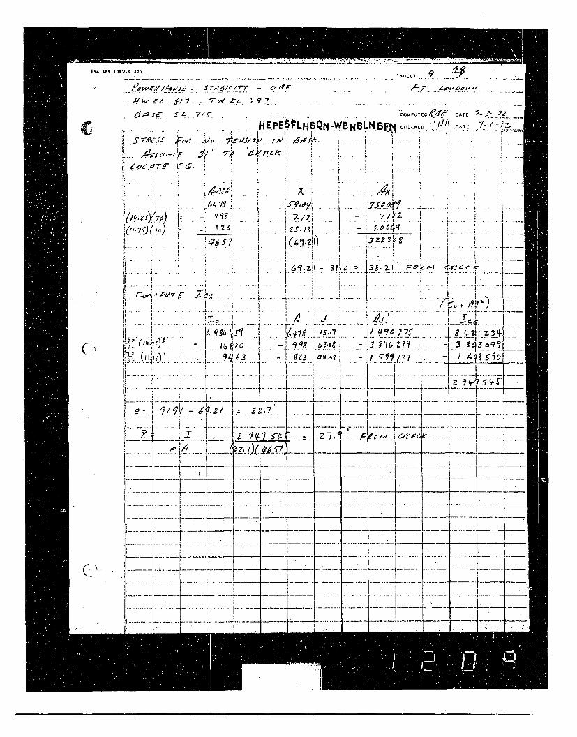
T.. 4 • _ lR.V.9- 471 . 314CET
C
A ' • iZ
7,(•
e{ i
p! ... . .K-I. °i•
L.-.--
'7
AID
3/
I"
7A
~ q
H-.PSLHSQN- SO BF ! .DATE i.
.... 41 .
f7./.7 i7 /n-
I t .131
.. .. 1 .j.. ... ... . . . . . .. i . . . . .1... .. . . . .i . . . I . . ... . .. . . .. . . . . . .61.- 70 3 -
~Y-• .... i ....... -. .. ... 11 ...... z , : { z l.. ...... -i-• - - -
63r.- -9Z3- s-K. /-7 F00-_---__-__- .
!z • -•.( =__z-/.,_1_.• o-,-i ,, _ T...... I -
. .... .
I.r
1!~*~
i .........
I
,(1i •
4 - -... .- - •" • "t •" "1-1~ --
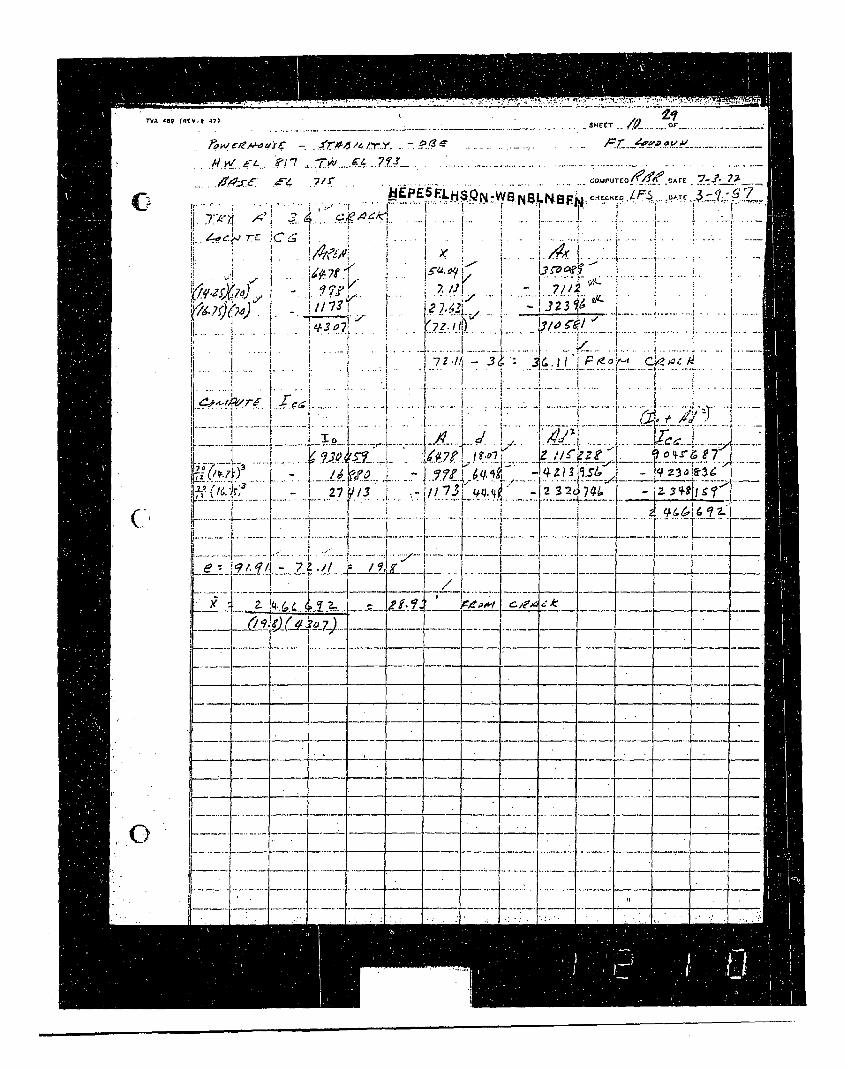
Tiv 489 I# lCv.R 47)
titA UJC -. S • '-ri.r'.., ....... ../Fr. .. . ............. ..
AIW L ?17
C-eyex ýX
i,. •* -
*14
'i " • ' "
I i
, . . . " - ,rurio/,',,, ArE 7-.. 7- z
<• • c• • I /* -•" .! .
• ..- . I. * F
1 6X
7/I 411 7112'
. I j. -
.. .... I ....
- . . .- i - 1 .-...-. ....-..............
i t / j / I _.
Iz I~zz Ire 9" 7' t i(SI 4: I--7 -4. . .. ..f )l/.. 6-.2
L4>- ..
-7-
4% (p~4~74,
4 .~L -- --.-- -..- - -. _
~~~~1
_- ~ _-
0
11
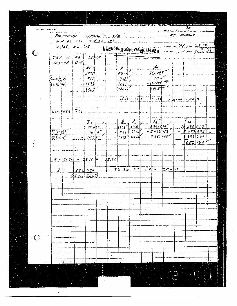
TvA 48a rEV. Q All KH l L Ci_
' -. .... ... ... .-/ .•._ • e 17 . T ..K .. .7/ _ 3 ... .... .....- ,. ... . . . . ........... ..... . .... .
SI..
I " ! ,i
" ' I:. . ., . . .i " ,. ". I .
"-. • , • ... . 't' .
214zI.)(7)• • - -•q ' - .; . I_. .I. .. .. , -... i 7 .!// ,i .. ..I .. ..i ...i. .. .. . i .... w . . .. ', .. . ..7 .... , .... . ..? - - -• - - i i .... ... . .. . . ..- .......-- ,...
. . . . .. . . .. . .. .. .......... ..+" _ 7 , IS
" ..................:.. ..... . ... !...... ............ . ...... -.... ..... ...... ........ ....is!-q f '' 7 L •j I 33
•. •~x • • .... ..........t-~ , .[..... .... . ...... •... .i......... .. i.....
...... I.. . . .i I 3 a F
...... ..... ...... ...... . ....... L....." I I I.,z-- 2•.. d , /..~. -, •
x! i I_!n_ FT F t .--.-17 -
---'••.' K i 7.< IL • . -l_ __L_ ZIl ___.... -.. ...I ... -....' .... .. ...' . .... . ... . -'.. .. --....
K ~21122--V-H'........ I- ---- 4----.-----I-- -- t"----'-I ....
- 4. + -- 4. -- I I -- ~~-- t T -..... .....I- '-----4 -I------------I -- .. .. . .i'---- I- "1-
:rn.-..__ __ --- ~j--i. -- -- .-- .---- .- __ -
~ ______ ..---- ----. ---. -----. ______ -
--.-.----. Ir . I
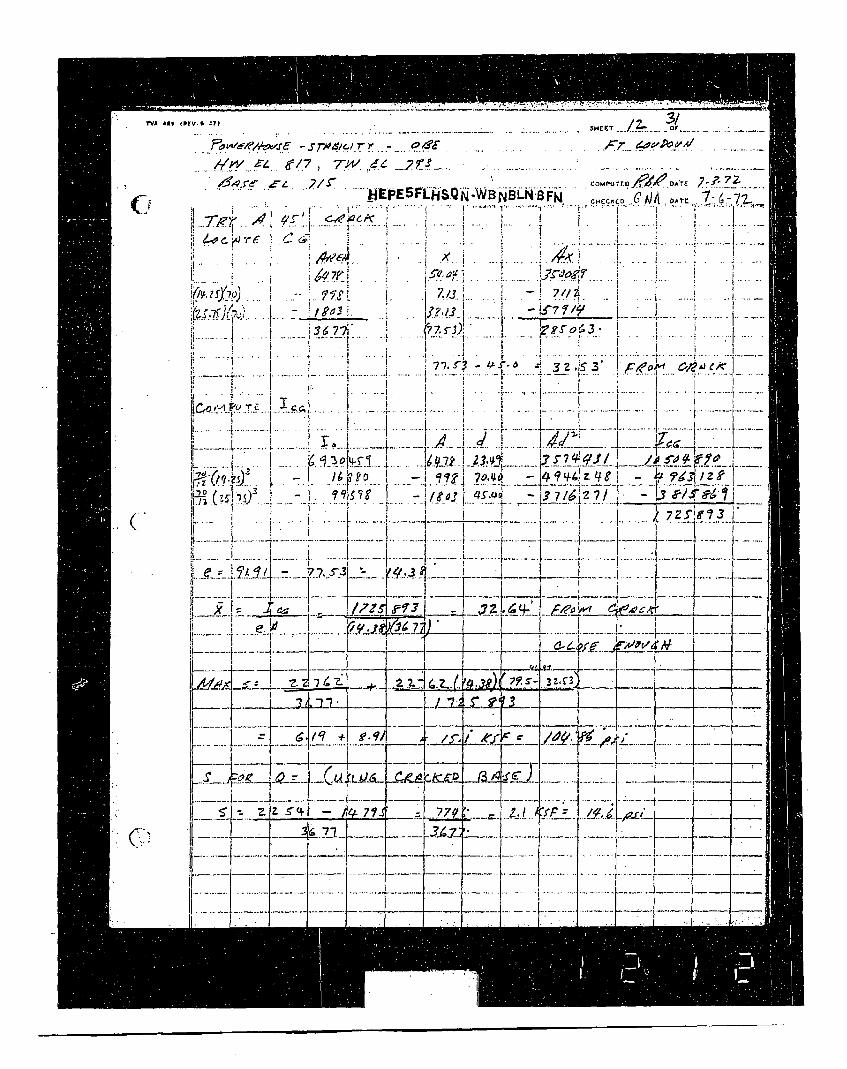
TVA 441 IREV.0 7
SHCET /.
.- , .... .... ...7 ... . ... .7 2-. . .
-WBNBLN'BFNA C1CHE ATC 7 -7-~
. .. : ". !1* j .
__,_.,.____ / , _" .. .. ... .+ • + , ..-. -. ..... . . I ..I, 3
,453' I F ' ; ;+ •)'
}7 -_ ..... I .... * I ... .* .. ....... . . .... .. .... ..~ . I.. .... • ",.....
....... ... .. ...... .. .
• + + • , !'-7'+•i .......... .. -- +f • . .+....i... .L. 2 ....I., .A 2$. I
.. ~70.0 J~9~1 q
7, 7. ~ s- - .73 /F -L /
.... + .. . .. .. .. . . .. . . . . .. ,... . . ...- 4.............. .__.........,_ .... .... ...;+ [I ....... L.. .... ' - I..., ... S ls ' I , , , ., . "
R ..... .................. L .. e. .I 7 . ......
... ,...... .... + + ..... .....[ :; + " .......... 2 _ I22 • _1 .. +...........K • .... -....yt... . ...
I I I _ _ _ _ _ _ _ _ +
V.. . .. .. ... /_.... -, -- ) -
l ,?P)
7j;,q 4;7J~~'Ii~~7/Jj KbI . f .i ......2___ ~Lii~ii
, +++P- IN:!+: + + ...........+ ..... l ..... ..... ... + +++++i ...... ........ + ............. . . . . . . .. ...... __. ..
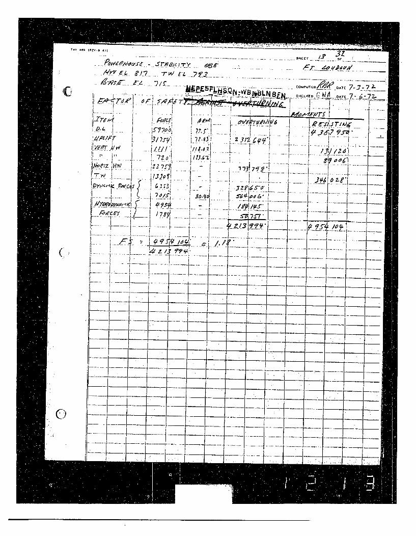
TVA 4AM inrv -o 47
._ r? . . / E L. . ./-* 7~/ --r L E . -_•_3 .... . . -.. ...
. . ...... . .. . .. .... .. E5FL-.:-sN Bi..................... Co uP T Lrj/.• . o^, 7-j- 7 2-Sr CL7CCD-C2-.
i.r . ......... .
I II•. ... .... ,... , , , , .. ... • . . ti ! S , ....I . i I' . .... - .. . -... .
I 2 •,'L ... • ;,:.....
,.f. . .I Y f - . I , I ,, . .
,7 -'- . . .. .. L77'?
.. . ... . .. . • 9 q...
....... 1.... . y o ••o•! ! •• I & I I
I •~ ~ ~ , • ! I L .... "...I: • "..--. r . "! ~~. . ..E~ tz... ..I-• - "• ...#- ...... .
I ... . I- ÷ ......---
f[- - r-- .1. . . ._
---- - -.• -
- - _ _ __ __ _IT- .- ..
C0
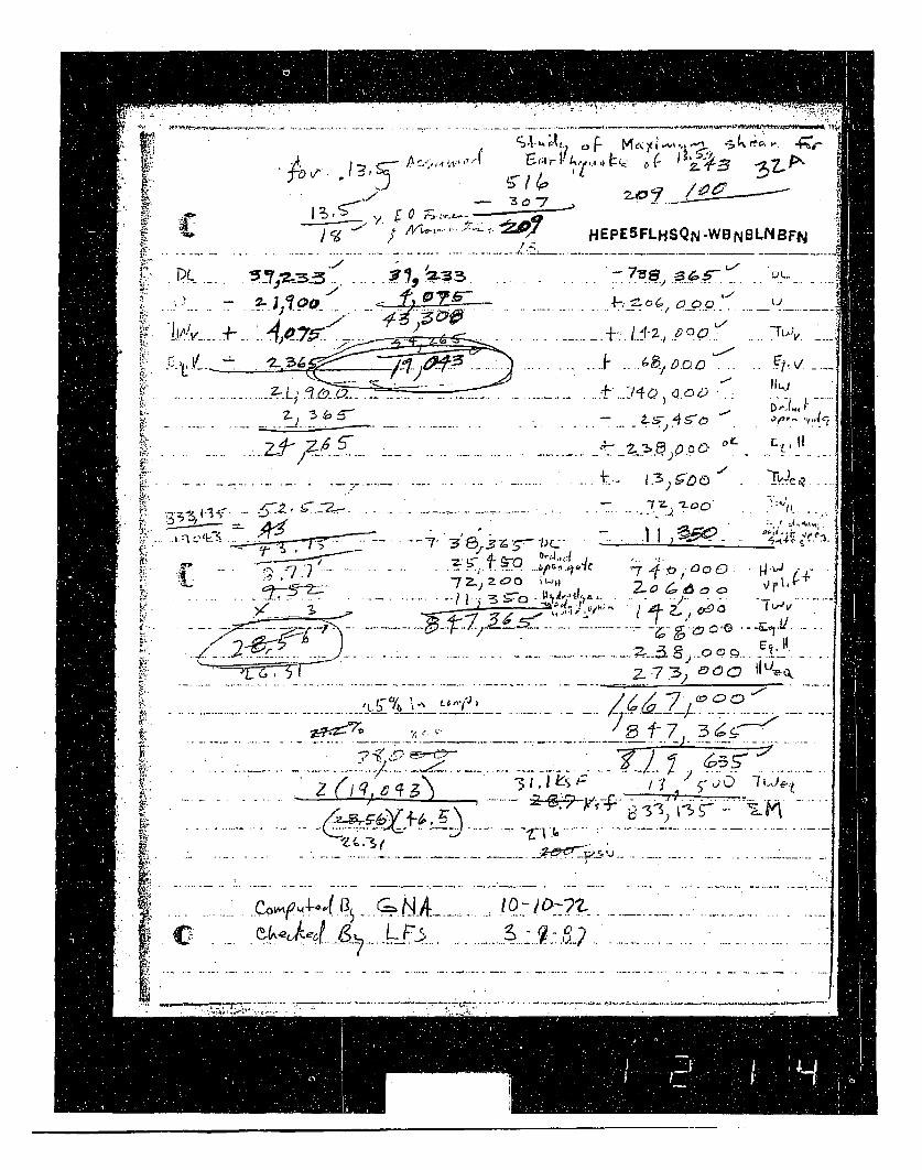
* . '/4HEPEF.WBN1LIBFNI Z._______
-z - 723 -3 A
- 1. ~ L' ). 0'
-~~ IZ3I& .h
's -LOD -
- .. ... . .. ... ... . -...... .
,-,-' - 7. ....... ... .. ... .. .. ... . ...
. .... . / . 2 (; .
".41• -- 7_ z -••-00 . .. I . . ..
'1" ".... . . 7.. .. .. . ."- j I o ,
/,. . . .. . . .... . . ... . ..- .. ..
"Z. .7.3 9 0 "
. . .. . .. . ."'
..... .... 4, ."- o'f: .= - 1-'• . .. i-.., _ -_7• . .. .. .. . ...... . ...... . .
-;':• :: ' " •' " '-- • .: • • .0 -'2
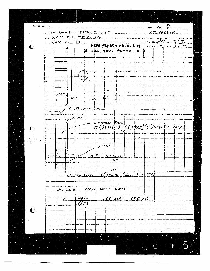
TVA 489 Ilnrv.9 47
SHEET /Aa
CI
.... p <,.•u • '• , .r•.. •:-..•.T .......... I. ..•._. .... ....... .. .. . . . T _ •
,i AfC ,e • HEPES ILHSQN.WB N BLI IBFII,,•I. 1.Jd'r . . ... .i "
7 - I
II
Ir o
.. ....... .---... .... . ---I -i i--- -
... . 12 if ,+. I __, j - iL • ! i . I .
i , I I '..-•-I *Il
i ,.•..K 7 .I... , -... - .. -. i. .... ..............-..... .:..-L..-.....
OATF 7-. • -. _'...
DT.....
(-I
tI.. 1 '.
.:-
- ~1
1~i 4- __,__
I 7 L-eA, zr.5-
'7 fl'
Akr
~LP~Lt~ , ... -4 . ... .... -
-. :t2 ---=t ---I-
I ._
I. " l,..
C) -4 .I.--------.
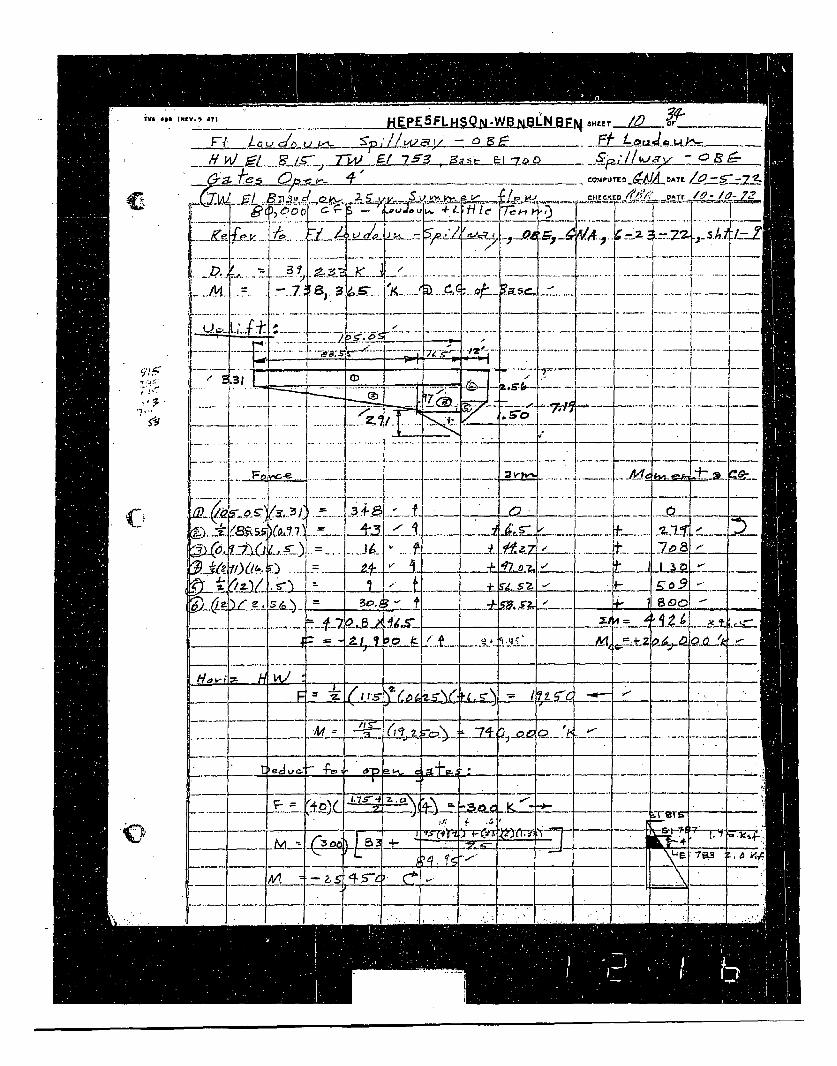
TVA 4DO (li_V. _ __) HEPE5FLHS -W B 1NW.,,I /U _____
___ W'J.PUrED_9AI4~bATL ZETw~ te~w4~ VIACr - /0 -k
J~fLJJUI~4L ~ - ..-....
i . . . . .. .... i . -- --- . ... .- -.. ... .. . .
YT,,--, __K~ -=- =7Z_
C -
J - --------- ------ LL 'I"7.~ r~i __'*_i_•_f ... .. .• .
- ..~._-.). -.- • : .. . . . . __ A.•F .~ J J2-
C)
I
- ., _.- -1•,---• t - .Y-2 6-ie,
UO.
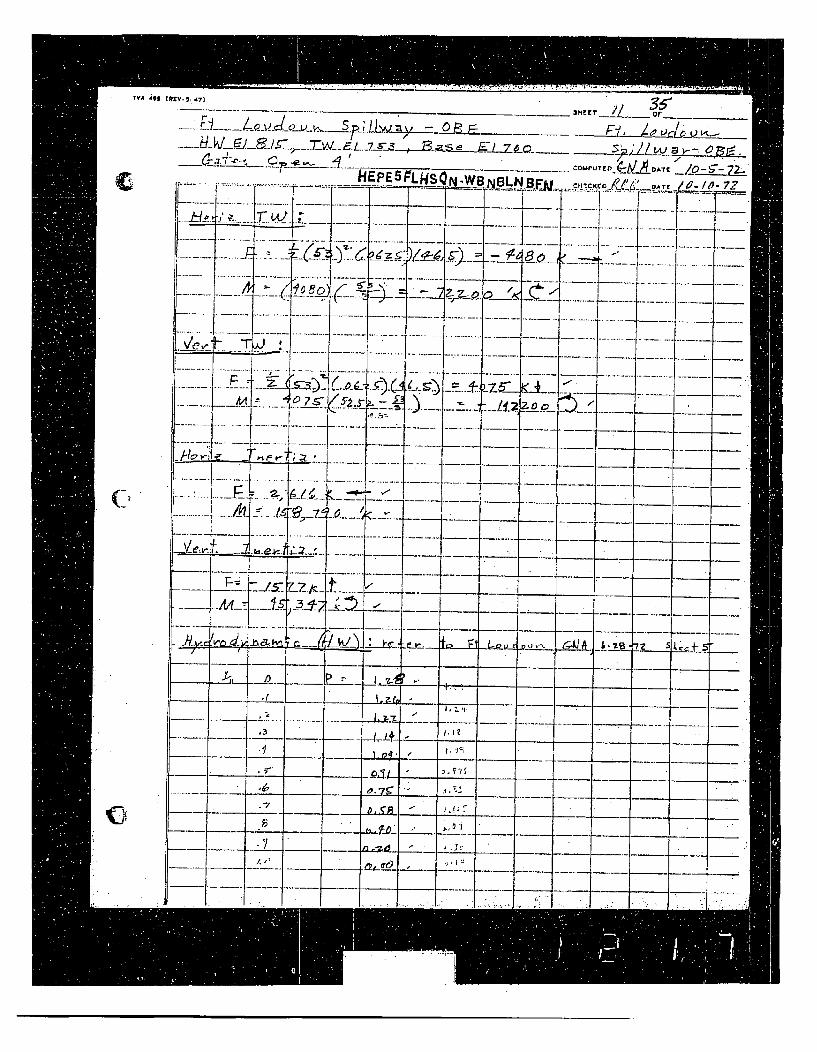
TVA IJ B IR EV . 5 47 1 5, _
--. _ _ t __ _,• <•_ • .,._..T'w__ '.y ._7.r_ • • P.IUT / or._ • _•_,_ __. _ ______
COMPUTED_ý1b/DA1C /0 $ 7E
. . . . ' - . .. .. . . " . . ._ . . - - -• - --._ _ _ _. . . .. -- - -. ... .. .... ...
F7.... II91Ii• !_ ,--!- - -.... . ......5- Z•. V,.--- -. ..
.k!_4 _ -
- .-,_ _ _ _. ___ L I--__ _ .0_ __": ... . . ... _ .. .. - -.... .. .
.. .. .... : .. . ~ . .. -- :' .... - .T• - ---
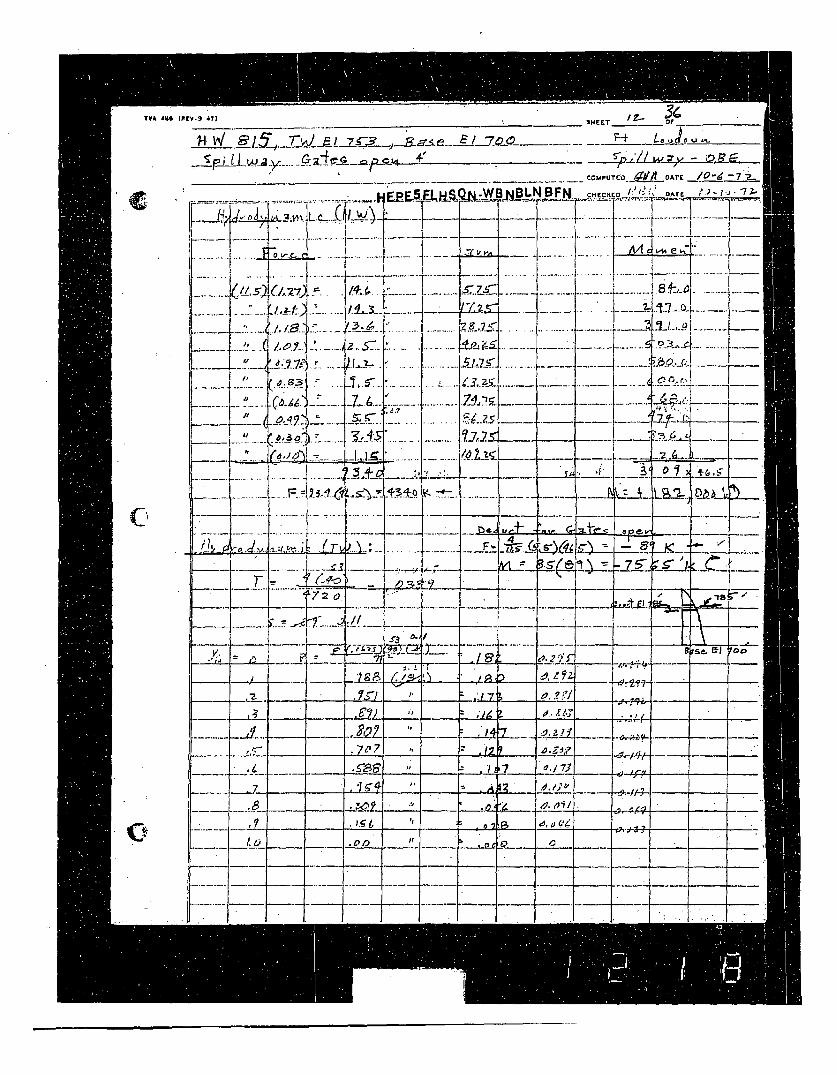
TVA 440 IPCV.5 471__________ or _________
J-~La~.. --R VJ gR I 11ý7 -rL' I r- ) -7 12 -ý' ý E / 7/) 6
_IP L L _ ... Y--- • -- ---
c
,, IL _.,•'C . -. .
-........ ........
iIv
77~.S
/4;'.
z... .sc~.LL.I-
~1S
-C---UT C A - DATEl -7 .
... .... t.. . ........ : :: "
[!f"~ ....... t7...• ....... I ... .
~~~~. ..................... ' .. %. .... I.....~....... ['-
i" - - .... . .. ! L V 7 '.'. -.. ... - --
I . . . ...1... - j . . ...
7 A ... .. . '_• • , _• . . . . ..- --.. .. .
..... ,.+ .,. _ ....................
lit. ,~ -~
.. 1.I. I iTI- -.. . L. _ T ....... r .....
'=•. .. . ... ... ~~ ----... . .. .--F --- - 4-.- I..-- ýr-l- Jý- -
II -- Z •J
r-TA4
= 1 -1 8i K 4-sV4~bA2 L~2~ ~I +
3-5-41cl ý = ý 7 5- ý -5- 'k (ý' -ý
- : .• _ _ _ _ _+L_.+ + --K ". . ..-.._. -- " -- -,_ _"---.. . . ... ... -Z ~Z .. . . .. --.. ..-__ , _ ~ ...... U :2.. _ O___ / -__-. -
I ... .... . . _, . . . ..-._ _ _ _ - 7 _ _ _ _. _-
. .. . - - -- -•,-
_- - ...... I... .- _+,_ _ .4.. ...... -7-- ---- . 2!. .. . . . . _B _ _ ___ ._ ___ . ; __ s' _.o ' 4.. _+ _ _,_
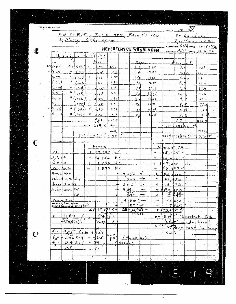
(I
C
TVA 48A (A .... .37... .. H"E"E"T OFL•--- •-•-_•/___L• ..j__TI__• 7••,, •--• /_-• o .. tT • L3_ .,_ or .____ _______
H EK~ DATE " '
.. _ .__._.._ ... . .. .. .
azý IL _
.. .... e... ..- I -
. . . . ..a L _3'•_ - ...__ _'. °• I I • • [ II , -- I
F7:1
Up'4.
L2),:4Iii
0.e~
v-~ .('~
4. A,,
.4-
* n* .fl
...............I "--I" • .... -a*• *-* • ,.
h1
111±2
,.t. /~4I:~ ~
I 1. -11 . I~
IX4.&. ',,'IL
......... - "7_.-> 4 tý -A, -
I I-4 _^ ,/
4:tl; - , G '
_J• . c___ ,t,4_ ....... .. -. __ __•. ' -- L__ ._ _ -- _- _ Z1: h_ •l~.__.__¢
_.,• • L • ;__ "-- _.r.:-K_4 _.__-"
o. ..... _ _ __ . _ -7_ ___T
_ -. _ ___ _ ___ -- •_ __.__ ... Z. _. __
-- --- - - ti •.• --. . .-.
• _= _. '-_ _p _______-___.
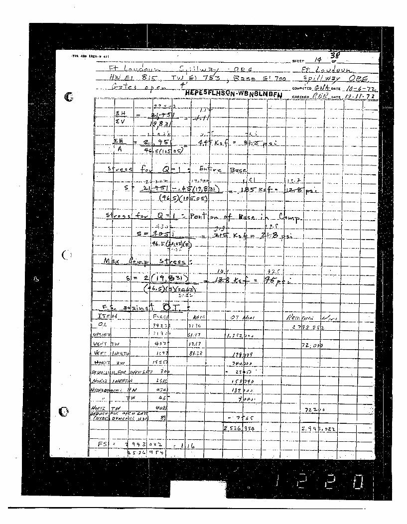
(.
-I440 :E- t. 17 .. -1
514 EET Opp '
N .~~COMP.JTCOi lADrc/6~7.f ozt l " L
-......... .... .
L s .4.. - .- .. • I
. .. ... I . .. I ... ... .. .. . .. ..... . ..... ..
A -------
•-I--
.. ..........
..........-- - -- - " .... .... .If -
-- -r- :=:'i:: _ •-__r-- ........ .i..... I'~---- -----
•__._., fr-_,_ ... ...... . ___. •
__. •ii -. - -[ b_ ___ _ ___ . .. .......... _ .. . .
~ ~ I.C~ __ _ K.2
U l i J:: I _..r I .Pi7JVr
~ ~ - . '-'-' i i~'? ____I 7Z 9)7iIPC-p~. -i --- --- - -- ____ - . - - - -
I. -j -. 1A A?2 ____
_ _ _
- - . . -
--
_ - _
I _.. .. . ..
- -.... ... .. ... . . . .. -. I- --
____-_ -Ill ,- -
- --
.. , d r .•.l •
- '
-- . .
. -• j
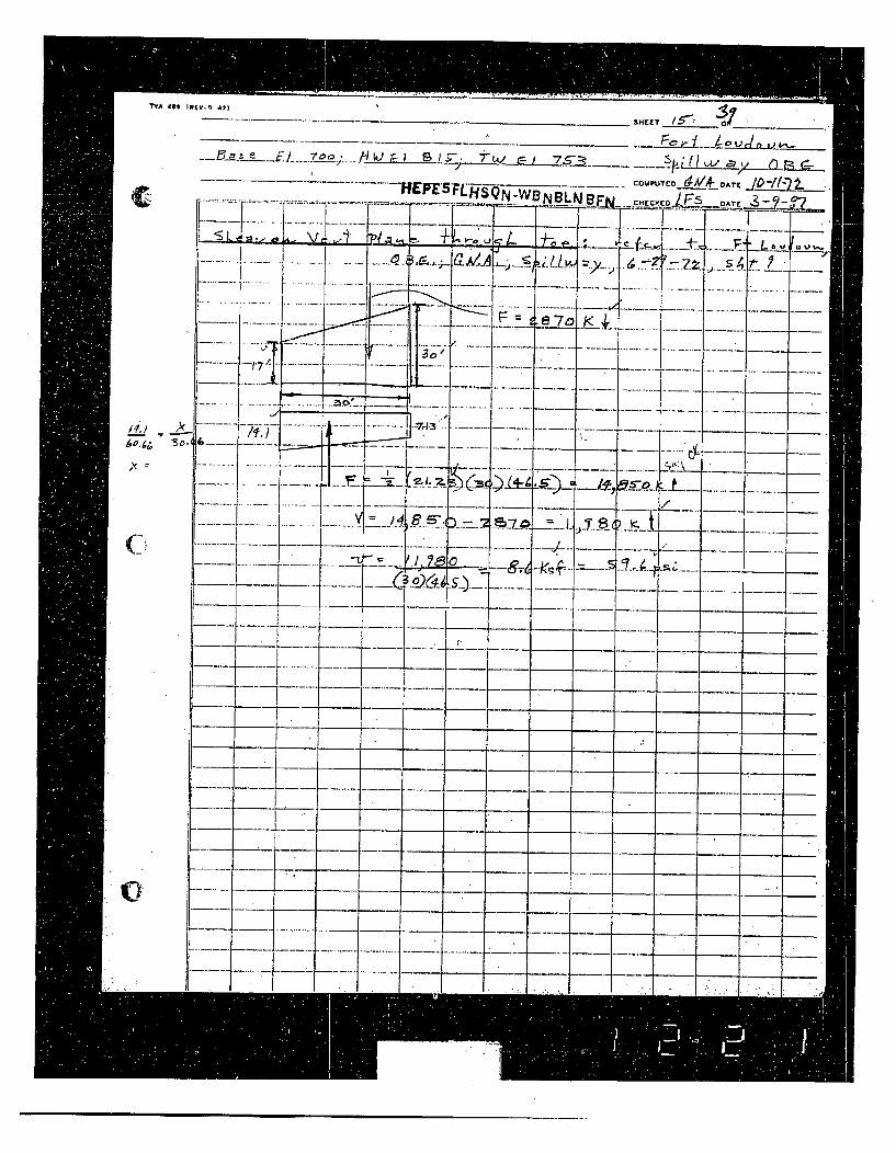
T'VA t8* InEv,3 4373 IL _____ _______
-- _________-_..._•_ _ p_- , w__ .
_ ....... _....... ........ OMPUTED_ O. .. AT .r T ~~~BLW r-~~-.- CCIrO~ DATE ~~
S.............
II.
------- :1 .. 7
_- ~31 11 .11 -~ 111 -- -. I_ -
________ I-- - ________ -- -.. -.-- . - - -.-- -
____ I --- --- -. ---- ____ -.--..- ____
F---- ~-.--.. -. ____ ____ _____ ____
* I --. --- --.- - _____ _____ ____ _____I0k
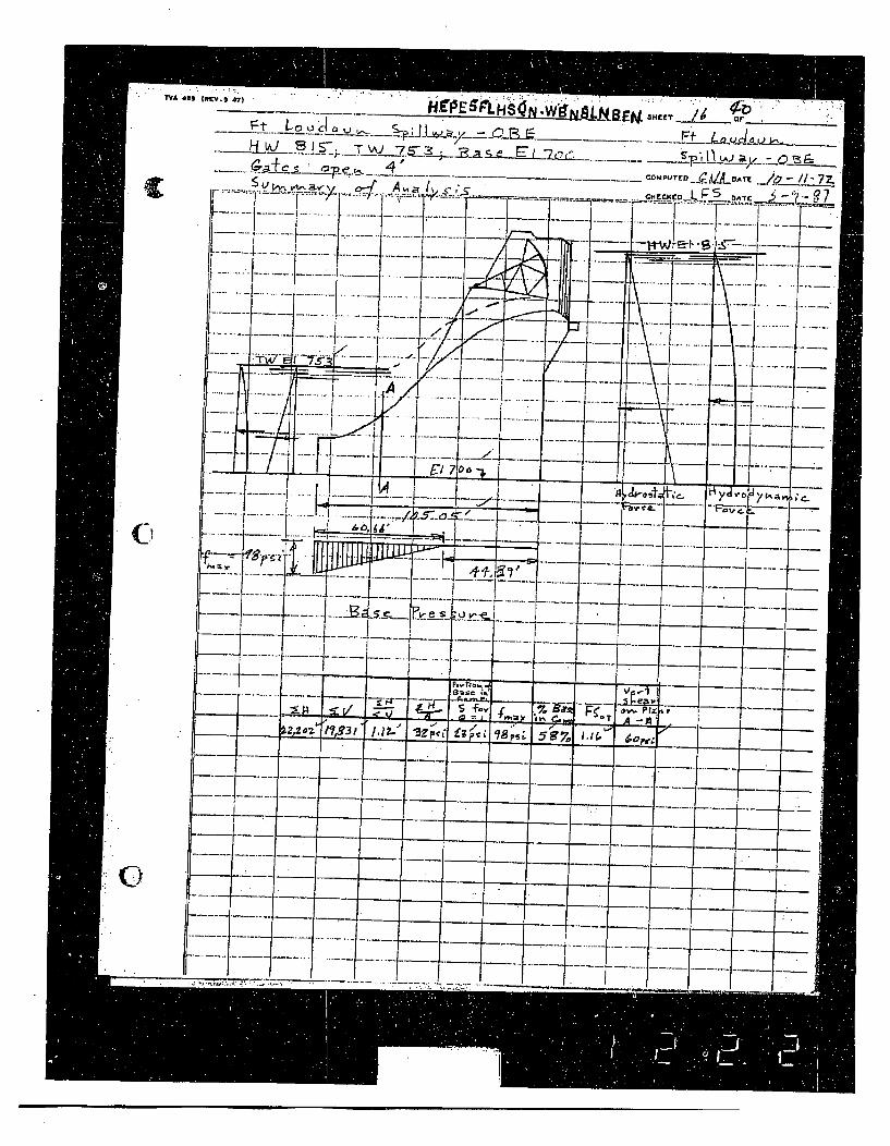
c
C
T YA*9JO IffEV.5" 47)" "- - . _ . _M
.•i~_F AS. BI- _. __ se Ei_• _ ZQI _>. 0
. , ,4_ COMPUT ... /LATE ....-.... - 77
A: 1~ i$ '5r cl LF . A
.-F*--:: -: - --- - ::*--.. ......-.--.-... ..I-... -.... ...-. .-.--.-..- j---.. --
f3 I:: : : :: :: : ... . . - ... ..
UL:" _j-± __- _
.. CC
. t -/1?- - h . ......
." "
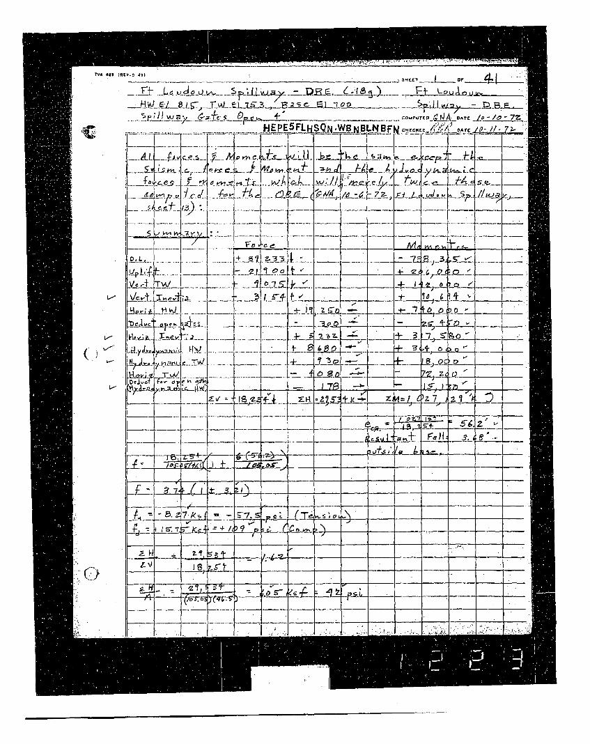
thA iag
(.) ,
.1 S AýD_____./j
" - ... ...z• .. " .. . . :..1. " D2,..T.. . .. .- /0
F___ .- ADATED /t -
MA~- LA4 ~A rjt
rý ~ ~ V< I e
- ->' .1' .-0.-<,.- - _- 0, _ - _ _- '
.......... .. ~ zi3 . 6
......-'-.••-r. 0 •;•-•. • 7• =i.:i ; -d_. - , - j_. - j-_•_' , ._ -.t_ ,.
-; C
- ---__ _ . -
........ t_..._. •... .. 2 ±•P22 -
..... I..... _. -• _ .- .) . . ..
......'- __ __ -.i --
_ _" ....... L •_ _., _.t--. l--- • ,:I-.-&-
-iT --:--. w.- -
I , .. I . I..; ý..
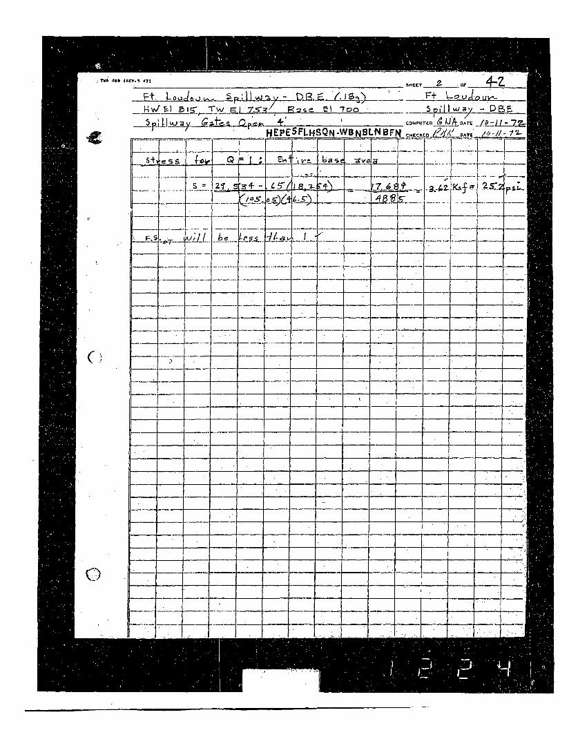
TVA 489 IRRV. 1 4l
W ET 2. at. I,,-ZF+ LouLj-,TJý.Pt. L o__ 5 s_ D•_ _ZK5 .E. l .. .S- DR F
HEPE5FLHSQN.WBNBLNBF Rc iýt!ý -/6--/
e §s -ai a-21 + ~. .45 -z- 4Jzsf
L_..!__•'-
-- f-d
-iii--- - ~~1 _----.
-
-- - _-----=- --K'---
C
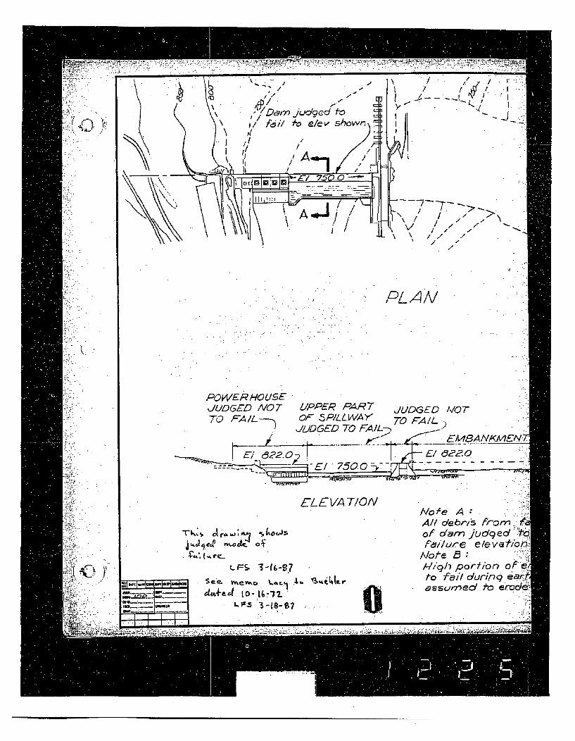
'I,/ fc~i/,1
,!
/.i/ *1
I.judgeditYo e/ev v •hown,
!
T~ -~
,I1ti,/ \ /x/ II
/I,1/
- -.
NN\ \N/
PL A /V
POWER HO USE,JUDGED AV07 LIPPER PAR7 jUDGED ,OT
TO FAIL.--- OF 5PILL W/AY TO FA/L.JIDGED TO FAIL- --.
• ., ........ .•._._...•_•_f. EMISANIXMENI,
E-1 61?2-- El (02. 0-El 75,
ELEVATIONM.
"?.'t4.
Tk .~4OLJS
~li*-o q
Not;e A:A// de brl; fro- - Mof dam judged 'q
'loue B : '',
/-//ih portio f -ecto f7/* dcurinq-earAassurrect Ao erod.
LFS- '3-(6-9S7
flu---
flu-- - I---,I~I
See- .terAD t.l86 Aft Lj tt.r
0
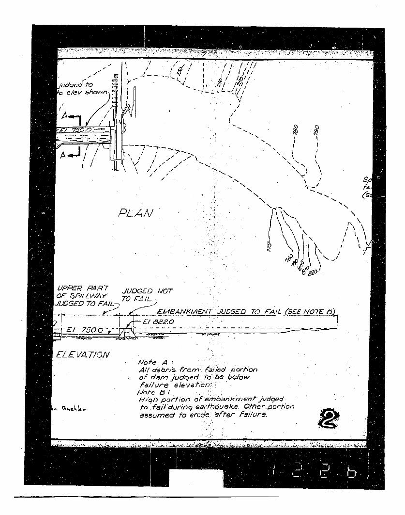
r" -. " : ""~~~~~~~~ " -;. ? " " -..-. .-.-. ."'" .,...,...-.z'-..,y'-...-e .•.? -. •..< . :.•-•
. , . I . Ž'I,." .. /,'//I-l
.0'...iudgcdfro d:/ /A),,0 e/e v si,owr"- I, _
\V/IiIS,
// . *1
/T--i-- . \
\ , II -
/ . ,'. . - NI, V / -, ,, "-,
PLAN. K: "" " /\
JUJDGEDT70FA/IL---- A/, '~ 20 '1
....- E18NX4~ -JUGE 70\Al N72ý
-E -7.0
ý0 0
E /LE VA 7/ONNoAe A
All deris.o. f/c f"/ed Pcortionof dam judged t6 -6e be/owfa/hTue elevafi*,on:
INofe B:Ali'/ porY ion of .emr76nkmnerný'JUded
Vo rj.•l•{• •kto6. f,7/durin9 earfh•ueke. OtCer.,cortionassumed to erodet6. df5er cailc/re.
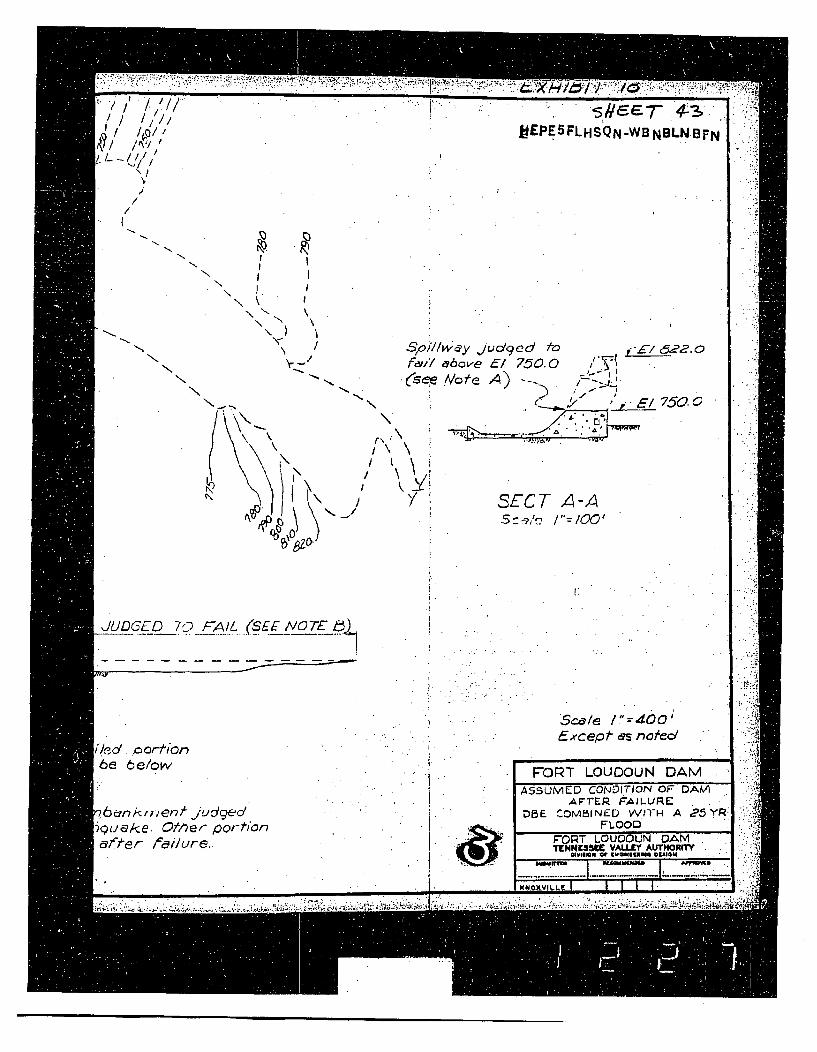
&...~r7/~I ;'* - -
V .1 '/7I.
'1~//
"dl
MEPE5FLHSQN-WB NBLN.BFN
'I/
/
-N.
N .,N
\N\ \
N- /
N.V
N-
N
Sto7llw•y jcudged Ao 0EI 822.0f,•,l' ,aove El 750.0 , -I I-
:e A/bota A) -750.
"* ' .* - .A
N
N' I
Js
r- \
i' \
SECT A-A-Sco--2.'? /"= 100'
1:
JUDGED 7T F-All (SEE NOTE
sc.d/e /1=400'Except as noted
6ed . /orivn6e 6e/ow
q6unk;r,,enf judge/di-u.ake. Otiver porh'ona fter failure.
FORT LOUDOUN DAM
ASSUMED CONDITION OF- DAVIAF"TERP FA)LURLE
DBE COM51INED WITH A ?5YR:FLOOD
F7O0T LOUDOUN DAMTI"NN93IMC VAU.EY AUTHORITY,-,,-.4 "Ct .agg."" a oDRUGa .
U~U~UXVILL~~ 5 I I I* -... I I I I I
Iml gIvltLt,
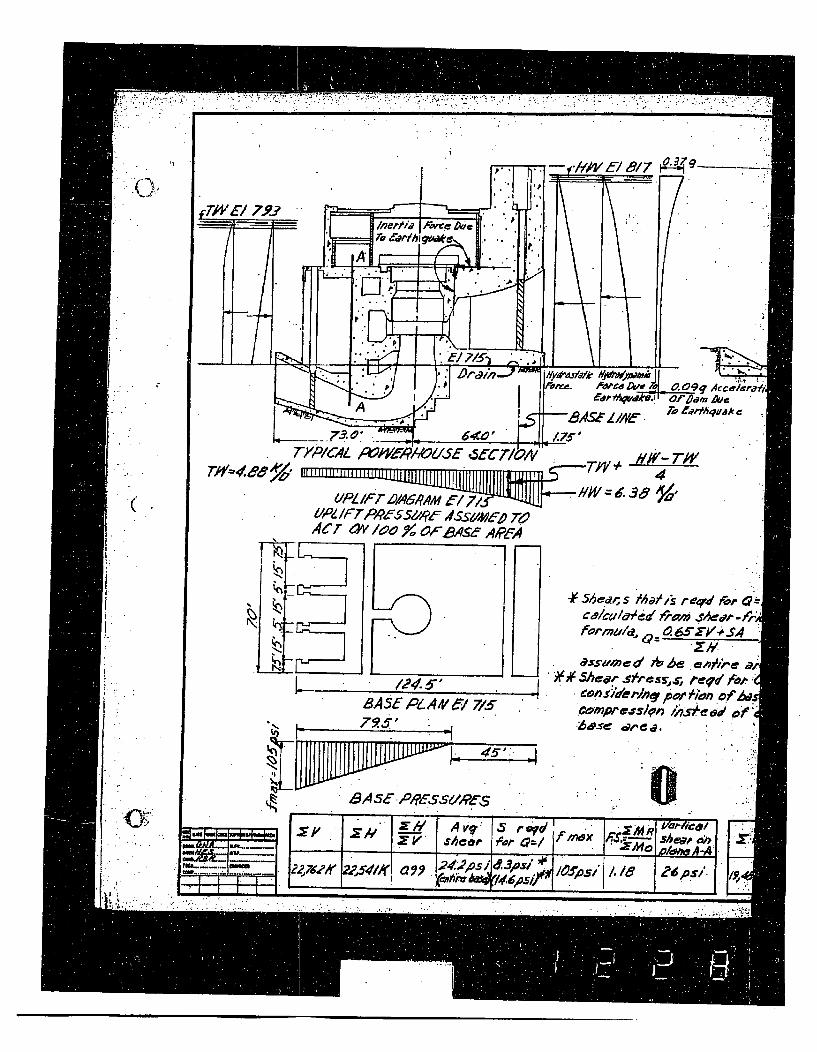
(I6I
: " ' q u O . 9am Ave
Th' 76o6 %' 4
,,UPLIF T A.38
.- PZ /IFTPCr$S//4f Ur// 7A1Mj- T
4cr 4v 'oo '-,cse, 4,fFA
-Y- *$hedes /Ihat,s- r eqdl for 0 i,". •i" forma'ld. _ _ _" __/.$
,. ias7umed " .e e• ae a.
8AS• ,. -14'5 7/ Coes. ,s~e '
0,:r
ro ##Sea Avqcrs re re'd '-
X p Vo--l iSef?2,1YI ?2|M11( i' , 8 ?6ý051 qoP
T!P

I . . , . .•.U A
g___
793
IY SLC2IOA
7mý- el r/,a -*YW~6.3~3 ~
~~~~I. ' ' "
I/PLIF T DI9A6AAM / 7io0/P,/ I-T7 PY9E$5d#E ASSUM~D 7"6ACT OW/6 I0 %¶ '.• AS gE4AA
4Ve-1 715
-4 56co, s 1h j/s,,k reed Aw 0=I/ Is
f'ormuld Q~.65"k'+,4 .A S 'Z#.assumed $m •e enirdie area..
' SheEar r reJd 4o"•/40"s)i'erhinP pop AiO. of Mese ih7
c,~e~s~o~., ',s~e • -,..~Irba,."I " ,"
• 4 SL PLA/ V-I 7O0
• -7-6
Th~L~. I ' ".94
.!',
I
-IM
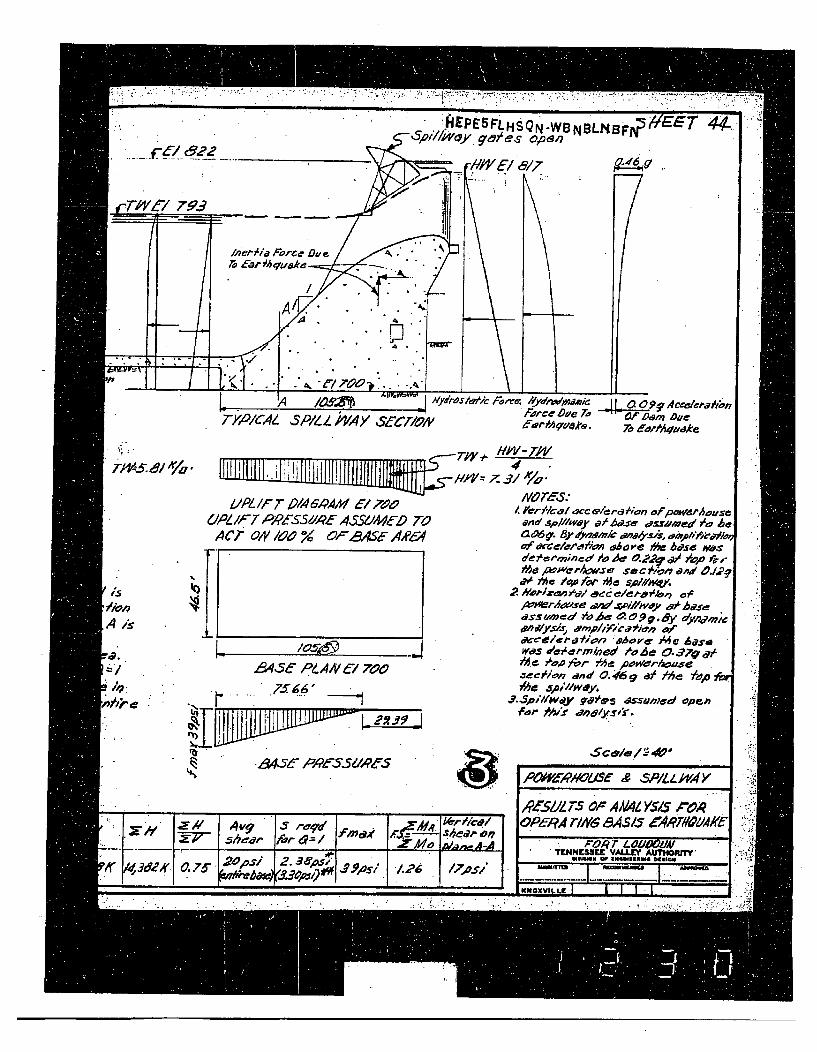
TYPICAL SP/LL UYAY TCZIMON* Fdorcov 12e
er K~elA.
040.95v Ac~eeepajho,Of Donm Due7o af'f!qadke
4is
--T#:V Hk/V- 14/
U P L /PTIF T P 1 4 & QA 1 x ' 7 M P Ae r l- lc a l &c r aeio i o n o f m w er ho m ss e61,ZII*7,RZ-SZIA-450CeC 7-0d'#f anal gVV111,se
(.IPLIF7 PPA$S'P.1#R 4$SS dM D TO awid .sp/.'way uP Ma.e ea-ru~ede /o Ac
AC~r 04 /a.0~ 92S AA?6 g09' Biyyi~tI a'06'SS, 1)1/de'n~incdhdo Af A.&S'-g 0 *v-
7• pvWr/2w.Ie Sec %0n ad O./.•
. " /he 4/40f' o i5,1sp//,.
aT"i iA. 1• I $'Oppiy,,4 a, e ,,W. "
.64,5es cPvtAANv61 7V.0
£J36PeAO' 70 .00~ gd' 0. 46 9 8)' /he 7,O75~lh. spM5illwvy.
~~~~F-or M.I ddyr
LIIJt.4 1J~ "p,q s.q
/-'-' 4v 1
P~iZAWOU~Se X SPl.5P/U-v4"
,IP£S 75 dcF ANAML YS/S AWOP6eRA T/i7-N 8A3S z•WTI#oAAe
I E' • ?E" LOV ,O OAm_ mw_ orI
1ENNE58~E VALLrV AUThORITYEWISM w ZN4~iEUmS OSEWI.qru mnK~m8
-- 1 1 l | !
JWNUXVILLC I * I I - I
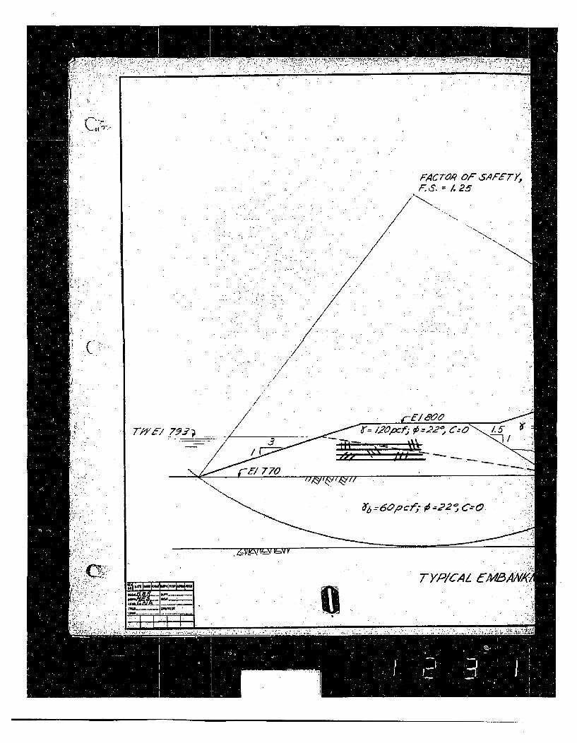
F4CTroR Ol sAFET4F.,S = 1.25
C
/
_.._._ __ E l 6 2 ,
TYPICAL CUBA
2
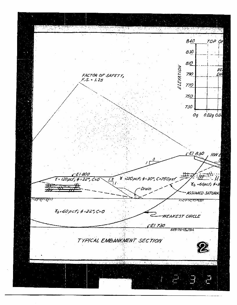
840
FACTR Op6F4'"1.25
NK
~44
-.4
"'4'~•
730-q
c'9 0029 0.
.5/600apc eo i.j-b /X0pcf,; € 30•,C
. "" -'- • •../ ,
TYPICAI (MaAAIKENMEA SeC7TQoIV
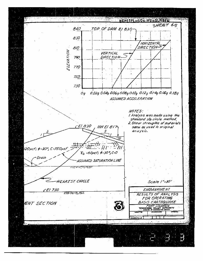
SM~T 4~-
N.K
0g -. 29 0.49 0 0 6g 0-0 1g0.lg 01 2 g 0 /45 0-D /5 6 1&q
ASS, OMCD A MceEZ Ziq-AT/9//
N
,V072fS:/ Ailalyss was made &.sin, /be
S'&n7d&rd SAP c/ilC/ melhhod*2. Shear s(ren'/As e",o/s
.sme.as 11sead in o0i-,/n7o1/d17 d/.JS.11,.3
,6- 6L_.§ (l4 ý . /•b s6opCb, •--:30 ,C--o
A S1MED SA T7MA TION Y IF
Sc&/c / "=30'
I fA43AA/OWE N TI ReS Z1. TS OF ANA L >/S/5
f-OR OPeRAT7'16BA/5 5AfARrT/V UAKf
. m
PEXT S6C 71O/V m l
FORT LOU4 OU4/TEHNNCEEE VALLEY AUTHORITY
OIIm 4 W tNolwe~mhU 048.0m i
SWUIT1SS RLcMsau l:iiI flAILI I I II.,14.OXVILLIF I t I 'I I
Tofs wr m•--- rw zwEv
aE P" 5 "[Ht-jp-W8NBLNBFN
SHEEUT 440. OF__ _ i
rOMPUTEO _____OATEVC"Ecm0 DAT-
THIS IS THE LAST PAGE OF THE CALCULATION
C) 2
I
TENNESSEE VALLEY AUTHORITYRIVER SYSTEM OPERATIONS & ENVIRONMENT
RIVER OPERATIONS
FORT LOUDOUN DAM
SPILLWAY DISCHARGE TABLES
NOVEMBER 2004
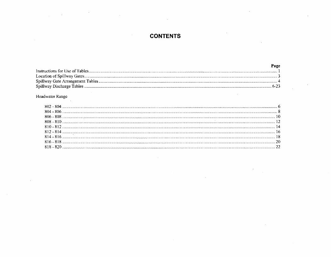
CONTENTS
PageInstructions for Use of Tables ........................................................................................................................................................................... ILocation of Spillway Gates ............................................................................................................................................................................... 3Spillway Gate Arrangement Tables .................................................................................................................................................................. 4Spillway Discharge Tables .......................................................................................................................................................................... 6-23
Headwater Range
8 0 2 - 8 0 4 ................................................................................................................................................................................................... 68 0 4 - 8 0 6 ................................................................................................................................................................................................... 88 0 6 - 8 0 8 ................... : ............................................................................................................................................................................. 108 0 8 - 8 10 ................................................................................................................................ ....... *" *" ** .................... 128 10 - 8 12 ................................................................................................................................ ................. 148 12 - 8 14 ................................................................................................................................................................................................. 16814-816 .......... ................. 18816-818 ........... ...... ................. 208 18 - 8 2 0 ................................................................................................................................................................................................. 2 2
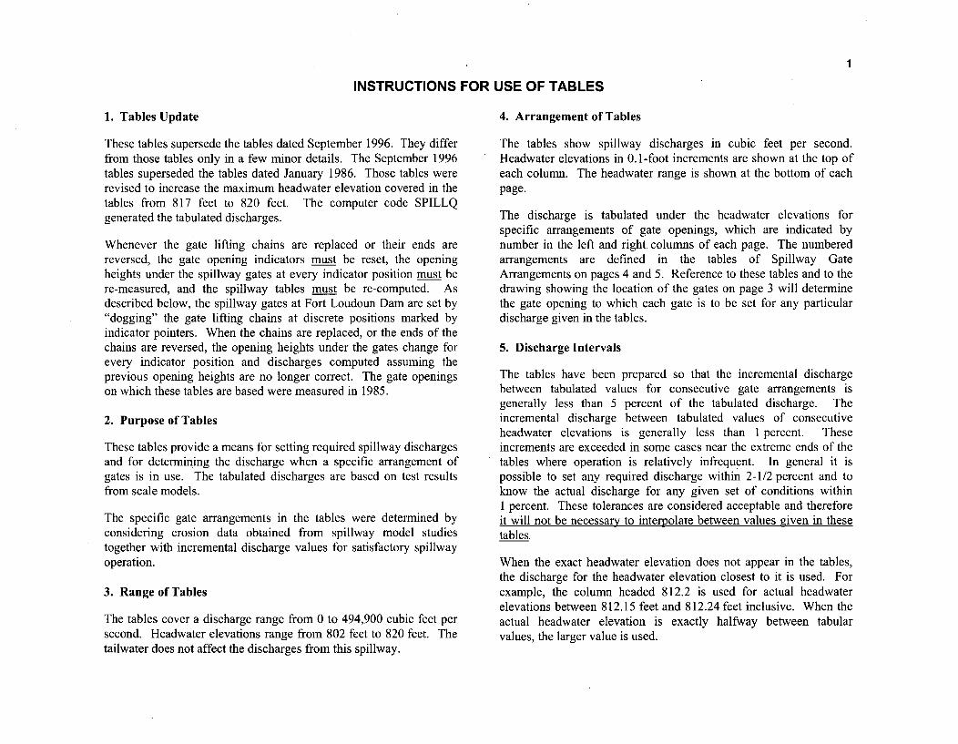
1
INSTRUCTIONS FOR USE OF TABLES
1. Tables Update 4. Arrangement of Tables
These tables supersede the tables dated September 1996. They differfrom those tables only in a few minor details. The September 1996tables superseded the tables dated January 1986. Those tables wererevised to increase the maximum headwater elevation covered in thetables from 817 feet to 820 feet. The computer code SPILLQgenerated the tabulated discharges.
Whenever the gate lifting chains are replaced or their ends arereversed, the gate opening indicators must be reset, the openingheights under the spillway gates at every indicator position must bere-measured, and the spillway tables must be re-computed. Asdescribed below, the spillway gates at Fort Loudoun Dam are set by"dogging" the gate lifting chains at discrete positions marked byindicator pointers. When the chains are replaced, or the ends of thechains are reversed, the opening heights under the gates change forevery indicator position and discharges computed assuming theprevious opening heights are no longer correct. The gate openingson which these tables are based were measured in 1985.
2. Purpose of Tables
These tables provide a means for setting required spillway dischargesand for determining the discharge when a specific arrangement ofgates is in use. The tabulated discharges are based on test resultsfrom scale models.
The specific gate arrangements in the tables were determined byconsidering erosion data obtained from spillway model studiestogether with incremental discharge values for satisfactory spillwayoperation.
3. Range of Tables
The tables cover a discharge range from 0 to 494,900 cubic feet persecond. Headwater elevations range from 802 feet to 820 feet. Thetailwater does not affect the discharges from this spillway.
The tables show spillway discharges in cubic feet per second.Headwater elevations in 0.1-foot increments are shown at the top ofeach column. The headwater range is shown at the bottom of eachpage.
The discharge is tabulated under the headwater elevations forspecific arrangements of gate openings, which are indicated bynumber in the left and right, coluirms of each page. The numberedarrangements are defined in the tables of Spillway GateArrangements on pages 4 and 5. Reference to these tables and to thedrawing showing the location of the gates on page 3 will determinethe gate opening to which each gate is to be set for any particulardischarge given in the tables.
5. Discharge Intervals
The tables have been prepared so that the incremental dischargebetween tabulated values for consecutive gate arrangements isgenerally less than 5 percent of the tabulated discharge. Theincremental discharge between tabulated values of consecutiveheadwater elevations is generally less than I percent. Theseincrements are exceeded in some cases near the extreme ends of thetables where operation is relatively infrequent. In general it ispossible to set any required discharge within 2-1/2 percent and toknow the actual discharge for any given set of conditions withinI percent. These tolerances are considered acceptable and thereforeit will not be necessajy to interpolate between values given in thesetables
When the exact headwater elevation does not appear in the tables,the discharge for the headwater elevation closest to it is used. Forexample, the column headed 812.2 is used for actual headwaterelevations between 812.15 feet and 812.24 feet inclusive. When theactual headwater elevation is exactly halfway between tabularvalues, the larger value is used.
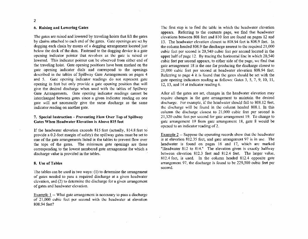
2
6. Raising and Lowering Gates
The gates are raised and lowered by traveling hoists that lift the gatesby chains attached to each end of the gates. Gate openings are set bydogging each chain by means of a dogging arrangement located justbelow the deck of the dam. Fastened to the dogging device is a gateopening indicator pointer that revolves as the gate is raised orlowered. This indicator pointer can be observed from either end ofthe traveling hoist. Gate opening positions have been marked on thegate opening indicator dials and correspond to the openingsdescribed in the tables of Spillway Gate Arrangements on pages 4and 5. Gate opening indicator readings do not represent gateopening in feet but only provide a gate opening position that willgive the desired discharge when used with the tables of SpillwayGate Arrangements. Gate opening indicator readings cannot beinterchanged between gates since a given indicator reading on onegate will not necessarily give the same discharge as the sameindicator reading on another gate.
7. Special Instruction - Preventing Flow Over Top of SpillwayGates When Headwater Elevation is Above 815 feet
If the headwater elevation exceeds 815 feet (actually, 814.8 feet toprovide a 0.2-foot margin of safety) the spillway gates must be set toone of the gate arrangements listed in the tables to prevent flow overthe tops of the gates. The minimum gate openings are thosecorresponding to the lowest numbered gate arrangement for which adischarge value is provided in the tables.
8. Use of Tables
The tables can be used in two ways: (1) to determine the arrangementof gates needed to pass a required discharge at a given headwaterelevation, and (2) to determine the discharge for a given arrangementof gates and headwater elevation.
Example I -- What gate arrangement is necessary to pass a dischargeof 2 1,000 cubic feet per second with the headwater at elevation808.94 feet?
The first step is to find the table in which the headwater elevationappears. Referring to the contents page, we find that headwaterelevations between 808 feet and 810 feet are found on pages 12 and13. The headwater elevation closest to 808.94 feet is 808.9 feet. Inthe column headed 808.9 the discharge nearest to the required 21,000cubic feet per second is 20,540 cubic feet per second located in theupper half of page 12. By tracing the horizontal line in which 20,540cubic feet per second appears, to either side of the page, we find thatgate arrangement 18 is the one for producing the discharge closest to21,000 cubic feet per second at headwater elevation 808.94 feet.Referring to page 4 it is found that the gates should be set with thegate opening indicators reading as follows: Gates 3, 5, 7, 9, 10, 11,12, 13, and 14 at indicator reading 6.
After all the gates are set, changes in the headwater elevation mayrequire changes in the gate arrangement to maintain the desireddischarge. For example, if the headwater should fall to 808.12 feet,the discharge will be found in the column headed 808. 1. In thiscolumn the discharge closest to 21,000 cubic feet per second is21,320 cubic feet per second for gate arrangement 19. To change togate arrangement 19 from gate arrangement 18, gate 8 would beopened to an indicator reading of 2.
Example 2 -- Suppose the operating records show that the headwateris at elevation 812.35 feet, and gate arrangement 97 is in use. Theheadwater is found on pages 16 and 17, which are marked"Headwater 812 to 814." The elevation given is exactly halfwaybetween elevation 812.3 feet and 812.4 feet. The larger value,812.4 feet, is used. In the column headed 812.4 opposite gatearrangement 97, the discharge is found to be 229,500 cubic feet persecond.
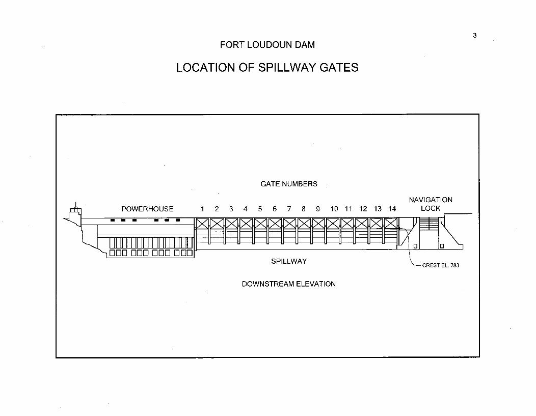
3
FORT LOUDOUN DAM
LOCATION OF SPILLWAY GATES
GATE NUMBERS
NAVIGATION5 6 7 8 9 10 11 12 13 14 LOCKPOWERHOUSE 1 2 3 4
SPILLWAYCREST EL. 783
DOWNSTREAM ELEVATION
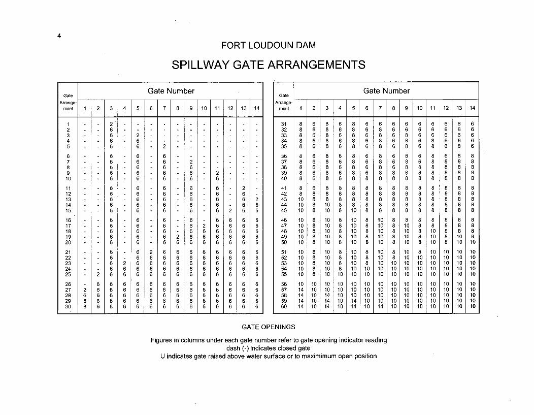
4
FORT LOUDOUN DAM
SPILLWAY GATE ARRANGEMENTS
Gate Gate NumberArrange-
ment 1 2 3 4 5 6 7 8 9 10 11 12 13 14
1 22 63 6 24 6 65 6 6 2
6 6 6 67 6 6 6 28 6 6 6 69 6 6 6 6 2
10 6 6 6 6 6
11 6 6 6 6 6 212 6 6 6 6 6 613 6 6 6 6 6 6 214 6 6 6 6 6 6 615 6 - 6 6 6 6 2 6 6
16 6 - 6 6 6 6 6 6 617 6 - 6 6 6 2 6 6 6 618 6 - 6 6 6 6 6 6 6 619 6 - 6 6 2 6 6 6 6 6 620 6 - 6 6 6 6 6 6 6 6 6
21 6 - 6 2 6 6 6 6 6 6 6 622 6 - 6 6 6 6 6 6 6 6 6 623 6 2 6 6 6 6 6 6 6 6 6 624 6 6 6 6 6 6 6 6 6 6 6 625 2 6 6 6 6 6 6 6 6 6 6 6 6
26 6 6 6 6 6 6 6 6 6 6 6 6 627 2 6 6 6 6 6 6 6 6 6 6 6 6 628 6 6 6 6 6 6 6 6 6 6 6 6 6 629 8 6 6 6 6 6 6 6 6 6 6 6 6 630 8 6 8 6 6 6 6 6 6 6 6 6 6 6
Gate NumberGate
Arrange-ment 1 2 3 4 5 6 7 8 9 10 11 12 13 14
31 8 6 8 6 8 6 6 6 6 6 6 6 6 632 8 6 8 6 8 6 8 6 6 6 6 6 6 633 8 6 8 6 8 6 8 6 8 6 6 6 6 634 8 6 8 6 8 6 8 6 8 6 8 6 6 635 8 6 8 6 8 6 8 6 8 6 8 6 8 6
36 8 6 8 6 8 6 8 6 8 6 8 6 8 837 8 6 8 6 8 6 8 6 8 6 8 8 8 838 8 6 8 6 8 6 8 6 8 8 8 8 8 839 8 6 8 6 8 6 8 8 8 8 8 8 8 840 8 6 8 6 8 8 8 8 8 8 8 8 8 8
41 8 6 8 8 8 8 8 8 8 8 8 8 8 842 8 8 8 8 8 8 8 8 8 8 8 8 8 843 10 8 8 8 8 8 8 8 8 8 8 8 8 844 10 8 10 8 8 8 8 8 8 8 8 8 8 845 10 8 10 8 10 8 8 8 8 8 8 8 8 8
46 10 8 10 8 10 8 10 8 8 8 8 8 8 847 10 8 10 8 10 8 10 8 10 8 8 8 8 848 10 8 10 8 10 8 10 8 10 8 10 8 8 849 10 8 10 8 10 8 10 8 10 8 10 8 10 850 10 8 10 8 10 8 10 8 10 8 10 8 10 10
51 10 8 10 8 10 8 10 8 10 8 10 10 10 1052 10 8 10 8 10 8 10 8 10 10 10 10 10 1053 10 8 10 8 10 8 10 10 10 10 10 10 10 1054 10 8 10 8 10 10 10 10 10 10 10 10 10 1055 10 8 10 10 10 10 10 10 10 10 10 10 10 10
56 10 10 10 10 10 10 10 10 10 10 10 10 10 1057 14 10 10 10 10 10 10 10 10 10 10 10 10 1058 14 14 10 10 10 10 10 10 10 10 10 10 1059 14 1 14 10 14 10 10 10 10 10 10 '10 10 1060 14 10 14 10 14 10 14 10 10 10 10 10 10 10
GATE OPENINGS
Figures in columns under each gate number refer to gate opening indicator readingdash (-) indicates closed gate
U indicates gate raised above water surface or to maximimum open position
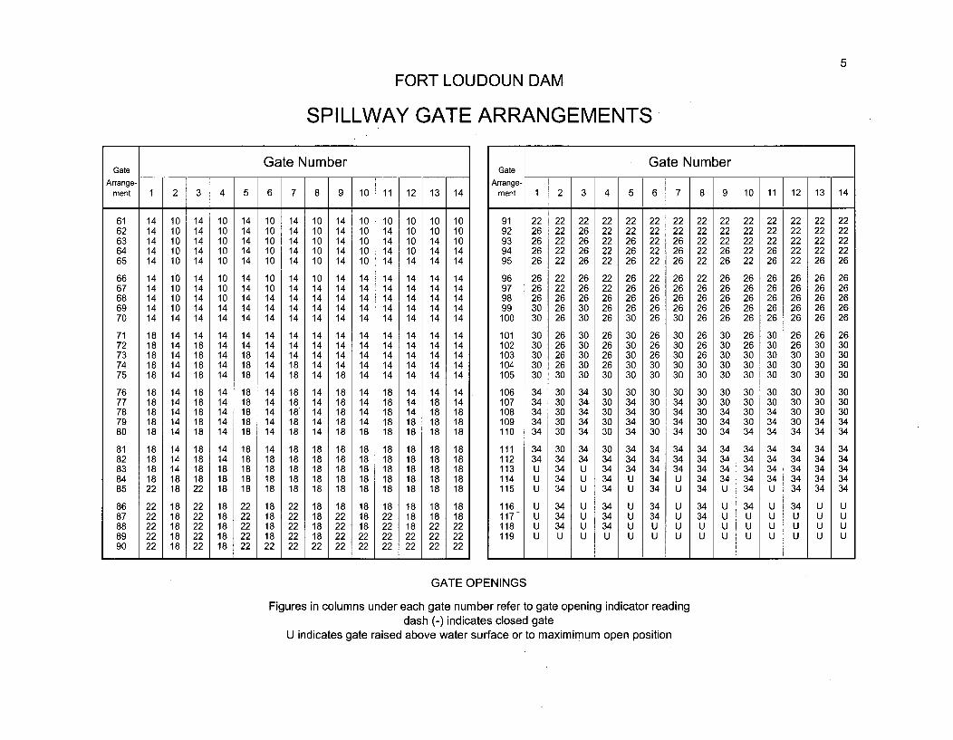
5
FORT LOUDOUN DAM
SPILLWAY GATE ARRANGEMENTS
Gate NumberGate
Arrange-ment 1 2 3 4 5 6 7 8 9 10 11 12 13 14
61 14 10 14 10 14 10 14 10 14 10 10 10 10 1062 14 10 14 10 14 10 14 10 14 10 14 10 10 1063 14 10 14 10 14 10 14 10 14 10 14 10 14 1064 14 10 14 10 14 10 14 10 14 10 14 10 14 1465 14 10 14 10 14 10 14 10 14 10 14 14 14 14
66 14 10 14 10 14 10 14 10 14 14 14 14 14 1467 14 10 14 10 14 10 14 14 14 14 14 14 14 1468 14 10 14 10 14 14 14 14 14 14 14 14 14 1469 14 10 14 14 14 14 14 14 14 14 14 14 14 1470 14 14 14 14 14 14 14 14 14 14 14 14 14 14
71 18 14 14 14 14 14 14 14 14 14 14 14 14 1472 18 14 18 14 14 14 14 14 14 14 14 14 14 1473 18 14 18 14 18 14 14 14 14 14 14 14 14 1474 18 14 18 14 18 14 18 14 14 14 14 14 14 1475 18 14 18 14 18 14 18 14 18 14 14 14 14 14
76 18 14 18 14 18 14 18 14 18 14 18 14 14 1477 18 14 18 14 18 14 18 14 18 14 18 14 18 1478 18 14 18 14 18 14 18 14 18 14 18 14 18 1879 18 14 18 14 18 14 18 14 18 14 18 18 18 1880 18 14 18 14 18 14 18 14 18 18 18 18 18 18
81 18 14 18 14 18 14 18 18 18 18 18 18 18 1882 18 14 18 14 18 18 18 18 18 18 18 18 18 1883 18 14 18 18 18 18 18 18 18 18 18 18 18 1884 18 18 18 18 18 18 18 18 18 18 18 18 18 1885 22 18 22 18 18 18 18 18 18 18 18 18 18 18
86 22 18 22 18 22 18 22 18 18 18 18 18 18 1887 22 18 22 18 22 18 22 18 22 18 22 18 18 1888 22 18 22 18 22 18 22 18 22 18 22 18 22 2289 22 18 22 18 22 18 22 18 22 22 22 22 22 2290 22 18 22 18 22 22 22 22 22 22 22 22 22 22
Gate NumberGate
Arrange-ment 1 2 3 4 5 6 7 8 9 10 11 12 13 14
91 22 22 22 22 22 22 22 22 22 22 22 22 22 2292 26 22 26 22 22 22 22 22 22 22 22 22 22 2293 26 22 26 22 26 22 26 22 22 22 22 22 22 2294 26 22 26 22 26 22 26 22 26 22 26 22 22 2295 26 22 26 22 26 22 26 22 26 22 26 22 26 26
96 26 22 26 22 26 22 26 22 26 26 26 26 26 2697 26 22 26 22 26 26 26 26 26 26 26 26 26 2698 26 26 26 26 26 26 26 26 26 26 26 26 26 2699 30 26 30 26 26 26 26 26 26 26 26 26 26 26
100 30 26 30 26 30 26 30 26 26 26 26 26 26 26
101 30 26 30 26 30 26 30 26 30 26 30 26 26 26102 30 26 30 26 30 26 30 26 30 26 30 26 30 30103 30 26 30 26 30 26 30 26 30 30 30 30 30 30104 30 26 30 26 30 30 30 30 30 30 30 30 30 30105 30 30 30 30 30 30 30 30 30 30 30 30 30 30
106 34 30 34 30 30 30 30 30 30 30 30 30 30 30107 34 30 34 30 34 30 34 30 30 30 30 30 30 30108 34 30 34 30 34 30 34 30 34 30 34 30 30 30109 34 30 34 30 34 30 34 30 34 30 34 30 34 34110 34 30 34 30 34 30 34 30 34 34 34 34 34 34
111 34 30 34 30 34 34 34 34 34 34 34 34 34 34112 34 34 34 34 34 34 34 34 34 34 34 34 34 34113 U 34 U 34 34 34 34 34 34 34 34 34 34 34114 U 34 U 34 U 34 U 34 34 34 34 34 34 34115 U 34 U 34 U 34 U 34 U 34 U 34 34 34
116 U 34 U 34 U 34 U 34 U 34 U 34 U U117 U 34 U 34 U 34 U 34 U U U U U U118 U 34 U 34 U U U U U U U U U U119 U U U U U U U U U U U U U U
GATE OPENINGS
Figures in columns under each gate number refer to gate opening indicator readingdash (-) indicates closed gate
U indicates gate raised above water surface or to maximimum open position
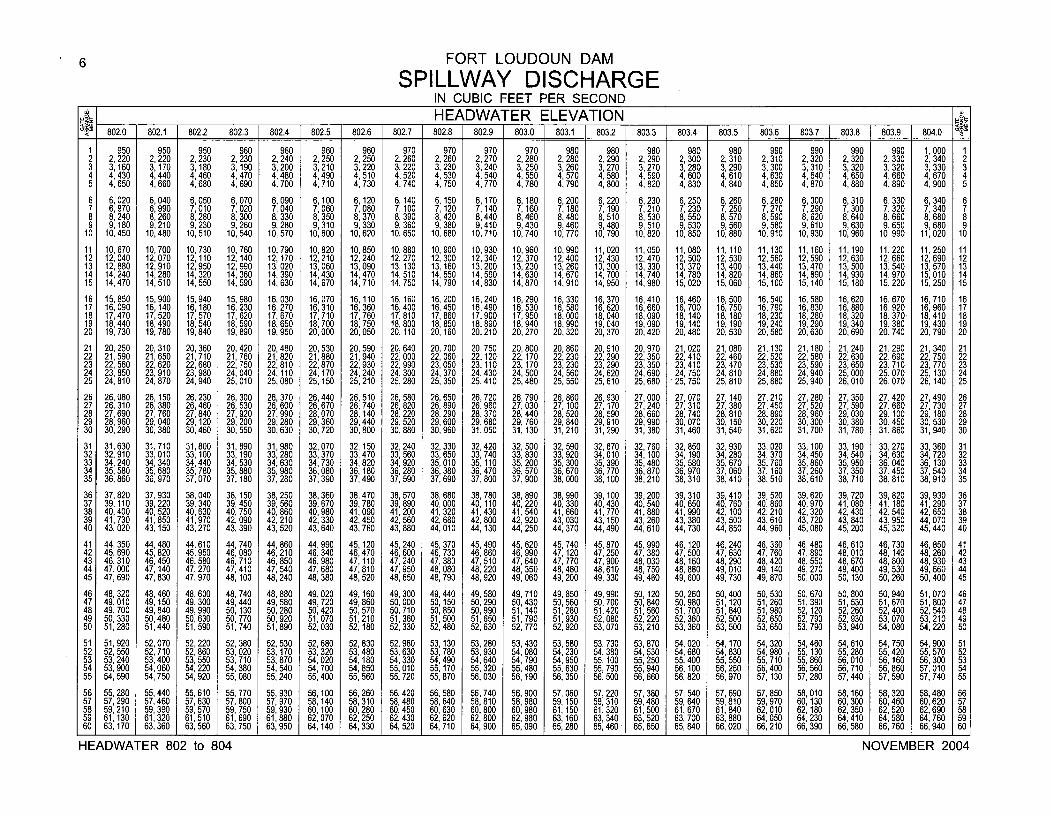
6 FORT LOUDOUN DAM
SPILLWAY DISCHARGEIN CUBIC FEET PER SECOND
___• __ _ ___HEADWATER ELEVATION _ _ __
802.0 802.1 802.2 802.3 802.4 802.5 802.6 802.7 802.8 802.9 803.0 803.1 803.2 803.3 803.4 803.5 803.6 803.7 1 803.8 803.9 1 804.0
1 950 950 950 960 960 960 960 970 970 970 970 980 980 980 980 980 990 990 990 990 1,000 12 2,220 2,220 2,230 2,230 2,240 2,250 2,250 2,260 2,260 2,270 2,280 2,280 2,290 2, 290 2,300 2,310 2,310 2,320 2,320 2,330 2,340 23 3,160 3,170 3,180 3, 190 3,200 3,210 3,220 3,220 3, 230 3,240 3,250 3,260 3,270 3,270 3, 280 3,290 3,300 3,310 3,320 3,320 3,330 34 4,430 4,440 4,460 4,470 4,480 4,490 4,510 4,520 4, 530 4,540 4,550 4,570 4,580 4,590 4, 600 4,610 4,630 4,640 4,650 4,660 4,670 45 4,650 4,660 4,680 4,690 4,700 4,710 4,730 4,740 4,750 4,770 4,780 4,790 4,800 4, 820 4, 830 4,840 4,850 4,870 4,880 4,890 4,900 5
6 6,020 6,040 6,050 6,070 6,090 6,100 6,120 6,140 6,150 6,170 6,180 6,200 6,220 6,230 6,250 6,260 6,280 6,300 6,310 6,330 6,340 67 6,970 6,990 7,010 7,020 7,040 7,060 7 080 7 100 7,120 7,140 7,160 7,180 7,190 7,210 7,230 7,250 7,270 7,290 7,300 7,320 7,340 78 8,240 8,260 8,280 8, 300 8, 330 8,350 8,370 8,390 8, 420 8,440 8,460 8,480 8,510 8,530 8,550 8,570 8,590 8, 620 8,640 8,660 8,680 89 9180 9,210 9,230 9,260 9, 280 9,310 9,330 9,360 9,380 9,410 9,430 9,460 9,480 9,510 9, 530 9, 560 9,580 9, 610 9,630 9,650 9,680 910 10:1450 10,480 10,510 10,540 10,570 10,600 10,620 10,650 10,680 10,710 10,740 10,770 10,790 10,820 10,850 10,880 10,910 10,930 10,960 10,990 11,020 10
11 10,670 10,700 10,730 10,760 10,790 10,820 10,850 10,880 10,900 10,930 10,960 10,990 11,020 11,050 11,080 11,110 11,130 11,160 11,190 11,220 11,250 1112 12,040 12,070 12,110 12, 140 12,170 12,210 12,240 12,270 12, 300 12,340 12,370 12,400 12,430 12,470 12, 500 12, 530 12,560 12, 590 12,630 12,660 12,690 1213 12,880 12,910 12,950 12,990 13, 020 13,060 13,090 13,130 13,160 13,200 13,230 13,260 13,300 13,330 13,370 13,400 13,440 13,470 13,500 13,540 13,570 1314 14,240 14,280 14,320 14, 360 14, 390 14,430 14,470 14, 510 14, 550 14,590 14,630 14,670 14,700 14,740 14, 780 14,820 14,860 14, 890 14,930 14,970 15,010 1415 14,470 14,510 14,550 14,590 14,630 14,670 14,710 14,750 14,790 14,830 14,870 14,910 14,950 14,980 15,020 15,060 15,100 15,140 15,180 15,220 15,250 15
16 15,850 15,900 15,940 15, 980 16,030 16,070 16,110 16,160 16, 200 16,240 16,290 16,330 16,370 16,410 16,460 16,500 16,540 16, 580 16,620 16,670 16,710 1617 16,090 16,140 16,180 16, 230 16,270 16,310 16,360 16,400 16,450 16,490 16,530 16,580 16,620 16,660 16,700 16,750 16,790 16,830 16,880 16,920 16,960 1718 17,470 17,520 17,570 17, 620 17,670 17,710 17,760 17,810 17, 860 17,900 17,950 18,000 18,040 18,090 18,140 18,180 18,230 18,280 18,320 18,370 18,410 1819 18,440 18,490 18,540 18, 590 18,650 18,700 18,750 18,800 18, 850 18,890 18,940 18,990 19,040 19,090 19,140 19,190 19,240 19,290 19,340 19,380 19,430 1920 19, 730 19,780 19,840 19, 890 19,950 20,000 20,050 20,110 20, 160 20,210 20,270 20,320 20,370 20,420 20,480 20,530 20,580 20,630 20, 690 20,740 20,790 20
21 20, 250 20,310 20,360 20, 420 20,480 20,530 20,590 20, 640 20, 700 20, 750 20,800 20, 860 20, 910 20,970 21,020 21,080 21,130 21,180 21,240 21,290 21,340 2122 21, 590 21,650 21,710 21, 760 21,820 21,880 21,940 22,000 22,060 22,120 22,170 22,230 22,290 22,350 22,410 22,460 22,520 22,580 22,630 22,690 22, 750 2223 22, 560 22,620 22,680 22, 750 22,810 22,870 22,930 22,990 23, 050 23,110 23,170 23,230 23,290 23,350 23,410 23,470 23,530 23,590 23,650 23,710 23, 770 2324 23, 850 23,910 23,980 24, 040 24,110 24,170 24,240 24,300 24, 370 24,430 24,500 24,560 24,620 24,690 24, 750 24,810 24,880 24,940 25, 000 25,070 25, 130 2425 24, 810 24,870 24,940 25, 010 25,080 25,150 25,210 25,280 25, 350 25,410 25,480 25,550 25,610 25,680 25, 750 25,810 25,880 25,940 26, 010 26,070 26, 140 25
26 26,080 26,150 26,230 26,300 26,370 26,440 26,510 26,580 26,650 26,720 26,790 26, 860 26,930 27,000 27,070 27,140 27,210 27,280 27, 350 27,420 27,490 2627 26, 310 26,380 26,460 26, 530 26,600 26,670 26,740 26,820 26,890 26,960 27, 030 27,100 27, 170 27,240 27, 310 27, 380 27,450 27,520 27, 590 27,660 27, 730 2728 27,690 27,760 27,840 27,920 27,990 28,070 28,140 28,220 28,290 28,370 28,440 28,520 28,590 28,660 28, 740 28,810 28,890 28 960 29, 030 29,100 29, 180 2829 28,960 29,040 29,120 29, 200 29,280 29,360 29,440 29,520 29, 600 29,680 29, 760 29, 840 29,910 29,990 30, 070 30,150 30,220 30, 300 30, 380 30, 450 30, 530 2930 30,290 30,380 30,460 30, 550 30,630 30,720 30,800 30,880 30, 960 31,050 31, 130 31,210 31,290 31,380 31,460 31,540 31,620 31,700 31,780 31,860 31,940 30
31 31,630 31,710 31,800 31, 890 31,980 32,070 32,150 32,240 32, 330 32,420 32, 500 32, 590 32,670 32,760 32, 850 32,930 33,020 33, 100 33,190 33,270 33,360 3132 32, 910 33,010 33,100 33, 190 33,280 33,370 33,470 33,560 33, 650 33,740 33, 830 33, 920 34,010 34,100 34, 190 34,280 34, 370 34,450 34, 540 34,630 34,720 3233 34,240 34,340 34,440 34, 530 34, 630 34,730 34,820 34, 920 35,010 35,110 35,200 35, 300 35,390 35,480 35, 580 35,670 35,760 35,860 35, 950 36,040 36,130 3334 35, 580 35,680 35, 780 35,880 35, 980 36,080 36,180 36,280 36,380 36, 470 36, 570 36, 670 36,770 36,870 36, 970 37, 060 37,160 37,260 37, 350 37,450 37, 540 3435 36, 860 36,970 37,070 37, 180 37,280 37,390 37,490 37,590 37, 690 37, 800 37, 900 38,000 38,100 38,210 38, 310 38,410 38, 510 38,610 38, 710 38,810 38, 910 35
36 37,820 37,930 38,040 38, 150 38,250 38,360 38,470 38, 570 38, 680 38,780 38,890 38,990 39, 100 39,200 39, 310 39,410 39, 520 39,620 39, 720 39,820 39,930 3637 39,110 39,220 39,340 39, 450 39, 560 39,670 39,780 39, 890 40, 000 40,110 40,220 40, 330 40,430 40,540 40,650 40,760 40,860 40,970 41,080 41,180 41,290 3738 40,400 40,520 40,630 40, 750 40,860 40,980 41,090 41,200 41,320 41,430 41,540 41,660 41,770 41,880 41,990 42,100 42, 210 42,320 42,430 42,540 42,650 3839 41,730 41,850 41,970 42, 090 42,210 42,330 42,450 42, 560 42, 680 42,800 42,920 43,030 43,150 43,260 43,380 43,500 43, 610 43, 720 43, 840 43,950 44,070 3940 43, 020 43,150 43,270 43, 390 43,520 43,640 43,760 43,880 44,010 44,130 44,250 44,370 44,490 44,610 44, 730 44,850 44,960 45, 080 45,200 45,320 45,440 40
41 44, 350 44,480 44,610 44, 740 44,860 44,990 45,120 45,240 45,370 45,490 45,620 45, 740 45,870 45,990 46, 120 46,240 46,360 46,480 46,610 46,730 46, 850 4142 45,690 45,820 45,950 46,080 46,210 46,340 46,470 46,600 46,730 46,860 46,990 47, 120 47,250 47,380 47, 500 47,630 47,760 47,890 48,010 48,140 48, 260 4243 46,310 46,450 46,580 46, 710 46,850 46,980 47,110 47, 240 47,380 47,510 47, 640 47,770 47,900 48,030 48, 160 48,290 48,420 48,550 48,670 48,800 48, 930 4344 47,000 47, 140 47,270 47,410 47,540 47,680 47,810 47, 950 48,080 48,220 48, 350 48, 480 48,610 48,750 48, 880 49,010 49,140 49,270 49, 400 49,530 49, 660 4445 47,690 47,830 47,970 48, 100 48,240 48,380 48,520 48,650 48,790 48,920 49, 060 49, 200 49,330 49,460 49, 600 49, 730 49,870 50,000 50, 130 50,260 50,400 45
46 48, 320 48, 460 48, 600 48, 740 48, 880 49,020 49,160 49, 300 49,440 49, 580 49, 710 49, 850 49, 990 50,120 50, 260 50, 400 50,530 50, 670 50, 800 50,940 51,070 4647 49, 010 49,150 49, 300 49,440 49, 580 49, 720 49,860 50, 000 50, 150 50, 290 50, 430 50, 560 50, 700 50,840 50, 980 51,120 51,260 51,390 51,530 51,670 51,800 4748 49,700 49,840 49,990 50, 130 50, 280 50,420 50,570 50, 710 50, 850 50,990 51, 140 51,280 51,420 51,560 51,700 51,840 51,980 52, 120 52,260 52,400 52,540 4849 50, 330 50,480 50,630 50, 770 50,920 51,070 51,210 51,360 51,500 51,650 51,790 51,930 52, 080 52,220 52, 360 52,500 52, 650 52,790 52,930 53,070 53, 210 4950 51, 280 51,440 51,590 51, 740 51,890 52, 030 52,180 52, 330 52,480 52, 630 52, 770 52, 920 53, 070 53,210 53, 360 53,500 53, 650 53, 790 53,940 54, 080 54,220 50
51 51,920 52,070 52,220 52, 380 52,530 52,680 52,830 52,980 53, 130 53,280 53,430 53,580 53, 730 53,870 54,020 54,170 54,320 54,460 54,610 54,750 54,900 5152 52, 550 52,710 52,860 53, 020 53,170 53, 320 53,480 53,630 53,780 53,930 54, 080 54,230 54, 380 54, 530 54, 680 54,830 54,980 55,130 55, 280 55,420 55,570 5253 53, 240 53,400 53,550 53, 710 53, 870 54,020 54,180 54,330 54,490 54,640 54, 790 54,950 55,100 55, 250 55, 400 55,550 55,710 55,860 56,010 56,160 56,300 5354 53,900 54,060 54,220 54, 380 54,540 54,700 54,850 55, 010 55, 170 55,320 55,480 55,630 55,790 55,940 56, 100 56,250 56,400 56,560 56, 710 56,860 57,010 5455 54,590 54,750 54,920 55, 080 55,240 55,400 55,560 55,720 55,870 56, 030 56,190 56,350 56,500 56,660 56, 820 56,970 57, 130 57,280 57,440 57,590 57, 740 55
56 55, 280 55,440 55,610 55, 770 55, 930 56,100 56,260 56, 420 56, 580 56,740 56, 900 57, 060 57,220 57,380 57, 540 57, 690 57,850 58,010 58,160 58,320 58,480 5657 57, 290 57, 460 57, 630 57, 800 57, 970 58,140 58,310 58, 480 58,640 58, 810 58, 980 59,150 59, 310 59,480 59,640 59, 810 59,970 60, 130 60, 300 60,460 60, 620 5758 59, 210 59, 390 59, 570 59, 750 59, 930 60,100 60,280 60,450 60, 630 60, 800 60, 980 61,150 61,320 61,500 61,670 61,840 62, 010 62, 180 62, 350 62,520 62, 690 5859 61,130 61,320 61, 510 61, 690 61,880 62,070 62,250 62,430 62, 620 62, 800 62, 980 63,160 63,340 63, 520 63, 700 63, 880 64,050 64,230 64, 410 64,580 64,760 5960 63, 170 63,360 63, 560 63, 750 63, 950 64,140 64,330 64, 520 64, 710 64,900 65, 090 65,280 65,460 65,650 65, 840 66, 020 66, 210 66, 390 66,580 66, 760 66,940 60
HEADWATER 802 to 804 NOVEMBER 2004
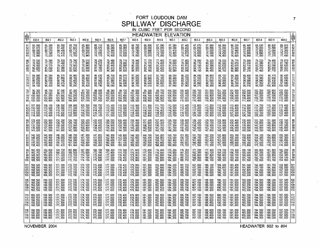
FORT LOUDOUN DAM 7
SPILLWAY DISCHARGEIN CUBIC FEET PER SECOND
_ _ _ _ _ _ HEADWATER ELEVATION _.
802.0 802.1 802.2 802.3 802.4 802.5 802.6 802.7 802.8 802.9 1 803.0 803.1 1 803.2 803.3 803.4 803.5 803.6 803.7 803.8 803.9 804.0 1
61 65,090 65,290 65,500 65, 700 65, 900 66,110 66,300 66,500 66, 700 66, 890 67, 090 67,280 67,480 67,670 67,860 68, 060 68,250 68,440 68,630 68,820 69,010 6162 67,010 67,220 67,440 67, 650 67, 860 68,070 68,280 68,480 68, 680 68, 890 69, 090 69,290 69,490 69,690 69,890 70, 090 70,290 70,490 70,690 70,880 71,080 6263 69,050 69,270 69,490 69, 710 69, 930 70,150 70,360 70, 570 70, 780 70,990 71, 200 71,410 71,620 71,820 72,030 72, 240 72,440 72,650 72,850 73,060 73,260 6364 70,950 71,180 71,410 71, 640 71, 870 72,090 72, 310 72, 530 72, 750 72,970 73,180 73,400 73,610 73,830 74,040 74, 250 74,470 74,680 74,890 75,100 75, 310 6465 72,990 73,230 73,470 73, 700 73, 940 74,170 74, 400 74, 620 74, 850 75,070 75,290 75, 520 75,740 75,960 76, 180 76,400 76,620 76,840 77,060 77,270 77,490 65
66 75,030 75,280 75,520 75, 760 76, 010 76,250 76,480 76, 710 76, 940 77,170 77,400 77, 630 77,860 78,090 78,320 78,550 78,770 79,000 79,220 79, 450 79, 670 6667 76, 950 77,210 77, 460 77, 710 77, 960 78,210 78, 450 78, 690 78, 930 79,170 79,400 79, 640 79, 880 80,110 80, 350 80, 580 80, 810 81,050 81,280 81, 510 81, 740 6768 78,900 79,170 79,420 79, 680 79, 940 80,190 80,440 80,690 80, 930 81,180 81,420 81, 670 81,910 82,150 82, 390 82,630 82,870 83,110 83, 350 83,590 83, 830 6869 80,830 81,090 81,360 81,630 81,900 82,160 82,410 82,670 82, 920 83,170 83,420 83, 670 83, 920 84, 170 84, 420 84, 670 84,920 85,160 85, 410 85,650 85, 900 6970 82,750 83,020 83,300 83, 580 83, 850 84,120 84,380 84,650 84, 910 85,160 85,420 85, 680 85, 940 86, 190 86, 450 86, 700 86,960 87,210 87,460 87,710 87, 970 70
71 84,990 85,280 85,570 85, 860 86,140 86,430 86,700 86,970 87,240 87,510 87, 780 88, 050 88,320 88,590 88,850 89, 120 89,380 89,650 89, 910 90,170 90,430 7172 87, 260 87,560 87,860 88,160 88,450 88,740 89,030 89, 310 89, 590 89,880 90,160 90, 440 90,720 91,000 91,270 91,550 91,830 92,100 92, 380 92,650 92,920 7273 89, 530 89,830 90,140 90,450 90, 760 91,060 91,360 91, 650 91, 950 92,240 92,530 92, 820 93, 120 93, 410 93, 690 93, 980 94,270 94,560 94, 840 95,130 95, 410 7374 91,830 92,150 92,470 92, 790 93,110 93,420 93,730 94, 040 94, 340 94, 650 94,950 95,260 95, 560 95, 860 96, 160 96, 460 96,760 97,050 97,350 97,650 97, 940 7475 94,100 94,430 94,760 95, 090 95,420 95,740 96,060 96,380 96, 700 97,010 97, 330 97, 640 97,960 98,270 98,580 98,890 99,200 99,510 99,820 100,100 100,400 75
76 96, 360 96,700 97,040 97, 380 97,720 98,060 98,390 98, 720 99,050 99,380 99,700 100, 000 100,400 100,700 101,000 101,300 101,600 102,000 102, 300 102, 600 102,900 7677 98,670 99,020 99,370 99,730 100,100 100,400 100,800 101,100 101,400 101,800 102,100 102, 500 102,800 103,100 103,500 103,800 104,100 104,500 104,800 105,100 105,500 7778 100,900 101,200 101,600 102,000 102,300 102,700 103,000 103,400 103,700 104,100 104,400 104, 800 105,100 105,500 105,800 106,200 106,500 106,900 107,200 107,500 107,900 7879 103,200 103,600 103,900 104,300 104,700 105,000 105,400 105,800 106,100 106,500 106,900 107,200 107,600 107,900 108,300 108,600 109,000 109,400 109,700 110,100 110,400 7980 105,500 105,900 106,300 106,600 107,000 107,400 107,800 108,200 108,500 108,900 109,300 109,600 110,000 110,400 110,800 111,100 111,500 111,800 112,200 112, 600 112,900 80
81 107,800 108,100 108,500 108,900 109,300 109,700 110,100 110,500 110,900 111,300 111,700 112,000 112,400 112,800 113,200 113,600 113,900 114,300 114,700 115, 100 115,400 8182 110,000 110,500 110,900 111,300 111,700 112,100 112,500 112,900 113,300 113,700 114,100 114,500 114,800 115,200 115,600 116,000 116,400 116,800 117,200 117,600 117,900 8283 112,300 112,700 113,100 113,600 114,000 114,400 114,800 115,200 115,600 116,000 116,400 116,800 117,200 117,600 118,000 118,500 118,800 119,200 119,600 120,000 120,400 8384 114, 600 115,000 115,400 115,900 116,300 116,700 117,100 117,600 118,000 118,400 118,800 119,200 119,600 120,100 120,500 120,900 121,300 121,700 122,100 122,500 122,900 8485 118, 900 119,400 119,800 120,200 120,700 121,100 121,500 122,000 122,400 122,800 123,200 123, 700 124,100 124,500 124,900 125,400 125,800 126,200 126,600 127,000 127,400 85
86 123,400 123,800 124,200 124,700 125, 100 125,600 126,000 126,400 126, 900 127,300 127,800 128,200 128,600 129,100 129,500 129,900 130,400 130,800 131, 200 131, 600 132, 100 8687 127,900 128,300 128,700 129,100 129,600 130,000 130,500 130,900 131,400 131,800 132,300 132, 700 133,200 133,600 134, 100 134,500 134,900 135,400 135, 800 136, 200 136,700 8788 132, 200 132,600 133,000 133,500 133,900 134,400 134,900 135,300 135,800 136, 300 136, 700 137, 200 137,600 138,100 138, 500 139,000 139,400 139,900 140,300 140,800 141,200 8889 136, 600 137,000 137,500 137,900 138, 400 138,900 139,300 139,800 140,300 140, 800 141,200 141,700 142,200 142,600 143, 100 143,500 144,000 144,500 144,900 145,400 145,800 8990 141,000 141,500 141,900 142,300 142, 800 143,300 143,800 144,300 144,800 145,200 145,700 146,200 146,700 147,100 147,600 148,100 148,500 149,000 149,500 149,900 150,400 90
91 145, 500 145,900 146,300 146,700 147,300 147, 800 148,300 148,800 149,300 149,700 150,200 150, 700 151,200 151,700 152, 200 152,600 153,100 153, 600 154,100 154,500 155,000 9192 148, 800 149,400 149,900 150,500 151,100 151,800 152,400 153,000 153,600 154,300 154,900 155, 500 156,100 156,700 157, 200 157,800 158,300 158, 800 159,300 159,800 160, 300 9293 152, 200 152,900 153,600 154,300 155, 100 155,800 156,600 157,400 158, 100 158,900 159,700 160,400 161,200 161,800 162, 400 163,000 163,600 164, 100 164, 700 165, 300 165,800 9394 155,000 155,800 156,700 157, 500 158,400 159,300 160,200 161,100 162,000 162,900 163,800 164,700 165,600 166,400 167,100 167,800 168,600 169,300 170,000 170,700 171,400 9495 158,400 159,400 160,400 161,400 162,400 163,400 164,500 165,500 166,500 167,600 168,600 169,600 170,700 171,500 172,300 173, 100 173,800 174,600 175,300 176, 100 176,800 95
96 162,500 163,600 164,700 165,800 167,000 168,100 169,300 170,500 171,600 172,800 174,000 175,200 176,300 177,200 177,900 178,700 179,400 180,100 180,800 181,500 182,200 9697 165,700 167,000 168,200 169,500 170,800 172,100 173,400 174,700 176,000 177,300 178,600 179,900 181,200 182,300 183,100 184,000 184, 700 185,500 186,200 187,000 187,800 9798 168,500 169,900 171,300 172,700 174,100 175,600 177,000 178,400 179,900 181,300 182,800 184,200 185,700 186,800 187,800 188,800 189,700 190,600 191,500 192,400 193,300 9899 168, 500 169,900 171,300 172, 700 174, 100 175,600 177,000 178, 400 179, 900 181,300 182,800 184,200 185, 700 186,900 188,000 189, 100 190, 100 191,100 192, 100 193, 100 194,100 99
100 168,500 169,900 171,300 172,700 174, 100 175,600 177,000 178,400 179, 900 181,300 182,800 184,200 185,700 187,000 188,100 189,300 190,400 191,500 192,600 193, 700 194,800 100
101 168,500 169,900 171,300 172,700 174,100 175,600 177,000 178,400 179, 900 181,300 182,800 184,200 185,700 187,000 188,100 189,300 190,400 191,500 192,600 193,700 194,800 101102 168,500 169,900 171,300 172,700 174,100 175,600 177,000 178,400 179, 900 181,300 182,800 184,200 185,700 187,000 188,300 189,600 190,800 191,900 193,100 194,300 195, 500 102103 168, 500 169,900 171 300 172, 700 174,100 175,600 177,000 178,400 179,900 181,300 182,800 184,200 185,700 187,100 188,600 190,100 191,400 192,800 194,200 195,600 197,000 103104 168,500 169,900 171,300 172,700 174, 100 175,600 177,000 178,400 179,900 181,300 182,800 184,200 185,700 187,100 188,600 190,100 191,600 193,000 194,500 196,000 197,500 104105 168, 500 169,900 171,300 172,700 174,100 175,600 177,000 178,400 179,900 181,300 182,800 184,200 185,700 187,100 188,600 190, 100 191, 600 193,000 194,500 196,000 197, 500 105
106 168,500 169,900 171,300 172,700 174, 100 175,600 177,000 178,400 179,900 181,300 182,800 184,200 185,700 187,100 188,600 190, 100 191,600 193,000 194,500 196,000 197,500 106107 168,500 169,900 171,300 172,700 174,100 175,600 177,000 178,400 179,900 181,300 182,800 184,200 185,700 187,100 188,600 190,100 191,600 193,000 194,500 196,000 197,500 107108 168,500 169,900 171,300 172,700 174,100 175,600 177,000 178,400 179,900 181,300 182,800 184,200 185,700 187,100 188, 600 190,100 191,600 193,000 194, 500 196,000 197,500 108109 168,500 169,900 171, 300 172,700 174, 100 175, 600 177,000 178, 400 179,900 181,300 182,800 184,200 185,700 187,100 188,600 190,100 191,600 193,000 194,500 196,000 197,500 109110 168,500 169,900 171,300 172,700 174,100 175,600 177,000 178,400 179,900 181,300 182,800 184,200 185,700 187,100 188, 600 190,100 191,600 193,000 194,500 196,000 197,500 110
111 168,500 169,900 171,300 172,700 174,100 175,600 177,000 178,400 179,900 181,300 182,800 184,200 185,700 187,100 188, 600 190,100 191,600 193,000 194,500 196,000 197,500 111112 168,500 169,900 171,300 172,700 174,100 175,600 177,000 178,400 179,900 181,300 182,800 184,200 185,700 187,100 188,600 190,100 191,600 193,000 194,500 196,000 197,500 1121131 168,500 169,900 171,300 172,700 174,100 175,600 177,000 178,400 179,900 181,300 182,800 184,200 185,700 187,100 188,600 190,100 191,600 193,000 194,500 196,000 197,500 113114 168,500 169,900 171,300 172,700 174, 100 175,600 177,000 178,400 179, 900 181,300 182, 800 184,200 185,700 187,100 188,600 190, 100 191,600 193,000 194,500 196,000 197,500 114115 168,500 169,900 171,300 172,700 174,100 175,600 177,000 178,400 179,900 181,300 182,800 184,200 185,700 187,100 188,600 190,100 191,600 193,000 194,500 196,000 197,500 115
116 168,500 169,900 171,300 172, 700 174,100 175,600 177,000 178,400 179, 900 181,300 182,800 184,200 185,700 187,100 188,600 190,100 191,600 193,000 194,500 196,000 197,500 116117 168,500 169,900 171,300 172,700 174,100 175,600 177,000 178,400 179, 900 181,300 182,800 184,200 185,700 187,100 188,600 190,100 191,600 193,000 194,500 196,000 197,500 117118 168,500 169,900 171,300 172, 700 174,100 175,600 177,000 178,400 179, 900 181,300 182,800 184,200 185,700 187,100 188,600 190,100 191,600 193,000 194,500 196,000 197,500 118119 168,500 169,900 171,300 172,700 174,100 175,600 177,000 178,400 179,900 181,300 182,800 184,200 185,700 187,100 188,600 190,100 191,600 193,000 194,500 196,000 197,500 119
NOVEMBER 2004 HEADWATER 802 to 804
NOVEMBER 2004 HEADWATER 802 to 804
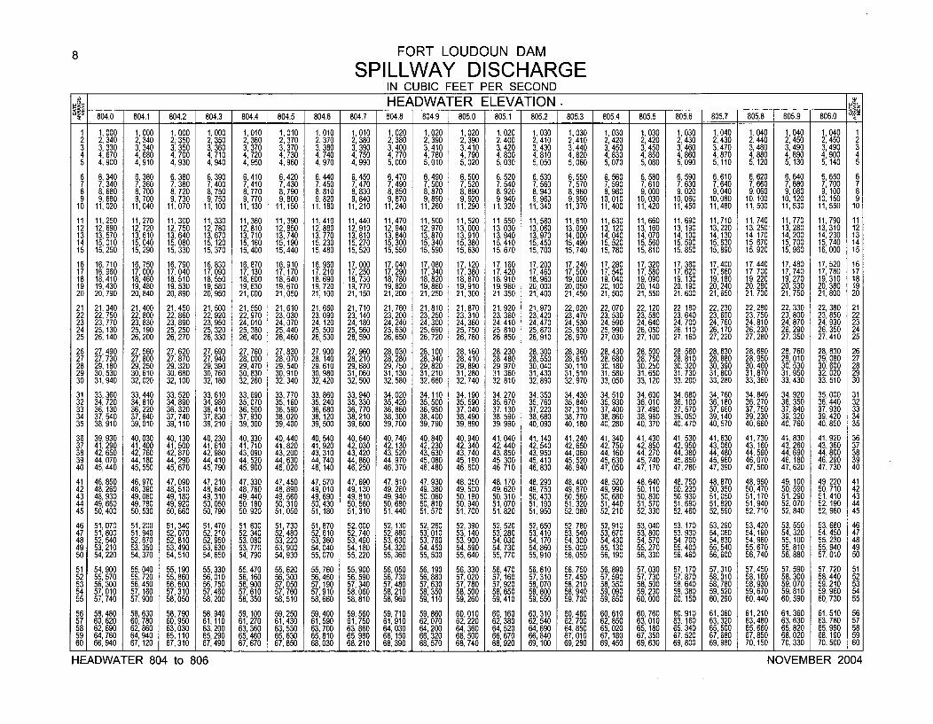
8 FORT LOUDOUN DAM
SPILLWAY DISCHARGEIN CUBIC FEET PER SECOND
•o.• ~HEADWATER ELEVATION. •°S804.0 804.1 804.2_ 804.3 804.4 804.5 804.6 804.7 8HT8 804R9 805L0 V8051 805.2 805.3 805.4 805.5 805.6 805.7 805.8 805.9 806.0
1 1,000 1,000 1,000 1,000 1,010 1,010 1,010 1,010 1,020 1,020 1,020 1,020 1,030 1,030 1,030 1,030 1,030 1,040 1,040 1,040 1,040 12 2,340 2 340 2,350 2,350 2,360 2,370 2, 370 2, 380 2,380 2,390 2,390 2,400 2,410 2,410 2, 420 2,420 2,430 2,430 2,440 2,450 2,450 23 3,330 3,340 3,350 3,360 3,370 3,370 3,380 3,390 3,400 3,410 3,410 3,420 3,430 3,440 3,450 3,450 3,460 3,470 3,480 3,490 3,490 34 4,670 4,680 4,700 4,710 4,720 4,730 4,740 4,750 4,770 4,780 4,790 4,800 4,810 4,820 4,830 4,850 4,860 4,870 4,880 4,890 4,900 45 4, 900 4,910 4,930 4,940 4,950 4,960 4,970 4,990 5,000 5,010 5,020 5,030 5,050 5,060 5,070 5,080 5,090 5,110 5,120 5,130 5,140 5
6 6,340 6,360 6,380 6,390 6,410 6,420 6,440 6,450 6,470 6,490 6,500 6,520 6,530 6,550 6,560 6,580 6,590 6,610 6,620 6,640 6,650 67 7, 340 7, 360 7, 380 7, 400 7,410 7,430 7, 450 7, 470 7,490 7,500 7, 520 7,540 7,560 7,570 7,590 7, 610 7,630 7,640 7,660 7,680 7, 700 78 8,680 8,700 8,720 8, 750 8,770 8,790 8,810 8, 830 8,850 8,870 8,890 8,920 8,940 8,960 8,980 9,000 9,020 9,040 9,060 9,080 9,100 89 9,680 9,700 9, 730 9, 750 9,770 9,800 9, 820 9,840 9,870 9,890 9,920 9,940 9,960 9,990 10, 010 10, 030 10,060 10, 080 10,100 10,120 10, 150 9
10 11,020 11,040 11,070 11,100 11,130 11,150 11,180 11,210 11,240 11,260 11,290 11,320 11,340 11,370 11,400 11,420 11,450 11,480 11,500 11,530 11,550 10
11 11,250 11,270 11,300 11,330 11,360 11,390 11,410 11,440 11,470 11,500 11,520 11,550 11,580 11,610 11,630 11,660 11,690 11,710 11,740 11,770 11,790 1112 12,690 12,720 12,750 12,780 12,810 12,850 12,880 12,910 12,940 12,970 13,000 13,030 13,060 13,090 13,120 13,160 13,190 13,220 13,250 13,280 13,310 1213 13, 570 13, 610 13, 640 13, 670 13,710 13,740 13, 770 13, 810 13,840 13, 870 13, 910 13,940 13,970 14, 000 14, 040 14,070 14,100 14,130 14,170 14, 200 14,230 1314 15,010 15,040 15,080 15,120 15,160 15,190 15,230 15,270 15,300 15,340 15,380 15,410 15,450 15,490 15,520 15,560 15,590 15,630 15,670 15,700 15,740 1415 15,250 15,290 15,330 15,370 15,400 15,440 15,480 15,520 15,550 15,590 15,630 15,670 15,700 15,740 15,780 15,810 15,850 15,890 15,920 15,960 16,000 15
16 16,710 16,750 16,790 16,830 16,870 16,910 16,960 17, 000 17,040 17,080 17,120 17,160 17,200 17,240 17,280 17,320 17,360 17,400 17,440 17,480 17,520 1617 16,960 17,000 17,040 17,090 17,130 17,170 17,210 17, 250 17,290 17,340 17,380 17,420 17,460 17,500 17,540 17,580 17,620 17,660 17,700 17,740 17,780 1718 18,410 18,460 18,510 18,550 18,600 18,640 18,690 18, 730 18,780 18,820 18,870 18,910 18,960 19,000 19,040 19, 090 19,130 19,180 19,220 19,270 19,310 1819 19, 430 19,480 19,530 19,580 19,630 19,670 19, 720 19, 770 19,820 19,860 19,910 19,960 20,000 20,050 20, 100 20, 140 20,190 20,240 20, 280 20,330 20,380 1920 20,790 20,840 20,890 20,950 21,000 21,050 21,100 21,150 21,200 21,250 21,300 21,350 21,400 21,450 21,500 21,550 21,600 21,650 21,700 21,750 21,800 20
21 21,340 21,400 21,450 21,500 21,550 21,610 21,660 21,710 21,760 21,810 21,870 21,920 21,970 22,020 22,070 22,120 22,180 22,230 22,280 22,330 22,380 2122 22, 750 22,800 22,860 22,920 22,970 23,030 23,090 23, 140 23,200 23,250 23,310 23, 360 23,420 23,470 23, 530 23,580 23,640 23,690 23,750 23,800 23,850 2223 23, 770 23,830 23,890 23,950 24,010 24,070 24, 120 24,180 24,240 24,300 24,360 24,410 24,470 24,530 24, 590 24,640 24, 700 24,760 24,810 24,870 24,930 2324 25, 130 25, 190 25,250 25, 320 25,380 25,440 25, 500 25, 560 25,630 25,690 25,750 25, 810 25,870 25,930 25,990 26,050 26,110 26, 170 26,230 26,290 26, 350 2425 26, 140 26,200 26,270 26, 330 26,400 26,460 26,530 26, 590 26,650 26,720 26,780 26,850 26,910 26,970 27,030 27, 100 27, 160 27,220 27,280 27, 350 27, 410 25
26 27, 490 27,560 27,620 27,690 27,760 27,830 27,900 27, 960 28,030 28,100 28, 160 28,230 28,300 28,360 28,430 28,500 28,560 28,630 28,690 28, 760 28, 830 2627 27, 730 27,800 27,870 27,940 28, 000 28,070 28, 140 28,210 28,280 28,340 28,410 28,480 28,550 28,610 28,680 28,750 28,810 28,880 28,950 29,010 29, 080 2728 29,180 29,250 29,320 29,390 29, 470 29,540 29,610 29,680 29, 750 29,820 29,890 29,970 30,040 30,110 30, 180 30,250 30, 320 30,390 30,460 30, 530 30, 600 2829 30,530 30,610 30,680 30,760 30, 830 30,910 30,980 31,060 31,130 31,210 31,280 31,360 31,430 31,510 31,580 31,650 31,730 31,800 31,870 31,950 32,020 2930 31,940 32,020 32, 100 32, 180 32, 260 32,340 32,420 32, 500 32,580 32,660 32, 740 32, 810 32,890 32,970 33,050 33, 120 33,200 33,280 33,360 33,430 33, 510 30
31 33,360 33,440 33,520 33,610 33, 690 33,770 33,860 33,940 34,020 34,110 34, 190 34, 270 34,350 34,430 34, 510 34,600 34,680 34,760 34,840 34,920 35,000 3132 34, 720 34,810 34,890 34,980 35, 070 35,160 35,240 35,330 35,420 35,500 35, 590 35, 670 35,760 35,840 35, 930 36,010 36, 100 36,180 36,270 36, 350 36,440 3233 36, 130 36,220 36,320 36, 410 36, 500 36,590 36,680 36, 770 36,860 36,950 37, 040 37, 130 37,220 37,310 37,400 37, 490 37,570 37,660 37,750 37,840 37,930 3334 37, 540 37,640 37,740 37, 830 37, 930 38,020 38,120 38,210 38,300 38,400 38, 490 38, 590 38,680 38,770 38, 860 38, 960 39,050 39, 140 39,230 39, 320 39,420 3435 38, 910 39,010 39,110 39,210 39, 300 39,400 39,500 39, 600 39,700 39,790 39,890 39,990 40,090 40,180 40, 280 40,370 40,470 40,570 40,660 40, 760 40,850 35
36 39, 930 40, 030 40,130 40, 230 40, 330 40,440 40, 540 40,640 40, 740 40, 840 40, 940 41,040 41,140 41,240 41,340 41,430 41,530 41,630 41,730 41,830 41,920 3637 41, 290 41,400 41,500 41,610 41, 710 41,820 41,920 42, 030 42,130 42,230 42,340 42,440 42,540 42,650 42, 750 42,850 42, 950 43, 060 43, 160 43, 260 43, 360 3738 42, 650 42,760 42, 870 42,980 43,090 43,200 43,310 43,420 43, 520 43,630 43, 740 43,850 43,950 44,060 44,160 44,270 44, 380 44,480 44, 590 44,690 44,800 3839 44, 070 44,180 44,290 44,410 44, 520 44,630 44,740 44,860 44, 970 45, 080 45,190 45, 300 45,410 45,520 45,630 45,740 45,850 45,960 46,070 46, 180 46,290 3940 45,440 45, 550 45,670 45,790 45,900 46,020 46, 140 46,250 46, 370 46, 480 46, 600 46,710 46,830 46,940 47,050 47, 170 47,280 47,390 47,500 47,620 47, 730 40
41 46, 850 46,970 47,090 47,210 47,330 47,450 47,570 47,690 47,810 47,930 48,050 48,170 48,290 48,400 48, 520 48,640 48,750 48,870 48,990 49,100 49,220 4142 48, 260 48, 390 48, 510 48,640 48, 760 48, 890 49, 010 49,130 49,260 49, 380 49, 500 49,620 49, 750 49, 870 49, 990 50, 110 50,230 50, 350 50, 470 50, 590 50, 710 4243 48, 930 49, 060 49,180 49, 310 49,440 49, 560 49, 690 49, 810 49, 940 50, 060 50, 190 50, 310 50, 430 50, 560 50, 680 50, 800 50,930 51, 050 51,170 51,290 51,410 4344 49,660 49,790 49,920 50,050 50, 180 50,310 50,430 50, 560 50, 690 50,810 50, 940 51,070 51,190 51,320 51,440 51,570 51,690 51, 820 51,940 52,070 52, 190 4445 50,400 50,530 50,660 50, 790 50, 920 51,050 51,180 51,310 51,440 51,570 51,700 51,820 51,950 52, 080 52,210 52,330 52,460 52,590 52,710 52, 840 52, 960 45
46 51,070 51,200 51,340 51,470 51,600 51,730 51,870 52,000 52,130 52,260 52, 390 52,520 52,650 52, 780 52, 910 53,040 53, 170 53,290 53, 420 53, 550 53, 680 4647 51, 800 51,940 52,070 52,210 52, 340 52,480 52,610 52, 740 52,880 53,010 53,140 53,280 53,410 53, 540 53, 670 53,800 53, 930 54,060 54, 190 54, 320 54, 450 4748 52,540 52, 670 52, 810 52, 950 53,080 53, 220 53, 360 53, 490 53, 630 53, 760 53, 900 54,030 54,170 54, 300 54, 430 54, 570 54, 700 54, 830 54, 960 55,100 55, 230 4849 53, 210 53, 350 53,490 53, 630 53, 770 53, 900 54,040 54,180 54,320 54,450 54, 590 54,730 54, 860 55, 000 55, 130 55, 270 55, 400 55, 540 55, 670 55, 810 55, 940 4950 54, 220 54,370 54, 510 54,650 54, 790 54,930 55,070 55,220 55,360 55,500 55,640 55,770 55, 910 56, 050 56, 190 56, 330 56,460 56,600 56,740 56,880 57, 010 50
51 54, 900 55,040 55,190 55,330 55,470 55, 620 55,760 55,900 56,050 56,190 56,330 56,470 56,610 56,750 56, 890 57, 030 57, 170 57,310 57,450 57,590 57, 720 5152 55, 570 55, 720 55,860 56,010 56, 160 56,300 56,450 56,590 56,730 56,880 57,020 57,160 57,310 57,450 57, 590 57, 730 57,870 58,010 58, 160 58,300 58, 440 5253 56, 300 56, 450 56, 600 56, 750 56, 900 57,050 57,190 57,340 57, 480 57,630 57, 780 57, 920 58, 070 58, 210 58, 350 58, 500 58, 640 58, 780 58, 930 59, 070 59, 210 5354 57,010 57, 160 57,310 57,460 57,610 57,760 57,910 58,060 58, 210 58,350 58, 500 58,650 58,800 58, 940 59, 090 59, 230 59,380 59,520 59,670 59,810 59,960 5455 57, 740 57, 900 58,050 58,200 58, 350 58, 510 58,660 58, 810 58, 960 59,110 59, 260 59,410 59, 550 59, 700 59, 850 60, 000 60, 150 60, 290 60,440 60, 590 60, 730 55
56 58,480 58,630 58,790 58, 940 59, 100 59,250 59,400 59,560 59, 710 59, 860 60, 010 60,160 60,310 60,460 60, 610 60, 760 60,910 61,060 61, 210 61,360 61,510 5657 60,620 60,780 60,950 61,110 61,270 61,430 61,590 61,750 61,910 62,070 62, 220 62,380 62,540 62,700 62, 850 63, 010 63, 160 63,320 63, 480 63,630 63,780 5758 62,690 62,860 63,030 63,200 63, 360 63,530 63,700 63, 860 64,030 64,200 64, 360 64, 520 64,690 64,850 65, 020 65,180 65,340 65,500 65,660 65,820 65,990 5859 64,760 64,940 65,110 65,290 65,460 65,630 65,810 65, 980 66,150 66, 320 66, 500 66,670 66,840 67, 010 67, 180 67, 350 67,520 67,680 67, 850 68,020 68, 190 5960 66,940 67,120 67,310 67,490 67,670 67,850 68,030 68,210 68,390 68,570 68, 740 68,920 69,100 69,280 69,450 69, 630 69,800 69,980 70,150 70, 330 70, 500 60
-IEADWATER 804 to 806 NOVEMBER 2004
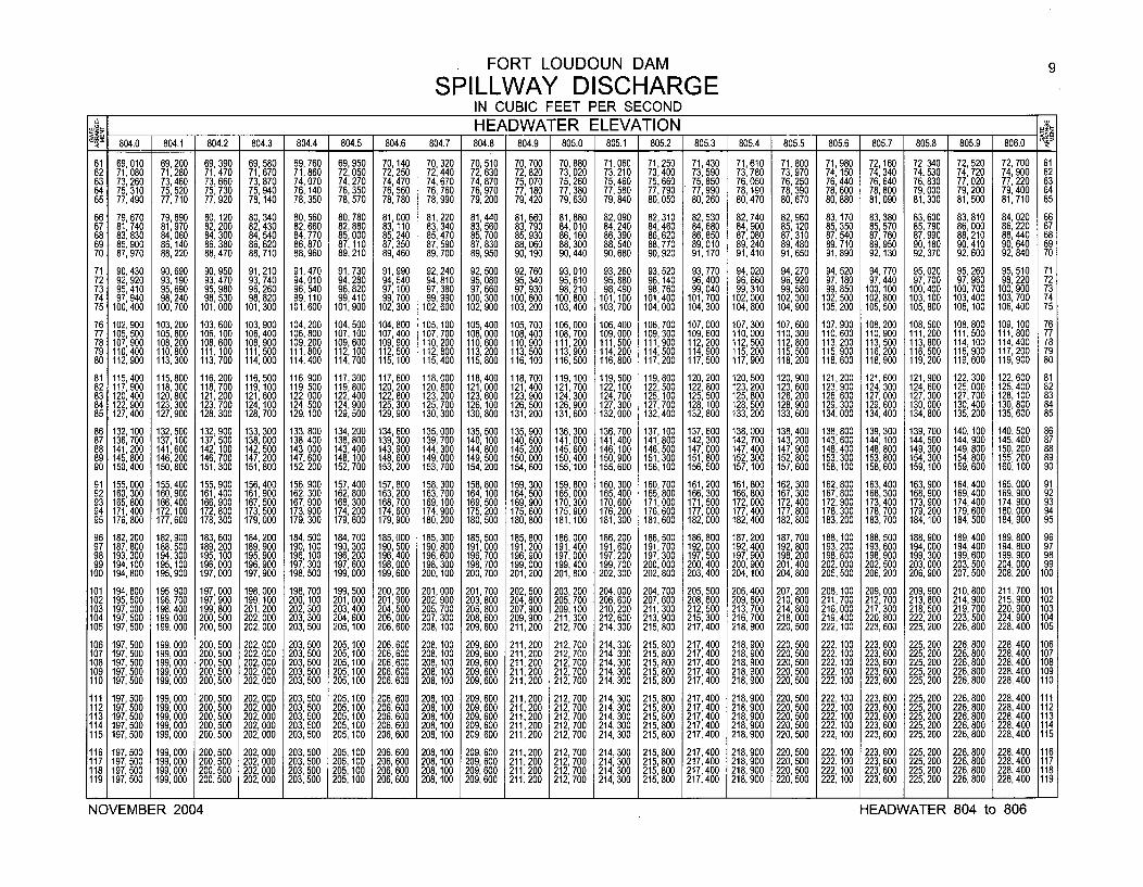
FORT LOUDOUN DAM 9
SPILLWAY DISCHARGEIN CUBIC FEET PER SECOND
___ _ _HEADWATER ELEVATION _
804.0 804.1 804.2 804.3 804.4 804.5 804.6 804.7 804.8 804.9 805.0 805.1 805.2 805.3 805.4 805.5 805.6 805.7 805.8 805.9 806.0
61 69, 010 69,200 69,390 69, 580 69, 760 69,950 70,140 70, 320 70, 510 70,700 70,880 71,060 71,250 71,430 71,610 71, 800 71,980 72, 160 72, 340 72, 520 72, 700 6162 71,080 71,280 71,470 71,670 71,860 72,050 72,250 72,440 72, 630 72,820 73,020 73,210 73,400 73, 590 73, 780 73, 970 74,150 74,340 74, 530 74,720 74, 900 6263 73,260 73,460 73,660 73, 870 74,070 74,270 74,470 74,670 74, 870 75,070 75,260 75, 460 75,660 75, 850 76, 050 76, 250 76,440 76,640 76,830 77,020 77, 220 6364 75,310 75,520 75,730 75,940 76, 140 76,350 76,560 76, 760 76, 970 77,180 77, 380 77, 580 77,790 77,990 78, 190 78, 390 78,600 78,800 79,000 79,200 79, 400 6465 77, 490 77, 710 77, 920 78, 140 78, 350 78,570 78, 780 78, 990 79, 200 79,420 79, 630 79,840 80,050 80, 260 80, 470 80, 670 80, 880 81,090 81,300 81,500 81, 710 65
66 79,670 79,890 80, 120 80,340 80, 560 80,780 81,000 81,220 81,440 81,660 81,880 82,090 82,310 82,530 82,740 82, 960 83,170 83,380 83, 600 83,810 84, 020 6667 81,740 81,970 82, 200 82,430 82,660 82,880 83, 110 83, 340 83, 560 83,790 84,010 84,240 84,460 84,680 84,900 85, 120 85,350 85,570 85, 790 86, 000 86, 220 6768 83,830 84,060 84,300 84,540 84,770 85,000 85,240 85,470 85, 700 85,930 86, 160 86,390 86,620 86,850 87,080 87, 310 87,540 87,760 87, 990 88, 210 88,440 6869 85, 900 86,140 86, 380 86, 620 86, 870 87,110 87, 350 87, 590 87, 830 88,060 88, 300 88, 540 88,770 89, 010 89, 240 89, 480 89, 710 89, 950 90, 180 90, 410 90, 640 6970 87, 970 88,220 88,470 88, 710 88, 960 89,210 89, 460 89, 700 89, 950 90,190 90, 440 90, 680 90,920 91,170 91,410 91,650 91,890 92,130 92, 370 92, 600 92, 840 70
71 90,430 90,690 90,950 91,210 91,470 91,730 91,990 92,240 92, 500 92,760 93,010 93,260 93,520 93,770 94, 020 94, 270 94,520 94,770 95,020 95,260 95, 510 7172 92, 920 93, 190 93,470 93, 740 94,010 94,280 94,540 94,810 95,080 95,340 95,610 95,880 96,140 96,400 96, 660 96, 920 97, 180 97,440 97,700 97, 960 98, 220 7273 95, 410 95, 690 95,980 96, 260 96,540 96,820 97,100 97, 380 97, 660 97,930 98, 210 98,490 98,760 99, 040 99,310 99, 580 99,850 100,100 100,400 100, 700 100, 900 7374 97,940 98,240 98,530 98,820 99,110 99,410 99,700 99,990 100,300 100,600 100,800 101,100 101,400 101,700 102,000 102,300 102,500 102,800 103,100 103,400 103,700 7475 100,400 100,700 101,000 101,300 101,600 101,900 102,300 102,600 102,900 103,200 103,400 103,700 104, 000 104,300 104,600 104,900 105,200 105,500 105,800 106, 00 106,400 75
76 102,900 103,200 103,600 103,900 104,200 104,500 104,800 105,100 105, 400 105,700 106,000 106, 400 106,700 107,000 107,300 107,600 107,900 108,200 108, 500 108,800 109,100 7677 105,500 105,800 106,100 106,400 106,800 107,100 107,400 107,700 108,000 108,400 108,700 109,000 109,300 109,600 110,000 110, 300 110,600 110,900 111,200 111,500 111,800 7778 107,900 108,200 108, 600 108,900 109,200 109,600 109, 900 110, 200 110,600 110,900 111,200 111,500 111,900 112,200 112, 500 112, 800 113,200 113,500 113,800 114,100 114,400 7879 110,400 110,800 111,100 111,500 111,800 112,100 112,500 112,800 113,200 113,500 113,900 114,200 114,500 114,900 115,200 115,500 115,900 116,200 116,500 116,900 117,200 7980 112,900 113,300 113,700 114,000 114,400 114,700 115,100 115,400 115,800 116,100 116,500 116,800 117,200 117,500 117,900 118,200 118,600 118,900 119, 200 119,600 119,900 80
81 115,400 115,800 116,200 116,500 116,900 117,300 117,600 118,000 118,400 118,700 119,100 119,500 119,800 120,200 120,500 120,900 121,200 121,600 121,900 122,300 122,600 8182 117,900 118,300 118,700 119,100 119,500 119,800 120,200 120,600 121,000 121,400 121,700 122,100 122,500 122,800 123,200 123, 600 123,900 124,300 124,600 125,000 125,400 8283 120,400 120,800 121,200 121,600 122,000 122,400 122,800 123,200 123,600 123,900 124,300 124,700 125,100 125,500 125,800 126,200 126,600 127,000 127,300 127,700 128,100 8384 122, 900 123,300 123,700 124,100 124,500 124,900 125,300 125,700 126,100 126,500 126,900 127,300 127,700 128, 100 128, 500 128, 900 129,300 129,600 130,000 130,400 130,800 8485 127,400 127,900 128,300 128,700 129, 100 129,500 129,900 130,300 130, 800 131,200 131,600 132,000 132,400 132, 800 133, 200 133,600 134,000 134,400 134,800 135,200 135,600 85
86 132, 100 132,500 132,900 133, 300 133,800 134,200 134, 600 135,000 135,500 135,900 136,300 136,700 137,100 137,600 138,000 138,400 138,800 139, 300 139,700 140, 100 140, 500 8687 136,700 137,100 137,500 138,000 138,400 138,800 139,300 139,700 140,100 140,600 141,000 141,400 141,800 142,300 142,700 143,200 143,600 144,100 1144,500 144,900 145,400 8788 141,200 141,600 142,100 142, 500 143,000 143,400 143,900 144,300 144,800 145,200 145,600 146,100 146,500 147,000 147,400 147, 900 148,400 148,800 149,300 149,800 150,200 8889 145, 800 146,200 146,700 147,200 147,600 148,100 148,600 149,000 149,500 150,000 150,400 150,900 151,300 151,800 152,300 152,800 153,300 153,800 154,300 154,800 155,200 8990 150,400 150,800 151,300 151,800 152,200 152,700 153,200 153, 700 154,200 154,600 155,100 155,600 156,100 156,500 157,100 157,600 158,100 158,600 159,100 159,600 160,100 90
91 155,000 155,400 155,900 156,400 156,900 157,400 157,800 158,300 158,800 159,300 159,800 160,300 160,700 161,200 161,800 162,300 162,800 163,400 163,900 164,400 165,000 9192 160, 300 160,900 161,400 161,900 162,300 162,800 163,200 163,700 164,100 164,500 165,000 165,400 165,800 166,300 166,800 167,300 167,800 168,300 168,900 169,400 169,900 9293 165, 800 166,400 166,900 167,500 167,900 168,300 168,700 169,100 169,500 169,900 170,300 170,600 171,000 171,500 172,000 172,400 172,900 173,400 173,900 174,400 174,900 9394 171,400 172,100 172,800 173,500 173,900 174,200 174,600 174,900 175,200 175,600 175,900 176,200 176,600 177,000 177,400 177, 800 178,300 178,700 179,200 179,600 180,000 9495 176,800 177,600 178,300 179,000 179,300 179,600 179,900 180,200 180,500 180,800 181,100 181,300 181,600 182,000 182,400 182, 800 183,200 183,700 184,100 184, 500 184,900 95
96 182,200 182,900 183,600 184,200 184,500 184,700 185,000 185,300 185,500 185,800 186,000 186,200 186,500 186,800 187,200 187,700 188,100 188,500 188,900 189,400 189,800 9697 187,800 188,500 189, 200 189, 900 190, 100 190,300 190,500 190, 800 191,000 191,200 191,400 191,600 191,700 192,000 192,400 192,800 193,200 193,600 194,000 194,400 194, 800 9798 193,300 194,300 195,100 195,900 196,100 196,200 196,400 196,600 196,700 196,900 197,000 197,200 197,300 197,500 197,900 198,200 198,600 198,900 199,300 199,600 199,900 9899 194, 100 195,100 196, 000 196, 900 197,300 197,600 198,000 198,300 198,700 199,000 199,400 199,700 200,000 200,400 200, 900 201,400 202, 000 202,500 203,000 203, 500 204,000 99
100 194,800 195,900 197, 000 197, 900 198,500 199,000 199,600 200,100 200,700 201,200 201,800 202,300 202,800 203,400 204,100 204, 800 205, 500 206,200 206,900 207, 500 208,200 100
101 194, 800 195,900 197,000 198,000 198, 700 199,500 200, 200 201,000 201,700 202,500 203, 200 204,000 204,700 205, 500 206, 400 207, 200 208, 100 209,000 209, 900 210, 800 211,700 101102 195, 500 196,700 197,900 199,100 200, 100 201,000 201,900 202, 900 203, 800 204,800 205, 700 206,600 207,600 208,600 209, 600 210, 600 211,700 212,700 213,800 214,900 215,900 102103 197,000 198,400 199,800 201,200 202,300 203,400 204,500 205,700 206,800 207,900 209,100 210,200 211,300 212,500 213,700 214,800 216,000 217,300 218,500 219,700 220,900 103104 197, 500 199,000 200,500 202,000 203,300 204,600 206,000 207, 300 208, 600 209,900 211,300 212,600 213, 900 215, 300 216, 700 218,000 219,400 220,800 222,200 223,500 224, 900 104105 197,500 199,000 200,500 202,000 203, 500 205, 100 206,600 208, 100 209, 600 211,200 212, 700 214,300 215, 800 217,400 218, 900 220, 500 222,100 223,600 225,200 226, 800 228,400 105
106 197, 500 199,000 200,500 202,000 203, 500 205, 100 206,600 208, 100 209,600 211,200 212, 700 214,300 215, 800 217,400 218, 900 220, 500 222,100 223,600 225,200 226,800 228,400 106107 197, 500 199,000 200,500 202,000 203, 500 205, 100 206,600 208, 100 209,600 211,200 212, 700 214, 300 215,800 217,400 218, 900 220, 500 222, 100 223,600 225,200 226, 800 228,400 107108 197, 500 199,000 200,500 202,000 203,500 205, 100 206,600 208, 100 209,600 211,200 212, 700 214,300 215,800 217,400 218, 900 220,500 222, 100 223,600 225, 200 226,800 228,400 108109 197, 500 199,000 200, 500 202,000 203,500 205,100 206, 600 208, 100 209, 600 211,200 212, 700 214,300 215, 800 217, 400 218, 900 220, 500 222, 100 223, 600 225, 200 226, 800 228, 400 109110 197, 500 199,000 200,500 202,000 203,500 205,100 206,600 208, 100 209,600 211,200 212,700 214,300 215,800 217,400 218,900 220, 500 222,100 223, 600 225, 200 226,800 228,400 110
111 197,500 199,000 200,500 202,000 203,500 205,100 206,600 208, 100 209,600 211,200 212,700 214,300 215,800 217,400 218,900 220, 500 222,100 223,600 225, 200 226,800 228,400 111112 197, 500 199,000 200,500 202,000 203, 500 205,100 206, 600 208,100 209,600 211,200 212, 700 214,300 215,800 217,400 218,900 220, 500 222,100 223, 600 225, 200 226, 800 228,400 112113 197, 500 199,000 200, 500 202,000 203, 500 205,100 206, 600 208,100 209, 600 211,200 212, 700 214, 300 215,800 217,400 218, 900 220, 500 222, 100 223, 600 225, 200 226, 800 228, 400 113114 197,500 199,000 200,500 202,000 203,500 205,100 206,600 208,100 209,600 211,200 212, 700 214, 300 215,800 217,400 218,900 220, 500 222, 100 223,600 225, 200 226,800 228,400 114115 197,500 199,000 200, 500 202,000 203,500 205, 100 206,600 208,100 209, 600 211,200 212, 700 214,300 215,800 217,400 218,900 220, 500 222,100 223,600 225, 200 226,800 228,400 115
116 197,500 199,000 200, 500 202,000 203,500 205,100 206,600 208,100 209,600 211,200 212,700 214,300 215,800 217,400 218,900 220,500 222,100 223,600 225, 200 226,800 228,400 116117 197, 500 199,000 200,500 202,000 203,500 205,100 206,600 208,100 209,600 211,200 212, 700 214,300 215,800 217,400 218,900 220,500 222,100 223,600 225,200 226,800 228,400 117118 197, 500 199,000 200,500 202,000 203,500 205,100 206,600 208,100 209,600 211,200 212, 700 214,300 215,800 217,400 218,900 220,500 222,100 223,600 225,200 226,800 228,400 118119 197,500 199,000 200,500 202,000 203,500 205,100 206,600 208,100 209,600 211,200 212,700 214,300 215,800 217,400 218,900 220,500 222,100 223,600 225,200 226,800 228,400 119
NO EM E 2 7 50 19004 HEADWATER 8040 0,0t2660 20,10o0:60 1,0 2270 :30 1 8027:40 28:90 20,0 221023:60 258062680 28,0 1NOVEMBER 2004 HEADWATER 804 to 806
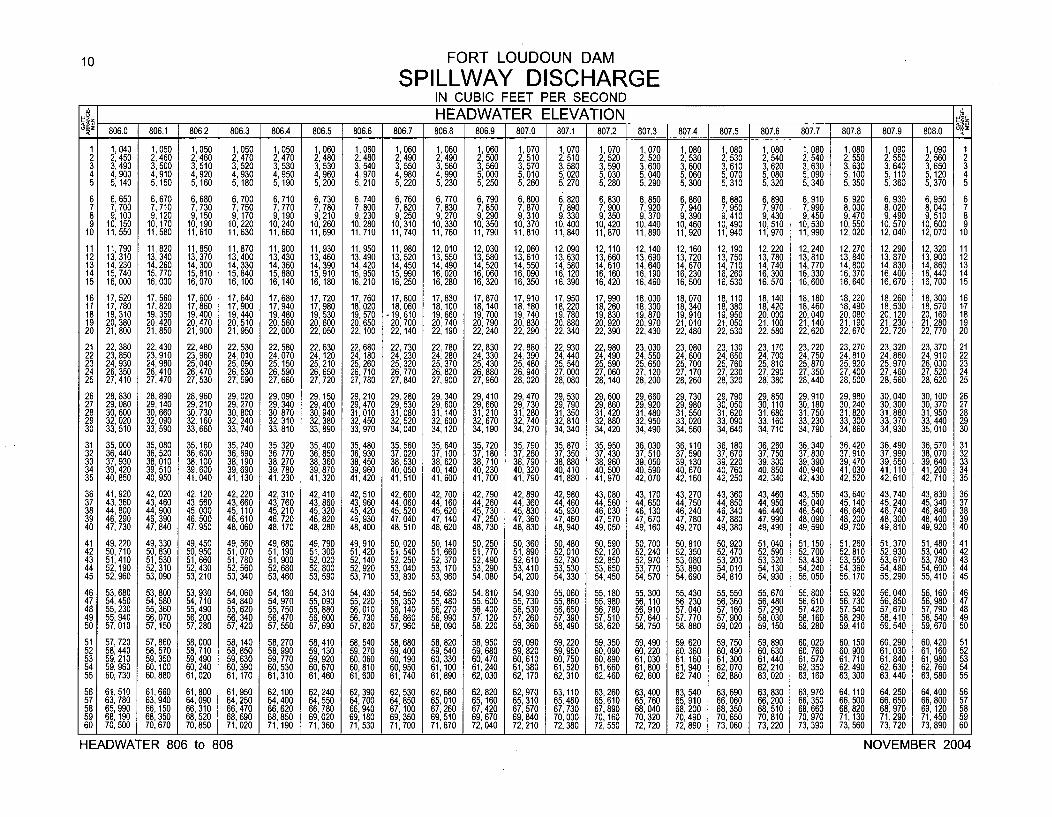
10 FORT LOUDOUN DAM
SPILLWAY DISCHARGEIN CUBIC FEET PER SECONDHEADWATER ELEVATION
806.0 806.1 806.2 806.3 806.4 806.5 806.6 806.7 806.8 806.9 807.0 807.1 807.2 807.3 807.4 807.5 807.6 807.7 807.8 807.9 808.0
1 1,040 1,050 1,050 1,050 1,050 1,060 1,060 1,060 1,060 1,060 1 070 1,070 1,070 1,070 1,080 1,080 1,080 1,080 1,080 1,090 1,090 12 2,450 2,460 2,460 2,470 2,470 2,480 2,480 2,490 2,490 2,500 2: 510 2,510 2,520 2,520 2,530 2,530 2,540 2,540 2,550 2,550 2,560 23 3,490 3,500 3,510 3,520 3,530 3,530 3 540 3,550 3,560 3 560 3 570 3,580 3,590 3 600 3,600 3,610 3,620 3,630 3 630 3,640 3,650 34 4,900 4,910 4,920 4,930 4 950 4 960 4: 970 4,980 4,990 5: 000 5: 010 5,020 5,030 5: 040 5,060 5,070 5,080 5,090 5: 100 5,110 5,120 45 5,140 5,150 5,160 5, 180 5: 190 5: 200 5,210 5,220 5,230 5,250 5 , 260 5,270 5,280 5,290 5,300 5,310 5,320 5,340 5,350 5,360 5,370 5
6 6 650 6,670 6,680 6,700 6,710 6,730 6,740 6,760 6,770 6,790 6.800 6,820 6, 830 6,850 6,860 6,880 6,890 6 910 6 920 6,930 6,950 67 7: 700 7,710 7,730 7 750 7,770 7,780 7,800 7,820 7,830 7,850 7,870 7,890 7,900 7,920 7,940 7,950 7 970 7: 990 8: 000 8,020 8 040 78 9 , 100 9,120 9,150 9: 170 9, 190 9,210 9,230 9,250 9,270 9,290 9,310 9,330 9,350 9,370 9,390 9,410 1 9: 430 9 , 450 9,470 9,490 9: 510 89 10,150 10,170 10,190 10,220 10,240 10,260 10,280 10,310 10,330 10,350 10,370 10,400 10,420 10,440 10,460 10,490 1 0,510 10,530 10,550 10,570 1 0 600 9
10 11,550 11,580 11,610 11,630 11,660 11,690 11,710 11,740 11,760 11,790 11,810 11,840 11,870 11,890 11,920 11,940 1,970 11,990 12,020 12,040 12: 070 10
11 11,790 11,820 11,850 11,870 11,900 11,930 11,950 11,980 12,010 12,030 12,060 12,090 12,110 12,140 12,160 12,190 12,220 12,240 12,270 12,290 12,320 1112 13 310 13,340 13,370 1 3,400 13,430 13,460 13 490 13 520 13,550 13,580 1 3 610 13,630 13,660 13,690 13,720 13,750 13,780 13,810 13,840 13,870 13,900 121 3 1 4: 230 14,260 14,300 14 330 14,360 14,390 1 4: 420 1 4: 450 14,490 14,520 14: 550 14,580 14,610 14,640 14,670 14 710 14,740 14,770 14,800 14,830 1 4 860 1314 15,740 15,770 15,810 15: 840 15,880 15,910 15,950 15,990 16,020 16,060 16 , 090 16,120 16,160 16,190 16,230 1 6: 260 16,300 16,330 1 6 370 16,400 16: 440 1415 16,000 16,030 16,070 16,100 16,140 16,180 16,210 16,250 16,280 16,320 16,350 16,390 16,420 16,460 16,500 16,530 16,570 16,600 16: 640 16,670 16,700 1 5
16 17 520 17 560 1 7 600 17,640 17,680 17,720 17,760 17 800 17,830 17,870 17,910 17,950 17,990 18,030 1 8 070 18,110 18,140 18,180 18,220 18,260 18,300 161 7 1 7: 780 1 7: 820 17: 860 17.900 17,940 17,980 18,020 1 8: 060 18,100 18,140 18,180 18,220 18,260 18,300 1340 18,380 18,420 18,460 18,490 18,530 18,570 17
1 8 19 310 19 350 19,400 19,440 19 480 19,530 19,570 -19 610 19,660 19,700 19 740 19,780 19,830 19,870 19,910 19,950 20,000 20,040 20,080 20,120 20, 160 1819 20: 380 20: 420 20 470 20 510 20: 560 20,600 20,650 20: 700 20,740 20,790 20: 830 20,880 20,920 20,970 21 010 21,050 21,100 21,140 21,190 21,230 21,280 1920 21,800 21,850 21: 900 21: 950 22,000 22,050 22, 100 22, 140 22, 190 22,240 22,290 22,340 22,390 22,430 22: 480 22,530 22,580 22,620 22,670 22,720 22,770 20
21 22,380 22,430 22,480 22,530 22,580 22,630 22,680 22,730 22,780 22,830 22,880 22,930 22,980 23,030 23,080 23, 130 23, 170 23,220 23,270 23,320 23,370 2122 23,850 23,910 23,960 24 010 24,070 24,120 24,180 24,230 24,280 24,330 24,390 24,440 24,490 24,550 24 600 24,650 24,700 24,750 24,810 24 860 24,910 2223 24,930 24,980 25,040 25: 090 25, 150 25,210 25 260 25 320 25,370 25,430 25,480 25,540 25,590 25,650 25: 700 25,760 25,810 25,870 25,920 25: 970 26,030 2324 26,350 26,410 26 470 26 530 26,590 26,650 26: 710 26: 770 26,820 26,880 26 940 27,000 27,060 27, 120 27, 170 27 230 27,290 27,350 27,400 27,460 27 520 2425 27,410 27,470 27: 530 27: 590 27,660 27,720 27,780 27,840 27,900 27,960 28: 020 28,080 28,140 28,200 28,260 28: 320 28,380 28,440 28,500 28,560 28: 620 25
26 28 830 28,890 28,960 29 020 29 090 29,150 29,210 29 280 29,340 29,410 29,470 29,530 29 600 29,660 29,730 29,790 29,850 29 910 29,980 30,040 30 100 2627 29: 080 29,140 29,210 29: 270 29: 340 29,400 29,470 29: 530 29,600 29,660 29,730 29,790 29: 860 29,920 29,980 30,050 30,110 30: 180 30,240 30,300 30: 370 2728 30,600 30,660 30,730 30,800 30 870 30,940 31,010 31,080 31, 140 31,210 31,280 31,350 31,420 31 480 31,550 31,620 31,680 31,750 31 820 31,880 31,950 2829 32,020 32,090 32,160 32,240 32: 310 32,380 32,450 32 520 32,600 32,670 32,740 32,810 32,880 32: 950 33,020 33,090 33 160 33,230 33: 300 33,370 33,440 2930 33,510 33,590 33,660 33,740 33 , 8 1 0 33,890 33,970 34: 040 34, 120 34,190 34,270 34,340 34,420 34,490 34,560 34,640 34: 710 34,790 34,860 34,930 35,010 30
31 35 000 35,080 35, 160 35,240 35,320 35,400 35,480 35,560 35,640 35 720 35 790 35 870 35,950 36,030 36 110 36, 180 36,260 36,340 36,420 36,490 36,570 3132 36: 440 36,520 36,600 36,690 36,770 36,850 36,930 37,020 37, 100 37: 180 37: 260 37: 350 37,430 37,510 37: 590 37,670 37,750 37,830 37 910 37 990 38,070 3233 37 930 38,010 38,100 38,190 38,270 38,360 38,450 38 530 38 620 38,710 38,790 38,880 38,960 39,050 39, 130 39,220 39,300 39,390 39: 470 39: 550 39,640 3334 39: 420 39,510 39,600 39,690 39 780 39,870 39,960 40: 050 40: 140 40,230 40,320 40,410 40,500 40 590 40 670 40,760 40,850 40,940 41,030 41,110 41,200 3435 40,850 40,950 41,040 41,130 41: 230 41,320 41,420 41,510 41,600 41,700 41,790 41,880 41,970 42: 070 42: 160 42,250 42,340 42,430 42,520 42,610 42,710 35
36 41,920 42,020 42, 120 42,220 42,310 42,410 42,510 42,600 42,700 42,790 42,890 42,980 43,080 43,170 43,270 43,360 43,460 43,550 43,640 43,740 43,830 3637 43,360 43,460 43,560 43,660 43 760 43,860 43,960 44 060 44,160 44,260 44 360 44,460 44,560 44,650 44,750 44,850 44,950 45,040 45,140 45,240 45,340 3738 44,800 44,900 45,000 45,110 45: 210 45,320 45,420 45: 520 45,620 45,730 45: 830 45,930 46,030 46,130 46,240 46,340 46,440 46,540 46,640 46,740 46,840 3839 46 290 46,390 46,500 46 610 46,720 46,820 46,930 47,040 47 140 47,250 47,360 47,460 47.570 47 670 47 780 47 880 47,990 48,090 48 200 48,300 48,400 3940 47: 730 47,840 47,950 48: 060 48, 170 48,280 48,400 48,510 48: 620 48,730 48,830 48,940 49,050 49:160 49: 270 49: 380 49,490 49,590 49: 700 49,810 49,920 40
41 49,220 49,330 49,450 49,560 49,680 49,790 49,910 50,020 50 140 50,250 50,360 50,480 50,590 50 700 50,810 50,920 51,040 51,150 51 260 51,370 51,480 4142 50,710 50,830 50,950 51,070 51,190 51,300 51,420 51,540 51: 660 51,770 51,890 52,010 52,120 52: 240 52,350 52,470 52,590 52,700 52: 810 52,930 53,040 4243 51 410 51,530 51,660 51,780 51,900 52,020 52, 140 52 250 52,370 52,490 52 610 52 730 52 850 52,970 53,080 53 200 53,320 53,430 53,550 53,670 53,780 4344 52: 190 52,310 52,430 52,560 52,680 52,800 52,920 53: 040 53, 170 53,290 53: 4 1 0 53: 530 53: 650 53,770 53,890 54: 010 54,130 54,240 54,360 54,480 54,600 4445 52,960 53,090 53,210 53,340 53,460 53,590 53,710 53,830 53,960 54,080 54,200 54,330 54 , 450 54,570 54,690 54,810 54,930 55,050 55,170 55,290 55,410 45
46 53,680 53,800 53,930 54,060 54 180 54,310 54,430 54,560 54,680 54 810 54,930 55,060 55,180 55,300 55,430 55,550 55,670 55,800 55,920 56 040 56, 160 4647 54,450 54,580 54,710 54,840 54: 970 55,090 55,220 55 350 55,480 55: 600 55 730 55,860 55,980 56,110 56,230 56 360 56 480 56,610 56,730 56: 850 56,980 4748 55,230 55,360 55,490 55,620 55 , 750 55,880 56,010 56: 140 56,270 56,400 56: 530 56,650 56,780 56,910 57,040 57: 160 57: 290 57,420 57,540 57 , 670 57,790 4849 55,940 56,070 56 200 56,340 56,470 56,600 56,730 56,860 56,990 57,120 57,260 57 390 57,510 57,640 57 770 57,900 58,030 58, 160 58,290 58 410 58 540 4950 57,010 57,150 57: 280 57,420 57,550 57,690 57,820 57,960 58,090 58,220 58,360 58:490 58,620 58,750 58: 880 59,020 59, 150 59,280 59,410 59: 540 59: 670 50
51 57,720 57,860 58,000 58, 140 58,270 58,410 58,540 58,680 58,820 58,950 59,090 59,220 59,350 59,490 59,620 59,750 59,890 60,020 60,150 60,290 60,420 5152 58,440 58,570 58,710 58,850 58,990 59,130 59,270 59,400 59,540 59,680 59,820 59,950 60,090 60,220 60,360 60,490 60,630 60,760 60,900 61,030 61 160 5253 59 210 59,350 59,490 59 630 59 770 59,920 60,060 60 190 60,330 60,470 60 610 60 750 60,890 61,030 61, 160 61,300 61,440 61,570 61,710 61,840 61: 980 5354 59: 960 60,100 60,240 60: 390 60: 530 60,670 60,810 60: 950 61,100 61,240 61: 380 61: 520 61,660 61,800 61,940 62,070 62,210 62,350 62,490 62,630 62,760 5455 60 , 730 60,880 61,020 61,170 61,310 61,460 61,600 61,740 61,890 62,030 62, 170 62,310 62,460 62,600 62,740 62,880 63,020 63, 160 63,300 63,440 63,580 55
56 61 510 61,660 61,800 61,950 62,100 62,240 62,390 62,530 62,680 62,820 62,970 63 110 63,260 63,400 63 540 63,690 63,830 63 970 64,110 64,250 64,400 5657 63 : 780 63,940 64,090 64,250 64,400 64,550 64,700 64,850 65,010 65,160 65,310 65: 460 65,610 65,760 65: 910 66,060 66,200 66: 350 66,500 66,650 66,800 5758 65 990 66, 150 66,310 66,470 66,620 66,780 66,940 67 100 67,260 67 420 67,570 67,730 67,890 68,040 68,200 68,350 68 510 68,660 68,820 68,970 69, 120 5859 68:190 68,350 68,520 68,690 68,850 69,020 69 180 69: 350 69,510 69: 670 69,840 70,000 70,160 70,320 70,490 70,650 70: 810 70,970 71,130 71,290 71,450 5960 70,500 70,670 70,850 71,020 71,190 71,360 71: 530 71,700 71,870 72,040 72,210 72,380 72,550 72,720 72,890 73,060 73,220 73,390 73,560 73,720 73,890 60
HEADWATER 806 to 808 NOVEMBER 2004
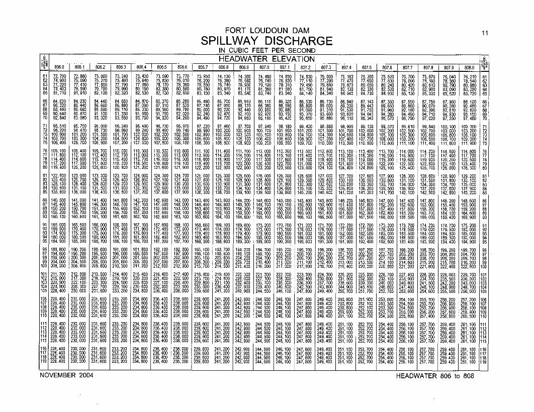
FORT LOUDOUN DAM
SPILLWAY DISCHARGEIN CUBIC FEET PER SECOND
___. _HEADWATER ELEVATION806.0 806.1 806.2 806.3 806.4 806.5 806.6 806.7 806.8 806.9 807.0 807.1 807.2 807.3 807.4 807.5 807.6 807.7 807.8 807.9 808.0 1
61 72, 700 72,880 73,060 73, 240 73, 420 73,590 73, 770 73, 950 74,130 74,300 74, 480 74,650 74,830 75,000 75, 180 75, 350 75,520 75,700 75, 870 76,040 76,210 6162 74, 900 75, 090 75, 270 75, 460 75,640 75,830 76, 010 76, 200 76, 380 76,560 76, 740 76, 920 77,110 77,290 77, 470 77, 650 77,830 78,000 78, 180 78,360 78,540 6263 77, 220 77,410 77,600 77, 790 77,980 78,170 78, 360 78, 550 78,740 78,930 79, 120 79, 310 79,490 79,680 79,870 80, 050 80,240 80,420 80, 610 80,790 80,980 6364 79, 400 79,590 79, 790 79, 990 80,190 80,380 80, 580 80, 780 80, 970 81,170 81, 360 81, 560 81,750 81,940 82, 130 82, 330 82,520 82,710 82, 900 83,090 83,280 6465 81,710 81,910 82,120 82, 320 82, 530 82,730 82,930 83, 130 83, 340 83,540 83, 740 83, 940 84,140 84,340 84,540 84, 730 84,930 85, 130 85, 330 85,520 85, 720 65
66 84,020 84,230 84,440 84, 660 84, 870 85,070 85,280 85,490 85, 700 85,910 86, 110 86,320 86,530 86,730 86,940 87,140 87,350 87,550 87,750 87,960 88,160 6667 86, 220 86, 440 86, 660 86,880 87,090 87,310 87,520 87,740 87, 950 88,170 88, 380 88,590 88,800 89,020 89,230 89,440 89,650 89,860 90,070 90,280 90,480 6768 88, 440 88, 660 88,890 89,110 89,330 89,560 89, 780 90,000 90,220 90,440 90, 660 90,880 91,090 91,310 91,530 91,750 91,960 92,180 92,390 92,610 92,820 6869 90,640 90, 870 91, 100 91, 330 91,560 91,790 92,020 92,240 92,470 92,700 92, 920 93, 150 93,370 93,600 93, 820 94,040 94,260 94,490 94,710 94, 930 95, 150 6970 92,840 93, 080 93, 320 93, 550 93, 790 94,020 94,260 94,490 94, 720 94,950 95, 190 95, 420 95, 650 95,880 96, 110 96,340 96, 570 96, 790 97, 020 97, 250 97, 480 70
71 95, 510 95, 750 96, 000 96, 240 96, 490 96, 730 96,970 97, 220 97, 460 97,700 97, 940 98,180 98, 420 98, 660 98, 900 99,130 99,370 99,610 99,840 100, 100 100, 300 7172 98,220 98,470 98, 730 98,980 99, 240 99, 490 99,740 99,990 100,200 100 500 100,700 101,000 101,200 101,500 101, 700 102,000 102,200 102, 500 102, 700 103, 000 103, 200 7273 100,900 101,200 101,500 101,700 102,000 102,200 102,500 102,800 103,000 103,300 103,500 103,800 104,100 104,300 104,600 104,800 105,100 105,300 105,600 105,800 106,100 7374 103,700 103,900 104,200 104,500 104,800 105,000 105,300 105,600 105,800 106,100 106,400 106,600 106,900 107,200 107,400 107,700 108,000 108,200 108,500 108,700 109,000 7475 106,400 106,700 106,900 107,200 107,500 107,800 108,100 108,300 108,600 108,900 109,200 109,500 109,700 110,000 110,300 110,500 110,800 111,100 111,400 111,600 111,900 75
76 109,100 109,400 109,700 110,000 110,300 110,500 110,800 111,100 111,400 111,700 112,000 112,300 112,500 112,800 113,100 113,400' 113,700 114,000 114,200 114,500 114,800 7677 111,800 112,100 112,400 112,700 113,000 113,300 113,600 113,900 114,200 114,500 114,800 115,100 115,400 115,700 116,000 116,300 116,500 116,800 117,100 117,400 117,700 7778 114,400 114,800 115,100 115,400 115,700 116,000 116,300 116,600 116,900 117,200 117,500 117,800 118,100 118,400 118,700 119,000 119,300 119,600 119,900 120,200 120,500 7879 117,200 117,500 1117,800 118,200 118,500 118,800 119,100 119,400 119,700 120,000 120,400 120,700 121,000 121,300 121,600 121,900 122,200 122,500 122,800 123,100 123,400 7980 119, 900 120,200 120,600 120, 900 121,200 121,600 121,900 122,200 122,500 122,900 123,200 123,500 123,800 124,100 124,400 124,800 125,100 125,400 125,700 126,000 126,300 80
81 122,600 123,000 123,300 123,700 124,000 124,300 124,700 125,000 125,300 125,600 126,000 126,300 126,600 127,000 127,300 127,600 127,900 128,300 128,600 128,900 129,200 8182 125,400 125,700 126, 100 126,400 126, 800 127, 100 127,400 127, 800 128, 100 128 500 128,800 129, 100 129, 500 129,800 130, 100 130, 500 130,800 131,100 131,500 131,800 132, 100 8283 128,100 128,400 128,800 129,200 129,500 129,900 130,200 130,600 130,900 131,300 131,600 131,900 132,300 132,600 133,000 133,300 133,700 134,000 134,300 134,700 135,000 8384 130, 800 131,100 131,500 131,900 132, 300 132,600 133,000 133,300 133,700 134, 100 134,400 134, 800 135, 100 135,500 135,800 136, 200 136,500 136,900 137, 200 137,600 137,900 8485 135, 600 136,000 136,400 136, 800 137,200 137,600 137,900 138,300 138,700 139,100 139,500 139, 800 140,200 140,600 141,000 141,300 141,700 142,100 142,500 142,800 143,200 85
86 140,500 141,000 141,400 141,800 142, 200 142,600 143,000 143, 400 143, 800 144 200 144, 600 145,000 145,400 145,800 146, 200 146,600 147,000 147,400 147,800 148, 200 148,600 8687 145,400 145,800 146,300 146,700 147,100 147,500 148,000 148,400 148,800 149,300 149,700 150,100 150,500 150,900 151,400 151,800 152,200 152,600 153,000 153,400 153,900 8788 150, 200 150,700 151,200 151,600 152, 100 152,500 153,000 153,400 153, 900 154,300 154, 800 155,200 155,600 156, 100 156,500 157,000 157,400 157,800 158, 300 158,700 159,200 8889 155,200 155,700 156,200 156,700 157, 200 157,600 158,100 158, 600 159, 100 159, 500 160,000 160,500 160,900 161,400 161,800 162, 300 162,800 163,200 163, 700 164, 100 164,600 8990 160,100 160,600 161,100 161,600 162, 100 162,600 163,100 163,600 164, 100 164,600 165, 100 165,600 166,100 166,500 167,000 167, 500 168,000 168,500 169,000 169,400 169,900 90
91 165, 000 165,500 166,000 166, 500 167, 100 167,600 168,100 168, 600 169, 100 169,600 170,200 170, 700 171,200 171,700 172, 200 172,700 173, 200 173, 700 174,200 174, 700 175, 200 9192 169,900 170,400 170,900 171,400 171,900 172,400 172,900 173,400 174,000 174,500 175,000 175,500 176,000 176,500 177,000 177,500 178,000 178,500 179,000 179,500 180,000 9293 174,900 175,300 175,800 176,300 176,800 177,400 177,900 178,400 178, 900 179,400 179,900 180,500 181,000 181,500 182,000 182,500 183,000 183,500 184,000 184, 500 185,000 9394 180,000 180,500 180,900 181,300 181,800 182,400 182,900 183,400 183,900 184,500 185,000 185,500 186,000 186,500 187,000 187,500 188,000 188,500 189,000 189,500 190,000 9495 184,900 185,300 185,700 186,100 186,700 187,200 187,700 188,300 188,800 189,300 189,800 190,300 190,800 191,300 191,900 192,400 192,900 193,400 193,900 194,400 194,900 95
96 189,800 190,200 190,600 191,000 191,600 192,100 192,600 193,100 193,700 194,200 194,700 195,200 195,700 196,200 196,700 197,200 197,700 198,200 198,700 199,200 199,700 9697 194, 800 195,200 195,500 196,000 196, 500 197,000 197,600 198,100 198, 600 199 100 199, 700 200,200 200,700 201,200 201, 700 202,200 202, 700 203, 200 203, 700 204, 200 204,700 9798 199,900 200,300 200,600 201,000 201,500 202,000 202,600 203, 100 203,600 204,200 204,700 205,200 205,700 206,200 206, 700 207,200 207,700 208, 200 208,700 209,200 209,700 9899 204,000 204,500 205,000 205, 600 206, 300 207,000 207, 600 208, 300 209,000 209 700 210, 400 211,000 211,700 212,400 213,000 213,500 214,100 214,600 215,200 215, 700 216,200 99
100 208,200 208,900 209,600 210,300 211,200 212,000 212,900 213,700 214,500 215,400 216,200 217,000 217,900 218,700 219,400 220,000 220,600 221,200 221,800 222,400 222,900 100
101 211,700 212,600 213,500 214,400 215,400 216,400 217,400 218,400 219,400 220,300 221,300 222,300 223,300 224,300 225,200 225,900 226,700 227,400 228,200 229,000 229,700 101102 215,900 217,000 218,000 219,100 220, 300 221,400 222,500 223,700 224,800 226,000 227, 100 228,300 229,400 230,600 231,500 232,300 233,100 233,900 234,700 235, 500 236,300 102103 220, 900 222, 100 223,300 224, 500 225, 800 227, 100 228,400 229, 800 231, 100 232,400 233, 700 235,000 236,300 237,700 238,600 239, 300 240, 000 240, 800 241,500 242, 200 243, 000 103104 224,900 226,300 227,700 229, 100 230, 600 232,000 233,500 235, 000 236,400 237,900 239, 400 240, 800 242,300 243,800 244,900 245, 800 246,600 247,400 248,100 248,900 249, 700 104105 228,400 230,000 231,600 233, 200 234, 800 236,400 238,000 239, 600 241,200 242,900 244, 500 246, 100 247, 800 249,400 250, 700 251,700 252, 700 253,600 254,600 255, 500 256, 500 105
106 228, 400 230,000 231 600 233, 200 234, 800 236, 400 238,000 239, 600 241,200 242,900 244, 500 246, 100 247,800 249, 400 250, 800 251,900 253,000 254,100 255, 100 256, 200 257, 200 106107 228,400 230,000 231, 600 233,200 234,800 236, 400 238,000 239,600 241,200 242,900 244,500 246, 100 247,800 249, 400 250, 800 252,100 253, 300 254,500 255,700 256,900 258,100 107108 228,400 230,000 231, 600 233,200 234,800 236,400 238,000 239,600 241,200 242,900 244,500 246,100 247,800 249,400 250,800 252,100 253,300 254,500 255,700 256,900 258,100 108109 228,400 230,000 231, 600 233, 200 234, 800 236,400 238,000 239, 600 241,200 242,900 244,500 246,100 247,800 249, 400 250, 900 252, 300 253, 700 255,000 256, 200 257,600 258, 900 109110 228,400 230,000 231,600 233,200 234,800 236,400 238,000 239,600 241,200 242,900 244,500 246, 100 247,800 249,400 251, 100 252,700 254,300 255,800 257,400 258,900 260,500 110
111 228,400 230,000 231,600 233,200 234, 800 236,400 238,000 239,600 241,200 242,900 244, 500 246, 100 247,800 249,400 251, 100 252,700 254,400 256,100 257, 700 259,400 261,100 111112 228,400 230,000 231, 600 233,200 234; 800 236,400 238,000 239, 600 241,200 242,900 244, 500 246, 100 247,800 249,400 251, 100 252, 700 254,400 256,100 257, 700 259,400 261,100 112113 228,400 230,000 231,600 233,200 234,800 236,400 238,000 239, 600 241,200 242,900 244, 500 246, 100 247,800 249,400 251, 100 252, 700 254,400 256, 100 257, 700 259,400 261,100 113114 228,400 230,000 231,600 233,200 234,800 236,400 238,000 239,600 241,200 242,900 244,500 246, 100 247,800 249,400 251, 100 252,700 254,400 256, 100 257,700 259,400 261,100 114115 228,400 230,000 231,600 233,200 234,800 236,400 238,000 239,600 241,200 242,900 244,500 246, 100 247,800 249,400 251,100 252,700 254,400 256, 100 257,700 259,400 261,100 115
116 228, 400 230,000 231,600 233, 200 234,800 236,400 238,000 239, 600 241,200 242,900 244,500 246, 100 247,800 249,400 251,100 252,700 254,400 256, 100 257,700 259, 400 261,100 116117 228, 400 230,000 231,600 233, 200 234,800 236,400 238,000 239, 600 241,200 242,900 244,500 246, 100 247,800 249,400 251,100 252,700 254,400 256, 100 257,700 259, 400 261,100 117118 228, 400 230,000 231,600 233, 200 234, 800 236,400 238,000 239, 600 241,200 242, 900 244,500 246, 100 247, 800 249,400 251,100 252, 700 254,400 256, 100 257, 700 259, 400 261,100 118119 228,400 230,000 231,600 233,200 234,800 236,400 238,000 239,600 241,200 242,900 244,500 246, 100 247,800 249,400 251,100 252,700 254,400 256,100 257,700 259, 400 261,100 119
NOVEMBER 2004 HEADWATER 806 to 808
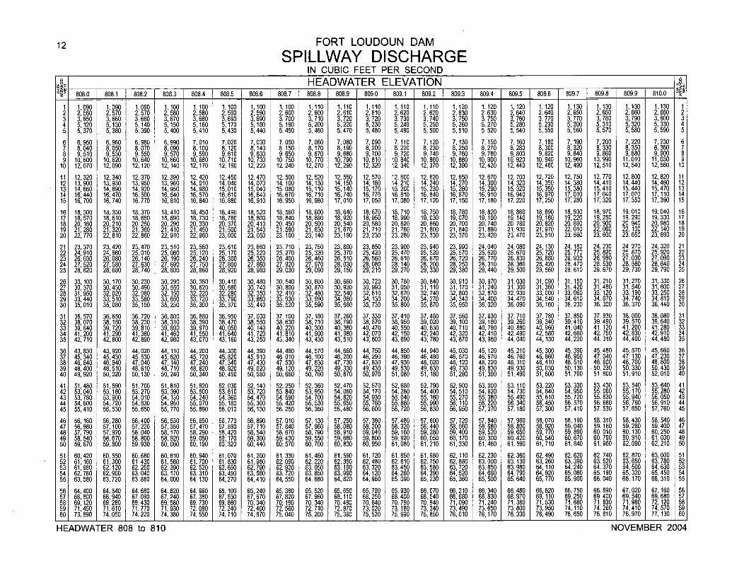
12 FORT LOUDOUN DAM
SPILLWAY DISCHARGEIN CUBIC FEET PER SECOND
J _ HEADWATER ELEVATION ____P 808.0 808.1 1 808.2 1 808.3 808.4 808.5 808.6 808.7 808.8 808.9 809.0 809.1 809.2 809.3 809.4 809.5 [ 809.6 809.7 809.8 1 809.9 810.0 q
1 1,090 1,090 1,090 1,100 1,100 1,100 1,100 1,100 1,110 1,110 1,110 1,110 1,110 1,120 1,120 1, 120 1,120 1,130 1,130 1,130 1,130 12 2,560 2, 570 2, 570 2, 580 2, 580 2,590 2,590 2, 600 2, 600 2, 610 2,610 2, 620 2,620 2, 630 2, 630 2,640 2, 640 2, 650 2, 650 2, 660 2, 660 23 3,650 3,660 3,660 3, 670 3,680 3,690 3,690 3, 700 3,710 3,720 3,720 3,730 3,740 3,750 3, 750 3,760 3,770 3,770 3,780 3,790 3,800 34 5,120 5,130 5,140 5,150 5,160 5,170 5,180 5,190 5,200 5,220 5,230 5,240 5,250 5,260 5,270 5,280 5,290 5,300 5, 310 5,320 5,330 45 5,370 5,380 5,390 5, 400 5, 410 5,430 5,440 5,450 5,460 5,470 5,480 5,490 5,500 5,510 5,520 5,540 5,550 5,560 5,570 5,580 5,590 5
6 6,950 6,960 6,980 6,990 7,010 7,020 7,030 7,050 7,060 7,080 7,090 7,110 7,120 7,130 7,150 7, 160 7,180 7,190 7,200 7,220 7,230 67 8,040 8,050 8,070 8,090 8,100 8,120 8,140 8,150 8,170 8,190 8,200 8,220 8,230 8,250 8,270 8,280 8,300 8,320 8,330 8,350 8,360 78 9, 510 9,530 9,550 9,570 9,590 9,610 9,630 9,650 9,670 9,680 9,700 9,720 9,740 9,760 9,780 9,800 9,820 9,840 9,860 9,880 9,900 89 10,600 10,620 10,640 10,660 10,680 10,710 10,730 10,750 10,770 10,790 10,810 10,840 10,860 10,880 0, 900 10,920 10,940 10,960 10,990 11,010 11,030 910 12, 070 12,090 12,120 12, 140 12,170 12,190 12,220 12,240 12,270 12,290 12,320 12,340 12,370 12,390 12,420 12, 440 12,460 12,490 12,510 12,540 12, 560 10
11 12,320 12,340 12,370 12,390 12,420 12,450 12,470 12,500 12,520 12,550 12,570 12,600 12,620 12,650 12,670 12,700 12,720 12,750 12,770 12,800 12,820 1112 13, 900 13,930 13, 950 13, 980 14, 010 14,040 14,070 14, 100 14,130 14,150 14,180 14, 210 14, 240 14,270 14,300 14, 320 14,350 14, 380 14,410 14,440 14,460 1213 14,860 14,890 14,920 14,950 14,980 15,010 15,040 15,080 15 ,140 15,170 15,200 15,230 15,260 15,290 15,320 15,350 15,380 15,410 15,440 15,470 1314 16, 440 16,470 16,500 16,540 16,570 16,610 16,640 16,670 16,710 16,740 16,770 16,810 16,840 16,870 16, 910 16,940 16,970 17,010 17,040 17,070 17,110 1415 16,700 16,740 16,770 16,810 16,640 16,880 16,910 16,950 16,980 17,010 17,050 17,080 17,120 17,150 17, 180 17,220 17,250 17,280 17,320 17, 350 17,390 15
16 18, 300 18,330 18,370 18,410 18,450 18,490 18,520 18,560 18,600 18,640 18,670 18,710 18,750 18,780 18,820 18, 860 18,890 18,930 18, 970 19,010 19,040 1617 18,570 18,610 18,650 18,690 18,730 18,760 18,800 18,840 18,880 18,920 18,950 18,990 19,030 19,070 19,100 19,140 19,180 19,220 19,250 19,290 19,330 17
18 20, 160 20, 210 20, 250 20, 290 20, 330 20,370 20,410 20,450 20, 500 20,540 20, 580 20, 620 20,660 20, 700 20, 740 20, 780 20, 820 20,860 20,900 20,940 20,980 1819 21,280 21,320 21,360 21,410 21,450 21,500 21,540 21,580 21,630 21,670 21,710 21,760 21,800 21,840 21,880 21,930 21,970 22,010 22,060 22,100 22,140 1920 22, 770 22,810 22,860 22, 910 22, 960 23,000 23,050 23, 100 23, 140 23,190 23, 230 23,280 23,330 23, 370 23, 420 23,470 23, 510 23,560 23,600 23, 650 23,690 20
21 23, 370 23,420 23,470 23, 510 23, 560 23,610 23,660 23,710 23, 750 23,800 23, 850 23,900 23,940 23,990 24,040 24,080 24,130 24,180 24,230 24,270 24, 320 2122 24, 910 24,960 25, 010 25, 060 25, 120 25,170 25,220 25,270 25, 320 25,370 25,420 25,470 25,520 25, 570 25, 620 25,670 25,720 25,770 25,820 25,870 25, 920 2223 26, 030 26,080 26, 140 26, 190 26, 240 26,300 26,350 26,400 26, 460 26,510 26,560 26,610 26,670 26, 720 26, 770 26,830 26,880 26,930 26,980 27, 030 27, 090 2324 27, 520 27, 580 27, 630 27, 690 27, 750 27,800 27,860 27, 920 27, 970 28,030 28, 080 28, 140 28,200 28, 250 28, 310 28,360 28,420 28, 470 28, 530 28,580 28, 640 2425 28, 620 28,680 28,740 28, 800 28, 860 28,920 28,980 29,030 29, 090 29,150 29,210 29, 270 29, 330 29,380 29, 440 29,500 29,560 29,610 29,670 29,730 29, 790 25
26 30, 100 30, 170 30,230 30, 290 30, 350 30,410 30,480 30,540 30, 600 30,660 30,720 30,780 30,840 30,910 30,970 31,030 31,090 31,150 31,210 31,270 31, 330 2627 30,370 30,430 30,490 30, 550 30,620 30,680 30,740 30,800 30, 870 30,930 30,990 31,050 31,110 31,170 31,240 31,300 31,360 31,420 31,480 31,540 31,600 2728 31,950 32,020 32, 080 32, 150 32, 220 32,280 32,350 32,410 32, 480 32,540 32, 610 32,670 32, 740 32,800 32, 870 32, 930 33,000 33,060 33, 120 33,190 33, 250 2829 33,440 33,510 33, 580 33, 650 33,720 33,790 33,860 33,930 33, 990 34,060 34, 130 34, 200 34,270 34,340 34,400 34,470 34,540 34,610 34,670 34,740 34, 810 2930 35, 010 35,080 35,150 35, 230 35, 300 35,370 35,440 35,520 35, 590 35,660 35, 730 35,800 35,870 35,950 36,020 36,090 36, 160 36,230 36, 300 36,370 36, 440 30
31 36, 570 36,650 36,720 36, 800 36, 880 36,950 37,030 37, 100 37, 180 37,260 37,330 37,410 37,480 37,560 37,630 37,710 37, 780 37,850 37, 930 38,000 38,080 3132 38, 070 38, 150 38,230 38, 310 38, 390 38,470 38,550 38,630 38, 710 38,790 38,870 38,950 39,020 39,100 39,180 39,260 39, 340 39,410 39,490 39,570 39,640 3233 39,640 39, 720 39, 810 39, 890 39, 970 40,050 40,140 40,220 40, 300 40,380 40, 470 40, 550 40,630 40,710 40, 790 40,880 40, 960 41,040 41,120 41,200 41,280 3334 41,200 41,290 41,380 41,460 41,550 41,640 41,720 41,810 41,900 41,980 42,070 42,150 42,240 42,320 42,410 42,490 42,580 42,660 42, 750 42,830 42,910 3435 42, 710 42,800 42,890 42, 980 43, 070 43,160 43,250 43,340 43, 430 43,510 43, 600 43, 690 43, 780 43,870 43, 960 44,040 44,130 44,220 44, 310 44,400 44,480 35
36 43,830 43,920 44,020 44, 110 44,200 44,300 44,390 44,480 44,570 44,660 44,750 44,850 44,940 45,030 45,120 45,210 45,300 45,390 45,480 45,570 45,660 3637 45, 340 45, 430 45,530 45, 620 45, 720 45,820 45, 910 46,010 46,100 46,200 46,290 46, 390 46,480 46,570 46,670 46,760 46,860 46,950 47, 040 47,130 47,230 3738 46, 840 46, 940 47, 040 47, 140 47, 240 47,340 47, 430 47, 530 47, 630 47,730 47, 830 47, 930 48,020 48, 120 48, 220 48,310 48, 410 48,510 48, 600 48,700 48, 800 3839 48, 400 48,510 48,610 48, 710 48, 820 48,920 49, 020 49, 120 49, 220 49,330 49,430 49,530 49,630 49,730 49,830 49,930 50, 030 50,130 50, 230 50, 330 50,430 3940 49, 920 50,020 50,130 50, 240 50, 340 50,450 50, 550 50, 660 50, 760 50,870 50, 970 51,080 51,180 51,290 51,390 51, 490 51,600 51,700 51,800 51, 910 52,010 40
41 51,480 51,590 51, 700 51, 810 51,920 52,030 52,140 52, 250 52, 360 52,470 52, 570 52,680 52,790 52,900 53,000 53,110 53,220 53,330 53,430 53, 540 53, 640 4142 53, 040 53,160 53, 270 53, 390 53, 500 53,610 53,720 53, 840 53, 950 54,060 54, 170 54,280 54,400 54,510 54,620 54,730 54,840 54,950 55, 060 55,170 55, 280 4243 53, 780 53,900 54,010 54, 130 54, 240 54,360 54,470 54, 590 54, 700 54,820 54, 930 55,040 55, 160 55,270 55,380 55,490 55,610 55,720 55, 830 55,940 56,050 4344 54, 600 54,720 54,830 54, 950 55, 070 55,180 55,300 55, 420 55, 530 55,650 55, 760 55,880 55, 990 56,110 56, 220 56,340 56,450 56,570 56, 680 56,790 56,910 4445 55,410 55,530 55,650 55, 770 55,890 56,010 56,130 56, 250 56, 360 56,480 56,600 56, 720 56, 830 56,950 57, 070 57,180 57,300 57,410 57, 530 57,650 57,760 45
46 56, 160 56,280 56,400 56, 530 56, 650 56,770 56,890 57, 010 57, 130 57, 250 57, 360 57, 480 57, 600 57, 720 57,640 57, 960 58, 070 58,190 58, 310 58,430 58,540 4647 56, 980 57,100 57,220 57, 350 57,470 57,590 57,710 57,640 57, 960 58,080 58, 200 58, 320 58, 440 58,560 58, 680 58, 800 58, 920 59, 040 59, 160 59, 280 59, 400 4748 57, 790 57,920 58,040 58, 170 58,290 58,420 58,540 58, 670 58, 790 58,910 59,040 59,160 59,280 59,400 59, 520 59, 650 59,770 59,890 60, 010 60,130 60,250 4849 58,540 58,670 58,800 58, 920 59,050 59,170 59,300 59,430 59, 550 59,680 59,800 59, 920 60, 050 60,170 60, 300 60,420 60,540 60,670 60, 790 60,910 61,030 4950 59,670 59,800 59,930 60,060 60,190 60,320 60,440 60, 570 60, 700 60,830 60,950 61,080 61,210 61,330 61,460 61,590 61,710 61,840 61, 960 62,090 62,210 50
51 60,420 60,550 60,680 60,810 60,940 61,070 61,200 61,330 61,460 61,590 61,720 61,850 61,980 62,110 62,230 62,360 62,490 62,620 62, 740 62,870 63,000 5152 61,160 61,300 61,430 61,560 61,700 61,830 61,960 62,090 62,220 62,350 62,480 62,610 62,750 62,880 63,000 63,130 63,260 63,390 63, 520 63,650 63,780 5253 61, 980 62,120 62,250 62, 390 62, 520 62,650 62,790 62, 920 63,050 63,190 63, 320 63,450 63, 580 63,720 63,850 63,980 64,110 64,240 64 370 64,500 64,630 5354 62, 760 62,900 63,040 63, 170 63, 310 63,450 63,580 63, 720 63, 850 63,990 64,120 64,260 64, 390 64,520 64,660 64,790 64,920 65, 060 65,190 65,320 65,450 5455 63, 580 63, 720 63, 860 64, 000 64, 130 64,270 64,410 64, 550 64, 680 64,820 64,960 65, 090 65, 230 65, 360 65, 500 65,640 65, 770 65,900 66,040 66,170 66,310 55
56 64,400 64,540 64,680 64, 820 64, 960 65,100 65,240 65,380 65, 520 65, 650 65,790 65, 930 66, 070 66, 210 66,340 66,480 66,620 66,750 66, 890 67,020 67,160 5657 66,800 66,940 67, 090 67, 240 67, 380 67,530 67,670 67,820 67, 960 68,110 68,250 68,400 68, 540 68,680 68,830 68,970 69,110 69,250 69,400 69,540 69,680 5758 69, 120 69, 280 69, 430 69, 580 69, 730 69, 880 70,040 70, 190 70,340 70,490 70,640 70, 790 70, 940 71,090 71, 240 71,380 71,530 71,680 71,830 71,980 72,120 5859 71, 450 71, 610' 71,770 71, 930 72, 080 72,240 72,400 72,560 72, 710 72,870 73, 020 73,180 73, 340 73,490 73, 650 73,800 73,950 74,110 74,260 74,410 74,570 5960 73,890 74,050 74,220 74, 380 74, 550 74,710 74,870 75,040 75, 200 75,360 75, 520 75, 690 75, 850 76,010 76, 170 76,330 76,490 76,650 76, 810 76,970 77,130 60
HEADWATER 808 to 810 NOVEMBER 2004
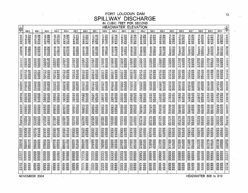
FORT LOUDOUN DAM 13
SPILLWAY DISCHARGEIN CUBIC FEET PER SECOND
808.0 81 8 8HEADWATER ELEVATION 81.0808.0 1808.1 808.2 808.3 1808.4 1808.5 1808.6 1808.7 808.8 808.9 1 809.0 809.1 809.2 809.3 809.4 809.5 809.6 809.7 809.8 809.9 810.0
61 76, 210 76,380 76,560 76, 730 76,900 77,070 77,240 77,400 77, 570 77, 740 77, 910 78,080 78,240 78,410 78, 580 78, 740 78,910 79,080 79, 240 79,410 79,570 6162 78, 540 78,720 78,890 79, 070 79,250 79,420 79,600 79,770 79,950 80,120 80, 300 80,470 80,640 80,820 80, 990 81, 160 81,330 81, 500 81, 670 81,840 82,020 6263 80, 980 81,160 81, 340 81,530 81,710 81,890 82,070 82,250 82,430 82,610 82,790 82,970 83,150 83,330 83,510 83,690 83,870 84,040 84, 220 84, 400 84,570 6364 83, 280 83,470 83, 660 83,850 84,040 84,220 84,410 84,600 84, 790 84,970 85,160 85,340 85,530 85,710 85,900 86,080 86,260 86,450 86, 630 86, 810 86,990 6465 85, 720 85,920 86,110 86,310 86,500 86,690 86,890 87,080 87,270 87,460 87,660 87,850 88,040 88,230 88,420 88,610 88,800 88,990 89, 180 89,360 89,550 65
66 88,160 88,360 88, 560 88,760 88,960 89,160 89,360 89, 560 89, 760 89,960 90,150 90,350 90, 550 90,750 90, 940 91,140 91, 330 91, 530 91, 720 91,920 92,110 6667 90, 480 90, 690 90, 900 91,110 91,310 91,520 91,720 91, 930 92, 130 92,340 92,540 92, 740 92, 950 93, 150 93, 350 93, 550 93, 750 93, 950 94, 150 94, 350 94,550 6768 92,820 93,040 93, 250 93, 460 93,670 93,890 94,100 94, 310 94, 520 94,730 94,940 95,150 95,360 95,560 95,770 95, 980 96,190 96,390 96,600 96,800 97,010 6869 95, 150 95, 370 95,590 95,810 96,030 96,240 96,460 96, 680 96, 890 97,110 97,320 97, 540 97, 750 97,970 98,180 98, 390 98,610 98,820 99,030 99,240 99,450 6970 97,480 97,700 97,930 98, 150 98, 380 98,600 98,820 99,050 99,270 99,490 99,710 99,930 100,200 100,400 100,600 100,800 101,000 101,200 101,500 101,700 101,900 70
71 100,300 100,500 100,800 101,000 101,200 101,500 101,700 101,900 102,200 102,400 102,600 102,900 103,100 103,300 103,500 103,800 104,000 104,200 104,400 104,700 104,900 7172 103, 200 103,400 103,700 103,900 104, 200 104,400 104,700 104,900 105, 100 105,400 105,600 105, 800 106, 100 106, 300 106, 600 106,800 107,000 107, 300 107,500 107,700 108,000 7273 106, 100 106, 300 106,600 106,900 107, 100 107,400 107,600 107, 800 108, 100 108,300 108,600 108, 800 109, 100 109, 300 109, 600 109,800 110,100 110, 300 110,500 110,800 111,000 7374 109,000 109,300 109,500 109,800 110,000 110,300 110,600 110,800 111,100 111,300 111,600 111,800 112,100 112,300 112,600 112,800 113,100 113,300 113,600 113,800 114,100 7475 111,900 112,200 112,400 112,700 113,000 113,200 113, 500 113,800 114,000 114,300 114,600 114,800 115,100 115,300 115,600 115,900 116,100 116,400 116,600 116,900 117,200 75
76 114,800 115,100 115,300 115,600 115,900 116,200 116,400 116,700 117,000 117,300 117,500 117,800 118,100 118,300 118,600 118,900 119,200 119,400 119,700 120,000 120,200 7677 117,700 118,000 118,300 118,600 118,800 119,100 119,400 119, 700 120,000 120,200 120,500 120,800 121,100 121,400 121,600 121,900 122,200 122,500 122,700 123,000 123,300 7778 120, 500 120,800 121,100 121,400 121,700 122,000 122,300 122,600 122, 800 123,100 123,400 123,700 124,000 124,300 124,600 124,900 125,100 125,400 125,700 126,000 126,300 7879 123,400 123,700 124,000 124,300 124,600 124,900 125,200 125,500 125, 800 126,100 126,400 126,700 127,000 127,300 127,600 127,900 128,200 128,500 128,800 129,100 129,300 7980 126, 300 126,600 127,000 127,300 127,600 127,900 128,200 128,500 128, 800 129,100 129,400 129,700 130,000 130,300 130,600 130,900 131,200 131,500 131,800 132,100 132,400 80
81 129,200 129,500 129,900 130,200 130,500 130,800 131,100 131,400 131,800 132,100 132,400 132,700 133,000 133,300 133,600 133,900 134,300 134,600 134,900 135,200 135,500 8182 132, 100 132,500 132, 800 133, 100 133,400 133,800 134,100 134,400 134, 700 135,100 135, 400 135,700 136,000 136,300 136,700 137,000 137,300 137,600 137, 900 138,200 138,600 8283 135,000 135,400 135, 700 136,000 136,400 136,700 137,000 137,400 137,700 138,000 138,400 138,700 139,000 139, 300 139,700 140,000 140,300 140,600 141,000 141,300 141,600 8384 137, 900 138,300 138, 600 139,000 139,300 139,600 140,000 140, 300 140, 700 141,000 141,300 141, 700 142,000 142, 300 142,700 143,000 143,400 143,700 144,000 144,300 144,700 8485 143, 200 143,600 143,900 144,300 144, 700 145,000 145,400 145, 700 146, 100 146,500 146,800 147, 200 147, 500 147,900 148,300 148, 600 149,000 149,300 149,700 150,000 150,400 85
86 148,600 148,900 149,300 149, 700 150,100 150,500 150,900 151,300 151,600 152,000 152,400 152,800 153,200 153,500 153,900 154,300 154,700 155,000 155,400 155, 800 156,200 8687 153, 900 154,300 154, 700 155, 100 155, 500 155,900 156,300 156, 700 157, 100 157,500 157, 900 158, 300 158, 700 159, 100 159, 500 159, 900 160,300 160,700 161,100 161, 500 161, 900 8788 159,200 159,600 160,000 160,500 160,900 161,300 161,700 162,200 162,600 163,000 163,400 163,900 164,300 164,700 165,100 165, 500 166,000 166,400 166,800 167,200 167,600 8889 164,600 165,100 165,500 166,000 166,400 166,900 167,300 167,800 168,200 168,700 169,100 169,500 170,000 170,400 170,900 171,300 171,700 172,200 172,600 173,000 173,400 8990 169,900 170,400 170,900 171,300 171,800 172,300 172,800 173,200 173,700 174,200 174,600 175,100 175,600 176,000 176,500 176,900 177,400 177,800 178,300 178,700 179,200 90
91 175, 200 175, 700 176,200 176,700 177, 200 177,700 178,200 178, 700 179,200 179,700 180,100 180,600 181,100 181, 600 182, 100 182,600 183,000 183,500 184,000 184,400 184, 900 9192 180,000 180, 500 181,000 181,500 182,000 182,500 183,100 183, 600 184,100 184,500 185,000 185,500 186,000 186, 500 187,000 187,500 188,000 188,500 189,000 189,500 190,000 9293 185,000 185, 500 186,000 186,500 187,000 187,500 188,000 188,500 189,100 189,600 190,100 190,600 191, 100 191,600 192, 100 192,600 193,100 193,600 194, 100 194,700 195,200 9394 190,000 190, 500 191,000 191,500 192,000 192,500 193,000 193,600 194, 100 194,600 195, 100 195,600 196, 100 196,600 197,100 197,600 198,200 198,700 199,200 199,800 200,300 9495 194, 900 195,400 195,800 196,400 196,900 197,400 197,900 198,400 198,900 199,500 200, 000 200,500 201,000 201,500 202, 100 202, 600 203,200 203,700 204,300 204, 800 205,400 95
96 199, 700 200, 200 200,700 201,200 201,800 202, 300 202, 900 203, 400 203, 900 204,500 205,000 205, 500 206, 100 206, 600 207, 200 207, 800 208,300 208, 900 209, 500 210, 100 210, 600 9697 204, 700 205, 200 205,700 206, 200 206, 700 207, 300 207,800 208, 400 208, 900 209, 400 210,000 210, 500 211,100 211, 600 212, 200 212, 800 213,400 214,000 214,600 215, 200 215,800 9798 209, 700 210,200 210,700 211,200 211,700 212,300 212,800 213,400 213,900 214,500 215,000 215,500 216,100 216, 600 217, 200 217,800 218,500 219, 100 219,700 220, 300 220,900 9899 216,200 216,800 217,300 217, 900 218, 500 218,900 219,400 219, 900 220, 300 220,800 221, 300 221,700 222,200 222,600 223,200 223, 800 224,400 224,900 225,500 226,100 226,700 99
100 222, 900 223, 500 224,100 224, 700 225, 300 225,700 226,100 226, 500 226,900 227,300 227, 700 228, 100 228,400 228,800 229,300 229, 900 230,400 231,000 231,500 232,000 232,600 100
101 229,700 230, 500 231,200 232,000 232,700 233,000 233, 400 233, 700 234,000 234,300 234,600 234, 900 235,200 235,500 235,900 236,400 236,900 237,300 237, 800 238,200 238, 700 101102 236,300 237, 100 237,900 238, 700 239,400 239,600 239,800 240,100 240, 300 240,500 240,800 241,000 241,300 241,500 241,800 242,300 242,700 243,100 243,600 244,000 244,400 102103 243,000 243,700 244,400 245, 100 245, 700 245,900 246,000 246, 200 246,400 246,500 246,700 246, 900 247,000 247,200 247,500 248,000 248,400 248,800 249, 200 249,600 250,000 103104 249, 700 250, 500 251,300 252,000 252, 600 252, 700 252, 800 252, 900 253,000 253, 100 253,200 253, 300 253, 300 253,400 253, 700 254,000 254,400 254,800 255, 200 255, 500 255, 900 104105 256,500 257,400 258,400 259, 300 260,000 260,000 260, 100 260,100 260, 100 260,100 260,100 260, 100 260,100 260,100 260,300 260,600 260,900 261,200 261,500 261,800 262, 100 105
106 257, 200 258, 300 259,400 260, 400 261,300 261,500 261, 800 262, 000 262, 300 262, 500 262,800 263,000 263,300 263, 500 263, 900 264, 400 264, 900 265,400 265, 900 266, 400 266, 900 106107 258, 100 259,300 260, 500 261,600 262,600 263,100 263,600 264,100 264, 600 265,000 265,500 266,000 266,500 267,000 267, 600 268,300 269, 000 269,700 270,400 271,100 271, 800 107108 258, 100 259,300 260, 500 261,600 262, 700 263,400 264,100 264, 900 265, 600 266,400 267, 100 267,900 268,600 269,400 270, 200 271,200 272, 100 273,100 274,000 274,900 275, 900 108109 258,900 260,200 261,500 262, 800 264,100 265,100 266,100 267,000 268,000 269,000 270,000 271,000 272,000 273,000 274,000 275, 100 276, 300 277,400 278, 600 279, 700 280,900 109110 260,500 262,100 263,600 265, 200 266, 700 267,900 269,100 270, 300 271,500 272,700 274,000 275,200 276,400 277,700 278,900 280,200 281, 500 282,800 284,100 285, 400 286,700 110
111 261,100 262,800 264,500 266, 100 267,800 269, 200 270, 700 272, 200 273, 600 275, 100 276, 500 278,000 279, 500 281,000 282, 500 264,000 285, 500 287,000 288, 500 290, 100 291, 600 111112 261,100 262,800 264,500 266, 100 267, 800 269, 500 271,300 273,000 274, 700 276,400 278,100 279, 900 281, 600 283,300 285, 100 286, 800 288, 600 290, 300 292, 100 293, 900 295, 600 112113 261,100 262,800 264,500 266, 100 267, 800 269,500 271,300 273,000 274, 700 276,400 278, 100 279,900 281, 600 283,300 285, 100 286, 800 288,600 290, 300 292, 100 293, 900 295,600 113114 261,100 262,800 264, 500 266, 100 267, 800 269, 500 271, 300 273,000 274, 700 276, 400 278, 100 279, 900 281,600 283,300 285, 100 286, 800 288, 600 290, 300 292, 100 293, 900 295,600 114115 261,100 262,800 264,500 266, 100 267,800 269, 500 271,300 273,000 274,700 276,400 278, 100 279,900 281,600 283,300 285, 100 286,800 288,600 290, 300 292, 100 293,900 295,600 115
116 261, 100 262,800 264, 500 266, 100 267,800 269,500 271,300 273, 000 274,700 276,400 278, 100 279,900 281,600 283, 300 285, 100 286, 800 288,600 290,300 292, 100 293, 900 295,600 116117 261, 100 262,800 264, 500 266,100 267,800 269,500 271,300 273, 000 274,700 276,400 278, 100 279,900 281, 600 283, 300 285, 100 286, 800 288,600 290,300 292, 100 293, 900 295,600 117118 261, 100 262, 800 264, 500 266,100 267, 800 269,500 271, 300 273, 000 274, 700 276, 400 278, 100 279, 900 281, 600 283, 300 285, 100 286, 800 288,600 290, 300 292, 100 293, 900 295, 600 118119 261, 100 262,800 264, 500 266, 100 267,800 269,500 271,300 273, 000 274,700 276,400 278, 100 279,900 281, 600 283,300 285, 100 286,800 288,600 290,300 292, 100 293, 900 295,600 119
NOVEMBER 2004 HEADWATER 808 to 810
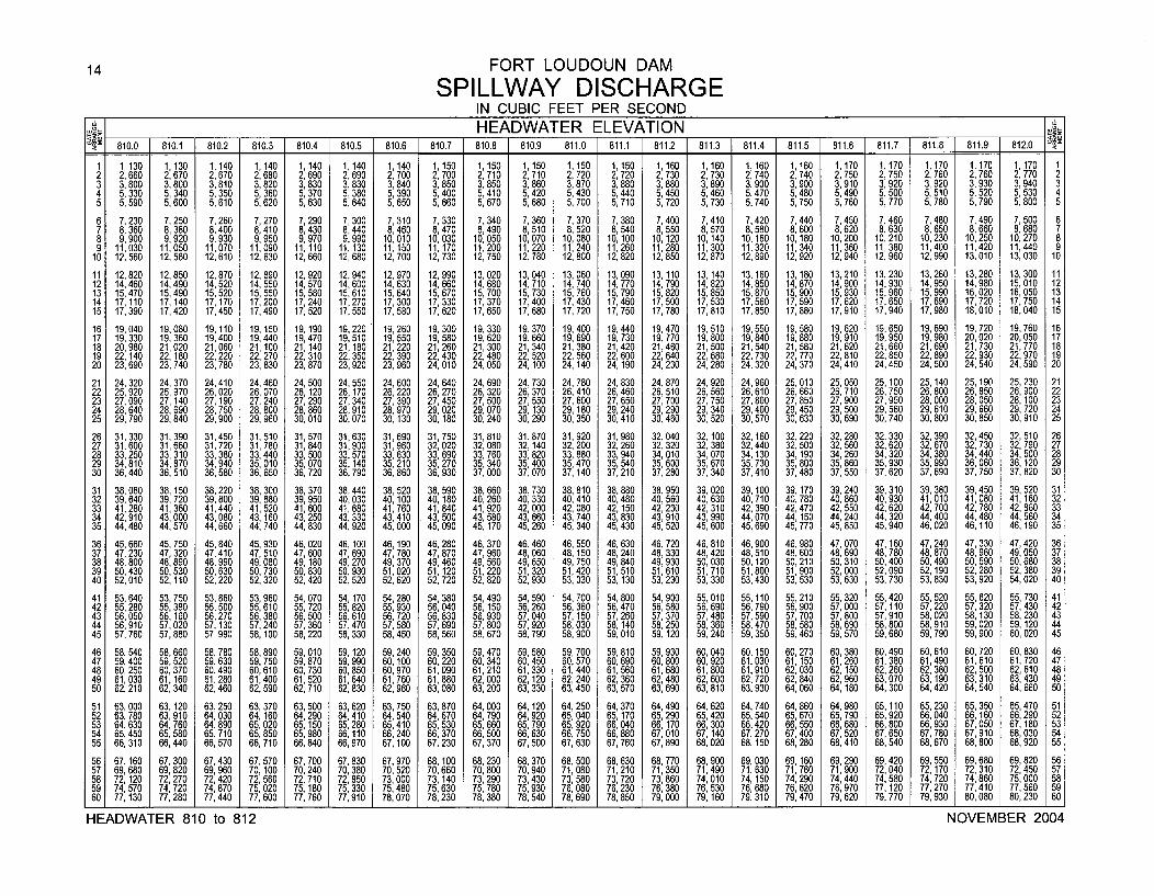
14 FORT LOUDOUN DAM
SPILLWAY DISCHARGEIN CUBIC FEET PER SECOND
J-• HEADWATER ELEVATION o.__ __ 810.0 810.1 810.2 810.3 810.4 810.5 810.6 810.7 810.8 810.9 811.0 811.1 [ 811.2 811.3 [ 811.4 811.5 1 811.6 1 811.7 811.8 1 811.9 1 812.081. I 1. 1. 1. 1. 1. 1. 1. EDAERLVTO ___ ___ ______ ______
1 1,130 1,130 1,140 1,140 1,140 1,140 1,140 1,150 1,150 1,150 1,150 1,150 1,160 1,160 1,160 1,160 1,170 1,170 1,170 1,170 1,170 12 2,660 2,670 2,670 2,680 2,690 2,690 2,700 2,700 2,710 2,710 2,720 2,720 2,730 2, 730 2,740 2,740 2,750 2,750 2,760 2,760 2,770 23 3,800 3,800 3,810 3,820 3,830 3,830 3,840 3,850 3,850 3,860 3,870 3,880 3,880 3,890 3,900 3,900 3,910 3,920 3,920 3,930 3,940 34 5, 330 5,340 5,350 5,360 5,370 5,380 5, 390 5,400 5, 410 5,420 5,430 5,440 5,450 5,460 5,470 5, 480 5,490 5,500 5, 510 5,520 5,530 45 5,590 5,600 5,610 5,620 5,630 5,640 5,650 5,660 5,670 5,680 5,700 5,710 5,720 5,730 5,740 5,750 5,760 5,770 5,780 5,790 5,800 5
6 7,230 7,250 7,260 7, 270 7, 290 7, 300 7,310 7, 330 7,340 7,360 7, 370 7, 380 7,400 7,410 7, 420 7,440 7,450 7,460 7, 480 7,490 7,500 67 8 360 8,380 8,400 8,410 8,430 8,440 8,460 8,470 8,490 8,510 8, 520 8, 540 8,550 8,570 8,580 8,600 8,620 8,630 8,650 8,660 8,680 78 9,900 9,920 9,930 9,950 9,970 9,990 10,010 10, 030 10,050 10,070 10,080 10,100 10,120 10, 140 10,160 10,180 10,200 10, 210 10,230 10,250 10,270 89 11,030 11,050 11,070 11,090 11,110 11,130 11,150 11,170 11,200 11,220 11,240 11,260 11,280 11,300 11,320 11,340 11,360 11,380 11,400 11,420 11,440 9
10 12,560 12,580 12,610 12, 630 12, 660 12,680 12,700 12, 730 12,750 12,780 12, 800 12,820 12,850 12,870 12,890 12, 920 12,940 12, 960 12,990 13,010 13, 030 10
11 12,820 12,850 12,870 12,890 12,920 12,940 12,970 12,990 13,020 13,040 13,060 13,090 13,110 13,140 13,160 13,180 13,210 13,230 13,260 13,280 13,300 1112 14,460 14,490 14,520 14, 550 14, 570 14,600 14,630 14, 660 14,680 14,710 14, 740 14, 770 14,790 14,820 14,850 14, 870 14,900 14, 930 14,950 14,980 15, 010 1213 15,470 15,490 15,520 15, 550 15,580 15,610 15,640 15,670 15,700 15,730 15, 760 15,790 15,820 15,850 15,870 15,900 15,930 15,960 15,990 16,020 16,050 1314 17,110 17,140 17,170 17,200 17,240 17,270 17,300 17,330 17,370 17,400 17,430 17,460 17,500 17,530 17,560 17,590 17,620 17,650 17,690 17,720 17,750 1415 17,390 17,420 17,450 17,490 17,520 17,550 17,580 17,620 17,650 17,680 17,720 17,750 17,780 17,810 17,850 17,880 17,910 17,940 17,980 18,010 18,040 15
16 19,040 19,080 19,110 19,150 19,190 19,220 19,260 19,300 19,330 19,370 19, 400 19,440 19,470 19,510 19,550 19,580 19,620 19,650 19,690 19,720 19,760 1617 19, 330 19,360 19,400 19,440 19, 470 19, 510 19,550 19,580 19,620 19,660 19, 690 19,730 19,770 19,800 19,840 19,880 19, 910 19, 950 19, 980 20,020 20,050 1718 20, 980 21,020 21,060 21,100 21,140 21,180 21,220 21,260 21,300 21,340 21,380 21,420 21,460 21,500 21,540 21,580 21,620 21,660 21,690 21,730 21,770 1819 22,140 22, 180 22,220 22, 270 22, 310 22,350 22,390 22, 430 22,480 22,520 22, 560 22,600 22,640 22, 680 22,730 22,770 22,810 22,850 22,890 22, 930 22,970 1920 23,690 23,740 23,780 23, 830 23, 870 23,920 23, 960 24, 010 24,050 24,100 24,140 24,190 24,230 24,280 24,320 24,370 24,410 24,450 24, 500 24,540 24,590 20
21 24,320 24, 370 24,410 24,460 24, 500 24,550 24,600 24, 640 24, 690 24,730 24, 780 24, 830 24,870 24, 920 24,960 25,010 25,050 25,100 25,140 25,190 25, 230 2122 25,920 25,970 26,020 26, 070 26, 120 26,170 26,220 26, 270 26, 320 26,370 26,410 26, 460 26, 510 26, 560 26,610 26, 660 26,710 26,750 26, 800 26,850 26, 900 2223 27,090 27,140 27, 190 27, 240 27, 290 27,340 27,390 27, 450 27, 500 27,550 27, 600 27, 650 27, 700 27, 750 27,800 27, 850 27,900 27,950 28, 000 28,050 28, 100 2324 28,640 28,690 28,750 28, 800 28,860 28,910 28,970 29,020 29, 070 29,130 29,180 29,240 29,290 29,340 29,400 29, 450 29, 500 29,560 29,610 29,660 29,720 2425 29,790 29,840 29,900 29, 960 30, 010 30,070 30,130 30,180 30, 240 30,290 30, 350 30,410 30,460 30, 520 30,570 30, 630 30, 690 30,740 30, 800 30,850 30, 910 25
26 31,330 31,390 31,450 31,510 31,570 31,630 31,690 31,750 31,810 31,870 31,920 31,980 32,040 32,100 32,160 32,220 32,280 32,330 32, 390 32,450 32,510 2627 31, 600 31,660 31,720 31, 780 31,840 31, 900 31,960 32, 020 32,080 32,140 32, 200 32, 260 32,320 32, 380 32,440 32, 500 32, 560 32, 620 32, 670 32,730 32, 790 2728 33,250 33,310 33 380 33, 440 33, 500 33, 570 33,630 33, 690 33, 760 33,820 33, 880 33,940 34,010 34, 070 34, 130 34, 190 34, 260 34, 320 34, 380 34,440 34, 500 2829 34, 810 34,870 34,940 35, 010 35,070 35,140 35,210 35,270 35,340 35,400 35,470 35,540 35, 600 35, 670 35, 730 35,800 35,860 35, 930 35,990 36,060 36, 120 2930 36,440 36,510 36, 580 36, 650 36,720 36,790 36,860 36, 930 37,000 37,070 37, 140 37, 210 37, 280 37, 340 37,410 37,480 37,550 37,620 37, 690 37,750 37, 820 30
31 38,080 38,150 38,220 38,300 38, 370 38,440 38,520 38, 590 38, 660 38,730 38, 810 38,880 38,950 39, 020 39,100 39,170 39,240 39,310 39, 380 39, 450 39, 520 3132 39,640 39, 720 39,800 39, 880 39, 950 40,030 40,100 40,180 40,260 40,330 40,410 40,480 40,560 40, 630 40,710 40,780 40,860 40,930 41, 010 41,080 41,160 3233 41,280 41, 360 41,440 41,520 41,600 41,680 41,760 41,840 41,920 42,000 42, 080 42,150 42,230 42, 310 42,390 42,470 42, 550 42,620 42, 700 42,780 42, 860 3334 42,910 43,000 43,080 43,160 43, 250 43, 330 43,410 43, 500 43, 580 43,660 43, 740 43,830 43,910 43, 990 44, 070 44,150 44,240 44,320 44,400 44,480 44, 560 3435 44,480 44,570 44,660 44, 740 44, 830 44,920 45,000 45, 090 45,170 45,260 45, 340 45,430 45,520 45, 600 45, 690 45,770 45,850 45,940 46, 020 46,110 46,190 35
36 45,660 45,750 45,840 45,930 46,020 46, 100 46,190 46,280 46,370 46,460 46,550 46,630 46,720 46,810 46,900 46,980 47,070 47,160 47,240 47,330 47,420 3637 47, 230 47,320 47,410 47,510 47,600 47, 690 47,780 47,870 47,960 48,060 48, 150 48, 240 48,330 48,420 48,510 48,600 48, 690 48,780 48,870 48,960 49, 050 3738 48, 800 48,890 48,990 49,080 49,180 49, 270 49,370 49,460 49,560 49, 650 49, 750 49, 840 49,930 50,030 50, 120 50,210 50, 310 50,400 50,490 50, 590 50, 680 3839 50,430 50,530 50,630 50,730 50, 830 50,930 51,020 51,120 51,220 51,320 51,420 51, 510 51,610 51, 710 51, 800 51,900 52,000 52,090 52, 190 52,280 52, 380 3940 52, 010 52,110 52,220 52,320 52, 420 52,520 52,620 52, 720 52,820 52,930 53, 030 53, 130 53, 230 53, 330 53, 430 53, 530 53,630 53,730 53, 830 53,920 54,020 40
41 53,640 53,750 53,860 53, 960 54, 070 54,170 54,280 54, 380 54,490 54,590 54, 700 54, 800 54, 900 55, 010 55,110 55, 210 55, 320 55, 420 55, 520 55, 620 55, 730 4142 55, 280 55,390 55,500 55, 610 55, 720 55,820 55,930 56,040 56, 150 56,260 56, 360 56,470 56, 580 56,690 56,790 56, 900 57,000 57,110 57, 220 57,320 57, 430 4243 56,050 56, 160 56,270 56,380 56,500 56,610 56,720 56,830 56, 930 57,040 57, 150 57, 260 57,370 57,480 57,590 57,700 57,800 57,910 58, 020 58, 130 58, 230 4344 56,910 57,020 57,130 57,240 57,360 57,470 57,580 57,690 57, 800 57,920 58,030 58,140 58,250 58, 360 58,470 58,580 58,690 58,800 58, 910 59, 020 59, 120 4445 57,760 57,880 57,990 58,100 58,220 58,330 58,450 58,560 58,670 58,790 58,900 59,010 59,120 59,240 59,350 59,460 59,570 59,680 59, 790 59,900 60, 020 45
46 58, 540 58,660 58, 780 58, 890 59,010 59,120 59,240 59,350 59,470 59,580 59, 700 59,810 59,930 60,040 60,150 60, 270 60,380 60, 490 60, 610 60,720 60, 830 4647 59, 400 59, 520 59, 630 59, 750 59, 870 59, 990 60, 100 60, 220 60,340 60, 450 60, 570 60, 690 60,800 60,920 61,030 61, 150 61,260 61, 380 61,490 61, 610 61, 720 4748 60,250 60,370 60,490 60, 610 60,730 60,850 60,970 61,090 61,210 61,330 61,440 61,560 61,680 61,800 61, 910 62,030 62, 150 62,260 62, 380 62,500 62, 610 4849 61, 030 61,160 61,280 61,400 61,520 61,640 61,760 61,880 62, 000 62,120 62, 240 62,360 62,480 62,600 62,720 62, 840 62,960 63,070 63,190 63,310 63, 430 4950 62, 210 62,340 62,460 62, 590 62, 710 62,830 62,960 63, 080 63, 200 63,330 63,450 63,570 63,690 63,810 63,930 64, 060 64,180 84,300 64,420 64,540 64, 660 50
51 63,000 63,120 63,250 63, 370 63, 500 63, 620 63,750 63, 870 64,000 64,120 64,250 64,370 64,490 84,620 64,740 64,860 64,980 65,110 65,230 65,350 65,470 5152 63, 780 63,910 84,030 64,160 64,290 84,410 84,540 64, 670 64, 790 64,920 65,040 65, 170 65,290 65,420 65,540 65, 670 65, 790 65,920 66,040 66, 160 66, 290 5253 64, 630 64,760 84,890 65, 020 65, 150 65, 280 65,410 65, 530 65, 660 65,790 65, 920 66, 040 66,170 66, 300 66, 420 66, 550 66, 680 66,800 66,930 67, 050 67, 180 5354 65,450 65,580 65,710 65,850 65,980 66,110 66,240 66,370 66,500 66,630 66, 750 66, 880 67,010 67,140 67, 270 67,400 67,520 67,650 67,780 67,910 68,030 5455 66, 310 66,440 66,570 66, 710 66,840 66,970 67,100 67,230 67, 370 67,500 67, 630 67,760 67,890 68,020 68,150 68, 280 68,410 68,540 68,670 68,800 68,920 55
56 67, 60 67,300 67,430 67,570 67,700 67,830 67,970 68,100 68,230 68,370 68, 500 68,630 68, 770 68,900 69,030 69, 160 69,290 69,420 69,550 69,680 69, 820 5657 69, 680 69,820 69,960 70,100 70,240 70,380 70,520 70,660 70,800 70, 940 71,080 71,210 71,350 71,490 71,630 71, 760 71,900 72,040 72,170 72, 310 72,450 5758 72,120 72,270 72,420 72,560 72,710 72,850 73,000 73,140 73,290 73,430 73, 580 73, 720 73, 860 74,010 74, 150 74, 290 74,440 74, 580 74,720 74,860 75,000 5859 74,570 74,720 74, 870 75,020 75,180 75,330 75,480 75,630 75, 780 75,930 76,080 76, 230 76, 380 76,530 76, 680 76, 820 76,970 77, 120 77, 270 77,410 77,560 5960 77,130 77,280 77,440 77,600 77,760 77,910 78,070 78,230 78, 380 78,540 78,690 78,850 79,000 79,160 79, 310 79,470 79,620 79, 770 79, 930 80,080 80,230 60
HEADWATER 810 to 812 NOVEMBER 2004
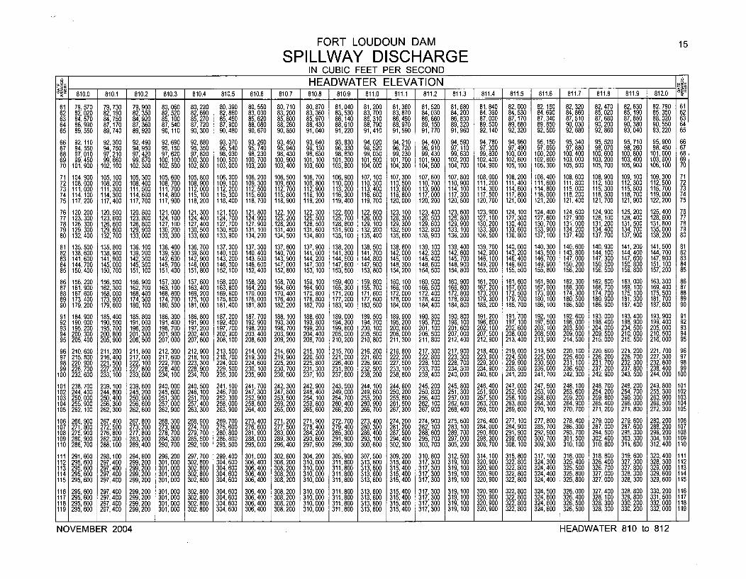
FORT LOUDOUN DAM 15
SPILLWAY DISCHARGEIN CUBIC FEET PER SECOND
J _ HEADWATER ELEVATION __ _
810.0 1 810.1 1 810.2 810.3 810.4 1 810.5 1 810.6 1 810.7 1 810.8 1 810.9 811.0 811.1 811.2 811.3 811.4 811.5 811.6 1 811.7 F 811.8 811.9 6 812.0
61 79, 570 79,730 79,900 80, 060 80, 220 80,390 80, 550 80, 710 80, 870 81,040 81,200 81,360 81,520 81,680 81,840 82,000 82, 160 82, 320 82, 470 82, 630 82, 790 6162 82,020 82,190 82,350 82, 520 82, 690 82,860 83,030 83,200 83,360 83, 530 83,700 83,870 84,030 84,200 84,360 84,530 84,690 84, 860 85,020 85,190 85, 350 6263 84, 570 84,750 84,920 85, 100 85,270 85,450 85,620 85,800 85,970 86,140 86, 310 86,490 86,660 86, 830 87,000 87, 170 87, 340 87,510 87,680 87, 850 88, 020 6364 86, 990 87,170 87,360 87,540 87, 720 87,900 88,080 88, 260 88, 430 88,610 88, 790 88,970 89,150 89, 320 89,500 89, 680 89, 850 90,030 90,200 90, 380 90, 550 6465 89, 550 89,740 89,920 90, 110 90, 300 90,480 90,670 90,850 91,040 91,220 91,410 91,590 91,770 91,960 92,140 92, 320 92,500 92,680 92,860 93,040 93,220 65
66 92, 110 92, 300 92,490 92, 690 92, 880 93,070 93,260 93, 450 93,640 93, 830 94, 020 94, 210 94,400 94,590 94, 780 94, 960 95, 150 95, 340 95, 520 95, 710 95, 900 6667 94, 550 94,750 94,950 95, 150 95,350 95,540 95,740 95, 940 96, 130 96,330 96,520 96,720 96,910 97, 110 97, 300 97,490 97, 690 97,880 98, 070 98,260 98,450 6768 97, 010 97,210 97,420 97, 620 97,820 98,030 98,230 98, 430 98,630 98, 830 99,030 99,230 99,430 99, 630 99, 830 100, 000 100,200 100,400 100, 600 100,800 101,000 6869 99, 450 99,660 99,870 100, 100 100,300 100,500 100,700 100,900 101,100 101,300 101,500 101,700 101,900 102,200 102,400 102, 600 102,800 103,000 103, 200 103, 400 103,600 6970 101,900 102,100 102,300 102,500 102,800 103,000 103,200 103,400 103,600 103,800 104,000 104,300 104,500 104,700 104,900 105,100 105,300 105,500 105, 700 105,900 106,100 70
71 104,900 105,100 105,300 105,600 105,800 106,000 106,200 106,500 106,700 106,900 107,100 107,300 107,600 107,800 108,000 108,200 108,400 108,600 108, 900 109,100 109,300 7172 108,000 108,200 108,400 108,700 108,900 109,100 109,300 109,600 109,800 110,000 110,300 110,500 110,700 110,900 111,200 111,400 111,600 111,800 112, 100 112,300 112,500 7273 111,000 111,300 111,500 111,700 112,000 112,200 112,500 112, 700 112, 900 113,200 113,400 113,600 113,900 114,100 114,300 114,600 114,800 115,000 115,300 115,500 115,700 7374 114,100 114,300 114,600 114,800 115,100 115,300 115,600 115,800 116,100 116,300 116,600 116,800 117,000 117,300 117,500 117,800 118,000 118,200 118,500 118,700 119,000 7475 117,200 117,400 117,700 117,900 118,200 118,400 118,700 118,900 119,200 119,400 119,700 120,000 120,200 120,500 120,700 121,000 121,200 121,400 121,700 121,900 122,200 75
76 120,200 120,500 120,800 121,000 121,300 121,500 121,800 122,100 122, 300 122,600 122,800 123,100 123,400 123,600 123,900 124,100 124,400 124,600 124,900 125, 200 125,400 7677 123,300 123,600 123,800 124, 100 124,400 124,700 124,900 125, 200 125, 500 125,700 126,000 126, 300 126,500 126,800 127, 100 127,300 127,600 127,900 128,100 128. 400 128, 600 7778 126,300 126,600 126,800 127,100 127,400 127,700 127,900 128,200 128,500 128,800 129,100 129,300 129,600 129,900 130,200 130,400 130,700 131,000 131,200 131,500 131,800 7879 129,300 129,600 129,900 130, 200 130,500 130,800 131,100 131,400 131,600 131,900 132,200 132,500 132,800 133,100 133,300 133,600 133,900 134,200 134,400 134,700 135,000 7980 132,400 132,700 133,000 133,300 133,600 133,900 134,200 134,500 134,800 135,100 135,400 135,600 135,900 136,200 136,500 136,800 137,100 137,400 137,700 137,900 138,200 80
81 135,500 135,800 136,100 136,400 136,700 137,000 137,300 137,600 137,900 138,200 138,500 138,800 139,100 139,400 139,700 140,000 140,300 140,600 140,900 141,200 141,500 8182 138,600 138,900 139,200 139,500 139, 800 140,100 140,400 140,700 141,000 141,300 141,700 142,000 142,300 142,600 142,900 143,200 143,500 143, 800 144,100 144,400 144, 700 8283 141,600 141,900 142,300 142,600 142, 900 143,200 143,500 143,900 144,200 144,500 144,800 145,100 145,400 145,700 146,100 146,400 146,700 147,000 147,300 147,600 147,900 8384 144,700 145,000 145,300 145,700 146,000 146,300 146,600 147,000 147, 300 147,600 147,900 148,300 148,600 148,900 149, 200 149,600 149,900 150,200 150,500 150,800 151,100 8485 150,400 150,700 151,100 151,400 151,800 152,100 152,400 152, 800 153,100 153,500 153,800 154,200 154,500 154,800 155,200 155,500 155,800 156,200 156,500 156,800 157,200 85
86 156, 200 156,500 156,900 157, 300 157,600 158,000 158,300 158,700 159,100 159,400 159,800 160,100 160,500 160, 900 161,200 161,600 161,900 162,300 162,600 163,000 163,300 8687 161, 900 162,300 162,700 163,100 163,400 163,800 164,200 164,600 164,900 165,300 165,700 166,100 166,500 166, 800 167,200 167,600 167,900 168,300 168, 700 169, 100 169,400 8788 167,600 168,000 168,400 168,800 169,200 169,600 170,000 170,400 170,800 171,200 171,600 172,000 172,400 172,800 173,200 173,500 173,900 174,300 174, 700 175,100 175,500 8889 173,400 173,900 174,300 174,700 175,100 175,600 176,000 176,400 176,800 177,200 177,600 178,000 178,400 178,800 179,300 179,700 180,100 180,500 180,900 181,300 181,700 8990 179,200 179,600 180,100 180,500 181,000 181,400 181,800 182,200 182,700 183,100 183,500 184,000 184,400 184,800 185,200 185,700 186,100 186,500 186,900 187,400 187,800 90
91 184,900 185,400 185,800 186,300 186,800 187,200 187,700 188,100 188, 600 189,000 189,500 189,900 190,300 190,800 191,200 191,700 192,100 192,600 193,000 193,400 193,900 9192 190,000 190,500 191,000 191,400 191,900 192,400 192,900 193, 300 193, 800 194,300 194,700 195,200 195,700 196,100 196,600 197,100 197,500 198,000 198,400 198, 900 199,400 9293 195, 200 195,700 196,200 196, 700 197,200 197,700 198,200 198, 700 199,200 199,600 200, 100 200,600 201,100 201,600 202,100 202, 600 203, 100 203,500 204, 000 204, 500 205, 000 9394 200, 300 200,800 201, 300 201,900 202,400 202,900 203,400 203, 900 204,400 205,000 205,500 206,000 206,500 207,000 207,500 208, 000 208,500 209,000 209, 500 210, 000 210,500 9495 205,400 205,900 206,500 207,000 207,600 208,100 208,600 209,200 209, 700 210,200 210,800 211,300 211,800 212,400 212,900 213,400 213,900 214,500 215, 000 215, 500 216,000 95
96 210,600 211,200 211,800 212,300 212,900 213,500 214,000 214,600 215,100 215,700 216,200 216,800 217,300 217,900 218,400 219,000 219,500 220,100 220, 600 221,200 221,700 9697 215, 800 216,400 217, 000 217, 600 218, 100 218,700 219,300 219, 900 220, 500 221,000 221,600 222, 200 222,800 223, 300 223, 900 224, 500 225, 000 225, 600 226, 200 226, 700 227, 300 9798 220, 900 221,500 222, 100 222,700 223, 300 224,000 224,600 225, 200 225, 800 226, 400 226, 900 227, 500 228, 100 228,700 229, 300 229, 900 230, 500 231, 100 231,700 232, 300 232, 800 9899 226, 700 227, 200 227, 800 228, 400 228, 900 229, 500 230, 100 230, 700 231,300 231, 900 232, 500 233, 100 233,700 234, 300 234, 900 235, 500 236,000 236, 600 237, 200 237, 800 238, 400 99
100 232, 600 233, 100 233,600 234, 100 234, 700 235,300 235,900 236,500 237, 100 237,600 238,200 238,800 239,400 240,000 240, 600 241, 200 241,700 242,300 242, 900 243, 500 244,000 100
101 238, 700 239, 100 239, 600 240,000 240, 500 241,100 241,700 242, 300 242,900 243, 500 244,100 244, 600 245,200 245, 800 246, 400 247,000 247,500 248, 100 248, 700 249, 200 249, 800 101102 244, 400 244,800 245, 200 245, 600 246, 100 246, 700 247, 300 247, 800 248,400 249,000 249, 600 250, 200 250, 800 251, 300 251,900 252, 500 253, 100 253, 600 254,200 254, 700 255, 300 102103 250,000 250,400 250,900 251,300 251, 700 252,300 252,900 253, 500 254,100 254,700 255,200 255, 800 256,400 257,000 257, 500 258, 100 258, 600 259, 200 259,800 260, 300 260, 900 103104 255, 900 256, 300 256,600 257,000 257, 400 258,000 258,600 259, 200 259, 800 260, 400 260, 900 261, 500 262,100 262, 600 263, 200 263, 800 264,300 264, 900 265,400 266, 000 266, 500 104105 262, 100 262,300 262,600 262,900 263, 300 263,900 264,400 265,000 265, 600 266,200 266,700 267,300 267,900 268,400 269,000 269,600 270, 100 270,700 271,200 271, 800 272,300 105
106 266, 900 267,400 267,800 268, 300 268, 900 269,700 270,400 271,200 271,900 272,700 273,400 274,200 274,900 275,600 276,400 277, 100 277,800 278,400 279, 000 279, 600 280,200 106107 271,800 272,500 273,200 273, 900 274,700 275,600 276, 600 277, 500 278, 400 279,400 280,300 281, 200 282,100 283, 100 284,000 284,900 285,700 286,300 287, 000 287, 600 288, 200 107108 275,900 276,800 277,800 278, 700 279, 700 280,800 281, 900 283,000 284, 200 285,300 286,400 287, 500 288,600 289,700 290,800 291,900 292,900 293,700 294, 500 295, 300 296, 200 108109 280, 900 282,000 283, 200 284, 300 285, 500 286, 800 288,000 289, 300 290, 600 291,900 293, 100 294,400 295, 700 297,000 298, 300 299, 600 300, 700 301,500 302, 400 303, 300 304,100 109110 286, 700 288,100 289,400 290, 700 292, 100 293,500 295,000 296,400 297, 900 299,300 300,800 302, 300 303,700 305,200 306,700 308, 100 309,300 310, 100 310, 800 311, 600 312,400 110
111 291,600 293, 100 294,600 296,200 297,700 299,400 301,000 302,600 304,200 305, 900 307,500 309,200 310, 800 312, 500 314, 100 315,800 317,100 318,000 318,800 319,600 320,400 111112 295,600 297,400 299,200 301,000 302,800 304,600 306,400 308,200 310,000 311,800 313,600 315,400 317,300 319,100 320,900 322,800 324,300 325,400 326,400 327,300 328,300 112113 295, 600 297,400 299,200 301,000 302, 800 304,600 306,400 308, 200 310, 000 311,800 313,600 315,400 317, 300 319,100 320,900 322,800 324,400 325,500 326, 700 327, 800 329,000 113114 295, 600 297,400 299,200 301,000 302,800 304,600 306,400 308, 200 310,000 311,800 313, 600 315,400 317, 300 319,100 320,900 322,800 324,400 325,800 327,000 328, 300 329,600 114115 295, 600 297,400 299,200 301,000 302,800 304,600 306,400 308, 200 310,000 311,800 313, 600 315, 400 317, 300 319, 100 320, 900 322, 800 324,400 325, 800 327,000 328, 300 329,600 115
116 295, 600 297,400 299,200 301,000 302,800 304,600 306,400 308,200 310,000 311,800 313,600 315,400 317, 300 319,100 320,900 322,800 324,500 326,000 327, 400 328,800 330,200 116117 295, 600 297,400 299,200 301,000 302,800 304,600 306,400 308,200 310,000 311,800 313,600 315,400 317, 300 319,100 320,900 322,800 324,600 326,400 328,100 329,800 331,500 117118 295, 600 297,400 299,200 301,000 302,800 304,600 306,400 308,200 310,000 311,800 313,600 315,400 317,300 319,100 320,900 322,800 324,600 326,500 328, 300 330,200 332,000 118119 295, 600 297,400 299,200 301,000 302,800 304,600 306,400 308,200 310,000 311,800 313, 600 315,400 317, 300 319,100 320, 900 322,800 324,600 326,500 328,300 330, 200 332,000 119
NOVEMBER 2004 HEADWATER 810 to 812
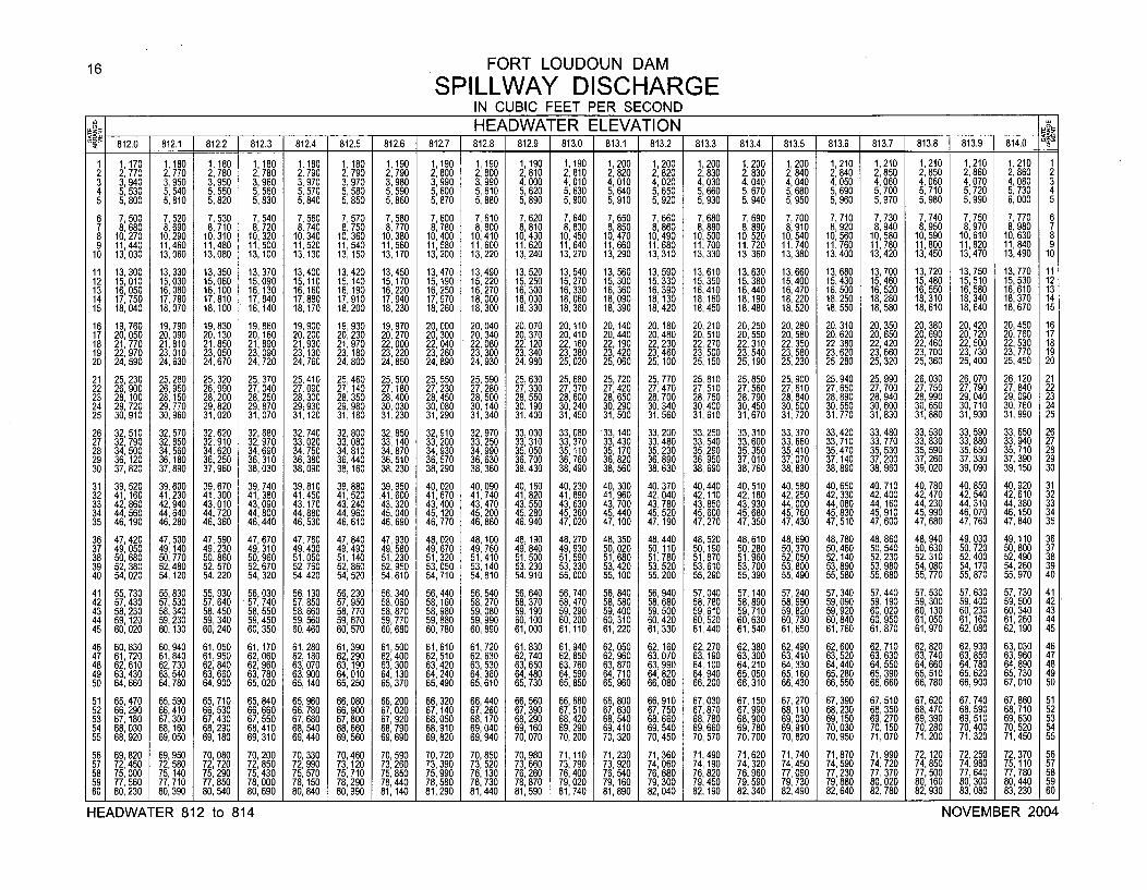
16 FORT LOUDOUN DAM
SPILLWAY DISCHARGEIN CUBIC FEET PER SECOND
1 1 1 1__ HEADWATER ELEVATIONf 812.0 812.1 812.2 812.3 812.4 812.5 812.6 812.7 812.8 812.9 813.0 813.1 813.2 813.3 813.4 813.5 [ 813.6 813.7 813.8 813.9 814.0
1 1,170 1,180 1,180 1,180 1,180 1,180 1,190 1,190 1,190 1,190 1,190 1,200 1,200 1,200 1,200 1,200 1,210 1,210 1,210 1,210 1,210 12 2, 770 2,770 2,780 2, 780 2, 790 2, 790 2, 790 2, 800 2,800 2, 810 2, 810 2,820 2,820 2,830 2, 830 2,840 2, 840 2,850 2, 850 2, 860 2, 860 23 3, 940 3,950 3,950 3,960 3,970 3,970 3,980 3,990 3,990 4,000 4,010 4,010 4,020 4,030 4,040 4,040 4,050 4,060 4,060 4,070 4,080 34 5,530 5,540 5,550 5,560 5,570 5,580 5,590 5 600 5 610 5,620 5,630 5, 640 5,650 5,660 5,670 5,680 5,690 5,700 5,710 5,720 5,730 45 5,800 5,810 5,820 5,830 5,840 5,850 5,860 5,870 5,880 5,890 5,900 5,910 5,920 5,930 5,940 5,950 5,960 5,970 5,980 5,990 6,000 5
6 7, 500 7,520 7,530 7, 540 7,560 7,570 7,580 7,600 7, 610 7,620 7,640 7, 650 7,660 7,680 7, 690 7,700 7,710 7,730 7,740 7,750 7,770 67 8,680 8,690 8,710 8,720 8,740 8,750 8 770 8,780 8,800 8,810 8,830 8,850 8,860 8,880 8,890 8,910 8,920 8,940 8,950 8,970 8,980 78 10, 270 10,290 10,310 10,320 10,340 10,360 10,380 10,400 10,410 10,430 10,450 10,470 10,490 10,500 10,520 10,540 10, 560 10, 580 10, 590 10,610 10,630 89 11,440 11,460 11,480 11,500 11,520 11,540 11,560 11,580 11,600 11,620 11,640 11,660 11,680 11,700 11,720 11,740 11,760 11,780 11,800 11,820 11,840 910 13,030 13,060 13,080 13,100 13,130 13,150 13,170 13,200 13,220 13,240 13,270 13,290 13,310 13,330 13,360 13,380 13,400 13,420 13,450 13,470 13,490 10
11 13,300 13,330 13,350 13,370 13,400 13,420 13,450 13,470 13,490 13,520 13,540 13,560 13,590 13,610 13,630 13,660 13,680 13,700 13,720 13,750 13,770 1112 15,010 15,030 15,060 15,090 15,110 15,140 15,170 15,190 15,220 15,250 15,270 15,300 15,330 15,350 15,380 15,400 15,430 15,460 15,480 15,510 15,530 1213 16,050 16,080 16,100 16,130 16,160 16,190 16,220 16,250 16,270 16,300 16,330 16,360 16,390 16,410 16,440 16,470 16,500 16,520 16, 550 16,580 16,610 1314 17, 750 17,780 17,810 17,840 17,880 17,910 17,940 17,970 18,000 18,030 18,060 18,090 18,130 18,160 18,190 18,220 18,250 18,280 18,310 18,340 18,370 1415 18,040 18,070 18,100 18,140 18,170 18,200 18,230 18,260 18,300 18,330 18,360 18,390 18,420 18,450 18,480 18,520 18,550 18,580 18,610 18,640 18,670 15
16 19, 760 19,790 19,830 19, 860 19,900 19,930 19,970 20,000 20,040 20,070 20,110 20, 140 20,180 20,210 20,250 20, 280 20,310 20,350 20,380 20,420 20, 450 1617 20, 050 20, 090 20, 130 20, 160 20,200 20,230 20, 270 20, 300 20,340 20, 370 20, 410 20,440 20,480 20, 510 20,550 20, 580 20,620 20,650 20,690 20,720 20, 760 1718 21,770 21,810 21,850 21,890 21,930 21,970 22,000 22,040 22,080 22,120 22, 160 22, 190 22,230 22,270 22,310 22, 350 22,380 22,420 22,460 22,500 22,530 1819 22, 970 23,010 23,050 23, 090 23,130 23,180 23,220 23,260 23, 300 23,340 23,380 23,420 23,460 23, 500 23,540 23, 580 23,620 23, 660 23, 700 23,730 23,770 1920 24, 590 24,630 24,670 24, 720 24,760 24,800 24,850 24,890 24,930 24,980 25,020 25,060 25,100 25, 150 25,190 25,230 25,280 25, 320 25, 360 25,400 25,450 20
21 25, 230 25,280 25,320 25, 370 25,410 25,460 25,500 25,550 25,590 25,630 25,680 25,720 25,770 25, 810 25,850 25, 900 25,940 25,990 26,030 26,070 26, 120 2122 26, 900 26,950 26,990 27, 040 27,090 27, 140 27, 180 27,230 27,280 27,330 27,370 27, 420 27,470 27,510 27,560 27, 610 27,650 27, 700 27, 750 27,790 27,840 2223 28, 100 28,150 28,200 28,250 28,300 28, 350 28,400 28,450 28,500 28,550 28,600 28, 650 28,700 28, 750 28,790 28, 840 28,890 28,940 28, 990 29,040 29, 090 2324 29, 720 29,770 29,820 29, 870 29,930 29, 980 30,030 30,080 30, 140 30, 190 30,240 30, 290 30,340 30,400 30, 450 30,500 30,550 30, 600 30, 650 30,710 30,760 2425 30, 910 30,960 31,020 31,070 31,120 31,180 31,230 31,290 31,340 31,400 31,450 31,500 31,560 31,610 31,670 31,720 31,770 31,830 31,880 31,930 31,990 25
26 32, 510 32,570 32,620 32,680 32,740 32, 800 32, 850 32,910 32, 970 33,030 33,080 33, 140 33, 200 33,250 33,310 33, 370 33,420 33,480 33,530 33, 590 33, 650 2627 32, 790 32,850 32, 910 32,970 33, 020 33, 080 33, 140 33,200 33, 250 33, 310 33, 370 33, 430 33, 480 33, 540 33, 600 33, 660 33, 710 33,770 33, 830 33, 880 33, 940 2728 34, 500 34,560 34,620 34,690 34,750 34,810 34,870 34,930 34,990 35, 050 35,110 35, 170 35,230 35,290 35, 350 35,410 35,470 35,530 35,590 35, 650 35, 710 2829 36, 120 36,180 36,250 36, 310 36,380 36,440 36,510 36,570 36,630 36, 700 36,760 36,820 36,890 36, 950 37, 010 37, 070 37,140 37,200 37,260 37, 330 37, 390 2930 37, 820 37,890 37,960 38,030 38,090 38, 160 38,230 38,290 38,360 38,430 38,490 38,560 38,630 38,690 38,760 38, 830 38,890 38,960 39, 020 39,090 39,150 30
31 39, 520 39,600 39, 670 39, 740 39,810 39,880 39,950 40,020 40,090 40,160 40,230 40, 300 40,370 40,440 40,510 40, 580 40,650 40,710 40, 780 40,850 40,920 3132 41,160 41,230 41,300 41,380 41,450 41,520 41,600 41,670 41,740 41,820 41,890 41,960 42,040 42,110 42,180 42,250 42,330 42,400 42,470 42,540 42,610 3233 42, 860 42,940 43,010 43,090 43,170 43,240 43,320 43, 400 43, 470 43,550 43,630 43,700 43,780 43,850 43,930 44, 000 44,080 44,160 44, 230 44,310 44,380 3334 44,560 44,640 44,720 44,800 44,880 44,960 45,040 45,120 45, 200 45,280 45,360 45,440 45,520 45,600 45,680 45,760 45,830 45, 910 45,990 46,070 46,150 3435 46,190 46,280 46, 360 46,440 46,530 46,610 46,690 46,770 46,860 46,940 47,020 47, 100 47,190 47,270 47,350 47,430 47,510 47, 600 47,680 47,760 47,840 35
36 47, 420 47, 500 47, 590 47, 670 47, 760 47, 840 47, 930 48,020 48, 100 48,190 48, 270 48, 350 48,440 48,520 48,610 48, 690 48, 780 48,860 48,940 49, 030 49,110 3637 49, 050 49, 140 49, 230 49, 310 49,400 49, 490 49, 580 49,670 49,760 49,840 49, 930 50, 020 50,110 50,190 50,280 50,370 50, 460 50,540 50,630 50,720 50,800 3738 50,680 50,770 50, 860 50,960 51,050 51,140 51,230 51,320 51,410 51,500 51,590 51,680 51,780 51,870 51,960 52,050 52,140 52,230 52,310 52,400 52,490 3839 52, 380 52,480 52, 570 52, 670 52,760 52,860 52, 950 53,050 53, 140 53,230 53, 330 53, 420 53,520 53,610 53,700 53, 800 53,890 53,980 54,080 54,170 54,260 3940 54, 020 54,120 54, 220 54, 320 54,420 54,520 54,610 54,710 54,810 54,910 55, 000 55, 100 55,200 55,290 55,390 55,490 55,580 55,680 55,770 55,870 55, 970 40
41 55, 730 55, 830 55, 930 56, 030 56, 130 56,230 56, 340 56, 440 56,540 56, 640 56, 740 56, 840 56, 940 57,040 57, 140 57, 240 57, 340 57, 440 57,530 57, 630 57, 730 4142 57, 430 57, 530 57, 640 57, 740 57, 850 57,950 58,060 58,160 58, 270 58,370 58,470 58, 580 58, 680 58,780 58,890 58, 990 59, 090 59,190 59,300 59, 400 59, 500 4243 58, 230 58,340 58,450 58, 550 58,660 58,770 58,870 58,980 59, 080 59,190 59,290 59, 400 59,500 59,610 59,710 59, 820 59, 920 60,020 60, 130 60, 230 60, 340 4344 59, 120 59,230 59, 340 59, 450 59, 560 59,670 59,770 59, 880 59, 990 60,100 60,200 60, 310 60,420 60,520 60,630 60, 730 60, 840 60,950 61, 050 61, 160 61, 260 4445 60,020 60,130 60,240 60, 350 60, 460 60,570 60,680 60, 780 60, 890 61,000 61, 110 61,220 61,330 61,440 61,540 61,650 61,760 61,870 61,970 62,080 62,190 45
46 60,830 60,940 61,050 61,170 61,280 61,390 61,500 61,610 61,720 61,830 61,940 62, 050 62,160 62,270 62,380 62, 490 62,600 62,710 62, 820 62,930 63,030 4647 61,720 61,840 61,950 62, 060 62,180 62,290 62, 400 62, 510 62, 630 62,740 62, 850 62, 960 63,070 63,190 63,300 63, 410 63,520 63,630 63, 740 63,850 63, 960 4748 62,610 62,730 62,840 62, 960 63,070 63, 190 63, 300 63,420 63, 530 63,650 63, 760 63, 870 63,990 64, 100 64,210 64,330 64,440 64,550 64, 660 64,780 64, 890 4849 63,430 63,540 63,660 63,780 63,900 64,010 64, 130 64,240 64,360 84,480 64,590 64, 710 6 4820 84,940 65,050 65,160 65,280 65,390 65 510 65,620 65, 730 4950 64,660 84,780 64,900 65,020 65,140 65,250 65,370 65,490 65,610 65,730 65,850 65, 960 66, 080 66,200 66,310 66,430 66,550 66,660 66, 780 66,900 67,010 50
51 65,470 65,590 65,710 65,840 65,960 66,080 66,200 66, 320 66,440 66,560 66, 680 66, 800 66,910 67, 030 67,150 67, 270 67,390 67,510 67,620 67,740 67,860 5152 66,290 66,410 66,530 66,660 66,780 66,900 67, 020 67,140 67,260 67,390 67, 510 67, 630 67,750 67, 870 67, 990 68,110 68,230 68,350 68,470 68,590 68,710 5253 67, 180 67,300 67,430 67, 550 67, 680 67, 800 67, 920 68, 050 68, 170 68,290 68, 420 68,540 68, 660 68, 780 68, 900 69, 030 69, 150 69, 270 69, 390 69, 510 69, 630 5354 68, 030 68,160 68, 290 68, 410 68,540 68, 660 68, 790 68,910 69, 040 69,160 69, 290 69, 410 69, 540 69, 660 69, 780 69, 910 70, 030 70,150 70, 280 70,400 70, 520 5455 68, 920 69,050 69,180 69, 310 69,440 69,560 69, 690 69,820 69, 940 70,070 70, 200 70, 320 70,450 70, 570 70,700 70, 820 70, 950 71,070 71,200 71,320 71, 450 55
56 69, 820 69,950 70,080 70,200 70,330 70,460 70, 590 70,720 70,850 70,980 71,110 71, 230 71,360 71,490 71,620 71,740 71,870 71,990 72, 120 72,250 72,370 5657 72,450 72,580 72, 720 72, 850 72,990 73,120 73,260 73,390 73, 520 73,660 73, 790 73, 920 74, 060 74,190 74,320 74,450 74,590 74,720 74, 850 74,980 75, 110 5758 75, 000 75, 140 75,290 75, 430 75,570 75,710 75, 850 75,990 76, 130 76,260 76, 400 76, 540 76, 680 76,820 76,960 77,090 77,230 77,370 77,500 77,640 77, 780 5859 77, 560 77,710 77,850 78, 000 78,150 78,290 78, 440 78, 580 78,730 78,870 79,020 79,160 79, 300 79, 450 79, 590 79, 730 79, 880 80,020 80,160 80,300 80,440 5960 80, 230 80,390 80,540 80, 690 80,840 80,990 81,140 81,290 81,440 81,590 81,740 81,890 82, 040 82, 190 82, 340 82,490 82, 640 82,780 82, 930 83,080 83,230 60
HEADWATER 812 to 814 NOVEMBER 2004
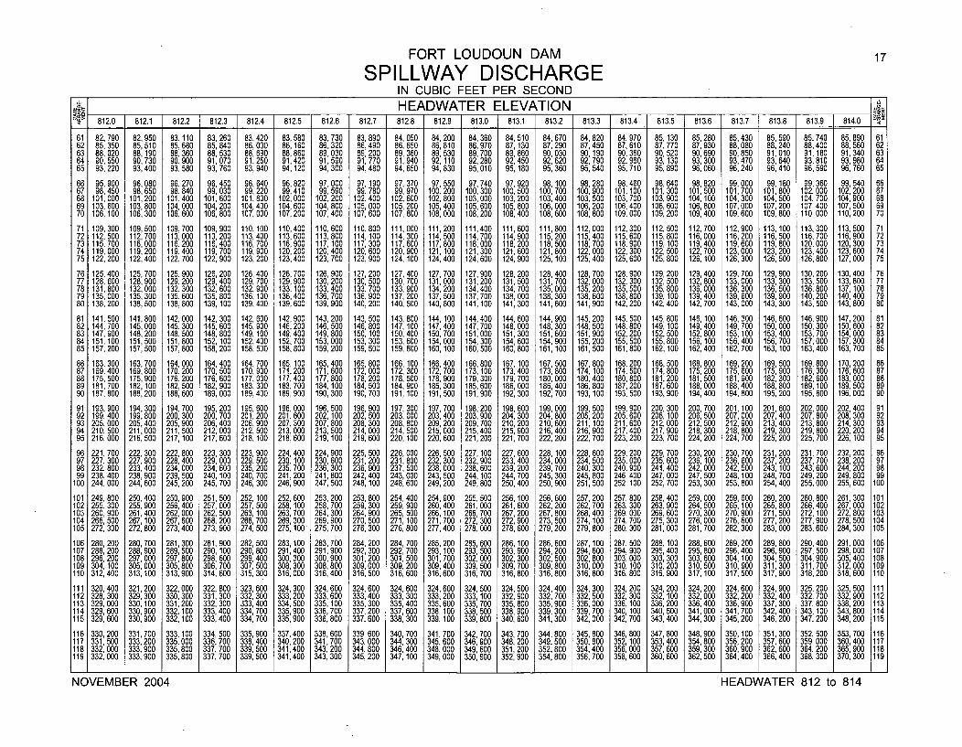
FORT LOUDOUN DAM 17
SPILLWAY DISCHARGEIN CUBIC FEET PER SECOND
_ __ _ _ _ _ HEADWATER ELEVATION '_812.0 812.1 812.2 1 812.3 812.4 812.5 812.6 812.7 812.8 812.9 813.0 813.1 1 813.2 813.3 813.4 813.5 1 813.6 813813 .13.8 813.9 814.0
61 82, 790 82,950 83,110 83, 260 83, 420 83,580 83,730 83,890 84, 050 84,200 84,360 84,510 84,670 84,820 84, 970 85,130 85, 280 85,430 85, 590 85,740 85, 890 6162 85, 350 85,510 85, 680 85,840 86, 000 86,160 86, 320 86, 490 86, 650 86,810 86, 970 87, 130 87, 290 87, 450 87, 610 87, 770 87, 930 88, 080 88, 240 88, 400 88, 560 6263 88, 020 88,190 88,360 88,530 88, 690 88,860 89,030 89,200 89, 360 89,530 89,700 89,860 90,030 90, 190 90,360 90,520 90,690 90,850 91, 010 91,180 91,340 6364 90, 550 90,730 90,900 91,070 91,250 91,420 91,590 91,770 91,940 92,110 92,280 92,450 92,620 92, 790 92,960 93, 130 93,300 93,470 93,640 93, 810 93, 980 6465 93, 220 93,400 93, 580 93, 760 93,940 94,120 94,300 94, 480 94, 650 94, 830 95, 010 95, 180 95,360 95, 540 95, 710 95, 890 96,060 96,240 96, 410 96, 590 96, 760 65
66 95, 900 96,080 96,270 96,450 96, 640 96,820 97,000 97, 190 97, 370 97,550 97,740 97,920 98,100 98, 280 98, 460 98, 640 98,820 99,000 99,180 99,360 99, 540 6667 98,450 98,650 98,840 99,030 99, 220 99,410 99,590 99,780 99,970 100,200 100,300 100,500 100,700 100,900 101,100 101,300 101,500 101,700 101,800 102,000 102,200 6768 101,000 101,200 101,400 101,600 101,800 102,000 102,200 102,400 102,600 102,800 103,000 103,200 103,400 103,500 103,700 103,900 104,100 104,300 104,500 104,700 104,900 6869 103, 600 103,800 104,000 104,200 104,400 104,600 104,800 105,000 105,200 105,400 105,600 105,800 106,000 106,200 106,400 106,600 106,800 107,000 107,200 107,400 107,500 6970 106,100 106,300 106,600 106,800 107,000 107,200 107,400 107,600 107,800 108,000 108,200 108,400 108,600 108,800 109,000 109,200 109,400 109,600 109,800 110,000 110,200 70
71 109,300 109,500 109,700 109,900 110,100 110,400 110,600 110,800 111,000 111,200 111,400 111,600 111,800 112,000 112,300 112,500 112,700 112,900 113,100 113,300 113,500 7172 112, 500 112,700 113,000 113, 200 113,400 113,600 113,800 114,100 114,300 114,500 114,700 114,900 115,200 115,400 115,600 115,800 116,000 116,200 116,500 116,700 116,900 7273 115, 700 116,000 116,200 116, 400 116,700 116,900 117,100 117,300 117,600 117,800 118,000 118,200 118,500 118,700 118,900 119,100 119,400 119,600 119, 800 120,000 120,300 7374 119,000 119,200 119,400 119,700 119,900 120,200 120,400 120,600 120,900 121,100 121,300 121,600 121,800 122,000 122,300 122, 500 122,700 123,000 123, 200 123,400 123,600 7475 122, 200 122,400 122,700 122, 900 123, 200 123,400 123,700 123,900 124, 100 124,400 124,600 124,900 125, 100 125,400 125,600 125,800 126,100 126, 300 126, 500 126,800 127,000 75
76 125,400 125,700 125,900 126,200 126,400 126,700 126,900 127,200 127,400 127,700 127,900 128,200 128,400 128,700 128,900 129,200 129,400 129,700 129, 900 130,200 130,400 7677 128, 600 128,900 129,200 129, 400 129,700 129,900 130,200 130,500 130,700 131,000 131,200 131,500 131,700 132,000 132,300 132,500 132,800 133,000 133, 300 133,500 133,800 7778 131,800 132,000 132,300 132, 600 132,900 133,100 133,400 133,700 133, 900 134,200 134,400 134,700 135,000 135,200 135,500 135,800 136,000 136,300 136, 500 136,800 137,100 7879 135,000 135,300 135,600 135, 800 136,100 136,400 136,700 136,900 137, 200 137,500 137,700 138,000 138,300 138,600 138,800 139,100 139,400 139,600 139, 900 140,200 140,400 7980 138, 200 138,500 138,800 139, 100 139, 400 139,600 139,900 140,200 140, 500 140, 800 141,100 141,300 141,600 141,900 142, 200 142,400 142,700 143,000 143, 300 143, 500 143,800 80
81 141,500 141,800 142,000 142,300 142, 600 142,900 143,200 143,500 143,800 144,100 144,400 144,600 144,900 145,200 145,500 145,800 146,100 146,300 146,600 146,900 147,200 8182 144, 700 145,000 145,300 145, 600 145, 900 146,200 146,500 146, 800 147, 100 147,400 147,700 148,000 148, 300 148,500 148, 800 149,100 149,400 149, 700 150, 000 150,300 150,600 8283 147, 900 148,200 148,500 148, 800 149,100 149,400 149, 800 150,100 150,400 150,700 151,000 151,300 151,600 151,900 152, 200 152, 500 152,800 153, 100 153, 400 153,700 154,000 8384 151,100 151,500 151,800 152,100 152,400 152,700 153,000 153,300 153,600 154,000 154, 300 154,600 154,900 155,200 155, 500 155,800 156, 100 156, 400 156, 700 157,000 157,300 8485 157,200 157,500 157,800 158,200 158,500 158,800 159,200 159,500 159,800 160,100 160,500 160,800 161,100 161,500 161,800 162,100 162,400 162,700 163,100 163,400 163,700 85
86 163, 300 163,700 164,000 164, 400 164, 700 165,100 165,400 165, 800 166, 100 166,400 166,800 167, 100 167, 500 167,800 168, 200 168,500 168,800 169, 200 169,500 169,800 170, 200 8687 169,400 169,800 170,200 170, 500 170,900 171,200 171,600 172,000 172,300 172,700 173,100 173,400 173,800 174,100 174,500 174,800 175,200 175, 600 175,900 176,300 176,600 8788 175, 500 175,900 176,200 176, 600 177,000 177,400 177,800 178,200 178,500 178,900 179,300 179,700 180,000 180,400 180,800 181,200 181,500 181,900 182,300 182,600 183,000 8889 181,700 182,100 182,500 182, 900 183,300 183,700 184,100 184,500 184,900 185,300 185,600 186,000 186,400 186,800 187,200 187,600 188,000 188,400 188, 800 189,100 189,500 8990 187, 800 188,200 188,600 189,000 189,400 189,900 190,300 190,700 191,100 191,500 191,900 192,300 192,700 193,100 193,500 193,900 194,400 194,800 195,200 195,600 196,000 90
91 193, 900 194,300 194,700 195, 200 195,600 196, 000 196,500 196, 900 197, 300 197, 700 198,200 198,600 199,000 199,500 199, 900 200, 300 200,700 201, 100 201, 600 202,000 202,400 9192 199, 400 199,800 200,300 200, 700 201,200 201, 600 202,100 202, 500 203,000 203,400 203,900 204,300 204,800 205,200 205, 600 206, 100 206,500 207,000 207,400 207,800 208,300 9293 205,000 205,400 205,900 206,400 206,900 207,300 207,800 208, 300 208, 800 209,200 209,700 210,200 210,600 211,100 211,600 212,000 212,500 212,900 213,400 213,800 214,300 9394 210, 500 211,000 211,500 212,000 212,500 213,000 213,500 214,000 214,500 215,000 215,400 215,900 216,400 216,900 217,400 217,900 218,300 218,800 219,300 219,800 220,200 9495 216, 000 216,500 217,100 217, 600 218, 100 218,600 219, 100 219, 600 220,100 220,600 221,200 221,700 222,200 222,700 223, 200 223, 700 224,200 224,700 225, 200 225, 700 226,100 95
96 221,700 222, 300 222,800 223, 300 223, 900 224,400 224,900 225, 500 226,000 226, 500 227,100 227, 600 228,100 228, 600 229, 200 229, 700 230, 200 230, 700 231,200 231,700 232, 200 9697 227, 300 227,900 228, 400 229,000 229,500 230,100 230,600 231,200 231,800 232,300 232,900 233,400 234,000 234, 500 235,000 235,600 236,100 236, 600 237,200 237, 700 238,200 9798 232, 800 233, 400 234,000 234, 600 235, 200 235, 700 236,300 236, 900 237, 500 238,000 238, 600 239, 200 239,700 240, 300 240, 900 241,400 242,000 242, 500 243, 100 243,600 244,200 9899 238, 400 238,900 239,500 240,100 240, 700 241,200 241,800 242,400 243,000 243,500 244,100 244,700 245,300 245,800 246,400 247,000 247, 500 248, 100 248, 700 249,200 249,800 99
100 244,000 244,600 245,200 245, 700 246, 300 246,900 247,500 248,100 248,600 249,200 249,800 250,400 250,900 251,500 252, 100 252, 700 253, 300 253,800 254, 400 255,000 255,600 100
101 249, 800 250,400 250, 900 251,500 252, 100 252,600 253, 200 253, 800 254, 400 254,900 255, 500 256, 100 256, 600 257, 200 257, 800 258, 400 259,000 259, 600 260, 200 260,800 261,300 101102 255, 300 255,900 256,400 257,000 257, 500 258,100 258,700 259,300 259, 900 260,400 261,000 261,600 262, 200 262, 700 263, 300 263,900 264,500 265, 100 265, 800 266,400 267,000 102103 260, 900 261,400 262,000 262, 500 263, 100 263,700 264,300 264, 900 265, 500 266, 100 266,700 267, 200 267, 800 268,400 269,000 269,600 270,300 270, 900 271,500 272, 100 272,800 103104 266, 500 267,100 267,600 268, 200 268, 700 269,300 269,900 270, 500 271,100 271,700 272,300 272, 900 273, 500 274, 100 274, 700 275,300 276,000 276, 600 277, 200 277, 900 278,500 104105 272, 300 272,800 273,400 273, 900 274, 500 275, 100 275, 700 276, 300 276, 800 277, 400 278,000 278, 600 279, 200 279, 800 280, 300 281,000 281,700 282, 300 283,000 283, 600 284,300 105
106 280, 200 280,700 281,300 281,900 282, 500 283, 100 283,700 284,200 284, 700 285,200 285,600 286, 100 286, 600 287, 100 287, 500 288, 100 288,600 289,200 289, 800 290,400 291,000 106107 288, 200 288,900 289,500 290, 100 290, 800 291,400 291,900 292, 300 292, 700 293, 100 293, 500 293, 900 294, 200 294, 600 294, 900 295, 400 295, 800 296, 400 296, 900 297, 500 298,000 107108 296, 200 297,000 297,800 298, 600 299,400 300,300 300,900 301,200 301,500 301,700 302,000 302, 300 302, 500 302, 800 303,000 303,300 303,600 304,100 304, 500 304,900 305,400 108109 304, 100 305,000 305,800 306, 700 307, 500 308,300 308,800 309, 000 309, 200 309,400 309,500 309, 700 309,800 310,000 310, 100 310,200 310,500 310, 900 311,300 311,700 312,000 109110 312,400 313,100 313,900 314,600 315,300 316,000 316,400 316,500 316,600 316,600 316,700 316,800 316,800 316,800 316,800 316,900 317,100 317,500 317,900 318,200 318,600 110
111 320, 400 321,200 322,000 322, 800 323,600 324,300 324,600 324,600 324,600 324,600 324,500 324,500 324,400 324,300 324,200 324,200 324,200 324,600 324, 900 325,200 325,500 111112 328, 300 329,300 330,300 331,300 332, 300 333,200 333,600 333,400 333,300 333,200 333,100 332,900 332,700 332,500 332,300 332,100 332,000 332, 200 332,400 332, 700 332,900 112113 329,000 330,100 331,200 332,300 333,400 334,500 335,100 335,300 335, 400 335,600 335, 700 335,800 335,900 336,000 336, 100 336,200 336,400 336,900 337, 300 337, 800 338, 200 113114 329, 600 330, 900 332,100 333, 400 334, 700 335,900 336, 700 337,200 337, 600 338, 100 338, 500 338, 900 339,300 339, 700 340, 100 340, 500 341,000 341,700 342,400 343, 100 343, 800 114115 329, 600 330, 900 332,100 333, 400 334, 700 335,900 336, 800 337, 600 338, 300 339, 100 339, 800 340, 600 341,300 342,000 342, 700 343,400 344,300 345,200 346,200 347,200 348,200 115
116 330,200 331,700 333,100 334,500 335, 900 337,400 338,600 339,600 340,700 341,700 342,700 343,700 344,800 345,800 346, 800 347,800 348,900 350, 100 351,300 352, 500 353,700 116117 331,500 333, 200 335,000 336, 700 338,400 340, 200 341,700 343,000 344,300 345, 600 346, 900 348, 200 349, 500 350,800 352, 100 353, 400 354,800 356, 200 357, 600 359, 000 360, 400 117118 332,000 333,900 335,800 337, 700 339, 500 341,400 343, 200 344,800 346,400 348,000 349, 600 351,200 352, 800 354,400 356, 000 357, 600 359, 300 360,900 362, 600 364, 200 365,900 118119 332,000 333,900 335,800 337, 700 339, 500 341,400 343, 300 345,200 347,100 349,000 350, 900 352, 900 354, 800 356, 700 358, 600 360, 600 362, 500 364,400 366, 400 368, 300 370, 300 119
NOVEMBER 2004 HEADWATER 812 to 814
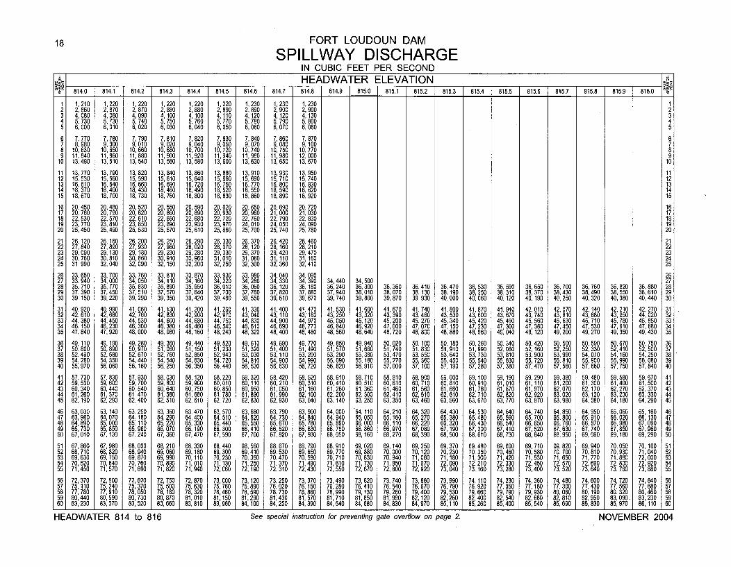
18 FORT LOUDOUN DAM
SPILLWAY DISCHARGEIN CUBIC FEET PER SECOND
___• _HEADWATER ELEVATION814.0 1 814.1 814.2 814.3 814.4 814.5 814.6 814.7 814.8 814.9 815.0 815.1 815.2 815.3 815.4 815.5 815.6 815.7 815.8 815.9 816.0
1 1,210 1,220 1,220 1,220 1,220 1,220 1,230 1,230 1,230 12 2,860 2,870 2,870 2, 880 2,880 2,890 2,890 2,900 2,900 23 4,080 4,080 4,090 4,100 4,100 4,110 4,120 4,120 4, 130 34 5, 730 5,730 5, 740 5, 750 5, 760 5,770 5,780 5,790 5,800 45 6,000 6,010 6,020 6,030 6,040 6,050 6,060 6,070 6,080 5
6 7, 770 7,780 7,790 7, 810 7,820 7,830 7,840 7,860 7,870 67 8, 980 9,000 9,010 9, 020 9,040 9,050 9,070 9, 080 9,100 78 10,630 10,650 10,660 10,680 10,700 10,720 10,740 10,750 10, 770 89 11,840 11,860 11,880 11,900 11,920 11,940 11,960 11,980 12,000 9
10 13,490 13,510 13,540 13,560 13,580 13,600 13,630 13,650 13,670 10
11 13,770 13,790 13,820 13,840 13,860 13,880 13,910 13,930 13,950 1112 15,530 15,560 15,590 15,610 15,640 15,660 15,690 15,710 15,740 1213 16,610 16,640 16,660 16,690 16,720 16,750 16,770 16,800 16,830 1314 18, 370 18,400 18,430 18,460 18,490 18,520 18,550 18,590 18, 620 1415 18,670 18,700 18,730 18,760 18,800 18,830 18,860 18,890 18,920 15
16 20,450 20,480 20,520 20, 550 20, 590 20,620 20,650 20, 690 20, 720 1617 20,760 20,790 20,820 20, 860 20, 890 20,930 20,960 21,000 21,030 1718 22, 530 22,570 22,610 22, 650 22, 680 22,720 22,760 22,790 22,830 1819 23, 770 23, 810 23,850 23, 890 23, 930 23,970 24,010 24, 050 24, 090 1920 25, 450 25, 490 25,530 25, 570 25,610 25,660 25, 700 25, 740 25, 780 20
21 26, 120 26, 160 26,200 26,250 26,290 26,330 26,370 26,420 26,460 2122 27, 840 27,890 27,930 27, 980 28, 020 28,070 28,120 28,160 28, 210 2223 29, 090 29,130 29,180 29, 230 29, 280 29,330 29,370 29,420 29,470 2324 30,760 30,810 30,860 30,910 30,960 31,010 31,060 31,110 31,160 2425 31, 990 32,040 32,090 32, 150 32,200 32,250 32, 300 32, 360 32,410 25
26 33, 650 33,700 33,760 33,810 33,870 33,930 33,980 34,040 34,090 2627 33, 940 34,000 34,050 34,110 34, 160 34,220 34,280 34,330 34, 390 34,440 34, 500 2728 35, 710 35,770 35,830 35,890 35,950 36,010 36, 060 36,120 36,180 36,240 36,300 36,360 36,410 36,470 36, 530 36,590 36,650 36,700 36,760 36, 820 36,880 2829 37, 390 37, 450 37, 510 37, 570 37,640 37,700 37,760 37,820 37, 880 37,940 38, 010 38, 070 38,130 38,190 38, 250 38, 310 38, 370 38, 430 38, 490 38, 550 38,610 2930 39, 150 39,220 39,290 39,350 39, 420 39,480 39,550 39,610 39,670 39,740 39,800 39, 870 39,930 40,000 40,060 40,120 40,190 40,250 40, 320 40,380 40,440 30
31 40,920 40,990 41,060 41,130 41,200 41,260 41,330 41,400 41,470 41,530 41,600 41,670 41,740 41,800 41,870 41,940 42,010 42, 070 42,140 42,210 42,270 3132 42, 610 42,680 42,760 42,830 42, 900 42,970 43,040 43,110 43,180 43, 250 43,320 43,390 43,460 43,530 43,600 43 670 43, 740 43, 810 43,880 43,950 44, 020 3233 44,380 44,450 44,530 44,600 44,680 44,750 44,830 44, 900 44,970 45,050 45,120 45,200 45,270 45,340 45,420 45,490 45,560 45, 630 45, 710 45,780 45,850 3334 46,150 46,230 46,300 46, 380 46,460 46,540 46, 610 46,690 46,770 46, 840 46,920 47,000 47,070 47,150 47,230 47,300 47,380 47, 450 47, 530 47,610 47, 680 3435 47, 840 47,920 48,000 48, 080 48, 160 48, 240 48,320 48, 400 48,480 48, 560 48,640 48, 720 48,800 48,880 48, 960 49,040 49, 120 49, 200 49, 270 49,350 49,430 35
36 49, 110 49,190 49,280 49, 360 49, 440 49, 520 49,610 49,690 49,770 49,850 49,940 50, 020 50,100 50,180 50, 260 50,340 50,420 50, 500 50, 590 50, 670 50, 750 3637 50,800 50,890 50,970 51,060 51,150 51,230 51,320 51,400 51,490 51,570 51,660 51,740 51,830 51,910 51,990 52,080 52,160 52,250 52,330 52,410 52,500 3738 52,490 52,580 52,670 52, 760 52,850 52,940 53,030 53,110 53, 200 53,290 53,380 53, 470 53,550 53,640 53,730 53,810 53,900 53, 990 54,070 54,160 54, 250 3839 54,260 54, 350 54,440 54,540 54, 630 54,720 54,810 54, 900 54, 990 55, 090 55,180 55, 270 55, 360 55,450 55, 540 55, 630 55, 720 55, 810 55, 900 55,990 56, 080 3940 55,970 56,060 56,160 56,250 56, 350 56,440 56,530 56,630 56, 720 56,820 56,910 57,000 57, 100 57,190 57, 280 57, 380 57,470 57,560 57, 660 57,750 57,840 40
41 57,730 57,830 57,930 58,030 58, 120 58,220 58, 320 58,420 58, 520 58, 610 58,710 58, 810 58,900 59,000 59, 100 59,190 59,290 59,380 59,480 59, 580 59, 670 4142 59,500 59,600 59,700 59,800 59,900 60,010 60,110 60,210 60, 310 60,410 60,510 60,610 60,710 60,810 60, 910 61,010 61,110 61,200 61,300 61,400 61,500 4243 60,340 60,440 60,540 60, 640 60,750 60,850 60, 950 61,050 61,160 61,260 61,360 61, 460 61,560 61,660 61,760 61,870 61,970 62,070 62, 170 62, 270 62, 370 4344 61,260 61,370 61,470 61,580 61,680 61,780 61,890 61,990 62,100 62,200 62,300 62,410 62,510 62,610 62,710 62,820 62,920 63,020 63,120 63,230 63,330 4445 62,190 62,290 62,400 62, 510 62, 610 62,720 62,830 62,930 63,040 63,140 63,250 63,350 63,460 63,560 63,670 63, 770 63, 870 63,980 64, 080 64,180 64,290 45
46 63, 030 63, 140 63, 250 63, 360 63, 470 63, 570 63, 680 63,790 63, 900 64, 000 64,110 64,210 64,320 64,430 64,530 64,640 64,740 64,850 64, 950 65,060 65,160 4647 63, 960 64,070 64, 180 64, 290 64, 400 64,510 64,620 64,730 64,840 64, 940 65, 050 65, 160 65,270 65,380 65, 480 65, 590 65, 700 65, 800 65, 910 66, 020 66, 130 4748 64, 890 65, 000 65,110 65, 220 65, 330 65, 440 65, 550 65,670 65, 780 65, 890 66, 000 66,110 66,220 66,320 66, 430 66,540 66, 650 66, 760 66,870 66,980 67, 090 4849 65, 730 65,850 65,960 66, 070 66, 190 66, 300 66, 410 66,520 66,630 66, 750 66,860 66,970 67,080 67,190 67, 300 67, 410 67,520 67,630 67, 740 67,850 67,960 4950 67, 010 67,130 67,240 67, 360 67,470 67, 590 67, 700 67, 820 67,930 68,050 68,160 68,270 68,390 68,500 68, 610 68, 730 68,840 68,950 69,060 69,180 69,290 50
51 67,860 67, 980 68,090 68,210 68,330 68,440 68,560 68,670 68,790 68,910 69,020 69, 140 69,250 69,370 69, 480 69,600 69,710 69,820 69,940 70,050 70,160 5152 68,710 68,820 68,940 69, 060 69, 180 69,300 69,410 69,530 69, 650 69,770 69,880 70, 000 70,120 70,230 70, 350 70,460 70,580 70, 700 70,810 70,930 71,040 5253 69,630 69,750 69,870 69,990 70,110 70,230 70,350 70,470 70, 590 70,710 70,830 70, 940 71, 060 71,180 71, 300 71,420 71,530 71, 650 71,770 71,880 72, 000 5354 70,520 70,640 70,760 70,890 71,010 71,130 71,250 71,370 71,490 71,610 71,730 71, 850 71, 970 72,090 72, 210 72, 330 72,450 72, 570 72,690 72,800 72, 920 5455 71,450 71,570 71,690 71,820 71,940 72,060 72, 190 72, 310 72, 430 72, 550 72, 670 72, 800 72, 920 73,040 73, 160 73, 280 73,400 73, 520 73,640 73, 760 73, 880 55
56 72, 370 72,500 72,620 72, 750 72, 870 73,000 73, 120 73,250 73,370 73,490 73,620 73, 740 73,860 73, 990 74,110 74,230 74,360 74,480 74, 600 74,720 74,840 5657 75, 110 75, 240 75,370 75, 500 75, 630 75, 760 75, 890 76,020 76, 150 76, 280 76, 410 76,540 76,670 76, 790 76, 920 77, 050 77,180 77, 300 77, 430 77, 560 77, 680 5758 77, 780 77,910 78,050 78, 180 78, 320 78,460 78, 590 78,730 78,860 78, 990 79, 130 79,260 79,400 79,530 79,660 79, 790 79,930 80,060 80, 190 80,320 80, 460 5859 80,440 80, 590 80,730 80, 870 81,010 81,150 81, 290 81,430 81,570 81,710 81,850 81,990 82,120 82, 260 82, 400 82,540 82,680 82,810 82, 950 83,090. 83, 230 5960 83,230 83,370 83,520 83, 660 83, 810 83,960 84,100 84,250 84,390 84,540 84,680 84,830 84,970 85,110 85, 260 85, 400 85,540 85,690 85, 830 85,970 86,110 60
HEADWATER 814 to 816 See special instruction for preventing gate overflow on page 2. NOVEMBER 2004
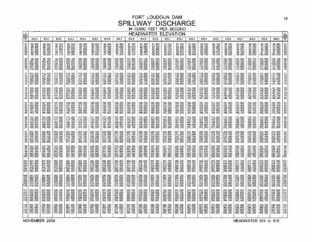
FORT LOUDOUN DAM 19
SPILLWAY DISCHARGEIN CUBIC FEET PER SECOND
___6 HEADWATER ELEVATION __R. 814.0 814.1 814.2 1 814.3 814.4 814.5 814.6 814.7 814.8 1 814.9 [ 815.0 815.1 815.2 815.3 1 815.4 1 815.5 815.6 815.7 815.8 815.9 1 816.0
61 85, 890 86, 040 86, 200 86, 350 86, 500 86,650 86,800 86,950 87, 100 87,250 87, 400 87, 550 87,700 87,850 88, 000 88,150 88,290 88, 440 88, 590 88, 740 88, 880 6162 88,560 88, 720 88, 870 89, 030 89, 190 89,340 89,500 89,650 89, 810 89,960 90, 120 90, 270 90,430 90,580 90,740 90,890 91,040 91, 200 91,350 91,500 91, 650 6263 91,340 91, 500 91, 660 91, 830 91,990 92, 150 92,310 92,470 92, 630 92, 790 92, 950 93, 110 93,270 93,430 93,590 93, 750 93,910 94,070 94,230 94,380 94, 540 6364 93, 980 94,150 94, 310 94, 480 94, 650 94,810 94,980 95, 150 95, 310 95, 480 95, 640 95, 810 95,970 96,140 96, 300 96,470 96, 630 96, 790 96, 960 97, 120 97, 280 6465 96, 760 96, 930 97,110 97, 280 97,450 97,620 97,790 97,970 98, 140 98, 310 98,480 98,650 98,820 98,990 99,160 99, 330 99,500 99,660 99,830 100, 000 100,200 65
66 99, 540 99,720 99,900 100, 100 100, 300 100,400 100,600 100,800 101,000 101,100 101, 300 101,500 101,700 101,800 102, 000 102,200 102,400 102, 500 102, 700 102, 900 103,100 6667 102, 200 102,400 102,600 102, 800 102,900 103, 100 103,300 103,500 103, 700 103,900 104,000 104,200 104,400 104, 600 104, 800 104,900 105,100 105, 300 105, 500 105, 600 105,800 6768 104,900 105,100 105,300 105,400 105,600 105,800 106,000 106,200 106,400 106,600 106,800 106,900 107,100 107,300 107,500 107,700 107,900 108,000 108,200 108,400 108,600 6869 107,500 107,700 107,900 108, 100 108,300 108,500 108,700 108,900 109,100 109,300 109,500 109,700 109,900 110,000 110,200 110,400 110,600 110,800 111,000 111,200 111,400 6970 110,200 110,400 110,600 110,800 111,000 111,200 111,400 111,600 111,800 112,000 112,200 112,400 112,600 112,800 113,000 113,200 113,400 113,600 113,800 113,900 114,100 70
71 113,500 113,700 113,900 114, 100 114,300 114,500 114,700 114,900 115,200 115,400 115,600 115,800 116,000 116,200 116,400 116,600 116,800 117,000 117,200 117,400 117,600 7172 116,900 117,100 117,300 117,500 117,700 118,000 118,200 118,400 118,600 118,800 119,000 119,200 119,400 119,600 119,900 120,100 120,300 120,500 120,700 120,900 121,100 7273 120,300 120,500 120,700 120,900 121,200 121,400 121,600 121,800 122,000 122,200 122,500 122,700 122,900 123,100 123,300 123,600 123,800 124,000 124,200 124,400 124,600 7374 123,600 123,900 124,100 124,300 124,600 124,800 125,000 125,200 125,500 125,700 125,900 126,100 126,400 126,600 126,800 127,000 127,300 127,500 127,700 127,900 128,100 7475 127,000 127,300 127,500 127,700 128,000 128,200 128,400 128,700 128,900 129,100 129,400 129,600 129,800 130,100 130,300 130,500 130,800 131,000 131,200 131,400 131,700 75
76 130, 400 130, 600 130, 900 131,100 131,400 131,600 131,900 132, 100 132, 300 132, 600 132, 800 133, 100 133,300 133, 500 133, 800 134,000 134, 300 134,500 134,700 135,000 135, 200 7677 133, 800 134,000 134,300 134,500 134,800 135,000 135,300 135, 500 135,800 136,000 136,300 136,500 136,800 137,000 137,300 137,500 137,700 138,000 138,200 138,500 138, 700 7778 137,100 137, 300 137, 600 137, 800 138, 100 138,400 138,600 138,900 139, 100 139,400 139, 600 139,900 140,100 140,400 140,600 140,900 141,100 141,400 141,700 141, 900 142, 200 7879 140, 400 140,700 141,000 141,200 141,500 141,800 142,000 142, 300 142,600 142,800 143, 100 143,300 143,600 143,900 144, 100 144,400 144,600 144, 900 145, 200 145, 400 145,700 7980 143, 800 144,100 144,400 144, 600 144,900 145,200 145, 400 145, 700 146,000 146,300 146,500 146,800 147,100 147,300 147, 600 147,900 148, 100 148, 400 148, 700 148, 900 149,200 80
81 147,200 147,500 147,800 148,000 148,300 148,600 148,900 149,200 149,400 149,700 150,000 150,300 150,500 150,800 151,100 151,400 151,600 151,900 152,200 152,400 152,700 8182 150,600 150,900 151,200 151,400 151,700 152,000 152,300 152,600 152,900 153, 200 153, 400 153,700 154,000 154, 300 154, 600 154, 800 155, 100 155,400 155, 700 156,000 156,200 8283 154,000 154,300 154, 500 154, 800 155, 100 155, 400 155, 700 156,000 156, 300 156, 600 156, 900 157, 200 157,500 157, 800 158, 000 158, 300 158, 600 158, 900 159, 200 159, 500 159,800 8384 157,300 157,600 157,900 158, 200 158,500 158,800 159,100 159,400 159,700 160,000 160,300 160,600 160,900 161,200 161,500 161,800 162,100 162,400 162,700 163,000 163,300 8485 163, 700 164,000 164,300 164, 700 165,000 165,300 165,600 165, 900 166,200 166,600 166,900 167,200 167,500 167,800 168,100 168,400 168,700 169,100 169,400 169,700 170,000 85
86 170, 200 170,500 170,900 171,200 171,500 171,900 172,200 172,500 172,900 173,200 173, 500 173,800 174,200 174,500 174,800 175,200 175,500 175,800 176,100 176,500 176,800 8687 176, 600 177,000 177,300 177, 700 178,000 178,400 178,700 179,100 179,400 179,800 180,100 180,500 180,800 181,100 181,500 181,800 182,200 182,500 182,900 183,200 183, 500 8788 183,000 183,400 183,700 184, 100 184,500 184, 800 185,200 185,600 185,900 186, 300 186, 700 187,000 187,400 187,700 188,100 188, 500 188, 800 189, 200 189, 500 189, 900 190,200 8889 189, 500 189,900 190,300 190,700 191,100 191,400 191,800 192,200 192,600 193,000 193, 300 193,700 194,100 194,500 194,800 195,200 195,600 196,000 196,300 196, 700 197,100 8990 196,000 196,400 196,800 197,200 197, 600 198,000 198,400 198, 700 199,100 199,500 199, 900 200, 300 200,700 201, 100 201,500 201,900 202,300 202,700 203,000 203,400 203,800 90
91 202,400 202,800 203,200 203,600 204, 100 204, 500 204,900 205, 300 205,700 206,100 206, 500 206,900 207,300 207,800 208,200 208,600 209,000 209,400 209,800 210, 200 210,600 9192 208,300 208,700 209,100 209,600 210,000 210,400 210,900 211,300 211,700 212,200 212,600 213,000 213,400 213,900 214,300 214,700 215,100 215,500 216,000 216, 400 216,800 9293 214,300 214,700 215,200 215,700 216, 100 216,500 217,000 217,400 217,900 218,300 218,800 219,200 219, 700 220, 100 220,500 221,000 221,400 221,900 222,300 222,700 223,200 9394 220, 200 220,700 221,200 221,700 222, 100 222, 600 223, 100 223, 500 224, 000 224,400 224, 900 225, 400 225,800 226,300 226, 700 227, 200 227, 600 228, 100 228, 600 229, 000 229, 500 9495 226,100 226,600 227, 100 227, 600 228, 100 228,600 229, 100 229, 500 230, 000 230,500 231,000 231,500 231,900 232,400 232,900 233,400 233, 800 234,300 234, 800 235, 200 235,700 95
96 232,200 232,700 233, 300 233, 800 234,300 234,800 235,300 235,800 236, 300 236,800 237, 200 237,700 238,200 238,700 239,200 239,700 240,200 240,700 241,200 241,700 242, 100 9697 238, 200 238, 800 239, 300 239, 800 240, 300 240,800 241, 400 241,900 242, 400 242, 900 243, 400 243, 900 244, 400 244, 900 245, 400 245,900 246, 500 247,000 247, 500 248,000 248, 500 9798 244,200 244,700 245, 300 245, 800 246, 300 246, 900 247, 400 247, 900 248, 500 249,000 249, 500 250, 100 250,600 251,100 251,600 252,200 252, 700 253, 200 253, 700 254, 200 254, 800 9899 249, 800 250, 400 250, 900 251,500 252, 000 252, 600 253, 100 253, 700 254, 200 254,800 255, 300 255, 800 256,400 256,900 257, 500 258,000 258, 500 259, 100 259, 600 260, 100 260, 700 99
100 255,600 256,200 256,700 257, 300 257, 900 258,400 259,000 259,600 260, 100 260,700 261,200 261,800 262,400 262,900 263,500 264,000 264,600 265,100 265,700 266,200 266,800 100
101 261,300 261,900 262,500 263, 100 263, 700 264,300 264,900 265,400 266, 000 266,600 267, 200 267,700 268,300 268, 900 269, 400 270, 000 270,600 271,100 271, 700 272,300 272,800 101102 267,000 267,600 268,200 268, 800 269,400 270,000 270,600 271,200 271, 700 272,300 272,900 273, 500 274,100 274, 700 275, 300 275, 800 276,400 277,000 277, 600 278,200 278,700 102103 272, 800 273, 400 274,000 274,600 275, 200 275, 900 276, 500 277, 100 277, 700 278, 300 278, 900 279, 500 280,100 280, 700 281,300 281,900 282, 500 283, 100 283 700 284, 300 264,900 103104 278,500 279, 100 279,800 280,400 281, 000 281,700 282,300 282, 900 283,500 284,200 284,800 285,400 286,000 286,600 287,200 287,900 288,500 289,100 289,700 290,300 290,900 104105 284, 300 284,900 285,600 286, 200 286, 900 287, 500 288, 100 288, 800 289, 400 290, 100 290, 700 291,300 292,000 292, 600 293,200 293, 800 294,500 295, 100 295,700 296,300 296, 900 105
106 291,000 291,600 292, 200 292, 800 293, 400 294,000 294, 600 295, 200 295, 800 296, 500 297, 100 297, 700 298, 300 299,000 299, 600 300, 200 300, 800 301,400 302, 000 302, 700 303, 300 106107 298,000 298, 500 299, 100 299, 600 300, 100 300, 600 301,200 301,800 302, 500 303, 100 303,700 304,300 304, 900 305, 600 306, 200 306, 800 307, 400 308,000 308, 600 309, 200 309, 800 107108 305,400 305, 800 306, 200 306, 600 307, 000 307, 400 307, 900 308, 600 309, 200 309,800 310, 400 311,000 311,600 312,200 312,900 313, 500 314, 100 314,700 315, 300 315, 800 316,400 108109 312,000 312,400 312,800 313, 100 313,500 313,900 314,300 315,000 315,600 316,200 316,800 317,400 318,000 318,600 319,200 319,800 320,400 321,000 321,600 322,200 322,700 109110 318, 600 319,000 319, 300 319, 700 320,000 320,400 320,900 321,500 322, 100 322, 700 323, 300 323,900 324,500 325,100 325, 700 326,300 326,900 327,400 328,000 328,600 329,200 110
111 325, 500 325, 800 326, 100 326,400 326, 700 327,000 327, 500 328, 100 328, 700 329, 300 329, 900 330, 400 331,000 331,600 332, 200 332, 800 333, 400 333, 900 334, 500 335, 100 335, 600 111112 332, 900 333,000 333, 200 333, 400 333, 600 333, 800 334,200 334,800 335, 400 336,000 336, 600 337, 200 337, 700 338,300 338, 900 339, 500 340,000 340, 600 341,200 341,700 342,300 112113 338,200 338,600 339,100 339,500 339,900 340,400 341,000 341,800 342,600 343,400 344,100 344,900 345,700 346,500 347,300 348,000 348, 800 349, 600 350,300 351,100 351, 900 113114 343,800 344,400 345,100 345,800 346,500 347, 200 348,000 349,000 350,000 351,000 352,000 353,000 354,000 354,900 355,900 356,900 357, 900 358,900 359, 900 360, 800 361, 800 114115 348,200 349, 200 350,100 351, 100 352, 100 353, 100 354,200 355, 400 356, 600 357, 800 359,000 360, 100 361,300 362, 500 363, 700 364,900 366,100 367, 300 368, 500 369, 700 370, 900 115
116 353, 700 354,900 356,200 357, 400 358, 600 359, 800 361,100 362, 500 363, 900 365, 300 366, 700 368,100 369, 500 370, 800 372, 200 373, 600 375, 000 376, 400 377, 800 379, 200 380, 600 116117 360, 400 361,800 363,200 364, 700 366, 100 367,500 369,000 370, 600 372,200 373,800 375, 400 377,000 378,600 380, 200 381, 800 383, 400 385, 000 386,600 388, 200 389,800 391,400 117118 365, 900 367, 500 369, 200 370, 900 372, 500 374,200 375, 900 377, 700 379, 500 381,300 383, 100 384,900 386, 700 388, 500 390,400 392, 200 394,000 395, 800 397,600 399, 500 401,300 118119 370,300 372,300 374,200 376,200 378, 200 380, 100 382, 100 384, 100 386, 100 388,100 390, 100 392,100 394,100 396, 100 398,200 400,200 402,200 404,200 406,300 408,300 410,400 119
NOVEMBER 2004 HEADWATER 814 to 816
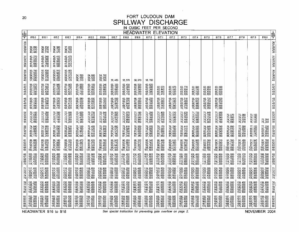
20 FORT LOUDOUN DAM
SPILLWAY DISCHARGEIN CUBIC FEET PER SECOND
UlmJ-1 HEADWATER ELEVATION7 816.8 816.9 1 817.0 1 817.1 1 817.2 1 817 .9% 816.0 1 816.1 816.2 816.3 816.4 816.5 1 816.6 816. .3 817.4 817.5 817.6 817.7 817.8 817 818.0
26 2627 2728 36 880 36,930 36,990 37,050 2829 38: 610 38,670 38,730 38,790 2930 40,440 40,510 40,570 40,630 30
31 42,270 42,340 42,410 42,470 3132 44,020 44,090 44 160 44 230 3233 45,850 45,920 46: 000 46: 070 3334 47,680 47,760 47,830 47,910 3435 49,430 49,510 49,590 49,670 35
36 50,750 50,830 50,910 50,990 3637 52,500 52,580 52 660 52,750 3738 54,250 54,330 54: 420 54,510 54,590 54,680 54,760 3839 56,080 56, 170 56,260 56,340 56,430 56,520 56,610 3940 57,840 57,930 58,030 58, 120 58,210 58,300 58,390 58,480 58,570 58,670 58,760 40
41 59 670 59,770 59,860 59 960 60,050 60,150 60,240 60,330 60 430 60,520 60,620 4142 61: 500 61,600 61,700 61: 790 61,890 61,990 62,090 62,190 62: 280 62,380 62,480 62,570 62,670 62,770 62,860 62,960 63 060 4243 62,370 62,470 62 570 62,670 62,770 62,860 62,960 63,060 63, 160 63,260 63,360 63,460 63,550 63,650 63,750 63,850 63: 950 4344 63,330 63,430 63: 530 63,630 63 730 63,830 63,930 64,030 64, 130 64 240 64,340 64,440 64 530 64,630 64,730 64,830 64,930 4445 64,290 64,390 64,490 64,600 64: 700 64,800 64,900 65,010 65,110 65: 210 65,310 65,410 65: 520 65,620 65,720 65,820 65,920 45
46 65, 160 65,270 65,370 65,480 65 580 65,690 65,790 65,890 66,000 66,100 66,200 66,310 66,410 66,510 66,610 66,720 66,820 4647 66 130 66,230 66,340 66,440 66: 550 66 660 66,760 66,870 66,970 67,080 67, 180 67,290 67,390 67,490 67 600 67 700 67,810 4748 67: 090 67, 190 67,300 67,410 67 520 67: 620 67,730 67,840 67,940 68,050 68,160 68,260 68,370 68,480 68: 580 68: 690 68,790 4849 67 960 68,070 68,180 68,290 68: 400 68 510 68,620 68,730 68,830 68,940 69 050 69,160 69,260 69 370 69 480 69,590 69,690 4950 69: 290 69,400 69,510 69,620 69,730 69: 840 69,960 70,070 70, 180 70,290 70: 400 70,510 70,620 70: 730 70: 840 70,950 71,060 50
51 70 160 70 280 70,390 70,500 70 620 70,730 70,840 70 950 71,070 71,180 71,290 71,400 71,510 71,620 71 730 71 840 71,960 5152 71: 040 71: 160 71,270 71,380 71: 500 71,610 71,730 71: 840 71,950 72 070 72, 180 72,290 72,410 72,520 72: 630 72: 740 72,860 72,970 73,080 73,190 5253 72,000 72, 120 72 230 72,350 72,470 72,580 72,700 72 810 72,930 73: 040 73 160 73,270 73,390 73,500 73,620 73,730 73,840 73 960 74,070 74,180 5354 72,920 73,040 73:160 73,280 73,390 73,510 73,630 73: 740 73,860 73,980 74: 090 74,210 74,330 74,440 74,560 74,670 74,790 74: 900 75 020 75,130 75,250 5455 73,880 74,000 74,120 74,240 74,360 74,480 74,600 74,720 74,830 74,950 75,070 75,190 75,310 75,420 75,540 75,660 75,780 75,890 76: 010 76,120 76,240 55
56 74,840 74,960 75,090 75, M 75 330 75,450 75,570 75 690 75 810 75,930 76,050 76, 170 76,290 76,410 76,520 76 640 76,760 76,880 77 000 77,120 77,230 5657 77,680 77,810 77 940 78,060 78: 190 78,320 78,440 78: 570 78: 690 78,820 78,940 79,060 79,190 79,310 79,440 79: 560 79,680 79,810 79: 930 80,050 80, 180 5758 80,460 80,590 80: 720 80,850 80 980 81,110 81,240 81 370 81 500 81,630 81,760 81,890 82,020 82,150 82,280 82,410 82,540 82,660 82,790 82 920 83 050 5859 83 230 83 360 83,500 83,640 83: 770 83,910 84,040 84: 180 84: 310 84,450 84,580 84,720 84 850 84 990 85 120 85,250 85,390 85 520 85,650 85: 790 85: 920 5960 86: 110 86: 250 86,400 86,540 86 , 680 86,820 86,960 87, 100 87,240 87,380 87,520 87,660 87: 800 87: 940 88: 080 88,220 88,360 88: 490 88,630 88,770 88,910 60
61 88 880 89,030 89,180 89,320 89,470 89,620 89.760 89,910 90,050 90,200 90,340 90,490 90,630 90,780 90,920 91.060 91,210 91,350 91,490 91,640 91,780 6162 91: 650 91,810 91,960 92, 110 92,260 92,410 92,560 92,710 92,860 93,010 93,160 93,310 93,460 93,610 93,760 93,910 94,060 94,210 94,350 94 500 94,650 6263 94,540 94,700 94,860 95,0 1 0 95, 170 95,320 95,480 95,640 95,790 95,950 96,100 96,260 96,410 96,560 96,720 96,870 97,030 97,180 97,330 97: 480 97,640 6364 97 280 97,440 97,610 97,770 97,930 98,090 98,250 98 410 98,570 98,730 98,890 99,050 99,210 99,370 99 530 99,690 99,850 100,000 100,200 100 300 100,500 6465 100: 200 100,300 100,500 100,700 100,800 101,000 101,200 101: 300 101,500 101,700 101,800 102,000 102,200 102,300 102: 500 102,700 102,800 103,000 103,100 1 03: 300 103,500 65
66 103 100 103,200 103,400 103 600 103,700 103,900 104,100 104,300 104,400 104,600 104,800 104,900 105, 100 105,300 105,400 105,600 105 800 106,000 106,100 106 300 106,500 6667 1 05: 800 1 06,000 106,200 106: 400 106 500 106,700 106,900 107, 100 107,200 107,400 107,600 107,800 1 07,900 108,100 108,300 108,500 108: 600 108,800 109,000 1 09: 200 109,300 6768 108,600 108,800 109,000 109, 100 1 09: 300 109,500 109,700 109 900 110 100 110,200 110,400 110 600 110 800 Ill 000 111, 100 111,300 111 500 111 700 1111 800 112 , 000 112,200 6869 111,400 111,600 111,700 111,900 112 , 100 1 12,300 112,500 112: 700 11 2: 900 113,100 113,200 11 3: 400 11 3: 600 11 3: 800 114,000 114,200 11 4: 300 11 4: 500 1 4: 700 114,900 115,100 6970 114,100 114,300 114,500 114,700 114,900 115,100 115,300 115,500 115,700 115,900 116,100 116,200 116,400 116,600 116,800 117,000 117,200 117,400 117,600 117,800 117,900 70
71 117 600 117,800 118,000 118 200 118 400 118,600 118,800 119,000 119,200 119,400 119,600 119,800 120,000 120,100 120,300 120,500 120,700 120,900 12 100 121,300 121,500 7172 1 21 100 121,300 121,500 1 21 700 1 21 900 1 22, 100 122,300 122 500 122,700 123,000 1 23,200 123,400 123,600 123,800 124 000 124,200 124,400 124,600 12':4 800 125,000 125,200 7273 124,600 124,800 125, 100 125,300 125 , 500 125,700 125,900 126: 100 126,300 126,500 126,800 127,000 127,200 127,400 127: 600 127,800 128,000 128,200 128,400 128,600 128,800 7374 128 100 128,400 128,600 128 800 129,000 129,300 129,500 129,700 129 900 130,100 130,300 130,600 1 30,800 131,000 131,200 131,400 131,600 131 900 132,100 132,300 132,500 7475 1 31: 700 131.900 132,100 1 32: 400 132,600 132,800 1 33,000 133,300 133: 500 133,700 133,900 134,200 134,400 1 34,600 134,800 135,100 135,300 135: 500 135,700 136,000 136,200 75
76 135,200 135,400 135,700 135,900 136, 100 136,400 136,600 136,800 137,100 137,300 137,500 137,800 138,000 138,200 138,500 138,700 138,900 139,200 139,400 139,600 139,800 7677 1 38 700 139,000 139,200 139,400 139,700 139,900 140,200 140,400 140,700 140,900 141,100 141,400 141,600 141 800 142 100 142,300 142,600 142,800 143,000 .143,300 143,500 7778 42: 200 142,400 142,600 1 42,900 143 100 143,400 143,600 143 900 144,100 144,400 144 600 144,900 145, 100 145: 400 1 45: 600 145,900 146, 100 1 46,300 146,600 146,800 147,100 7879 145,700 145,900 146,200 146,400 46 700 146,900 147,200 47 500 47,700 148,000 148 200 148,500 148,700 149,000 149,200 149,500 149,700 150,000 150,200 50,500 150,700 7980 149,200 149,500 149,700 150,000 150 , 200 150,500 150,800 151,000 151,300 151,500 151,800 152,100 152,300 152,600 152,800 153, 100 153,400 153,600 153,900 154, 100 154,400 80
81 152,700 153,000 153,300 153,500 153 800 154, 100 154,300 154,600 154,900 155,100 155,400 155,700 155,900 156,200 156,500 156 700 157,000 157,300 157 500 157,800 158,000 8182 156,200 156,500 156,800 157, 100 1 57: 400 157,600 157,900 158,200 158,500 1 58,700 159,000 159,300 159,500 159,800 160, 100 160: 400 160,600 160,900 1 61: 200 161,400 161,700 8283 159 800 160,100 160,300 160,600 160,900 161 200 161,500 161,800 162 000 162,300 162,600 162,900 163,200 163,400 163,700 164 000 164 300 164 600 164 800 165, 100 165,400 8384 1 63: 300 163,600 163,900 164,200 164,500 1 64: 800 1 65,000 165,300 165: 600 165,900 166,200 166,500 166,800 1 67,100 167,300 167: 600 1 67: 900 1 68: 200 1 68: 500 168,800 169,000 8485 170,000 170,300 170,600 170,900 171,200 171,500 171,800 172, 100 172,400 172,700 173,000 173,300 173,600 173,900 174,200 174,500 174,800 175, 100 175,400 175,700 176,000 85
HEADWATER 816 to 818 See special instruction for preventing gate overflow on page 2. NOVEMBER 2004
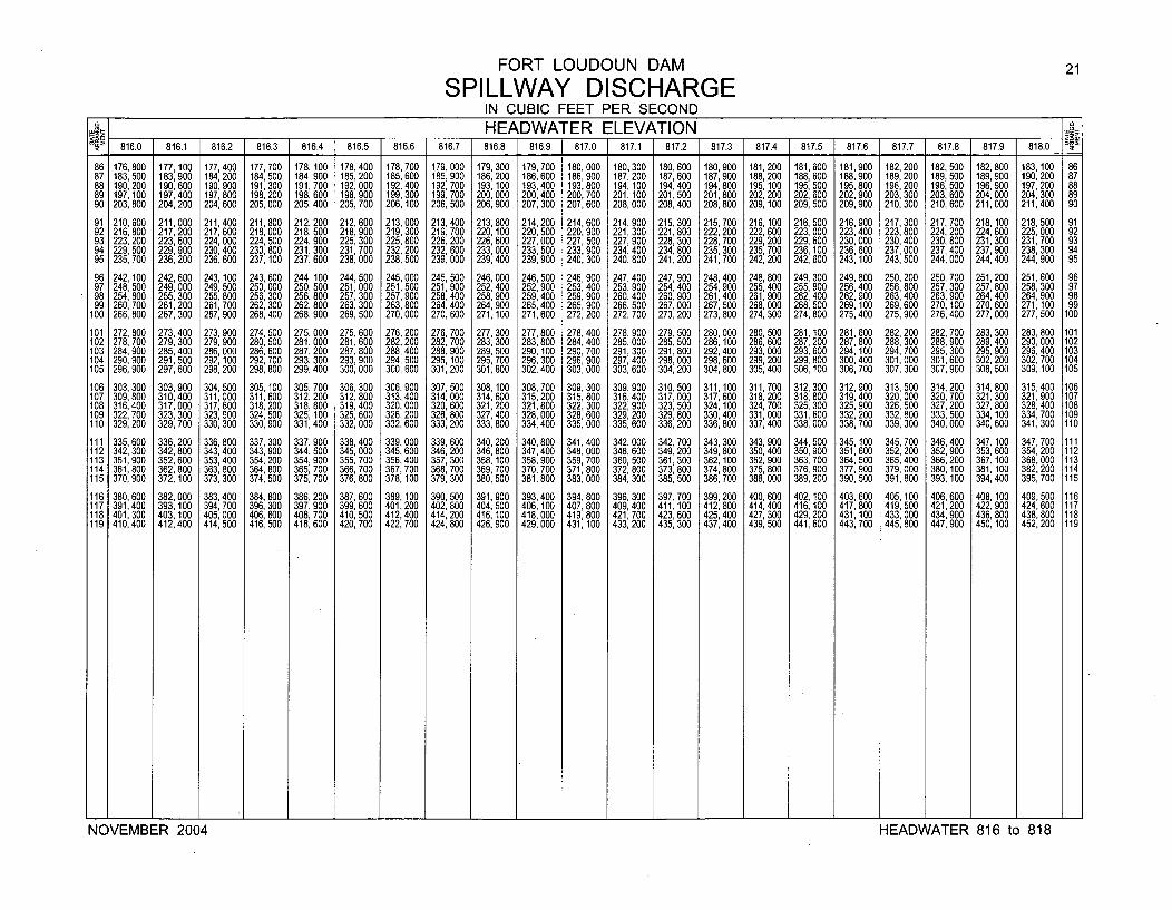
FORT LOUDOUN DAM 21
SPILLWAY DISCHARGEIN CUBIC FEET PER SECOND
A _ HEADWATER ELEVATION _1'1. 816.0 1 816.1 816.2 816.3 816.4 816.5 816.6 816.7 816.8 816.9 1 817.0 1 817.1 1 817.2 1 817.3 1 817.4 [ 817.5 1 817.6 1 817.7 817.8 817.9 818.0
81 . 7 1 81 . 1 81 . 1 818.0 FF
86 176,800 177,100 177,400 177,700 178,100 178,400 178,700 179,000 179,300 179,700 180,000 180,300 180,600 180,900 181,200 181,600 181,900 182,200 182,500 182,800 183,100 8687 183,500 183, 900 184,200 184, 500 184,900 185, 200 185, 600 185, 900 186,200 186,600 186,900 187,200 187,600 187, 900 188,200 188,600 188,900 189,200 189,500 189, 900 190, 200 8788 190,200 190,600 190,900 191,300 191,700 192,000 192,400 192,700 193, 100 193,400 193, 800 194,100 194,400 194,800 195, 100 195,500 195,800 196,200 196,500 196, 900 197,200 8889 197, 100 197,400 197,800 198, 200 198, 600 198, 900 199,300 199, 700 200,000 200,400 200, 700 201,100 201,500 201,800 202, 200 202, 600 202,900 203,300 203, 600 204, 000 204, 300 8990 203,800 204,200 204,600 205,000 205,400 205,700 206,100 206, 500 206, 900 207,300 207,600 208,000 208,400 208,800 209, 100 209, 500 209,900 210,300 210, 600 211,000 211,400 90
91 210,600 211,000 211,400 211,800 212,200 212,600 213,000 213,400 213,800 214,200 214,600 214,900 215,300 215, 700 216,100 216,500 216,900 217,300 217,700 218,100 218,500 9192 216, 800 217,200 217,600 218,000 218, 500 218, 900 219,300 219, 700 220, 100 220,500 220, 900 221,300 221,800 222,200 222, 600 223, 000 223, 400 223, 800 224, 200 224, 600 225,000 9293 223, 200 223,600 224,000 224, 500 224, 900 225, 300 225, 800 226, 200 226, 600 227,000 227, 500 227, 900 228,300 228, 700 229, 200 229, 600 230, 000 230, 400 230,800 231,300 231,700 9394 229,500 229,900 230,400 230, 800 231,300 231,700 232,200 232, 600 233,000 233,500 233, 900 234,400 234, 800 235, 300 235, 700 236, 100 236, 600 237, 000 237, 400 237,900 238,300 9495 235,700 236,200 236,600 237, 100 237, 600 238,000 238,500 239,000 239,400 239,900 240, 300 240,800 241,200 241,700 242, 200 242,600 243,100 243, 500 244, 000 244,400 244,900 95
96 242,100 242,600 243, 100 243, 600 244, 100 244, 500 245,000 245, 500 246,000 246, 500 246, 900 247, 400 247, 900 248,400 248, 800 249, 300 249, 800 250, 200 250, 700 251,200 251,600 9697 248, 500 249,000 249, 500 250,000 250, 500 251,000 251,500 251,900 252, 400 252, 900 253, 400 253, 900 254, 400 254, 900 255, 400 255, 900 256,400 256, 800 257, 300 257, 800 258,300 9798 254, 800 255,300 255,800 256,300 256, 800 257,300 257,900 258,400 258, 900 259,400 259, 900 260, 400 260, 900 261, 400 261,900 262,400 262, 900 263, 400 263, 900 264, 400 264,900 9899 260, 700 261,200 261,700 262, 300 262, 800 263,300 263,800 264,400 264, 900 265,400 265, 900 266, 500 267,000 267, 500 268,000 268,500 269, 100 269, 600 270, 100 270, 600 271, 100 99
100 266, 800 267, 300 267,900 268,400 268, 900 269, 500 270,000 270, 600 271, 100 271,600 272, 200 272, 700 273, 200 273, 800 274, 300 274, 800 275,400 275, 900 276, 400 277,000 277, 500 100
101 272, 800 273,400 273,900 274,500 275,000 275,600 276,200 276, 700 277, 300 277,800 278,400 278,900 279,500 280,000 280, 500 281, 100 281,600 282,200 282,700 283, 300 283,800 101102 278, 700 279,300 279,900 280,500 281,000 281, 600 282,200 282, 700 283, 300 283,800 284, 400 285,000 285,500 286,100 286, 600 287, 200 287, 800 288, 300 288, 900 289,400 290, 000 102103 284, 900 285,400 286,000 286,600 287, 200 287,800 288,400 288, 900 289, 500 290, 100 290, 700 291,300 291,800 292, 400 293,000 293,600 294,100 294, 700 295,300 295, 900 296,400 103104 290,900 291,500 292, 100 292,700 293, 300 293,900 294, 500 295, 100 295, 700 296,300 296, 900 297,400 298,000 298, 600 299, 200 299, 800 300,400 301,000 301, 600 302, 200 302,700 104105 296,900 297,600 298,200 298,800 299, 400 300,000 300, 600 301,200 301,800 302,400 303,000 303,600 304,200 304,800 305,400 306, 100 306,700 307, 300 307, 900 308,500 309, 100 105
106 303, 300 303, 900 304,500 305, 100 305, 700 306, 300 306, 900 307, 500 308, 100 308, 700 309, 300 309, 900 310,500 311,100 311,700 312, 300 312,900 313, 500 314,200 314, 800 315, 400 106107 309, 800 310, 400 311,000 311, 600 312, 200 312,800 313, 400 314,000 314,600 315,200 315,800 316, 400 317,000 317,600 318,200 318,800 319,400 320,000 320,700 321,300 321,900 107108 316, 400 317, 000 317, 600 3318, 200 318, 800 319,400 320,000 320, 600 321,200 321,800 322, 300 322, 900 323, 500 324, 100 324, 700 325, 300 325,900 326, 500 327, 200 327, 800 328, 400 108109 322, 700 323, 300 323, 900 324,500 325, 100 325, 600 326, 200 326, 800 327, 400 328,000 328, 600 329, 200 329,800 330, 400 331,000 331,600 332, 200 332, 800 333, 500 334, 100 334, 700 109110 329, 200 329, 700 330, 300 330, 900 331,400 332,000 332, 600 333, 200 333, 800 334,400 335,000 335, 600 336, 200 336, 800 337, 400 338,000 338, 700 339, 300 340,000 340, 600 341,300 110
111 335,600 336,200 336, 800 337, 300 337, 900 338,400 339,000 339, 600 340, 200 340, 800 341,400 342,000 342, 700 343, 300 343, 900 344,500 345,100 345,700 346,400 347,100 347,700 111112 342,300 342,800 343,400 343, 900 344, 500 345,000 345,600 346, 200 346, 800 347,400 348,000 348,600 349, 200 349, 800 350,400 350,900 351, 600 352,200 352,900 353,600 354,200 112113 351,900 352,600 353,400 354, 200 354,900 355,700 356, 400 357, 300 358, 100 358,900 359, 700 360,500 361,300 362, 100 362, 900 363,700 364,500 365,400 366,200 367, 100 368,000 113114 361,800 362,800 363,800 364,800 365, 700 366,700 367,700 368, 700 369,700 370,700 371,800 372,800 373,800 374,800 375, 800 376,900 377,900 379,000 380, 100 381, 100 382,200 114115 370,900 372,100 373,300 374,500 375,700 376,800 378, 100 379, 300 380,500 381,800 383,000 384,300 385,500 386, 700 388,000 389,200 390,500 391,800 393, 100 394,400 395,700 115
116 380,600 382,000 383,400 384,800 386,200 387,600 389, 100 390, 500 391,900 393,400 394, 800 396,300 397,700 399,200 400,600 402, 100 403,600 405,100 406,600 408, 100 409,500 116117 391,400 393,100 394,700 396,300 397,900 399,600 401,200 402, 800 404,500 406,100 407,800 409,400 411,100 412,800 414,400 416,100 417,800 419,500 421,200 422,900 424,600 117118 401,300 403,100 405,000 406,800 408,700 410,500 412,400 414,200 416,100 418,000 419,800 421,700 423,600 425,400 427,300 429,200 431,100 433,000 434,900 436,800 438,800 118119 410,400 412,400 414,500 416, 500 418,600 420, 700 422,700 424, 800 426,900 429,000 431,100 433,200 435,300 437,400 439, 500 441,600 443,700 445,800 447,900 450, 100 452,200 119
______ ± ______ .1 ______ ± ______ L ______ ± ± ± ______ ± I ______ I ______ I ______ I ______ ± ______ J. ______ U ______ I. ______ U ______ J. ______ J. ______ C ______ 1-
NOVEMBER 2004 HEADWATER 816 to 818
NOVEMBER 2004 HEADWATER 816 to 818
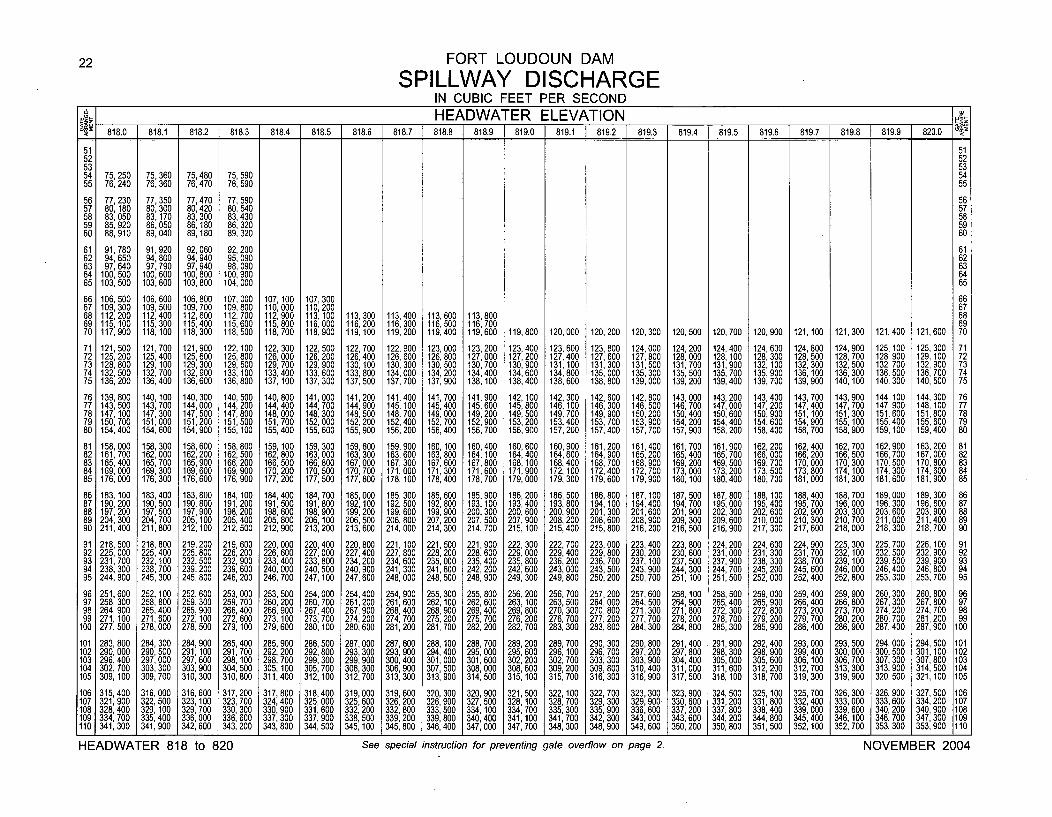
22 FORT LOUDOUN DAM
SPILLWAY DISCHARGEIN CUBIC FEET PER SECONDHEADWATER ELEVATION dz
818.0 1 818.1 i 818.2 1 818.3 1 818.4 1 818.5 1 818.6 1 818.7 1 818.8 1 818.9 1 819.0 1 819.1 1 819.2 1 819.3 1 819.4 1 819.5 1 819.6 1 819.7 1 819.8 1 819.9 820.0
51 5152 5253 5354 75,250 75,360 75,480 75,59055 76,240 76,360 76,470 76,590
5455
56 77 230 77,350 77,470 77,59057 80: 180 80,300 80,420 80,540
56
58 83,050 83,170 83,300 83,430 57
59 85,920 86,050 86 80 86,320 58
60 88,910 89,040 89:1180 89,320 5960
61 91,780 91,920 92 060 92,20062 94,650 94,800 94: 940 95,090
61
63 97,640 97,790 97,940 98,090 62
64 100,500 100,600 100,800 100,900 63
65 103,500 103,600 103,800 104,000 6465
66 106,500 106,600 106,800 107,000 107 100 107,30067 109,300 109,500 109,700 109,800 1 10: 000 110,200
66
68 112 200 112 400 1 1 2,600 112 700 112 900 113,100 113,300 113,400 113,600 113,800 6869 11 5: 100 11 5: 300 1 15 400 11 5: 600 11 5: 800 1116 000 116,200 116,300 1116 500 116,700 6970 117,900 118 , 100 118: 300 118,500 118,700 1 8: 900 119,100 119,200 1 9: 400 119,600 119,800 120,000 120,200 120,300 120,500 120,700 120,900 121, 100 121,300 121,400 12l, 600 70
71 121,500 121,700 121,900 122, 100 122,300 122,500 122,700 122,900 123 000 123,200 123,400 123,600 123,800 124,000 124,200 124,400 124,600 124,800 124,900 125,100 125,300 7172 125 200 125,400 125, 600 125 800 126,000 126,200 126 400 126 600 1 26: 800 127,000 127,200 127,400 127,600 127,800 128,000 128 100 128,300 128,500 128,700 128.900 129,100 7273 1 28: 800 129,100 129,300 1 29: 500 129,700 129,900 1 30:100 1 30: 300 130 , 500 130,700 130 900 131,100 131,300 1 31,500 131,700 131: 900 132, 100 132,300 132,500 132,700 132,900 7374 132,500 132,700 132,900 133, 100 1 33,400 133,600 133 800 134,000 134,200 134,400 134: 600 134,800 135,000 135,300 135,500 135 700 135,900 136,100 136 300 136 500 136 700 7475 136,200 136,400 1 36,600 136,800 137, 100 137,300 137: 500 137,700 137,900 1 38, 100 138,400 138,600 138,800 139,000 139,200 139: 400 139,700 139,900 1 40: 100 1 40: 300 1 40: 500 75
76 139 800 140 100 140 300 140 500 140,800 141,000 141,200 141,400 141,700 141,900 142, 100 142,300 142,600 142,800 143 000 143 200 143,400 143,700 143 900 144, 100 144,300 7677 , 43: 500 1 43: 700 1 44: 000 1 44: 200 144,400 144,700 1 44,900 145, 100 145,400 145,600 145,800 146,100 146,300 146,500 146: 700 1 47: 000 147,200 147,400 1 47: 700 147,900 148, 100 7778 147 100 147,300 147,500 147,800 1 48,000 148,300 148,500 148,700 149 000 149,200 149,500 149 700 149,900 150,200 150 400 150 600 150,900 151,100 151 300 151,600 151,800 7879 1 50: 700 1 51,000 151,200 151,500 151,700 152,000 1 52,200 152,400 152: 700 152,900 153,200 1 53: 400 153,700 153,900 1 54: 200 1 54: 400 154,600 154,900 1 55: 100 155,400 155,600 7980 154,400 154,600 154,900 155,100 155,400 155,600 155,900 156,200 156,400 156,700 156,900 157,200 157,400 157,700 157,900 158,200 158,400 158,700 158,900 159,100 159,400 80
81 158,000 158,300 158,600 158,800 159 100 159,300 159,600 159 900 160, 100 160,400 160 600 160,900 161,200 161 400 161 700 161,900 162,200 162,400 162,700 162: 900 163,200 8182 161,700 162,000 1 62 200 162,500 162: 800 163,000 163,300 1 63: 600 163,800 164, 100 1 64: 400 164,600 164,900 1 65: 200 1 65: 400 1 65,700 166,000 166,200 166,500 166 700 1 67,000 8283 165 400 165,700 65: 900 166,200 166,500 166,800 167,000 167 , 300 167,600 167 800 168 100 168,400 168,700 168,900 169,200 169,500 169,700 170,000 170,300 170,500 170,800 83
4 69 000 169,300 169,600 169 900 170,200 1 70,500 170,700 171,000 171,300 171 600 1 71 900 1 72, 100 172 400 172 700 173 000 173 200 173,500 173,800 1 74, 100 174,300 174 600 8485 176 , 000 176,300 176,600 1 76: 900 177,200 177,500 1 77,800 178, 100 178,400 178,700 179,000 179,300 179: 600 1 79: 900 1 80: 100 1 80: 400 180,700 181,000 181,300 181,600 181: 900 85
86 183, 100 183,400 183,800 184, 100 184,400 194,700 185,000 185,300 185,600 185,900 186,200 186,500 186,800 187,100 187 500 187,800 188, 100 188,400 188,700 189,000 189,300 8687 190 200 190,500 1 90,800 191 200 191,500 191,800 192,100 192,500 192,800 193,100 193,400 193,800 194,100 194,400 194: 700 195,000 195,400 195,700 196,000 196,300 196,600 8788 1 97: 200 197,500 197,900 1 98: 200 198 600 198,900 199,200 199,600 199,900 200 300 200,600 200,900 201,300 201,600 201,900 202,300 202 600 202,900 203,300 203,600 203,900 8889 204 300 204,700 205,100 205,400 205: 800 206 100 206 500 206,800 207,200 207: 500 207,900 208,200 208,600 208 900 209,300 209,600 210: 000 210,300 2110 700 2111 000 211,400 8990 211: 400 211,800 212,100 212,500 212,900 213: 200 213: 600 214,000 214,300 214,700 215, 100 215,400 215,800 216: 200 216,500 216,900 217,300 217,600 2 8: 000 2 8: 300 218,700 90
91 218,500 218,800 219,200 219,600 220,000 220,400 220,800 221, 100 221,500 221,900 222,300 222,700 223,000 223,400 223 800 224,200 224,600 224,900 225,300 225,700 226,100 9192 225,000 225,400 225,800 226,200 226,600 227,000 227,400 227,800 228,200 228,600 229,000 229,400 229,800 230,200 230: 600 231,000 231,300 231,700 232, 100 232,500 232,900 9293 231,700 232, 100 232,500 232,900 233,400 233,800 234 200 234,600 235,000 235,400 235,800 236,200 236,700 237, 100 237,500 237,900 238,300 238,700 239, 100 239,500 239,900 9394 238,300 238,700 239,200 239,600 240,000 240,500 240: 900 241,300 241,800 242,200 242,600 243,000 243,500 243,900 244,300 244,700 245,200 245,600 246,000 246,400 246,800 9495 244,900 245,300 245,800 246,200 246,700 247,100 247,600 248,000 248,500 248,900 249,300 249.800 250,200 250,700 251, 100 251,500 252,000 252,400 252,800 253,300 253,700 95
96 251,600 252, 100 252 600 253,000 253,500 254,000 254,400 254,900 255,300 255,800 256,200 256,700 257,200 257,600 258, 100 258,500 259,000 259,400 259 900 260,300 260,800 9697 258 300 258,800 259: 300 259,700 260,200 260,700 261,200 261,600 262, 100 262,600 263 100 263,500 264,000 264 500 264,900 265,400 265,900 266,400 266: 800 267,300 267,800 9798 264: 900 265,400 265,900 266,400 266,900 267,400 267,900 268,400 268,900 269,400 269: 800 270,300 270,800 271: 300 271,800 272,300 272,800 273,200 273 , 700 274,200 274,700 9899 271, 100 271,600 272,100 272,600 273, 100 273,700 274,200 274,700 275 200 275,700 276,200 276,700 277,200 277 700 278,200 278,700 279,200 279,700 280,200 280,700 281 200 99
100 277,500 278,000 278,500 279, 100 279,600 280, 100 280,600 281,200 281: 700 282,200 282,700 283,300 283,800 284: 300 284,800 285,300 285,900 286,400 286,900 287,400 287: 900 100
101 283,800 284,300 284,900 285,400 285,900 286,500 287,000 287,600 288,100 288,700 289,200 289,700 290,300 290,800 291,400 291,900 292,400 293,000 293,500 294,000 294,500 101
1 02 290,000 290,500 291,100 291,700 292,200 292,800 293 300 293,900 294,400 295 000 295,600 296,100 296,700 297,200 297 800 298,300 298,900 299,400 300,000 300,500 301,100 102103 296,400 297,000 297,600 298, 100 298,700 299,300 299: 900 300,400 301,000 301: 600 302,200 302,700 303,300 303,900 304: 400 305,000 305,600 306, 100 306,700 307,300 307,800 103104 302,700 303,300 303,900 304,500 305, 100 305,700 306,300 306,900 307,500 308,000 308,600 309,200 309,800 310,400 311,000 311,600 312,200 312,700 313 300 313,900 314,500 104105 309,100 309,700 310,300 310.800 311,400 312,100 312,700 313,300 313,900 314,500 315,100 315,700 316,300 316,900 317,500 318, 100 318,700 319,300 3 1 9: 900 320,500 321,100 105
1 06 315,400 316,000 316,600 317,200 317,800 318,400 319,000 319,600 320,300 320,900 321,500 322,100 322 700 323,300 323,900 324,500 325, 100 325,700 326,300 326,900 327,500 106107 321,900 322,500 323,100 323,700 324,400 325,000 325,600 326,200 326,900 327,500 328, 100 328,700 329: 300 329,900 330,600 331,200 331,800 332,400 333,000 333,600 334,200 107108 328,400 329, 100 329,700 330,300 330,900 331,600 332,200 332,800 333,500 334,100 334,700 335,300 335,900 336,600 337,200 337,800 338,400 339,000 339 600 340,200 340,900 108109 334,700 335,400 336,000 336,600 337,300 337,900 338,500 339,200 339,800 340,400 341, 100 341,700 342,300 343,000 343,600 344,200 344,800 345,400 346: 100 346,700 347,300 109110 341,300 341,900 342,600 343,200 343,800 344,500 345,100 345,800 346,400 347,000 347,700 348,300 348,900 349,600 350,200 350,800 351,500 352, 100 352 '700 353,300 353,900 110
HEADWATER 818 to 820 See special instruction for preventing gate overflow on page 2. NOVEMBER 2004
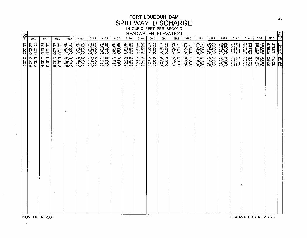
FORT LOUDOUN DAM 23
SPILLWAY DISCHARGEIN CUBIC FEET PER SECOND
__o__HEADWATER ELEVATION d_818.0 818.1 818.2 818.3 818.4 818.5 818.6 818.7 818.8 818.9 819.0 819.1 819.2 819.3 819.4 819.5 819.6 819.7 819.8 819.9 820.0 12
111 347, 700 348, 400 349, 000 349, 700 350,300 351 000 351,600 352, 300 352, 900 353, 600 354, 200 354, 800 355, 500 356, 100 356, 700 357, 400 358, 000 358, 600 359, 300 359, 900 360, 500 111112 354, 200 354,900 355, 600 356, 200 356, 900 357, 500 358,200 358, 900 359, 500 360, 200 360, 800 361, 400 362, 100 362, 700 363, 400 364, 000 364, 600 365, 300 365, 900 366, 500 367,200 112113 368, 000 368,900 369, 700 370, 600 371, 500 372,300 373, 200 374,000 374, 900 375,800 376,600 377, 500 378, 300 379, 200 380,000 380, 900 381,700 382, 600 383, 400 384,300 385,100 113114 382, 200 383,300 384,400 385, 500 386,600 387,600 388,700 389, 800 390, 900 392,000 393,000 394, 100 395,200 396, 300 397,300 398,400 399,500 400,600 401,700 402,700 403,800 114115 395,700 397,000 398,300 399,600 400,800 402,100 403,400 404,700 406,000 407,300 408,600 409,900 411,200 412,500 413,800 415,100 416,400 417,700 419,000 420,300 421,600 115
116 409,500 411,000 412,500 414,000 415,500 417,000 418,600 420,100 421,600 423,100 424,600 426,100 427,600 429,100 430,600 432,200 433,700 435,200 436,700 438,200 439,800 116117 424,600 426,300 428,000 429,700 431,400 433,200 434,900 436, 600 438, 300 440,100 441,800 443,500 445,300 447,000 448,800 450,500 452,200 454,000 455,700 457, 500 459,200 117118 438, 800 440,700 442,600 444, 500 446, 500 448,400 450,400 452, 300 454, 200 456,200 458, 100 460, 100 462,100 464,000 466,000 468,000 469,900 471,700 473, 500 475, 300 477, 100 118119 452,200 454,300 456,500 458, 600 460,800 462,900 465, 100 467, 200 469,400 471,600 473,700 475,900 478, 100 480,300 482, 500 484,700 486,800 488, 800 490,900 492, 900 494,900 119
NOVEMBER 2004 HEADWATER 818 to 820
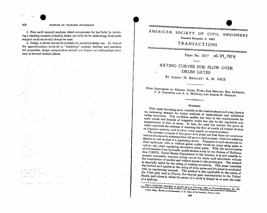
402 HOPKINS ON FLEXIBLE BUtLKHEADS
3. Free earth-support analyses which compensate for toe fixity by includ-
ing a bending moment reduction factor are liable to be misleading; fixed earth
support methods should always be used.4. Design analyses should be suitable for practical design use. In view of
the approximations involved in "idealizing" geologic sections and assessing
soil properties, design computations should not dependl on arithmetical accu-
racy to several decimal places.
0AMERICAN SOCIETY OF CIVIL ENGINEERS
Founded November 5. 1852
TRANSACTIONS
Paper No. 2677 Vol. 1111) I&'Lf
RATING CURVES FOR FLOW OVERDRUM GATES
BY JOSEPH N. BRADLEY,' A. M. ASCE
WiTu DiscussIoN ny MESSas. GUXDO Wyss; SAU SfUlaTs; Bon BUEZHLERF. 13. CAMPBELL AND A. A. MCCOOL; AND JOSEpu N. BRADLEY
SYNOPSIS.
With water becoming more valuable in the western states each year, there isan increasing demand for better methods of measurement and additionalrating structures. This condition applies not only to the requiremeais formain canals and laterals of irrigation works but also to the regulation and
measurement of flow at dams. In fact, the need has reached the point atwhich operators are desirous of metering the flow at nearly all control devicesin irrigation systems, and in other water supply or control systems.
The primary purpose of this paper is to point out that there are numerouscontrol structures in existence that will serve a dual purpose-that of a meteringstation a's well as that of a regulating device. Examples of such structures in-elude spillways, with or without gates; outlet works for dams using gates orvalves; and canal regulating structures using gates. With the accumulation
of information from lydraulic model studies made by the Bureau of Reclama.tion (USBR), United States Department of the Interior, it is now possible toprepare reasonably accurate rating curves for many such structures withoutthe construction of models and without access to the prototypes. The methodis especially useful for the rating of existing structures. This paper describesthe method as it applies to the rating of drum gates and the paper is concludedwith an engineering example. The method is also applicable to the rating ofthe Volet gate used in France, the bascule gate manufactured in the UnitedStates, and others in which the sector of a circle is hinged at or. near the crestof a spillway.
Nosi-tPbiosan d, essentially a, printed here, in Februaryi 1953, as Prneedinas-Separate No. 169.Positions and titles given aj.tlose to effct~ when the paper or iscnssion was received for publicationHydr. Eagr.. Bureau of Reclamation, U. S. Dept. of the Interior. Denveri Colo.
403
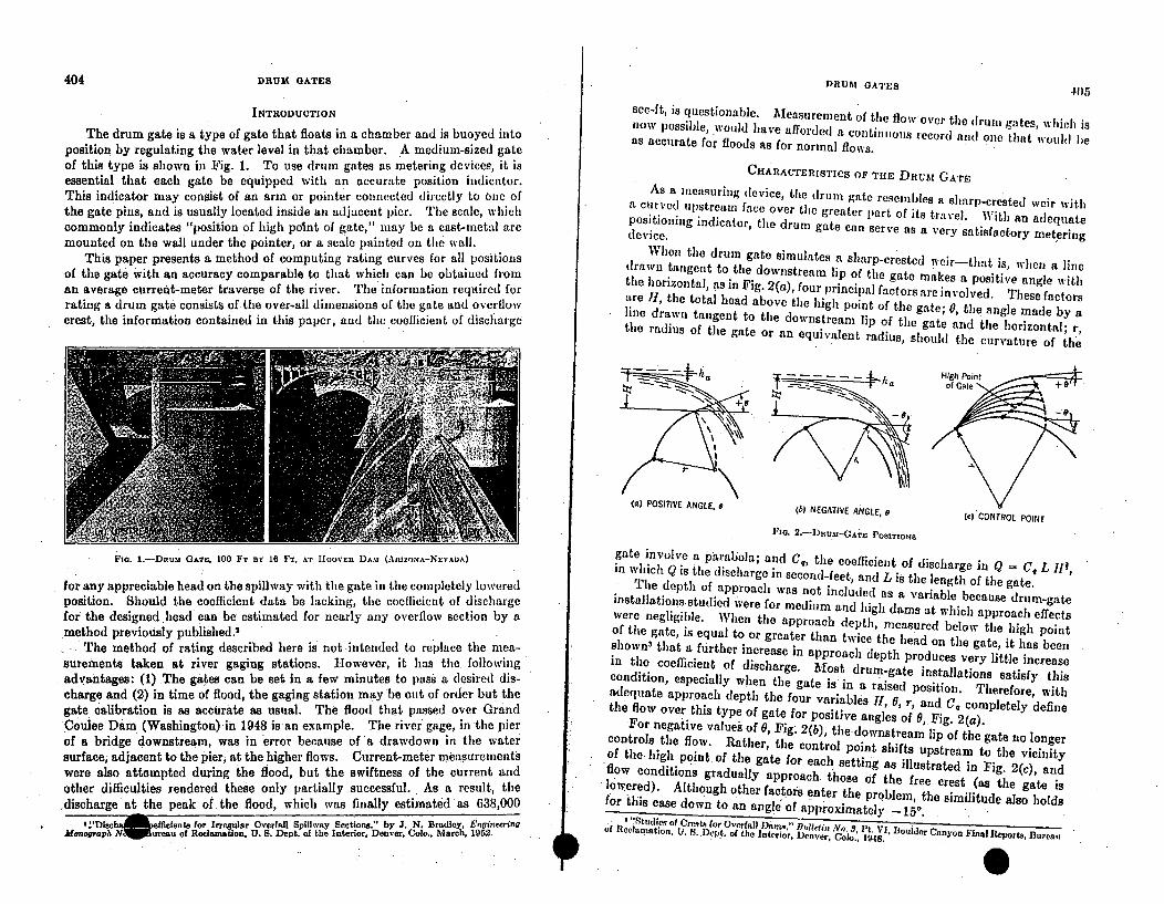
404 DRUM GATES DRIT]•! f/A q,*• o
INTRODUCTION
The drum gate is a type of gate that floats in a chamber and is buoyed intoposition by regulating the water level in that chamber. A medium-sized gateof this type is shown in Fig. 1. To use drum gates as metering devices, it isessential that each gate be equipped with an accurate position indicator.This indicator may consist of an arm or pointer connected directly to one ofthe gate pins, and is usually located inside an adjacent pier. The scale, whichcommonly indicates "position of high point of gate," may be a cast-metal arcmounted on the wall under the pointer, or a scale painted oil the wall.
This paper presents a method of computing rating curves for all positionsof the gate with an accuracy comparable to that which can be obtaiued froman average current-meter traverse of the river. The information requlired forrating a drum gate consists of the over-all dimensions of the gate and overflowcrest, the information contained in this paper, and the coefficient of discharge
D. G.... 405
see-It, is questionable. Measurement of the flow over the drumn gates, which isnow possible, would have afforded a continuous record and one that would beas accurate for floods as for normal flows.
CHARACTERISTICS OF TIlE D]RJM GATE
As a me'suring device, the drum gate resembles a sharp-crested weir withia curved upstream face over the greater part of its travel. With an adequatepositioning indicator, the drum gate can serve as a very satisfactory meteringdevice.
When the drum gate simulates a sharp-crested weir-that is, when a linedrawn tangent to the downstream lip of the gate makes a positive angle withthe horizontal, as in Fig. 2(a), four principal factors are involved. These factorsare II, the total head above the high point of the gate; 0, the angle made by aline drawn tangent to the downstream lip of the gate and the horizontal; r,the radius of the gate or an equivalent radius, should the curvature of the
(a) POSITIVE ANGLE, B (b) NEGATIVE ANGLE, e
FI1a. 2 .-- DRu . -CATE POSITIONS
(c) CONTROL POINT
Fia. 1.-DRum GATE, 100 FT BY 16 FT. AT hloovEn DA.%, (ARIZONA-NEVADA)
for any appreciable head on the spillway with the gate in the completely loweredposition. Should the coefficient data be lacking, the coefficient of dischargefor the designed head can be estimated for nearly any overflow section by amethod previously published.'
The method of rating described here is not -intended to replace the mea-surements taken at river gaging stations. However, it has the, followingadvantages: (1) The gates can be set in a few minutes to pass a desired dis-charge and (2) in time of flood, the gaging station may be out of order but thegate calibration is as accurate as usual. The flood that passed over GrandCoulee Dam (Washington) in 1948 isan example. The river gage, in the pierof a bridge downstream, was in error because of a drawdown in the watersurface, adjacent to the pier, at the higher flows. Current-meter measurementswere also attempted during the flood, but the swiftness of the current andother difficulties rendered these only partially successful. As a result, the,discharge at the peak of. the flood, which was finally estimated as 638,000
2:'Diachafin effielents for Irregular Overfali Spillway Sections," by J. N. Bradley, EngineeringMonograph NMBureau of Reclamation. U. S. Dept. of the Interior, Deaver, Colo., March, 1952.
gate involve a paraboila; and C0, the coefficient of discharge in Q = C, L III,in which Q is the disehlarge in second-feet, and L is the length of the gate.The depth of approach was not included as a variable because drum-gateinstallations studied were for medium and high dams at which approach effectswere negligible. When the approach depth, measured below the high pointof the gate, is equal to or greater than twice the head on the gate, it has beenshown' that a further increase in approach depth produces very little increasein the coefficient of discharge. Most drum-gate installations satisfy thiscondition, especially when the gate is in a raised position. Therefore, withadequate approach depth the four variables H, 0, r, and C, completely definethe flow over this type of gate for positive angles of 0,. Fig. 2(a).TFor negative values of 0, Fig. 2(b), the'downstream lip of the gate no longercontrols the flow. Rather, the control point shifts upstream to the vicinityof the high point of the gate for each setting as illustrated in Fig. 2 (c), andflow conditions gradually approach. those of the free crest (as the gate islowered). Although other factors enter the problem, the similitude also holdsfor this case down to an angle of approximately - 15o.
'. "Studieq of Crests for Overfall MDum," BdIclin No. 3, I't. VI, Boulder Canyon Final Reports, Burea,,of Reclamnation. U. S. D'lc;,t. of the Interior, Denver, Coo., 1948.40
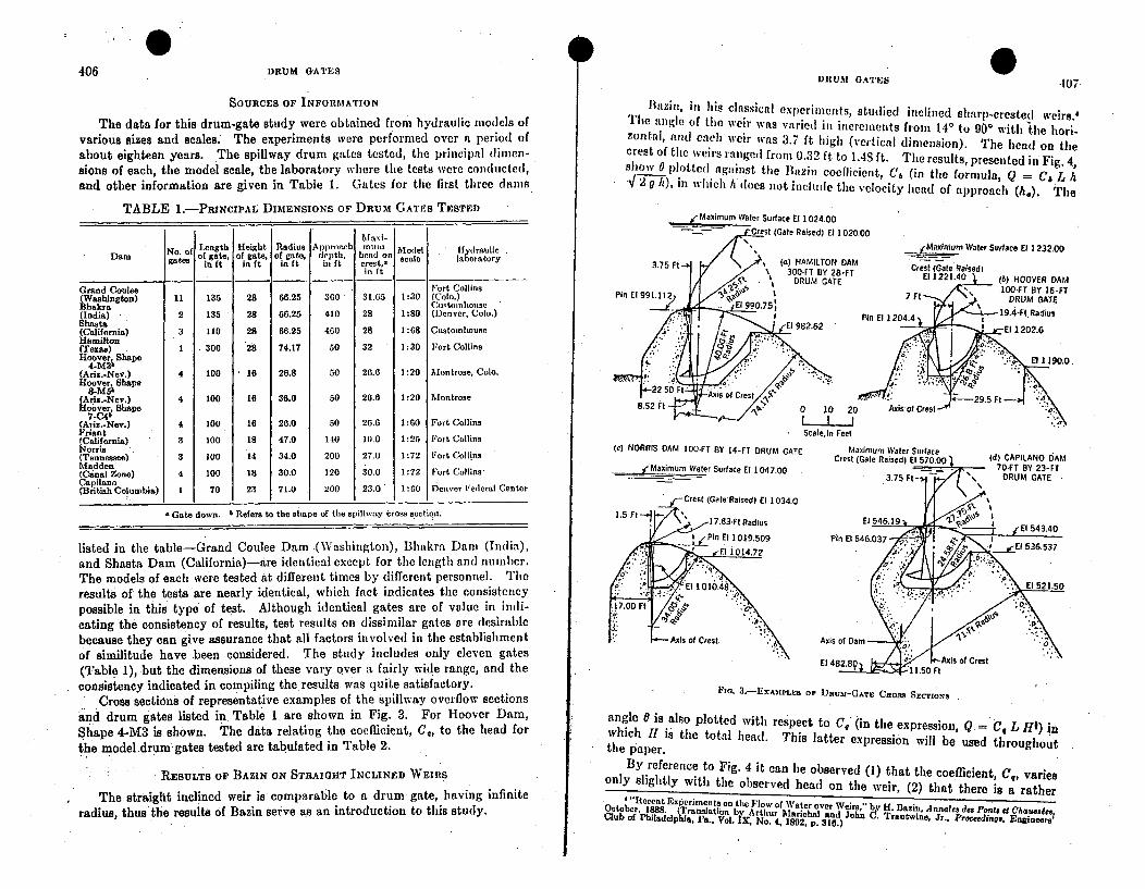
0 4406 DRUM GATES
DRUM GATES -407
SOURCES OF INFORMATION
The data for this drum-gate study were obtained from hydraulic models ofvarious sizes and scales. The experiments were performed over a period ofabout eighteen years. The spillway drum gates tested, the principal dimen-sions of each, the model scale, the laboratory where the tests were conducted,and other information are given in Table 1. Gates for the first three dams
TABLE 1.-PRINCIPAL DIMENSIONS OF DRum GATES TESTED
Maxi-No. of Length Height Radius Approach .... Model lfydraulie
Dam f gateso gate, of gate, of gate, depth, hendro scale la oratorygates in ft in ft in ft in ft crest,- sortrin ft
Grand Coulee Fort Collins(Washington) 11 135 28 66.25 360 31.65 1:30 (Colo.)Bhakra C,,stoulhonse"(India) 2 135 28 66.25 410 28 1:80 (Denver, Colo.)Shasta(California) 3 110 28 66.25 400 28 1:68 CustomhouseHamilton(Texas) 1 300 28 74.17 50 32 1:30 Fort CollinsHoover. Shape
4-Mill(Ariz.-Nev.) 4 100 16 26.8 50 26.6 1:20 Montrose, Colo.Hoover, Shape
8-MSb(Ariz.-Nev,) 4 100 16 36.0 50 26.6 1:20 MontroseHoover, Shape
7-O4b(Ariz.-Nev.) 4 100 16 26.0 50 26.6 1:60 Fort CollinsFriant(California) 3 100 18 47.0 110 1.0o 1:25 Fort CollinsNorris(Tennessee) 3 100 14 34.0 200 27.0 1:72 Fort CollinsMadden(Canal Zone) 4 100 18 30.0 120 30.0 1:72 Fort Collins'Capilano(British Columbia) 1 70 23 71.0 200 23.0 1:60 Denver Federal Center
Gate down. I Refers to the shape of the spillway cross section.
listed in the table-Grand Coulee Dam .(Washington), Blhakra Dam (India),and Shasta Dam (California)-dre identical except for the length and number.The models of each were tested at different times by different personnel. Theresults of the tests are nearly identical, which fact indicates the consistencypossible in this type of test. Although identical gates are of value in indi-cating the consistency of results, test results on dissimilar gates are desirablebecause they can give assurance that all factors involved in the establishmentof similitude have been considered. The study includes only eleven gates(Table 1), but the dimensions of these vary over a fairly wide range, and theconsistency indicated in compiling theresults was quite satisfactory.
Cross sections of representative examples of the Spillway overflow sectionsand drum gates listed in. Table I are shown in Fig. 3. For Hoover Dam,Shape 4-M3 is shown. The data relating the coefficient, C,, to the head for
the model drum gates tested are tabulated in Table 2.
RESULTS OF BAZIN ON STRAIGHT INCLINED WEIRS
The straight inclined weir is comparable to a drum gate, having infiniteradius, thus the results of Bazin serve as an introduction to this study.
Bazin, in his classical experiments, studied inclined sharp-crested weirs.dThe anl1gle of the weir was varied ill increments from 14° to 900 with -the hori-zontal, and each weir was 3.7 ft high (vertical dimension). The head on thecrest of the weirs range,l from 0.32 ft to l.S ft. The results, presented in Fig. 4,show 0 plotted against the ]lazin coellicient, Ci (in the formula, Q = C6 L hV'2g/l), in which h( does not include the velocity head of approach (h,). The
jmaximum waler Surface El 1024.00
CCrest (Gale Raised) El 1020.00
(c) NORRIS DAM 100-FT BY 14-FT DRUM GATE
jMaximum Waler Surface El 1047.00
Axis of Dam " ...'El 482
'-I .' 50 L;
Fla. 3
.- EXAMPLEa OF DIJUM-GATE CRoss SECrIONS
angle 0 is also plotted with respect to C5 " (in the expression, Q = C, L HI) inwhich 11 is the total head. This latter expression will be used throughoutthe paper.
By reference to Fig. 4 it can he observed (1) that the coefficient, C5, variesonly slightly with the observed head on the weir, (2) that there is a rather
I 4 "Rtecent Experiments on the Flow of Water over Weirs " by H. Bazin, Annales des Ports et Chausa~eeOctober, 1888. (Translation by Arthur Alari:hal and John C. Trautiine, Jr.. Proceedmngs. Engineers;Club of Philadelphia 'a., Vol. X. No. 4, 1892, p. 3E10.)
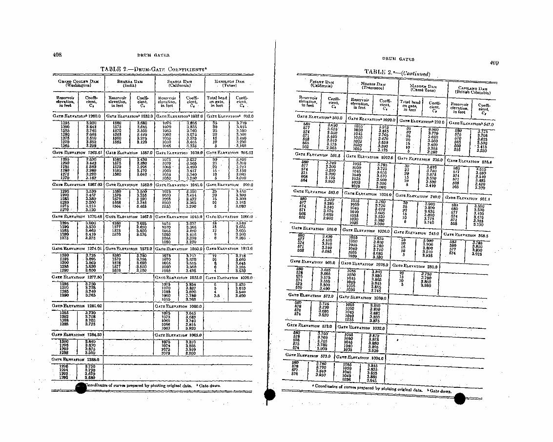
408 DRU•M GATES,
TABLE 2.--DRUM-GATT' COE-FFICIENTI3*
GRAND COULEE DAM HHARA. DAMSAT DMIAILO A(Weawlngton) " "(India) (Ca lifsornDa)
Reservoir I o• ]IReservoir Coe ffi- IRcseroir I COet- [Total headI ofi
elevation, 0 Pln• lvation, cieat, |elevation, c ient, Jon gato, ý ioe.tlin feet ] C, in feet C, in feet cc in feetI Ut
GATE Eu~v.,.iorN 1260.0 G ATEz EL.EvA~o~b 1552.0 C AT• ELFVATION' 1937.0 UXTErELCVA-110.b 9092,0
1290 3,.942, 15758 .5 "110 3,835 30 361125 3.745 170 3,550 ý115 3-760 25 3.5a0
1280 3.635 1565 3.420 IwHo 3.675 20 3.5|001275 1,510 1660 3.275 1055 3.575 15 3.4001270 3.352 1555 3.120 1050 3,A65 10 3.290J12ms 3.220 1045' 3,3'35 5 3. lW
GATE ELVTO 235,44 GATE ELVTO. 1570 G 00 ELVTO 039.505 2G "A.3 E~ioN952
1285 1 3.30 10 3.4305 10- 340 2 . ,2120- 3.0 15850 .17 1 16 347 ' 3,100
1275 ZI.220 1560 1 3.040 - 1055 3.340 to T851270 3,182 :1050 3.250 1 5 1 3.010
IGATE ]R IevAT roK 1207.02 1 GAT•EELEVATIoN 156:3.0 1G.ArI.EE V TO ... .. 041.0 JGx , P. l.:LFvATr; 0 9.
.1290 3.457 1676 3355 1 070 3'4.- 4 0 3.39,0128 3.380 1572 3.290 ,065 3.432, 15 3.11001280 3.00 1568 3,345 1060 3.365 to 3.19,51275 3.213 156 3.465 1055 3.290 3.090
.. 1290 3213'0" 15570 3.650 1070 3.565 11 3, .- '51285 3.462 1573 3.600 1065 3.490 12 3.60.51280 3.410 11570 1;535 1060 3.415 9 3.5G01275 3.375 1055 3.330 - 3.505
1 5 18 70 1075 3.717 1
1295 3.095 1579 3,.755 1070 3.6}70 to 33.76901129 3:662 1678 3.690 1065 3.615 8 3.6451285 3.630 1577 .3.500 1060 U,60 6 31595
120 3.000 1576 3-11n 1055 3.4.95 4 3.530
DRtUM GATE,130
Reevimfe ' Co effi- Cofi T•ori . -- ' r o"a -I
ele~~atin f ~ nt elevto et oG, In etc, -eleration, oefie
G AT }ELYSVArTo~t 550.O | -GATE LFV,,,ON• 1020.0IG ., . ... ELVTIN 232. GATE
------ - ELEVTION 5475" ' ;• 5i. 0...
1100•0 01, 3.765 ' 0 3-900 580 3o1 3.460 10104 360 20 .0 5•0
5 3,340 3.650 0 3.500 0 3.6255 5 3.1750 •0 3.3 50 15 3 ;• 46 .5 3.530562 [ •96 J ]u• ( 3.30 10 | 3"365• J.oO 3.415
GAT ELVTO lid 5 -GAT E VATION 1022,01 GATU ELEVATION 236.0 C ATeE ELVAIN5 4
577 3 3..d0 1 1o5 3:7I1V :5o • 5z --67 2',0 305 57 25 "'' 8 3 5t58 3. 2 1045 . 3 .5 21) 3.7500 5• 0.57.1 3*0 1 3.675 0 5 3.
, 5680 3 3.320 105 3.790 "7 30..o
674 3 57 3.6 60 "3.453
150 ... 3.0 ;50I8•8 '&• l ._• .20 ..... 3oo 6 3.4,20C T E L V T ON 0 .0 [ G -• T ME 1 , tv A Tz o N 1 0 2 4 .0 C A E P ý Z V TZ- 4 0 0 -•••5~ ~ "- 30 1 =•rrx',s 4. GATE• r•rYAwoN 501.1o77 / 3:,28o I 1o, d 58
7t8 3.7 104 6••~ .4 0 ooJ 77 3.890so0 . 1035 • 3.52010 574 3.5
102• I .0 /1• 3.000 1u 56 3.750
680 3.450 I 1040 - 3a• • l 3_68707~ 3.4100. . 3 3 .8350- 0 3.85713 3.4 1045 4 15 I .0 58IO2€ ~374 872. 3.910,z,,w•10
5680 3,085 1 30 5 3 .8 SA 3.921' 3I 3,58[ 501 3.9"35
-'- 80 1 3.76 2. 1o 55 a g 20 .75$7 3 .605 ,050 3 •ý75 I6_74 3 .7 s)0oo I. 10, 3 -3"Sooo 67•,, o 3 5.0 0o .3.4
572 o~U 10 5 | 385
3 / 1o8 / S'4 .87 3oriae 0 f eo1 e prprdbypot.g745a dtI Gt on., =.
GATE ELEVATIO 1277.501 G .-reELPYATIoN 105&.0 CATEP ELE VA•TION 1020.0•
1295 3.7501290 3.T3s129,5 3.7401280 1 3.765 1075 1 3.'854
)070 3.8271065 3.800
•1060 3.780 5 3.6.104 3.540
3.5 3.400
G3ATE EttyAox• 1281.02 1 GATEE•LEVATION 1060.0 }
1292 3708 1072 3.683.1298 8,05 "1069 3.740128,5 3.8725 load 3.815
0 1063 3.920 .GAME• ELEVATION 1284.501 'jA'r•ELPVATION 1065.0 1
"i296 318,380 - 1074 3.80512I92 . 3,875 1072 3.9101288 3,050 1070 3.050
GATE E-•VAXiON 1289.01290 375S1294 3:720
1292. 3.6701290 358
_• ,•._.=• ordinates of curves prepared by platting original. data. 4 Gate down.
I
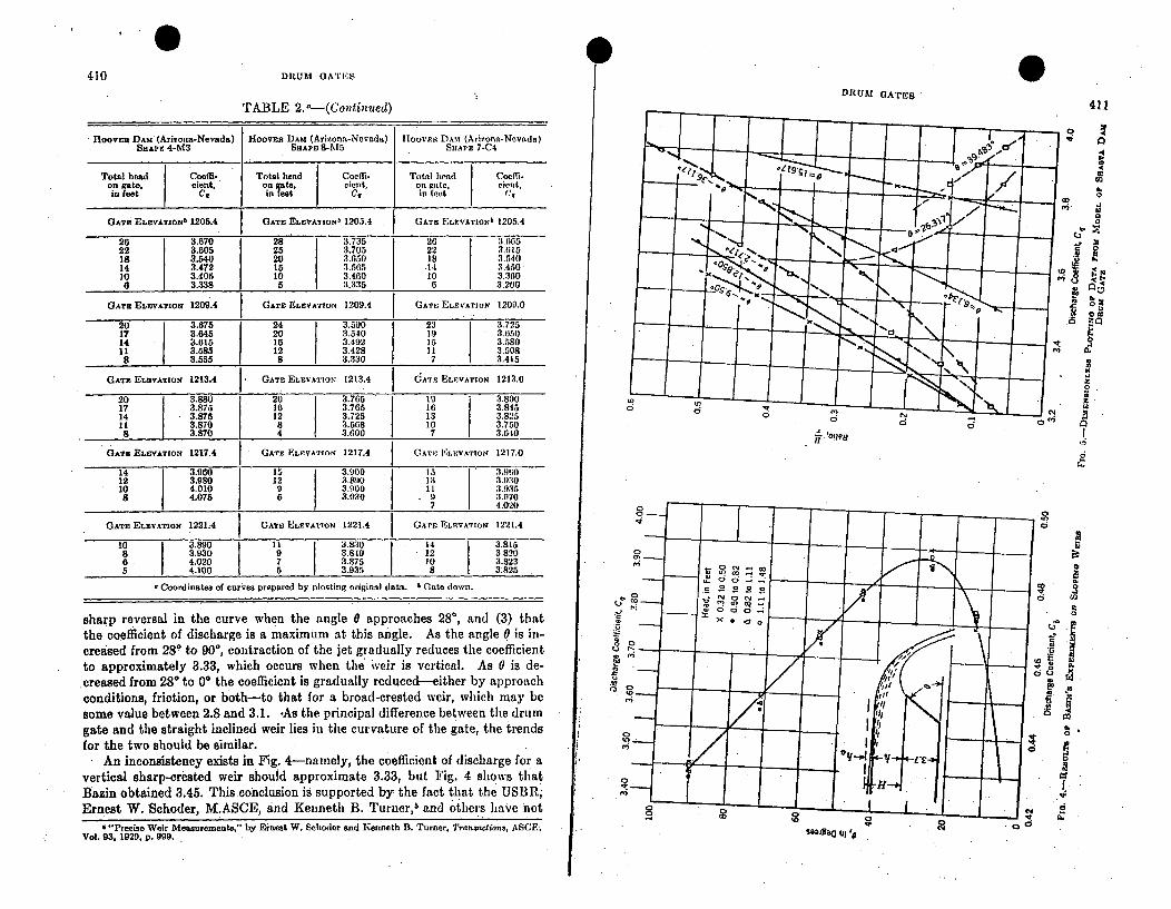
0410 DRUM GATEi:S
TABLE 2. -- (Continued)
HOOVEn DAM (Arizona-Nevada) Hooven DAM (Arizona-Nevada) llooVr DAMt (Arizona-Nevada)SHAPE 4-M3 SHAPE 8-3%5 SHAPE 7-C4
Total head Coeffi- Total hand Coefi- Total hend Cocfi-on gate, cient. on gate, cient, on gate. cient,in feet Cc in feet C, in feet C,
GATE ELEVATION' 1205.4 GATE ELEVATIONb 1205.4 GATE ELEVATIONb 1205.4
26 3.670 28 3.735 26 3.66522 3.605 25 3,705 22 3.11518 3.540 20 3.650 18 3.54014 3.472 15 3.565 *14 3.45010 3.405 10 3.460 10 3.3608 3.338 5 • 3.335 6 3.200
GATE ELEVATION 1209.4 GATE ELEVATION 1209.4 GATE ELEVATION 1209.0
20 3.675 24 3.590 23 3.72517 3.645 20 3.540 19 3.65014 3.615 16 3.492 15 3.58011 3.585 12 3.428 11] 3,508
8 3.655 8 3.330 7 3.415
GATE ELEVATIoO 1213.4 GATE ELEVATION 1213.4 dATE ELEVATION 1213.0
20 3.*880 . 20 3.765 193.80017 3.875 16 3.765 16 3.84514 3.875 12 3.725 13 3.82511 3.870 8 3.668 10 3.7508 3.870 4 3.600 7 3.640
GATE ELEVATION 1217.4 GATE ELEVATION 1217.4 GAT• ELEVATION 1217.0
14 3.960 15 U .00 IS 3.9W12 3.980 12 3.820 135 3.9:3010 4.010 9 3-900 11 3.9358 4.075 6 3.930 9 3.1170
S"_ 7 4.020
GATE ELEVATION 12214A GATE ELEVATION 1221.4 GATE ELEVATION 1221.4
10 3.890 11 3.830 3. 14 3.8t68 3.930 9 3:840 - 12 3.8206 4.020 7 3.875 10 3.8235 4.100 5 3.935 8 3:825
Coordinates of curves prepared by plotting original data. Gate down.
DRUMr GATES
.J
411
0
am0 ;r
hiiZ
.Zo
d ,
sharp reversal in the curve when the angle 0 approaches 28', and (3) thatthe coefficient of. discharge is a maximum at this angle. As the angle 0 is in-creased from 280 to 90*, contraction of the jet gradually reduces the coefficientto approximately 3.33, which occurs when the weir is vertical. As 0 is de-.creased from 280 to 0* the coefficient is gradually reduced--either by approachconditions, friction, or both-to that for a broad-crested weir, which may besome value between 2.8 and 3.1. -As the principal difference between the drumgate and the straight inclined weir lies in the curvature of the gate, the trendsfor the two should be similar.
An inconsistency exists in Fig. 4-namely, the coefficient of discharge for avertical sharp-crested weir should approximate 3.33, but Fig. 4 shows thatBazin obtained 3.45. This conclusion is supported by the fact that the USBR,Ernest W. Schoder, M.ASCE, and Kenneth B. Turner,5 and others have not
'"Precise Weir Measurements," by Ernest W. Schoder and Renneth B. Turner. Transaclions, ASCE.Vol. 93, 1929. p. 999. S43h100 Ul,,'
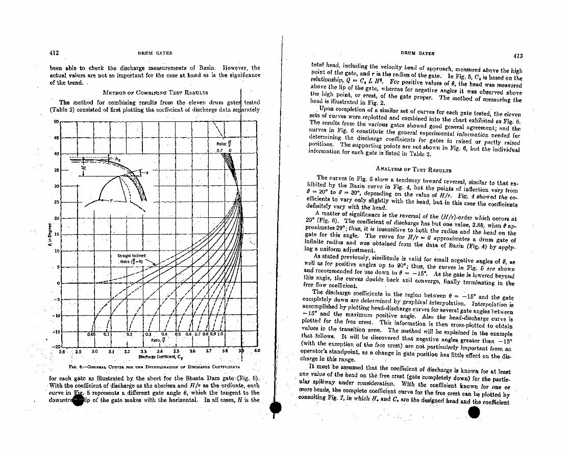
412 DRUM GATES
been able to check the discharge measurements of Bazin. However, theactual values are not so important for the case at hand as is the significanceof the trend.
METHOD OF ComBINiNo TEST IRESULTS
The method for combining results from the eleven drum gF(Table 2) consisted of first plotting the coefficient of discharge data
a•
........ 413
total }head, ircluding the velocity head of approach, measured above the highpooint of the gate, and r is the radius of the gate. In Fig. 5, C0 is based on therelationship, Q - C, L Hi. For positive values of 0, the head was measuredabove the lip of the gate, whereas for negative angles it was observed abovetile high point, or crest, of the gate proper. The method of measuring thehead is illustrated in Fig. 2.
Upon completion of a similar set of curves for each gate tested, the elevensets of curves were replotted and combined into the chart exhibited as Fig. 13.The results from the various gates showed good general agreement; and thecurves in Fig. 6 constitute the general experimental information needed fordetermining the discharge coefficients for gates in raised or partly raisedpositions. The supporting points are not shown in Fig. 6, but the individualinformation for each gate is listed in Table 2.
ANALYSIS OF TEST RESULTS
The curves in Fig. 6 show a tendency toward reversal, similar to that ex-hibited by the ]Bazin curve in Fig. 4, but the points of inflection vdry from0 = 20' to 0= 300, depending on the value of H/r. Fig. 4 showed the co-efficients to vary only slightly with the head, but in this case the coefficientsdefinitely vary with the head.A matter of significance is the reversal of the (II/r)-order which occurs at29' (Fig. 6). The coefficient of discharge has but one value, 3.88, when 0 ap-proximates 29°; thus, it is insensitive to both the radius and the head on thegate for this angle. The curve for 11/r 0 approximates a drum gate ofinfinite radius and was obtained from the data of Bazin (Fig. 4) by apply-ing a uniform adjustment.
As stated previously, similitude is valid for small negative angles of 0, aswell as for positive angles up to 90*; thus, the curves in Fig. 6 are shownand recommended for use down to 0 W. As the gate is lowered beyondthis angle, the curves double: back and converge, finally terminating in thefree flow coefficient.The discharge coefficients in the region between 0 = 15° and the gatecompletely down are determined by graphical interpolation. Interpolation isaccomplished by plotting head-discharge curves for several gate angles between-150 and the maximum positive angle. Also the head-discharge curve isplotted for the free crest. This information is then cross-plotted to obtainvalues in the transition zone. The method will be explained in the examplethat follows. It will be discovered that negative angles: greater than -I5°(with the exception of the free crest) are not particularly important from anoperator's standpoint, as a change in gate position has little effect on the dis-charge in this range.
It must be assumed that the coefficient of discharge is known for at leastone value of the head on the free crest (gate completely down) for the partic-ular spillway under consideration. With the coefficient known for one ormore heads, the complete coefficient curve for the free crest can be plotted byconsulting Fig. 7, in which H. and C. are the designed head and the coefficient
noa. 6.--G-NBVAL CUI&VES ?OK THE P)ErmuJqTa,;0; or DISCEARGE COEFFICIENTS
for each gate as illustrated by the sheet for the Shasta Dam gate (Fig. 5).With the coefficient of discharge as the abscissa and H/r as the ordinate, each,curve in1.• 5 represents adifferent gate angle 0, which the tangent to thedownstrilip of the gate makes with the horizontal. In all cases, 11 is the
I
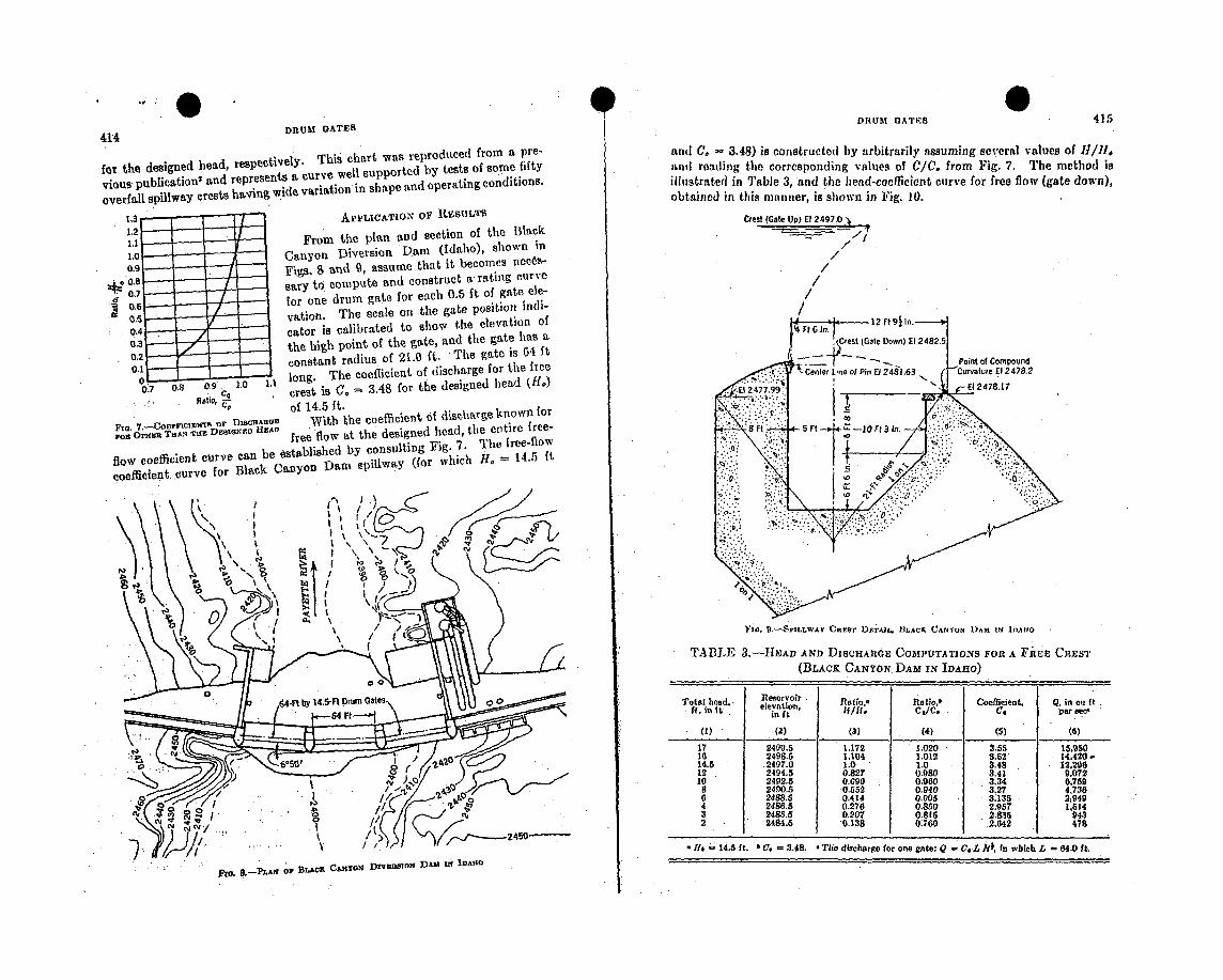
DRUtUM O(ATES 415
414 DRUM GATES
for the designed head, respectively. This chart was reproduced from a pre-
vious publicationt and represents a curve well supported by tests of some fifty
overfall spillway crests having wide variation in shape and operating conditions.
1.3 APPLICATION OF 11AESULT51.21.1 From the plan and section of the Black
1.0 Canyon Diversion Dam (Idaho), shown in
0.9 Figs. S and 9, assume that it becomes necos-
.0. sary to compute and construct a rating curve
ci t.5 for one drum gate for each 0.5 ft of gate ele-vation. The scale on the gate position ndi-
0.4 cater is calibrated to show the elevation of
00.3 the high point of the gate, and the gate has a
0.2 constant radius of 21.0 ft. The gate is 04 ft0.1
0. 9 1.1 long. The coefficient of discharge for the free
0.70.... 09 , " crest is C. = 3.48 for the designed head (ff.)... .. of 14.5 ft.
of 15 fWith e coefficient of discharge known for
SOE DgIGNEO H15AD free flow at the designed head, the entire free-
flow coefficient curve can be established by consulting Fig. 7. The free-flow
coefficient curve for Black Canyon Dam spillway (for which 110 = 14.5 ft
and C. - 3.48) is constructed by arbitrarily assuming several values of H11/,and reading the corresponding values of C/C, from Fig. 7. The method is
illustrated in Table 3, and the head-coefficient curve for free flow (gate down),
obtained in this manner, is shown in Fig. 10.
Crest (Gate UP) E? 2497.0
//
//
/
/
I'm. 9.-SriLLWAy CnEAA' DTrAz•., I3ACJE CANt•ON D)ASI IN IDJAlO
TABLE 3.-J-EAD AND DiscHAnGE CosIPuTATl.oNs FOR A FiviE CREST
(BLACK CANYON DAM IN IDAHo)
Total head. eservoir Ratio.' Ratlo,b Coefficieot, Q, in CI ftIr, in it. elevation, l/l. C O/C. CI per sece
(1) (2) () (4) (5) (6)
17 2490.5 1.172 1.020 3.55 15,950
16 2498.5 1.104 1.012 3.62' 14,420-
14.5 .2497.0 1.0 1.0 3.48 12.296
12 2494.5 0.827 0.980 3.41 9,072
10 2492.5 0.690 0.960 3.34 0,759
8 2490.5 0.552 0.940 3.27 4,736
6 2488.6 0.414 0.905 3135 2j949
4 2486.5 0.270 0.820 2.957 1.614
3 2485.5 0.207 0.815 2Z835 9432 2484.5 0.138 0.760 2.642 478
1 -I. 14.5 ft. • C. = 3.48. T Tie discharge for one gate: Q 0 C.L R1, in which L 64.0 It.
fto, ,9-PLM1 oI BUi&C CAXTo•N DIV;MSION DAM INh IDAHO
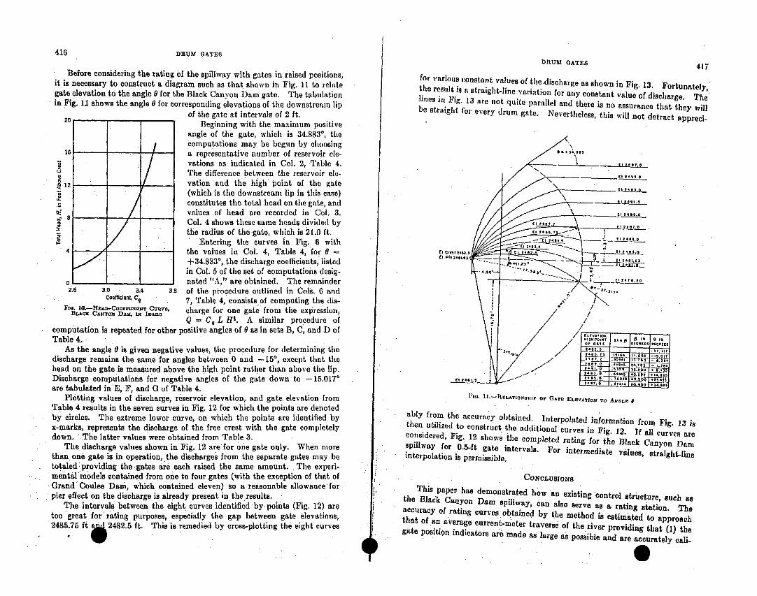
416 DRUM GATES DRUM GATES 417
Before considering the rating of the spillway with gates in raised positions,
it is necessary to construct a diagram such as that shown in Fig. 11 to relate
gate elevation to the angle 0 for the Black Canyon Dam gate. The tabulation
in Fig. 11 shows the angle 0 for corresponding elevations of the downstream lip
of the gate at intervals of 2 ft.
20 Beginning with the maximum positive
angle of the gate, which is 34.883', the
16 I computations may be begun by choosing
a representative number of reservoir elc-
vations as indicated in Col. 2, Table 4.
The difference between the reservoir ale-
12 vation and the high point of the gate
(which is the downstream lip in this case)
constitutes the total head on the gate, and
values of head are recorded in Col. 3.
Col. 4 shows these same heads divided by
the radius of the gate, which is 21.0 ft.
12 Entering the curves in Fig. 6 with
4 the values in Col. 4, Table 4, for 0 =
+34.883°, the discharge coefficients, listed
in Col. 5 of the set of computations desig-
o -nated "A," are obtained. The remainder
2.6 3.0 3.4 3.8 of the procedure outlined in Cols. 6 and
coefficient C9 7, Table 4, consists of computing the dis-
Fr. C0.-AHEAN-CoYNA r CUAnY, charge for one gate from the expression,
Q = C L H. A similar procedure of
computation is repeated for other positive angles of 0 as in sets B, C, and D of
Table 4.As the angle 0 is given negative values, the procedure for determining the
discharge remains the same for angles between 0 and -15*, except that the
head on the gate is measured above the high point rather than above the lip.
Discharge computations for negative angles of the gate down to -15.017'
are tabulated in E, F, and G of Table 4.Plotting values of discharge, reservoir elevation, and gate elevation from
Table 4 results in the seven curves in Fig. 12 for which the points are denoted
by circles. The extreme lower curve, on which the points are identified by
x-marks, represents the discharge of the free crest with the gate completely
down. The latter values were obtained from Table 3.
The discharge values shown in Fig. 12 are for one gate only. When more
than one gate is in operation, the discharges from the separate gates may be
totaled providing the gates are each raised the same amount. The experi-
mental models contained from one to four gates (with the exception of that of
Grand Coulee Dam, which contained eleven) so a reasonable allowance for
pier effect on the discharge is already present in the results.
The intervals between the eight Curves identified by points (Fig. 12) are
too great for rating purposes, especially the gap between gate elevations,
2485.75 ft •2482.5 ft. This is remedied by cross-plotting the eight curves
for various constant values of the discharge as shown in Fig. 13. Fortunately,
the result is a straight-line variation for any constant value of discharge. The
lines in Fig. 13 are not quite parallel and there is no assurance that they will
be straight for every drum gate. Nevertheless, this will not detract appreci-
El st 9.5m01 Pin 2eQ
el 2- 6..5 "-
FIG. lI.-REILATION•11ip OF GATE ELEVATION, TO ANGLE a
ably from the accuracy obtained. Interpolated information from Fig. 13 is
then utilized to construct the additional curves in Fig. 12. If all curves are
considered, Fig. 12 shows the completed rating for the. Black Canyon Dam
spillway for is0.5-ft gate intervals. For intermediate values, straight-line
interpolation is permissible.
CONCLUSION~S
This paper has demonstrated how an existing control structure, such as
the Black Canyon Dam spillway, can also serve as a rating station. The
accuracy of rating curves obtained by the method is estimated to approach
that of an average current-meter traverse of the river providing that (1) the
gate position indicators are made as large as possible and are accurately cali-
. SiI
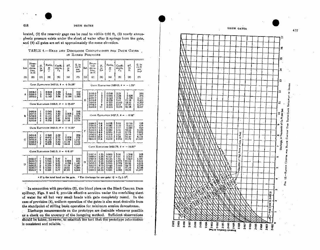
418DRUM GATES
0IUIUM OATES
419
brated, (2) the reservoir gage can be read to within 0.05 ft, (3) nearly atinos-
pheric pressure exists under the sheet of water after it springs from the gate,
and (4) all gates are set at approximately the same elevation.
TABLE 4.-HEAD AND DISCHARGE COMPUTATIONS FOn DRuM GATES
IN RAISED POSITIONS
Reser- Qin Resw-i
voir H, Ratio, Coeffi- 114, Q.i in 1, Ratio, Coeffi. I. i
Set eleva- in H cients, in cu it Set elera- in u | cnts, in cu It
tion, ftt 7 C, it per tion, It- 7 C' ft
it . et It ne
(1) (2) (3) (4) (5) (6) (7) (1) (2) (3) (4) (5) (6) (7)
GATE ELEVATION 2497.0; + + 34.89* GATE ELEVATIoN 2489.0: 0 - 1.28'
2498.0 10.048 3.8 1A 2499.00 2 0. 3.86 2..28 699 2490.0 1 0.0.18 3.21 1 205
A.292 3.86 2..9.
2500.0 3 0.143 3.86 5.196 1.283 2491.0 2 0.095 3.28 2.828 594
2492.0 3 0.143 3.34 5.190 1.111
E 12494.0 5 0.238 3.45 11.18 2.469
2.4960 7 0.333 3.515 18.42 4,202
GATE ELEVATION 2495.0; 0 = + 23.43* 2498.0 9 0.429 3.63 27.00 0.273
2500.0 1 0.52t 3.695 30.48 •i 8,627
2496. 1 0.048 3.85 1 246
2497.0 2 0.095 3.86 2
B 2498.0 3 0143 3.87 5.190 g 1,281 (;ATP ELXVATTON 2487.2; 0 - 8.28'
2499,0 4 0.190 3.87 8.00 1,979
2500.0 5 0.238 3.88 11.18 2,7702188.0 0.8 0.038 3.02 0.716 138
2489.0 1.8 0.080 3.10 2.415 479
GATE ELEVATION 2493.0; 6 - + 14.22* 2490.0 2,8 T,133 3.17 4.685 r 950
2192.0 4.8 0.229 3.31 10.52 2.2292194.0 6.8 0.324 3.13 17,73 3.892
2494.0 1 0.048 3.09 1 236 2196.0 8.8 0.419 3.51 23.10 5,803
2495.0 2 0.095 3.73 2.828 675 2498.0 10.8 0. 3 3 MS 35.49 8,131
C 2496.0 3 0.143 3.75 5.198 1,247 2500.0 12.8 0.610 M30 45.79 10.653
2498.0 5 0.238 3.80 11.18 2,719
2500.0 7 0.333 3.84 18.52 4,65250 , .• 1 5 GATE ELEVATION 2485.75; 0 - - 15.02'
GATm ELEVATION 2491.0; 0 + 6.13 - . - -
2187.0 1.25 0.000 3(00 1.398 268
24884.1 2.25 0.107 3.07 3.375 663
2492.0 1 0.048 3.47 1 222 2489.0 3.25 0.155 3.15 5.859 1.181
2493.0 2 0.095 3.51 2.828 635 G 2491.0 5.25 0-250 3.275 12.03 2,522
D 2494.0 3 0.143 3.57 5.196 1,187 . 2493.0 7.25 0.345 3.375 19.52 4,216
2490.0 5 0.235 3.63 11.18 2.597 2495.0 9.25 0.440 3.465 28.13 6,238
2498.0 7 0.333 3.70 18.52 4,386 2197.0 11.25 0.536 3.54 37.73 8,548
2500.0 9 0.429 3.77 27.00 6,515 2499.0 13.25 0.031 3.595 48.23 11,097
H is the total head on the gate. 4 The discharge for one gate: Q - C. L II1.
In connection with provision (3), the blunt piers on the Black Canyon Dam
spillway, Figs. 8 and 9, provide effective aeration under the overfalling sheet
of. water for all but very small heads with gate completely raised.. In the
case of provision (4), uniform operation of the gates is also most desirable from
the standpoint of stilling basin operation for minimum erosion downstream.
Discharge measurements on the prototype are desirable whenever possible
asa check on the accuracy of the foregoing method. Sufficient observations
should be taken, however, to establish te-fact that the prototype o"mation
is consistent and reliable.
0
0.
I.
.4
em
III U U0I1RAej3 JIoaMoogj N Y CI C4 N N
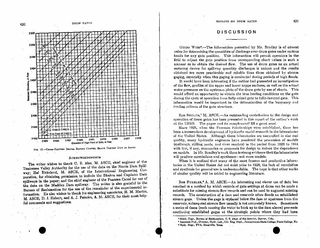
SIIULITS ON DRUM GATES 421
420 DRUM GATES
DISCUSSION
GuiDo Wss 6.- The information presented by Mr. Bradley is of utmost
value for determining the quantities of discharge over drum gates under various
)leads for any gate position. This information will permit operators in the
field to adjust the gate position from correspondiing chart values in such a
manner as to obtain the desired flow. The use of drum gates as an actual
metering device for spillway quantity discharges is unique and the results
obtained are more practicable and reliable than those obtained by Stream
gaging, especially when this gaging is conducted during periods of high floods.
It would have been interesting if the author had presented an investigation
of the flow, profiles of the upper and lower nappe surfaces, as well as the actual
water l)ressures on the upstream plate of the drum gate by use of charts. This
would afford an opportunity to obtain the true loading conditions on the gate
during the cycle of operation from fully-raised gate to fully-lowered gate. This
information would be important in the determination of the buoyancy and
Inading criteria of the gate structure.
SAM SlIULIrS,' M. ASCE.-An outstanding contribution to the design and
operation of drum gates has been presented in this report of the author's work
at the USI3R. The lpper andl its comnplCmcnt2 fill a great nee(d.
Since 192S, when the Freeeman Schl(arships were establidshed, there hias
been a tremendous development of hydraulic model research in the laboratories
of the United States. Although these laboratories are unexcelled in size and
quality, many hydraulic engineers have pondered the procession of models
(spillways, stilling pools, and river reaches) in the period from 1928 to 1953with few, if any, summaries or proposals for design to reduce the dependence
on models. In Mr. Bradley's work there is strong evidence that the laboratories
will produce correlations and syntheses-not more models.
When it is realized that many of the most famous and productive labora-
tories in the United States did not exist prior to 1928, the lack of correlation
and synthesis for general use is understandable. The hope is that other works
of similar quality will be added to engineering literature.
Ben BUEHLEn, 8 .A. M. ASCE.-An interesting and clever use of data has
resulted in a method by which records of gate settings at dams can be made asubstitute for missing stream-flow records and can be used to augment existing
records. The construction of a dam and reservoir often floods an established
stream gage. Unless the gage is replaced below the dam or upstream from the
reservoir, subsequent stream flow usually is not accurately known. Sometimes
a Series of dams (each causing the water to back up to the dam above) prevents
continuing established gages at the. strategic points where:they had been
2483 2485 247 2489. 2491 2493 2495 2497 2499
Elevation of High Point of Gate. in Feet
Fiz. 13.-CaoSS-PLOTTED INITIAL RATINg CunvEY BLACK C ANTON -DAM IN IDAHO
ACKNOWLEDGMENTS
The writer wishes to thank C. E. Blee, M. ASCE, chief engineer of the
Tennessee Valley Authority for the use of the data on the Norris Dam Spill-
way; Hal Birkeland, M. ASCE, of the International Engineering Cor-
poration, for obtaining permission to include the Bhakra and Capilano Dam
spiliways in the paper; and the chief engineer of the Panama Canal for use of
the data on the Madden Dam spillway. The writer is also grateful to the
Bureau of Reclamation for the use of the. remainder of the experimental in-
formation. He also wishes to thank his engineering associates, 11. M. Martin,
M. ASCE, D. J. Hebert, and A. J. Peterka, A. M. ASCE, for their most help-
ful comments and suggestions.
I Mech. Engr., Bureau of Reclamation, U. S. Dept. of the Interior, Denver, Colo.I Associate Prof., Director, Hydr. Lab., Cir. Eng. Dept., Pennsylvania State College, State College, Pa.
• Hydr. Engr., TVA, Knoxville, Tenn.E
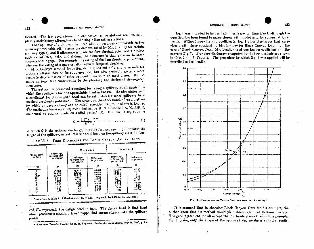
09BU1EItU ON DRUM GAlES 423
422 BUERLER ON DItUM GATES
located. The less accurate--and more costly--slope statiols are not cow-
pletely satisfactory alternatives to the single-line rating stations.
If the spillway of a dam canbe rated with an accuracy comparable to the
accuracy obtainable with a gage (as demonstrated by Mr. Bradley for certain
spillway types), and if allowance is made for flow through other whter outlets
such as turbines, locks, and sluices, the structure is then superior in soine
respects to the gage. For example, the rating of the damn should be permanent,
whereas the rating of a gage usually requires frequent checking.
Mr.-Bradley's method for rating drum gates not only allows records for
ordinary stream flow to be supplemented, but also probably gives a more
accurate determination of extreme flood rates than do most gages. lie has
made an important contribution to the planning and design of drun-gate~d
structures.The author has presented a method for rating a spillway at all heads pro-
vided the coefficient for one appreciable head is known. He also states that
a coefficient for the designed head can be estimated for most spillways by a
method previously published.' The writer, on the other hand, offers a method
by which an ogee spillway can be rated, provided its profile shape is known.
The method is based on an equation derived by R. N. Brudenell, A. M. ASC1E,
incidental to studies made on radial gates.' Mr. Brudenell's equation is
3 97 L H-112Q H D..-12 D ......................... (1)
in which Q is the spillway discharge, in cubic feet per second; L denotes the
length of the spillway, in feet; Ii is the total head on the spillway crest, in feet:
TABLE 5.-FREE DiCAO•RGES FOn BLACK CANYON DAM IN IDAHO
USING Eq. 1 USING FDo. 14
Total head, Discharge,in feet in cubic feet Dischrge 1 )iirrenro,
per second- Discharge, Difference, ioc ciice, eet iiree,
in cubic eet in percent if|re feeet
per second persecond
(1) (2) (3) (4) (5) (6)
17 15,950 15,847 -0.65 15,910 -0.25
1i 14,420 1,4363 -0.39 14,421 -0.01
14.5b 12,296 12.247' -0.40 .12,290 0
12 9,072 9,013 -0.05 9,049 -0.25
10 6,759 6,708 -0.75 6,735 -0.30
8 4,736 4,073 -1.33 4,692 -0.93
6 2,949 2,932 -0.58 2,944 -0.20
4 1,514 1,521 +0.46 1,527 +0.8G
3 0943 954 +1.17 958 +1.59
2 478 494 +3.35 496 +3.76
- Froma Col. 8, Table 3. a Head at which C, -3.48. * C, would be 3.486 for this discharge.
and Hfi represents, the design head in feet. The design head is that head
which produces a standard lower nappe that agrees closely with the spillway
profile.
I "Flow over Rounded Create," by R. N. Brudenell. Enginering Neiv-Record. July 18, 1935, p. 95.
Eq. I wits intended to be used with heatds greiater than ll,/4, although theequation has been found to agree closely with model data for somewhat lower
heads. Without knowing any coefficients, Eq. I gives discharges that agree
closely with those obtained by MAr. Bradley for Black Canyon Dam. In the
case of Black Canyon Dain, Mr. Bradley used one known coefficient and the
curve of Fig. 7. Free-flow discharges computed by the two methods are shown
in Cols. 2 anu 3, Table 5. The procedure by which Eq. 1 was applied will be
des(ribed subsequently.
1.8 - -
1.5 - -
1.4
1.2
21.0
S0.8~________
/
0.6
o I.OI
/ Fig.7,
7-
/S/
0.
0.2
015 0.80 0.85 0.90 0.95 1.00 1.05 1.I0
Value of the Ratio ce
Fia. 14.-Co.mPARISON oF VALUES O rBTAINEDYnoi FIG. 7 A. , Eq. 1
It is assumed that in choosing Black Canyon Dam for his example, the
author knew that his method would yield discharges close to known values.
The good agreement for all. except the low heads shows thai, in this example,
Eq. I (using only the shape of the spillway) also produces suitable results.
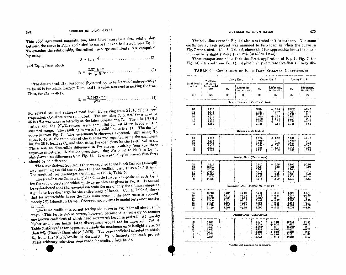
424 BUEHLER ON DRUM GATES
This good agreement suggests, too, that there must. be a close relationship
between the curve in Fig. 7 and a similar curve that can be derived from Eq. -.
To examine the relationship, theoretical discharge coefficients were computed
by using
BUEHLER ON DRUM GATES 425
The sod-line curve in Fig. 14 also was tested in'this manner. The samecoefficient at each project was assumed to be known as when the curve in
Fig. 7 was tested. Col. 8, Table 6, shows that for appreciable heads the mnaxi-
munm error is slightly nmore than 2% (Madden Dam).
These colmprisons show that the direct application of Eq. 1, Fig. 7 (or
Fig. 14) (derived from Eq. 1), all give highly accurate free-flow spillway dis-
TABLE 6.-CoMPARIsON 01' FIEE-FLow SrILLWAY COEFPICIE•NTSand Eq. 1, from which
Q Cq L IP2.......................
3.97 i"n .. (3)c, -- /2. . . . . . . . . . .. . . . . . . . . . . . .. . . 3
The design head, 11D, was found (by a method to be described subsequently)
to be 45 ft for Black Canyon Dam, and this value was used in making the test.
Thus, for HD 45 ft,2.5 143 tI1 0)
For several assumed values of total head, II, varying from 2 ft to 58.5 ft, cor-
responding CG-values were computed. The resulting Cq of 3.97 for a head of
45 ft (ff.) was taken arbitrarily as the known coefficient, C.. Then the (II/IH.)
-ratios and the (Cq/Co)-ratios were computed for all other heads in the
assumed range. The resulting curve is the solid line in Fig. 14. The dashed
curve is from Fig. 7. The agreement is close-as expected. Still using HD
equal to 45 ft, the remainder of the process was repeated using the coefficient
for the 25-ft head as C., and then using the coefficient for the 12-ft head as C0.
There was no discernible difference in the curves resulting from the three
separate selections. A similar procedure, using Hp equal to 20 ft in Eq. 1,
also showed no differences from Fig. 14. It can probably be proved that there
should be no difference.
Thecurve derived from Eq. 1 then wasapplied to the Black Canyon Dai spill-
way, assuming (as did the author) that the coefficient is. 3.48 at a 14.5-ft head.
The resultant free discharges are shown in Col. 5, Table 5.
The free-flow coefficients in Table 2 invite further comparisons with Eq: I
for the four projects for which spillway profiles are given in Fig. 3. It should
be remembered that this comparison tests the use of only the spillway shape as
a guide to free discharge.for the entire range of heads. Col. 4, Table 6, shows
that for appreciable heads the maximum error in the four cases is approxi-
mately 2% (Hamilton Dam). Observed coefficients in model tests often scatter
as much..The same coefficients permit testing the curve in Fig. 7 for all eleven spill-
ways. This test is not as severe, however, because it is necessary to assumae
one known coefficient at which head agreement becomes perfect. At near-by
higher and lower heads, large divergences would not be expected. Col. 6,
Table 6, showsthat for appreciable heads the maximum error is slightly greater
than 2% (Hoover Dam, shape 8-M5). The base coefficient selected to obtain
C, from the (Cq/Co)-ratios is designated by a footnote for each project.
These arbitrary selections were made for medium high heads.
(oeffieielt U F.No EQ. I L'wxa I'm.7 UBInO Imo. 14
T o tal hIad, obtnined ._-in feet from ,uodel
iest f. .mifference. C9 Difrerence. pDifference,in percent in percent in percent
(1) (2) (3) (4) (5) (6) (7) (a)
GRAND CovLEr DAm (W.o,,,NUTOZN)
35 3.920 .3.914 - 0.15 3.902 "-0.4 6
30 3.842 3.831 - 0.29 3.827 -0.3925 3.745 3.745. 0 3.745- 0
20 3.635 3M655 + 0.55 3.651 +0.4$
15 3.510 3.550 + 1.14 3.524 +0.40
10 3.352 3.370 + 0.54 3.356 +0.12
5 3.220 3.138 2.54 3.168 -1.62
BIIAKIA DAAM (INDIA)
28 3.680 3.736 + 1.52 3.732 +1.41
23 3.645 3.015. 0 3.645- 0
18 3.550 3.547 - 0.08 3.543 -0.20
13 3.420 3.434 + 0.41 3.401 -0.47
8 3.275 3.215 - 1.83 3.208 -2.04
3 3.120 2.748 -11.92 2.854 -8.53
SlIASTA DAM (CALIOnRNIA)
38 3.895 3.910 + 0.39 3.899 +0.10
33 3.835 3.839 +.0.10 3.831 -0.10
28 3.760 3.760, 0 3.7(0, (0
2: *. 3.075 "M3.77 +, •005 3.674 -0(A0
I 3.575 3.591 , 0.45 3.568 -0.20
13 3.465 3.455 - 0.29 3.429 -1.04a 3.335 3.215 -- 3.60 3,230 -- 3.15
HAMILTON DAM (TEXAS) lID - 52 FT
35 3.710 3.785 +2.02 3.741 + 0.84 3.730 +0.54
30 3.645 3.716 +1.95 3.662 + 0.47 3.059 +0.3825 3.580 . 3.635 +1.54 3.580- 0 3.580. 0
20 3 3.500 3.539 +1.11 3.494 - 0.17 3.490 -0.29
15 3.400 3.420 +0.59 3.394 0.18 .3.369 --0.91
10 3.290 3.258 -0.97 3,222 2.07 3.208 --2.50
a 3.160 2.997 -6.10 31000 5.06 3.029 -4.14
FUAxN D•Jm (CAL•rorwuN)
20 3.050 3.717 + 1.84 3.700 +1.53
17 3.025 |3.039. + 0.39 -|3.632 +0.1914 3.550 3.550- 0 3.550' 0U 8.460 •3.408 - 0.06. [3.452 -0.23
8 3.340 3.348 -+ 024 3.319 -0,635 3&175 3.142 - 1.04 3.131 -1.38
2 2.005 -2.723 .15 2.812 -5.10
'Lencintasu2.812o n~n
a C:Oera~Cielt a.ssamen to be Kn~own.
4 S
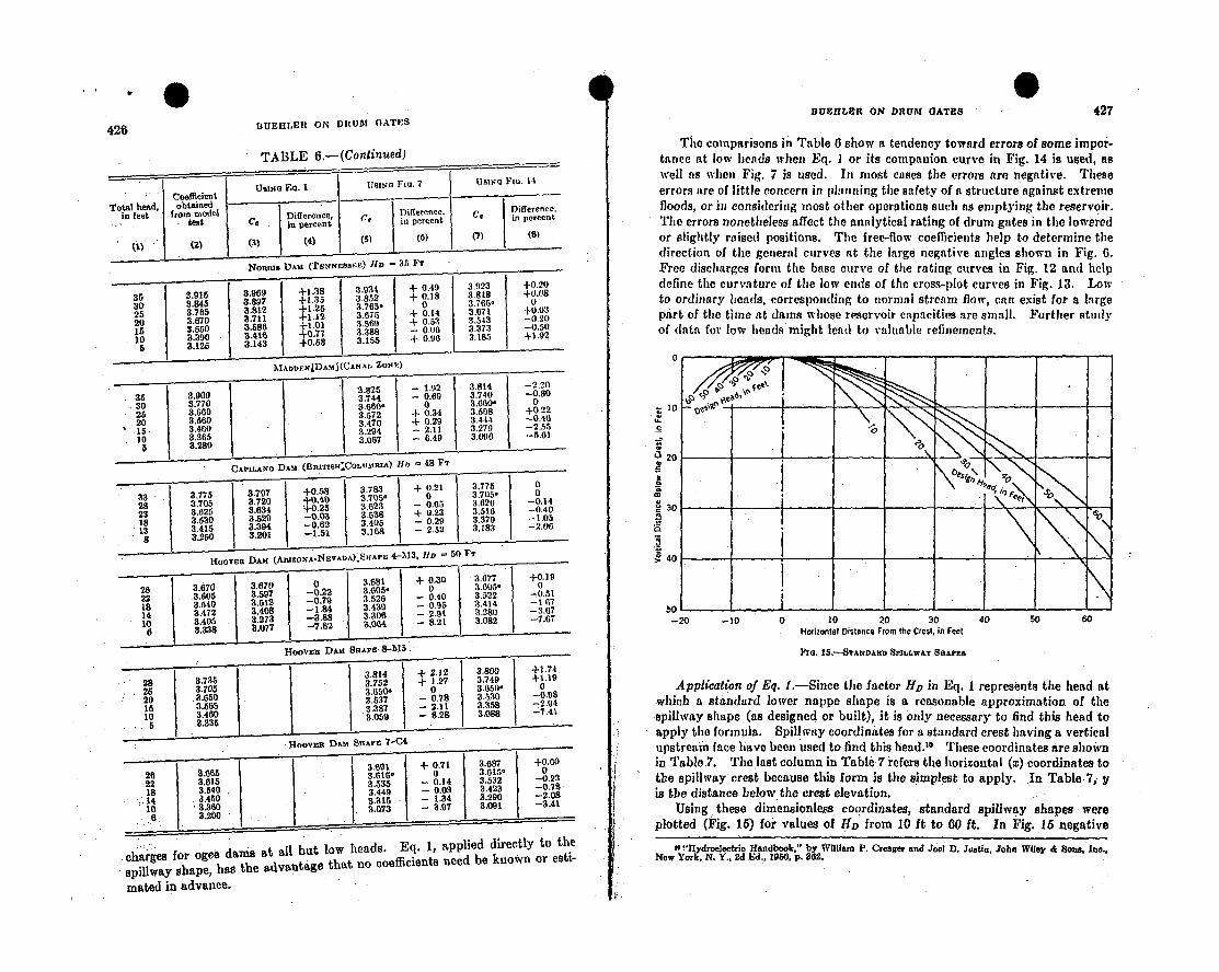
I IV@BtEllLnfl ON" DRUM GATES 427
BUEHLER ON DRtU24 GATES426
TABLE 6.-(Continued)The comparisons in Table 6 show a tendency toward errors of some impor-
tance at low heads when Eq. I or its companion curve in Fig. 14 is used, as
well as when Fig. 7 is used. In most cases the errors are negative. These
errors are of little concern in plafnning the safety of a structure against extreme
floods, or in considering most other operations such as emptying the reservoir.
The errors nonetheless affect the analytical rating of drum gates in the lowered
or slightly raised positions. The free-flow coefficients help to determine the
direction of the general curves at the large negative angles shown in Fig, 6.
Free discharges form the base curve of the rating curves in Fig. 12 and help
define the curvature of the low ends of the cross-plot curves in Fig. 13. Low
to ordinary heads, corresponding to normal stream flow, can exist for a large
part of the time at dams whose reservoir capacities are small. Further study
of data for low heads might lead to valuable refinements,
NotrRs DAM (TENiqEEsIE) 1tD 35 FT
35 3.915 3.969 +1+38 3 - 0.49 3.923 +0.20
30 3.845 31897 +1.35 3.852 + 0.18 3.818 +0,08
• 25 3.785 3.812 +1,25 3.765- 0 3.765' )
20 3.670 3.711 +112 3.675 + 0.14 3.071 +0.0315 3.650 3.586 +1.01 3.569 + 0.63 3.543 -0.20
10 3.390 3.41 -0.77 3.388 - 0.00 3.37:1 -0.50
5 3.125 3.143 i0.58 3.155 + 0.98 3.185 +1.92
MAoFlNjDAhfj(CANAt, 70, P.)
•.0 3.825 1.92 3.814 -2.20
S35 3.900 3.744 -0.69 3.740 -0.8030 3.770 3.7600o 3.660' 0
25 3.660 3.572 4 0.34 3.568 +0.22
20 .60 3.470 + 0.29 3.44.14 -0.40
1 3.460 3.294 2.11 3.279 -2.55
10 3.365 3.067 6.49 3.090 -5.015 3.280
* CAPILANO DAM (BnITrH:CoLUMR1A) Bb = 48 Fr
33 " 3.775 3.797 +058 3.793 + 0.21 3.775 0
28 3.705 3 -3.72 . 3.05d 0 3.705- 023 3.25 3.634 + 0.2 3.623 - 0.05 3.620 -0.14
• 18 3.530 3.529 -0.04 3.538 •+0.23 3.510 -0.4013 3.415 3,394 -0.02 3.405 +- 0.29 3.379 -5.158 3.250 3.201 -1.51 3.168 - 2.52 3.183 -2.05
HOOVER DAM (AIlgZONA-NEVADA)" SuAPE 4-1M3, Hie 50 FT
26 3.70 3.70 0 .61 + 0.30 ý1 3.077 +0,1922 I. 3.60 3 -. 605 0 3.P05' 0
18 3.540 3.512 -0.79 3.522 - 0.40 3.522 -0.51
145 3472 3.408 -1.84 3.439 0.95 3.414 -- (17
10 3.405 3.273 -3.88 3.306 2.91 3.289 --3.67
* 3.338 3.077 -7.82 " 3.064 8.21 3.082 -7.07
HoovEr DAM, SHAPE 8--115
3.84 2.12 3.800 +1.7420"3.85• 3752 T l27 3.749 +1.19
25 3.705 3.6504 0 V3.0.50 0
5 o 3.6- 10 3.537 -0.78 3.530 -0.08
15 3.450 5 3.387 2.11 3.358 -2.94
105 3.33540 3.059 8.28 3.088 -1.41
HOVRD~m BRAPE 7-C4
2 3685 " 3.691 + 071 3.087 +0.0022 um1 - 3.615- 0, 3.015' -0.222 3.5015 .3.535 - 0.14 3.32 -0.2314 3.450 3449 - 0.03 3.423 -0.78
:.14 3.560 3.315 - - 1.34 3.290 I -2.0610 83.0 3.073 - 3.97 3.091 . -3.41
..charges for ogee dams at all but low heads. Eq. 1, applied directly to the
spillway shape, has the advantage that no coefficients need be known or esti-
mated in advance.
10
U 20
30
40
50 L--20 -10 0 10 20 30 40 50 60Horizontal Distance From the Crest, in Feel
FING, 15,'--STrANDARD SILLhW.XY BRAVES
Application of Eq. I.-Since the factor HZ in Eq. 1 represents the head at
which a standard lower nappe shape is a reasonable approximation of the
spillway shape (as designed or built), it is only necessary to find this head to
apply the formula. Spillway coordinates for a standard crest having a vertical
upstream face have been used to find this head.10 These coordinates are shown
in Table 7. The last column in Table 7 refers the horizontal (x) coordinates to
the spillway crest because this form is the simplest to apply. In Table 7, y
is the distance below the crest elevation.
Using, these dimensionless coordinates, standard spillway shapes -were
plotted (Fig. 15) for values of HD from 10 ft to 60 ft. In Fig. .15 negative
Ne "Hydroelectric Handbook." by W6ll2. r P. Creaser and J001 D. Jutin, John Wiley & Son& Lao.,NwYork, N. Y., 2d FA•., 190,0 p. 362.
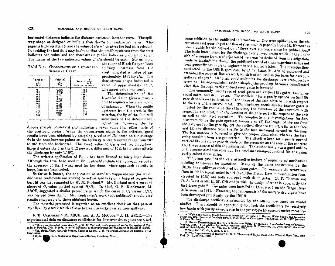
428 CAMPBELL AND MCeOOL ON DRUM GATESCAMPBELL AND MCCOOI, ON DRUM GATES 429
horizontal distances indicate the distance upstream from the crest. The spill-way shape as designed or built is then drawn on transparent paper. Thispaper is laid over Fig. 15, and the value of HD which gives the best fit is selected.In deciding the best fit it may be found that the profile upstream from the crestindicates one value and the downstream profile indicates a different value.The higher of the two indicated values of iID should be used. For example,
the shape of Black Canyon D'inuTABLE 7.-COORDINATES OF A STANDARD.
SPILLWAY CREST
Value of Value of/TX Value of
11D. referred to crest
0 0.126 -0.30.1 0.036 -0.20.2, 0.007 -0.10.3 0 00.4 0.007 0.10.6 0.063 0.3
.0.8 0.153 0.51.0 0.267 0.71.2 0.410 0.91.4 0.590 l..l1.7 0.920 1.42.0 .31 : 1.7.
spillway upstream from thecrest indicated a value of ap-proximately 45 ft for 1D. Thedownstream shape indicated avalue of approximately 25 ft.The larger, value was used.
The determination of theliD-value which gives a reason-able fit requires a certain aniountof judgmnent, When the profileupstream from the crest is thecriterion, the lip of the dam willsometimes be the determinant.Sometimes, however, the lip
droops sharply downward and indicates a lower value than other parts ofthe upstream profile.. When the downstream shape is the criterion, goodresults have been obtained by assigning, a value of HD based on the averagefit in the zone between points on the spillway where tangents range from 20'to 350 from the horizontal. The exact value of HD is not too important.Since it enters Eq. 1 in the 0.12 power, a difference of 10% in its value affectsthe discharge by only 1.15%.
The writer's application of Eq. 1 has been limited to fairly high dams.Although the total head used in Eq. 1 should include the approach velocity,the accuracy of Eq. 1 when used for low dams, where approach velocity islarge, has not been tested.
So far as is known, the application of standard nappe shapes (for whichdischarge coefficients are known) to actual spillways on a basis of reasonablebest fit was first suggested by W. M. Borlund.1' Mr. Borlund used a curve ofobserved Cr-value plotted against H/H,. In 1942, C. E. Kindsvater, M.ASCE, suggested a similar procedure in which the curve of Ci versus IU/1,was derived from Eq. 1. Mr. Kindsvater's work (not published) should giveresults comparable to those obtained herein.
The material presented is regarded as an excellent: check on that part ofMAr.: Bradley's work which relates to free discharge over an ogee spillway.
F'. B. CAMPBELL, 1 M•. ASCE, AND A. A. MCCOOL1,'1 J. M. ASCE.-Theexperimental data on discharge coefficients for flow over drum gates are a wel-
U "Flow over Rounded Crest Welis," by W. M. Borhumd, thesis presented to the University of Colo-:rado. at Boulder Colo., in 1938, in partial fulfilment of the requirement for the degree of Master of Science.12 CbI. Hydr. E., Analysis Branch, Corps of Engrs., U. S. Waterways Experiment Station. Vicks-
burg, M4is.isydro. U. 8.-Waterways Experiment Station, Viclksburg, Mis..
conic addition to the published information on flow over spillways, or the ob-servation and recording of the flow of streams. • A paper by Robert B. Horton has)been a guide for the estimation of flows over Spillways since its publieation.14Tie basic information for the discharge ovef curved crests which fit the underside of a nappe front a slharp-creste(f weir can be deduced from investigationsmade by Bazinl,.1,is although the published record of these experiments has notbeen generally available to engineers in the United States. Tle investigationsconducted by the USBR (proposed by E. W. Lane, Al. ASCE) embraced andextended the scope of Bazin's work which is often used as tile basis for overflowspillway shapes.1 Although good estimates for discharge over free-overflowcrests can be accomplished rather simply, the problem becomes complicatedwhen flow through partly opened crest gates is involved.
The commonly used types of crest gates are vertical lift gates, fainter orradial gates, and drum gates. The coefficient for a partly opened vertical liftgate depends on the location of the plane of the skin plate or lip with respectto the axis of the curved crest. The discharge coefficient for fainter gates isaffected by the radius of the skin plate, the elevation of the trunnion withrespect to the crest, and the location of the gate seat with respect to the axisis well as the crest curvature. To complicate any investigations further,observers define the gate opening variously as (1) the length of the are fromthle gate seat to the gate lip, (2) the vertical distance from the lip to the face,and (3) the distance fromn the lip to the face measured normal to the face.The last mnethod is believed to give the proper dimension, whereas the fore-going considerations are geometrical. Time effective head for a partly openedvertical lift or tainter gate depends on the pressures on the face of the concreteand the pressures within the issuing jet. The author has given a good outlineof the geometrical variables and the head-measurement method for analyzingpartly raised drum gates.The drum gate has the very attractive feature of requiring no mechanical
hoisting equipment for operation. Many of the dams constructed by the*s USBR have spillways controlled by drum gates. For example the ArrowrockDain in fdaho (constructed in 1915) and the Tieton Dam in Washington (con-structed in 1925) are both equipped with drum gates. B. F. Thomas andD. A. Watt credit If. Ai. Crittenden with the design of what is apparently thefirst drum gate.'7 The gates were installed in Dam No. 1 on the Osage Riverin Missouri in 1911* However, the refinements of the modern drum gate havebeen developed principally by the USBR.
The discharge coefficients presented by the author are based on modelstudies. There should be opportunity to check the coefficients for relativelylow heads with partly raised gates in the prototype by current-meter measure-
F, "NVeir Exeriments, Coefficient. and Formula,'" by Robert E. Horton. Water Supp, and ImgotienPar No, eO0• Coast and Geodetic Surrey, V. S. Dept. of Commerce, Washiogton., D. ., 1907 (revisionof Paper No. 150).
t '"Reent Experiments on the Flow of Water over Wler "by H. B .. e...Otober, 1888. Translation b Arthur Marichal and John... Tr.uta., Jr., Proceedings. Engineerst Cub of Philadelp Ia. Pa., Vol.~I 1No 5 la8op. 239.)"Ibid., Vol. IX, No. 3, 1')2, p. 231.If "The Improvement of Rivers." by. B. F. Thomas and D. A. Watt, John Wiley & Sons, Inc.. NewYork, N. Y., 2d Ed., 1913.
4
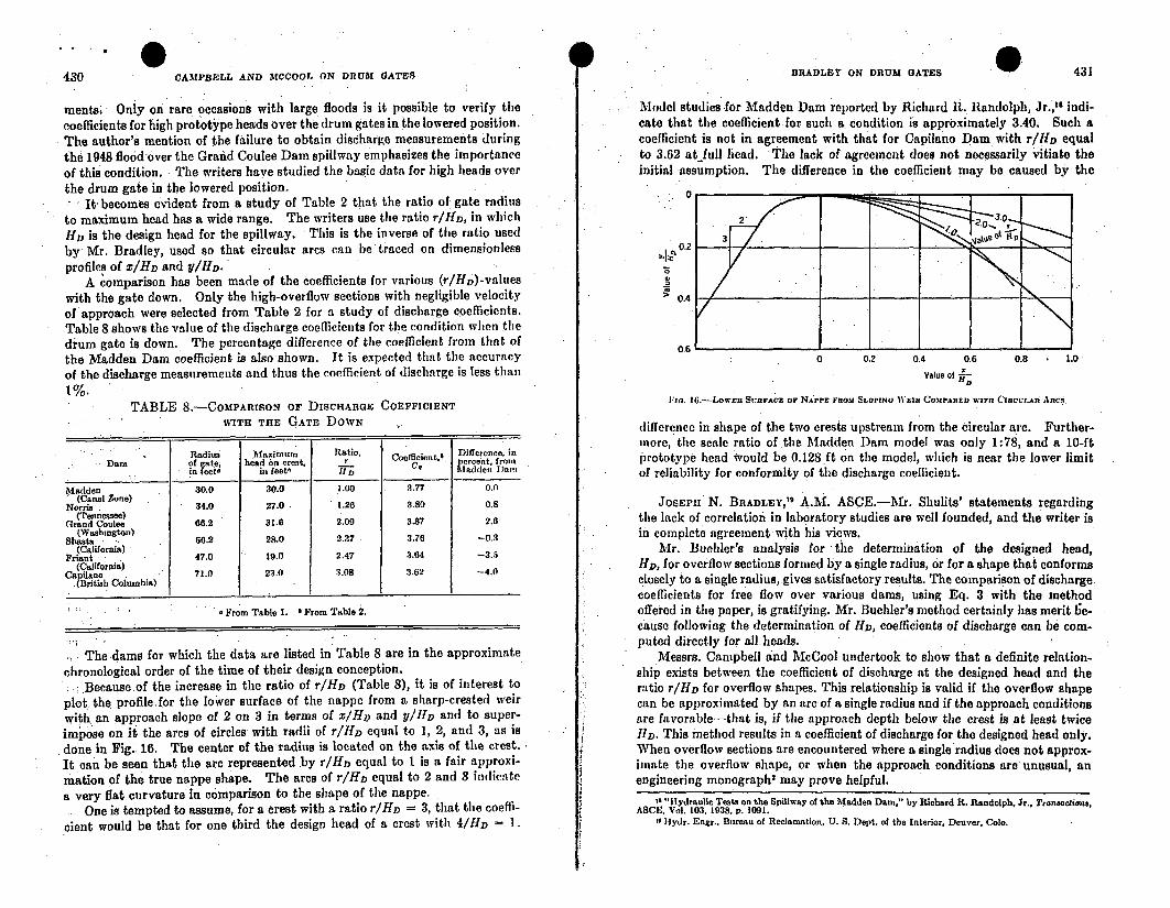
4 .31 10 0430 0
CAMPBELL AND MCCOOL ON DRUM OATES BRADLEY ON DRUM GATES 431
ments; Only on rare occasions with large floods is it possible to verify thecoefficients for high prototype heads over the drum gates in the lowered position.The author's mention of the failure to obtain discharge measurements duringthe 1948 flood over the Grand Coulee Dam spillway emphasizes the importanceof this condition. The writers have studied the basic data for high heads overthe drum gate in the lowered position.
X It becomes evident from a study of Table 2 that the ratio of gate radiusto maximum head has a wide range. The writers use the ratio rIHD, in which11D is the design head for the spillway. This is the inverse of tire ratio usedby Mr. Bradley, used so that circular arcs can be traced on dimensionlessprofiles of z/HD and y/HD.
A comparison has been made of the coefficients for various (r/HD)-valueswith the gate down. Only the high-overflow sections with negligible velocityof approach were selected from Table 2 for a study of discharge coefficients.Table 8 shows the value of the discharge coefficients for the condition when thedium gate is down. The percentage difference of the coefficient from that ofthe Madden Dam coefficient is also shown. It is expected that the accuracyof the discharge measurements and thus the coefficient of discharge is less than1%.
Model studies for Madden Dam reported by Richard R.. Randolph, Jr.,18 indi-cate that the coefficient for such a condition is approximately 3.40, Such acoefficient is not in agreement with that for Capilano Dam with r/HD equalto 3.62 at full head. The lack of agreement does not necessarily vitiate theinitial assumption. The difference in the coefficient may be caused by the
0
o
gc
0.2
0.4
0.60 0.2 0.4 0.6
Value ofB,
0.8 - 1.0
TABLE 8.-CoMPARISON OF DISCHARGEWITH THE GATE DOWN
COEFFICIENT
Radius Mlaxinum Ratio, Coefficient. Difference, inDam of gate, bead on crest, r Cofn Percent, fro,
in feefe in feet- 7-"D Aladden Dam
Madden 30.0 30.0 1.00 3.77 0.0(Canal Zone)
Norris . 34.0 27.0 1.26 3.80 0.8(Tennessee)
Grand Coulee 66.2 31.6 2.09 3.87 2.6(Wtashington)
Shasta 66.2 28.0 2.37 3.76 -0.3(California)
Friant 47.0 19.0 2.47 3.64 -3.5(California)
apihao .no 71.0 23.0 3.08 3,62 -4.0(British Columbia)
: From Table 1. & From Table 2.
The dams for which the data are listed in Table 8 are in the approximatechronological order of the time of their design conception.
Because of the increase in the ratio of r/ID (Table 8), it is of interest toplot the profile~for the lower surface of the nappe from a sharp-crested weirwith an approach slope of 2 on 3 in terms of x/IH and y/lID and to super-impose on it the ares of circles with radii of r/1 1
D equal to 1, 2, and 3, as isdone in Fig. 16. The center of the radius is located on the axis of the crest.It can be seen that the arc represented by r/HjD equal to 1 is a fair approxi-mation of the true nappe shape. The arcs of r/HD equal to 2 and 3 indicatea very flat curvature in comparison to the shape of the nappe.
- One is tempted to assume, for a crest with a ratio r/HD =- 3, that the coeffi-cient would be that for one third the design head of a crest with 4 /HD = I.
lia. 16-Lower Sr•RFAcE or NAPPE FROM SLOPING WEIR COMPARED WITSO OCULAa ARCS
difference in shape of the two crests upstream from the circular arc. Further-more, the scale ratio of the Madden Dam model was only 1:78, and a 10-ftprototype head would be 0.128,ft on the model, which is near the lower limitof reliability for conformity of the discharge coefficient.
JOSEPH N. BRADLEY,19 A.M. ASCE.-Mr. Shulits' statements regardingthe lack of correlation in laboratory studies are well founded, and the writer isin complete agreement with his views.
Mr. Buehler's analysis for the determination of the designed head,HD, for overflow sections formed by a single radius, or for a shape that conformsclosely to a single radius,gives satisfactory results. The comparison of dischargecoefficients for free flow over various dams, using Eq. 3 with the method.offered in the paper, is gratifying. Mr. Buehler's method certainly has merit 1e-cause following the determination of HD, coefficients of discharge can be com-puted directly for all heads.
Messrs. Campbell and McCool undertook to show that a definite relation-ship exists between the coefficient of discharge at the designed head and theratio r/HD for overflow shapes. This relationship is valid if the overflow shapecan be approximated by an arc of a single radius and if the approach conditionsare favorable-that is, if the approach depth below the crest is at least twiceRD. This method results in a coefficient of discharge for the designed head only.When overflow sections are encountered where a single radius does not approx-imate the overflow shape, or when the approach conditions are unusual, anengineering monograph' may prove helpful.
N Hydraulic Tests on the Spillway of the Madden Dam,." by Richard R. Randolph, Jr., Transactions,ASCEI, Vol. 103, 1938. p. 1091.
1 Iydr. Engr., Bureau of Reclamation, U. S. Dept. of the Interior, Denver. Colo.
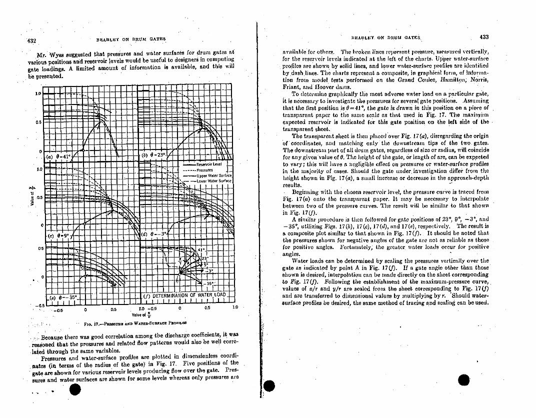
BRADLIEY. ON DRUM GATES 433432 BRADLEY ON DRUM GATES
Mr. *Wyss suggested that pressures and water surfaces for drum gates atvarious positions and reservoir levels would be useful to designers in computinggate loadings. A limited amount of information is available, and this will* be presented.
a'ailalhle for others. The broken lines represent pressure, measured vertically,for the reservoir levels indicated at the left of the charts. Upper water-surfaceprofiles are shown by solid lines,, and lower water-surface profiles are identifiedby dash lines. The charts represent a composite, in graphical form, of informia-tion from model tests performed oil the Grand Coulee, Hamilton, Norris,Friant, and Hoover dams.
To determine graphically thle most adverse water load on a particular gate,it is necessary to investigate the pressures for several gate positions. .Assuningthat the first position is 0= 410, the gate is drawn in this position on a piece oftransparent paper to the same scale as that used in Fig. 17. The maximumexpected reservoir is indicated for this gate position on the left side of thetransparent sheet.
• The transparent sheet is then placed over Fig. 17 (a), disregarding the originof coordinates, and matching only the downstream tips of the two gates.The downstream part of all drum gates, regardless of size or radius, will coincidefor any given value of 0. The height of the gate, or length of arc, can be expectedto vary; this will have a negligible effect on pressures or water-surface profilesin the majority of cases. Should the gate under. investigation differ from theheight shown in Fig. 17 (a), a small increase or decrease in the approach-depthresults.. Beginning with the chosen reservoir level, the pressure curve is traced fromFig. 17(a) onto the transparent paper. It may be necessary to. interpolatebetween two of the pressure curves. The result will be similar to that shownin Fig. 17(f).
A similar procedure is then followed forgate positions of 230, 90, -3*, and-350, utilizing Figs. 17(b), 17(c), 17(d), and 17(e), respectively. The result isa composite plot similar to that shown in Fig. 17(f). . It should be noted thatthe pressures shown for negative angles of the gate are not as reliable as thosefor positive angles. Fortunately, the greater water loads occur for positiveangles.
Water loads can be determined by scaling the pressures vertically over tilegate as indicated by point A in Fig. 17 (f). If a gate angle other than thoseshown is desired, interpolation can be made directly on the sheet correspondingto Fig. 17(f). Following the establishment of the maximum-pressure curve,values of x/r and V/r are scaled from the sheet corresponding to Fig. 17(f)and are transferred to dimensional values by multiplying by r. 'Should water-surface profiles be desired, the same method of tracing and scaling can be used.
-0.5
I I I Ij l(f) DE
0.5 r.O -0.5Value of
0,5 1.0-0.5
Fia. 17.-Pazausz: AND WATER-SURYACE PROFILES
.Becauge there was good correlation among the discharge coefficients, it wasreasoned that the pressures and related flow patterns would also be well corre-lated through the same variables.
. Pressures and water-surface profiles are plotted in dimensionless coordi-nates (in terms of the radius of the gate) in Fig. 17. Five positions of thegate are shown for various reservoir levels producing flow over the gate. Pres-sures and water surfaces are shown for some levels whereas only pressures are

FORT LOUDOUN DAM
-~
July 1998
June 1999 Ft.Loudoun ii
RESERVOIR OPERATION OVERVIEW
Fort Loudoun Dam is a multipurpose main river project, the uppermostof 9 such projects located on the Tennessee River which provide anavigable waterway from the mouth of the river at Paducah, Kentucky tothe source of the river above Knoxville, Tennessee, some 652 rivermiles apart. Fort Loudoun was constructed in the early 1940's as partof the War effort. In addition to completing the navigation linkalong the Tennessee River, Fort Loudoun provides significant floodreduction benefits for downstream locations including Chattanooga,Tennessee, and also contributes hydroelectric generation. FortLoudoun Lake is fed by releases from TVA'S Douglas and Cherokee Lakesin addition to the unregulated inflow from a significant localdrainage area which includes portions of the Great Smoky Mountains.Inflow to Fort Loudoun also is contributed by Tellico Lake, a TVAproject on the Little Tennessee River which is connected to FortLoudoun Lake via an unregulated canal.
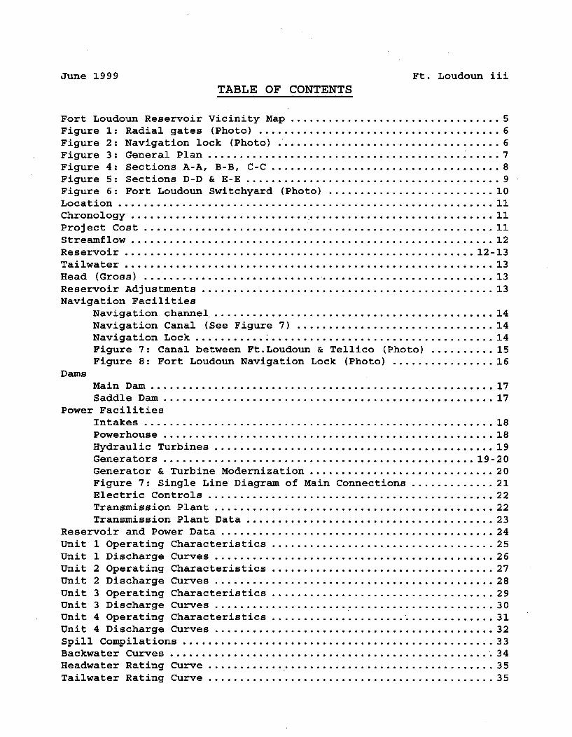
June 1999 Ft. Loudoun iiiTABLE OF CONTENTS
Fort Loudoun Reservoir Vicinity Map ................................. 5Figure 1: Radial gates (Photo) ...................................... 6Figure 2: Navigation lock (Photo) ...................................... 6Figure 3: General Plan .............................................. 7Figure 4: Sections A-A, B-B, C-C .................................... 8Figure 5: Sections D-D & E-E ........................................ 9Figure 6: Fort Loudoun Switchyard (Photo) ........................... 10Location ........................................................... 11Chronology ......................................................... 11Project Cost . ...................................................... 11Streamflow ......................................................... 12Reservoir ....................................................... 12-13Tailwater .......................................................... 13Head (Gross) ....................................................... 13Reservoir Adjustments .............................................. 13Navigation Facilities
Navigation channel ............................................. 14Navigation Canal (See Figure 7) ............................... 14Navigation Lock ............................................... 14Figure 7: Canal between Ft.Loudoun & Tellico (Photo) .......... 15Figure 8: Fort Loudoun Navigation Lock (Photo) ................ 16
DamsMain Dam ...................................................... 17Saddle Dam .................................................... 17
Power FacilitiesIntakes ....................................................... 18Powerhouse .................................................... 18Hydraulic Turbines ............................................ 19Generators ................................................. 19-20Generator & Turbine Modernization ............................. 20Figure 7: Single Line Diagram of Main Connections ............. 21Electric Controls ............................................. 22Transmission Plant ............................................ 22Transmission Plant Data ....................................... 23
Reservoir and Power Data ...... . ..................................... 24Unit 1 Operating Characteristics ................................... 25Unit 1 Discharge Curves ............................................ 26Unit 2 Operating Characteristics ................................... 27Unit 2 Discharge Curves ............................................ 28Unit 3 Operating Characteristics ................................... 29Unit 3 Discharge Curves ............................................ 30Unit 4 Operating Characteristics ..................................... 31Unit 4 Discharge Curves ............................................ 32Spill Compilations ................................................. 33Backwater Curves ................................................... 34Headwater Rating Curve .............................................. 35Tailwater Rating Curve ............................................. 35
June 1999 Ft. Loudoun iv
TABLE OF CONTENTS (CONT.)
Maximum & Minimum Elevations ..................................... 36-37Average Weekly CFS ............................................... 38-42Annual Operating Cycle ............................................. 43Reservoir Areas and Volumes ........................................ 44Safety modifications for probable maximum flood ................. 45-46Figure 10: Barrier wall atop south embankment ....................... 47Figure 11: Barrier wall atop right rim saddle dam (near marina) .... 47Figure 12: Embankment paving adjacent to navigation Lock .......... 48Housing Facilities ................................................. 49Original Construction Data
Personnel ..................................................... 49Quantities .................................................... 49
Figure 13: Construction Plant Layout ............................... 50Construction Schedule Units 3 & 4 .................................. 51Construction Schedule ........................................... 52-53
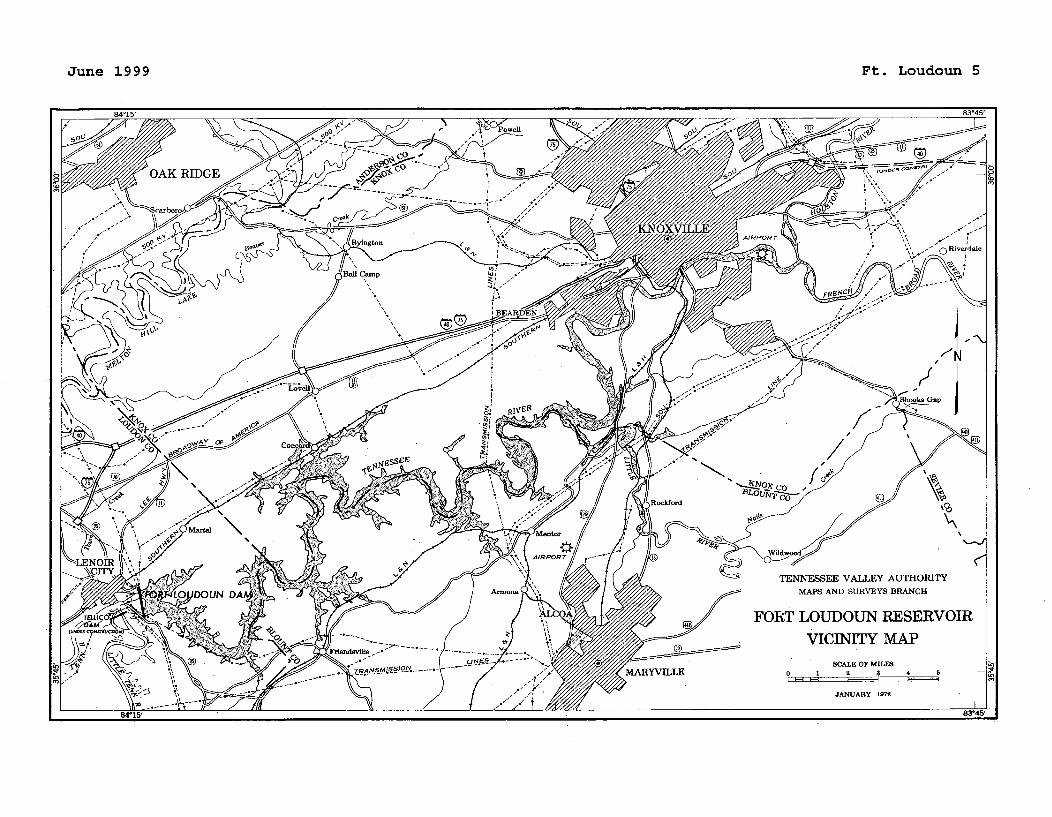
June 1999 Ft. Loudoun 5
TENNESSEE VALLEY AUTHORITYMAPS AND SURVEYS BRANCH
FORT LOUDOUN RESERVOIR
VICINITY MAPSCALE OF MILES
0 1 2 a 4 5
JANUARY 1972
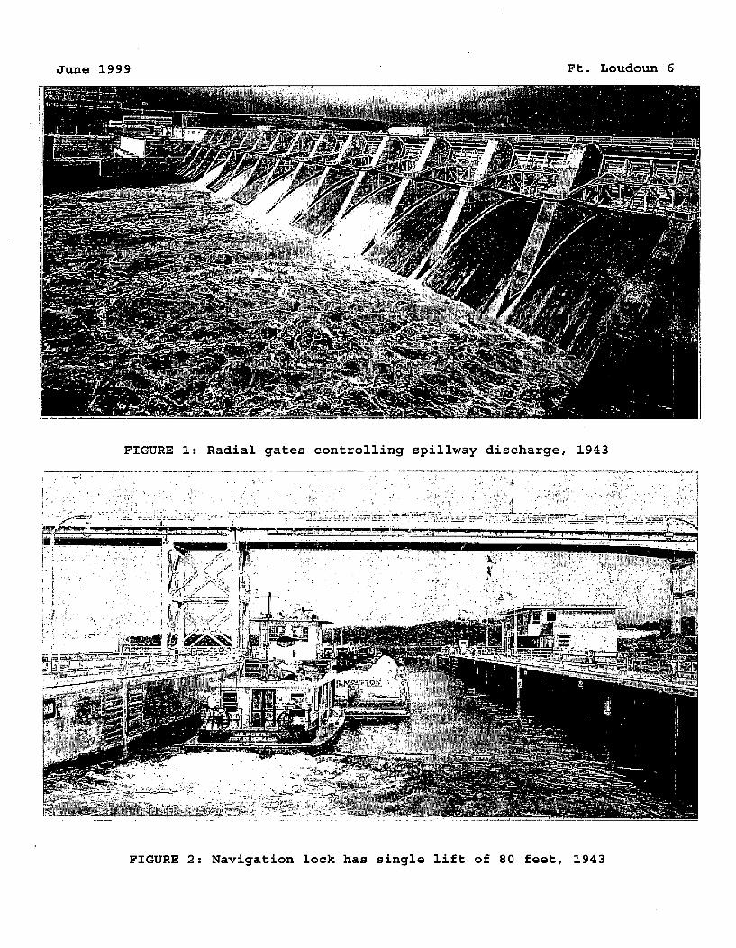
June 1999 Ft. Loudoun 6
FIGURE 1: Radial gates controlling spillway discharge, 1943
LW
fA1 --OS"
FIGURE 2: Navigation lock has single lift of 80 feet, 1943
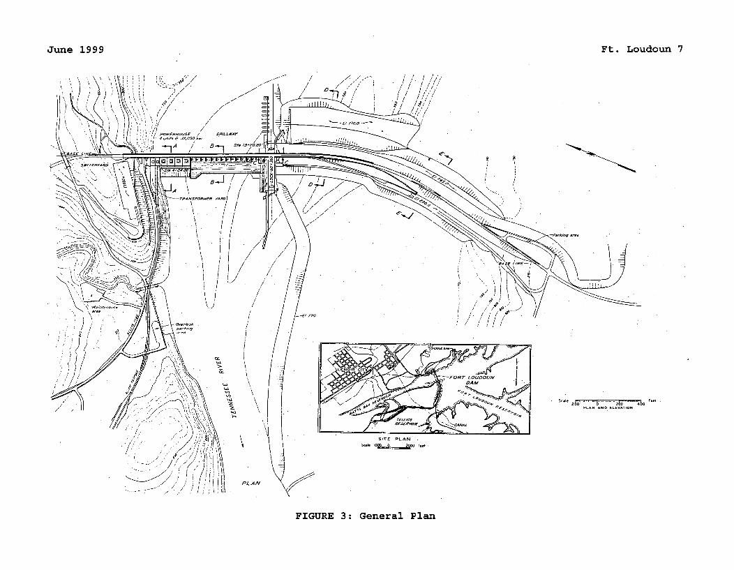
June 1999 Ft. Loudoun 7
/!
V
!770
c•
Scale - - -1 i.- Feet200 0 200 n00
-LN 'No E-eVATiON
SITE PLAN
PLAN.</ "V , .
FIGURE 3: General Plan
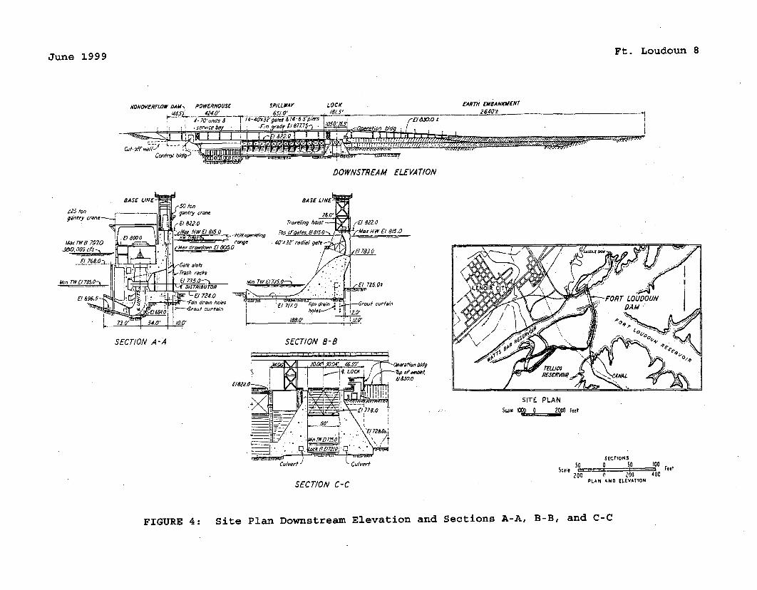
Ft. Loudoun 8June 1999
ONO'OVZRFLOW DAM, POWERHOUSE SPILLWAY LOCK424.0' 6510' . /5'
4- 70'uns t -5oiers
se ce bd I. .n qrad a &P 8 .081717' Y r b•d
Ccentrolb1 - ,
fARTH EMBANKME•NT2640'.f
-wAy''
DOWNSTREAM ELEVATION
B ASE LINE•,t50 ton
Z25r tone " V gantry cranegantry crane--•• (-EI8220
Mjar fl El 73Z0 El r815 e 0
Jd0, o00cfs -. c •~~'dwE&50El 8 0 107.; .Wpeatn
b. Gate slots0 (Trash racks
Miii TWEI 73 0-'. 5L 735.0. - Mign TWA-f ISTRIOUTOR
•!724. 09. -ý'dn drain holes
El 6 ,6 1 G curtain
SECT/ON A-A SECTION B-B
SITE PLANscale l Feet
SECTIONS50 0 50 100
Scale 'T - FeetM00 0 g00 400PLAN AND ELEVATIONO
Culvert Culvert
SECT/ON C-C
FIGURE 4: Site Plan Downstream Elevation and Sections A-A, B-B, and C-C
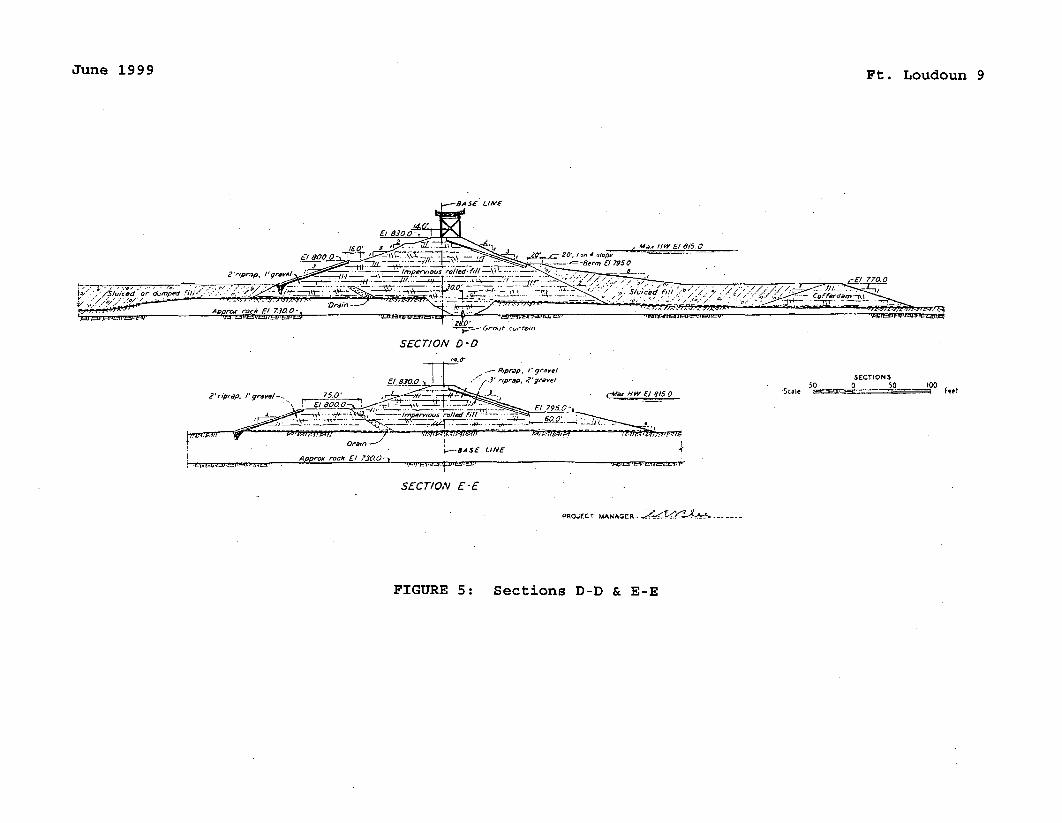
June 1999 Ft. Loudoun 9
8ASE LINE
Al•r roc El 7302 ,p,•p. /'g,-.s.e •.0.0_4L 2,z 2 /75.:,_,_. ..-..:_ - . , impe..rv..•,, ..-. II;
-•/ "'/siuA~i< Ord•med
SECTION D0-
,I 800 Cprap, Z gavel
2'riprap. g, e- 75.0' r Afa, HW V/ 815.0
~7~363~ V 799.0
-. .•...l> ..... ... ..-__, .•:• -• _• £ ..:_• .. .... • .Mr,
SECTIONS
-Scae '0 0 50 00 Ft
A.-0, ro-k '/ 7300-NK8ASE LINE 4
SECTION E-E
PROJECT MANAGER- ý_ ........
FIGURE 5: Sections D-D & E-E
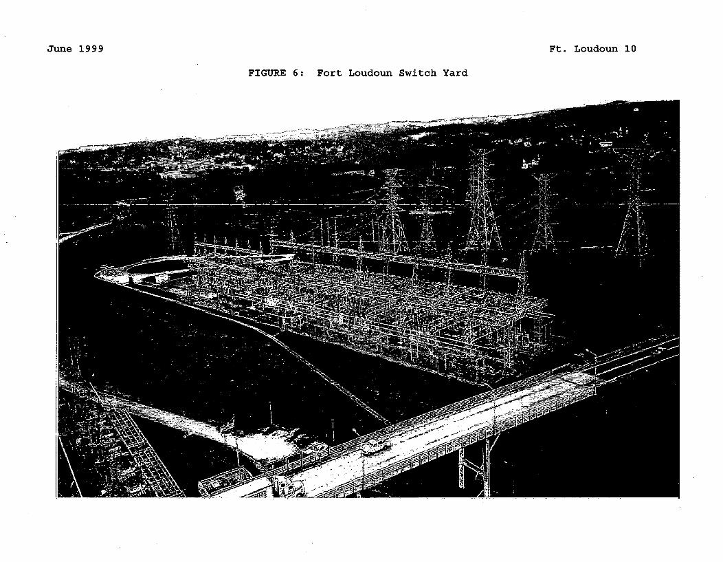
June 1999 Ft. Loudoun 10
FIGURE 6: Fort Loudoun Switch Yard
~- -e
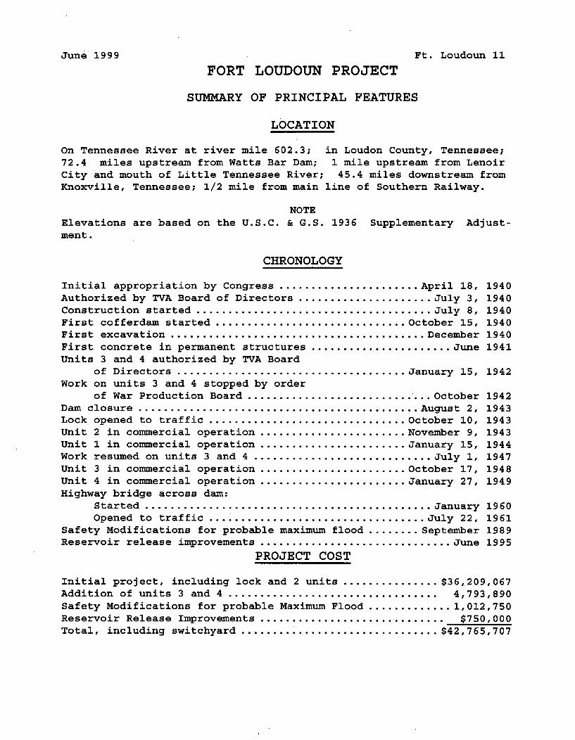
June 1999 Ft. Loudoun 11
FORT LOUDOUN PROJECT
SUMMARY OF PRINCIPAL FEATURES
LOCATION
On Tennessee River at river mile 602.3; in Loudon County, Tennessee;
72.4 miles upstream from Watts Bar Dam; 1 mile upstream from LenoirCity and mouth of Little Tennessee River; 45.4 miles downstream fromKnoxville, Tennessee; 1/2 mile from main line of Southern Railway.
NOTE
Elevations are based on the U.S.C. & G.S. 1936 Supplementary Adjust-
ment.
CHRONOLOGY
Initial appropriation by Congress ...................... April 18, 1940Authorized by TVA Board of Directors ..................... July 3, 1940Construction started ..................................... July 8, 1940First cofferdam started .............................. October 15, 1940First excavation ........................................ December 1940First concrete in permanent structures ...................... June 1941Units 3 and 4 authorized by TVA Board
of Directors .................................... January 15, 1942Work on units 3 and 4 stopped by order
of War Production Board ............................. October 1942Dam closure ............................................ August 2, 1943Lock opened to traffic ............................... October 10, 1943Unit 2 in commercial operation ....................... November 9, 1943Unit 1 in commercial operation ....................... January 15, 1944Work resumed on units 3 and 4 ............................ July 1, 1947Unit 3 in commercial operation ....................... October 17, 1948Unit 4 in commercial operation ....................... January 27, 1949Highway bridge across dam:
Started ............................................. January 1960Opened to traffic .................................. July 22, 1961
Safety Modifications for probable maximum flood ........ September 1989Reservoir release improvements .............................. June 1995
PROJECT COST
Initial project, including lock and 2 units ............... $36,209,067Addition of units 3 and 4 ................................. 4,793,890Safety Modifications for probable Maximum Flood ............. 1,012,750Reservoir Release Improvements .............................. $750,000Total, including switchyard ................................ $42,765,707
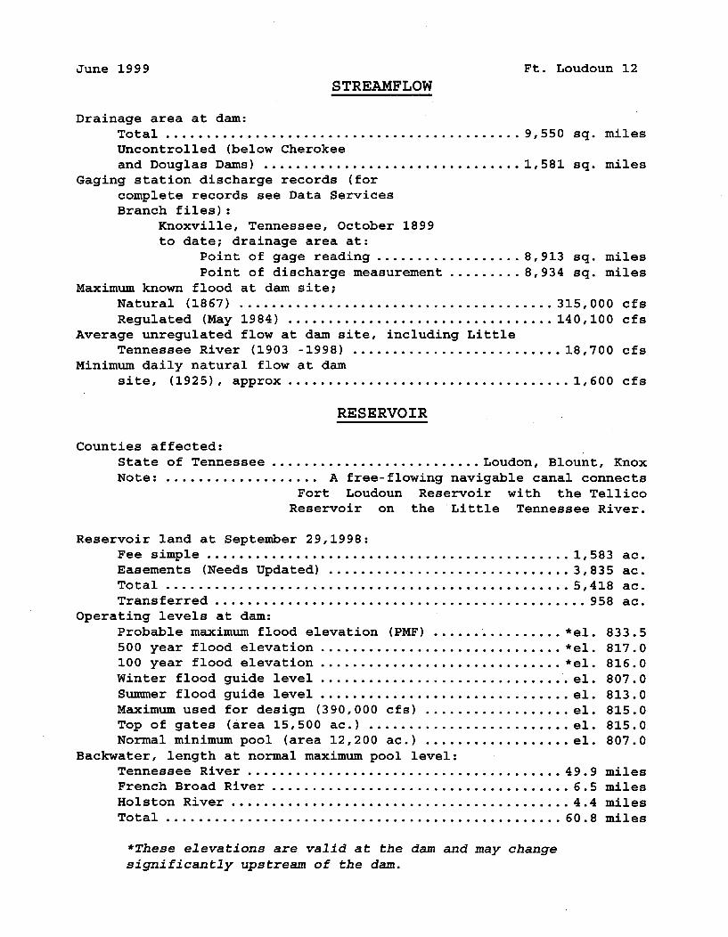
June 1999 Ft. Loudoun 12
STREAMFLOW
Drainage area at dam:
Total ............................................ 9,550 sq. miles
Uncontrolled (below Cherokee
and Douglas Dams) ................................ 1,581 sq. milesGaging station discharge records (for
complete records see Data ServicesBranch files):
Knoxville, Tennessee, October 1899to date; drainage area at:
Point of gage reading .................. 8,913 sq. miles
Point of discharge measurement ......... 8,934 sq. miles
Maximum known flood at dam site;
Natural (1867) ....................................... 315,000 cfs
Regulated (May 1984) ................................. 140,100 cfsAverage unregulated flow at dam site, including Little
Tennessee River (1903 -1998) .......................... 18,700 cfsMinimum daily natural flow at dam
site, (1925), approx ................................... 1,600 cfs
RESERVOIR
Counties affected:
State of Tennessee .......................... Loudon, Blount, KnoxNote: ................... A free-flowing navigable canal connects
Fort Loudoun Reservoir with the TellicoReservoir on the 'Little Tennessee River.
Reservoir land at September 29,1998:Fee simple ............................................. 1,583 ac.Easements (Needs Updated) .............................. 3,835 ac.Total .................................................. 5,418 ac.Transferred .............................................. 958 ac.
Operating levels at dam:
Probable maximum flood elevation (PMF) ................ *el. 833.5500 year flood elevation .............................. *el. 817.0100 year flood elevation .............................. *el. 816.0Winter flood guide level ................................ el. 807.0Summer flood guide level ............................... el. 813.0Maximum used for design (390,000 cfs) .................. el. 815.0Top of gates (area 15,500 ac.) ......................... el. 815.0Normal minimum pool (area 12,200 ac.) .................. el. 807.0
Backwater, length at normal maximum pool level:Tennessee River ....................................... 49.9 milesFrench Broad River ..................................... 6.5 milesHolston River .......................................... 4.4 milesTotal ................................................. 60.8 miles
*These elevations are valid at the dam and may changesignificantly upstream of the dam.
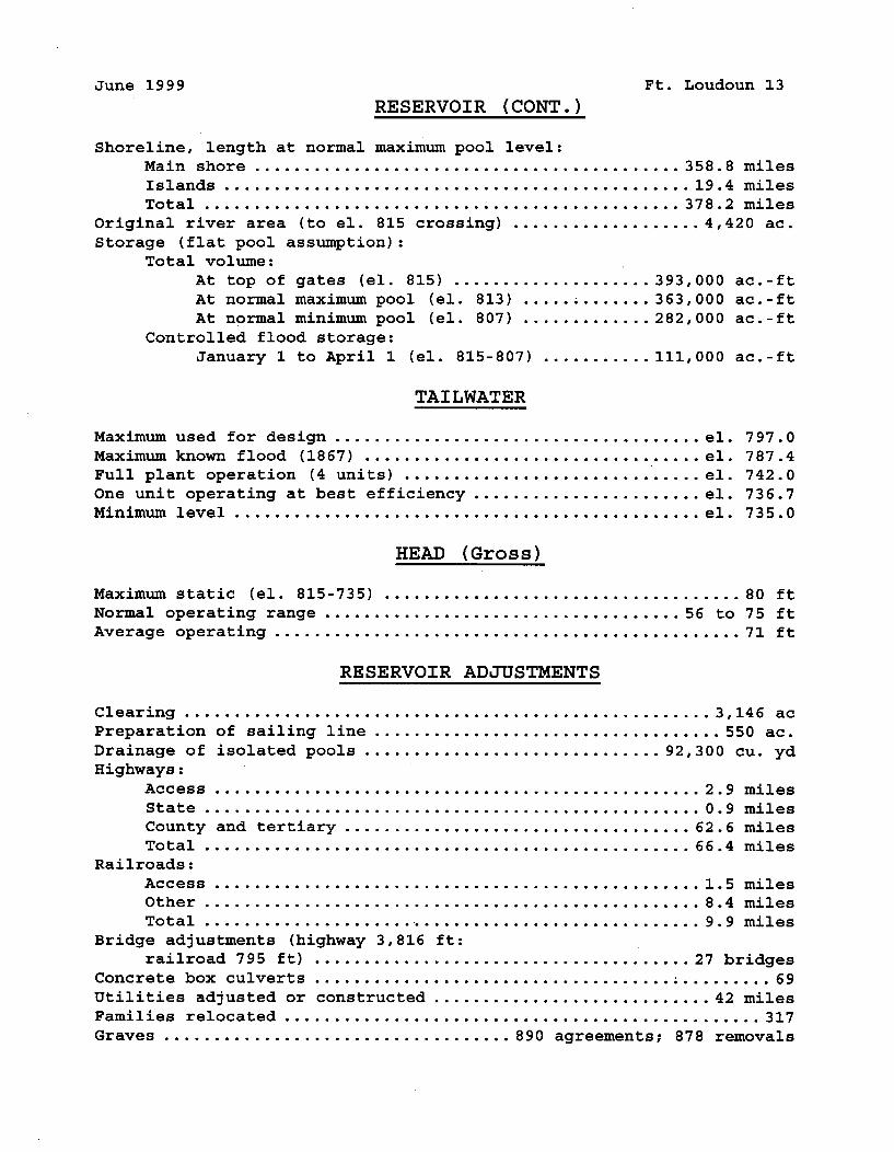
June 1999 Ft. Loudoun 13
RESERVOIR (CONT.)
Shoreline, length at normal maximum pool level:
Main shore ........................................... 358.8 milesIslands ............................................... 19.4 milesTotal ................................................ 378.2 miles
original river area (to el. 815 crossing) ................... 4,420 ac.Storage (flat pool assumption):
Total volume:
At top of gates (el. 815) .................... 393,000 ac.-ftAt normal maximum pool (el. 813) ..... ; ....... 363,000 ac.-ftAt normal minimum pool (el. 807) .............. 282,000 ac.-ft
Controlled flood storage:
January 1 to April 1 (el. 815-807) ........... 111,000 ac.-ft
TAILWATER
Maximum used for design ..................................... el. 797.0Maximum known flood (1867) .................................. el. 787.4Full plant operation (4 units) ............................... el. 742.0One unit operating at best efficiency ....................... el. 736.7Minimum level ............................................... el. 735.0
HEAD (Gross)
Maximum static (el. 815-735) .................................... 80 ftNormal operating range .................................... 56 to 75 ftAverage operating ............................................... 71 ft
RESERVOIR ADJUSTMENTS
Clearing ..................................................... 3,146 acPreparation of sailing line ................................... 550 ac.Drainage of isolated pools ............................... 92,300 cu. ydHighways:
Access ................................................. 2.9 milesState .................................................. 0.9 milesCounty and tertiary ................................... 62.6 milesTotal ................................................. 66.4 miles
Railroads:Access ................................................. 1.5 milesOther .................................................. 8.4 milesTotal ................................................... 9.9 miles
Bridge adjustments (highway 3,816 ft:railroad 795 ft) ...................................... 27 bridges
Concrete box culverts .................................... ; ......... 69Utilities adjusted or constructed ............................ 42 milesFamilies relocated ................................................ 317Graves ................................... 890 agreements; 878 removals
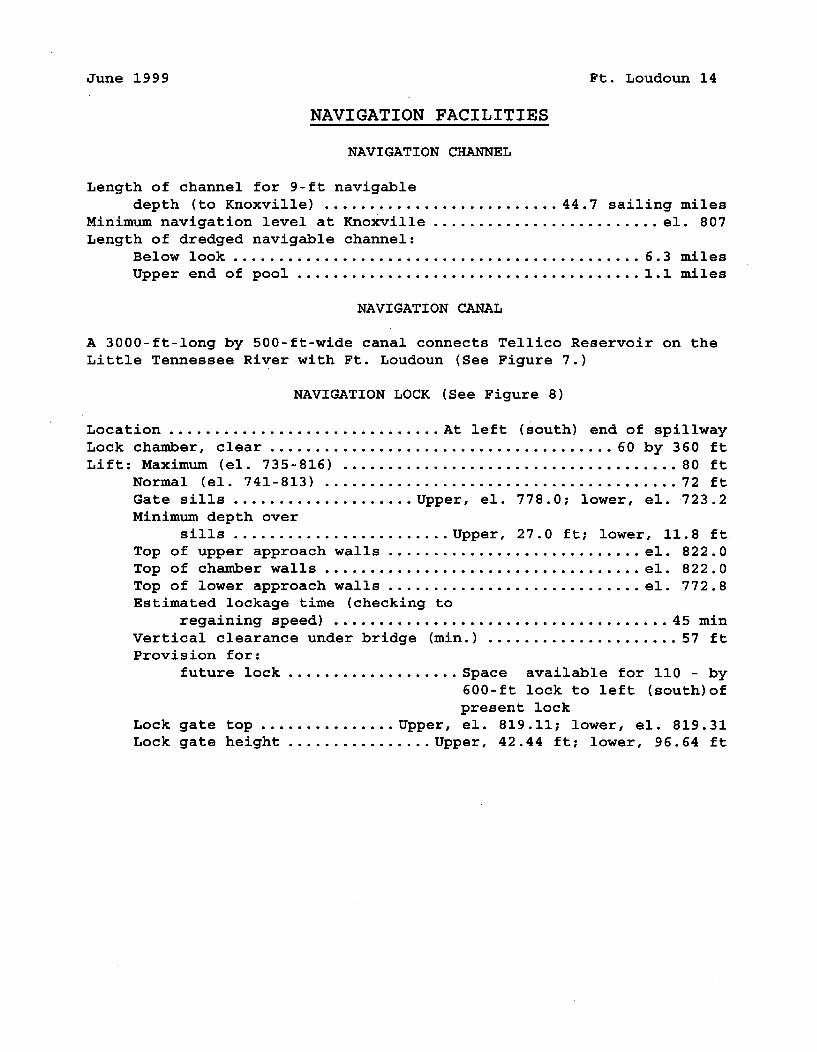
June 1999 Ft. Loudoun 14
NAVIGATION FACILITIES
NAVIGATION CHANNEL
Length of channel for 9-ft navigabledepth (to Knoxville) ........................... 44.7 sailing miles
Minimum navigation level at Knoxville ......................... el. 807Length of dredged navigable channel:
Below look ............................................. 6.3 milesUpper end of pool ...................................... 1.1 miles
NAVIGATION CANAL
A 3000-ft-long by 500-ft-wide canal connects Tellico Reservoir on theLittle Tennessee River with Ft. Loudoun (See Figure 7.)
NAVIGATION LOCK (See Figure 8)
Location .............................. At leftLock chamber, clear ...........................Lift: Maximum (el. 735-816) ...................
Normal (el. 741-813) .....................Gate sills ..................... Upper, el.Minimum depth over
sills ........................ Upper,Top of upper approach walls ..............Top of chamber walls .....................Top of lower approach walls ..............Estimated lockage time (checking to
regaining speed) ....................Vertical clearance under bridge (min.) ...Provision for:
future lock .................... Space
(south) end of spillway........... 60 by 360 ft................... 80 ft................... 72 ft778.0; lower, el. 723.2
27.0 ft; lower, 11.8 ft.............. el. 822.0.............. el. 822.0.............. el. 772.8
.................. 45 min
................... 57 ft
available for 110 - by600-ft lock to left (south)ofpresent lock
Lock gate top ............... Upper, el. 819.11; lower, el. 819.31Lock gate height ................ Upper, 42.44 ft; lower, 96.64 ft
June 1999 Ft. Loudoun 15
Canal between Ft. Loudoun & Tellico
FIGURE 7
<1
June 1999 Ft. Loudoun 16
Navigation Lock
FIGURE 8
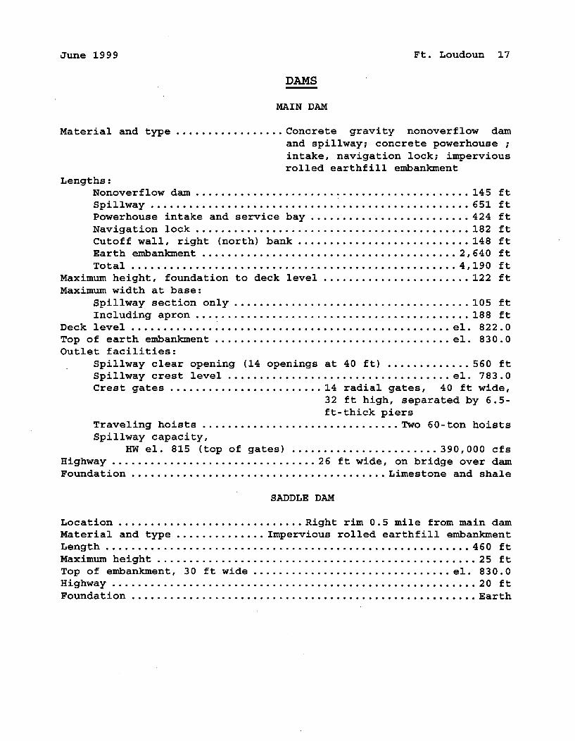
June 1999 Ft. Loudoun 17
DAMS
MAIN DAM
Material and type ................. Concrete gravity nonoverflow damand spillway; concrete powerhouse ;intake, navigation lock; imperviousrolled earthfill embankment
Lengths:Nonoverflow dam ........................................... 145 ftSpillway .................................................. 651 ftPowerhouse intake and service bay ......................... 424 ftNavigation lock ........................................... 182 ftCutoff wall, right (north) bank ........................... 148 ftEarth embankment ........................................ 2,640 ftTotal ................................................... 4,190 ft
Maximum height, foundation to deck level ........................ 122 ftMaximum width at base:
Spillway section only ..................................... 105 ftIncluding apron ........................................... 188 ft
Deck level .................................................. el. 822.0Top of earth embankment ..................................... el. 830.0Outlet facilities:
Spillway clear opening (14 openings at 40 ft) ............. 560 ftSpillway crest level ................................... el. 783.0Crest gates ......................... 14 radial gates, 40 ft wide,
32 ft high, separated by 6.5-ft-thick piers
Traveling hoists ............................... Two 60-ton hoistsSpillway capacity,
HW el. 815 (top of gates) ....................... 390,000 cfsHighway ................................ 26 ft wide, on bridge over damFoundation ........................................ Limestone and shale
SADDLE DAM
Location ............................. Right rim 0.5 mile from main damMaterial and type .............. Impervious rolled earthfill embankmentLength ......................................................... 460 ftMaximum height .................................................. 25 ftTop of embankment, 30 ft wide ............................... el. 830.0Highway ......................................................... 20 ftFoundation ....................................................... Earth
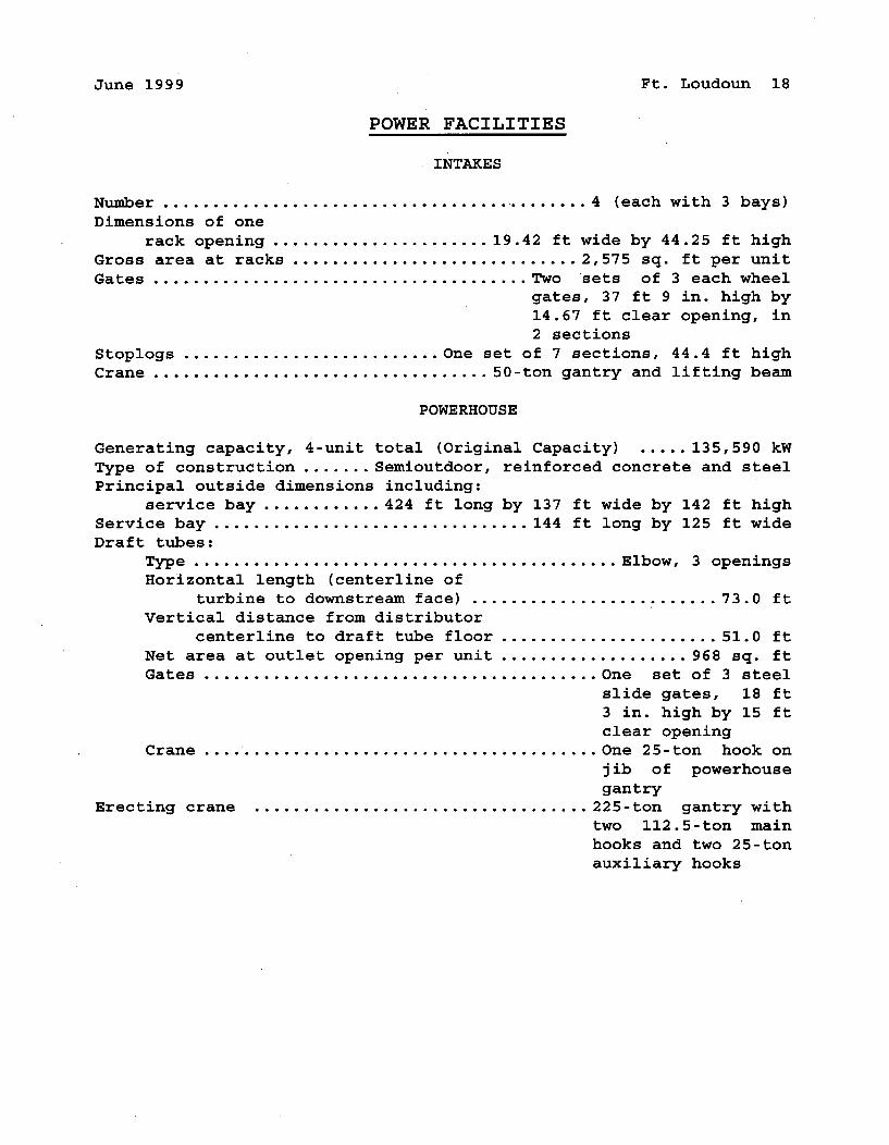
June 1999 Ft. Loudoun 18
POWER FACILITIES
INTAKES
Number ........................................... 4 (each with 3 bays)Dimensions of one
rack opening ....................... 19.42 ft wide by 44.25 ft highGross area at racks ............................. 2,575 sq. ft per unitGates ...................................... Two sets of 3 each wheel
gates, 37 ft 9 in. high by14.67 ft clear opening, in2 sections
Stoplogs .......................... One set of 7 sections, 44.4 ft highCrane .................................. 50-ton gantry and lifting beam
POWERHOUSE
Generating capacity, 4-unit total (Original Capacity) ..... 135,590 kWType of construction ....... Semioutdoor, reinforced concrete and steelPrincipal outside dimensions including:
service bay ............ 424 ft long by 137 ft wide by 142 ft highService bay ................................ 144 ft long by 125 ft wideDraft tubes:
Type ........................................... Elbow, 3 openingsHorizontal length (centerline of
turbine to downstream face) .......................... 73.0 ftVertical distance from distributor
centerline to draft tube floor ....................... 51.0 ftNet area at outlet opening per unit .................... 968 sq. ftGates ........................................ One set of 3 steel
slide gates, 18 ft3 in. high by 15 ftclear opening
Crane ........................................ One 25-ton hook onjib of powerhousegantry
Erecting crane .................................. 225-ton gantry withtwo 112.5-ton mainhooks and two 25-tonauxiliary hooks
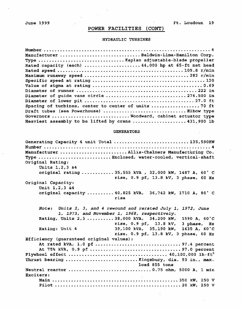
June 1999 Ft. Loudoun 19POWER FACILITIES (CONT)
HYDRAULIC TURBINES
Number .............................................................. 4Manufacturer .............................. Baldwin-Lima-Hamilton Corp.Type ................................ Kaplan adjustable-blade propellerRated capacity (each) ..................... 44,000 hp at 65-ft net headRated speed ........................................ ....... 105.8 r/minMaximum runaway speed ....................................... 282 r/minSpecific speed at rating .......................................... 120Value of sigma at rating ......................................... 0.69Diameter of runner .............................................. 222 inDiameter of guide vane circle .............................. 276.500 inDiameter of lower pit ......................................... 27.0 ftSpacing of turbines, center to center of units ................... 70 ftDraft tubes (see Powerhouse) ............................... Elbow typeGovernors ............................. Woodward, cabinet actuator typeHeaviest assembly to be lifted by crane ..................... 431,900 lb
GENERATORS
Generating Capacity 4 unit Total ............................ 135,590KWNumber . ............................................................. 4Manufacturer ......................... Allis-Chalmers Manufacturing Co.Type ........................... Enclosed, water-cooled, vertical-shaftOriginal Rating:
Units 1,2,3 &4original rating ............ 35,555 kVA , 32,000 kW, 1487 A, 60° C
rise, 0.9 pf, 13.8 kV, 3 phase, 60 HzOriginal Capacity:
Unit 1,2,3 &4original capacity .......... 40,825 kVA, 36,742 kW, 1710 A, 80° C
rise
Note: Units 2, 3, and 4 rewound and rerated July 1, 1972, June1, 1973, and November 1, 1968, respectively.
Rating, Units 2,3 .......... 38,000 kVA, 34,200 kW, 1590 A, 60°Crise, 0.9 pf, 13.8 kV, 3 phase, Hz
Rating: Unit 4 39,100 kVA, 35,190 kW, 1635 A, 60°Crise, 0.9 pf, 13.8 kV, 3 phase, 60 Hz
Efficiency (guaranteed original values):At rated kVA, 1.0 pf ................................ 97.4 percentAt 75% kVA, 0.9 pf .................................. 97.0 percent
Flywheel effect ..................................... 40,100,000 lb-ft 2
Thrust bearing ........................... Kingsbury, dia. 93 in., max.load 855 tons
Neutral reactor ............................... 0.75 ohm, 5000 A, 1 minExciters:
Main ............................................... 350 kW, 250 VPilot ............................................... 20 kW, 250 V
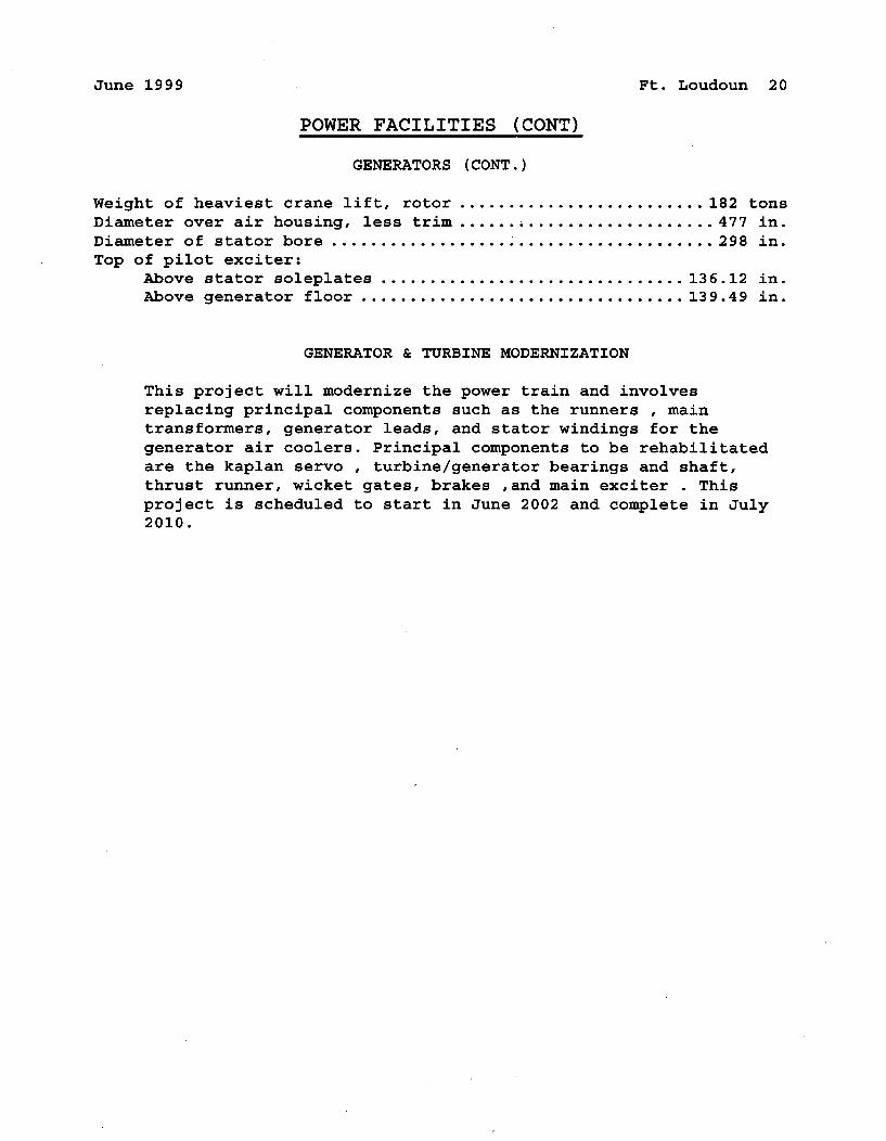
June 1999 Ft. Loudoun 20
POWER FACILITIES (CONT)
GENERATORS (CONT.)
Weight of heaviest crane lift, rotor ......................... 182 tonsDiameter over air housing, less trim ........ ................... 477 in.Diameter of stator bore ....................................... 298 in.Top of pilot exciter:
Above stator soleplates ............................... 136.12 in.Above generator floor ................................. 139.49 in.
GENERATOR & TURBINE MODERNIZATION
This project will modernize the power train and involvesreplacing principal components such as the runners , maintransformers, generator leads, and stator windings for thegenerator air coolers. Principal components to be rehabilitatedare the kaplan servo , turbine/generator bearings and shaft,thrust runner, wicket gates, brakes ,and main exciter . Thisproject is scheduled to start in June 2002 and complete in July2010.
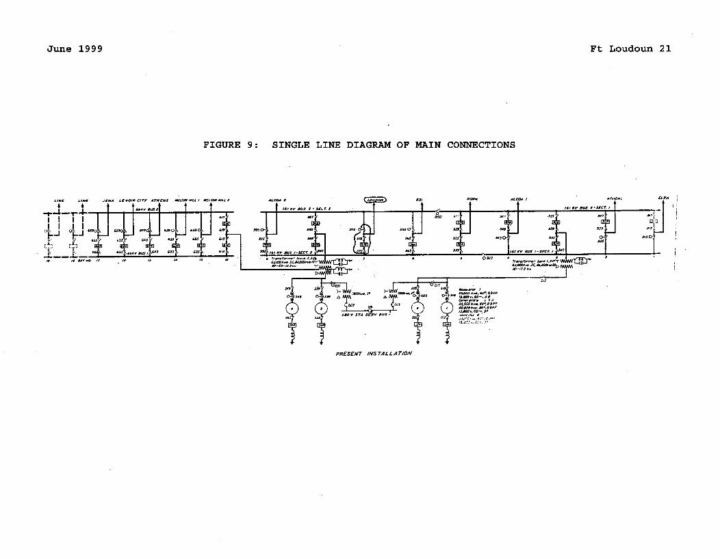
June 1999 Ft Loudoun 21
FIGURE 9: SINGLE LINE DIAGRAM OF MAIN CONNECTIONS
-. 1E
S•a, dVN• tr • S• S• /4
6.I, OPP,•O...SAts.W ,. •SO. frc
PRESENT INS TALLA TION
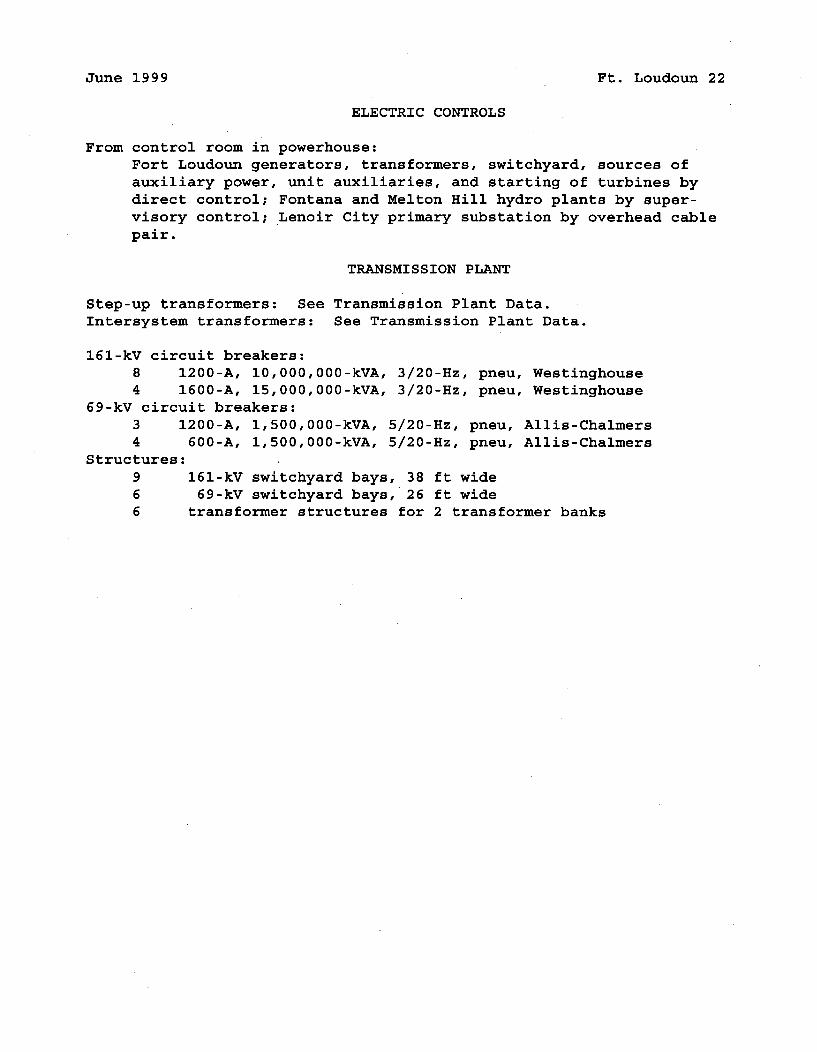
June 1999 Ft. Loudoun 22
ELECTRIC CONTROLS
From control room in powerhouse:Fort Loudoun generators, transformers, switchyard, sources ofauxiliary power, unit auxiliaries, and starting of turbines bydirect control; Fontana and Melton Hill hydro plants by super-visory control; Lenoir City primary substation by overhead cablepair.
TRANSMISSION PLANT
Step-up transformers: See Transmission Plant Data.Intersystem transformers: See Transmission Plant Data.
161-kV circuit breakers:8 1200-A, 10,000,000-kVA, 3/20-Hz, pneu, Westinghouse4 1600-A, 15,000,000-kVA, 3/20-Hz, pneu, Westinghouse
69-kV circuit breakers:3 1200-A, 1,500,000-kVA, 5/20-Hz, pneu, Allis-Chalmers4 600-A, 1,500,000-kVA, 5/20-Hz, pneu, Allis-Chalmers
Structures:9 161-kV switchyard bays, 38 ft wide6 69-kV switchyard bays, 26 ft wide6 transformer structures for 2 transformer banks
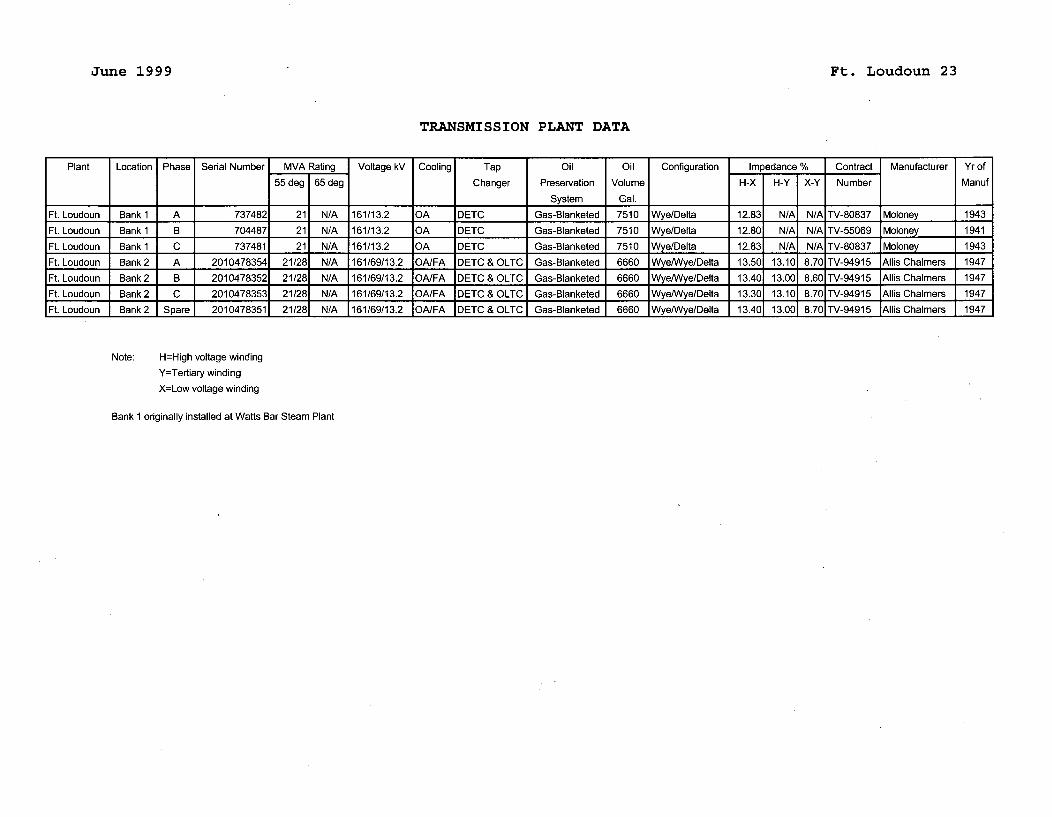
June 1999 Ft. Loudoun 23
TRANSMISSION PLANT DATA
Plant Location Phase Serial Number MVA Rating Voltage kV Cooling Tap Oil Oil Configuration Impedance % Contract Manufacturer Yr of
55 deg 65 deg Changer Preservation Volume H-X H-Y X-Y Number Manuf
I System Gal.
Ft. Loudoun Bank 1 A 737482 21 N/A 161/13.2 OA DETC Gas-Blanketed 7510 Wye/Delta 12.83 N/A N/A TV-80837 Moloney 1943
Ft. Loudoun Bank 1 B 704487 21 N/A 161/13.2 OA DETC Gas-Blanketed 7510 Wye/Delta 12.80 N/A N/A TV-55069 Moloney 1941
Ft. Loudoun Bank 1 C 737481 21 N/A 161/13.2 OA DETC Gas-Blanketed 7510 Wye/Delta 12.83 N/A N/A TV-80837 Moloney 1943Ft. Loudoun Bank 2 A 2010478354 21/28 N/A 161/69/13.2 OA/FA DETC & OLTC Gas-Blanketed 6660 Wye/Wye/Delta 13.50 13.10 8.70 TV-94915 Allis Chalmers 1947
Ft. Loudoun Bank 2 B 2010478352 21/28 N/A 161/69/13.2 OA/FA DETC & OLTC Gas-Blanketed 6660 Wye/Wye/Delta 13.40 13.00 8.60 TV-94915 Allis Chalmers 1947
Ft. Loudoun Bank 2 C 2010478353 21/28 N/A 161/69/13.2 OA/FA DETC & OLTC Gas-Blanketed 6660 Wye/Wye/Delta 13.30 13.10 8.70 TV-94915 Allis Chalmers 1947
Ft. Loudoun Bank 2 Spare 2010478351 21/28 N/A 161/69/13.2 OA/FA DETC & OLTC Gas-Blanketed 6660 Wye/Wye/Delta 13.40 13.00 8.70 TV-94915 Allis Chalmers 1947
Note: H=High voltage winding
Y=Tertiary winding
X=Low voltage winding
Bank 1 originally installed at Watts Bar Steam Plant
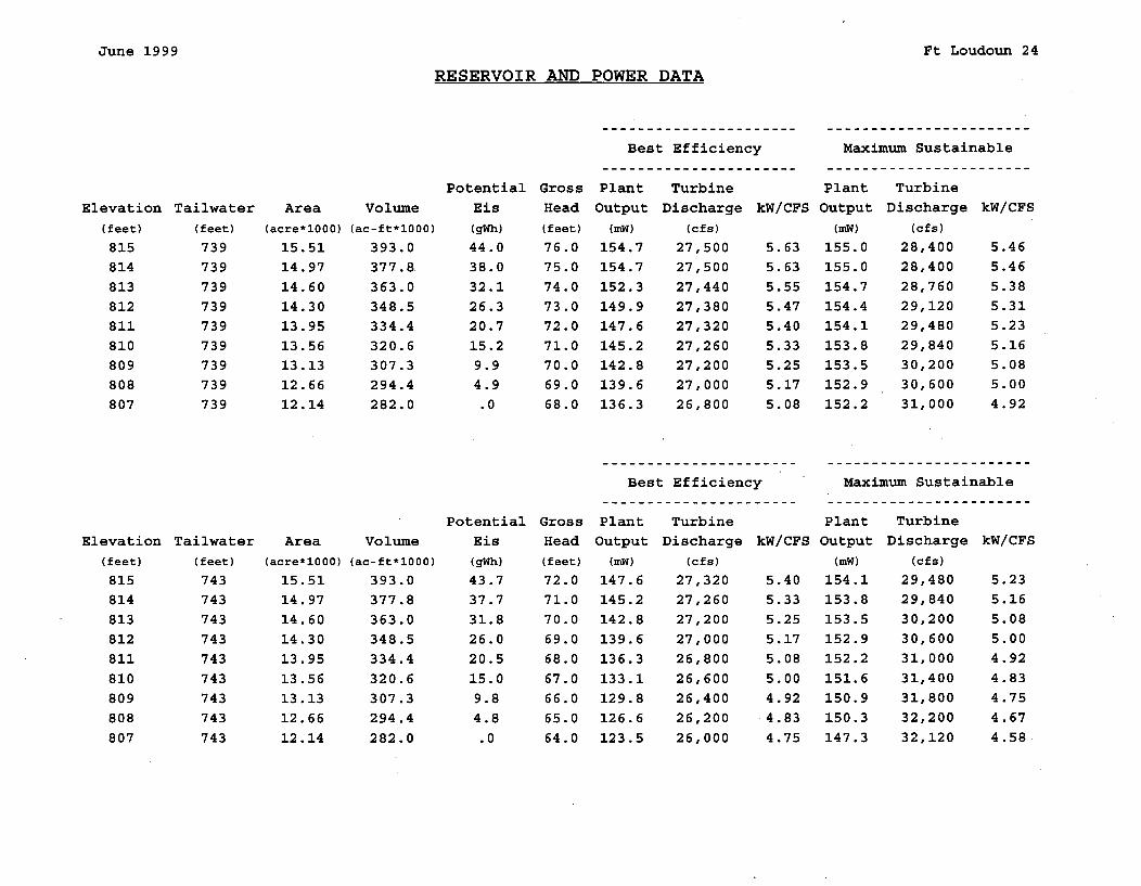
June 1999 Ft Loudoun 24
RESERVOIR AND POWER DATA
Best Efficiency Maximum Sustainable
Elevation
(feet)
815814813812811810809808807
Tailwater
(feet)
739739739739739739739739739
Area
(acre*1000)
15.5114.9714.6014.3013.9513.56
13.13
12.6612.14
Volume(ac-ft*1000)
393.0377.8363.0348.5334.4320.6307.3294.4282.0
PotentialEis
(gWh)44.038.032.126.320.715.2
9.94.9.0
GrossHead
(feet)
76.075.074.073.072.071.070.069.068.0
Plant Turbine
Output Discharge kW/CFS(mW) (cfs)
154.7 27,500 5.63154.7 27,500 5.63152.3 27,440 5.55149.9 27,380 5.47147.6 27,320 5.40
145.2 27,260 5.33142.8 27,200 5.25139.6 27,000 5.17
136.3 26,800 5.08
Plant TurbineOutput Discharge kW/CFS
(mW) (cfs)
155.0 28,400 5.46155.0 28,400 5.46
154.7 28,760 5.38154.4 29,120 5.31154.1 29,480 5.23
153.8 29,840 5.16153.5 30,200 5.08152.9 30,600 5.00
152.2 31,000 4.92
Best Efficiency Maximum Sustainable
Elevation(feet)
815814813812811810809808807
Tailwater(feet)
743743743743743743743743743
Area(acre*1000)
15.5114.9714.6014.30
13.9513.5613.1312.66
12.14
Volume(ac-ft*1000)
393.0377.8363.0348.5
334.4320.6307.3294.4282.0
PotentialEis
(gWh)
43.737.731.826.020.515.09.84.8.0
GrossHead(feet)
72.071.070.069.068.067.066.065.064.0
Plant TurbineOutput Discharge kW/CFS
(mW) (cfs)
147.6 27,320 5.40145.2 27,260 5.33142.8 27,200 5.25139.6 27,000 5.17136.3 26,800 5.08133.1 26,600 5.00129.8 26,400 4.92
126.6 26,200 4.83
123.5 26,000 4.75
Plant TurbineOutput Discharge kW/CFS
(mW) (cfs)
154.1 29,480 5.23153.8 29,840 5.16153.5 30,200 5.08152.9 30,600 5.00152.2 31,000 4.92151.6 31,400 4.83150.9 31,800 4.75
150.3 32,200 4.67147.3 32,120 4.58
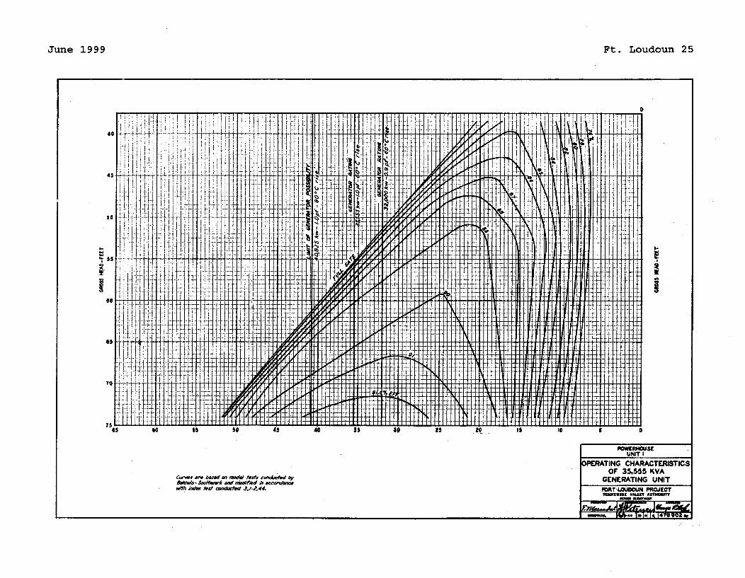
June 1999 Ft. Loudoun 25
I-
1 0
POWERHOUSE
UNMT I
DPFRATING CHARACTERISTICSOF 35.555 KVA
GENERATING UNITFORT '4.UOOUN PROJECTTRWUMUKS VAUfT ""MB"
SeJimmm
C rse bAwed an model wter edotcferd byBAdpb- Jexasw* aid "Vdified a -. 4ccwc0c.w/M inow *A't cap7ced Jo-d~
ý. I ý, ýý ý 1ýW-
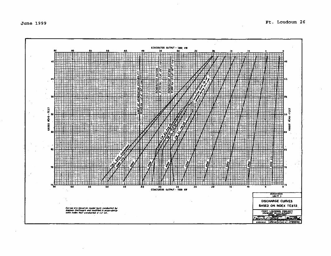
June 1999 Ft. Loudoun 26
,-M I'm 15
.5 00 .5 .. 4. 0 .- -30 2- -0 IS II 5 0n
goGNiRATOR OUTPUT- 000 LW
S powztm"•,.UNIT I
DISCHARGE CURVESBASED ON INDEX TESTS
5,gon Sd#e. , ..•/•, n•'mkdi p ,•w• FORT LOUDOW4 PROJI•cTindex rest ConoSACtEd 2-.4,2- 44. TDJNI •ALLV AnTom'rTy
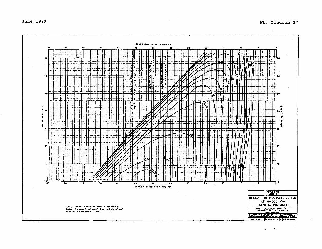
June 1999 Ft. Loudoun 27
GENERATOR OUTPUT - 1000 KW
9-
40 35 30GENERATOR OUTPUT - 1O00 KW
POWEPHOUSUUNIT 2
OPERATING CHARACTERISTICSOF 40.000 KVA
GENERATING UNITCurvws re boxed on model tests conducted byR&dWwn- $Suthwav* and mod1ied o veaCCodfnCe .ithtndex test conducted 2 -29-44.
FORT LOUDOUN PROJECTTENNIWESS VALLEY AUTWORITY
• [ I o-*IluIAI.ý nt
oamLa I)Ao-44110IM14 47SO05"
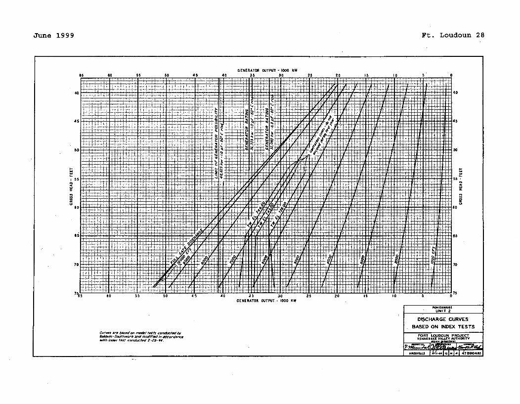
June 1999 Ft. Loudoun 28
!
GENERATOR OUTPUT - 1000 KW
POWE[N8U8UNIT 2"
DISCHARGE CURVES
BASED ON INDEX TESTSC.rvws art bwed on moel/ tests cond•uod by&WiDe -Soi teswt and nweified in o-2 rd-4 ewfth inaiex test co',duced,2-239-44r.
FORT LOUJDOUN PROJECTTgNNESSEE VALLEY AUTHORITY
i,,aILU I 1 , 1m, 4 1478 904*0
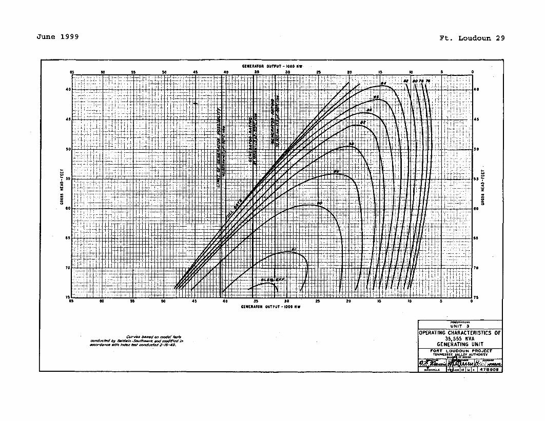
June 1999 Ft. Loudoun 29
GENERATOR OUTPUT - 1000 KW
GrN[ATO
OUTUT I00 K4
0
0
a0CS
a
GENERATOR OUTPUT - 1000 KW
PowUNRT V
UNIT 3
Curves based on model/'•r.conducted by Baldwin -Sacehwwr* wd•modY'ed inamoOa-nce wath Ind" est conducted 2-16-49.
OPERATING CHARACTERISTICS OF35,555 KVA
GENERATING UNITFORT LOUDOUN PROJECT
TIENMU4S& LA HOWTY
wyoý 9 10 M 4 478909ILM*4 I I I I
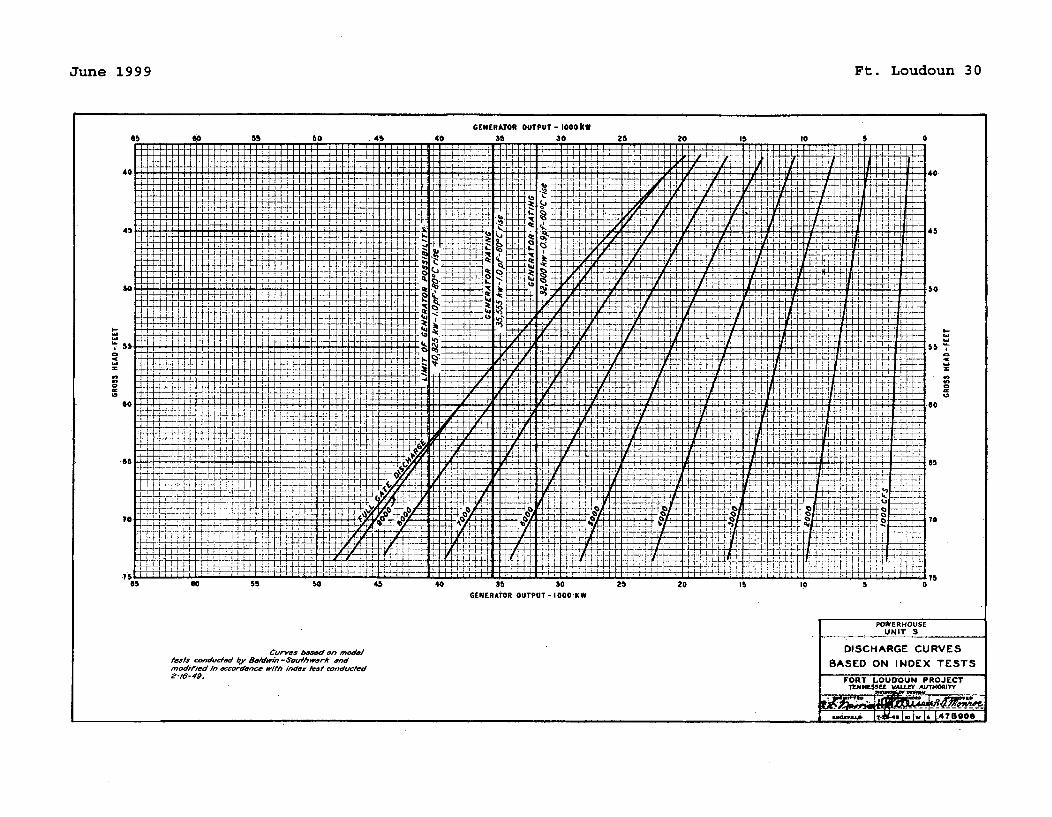
June 1999 Ft. Loudoun 30
60 5 " SO 4S
GENERATOR OUTPUT - 1000kw40 35 30 25 20 15 10 5
41: . . ... .L•:
+i L- I I " i•, H-H-, ~±H±#~tr~H1h-i±rtUL4-
LE U4-'ii~ l +
-rk+.L244
LLIU4 LL •
T:- i
4z.J
i-H-h kfrf±tmlHtThli±
--PT 4H-1-$--i-4-I ,I ~. SI IS-
F,: • : : "50
1I]
I~AI
'.S5
_•_+_+_+_•
-iiiii1~HI~I 7P1
T
4-14-
4-i-f
6f 11644-:_ -K-Ht+HH ~ivvftIHk ]
-I
r11TTmF'174TrETTTV17TV7I~I-V1YVVF
i.i
50.........I'~,,
I,,
1 E .4 - .- -'' :' ,i
H-fr.........i PF~~T~ q••..i-.i.•b.•-H- Tr4j421±t H'tV i#~ 2
4';- 2
+-+ 2~
I
$~4-: K 4-i-••- ÷e-•-• -4-4-/- • <--iqz-i•-i-•-l--L
4.÷
-III
4,+-4- -1-4C
-+•p -~-j-~-4-4- /-H-L24 ~
-I---I -- ,-'.--' - ,T Tr.. 7 - -. Fitt--
as o0 55 50 45 40 35 30 25 20 15 I0GENERATOR OUTPUT - 1000KW
5 0
Curies based on modeltests condu~ted b~y"ba/dinm-.Sou/hwark endmodifed in eccorodnce with indez Mat conducted2-16-4D.
POWERMOUSE
UNIT 3
DISCHARGE CURVES
BASED ON INDEX TESTS
FORT LOUDOUN PROJECT1t~fN$SEE VALEY. AUJTHORITY
Aie~I~,-*Iof~IA 78900
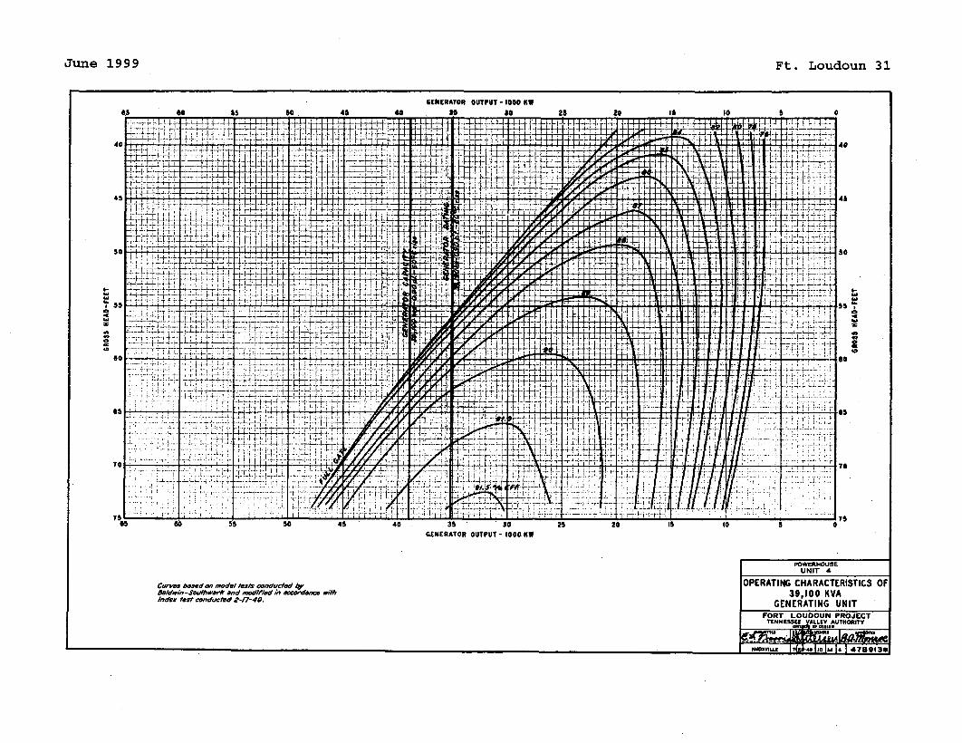
June 1999 Ft. Loudoun 31
GENERATOR OUTPUT - I000 KI
3l 300. 60 65 so . 45 40 25 20 is 10 5 0
0
T 1-4. -40 4"-")0•'"-
~ 4,, TT id:± 1t:j:: 4
F~~.J - .*-_.-._t1_÷ . - -- I+ -.44-
i . ,, 4 - -------•--L ' .
-. 44 "-4 ...... . .... .... t .... ... ,
.- I I'M± V -,
d I• .Z_.+.. .•_ ...... ..
7w--
tF 14"
•'7
F'
-''
r r*~ IVT t: 4,
74 __÷-J_-_-J
.... __+ _'__._ _'.
-7._• T+ -TJ
AL0 - T
0-:y+ ::--- ....+;'4-A di _T++• l..
-+ ............... , ....... , • +;-+ -;i ", ++ _+,
•4: -• • +: ;..&6 . 5 'Z .i "..
..:"... ':T .. . .L + ! . +,,o +" +"7. 4-- .....i-..•..,_,4
J"- "-7"
+"•• ...........
.. j . .!_. _• + +. +._i-" .k i:7"
. . ' ' :...70
7: 70' • .. :7II {•'".....•-: ,.:..
...... :'.:!!i ; !1"i}.•'
" : ;. :' ,
!7....... •:i.!. .... + +•
..... ~~~ L i... ..75 7.. - :! : ..... :
I-
4
a
U.5
65 60 55 so 45 40 35 30GENERATOR OUTPUT- 1000 KW
25 20 I0 t 5
POWERIHOUSEUNIT A
&,idwln-Seulhwerk end moditied £, eccorddnce e'iinde, test conducted 2-17-40•.
OPERATING CHARACTERISTICS OF39,100 KVA
GENERATING UNITFORT LOUDOUN PROJECTThNNESSU VALLEY AUTHOIIITY
,,.,+,.+,,J,. l,,+•lol,.l. 147ao,3-I MMY'ug 1i(zM.'c It m11 4780130
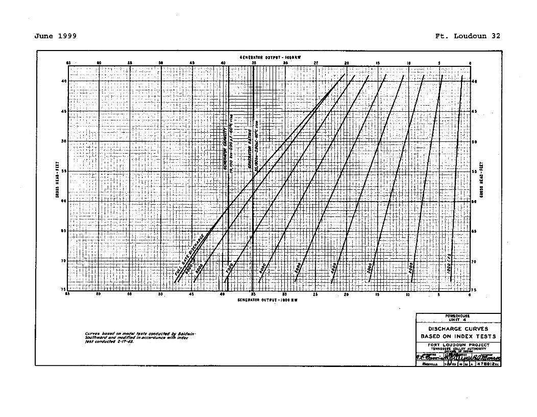
June 1999 Ft. Loudoun 32
GENERATOR OUTPUT- IO00KW
I..
4
0
8-
4
aC
GENERATOR OUTPUT -1000 KW
POWERHOUSE
'UNIT 4
DISCHARGE CURVESBASED ON INDEX TESTSCuvas hased of ~vd/ tests conducted 6y saldwin-
Southward and modid in accorduwce wIh /ndeoxt$St conducted 2-17-4W.
FORT LOUDOUN PROJECTT1•wNI5UE LLeY AUTHORrrY.. lal O w.
AOMM 7-&149I
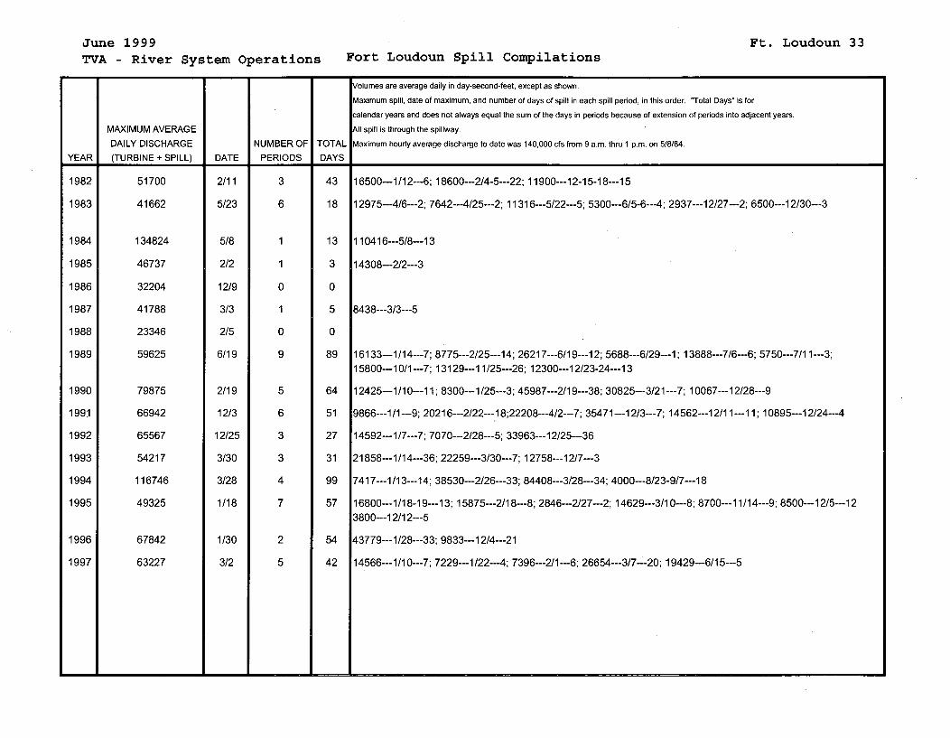
June 1999TVA - River System Operations Fort Loudoun Spill Compilations
Ft. Loudoun 33
Volumes are average daily in day-second-feet, except as shown.
Maximum spill, date of maximum, and number of days of spill in each spill period, in this order. "Total Days" is for
calendar years and does not always equal the sum of the days in periods because of extension of periods into adjacent years.
MAXIMUM AVERAGE All spill is through the spillway.
DAILY DISCHARGE NUMBER OF TOTAL Maximum hourly average discharge to date was 140,000 cfs from 9 a.m. thru 1 p.m. on 5/8/84.
YEAR (TURBINE + SPILL) DATE PERIODS DAYS
1982 51700 2/11 3 43 16500---1/12---6; 18600---2/4-5---22; 11900---12-15-18---15
1983 41662 5/23 6 18 12975---4/6---2; 7642---4/25---2; 11316---5/22---5; 5300---6/5-6---4; 2937---12/27---2; 6500---12/30---3
1984 134824 5/8 1 13 110416---5/8---13
1985 46737 2/2 1 3 14308---2/2---3
1986 32204 12/9 0 0
1987 41788 3/3 1 5 8438---3/3---5
1988 23346 2/5 0 0
1989 59625 6/19 9 89 16133---1/14---7; 8775---2/25---14; 26217---6/19---12; 5688---6/29---1; 13888---7/6---6; 5750---7/11---3;15800---10/1---7; 13129---11/25---26; 12300---12/23-24--- 13
1990 79875 2/19 5 64 12425---1/10---11; 8300---1/25---3; 45987---2/19---38; 30825---3/21---7; 10067---12/28---9
1991 66942 12/3 6 51 9866---1/1---9; 20216---2/22---18;22208---4/2---7; 35471---12/3---7; 14562---12/11---11; 10895---12/24---4
1992 65567 12/25 3 27 14592---1/7---7; 7070---2/28---5; 33963---12/25---36
1993 54217 3/30 3 31 21858---1/14---36; 22259---3/30---7; 12758---12/7---3
1994 116746 3/28 4 99 7417---1/13---14; 38530---2/26---33; 84408---3/28---34; 4000---8/23-9/7---18
1995 49325 1/18 7 57 16800---1/18-19---13; 15875---2/18---8; 2846---2/27---2; 14629---3/10---8; 8700---11/14---9; 8500---12/5---123800---12/12---5
1996 67842 1/30 2 54 43779---1/28---33; 9833---12/4---21
1997 63227 3/2 5 42 14566---1/10---7; 7229---1/22---4; 7396---2/1---6; 26654---3/7---20; 19429---6/15---5
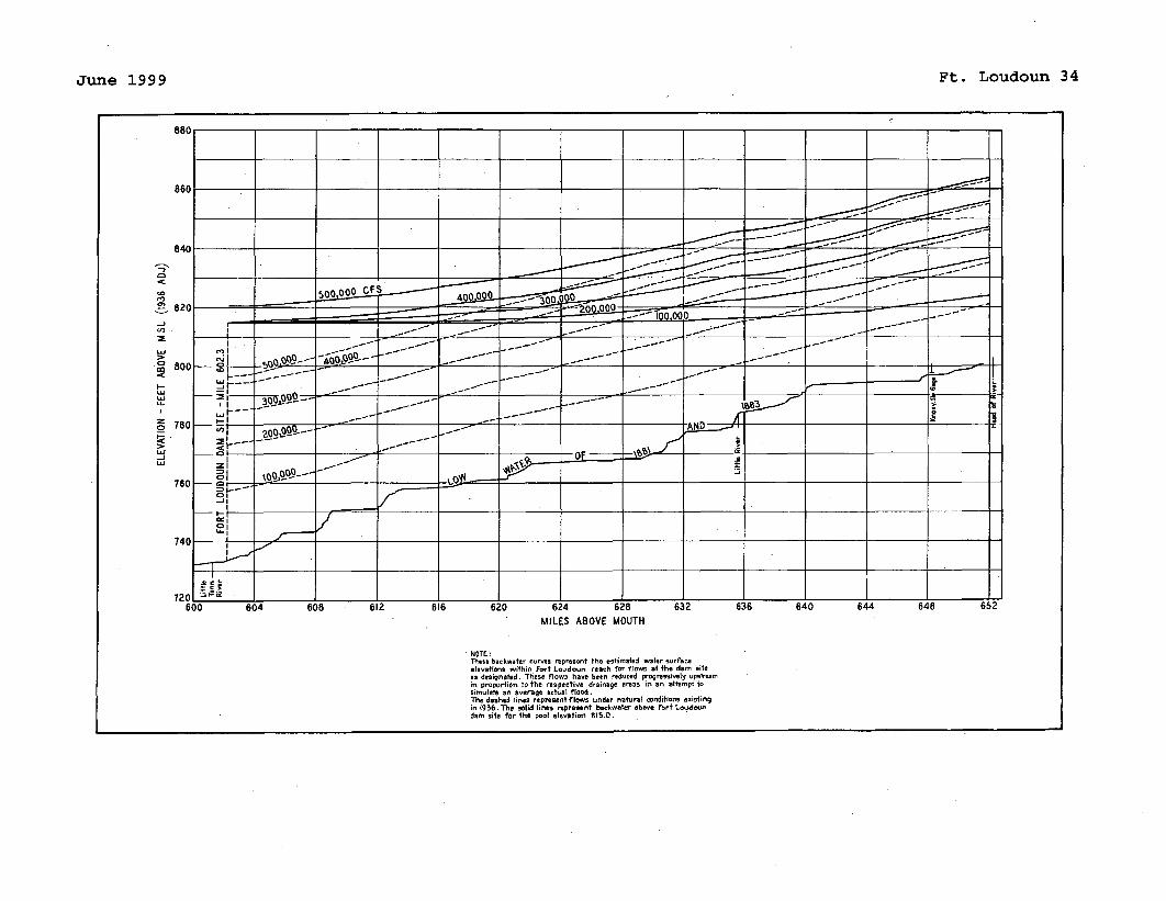
June 1999 Ft. Loudoun 34
,C>
cc
C.0•
I-
-J
MILES ABOVE MOUTH
NOTE~These backwater curves represent the estinmated water surfaceelevations within Fort Loudaon reach far flawts at the dam siteas designated. These flow3 heave been reduced progressively Psirnanin Proportion toe the respective drainage areas in en attempt tosimulate e n average actual fioed.The dashed lines represent flaws under natuael conditions existingin 1936.7h. solid line, represvent backwater eabeve Frtr L~oucdaundew site for the pool elevatian 815.0.
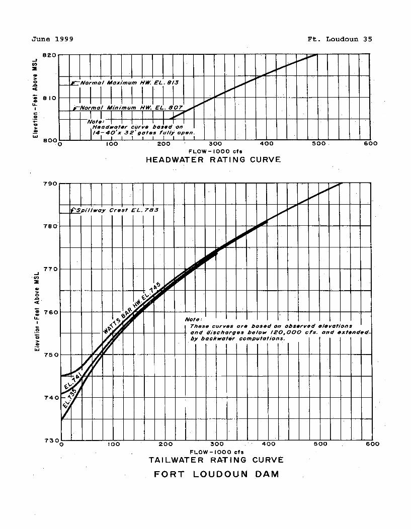
June 1999 Ft. Loudoun 35
-JC'
0
0
a,
I.-
0
820
810
-- :-Normal Maximum HW EL. 813....LL I .II I I I I I I I I I I
r-Normal Minimum HW. EL. 807 7
-N ote: 1---I I14-40'x 32'gates fullyopn
a rNn 1 ---- 4--6 . . .100 200 300 400 500 600
FLOW-I000 cfs
HEADWATER RATING CURVE
- . . . . . . . . . . . . .I I - r - T ~ -4U)
I- I I I I :780
770
V)
760
750
740
__LSpillway Crest EL. 783
Not e:These curves are based on observed elevations
So-and dischorges below 120,000 cfs. and extended.by backwoter computations.
7300100 200 300 400
FLOW-I000 cfs
TAILWATER RATING CURVE
500 600
FORT LOUDOUN DAM
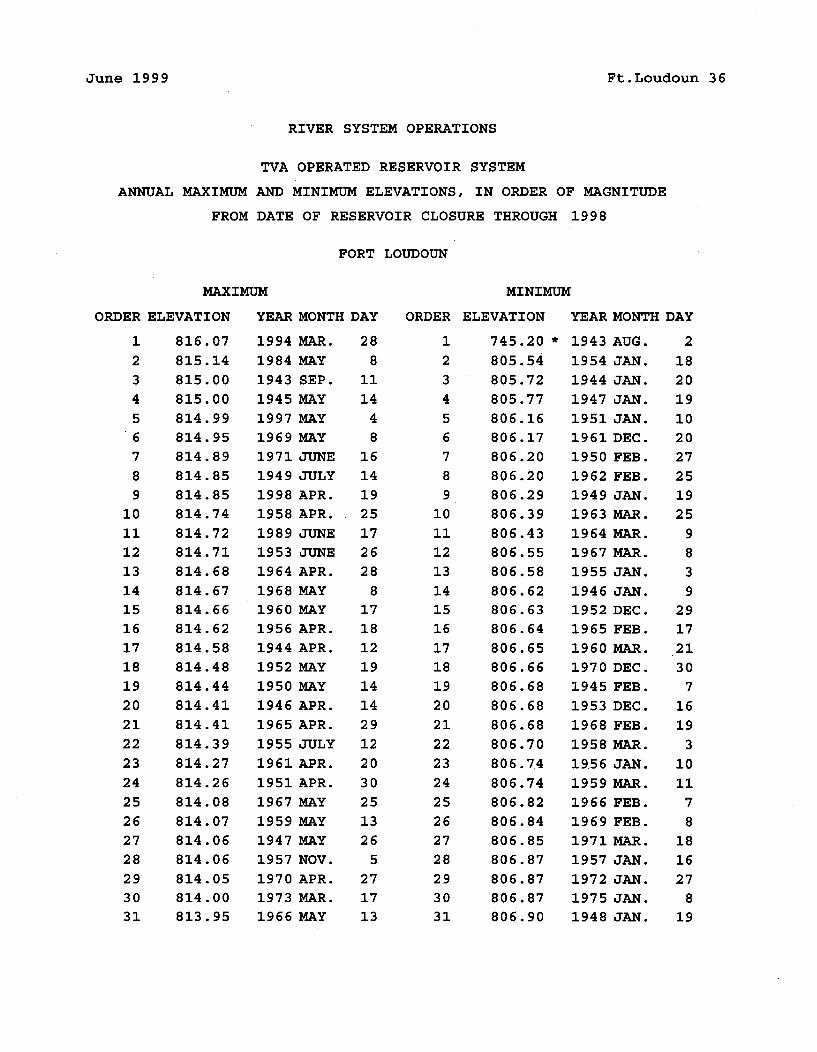
June 1999 Ft.Loudoun 36
RIVER SYSTEM OPERATIONS
TVA OPERATED RESERVOIR SYSTEM
ANNUAL MAXIMUM AND MINIMUM ELEVATIONS, IN ORDER OF MAGNITUDE
FROM DATE OF RESERVOIR CLOSURE THROUGH 1998
FORT LOUDOUN
MAXIMUM MINIMUM
ORDER ELEVATION YEAR MONTH DAY ORDER ELEVATION YEAR MONTH DAY
1
2
34
56789
10
1112
1314
151617181920
21
22
23
24
2526
2728
293031
816.07815.14
815.00815.00
814.99
814.95814.89814.85814.85814.74
814.72814.71814.68814.67814.66814.62
814.58814.48
814.44
814.41
814.41
814.39
814.27
814.26
814.08814.07814.06
814.06
814.05
814.00
813.95
1994 MAR.
1984 MAY
1943 SEP.
1945 MAY
1997 MAY
1969 MAY
1971 JUNE1949 JULY
1998 APR.
1958 APR.
1989 JUNE1953 JUNE
1964 APR.
1968 MAY
1960 MAY
1956 APR.
1944 APR.
1952 MAY
1950 MAY
1946 APR.
1965 APR.
1955 JULY
1961 APR.
1951 APR.
1967 MAY
1959 MAY
1947 MAY
1957 NOV.
1970 APR.
1973 MAR.
1966 MAY
28
811
14
4
81614
1925
172628
8171812
1914
14
2912
20
3025
1326
5271713
1
2
3
4
56789
10
1112
13
14
1516
17181920
21
22
23
24
2526
2728
293031
745.20
805.54805.72805.77
806.16806.17806.20806.20806.29806.39
806.43806.55806.58
806.62806.63806.64806.65
806.66806.68806.68806.68
806.70806.74
806.74806.82
806.84806.85806.87806.87806.87806.90
1943 AUG.1954 JAN.
1944 JAN.
1947 JAN.
1951 JAN.1961 DEC.1950 FEB.
1962 FEB.
1949 JAN.
1963 MAR.
1964 MAR.
1967 MAR.
1955 JAN.
1946 JAN.
1952 DEC.1965 FEB.
1960 MAR.
1970 DEC.1945 FEB.
1953 DEC.1968 FEB.
1958 MAR.
19.56 JAN.
1959 MAR.
1966 FEB.
1969 FEB.1971 MAR.1957 JAN.
1972 JAN.
1975 JAN.
1948 JAN.
2
1820
19
1020
27251925
983
92917
.2130
7
1619
3
10
117
8181627
819
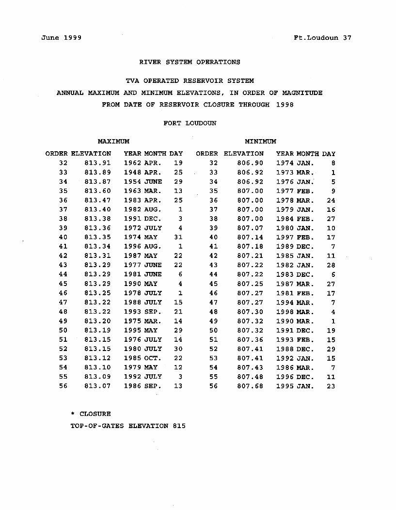
June 1999 Ft.Loudoun 37
RIVER SYSTEM OPERATIONS
TVA OPERATED RESERVOIR SYSTEM
ANNUAL MAXIMUM AND MINIMUM ELEVATIONS, IN ORDER OF MAGNITUDE
FROM DATE OF RESERVOIR CLOSURE THROUGH 1998
FORT LOUDOUN
MAXIMUM MINIMUM
ORDER
32
3334
35
363738
3940
41
42
43
44
45
46
47
48
49
5051525354
5556
ELEVATION
813.91
813.89813.87
813.60
813.47
813.40
813.38813.36
813.35
813.34
813.31
813.29
813.29
813.29813.25
813.22
813.22
813.20
813.19
813.15
813.15
813.12
813.10
813.09
813.07
CLOSURE
YEAR MONTH
1962 APR.
1948 APR.
1954 JUNE
1963 MAR.
1983 APR.
1982 AUG.
1991 DEC.
1972 JULY
1974 MAY
1996 AUG.
1987 MAY
1977 JUNE
1981 JUNE
1990 MAY
1978 JULY
1988 JULY
1993 SEP.
1975 MAR.
1995 MAY
1976 JULY
1980 JULY
1985 OCT.
1979 MAY
1992 JULY
1986 SEP.
DAY
192529
1325
134
311
22
22
6
4
11521
14
2914
3022
12
313
ORDER
32
33
34
35
36
37
38
39
40
41
42
43
44
45
46
47
48
49
50
51
52
53
54
55
56
ELEVATION
806.90
806.92
806.92
807.00
807.00
807.00
807.00
807.07
807.14
807.18
807.21
807.22
807.22
807.25
807.27
807.27
807.30
807.32
807.32
807.36
807.41
807.41
807.43
807.48
807.68
YEAR MONTH
1974 JAN.
1973 MAR.
1976 JAN.'
1977 FEB.
1978 MAR.
1979 JAN.
1984 FEB.
1980 JAN.
1997 FEB.
1989 DEC.
1985 JAN.
1982 JAN.
1983 DEC.
1987 MAR.
1981 FEB.
1994 MAR.
19 98 MAR.
1990 MAR.
1991 DEC.
1993 FEB.
1988 DEC.
1992 JAN.
1986 MAR.
1996 DEC.
1995 JAN.
DAY
8
1
5
9
24
16
27
10
17
7
11
28
6
27
17
7
4
1
19
15
29
15
7
11
23
TOP-OF-GATES ELEVATION 815
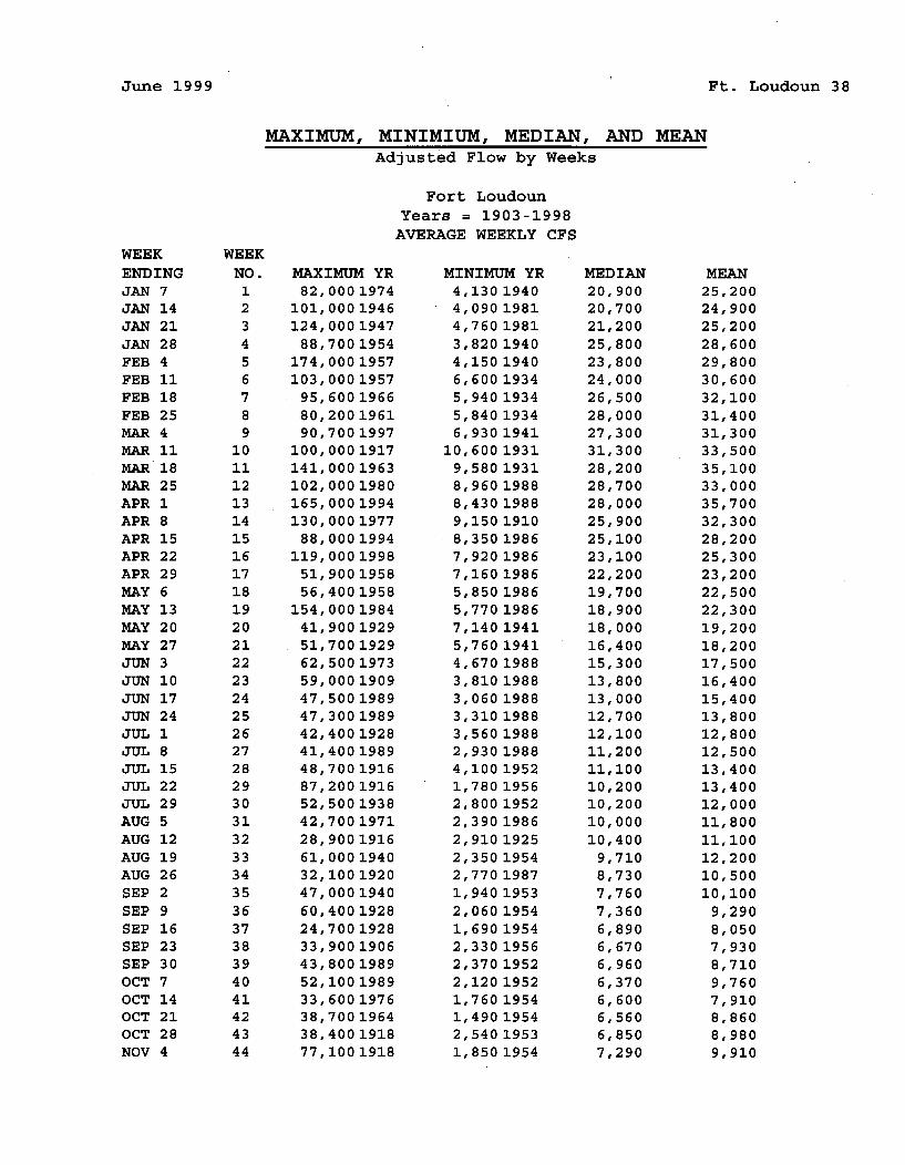
June 1999 Ft. Loudoun 38
MAXIMUM, MINIMIUM, MEDIAN, AND MEANAdjusted Flow by Weeks
Fort LoudounYears = 1903-1998AVERAGE WEEKLY CFS
WEEKENDINGJAN 7JAN 14JAN 21JAN 28FEB 4FEB 11FEB 18FEB 25MAR 4MAR 11MAR 18MAR 25APR 1APR 8APR 15APR 22APR 29MAY 6MAY 13MAY 20MAY 27JUN 3JUN 10JUN 17JUN 24JUL 1JUL 8JUL 15JUL 22JUL 29AUG 5AUG 12AUG 19AUG 26SEP 2SEP 9SEP 16SEP 23SEP 30OCT 7OCT 14OCT 21OCT 28NOV 4
WEEK
NO.123456789
1011121314151617181920212223242526272829303132333435363738394041424344
MAXIMUM YR82,0001974
101, 00 0 1946124,0001947
88,7001954174, 00 0 1957103, 00 0 195795,600196680,200196190,7001997
100, 00 0 1917141, 00 0 1963102, 00 0 1980165, 00 0 1994130,0001977
88,0001994119, 000 199851,900195856,4001958
154, 000 198441,900192951,700192962,5001973
59,0001909
47,5001989
47,3001989
42,400192841,400198948,700191687,200191652,5001938
42,700197128,900191661,000194032,100192047,0001940
60,400192824,7001928
33,900190643,8001989
52,100198933,600197638,700196438,400191877,1001918
MINIMUM YR4,130 19404,090 19814,760 19813,820 19404,150 19406,600 19345,940 19345,840 19346,930 1941
10,600 19319,580 19318,960 19888,430 19889,150 19108,350 19867,920 19867,160 19865,850 19865,770 19867,140 19415,760 19414,670 19883,810 19883,060 19883,310 19883,560 19882,930 19884,100 19521,780 19562,800 19522,390 19862,910 19252,350 19542,770 19871,940 19532,060 19541,690 19542,330 19562,370 19522,120 19521,760 19541,490 19542,540 19531,850 1954
MEDIAN
20,90020,70021,20025,80023,80024,00026,50028,00027,30031,30028,20028,70028,00025,90025,10023,10022,20019,70018,90018,00016,40015,30013,80013,00012,70012,10011,20011,10010,20010,20010,00010,400
9,7108,7307,7607,3606,8906,6706,9606,3706,6006,5606,8507,290
MEAN25,20024,90025,20028,60029,80030,60032,10031,40031,30033,50035,10033,00035,70032,30028,20025,30023,20022,50022,30019,20018,20017,50016,40015,40013,80012,80012,50013,40013,40012,00011,80011,10012, 2 0 0'10,50010,1009,2908,0507,9308,7109,7607,9108,8608,98091910
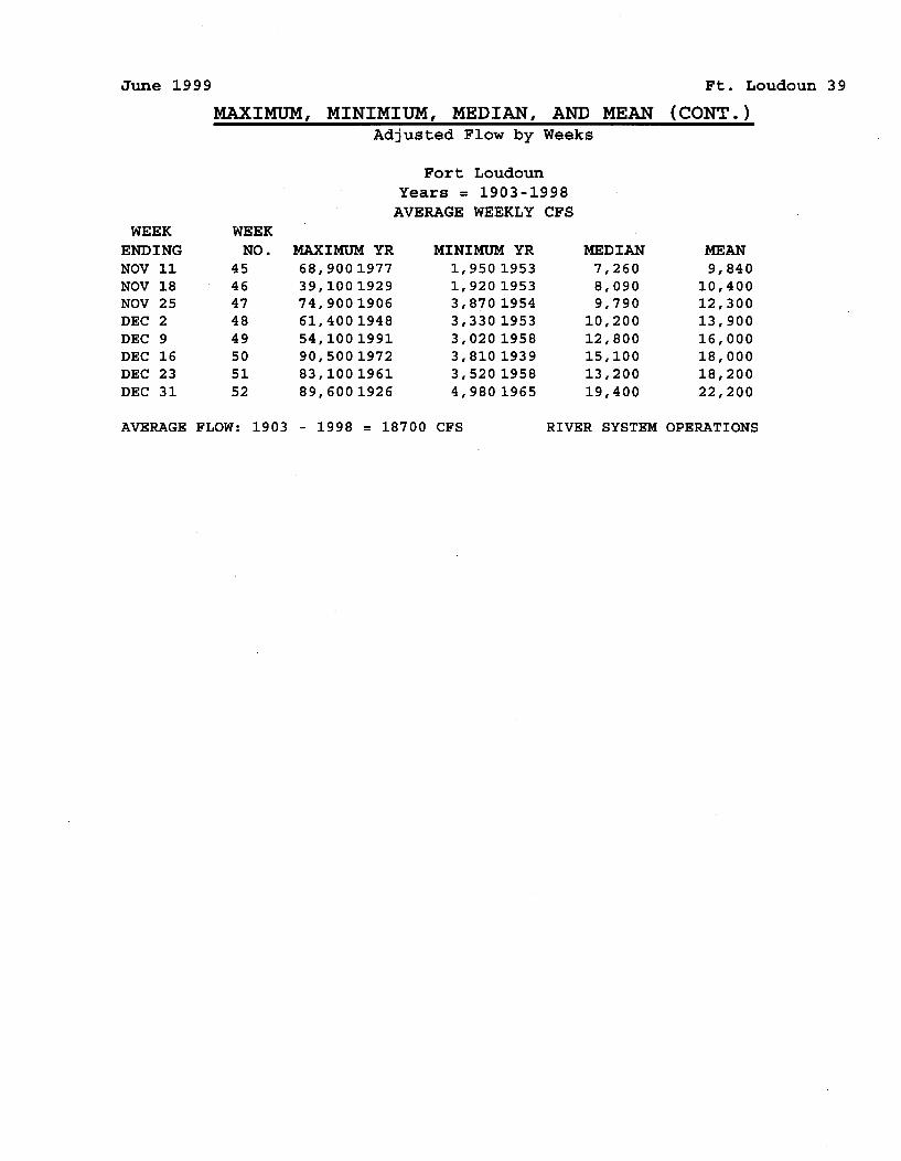
June 1999 Ft. Loudoun 39
MAXIMUM, MINIMIUM, MEDIAN, AND MEAN (CONT.)Adjusted Flow by Weeks
Fort LoudounYears = 1903-1998
AVERAGE WEEKLY CFSWEEK
ENDINGNOV 11NOV 18NOV 25DEC 2DEC 9DEC 16DEC 23DEC 31
WEEK
NO.4546474849505152
MAXIMUM YR68,900197739,100192974,900190661,400194854,100199190,500197283,100196189,6001926
MINIMUM YR1,950 19531,920 19533,870 19543,330 19533,020 19583,810 19393,520 1958
4,980 1965
MEDIAN7,2608,0909,790
10,20012,80015,10013,20019,400
MEAN9,840
10,40012,30013,90016,00018,00018,20022,200
AVERAGE FLOW: 1903 - 1998 = 18700 CFS RIVER SYSTEM OPERATIONS
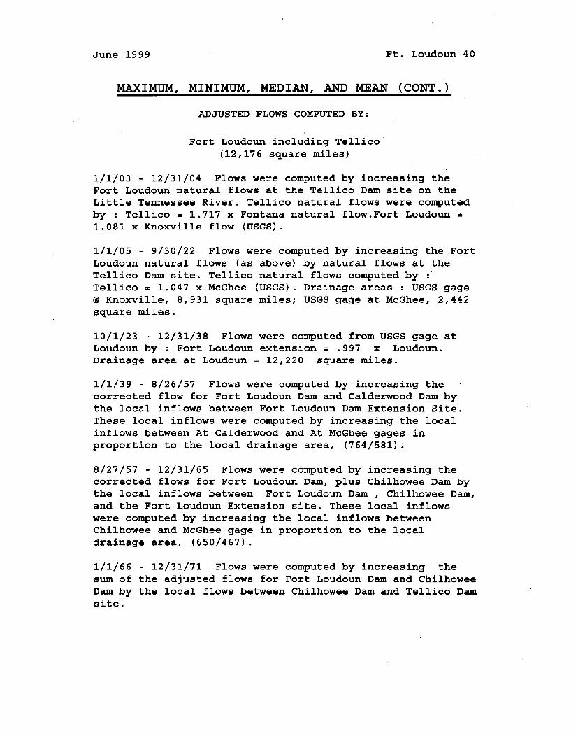
June 1999 Ft. Loudoun 40
MAXIMUM, MINIMUM, MEDIAN, AND MEAN (CONT.)
ADJUSTED FLOWS COMPUTED BY:
Fort Loudoun including Tellico(12,176 square miles)
1/1/03 - 12/31/04 Flows were computed by increasing theFort Loudoun natural flows at the Tellico Dam site on theLittle Tennessee River. Tellico natural flows were computedby : Tellico = 1.717 x Fontana natural flow.Fort Loudoun =
1.081 x Knoxville flow (USGS).
1/1/05 - 9/30/22 Flows were computed by increasing the FortLoudoun natural flows (as above) by natural flows at theTellico Dam site. Tellico natural flows computed byTellico = 1.047 x McGhee (USGS). Drainage areas : USGS gage@ Knoxville, 8,931 square miles; USGS gage at McGhee, 2,442square miles.
10/1/23 - 12/31/38 Flows were computed from USGS gage atLoudoun by : Fort Loudoun extension = .997 x Loudoun.Drainage area at Loudoun = 12,220 square miles.
1/1/39 - 8/26/57 Flows were computed by increasing thecorrected flow for Fort Loudoun Dam and Calderwood Dam bythe local inflows between Fort Loudoun Dam Extension Site.These local inflows were computed by increasing the localinflows between At Calderwood and At McGhee gages inproportion to the local drainage area, (764/581).
8/27/57 - 12/31/65 Flows were computed by increasing thecorrected flows for Fort Loudoun Dam, plus Chilhowee Dam bythe local inflows between Fort Loudoun Dam , Chilhowee Dam,and the Fort Loudoun Extension site. These local inflowswere computed by increasing the local inflows betweenChilhowee and McGhee gage in proportion to the localdrainage area, (650/467).
1/1/66 - 12/31/71 Flows were computed by increasing thesum of the adjusted flows for Fort Loudoun Dam and ChilhoweeDam by the local flows between Chilhowee Dam and Tellico Damsite.
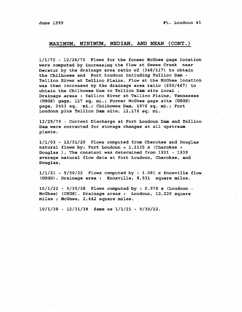
June 1999 Ft. Loudoun 41
MAXIMUM, MINIMUM, MEDIAN, AND MEAN (CONT.)
1/1/72 - 12/24/79 Flows for the former McGhee gage locationwere computed by increasing the flow at Sewee Creek nearDecatur by the drainage area ratio of (348/117) to obtainthe Chilhowee and Fort Loudoun including Tellico Dam -Tellico River at Tellico Plains. Flow at the McGhee locationwas then increased by the drainage area ratio (650/467) toobtain the Chilhowee Dam to Tellico Dam site local .Drainage areas : Tellico River at Tellico Plains, Tennessee(USGS) gage, 117 sq. mi.; Former McGhee gage site (USGS)gage, 2443 sq. mi.; Chilhowee Dam, 1976 sq. mi.; FortLoudoun plus Tellico Dam site, 12,176 sq. mi.
12/25/79 - Current Discharge at Fort Loudoun Dam and TellicoDam were corrected for storage changes at all upstreamplants.
1/1/03 - 12/31/20 Flows computed from Cherokee and Douglasnatural flows by; Fort Loudoun = 1.2135 x (Cherokee +Douglas ). The constant was determined from 1921 - 1939average natural flow data at Fort Loudoun, Cherokee, andDouglas.
1/1/21 - 9/30/22 Flows computed by : 1.081 x Knoxville flow(USGS). Drainage area : Knoxville, 8,931 square miles.
10/1/22 - 9/30/38 Flows computed by : 0.978 x (Loudoun -
McGhee) (USGS). Drainage areas : Loudoun, 12,220 squaremiles ; McGhee, 2,442 square miles.
10/1/38 - 12/31/38 Same as 1/1/21 - 9/30/22.
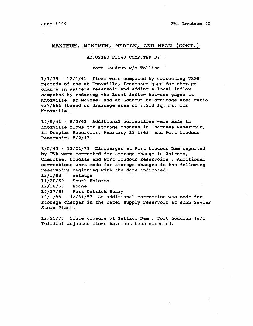
June 1999 Ft. Loudoun 42
MAXIMUM, MINIMUM, MEDIAN, AND MEAN (CONT.)
ADJUSTED FLOWS COMPUTED BY
Fort Loudoun w/o Tellico
1/1/39 - 12/4/41 Flows were computed by correcting USGSrecords of the at Knoxville, Tennessee gage for storagechange in Walters Reservoir and adding a local inflowcomputed by reducing the local inflow between gages atKnoxville, at McGhee, and at Loudoun by drainage area ratio637/864 (based on drainage area of 8,913 sq. mi. forKnoxville).
12/5/41 - 8/5/43 Additional corrections were made inKnoxville flows for storage changes in Cherokee Reservoir,in Douglas Reservoir, February 19,1943, and Fort LoudounReservoir, 8/2/43.
8/5/43 - 12/21/79 Discharges at Fort Loudoun Dam reportedby TVA were corrected for storage change in Walters,Cherokee, Douglas and Fort Loudoun Reservoirs . Additionalcorrections were made for storage changes in the followingreservoirs beginning with the date indicated.12/1/48 Watauga11/20/50 South Holston12/16/52 Boone10/27/53 Fort Patrick Henry10/1/55 - 12/31/57 An additional correction was made forstorage changes in the water supply reservoir at John SevierSteam Plant.
12/25/79 Since closure of Tellico Dam , Fort Loudoun (w/oTellico) adjusted flows have not been computed.
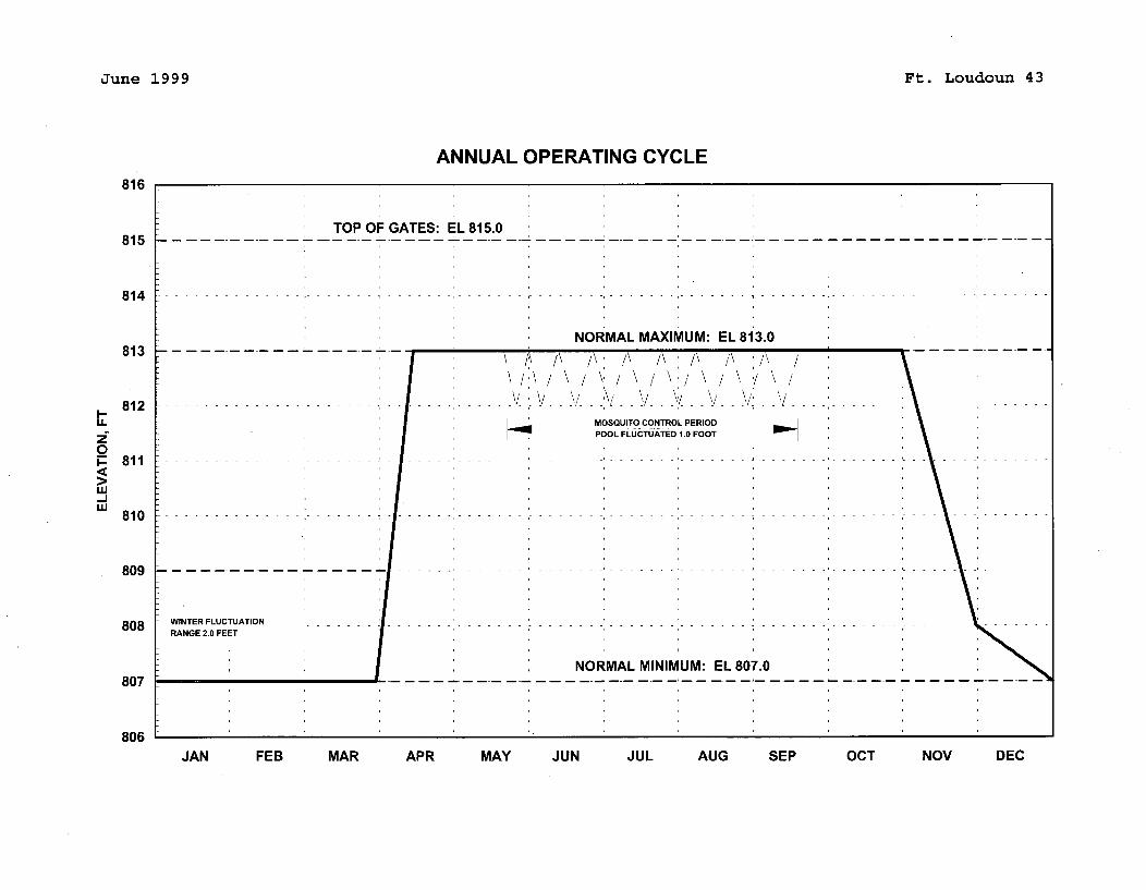
June 1999 Ft. Loudoun 43
ANNUAL OPERATING CYCLE816
TOP OF GATES: EL 815.0815 7-----
8 14 -------------------------------------------------------------------- ------- -------------
NORMAL MAXIMUM: EL 813.0813
812 ------------------------ - --- - V V V V . ------ ------- -------- --- --
LL MOSQUITO CONTROL PERIOD
2F POOL FLUCTUATED 1.0 FOOT
0p 8 1 1 ---------------------- -- ------- ------ --------- -------- ------ --------- ------------------ --
ww
8 1 0 ---------- -------- ------ ------------------------ ----------------------- ---------- ------ ---
8 0 9 --------------- -- ----- ------ ---------- ------ ----- ---- -- ---
808 WINTER FLUCTUATION - - - - - - - - - - - - - - - - - - - - - - - - - - - - - - - - - - --- - - - - - - - - - - - - --- - - - - - - - - -- - - - - -RANGE 2.0 FEET
NORMAL MINIMUM: EL 807.0807
806JAN FEB MAR APR MAY JUN JUL AUG SEP OCT NOV DEC
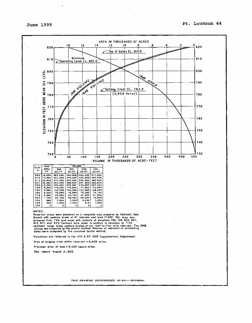
June 1999 Ft. Loudoun 44
_J
.. C
u-i
0.
-JW
150 200 250 300 350VOLUME IN THOUSANDS OF ACRE-FEET
ELEV 194 8 VOLUMEAAREA 1944 1951 950 1961VT AC AC-VT AC-FT AC-FT AC-FT
820 18.000 485.000 483.000 482.000 477.000815 15.500 401.000 399.000 398.000 393.000813 14. 00 371 .000 369.000 368.000 3 3.000807 12.200 290.000 289.000 287.000 382,000802 10.200 234.000 233.000 232.000 227.000794 8.340 179.000 178.000 177.000 172.000790 8.680 133:000 133.000 132.000 128.000780 4.030 79.200 78,800 78.500 75.700770 2.860 43.800 43,700 43.800 41.00760 1.790 20. 700 20.400 20.200 19.600750 966 7,930 7.550 6.950 7.450740 324 1.620 1.350 610 1.890730 0 0 0 0 0
NOTES:Reservoir areas were measured on a composite map prepared by Hydraulic DataBranch with contours drawn at 10' intervals and scale 1"-500' The map wasprepared from TVA land maps with contours at elevations 790, 796. 802, 807,813, 815 and 820. Contours were made to conform to elevations on TVAsediment range cross sections located at one - half to five- mile intervals. The 1946volume was computed by the contour method. Volumes of sediment on succeedingdates were computed by the constant factor method.
Elevations are referred to the USC & GS 1936 Supplementary Adjustment.
Area of original river within reservoir = 4,420 acres.
Drainage area at dam = 9.550 square miles.
Dam closure August 2,1943.
THIS DRAWIWNG SUPERSEDES lO-DA-1-2 /0424.,
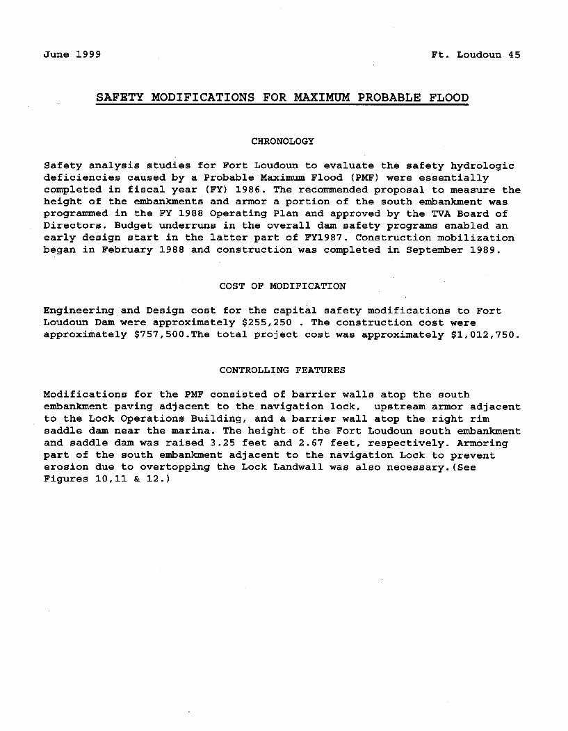
June 1999 Ft. Loudoun 45
SAFETY MODIFICATIONS FOR MAXIMUM PROBABLE FLOOD
CHRONOLOGY
Safety analysis studies for Fort Loudoun to evaluate the safety hydrologicdeficiencies caused by a Probable Maximum Flood (PMF) were essentiallycompleted in fiscal year (FY) 1986. The recommended proposal to measure theheight of the embankments and armor a portion of the south embankment wasprogrammed in the FY 1988 Operating Plan and approved by the TVA Board ofDirectors. Budget underruns in the overall dam safety programs enabled anearly design start in the latter part of FY1987. Construction mobilizationbegan in February 1988 and construction was completed in September 1989.
COST OF MODIFICATION
Engineering and Design cost for the capital safety modifications to FortLoudoun Dam were approximately $255,250 . The construction cost wereapproximately $757,500.The total project cost was approximately $1,012,750.
CONTROLLING FEATURES
Modifications for the PMF consisted of barrier walls atop the southembankment paving adjacent to the navigation lock, upstream armor adjacentto the Lock Operations Building, and a barrier wall atop the right rimsaddle dam near the marina. The height of the Fort Loudoun south embankmentand saddle dam was raised 3.25 feet and 2.67 feet, respectively. Armoringpart of the south embankment adjacent to the navigation Lock to preventerosion due to overtopping the Lock Landwall was also necessary. (SeeFigures 10,11 & 12.)
June 1999 Ft. Loudoun 46
SAFETY MODIFICATIONS FOR MAXIMUM PROBABLE FLOOD (CONT.)
MODIFICATIONS FOR PMF
QUANTITIES
Fort Loudoun South Embankment & Barrier Wall atop Right Rim Saddle Dam
Excavation ....................................... 3,250 cu. ydConcrete .......................................... 2,144 cu. ydRolled fill ...................................... 1,885 cu. ydCrushed stone .................................... 2,290 tonsRiprap ........................................... 1,800 tons
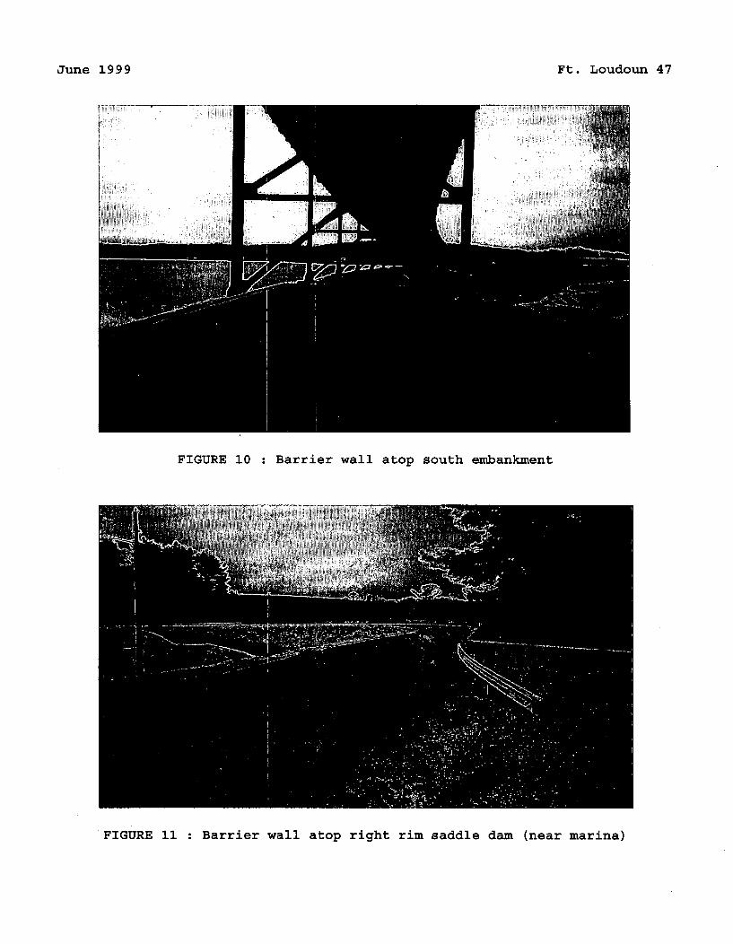
June 1999 Ft. Loudoun 47
FIGURE 10 : Barrier wall atop south embankment
FIGURE 11 : Barrier wall atop right rim saddle dam (near marina)
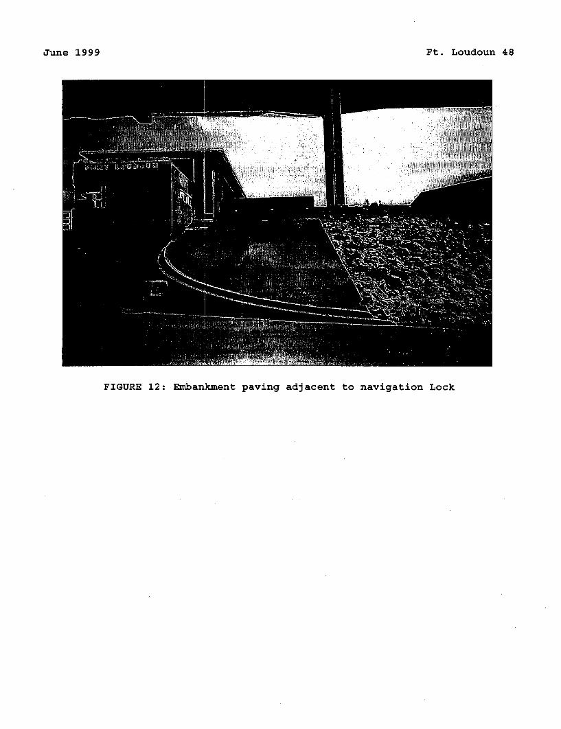
June 1999 Ft. Loudoun 48
FIGURE 12: Embankment paving adjacent to navigation Lock
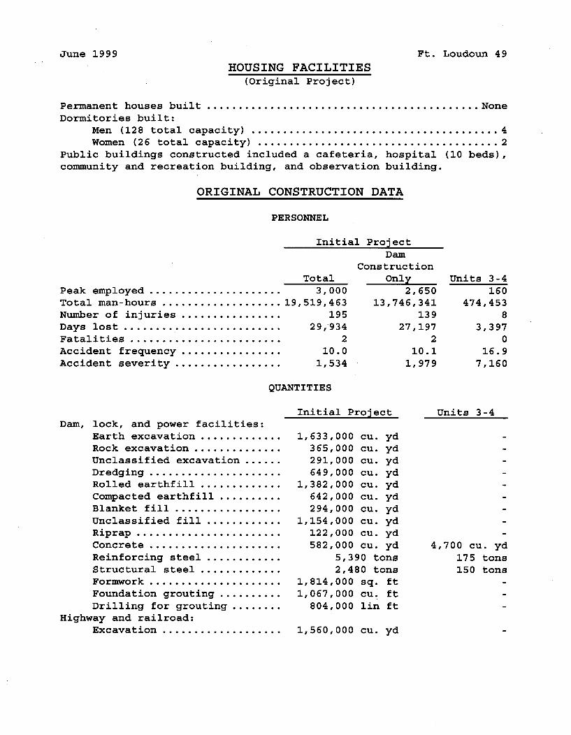
June 1999 Ft. Loudoun 49
HOUSING FACILITIES(original Project)
Permanent houses built ........................................... None
Dormitories built:Men (128 total capacity) ....................................... 4Women (26 total capacity) ...................................... 2
Public buildings constructed included a cafeteria, hospital (10 beds),community and recreation building, and observation building.
ORIGINAL CONSTRUCTION DATA
PERSONNEL
Peak employed .....................Total man-hours ...................Number of injuries ................Days lost .........................Fatalities ........................
Accident frequency ................
Accident severity .................
Initial Project
Dam
Construction
Total Only
3,000 2,650
19,519,463 13,746,341
195 13929,-934 27,197
2 2
10.0 10.1
1,534 1,979
Units 3-4160
474,4538
3,3970
16.97,160
QUANTITIES
Dam, lock, and power facilities:
Earth excavation .............Rock excavation ..............Unclassified excavation ......Dredging .....................Rolled earthfill .............
Compacted earthfill ..........Blanket fill .................
Unclassified fill ............Riprap .......................
Concrete .....................
Reinforcing steel ............Structural steel .............Formwork .....................
Foundation grouting ..........
Drilling for grouting ........Highway and railroad:
Excavation ...................
Initial Project
1,633,000 cu. yd365,000 cu. yd291,000 cu. yd649,000 cu. yd
1,382,000 cu. yd642,000 cu. yd294,000 cu. yd
1,154,000 cu. yd122,000 cu. yd582,000 cu. yd
5,390 tons2,480 tons
1,814,000 sq. ft1,067,000 cu. ft
804,000 lin ft
1,560,000 cu. yd
Units 3-4
4,700 cu. yd
175 tons150 tons
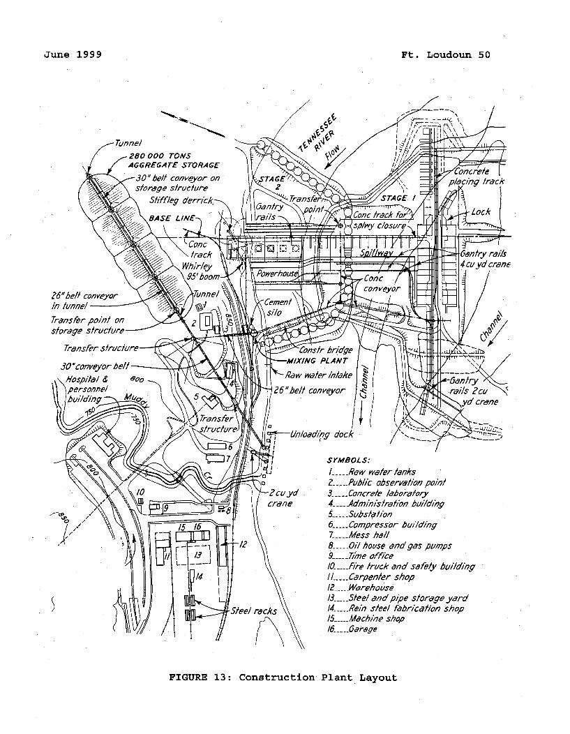
June 1999 Ft. Loudoun 50
Tunnel.280 000 TONSAGGREGATE STORAGE
-30" belt conVeyor onstorage structure
f5iffleg derrick.-.
, BASE LINE-,
in tunnel '
storage
SrMBOLs:
/ ----- Raw water tanksZ_ .... Public observation point3- .... Concrete laboratory4_--Adminisfra'o1n buildinqg5-Subsldhon6- .... Compressor bul/ding7----Mess h1/I8-_...01/ house and gas pumps9-_ .. Timne ofiýce/0- --- fl'-e truck and safely building"I/----.Carpenler shopI2 ---- arehouse/3- --- Steel and pipe storage yard14-__Rein steel fabrication shop/5_._•_Machine shop16- .. arage
FIGURE 13: Construction Plant Layout
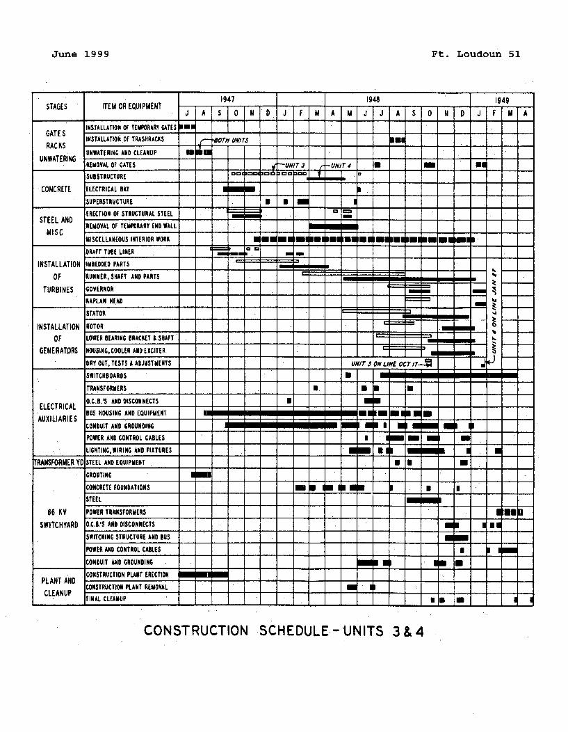
June 1999 Ft. Loudoun 51
1947 1948 1949J A S 0 N D J F M A M J J A S O N D J F M A
INSTALLATION or TEMPORARY GATES 10•
RACKS INSTAU.ATION OFTRASHRACKS -OTi UNITS URACKS "J-
UNWATERING AND CLEANUP mUllmUNWATERING - - - - - - - - - - - - -
REMOVAL or GATES. -UNIT i r-UNIT 4SUBSTRUCTURE I I a
CONCRETE ELECTRICAL BAY
SUPERSTRUCTURE
ERECTION OF STRUCTURAL STEELSTEEL AND . . ..REMOVAL OF TEMPORARY END WALL
MISCELLANEOUS INTERIOR WORK O ME 1111 a l a
DRAFT TUBE LINER
INSTALLATION IMBEDDED PARTS
OF RUNNER,SHAFT AND PARTS
TURBINES GOVERNORKAPLAN HEAD i
STATOR
INSTALLATION ROTOR
OF LOWER BEARING BRACKET & SHAFT. b
GENERATORS HOUSING, COOLER AND EXCITER
* DRY OUT. TESTS & ADJUSTMEHTS UNIT i ON LINE OCT r7-/ 7 -
SWITCHBOARDS • 0
TRANSFORMERS
ELECTRICAL O.CB.'S AND DISCONNECTSBUS HOUSING AND EQUIPMENT 11
AUXILIARIESCONDUIT AND GROUNDING
POWER AND CONTROL CABLES I Hi i N 0
LIGHTINC,WIRING AND FIXTURES Brae 0 ll * 0 m
TRANSFORMER YD STEEL AND EQUIPMENT
GROUTING
CONCRETE FOUNDATIONS I onSTEEL m I
66 KV POWER TRANSFORMERSSWITCHYARD O.C.,'S AND DISCONNECTS
SWITCHING STRUCTURE AND BUS
POWER AND CONTROL CABLES
CONDUIT AND GROUNDING W
PLANT AND CONSTRUCTION PLANT ERECTION
CONSTRUCTION PLANT REMOVAL NoCLEANUP
* FINAL CLEANUP 7
CONSTRUCTION SCHEDULE -UNITS 3 & 4
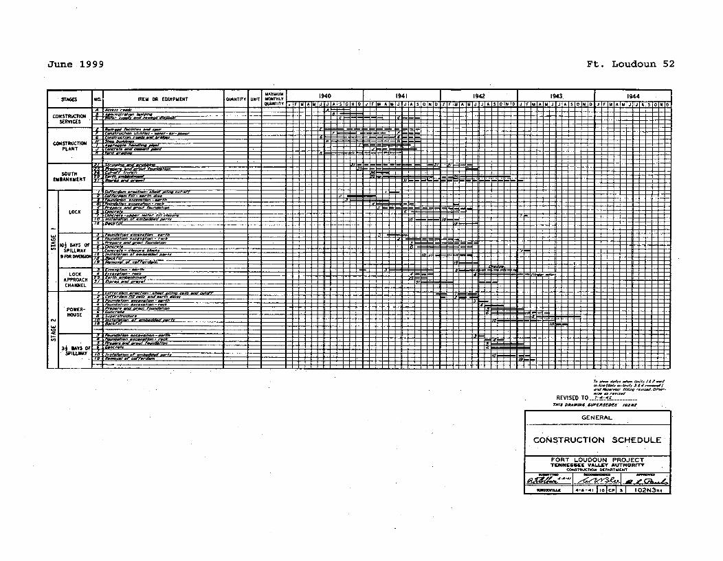
June 1999 Ft. Loudoun 52
,-I-Y-Y 7 7 7 7
NO.1STAGES
CON STRUCTIONSERVICES
CONSTRUCTIONPLANT
ITEM OR EOUIPMENTMAXIMUMQUANTTYIUNI I~ _UOMT.LI 1940
75 757I 1941. I 1942 I
SOUTHEMBANKMENT
A,
LOCK
IO BAYS OFSPILLWAY
9 FOR DrWION
1943 1 1944
REVISED TO __Z s-J ---TIHIS DRAWINC. SUPERSEDES /OZA'S
LOCKAPPROACHCHANNEL
POWER-HOUSE
A,
3, BAYS OFSPILLWAY
GENERAL
CONSTRUCTION SCHEDULE
FORT LOUDOUN PROJECTTENNESSEE VALLEY AUTHORITY
CoI4'rRuTION OtPARThAtWT
,imo=,i, 14-41- I'lcPl 3f 102N3R4
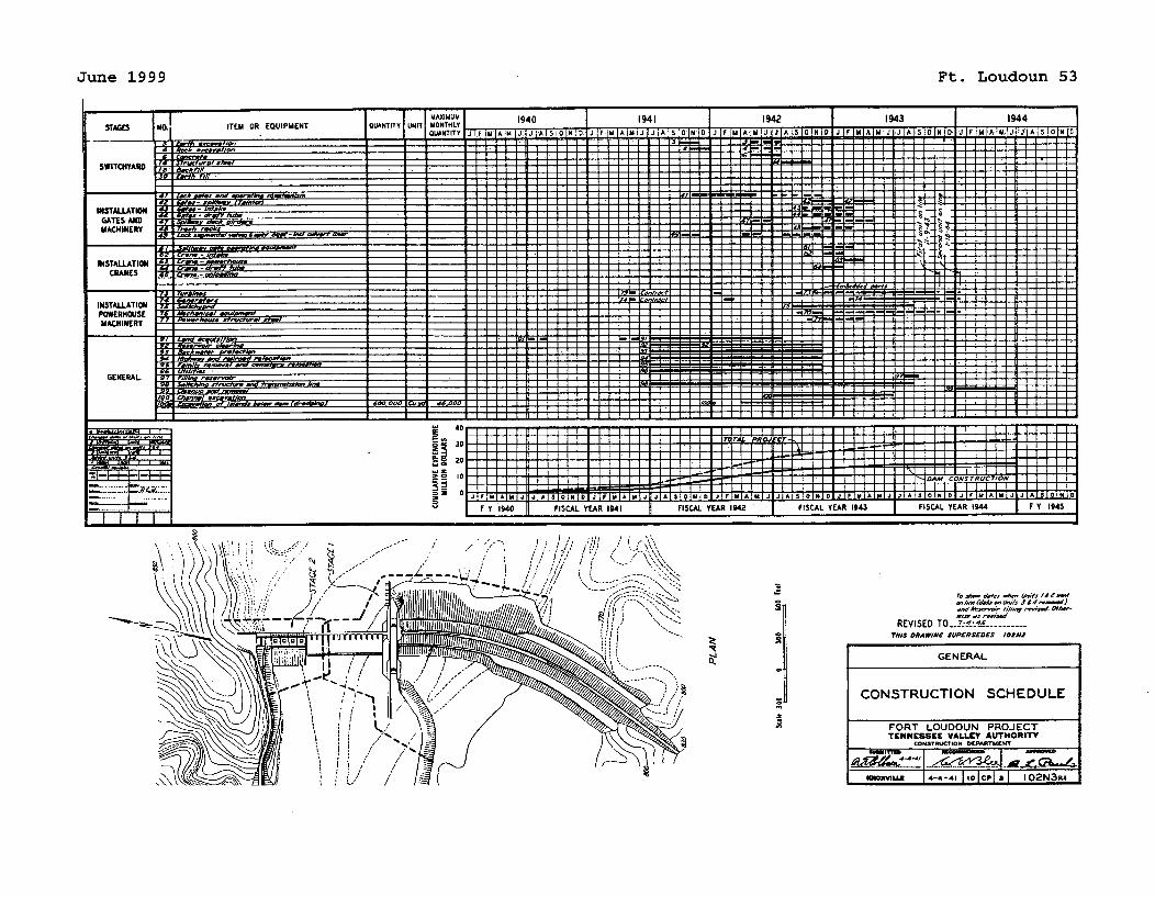
June 1999 Ft. Loudoun 53
,ise as revi/e f
REVISED TO .. 4_TMIS DRAW#IN SUPERS£OES 1I0N2
GENERAL
CONSTRUCTION SCHEDULE
FORT LOUDOUN PROJECTTENNrSSEE VALLEY AUTHORITY
coWNSlMlON DOPRMTUENH
. .. . I . . .. .. : - :- -_-;- -T0080"iu. I 4-4-41 I olcel a I 102N3R4
I I I l I -
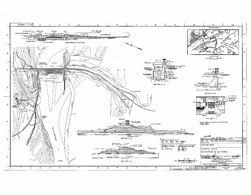
OOMOL o1 1 OLl 2 I 3 I 4 I 5 I 6 1 7 I 8 I 9 I 10 I 11 I 12v -r-
f.... KFL.. . .. B.. CSPO ILLW LOC. ,J• ý- MB ýENT
- 1 A- - , -11 A. . I - oKK
.DOWNSTREAM E
Ut .,,1C K / I,,'.',
SE I SETINADD . TE
.-:,,= .,, = _ ~~~~~~~A . .. . .... ... .... . ...... . . ......... ....
SITE PLAN
SECTION B-8
ARRNRNSECTON -CA
SE M •OYCATION B-8L, EDAWNS
23R2-SERIE23W•-SERIES
A
8
C
D
E
F
"1I lOS ,NAC -AC IA -A 11.CO
MAIN DAM WORKS
GENERAL PLAN
ELEVATION & SECTIONS
FORT LOUOOUN PROJECTTENNESSEE VALLEY AUT•ORITT
PLANMD ENIO
AUTOCAD 2006 I 10 l C 1 1 O)W29JO RI11
--ITAS T .,CS -I SA AANDS~LCECEDES :,1.2.AT 1ASI--- ER
•AO •AWINGNOT AL• •U•Y
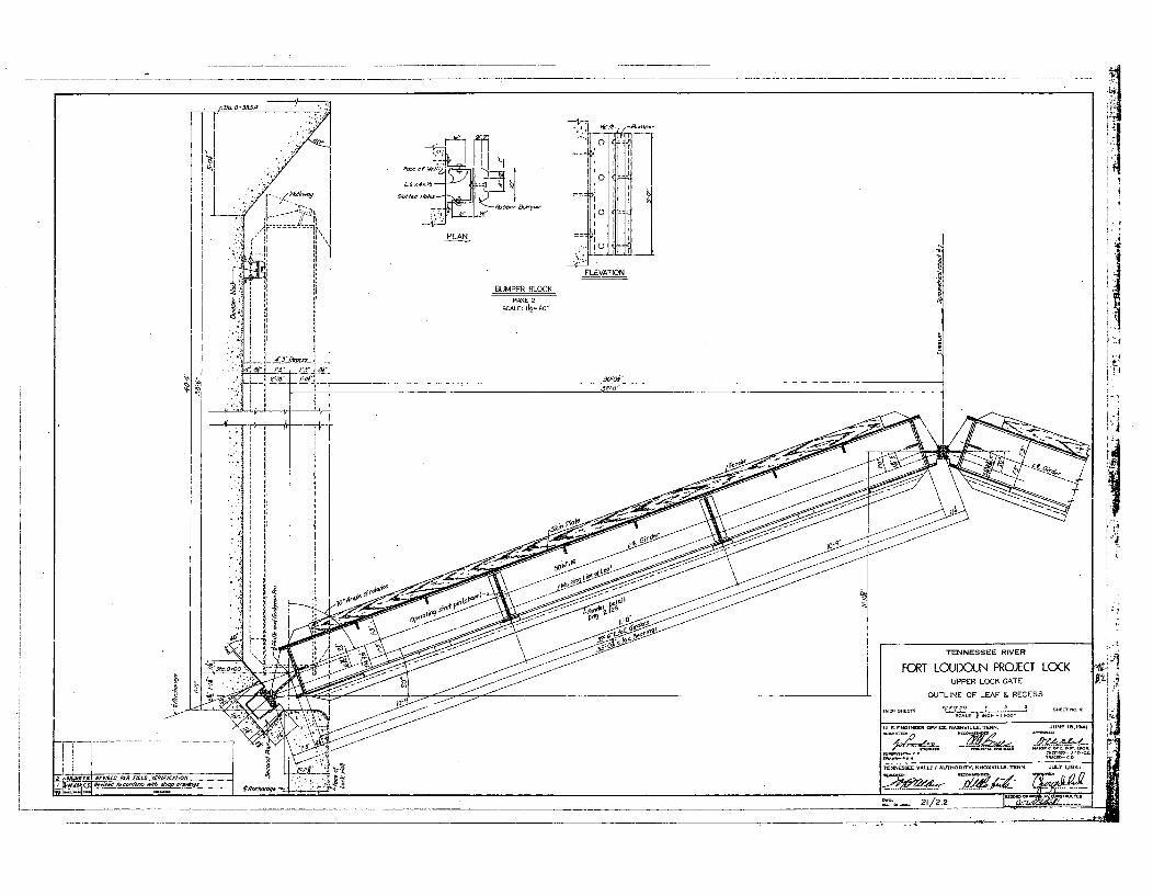
77I .. . ...
.. _I I
[, •_ELEVATION
BUMPER BLOCK
ka I CMAE 2
30 .W i
00
'I _ _ _ _ _ _ _ _ _ _ o_
Lin,. io
:•\ •• \ 1TENNESSEE RIVER
" i FORT LOUDOUN PROJECT LOCK .EUPPER
LOCK GATE
OUT LI NE OF LEAF RECESS
• • N • v m ( A • O RI. ... . IL.. . N. . J -L y -g~
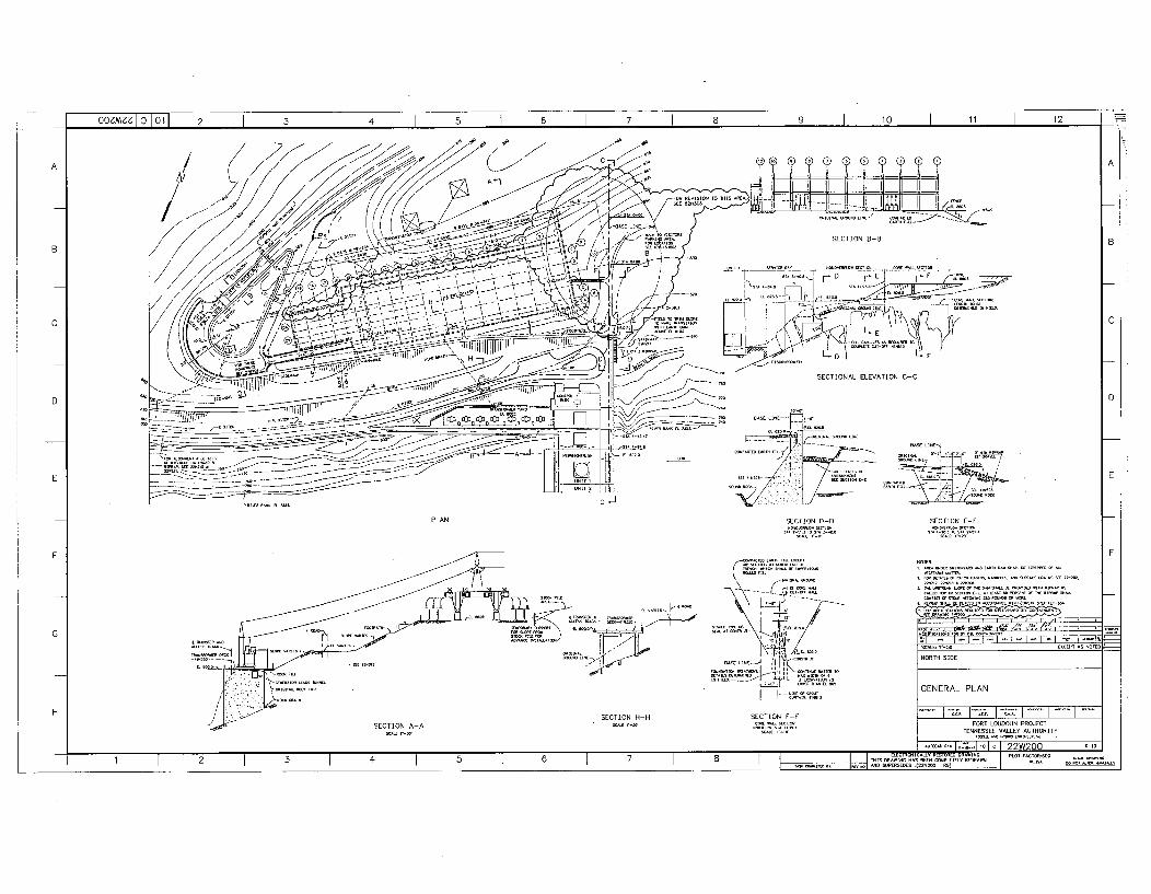
oozmzI 10 oi 2 1 3 I 4 I 5 I 6 I I 8 I 9 I 10 I 11 I 12 =-I -
A
B
c
FOR RE0S00 0RO 0001 -.11 __
0000 04
0O~~~C0
~SECTION 3-13
0~~ D E.- F- F_____
SECTIONAL ELEVATION C-
jozzzrr0
z0 0
cc] .' 0
W M .D000
-A-J-CP.--'
B
A
TO
C
D D
E
-- D. 1-PLAN
F
SECTION D-D
C-RD0.- - "0OFF"I
SECTION F-F
SECTION E-E
(.s. 0
G.. E: -SO EXCEPT IS NOTEDNORTH SIDE
GENERAL PLAN
FORT LOUDOUN PROJECT
TENNESSEE VA LEY AUTHORITY0o_00 _,o0 L _.ooýo
HSECTION H-H
SECTION A-A
5~~~~~ , I -" 7 I lo I c 22W200000.0 .000001 1 2 I I I 5 I 6 1 7 1 TFI I I 1ý.l-S DR llfýl 111DRI IRDIRD SuRISSIDES
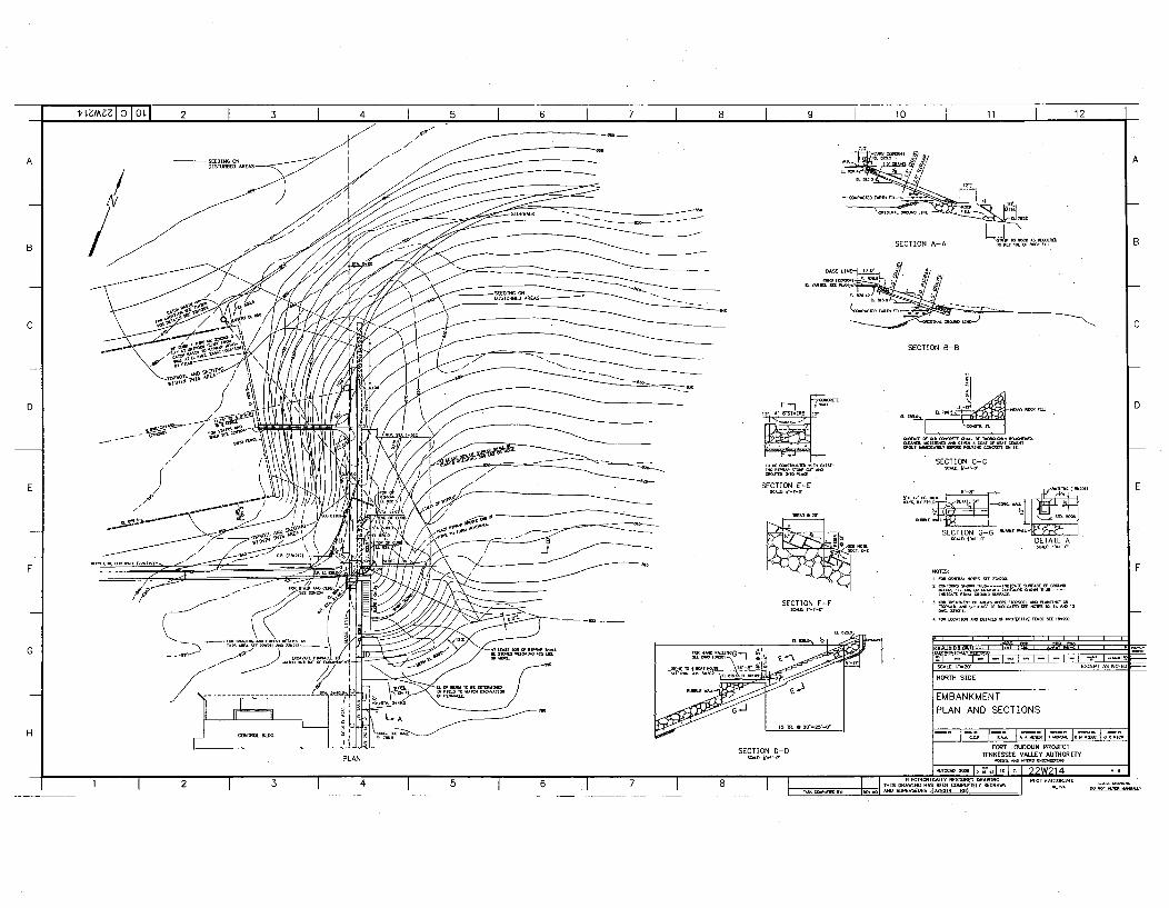
LZM3ZI o loLl 2 I 3 4 I 5 I 6 I 7 1 I 9 I 10 I 11 I 12-I. -
1ý -A"/
477477-
~~ /
- 5- - - --
-7.0-
SECTION. A- A 1 A
-- - - - --
SECTION B-8
B
C
SECTION E-E
SECTION C-C
SECTION 7 -G
• r-•-o" DETAIL A "
ND-S
D
SECTION F-F
G-1
SECTION D-D
i T?'7 7 .~ 0
¶~~79 , ~ --
-, ,,,.,,,,~J-..EX-I AS N-I
NORTH SIDE
EMBANKMENTPLAN AND SECTIONS
PLAN
FORT LOUDOUN PROJECTTENNESSEE VIE YAU7hORITY
F'0~ 07I-,~ORTlC LOUDUN POJE4 R9
? i I I= J/ l OI S 070*100000 • 7077 I 0 I7r77770I.7 70770071
1 1 2 1 3 I 1 0 I 6 I 1 7 I I -* SS~.So,, TSS..1 7710 lOPERAIOEN (200007 77) I --r .... . ... ... '1-" "!1 I I
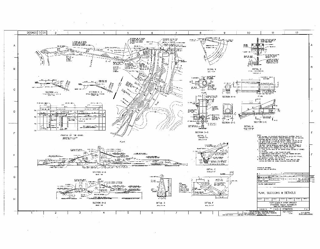
oo0M5:IO I0 L 1 2 I 3 I 4 I 5 I I 10 I 11 I 12-- I. - 1-
A
B
BES UNEB
PF •DET'l ,•L : •
SECTIO J - SEC..ON K- ... ...... 4-\ 4 kBo, . . . . • . .
N .... f .......E~ -IL
EBB - Rll;t....-: -1; /1"•',SIR.
IS A
F TOE' I// # •/T DRAIN
PROE L OH TEDRI /
C
DETAILX
PLAN ]•
-gT-
SECTION O-
SECCTIN 0 5
DETAIL'ý
- -- - - - - - -
to 1 M_
DEAI C
A
DETAIL G
H PLAN
LDA LA H
G SECTION E-E
DETAIL H
C
B
D D
E E
= Z"t! 'IAý.;ýM
PLAN
FI___ _ HPA .7:.A!! -A L- -. I
BA. tE IM D. IN11-
EB R-IB I RB- ~~Xo~P EBEBOEA
1. ALL GIBANC ON O1ERISE OLCTICIASCN•L IATF SHAL BEREMO D FROM THE NATIRAL -BN SURFACE AID TBE SLFACEHARRIID BEFORE STARING 11 PLAIE R-D FL
2ý THE LOATO OF THE E.6OF .1•-1 R NENH AT ITA -DOMAY BE CHAIGED , THE E"' TO SUIT ACTUAL COGNI HSOF_PEVRDEM ENS TaRED. IF TE L NGTH IS RBBOUE,ADDITONAL RISERS SHALL BE ADE ALOG -H T IRA IN AT200't DO. THE 250-1 OERLAP OF GT-O• AND RISER AREASAS INDICATED ON THE PROFILE SEAL BE MAINTANIET.
3. AT LEAST 50 BER GENT OF THE RIPRAP SHALL -OSIST OF STONES
A. LISTREAl SLOPE - 350 POUNDS OR MORE
. DWSTREAM IDpE B1L- EL 110-1.0 POUN.S OR -. 1C LO. APPROACH . ANNEL AS NOTE.
4, FOB BERM DRAINAGE, PARIING AREAS, AND O-R TER' DETAILS,SEE ERAING5 •2312GI 2.3 _0 ' 21"
5ý PIPE TO BE LAID - OPEN JDNTE, EL GIlN ARE FOR PIPEINVETS. S IA TIONS ARE THOSE MEASURED ALONG BASE LINE
REFEREN.. DRAWINGOlB.20..BI OMATERAL
F
DETAIL C
G
SECTION A-A
L.EBA. MBA B->ý
IPE LLRBEC BRERABRRRBBI.BBRROE ~ ~ ý1 hlp IIBMR RBAlA .AB R
ROBAB lB-_ _ __ _
-RBJ~tNRE~B-- 4BRRRBBR o
DETAIL S
$2 ......... [ I I I I I r '.. '• . L. ,,• r• --EXCEP AS NDI=
SOOIH EMBANKMENT
%7 7TILý-I D~E E E TAL.j ----
HI PLAN, SECTIONS & DETAILS
FORT LOUDOUN HYDRO PROJECTTENNESSEE VALLEY AUTHORITY
B ._E I .--,fl,-
SECTION B-B DETAIL F
-= -, I -" I HG I G I 9 , ;W? nn£ R 1ý
1 1 2 1 3) 1 4 1 5 1 6 I BA..EBB ... E....E .I B.. B..-. t-7,7 -1
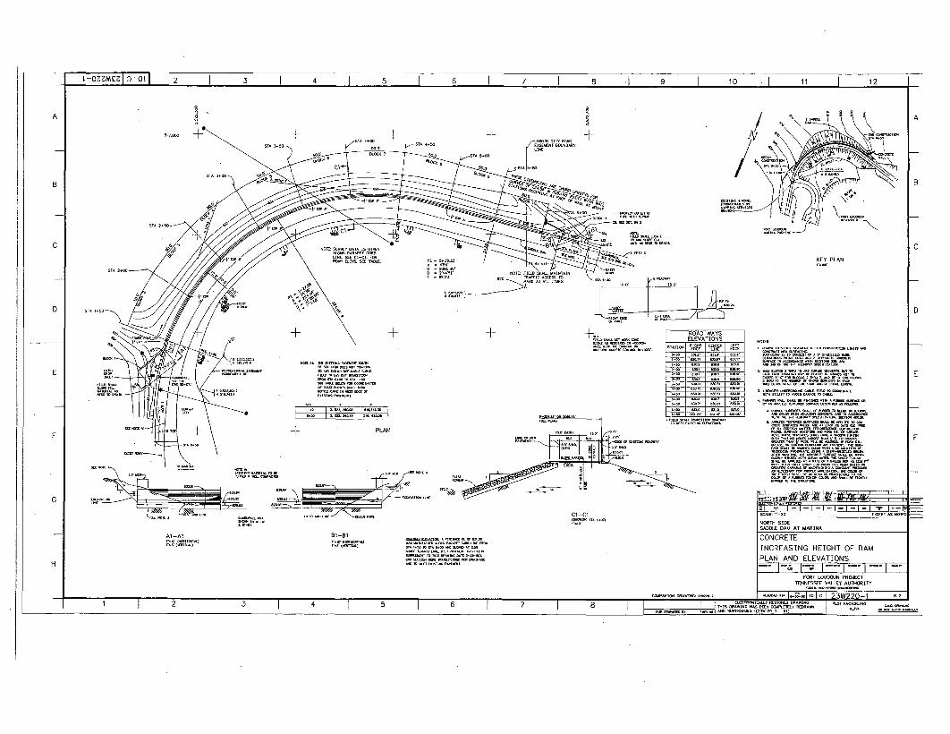
L-OzEmczI 0 lo I 2 1 I 4 I 5 1 6 I 7 1 8 '1 9 1 10 I 11 I 12
A
*1.911,001 _- +-
•STA 4+50-0O]R CITY P"RE- T BWNDMYL NE
6
KEY PLAN
B
A
C
ý .. 3p
D
+- ±-
E
-I- PLAN
ROAD WAYSELEVATIONS 50455
SU - R,'ý,T CT LEFT
W., A., 1 -1.
5.45 (00 +00 I.00001+0+000000+10+14 + (0505+T
(.00 ((3 (+13 5+ +. 0~5 2 ( 1.0+10 5150+30
455+11010100030+51+3 =W.04+551++05000505
ISO 5500 1+13
0000+00 l+~ 000+
1+0
-iW.
I I . 11G 2 WM w 01 ,a , .A
------------------------------------------------------------------------------------------------------------------------------------------------------------------------II-cl-cl
Al -Al B1-81
NORTH SIDESADDLE DAM AT MARINA
CONCRETE
INCREASING HEIGHT OF DAM
PLAN AND ELEVATIONSH - I- 1 -; 1--'-I +I-. I-
FORT LOUDOUN PROJECTTENNESSEE VAILEY AUTHARITY
-4. .I
1l80101004T50 -J1030U0R554 RWN05T350T1041+005.15( 01 0 . . ..145555 1252- 31_______
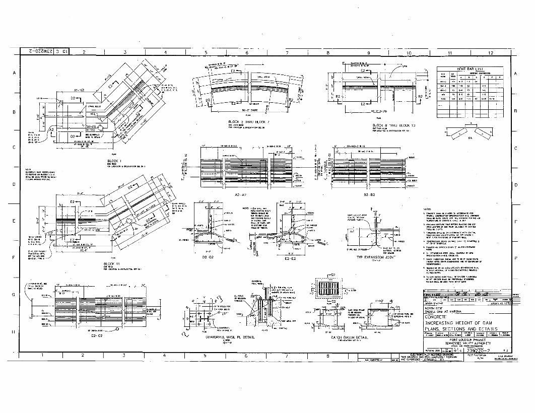
r -Z-oZWz 1I0 1 IOLI 2 1 3 I 4 I 5 1 I 7 I R I o I so I 11 17
61 1 7. 1 8 1 , '- 1 10 1 1 1
BENT BAR LIST-~ NO. aEW a[•
=•[ I I C
SAl I 1 • E -
A
B
BLOCK 2 THRU BLOCK 7BLOCK 8 THRU BLOCK 10
BLOCK 1
N-TE
D
A2 B2-B2
E2-E2TYP EXPANSION JOINT
GamlaS~mGlaS InGsa-an--OS ~nnn~n
E
FBLOCK 11
.SK 11I IT•I
-GU •IARD}RAIL BASE PL DE•TAIL CATCH• BA TIN DETAIL
- , ýw 1 i9m .611ý1 I I
NORTH SIDESADDLE DAM AT MARINA
CONCRETEINCREASING HEIGHT OF DAMPLANS, SECTIONS AND DETAILS
C2-C2 I~aasamF naG 555555
FORT LOUDOUS1 PROJECTTENNESSEE VALLEýYATORT
Fon~1ORT LOUDON PROJECTs
--p - I IS-S 'I
1 2 3 4 8 IS D Ln--~Sa.-~~aS~~G n -. A -2S
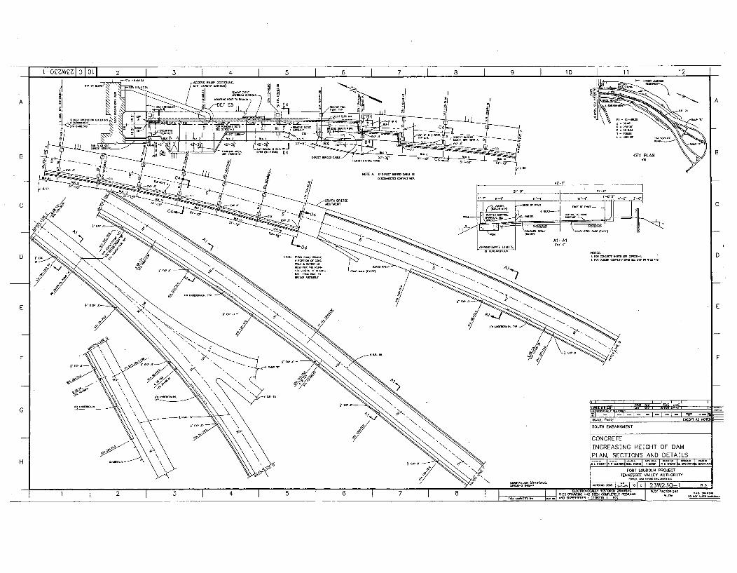
2-° MI 2 3 4 5 6 7 8 9 10 211 I
-PRXIAI (EXIISTING-•
A. D L4 P
'- -% -• - -- -_ . . . . -- - L- _---- -- 6
-- 2 2 f r P, CONC RET -
PLAN SECT ON AND DE A L
ý".T' -1.• .... _j• -- ---- I--I-I2•~ a -
B G- -I.KEY PLAN
\P
N-o II I--I7 I2- . . . . -. .
SOT EMBA KMEN
PLAN SETOSANEAL
TENSSETAEEATORTD02222 NOTE. 0ý1 1. 23W3.- -T
1 ~ ~ ~ ~ ~ ~ NX 2 7IX sN2002222
A
B
C
D
F
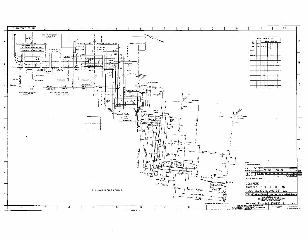
z-o•mýz10 I L LI 2 1 3 1 4 I 5 I 6 I 7 I 8 1 9 I 10 I 11 I 12
BENT BAR LIST
AA -,.I, -i .
I C
D
I / N £NENNN.c,,
7
E
-Hb1 20 -- --i- l- I- I- - - r L
SCALE: •.-,.-•EXCESt As NOTES
SOUTH EMBANKMENT
CONCRETEINCREASING HEIGHT OF DAMPLAN, SECTIONS AND DETAILSPLAN-WALL BLOCKS 1 THRU 8
k 1 =_7XNN I.nNm TE =N~ 4LFORT LOUDOUN PROJECT
TENNESSEE VALLEY AUthORITY
-. I. D-: -, I, . AS -- - ION. I ,o I - I 23W230-2
DRAWING HAS E N OD I)- =R NA_____i • • ~~~AND SURCSUES5: (2-k3- 2 RI) P T• •
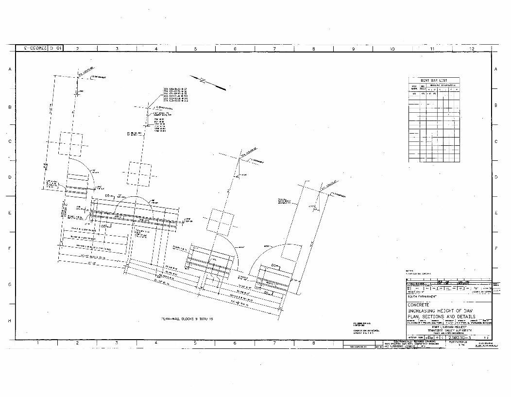
01100
I14111111+010
A1220,54.18 0 S7
A122+11." I S10A 1U-+658 . -11 1-316.05 * S12
BENT BAR LIST
/
!
I
- 41..
/
N-TE:
PLAN-WALL BLOCKS 9 THRU 16
SCAU0: 4.1-0'-• EXCEPT 0S N010
SOUTH EMBANKMENT
CONCRETEINCREASING HEIGHT OF DAMPLAN, SECTIONS AND DETAILS
FORT LOUDOUN PROJECT
TENNESSEE VALLEY AUTHORITY
....00+ 0 1,0l c !23W230-3 03ICOLON 1000O00 0040000 I PLOT 0ACTO0:Z€
(234400-3 RI) 001T 1 00U4y
-ANION DRAWNS
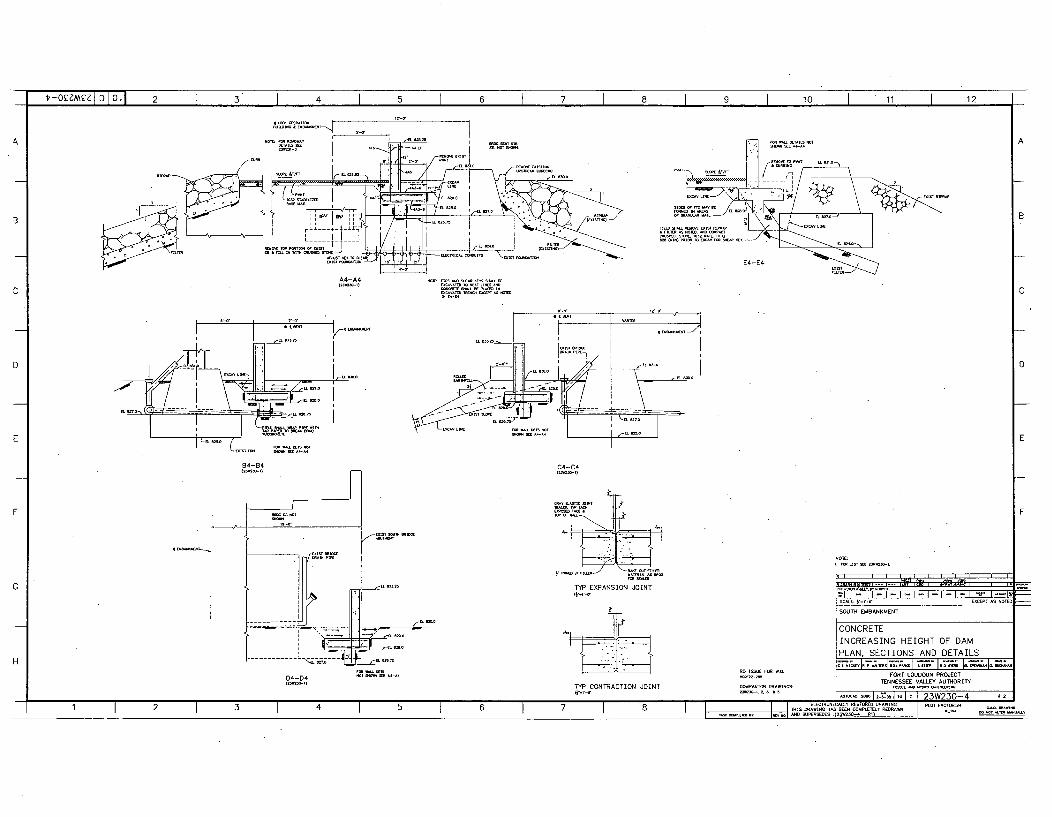
i'-oZMI1 0 IL 2 3 4 5 6 7 8 9 10 11 12 j
E4-E4
A4-A4
D
E
C4-C4
TYP EXPANSION JOINTW.,r•
NOTE:
I I It~i
'Z I . I - I - I - I - I - I - I - I ý I -- ll
SOUTH EMBANKMENT
CONCRETEINCREASING HEIGHT OF DAMPLAN, SECTIONS AND DETAILS
D4-D4RO -SSE -O W.O.
FORT LOUDOUN PROJECTTENNESSEE VALLEY AUTHORITY
TYP CONTRACTION JOINT', "•-oATE ARR A1S-O lER I 9R iWg,3--4
RE a RAN RAT AJERSTESE IAR:(2- -4 RE) _-____________
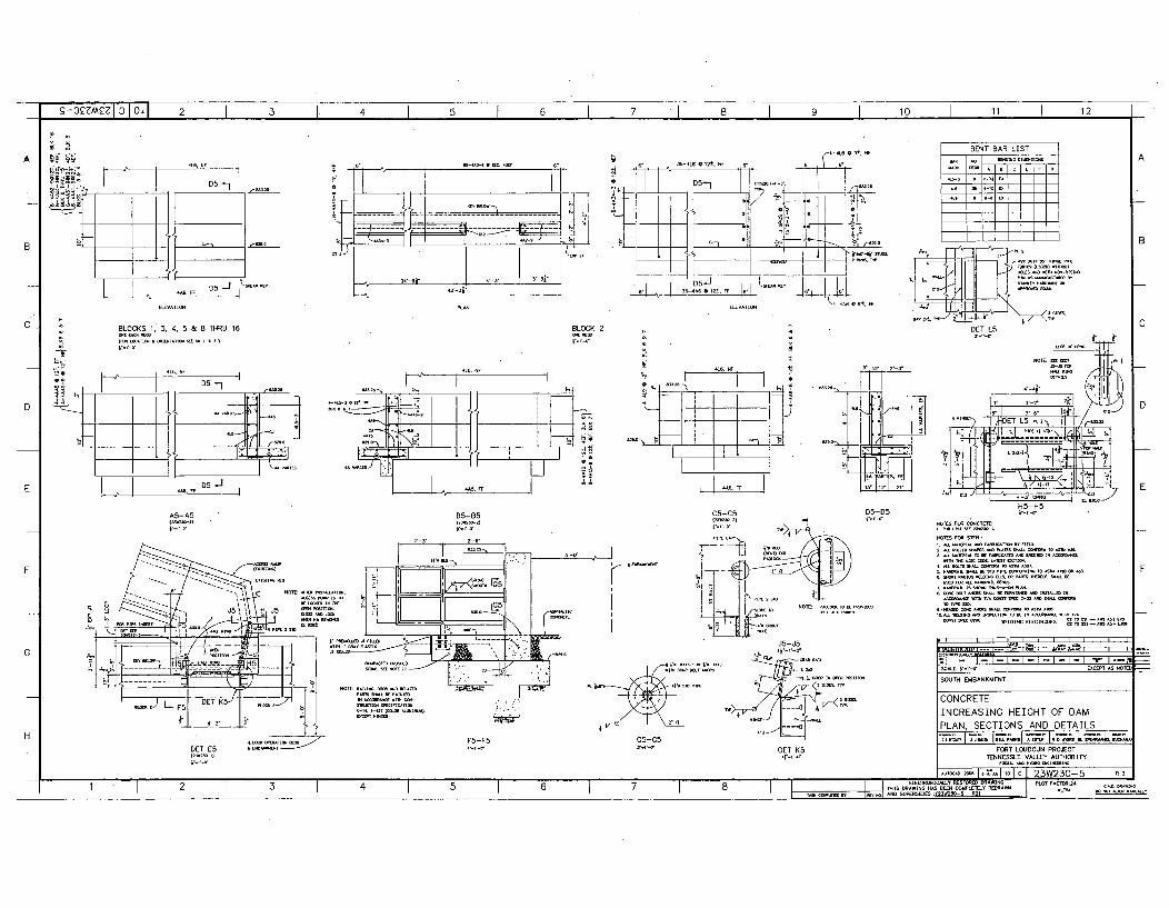
g-oC3m•,7 -0l] 2 3 4 5 6 7 8 9 10 1 11 I 12
NF
1 -- • , .... D5"
ET IT~r
,6",
---- ---
-* 0±. NF BENT BAR LIST
64 35-4 1-612±. NF N.
- o 4 , o6 6 .±2-4
I1 I 11
6-ATO 4 ' A 6 9.f
.• D'ET L5
A
B
S I I66,-lI'
42 -3j"
l•/+t+
CBLOCKS 1, 3, 4. 5 & 8 THRU 16 BLOCK 2
S-•'o
D
E
A5-A5 85-85G-2)6
CS-CS D5-D52,6661 p06
N-66 No2i44016660
m
NOTES FOR -EWRZ:
NOmZS FOR sTBD,
4. ýl ttsmr rm•,m F
. I I . I IJ5-J5
& =6" "T
6664-6 ET K5
-' lII6I660I6I~II hIINI,~~~,'+ +. I--I--I•l--I--I--I-I "• l-•l•;--" T I I ? . . . . . . .°- 4 .ý -SOUTH EMBANKMENT
CONCRETEINCREASING HEIGHT OF DAMPLAN, SECTIONS AND DETAILS
FORT LOUDOUN PROJECTTENNESSEE VALLEY AUTHORITY
DET E5I-I-I+'
Au- - 1 ... 1'. 1 G 1 R 3
I ,.. I ', I 6 I .. I I 6 I I I I I 66.5666660660±6SN0664166664I60 I
I I I I I / I I I I I 1U.PYIt~W2 1160 6506 4106604-66.0 6666666 I 060166014066911 I66066I040Il000I.l±0~b±I±66~I 06~ I2 1 3 1 4 , 1 5 1 6 1 7 1I .. I- s- DR I.. PLOT FACT-24-S DRAWING N- BUN GGU-IBLY KDRAWN
AN 2
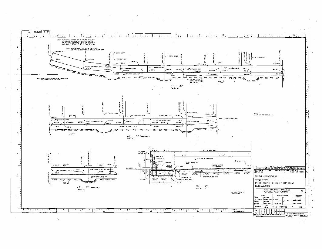
I - OEEREEj~O~j4Ii I , 11 1211,111 ~ ~~ ~~ ~ ~ ~ ~ ~ ~ " ly l l 11 1 11 1 Ii li ly i 1 1 11[ 111 1 111 1 j i ii i i
i i I i I . . . . . . . . . . . I Ii I I I I I I I I I I I ] I I I I
8ADSTOACCR~GyT ALLDW A -NMU•A-i 8J AT 1 1-R11TWAL
NOT'RIFRCMN OT- 1 ORCXT
2/1EP•N,,~ es~
NOreCOmAPN O~S OV OCEDP
IA
rSTA 127+720 T/ANLL
n- CA -0A0
8330. j B7-.]
IA
-A
A 8502.03000 SOOT 1k~,~ £5000000 SOOTho I-.-ajo 84 00000 83008 Er 3000.400104 .aor783058 rO000Ao -. 5
I " I
, . .. .. . f
Es3 2 2 8~ ~ m full0ST.IO 32
A7 - A7(00r 8-)
c- I4 70A03or So<-.03080 TYTTO BS - )
-2-1
B?4
/
97 j000
C
F-
SOUTH EMBANKMENT
B7?- B?A7 A7 A)
CONCRETEINCREASING HEIGHT OF DAMELEVATIONS
FORT LOUDOUN PROJECTTENNESSEE VOLLEY 000000,03 N
H•22-2-
0003 I c00 I 23W230 -7 R4
- --- -* - DO -- T--- 2.0...... - M A LHA.1t LLII I I I . . . I I. . . .I I I I I I I I ' ' . . . . . .I . . . .. I. .
1 3 4 1 5 -MMM
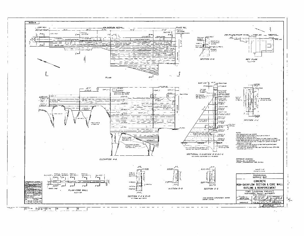
_2O N ll
C S E T O C E/ O T C T /S S L
L, F-
CC/ 1 ~ I - o //S3/OSsWO -'O
C _o 1C4- T ~ -.
0/S/N 4d~1 CIOCS CC/SN
-h•on~t
FýJJCLi
L
~<i/E//,//OCE//N ~ CO //CC/S/C
C SWECTIO C COSK
SECTION K-K KEY" PLAN
A
--IPLAN
. .C/.0220
... .. r... .. .. --
/ A C/SOS/S CC,//OJ/-.
CCS/o,~ ~C/I/O C ~ - ~ - ---- -
/ ______ C~o/S. --
/6/0/51/.-- I
/CCCC/CCSI. ~SCC'S..// 'Xi
7101-
I
/C.WN//I -oOOC
C/STI 6- &l-
foroSect
// • '°' ;:.n.,-,'. C//OS,
SECTIONAL ELEVATION B-B = C-C
sC/SOILL
SECTION J.
"~•c FAW/a.""
/CC 5/00 /N SS //O
••,I,%'=LL" V7650- ...-
ELEVATION A-A
.rElC-1!S-C/1 R-/ F-1 I F•-1S1/ / - F- I-]/ / : .
PLAN-CORE WALL
SECTION F-F , Fl-Fl
SECTION R-R
El CTO N0-
SECTION S-S
POWERHOUSE
SERVICE SAY
CONCRETENON-OVERFLOW SECTION & CORE WALL
OUTLINE & REINFORCEMENTFORT LOUDOUN PROJECT
TENNESSEE VALLEY AUTHORITY
K.NOXVILL I -.-.. Iol-sc I IV 4IlM508R.
__ J®
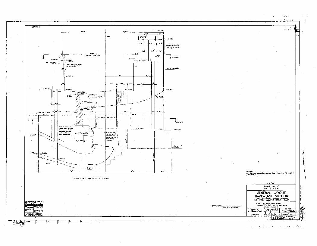
SI9NIt, I
I, •I •
TRANSVERSE SECTION ON f 1I/IT
POWER HOUSE.
UNITS 3 &4
GENERAL LAYOUTTRANSVERSE SECTIONINITIAL CO" STRUCTION
, .FORT LOUDOUN PROJECT-V 35050/0 O~TENN ESSEE VALLEY AUTHORITY
I xwxvý 1.01 C " . 1 4 6 A,
.... •'• •-. ®" I ® I® I® I® I
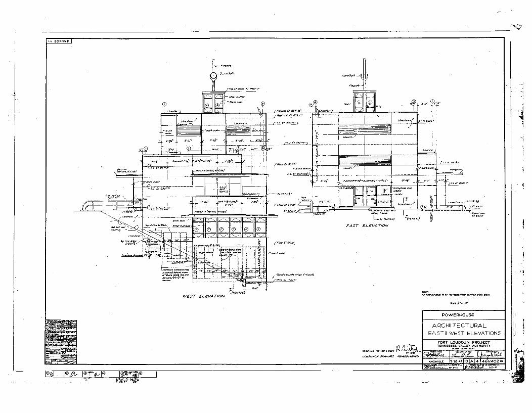
6 8O~N9~ I
I.aF,,, - "
0 ,t-H
2-Z-d"
0~0£~/
0 Oj s'ot 470'
fPooa~ok0 P0 8.07
ar-.
_ 16•0"
'i-i h
, | 'I /
9 ,. ,-.... ,.,•,.,,°, ,, . - - I
- a"•',°,Oa"- r•,,,,, I
q, 1- 1 _;• " i' ,
- -Q~,;--,----.-..- _- ... . . . .. ' _-1a-- .-0*- , .- ---"-- .... (20'•'' 47 ,
0a .f
a = ro __4~',fj ',
T r-d.....
(55. £7 £4r-0 2
000£~ 8800'
t.0.,,,£ 5,100,.
, 227Sj"
00.,,Pj 820.0' 0
000 462 0'$ZIZZI]
t:: -- -- ----- 7 --
I MEOi
ILL 2o..0~ta~010
---"-
- -- £ 22. '
EAST ELEVATION ,!
S800.£
4S.,Mro-6o 00. t~.0 .bn&og poS£Mdp0~9 g0.oo.WEST ELEVATION
POWERHOUSE I,APCHI-II TECTURAL
EAST& WEST ELEVATIONS
Raaa£C S7001 S 09 W, jq W.
FORT LOUDOUN PROJECTTENNESSEE VALLEY AUTHORITY
--.0IL 00 -2A.A2 IIn I A I & I Mdn2 A.
.- .- ll&ýý L-IDh&. I@ /, l@, , at-,,le Ir
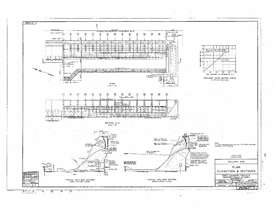
I2
32
2a
S2o
o no No. 400 Soo
TOTAL DISCHARGE SN THOUSANDS OF CFS
SPILLWAY GATE RATING CURVE5432sz", 42" 525,552,0052,
SECTION A-A
I 5-, a 6
\£57050o- 52. 2,-027
00'' 27T
-022/ /080- -- - --. 9 252t205e"M 50070w5w
5 20 e2 10805 70522 2 '2
257. , 04 202022or donw0
I . 25.- 585/'5520522227
t- .2 20
£2717 700 /285 772 ,2 2 8 2 0 2 2/
Scale I*-2 ISPILLWAY DAM
PLAN
ELEVATION & SECTIONS
FORT LOUDOUN PROJECTTENNESSEE VALLEY AUTHORITY
TYPICAL SPILL WAY SECTION TYPICAL SPILLWAY SECTION
I'1
..... ........ q) F@ L(? _ _ - 1@ -
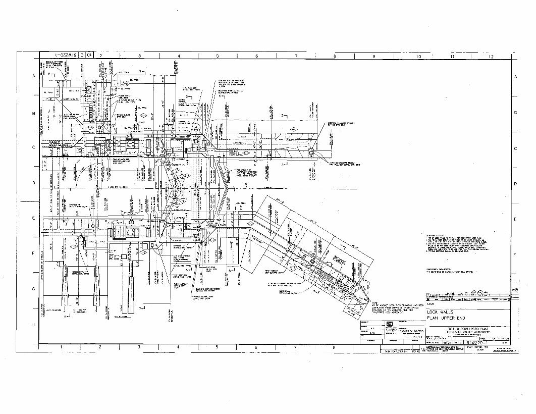
impRA 12O41 te
AS Of AUOUST ODRO ThIS DRAWING HAS B- LOCK
DRTING 10 0A 0010000 PILE PERTA./C-PS 19• _NENT. LOCK WALLS
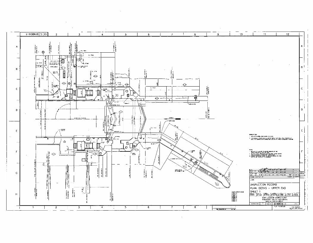
NA
VA
TN
LOCK
INSPECTION RECORD
PLAN, DECKS - UPPER END
SHEET 1
FORT LOUDOUN HYDRO PLANTTENNESSEE VALLEY AUTHORNITY
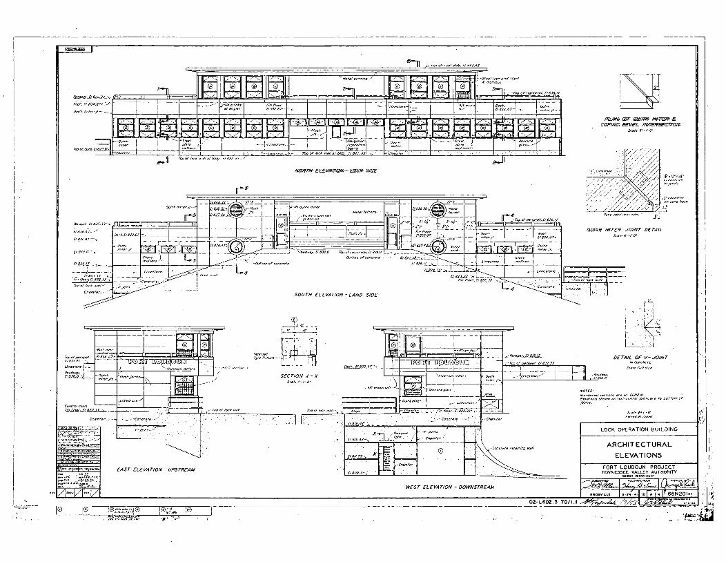
,ýý ol - - 11 "1 11
'In3>-i II /1/ ~--S7e,/SodAfldS/50/mm T~I-'-::r.I ~'"'j ~ --rod 97 /,S/,d78,/.9/836/Z811.e/,£/ 81"51
It Lý Wý d I==_Rot.FE0ui1-
. -8 . .. ."Sd. - - - " ,,,o//;r"I -• '- L 1 ho,,, " 'ý, ,.
teor - .N 14 p p - 9Oesto// ÷d Oe/u55 ,$ • e
PLAM4 ' QWRa' -- AWA-o &CaO71%T BEVEL //MT/E9RlInl,%
Fop .1/1-0 -- d'g., E1111.25. ,j)XZW77# EQfVq74EM- L96i, SIDE
. ./ , / .
. ..... .. . .. d/ ,'/ . 4 ; •' ' s
•ulrk miterlt-.
1115,, /8333-
El98589a,--- :Z -- " __' _'A _
19/8833 /'
I/700 1--0 1190 "~/'dZ.d .0e/al- /to,-, $0-7 9
. . . . -_-_ _ - r - .. . .5 . . - - - • - -- ---------- LI_,.dZO -, EE ,L,,i 19
SOUTH ELEVATION - LAND SIDE
QUIRK MITER JOINT DSTA'ILS-1t "-,".O
R "-"33r,-,0 900/_,•
5/00, /09/9/0/70> -
i--3,
*9j0/0/ -~* -, I* -- 9..
7--:=--- 7E'•-=, _1--
SECTION X - X
L
DETAIL OF V-JOINT
Numbered $9ti7n0 0re 079//9/9,97,07/ show0n o,00/ ho8,nt/jo?/h 09e 70o /70omr
s/tele P-78090999788 5070
LOCK OPERATION BUILDING
ARCHITECTURAL
ELEVATIONS
FORT
WEST ELEVATION - DOWNSTREAM
--w. *®J• , ®
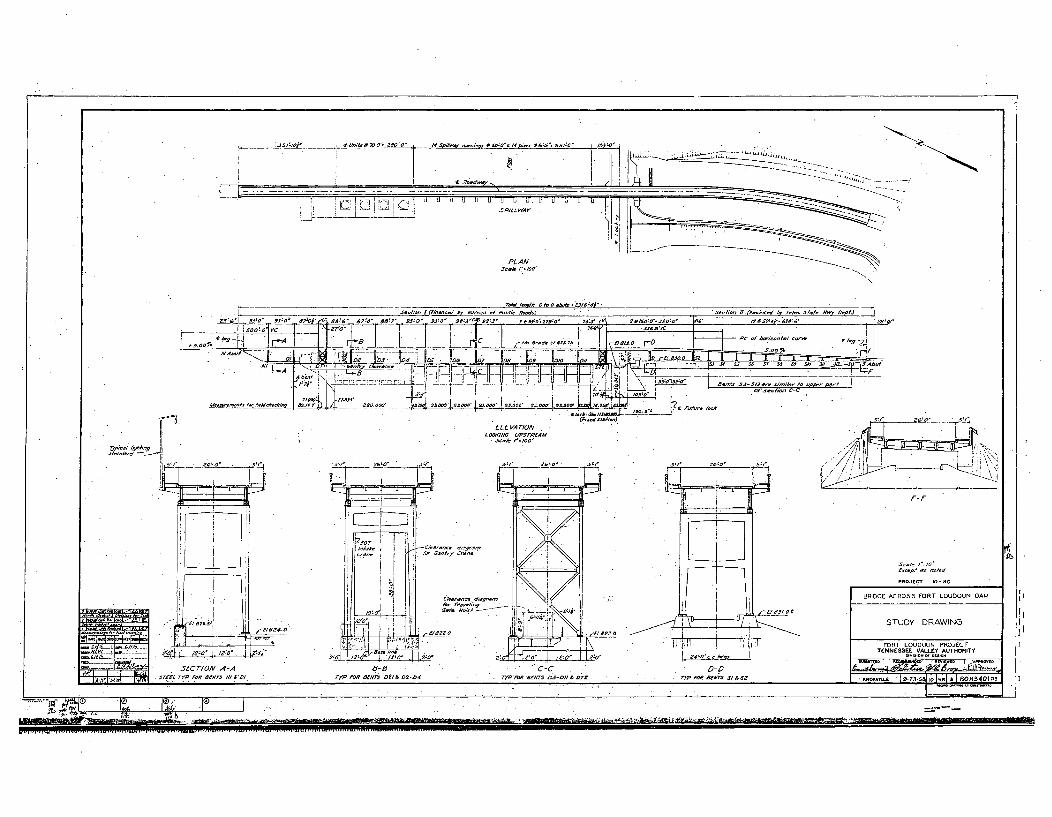
- •,, I (cF• , • So...s b H .. ... i, H~co-, HSO, •,•. D. pf
' "_;__. ___. __o" ________-_ ___-" _:_"____" __o ___"_z__ _o___o 7:37 (, ' too.•oo HES"7 " ,es?'.67876" " '"
-- ' . " .. " , ". I PC" ' 3r+ zo" t' ... .W-' 8-C'870'88l 9LO M S-3 fRP n &,we. 27s8fl OSeS 626W r 0
-SooooS . I0'F7 • _--- - c . --'" "o"
-. 0L0VAT/ON 1. ( . ... -
. • - .5556 4 75'=1o
F-p
PRO j £"ro-o
[!
D-D
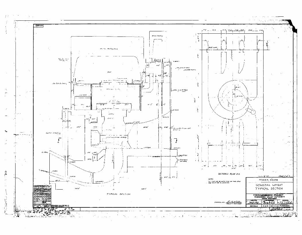
OO9NIPI
C7010W !SaSA
ACS~~U'/. CI7~7C,
Al
Po 5' .L
1-ijLi
301 '0-0 I7~
N-
SECTIONAL PLAN A-A
gcO- 7. 00 0O.tESs.00704~i FOWER HOU5E
TYPICAL 5fC7,)N
G.EN-ERAL LAYOUT
TYPICAL 5[CTION
-4t~eRq0%Qt4)- PROJECTTENNESSEE VALL.EY AU)THORITY
,-- -),L I ag - - -, IMDXViý 3 2 41 10 C 4 41 N600m
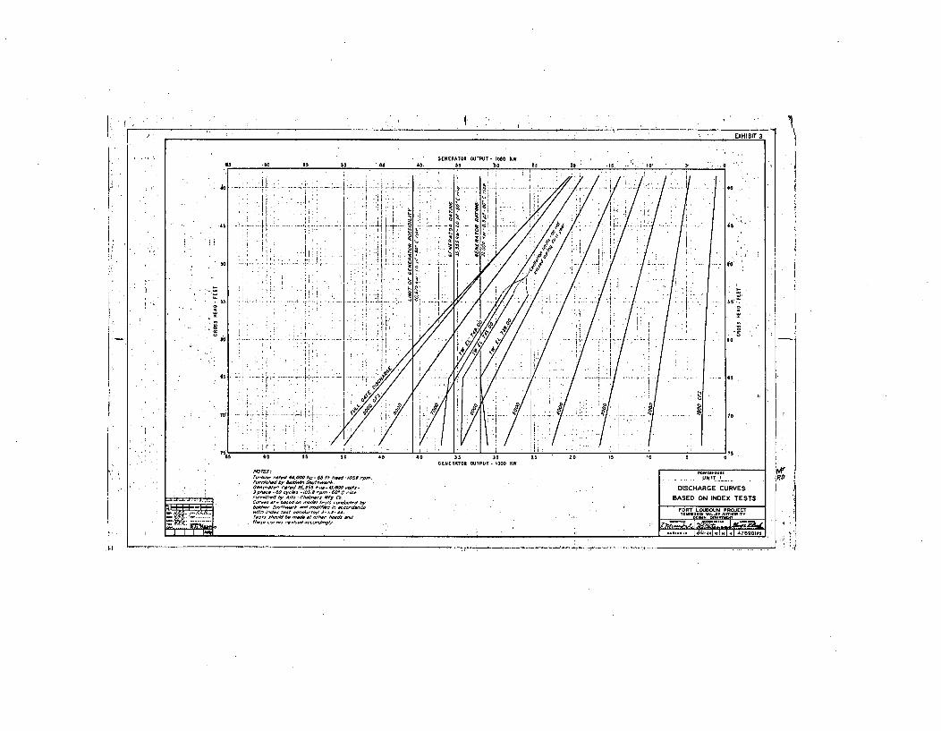
go
4-1
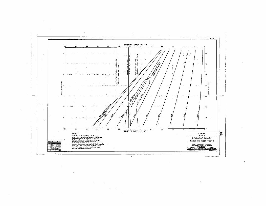
EXHIBIT I
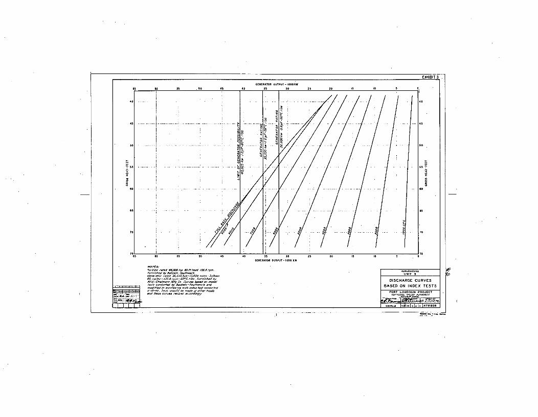
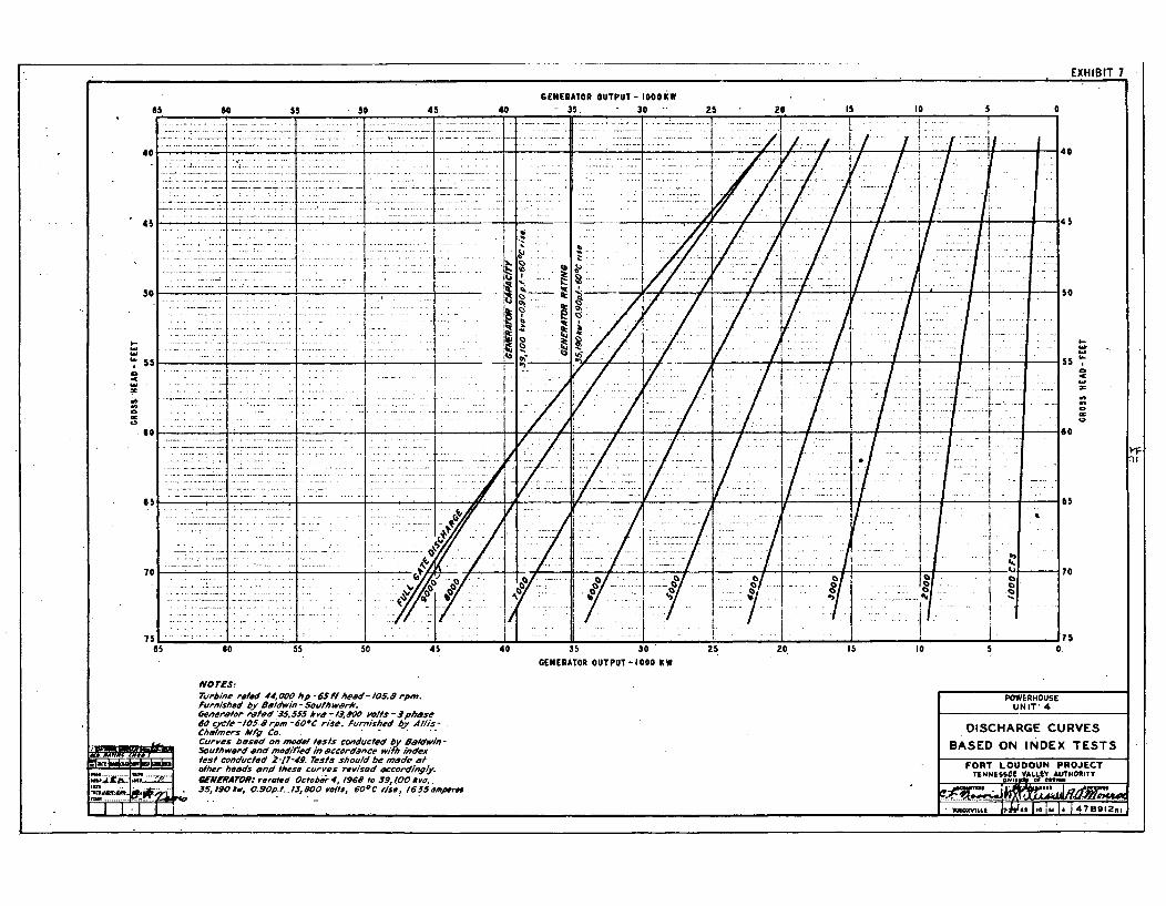
EXHIBIT 7
GENERA .TOR OUTPUT - 1000 kw60 55 50 40 35 30 25 20 15 10 5
_____________ ¶ 9* I I.....!•• ..../ i! I~ Il/ !
451 .4. 4 4 4-.I 4 . .4- ....... AA
"00
( ( t'7/..40
I___ __I _ _ __i
so _ _ _ _ _
5 5 _ _ _ _ _ .I.
t~.
Lb
(j
Lb
'~ k
~ t
~
-~ 'ULb
'I
- + . 5 .4, '-#-- 4 -1------- 1
4 / I /1i IGENERA10R OUTPU1- IoooKw!
s
I /I.-
4
0
/t /l / /i
I•v
-I / 1!.
/l• / /55
- - - -I- - :•"I -
so ISO
70 % 70
7-----V -.77.I
75 1 75 - - .. j . -I. . . .. ...' " ... ""I............ ... .. .... . . . . .I___.__-,_ -_.______-- _-____ "__ _____-i I __-__--'__-i-
65 s0 55 45 40 35 30
GENERATOR OUTPUT - 1000 KW
25 20 IS 10 5 0.
VO rEstTurbine roled 44,000 hp 6•l heed- /05.Y rpm.furnished by. Baldwin- Scul#hwe#rk.Oenar#tor ,w#ad .35.555 kve -13,200 bOllS -zphase60 cycle -105. rpm -600C rise. Furnished by Allis-Chalmers Mfg Co. .Curves based on model#ests conducted by Baldwin-Southward Ond modified in accordance wifh inde'rtest conducled 2-17-49. Tests should be made a-o/her heads and these curves revised [email protected] reroted October 4, 1968 to 39, ff0O kvo,.
35, 190 kw, 0. 90p.#.. /3, 800 volts, 600
C tise, 16J5 amperes
POWERHOUSEUNIT'4
DISCHARGE CURVES
BASED ON INDEX TESTS
FORT LOUDOUN PROJECTTENNESSEE VALLEY AUTHORITY
y"?g, °' "f,
I.
~'Ko "I 1... . I ~ .. ... f IN 14 14 .......
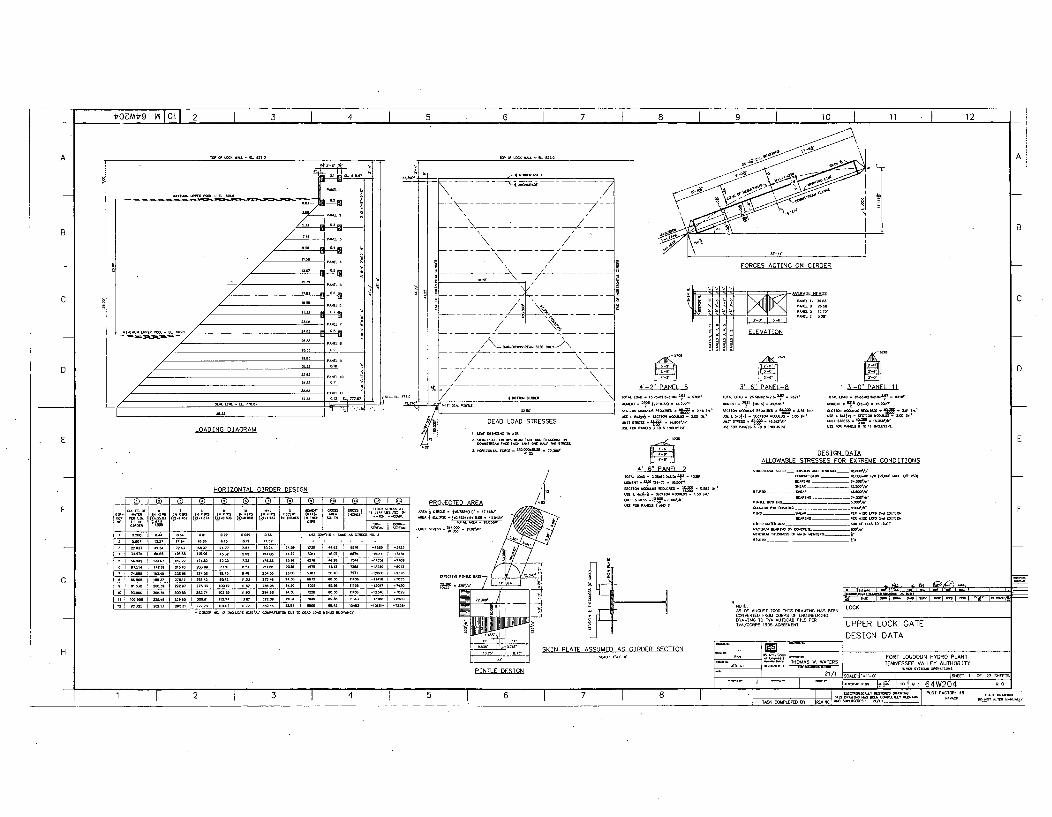
t'OZMt'9I ViI Ot1 2 I 3 I 4 I 5 I 6 I 7 I 8 I 9 I 10 I 11 I 12
A
B
FORCES ACTING ON GIRDER
CWl ., I I'
0 I ELEVATION
n10
D
MI- PNEN
~ANAl
3-6' PANEL-S
ONMO~1l~NANAON~wI0020~~~00~,NMO12012044 ~ON0TlON200NO00.O2NlN'
3-T'PANEL-ll
20AAN00AN4NONO~NINION
ONCTi00flONW~2 0 0
ION LNNA4.2020100.00NON-N0020'1ONON1ONNN.2~6B ~
ALLOWABLE STRESSES FOR EXTREME CONDITIONS
HORIZONTAL GIRDER DESIGN
1 (1 i Q+ - T C 4
• F 4 4F
I .d Ai ., ý S., IA M .IA d7 NIN Q00' Al.vm 020 OOJ
ONAl NC200000ANNajNON' ____
PROJECTED AREA
DRAWING TO WA U TOCDFILE PER
~IAI
SKIN PLAE ASSUMET AS G RDER SECTION AO
STHOMAS W. WATERSPINILE DESIGN 2/
- NON.aA
0SANAA
- F.
LOCK• •I• N• IZ I•5 I•W/•" •l• •[ TO • LO• •N• •UO•Y
UPPER LOCK GATE
DESIGN DATA
H- FORT LOUDOUN HYDRO PLANTTENNESSEE VALLEY AUTHORITY
IT LII0 I I-ETI 1 AF 27 S-OT!G.0 1000 9 twTTIO RO
1 j 2 3 4 I 5 I IT 7 ' NOMAO.ASNTNONT0NONON -.0 PLOTTNTL 484 5 6 7 AO ALO0N A 200AM ONNON G _______
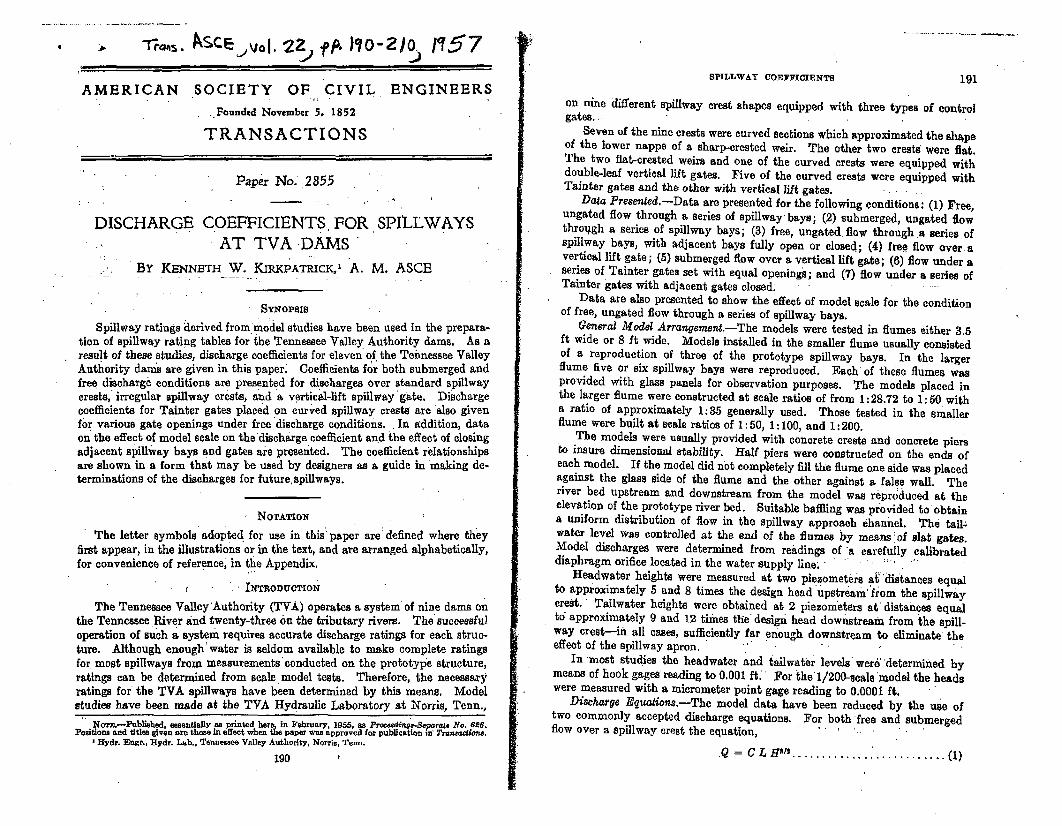
-r*AI. Asce vol -27- f lo-Zio. 1i57
AMERICAN SOCIETY OF CIVIL ENGINEERS
•..Pounded November 5. 1852
TRANSACTIONS
Paper No. 2855
DISCHARGE COEFFICIENTS, FOR SPILLWAYS'AT TVA -DAMS
By KENNETH W. KIRKPATRICK,' A. M. ASCE
SYNOPSIS
Spillway ratings derived frommodel studies have been used in the prepara-tion of spillway rating tables for the Tennessee Valley Authority dams. As aresult of these studies, discharge coefficients for eleven of the Tennessee ValleyAuthority darms are given in this paper. Coefficients for both submerged andfree discharge conditions are presented for discharges over standard spillwaycrests, irregular spillway crests, and a vertical-lift spillway gate. Dischargecoefficients for Tainter gates placed on curved spillway crests are also givenfor various gate openings under free discharge conditions.. In addition, dataon the effect of model scale on the'discharge coefficient and the effect of closingadjacent spillway bays and gates are presented. The coefficient relationshipsare shown in a form that may be used by designers as a guide in making de-terminations of the discharges for future, spillways.
NOTATION
The letter symbols adopted for use in this' paper are defined where theyfirst appear, in the illustrations or in the text, and are arranged alphabetically,for convenience of reference, in the Appendix.
" INTRODUCTION
The Tennessee Valley 'Authority (TVA) operates a system of nine dams onthe Tennessee River and twenty-three On the tributary rivers. The successfuloperation of such a system requires accurate discharge ratings for each struc-ture. Although enough' water is seldom available to make complete ratingsfor most spillways from measurements 'conducted on the prototype structure,ratings can be determined from scale, model tests. Therefore, the necessaryratings for the TVA spillways have been determined by this means. Modelstudies have been made at the TVA Hydraulic Laboratory at Norris, Tenn.,
NorT.-Publisehd. essentially as printed here, in February. 1955, as Prowedinqs.Sepurale No. 626.Positions and tJtles given ame those in effect when the paper was approved for publication s" Trantauiou,
'Hydr. Engr., Hydr. Lab., Tennessee Valley Authority, Norris, Tenn.
190
SPILLWAY COEFFICIENTS 191
on nine different spillway crest shapes equipped with three types of controlgates..
Seven of the nine crests were curved sections which approximated the shapeof the lower nappe of a sharp-crested weir. The other two crests were flat.The two flat-crested weirs and one of the curved crests were equipped withdouble-leaf vertical lift gates. Five of the curved crests were equipped withTainter gates and the other with vertical lift gates.
Data Presented.-Data are presented for the following conditions: (1) Free,ungated flow through a series of spillway' bays; (2) submerged, ungated flowthrough a series of spillway bays; (3) free, ungated flow through a series ofspillway bays, with adjacent bays fully open or closed; (4) free flow over, avertical lift gate; (5) submerged flow over a vertical lift gate; (6) flow under aseries of Tainter gates set with equal openings; and (7) flow under a series ofTainter gates with adjacent gates closed;.
Data are also presented to show the effect of model scale for the conditionof free, ungated flow through a series of spillway bays.
General Model Arrangement.-The models were tested in flumes either 3.5ft wide or 8 ft wide. Models installed in the smaller flume usually consistedof a reproduction of three of the prototype spillway bays. In the largerflume five or six spillway bays were reproduced. Each of these flumes wasprovided with glass panels for observation purposes. The models placed inthe larger flume were constructed at scale ratios of from 1: 28.72 to 1: 50 witha ratio of approximately 1:35 generally used. Those tested in the smallerflume were built at scale ratios of 1: 50, 1:100, and 1: 200.
The models were usually provided with concrete crests and concrete piersto insure dimensional stability. Half piers were constructed on the ends ofeach model. If the model did not completely fill the flume one side was placedagainst the glass side of the flume and the other against a false wall. Theriver bed upstream and downstream from the model was reproduced at theelevation of the prototype river bed. Suitable baffling was provided to obtaina uniform distribution of flow in the spillway approach ehanhel. The tail-water level was controlled at the end of the flumes by means:of slat gates.Model discharges were determined from readings of 'a carefully calibrateddiaphragm orifice located in the water supply line; - ' " • " ý'
Headwater heights were measured at two piezometers a4distances equalto approximately 5 and 8 times the design head upstream from the spillwaycrest. Tailwater heights were obtained at 2 piezorneters at' distances equalt6 approximately 9 and 12 times the design head downstream from the spill-way crest-in all cases, sufficiently far enough downstream to eliminate theeffect of the spillway apron.
In 'most studies the headwater and tailwater levels wer6:'determined bymeans of hook gages reading to 0.001 ft For the 1/200-scale 'model the headswere measured with a micrometer point gage reading to 0.0001 ft.
Discharge Equaiions,-The model data have been reduced by the use oftwo commonly accepted discharge equations. For both free and submergedflow over a spillway crest the equation, .... -. "
.Q=C L H'....................(1
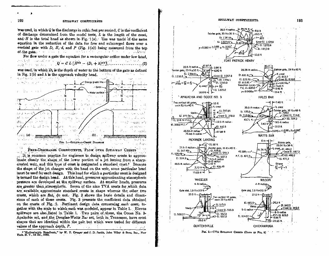
4 P. r192 SPILLWAY COEFFIC=I6ZS SPILLWAY. COESFFCIENTS 193
Was used, in which Q is the discharge in cubic feet per second, C is the coefficientof discharge determined from the model tests, L is the length of the crest,and; H is the totaI head'as shown. in Fig.- 1(a). Use was madd 'bf the sameequation in the reduction of the data for free and submerged flows over. a,vertical gate with P, Hi41d, and P- (Fig. 1(a)) -being measured frour the topf, the gate. . .-- . .
For flow under a gate the equation for a rectangular orifice under low -head,
.. L. [H1C (2. + ...... ..................... 2was used, in which'Di is the'depth of water to the bottom of the gate as definedin Fig. 1(b) and hAis the approach velocity head. '
,.--. ... . ..- Eqergy grade line - --
:-Gate: 4"W:' " ": / " I ( ".'ater sLurfae T7 7- F
. . . .. .. .. . -.. . : ., .-- •.
(a) J)
Figý. 1,-7PILLW-Cansr 131AGAm
imate closely the,'ihap,.of. the lower portion 'of a jet. issing from a. harp-cre ste .d. weW, and this.'type .bf crest. is designated .a standard cr .est.! Becausethe s~hape. of the. jet changes with the head on the we~ir, some particular headmust be used for each design. This head for, which a particular crest is dsign.edis. termed the design head. At thishead, pressures approximating atmosphericpressure are developed, at. the spillway. surface. At smaller heads; pressuresare greater than atmospheric. Seven of -the nine TVA crests for ,which dataax. available, approximate standard crests in.shape whereas th•e. othertwocrests, which are fiat,, do.not.. Fig. 2.shows the basic details and dimen-sions of each of these crests. Fig. 3 presents the, coefficient data obtainedon the :crests of Yig. :2. : Pertinent design data concerning each crest,z to-gether with the scale to which, each was. modeled, appear in Table 1. Elevenspillways are. also listed in. Table. 1. -Two pairs of,;these, the: Ocoee. No. 3TApalach'a set, and .thq Douglas-Watts Bar set, both in, Tennessee, have crestshapes that' are identical, within the: pair. but which were tested for differentvalues of the approach depth, P. . . • ,.
36.01-i radius 49.25 1 S 8.00
Tainter gate, 35 Iit35 it 10.5 ft,33
Ei. 1227.4l"N 533 Crest Ell. 1228,0
y 0.593+ 3 (5.3339 El. 1223.6r'. Z0. 1217.0
12.0 1`1
FORT PATRICK HENRY
22.5-I radiu 32.9t3.99 itTainter gate, 23 ftx32 ft -6.90 ftut. 1256.5 El 5,, Crest El4 1257.0
. 11245.0El. 1254.1
El. 1i45.0
cres ft 9
30.21 It
26.28-lt 4radius -... riiii-(Tainter gate, I9 ftX40 It
El, 63 1.5.J/f crest.El. 6 13.7
El. 615.39-- • -..... 1 .JrCrest El. 616.0El. 613.91 r.yt14uisk, o144x3Transition rcur ve j -5 fte 5.40 i
9,45 "1
y - .045x 13.4 ft'
R'.
WHEELER4-fl radius
Gate stat, ii5 (t X3.5 137.0 it -~ri'
I4.-.1t~JPV Two vertical lift gales,etseach 20 f tx40 It
E.575.0Vents
6 it Crest El. 555,0Ei 1•••l 57 5 5.0
El. 538.0! Li El. 552.0E E 53-7.0
-- I "Ef 477ý3
Ellipse
WILSON
4-ft raditts
Gate slot. 1,5 ftx3.5 ft. . 37.0 ft--ý:
El. 665. o , 243 ft...en El. 64Z,0
5-trdius Crest El. 645.0. 5-ft r dius •.. . . .
Ia 4-fl radiusEl. 14.± ~Ell. 625.0
CHICKAMAUGAGUNTERSVILLE
"Hydroelectric Handbook," by' W. P. Cmacer and .1 D. Juatin. Yohn Wiley & Soom, lIa., N•wYork, N. Y., 2d Ed.. 1950.
nc. t-TVA-Snrauwn G~nat (DJATA xN Iso. 8)
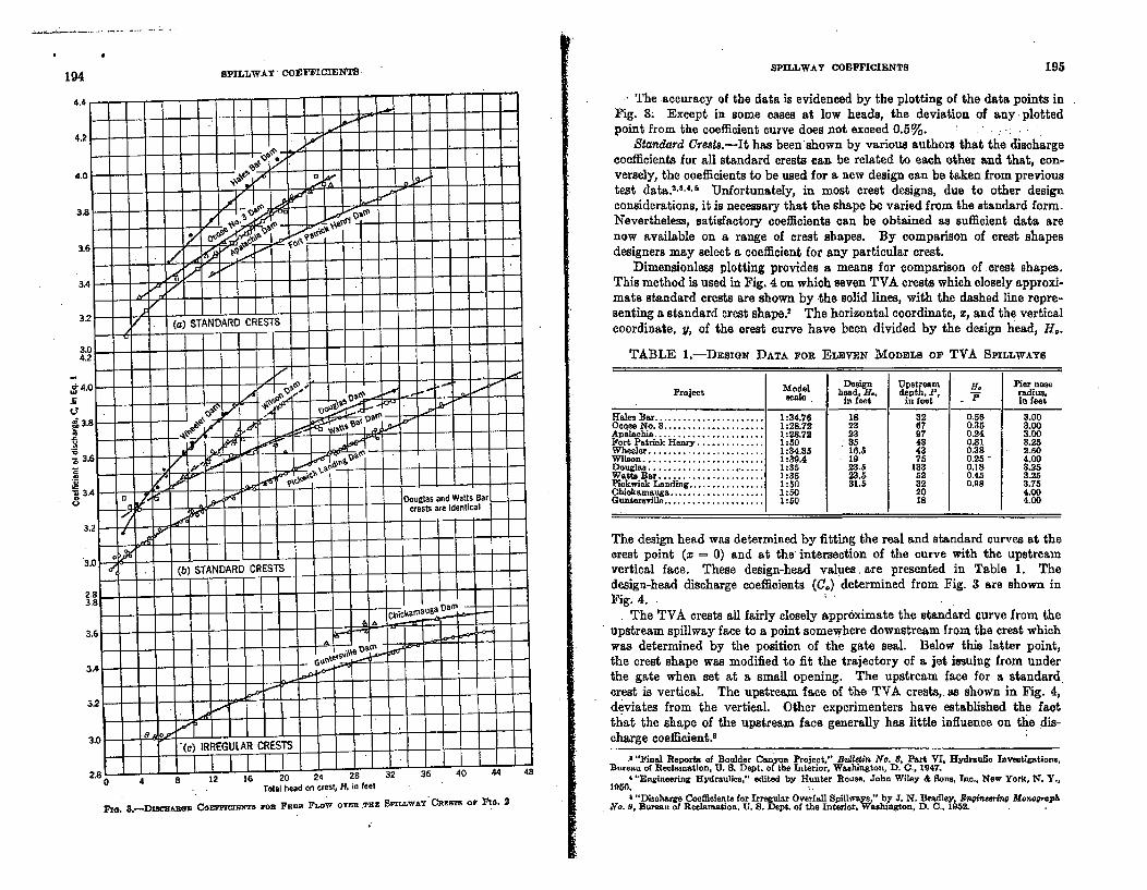
P194 SPILLWAY COVFFICIENTS SPILLWAY COEPFICIENTS 195
The accuracy of the data is evidenced by the plotting of the data points inFig. 3S Except in some cases at low heads, the deviation of any -plotted
S - - - - - point from the coefficient curve does not exceed 0.5%.Standard Crests.-It has been'shown by various authors that the discharge
coefficients for all standard crests can be related to each other and that, con-versely, the coefficients to be used for a new design can be taken from previoustest data.2", 4'6 Unfortunately, in most crest designs, due to other designconsiderations, it is necessary that the shape be varied from the standard form.Nevertheless, satisfactory coefficients can be obtained as sufficient data arenow available on a range of crest shapes. By comparison of crest shapesdesigners may select a coefficient for any particular crest.
Dimensionless plotting provides a means for comparison of crest shapes.This method is used in Fig. 4 on which seven TVA crests which closely approxi-mate standard crests are shown by -the solid lines, with the dashed line repre-
)ARD CRESTS -senting a standard crest shape.2 The horizontal coordinate, z, and the vertical- - - coordinate, y, of the crest curve have been divided by the design head, H..
ITABLE 1.-DxEsron DATA FOR ELEVEN MODELS OF TVA SPILLWA.TS
rojet Model Design Upstream f, Pier noseProjt head, H.. depth, _P, - radius,in feet infeat infeet
Hales Bar ....................... 1:34.76 18 32 0.66 3.000co.ee No 3.................... 1:28.72 23 67 0.36 8.00Apalach -....................... 1:28.72 23 97 0.24 3.00Fort Pat.ckc Henry .............. 1:50 35 43 0.81 3.25Wheeler ...... 1:34.35 16.5 43 0.38 2.50Wilson ................... 1:30.4 19 75 0.25- 4.00Doug........................ 1:35 23.5 133 0,18 8.25Watts Bar... ........... 1:35 23.5 52 0.43 325Pickwick Landing ............... 1: 50 31.5 32 0.08 3.75Chiokamauga .................... 1:50 20 4.00
untervlle ............... 1:50 18 4.00
The design head was determined by fitting the real and standard curves at thecrest point (z = 0) and at the intersection of the curve with the upstreamvertical face. These design-head values, are presented in Table 1. Thedesign-head discharge coefficients (C.) determined from Fig. 3 are shown inFig. 4.
. The TVA crests all fairly closely approximate the standard curve from theupstream spillway face to a point somewhere downstream from the crest whichwas determined by the position of the gate seal. Below this latter point,the crest shape was modified to fit the trajectory of a jet issuing from underthe gate when set at a small opening, The upstream face for a standardcrest is vertical. The upstream face of the TVA crests,. as shown in Fig. 4,deviates from the vertical. Other experimenters have established the factthat the shape of the upstream face generally has little influence on the dis-charge coefficient.$
."Pinal Reports of Boulder Canyon Project," Bulletn No. 8, Part VI. Hydraulic Investigations,Bureau of Reclamation, U. S. Dept. of the Interior. Washington, D. C., 1947.
' "Engineering Hydraulics," edited by Hunter Rouse. John Wiley & Sons, Inc,, New York, N. Y.,1950. -
'"Discharge Cooffieienta for Irregular Overfal Spiliwa•." by J. N. Bradley, Jtsgineerine MenographNo.9, Bureau of Reclamation, U. S. Dept. of the Interior. Wsahington, D. C., 1952.
-(c) IRREGULAR CRESTS I
1 12 16 20 24 28 32 36 40
Total head on crest, H, in feel
Pro0. 3.-DsWAcssaeo Cozrnaawra Font Pnes FLOW onE R.Et SPILLWAY CREem7 OP ING. 2
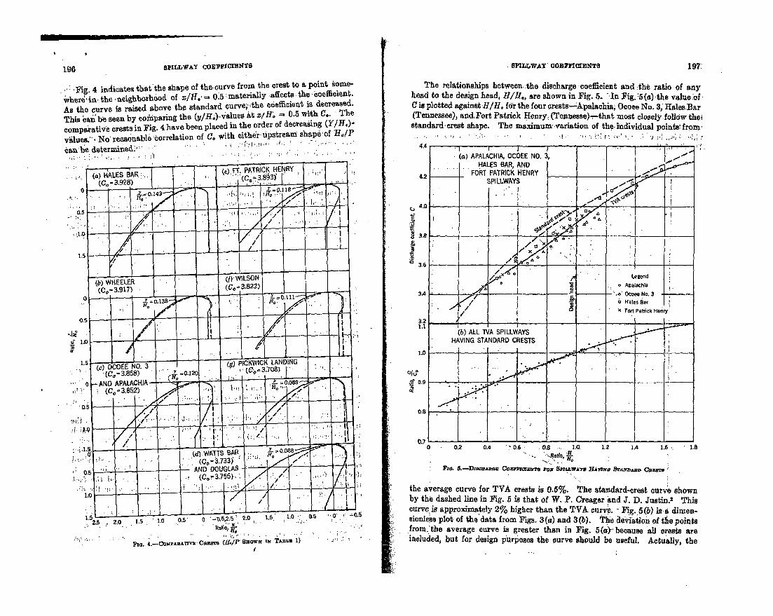
l~ll PILLW&-Y C0EPFICIENW8 SPILLWAY COnXClEiNTS 197:
, : ;Fig. 4 indicates that'the shape of the curve from .the crest to a point .ome-
wvherlu.,theneijghborhood of xlf/.o' 0.5: materially :affects the. oefficient.
As the curve is raised above the standard curve, -the o6efficient is decreased.
This 6nanbe seen by coinparing the (y,/Ho)-4&alues 4t s/Ho. = 0.5 with C.. " The
comparative crests in Fig. 4 have been placed in the order of decreasing (Y/HI)-
vilues.". No reasonable tcorrelation of C. with either Upstreami shape of HI/Pcan he determined.'• . .. •"" ..
The relationships between. :the discharge coeffcient and :the ratio of anyhead to the design head, H/IH, are shown in Fig. 5.. In Fig. :5 (a) -the value of.
C is plotted against H/H, for the four crests-Apalachia, Ocoee No. 3, Hales.Bar
(Tennessee), and,Fort Patrick Henry, (Tennesse) .- that most closely.folldw thei
standard: crest shape. The maximumr-variation of the- individual points' from
r,.
.• o
0.2 0.4 "0.6 -. 0.8 -.. 1.0 L2 1A 1.6""- -'• atio, Lo
Fr&ý 6-Damm"ag Co XmB?#Ts ko3 SnlawAYS HAWN0 vgSýMNAAm Cao8u
the average curve for TVA crests is 0.5%. The standard-crest curve shown
by the dashed line in Fig. 5 is that of W. P. Creager and J. D. Justin.2 This
curve is approximately 2% higher than the TVA curve.- Fig. 5(b) isai dimen-sionless plot of the data from Figs. 3(a) and 3(b). The deviation of te points
-from.'the average curve is greater than in Fig. 5(a)- because all crests are
included, but for design purposes the curve should be useful. Actually, the
15' 1.5 • -- ~ ~ 2.0. "L ' .2.5 • 2,0 1.5 1.0 0.5 0 -o.5,2. ; 2.0 1.
-"R" 'a Hto,
Flo.' 4,--mCo AM E-t~'CszsTs (M. ýP Sjow• z TA~a• 1)
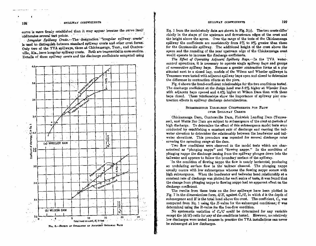
198" SPILLWAY cOOErxCrINTs
curve is more firmly established than it may appear because the curve itselfobliterates several test points.
Irregular Spillway Urests.-The :designation "irregular spillway; crests"is used' to distinguish zetween standard spillway crests and- other crest forms.,Only two of the TVA spillways, those at Chickamauga, Tenn., and Gunters-viUe, Ala., have irregular spillway crests. Both are trapezoidal in cross section.Details of these spillway crests and the discharge coeflicients computed using
SPILLWAY COnrnrrwTEs 199
Eq. I from the model-study data are shown in Fig. 3(c). The two crests differ'chiefly in the shape of the upstream and downstream edges of the crest andthe height above the apron. Over the range of the tests of the Chickamaugaspillway' the coefficients are consistently from 3% to 5% greater than thosefor the Guntersville spillway. The :additional height of the crest above theapron and the rounding of the near upstream edge of the Chickamahga crestwould operate to increase the discharge coefficients.
The Effect of Operating Adjacent Spillway Bays.-In the TVA water-control operations, it is necessary to operate single spillway bays and groupsof consecutive spillway bays. Because a greater contraction forms at a piqrsituated next to a closed bay, models of the Wilson and Wheeler spillways inTennessee were tested with adjacent spillway bays open and closed to determinethe difference in-contraction effects at the piers.
Fig. 6 shows the head-coefficient relationships for the two conditions tested.The discharge coefficient at the design head was 5.6% higher at Wheeler Damwith adjacent bays opened and 4.4% higher at Wilson Dam than with thesebays closed. These relationships show the importance of spillway pier: con-traction effects in spillway discharge determinations.
SUnInERGEOa DDIsCoARGE COEFm1Ix3a TS POx FLOWOVER SPILL-WiAY t ESTs
Chickamauga Dam, Guntersville Dam, Pickwick Landing Dam (Tennes-see), and Watts Bar Dam are subject to submergence of the crest at periods ofhigh discharge. To determine the effect of this submergence model tests wereconducted by establishing a constant rate of discharge and varying the tail-water elevation to determine the relationship between the headwater and tail-water elevations. This procedure was repeated for several discharge ratescovering the operating range at the dam.
, Two flow conditions were observed in the model tests which are char-acterized as "plunging nappe" and "flowing nappe." In the condition ofplunging nappe the discharge issuing from the spillway plunges down into thetailwater and appears to follow the boundary surface of the spillway.
In the condition of flowing nappe the flo* is nearly horizontal, producingan undulating surface flow in the' tailrace channel. The plunging nappeusually occurs with low submergence whereas the flowing nappe occurs withhigh submergence. When the headwater and tailwater head relationship at aconstant rate of discharge was plotted for each: series of tests, it was found thatthe change from plunging nappe to flowing nappe had no apparent effect on thedischarge coefficient.
The results from these tests on the four spillways have been plotted inFig. 7 in the dimensionless form, d/H, against C./1, in which d is the depth ofsubmergence and H is the total head above the crest. The coefficient, C., wascomputed from Eq. 1 using the H-value for the submerged conditions; C wasdetermined using the H-value for the free-flow condition.
No systematic variation of (./C could be determined for any variableexcept the (d/H)-ratio for any of the conditions tested. However, no relativelylow discharges were tested because in practice the TVA installations can neverbe submerged at low discharges.
(b
•0
)WILSON DAM a
4 8 12 16 20 24Totalheadoncr.est feer"' ":t
Pic. 5.--Ewnicr or, Ona4rzor or AnnAcznr SrnWATw BAirN
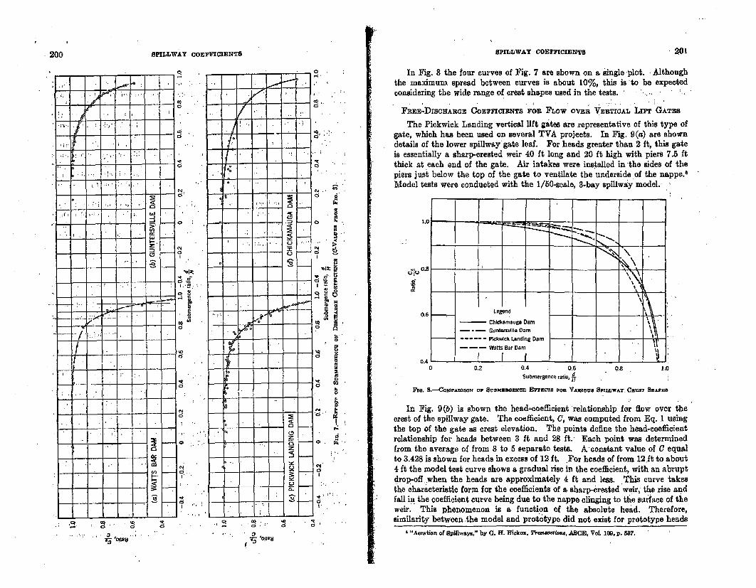
200 *SPILLWAY COEFFICIENTS0 SPIKOJWAY -COEFFICI[ENTS " 201
In Fig. 8 the four curves of Fig. 7 are shown on a single 1plot. : Althoughthe maximum spread between curves is about 10%, this is to be expectedconsidering the wide range of crest shapes used in the tests.......
FREE-DISCHAILGE COEFFICIENTS FOR FLOW OVER VERTICAL Liii GATES
The Pickwick Landing vertical lift gates are representative of this type ofgate, which has been used on several TVA projects. In Fig. 9(a) are showndetails of the lower spillway' gate leaf. For heads greater than 2 it, this gateis essentially a sharp-crested weir 40 ft long and 20 ft high with piers 7.5 ftthick at each end of the gate. Air intakes were installed in-the sides of thepiers just below the top of the gate to ventilate the underside of the nappe.6Model tests were conducted with the 1/50-scale, 3-bay spillws~y model.
1.0__ ___i
IL \
0.6 . Legend
Chickamauga Dam= -~ Guntersville Dam
------ Pickwick Landing Dam
Watts Bar Dam j -.
0.4 I fD 0.2 0.4 0.6 0.8 1.0
Submergence ratio, d
Reo. S,-CompAu.ODsoN o0 Sramo•nwm -Epi•g-B Oba VsAOeno SpI.LLwAr. Clast BHar .SH s
In Fig. 9(b) is shown the head-coefficient relationship for flow over thecrest of the spillway gate. The coefficient, C, was computed from Eq. 1 usingthe top of the gate as crest elevation. The points define the head-coefficientrelationship for heads between 3 ft and 28 ft. Each point was determinedfrom the average of from 8 to 5 separate tests. A constant value of C equalto 3.428 is shown for heads in excess of 12 ft. For heads of from 12.1t to about4 ft the model test curve shows a gradual rise in the coefficient, with an abruptdrop-off when the heads are approximately 4 ft and less. This curve takesthe characteristic form for the coefficients of a sharp-crested weir, the rise andfall in the coefficient curve being due to the nappe clinging to the surface of theweir. This phenomenon is a function of the absolute head. Therefore,similarity between the model and prototype did not exist for prototype heads
' "Aeration of Spiflways," by (. ff. Rfielco. 7ranwet4no, ASCE, Vol. 109, p. 537.
- 0 . - •.. ,: .. 3 , ,. , .• ;' - ' 7.
03'iW
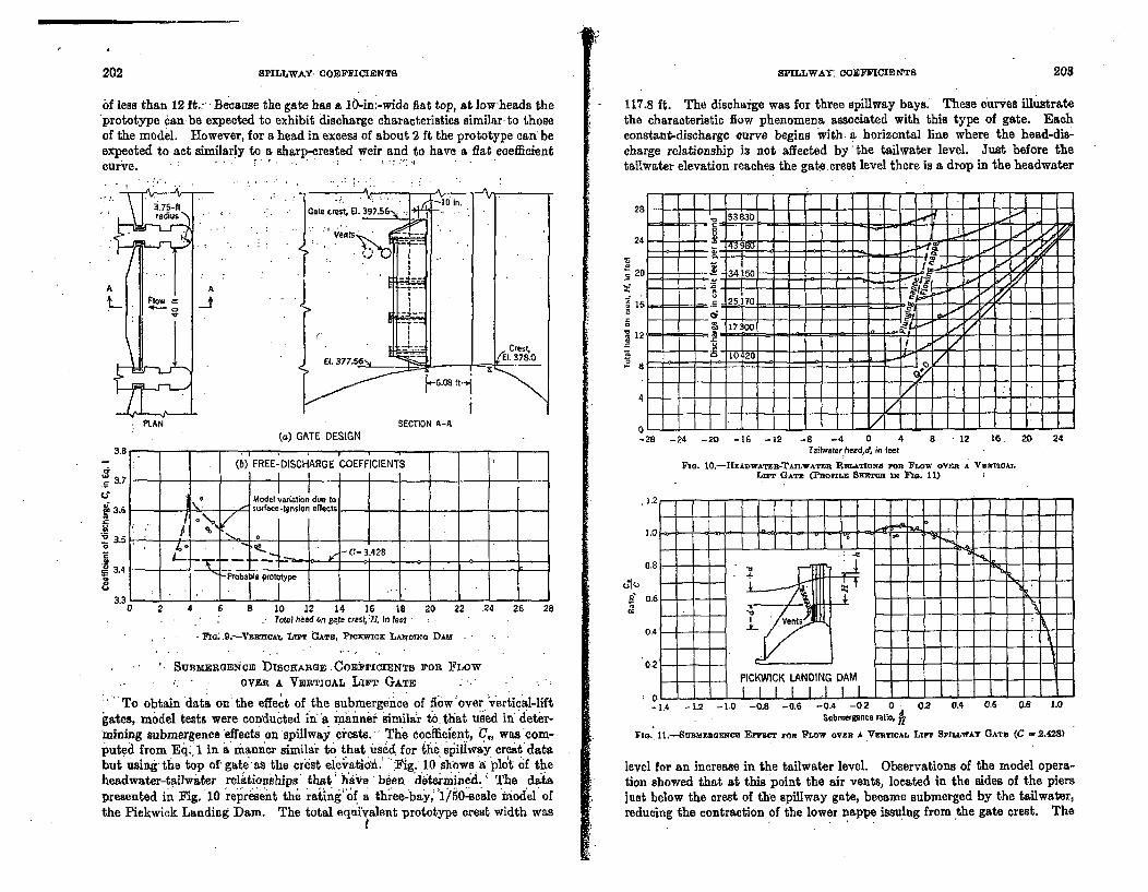
202 SPILLWAY* COEFFICIENTB
of less than 12 ft..-- Because the gate has a 10-in;-wide flat top, at low-heads theprototype can-be expected to exhibit discharge characteristics similar-to thoseof the model. However, for a head in excess of about 2 ft the prototype can beexpected to act similarly to a sharp-crested weir and to have a fiat coefficientcurve. - .
PSPILLWAY: COEFFICIENTS 203
117.8 ft. The dischaige was for three spillway bays. These iurves illustratethe characteristic flow phenomena associated with this type of gate. Eachconstant-discharge curve begins with. a horizontal line where the head-dis-charge relationship is not affected by the tailwater level. Just before thetallwater elevation reaches the gat.ecrest level there is a drop in the headwater
3.75-ft
(a) GATE DESIGNSECTION A-A
oI L., - .. .-28 -
I (b) FREE-DISCHARGE COEFFICIENTS
24 -20 -16 -12 -8 -4 0 4 8 - 12 16.Taitwater heedd, in feet
Fzo. 10.-HEADwATE3R-TAXLwATt R•Am.TIONS FORE FLOW OVER A VRTIDAT,LIFT GATE (PROFaILE SKErcT IN FIG, 11)
20 24
a . I I I I III I3 .7 1 -
Model variation due to3.6 surface-tension effel --
L.-.•. C=3.428_ 3.4 -. 2
Probable prototype
3.3 --
b a 10 1Z 14 16 18Total heed on gate rresL:, In feel
20 22 24 26 28
LI F.- . AT. PICXVICK L.Aorxa DAM
SUBMERGENCE lISCOHARGE 3.CoTErCMNTs FOR FLOWOVIER A VERTICAL LIrr GATE
To obtain 'data on the effect of the submergence of flow 'over •vertical-lift
gates, model tests were conducted in "a manner similar to that used ii deter-mining submergence effects on spillway piests. The coefficient, -U., wascom-puteci from Eq., 1 in a manner similar to that used for the sliltway crest databut using the top of- gate es the crest elev"atid.: 'Fig.' 10 shbws - plot of theheadwater-tailwater reltion'ships' that ha'Ae been "d'etmineA. ': The datapresented in Fig. 10 represent the rating-of a three-bay,: '1/50-scale miod'el' ofthe Pickwick Landing Dam. The total equivalent prototype crest width was
S 0I I II I -'
-1.4 -1.2 -1.0 -0,8 -0.6 -0.4 -02 0 0.2 0.4 0.6 0.8 1.0Submergence ratio, 1
FIo. 11.--SURMt GaFXCE Emcr FOR FLOW OVER A VERTICAL LIFT SPILLWAT GAT (C - 2.428)
level for an increase in the tailwater level, Observations of the model opera-tion showed that at this point the air vents, located in the sides of the piersjust below the crest of the spillway gate, became submerged by the tailwater,reducing the contraction of the lower nappe issuing from the gate crest. The
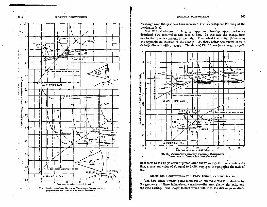
204 20PILLWAY COEFFICIENTS SPLLW.AY CO'EM=~e.-INT 205
discharge over the gaite was thus increased, with a consequent lowering .of theheadwater level.
The flow conditions of plunging nappe and flowing- nappe, previouslydescribed, also occurred in this type of flow.. In this case the change .fromone to the other is apparent in the data.. The dashed line in Fig. 10 indicatesthe approximate location of the change. At these points the curves show -adefinite discontinuity in shape. The data -of Fig. 10 can be reduced in coeffi-
4.2 .-
4.0
3.8
" 3.6
g3.24
(.3,9
3.7
3.5 I0 12 16 20 24 32 36
Total neaon spillway Cre.S Ix in ete
PIa. 13.-TAmnzufl-GATm SnxrwAy TD•sacea Commolma(DrMEntaxoNs ox Ctna'vxs A.z GgTC Omaeae)
cient form to the single-curve representation shown in Fig. 11. In this illustra-tion, a constant. value of C, equal to 3.428, was used in computing the ratio ofc./1 . " ". "
DiscHAROn COEFFICIENTS ron FLOW .tNDnEn TATnBi, (GATas
The flow under Tainter gates mounted on curved crests is -controlled bythe geometry of three interrelated variables-the crest shape, the gate, andthe gate setting. The major factors which influence the discharge relation-
0. 4 8- 12 16 20STotal head on spillway creslt R in feet
Poo. 12.--TAu4T=-GA~z SrimLAY DiscaAaoz CoErnCaLXwr(Dnuimanazots ax Cunvics Amx GATn pPuBMxO)
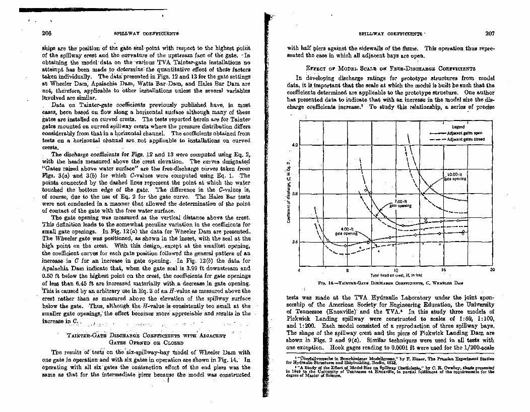
206 SPILLWAY COIFIF[IIRNTS
pg
SPILLWAY COmFOCIMNT" - 207
ships are the position- of the gate seal point with respect to the highest poiiitof the spillway crest and the curvature of the upstream face of the gate; -Inobtaining the model!data on the various TVA Tainter-gate installations noattempt has been made to determine the quantitative effect of these factorstaken individually. The dat&i presented. in Figs. 12 and 13 for the gate settingsat Wheeler Dam' Apalachia Dam, Watts BarDam, and Hales Bar Dam arenot, therefore, applicable to other installations unless the several variablesinvolved are similar.* Data on Tainter-gate coefficients previously published have, in mosteases, been based on flow along a horizontal surface although many of thesegates are installed on curved crests. The tests reported herein are for Taintergates mounted on curved spillway crests where the pressure distribution differsconsiderably from that in a horizontal channel. The coefficients obtained fromtests on a horizontal channel are. not applicable to installations on curvedcrests.. The discharge coefficients for Figs. 12 and 13 were computed using Eq. 2,with the heads measured'above the:crest elevation. The curves designated"Gates raised above water surface" are the free-discharge curves taken fromFigs. 3(a) 'and 3(6) for which C-values were computed using Eq. 1. Thepoints connected by the dashed lines represent the point at which the watertouched the bottom edge of the gate. The difference in the C-valued is,of course, due to the use of Eq. 2 for the gate curve. The Hales Bar testswere not conducted in a manner that allowed the -determination of the pointof contact of the gate with the free water surface.
The gate opening was measured as the vertical distance above the crest.This definition leads to the somewhat peculiar variation in the coefficients forsmall gate openings. In Fig. 12(a) the data for Wheeler Dam are presented.The Wheeler gate was positioned, as shown in the insert, with the seal at thehigh point on the crest. With this design, .except at the smallest opening,the coefficient curves for each gate position followed the general pattern of anincrease in C for an increase in gate opening. In Fig. 12(b) the data forApalachia Dam indicate that, when the gate seal is 3.99 ft downstream and0.50 ft below the highest point on the crest, the coefficients for gate openingsof less than 6.45 ft are increased materially with a decrease in gate opening.This is caused by an arbitrary use in Eq. 2 of an LHvalue as measured above thecrest rather than as measured above the elevation of the spillway surfacebelow the gate. Thus, although the H-value is -consistently too small at thesmaller gate openings, the effect hdcoines m~ re alpreeiable ad results in theincrease in C.
, . .
V kTMR~ru-GýTB DirnCzAnon ConncrsCINTs WITH ADJACENTGATES OPENED OR CLOSED
The results'oftests" on the: six-spillway-bay mbdel of Wheeler Dam withone gate in operation and with six gates in operation are shown in Fig. 14.A Inbperating with all sixtgates the contraction effect of the end piers was thesame as that for the intermediate piers because the model was constructed
with half piers against the sidewalls of the flume. This operation thus repre-sented the case in which all adjacent bays are open.
ErV.nCT Or MODEL SCALz ox FEzE-DiSOHABQS COEFFIO!ENTS
In developing discharge ratings for prototype structures from modeldata, it is. important that the scale at which the model is built be such that thecoefficients determined are applicable to the prototype structure. One authorhas presented data to indicate that with an increase in the model size the dis-charge coefficients increase.7 To study this relationship, a series of precise
s 12 I1Total head on CreSt, H, in test
Fin. 14.-TAixir -CATn DisanARG COEFFICIENTs, C, WHamLea Dis
20
tests was made at the TVA Hydraulic Laboratory under the joint spon-sorship of the American Society for Engineering Education, the Universityof Tennessee (Knoxville)' and the TVA.' In this study three models ofPickwick Landing spillway were constructed to scales of 1:50, 1:100,and 1:200. Each model consisted of a reproduction of three spillway bays.The shape of the spillway crest and the piers of Pickwick Landing Dam areshown in Figs. 2 and, 9(a). Similar techniques were used in all tests withone exception. Hook gages reading to 0.0001 ft were used for the 1/200-scale
'"Oberfaliversuche In Dersehiedener Modellgroeae," by F. Eisner, The Prussian Experiment Stationfor Hydraulic Structures and Shipbuilding, Berlin, 1933.
"'A Study of the Effect of Model Size on Spillway Coefficfents," by C. IL. Ownhey. thesis presentedin 1949 to the University of Tennessee at Knoxville, in partial fulfilment of the requirements for thedegree of Master of Science.
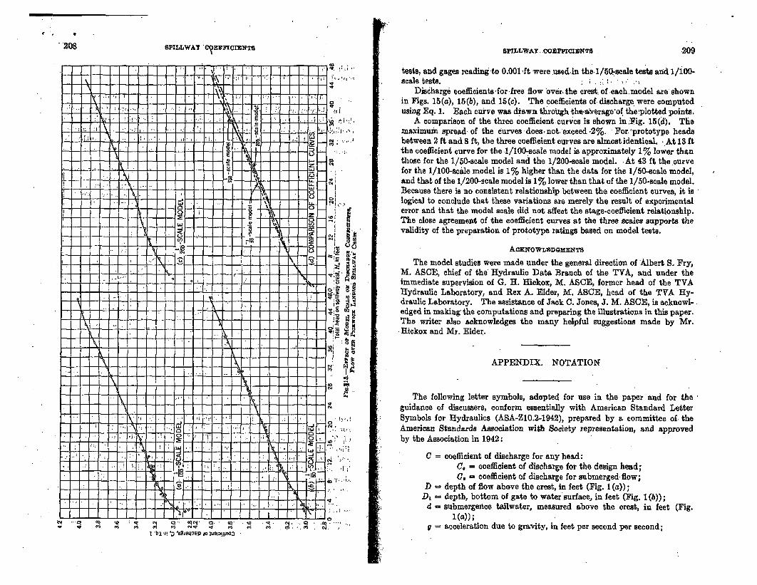
•208SPILLWAY 'C?EfF¶OIlNTS 209S1'ILLWAY. OoBFFICIENTS
I' ] f I P ,
- VI":•F F" F!
:U k % U. :4 i ' .
0
- -r -- I
v'%
I-I- -A -
. .. . . . I N I
7 to
.0
- r
-;EF ', _C/
T-7 i- I 'I 7 - .
I-,..'
U
N.
PC
P
'I~i
. ..
tests, and gages reading to 0.0011ft were usedin the-i/0•-scale tests and 1/100-scale tests.
Discharge eoefficientsfor free flow boverthe crest of -each model are shownin Figs. 15(a), 15(5), and 15(c). The coefficients of. discharge were computedusing Eq. 1. Bach curve was d&awn throegh the.ta.verage'of the•:plotted points.
A comparison of the three coefficient- curves is shown in Fig. -15(a). Themaximum spread- of the curves does not. exceed 2%. - For 'prototype beadsbetween 2 ft and 8 ft, the three coefficient curves are almost identical. : At 13 ftthe coefficient curve for the-,1/100-scale model is approximately 1% lower thanthose for the 1/50-scale model and the 1/200-scale model. - At 43 ft the curvefor the 1/100-scale model is 1% higher than the data for the 1/50-scale model,and that of the 1/200-scale model is 1% lower than that of the 1/50-scale model.Because there is no consistent relationship between the coefficient curves, it is - -
logical to conclude that these variations are merely the result of experimentalerror and that the model scale did not affect the stage-coefficient relationship.The close agreement of the coefficient curves at the three scales supports thevalidity of the preparation of prototype ratings based on model tests.
AcwowLnaDnMrNTs
The model studies were made under the general direction of Albert S. Fry,M. ASCE, chief of the Hydraulic Data Branch of the TVA, and under theimmediate supervision of G. H. Hickox, M. ASCE, former head of the TVAHydraulic Laboratory, and Rex A. Elder, M. ASCE, head of the TVA Hy-draulic Laboratory. The assistance of Jack C. Jones, J. M. ASCE, is acknowl-edged in making the computations and preparing the illustrations in this paper.The writer also acknowledges the many helpful suggestions made by Mr.
- Hickox and Mr. Elder.
APPENDIX. NOTATION
The following letter symbols, adopted for use in the paper and for theguidance of discussers, conform essentially with American Standard LetterSymbols for Hydraulics (ASA-ZIO.2-1942), prepared by a committee of- theAmerican Standards Association with Society representation, and approvedby the Association in 1942:
C = coefficient of discharge for any head:C. = coefficient of discharge for the design head;C. = coefficient of discharge for submerged flow;
D - depth of flow above the crest, in feet (Fig. 1 (a));D, = depth, bottom of gate to water'surface, in feet (Fig. 1(b));
4 = submergetce tailwater, measured above the crest, in feet (Fig.I (a));
gacceleration due to gravity, in feet per second per second;"'O q=, 10ret ' i 14 qu ' ql" Q e -
to ~.VlI ! 1, ...,
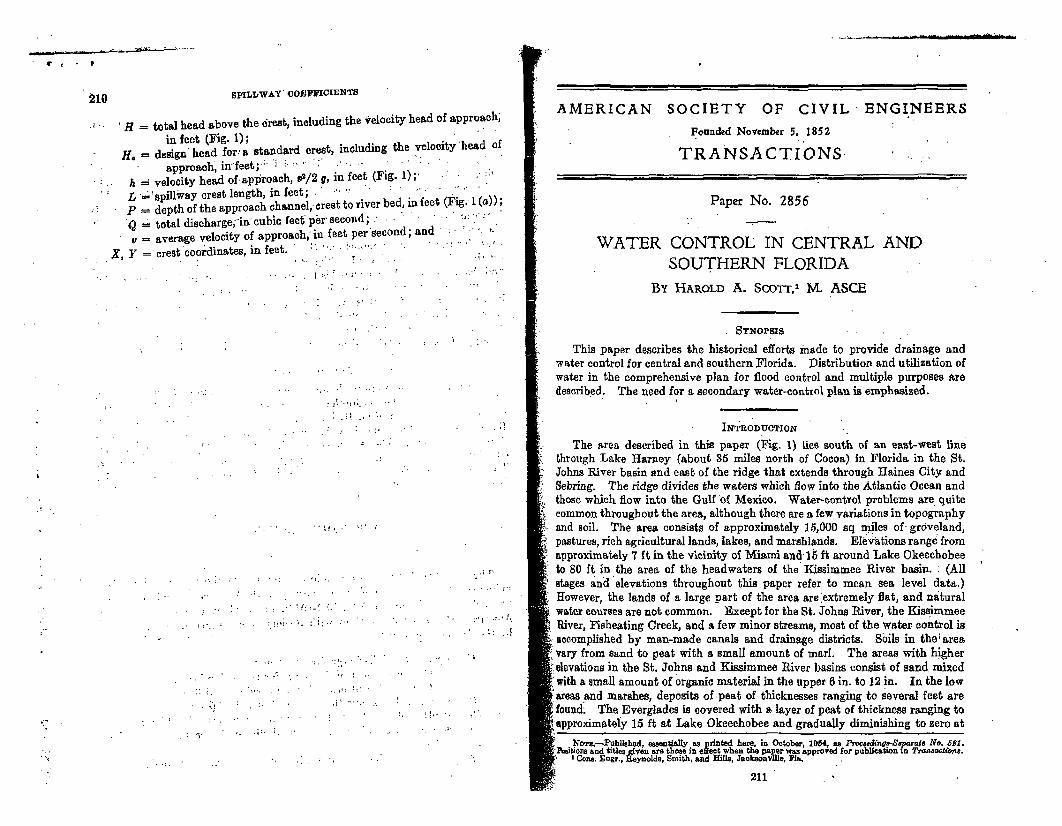
Vt * 1 '1210 SPILLWAY cOEFFICIENTS
j H = total head above the &rest, including the velocity head of approach,
in feet (Fig. 1);H. = design' head for.'a standard crest, including the velocity head of
approach, in: feet;.: . i. ; .... "' ...- : .
h = velocity head of-approach, v0/2 g, in feet (Fig. 1);. ' * .L ='spillway crest length, in feet; ". *- '! " ...
P - depth of the approach channel, crest to river bed, in feet (Fig. 1 (a));
Q total discharge;"in cubic feet p6r" second; ' • • "S;: average velocity of approach*in feet per'second; and
X, Y crest coordinates, in feet. :; -"" -!' • . -
,~~~...... . . ..
AMERICAN SOCIETY OF CIVIL ENGINEERS
Founded November 5, 1852
TRANSACTIONS.
Paper No. 2856
WATER CONTROL IN CENTRAL ANDSOUTHERN FLORIDA
BY HAROLD A. ScoTT,1 M. ASCE
-SYnopsrs --
This paper describes the historical efforts made to provide drainage andwater control for central and southern Florida. Distribution and utilization ofwater in the comprehensive plan for flood control and multiple purposes aredescribed. The need for a secondary water-control plan is emphasized.
INTRODUCTION
The area described in this paper (Fig. 1) lies south of an east-west linethrough Lake Harney (about 35 miles north of Cocoa) in Florida in the St.Johns River basin and east of the ridge that extends through Raines City andSebring. The ridge divides the waters which flow into the Atlantic Ocean andthose which flow into the Gulf 'of Mexico. Water-control problems are quitecommon throughout the area, although there are a few variations in topographyand soil. The area consists of approximately 15,000 sq miles of- grdveland,pastures, rich agricultural lands, lakes, and marshlands. EIkvations range fromapproximately 7 ft in the vicinity of Miami and 15 ft around Lake Okeechobeeto 80 ft in the area of the headwaters of the Kissimmee River basin. : (Allstages and elevations throughout this paper refer to mean sea level data.)However, the lands of a large part of the area are extremely flat, and naturalwater courses are not common. Except for the St. Johns River, the KissimmeeRiver, Fisheating Creek, and a few minor streams, most of the water control isaccomplished by man-made canals and drainage districts. Sbils in the: areavary from sand to peat with a small amount of marl. The areas with higherelevations in the St. Johns and Kissimmee River basins consist of sand, mixedwith a small amount of organic material in the upper 6 in. to 12 in. In the lowareas and marshes, deposits of -peat of thicknesses ranging to several feet arefound; The Everglades is covered with a layer of peat of thickness ranging toapproximately 15 ft at Lake Okeechobee and gradually diminishing to zero at
-,-, .
.... - . .. -.
-I
- - -~'':--- .
I I o -F u bniahed, essentially a&a printed here, in October, 1054, as Ptvod.I.n1-Sqcraf No. O1.sto n itens r those inetc hnthe paper was approved for publication in .voaaocteme.Cons Enar., Reynolds, Smith, and Hlls, Jackeonville, Fin.
211
L58 080821 001Tennessee Vc.2-.lcy AuthorityDivision of Water Control Planning
Engineering Laboratory,
TAII'"TER GATE RATIG .DATA
DETET4EIMED FROM EIGHT TVA MODEL- STUDIES
0
g
Norris, TennesseeMarch 1962
if
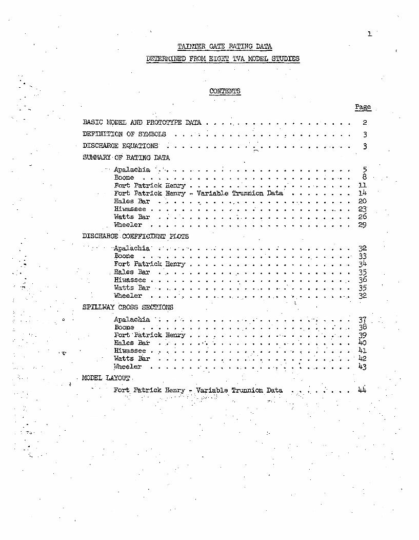
I
TADI=R GATE RATING DATA
DETERMIBED FROM EIGHT TVA MODEL STUDIES
CONTENTS
BASIC MODEL AND PROTOTYPE DATA ..............
DEFINITION OF SY1DBLS . . . . .............
DISCHARGE EQUATIONS* ...................
SM%%tjRY OF RATING DATA
Apalachia .. .. . ... . . . . . . . . . . . . .Boone ............. ........... ..........Fort Patrick Henry ...................... .•Fort Patrick Henry - Variable Trunion DataHales Bar ... ................
Hiwassee .......... ........... . . . ......Watts Bar .......... .. *.......Wheeler ...... ........................
DISCHARGE COEFFICIENT PLOTS
Page
2
3
3
58
1i20232629
32333435363532
373839
.414243
-Apalachia.........Boone . ... ......Fort Patrick HenryHales Bar ..
Hiwassee ........Watts Bar . .
Wheeler
SPILLWAY CROSS SECTIONS
Apalachia .
Boone. . . .Fort Patrick HenryHales Bat......Riwassee .Watts Bar ........Wheeler
MODEL LAYOUT.
4
I
I
t
B
U.
@
m
@
t
B
Q
W
@
@
. ..Z.
Fort Patrick Henry - Variable Trunnion Data.. ....
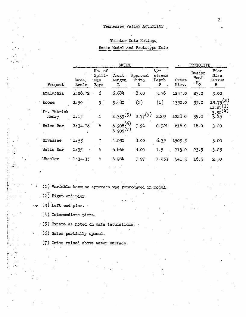
2
Tennessee Valley Authority
Tainter Gate Ratings
Basic Model and Prototype Data
MODEL
ModelProject Scale
Apalachia 1:28.72
Boone 1:50
Ft. PatrickHenry 1:15
Hales Bar 1:34.76
Hiwassee -'1:55
Watts Bar 1:35
Wheeler 1:34.35
No. of
wayays
65,
1
6
7
6
6
Crest ApproachLength.
L
6.6814
3.48o
2.333(5)
6.908(6 )
4.o5o
6.866
6.984
TUp-
WidthW
(1)
2.77(5)
7.94
8.00
8.00
7-97
streamDepth
P
3.38
(a)
2.29
0.921
6.35
1.5
1.253
Crest
Elev.
1257.0
1350.0
1228. 0
616.o
1503.5
713.0
541.3
PROTOTYPE
DesignHead
HO
23.0
35.0 :
35.0
18.0
23.5
16.5
PierNoseRadius
R
3.00
L2.7(2)
3.25
3.00
3.00
3.25
2.50
(1) Variable because approach was reproduced in model.
(2) Right end: pier.
v '• (3) Left end pier.
(4) Intermediate piers.
(5) Except as noted on data tabulations.
(6) Gates Partially opened.
(7) Gates raised above water surface.
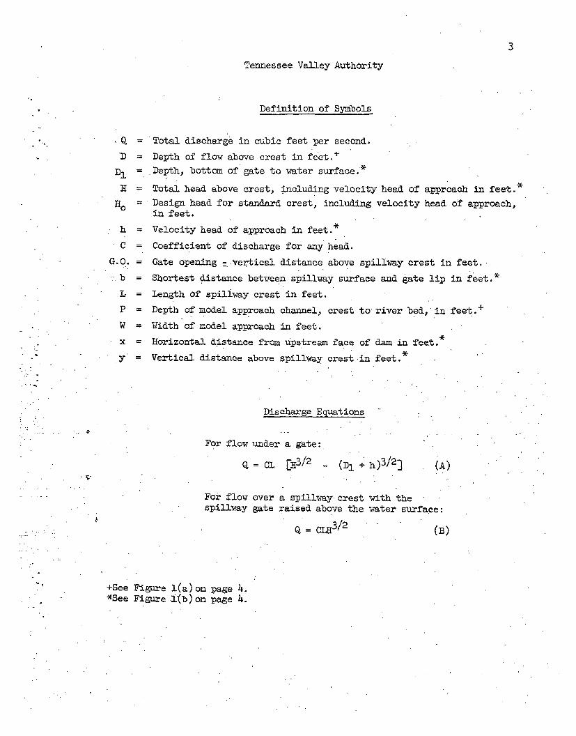
3
Tennessee Valley Authority
* Definition of Symbols
,Q = Total discharge in cubic feet per second.
D = Depth of flow above crest in feet."+D1= Depth, bottom of gate to water surface.*
H = Total head above crest, including velocity head of approach in feet.*
Ho 0 Design head for standard crest, including velocity head of approach,in feet.
h Velocity head of approach in feet.*
C = Coefficient of discharge for any head.
G.O. = Gate opening =.Vertical distance above spillway crest in feet.
b = Shortest distance between spillway surface and gate lip in feet.*
L Length of spiliway crest in feet.
P = Depth of model approach channel, crest to river bed, in feet.+
W = Width of model approach in feet.
x = Horizontal distance from upstream face of dam in feet. *
y' Vertical distance above spillway crest in feet.
Discharge Equations
For flow under a g.te:
C= L. [13/2 _ (Dl + h)3/23 (A)
For flow over a spillway, crest with thespillway gate raised above the water surface:
Q c-3/2 (B)
* +See Figure l(a) on page 4.*See Figure f(b)on page 4.
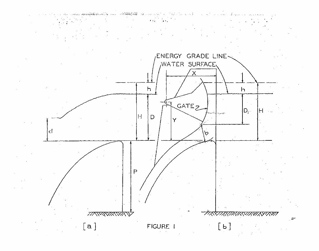
ENERGY GRADE LINE,WATER SURFACE,
H
FIGURE 1
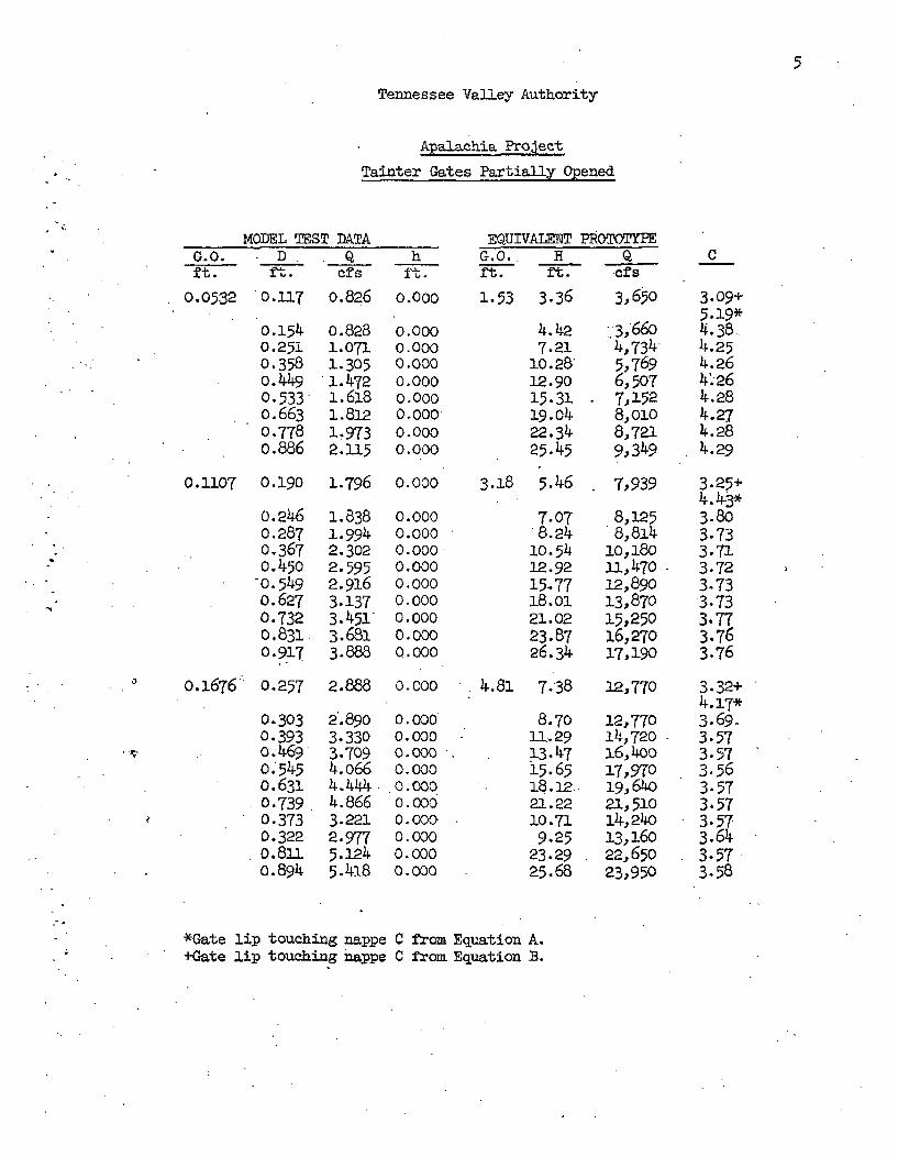
5
Tennessee Valley Authority
Apalachie. Project
Tainter Gates Partially Opened
MODEL TEST DATAG.O. D. . Q hNt. F. cfs f%.
EQUIVALENT PROTOTYPEG.O. H Qft. ft. cfs
0.0532 0.117
o.1540.2510.358o. 4490. 5330. 6630.7780.886
o.826
o.8281.0711.3051.4721.6181.8121.9732.115
0.000
0.0000.0000.0000.0000.0000.0000.0000.000
1.53 3.36
4.427.21
10.2812.9015.3119.04
22.3425.45
3, 650
.'.3,6604.,7345,7696,507.,152
8,0108,7219,349
0.1107 0.190 1.796 O.000 3.18 5.46 7,939
0.2460.2870.3670.450
-0.549
0.6270.7320.8310. 917
0.1676 0.257
0.3030.393). .4690.5450.6310.7390.3730.3220.81.0.894
1.8381.9942.3022.5952.9163.1373.451-3.6813.888
0.0000.0000.0000.0000.0000.0000.0000.000Q.000
7.078.24
10.5412.9215.7718.0o21.0223.8726.34
8,1258,814
10,18011,47012,89013,87015,25016,27017,190
C
3.09+5.19*4.38-4.254.264'.264.284.274.284.29
3.25+4.43*3.803.733.713.723.733.733.773.763.76
3.32+4.17*3.69-3.573.573.563.573.573.573.643.57-3.58
2.888 0.000
21.8903.3303.7094.0664.4444.8663.2212.9775.12 45.418
0.0000.0000.0000.0000. 0000.0000. 0000.0000.0000.000
4.81 7.38 12,770
8.70 12,77011.129 14,72013.47 16,4ooi5.65 17,970
' 18.12 19,64021.22 21,51010.71 14,2409.25 13,160
23.29 22,65025.68 23,950
*Gate lip touching nappe+Gate lip touching nappe
C from Equation A.C from Equation B.
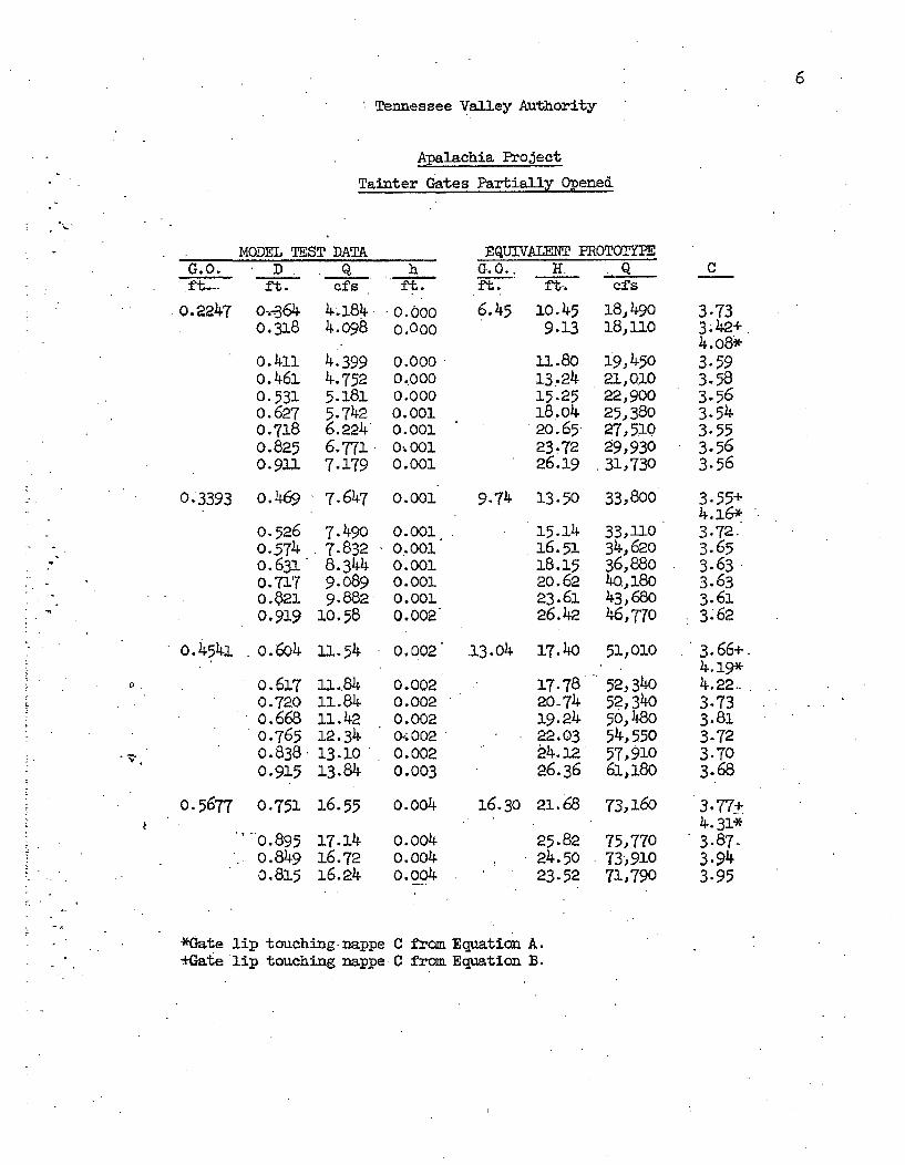
6
Tennessee Valley Authority
Apalachia Project
Tainter Gates Partially Opened
MODEL TEST DATA EQUIVALENT PROTOTYPEG.0. D Q h G. 0.. H Qft.-- ft. c(Ts ft. ft. ft. cfs
.0.2247 0,-364 -184 0.000 6.45 10.45 18,4900.318 4.098 o.0oo 9.13 18,no
0.411o. 461
0.531o.627o .7180.8250.91)
4.3994.7525.1815.7426.2246.7717.179
0.0000.0000.0000.0010.0010.-0010.001
0.001
0.0010.0010.0010.0010.0010.002
11.8013. 2415.2518.o420.6523.7226.19
19,45021, Q1O22,90025,38027, 51099,93031,730
C
3.733.42+4.o8*3.593.583.563.543.553.563.56
0.3393 0.469 7.647 9.74 13.50 33,800
.7
0.5260.574o.6310.7170.ý210.919
7.4907.8328.3449.0899.88210.58
15.141.6.5118..1520.6223.6126. 4a
33,11034,62036,8804Q,18o43,68o46,770
3.55+4.16*3.72.3.653.633.633.613.62
o.4541 o.6o4 11.54
0 0.617j0.7200.6680.7650.8380.915
11.8411.8411.4212.3413.1013.84
0.002 .13.o4 17.4o 51,010 3.66+.4.19*
0.002 17.78 52,340 4.22-0.002 20-74 52,340 3.730.002 19.24 50,480 3.810;002 22.03 54,55o 3.720.002 24.12 57,910 3.700.003 26.36 61,18o 3.68
0.5677 0.751 16.55
"o.8950.8490.815
17.1416.7216.24
0.0o4
0.0040.004o.o4
16.30 21.65
25.8224.5023.52
73,160
75,77073%91071,790
3.77t'4.31*3.87.3.943.95
*Gate lip touching nappe 0 from Equation A.+Gate lip touching nappe C fran Equation B.
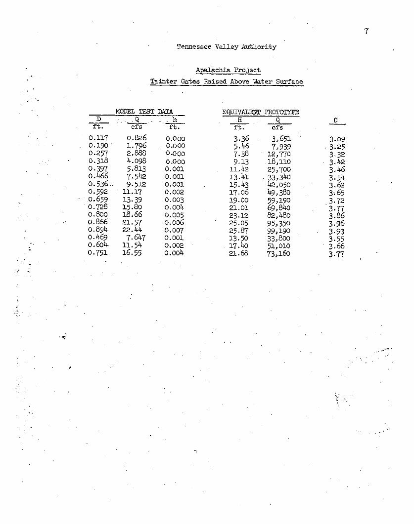
7
Tennessee Valley Authority
Apalachia Project
Tainter Gates Raised Above Water Surface
MODEL TEST DATAD . .Q . - hff. -cfs . -ft.
0.1170.1900.2570.3180.3970.4660.536..0.592.o.6590.7280.800o.866o.8940.4690.604-0.751
0.8261.7962.8884.0985.8137.5429.512
11.1713.3915.8018.6621.5722.447.64711. 5416-55
0.0000.0000.0000.0000, OO10.0010.0010.0020.003o.0040.0050.006o.oo60.0070.0010.0020.004
EQUlIALE NTH
f.t.
3.365.467.389.13
11.4213.4115.4317.0619.0021.0123.1225.0525.8713.5017. 421.68
PROTOTYPEQ
cfs
3,6517,939
12.,770.18,ii025,70033,34042,050'49,38059,19069,84082,48095,35099,19033,80051,01073,160
C
3.093.253.323. 423.463.543.623.653.723.773.863.963.933.553.663.77
r,
*1
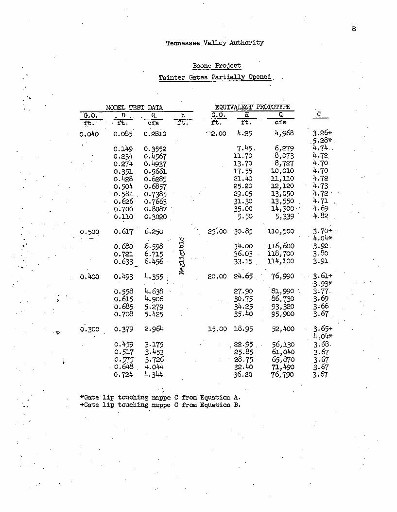
8
Tennessee Valley Authority
Boone Project
Tainter Gates Partially Opened
MODEL TEST DATA EQUIVALENT PROTOTYPE
ft.G.040
Dft.
0.085.
0.1490.2340.2740.3510.4280o.5o40.581o.6260.7000.110
Q, hcft's ft.
0.2810
0.35520. 45670.49370.56610.62850.68570.73850.76630.80870.3020
':2.00 4.25
7.45.11.7013.7017.5521.4025.2029.0531.3035.005.50
4,968
6,2798,0738,727
10,01011, 11012,12013,05013,55014,300'
5,339
G.O.. H. Qft. ft. cfs
C
3.26+5.28*4.74..4.724.704.704.724.734.724.714. 694.82
3.70+.4.04*3.92.3.803.91
3.61+-393*3677-3.693.663.67
0.500 o.617 6.250
o.68o 6.598o.721- 6.7150.633_ 6.456
0. 400 0.493 4.355
25 .00 30.85 110,500
r4Ai34-0036.0333.15
20.00 24.65
a16,600l18,700114,100
76,990
81, 99086,73093,32095,900
3
0. 5580. 6150.685.0.708
4.6384.9065.2795.425
27.9030.7534.2535.40
0.300 o. 379 2.964
o.4590.5170.5750.6480.724
3.175.3.4533.7264.o444.344
15.00 18.95
22.9525.8528.7532.4036.20
52,400 3.65+
56,i30 3.68,61,040 3.6765,870 3.6771,490 3.6776,790 3.67
*Gate lip touching nappe+Gate lip touching nappe
C from Equation A.C from Equation B.
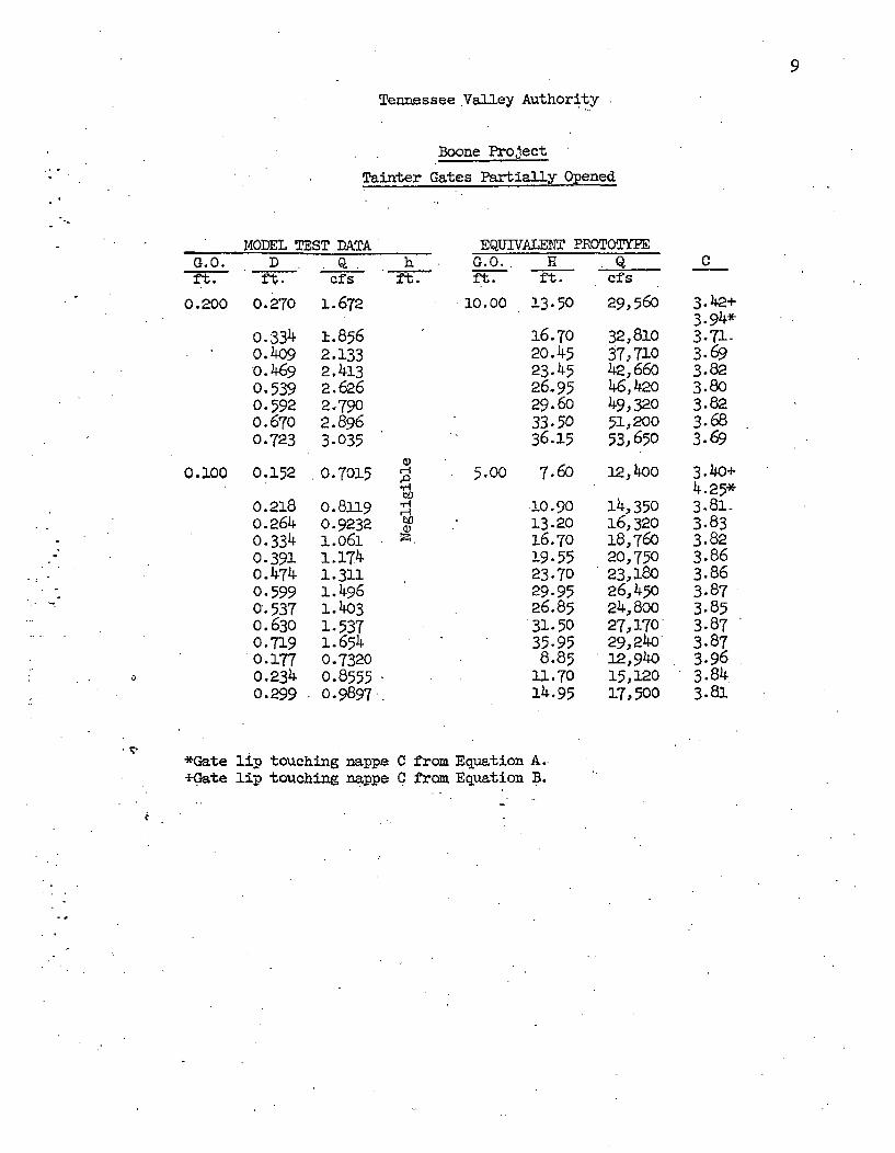
9
Tennessee Valley Authority
Boone Project
Tainter Gates Partially Opened
G.0.ft.
0.200
MODEL TEST DATAD__ Q.
ft. cfs0. 270 1. 672
hft.
EQUIVALENT PROTOTYPEG.O.. H Qft. ft. cfs
C
0.334o.4o9o.24690.5390.5920.6700.723
i.8562.1332,4.132.6262-7902.8963.035
0.2100 0.152 0.7015
0. 218 0. 8119
o.264 0.9232 0n Z-ZL -I oMi ý
10.00 13.50 29,560 3.42+3-94*
16.70 32,810 3.71-20.45 37,710 3.6923.45 42,660 3.8226.95 4-6,420 3.8029.60 49,320 3.8233.50 51,200 3.6836.15 53,650 3.69
5.0O 7.6o 12,4oo 3.40+4.25*
o10.90 14,350 3-81-13-20 16,320 3.8316.70 18,76o 3.8219.55 20,750 3.8623.70 23,180 3.8629.95 26,450 3.8726.85 24,800 3.8531.50 27,170 3.8735.95 29,240 3.878.85 12,940 3.96
11.70 15,120 3.8414.95 17,500 3.81
0.3910.4740.5990. 537o.6300.719
0.1770.2340.299
1.1741.3111.24961.4031.5371.6540.73200.85550.9897
*Gate lip touching nappei-Gate lip touching nappe
C from Equation A..C from Equation B.
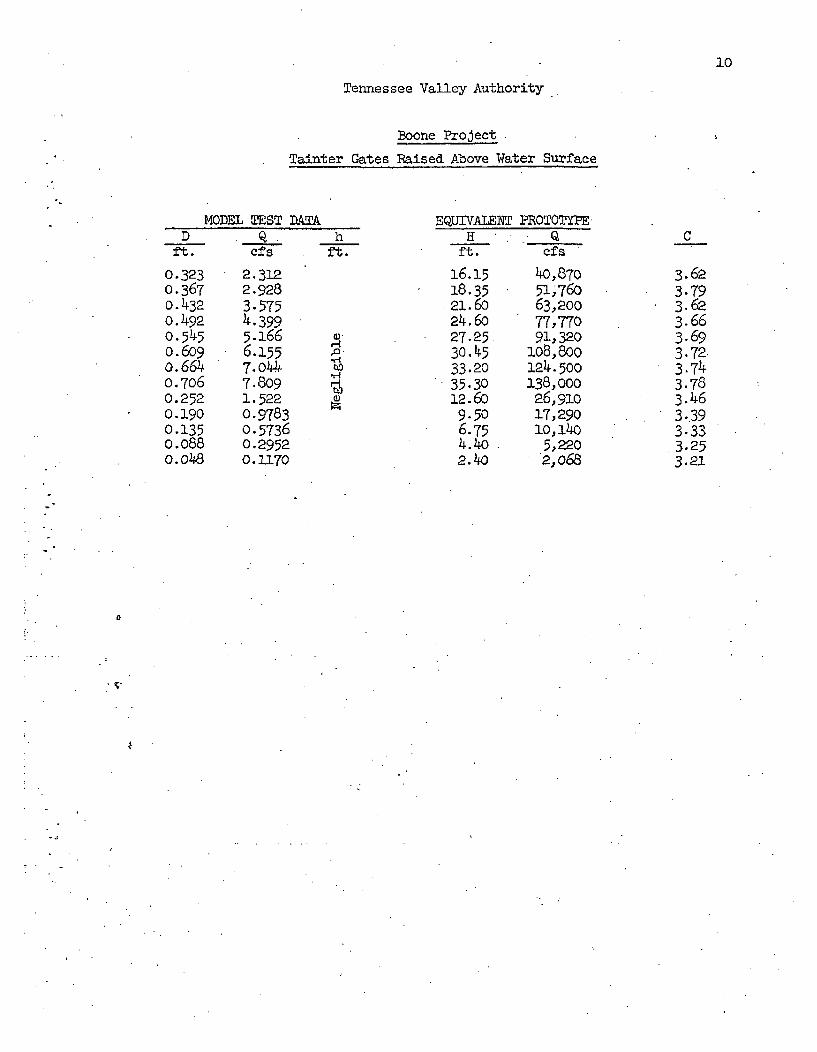
10
Tennessee Valley Authority
Boone Project
Tainter Gates Raised Above Water Surface
Dft.
0.3230.367o. 4320.492o.5450.609o.6640.7060.2520.1900.1350.088o.o48
MODEL TEST DATA
. f s hft.
EQUIVAIMET PROTOTYPEH . Q
ft. efs
2.3122.9283.5754.3995.1666.1557.o447.8091.5220.97830.57360.29520.1170
16.1518.3521.6o24.6o27.2530. 4533.2035.3012.6o9.506.754.402.4o0
40,87051,76063,20077,77091,320
108,800124.500138,00026,91017,29010,140
5,2202,068
C
3.623.793.623.663.693.72.3.743.783.463-393.333.253.21
0
, ..•.
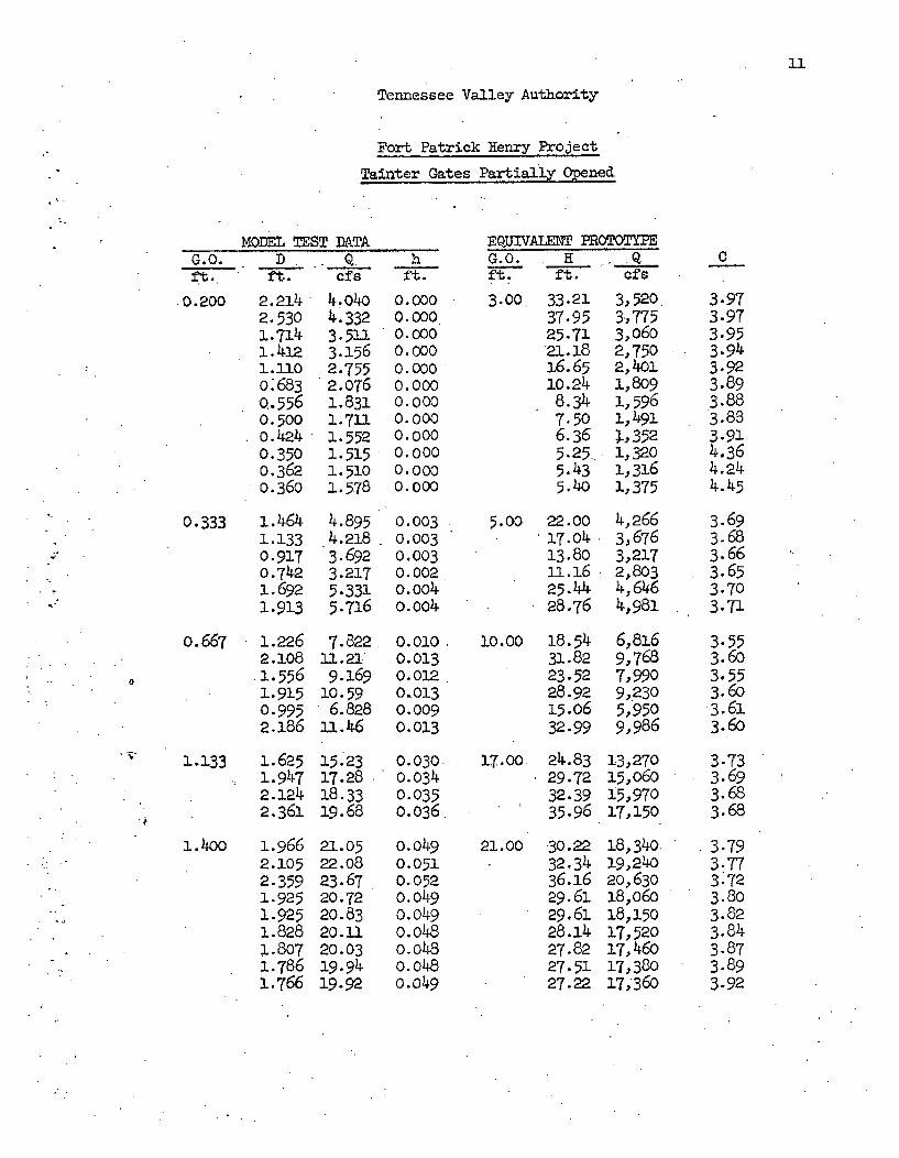
11
Tennessee Valley Authority
Fort Patrick Henry Project
Tainter Gates Partially Opened
MODEL TEST DATAAG.0. D. Q.ft. ft. cNs
.0.200 2.2142.5301.714i.- 4121.110o.6830.5560.500o.4240.3500.3620.36o
0.333 i. 4641.1330.9170.7421.6921.913
0.667 1.2262.1081. 5561.92.50.9952.186
1.133 1. 6251.9472.1242.361
1.4oo 1.9662.1052.3591.9251.9251.8281.8071.7861.766
4.0!404.3323.5113.1562.7552.o761.8311.7111.5521.5151.5101.578
4.8954.2183.6923.2175.3315.716
7.82211.219.169
10.596.828
u1.46
15.2317.2818.3319.68
21.0522.0823.6720.7220.8320.1120.0319.9419.92
hft0.
0.0000.0000.0000.0000.0000.000
0.0000.0000.0000.0000.000
0.003
-0.003
0.0030.0020.004
o. oo4
0.01.0.0o013
0.0120.0130.0090.01.3
0.0300m340.0350.036
o.o040.0510.0520.0490.0490.480.-0480.048o.o49
EQUIVALENT PROTOTYPEG.O. H Qft. ft. cfs
3.00 33.21 3,52037-95 3,77525.71 3,060'21.18 2,75016.65 2,4o010.24 1,8098.34 1,5967.50 1,4916.36 1,3525.25. ij3205.43 1,3165.40 1,375
5.00 22.00 4,26617.04 3,67613.80 3,217ul.6 2,80325.44 4,64628.76 4,981
10.00 o 8.54 6,81631.82 9,76823.52 7,99028.92 9,23015.o6 5,95032.99 9,986
17.00 24.83 13,27029.72 15,06032.39 15,97035.96 17,150
21.00 •30.22 18,34032.34 19,24036.16 20,63029.61 18,o6o29.61 18,15028.14 127,52027.82 17,46o27.51 17,38027.22 17,360
C
3.973.973.953.943.923.893.883.883.914.364.244.45
3.693.683.663.653.703.71
3.553.6o3.553.603.613.60
3-733.693.683.68
3.793.773.723.803.823.843.873.893.92
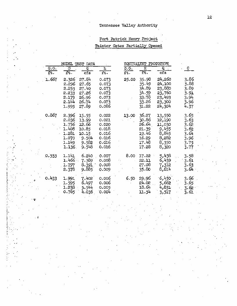
12
Tennessee Valley Authority
Fort Patrick Henry Project
Tainter Gates Partially Opened
MODEL TEST DATPAG. 0.ft.
1.667- tD . . Q:ft. c -f s
2.3262.2962.2532.2332.1792.1441.995
o.867 2.3962.0361.17561.4081.2811.0701.1491. 136
0. 533 1. 1411.4661.7972.378
0.433 1.9913.5951.2380.765
27.8427.6527.4027.2626.9626.7427.89
15.5513.9912. 661o.8510.159.5o49.5829.548
6.2407.3898.391.9.885
7.4026,4975.5444.036
hft.
0.0730.0730.0730.0730.0730.073
m.066
0.0220.0210.020
m.16
0.d16o. o16
0.007o.oo80.008
0.009
0.006
0.005o.004
25.00 35.9835.4934.8934.5933.7833.2631.22
13.00 36.2730.8626.64.21.3919-4616.2917.4817.28
8.00 17.2222.1127.0835.80
6.50 29.9624.0218.6411.54
EQUIVA- P0OTOTYPEG.0. H Q.ft. ft. cfs
24,26024, 10023,88023,76023,49323,30024,304
13 55012,19011,030
9,,4558,8458,2828,3508,320
5,4386,4397,3128,614-
'6,450'.5,6624,831-3,517
.C
3.863.883.893.913.943.964.37
3.653.633.623.623.643.963.753.77
3.583.613.633.64
3.663.651.'.623.61
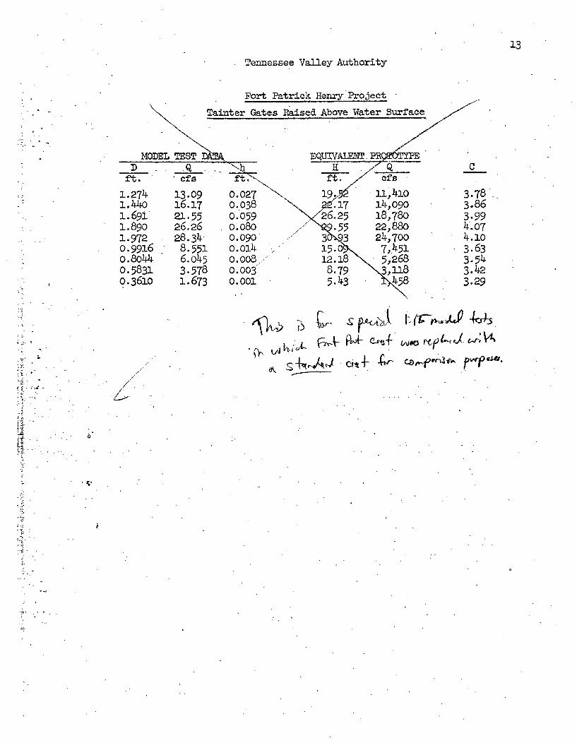
13Tennessee Valley Authority
Fort Patrick Henry Project
Tainter Gates Raised Above Water Surface
Il Qfs-
C
1.2741.44o1.6911.89o1.972o.99160.80440.58310.3610
13.09 0.02716.17 0.03821.55 0.05926.26 0.08o28.34ý 0.090•8.551 o.oi46.o45 0.008,3.578 0.0031.673 0.001
3.783.863.994.074.1o3.633.543.423.29
8.795.43
a
It i h>~L~~4 SiOksbv 'L rt- G CoVkf1b pw#.
///
O"
3. '
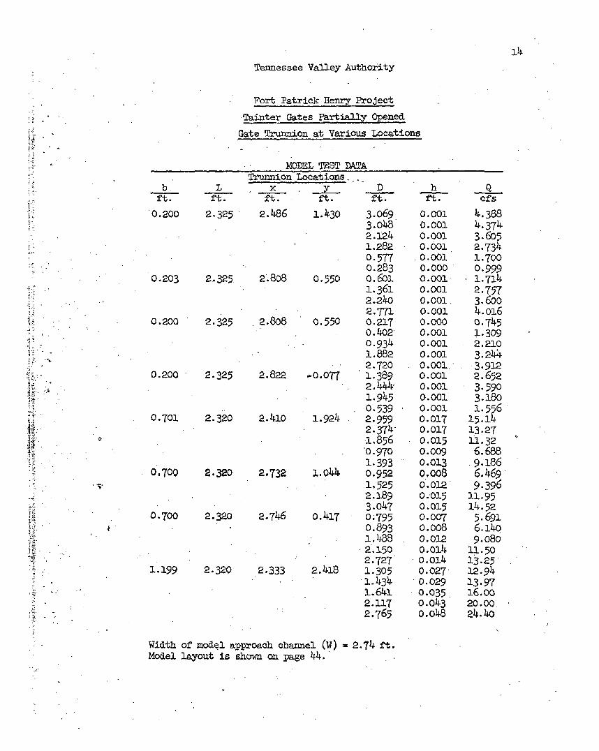
Tennessee Valley Authority
Fort Patrick Henry Project
•Tainter Gates Partially Opened
Gate Trunnion at Various Locations
MODEL TEST DATA
Trunnion Locations.b L x _ D h Q
ft. ft. ft. ft. ft. ft. cfs
0.200 2.325 2 .486 1.430 3.069 0.001 4.3883 3.0h 0.001 4.374
P2,124 0.001 3.6051..282 0.601 2.7340.577 0.0o01 1.700
0.283 0.000 0.999
0.203 2.325 2.808 0.550 o.6ol. o.0oo0- 17141.361 0.001 2.7572.24o 0.001. 3.6002.771 0.001 4.O16
0.200 2.325 2.808 o0.550 0.217 0.000 0.7450.402 0.001 1.3090.934 0.001 2.210
1.882 0.001 3.2"42.720 0.001. -3.912
0.200 2.325 2.822 .-0.077 1.389 0.001 2.6522.44,4 0.001 3.590
1.945 0.001 3.18005.39 0.001 1.556
0.70oi 2.320 2.41o 1.924 2.959 0.017 15.142.374 .0.017 13.27-1.856 0.015 11.32'0. 970 0.009 6.688
1.393 0.013 o9.186
0.700 2.320 2.732 ..0414 0.952 o,008 6.4.691.525 0.012 9.3962.89 0.015 3.1.953.047 0.015 1.4.52
0.700 2.320 2.746 0.417 0.795 0.007 5.6910.893 0.008 6.14o
1..488 0.012 9.0802. 150 o.o14 11.502.727 o.m14 13.25
1.199 2.320 2.333 2.418 1.305 0.027 12.94
1.434 . 029 13.97• • ~1.641L o1B 6.oo
0.035 1602.117 o.o43 20.00.
2.765 O.0•48 24.40
Width of model approach channel (W) 2.74 ft.
Model layout is shown on page 44.
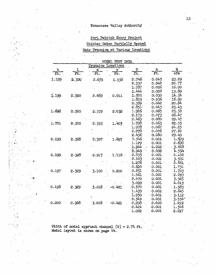
15
Tennessee Valley Authorit:
Fort Patrick Henry Project
Tainter Gates PartiallyOpened
Gate Trwanion at Various Locations
MODEL TEST DA~TATrunnion Locations.
bft.
1.199
ý.199
Lft.
2.320
2.320
1.698 2-320
1.1701 2.320
0.199 2.328
0.199 2.328
0.197 2.329
x _ Dft. ft. ft.
2.655 1°538 2.7462.3371.787
2.669 o.911 1.500-1.8032.3892.851''
2.579 2.032 1.9262.1732.465
2.593 1.iC5 1.7981.9782.2782.456
2.397 1.897 o.5461.1291.9442.949
2.917 -.U8 2.8352.1031.2760.620
3.100 0.200 o.65i1. 461.2. 4703.099
3.018 -0.421 .O57o1.4391.9502.549
3.018 -0.42.1 0.2980.424
ft.
0.0450. 0420.0360.0280.0300.036o.042o.o430.0650.0730.0800.0630.0670.0760.0800.0010.001.0,.0020.0020.0010.001010010.0010.0010.0010.001.0.0010.0010.0010.0010.0010.0000.00).0.001
Qcfs
23.2920.7716.9013.8914.3416.9220.8423.4323.5826.4729.4722.5524.2527.6229.491.6992.6983.6684.5944.1023.5012.6611.7311.7032.6933.5654.013
:.15832.6453.1123.534 t1.2•191.3462.217
0.198 2.329
0.200 2.328
Width of model approach channel (W) = 2.74-ft.Model layout is shovn on page 44.
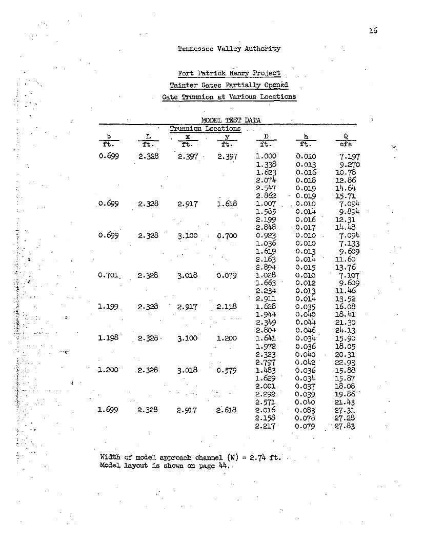
Tennessee Valley Authority
Fort Patrick Henry Project
Tainter Gates Partially Opened
Gate Trunnion at Various Locations
MODEL TEST DATATrunnion Locations
b L y D)h D_ft. ft. ft. ft. ft. ft. cfs
0.699 2.328 2.397 2.397 1.000 0.010 7.1971.338 0.013 9.2701.623 0.016 10.782.074 0-.018 12.862 .57 o0,019 )k.642.862 O.019 15-71
o.699 2.328 2.917 l.6i8 1.007 0.010 7.0941.585 O0.14 9.8942.199 o. o06 12.312.848 0.017 14.48
0.699 2.328 3,100 0.700 0.923 '.o010 7.0941.036 0:. oi0 7.133
- 1.619 0.013 9.6092.163 o.014 1. 602.894 0.015 13.76
0.701 2.328 3.018 0.079 1.028 0.010 7.1071.663 0.012 9.609
*"2,234 0.013 ll.462.911 0.014 13-52
1.199 2.328 2.917 2.118 1.628 0.035 16.081.944 0.04o 18.412.349 m.044 21.302.804 0.046 24.13
1.198' 2.328- 3.100 1.200 1.60.1 0.034 15.901.972 0.036 18.052.323 0.o4o 20.312.797 0.042 22.93
1.200 2.328 3.018 0.579 1.483 0.036 15.881.629 0.034 15.872.001 0.037 18.08
... 2.292 0.039 19.862.571 O.04o 21.43
1.699 2.328 2.917 2.618 2.016 0.083 27-312.158 0.078 27.282.217 0. 079 27.83
Width of model approach channel (W) 2.74 ft.Model layout is shown on page 44..
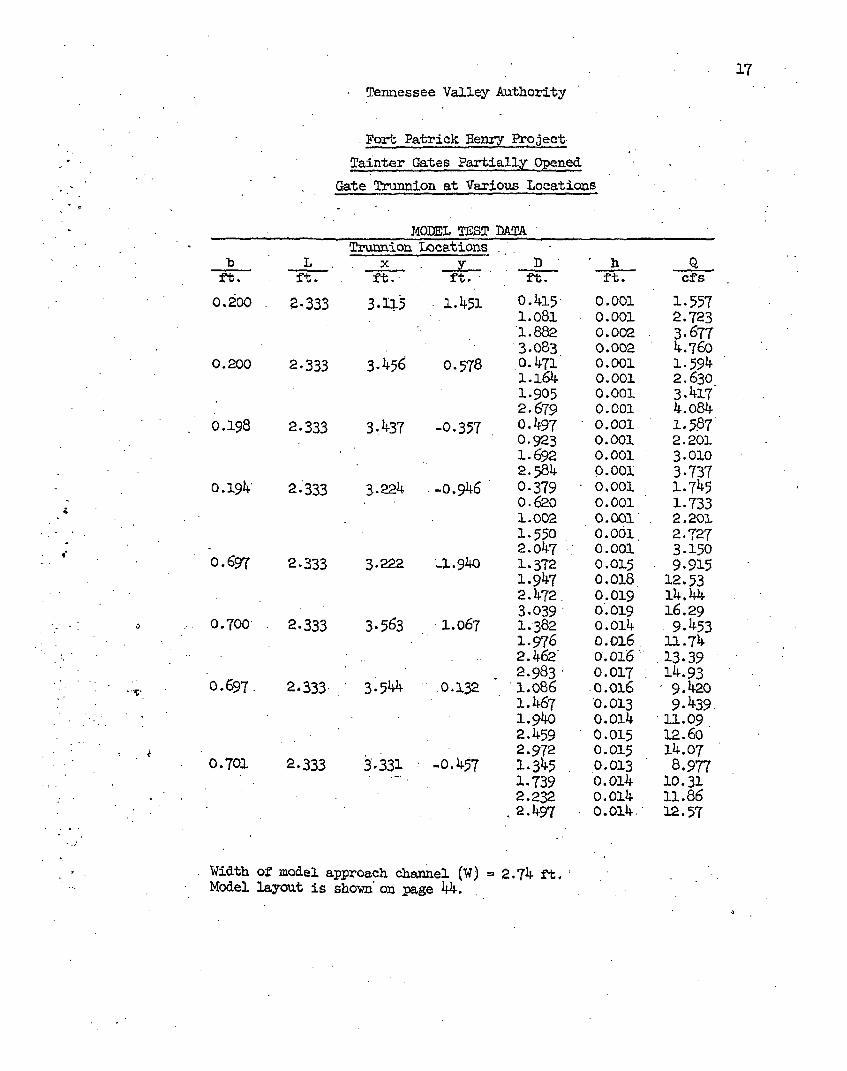
17
Tennessee Valley Authority
Fort Patrick Henry Project
* Tainter Gates Partial:y Opened
Gate Trunnion at Various Locations
MODEL TEST DATA[
Trunnion Locationsb L x __L_ Dh
ft.- ft. ft. ft. ft. ft. cfs
0.200 2.333 3.15 1.451 0.415 0.001 1.5571.081 0. 001 2.723
1.882 0.002 3.677
3.083 0.002 4.76c
0.200 2.333 3.456 0.578 0.0471 0.001 1.594
1.164 0.001 2.630
1.905 0.001 3.417
2.679 0.001 4.o84
0.198 2.333 3.437 -0.357 0.497 0.001 1.587
0.923 0.001 2.201
1.692 0.001 3.010
2.584 0.00oo 3.737
0.194 -2.'333 3.224 -0.946 0.379 0. 001 1.745
0.620 0.001 1.7331.002 0.001" 2.201
1.550 0.001. 2.727
2.047 0.001 3.150
0.697 2.333 3.222 -.1!940 1.372 0.0015 9.915
1.947 0.018 12.532.472 o.0o19 14.44
3,039 0. 019 16.29
0.700' 2.333 3-563 1. 067 1.382 O.014 9.453
1.976 o.x16, 11.742.462• .016* 13.39
2.983 0.017 14.93
0.697 2.333 3.544 0.132 1.086 0.016 9.420
1.467 0. 013 9.439
1.940 0.014 11.o09
2.459 0.015 12.602.972 0.015 14.07
0.701 2.333 3.331 -0.457 1.345 0,013 8.977
1.739 0.014 10.312.232 o.014 11.86
.2.497 0o.o014- i.57
Width of model approach channel (W) 2.74 ft,
Model layout is shown on zage 44.
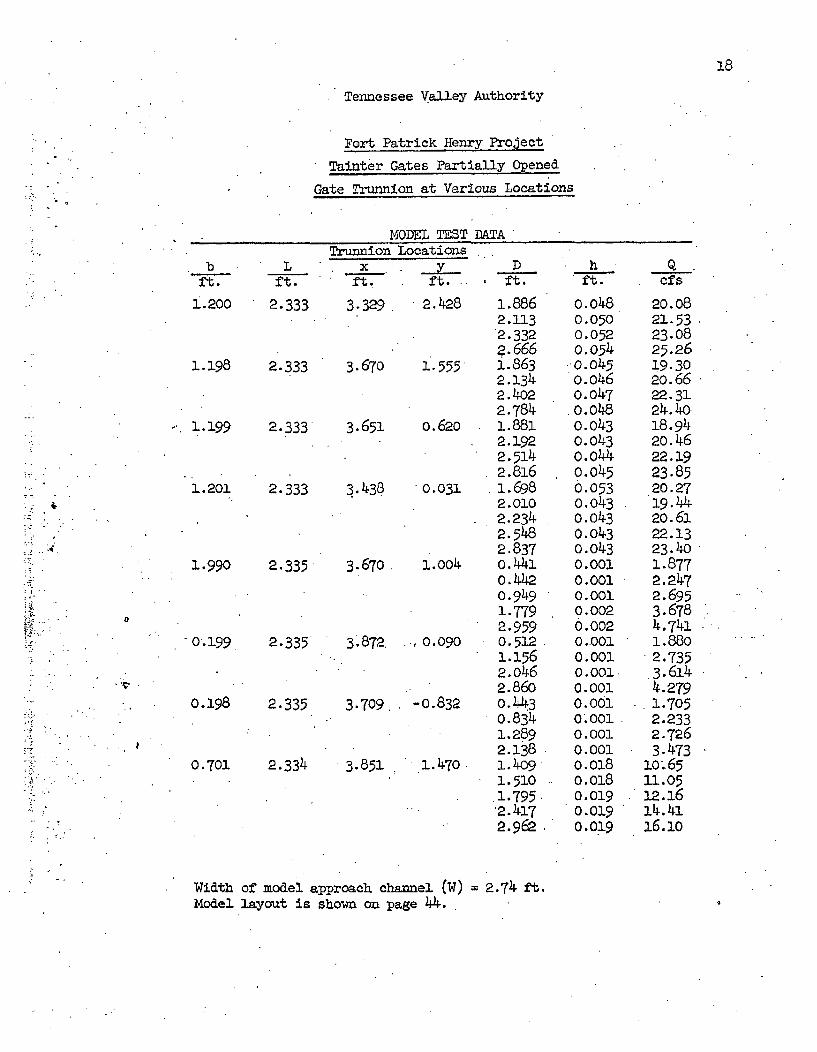
Tennessee Valley Authority
Fort Patrick Henry Project
Tainter Gates Partially Opened
Gate Trunnion at Various Locations
MODEL TEST DATATrunnion Locations
bft.
i.200
1.198
-. 1.199
Lft.
Xft.
D h Qft .. . ft- fs
•' 4
1.201
..990
2.333 3.329 2.428 1.8862.1132.332$.666
2.333 3.670 1.555 1.8632.1342.4o22.784
2.333 3.651 o.620 1.8812.1922.5142.816
2.333 3.438 0.031 1.6982.0102.2342.5482.837
2.335 3.670 1.004 o.44io.4420.9491.7792P.959
2.335 3.872 ., 0.090 0.5121.1562.0462.86D
2.335 3.709, -o.832 o.4430.8341.2892.138
2.334 3.851 1.470 1.4091.5101.7952.4-172.962
o.o480.0500.0520.054-o. os5o.o46
0.047o.o48o.043o.o43o.o440.0450.053o.0430.043o.o430.0430.0010.0010.0010.0020.0020.0010.0010.0010.0010.0010.0010.0010.0010.0180.o180.0190.0190.019
20.0821.5323.0825.2619.3020.6622.3124.4018.9420.4622.1923.8520.2719.4420.6122.1323.401.8772.2472.6953.6784.7411.8802.7353.6144.2791.7052.2332.7263.473
10.6511.0512.1614.4116.1o
0
0.199
0.198
0.701
Width of model approach channel (W) = 2.74 ft.Model layout is shown on page 44. 4
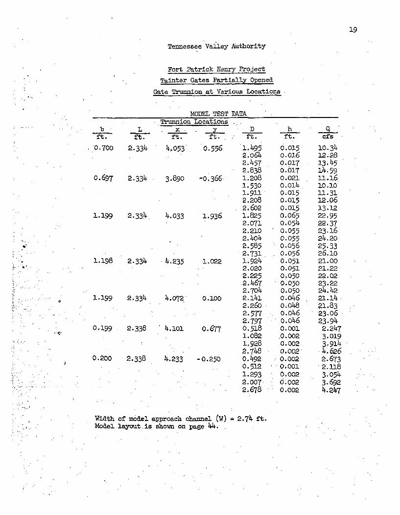
19
Tennessee Vailey Authority
Fort Patrick Henry Project
Tainter Gates Partially Opened
Gate Trunnion at Various Locations
MODEL TEST DALTATru.nnion Locations-
bft.
0 . 700
o.697
Lft.
2.334
ft.4:053
.Y Dft. ft.
0.556
2.334 3.890 -0.366
1.199 2.334 4.033 1.936
1.0221.198 2.334 4.235
1.4952.0642.4572.8381.2081.5301.9112.2082.6o21.8252.0712.2102.4042.5852.7311- 9242.0202.225.2.4672.7o42.1412.2602.5772.7970.5181.0821.9282.7480.4920.5121.2932.0072.678
hft.
0.015o.x160.0170.0170.021o. a40.0150.0150.0150.0650.0540.0550.0550.0560.0560.0510.0510.0500.0500.050o.o460.0480.0460.0460.001.0.0020.0020.0020.0020.0010.0020.0020.002
cfs
10.3412.2813.4514.5911.1610.1011.3112.o613.1222.9522.3723.624.2o25.3326.1o21.0021.2222.0223.2224.4221.1421,8323.0623.942.2473.0193.914
.4.6262.6732.1183.0543.6924.247
1.199 2.334 4.072 0.1000
0.199 2.338
0.200 2.338
4.101 0.677
4.233 -0.250
Width of model approach channel (W) = 2.74 ft.Model layut. is shown on page 44.
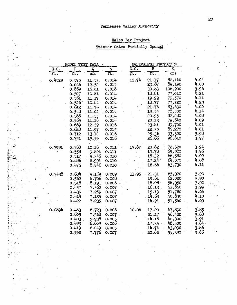
20
Tennessee Valley Authority
Hales Bar Project
Tainter Gates Partially Opened
MODEL TEST DATAG.O. D Q hft. ft. cf 4s ft.
0.4529 0.595o.6660.8690.5270.5610.5260.6120.5480.5880.5650.669o.6280.7120.751
0.3991 0.5880.5580.517oo..4860.475
o.3438 o.6o40.5620.518o.4570.430o.4140.422
0.2894 o.483o.6o50.4030.4930.4190.592
11.53.32.521.5.0110.8111.1710.843-.7411.0211.55ii.1812.5911.9713.1013.59
10.189.8249.3468.9948.946
9.1698.7068.191
7.5607.2697.1357.235
6.7237.9285.9386.8096.0497.776
o .0140.015o.018o. 014o.0o140.0o140.014o.0o14o.o140. 0]140.0160.015o.016o.o16
O.Oi.0.0110.0100.0100.010
0.009o.oo80.0080.0070.0070.0070.007
o.oo7.0.0070.0050.006
o.0o50.007
EQUIVAIENT PROTTYPEG.0. H Qft. ft. cfs
15.74 21.17 82,14023.67 89,19030,83 106,90018.81 77,01019.99 79,57018.77 77,22021.76 83,63019.54 78,50020.93 82,28020.13 79,64023.81 89,70022.35 85,27025.31 93,32026.66 96,81o
0
13.87 20.8219.7818.3217.2416.86
11.95 21.31-19.8118.2816.1315.1914.6314.91
1o.o6 17.0021.27
•14. 1817.3514.7420.82
72,52069,98066,58064,07063,730
65,32062,02058,35053,85051,78050,83051,5400
47,89056,48042,30048,50043,090.55,390
C
4.044.0o3.964.214.234.234. oa4.044.o84.094.oi4.01.3.98.3.97
3.943.964.024.084.14
3.903.903.90.3.994.04
4.o9
3.853.883.913.84.3.863.86
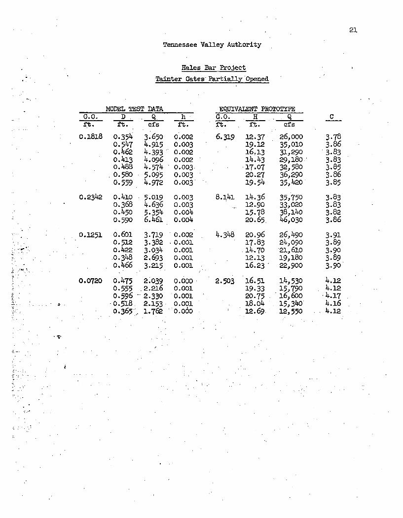
21
Tennessee Valley Authority
Hales Bar Project
Tainter Gates Partially Opened
0.0.ft.
MODEL TEST DATAD Q
ft. cfs
o.1818 0.3540.5470.4620.4130.4880.5800.559
0.2342 o.41o0.368o.4500.590
3.6504.9154.3934.0964.5745.0954.972
5.0194.6365.3546.461
hft.
0 .0020.0030.0020.0020.003.0.0030.003
0.0030.0030.004o.oo4
0.002.0.0010.0010.0010.001
0.001*0.0010.0010.001
•OW0O0
EQUIVALENT PROTOTYPEG.O. H Qft. ft. cfs
6.319 12.37 26,ooo19.12 35,01016.13 31,29014.43 29,180'17.07 32,58020.27 36,29019.54 35,42.0
0.1251 o. 6010.5120.422.0.348o.466
3.7193.3823.0342.16933.215
2 039.2.2162.3302.1531.762
8.141 14.3612.-9015.7820.65.
4.348 20.9617.83
I 14.7012.1316.23
2.503 16.5119.3320.7518.0412.69.
35,75033,02038.,14046,030
26,49024,o090p1, 6io19,18022,900
14,53015,79016,60015,34012,550
C
3.783.863.833.833.853.863.85
3.833.833.823.86
3.913.893.903.893.90
4.124.124.174.164.12
0.0720 0.4750.555o0.5960. 518o.365.0
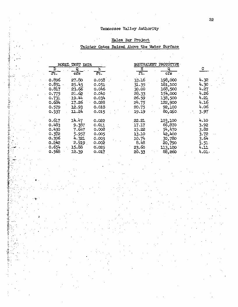
22
Tennessee Valley Authority
Z_
Hales Bar Project
Tainter Gates Raised Above the Water Surface
D-ft.
o.80.80.8:0.T0.70.•o. 570.5'0.5:
0.6
0 .40.30.30.20.60.54
MODEL TEST DATA
cfs
?6 27.8051 25.4317 23.6675 21.6231 i9. 4434 17.26T9 12.9337 11.24
L7 14.4783 9.38730 7.647T2 5.95706 •4.321
2.919.54 15.8868 12.39
hft.
0.0580.051o.o46o.o4o0.034o.0280.0180.015
0.0220.011o.0080.0050.003o. 0Q20.0250-017
EQUIVA=H
ft.
33.1631.3530.0028.3326.5924.7520.7519.19
22.21
17.1715.2213.1010.748.48
23.6o20.33
PROr6TYPE*Q .
cIfs
198,000181,100168,500154,000138,500122,90092,10080,060.
103,10066,87054,47042.,ý4oo
.30,78020,790
113, 10088,260
C
4.324.304.274.264.214.164.o63.97
3.923.823.723.643.514..14.ol.
0
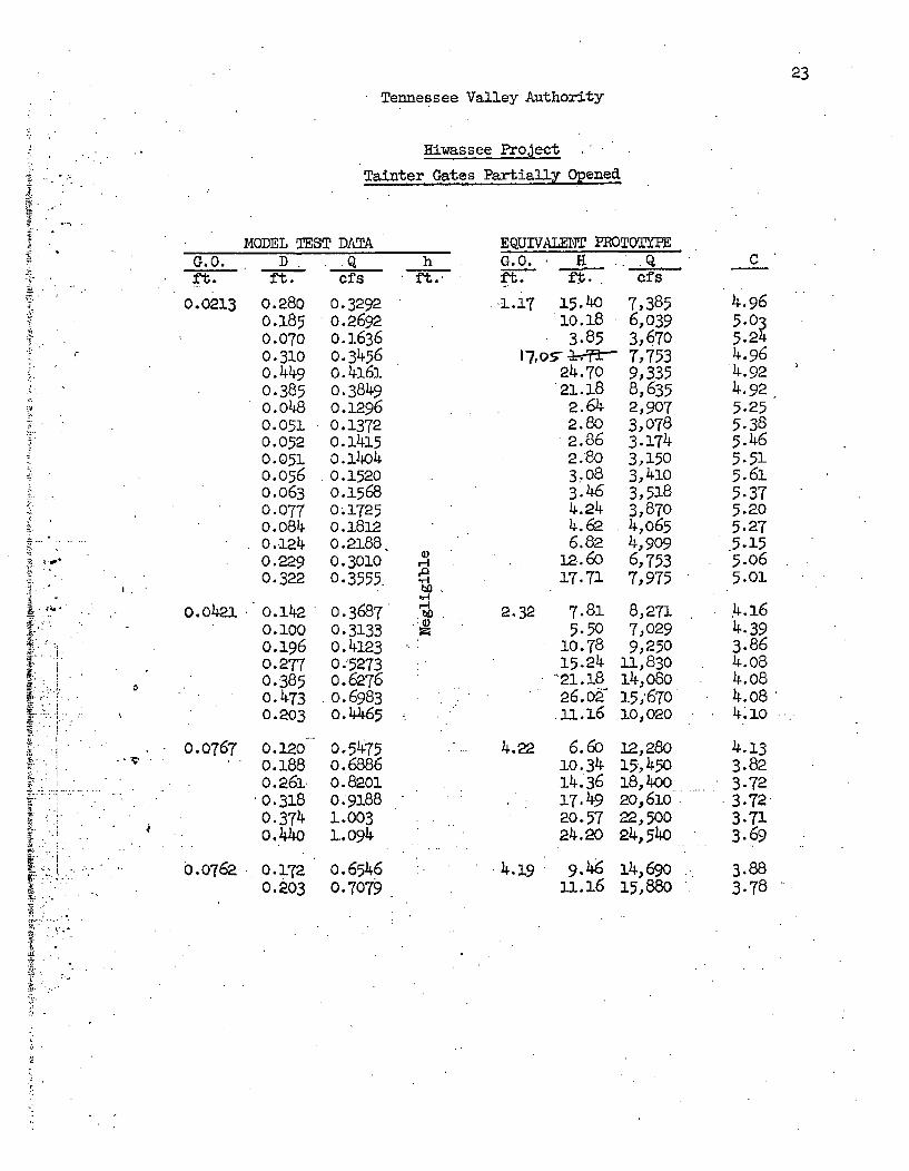
23
Tennessee Valley Authority
Hiwassee Project
Tainter Gates Partially Opened
MODEL TEST DATA EQUIVALET PROTOTYPEG. 0.
ft.
0.0213
D. .Q
ft. cfs
0.280 0.32920.185 0.26920. 070 0.16360.310 0.3456o.449 o.41610.385 0.3849
m.o48 o.12960.051 0.13720.052 o.124150.051 0.14040.056 0.15200m063 0.15680.077 0.17250.084 0.18120.124 o.21880.229 0.30100.322 0.3555
o.142 0.36870.100 0.3133o.196 o.41230.277 0.52730.385 o.62760.473 0.69830.203 o.4465
hft.
p
ri
bo I
G.0. 9't-- ft.
.17 15.4010.183.85
24.7021.182.642.80
.2.862.8037083.464.244.626.82
12. 6017.71
2.32 7.815.50
10.7815.24
"21.18*26.0o.1.16
4.22 6.6010. 3414.3617.4920.5724.20
4.,19 9.45-1.16
cf.s
7,3856,0393,6707,7539,3358,6352,9073,0783.1743,1503,4103,5183,8704,0654,9096,7537,975
8,2717,0299,250
ll, 83014,08o15,67o10,020
12,28015,45018,40020,61022,50024,,54o
14,69o15,880
C
4.965.0ý5.244.964.924.925.255.385.465.515. 615.375.205.275.155.065.01
4.164-393.864.084.084.084 7lO
4.133.823.723.723.713.69
3.883.78
I .o.o421
0.0767 o.12o-o 0.188
0 o.261ý" 0.318o0.374o.44o
0.0762 0.1720.203
0.5475o.6886O.82010.91881.0031-.094
o.65460.7079
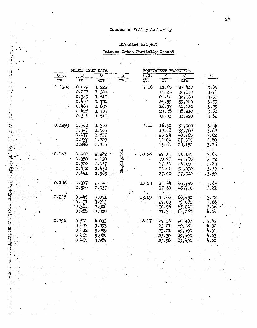
Tennessee Valley Authority
Rirassee Project
Tainter Gates Partially ened
MODEL TEST DATAG.t. D ,. Q.ft. et fs
hft.
EQUIVALENT PROTOTYPEG.O. H . Qft. ft. cfs
0.1302 0.2290.2770.389o.4470.4830.4250.346
1.2221. 344
1.7511.8331.7031.512
~AE4 i -
0.2293 0.3000.3470.4770.237,0.248
0.187 0.4020.3500.320o.4520.491
0.186 0.3170.320
,0
0.238 o.445- o. 491
o0.3810.388
1. 3821.5051.8171.229.1.255
2.2822.1302.0572.4382.563
2.0412.037.
7.16 12.6o15.24P2.,4024.5926.5723.3819.03
7.11 16.5019.08P26.2413.0413.64
10.28 22.1119.25.17.6o24.8627.00
27,41030,15036,, 16039,28041, L2O38,21033,920
31,00033,76040,76o27,57028,150
51,19047,78046, a50
54,69057,500
C
3.853.713.593.593.593.603.62
10.23 17.44 45,79017.60 45,7o00
3.653.623.623.803.76
3.633.723.833.59.3.59
3.843.81
3.723.663.964.o4
3.824.324.314.03.4.00
0.294 0.5010.422S 0.4220.46oo.465
3.0513.2132.9082.909
4.0333-9933.9893.9893.989
13.09
16.17 27.5623.2123.21
25.3025.58
24.4827-0020.9621.34
68,45072,08065,24•65,260
90,48089,58089,49089,49089,490
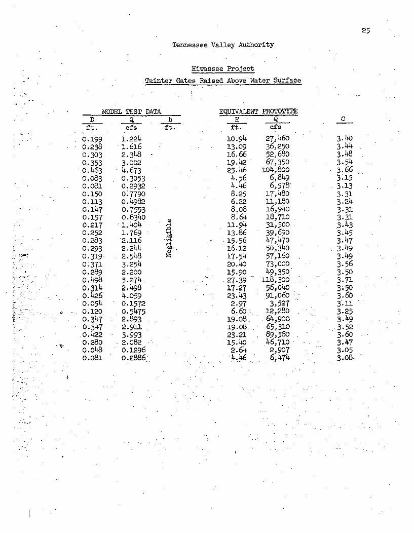
25
Tennessee Valley Authority
Hiiassee Project
Tainter Gates Raised Above Water Surface
Dft.
0.1990.238o. 3030.-3530.4630.083o0.0810.1500.113o. 1470.1570.2170.2520.2830.293o. 3190.3710..289o.498o.314o.4260.054
o -0.1200.3470.3470.4220.280
m.o48o.081
VI0DEL TEST DATAQ
ef s
1.224i. 6162.3483.0024.6730. 30530.29320.77900. 49820.75530.834o
1.769
2.2442.5483.2542.2005.274.2.4984.0590.315720. 54752.8932.9113.9932.082o .. 2960.2886.
hft.
10.9413.0916.6619.4225.464.564.468.256.228.088.64
11.9413.8615.5616.1217.5420.40* 15.9027.3917.2723.432.976.60.
19.0819.0823.2115.402.644.46
27,46036,25052,68067,350
i04,8006,8496, 578
17, 48011,18016,94018,71031,50039,69047,47050,34057,16073,00049,350
118,30056,04o91,0603,527
12,28064,90065,31089,580.46,7102,9076, 474
EQUIVALENT PROTOTYPEH Q
ft. cfsC
3.4o3.443.483.543.663.153.133.313.243.313.313.433.453.473.493.493.563.503-713.503.603.113.253.493.523.6o3.473.053.08,
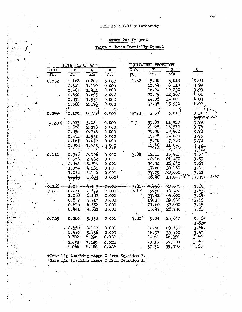
26
Tennessee Valley Authority
Watts. Bar Project
Tain ter ae Partiallyened
M0DEL TEST DATAG.O. D Q. hft. ft. cfs ft.
--.
"4
0.052 0.1680.301
,o. 4630.6500.8311.o68
0.08 1.0230.6o80.856
" ,0.451>0.1650. 299-:
0 .1.). 0.,346S• o0.576
o0.8421.0741.056
0.803 0.0001.119 0.0001.411 0.0001.695 0.00001.932 0.0002,198 0.000
0 o7i9l 0.o0Z
EQUIVAIENT PROTOTYPEG.O. H - _-_Q
ft. ft. cfs
1.82 5.88 5,81910.54 8,11016.20 10,23022.75 12,28029.08 14,00037.38 15,930
35.
3.0242.2782.7461.9S21.0721.523
2.1962,9623.7034.1614.140
0.0000.000,0.0000.0000.000
.0.00
0.0000.0000.0010.0010.0010.0019
2-73 35-8021..2829.9615.78
5.78
3.88 12.13-2o.1629.5037.6237.0036.•
21,920-16,51019,90014,0007,769
ll,040
15,91021,47026,84030,160.30,0001 0oyO
C
3.993.993.994.014.034.02
3.79-3.763-783.753.783.72-/
3-57'. .
3.59.3.65-3.61'3.62'
•i , 0.271 2.679 O.0O1 . -S'/ 9.52 19,420 3.631io68 6.182 0.0o0 37.42 44,8oo 3.64-0.837 5.417 0.001 29.33 39,260 3.65o.616 4.552 0.001 21.60 32,990 3.65O.441 3.688. 0.o01 15.47 26,730 .. 3.61
0.223 0.280 3.538 0.001 7.80 9.84 25,64o
0.356 4.1o2o.54o0 5.4360.702 6.3960.858 v.189l.o64 U.:86
0.0010.0020.0020.0020.002
12.5018.9.P-4.6
.301037.31
29,73039,40046,35052,10059,330
3.46+3.82*3.64-3.623.623.623.65
+Gate lip touching nappe C.from Equation B.*Gate lip touching nappe C from Equation A..
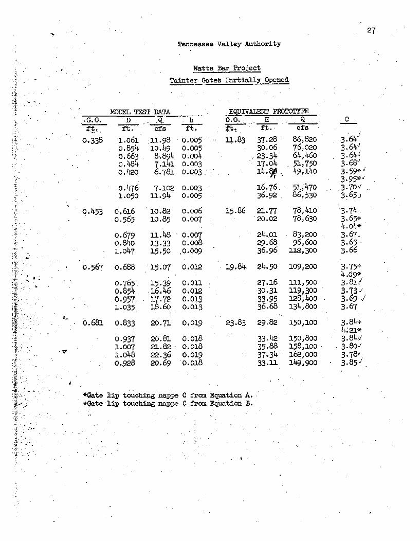
27
b
--A
X- "
Tennessee Valley Authority
Watts Bar Project
Tainter Gates PartiýLuy Opened
i
•G.0.
0.338
MODEL TEST DATAD . ... .Q
ft. cfs
1.06.0.854o.6630.484o.420
o.4761.050
1i. 981o.498.8947.1416.781
•hft.
0.005.0.005o.oo40.0030.003
EQUIVALENT PR0TOTYPEG.O.. H _Q
ft. ft. cfs
11.83 37.2830.06
23.3417.04j-4. I,
16.76.,36.92
86,82076,02064,46051,75049, 14o
51;47086,530
7.102 0.00311.94 0.005
0.453 0.616 10.82 o.0o60.565 10.85 0.007
0.679a.84o1.047
u.4813.3315.50
0.007o.oo8,0.009
15.86 21.77 78,410o20.02 78,63P
24.01 83,20029.68 96,60036.96 112,300
19.84. 24.50 109,200
C
.3.64'3.64-.3.64,I3. 68e3.59+',3-95*'"3.70 '3.65J
3.65+4.04*3.67..3.653.66
3.75+4.09*3.8133 .73,/3.69.3.67
3.84+
3.84,/3.80/3.78v;3.85`/
0.567 0.688 15.07 0.01P
0.765.0. 8ý4.0.9571.035
15.3916.4617.7218.60
0.0110.0120.0130.013
27.1630.3133.9536.68
111,500119,300128,400134, 8o0
a-
o.68, 0.833 20.71 0.019 23.83 29.82 150,100
0.9371.0071.O480.928
20.8121.8222.3620.69
o.oi80.018
0.0190.018
33.4235.8837.3433.11
150,800158, 0oo162,000149,900
*Gate JI;p touching nappe C from Equation A.+Pate lip touching nappe C from Equation B.
4.
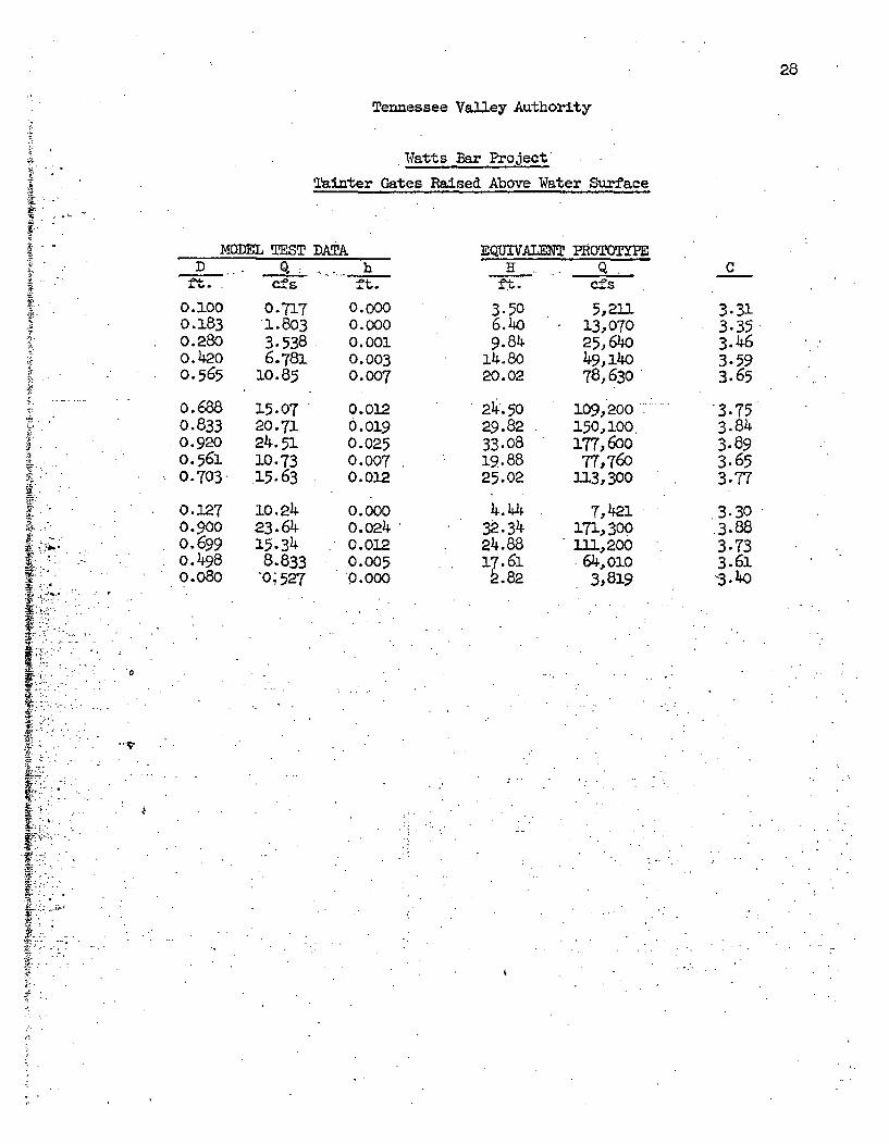
28
I
K
4
Tennessee Valley Authority
Watts Bar Project*
Tainter Gates Raised Above Water Surface
MODEL TEST DATAD . Qh h
-1.-us ft.
E•UiVALENT PROTOTYPEH . Q
f.cf.
0.1000.1830.2800.4200.565
0.688
0.8330.9200.5610.703-
0.1.270.9000.6990.4980.080
0.7171.8033.5386.781
10.85
15.0720.7124.5110.73.15.63
o. 02423.6415.348.833
-0 527
0.0000.0000.0010.0030.007
0.0120.0190.0250.0070.012
0.0000.0240.0120.0050.0oo
3.506.409.84
14.8o20.02
21. 5029.8233.082.9.8825.02
4.4.432.34
24.8817.61
.82
5,21113,07025,64049,14078,630
109,200150,100177, 60077,760
113,300
7,421171,300111,200
64,0103,819
C
3.313.353.463.593.65
3.753.843.893.653.77
3.30.3.883.733.61'3.4o
"0
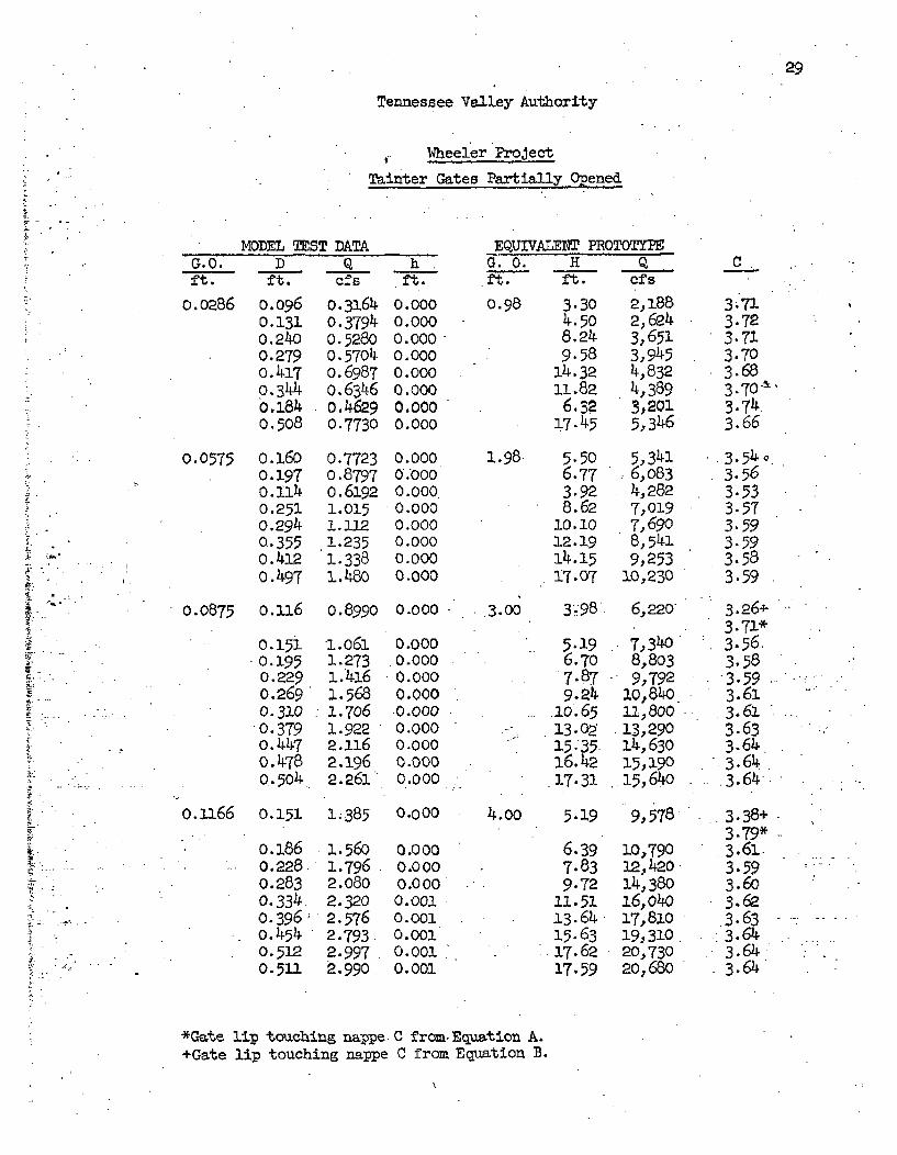
29
Tennessee Valley Authority
Wheeler Project
Tainter Gates Partially Opened
MODEL TEST DATA EQUIVALEfT PROTOTYPEG.O. D Q h G. 0. H Q Cft. ft. cfs ft. ft. ft. ofs
0.0286 0.096 O.3164 0.0oo 0.98 3.30 2,188 3.710.131 0.3794 0.000 4.50 2,624 3.720.240 0.5280 0.000 8.24 3,651 3.7310.279 0.5704 0.000 9.58 3,945 3.70o.417 0.6987 0.000 14.32 4,832 3.680.344 o.6346 0000 11.82 4,389 3.70-'o.184 0.4629 0.000 m 3,201 3.740.508 0.7730 0.000 17.45 5,346 3.66
0.0575 0.160 0.7723 0.000 1.98 5.50 5,341 3.54o0.3197 0.8797 0.000 6.77 6,083 3.560.114 0.6192 0.000 3.92 4,282 3.530.251 1.015 0.000 8.62 7,019 3.57.0294 1.112 0.o00 10.10 7,690 3.59
0.355 1.235 0.000 12.19 8,541 3.590.412 1.338 0.000 14.15 9,253 3.580.497 i.48O 0.000 17.07 10,230 3.59
0.0875 0.316 0.8990 0.000 • 3.00 3.98 6,220 3.26+3.71*
0.15i i.06i 0O000 5.19 7,340- 3.560.195 1.273 0.000 6.70 8,803 3.580.229 1.416 o.ooo 7.87 9,792 3.590.269 1.568 0.00o 9.24 io,84o 3.610.310 1.706 0.000 10.65 1, 800 3.610.379 1.922 0.000 - 13.09 .13,290 3.63o.447 2.116 o.ooo 15:35 14,630 3.64o0. 478 2.196 0.000 16.42 15,190 3.64
• 0.504 2.261 0.000 17.31 15,640 .3.64
0.1166 0.151 1;385 0.000 4.00 5.19 9,578 3.38+
3.79*-o0.i86 1.560 0.000 6.39 10,790 .3.61.
*.0.-228 1.796 0. oo 7.83 12,420 3.-590.283 2.080 0.000 9.72 14,38o 3.6o0.334. 2-.320 0.001 11.51 16,o4o 3.62
- .... 0.396; 2.576 0.001 13.64 17,810 3.63o.454 2.793. 0.001 15.63- 19,310 3.640o.51 2.997 0.001 17.62 20,730 3.64.. 511 2.990 0.2001 17059 2O,680 3.64
*Gate lip touching nappe C fromEquation A.+Gate lip touching nappe C from Equation B.
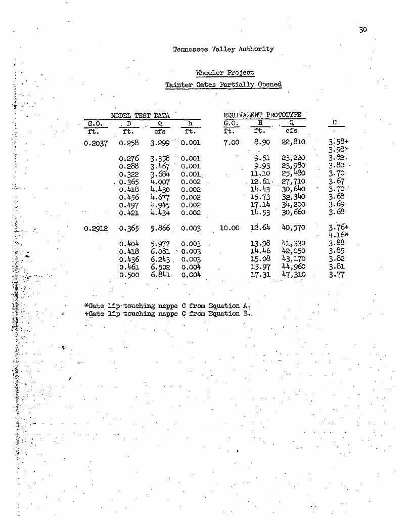
30
Tennessee Valley Authority
Wheeler Project
Tainter Gates Partially Opened
MODEL TEST DATAG.0. D Q hft. ft. cfs ft.
0.2037 0.258 3.299 0.001
EQUIVALENT PROTOTYPEG.0. H , Qft. ft. cfs
7.00 8.90
0.2760.2880.3220.3650.4180o•560.1497o.421
3.3583.4673.6844.0074.4304.6774.9454.434
0.0010.0010.0010.0020.0020.0020.0020.002
9.519.9311.1012.61"4.4315.7317.14
•4.53
22,810
23,22023,98025,48027,71030,64032,34034,20030,66o
C
3'58+3.98*3.82.3.803.703.673.703.683.693.68
3.76+4.16*3.883.853.823.813.77
0.2912 0.365 5.866 0.003 1o.oo iP.64 4o,570
h
-t
4
A
o.4o40.4180.436o.4610.500
5.9776.0816.2436.5o26.841
0.0030.0030.003o.oo40.004
13.98ai4.4615; o815.9717.31
41,33042,05043,17044,96047,310
*Gate lip touching nappe+Gate lip touching nappe
C from Equation A.o from Equation B.
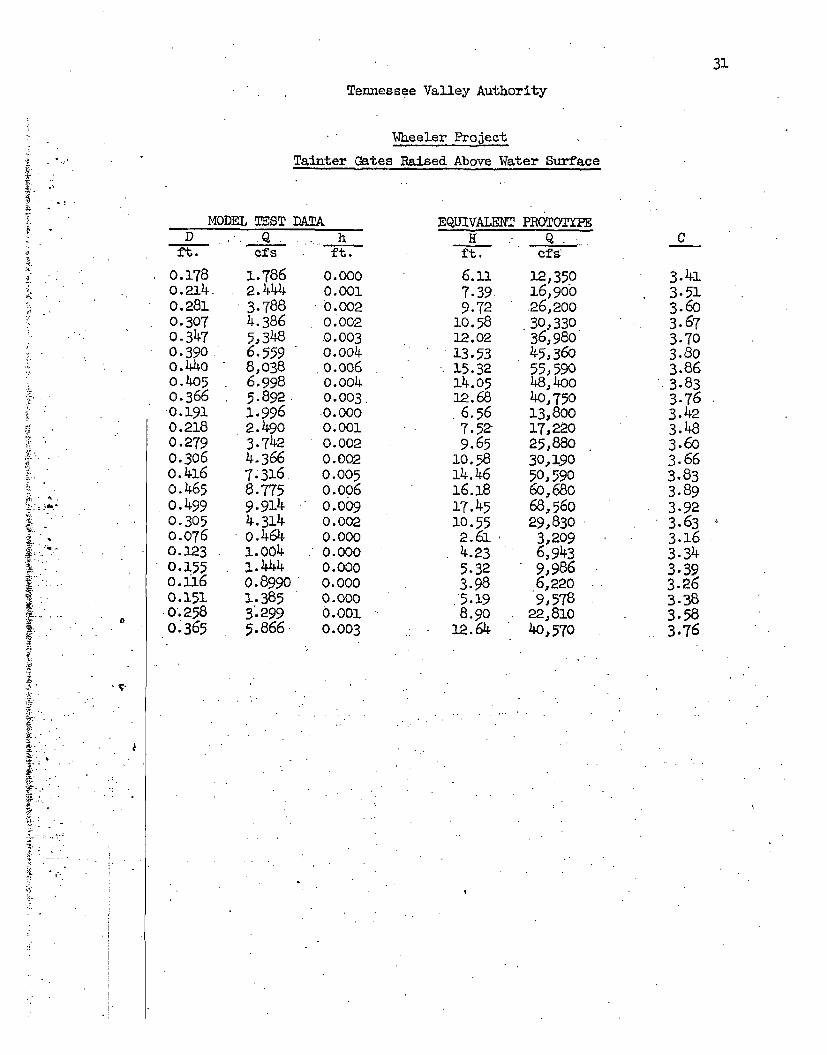
Tennessee Valley Authority
Wheeler Project
Tainter Gates Raised Above Water Surface
MODEL TEST DATA EQUIVALENT PROTOTYPED Q h H Q C
Ift. cfs ft. ft. cfs:
*o0.178 1.786 0.000 6.11 12,350 3.41o.214. 2.444 0.001 7.39 16,9oo 3.510.281 3.788 0.002 9.72 26,200 3.60
*0.307 4.386 o.'002 10.58 .30,330 3.670- o.347 5,348 0.003 12.02 36,980 3.700o39o 6.559 0.004 13.53 45,_36o 3.800.440 8,038 .0.006 15.32 55,590 3.86o.405 6.998 0.004 14.05 48,400 3.83
* 0.366 5.892. 0.003. 12.68 40,750 3.76.0.191 1.996 0.000 6.56 13,800 3.420.218 2.490 0.001 7.52- 17,220 3.480.279 3.742 0.002 9.65 25,880 3.6o0.306 4.366 0.002 1o.58 30,190 3.66o.43-6 7.316 0.005 14.46 50,590 3.83o.465 8.775 0.oo6 16.18 60,680 3.890.499 9.914 0.009 17.45 68,560 3.920.305 4.31-4 0.002 .10.55 29,830 3.630.076 o.464 0.000 2.61 3,209 3.160.123 l.OO4 0.0oo 4.23 6,943 3.340.155 1.444 0.000 5.32 9,986 3.39o.ni6 0.8990 0.000 3.98 6,220 3.260.151 1.385 0.000 5.519 9,578 3.38
.0'.258 3'.299 0.001 8.90 22,810 o3.580.365 5.866 0.003 12.64 40,570 3.76
yT
ýý4
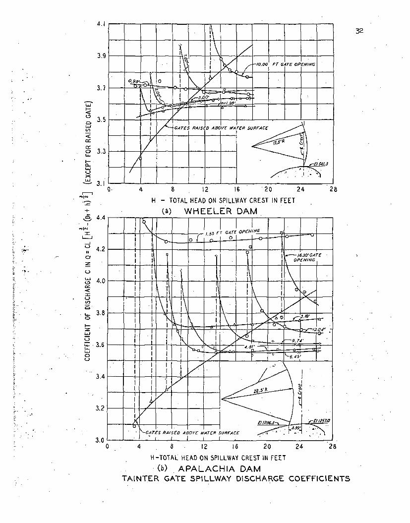
4.1
3.9
3.7
32
I-
LLIU,
0
I--0~
L~i
3.5
3.3
3.1
-I-
4,4
S II
) 4.0
34
I-
L~J
U--LU
.L 3.4
-,3.2
H - TOTAL HEAD ON SPILLWAY CREST IN FEET
(a) WHEELER DAM
3.00 28
H-TOTAL HEAD ON SPILLWAY CREST IN FEET
(b) APALACHIA DAMTAINTER GATE SPILLWAY DISCHARGE COEFFICIENTS
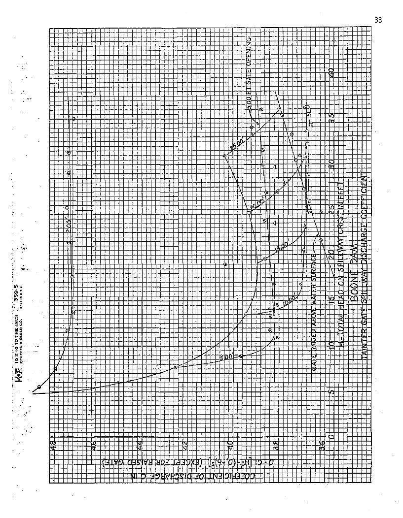
33
mJIZill
fIi ---1-4
~1~~t~I -
rI
li ]
I
TnF-H
H2I\
I -
I
11 1, lei.4
~HM~ F-"i
P1-
-'.U
"0u
Ito
-4 anUA I
I I I
A
I
I
-4i [W-1 II 1--f% IA 41•JI1 II
II
I -III,• L,I I li- i
=,l,•lI
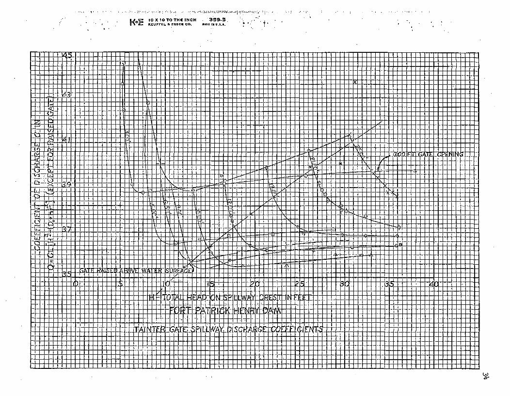
" ."' KEUFFE. A EGMR GO. 0 IN U.S.A.t
• T .. -.
119111 IlAi~I III 1111111 II 111111 III I IlIllIli 1111111111111111 11111111 111111111111111
a
I. I
I c .-If
-IIci t it~sI I
-T-r Nil H
b-.. 1
I
11 1 1
i i i i i ~ ~ I I I I I I I . . . 1 . .1 .I1?i
6 41,
u r
iI.
III
I I II I RiI I II I i
, • T , ] , . , i J ] 3 J , • , i l l l l = J l •
C-.714:-
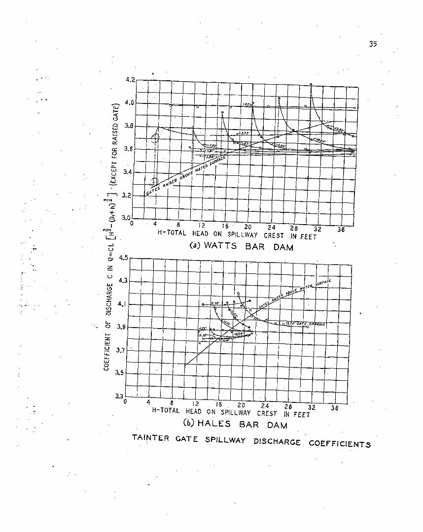
35
1,- 40
.-' 3.8 -
3,6
•J3.4 v
rm3.2 GA
+'E 3.0
0 4 8 12 16 20 24 28 32 36
H-TOTAL HEAD ON SPILLWAY CREST IN FEET
(a) WATTS BAR DAM
o. 4.5
4.3
I--
00
u 4.1 f--
.. o 3.9,.,
3.7Z
3.5
4 8 12 16 20 24 28 32 36
H-TOTAL HEAD ON SPILLWAY CREST IN FEET
(b) HALES BAR DAM
TAINTER GATE sPJLLWAY DISCHARGE COEFFICIENTS
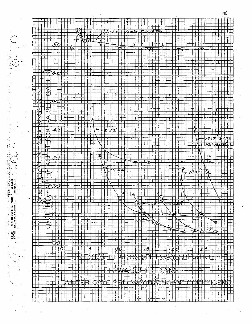
36I1 I I I I I IJ F I III IL I 1 : =
I I
M,• I
I I_
ý- 4-1
N.l I l o tI
L, i
z.o
-W.
0w
0:. -
C..
MT1-'2±11I/L
T-H
:vM, A
1h IAT" I
A It H
"I I i I I I
Nlýiill ill ii
-fLt 1.T,
I I
I-I Iili Il #1/ 1 III ', : l
I i1 lI II- FF F.I- 2_ : I I !I I I I I I I I
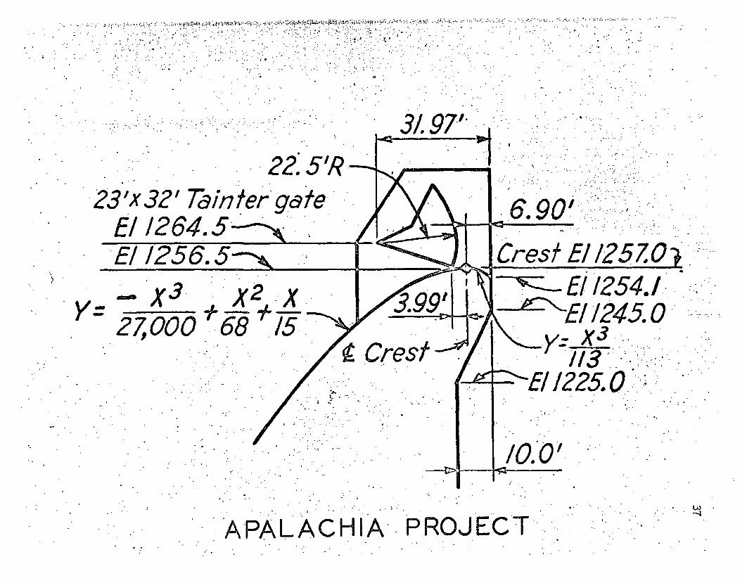
• ..'. '" " .3 1. 9 7
22. 5'R23 'x 32' Tahin ter gate
6 -. 90.,
Crest E/125 Z0El /2 64.5 -ý,,,.E11256.5
!
.X3.27,oo0 .68
- ",-'-- E! 1254.1AEl 1245. 0112.__.X3-
-ý-"E11225. * .I ,
/0.0'
APALACHIIA PROJECTL~3
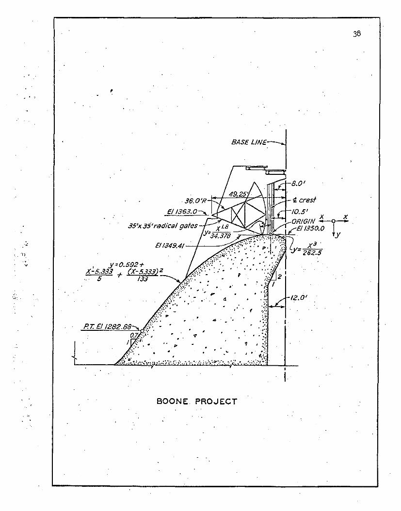
38
BASE LIME
36. 0 -'R -t crest
35'xS35'radicalgates X/. V•OP/GIN 15 X__ -CI.313 0•0
, y- y0.592÷x-5.333 + (x-5. 2s)2
... 5 133
I.
BOONE. PROJECT

* Y:= 0.592 X-533
FORT PATRICK- HEN'RY PROJECTCA)
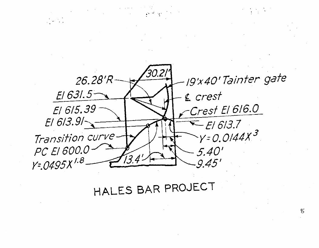
.~, ~,'
26.E1 63L/5-/ 6/5. 39
E£613. 9/1
Transition cu
PC El600. 06OY--. 0495X'/" 8
l9 'x 40' Tainfer-- , crest
CresEl £6136.0•2 -- /6/3.7
gate
Y-O0. o/4vx35.40'.9.451
HALES BAR PROJECT
0
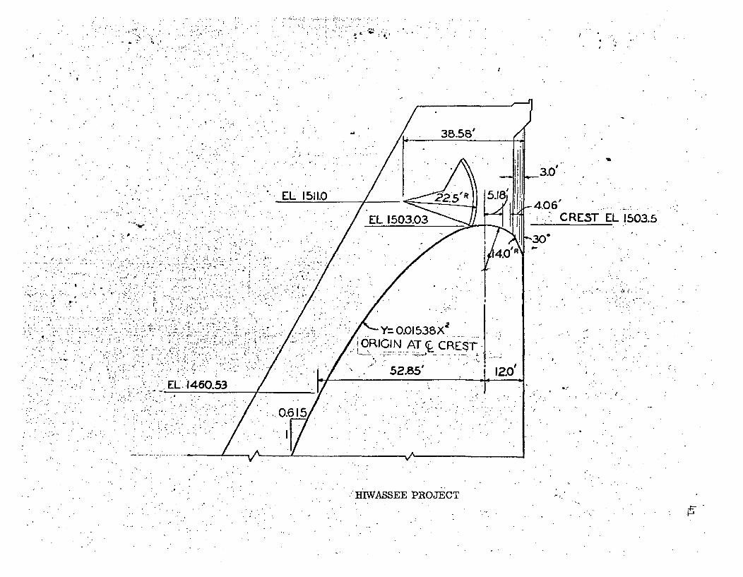
i
* ~7..j -~
L.
9Di
3.0'
EL 1511.0 .a5" R
Y= 0.01538X~
J ORICIN AT CREý-
EL .1460.53
IF.1
CREST EL 1503.5
-', .0.
Y . v
HIWASSEE PROJECT
H
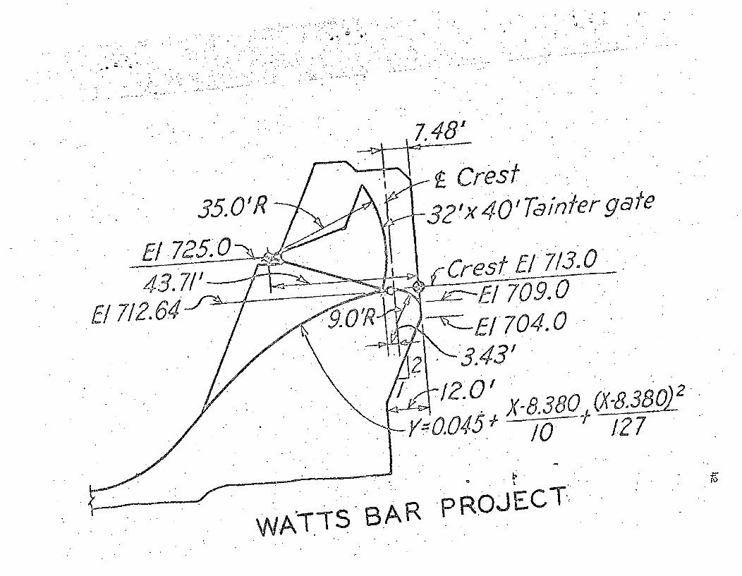
I
A8
Crest3E5.0'R
El. 725.0 0 <p.ýý
Cr
40o Ta nper gateest f¶- 7/3.0
7l0! 709.0-E/704.0El"712.64
).8.3
X-8,380/0
127
WATTS AR oPROJECT
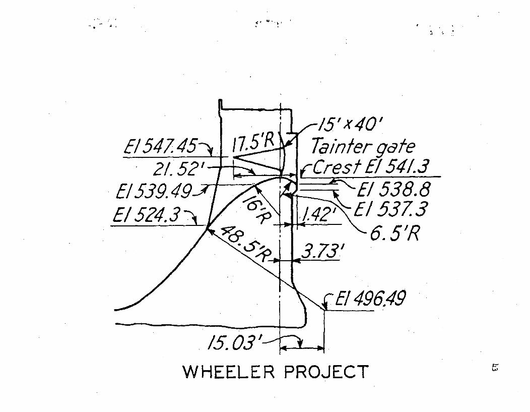
£~
Ta inter g9cteCrest El 541.3
538.85373). 5'R
496.49
WHEELER PROJECT ,;'7
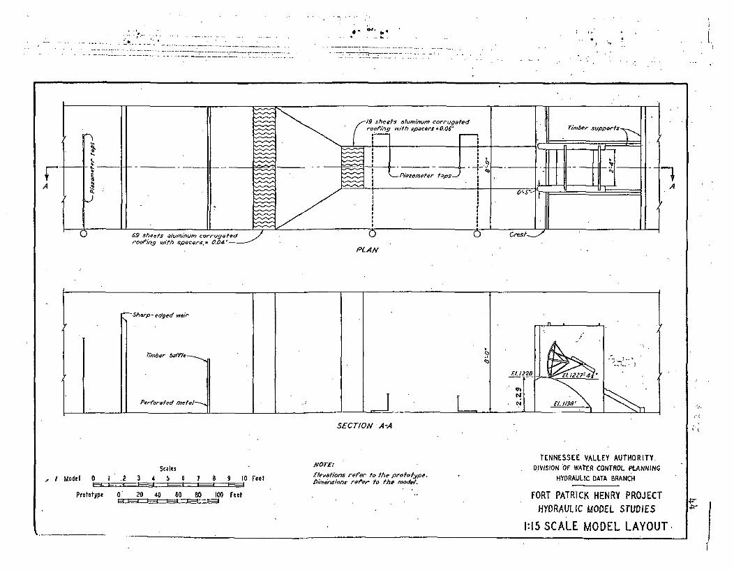
* . _ SL.
PLAN
SECTION ' A-A
Scales1 .2 3 4 5 6
ANOTE:
flevations refer to fhe proto?'ype.DXmeaions refyer to Mhe model.
I 1 Model 0 7 8 9 10 Feet
TENNESSEE VALLEY AUTHORITY.DIVISION OF WAEt1 CONTROL PLANNING
HYDRAULIC DATA BRANCH
FORT PATRICK HENRY PROJECTHYDRAULIC MODEL STUDIES
Prototype 0 20 40 60 80 100 Feet
1:15 SCALE MODEL LAYOUT.
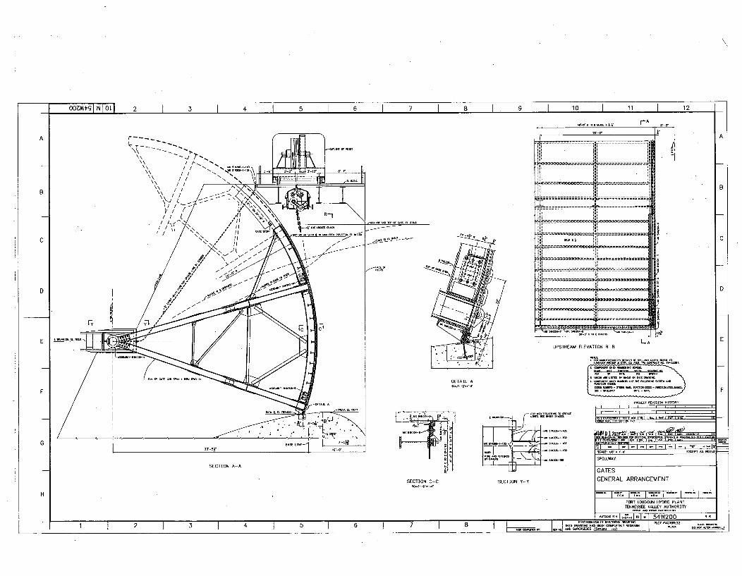
00ZMt'II i oL 2 I I 4 I 6 I 7 1 8 9 I 10 I 11 I 12I
- . .. . .. A r r-A _ I
AA
B
Iii in i- - - - - - - - - - - - - - - - - - - - -
- - - I- -
i• I* I
*1V1 , - T---------------- ... : ...• "
-- - - -- - - - -- -- - -- -- -
J, L -- - - -- - - -
-- - - -- - - - - - - - - -- -- - - -
Im --l -- - -- - -
.___--- •-------------- .. .. _
B
AI,
C C
D D
E L.AE
UPSTREAM ELEVATION B-B
I
F
DETAIL A
SECTION C.-C SECTION Y-Y
_ 'r
F
. -. ,-Wid& " 2G S--
SECTION A-A
SACOL fi" - -'0 EXCOE As NOTE
SPILLWAY
GATESGENERAL ARRANGEMENT
H I I• I"; I;.I- 1 1- -FORT LOUDOUN HYDRO PLANTTENNESSEE VALLEY AUTHORITY
R6
I~~ -~ 1~ 10'7 1 54W1 1 2 1 I 1 5 1 6 1 7 8
[ I I •C•[•Y •T• •W[• ..........
4] ISIS AACAKIC EnS OWl CONPILIELY SOuuI- (ASASAC As,
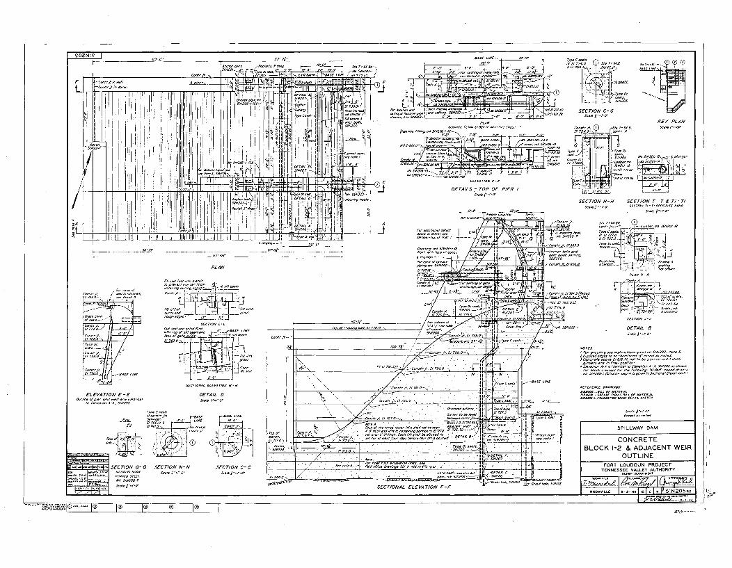
0A000L0No. l I0'
0-0' 00 00' 00'020 01 00.o- aoooo
0 '9 co-re toO 20
oO'. 00
.00. ~ p.t.00.jozo* fl~> 0t*0206'2*4. 5'
.. 010 2066.t0060 2*0 P100 022 I oflt~ .--- I* •, •1 (11•, • : I•T iTdi,¸ • - • {•
IA
4'.
10rfr)0~Vi~40..Aj(P '
01.j404 201 I
- ~~:0
i0 ~®WI
6025/2000 I
>- ----- 1 41l ------ -
.. .. 0o~,,00• ..... 0 02 -T r- 10 ....
0020 220< 0007 000070 I.c00022-. /0000000020T 0
SECTION C - G
ýj
I~~~~~. 1111 000020 00 ,20, .- 6 p00000
SECTION H-H SECTION T-T & TI-TI
50206 1lro0'
DETAILS:- TOP OF PIER I500 " 00~o• ',-o
A28, 6-
.41.0 st0oj'
7 . .. .. . -. -... _ . /*020000200,IN C
LC-t ot,
--oh bo000s200d
0*0, goDOotogJoT-oc
PLAN
.002 000 of 2000...0.. 0....... 0050 01. -:l 0,0°
000200 -.0 , 2 o.10 ouo0006• , .ootoo
1o6t.00001 . 1 12 o0 '" " ,
0ao ,co A b -,I•:r,of r o dmT,00
Co.,:,000000 0 •
1 CI~600-.o,.070001'260e0
F0 0200000004 0
Coo,. 00 0000 0o2t.,
01o00 025.020002 te.oto(0 724 00J 200020900
EL EVA TION E -E0_0
0 do4o sod .oo-itodoO2O l-oooo AA, 000020
DETAIL D
. ........200....... .. .. .. 0. .
• ~ ~ ~ P 75, V 7- i..1,N• II•, 0 0 .. 5r•00 0 . N NII ........ , • ............
0.~
000 . oaoothc r Od 004000 tngoh¢ot e*0 /T0O620 TAZS O- 2 i ko .00,0 .f4 " • o opi 2
00011 -,ýw - - -
,020.' 0040A- toloff .d00w 02700 45o4702 1-0 l/', . • 660 1[
2200*0. ." .oo00.. . . loo II . . . .... 0
00-4 - j0-o-, to 5000
0,-. r am •mts~c
DETAIL B-P-0 4 .10
oaed oxo• to 02 ,Ooamfered io"'eooeoo 2o oote.0000670 20000. £0000.0 o• o
t to 02 000000 0000i0 d.00
00.ol *02 0x4000o te . l0 ,. 000I-00u00el i
O SaO ~.0 6600 utoor •tho P0000000
(00 020ft-00ot0 00200
T00.0C20
60cio 5t to r ~ 0O00
00200 0 (0D00. - aoSPILLWAY DAM
CONCRETELOCK 1-2 & ADJACENT WEIR
OUTLINE
PROJECTAUTHORITY
SECTIONAL ELEVATION F-FI~0>
to.0o.6~o.0O'60.*'0" ® H® ®~ I® ~®