
Graphene-Supported Pt, Ir, and Pt-Ir Nanoparticles as Electrocatalysts for the Oxidation of Ammonia
9
Graphene-Supported Pt, Ir, and Pt-Ir Nanoparticles as Electrocatalysts for the Oxidation of Ammonia Lisandro Cunci & Chitturi Venkateswara Rao & Carlos Velez & Yasuyuki Ishikawa & Carlos R. Cabrera # Springer Science+Business Media New York 2013 Abstract Graphene oxide nanosheets are used as a support to anchor metal ions and produce graphene–metal nanoparticle hybrids in a sol–gel method. The influence of experimental conditions on the features of graphene-supported Pt, Ir, and Pt- Ir alloy nanoparticles is studied using transmission electron microscopy. Good dispersion of metal nanoparticles on the graphene sheets are observed for the catalysts heat-treated under exposure to N 2 gas. The existence of metal species with zero oxidation state in the prepared catalysts is evident from the X-ray photoelectron spectroscopy. The characteristic X- ray diffraction peaks of Pt are observed for the graphene- supported Pt and Pt-Ir catalysts. Electrochemical activity of the finely dispersed catalysts toward ammonia oxidation is investigated using cyclic voltammetry. The performance in- creased in the order Ir < Pt ≈ Pt-Ir. Keywords Graphene . Ammonia oxidation . Platinum . Platinum–iridium alloy . Nanomaterials Introduction The interest in the oxidation of ammonia has increased due to its high capacity for hydrogen storage, wastewater treat- ment, and alkaline ammonia fuel cells [1, 2]. In order to oxidize ammonia, a highly efficient electrocatalyst is neces- sary. Pt-based materials have been known to be the best electrocatalysts for the oxidation of ammonia. Especially, Pt (100) faces being the most active for ammonia oxidation [ 2 – 4 ]. According to Gerischer and Maurer [ 5 ], the electrooxidation of ammonia leads to nitrogen and hydrogen through the following equations: NH 3 aq ð Þ! NH 3;ads ð1Þ NH 3;ads $ NH 2;ads þ H þ þ e ð2Þ NH 2;ads ! NH ads þ H þ þ e ð3Þ NH x;ads þ NH y;ads ! N 2 g ð Þþ x þ y ð ÞH þ þ x þ y ð Þe ð4Þ NH ads ! N ads þ H þ þ e ð5Þ N ads þ N ads ! N 2 g ðÞ ð6Þ To improve the catalytic activity and reduce Pt loading, various attempts have been made by researchers and most of the works have been focused on the dispersion of Pt or Pt alloy nanoparticles on a suitable support [6–10]. In general, the support materials should provide high amount of nucle- ation sites, which in turn helps to avoid agglomeration of nanoparticles and decrease the nanoparticle size [11]. Carbon supports are one of the most used due to their ease of prepa- ration, low cost, high conductivity, and high surface area [12]. In the recent years, graphene has been used as a promising material for various applications due to its metallic conduc- tivity (ballistic) at room temperature, low electric noise, and low cost potential [13]. Since Hummers and Offeman stated in 1958 the most used procedure to exfoliate graphite particles into graphene oxide (GO x )[14], which is graphene function- alized with carbon–oxygen-based moieties, graphene was believed to be unstable. It was not until 2004 that K. S. L. Cunci : C. V. Rao : C. Velez : Y. Ishikawa : C. R. Cabrera (*) Department of Chemistry and Center for Advanced Nanoscale Materials, University of Puerto Rico, Río Piedras Campus, P.O. Box 23346, San Juan, PR 00931-3346, USA e-mail: [email protected] Electrocatalysis DOI 10.1007/s12678-012-0120-3
Transcript of Graphene-Supported Pt, Ir, and Pt-Ir Nanoparticles as Electrocatalysts for the Oxidation of Ammonia
Graphene-Supported Pt, Ir, and Pt-Ir Nanoparticlesas Electrocatalysts for the Oxidation of Ammonia
Lisandro Cunci & Chitturi Venkateswara Rao &
Carlos Velez & Yasuyuki Ishikawa & Carlos R. Cabrera
# Springer Science+Business Media New York 2013
Abstract Graphene oxide nanosheets are used as a support toanchor metal ions and produce graphene–metal nanoparticlehybrids in a sol–gel method. The influence of experimentalconditions on the features of graphene-supported Pt, Ir, and Pt-Ir alloy nanoparticles is studied using transmission electronmicroscopy. Good dispersion of metal nanoparticles on thegraphene sheets are observed for the catalysts heat-treatedunder exposure to N2 gas. The existence of metal species withzero oxidation state in the prepared catalysts is evident fromthe X-ray photoelectron spectroscopy. The characteristic X-ray diffraction peaks of Pt are observed for the graphene-supported Pt and Pt-Ir catalysts. Electrochemical activity ofthe finely dispersed catalysts toward ammonia oxidation isinvestigated using cyclic voltammetry. The performance in-creased in the order Ir < Pt ≈ Pt-Ir.
Keywords Graphene . Ammonia oxidation . Platinum .
Platinum–iridium alloy . Nanomaterials
Introduction
The interest in the oxidation of ammonia has increased dueto its high capacity for hydrogen storage, wastewater treat-ment, and alkaline ammonia fuel cells [1, 2]. In order tooxidize ammonia, a highly efficient electrocatalyst is neces-sary. Pt-based materials have been known to be the bestelectrocatalysts for the oxidation of ammonia. Especially, Pt(100) faces being the most active for ammonia oxidation[2–4]. According to Gerischer and Maurer [5], the
electrooxidation of ammonia leads to nitrogen and hydrogenthrough the following equations:
NH3 aqð Þ ! NH3;ads ð1Þ
NH3;ads $ NH2;ads þ Hþ þ e� ð2Þ
NH2;ads ! NHads þ Hþ þ e� ð3Þ
NHx;ads þ NHy;ads ! N2 gð Þ þ xþ yð ÞHþ þ xþ yð Þe� ð4Þ
NHads ! Nads þ Hþ þ e� ð5Þ
Nads þ Nads ! N2 gð Þ ð6ÞTo improve the catalytic activity and reduce Pt loading,
various attempts have been made by researchers and most ofthe works have been focused on the dispersion of Pt or Ptalloy nanoparticles on a suitable support [6–10]. In general,the support materials should provide high amount of nucle-ation sites, which in turn helps to avoid agglomeration ofnanoparticles and decrease the nanoparticle size [11]. Carbonsupports are one of the most used due to their ease of prepa-ration, low cost, high conductivity, and high surface area [12].In the recent years, graphene has been used as a promisingmaterial for various applications due to its metallic conduc-tivity (ballistic) at room temperature, low electric noise, andlow cost potential [13]. Since Hummers and Offeman stated in1958 the most used procedure to exfoliate graphite particlesinto graphene oxide (GOx) [14], which is graphene function-alized with carbon–oxygen-based moieties, graphene wasbelieved to be unstable. It was not until 2004 that K. S.
L. Cunci : C. V. Rao : C. Velez :Y. Ishikawa : C. R. Cabrera (*)Department of Chemistry and Center for Advanced NanoscaleMaterials, University of Puerto Rico, Río Piedras Campus,P.O. Box 23346, San Juan, PR 00931-3346, USAe-mail: [email protected]
ElectrocatalysisDOI 10.1007/s12678-012-0120-3
Novoselov and A. K. Geim, 2010 Nobel Laureates, showedthat graphene can be isolated simply by sticking and unstick-ing tape with graphite until only one layer is separated fromthe rest and can be placed in another surface to be used [15,16]. Since then, graphene has been explored for practicalapplications. Being the only two-dimensional carbon materialknown until now, all its volume is at its surface having atheoretical surface area of 2,630 m2/g. The specific surfacearea values reported for graphene are much higher than themost commonly used amorphous carbon support, Vulcan XC-72 [17]. The high conductivity, surface area, and transparencyof graphene can be altered by introducing defects such asdiscontinuity in the electron density promoted by carbon–oxygen moieties (i.e., carbonyl, carboxyl, hydroxyl, etc.)[18, 19]. On the other hand, GOx can be easily synthesized[14, 20] and the abundant functional groups on the graphenesurface can be used as anchoring sites for metal nanoparticlesto produce metal/graphene hybrid nanostructures. In recentyears, GOx has been used as an electrode support in variousenergy conversion devices. The results indicate the enhancedelectrocatalytic activity and durability of graphene-supportedmetal electrodes compared with commercial carbon-supported electrodes. This is attributed to the intrinsic graph-itization degree and the enhanced metal–graphene interaction[21–23].
To the best of our knowledge, graphene is not used assupport for the ammonia oxidation electrocatalysts until now.In the present work, GOx was synthesized using a modifiedHummer’s method and metal (Pt, Ir, and Pt-Ir) nanoparticles ofabout 1–4 nm were deposited using sol–gel technique. Theprepared materials are characterized using transmission elec-tron microscopy (TEM), X-ray photoelectron spectroscopy(XPS), and X-ray diffraction (XRD). Finally, electrocatalyticperformance of the materials toward the oxidation of am-monia is investigated using cyclic voltammetry (CV).
Experimental Section
Synthesis of Graphene Oxide
High quality GOx nanosheets were prepared by modifiedHummer’s method [14]. In a typical synthesis, 1 g of graph-ite powder (pre-oxidized by refluxing with conc. HNO3 for5 h), 0.5 g of NaNO2, and 30 mL of H2SO4 were mixed andstirred in an ice-bath for 20 min. To this suspension, 3 g ofKMnO4 was added slowly and stirred for 30 min at roomtemperature. Thereafter, 60 mL of water was added slowlyto the brownish-gray suspension for 10 min and stirred for1 h while the temperature was raised to 95 °C. Subsequently,the suspension was diluted by 200 mL of warm water andtreated with 10 mL of 37 wt% H2O2. Finally, the resultingsuspension was filtered, washed thoroughly with water, and
dried in a vacuum oven at 40 °C for 24 h. The composition(in weight percent) is determined to be C, 68.3; O, 28.4; H,2.9; and N, <0.5.
Deposition of Pt, Ir, and Pt-Ir Nanoparticles on ReducedGraphene Oxide
In order to synthesize the graphene-supported metal catalysts,a modification of the procedure reported previously was used[24]. Pt and Ir acetylacetonates (Aldrich) were mixed in eth-anol and acetic acid (3:2 v/v) with GOx, and they were soni-cated to get a homogeneous dispersion. The suspension wasthen left stirring overnight and evaporated to dryness. Theresulted material was then heat-treated. Two different heattreatments were used after the synthesis: one under air andthe other under dry N2. Both heat treatments consisted onheating the powder material using a tubular oven with a quartztube. Gas flow entered from one side and the other side had aK-type thermocouple with its tip centered about 1 cm over thepowder material. The thermocouple had a little lower diameterthan the opening so that gas could flow out of the tube. First,gas flow was started for 10 min at room temperature, afterwhich, the oven was turned on. Then, the samples were heatedfor 1 h at 400 °C, and after that, the oven was turned off.
Characterization Techniques
TEM images were recorded using a Carl Zeiss LEO 922system operated with an accelerating voltage of 200 kV.Powder XRD patterns were obtained on a Siemens D5000Diffractometer operating with the Cu Kα radiation (λ=1.5408 Å) generated at 40 kV and 30 mA. Micro-Ramanscattering experiments were performed on a ISA Jobin-Yvon Inc. Model T64000 FT-Raman at room temperaturein a quasi-backscattering geometry with parallel polarizationincident light. The excitation source used was an Ar-ionlaser operating at 514.5 nm. Morphology of the materialswas examined using a field emission scanning electronmicroscope (FESEM; JEOL JSM-7500F). XPS spectra wereobtained using a PHI 5600ci spectrometer equipped with aAl Kα monochromatic source at a power of 350 W. Spectrawere obtained with a pass energy of 58.70 eV. All thebinding energies reported were corrected using the signalfor the carbon peak (C 1 s) at 284.5 eV.
Electrochemical Measurements
The electrodes were prepared by the ink-paste method de-scribed elsewhere [24]. Two different procedures were used:in the first procedure, 2 mg of catalyst was added to 200 μLof isopropanol and 8 μL of a Nafion® solution of 5 %dispersion in lower aliphatic alcohols (Aldrich) and themixture was sonicated until dispersion. In the second
Electrocatalysis
procedure, 2 mg of catalyst was added to 150 μL of DMF, and100 μL of a Fumion® (Fumatech) solution in DMF, and themixture was sonicated until dispersion. Ten microliter of eachsolution was placed in different glassy carbon electrodes anddried at room temperature. Electrochemical measurements arecarried out using a three-electrode electrochemical cellequipped with catalyst-coated glassy carbon as working elec-trode, Pt wire as counter electrode, and Ag|AgCl as referenceelectrode (BASi). All electrochemical measurements wereperformed with an Autolab (PGSTAT 30) potentiostat.
Results and Discussion
Salient Features of Graphene Oxide Support
The effect of chemical processes performed during thematerials synthesis was monitored by the appearance/disap-pearance of the (002) diffraction peak that corresponds to
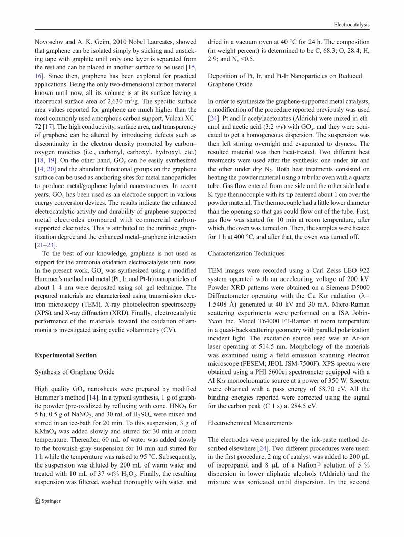
the interlayer spacing between graphene sheets. PowderXRD pattern of graphite and GOx samples is shown inFig. 1a. Graphite exhibited the characteristic (002) diffrac-tion peak at 26.7° with an interlayer spacing of 3.34 Å,whereas GOx showed a smaller broader peak at 10.1, whichindicates the oxidation of graphite. The interlayer spacing isincreased from 3.34 to 8.47 Å for GOx. This is ascribed tothe presence of a variety of oxygen-containing functionalgroups and water molecules bonded on both sides of thegraphene sheets [25]. The surface oxygen functionalities ofGOx can be used as anchoring sites for metal nanoparticlesand produce graphene–metal nanoparticle hybrids. First-order Raman spectrum of the graphite and GOx (Fig. 1b)shows the characteristic D, G, and 2D bands at ca. 1,355,1,582, and 2,705 cm−1, respectively [26]. The significantfeatures of GOx, such as a high-intensity D band atca.1,355 cm−1, low I2D/IG ratio (<0.5), and broad 2D bandat ca. 2,700 cm−1, are indicative of disordered and exfoliatednature of graphite. Morphological features of the GOx are
Fig. 1 a Powder X-ray diffraction patterns of graphite and graphene oxide; b Raman spectra of graphite and graphene oxide; and c field emissionscanning electron microscopy image of graphene oxide
Electrocatalysis
examined using FESEM and the image is depicted inFig. 1c. It shows the randomly oriented, transparent graphene
sheets with several micrometers in size and ripple-like papermorphology.
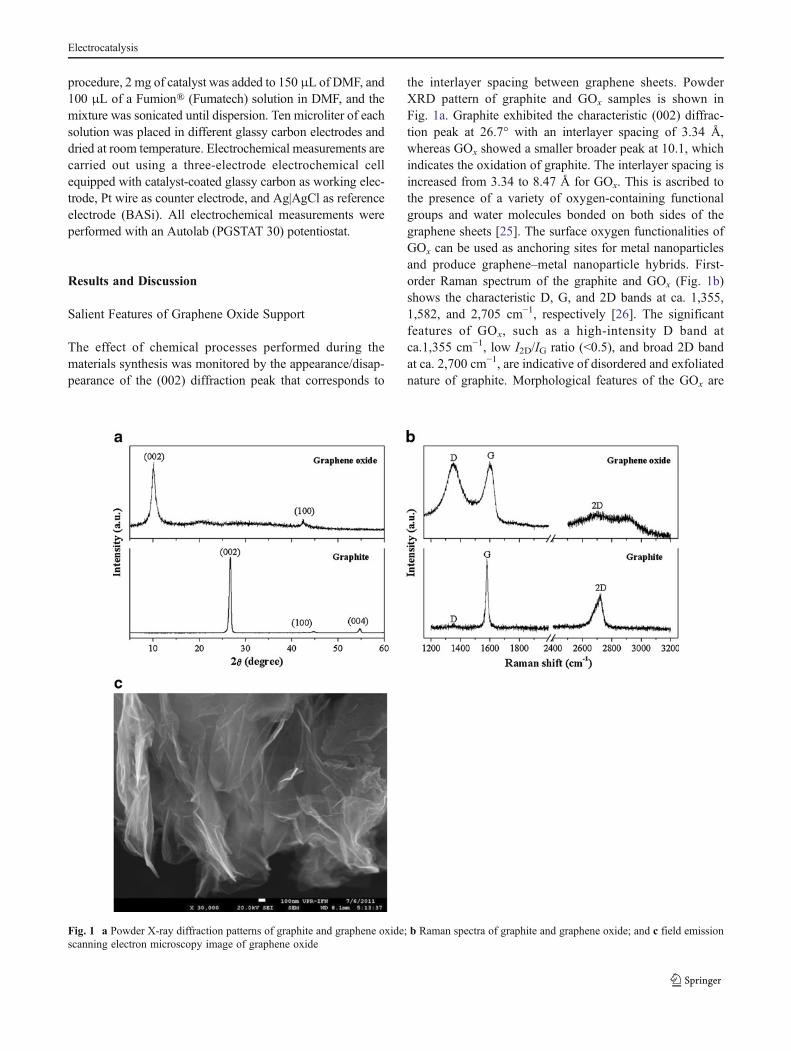
Fig. 2 Transmission electronmicroscopy images of the heat-treated catalysts under exposureto air: a RGO/Pt; b RGO/Pt-Ir
Fig. 3 Low-magnification(left) and high-magnificationtransmission electron microsco-py (right) images of the heat-treated catalysts under exposureto N2, RGO/Pt (a and a1),RGO/Ir (b and b1), and RGO/Pt-Ir (c and c1). Boxes in thelow-magnification images showthe enlarged region
Electrocatalysis
Influence of Gas Atmosphere on the Particle Size
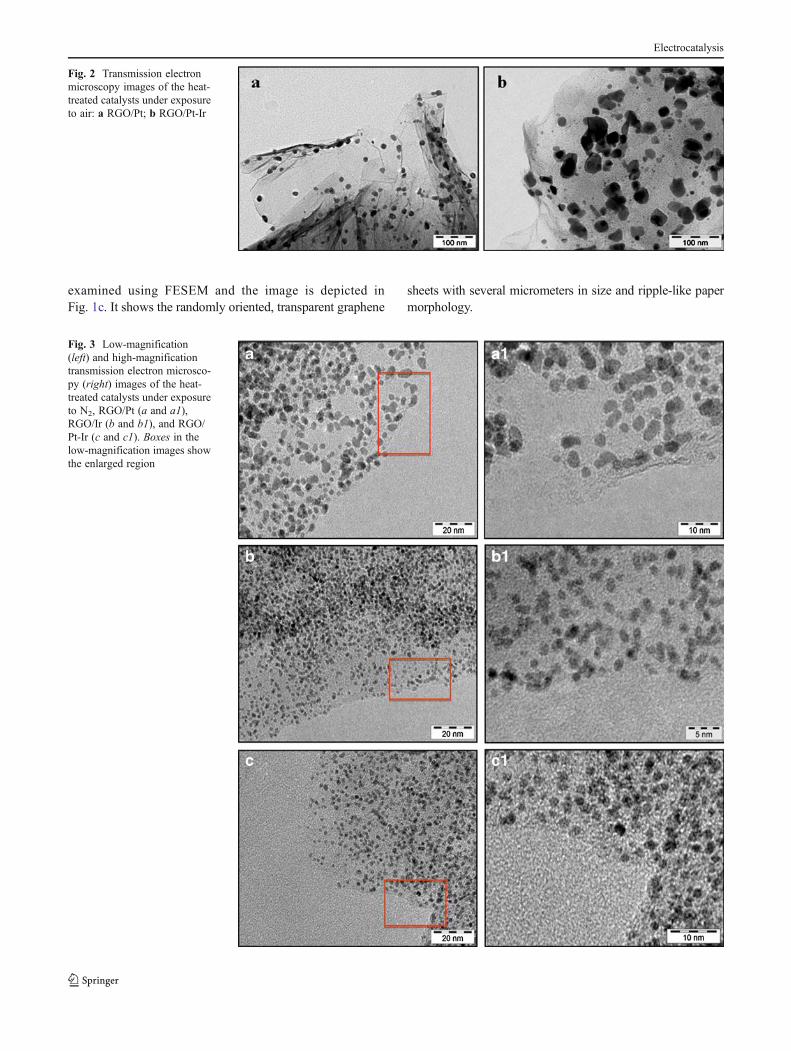
The influence of gas atmosphere on the morphologicalfeatures of the materials were examined using TEM andshown in Fig. 2a–b. All the samples were found to havemicrometer-sized graphene sheets with good dispersion ofmetal/metal oxide nanoparticles. Figure 2a shows the re-duced graphene oxide (RGO)-supported Pt nanoparticles,and Fig. 2b shows the RGO-supported Pt-Ir nanoparticlesheat-treated in the presence of air. These samples had nano-particles that ranged between 2 and 30 nm. Although nano-particles were found to be well-dispersed on the RGO, theuse of air favored the growth of metal oxide with largeparticle size. Metal oxide nanoparticles were found to bespherical in shape. These characteristics make them as ineffi-cient electrocatalysts for the oxidation of ammonia.
TEM images of the catalysts heat-treated under N2 areshown in Fig. 3a–c. Awell-dispersed spherical-shaped metalnanoparticles with a narrow size distribution was observed.The deposited metal nanoparticles were in the size range of1–4 nm. Since there was no oxygen in the atmosphere, theprepared materials were free of metal oxides. Since thesewere found to be more useful for the ammonia oxidation due
to the small particle size (or high surface area), furthermeasurements were carried out. Pt-Ir nanoparticles showeda deposition as dispersed as Pt nanoparticles, as well as ithappened with the air-treated samples. Also, Pt and Ir arenext to each other in the periodic table with similar physical
Pt 4f Ir 4f
Ir 4fPt 4f
c d
a b
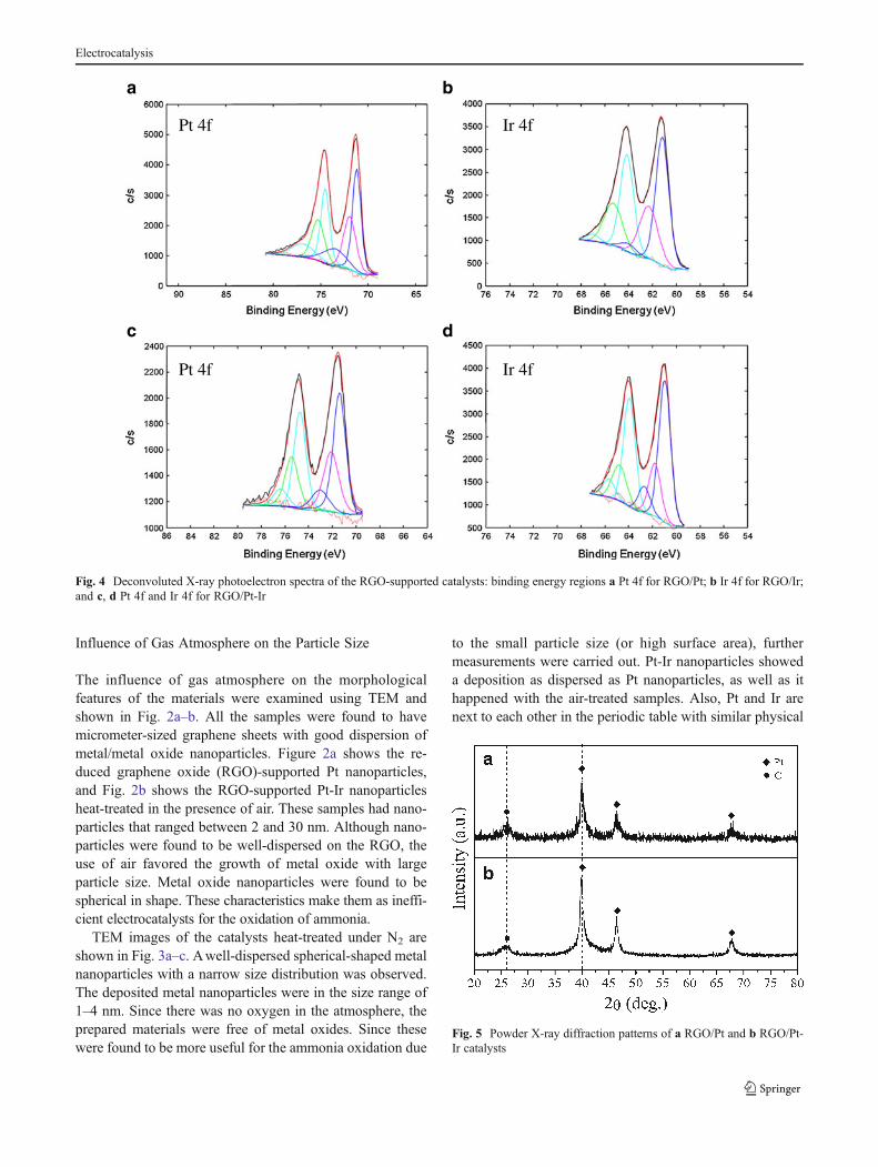
Fig. 4 Deconvoluted X-ray photoelectron spectra of the RGO-supported catalysts: binding energy regions a Pt 4f for RGO/Pt; b Ir 4f for RGO/Ir;and c, d Pt 4f and Ir 4f for RGO/Pt-Ir
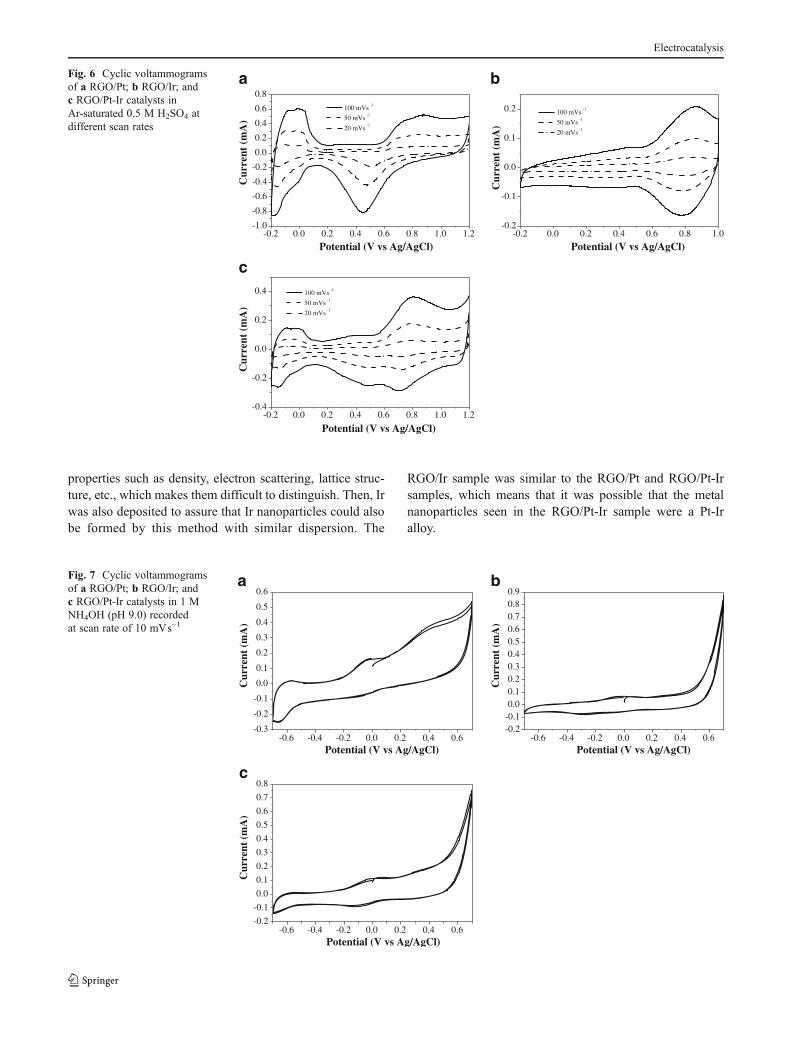
Fig. 5 Powder X-ray diffraction patterns of a RGO/Pt and b RGO/Pt-Ir catalysts
Electrocatalysis
properties such as density, electron scattering, lattice struc-ture, etc., which makes them difficult to distinguish. Then, Irwas also deposited to assure that Ir nanoparticles could alsobe formed by this method with similar dispersion. The
RGO/Ir sample was similar to the RGO/Pt and RGO/Pt-Irsamples, which means that it was possible that the metalnanoparticles seen in the RGO/Pt-Ir sample were a Pt-Iralloy.
a b
c
-0.2 0.0 0.2 0.4 0.6 0.8 1.0 1.2-1.0
-0.8
-0.6
-0.4
-0.2
0.0
0.2
0.4
0.6
0.8
Cur
rent
(m
A)
Potential (V vs Ag/AgCl)
100 mVs-1
50 mVs-1
20 mVs-1
-0.2 0.0 0.2 0.4 0.6 0.8 1.0-0.2
-0.1
0.0
0.1
0.2
Cur
rent
(m
A)
Potential (V vs Ag/AgCl)
100 mVs-1
50 mVs-1
20 mVs-1
-0.2 0.0 0.2 0.4 0.6 0.8 1.0 1.2-0.4
-0.2
0.0
0.2
0.4
Potential (V vs Ag/AgCl)
Cur
rent
(m
A)
100 mVs-1
50 mVs-1
20 mVs-1
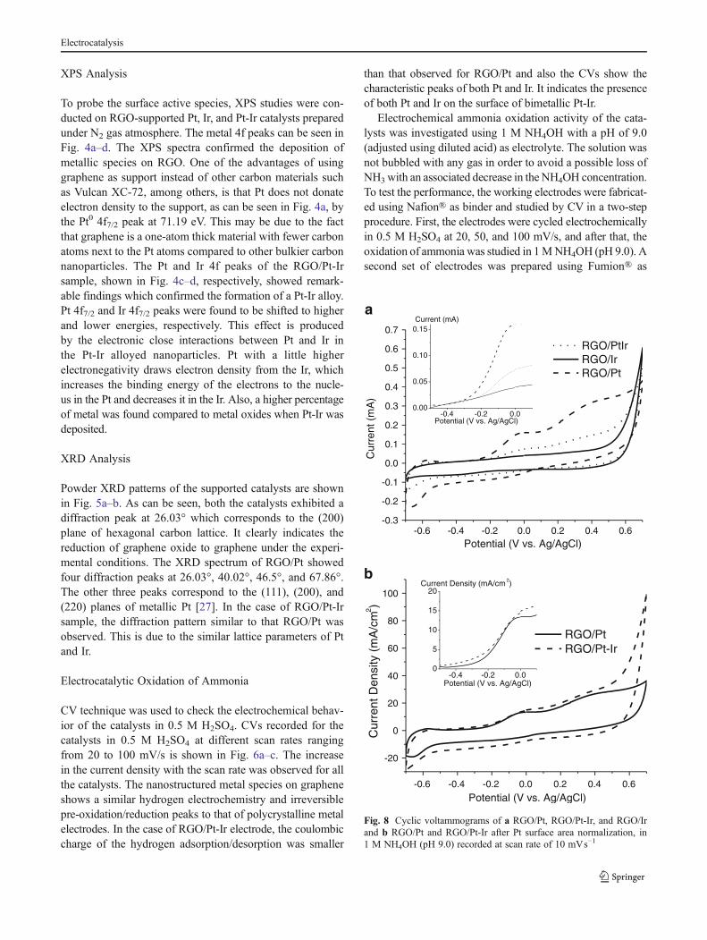
Fig. 6 Cyclic voltammogramsof a RGO/Pt; b RGO/Ir; andc RGO/Pt-Ir catalysts inAr-saturated 0.5 M H2SO4 atdifferent scan rates
a b
c
-0.6 -0.4 -0.2 0.0 0.2 0.4 0.6-0.2-0.10.00.10.20.30.40.50.60.70.80.9
Cur
rent
(m
A)
Potential (V vs Ag/AgCl)
-0.6 -0.4 -0.2 0.0 0.2 0.4 0.6-0.2
-0.1
0.0
0.1
0.2
0.3
0.4
0.5
0.6
0.7
0.8
Cur
rent
(m
A)
Potential (V vs Ag/AgCl)
-0.6 -0.4 -0.2 0.0 0.2 0.4 0.6-0.3
-0.2
-0.1
0.0
0.1
0.2
0.3
0.4
0.5
0.6
Cur
rent
(m
A)
Potential (V vs Ag/AgCl)
Fig. 7 Cyclic voltammogramsof a RGO/Pt; b RGO/Ir; andc RGO/Pt-Ir catalysts in 1 MNH4OH (pH 9.0) recordedat scan rate of 10 mVs−1
Electrocatalysis
XPS Analysis
To probe the surface active species, XPS studies were con-ducted on RGO-supported Pt, Ir, and Pt-Ir catalysts preparedunder N2 gas atmosphere. The metal 4f peaks can be seen inFig. 4a–d. The XPS spectra confirmed the deposition ofmetallic species on RGO. One of the advantages of usinggraphene as support instead of other carbon materials suchas Vulcan XC-72, among others, is that Pt does not donateelectron density to the support, as can be seen in Fig. 4a, bythe Pt0 4f7/2 peak at 71.19 eV. This may be due to the factthat graphene is a one-atom thick material with fewer carbonatoms next to the Pt atoms compared to other bulkier carbonnanoparticles. The Pt and Ir 4f peaks of the RGO/Pt-Irsample, shown in Fig. 4c–d, respectively, showed remark-able findings which confirmed the formation of a Pt-Ir alloy.Pt 4f7/2 and Ir 4f7/2 peaks were found to be shifted to higherand lower energies, respectively. This effect is producedby the electronic close interactions between Pt and Ir inthe Pt-Ir alloyed nanoparticles. Pt with a little higherelectronegativity draws electron density from the Ir, whichincreases the binding energy of the electrons to the nucle-us in the Pt and decreases it in the Ir. Also, a higher percentageof metal was found compared to metal oxides when Pt-Ir wasdeposited.
XRD Analysis
Powder XRD patterns of the supported catalysts are shownin Fig. 5a–b. As can be seen, both the catalysts exhibited adiffraction peak at 26.03° which corresponds to the (200)plane of hexagonal carbon lattice. It clearly indicates thereduction of graphene oxide to graphene under the experi-mental conditions. The XRD spectrum of RGO/Pt showedfour diffraction peaks at 26.03°, 40.02°, 46.5°, and 67.86°.The other three peaks correspond to the (111), (200), and(220) planes of metallic Pt [27]. In the case of RGO/Pt-Irsample, the diffraction pattern similar to that RGO/Pt wasobserved. This is due to the similar lattice parameters of Ptand Ir.
Electrocatalytic Oxidation of Ammonia
CV technique was used to check the electrochemical behav-ior of the catalysts in 0.5 M H2SO4. CVs recorded for thecatalysts in 0.5 M H2SO4 at different scan rates rangingfrom 20 to 100 mV/s is shown in Fig. 6a–c. The increasein the current density with the scan rate was observed for allthe catalysts. The nanostructured metal species on grapheneshows a similar hydrogen electrochemistry and irreversiblepre-oxidation/reduction peaks to that of polycrystalline metalelectrodes. In the case of RGO/Pt-Ir electrode, the coulombiccharge of the hydrogen adsorption/desorption was smaller
than that observed for RGO/Pt and also the CVs show thecharacteristic peaks of both Pt and Ir. It indicates the presenceof both Pt and Ir on the surface of bimetallic Pt-Ir.
Electrochemical ammonia oxidation activity of the cata-lysts was investigated using 1 M NH4OH with a pH of 9.0(adjusted using diluted acid) as electrolyte. The solution wasnot bubbled with any gas in order to avoid a possible loss ofNH3with an associated decrease in the NH4OH concentration.To test the performance, the working electrodes were fabricat-ed using Nafion® as binder and studied by CV in a two-stepprocedure. First, the electrodes were cycled electrochemicallyin 0.5 M H2SO4 at 20, 50, and 100 mV/s, and after that, theoxidation of ammonia was studied in 1MNH4OH (pH 9.0). Asecond set of electrodes was prepared using Fumion® as
-0.6 -0.4 -0.2 0.0 0.2 0.4 0.6
-20
0
20
40
60
80
100
Cur
rent
Den
sity
(m
A/c
m2 )
Potential (V vs. Ag/AgCl)
RGO/Pt RGO/Pt-Ir
-0.4 -0.2 0.00
5
10
15
20Current Density (mA/cm 2)
Potential (V vs. Ag/AgCl)
-0.6 -0.4 -0.2 0.0 0.2 0.4 0.6-0.3
-0.2
-0.1
0.0
0.1
0.2
0.3
0.4
0.5
0.6
0.7
Cur
rent
(m
A)
Potential (V vs. Ag/AgCl)
RGO/PtIr RGO/Ir RGO/Pt
-0.4 -0.2 0.00.00
0.05
0.10
0.15Current (mA)
Potential (V vs. Ag/AgCl)
a
b
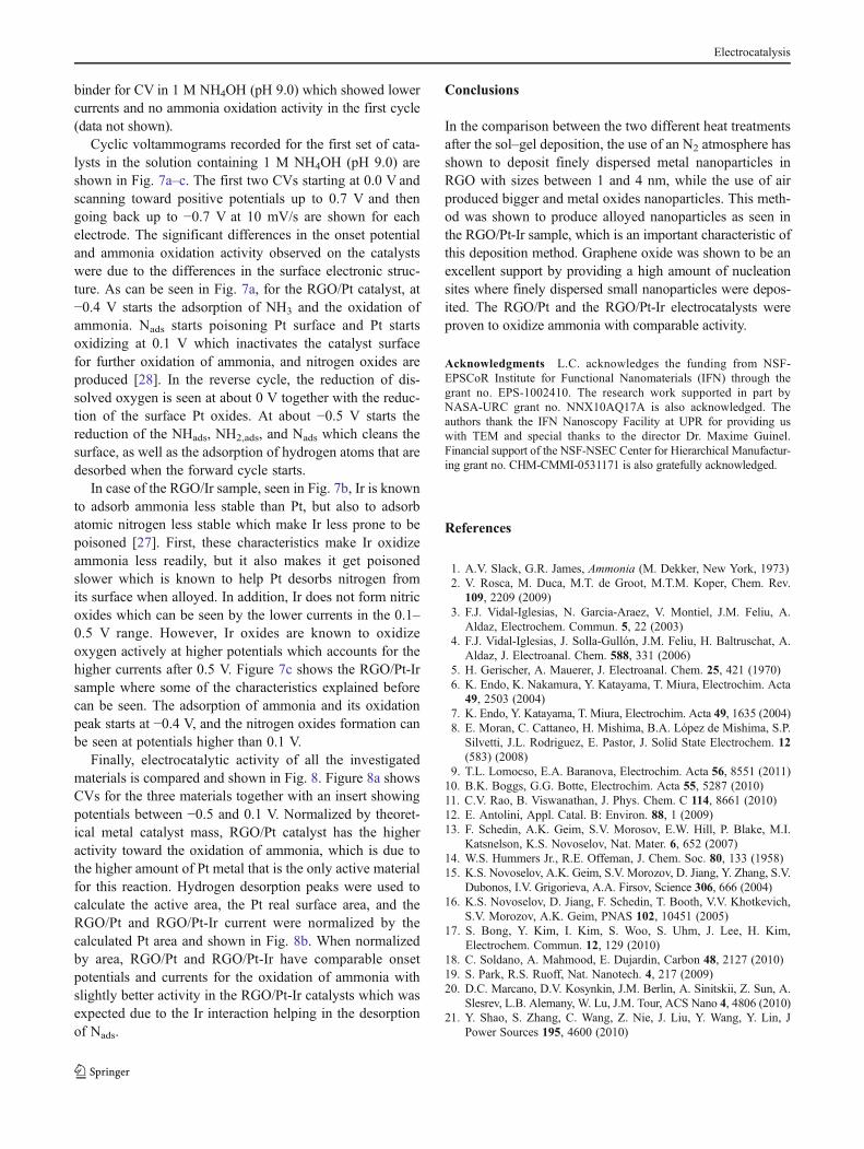
Fig. 8 Cyclic voltammograms of a RGO/Pt, RGO/Pt-Ir, and RGO/Irand b RGO/Pt and RGO/Pt-Ir after Pt surface area normalization, in1 M NH4OH (pH 9.0) recorded at scan rate of 10 mVs−1
Electrocatalysis
binder for CV in 1 M NH4OH (pH 9.0) which showed lowercurrents and no ammonia oxidation activity in the first cycle(data not shown).
Cyclic voltammograms recorded for the first set of cata-lysts in the solution containing 1 M NH4OH (pH 9.0) areshown in Fig. 7a–c. The first two CVs starting at 0.0 V andscanning toward positive potentials up to 0.7 V and thengoing back up to −0.7 V at 10 mV/s are shown for eachelectrode. The significant differences in the onset potentialand ammonia oxidation activity observed on the catalystswere due to the differences in the surface electronic struc-ture. As can be seen in Fig. 7a, for the RGO/Pt catalyst, at−0.4 V starts the adsorption of NH3 and the oxidation ofammonia. Nads starts poisoning Pt surface and Pt startsoxidizing at 0.1 V which inactivates the catalyst surfacefor further oxidation of ammonia, and nitrogen oxides areproduced [28]. In the reverse cycle, the reduction of dis-solved oxygen is seen at about 0 V together with the reduc-tion of the surface Pt oxides. At about −0.5 V starts thereduction of the NHads, NH2,ads, and Nads which cleans thesurface, as well as the adsorption of hydrogen atoms that aredesorbed when the forward cycle starts.
In case of the RGO/Ir sample, seen in Fig. 7b, Ir is knownto adsorb ammonia less stable than Pt, but also to adsorbatomic nitrogen less stable which make Ir less prone to bepoisoned [27]. First, these characteristics make Ir oxidizeammonia less readily, but it also makes it get poisonedslower which is known to help Pt desorbs nitrogen fromits surface when alloyed. In addition, Ir does not form nitricoxides which can be seen by the lower currents in the 0.1–0.5 V range. However, Ir oxides are known to oxidizeoxygen actively at higher potentials which accounts for thehigher currents after 0.5 V. Figure 7c shows the RGO/Pt-Irsample where some of the characteristics explained beforecan be seen. The adsorption of ammonia and its oxidationpeak starts at −0.4 V, and the nitrogen oxides formation canbe seen at potentials higher than 0.1 V.
Finally, electrocatalytic activity of all the investigatedmaterials is compared and shown in Fig. 8. Figure 8a showsCVs for the three materials together with an insert showingpotentials between −0.5 and 0.1 V. Normalized by theoret-ical metal catalyst mass, RGO/Pt catalyst has the higheractivity toward the oxidation of ammonia, which is due tothe higher amount of Pt metal that is the only active materialfor this reaction. Hydrogen desorption peaks were used tocalculate the active area, the Pt real surface area, and theRGO/Pt and RGO/Pt-Ir current were normalized by thecalculated Pt area and shown in Fig. 8b. When normalizedby area, RGO/Pt and RGO/Pt-Ir have comparable onsetpotentials and currents for the oxidation of ammonia withslightly better activity in the RGO/Pt-Ir catalysts which wasexpected due to the Ir interaction helping in the desorptionof Nads.
Conclusions
In the comparison between the two different heat treatmentsafter the sol–gel deposition, the use of an N2 atmosphere hasshown to deposit finely dispersed metal nanoparticles inRGO with sizes between 1 and 4 nm, while the use of airproduced bigger and metal oxides nanoparticles. This meth-od was shown to produce alloyed nanoparticles as seen inthe RGO/Pt-Ir sample, which is an important characteristic ofthis deposition method. Graphene oxide was shown to be anexcellent support by providing a high amount of nucleationsites where finely dispersed small nanoparticles were depos-ited. The RGO/Pt and the RGO/Pt-Ir electrocatalysts wereproven to oxidize ammonia with comparable activity.
Acknowledgments L.C. acknowledges the funding from NSF-EPSCoR Institute for Functional Nanomaterials (IFN) through thegrant no. EPS-1002410. The research work supported in part byNASA-URC grant no. NNX10AQ17A is also acknowledged. Theauthors thank the IFN Nanoscopy Facility at UPR for providing uswith TEM and special thanks to the director Dr. Maxime Guinel.Financial support of the NSF-NSEC Center for Hierarchical Manufactur-ing grant no. CHM-CMMI-0531171 is also gratefully acknowledged.
References
1. A.V. Slack, G.R. James, Ammonia (M. Dekker, New York, 1973)2. V. Rosca, M. Duca, M.T. de Groot, M.T.M. Koper, Chem. Rev.
109, 2209 (2009)3. F.J. Vidal-Iglesias, N. Garcia-Araez, V. Montiel, J.M. Feliu, A.
Aldaz, Electrochem. Commun. 5, 22 (2003)4. F.J. Vidal-Iglesias, J. Solla-Gullón, J.M. Feliu, H. Baltruschat, A.
Aldaz, J. Electroanal. Chem. 588, 331 (2006)5. H. Gerischer, A. Mauerer, J. Electroanal. Chem. 25, 421 (1970)6. K. Endo, K. Nakamura, Y. Katayama, T. Miura, Electrochim. Acta
49, 2503 (2004)7. K. Endo, Y. Katayama, T. Miura, Electrochim. Acta 49, 1635 (2004)8. E. Moran, C. Cattaneo, H. Mishima, B.A. López de Mishima, S.P.
Silvetti, J.L. Rodriguez, E. Pastor, J. Solid State Electrochem. 12(583) (2008)
9. T.L. Lomocso, E.A. Baranova, Electrochim. Acta 56, 8551 (2011)10. B.K. Boggs, G.G. Botte, Electrochim. Acta 55, 5287 (2010)11. C.V. Rao, B. Viswanathan, J. Phys. Chem. C 114, 8661 (2010)12. E. Antolini, Appl. Catal. B: Environ. 88, 1 (2009)13. F. Schedin, A.K. Geim, S.V. Morosov, E.W. Hill, P. Blake, M.I.
Katsnelson, K.S. Novoselov, Nat. Mater. 6, 652 (2007)14. W.S. Hummers Jr., R.E. Offeman, J. Chem. Soc. 80, 133 (1958)15. K.S. Novoselov, A.K. Geim, S.V. Morozov, D. Jiang, Y. Zhang, S.V.
Dubonos, I.V. Grigorieva, A.A. Firsov, Science 306, 666 (2004)16. K.S. Novoselov, D. Jiang, F. Schedin, T. Booth, V.V. Khotkevich,
S.V. Morozov, A.K. Geim, PNAS 102, 10451 (2005)17. S. Bong, Y. Kim, I. Kim, S. Woo, S. Uhm, J. Lee, H. Kim,
Electrochem. Commun. 12, 129 (2010)18. C. Soldano, A. Mahmood, E. Dujardin, Carbon 48, 2127 (2010)19. S. Park, R.S. Ruoff, Nat. Nanotech. 4, 217 (2009)20. D.C. Marcano, D.V. Kosynkin, J.M. Berlin, A. Sinitskii, Z. Sun, A.
Slesrev, L.B. Alemany, W. Lu, J.M. Tour, ACS Nano 4, 4806 (2010)21. Y. Shao, S. Zhang, C. Wang, Z. Nie, J. Liu, Y. Wang, Y. Lin, J
Power Sources 195, 4600 (2010)
Electrocatalysis

22. C.V. Rao, C.R. Cabrera, Y. Ishikawa, J. Phys. Chem. C 115, 21963(2011)
23. S. Bong, S. Uhm, Y.-R. Kim, J. Lee, H. Kim, Electrocatal. 1, 139(2010)
24. L. Cunci, C.R. Cabrera, Electrochem. Solid-State Lett. 14, K17 (2011)25. C.V. Rao, A.L.M. Reddy, Y. Ishikawa, P.M. Ajayan, Carbon 49,
931 (2011)
26. A.C. Ferrari, J.C. Meyer, V. Scardaci, C. Casiraghi, M. Lazzeri, F.Mauri, S. Piscanec, D. Jiang, K.S. Novoselov, S. Roth, A.K. Geim,Phys. Rev. Lett. 97, 187401 (2006)
27. K.S. Han, Y. Moon, O.H. Han, K.J. Hwang, I. Kim, H. Kim,Electrochem. Commun. 9, 317 (2007)
28. A.C.A. de Vooys, M.T.M. Koper, R.A. van Santen, J.A.R. vanVeen, J. Electroanal. Chem. 506, 127 (2001)
Electrocatalysis