Mars Express Interplanetary Navigation from Launch to Mars Orbit Insertion: The JPL Experience
Upload
khangminh22Category
view
2download
0
GRAIL
DATA PRODUCT
SOFTWARE INTERFACE SPECIFICATION
JPL D-76383
Version 1.8
May 3, 2016
Daniel Kahan
Copyright 2013 California Institute of Technology. Government sponsorship acknowledged.
Copyright 2013. All rights reserved.
GRAIL DATA PRODUCT SOFTWARE INTERFACE SPECIFICATION
2
TABLE OF CONTENTS
TABLES 5 DOCUMENT CHANGE LOG ....................................................................................................................... 7 1 Purpose and Scope of Document ........................................................................................................... 8 2 Definitions of Data Processing Levels ................................................................................................... 9 3 Relationships with Other Interfaces ....................................................................................................... 9 4 Data Product Characteristics and Environment ...................................................................................... 9
4.1 Instrument Overview ..................................................................................................................................9
4.2 Data Product Overview ........................................................................................................................... 11
4.2.1 LGRS EDR (NASA Level 0 Products) ............................................................. 11
4.2.2 LGRS CDR (NASA Level 1A and Level 1B Products) .................................... 12
4.2.2.1 Timing [17] .................................................................................................................................. 12
4.2.2.2 Position ........................................................................................................................................ 13
4.2.2.3 Ka-band ....................................................................................................................................... 14
4.2.2.4 S-band .......................................................................................................................................... 14
4.2.2.5 Satellite Attitude .......................................................................................................................... 14
4.2.2.6 Events .......................................................................................................................................... 15
4.2.2.7 Satellite Condition ....................................................................................................................... 15
4.2.2.8 DSN Tracking .............................................................................................................................. 15
4.2.3 RSS EDR ........................................................................................................... 15
4.2.3.1 DSN Radio Data .......................................................................................................................... 15
4.2.3.2 Ancillary DSN Data..................................................................................................................... 16
4.2.4 LGRS RDR (NASA Level 2 Products) ............................................................. 17
4.2.5 Data Flow and Product Generation ................................................................... 17
4.2.6 Labeling and Identification ................................................................................ 18
4.2.6.1 LGRS EDR and LGRS CDR File Naming Convention .............................................................. 18
4.2.6.2 RSS EDR File Naming Convention ............................................................................................ 19
4.2.6.3 LGRS RDR File Naming Convention ......................................................................................... 20
4.3 Standards Used in Generating Data Products .......................................................................................... 22
4.3.1 PDS Standards ................................................................................................... 22
4.3.2 Time Standards .................................................................................................. 22
4.3.2.1 LGRS clock ................................................................................................................................. 23
4.3.2.2 Onboard spacecraft clocks ........................................................................................................... 23
4.3.2.3 UTC clock used by DSN ............................................................................................................. 23
GRAIL DATA PRODUCT SOFTWARE INTERFACE SPECIFICATION
3
4.3.3 Coordinate Systems ........................................................................................... 24
4.4 Data Validation ........................................................................................................................................ 27
5 Detailed Data Product Specifications ................................................................................................... 27 5.1 Data Product Structure and Organization ................................................................................................ 27
5.2 Data Format Descriptions ........................................................................................................................ 31
5.2.1 LGRS EDR (Level 0) Products ......................................................................... 31
5.2.2 LGRS CDR Products ......................................................................................... 34
5.2.2.1 Level 1A ...................................................................................................................................... 34
5.2.2.2 Level 1B ...................................................................................................................................... 48
5.2.3 RSS EDR Products ............................................................................................ 56
5.3 Header Descriptions ................................................................................................................................ 57
5.3.1 Headers for LGRS EDR .................................................................................... 57
5.3.2 Headers for LGRS CDR .................................................................................... 57
5.3.3 Headers for LGRS RDR .................................................................................... 58
5.3.4 Headers for RSS EDR ....................................................................................... 58
6 Applicable Software ............................................................................................................................. 59 6.1 Utility Programs ...................................................................................................................................... 59
7 Appendices ........................................................................................................................................... 59 7.1 Glossary ................................................................................................................................................... 59
7.2 Acronyms ................................................................................................................................................ 60
7.3 Example PDS Labels ............................................................................................................................... 62
7.3.1 LGRS EDR ........................................................................................................ 62
7.3.2 LGRS CDR ........................................................................................................ 62
7.3.3 RSS EDR ........................................................................................................... 63
7.3.3.1 BTM, EOP, ION, TDM, TNF, TRO, WEA, & XFR ................................................................... 63
7.3.3.2 ODF, OLF, and BOF ................................................................................................................... 64
7.3.3.3 RSR.............................................................................................................................................. 92
7.3.4 LGRS RDR ...................................................................................................... 113
7.3.4.1 Radio Science Digital Map Products (RSDMAP) ..................................................................... 113
7.3.4.2 Spherical Harmonics ASCII Data Record (SHADR) ................................................................ 114
7.3.4.3 Spherical Harmonics Binary Data Record (SHBDR) ................................................................ 119
7.3.4.4 SPICE ephemeris files (SPK) .................................................................................................... 124
8 Applicable Documents ....................................................................................................................... 124
GRAIL DATA PRODUCT SOFTWARE INTERFACE SPECIFICATION
4
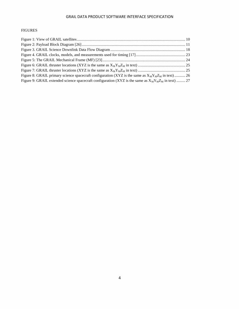
FIGURES
Figure 1: View of GRAIL satellites .............................................................................................................. 10 Figure 2: Payload Block Diagram [26] ......................................................................................................... 11 Figure 3. GRAIL Science Downlink Data Flow Diagram ............................................................................ 18 Figure 4. GRAIL clocks, models, and measurements used for timing [17] .................................................. 23 Figure 5: The GRAIL Mechanical Frame (MF) [23] .................................................................................... 24 Figure 6: GRAIL thruster locations (XYZ is the same as XMYMZM in text) ................................................ 25 Figure 7: GRAIL thruster locations (XYZ is the same as XMYMZM in text) ................................................ 25 Figure 8: GRAIL primary science spacecraft configuration (XYZ is the same as XMYMZM in text) ........... 26 Figure 9: GRAIL extended science spacecraft configuration (XYZ is the same as XMYMZM in text) ......... 27
GRAIL DATA PRODUCT SOFTWARE INTERFACE SPECIFICATION
5
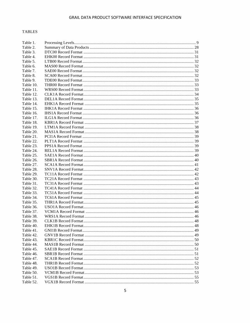
TABLES
Table 1. Processing Levels...................................................................................................................... 9 Table 2. Summary of Data Products ..................................................................................................... 28 Table 3. DTC00 Record Format ........................................................................................................... 31 Table 4. EHK00 Record Format ........................................................................................................... 31 Table 5. LTB00 Record Format ............................................................................................................ 32 Table 6. MAS00 Record Format ........................................................................................................... 32 Table 7. SAE00 Record Format ............................................................................................................ 32 Table 8. SCA00 Record Format ............................................................................................................ 32 Table 9. TDE00 Record Format ............................................................................................................ 33 Table 10. THR00 Record Format ........................................................................................................... 33 Table 11. WRS00 Record Format ........................................................................................................... 33 Table 12. CLK1A Record Format ........................................................................................................... 34 Table 13. DEL1A Record Format ........................................................................................................... 35 Table 14. EHK1A Record Format .......................................................................................................... 35 Table 15. IHK1A Record Format ........................................................................................................... 36 Table 16. IHS1A Record Format ............................................................................................................ 36 Table 17. ILG1A Record Format ............................................................................................................ 36 Table 18. KBR1A Record Format .......................................................................................................... 37 Table 19. LTM1A Record Format .......................................................................................................... 38 Table 20. MAS1A Record Format .......................................................................................................... 38 Table 21. PCI1A Record Format ............................................................................................................ 39 Table 22. PLT1A Record Format ........................................................................................................... 39 Table 23. PPS1A Record Format ............................................................................................................ 39 Table 24. REL1A Record Format ........................................................................................................... 39 Table 25. SAE1A Record Format ........................................................................................................... 40 Table 26. SBR1A Record Format ........................................................................................................... 40 Table 27. SCA1A Record Format ........................................................................................................... 41 Table 28. SNV1A Record Format ........................................................................................................... 42 Table 29. TC11A Record Format ........................................................................................................... 42 Table 30. TC21A Record Format ........................................................................................................... 43 Table 31. TC31A Record Format ........................................................................................................... 43 Table 32. TC41A Record Format ........................................................................................................... 44 Table 33. TC51A Record Format ........................................................................................................... 44 Table 34. TC61A Record Format ........................................................................................................... 45 Table 35. THR1A Record Format ........................................................................................................... 45 Table 36. USO1A Record Format ........................................................................................................... 46 Table 37. VCM1A Record Format ......................................................................................................... 46 Table 38. WRS1A Record Format .......................................................................................................... 46 Table 39. CLK1B Record Format ........................................................................................................... 48 Table 40. EHK1B Record Format ........................................................................................................... 48 Table 41. GNI1B Record Format ............................................................................................................ 49 Table 42. GNV1B Record Format .......................................................................................................... 49 Table 43. KBR1C Record Format ........................................................................................................... 50 Table 44. MAS1B Record Format .......................................................................................................... 50 Table 45. SAE1B Record Format ........................................................................................................... 51 Table 46. SBR1B Record Format ........................................................................................................... 51 Table 47. SCA1B Record Format ........................................................................................................... 52 Table 48. THR1B Record Format ........................................................................................................... 52 Table 49. USO1B Record Format ........................................................................................................... 53 Table 50. VCM1B Record Format .......................................................................................................... 53 Table 51. VGS1B Record Format ........................................................................................................... 55 Table 52. VGX1B Record Format .......................................................................................................... 55
GRAIL DATA PRODUCT SOFTWARE INTERFACE SPECIFICATION
6
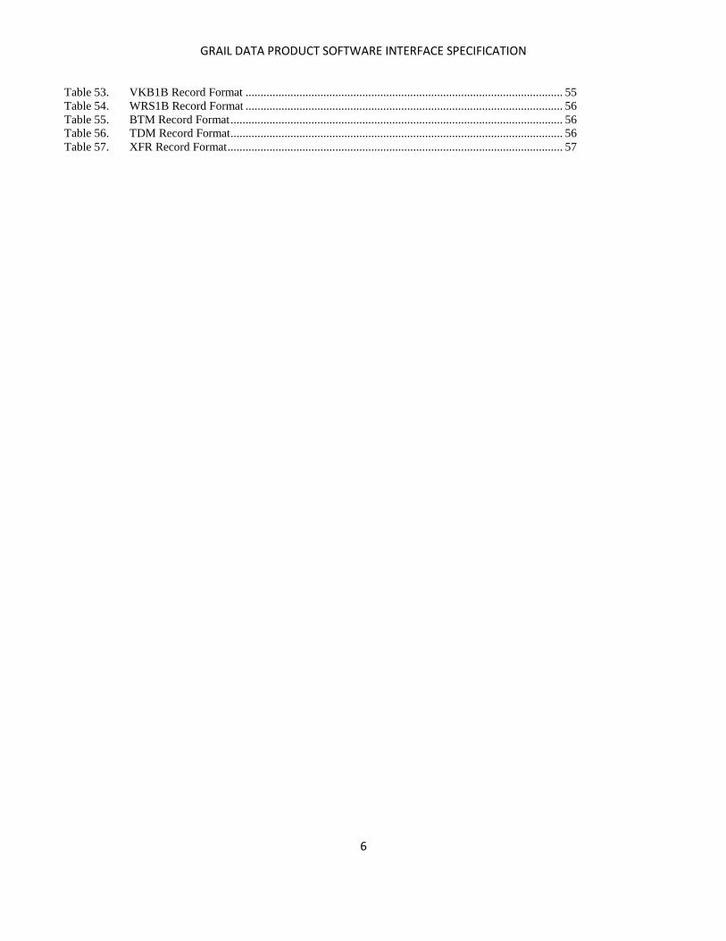
Table 53. VKB1B Record Format .......................................................................................................... 55 Table 54. WRS1B Record Format .......................................................................................................... 56 Table 55. BTM Record Format ............................................................................................................... 56 Table 56. TDM Record Format ............................................................................................................... 56 Table 57. XFR Record Format ................................................................................................................ 57
GRAIL DATA PRODUCT SOFTWARE INTERFACE SPECIFICATION
7
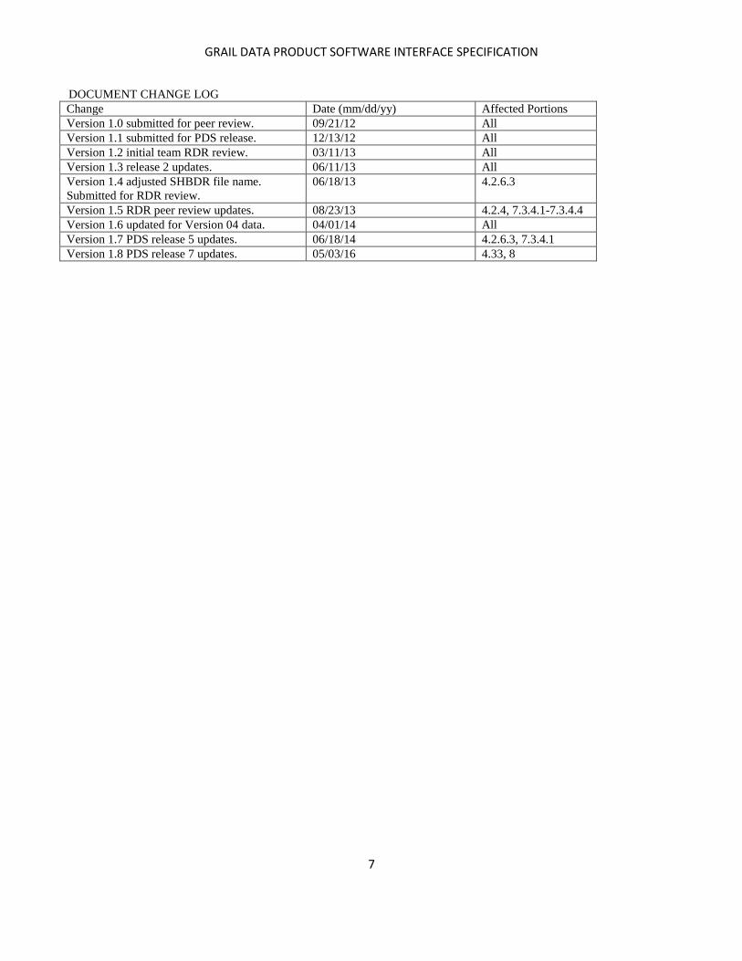
DOCUMENT CHANGE LOG
Change Date (mm/dd/yy) Affected Portions
Version 1.0 submitted for peer review. 09/21/12 All
Version 1.1 submitted for PDS release. 12/13/12 All
Version 1.2 initial team RDR review. 03/11/13 All
Version 1.3 release 2 updates. 06/11/13 All
Version 1.4 adjusted SHBDR file name.
Submitted for RDR review.
06/18/13 4.2.6.3
Version 1.5 RDR peer review updates. 08/23/13 4.2.4, 7.3.4.1-7.3.4.4
Version 1.6 updated for Version 04 data. 04/01/14 All
Version 1.7 PDS release 5 updates. 06/18/14 4.2.6.3, 7.3.4.1
Version 1.8 PDS release 7 updates. 05/03/16 4.33, 8
GRAIL DATA PRODUCT SOFTWARE INTERFACE SPECIFICATION
8
1 Purpose and Scope of Document
This document provides a detailed description of data products at all levels for the Gravity Recovery and Interior Laboratory
(GRAIL) Mission. The data products specified in this document are obtained from the science instruments and subsystems on
board the twin GRAIL spacecraft; some include the results of ground data processing carried out by the GRAIL Science Data
System (SDS). Also included are data products from the NASA Deep Space Network (DSN) and products that resulted from
processing by GRAIL Science Team members at their home institutions.
The GRAIL Science Data System (SDS) is defined as the infrastructure at NASA’s Jet Propulsion Laboratory (JPL) for the
collection of all science and ancillary data relevant to the GRAIL mission. It includes hardware, software tools, procedures,
and trained personnel. The SDS receives data from three sources (as described below) and carries out calibration, editing, and
processing to produce NASA Level 1A and 1B GRAIL science data as described below.
The GRAIL archive comprises the following four separate volumes (also known as data sets):
GRAIL-L-LGRS-2-EDR-V1.0 – Raw science data, originating from spacecraft telemetry, in time order with duplicates and
transmission errors removed. Also known as NASA Level 0 science data (NASA processing levels are described in section 2)
and stored in this archive for historical purposes only. All Level 0 products have been processed to Level 1A by the GRAIL
SDS.
GRAIL-L-LGRS-3-CDR-V1.0 – Calibrated and resampled engineering (e.g., star tracker data and timing) and science data
acquired from the Lunar Gravity and Ranging System (LGRS). NASA Level 1A and 1B.
GRAIL-L-RSS-2-EDR-V1.0 – Raw Radio Science data acquired at the Deep Space Network.
GRAIL-L-LGRS-5-RDR-V1.0 – Lunar gravitational field, NASA Level 2 data. Includes SPICE geometry and navigation
kernels created by the GRAIL SDS. SPICE is the ephemeris, orientation, and event information system developed by the
Navigation and Ancillary Information Facility (NAIF) at NASA’s JPL (see section 7.2).
The above data set identifiers (IDs) may be abbreviated as LGRS EDR, LGRS CDR, RSS EDR, and LGRS RDR in the
sections that follow. The first digit in each data set ID refers to the CODMAC processing level (see section 2).

GRAIL DATA PRODUCT SOFTWARE INTERFACE SPECIFICATION
9
2 Definitions of Data Processing Levels
The GRAIL Science Data System (SDS) uses NASA processing levels, which are defined in Table 1. Data set IDs use the
processing levels defined by the Committee on Data Management, Archiving, and Computation (CODMAC), which are also
given in Table 1.
Table 1. Processing Levels
NASA CODMAC Description
Packet data Raw - Level 1 Telemetry with data embedded.
Level 0 Edited - Level 2 Corrected for telemetry errors and split or decommutated
according to instrument. Sometimes called Experimental Data
Record (EDR). Data are also tagged with time and location of
acquisition.
Level 1A Calibrated - Level 3 Edited data that are still in units produced by instrument, but that
have been corrected so that values are expressed in or are
proportional to some physical unit such as radiance. No
resampling, so original values can be recovered.
Level 1B Resampled - Level 4 Data that have been resampled in the time or space domains in
such a way that the original edited data cannot be reconstructed.
Could be calibrated in addition to being resampled.
Level 2 Derived - Level 5 Derived results, as maps, reports, graphics, etc.
Ancillary - Level 6 Non-science data needed to generate calibrated or resampled
data sets. Consists of instrument gains and/or offsets, pointing
information for scan platforms, etc.
3 Relationships with Other Interfaces
The descriptions of data products in this document are consistent with the corresponding descriptions in “dataset” catalog
files in the CATALOG directory of each GRAIL volume. File/directory names are consistent with the conventions used in
the GRAIL Archive Volume Software Interface Specification (SIS) [16].
4 Data Product Characteristics and Environment
4.1 Instrument Overview
Lockheed Martin built GRAIL-A and GRAIL-B as near-twins (Figure 1). Each satellite contains the following components:
1) Rectangular bus
2) Fixed solar panels
3) Titanium diaphragm fuel tank
4) Ultra stable oscillator (USO), which drives onboard LGRS clock and provides frequency reference for S-, X-, and
Ka-Band radio systems
5) Attitude control system (ACS) [23], consisting of:
a. Four reaction wheels to change attitude
b. Inertial Measurement Unit (IMU) to measure the rate components of angular rotation
c. Star Tracker to measure the absolute attitude
d. Sun Sensor
e. Eight thrusters, coupled to allow applications of torque
f. Main engine
6) Ka-band carrier phase tracking inter-satellite receiver/transmitter

GRAIL DATA PRODUCT SOFTWARE INTERFACE SPECIFICATION
10
7) S-band inter-satellite Time Transfer System (TTS)
8) Two low-gain antennas (LGA) for S-band communication with the DSN
9) Two Radio Science Beacons (RSB), which transmit X-band carriers to the DSN
For the mechanical and optical properties of the spacecraft, see GRAILCOMPONENTS.TXT in the CALIB directory
[11].
Figure 1: View of GRAIL satellites
There are two payload elements on each GRAIL orbiter: the Lunar Gravity Ranging System (LGRS) which is the science
instrument, and the MoonKAM lunar imager which is used for education and public outreach. The LGRS is based on the
instrument used for the Gravity Recovery and Climate Experiment (GRACE) mission [32], which has been mapping Earth's
gravity since 2002. The LGRS is responsible for sending and receiving the signals needed to accurately and precisely
measure the changes in range between the two orbiters. The LGRS consists of an Ultra-Stable Oscillator (USO), Microwave
Assembly (MWA), a Time-Transfer Assembly (TTA), and the Gravity Recovery Processor Assembly (GPA). See Figure 2.
GRAIL DATA PRODUCT SOFTWARE INTERFACE SPECIFICATION
11
Figure 2: Payload Block Diagram [26]
The USO provides a steady reference signal that is used by all of the instrument subsystems. Within the LGRS, the USO
provides the reference frequency for the MWA and the TTA. The MWA converts the USO reference signal to the Ka-band
frequency, which is transmitted to the other orbiter.
The function of the TTA is to provide a two-way time-transfer link between the spacecraft to both synchronize and measure
the clock offset between the two LGRS clocks. The TTA generates an S-band signal from the USO reference frequency and
sends a GPS-like ranging code to the other spacecraft. The GPA combines all the inputs received from the MWA and TTA to
produce the radiometric data that are downlinked to the Deep Space Network. In addition to acquiring the inter-spacecraft
measurements, the LGRS also provides a one-way signal to the DSN based on the USO, which is transmitted via the X-band
Radio Science Beacon (RSB). The steady-state drift of the USO is measured via the one-way Doppler data provided by the
RSB.
4.2 Data Product Overview
The scientific goals of the GRAIL project are achieved by measuring the lunar gravitational attraction on the two spacecraft;
GRAIL’s instrumentation is specifically designed to sense this through relative motion between the two spacecraft and with
DSN stations on Earth. The GRAIL payload on each spacecraft consists of a single science instrument called the Lunar
Gravity Ranging System (LGRS), a Ka-band ranging system that determines the precise instantaneous relative range-rate of
the two spacecraft. Also, as part of the LGRS, the GRAIL investigation requires a radio link from each spacecraft’s Radio
Science Beacon to the stations of the NASA Deep Space Network (DSN).
The rest of this section gives an overview of the data products and the measurements GRAIL provides. Product name suffixes
indicate NASA processing level. For example, the Level 1A S-band product is named SBR1A, and the Level 1B S-band
product is SBR1B.
The Algorithm Theoretical Basis Document (ATBD) [15] in the DOCUMENT directory contains a detailed description of the
processing flow from EDR to CDR as implemented by the GRAIL SDS.
4.2.1 LGRS EDR (NASA Level 0 Products)
GRAIL DATA PRODUCT SOFTWARE INTERFACE SPECIFICATION
12
The GRAIL SDS receives science packets and engineering data from the JPL Ground Data System (GDS) (Figure 3). The
LGRS EDR data set contains the raw data in time order with duplicates and transmission errors removed. These data are
archived mainly for completeness, as they are immediately processed to Level 1A and/or 1B (the LGRS CDR data set) by the
SDS. There are twelve product types in the LGRS EDR data set:
DTC00 - Time Correlation Data Record File (DRF) (ASCII) – Clock correlation among RTC, BTC, and the 1-per-
second pulse associated with LGRS time. See section 4.2.2.1.
EHK00 - Spacecraft Engineering Housekeeping data, including temperature sensor data for locations near the LGRS
instrumentation (ASCII)
LTB00 - LGRS Time Bias of the Lunar Gravity Ranging System in BTC time (ASCII). Accumulated list of biases over
the complete mission. Biases apply to the LGRS time tag of both spacecraft
MAS00 - Satellite Mass Data (ASCII). Accumulated list of center of mass and spacecraft mass over the complete
mission.
S7200 - Engineering SFDU ID #72 (binary)
S7300 - Science SFDU ID #73 (binary)
SAE00 - Solar Array Eclipse data, including solar array short circuit currents and open circuit voltages, to identify
eclipse events for spacecraft ephemeris models (ASCII)
SCA00 - Star Tracker Data. Including attitudes from an on-board Kalman filter that processes Star Tracker attitude data
and Inertial Measurement Unit (IMU) angular rotation data (ASCII)
STC00 - Time Correlation SFDU (binary)
TDE00 - measured time correlation between LGRS time and UTC, using Time Transfer System (TTS) S-Band ranging
collected at DSS-24 (ASCII)
THR00 - Thruster Activation Data, including time tags, counts of cumulative work cycles for each thruster, recent
thruster ‘on’ time, and cumulative thruster ‘on’ time (ASCII)
WRS00 – Wheel Rotational Speed data, including time tags, measures rotational wheel speed of each of four reaction
wheels as determined by a digital tachometer (ASCII)
The SFDU products — S7200, S7300, and STC00 — are binary and contain (besides the appropriate headers) the unscaled,
binary encoded instrument communication packets. For information on extracting the SFDU data contents. see the following
in the DOCUMENT directory:
0161_TELECOMM_L5_8.TXT [8]
0171_TELECOMM_NJPL_L5.TXT [20]
090_REVC_1.TXT [1], and
0172_TELECOMM_CHDO_REVE_L5.TXT [35]
Each telemetry packet generated by the LGRS flight software is wrapped inside a packet called a BlackJack Protocol Frame,
which ensures the integrity of the data; Blackjack was inherited from the predecessor Gravity Recovery and Climate
Experiment (GRACE) terrestrial gravity mission. The documents GPA_TD_D_71987_REVE.TXT [14] and
BLACKJACKDLP.TXT [12] in the DOCUMENT directory describe the format of the Blackjack binary data for processing
to Level 1A.
The remaining nine LGRS EDR product types are in ASCII format.
4.2.2 LGRS CDR (NASA Level 1A and Level 1B Products)
The LGRS CDR data set contains (calibrated and resampled) Level 1A and 1B science data from the Lunar Gravity Ranging
System. All forty-three LGRS CDR file types are in ASCII format. Most of the file types apply to both spacecraft separately.
A few apply to both spacecraft together, as they are indicative of a relationship between the two.
4.2.2.1 Timing [17]
GRAIL timing (discussed further in section 4.3.2) requires coordination of three clocks on each satellite, and two time
standards:
GRAIL DATA PRODUCT SOFTWARE INTERFACE SPECIFICATION
13
1. LGRS: Lunar Gravity Ranging System clock. Very stable clock for on-board Ka-band ranging (KBR), X-band
(RSB), and S-band (TTS) instruments. Driven by an Ultra-Stable Oscillator (USO). Set to 0 when booted. Produces
a pulse per second (pps) signal. LGRS time starts at 0 seconds when powered on. The SDS adds a bias to LGRS
time to create an approximate UTC time tag. This time will be referred to as LGRS + bias.
2. BTC: Base Time Clock. On-board satellite clock, comparable in stability to a wristwatch. Roughly synced to UTC at
launch time.
3. RTC: Real Time Clock. Flight software clock. Set to 0 when booted. Relatively unstable clock.
4. UTC: Coordinated Universal Time.
5. TDB: Barycentric Dynamical Time.
Seven Level 1A products establish the relationships among the clocks:
TC11A: LGRS to BTC, approximated by flight software.
TC21A: LGRS to BTC. more accurate mapping than TC11A, from BTC clock cycle counts.
TC31A: BTC to RTC.
TC41A: LGRS to RTC.
TC51A: RTC to UTC.
TC61A: UTC to TDB. One product applies to both spacecraft.
CLK1A: TDB toLGRS.
An approximation of the relativistic time correction from TDB to on-board satellite proper time is calculated in the REL1A
product, treating the moon as a point mass, based on [17]:
d
dt1
U
c21
2
v2
c2L
where = proper time, t = coordinate time, U = gravitational potential, v = velocity, and L is a constant offset (1.550520e-8).
Measurements from the S-band time transfer system (TTS) are processed to produce DEL1A, which lists inter-satellite
LGRS clock offset between spacecraft by TDB time.
Radio Science Receivers (RSR), located at DSN sites and discussed in section 4.2.3, record X-band Radio Science Beacon
(RSB) signals. Since the LGRS clock drives the RSB, LGRS frequency at TDB can be estimated for USO1A.
A PPS1A product is also created, listing the LGRS time of PPS signals.
A least squares fit to DEL1A, CLK1A, and USO1A produces CLK1B and USO1B, best estimates of LGRS to TDB and
LGRS frequency at TDB.
The TTS Direct-to-Earth (DTE) experiment was devised to independently measure the absolute clock offset between the
GRAIL Moon orbiters and Earth. This experiment prompted the development of software for acquiring weak signals and
extracting observables (i.e., phase, range, range rate). Data collected during TTS DTE tracks enabled SDS team to compute
more accurately the delay in the spacecraft which led to a more accurate gravity field solutions. The TTS DTE activities were
done about once per week due to limitations in geometry and equipment availability at the DSN. Specifically, only DSS-24
had the necessary equipment allocated to collect the data.
The TDE00 product is the result of the TTS DTE experiment. TDE00 data provide the only direct measurement of the
absolute LGRS time tag. This measurement is used to calibrate the CLK1A product as part of the generation of the CLK1B
product.
4.2.2.2 Position
As an improved estimate for the Moon’s gravity field is built, GRAIL-A and GRAIL-B orbital solutions are improved. Best
estimates of the ephemerides are saved in two frames (further detailed in section 4.3.3):
GNI1B: EME 2000 Lunar-Centered Solar System Barycentric Frame

GRAIL DATA PRODUCT SOFTWARE INTERFACE SPECIFICATION
14
GNV1B: DE 421 Lunar Body-Fixed Frame
From the best ephemeris solution, spacecraft to DSN relative position and light time are computed in EME 2000 (LTM1A),
and spacecraft to spacecraft relative position and light time are computed in DE 421 (PLT1A).
4.2.2.3 Ka-band
GRAIL science depends on estimating the relative movements of GRAIL-A and GRAIL-B. The estimate depends primarily
on an inter-satellite Ka-band system: GRAIL-A carrier-phase-tracks a Ka-band signal from GRAIL-B, and GRAIL-B carrier-
phase-tracks a Ka-band signal from GRAIL-A. In each continuous phase arc, carrier-phase gives a one-way range, biased by
an unknown constant.
KBR1A records raw carrier-phase measurements, flagged for phase breaks. Gaps of up to 2 seconds are filled in by quadratic
interpolation; longer gaps are classified as “missing data.”
KBR1C contains biased dual one-way range between GRAIL-A and GRAIL-B [17], digitally filtered, but not corrected for
time of flight or antenna offset. After the dual one-way range combination has been formed, gaps of up to 20 seconds are
filled in by quadratic interpolation. KBR1C also contains corrections for time of flight and antenna offset from center of
mass.
In addition, KBR1C also contains the first and second derivatives of the biased dual one-way range between GRAIL-A and –
B and associated time of flight and antenna offset corrections.
In general, the instantaneous range, range rate, and range acceleration is used for scientific analysis. The instantaneous range,
range rate, and range acceleration are computed by adding the time of flight correction and antenna offset correction to the
dual one-way range, range rate, or range acceleration measurement.
This (level 1B) product is designated as ‘1C’ to distinguish it from earlier versions of KBR1B which did not contain an
additional four columns of information on the temperature range corrections. The raw temperature range correction, filtered
temperature range correction, filtered temperature range rate correction, and filtered temperature range acceleration
correction are the final four columns of the KBR1C product.
4.2.2.4 S-band
The S-band inter-satellite Time Transfer System (TTS) produces files in parallel to the Ka-band system mentioned above.
Carrier phase and a modulating range code are tracked in products SBR1A and SBR1B, which are analogous to KBR1A
and KBR1C. In SBR1B, a more accurate range is produced by carrier smoothing over each arc.
The SNV1A S-band navigation product contains ancillary information for TTS, which primarily serves to tell the ground
whether GRAIL-A and GRAIL-B are communicating correctly with each other.
4.2.2.5 Satellite Attitude
Because GRAIL-A and GRAIL-B antennas are offset from the spacecraft center of mass, distance between GRAIL-A and
GRAIL-B Ka-band antennas depends on spacecraft attitude. An on-board Kalman filter processes Star Tracker attitude data
and Inertial Measurement Unit (IMU) angular rotation data. Filtered attitudes are saved in SCA1A, tagged by BTC time.
SCA1B contains the same results, tagged by TDB.
PCI1A lists Ka-band antenna range corrections, range rate corrections, and range acceleration corrections.

GRAIL DATA PRODUCT SOFTWARE INTERFACE SPECIFICATION
15
WRS1A lists rotational wheel speed data for each of the spacecraft’s four reaction wheels, as determined by digital
tachometer. WRS1B lists the same information in TDB.
4.2.2.6 Events
GRAIL-A and GRAIL-B events are noted in a variety of files. ILG1A contains log messages from the LGRS. SAE1A lists
solar array short circuit currents and voltages, to identify eclipse events for spacecraft ephemeris models. THR1A contains
thruster activation data, including time tags, cumulative work cycles by thruster, current thruster on time, and cumulative
thruster on time.
SAE1B and THR1B contain the same information as in SAE1A and THR1A, but time-tagged by TDB rather than UTC
SCET.
4.2.2.7 Satellite Condition
On-board sensors and a priori information describe spacecraft condition. EHK1A contains temperature sensor data for
locations near LGRS instruments. Housekeeping data for the LGRS in IHK1A includes voltage, temperature, and current
measurements; IHS1A includes other LGRS status data. MAS1A lists spacecraft mass as a function of UTC time, while
VCM1A describes center of mass displacement from the spacecraft mechanical frame origin.
EHK1B, MAS1B, and VCM1B list results relative to TDB rather than UTC SCET.
The VKB1B file is the Ka boresight vector, as a result of Ka-Band boresight calibration analysis and is stored in VKB1B
format in TDB format. Therefore, no VKB1A file exists.
4.2.2.8 DSN Tracking
GRAIL transmits information to the Deep Space Network using S-band. S-band communication from each GRAIL spacecraft
to the DSN depends on a pair of low-gain antennas (LGAs), located on opposite sides of the spacecraft. At a given TDB, only
one antenna can communicate with the DSN. The VGS1B product contains a time history of the active S-Band antenna phase
center location, in TDB time. The vector is described in the Mechanical Frame (MF).
Each GRAIL spacecraft also transmits an unmodulated X-band carrier to the DSN through one of a pair of Radio Science
Beacons (RSB). The VGX1B product contains a time history of the active X-Band antenna phase center location, in TDB
time, The vector is described in the Mechanical Frame (MF).
4.2.3 RSS EDR
The RSS EDR data set contains raw radio science data, which include DSN Doppler tracking data, open-loop data, media
calibrations, and others.
4.2.3.1 DSN Radio Data
X-Band Open-Loop data, used in the creation of USO1A (LGRS CDR data set), are recorded at the DSN on the Radio
Science Receiver (RSR). The RSR is a computer-controlled open loop receiver that digitally records a spacecraft signal using
an analog-to-digital converter (ADC) and up to four digital filter sub-channels. The digital samples from each sub-channel
are stored to disk in one-second records in real time. In near real time the one-second records are partitioned and formatted
into a sequence of RSR Standard Format Data Units (SFDUs) which are transmitted to the Advanced Multi-Mission
Operations System (AMMOS) at the Jet Propulsion Laboratory (JPL). Included in each RSR SFDU are the ancillary data
necessary to reconstruct the signal represented by the recorded data samples. See 0159_SCIENCE_L5.TXT [9] in the
DOCUMENT directory for more information on this data type.
GRAIL DATA PRODUCT SOFTWARE INTERFACE SPECIFICATION
16
S-Band closed-loop data are recorded at the DSN and stored as Orbit Data Files (ODFs). ODFs are produced by the
NASA/JPL Multi-Mission Navigation Radio Metric Data Conditioning Team for use in determining spacecraft trajectories,
gravity fields affecting them, and radio propagation conditions. Each ODF consists of many 36-byte logical records, which
fall into 7 primary groups plus an End-of-File Group. An ODF usually contains most groups, but may not have all. The first
record in each of the 7 primary groups is a header record; depending on the group, there may be from zero to many data
records following each header. See NAV023_ODF_2_18_REV3.HTM [18] in the DOCUMENT directory for more
information.
The SDS also archives the Tracking and Navigation File (TNF). The TNF data type captures radiometric tracking data for
delivery to navigation and radio science users from the Telecommunications Services at JPL. The product replaces data types
formerly known as Archival Tracking Data Files and others. See TNFSIS.TXT [6] in the DOCUMENT directory for
information. Although the TNF is not used for processing by the SDS, it is saved in parallel with the ODF for this archive.
RSR data are processed by the SDS to determine the X-Band sky frequency (XFR, an ASCII file) at the DSN versus UTC-
Earth Received Time. XFR data are converted into Tracking Data Messages (TDM, also ASCII [34]). From the TDM, the
(binary) Open Loop File (OLF) is created. The OLF contains the sky frequency information derived from RSR data, but in
the format of the ODF. Along with the closed-loop S-Band ODF, the X-Band OLF is used for orbit determination, which is
recorded in the GNI, GNV, LTM, and PLT products in the LGRS CDR data set.
The "biased TDM" product (BTM, ASCII [34]) is in exactly the same format as the TDM. It is generated by subtracting off a
one-way Doppler frequency bias at X-band from the TDM file containing the raw one-way Doppler measurement provided
by the radio science team. The one-way Doppler frequency bias was estimated every orbit (approximately 2 hours) as part of
the gravity field determination process and the estimates are reported in the USO1A data product. The one-way Doppler bias
is computed by linearly interpolating the one-way Doppler bias time series in the USO1A product to the time tag of the one-
way Doppler measurement. The computed one-way Doppler bias is then subtracted from the original raw TDM value and the
result in stored in the "biased TDM" product. The "biased TDM" product is intended to remove non-linear drifts in the one-
way Doppler bias induced by solar activity during the GRAIL mission.
The (binary) Biased Open Loop File (BOF) is the same format as the OLF and is converted from the BTM.
4.2.3.2 Ancillary DSN Data
To calibrate the radio data recorded at the DSN, several data types are also collected as listed below:
The DSN and flight projects use Earth Orientation Parameters (EOP), which include Universal Time and Polar Motion data,
in the process of performing orbit determination and generating prediction data. See TRK_2_21_950831.TXT [21] in the
DOCUMENT directory.
Ionospheric Media Calibrations (ION) are created by the Radio Metric Modeling and Calibration (RMC) Subsystem and
delivered to a central repository on the flight operations network by the DSN Operations and Maintenance Contract (OMC)
Media Analyst. Ionosphere calibration files are specific to one spacecraft or other user and provide one calibration per
tracking pass or other time period of interest at each Deep Space Communications Complex (DSCC) or Deep Space Station
(DSS). See DSN006_MEDIALCAL_REV2.HTM [27] in the DOCUMENT directory.
Tropospheric Media Calibrations (TRO) are created by the Radio Metric Modeling and Calibration (RMC) Subsystem and
delivered to a central repository on the flight operations network by the DSN Operations and Maintenance Contract (OMC)
Media Analyst. Troposphere calibration files are spacecraft-independent; their calibrations collectively cover all 24 hours of
each day at each Deep Space Communications Complex (DSCC) in contiguous “passes” of approximately six hours each.
Two troposphere calibrations are provided for each such pass: a “dry” tropospheric delay calibration and a “wet” tropospheric
delay calibration. See DSN006_MEDIALCAL_REV2.HTM [27] in the DOCUMENT directory.
Weather data (WEA) provided by the Deep Space Network (DSN) are used by radio science teams and other investigators to
estimate meteorological corrections to radio tracking and propagation data. Measurements are recorded at one-minute
GRAIL DATA PRODUCT SOFTWARE INTERFACE SPECIFICATION
17
intervals, thinned to a sampling rate that is determined by the user accuracy requirements, and delivered post-real time at
intervals that are determined by the timeliness requirement of the primary users and by negotiations with the various DSN
users. There will be one file per weather station at each complex for each delivery interval. See T2_24_L5.HTM [10] in the
DOCUMENT directory.
4.2.4 LGRS RDR (NASA Level 2 Products)
The LGRS RDR data set contains Level 2 products resulting from analysis of the GRAIL science data. The products include:
The Spherical Harmonics ASCII Data Record (SHADR), which contains ASCII coefficients and/or an ASCII covariance
matrix for a spherical harmonic expansion of the lunar gravity field. See SHADR.HTM [29] in the DOCUMENT
directory.
The Spherical Harmonics Binary Data Record (SHBDR), which contains binary coefficients and/or a binary covariance
matrix for a spherical harmonic expansion of the lunar gravity fields. See SHBDR.HTM [30] in the DOCUMENT
directory.
Radio Science Digital Map Products (RSDMAP), which are geoid, isostatic anomaly, Bouguer anomaly, or other digital
maps derived primarily from GRAIL science results including the spherical harmonics models above. See
RSDMAP.HTM [19] in the DOCUMENT directory.
SPICE Spacecraft and Planet Ephemeris Kernels (SPK), which are the physical realization of two logical elements of the
SPICE system––the S-kernel (spacecraft ephemeris) and the ephemeris portion of the P-kernel (planet, satellite, asteroid
and comet ephemerides). When read using an appropriate subroutine from the SPICE Toolkit, an SPK file will yield state
vectors––Cartesian position and velocity––of one user-specified ephemeris object relative to another, at a specified
epoch and in a specified reference frame. See SPK_MM_SIS.HTM [5] in the DOCUMENT directory.
The SPK products in this data set differ from those archived by GRAIL navigation; they are created by the GRAIL SDS and
make use of the LGRS to provide a more refined solution than those produced by GRAIL Navigation.
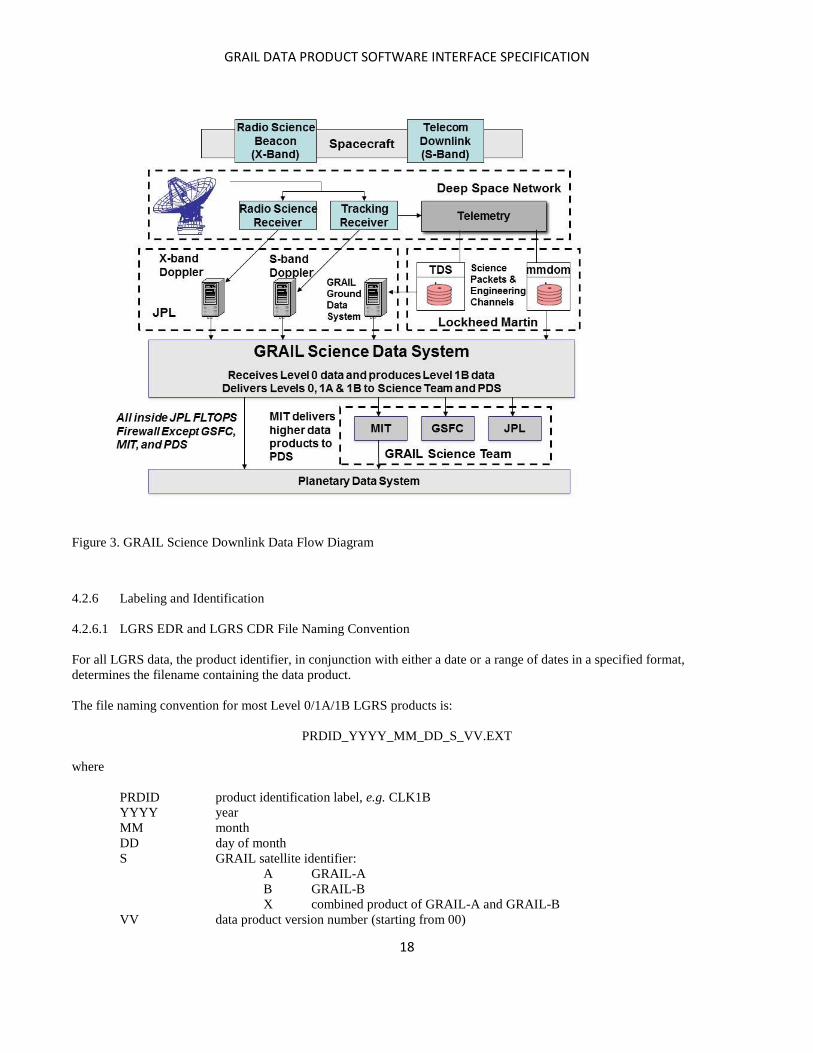
4.2.5 Data Flow and Product Generation
As shown in the downlink data flow diagram (Figure 3), telemetry packets from the Deep Space Network (DSN) are placed
on the Telemetry Delivery System (TDS). Science data and engineering data packets are transferred from the TDS to the
GRAIL SDS computers on a regular basis. The SDS also receives Level 1 Doppler (tracking) data from the Radio Science
Group (X-band) and the Tracking Data System (S-band). Finally, the SDS receives high-rate telemetry data from the Multi-
Mission Distributed Object Manager (MMDOM) servers, placed there by the Lockheed Mission Operations Center (MOC).
GRAIL DATA PRODUCT SOFTWARE INTERFACE SPECIFICATION
18
Figure 3. GRAIL Science Downlink Data Flow Diagram
4.2.6 Labeling and Identification
4.2.6.1 LGRS EDR and LGRS CDR File Naming Convention
For all LGRS data, the product identifier, in conjunction with either a date or a range of dates in a specified format,
determines the filename containing the data product.
The file naming convention for most Level 0/1A/1B LGRS products is:
PRDID_YYYY_MM_DD_S_VV.EXT
where
PRDID product identification label, e.g. CLK1B
YYYY year
MM month
DD day of month
S GRAIL satellite identifier:
A GRAIL-A
B GRAIL-B
X combined product of GRAIL-A and GRAIL-B
VV data product version number (starting from 00)
GRAIL DATA PRODUCT SOFTWARE INTERFACE SPECIFICATION
19
EXT file extension indicating binary (DAT) or ASCII (ASC) files
The Product ID (PRDID) is of the form XXXLL, where:
XXX is a three-character mnemonic, and
LL specifies the data product Level (00, 1A, 1B).
The only exception to this naming convention is TDE00. To accommodate multiple direct-to-earth measurements within the
same day, the convention is the same as above with the addition of the start time in seconds past midnight (NNNNN):
PRDID_YYYY_MM_DD_S_NNNNN_VV.EXT
4.2.6.2 RSS EDR File Naming Convention
Orbit Data Files (ODFs) and Tracking and Navigation Files (TNFs) are named, respectively, as follows:
sssttaayyyy_ddd_hhmmwuudV#.odf,
sssttaayyyy_ddd_hhmmwuudV#.tnf,
where
sss 3-character spacecraft identifier
GRA GRAIL-A
GRB GRAIL-B
GRX both
tt Target ID, e.g., LU = Moon
aa Activity/Experiment ID, e.g. GF = gravity field
yyyy year
ddd day of year
hhmm hours/minutes
w Ground Transmitter Band(s):
N none
M multiple
S S-band
X X-band
uu Uplinking Station(s) = the DSN station number, or
NN none
MM multiple
d way
1 one-way
2 two-way
M multiple
V# version number
Radio Science Receiver (RSR) data, Tracking Data Messages (TDM), Biased Tracking Data Messages (BTM), Sky
Frequency Files (XFR), Open Loop Files (OLF), and Biased Open Loop Files (BOF) are named, respectively, as follows:
sssttaayyyyddd_hhmmxuudrrpD.rcs,
sssttaayyyyddd_hhmmxuudrrpD.tdm,
sssttaayyyyddd_hhmmxuudrrpD.btm,
sssttaayyyyddd_hhmmxuudrrpD.xfr,
sssttaayyyyddd_hhmmxuudrrpD.olf
sssttaayyyyddd_hhmmxuudrrpD.bof
where:
sss 3-character spacecraft identifier

GRAIL DATA PRODUCT SOFTWARE INTERFACE SPECIFICATION
20
GRA GRAIL-A
GRB GRAIL-B
tt Target ID, e.g., LU = Moon
aa Activity/Experiment ID, e.g. GF = gravity field
yyyy year
ddd day of year
hhmm hours/minutes
xuu Uplink Transmitter Band (e.g., S, X) and 2-digit Uplinking Station number, or
"NNN" = 1-way
drr Downlink Band (e.g., X) and 2-digit Receiving Station number
p Polarization
L = left hand;
R = right hand;
M = mixed
D Open-loop data type
D RSR data
V VSR data
W WVSR data
rcs RSR number + channel + subchannel
tdm Tracking Data Message
btm Biased Tracking Data Message
xfr Sky Frequency File
olf Open Loop File
bof Biased Open Loop File
Ionospheric Media Calibration (ION) files, Tropospheric Media Calibration (TRO) files, Earth Orientation Parameter (EOP)
files, and weather (WEA) files are named, respectively, as follows:
sssttaaYYYY_DDD_yyyy_ddd.ion,
sssttaaYYYY_DDD_yyyy_ddd.tro,
sssttaaYYYY_DDD_yyyy_ddd.eop,
sssttaaYYYYDDDyyyyddd_##.wea,
where:
sss 3-character spacecraft identifier
GRA GRAIL-A
GRB GRAIL-B
GRX both
tt Target ID, e.g., LU = Moon
aa Activity/Experiment ID, e.g. GF = gravity field
YYYY start year
DDD start day of year
yyyy end year
ddd end day of year
## DSN station number
4.2.6.3 LGRS RDR File Naming Convention
Spherical Harmonics ASCII Data Records (SHADR) and Spherical Harmonics Binary Data Records (SHBDR) are named,
respectively, as follows:
GTsss_nnnnvv_SHA.TAB,
GTsss_nnnnvv_SHB_Lccc.DAT,
GRAIL DATA PRODUCT SOFTWARE INTERFACE SPECIFICATION
21
where
G denotes the generating institution
J Jet Propulsion Laboratory
G Goddard Space Flight Center
M Massachusetts Institute of Technology
T indicates the type of data represented
G gravity field
sss a 3-character modifier specified by the data producer. This modifier is used to indicate the source
spacecraft or project, such as GRX (the pair of GRAIL spacecraft).
nnnnvv a 4- to 6-character modifier specified by the data producer. Among other things, this modifier may be used
to indicate the target body, whether the SHADR contains primary data values as specified by "T" or
uncertainties/errors, and/or the version number. For GRAIL, this modifier indicates the degree and order of
the solution for the gravity field.
"SHA" or “SHB” denotes that this is an ASCII or binary file, respectively.
“Lccc” is a 2- to 4-character modifier specified by the data producer to indicate the degree and order to which
degree (L) the gravity covariance has been truncated, if applicable.
"TAB" or “DAT” denotes that this is an ASCII or binary file, respectively.
Bouguer gravity data products will have the name "Bouguer" following the degree and order identifier, i.e.
GTsss_nnnnvv_BOUGUER_SHA.TAB
Radio Science Digital Map Products (RSDMAP) are named as follows:
GTsss_ffff_nnnn_cccc.IMG,
where
G denotes the generating institution:
J Jet Propulsion Laboratory
G Goddard Space Flight Center
M Massachusetts Institute of Technology
T indicates the type of mission data represented:
G gravity field
sss a 3-character modifier specified by the data producer. This modifier is used to indicate the source
spacecraft or project, such as GRX (the pair of GRAIL spacecraft).
ffff a 4- to 6-character modifier specified by the data producer to indicate the degree and order of the solution
for the gravity field.
nnnn a 4- to 8-character modifier indicating the type of data represented:
ANOM free air gravity anomalies
ANOMERR free air gravity anomaly errors (1)
GEOID geoid heights
GEOIDERR geoid height errors (1)
BOUG Bouguer anomaly
ISOS isostatic anomaly
TOPO topography
MAGF magnetic field
DIST gravity disturbances
DEGSTR degree strength
(1) Geoid and gravity anomaly errors are computed from a mapping of the error covariance matrix
of the gravity field solution.
cccc a 2- to 4-character modifier specified by the data producer to indicate the degree and order to which the
potential solution (gravity, topography or magnetic field) has been evaluated. In the case of the error maps
for the gravity anomalies or geoid, this field indicates to which maximum degree and order the error
covariance was used to propagate the spatial errors.
.IMG the data is stored as an image.

GRAIL DATA PRODUCT SOFTWARE INTERFACE SPECIFICATION
22
Spacecraft and Planet Ephemeris Kernels (SPK) are named as follows:
sssttaaYYYY_DDD_yyyy_ddd.spk,
where:
sss 3-character spacecraft identifier
GRA GRAIL-A
GRB GRAIL-B
GRX both
tt Target ID, e.g., LU = Moon
aa Activity/Experiment ID, e.g. GF = gravity field
YYYY start year
DDD start day of year
yyyy end year
ddd end day of year
4.3 Standards Used in Generating Data Products
4.3.1 PDS Standards
All data products comply with Planetary Data System standards [25] for file formats and labels.
4.3.2 Time Standards
The objective of the GRAIL mission is to determine with high accuracy the lunar gravity field for scientific research. The
input data for the gravity field determination process are Ka-Band phase measurements between the two GRAIL spacecraft;
the phase measurements are used to compute the dual one-way range (DOWR). The DOWR measurement is then converted
to instantaneous range, range rate and range acceleration measurements, which serve as inputs to the gravity field estimation
process. Very accurate timing of the GRAIL measurements is crucial to achieving the high accuracy measurements needed
for a high quality gravity field.
Science data from the GRAIL spacecraft are time tagged by onboard clocks. However, most of the SDS scientific computer
programs process data with Barycentric Dynamic Time (TDB). Timing data from the Deep Space Network (DSN) and the
onboard Time Transfer System (TTS) and frequency observations from the Radio Science Receiver (RSR) are combined to
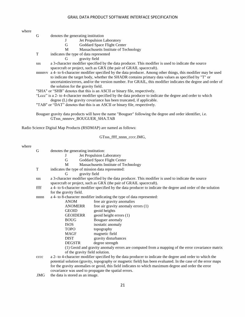
estimate the time tag conversion for the GRAIL science data. Figure 4 provides an overview of the relationships among the
three timing systems; the three subsections which follow have additional detail.
GRAIL DATA PRODUCT SOFTWARE INTERFACE SPECIFICATION
23
Figure 4. GRAIL
clocks, models, and measurements used for timing [17]
4.3.2.1 LGRS clock
Each spacecraft has an LGRS clock; its USO frequency reference makes it very stable. The LGRS clock is used for timing of
the LGRS Ka-Band phase measurement and the ranging data from the TTS. The LGRS clock has no notion of absolute time;
instead, the LGRS clock reading is with respect to its startup epoch.
4.3.2.2 Onboard spacecraft clocks
The Onboard Spacecraft Clocks (OSC) are run by crystal oscillators, which have inferior stability characteristics compared to
the USO (and LGRS clock). The two OSC clocks are the Real Time Clock (RTC) and the Base Time Clock (BTC). The real
time clock starts at 0 at boot-up of the onboard computer, whereas the Base Time Clock is set at launch and is never reset.
The OSCs are used for time tagging all spacecraft data and the arrival of the LGRS data packets (which include the LGRS 1
Pulse per Second (PPS) packets) by the onboard computer. By time tagging the arrival of LGRS data packets and the arrival
of the LGRS 1 PPS, a time correlation can be established between the LGRS clock and the OSCs.
The RTC is used to time stamp spacecraft time correlation packets, which are then transmitted to a DSN station where the
arrival time is recorded in UTC, thus providing a time correlation between the RTC and UTC. By combining LGRS/BTC,
BTC/RTC, and RTC/UTC time correlation products, a time correlation between the LGRS and UTC can be determined, and
the OSC clocks drop out. Hence, the stability characteristics of the OSCs do not affect the LGRS and UTC time correlation
because the OSC errors over short intervals (< 1 second) are less than 1 microsecond.
4.3.2.3 UTC clock used by DSN
The DSN uses very stable clocks which are based on the DSN Frequency and Timing Subsystem (FTS) [33]. The DSN time
stamps the arrival of telemetry and radio metric tracking data in UTC. Based on FTS reports, the real-time timing
performance is at the microsecond level and post processing analysis improves the performance to the nanosecond level.
GRAIL DATA PRODUCT SOFTWARE INTERFACE SPECIFICATION
24
4.3.3 Coordinate Systems
Four coordinate systems are used to define the various GRAIL data products; see [23] for detail. The definitions are
summarized below.
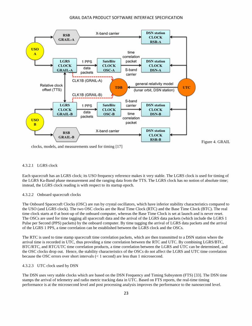
1) Mechanical Frame (MF) (Figure 5): This is defined by the spacecraft manufacturer. It is the reference frame for such
things as KBR horn location, center of mass, and thruster locations (Figures 6 and 7).
+XM = Parallel to, and in opposite direction from, the solar array normal vector
+ZM = Normal to star tracker bus plate
+YM = +ZM +XM
An onboard attitude control system approximately orients the mechanical frame with -ZM along the line of flight and
-/+ YM pointed towards the moon. For the orientation of the mechanical frame, during the primary and extended
missions, see figures 8 and 9.
2) Science Reference Frame (SRF): This is the Mechanical Frame as realized by the Star Tracker. If the Star Tracker
were perfectly aligned, MF would equal SRF. SRF is the reference frame for GRAIL science measurements.
3) EME 2000 Lunar-Centered Solar System Barycentric Frame: This is the Earth Mean Equator 2000 inertial reference
frame [31], re-centered at the moon using the DE 421 planetary ephemeris. It is the reference frame for ephemeris
products.
4) DE 421 Lunar Body-Fixed Frame: This is the lunar body-fixed frame as defined in the DE 421 planetary ephemeris
[13]. It is the reference frame for gravity products. GRGM1200A products use the DE 430 ephemeris [37].
Figure 5: The GRAIL Mechanical Frame (MF) [23]

GRAIL DATA PRODUCT SOFTWARE INTERFACE SPECIFICATION
25
Figure 6: GRAIL thruster locations (XYZ is the same as XMYMZM in text)
Figure 7: GRAIL thruster locations (XYZ is the same as XMYMZM in text)

GRAIL DATA PRODUCT SOFTWARE INTERFACE SPECIFICATION
26
Figure 8: GRAIL primary science spacecraft configuration (XYZ is the same as XMYMZM in text)
GRAIL DATA PRODUCT SOFTWARE INTERFACE SPECIFICATION
27
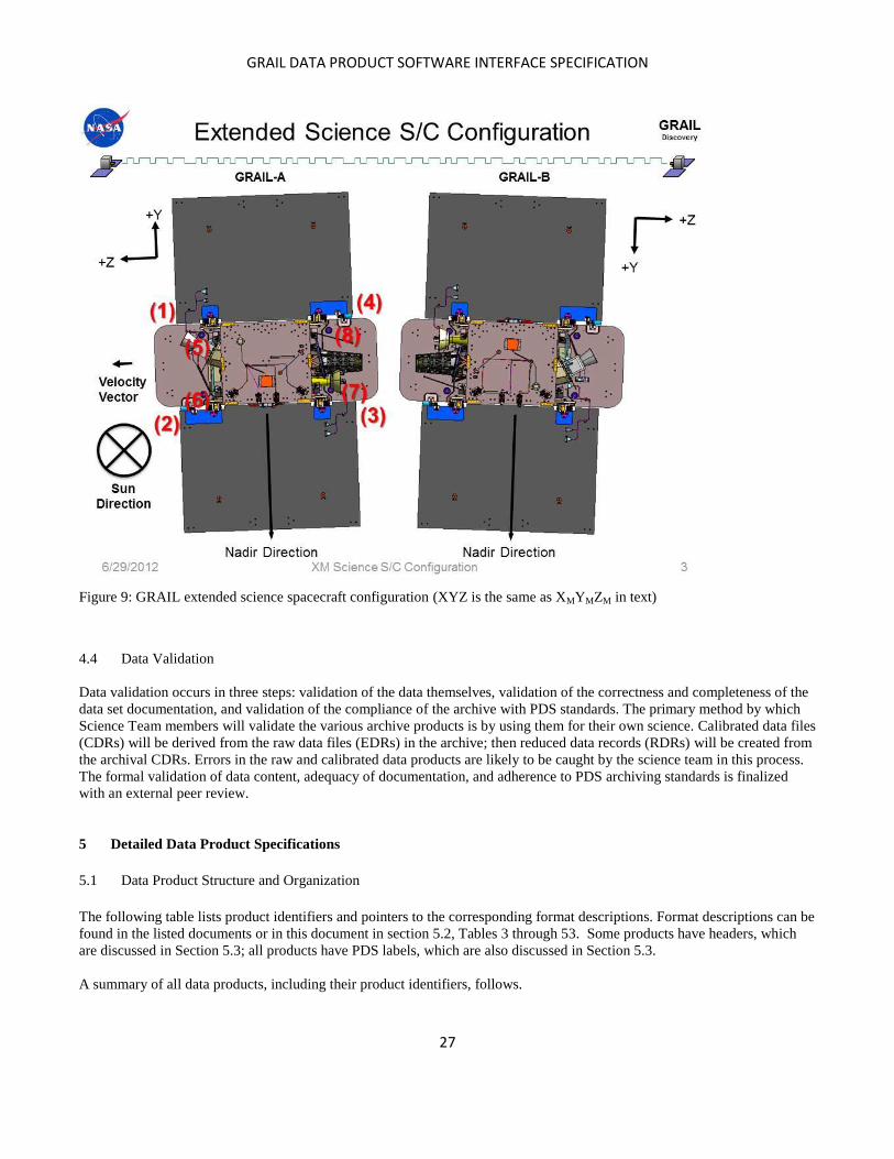
Figure 9: GRAIL extended science spacecraft configuration (XYZ is the same as XMYMZM in text)
4.4 Data Validation
Data validation occurs in three steps: validation of the data themselves, validation of the correctness and completeness of the
data set documentation, and validation of the compliance of the archive with PDS standards. The primary method by which
Science Team members will validate the various archive products is by using them for their own science. Calibrated data files
(CDRs) will be derived from the raw data files (EDRs) in the archive; then reduced data records (RDRs) will be created from
the archival CDRs. Errors in the raw and calibrated data products are likely to be caught by the science team in this process.
The formal validation of data content, adequacy of documentation, and adherence to PDS archiving standards is finalized
with an external peer review.
5 Detailed Data Product Specifications
5.1 Data Product Structure and Organization
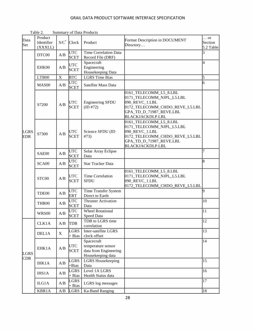
The following table lists product identifiers and pointers to the corresponding format descriptions. Format descriptions can be
found in the listed documents or in this document in section 5.2, Tables 3 through 53. Some products have headers, which
are discussed in Section 5.3; all products have PDS labels, which are also discussed in Section 5.3.
A summary of all data products, including their product identifiers, follows.
GRAIL DATA PRODUCT SOFTWARE INTERFACE SPECIFICATION
28
Table 2. Summary of Data Products
Data
Set
Product
Identifier
(XXXLL)
S/C* Clock Product
Format Description in DOCUMENT
Directory…
… or
Section
5.2 Table
LGRS
EDR
DTC00 A/B UTC
SCET
Time Correlation Data
Record File (DRF)
3
EHK00 A/B UTC
SCET
Spacecraft
Engineering
Housekeeping Data
4
LTB00 X BTC LGRS Time Bias 5
MAS00 A/B UTC
SCET Satellite Mass Data
6
S7200 A/B UTC
SCET
Engineering SFDU
(ID #72)
0161_TELECOMM_L5_8.LBL
0171_TELECOMM_NJPL_L5.LBL
090_REVC_1.LBL
0172_TELECOMM_CHDO_REVE_L5.LBL
GPA_TD_D_71987_REVE.LBL
BLACKJACKDLP.LBL
S7300 A/B UTC
SCET
Science SFDU (ID
#73)
0161_TELECOMM_L5_8.LBL
0171_TELECOMM_NJPL_L5.LBL
090_REVC_1.LBL
0172_TELECOMM_CHDO_REVE_L5.LBL
GPA_TD_D_71987_REVE.LBL
BLACKJACKDLP.LBL
SAE00 A/B UTC
SCET
Solar Array Eclipse
Data
7
SCA00 A/B UTC
SCET Star Tracker Data
8
STC00 A/B UTC
SCET
Time Correlation
SFDU
0161_TELECOMM_L5_8.LBL
0171_TELECOMM_NJPL_L5.LBL
090_REVC_1.LBL
0172_TELECOMM_CHDO_REVE_L5.LBL
TDE00 A/B UTC
ERT
Time Transfer System
Direct to Earth
9
THR00 A/B UTC
SCET
Thruster Activation
Data
10
WRS00 A/B UTC
SCET
Wheel Rotational
Speed Data
11
LGRS
CDR
CLK1A A/B TDB TDB to LGRS time
correlation
12
DEL1A X LGRS
+ Bias
Inter-satellite LGRS
clock offset
13
EHK1A A/B UTC
SCET
Spacecraft
temperature sensor
data from Engineering
Housekeeping data
14
IHK1A A/B LGRS
+Bias
LGRS Housekeeping
Data
15
IHS1A A/B LGRS
+ Bias
Level 1A LGRS
Health Status data
16
ILG1A A/B LGRS
+ Bias LGRS log messages
17
KBR1A A/B LGRS Ka-Band Ranging 18

GRAIL DATA PRODUCT SOFTWARE INTERFACE SPECIFICATION
29
+ Bias Data
LTM1A A/B TDB
Position vector and
light time between one
S/C and DSN station
19
MAS1A A/B UTC
SCET Satellite Mass Data
20
PCI1A A/B TDB Phase Center to Center
of Mass Correction
21
PLT1A X TDB
Position vector and
light time between two
spacecraft
22
PPS1A A/B LGRS
+ Bias
LGRS Pulse Per
Second (PPS) Time
Record
23
REL1A A/B TDB
Relativistic time
correction (TDB to
onboard satellite
proper time)
24
SAE1A A/B UTC
SCET
Solar Array Eclipse
Data
25
SBR1A A/B LGRS
+ Bias S-Band Ranging Data
26
SCA1A A/B BTC Star Tracker Data 27
SNV1A A/B LGRS
+ Bias
S-Band navigation
product
28
TC11A A/B LGRS
+ Bias
LGRS to BTC time
correlation
29
TC21A A/B LGRS
+ Bias
LGRS to BTC time
correlation from BTC
clock cycle counts
30
TC31A A/B BTC BTC to RTC time
correlation
31
TC41A A/B LGRS
+ Bias
LGRS to RTC time
correlation
32
TC51A A/B RTC RTC to UTC time
correlation
33
TC61A X UTC UTC to TDB time
correlation
34
THR1A A/B UTC
SCET
Thruster Activation
Data
35
USO1A A/B TDB Oscillator frequency
data
36
VCM1A A/B UTC
SCET
center of mass
displacement from
spacecraft mechanical
frame origin
37
WRS1A A/B UTC
SCET
Wheel Rotational
Speed Data
38
CLK1B A/B LGRS
+ Bias
Time correlation
between LGRS time
+Bias and TDB
39
EHK1B A/B TDB Spacecraft 40

GRAIL DATA PRODUCT SOFTWARE INTERFACE SPECIFICATION
30
temperature sensor
data from Engineering
Housekeeping Data
GNI1B A/B TDB
satellite orbit solution
in Moon centered
Inertial frame
41
GNV1B A/B TDB
satellite orbit Solution
in lunar body fixed
frame
42
KBR1C X TDB Dual-One-Way Ka-
Band Ranging Data
43
MAS1B A/B TDB Satellite Mass Data 44
SAE1B A/B TDB Solar Array Eclipse
Data
45
SBR1B X TDB Dual one-way S-Band
Ranging data
46
SCA1B A/B TDB Star Tracker Data 47
THR1B A/B TDB Thruster Activation
Data
48
USO1B A/B TDB USO Frequency
Estimate
49
VCM1B A/B TDB
center of mass
displacement from
spacecraft mechanical
frame origin
50
VGS1B A/B TDB
S-Band antenna offset
vector and switch time
(TDB time)
51
VGX1B A/B TDB
X-Band antenna offset
vector and switch time
(TDB time)
52
VKB1B A/B TDB Ka-Band Boresight
Vector
53
WRS1B A/B TDB Wheel Rotational
Speed Data
54
RSS
EDR
BOF A/B UTC Biased Open Loop
File
SEE LABEL FILE
BTM A/B UTC Biased Tracking Data
Message Standard
55
EOP X TDB Earth Orientation
Parameters
TRK_2_21_950831.LBL
ION A/B UTC Ionospheric Media
Calibration
DSN006_MEDIACAL_REV2.LBL
ODF A/B UTC Tracking Data, Orbit
Data File
SEE LABEL FILE
OLF A/B UTC Open Loop File SEE LABEL FILE
RSR A/B UTC Radio Science
Receiver 0159
SEE LABEL FILE
TDM A/B UTC Tracking Data
Message Standard
56
TNF A/B UTC Tracking and
Navigation File
TNFSIS.LBL
GRAIL DATA PRODUCT SOFTWARE INTERFACE SPECIFICATION
31
TRO X UTC Tropospheric Media
Calibration
DSN006_MEDIACAL_REV2.LBL
WEA X UTC Weather Files TRK_2_24.LBL
XFR A/B UTC X-Band sky frequency 57
LGRS
RDR
RSDMAP X N/A Radio Science Digital
Map Products
RSDMAP.LBL
SHADR X N/A Spherical Harmonics
ASCII Data Record
SHADR.LBL
SHBDR X N/A Spherical Harmonics
Binary Data Record
SHBDR.LBL
SPK A/B TDB Spacecraft Ephemeris
Kernel
SPK_MM_SIS.LBL
* Spacecraft: Value “A/B” means that there is one file for GRAIL-A and a second file for GRAIL-B; value “X” means that
GRAIL-A and GRAIL-B data are combined into a single file
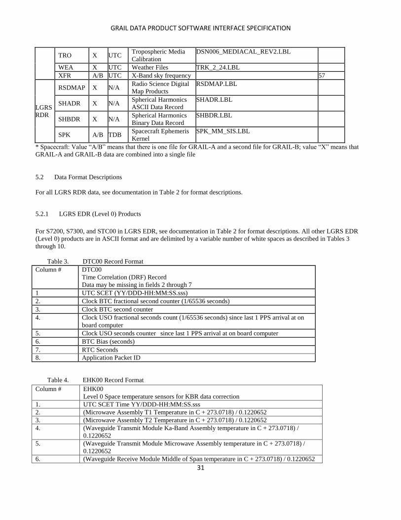
5.2 Data Format Descriptions
For all LGRS RDR data, see documentation in Table 2 for format descriptions.
5.2.1 LGRS EDR (Level 0) Products
For S7200, S7300, and STC00 in LGRS EDR, see documentation in Table 2 for format descriptions. All other LGRS EDR
(Level 0) products are in ASCII format and are delimited by a variable number of white spaces as described in Tables 3
through 10.
Table 3. DTC00 Record Format
Column # DTC00
Time Correlation (DRF) Record
Data may be missing in fields 2 through 7
1 UTC SCET (YY/DDD-HH:MM:SS.sss)
2. Clock BTC fractional second counter (1/65536 seconds)
3. Clock BTC second counter
4. Clock USO fractional seconds count (1/65536 seconds) since last 1 PPS arrival at on
board computer
5. Clock USO seconds counter since last 1 PPS arrival at on board computer
6. BTC Bias (seconds)
7. RTC Seconds
8. Application Packet ID
Table 4. EHK00 Record Format
Column # EHK00
Level 0 Space temperature sensors for KBR data correction
1. UTC SCET Time YY/DDD-HH:MM:SS.sss
2. (Microwave Assembly T1 Temperature in C + 273.0718) / 0.1220652
3. (Microwave Assembly T2 Temperature in C + 273.0718) / 0.1220652
4. (Waveguide Transmit Module Ka-Band Assembly temperature in C + 273.0718) /
0.1220652
5. (Waveguide Transmit Module Microwave Assembly temperature in C + 273.0718) /
0.1220652
6. (Waveguide Receive Module Middle of Span temperature in C + 273.0718) / 0.1220652

GRAIL DATA PRODUCT SOFTWARE INTERFACE SPECIFICATION
32
7. (Waveguide Transmit Module Middle of Span temperature in C + 273.0718) / 0.1220652
8. (Aperture temperature in C + 273.0718) / 0.1220652
9. (Radome temperature in C + 273.0718) / 0.1220652
10. (Horn Base temperature in C + 273.0718) / 0.1220652
11. (Midway on Horn temperature in C + 273.0718) / 0.1220652
12. (Orthomode transducer (where transmit and receive modules are split off at base of horn)
temperature + 273.0718) / 0.1220652 in C
13. Ground Data System Application Packet Identification
Table 5. LTB00 Record Format
Column # LTB00
LGRS Time Bias
1 BTC time (seconds)
2. LGRS Bias (seconds)
Table 6. MAS00 Record Format
Column # MAS00
Level 0 Spacecraft Mass Data
1. Spacecraft Event name
2. UTC SCET Date MM/DD/YYYY
3. UTC SCET Day of Year YY-DDD
4. UTC SCET Maneuver End Time HH:MM:SS.sss
5. Fuel Mass Remaining Book Keeping (kg)
6. Fuel Mass Remaining Book Keeping Uncertainty (kg)
7. Post Maneuver Spacecraft Mass
8. Post Maneuver Center of Mass X coordinate (meters) in mechanical reference frame
9. Post Maneuver Center of Mass Y coordinate (meters) in mechanical reference frame
10. Post Maneuver Center of Mass Z coordinate (meters) in mechanical reference frame
11. Post Maneuver Boresight Vector X coordinate
12. Post Maneuver Boresight Vector Y coordinate
13. Post Maneuver Boresight Vector Z coordinate
Table 7. SAE00 Record Format
Column # SAE00
Level 0 Solar array eclipse data
1. UTC SCET Time YY/DDD-HH:MM:SS.sss
2. Solar array short circuit current (Amperes / 2.442000E-04), as reported by the Solar
Array Battery Control
3. Solar array open circuit voltage (Volts / 9.760000E-04), as reported by the Solar Array
Battery Control
4. GDS Application Packet Identification
Table 8. SCA00 Record Format
Column # SCA00
Level 0 Star Tracker Data
1. UTC SCET Time YY/DDD-HH:MM:SS.sss
2. 1st element of current spacecraft attitude quaternion based on the onboard filter, phased
as inertial to body.
3. 2nd element of current spacecraft attitude quaternion based on the onboard filter, phased
as inertial to body.

GRAIL DATA PRODUCT SOFTWARE INTERFACE SPECIFICATION
33
4. ADS (quat_body(3)). 3rd element of current spacecraft attitude quaternion based on the
onboard filter, phased as inertial to body.
5. ADS (quat_body(4)). Scalar component of current spacecraft attitude quaternion based
on the onboard filter, phased as inertial to body.
6. Star tracker time stamp (SCLK) of current spacecraft attitude quaternion based on the
onboard filter
7. GDS Application Packet Identification number
Table 9. TDE00 Record Format
Column # TDE00
Time Transfer System Direct to Earth Data
1. ERT = UTC-ERT: Seconds past initial start time in header (Data Date), indicating the
time at which measurements in columns 2-4 were made
2. Range (seconds), integrated carrier phase measurement with N-cycle ambiguity
unresolved
3. Pseudo range (seconds). Equal to Column 1 minus Column 4 plus a constant to set the
pseudo range equal to zero at the start of the first observation of the primary and
extended mission
4. Transmit Time of the TTS range code in LGRS time (seconds). Computed by decoding
the GRAIL data message and adding fractional timing information from the Code
Delay Lock Loop
Table 10. THR00 Record Format
Column # THR00
Level 0 Thruster Activation Data
1. UTC SCET Time YY/DDD-HH:MM:SS.sss
2. The cumulative on time for thruster Attitude Control System 1 (milliseconds).
3. The cumulative on time for thruster Attitude Control System 2 (milliseconds).
4. The cumulative on time for thruster Attitude Control System 3 (milliseconds).
5. The cumulative on time for thruster Attitude Control System 4 (milliseconds).
6. The cumulative on time for thruster Attitude Control System 5 (milliseconds).
7. The cumulative on time for thruster Attitude Control System 6 (milliseconds).
8. The cumulative on time for thruster Attitude Control System 7 (milliseconds).
9. The cumulative on time for thruster Attitude Control System 8 (milliseconds).
10. GDS Application Packet Identification
Table 11. WRS00 Record Format
Column # WRS00
Level 0 Wheel Rotational Speed Data
1. UTC SCET Activation Time YY/DDD-HH:MM:SS.sss
2. Reaction wheel 1 rotational speed as determined by digital tachometer (radians/sec)
3. Reaction wheel 2 rotational speed as determined by digital tachometer (radians/sec)
4. Reaction wheel 3 rotational speed as determined by digital tachometer (radians/sec)
5. Reaction wheel 4 rotational speed as determined by digital tachometer (radians/sec)
GRAIL DATA PRODUCT SOFTWARE INTERFACE SPECIFICATION
34
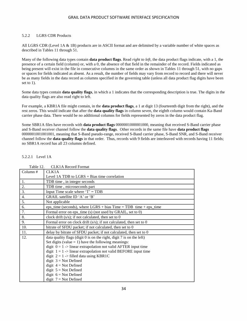
5.2.2 LGRS CDR Products
All LGRS CDR (Level 1A & 1B) products are in ASCII format and are delimited by a variable number of white spaces as
described in Tables 11 through 51.
Many of the following data types contain data product flags. Read right to left, the data product flags indicate, with a 1, the
presence of a certain field (column) or, with a 0, the absence of that field in the remainder of the record. Fields indicated as
being present will exist in the file in consecutive columns in the same order as shown in Tables 11 through 51, with no gaps
or spaces for fields indicated as absent. As a result, the number of fields may vary from record to record and there will never
be as many fields in the data record as columns specified in the governing table (unless all data product flag digits have been
set to 1).
Some data types contain data quality flags, in which a 1 indicates that the corresponding description is true. The digits in the
data quality flags are also read right to left.
For example, a KBR1A file might contain, in the data product flags, a 1 at digit 13 (fourteenth digit from the right), and the
rest zeros. This would indicate that after the data quality flags in column seven, the eighth column would contain Ka-Band
carrier phase data. There would be no additional columns for fields represented by zeros in the data product flag.
Some SBR1A files have records with data product flags 0000001000001000, meaning that received S-Band carrier phase
and S-Band receiver channel follow the data quality flags. Other records in the same file have data product flags
0000001001001001, meaning that S-Band pseudo-range, received S-Band carrier phase, S-Band SNR, and S-Band receiver
channel follow the data quality flags in that order. Thus, records with 9 fields are interleaved with records having 11 fields;
no SBR1A record has all 23 columns defined.
5.2.2.1 Level 1A
Table 12. CLK1A Record Format
Column # CLK1A
Level 1A TDB to LGRS + Bias time correlation
1. TDB time , in integer seconds
2. TDB time , microseconds part
3. Input Time scale where ‘T’ = TDB
4. GRAIL satellite ID ‘A’ or ‘B’
5. Not applicable
6. eps_time (seconds), where LGRS + bias Time = TDB time + eps_time
7. Formal error on eps_time (s) (not used by GRAIL, set to 0)
8. clock drift (s/s); if not calculated, then set to 0
9. Formal error on clock drift (s/s); if not calculated, then set to 0
10. bitrate of SFDU packet; if not calculated, then set to 0
11. delay by bitrate of SFDU packet; if not calculated, then set to 0
12. data quality flags (digit 0 is on the right, digit 7 is on the left)
Set digits (value = 1) have the following meanings:
digit 0 = 1 -> linear extrapolation not valid AFTER input time
digit 1 = 1 -> linear extrapolation not valid BEFORE input time
digit 2 = 1 -> filled data using KBR1C
digit 3 = Not Defined
digit 4 = Not Defined
digit 5 = Not Defined
digit 6 = Not Defined
digit 7 = Not Defined

GRAIL DATA PRODUCT SOFTWARE INTERFACE SPECIFICATION
35
Table 13. DEL1A Record Format
Column # DEL1A
Inter-satellite LGRS clock offset between spacecraft
1. TDB time, in integer seconds
2. TDB time, microseconds part
3. Input Time scale where ‘T’ = TDB
4. GRAIL satellite ID ‘X’ to indicate a single product for two spacecraft
5. Not applicable
6. eps_time (in LGRS seconds), where eps_time = LGRS-A clock – LGRS-B clock
7. Formal error on eps_time (s); if not calculated, then set to 0
8. Clock offset corrected for LGRS resets. Identical to column 6 if no reset.
9. Formal error on clock drift (s/s); if not calculated, then set to 0
10. bitrate of SFDU packet; if not calculated, then set to 0
11. delay by bitrate of SFDU packet; if not calculated, then set to 0
12. data quality flags (digit 0 is on the right, digit 7 is on the left)
Set digits (value = 1) have the following meanings:
digit 0 = 1 -> linear extrapolation not valid AFTER input time
digit 1 = 1 -> linear extrapolation not valid BEFORE input time
digit 2 = 1 -> filled data using KBR1C
digit 3 = Not Defined
digit 4 = Not Defined
digit 5 = Not Defined
digit 6 = Not Defined
digit 7 = Not Defined
Table 14. EHK1A Record Format
Column
#
EHK1A
Level 1A Spacecraft temperature sensor data from Engineering Housekeeping data for KBR
data correction
1. UTC SCET, integer seconds past 12:00:00 noon 01-Jan-2000
2. UTC SCET, microseconds part
3. Time reference where 'U' = UTC SCET
4. GRAIL satellite ID ‘A’ or ‘B’
5. Microwave Assembly T1 temperature in C
6. Microwave Assembly T2 temperature in C
7. Waveguide transmit Ka-Band Assembly temperature in C
8. Waveguide transmit Microwave Assembly temperature in C
9. Waveguide Rx Mid temperature in C
10. Waveguide Tx Mid temperature in C
11. Aperture temperature in C
12. Radome temperature in C
13. HornBase temperature in C
14. Midway on Horn temperature in C
15. Orthomode Transducer (where transmit and receive modules are split off at base of horn)
temperature in C
16. data quality flags (digit 0 is on the right, digit 7 is on the left)
LSB = digit 0
digit 0 = Not Defined
digit 1 = Not Defined
digit 2 = Not Defined
digit 3 = Not Defined
digit 4 = Not Defined
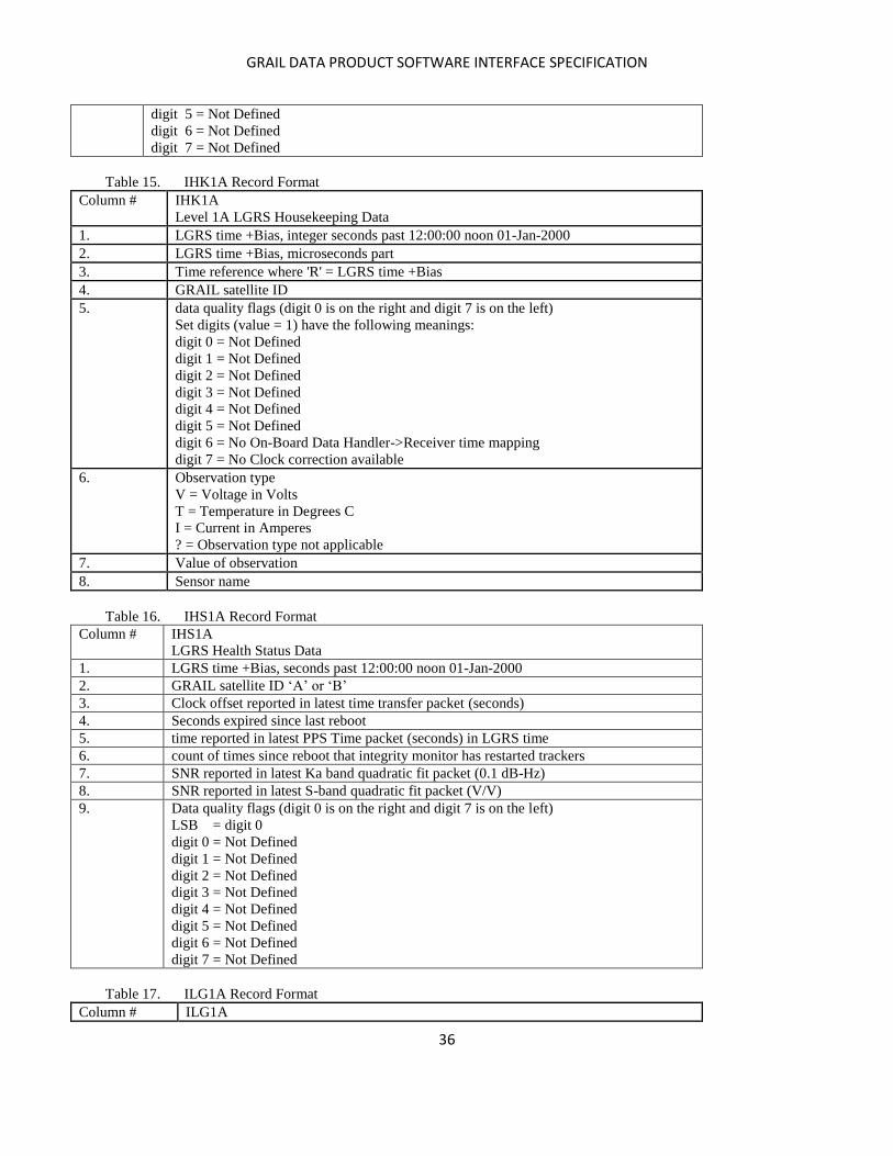
GRAIL DATA PRODUCT SOFTWARE INTERFACE SPECIFICATION
36
digit 5 = Not Defined
digit 6 = Not Defined
digit 7 = Not Defined
Table 15. IHK1A Record Format
Column # IHK1A
Level 1A LGRS Housekeeping Data
1. LGRS time +Bias, integer seconds past 12:00:00 noon 01-Jan-2000
2. LGRS time +Bias, microseconds part
3. Time reference where 'R' = LGRS time +Bias
4. GRAIL satellite ID
5. data quality flags (digit 0 is on the right and digit 7 is on the left)
Set digits (value = 1) have the following meanings:
digit 0 = Not Defined
digit 1 = Not Defined
digit 2 = Not Defined
digit 3 = Not Defined
digit 4 = Not Defined
digit 5 = Not Defined
digit 6 = No On-Board Data Handler->Receiver time mapping
digit 7 = No Clock correction available
6. Observation type
V = Voltage in Volts
T = Temperature in Degrees C
I = Current in Amperes
? = Observation type not applicable
7. Value of observation
8. Sensor name
Table 16. IHS1A Record Format
Column # IHS1A
LGRS Health Status Data
1. LGRS time +Bias, seconds past 12:00:00 noon 01-Jan-2000
2. GRAIL satellite ID ‘A’ or ‘B’
3. Clock offset reported in latest time transfer packet (seconds)
4. Seconds expired since last reboot
5. time reported in latest PPS Time packet (seconds) in LGRS time
6. count of times since reboot that integrity monitor has restarted trackers
7. SNR reported in latest Ka band quadratic fit packet (0.1 dB-Hz)
8. SNR reported in latest S-band quadratic fit packet (V/V)
9. Data quality flags (digit 0 is on the right and digit 7 is on the left)
LSB = digit 0
digit 0 = Not Defined
digit 1 = Not Defined
digit 2 = Not Defined
digit 3 = Not Defined
digit 4 = Not Defined
digit 5 = Not Defined
digit 6 = Not Defined
digit 7 = Not Defined
Table 17. ILG1A Record Format
Column # ILG1A
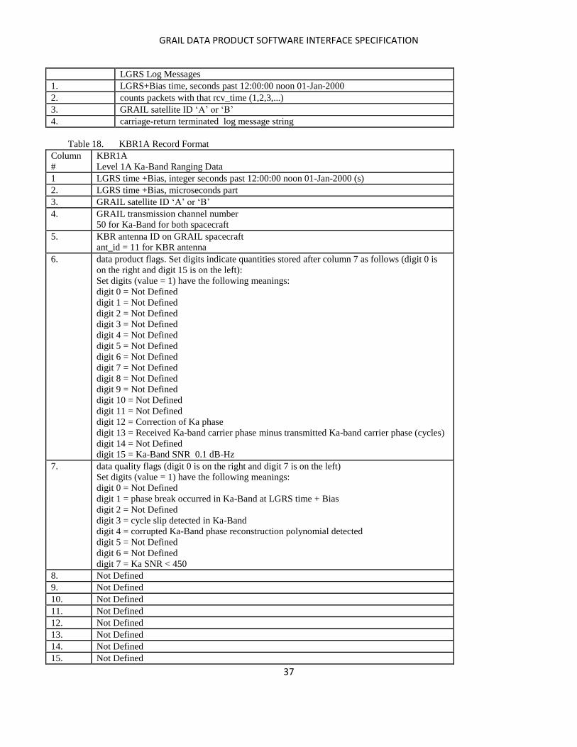
GRAIL DATA PRODUCT SOFTWARE INTERFACE SPECIFICATION
37
LGRS Log Messages
1. LGRS+Bias time, seconds past 12:00:00 noon 01-Jan-2000
2. counts packets with that rcv_time (1,2,3,...)
3. GRAIL satellite ID ‘A’ or ‘B’
4. carriage-return terminated log message string
Table 18. KBR1A Record Format
Column
#
KBR1A
Level 1A Ka-Band Ranging Data
1 LGRS time +Bias, integer seconds past 12:00:00 noon 01-Jan-2000 (s)
2. LGRS time +Bias, microseconds part
3. GRAIL satellite ID ‘A’ or ‘B’
4. GRAIL transmission channel number
50 for Ka-Band for both spacecraft
5. KBR antenna ID on GRAIL spacecraft
ant_id = 11 for KBR antenna
6. data product flags. Set digits indicate quantities stored after column 7 as follows (digit 0 is
on the right and digit 15 is on the left):
Set digits (value = 1) have the following meanings:
digit 0 = Not Defined
digit 1 = Not Defined
digit 2 = Not Defined
digit 3 = Not Defined
digit 4 = Not Defined
digit 5 = Not Defined
digit 6 = Not Defined
digit 7 = Not Defined
digit 8 = Not Defined
digit 9 = Not Defined
digit 10 = Not Defined
digit 11 = Not Defined
digit 12 = Correction of Ka phase
digit 13 = Received Ka-band carrier phase minus transmitted Ka-band carrier phase (cycles)
digit 14 = Not Defined
digit 15 = Ka-Band SNR 0.1 dB-Hz
7. data quality flags (digit 0 is on the right and digit 7 is on the left)
Set digits (value = 1) have the following meanings:
digit 0 = Not Defined
digit 1 = phase break occurred in Ka-Band at LGRS time + Bias
digit 2 = Not Defined
digit 3 = cycle slip detected in Ka-Band
digit 4 = corrupted Ka-Band phase reconstruction polynomial detected
digit 5 = Not Defined
digit 6 = Not Defined
digit 7 = Ka SNR < 450
8. Not Defined
9. Not Defined
10. Not Defined
11. Not Defined
12. Not Defined
13. Not Defined
14. Not Defined
15. Not Defined
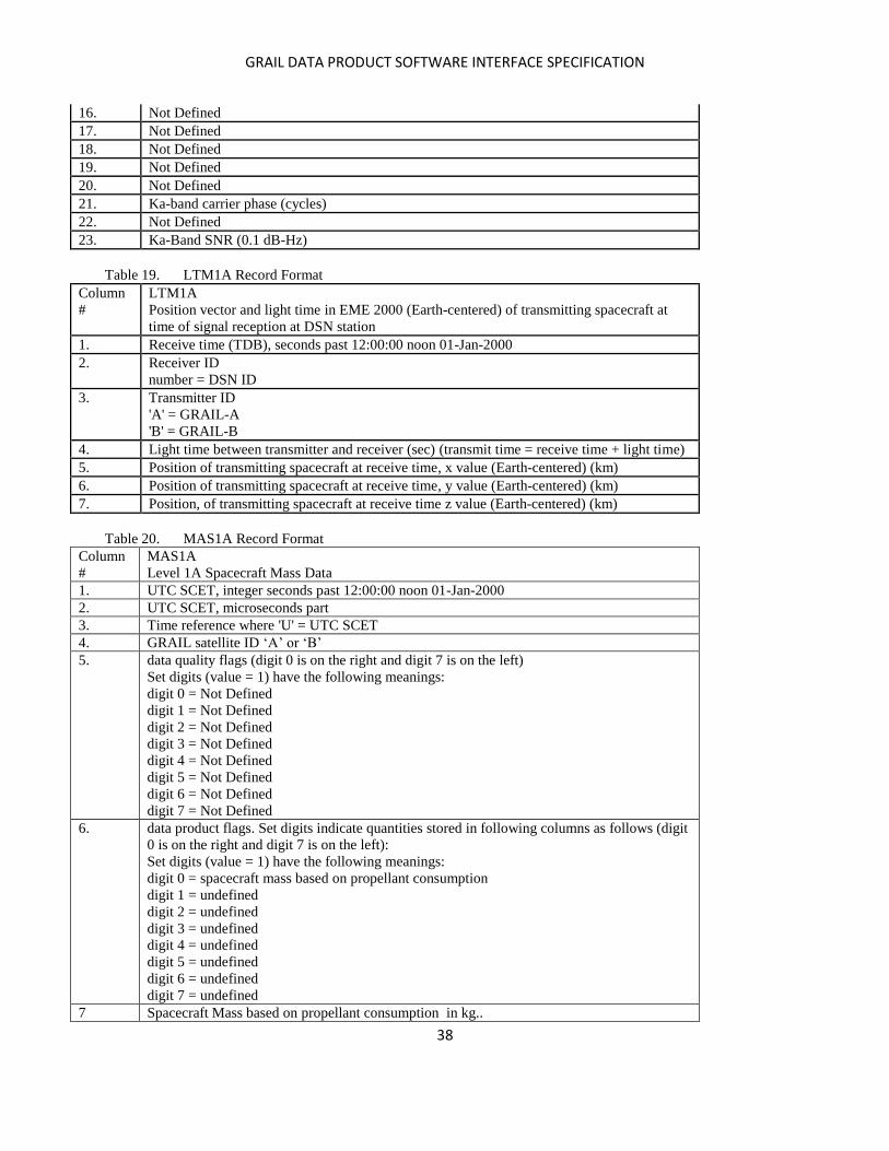
GRAIL DATA PRODUCT SOFTWARE INTERFACE SPECIFICATION
38
16. Not Defined
17. Not Defined
18. Not Defined
19. Not Defined
20. Not Defined
21. Ka-band carrier phase (cycles)
22. Not Defined
23. Ka-Band SNR (0.1 dB-Hz)
Table 19. LTM1A Record Format
Column
#
LTM1A
Position vector and light time in EME 2000 (Earth-centered) of transmitting spacecraft at
time of signal reception at DSN station
1. Receive time (TDB), seconds past 12:00:00 noon 01-Jan-2000
2. Receiver ID
number = DSN ID
3. Transmitter ID
'A' = GRAIL-A
'B' = GRAIL-B
4. Light time between transmitter and receiver (sec) (transmit time = receive time + light time)
5. Position of transmitting spacecraft at receive time, x value (Earth-centered) (km)
6. Position of transmitting spacecraft at receive time, y value (Earth-centered) (km)
7. Position, of transmitting spacecraft at receive time z value (Earth-centered) (km)
Table 20. MAS1A Record Format
Column
#
MAS1A
Level 1A Spacecraft Mass Data
1. UTC SCET, integer seconds past 12:00:00 noon 01-Jan-2000
2. UTC SCET, microseconds part
3. Time reference where 'U' = UTC SCET
4. GRAIL satellite ID ‘A’ or ‘B’
5. data quality flags (digit 0 is on the right and digit 7 is on the left)
Set digits (value = 1) have the following meanings:
digit 0 = Not Defined
digit 1 = Not Defined
digit 2 = Not Defined
digit 3 = Not Defined
digit 4 = Not Defined
digit 5 = Not Defined
digit 6 = Not Defined
digit 7 = Not Defined
6. data product flags. Set digits indicate quantities stored in following columns as follows (digit
0 is on the right and digit 7 is on the left):
Set digits (value = 1) have the following meanings:
digit 0 = spacecraft mass based on propellant consumption
digit 1 = undefined
digit 2 = undefined
digit 3 = undefined
digit 4 = undefined
digit 5 = undefined
digit 6 = undefined
digit 7 = undefined
7 Spacecraft Mass based on propellant consumption in kg..

GRAIL DATA PRODUCT SOFTWARE INTERFACE SPECIFICATION
39
Table 21. PCI1A Record Format
Column
#
PCI1A
Phase Center to Center of Mass Correction
1. TDB, seconds past 12:00:00 noon 01-Jan-2000
2. GRAIL satellite ID ‘A’ or ‘B’
3. Antenna phase center range correction (m)
4. Antenna phase center range rate correction (m/sec)
5. Antenna phase center range acceleration correction (m/sec^2)
6. data quality flags (digit 0 is on the right and digit 7 is on the left)
Set digits (value = 1) have the following meanings:
digit 0 = Not Defined
digit 1 = bit 1 = From raw data for ka boresight calibration period or prediction change
period
digit 2 = Not Defined
digit 3 = Not Defined
digit 4 = Not Defined
digit 5 = Not Defined
digit 6 = Not Defined
digit 7 = Not Defined
Table 22. PLT1A Record Format
Column
#
PLT1A
Position vector and light time in EME 2000 (moon centered) of transmitting spacecraft at
time of signal reception at receiving spacecraft
1. Receive time (TDB), seconds past 12:00:00 noon 01-Jan-2000
2. Receiver ID
'A' = GRAIL-A
'B' = GRAIL-B
3. Transmitter ID
'A' = GRAIL-A
'B' = GRAIL-B
4. Light time between transmitter and receiver (sec) (transmit time = receive time + light time)
5. Position of transmitting spacecraft at receive time, x value (moon centered) (km)
6. Position of transmitting spacecraft at receive time, y value (moon centered) (km)
7. Position of transmitting spacecraft at receive time z value (moon centered) (km)
Table 23. PPS1A Record Format
Column # PPS1A
LGRS Pulse Per Second (PPS) Time Record
1. LGRS time +Bias, seconds past 12:00:00 noon 01-Jan-2000
2. GRAIL satellite ID ‘A’ or ‘B’
3. LGRS time
Table 24. REL1A Record Format
Column # REL1A
Relativistic time correction (TDB to onboard satellite proper time)
1. TDB, in integer seconds
2. TDB, microseconds part
3. Time scale where ‘T’ = TDB
4. GRAIL satellite ID ‘A’ or ‘B’
5. Not applicable
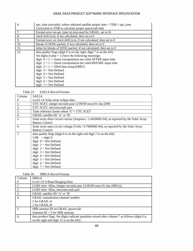
GRAIL DATA PRODUCT SOFTWARE INTERFACE SPECIFICATION
40
6. eps_time (seconds), where onboard satellite proper time = TDB + eps_time
Correction to TDB to calculate proper spacecraft time
7. Formal error on eps_time (s) (not used by GRAIL, set to 0)
8. clock drift (s/s); if not calculated, then set to 0
9. Formal error on clock drift (s/s); if not calculated, then set to 0
10. bitrate of SFDU packet; if not calculated, then set to 0
11. delay by bitrate of SFDU packet; if not calculated, then set to 0
12. data quality flags (digit 0 is on the right, digit 7 is on the left)
Set digits (value = 1) have the following meanings:
digit 0 = 1 -> linear extrapolation not valid AFTER input time
digit 1 = 1 -> linear extrapolation not valid BEFORE input time
digit 2 = 1 -> filled data using KBR1C
digit 3 = Not Defined
digit 4 = Not Defined
digit 5 = Not Defined
digit 6 = Not Defined
digit 7 = Not Defined
Table 25. SAE1A Record Format
Column
#
SAE1A
Level 1A Solar array eclipse data
1. UTC SCET, integer seconds past 12:00:00 noon 01-Jan-2000
2. UTC SCET, microseconds part
3. Time reference frame where 'U' = UTC SCET
4. GRAIL satellite ID ‘A’ or ‘B’
5. Solar array short circuit current (Amperes / 2.442000E-04), as reported by the Solar Array
Battery Control
6. Solar array open circuit voltage (Volts / 9.760000E-04), as reported by the Solar Array
Battery Control
7. data quality flags (digit 0 is on the right and digit 7 is on the left)
LSB = digit 0
digit 0 = Not Defined
digit 1 = Not Defined
digit 2 = Not Defined
digit 3 = Not Defined
digit 4 = Not Defined
digit 5 = Not Defined
digit 6 = Not Defined
digit 7 = Not Defined
Table 26. SBR1A Record Format
Column
#
SBR1A
Level 1A S-Band Ranging Data
1 LGRS time +Bias, integer seconds past 12:00:00 noon 01-Jan-2000 (s)
2. LGRS time +Bias, microseconds part
3. GRAIL satellite ID ‘A’ or ‘B’
4. GRAIL transmission channel number
2 for GRAIL-A
1 for GRAIL-B
5. SBR antenna ID on GRAIL spacecraft
Antenna ID = 3 for SBR antenna
6. data product flags. Set digits indicate quantities stored after column 7 as follows (digit 0 is
on the right and digit 15 is on the left):
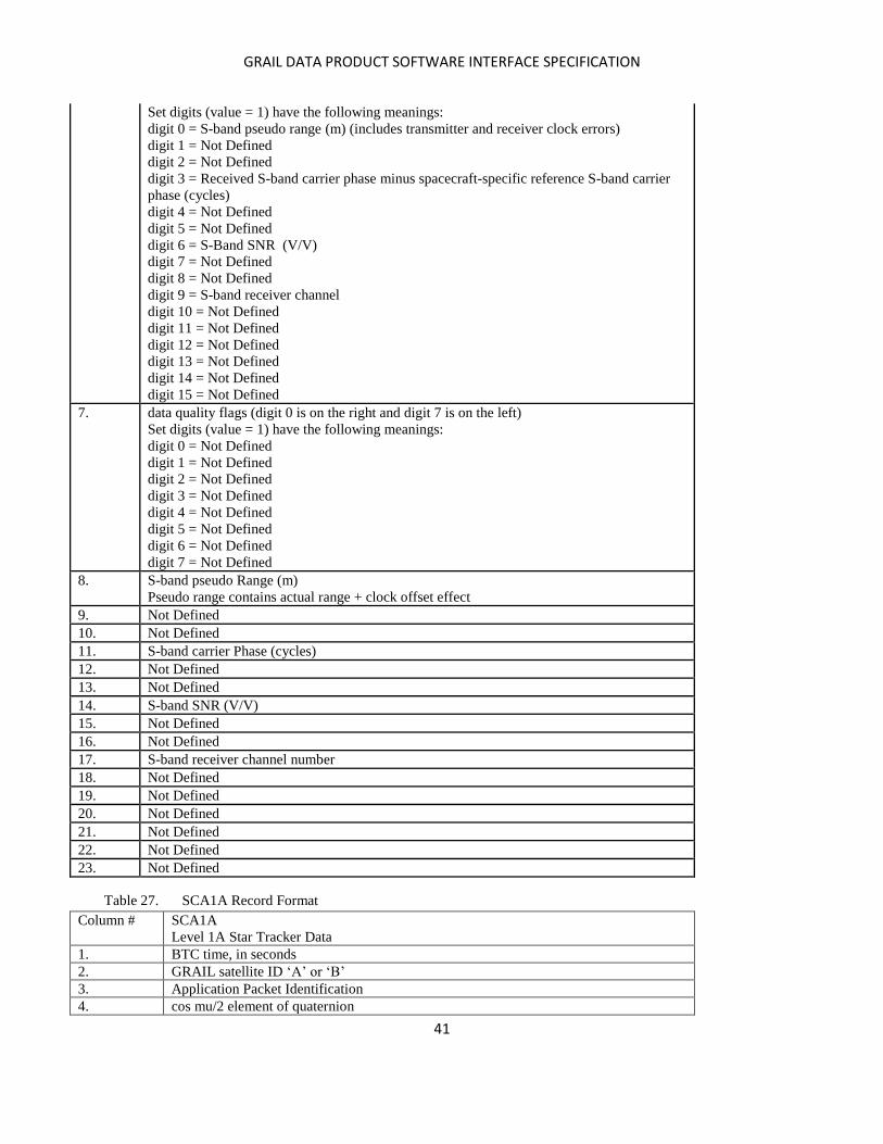
GRAIL DATA PRODUCT SOFTWARE INTERFACE SPECIFICATION
41
Set digits (value = 1) have the following meanings:
digit 0 = S-band pseudo range (m) (includes transmitter and receiver clock errors)
digit 1 = Not Defined
digit 2 = Not Defined
digit 3 = Received S-band carrier phase minus spacecraft-specific reference S-band carrier
phase (cycles)
digit 4 = Not Defined
digit 5 = Not Defined
digit 6 = S-Band SNR (V/V)
digit 7 = Not Defined
digit 8 = Not Defined
digit 9 = S-band receiver channel
digit 10 = Not Defined
digit 11 = Not Defined
digit 12 = Not Defined
digit 13 = Not Defined
digit 14 = Not Defined
digit 15 = Not Defined
7. data quality flags (digit 0 is on the right and digit 7 is on the left)
Set digits (value = 1) have the following meanings:
digit 0 = Not Defined
digit 1 = Not Defined
digit 2 = Not Defined
digit 3 = Not Defined
digit 4 = Not Defined
digit 5 = Not Defined
digit 6 = Not Defined
digit 7 = Not Defined
8. S-band pseudo Range (m)
Pseudo range contains actual range + clock offset effect
9. Not Defined
10. Not Defined
11. S-band carrier Phase (cycles)
12. Not Defined
13. Not Defined
14. S-band SNR (V/V)
15. Not Defined
16. Not Defined
17. S-band receiver channel number
18. Not Defined
19. Not Defined
20. Not Defined
21. Not Defined
22. Not Defined
23. Not Defined
Table 27. SCA1A Record Format
Column # SCA1A
Level 1A Star Tracker Data
1. BTC time, in seconds
2. GRAIL satellite ID ‘A’ or ‘B’
3. Application Packet Identification
4. cos mu/2 element of quaternion

GRAIL DATA PRODUCT SOFTWARE INTERFACE SPECIFICATION
42
5. I element of quaternion rotation axis
6. J element of quaternion rotation axis
7. K element of quaternion rotation axis
8. rss of formal error of quaternions; if not calculated, then set to 0
9. data quality flags (digit 0 is at the right and digit 7 is at the left).
LSB = digit 0
digit 0 = Not Defined
digit 1 = Ka boresight calibration period or prediction change period
digit 2 = Not Defined
digit 3 = Not Defined
digit 4 = Not Defined
digit 5 = Not Defined
digit 6 = Not Defined
digit 7 = Not Defined
Table 28. SNV1A Record Format
Column
#
SNV1A
S-Band Navigation Product
1. LGRS time + Bias, seconds past 12:00:00 noon 01-Jan-2000
2 LGRS time + Bias, microseconds part
3. GRAIL satellite ID ‘A’ or ‘B’
4. Measured range =(local measured pseudorange range + remote measured pseudorange)/2
(seconds). Pseudorange contains actual range + clock offset effect.
5. Measured clock offset =(local measuredpseudorange– remote measured pseudorange)/2
(seconds). Pseudorange contains actual range + clock offset effect.
6. Local spacecraft S-Band SNR (V/V)
7. Remote spacecraft S-Band SNR (V/V); if not calculated, then set to 0
8. Local spacecraft Ka-Band SNR (0.1 dB-Hz)
9. Remote spacecraft Ka-Band SNR (0.1 dB-Hz); if not calculated, then set to 0
10. data quality flags (digit 0 is on the right and digit 7 is on the left
LSB = digit 0
digit 0 = Not Defined
digit 1 = Not Defined
digit 2 = Not Defined
digit 3 = Not Defined
digit 4 = Not Defined
digit 5 = Not Defined
digit 6 = Not Defined
digit 7 = Not Defined
Table 29. TC11A Record Format
Column # TC11A
LGRS to BTC time correlation
1. Input time, in integer seconds
2. Input time, microseconds part
3. Time scale where ‘L’ = LGRS time + Bias
4. GRAIL satellite ID ‘A’ or ‘B’
5. Not applicable
6. eps_time (seconds), where Output time scale = Input time scale + eps_time
7. Formal error on eps_time (s); if not calculated then set to 0
8. Blackjack packet arrival time in RTC time
GRAIL DATA PRODUCT SOFTWARE INTERFACE SPECIFICATION
43
9. Formal error on clock drift (s/s); if not calculated then set to 0
10. bitrate of SFDU packet; if not calculated, then set to 0
11. delay by bitrate of SFDU packet; if not calculated, then set to 0
12. data quality flags (digit 0 is on the right, digit 7 is on the left)
Set digits (value = 1) have the following meanings:
digit 0 = 1 -> linear extrapolation not valid AFTER input time
digit 1 = 1 -> linear extrapolation not valid BEFORE input time
digit 2 = 1 -> filled data using KBR1C
digit 3 = Not Defined
digit 4 = Not Defined
digit 5 = Not Defined
digit 6 = Not Defined
digit 7 = Not Defined
Table 30. TC21A Record Format
Column # TC21A
LGRS to BTC time correlation from BTC clock cycle counts
1. LGRS time + Bias, in integer seconds
2. LGRS time + Bias, microseconds part
3. Time scale where ‘L’ = LGRS time + Bias
4. GRAIL satellite ID ‘A’ or ‘B’
5. Not applicable
6. eps_time (seconds), where BTC time = LGRS time + Bias + eps_time
7. Formal error on eps_time (s); if not calculated, then set to 0
8. Not applicable and set to 0
9. Formal error on clock drift (s/s); if not calculated, then set to 0
10. bitrate of SFDU packet; if not calculated, then set to 0
11. delay by bitrate of SFDU packet; if not calculated, then set to 0
12. data quality flags (digit 0 is on the right, digit 7 is on the left)
Set digits (value = 1) have the following meanings:
digit 0 = 1 -> linear extrapolation not valid AFTER input time
digit 1 = 1 -> linear extrapolation not valid BEFORE input time
digit 2 = 1 -> filled data using KBR1C
digit 3 = Not Defined
digit 4 = Not Defined
digit 5 = Not Defined
digit 6 = Not Defined
digit 7 = Not Defined
Table 31. TC31A Record Format
Column # TC31A
BTC to RTC time correlation
1. BTC, in integer seconds
2. BTC, microseconds part
3. Time scale where ‘B’ = BTC time
4. GRAIL satellite ID ‘A’ or ‘B’
5. Not applicable
6. eps_time (seconds), where RTC = BTC + eps_time
7. Formal error on eps_time (s); if not calculated, then set to 0
8. Not applicable and set to 0
9. Formal error on clock drift (s/s); if not calculated, then set to 0
10. bitrate of SFDU packet; if not calculated, then set to 0
GRAIL DATA PRODUCT SOFTWARE INTERFACE SPECIFICATION
44
11. delay by bitrate of SFDU packet; if not calculated, then set to 0
12. data quality flags (digit 0 is on the right, digit 7 is on the left)
Set digits (value = 1) have the following meanings:
digit 0 = 1 -> linear extrapolation not valid AFTER input time
digit 1 = 1 -> linear extrapolation not valid BEFORE input time
digit 2 = 1 -> filled data using KBR1C
digit 3 = Not Defined
digit 4 = Not Defined
digit 5 = Not Defined
digit 6 = Not Defined
digit 7 = Not Defined
Table 32. TC41A Record Format
Column # TC41A
LGRS to RTC time correlation
1. LGRS time + Bias, in integer seconds
2. LGRS time + Bias, microseconds part
3. Time scale where ‘L’ = LGRS time + Bias
4. GRAIL satellite ID ‘A’ or ‘B’
5. Not applicable
6. eps_time (seconds), where RTC = LGRS time + Bias + eps_time
7. Formal error on eps_time (s); if not calculated, then set to 0
8. Not applicable and set to 0
9. Formal error on clock drift (s/s); if not calculated, then set to 0
10. bitrate of SFDU packet; if not calculated, then set to 0
11. delay by bitrate of SFDU packet; if not calculated, then set to 0
12. data quality flags (digit 0 is on the right, digit 7 is on the left)
Set digits (value = 1) have the following meanings:
digit 0 = 1 -> linear extrapolation not valid AFTER input time
digit 1 = 1 -> linear extrapolation not valid BEFORE input time
digit 2 = 1 -> filled data using KBR1C
digit 3 = Not Defined
digit 4 = Not Defined
digit 5 = Not Defined
digit 6 = Not Defined
digit 7 = Not Defined
Table 33. TC51A Record Format
Column # TC51A
RTC to UTC time correlation
1. RTC, in integer seconds
2. RTC, microseconds part
3. Time scale where ‘R’ = RTC time
4. GRAIL satellite ID ‘A’ or ‘B’
5. DSN station ID
6. eps_time (seconds), where UTC at DSN station = RTC + eps_time and UTC is in
seconds since 12:00:00 noon on 1 January 2000
7. Formal error on eps_time (s); if not calculated, then set to 0
8. Not applicable and set to 0
9. Formal error on clock drift (s/s); if not calculated, then set to 0
10. bitrate of SFDU packet
11. delay by bitrate of SFDU packet; if not calculated, then set to 0
GRAIL DATA PRODUCT SOFTWARE INTERFACE SPECIFICATION
45
12. data quality flags (digit 0 is on the right, digit 7 is on the left)
Set digits (value = 1) have the following meanings:
digit 0 = 1 -> linear extrapolation not valid AFTER input time
digit 1 = 1 -> linear extrapolation not valid BEFORE input time
digit 2 = 1 -> filled data using KBR1C
digit 3 = Not Defined
digit 4 = Not Defined
digit 5 = Not Defined
digit 6 = Not Defined
digit 7 = Not Defined
Table 34. TC61A Record Format
Column # TC61A
UTC to TDB time correlation
1. UTC, in integer seconds
2. UTC, microseconds part
3. Time scale where ‘U’ = UTC
4. GRAIL satellite ID ‘X’ to indicate a single product for two spacecraft
5. Not applicable
6. eps_time (seconds), where TDB = UTC + eps_time
7. Formal error on eps_time (s); if not calculated, then set to 0
8. Clock drift (s/s) deps_time/dt
9. Formal error on clock drift (s/s); if not calculated, then set to 0
10. bitrate of SFDU packet ; if not calculated, then set to 0
11. delay by bitrate of SFDU packet; if not calculated, then set to 0
12. data quality flags (digit 0 is on the right, digit 7 is on the left)
Set digits (value = 1) have the following meanings:
digit 0 = 1 -> linear extrapolation not valid AFTER input time
digit 1 = 1 -> linear extrapolation not valid BEFORE input time
digit 2 = 1 -> filled data using KBR1C
digit 3 = Not Defined
digit 4 = Not Defined
digit 5 = Not Defined
digit 6 = Not Defined
digit 7 = Not Defined
Table 35. THR1A Record Format
Column # THR1A
Level 1A Thruster Activation Data
1. UTC SCET, integer seconds past 12:00:00 noon 01-Jan-2000
2. UTC SCET, microseconds part
3. Time reference frame where 'U' = UTC SCET
4. GRAIL satellite ID ‘A’ or ‘B’
5-12. Count of number of work cycles that each thruster has been activated
Set to 0 for GRAIL.
13-20. Thruster on-time for this activation time (milliseconds)
21-28. Accumulated thruster firing duration time (milliseconds)
integer will wrap after 4294967295
29. data quality flags (digit 0 is on the right and digit 7 is on the left)
Set digits (value = 1) have the following meanings:
digit 0 = 1 On time not calculated
digit 1 = 1 Multiple unaccounted thrusts prior to current record
GRAIL DATA PRODUCT SOFTWARE INTERFACE SPECIFICATION
46
digit 2 = Not Defined
digit 3 = Not Defined
digit 4 = Not Defined
digit 5 = Not Defined
digit 6 = Not Defined
digit 7 = Not Defined
Table 36. USO1A Record Format
Column # USO1A
Level 1A Ultra Stable Oscillator Stability Data
1. TDB, seconds past 12:00:00 noon 01-Jan-2000
2. GRAIL satellite ID ‘A’ or ‘B’
3. USO identification number set to 0
4. Not applicable, set to 0
5. X-Band RSB frequency (Hz)
6. Not applicable, set to 0
7. data quality flags (digit 0 is on the right and digit 7 is on the left)
Set digits (value = 1) have the following meanings:
digit 0 = Not Defined
digit 1 = Not Defined
digit 2 = Not Defined
digit 3 = Not Defined
digit 4 = Not Defined
digit 5 = Not Defined
digit 6 = Not Defined
digit 7 = Not Defined
Table 37. VCM1A Record Format
Column # VCM1A
Level 1A Center of mass displacement from spacecraft mechanical frame origin
1. UTC SCET, seconds past 12:00:00 noon 01-Jan-2000
2. GRAIL satellite ID ‘A’ or ‘B’
3. Magnitude of center of mass vector in mechanical frame (m)
4. Direction cosine of vector with Mechanical Reference Frame x-axis
5. Direction cosine of vector with Mechanical Reference Frame y-axis
6. Direction cosine of vector with Mechanical Reference Frame z-axis
7. data quality flags (digit 0 is on the right and digit 7 is on the left)
Set digits (value = 1) have the following meanings:
digit 0 = Not Defined
digit 1 = Not Defined
digit 2 = Not Defined
digit 3 = Not Defined
digit 4 = Not Defined
digit 5 = Not Defined
digit 6 = Not Defined
digit 7 = Not Defined
Table 38. WRS1A Record Format
Column # WRS1A
Level 1A Wheel rotational speed data
1. UTC SCET Activation time, integer seconds past 12:00:00 noon 01-01-2000
2. Activation time, microseconds part
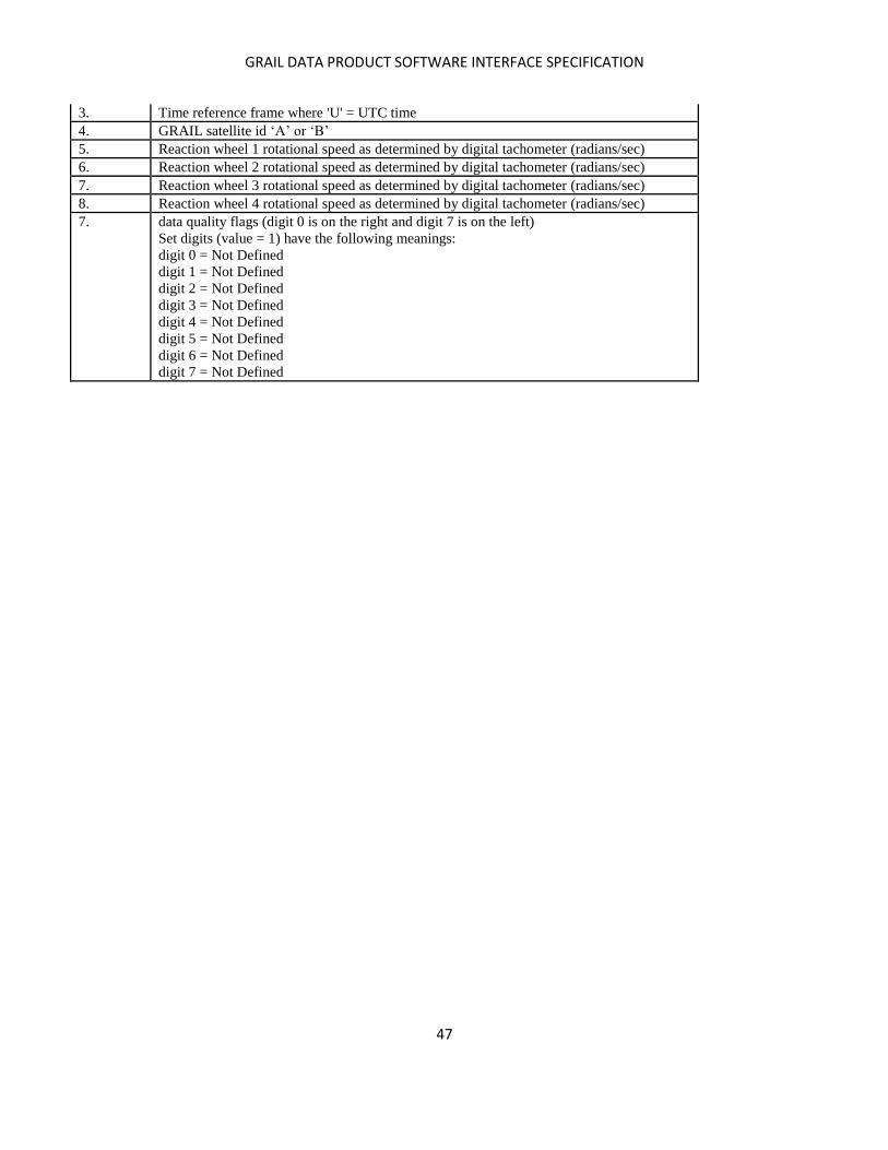
GRAIL DATA PRODUCT SOFTWARE INTERFACE SPECIFICATION
47
3. Time reference frame where 'U' = UTC time
4. GRAIL satellite id ‘A’ or ‘B’
5. Reaction wheel 1 rotational speed as determined by digital tachometer (radians/sec)
6. Reaction wheel 2 rotational speed as determined by digital tachometer (radians/sec)
7. Reaction wheel 3 rotational speed as determined by digital tachometer (radians/sec)
8. Reaction wheel 4 rotational speed as determined by digital tachometer (radians/sec)
7. data quality flags (digit 0 is on the right and digit 7 is on the left)
Set digits (value = 1) have the following meanings:
digit 0 = Not Defined
digit 1 = Not Defined
digit 2 = Not Defined
digit 3 = Not Defined
digit 4 = Not Defined
digit 5 = Not Defined
digit 6 = Not Defined
digit 7 = Not Defined
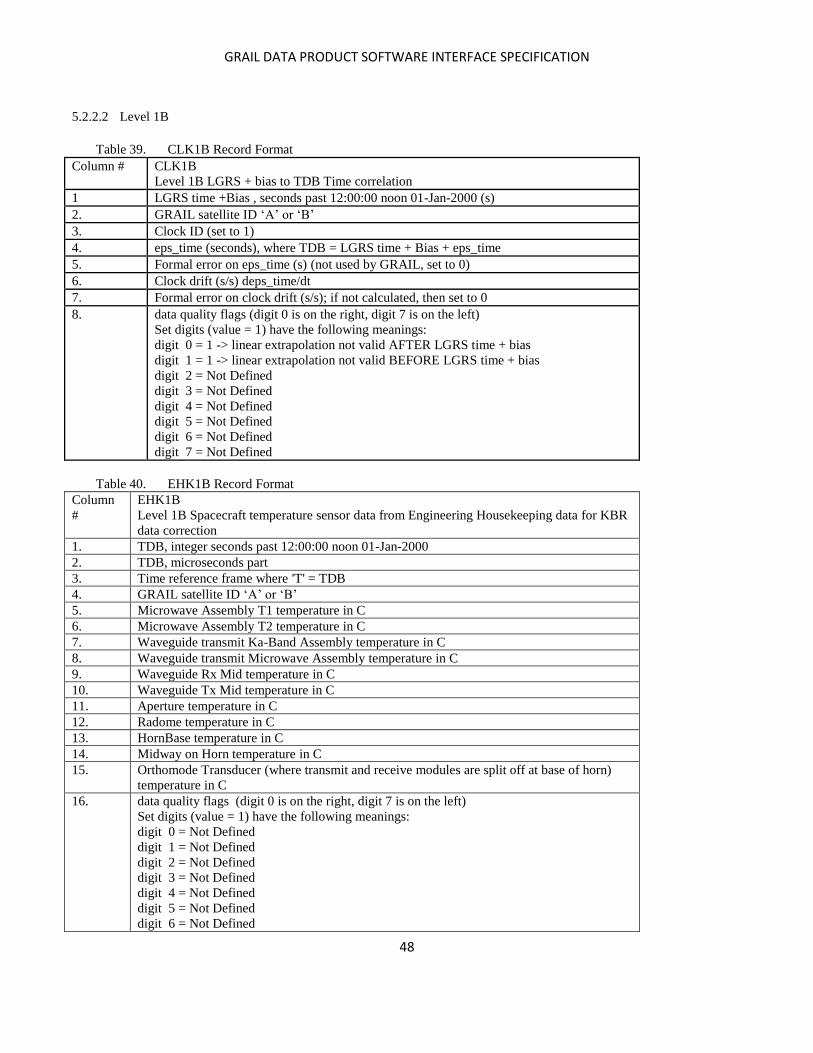
GRAIL DATA PRODUCT SOFTWARE INTERFACE SPECIFICATION
48
5.2.2.2 Level 1B
Table 39. CLK1B Record Format
Column # CLK1B
Level 1B LGRS + bias to TDB Time correlation
1 LGRS time +Bias , seconds past 12:00:00 noon 01-Jan-2000 (s)
2. GRAIL satellite ID ‘A’ or ‘B’
3. Clock ID (set to 1)
4. eps_time (seconds), where TDB = LGRS time + Bias + eps_time
5. Formal error on eps_time (s) (not used by GRAIL, set to 0)
6. Clock drift (s/s) deps_time/dt
7. Formal error on clock drift (s/s); if not calculated, then set to 0
8. data quality flags (digit 0 is on the right, digit 7 is on the left)
Set digits (value = 1) have the following meanings:
digit 0 = 1 -> linear extrapolation not valid AFTER LGRS time + bias
digit 1 = 1 -> linear extrapolation not valid BEFORE LGRS time + bias
digit 2 = Not Defined
digit 3 = Not Defined
digit 4 = Not Defined
digit 5 = Not Defined
digit 6 = Not Defined
digit 7 = Not Defined
Table 40. EHK1B Record Format
Column
#
EHK1B
Level 1B Spacecraft temperature sensor data from Engineering Housekeeping data for KBR
data correction
1. TDB, integer seconds past 12:00:00 noon 01-Jan-2000
2. TDB, microseconds part
3. Time reference frame where 'T' = TDB
4. GRAIL satellite ID ‘A’ or ‘B’
5. Microwave Assembly T1 temperature in C
6. Microwave Assembly T2 temperature in C
7. Waveguide transmit Ka-Band Assembly temperature in C
8. Waveguide transmit Microwave Assembly temperature in C
9. Waveguide Rx Mid temperature in C
10. Waveguide Tx Mid temperature in C
11. Aperture temperature in C
12. Radome temperature in C
13. HornBase temperature in C
14. Midway on Horn temperature in C
15. Orthomode Transducer (where transmit and receive modules are split off at base of horn)
temperature in C
16. data quality flags (digit 0 is on the right, digit 7 is on the left)
Set digits (value = 1) have the following meanings:
digit 0 = Not Defined
digit 1 = Not Defined
digit 2 = Not Defined
digit 3 = Not Defined
digit 4 = Not Defined
digit 5 = Not Defined
digit 6 = Not Defined

GRAIL DATA PRODUCT SOFTWARE INTERFACE SPECIFICATION
49
digit 7 = Not Defined
Table 41. GNI1B Record Format
Column # GNI1B
Navigation Level 1B satellite orbit solution in Moon-centered Inertial frame
1. TDB, seconds past 12:00:00 noon 01-Jan-2000
2. GRAIL satellite ID, ‘1’ for GRAIL-A, ‘2’ for GRAIL-B
3. Coordinate reference frame where
'I' = Inertial centered on Moon in EME 2000 Solar System Barycentric Frame
4. Position, x value (m)
5. Position, y value (m)
6. Position, z value (m)
7. Formal error on x position (m); if not calculated, then set to 0
8. Formal error on y position (m); if not calculated, then set to 0
9. Formal error on z position (m); if not calculated, then set to 0
10. Velocity along x-axis (m/s)
11. Velocity along y-axis (m/s)
12. Velocity along z-axis (m/s)
13. Formal error in velocity along x-axis (m/s); if not calculated, then set to 0
14. Formal error in velocity along y-axis (m/s); if not calculated, then set to 0
15. Formal error in velocity along z-axis (m/s); if not calculated, then set to 0
16. Data quality flags (digit 0 is on the right and digit 7 is on the left)
Set digits (value = 1) have the following meanings:
digit 0 = Not Defined
digit 1 = Not Defined
digit 2 = Not Defined
digit 3 = Not Defined
digit 4 = Not Defined
digit 5 = Not Defined
digit 6 = Not Defined
digit 7 = Not Defined
Table 42. GNV1B Record Format
Column # GNV1B
Navigation Level 1B Satellite orbit solution in lunar body fixed frame
1. TDB, seconds past 12:00:00 noon 01-Jan-2000
2. GRAIL satellite ID, ‘1’ for GRAIL-A, ‘2’ for GRAIL-B
3. Coordinate reference frame where 'M' = Moon-centered-body-fixed
4. Position, x value (m)
5. Position, y value (m)
6. Position, z value (m)
7. Formal error on x position (m); if not calculated, then set to 0
8. Formal error on y position (m); if not calculated, then set to 0
9. Formal error on z position (m); if not calculated, then set to 0
10. Velocity along x-axis (m/s)
11. Velocity along y-axis (m/s)
12. Velocity along z-axis (m/s)
13. Formal error in velocity along x-axis (m/s); if not calculated, then set to 0
14. Formal error in velocity along y-axis (m/s); if not calculated, then set to 0
15. Formal error in velocity along z-axis (m/s); if not calculated, then set to 0
16. Data quality flags (digit 0 is on the right and digit 7 is on the left)
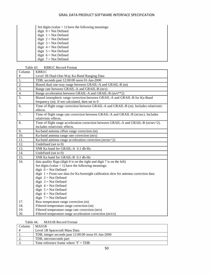
GRAIL DATA PRODUCT SOFTWARE INTERFACE SPECIFICATION
50
Set digits (value = 1) have the following meanings:
digit 0 = Not Defined
digit 1 = Not Defined
digit 2 = Not Defined
digit 3 = Not Defined
digit 4 = Not Defined
digit 5 = Not Defined
digit 6 = Not Defined
digit 7 = Not Defined
Table 43. KBR1C Record Format
Column
#
KBR1C
Level 1B Dual-One-Way Ka-Band Ranging Data
1. TDB, seconds past 12:00:00 noon 01-Jan-2000
2. Biased dual one-way range between GRAIL-A and GRAIL-B (m)
3. Range rate between GRAIL-A and GRAIL-B (m/s)
4. Range acceleration between GRAIL-A and GRAIL-B (m/s**2)
5. Biased ionospheric range correction between GRAIL-A and GRAIL-B for Ka-Band
frequency (m). If not calculated, then set to 0
6. Time of flight range correction between GRAIL-A and GRAIL-B (m). Includes relativistic
effects.
7. Time of flight range rate correction between GRAIL-A and GRAIL-B (m/sec). Includes
relativistic effects.
8. Time of flight range acceleration correction between GRAIL-A and GRAIL-B (m/sec^2).
Includes relativistic effects.
9. Ka-band antenna offset range correction (m)
10. Ka-band antenna range rate correction (m/s)
11. Ka-band antenna range acceleration correction (m/sec^2)
12. Undefined (set to 0)
13. SNR Ka band for GRAIL-A 0.1 db-Hz
14. Undefined (set to 0)
15. SNR Ka band for GRAIL-B 0.1 db-Hz
16. data quality flags (digit 0 is on the right and digit 7 is on the left)
Set digits (value = 1) have the following meanings:
digit 0 = Not Defined
digit 1 = From raw data for Ka boresight calibration slew for antenna correction data
digit 2 = Not Defined
digit 3 = Not Defined
digit 4 = Not Defined
digit 5 = Not Defined
digit 6 = Not Defined
digit 7 = Not Defined
17. Raw temperature range correction (m)
18. Filtered temperature range correction (m)
19. Filtered temperature range rate correction (m/s)
20. Filtered temperature range acceleration correction (m/s/s)
Table 44. MAS1B Record Format
Column
#
MAS1B
Level 1B Spacecraft Mass Data
1. TDB, integer seconds past 12:00:00 noon 01-Jan-2000
2. TDB, microseconds part
3. Time reference frame where 'T' = TDB
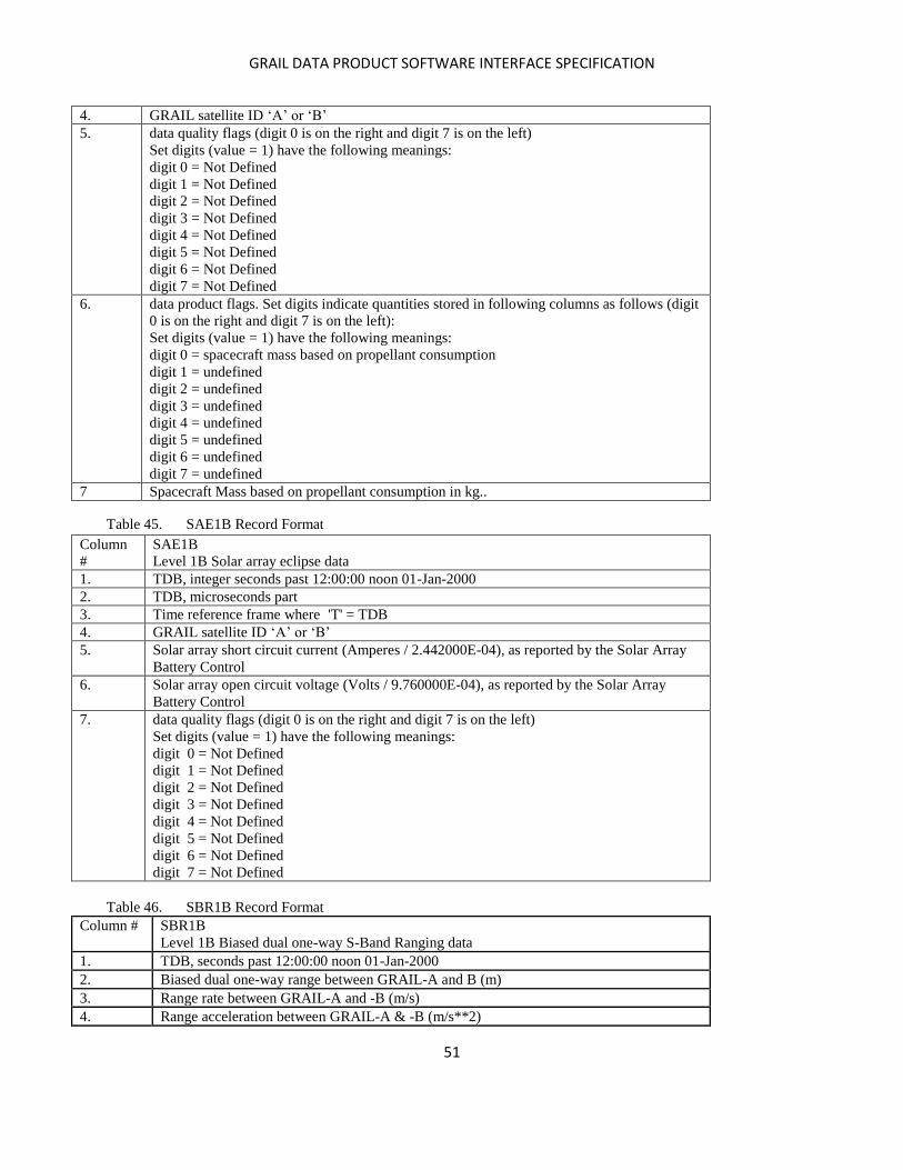
GRAIL DATA PRODUCT SOFTWARE INTERFACE SPECIFICATION
51
4. GRAIL satellite ID ‘A’ or ‘B’
5. data quality flags (digit 0 is on the right and digit 7 is on the left)
Set digits (value = 1) have the following meanings:
digit 0 = Not Defined
digit 1 = Not Defined
digit 2 = Not Defined
digit 3 = Not Defined
digit 4 = Not Defined
digit 5 = Not Defined
digit 6 = Not Defined
digit 7 = Not Defined
6. data product flags. Set digits indicate quantities stored in following columns as follows (digit
0 is on the right and digit 7 is on the left):
Set digits (value = 1) have the following meanings:
digit 0 = spacecraft mass based on propellant consumption
digit 1 = undefined
digit 2 = undefined
digit 3 = undefined
digit 4 = undefined
digit 5 = undefined
digit 6 = undefined
digit 7 = undefined
7 Spacecraft Mass based on propellant consumption in kg..
Table 45. SAE1B Record Format
Column
#
SAE1B
Level 1B Solar array eclipse data
1. TDB, integer seconds past 12:00:00 noon 01-Jan-2000
2. TDB, microseconds part
3. Time reference frame where 'T' = TDB
4. GRAIL satellite ID ‘A’ or ‘B’
5. Solar array short circuit current (Amperes / 2.442000E-04), as reported by the Solar Array
Battery Control
6. Solar array open circuit voltage (Volts / 9.760000E-04), as reported by the Solar Array
Battery Control
7. data quality flags (digit 0 is on the right and digit 7 is on the left)
Set digits (value = 1) have the following meanings:
digit 0 = Not Defined
digit 1 = Not Defined
digit 2 = Not Defined
digit 3 = Not Defined
digit 4 = Not Defined
digit 5 = Not Defined
digit 6 = Not Defined
digit 7 = Not Defined
Table 46. SBR1B Record Format
Column # SBR1B
Level 1B Biased dual one-way S-Band Ranging data
1. TDB, seconds past 12:00:00 noon 01-Jan-2000
2. Biased dual one-way range between GRAIL-A and B (m)
3. Range rate between GRAIL-A and -B (m/s)
4. Range acceleration between GRAIL-A & -B (m/s**2)

GRAIL DATA PRODUCT SOFTWARE INTERFACE SPECIFICATION
52
5. Not Defined. Set to 0 for GRAIL
6. Not defined. Set to 0 for GRAIL
7. Not defined. Set to 0 for GRAIL
8. Not defined. Set to 0 for GRAIL
9. Not defined. Set to 0 for GRAIL
10. Not defined. Set to 0 for GRAIL
11. Not defined. Set to 0 for GRAIL
12. Not defined. Set to 0 for GRAIL
13. Not defined. Set to 0 for GRAIL
14. Not defined. Set to 0 for GRAIL
15. Not defined. Set to 0 for GRAIL
16. data quality flags (digit 0 is on the right and digit 7 is on the left)
Set digits (value = 1) have the following meanings:
digit 0 = Not Defined
digit 1 = From raw data for Ka boresight calibration slew for antenna correction data
digit 2 = Not Defined
digit 3 = Not Defined
digit 4 = Not Defined
digit 5 = Not Defined
digit 6 = Not Defined
digit 7 = Not Defined
Table 47. SCA1B Record Format
Column # SCA1B
Level 1B Star Tracker Data
1. TDB, seconds past 12:00:00 noon 01-Jan-2000
2. GRAIL satellite ID ‘A’ or ‘B’
3. SCA identification number set to 1
4. Cos mu/2 element of quaternion
5. I element of quaternion rotation axis
6. J element of quaternion rotation axis
7. K element of quaternion rotation axis
8. rss of formal error of quaternions; if not calculated, then set to 0
9. data quality flags (digit 0 is at the right and digit 7 is at the left)
Set digits (value = 1) have the following meanings:
digit 0 = Data filled by interpolation
digit 1 = Ka boresight calibration periodor prediction change period
digit 2 = Not Defined
digit 3 = Not Defined
digit 4 = Not Defined
digit 5 = Not Defined
digit 6 = Not Defined
digit 7 = Not Defined
Table 48. THR1B Record Format
Column # THR1B
Level 1B Thruster Activation Data
1. TDB, integer seconds past 12:00:00 noon 01-Jan-2000
2. TDB, microseconds part
3. Time reference frame where 'T' = TDB
4. GRAIL satellite ID ‘A’ or ‘B’
5-12. Count of number of work cycles that each thruster has been activated

GRAIL DATA PRODUCT SOFTWARE INTERFACE SPECIFICATION
53
Set to 0 for GRAIL.
13-20. Thruster on-time for this activation time (milliseconds)
21-28. Accumulated thruster firing duration time (milliseconds)
integer will wrap after 4294967295
29. data quality flags (digit 0 is on the right and digit 7 is on the left)
Set digits (value = 1) have the following meanings:
digit 0 = 1 On time not calculated
digit 1 = 1 Multiple unaccounted thrusts prior to current record
digit 2 = Not Defined
digit 3 = Not Defined
digit 4 = Not Defined
digit 5 = Not Defined
digit 6 = Not Defined
digit 7 = Not Defined
Table 49. USO1B Record Format
Column # USO1B
Level 1B Ultra Stable Oscillator Stability Data
1. TDB, seconds past 12:00:00 noon 01-Jan-2000
2. GRAIL satellite ID ‘A’ or ‘B’
3. USO identification number set to 0
4. Frequency of USO (Hz)
5. X-Band RSB frequency (Hz)
6. Ka band frequency of KBR (Hz) for USO1B
7. data quality flags (digit 0 is on the right and digit 7 is on the left)
Set digits (value = 1) have the following meanings:
digit 0 = Not Defined
digit 1 = Not Defined
digit 2 = Not Defined
digit 3 = Not Defined
digit 4 = Not Defined
digit 5 = Not Defined
digit 6 = Not Defined
digit 7 = Not Defined
Table 50. VCM1B Record Format
Column # VCM1B
Level 1B Center of mass displacement from spacecraft mechanical frame origin
1. TDB, seconds past 12:00:00 noon 01-Jan-2000
2. GRAIL satellite ID ‘A’ or ‘B’
3. Magnitude of center of mass vector in mechanical frame (m)
4. Direction cosine of vector with Mechanical Reference Frame x-axis
5. Direction cosine of vector with Mechanical Reference Frame y-axis
6. Direction cosine of vector with Mechanical Reference Frame z-axis
7. data quality flags (digit 0 is on the right and digit 7 is on the left)
Set digits (value = 1) have the following meanings:
digit 0 = Not Defined
digit 1 = Not Defined
digit 2 = Not Defined
digit 3 = Not Defined
digit 4 = Not Defined
digit 5 = Not Defined
digit 6 = Not Defined

GRAIL DATA PRODUCT SOFTWARE INTERFACE SPECIFICATION
54
digit 7 = Not Defined
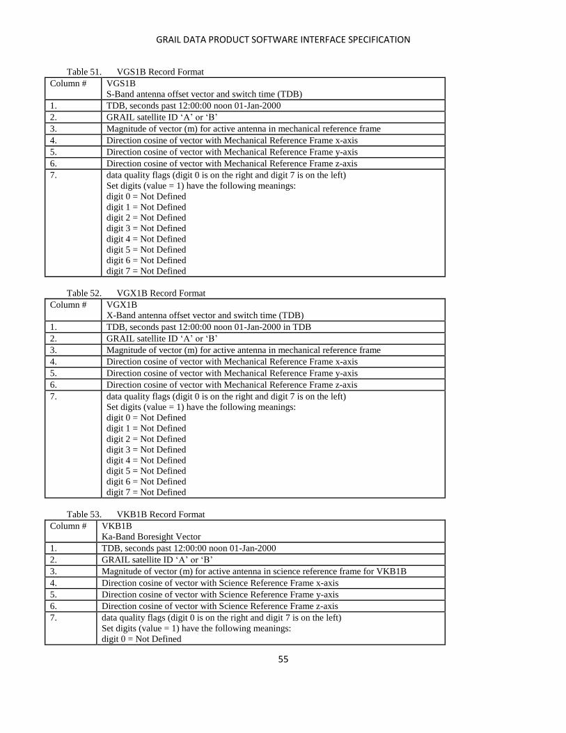
GRAIL DATA PRODUCT SOFTWARE INTERFACE SPECIFICATION
55
Table 51. VGS1B Record Format
Column # VGS1B
S-Band antenna offset vector and switch time (TDB)
1. TDB, seconds past 12:00:00 noon 01-Jan-2000
2. GRAIL satellite ID ‘A’ or ‘B’
3. Magnitude of vector (m) for active antenna in mechanical reference frame
4. Direction cosine of vector with Mechanical Reference Frame x-axis
5. Direction cosine of vector with Mechanical Reference Frame y-axis
6. Direction cosine of vector with Mechanical Reference Frame z-axis
7. data quality flags (digit 0 is on the right and digit 7 is on the left)
Set digits (value = 1) have the following meanings:
digit 0 = Not Defined
digit 1 = Not Defined
digit 2 = Not Defined
digit 3 = Not Defined
digit 4 = Not Defined
digit 5 = Not Defined
digit 6 = Not Defined
digit 7 = Not Defined
Table 52. VGX1B Record Format
Column # VGX1B
X-Band antenna offset vector and switch time (TDB)
1. TDB, seconds past 12:00:00 noon 01-Jan-2000 in TDB
2. GRAIL satellite ID ‘A’ or ‘B’
3. Magnitude of vector (m) for active antenna in mechanical reference frame
4. Direction cosine of vector with Mechanical Reference Frame x-axis
5. Direction cosine of vector with Mechanical Reference Frame y-axis
6. Direction cosine of vector with Mechanical Reference Frame z-axis
7. data quality flags (digit 0 is on the right and digit 7 is on the left)
Set digits (value = 1) have the following meanings:
digit 0 = Not Defined
digit 1 = Not Defined
digit 2 = Not Defined
digit 3 = Not Defined
digit 4 = Not Defined
digit 5 = Not Defined
digit 6 = Not Defined
digit 7 = Not Defined
Table 53. VKB1B Record Format
Column # VKB1B
Ka-Band Boresight Vector
1. TDB, seconds past 12:00:00 noon 01-Jan-2000
2. GRAIL satellite ID ‘A’ or ‘B’
3. Magnitude of vector (m) for active antenna in science reference frame for VKB1B
4. Direction cosine of vector with Science Reference Frame x-axis
5. Direction cosine of vector with Science Reference Frame y-axis
6. Direction cosine of vector with Science Reference Frame z-axis
7. data quality flags (digit 0 is on the right and digit 7 is on the left)
Set digits (value = 1) have the following meanings:
digit 0 = Not Defined
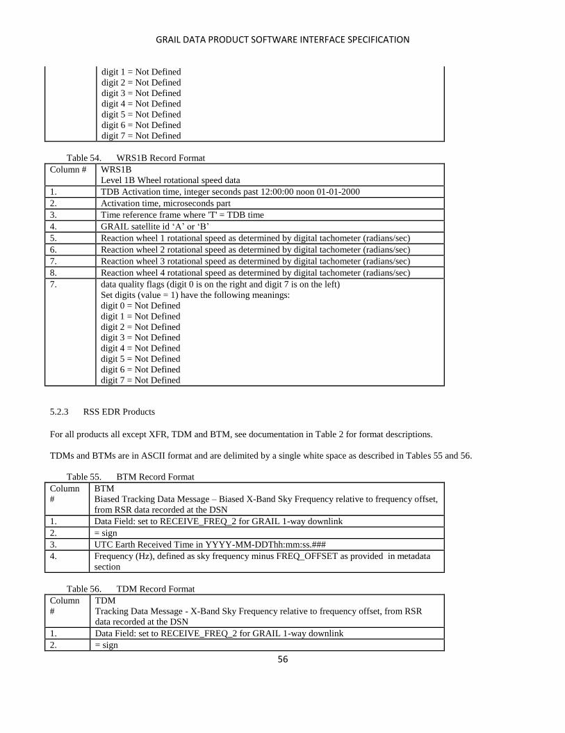
GRAIL DATA PRODUCT SOFTWARE INTERFACE SPECIFICATION
56
digit 1 = Not Defined
digit 2 = Not Defined
digit 3 = Not Defined
digit 4 = Not Defined
digit 5 = Not Defined
digit 6 = Not Defined
digit 7 = Not Defined
Table 54. WRS1B Record Format
Column # WRS1B
Level 1B Wheel rotational speed data
1. TDB Activation time, integer seconds past 12:00:00 noon 01-01-2000
2. Activation time, microseconds part
3. Time reference frame where 'T' = TDB time
4. GRAIL satellite id ‘A’ or ‘B’
5. Reaction wheel 1 rotational speed as determined by digital tachometer (radians/sec)
6. Reaction wheel 2 rotational speed as determined by digital tachometer (radians/sec)
7. Reaction wheel 3 rotational speed as determined by digital tachometer (radians/sec)
8. Reaction wheel 4 rotational speed as determined by digital tachometer (radians/sec)
7. data quality flags (digit 0 is on the right and digit 7 is on the left)
Set digits (value = 1) have the following meanings:
digit 0 = Not Defined
digit 1 = Not Defined
digit 2 = Not Defined
digit 3 = Not Defined
digit 4 = Not Defined
digit 5 = Not Defined
digit 6 = Not Defined
digit 7 = Not Defined
5.2.3 RSS EDR Products
For all products all except XFR, TDM and BTM, see documentation in Table 2 for format descriptions.
TDMs and BTMs are in ASCII format and are delimited by a single white space as described in Tables 55 and 56.
Table 55. BTM Record Format
Column
#
BTM
Biased Tracking Data Message – Biased X-Band Sky Frequency relative to frequency offset,
from RSR data recorded at the DSN
1. Data Field: set to RECEIVE_FREQ_2 for GRAIL 1-way downlink
2. = sign
3. UTC Earth Received Time in YYYY-MM-DDThh:mm:ss.###
4. Frequency (Hz), defined as sky frequency minus FREQ_OFFSET as provided in metadata
section
Table 56. TDM Record Format
Column
#
TDM
Tracking Data Message - X-Band Sky Frequency relative to frequency offset, from RSR
data recorded at the DSN
1. Data Field: set to RECEIVE_FREQ_2 for GRAIL 1-way downlink
2. = sign
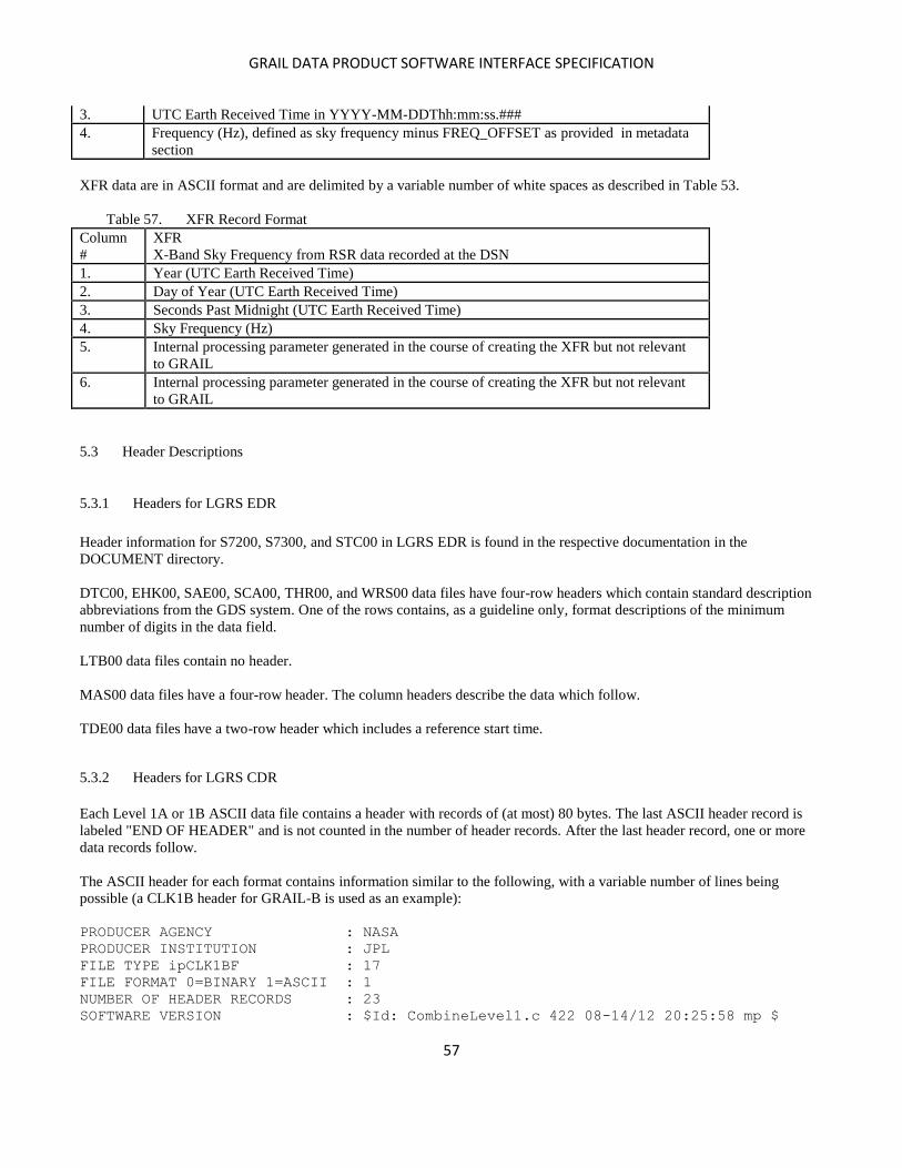
GRAIL DATA PRODUCT SOFTWARE INTERFACE SPECIFICATION
57
3. UTC Earth Received Time in YYYY-MM-DDThh:mm:ss.###
4. Frequency (Hz), defined as sky frequency minus FREQ_OFFSET as provided in metadata
section
XFR data are in ASCII format and are delimited by a variable number of white spaces as described in Table 53.
Table 57. XFR Record Format
Column
#
XFR
X-Band Sky Frequency from RSR data recorded at the DSN
1. Year (UTC Earth Received Time)
2. Day of Year (UTC Earth Received Time)
3. Seconds Past Midnight (UTC Earth Received Time)
4. Sky Frequency (Hz)
5. Internal processing parameter generated in the course of creating the XFR but not relevant
to GRAIL
6. Internal processing parameter generated in the course of creating the XFR but not relevant
to GRAIL
5.3 Header Descriptions
5.3.1 Headers for LGRS EDR
Header information for S7200, S7300, and STC00 in LGRS EDR is found in the respective documentation in the
DOCUMENT directory.
DTC00, EHK00, SAE00, SCA00, THR00, and WRS00 data files have four-row headers which contain standard description
abbreviations from the GDS system. One of the rows contains, as a guideline only, format descriptions of the minimum
number of digits in the data field.
LTB00 data files contain no header.
MAS00 data files have a four-row header. The column headers describe the data which follow.
TDE00 data files have a two-row header which includes a reference start time.
5.3.2 Headers for LGRS CDR
Each Level 1A or 1B ASCII data file contains a header with records of (at most) 80 bytes. The last ASCII header record is
labeled "END OF HEADER" and is not counted in the number of header records. After the last header record, one or more
data records follow.
The ASCII header for each format contains information similar to the following, with a variable number of lines being
possible (a CLK1B header for GRAIL-B is used as an example):
PRODUCER AGENCY : NASA
PRODUCER INSTITUTION : JPL
FILE TYPE ipCLK1BF : 17
FILE FORMAT 0=BINARY 1=ASCII : 1
NUMBER OF HEADER RECORDS : 23
SOFTWARE VERSION : $Id: CombineLevel1.c 422 08-14/12 20:25:58 mp $
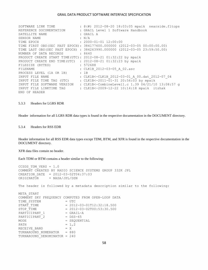
GRAIL DATA PRODUCT SOFTWARE INTERFACE SPECIFICATION
58
SOFTWARE LINK TIME : @(#) 2012-08-20 18:03:05 mpaik nearside.fltops
REFERENCE DOCUMENTATION : GRAIL Level 1 Software Handbook
SATELLITE NAME : GRAIL A
SENSOR NAME : N/A
TIME EPOCH : 2000-01-01 12:00:00
TIME FIRST OBS(SEC PAST EPOCH): 384177600.000000 (2012-03-05 00:00:00.00)
TIME LAST OBS(SEC PAST EPOCH) : 384263990.000000 (2012-03-05 23:59:50.00)
NUMBER OF DATA RECORDS : 8640
PRODUCT CREATE START TIME(UTC): 2012-08-21 01:32:22 by mpaik
PRODUCT CREATE END TIME(UTC) : 2012-08-21 01:32:23 by mpaik
FILESIZE (BYTES) : 572688
FILENAME : CLK1B_2012-03-05_A_02.asc
PROCESS LEVEL (1A OR 1B) : 1B
INPUT FILE NAME : CLK1B<-CLK1B_2012-03-01_A_00.dat_2012-07_04
INPUT FILE TIME TAG (UTC) : CLK1B<-2011-01-31 20:56:03 by mpaik
INPUT FILE SOFTWARE VERSION : CLK1B<-CombineLevel1.c 1.39 04/21/10 13:08:57 g
INPUT FILE LINKTIME TAG : CLK1B<-2009-12-22 10:14:18 mpaik itzhak
END OF HEADER
5.3.3 Headers for LGRS RDR
Header information for all LGRS RDR data types is found in the respective documentation in the DOCUMENT directory.
5.3.4 Headers for RSS EDR
Header information for all RSS EDR data types except TDM, BTM, and XFR is found in the respective documentation in the
DOCUMENT directory.
XFR data files contain no header.
Each TDM or BTM contains a header similar to the following:
CCSDS_TDM_VERS = 1.0
COMMENT CREATED BY RADIO SCIENCE SYSTEMS GROUP 332K JPL
CREATION_DATE = 2012-03-02T04:37:03
ORIGINATOR = NASA/JPL/DSN
The header is followed by a metadata description similar to the following:
META_START
COMMENT SKY FREQUENCY COMPUTED FROM OPEN-LOOP DATA
TIME_SYSTEM = UTC
START_TIME = 2012-03-01T12:32:18.500
STOP_TIME = 2012-03-02T00:53:30.500
PARTICIPANT_1 = GRAIL-A
PARTICIPANT_2 = DSS-65
MODE = SEQUENTIAL
PATH = 1,2
RECEIVE_BAND = X
TURNAROUND_NUMERATOR = 880
TURNAROUND_DENOMINATOR = 240
GRAIL DATA PRODUCT SOFTWARE INTERFACE SPECIFICATION
59
TIMETAG_REF = RECEIVE
INTEGRATION_INTERVAL = 1.000
INTEGRATION_REF = MIDDLE
FREQ_OFFSET = 8451600000
META_STOP
The data records are preceded by the string DATA_START and followed by the string
DATA_STOP.
6 Applicable Software
All products have already been processed with the appropriate software by the GRAIL SDS. Software in this archive is
provided as an example only. The SOFTWARE directory contents are listed in table 2.9 of the Archive Volume SIS [16].
6.1 Utility Programs
The SOFTWARE directory on the GRAIL_0001 volume (GRAIL-L-LGRS-2-EDR-V1.0) contains utilities or application
programs to aid the user in viewing or extracting data from the Level 0 data product files. The codes are provided as
illustrations of how to extract the Blackjack packets from Blackjack binary data. See section 4.2.1 for a description of
Blackjack.
7 Appendices
7.1 Glossary
Barycenter - center of mass; the unique point where the weighted relative position of a distributed mass sums to zero.
Barycentric Dynamical Time - the independent argument of ephemerides and dynamical theories that are referred to the solar
system barycenter. See http://tycho.usno.navy.mil/systime.html for more information.
Base Time Clock (BTC) - On-board satellite clock, comparable in stability to a wristwatch. Roughly synced to UTC at
launch time.
Coordinated Universal Time (UTC) - differs from International Atomic Time by an integral number of seconds. See
http://tycho.usno.navy.mil/systime.html for more information.
Blackjack - a data format utilized by the science instruments on board the GRACE and GRAIL projects to encode telemetry.
Dual One Way Range (DOWR) - instantaneous measurement of distance, including a bias, between two spacecraft, which is
formed by the combination of a range signal from spacecraft A to spacecraft B and from spacecraft B to spacecraft A.
Ephemeris - a table of values that gives the positions of astronomical objects at given times.
Gravity Recovery Processor Assembly (GPA) - the equipment that combines all the inputs received from the microwave
assembly and the time transfer assembly to produce the radiometric data that are downlinked to the ground.
International Atomic Time (TAI) - the International Atomic Time scale, a statistical timescale based on a large number of
atomic clocks. See http://tycho.usno.navy.mil/systime.html for more information.
Inertial Measurement Unit - an electronic device that measures and reports on a spacecraft's rotational velocities and
accelerations experienced by the instrument.
GRAIL DATA PRODUCT SOFTWARE INTERFACE SPECIFICATION
60
Ka-Band - part of the microwave electromagnetic spectrum between 26.5 and 40 GHz.
Kalman filter - an algorithm which uses a series of measurements observed over time, containing noise (random variations)
and other inaccuracies, and produces estimates of unknown variables that tend to be more precise than those that would be
based on a single measurement alone.
Lunar Gravity Ranging System - The equipment responsible for sending and receiving the signals needed to accurately and
precisely measure the changes in range between the two orbiters. Consists of an Ultra-Stable Oscillator (USO), Microwave
Assembly (MWA), a Time-Transfer Assembly (TTA), and the Gravity Recovery Processor Assembly (GPA).
Microwave Assembly (MWA) - the equipment that converts the USO reference signal to Ka-band frequency, which is
transmitted to the other orbiter.
Open Loop - does not use feedback to determine if the output has achieved the desired goal of the input.
Quaternion - A vector with four components that describes the attitude of a spacecraft. [36].
Radio Science - Utilization of the telecommunication links between spacecraft and Earth for scientific application involving
examination of (sometimes very small) changes in the phase/frequency, amplitude, and/or polarization of radio signals.
Radio Science Receiver - a computer-controlled open loop receiver that digitally down-converts and records a spacecraft
signal spectrum using an analog-to-digital converter (ADC) and up to four digital filter sub-channels.
Real Time Clock (RTC) - Flight software clock. Set to 0 when booted. Relatively unstable clock.
S-Band - part of the microwave electromagnetic spectrum between 2 and 4 GHz.
Science Data System (SDS) - the infrastructure at NASA’s Jet Propulsion Laboratory (JPL) for the collection of all science
and ancillary data relevant to the GRAIL mission. Includes hardware, software tools, procedures, and trained personnel. The
SDS receives science packets and engineering data and carries out calibration, editing, and processing to produce NASA
Level 1A and 1B GRAIL science data.
Time Transfer Assembly (TTA) - the equipment that generates an S-band signal from the USO reference frequency and sends
a GPS-like ranging code to the other spacecraft. The function of the TTA is to provide a two-way time-transfer link between
the spacecraft to both synchronize and measure the clock offset between the two LGRS clocks.
Ultra Stable Oscillator - electronic assembly that provides a highly stable timing and frequency reference signal onboard a
spacecraft that is used by all of the instrument subsystems, typically based on ovenized quartz crystal or Rubidium atomic
standard.
X-Band - part of the microwave radio region of the electromagnetic spectrum between 7 and 12 GHz.
7.2 Acronyms
ACS Attitude control system
ADC Analog-Digital Converter
AMMOS Advanced Multi-Mission Operations System
ASCII American Standard Code for Information Interchange
BTC Base Time Clock
CCK Spacecraft Orientation Kernel
CDR Calibrated Data Record
CODMAC Committee on Data Management, Archiving, and Computation
DOWR Dual One Way Range
DSCC Deep Space Communications Complex
DRF Data Record File
GRAIL DATA PRODUCT SOFTWARE INTERFACE SPECIFICATION
61
DSN Deep Space Network
DTE Direct to Earth
EDR Experimental Data Record
EPS Epsilon
FTS Frequency and Timing Subsystem
GDS Ground Data System
GHz gigahertz
GRACE Gravity Recovery and Climate Experiment
GRAIL Gravity Recovery and Interior Laboratory
GRLSCI GRAIL Science
ICRF International Celestial Reference Frame
IMU Inertial Measurement Unit
JPL Jet Propulsion Laboratory
KBR Ka-Band Ranging System
LGA Low Gain Antenna
LGRS Lunar Gravity Ranging System
LSK Leap Second Kernel
MF Mechanical Frame
MMDOM Multi-Mission Distributed Object Manager
MOC Mission Operations Center
MOS Mission Operations System
NAIF Navigation and Ancillary Information Facility
NASA National Aeronautics and Space Administration
ODF Orbit Data File
OMC Operations and Maintenance Contract
OSC Onboard Spacecraft Clock
PDS Planetary Data System
PPS Pulse per Second
RDR Reduced Data Record
RODAN Radio Occultation Data Analysis Network
RSB Radio Science Beacon
RSDMAP Radio Science Digital Map
RSR Radio Science Receiver
RSS Radio Science Systems
RTC Real-Time Clock
SABC Solar Array Battery Control
SBR S-Band Ranging System
SCA Star Tracker Assembly
SCLK Spacecraft Clock Kernel
SDS Science Data System
SF Satellite Frame
SFDU Standard Formatted Data Unit
SIS Software Interface Specification
SHADR Spherical Harmonic ASCII Data Record
SHBDR Spherical Harmonic Binary Data Record
SOE Sequence of Events file
SPICE S- Spacecraft ephemeris, given as a function of time.
P- Planet, satellite, comet, or asteroid ephemerides, or more generally, location of any target
body, given as a function of time.
The P kernel also logically includes certain physical, dynamical and cartographic constants
for target bodies, such as size and shape specifications, and orientation of the spin axis and
prime meridian.
I- Instrument description kernel, containing descriptive data peculiar to a particular scientific
instrument, such as field-of-view size, shape and orientation parameters.
C- Pointing kernel, containing a transformation, traditionally called the C-matrix, which

GRAIL DATA PRODUCT SOFTWARE INTERFACE SPECIFICATION
62
provides time-tagged pointing (orientation) angles for a spacecraft structure upon which
science instruments are mounted. May also include angular rate data.
E- Events kernel, summarizing mission activities - both planned and unanticipated. Events
data are contained in the SPICE EK file set, which consists of three components: Science
Plans, Sequences, and Notes. SPK Spacecraft and Planetary Ephemeris Kernel
SRF Science Reference Frame
TAI International Atomic Time
TBD To Be Done
TDB Barycentric Dynamical Time
TDS Telemetry Delivery System
TTS Time Transfer System
USO Ultra-Stable Oscillator
UTC Coordinated Universal Time
V/V Volts per Volt
7.3 Example PDS Labels
7.3.1 LGRS EDR
Products in the LGRS EDR data set (GRAIL-L-LGRS-2-EDR-V1.0) all have labels similar to the following:
PDS_VERSION_ID = PDS3
RECORD_TYPE = UNDEFINED
INSTRUMENT_NAME = "LUNAR GRAVITY RANGING SYSTEM A"
TARGET_NAME = "MOON"
DATA_SET_ID = "GRAIL-L-LGRS-2-EDR-V1.0"
MISSION_NAME = "GRAVITY RECOVERY AND INTERIOR LABORATORY"
INSTRUMENT_HOST_NAME = "GRAVITY RECOVERY AND INTERIOR LABORATORY A"
PRODUCT_ID = "STC00_2012_03_01_A_02.DAT"
FILE_NAME = "STC00_2012_03_01_A_02.DAT"
ORIGINAL_PRODUCT_ID = "TIME_CORR_A.SFDU"
START_TIME = 2012-061T00:00:00
STOP_TIME = 2012-061T23:59:59
PRODUCT_CREATION_TIME = 2012-061T23:59:59
OBSERVATION_TYPE = SCIENCE
PRODUCER_ID = "SDS"
NOTE = "Time Correlation SFDU"
^DESCRIPTION = {"0161_TELECOMM_L5_8.TXT",
"0171_TELECOMM_NJPL_L5.TXT",
"090_REVC_1.TXT",
"0172_TELECOMM_CHDO_REVE_L5.TXT"}
END
7.3.2 LGRS CDR
Products in the LGRS CDR data set (GRAIL-L-LGRS-3-CDR-V1.0) all have labels similar to the following:
PDS_VERSION_ID = PDS3
RECORD_TYPE = STREAM
INSTRUMENT_NAME = "LUNAR GRAVITY RANGING SYSTEM A"
TARGET_NAME = "MOON"

GRAIL DATA PRODUCT SOFTWARE INTERFACE SPECIFICATION
63
DATA_SET_ID = "GRAIL-L-LGRS-3-CDR-V1.0"
MISSION_NAME = "GRAVITY RECOVERY AND INTERIOR LABORATORY"
INSTRUMENT_HOST_NAME = "GRAVITY RECOVERY AND INTERIOR LABORATORY A"
PRODUCT_ID = "CLK1A_2012_03_01_A_02.ASC"
FILE_NAME = "CLK1A_2012_03_01_A_02.ASC"
ORIGINAL_PRODUCT_ID = "CLK1A_2012-03-01_A_02.ASC"
START_TIME = 2012-061T12:43:45
STOP_TIME = 2012-061T22:53:47
PRODUCT_CREATION_TIME = 2012-234T01:05:25
OBSERVATION_TYPE = SCIENCE
PRODUCER_ID = "SDS"
NOTE = "Level 1A TDB to LGRS time correlation.
See Table 11 in DPSIS.PDF for format."
^DESCRIPTION = "DPSIS.PDF"
END
7.3.3 RSS EDR
Labels in the RSS EDR data set (GRAIL-L-RSS-2-EDR-V1.0) may be minimal or full.
7.3.3.1 BTM, EOP, ION, TDM, TNF, TRO, WEA, & XFR
Data products BTM, EOP, ION, TDM, TNF [22], TRO, WEA, and XFR have labels similar to the following:
PDS_VERSION_ID = PDS3
RECORD_TYPE = UNDEFINED
INSTRUMENT_NAME = "LUNAR GRAVITY RANGING SYSTEM A"
TARGET_NAME = "MOON"
DATA_SET_ID = "GRAIL-L-RSS-2-EDR-V1.0"
MISSION_NAME = "GRAVITY RECOVERY AND INTERIOR LABORATORY"
INSTRUMENT_HOST_NAME = "GRAVITY RECOVERY AND INTERIOR LABORATORY A"
PRODUCT_ID = "GRALUGF2012_148_0520SMMMV1.TNF"
FILE_NAME = "GRALUGF2012_148_0520SMMMV1.TNF"
START_TIME = 2012-148T05:20:00
STOP_TIME = 2012-149T06:52:53
PRODUCT_CREATION_TIME = 2012-209T22:28:18
OBSERVATION_TYPE = SCIENCE
PRODUCER_ID = "DSN"
DESCRIPTION = "
The TNF data type captures radiometric tracking data for delivery
to navigation and radio science users from the Telecommunications
Services at JPL. The product replaces data types formerly known
as Orbit Data Files, Archival Tracking Data Files, and others.
Format and content of the TNF data product is documented in:
820-013
Deep Space Mission System (DSMS)
External Interface Specification
JPL D-16765
TRK-2-34
DSMS Tracking System Data Archival Format
Jet Propulsion Laboratory
4800 Oak Grove Drive
Pasadena, CA 91109-8099

GRAIL DATA PRODUCT SOFTWARE INTERFACE SPECIFICATION
64
Background information on the radiometric system may be found in:
Formulation for Observed and Computed Values
of Deep Space Network Data Types for Navigation
by Theodore D. Moyer
JPL Publication 00-7, October 2000
Monograph 2, Deep Space Communications and Navigation Series
Jet Propulsion Laboratory
4800 Oak Grove Drive
Pasadena, CA 91109-8099 "
END
7.3.3.2 ODF, OLF, and BOF
The ODF products have labels as follows. The OLF or BOF label is similar, with minor differences.
PDS_VERSION_ID = PDS3
RECORD_TYPE = FIXED_LENGTH
RECORD_BYTES = 36
FILE_RECORDS = 64288
DATA_SET_ID = "GRAIL-L-RSS-2-EDR-V1.0"
TARGET_NAME = "MOON"
INSTRUMENT_HOST_NAME = "GRAVITY RECOVERY AND INTERIOR
LABORATORY A"
INSTRUMENT_NAME = "LUNAR GRAVITY RANGING SYSTEM A"
INSTRUMENT_ID = "LGRS-A"
PRODUCER_ID = "DSN"
MISSION_NAME = "GRAVITY RECOVERY AND INTERIOR
LABORATORY"
OBSERVATION_TYPE = "SCIENCE"
DSN_STATION_NUMBER = {45,24}
PRODUCT_CREATION_TIME = 2012-151T17:12:37
PRODUCT_ID = "GRALUGF2012_148_0605SMMMV1.ODF"
ORIGINAL_PRODUCT_ID = "GRALUGF2012_148_0605SMMMV1.ODF"
START_TIME = 2012-148T06:05:08
STOP_TIME = 2012-149T06:45:16
HARDWARE_MODEL_ID = "TDDS"
SOFTWARE_NAME = "AMMOS"
DESCRIPTION = "Orbit Data Files (ODFs) are
produced by the NASA/JPL Multi-Mission Navigation Radio
Metric Data Conditioning Team for use in determining
spacecraft trajectories, gravity fields affecting them,
and radio propagation conditions. Each ODF consists of
many 36-byte logical records, which fall into 7 primary
groups plus an End-of-File Group. An ODF usually
contains most groups, but may not have all. The first
record in each of the 7 primary groups is a header
record; depending on the group, there may be from zero
to many data records following each header. The ODF is
described in JPL/DSN Document 820-13, TRK-2-18
(various versions, with significant changes in April
1997). The latest version is included in this archive
as NAV023_ODF_2_18_Rev3.htm in the DOCUMENT directory."
^ODF1A_TABLE = ("MROMAGR2010_363_1716XMMMV1.ODF",1)
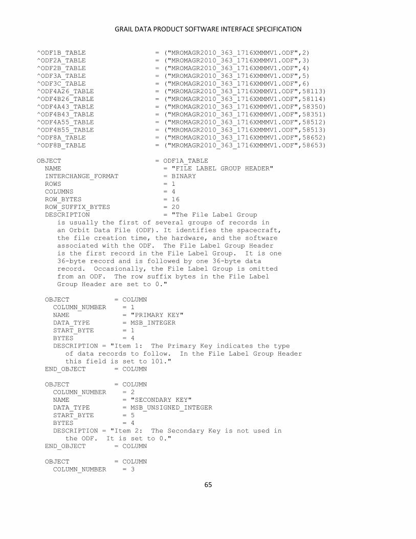
GRAIL DATA PRODUCT SOFTWARE INTERFACE SPECIFICATION
65
^ODF1B_TABLE = ("MROMAGR2010_363_1716XMMMV1.ODF",2)
^ODF2A_TABLE = ("MROMAGR2010_363_1716XMMMV1.ODF",3)
^ODF2B_TABLE = ("MROMAGR2010_363_1716XMMMV1.ODF",4)
^ODF3A_TABLE = ("MROMAGR2010_363_1716XMMMV1.ODF",5)
^ODF3C_TABLE = ("MROMAGR2010_363_1716XMMMV1.ODF",6)
^ODF4A26_TABLE = ("MROMAGR2010_363_1716XMMMV1.ODF",58113)
^ODF4B26_TABLE = ("MROMAGR2010_363_1716XMMMV1.ODF",58114)
^ODF4A43_TABLE = ("MROMAGR2010_363_1716XMMMV1.ODF",58350)
^ODF4B43_TABLE = ("MROMAGR2010_363_1716XMMMV1.ODF",58351)
^ODF4A55_TABLE = ("MROMAGR2010_363_1716XMMMV1.ODF",58512)
^ODF4B55_TABLE = ("MROMAGR2010_363_1716XMMMV1.ODF",58513)
^ODF8A_TABLE = ("MROMAGR2010_363_1716XMMMV1.ODF",58652)
^ODF8B_TABLE = ("MROMAGR2010_363_1716XMMMV1.ODF",58653)
OBJECT = ODF1A_TABLE
NAME = "FILE LABEL GROUP HEADER"
INTERCHANGE_FORMAT = BINARY
ROWS = 1
COLUMNS = 4
ROW_BYTES = 16
ROW_SUFFIX_BYTES = 20
DESCRIPTION = "The File Label Group
is usually the first of several groups of records in
an Orbit Data File (ODF). It identifies the spacecraft,
the file creation time, the hardware, and the software
associated with the ODF. The File Label Group Header
is the first record in the File Label Group. It is one
36-byte record and is followed by one 36-byte data
record. Occasionally, the File Label Group is omitted
from an ODF. The row suffix bytes in the File Label
Group Header are set to 0."
OBJECT = COLUMN
COLUMN_NUMBER = 1
NAME = "PRIMARY KEY"
DATA_TYPE = MSB_INTEGER
START_BYTE = 1
BYTES = 4
DESCRIPTION = "Item 1: The Primary Key indicates the type
of data records to follow. In the File Label Group Header
this field is set to 101."
END_OBJECT = COLUMN
OBJECT = COLUMN
COLUMN_NUMBER = 2
NAME = "SECONDARY KEY"
DATA_TYPE = MSB_UNSIGNED_INTEGER
START_BYTE = 5
BYTES = 4
DESCRIPTION = "Item 2: The Secondary Key is not used in
the ODF. It is set to 0."
END_OBJECT = COLUMN
OBJECT = COLUMN
COLUMN_NUMBER = 3
GRAIL DATA PRODUCT SOFTWARE INTERFACE SPECIFICATION
66
NAME = "LOGICAL RECORD LENGTH"
DATA_TYPE = MSB_UNSIGNED_INTEGER
START_BYTE = 9
BYTES = 4
UNIT = PACKET
DESCRIPTION = "Item 3: The Logical Record Length gives the
number of 36-byte physical records making up each logical
record in a File Label Group data record. For the File Label
Group it is set to 1."
END_OBJECT = COLUMN
OBJECT = COLUMN
COLUMN_NUMBER = 4
NAME = "GROUP START PACKET NUMBER"
DATA_TYPE = MSB_UNSIGNED_INTEGER
START_BYTE = 13
BYTES = 4
DESCRIPTION = "Item 4: The Group Start Packet Number
gives the number of the ODF packet containing the File
Label Group Header. Set to 0, since the File Label Group
Header, when it appears, is always first."
END_OBJECT = COLUMN
END_OBJECT = ODF1A_TABLE
OBJECT = ODF1B_TABLE
NAME = "FILE LABEL GROUP DATA"
INTERCHANGE_FORMAT = BINARY
ROWS = 1
COLUMNS = 7
ROW_BYTES = 36
DESCRIPTION = "The File Label Group
is usually the first of several groups of records in
an Orbit Data File (ODF). It identifies the spacecraft,
the file creation time, the hardware, and the software
associated with the ODF. The File Label Group data
record is the second record in the File Label Group. It
is one 36-byte record and is preceded by one 36-byte
File Label Group header record. Occasionally, the File
Label Group is omitted from an ODF."
OBJECT = COLUMN
COLUMN_NUMBER = 1
NAME = "SYSTEM ID"
DATA_TYPE = CHARACTER
START_BYTE = 1
BYTES = 8
DESCRIPTION = "Items 1-8: A character string identifying
the hardware on which the ODF was created."
END_OBJECT = COLUMN
OBJECT = COLUMN
COLUMN_NUMBER = 2
NAME = "PROGRAM ID"
DATA_TYPE = CHARACTER
START_BYTE = 9
GRAIL DATA PRODUCT SOFTWARE INTERFACE SPECIFICATION
67
BYTES = 8
DESCRIPTION = "Items 9-16: A character string identifying
the program under which the ODF was created."
END_OBJECT = COLUMN
OBJECT = COLUMN
COLUMN_NUMBER = 3
NAME = "SPACECRAFT ID"
DATA_TYPE = MSB_UNSIGNED_INTEGER
START_BYTE = 17
BYTES = 4
DESCRIPTION = "Item 17: ID number for the spacecraft. These
are specified in DSN document OPS-6-8. Representative
values include
Magellan 18
Voyager 1 31
Voyager 2 32
Clementine 64
Galileo Orbiter 77
Mars Global Surveyor 94"
END_OBJECT = COLUMN
OBJECT = COLUMN
COLUMN_NUMBER = 4
NAME = "FILE CREATION DATE"
DATA_TYPE = MSB_UNSIGNED_INTEGER
START_BYTE = 21
BYTES = 4
DESCRIPTION = "Item 18: The date on which the ODF was
created, given as a single number of the form YYMMDD.
where
YY is the two least significant digits of the year
MM is the month (01 through 12)
DD is the day of month (01 through 31)"
END_OBJECT = COLUMN
OBJECT = COLUMN
COLUMN_NUMBER = 5
NAME = "FILE CREATION TIME"
DATA_TYPE = MSB_UNSIGNED_INTEGER
START_BYTE = 25
BYTES = 4
DESCRIPTION = "Item 19: The time at which the ODF was
created, given as a single number of the form HHMMSS.
where
HH is the two-digit hour (00 through 23)
MM is the two-digit minute (00 through 59)
SS is the two-digit second (00 through 59)"
END_OBJECT = COLUMN
OBJECT = COLUMN
COLUMN_NUMBER = 6
NAME = "FILE REFERENCE DATE"
DATA_TYPE = MSB_UNSIGNED_INTEGER
START_BYTE = 29

GRAIL DATA PRODUCT SOFTWARE INTERFACE SPECIFICATION
68
BYTES = 4
DESCRIPTION = "Item 20: The reference date for ODF
time tags -- for example, 19500101
for EME50. Older files which have
reference dates of zero will be
assumed to be EME50."
END_OBJECT = COLUMN
OBJECT = COLUMN
COLUMN_NUMBER = 7
NAME = "FILE REFERENCE TIME"
DATA_TYPE = MSB_UNSIGNED_INTEGER
START_BYTE = 33
BYTES = 4
DESCRIPTION = "Item 21: The reference time for ODF
time tags. Set to 000000."
END_OBJECT = COLUMN
END_OBJECT = ODF1B_TABLE
OBJECT = ODF2A_TABLE
NAME = "IDENTIFIER GROUP HEADER"
INTERCHANGE_FORMAT = BINARY
ROWS = 1
COLUMNS = 4
ROW_BYTES = 16
ROW_SUFFIX_BYTES = 20
DESCRIPTION = "The Identifier Group
is usually the second of several groups of records in
an Orbit Data File (ODF). It is sometimes used to
identify contents of data records that follow. The
Identifier Group Header is the first record in the
Identifier Group. It is one 36-byte record and is
followed by one 36-byte Identifier Group data record.
Occasionally the Identifier Group is omitted from an
ODF. The row suffix bytes in the Identifier Group
Header are set to 0."
OBJECT = COLUMN
COLUMN_NUMBER = 1
NAME = "PRIMARY KEY"
DATA_TYPE = MSB_INTEGER
START_BYTE = 1
BYTES = 4
DESCRIPTION = "Item 1: The Primary Key indicates the type
of data records to follow. In the Identifier Group Header
this field is set to 107."
END_OBJECT = COLUMN
OBJECT = COLUMN
COLUMN_NUMBER = 2
NAME = "SECONDARY KEY"
DATA_TYPE = MSB_UNSIGNED_INTEGER
START_BYTE = 5
BYTES = 4
DESCRIPTION = "Item 2: The Secondary Key is not used in
GRAIL DATA PRODUCT SOFTWARE INTERFACE SPECIFICATION
69
the ODF. It is set to 0."
END_OBJECT = COLUMN
OBJECT = COLUMN
COLUMN_NUMBER = 3
NAME = "LOGICAL RECORD LENGTH"
DATA_TYPE = MSB_UNSIGNED_INTEGER
START_BYTE = 9
BYTES = 4
UNIT = PACKET
DESCRIPTION = "Item 3: The Logical Record Length gives the
number of 36-byte physical records making up each logical
record in an Identifier Group data record. For the
Identifier Group it is set to 1."
END_OBJECT = COLUMN
OBJECT = COLUMN
COLUMN_NUMBER = 4
NAME = "GROUP START PACKET NUMBER"
DATA_TYPE = MSB_UNSIGNED_INTEGER
START_BYTE = 13
BYTES = 4
DESCRIPTION = "Item 4: The Group Start Packet Number
gives the number of the ODF packet containing the
Identifier Group Header. Usually set to 2, since the
Identifier Group usually follows the Label Group
immediately in the ODF."
END_OBJECT = COLUMN
END_OBJECT = ODF2A_TABLE
OBJECT = ODF2B_TABLE
NAME = "IDENTIFIER GROUP DATA"
INTERCHANGE_FORMAT = BINARY
ROWS = 1
COLUMNS = 3
ROW_BYTES = 36
DESCRIPTION = "The Identifier Group
is usually the second of several groups of records in
an Orbit Data File (ODF). It is sometimes used to
identify contents of data records that follow. The
Identifier Group data record is the second record in
the Identifier Group. It is one 36-byte record and is
preceded by one 36-byte Identifier Group header record.
Occasionally the Identifier Group is omitted from an
ODF."
OBJECT = COLUMN
COLUMN_NUMBER = 1
NAME = "ITEM 1"
DATA_TYPE = CHARACTER
START_BYTE = 1
BYTES = 8
DESCRIPTION = "Item 1: A character string sometimes used to
identify contents of data records to follow. Often the
ASCII characters 'TIMETAG' followed by one ASCII 'blank'."

GRAIL DATA PRODUCT SOFTWARE INTERFACE SPECIFICATION
70
END_OBJECT = COLUMN
OBJECT = COLUMN
COLUMN_NUMBER = 2
NAME = "ITEM 2"
DATA_TYPE = CHARACTER
START_BYTE = 9
BYTES = 8
DESCRIPTION = "Item 2: A character string sometimes used to
identify contents of data records to follow. Often the
ASCII characters 'OBSRVBL' followed by one ASCII 'blank'."
END_OBJECT = COLUMN
OBJECT = COLUMN
COLUMN_NUMBER = 3
NAME = "ITEM 3"
DATA_TYPE = CHARACTER
START_BYTE = 17
BYTES = 20
DESCRIPTION = "Item 3: A character string sometimes used to
identify contents of data records to follow. For example,
ASCII characters 'OD-SAMPL-ID FRQ RSD '."
END_OBJECT = COLUMN
END_OBJECT = ODF2B_TABLE
OBJECT = ODF3A_TABLE
NAME = "ORBIT DATA GROUP HEADER"
INTERCHANGE_FORMAT = BINARY
ROWS = 1
COLUMNS = 4
ROW_BYTES = 16
ROW_SUFFIX_BYTES = 20
DESCRIPTION = "The Orbit Data Group
is usually the third of several groups of records in an
Orbit Data File (ODF). It contains the majority of the
data included in the file. The Orbit Data Group Header
is the first record in the Orbit Data Group; it is
usually followed by many Orbit Data Group data records,
ordered by time. All records in the Orbit Data Group
have 36 bytes. The row suffix bytes in the Orbit Data
Group Header are set to 0. This Orbit Data Group
follows TRK-2-18, version of 1 August 1996."
OBJECT = COLUMN
COLUMN_NUMBER = 1
NAME = "PRIMARY KEY"
DATA_TYPE = MSB_INTEGER
START_BYTE = 1
BYTES = 4
DESCRIPTION = "Item 1: The Primary Key indicates the
type of data records to follow. In the Orbit Data
Group Header this field is set to 109."
END_OBJECT = COLUMN
OBJECT = COLUMN
GRAIL DATA PRODUCT SOFTWARE INTERFACE SPECIFICATION
71
COLUMN_NUMBER = 2
NAME = "SECONDARY KEY"
DATA_TYPE = MSB_UNSIGNED_INTEGER
START_BYTE = 5
BYTES = 4
DESCRIPTION = "Item 2: The Secondary Key is not used in
the ODF. It is set to 0."
END_OBJECT = COLUMN
OBJECT = COLUMN
COLUMN_NUMBER = 3
NAME = "LOGICAL RECORD LENGTH"
DATA_TYPE = MSB_UNSIGNED_INTEGER
START_BYTE = 9
BYTES = 4
UNIT = PACKET
DESCRIPTION = "Item 3: The Logical Record Length gives the
number of 36-byte physical records making up each logical
record in an Orbit Data Group data record. For the Orbit
Data Group it is set to 1."
END_OBJECT = COLUMN
OBJECT = COLUMN
COLUMN_NUMBER = 4
NAME = "GROUP START PACKET NUMBER"
DATA_TYPE = MSB_UNSIGNED_INTEGER
START_BYTE = 13
BYTES = 4
DESCRIPTION = "Item 4: The Group Start Packet Number
gives the number of the ODF packet containing the
Orbit Data Group Header. Since the Orbit Data Group
usually follows immediately after the File Label Group
and the Identifier Group, it is usually set to 4."
END_OBJECT = COLUMN
END_OBJECT = ODF3A_TABLE
OBJECT = ODF3C_TABLE
NAME = "ORBIT DATA GROUP DATA"
INTERCHANGE_FORMAT = BINARY
ROWS = 58107
COLUMNS = 6
ROW_BYTES = 36
DESCRIPTION = "The Orbit Data Group
is usually the third of several groups of records in an
Orbit Data File (ODF). It contains the majority of the
data included in the file. The Orbit Data Group Header
is the first record in the Orbit Data Group; it is
usually followed by many Orbit Data Group data records,
ordered by time. All records in the Orbit Data Group
have 36 bytes. Their format and content follows the
specification in TRK-2-18, version of 1 August 1996."
OBJECT = COLUMN
COLUMN_NUMBER = 1
NAME = "TIME TAG - INTEGER PART"

GRAIL DATA PRODUCT SOFTWARE INTERFACE SPECIFICATION
72
DATA_TYPE = MSB_UNSIGNED_INTEGER
START_BYTE = 1
BYTES = 4
UNIT = SECOND
DESCRIPTION = "Item 1: The integer part of the record
time tag, measured from 0 hours UTC on 1 January 1950.
The fractional part of the time tag is in Item 2."
END_OBJECT = COLUMN
OBJECT = COLUMN
COLUMN_NUMBER = 2
NAME = "ITEMS 2-3"
DATA_TYPE = MSB_BIT_STRING
START_BYTE = 5
BYTES = 4
DESCRIPTION = "Items 2-3 of the ODF."
OBJECT = BIT_COLUMN
NAME = "TIME TAG - FRACTIONAL PART"
BIT_DATA_TYPE = MSB_UNSIGNED_INTEGER
START_BIT = 1
BITS = 10
UNIT = MILLISECOND
DESCRIPTION = "Item 2: The fractional part of the record
time tag (see Column 1)."
END_OBJECT = BIT_COLUMN
OBJECT = BIT_COLUMN
NAME = "PRIMARY RECEIVING STATION DOWNLINK DELAY"
BIT_DATA_TYPE = MSB_UNSIGNED_INTEGER
START_BIT = 11
BITS = 22
UNIT = NANOSECOND
DESCRIPTION = "Item 3: Downlink delay for the primary
receiving station."
END_OBJECT = BIT_COLUMN
END_OBJECT = COLUMN
OBJECT = COLUMN
COLUMN_NUMBER = 3
NAME = "OBSERVABLE - INTEGER PART"
DATA_TYPE = MSB_INTEGER
START_BYTE = 9
BYTES = 4
DESCRIPTION = "Item 4: The integer part of the observable.
The fractional part is in Column 4 (Item 5). See Item
10 for the data type stored in these fields.
The Doppler observable (in Hertz) is computed according
to the following equation. The time tag tr is the
mid-point of the compression interval ti to tj.
Observable = [B/|B|]*[(Nj-Ni)/(tj-ti) - |Fb*K + B|]
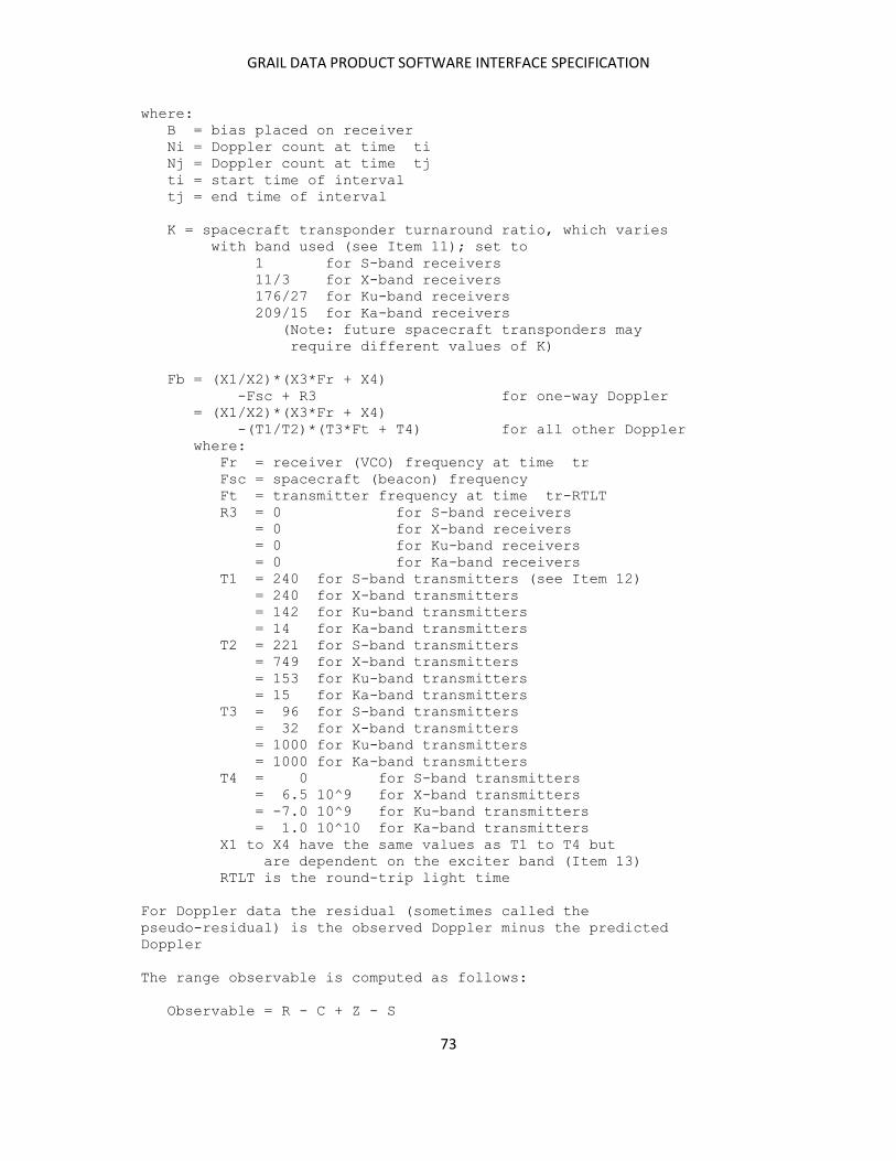
GRAIL DATA PRODUCT SOFTWARE INTERFACE SPECIFICATION
73
where:
B = bias placed on receiver
Ni = Doppler count at time ti
Nj = Doppler count at time tj
ti = start time of interval
tj = end time of interval
K = spacecraft transponder turnaround ratio, which varies
with band used (see Item 11); set to
1 for S-band receivers
11/3 for X-band receivers
176/27 for Ku-band receivers
209/15 for Ka-band receivers
(Note: future spacecraft transponders may
require different values of K)
Fb = (X1/X2)*(X3*Fr + X4)
-Fsc + R3 for one-way Doppler
= (X1/X2)*(X3*Fr + X4)
-(T1/T2)*(T3*Ft + T4) for all other Doppler
where:
Fr = receiver (VCO) frequency at time tr
Fsc = spacecraft (beacon) frequency
Ft = transmitter frequency at time tr-RTLT
R3 = 0 for S-band receivers
= 0 for X-band receivers
= 0 for Ku-band receivers
= 0 for Ka-band receivers
T1 = 240 for S-band transmitters (see Item 12)
= 240 for X-band transmitters
= 142 for Ku-band transmitters
= 14 for Ka-band transmitters
T2 = 221 for S-band transmitters
= 749 for X-band transmitters
= 153 for Ku-band transmitters
= 15 for Ka-band transmitters
T3 = 96 for S-band transmitters
= 32 for X-band transmitters
= 1000 for Ku-band transmitters
= 1000 for Ka-band transmitters
T4 = 0 for S-band transmitters
= 6.5 10^9 for X-band transmitters
= -7.0 10^9 for Ku-band transmitters
= 1.0 10^10 for Ka-band transmitters
X1 to X4 have the same values as T1 to T4 but
are dependent on the exciter band (Item 13)
RTLT is the round-trip light time
For Doppler data the residual (sometimes called the
pseudo-residual) is the observed Doppler minus the predicted
Doppler
The range observable is computed as follows:
Observable = R - C + Z - S
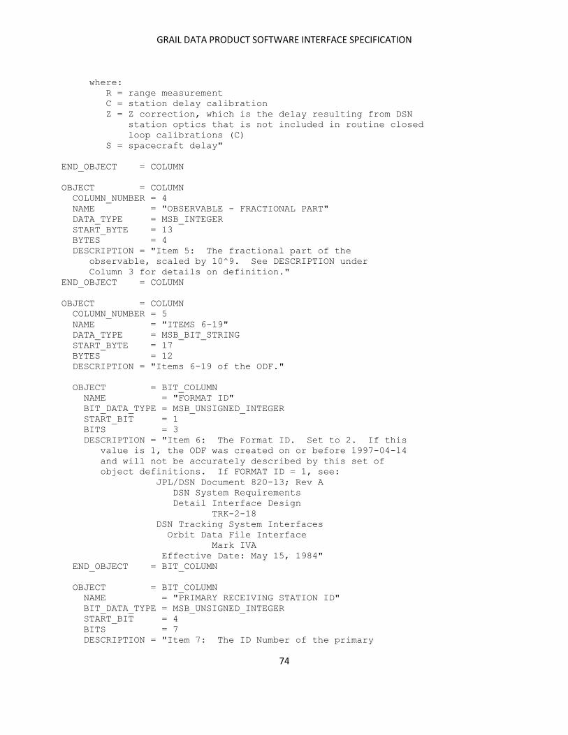
GRAIL DATA PRODUCT SOFTWARE INTERFACE SPECIFICATION
74
where:
R = range measurement
C = station delay calibration
Z = Z correction, which is the delay resulting from DSN
station optics that is not included in routine closed
loop calibrations (C)
S = spacecraft delay"
END_OBJECT = COLUMN
OBJECT = COLUMN
COLUMN_NUMBER = 4
NAME = "OBSERVABLE - FRACTIONAL PART"
DATA_TYPE = MSB_INTEGER
START_BYTE = 13
BYTES = 4
DESCRIPTION = "Item 5: The fractional part of the
observable, scaled by 10^9. See DESCRIPTION under
Column 3 for details on definition."
END_OBJECT = COLUMN
OBJECT = COLUMN
COLUMN_NUMBER = 5
NAME = "ITEMS 6-19"
DATA_TYPE = MSB_BIT_STRING
START_BYTE = 17
BYTES = 12
DESCRIPTION = "Items 6-19 of the ODF."
OBJECT = BIT_COLUMN
NAME = "FORMAT ID"
BIT_DATA_TYPE = MSB_UNSIGNED_INTEGER
START_BIT = 1
BITS = 3
DESCRIPTION = "Item 6: The Format ID. Set to 2. If this
value is 1, the ODF was created on or before 1997-04-14
and will not be accurately described by this set of
object definitions. If FORMAT ID = 1, see:
JPL/DSN Document 820-13; Rev A
DSN System Requirements
Detail Interface Design
TRK-2-18
DSN Tracking System Interfaces
Orbit Data File Interface
Mark IVA
Effective Date: May 15, 1984"
END_OBJECT = BIT_COLUMN
OBJECT = BIT_COLUMN
NAME = "PRIMARY RECEIVING STATION ID"
BIT_DATA_TYPE = MSB_UNSIGNED_INTEGER
START_BIT = 4
BITS = 7
DESCRIPTION = "Item 7: The ID Number of the primary
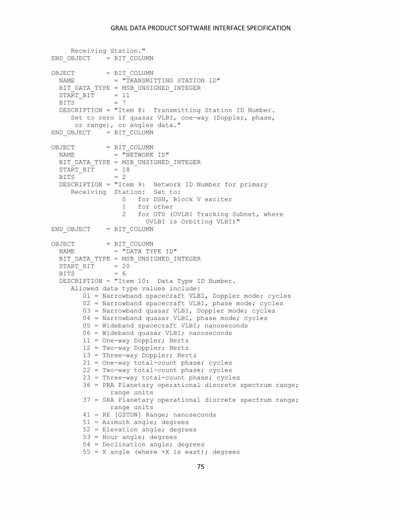
GRAIL DATA PRODUCT SOFTWARE INTERFACE SPECIFICATION
75
Receiving Station."
END_OBJECT = BIT_COLUMN
OBJECT = BIT_COLUMN
NAME = "TRANSMITTING STATION ID"
BIT_DATA_TYPE = MSB_UNSIGNED_INTEGER
START_BIT = 11
BITS = 7
DESCRIPTION = "Item 8: Transmitting Station ID Number.
Set to zero if quasar VLBI, one-way (Doppler, phase,
or range), or angles data."
END_OBJECT = BIT_COLUMN
OBJECT = BIT_COLUMN
NAME = "NETWORK ID"
BIT_DATA_TYPE = MSB_UNSIGNED_INTEGER
START_BIT = 18
BITS = 2
DESCRIPTION = "Item 9: Network ID Number for primary
Receiving Station: Set to:
0 for DSN, Block V exciter
1 for other
2 for OTS (OVLBI Tracking Subnet, where
OVLBI is Orbiting VLBI)"
END_OBJECT = BIT_COLUMN
OBJECT = BIT_COLUMN
NAME = "DATA TYPE ID"
BIT_DATA_TYPE = MSB_UNSIGNED_INTEGER
START_BIT = 20
BITS = 6
DESCRIPTION = "Item 10: Data Type ID Number.
Allowed data type values include:
01 = Narrowband spacecraft VLBI, Doppler mode; cycles
02 = Narrowband spacecraft VLBI, phase mode; cycles
03 = Narrowband quasar VLBI, Doppler mode; cycles
04 = Narrowband quasar VLBI, phase mode; cycles
05 = Wideband spacecraft VLBI; nanoseconds
06 = Wideband quasar VLBI; nanoseconds
11 = One-way Doppler; Hertz
12 = Two-way Doppler; Hertz
13 = Three-way Doppler; Hertz
21 = One-way total-count phase; cycles
22 = Two-way total-count phase; cycles
23 = Three-way total-count phase; cycles
36 = PRA Planetary operational discrete spectrum range;
range units
37 = SRA Planetary operational discrete spectrum range;
range units
41 = RE [GSTDN] Range; nanoseconds
51 = Azimuth angle; degrees
52 = Elevation angle; degrees
53 = Hour angle; degrees
54 = Declination angle; degrees
55 = X angle (where +X is east); degrees

GRAIL DATA PRODUCT SOFTWARE INTERFACE SPECIFICATION
76
56 = Y angle (where +X is east); degrees
57 = X angle (where +X is south); degrees
58 = Y angle (where +X is south); degrees
Notes: Some of the descriptions below refer to 'generic'
data types. These are defined as follows:
Data Types Generic Term
---------- ------------
01-06 VLBI
01-04 Narrowband VLBI
05-06 Wideband VLBI
03, 04, 06 Quasar
11-58 Tracking or TRK
01-58 Radiometric"
END_OBJECT = BIT_COLUMN
OBJECT = BIT_COLUMN
NAME = "DOWNLINK BAND ID"
BIT_DATA_TYPE = MSB_UNSIGNED_INTEGER
START_BIT = 26
BITS = 2
DESCRIPTION = "Item 11: Downlink Band ID. Allowed
values include:
0 = Not applicable if angle data,
Ku-band otherwise
1 = S-band
2 = X-band
3 = Ka-band"
END_OBJECT = BIT_COLUMN
OBJECT = BIT_COLUMN
NAME = "UPLINK BAND ID"
BIT_DATA_TYPE = MSB_UNSIGNED_INTEGER
START_BIT = 28
BITS = 2
DESCRIPTION = "Item 12: Uplink Band ID. Allowed
values include:
0 = Not applicable if angle data or 1-way data,
Ku-band otherwise
1 = S-band
2 = X-band
3 = Ka-band"
END_OBJECT = BIT_COLUMN
OBJECT = BIT_COLUMN
NAME = "EXCITER BAND ID"
BIT_DATA_TYPE = MSB_UNSIGNED_INTEGER
START_BIT = 30
BITS = 2
DESCRIPTION = "Item 13: Exciter Band ID. Allowed
values include:
0 = Not applicable if angle data,
Ku-band otherwise
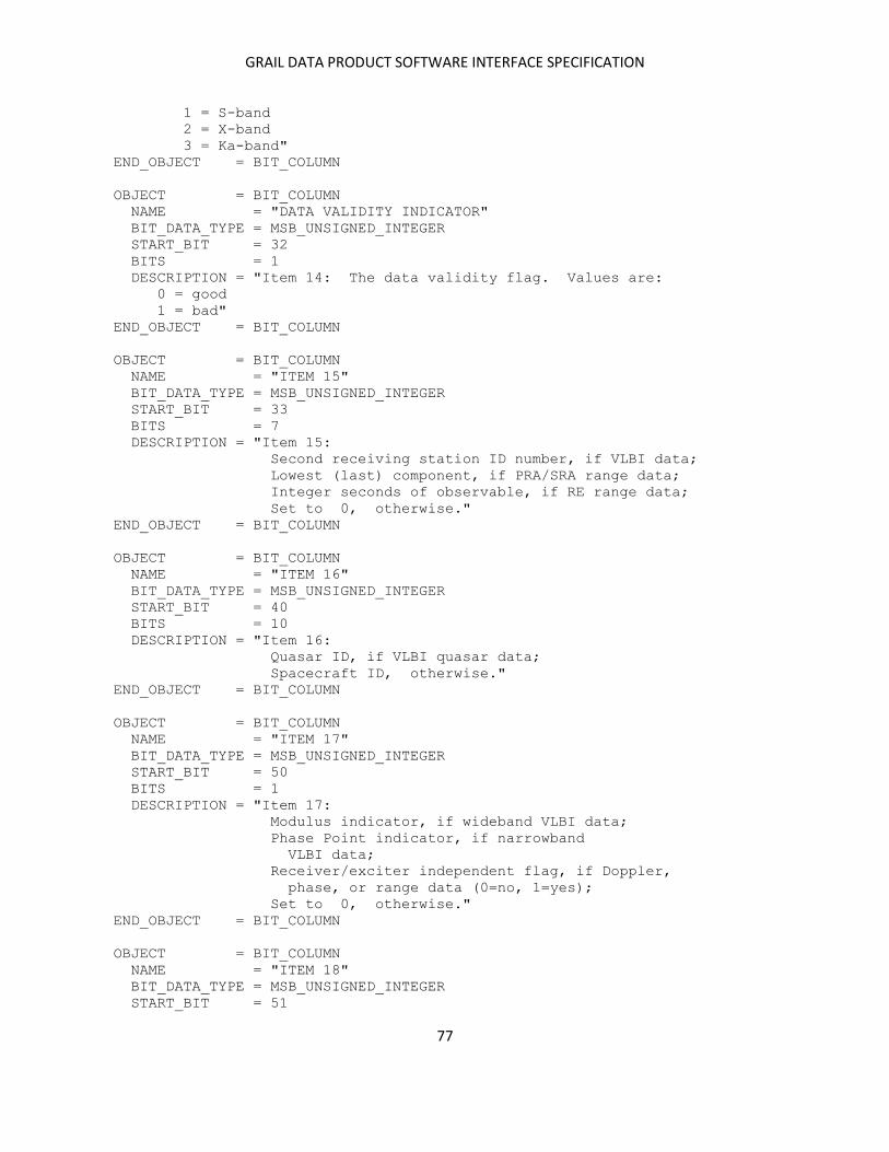
GRAIL DATA PRODUCT SOFTWARE INTERFACE SPECIFICATION
77
1 = S-band
2 = X-band
3 = Ka-band"
END_OBJECT = BIT_COLUMN
OBJECT = BIT_COLUMN
NAME = "DATA VALIDITY INDICATOR"
BIT_DATA_TYPE = MSB_UNSIGNED_INTEGER
START_BIT = 32
BITS = 1
DESCRIPTION = "Item 14: The data validity flag. Values are:
0 = good
1 = bad"
END_OBJECT = BIT_COLUMN
OBJECT = BIT_COLUMN
NAME = "ITEM 15"
BIT_DATA_TYPE = MSB_UNSIGNED_INTEGER
START_BIT = 33
BITS = 7
DESCRIPTION = "Item 15:
Second receiving station ID number, if VLBI data;
Lowest (last) component, if PRA/SRA range data;
Integer seconds of observable, if RE range data;
Set to 0, otherwise."
END_OBJECT = BIT_COLUMN
OBJECT = BIT_COLUMN
NAME = "ITEM 16"
BIT_DATA_TYPE = MSB_UNSIGNED_INTEGER
START_BIT = 40
BITS = 10
DESCRIPTION = "Item 16:
Quasar ID, if VLBI quasar data;
Spacecraft ID, otherwise."
END_OBJECT = BIT_COLUMN
OBJECT = BIT_COLUMN
NAME = "ITEM 17"
BIT_DATA_TYPE = MSB_UNSIGNED_INTEGER
START_BIT = 50
BITS = 1
DESCRIPTION = "Item 17:
Modulus indicator, if wideband VLBI data;
Phase Point indicator, if narrowband
VLBI data;
Receiver/exciter independent flag, if Doppler,
phase, or range data (0=no, 1=yes);
Set to 0, otherwise."
END_OBJECT = BIT_COLUMN
OBJECT = BIT_COLUMN
NAME = "ITEM 18"
BIT_DATA_TYPE = MSB_UNSIGNED_INTEGER
START_BIT = 51
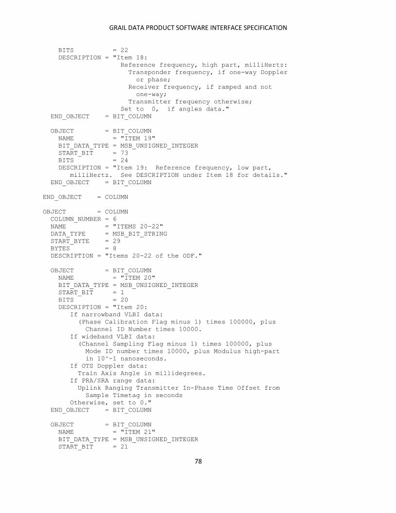
GRAIL DATA PRODUCT SOFTWARE INTERFACE SPECIFICATION
78
BITS = 22
DESCRIPTION = "Item 18:
Reference frequency, high part, milliHertz:
Transponder frequency, if one-way Doppler
or phase;
Receiver frequency, if ramped and not
one-way;
Transmitter frequency otherwise;
Set to 0, if angles data."
END_OBJECT = BIT_COLUMN
OBJECT = BIT_COLUMN
NAME = "ITEM 19"
BIT_DATA_TYPE = MSB_UNSIGNED_INTEGER
START_BIT = 73
BITS = 24
DESCRIPTION = "Item 19: Reference frequency, low part,
milliHertz. See DESCRIPTION under Item 18 for details."
END_OBJECT = BIT_COLUMN
END_OBJECT = COLUMN
OBJECT = COLUMN
COLUMN_NUMBER = 6
NAME = "ITEMS 20-22"
DATA_TYPE = MSB_BIT_STRING
START_BYTE = 29
BYTES = 8
DESCRIPTION = "Items 20-22 of the ODF."
OBJECT = BIT_COLUMN
NAME = "ITEM 20"
BIT_DATA_TYPE = MSB_UNSIGNED_INTEGER
START_BIT = 1
BITS = 20
DESCRIPTION = "Item 20:
If narrowband VLBI data:
(Phase Calibration Flag minus 1) times 100000, plus
Channel ID Number times 10000.
If wideband VLBI data:
(Channel Sampling Flag minus 1) times 100000, plus
Mode ID number times 10000, plus Modulus high-part
in 10^-1 nanoseconds.
If OTS Doppler data:
Train Axis Angle in millidegrees.
If PRA/SRA range data:
Uplink Ranging Transmitter In-Phase Time Offset from
Sample Timetag in seconds
Otherwise, set to 0."
END_OBJECT = BIT_COLUMN
OBJECT = BIT_COLUMN
NAME = "ITEM 21"
BIT_DATA_TYPE = MSB_UNSIGNED_INTEGER
START_BIT = 21
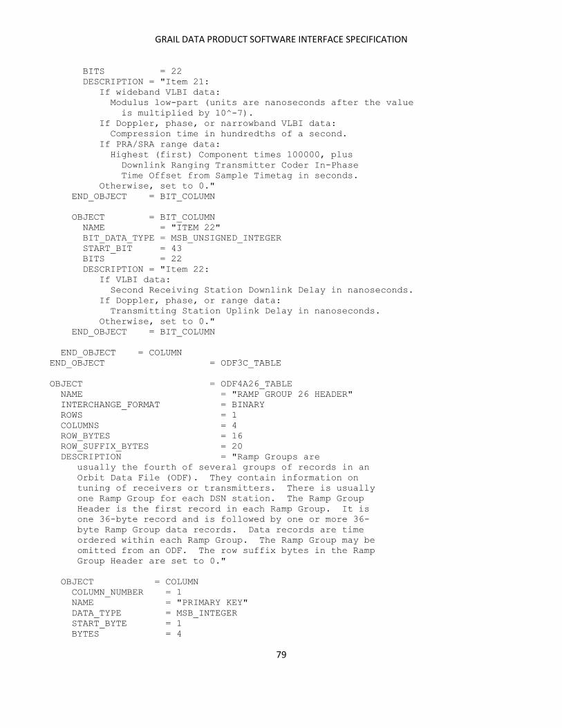
GRAIL DATA PRODUCT SOFTWARE INTERFACE SPECIFICATION
79
BITS = 22
DESCRIPTION = "Item 21:
If wideband VLBI data:
Modulus low-part (units are nanoseconds after the value
is multiplied by 10^-7).
If Doppler, phase, or narrowband VLBI data:
Compression time in hundredths of a second.
If PRA/SRA range data:
Highest (first) Component times 100000, plus
Downlink Ranging Transmitter Coder In-Phase
Time Offset from Sample Timetag in seconds.
Otherwise, set to 0."
END_OBJECT = BIT_COLUMN
OBJECT = BIT_COLUMN
NAME = "ITEM 22"
BIT_DATA_TYPE = MSB_UNSIGNED_INTEGER
START_BIT = 43
BITS = 22
DESCRIPTION = "Item 22:
If VLBI data:
Second Receiving Station Downlink Delay in nanoseconds.
If Doppler, phase, or range data:
Transmitting Station Uplink Delay in nanoseconds.
Otherwise, set to 0."
END_OBJECT = BIT_COLUMN
END_OBJECT = COLUMN
END_OBJECT = ODF3C_TABLE
OBJECT = ODF4A26_TABLE
NAME = "RAMP GROUP 26 HEADER"
INTERCHANGE_FORMAT = BINARY
ROWS = 1
COLUMNS = 4
ROW_BYTES = 16
ROW_SUFFIX_BYTES = 20
DESCRIPTION = "Ramp Groups are
usually the fourth of several groups of records in an
Orbit Data File (ODF). They contain information on
tuning of receivers or transmitters. There is usually
one Ramp Group for each DSN station. The Ramp Group
Header is the first record in each Ramp Group. It is
one 36-byte record and is followed by one or more 36-
byte Ramp Group data records. Data records are time
ordered within each Ramp Group. The Ramp Group may be
omitted from an ODF. The row suffix bytes in the Ramp
Group Header are set to 0."
OBJECT = COLUMN
COLUMN_NUMBER = 1
NAME = "PRIMARY KEY"
DATA_TYPE = MSB_INTEGER
START_BYTE = 1
BYTES = 4

GRAIL DATA PRODUCT SOFTWARE INTERFACE SPECIFICATION
80
DESCRIPTION = "Item 1: The Primary Key indicates the type
of data records to follow. In the Ramp Group Header
this field is set to 2030."
END_OBJECT = COLUMN
OBJECT = COLUMN
COLUMN_NUMBER = 2
NAME = "SECONDARY KEY"
DATA_TYPE = MSB_UNSIGNED_INTEGER
START_BYTE = 5
BYTES = 4
DESCRIPTION = "Item 2: Set to the Station ID Number."
END_OBJECT = COLUMN
OBJECT = COLUMN
COLUMN_NUMBER = 3
NAME = "LOGICAL RECORD LENGTH"
DATA_TYPE = MSB_UNSIGNED_INTEGER
START_BYTE = 9
BYTES = 4
UNIT = PACKET
DESCRIPTION = "Item 3: The Logical Record Length gives the
number of 36-byte physical records making up each logical
record in a Ramp Group data record. For the Ramp Group
it is set to 1."
END_OBJECT = COLUMN
OBJECT = COLUMN
COLUMN_NUMBER = 4
NAME = "GROUP START PACKET NUMBER"
DATA_TYPE = MSB_UNSIGNED_INTEGER
START_BYTE = 13
BYTES = 4
DESCRIPTION = "Item 4: The Group Start Packet Number
gives the number of the ODF packet containing the
Ramp Group Header; packet numbering starts with 0
for the File Label Group Header."
END_OBJECT = COLUMN
END_OBJECT = ODF4A26_TABLE
OBJECT = ODF4B26_TABLE
NAME = "RAMP GROUP 26 DATA"
INTERCHANGE_FORMAT = BINARY
ROWS = 236
COLUMNS = 9
ROW_BYTES = 36
DESCRIPTION = "Ramp Groups are
usually the fourth of several groups of records in an
Orbit Data File (ODF). They contain information on
tuning of receivers or transmitters. There is usually
one Ramp Group for each DSN station. The Ramp Group
Header is the first record in each Ramp Group. It is
one 36-byte record and is followed by one or more 36-
byte Ramp Group data records. Data records are time
ordered within each Ramp Group. The Ramp Group may be

GRAIL DATA PRODUCT SOFTWARE INTERFACE SPECIFICATION
81
omitted from an ODF."
OBJECT = COLUMN
COLUMN_NUMBER = 1
NAME = "RAMP START TIME - INTEGER PART"
DATA_TYPE = MSB_UNSIGNED_INTEGER
START_BYTE = 1
BYTES = 4
UNIT = SECOND
DESCRIPTION = "Item 1: The integer part of the ramp
start time, measured from 0 hours UTC on 1 January 1950."
END_OBJECT = COLUMN
OBJECT = COLUMN
COLUMN_NUMBER = 2
NAME = "RAMP START TIME - FRACTIONAL PART"
DATA_TYPE = MSB_UNSIGNED_INTEGER
START_BYTE = 5
BYTES = 4
UNIT = NANOSECOND
DESCRIPTION = "Item 2: The fractional part of the ramp
start time - see Column 1 (Item 1)."
END_OBJECT = COLUMN
OBJECT = COLUMN
COLUMN_NUMBER = 3
NAME = "RAMP RATE - INTEGER PART"
DATA_TYPE = MSB_INTEGER
START_BYTE = 9
BYTES = 4
DESCRIPTION = "Item 3: The integer part of the ramp
rate."
END_OBJECT = COLUMN
OBJECT = COLUMN
COLUMN_NUMBER = 4
NAME = "RAMP RATE - FRACTIONAL PART"
DATA_TYPE = MSB_INTEGER
START_BYTE = 13
BYTES = 4
DESCRIPTION = "Item 4: The fractional part of the ramp
rate, in units of 10^-9 of Column 3."
END_OBJECT = COLUMN
OBJECT = COLUMN
COLUMN_NUMBER = 5
NAME = "ITEMS 5-6"
DATA_TYPE = MSB_BIT_STRING
START_BYTE = 17
BYTES = 4
DESCRIPTION = "Items 5-6 of the ODF."
OBJECT = BIT_COLUMN
NAME = "RAMP START FREQUENCY - GHZ"
BIT_DATA_TYPE = MSB_UNSIGNED_INTEGER

GRAIL DATA PRODUCT SOFTWARE INTERFACE SPECIFICATION
82
START_BIT = 1
BITS = 22
UNIT = GIGAHERTZ
DESCRIPTION = "Item 5: Ramp Start Frequency, integer GHz.
If this value is non-zero, Ramp Start Frequency and Ramp
Rate are at sky level."
END_OBJECT = BIT_COLUMN
OBJECT = BIT_COLUMN
NAME = "STATION ID"
BIT_DATA_TYPE = MSB_UNSIGNED_INTEGER
START_BIT = 23
BITS = 10
DESCRIPTION = "Item 6: Receiving/Transmitting Station
ID Number."
END_OBJECT = BIT_COLUMN
END_OBJECT = COLUMN
OBJECT = COLUMN
COLUMN_NUMBER = 6
NAME = "RAMP START FREQUENCY - INTEGER PART"
DATA_TYPE = MSB_UNSIGNED_INTEGER
START_BYTE = 21
BYTES = 4
UNIT = HERTZ
DESCRIPTION = "Item 7: The integer part of the
Ramp Start Frequency, modulo 10^9."
END_OBJECT = COLUMN
OBJECT = COLUMN
COLUMN_NUMBER = 7
NAME = "RAMP START FREQUENCY - FRACTIONAL PART"
DATA_TYPE = MSB_UNSIGNED_INTEGER
START_BYTE = 25
BYTES = 4
DESCRIPTION = "Item 8: The fractional part of the
Ramp Start Frequency, in units of 10^-9 of
Column 6."
END_OBJECT = COLUMN
OBJECT = COLUMN
COLUMN_NUMBER = 8
NAME = "RAMP END TIME - INTEGER PART"
DATA_TYPE = MSB_UNSIGNED_INTEGER
START_BYTE = 29
BYTES = 4
UNIT = SECOND
DESCRIPTION = "Item 9: The integer part of the ramp
end time, measured from 0 hours UTC on 1 January 1950."
END_OBJECT = COLUMN
OBJECT = COLUMN
COLUMN_NUMBER = 9
NAME = "RAMP END TIME - FRACTIONAL PART"
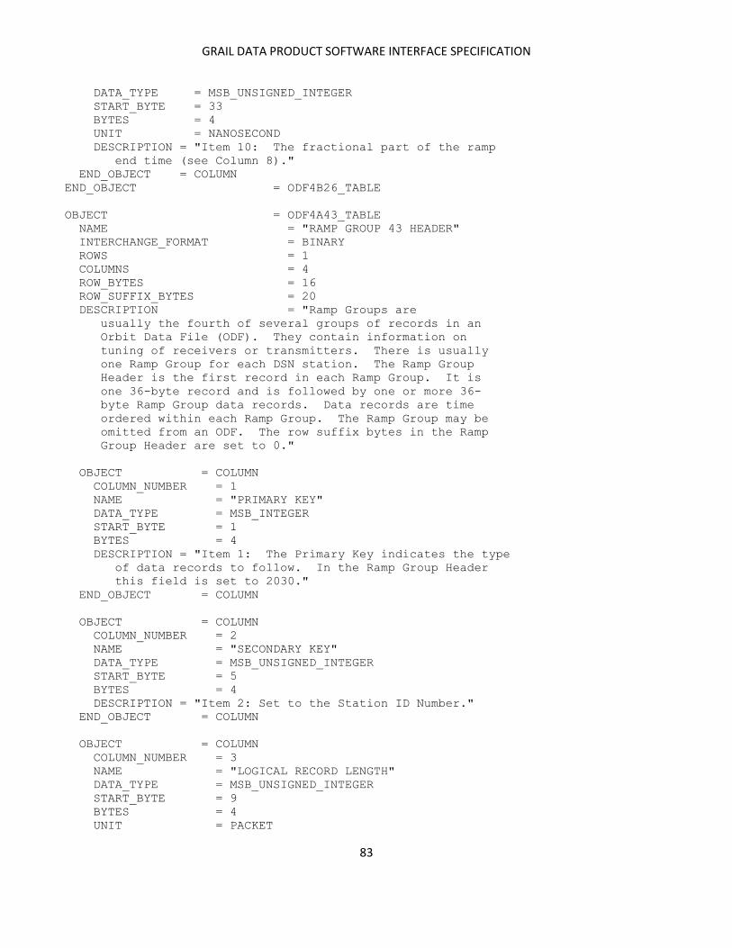
GRAIL DATA PRODUCT SOFTWARE INTERFACE SPECIFICATION
83
DATA_TYPE = MSB_UNSIGNED_INTEGER
START_BYTE = 33
BYTES = 4
UNIT = NANOSECOND
DESCRIPTION = "Item 10: The fractional part of the ramp
end time (see Column 8)."
END_OBJECT = COLUMN
END_OBJECT = ODF4B26_TABLE
OBJECT = ODF4A43_TABLE
NAME = "RAMP GROUP 43 HEADER"
INTERCHANGE_FORMAT = BINARY
ROWS = 1
COLUMNS = 4
ROW_BYTES = 16
ROW_SUFFIX_BYTES = 20
DESCRIPTION = "Ramp Groups are
usually the fourth of several groups of records in an
Orbit Data File (ODF). They contain information on
tuning of receivers or transmitters. There is usually
one Ramp Group for each DSN station. The Ramp Group
Header is the first record in each Ramp Group. It is
one 36-byte record and is followed by one or more 36-
byte Ramp Group data records. Data records are time
ordered within each Ramp Group. The Ramp Group may be
omitted from an ODF. The row suffix bytes in the Ramp
Group Header are set to 0."
OBJECT = COLUMN
COLUMN_NUMBER = 1
NAME = "PRIMARY KEY"
DATA_TYPE = MSB_INTEGER
START_BYTE = 1
BYTES = 4
DESCRIPTION = "Item 1: The Primary Key indicates the type
of data records to follow. In the Ramp Group Header
this field is set to 2030."
END_OBJECT = COLUMN
OBJECT = COLUMN
COLUMN_NUMBER = 2
NAME = "SECONDARY KEY"
DATA_TYPE = MSB_UNSIGNED_INTEGER
START_BYTE = 5
BYTES = 4
DESCRIPTION = "Item 2: Set to the Station ID Number."
END_OBJECT = COLUMN
OBJECT = COLUMN
COLUMN_NUMBER = 3
NAME = "LOGICAL RECORD LENGTH"
DATA_TYPE = MSB_UNSIGNED_INTEGER
START_BYTE = 9
BYTES = 4
UNIT = PACKET
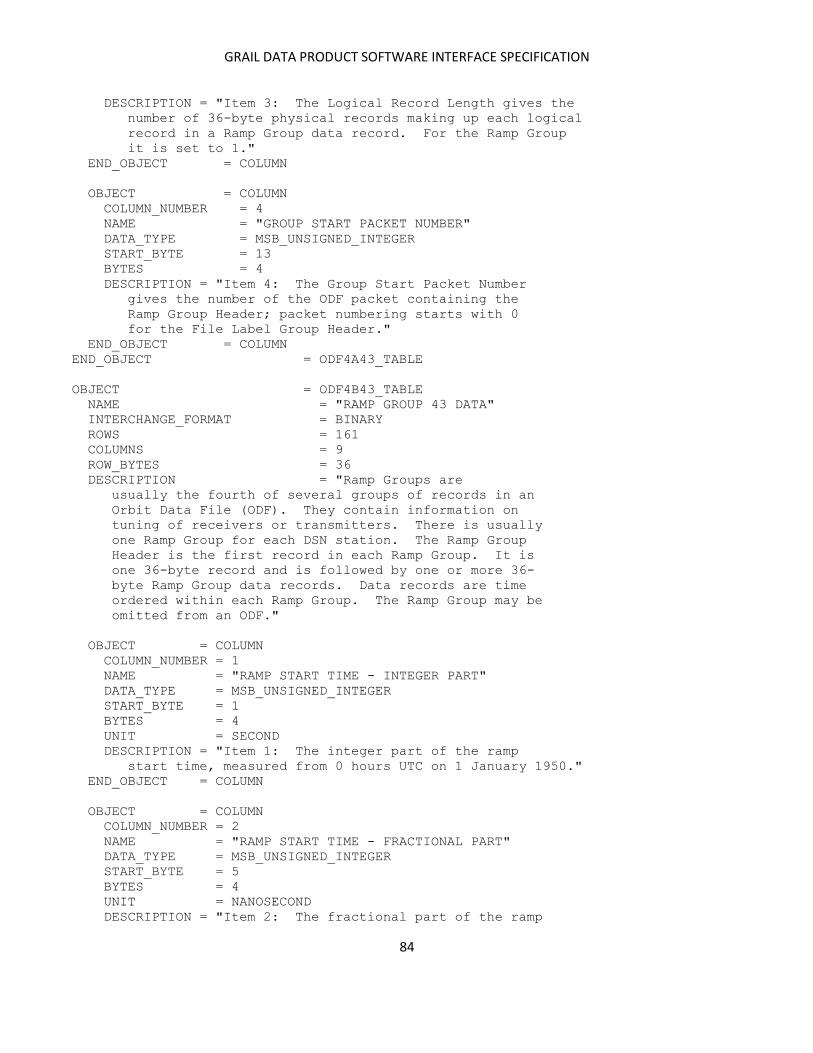
GRAIL DATA PRODUCT SOFTWARE INTERFACE SPECIFICATION
84
DESCRIPTION = "Item 3: The Logical Record Length gives the
number of 36-byte physical records making up each logical
record in a Ramp Group data record. For the Ramp Group
it is set to 1."
END_OBJECT = COLUMN
OBJECT = COLUMN
COLUMN_NUMBER = 4
NAME = "GROUP START PACKET NUMBER"
DATA_TYPE = MSB_UNSIGNED_INTEGER
START_BYTE = 13
BYTES = 4
DESCRIPTION = "Item 4: The Group Start Packet Number
gives the number of the ODF packet containing the
Ramp Group Header; packet numbering starts with 0
for the File Label Group Header."
END_OBJECT = COLUMN
END_OBJECT = ODF4A43_TABLE
OBJECT = ODF4B43_TABLE
NAME = "RAMP GROUP 43 DATA"
INTERCHANGE_FORMAT = BINARY
ROWS = 161
COLUMNS = 9
ROW_BYTES = 36
DESCRIPTION = "Ramp Groups are
usually the fourth of several groups of records in an
Orbit Data File (ODF). They contain information on
tuning of receivers or transmitters. There is usually
one Ramp Group for each DSN station. The Ramp Group
Header is the first record in each Ramp Group. It is
one 36-byte record and is followed by one or more 36-
byte Ramp Group data records. Data records are time
ordered within each Ramp Group. The Ramp Group may be
omitted from an ODF."
OBJECT = COLUMN
COLUMN_NUMBER = 1
NAME = "RAMP START TIME - INTEGER PART"
DATA_TYPE = MSB_UNSIGNED_INTEGER
START_BYTE = 1
BYTES = 4
UNIT = SECOND
DESCRIPTION = "Item 1: The integer part of the ramp
start time, measured from 0 hours UTC on 1 January 1950."
END_OBJECT = COLUMN
OBJECT = COLUMN
COLUMN_NUMBER = 2
NAME = "RAMP START TIME - FRACTIONAL PART"
DATA_TYPE = MSB_UNSIGNED_INTEGER
START_BYTE = 5
BYTES = 4
UNIT = NANOSECOND
DESCRIPTION = "Item 2: The fractional part of the ramp
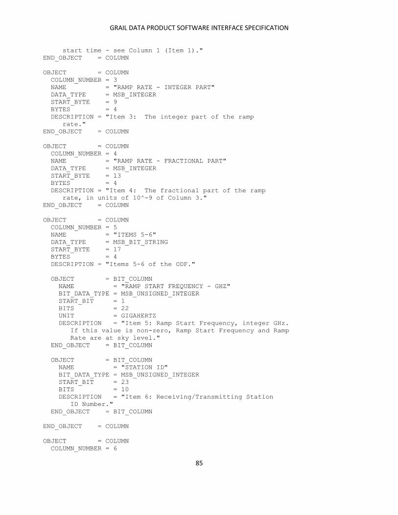
GRAIL DATA PRODUCT SOFTWARE INTERFACE SPECIFICATION
85
start time - see Column 1 (Item 1)."
END_OBJECT = COLUMN
OBJECT = COLUMN
COLUMN_NUMBER = 3
NAME = "RAMP RATE - INTEGER PART"
DATA_TYPE = MSB_INTEGER
START_BYTE = 9
BYTES = 4
DESCRIPTION = "Item 3: The integer part of the ramp
rate."
END_OBJECT = COLUMN
OBJECT = COLUMN
COLUMN_NUMBER = 4
NAME = "RAMP RATE - FRACTIONAL PART"
DATA_TYPE = MSB_INTEGER
START_BYTE = 13
BYTES = 4
DESCRIPTION = "Item 4: The fractional part of the ramp
rate, in units of 10^-9 of Column 3."
END_OBJECT = COLUMN
OBJECT = COLUMN
COLUMN_NUMBER = 5
NAME = "ITEMS 5-6"
DATA_TYPE = MSB_BIT_STRING
START_BYTE = 17
BYTES = 4
DESCRIPTION = "Items 5-6 of the ODF."
OBJECT = BIT_COLUMN
NAME = "RAMP START FREQUENCY - GHZ"
BIT_DATA_TYPE = MSB_UNSIGNED_INTEGER
START_BIT = 1
BITS = 22
UNIT = GIGAHERTZ
DESCRIPTION = "Item 5: Ramp Start Frequency, integer GHz.
If this value is non-zero, Ramp Start Frequency and Ramp
Rate are at sky level."
END_OBJECT = BIT_COLUMN
OBJECT = BIT_COLUMN
NAME = "STATION ID"
BIT_DATA_TYPE = MSB_UNSIGNED_INTEGER
START_BIT = 23
BITS = 10
DESCRIPTION = "Item 6: Receiving/Transmitting Station
ID Number."
END_OBJECT = BIT_COLUMN
END_OBJECT = COLUMN
OBJECT = COLUMN
COLUMN_NUMBER = 6
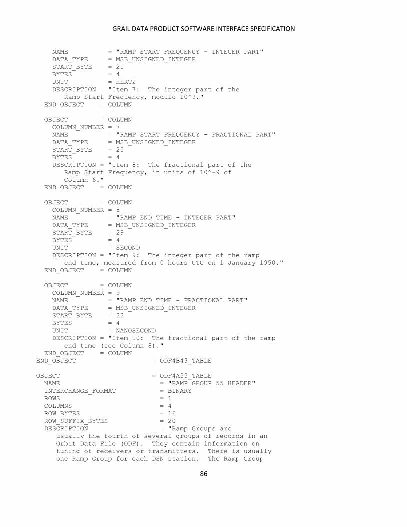
GRAIL DATA PRODUCT SOFTWARE INTERFACE SPECIFICATION
86
NAME = "RAMP START FREQUENCY - INTEGER PART"
DATA_TYPE = MSB_UNSIGNED_INTEGER
START_BYTE = 21
BYTES = 4
UNIT = HERTZ
DESCRIPTION = "Item 7: The integer part of the
Ramp Start Frequency, modulo 10^9."
END_OBJECT = COLUMN
OBJECT = COLUMN
COLUMN_NUMBER = 7
NAME = "RAMP START FREQUENCY - FRACTIONAL PART"
DATA_TYPE = MSB_UNSIGNED_INTEGER
START_BYTE = 25
BYTES = 4
DESCRIPTION = "Item 8: The fractional part of the
Ramp Start Frequency, in units of 10^-9 of
Column 6."
END_OBJECT = COLUMN
OBJECT = COLUMN
COLUMN_NUMBER = 8
NAME = "RAMP END TIME - INTEGER PART"
DATA_TYPE = MSB_UNSIGNED_INTEGER
START_BYTE = 29
BYTES = 4
UNIT = SECOND
DESCRIPTION = "Item 9: The integer part of the ramp
end time, measured from 0 hours UTC on 1 January 1950."
END_OBJECT = COLUMN
OBJECT = COLUMN
COLUMN_NUMBER = 9
NAME = "RAMP END TIME - FRACTIONAL PART"
DATA_TYPE = MSB_UNSIGNED_INTEGER
START_BYTE = 33
BYTES = 4
UNIT = NANOSECOND
DESCRIPTION = "Item 10: The fractional part of the ramp
end time (see Column 8)."
END_OBJECT = COLUMN
END_OBJECT = ODF4B43_TABLE
OBJECT = ODF4A55_TABLE
NAME = "RAMP GROUP 55 HEADER"
INTERCHANGE_FORMAT = BINARY
ROWS = 1
COLUMNS = 4
ROW_BYTES = 16
ROW_SUFFIX_BYTES = 20
DESCRIPTION = "Ramp Groups are
usually the fourth of several groups of records in an
Orbit Data File (ODF). They contain information on
tuning of receivers or transmitters. There is usually
one Ramp Group for each DSN station. The Ramp Group
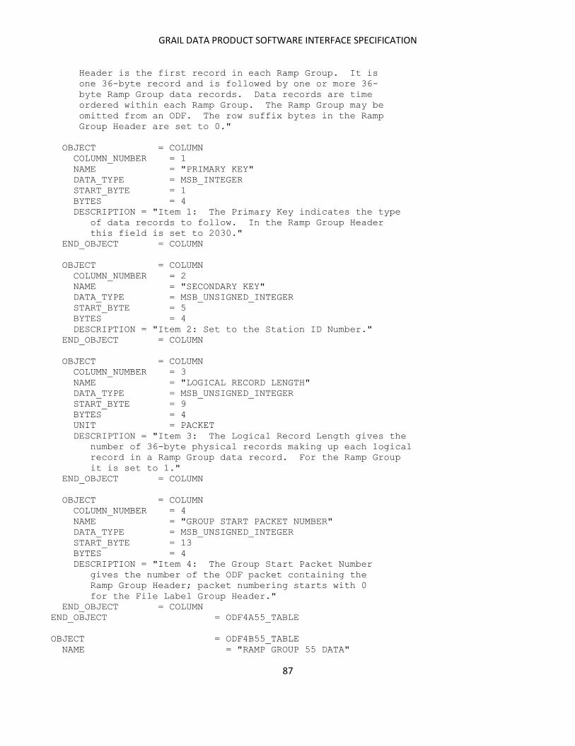
GRAIL DATA PRODUCT SOFTWARE INTERFACE SPECIFICATION
87
Header is the first record in each Ramp Group. It is
one 36-byte record and is followed by one or more 36-
byte Ramp Group data records. Data records are time
ordered within each Ramp Group. The Ramp Group may be
omitted from an ODF. The row suffix bytes in the Ramp
Group Header are set to 0."
OBJECT = COLUMN
COLUMN_NUMBER = 1
NAME = "PRIMARY KEY"
DATA_TYPE = MSB_INTEGER
START_BYTE = 1
BYTES = 4
DESCRIPTION = "Item 1: The Primary Key indicates the type
of data records to follow. In the Ramp Group Header
this field is set to 2030."
END_OBJECT = COLUMN
OBJECT = COLUMN
COLUMN_NUMBER = 2
NAME = "SECONDARY KEY"
DATA_TYPE = MSB_UNSIGNED_INTEGER
START_BYTE = 5
BYTES = 4
DESCRIPTION = "Item 2: Set to the Station ID Number."
END_OBJECT = COLUMN
OBJECT = COLUMN
COLUMN_NUMBER = 3
NAME = "LOGICAL RECORD LENGTH"
DATA_TYPE = MSB_UNSIGNED_INTEGER
START_BYTE = 9
BYTES = 4
UNIT = PACKET
DESCRIPTION = "Item 3: The Logical Record Length gives the
number of 36-byte physical records making up each logical
record in a Ramp Group data record. For the Ramp Group
it is set to 1."
END_OBJECT = COLUMN
OBJECT = COLUMN
COLUMN_NUMBER = 4
NAME = "GROUP START PACKET NUMBER"
DATA_TYPE = MSB_UNSIGNED_INTEGER
START_BYTE = 13
BYTES = 4
DESCRIPTION = "Item 4: The Group Start Packet Number
gives the number of the ODF packet containing the
Ramp Group Header; packet numbering starts with 0
for the File Label Group Header."
END_OBJECT = COLUMN
END_OBJECT = ODF4A55_TABLE
OBJECT = ODF4B55_TABLE
NAME = "RAMP GROUP 55 DATA"

GRAIL DATA PRODUCT SOFTWARE INTERFACE SPECIFICATION
88
INTERCHANGE_FORMAT = BINARY
ROWS = 139
COLUMNS = 9
ROW_BYTES = 36
DESCRIPTION = "Ramp Groups are
usually the fourth of several groups of records in an
Orbit Data File (ODF). They contain information on
tuning of receivers or transmitters. There is usually
one Ramp Group for each DSN station. The Ramp Group
Header is the first record in each Ramp Group. It is
one 36-byte record and is followed by one or more 36-
byte Ramp Group data records. Data records are time
ordered within each Ramp Group. The Ramp Group may be
omitted from an ODF."
OBJECT = COLUMN
COLUMN_NUMBER = 1
NAME = "RAMP START TIME - INTEGER PART"
DATA_TYPE = MSB_UNSIGNED_INTEGER
START_BYTE = 1
BYTES = 4
UNIT = SECOND
DESCRIPTION = "Item 1: The integer part of the ramp
start time, measured from 0 hours UTC on 1 January 1950."
END_OBJECT = COLUMN
OBJECT = COLUMN
COLUMN_NUMBER = 2
NAME = "RAMP START TIME - FRACTIONAL PART"
DATA_TYPE = MSB_UNSIGNED_INTEGER
START_BYTE = 5
BYTES = 4
UNIT = NANOSECOND
DESCRIPTION = "Item 2: The fractional part of the ramp
start time - see Column 1 (Item 1)."
END_OBJECT = COLUMN
OBJECT = COLUMN
COLUMN_NUMBER = 3
NAME = "RAMP RATE - INTEGER PART"
DATA_TYPE = MSB_INTEGER
START_BYTE = 9
BYTES = 4
DESCRIPTION = "Item 3: The integer part of the ramp
rate."
END_OBJECT = COLUMN
OBJECT = COLUMN
COLUMN_NUMBER = 4
NAME = "RAMP RATE - FRACTIONAL PART"
DATA_TYPE = MSB_INTEGER
START_BYTE = 13
BYTES = 4
DESCRIPTION = "Item 4: The fractional part of the ramp
rate, in units of 10^-9 of Column 3."
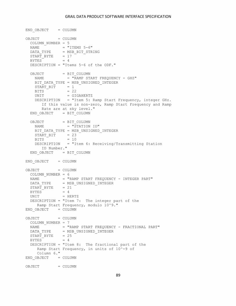
GRAIL DATA PRODUCT SOFTWARE INTERFACE SPECIFICATION
89
END_OBJECT = COLUMN
OBJECT = COLUMN
COLUMN_NUMBER = 5
NAME = "ITEMS 5-6"
DATA_TYPE = MSB_BIT_STRING
START_BYTE = 17
BYTES = 4
DESCRIPTION = "Items 5-6 of the ODF."
OBJECT = BIT_COLUMN
NAME = "RAMP START FREQUENCY - GHZ"
BIT_DATA_TYPE = MSB_UNSIGNED_INTEGER
START_BIT = 1
BITS = 22
UNIT = GIGAHERTZ
DESCRIPTION = "Item 5: Ramp Start Frequency, integer GHz.
If this value is non-zero, Ramp Start Frequency and Ramp
Rate are at sky level."
END_OBJECT = BIT_COLUMN
OBJECT = BIT_COLUMN
NAME = "STATION ID"
BIT_DATA_TYPE = MSB_UNSIGNED_INTEGER
START_BIT = 23
BITS = 10
DESCRIPTION = "Item 6: Receiving/Transmitting Station
ID Number."
END_OBJECT = BIT_COLUMN
END_OBJECT = COLUMN
OBJECT = COLUMN
COLUMN_NUMBER = 6
NAME = "RAMP START FREQUENCY - INTEGER PART"
DATA_TYPE = MSB_UNSIGNED_INTEGER
START_BYTE = 21
BYTES = 4
UNIT = HERTZ
DESCRIPTION = "Item 7: The integer part of the
Ramp Start Frequency, modulo 10^9."
END_OBJECT = COLUMN
OBJECT = COLUMN
COLUMN_NUMBER = 7
NAME = "RAMP START FREQUENCY - FRACTIONAL PART"
DATA_TYPE = MSB_UNSIGNED_INTEGER
START_BYTE = 25
BYTES = 4
DESCRIPTION = "Item 8: The fractional part of the
Ramp Start Frequency, in units of 10^-9 of
Column 6."
END_OBJECT = COLUMN
OBJECT = COLUMN
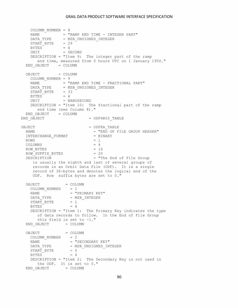
GRAIL DATA PRODUCT SOFTWARE INTERFACE SPECIFICATION
90
COLUMN_NUMBER = 8
NAME = "RAMP END TIME - INTEGER PART"
DATA_TYPE = MSB_UNSIGNED_INTEGER
START_BYTE = 29
BYTES = 4
UNIT = SECOND
DESCRIPTION = "Item 9: The integer part of the ramp
end time, measured from 0 hours UTC on 1 January 1950."
END_OBJECT = COLUMN
OBJECT = COLUMN
COLUMN_NUMBER = 9
NAME = "RAMP END TIME - FRACTIONAL PART"
DATA_TYPE = MSB_UNSIGNED_INTEGER
START_BYTE = 33
BYTES = 4
UNIT = NANOSECOND
DESCRIPTION = "Item 10: The fractional part of the ramp
end time (see Column 8)."
END_OBJECT = COLUMN
END_OBJECT = ODF4B55_TABLE
OBJECT = ODF8A_TABLE
NAME = "END OF FILE GROUP HEADER"
INTERCHANGE_FORMAT = BINARY
ROWS = 1
COLUMNS = 4
ROW_BYTES = 16
ROW_SUFFIX_BYTES = 20
DESCRIPTION = "The End of File Group
is usually the eighth and last of several groups of
records in an Orbit Data File (ODF). It is a single
record of 36-bytes and denotes the logical end of the
ODF. Row suffix bytes are set to 0."
OBJECT = COLUMN
COLUMN_NUMBER = 1
NAME = "PRIMARY KEY"
DATA_TYPE = MSB_INTEGER
START_BYTE = 1
BYTES = 4
DESCRIPTION = "Item 1: The Primary Key indicates the type
of data records to follow. In the End of File Group
this field is set to -1."
END_OBJECT = COLUMN
OBJECT = COLUMN
COLUMN_NUMBER = 2
NAME = "SECONDARY KEY"
DATA_TYPE = MSB_UNSIGNED_INTEGER
START_BYTE = 5
BYTES = 4
DESCRIPTION = "Item 2: The Secondary Key is not used in
the ODF. It is set to 0."
END_OBJECT = COLUMN
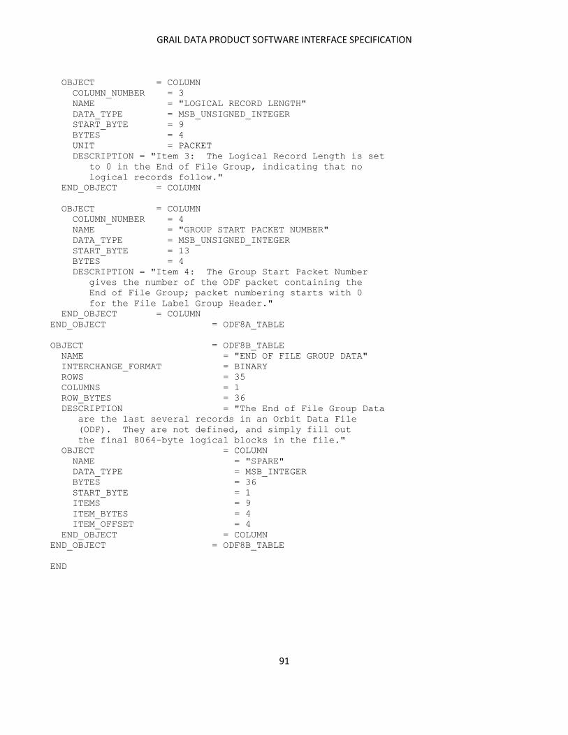
GRAIL DATA PRODUCT SOFTWARE INTERFACE SPECIFICATION
91
OBJECT = COLUMN
COLUMN_NUMBER = 3
NAME = "LOGICAL RECORD LENGTH"
DATA_TYPE = MSB_UNSIGNED_INTEGER
START_BYTE = 9
BYTES = 4
UNIT = PACKET
DESCRIPTION = "Item 3: The Logical Record Length is set
to 0 in the End of File Group, indicating that no
logical records follow."
END_OBJECT = COLUMN
OBJECT = COLUMN
COLUMN_NUMBER = 4
NAME = "GROUP START PACKET NUMBER"
DATA_TYPE = MSB_UNSIGNED_INTEGER
START_BYTE = 13
BYTES = 4
DESCRIPTION = "Item 4: The Group Start Packet Number
gives the number of the ODF packet containing the
End of File Group; packet numbering starts with 0
for the File Label Group Header."
END_OBJECT = COLUMN
END_OBJECT = ODF8A_TABLE
OBJECT = ODF8B_TABLE
NAME = "END OF FILE GROUP DATA"
INTERCHANGE_FORMAT = BINARY
ROWS = 35
COLUMNS = 1
ROW_BYTES = 36
DESCRIPTION = "The End of File Group Data
are the last several records in an Orbit Data File
(ODF). They are not defined, and simply fill out
the final 8064-byte logical blocks in the file."
OBJECT = COLUMN
NAME = "SPARE"
DATA_TYPE = MSB_INTEGER
BYTES = 36
START_BYTE = 1
ITEMS = 9
ITEM_BYTES = 4
ITEM_OFFSET = 4
END_OBJECT = COLUMN
END_OBJECT = ODF8B_TABLE
END
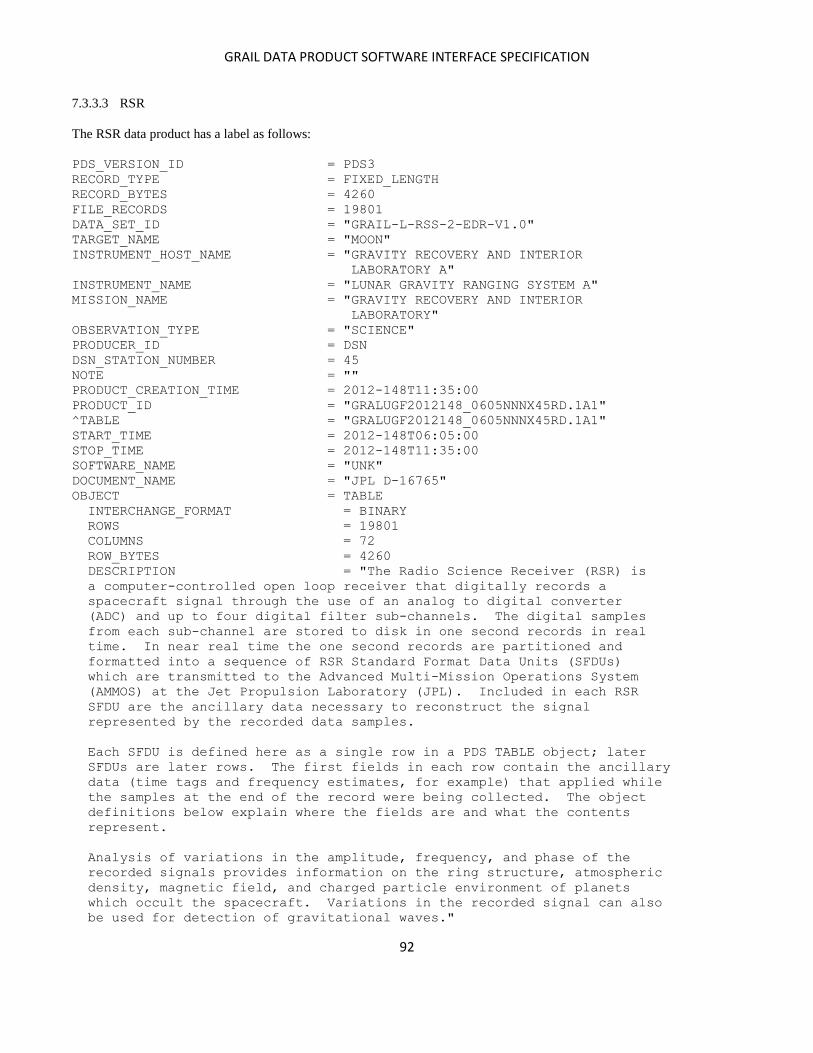
GRAIL DATA PRODUCT SOFTWARE INTERFACE SPECIFICATION
92
7.3.3.3 RSR
The RSR data product has a label as follows:
PDS_VERSION_ID = PDS3
RECORD_TYPE = FIXED_LENGTH
RECORD_BYTES = 4260
FILE_RECORDS = 19801
DATA_SET_ID = "GRAIL-L-RSS-2-EDR-V1.0"
TARGET_NAME = "MOON"
INSTRUMENT_HOST_NAME = "GRAVITY RECOVERY AND INTERIOR
LABORATORY A"
INSTRUMENT_NAME = "LUNAR GRAVITY RANGING SYSTEM A"
MISSION_NAME = "GRAVITY RECOVERY AND INTERIOR
LABORATORY"
OBSERVATION_TYPE = "SCIENCE"
PRODUCER_ID = DSN
DSN_STATION_NUMBER = 45
NOTE = ""
PRODUCT_CREATION_TIME = 2012-148T11:35:00
PRODUCT_ID = "GRALUGF2012148_0605NNNX45RD.1A1"
^TABLE = "GRALUGF2012148_0605NNNX45RD.1A1"
START_TIME = 2012-148T06:05:00
STOP_TIME = 2012-148T11:35:00
SOFTWARE_NAME = "UNK"
DOCUMENT_NAME = "JPL D-16765"
OBJECT = TABLE
INTERCHANGE_FORMAT = BINARY
ROWS = 19801
COLUMNS = 72
ROW_BYTES = 4260
DESCRIPTION = "The Radio Science Receiver (RSR) is
a computer-controlled open loop receiver that digitally records a
spacecraft signal through the use of an analog to digital converter
(ADC) and up to four digital filter sub-channels. The digital samples
from each sub-channel are stored to disk in one second records in real
time. In near real time the one second records are partitioned and
formatted into a sequence of RSR Standard Format Data Units (SFDUs)
which are transmitted to the Advanced Multi-Mission Operations System
(AMMOS) at the Jet Propulsion Laboratory (JPL). Included in each RSR
SFDU are the ancillary data necessary to reconstruct the signal
represented by the recorded data samples.
Each SFDU is defined here as a single row in a PDS TABLE object; later
SFDUs are later rows. The first fields in each row contain the ancillary
data (time tags and frequency estimates, for example) that applied while
the samples at the end of the record were being collected. The object
definitions below explain where the fields are and what the contents
represent.
Analysis of variations in the amplitude, frequency, and phase of the
recorded signals provides information on the ring structure, atmospheric
density, magnetic field, and charged particle environment of planets
which occult the spacecraft. Variations in the recorded signal can also
be used for detection of gravitational waves."

GRAIL DATA PRODUCT SOFTWARE INTERFACE SPECIFICATION
93
OBJECT = COLUMN
NAME = "SFDU CONTROL AUTHORITY"
COLUMN_NUMBER = 1
START_BYTE = 1
BYTES = 4
DATA_TYPE = CHARACTER
UNIT = "N/A"
DESCRIPTION = "An ASCII string giving the SFDU
Control Authority for this data
type. Set to 'NJPL', meaning the
data description information for
this type of SFDU is maintained
by the NASA/JPL Control Authority."
END_OBJECT = COLUMN
OBJECT = COLUMN
NAME = "SFDU LABEL VERSION ID"
COLUMN_NUMBER = 2
START_BYTE = 5
BYTES = 1
DATA_TYPE = CHARACTER
UNIT = "N/A"
DESCRIPTION = "An ASCII character giving the SFDU
Label Version Identifier. Set to
'2', meaning the length given in
bytes 13-20 is formatted as a
binary unsigned integer."
END_OBJECT = COLUMN
OBJECT = COLUMN
NAME = "SFDU CLASS ID"
COLUMN_NUMBER = 3
START_BYTE = 6
BYTES = 1
DATA_TYPE = CHARACTER
UNIT = "N/A"
DESCRIPTION = "An ASCII character giving the SFDU
Class Identifier. Set to 'I',
meaning this is a Compressed Header
Data Object (CHDO) structured SFDU."
END_OBJECT = COLUMN
OBJECT = COLUMN
NAME = "SFDU RESERVED"
COLUMN_NUMBER = 4
START_BYTE = 7
BYTES = 2
DATA_TYPE = MSB_INTEGER
UNIT = "N/A"
DESCRIPTION = "These two bytes are not defined."
END_OBJECT = COLUMN
OBJECT = COLUMN
NAME = "SFDU DATA DESCRIPTION ID"
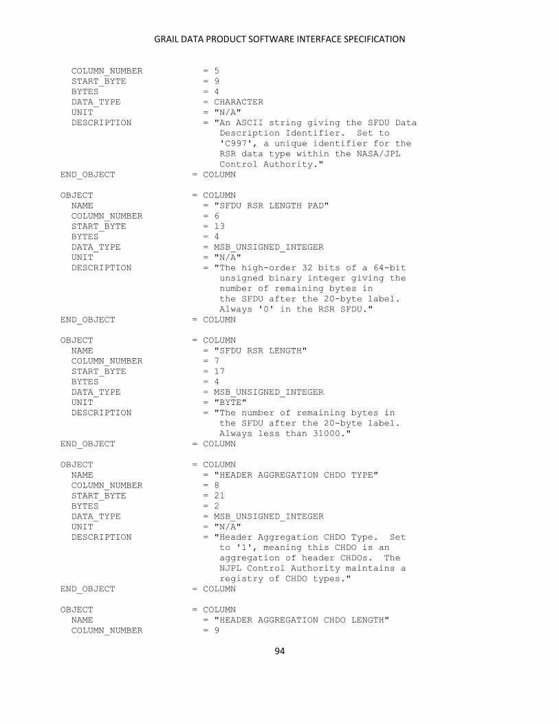
GRAIL DATA PRODUCT SOFTWARE INTERFACE SPECIFICATION
94
COLUMN_NUMBER = 5
START_BYTE = 9
BYTES = 4
DATA_TYPE = CHARACTER
UNIT = "N/A"
DESCRIPTION = "An ASCII string giving the SFDU Data
Description Identifier. Set to
'C997', a unique identifier for the
RSR data type within the NASA/JPL
Control Authority."
END_OBJECT = COLUMN
OBJECT = COLUMN
NAME = "SFDU RSR LENGTH PAD"
COLUMN_NUMBER = 6
START_BYTE = 13
BYTES = 4
DATA_TYPE = MSB_UNSIGNED_INTEGER
UNIT = "N/A"
DESCRIPTION = "The high-order 32 bits of a 64-bit
unsigned binary integer giving the
number of remaining bytes in
the SFDU after the 20-byte label.
Always '0' in the RSR SFDU."
END_OBJECT = COLUMN
OBJECT = COLUMN
NAME = "SFDU RSR LENGTH"
COLUMN_NUMBER = 7
START_BYTE = 17
BYTES = 4
DATA_TYPE = MSB_UNSIGNED_INTEGER
UNIT = "BYTE"
DESCRIPTION = "The number of remaining bytes in
the SFDU after the 20-byte label.
Always less than 31000."
END_OBJECT = COLUMN
OBJECT = COLUMN
NAME = "HEADER AGGREGATION CHDO TYPE"
COLUMN_NUMBER = 8
START_BYTE = 21
BYTES = 2
DATA_TYPE = MSB_UNSIGNED_INTEGER
UNIT = "N/A"
DESCRIPTION = "Header Aggregation CHDO Type. Set
to '1', meaning this CHDO is an
aggregation of header CHDOs. The
NJPL Control Authority maintains a
registry of CHDO types."
END_OBJECT = COLUMN
OBJECT = COLUMN
NAME = "HEADER AGGREGATION CHDO LENGTH"
COLUMN_NUMBER = 9

GRAIL DATA PRODUCT SOFTWARE INTERFACE SPECIFICATION
95
START_BYTE = 23
BYTES = 2
DATA_TYPE = MSB_UNSIGNED_INTEGER
UNIT = "BYTE"
DESCRIPTION = "Header Aggregation CHDO Length. Set
to '232', meaning length of the
value field of the Header Aggregation
CHDO is 232 bytes (bytes 25-256)."
END_OBJECT = COLUMN
OBJECT = COLUMN
NAME = "PRIMARY HEADER CHDO TYPE"
COLUMN_NUMBER = 10
START_BYTE = 25
BYTES = 2
DATA_TYPE = MSB_UNSIGNED_INTEGER
UNIT = "N/A"
DESCRIPTION = "Primary Header CHDO Type. Set to
to '2', meaning this CHDO is a
primary header CHDO. The NJPL
Control Authority maintains a
registry of CHDO types."
END_OBJECT = COLUMN
OBJECT = COLUMN
NAME = "PRIMARY HEADER CHDO LENGTH"
COLUMN_NUMBER = 11
START_BYTE = 27
BYTES = 2
DATA_TYPE = MSB_UNSIGNED_INTEGER
UNIT = "BYTE"
DESCRIPTION = "Primary Header CHDO Length. Set to
'4', meaning length of the value
field of the Primary Header CHDO is
4 bytes (bytes 29-32)."
END_OBJECT = COLUMN
OBJECT = COLUMN
NAME = "MAJOR DATA CLASS"
COLUMN_NUMBER = 12
START_BYTE = 29
BYTES = 1
DATA_TYPE = MSB_UNSIGNED_INTEGER
UNIT = "N/A"
DESCRIPTION = "Major Data Class. Set to '21',
meaning this SFDU contains Radio
Science data."
END_OBJECT = COLUMN
OBJECT = COLUMN
NAME = "MINOR DATA CLASS"
COLUMN_NUMBER = 13
START_BYTE = 30
BYTES = 1
DATA_TYPE = MSB_UNSIGNED_INTEGER
GRAIL DATA PRODUCT SOFTWARE INTERFACE SPECIFICATION
96
UNIT = "N/A"
DESCRIPTION = "Minor Data Class. Set to '4'.
This Major/Minor Data Class
combination means the SFDU contains
Radio Science RSR data."
END_OBJECT = COLUMN
OBJECT = COLUMN
NAME = "MISSION IDENTIFIER"
COLUMN_NUMBER = 14
START_BYTE = 31
BYTES = 1
DATA_TYPE = MSB_UNSIGNED_INTEGER
UNIT = "N/A"
DESCRIPTION = "Mission Identifier. Set to '0',
meaning the RSR does not use this
field. The value may be changed
if the Ground Data System handles
the data. If a Mission Identifier
is needed, values may be found in
DSN document 820-013, OPS-6-21A,
Table 3-4."
END_OBJECT = COLUMN
OBJECT = COLUMN
NAME = "FORMAT CODE"
COLUMN_NUMBER = 15
START_BYTE = 32
BYTES = 1
DATA_TYPE = MSB_UNSIGNED_INTEGER
UNIT = "N/A"
DESCRIPTION = "Format Code. Set to '0'. The RSR
supports only one data format."
END_OBJECT = COLUMN
OBJECT = COLUMN
NAME = "SECONDARY HEADER CHDO TYPE"
COLUMN_NUMBER = 16
START_BYTE = 33
BYTES = 2
DATA_TYPE = MSB_UNSIGNED_INTEGER
UNIT = "N/A"
DESCRIPTION = "Secondary Header CHDO Type. Set to
to '104', meaning this CHDO is an
RSR secondary header CHDO. The NJPL
Control Authority maintains a
registry of CHDO types."
END_OBJECT = COLUMN
OBJECT = COLUMN
NAME = "SECONDARY HEADER CHDO LENGTH"
COLUMN_NUMBER = 17
START_BYTE = 35
BYTES = 2
DATA_TYPE = MSB_UNSIGNED_INTEGER
GRAIL DATA PRODUCT SOFTWARE INTERFACE SPECIFICATION
97
UNIT = "BYTE"
DESCRIPTION = "Secondary Header CHDO Length. Set to
'220', meaning length of the value
field of the Secondary Header CHDO is
220 bytes (bytes 37-256)."
END_OBJECT = COLUMN
OBJECT = COLUMN
NAME = "ORIGINATOR ID"
COLUMN_NUMBER = 18
START_BYTE = 37
BYTES = 1
DATA_TYPE = MSB_UNSIGNED_INTEGER
UNIT = "N/A"
DESCRIPTION = "Originator Identifier. A value '48'
means the data originated within the
DSN."
END_OBJECT = COLUMN
OBJECT = COLUMN
NAME = "LAST MODIFIER ID"
COLUMN_NUMBER = 19
START_BYTE = 38
BYTES = 1
DATA_TYPE = MSB_UNSIGNED_INTEGER
UNIT = "N/A"
DESCRIPTION = "Last Modifier Identifier. A value
'48' means the contents of the SFDU
were last modified by the DSN."
END_OBJECT = COLUMN
OBJECT = COLUMN
NAME = "RSR SOFTWARE ID"
COLUMN_NUMBER = 20
START_BYTE = 39
BYTES = 2
DATA_TYPE = MSB_UNSIGNED_INTEGER
UNIT = "N/A"
DESCRIPTION = "RSR Software Identifier. The version
of the RSR software is indicated by
an unsigned binary integer between
0 and 65535."
END_OBJECT = COLUMN
OBJECT = COLUMN
NAME = "RECORD SEQUENCE NUMBER"
COLUMN_NUMBER = 21
START_BYTE = 41
BYTES = 2
DATA_TYPE = MSB_UNSIGNED_INTEGER
UNIT = "N/A"
DESCRIPTION = "The Record Sequence Number (RSN)
starts at 0 for the first RSR SFDU
and increments by 1 for each
successive SFDU to a maximum of

GRAIL DATA PRODUCT SOFTWARE INTERFACE SPECIFICATION
98
65535, after which it resets to 0
and begins incrementing again.
The RSN may be reset at other times,
such as when the RSR is started or
restarted. The RSN is provided by
the originator of the SFDU and should
not be changed during subsequent
handling or modification."
END_OBJECT = COLUMN
OBJECT = COLUMN
NAME = "SIGNAL PROCESSING CENTER"
COLUMN_NUMBER = 22
START_BYTE = 43
BYTES = 1
DATA_TYPE = MSB_UNSIGNED_INTEGER
UNIT = "N/A"
DESCRIPTION = "Signal Processing Center (SPC)
Identifier. Valid numbers include
10 Goldstone
40 Canberra
60 Madrid
21 DTF21"
END_OBJECT = COLUMN
OBJECT = COLUMN
NAME = "DEEP SPACE STATION"
COLUMN_NUMBER = 23
START_BYTE = 44
BYTES = 1
DATA_TYPE = MSB_UNSIGNED_INTEGER
UNIT = "N/A"
DESCRIPTION = "Deep Space Station (DSS) Identifier.
This is the DSS identifier listed in
the frequency predicts file used to
collect the data in this SFDU. DSS
identifiers are listed in DSN
document 820-013, OPS-6-3 and include
valid numbers such as 14, 15, 25, 43,
45, 54, and 63."
END_OBJECT = COLUMN
OBJECT = COLUMN
NAME = "RADIO SCIENCE RECEIVER"
COLUMN_NUMBER = 24
START_BYTE = 45
BYTES = 1
DATA_TYPE = MSB_UNSIGNED_INTEGER
UNIT = "N/A"
DESCRIPTION = "Radio Science Receiver (RSR)
Identifier. Values can be in the
range 1-16 and specify the RSR used
to collect the data in this SFDU.
For example,
RSR ID = 1 denotes RSR1A

GRAIL DATA PRODUCT SOFTWARE INTERFACE SPECIFICATION
99
RSR ID = 2 denotes RSR1B
RSR ID = 3 denotes RSR2A
The SPC ID and RSR ID uniquely
specify the hardware used in the
data acquisition. SPC 10 has three
RSR racks; SPC 40 and SPC 60 each
have two. Each rack has two
receivers (A and B). Except for the
analog components in the ADCs, the
end-to-end performance of every RSR
should be identical."
END_OBJECT = COLUMN
OBJECT = COLUMN
NAME = "SUB-CHANNEL IDENTIFIER"
COLUMN_NUMBER = 25
START_BYTE = 46
BYTES = 1
DATA_TYPE = MSB_UNSIGNED_INTEGER
UNIT = "N/A"
DESCRIPTION = "Sub-Channel Identifier. This can be
in the range 1-4 and specifies the
RSR sub-channel used to acquire the
the data in this SFDU."
END_OBJECT = COLUMN
OBJECT = COLUMN
NAME = "SECONDARY HEADER CHDO RESERVED"
COLUMN_NUMBER = 26
START_BYTE = 47
BYTES = 1
DATA_TYPE = MSB_UNSIGNED_INTEGER
UNIT = "N/A"
DESCRIPTION = "This field is not used."
END_OBJECT = COLUMN
OBJECT = COLUMN
NAME = "SPACECRAFT"
COLUMN_NUMBER = 27
START_BYTE = 48
BYTES = 1
DATA_TYPE = MSB_UNSIGNED_INTEGER
UNIT = "N/A"
DESCRIPTION = "Spacecraft Identifier, as listed in
the frequency predicts file used to
collect the data in this SFDU. Values
are assigned by the Deep Space
Mission System (DSMS) and are in the
range 0-255. Assignments are given
in DSN document 820-013, OPS-6-21A,
Table 3-4."
END_OBJECT = COLUMN
OBJECT = COLUMN
NAME = "PREDICTS PASS NUMBER"
GRAIL DATA PRODUCT SOFTWARE INTERFACE SPECIFICATION
100
COLUMN_NUMBER = 28
START_BYTE = 49
BYTES = 2
DATA_TYPE = MSB_UNSIGNED_INTEGER
UNIT = "N/A"
DESCRIPTION = "Predicts Pass Number (range 0-65535)
gives the DSN pass number in the
predicts file used to collect the
data in this SFDU."
END_OBJECT = COLUMN
OBJECT = COLUMN
NAME = "UPLINK FREQUENCY BAND"
COLUMN_NUMBER = 29
START_BYTE = 51
BYTES = 1
DATA_TYPE = CHARACTER
UNIT = "N/A"
DESCRIPTION = "The Uplink Frequency Band specified
in the predicts file used to collect
the data in this SFDU. Possible
values include 'S' (S-Band), 'X' (X-
Band), and 'K' (Ka-Band)."
END_OBJECT = COLUMN
OBJECT = COLUMN
NAME = "DOWNLINK FREQUENCY BAND"
COLUMN_NUMBER = 30
START_BYTE = 52
BYTES = 1
DATA_TYPE = CHARACTER
UNIT = "N/A"
DESCRIPTION = "The Downlink Frequency Band specified
in the predicts file used to collect
the data in this SFDU. Possible
values include 'S' (S-Band), 'X' (X-
Band), and 'K' (Ka-Band)."
END_OBJECT = COLUMN
OBJECT = COLUMN
NAME = "TRACKING MODE"
COLUMN_NUMBER = 31
START_BYTE = 53
BYTES = 1
DATA_TYPE = MSB_UNSIGNED_INTEGER
UNIT = "N/A"
DESCRIPTION = "The Tracking Mode in use when the
data in this SFDU were acquired.
Possible values are '1' (one-way),
'2' (two-way), and '3' (three-way)."
END_OBJECT = COLUMN
OBJECT = COLUMN
NAME = "UPLINK DSS ID FOR 3-WAY TRACKING"
COLUMN_NUMBER = 32

GRAIL DATA PRODUCT SOFTWARE INTERFACE SPECIFICATION
101
START_BYTE = 54
BYTES = 1
DATA_TYPE = MSB_UNSIGNED_INTEGER
UNIT = "N/A"
DESCRIPTION = "Deep Space Station (DSS) Identifier
for the uplink antenna when
TRACKING_MODE=3; otherwise,
undefined. DSS identifiers are
listed in DSN document 820-013,
OPS-6-3 and include valid numbers
such as 14, 15, 25, 43, 45, 54, and
63."
END_OBJECT = COLUMN
OBJECT = COLUMN
NAME = "FGAIN"
COLUMN_NUMBER = 33
START_BYTE = 55
BYTES = 1
DATA_TYPE = MSB_INTEGER
UNIT = "DECIBEL HERTZ"
DESCRIPTION = "Expected ratio of signal power to
noise power in a one Hz bandwidth
when the data in this SFDU were
collected. This parameter is used
to estimate the sample voltage
amplitudes at the RSR output and
to compute settings of the
sub-channel filter gain so that
there is no clipping of the sample
values. Possible values are in the
range -127 to +128."
END_OBJECT = COLUMN
OBJECT = COLUMN
NAME = "FGAIN IF BANDWIDTH"
COLUMN_NUMBER = 34
START_BYTE = 56
BYTES = 1
DATA_TYPE = MSB_UNSIGNED_INTEGER
UNIT = "MEGAHERTZ"
DESCRIPTION = "IF Bandwidth expected to be in use
by the RSR at the time the data in
this SFDU were acquired. This value
is used to compute the settings of
the sub-channel filter gain. Values
can be in the range 1-127."
END_OBJECT = COLUMN
OBJECT = COLUMN
NAME = "FROV FLAG"
COLUMN_NUMBER = 35
START_BYTE = 57
BYTES = 1
DATA_TYPE = MSB_UNSIGNED_INTEGER
GRAIL DATA PRODUCT SOFTWARE INTERFACE SPECIFICATION
102
UNIT = "N/A"
DESCRIPTION = "Frequency Predicts Override Flag.
Set to '0', this indicates that the
frequency predicts file was in use;
any other value indicates that the
frequency specified by the FROV
command was in use. The value of
the override frequency is given by
PREDICTS_FREQUENCY_OVERRIDE in
Column 51."
END_OBJECT = COLUMN
OBJECT = COLUMN
NAME = "DIG ATTENUATION"
COLUMN_NUMBER = 36
START_BYTE = 58
BYTES = 1
DATA_TYPE = MSB_UNSIGNED_INTEGER
UNIT = "N/A"
DESCRIPTION = "RSR Digitizer Subassembly (DIG)
setting. Values are in the range
0-63, which correspond to 0.5 dB
increments in attenuation."
END_OBJECT = COLUMN
OBJECT = COLUMN
NAME = "DIG ADC RMS"
COLUMN_NUMBER = 37
START_BYTE = 59
BYTES = 1
DATA_TYPE = MSB_UNSIGNED_INTEGER
UNIT = "N/A"
DESCRIPTION = "Root-mean-square amplitude of about
10000 8-bit samples taken from the DIG
ADC stream. Time of the measurement
is stored in bytes Columns 39-41."
END_OBJECT = COLUMN
OBJECT = COLUMN
NAME = "DIG ADC PEAK"
COLUMN_NUMBER = 38
START_BYTE = 60
BYTES = 1
DATA_TYPE = MSB_UNSIGNED_INTEGER
UNIT = "N/A"
DESCRIPTION = "Peak amplitude from about 10000 8-bit
samples taken from the DIG ADC stream.
Time for the measurement is stored in
Columns 39-41."
END_OBJECT = COLUMN
OBJECT = COLUMN
NAME = "DIG ADC YEAR"
COLUMN_NUMBER = 39
START_BYTE = 61
GRAIL DATA PRODUCT SOFTWARE INTERFACE SPECIFICATION
103
BYTES = 2
DATA_TYPE = MSB_UNSIGNED_INTEGER
UNIT = "N/A"
DESCRIPTION = "UTC year on which the ADC data were
computed. Values can range over
1900-3000."
END_OBJECT = COLUMN
OBJECT = COLUMN
NAME = "DIG ADC DAY OF YEAR"
COLUMN_NUMBER = 40
START_BYTE = 63
BYTES = 2
DATA_TYPE = MSB_UNSIGNED_INTEGER
UNIT = "N/A"
DESCRIPTION = "UTC day-of-year on which the ADC
data were computed. Values can
range over 1-366."
END_OBJECT = COLUMN
OBJECT = COLUMN
NAME = "DIG ADC SECOND"
COLUMN_NUMBER = 41
START_BYTE = 65
BYTES = 4
DATA_TYPE = MSB_UNSIGNED_INTEGER
UNIT = "SECOND"
DESCRIPTION = "UTC second of day on which the ADC
data were computed. Values can
range over 0-86400."
END_OBJECT = COLUMN
OBJECT = COLUMN
NAME = "SAMPLE RESOLUTION"
COLUMN_NUMBER = 42
START_BYTE = 69
BYTES = 1
DATA_TYPE = MSB_UNSIGNED_INTEGER
UNIT = "BIT"
DESCRIPTION = "Bits per sample in the data in this
SFDU. Valid values are 1, 2, 4, 8,
and 16 and are selected by the RSR
operator while it is in configure
state."
END_OBJECT = COLUMN
OBJECT = COLUMN
NAME = "DATA ERROR COUNT"
COLUMN_NUMBER = 43
START_BYTE = 70
BYTES = 1
DATA_TYPE = MSB_UNSIGNED_INTEGER
UNIT = "N/A"
DESCRIPTION = "Number of hardware errors encountered
while the data in this SFDU were
GRAIL DATA PRODUCT SOFTWARE INTERFACE SPECIFICATION
104
being recorded. Values can range over
0-255, but any value greater than 0
indicates data may have been
corrupted by hardware errors."
END_OBJECT = COLUMN
OBJECT = COLUMN
NAME = "SAMPLE RATE"
COLUMN_NUMBER = 44
START_BYTE = 71
BYTES = 2
DATA_TYPE = MSB_UNSIGNED_INTEGER
UNIT = "KILOSAMPLE PER SECOND"
DESCRIPTION = "The rate at which samples were
collected in this SFDU. Sample rate
or bandwidth is specified by the
operator while the RSR is in the
configure state."
END_OBJECT = COLUMN
OBJECT = COLUMN
NAME = "DDC LO FREQUENCY"
COLUMN_NUMBER = 45
START_BYTE = 73
BYTES = 2
DATA_TYPE = MSB_UNSIGNED_INTEGER
UNIT = "MEGAHERTZ"
DESCRIPTION = "Digital Down Converter (DDC) Local
Oscillator (LO) Frequency. This
specifies the downconversion applied
to the signal in the DIG and DDC.
This frequency is needed to compute
the sky frequency of the data in
this SFDU:
Fsky = RFtoIF_LO +
DDC_LO -
NCO_Freq +
Fresid
where
RFtoIF_LO is in Column 46,
DDC_LO is in Column 45,
NCO_Freq from Columns 61-63, and
Fresid is the signal offset
from DC in the RSR data."
END_OBJECT = COLUMN
OBJECT = COLUMN
NAME = "RF-IF LO FREQUENCY"
COLUMN_NUMBER = 46
START_BYTE = 75
BYTES = 2
DATA_TYPE = MSB_UNSIGNED_INTEGER
UNIT = "MEGAHERTZ"

GRAIL DATA PRODUCT SOFTWARE INTERFACE SPECIFICATION
105
DESCRIPTION = "RF to IF Down Converter Local
Oscillator (LO) Frequency. This
specifies the total downconversion
applied to the signal before it
entered the RSR DIG. The value is
subtracted from the RF predict
points in order to obtain the
frequency of the desired signal at
IF. The RSR selects a default value
based on the downlink band: 2000
(S-Band), 8100 (X-Band), or 31700
(Ka-Band). This frequency is needed
in order to reconstruct the sky
frequency of the data contained in
this SFDU:
Fsky = RFtoIF_LO +
DDC_LO -
NCO_Freq +
Fresid
where
RFtoIF_LO is in Column 46,
DDC_LO is in Column 45,
NCO_Freq from Columns 61-63, and
Fresid is the signal offset
from DC in the RSR data."
END_OBJECT = COLUMN
OBJECT = COLUMN
NAME = "SFDU YEAR"
COLUMN_NUMBER = 47
START_BYTE = 77
BYTES = 2
DATA_TYPE = MSB_UNSIGNED_INTEGER
UNIT = "N/A"
DESCRIPTION = "UTC year for the SFDU data and
models. Values can range over
1900-3000."
END_OBJECT = COLUMN
OBJECT = COLUMN
NAME = "SFDU DAY OF YEAR"
COLUMN_NUMBER = 48
START_BYTE = 79
BYTES = 2
DATA_TYPE = MSB_UNSIGNED_INTEGER
UNIT = "N/A"
DESCRIPTION = "UTC day-of-year for the SFDU
data and models. Values can
range over 1-366."
END_OBJECT = COLUMN
OBJECT = COLUMN
NAME = "SFDU SECOND"
GRAIL DATA PRODUCT SOFTWARE INTERFACE SPECIFICATION
106
COLUMN_NUMBER = 49
START_BYTE = 81
BYTES = 8
DATA_TYPE = IEEE_REAL
UNIT = "SECOND"
DESCRIPTION = "UTC seconds of day for the SFDU
data and models. Values can range
over 0-86400."
END_OBJECT = COLUMN
OBJECT = COLUMN
NAME = "PREDICTS TIME SHIFT"
COLUMN_NUMBER = 50
START_BYTE = 89
BYTES = 8
DATA_TYPE = IEEE_REAL
UNIT = "SECOND"
DESCRIPTION = "The number of seconds added to the
time tags of the frequency predicts
to shift them in time. This feature
allows testing the RSR with old
predict files. The value should be
0.0 during normal operations."
END_OBJECT = COLUMN
OBJECT = COLUMN
NAME = "PREDICTS FREQUENCY OVERRIDE"
COLUMN_NUMBER = 51
START_BYTE = 97
BYTES = 8
DATA_TYPE = IEEE_REAL
UNIT = "HERTZ"
DESCRIPTION = "The value of the predicts frequency
override specified by the FROV
command; this constant value is
substituted for the value derived
from the predicts. The flag in
Column 35 indicates whether the
frequency override is active."
END_OBJECT = COLUMN
OBJECT = COLUMN
NAME = "PREDICTS FREQUENCY RATE"
COLUMN_NUMBER = 52
START_BYTE = 105
BYTES = 8
DATA_TYPE = IEEE_REAL
UNIT = "HERTZ PER SECOND"
DESCRIPTION = "The frequency rate added to the RF
frequency predicts as specified by
the FRR command. The allowable range
is -8000 to +8000 Hz/s."
END_OBJECT = COLUMN
OBJECT = COLUMN
GRAIL DATA PRODUCT SOFTWARE INTERFACE SPECIFICATION
107
NAME = "PREDICTS FREQUENCY OFFSET"
COLUMN_NUMBER = 53
START_BYTE = 113
BYTES = 8
DATA_TYPE = IEEE_REAL
UNIT = "HERTZ"
DESCRIPTION = "The total frequency added to the
RF frequency predicts as specified
the FRO command and the accumulated
frequency rate as specified by the
FRR command. The allowable
range is -8 to +8 MHz."
END_OBJECT = COLUMN
OBJECT = COLUMN
NAME = "SUB-CHANNEL FREQUENCY OFFSET"
COLUMN_NUMBER = 54
START_BYTE = 121
BYTES = 8
DATA_TYPE = IEEE_REAL
UNIT = "HERTZ"
DESCRIPTION = "The frequency added to the frequency
predicts for this sub-channel as
specified by the SFRO command."
END_OBJECT = COLUMN
OBJECT = COLUMN
NAME = "RF POINT 1"
COLUMN_NUMBER = 55
START_BYTE = 129
BYTES = 8
DATA_TYPE = IEEE_REAL
UNIT = "HERTZ"
DESCRIPTION = "The radio frequency at the beginning
of the second as calculated from the
predicts."
END_OBJECT = COLUMN
OBJECT = COLUMN
NAME = "RF POINT 2"
COLUMN_NUMBER = 56
START_BYTE = 137
BYTES = 8
DATA_TYPE = IEEE_REAL
UNIT = "HERTZ"
DESCRIPTION = "The radio frequency at the middle
of the second as calculated from the
predicts."
END_OBJECT = COLUMN
OBJECT = COLUMN
NAME = "RF POINT 3"
COLUMN_NUMBER = 57
START_BYTE = 145
BYTES = 8
GRAIL DATA PRODUCT SOFTWARE INTERFACE SPECIFICATION
108
DATA_TYPE = IEEE_REAL
UNIT = "HERTZ"
DESCRIPTION = "The radio frequency at the end
of the second as calculated from the
predicts."
END_OBJECT = COLUMN
OBJECT = COLUMN
NAME = "SUB-CHANNEL FREQUENCY POINT 1"
COLUMN_NUMBER = 58
START_BYTE = 153
BYTES = 8
DATA_TYPE = IEEE_REAL
UNIT = "HERTZ"
DESCRIPTION = "The sub-channel frequency at the
beginning of the second. This
point is used to create the
sub-channel frequency and phase
polynomials."
END_OBJECT = COLUMN
OBJECT = COLUMN
NAME = "SUB-CHANNEL FREQUENCY POINT 2"
COLUMN_NUMBER = 59
START_BYTE = 161
BYTES = 8
DATA_TYPE = IEEE_REAL
UNIT = "HERTZ"
DESCRIPTION = "The sub-channel frequency at the
middle of the second. This
point is used to create the
sub-channel frequency and phase
polynomials."
END_OBJECT = COLUMN
OBJECT = COLUMN
NAME = "SUB-CHANNEL FREQUENCY POINT 3"
COLUMN_NUMBER = 60
START_BYTE = 169
BYTES = 8
DATA_TYPE = IEEE_REAL
UNIT = "HERTZ"
DESCRIPTION = "The sub-channel frequency at the
end of the second. This
point is used to create the
sub-channel frequency and phase
polynomials."
END_OBJECT = COLUMN
OBJECT = COLUMN
NAME = "SUB-CHANNEL FREQUENCY COEF F1"
COLUMN_NUMBER = 61
START_BYTE = 177
BYTES = 8
DATA_TYPE = IEEE_REAL
GRAIL DATA PRODUCT SOFTWARE INTERFACE SPECIFICATION
109
UNIT = "HERTZ"
DESCRIPTION = "The sub-channel frequency polynomial
coefficient F1 where the frequency
over a one millisecond interval
beginning at t in msec is evaluated
F(t) = F1 +
F2*((t+0.5)/1000) +
F3*((t+0.5)/1000)**2
The coefficients are derived from
the frequency points in columns
58-60."
END_OBJECT = COLUMN
OBJECT = COLUMN
NAME = "SUB-CHANNEL FREQUENCY COEF F2"
COLUMN_NUMBER = 62
START_BYTE = 185
BYTES = 8
DATA_TYPE = IEEE_REAL
UNIT = "HERTZ"
DESCRIPTION = "The sub-channel frequency polynomial
coefficient F2 where the frequency
over a one millisecond interval
beginning at t in msec is evaluated
F(t) = F1 +
F2*((t+0.5)/1000) +
F3*((t+0.5)/1000)**2
The coefficients are derived from
the frequency points in columns
58-60."
END_OBJECT = COLUMN
OBJECT = COLUMN
NAME = "SUB-CHANNEL FREQUENCY COEF F3"
COLUMN_NUMBER = 63
START_BYTE = 193
BYTES = 8
DATA_TYPE = IEEE_REAL
UNIT = "HERTZ"
DESCRIPTION = "The sub-channel frequency polynomial
coefficient F3 where the frequency
over a one millisecond interval
beginning at t in msec is evaluated
F(t) = F1 +
F2*((t+0.5)/1000) +
F3*((t+0.5)/1000)**2
The coefficients are derived from
the frequency points in columns
58-60."
END_OBJECT = COLUMN
OBJECT = COLUMN
NAME = "SUB-CHANNEL ACCUMULATED PHASE"
COLUMN_NUMBER = 64
START_BYTE = 201
GRAIL DATA PRODUCT SOFTWARE INTERFACE SPECIFICATION
110
BYTES = 8
DATA_TYPE = IEEE_REAL
UNIT = "CYCLE"
DESCRIPTION = "The accumulated whole turns of the
sub-channel phase at the beginning
of the present second. The phase
during this second is the accumulated
phase incremented by the phase
computed using the coefficients in
Columns 65-68."
END_OBJECT = COLUMN
OBJECT = COLUMN
NAME = "SUB-CHANNEL PHASE COEF P1"
COLUMN_NUMBER = 65
START_BYTE = 209
BYTES = 8
DATA_TYPE = IEEE_REAL
UNIT = "CYCLE"
DESCRIPTION = "The sub-channel phase polynomial
coefficient P1 where the phase
over a one millisecond interval
beginning at t in msec is evaluated
P(t) = P1 +
P2*((t+0.5)/1000) +
P3*((t+0.5)/1000)**2 +
P4*((t+0.5)/1000)**3
The coefficients are derived from
the frequency points in columns
58-60."
END_OBJECT = COLUMN
OBJECT = COLUMN
NAME = "SUB-CHANNEL PHASE COEF P2"
COLUMN_NUMBER = 66
START_BYTE = 217
BYTES = 8
DATA_TYPE = IEEE_REAL
UNIT = "CYCLE"
DESCRIPTION = "The sub-channel phase polynomial
coefficient P2 where the phase
over a one millisecond interval
beginning at t in msec is evaluated
P(t) = P1 +
P2*((t+0.5)/1000) +
P3*((t+0.5)/1000)**2 +
P4*((t+0.5)/1000)**3
The coefficients are derived from
the frequency points in columns
58-60."
END_OBJECT = COLUMN
OBJECT = COLUMN
NAME = "SUB-CHANNEL PHASE COEF P3"
COLUMN_NUMBER = 67
GRAIL DATA PRODUCT SOFTWARE INTERFACE SPECIFICATION
111
START_BYTE = 225
BYTES = 8
DATA_TYPE = IEEE_REAL
UNIT = "CYCLE"
DESCRIPTION = "The sub-channel phase polynomial
coefficient P3 where the phase
over a one millisecond interval
beginning at t in msec is evaluated
P(t) = P1 +
P2*((t+0.5)/1000) +
P3*((t+0.5)/1000)**2 +
P4*((t+0.5)/1000)**3
The coefficients are derived from
the frequency points in columns
58-60."
END_OBJECT = COLUMN
OBJECT = COLUMN
NAME = "SUB-CHANNEL PHASE COEF P4"
COLUMN_NUMBER = 68
START_BYTE = 233
BYTES = 8
DATA_TYPE = IEEE_REAL
UNIT = "CYCLE"
DESCRIPTION = "The sub-channel phase polynomial
coefficient P4 where the phase
over a one millisecond interval
beginning at t in msec is evaluated
P(t) = P1 +
P2*((t+0.5)/1000) +
P3*((t+0.5)/1000)**2 +
P4*((t+0.5)/1000)**3
The coefficients are derived from
the frequency points in columns
58-60."
END_OBJECT = COLUMN
OBJECT = COLUMN
NAME = "SPARES"
COLUMN_NUMBER = 69
BYTES = 16
ITEMS = 16
START_BYTE = 241
ITEM_BYTES = 1
ITEM_OFFSET = 1
DATA_TYPE = MSB_UNSIGNED_INTEGER
UNIT = "N/A"
DESCRIPTION = "These 16 bytes are undefined."
END_OBJECT = COLUMN
OBJECT = COLUMN
NAME = "DATA CHDO TYPE"
COLUMN_NUMBER = 70
START_BYTE = 257
BYTES = 2

GRAIL DATA PRODUCT SOFTWARE INTERFACE SPECIFICATION
112
DATA_TYPE = MSB_UNSIGNED_INTEGER
UNIT = "N/A"
DESCRIPTION = "Data CHDO Type. Set to '10', meaning
this CHDO contains binary data. The
NJPL Control Authority maintains a
registry of CHDO types."
END_OBJECT = COLUMN
OBJECT = COLUMN
NAME = "DATA CHDO LENGTH"
COLUMN_NUMBER = 71
START_BYTE = 259
BYTES = 2
DATA_TYPE = MSB_UNSIGNED_INTEGER
UNIT = "BYTE"
DESCRIPTION = "Data CHDO Length. Gives the number of
bytes in the value field of the Data
CHDO -- the number of bytes containing
I and Q samples."
END_OBJECT = COLUMN
OBJECT = COLUMN
NAME = "SAMPLE WORDS"
COLUMN_NUMBER = 72
START_BYTE = 261
BYTES = 4000
ITEMS = 1000
ITEM_BYTES = 4
ITEM_OFFSET = 4
DATA_TYPE = MSB_UNSIGNED_INTEGER
UNIT = "N/A"
DESCRIPTION = "Each ITEM contains one 32-bit sample
word: quadrature (Q) sample data in
the 16 most significant bits (MSBs)
followed by in-phase (I) sample data
in the 16 least significant bits
(LSBs). Within each Q and I word,
individual outputs from the analog
to digital converters (ADCs) are
stored as 1, 2, 4, 8, or 16 bit values
in LSB to MSB time order (the sample
size is set in Column 42). For
example, if the data were collected
using 8-bit samples, the arrangement
would be
BYTES 1-2
+-+-+-+-+-+-+-+-+-+-+-+-+-+-+-+-+
BITS |1|2|3|4|5|6|7|8|1|2|3|4|5|6|7|8|
+-+-+-+-+-+-+-+-+-+-+-+-+-+-+-+-+
|<------Q2----->|<------Q1----->|
+-+-+-+-+-+-+-+-+-+-+-+-+-+-+-+-+
BYTES 3-4
+-+-+-+-+-+-+-+-+-+-+-+-+-+-+-+-+
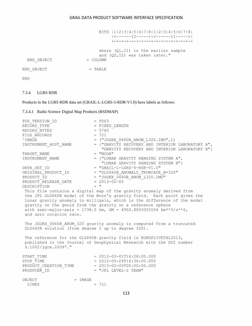
GRAIL DATA PRODUCT SOFTWARE INTERFACE SPECIFICATION
113
BITS |1|2|3|4|5|6|7|8|1|2|3|4|5|6|7|8|
|<------I2----->|<------I1----->|
+-+-+-+-+-+-+-+-+-+-+-+-+-+-+-+-+
where (Q1,I1) is the earlier sample
and (Q2,I2) was taken later."
END_OBJECT = COLUMN
END_OBJECT = TABLE
END
7.3.4 LGRS RDR
Products in the LGRS RDR data set (GRAIL-L-LGRS-5-RDR-V1.0) have labels as follows:
7.3.4.1 Radio Science Digital Map Products (RSDMAP)
PDS_VERSION_ID = PDS3
RECORD_TYPE = FIXED_LENGTH
RECORD_BYTES = 5760
FILE_RECORDS = 721
^IMAGE = ("JGGRX_0660B_ANOM_L320.IMG",1)
INSTRUMENT_HOST_NAME = {"GRAVITY RECOVERY AND INTERIOR LABORATORY A",
"GRAVITY RECOVERY AND INTERIOR LABORATORY B"}
TARGET_NAME = "MOON"
INSTRUMENT_NAME = {"LUNAR GRAVITY RANGING SYSTEM A",
"LUNAR GRAVITY RANGING SYSTEM B"}
DATA_SET_ID = "GRAIL-L-LGRS-5-RDR-V1.0"
ORIGINAL_PRODUCT_ID = "GL0660B_ANOMALY_TRUNCATE_N=320"
PRODUCT_ID = "JGGRX_0660B_ANOM_L320.IMG"
PRODUCT_RELEASE_DATE = 2013-02-05
DESCRIPTION = "
This file contains a digital map of the gravity anomaly derived from
the JPL GL0660B model of the Moon's gravity field. Each point gives the
Lunar gravity anomaly in milligals, which is the difference of the model
gravity on the geoid from the gravity on a reference sphere
with semi-major-axis = 1738.0 km, GM = 4902.8003055554 km**3/s**2,
and zero rotation rate.
The JGGRX_0660B_ANOM_320 gravity anomaly is computed from a truncated
GL0660B solution (from degree 2 up to degree 320).
The reference for the GL0660B gravity field is KONOPLIVETAL2013,
published in the Journal of Geophysical Research with the DOI number
0.1002/jgre.20097."
START_TIME = 2012-03-01T16:28:00.000
STOP_TIME = 2012-05-29T16:36:00.000
PRODUCT_CREATION_TIME = 2013-02-05T00:00:00.000
PRODUCER_ID = "JPL LEVEL-2 TEAM"
OBJECT = IMAGE
LINES = 721
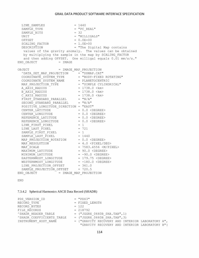
GRAIL DATA PRODUCT SOFTWARE INTERFACE SPECIFICATION
114
LINE_SAMPLES = 1440
SAMPLE_TYPE = "PC_REAL"
SAMPLE_BITS = 32
UNIT = "MILLIGALS"
OFFSET = 0.0E+00
SCALING_FACTOR = 1.0E+00
DESCRIPTION = "The Digital Map contains
values of the gravity anomaly. The values can be obtained
by multiplying the sample in the map by SCALING_FACTOR
and then adding OFFSET. One milligal equals 0.01 mm/s/s."
END_OBJECT = IMAGE
OBJECT = IMAGE_MAP_PROJECTION
^DATA_SET_MAP_PROJECTION = "DSMAP.CAT"
COORDINATE_SYSTEM_TYPE = "BODY-FIXED ROTATING"
COORDINATE_SYSTEM_NAME = PLANETOCENTRIC
MAP_PROJECTION_TYPE = "SIMPLE CYLINDRICAL"
A_AXIS_RADIUS = 1738.0 <km>
B_AXIS_RADIUS = 1738.0 <km>
C_AXIS_RADIUS = 1738.0 <km>
FIRST_STANDARD_PARALLEL = "N/A"
SECOND_STANDARD_PARALLEL = "N/A"
POSITIVE_LONGITUDE_DIRECTION = "EAST"
CENTER_LATITUDE = 0.0 <DEGREE>
CENTER_LONGITUDE = 0.0 <DEGREE>
REFERENCE_LATITUDE = 0.0 <DEGREE>
REFERENCE_LONGITUDE = 0.0 <DEGREE>
LINE_FIRST_PIXEL = 1
LINE_LAST_PIXEL = 721
SAMPLE_FIRST_PIXEL = 1
SAMPLE_LAST_PIXEL = 1440
MAP_PROJECTION_ROTATION = 0.0 <DEGREE>
MAP_RESOLUTION = 4.0 <PIXEL/DEG>
MAP_SCALE = 7583.4556 <M/PIXEL>
MAXIMUM_LATITUDE = 90.0 <DEGREE>
MINIMUM_LATITUDE = -90.0 <DEGREE>
EASTERNMOST_LONGITUDE = 179.75 <DEGREE>
WESTERNMOST_LONGITUDE = -180.0 <DEGREE>
LINE_PROJECTION_OFFSET = 361.0
SAMPLE_PROJECTION_OFFSET = 720.5
END_OBJECT = IMAGE_MAP_PROJECTION
END
7.3.4.2 Spherical Harmonics ASCII Data Record (SHADR)
PDS_VERSION_ID = "PDS3"
RECORD_TYPE = FIXED_LENGTH
RECORD_BYTES = 122
FILE_RECORDS = 218792
^SHADR_HEADER_TABLE = ("JGGRX_0660B_SHA.TAB",1)
^SHADR_COEFFICIENTS_TABLE = ("JGGRX_0660B_SHA.TAB",3)
INSTRUMENT_HOST_NAME = {"GRAVITY RECOVERY AND INTERIOR LABORATORY A",
"GRAVITY RECOVERY AND INTERIOR LABORATORY B"}

GRAIL DATA PRODUCT SOFTWARE INTERFACE SPECIFICATION
115
TARGET_NAME = "MOON"
INSTRUMENT_NAME = {"LUNAR GRAVITY RANGING SYSTEM A",
"LUNAR GRAVITY RANGING SYSTEM B"}
DATA_SET_ID = "GRAIL-L-LGRS-5-RDR-V1.0"
OBSERVATION_TYPE = "GRAVITY FIELD"
ORIGINAL_PRODUCT_ID = "GL0660B"
PRODUCT_ID = "JGGRX_0660B_SHA.TAB"
PRODUCT_RELEASE_DATE = 2013-02-05
DESCRIPTION = "
This file contains coefficients and related data for the JPL Lunar gravity
field GL0660B, a 660th degree and order spherical harmonic model. It is
a JPL gravity field that includes the entire primary mission of
GRAIL tracking data (March 1, 16:30 to May 29, 16:36:00, 2012).
Some details describing this model are:
The spherical harmonic coefficients are fully normalized.
The reference radius = 1738.0 km
The planetary ephemeris is de421 and defines the lunar body-fixed
coordinate system.
A Kaula type power law constraint is applied to the spherical harmonics
coefficients for degrees >330 (3.6e-4/n^2).
The weighting of the KBRR data is mostly 0.03 microns/sec.
The second degree Love number solution is k2=0.02405. The second degree
gravity coefficients of this model do not include the permanent tide.
The reference for the GL0660B gravity field is KONOPLIVETAL2013,
published in the Journal of Geophysical Research with the DOI number
0.1002/jgre.20097.
This file is a pair of ASCII tables: a header table and a table of
436920 coefficients plus a value for GM. Definitions of the tables
follow."
START_TIME = 2012-03-01T16:28:00.000
STOP_TIME = 2012-05-29T16:36:00.000
PRODUCT_CREATION_TIME = 2013-02-05T00:00:00.000
PRODUCER_FULL_NAME = "JPL LEVEL-2 TEAM"
PRODUCER_INSTITUTION_NAME = "JET PROPULSION LABORATORY"
PRODUCT_VERSION_TYPE = "PRELIMINARY"
PRODUCER_ID = "GRAIL"
OBJECT = SHADR_HEADER_TABLE
ROWS = 1
COLUMNS = 8
ROW_BYTES = 137
ROW_SUFFIX_BYTES = 107
INTERCHANGE_FORMAT = ASCII
DESCRIPTION = "The SHADR header includes
descriptive information about the spherical harmonic
coefficients which follow in SHADR_COEFFICIENTS_TABLE.
The header consists of a single record of eight (delimited)
data columns requiring 137 bytes, a pad of 105 unspecified
ASCII characters, an ASCII carriage-return, and an ASCII
GRAIL DATA PRODUCT SOFTWARE INTERFACE SPECIFICATION
116
line-feed."
OBJECT = COLUMN
NAME = "REFERENCE RADIUS"
DATA_TYPE = ASCII_REAL
START_BYTE = 1
BYTES = 23
FORMAT = "E23.16"
UNIT = "KILOMETER"
DESCRIPTION = "The assumed reference
radius of the spherical planet."
END_OBJECT = COLUMN
OBJECT = COLUMN
NAME = "CONSTANT"
DATA_TYPE = ASCII_REAL
START_BYTE = 25
BYTES = 23
FORMAT = "E23.16"
UNIT = "N/A"
DESCRIPTION = "For a gravity field model
the assumed gravitational constant GM in kilometers cubed
per seconds squared for the planet. For a topography
model, set to 1."
END_OBJECT = COLUMN
OBJECT = COLUMN
NAME = "UNCERTAINTY IN CONSTANT"
DATA_TYPE = ASCII_REAL
START_BYTE = 49
BYTES = 23
FORMAT = "E23.16"
UNIT = "N/A"
DESCRIPTION = "For a gravity field model
the uncertainty in the gravitational constant GM in kilometers
cubed per seconds squared for the planet. For a topography
model, set to 0."
END_OBJECT = COLUMN
OBJECT = COLUMN
NAME = "DEGREE OF FIELD"
DATA_TYPE = ASCII_INTEGER
START_BYTE = 73
BYTES = 5
FORMAT = "I5"
UNIT = "N/A"
DESCRIPTION = "The degree of model field."
END_OBJECT = COLUMN
OBJECT = COLUMN
NAME = "ORDER OF FIELD"
DATA_TYPE = ASCII_INTEGER
START_BYTE = 79
BYTES = 5
FORMAT = "I5"

GRAIL DATA PRODUCT SOFTWARE INTERFACE SPECIFICATION
117
UNIT = "N/A"
DESCRIPTION = "The order of the model field."
END_OBJECT = COLUMN
OBJECT = COLUMN
NAME = "NORMALIZATION STATE"
DATA_TYPE = ASCII_INTEGER
START_BYTE = 85
BYTES = 5
FORMAT = "I5"
UNIT = "N/A"
DESCRIPTION = "The normalization indicator.
For gravity field:
0 coefficients are unnormalized
1 coefficients are normalized
2 other."
END_OBJECT = COLUMN
OBJECT = COLUMN
NAME = "REFERENCE LONGITUDE"
POSITIVE_LONGITUDE_DIRECTION = "EAST"
DATA_TYPE = ASCII_REAL
START_BYTE = 91
BYTES = 23
FORMAT = "E23.16"
UNIT = "DEGREE"
DESCRIPTION = "The reference longitude for
the spherical harmonic expansion; normally 0."
END_OBJECT = COLUMN
OBJECT = COLUMN
NAME = "REFERENCE LATITUDE"
DATA_TYPE = ASCII_REAL
START_BYTE = 115
BYTES = 23
FORMAT = "E23.16"
UNIT = "DEGREE"
DESCRIPTION = "The reference latitude for
the spherical harmonic expansion; normally 0."
END_OBJECT = COLUMN
END_OBJECT = SHADR_HEADER_TABLE
OBJECT = SHADR_COEFFICIENTS_TABLE
ROWS = 218790
COLUMNS = 6
ROW_BYTES = 107
ROW_SUFFIX_BYTES = 15
INTERCHANGE_FORMAT = ASCII
DESCRIPTION = "The SHADR coefficients table
contains the coefficients for the spherical harmonic model.
Each row in the table contains the degree index m, the
order index n, the coefficients Cmn and Smn, and the
uncertainties in Cmn and Smn. The (delimited) data
require 107 ASCII characters; these are followed by a pad
GRAIL DATA PRODUCT SOFTWARE INTERFACE SPECIFICATION
118
of 13 unspecified ASCII characters, an ASCII carriage-
return, and an ASCII line-feed."
OBJECT = COLUMN
NAME = "COEFFICIENT DEGREE"
DATA_TYPE = ASCII_INTEGER
START_BYTE = 1
BYTES = 5
FORMAT = "I5"
UNIT = "N/A"
DESCRIPTION = "The degree index m of the
C and S coefficients in this record."
END_OBJECT = COLUMN
OBJECT = COLUMN
NAME = "COEFFICIENT ORDER"
DATA_TYPE = ASCII_INTEGER
START_BYTE = 7
BYTES = 5
FORMAT = "I5"
UNIT = "N/A"
DESCRIPTION = "The order index n of the
C and S coefficients in this record."
END_OBJECT = COLUMN
OBJECT = COLUMN
NAME = "C"
DATA_TYPE = ASCII_REAL
START_BYTE = 13
BYTES = 23
FORMAT = "E23.16"
UNIT = "N/A"
DESCRIPTION = "The coefficient Cmn
for this spherical harmonic model."
END_OBJECT = COLUMN
OBJECT = COLUMN
NAME = "S"
DATA_TYPE = ASCII_REAL
START_BYTE = 37
BYTES = 23
FORMAT = "E23.16"
UNIT = "N/A"
DESCRIPTION = "The coefficient Smn
for this spherical harmonic model."
END_OBJECT = COLUMN
OBJECT = COLUMN
NAME = "C UNCERTAINTY"
DATA_TYPE = ASCII_REAL
START_BYTE = 61
BYTES = 23
FORMAT = "E23.16"
UNIT = "N/A"
DESCRIPTION = "The uncertainty in the
GRAIL DATA PRODUCT SOFTWARE INTERFACE SPECIFICATION
119
coefficient Cmn for this spherical harmonic model."
END_OBJECT = COLUMN
OBJECT = COLUMN
NAME = "S UNCERTAINTY"
DATA_TYPE = ASCII_REAL
START_BYTE = 85
BYTES = 23
FORMAT = "E23.16"
UNIT = "N/A"
DESCRIPTION = "The uncertainty in the
coefficient Smn for this spherical harmonic model."
END_OBJECT = COLUMN
END_OBJECT = SHADR_COEFFICIENTS_TABLE
END
7.3.4.3 Spherical Harmonics Binary Data Record (SHBDR)
PDS_VERSION_ID = "PDS3"
FILE_NAME = "JGGRX_0660B_SHB_L50.DAT"
RECORD_TYPE = FIXED_LENGTH
RECORD_BYTES = 512
FILE_RECORDS = 52835
^SHBDR_HEADER_TABLE = ("JGGRX_0660B_SHB_L50.DAT",1)
^SHBDR_NAMES_TABLE = ("JGGRX_0660B_SHB_L50.DAT",2)
^SHBDR_COEFFICIENTS_TABLE = ("JGGRX_0660B_SHB_L50.DAT",43)
^SHBDR_COVARIANCE_TABLE = ("JGGRX_0660B_SHB_L50.DAT",84)
INSTRUMENT_HOST_NAME = {"GRAVITY RECOVERY AND INTERIOR LABORATORY A",
"GRAVITY RECOVERY AND INTERIOR LABORATORY B"}
TARGET_NAME = "MOON"
INSTRUMENT_NAME = {"LUNAR GRAVITY RANGING SYSTEM A",
"LUNAR GRAVITY RANGING SYSTEM B"}
DATA_SET_ID = "GRAIL-L-LGRS-5-RDR-V1.0"
OBSERVATION_TYPE = "GRAVITY FIELD"
PRODUCT_ID = "JGGRX_0660B_SHB_L50.DAT"
PRODUCT_RELEASE_DATE = 2012-07-31
DESCRIPTION = "
This file contains coefficients and related data for the JPL Lunar gravity
field GL0660B, a 660th degree and order spherical harmonic model. It is
a JPL gravity field that includes the entire primary mission of
GRAIL tracking data (March 1, 16:30 to May 29, 16:36:00, 2012).
Some details describing this model are:
The spherical harmonic coefficients are fully normalized.
The reference radius = 1738.0 km
The planetary ephemeris is de421 and defines the lunar body-fixed
coordinate system.
A Kaula type power law constraint is applied to the spherical harmonics
coefficients for degrees >330 (3.6e-4/n^2).
The weighting of the KBRR data is mostly 0.03 microns/sec.
GRAIL DATA PRODUCT SOFTWARE INTERFACE SPECIFICATION
120
The second degree Love number solution is k2=0.02405. The second degree
gravity coefficients of this model do not include the permanent tide.
This product contains the truncated n=50 covariance of the GL0660B
gravity model or JGGRX_0660B_SHA.
The reference for the GL0660B gravity field is KONOPLIVETAL2013,
published in the Journal of Geophysical Research with the DOI number
0.1002/jgre.20097.
This product is a set of binary tables:
a header table, a names table, a coefficients table, and a covariance
table. Definitions of the tables follow. This GRAIL moon gravity model
is in the form of a Spherical Harmonics Binary Data Record (SHBDR)."
START_TIME = 2012-03-01T16:28:00.000
STOP_TIME = 2012-05-29T16:36:00.000
PRODUCT_CREATION_TIME = 2013-06-06T00:00:00.000
PRODUCER_FULL_NAME = "JPL LEVEL-2 TEAM"
PRODUCER_INSTITUTION_NAME = "JET PROPULSION LABORATORY"
PRODUCT_VERSION_TYPE = "PRELIMINARY"
PRODUCER_ID = "GRAIL"
/* Structure Objects */
OBJECT = SHBDR_HEADER_TABLE
ROWS = 1
COLUMNS = 9
ROW_BYTES = 56
INTERCHANGE_FORMAT = BINARY
DESCRIPTION = "The SHBDR Header includes
descriptive information about the spherical harmonic
coefficients which follow in SHBDR_COEFFICIENTS_TABLE.
The header consists of a single record of nine data
columns requiring 56 bytes. The Header is followed by
a pad of binary integer zeroes to ensure alignment
with RECORD_BYTES."
OBJECT = COLUMN
NAME = "REFERENCE RADIUS"
DATA_TYPE = PC_REAL
START_BYTE = 1
BYTES = 8
UNIT = "KILOMETER"
DESCRIPTION = "The assumed reference
radius of the spherical planet."
END_OBJECT = COLUMN
OBJECT = COLUMN
NAME = "CONSTANT"
DATA_TYPE = PC_REAL
START_BYTE = 9
BYTES = 8
UNIT = "N/A"

GRAIL DATA PRODUCT SOFTWARE INTERFACE SPECIFICATION
121
DESCRIPTION = "For a gravity field model
the gravitational constant GM in kilometers cubed per seconds
squared for the planet. For a topography model, set to 1."
END_OBJECT = COLUMN
OBJECT = COLUMN
NAME = "UNCERTAINTY IN CONSTANT"
DATA_TYPE = PC_REAL
START_BYTE = 17
BYTES = 8
UNIT = "N/A"
DESCRIPTION = "For a gravity field model
the uncertainty in the gravitational constant GM in kilometers
cubed per seconds squared for the planet. For a topography
model, set to 0."
END_OBJECT = COLUMN
OBJECT = COLUMN
NAME = "DEGREE OF FIELD"
DATA_TYPE = LSB_INTEGER
START_BYTE = 25
BYTES = 4
UNIT = "N/A"
DESCRIPTION = "Degree of the model field."
END_OBJECT = COLUMN
OBJECT = COLUMN
NAME = "ORDER OF FIELD"
DATA_TYPE = LSB_INTEGER
START_BYTE = 29
BYTES = 4
UNIT = "N/A"
DESCRIPTION = "Order of the model field."
END_OBJECT = COLUMN
OBJECT = COLUMN
NAME = "NORMALIZATION STATE"
DATA_TYPE = LSB_INTEGER
START_BYTE = 33
BYTES = 4
UNIT = "N/A"
DESCRIPTION = "The normalization indicator.
For gravity field:
0 coefficients are unnormalized
1 coefficients are normalized
2 other."
END_OBJECT = COLUMN
OBJECT = COLUMN
NAME = "NUMBER OF NAMES"
DATA_TYPE = LSB_INTEGER
START_BYTE = 37
BYTES = 4
UNIT = "N/A"
DESCRIPTION = "Number of valid names in
GRAIL DATA PRODUCT SOFTWARE INTERFACE SPECIFICATION
122
the SHBDR Names Table. Also, the number of valid
coefficients in the SHBDR Coefficients Table."
END_OBJECT = COLUMN
OBJECT = COLUMN
NAME = "REFERENCE LONGITUDE"
POSITIVE_LONGITUDE_DIRECTION = "EAST"
DATA_TYPE = PC_REAL
START_BYTE = 41
BYTES = 8
UNIT = "DEGREE"
DESCRIPTION = "The reference longitude for
the spherical harmonic expansion; normally 0."
END_OBJECT = COLUMN
OBJECT = COLUMN
NAME = "REFERENCE LATITUDE"
DATA_TYPE = PC_REAL
START_BYTE = 49
BYTES = 8
UNIT = "DEGREE"
DESCRIPTION = "The reference latitude for
the spherical harmonic expansion; normally 0."
END_OBJECT = COLUMN
END_OBJECT = SHBDR_HEADER_TABLE
OBJECT = SHBDR_NAMES_TABLE
ROWS = 2598
COLUMNS = 1
ROW_BYTES = 8
INTERCHANGE_FORMAT = BINARY
DESCRIPTION = "The SHBDR Names Table
contains names for the solution parameters (including
gravity field coefficients) which will follow in
SHBDR_COEFFICIENTS_TABLE. The order of the names
in SHBDR_NAMES_TABLE corresponds identically to the
order of the parameters in SHBDR_COEFFICIENTS_TABLE.
Each coefficient name is of the form Cij or Sij
where i is the degree of the coefficient and j is
the order of the coefficient. Both indices are three-
digit zero-filled right-justified ASCII character strings
(for example, C010005 for the 10th degree 5th order C
coefficient, or S002001 for the 2nd degree 1st order
S coefficient). The eighth byte in the table is an
ASCII blank used to ensure that the row length
is equal to RECORD_BYTES. Names of other solution
parameters are limited to 8 ASCII characters; if less
than 8, they will be left-justified and padded with
ASCII blanks. The Names Table itself will be padded
with ASCII blanks, if necessary, so that its length is
an integral multiple of RECORD_BYTES."
OBJECT = COLUMN
NAME = "PARAMETER NAME"
GRAIL DATA PRODUCT SOFTWARE INTERFACE SPECIFICATION
123
DATA_TYPE = CHARACTER
START_BYTE = 1
BYTES = 8
UNIT = "N/A"
DESCRIPTION = "The name of the
coefficient or other solution parameter, left-
justified and padded with ASCII blanks (if needed)
to 8 characters."
END_OBJECT = COLUMN
END_OBJECT = SHBDR_NAMES_TABLE
OBJECT = SHBDR_COEFFICIENTS_TABLE
ROWS = 2598
COLUMNS = 1
ROW_BYTES = 8
INTERCHANGE_FORMAT = BINARY
DESCRIPTION = "The SHBDR Coefficients Table
contains the coefficients and other solution parameters
for the spherical harmonic model. The order of the
coefficients in this table corresponds exactly to the
order of the coefficient and parameter names in
SHBDR_NAMES_TABLE. The SHBDR Coefficients Table will be
padded with double precision DATA_TYPE zeroes so that
its total length is an integral multiple of RECORD_BYTES."
OBJECT = COLUMN
NAME = "COEFFICIENT VALUE"
DATA_TYPE = PC_REAL
START_BYTE = 1
BYTES = 8
UNIT = "N/A"
DESCRIPTION = "A coefficient Cij or
Sij or other solution parameter as specified in the
SHBDR Names Table."
END_OBJECT = COLUMN
END_OBJECT = SHBDR_COEFFICIENTS_TABLE
OBJECT = SHBDR_COVARIANCE_TABLE
ROWS = 3376101
COLUMNS = 1
ROW_BYTES = 8
INTERCHANGE_FORMAT = BINARY
DESCRIPTION = "The SHBDR Covariance Table
contains the covariances for the spherical harmonic model
coefficients and other solution parameters. The order of
the covariances in this table is defined as columnwise
vector storage of the upper triangular matrix formed by
the product of the SHBDR Names Table with its transpose.
For example, if the Names Table has four entries A, B,
C, and D, then the covariances are given by the column
vectors in the upper triangular matrix of
| A | [ A B C D ] = | AA AB AC AD |

GRAIL DATA PRODUCT SOFTWARE INTERFACE SPECIFICATION
124
| B | | BA BB BC BD |
| C | | CA CB CC CD |
| D | | DA DB DC DD |
That is, the covariance table will list (in this order)
AA, AB, BB, AC, BC, CC, AD, BD, CD, and DD.
The SHBDR Covariance Table will be padded with double
precision DATA_TYPE zeroes so that its total length is
an integral multiple of RECORD_BYTES."
OBJECT = COLUMN
NAME = "COVARIANCE VALUE"
DATA_TYPE = PC_REAL
START_BYTE = 1
BYTES = 8
UNIT = "N/A"
DESCRIPTION = "The covariance value
for the coefficients and other solution parameters
specified by the product of SHBDR_NAMES_TABLE with
its transpose, after omitting redundant terms."
END_OBJECT = COLUMN
END_OBJECT = SHBDR_COVARIANCE_TABLE
END
7.3.4.4 SPICE ephemeris files (SPK)
SPK files have labels similar to the following:
PDS_VERSION_ID = PDS3
RECORD_TYPE = UNDEFINED
RECORD_BYTES = 1024
INSTRUMENT_NAME = "LUNAR GRAVITY RANGING SYSTEM A"
INSTRUMENT_ID = "LGRS-A"
TARGET_NAME = "MOON"
DATA_SET_ID = "GRAIL-L-LGRS-5-RDR-V1.0"
MISSION_NAME = "GRAVITY RECOVERY AND INTERIOR LABORATORY"
INSTRUMENT_HOST_NAME = "GRAVITY RECOVERY AND INTERIOR LABORATORY A"
PRODUCT_ID = "GRALUGF2012_061_2012_062.SPK"
FILE_NAME = "GRALUGF2012_061_2012_062.SPK"
ORIGINAL_PRODUCT_ID = "GRA_LUGF2012_061_2012_061.BSP"
START_TIME = 2012-061T10:01:06
STOP_TIME = 2012-062T00:01:06
PRODUCT_CREATION_TIME = 2012-242T20:27:11
OBSERVATION_TYPE = SCIENCE
PRODUCER_ID = "SDS"
NOTE = "Based on V02 data, gravity field 660c7b"
^DESCRIPTION = "SPK_MM_SIS.LBL"
END
8 Applicable Documents
Bolded documents can be found in the DOCUMENT directory of the archive volumes.
GRAIL DATA PRODUCT SOFTWARE INTERFACE SPECIFICATION
125
1. 0172 Telecomm-090 Rev C: Multi-Mission TIS Packet Secondary, Turbo-era Data, 2010.
2. Acton, C., CK-MM-SIS, Multimission Software Interface Specification, SPICE C-Matrix Kernel, NAIF Document
No. 370, 14 June 2000.
3. Acton, C., LSK-MM-SIS, Multimission Software Interface Specification, SPICE Leapseconds Kernel, NAIF
Document No. 373, 25 May 2000.
4. Acton, C., SCLK-MM-SIS, Multimission Software Interface Specification, SPICE Spacecraft Clock Coefficients
Kernel, NAIF Document No. 374, 28 Aug 2001.
5. Acton, C., SPK-MM-SIS, Multimission Software Interface Specification, SPICE Spacecraft and Planetary
Ephemeris Kernel, NAIF Document No. 367, 25 May 2000.
6. Adams, Dana Flora, TRK-2-34 DSN Tracking System Data Archival Format, 2009. JPL D-16765.
7. Asmar, Sami, 2012. GRAIL Science Data Management Plan, JPL D-44349.
8. Clark, Tracy, 0161-Telecomm: Telemetry Standard Formatted Data Unit (SFDU) Interface, 2008. JPL D-
16765.
9. Connally, M. J., 0159-Science Radio Science Receiver Standard Formatted Data Unit (SFDU), 2004. JPL D-
16765.
10. Connally, M. J., TRK-2-24 DSN Tracking System Interfaces Weather Data Interface, 2006. JPL D-16765.
11. Fahnestock, E., R. Park, D-N Yuan, and A. Konopliv, Spacecraft Thermal and Optical Modeling Impacts on
Estimation of the GRAIL Lunar Gravity Field, AIAA Astrodynamics Specialist Conference, 13-16 August
2012, Minneapolis, Minnesota. http://arc.aiaa.org/doi/pdf/10.2514/6.2012-4428.
12. Farrington, Allen H, BlackJack Data Link Protocol: Interface and Implementation Description. JPL D-
20675.
13. Folkner, William M., The Planetary and Lunar Ephemeris DE 421, 2009. IPN Progress Report 42-178.
http://ipnpr.jpl.nasa.gov/progress_report/42-178/178C.pdf.
14. GRAIL Telemetry Dictionary (CTD). JPL D-49059.
15. Harvey, Nate, Eugene Fahnestock, Daniel Kahan, Alexander Konopliv, Gerhard Kruizinga, Kamal Oudrhiri,
Meegyeong Paik, Dah-Ning Yuan, Sami Asmar, and Mike Watkins, GRAIL Algorithm Theoretical Basis
Document, 2012. JPL D-75862.
16. Kahan, Daniel, 2013. GRAIL Archive Volume Software Interface Specification.
17. Kruizinga, Gerhard L. H., and William I. Bertiger, 2013. Timing of Science Data for the GRAIL mission.
JPL D-75620.
18. Kwok, Andrew, TRK-2-18, 1983. Tracking System Interfaces: Orbit Data File Interface. JPL D-16765.
19. Jester, P. L., Radio Science Digital Map (RSDMAP) Products Software Interface Specification, Version 4.2,
September 13, 2013.
20. Levesque, M., 0171-Telecomm-NJPL: JPL created SFDU structures, 2003. JPL D-16765.
21. Liewer, K., TRK-2-21 DSN Tracking System Earth Orientation Parameter Data Interface, 1995.
22. Moyer, Theodore, Formulation for Observed and Computed Values of Deep Space Network Data Types for
Navigation. Monograph 2, Deep Space Communications and Navigation Series, JPL, 2000.
http://descanso.jpl.nasa.gov/Monograph/series2/Descanso2_all.pdf
23. Olds, R., 2009, LIB-10: ACS Hardware Coordinate Frame Definitions and Transformations, EM Number
GRA-AC-09-0013. 24. Planetary Data System Archive Preparation Guide, April 1, 2010, Version 1.4, JPL D-31224.
25. Planetary Data System Standards Reference, February 27, 2009, Version 3.8, JPL D-7669, Part 2.
26. Roncoli, R. B., and K. K. Fujii, Mission Design Overview for the Gravity Recovery and Interior Laboratory
(GRAIL) Mission, AIAA/AAS Astrodynamics Specialist Conference, Toronto, Ontario, Canada, 2010.
http://arc.aiaa.org/doi/pdf/10.2514/6.2010-8383.
27. Runge, T., TRK-2-23 Media Calibration Interface, 2000. JPL D-16765.
28. Slavney, Susan, GRAIL Science Team and PDS Geosciences Node Interface Control Document (ICD), 2012.
29. Lemoine, F. G. and P. L. Jester, Spherical Harmonics ASCII Data Record (SHADR) Software Interface
Specification, Version 2.1, May 22, 2013.
30. Lemoine, F. G. and D. S. Kahan, Spherical Harmonics Binary Data Record (SHBDR) Software Interface
Specification, Version 2.3, September 11, 2013.
31. Standish, E. M., Jr. (November 1982), Conversion of positions and proper motions from B1950.0 to the IAU system
at J2000.0, Astronomy and Astrophysics 115 (1): 20–22. Bibcode 1982A&A...115...20S.
http://adsabs.harvard.edu/full/1982A%26A...115...20S
GRAIL DATA PRODUCT SOFTWARE INTERFACE SPECIFICATION
126
32. Tapley, B. D., Bettadpur, S., Watkins, M., Reigber, C., The gravity recovery and climate experiment: Mission
overview and early results, Geophys. Res. Lett., Vol. 31, No. 9, L09607, 10.1029/2004GL019920, 08 May 2004.
Copyright 2004, American Geophysical Union. http://www.agu.org/pubs/crossref/2004/2004GL019920.shtml
33. Tjoelker, R. L. Time and Frequency Activities at the NASA Jet Propulsion Laboratory. 39th Annual Precise Time
and Time Interval (PTTI) Meeting, Nov 2007. http://www.pttimeeting.org/archivemeetings/2007papers/paper14.pdf
34. Tracking Data Message: Recommended Standard, 2007. Published by CCSDS Secretariat, Space
Communications and navigation Office, 7L70, Space Operations Mission Directorate, NASA Headquarters,
Washington DC 20546-0001, USA.
35. Wilson, E., 0172-Telecomm-CHDO: DSN Created CHDO Structures, 2012. JPL D-16765.
36. Wu, Sien-Chong, Gerard Kruizinga, and Willy Bertiger, Algorithm Theoretical Basis for GRACE Level-1B Data
Processing V1.2. GRACE 327-741, 2006, JPL D-27672.
ftp://podaac.jpl.nasa.gov/allData/grace/docs/ATBD_L1B_v1.2.pdf
37. Folkner, William M., James G. Williams, Dale H. Boggs, Ryan S. Park, and Petr Kuchynka, The Planetary and
Lunar Ephemerides DE 430 and DE431, 2014. IPN Progress Report 42-196.
http://ipnpr.jpl.nasa.gov/progress_report/42-196/196C.pdf.
Copyright © 2022 FDOKUMEN