±!gfi!2!S 7H - International Nuclear Information System (INIS)
666
KAERI/RR-2015/99 KR0000173 ±!gfi!2!S 7H Development of Advanced LWR Fuel t f f l l l Dl a£Bl£!±=:8tAt "71^ 1H iJ OO/f 3C S ^ -l O ^ O O ^1 B'll B Development of Fuel Performance and Thermal Hydraulic Technology
-
Upload
khangminh22 -
Category
Documents
-
view
1 -
download
0
Transcript of ±!gfi!2!S 7H - International Nuclear Information System (INIS)
KAERI/RR-2015/99 KR0000173
±!gfi!2!S 7HDevelopment of Advanced LWR Fuel
t f f l l l Dl a£Bl£!±=:8tAt "71 1H iJOO/f 3C S ^ -l O ^ O O 1 B'll B
Development of Fuel Performance and Thermal Hydraulic Technology
KAERI/RR-2015/99
Development of Advanced LWR Fuel
Development of Fuel Performance and Thermal Hydraulic Technology
4 7|

Please be aware that all of the Missing Pages in this document wereoriginally blank pages
2000^
^ J :
£1^71, 01*1-^,
AH
- I -

I .
II.
fe 71 ufl
71- i-
Hardware
Software^} 7]$] Ar^ Hardware
•HI71
- iii -
60^70 MWD/kgUSj
1990 ^cfl ^ ^ > o]
m.
3x3^ 51 5x5%
7]
2.
- IV -
7}.
, J5Et> Dummy
- v -
nf. Seil^nf^ 7 |
( l )
- VI -
(2)
^ ^^ - , shakerofl
71 ^Itl
chamber^ 7]^^EJ)7f ^ 1 4 ^ ^ ^ ^ ' ^ 1 ^ ^ ->
(3) H
3.
7\.
- VII -
4
44
71^.71 «>
Cf. o|
- viii -
A
Hot-Wire
7}
4.
5. ^ < g S ^ - ^ DB ^ ^ ^ ^ ^ A ^ - S | | ^ s t | 7B,y.
DB
Siemens/KWUA}
, IFPE ^ ^ ^ ^ ^ DB
Halden Reactor ProjectoflA-j
- ix -
M-. RAPID •SS.JX
uo2
Rim Effects
ife RAPID £
. RAPID-GD S^.ZL
Gd -5hg-£ ^ ^ J E ^ ] rcj-ef Gd ^ ^ ^ ^S]-7} ^ ^ [ J L , Gd
rrj-ef
Gd7f
U02
Greenwood and Speight*} 7lS^^S. ci# °l-g-^°i ^AoH^ll VA
creep-out
- x -
*ffe 2-vi~lk 7^^}^}. 3-^i 4 a i # £lsH Halden Reactor Project^]
^ ^M^i-iivJI Creep-out
^ , CARO-D 5.5 J S H O M 4-§-^I creep-down S .^
creep-out S ^ # ^H^
Zircaloy
Hydride^ <g*o\ ^ 4 ^ r 4 ^ Li -§-o] ^uf. Li-Sj ^%v^r
Er203
6.
7}. U02 ^ ^ ^ | ^ 1 Rim Effect
a ^ i f c S . U02 ^ ^ ^ ] - S ] HBS(High Burnup Structure)^)
- xi -
< Displacement S p i k e H 5lSfl
HBS7f
U02
l*.Di. 71 # 5 1 U02
7]
U02 Rim
«>
element analysis module )o]
( finite
6.
u»
- XII -

IV.
4 s^#3x3^ iJ 5x5^
M(Notice of Allowance)!-
2.
7}.
chamber
FIV
- xiii -
FIV
10-2
Uf.
(adaptive)
4.
- xiv -
4. 4434 ^^3J ^ x\
4434
- xv -
-b 3 - ^ 4 7}^(loading) 4 ^ Sfl (unloading) 4 ^
*> Ai^o jH^. * f # til ^£1 - ^ i ^ 4-]^-*H, *l^*l-#5] 80%
3.
7}.
4
- xvi -
ne^f o]
j f e 3X3
R-134a 3
(25,
2.6 Mpaif ^ ^ - ^ - ^ 1500 kg/m2s^A-]^
( l )
CFX
- XVII -

*> £.*Hf-
K o) 3_ii£-
fecl| c] S ^ l ^ 7f
22497H<1]
r.m.s.
(3)
Hot-Wire!-
(4)
- xvm -
4. H
tlf*fH " M ^ , creep ^ , Burst ^ H ^
*fl £ -ilcapsule
CHF
5.
7\. 3.<&£,S. ^ ^ ^ . ^ - ^ DB
Siemens/KWU4 rt ABB-CE4 I *$<&£. ^}S.S^ OECD/NEAif IAEA7}
^ # J 1 Sl-c- IFPE DB (International Fuel Performance
Experments Data Base)# ^ e ] * ] - ^ ^ . BL*]r Halden Reactor Project^} ^ ^
4 l ° i > H ^-fi-?> ^ V ^ } 5 - # ^^*]-S5l^.^ f EPRI^ ^-^1 ^-^^1-S., NRC f
FRAPCON-3 ?m VA
-. RAPID S S ^
RAPID S ^ ^ ^ ^ 1
^ 2355u^ ^ l HELIOS
RAPID 5 S 1 ^ ^ 4 ^ ^ - ^ ^ . ^ -
4 § l 1 ^ RADAR Rj TUBRNP ^ S . a
RAPID s s a ^ ^ 235u - ^ ^ s io w/o
150 M W D / k g U ^ l U02
- xix -
Uf. RAPID-GD
.^91 HELIOS^
Gd
713E
7)^]
Greenwood-Speight
71
creep-out
Halden Reactor Project^]
^.Dif CARO-D 5.5 S H
creep-out
creep-out ^ ^
^ FRAPC0N-3)S ^l^-t>
creep £ ^ # 7)^-AS
S.^-^ 7]^S] Creep-down JS
Zircaloy
- xx -
Zircaloy
Li
^ e j ZIRCO#
4.
S I *
^ ^ ^ ^ - 247)1
4
6.
7}. U02 Rim Effect
U02 HBS
Spike
7} ^
^ ^ ( D i s p l a c e m e n t
HBS
3 . 6
^ Halden Reactor
- XXI -
U02
uo2
U02
$17]
U02 Rim
Rim
H2/H2OHI
105
4. 711^
Mesh generation,
- XXII -
c r e e p
7.
Engineering
5-1 £• Borons ^ ^ A>-§-
U02 60,000
MWd/MTU-rod avg.
- XXIII -
V .
2.
D B ^ § t ^
5J 2,3
- XXIV -
S U M M A R Y
I. Project Title
Development of Fuel Performance and Thermal Hydraulic Technology
II. Objective and Importance of the Project
The spacer grid assembly is one of the major components of nuclear
fuel. It enables the fuel rods to be supported and located properly in
the fuel assembly throughout the fuel life. It also provides a flow
channel between the fuel rods, which affords the heat transfer from
the fuel pellet into the coolant in a reactor. Therefore, the spacer
grid is a highly ranked component when the improvement of hardware is
pursued for promoting fuel performance.
Up to now, the technology of fuel design and fabrication in Korea
has been established in the area of adopting and adapting proven
foreign technologies. However, foreign fuel vendors have been
developing new and improved features of fuel and trying to extend
their market into Korea with newly developed technologies. Under such
circumstances, it would be very difficult to achieve the
self-establishment of fuel technology here in Korea if we do not
endeavor to develop our own technology and just import foreign ones.
To come by our own technology, we think that it is very important
to derive some candidates for the spacer grid on which the inherent
right can be insisted. Besides, it is also highly necessary for us to
- xxv -
possess the fundamental technologies of developing the spacer grid,
for instance, mechanical and structural analyses and test
capabilities. We must have these technologies not only to achieve the
self-establishment of the fuel technology but also to compete with
foreign vendors in the international market under WTO circumstances.
Main objectives of current worldwide fuel development are the
improvement of fuel economy as well as reactor safety. As the fuel
discharge burnup increases and high performance features are
introduced into fuel design, development of fuel performance analysis
code has been focused more on its accuracy and predictability.
Technology of fuel performance analysis has been improved along with
the increase of burnup. Since the late 1990's when the high
burnup-specific characteristics were found, fuel performance analysis
technology for the burnup of 60 - 70 MWD/kgU has been extensively
developed worldwide.
As the burnup increases steadily, new phenomena were identified,
so that there has risen a need of new fuel performance analysis code
due to the limitation of the conventional analysis code. To develop
the new performance model and code to predict new phenomena,
systematic data base for fuel behavior are essential.
- xxvi -
III. Scope and Contents of the Project
1. To derive the candidates of the spacer grid for patent possession.
To conduct experiments comparing the mechanical/structural and
thermal-hydraulic performance with proven spacer grids after
fabrication of the candidates.
To modify the shape of the candidates and to apply for the patents
from the test results.
2. To research the following subjects to establish the mechanical and
structural technologies related with the spacer grid.
To implement the relevant test equipment.
A. Development of the Vibration Analysis Model and Performance of
the Vibration Test for the Single Fuel Rod
Free vibration analyses have been performed analytically and
experimentally for the fuel rod multiply supported by a spring system
and subjected to an axial force. For analytical approaches, an FEM
program was developed, which has been verified by ANSYS code and the
vibration test of a dummy rod.
B. Research on the FIV Mechanism for the Fuel Rod Assembly
The excitation of a sub-critical vibration due to axial flow was
studied for the FIV mechanism of the fuel rod, which was accepted by
many researchers. On this basis, an analytical study has been
performed to develop the FIV model of the fuel rod by utilizing the
experimental PSD for fluid pressure, the random vibration theory, and
the normal mode method.
- xxvii -
C. Spacer Strap Characteristic Test, Spacer Grid Buckling Strength
and Dynamic Impact Strength Test
The strap characteristic test was conducted using the universal
tensile testing machine in the air condition at room temperature. This
test was executed with several candidate models, which were made of
stainless steel and Zircaloy-4, The results of this will be applicable
as basic data for the predicting the fuel rod support condition under
core conditions and for a fuel fretting wear test between the fuel rod
and spacer grid support.
A static buckling test was conducted using the universal tensile
testing machine in the air condition at room temperature. This test
was executed with several candidate models, which were made of
stainless steel and Zircaloy-4. The results of this test are the basic
data for evaluating the structural integrity of the fuel assembly
under seismic and LOCA conditions.
The dynamic impact test was conducted using the free fall shock
machine in the air condition at room temperature. This test was
executed with several candidate models, which were made of stainless
steel and Zircaloy-4.
D. Analytical Evaluation Methodology of Spacer Grid Structural
Strength
A numerical analysis model was established using the static
buckling/impact test results and the theory of applied mechanics. The
structural integrity of the supposed model was examined. On this
basis, a numerical methodology was developed in order to examine the
nonlinear buckling phenomena. Nonlinear buckling analysis, which
incorporates material hardening, was established to generate the
- xxviii -
characteristic curve, load vs. displacement, of the specimen. The
analytical results were compared with the test results.
E. Shape Optimization Methodology of the Spacer Strap
A shape optimization procedure is necessary to obtain the
optimal and realizable shape of the strap, which can be performed by
the mechanical tests and remedy/supplementation of the candidate
specimen together with the optimization technique. In order to
optimize the shape of the strap, an optimal design program which
utilizes the design sensitivity, was linked with the finite element
method.
F. Identification and Analysis of the Fretting Wear Mechanism
The size of the contact patch between the fuel rod and the
spacer grid was evaluated by the finite element method. The shear load
path was suggested, which could simulate the feasible behaviour of the
contact during FIV. The contact shear stresses and their
characteristics were evaluated. Friction energy dissipation and the
surface cracking behavior were regarded as the wear mechanism.
G. Spacer Strap Characteristic Simulation, Spacer Grid Static and
Dynamic Analysis
The nonlinear characteristic of the spacer grid support is
simulated the FE analysis method and the results from the simulation
are compared with the test results. This analysis model considers the
elastic and plastic properties of the material. The analysis results
were verified with the test results. In addition, structural strength
- xxix -
analyses on the spacer grid candidates are carried out using ABAQUS.
The results from the analyses are compared with the test results.
H. Test Equipment Setup for Spacer Grid Development
(a) Dynamic Impact Test Equipment
The dynamic impact test results of a spacer grid are used to
develop the accident analysis model on the fuel assembly at a virtual
fault events. The dynamic impact coefficient, and the restitution
coefficient which are necessary for the analysis of virtual accidents
are obtained from the test. Two kinds of dynamic impact test methods
are currently used, i.e., the free-fall type test and the pendulum
type test. The former uses a dummy weight which drops from a certain
height and impacts on the grid, while the latter uses an impact hammer
which moves angularly and impacts on the grid. Both test equipments
have been established for our tests.
(b) Fuel Rod Vibration Test Equipment
For a vibration test of the fuel rod supported by spacer
grids, a controlled signal from a shaker can be utilized instead of an
impact input by a hammer. For this reason, additional equipment is
needed to monitor and control the input level of the shaker signal. In
addition, a pressurization chamber for the vibration test has been
built to study the pressure effects on the vibration characteristics
of the fuel rod. A sequential process for a performance test and
modifications for the chamber have been repeatedly carried out since
its basic shape was built.
(c) Fretting Wear Test Equipment
- xxx -
Fretting wear test equipment has been designed and fabricated
for analysing the parameters which are thought to affect the wear of
the fuel rod. A servomotor of variable speed was adopted for the drive
mechanism to change the rotation into reciprocating motion. Test
parameters such as contact normal and shear force, vibration amplitude
and frequency are monitored and stored continuously during the test. A
surface roughness tester was equipped to examine and measure the width
and the depth of the worn surface.
3. The contents and scope of the thermal-hydraulic area are described
hereafter.
A. Design of Flow Mixing Devices
The numerical analysis was performed by the CFD (computational
fluid dynamics) code CFX to investigate the flow characteristics of
the invented flow mixing devices. This analysis was also used to
optimize the design of the flow mixing devices. From the flow
characteristics results of the devices, the most probable candidates
might be recommended.
B. Preliminary Thermal-Hydraulic Performance Test
Two kinds of preliminary T-H performance tests were conducted: a
wind tunnel rod bundle test and a Refrigerant Tube CHF test. The wind
tunnel test was to investigate the flow structure of the turbulent
flow in the subchannel of a rod bundle downstream the spacer grid with
the swirl vane. On the other hand, the CHF test was to examine the CHF
enhancement due to an existence of a swirl vane in the grid.
Refrigerant R-134a is used as the working fluid for the test
- XXXI -
convenience, since this test is to understand the relative CHF
increase. In addition, the optimum design of the swirl vane was also
experimentally investigated with three kinds of vane angles such as
25, 30 and 35 °.
C. Establishment of Thermal-Hydraulic Technologies for Flow Mixing
Device
a) Establishment of Numerical Computation System for Fluid Flow
The evaluation of a commercial CFD code CFX was performed in
order to validate its analysis for the flow structure in rod bundle.
It was accomplished with the available experimental data of various
turbulent flows in the open literatures. However, even the limitation
of the CFX code is identified, actually it is difficult to modify the
commercial code. So, our own numerical code are tried to be developed
on the open numerical code for fluid flow by means of implementing
various turbulence models and numerical schemes.
b) Development of the Thermal-Hydraulic Models
A pressure drop model was proposed on the mechanistic
approach. It can predict the pressure drops of various spacer grids
with mixing devices. It was validated with the hydraulic data
available in the data base. On the other hand, a study on the
phenomena of two phase flow and the CHF mechanism could help to
develop a theoretical CHF model. In addition, the method to increase
the CHF was also investigated.
c) Thermal-Hydraulic Test Equipment Set-ups
The wind tunnel test equipment is used to figure out the flow
structure in rod bundle with mixing device. The turbulence is measured
- xxxii -
by the hot-wire anemometer, and the mean axial velocity by a Pi tot
tube. The turbulence data are extracted using a DAP provided by TS1.
The matched hot wire signals are monitored periodically on a HP 54602B
oscilloscope. This test data is to be utilized for the validation of
turbulent model.
Refrigerant CHF test facility is set-up to pre-estimate the CHF
performance before water CHF test. This test facility is also useful
to study the boiling and CHF phenomena because of easy treatment by
means of low boiling temperature. At present, the test section is a
single channel but it will be upgraded to accomodate the bundle size
CHF test.
4. Preparation of Fuel Characterization Tests and Procedures
For the general evaluation of the advanced LWR fuel being
developed, characterization tests and in and out of pile tests were
analyzed for the key parameters affecting fuel performance. And their
test procedures and methodology to produce the fuel performance data
base were studied.
5. Fuel Performance Data Base and Performance Analysis Model
Development
- Compilation of High Burnup Fuel Performance Data Base
Fuel performance data base obtained through the cooperation with
Siemens and ABB/CE, IFPE(International Fuel Performance Evaluation)
data base, test results obtained from the international research
program, Halden Reactor Project and the literature data found during
the model development were analyzed and compiled as a file.
- xxxiii -
- RAPID Program
Due to the radial variation of neutron energy spectrum and flux
inside UO2 pellet, there is variation in local fission density and
concentrations of the fissionable nuclides. To analyze the high burnup
phenomena such as Rim effects, accurate prediction of those variation
is necessary. Therefore, RAPID program to predict the radial
distribution of power, burnup and fissionable nuclide densities as
function of burnup and U-235 enrichment was developed.
- RAPID-GD Program
Since there is strong dependence of Gd content and subsequently
the local power upon the burnup in the gadolinia burnable poison rod,
separate models to predict the local power distribution were developed
depending upon the burnup such that at low burnup when Gd content is
high so that local variation of power is severe, and at high burnup
when majority of Gd nuclides have disappeared and local variation of
power is similar to UO2.
- Fission Gas Bubble Swelling Model
Fission gas bubble swelling model during steady state and
transient in UO2 fuel was developed. Since bubble swelling is
proportional to the bubble growth by the diffusion and bubble
interconnection, the model calculates the bubble growth as a function
of time and temperature. Based upon Greenwood-Speight bubble growth
model, empirical bubble growth model was developed as a function of
burnup, time and temperature,
- Cladding Creep-out Model
As the fuel burnup increases, the rod internal pressure may
become higher than the coolant system pressure due to the fission gas
- xxxiv -
release. Then the cladding becomes under tensile stress so that the
model to predict the cladding creep-out behavior was developed. After
analyzing the Halden in-pile creep-out test results, creep-out model
was developed based upon the conventional creep-down model of CARO-D
5. 5 code.
- Cladding Corrosion Model
By analyzing the corrosion mechanisms and key parameters
affecting the corrosion behavior, corrosion model was developed. Key
parameters affecting the corrosion behavior are material properties,
fast neutron fluence, hydride and lithium content. Effect of lithium
on the corrosion was considered as an factor in the activation energy
of oxygen diffusion in the corrosion protective layer.
- Evaluation of Nuclear Performance of Duplex Integral Burnable
Absorber Rod .
Duplex integral burnable absorber rod with Gd2C>2 inner core and
Er203 out layer was designed to optimize the reactivity control
capability, and its nuclear performance and characteristics viere
evaluated.
6. High Burnup Fuel Behavior Analysis
- Modelling of High Burnup Rim Effects
Formation mechanism of high burnup structure(HBS) or rim effects
in high burnup UO2 fuel was proposed in terms of fission gas behavior.
Fission gas bubble is nucleated and stabilized with the help of the
fission fragments at the critical concentration of gas atoms inside
the grain. Then, grain sub-division in HBS region is helped by the
over-pressure of the stabilized bubbles. Since local gas atom
- xxxv -
concentration inside the grain in the pellet depends upon temperature,
burnup and U-235 enrichment, variation in the measured widths of HBS
region in UO2 pellet could be explained by this mechanism.
- Thermal Conductivity Model of Irradiated UO2
Thermal conductivity model of irradiated UO2 fuel was developed
based upon the thermal diffusivity data measured during the multiple
thermal cycling. The model considers solid fission products, gaseous
fission product, radiation damage and porosity as separate factors.
Reliability of those factors was confirmed by comparison with the
measured thermal diffusivity data during thermal cycling and other
thermal conductivity models. Since developed model can consider the
effect of the fission products as a separate factor, it can be applied
to the thermal conductivity in the rim region of the high burnup UO2
fuel where fission gas atoms are precipitated into the fission gas
bubbles.
- In addition, fuel failure by secondary hydriding of zircaloy
cladding was studied in the areas of its causes, controlling
parameters and progress in cooperation with Hanyang University.
2-dimensional finite element analysis programs were developed in
cooperation with Kyungbook University in the area of steady state and
transient thermal and elastic and plastic mechanical analyses.
7. Fuel Rod Design for Integral PWR
Fuel rod for integral PWR was designed and its performance during
steady state and transient was analyzed. And fuel design basis and
criteria were determined considering the reactor operation
requirements.
- xxxvi -
IV. Results of the Project
1. Seven kinds of candidates have been invented and applied for
domestic and US patents. In addition, the demo spacer grids(3x3 array
and 5x5 array) were fabricated, for which the mechanical/structural
tests were carried out. Recently, a "Notice of Allowance" for the
doublet spacer was acquired from the US patent and trademark office.
2. The Results of the Research on the Fundamental Subjects for the
Spacer Grid and the Implementation of the Experimental Devices.
A. Development of the Vibration Analysis Model and Performance of
the Vibration Test for a Single Fuel Rod
An FEM program was developed to analyze the free vibration of a
fuel rod subjected to an axial force and multiply supported by grid
springs, which has been verified through the ANSYS code and the
vibration test. After verification the developed code was utilized for
the vibration analysis of a single fuel rod. For the vibration test, a
dummy rod stuffed with lead was made, and the equipment and technique
for a modal test were developed for the rod under water, as well as
for a rod in air. In addition, for the further research on the
specific field, a shield chamber where the vibration test can be
carried out under a pressurized environment has been designed and
built, and indispensible equipment for further tests are being
constructed.
B. State of the Art on the FIV Mechanism of the Fuel Rod Assembly
and the Development of the Prediction Model of Axial-flow-
induced Vibration
- XXXVII -
Based on the state of the art of the previous research, it has
been concluded that the bundle effect can be disregarded in developing
the applicable F1V model of the fuel rod considering the coolant
conditions, the geometry and the property of the fuel rod. It has also
been judged that hydrodynamic coupling is negligible because the
coolant velocity is sufficiently less than the critical velocity that
brings about instability, and the vibration amplitude(yrms/D) is
generally less than 10". Therefore, for this study, an analytical
model for the single span of a single rod has been developed to
predict the vibration amplitude of the fuel rod. The FIV model has
been developed with consideration of the fuel rod subjected to an
axial force that occurs due to the pressure difference between the
inside and the outside of the fuel rod cladding.
C. Structural Strength Analytical Evaluation Model Creation of the
Spacer Grid and Establishment of an Analytical Procedure
A 5 X 5 cell model was developed for the finite element analysis
of the candidates of the spacer grid. The reaction force at the
supported ends were evaluated using the nonlinear buckling strength
analysis. By comparing the FE results with the test ones, an adaptive
model was developed which incorporated the reliable boundary
conditions and reduced the calculation time. From the developed model,
it is possible to obtain reliable and economical results even though
the number of cells increases.
D. Strap Shape Optimization Methodology Development and Shape
Optimal Design of the H-type Spring
The shape optimization of three kinds of spacer grid candidates,
- XXXVIII -
i.e., H-type strap, doublet, and swirl-type strap, is executed by
varying the object function since it has not been known which object
function affects the supporting condition of the fuel rod. Therefore,
the object functions were optimized from the point of the equivalent
stress of the strap, the contact stress between a fuel rod and its
support, and the wear volume of the fuel rod. As a result, the
optimized shape of the H-type strap has been derived and applied for
the patent.
E. Development of the Analysis Method for Contact Shear Stress on
the Fuel Rod
It was found that the fuel cladding could be assumed to be a
semi-infinite body, and the normal stress profile was very similar to
the Hertzian from the FE analysis. From this, a numerical method was
developed to obtain the contact shear stresses using the classical
theory of elasticity. The shear stresses obtained in the case of a
rectangular and closed shear force were examined. The suggested path
of the shear force was intended to simulate the physical behaviour of
the contact during FIV. The characteristics of the shear stress such
as irresponsibility, compliance increase, etc. were also investigated.
F. Analysis of the Fretting Wear Mechanism
Fretting wear was regarded as a friction energy dissipation from
the contact surface or a surface cracking behavior, from which the
analysis methods of the energy and the crack were established. The
friction energy is the scalar product of the contact shear stress and
slip displacement, therefore, it will decrease as the width of the
contact locus due to vibration decreases. To design the contact
- xxxix -
condition such that the locus width is narrowed becomes beneficial for
restraining fretting wear. On the other hand, stress intensity factors
of the crack initiated from the contact edge were evaluated from the
internal stresses induced by the contact stress field. The mode II
stress intensity factor, Kn, was thought to be the major driving force
for the crack, which was thought to form the wear particle. It was
also found that a part of the shear cycle is attributed to the
effective period of crack growth. It was suggested to find the
parametric values of the contact which reduced the effective period to
restrain wear.
G. Spacer Strap Characteristic Test, Spacer Grid Buckling Strength
Test Equipment Setup
The strap characteristic test was conducted using the universal
tensile testing machine in the air condition at room temperature. The
test setup was composed of a loading bar for loading/unloading and a
fixture for a unit cell specimen. Data during both loading and
unloading were acquired from the test setup.
The static buckling strength test was accomplished using the same
test setup used for the spring characteristic test. Load-displacement
curves were collected until the load dropped to 80% of the initial
value. Two kinds of dynamic impact test equipment, i.e., the free-fall
type and the pendulum type, have been designed and setup. The pendulum
type impact equipment using an electronic driving mechanism has the
flexibility of a specimen size up to full scale. The test can also be
done at elevated temperatures by the installed chamber.
H. Design of the Fretting Wear Test Equipment
- xl -
The mechanical drive mechanism for the fretting wear test
equipment was developed and fabricated. The equipment affords the wet
test as well as the dry test. Up to the boiling point of water is
available for the wet test temperature. This was used primarily to
discriminate the wear resistance capability of the proposed grid
springs.
3. The Results of the Thermal-Hydraulic Research for the Flow Mixing
Device
A. Flow Characteristics of Flow Mixing Devices
The flow mixing characteristics analyzed with CFX code for the
invented flow mixing devices and the existing advanced mixing devices
of Westinghouse and ABB/CE as well. The results are compared for the
parameters such as swirl ratio, cross flow ratio and turbulent
intensity. It said that among the candidates the probable ones are
swirl vane, duct vane, and twisted vane. Since this CFX results comes
from the single phase flow, the similar comparison for two-phase flow
is further required to represent the CHF performance properly.
B. Preliminary Thermal-Hydraulic Performance Tests
- Wind Tunnel Turbulent Test
In a 3X3 bundle wind tunnel test, the time mean axial and
lateral velocity and turbulent intensity downstream of spacer grids
with two types of mixing vane angles were measured over a center
subchannel at Reynolds number of 1.2X10⁵. The swirl flow with 30 vane
was stronger than that with 40 vane along the diagonal in subchannel.
The swirl flow at the end of test section was eccentric to the lower
- xli -
gap and the secondary flow was detected near the rod surface.
- Refrigerate CHF Test
The CHF enhancement is experimentally examined using with and
without the swirl vane grid units in a round tube. The simple grid (no
swirl vane grid) is utilized as a reference case. The test condition
simulates the PWR condition in water equivalence. For the results, the
swirl vane grids always showed better CHF performance than the simple
grid within the test conditions. Among the three vane angles, the 35
swirl vane revealed the highest CHF in most of the cases.
Particularly, for the condition of a 2.6 Mpa pressure and a mass flux
of 1500 kg/m2s (water equivalent to the normal operation condition of
PWR), the CHF enhancement is, at least, above 15% for the inlet
temperature range of 40 to 70 C.
C. Establishment of Thermal-Hydraulic Technologies for Flow Mixing
Device
- Establishment of Numerical Computation System for Fluid Flow
An orthogonal 2-dimensional numerical code TFC2D is made. The
present code contains nine kinds of turbulence models that are widely
used. They also include six kinds of numerical schemes including 5
kinds of low order schemes and 1 kind of high order scheme. To verify
this code, pipe flow, channel flow and expansion pipe flow are solved
with various options of turbulent models and numerical schemes and the
calculated outputs are compared against the experimental data.
- Thermal-Hydraulic models
i ) Pressure Drop Model
- xlii -
A pressure drop model for the PWR grids with and without
mixing device is proposed at single phase based on the fluid mechanic
approach. Total pressure loss is expressed in additive way for form
and frictional losses. As the results, the model shows better
predictions than the existing ones for the non-mixing grids, and
reasonable agreements within 11% error against the available
experimental data for mixing grids.
ii) CHF Model
A new theoretical CHF model was derived based on the
superheated liquid layer depletion process by evaporation, as an
integral equation from the developing bubbly layer to a certain
location where no liquid contacts the heated surface any longer called
CHF condition. In the derivation, the widely accepted two-phase
constitutive relationships are used without introducing the tuning
constant. The proposed model is validated for the bubble-detached to
the low quality range, mainly including the PWR conditions, through
the comparisons against the measured data from uniformly heated round
tubes: mean error of 0.002% and r.m. s. error of 10.4 % for 2249 data
points. The proposed model showed better predictions in accuracy
relative to the previous theoretical CHF models and correlation
assessed together.
4. Preparation of Fuel Characterization Tests and Procedures
For the new zircaloy cladding, characterization test procedures for
corrosion, creep, burst and in-pile test in research reactor were
prepared. For the new UO2 pellet and burnable absorber pellet,
procedures of characterization tests after manufacturing and in-pile
capsule test were prepared. For the fuel assembly structure components
- xliii -
such as spacer grid, procedures of flow induced vibrational test,
mechanical strength tests and spring force test as well as the
thermal-hydraulic tests such as pressure drop, flow mixing and CHF
tests were prepared.
5. Fuel Performance Analysis Model Development
- High Burnup Fuel Performance Data Base
High burnup fuel performance data base were analyzed and compiled
as a file from Siemens and ABB/CE data, IFPE data, Halden reactor test
data, data base compiled during FRAPCON-3 development and other
published data obtained during model development.
- RAPID Program
RAPID program can predict the radial distributions of power,
burnup and fissionable isotopes as a function of burnup, U-235
enrichment. It is based upon HELIOS neutronics code. RAPID considers
the specific variation of the different nuclides, prediction accuracy
of local power and burnup was improved compared with other programs
such as RADAR and TUBRNP which have more simple models. RAPID program
was validated up to 10 w/o U-235 enrichment and up to 150 MWD/kgU
pellet average burnup.
- RAPID-GD Program
Gadolinia rod is widely used as a burnable poison rod in high
burnup and longer cycle length fuel cycle. RAPID-GD predicts radial
power and burnup distribution as a function of Gd2O2 content, U-235
enrichment and burnup. It was developed and validated based upon
HELIOS neutronics code.
- xliv -
- Fission Gas Bubble Swelling
Fission gas atoms staying inside grain tends to move to the grain
boundary and forming the bubbles. Based upon the Greenwood-Speight
model, fission gas bubble swelling model was developed as a function
of burnup, time and temperature assuming constant bubble size with
variation of bubble number density.
- Cladding Creep-out Model
In-pile creep-out test results from Halden Reactor Project were
analyzed using CARO-D 5.5 and FRAPCON-3 codes. Then, new creep-out
model was developed based upon CARO-D 5.5 model by deriving new creep
constants and dependence of fast neutron flux and stress. It showed
good agreement with the test results.
- Cladding Corrosion Model
By analyzing the corrosion mechanisms as well as current
corrosion models, new corrosion model was developed. Key parameters
affecting the corrosion are material properties such as chemical
composition, cold work and microstructure, lithium content in the
coolant, hydride in the cladding and fast neutron fluence. Based upon
the derived model, ZIRCO program was developed to predict the
corrosion behavior along the axis of fuel rod.
- Evaluation of Nuclear Performance of Duplex Integral Burnable
Absorber Rod
By using the duplex integral burnable absorber rod, there is
flexibility in controlling the core reactivity, specially for longer
cycle length higher than 24 months. Even though its manufacturing cost
could be increased, there is still possibility and incentive to be
applied considering improvement in fuel economy.
- xlv -
6. High Burnup Fuel Behavior Analysis
- Modelling of High Burnup Rim Effects
Formation mechanism of HBS structure in high burnup UO2 fuel was
proposed in terms of fission gas atoms. Bubbles in HBS region were
nucleated and grown into the stabilized size near the displacement
spikes caused by the fission fragments at the critical concentration
of fission gas atoms inside the grain. Grain-subdivision results from
the bubble formation and over-pressurization. Variation of the HBS
width measured from the different irradiated fuels could be explained
by the proposed model considering the effects of temperature and U-235
enrichment. Detailed analysis of fission gas behavior showed that
fission gas release by bubble inter-connection at the grain boundary
occurs earlier for larger grain fuel than smaller grain fuel.
Therefore, fission gas release at low or intermediate burnup could be
higher for larger grain fuel, which was supported the in-pile on-line
measurement data of fission gas release in Halden Reactor Project.
- Thermal Conductivity Model of Irradiated UO2
Thermal conductivity model of irradiated UO2 fuel was developed
from the thermal diffusivity data measured during thermal cycling. The
model was validated by comparison with other models. Since the model
takes into account the effect of fission gas atoms as a separate
factor, it can be applied to the thermal conductivity of HBS region.
Evaluation of thermal conductivity of HBS region showed that thermal
conductivity degradation of HBS region by bubble porosity buildup
could be significantly compensated by positive effect of fission gas
depletion from the matrix.
- Fuel Failure by Secondary Hydriding(In cooperation with Hanyang
- xlvi -
University)
Experimental study was performed for kinetic of massive hydriding
of zircaloy cladding. It was found that critical ratio of H2/H2O for
hydriding is higher than 105. Effect of oxide layer upon massive
hydriding, and effect of pressure on steam corrosion and hydrogen
penetration were studied. Quantative kinetic model for hydriding was
derived through the identification of source of massive hydrogen.
- Finite Element Analysis Program(In cooperation with Kyungbook
University)
Finite element analysis programs were developed for steady state
elastic and plastic thermal and mechanical analysis, and transient
elastic and plastic thermal and mechanical analysis. Time dependent
deformation such as creep and swelling in the fuel rod were also
considered. In addition, finite element mesh generation module for
fuel rod was developed.
7. Fuel Rod Design for Integral PWR
Conceptual design of fuel rod for integral PWR was performed.
Design basis and criteria were determined and preliminary engineering
data were generated. In integral PWR, high purity pure water is used
as a coolant. Boron is not used as reactivity controlling element.
Ammonia is added to suppress the radiolysis of water. Fuel pellet
design is same as that of commercial PWR fuel, so that its performance
up to 60 MWD/kgU burnup was well confirmed already. However, due to
the severe power history of fuel rod, further study is needed in the
corrosion performance of the cladding. Fuel rod internal pressure and
centerline temperature met the design limit and mechanical integrity
was shown to be maintained.
- xlvii -

V. Proposal for Applications
1. All the patent-applied and patent-prepared candidates (each has
five different kinds) will be tested further in detail for examining
and analysing their mechanical/structural characteristics.
2. The fundamental technologies established will be utilized not only
for developing a spacer grid for ourselves but also for analysing the
characteristics of the proven spacer grids.
3. The test equipment procured for the spacer grid will be utilized
for data generation during the design and licensing of a new spacer
grid that might be developed by fuel vendors such as KNFC.
4. Developed performance models for high burnup fuel will become the
key part of the high burnup fuel performance analysis code to be
developed in the next stage.
5. Fuel performance data base will be used in the evaluation,
development and verification of the fuel performance analysis model
and code.
6. Procedures of characterization tests for fuel components such as
cladding, pellet and fuel structural parts will be used in the
verification tests and data base generation of those components in the
following stages.
- xlviii -
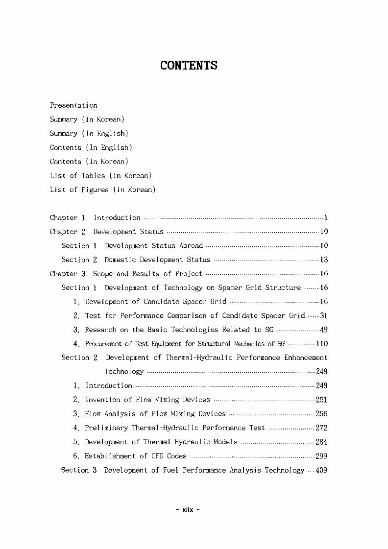
CONTENTS
Presentation
Summary (in Korean)
Summary (in English)
Contents (In English)
Contents (In Korean)
List of Tables (in Korean)
List of Figures (in Korean)
Chapter 1 Introduction 1
Chapter 2 Development Status 10
Section 1 Development Status Abroad 10
Section 2 Domestic Development Status 13
Chapter 3 Scope and Results of Project 16
Section 1 Development of Technology on Spacer Grid Structure 16
1. Development of Candidate Spacer Grid 16
2. Test for Performance Comparison of Candidate Spacer Grid 31
3. Research on the Basic Technologies Related to SG 49
4. Procurement of Test Equipnent for Structural Mechanics of SG 110
Section 2 Development of Thermal-Hydraulic Performance Enhancement
Technology 249
1. Introduction 249
2. Invention of Flow Mixing Devices 251
3. Flow Analysis of Flow Mixing Devices 256
4. Preliminary Thermal-Hydraulic Performance Test 272
5. Development of Thermal-Hydraulic Models 284
6. Establishment of CFD Codes 299
Section 3 Development of Fuel Performance Analysis Technology •••409
- xlix -
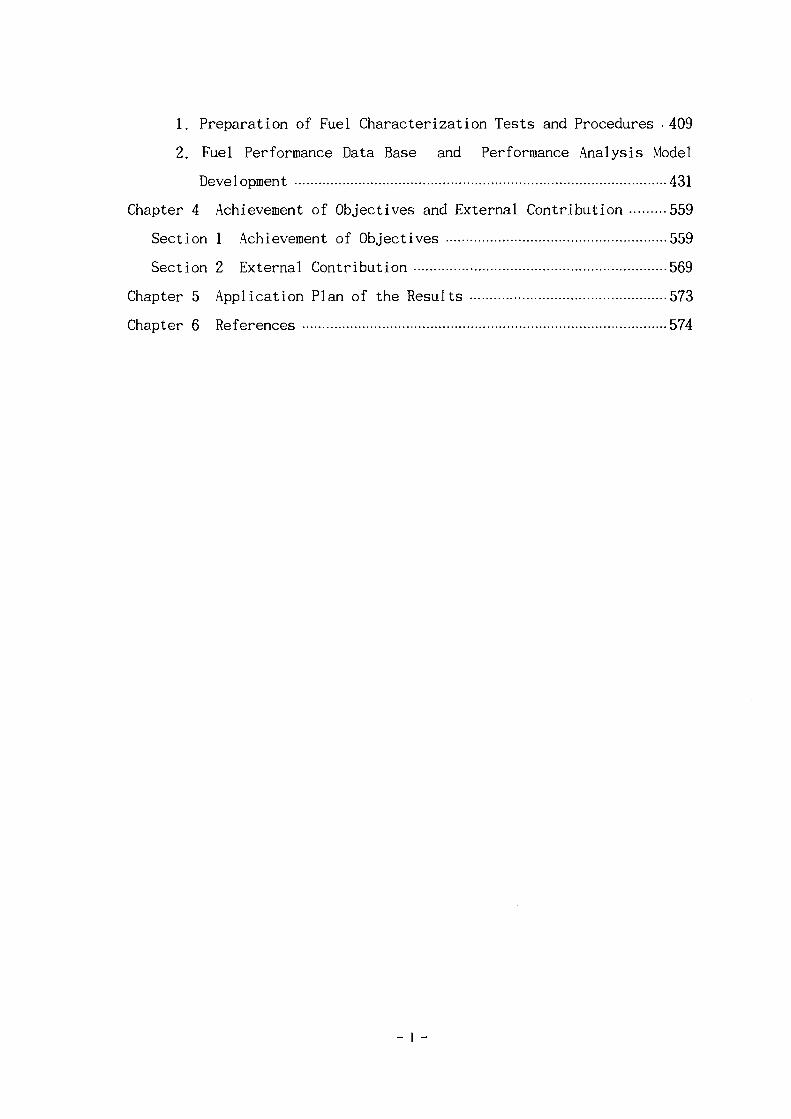
1. Preparation of Fuel Characterization Tests and Procedures • 409
2. Fuel Performance Data Base and Performance Analysis Model
Development 431
Chapter 4 Achievement of Objectives and External Contribution 559
Section 1 Achievement of Objectives 559
Section 2 External Contribution 569
Chapter 5 Application Plan of the Results 573
Chapter 6 References 574
_ I —
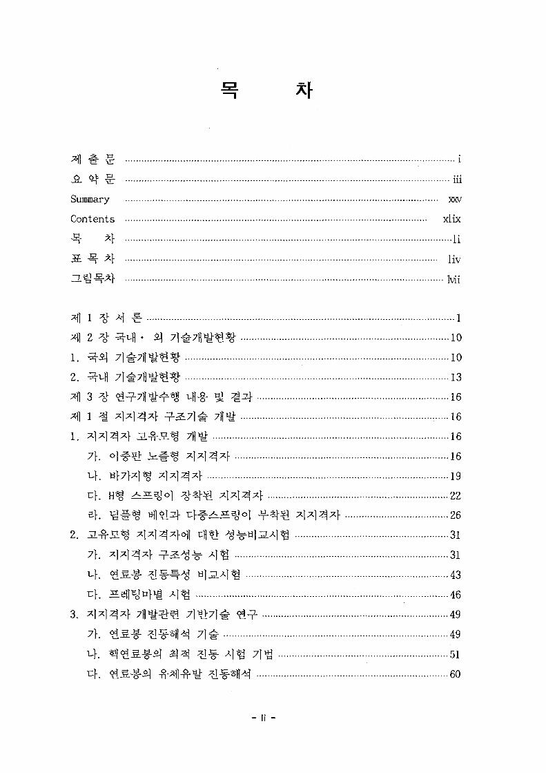
£. ^ £ illSummary xxv
Contents xlix
^ *} li
5E :Sr *} liv
2 # ^ - 4 - S] 7 l^7B«^% 1010
2. ^-a /i^H^^g- 131 3 # ^ ^ H ^ ^ J ^-§- ^ ^2f 16
x]) l ^ *]*13*1- ^ 2 : 7 ] # 7j[^ 16
1. ^1^1^^} ^ . ^ S ^ 7H«i 16
7\. ol-fa> ^ ^ . ^ x]x)^^f 16
19
22
^ l^ l^^ f 26
2. 31^-S^ *1*13*W cf l t l ^ ^ H l i ^ l ^ 31
7\. x\x]Ax\ - 7 - ^ ^ ^ A ] « 3143
^ : 46
3. x\*\A*\ 7 ] ^ ^ 7l«>7]^ <^ - 49
7}. <$.£.& ? 1 ^ H 71^- 49
51
60
- li -
eh SBflWig 7 ] ^ ^ - ^ ui ^ 7 ] ^ 6 8
4. *l*13*l 9 - 2 ^ *VA 964. 7)7*1/ 2:3 A ] ^ ^ 1 ^ 4 110
A. ^ tt*W M^*] 110*}°!.g.-g- * 1 ^ H A]^ #*)
)^}^ ]%[#] 115
118
*fl 2 ^ < i ^ ^ A ^ % ^ 7 } ^ 7|)^ 249
1. M # 249
2. *l*)3*f ^ - ^ - ^ ^ o ^ I S # 251
7\. S|^-fi-§-^7H 252
254
254
3. *1*13*> ^ ^ - ^ ^ ^ l ^ ^ l - ^ - ^ ^ ^ r^ 256
7\. 7fl -fi- 256
u}. ^ l * f l ^ S^i ^ ^T^I^^i 257
259a ^ 260
271
4. ^ ^ ^ ^]ti] J g ^ A ] ^ 272
7\. ^ - ^ ] ^ 272
U. ^ofl ^ 1 ^ 2795. <i-r^ S 1 ! 7fl»t 284
7\. ^ ^ i 284
^}. ^ T H ^ - H - ^ - S « i 291
6. -fr^g- ^ ^ ^ M gU 299
7}. ^ K A J 3 H (CFX-4) ^ 7 } 299
T-K ^-S- ^ A J 3 H (TFC2D) 7flyi 312
^1 3 *l ^ ^ 5 . ^ ^ ^ 7 } 7]^7fl^; 409
1. ^<^^ ^-^A]^ ^ H ^ l ^ ^ K ^ 409
- lii -
7\. 7fl A 409
410
3 r § i ! g } £ ^ A ^ 418
ef. «}<£5. S ^ A ) ^ * «y^ 428
n}. ja. »= ^ ^ 429
2. ^ £ 5 . ^ DB ^ ^<^5 . ^ * B ^ S - l 7fl^ 431
7\. JL<$.^5- ^<$_SL ^ - ^ DB 431
446
486
504
4 ^ ^ 9 - 4 ^ ^ - S ^ ^ J £ ^ cfl^ 7]o^s. 559
559
] m } B % H^ ^ ] ^ 1 559
2. AA*\x} 7]7\}/^-2,*\ 7}*}7]<k n&A^*] ^ ^ / ^ A ^ l ^ 560
3. - f } ~ § ^ # * l <£^ 6fla) ^-AJ 3g7} ^ A | ^ 5 6 4
4. *1*12]*} ^ ^ r ^ 7]»>7l# Sj- J 565
5. tfl<^^. ^ ^ 1 ^ ^ ^ ^ ^ 1 ^ ^^ f ^ 566
6. ^ ^ ^ . ^ ^ DB -^^- ^ ^-^*H^ S-^i 711^ 566
7. < ^ 1 ^ } S - g - ^ ^^ . -g - ^ ^ * H 567^ fli]H 569
] 4 % i ] 569
2. A*MA 7l«>7l^ 7 H ^ M l ^ ^ l 9-^./^-^A]tg 569
3. «?£J5L ^ ^ A j ^ gj ^ * H a ^ A f ^ ^ 571
4. «}o!S ^ ^ DB 9 - ^ 31 ^ ^ f l i { £ i : | 7||iy. 571
*fl 5 ^ ^ ^ B ^ l ^ f ^ %-§-7)lS| 573
574
- liii -
a 3.1.1 M] 7}x] *l*l:zJ*pg -M -g-Sl JL-fr*!^- ^ ^ ( H z ) 121a 3.1.2 S5l]^n]-ig A ] ^ ^ £ 121
d£ 3.1.3 *]*]3*M4 $)$. ^ -g-U ^ S ^ J ^$) ^jq^J ^ a ^ ^
3--n-^l^-^r(R0DVIB2) 122
a 3.1.4 R0DVIB2£f ANSYS5] j i ^ - ^ l - g ^ ^Af ^ i } y j i (oj-f-s]- xl^j^xf
k=395.9 N/mm) 122
S 3.1.5 ^l^l^^i- ##<^ 4 ^ 3-^^$} ^cfl ^ 1 aU(^-7l# A|^)
123
a 3.1.6 7}*m$) MUM 4 ^ : 3. -^1-g-^r^- 2|tf) £ $ | ajj2.(^-7l-f- A | ^ )
123
s 3.1.7 ^]^I^4 #^-ofl 4 € ^ ^ ^ l m ^^1 HlJi (Ao^ ^
a 3.1.8 7}*ms!\ 47M tcf ^^.^l^^Af 3]c)i ig^i aija. (^i-^. ^ ^
A ] ^ ) 124a 3.1.9 ^1^1^4 #^-ofl tr}^ j i -o.xl^^i | jqr-fl £$.] «Ua. (J I^ ^ ^
A ] ^ ) 124S 3.1.10 7f^T^5] M]7]o]} ir}^ ^ - o . ^ ] ^ . ^ ^ jsjcfl ^^] H]ja. ( J I ^ ^ ^
Al^) 124
S 3.1.11 ^ ^ 4 -^-?>A4iS.'g5] 3 . ^ - ^ 1 ^ ^ «lJ2. (Swirl Type) ...125
a 3.1.12 ^ 2 } - -B-*>Ji4iS^5] i -^^ l - i -^ H] L(H ^ ) 125
a 3.1.13 +1^3} -fr»>J&.4iS^5| 3.^-^1^.4: w]ja. (Double Strip %)
125
a 3.1.14 Sl7fl>d# $1$; ti>^- ^ ^ cfl ^ ^ ^5}(Swirl Type) 126
S 3.1.15 5.1711*1 ^ ^L-H- l- r 1LA ti|^L(Swirl %) 126
a 3.1.16 Chen f Kanazawaofl ^1*}^ ^ 1 ^ ^ f l ^ ^ I cjjo]^ 127
a 3.1.17 KOFA ^£^ .£1 #*j 51 %AoV cfloJE] 127
a 3.1.18 <?l^£6fi 43} KOFA ^<*t5.ofl 3]-§-*fe 4*f^ ^ (typical
- liv -
output of CARO) 127
X 3.1.19 ^ ^ . - ^ <£*} J2.-f}-*l-§- (Hz) 128
X 3.1.20 «?*iS.-g-i| °}x} Jl-fHJl^CHz) 128
a 3.1.21 S!}<*i£.-g-a] #*]• J I - O . ^ | ^ ^ ( H Z ) 128
5. 3.1.22 ANSYS codeif Hertz °]-|H-MJ *}$> 4 ^ ^°1 H l ^ 129
X 3.1.23 *!«3.S.-g-/*l*13*l-a!| ^ ^ ^ ^ £ ^ 1 * ] ^ wlja. 129
3. 3.1.24 *?£,§.-£/*!*13*l-afl ^ ^°1 129
S 3.1.25 ^TJl^^^l 4 € - Jl-n-^1^ al^2- 130
S 3.1.26 A4i Sli5olc:Hl i4€- 3 - ^ 1 «13- 130
S. 3.1.27 47H S-^ir^l ^tH «1^ 130
X 3.2.1 -f}~£ ^^711 ^ -^ 328
S 3.2.2 -^--i- # W 7 f l ^Aov^l 4 € - -^r^. -H-^-^^ • 329
1 3 . 2 . 3 7 ] ^ ]^1^^} 6 H V ^ ^ ^ ^ ] ^ fi'i -330S 3.2.4 2.W1 A}-§-^ % J- cv^^A^Tfl^.. 3 3 1
S 3.2.5 *1*13*1- 7]*}^^- ^ ^ 332
5. 3.2.6 P4 1^1^4 A &-&.% Q^&^A^r ^ r # 332
S 3.2.7 <$^^3.^i3} 7}^*3.^i$l M}3- ......333
5 3.2.8 #£) 6 j7^]^^-^ ^F^c ] cfl«> zj- S l l - ^ ^ 1 4 ^ ^ «1J3. 333
S 3.2.9 ^nflofl c j | ^ 7fl<g-B-4 <HI^ ^ ^ 7 ] - 334S 3.2.10 S%^ u>s. s t | 334
a 3.2.11 S%^ ^ l ^ ^ r - ? - ^ 335
S. 3.2.12 ^^ i t iH^^^^ t ^ ^ r t ^ 335
S 3.2.13 ^-g- Vl - S^^I S 1 ! ^"^ 335
S. 3.2.14 ^-g- t>^- JS.^^ % ^ 336
i 3.2.15 ^-§- Vl - 5 . 1 ^ ^ ^ - ^ 336
a 3.2.16 *}-§- ^ - S ^ ^ -7f%> 337
S 3.3.1 Frapcon-3 S £ . ^7}ofl 4-g-^ Ao>Ao^Hl^^ «^^S f - 515
X 3.3.2 Frapcon-3 2 H ^7}cH] A}-§-^ ^ A1-A1.E) |^ |^^ ^f l^^ir]^-^- *)..g.
515
s 3.3.3 ^7]ig # ^ ^ - ^ l a.H^7Hl 4-§- l n<££- *}£- 516
- Iv -
3. 3.3.4 IFA-429 *^<i 7] *([«<}•## 516
3 3.3.5 RISO-II i^^g- ^x}£- 517
3 3.3.6 FA-198 2 : 4 ^ ] ^ 4^. 518
5. 3.3.7 FA-222 4 ^ 4 % ! *}£. 518
5E 3.3.8 Gd -§-*14Ui:£l S. ^ ^ ^ H H ^ ^ 519
13.3.9 «}°iS. 2\}Q 52 £ ^ £ 519
S 3.3.10 °l#7}*I^^B^§~i- 4-§-tl ^^^'^1 ^ *}3. 485
a 3.3.11 -141 U02 4 ^ ££- ^f ° m 495
•3- 3.3.12 Fuel Rod Design Criteria and Limits 520
3. 3.3.13 Summary of Reactor Thermal Hydraulic Data in SMART 521
3 3.3.14 Summary of Fuel Rod Data in SMART 522
S 3.3.15 Summary of Fuel Pellet Data in SMART 522
J£ 3.3.16 List of Computer Codes used in Design Calculations and the
Corresponding Design Limits 523
3 3.3.17 Results of Longterm Calculations in SMART 524
J3i 3.3.18 Results of Hot Channel Calculations in SMART Fuel Rod 524
5. 3.3.19 SMART «t<gS.-g- Data Summary 525
- Ivi -
Bl
3.1.1
3.1.2
3.1.3
3.1.4
3.1.5
3.1.6
3.1.7
3.1.8
3.1.9
3.1.10
3.1.11
3.1.12
3.1.13
3.1.14
3.1.15
3.1.16
3.1.17
3.1.18
3.1.19
3.1.20
3.1.21
3.1.22
3 i L 2 3
3.1.24
3.1.25
3.1.26
3.1.27
>i
. 131
(5X5 tiM) 131
132
133
133
134
i ^ 135
(3X3 «fl-i) 136
136
137
^ I # ## f j ] f j | ] ^ 4 ] ...138
^-5] ^ 1 ^ ^ xjxl^xf^] 7H 3E 138
139
140
141
141
142
142
143
7}*$ &%•%$. 143
144
m «H1 145146
146
147
147
148
- Ivii -
3.1.28 3x3 -i ^*M ^ £ j 7l^ft|^ ^AV 1 4 9
3.1.29 5X5 -i ^*}*ll A]^[5| 7J*}*]-*} % # 1 5 |
3.1.30 ^ 2 f ^ l ^ 7fl5> 153
3.1.31 3X3 ^ ^*M ^ 2 } ^ ] ^ ^ 1533.1.32 5X5 >i ^x}-^} ^a^ 3^A]%I ^ 154
3.1.33 3X3 >g 3*f*fl^l 2M-.SJ5. *g>tf 154
3.1.34 5X5 -i 3*>*fl£| 4 ^ - S ^ ^ ^ 155
3.1.35 4^-^]- ^^^1^ ^ 1 ^ 7M 156
3.1.36 cflojB) ^ ^ ^ ^ 1 ^ ^ ] ^ ^ T ^ 7fl3* 157
3.1.37 ^ ^ ^ 1 ^ 7 ] ^ dfl^x] ^ ^ AI-HIIJC 1 5 8
3.1.38 4 - n - H ^ ^ ° I tfl ^ ^ ^ J £ 159
3.1.39 KOFA 3*l-ail£} ^ ^ ^ 1 ^ ^ ^ 160
3.1.40 o]^s> i ^ # % 3*V*fl^l ^ ^ A l ^ ^ ^ 161
3.1.41 S]^-^-g- ^^}^)1^| # ^ ^ ] ^ ^2f 162
3.1.42 H% ^^f^ll^ # ^ ^ ] ^ ^3f 163
3.1.43 3 x 3 ^ ^^Hl^l ^ ^ ^ l 1 ^ ^ ^ 164
3.1.44 S ] ^ ^ - ^ 5X5 -i ^xW$) -%-^A}^ ^^f 165
3.1.45 H% 5X5 -i ^^^]5] ^ ^ ^ ] ^ ^3} 166
3.1.46 uf7M^ 5X5 -i ^4^1^1 ^^^l^S ^ ^ " 167
3.1.47 c}fAE5oi 5x5 ^ ^ ^ M ^ ^ ^ ^ 1 ^ ^ 4 168
3.1.48 5X5 ^ ^ ^ 1 ^ ^ ^ 1 ^ ^2} 169
3.1.49 K0FA% 3x3 ^ ^^H]^! # ^ ^ ] ^1^1 3]-^-S=. %*& 170
3.1.50 o|^s> ^ # % 3X3 ^ ^^^1^1 ^ ^ ^ ] ^ t> 2 } i £ H ^ 171
3.1.51 Sl-S-S-f- 3x3 -i ^*W<H ^-^^1 ^lt> 2 | i £ H % ^ 172
3.1.52 H^ 3x3 ^ 3*}*fl£l ^ ^ ^ 1 ^1^1 ^ ^ - S S ^ ^ 173
3.1.53 S]^-^-^- 5X5 >i ^M$] ^o\] 51*1 2f^-SH ^ ^ 174
3.1.54 H^ 5X5 -i ^^H)5] I-RH ^]t> 2f^"SH ^^> 175
3.1.55 Hf7fx]^ 5x5 -i ^ 4 ^ 1 ^ ^^<>]| 5 *1 ^ f^SH %AO
V 176
3.1.56 4 ^ ^ ] 5x5 H q*M<!] ^^6fl £|«i 4 ^ S ^ %^---177
3.1.57 *KH£-^ M^^r $M ^ 1 ^ ^ --g- : 178
- Iviii -
3.7}
ZL3]
3.1.58
3.1.59
3.1.60
3.1.61
3.1.62
3.1.63 £H
3.1.64 <&
3.1.65 S
3.1.66 S]
3.1.67
3.1.68
3.1.69 Double p l a t e^
3.1.70 Double plated.
3.1.71 Double p l a t e d
3.1.72 Double plated.
3.1.73 Double plated,
3.1.74 Double plateS.
3.1.75
3.1.76
3.1.77
3.1.78 ^ 5
3.1.79 A B
3.1.80 ^ S
3.1.81
3.1.82 Chen^
3.1.83 Kanazawa^
3.1.84
3.1.85
3.1.86 >tS
3.1.87
178
179
1 7 9
accelerometer 180
Sfln] 180
£ 181
182
182
183
184
185
^ ^ 186
H]J2. 187
^ ^ «]-£! 187
3*} S.J5.^*j- Hjjl 188
4*f S.^.^^ *]3. 188
5^} l ^ ^ f ti]3. 189
( ^ . 7 ] ^ A ) ^ ) . . . i 9 0
t ^ l ^ ) . 191
• 192
W|ja.(Swirl %) 192
193
193
194
195
| 195
Chen*] S ^ J f 5 ] UliL 196
Kanazawa S»gj f^ HJJ2. 197
198
199
- lix -
3.1.88 ^^>£if 4 * } ^ ^ ^ H ^Hr 6^*} ^.-n-^l^^r^ *[£} 200
3.1.89 ^[4iS.if - % ^ £ | *ISH| *4€: °1*> a - f r ^ ^S } ^Sj- 200
3.1.90 <£^51^ ^*VfSl S ^ H n:}^ ^*} jr.-f}-*l^£| ^ 201
3.1.91 £4i£.£f ^ } # ^ ^sH nfs. 4*} ^ x i ^ o ] ^S\ 201
3.1.92 ^^^.-§-2} ^>^ ^]^]^ -a lt:-!*! <&*} S-^ylJi 202
3.1.93 ^<g^.-g-^ #£ X]X)S^ ^H]t:-|^ o]*\ SHtilJB. 202
3.1.94 ^^S^-J f ^ *}*)$. ^flc]^l #*1- S^H]J1 203
3.1.95 «9^S.-g-2l- ^>^ ^1^]^ -y?lc|5] 4*F S^ti]j2. 203
3.1.96 ^# * o * -B-^oi] ccf . a f ^ ^ ^ o f l A ^ ^ - ^ ^25] ^Sf 204
3.1.97 ^ -4^^-^ ! °^€- ^ 4 ^ r ^^°f l^5 | Joint acceptance Jl2 *]
204
3.1.98 # 4 ^ 1 ^^°11 4 € - ^ 4 ^ r ^ ^ ^ l ^ ^ l Joint acceptance J32
^ } 205
3.1.99 -fi-4 5m/s<>1H ^^1 PSD 206
3.1.100 -B-4 8m/sollA^ PSD 206
3.1.101 ^ 4 ^ 1 ^ ^7H1 4 € ^^^.^-^1 ^XI^i1«l^ ^5} 207
3.1.102 -B-4-51 ^S]-o1] n}-& «?*SlS.-g- oj7il^-^yl*] ^[^- 207
3#1-1o3 <^^S.^1 *IS|-6fl tr]-^- ^^^ .^-5] ^Tll^-^yl^ ^4f 208
3.1.104 ^ ] 7 , } cflti) ^ ^ S - g - ^ ofl - ufl ^1^- 208
3.1.105 ^ - ^ ] ^ - ^ ? l ^ ) ^ ^ ^ . ^ - ^ «>^ ^ ^ ^ i ^ * o ^ S . ^ ^ 2 0 9
3-1>1o6 ^ -^ l - a - y ^^ A] ^ J g . - ^ # ^ ^ - ^ S - ^ ^ ^ * } # 2093.1.107 ^- 9i^-ofl^ * I H ^ 7 | ^ t | ^ jgng 210
3.1.108 Hertz ^ ^ - ^ 4 ^ ^ ^ " ^ ^r^^^^ 210
3.1.109 S ^ ^ S t\^-o] z\^}^ ^-f^ 2 *R1 ^-g-^1 211
3.1.110 0 ] ^ . ^ A I - 4 ^ A I j . ^ _g.^ 211
3.1.111 Mindlin-Cattaneo ^^S\ sfl^ ^^ (C y / juJM). 5*1 ^ - f ) •-•212
3.1.112 ^ ^ - ^ ^51 iL> -g-^ (Qx < Qy 4 ) 212
3.1.113 ^ ^ - ^ ^$] ^^> -g-^ (Qx > Qy <£ itfl) 213
3.1.114 Qx7} ^--g-^- tcfl Compliances^]- 213
3.1.115 ^ ^ - ^ ^ B ^^d S^l (Qy/fiP= 0.33) 214
- Ix -
3.1.116 - M n l n ^ ^ | 6 ] H?}B]£ 214
3.1.117 ^ * } # ^ S ; (aM**l*ff*H 4&S1 #*fl £ * 1 ^ %$- :(b)
^-S.-fs l -7-sfl*] i ^ l ^ - i d * ^ 3 ^ M ^ ) 215
3.1.118 a^-3.1.11751 4 ^ H s ^ H ^ l ^ ^ 3 ^ ^ - s - ^ 217
3.1.119 S£-3:<g5l ^ ^ ] oj*> sejjEj 4 ^ 4 ^ AflA 217
3.1.120 dJ^^^]^j afl^S L M \ 3 ^^1%I A)-EH^ ^ ^ ^ < ^ 217
3.1.121 ^<i^] ^o]if 3 4 4 ^5f6]l ixf -g-^7o^7Jl^^ 7 ] ^ (Q /
jUP = 0 . 3 6 , Jl = 0 . 3 ) : ( a ) ^ ; ; ( b ) ^// 218
3.1.122 H^l 3.1.1175] 7flA>ofl Af^-s^ ^ ^ . ^ -§-^ 219
3.1.123 ZL l 3.1.1175] 5 : < i ^ ^ ^ . | ^of l4^ /^///T/ 219
3.1.124 (a) ^ ^ - ^^^f^ 4° l l " (aax / ^P = 0.36, y = 0.3; e f ^ ^
1,5,7,11,13<>fl4 JO! = G** / 3, * } # ^ 2 ,4 ,8 ,10^4 !fl! =
2Qmax / 3, G,/n = - Cffla, ): (b) ^^>*}# ^ ^ ^ 1 ^ 5 ] -§-^3-
Sl^Hr 7 ] ^ 220
3.1.125 £J*I-fHr ^ l^ l^^f ^ s ^ o 1 ^ ^- t l -S .^ s c l 221
3.1.126 4 * 1 3 4 4*1-fSj H l ^ ^ ^ s f l ^ l ^ - § - ^ TJl^^i 221
3.1.127 si^HH? 4 * 1 3 4 ^^BJ^1 a l ^ i^ sfl^^l ^t> ^-^^-^1 2223.1.128 H}*iig ^ 5 ] ) / ^ ) ^ « > ^ ^ ^ ^ ^ ^ B O I ^ ^ ^ ^ A J . 222
3.1.129 S]3HHf 4 4 3 4 ^ ^ ^ ^ 1 til^% *H^ 4^ 223
3.1.130 H^ ^>^34^ - ^ - l ^ i £ 1 224
3.1.131 134-Sl *}# ^ 3 ^ 2 2243.1.132 i£*l ^45] 2f^-S^ ^ ^ - 225
3.1.133 sfl^^l 4-§-^l <*M ^^ l^^^ l 7H^ 225
3.1.134 1>^ ^ 1>^.^ s f l ^ «>^-^/^t^| ^-^i H]ja. 226
3.1.135 47f4 - ^ - i ^ i S^-i-Sl ^ l ^ ^ / ^ ^ l ^ 226
3.1.136 3X3 34^1^1 *\^^ 9! 3 ^ 1 ^ ^ 227
3.1.137 3X3 34*ff£J -B-tl-S.^ S.'gsf ^ % ^ ^ - 227
3.1.138 5X5 34*11^1 -n-tl-S.^ 2.*£3} ^ 4.A 228
3.1.139 3 4 ^Ml i t ^ ^ ^ ^ / ^ l m* tilJ2. 2283.1.140 ^1^-5.^2} ^ | n _ t | ^ ^ ^ ^ 3 | . 229
- Ixi -
3.1.141 ^ J S . 1 ^ ^ M I S ^ ^ cJJ^^TJI 229
3.1.142 %& 3.*i$] ^ ^ S 230
3.1.143 cV -1 ^ x } ^ ^ 4^s} SLxQ 230
3.1.144 37}*] JE^oU cR> ^ B<HW*j ^ ^ / ^ l ^ 231
3.1.145 ^ 4 ^ ] # -M*f7] £l*> -g- -f- H ^ s j 231
3.1.146 ^§^| Sf^-Aj^ ^5} i } s f fm^S]-^ Hjja. 232
3.1.147 H^ 3X3 -i ^4^11^ -S-*h&.4i S c | 232
3.1.148 «]#% ^ ^ ^ ^ s f [ ^ ^ - ]*> ^711^^1 233
3.1.149 271 ^^^ -H^) nfa. ^ ^ ^ i j igSf 233
3.1.150 ^7] ^-^^S. 0.40 m/s«Hl>H I ^ ^ ^ 234
3.1.151 ^.7] ^ ^ ^ - £ 0.40 m/sofH*] von Mises -§-7f-g-^ ^3. ..-234
3.1.152 27] ^^fS. 0.40 m/s6flA| l ^ 7 } ^ ^ ^ ^ ! - ^ S 235
3.1.153 H^ 3X3 >i 4^]^1 # ^ S . ^ ^ ^ 236
3.1.154 5l H -§^1^*1^} P^S. 237
3.1.155 ^^t^u\$Ji 7H^H 238
3.1.156 ^ 1 ^ ZL^^l^?- 238
3.1.157 ^ ^ ^ 1 S ^ ^ ] # 3-]*> ^ A ^ 239
3.1.158 ii(ii) 239
3.1.159 ^ ^ . - g - ^ S ^ j ^ # ^|*> 6»^^-7l 240
3.1.160 ^^-8-71 wli^^l xlx|^x|-l- JL^*> S ^ 240
3.1.161 ^^^.-g- ^sfl^nl-ig X\^ %%]$) 7^S. 241
3.1.162 «?^S>g- ^^J^n}ig A ] ^ *)-*](Aj-tL) 242
3.1.163 «f«l-S.-g- ^ ^l^l^^f ^^Bo7 ^ 1 ^ 242
3.1.164 A ] ^ o]^Jf 243
3.1.165 * \ ^ %^^l(Load Cell) 243
3.1.166 LVDT 244
3.1.167 ## 244
3.1.168 ^ u | 4° i - r - (^^ ) 245
3.1.169 ^2ll^n}ig A ] ^ ^ * | cflo]^ JtAl s } ^ 245
3.1.170 S ^ 7]^7l 4 ^ ^w] 246
- Ixii -
3.1.171 Stylus ^ -7-i-f 246
3.1.172 Stylus^] Sjt> 4 ^ ^ 247
3.1.173 nftg^ ^ 42}$] ojefl 247
3.1.174 nJ-igiSS] ^ n j ^ #$(X 50) 247
3.2.1 sl^-fr-^ ^ |^7 f l7 f -f*}-^ 4 4 ^ 4 4 4 S. 338
3.2.2 S]*l-f}»§- «^^7fl 44IE. 338
3.2.3 ^ ^ 44 S 338
3.2.4 3]3-8-^ ^J^7||7} - f*v^ ^ ^ ^ «qo4S^^^ 4 4 ^ 4 ^
44S. 339
3.2.5 ^ tii^ ^ 4 <%M 4^ : 4 4 ^ 4 ^ 1 ^ ^ £ 339
3.2.6 si^i-fr-i- ai^y-7ll7l- ^ -^ f i ^ s ^ t f l<^5.^^| 4 4 ^ x } ^g £ 340
3.2.7 ^ ^ - ^ ^%^7fl 4 4 ^ 4 ^-4s. 341
3.2.8 e i^^ ^^y-711 4 4 ^ 4 *$^S- 341
3.2.9 ¥.4^ ^^^711 4 4 ^ 4 ^(strip) 4 ^ £ 342
3.2.10 ^ ^ " ^ ^% l^7| | S$45L 342
3.2.11 ^y-711 CFD JS.«g 343
3.2.12 ^ e j ^ y-7l)(split-vane) - f ^g . # ^ ^ i ^ o ^ ^ - £ ^ S •••344
3.2.13 ^ e ] ^ ^7|f(split-vane) - f ^ S . - § ^ ^ t i o ^ ^S .^S . . .345
3.2.14 ^ e l ^ ^7fl(split-vane) ^ - ^ S t>T^lM^] 346
3.2.15 ^ S ) ^ ^7fl(split-vane) JM\§. S l ^ - ^ ^ 3.71 346
3.2.16 ^ - ^ S ^-S.t*|B| M]3. (z/Dh=2) 347
3.2.17 -f^S. ^-S.«]Bi tijja (z/Dh=10) 348
3.2.18 ^SL ^*<m a l J l (z/Dh=20) 349
3.2.19 ^ - ^ 5 . ^ ^ i ^ % * ^ £ ^ ; £ 350
3.2.20 JM^S. ^ i ^ ^ ^ ^£^S 351
3.2.21 -f^S. 4°l(gap) ^ ^ - ^i^-S 352
3.2.22 -f-^S. 4-T- Sl^i-n-^ ^IJ- 3.71 353
3.2.23 -*M\S. 4°l ^ ^ - ^ ^ 371 353
3.2.24 -f-^S. ^ ° H ^ ^ - S 354
- Ixiii -
3.2.25 ^S- ^ VHHIM*] £ S 3543.2.26 $ 1 * 1 ^ £ ^ 7 f l ^ 4 ^ 1 ttf§ ^ r ^ - ^HH? ^ £ . £ 3 . -355
3.2.27 n&&£- ¥^7% ^45K>fl ttfg- Jf- jsL S]*i-8-§- 3.7} -356
3.2.28 3]*l-8-§- ^W7)J ^ -^4^^ ] ty^r -f^-g. Q^gS. 356
32.29 S]*Mf- ^ ^ A ^z\S.°\] ixf - - ^ 5 . # ^ t>#^m^l -357
3.2.30 $1$.$-^ ^ " i n ^ ^ 4 H ^ 1 I 4 € ^ S 5]^-^-^ 3.71 ^O
H ^ ^ ^Sj. 357
3.2.31 3J*i-fh£ ^^^7H ^ - ^ 4 ^ ^ ^ ^ 1 ttf€- ^-^r^ 5]^-^-^
3.71 358
3.2.32 SJ^-B-i- ^^^7fl -g-^^-S.^ ^ W | nfs. ^ . ^ ^ ^ ^ - ^ S .
^S(^-l) % 5]^-^^- 37l(o}Bfl) 358
3.2.33 ^-7) S.1 ^1^14^ 71*} tgJ£ 359
3.2.34 Al^-f 359
3.2.35 ^ ^ ^ 360
3.2.36 ^ - ^ ^ -S. :S 360
3.2.37 ^ ^ ^ ^ <*rS. ^"S 361
3.2.38 ^1^-f ^Hl^i ^ ^ ^ ^ - £ ^ : S 362
3.2.39 -*iS| <?]x} ^ 362
3.2.40 t f l zHIW V> - 4 £ ^ S 363
3.2.41 ^ ^ - ^ ^ VHf 4 S ^ 5 364
3.2.42 ^ o1-*©15 ^ ^ ^ ^ Hi3. 365
3.2.43 a } ^ ^ J£ ^ -S H]J2. 365
3.2.44 ^nfl# oj-g-tl ^711^-^-4 ^ l ^ ^ l ^ 7fl3>£ 366
3.2.45 ^ 1 ^ ^ ^ ^ ^ ^ - ^ - ^y :7 i ] ^ 367
3.2.46 # ^ 1.2 Mpa lA-1 o i ^ . ^ ^ ^ ^ ^ <y7}j .o_<fc- A ^ ^ 3 f ..-368
3.2.47 <>H 2.6 Mpaofl 6 ^ ^ 1 4 ^ - <g7fl<g-fl-4j- A I ^ ^ ^ ...369
3.2.48 «U^ 2.6 Mpa A-1 ^-^ .^^o]] tcj-S. c i^ l<i^-^ Aj^^^f ...370
3.2.49 4 SM-fr^ibll 4 S . 1 £ o | irfS. ^7ff<g-JH- &}% y l^- 371
3. 2. 50 ^ ^ 1 7 } -f^Sl^l & £ PWR 4^M1 tHtV o^^ l i f ^^^1^1 Hl i 372
3.2.51 ^HJ* l7 l - ^ Q PWR ^ 4 i 4 ^ : ^ l ^ l ^ f A J ^ ^ 1 ^ HI^L -373
- Ixiv -

HQ 3.2.52 FBR 2]*H] t}]*> o f l ^ i f > y ^ * l ^ H]iL 374
H ^ 3.2.53 <M<S-fMf S . ^ 7HM3 -7-^ 375
ZL ] 3.2.54 M ^ - f H ^ oJl^l^f ^ 8 * 1 ^ w]3. 376
ZL^ 3.2.55 ^%MH*r°fl c1l> o f l ^ m ^ 8 * 1 ^ * 1 ^ ^%* 377
ZLt] 3.2.56 6nT7fl<i-fMf 5 . ^ 7 J ) ^ - ^ 377
ZL^ 3.2.57 t ^ J ^ ] cH*> ofl^j i f 4 ^ ^ ^ u]*| ^ ^ 378
-L^ 3.2.58 ^ ^ ] ^ ^ ) cflsv ofl^jil- ^ ^ ^ 1 ^ M}$] 4*£ 378
HQ 3.2.59 L/Dofl cJJ^ of l^ l i f 4 ^ ^ ! ^ ul^l ^^o^ 379
ZL^ 3.2.60 i-JH A]^j^S.oJ| t:B*> <y>||^-fr4 ^ ] ^ ] i f ^-^^1^} «1 --379
ZLS] 3.2.61 Reynolds ^ ^ ^ 1 ^ } ^ ^ ^ 1 4 ^ - -fr^^Sf 380
ZL^ 3.2.62 #% -y^lx3| ^ ^ -^-^ ^-^ 381
ZL^ 3.2.63 VBfS-ioll ^\^r ^ ^ ^ Vi^^-i- ^-^ Hi a 382
ZL5] 3.2.64 ^ Bo ^ V>^-7o^ ^ S (P/D=1.25, Re=100000) 383
ZL^ 3.2.65 ^ S i } i-H-^^S. -^-^^-^ H]3. 384
ZL I 3.2.66 SA-^el^^i f ^ ^ ^ ^ - ^ ^ - ^ Hlja. 385
Zisi 3 2 . 67 ^ ^ ^ . ^ - f r ^ ^ ^ ^ S ^ r S M]i 386
ZL^ 3.2.68 ^ ^ S . ^ ] A - ] ^ ^ ^i^>-§-^ H]iL 387
n.^ 3.2.69 Sj-tH^ ^ ^ - ^ - ^ - ^ W ^ - S ^ : ^ 388
ZL^ 3.2.70 %c|l^- u>^-oim^l ^ : S 389
ZL*|] 3.2.71 ^ ^ S . ^ Matrix <^S. ^ ^ ^5. ^S. 390
H.^ 3.2.72 2r»£*2 ^£^S(Re=20000) 391
ZL5] 3.2.73 ^*&*£ ^-£^S(Re=40000) 392
ZL^ 3.2.74 -g-4°l # 6 o ^ ^ l ^ ^ ^ o ^ ^ i ^ S ( ^ l ) 91 t^^s.(o}efl)
(Re=40000) 393
ZL*!! 3.2.75 -g-^^MI^ ^ - ^ S ^>^ 394
ZLQ 3.2.76 TFC2D 3.H5] ^ i^ l^^ i J : ^ - £ 3g4
ZLs] 3.2.77 ^ % ^ * 1 2j*M-t^l(generated by wgridl routine) 395
ZL^T 3 .2 .78 ^ ^ ^ ^ A | ^ ^ ( g e n e r a t e d by wgrid2 r o u t i n e ) 395
Zisi 3.2.79 £ ^ ^ 7 ) 1 ^ ^ 5 ] ^«§- S.*H 395
ZL^ 3.2.80 ^ * } ^ ^}^1 A ] ^ ^ 396
- Ixv -
3.2.81 ^ ^ - f H f S l U <^S. ^S. (Re=17250) 397
3.2.82 ^ ^ H f ^ k ^ S (Re=17250) 397
3.2.83 ^ ^ - f r ^ - £ | U <SfS. ^-3£ <Re=40000) 398
3.2.84 31%3Mh§-S] k &£. (Re=40000) 398
3.2.85 *l% ^Ml^f 3*fX|£l til^- (Re-40000) 399
3.2.86 \S.-fH?£I U -S. -g-j& (Re=8200) 400
3.2.87 .S.-fHf2j c M f ^ - g ^ ^ a (Re-8200) 400
3.2.88 - %cB^^-^^ ^t*$*£ rS. S (Re=84000) 403
3.2.89 ^-^-cll^:^-^^ ^-W-^M^l S (Re=84000) 4063.2.90 ^-tTO-S-^JA-l ^|*^jjL2dfl rcf^ vb^oim^} £3*
(Re=84000) 408
3.3.1 Variation of radial fissile atomic density distribution
with the burnup(4 w/o 235U) 526
3.3.2 Radial variation of one group neutron flux(4 w/o 235U) 526
3.3.3 RAPID calculation flow 527
3.3.4 Variation of radial burnup distribution with the burnup
(4 w/o 235U) 528
3.3.5 Variation of radial burnup distribution with 5U enrichment
at the burnup of 30 MWD/kgU 528
3.3.6 Variation of atomic number density with the burnup at mid
radius(4 w/o 235U) 529
3.3.7 Comparison of radial distribution of total Pu concentration
with the measured STRO fuel data at the burnup of 29
MWD/kgU 529
3.3.8 Comparison of radial burnup distribution with the measured
STRO (2.9 w/o 235U) data and TUBRNP prediction at the burnup
of 29.571 MWD/kgU 530
3.3.9 Effect of 235U enrichment upon radial burnup distribution
in comparison with the measured BR-3 fuel(8.6 w/o Z35U) data 530
3.3.10 Comparison of total Pu concentration in the pellet with
- Ixvi -
0RIGEN(4 w/o 235U) 531
ZL^ 3.3.11 ^ J E ^ i ] 4 ^ . Gd-157 ^ £ ^Sf(0.71 w/o U-235) 531
H ^ 3.3.12 <a^So11 n}€ # 3 ^ 3 E ^S]-(9 w/o Gd2O3, 1.8 w/o U-235) -532
H^J 3.3.13 <£^S. 2 MWD/kgUoflA-js] # ^ £ S ( 1 . 8 w/o U-235) 532
ZL^ 3.3.14 <&£.S. 20 MWD/kgUoflA| # ^ ^ S ( 1 . 8 w/o U-235) 533
HQ 3.3.15 ^ S . ^ 1 4 € - Gd-157 £ S ^if(9w/o Gd203, 1.8w/o U-235) 533
nm 3.3.16 <&^S- 30 MWD/kgUofl*] U-235 -fe^Eofl 4 ^ # ^ ^ : S ^£f(12
w/o Gd203) 534
H ^ 3.3.17 ^ 4 i S 6 Ml»D/kgUofl>H^ S.^ <^)^} ^ ^ ( 4 w/o Gd203, 0.71
w/o U-235) 534
ZLQ 3.3.18 ^ [4 :£ 20 MWD/kgU^1^5] JS.^ ^ | ^ ] ^ ^ ( 6 w/o Gd2O3) 3 w/o
U-235) 535
H^ 3.3.19 #$-1 -fs}ofl^ 7 l S ^ %EH 7 f^s l 7]3E^^- ^ ^ 535
ZL^ 3.3.20 ^2}*]i|- I Zacharie ^ data point ti]J2. 536
~LS] 3.3.21 Aj^ofl nf^- ^3f-i|3f J. Burbach ^ ^ data point «lJ3. 536
3-Q 3.3.22 <^4iS6fl trf^- ^ ^ | ^ 4 Zimmermann ^ ^ data point H];2. . 537
ZL^ 3.3.23 ^rJ£o|| rcf - ^ 2 f ^ 2 f K. Une[10] ^ ^ data point ti]^L 537
O.& 3.3.24 FRAPCON-3 SH&fl 7}^] ^ ^ S . ' i ^-g-(BR-3^I ^ ^ w|3.) ...538
ZL^ 3.3.25 FRAPCON-3 3.^^1 7]*j| ^-grJE^ ^-§-(BR-3^| LHGR 10% ^7f u|
-2--^ ^ ^ ^ ) 538
D.% 3.3.26 IFA-585.1 ^ ^ # ^ ^ 1 ^ 7 l # 3 . H ^ 1 ^ ] 539
ZL } 3.3.27 IFA-585.4 ^ ^ ^-^^1 ^ 7 ) ^ 3 . ^ o f l ^ l 539
H ^ 3.3.28 Creep-out S « g ^ o f l ^ l i f ^^4^^1(IFA585.1) WJJ3. .-.540
H ^ 3.3.29 Creep-out S.^S] ^ 4 * 1 ^ - ^^^^^1( IFA585.4) W]i ---540
ZL I 3.3.30 FRAPCON-3 3 H ^ creep-out S 1! -§- 541
ZL^ 3.3.31 o ^ ^ ^ 1 ^ # ^ 1 , a)-4^ S ^ ^ £ ^ # ^ 541
ZLs] 3.3.32 Li %•£. ^S}o1| n:}^ A>J^f. ^ ^ ^ S f 542
ZL^J 3.3.33 Li ^ f£ . ^S } ^ ] ixf^- ^ - ^ ^ A>SJ-§. =-7)1 ^ 5 } 542
ZL^ 3.3.34 ^ ^ - ^ £ ^ % ^ 1 ^?> ^>5f# ^-^1 ^ 4 f 543
ZL5] 3.3.35 ^ 4 i ^ £ ^ S f ^ l ^ * > 4«J-*oi= ^>2f# ^-7)] ^ S f 543
- Ixvii -
f?fl ^ 4 f 544
3.3.37 ^ ^ ^ W - T - ^ I ] ^£1*1 VA ° f l^ l til^ 5443.3.38 Li <g*o*-§- JL5}t> ^*g*o* A>2].P1-=.^ 4 ^ * ] 545
3.3.39 Gd 7 } ^ ^ ^ ] # 4-§-*> *|<gfi^*||<il ^ ^ M ^ 545
3.3.40 °W 7}<£^^-g- T^S. 546
3.3.41 <>l
3.3.42 Variations of gas atom concentration 547
3.3.43 Gas atom concentrations in the bubbles in equilibrium •••547
3.3.44 HBS ini t ia t ion local burnup as a function of temperature,
grain size and fission density 548
3.3.45 Measured data of HBS width in the HBEP irradiation tests 548
3.3.46 : n * l l ^ < i ^ # < > 1 4 Hjja. (*M : ^ - ^ ^ 1 , *P : *K^1) 5493.3.47 7 l^ l^^ r< i^^ l -^ ] - a]jz 549
3.3.48 ao
v4^i^4^AoV<ll4 yl^- (*M : ^ ^ ^ 1 , *P : <^*1) 550
3.3.49 ^ S ^ l * } V]3. (*M : ^ ^ ^ ] , *P : ^1^1) 550
3.3.50 Hl^4Sj . U02 (95 % TD)£| < i ^ i £ £ 551
3.3.51 20 MWD/kgU U02^ < i ^ £ J £ 551
3.3.52 40 MWD/kgU U02£] < i ^ i £ £ 552
3. 3. 53 60 MWD/kgU U02£) <i^S.S. 552
3.3.54 Radial Power Distribution versus Pellet Radius for SMART
Fuel Rod 553
3.3.55 Rod Internal Gas Pressure versus EFPD for SMART Fuel 553
3.3.56 Cladding Oxide Layer Thickness versus EFPD for SMART Fuel • 554
3.3.57 SMART ^ < # 5 . -g-^n^H £.*£ 555
3.3.58 SMART «?<&§. i b ^ ^ I S-^ 556
3.3.59 SMART ^<&g. <g^^^ S.^. 557
3.3.60 SMART ^<^S.-g- S 1 ^ 558
- Ixviii -
1 & M
40]
Hardware
-L -6>off ^ H l ^ ^ ^ ^ 6 4 ^ . Hardware
Siemens/KWU47]- ^%-^.S. ^^]*> K0FA(K0rean Fuel
Assembly) £^.7} 1 9 8 9 ^ ^ - B ] -uff f ^ ^ ^ * l - f ^ ( W ) ^ ti^^^] ^-^-^
olsfl KAERIif ABB-CE47} ^-^^.S. ^TJJ^ ^ ^ ^ 7 f 1994^-f-^ -i-flSj CE
Vantage 5H
Vantage 5H
^ Vantage 5H
- 1 -
( ^ , 14^1 Pe r fo rmance*^ , ABB-CE4^ TURBO™
<$.£., SiemensH-f-^l nj-^-vfl 4 ^ I 4 c l l SPC(Siemens Power Corporation)43]
HTP 04jg., Siemens/KWU45l FOCUS <&g., ZLe]jL Fragema4£| AFA-3G
J ^ } H 1 9 8 6 ^ KOFA
? £-5.^717)#
# % l ] f ) ^ ^ i 4 \1 87 . 2 1 . ~ 2000 . 3 . 3 1 . )
44^4 ?m^
4
- 2 -
71
nf
- 3 -
, ~30bar),
, 300°c] ^
^ ^ ^ 4 ^ ^ }$= m 350
2200 bar7} ^ ^ a ^ ^
4f3i s#^ 4J5£*>
514.
7]
- 4 -
^ Databael-
71
Zj-
- 5 -
7}
200^^0)
^HH Siemens/KWU ^
Halden Reactor Project % NFIR -§• ^ f f M a ^ o l l S l 7}^# f-sfl
4
- 6 -
Lithium hydroxide^]
^*> ^ ^ , U02 i ^ ^ l l ^ 7}
rim effect 3£fe High Burnup Structure(HBS)BfjL ^ f e
creep-out ^^> -§-0] J L ^ ^ S . ^ ^ tcfef -
^ - f o|e1«> ^ ^ - # 5 ] ^ 3 ^ ^ ^ A ] ^ ^ Hal den Reactor
Project, NFIR -§-2} ^ H l ^ § - ^ 9 - S S J ' g t ^ K ^ ^ * } J L Sii-S.^, o|
rin effect7|- *|};A<§'s]-JEL.5L °)3]*} rim effect-S] ^ '"o^-
- 7 -
H^ZL^ RAPID-GD
lift-off
CARO-D 5.5 S ^ i f FRAPCON-3
creep- out ofl^-£| ^ ^ - ^ # ^7f-5rf^^.T^) Halden
creep-out 3 . ^ 7
A ^«S^<H ^ 4 . 4 5 - ^ : ^14^: ^-S-^ 7fl^2f ^ ^ * H Zircaloy
^ -f*l 7l -6fl c||t> <d^-51 iivilil A ] ^ ^ - .*U ^ * ^ o ] #t;K ZL
Zircaloy 2 ] ^ - ^ ^ ^ifl ^ A I 7]^^) ^ y o^^ ^AJ- 31 ^ ^ ^ ]^#o)
^ l f ( finite element
analysis module )7JH* ^ 2fS. -BHoflA-] <q ^<g5.-H.^] cfl«> ^ ^ tf
- 8 -
^ 950 MWe 17x17 KOFA
# KOFA^ 3658 mm |A-f 2000mm
- 9 -
1.
Sit:},
711
fe. TURBO™
1 1 ^1^1 A4^11 (Side Supported Spacer
Grid)* 43"*K2. Si4. o] 4
fe Performance'
fe HTP
contact) 0 ]
HBfl^Jnj-ig^^- 3.71] ^#X\?}^ HTP g£ HMP
- 10 -
2l-M, Siemens/KWIMfe 4 4 4 4 ^ Sg-5-g- 4 4 ^ 2 1 ; S7I1 %HM?U 4 4 4 4 ^ -?-i£#£# ~-?i
FOCUS 4 4 4 4 4 # 11^}^ £ § W
Fluid-induced v ibra t ion)^ ^
Paidoussis^l - S ^ l ^ FIV
FIV s . ^ # ^ ^ ^ 3 . XM g
4
7f S ^
4444
- 11
know-why ^ know-how# %J£^KlL $!*:}.
Halden Reactor Projectoj- NFIR
OECD/NEA<HH-b IAEA-iJ- ^^^.S. IFPE (International Fuel Performance
Data Base) ^ ^ S ^ cdoj^Hflol^^ n > ^ a ^ A t ^ ^ ^ f l ^ ] %• 3117]]
^ ^S-g-ofl tH^: ASM: Halden Reactor Project, RISO ^ HBEP (High
Burnup Effect Program) %•!%
^ CD-Rom t:]>*i3. 67H
H e J SIERA 3 . H , ^ JAERloflA-]^ FEMAX1-IV
fe- FRAPCON-3 5 . S # 7fl^
LOCA
- 12 -
2.
KAERI7} ^%-^-
KOFA C E ^
3.7]}
HTP
HTP
31
FlVi}
Siemens/KWU4
ABB-CEAf, 3.
3-7%
- 13
5X5
VHKh§- Full Scale
3x3
5a
autoclave
Loop
o] ^ ^ . T
. U02
Halden reactor project^]
"A
- 14 -
7} n>
Ur Siemens/KWU
^r Halden reactor projectofl
71 -
31
- 15 -
3 s-
1.
,#^ 4444
~ ^ 3.1.13} sj-o] 4444
4
44^14
. 444
. 444
- 16 -

^r Siemens/KWU, ABB-CE H
Westinghouse(o]*} W
^r Siemens/SPC7f
ojofl
- 17 -
SL3.
4444^1 7]
j^-tif 3.7lJL4(size effect)ofl
ZL^ 3.1.2-b
5X5
-g-.. nt! 3.1.2*1
. -L^ 3.1.3a
ii#
^ ^^J 3.1.4 3.1.5^] S.A]5|O] a l4 . H ^ 3.1.4^
514 ^ ^ ^ ^ - ^ ^ ^ ^ 3.1.451 *&%•
r a^l 3.1.5^1
- 18 -
3.% 3.1.64
4451 u}.
fe ) 3.
71
fe 3L c}f . o]
- 19 -
4434
H^ 3.1.7aif a ^ 3.1.7b^ H J 3.1.8^1
a ^ 3.1.
fe 4
44:^. ZI^J 3.1.7a
3.1.84 -£4^ 44^4^11^ ^ 3.1.7a gj H^ 3.1.7b4
1- 3X3 n<£5L
a^l 3.i.i0a ^ a^l 3.i.iob4
- 20 -
7]
-r^ 3.1.10aofl
uf, a ^ 3.1.10bif
7]$]
ttfl
4
^ - S ^ Df -
S]
21 -
51JL,
(1)
H % i
"A(conformal)^
stress)^ 3.7 o)
7]
(2)
4
- 22 -

S(channel)# #?fl * M U ^ ^ f ^ l SJ3L <>]
o
- 23 -
^ . ^ , o]
04jg.-g.6fl
(3)
- 24 -
3.7]
(4) 4 -51H^ 3.1.11^
67B X)
J 3.1.12^7 6^
)«.
^ ^ 3.1.13U)
Wl^4(non-conformal)
- 25 -
fe ^ 3.1.15(a)fe o|s. H
4 4 ^ 3 2 . Sa-bt-11
^ o|
(5)
SIM,
(1)
4
- 26 -
(2)
o] ^ i
- 27 -
(3)
- 28 -
sa
edge )
(4) 4
o)
a^J 3.1.17^1
- 29 -
JjL-fiStig(103f 103')^g. ^ $ 5 ] of ^ h H ^ 3.1.18^
J2.*Hf7l-
3.1.19-
H ^ 3.1.20^
(104W
H^I 3.1.212} $13.Q 3.1.22(a)
51 *H
(5)
30 -
2. J2.-fK
(1)
Tensile testing Machine; UTM)# <>l-§-*H
o ^-^ aMfl 6 J - ^ f # : 100 N(10 kgf)
o 5 ] ^ 5LSifi«j|J= ^ S : 0.5 mm/ i: o
o 7}^(loading) ^ *fl^(unloading) *)$) v
- ASCIIS,
- 31 -
3J-J2. & f e
^-^ 3.1.232]-
3.1.24if ^
3.1.25^1
itfl
(4)
A.
JL^^fjl
3.1.26^1
7}
- 32 -
# =LQ 3.1.25^1
o
# 0.5
(of)
ASCI I
0.6 mm^. ^ 1 ^ * 1 A
% 3.1.27(a)
- 33 -
3.1.27(b)ofl
(2)
7] (Universal
Tensile testing Machine; UTM)#
o ^ - ^ 5]cfl <y-^f^: 50 kN(5000 kgf)
o 5{4i a i ^ ^ ^ I ^ ^ £ : 2.0 mm/^ o]*}
o 7}#( loading) ^ ^ ( u n l o a d i n g ) A]i) t
o A ] ^ ^ 5 ] e]-^, i g ^ c(l6]Bi ZLEfl^ AflA>
^ ] ] ^ l | ASCIIS
"77.-7] .<£.
(ef) *1 ^
- 34 -
37H
£ H ^ 3.1.28 *J 3.1.29i}
H^ 3.1.30^
- 35 -
o 3 .^ -
J£# 2.0
(4)37B
(of)
304) 0.6 mrn-1-
2500N,
20
iiuf 4^cfl 71 1*1 ^^ .5 . jioicf. n ^ 3.1.33
(3)
- 36
(7}) ^ 3 4 ^ 7fl.fi.
Siemens/KWU4 1- ^ x K h ^ H ^ Westinghouse(o|Sf
^(duration time)of[
history)o]uK
(correctionH
.OS. «^^
a
4
4 ^>^
- 37 -
(Uf)
cf. Z l ^ 3.1.35^)
. 0}
, o)
7]-
^r 20.43
^ 1676.4
, 3.7]fe 254X254
^ J^tfl 4000
, ^cfl
u}.
2225#
6.35
I-STAR
fe FEMtoolsS
A]
- 38 -
3.1.366fl
(ef)
o
o #0^3} A } ^
o
o
o
o A
o
o
o
o
o]
( 3 . 1 . 1 )
( 3 . 1 . 2 )
- 39 -
o] x\£ AI (3.1.
or a>nUl2-h2) (3.1.3)
v
k
m
xo ^
2.7}
(3.1.3)^- 3.1.38^1
(Hf)
o}
o]
- 40 -
3x3 ^ ^M
3X3 ^ ^*\n A J s ^ T. 71
l^7o)- 0.6 mm
. ^ a 7]
4^. FEMtool
ZL^ 3.1.28(a)i} ^ ^ r KOFA^
o) B^Afl^i o j ^ ^ l ^ 6 l
6916
f ^1 8
fe 0.06986 m o ^ ^ ,
- ^ ^ ^ 0.32 m/sec
^ 13.9 g^l4 27.2
£ 3470
4 1# 37H
ZL^ 3.i.28(b)if ^ - ^
^ 8
14
*>
3271
0.06356n 0.30
9.6 g^!4 13.5
J £ # H^J 3.1.40(a)
^ 2340
ZL J 3.1.28(c)if 7^^ Sl
]2= 9
- 41 -
lfe 0.079375 mol&o_n}, o ) ^ AT
r ^ 0.34 m/secol^uK - f 2 ^ £ - 3051
7606 Nol&ja, - f ^ H r S f e 12.6 g^]^ 30.4 gSJ
^ * M H ^ & ^ u! ^ 7 ^ J E # -L^J 3.1.41U)
15J 3.1.28(d)3j- ££ H^ ^ ^ ^ 1 5
) ^ 7 msol&JL, 2}^-
*f7] oj^ljii;]. 1 9
^ 0.08255 moj^A^, o)^^- AI (3.1.3M- 4-§-*H 4
fe ^ 0.35 m/seco] Sir}. ^ ^ ^ ^ 3474 m]M 6402 No]
-b 14.0 g^l^i 25.8
l . -^^T 3.i.42(a)
5X5 -i ^
Zis| 3.1.29(a)if ^ - ^ 5X5 ^ S
l ]^iLu} 1 11
0.079375
fe °-t 0.34
£: 3051 N flA-l 7606 N*>1 SiJL, ^ - ^ 7 f ^ H ^ 12.6 g<HM 30.4
r:£t- "L?J 3.1.44(a)
5X5
^ 7 l & , f
o l ^ i c } 1 9
^ 0.08255 mol^o.^, o]%£ AI (3.1.3)#
fe ^ 0.35 m/secol5iu}. ^ ^ ^ ^ 3474
6402 N^l^JL, ^ ^ 7 } 4 £ ^ 14.0 g*)]M 25.8 g^ ^ ^ # L-fEfvfl $14.
- 42 -
^ 3.1.45(a)
H ^ 3.1.29(c)£f ^ 5X5
! ^ 9
7606
0.079375
fe ^ 0.34
12.6 g«>fl>M 30.4
. # 3.% 3.1.46(a)
(3.1.3)
^- 3051
uf
ZL^ 3.1.29(d)if ^ ^ 5X5
^ . 7
^r 3474 NoflA] 6402
^ 0.08255 m o l ^ A ^ o ] ^ ^ - A]
fe ^ 0.35 m/sec
^ 14.0 g^A-j 25.8
O.B] 3.1.47(a) ^ (b)
3.1.48^1
7} 7}% 7^7}
7]
. ^ # # ZLsi 3.1.
3.1.56011 3
^ ^ n>S. 3
- 43 -
(1)
ZL J 3.1.57^ ^o] ^ l ^ ^ ^ i : } . Al^-g-^j s}
, J-Bl L plenum ^ ^ s j ^ i ^ ^ I l l - >H^tl S.€
. S ^ l ^ # 1*> A ] ^ #*]fe ZL^ 3.1.583]-
fe trigger ^ 1 S -?^-5]JL o } ^ ^ ^ Z j ^
if- 7}4£^]5.-?-5) ^ # ^ f e # ^ ^1^-fe patch panel if accelerometer
conditioner^ 7]^J^ cflo]Bj #-]S.^](data aquisition system)^ ^ ^ ^ - f-
CCC(Concurrent Computer Company) 9502 A]^^o]) I-STAR software-!- o]
-g-^f^JI, Ideas*] T-DAS . S ^ ^ # # *> ^ ESI (Engineering Systems
International)*] FEMtools#
span*] 1/4 ^ 3/4
3.Q 3.1.59^f ^H " . ^ 1 - ^ 4 . ne]jL f- 7f^l# *fe span*] J^-eJ 3.1.60^-
- 44 -
4 4 4 4 ^ 4^-g-^J S ^ # J£<H^ 4 4 ° M , ^ 3.1.61
dental cement# o]-g-*H 4^-§" $ H -f-^tl accelerometer^l
. ^ 3.1.62^ trigger^
37M ^^l^^Hl £fl*M ^-^ 3.1.632}
(2) 4 ^ i f
S.JE.7]-
44
2.189m*] ^
4 4 4 4 #^-^1 tt>e> j q ^ 34
4 4 4 4 ^ ^#°1 €-*U*Rf ^€- 4
4444^1 44 2«14 4444^
444
fe 4 4 4 4 #-W- ^4^i°l ^ i44
- 45 -
717]-
3.1.64^1 ufEfuflSiul-. swirltg x l^J^^f i - Af-§-»>
0.2 mmolr4 <£%} jL^-^l^-^fe 36.5 Hz ^ j^^ t t f ^cfl^^}7f 0.6 mm
fe 33.5 HzS. ^ W ^ 2 . 2\^¥_5-}7\ t[A] 1.4 mm
^ 31.5 Hz^Ml
56 Hz, 54 Hz, Z15JJL 51
s o ]
3 .7 ]^ ^ x ^ Swirl, o l ^ ^ , n e
(1)
- 46 -
m ^ $lm }%} ]% %M R o ) ^ ^ ^ 1 3
H^, Swirl^, Dipper^ ^ 4 # ^ H
60
(2)
BO1O] ^ ^ f e ^ 3 | ^f^^- ^-A> ^ ^ . o ] ^ - f ^ ^ s j ^ol 18±6
S. 20 N# ^d^^f^^-, ¥ ^ 4°1^] ^ 1 ^ - ^ 15 um,
15 NJ5.S ^ ^ 4 . t>^l ^1-^^rSfe ^ ^ ^ t
JL-B- ^ 1 ^ 7 1 - 30 Hz - f e ^ # JL3|^M 30 Hz^.
20 N, ^ 1 ^ ^ 30
t l > ^ ^ } °-v\ H 3.71^ 3.5 4 N^.S ^ ^
- 47 -
*i ^
7] ^ - ^ ^ 1 1 - °]-§-*H ^ ^ ^ ^ ?io] ^ ^ ^AoMcontour)-§•
(3) Al^ ^ ^ ^ J l #
3.1.65^] $m «]J2. tll^-^1 ^ ^ ^ Ml 7fx] ^ Dipper^ofl )*> n}^o] 7f
^ ^-E 4 7 H ^ A = ^ ) concaved *g
«>*11 Dipper^ ^ ^ e j ^ r convex*]; £o] ^-
*i 5-ofl ^-§-«rfe ^ ^ | * f # ^ H^o|v} Swirl ^ ^
S. 1^?"*^ Dipper^ ^ ^ s j ^ ] ^ ^ . nf^71] v}Ef^u f e 3 ^ ^ ^^^A-l ^lxl^xf AKBlf 3.01-sj- 4
conformal contacto] S]J£.^- fj- tcfl. H
*i
. o]
- 48 -
tiov%*
0 ^ ^
3.
7\.
o.S 7-11 fe ^.^ 3.1.
7il
«l--g-*>JL,
380 psi
-b 2250 psi^l
120 N
rc)-e|-
Tse[3.1.
15]
H f 3.7)]
Cf.
51- £.5} bending £ £ 7 } <£^ (coupling)£)7l
translation
- 49 -
£ Miles[3.1.8], Lin[3.1.9], U S ] : ! Chung[3.1.10]
u]. 61O.U1-, Miles*} < £ ^
Chungs Lagrange multiplier!- T 1
^^o]L.f ^^-c^] ij-^] Premount[3.1.5],
[3.1.12]$} ^-7-
ABAQUS
(1)
3
3.1.33f ^-Cf. J l - ^ ? ! ^ ^ ^ - 9J^r ^}# ^?« double p la ted
7oVAi°] €• H^^l ^ - f ^ 3 . ^ .g . ufEKll^c}. double plate
l 100 Nm/rad^]^ 400 Nm/rad^. #
r 34 HzoflA] 42 H z ^ l ^ ^ 1 ^ 5^f5] ^ - f f e swirl
106 HzollA-| 113 Hz7H, ZLejJl H ^ ^ ^-f-fe- o|^.u} uf^ 3 . 108 Hz
121 Hz7M ^ ^ 1 ^ l z f # ^ E M ^ u f . double p l a t e ^ i ]
^ 28.6 Hz, ZielJI 5 f a^-^I- i -^5] Jg-f^ 101.6 HzS
3.1.4-fe double p l a t e^ x\x]?*x}S_ 7J|^?> RODV1B2£| ^^-5} ANSYS
- 50 -
^ 2-D beam3,
S.^^r conbinl4# °l-§-^-&^h S 3.1.4< (|>M J£-b aj-isf ^-o] R0DVIB2*]
ANSYS*] ^ 2 f e
(2)
3 ^ ^ I7 - a ^ 3.1.69^1
*1Til ^ ^ 5 ] ° ] Slfe- ^ ^ ^ - ^l^^l^f. swirl
~L^ 3.1.70-3.1.74^]^ double plate^ x]x]qx\S. *}x]Q ^1^-g-^l £ H
^oM- R0DVIB2 *L3}$} ANSYS# o|-g-«]-o 7fl*K> ^ 3 ^ #
cf. H^^A-I -oiiy- ^ al^ am go] S-*m 5 1- £H
- 51 -
Swirl
(1)
^ 10 Hz 100 0.5 N# 7>*}5d^-^. A
-^-i-TC a 3.1.5 gj n^ l 3.1.754
alJ2.?> 3 ^ 3.1.75b ^ ^
Swirl, Double-Strip, H Type ^J5_5_ JL- -
H, Double-Strip, Swirl Type
# 4 7]^2f nf
3 . 1 . 6 ^
±0.2 mm7]- 3.71 2N
4
(2)
10 Hz 100 0.5 N# 7f*><H
^ 1 ^ S 3.1.7
^ 43.1 .76 a ) ,
- 52 -
61 cf. o)i=
Effect
JjL7|.
±0.2 mm7l-
Mass
35] cfl 2N 3.1.82)-
4
(3)
Heater if Thermo-couple#
10 Hz ~ 100
4 «gEn^3.1.774
91
0.5 N# ^-7f
^1^ s 3.1.9 ^ n
tiU X\,
nfl-f
4 ±0.2 mm7f £}S.^- 7>^*m^ 3.71 # 514 2N
} ^ S. 3.1.104
44 4
(4)
- 53 -
2.
o\]
4
(7}) SS
o.t^t 0.5
10-100
(Frequency Response Function)
l IDEAS-TDASl- ol-§-
SJE (Modal Assurance Criteria)°j
- 54 -
MAC{V,,V} = (y'y.^y/gfy (3.1.4)
*£*o °3 H (Directional Cosine)
^ ^ I 0.8, 0.1 o ]^c j ^ ^ e H l ^ £
^ 4fe 10 *
Swirl Type*] ^ - f 100 Hz o] >-*| ^ 4 ^ r ^H^^l^f # 47H*| S.B.
7} &*K
H Type £) ^ - ^ - 1 0 0 Hz
^*V5i4. -B-4tl ^1^1 M l - IVl Swirl Type^100 Hz o |
3.1.12ofl
Double Strip Typei] ^-foflS. 100 Hz
E. 3.1.134
- 55 -
(*-]•) yi^S. *f| (Sensitivity Analysis)
^ ( S t r u c t u r a l Dynamic Modification)A]
(Element) ^ ^-^(Property)-§-^ s}<i|-# ^ 2 } a | o | ^ ^ ^ ^ } 7 l ] ^ 7 ] 1§H
M±? ^ - ^ # ^ 1 ^ - ^ ^ ^ tH»> 4 ^ . ^ ^ ^ " A ^ l ^ ^l^S.*H*i (Sensitivity
Analysis)^!
Young's Modulus,
5? JLE.
i
ak= 3
(3.1.5)
S 5tf :
- 56
l-*i*l*r 7 ^ * 1 nfl-f
4 # ^
4 X}*}^
100
Swirl Type^j c|J*>
Swirl Type^l Zj- x
S1 «1 7fl ^ S
nfl-f 3
ZL J 3.1.784 ^ 4 .
* M H Typeofl cfl V 4 ^% ^^^ ^ ^AV ^ ^ cfl«V
^ ^ . ^ 3.1.794 4 ° l Swirl Type^l en*! sfl^ 1 4 4
Double Strip Type^l cfl*> Z|
14-b n ^ 3.1.804
4
4
- 57 -
{t[) S.^i7^(Model Tuning)
^(Parameter Estimation Method)o]cf.
Function)^
(3.1.8)
(3.1.9)
(3.1.10)
(3.1.11)
- 58 -
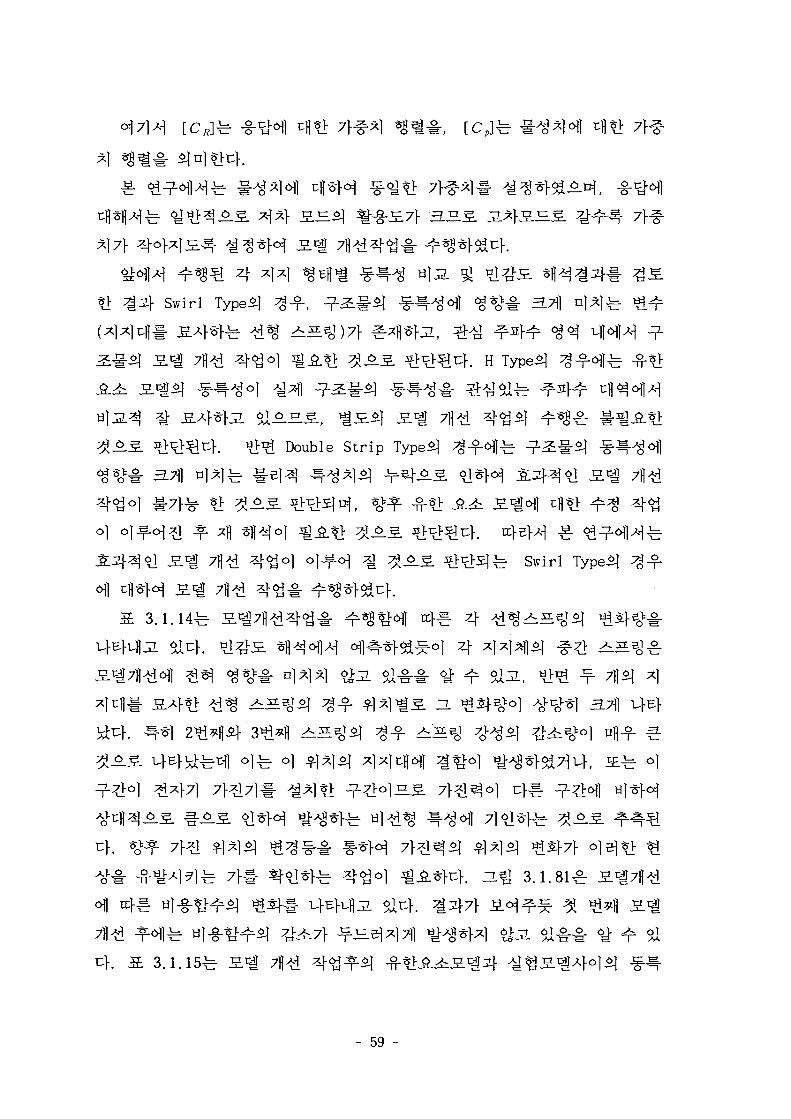
*> ^31} Swirl Type^ ^ ^ - , ^ - ^ # ^ ^ ^ - ^ ^ 1 ^ % v # 3.71]
H
Double S t r ip Type*]
<go] o]s.oj ^ ^ o . ^ ^>^Sjfe Swirl Typei]
3.1.14^
( J £ ^ o)
3.1.81^
SIX
3.1.15-
- 59 -
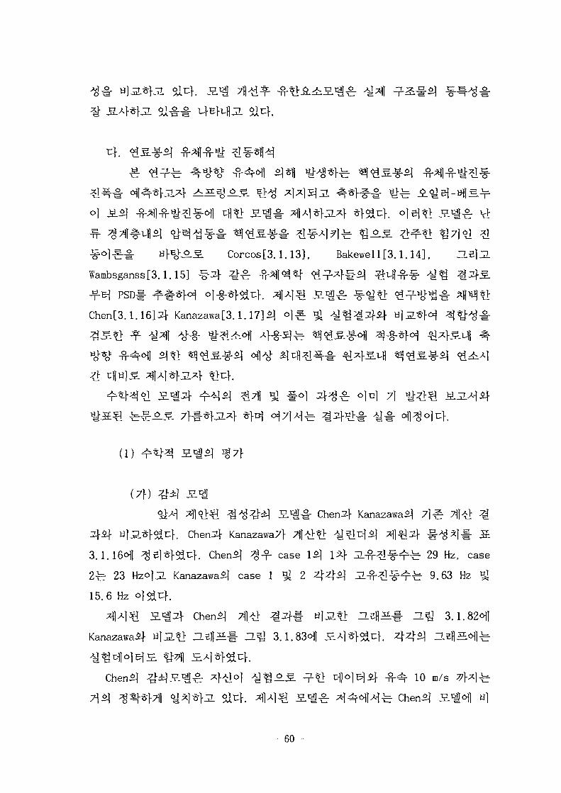
Corcos[3.1.13], Bakewell[3.1.14], H
Wambsganss[3.1.15] ^3\ ^ ^
Chen[3.1.16]3|- Kanazawa[3.1.17]51
^ ojnl 71
(1)
(7f)
^M ^ ^ ^ ^ ^ ^ i l S . ^ # Chen3L(- Kanazawa£|
ylJ^f^u}-. Chen f Kanazawa f 4^>*> ^ S ] D | ^ *fl^2f # A ^ ] # Jt
3.1.16<H1 ^e]^]-^c}. Chen^ ^ - f case I*! 1*1- J i - $ - ^ ^ r 29 Hz, case
2fe 23 HzojJL Kanazawai] case 1 ^ 2 4 4 ^ 1 JL-n-^^^-b 9.63 Hz *
15.6 Hz o]^u}.
^l^l^l 2 . ^ Chenil 7j] l ^ ^ - t til^-tl ^ 5 l 5 f HQ 3.1.82^]
Kanazawaif ti]jl*> JZeflS-t a ^ 3.1.83<H]
«]; c f l o ] ^ ^ - ^ -^ 10 m/s 77>x]^
- 60 -

10 m/s
Ml
, Coriolis^
Chen*] S^3f ^]
"L ^ 7 } # £ =Lx] $>U} o]el c]-O.^ ^ ^ o j 9]*M *ftX\& 3
•fe H ^ 3.1.82^-1 -fH r 15 m/so|Aoi-6] J J L ^ ^ ] ^ i,fEft>4.
ife ^ 3.1.82ofl^ -^ 15 m/s ol*f*j
Kanazawa*]
"l S.1- #±r - -S >ii4. 4^1^ Scl^ Kanazawa
]^fe 5 Mtel-. Kanazawafe
4K§-(Re
Kanazawa
^-U 3.1.82 3.1.83^]
. Cheni]
- 61 -
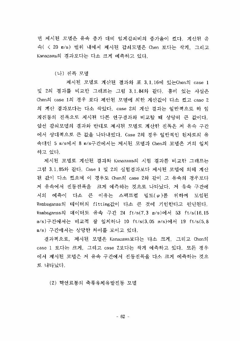
< 20 m/s) ^^] vflofl H *M3[ ^ S . 1 ^ Chen I t f e
Kanazawa5]
s 3.1.16ofl ai^Chenil case 1
n e f l S ^ a^» 3.1.84if ^cf. *nj & ^ 4>y^
Chen3] case 1*] ^ - f Jicf i | |^^l S^^J 5|?> Tfl-tf&ol cf4: ^ ^ . case 2
f. case
3. ^ ^ . ufEKH^u}. Case 25]
8
Zl^ 3.1.85AI- ^ 4 . Case 1 ^ 2^ ^ ^
si ^o] t : }^ ^An^ o] ^-6.35. Chen l case 24}
Wambsganss^ c||o|E]i| f i t t ing^ 0 !
Wambsganss3| c-}jo|Bi£ -fH*f n 1 ^ 24 ft/s(7.3 m/s)ofl-H 53 ft/s(16.15
m/s)^?];ofl^^ U)J2.^ ^ ^ ^ I * M 10 ft/s(3.05 m/s)ofl^ 19 ft/s(5.8
m/s)
case 1 ^ . c fe 371], He]jL case 2^.r:}^ ^Tfl ofl .«}jL Sit}. S ^
(2)
- 62 -
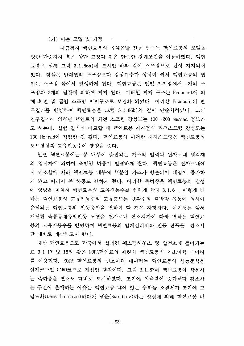
(7f)
^ 3.1.86aH
I: Premount£]
3.1.86b)if ^ o | ^V^^f^uf . ~
100-200 Nm/rad ^
100 Nm/racH
711 ^JL tt
3.1.17 ^ 185f ^ ^ r
K K0FA ^ ^ i l
h n.^T 3.1.87611
- 63 -

ofl 7) t S * i FEM 5fl^
(D ZL ] 3.1.86a)5f
3.1.86b)£j- <>1
, Chenofl 51
4 SJE.?>51 ^ ( C o u p l i n g )
-g- S . c | # FEM S.c|Sf ^}^^f. o|5)S]- FEM
3.1.17-185^ t ^ l ^ i f ^ 4 «fo4^.-g-i- *]*I^Rr ^ ^ S J ^^r^70-100
N/mm 51 ^ ^ Jl^^l 7^^JL $X^ ^1^144^1 ^ ^ ^ Ao^l- 3L3|*H
100 N/mml- ^l-g-*}^4. oj^Tll ^^1^1 ^L^-^I^^# S 3.1.19-21^1 He]
3. nm 3.1.88-91^1 £Al^rf^r>. a 3.1.19-21^]^ <g ^
Jl-n-^l-^^r^ ^.71 17.1
23.1 Hz 7 H HM
H^J 3.1.92-95^1
- 64 -
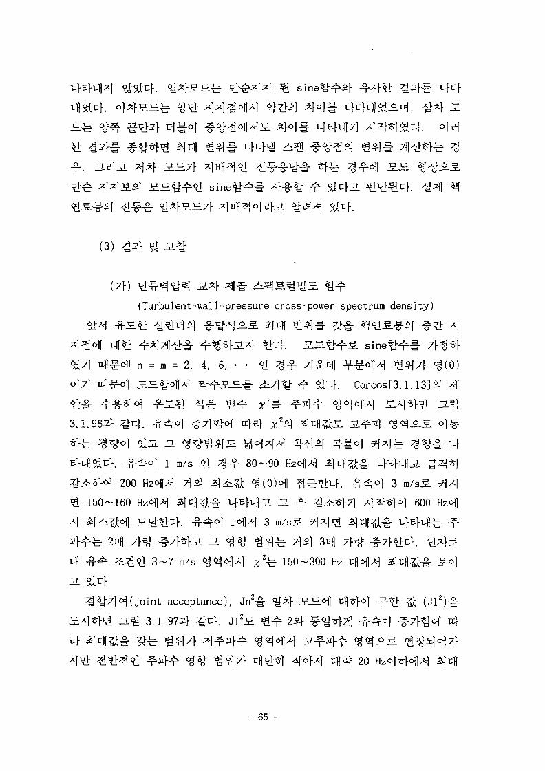
(3) ^
(7V)
(Turbulent-wall-pressure cross-power spectrum density)
^7] ffd^ofl n = m = 2, 4, 6, • • °J ^ - f 7 ^ -f- -oflA-] ^^]7f <§(0)
o|7] v^^o\] £ H ^ ^ ) ^ £ B | ^ 7 1 ^ - ^ al^K Corcos[3.1.13]Sj 4
3.1.962]-
150-160 Hzofl>H i|i:l|?]t-i- i-]- l--ufl L ZL ^ ^ ^ ^ 7 ] A ] 3 | - * H 600
ZL <$*£ ^ \ ^ 7\S\
3 - 7 m/s ^^<H|^ x2^ 150-300 Hz
acceptance), Jn2# <£%} S H i tH
3.1.974 ^ h J l 2 ^ ^n" 2if -i-^^Tfl -fMrO} ^7 f^M re}
20
- 65 -
15 m/s 7W^ £.€ -fH^W 10
~L^ 3 . 1 . 9 8 ^
30 Hz 4 ^ ^ f
rtj-sf ZL
^7}^(H1 tc>B> J 3 2 ^ <y*> 4
40 Hz ^ ^ o | H J32
0.2, jq>fc 0.015] ^ # u
55} 8 m/sofl^ 7i]^t
^ ZL^ 3.1.99 91 1002]-
8 m/s-g- JL^
5 m/s6)}*\ 8 m/sS.
103~104
(Uf)
200, 600, 1000,ZLelJL 1200
3.1.1013]-
a^J 3.1.10251 ^ ^%t
- 66 -
ZLB] 3.1.103^
16.3
^- 0.01
0.02
^ol|A-| 7J--&1-71 Ttfi -off, HBJJL H ^ 3.1.99 ^ lOOo]]
100 Hz o)^3] ^ 4 ^ cH^^. ^1^-^1^-ofl 7 l ^ « f e V}7
^]}S. n^*k n^ 100 H z o ] ^ ^ # JL
y J 240 Hz7}^l *J^-t> ^ ^ - ^ 110 Hz 7}^j *j
ZL 4°lfe
ZL5] 3.1.104^
PSD7} ^ x ] ^
- 67 -
^ ^ Westinghouse^
Rubbing, Tapping, Impacting^! Whirling
xcfl
^ o.^ 3.1.1074
- 68 -

(2)
(Semi-infinite Body) ^ ^ ^ ^ ^ l (Infinite Body)S 7}^f>}3_ $X^\
3.7]7} - -*V«1 ^-f<y 4^1 Fourier Transform -§-# %
(7f)
Hertz
^r Hertz ^ ^ ^ ^ «H^# #^f<^ ^ ^ 5 ] f e *H
Verion 5.
Contact Element^]- Modeling
ANSYSoflA-] 4 ^ - * f e ^ ^ - f i ^ t ^ , C0NTAC48 r Solid bodyi-f
, flexible-to-flexible body, rigid-to-flexible body-S] ^^~
L al4. C0NTAC48 A ^ ^ * > ^
"Contact Surface" BfJL ^ ^ ) A o^ t> 7fl node5|
- 69 -
(ANSYS .3JS.61H "Target Surface"efjL ^ 5 ^ ) ^ -r" 4 nodeS
*} 3-node _S.-fc°M, 3*}^[ ^ M 4-§-*fe C0NTAC49
Contact Surf ace Aov- t l >H nodeif Target Surface *££[ 3 7fl node SE-fe- 4
7fl nodeS ^ l ^ o i * ! 4 S f e 5-node
Hertz
# , Ao^^l Contact Bodyfe ^ ] - | - o ] 10 mm«>]n|, Inc-718^ # ^ ^ ] S ^ £1 =
20,000 N/mm2, Vl = 0 .29^ Zry-4^| ! " $ * ] , £> = 98,100 N/mm2, y2 = 0.29
-T- 7MS *}$i-c} olofl cH*H *HN!J Target Body^ ^ ] # # 13
= 98,100 N/mm2, v2 = 0.29)#
^ S . ^ 20
^ ^ ^ 4 1 ^ 10 N-i-
K °1# ^ H Contact Surface*] Top lineAo^ S.^
n o d e # # Coupled node setJ5.S TT<>H tfe-S x}-^-S(D0F)°>^- 7 } ^ ) £ 4 ^^g
^f^u} . HB]JL Contact Surface^- Target Surface^).*-] ofl J-3c|-fe- 3L7) ^^~
-T-S- ^^1# refine ^
3.1.22-b ANSYS S £ i oj*> S f l * ^ : ^ Hertz
Hertz
3.1.108^1 i ^ ^ i : } . ^ 4 ^ ^r^1 -§-3, ^ Hertz-§-^, p(y)^- ANSYS
- 70 -
3.1.108^ S 3.1.223]
o]i:V. ZL^ 3 . 1 . 1 0 8 ^
ll Node
ANSYS 3 . ^
(uf)
^ Hertz <>!-§-
^ 1 ^ : J£ 3.1.232}
0.305 - 0 . 6 5 m
37171-
Hir 0.725
3.1.24^1
^ 14X14
16X16 ^ 17X17 ^ 0.64 mm
"ATil
- 71 -
3.1.24-fe-
ANSYS
# 0.00625 mm . ^ } $ 1 ^ L H S
0.00313(= 0.00625 4- 2) mm
^ N o d e A].o]^ ^ e]
TT S 3.1.243]
3.1.245]
3-T-lr 3 . 3 j * ^ , 14X14
0.725 = 0.198°H, 16X16 ^ 17X17
x 2 / 0.64 = 0.
1/5
3.71 (
(0.06875 + 0.00313) x 2 /
^ - f (0.05625 + 0.00313)
SH o]4
(3)
5]fe
- 72
5a
^^J- ^ 4 ^ 1 -&*i|(mixed boundary value problem)7f
H*Q 3.1.109if- ^-^r 2*}Q £ - * H M ^ Flamant Potent ia l^ «
Flamant Potent ia l^
<Z>F = ArOSind (3.1.12)
: 2
S ^ ^ (traction)^
[3.1.9].
d e J 3.1.109 %^) 4 £ ^^i (^^>) -§-^°)^, u 91 4 4 y
- 73 -
(3.1.13) £ (3.1.14)^- y= £ <y 4 s .o)^ (singular point)!- 7f
4 £ 71^1 ^ ^ Kernelo] i / ( y _f ) ^ Cauchy^olHS. Cauchy^ J=-
:yo^^(Cauchy Singular Integral Equation Me}. ^-7] ^-oj :*]«- *£
3 i £ 2 *R1 ^ €"*!# *l«H*Rr 7 ^ 7 ] ^ o j «o^^o]uK A]
(3.1.13) ^ (3.1.14)5^ Sflfe ^ ^ - ^ ^ . 5 . ^^sfl(exact or closed form
solution)!- ^*l-7iT~K3.1.2O] ^ ^ ^ j ^ ^ S -7-tl4[3.1.21].
7)
^ . j a c o b i polynomial^
r ^ i*-^ 2
(3.1.13) JE
al-^-^ oil- ' S W T ^ (The Influence
Function Method)ole}
(4)
(7f) o-o
(profileH
- 74 -
*H
-^, 9(y)7f n}^ -g-^,
4
^^-(piecewise continuous)ol
2c?o] o]= .^ ^ 4 ^ ^ ^ -g-^ ^.^f. ^51 3.1.110^
lfe (2S -6o>
}JL)S. %• (2S -
collocation point#o]c|-.
transverse direction, H^ 3.1.110^1
ii ^ ^ o M axial direction, ZL^
- 75 -
y = nth Triangle)
qny{ £ ) = qny(\ -
I f an/5, rfl- a/SS. 4 4
J I+ constant.
(3.1.16)
(3.1.16)^1
(m— w— I)2 ln(m— n— I)2 —— w)2ln (m— n)2} + constant.
(3.1.17)
o)
(3.1.17)51
S im-n+I)2 In (m-n+I)2 +
(m— n— l)2ln(m— n— 1) —w)2ln (w— n)2} + constant.
(3.1.18)
- 76 -
-7- 1 M (3.1.16)^ ^ ^ s ^ ^ l ^ ^o^l ^ 3 SI
(transverse direct ion) £.£. $*\ *Ji£ *}^-o] 3]-§- - 4
o l ^ ^ 4 ^ ^ - S ** tt)l^ " ^ ^ M ^ M ^ (3.1.18)^
°l-§-*}7) ^-1*H ^r^: r^^l ^^^^(discretized influence function)©]
7]el
= - Qx (3.1.19)
(3.1.19)^-
(3.1.20)
/ rx /~» ' (3.1.21)
Modulus)#
. ^ ^ (3.1.20) Sl-^^M ^ur /e>x-= 0
- 0) ^1# i^^f^.^ r
(3.1.15) «HlA-| (3.1.18)
- 77 -
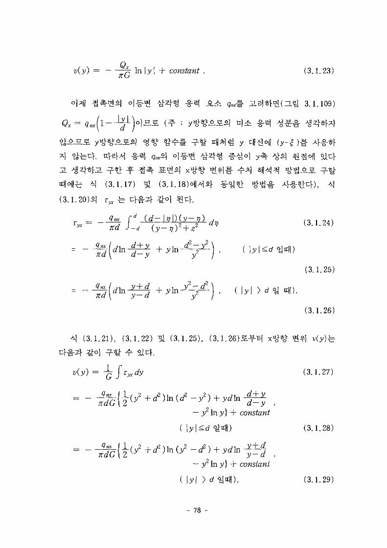
v(y) = g- In \y\ + constant . (3,1.23)
- L ^ 3.1.109)
y
^r *| (3.1.17) ^ (3.1
(3.1.20)51 rjK -b 4 # ^ } ^°1 ^ 4 .
d (d-\v\){y-v) (3 .1 .
\y\<Ldy
(3.1.25)
(3.1.26)
(3.1.21) , (3.1.22) gj (3.1.25) , (3.1
(3.1.27)
— 3 2 In 3;} + constant
(3.1.28)
— y2 In y] + constant
( \y\ > d ^nfl) . (3.1.29)
- 78 -
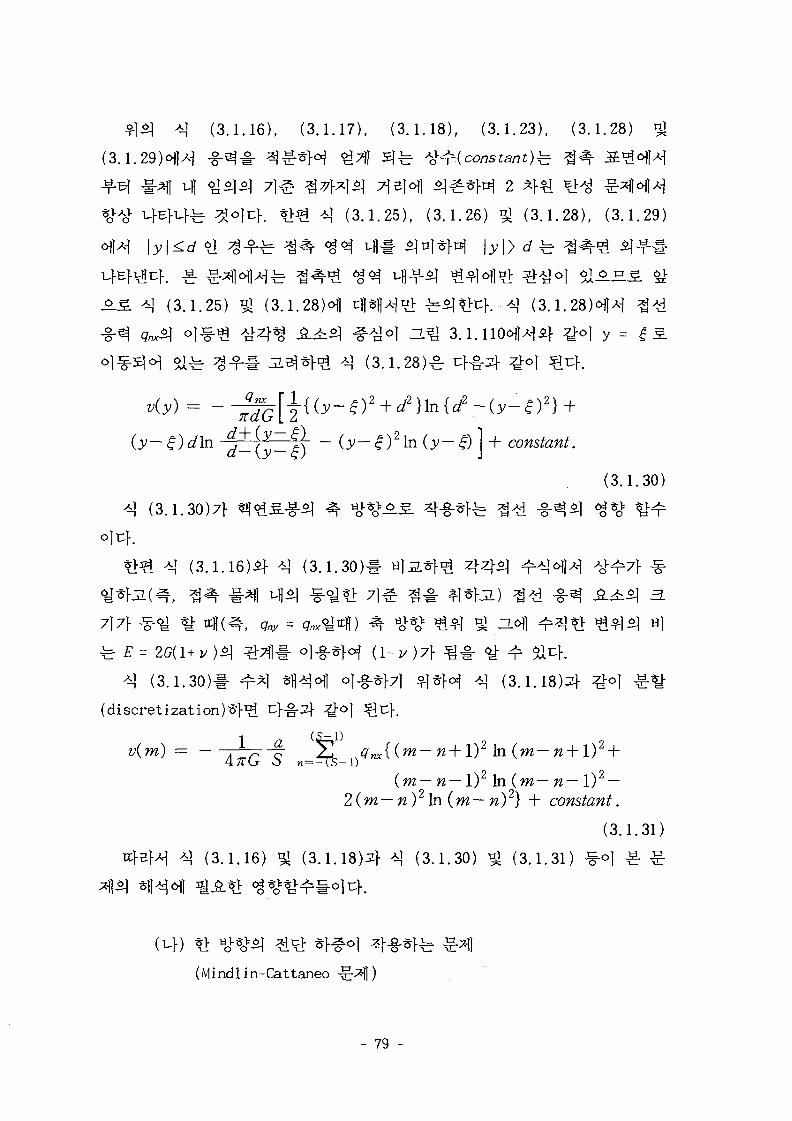
( 3 . 1 . 1 6 ) , ( 3 . 1 . 1 7 ) , ( 3 . 1 . 1 8 ) , ( 3 . 1 . 2 3 ) , ( 3 . 1 . 2 8 )
(3.1.29)ofl>H
*] (3 .1 .25) , (3 .1.26) 91 (3 .1 .28) , (3 .1.29)
(3.1.25) £ ( 3 . 1 . 2 8 H
y =
^ (3.1.28)^
(y~ (y- 6) ] constant.
(3.1.30)
(3.1.30)7}
(3.1.16)*]- *] (3.1.30)
7]7f
±f E= i ) \ l l ) g
M ( 3 . 1 . 3 0 ) # ^ 1 ^ H ^ ^ l <>l-§-*}7l
(discretization)^}1^ ^-5-2} ^
]
(3.1.18)2}
v(m) = . n -§• 4] Q^Km—n+I)2 In (m—n+I)2 +47T(_r O w= —(.S'— 1)
( m - w-1) 2 In ( m - w - 1 ) 2 -2(M—w) 2 ln (m—w)2} + constant.
(3.1.31)
(3.1.16) ^ (3.1.18)2} ^ (3.1.30) 91 (3.1.31)
(Mindlin-Cattaneo
- 79 -
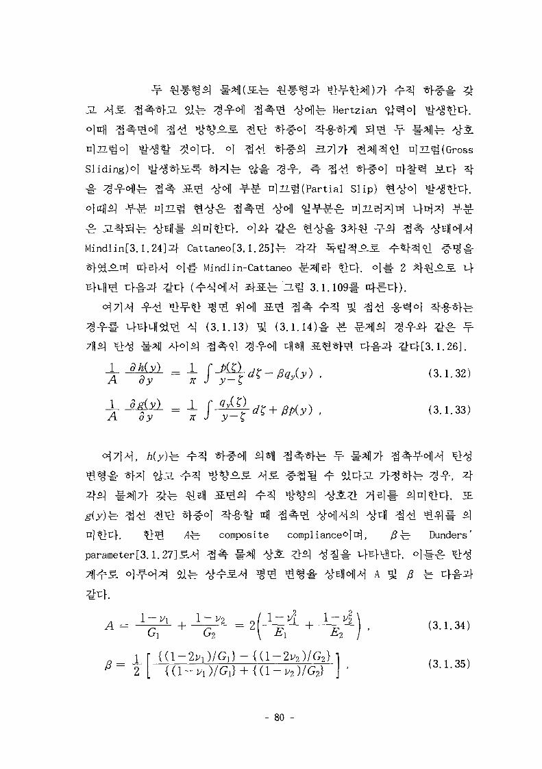
J2. OUir fe Hertzian
3.7] 7\ 21^[(Gross
Sliding)o]
(Partial Slip)
Mindlin[3.1. Cattaneo[3.1.25]-b
]^. Mindlin-Cattaneo ^^z} ?>t:f. o|-§. 2
^ a ^ 3.1.1091- ccf^-uf).
(3.1.13)
(3-1-33)
^ composite compliances]!^, ^^- Dunders'
parameter[3.1.27]5.>M ^ ^ #^1 5l 4 ^ A ^ #
(3.1.34)
1 [ {(1-2V 1)/G 1}-{(1-2V 2)/G 2}
2
- 80 -
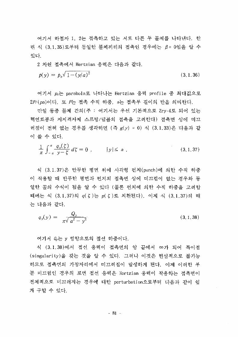
(3.1.
ntii tz, i CLII ^ ^ ^ ^ '-'1 X3 " n
) 2 (3.1.36)
fe parabola^. L.}E}uj-fe Hertzian -g-^ profile
g(y) = 0) *| (3.i.33)£ ^f-i-
(3.1.37)^ ^ t i ^ ^ ^ofl 4 4 % ^i^l(punchH
(3.1.37)^ q(^)fe p ( £ ) S ^ m ^ c } ) . o]4 AI (3.1.37)51
Q2 2 (3.1.38)a - yz
(singularity)^ ^ ^ ^ # <y- ^ ^uf. ZL^uf o ] ^ ^
n]7i^o] ^ .o . ^ S ^ ^ A I ^ . ^ ^ Hertzianperturbati
- 81
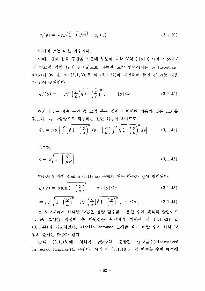
(3.1.39)
<^<^ ( c < ^ perturbation,
q'iy)7\ (3.1.37)^1
(3.1.40)
c = ay 1 — (3.1.42)
2 ^}^J Mindlin-Cattaneo
(3.1.43)
(3-1-44)
(3.1.43)
(3.1.44)^]- ti|J2.^^cK Mindlin-Cattaneo
® ^ (3.1.18) 1
influence function)# . °M *\ (3.1.18) 4 "r#
- 82 -
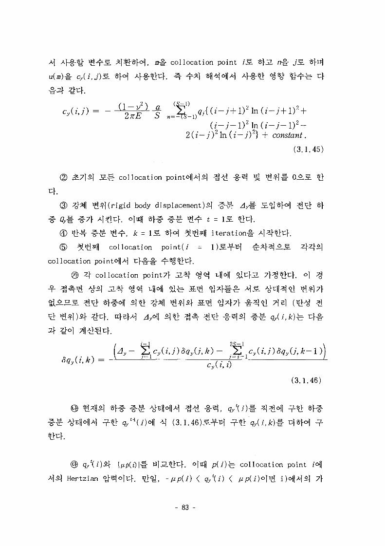
collocation point iS. t\3L rr§r jS.
(i-y-D2 in (x-y-i)2-2(i—j)2\a(i—j)2} + constant.
(3.1.45)
collocation
rigid body displacement)^
^luf. o]irfl ^rf^ ^ ^ - ^ t
^^ r , A: = IS. * H ^«i^H i t e r a t ion^
collocation point(i =
collocation point^A| c f^-# *J*>r:f.
@ 4 collocation point7f JL*$ <
cy(i,j)SqyU, k—\
(3.1.46)
. o|ic|J p(j)fe collocation point H
Hertzian ^^ojnf. nf^f -^p(i) < g/(i) < ^p(i)o]r^ ijofl^sj 7f
- 83 -
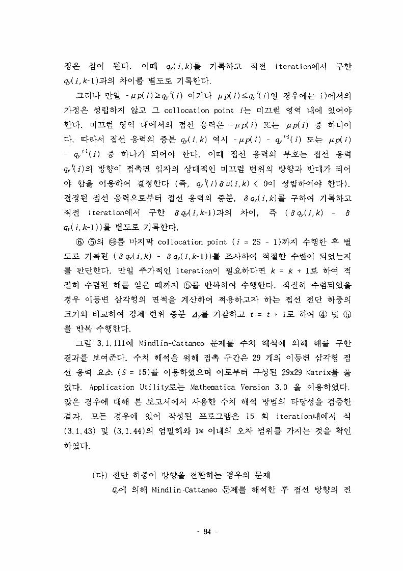
iteration^
ZL collocation point jfe- n|ZL tjofl
(dqy(i,k) - 8
nWn-l collocation point (i = 2S - \)7?\*\
(dqy(l,k) - 8qy{i,k-\)m ^ 4 * M ^ t ! ^
1 iterationo] ^^L^cf^ Jt = k +
£ =
Mindlin-Cattaneo l#
K r l *H-i- 1*11 4 -££: 29(5 = 15)1- ol-§-*f&AB} o)£.^tf ^-^^ 29x29 Matrix
Application UtilityS.-^- Mathematica Version 3.0 -§
^ 15
# #
(3.1.43) (3.1.44)51
(-D})
Mindlin-Cattaneo
- 84 -
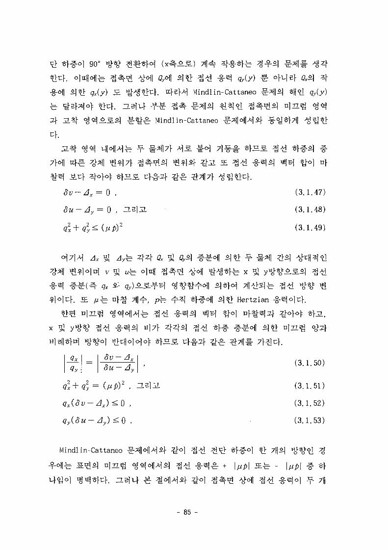
*}%•*] 90°
Mindlin-Cattaneo
^r Mindlin-Cattaneo
^z;-Z/x - 0 ,
8u- Ay= 0 , a
u\
(3.1.47)
(3.1.48)
(3.1.49)
±= 4 4
Hertzian
8u-Av '
Q2x+Q2y= (UP)2 . ^ -
qy(du- Ay) <0
(3.1.50)
(3.1.51)
(3.1.52)
(3.1.53)
Mindlin-Cattaneo
- 85
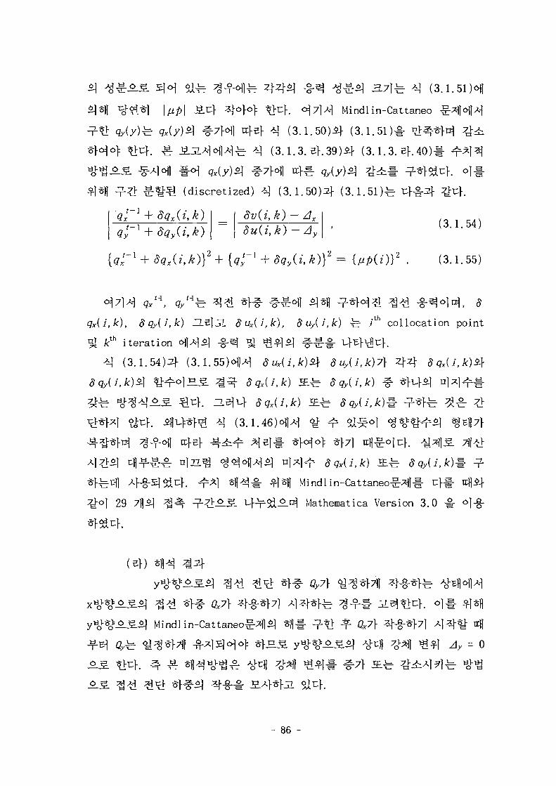
i
-fotf-b 4 4 4 -§-3 A J^4 3.71 fe *] (3.1.51H
4°}°) t M . ° 7]A-] Mindlin-Cattaneo ^ H H
4 4 ^ (3.1.50)5} (3.1.51)# °1
fe (3.1.3. e>.39)5} (3.1.3. ef.40)1-
(discret ized) ^ ( 3 . 1 . 5 0 ) 4 (3.1.51)^-
3v(i,k)-dx
8u(i,k) -Ay
y~l + 8qy(i,k)} =
(3.1.54)
(3.1.55)
, 8
qx{i,k), 8qy{i,k) H
^ y th iteration ofl
^ l (3 .1 .54)4
8ux(i,k), 8uy{i,k) ^r i1 collocation point
8qx(i,k) JEi, 8qy{i,k)
dqx(i,k) S ^
29 [ A ^ Mathematica Version 3.0 o]-g-
0,7}
- 86 -
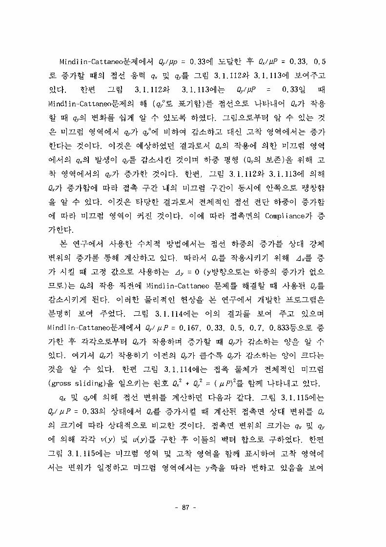
"A gy#
Mindlin-Cattaneo^HM Qy/pp
£- &}*} *fi^ 3 # -§-3Sa K t>^ H ^ 3.1.1124}Mindlin-Cattaneo<g^|Sj Sfl ( q / 5
^ itfl g y ^ ^ 5 } ^ x | 6^ ^ ^
*. n )22^ ^^cHlx-1 qy7\ qy°6\] HJ
= 0. = 0.33, 0,5
3.1.112*} 3.1.113^]
J l
QX7\
T . ^ 3.1.112^} 3.1.11301]
Compliance7f
7f A ] ^ ttfl § f e Ay = 0Mindlin-Cattaneo
^ ^ c f . ZL^ 3.1.114^)^ o|o|
Mindlin-Cattaneo-g-*fN>M Qy/ pP = 0.167, 0.33, 0.5, 0.7
(gross s l i d i n g ) ^ ^ A
Gy//zF = 0.33^
+ Qy2 =
O.^ 3. l.HSoflfe- nlzz.
- 87 -
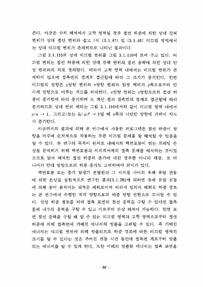
O.^ 3.1.115*]
(3.1.47) ^ (3.1.48) n | n
3.1.116*11
H 3.717}
AfTfl #»<>**-
^-o] n)T7.^
y / a fe Qx/
28H
91
- 88 -
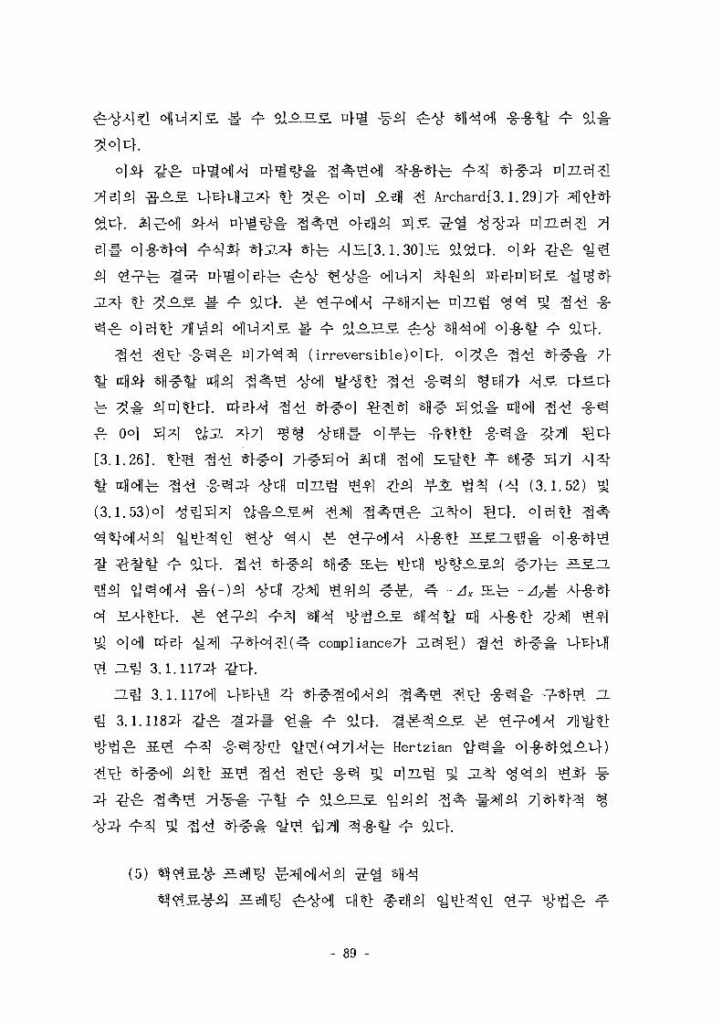
*> # £ o]n] .Efl *l Archard[3.1.29]7}
1^ (irreversible)°]t]-. °l^^c: -tl'ii ^ 1 " ^ ^ 71
[3.1.26].
^ ulN-b ^ ^ i - § - ^ 4 ^ 4 °)T7^ ^ ] ^-o] « . ^ ^ * | (>o (3.1.52)
(3.1.53)0]
-Ax JEfe -
ojofl ucJ-Bf >y^] ^ ^ o ^ ^ l ( ^ . compl iance7f
ZL J 3.1.1172]- u>.
n ^ 3.1.117^1 i Ef^fl 4 * f # ^ ^ > M ^
3.1.11831} ^ - ^ | 3 } | <M - oiu}. ^ ^ ^ ^
^ V l ^ H ^ r H e r t z i a n
- 89 -
WestinghouseAf r£ ABB-CE4
ofl,
01 *
^[3.1.33-35]
- 90 -
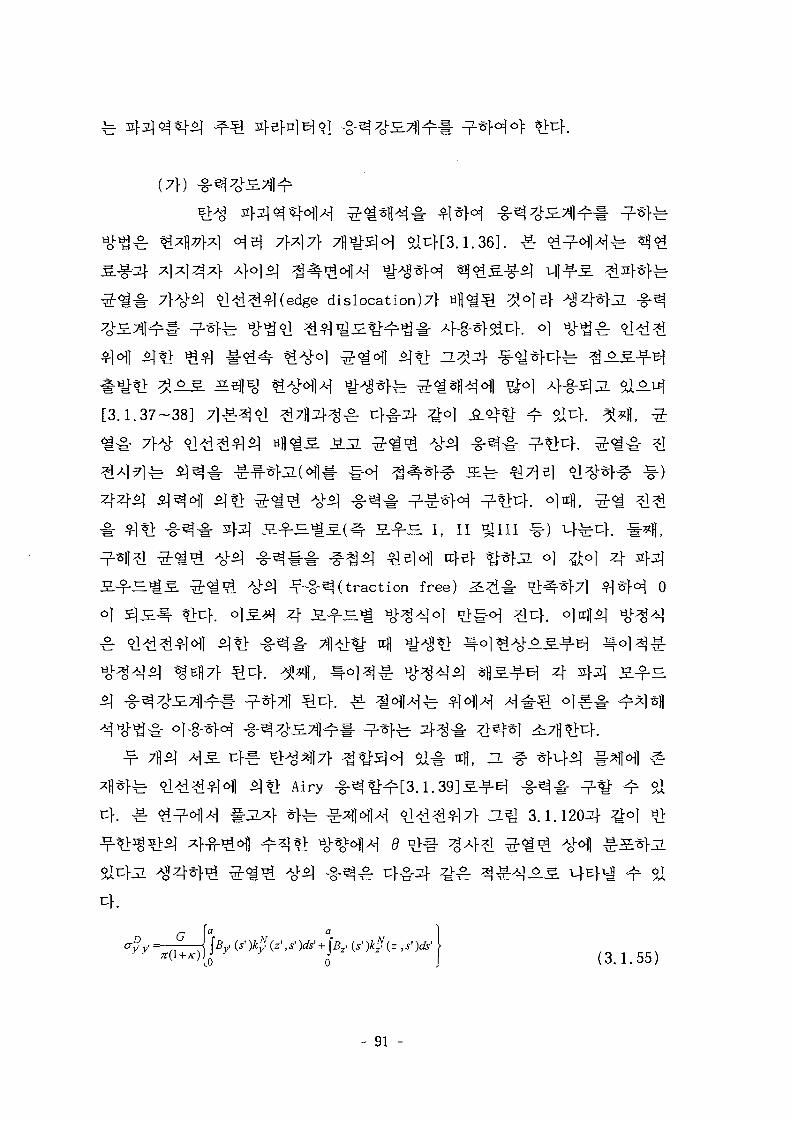
(7f)
edge dislocation^}
[3.1.37-38]
d ^ l ^ *W£- JSL2.
3> ^*fjL o] ^o] 4
^-§-^(traction free)
-§-3§•
4
Airy -
a^J 3.1.1204
( 3 ^ 5 5 )
- 91 -
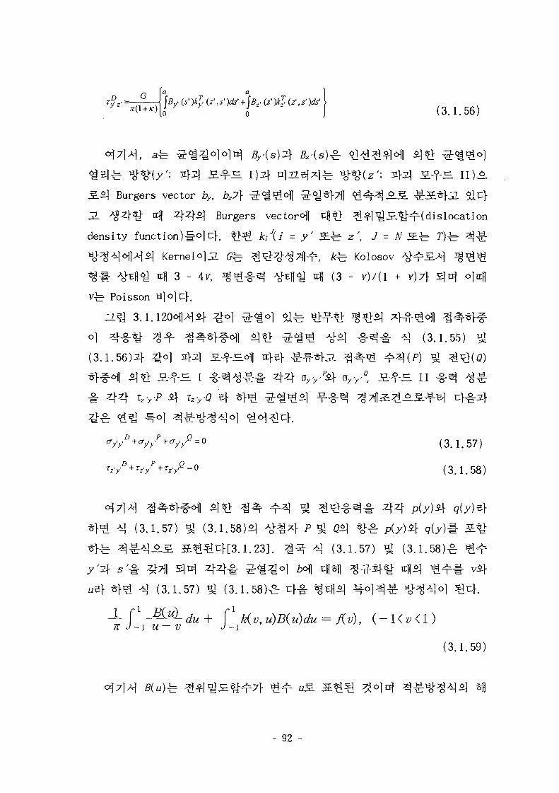
r ^ j(3.1.56)
Burgers vector iy, ^7]- ^-<
3. ^ 4 ^ - ttU 4 4 S ] Burgers vector^] c|Jt> ^ l^S^HHdis loca t ion
density function)#o|uf. *>^ k/(i = y ' JE^ z', J = # i £ ^ 7 ) ^ ^ §
KernelolJl e ^ ^ ^ 4 ^ ^ 1 ^ r , k±= Kolosov
til 3 - 4v, ^ - g - ^ i > E||<y xcfl (3 - v)/(l
vfe- Poisson «]o]cK
-S-^l : *} (3.1.55)
(3.1.56)^- ^ o ] 2}3q a.-fS.ofl rc}e}
S ^ I -g-^^-gr-i- 4 44 4 T r rP 4 rz>'0 e}
v / = ° (3.1.57)
y e = 0 (3.1.58)
# 44(3.1.57) nj (3.1.58)4 A o ^ 4 P ^ Q^ % ^
(3.1.57) ^ (3 .1 .58)^
A] (3.1.57) * (3 .1 .58)^ c}-§- ^
1 _ f e L j M + f1 k(v,u)B(u)du= f(v), ( - K v < l )7T J ~\ Zl V J — 1
(3.1.59)
- 92 -
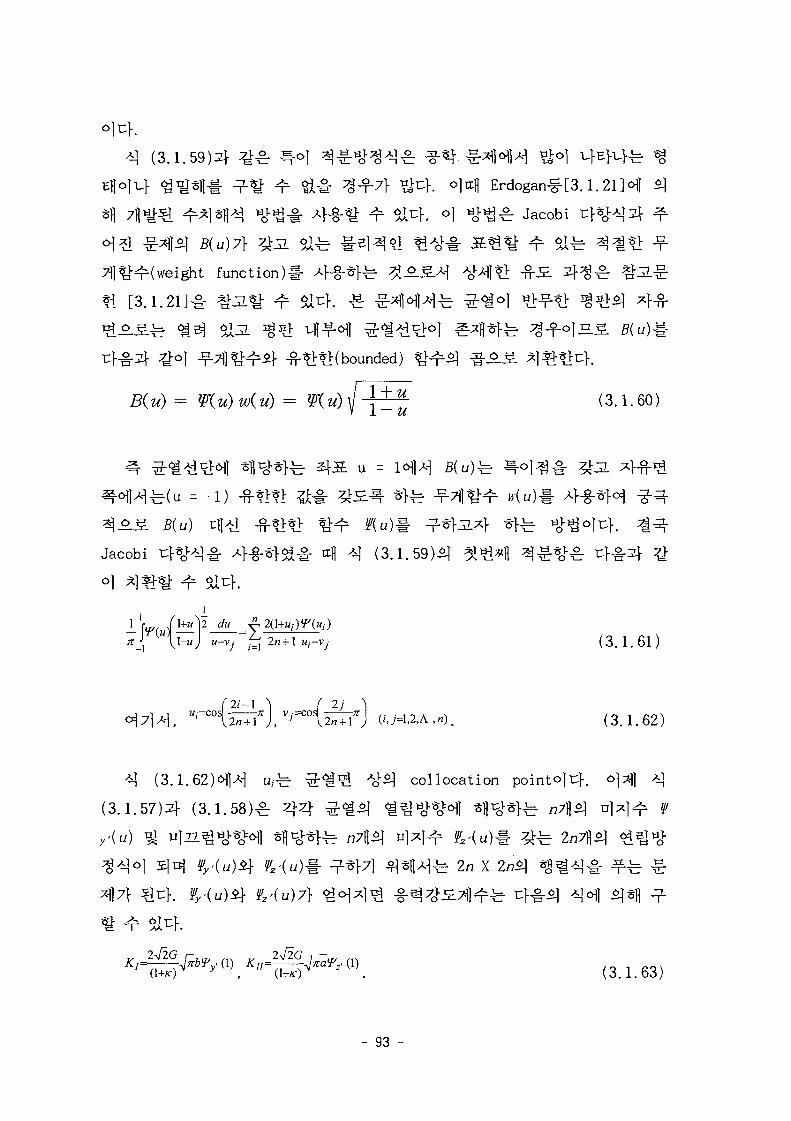
(3.1.59)4 %£ J=-o] 3Erdogan-^[3.1.
weight function)!- 4-§"*1"fe
[3.1.21]-§•
-*>*]:(bounded)
^ ^ (3.1.60)
1Wfe 1 U =(u = -1) -
Jacobi t H H # 4-§-*f^# 4 -n (3.1.59)-^
— vriul\-u) u-vj fam + lu-vj (3.1.61)\\-u) u-vj fa
*] (3.1.62)^]^ u/fe ^ ^ ^ j-51 collocation
(3.1.57)4 (3.1.58)^ 4 4 ^ ^ 4 <
- 93 -
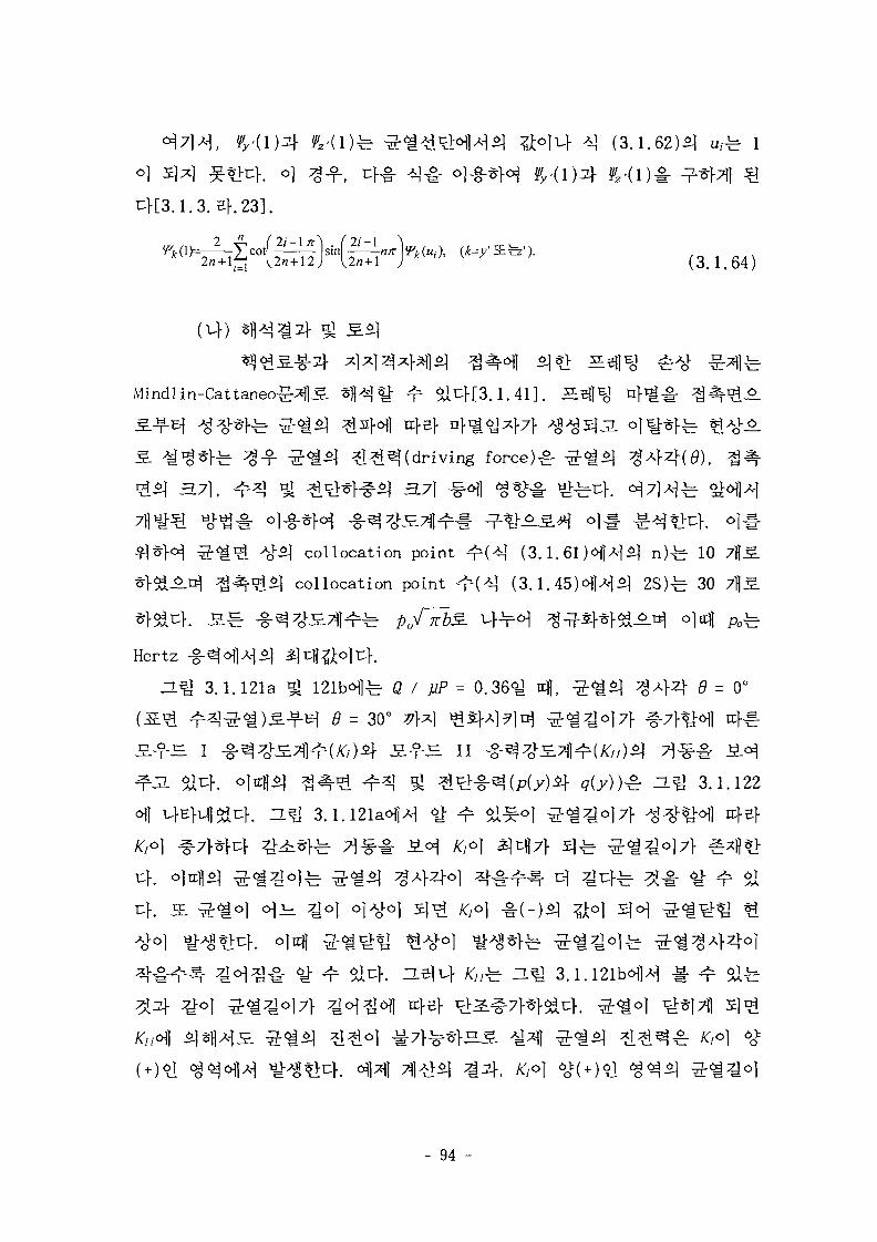
(3.1.62)^1 u,±r
B}.23].
(3.1.64)
Mindlin-Cattaneo-g-^S. .1.41]. ^
3.7], 37]
collocation point
collocation point
(3.1.61 M*\£[ n)-b 10
( 3 . 1 . 4 5 ) ^ ] ^ ^ 2S )^ 30
Hertz -
ZL J 3.1.121a
- ^ I
fe- Q I fiP = 0 . 3 6 ^
= 30° 7}x] ^ } ]
/ ) i f S-fJS. II
= 0°
^ ^ . ^ 3.1.122
3.1.121a<HH
uf.
- 94 -
H ^ 3.1.123^]
3.1.124aif
3.1.121aoflA-| S j c ^ AT7O] ufEfu> ^ - ^ ^ o K a / i r = 0.0015)
-Ei 711^1^ Kl2\ Kir$] 7 i ^ # ZL^ 3.1.124bofl
3.1.124b5]
nfloflJE. ^ ^ ^I*f( fully unloaded) 5] 7] ^ ojn] ^ < ^ ^
Elber [3.1.42]^ 0)^3}
0.07 - 0.1 mm o]jn
3.1.121a ^
> 0) ^ r ^ o ] - ^ tH7j|
^ [3 .1 .33]o | AISI 1020
5 mm ^JE
(3.1.65) [3.1.43]^! tfl^^-g- 2I-M.3]- 4 ^ 0 ] Zircaloy-4^1 ^-^^-E-O 320
^ 1/100 ol*K§.
rrfl H
- 95 -
}. 4434
(1) 4434 4 4 ^
(7}) 7JJ
ABAQUS/Standard
44^-^44^4
44^4
4
-l^r 4 4 ^ 4 4 4 ^ - ^ tg^o] 3.7]ofl Hl*H
n^J 3.1.125fer 3077flo|j7 ^ . ^ 5 ] ^ - ^ 1707flo]uf.
fe 186.8 GPa, S i f ^ t i ] ^ 0.33Lf
- 96 -
3.1.126ofl
(Uf)
H H W I ^ B }# ^ 45
-^-^l, c) 4 ^ ^1-fe 0.7a^J 3.1.127^1
L*U 3.1.129(b)ofl
(2) *1
(7})
0
- 97 -
3X3
ABAQUS
4
- 98 -
(uf)
i furcation
-?-^## ^ ^ 1 ^ : 4 ^ -g-^^(bending
i£fe ^mmembrane force)c^l ^ S .
^•(column) ^ - ^ 3W 7O^ ^ p . ^ ^ . ^ cf la^o] <^]o)u}. o) ^ - ^ 1 - ^ <^^|
$\2_ ^ 713]
fe^j ZL
imperfection)^] 3.7]}
- 99 -
7]
RIKS
*BUCKLE
^ ^ 3.1.130^ ^
- 100 -
^ 4 4 5567fl£} 21567flo]uf. c]
3.1.
-fl edges
2)
^ y
]-b x, y, z #
*Rr 4O.^ 3.1.
711
- 3 '
*}*}. ^ ^ '3711^^-2' ^ edge 2<>fl
edge 2 ^ edgel
4 3C-11 4
4
3.1.1323] 43 4
- 101 -
zj-
3X3
7} <&^-B. coarse model•§• 3 X 3 5 . JL-R-
coarse
5X5
7} &Ai ^ coarse model# 5x55.
coarse
7X7
11- coarse
EL7]o\\
(•c\) t i ] ^
- 102-
3
^ 7]
5-50 % *$5L 3.7)5]
snap-through
ZL J 3.1.130ofl i ^ 4 . 4 3fe 0.6 mm}
^ 4 4 1688 7flif 6008
711 cf.
iA-uf o] 4
3.1.13351 '
2*1- 3S.(secondary path)#
- 103-

4
3.1.135^1
2600
*-Mesh-14 ^ ^
44t!4. 444
Mesh-1# 3X3
3X3^4
^4^14^AS 44 ^
4
44
. 3X34 5x
^ 4 1 4 4 ^ Mesh-
444 ^# ^3.1.1364 14
5 44^1# *«©..£. ^ 1 -y^# 4^4^^-^! 44 ^
^ ^ 3X37f 23527114 91447flo]jL 5x57} 58807H4 227287floluf. D.Q
3.1.1374 3.1.138^fe 4 1 - S 1 4 ^ ^ ^ 4 - t Ji^^cll ^Tll ^ # 44
- 104-
^ ZL ^ ^ t g ^ o ] Uj-H.711
£ T.^J 3.1.139^1 £Al*f$iuK o)
o)
-f- -11
- 105-
^ 3.1.1405]
cfe]
sa
0]
3.1.142^1
3.1.143^1 Bi}
fe Bi} C
1- ^ $au>. oil- n
^ S . ^7 ]
fe 23537J1 Zi
3 x 3 ^
#7^1-71!
sa
- 106-
^ 3.1.142^ Ji^o)
^ . ^ 3.1.1302} ^ " ^ J
i f ^ ^ ^ ^ 7 f 4 4 55671)i}
(adaptive modeling) a ^ 3.1.143^
fe 4 4 748, 27967Bo]u}.
*><H ^.H 3.1.144^1 J5L£r:K o] Ttfl
4 4 16887Bif 60087flolt:f. nfeM
4 4 0.44, 0.
3X3,
3.1.145^ 4 ^ 7]
-l^J 3.1,146°fl
- 107-
(3) 2j
(7f) 7fl
ABAQUS/Explicit 5 H
-g.
3.1.147^: 3X3 ^ ^^ ^ ^ 1 ^rfe 329671]o]JL ^ . ^ ^ > ^ 23527l|o|i:K
^ f ^ # O)S.JL 6)^. ^fl^oi ^.EflSleil^i-jq ^ £ - l>^7fl^fe 186.8
GPa, ^ i ^ t f l i r } ^ ^ ^ f l ^ ^ ^ U l \ ^
n^» 3.1.148ail
10
- 108-
0.1
40 ms-t nfl 2 msnj-uf
0.1
o.4O
o)
3.1.1494
3.1.151^
0.40 m/sec<H Ttfl 5457 N«>1 #3., o]
8 mso)^u}. ^.7]
0.40
H ^ 3.1.150ofl -ufEfa^u
von Mises
. H ^ 3.1.152^
c]
7] ^ ^ ^ o ] o]
- 109-
^ 3.1.153
3X3
^ ^ 21
4.
7}.
(1) 7j( ^
*1*J2}*!-,&} ^-^ ^ ^ ^ ] ^ ^ r i -Mj ^^5 .^1 4^.^H(Seismic
and LOCA) S«g 7fl1|Mr ^]t> 7]Ji ^ £ 5 . 4-§-^^F. °1 4 ^ ^ ^ * } ^
A?> 4 4 ^ 4 ^ 1 -^^1 # ^ ^ - ^ S ( impact stiffness)7>
^^-(coefficient of restitution)#
- 110-
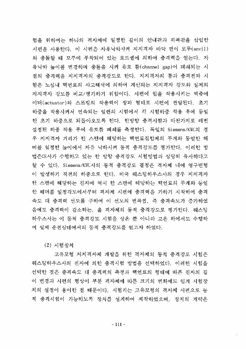
rgo] S.^-(anvil)
(channel gap)o)
)^(actuator)^ ^ i ^
el71- *> ^ofl sf l^*^. ^ « ? 1 ^ ^ ^ I ^ ^-7])i} ^<y*> sfl
K Siemens/KWUAfi] ^ . ^ ^ ^ ^ £ ^ ^ ^ ^ ^ ^ | uflofl
(2)
- I l l -
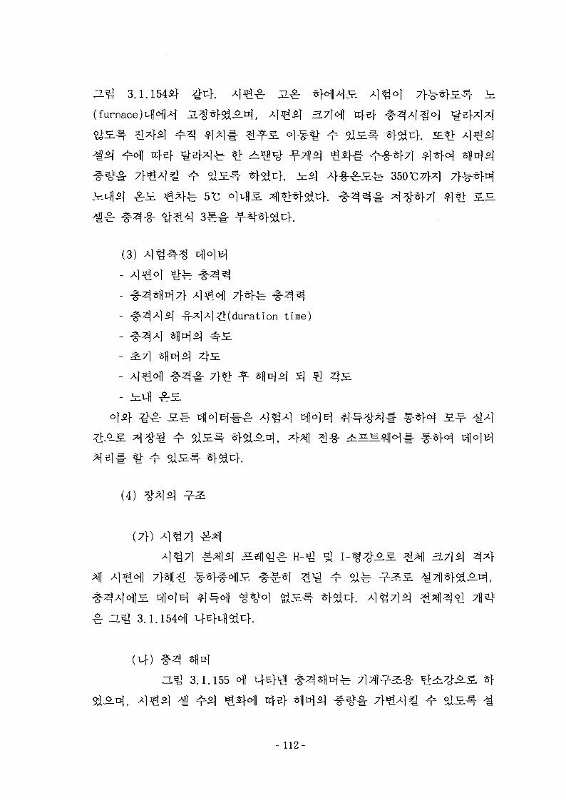
H ^ 3.1.1544}
(furnace rcfef
(3)
A] (duration time)
0)3} 7^ S ^
(4)
(7f)
H - ^ 51 3.715]
Z151 3.1.154<H1
3.1.155
- 112-
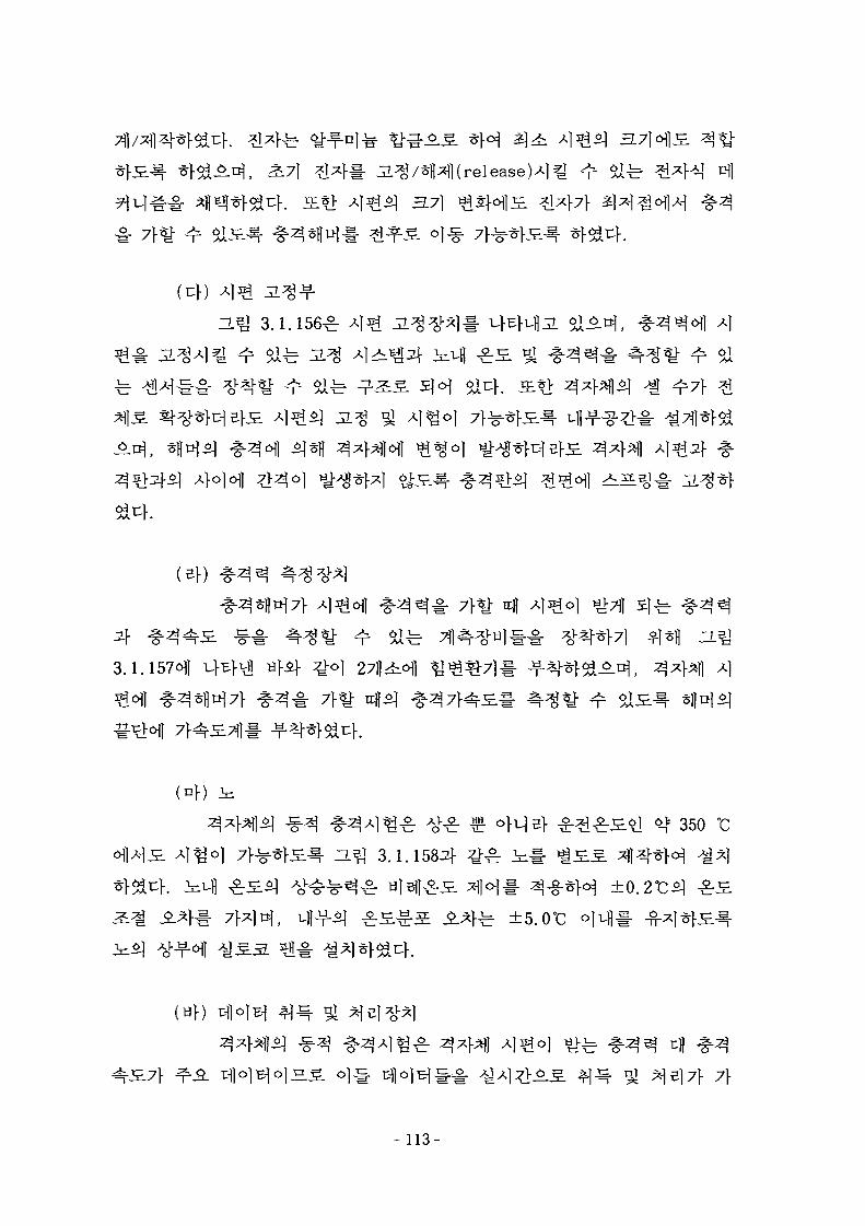
3.7]
-§•
(ef)
7}^" Ufl
3.1.157011
350
ZL^ 3.1.1584 ^ V ^
fe ±5.0°C olvH#
(yf)
- 1 1 3 -
3.7}
71STAR accelermeter
multi-channel analyzer*]
HP
IDEAS T-DAS
shakerl- -T-nfl*} !:]-. shaker^
^ Wf^- ^\^}^v\. Shaker5f
Power amplifier
- 114-
3-Q 3.1.159
3.1.1602}
3.1.161 oil
-; ofefl^
550 x 550 x 1400 rmHt*| n
§1-7]
. ^-^ 3.1.162-b
4
(1)
30 mm
¥-fe SS4151
*} 7fl
(2)
115-
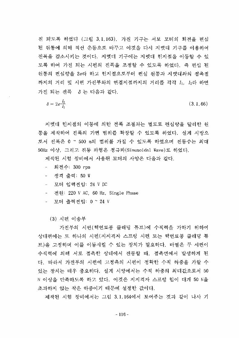
(ZL% 3.1.163).
(3.1.66)
-^ 0 - 500
50Hz ^^-2}(Sinusoidal Wave)^.
: 300 rpm
# 4 : 50 W
y ^ ? l 6 j - : 24 V DC
220 V AC, 60 Hz, Single Phase
#4^1^: 0 ~ 24 V
(3)
^[Tfl^ O.^Ai 50
50 m
a ^ 3.1.164^)4 4Vol ^ 4 71
- 116-
Lash)
Dovetail^-
^ ^ . 4 ^ Dovetail^ 7>
(4)
Load Ce l l# ^•
^ - ^ 4 ^ Load Cell5] ^ ^ -g-^o^ 10 kg( <J> 100 N)
fe ~L^ 3.1.165^1-
(5)
- 117-
$) *1^§- £t%%k±3L^ ^%± ^ ai^h £ W f e LVDT(linear Variable
Differential Transducer ) # ol-g-*H ^ 1 ^ # ^ r ^ f e ^ S S 5j<H $l^.»l
fe 2.5 kHz - 20
^ S Dfl-f- 47]
(6) ^f-f$1*11
BI
^-U 3.1.1672f ^ ^
eater
(7)
Load
Al^ A}o]o]
Fourier Transform^f<^
^ - ^ 3.1.169^ ^
- 118-
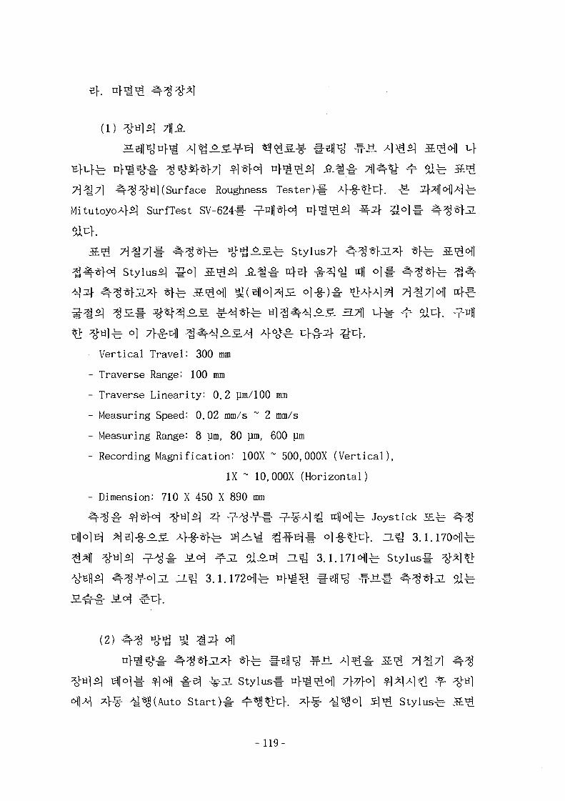
1) ^ H ^ 7fl.fi.
7]?g7\ ^-^^tiKSurface Roughness Tester)#
SurfTest SV-624# -Pfl
7^711- ^-^K=r »^°_£-±= Stylus7f
Stylus^ ^©1
6.5. 3.7]}
- Vertical Travel: 300 mm
- Traverse Range: 100 mm
- Traverse Linearity: 0.2 Jim/100 mm
- Measuring Speed: 0.02 mm/s ~ 2 mm/s
- Measuring Range". 8 ]lm, 80 }im, 600 Jim
- Recording Magnification: 100X ~ 500,000X (Vert ical) ,
IX ~ 10,000X (Horizontal)
- Dimension: 710 X 450 X 890 mm
^ ^ # *}*H ^«l^l 4 -7-^^-1- -T-^^l^ 4 ^ ) ^ Joystick
Dj)o)B| ^Bl-§-^g. 4-g-^fe 5]>i^ ? ^ t - ol-g-^c}. ZL^ 3.
%} l 4 ^ Stylus
(2)
stylusl- n f ^ ^ ^ l 7]-7].o] ^ I ^ A I ^ Jf.
A J **l(Auto Start)-§• ^ ^ ^ K 4 ^ ^ ^ ° 1 3 ^ StylusA J * l
- 119-
Stylus-t
a, Rz, Rq, Ry
3.1.174^1
- 120-
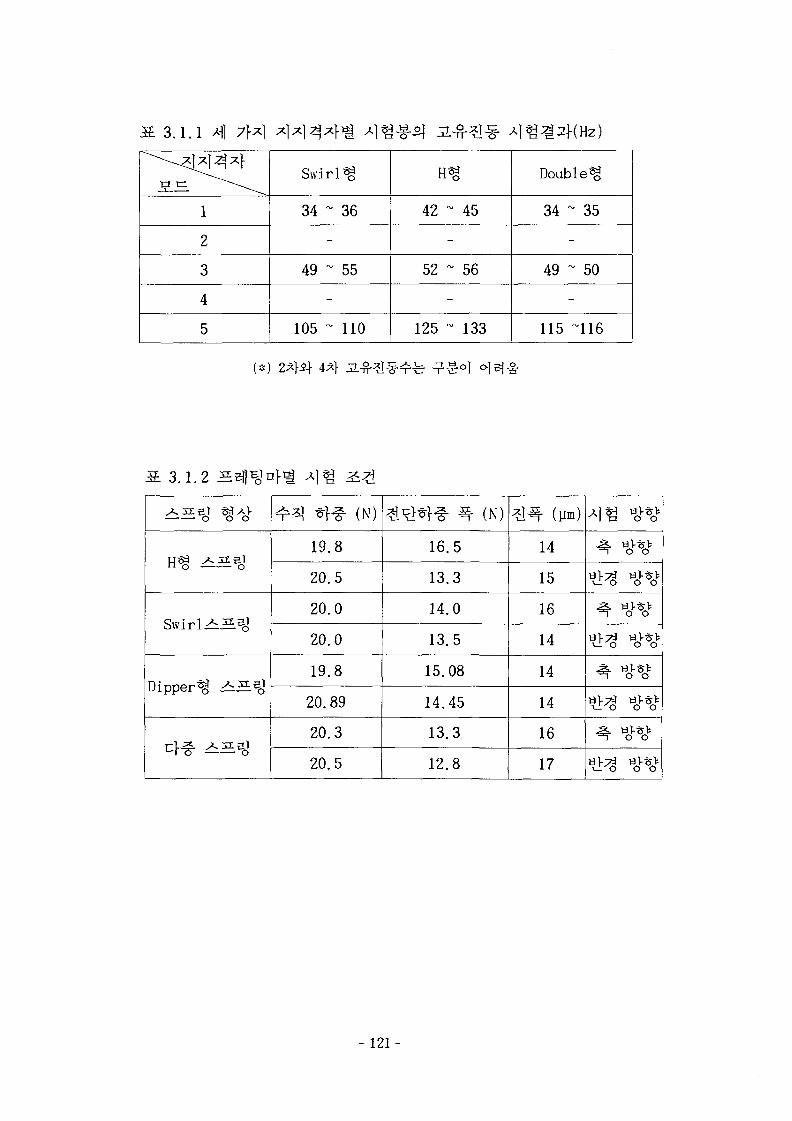
1 3 . 1 . 1 M]
1
2
3
4
5
Swirl
34 ~
-
49 ~
-
105 ~
36
55
110
42 ~
-
52 ~
-
125 ~
>
45
56
133
Double^
34 '
49 '
115
- 35
u 50
"116
3.1.2 H
Swirl H 5O '
Dipper^ ^iS.^1
^r^1 *f-f (N)
19.8
20.5
20.0
20.0
19.8
20.89
20.3
20.5
*tH« ^ (N)
16.5
13.3
14.0
13.5
15.08
14.45
13.3
12.8
*K (P.)
14
15
16
14
14
14
16
17
y . [ $> ^ • *"
- 121-
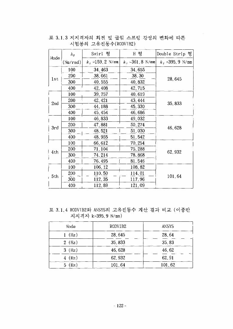
3.1.3
Mode
1st
2nd
3rd
4th
5th
ke(Nm/rad)
100200300400100200300400100200300400100200300400100200300400
Swirl ^
k, =159.2 N/mm
34.46338.06140.55542.40839.75742.42144.18845. 45446.83347.88148. 52148.95566.61271.10474.21476.495106.12110.50112.35112.89
H %
kt =361.8 N/mm
34.65538.3040.83242.71540.61943.44445.33046.68649.03250.27451.03051.54270.25475.28878.86881.546108.82114.01117.96121.09
Double Strip %
k, =395.9 N/mm
28.645
35.833
46.628
62.932
101.64
3.1.4 R0DVIB2£f ANSYSS] JL^-)- k=395.9 N/mm)
Mode
1 (Hz)
2 (Hz)
3 (Hz)
4 (Hz)
5 (Hz)
R0DVIB2
28.645
35.833
46. 628
62.932
101.64
ANSYS
28.64
35.83
46.62
62.91
101.62
- 122-
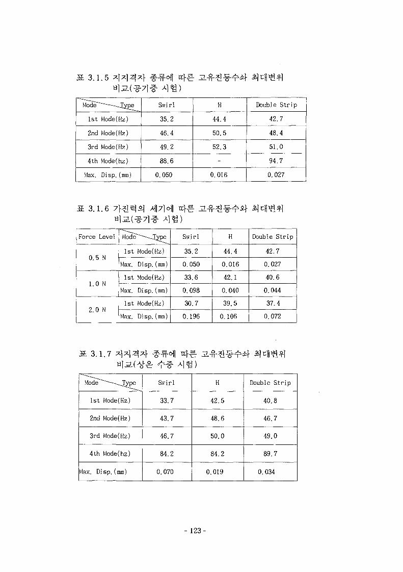
13.1.5
Mode~~~~—-JJ£pe
1st Mode(Hz)
2nd Mode(Hz)
3rd Mode(Hz)
4th Mode(hz)
Max. Disp.(mm)
Swirl
35.2
46.4
49.2
88.6
0.050
H
44.4
50.5
52.3
-
0.016
Double S t r ip
42.7
48.4
51.0
94.7
0.027
1 3 . 1 . 6
Force Level
0. 5 N
1.0 N
2.0 N
Mode~~~-~-J^pe
1st Mode(Hz)
Max. Disp. (mm)
1st Mode(Hz)
Max. Disp. (mm)
1st Mode(Hz)
Max. Disp.(mm)
Swirl
35.2
0.050
33.6
0.098
30.7
0.196
H
44.4
0.016
42.1
0.040
39.5
0.106
Double S t r ip
42.7
0.027
40.6
0.044
37.4
0.072
i-fr^-cr-r;
Mode~~~~--~^JVpe
1st Mode(Hz)
2nd Mode(Hz)
3rd Mode(Hz)
4th Mode(hz)
Max. Disp.(mm)
Swirl
33.7
43.7
46.7
84.2
0.070
H
42.5
48.6
50.0
84.2
0.019
Double St r ip
40.8
46.7
49.0
89.7
0.034
- 123-
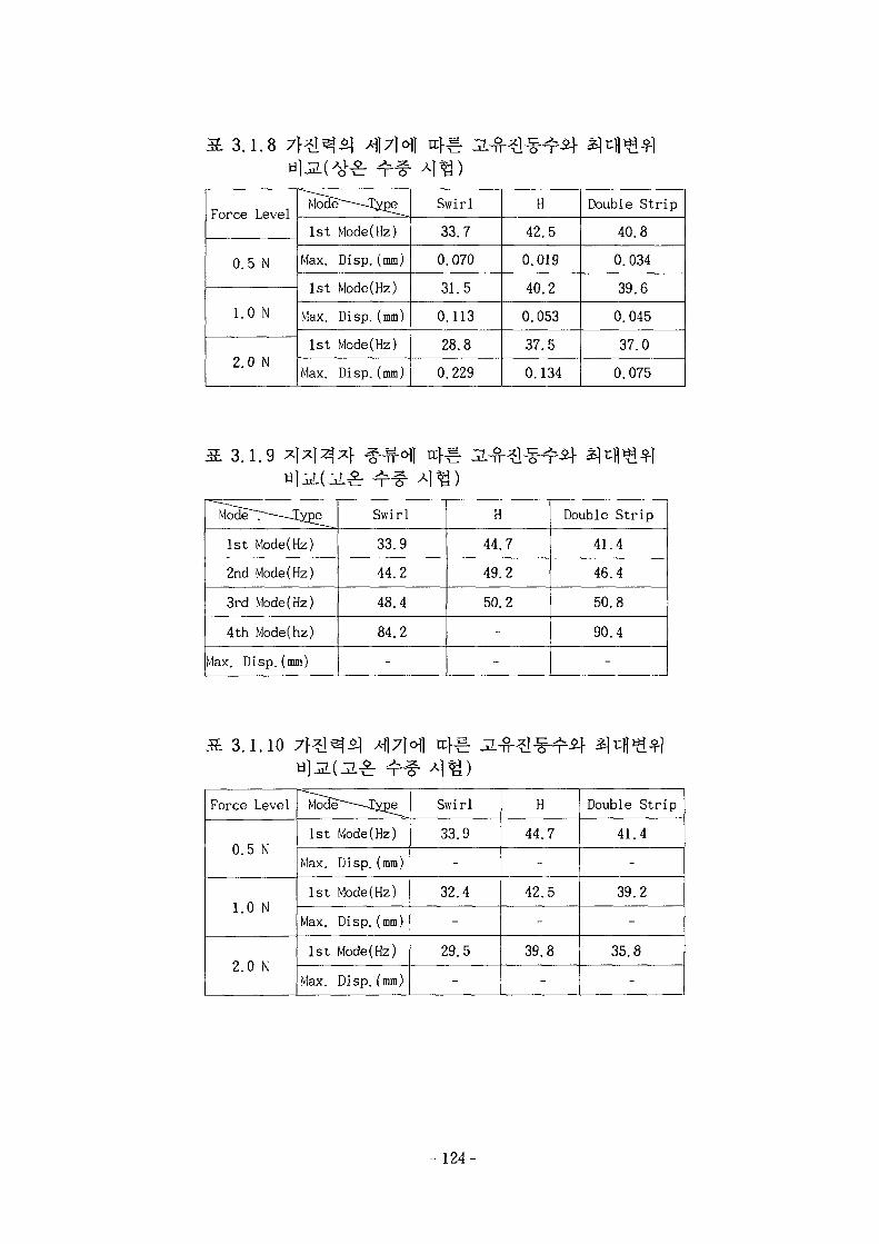
3.1.8
Force Level
0.5 N
1.0 N
2.0 N
^Eae-^yp^
1st Mode(Hz)
Max. Disp. (mm)
1st Mode(Hz)
Max. Disp. (mm)
1st Mode(Hz)
Max. Disp. (mm)
Swirl
33.7
0.070
31.5
0.113
28.8
0.229
H
42.5
0.019
40.2
0.053
37.5
0.134
Double Strip
40.8
0.034
39.6
0.045
37.0
0.075
3.1.9
Mode~~T~--~-Xype
1st Mode(Hz)
2nd Mode(Hz)
3rd Mode(Hz)
4th Mode(hz)
Max. Disp. (mm)
Swirl
33.9
44.2
48.4
84.2
-
H
44.7
49.2
50.2
-
-
Double Strip
41.4
46.4
50.8
90.4
-
3.1.10 M]7]o\] n f ^
Force
0.5
1.0
2.0
Level
N
N
N
Mod*
1st
Max.
1st
Max.
1st
Max.
ET~ lype
Mode(Hz)
Disp.(mm)
Mode(Hz)
Disp.(mm)
Mode(Hz)
Disp.(mm)
Swirl
33.9
-
32.4
-
29.5
-
H
44.
-
42.
-
39.
-
7
5
8
Double
41
39
35.
Strip
.4
.2
8
- 124 -

3.1.11 (Swirl
No.
1
2
3
4
Type
FEA
1
2
3
4
)
Hz
43.88
48.28
53.82
86.78
EMA
1
2
3
4
Hz
35.19
46.36
49.17
88.64
Error{%)
24.69
4.14
9.45
-2.10
MAC (SB)
83.2
55.4
94.8
51.3
3.1.12
3.1.13
«T-2-(H %)
No.
1
2
3
FEA
1
2
3
Hz
42.92
47.58
53.54
EMA
1
2
3
Hz
44.36
50.52
52.31
Error(%)
-3.24
-5.82
2.35
MAC(%)
88.8
59.5
92.6
H1J2. (DoubleStrip %)
NO.
1
2
3
4
FEA
1
2
3
4
Hz
28.68
36.04
47.23
64.00
EMA
1
2
3
4
Hz
42.7
48.4
51.0
94.7
Error{%)
-30.16
-22.62
-3.57
-32.42
MAC(*)
82.6
55.4
80.5
86.4
- 125-
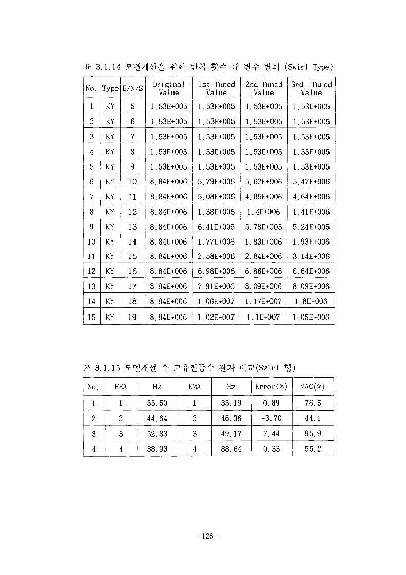
3.1.14 (Swirl Type)
No.
1
2
3
4
5
6
7
8
9
10
11
12
13
14
15
Type
KY
KY
KY
KY
KY
KY
KY
KY
KY
KY
KY
KY
KY
KY
KY
E/N/S
5
6
7
8
9
10
11
12
13
14
15
16
17
18
19
OriginalValue
1.53E+005
1.53E+005
1.53E+005
1.53E+005
1.53E+005
8.84E+006
8.84E+006
8.84E+006
8.84E+006
8.84E+006
8.84E+006
8.84E+006
8.84E+006
8.84E+006
8.84E+006
1st TunedValue
1.53E+005
1.53E+005
1.53E+005
1.53E+005
1.53E+005
5.79E+006
5.08E+006
1.38E+006
6.41E+005
1.77E+006
2.58E+006
6.98E+006
7.91E+006
1.06E+007
1.02E+007
2nd TunedValue
1.53E+005
1.53E+005
1.53E+005
1.53E+005
1.53E+005
5.62E+006
4.85E+006
1.4E+006
5.78E+005
1.83E+006
2.84E+006
6.86E+006
8.09E+006
1.17E+007
1.1E+007
3rd TunedValue
1.53E+005
1.53E+005
1.53E+005
1.53E+005
1.53E+005
5.47E+006
4.64E+006
1.41E+006
5.24E+005
1.93E+006
3.14E+006
6.64E+006
8.09E+006
1.8E+006
1.05E+006
3.1.15
No.
1
2
3
4
FEA
1
2
3
4
Hz
35.50
44.64
52.83
88.93
EMA
1
2
3
4
Hz
35.19
46.36
49.17
88.64
Error(%)
0.89
-3.70
7.44
0.33
MAC(%)
76.5
44.1
95.9
55.2
- 126-
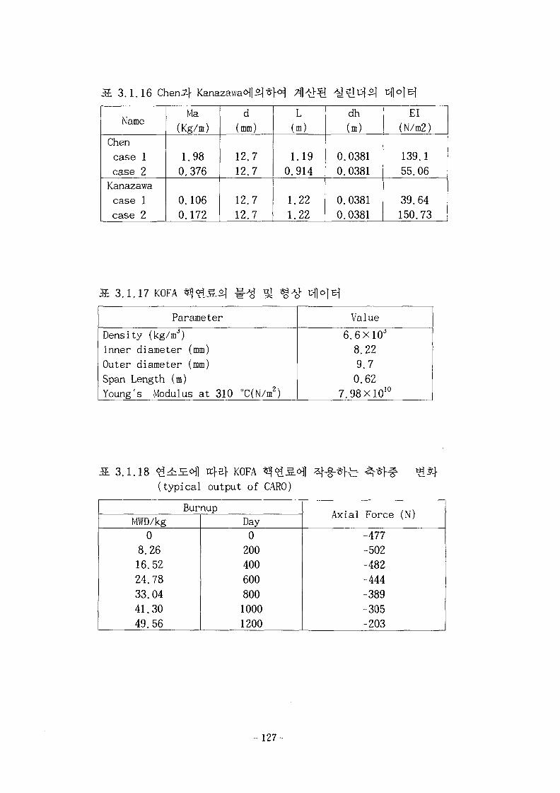
S. 3.1.16 Chen f Kanazawaofli^M
Name
Chencase 1case 2Kanazawacase 1case 2
Ma(Kg/m)
1.980.376
0.1060.172
d(mm)
12.712.7
12.712.7
L(m)
1.190.914
1.221.22
dh
(m)
0.03810.0381
0.03810.0381
El(N/m2)
139.155.06
39.64150.73
3.1.17 KOFA
Parameter
Density (kg/mJ)Inner diameter (mm)Outer diameter (mm)Span Length (m)Young's Modulus at 310 °C(N/m2)
Value
6.6X10"8.229.70.62
7.98X10¹⁰
3.1.18 ^i£«1] n}ef KOFA(typical output of CARO)
BurnupMWD/kg0
8.2616.5224.7833.0441.3049.56
Day020040060080010001200
Axial Force (N)
-477-502-482-444-389-305-203
- 127-
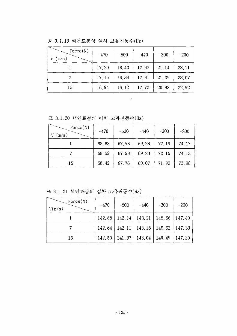
3.1.19
V (m/s)
Force(N)
1
7
15
-470
17.20
17.15
16.94
-500
16.
16.
16.
40
34
12
-440
17.
17.
17.
97
91
72
-300
21
21.
20.
14
09
93
-200
23.
23.
22.
11
07
92
3.1.20
V (m/s)
Force(N)
1
7
15
-470
68.63
68.59
68.42
-500
67.98
67.93
67.76
-440
69.
69.
69.
28
23
07
-300
72.
72.
71.
19
15
99
-200
74.
74.
73.
17
13
98
3.1.21
V(m/s)
Force(N)
1
7
15
-470
142.
142.
142.
68
64
50
-500
142.
142.
141.
14
11
97
-440
143.
143.
143.
21
18
04
-300
145.
145.
145.
66
62
49
-200
147.
147.
147.
40
33
20
128-
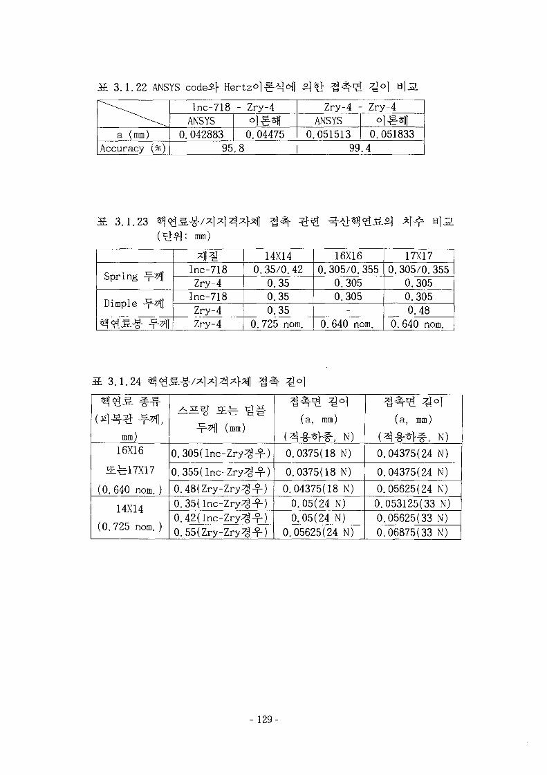
3.1.22 ANSYS codeif Hertzo]SA] ofl
a (mm)Accuracy
\ .
(*)0
Inc-718ANSYS. 042883
95
- Zry-4
0.04475.8
0
Zry-4 -ANSYS.051513
99
- Zry-4
0.051833.4
3.1.23mm)
Spring -x- j
Dimple -x-3*H
Inc-718Zry-4Inc-718Zry-4Zry-4
14X140.35/0.42
0.350.350.35
0.725 nom.
16X160.305/0.355
0.3050.305-
0. 640 nom.
17X170.305/0.355
0.3050.3050.48
0.640 nom.
3.1.24
in]4^ ^fi,mm)16X16
i£^17X17
(0.640 nom. )
14X14
(0.725 nom.)
o —1— i— ct ^
-r- l] (mm)
0.305(Inc-Zry^-f)
0.355(Inc-Zry^-f)
0.48(Zry-Zry^-f)0.35(Inc-Zry^-f)0.42(Inc-Zry^^-)0.55(Zry-Zry^-f)
^ - *H(a, mm)
( -§- , N)0.0375(18 N)
0.0375(18 N)
0.04375(18 N)0.05(24 N)0.05(24 N)
0.05625(24 N)
(a, mm)
(^-§-*>^, N)0.04375(24 N)
0.04375(24 N)
0.05625(24 N)0.053125(33 N)0.05625(33 N)0.06875(33 N)
- 129-
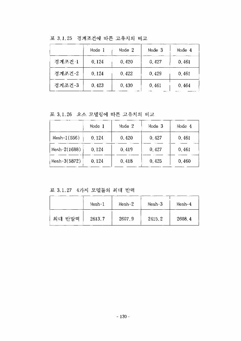
3.1.25
^1^2-1
TJl -2
3^3-3
Mode 1
0.124
0.124
0.423
Mode 2
0.420
0.422
0.430
Mode 3
0.427
0.429
0.461
Mode 4
0.461
0.461
0.464
3.1.26
Mesh-1(556)
Mesh-2(1688)
Mesh-3(5872)
Mode 1
0.124
0.124
0.124
Mode 2
0.420
0.419
0.418
Mode 3
0.427
0.427
0.425
Mode 4
0.461
0.461
0.460
l.
« •
27 47|*| T3 O l }— Ol»J ^ ^^ -^-j
Mesh-1
2613.7
Mesh-2
2607.9
Mesh-3
2415.2
Mesh-4
2608.4
- 130-
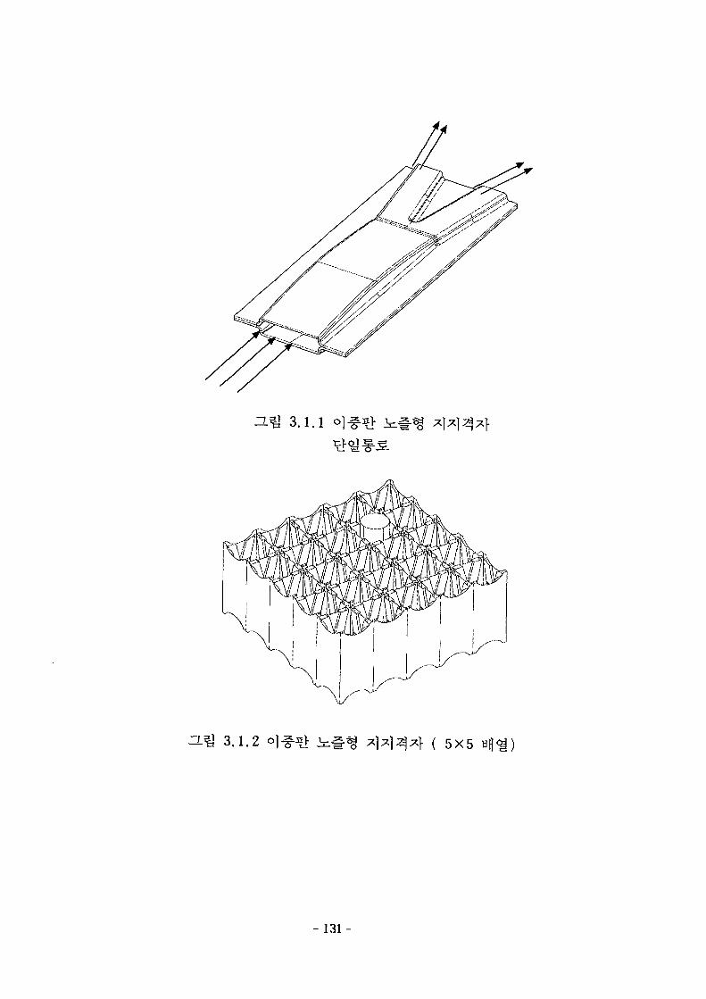
^ 3.1.1
3-Q 3.1.2 ( 5X5
- 131-
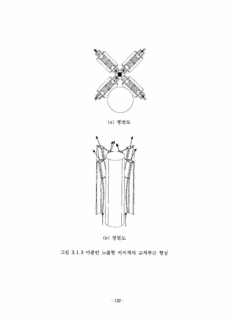
(a)
(b)
^ T 3.1.3
- 132-
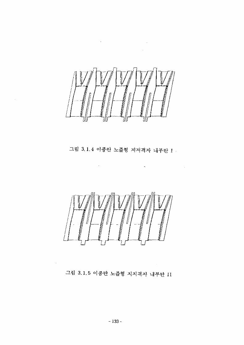
^ 3.1.4
^ 3.1.5
- 133-
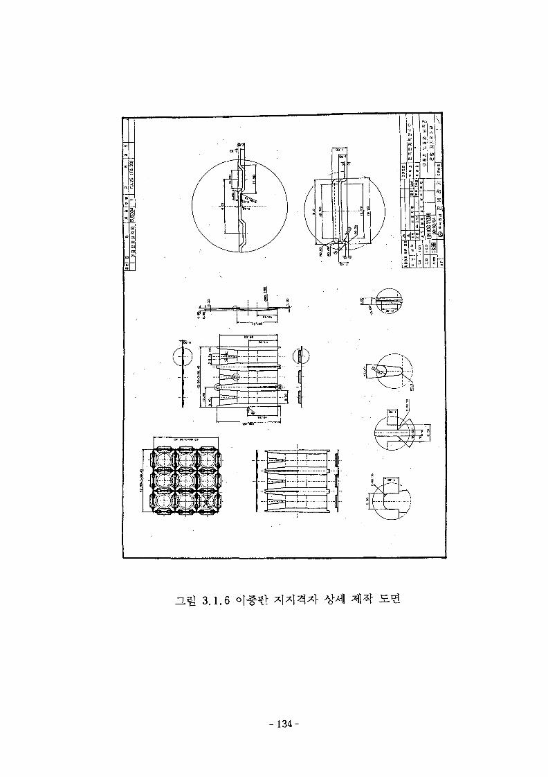
f
Oh;*a si
IT
r..J
s
i ?
ss
H -
o:i
ZL& 3.1.6
- 1 3 4 -
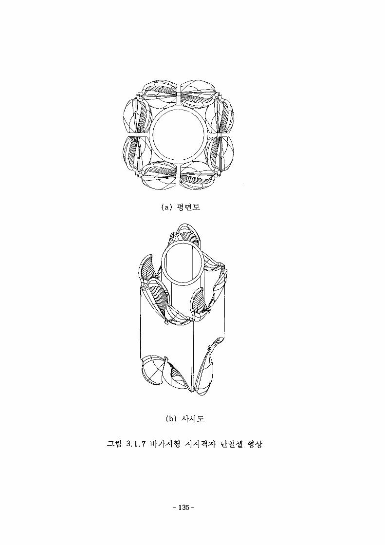
(a)
(b)
ZL% 3.1.7
- 135-
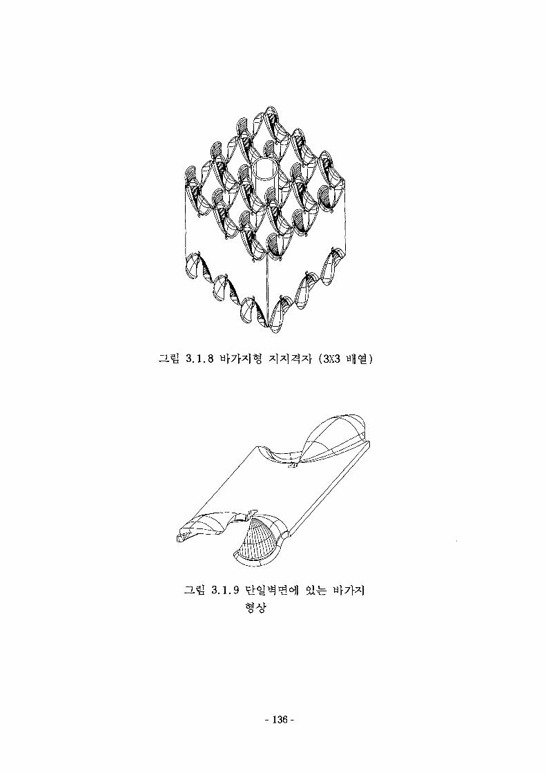
3.1.8 (3X3
3.1.9
- 136-
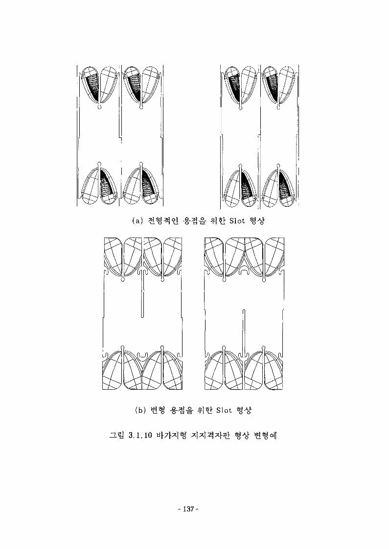
(a) Slot
(b) »
3.1.10
h
Slot
- 137-
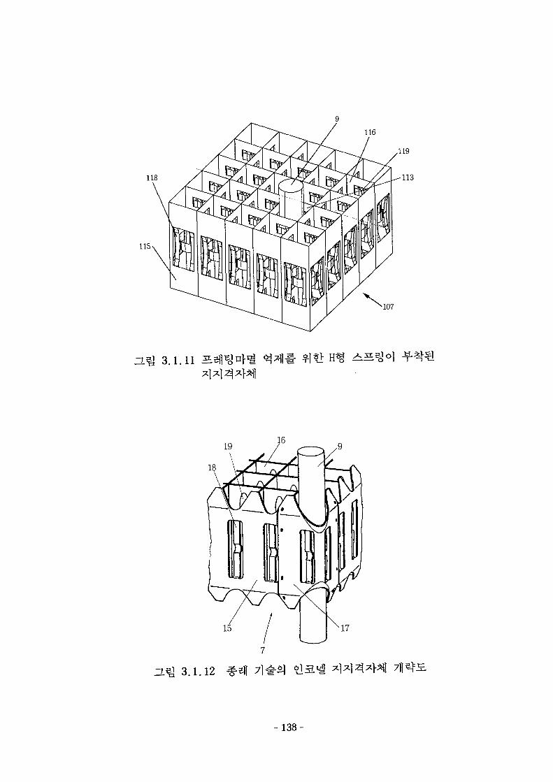
116
118
107
ZLQ 3.1.11 S
19
15 17
H^I 3.1.12
-138-
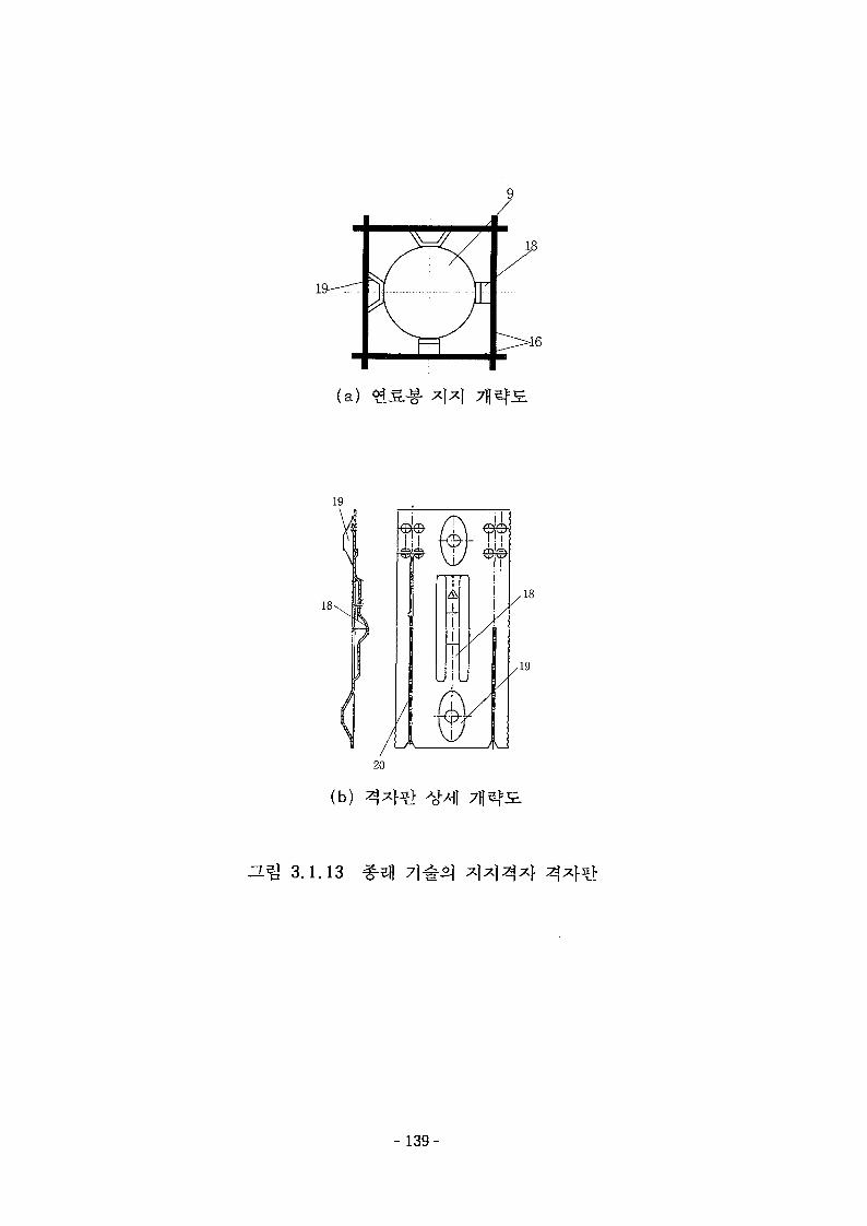
(a)
19
18-
IN
20
il
,18
,19
(b)
3-m 3.1.13
- 139-
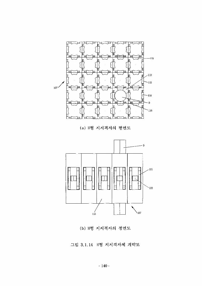
(a)
115
-121
•122
(b)
H ^ 3.1.14
- 140-
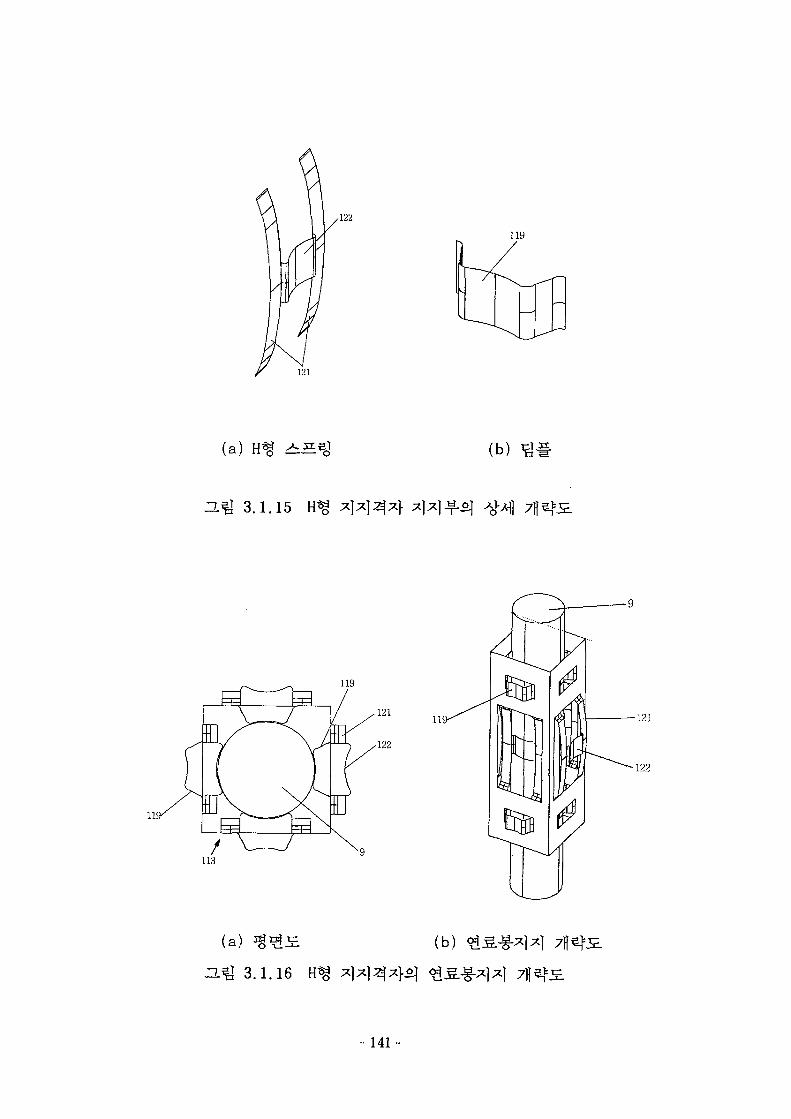
,122
121
(a) H*g ^
-^ 3.1.15
119
1 /
(b) g #
(a)
121
(b)
122
3.1.16
- 1 4 1 -
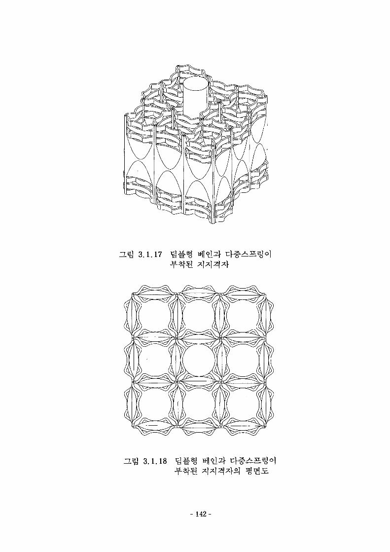
H ^ 3.1.17
ZL^ 3.1.18
-142-
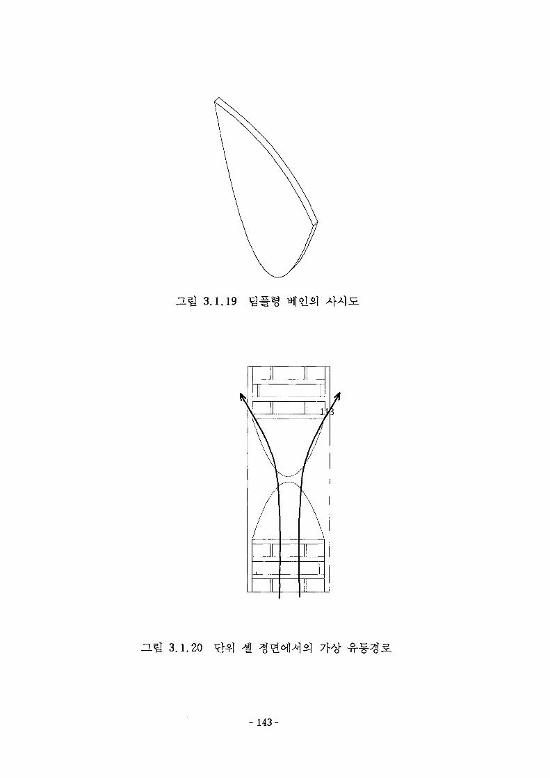
a ^ 3.1.19
ZIZZ
H ^ 3.1.20 7}^
143-

~L^ 3.1.21
- 144-
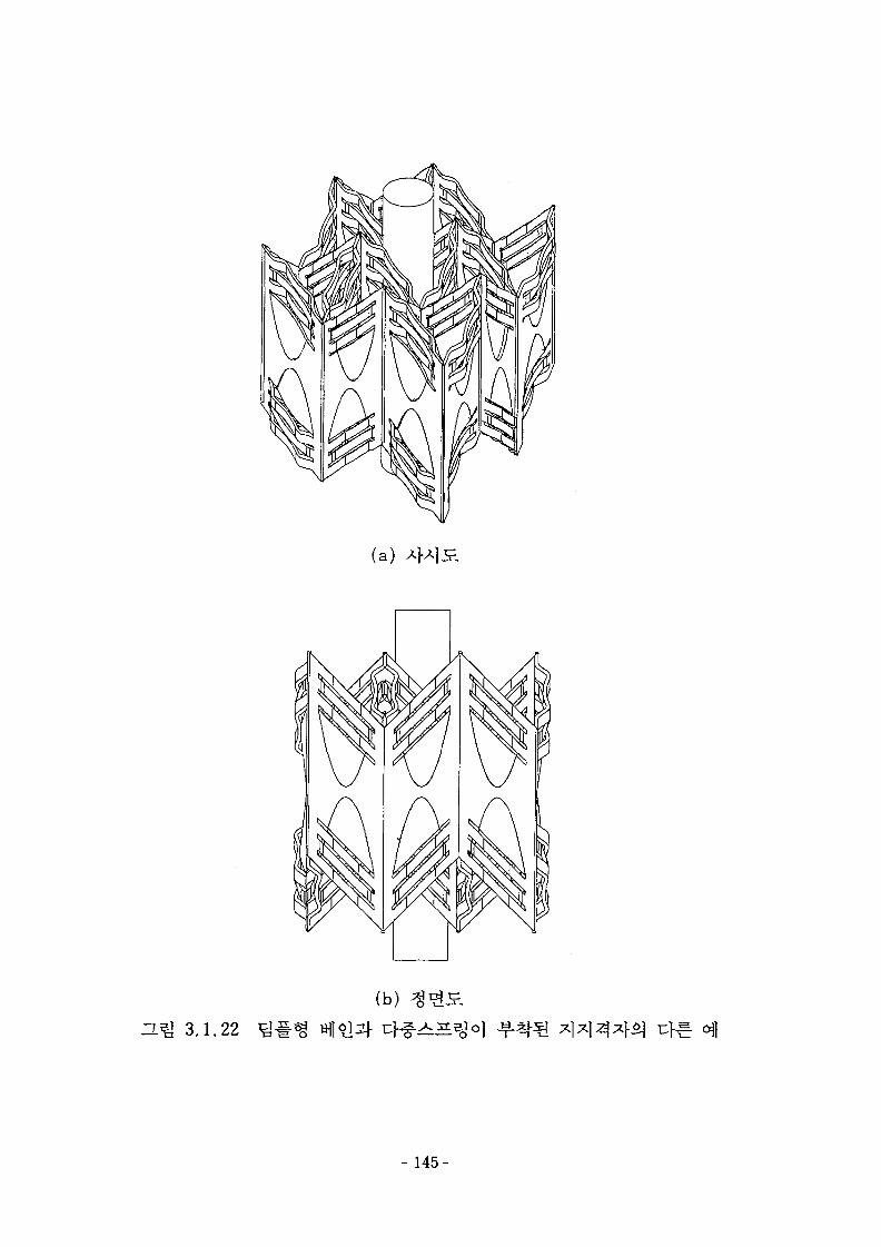
(a)
H^ 3.1.22
(b)
- 145-
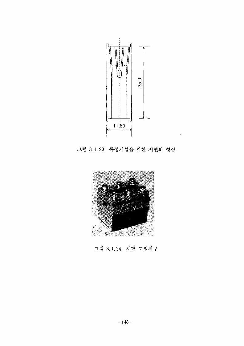
IS)CO
11.80
ZL J 3.1.23
\
ZL J 3.1.24
- 146-
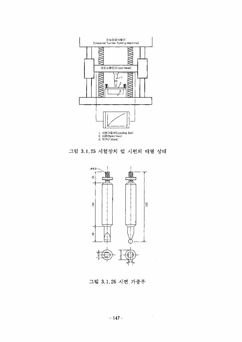
(Universal Tensile Testing
!
Machine)
I3ic^E>l|£(Cross Head)
i }\
1. AIH3(g¥(Loading Bar)2. AiaCSpecimen)3. XI (Fixture)
HQ 3.1.25
(P6.0
-L^ 3.1.26 A] ^
-147
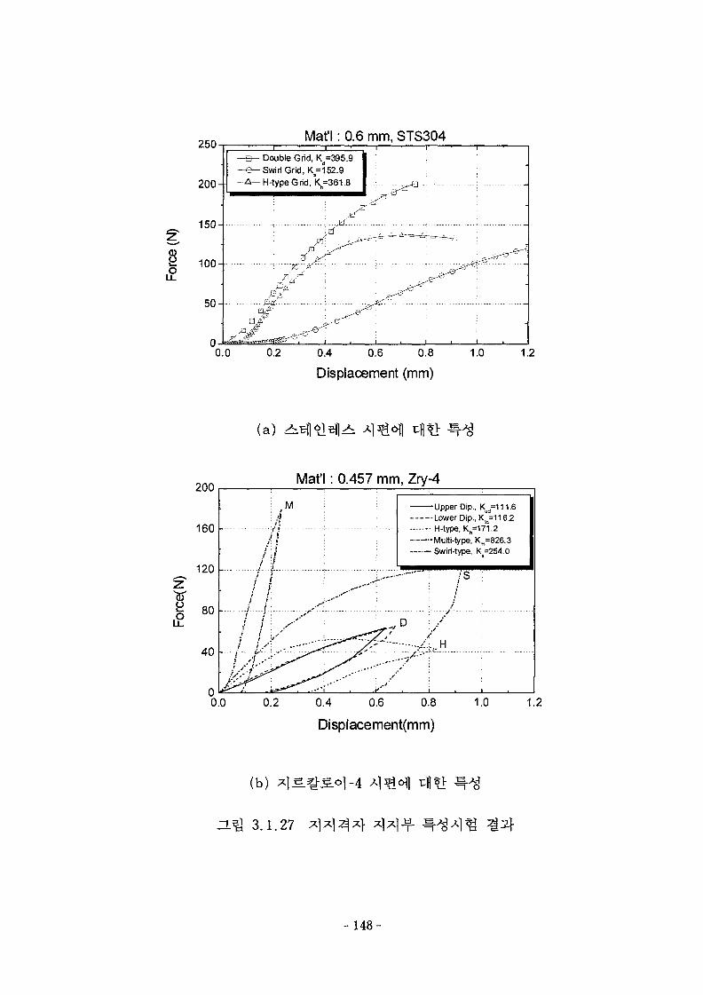
250
o
200-
150-
100-
50-
Maf 1: 0.6 mm, STS304Double Grid, Kd=395.9
- Swirl Grid, K,=152.9
-H-type Grid, Kh=361.8
0.2 0.4 0.6 0.8
Displacement (mm)1.0 1.2
(a) ^
£
200
160
120
80
40
Mat'l: 0.457 mm, Zry-4
M
••t+-
-Upper Dip., Kud=111.6•Lower Dip., K^=116.2• H-type, Kb=171.2-Multi-1ype, Km=826.3• Swirl-type, K =254.0
0.0 0.2 0.4 0.6 0.8 1.0
Displacement(mm)
1.2
(b) * ]S =
H^ 3.1.27
- 148-
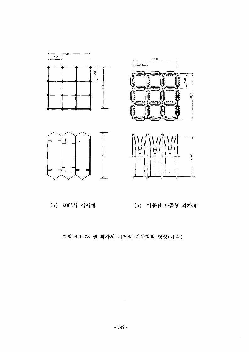
-38.4-12.8 1
38.40
12.80
a D
a D
(a) KOFA g (b)
ZLH 3.1.28
- 149-
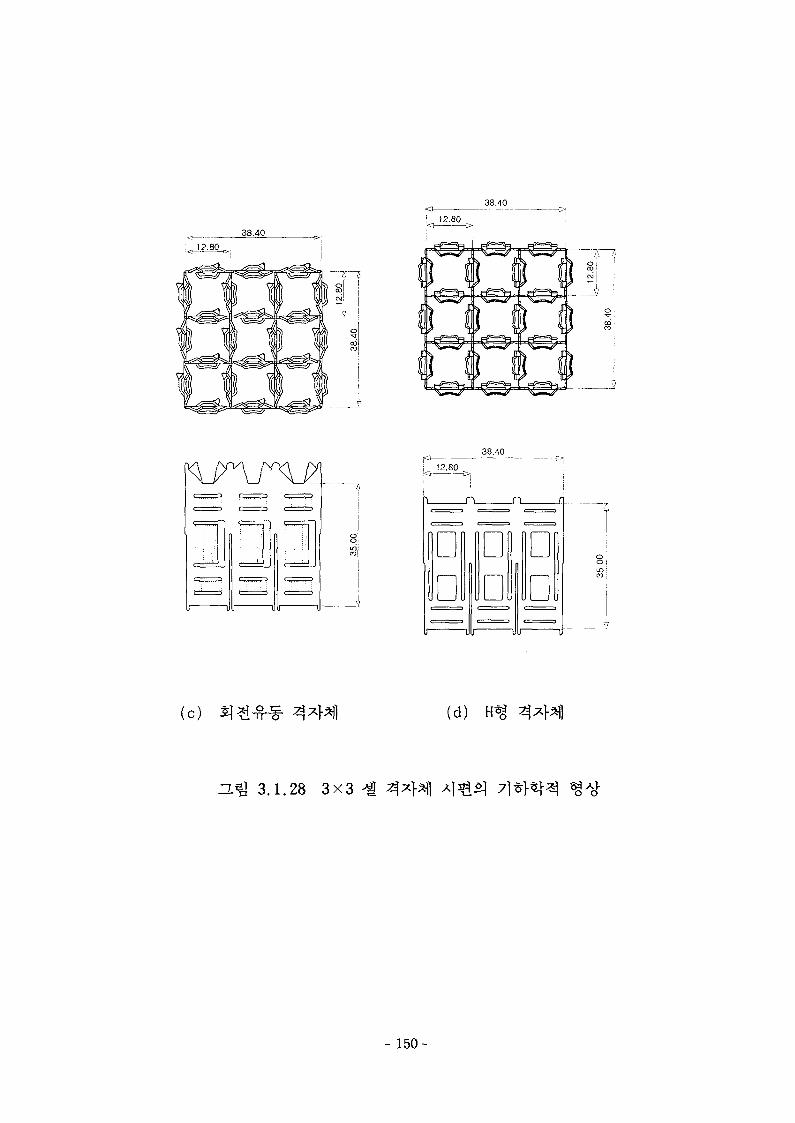
38.40
12.80
11
I
"Ulr
I 12.80
38.40
38.40
12.80 .
DD
DD
VI UU U
DD
(c) 3} (d)
H ^ 3.1.28 3X3
150-
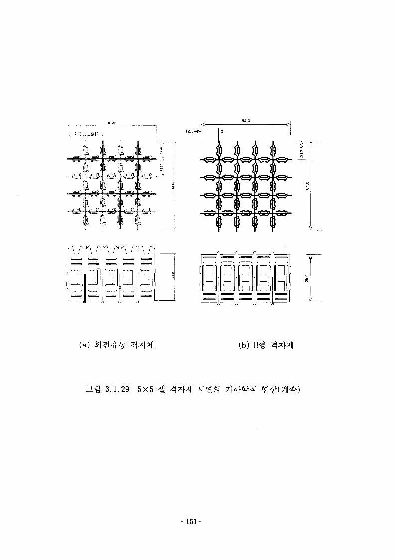
12.47 . , 12.8C 12.8-e.
\ I
64.0
=3-
A A
(a) (b)
H ^ 3.1.29 5X5 7j
- 151-
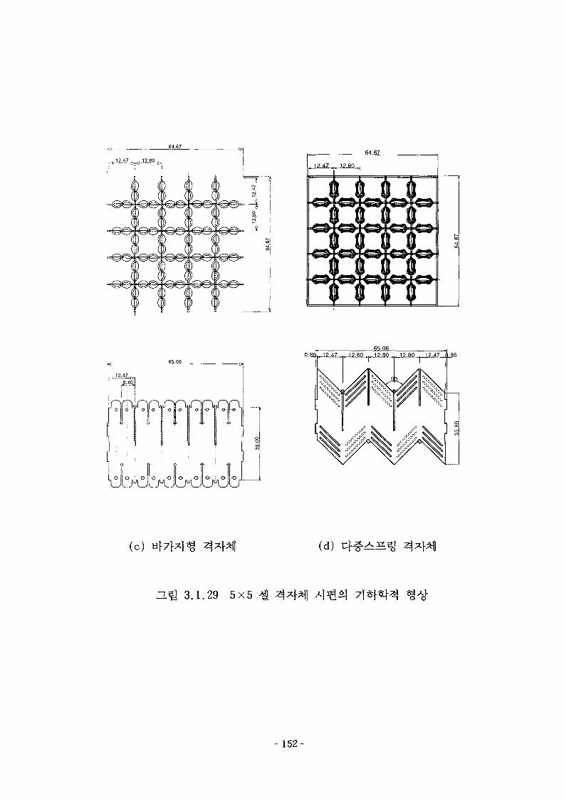
,,12.47 12.80 .
V W f
0 {) i(P
Q
(L_(L_ 4
® 0 P f
)0 0
(?
(c) (d) C f ^ ^ ^
a ^ 3.1.29 5X5 7)*}^
- 152-
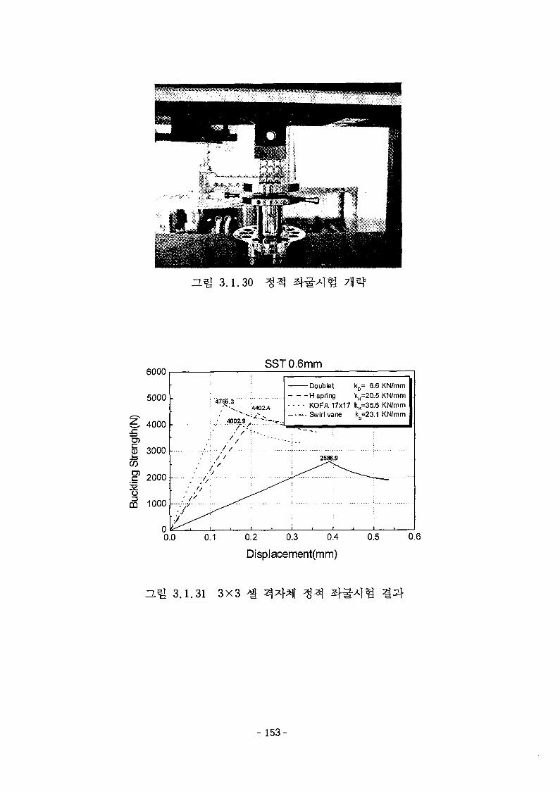
ZL^ 3.1.30
6000SST 0.6mm
H spring kH=20.5 KN/mm• - - - KOFA 17x17 k..=35.6 KN/mm
Swirl vane
0.2 0.3 0.4
Displacement(mm)
ZMH 3.1.31 3X3
- 1 5 3 -
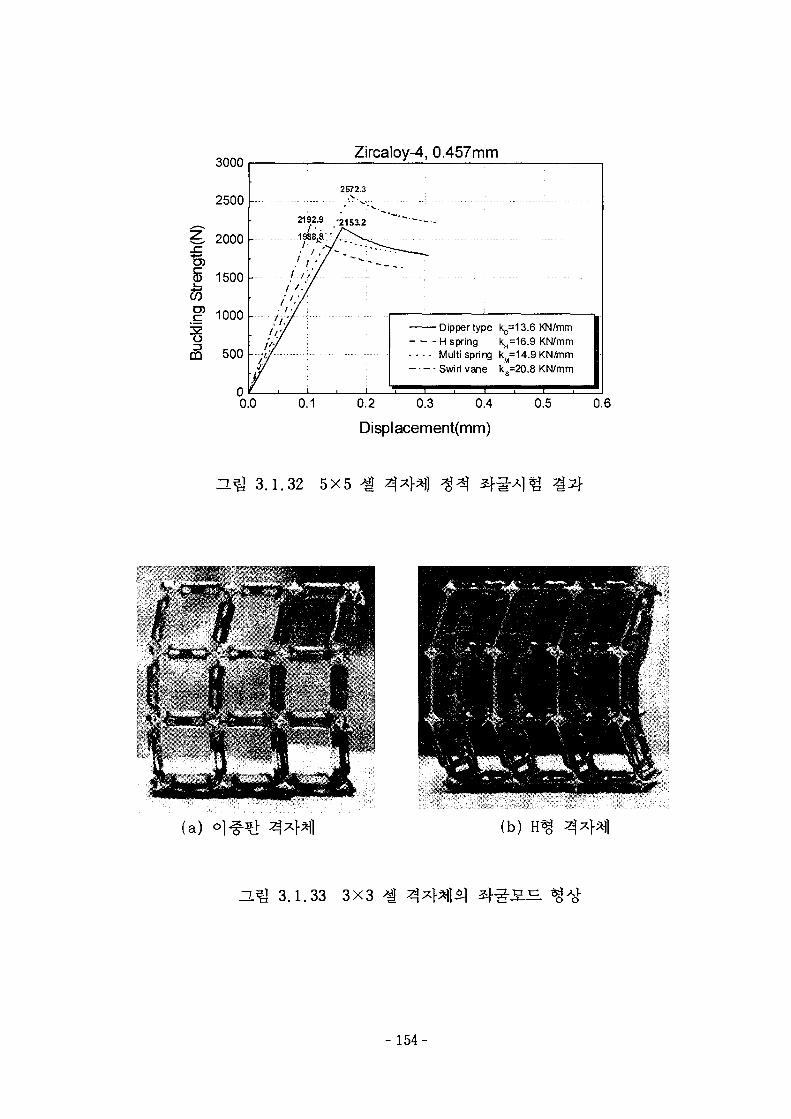
3000Zircaloy-4, 0.457mm
Dippertype k =13.6 KN/mtn
• Multi spring kM=14.9 KN/mmSwirl vane ks=20.8 KN/mm
0.2 0.3 0.4
Displacement(mm)
3.1.32 5X5
(a) (b)
ZL I 3.1.33 3X3
- 154-
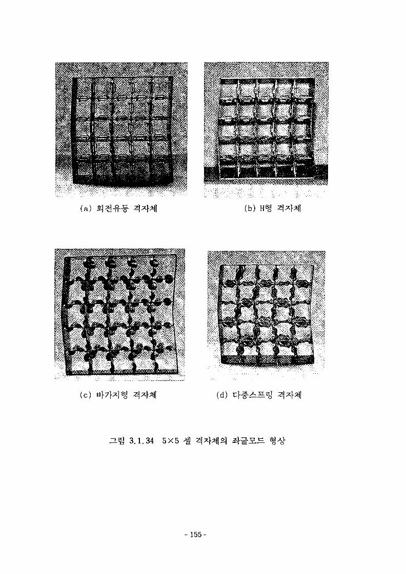
(a) (b)
(c) (d) 4#>iS
ZL^ 3.1.34 5X5 4
- 155-
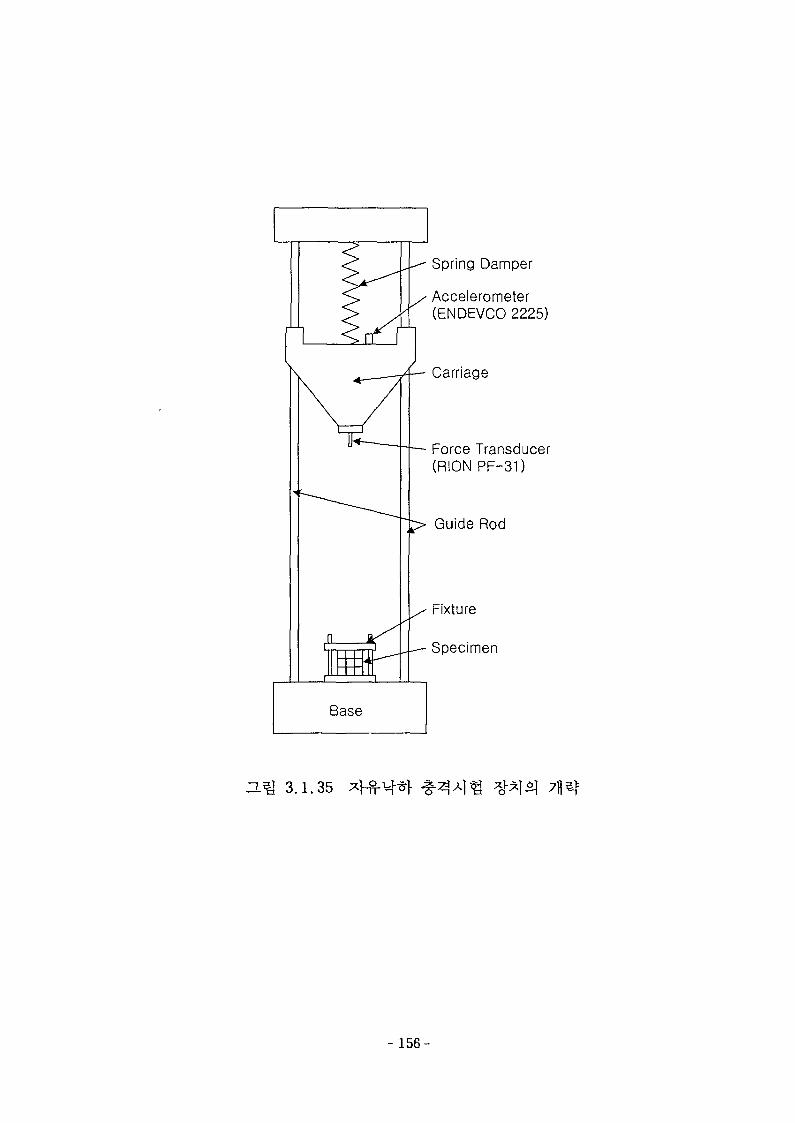
Spring Dannper
Accelerometer(ENDEVCO 2225)
Carriage
Force Transducer(RION PF-31)
Guide Rod
Fixture
Specimen
Base
D.Q 3.1.35
- 156-
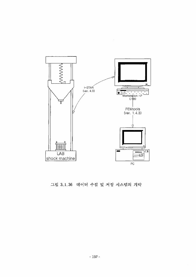
I-STAR(ver. 4.0)
LABshock machine
FEMtOOls(ver. 1.4.3)
ar- S -
PC
3.1.36
- 157-
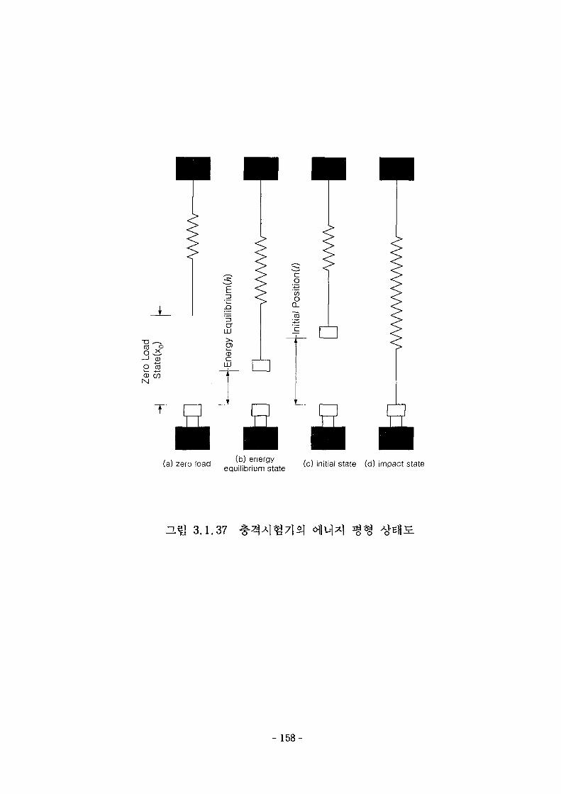
(a) zero load (b) energyequilibrium state (c) initial state (d) impact state
D.^ 3.1.37
- 158-
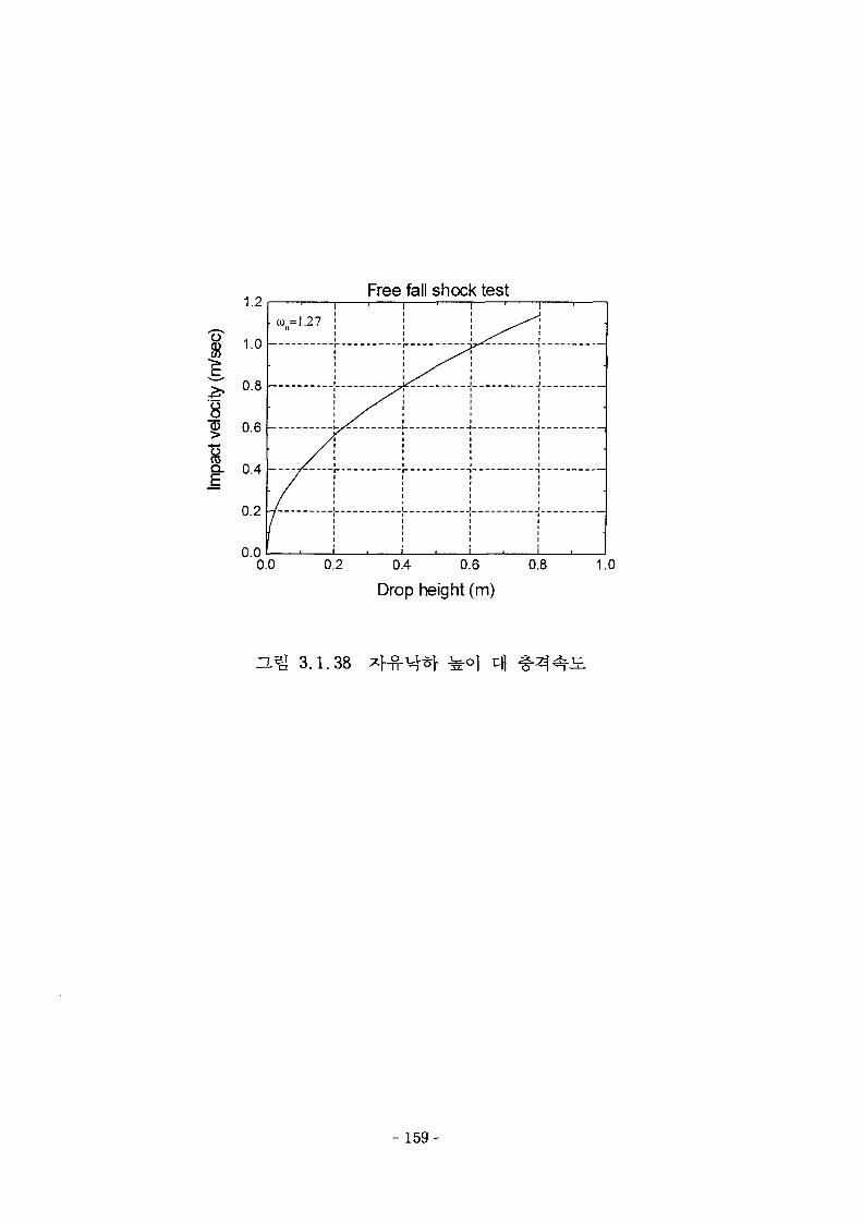
o
1.2
1.0 -
0.8 -
Free fall shock test
"?> 0.6
| 0.4
0.2
0.0
• co =1.27n
__/
/
i
1
_ _ _ i
•
1
•
0.0 0.2 0.4 0.6 0.8
Drop height (m)
1.0
3.^ 3.1.38
- 159-
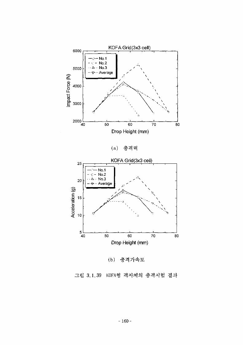
6000
5000
2 4000
£ 3000
KOFA Grid(3x3 cell)
2000
—ry-
- c -. -A-
- v
- N o- No• No
123
• - Average
40 50 60 70
Drop Height (mm)
80
25
20
3.2 15tsto
<; 10
(a)
KOFA Grid(3x3 cell)
-a— No.1C- No.2
• A- • N o . 3
-V-- Average
40 50 60 70
Drop Height (mm)80
(b)
H ^ 3.1.39 KOFAf
160-
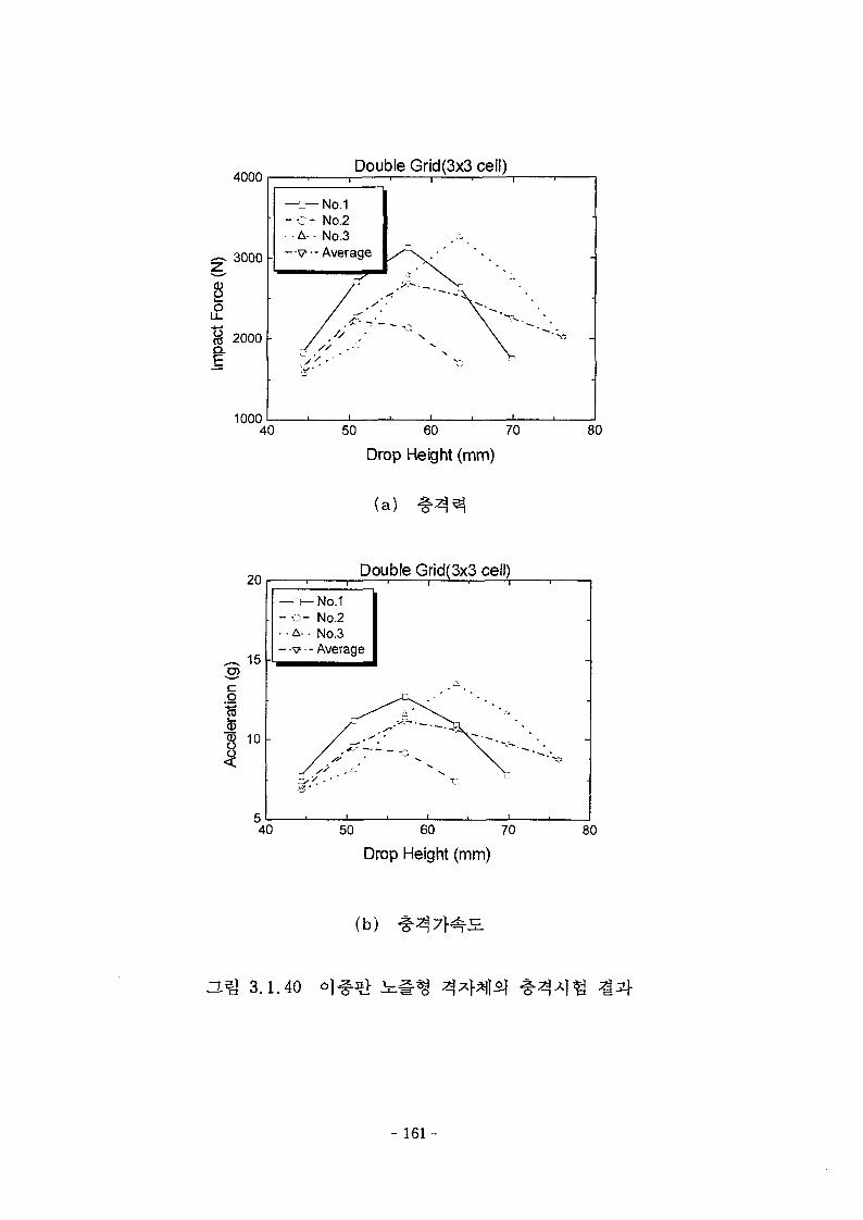
£Q.
4000
3000
2000
mnn
• A- •
_ --v-
^/
Double
-No.1No.2No.3
- Average
/
/
*
1
h .>
_ / ' •
Grid(3x3
V
i ,
cell)
• -
\ " " " * * — •
i i
40 50 60 70
Drop Height (mm)
(a)
80
20
15
038 10
Double Grid(3x3 cell)1 1
—o-No.1- o - No.2•A- No.3
- -v - Average
• / ^ ~
^ _ LJ
• 1 . 1 •
40 50 60 70
Drop Height (mm)
80
(b)
H ^ 3.1.40
- 161-
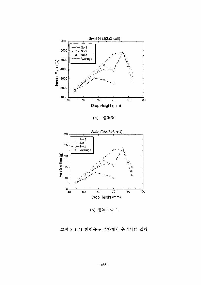
Q_
7000
6000
5000
4000
3000
2000
1000
Swirl Grid(3x3i
—z~ No.1" - C - No.2
-A—No.3-•<?---Average
1 1 1
/ '
cell)
a//
\
-
40 50 60 70 80
Drop Height (mm)
90
(a)
30
25
3 20o
Swirl Grid(3x3 cell)
to15 -
10 -
40
— o - No.1- c - No2—V- -No.3--V-- Average
1
i i i I • i . i •
50 60 70 80
Drop Height (mm)90
(b)
O.^ 3.1.41
- 162-
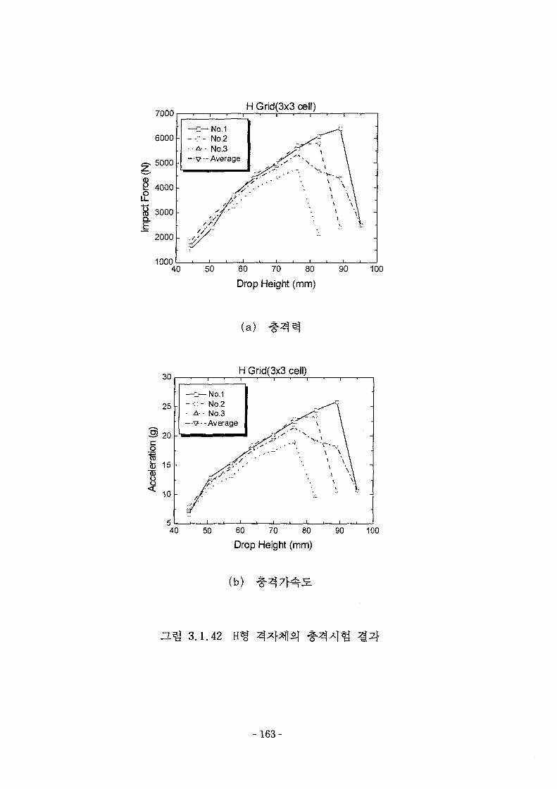
7000
6000
gs 5000
2 4000 -
1& 3000
~~ 2000
H Grid(3x3 cell)
1000
1 • 1
— i h - No.1- - c - No.2. • • A- - No.3
—v--Average
>•
' • / '
X~ X - 1 \
1 \ \1 \\\ "Ai -\
• i i i i i i
40 50 60 70 80 90 100
Drop Height (mm)
(a)
H Grid(3x3 cell)
z— No.1- c - No.2
A- • No.3--V--Average
40 50 60 70 80 90Drop Height (mm)
(b)
H ^ 3.1.42
- 1 6 3 -
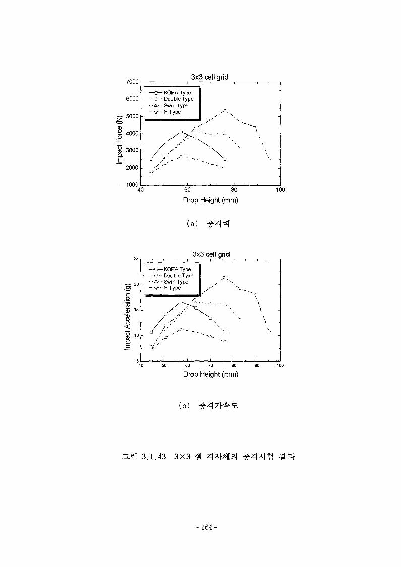
Q .
7000
6000
5000
4000
3000
2000
inoo
3x3 cell grid
—a— KOFA Type- - o - Double Type
• -A - Swirl Type- V - • H Type
-
\\
\
40 60 80
Drop Height (mm)100
(a)
253x3 cell grid
20 -
15 -
i
- o-• -A-
- V
_
i"
I ' i
-KOFA TypeDouble Type
• Swirl TypeHType
/ ;
/ ^
i ' 1 ' 1 '
\
X •., \X " \ •
40 50 60 70 80
Drop Height (mm)90 100
(b)
3J% 3.1.43 3X3
- 164-
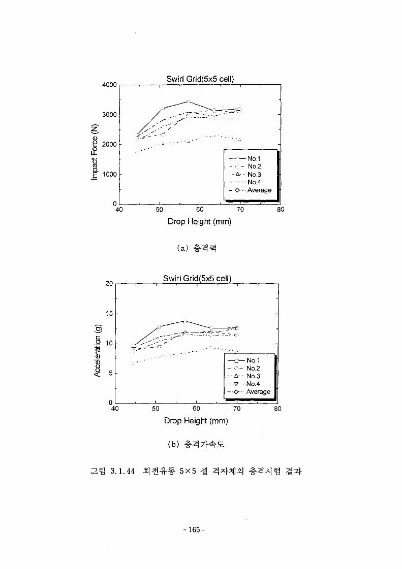
8
AC\r\n
3000
2000
1000
n
Swirl
-
Grid(5x5cell)
i ,
—c— No.1- o - No.2. . A- • No.3— -No.4- O-- Average
i i .
40 50 60 70
Drop Height (mm)
80
(a)
20
15 -
Swirl Grid(5x5 cell)
3cQ 10t3
5 -
40
1 1 • 1 I
fe^"^ „ . - • • • - " - • - -
— o —- - A- -
- O
-
No.1No.2No.3No.4Average
50 60 70
Drop Height (mm)
(b)
80
3.1.44 5X5
- 165-
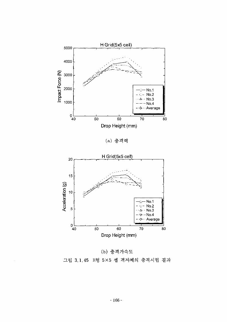
5000
4000 -
3000 -
oz: 2000Ha.
— 1000
40
H Grid(5x5 cell)' f • 1 '
-S^yS
• l i t !
—z— No.1- - : - No.2- A- - No.3
No.4- 0 - - Average
50 60 70
Drop Height (mm)
80
(a)
H Grid(5x5 cell)
40 50 60 70
Drop Height (mm)
3.1.45
(b) *
5X5
- 1 6 6 -
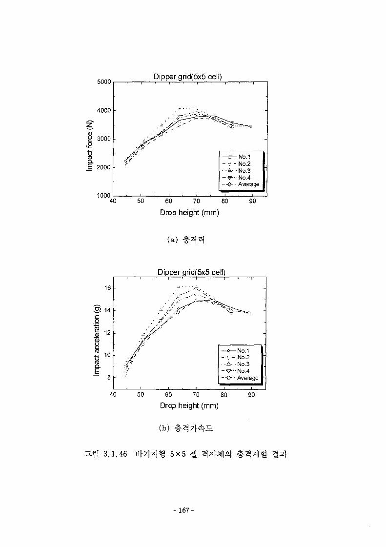
5000
1000
Dipper grid(5x5 cell)
- e - No.2- - No.3
- V No.4--O-- Average
50 60 70 80
Drop height (mm)
90
(a)
Dipper grid(5x5 cell)
50 60 70 80
Drop height (mm)
(b)
90
n ^ 3.1.46 5X5
- 167-
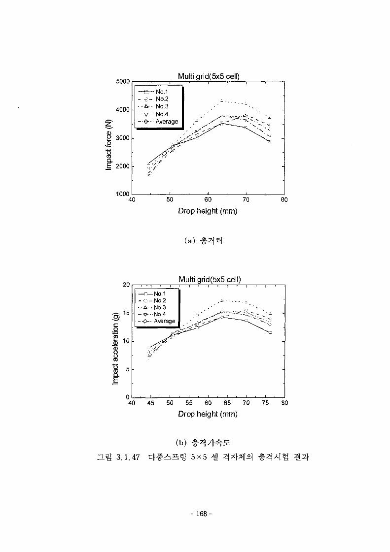
5000
4000
g 3000
I£ 2000
Multi grid(5x5 cell)
1000
- - £ -. . A-
- o-
-No.1No.2No.3
-No.4Average
/?.'•/'
i | i | i
_ * * " * * • .
• I . I .
40 50 60 70
Drop height (mm)80
(a )
Multi grid(5x5 cell)
40 45 50 55 60 65 70
Drop height (mm)80
3.1.47
(b)
^ s s j 5X5 A*\H$\
- 168-
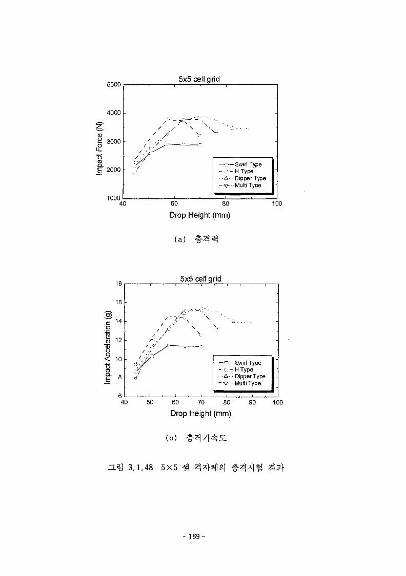
5000
4000 -
3000 •
I" 2000
5x5 cell grid
1000
/ / ' \/ Ji
f ••
= /
. i
-
—c—Swirl Type- c - H Type• -A- Dipper Type- V - MultiType
i
40 60 80
Drop Height (mm)
100
(a)
18
16
3o
14
12
<: 10
~ I
5x5 cell grid
f-r ,
\X \
- c -. -A- -
- v-
Swirl TypeHTypeDipper TypeMultiType
40 50 60 70 80
Drop Height (mm)
90 100
(b)
3.^ 3.1.48 5X5
-169-
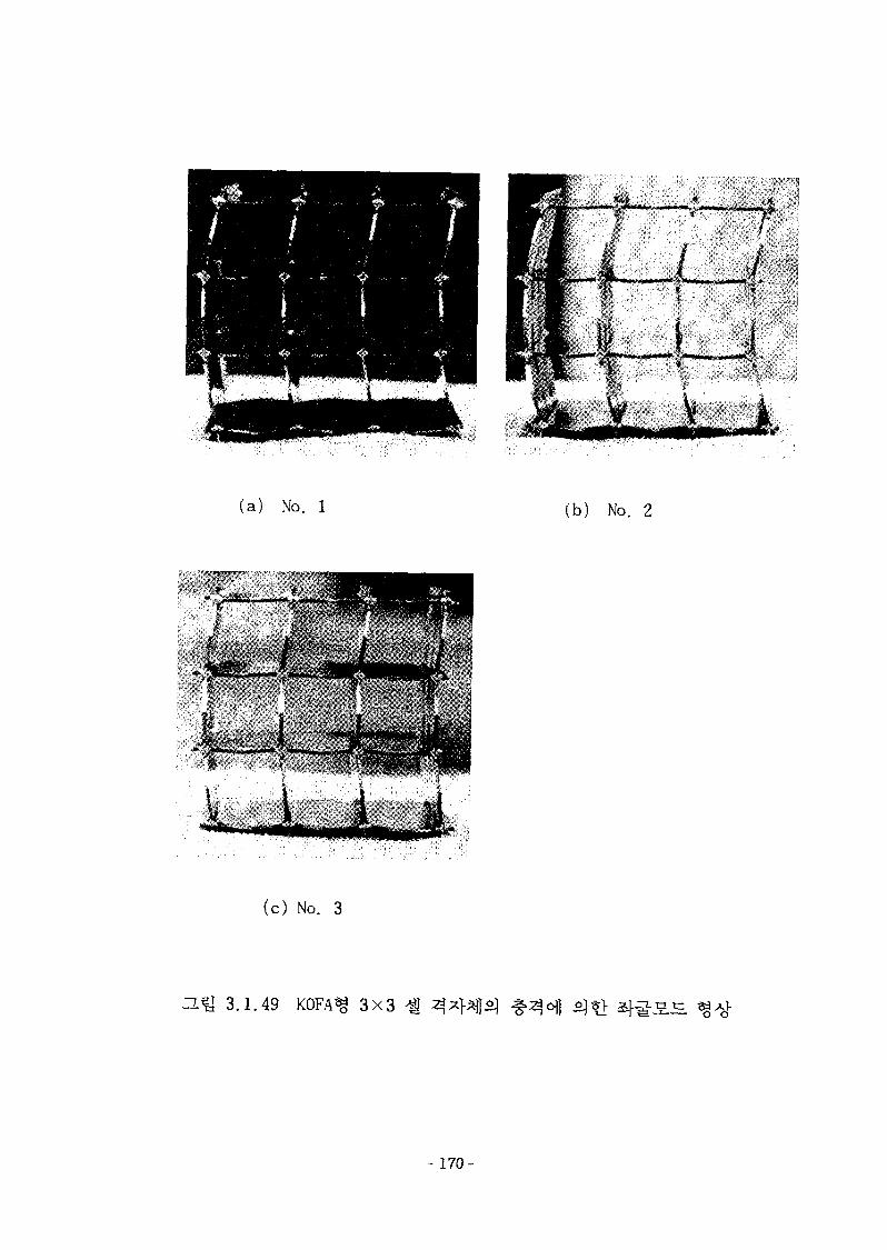
(a) No. 1 (b) No. 2
(c) No. 3
H ^ 3.1.49 KOFA j 3X3
~ 170
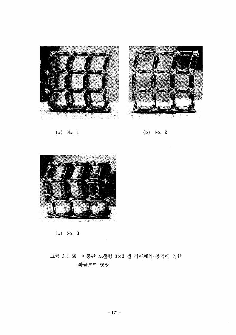
(a) No. 1 (b) No. 2
(c) No. 3
H1J 3.1.50 3x3
- 171 -
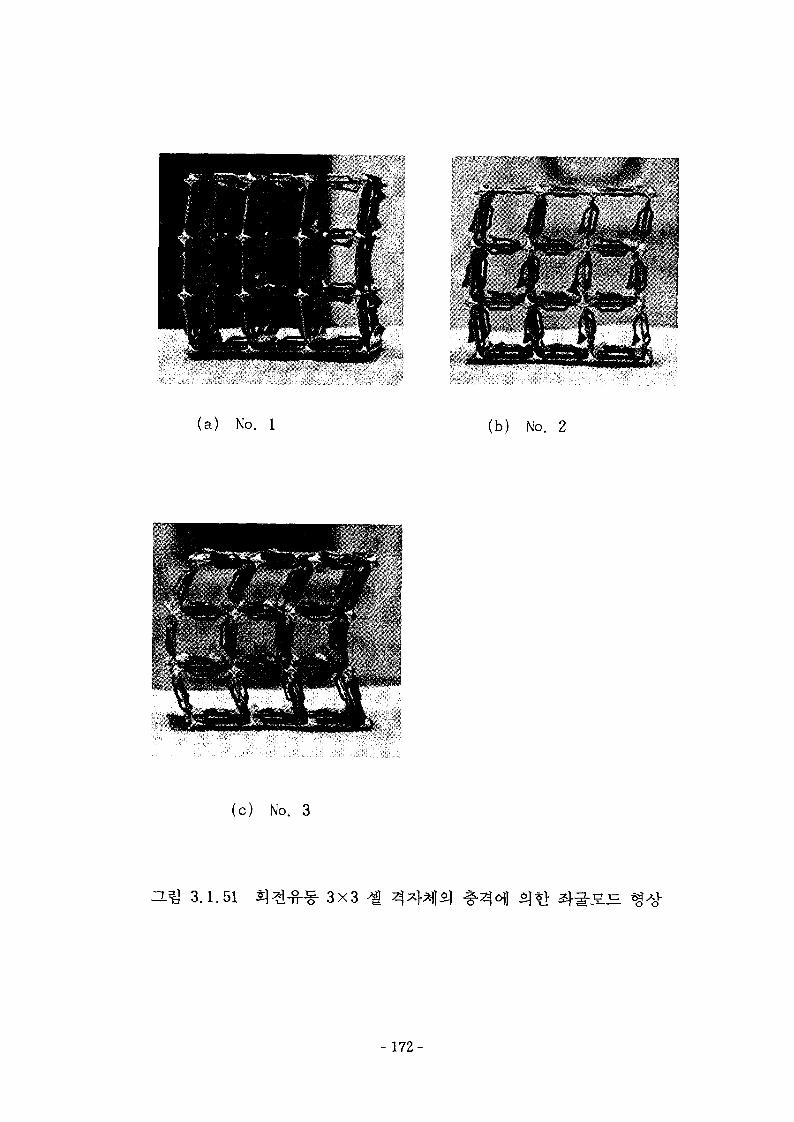
(a) No. 1 (b) No. 2
(c) No. 3
3.1.51 3X3
- 172-
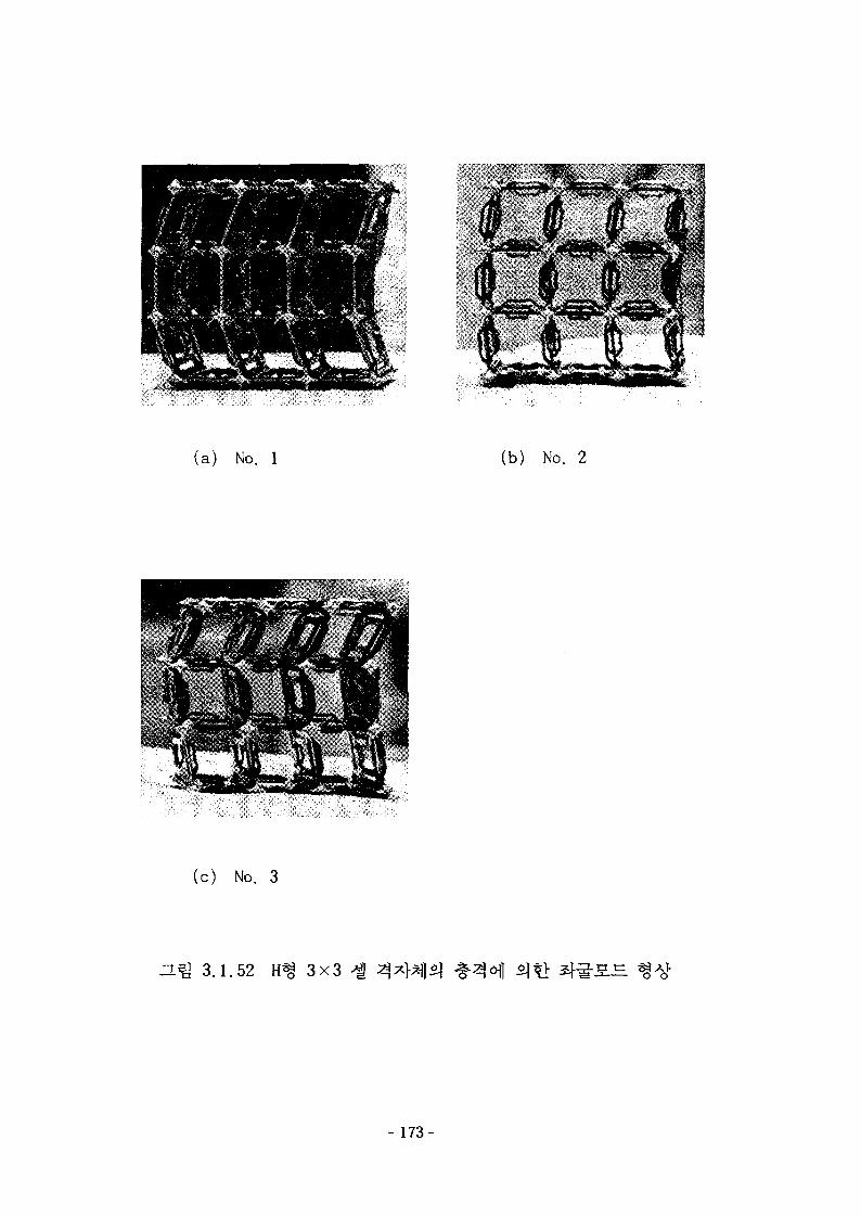
(a ) No. 1 (b) No. 2
(c) No. 3
H^ 3.1.52 3x3 -g
- 173-
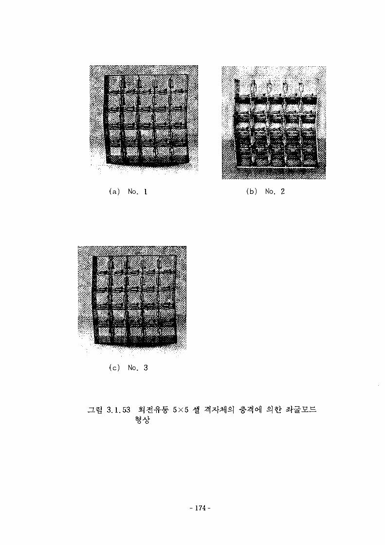
* : T :»• **;
(a) No. 1 (b) No. 2
(c) No. 3
n.% 3.1.53 5x5
- 1 7 4 -
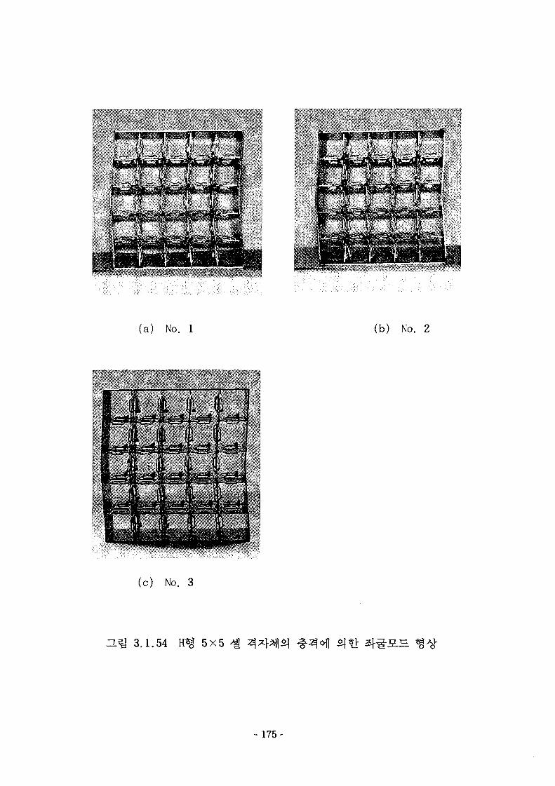
(a) No. 1 (b) No. 2
(c) No. 3
H^I 3.1.54 5X5
- 175-
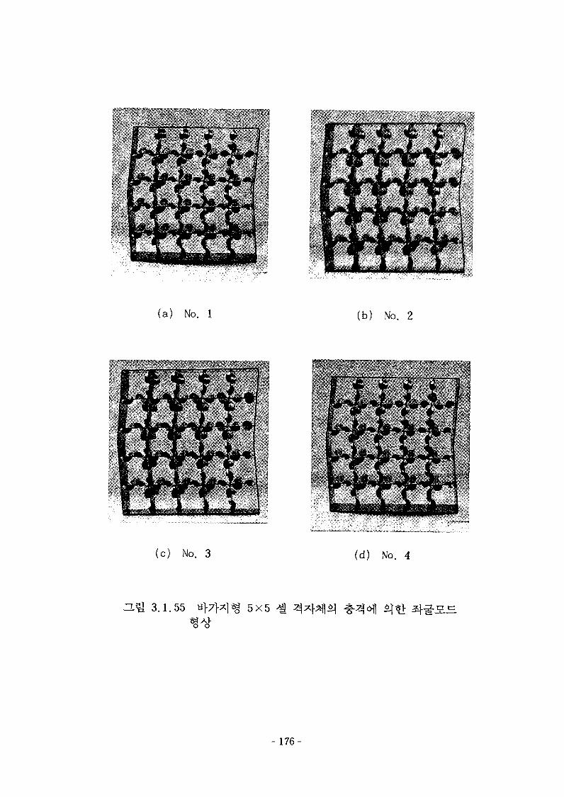
(a) No. 1 (b) No. 2
(c) No. 3 (d) No. 4
a*U 3.1.55 5X5
- 176-
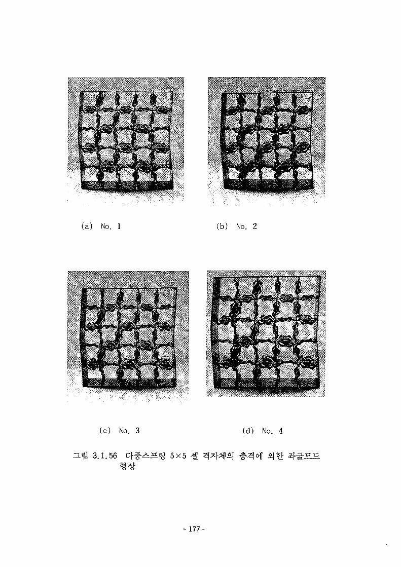
(a) No. 1 (b) No. 2
(c) No. 3 (d) No. 4
n ^ 3.1.56 ^ 5X5
- 177-
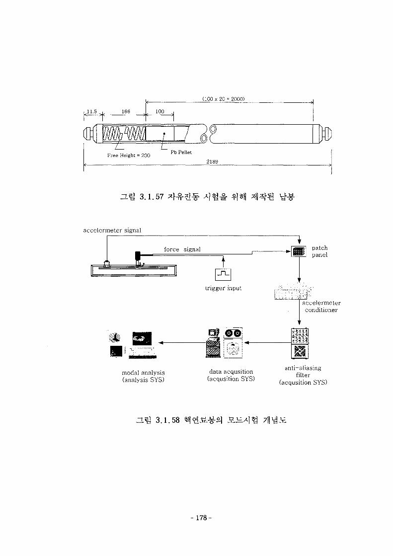
11.5 166
(100 x 20 = 2000)
100
Free Height = 200 Pb Pellet
2189
H ^ 3.1.57
accelermeter signal
1force signal
modal analysis(analysis SYS)
trigger input
data acqusition(acqusition SYS)
patchpanel
accelermeterconditioner
itanti-aliasing
filter(acqusition SYS)
H*& 3.1.58
- 178-
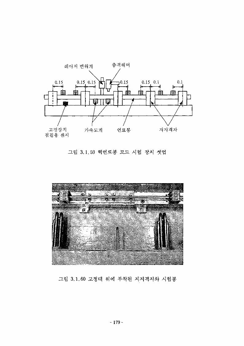
H ^ 3.1.59
I ,
1
n^ 3.1.60
- 179-
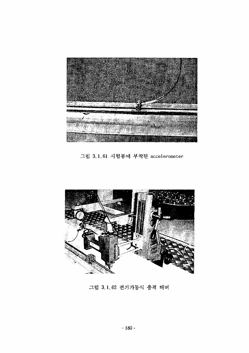
• • • • v•"•V-1.;
•• • • • ? . ' • ' • • • , • . > • •
. • - .'i
..jjT .••
.• > - • " '•
*
J l ^ 3.1.61 accelerometer
D.^ 3.1.62 ^
180-
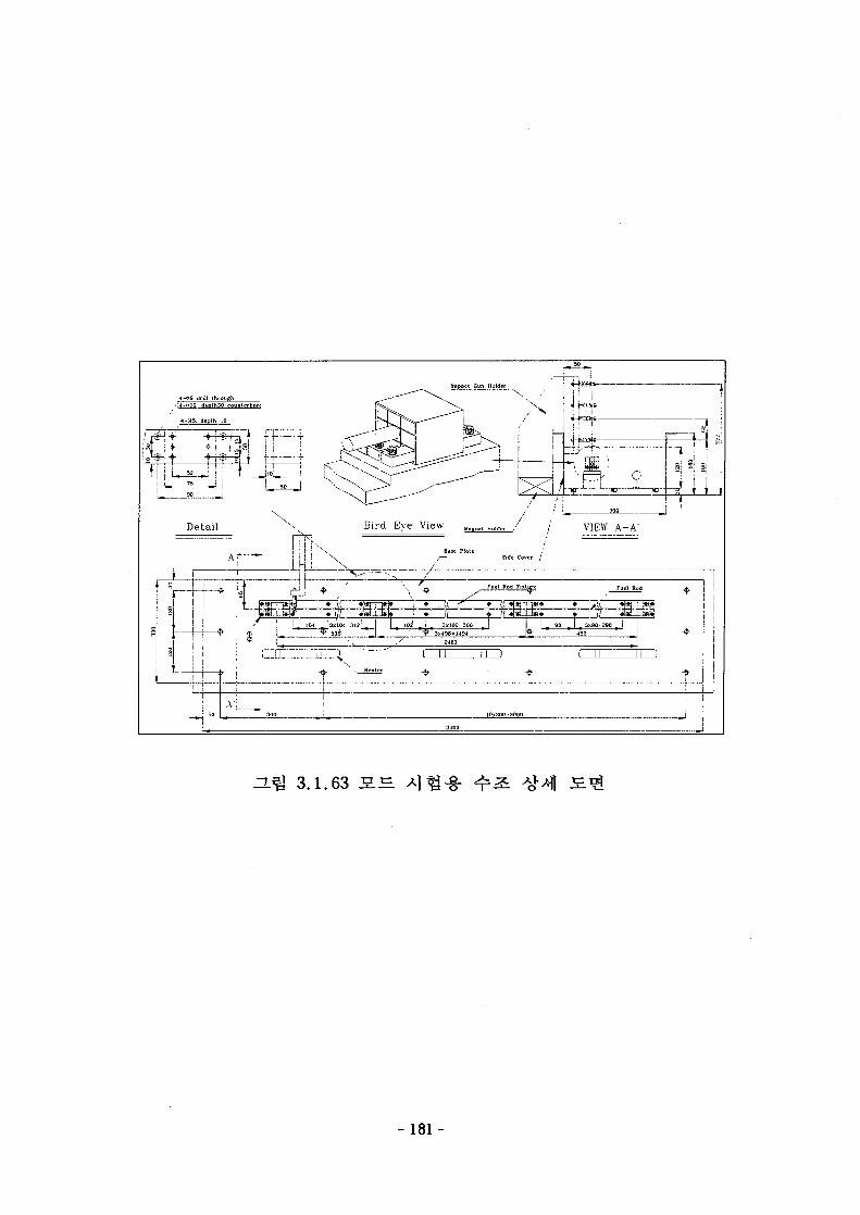
4-Q6 drill throughl4-o]0 dcplh30 counlerbort
4-M5. depth 10
°i i+
Detail \ Bird Eve View Magnel Holder VIEW A
Ar---
J ! !\T Fuel Bod fixtta
I 13x^04 = 3121 I IQZ i 3x102=306• SO* I ' • » 3XJ08.US1
A'L
—1
l i
-HU 3.1.63 I E
- 181-
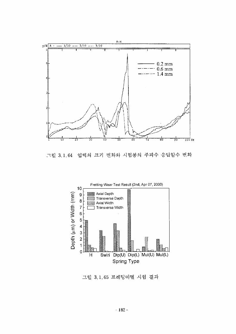
g/K|A ; 3/10 3/10 - 3/10A:H
( I r 1 I r
0.2 mm0.6 mm1.4 mm
80 30 ICO Hz
3.1.64 3.7]
Fretting Wear Test Result (2nd, Apr 07, 2000)
Axial DepthTransverse DepthAxial Width
I | Transverse Width
H Swirl Dip(U) Dip(L) Mul(U) Mul(L)
Spring Type
HQ 3.1.65 X\i&
- 182-
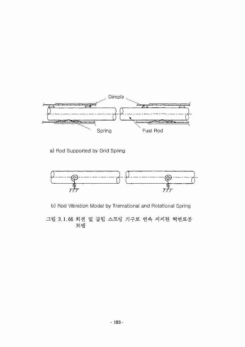
Dimple
Spring Fuel Rod
a) Rod Supported by Grid Spring
b) Rod Vibration Model by Tranrational and Rotational Spring
ZL^ 3.1.66
- 183-
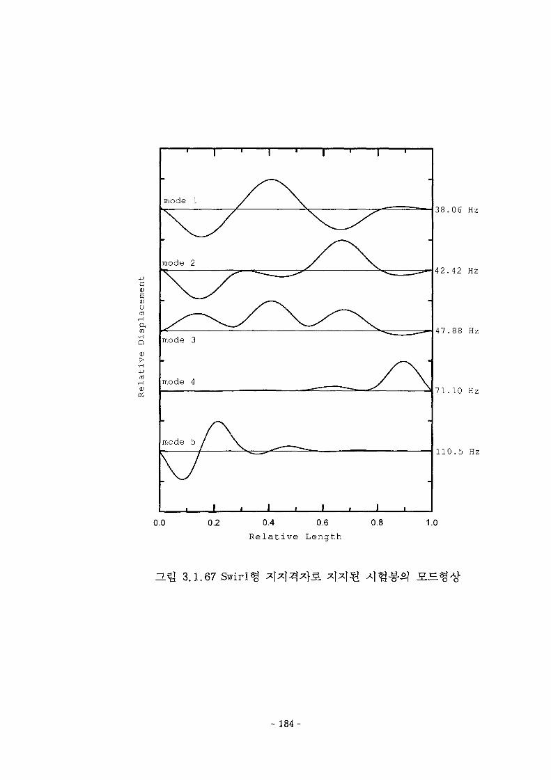
cw6CDOrd
a,
Q
>•rH
mr-H
mode 1
mode 2
mode 3
mode 4
mode 5
i • r
I I
38.06 Hz
42.42 Hz
47.88 Hz
71.10 Hz
110.5 Hz
0.0 0.2 0.4 0.6
Relative Length
0.8 1.0
H ^ 3.1.67 Swirl
- 184-
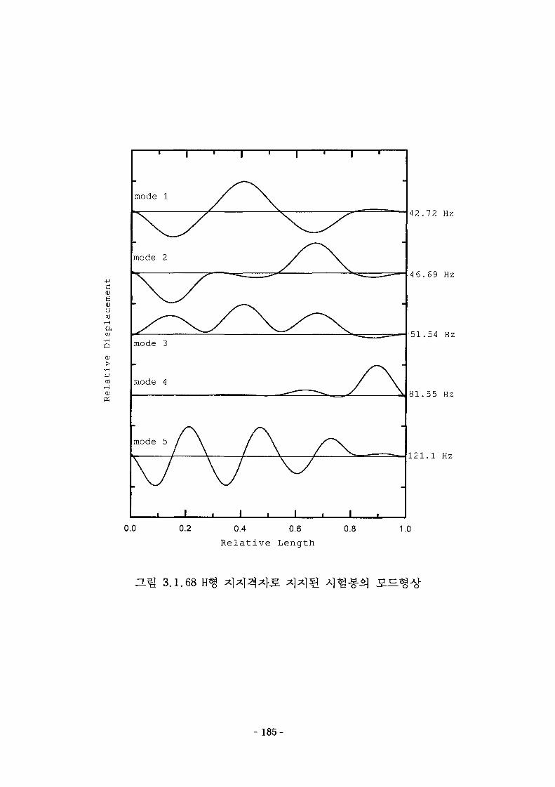
1 i i i i i | -
mode 1
g(DO03,—I
aCO
a
01
mode 3
mode 4
mode 5
I . I0.0 0.2
I I ,
0.4 0.6
Relative Length
42.72 Hz
46.69 Hz
51.54 Hz
81.55 Hz
121.1 Hz
0.8 1.0
H ^ 3.1.68
- 185-
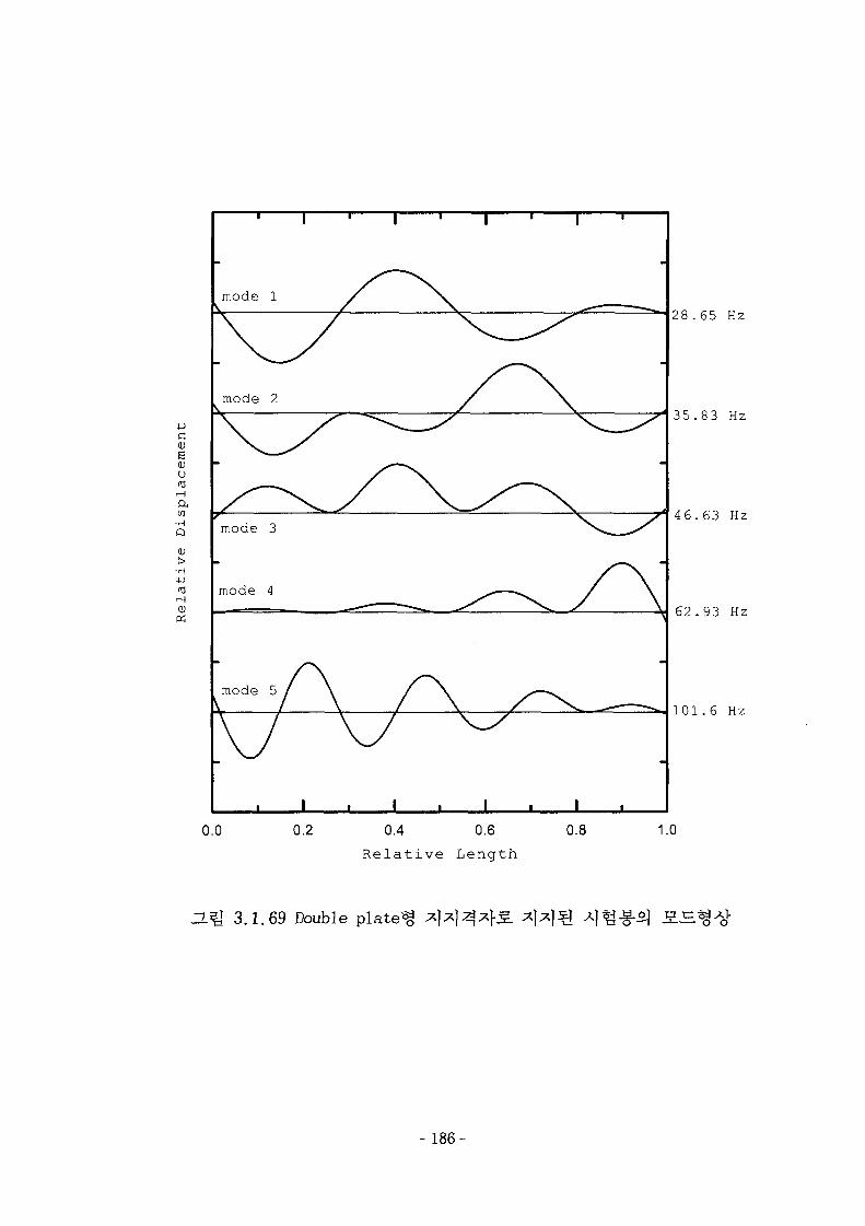
mode 1
mode 2
cg<x>u
CO•H
Q
0)
•H
4JtO
<-\
mode 3
mode 4
I
28.65 Hz
35.83 Hz
46.63 Hz
62.93 Hz
101.6 Hz
0.0 0.2 0.4 0.6
Relative Length
0.8 1.0
3.1.69 Double pla ted
-186-
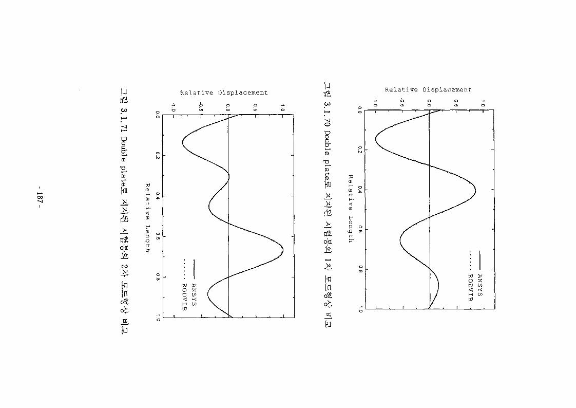
I
oo
i
uCO
II—I
CD
CD
5
ojnc
CO
Hin
Relative DisplacementpCO
I—I
o
o
cT13
r+CD
Relative Displacement
Inot
(Dh-•0)rtH-
(D
tr1
CD
rttr
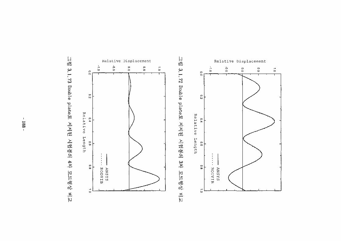
0000
uCO
CO
aotraT
(t>
Relative Displacement
o[n:
Hin
(D
r+
U
CO
roaocr0)
r
Relative Displacement
o|n;i£CO
faIn
°±a.
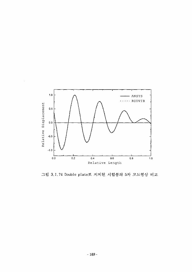
0.4 0.6 0.8
Relative Length
1.0
ZL^ 3.1.74 Double p l a t e d
- 189-
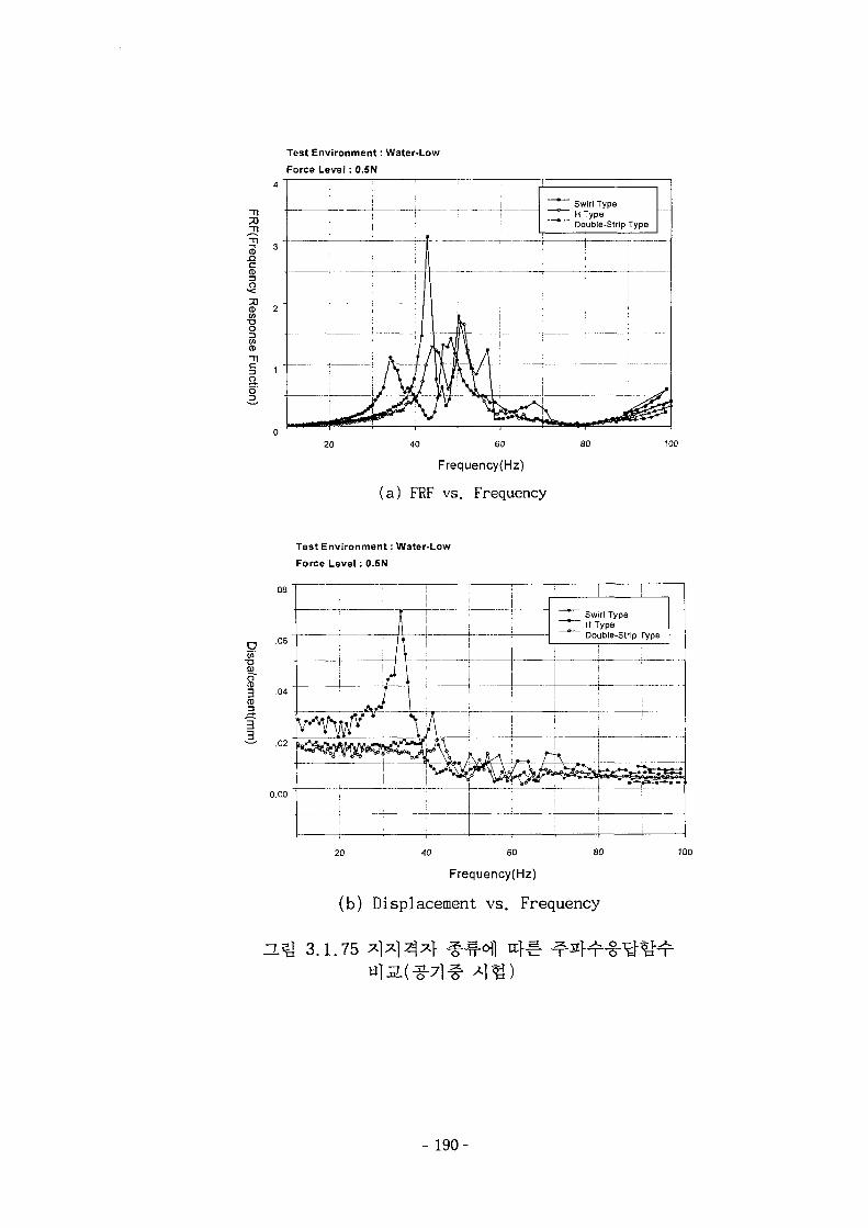
Test Environment: Water-Low
Force Level: 0.5N
I5" 2<nT3OCOCD
T 1
§ 1fto'
20 40 60
Frequency(Hz)
(a) FRF vs . Frequency
! i : jI : . ;
i n
• I Ii iO I
- hiiW\
\^ ~ Swirl Type° H Type" Double-Strip Type
!i |
i
• |
Test Environment: Water-Low
Force Level: O.SN
.08
•a
3 .04CD
l .02
0.00
—L_
_ Swirl Type* H Type" Double-Strip Type
i 1i
1 i
! ; IT i1 1
ao20 40 SO
Frequency(Hz)
(b) Displacement vs. Frequency
100
ZL^ 3.1.75
- 190-
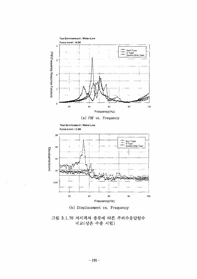
Test Environment: Water-Low
Force Level : 0.5N
Tl
Tl-n 4-
|
Ienno
i
1 i !
1 i Tr rlt:* Swirl Type. H Type
Double-Strip Type
i
20 40 60
Frequency(Hz)
(a) FRF vs. Frequency
80 100
Test Environment: Water-Low
Force Level : 0.5N
.08
n 0 6
"a
83 .04(D
3• = • .02
o.oo
j I
AI
1
!Swirl Type
~ p ~ H Type" Double-Strip Type
1u 1 i
;
| i :
; i
;
! 120 40 60 80
Frequency(Hz)
(b) Displacement vs. Frequency
3.1.76
191-
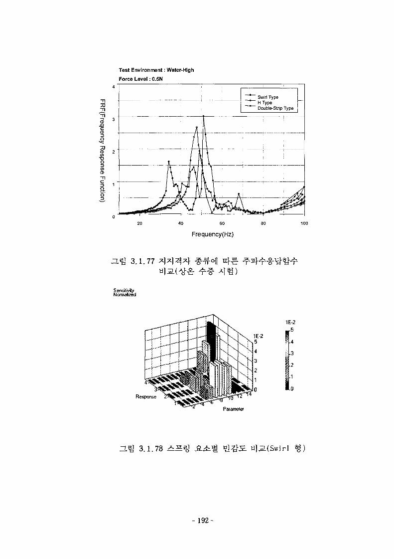
Test Environment: Water-High
Force Level: 0.5N
Swirl TypeHTypeDouble-Slrip Type
40 60 80
Frequency(Hz)
100
3.1.77
SensiMyNonnafeed
Response
1E-2
1E-25
4
3
2
1
0
r5
.4
.3
.2
.1
.0
Parametef
a?J 3.1.78 A ^ H]ji(Swirl
-192-
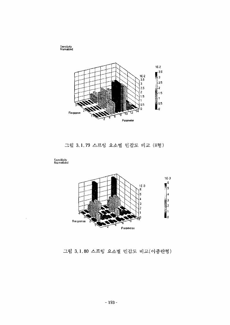
SensitivityN a
1E-2
3.5
3
•2.5
• 2
1.5
1
0.5
0
Parameter
ZLQ 3.1.79 ^ S aj
Sensitivity
Response
1E-3
.6
Parameter
H^ 3.1.80 ^ S
- 1 9 3 -
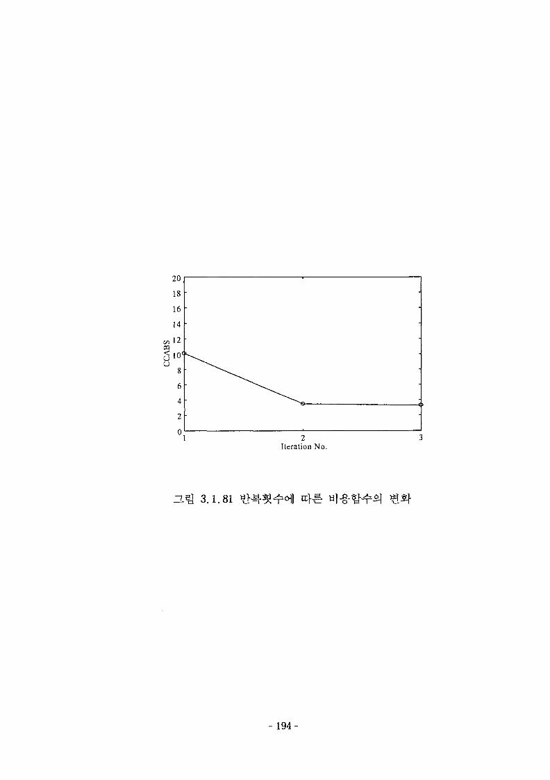
Iteration No.
a^} 3.1.81
- 194-
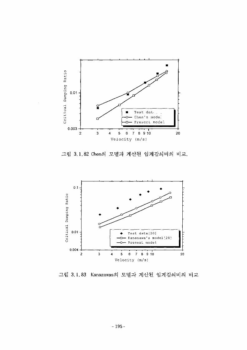
o•H
G
o•H
U
0.01 -
0.003
• Test dat.O— Chen ' s mode!
—•— Present model
4 5 6 7 8 9 10
Velocity (m/s)
20
ZL% 3.1.82
o•H
05
c•H
aQ
o
uu
0.1 -
H 0.01 -
0.004
• Test data[20]-n— Kanazawa's model[20]-O— Present model
4 5 6 7 8 9 10Velocity (m/s)
20
H ^ 3.1.83 Kanazawas^
- 195-
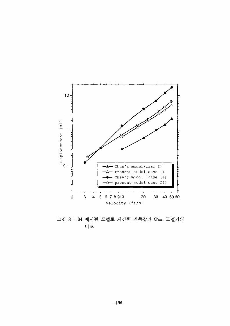
10-
1 -
cCDgCDOU
roaCO•H
Q 0.1 - — • — Chen's model(case I)— A — Present model(case I)
Chen's model (case II)present model(case II)
5 6 7 8 910 20
Velocity (ft/s)
30 40 50 60
ZL^ 3.1.84 Chen
- 196-
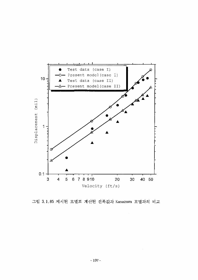
-H
- P
CDea;o(0
to•H
Q
10-—a
•—A-
I
Test data (case I)
Present model(case
Test data (case II]
Present model(case I I '
1 -
0.16 7 8 910 20
Velocity (ft/s)
30 40 50
ZLQ 3.1.85 Kanazawa H|J2.
- 197-

Dimple
Spring Fuel Rod
a) Rod supported by grid spring
rfrb) Rod vibration model simplified by rotary and bent
spring
H ^ 3.1.86 i ^ ^ l
- 198-
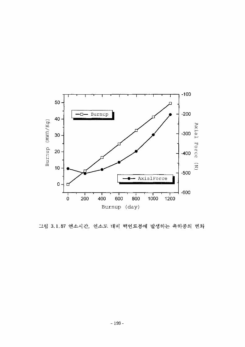
Cn
Q
PQ
5 0 -
4 0 -
3 0 -
2 0 -
1 0 -
0 -
0 200 400 600 800
Burnup (day)
1000 1200
-100
-200
-300
-400
Ax
ial
on0)
-500
-600
-L^ 3.1.87
- 199-
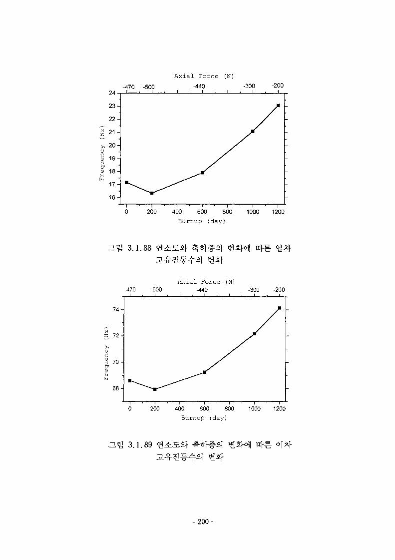
A x i a l F o r c e (N)
-470 -500i . i
200 400 600 800Burnup (day)
1000 1200
3.Q 3.1.88
Axial Force (N)-440
200 400 600 800Burnup (day)
1000 1200
-L^ 3.1.89
- 2 0 0 -
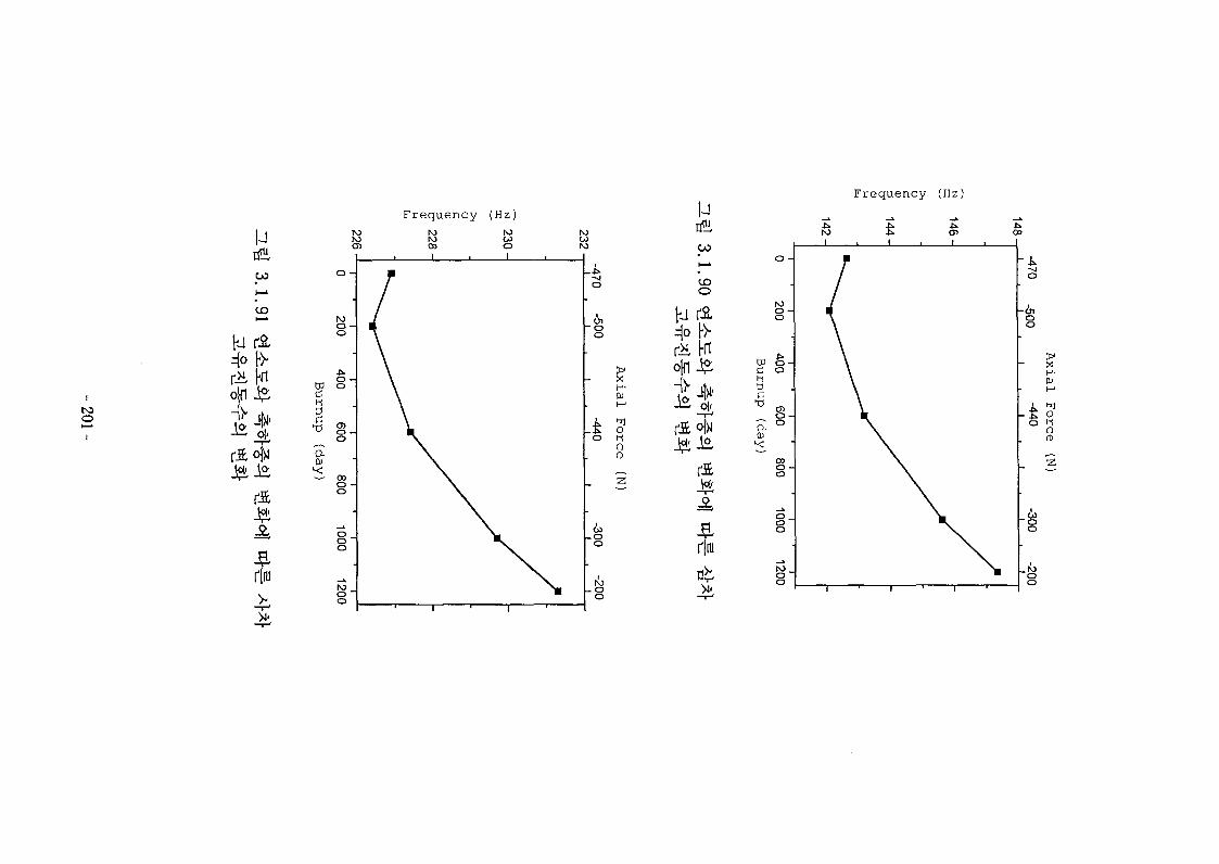
F r e q u e n c y (Hz)
urfH,00
*
O
• •
Fn
rJ£°bi
r|iu
MCO
too
F r e q u e n c y (Hz)
Ol-i0CD
ofn-ft-Ja
r|iu
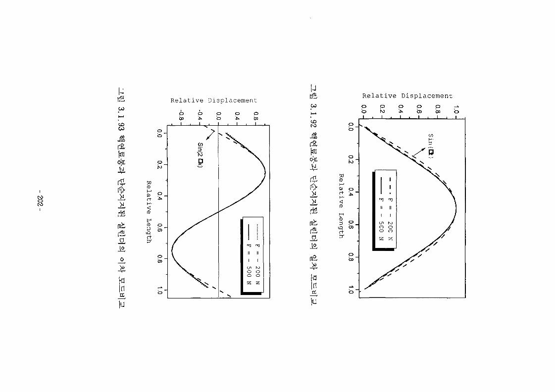
COOto
uCO
CO
r£
m
Relative Displacement
ob
?0fD
01rt
f1
fD
r t
©
CD
O
bo
inIX
oCD1
v «
o
|
p o, 1 t
y
] i
II
i
mooz
Oboi
\
)
IIII
i
rooo
21
uCO
CO
I Ti r
ojn;
tub
Jl
mi
inrt
Relative Displacement
pb'
oho
50fDt-1
0)rt
r t
pcn '
pbo '
0
b1 1
0ho1
II
enOO
Z
• • •
O
, 1
11
Tl11
II
1
(-O0O
Z
O p ->•O) 00 OI . I . I
COV-
1J//'J
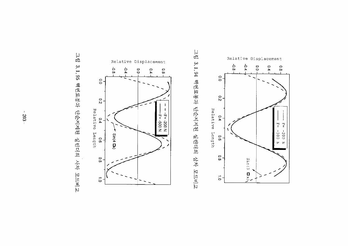
rooi
uCO
CO
o(n;
r-fr
nib
pb
pho
QJ
rt
tr1
r+
pen
pbo
Relative Displacement
I*In
uOJ
CD
o(c;
r-D-_>^
nib
Hin
&j
rt
tr1
r t
Relative Displacement
pb
pho
p
obo
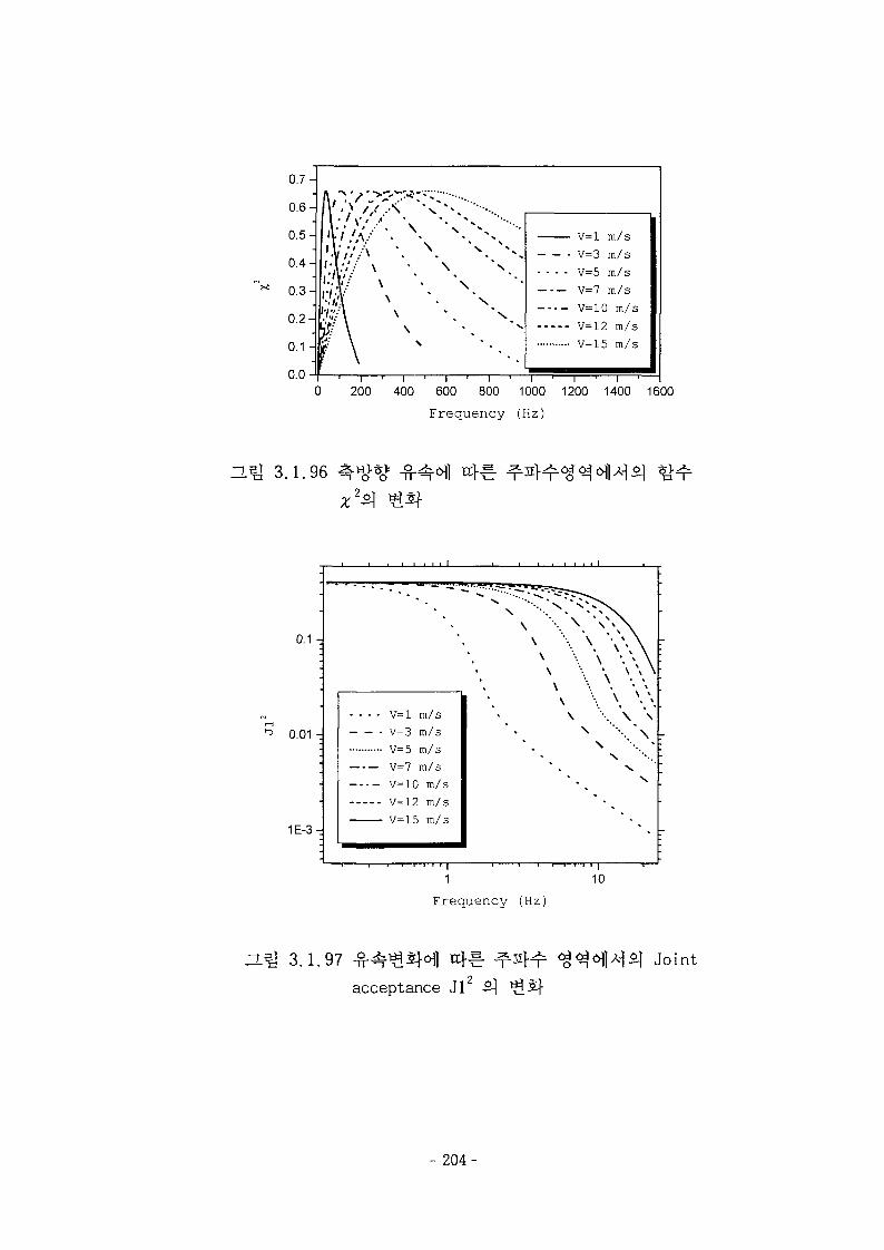
0.7-
1 •'} / / x ' " " - ^ ^ r ••••-..
\\
\
N.
X
V=l m/s- V=3 m/s
- - - - V=5 m/sV=7 m/sV=10 m/sV=12 m/sV=15 m/s
200 400 600 800 1000 1200 1400 1600
Frequency (Hz)
H*y 3.1.96
•
0.1 -
0.01 -.'•
•
•
•
1E-3-
•
.... v=l
V=3V-5V=7
V=10
V-12
m/sm/sm/sm/sm/s
m/sm/s
v \ \ \ \
\ w •.\ • " • • • ^
\ • • • . \
\
\
•
\ \
\ *
\
\
• . . '
1
F r e q u e n c y (Hz)
10
He] 3 - 1 .97 ix}^-
acceptance Jl
Joint
- 2 0 4 -
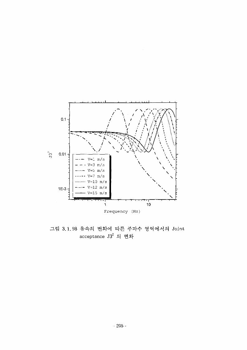
.
0.1 -
-
-
n m -U.VJ I ~
-
-
1E-3-_-
• i i i i
""*,\
\
V=l
V=3
V=5
V=7
v-ioV=12\T. ~\ c:
1 " " I I T )
, , , i
I
i
/m/sm/sm/sm/s
m/sm/sm/s
-r-r-TT
1
/ N • / / \ ' '
' \ / v'
\ 1 •' X:
\
\\
\
' I
\*
\ / \
sV)•V/ /
7\/ \\\\\
\
>.yr\ •
( \ \ :t \ -\ * \
\ \ * 'I \1 •1
\ \ *
\ \« \% \
\ ^ :
\ •
\ * t •
\
\
\ :
\ :
1
Frequency (Hz)
10
ZLQ 3.1.98acceptance J32
Joint
- 205-
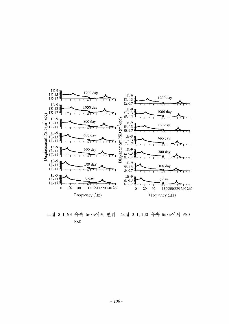
1200 day
//I • I T .
7 IE-13g 1E-17§ 1E-9JS, IE-13S-1E-17
20 40 18020022024026
Frequency (Hz)
i • i • i • i18020022024026040
Frequency (Hz)
3.1.99
PSD
3.1.100 PSD
- 2 0 6 -
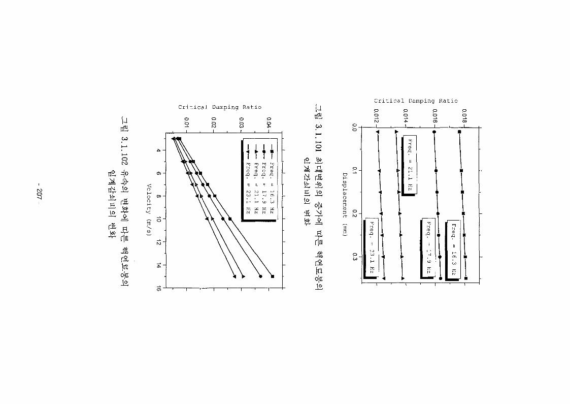
roo
uto
•£ -ft
rftrliu
ojn:
ooH-rr•<
Critical Damping Ratio
po
ooI
po
j
Freq.
II
23.
ccN
HFreq.
Freq.
» II
r ?pc mN N
T
Freq.
II
16..
N
M0 0
Critical Damping Ratio
it ±,it to
riiu
ojn;
P
a
0)O
I P.
p
poho
_j
pb
i
pb
pbCDi
Freq.
1!
17.
N
T
1T1
Freq.
II
i—1
<n
a:
I
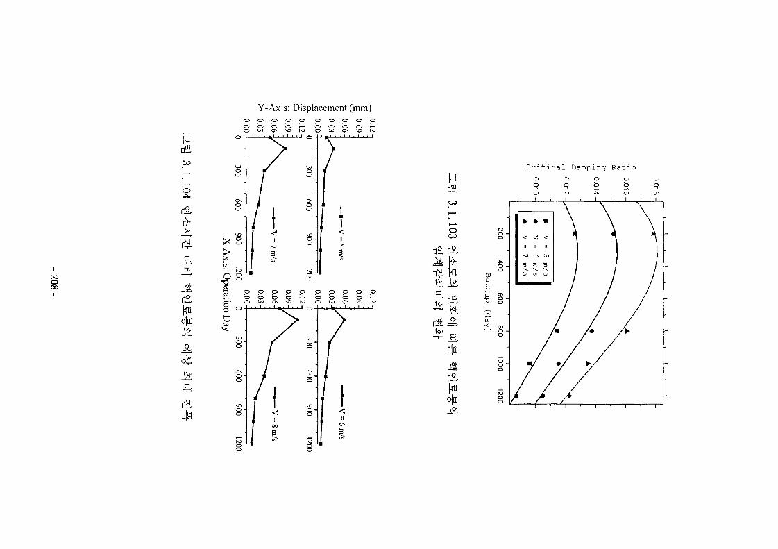
Y-Axis: Displacement (mm)
CO
I—*
I—'
o
too00
ojn:
1*
p o o o oo o o o i—
CO
oCO
Critical Damping Ratio
to1-1
a
o[iE
00oo
ooo
N3O
o
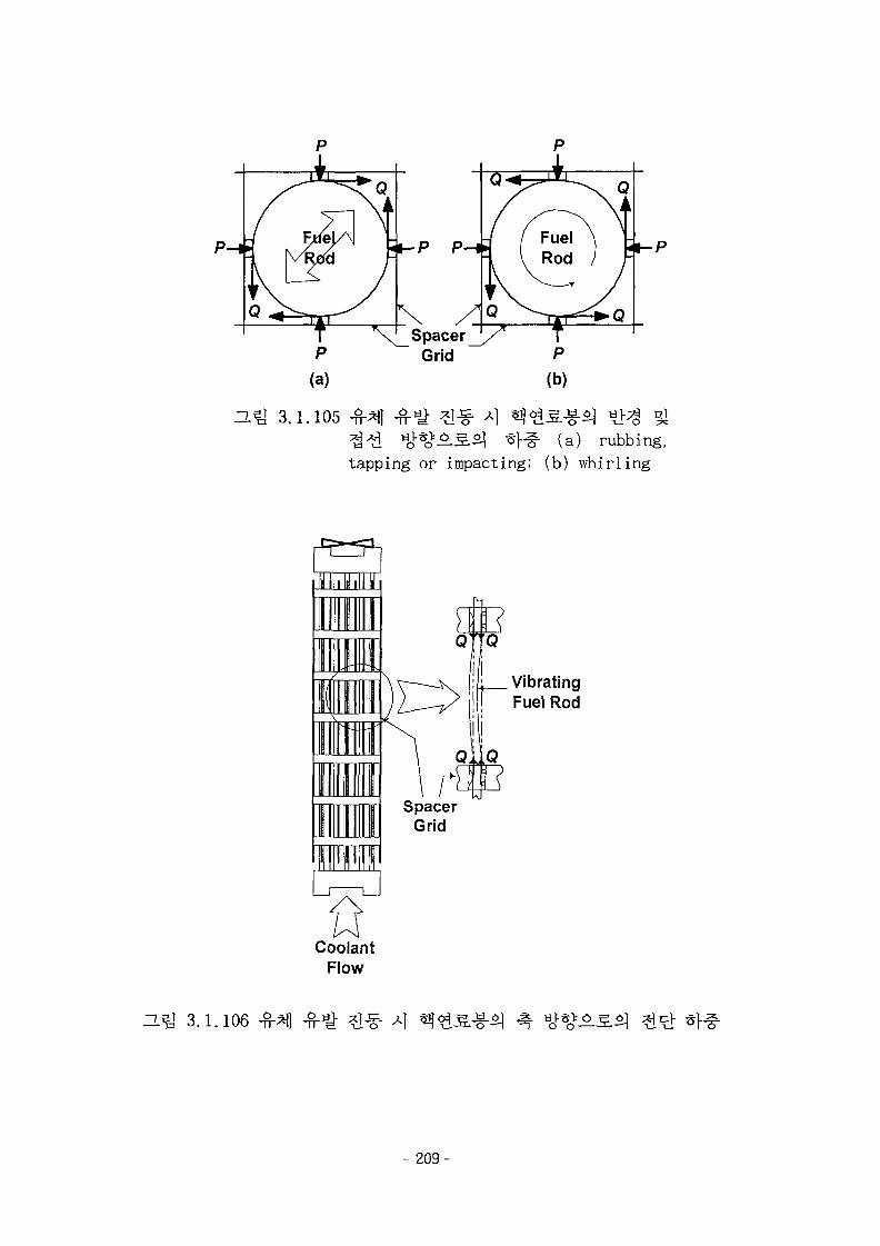
p p
T X^SpacerP Grid
(a)
3.1.105(a) rubbing,
tapping or impacting; (b) whirling
VibratingFuel Rod
SpacerGrid
CoolantFlow
He] 3.1.106
-209-
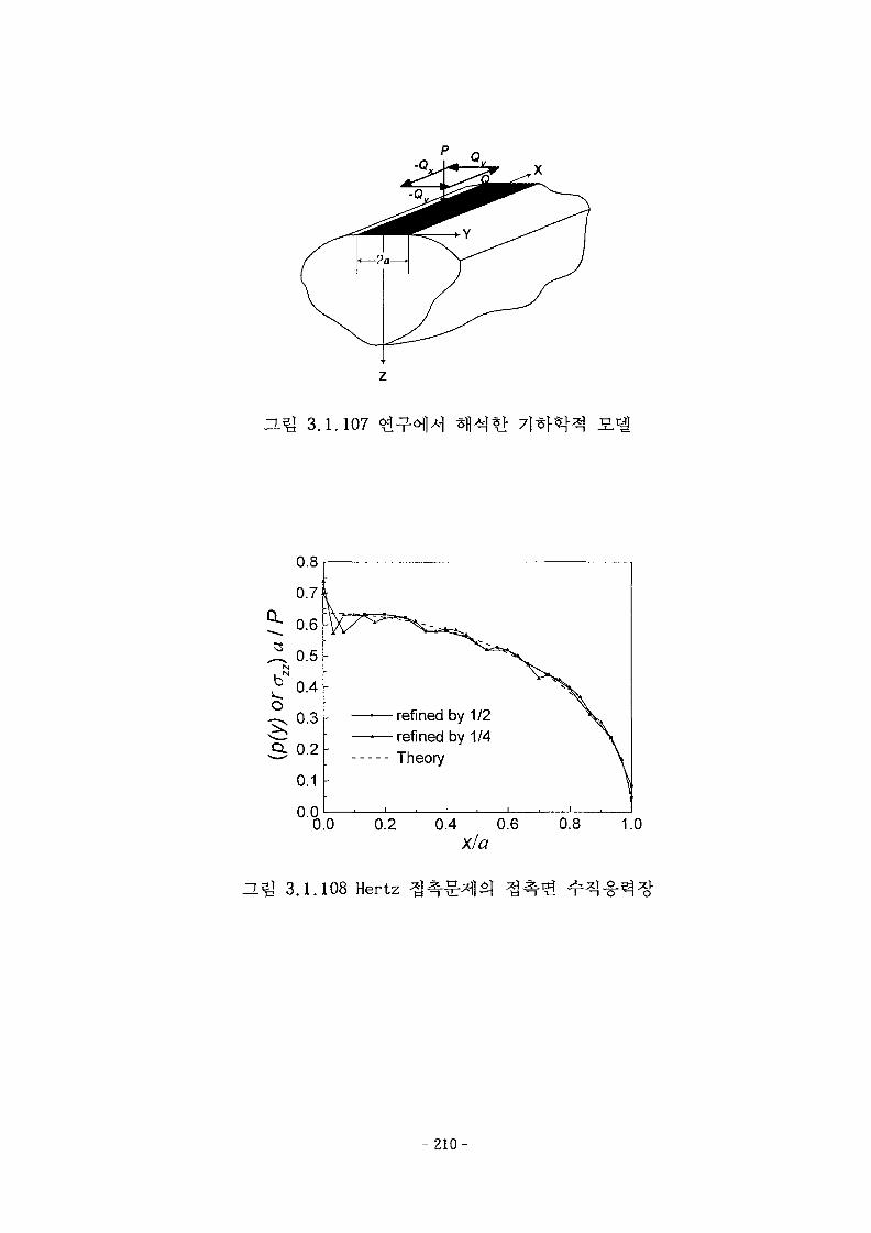
D.Q 3.1.107
0.8
0.7
0.6 K
0.5
0.4
0.3
0.1
•—refined by 1/2•—refined by 1/4•-- Theory
o ooo 0.2 0.4 0.6X/a
0.8 1.0
25J 3.1.108 Hertz
- 2 1 0 -
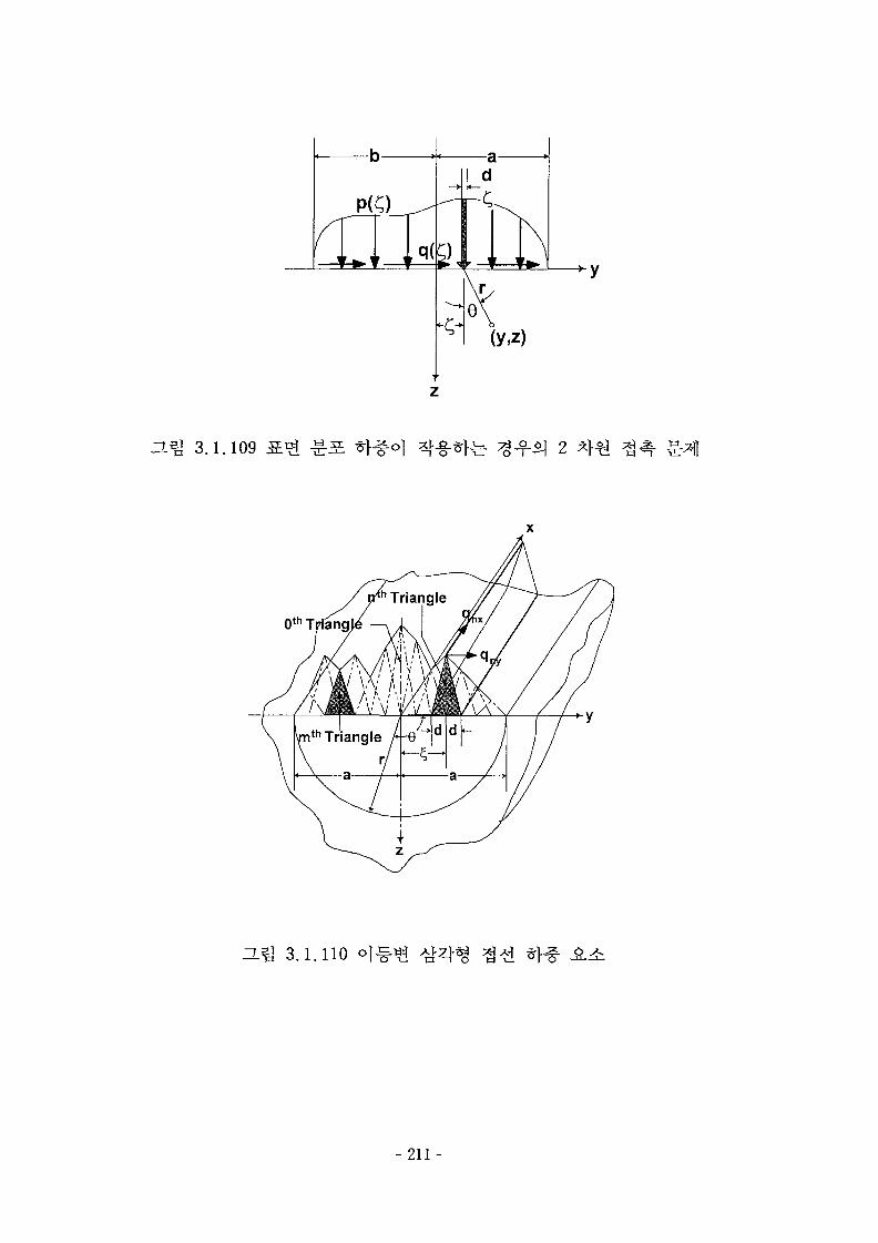
3.1.109
0 th T
ZL^] 3.1.110
- 2 1 1 -

0.8
0.6
0.4
0.2
n n
SL
- 1P
- /
7f
Exact solution
\ /
sL1P
\
-1.0 -0.5 0.0
y/a
0.5 1.0
3.1.111 Mindlin-Cattaneo ^/ fiP= 0.5
Hm 3.1.112 (Or < Qy °i
- 2 1 2 -
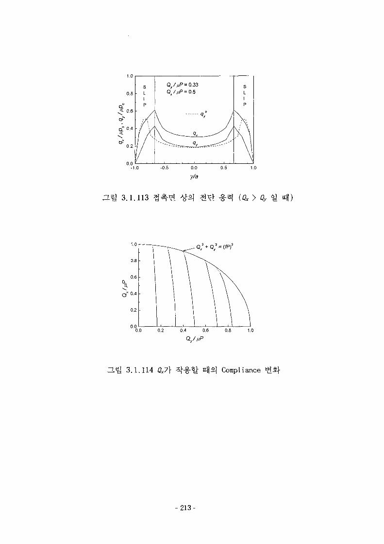
1.0
-1.0
Q/AP=0.33
a ^ 3.1.113
1.U
0.8
0.6CL
a*0-4
0.2
no
~ 2-~ O + O
\ \
1 \\
1 , 1 p 1 1
= (fF)2
\ \
\ \
0.0 0.2 0.4 0.6 0.8 1.0
H^l 3.1.114 ^7]- Compliance
-213-
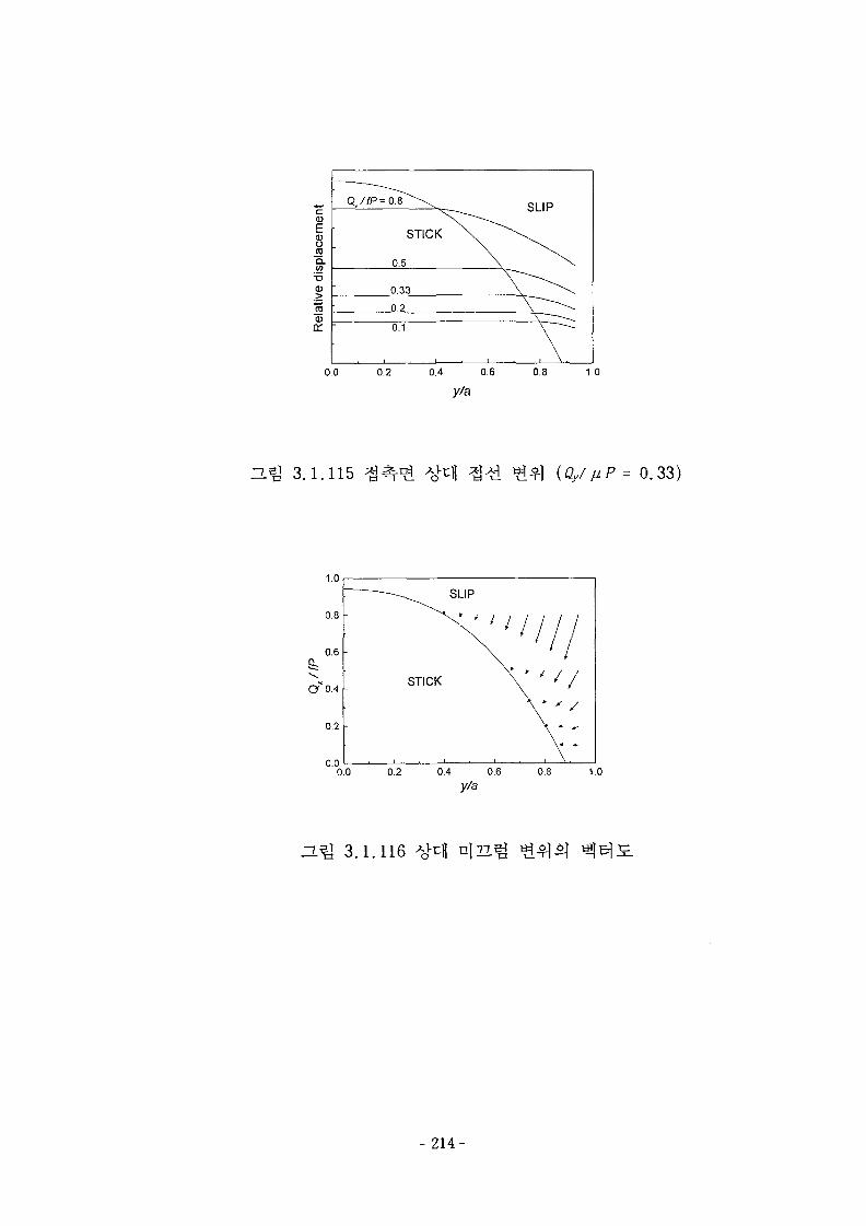
0)
a>ojoQ .CO
CD>
a:
Q//P =OfT^\
STICK X .
0.5
0.33
0.2
0.1
SLIP
.V0.0 0.2 0.4 0.6
y/a0.8 1.0
H ^ 3.1.115 ^ (Qy/vP= 0.33)
0.0 0.2 0.4 0.6y/a
0.8 1.0
ZL^ 3.1.116
- 214-
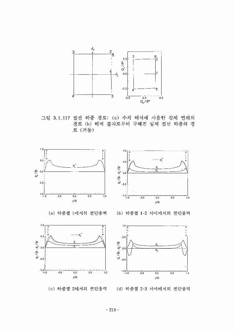
I
I
1 2
1
6
b
0.2
6:o"
Ay 0.0
4
6•-»
1
-0.5 0.0 0.5
3.1.117 ^ * f# 3 3 : (a)(b) * f l^
-0 .5 •
-1.0
(a) (b) 1-2
-1.0
(c) (d) 2-3
- 215-

1.0
0.5
a-Or" 0.0
-0.5 -
-1.0-1.0
sLIP
/
\
1
SL1P
\
-0.5 0.0
y/a
0.5 1.0
0.5 •
a-cf" o.o
a-
-1.0-1.0
sLIP
q,qy
sLIP
-0.5 0.0
y/a
0.5 1.0
(e) (f) 3-4
0.5
a-Or1 0.0
.1 n
sLIP
\ , — q.
siip
A
-1.0 -0.5 0.0
y/a0.5 1.0
-1.0
(g) (h) 4-5
1.0
0.5 -
•B-
0.0
-0.5 h
-1.0-1.0
.s
. L• ]
q,
sLI
-0.5 0.0
y/a
0.5 1.0
( i ) ( j ) 5-6
- 216-
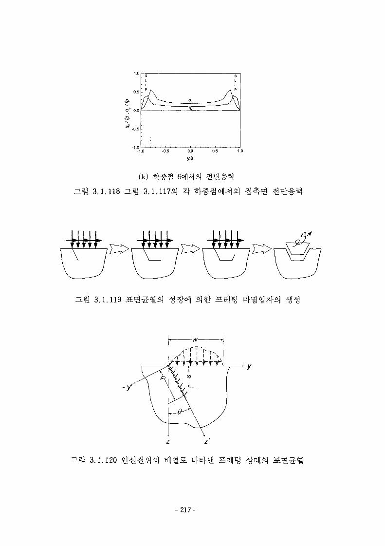
1.0
0.5 -
Cr" 0.0
-1.0
sLIp
V21
Q,
. . . . i . . . .
sL1
-1.0 -0.5 0.0
y/a
(k)
ZL J 3.1.118 H^ 3.1.117^ 4
0.5 1.0
nf j 3.1.119
H ^ 3.1.120
- 2 1 7 -

(X10"2)0.5
0.0
o-0.5
-1.0 -
-1.5 -0
'. Crack*
-.
Closusuren°u
10°20°
30°
i i
•y * ^ ^
\ " \ ^ ^
N ^
N * \
\ N^
\
\
\
\
• t
2 32a/w
(a)
(X10'2)
(X102)1.0
0.8
o
^ 0.4
0.2
0.00
10°
20°
30°
(X10"2)
l ^ j 3.1.121
(b)
(Q / UP = 0.36, U = 0 .3 ) : (a) Kr, (b) Kn
218-
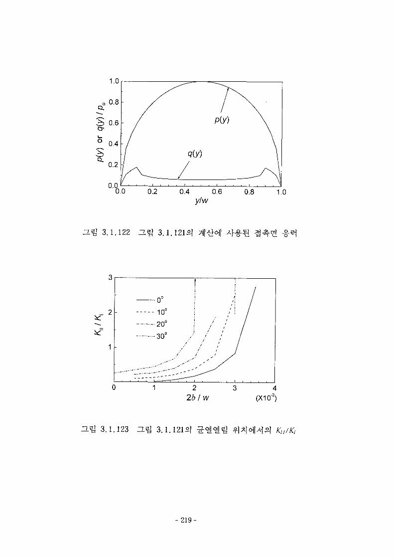
n.m 3.1.122 IHg 3.1.121^1
(X10~2)
3.1.123 3.1.121^
- 2 1 9 -
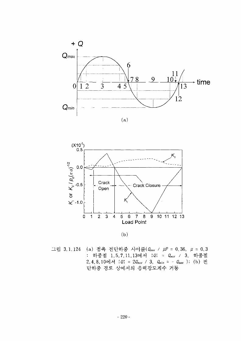
+ Q
Qmax
0
omm
1 2 3 4 5
(X10"2)
(a)
0 1 2 3 4 5 6 7 8 9 10 11 12 13Load Point
(b)
time
U.*g 3.1.124 (a)
\Q\ = 2Qmax / 3 , Qmin =
= 0.36, fi = 0.3
fflax / 3, *}^-%- C^ ): (b) £
- 2 2 0 -
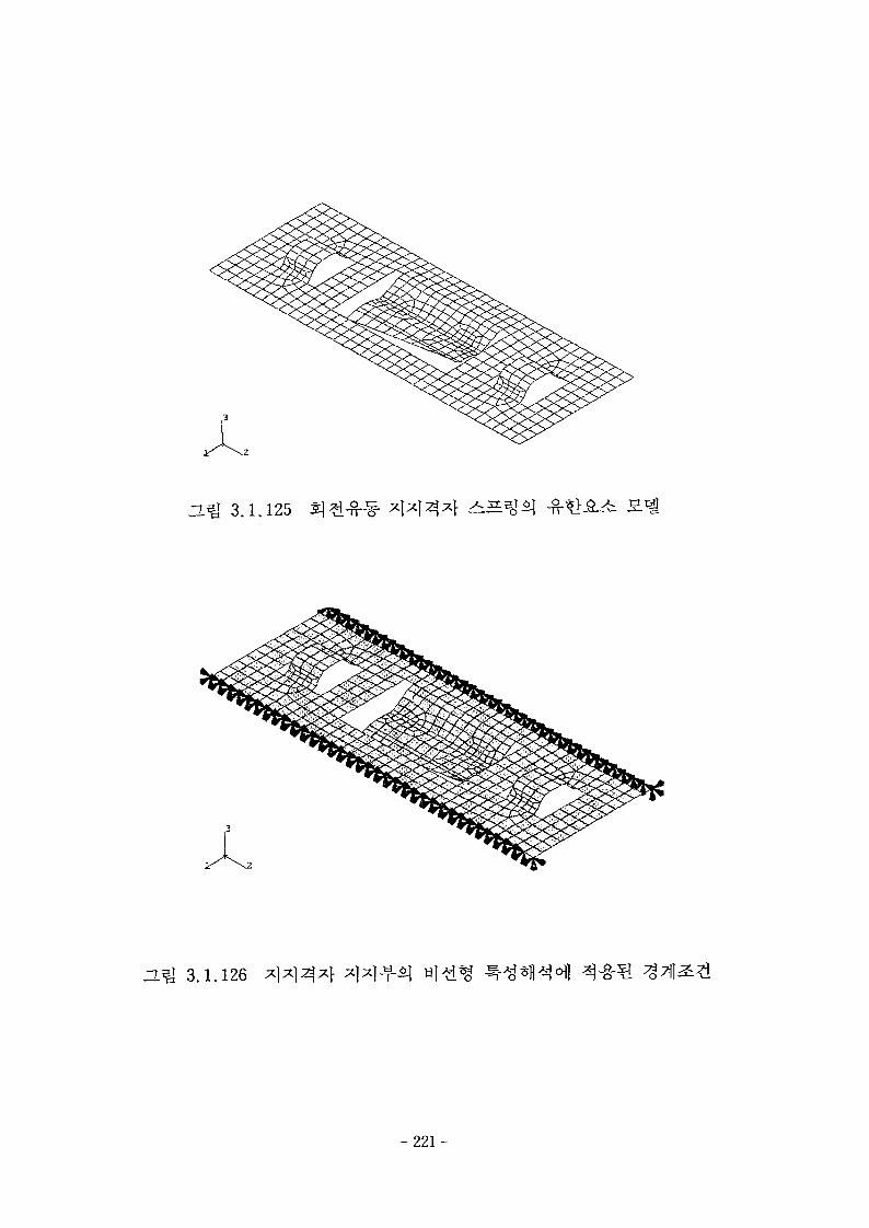
H ^ 3.1.125
H^ 3.1.126
-221-
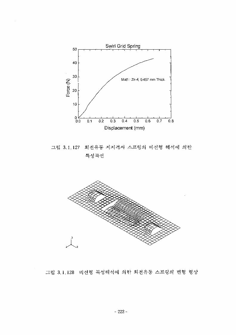
Swirl Grid Spring
Mat'l: Zir-4, 0.457 mm Thick
0.0 0.1 0.2 0.3 0.4 0.5 0.6 0.7 0.8
Displacement (mm)
ZL% 3.1.127
ZL^ 3.1.128
- 2 2 2 -
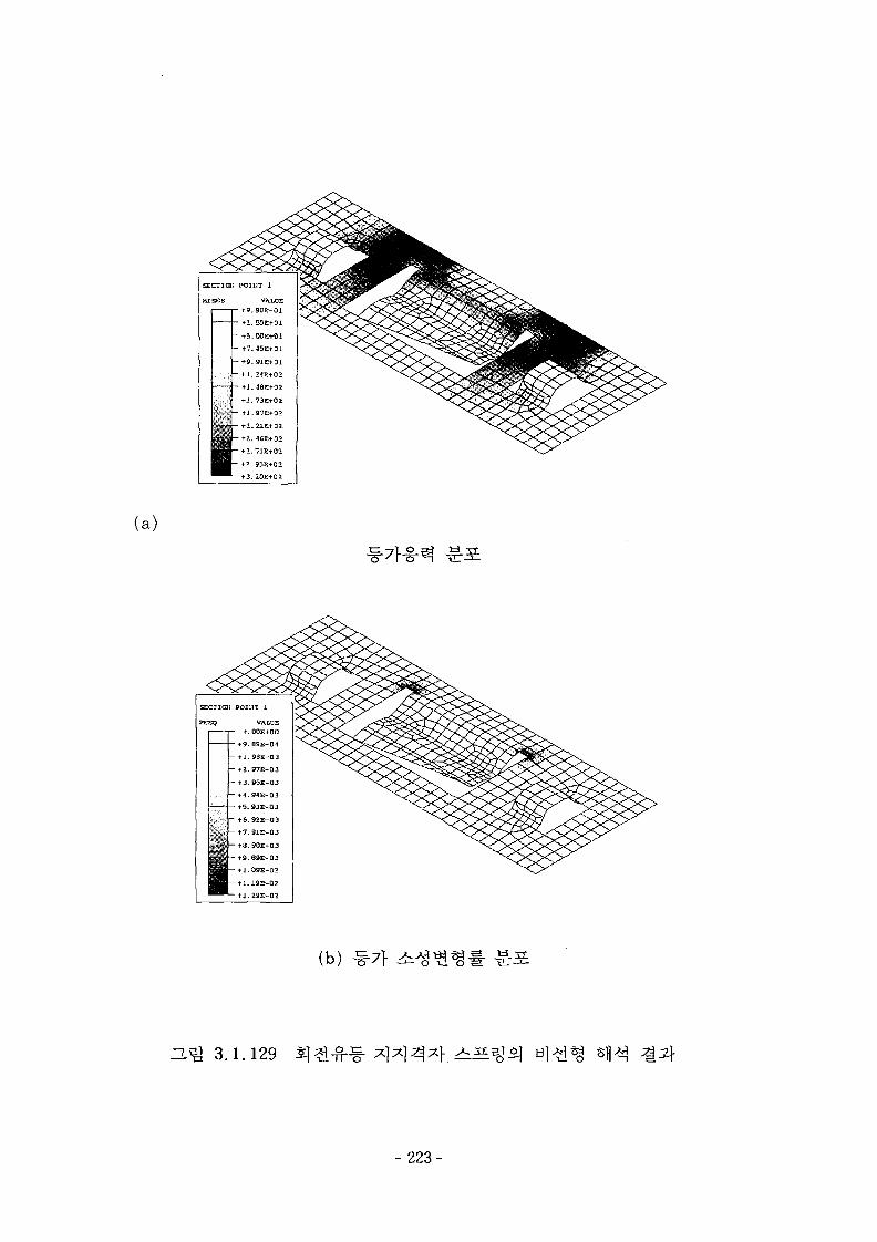
(a)
tl.48E+O2
- tl.73E+02
- +1.97E+01
- +2.21E+02
+2.46E+02
+1.71S+02
• t9.89E-01- ti.9BE-D3
- +2.97E-03
- + 3.95E-0.3
- +4.94E-03
tO.93E-03
(b)
ZL^ 3.1.129
- 223-
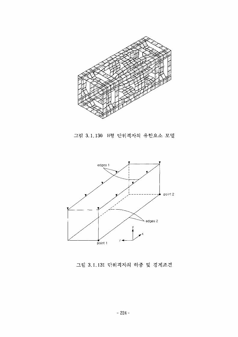
1a1
IT
H& 3.1.130
edges 1
point 2
edges 2
point 1
H1I 3.1.131
- 2 2 4 -
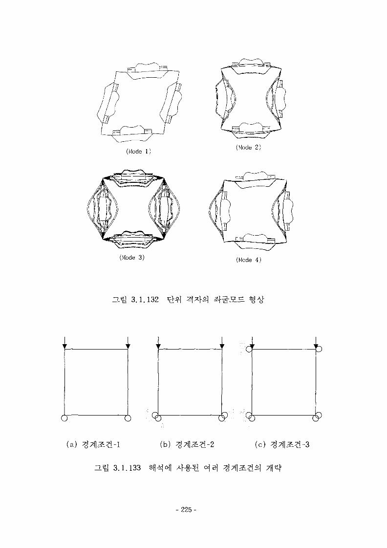
(Mode 1)(Mode 2)
(Mode 3) (Mode 4)
ZLB] 3.1.132
c^
(a) (b) (c)
ZL5j 3.1.133
-225-
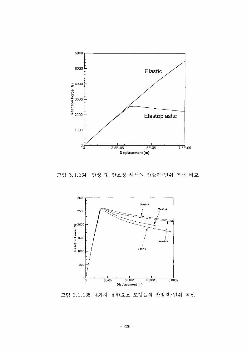
6000
5000 -
2.5E-05 5E-05Displacement (m)
7.5E-05
3.1.134
3000
2500
Mesh-1
Mcsh-4
0 5E-05 0.0001 0.00015Displacement (m)
0.0002
H^ 3.1.135 47}^|
- 2 2 6 -
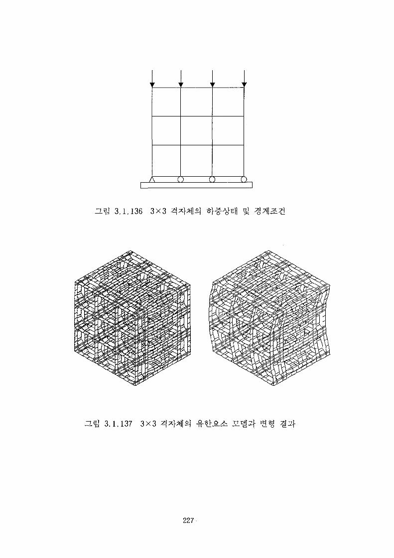
A c
r v
3.1.136 3X3 ^
3.1.137 3X3
- 2 2 7 -
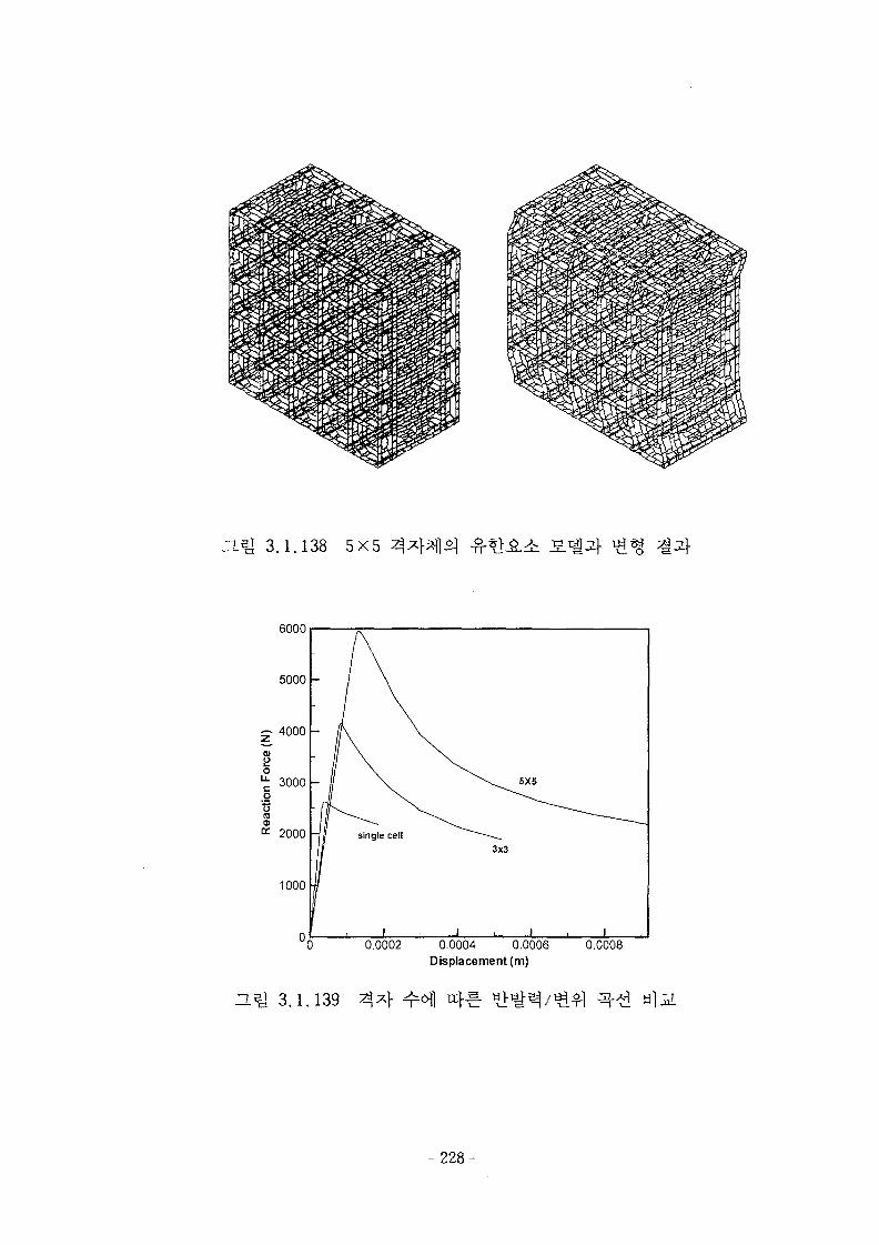
n.^ 3.1.138 5X5
6000
0.0002 0.0004 0.0006Displacement (m)
0.0008
T.S] 3.1.139
- 228-
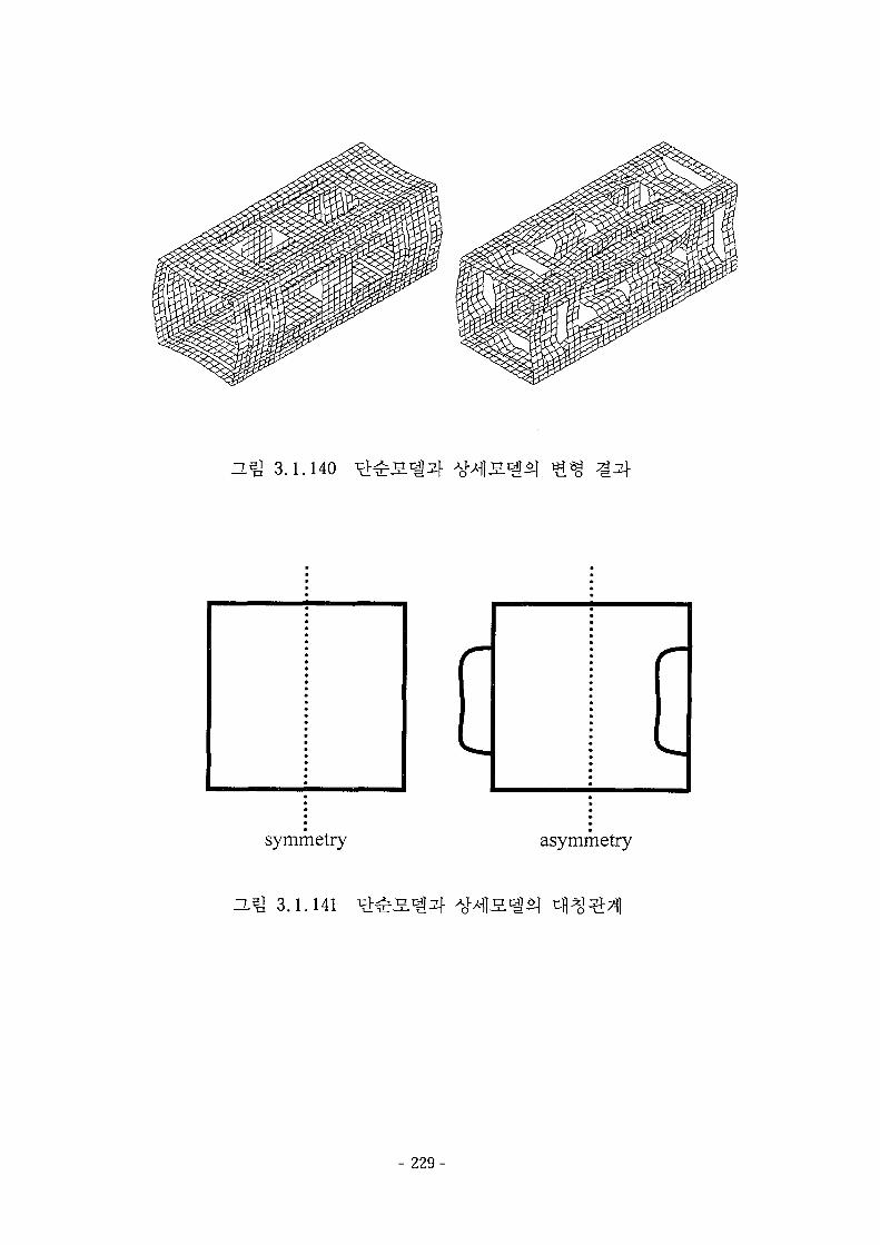
3.1.140
asymmetry
- 229-
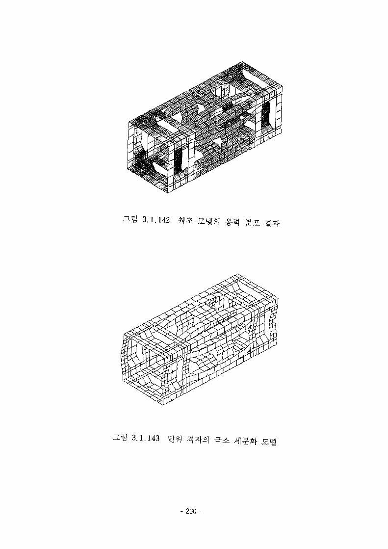
3.1.142
3.1.143 /-fl^-Sf
- 2 3 0 -
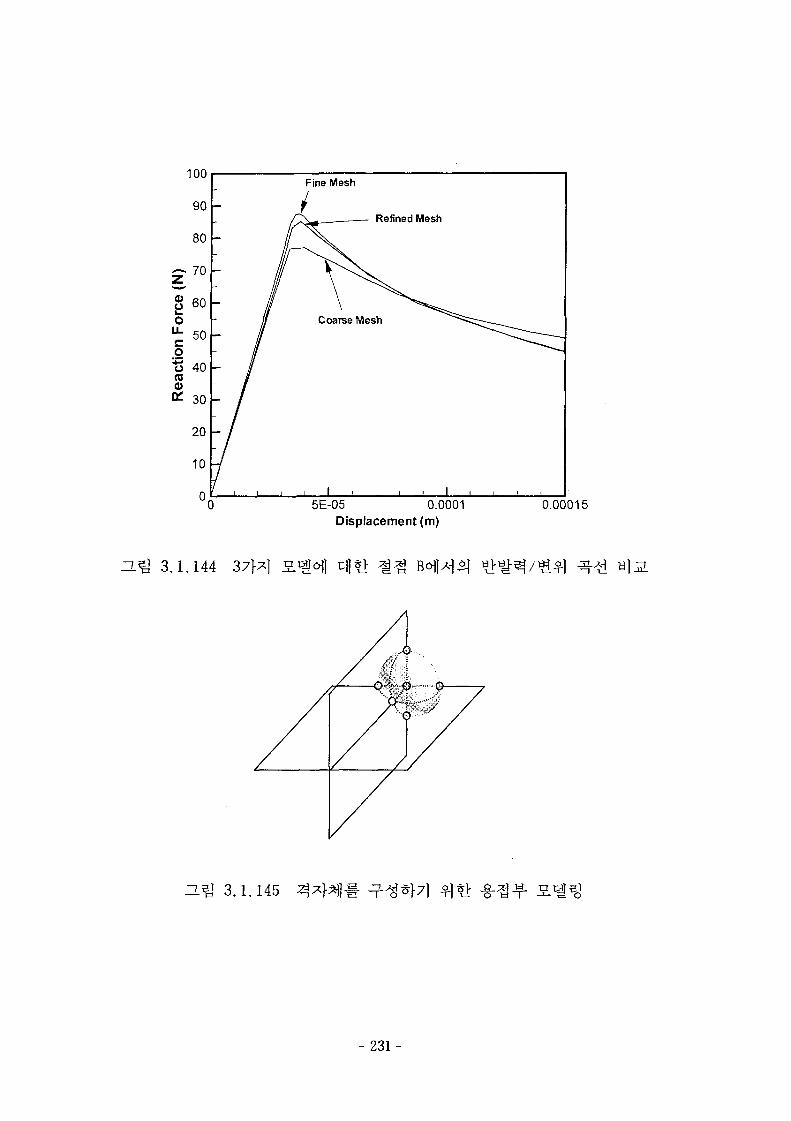
0
Fine Mesh
Refined Mesh
5E-05 0.0001Displacement (m)
0.00015
n.^ 3.1.144
3.1.145
- 231 -
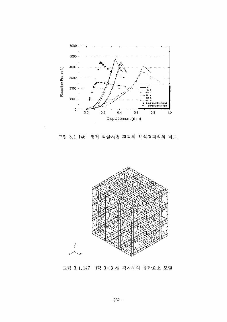
6000
5000 -
I£co"8a:
4000
3000
2000
1000 -
1 ' 1 ' t ' J
' - ' • • / • A--.\/ • • • • • . . •=
/ / ' * ^
— ^ - N o . 1- -:- - No. 2
No 3—r—No 4
No. 5No. 6
- » - 6-pdni welding model- • - 1-point welding modeJ
0.0 0.2 0.4 0.6 0.8 1.0
Displacement (mm)
a ^ 3.1.146
H ^ 3.1.147 3X3
- 232-
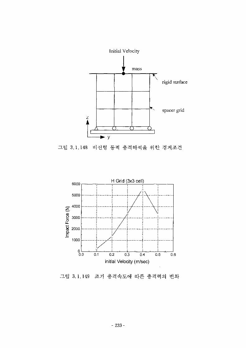
Initial Velocity
1
• y
ZLBl 3 .1 .H8 H
mass
\rigid surface
spacer grid
A () C) O
6000
5000 -
4000 -
3000 -
8f
2000 -
1000 -
H Grid (3x3 cell)
.
r
//
/
/
\
\
00.0 0.1 0.2 0.3 0.4 0.5 0.6
Initial Velocity (m/sec)
3.1.149
- 233-
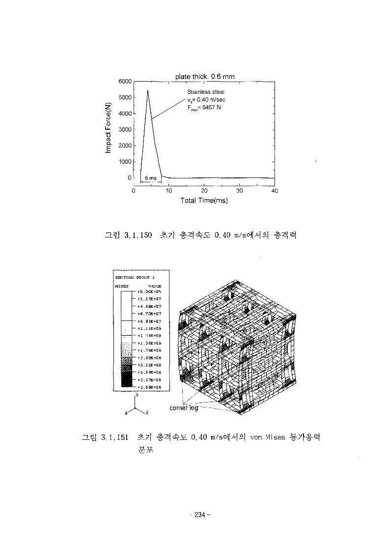
o
o03
plate thick. 0.6 mm
30
Total Time(ms)40
ZL^ 3.1.150 S.7] 0.40
SECTIO1I POI11T 1
M3SES VALtE
- +2.57E+07
— +4 ,49E+07
~ t-€.7QE+07
t».92E+07-+ l . i iE tOf t
- +J .56E-K3S
,1— +1.73E+0S
\
cornerleg'
ZL& 3.1.151 0.40 von Mises ^7f-g-
- 2 3 4 -
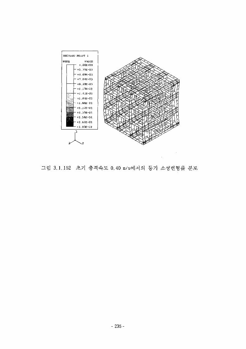
- t».35E-03
- +4.69E-0i
- +7.04E-O3
+ 9.39E-03
t2.ilE-02
tl.35E-01
+2.58E-02
t2.82E-02
+3.03E-D2
3.1.152 L7] 0.40
- 235-
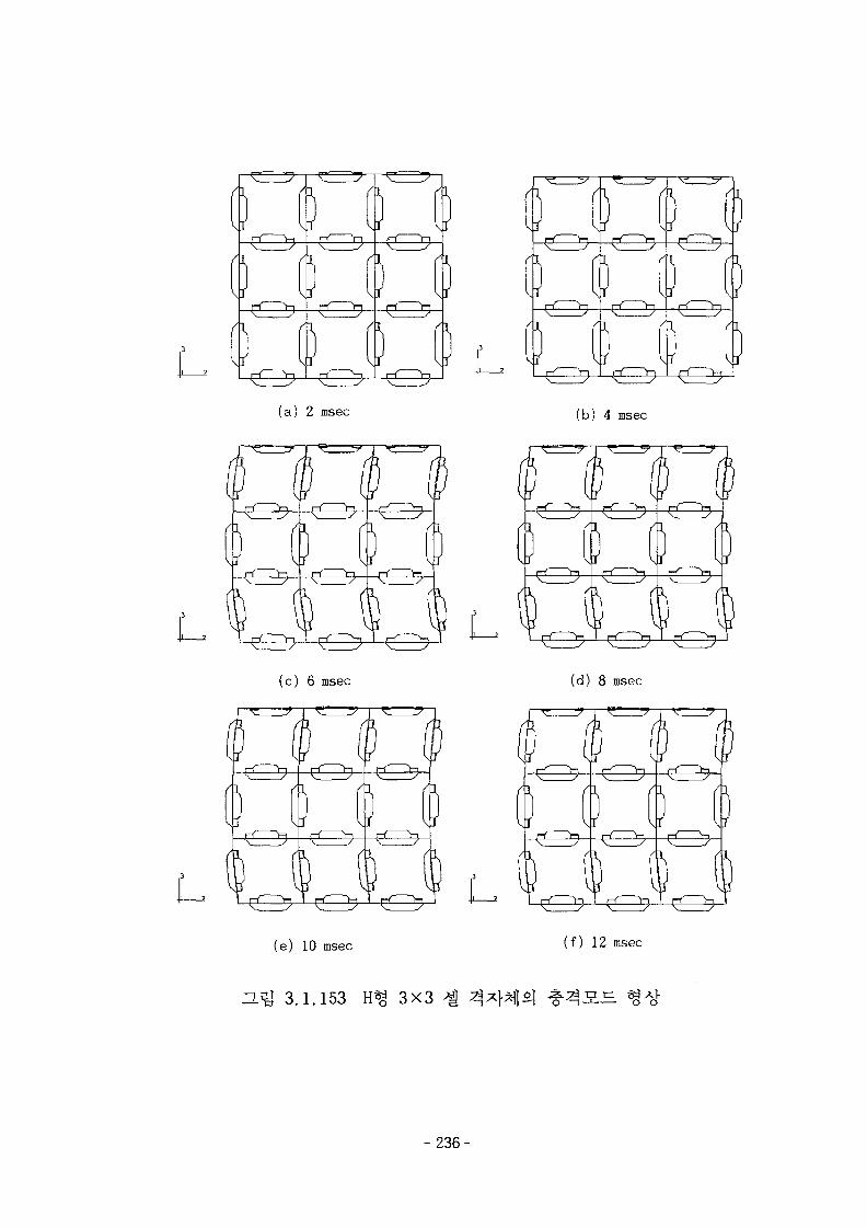
(a) 2 msec (b) 4 msec
(c) 6 msec (d) 8 msec
D
D(e) 10 msec (f) 12 msec
H^l 3.1.153 H^ 3X3
-236-
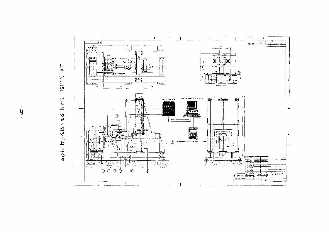
00-0
u
C71
>4
3Hi
0 © ® © © ©
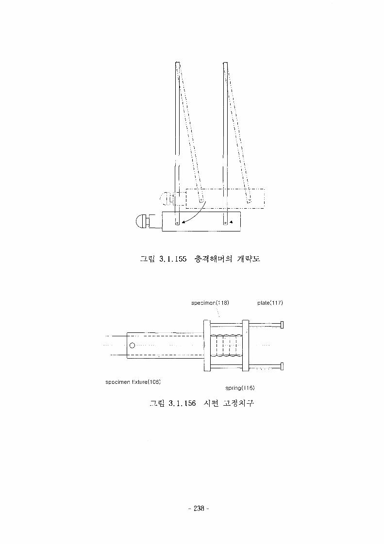
\
: \\ '.
•. \
\ ' .
• . \
\ :
: \
\ '.
: \
\ ' •
•. ll '.• \
\ :
: \
i •.•. \
i '.•. \
\ '
•. \
\ ' .
: i\ '•
-i \ '.i • i
ZL^ 3.1.155
specimend 18) plated 17)
O • - -
I I I I
I I II I II I 1] 1 \
specimen fixtured 06)springd 16)
3.1.156
- 238-
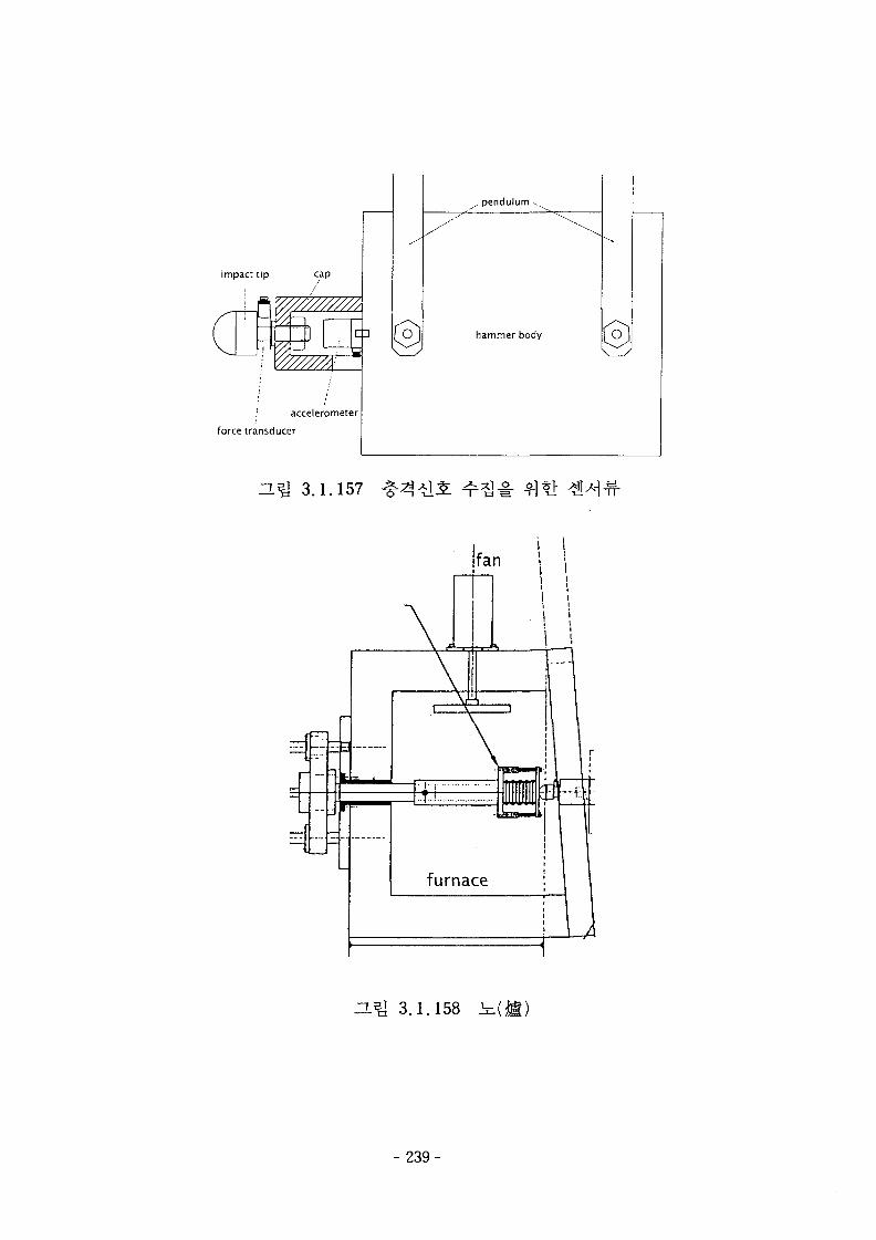
impact tip cap
: accelerometer
force transducer
. pendulum .
hammer body
ZL^ 3.1.157
3.1.158
- 2 3 9 -
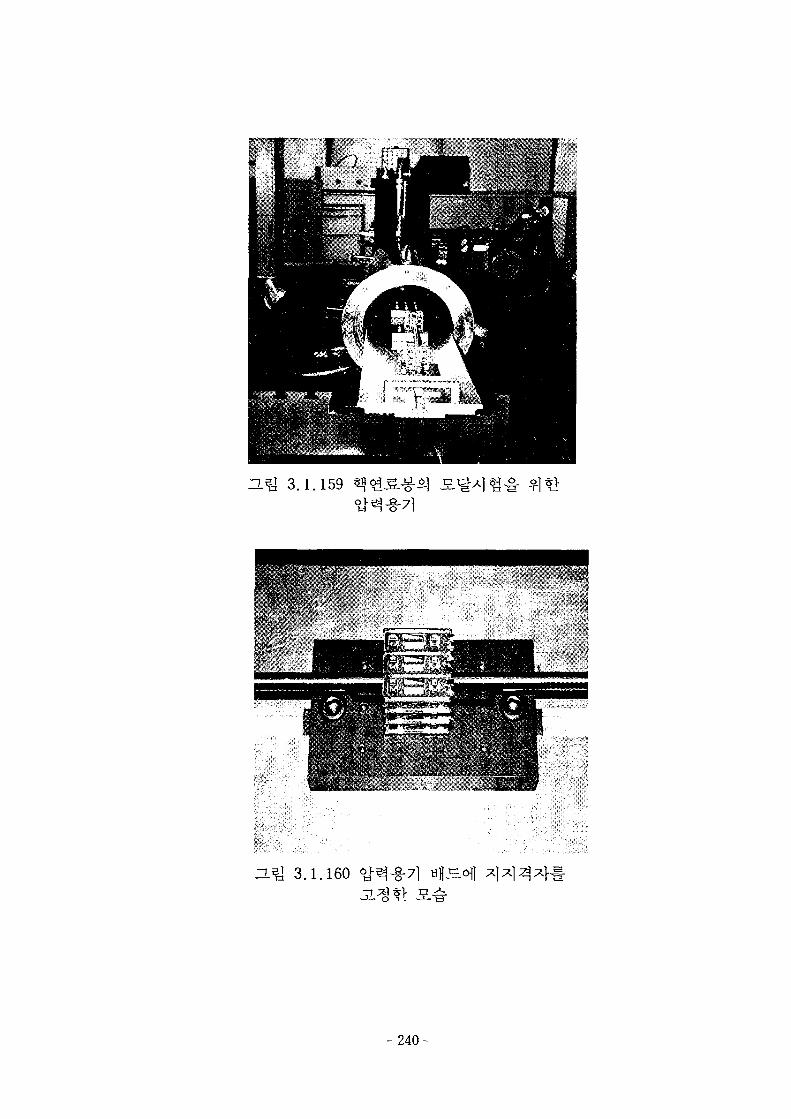
n i l 3.1.160
- 2 4 0 -
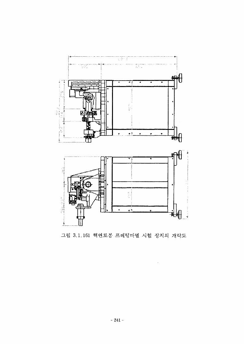
P -9 '- * *
3.1.161
- 2 4 1 -
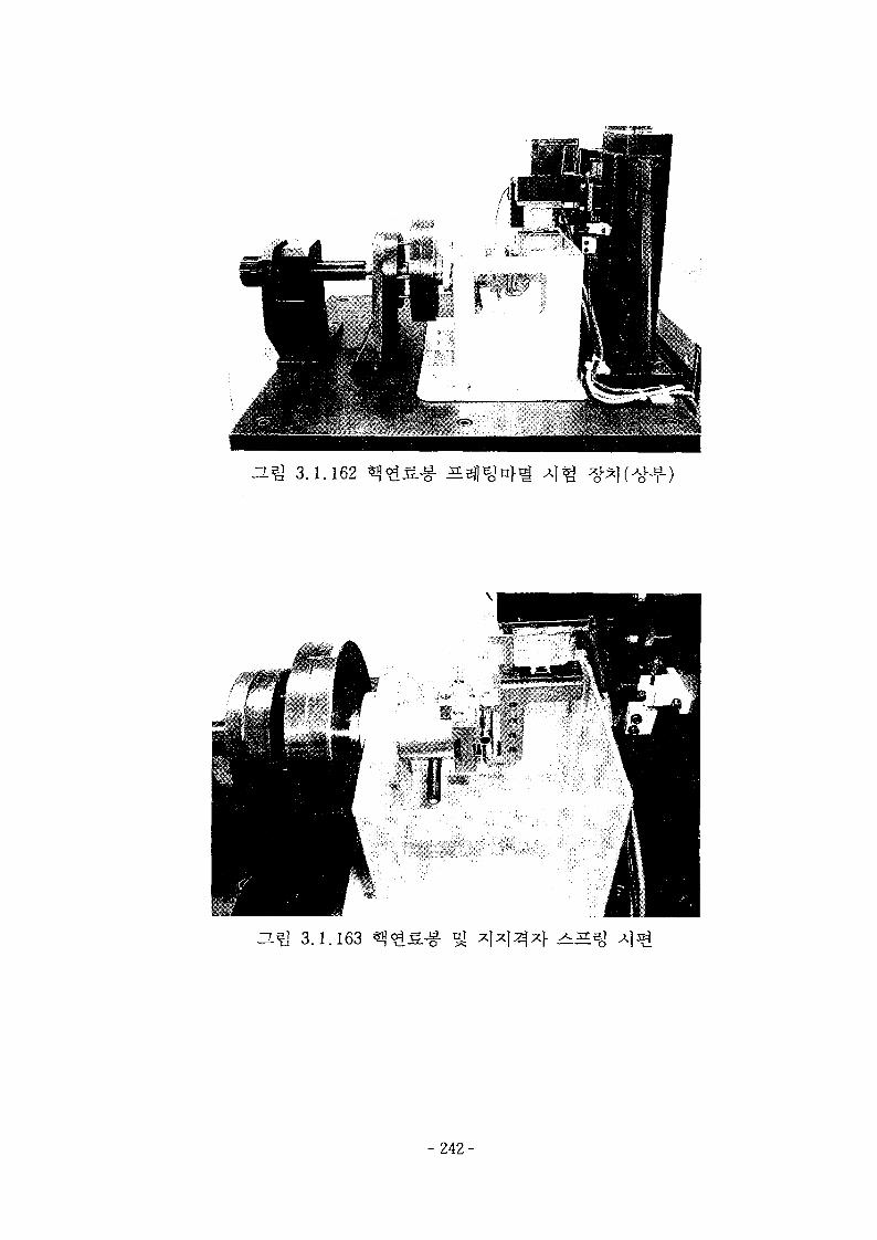
O.Q 3.1.162
DJQ 3.1.163
- 2 4 2 -
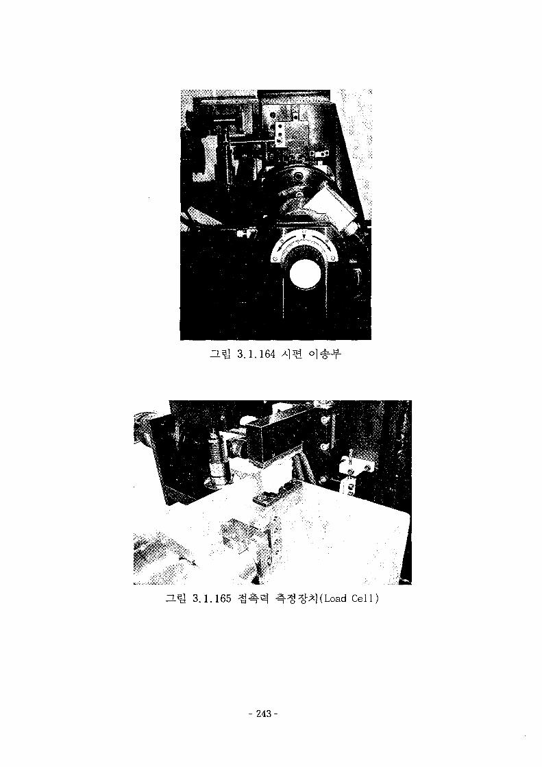
3.1.164
~L5i 3.1.165 Cell)
- 2 4 3 -
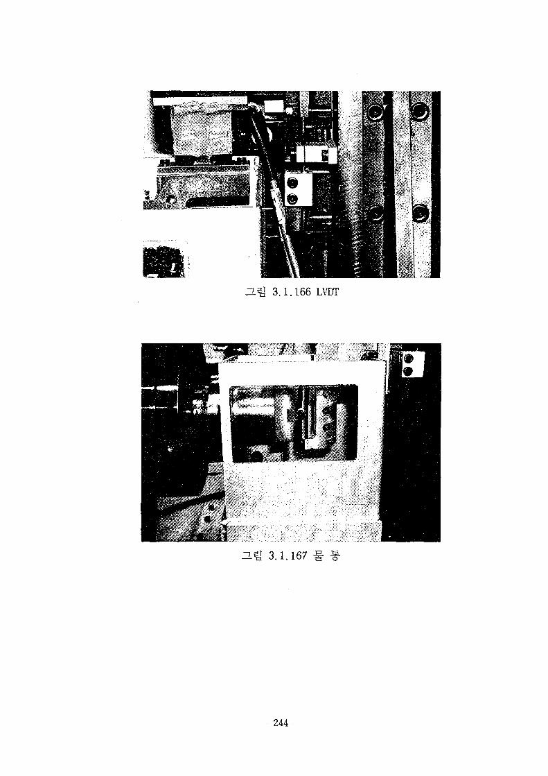
3.Q 3.1.166 LVDT
HU 3.1.167
- 2 4 4 -
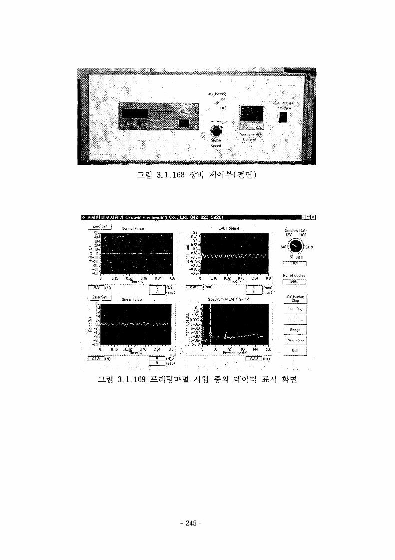
H*y 3.1.168
HaiSDIEA)g3| (Power Engineeiing Co.. Ltd, 042-823-5920)
0.8 I
LVDT Signal
0 0.16 0,32 D.48 0,64 0.8Tims(s)
B. 0.16 0.32 0,48 K M 0.8 j
O(N) '• ": C (N)(sec)
Srnplins R-a'12.50 182
3000
No. ol Cycles
CaiibratjohStop
Ouit
a ^ 3.1.169
- 2 4 5 -
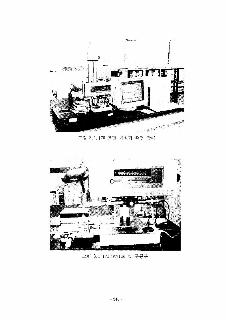
H.^ 3.1.170
3.1.171 Stylus
- 2 4 6 -
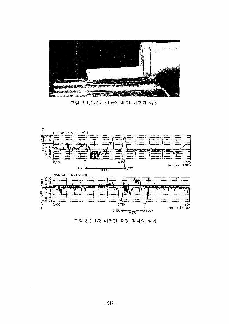
3.1.172 Stylus^]
0,347
Profile=R - Section=[1]
0.4350,782
1.500[mm] (x 83,485)
1,500[mm] (x 88.485)
0.258
H-Q 3.1.173
- 2 4 7 -
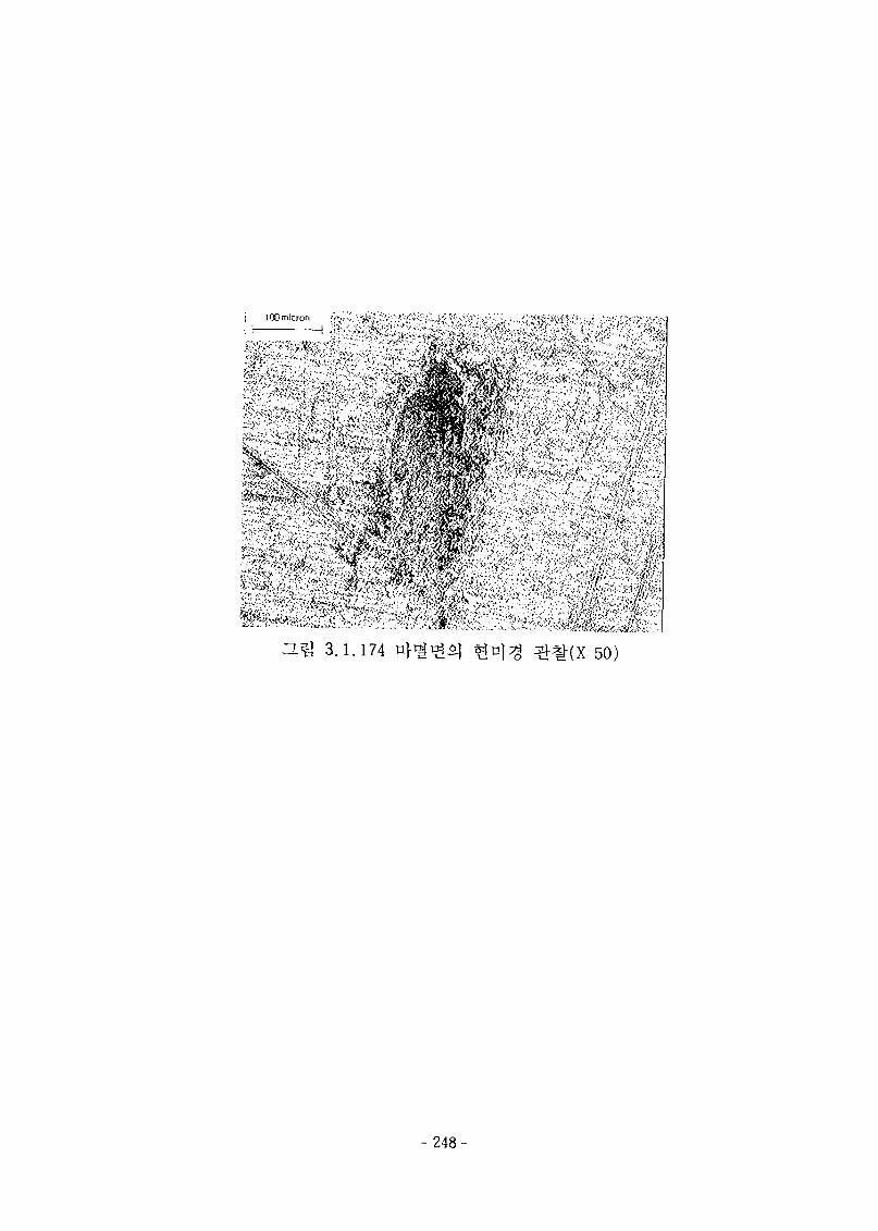
ICO micron
$L " -a sfflft
O.^ 3.1.174 n} 50)
- 2 4 8 -
l. 4
4444^1 «^£
4 ^47}
CFX-4
[3.2.
CFX-45] f^ 4
4
- 2 4 9 -
^ § ^ £ j ^ ^ ^ ) l ] ^ 4 f # ^ i 3X3
Hot-Wire } } H 3UK o]
o)
TFC2D[3.2.2]^1 7fl^ol ^u} . o]
ot
^^^?i*l ^hg ^ ^ ^i£ ^^1
Elliptic
. TFC2D^ *}J2.(Cartesian) 3}S7^] ^ ^ # ^ (Cylindrical)
^I 7)2.*}
^1 5llol^-^ ^r 1d:-ff-S.ll(Jones- Launder, Launder
Sharma, Chi en, Nagano-Tagawa ^-)o)
- 2 5 0 -
2} y^o] ^ B ]
2. 4444
4444
7}
tic}.
7]
4 0
4692302[3.2.1]^r
7H
45440599[3.2.2]fe 4 4 4 4 4
S 90°
44
- 251-
7}.
- 2 5 2 -
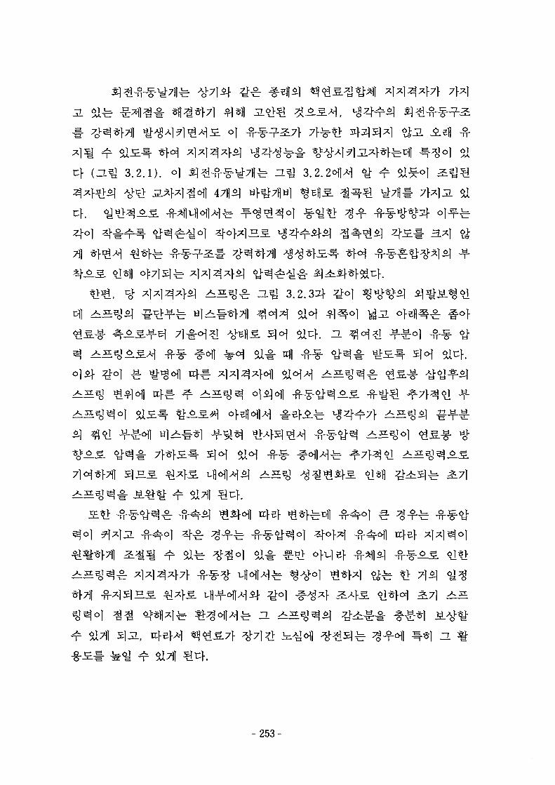
3. Safe
3.2.D.4711*1
40]
^ ^ ^ ^ a^l 3.2.3^
^*fl*Ife ^ o l H f e 3. ^
fe ^g-f«>fl
- 2 5 3 -

fe ^ f j 3.2.4^^
ZL^ 2 . 2 . 6 ^ -g-o] rrfl -g-2]- ^
-g-
- 2 5 4 -
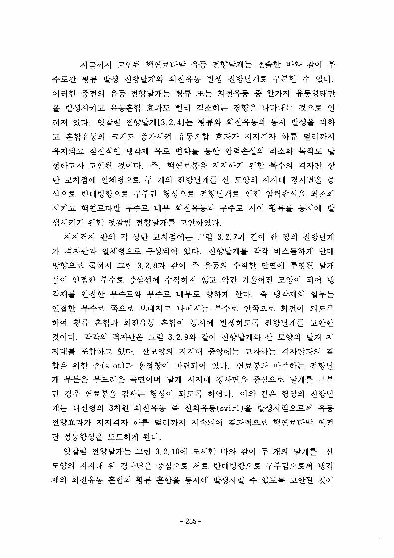
3.7}S. ^
7}
n ^ 3.2.85}
$14.$14.
b ^-^ 3.2.10^1elf
- 255-
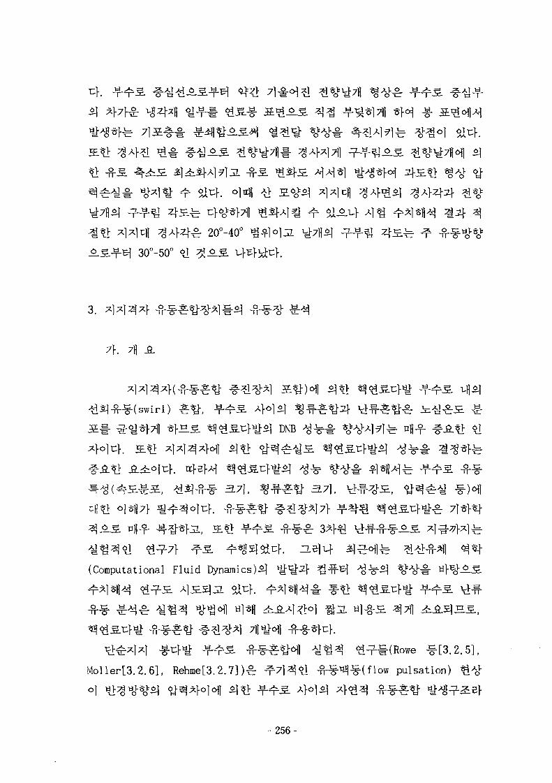
.^=.T= ^ - I J S -
^ 20°-40°
30°-50°
3.
7\. 7fl SL
^
DNB
371, 37],
(Computational Fluid Dynamics)^
Moller[3.2.6L Rehme[3.2.7] )
0}
^^-l-(Rowe ^ [ 3 . 2 . 5 ] ,
pulsation) &^
- 2 5 6 -
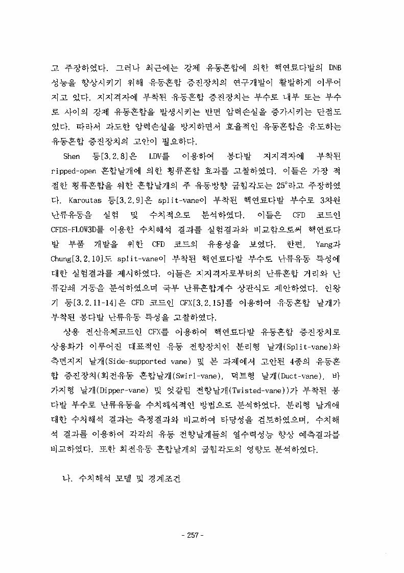
DNB
Shen ^ [ 3 . 2 . 8 ] ^ LDV
ripped-open
rf. Karoutas -§-[3.2.9]£ split-vaneo]
VHM-i^- A^^ 9J ^ * 1 ^ ^ S £ * W a ^ . *]%£ CFD 2 BCFDS-FL0W3D# <>]-§• ?> ^^]«fl^ ^ ^tii -¥-•§• 7 H ^ # ^1*> CFD 3 H
Chung[3.2.10]S split-vaneo]
71 -^[3.2.11-14]^ CFD 3.S.61 CFX[3.2.15]#
^ ^ l CFX# ] g M ^ ^ f ^ e
t H S ^ ^ l ^ - ^ ^%H^1 6 J ^ S ) ^ y-7fl(Split-vane)if
y-7fl( Si de-supported vane) ^ £ 2}*\MM 3.&Q 4#5] - ^ - ^ ^
^^-^7l|(Swirl-vane), ^ S % ^7fl(Duct-vane), «}
ipper-vane) ^ ^ ^ ^ ^%^7|l(Twisted-vane) )7>
- 257-
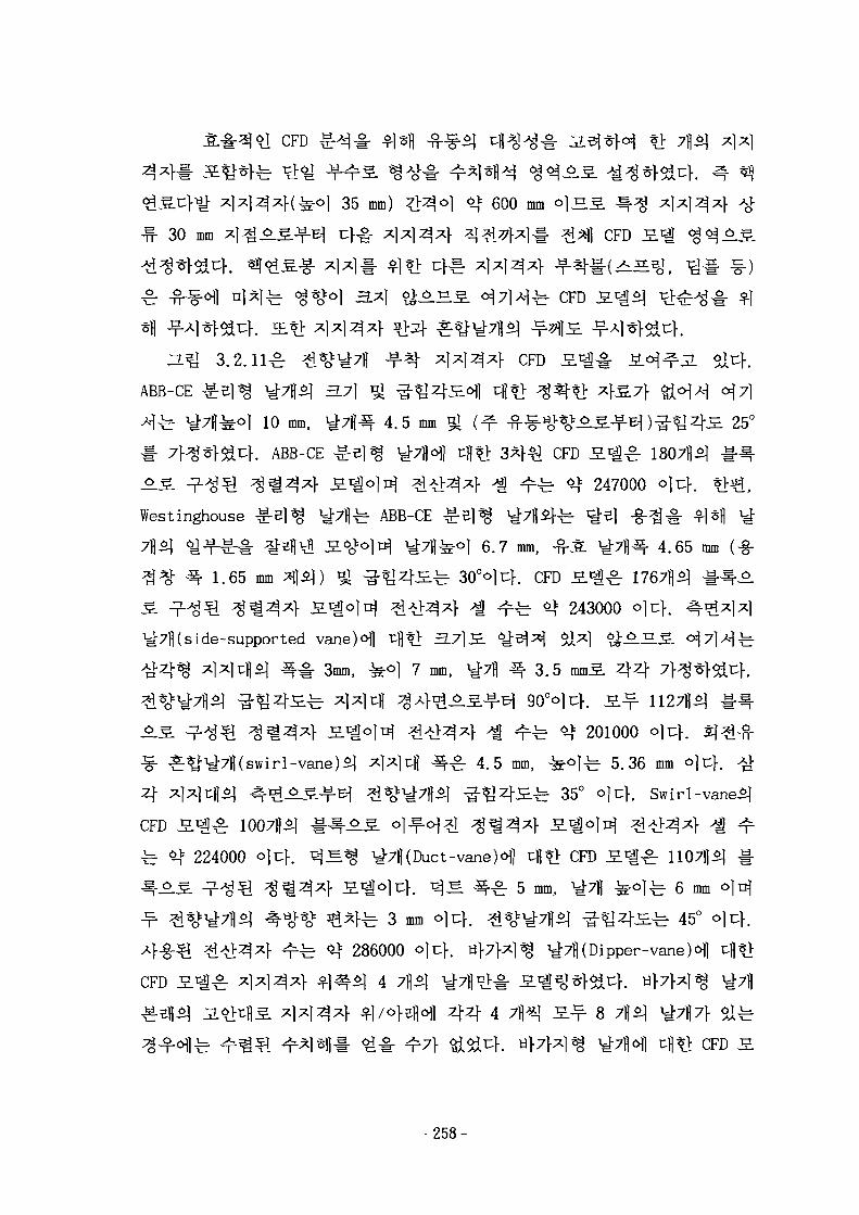
35 mm)
30 mm
600 mm ° ] H . S ^
CFD
^ CFD
3-m 3.2.U-B:ABB-CE ^ 5 1 %
ffl 1 0 mm,
f. ABB-CE
CFD
4 .5 mm 25°
Westinghouse ^ -
^ - 1-65 mm
^ ABB-CE
CFD S « g ^ 1807]}^
fe ^ 247000 o)c]-.
4.65 mm6.7 mm, -£-JL
°<>1T -. CFD S ^ ^ r
^rfe ^ 243000
side-supported vane)e>fl tfl^f 3.7]S.
^ # 3mm, ^ o ] 7 mm, 44
4CFD
^ <$ 224000 ©Inf.
-vane)$]
f fe *t 201000
£: 4.5 mm, ^t°]^ 5.36 mm o|cf. <£
^ 35° o)-c.}. Swirl-vane^)
CFD
S ^ y-7j|( Duct -vane )dfl cfl*> CFD
" S c l ° ] 4 . ^ S ^-^r 5 mm,
fe 3 mm
286000 o
&1 4
1107fl*]
] ^ 6 mm °
fe 45° ojt;]-
ipper-vane
4 4 4 7^ 3.^- 8 ^p\ safeCFD 3.
- 2 5 8 -
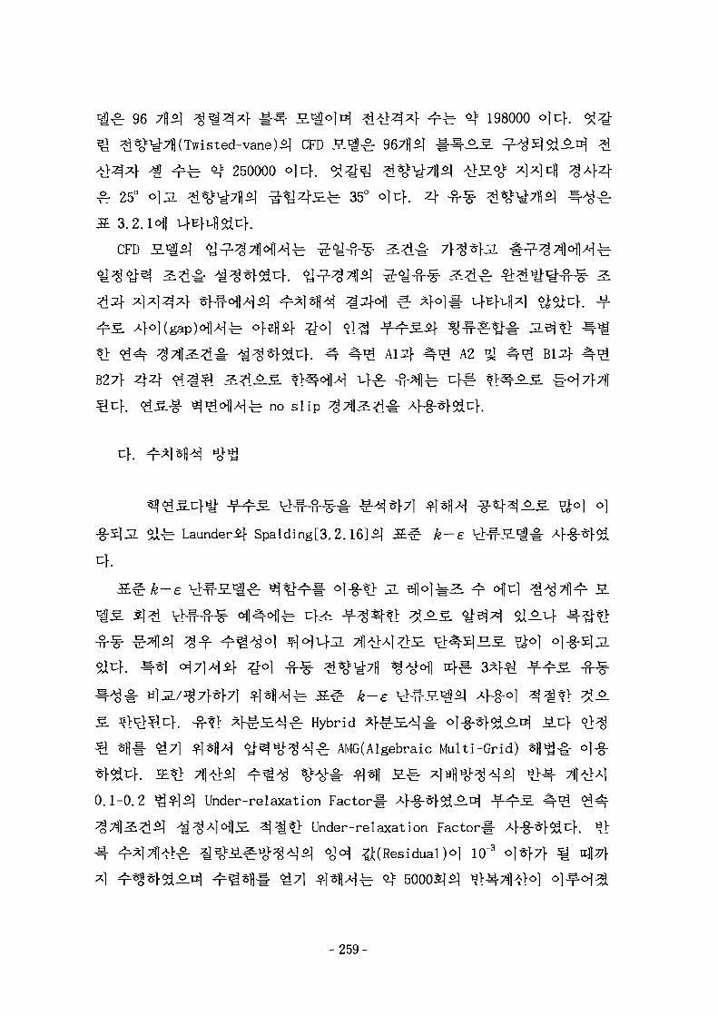
96 7fl£| ^ ^ 4 # ^ - H^o]t^ #>hM4 <^fe ot 198000 °)
ane)*} CFD S ^ - ^ 9 6 7 ^ 1-^-^S. ^ 3 &
250000 °}K}. ^ O T ^%>y-7||^ -tlS.^ 4 4 ^
25° OIJL ^%^7f l^ ^ J 4 £ f e 35°
3 . 2 . H
CFD £ .
| 2 # i 8 f K ^ 4 f 4 ^ A2B27|- 4 4 ^1^51 ^£°.£. *mo\)M u]-^ ^ - ^ 1 ^ cf^-
1 ^ no s l i p
-§•513. Slfe Lauaderif Spalding[3.2.16]£| S ^ yfe-e
JL
6i uf.
^r Hybrid ^
5} Sfl^. 6 i 7 | ^jsfl^ ^ ^ « o l - ^ ^ ^ : AMG(Algebraic Multi-Grid)
0.1-0.2 £*1S} Under-relaxation Factorl-
^ ^ * > Under-relaxation Factor#
o ^ ^ ^ <gc$ ^(Residual )o] 10"3 o}-&}7}
- 259-
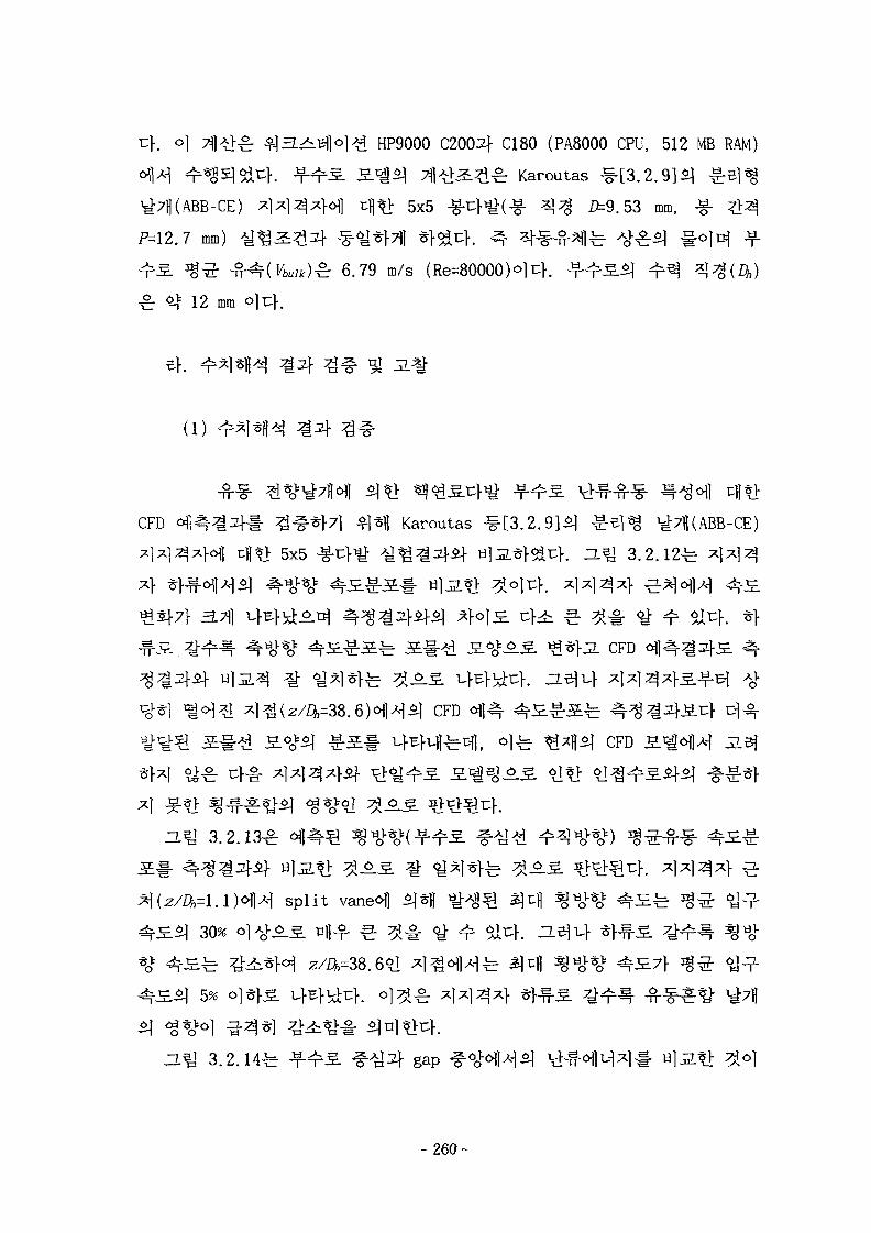
HP9000 C2004 C180 (PA8000 CPU, 512 MB RAM)
n^2L^-& Karoutas #[3.2.9]<q ^ 1 ^
5x5 -g-4H(-g- ^ 5=9.53 mm, -g-
.7 mm)
^^: -
4f 12 mm
^ 6.79 m/s (Re=80000)°li:K
91
(l)
CFD Karoutas
5x5
3.711
CFD
CFD
CFD
3.2.13^ ^
split vaneofl
30% o]^o.
5%
3.2.14-fe- gap
-260-
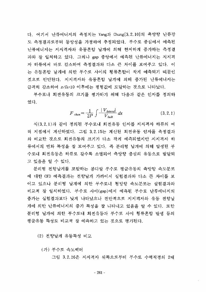
Yang^f Chung[3.2.
a* gap
SI*];
z/a=io
44
7-. __ 1 f•T chan— ~ T p
^ /afera/l0 *
n^ 3.2.15-fe-
$"§^) 3.717} Z}^ 4711
CFD
(2)
(7f)
-L5J 3.2.16^r
- 2 6 1 -
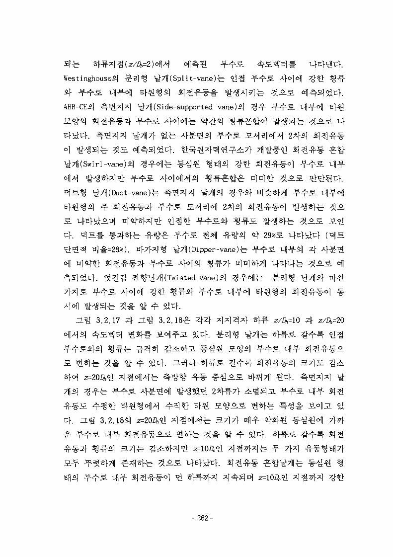
Westinghouse£] ^ B l ^ ^7fl(Spli t-vane)fe
ABB-CE*] ^7fl( Si de-supported vane) 2]
^7H( Swirl-vane)*]
C 4 S ^ ^7)1 (Duct-vane)^
ZL5J 3.2.17 ^ ~L^ 3 . 2 . 1 8 ^ 4 4
3.2.185] z= ^ 3.7]7f ofl-f
- 262-
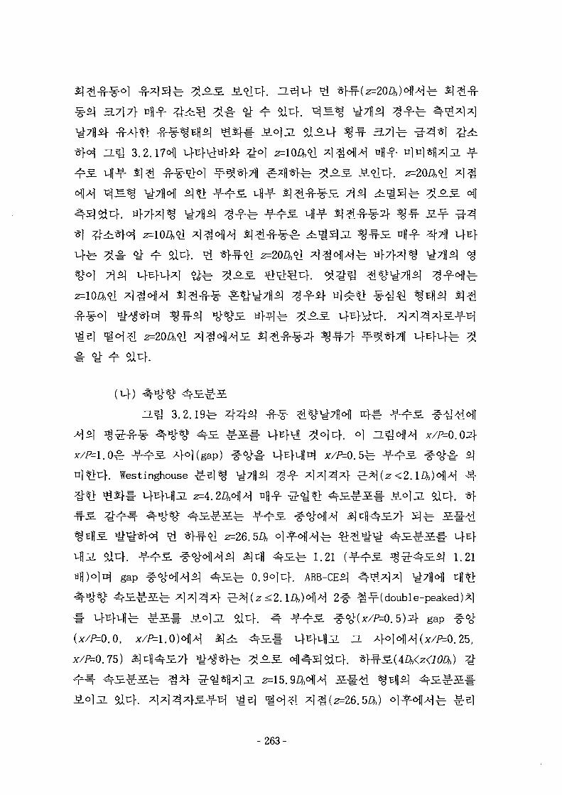
3.2.19^
) (gap) ^ - ^
c c } ^
Westinghouse
z=4.
2=26.
^ 1.21 1.21
gap
0.5)2]- gap #<^
- 2 6 3 -
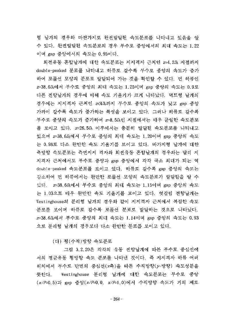
41 ait:}.
° H gap
double-peaked
Z\tft ^S-fe 1.22
fe 0.95°[t}.
gap ^ 0.9S.
gap
±= 0.9SS. alt:}.
gap
double-peaked
4 4 ^ ^ ^^7} 51
g a p
gap
Westinghouse^
gap #<y.«q ^ £ ^ 0.93
O]JL alt}.
(t})
3.2.20^ 445]
Westinghouse
gap ^
- 264-
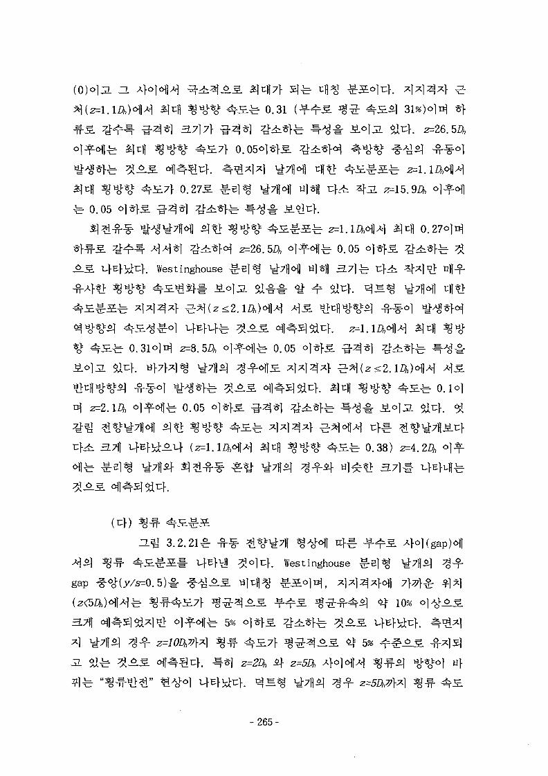
ZL
^ 0.31
0.27^
-b 0.05
0.2701^
^ 0.05
. Westinghouse
2=8. 0.05
3.
fe O.lo]
fe 0.05
^ 0.38) z=4.
5]£-
H^J 3.2.21^
Westinghouse
gap
3.711 ^ 5%
z=10DtP\A 5% ^ f ^z=2Dh i f z -
- 2 6 5 -
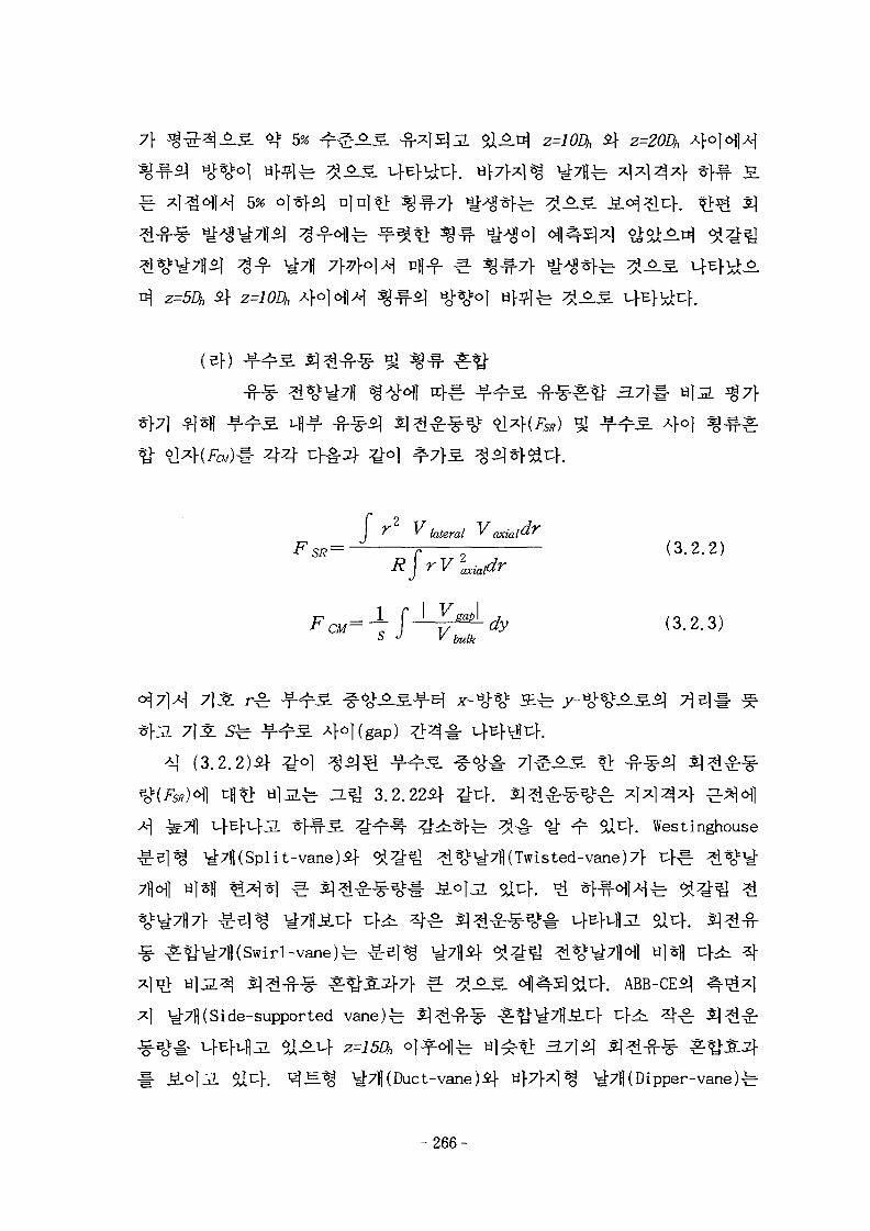
7} 5% [ A D | z=10Dh
fe 44445%
(5f)
4°)4 4 cfS-
F SR—
bulkdy
(3.2.2)
(3.2.3)
40)(gap)
(3 .2 .2 )^
fe a ^ 3.2.22A}-
4^-7H(Split-vane)if
6 i ^r 5ll4. Westinghouse
*o^7fl(Twisted-vane)7> u } ^
-vane)fe Hl*fl
4 y-^H( Si de-supported vane)^
ct-vane)if af7f4^ ^7fl(Dipper-vane)fe
- 2 6 6 -
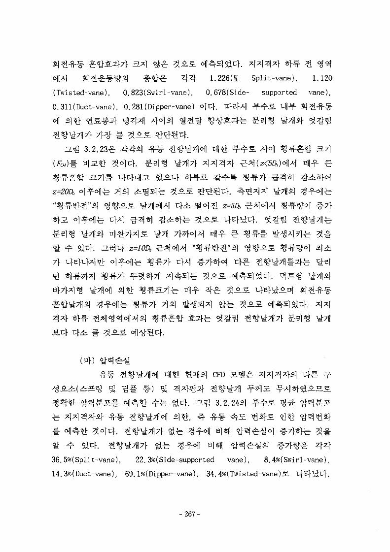
: 4 4 1.226(W Split-vane), 1.120
(Twisted-vane), 0.823(Swirl-vane), 0.678(Side- supported vane),
0.311 (Duct-vane), 0.281 (Dipper-vane) °\t\. n f sH T T ^ 4-f" S -fMJf-
ZL^ 3.2.23^ 4 4 5 ] -B-^- ^*0^7flofl tU*i ^ - ^ ^ A}c) ^ ^ - ^ ^ 3.71
7}
CFD H«g^
. n.^ 3.2.24*1
4436.5%(Split-vane), 22. 3%(Side-supported vane), 8.4%(Swirl-vane),
14.3%(Duct-vane), 69.1%(Dipper-vane), 34.4%(Twisted-vane)S L.]
- 2 6 7 -
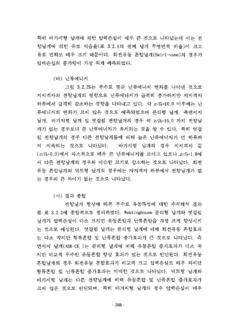
nfl-f 3.71 tcfl^olu}. SJ^-fi-g- £^7fl(Swirl-vane)*]
(«})
(4)
3.2.2^1 f ^ A S . ^Sl^f^t:}. Westinghouse
3.A * ^
n>
- 2 6 8 -
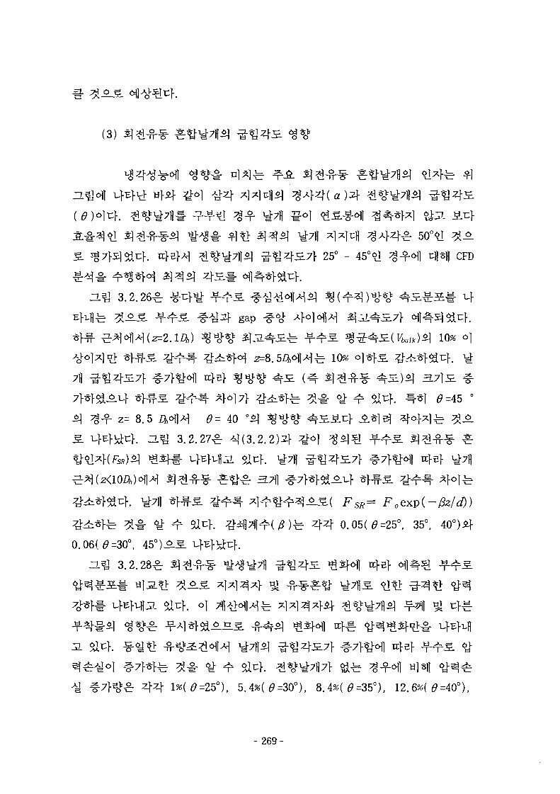
(3)
25° - CFD
ZL^ 3.2.26^ -g-u}^ ^
gap
10%
7B 3.7}5L
0=45
z= 8.5 ^ ^ ^K ^-^ 3.2.27^ ^ (3 .2 .2 )4
^ - ( F O T = FoeKp(-/2z/d))
4 4 0.05(0=25°, 35°, 40°)if
0.06(^=30°, 45o)-5-
H^l 3.2.28^ ^
£ 44 , 12.6*( 0=40°),
- 269-
2O.8*(0=45O)°H 0=40°
alcf. ZL^ 3.2.29^ Jf-
H%1 3.2.30^
AL} 0=40° ol
.7]- 40°
515.S. ZL J 3.2.27^]
31717} 3.7fl ^4i*>7l tt
3 M til^H 10%
° 40°fe 35° -40
fe 42°
ZL^ 3.2.31^ 4 4
01= z=
3.7l(Fc«)l-
5%
- 270-
3.7}
445]
71]
4
Westinghouse 3.x)n_V
y;7ll(ABB-CE
H]*lf
^-7}3L3}7} 3^] ei^r 3 6.5.
71]
-271-
4S.7} S-f- 35°-40°
JE1S -g-
4.
( l )
Sl^-W-(Swirl-flow)
-g-
- 2 7 2 -
4434
Wire Amemometry), LDV(Laser Doppler
Velocimeter) ^ PIV(Particle Image Ve loci meter)!- *}-§•?]:
CFD(Computational Fluid Dynamics)^] ^*
Kjellstrom[3.2.21]2} Trupp and Azad[3.2.22] ofl
1.20 Aj-oji] a ] i ^ ^ ^ . ^ . ^ 1 ^ ^ - ^ ^
. P/D=1.125<HI>H 1.25 A}C]O| a j j i ^ ^ ^ .
Rowe[3.2.23]^
Pulsation)if ^ ^ T ^ A ] ^ - ^ ^^-(Macroscopic Flow
Process) °] ^ H ^ j - J l ^.JL^}^uf. Hooper if Rehme[3.2.24]^ # ^ r ?> -
-717} # e i ^ ufl
fe Rowe[3.2.23]^ iguft
fe Shen[3.2.25], Yang[3.2.26] 5J Hejna[3.2.
. Shen[3.2.25]£ W/D=1.27 o]n| P/D=1.375 ^
7f T F * H ^7f*>i:}jL ^_3.*l-$it:|-. Yang[3.2.26] ^r W/D=l. 35 «>1^ P/D=1.49
rffl 4 4 3 4 ^tio>(Hl4^1 - ^ -T-^l- LDV# 4-§-*}<H ^ - ^ ^ 3 . Ingesson
-273-
Hedberg[3.2.28]
. Hejna[3.2.27]-b
^- 7)7} ^ B l ^ afl
In [ 3 . 2 . 2 9 H
f. K a r u t a s ^ ^ ^ ^ ^ 7 } - f ^ j - ^ ^ ^ 5 . -g-uf^ ^ - ^ 5 . 3
^ # J ^ ^ ^ ] ^ ^ ^ f ^ K j ^ CFD ^ ^ d j
CFDS-FL0S3D1- o)-g-> l f l ^ ] ^ f ^ ^ ^ ^ ^ l ^
) )*V CFD S H | B 8 ^ i S i K [ ] ^ ^
^ -f ol ^ ^ ^ § . ^x]^x}cH] cH*|J ^ 1 ^ * | j ^ CFD 53.B.
CFX[3.2.30]#
7]7}
(2)
3 X 3 ojnj ^Ixj^xf ^42] ; s|*j ^ ^4^11^1 ^ ° f e 4 4 100 mm 4f 275
mm °]3L x]*]^*}
^ - 1 4 -b 44H ^ 3.2.344} :gi;)-. ^ 5 . 5 ] t>^^r 300 mm X 300 mm <>H ^S. Ml
-g-^ 3 ] ^ o) 75 mm, 7jo) 2400
1.3351
- 274-
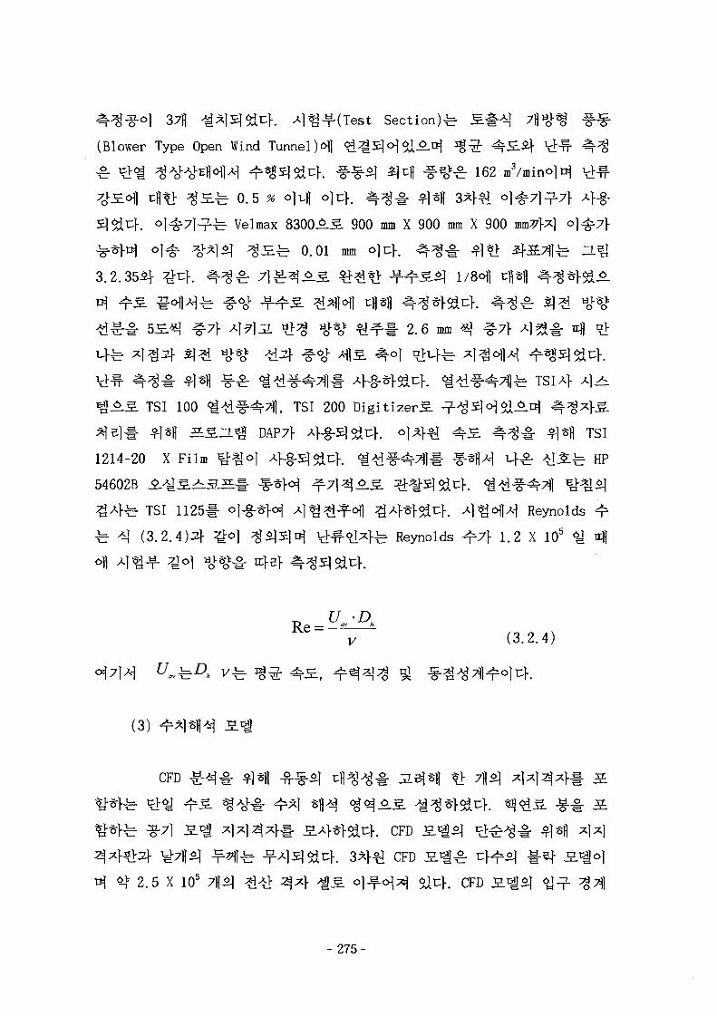
37fl 1i*lSl544. ^ J f ( T e s t Section)^
(Blower Type Open Wind TunnelH ^ S H S l - M
^ 3 5 4 4 . f~§^ ^M ^ £ 1620.5 % cm o}cf. 4 ^ # $1*1| 3 4 ^
-fe Velmax 8300AS. 900 mm X 900 mm X 900 mV}x]
^ ^ ^ 0.01 mm
3.2.35AJ-
2.6 mm
^ ^ S TSI 100 ^-tHHfXl, TSI 200 Digitizer^.
^e ]# $M SS-L^^ DAP7} 4-S-SJ544. °14^ ^S- 4 ^ # *M TSI
1214-20 X Film ^ o ] 4-fi-5l^uf. ^ ^ - f - ^ ^ 1 - #*1|A-| 4^- ^S.^ HP
54602B ^ . ^ S ^ 3 . S # ^ * H i M ^ A S ^-^S]^t:}. <i^^-^7fl ^«*1
^ 4 f e TSI 1125# °\~%r*W ^l^^i^ofl ^4*l-5i4. 4 f H H Reynolds ^
^ ^ (3.2.4)21- ^ol $$1£(TI\ t ^ ° J ^ f e Reynolds ^7} 1.2 X 10⁵ ^ fl
(3.2.4)
(3)
CFD
. CFD S
CFD J E l ^
io5 7if5i # # ^ 4 ^ s ^l^-o|^ ai4. CFD
- 2 7 5 -
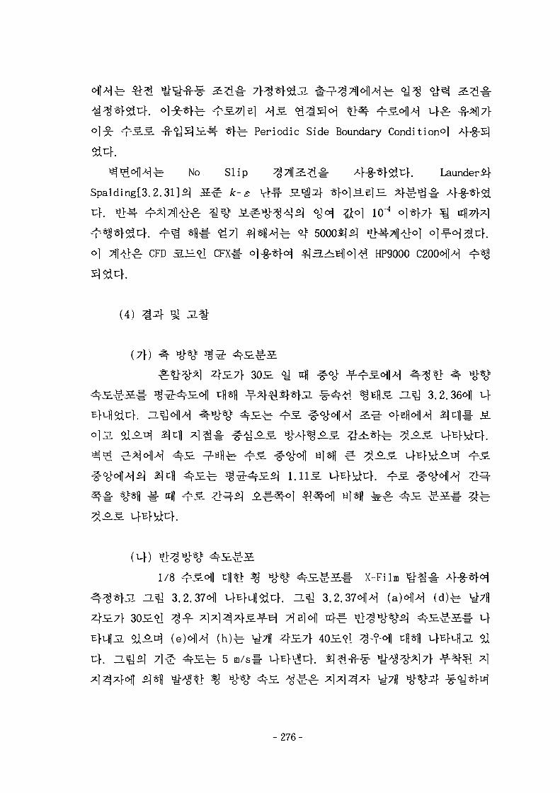
fe Periodic Side Boundary Condition^]
No Slip ^Tll^^l- A ^ ^ S J U } . Launder j-
Spalding[3.2.31]5] S § Jt-£ t>^- S-^^f STM^-BI^. ^}
CFD 3. . 1 CFX# ol-g-*H $ 3.^^1 °1^ HP9000
(4) ^
(7})
4 #^ -¥-T.^1 3.2.36 1
1/8 ^6fl c|*} % tiJ-%* 4 S « . S s . x_Film
^ 3.2.37^]
^ 5
-276-
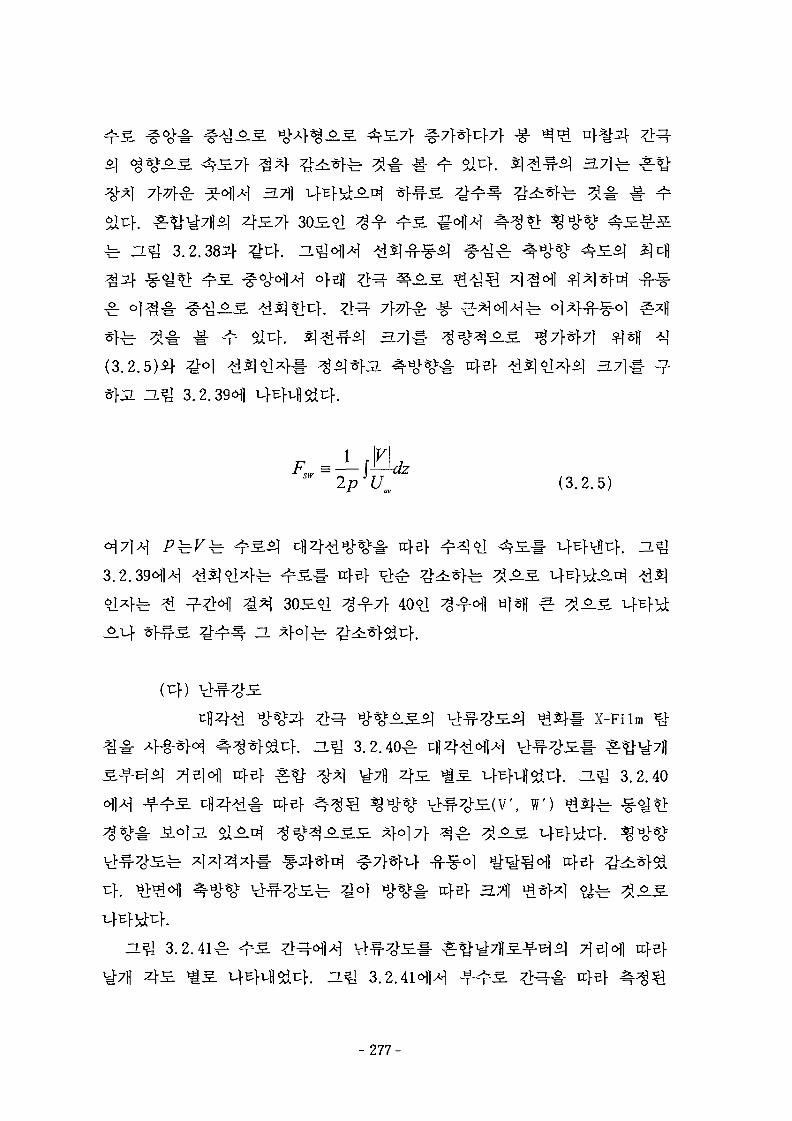
<g*oK«L *Rr £•§• 3.7] fe
£3.711
fe ZL J 3.2.383}
(3.2.5m
f—dz*Uf
2p*U (3.2.5)f
3.2.39^1^
7}
X-Film
3.2.40^
f. H ^ 3.2.40
W) ^ 5 f ^ -
H ^ 3.2.41^
- 277-
3.7]fe
(ef)H^ 3.2.42OJH
30J
2 M£ 4517} 3051
P/D7} 1.
- 2 7 8 -
Reynolds ^ 1.2 x 10⁵ofl4 <%3}*K2. ofeflif ^
1.11
2)
ZL 3.7}±r 7]-
3)
4) CFD
°1^ X ^ #
(1)
10«fl
2.33,3.2.34]
- 2 7 9 -
(Split Type mixing vane)7> $X^, «i?m°-S. °] #*}•£• n
al4[3.2.35]
-Zr 715] -
(2)
Sd
^ ^ ^ fl ^ f l R-134a
3.2.445} ^o] uflz[ ^ H , 7f<i7l)
K ^ 1 ^ ^ : ^ ^ : ^-^ 3.2.45^12mm ^ o | 3 m*| o j ^ u j ^ ^ ^ u | } o ] l 6 7 ^ ^ . ^ . ^ 34.8 cm
^ - ^ 3.2.45(7})) HL-b
3.2.45CH1 ^ J A l ^
n o ) ^ ^ 82.5 cm7f
AoV^^l Fan % ^ 47)1
- 2 8 0 -
cfl, , 30, 35
fe^l °1 ttB conversion factor^ Katto[3.2.37]^] Fluid-to- Fluid
Modeling
1.2 Mpa (Tsa t=49.4 °C), 2 .6 Mpa (Tsa t=86.4
750 - 2200 kg/m2s
Room Temp - 70 °C
uf.
250
T-type 180 °C
(3)
3.2.46(7}), (i4)fe <y- 1.2 Mpai}
380 kW/tn2
750 ^ 1500 kg/m2s
43.2.46^1^
-281
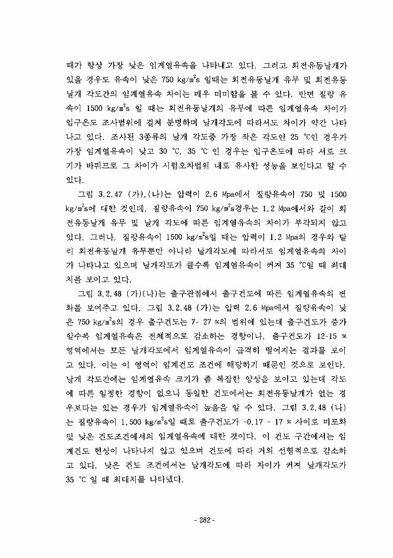
750 kg/m2S ^ 4 f e
1500 kg/m2s
25
30 «c, 35 °C
717} y f^« .S ZL
H%[ 3.2.47 °) 2.6
750
750 £ 1500
^ 1.2
1500 1.2
7} 35
H U 3.2.48
£ 750
3.2.48 (7»fe < ^ 2.6
^ £ ^ 7- 27 *<q
12-15
3.2.48
fe 1,500 kg/tn2s<^ oflS. -0.17 - 17
35 °c <y 4
- 282-
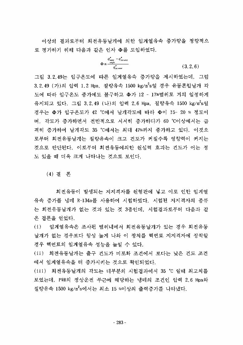
tfvane H no vane
(3.2.6)
ZL^ 3.2.49
3.2.49 1.2 Mpa,
fe <E>7>
3.2.49
7|- 42
1500 kg/mVj
12 -
2.6 Mpa,
4
35
1500 kg/m2s^
15- 20 % ^ £ o |
60
(4)
R-134a#
Stl
( i i )
( i i i ) 35 °C
2.6
1500 15
-283-
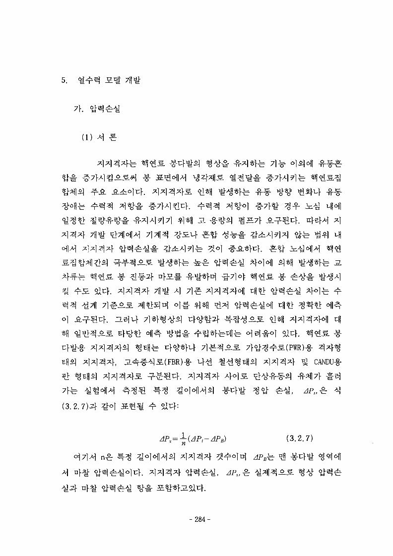
5.
(l)
^S^l -g-
^<&3L -g--g-
CANDU-g-
(3.2.7)5}
(3.2.7)
- 2 8 4 -
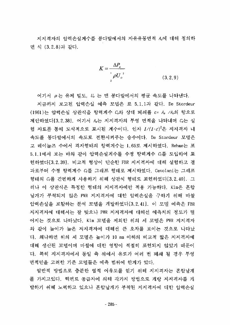
1 TT 2
(3.2.9)
^ 3.*££r S. Stordeur
K De Stordeur
JL
FBR
51
> ^ PWR
1^^- FBR^^-M" PWR
. Kim S ^ M] S^^r PWR
Uf
Uf
10 mm
-285-
(2)
^ 4 (3.2.10)4u}:
Z C 17 grid i IT1 SHi* i Z71 n"* i 17 """"form fnc fnc form
fe ^ (3.2.11)4 ^-^
(3.2.11)
fe *j (3.2.13)4
grid grid rod mixingK = K r + K r . + K r . + K r
form fnc fric form
(3.2.12)
- 2 8 6 -
Re=UoDh/u.$\
Jf Kim
De Stordeur
(3.2.14)2^
•A.-A. °\-e (3.2.14)
(a)
^ : ^ (3.2.11), (3.2.12)
(3.2.14)^1 ^«H ^ (3.2.15)if
A \ 1
(3.2.15)
(3.2.15)5] ^ .^ -^ % ^
3-7)}
7}
4 &^[3.2.42] o]) 7] 51 ^ ^ S S 5.1.2ofl
^ ^7} 5xio5 ^ . 4 i- nfl
- 287-
JL
L \*J(l-sy (3.2.16)
L, Lt 44
/ . t u r ^ ^ (3 .2 .17 ) , (3 .2 .18)
1.328
/Re, ,
0.455
^ (logReJ258 ( 3 . 2 . 1 7 , 3 . 2 . 1 8 )
Ltt
(c)
oh(\-s)2
44 °
(3 .2 .19)
McAdams/ = 0.184 Re 0'2
Blas ius / = 0.316 fle"0'25
3xlO4 < i?e < lxlO6 (3 .2 .20)
i?e < 3xlO4 (3 .2 .21)
- 2 8 8 -
(d)
fe- M (3.2.22m ^^r
-mixing JT -'A.
(3.2.22)
(3.2.16), (3.2.19) 5 | (3.2.22)
(3.2.15),
(3)
FBR ^ T ^5.1.331]-
4
1 A
PWR
R r PWR
44^1 Non-split
Split
8 7 ^ 5 ] PWR
FBR-g-
- 2 8 9 -
71
. Cevolani *&& fl^i 4 ^ ^ 1 4
4 . -L^ 3.2.50 (a),
n>*l-u> n s j 3.2.50 ( o j
°] ^ H ^ ^ - f 4°]fe 67*71-4 ^ I ^ T ; } . o l ^ Rehmeif Cevolani 3.^^ u}
# -^-S n^^r £ ^ 4 ^ 4 ^*f7l nfl^-olcK Kim 2 . ^ ZL^ 3.2.50
(a), ( bHH Pi3f P2
: .-uf P3 4 4 ^ 4 ^ 1 ^M^. ^ 50%
44^4^1 ^ - b H^ 3.2.51 14^ 3.2.51 (a) A-l ^6>s^ s ^ ^ - P4*4 Non-split 4 4 ^ 4 ^ 1 x^t^ J§^ 4%
51 J2-41- i ° l ^ ^ ofl^-JLto P5i} ^^r Split
7.5% ^fl l ^ f e 3 J l ^ 4 1 %
. ^2.511-1-
-L^ 3.2.52fe Rehme Al^ofl^ 4-g-5] 4 1 - 3 . ^ 4 ^ ^ %EflSl 4 4
- 2 9 0 -
4
2: ^ 3xlO4
^ P4
5.1.4
^ 50
20 o:S. 4 4
(4)
7).
^ | ^ FBR
PWR ^ x l
7 M PWR ^ FBR
Cevolan i i f Kim
(1) 7fl
- 2 9 1 -
[3.2.47, 3.2.48, 3.2.49]^ 7 ] S ^ JS.^[3.2. 50,3.2.51,3.2. 52]o]
tl -T- 4 ^ £ 7 H S #Sd^-^, ^-*] Fusion Reactor
Celata S.*£[3.2.49]5j ^g-f-b
2 } ^ gj
(2)
ZL^ 3.2.53^]
7 } ^ 7]S7} ^ ^ } J L o ] % ^ ^ ^ [ ^ ^ ^ (Departure PointH^f
. f e c | | o] ^ ^ ] # ^ S ^ ^ f
(Hydrodynamic instability)©]
-292-
3.2.5321- ^o] oJJn^ l 51^ M^I^^l tflSfl ^-7]*1 7 } ^ # # o]-§-
A mwat,= ^ (3.2.22)
Am=-A
lfg
Qevap == Q Qconv \ " • " • " /
z ? m = _ (g-g^'^fe (3 2 25)
(3.2.25)# #71
^^l^t-ll, Lee et al [3. 2. 55]ofl ^*>^ o)$\ ^ * > j-^^-f ofl^-c- Saha &
Zuber*][3.2.56]o|
293-
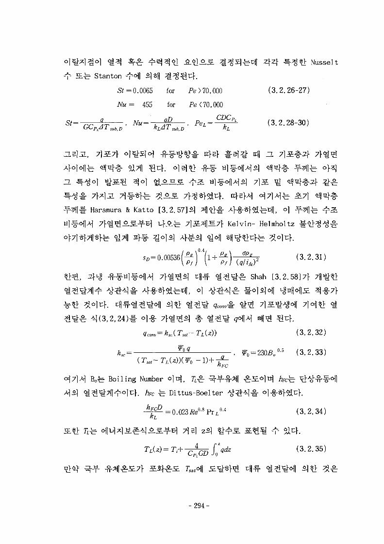
^nfl 4 4 ^ ^ 1 Nusselt
^ J£^ Stanton ^ofl ^*fl ^ ^ ^ 4 .
S* =0.0065 for Pe>70,000 (3.2.26-27)
Nu= 455 for Pe<70,000
St= r r q
AT . Nu=^-$ , PeL = ^ - (3.2.28-30)
^ 271
Haramura & Katto [3.2.57]*] ^|*1# 4-g-^^fe^l, °1 -^^l
] ^7f Kelvin- Helmholtz 1"^
(3.2.31)
^* ] cfl^- < i ^ i ^ ^ Shah [3.2.58171- 7fl
^ - i ] , o|
^(3,2,24)1-
MT^-T iU) ) (3.2.32)
hsc= ^ . ?T0 = 230So0-5 (3.2.33)
B o ^ Boiling Number o ^ , 71^-
A]51 ^^i^Tll^oluf. /3fC Dittus-Boelter
(3.2.34)
( 3 ' 2 - 3 5 )
Tsato])
-294-
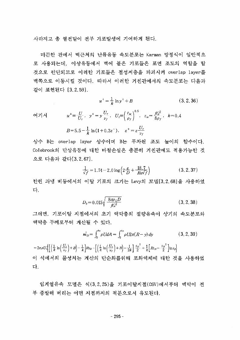
VHHH? ^K£-g-£*r Karman
overlap layerl-
[3.2.59].
| (3.2.36)
^=0.4
3b overlap layer
Colebrook.2] ^l^-n--^6!]
J. 2.67].
(3.2.37)
3.71-b Levy*]
fG2 0.2.38)
(3.2.39)
-295-
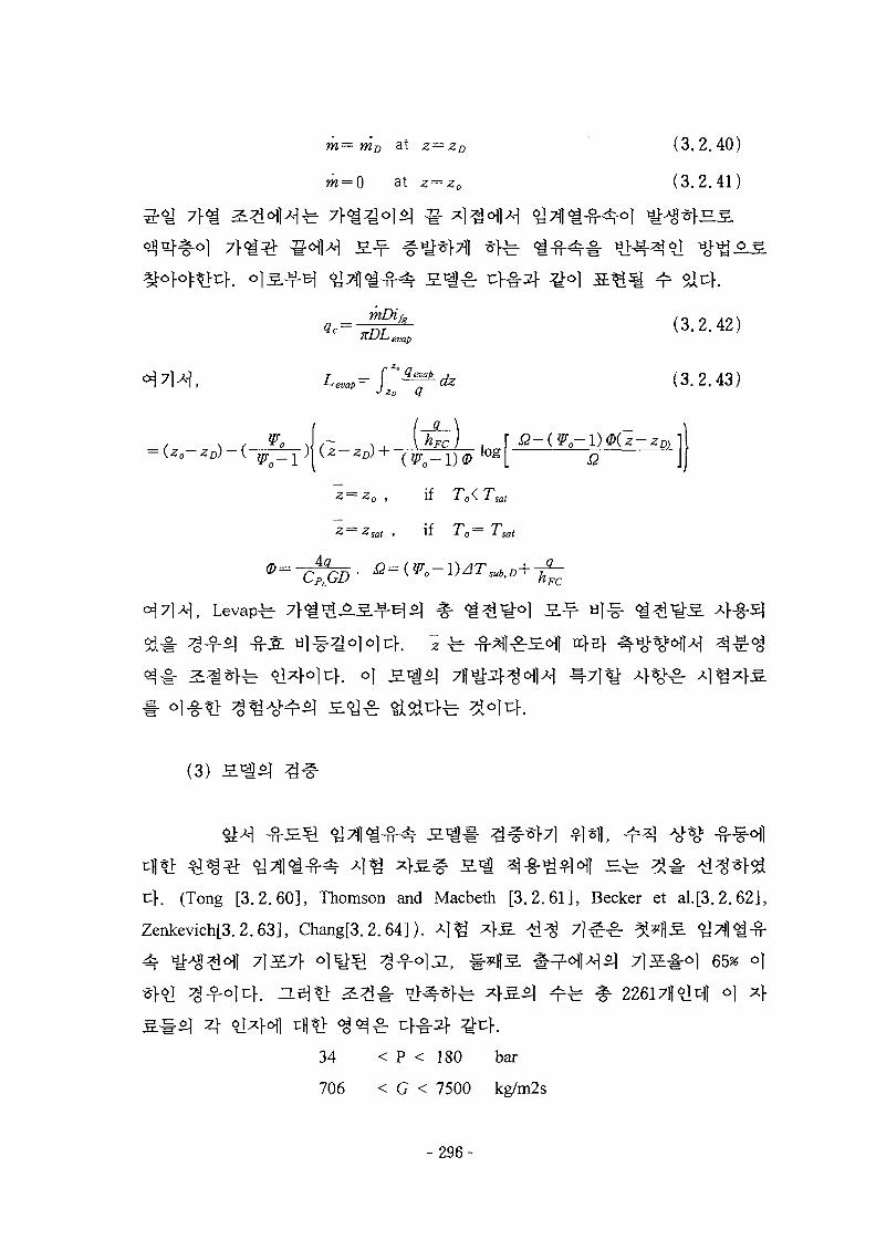
m— mD at z=zD (3.2.40)
w=0 at z = z0 (3.2.41)
mDih (3.2.42)nDLemp
: (3.2.43)o Q
AJJ
= 2 0 , if To<
= -2sa/ . if T o =
Levap-b
(3)
t[. (Tong [3.2.60], Thomson and Macbeth [3.2.61], Becker et al.[3.2.62],
Zenkevich[3.2.63], Chang[3.2.64]). *]% *}£. #$ 7 ] ^ ^ ; ^ s f l S 6j7}l<i^-
# 65% <>1
] o] ^
34 < P < 180 bar
706 < G < 7500 kg/m2s
- 2 9 6 -
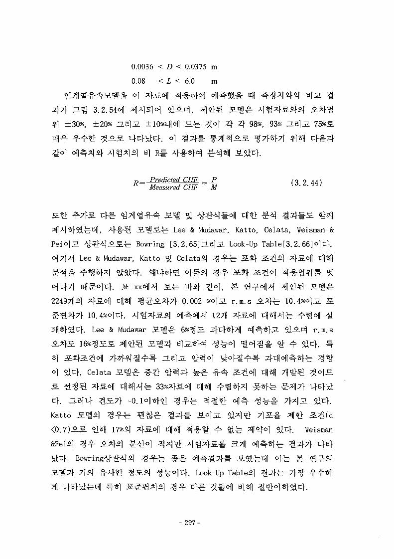
0.0036 < D < 0.0375 m
0.08 < L < 6.0 m
±30%, ±20% nelJL ±10%-uHI — ^ 3J°1 4 4 98%, 93%
r._ Predicted CHF __ P Ci ? Ad)K Measured CHF M \o. £,.**/
Lee & Mudawar, Katto, Celata, Weisman &
J^S.^- Bowring [3.2.65]ZLB\3- Look-Up Table[3.2.66]o]uf.
& Mudawar, Katto ^
0.002 %o]3. r.m.s .^fe 10.
. Lee & Mudawar S c | ^ 6%^H }4^f7fl ofl «]-JL ^1-^-^ r.m.s
o] sa^K Celata S^^g.
Katto
<0.7)±3. 9m 17*5] ^ £ ^ J tflsfl ^-g-^- ^ ^ ^ 4 ^ 0 ] aicf. Weisman
>\2) -n-4t> ^S.^1 ^ ^ 1 4 . Look-Up Tabled ^ 2 } ^
- 297-
d t l 3.2.55),
~L^ 3.2.56), # £ ( H ^ 3.2.57), ^K>^ ( T . ^ 3.2.58) ZLe]j7.
©1 ( H ^ 3.2.59H tfl*V p/M efl4 ;g*o\£ ^ A f ^ ^ c
} ] V ] Becker
R-ll, R-12 HB]JL R-113o]i:}. ZL 3}^ H^ 3.2.60<H] 4
scaling factor &o|j= §6flA-| iL^l afl^ ^J=.o]} ^ ^ ^
efl^- ^ 4 ^ S xxoflA-1 <y- 6 i^o) , R-ii ^ .o . 207H
1.09 S $ ^ ^ > 0.161, R-12 ^ - f 757H ^S^fl
0.98 S ^ ^ ^ f 0.056, R-22 ^ - f 2271] ^ l d | cH fl ^ ^ 0.96
0.085o]uf.
(4)
°1
- 2 9 8 -
6. -
7\. ^--g-^^^LE. (CFX-4) ig 7f
(1) 7H A
CFD(Computational Fluid Dynamics)
fcs-H tf-g-s]- slsdcK ° l l - ^-g- CFDPre-processor, Solver S\ Post-processor JiL -p
Pre-processor^ CAD 7fl^# o]-g-*H ^ ^ M ^ # 2 f ^ ^ ^ 4 #
JL Solver^A-] ^-^-^ ^ t i f l ^ ^ - i - -n-^l^i^^ (JE-b -^-«>J5L^^)
. Post-processorfe -
CFD 3 H § 5 ] Solver^ SIMPLE ^JLe]#^- 7 l ^ ^ S . *fjL
<&°_B.£. Solver^ fo}^
. Post-processor^ ^ ^ tfl-f- *J ^-g- CFD
7j
Pre-processor7}
^ } . ^ H W ^ ^g CFD 1 H
CFX 1H71 }
CFX s^^
CFDS-FL0W3D (CFX
- 2 9 9 -
CFX 3.
CFX S H ^ ^ ^ AEA Technology A} 7} 7fl^»> *g-g- CFD 3-B.SL
Multi-block 7 H ^ # 4-g- t l - f r W l ^ (Finite Volume Method)# 7 ] ^ ^ g .
1-fe- >v-g- 5LE.<>1 uf. Multi-block 7 f l ^ # oj-§-%*• JL
J§-^K|- ^^*1-7J1 S ^ l 3 ^ 4s- $Jt-b ^ ^ ° 1 al^}. CFX 2 H 5 ]
^ J L e l ^ ^ r SIMPLEC^H ^H -%1- 1 ^ ^ r ^ ^ r HYBRID Scheme, UPWIND Scheme
5J QUICK Scheme ^-o) 6Vc\m CFX^ C > ^ ^ § - , °J^F
h-c: ^2. Reynolds ^ ^ —£ JS.1^, ^1
Reynolds ^ yfe— £ S . c | , RNG(Re-Normalized Group) k — £ SJQ, k — (O 3.
^i, ASM(Algebraic Stress Model), RSM(Reynolds Stress Model) ^
RSM(Reynolds Flux Model) - ^ # ^-g-^f0^ S . C | 5O ^ ^r
Pre-processor^fe CFX-MESHBUILDif CFX-BUILD#
Multi-block 7fl ^ #
^ $ir}. CFX-BUILD
fe- CFX-NESHBUILDofl 1*11 ^}4i *f§-° | ^Sl^}tt^ CAD < y^3l- < y# ^ ^ 9 i ^
^ ^r 51^- 7 ] ^ o | 6 l o . £ 5 . ^ ^ o f l - b CFX-BUILDn># Pre-processorD. Af-g-
^ 6}l^o]t:>. Post-processorSfe CFX-VIEW, CFX-VISUALIZE, CFX-LINEGRAPH
%•<>} al^-^F CFX-VISUALIZE7f uf^- P o s t - p r o c e s s o r ^
Post-processorS CFX-VISUAL I ZED. ^ ^ ^ ^ D . ^
(2) CFX 3 . H $7}
•#-%•(Backward-Facing Step Flow)
- 300-
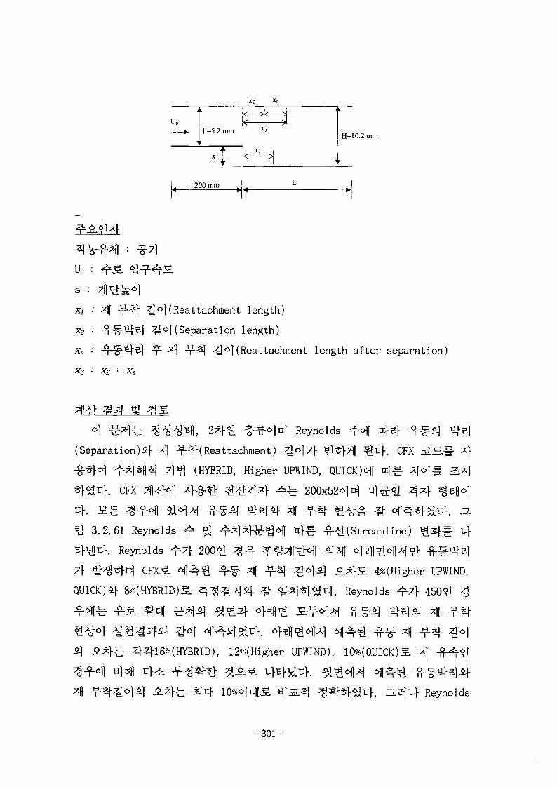
X2
h=5.2 mmH=10.2 mm
200 mm L
s :
Xj : *fl
xs • -n-
x3 : x2
^o|(Reattachment length)
^©1 (Separation length)
^ 4 ^ - ^ j - 2jo|(Reattachment length after separation)
Reynolds ^ ^ rcfef
(Separation)^ 4 -f-^(Reattachment) A°]A \A %z\. CFX S H
^-*fo^ ^1*1|-&| 7|^ (HYBRID, Higher UPWIND, QUICKH
. CFX TIIHI
^ 3.2.61 Reynolds ^
^>VE4. Reynolds 7 }
7} ^ * H CFXS 1
8%(HYBRID)5.
(Streamline)
200*1
4%(Higher UPWIND,
Reynolds ^ 7 } 450*1 ^
fe 4416%(HYBRID), 12%(Higher UPWIND), 10%(QUICK)^
. ZLBil-} Reynolds
-301-
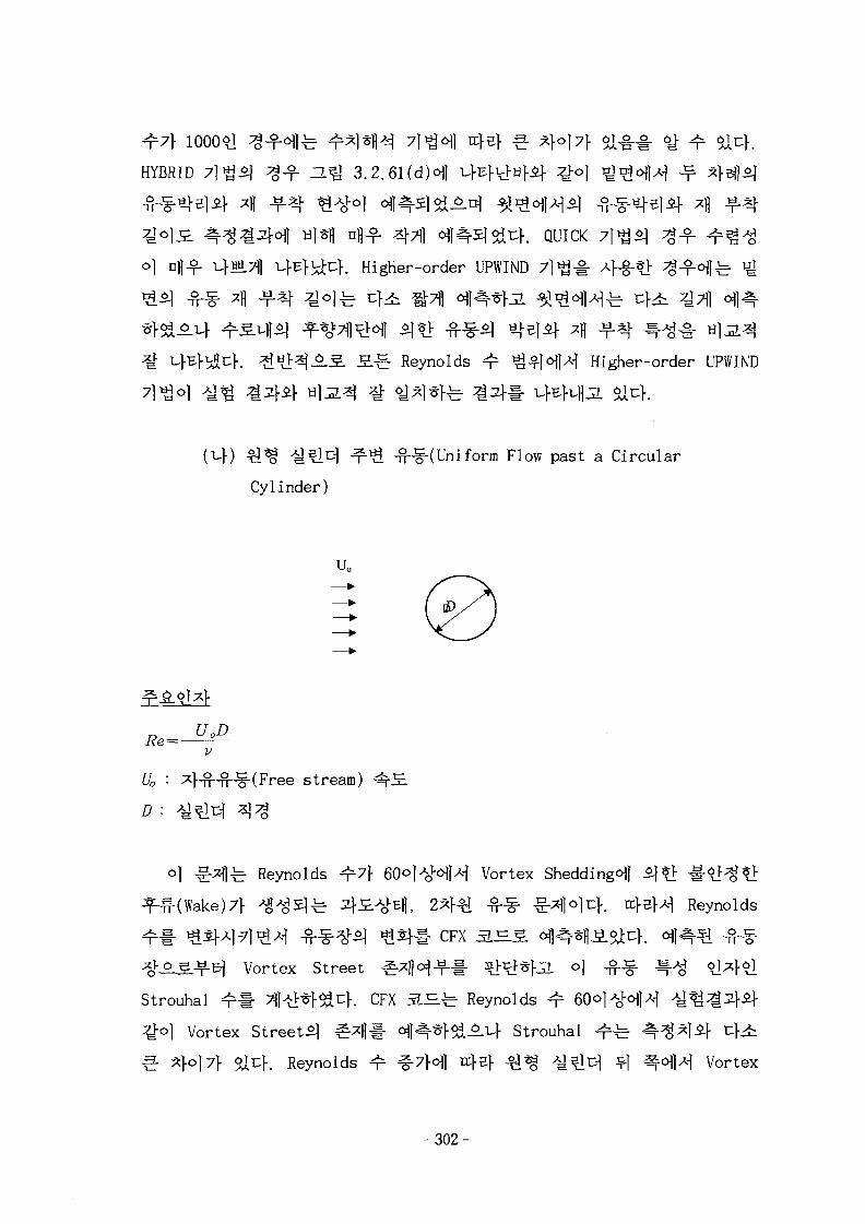
^7} 1000*1
HYBRID 71^3] ^g-f ZL^ 3.2.61 ( d H t}E}u>H}£|. Qo]
. QUICK 7}*$)
o) cfl-f v}«i7fl ufEf^uf. Higher-order UPWIND
. . S-g- Reynolds ^ ^^Hl^] Higher-order UPWIND
^ ^ -H-^(Uniforin Flow past a Circular
Cylinder)
UQ
f/0 : ^}-n-n-^(Free stream)
D :
°1 ^r^I-b Reynolds ^ 7 } 60°}*ol-cflA{ Vortex Shedding^!
^HHWake)7} ^ ^ 5 ] ^ ^ £ A o ^ i 2^}€ -fi-^ £ * W c } . H } B M Reynolds
^ ^ 2 ) ^ S f # CFX 5 . ^
Vortex Street ^ H - f - # ^ t>*F^. °]
Strouhal ^ # 7J|^*}^i:}. CFX 3.S.^ Reynolds ^ 60
£°1 Vortex St ree t^ ^ f l # <HI4*f5lAi-} Strouhal
€• x}°}7\ Sit:}. Reynolds ^ ^7}<Hl n:}^} T J ^ ^ t l ^ ^1 ^ ^ 1 ^ Vortex
- 3 0 2 -
StreetJ} ^*M ^W^= ^ %6J ** ^ $14. Reynolds
ofl n:}5]- £Hf( Vortex )7>
3.2.62). CFX 3.IL7}
CFX S J £ ^ V>^-S.^# Hi3. ^ 7 ^ 7 1
f z. ^ife S ^ yfe-e
Reynolds ^ - £ S ^ ^ ^ Reynolds ^-ty S ^ ^ - tili^^uf. Q^# \t
Reynolds ^ ^ Laufer*] ^ ^ ^ ^ 4 -g-<y*> 40,000^.5
Higher-order UPWIND 7 ] ^ # 4^ -*>^4 . fi
function)!-
^il*}7ll n>#<H # 1^71- ^Cf. ZLejuf ^Reynolds
fe ^
Reynolds ^ t ^ S l l " 4-§-^fe ^g-f ^-t>^^f HJ|
.fi. ^-^ ^ ^ - ^ H^I 3.2.63^-
71 4-§-?I: Vl:^-S^^ 3-*]-3.^g. o)-g-£7f n>^ fit ^ - e
Reynolds yfe-e S ^ ^ ^j Reynolds ^-^y S^olrf . o]
Reynolds t ^ £ l 5 ] ^ - f o j ^ . 557]fl- 4-g-*J-&t;h ^ Reynolds
}. H^J 3.2.63(a)^
;*} Reynolds
3.2.63(b)5l Reynolds stressif 3.Q 3.2.63(c)5l V>^-^^§- ^Mx) Hjja
Reynolds S ^ | ^ 7$^-7\ t[^ ^^M UE>^]n> fit k~£
- 3 0 3 -
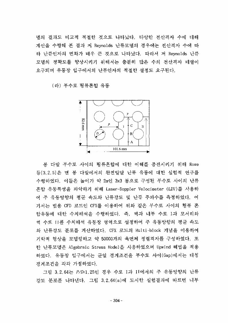
4 Reynolds ;g-f afl-bReynolds
(ef) JJL^S. 3-?f*tf-8-§-
Rowe
3x3
Laser-Doppler Velocimeter (LDV)#
CFD 3J=<y CFX#
H
if f. CFX 3.^$] Multi-block
500007B*]
^r Algebraic Stress Model# - - Upwind
# 443.2.64^
a ^ 3.2.64(a)c^l 5.4*1 } ^ i-fl-f
-304-
^ 5 . ^ M ^ S^&^r 4 4 0.0412} 0.0455.
-g-0.0525. ^H] ^ } 1
#A}2} -g. 4o]
*> «^ofl 7^} t^4 t>f^n7} cj^. ^7f^l-H5. ^ ^ ] ^ ^ . 5 ^ 'Saddle
Point'7}
#^6fl4 i|^^t 0.04
]fe 0.055.
n^J 3.2.65 ^ 3 } vfl-f- ^ 5 I
Aj- V l ^ - 4 ^ £ ^ 1 cfl?> CFX T^ j^^^ i} ^ ^ ^ ^ 1 - H].2.s>
3.2.65(a)ofl
^}^. -g- 4JL a l 4 . J£?> Reynolds
pt.
U ^ ^ ^ 1 ^ 5 : <cHf#5.7f ^ 0.045^1 «_>^^1 ofl^^l ^ ^ r «^ 0.0555
-fc EL7\} UBfVicf. *>^, ^ ^ - ^ ^ ^ 5 ] <tHf#S.6l| ^?> Reynolds
^-1T 3.2.66^ S^5 |5} ^ ^ 5 . II ^ ^ > d # itff fHofl c||*> CFX Til
S) ^ 5 ^ ]
Reynolds
- 3 0 5 -
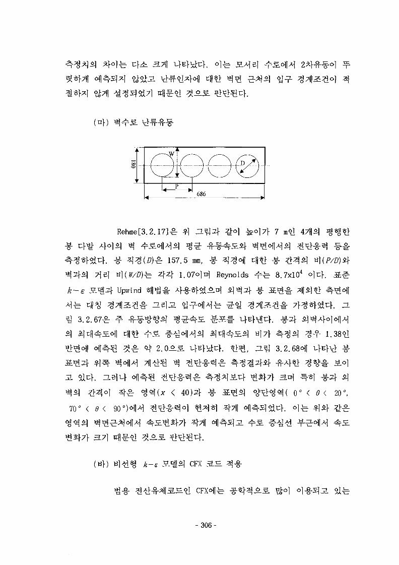
3.7]}
(nf)
•W
4 •686
YJ
Rehme[3.2.17]^
^ 157.5 mm, -g-
4 4 1.07<>l^ Reynolds 8.7xlO4 O]T:]-.
k-e Upwind -g-
3.2.67^
cfl*l. -g-sf
a]7} ^ ^ ^ ^ ^ 1.38^1
^ 3.2.68<>fl ^Eft> -g-
3 . Slut. ZL^^f c^l^
*$$] ^>4ol 3]-^- <g
70° < d< 90°)^)^
0° < 9< 20°,
3.71
^ ^ CFX 3 H 4-g-
- 3 0 6 -
a -§-§-3
£-£
. CFX 3.^
RNG £
k-co
JL
CFX 3.H
Speziale[3.2.18]
yfe-e
CFX 3 . ^
7]
CFX a_E.5f ^
source) *ON§-
k-e
k-e
CFX 3
^i CFX
'USRSRC'
l-§-t>
-^-(Sudden-Expansion Pipe Flow)
- 307-
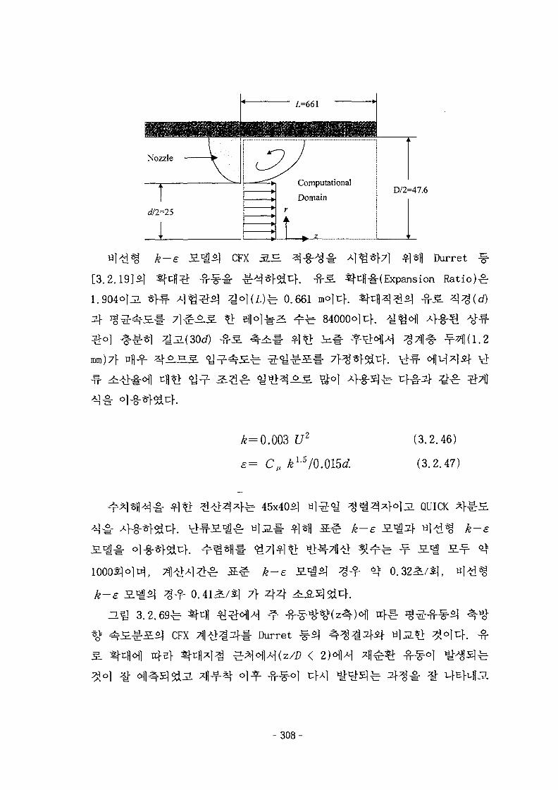
D/2=47.6
k-e CFX 5 H
[3.2.19]*]
1.904OJJL
^l^fl Durret %•
|f-i-(Expansion Rat io)^
0.661
84000olu}.
mm)7f
£=0.003 U2
e= Cu kL5/0.015d
(3.2.46)
(3.2.47)
10005]
fe 45x40^1 QUICK
0.32^/5],
CFX
rcfe}
7f 44
Durret -§-5]
< 2 ) ^
- 3 0 8 -
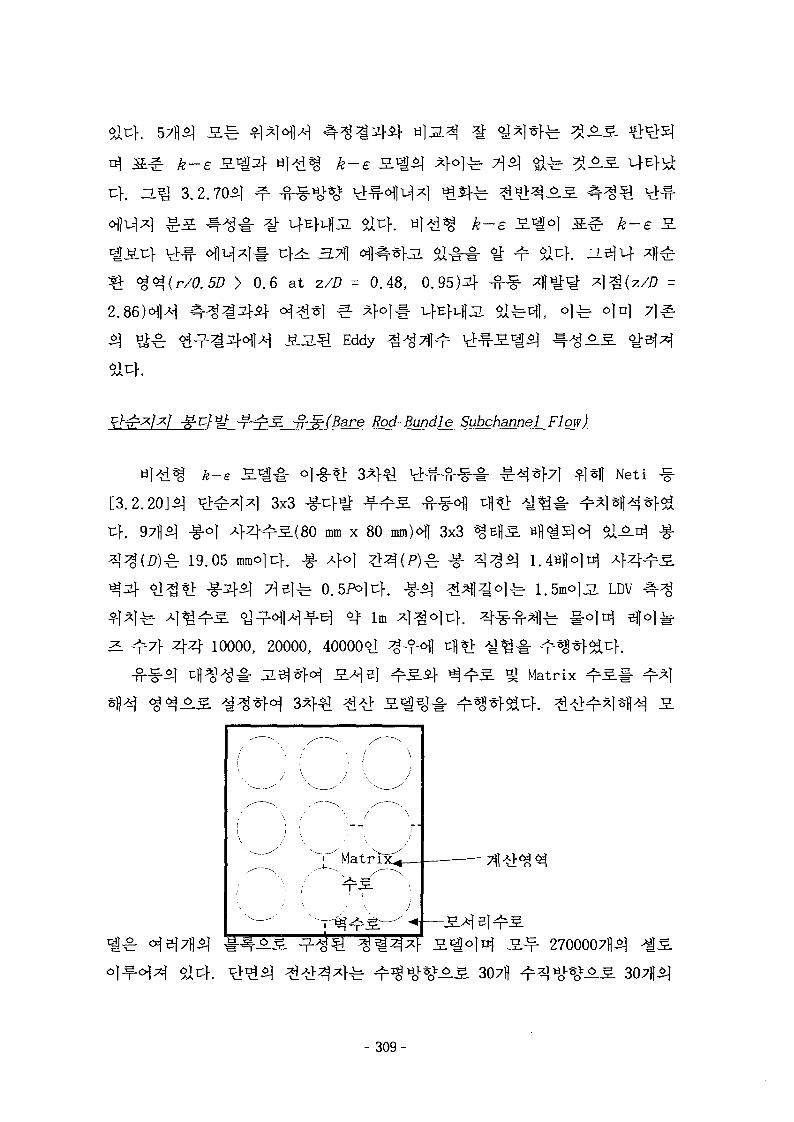
Ar-e
3.2.70^
k-e
0.6 at z/Z7 = 0.48, 0.
B 4Eddy
-T-^TM ~n-^(Bare Rod-Bundle Subchannel Flow)
k—e S-^-s- < Neti
[3.2.20]^ t>^^lx] 3x3
4 . 97H5] -g-o] 4 4 ^ ^ ( 8 0 mm x 80 mm)<Hl 3x3
^: 19.05 mmolcK -g- 4°1 ^^( / J )^r -g- 1 . 4 H | | O | ^
LDV
4 4 10000, 20000, 40000^1
Matrix
.^.s. 307)1
- 309-
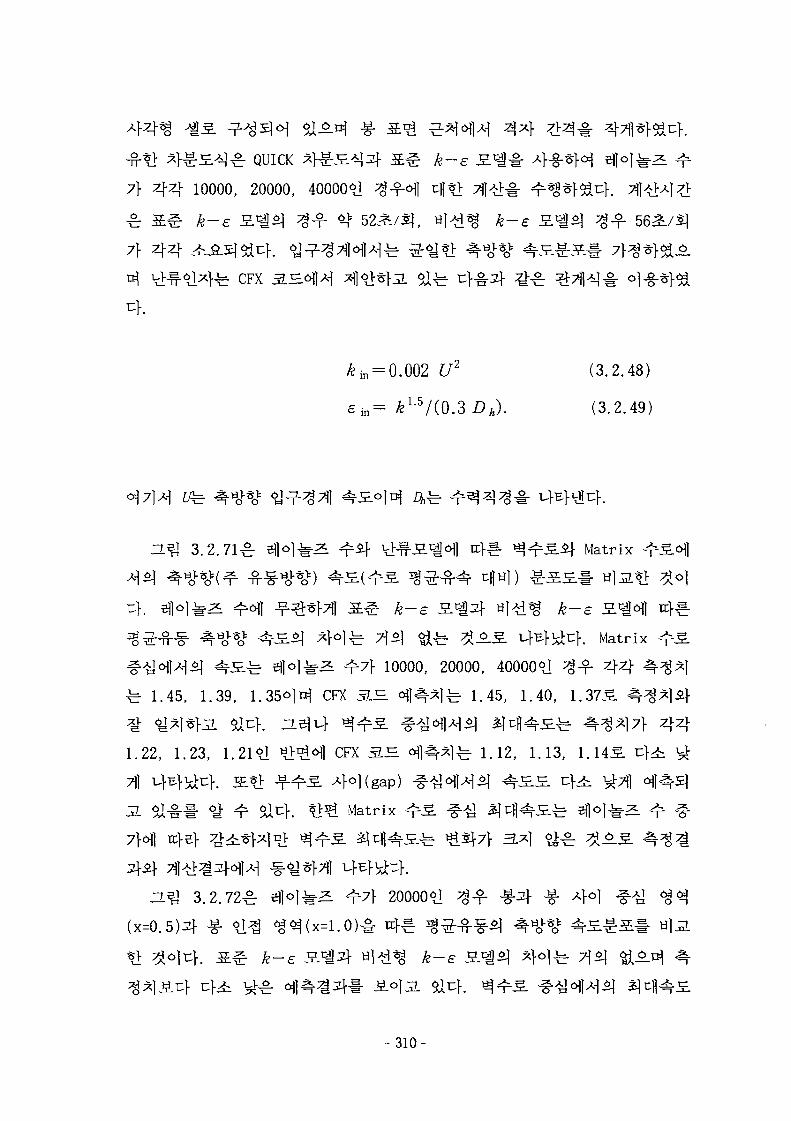
] £ QUICK *f£vE.*]:zf S ^ k-e
7} 4 4 10000, 20000, 40000*1
7} 44
CFX S H
(3.2.48)
(3.2.49)
n ^ 3.2.71^ Matrix
^}o}^ T] 6] <£^ ^ ^ . ^ i-WiiT:}. Matrix
2L ^ 7 } 10000, 20000, 400006J ^ - f 4 4
^ 1.45, 1.39, 1.35-^H CFX 3.B. <HI^]fe 1.45, 1.40, 1.375.
441.22, 1.23, 1.21*1 CFX 3.B. ^ 1.12, 1.13, 1.145.
Matrix
7}o\\ xc}
ZL^ 3.2 .72^ 20000*1
t:}-
- 310-
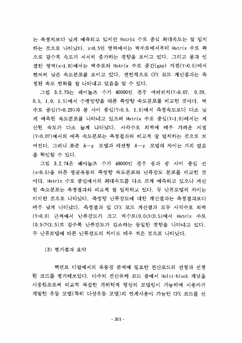
Matrix
4 4 ^ 4 . x=0.5*l - ^ Matrix
9J4. nelJLMatrix
A S CFX 3.B.
40000*1 =0.07, 0.29,
0.5, 1.0, 1.
-g- 4°1 (Y=0.5, 1.
o.ni Matrix
(Y=0. F— -^ J^LS. iL
k-e
-L^ 3.2.74^
(x=0.5)# rt
o]uf. Matrix
44^4.(Y=0.0)
(3)
40000*1 >g-f -g-jf ^- xfoj
CFX 3.^
Matrix
^ ^1S 44^4.
Multi-block
fet> CFX S H
-311-
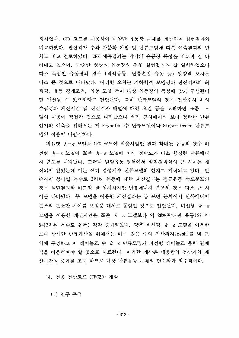
. CFX
. CFX
, -fi-g-
fe ^ Reynolds Higher Order
k-e Syg-%: CFX S ^ w)
k-e
k-e
H (TFC2D)
(1)
-312
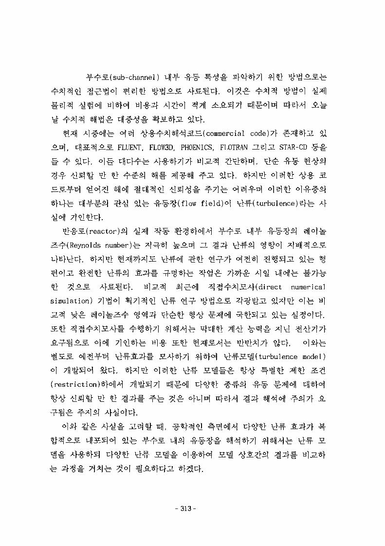
sub-channel)
H(commercial code)7} ^fl*>J
FLUENT, FL0W3D, PHOENICS, FLOTRAN asjjl STAR-CD
field)o| Vl^-( turbulence)B}-b
3^(Reynolds number)^ * 1 ^ 1 ^-^.^ H ^3f ^ # ^ 1 <8*cM
t> ^J5.S Af^sjcf. H]J2.3} aj -ofl ^ ] ^ ^ l S A f ( direct numerical
simulation)
S.A>*}71 ^-]*H V^^-S^Kturbulence model)
(restriction)*}^^
J S 1
-313-
(high Reynolds number) fi<l#
function)7>
(turbulent kinetic energy) ZLfi]jL Vl^-^m^] ^^-^-(dissipation rate)
7}
-^-*V>il^^( finite volume method)^]
equation)^
(control volume face)^o||45] #e ] ^ #
51 C>. ^-*1 cfl^-^-^^Mconvection-diffusion terrn)^
scheme)efjl
flow)*] ^ ^ o | 34^}(grid line)ofl tfl
(numerical diffusion)2HMl
* >
-711^4 ?ib
-314-
MI
$14.^-^.fe EL2D, EL3D ZL
JL
#
u>s.
J.^^S.M TFC2D(Turbulent Flow Calculation for 2-Dimension)
(2)
ZL^J 3.2.75<>11 rod-bundles)*]
(non-orthogonality)
coordinate
g: <y «>5f lET l (generalized
51 uf.
ZL
(axisymmetric)
4.-°~&
TFC2D £ 1 1 ^ 5|#(algorithm)^ EL2D
s^i# gl 4
TFC2D ^ i
^^(high Reynolds number) S i I7f*]4|
Reynolds number) JE^o]
- 315-
! • £ S 3.2.10<Hl ±.7^o\ $1^-}. TFC2D ^
*1*}^ - ? ^ r 57\*}$\ ^^(low order)*] ^*}*fg-^2: £ l7f*jSj JL%\
(high order)*]
^ S 3.2.1 H ^Bfuf $X$X
(3) ^ l a f l ^ ^ ^
A] (continuity equation)2f
momentum equation)^- # ^ o >
^1 Vl^- S c | ( two equations turbulence model
turbulent kinetic energy, k) ^^^ HZ}3-
(dissipation rate, e) ^ ^ ^ ^ #<H-M V): - - ^ ^ l ^ H e d d y viscosity)r^l TcKIX[(closed system)!- <^# ^ 7} $1^}. *fx|
S.S. S-E U-^^-i- *Kf^ ^ ^ I H H ^ ^ K g e n e r i c equation)^]
(conservative form)S.
^ p l = 0 . (3.2.50)
Eulerian ^
!)• vp+pv -1=0 (3.2.51)
(3.2.52)
- 316-
T+P~b (3.2.53)
°J7M T fe -§-^^l^(stress tensor)!- T-^HM 1
force)# ufEfvfli:}. ^$1 3f*l# Eulerian
^ V • (pT^) = v • T+ p i (3.2.54)
Newtonian -fM]# 7 } ^ ^ } ^ , ^ ^ T ±r 4 ^ ^ c l ^<H?14.
T = - p 1+ A( v •~v) + 2(iD (3.2.55)
ojjL D ^ ^ ^ ^ 1 | >#1 £
i)=j(v^+vlr) (3.2.56)
4 ^ ( imcompressibility)
(3.2.57)
(3.2.58)
^ ^^5}(Reynolds averaged)^
l-el^w !i^ A^(mean component)^-
^^•(fluctuating component)JLS. 4-r-1^ ^f^-^ h
v= v+ v', p= p+ p'', ii= fi + (x b= b+ b'
(ensemble average)^ v}^ 44*] ^ ] ^
+ v • (71) = 0 (3.2.59)
V * ( ^ ) = - v"^+ v - M v l + v T ) + r]+Tl (3-2-60)
(Reynolds s t r e s s ) ^ U ^ K l l ^ , ^ 1 * 1 ^ ^ » l f e v'-vP' = 0, p ' v ' =
- 3 1 7 -
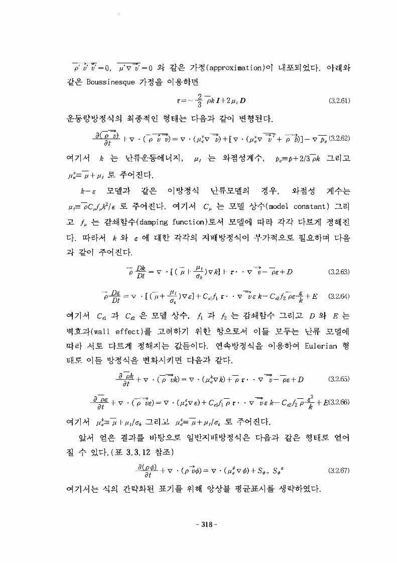
pv'v' = O, / / v 1 / = 0 S\ %£ 7Hg (approximation^!
£ Boussinesque
(3.2.61)
C, ^ S-^i ^"^r(model constant) JIB]
f, ^ ^ i f l ^ H d a m p i n g function)^A^ 3.^o\] trj-sj-
k S\ e ofl
)vk}+ z- -v^l-~pe+D (3.2.63)
7 ^ e l 1 C z z T f + S (3.2.64)
CA 4 C£2 S^J ^ ^ r , / . 4 / 2 r ^ ^ l ^ ^ r ^-S]JL £» £} £ ^
effect)!- 3-$*}7] ^I*> %^S.Af o}§ S ^ ^ ufs.
Eulerian
= v • (/i*vj^)+"pr' • v^-^e+Z> (3.2.65)
v • Cpl>£) = v • (^v £ ) + CAA~P r • • v ^ £ * - Ctf/2"p-j" + £(3.2.66)
3.3.12
dip a (3.2.67)
- 3 1 8 -
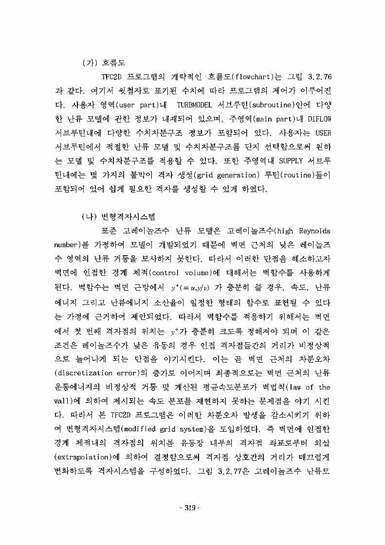
(7f) S#£
TFC2D i g - Z L ^ ^ 711^^6] Jl#£(flowchart)^ H ^ 3.2.76
part)Ml TURBMODEL x\ «.-f-1H(subroutine)
in part)4 DIFLOW
fe USER
IE?}- ^ ^ ^ v H SUPPLY A-|H.
^^(grid generation) -f-
jn^.g. jL5flo]^^^(high Reynolds
number)!-
7%A H^(control volume)^]
71B17}
(discretization error)*] ^-7}S. <>M^]^ 5 | # ^ ^ . ^ . ^ ^ ^ ^r^-^ 1cHf-
^ r ^ ^ M ^ l ^ H ] ^ ^ ^ ^ ^ ^ 7?1 >^ j g ^ ^ ^ y - ^ y f ^^A|(law of the
wallH 51 *H ^1^1^^ ^S. ^:
TFC2D HSZL^^r
ified grid system)-§-
(extrapolation)^] Sj
^ 1 . H ^ 3.2.77^
-319-
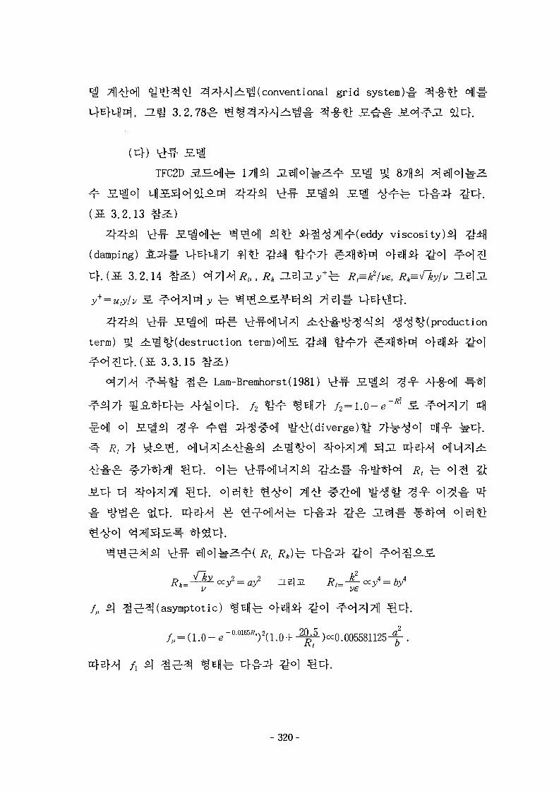
^(conventional grid system)^
, O.^ 3.2.78 £ % 4 *
TFC2D 3-J^fe I7fl£) JL3H"k^r £.»g 87fl5j
( S 3.2.13 *h£)
4 4 ^ t>^- S ^ ^ l ^ ^^<H1 t> i}^A^l^(eddy viscosity)*]
(damping)
4 . ( S 3.2.14
y+ = uTy/v 3. i y
44^1 t>^- S l ^ j 4 ^ . Vl -cHmx] ^.Af^-tii-^Ai^ A§A$9£(production
term) ^ 4i^%Kdestruction term)^l£ 4 ^
^°i^l^}. (X 3.3.15 *h£)
^-^ ^^r Lam-Bremhorst(1981)
o] | ^ %° ^ ^
, 7}
4(asymptotic) ^Eflfe
= ( 1 . 0 - e"00165'?t)2(1.0 + -2^S-)«:0.005581125^
-320-
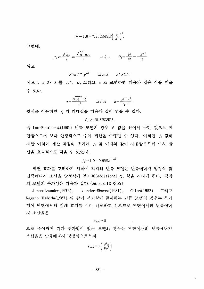
/, = 1.0 + 719. 0262812f-r) .
* v v v£ e
k+ozA+y+2
a Q b # A\ uT He
/i oc 90.87828515.
Lam-Bremhorst(1981)
/2
7H(additional)*] %># ^)i.|7i| ^ u } . 4 4
S 3.2.16 # i )
Jones-Launder(1972), Launder-Sharma(1981), Chien(l982) ZLB]JL
Nagano-Hishida( 1987) 3} £<>}
ojn|
71
-321-
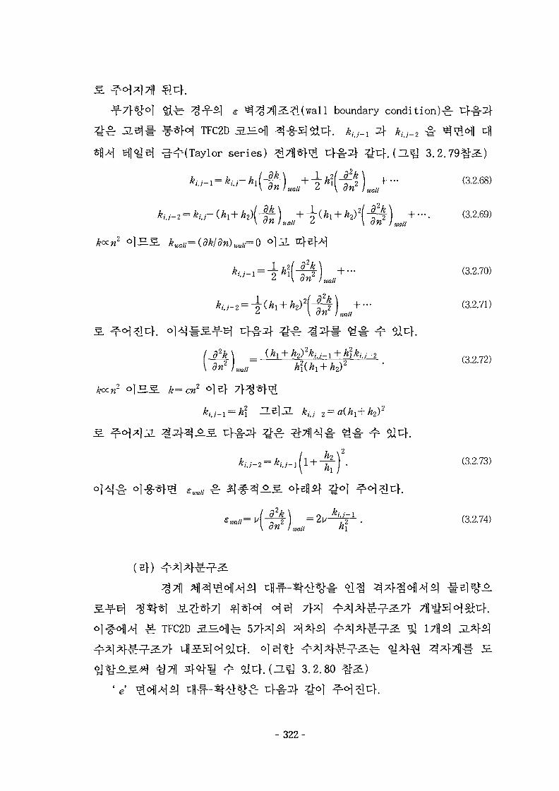
boundary condition)^ rj-g^
TFC2D S £ 1 ^ -§-5]^f . *,-,-_! 2} *. ._2 -§• * ) ^ 1 ufl
^ ( T a y l o r series) ^ 7 f l ^ ^ cj-^-2]- ^ t : } . (ZL J 3.2.79%^)
) ^1 2 p )on j wau i \ an ) waa
kwali=(dk/dn)wau=0 <>]JL
£ S k=cn2
(ef)
TFC2D S H
(^.fj 3.2.so
- 3 2 2 -
i?(0)««/; & \ OH I wau
?) . (3.2.69)
+ - «.2.70)wall
(3.2.71)
(3.2.73)
( 3 ' 2 ' 7 4 )
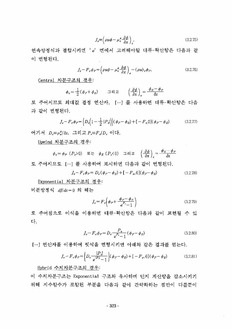
(3.2.75)
V
/.e^(p^^|^)<p(!^. (3.2.76)
Central aR^^Sl f
(3.2.77)
Upwind
(3.2.78)
Exponential * H ^ ^ g ?
Je=F.UP+ *PP~*B) (3.2.79)
V e - 1 /
e — 1(3.2.80)
« 1 ^e — 1
Hybrid
(3.2.81)
Exponential
- 3 2 3 -
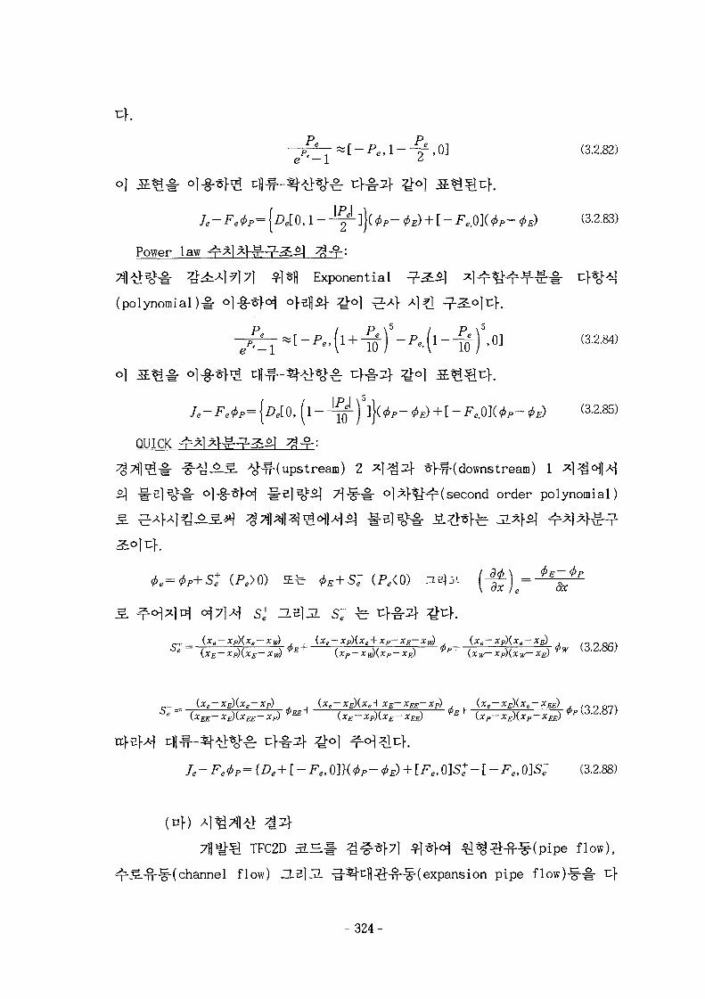
-^--[-^1-4,0] (3.2.82)e — 1 *
e e 0 p { e [ O , l ^ ] } ( ^ ^ ) [ e , O ] ( 9 p ^ ) (3.2.83)
P o w e r l a w 1 R l J 3
Exponential
(polynomial )#
(3.2.84)
/e^0p{JDe[O)(l^)]}(^^) + [Fe.O](^p^) 0.2.85)
QUICK l l £ £ ) ^ 4
^ - ^ . 5 . Ao^( upstream) 2 ^ | ^ 3 f *f^-( downs tream) 1 *]^J<HM
°l-§-*M - i - s | ^ >}-§•# o]^}^-^(second order polynomial)
(pe<o)
{xe-xP){xe+xP-
(xe-xE)(xe + xE-xEE-xP)
(3.2.88)
(U\)
7 « ^ ^ TFC2D S ^ # ^^}7) ^1*H €^^^-^(pipe flow),
-J§-(channel flow) ZLZ\3L -%cfl^-^^-(expansion pipe flow)-
324-
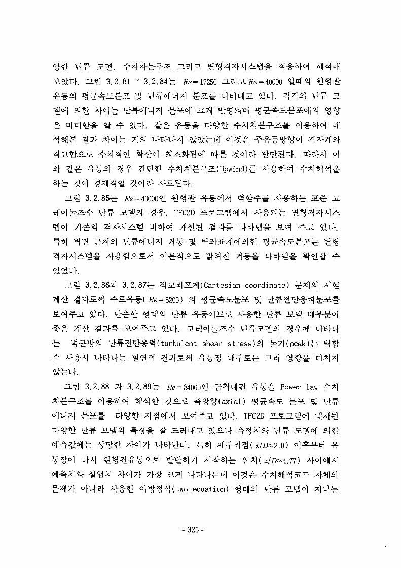
3-Q 3.2.81 ~ 3.2 .84^ Re = 17250 HBl:2.Jte = 40000
3.2 .85^ i?e=
^ f , TFC2D S5.ZL
3.2.8621- 3 .2 .87^ 3|J2.S]-S7(|(Cartesian coordinate)
014. ^ ^ t l ^Bfl^ u^- ^-^o]H5. 4-g-tf
6ix:K ^ ^ j o l ^ i ^ vHf-S
turbulent shear stress)*] l-7](peak)fe
ZL^ 3.2.88 4 3 .2 .89^ i?e = 84000 1 -g-%tj |^ - ^ - ^ # Power law
. TFC2D 5 1 1
equation)
- 3 2 5 -
a ^ 3.2.90^- <%X\ i?e=84000
(4) £ s.
TFC2D 3 . ^ # 7 H ^ } ^ l ^ f l b i ^ ^ ^
^ ^ ^ > I ^ ^ ^ ^ ^ ^ f 4 SIMPLER
TFC2D 2 H
n
3.711
^3 " ^ ^ ^ ^ ^ *~'\ . •( 1 I VJLIL'
QUICK 9-^7} 4-g-5lJL al-^-1^ 7lEf ^Af5] - ^ - ^ S . ^ Central
^ 5 7 M -?^7f Af-g-SJJL &CJ-. QUICK
QUICK 9 ^ 5 ]
- 326-
- 3 2 7 -
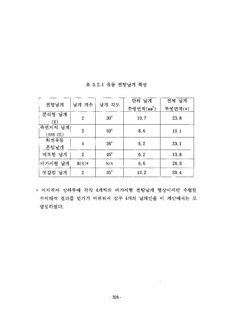
.2.1
£%^7fl
^3l«g ^7fl(W)
^£*1*1 ^7fl(ABB-CE)SJ #-&-•§•
£^7fl
^ < g ^ 7 H
^ ^ U ^ 7 i |
^7H 7 | | ^
2
2
4
2
8(4)*
2
30°
90°
35°
45°
N/A
35°
#*1 ^7|{
^ ^ ^ ^ ( m n , 2 )
10.7
8.6
5.2
6.2
6.6
13.2
^ i ^ l ^7fl
^ ^ ^ ^ ( % )
23.8
19.1
23.1
13.8
28.3
29.4
44o]
- 328-
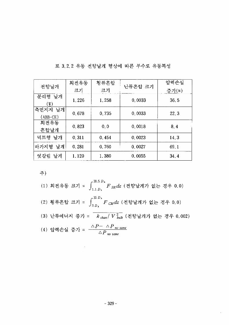
3.2.2
£^1*8 ^7fl(I)
(ABB-CE)
H } 7 M ^ y-7ii
3.7]
1.226
0.678
0.823
0.311
0.281
1.120
3.7]
1.258
0.735
0.0
0.454
0.760
1.380
letfr J- 371
0.0033
0.0033
0.0018
0.0023
0.0027
0.0055
&}(*)
36.5
22.3
8.4
14.3
69.1
34.4
(1)
(2)
(3)
(4)
3.7} = r38
^ i . i D h
3.7] = r
kchajV\uik
0.0)
0.0)
f 0.002)
- 329-
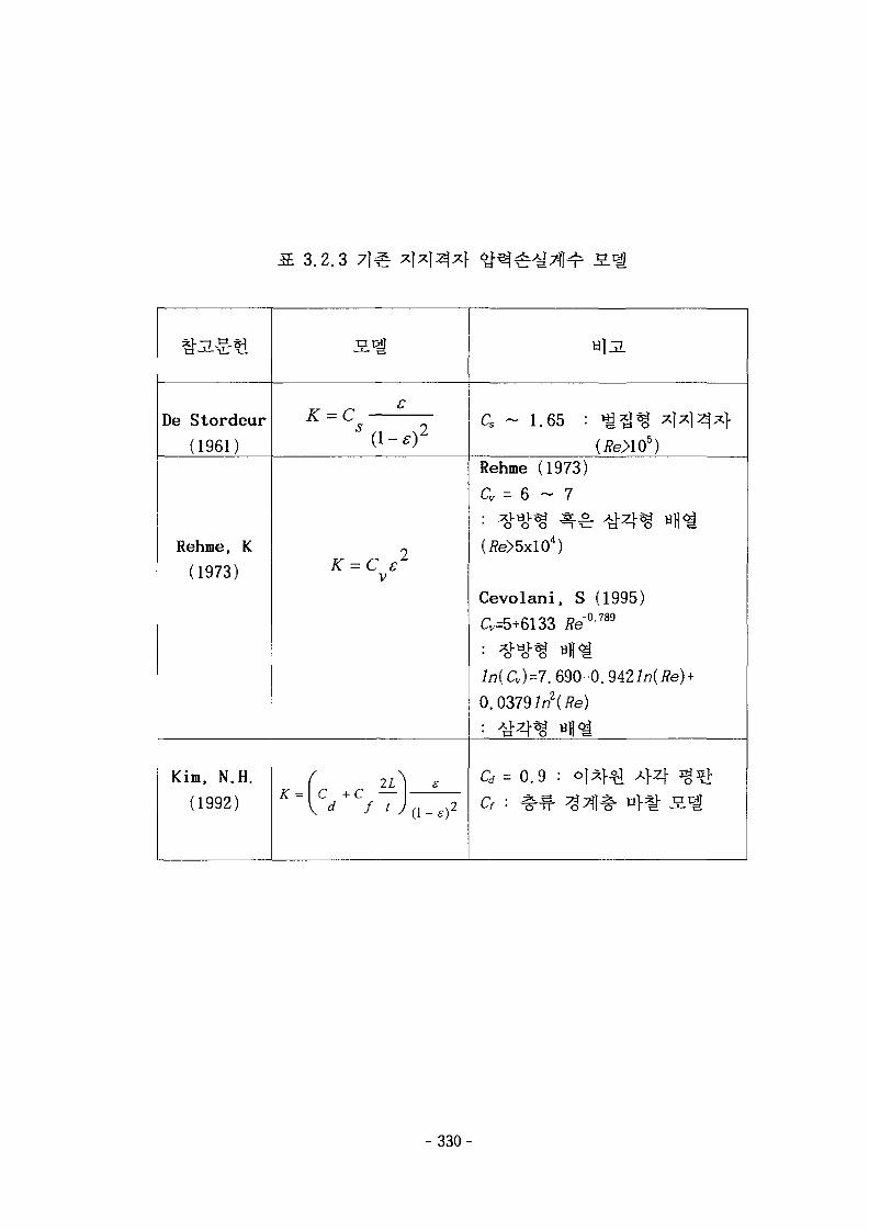
13.2.3
De Stordeur
(1961)
Rehme, K(1973)
Kim, N.H.
(1992)
s
S(\-s)2
K = C e2
V
( 2L} EA. — 1 C 4- C
(fe>105)Rehme (1973)
a = 6 ~ 7
(*e>M0<>
Cevolani, S (1995)
Cv=5+6133 i?e"0789
in(a)=7. 690-0.942in(i?e) +0.0379 in2 (/?e)
0/ - 0.9 ; oi*}4i 4 4 3g2>
- 330-
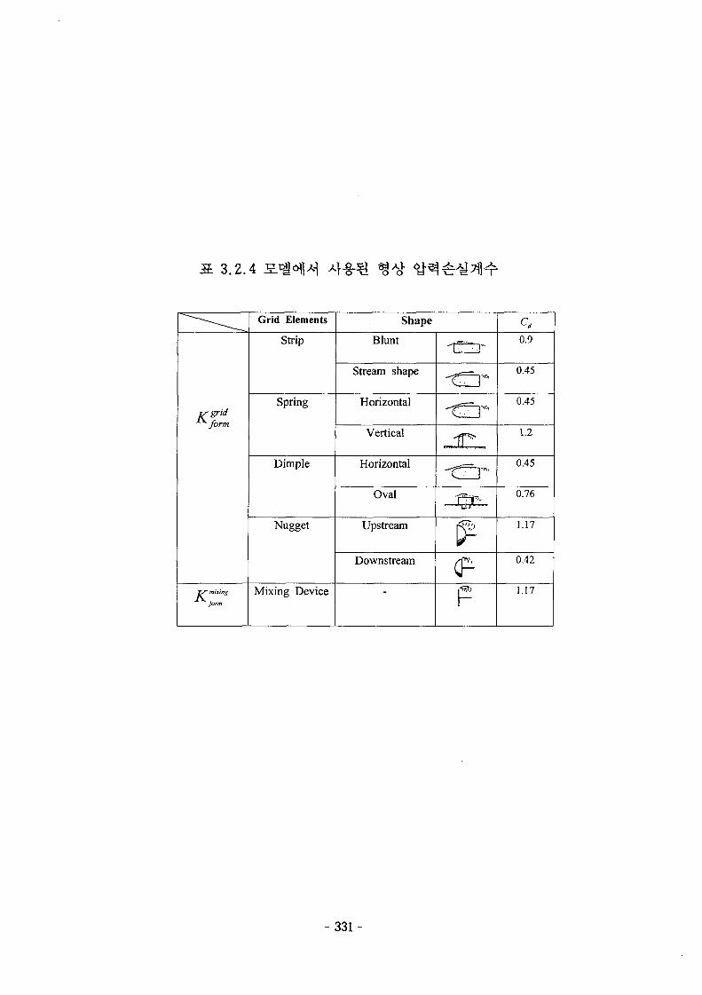
S. 3.2.4
is gridt^form
ry' mixing
form
Grid Elements
Strip
Spring
Dimple
Nugget
Mixing Device
Shape
Blunt
Stream shape
Horizontal
Vertical
Horizontal
Oval
Upstream
Downstream
frf-
0.9
0.45
0.45
1.2
0.45
0.76
1.17
0.42
1.17
- 3 3 1 -
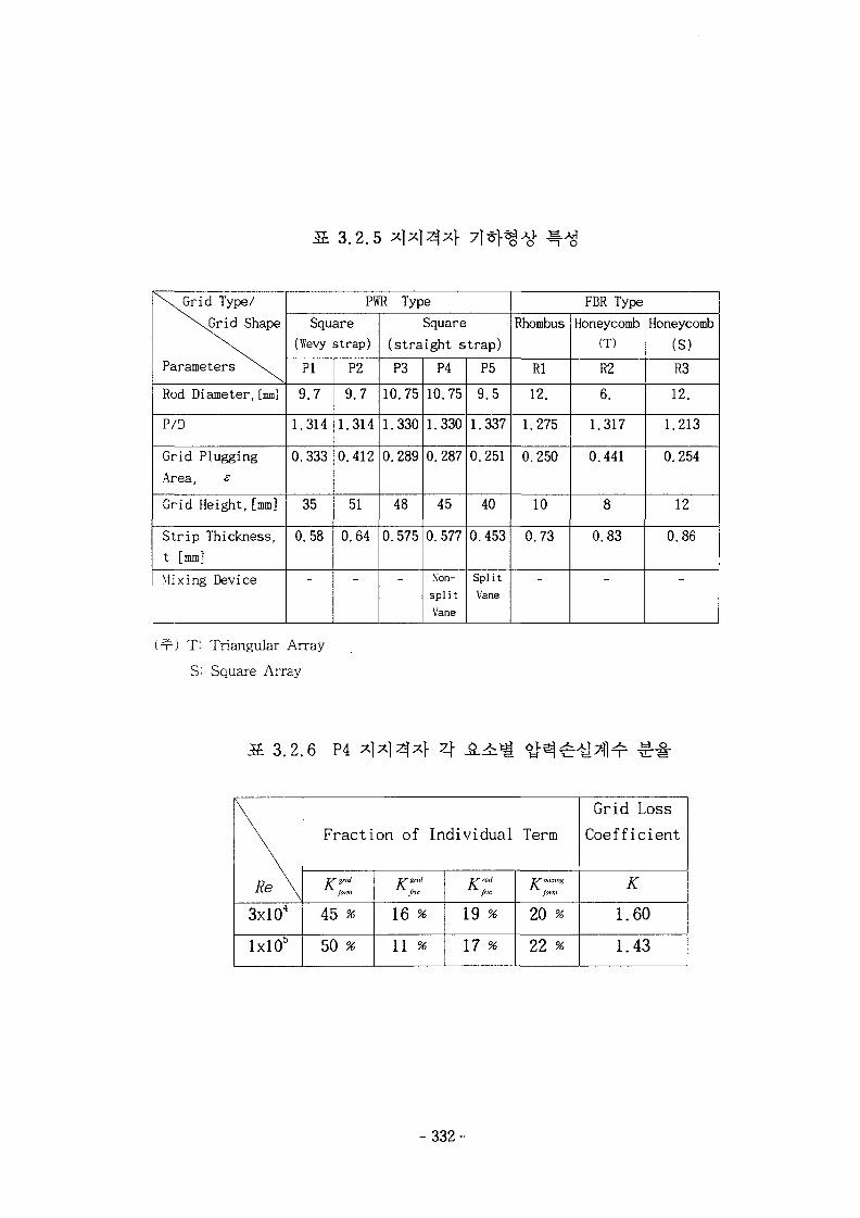
13.2,5
\ i G r i d Type/X^Grid Shape
Parameters \ .
Rod Diameter, [mm]
P/D
Grid PluggingArea, £
Grid Height,[mm]
Strip Thickness,t [mm]
Mixing Device
PWR Type
Square(Wevy strap)
PI
9.7
1.314
0.333
35
0.58
P2
9.7
1.314
0.412
51
0.64
Square
(straight strap)
P3
10.75
1.330
0.289
48
0.575
P4
10.75
1.330
0.287
45
0.577
Non-splitVane
P5
9.5
1.337
0.251
40
0.453
SplitVane
FBR Type
Rhombus
Rl
12.
1.275
0.250
10
0.73
Honeycomb(T)
R2
6.
1.317
0.441
8
0.83
Honeycomb
(S)
R3
12.
1.213
0.254
12
0.86
T: Triangular Array
S: Square Array
3.2.6 P4 4
Re \
3x10⁴
1x10"
Fraction of Individual Term
form
45 %
50 %
16 %
11 %
7/" rod
19 %
17 %
form
20 %
22 %
Grid LossCoefficient
K
1.60
1.43
- 3 3 2 -
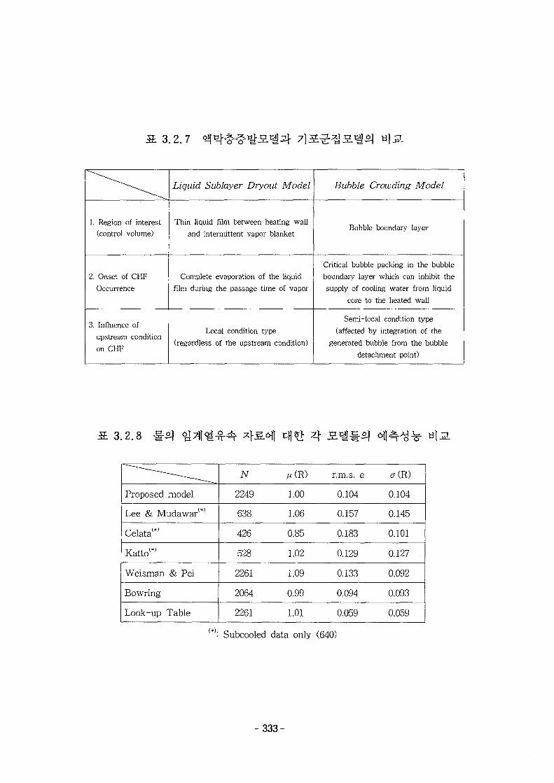
13.2 .7
1. Region of interest(control volume)
2. Onset of CHFOccurrence
3. Influence of
upstream condition
on CHF
Liquid Sublayer Dryout Model
Thin liquid film between heating wall
and intermittent vapor blanket
Complete evaporation of the liquid
film during the passage time of vapor
Local condition type
(regardless of the upstream condition)
Bubble Crowding Model
Bubble boundary layer
Critical bubble packing in the bubble
boundary layer which can inhibit the
supply of cooling water from liquid
core to the heated wall
Semi-local condition type
(affected by integration of the
generated bubble from the bubble
detachment point)
3.2.8 4 2-^$] <^
Proposed model
Lee & Mudawar1*'
Celata1*'
Kattol*J
Weisman & Pei
Bowring
Look-up Table
N
2249
638
426
528
2261
2064
2261
A«(R)
1.00
1.06
0.85
1.02
1.09
0.99
1.01
r.m.s. e
0.104
0.157
0.183
0.129
0.133
0.094
0.059
aCR)
0.104
0.145
0.101
0.127
0.092
0.093
0.059
Subcooled data only (640)
- 3 3 3 -
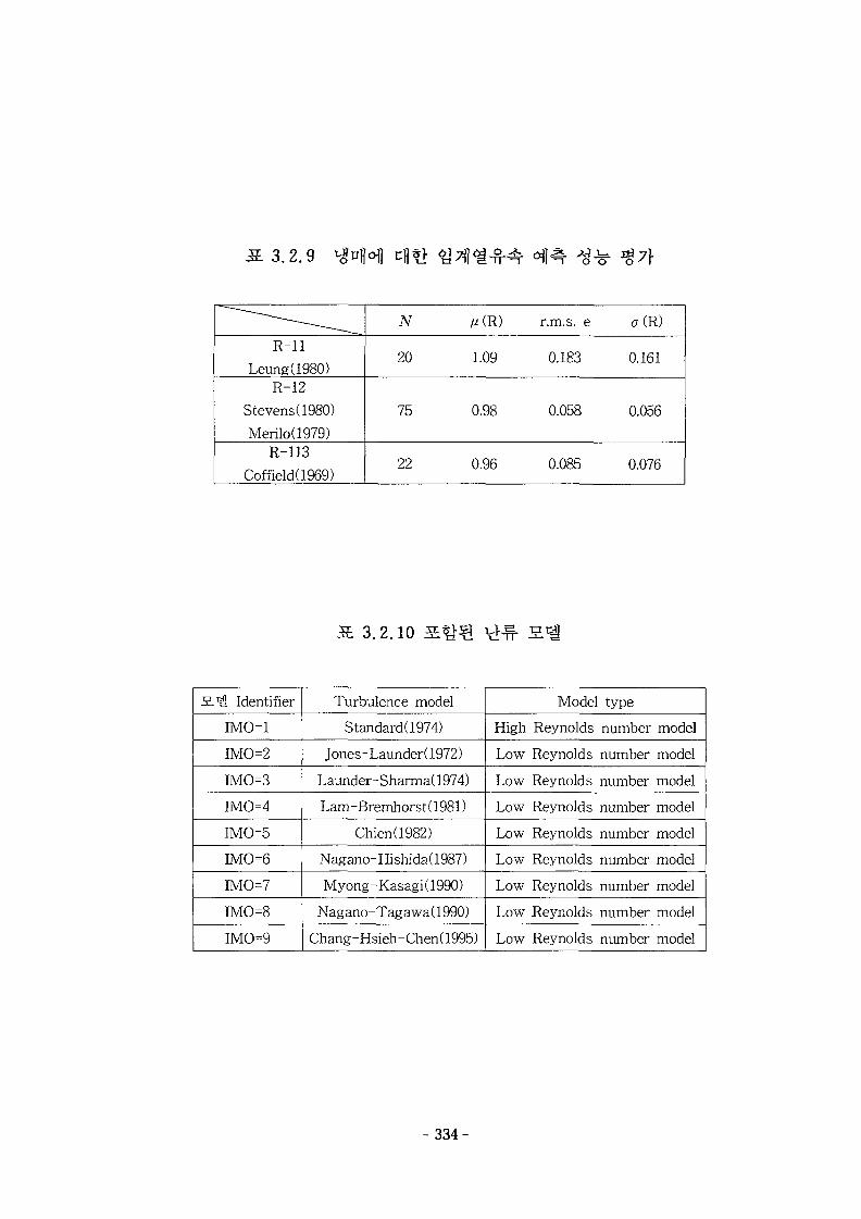
1 3 , 2 . 9 cfl*}
R-l lLeung(1980)
R-12
Stevens(1980)
Merilo(1979)R-113
Coffield(1969)
TV
20
75
22
MR)
1.09
0.98
0.96
r.m.s. e
0.183
0.058
0.085
<T(R)
0.161
0.056
0.076
3.2.10
S.'i Identifier
IMO=1
IMO2
IM0=3
IM0=4
IM0=5
IM0=6
IM0=7
IM0=8
IM0=9
Turbulence model
Standard(1974)
Jones - Launder (1972)
Launder-Sharma(1974)
Lam-Bremhorst(1981)
Chien(1982)
Nagano-Hishida(1987)
Myong-Kasagi(1990)
Nagano-Tagawa(1990)
Chang-Hsieh-Chen(1995)
Model type
High Reynolds number model
Low Reynolds number model
Low Reynolds number model
Low Reynolds number model
Low Reynolds number model
Low Reynolds number model
Low Reynolds number model
Low Reynolds number model
Low Reynolds number model
- 334-
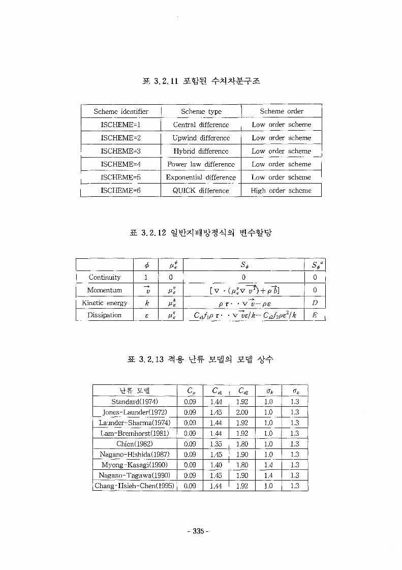
3.2.11
Scheme identifier
ISCHEME=1
ISCHEME=2
ISCHEME=3
ISCHEME=4
ISCHEME=5
ISCHEME=6
Scheme type
Central difference
Upwind difference
Hybrid difference
Power law difference
Exponential difference
QUICK difference
Scheme order
Low order scheme
Low order scheme
Low order scheme
Low order scheme
Low order scheme
High order scheme
3.2.12
Continuity
Momentum
Kinetic energy
Dissipation
4>1
V
k
£
AMe
0
Ml
Me
s40
[v -(^v~^) + pl]pT• • v v — pe
CJxP T • • v~ve/k- C&f2pe2/k
0
0
D
E
3.2.13
Standard(1974)
Jones-Launder(1972)
Launder-Sharma(1974)
Lam-Bremhorst( 1981)
Chien(1982)
Nagano-Hishida(1987)
Myong-Kasagi(1990)
Nagano-Tagawa(1990)
Chang-Hsieh-Chen(1995)
c.0.09
0.09
0.09
0.09
0.09
0.09
0.09
0.09
0.09
cA1.44
1.45
1.44
1.44
1.35
1.45
1.40
1.45
1.44
c&1.92
2.00
1.92
1.92
1.80
1.90
1.80
1.90
1.92
1.0
1.0
1.0
1.01.0
1.01.41.4
1.0
1.3
1.3
1.3
1.3
1.3
1.3
1.3
1.3
1.3
- 3 3 5 -
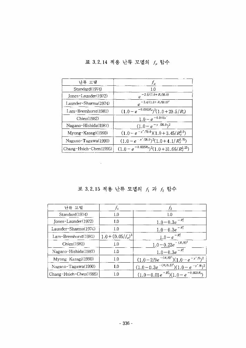
3.2.14 -g- / „
Standard(1974)
Jones-Launder (1972)
Launder- Sharma (1974)
Lam- Bremhorst( 1981)
Chien(1982)
Nagano-Hishida(1987)
Myong-Kasagi(1990)
Nagano-Tagawa(1990)
Chang -Hsieh -Chen (1995)
1.0-2.5/(1.0+i?,/50.0)
e- 3.4/(1.0+ #,/50.0)z
e( 1 . 0 - e~°-0165^)2(1.0 + 20.5/Rt)
LO_e-o.oii5>-
a.o-e-*'176-0)2
(l.0-e-y'noo)a.0 + 3A5/R°l-s)
(1.0- e- r / 2 6- 0) 2(1.0 + 4.1/i??-75)
(1 .0 - e"00215;?t)2(l.0 + 31.66//?P5)
3.2.15 /2
Standard(1974)
Jones-Launder(1972)
Launder-Sharma(1974)
Lam- Bremhorst( 1981)
Chien(1982)
Nagano-Hishida(1987)
Myong-Kasagi(1990)
Nagano-Tagawa(1990)
Chang-Hsieh-Chen(1995)
/ i
1.0
1.0
1.0
1.0 + (0.05//^)3
1.0
1.0
1.0
1.0
1.0
h1.0
1.0-0.3e"^
1.0-0.3e~*?
1.0-e"*1
1.0-0.22e~(/?l/6)2
1.0-0.3e"^!
a.o-2/9<r(*'/6)2)(i.o-e^+/5)2
(1.0-0.3e"W6"5)2)(1.0-e-^ / 6)2
(l.O-O.Ole'^Xl.O-e"0-0631^)
- 336-

JJ- O, t-r. 1 U 1
Standard(1974)
Jones - Launder (1972)
Launder-Sharma(1974)
Lam-Bremhorst(1981)
Chien(1982)
Nagano-Hishida(1987)
Myong-Kasagi(1990)
Nagano-Tagawa(1990)
Chang-Hsieh-Chen(1995)
D( fc-equation)
0
_IL( dk\2
2k\ dy)
.JLl dk\2
2k\ dy)
0
-2Mk/y2
_JJ_I 8k\2
2k\ dy)
0
0
0
E( e-equation)
0
0
-2ttetfe-0-5y~
(1.0 fM(\$)
0
0
0
- 3 3 7 -
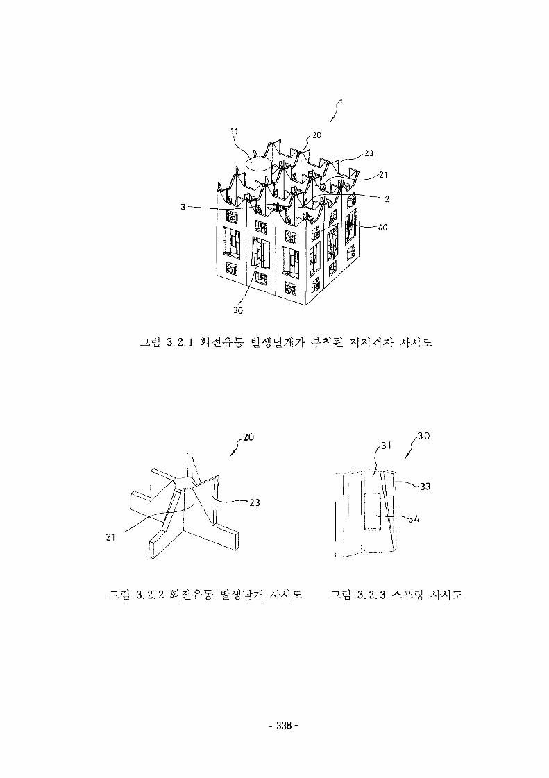
23
•21
3.2.1
21
i U—"
H^I 3.2.2 15J 3.2.3 +^%
- 3 3 8 -
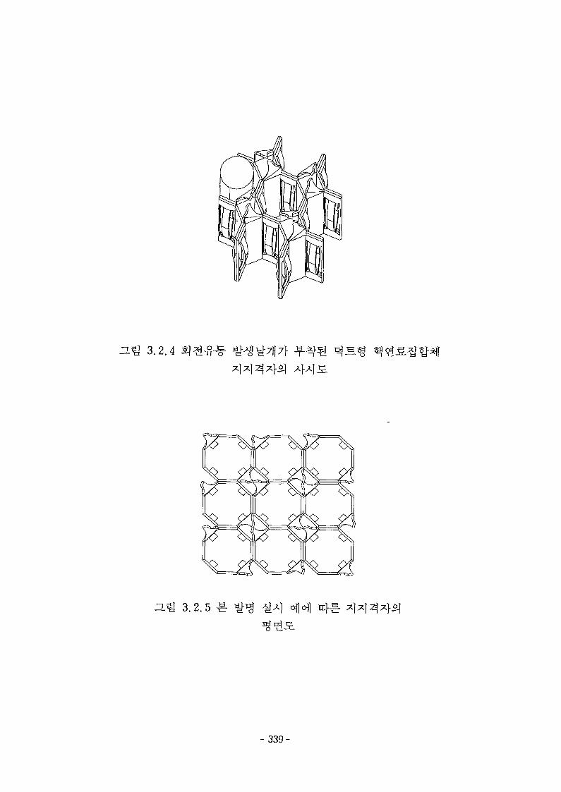
3-% 3.2.4
ZL^ 3 .2.5 ^ofl 4^-
- 339-
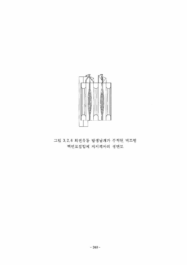
D.Q 3.2.6 £1
- 340-
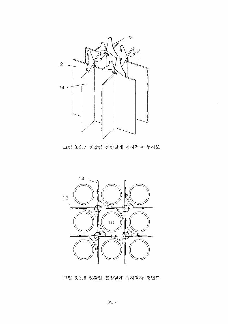
14
D.m 3.2.7
"L^ 3.2.8
- 3 4 1 -
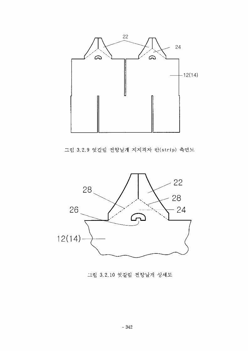
•12(14)
H.^ 3.2.9 ^l(strip)
28
12(14)
22
zi5i 3.2.10
- 342-
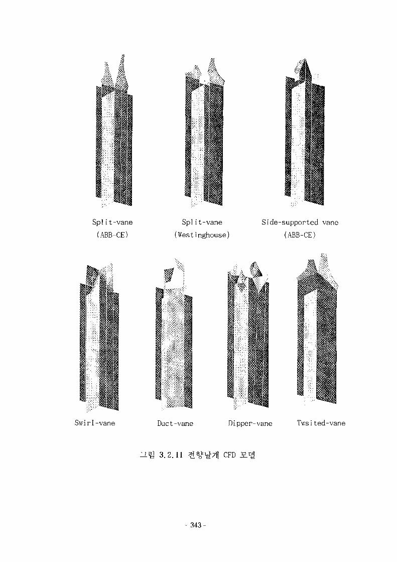
i
ij
Split-vane
(ABB-CE)
Split-vane
(Westinghouse)
Side-supported vane
(ABB-CE)
Swirl-vane Duct-vane Dipper-vane Twsited-vane
HQ 3.2.11 CFD
- 343-
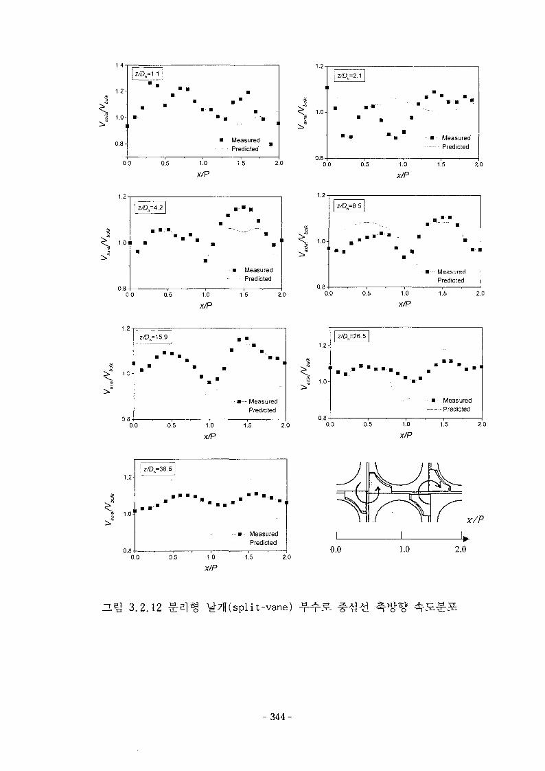
1.4
1.2-
s 1.0-
0.8-MeasuredPredicted
0.0 0.5 1.0
X/P1.5 2.0
1.0-
0.8-
• • "
• •
- - •
•
— • - MeasuredPredicted
0.0 0.5 1.0
x/P1.5 2.0
1.2
0.8
— MeasuredPredicted
0 0 0.5 1.0
X/P
1.5 2.0
1.2
0.8
MeasuredPredicted
0.0 0.5 1.0
X/P1.5 2.0
1 0-
0 8 -
z/D=15.9
• • • • • • - • .
• •
• •• •
•
•
••••— Measured
Predicted
0.0 0.5 1.0
X/P
1.5 2.0
1.2-
1
LO-
OS-
Z/Oh=26.5
. . • " . . . . . • " • . -
- • MeasuredPredicted
0.0 0.5 1.0x/P
1.5 2.0
axi
al
bulk
1.2-
1.0!
0.8-
z/Dh=38.5 |
- • " • • - . . . . • • • • •
• - • • - Measured- Predicted
0.0 0.5 1.0
X/P1.5 2.0
0.0 1.0
X/P
2.0
O.5J 3.2.12 split-vane)
- 3 4 4 -
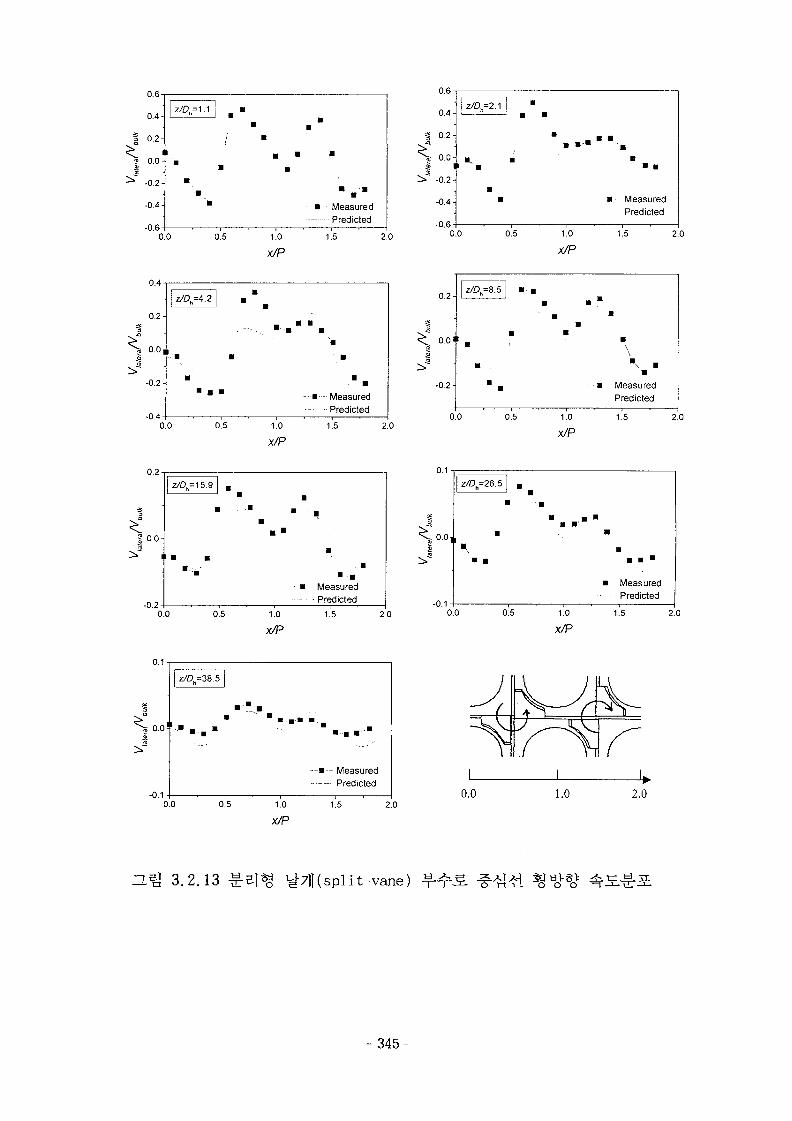
0.4-
0.2-
10.0-
0.2-
0.4-
OR-
z/Dt
I•
a
=1
a
ZJ -•B
/ a
aB
B
a
B
B
-• a
B
" • •MeasuredPredicted
0.0 0.5 1.0
x/P1.5 2.0
u.o -
0.4-
0.2-
0.0-1
-0.2-
-0.4-
-0.6-
z/Dh=2.1 j "
B
B
••
I > I
• ' • aB
a a
a MeasuredPredicted
' 1 •
0.0 0.5 1.0
X/P
1.5 2.0
0.2-
0.0,
-0.2-
-0 4-
1
a
• a a
BB
aB • " •
• ""•--. a a
a
- • - B - -
B
' B
" a
MeasuredPredicted
0.0 0.5 1.0
X/P
1.5 2.0
0.2-
0.0'I
-0.2-
0.0 0.5
MeasuredPredicted
1.0
X/P
1.5 2.0
0.2
^
-0.2
I =15.9
0.0 0.5
• BMeasured
- Predicted1.0
X/P
1.5 2.0
0.1
-0.1
Z/Dh=26.5
0.0 0.5 1.0
X/P
MeasuredPredicted
1.5 2.0
0.0-
-0.1-
z/On=38.5
—a — MeasuredPredicted
0.0 0.5 1.0
X/P
1.5 2.00.0 1.0 2.0
n.^ 3.2.13 it-vane)
- 3 4 5 -
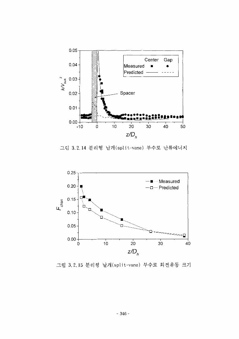
0.05
0.04-
0.00
Center GapMeasured • •
-10 0 10 20 30 40
nm 3.2.14 ^7B(split-vane)^
0.25
0.20-
0.05-
0.00
D.Q 3.2.15
—•— Measured—•— Predicted
10
d7fl(spl
20
it-vane) 3.7}
- 346-
VTO, Split-vane(W)\**I^.*if Side-supported
vane (ABB-CE)
Swirl-vane
• r r f * > . \/r f !• r '
/ ? r .> ,-
>*•""•• < « i if
Y.W'iWl Duct-vane
Dipper-vane V Tw i s ted -vane
3.2.16
- 347-
A.V\
di:
T f n \
•'••'••'^^...^VV-.N-X
-. -^ ^ iTi"
» • • i
..,-•-•!
H ^ 3.2.17
- 348-
V-«-. »- "•
•*S>Sja
r ,' .» ;r »t •
«
i * •
, < < .
\
s
n
X
\\
f ,
g
I!
/
\
U
is.
f
• *
t:;;:;;;r : i;-;;?!;:;;
; ; . . - ^ ' n
.-•ft f • • ^ .c
r i T •'
' ' '!
O.^ 3.2.18
- 3 4 9 -
1.3-
1.2-
1.1-
1.0-
0.9
• • - z / D B = 1 . 1
» z/Dh=&5
*- z/DB=38.6
^ '"
•
* *
T T
•
Z«=2.1 * z/D=4.2
2^=15 .9 •*- z/D=2G.b
, . • • • • > - • , .
Split-vane (W) ^ ^
0.00 0.25 0.50x/P
0.75 1.00
1.4
1.3-
1.0-
0.9-
0.8
z/DB= 1.1
»••• z/D =38.6
!, , ! Side-supported'vane
0.00 0.25 0.50x/P
0.75 1.00
1.3
1.2-
^ 1-1"
0.9-
0.80.00 0.25
z/Dh=26.5
* * • » » •
Swirl-vane
0.50x/P
0.75 1.00
1.3
1.2-
1.1-
1.0
0.9-I
0.8
z/DA=1.1 --T
Z/D =2.1 » z O = 1 5 . 9
Z/D=26.5
its'
0.00
Duct-vane
0.25 0.50x/P
0.75 1.00
1.4
1.3-
1.2-
1.1-
1.0-
0.9-
0.8-
0.7
z/0^1.1 T z/Dh=8.5
z/D=2A o z/Dfc=15.9
0.00 0.25
Dipper-vane
0.50x/P
Z/D=26.5
0.75
1.3
1.2-1
^ 1.0-
0.9-
1.000.8
z/D=2A
- Z/D =4.2
z/D =8.5
• z/DB=15.9
< z/D =26.5
: * : • •
0.00 0.25 0.50x/P
Twisted-vane
0.75 1.00
H ^ 3.2.19
- 350
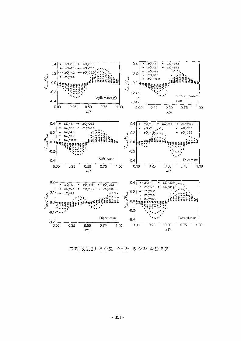
0.4-
0.2-
0.04
-0.2-
-0.4-
• z/D=\A • -o—z/Dft=15.9
•--• z/D =2.1 * - z/D =26.5 . . • • . .
A- z/Dh=4.2 ->-z/D ) )=38.s). ' ••••i*.
Split-vaneQV)
0.00 0.25 0.50 0.75 1.00
0.4-
0.2-
0.0-
-0.2-
-0.4-
- • -
• -
- T
o
z/Dn=1.1 •«
z/D,=2.1 *
z/DA=4.2z/D0=8.5Z/O6=15.9
•m m
* • • "
Z/DA=26.5
z/D =38.6
Side-supported
vane
0.00 0.25 0.50
x/P
0.75 1.00
0.00
ater
af
bu
0.4-
0.2-
0.0-
-0.2-
-0.4-
• z/D=2A
^-zA3 =4.2
- -<- z/Dft=26.5- »~ z/D =38.6
*• • • • •
Swirl-vane
0.25 0.50 0.75 1.00
0.4-
0.2-
-0.2-
-0.4-
» Z/Dh=1.1 • T • 2/
• - • z C , = 2 . 1 . • • .
1 1 1
0^=8.5 o
a
• •
2/0^15.9
Z^B=26.5
z^56=38.6• • •
•
••
a
Duct-vane
0.00 0.25 0.50
x/P
0.75 1.00
0.2
0.1-
1 0.0-
-0.1-
-0.2
• 7/D=\.\-
- Z/D=2A
- - 4 - z/D =4.2
a
• •. • a a a •
T
O
• • •
2^=8.5
z/Dft=15.9
• • •
J?
• a
Z/Dft=26.5
•-z© f t=38.6a • • a _a •
Dipper-vane
0.00 0.25 0.50
x/P
0.75 1.00
0.4-I
-0.2-
-0.4-
z©B=1.1
0.00 0.25
Twisted-vane
0.50x/P
0.75 1.00
DJ& 3.2.20 -4-:
- 351-
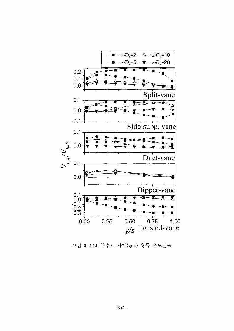
0
- Q
I0.0
0
Split-vane
Side-supp. vane
Duct-vane
Dipper-vane
0.00 0.25 0.50 0.75 1.00v/s Twisted-vane
3.2.21 4°l(gap)
- 352-
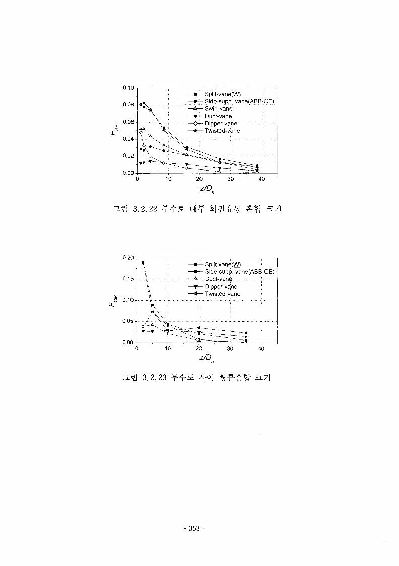
0.10Split-vane(W) :Side-supp. vane(ABB-CE)Swirl-vane [Duct-vaneDfpper-vape •Twisted-vane ;
z/D.
J^j 3.2.22 3.7]
0.20
0.15-
o 0.10-
Split-vane(W) ;Side-supp. vane(ABB-CE)Duct-van^
- Dipper-vanej - Twisted-vane
- 3 5 3 -
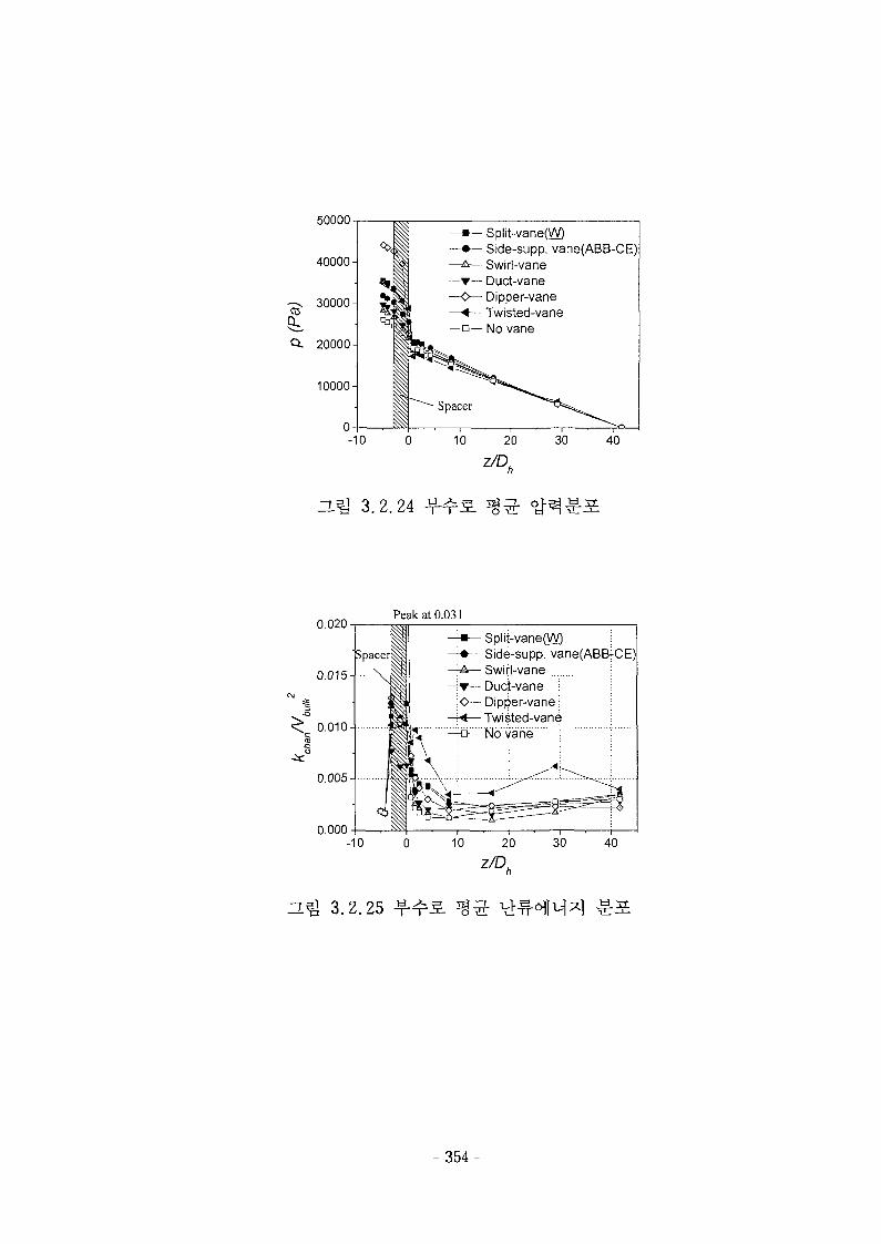
50000-Split-vane(W)Side-supp. vane(ABB-CE)Swirl-vaneDuct-vaneDipper-vane
— Twisted-vaneNo vane
-10
nm 3.2.24
z/D,40
0.020Peak at 0.03 ]
Split-vane(W) ;Side-supp. vane(ABB^-CE)Svyirl-yane • ..jDuct-vane ;Dipper-vane:Twisted-vane
S ^ No varie
0.00040
—LQ O. L. CD -\—T-
- 354-
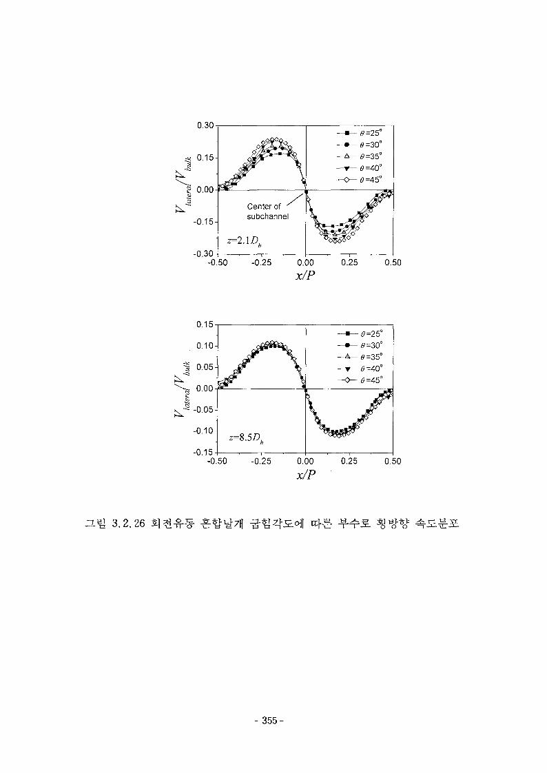
3.2.26
0.30
•* 0.15-3
g 0.00
-0.15-
-0.30
Center of y
subchannel
z=l.\D,
-0.50 -0.25 0.00
x/P
•0=30°-0=35°•0=40°•5=45°
0.25 0.50
0.15
0.10-
=1 0.05-
^ 0.00
-0.10-
-0.15
z=8.5D,
-0.50 -0.25 0.00
x/P
•6=25°
0=30°
0=40°
0.25 0.50
- 355
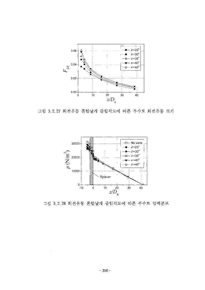
D.^ 3.2.27
0.06-
0.04-
0.02-
0.0010 20
z/D,30 40
30000-
20000-
10000-
-10 0
3.2.28
- 356-
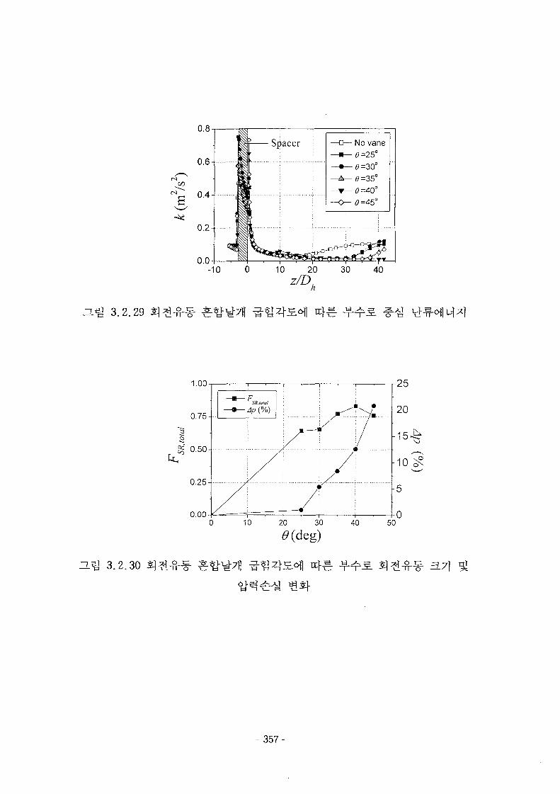
40
3.2.29
1.00
10 20 30 400.00
- 357-
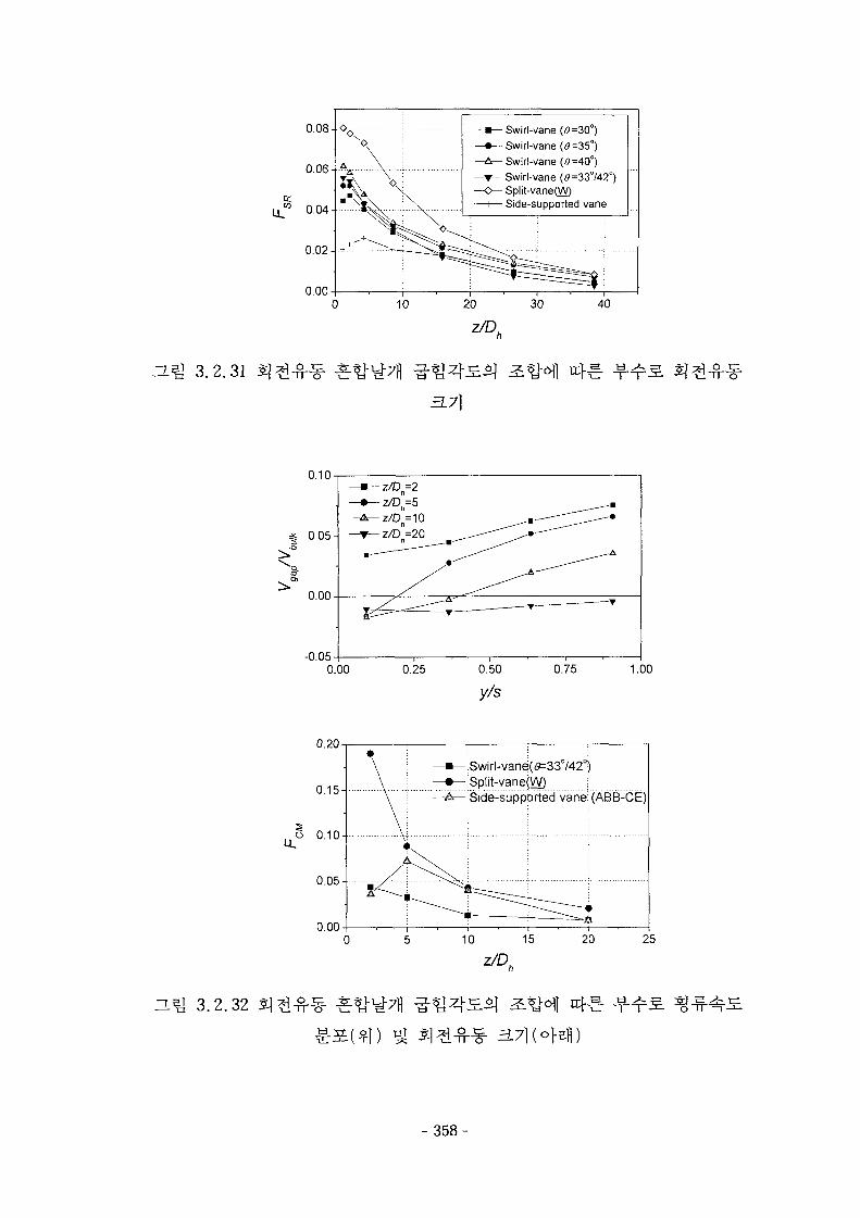
nm 3.2.31
0.08-
0.06-
0.02-
0.000 10
• Swirl-vane (5=30°)—•— Swirl-vane (9=35°)—A— Swirl-vane (5=40°)
Swirl-vane (e=33°/42°)—<^~ Split-vane(W)
- Side-supported vane
20
3.7}
30 40
-f-
0.10
« 0.05-
I0.00
-0.050.00 1.00
0.20
3.2.32
0.15-
o 0.10-1
0.05-
0.00
Swirl-vane(19=330/420)Split-varied)Side-supported vane:
0 5 10 15 20 25
3.71 (ofefl)
- 358-
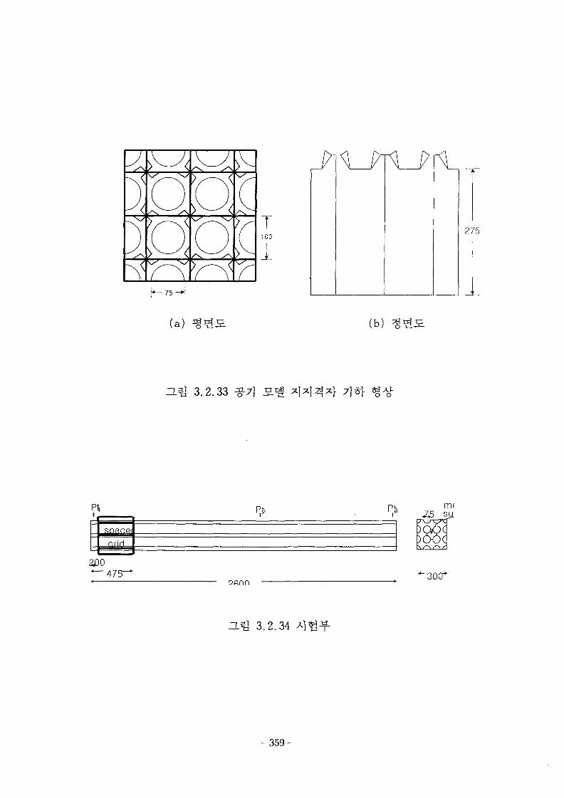
J
\
io
[QTV r
100
1U--
275
(a) (b) ^
ZL^ 3.2.33 ^-7) 7]*]-
PI
soacej
aoo
rmsu.
•30(T
ZL j 3.2.34 Al^^-
- 3 5 9 -
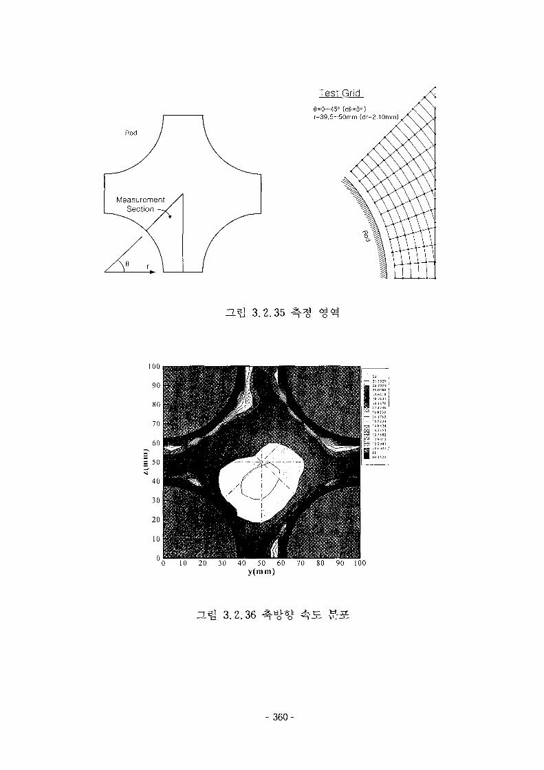
Rod
Test Grid
8=0-45° (d8=5°)r=39.5~50mm (dr=2.10mm).
3.2.35
_'L 30 40 50 60 70 80 90 100y(mm)
el ^ 9
- 360-
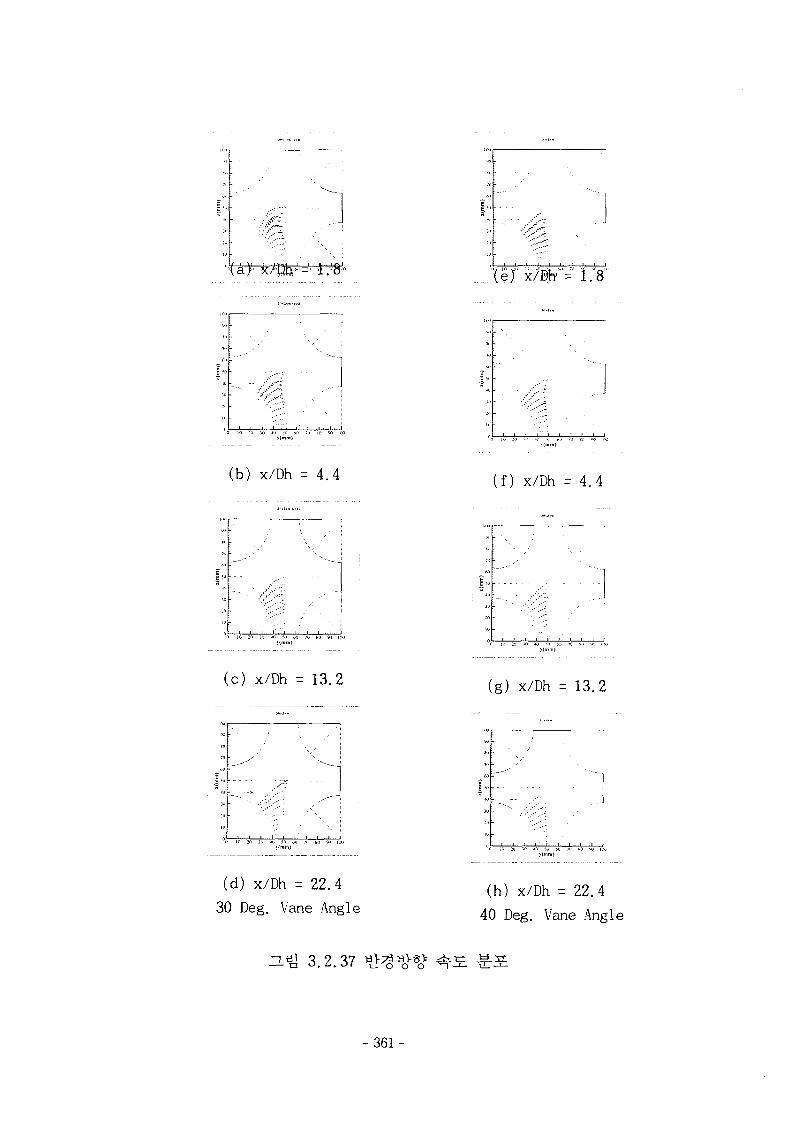
1/ i \i
°la} ;>
TO SD 90 100
(b) x/Dh = 4 . 4
(c) x/Dh = 13.2
(d) x/Dh = 22.4
30 Deg. Vane Angle
He] 3.2.37
"(ej' x
(f) x/Dh = 4 . 4
(g) x/Dh = 13.2
(h) x/Dh = 22.4
40 Deg. Vane Angle
- 361 -

1 1 I I I I I I 1 1 I I I ! I I I I I I I I I I 1 I I
0 10 20 30 40 50 60 70 80 90 100y(mm)
3.Q 3.2.38
H^ 3.2.39
- 3 6 2 -
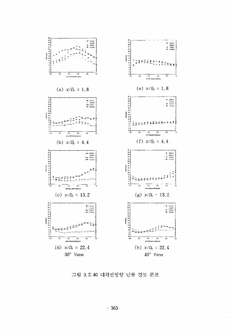
(a) x/Dh = 1.8
(b) x/Dh = 4.4
2S.26.
2*22-20
£• 16-
, t
-» -u " (uv ) •
0.0 0.2 0 4 0 6 0.5 1.0
normalized distance
(c) x/Dh = 13.2
- . » - u-(uv)
- • - W(ira)
^ ^ - ^
0.2 0.-C 0.6 0B 1.0
oormalijeddistaDce
(d) x/Dh = 22.4
30° Vane
(e) x/Dh = 1.8
normalized distant
( f ) X/Dh = 4 . 4
0.0 02
(g) x/Z}, = 13.2
0.0 0.2
(h) x/Dh = 22.
40° Vane
3.2.40
-363-
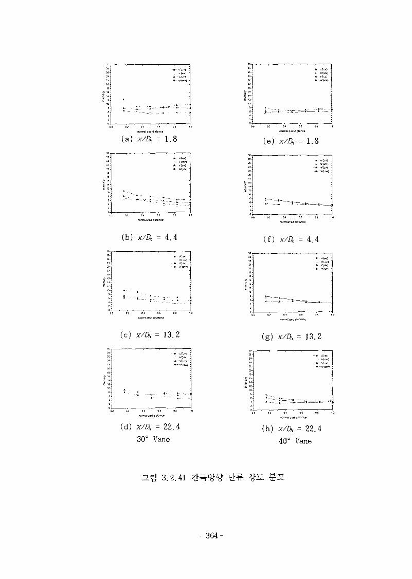
- • - u-(uv) '
A - v|uv) '• w'(uw) -
:. u'(uw)-A- v'(uv)
(a) X/DH = 1.8
(b) x/Dt, = 4.4
rwnnalned <istarice
(c) X/DH = 13.2
2B-26-2*-22-20-
1 «~6
2
• • » u(uv) •: u'luw) "i-v'<uv) -
- • -W l im) •
•
00 02
(d) x/A = 22.4
30° Vane
(e ) x/Dh = 1.8
0 2 0* QG
normalized distance
(f) x/Dh = 4.4
2a-
26-24<22-20-
i- 16
1 "•
• • U"{UV) "
L; U'(UW) "
* - V(uv) "
(g) x/ft = 13.2
(h) x/Q, = 22.4
40° Vane
D.Q 3.2.41
- 3 6 4 -
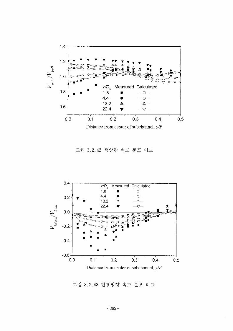
a
1.4
1.2-
1.0-
0.8-
0.6-
T T • • • • T
o-o- o-g-Sc8^B=B='^^"—o—^—"
v~~v—v—v—v-z/D^ Measured Calculated1.8 • —a—
13.2 A —A—22.4 • — v -
0.0 0.1 0.2 0.3 0.4
Distance from center of subchannel, y/P
0.5
u s ] 3.2.42
z/Dh Measured Calculated
0.1 0.2 0.3 0.4
Distance from center of subchannel, y/P
0.5
3.2.43
- 3 6 5 -
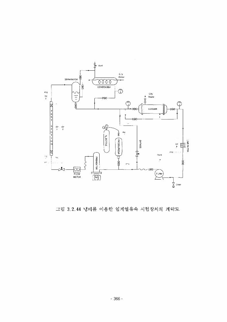
3.2.44
- 366-
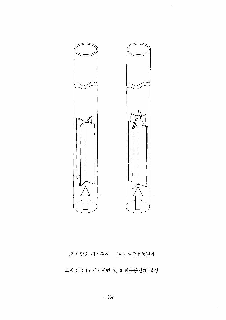
(7\)
ZL^ 3 .2 .45
- 367-
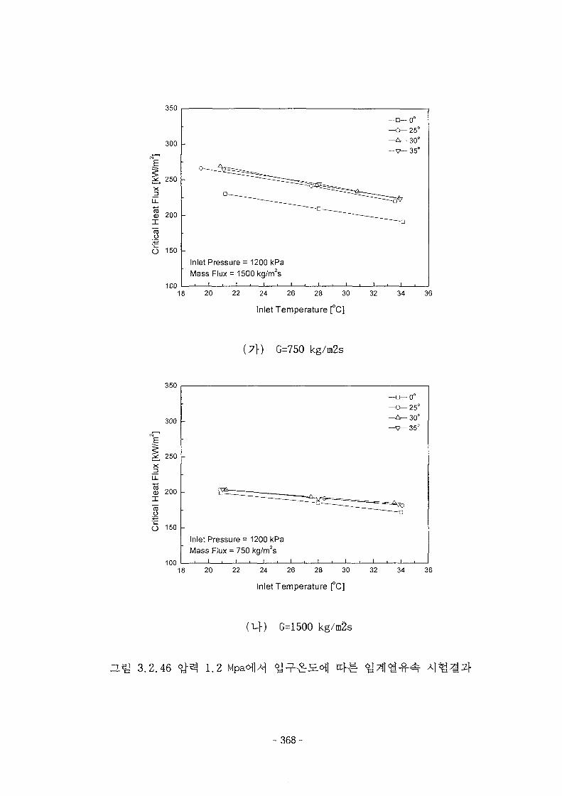
350
300
250
COCO
I
o
200
O 150
100
Inlet Pressure = 1200 kPaMass Flux = 1500 kg/m2s
18 20 22 24 26 28 30
Inlet Temperature [°C]
32
-0°-25°-30°-35°
34 36
(7f) G=750 kg/m2s
350
300
250
200
CDO
O 150
100
Inlet Pressure = 1200 kPaMass Flux = 750 kg./m2s
i . i i i i
18 20 22 24 26 28 30
Inlet Temperature [°C]
32
-0°-25°-30°-35°
34 36
(uf) G=1500 kg/m2s
H ^ 3.2.46 1.2
- 368-
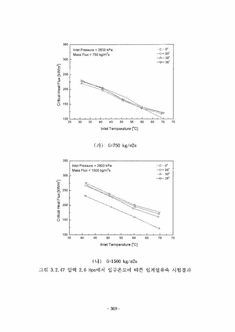
350
300
250
x3
3 200
CDO
O 150
100
Inlet Pressure = 2600 kPaMass Flux = 750 kg/m2s
j i L
-O-25°
Inlet Temperature [°C]
(7\) G=750 kg/m2s
25 30 35 40 45 50 55 60 65 70 75
350
300
250
S 200
TOO
O 150
100
Inlet Pressure = 2600 kPaMass Flux = 1500 kg/m2s
I . I . I . I i , i
c—0°
-V-35 0
35 40 45 50 55 60 65 70 75
Inlet Temperature [°C]
3.2.47 <£^ 2.6
G=1500 kg/m2s
369-
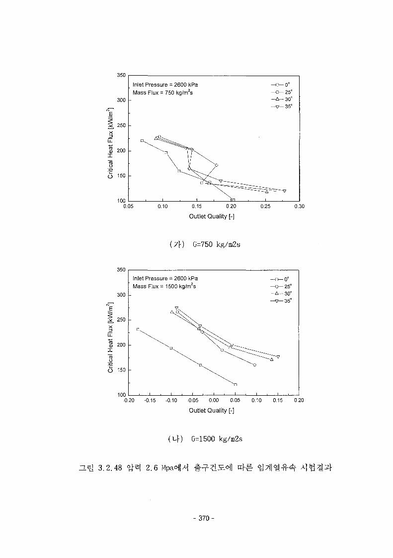
350
300
2L 250
x_2LL
S 200
too
O 150
100
Inlet Pressure = 2600 kPa
Mass Flux = 750 kg/m2s
0.05 0.10 0.15 0.20
Outlet Quality [-]
0.25
-25°-30°-35°
0.30
(7}) G=750 kg/m2s
350
300
250
xlo-
200
eno
O 150
100
Inlet Pressure = 2600 kPa
Mass Flux = 1500 kg/m2s
i . i
-0°-25°-30°-35°
-0.20 -0.15 -0.10 -0.05 0.00 0.05 0.10 0.15 0.20
Outlet Quality [-]
G=1500 kg/m2s
ZL5] 3.2.48 # 3 2.6 Mpa<Hl*f
- 3 7 0 -
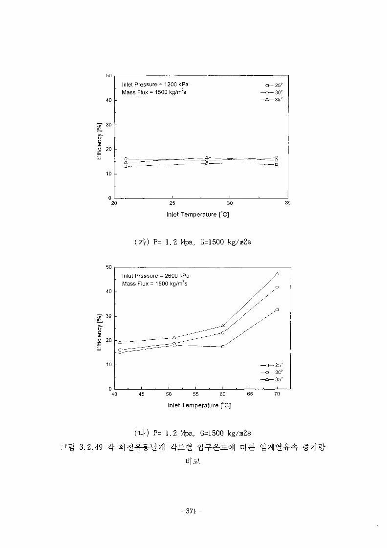
50
40 -
>oco 20itLU
10 -
20
Inlet Pressure = 1200 kPaMass Flux = 1500 kg/m2s
-
A• ~
& -^=_o-
-3-25°
-0-30°
^ ^ 3 5 °
—-Q
25 30
Inlet Temperature [°C]
35
(7\) P= 1.2 Mpa, G=1500 kg/m2s
50
40
C? 30
10
Inlet Pressure = 2600 kPaMass Flux = 1500 kg/m2s
40 45 50 55 60
Inlet Temperature [°C]
65
-25°30°
-35°
70
H ^ 3.2.49 4
P= 1.2 Mpa, G=1500 kg/m2s
- 3 7 1 -
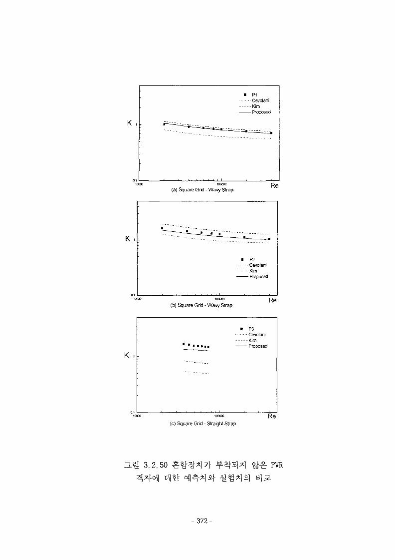
K 1
• P1CevolaniKimProposed
(a) Square Grid - Wavy StrapRe
K
0.110000
P2• Cevolani-Kim- Proposed
(b) Square Grid - Wavy StrapRe
K
1 • • • •
• P3CevolaniKimProposed
1000O0
(c) Square Grid - Straight StrapRe
"L^J 3 .2 .50 PWR
- 3 7 2 -
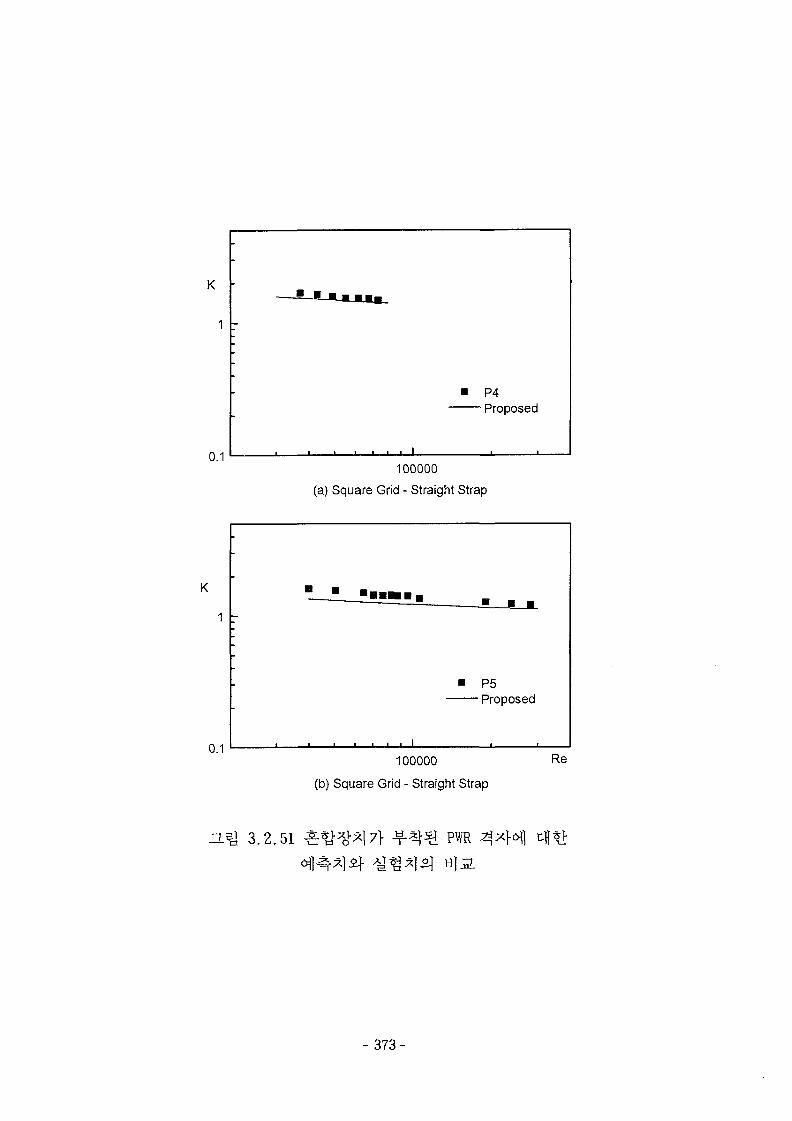
100000
(a) Square Grid - Straight Strap
100000 Re
(b) Square Grid - Straight Strap
OL^ 3.2.51 £^H)"*l7} ^ - ^ PWR
^ * l ^ til a
- 373-
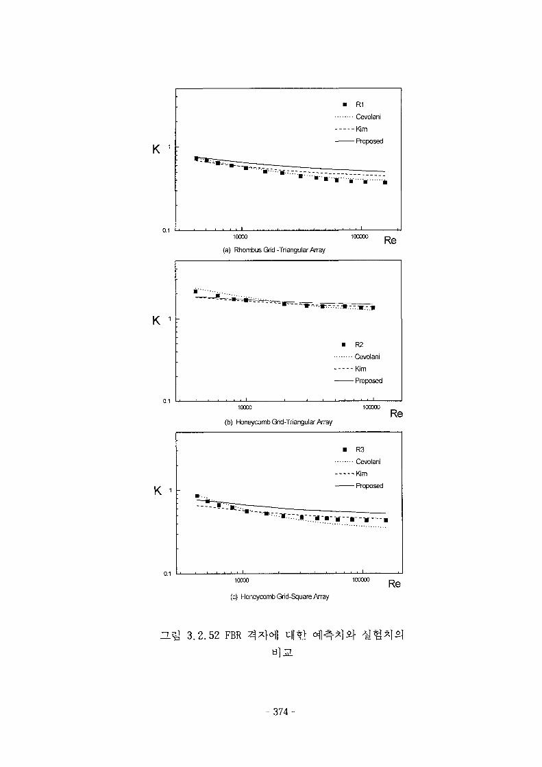
K
0.1
K
0.1
K
0.1
• R1
Cevolani
Kim
Proposed
• * • • • • • • * *
10000
(a) Rhombus Grid-Triangular Array
100000 Re
R2
Cevolani
-Kim
- Proposed
. . . i
10O0O
(b) Honeycomb Grid-Triangular Array
100000Re
R3
Cevolani
-Kim
- Proposed
:r*~~:.»::.it-m--j-
I \ < i
10000 100000 Re(c) Honeycomb Grid-Square Array
H.Q 3.2.52 FBR
- 3 7 4 -
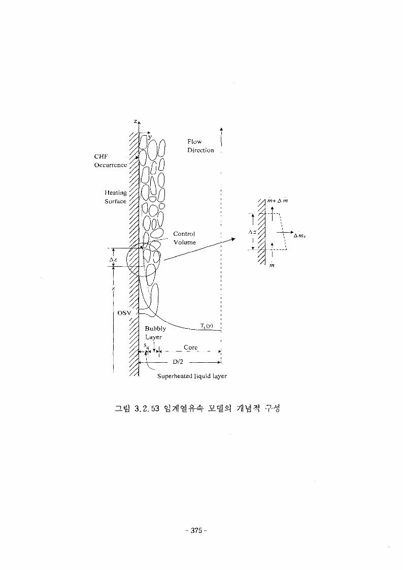
CHFOccurrence
HeatingSurface //] m+ A m
A.'AmE
Superheated liquid layer
H ^ 3.2.53
- 3 7 5 -
9000
0 1000 2000 3000 4000 5000 6000 7000 8000 9000
Measured CHF [kWm2]
ZL^ 3.2.54
- 376-
2.0
1.5
P/M 10
0.5D •
+20%
-20%
0.01000 2000 3000 4000 5000 6000 7000 8000
G [kg/m S]
=L% 3.2.55
P/M 10
20 100 120
P [bar]
a^J 3.2.56 7 **
- 377-
P/M 1-
-0.5
ZLB] 3 .2 .57
P/M i-
3.2.58
- 3 7 8 -
P/M 10
1000
LTD
D.^ 3.2.59
1000
XoT3
a;
£QL
100 -
o R-11A R-12n R-113
/
100 1000
Measured CHF [kW/m
ZLig 3.2.60
-379-
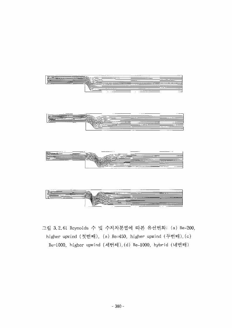
LQ 3.2.61 Reynolds ^ *J ^*1 ^ °fl -fMd*!*!-; (a) Re=200,
higher upwind (^Si^fl), (a) Re=450, higher upwind (^^^fl), (c)
Re=1000, higher upwind (4«i*H),(d) Re=1000, hybrid
-380-
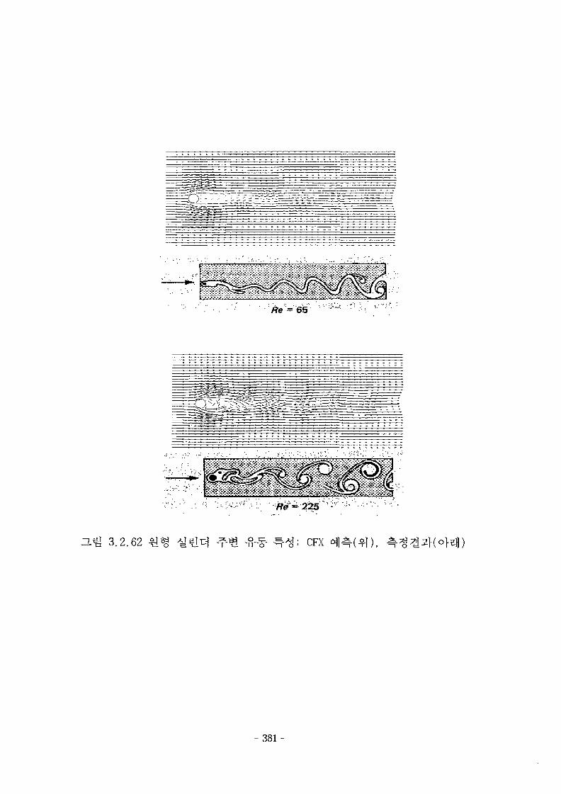
"- 65
H.^ 3.2.62 CFX
- 3 8 1 -

1.0
0.8-
e3 0.4-
0.2-
(a)
k-z model(yw'=36)
° Low Re k-z model(yw*=0.6)
Low Re k-a model(yw*=0.6)
• Laufer0.0 <!>
0.0 0.2 0.4 0.6 0.8
Distance from wall, y/(D/2)
1.0
0.8-
<" „ 0.6-
? 0.4-
0.0-
: o
•
•
oo •
o
o
k-z model(yw*=36) °
Low Re k-z model(yw
Low Re k-a model(yv
Laufer
•o
* = 0 . 6 * o
>0.6)
(b)
O• .
o
0.0 0.2 0.4 0.6 0.8
Distance from wall, y/(D/2)
1.0
3-
2-
k-e model(yw'=36)
Low Re k-z model(yw*=0.6)
Low Re k-a model(yw*=0.6)
Laufer
(c)
0.0 0.2 0.4 0.6 0.8
Distance from wall, y/(D/2)
1.0
D.& 3.2.63
- 382-
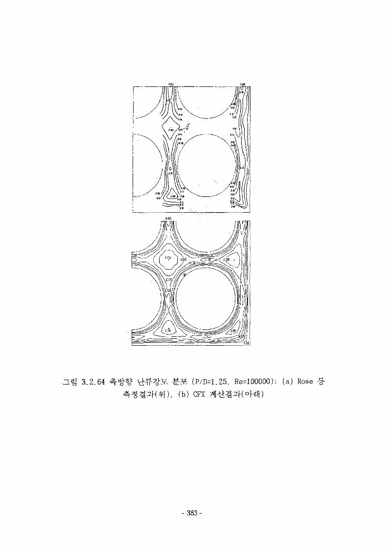
r
3.^ 3.2.64 S. ( P / D = 1 . 2 5 , Re^lOOOOO); ( a ) Rowe
( b ) CFX
-383-
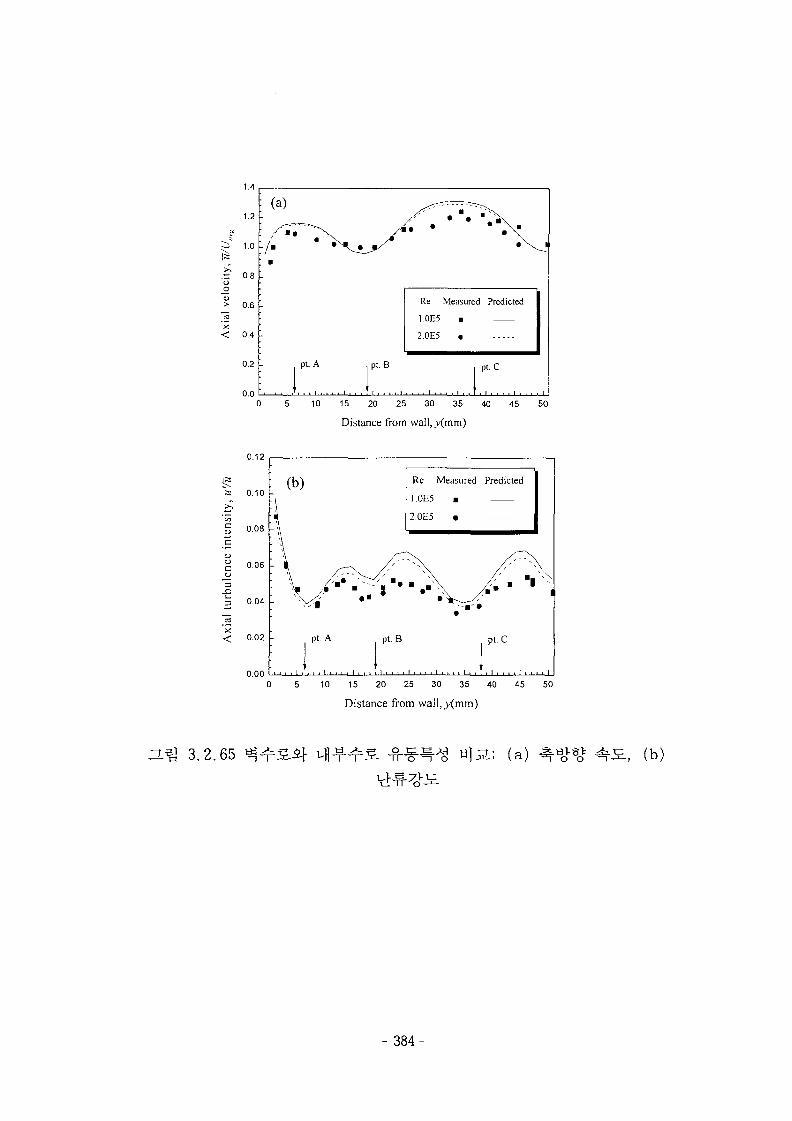
1.4
1.2 -
i" 1.0 -
.~ 0.8o
> 0.6 -
< 0.4
0.2 -
0.0
: (a)
: ys°^
: / •: •
-
A Pt-
r
/ *
B
Re
1 0E5
2.0E5
Measured Predicted
•
pt.C
1
0 5 10 15 20 25 30 35 40 45 50
Distance from wall, _y(mm)
0.12
0.00
Re Measured Predicted
] ,0E5 •
2.0E5 •
10 15 20 25 30 35 40 45 50
Distance from wal!,_y(mm)
O.^ 3.2.65 -, (b)
- 384-
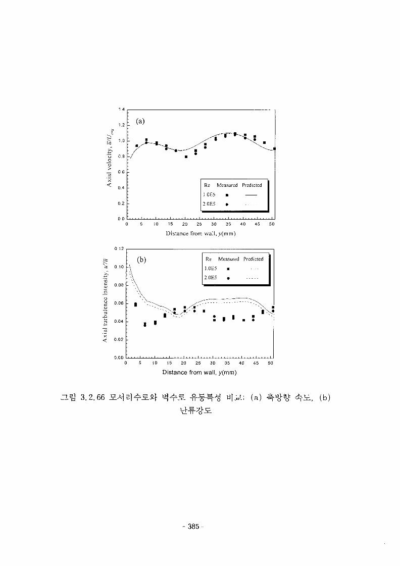
1.4
0.4 -
0.2 -
0.0
3
0.12
0.10 -
0.08 -
0.06 -
0.04 -
0.02 -
o.oo
Re
I.0E5
2.0E5
Measured
•
•
Predicted
0 5 10 15 20 25 30 35 40 45 50
Distance from wall.^mm)
: (b)
1 >
Re Measured Predicted
1.0E5 •
2.0E5 •
• rN* • 1 •• 1 • • •
i
10 15 20 25 30 35 40 45 50
Distance from wall, y(mm)
O.S] 3.2.66 .; (a) (b)
-385-
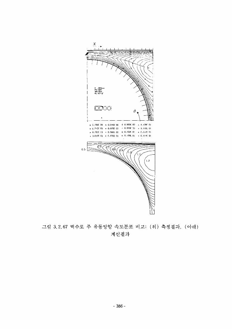
0.700E 00 x 0.8<0E 00 ' 0.960E 00 « 0. I08E 01
0.7«E 00 • Q.870E 00 * 0.990E GO » 0. I IOE 01
0.760E 00 . 0.900E 00 o 0.10?E 01 x 0. I 12E 01
0.8I0E 00 x 0.930E 00 o.O.lOSt 01 • o: 1-HE 01
~L^ 3.2.67 (o
-386-
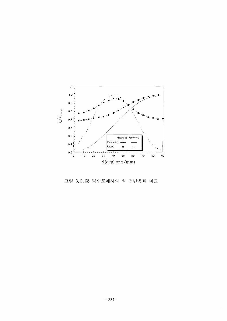
1.1
1.0
0.9
0.8
0.6
0.5
0.4
0.3
• ' • ' ' / '
Measured Predicted
Channel(Ar) — m—
Rod(e) - •»- •
. . . I • • • •
\
10 20 30 40 50 60 70 80 90
(9(deg) orx(mm)
ZL% 3.2.68
- 387-

1.0-1
0.8-
0.6-
0.4-
0.2-
0.0
z/D=0. 48
• Durret et al.o - Standard k-z model
A Non-linear k-z model
-0.2 0.0 0.2 0.4 0.6 0.8
U/U
1.0-
0.8-
0.6-
0.4-
0.2-
0.0
z/D=0.95
• Ourret et al.o Standard k-z modelA - Non-linear k-z model
-0.2 0.0 0.2 0.4 0.6
U/U0.8 1.0
1.0-,
0.6-
0.4-
0.2-
0.0
z/D=\. 90
• Durret et al.o Standard k-z model& Non-linear k-z model
-0.2 0.0 0.2 0.4 0.6
U/U0.8 1.0
1.0-I
0.8-
£}• 0.6-
"fc 0.4-
0.2-
0.0
z/D=2. 86
• Durret et al.o Standard k-z model
A Non-linear k-e model
ffl
-0.2 0.0 0.2 0.4 0.6 0.8 1.0U/U
z/D=A. 77
0.8-
0.6-
0.4-
0.2-
0.0-
•oA
Durret et al.Standard k-z model
- Non-linear k-z model
-0.2 0.0 0.2 0.4 0.6 0.8 1.0
U/U
ZL3] 3.2.69
- 3 8 8 -
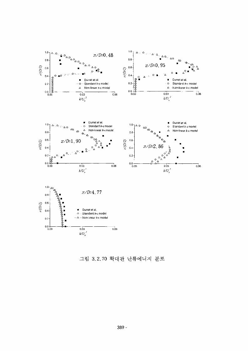
1.0-1
0.8-
0.6-
0.4-
0.2-
0.00.00
"A,o z/D=Q.48
"A. O
•P--.T--- a *
AOo " A ,
• Durretetal.o Standard k-z modelA Non-linear k-z model
0.03 0.06
1.0-,
0.8-
0.6-
0.4-
0.2-
A O-A ft...
z/ZfcO. 95
o o •
02.a o A
Q A
O Ai •
0.0 iS0.00
• Durret et al.o Standard k-z modelA Non-linear k-s model
0.03
k/U2
0.06
1.0-
0.8-
0.6-
0.4-
0.2-
0.0-IS
A. _O;...• Durret et al.o Standard k-z modelA - Non-linear k-z model
z/D=l. 90
A°-
OAO AO A
O AO A a
O AA
0.03
k/U2
1.0-
0.8-
0.6-
0.4-
0.2-
0.0
A O
0.00
AQ
• Durret et al.
o Standard k-z model
- A Non-linear k-t model
z/D=2.86 kA
„ AO A
O AO A
O AO A
OA0 03
k/U20.06
1 .U
0.8-
0.6-
0.4-
0.2-
0.0-
%m
% u%m
o •a3 •
•-o—
— A —
z/^4.77
Durretetal.Standard k-z modelNon-linear k-z model
0.00
ZL^J 3 .2 .70
- 389-
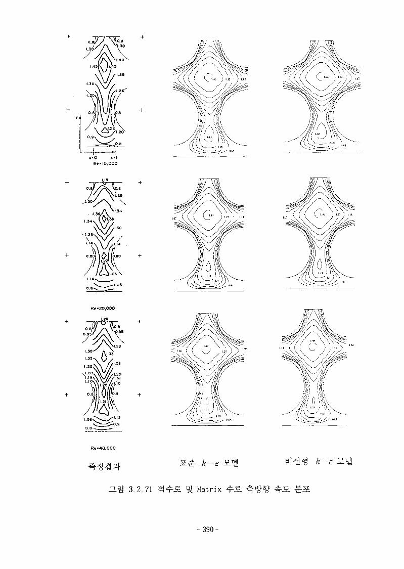
x»0Re* 10,000
I— +
R«« 20,000
Re-40,000
k-e
H^J 3.2.71 Matrix
390-

>
gUJ
co
LLJ
UJ
<UJ
1.6-r
1.4-
1.2-
1.0-
0.8-
0.6-
0.4-
0.2-
0.0
• Measured
— o — Standard k-z model
—A— Non-linear /f-e model
0.00 0.25 0.50 0.75 1.00 1.25
Y, DISTANCE FROM WALL / PITCH
1.50
1.6oo_JJJ
ULI
CO
_iJU>
o
a:JJ
1.4-
1.2-
1.0-
0.8-
0.6-
0.4-
0.2-
<LU
0.0
Measured
• Standard k-E model
Non-linear k-s model
0.00 0.25 0.50 0.75 1.00 1.25
Y, DISTANCE FROM WALL / PITCH
1.50
3.2.72
- 3 9 1 -
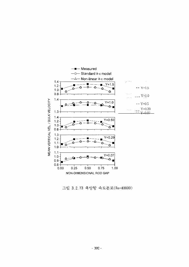
—•— Measured—o— Standard k-e model
—A— Non-linear k-e model
ogLU
X._ l
CD
1±J
<O
enHI
0.8
- - Y=1.5
___ Y=1.0
- - Y=0.5
.__ Y=0,29— Y~0 07
0.00 0.25 0.50 0.75 1.00
NON-DIMENSIONAL ROD GAP
3.2.73
- 392-
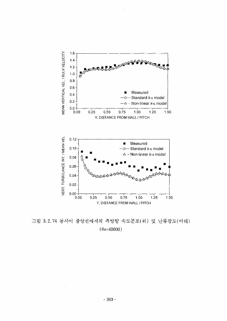
oOLLJ
m
LU
<
oa:LU
<LU
1.6-T
1.4-
1.2-
1.0-
0.8-
0.6-
0.4-
0.2-
0.0
• Measured—o— Standard /c-s model—A— Non-linear k-e model
0.00 0.25 0.50 0.75 1.00 1.25
Y, DISTANCE FROM WALL/ PITCH
1.50
oi 0.12
LU
LU
0.10
H 0.08 -
LU
o 0.06-
0.04-
0.02-
0.00
A
\
• Measured—o— Standard /c-s model— A — Non-linear k-t model
V\
0.00 0.25 0.50 0.75 1.00 1.25
Y, DISTANCE FROM WALL / PITCH
1.50
3.2.74
(Re=40000)
- 3 9 3 -
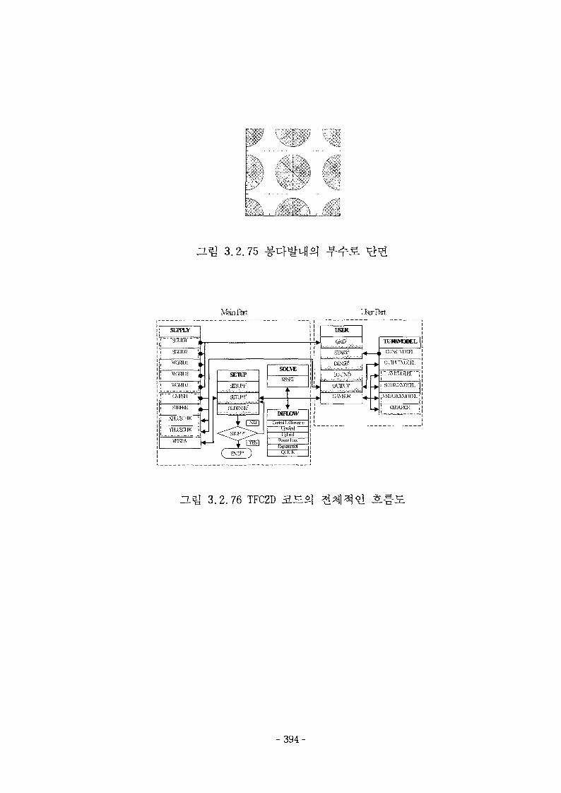
HQ 3.2.75 H
SUPPLY
| i
1 XMD2 \
, \KMU1 ^
; «™IK I
' WMIB '.
i SIIJM: j
; XH.IMIK !
; flusaiK i
WSDL"
h
H
-4
4
4
h
MainRtt
SETUP
.JEILH 2
lJD B^7 , . , r
SOLVE
H F I J O W
Oitnd Uiflurrce
1 iitnd
! >
i
USER
CMD1
c e ^LOLND
OOKT
4h
rJ
rJ-
—<
iart
TUISMODEL
, a).\?i\on3.
OHRINBrH.
f^fOBU-f";
! CBOLKQ; ;
ZL^ 3.2.76 TFC2D 3.^.
- 3 9 4 -
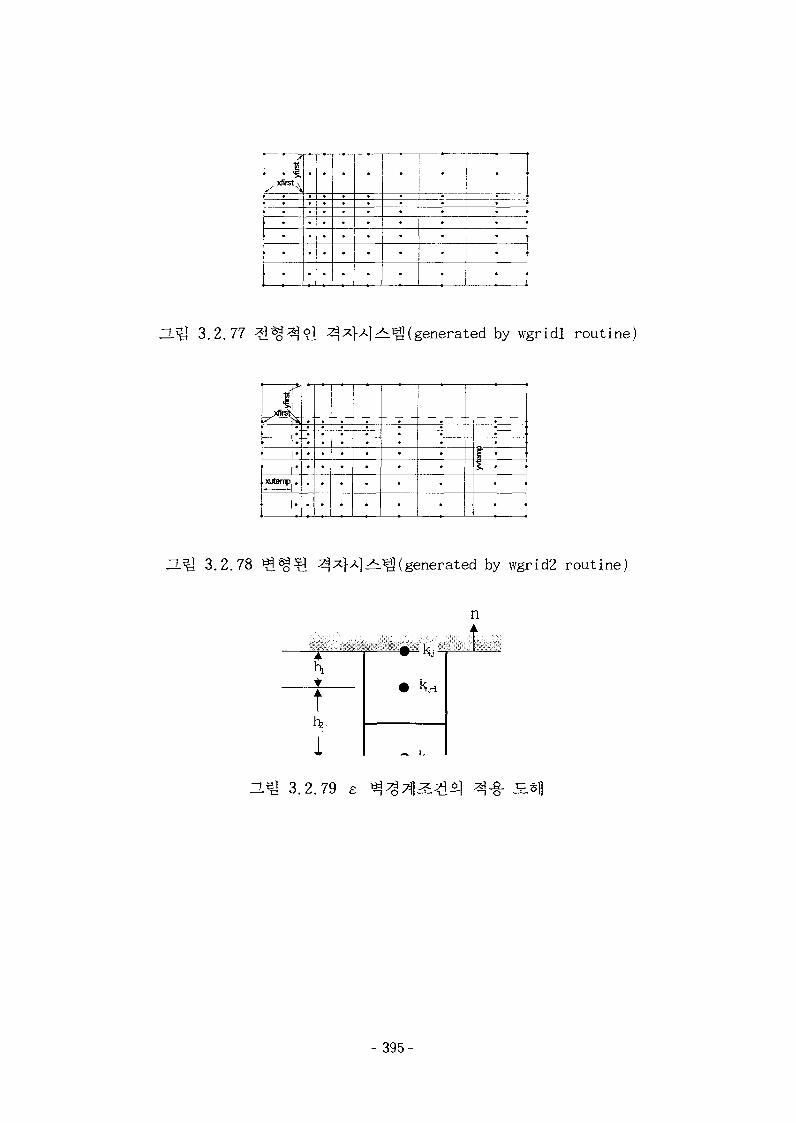
i
* —
•
•
•
—;—'
•
•
•
-•••••
*
*•
!. j
•
•
•
* i
ZL^ 3.2.77 ^^(generated by wgridl routine)
.i"
xutemo .
1-
•••••
•
•••••
•••••
•••••
•
•••••
•••••
•
•
1
ZLQ 3.2.78 ^^(generated by wgrid2 routine)
ZLQ 3.2.79 £
- 395-
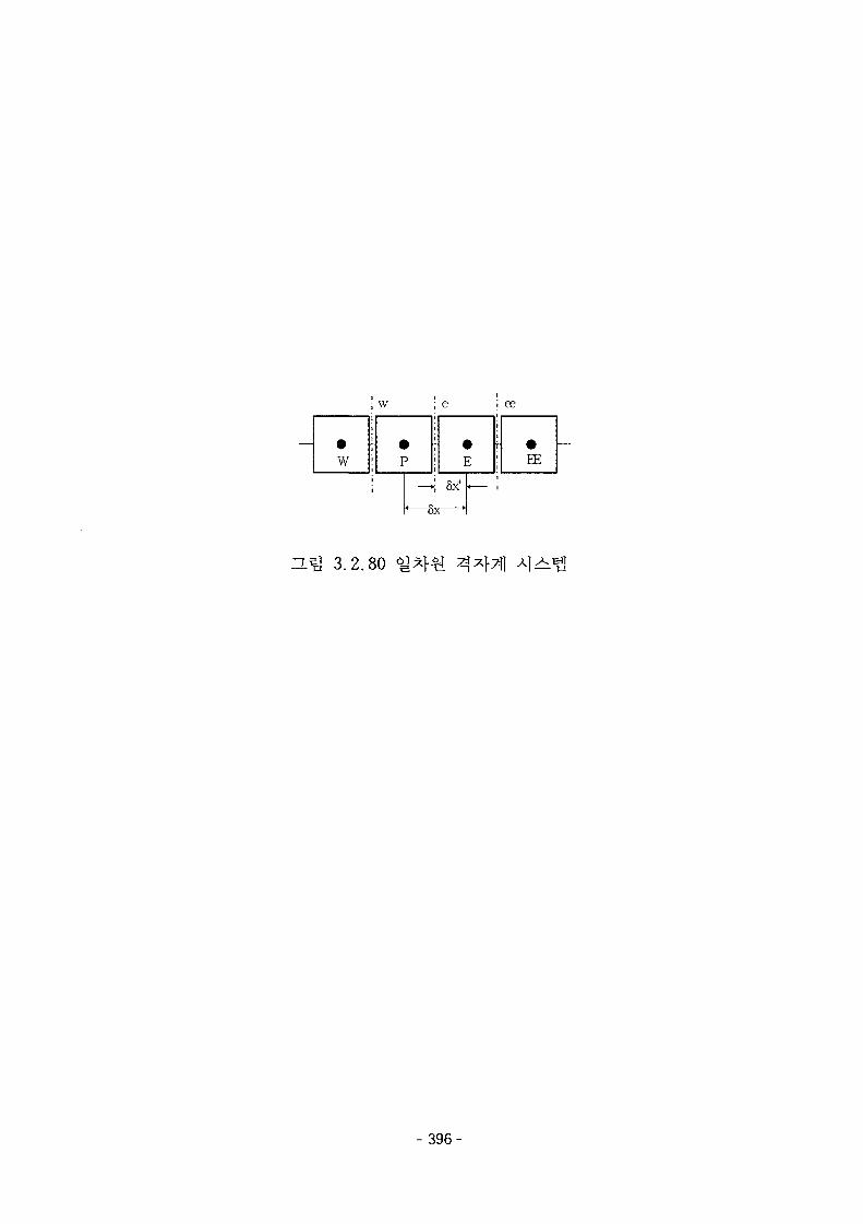
w
w
P
«—
; E
>| 5x+ -—
3x •
ee
EE
3.2.80
- 396-
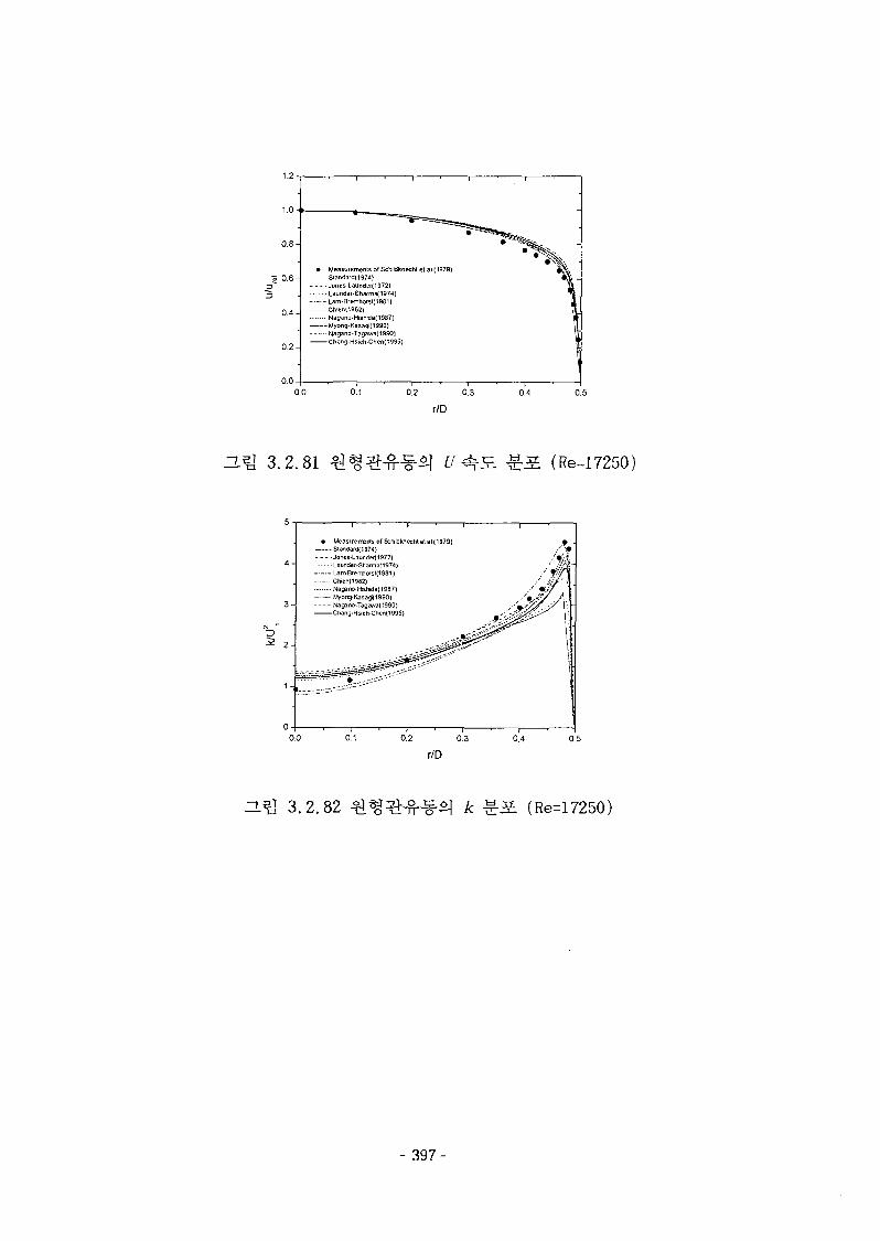
0.8 A
s 0.6 A
0.2 A
Measurement of Schildfcnecht etal(1979)S! and ard( 1974)
• Jones-Launder( 1972)•Launder-Sharma(1974)
Lam-Bremhofsl(1931)Ghien(l952)Nagano-Hishida(1987)Myong-Kasagi(1990)Magano-Tagawa[i99O)Chang-Hsieh.Chen{1995)
0.0 0.1 0.2 0.3 0.4 0.5
r/D
H ^ 3.2.81 (Re-17250)
5 -
4 -
3 -
2 -
1 -
0 -
i i ' i i i
• Measuemerts of Sehldknechtetal(i979)Standard{i974)
• Jones-Launder(1972)Launder-Sharma( 1974)Lam-Bferrtiorsl(1981)Chien(1982)Na9ano-l-ishida(1987)
• — Myorg-Kasag(1990)Nagano-Tag3wa(1990)Chang-Hsieh-Chen(1995)
1 1 ' i ' I
—' 1 '
•' «
.' J/rt-•'•#1
• • ' • # • !
••' •-•/ 1
—i 1 i i0.2 0.3 0.4 0.5
r/D
ZL^ 3.2.82 (Re=17250)
- 397-
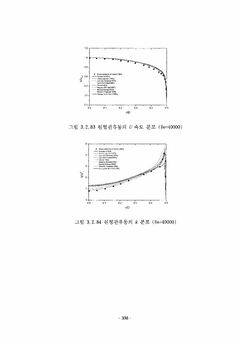
1.2-
Measurements of Laufer(1954;-Siandard<1974)-Jones-Launder(1972>Launder-Sharma{1974)
- Lam-Bremhorsl(1981}-•Ctvei\(l982)• Nagano-Hishida(1937)-Myong-Kasagi(1990)-• Nagano-Tagawa(199O}- Chang-Hsieh-Chen( 1995}
0.5
r/D
O.^ 3.2.83 (Re=40000)
• Measurements of Laufer(19S4)Standard) 1974)Jones-Launder(1972)Launder-Sharma[i9?4)Lam-8remhofSt(198l)Chien(1982)Nagano-HishJda(1987J
- — - Myong-Kasagi{1990)Nagano-Tagawa(1990)Chang-Hsieh-Chen(i995)
0.0 0.1 0.2 0.3
1 2 ] 3.2.84 (Re=40000)
398-
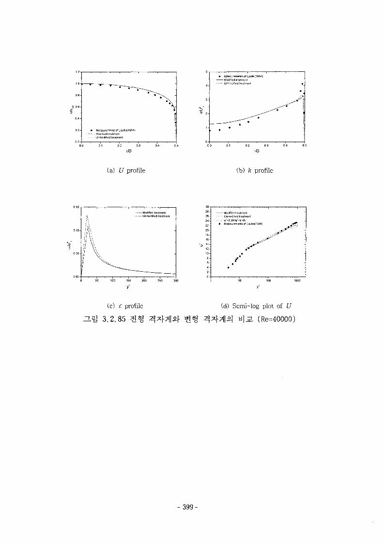
• Measurements olLaufer(1954)Modihed treatmentUnmodified treatment
0 0 0 1 02 03 04 OS
r/D
(a) U profile (b) k profile
Modified treatmentUnmodified treatment
0 50 100 150 200 250 300
28-
25-
24-
22-
20-
- Modified treatment- Unmodified treatment• u'=2.39,iy"*5 15
Measuremerts of Lau(er(1954)
(c) c profile
3.2.85 ^
(d) Semi-log plot of U
wl L (Re=40000)
-399-
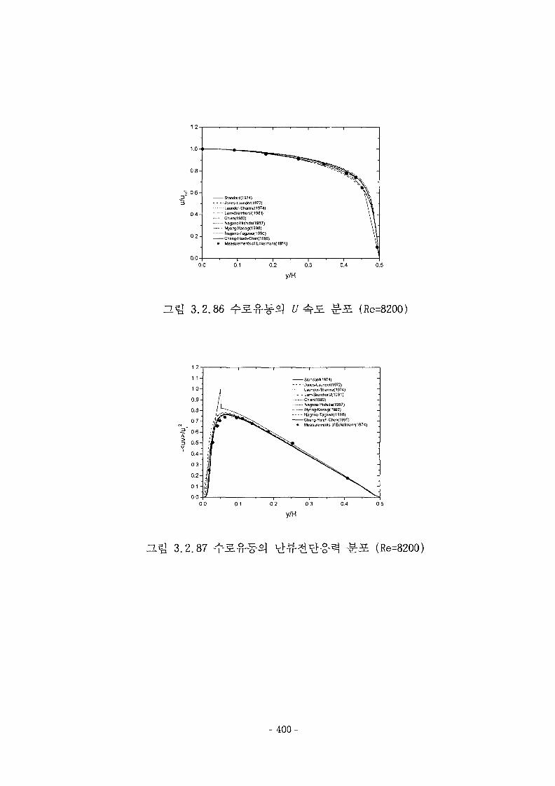
0.8-
» 0 6 -
1
0.0
-Standard(1974)-Jones-L3undef(1972)
- - Launder-Sharma( 1974)- LanvflrGfTHo/st(1981}-Chien(1982)- N3ffino+lisNd3(198r)- Myarg-Kasag(1990)-Nagano-Tagawa(1990)-Cfian5-HsJeh-Chen(1995)
Measurement of Ectelrrenn(197.l)
0.0 0.1 0.2 0.3
y/H0.4
3.2.86 V J=L sr (Re=8200)
Standard(i974)- - •Jones-Laundet[1972)
Launder-Sharma<1974)
3.2. 87 (Re=8200)
- 4 0 0 -
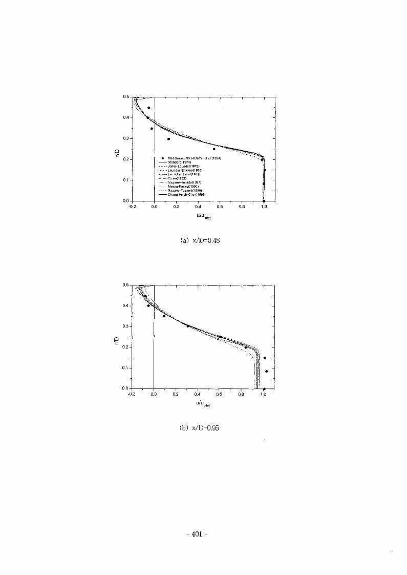
• Measurements of Durrel et al.(1988)Standards 974)Jones-Launder(1972)Launder-SharmaO 974)Lam-Bremhorst(19ai)Chien(1982)Nagano-Hishida(l9S7)Myong-Kasagi(1990)Nagano-Tagawa(1990)Chang-Hsieh-Chen(1995)
— I —0.2
10.4
u/u.
— I —0.6
— I —0.8-0.2 1.0
(a) x/D=0.48
-0.2 0.0 1.0
(b) x/D=0.95
-401 -
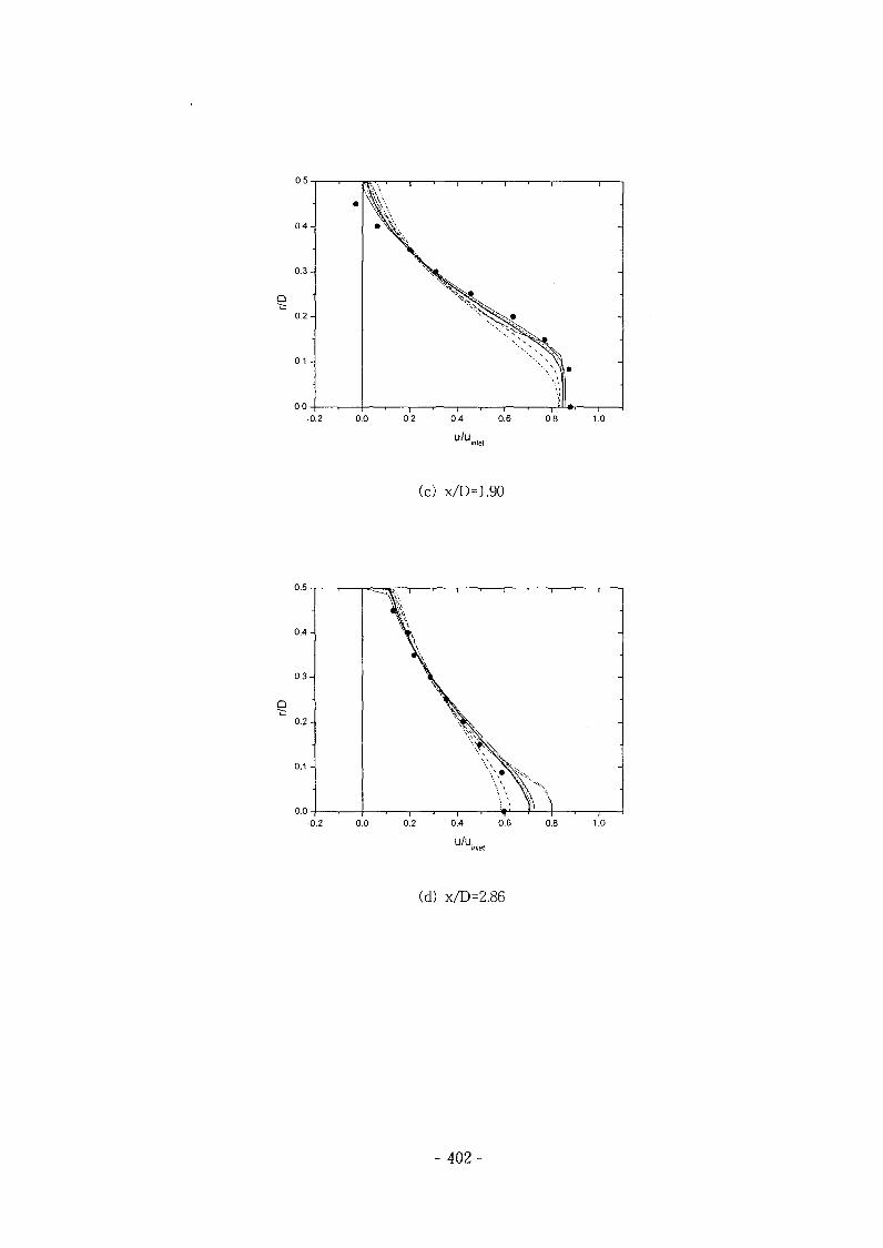
\J.\J —
0.4-
0 .3-
0.2-
0.1 -
0.0 -
1 1 1 i ' 1
-
' 1 • 1 * ' 1-0.2 0.0 0.2 0.4
u/u
0.6 0.8 1.0
(c) x/D=1.90
0.4-
0.3-
0 .2 -
0.1 -
0.0-
\
\
\
' 1 •"
— 1 • 1 ' 1 ' 1
-
-0.2 0.0 0.2 0.4 0.6 0.8 1.0
u/u.,
(d) x/D=2.86
- 402-
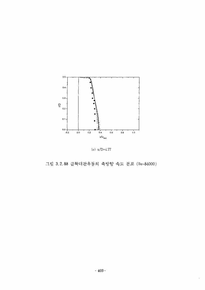
-0.2 0.0
u/u.
(e) x/D=4.77
0.8 1.0
(Re=84000)
- 403-
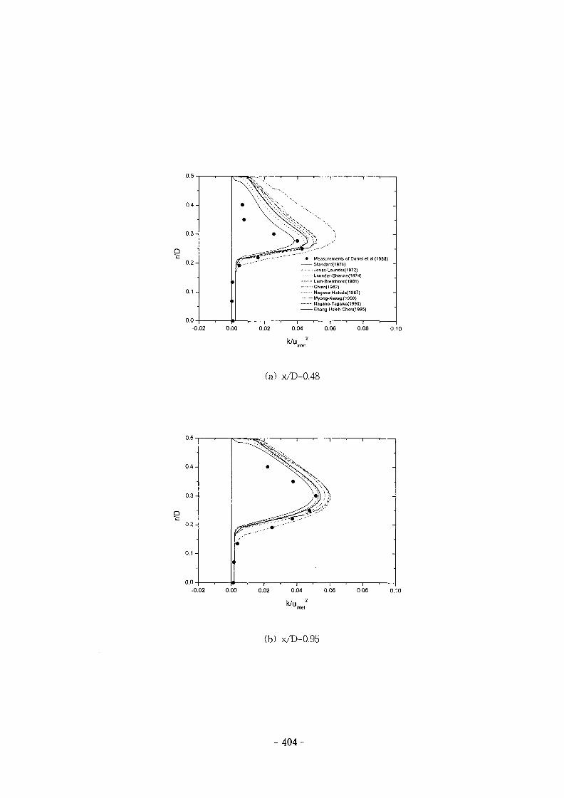
0.5
0 .4 -
0 . 3 -
0 .2 -
0.1 -
0.0-
-0.02
• Measurements of Durret et al.(1963)Standard(1974)Janes-Launder{1972)Launder-Sharma(1974)Lam-8remhorst(1981)Chien(1982)Nagano-Hishida(1987)Myong-Xasagif 1990)Nagano-Tagawa{1990)Chang-Hsieh-Chen(1995)
0.00 0.02 0.04 0.06, 2
o.oa 0.10
(a) x/D=0.48
0.4-
0.3-
0 .2 -
0.1 -
0 .0 -
v ^ «^jj ' 1 ' 1 ' 1 >
*
l
J , 1 , , , , , 1 ,-0.02 0.00 0.02 0.04 0.06 0.08 0.10
(b) x/D=0.95
- 4 0 4 -
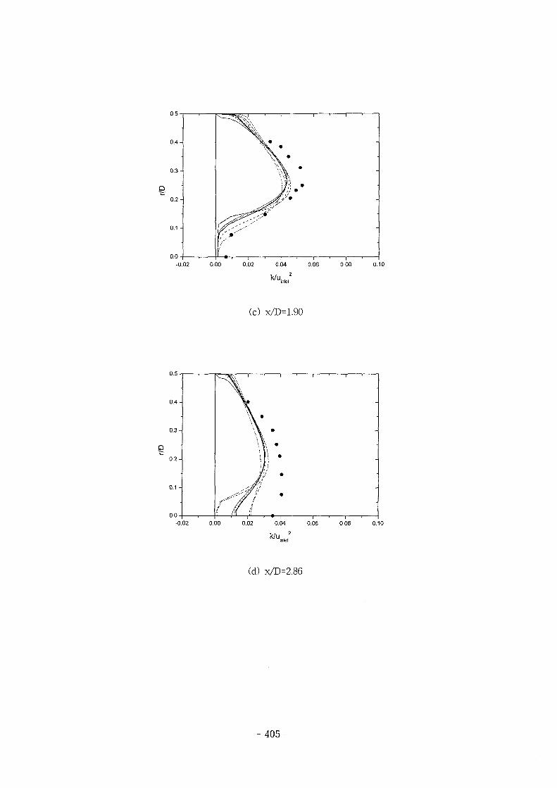
u.o -
0.4-
0 .3-
0.2-
0.1 -
0 .0 -
\^J^.;V.I ' 1 ' 1 ' 1 '
f .-0.02 0.00 0.02 0.04 0.06 0.08 0.10
Wu. , 2
(c) x/D=1.90
D
0.4-
0 .3-
0.2-
0.1 -
0.0-
Vf •,J! ' -
-0.02 0.00 0.02 0.04 0.06 0.08 0.10
k /u . 2
(d) x/D=2.86
- 405-
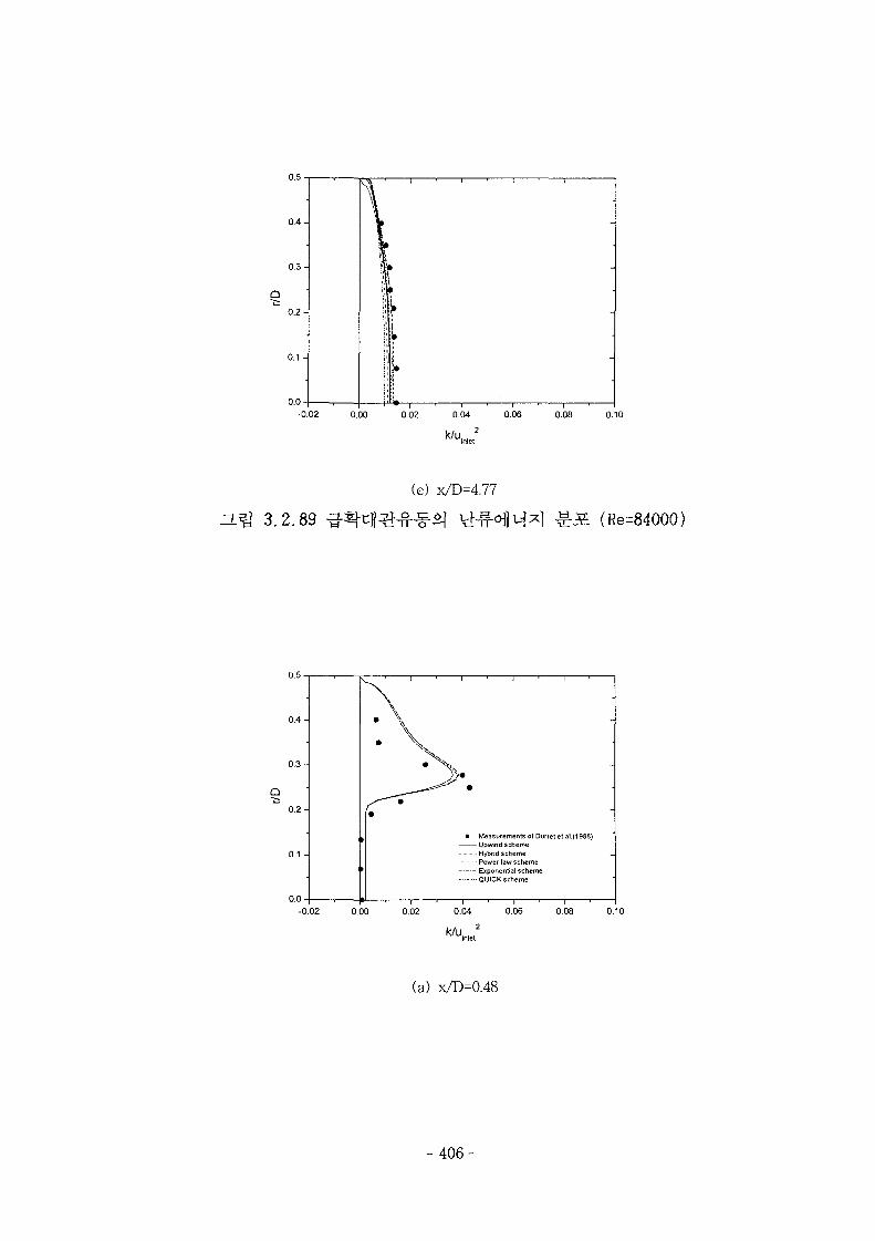
\J.-J —
0.4-
0.3-
0.2-
0.1 -
0.0-
. . . . _
11 •
r1
!
*
%—1 , 1 1 1 1 1 1
-0.02 0.00 0.02 0.04 0.06 0.08 0.10
3.2.89
(e) x/D=4.77
^ : S (Re=84000)
0.1 -
0.0
• Measurements of Durret et al.(1988)Upwind scheme
-Hybrid schemePower law schemeExponential schemeQUICK scheme
-0.02 0.00 0.02 0.04 0.06 0.08 0.10
(a) x/D=0.48
- 406-
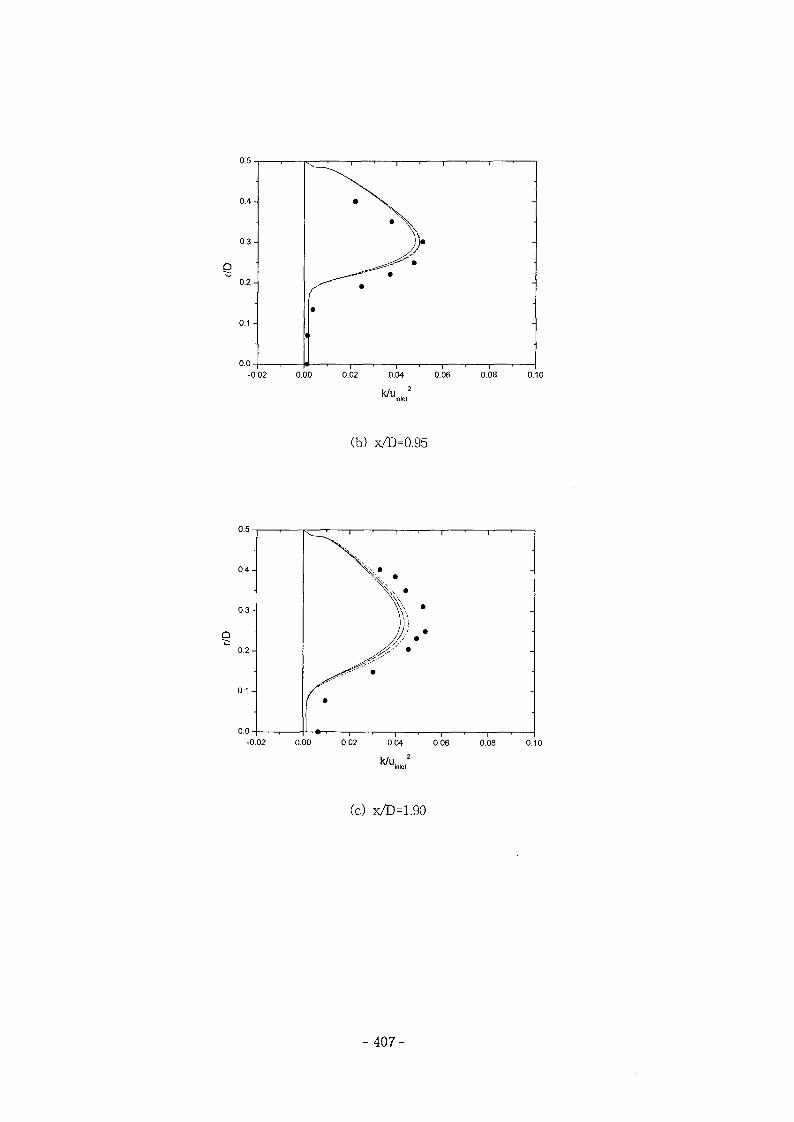
-0.02 0.00 0.02 0.04 0.06 0.08 0.10
k/u,...2
(b) x/D=0.95
0.4-
0.3-
0.2-
0.1 -
0.0-
\ '
!—»-, 1 , 1 , , , , ,
-0.02 0.00 0.02 0.04 0.06 0.08 0.10
k/u , ,2
(c) x/D=1.90
- 407-
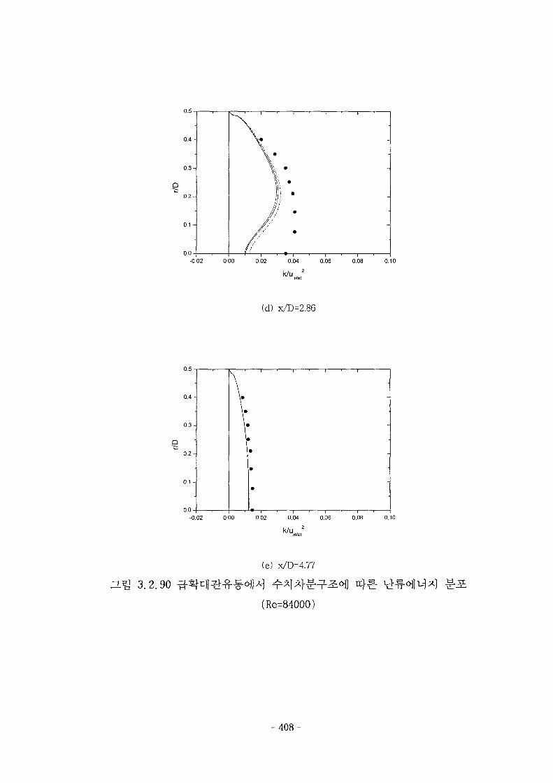
\J.^J -
0 .4 -
0 .3 -
0 . 2 -
0.1 -
0 .0 -
^——i 1 1 1 1 1 1 1 1
\ -
1i
/ •jL-i , «— , , ,
-0.02 0.00 0.02 0.04 0.06 0.08 0.10
k/u.. .2
(d) x/D=2.86
0 . 4 -
0.3-
0 .2 -
0.1 -
0 .0 -
\ *
\ *
\-
•
•
•
1+—1 1 ; 1 1 1 1 1
-0.02 0.00 0.02 0.04 0.06 0.08 0.10
O.^ 3.2.90
(e) x/D=4.77
(Re=84000)
- 408-
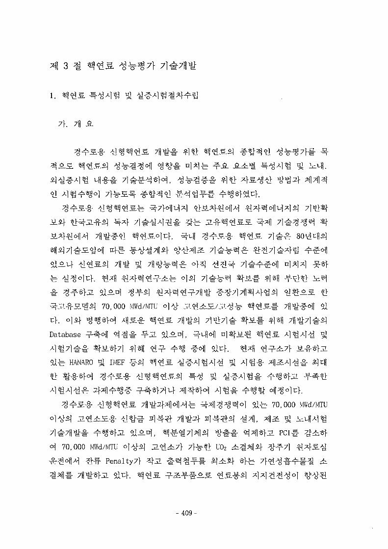
7\. 7fl
^ 0]$]
70,000 MWd/MTU OJA)- J L ^
Database
HANARO ^ IMEF
6Tfe 70,000 MWd/MTU
# ^ | > J L PCI
70,000 MWd/MTU O]AVO] 32.0^^7). 7f-^*> U02
Penal ty7f
- 4 0 9 -
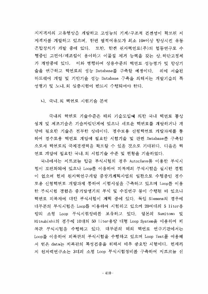
7} 7fl^#c^l olu}.
# £ ^ n $ $ ^ Database^- ^ - ^ ^
^ Database ^ - ^ - #
7]
Database!-
Autoclavel- oj-g-*];
Loopl- } f ^ 1 4
^ - ^ Siemens^
^ Loop# ol-g-^rf^ Al^^JL £ULn} 20^tf l^ 5 liter-g-
Loop ^ - ^ ^ ] ^ ^ y l # >S--n-*}JL a l 4 . ^ ^ ^ 1 Sumitomo ^
Mitsubishi^ ^-fofl lOtflSj 50 liter-g-^1 cfl^ Loop System^
Loop# o]-g-*|.of 2 } 4 ^ ^ - f ^ J A j ^ ^ ^ * K 2 . Sa^-Di Loop Test
Loop
- 410-
Capsule^ °l-g-*> zfl.g.<q ^ A ^ S f A].%|£ ^-ufl ]A^ o]nl
^ ^ f l A J ^ 7 ] # ° > ^ g . j £ 7}-^*]-i:f. ZL^uf S l ^ H ^ Coupon
Coolant Flow 7}- £l^r ^ ^ ^ 1 4 ^r*^ S j ^
Fuel Test Loopo] Q ^ ^-fofl
Lab Test# ^-*M ^-M. ^°] ^ 5 ] ^ ^ ^ S o f l ^ Coupon Test# 7\
*!^P TubeS. ^]2:^f^ ^^-^6fl4 t\x\ Tube Test# ^ ^ 1 * ^ ^ . L e a d T e s t
Assembly!- * f l ^ H ^-§-^^14 t ^ I A ^ # ^ ^ * f e tio^ [Lab T e s t ^ ^
Coupon Test(Loop<>M iii | -¥-^ )->Tube 4 ^ - ^ ^ - T - S Tube Test(Loop)
Test], Lab Test^-^j Coupon Test# *fx] *>J1 Wj-S. TubeS afl^
-5.5] Loop Test!- ^^]*l"7ll-} •-§-S.«>fl-H 4 ^ * f e yoV^ [Lab Test
->(^rs>)->Tube ^ ] ^ - > ^ ^ - S . Tube Test(Loop)->^-g-S Test], «1
Coupon - oj-g-^f^ ^ 4 4 ] 2]-4^( Cool ant 7} ^ ^ CapsuleA]^ )n> ^
TubeS. ^ I ^ * H ^-T"^-^ Coolant7]-$i^ Loop T e s t ! ^A}*]-^ . «J-^ [Lab
Test^^-^-S. Coupon Test(Capsuleo|-§- ^Af^]sf)^Tube ^ j ^ - ^ ^ - S . Tube
Test (Loop) ^--§-5. Test], Coupon Test-fej ^-g-^^l-S.# °l-§-*fe ^ ^
Dummy Neutron Source Holder^ Coupon
Coupon Test(BWR ^^-5tfli-H)->Tube ^|3:->>^-§-S Test] •§•<>}
A]
Capsule^
# ^ ^r a l ^ A]A^O| of-L.|t^, 3L]^&<>) iiufl^-A] e .^ ig 7 | . ^ . Coolant Flow
7} $X*r
Capcule
U02 ^
- 4 1 1 -
Halden
U02 ^^gafl i^fl Capsule 4^*K§-fe Haden Program*] Ultra High Burnup
Test, IFA-5627} $l°-tf °14 ^ - S ^ S . ^ - 100 ~ 110 MWd/kgU ojuf. *£jL
^}fi5. HP-753, 892, 902, 944£f HWR-238, 245, 247, 299, 341, 415, 469,
288 %•<>] al^f. 7 } ^ ^ -S^r-i-^ ^ ^ ^ 1 ^ 1 iiufl Capsule ^1^^1-S-b Haden
Program*] High Burnup Gd Fuel Test, IFA-5157f $i^&\ °W ^ - S < g ^ J £ ^
60 MWd /kgU o)u>. ^ J l ^ l - S S . HP-888, 892, 968, 985SJ- HWR-252, 354,
410, 470 ^^>1 ^14.
& ] ^^1^} ^ ^ ^ ^ loop
Power ramp ^ ^ | ^ ^ ^ )
PCI ^7}e}<H idTfl da ta#
stack lengthl-
transient }"
Efl# S 4 * f e Power ramp 4 ^ # ^ H 4 ^^^il^l ^ ^ ^ 7 ] ^ ] *y# ^ PCI
looPofl4
4
- 4 1 2
, 2) 3*>*fl£| 2 ^ ^ H ^ - § ^ ^ ^1^7]^, 3)
ABB-CEAf, ^i$] Siemens/KWlMh S 5o^^l Fragema4 ^
f 2)
1300
mixing vane
NRCC^ Tubeif Tube SupportAfo)^) impact sliding^]
^^- Steam Generator U-Tube^ S e H %
Westinghouse, ABB-CE, SIEMENS/KWU
Test Channel^)
-413-
JL
-8- j"
=.
CRNL J E - b NRCC
7]
-4 4.
2000\1
$14.
2000^^-4
- 4 1 4 -
^ o | A } ^ 7 1 ^ 4 ^ Yang*]
n ] ^ ^ <gig=o| 3g7].5]^c]-. s/D7f 1.35
°]nj w/Drl 1.49*1 5x5 tifl^ -g-cf^^ £ W 7 f l *
<H St lM, - ^ J ^ t ^ r ^ 4 ^ t g ^ H u " ^ RMS
«1 Ingesson^ Hedberg
7H 4S.71- -
LDV
-g-
4x4
^- 1.326 1 c}. A | ^ ^ 2 } x l x ] ^ 4 ^ ^^-ol^fb Shen l
o] 7^i\o] ^ ^ ^ xj^cHl %-g-^T-i Slcf. Yang^ KWU f l FOCUS
KMRR-§-
LDV
uf. 4 4 4 4 *l-W-6flA-l 4^«o> V>^-4£ # 4 l | 7 i ^ : mesh 4 4 ^^r screen
- 415
x/Dh=15
. 1974^d Rowe^ P/D^ 1.125*1 # 4 * 8 ^
iH cfl*H tHM^ofl tfltl: ^ I t l ^ 4 1 " ^SW. Re50,000^4 200,000 4 6 M ^ # # 4-§-^H 4^*K2. 3 . ^ ^:£, vhfr-^ • 5 . ^ autocorrelation function ^ # ^ ^ ^ f ^ . ^ } . Rowe-S] ^ 2 } ^ ] ^ gap
spacing^- -^-^-^-^cHl <g^-i- ^ f e 7}# #JSL^ 7]^fo]xfol^ rod gapA}o]
ofl'H macroscopic flow process7}
1979V1 C h i e n g ^ water loopofl^ LDV# ^-§-*}<H CANDU «g 197H
(-0.002 m/s )-b ^ a t - ^
*f$irf. 1988V1 Vonka-b
P/D=1.30^1 cH fc^ Reynods <g<* 60,000^1^ 175,000
CHF
5H 10
CHF A ] « ^ ^ u | b ^B^l^ °^Si 7 ] ^ (Columbia University,
H ^ , SIMENSE, 1PPE, RDIPE ^-)o) J
IPPE7} ^ ^ l ! : 71^+AS.
ABB/CEA}7} AI% «?£S. 7)]^Al ^1^14^}^ A ^ ^g?!-!- $\n CHF
-416-
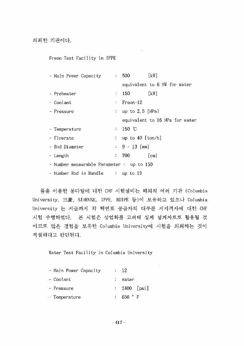
Freon Test Facility in IPPE
- Main Power Capacity :
- Preheater :
- Coolant :
- Pressure :
- Temperature :
- Flowrate :
- Rod Diameter :
- Length :
500 [kW]
equivalent to 6 MW for water
150 [kW]
Freon-12
up to 2.5 [MPa]
equivalent to 16 MPa for water
150 °C
up to 40 [ton/h]
9 - 13 [mm]
700 [cm]
- Number measurable Parameter : up to 150
- Number Rod in Bundle : up to 19
ihi-University, H
University ^
CHF xl^^ ufeSIMENSE, IPPE, RDIPE -§-)<>l
Columbia University^
Water Test Facility in Columbia University
Main Power Capacity
Coolant
Pressure
Temperature
: 12
: water
: 2400
: 650 °
[psi]
F
(Columbia
°-^} Columbia
^*> CHF
- 417-
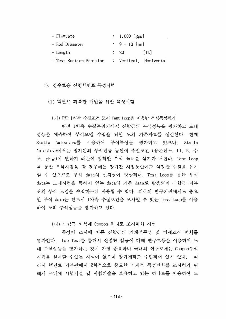
- Flowrate : 1,000 [gpm]
- Rod Diameter : 9 - 1 3 [mm]
- Length : 20 [ft]
- Test Section Position : Vertical, Horizontal
cf.
( l )
(7\) PWR l*f^- ^zl2& J5.-4 Test Loop#
Static Autoclave# °]-§-*f^ - T - ^ ^ - A ^ # ^7}is}3L $1^.^-}, Static
- -<LH] ^ ^ ^ (-§-^^4,, Li, B, ^
> -^] data# ^7)7} <H^u>. Test Loop
, Test Loop
datafe iiuHAlig^ .SflAl ^ ^ data*] 7 l ^ dataS %-§-£!«H
*> -f-^1 datafe tilJEA] 1 4 ^ - >,^^^^- S A f ^ - o l ^ Test Loopl- °]-§-
Coupon
Lab Test
-418-
Fluenceoil
Capsul H
4-g" 7\¥nl Tube
Creep ^
fl Creep# <^^-*f7l ^1*1 < i^ Creep ^-
fe ^£<>fl4 -n-45|7] nfl^oll tuff Creep 7]^ <i^ Creep^
Creepy ^ B H * ! A^lofl ^ ^ A ] V-ftf^uf.
Creepo] DJ #A*f4° l , J L ^ ^ 1 A - | ^ <£^ Creepo]
PWR
3.711 ^ e ^ £ S ^vB 3.^Jig7M ^ 4 ^ 1 < ^ Creeps
) t>t:f. <i^ Creep Jg7HH ^ ^ ^ ^ ^ Creep
Burst ^-
Burst Strain
- 4 1 9 -
$] ^-f°fl 400°C^]^ Burst ^ # ^ 7 ] - ^ ^ ^ #_&. Specification.^.
Burst £ »±£.
Burst ^-^^r J I ^ ^ S «?^S.«^>H Fission Gas Release^] 4 e }
Swellingol
Burst ^-^^°> ^ ] ef L^r^l^l^l Burst Deformation^
, LOCA7f
|. Rupture7}
LOCA ^ ^ ^ 1 ^ ^ | 2]-4^- Burst -^^ ^].^f
Lab Test
±3. Tube *fl^7f 7f-^^- ^g-fofl^. Coupon Test-
(Hf) ^ t l |
LOCAJg7>«l-3. s]^-^51 a ^ ^ S f l - ^ 7 } ^ ^ , Thermal Shocks] $]*}
^11 # 4 4 ^ - ^ 1 ^14^- A ^ ^ Database
fe Zircaloy^l ^-g-^ LOCA X[JLA\
- 420-
LOCA i * H 4
NRC ^ 1 4 5 - ]^] ^
Acceptance Cr i t e r i a# 7 f l ^ Sj^^dow-Sn Zry, ZIRLO™
a l h ] f l ^ ^ 17% Oxidation1200°C ^ £ Limitoj J 1 O ! ^
Database-
(4) -tlW" 3)^*] FTL(Fuel Test Loop) i vf)
Test#
^ 6x6
Fuel Test Loop#
(2)
(7f) JL<S^£^- U02 4i^^I «
^^^C^)A-| 7fl -»> Jl^^i-g- U02
U02
capsule^
^ ^ < i 7]^1^#(capsule
> fluence
71 j t>^-^#
- 421 -
capsule^
(capsule fluence
(cf) Loop
stack length
(e» ^ ^ 5 . ai^^l Ramp
Power ramp | 7^1
fe Power ramp
PCI
transient tf
^ # ^ PCI#
(3)
(7\) -7} rt FIV
-422-

parameters (
modal
Forced Random Vibration
S]
3.7])
Modal Parameters
^ 71
- 423-
,- o] S]
( C »
Wife (Coolable Geometry)7}
71
Guideline^ £.#*}•
-424-
-§•
7^71,
o]
^ . 4Til^ ©. m-^h rcfsM
(4)
^ LDV#
^ LDV ^ ^ - c ^ ] U ] « ] |
- 4 2 5 -
4434 #*H *}# CHF ^ #Database
CHF ^
7}
(4) -S-WtJ91 < f } - & ^ ^ ^
, CFD
Database
O -g- Vq-ofl^^ ^ ^ ^ ^ ^ ^ ^ ^ ^ ^^-^S-fe LDV( laser
doppler velocimeter)!- ^1-g-^M ^^t>^}. *\W 4-§" l wfl<i r 5x5
Reynolds fe 140,000oH, ^ « o ^ -^§-^ 4 ^ % ^ ^ f 12
CHF
- 426
, 44Database!-
CHF
^ 44^4 A
- 4 2 7 -
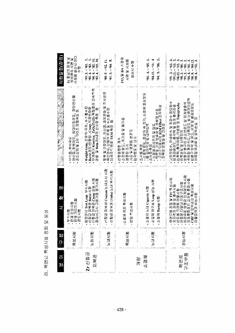
5IU
m
rairart
nJ
5J
«UI0
.^ t
k-'i3 HI
W 51 PcO
N « o o ; _;
o ?
o —O O
»r<VnooT
KO
K1
I 1 ' 0M5KKO
[ iSiniO S 3 L H S r "
i f f iDha; «ooin
: g = S o £i j eo u ojj •; O ^I iSf^JftlR ' S ft
^; mr nr• i no no
I I - tU tU RO ; ofl j < j KK) i <J <J
.150
6" -<
<r,o" j
- *
00.
(
10.
04.
ooi
04.
ou
;; oio Kr %>
no
3K ^no en
nil n i l
5«l K mJ'HO Rl) R0 I
KJ^Br^jpTJioon-Rai
7 . ' 7 i PI 50 RB 31 oFJ W 5115
so
<60
air $0
Kill
so
(50 j |o
I 8 MO« wJ •
5 l>-H 8J
a
H O R u j f l j S i ^ snt) Rr mo no o t «u •=* KIU
• i i i i i
m
JiJIO
no ^II ISI
2 5 mlmDh5Jffrv
- 428-
4.
, Screening Test -§*] J f ^ # 7 ] ^ , 7]7JJJ ^
Autoclave
Test Loop#
Capsule^ ol-§-*> A]^-^- ij^fl^ Coupon^ cHt>
«g^ Creep ^ - ^ 7 } , Burst
Strain $7} ^ ] ^ fl ] ^ ^ f ] ^
fe LOCA
Thermal Shock^
fe uo2
-429-
U02
Capsule^
L Data
RIM Effect , 4i^>)] Relocation
}. ^-S-4 Capsule A]^O|
Loop^W «^iA|^^- .*H Capsule Data
Power Ramp #0]] PCI
5!
51
44^444^4^-
71^1 51
51 71 Til^
4444
- 430-
4€- 91 CHF
CHF
91
D a t a b a s e s.
Database^
2. DB
7\. DB
711
Si
- 4 3 1 -
Siemens/KWU %
Hal den Reactor Project % NFIR
4
1996^ 3 ^ "ABB CE Nuclear Operating Fuel Performance Database"
, uo2
B ] 91tf, ^ 4 ^ Work
W/S -§- 4 ^ ^ ^ H
IFPE ^ 4 5 - VA Frapcon-3 3.H £ ^
-432-
(1) FRAPCON-3 3.Z. *§ 7}x}£.[3. 3.1 ]
-c- Frapcon-3 S ^ # ^
:2. 107flii]
. Frapcon-3
PWR ^ BWR
1 H ^ } 1
ramp)4^1
^ 1§7fl- -1*11 4-§-^l ^ ^ 4 ^ - ^ a 3.3.KH1
I PWR ^ BWR
(HUHB) ^ ^ ^ . ^ ^ H l f e 4 ^ 4 ^ ^ 3-
BR-3^1 ^ - f 6~8% Haldeni] ^ - f fe - 10~13%S i^ ^uf .
-5] ^ - f 2~74 GWD/MTU51
76GWD/MTU ^^f. JLB]JL ^7)
^ - f ^cH 18kw/ft ol^L t««-
IFA-432 rod 3
- 433-
7}
3 .3 .2^ 1 V
^aoJ-*o)= ^ ^ H.AT Ri ^ ^ S f o i l <§«OT:^. ^ 7 }
3.3.3^ # ^ ^-^4 Frapcon-3 3.H
4^-4(
(2) IFPE (International Fuel Performance Experiments)
[3.3.2]
OECD/NEA NSC (Nuclear Science Committee)ofl4fe
-^-1^, IAEAif f f A S IFPE( International Fuel Performance
Exepriments Data Base) ^ ^ 5 . ^ ^ cf[o]ElBfl
4 # 31l7fl£| ^ S - g - ^ tfltl 4-S.-1- Halden Reactor Projects, Riso
HBEP (High Burnup Effect Program) %•$) ^
}H ^ 4 ^ ^ ^ I K ^ M 4 ^ ^ Q 4 ^ CR-ROM
Disk 67115. 6i3j4 ai^^l, ^ 4 4 4 CJ^^: 4 t eCD-ROM Disk 1 7f lo l^ ^ ^ 7 i I ^ - ^ ^ .S 4-S-Sl
- 434-
IFPE
(7f) HBEP (High Burn-up Effects Programme)
M 3711 ^
1979 4 5^^1 ^
:g.7fl7l-
71 ^ 7
20-55MWD/kgM
711
7^*1-71
BNFL(127H), GE(87H) % KWU/CE(PWR -g- 217H, BWR-g-
^^51 ^^I7l^l^#
-. BNFL ^ ^ 5 . * ] < ? l 4 i H ^ 40-47 MWD/kgU02
- 435-
•<£ 7 ] * f | # # # £ 3.2-10.7% ^ j £ j l , GE
27-33MWD/kgUO2°l$3U * ^ < g 7] *ll *£#:§•£ ^tfl 5.2%
. KWU/CESl ^ 5 . - § - ^<£5.£| £ ^ £ ^ 1 ^ 22-46MWD/kgU02
12.2-55.8% ^ ^ l 0 ] ^ ^ ^ , # ^ 31.2-45.5 kW/m oj^uf. n e l J l BWR-g- ^
<&£.S>1 ^ H ^ ^ l f e 28-34 MWD/kgU
0.1-0.4% ] f
-fe FGA/CEA(37|1), BN(67H),
Wec(37fl) <H1-H ^ ^ J L i£*> HBEPl- $M ^ 1 ^ ^ tff^^.(167||)5. BR-3 Qx}
^ , BWR ^ ^ ^ . ^ TV0(97fl)6lH ^ $ i A ^ TVO-1 Qx}S.
.. HBEP-§-_o S. ^ ^ . ^ 1 6 7 | [ ^ ^ ^ ^ . ^ 4 7 } ^ ^ ^A 4°17}
-±r ^-& °«^ , 3711 ^ ^ S . f e ^ <U^, 37fl tfl<^
-S-^ ^ ^ ^ ^ ^ ^ ^ 1 # ^ 3 . S14. ^^r^ . -§- «?^-S-l-^ <£^S-^r 25-70
MWD/kgU02 ^ 1 ° 1 & - ^ , ^ ^ ^ 7 | ^ ] ^ - # # ^ 1.4-11.3 % j K
IFA-429
67fl^ ^S-g-ol 37f[ l ^ o ^ ^ - S - ^:A% cluster^ 2JQ& PWR
s.o| 1775^ 6-^-fB] 1990^ 9 ^ f * l Halden BWR<H14 ^ ^ 5 ] Si
A. 187}) ^s-g- ^^-Ajife ^ ^ o ^ i ^ # 7 l # 51 ^ - # ^ 4 ^ - ^ uo2
JI 97fl5l «££--§-£ elS.4 ^ - r - ^ ^ ^ monitoring *}7j *I*H null-balance
7}^°J-^ transducer!- ^^j-fffSicK
t f l^ -^7]^ l^## ^^*}7] ^SH 2«15| # ^ ^ - ^ A l ^ o | 1985^
1988 Vi 3^6fl ^ ^ S j ^ c } . ^<i7l*]l* o i -§^
transient7} ^*«^^JL, 4 4 ^ 1 transient 4 ^ ^ :
- 436-
-g-Sj tfl Tf f ^ ^ 5 1 ^ K S 3.3.4^
IFA-432
IFA-432 * I ^ £ BWR ^ l M l ^
M - ^7]7}!^| Tj-i-i- ^ ^ 1 ^ 7 ] ^Sfl ^*«^^i:f. ^olfi^. 1975
1984<d 6^7f^l <^^5]SiJI 3 ] 4 ^ ^ J £ ^ 44
Harwell ^ ^ f c o f l ^ S.^- X\^5)*Xz.}. o } ^ 27H ^S-g-S] < ^ 4 i H ^ ^ 20
MWd/kgU, 4 € 27H^ 30 MWd/kgU, IE c } ^ 37fl <^5.-g-^ 40MWd/kgU ^ISiJI ,
n W n - | *> 7B ^ ^ . ^ - ^ ^ 7 l ^ ] 7 | 4 7 l ^ JL^j-AS. ^ I # 5 ] ^ 3MWd/kgU o] &
91 ^ i £ 46 MWD/ kgU02 7}
, f i l l gas S ^ (He
. 20
230 ^n 91 80 /m
The Riso Project
Riso
IFA-148 ^ ] flfl ^ g l ] ^ 1 4 1
1 ! # ^ ^ * M ^ ^ - M ^ } . 2«l9fl Riso ^ ^ ^ 1982-1986 7l
-*.^ Halden<H|A-] <&£*} IFA-161 ^ ^ ^ - 67fl^- Millstone^}
GE *$<&3. 117H1- Af-g-^H ^ ^ 5 ] ^ ^ IFA-16151 « ^ ^ £ f e 31
tfl ~46MWD/kgU02 °l$j.Jl # ^ ^ 40kW/m o l ^ ^ n j , GE
14~29 MWD/kgU02^ HlJZ^ ^Sl t^ . # ^ £ 10-15 kW/m
- 437-
IFA-161S]
niobium
25kW o.Df, GE
27H
^ PCI
157H
M)
IFA-161
38MWD/kgU02*l
1986-1990^1 ^
^ ^ S . ^ < ^ ^ £ 7 f 13-46 MWd/kgU02
20-40 MWD/kgU02 *] 47})^ GE
ANF
(nf) SOFIT WWER Fuel Irradiat ion Programme
Sofit ^ S l ^ Bi>Mo|.S} Kirchatov MR
Sofit i
Sofit 2
Sofit 3
71
VVER-440
1.1
Sofit IS] 47fl
4
- 4 3 8 -
Sofit 1.1 2]- Sofit 1.35] ^^-7f-^«l; ^ 4 ^ . ^ Sofit l . lS]
1-6,
Sofit 1.3^ ^ - f ^ S ^ - 1,2,3 U 5*11
SOFIT 1.1 - 1.4-b 187B^ ^S-g-l-ol hexagonal^ Hfl^l^ 47])^
7$°. i40-290y™ o]3.,
*±7}^S-^ He ^ Xef>l A}-§-5] C^JT. <^-^O] 0 . 1 - 2 Mpa o] ^ u } . U02 ^
10.4 - 10.75 g/cc, grain sizefe ^ 5/wn o]^uf . ^ ^ S
1000mmo]jl <&g.^§- o } ^ 1200mmol$iuf.
Sofi t -1.1 % 1.3 S 4 4 ^ f e TRANSURANUS a.J^^ | ^ ^ #
4
SOFIT-1.3
(Hf) Kola-3
^ ^ ^ . * l^«Ul7f FA-198 ^ FA-222^1 27ff^ WWER-440
Kola-3 ^ 4 ^ - ^ 1 4 4 4 4, 5 ^ 7 l * j ^
FA-198O] 46.2 MWd/kgU <>l$i^I FA-222fe 48.2
^ WWER-440 J L ^ ^ S ^ ^
. i ^ S l & c h U02 ^
5 l4°J "Elemash"cHlA-1
- 439-
creep-down,
WWER
"Elemash"o]]4
FA-198 ^
32711
51
creep-down^
3.3.6-7 £ 4 4 FA-198
(4) Tribulation
TRIBULATION (Test Relative to High BUrnup limitation Arsing
Normally in LWR's) 5 S 2 5 ^ 1980\d 7^^] A ] ^ ] - ^ I : } . O] 3ES.ZL
r S ^ 197])7f 4 -g -^^ -^ -^ ° 1 ^ 117J1 ^ S - g - ^ Belgo
Nuc lea ire <Hj 4 H5JJ1 87H ^S-g-^cr Brown Boveri Reactor GmbH(BBR)< ]4
z\\3L5\$Xt\. °1# n<&3.^£ BR-3
-^ BR-2 ^
creep-down
IFA-562.1
IFA-562.1^8: ^ i^^ l^ l S ^ roughness7}
- 4 4 0 -
^ 71 Til ^Halden BWRofl 1987\1 6-SJ^E] 1989V1 8 ^ * 1 ^UtSlSW. ZLZ)3. 2*1
grain ^*ON§- PIES
rough 91 smooth ^ 3 f l £ f Xe ^ He 7l*fl.§.
smooth ^ ^ ^ l ^ ^ . i f rough ^ ^ ^ 1 ^5.-g-5l «lJ3-# ^ l t
^l^-^f^l -1*11 <£.£-§-#£ 4 ^ ^ ^ ^ . - s i ^ - ^ 7j 3.71s.
-S- ^ ^ ^ base irradiation -§•$]• 1200°C ol*}# ^ 1 * } ^ ^ } . 5:7151
gap closurel- *H^fjL ^ ^ t«
91 grain growth# ^°Hcuh ^ ^ ^ ^ f ^ ^ ^ 1 &^$1 roughness*!
4 ) IFA-533.2
J1^4i£^A-l ^045 .^ ^ ^ 7 ] ^ - # ^^-*l-7l ^1*F^ 271151
807, Rod 808H Halden BWR l l 12\d^> ^ d t ^ Jf-
1 - ^ IFA-409(Instrumented Fuel Assembly)«^>^ c ^ 47jf5l
1973\1 5^-f-^ 1985^1 6^^M ^ ^ ^ I $ i 4 . ^ ^ IFA-533.2^1
807*1 ^ W - i f ^ ^ ^ r ^ S 9lS-g- 807*!
808*1 ^ ^
91 ^ S . ^ 1 ^ 4 ^ 4 ^ . scram
i £ ^ 43.05
36kW/m S. ^
40-45kW/mS. ^
- 441 -
30kW/m i - t
IFA-535.5-6^
IAEA/OECD-NEA Fuel Performanace Database
500ms
IFA-535. 5 & 6
cK 47B <S.g.-g-°l 1973^ 5^-^-e] 1985
^ ^ £ l $ d - ^ ^ ^ ^ ^ £ ^ 43.4 MWd/kgUO2
^: 1FA-535.5 ^ IFA-535.6^14 4 4 ^i
27B ^S-g- 809 ^ 810^ 1985\1
811 ^ 812-b 1986\1 1
^ 1986^
1987^
\ IFA-535
IFA-535.
U02 ~ ^ ^ £ ^ 9.884% U-235, <>]&-$ ^SL^ 94.7 % o]
3 .7]^ 0.135mmoln}. «?lS.-g-^ 3^7] <£^-£: He 7 } ^ 1
bar °j£-°.u} A^A A^Q3?- ^ Q ^S-g- 809, 810, 811, 812 4 4 ^
•& 7.0, 7.6, 32.0, 32.1 °1&4. «J-g-^7]^lty-# ^}S-b <£^-g- 809
810 4 4 ^ 1 ^ 4 ^ 4 ^ 1 4 ^ -^s j 1.5 ccm ^ 1.7 ccm J ^S.-g-
IFA-535.5 ^ IFA-525.6^
- 442-
-g-
(3)
7]
(7f) 214^- creep-out ^ ^
creep-out^}
creep-out ^ ^
H»J SIERA 3.J£7|fwJ:6fl Af-g-^f^-^.^, Halden projec t^
IFA-585.1 [3.3.3]
2 7 ^ ^-§-5 .^1^ 2 : 4 ^ Zry-2S. ^3^. BWR-§-
3 . , PWR-g-
zero stress, creep-out A S ^ S f S l ^ K PWR
CWSR(Cold Worked Stress Relieved)^AS. *fl^S}&JL, PWR
300/an(Diametral Gap Width) ^ £ 5 . 3.7]} f>\&r.\.
- 4 4 3 -
370-380 °C &3L, PWR ^S-g-ofl * W #-g*Hr£ : LWR
5xlO13 n/cmJ-s(E>lMeV)
IFA-585.4 [3.3.4]
£ 4 ^ £ IFA-585.l3f
& ^ M^ £-§--§-£ KWO
^ 76*551
$1 PCI ^ ^ # as]4i4f*}7l *1*H 300/mi5. -Si-Sit:}.
^ 1.2xlO22 n/cnf(E>lMeV) o] £ a ,
^^1 26^-i- S ^ M 10.758
100 bar, 4 # ^ 4 ^ ^ : ^ ^ l ^ - g - ^ l 3.2xlO13 n/
cm3-s(E>lMeV) oj^JL *F-r-^l^^-°] 2.5xlO13 n/cm2-s(E>lMeV) ^ A ^ ,
^ 5 - ^ S ^ ^-T-^I^-g" 372-379°C, ^f^-AJ^-a 376-383 °C ^ A ^ ,
^ hoop s t r e s s ^ 4 4 85 MPa ^ 30 MPa ftt}.
900fph 7}4
Zircaloy-4
© Ringhals-3 ^^^;-^ Li
Ringhals-3
l-fi- Zircaloy -f^Ji
Zircaloy -f-^^-S.-^ ^7}^.] X\. °] 's^-S] ^ ^-^^c: Ringhals-3
Li - ri£.7f Zircaloy
444-
40.6 MWD/kgUoj^i 4
TT 39.7-43.4 MWD/kgU
4 <£:S.-^ ^7 l^ ]Ai 26.5 - 43
(2) PFCC(PWR Fuel Cladding Corrosion) 3.S.
Zircaloy ^ ^ ^ . s l^^o) ] 3. -r"^1 ^ hydridingo] tHJ^ofl tu>ef 3.<
PFCC (PWR Fuel Cladding Corrosion)# 7 f l ^ | - ^ c } . EPRKHl^^- PFCC
23737)1^
27H
20-102
® IFA-568.1[3.3.7]
IFA-568.1 A l ^ ^ ^ j ^ r Zircaloy-4^] -f-
Li ^ £ * ] ^%># ^7f*f7l £1*1] Halden #*K§.<q PWR f ^
1989hi 6 ^ ^ - ^ I99iid lO^^W ^ ^ S l S i c K ^ - g - £ KWU^A] ^ |
£l>ii) Goesgen ^Uf^oflA-j ^ ^ « > 47lj^ ^^--g-# S % V W . Halden #*}
$.o\]*\ e l i AJ2W <?1^£^ 28.5 MWD/kgU6| 5i^.ni, o|tUA| ^S}%- - ^ - ^ ^
10-40 /an o|^u>. ^ 4 ^ u f l Lii] - ^ £ ^ ^-§-^-^1 ^ 4 ^ ^ 7 f 2.2-2.5 ppm
°J ^3f tilJ2.SH 4 - 4 . 5 ppm# -S-x}*}^}. Halden
^ J 4 -g- ^ 4 i £ 7 f 45 MWD/kgU oj^cf. A>S | .^ - c ^ ] ^ 80, 245,
30-90/^
- 445-
(cf)
Rim
} ^ R A P I D ^ g . T .
Pu
(1)
L-235 ^ ^ £ 10 %<>]<>&,
Mechanical ^ % -
. 100,000 MWD/MTU O)AV
FEM(Finite Element Method)
- GUI
5 w/o
*i
- 446-
r 71^3} U02 «J£.g.S] ^ uj 2fS.^EH ^ * f | * j S H ^ I ESC0RE4}
FREY 3-B-M: -f-^^1 FALCON 3 . H # 7fliHrK2. $X£-tf, Siemens A } ^ 7 ] ^
CARO S B f tjf^W U02 <££.£] ^ ^ ^KE-^fl ^-^*1H ^ H ^ I SIERRA
a n t jflt^jL $14. on- 53.^ s.^- - f r*hs .^# 4-§-*K2. 014. a
B]J2. ^- ^f^Iofl^ 7H«i^ ^^M. ^ ^ ^ ^ 3 . ^ ^ Zj- ^ - ^ £ c | # Module .
^eltl 71 #
6J^ ^-ti] ^ 711^ ^2f5l JgB| ^ ^r^°l -g- ]«]-S.- - Graphic User
Interface!-
(2) U02 i ^ s f l ^ «V^^%> «g^S ^ :S - t 7fl-i>*fe RAPID
(7\) 7H J5.
uo2 ^4*\] *-M*\ # A ^f4^l 3.7]
7}
Ferti le
Empirical
^ 238U $) %.$*} ^-tri * . ^ ^ 6JsU 239Pu tfl^o] xfl
4* 2 - 3 wB ^ £
Kr Rim Effect7} ^ ^ ^ 1 4 . H}BM ojgf^ Rim
Effect^ ^ J # ^
- 447-
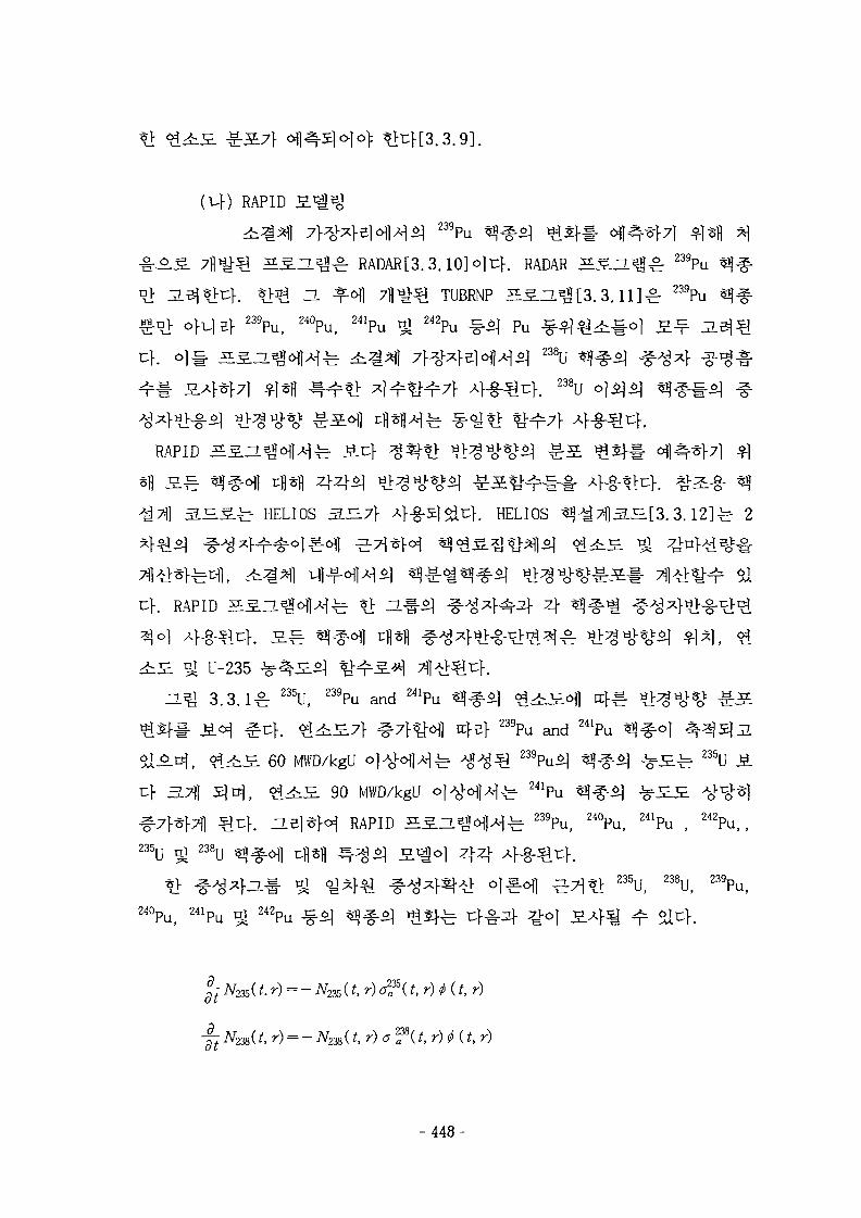
RAPID
S ^ L ^ RADAR[3.3.10]o]uK RADAR 5 1 2 ^ ^ 239Pu
] fl^ TUBRNP HS.-L^[3.3.11]^r 239Pu239Pu, 240Pu, 241Pu ^ 242Pu ^ Pu
238U «
238U
RAPID ^ S H
^. ^ 5 . ^ HELIOS 3.^7} A]-g-!E] uf. HELIOS ^^7fl3.S.[3.3.12]^ 2
. RAPID BSl^oI^fe ?> Hl- l ^ A ^ } ^ ^ 4
L-235 ^ fl
3 . 3 . 1 ^ 235U, 239Pu and 241Pu ^ ^ ^ ^ ^ H ^ l tcf^-
239Pu and 241Pu ^ ^ ) ^
Sll-^Df, ^ 4 x - £ 60 MWD/kgU ° 1 ^ H M T T ^ A ^ ^ 1 2 3 9PU^1 ^ ^ ^ ] ^ £ ^ 235U
cf 3.7]] £ ] D J , < ^ 4 i S 90 MWD/kgU ° l A c H M f e
RAPID ^ i = ^ | A f e 2 3 9pu , 240Pu, 241Pu , 242Pu ) (
235U ^ 238U
238U, 2 3 9Pu,
24OPu, 2 4 1Pu ^ 2 4 2Pu
^ iV235( f. r) = - iV235 ( t , r) o f (f, r ) «J (f, r )
- ^ iV238(/, r) = - iV238(*, r ) a f (/, r) (f, r)
- 4 4 8 -
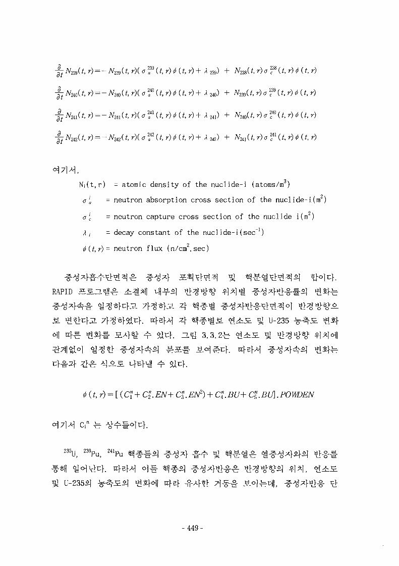
jjNm(t, r) = -NZS3(t, r)( a f U r) * U r)+ /I 239) + A ^ U r)<r f U, r) 4 (t, r)
J-tN2io(t, r) = -Nm{t, r)( CT f (f, r) ^ (t, r)+ A 240) + Nw(t, r)cf9(t, r) <t> (t, r)
J-tNw(t, r) = -Nm{t, r)( ff f U , r) (f, r)+ A 241) + A^240(^ r) a ™ (t. r) <!> (t, r)
4:Nm(t, r) = -NmU, r){ a f {t, r) <!> (t, r)+ A 242) + N2il(t, r)af{t, r) 0 (t. r)
N,-(t,r) = atomic density of the nuclide-i (atoms/m )
a'a - neutron absorption cross section of the nuclide-i(m )
a 'c - neutron capture cross section of the nuclide-i (m )
Ai - decay constant of the nuclide-i (sec"1)
0{t,r)- neutron flux (n/cm.sec)
RAPID J E S H ^ ±.^^] i-ll-f-5] ^
*>!:}• J l 7 f ^ ^ ^ u f . trfsfA-] 4 t f l f i ^ <£^S_ ^ U-235
(^ r) = [ (Ci + Cl. EN+ Cl. EN2) + C\. BU+ Cl. BU]. POWDEN
-449-
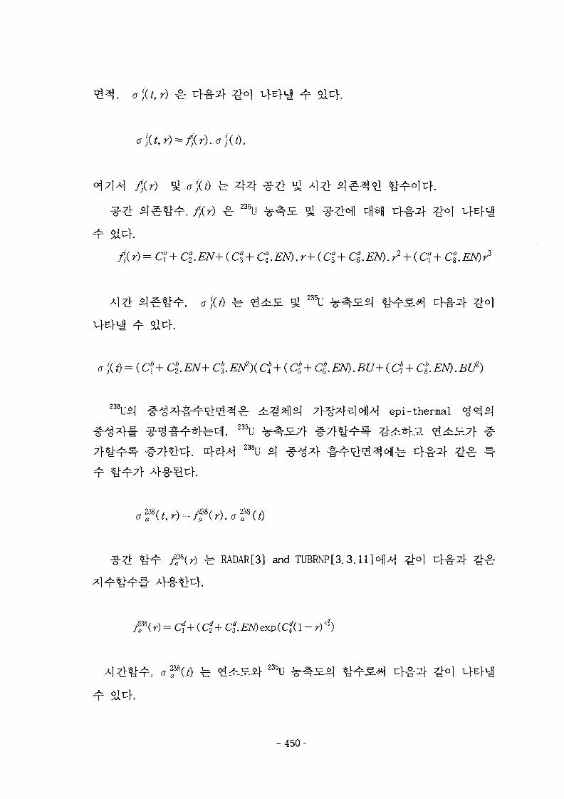
, o){t,r)
a)(t) fe 4 4
^ 2 3 5 U
f;{ r)=Cax + Cl EN+ (Cl + Cl EN).r+( Cf + Ca
e. EN). r2 + (C? + ClEN)r3
2 3 5 u
6 j\t) — (, C j T 02. £Ll\ -r C3. ziiV ){ C-4 T \. C5 -r C6. l i iv j . tS U +^07 + Cg.
] epi-thermal235U
^ RADAR[3] a n d TUBRNP[3.3.
Cf + {Cl+ CiEN)exp(Cd4a - r)4)
- 4 5 0 -
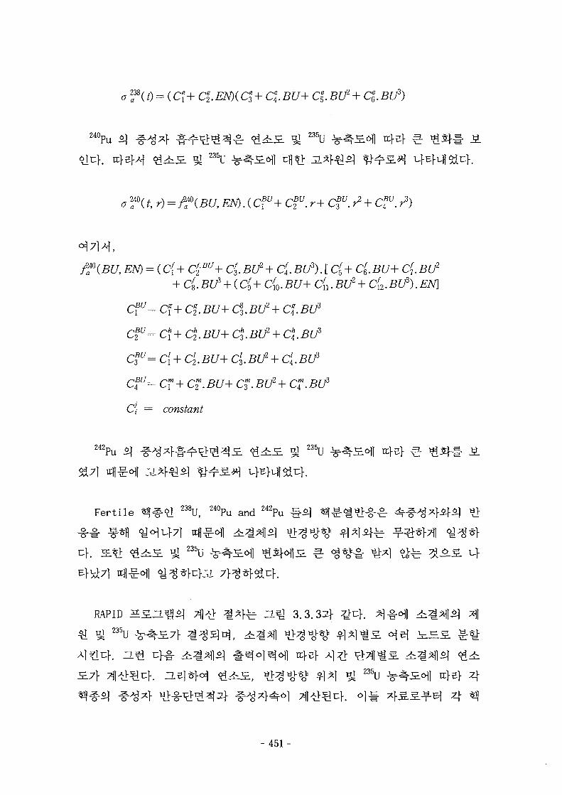
o f (t) = (C? + C\. EN)( Cl + C\. BU+ C%. BU2 + C\. BU3)
240Pu2 3 5 u
235U
C{.BU3). [ C£+ Cf6.BU+ C^
C{0.
C?u= Cf+ CI.BU+ C^.
Clu= C\ + Cl BU+ Ct.BU2 + Cl BU3
Clu= C[ + Cl2. BU+ Cl
3. BU2 + C{. BU3
Cfu= CT + C2m. BU+ C™. BU2 + CT. BU3
C\ = constant
C{2. BU3). EN\
SBl7]
3 235r rcfe} 3.
Fertile 238U, 2 4 0Pu a n d 2 4 2Pu
235U
RAPID
"A 235ufe H J 3.3.33} ^uf.
.7} $1*1 Si 235u 4s} 44 ^
- 4 5 1 -
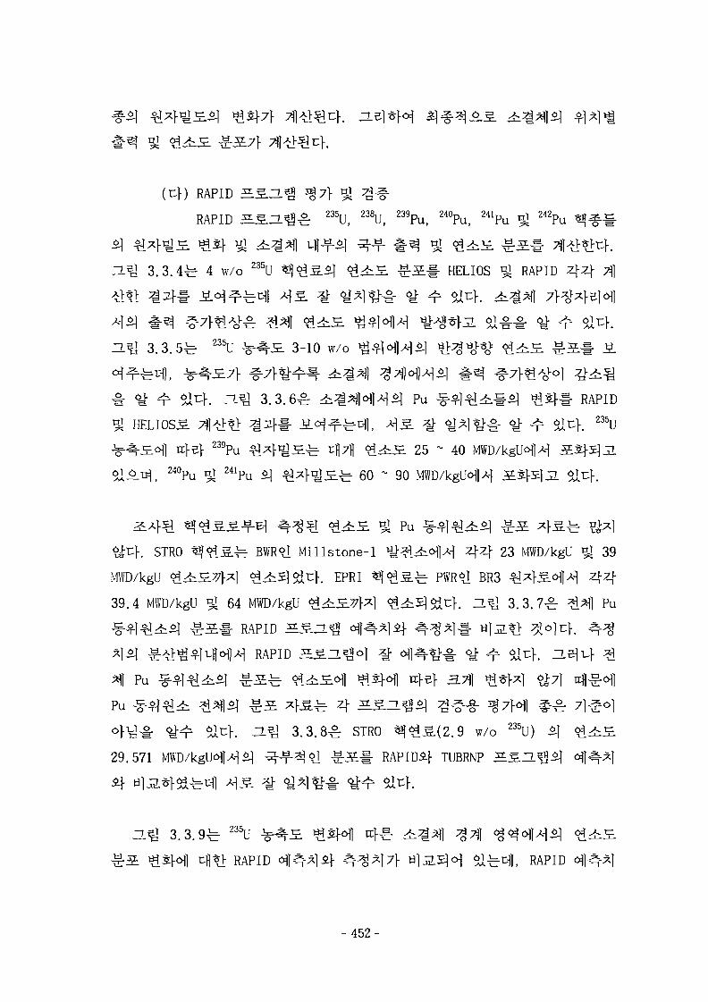
(Uf) RAPID ^SJ.^ ^ 7 } ^
RAPID 5 S 2 g ^ 235U, 238U, 239Pu, 240Pu, 241Pu * 242Pu « * # #
3 .3 .4^ 4 w/o 235U ^ ^ 5 . ^ <$.^S. ^ S # HELIOS % RAPID 4 4 Tj]
3 . 3 . 5 ^ 235U ^5L 3-10 w/o
a ^ I 3 .3 .6^ 4i^*f|<sflA-l^ Pu ^ - ^ 1 ^ ^ § ^ ^ 5 } # RAPID
HELIOSS 7ll^*> ^ 2 } # i ^ ^ ^ u f l , ^ S . ^ ^ ^ 1 ^ 1 - <t ^r S14. 235U239Pu ^ ^ F ^ H ^ ^711 <£i :£ 25 ~ 40
24i -2= 60 ~ 90
^ Pu
$>t}. STRO ^ < ^ S ^ BWR l Millstone-1 ^^ifcofl^ 4 4 23 MWD/kgU ^ 39
MWD/kgU o44i£7}^l ^ifc5|5it:K EPRI ^ ^ ^ . ^ PWR l BR3 ^ 4 5 . ^ 1 ^ 4 4
39.4 MWD/kgU ^ 64 MWD/kgU <£4iS-77}x\ <$.£.5\$X^}. D.Q 3.3.7^: 1*11 Pu
1 ^ ] ^ # RAPID HSZLefl « ^ ^ l i f ^ H * ] #
RAPID ^ s n ^ o l ^ ^ l ^ - ^ ^ <y-
Pu ^ ^ 1 ^ 4 ^ ^ ^ l i ] ^ r 5 *K£±r 4 ^ 5 . H
° } ^ # 6 i^r ai t}, a ^ 3.3.8^r STRO ^ ^ ^ . ( 2 . 9 w/o 235U)
29.571 MWD/kgUofl>M ^ M J S i ^ S l : RAPIDi} TUBRNP SS.ZL
9 f e 235U
c{[«> RAPID of l^ l i j - ^-^^17} Ul 3.5^0] ea^cfl, RAPID
- 452-
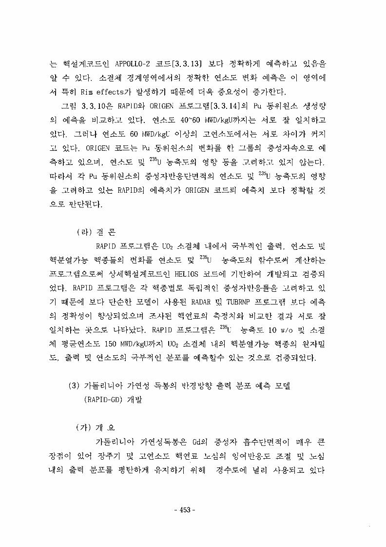
^ ^ l APPOLLO-2 3 . H [ 3 . 3 . o
Rim effects7}
3.3. lO^r RAPID^- ORIGEN ^ S Z L g [ 3 . 3 . 1 4 ] ^ Pu
^- tijj2.^1-jL 6iu>. < ^ ^ S 40^60
BJL.1- <£^S. 60 MWD/kgU
. ORIGEN 3-B.^ Pu
4 pu ^ ^ l ^ ^ ^ l ^ ^ F ^ - S - 1 ^ ^ ^ ^ £^51 il 235u*}J1 5^-b RAPID*] o j | ^ | 7 l - ORIGEN 3 . ^ 5 ] ^ ] ^ 1
(Bf) ^ ^
RAPID ELSJ.*&£: U02
2 3 5 U
=.^! HELIOS S J ^
. RAPID SSZLS^^- 4 $17] A^^ JB.cf ^>^-*l £ 1 ^ 1 4-g-Sl RADAR i i TUBRNP
. RAPID ^S-H^ 235U - ^ ^ £ 10 w/o
150 MWD/kgU7}x] U02
(3) 7}#elu jo}
(RAPID-GD)
(7 f ) 7)1 JSL
- 453-
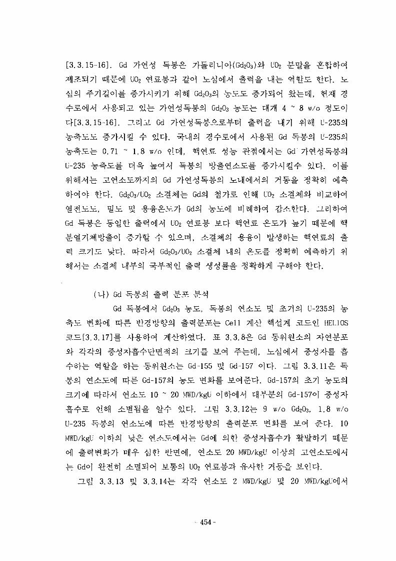
[3.3.15-16]. Gd U02
uo2
Gd2O3 ^E±f- cfl7fl 4 ~ 8 w/o
. ZLSla Gd
^ 0.71 - 1.8 w/o
Gd
-fe Gd
U-235
Gd
. Gd2O3/UO2 U02
Gd £fJ§-8; ^ U02
Gd203/U02
( v f ) Gd
Gd Gd2O3
Cell
3 .3 .8£ Gd
H°J HELIOS
i f
^ Gd-155 ^ Gd-157 o]z\. H ^ 3 .3 .11^
3.7}o\] n
U-235
MWD/kgU
10 ~ 20 MWD/kgU ol
^ Stlcf. Z L ^ 3 . 3 . 1 2 ^ 9 w/o Gd2O3) 1.8 w/o
^ 4 . 10
20 MWD/kgU
a?J 3.3.13
^ - ^ ^ U02
3.3.14 - 4 4 2 MWD/kgU ^ 20
-454-
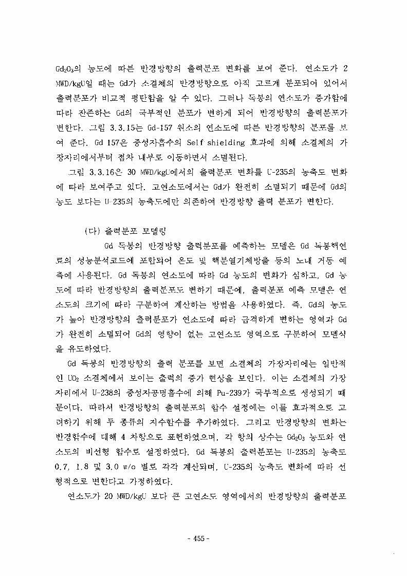
MWD/kgU<H 4 ^ - Gd7}
. He] 3 .3 .15^ Gd-157 ^4x^1 ^ - h £ ^ ] r
f. Gd-157^ # ^ 4 ^ ^ r ^ l Self-shielding 7}
3.3.16^ 30
6\] Gd7f
Gd fe S^l^ Gd
Gd , Gd
7F
7F
Gd
Gd
U02
Pu-2397F
fe oi
4 ^F%v-^ ^ Gd203
^ } . Gd f§
0.7, 1.8 91 3.0 w/o ^ 5 . 4 4 ^ 1 ^ ^ ] ^ , U-235^ xt\z}
20 MWD/kgU
- 455-
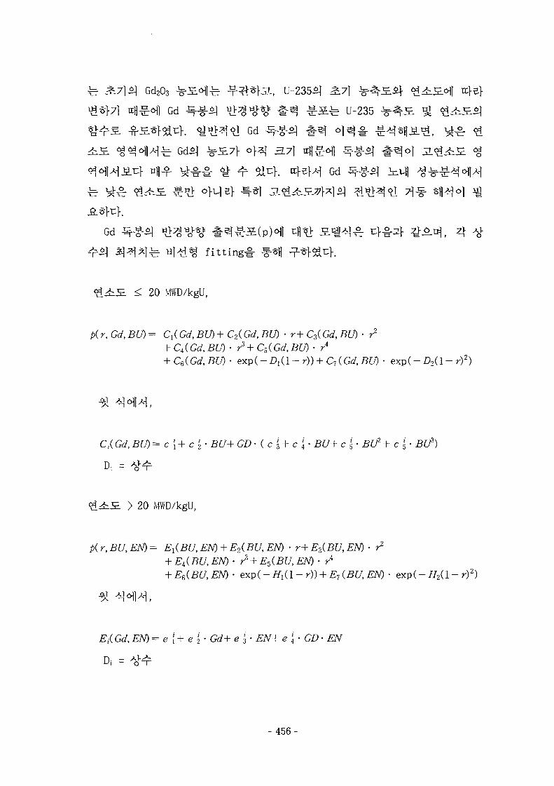
Gd203 ^JE-Ofc ^ r ^ F ^ l , U-235S]
g-^ Gd ^$] ^ ^ # ^ -g-S-fe U-235
l Gd ]
Gd
Gd ^ g 1 ^ ^ ^ ^ # ^ ^
] tii^i^ f i t t ing
20 MWD/kgU,
/>(r, Grf, -BfT) = d(Gd,BU) + C2(Gd, BU) • r+ C3(Grf, BU) • r2
r4
C6(Gd,BU)- e x p ( - A ( l - ^ ) ) + C7(Grf,5L0 • exp(-Z>2(l - r)2)
= c [ + c '2 • BU+ GD • ( c i + c \ • BU+ c !5- BU2+ c '5 • BU2)
> 20 MWD/kgU,
p(r,BU,EN)= E1(BU,EN) + E2(BU,EN) • r+Ez(BU,EN) • r1
+ E^BU, EN)- r3 + E5(BU, EN) • rA
+ Ee(BU,EN)- ex.p(-H1(l-r)) + E1(BU,EN)- exp(-H2(l- r)2)
, EN) = e [ + e \ • Gd+ e '3 • EN+ e \ • GD • EN
- 456-
=L^ 3.3.17 ^ 3 .3 .18^ al>d«g F i t t i n g ^ #Sfl - ^ Gd -Sj-g-S]
HELIOS ^ T f l
-& Gd
Pu-239ofl
RAPID(RAdial Power and Burnup
Prediction by following Fissile Isotope Distribution in the
Pel let) [3.3.18H ^7}${°] Gd
# ^ S # Gd2O3
^1-S-fe- Cell 7fl^ ^A^Tj] S ^ o | HELIOS*] 7}1 > )
20 MWD/kgU oj
^ Gd
(4) 3 . ^ 4 x S U02
(7\) U02 ^
U02 ^ ^ ^ 1 ^ J I ^ ^ # ^ * f SAfofl i|5|) cH^ 4 ~ 5 MWd/ kgU
- 457-
7)3,7} 5j*>
-, 7]
SEM
51
Zacharie. et. al. [3.3.19]5l
il-*f7ll s m SEM 4 ^ 1 5JS1-I3 25GWd/tU5l
60^: Annealingtl ^ - f 4.1 %,
71X151 71
^ D ( | 71
- 458
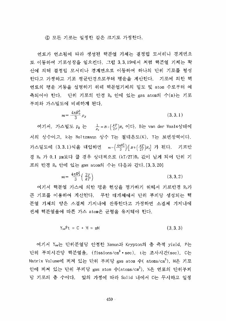
fe 7l5fe ^ t * ^ 3.7} S.
vlSL ^ atom
Rb o>6|| safe gas atom^ ^(m)fe 7 ] S
m=
^ i ^ £ pg fe -j-=B+(-^:)Rb olcK B r van der
^ Boltzmann
Rb 7} 0.1 ]imiu} H- ^-^- -#t:|)^_o_^. (kT/2T)Rb &°] ^Tj) 5 H ^1^1 71
Rb ^1^1 Safe gas atom5l ^ f e c } - ^ ^ ^cf. [3. 3.20]2
2r\ /o o 9 \
Y x en = C + M = mN ( 3 . 3 . 3 )
Yxefe #*l£-«£# <£$*} Xenons} Krypton^ .%• 4 ^ yield, Ffe
T^^I -f-2]Al^:^- ^ £ < i # , (fissions/cm3'sec), tfe ^ ^ W ^ ( s e c ) , Cfe
Matrix Volume* ^ ^ safe ^ 1 -f-sl^ gas atom ^ ( atoms/cm3), M^ 7 l 5
safe ^ 1 -T-21^ gas atom ^(atoms/cm3),
715^1 % ^ l n f . §i5l 7^ofl 4sf Solid
- 4 5 9 -
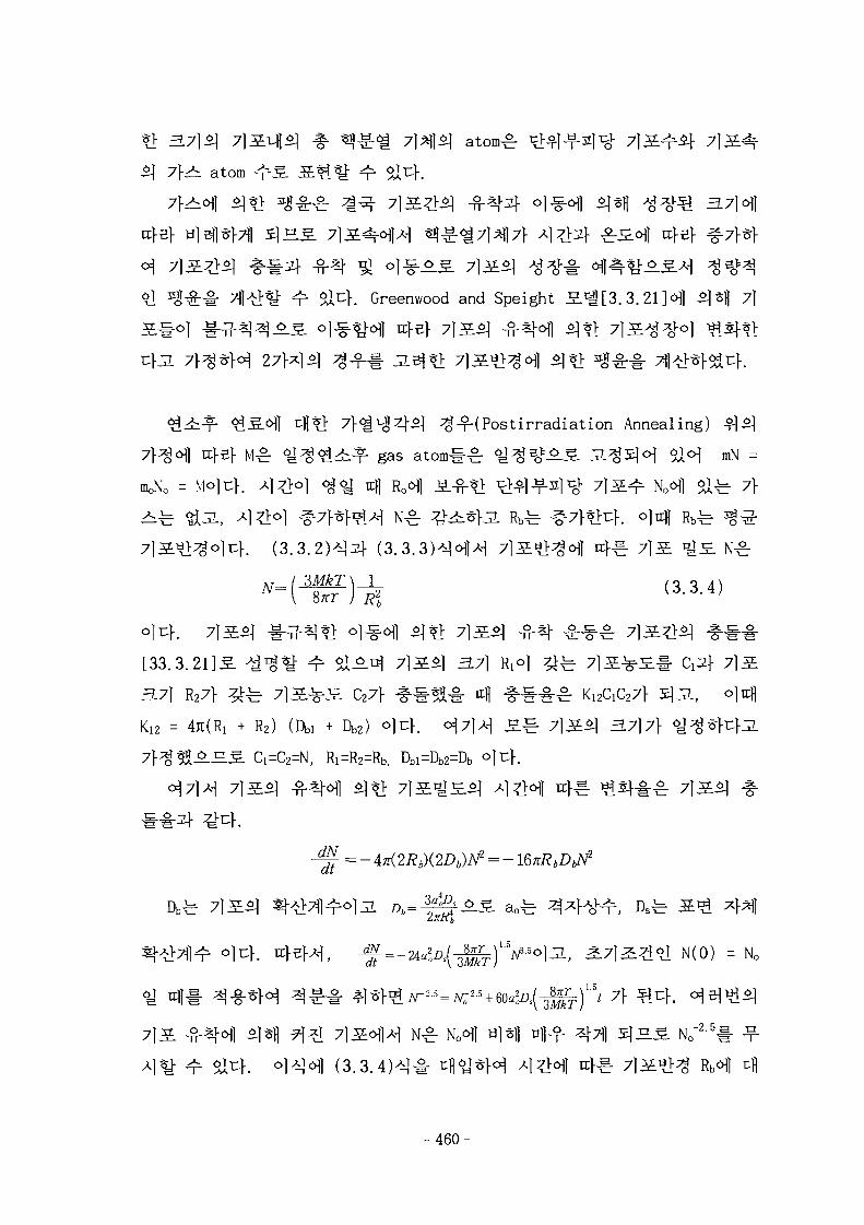
*> 3.7]$] 7]SL^S] %• *»|£<g 7M$] atom^ ^ - f ^ 7]
S] 7}^ atom
Greenwood and Speight S»g[3.3.21]«Hl ^s){ 7|
^g-f(Postirradiation Annealing)
gas atoml-^- ^ ^ s ^ ^ . J1^5]o] $1°] mN =
moNo = V|o|uK X[Dro] <$*-m Roo)) &$-*]• ^V^-fsl^- 7 l S ^ No l S fe 7f
[33.3.2US. ^ ^ ^ " ^ alAn^ 7 lS^ 3.7} R,o] z£^ 7 l S ^ £ # d ^ 7]3,
37} R27f ^ ^ 7lS-^S C27f ^ # ? « # n| # l"#^r K12dC27f 5]3.,
Kiz = 4JI(RI + R2) (Dbi + Db2) o]t[. <^7}M S.^ 7]3L$) 37}7} <£%
X&_H.£. Ci=C2=N, Ri=R2=Rb, Dbi=Db2=Db o|u>.
71S^ - -
fe 71S^ ^ ^
l V ] N ( 0 ) = No
(3.3.
- 460-
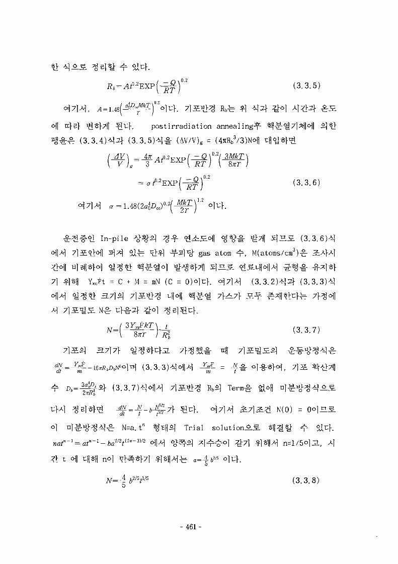
, _ r\ \ 0 .2
\RT) ( 3 - 3 ' 5 )
.0.2
o|l tr}5} ^^r}7l] ^ u } . postirradiation annealing^-
(AV/V)g = 3
AV\ AK ..o.2T?Vp/ - Q \ 0 - 2 / WkT\V )g~ 3 A i E X P l j I j
(3.3.6)
In-pile ^o>%^ Jg-f- ^ i £ o H ig%>^- tilTij 5 | S S (3.3.6)*]
^ 1 ^ ^41 ^-^l 1 ^ gas atom ^ , M(atoms/cm3)^
7] ^Isll Y x en = C + M = mN (C = 0)o|cf . 0^7 } ^ (3 .3 .2 ) * ]2 f (3 .3 .3 ) * ]
(3.3.3)*}ofl*] *£. = ^ # o]-g-*Hf 7]
= b^7}
N=a.tn %EH^1 Trial
N(0) -
(3.3.8)
- 461
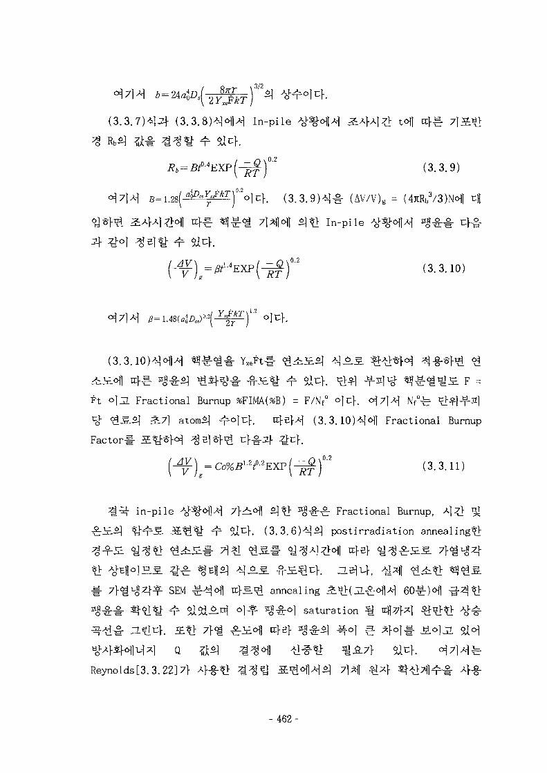
( 3 . 3 . 7 ) ^ (3.3.8)*H*j In-pile ^%<>M a ^ M ^ t*\} tf^
(^|) ' (3.3.9)
1- (AV/V)g = (4JiRb3/3)Nofl
In-pile
(3.3.10)
] f l ^ i ^ F =Ft O|JL Fractional Burnup %FIMA(%B) = F/Nf° ojcf. o j 7 H N f
0^ ^L^l^-s]
^ ^ [ S ^ 2.7] atom^I ^©li:}. H}S}A-] (3.3.10)*]«sfl Fractional Burnup
Factor#
(3.3.11)
in-pile ^"%ofl-H 7}^o\] ^1*> ^ ^ b c : Fractional Burnup,
- ^r SI^K (3.3.6HSJ post irradiation anneal i
SEM £ * H ix}s.^ annealing
^ a lS lA^ o] *- *fl£o] saturation
rrfBf
Reynolds[3.3.22]7}
- 462-
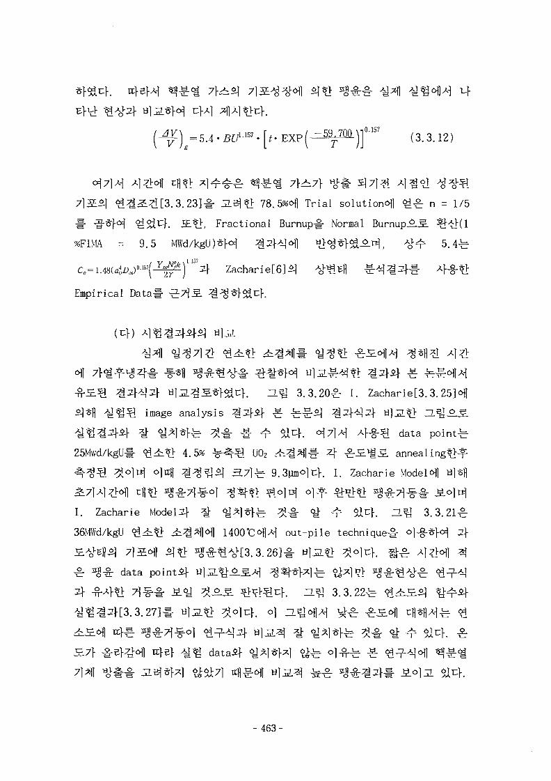
(3.3.12)
:2.3j*> 78.5%ofl Trial solution^] ^ ^ n = 1/5
>, Fractional Burnup# Normal BurnupAS ^^1(1
%FIMA = 9.5 MWd/kgU)*H ^ ^ ^ H l
^^)lA^ Zacharie[6]i]
Empirical Data# ] ^
3.3.20^: 1. Zacharie[3.3.25M
image analysis ^.2}$} £ ^^$] z£2\*\3\ M}3.%} H^^-S.
^ ^ l ^ f e ^ # # ^ $lz}. °)7]A\ Af-g-Sl data poin ty
25Mwd/kgU# ^ ^ * > 4.5% ^ ^ ^ U02 4 i ^ l l § - 4 ^ r S ^ S . annealing*];^
l-. I. Zacharie Models] B]isj\
I. Zacharie Model^ ^ ^ ^ I ^ f e ^ # 6 i ^r $lty. 3.Q 3.3.21^-
36MWd/kgU <£^*i ^ ^ ^ 1 ^ 1 HOOTCofl out-pile technique^-
data pointif u U ^
^ H^ 3 .3 .22^
dataif
- 463-
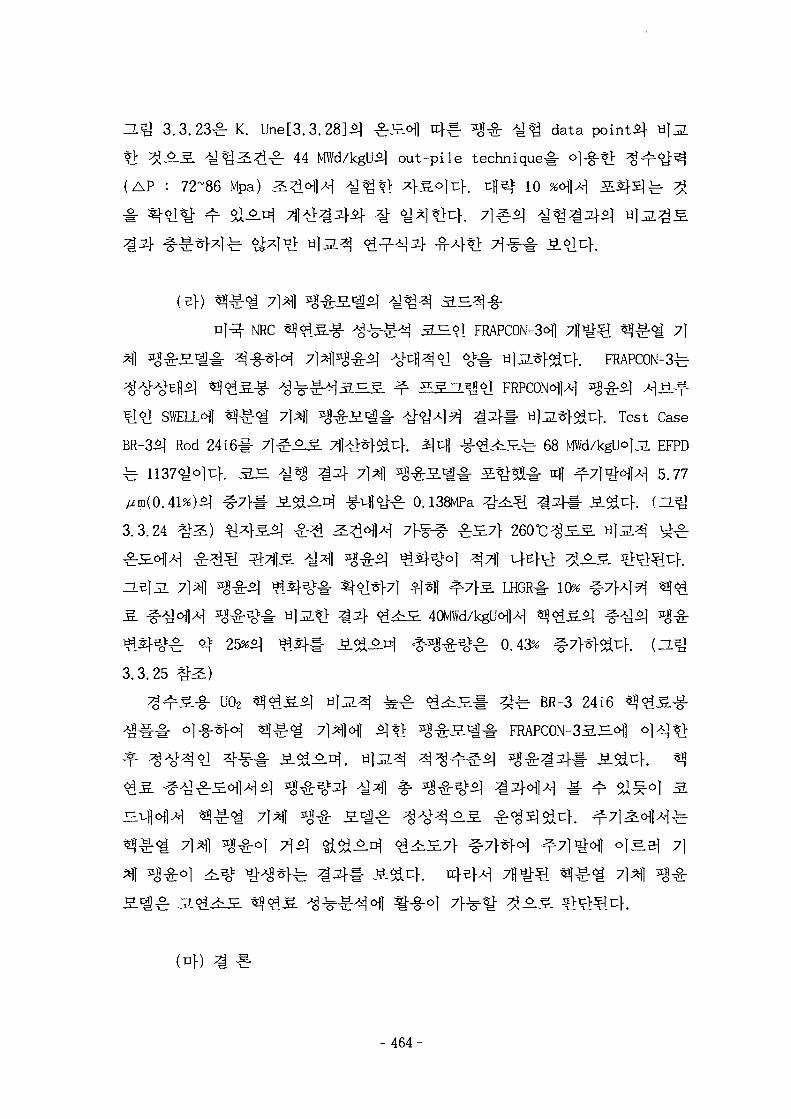
H ^ 3 .3 .23^ K. Une[3.3.28]£| ^H<^] r c ^ *J,g- ^ data points}
t> 3J-2-.S. ^ ^ ^ ^ ^ : 44 MWd/kgUSj out-pile technique^ ©]-g-$};
(AP : 72~86 Mpa) ^ £ o J H -g^*} ^j-S^li:}. tfls* 10 *ofl>H
^ 7)^] ^
NRC «?*lS-g- ^ - r o ^ 3^.<d FRAPCON-3 1 7^$. ^^ci 7]
SWELLS] ^^:^ 7]^} ^^3.^M #<&X\9) ^ # Ulja^^uf. Test Case
BR-3SJ Rod 24161- 7 ] § ^ S XI^I^^K ^ 4 -g-^^^fe 68 MWd/kgU lJI EFPD
^ ^ S l # S^^ - i - ttfl ^7liH>M 5.77
g ^ 0.138MPa
3.3.24
10%
^r ^ 25*^ igSj-t- i ^ - ^ . ^ ^ ^ s ^ o.43% # 7 } ^ ^ i
3.3.25 ^"^)U02 ^ ^ 5 . i | v}^ ^ ^ «?1^£# ^ -b BR-3 24i6
(4)
- 464-
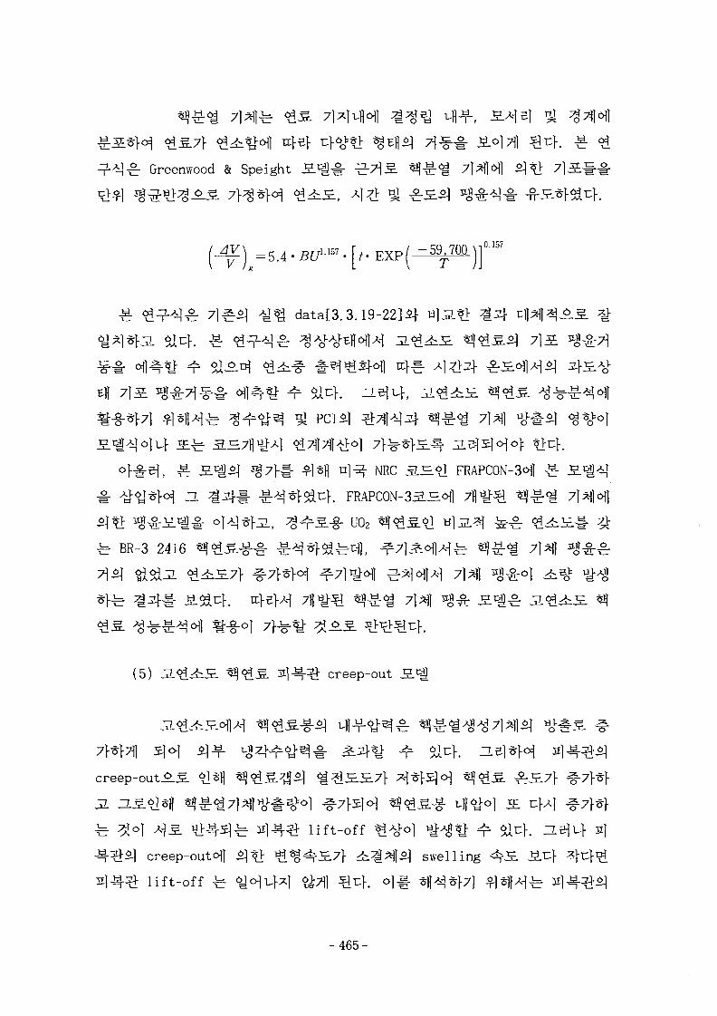
} £ Greenwood & Speight 7l*M
data[3.3.19-22]5t
PCI51
NRC 3.B.91 FRAPC0N-3<Hl
. FRAPC0N-351JElo|l
U02
BR-3 2416
(5) creep-out
JL
lift-off 21
creep-outofl
lift-off ^
swelling
&7]1
- 4 6 5 -
creep-out!;,§-
3 ^ 7 ] ^ ] cU?> ^ ^ - ^ Halden Reactor Project^
creep-out >J- - I tfltl A J ^ # r*l^f^K [3.3.29-33]
Zircaloy-2 ^ Zircaloy-4 2]4^j]- ^ 4 ^ | 4 *>^ Zircaloy-4
l ai^K [3.3.34]
creep-out JE.^ 7fl^# ^ f l ^ ^ ^
CARO-D 5.5 3.Hif FRAPCON-3 3 . ^ #
creep-out ^}^B] ^ % ^ # ^ 7 ^ ] . ^ ^ ^ ) Halden
creep-out S«g# 7fl<t*f&c}-.
(7}) 7}^ n<&&J§- n*\3.B.*) 3X]4^ creep
© CAR0-D5.5 1 £ creep S . ^
L, 4 3.si^- 143.5] 4 243-3]^
^ 4#4 3.3.14 ^1
£ c r ^ £ l,ft+ £ 2,&+ £ l,!rr+ £ 2,irr (3.3.13)
O
- 466-
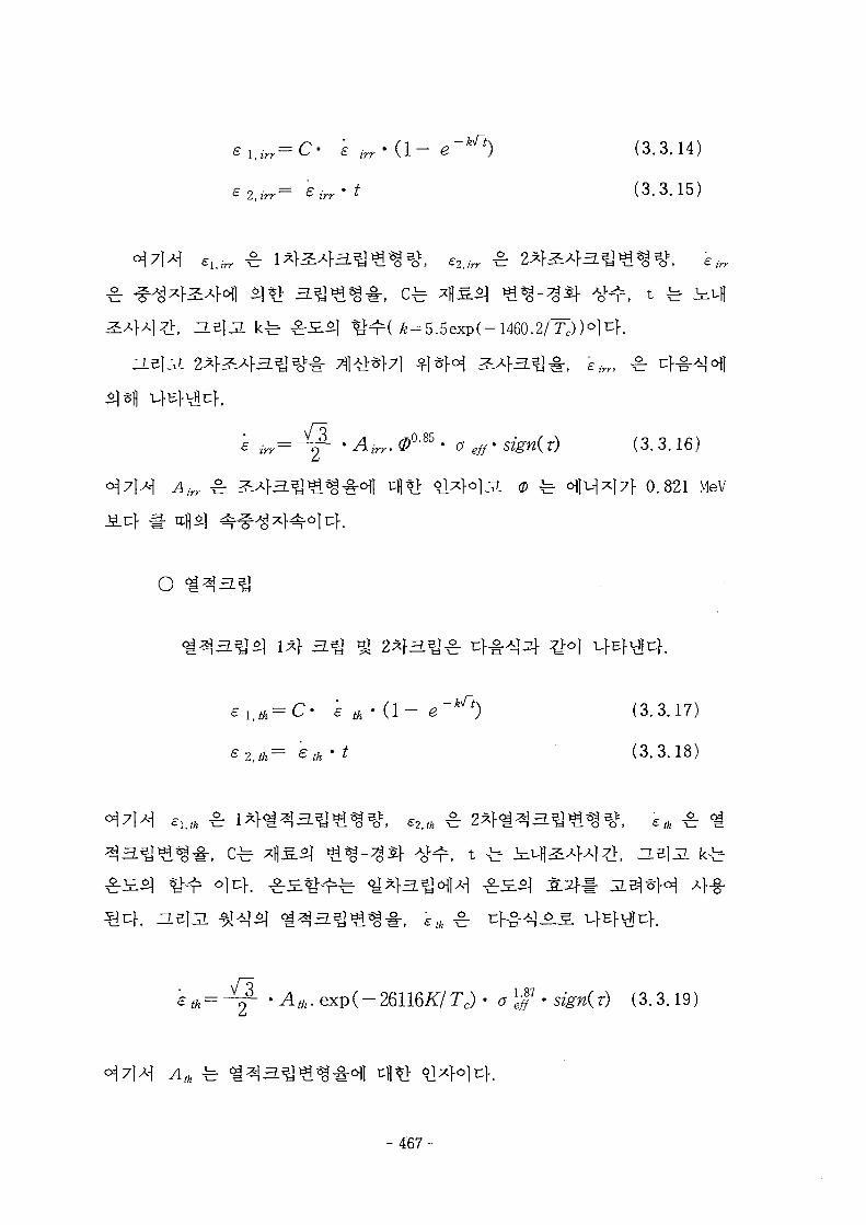
2,irr:= £ irr
, e2,ir
cr
Airr ^
O
th( 1 -
= e t h > t
eth
(3.3.14)
(3.3.15)
, eir
(3. 3.16)
0.821 MeV
(3.3.17)
(3.3.18)
4-§-
-26116/f /T c ) . 0)$-signer) (3.3.19)
- 467 -
£cr=D°C0 • ( e , , / r r + e2,I>y + £Uth+e2.th) (3. 3. 20)
D°ca ±.
ESCORE S ^ creep
ESCORE 3J^&1M ^]
PWR
ESCORE 3 . ^ . ^ 1 ^ A>^-Si creep S ^ ^
£ Toto/ = £ Thermal + £ Irradiati (3.3.21)
B A i A % { - A 1 I T ) (3. 3. 22)
4 J cos m a x ^ ] B ' (3. 3. 23)
(m/m)
(hrs)
. (E > 1 MeV, n/cm2-sec)
(7 hoop = hoop s t ress (MPa)
T = 2 1 4 ^ ^ ^ ^ r £ ( °K)
% V 4 ^ S (MPa) o]t\.
AJ-7] A) (3.3.21)^: Gorscakif- Pfenning worth [3.3.7]*fl ^sfl 7 } ^
- 468-
(3 .3 .23)^ Franklin[3.3.8]c5fl 5]*fl
T (3.321 - 23)
^.Bjl-K ESCORE SH^lA-i o)
FEMAXI-IV 3.S. Creep S.1!
FEMAXI-IV SHoflA^ Af-g-^ Zircaloy-4^1
= -1.07+ (-0.00343 +7.27xl0"5T)c7e?+1.05xl0"3T
^ (kgf/mm2) T fe ^
O
(3.3.24)
O <i
(3.3.25)
- 4 6 9 -
xiO-250L23aif (3.3.26)
(n/cmJs)o|cf.
FATES-3A 3.E, Creep
FATES 3 . ^ ^
71
(3.3.27)
(3.3.28)
, ] (3.3.29)
th= [B][ sinh(0.078<rfl)][ exp{ (277^-76000)/i?T,}] (3. 3. 30)
JL ^A$] A.B.C.K.R & £
7J t i . ^ 1 4 t i
tota/= I 'etotaidt (3.3.31)
- 4 7 0 -
Rc~R2^stotal (3.3.32)
/=0A i? c, (3.3.33)
rad ius )^
(T-1-)
down
if FRAPCON-3 a.S.o]cK FRAPCON-3 3 H f e
71 §• FRAPCON-2
creep-out ofl^-
£ ^ ^ ^ ^ - ^ ^ creep-
creep-out# <H
^ CARO-D 5.5
.HS, 37lf
Creep-out#
m±S>] 3.s]
^[3.3.3, 3.3.5]^)
^ 3.3.12} 3.3.2^ 7]
CAR0-D5. 5 3 . ^
Hal den Reactor Project
r ^ ^ ^ ^ ( ^ 3.3.1)1-
J£# 4-g-tl 4^^^SA-] 71 -5] 3.5]
creep-out^# Tij ^ f e # <y-
FRAPCON-3 SHJtr:]- -y^^ofl .cf ^
creep-outoj
creepdown gjc\ 20-30%
O.^ 3.3.2^
^-f 2^f 3.1] oj
FRAPCON-3
hoop stress7} 30MPa hoop stress7f
. CARO-D 5.5 3
CARO-D 5.5 3.^$]
L SI©.!-}, FRAPCON-3
- 471-
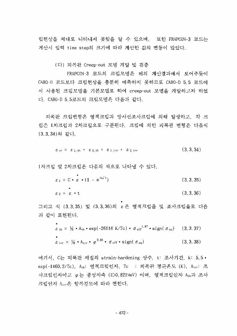
W <£ T $ L M . IE$> FRAPCON-3 3.JE.^
time s tep^ 3.7]6\] afs
Creep-out S . ^ 7 ^
FRAPCON-3 3 . - ^ ^ 3 . ^ ^ ^
CARO-D S ^ ^ C f 3.5] ^ ^ - # - § ^ 1 ^1^-^M ^-^rfS-S. CARO-D 5.5
4 4-§-^l H . ^ S . 1 ! ^ 7 1 ^ 5 . * ! ^ * } ^ creep-out S . ^ ^ - flyf
rK CARO-D 5. 5 S ^ ^ ] i f f ^ f
(3. 3.34
£ c r = £ l . t h + £ 2 , t h + £ l , i r r + £ 2 , i r r ( 3 . 3 . 3 4 )
= C • e • (1 - e~kA) (3.3.35)
£2 = e • t (3.3.36)
*] (3.3.35) ^ (3.3.36)5] £ ^ <
£ t h = K2 • A t h - e x p ( - 2 6 1 1 6 K/Tc) • ( 7 e f f 1 - 8 7 - s i g n ( ^ e q ) ( 3 . 3 . 3 7 )
£ i r r = % • A i r f • ^ ° ' 8 5 ' CTeff » s i g n ( CT eq) ( 3 . 3 . 3 8 )
strain-harden ing ^^r, t: A f 7 ] ^ , k: 5.5-
exp(-1460.2/Tc), Ath: <£$3.^91*}, Tc : s j ^ ^ § ^ ^ S (K), Airr: ^
(E>0.821MeV)
- 472-

ZL1I 3.3.26 ^ 3.3.27S-*f^ 1 4
irji, 24 3 ^ ^ M 4 - b ^
JE*> 24 31} ^ I H H ofHMlSl 7l#7]7f ^ § 4 ^ 3 ^ 7]-i-7]iul-
ttfl^ofl CARO 3H5 | H . H ] 5 . ^ 1 4 14 3.S]
strain-hardening ^ r C ^ j ; ^ 7fl"&l-JL secondary creep
1.7-1.75 x 10"20
K 24
14
3.3.951 4
hoop stress7f 7}% *}o]7\ ^>^-
^-47]- hoop stress7> D] ^ ^ ^ ^ - 1 1 ^1^4 -&*;} ^ A £ I 4 (3.3.37)
5 | (3.3.38)^1 stress ^ ^ 4 ^ ^ ^Tfl, # ^ 4 4 ^ ^ 4 ^ f e 37l] « H
^-^ 3.3.28 ^ 3.3.29ofl>HAf ^o] A^^
K °M stress ^ 4 ^ r ^ 1.87^^ 1.57
S i^g^fSi^., S.Q 143.U^^rfe 2800
h"1, 2 4 3 . ^ ^ ^ ^ 1.7xlO"20 (n/cnf-s)'0-85. (N/mrf)"1 • h"1 o]#u|.. a}ef4 ^
creep-out S . ^ ^ 1 ^ u}^- ^ 3.3.6 ^ 3.3.7S
e t h = ^ - A t h - e x p i - 2 6 1 1 6 K/Tc) • Jeff1 '57 » s i g n ( creq) ( 3 . 3 . 3 9 )
£ i r r = ^ 'A i r r • <P°M ' CTeff S lgn( ff e q ) ( 3 . 3 . 4 0 )
CARO creep 3.^2} 7^^. creep-out S
creep-out S ^ ^ ] # Frapcon-3 3.^<^) ^-g-^rf^uf. ~L^ 3.3.30^
Frapcon-3^] creep 3.^ tfl-il^l CARO-D a.H5] creep
- 473-
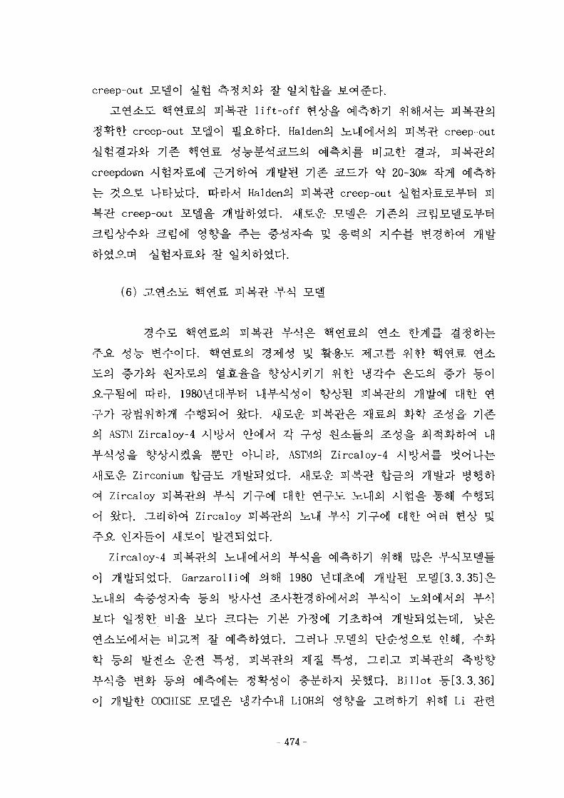
creep-out S.^o]
JL<g4i£. «?<££-^ I ] ^ - ^ lift-off
creep-out J5.*go] ^ ^ . ^ u ] - . HaldenS] creep-out
creepdown
creep-out
Haldeni)
3.^7} <$ 20-30%
creep-out ^ ^ s]
(6)
ASTM Zircaloy-4
/flS.^: Zirconium
^ Zircaloy
o| ^Df. -Le|*H Zircaloy
!4#<>1 43.°}Zircaloy-4
SJ .^
4Zircaloy-4
<*| 5] 51
1980 . 3 . 3 5 ] ^
COCHISE S ^ ^ r Li OH*] ^ ^ ^
. Billot #[3.3.36]
^l*fl Li
- 4 7 4 -
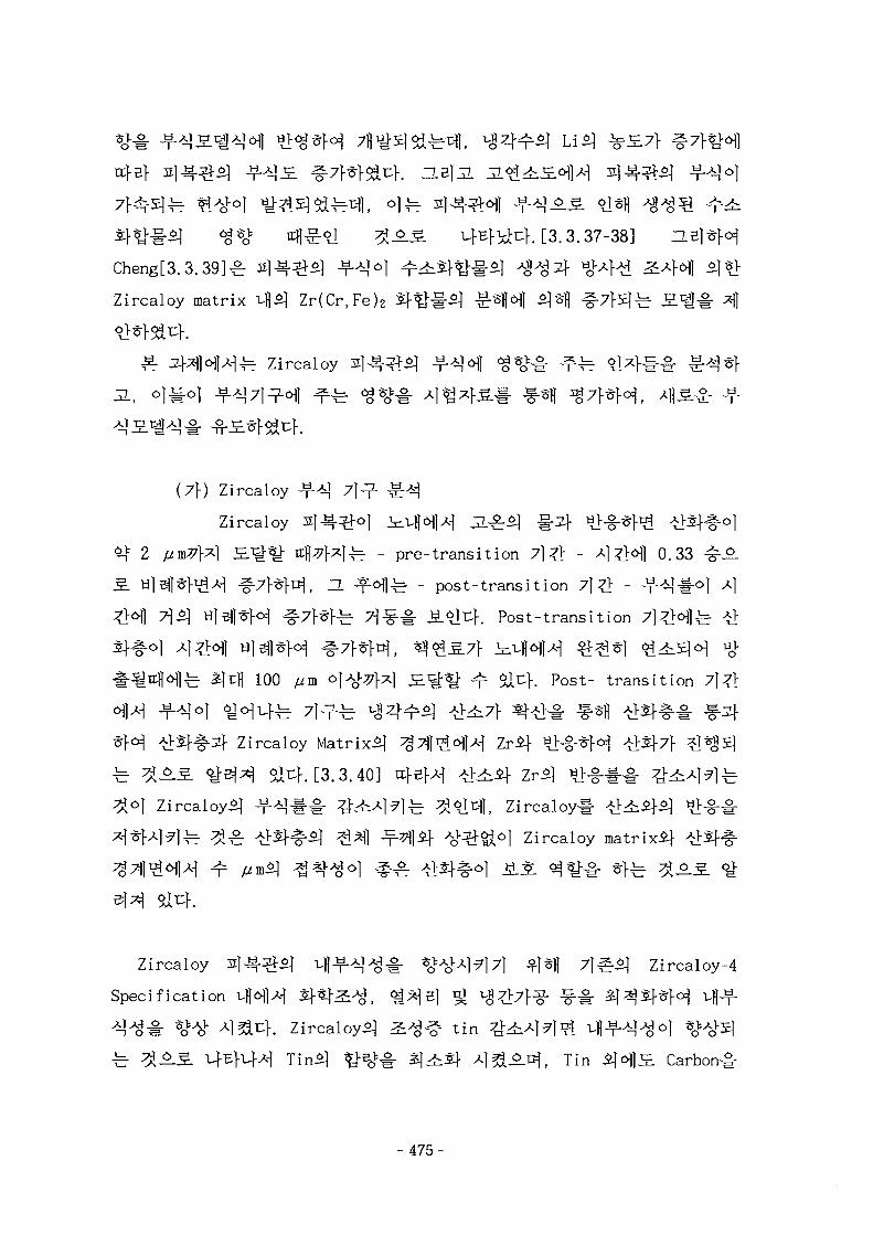
nfef
- <g*o* 4^-6] ^ A S ufEfi^uf. [3.3.37-38] n
Cheng[3.3.39]^ s l ^ - ^ ^ -?-*|o
Zircaloy matrix ^$] Zr(Cr,Fe)2
^ Zircaloy
(7\) Zircaloy
Zircaloy
2 [im77\*} SJ&%[ n | 7 f x | ^ - pre-transition 7}Z± - ^ 1 ^ 1 0.33
fi A-| ^7}^fr^, ZL ^ ^ f e - post-transition 7]Zt -
7]s] H|sjl*fo^ ^ 7 } ^ ] . ^ 7\3§~Br M.<(tr.}. Post-transition
100 yum ^ l ^ W S.^-^- ^r ^l^f. Post- transition
Zircaloy Matrix^
. [3.3.40]
Zircaloy
l Zircaloy matrix^}
Zircaloy 2 1 ^ - ^ ; ^ ufl^-AlAj^. * O ^ A | ^ 7 ] ^ * 1 | 71^5] Zircaloy-4
Specification uflolH Sf«]-^^, ^ ^ B ] ^
f. Zircaloyi) ^ ^ # tin
5)4ii|- Ajea^-^, Tin SHS. Carbon#
-475-
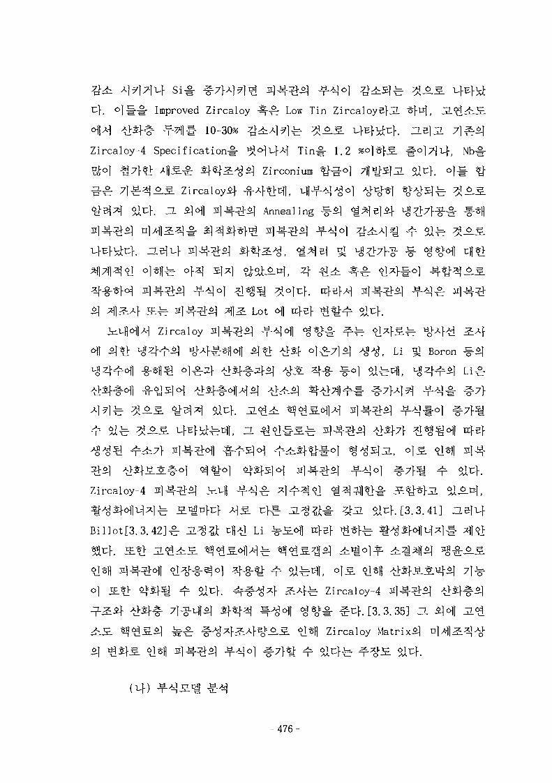
^h °l iMr Improved Zircaloy 4 £ - Low Tin Zircaloyefji
<H14 tf£J-# - M # 10-30% #^4?lfe ^^.S.Zircaloy-4 Specification^- 3Hi-H Tin^- 1.2
*}7f*> 4-§-£ W ^ S ] Zirconium ^g-oj
^ S . Zircaloyij- -g-A}^^],
] Annealing
Lot ofl rcfef ^ ^
Zircaloy s ] ^ - ^ ^ JJLA^J i g * ^ ^
^ ] ^ ) l f Li nj Boron
4?lfe ^ ^ ^
o) <^^o| <$$\}c\6\ 3114^-^ -f^o] ^7}
Zircaloy-4 2 ] 4 ^ ^ ±-q ^-A!^. 4 ^ ^ O ] ^ ^ - I | * > ^ - S^*}jL ^1-
^^Sf^u^lfe S^nfcf 4 S u}^- JL^g^-i- ^ i Slcf. [3.3.41] HBillot[3.3.42]£- JL^^ cfl-tl Li
Zircaloy-4
$uf.[3.3.35] 3.
Zircaloy Matrix^
(uf)
- 4 7 6 -
© KWU S-^i
ds/dt = A/s2 • exp(-Qi/RT)
ds/dt = B • exp(-Q2/RT)
B = C • F
Original EPRI S.1^
EPRI, CE ^ KWUofl^^- o | 4 i £ 50MWD/kgU°]^H Zircaloy^l
Li
EPRI S . ^ ^
ds/dt = A/s2 • exp(-Qi/RT)
- 477-
s t = D • exp(-Q3/RT - E • T)
ds/dt = B • exp(-Q2/RT)
B = C + U • (M • <p)?
Hillner
EPR1
t^r 6.4e9 18.9e9
B ^ ^
B = C + 5 -U • (M • <p)
© Original ESCORE
Original ESCORE
L" ?A^- 2.38e8//m/day o
, 5/an
£ original EPRI
1.91e-15
ESCORE S^l
ESCORE S'i^; original
35
- 478-
(6) CORPRO
CORPRO
£ original EPRI J5.«H]A] 4-§"3 S c | ^ 4 ^ 4 4 . EPRI
ESCORE
CORPRO £ 1 ^ .
ta = ka • exp(Qa/RT)
Al
ds/dt = C • E • exp(-Q2/RT)
E = 1 + u • <p • <s-sc>
<s-sc> -fe- Macauley
© COCHISE 3.^_
COCHISE 3.r^o_
7l>H-b 1991 Hi «J 1 9 9 4 ^ 1 U ^ 37fl^] SDi(C0CHISE-91B, C0CHISE-94P,
C0CHISE-94BH dJ*H
ds/dt = Kpre/s2 • exp(-Qpre/RT)
d s / d t = Kpost • exp(-Qpost/RT)
- 479-
|^ frequency factor - % A^ 3>HM *] # oxide/water ^
litium - -££} ^^rS ufE}u|^u}. COCHISE S . 1 ^ nucleate boiling^
^ L Frequency factorb
mul tiplcation factor7} ^ H ^ & ^ K H.Z\3L COCHISE-94B
frequency factors -b s ] ^ - ^ S ^ ^ -- 1 H^0]^}. Frequency factor
o C0CHISE-94P
K p r e = e a t b > [ L i ] . F B
o C0CHISE-94B
p r e = e • {l + (Q*pre/RT2) . (S0/X)} • FB
[ ! • ( S 0 / X ) } - F B - F i
Qpre/R = c + d • [ L i ]
R = 7 + 8 - [ L i ]
ln (Q p r e ) = f + g - l n [ L i ]
ln(Qpost) = £ + rj • l n [ L i ]
l e l l ^ o | ^ ^ - COCHISE-94P S . ' i ^ EPRI, ESCORE models}
C0CHISE-91B, -94B J S . 1 ^ t t = kt • exp(Qt/RT-at • T) o)uf.
NDC
- 480-
NDC £ 1 ^ t;}^ S ^ }
^ l ^ ° 1 35 mg/dm2 (2.4/um oxide)
dw/dt = C • F* • FH • exp(-Q2/RT)
^ pcikup ? >
FH = 1.0 CH < 200ppm
a + b • logCH CH > 200ppm
© ENIGMA
4 f ^ . al^-^. KWU 5ENIGMA S . ' g o f l ^ ^ 2,2/tan
Li
d s / d t = C • $>D + E • FHYD • FLITH • FRXA • exp(-QpoSt/RT)
FHYD = MAX{1.0, a + jS
FLITH = MAX(1.0, M I N { r ( C ! • [ L i ] j • t i ) , FL i , MAX})
FRXA = 1.0 - 0 . 3 4 1 «RXF
RXF : r e c r y s t a l l l z a t i o n f a c t o r
(nf) Zircaloy Jf
Zircaloy
- 481-
(3 .3 .41 )
ds = C2'FMat-FFlux- F H> e x p ( - Q'(CLi)/RT) ( 3 .3 .42 )dt
Pre-transit ion 7l # £ | -?-*]£ ^>S}#^t n^l7f 4* 2
£#^° f l ^r-b ^%H ^71 ttfl^ofl 7)^3] Garzarolli JS.«g-§-
. Post-transition l #
^-71 (3-3-2)if ^o
^ FFlux 614S ufEfvfl^cf. 3114^^ Hydride*} <g%K& FH
flgi^Dl}, EPRI*] PFCC S^iil- ^-o] 31^-^*1 ^ ^ 7 } 400 ppm
FH7]- oj-eU f ^o] ^7}e fe ^ 0.3
F H=\ for CH^mppm (3.3.43)
^ ^ 6 . 5 . Lio] 3x1^-^^ A>^#6fl -ff-*]
7} ^7f^6fl rcfef %
O*(CLl-)=28200-^- (CLl-0.5) (3.3.44)
Li5] ^ ^ ( p p m ) ^ ! ^ , A ^ 43.4 (cal/mol-ppm)
^ 1.2(W/m-K)
- 482-
(3.3.45)
Garzarolli7|- 4 ^ * ] ; 0. 24#,
1.4xlO"3 ((neutrons/cirf-s)"024!-
23 °C7f
3.3.32 51 3.3.33 ^ ^ 4
"A ^ ^ ^ S l - t ^ f \3^ f . Li*] ^ £ 7 } 0.5 ppmcHW 3.5 ppm^.
} l ^ | f } ^ ^ ^ 4 1 4 . ^-^ 3.3.343.3.35 ±r 2 1 ^ - ^ ^ ^ ^ i f ^ J - ^ . ^ ^%>o| 6T^- 4 ^ ^
400 p p l j f l ^
3.3 .36^
3.3.37^; EPRlcHlA-l t«64^ s j ^ ^ - f - ^ S ^ ^ l PFCC
3.3.38^ Ringhals-3
Zircaloy-4 ^ - ^ S . ^ ^ 1 ^ -?-^M < %> - ^ ^
Zircaloy
. Zircaloy
483-
Li
(7) o | ^ ^ ^ ] ^ 7}<£
Rod)*]
(Duplex Integral Burnable Absorber
(7\)
Gd2o3-b
^ <#*-:£..£.
-7f
-g-O) Ttfl
1.15 ttfi ZLU 3.3.39<HH
- 4 8 4 -
ZL
*}5L S^oflfe Er2O3 5]
Gd2037} S ^ qjjL «^,g.-g-Sj Jj^j-g. ^ S } ^ 1 ^ A ^ ^ Jit:}
7} al }. n i s ,
^gol 0.2825 cm ^ ^
0.4025 cm^ ^^^F^uf . vH^-7}<^^ ^ - ^ ^ - ^ ^ ^ ^ - f e f e ^ l 12 w/o<q
*l (4.95 w/o) ^<££.oi] 2 w/o^] Er203l-
^ - g - ^ ^ ^ 247HS -^-4*1 ^ ^ ^ 1 < a ^ ^ o j Gd203
167B
2 ^ 1 5 J 3.3.4131}
§ ^ ^ ^ 8 w/o Gd2O3
^-g- i67fl# 4-§-»> ^ ^ s ^ ^ i i f Hl.2.*H a 3.3.
MWD/MTU)
3.3.10.
- 485-
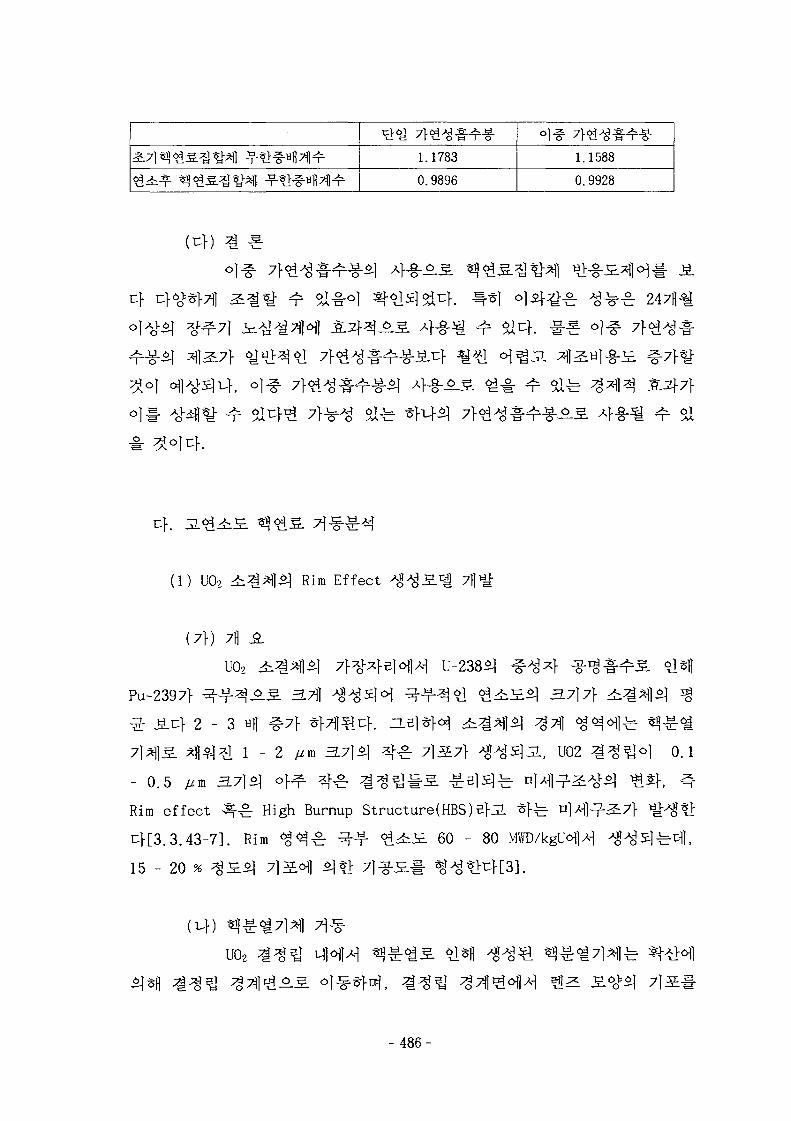
1.1783
0.9896
1.1588
0. 9928
Cf
H &
(1) U02 Rim Effect
(7\) 7H ^L
UO2 ^
Pu-2397f ^ - - f - ^ A ^ 3.7]}
~ o on ~o
^ ^ ^ 1 - 2 /zm 3.71*1 ^ " ^ 71S7V
- 0 . 5 ywin 3.7}5^ <
Rim effect ^^ High Burnup Structure(HBS)BfJL *}^ n]M]^-^7}
uf[3.3.43-7]. Rim ^^ -c r - -f- ^^-S- 60 - 80 MWD/kglWH
1*11
., U02 0.1
feel],
3 3.<$<i\ 7]
- 486-
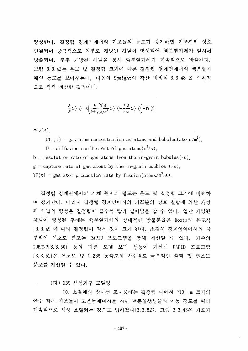
3.3.42^ ^S. ^ ^ ^ ^ 3.7]6|| nf^- ^ ^ e j
c|, uf#5] Speight^ ^ ^ H>>;8*U3.3.48]-
C(r,t) = gas atom concentration as atoms and bubbles(atoms/m ),
D = diffusion coefficient of gas atoms(m2/s),
b = resolution rate of gas atoms from the in-grain bubbles(/s),
g = capture rate of gas atoms by the in-grain bubbles (/s),
YF(t) = gas atom production rate by fission(atoms/m3. s).
7l*lJ
. Booths
f^ ^ ^ ^ RAPID s
TUBRNP[3.3.50] ^ ^ cfg- S.^ ^.u} A 4 ^ O | 7 ^ ^ RAPID ^SJ.
[3 .3 .51]^ <^4i£ 5| U-235
^ r S l - 71 >^ ^ 51^}.
(cf) HBS
U02 ^ * ) 1 ^ yoUW ^ ^ f ^ ^ f e ^ ^ 5 J ^-Hl^ ~10"9 m
^ %*-$- ^ ^ ^ [ [ 3 . 3 . 5 2 ] . ZL% 3 .3 .43^
-487-
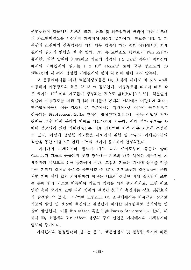
3.7],
. PWR §
i]-¥" 6J"^°1 9 MPao]jL 7}SL^\ 3 | ^ O ] 1.2
7]^] 4 * 1 i lS^r 1 x 1027 atoms/m3 £.#\ --f- ^ ^ i 7 f 70
rcfl 7M ^g^^[ 7 ) 4 ^ 4 ^ %^ 4j= 2 «H Ml l S]^l ^Mr^.
-2. ^ - ^ ^ M ^ ! # ^]Vl ^ f ^ « i ^ ^ # ^ : U02 4i^^f VH}A-| ^ 6.5 //m#
15 nm
10"9
^ Displacement Spike ^>tfo | y i ^*> t :} [3 .3 .53 ] .
Vacancy7} 7}^S. ^g-£]*l ^ ^ ^ ^ - ^ f e 7 l S ^ i-fl-f < ^ ^ ^ ^ 1 4 ^ 6J 7)
uflofl
U02
. o ] ^ - Rim effect ^ ^ High Burnup S t r u c t u r e s ] ^ *>i:f. rcf
U02 ^ ^ ^ 1 ^ ] Rim effect
- 4 8 8 -
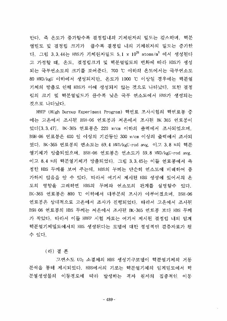
cf. H^ 3 .3 .44^ HBS7f 7 l ^ ] ^ 4 ^ £ 5.1 x 1026 atoms/m3
JL 7pg«* 4 , ^rS., ^ ^ ^ 3 . 7 1 £ ? « ^ ; < i ^ £ ^ ^Sf^fl ttfej- HBS7>
5 | ^ ^ - ^ - ^ ^ £ ^ 1 3 .7 ]# i<H^^K 700 °C <>}}
80 MWD/kgU o l * H ^ ^^5]xln>F ^ £ 7 } 1000 °C
^ - # S i*H HBS7} o}^] ^ 5 ] * ] ^ ^ ^
3.71 ^ ^ ^ - « i ^ S 7 ] - #^H=- ^ ^ r ^--f ^^£<HlA-1 HBS7f
HBEP (High Burnup Experiment Program)
°fl-b ^ - ^ r ^ ] ^ ^ 4 ^ 1 BSH-06 ^IS-f-Jl- ^1^:^14 &*}& BK-365
a I 4 [ 3 . 3 . 4 7 ] . BK-365 ^ ^ - ^ - ^ r 220 w/cm o]*}*]
BSH-06 <dS-g-^r 400 <y <5]AO^ 7l^>^-^> 300 w/cm ^ ^ 1
[. BK-365 ^ S - g - ^ < ? 1 ^ £ ^ 69.4 MWD/kgU-rod avg. O ] J I 3.8 % J « ^
5 ] ^ ^ ^ , BSH-06 ^^.-g-^r < ^ ^ £ 7 f 59.8 MWD/kgU-rod avg.
8.4 96$) tfl
HBS -*M|# ^ ^fe^L ^ f ^ 1 ^ ^
^ 14 >44 H l 4 4 4 1 HBS
BK-365 ^ S - g - ^ 800 °C ° 1 ^ ] 4 ^ - f -g :^ 3S}7\ o ] ^ - o ] ^ A ^ , BSH-06
BSH-06 ^ S - g - ^ HBS - ^ f e 4^°114 2:4^1 BK-365 ^S-g- Jicf HBS
7} 4 ^ } . a}5^i o i l - HBEP
HBS
U02 ^ ^ ^ 1 1 ^ 1 HBS
fe 34 €45]
- 4 8 9 -
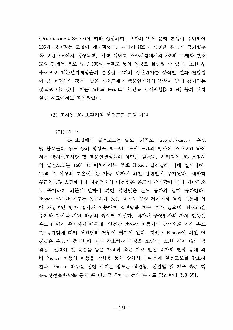
(Displacement SpikeH rc}5> ^ I ^ S M , ^*}£) n]Afl
HBS7}
-f-# ^ £%i& 3.7]*)
-fe Halden Reactor ^^.S. 2,*}X\^[3.3. 54] -§-
(2) 2A}sl U02
(7f) 7H ja.
U02 ^^^1^1 < i ^ £ H ^ ^ S . , 7l^g-S., Stoichiotnetry,
l uo2
^ < i ^ i £ £ ^ 1500 °C <>]*H-Hfe ^ ^ Phonon
1500 °C ° j ^
l U02
Phonon
ttj-e} ^ 7 ^ f 7 l ttfi^^l, < ^ ^ ^ Phonon
7f # 7 } ^ ^ 1 K}ef ^ ^ ^ ^
^ i ^ ^ £ £ 7 f ^ 7 f ^ ^ l trfef
Sfl Phonon 4-e-i] ol^ .^ . ^ f ^ # -*11 ^fl*}7l ttfl^l < i ? i£
K Phonon 2Xf - A>^> A ] ^ ) ^ £ ^ ^ ^ ^ , ^.4^ VA 7]
-490-
U02
71S ^^1 ^*H ^ ^ 4 . U02
Rim
U02
- Loeb J S . ^ ^ : fp = 1- a p
- Maxwell 3L%*\ • fP = (1-p) 1 '5
- Maxwell-Eucken i ^ ^ 1 : fp = ( l - p ) / ( l+
- Schulz i ^ ^ ] : fp = (1-1. 5p)
- Bakker JL%*\ : fp - (l-p)1 '7*0"7
Loeb % Maxwell-Eucken .S.^ ofl*) a^ 0 ^i^fe S.^ 7] g-o| ^-«go]
^ ^ : S £ l & # ^-f^ffe ° ] ^ A ^ z | 4 1 ^ 0.5 ojuK J 5 |
U02 d t ^ ^ l ^ -y^| ^ ^ s | <^^£H ^1-S# Fitting*! ^2} , or
^- 2.5 ± 1.5
Schulz ^ ^ ^
. Bakker 2i3l*l£ 25 MWD/kgU <^^S7M ^ 4 ^ 1 U02
- 4 9 1 -
£ uo2
: Sr, Zr, Nb, Y, La, Ce, Pr, Nd, Pm, Sm
.- : Mo, Tc, Ru, Rh, Pd, Ag, Cd, In, Sb, Te
!§-•• Ba, Zr, Nb, Mo, (Rb, Cs, Te)
# ^ ^44i : Kr, Xe, Br, I, (Rb, Cs, Te)
SIMFUEL . 3. 59]
U02 3.71 4
6 d U02
^ BCC
Gd 2 O 3 l -
U0 2 /Gd 20 3
FCC ^-2LS>\ U02
£J£l- * J * M W
r°fl Phonon-Phonon
Stoichiometry
- 4 9 2 -
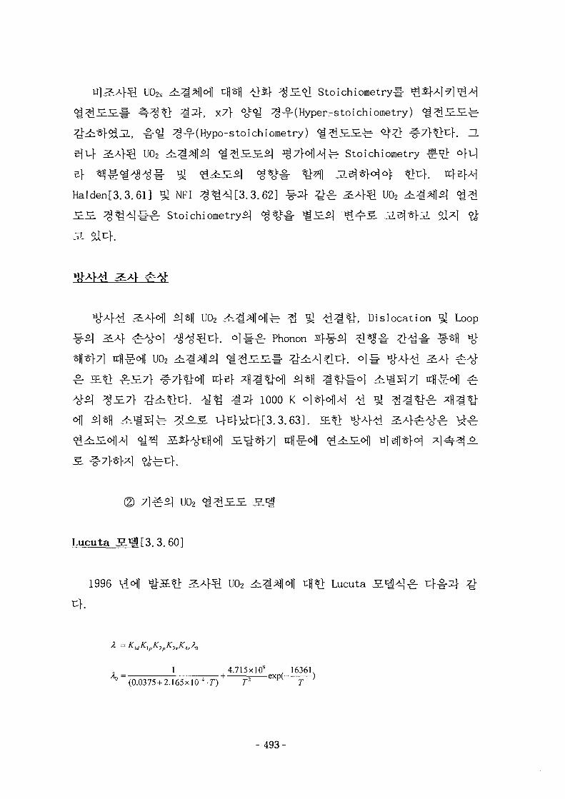
3JS.0] Stoichiometry#
^ - ^ t l ^2f, x7f ^ ^ ^(Hyper-stoichiometry)
-B-e ^-T-(Hypo-stoichiometry) < i ^ S £ f e <^# ^
U02 4i^*ll^ < i ^ £ S ^ I ^7HA"lfe Stoichiometry
Halden[3.3.61] ^ NFI ^ ^ ^ [ 3 . 3
^ Stoichiometryi)
U02 ^ ^ ^ H ] ^ ^ VA -Q^VL. Dislocation ^ Loop^ 4 _ o j^o . p h o n o n d| ^ » ^ fl
U02 ^%}$] «a^i£
^ ^ 4 1000 K
(2) 71-g- f U02 ^ ? i £ £ S c |
Lucuta S ^ [3. 3. 601
1996 \4ofl ^-S*> ^ 4 ? U02 4i^^l^l 4 t l Lucuta
= KldKtpK2pK3xKljrA0
1 4.715x10" , 16361,/L = — 1 exp( )
(0.0375 + 2.165 x l O ^ r ) T2 T
- 493-
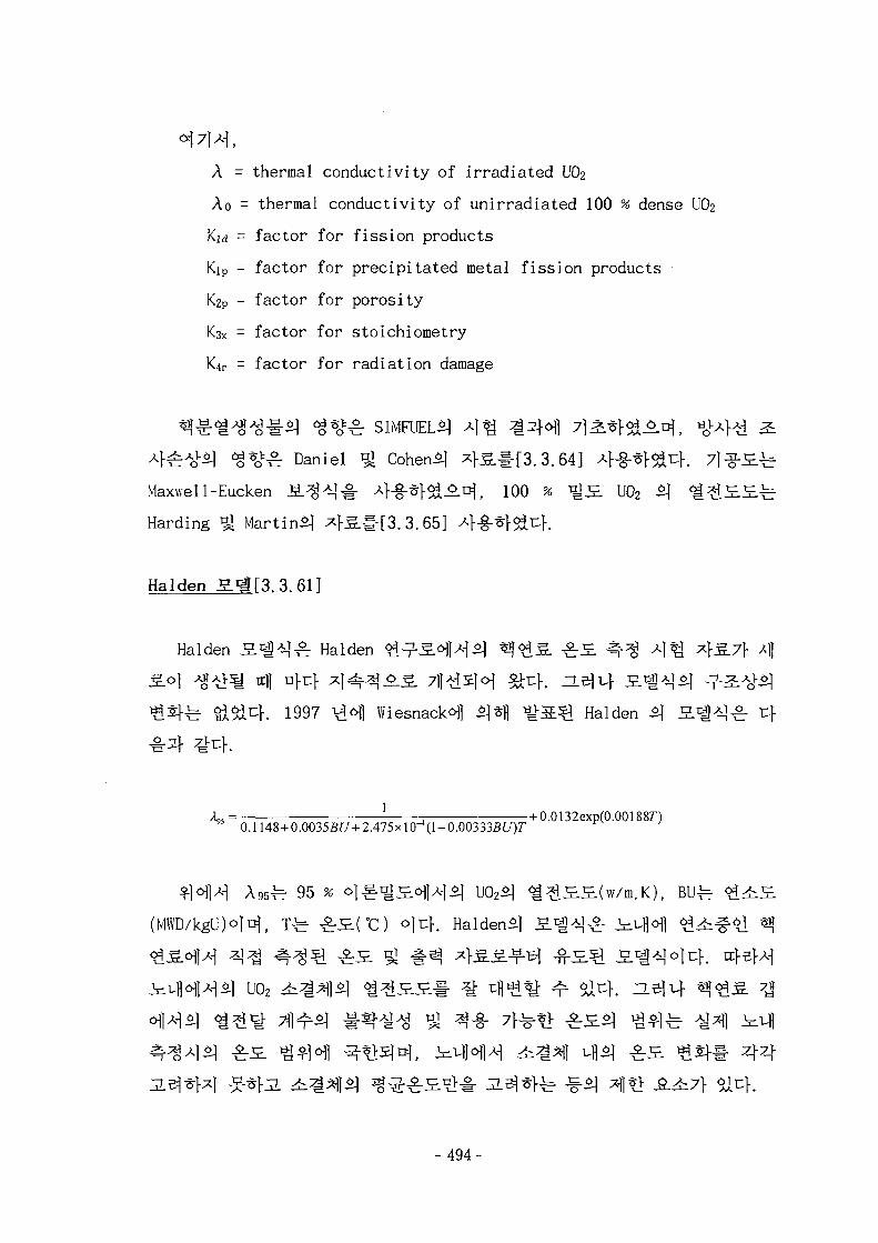
A = thermal conductivity of irradiated UO2
Ao = thermal conductivity of unirradiated 100 % dense UO2
Kid = factor for fission products
Kip = factor for precipitated metal fission products
K2P = factor for porosity
K3X = factor for stoichiometry
K4r = factor for radiation damage
<$*££: Daniel ^ Cohen*] *Kg.#[3.3.64] 4-§-*f5i^K 7l3-.5E.-b
Maxwell-Eucken i L ^ T § - 4-§-^f^-^-^, 100 % ^S. U02
Harding ^ Martin^ 4 S # [ 3 . 3 . 6 5 ]
Halden S.^[3.3.61]
Halden S l ^ ] f Halden ^ ^ - ^ - ^ ^ ^ ^}<£^. ^ H 4 ^ ^ 1 ^ *}£-7} 4
.}. 1997 VN VfiesnackoH ^«fl ^ a ^ Halden $] £ 1
.00355t/ + 2.475xlO"4(l-0.00333Sf/)7
5 ^ 95
+ 0.0132exp(0.001887*)
U02
- 494-
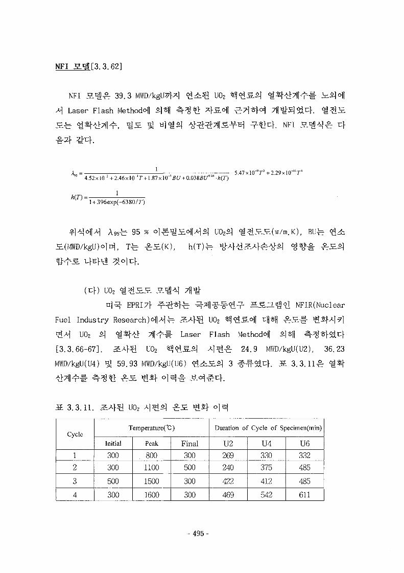
NFi_SM.[3. 3. 62]
NFI J S . ^ 39.3 MWD/kgU^j
4 Laser Flash Method^ «]Sj|
U02
NFI
l
4.52x 10"2 + 2.46x 10"*r +1.87 x 10'"BU + 0.03SBU02' • h{T)
1
~ l + 396exp(-6380/r)
-5.47xlO"9r+2.29xlO"'4r4
^ 95 %
(^}) uo2 < i ^ i £ £ s^ i^ j 7j|^-
n]^- EPRI71- ^ ^ f e ^ -^1^ -^^^ r S S - H H t l NFIR(Nuclear
Fuel Industry Research )^ \— 2i*\Q U02 ^ ^ ^ . ^ 1 tfl*l| £ £ # ^5f^ |^ l
^ ^ U02 ^ <m^l Tjj^l- Laser Flash Method^] *|sfl 4^^r}^cf
[3.3.66-67]. ^ 4 ^ 1 U02 ^ & g . £ | X\^^. 24.9 MWD/kgU(U2), 36.23
MWD/kgU(U4) Q 59.93 MWD/kgU(U6) ^ 4 i £ ^ l 3 fM
3.3.11.
Cycle
1
2
3
4
Temperature(°C)
Initial
300
300
500
300
Peak
800
1100
1500
1600
Final
300
500
300
300
Duration of Cycle of Specimen(min)
U2
269
240
422
469
U4
330
375
412
542
U6
332
485
485
611
- 4 9 5 -
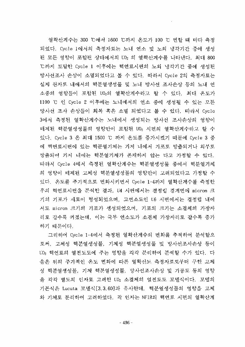
N r 300 TCofH 1600 100 °C
. Cycle
uo2 800
Cycle 1
Cycle 25]
1100 °C 6J Cycle 2
Cycle
uo2. Cycle 3 ^ 3)tfl i500 °C ~.7}X\%7] ttfl^^l Cycle 3
Cycle 4<H1-M
Cycle 1-
, U4 micron
U 6
micron 3.7}$] 7}^7
Cycle
uo2 AA
U02 ^
} ^ ^ Lucuta S ^ i [3.3.60]^ - -
if 7]^]S. ^ e ] * } ^ JL^-crfoJcf. 4 o]4fe NFIR^
<g*<>*•§•
- 4 9 6 -
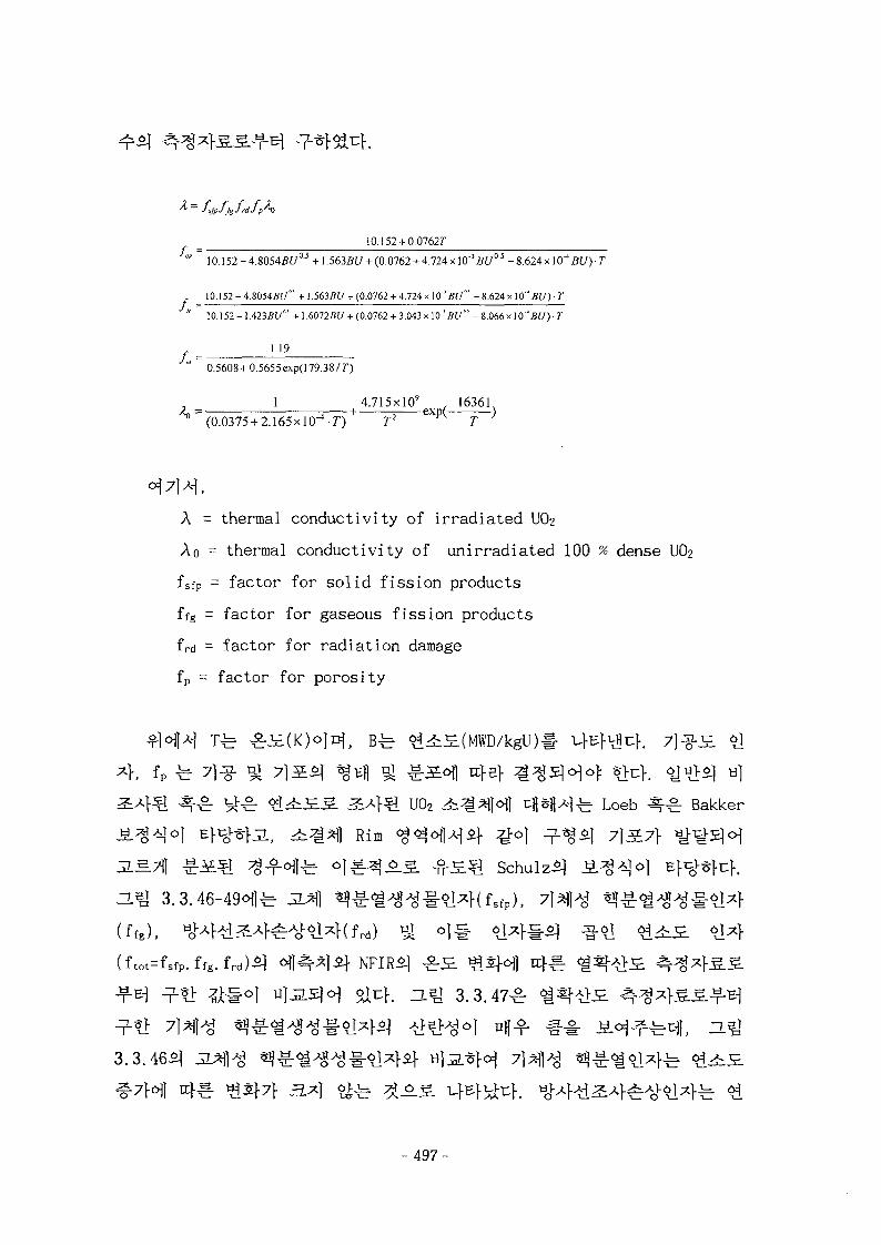
- - fifpffgfrdfp^O
10.152 + 0.07627"
/- =
10.152 - 4 .80545U 0 3 + 1.5635(7 + (0.0762 + 4.724 x 10~'BU°5 - 8 . 624 x 10"4 BU) • T
10.152 - 4.&054BU" + 1.563BU + (0.0762 + 4.724 x 10 ' BU" - 8.624 x 10" BU) • T
10.152-1.4235(7" + ].6012BU + (0.0762 + 3.043 x 10''BU" -8.066 x!0'i5f7)- T
U 9
0.5608 + 0.5655 exp(l 79.38/7")
1 4.715xlO9 , 16361,/L = ; + exp( )
A = thermal conductivity of irradiated UO2
Ao = thermal conductivity of unirradiated 100 % dense UO2
fSfp = factor for solid fission products
ffg = factor for gaseous fission products
frd = factor for radiation damage
fp = factor for porosity
U02 4 i ^ H i tflsfl^^ Loeb ^-^r Bakker
4i^^l Rim ^ ^ ^ - j i j . ^-o] ^2-^
ofl^. o l ^ . ^ ^ . S -o.s.5^ Schulz*]
H5J 3.3.46-49^1^ J2XI *}£<
^ - ^ 3.3.47^
- 4 9 7 -

. 1100 °C °l
. H^l 3.3.49^ °1#
} ^ i ^ , 1300 °C
1 ^ 3.3.50-53^:
NFI ^ ^ ! 7l^-^| uo2
£ NFI l
7]}
cf[3.3.55]. Lucuta
el], 500 800 °C
Lucuta, Halden
fetl NFI
r:f. Halden ^ 800 °C o]
^ Halden
, ^714 uo2
U02 Rim ^
Rim
^ 15 17
Rim
•1 , Trim f srimAr\m — Jsfp JrdJ p
Rim
80
ffj^ofl Schulz
71 -£.7} 15 %
Rim ^ 600
- 498-
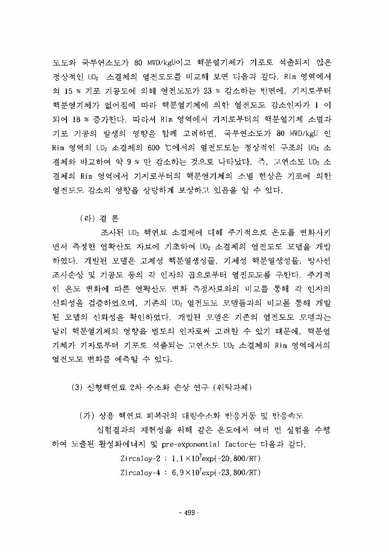
^ - ^ - ^ ^ . £ 7 1 - 80
U02 r t ^ l ^
15 % 7)S. 7}^rS.Cy\\ SjSfl < i ^ £ £ 7 f 23
18 K 7 K > 4 . tcl-sH Rim <§
7]S: 71^-5] ^ t t o ] <g*o*.g. ^ | 3.5(*1-^, ^-¥-<^^£7f 80 MWD/kgU
Rim ^ ^ * ] U02 * f l £ l 600 °C^1^^ < ^ ^ £ £ ^ ^ A o ^ ^ l n 2 - ^ U02
til3-^}^ ^ 9 % °> # ^ H r ^ ^ - ^ U^l-^V. ^-, i ^ H UO2
Rim <
U02
7]
4U02
71SS ^#^lfe JL^^S. U02 4i^^|5l Rim
2 ^
(7f)
*l ^ pre-exponential fac tor^
Zircaloy-2 : 1.1X 10⁷exp(-20,800/RT)
Zircaloy-4 : 6. 9 Xl07exp(-23, 800/RT)
-499-
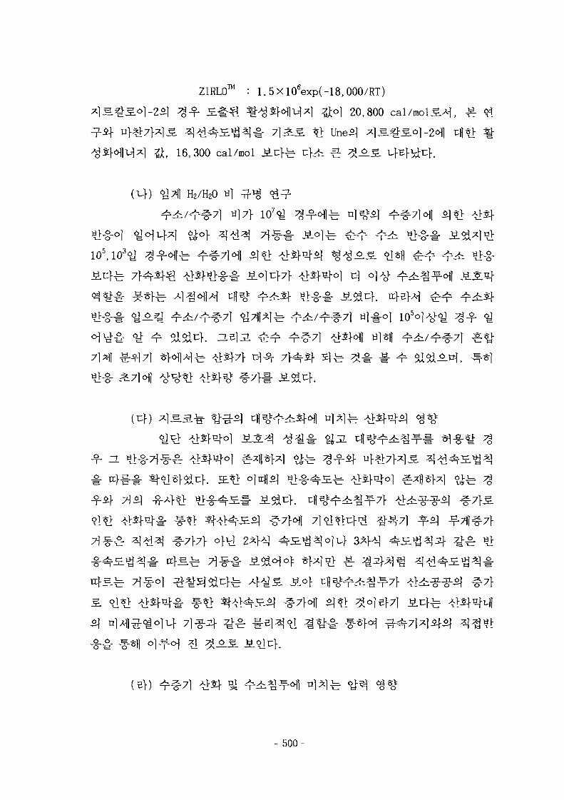
™ :ZIRLO™ : 1.5Xl06exp(-18,000/RT)
16,300 cal/mol J i i fe
20,800
:£©..§.
H2/H2O
io5,io3«y
+ ~
- 500-
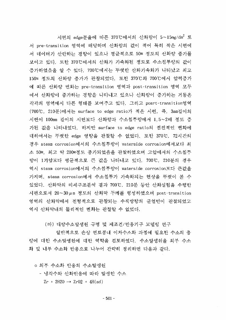
5~15mg/dm2
*\ pre-transit ion ^^ofl Sfl^j-*}^ ^ S j - ^ fto] 4°i J^] 4 ^
} A ^ 50% 4 ^
150% ^ ^ i f ^
l f ^ ^ffe- pre-transition ^ ^ ^ f post-transition
j i oTuf. a 5 ] 3 . pos r t - t r ans i t ion^^
(700°C, 210^r)<^]A-|^ surface to edge ratio7f
100mm ^o]^j Aj^iiul- *>SJ-i£:z]- ^ r ^ ^ ^ ^ l ^ 1.5~2Hfl
# T-MT-fltl^f. ^ H 1 ^ surface to edge rat io£| ^ ^ 1 4
Hfe ¥ ^ t > edge ^ % ^ ^ t ^ ^r tt^}. 3L*} 370°C,
steam corros ion^l^^ - ^ p ^ ^ ^ ^ ^ l waterside corrosion<>|]^-l^.c|-
50%, 3&\5L <$ 200%4^ ^7}5]Sd-g-^ ^^f^-^-^ JL^<
] 17l<y-iuf ^ ^ 4 - ^ - ^ e ^ # ^ K f l j l oiu}. 700°C,
steam corrosion^l^l^l ^ T ^ ^ - T " ^ 0 ] waterside corrosionJS.t]-
^, steam corrosionoJH ^r^^^f-7} 7
f 700°C,
20~30^m 4 £ ^ 1 ^5}V\ ¥ ^ 1 # %^*>SSl^.^ post-transit ion
(nf)
o i]
-
Zr + 2H20 -> ZrO2 + 4H(ad)
- 501-
l^ 2-5 ppm
2H2O -»• 2H + 20H -> H2 + H20
o M
( continuous-source S.1^., instantaneous-source S-
two stage
single stage with grain boundary saturation S-^-Sr ojJEL J_o_jg_
FEMAXI-IV ^i^S-H^l two-stage S ^ #
^ *}^cf. n ^af 56,500 MWd/MTU
^ two stagea^oj 0.235(equal radial ring volume*] ^-y-), 0.192(equal
radial ring size*] ^-f) ZL51JI -^^^.i^o] ^-§-5|o] *\J~ single
stage S ^ o j 0.167S ^7}t}<^u\. ^^^j;«y 0.218^1 H|*H two stage S«I
- 502-
°1 ^ 5 : 4 ^ 1 %7}*}&.3- single stage 3 . ^ u f i ^^7}^f^uf . 0}
T:]-H.7|1 J2.^*|-7] 4^<»]Df. Single stage 5.^1 £ Turnbull*]
. $13- two stage B.*i£: 2 ^ M ^ C-1]O|B]
, power ramping -§••§• J l ^ * ] ; NRC it^g <^^fl- ^ 40,000
MWd/MTU ^ 4 i £ °]Ao1-^^ 2 M 20,000Bl|7H ^ 7 } # JL^^fJl $17] nfl-g^
^ 7 } ov 50,000MWd/MTU ^ H 4 ^ fl f
two stage JS.»go| single stage S-^
(4)
finite element analysis module ) #
1 oil- 71^^]
commercial finite element analysis program
NISA 11/DISPLAY
7fl
0}
- 503-
-g- -8-*Lfi.4i*lH S . # # 7]^$] -#-§- -ff-*h£L^JH-g- ^SZLiS^l n]^- EMRC
^Q NISA II/DISPLAY III ^ n]-5*- MARC45J MARC/MENTAT
total Lagrange^ofl ^*>
SS-ZLsfl^l NISA H ^j MARCif
Cf.
L 4 4 ^ -^-tl-S.^ ^ - ^ S # ( finite element analysis
module )-§• 7H
4-S] -8-*>-S.4i ^ r ^ S # ( finite element analysis
module
finite element analysis module
*]£ ^ 1 ^ ^ creepfinite element analysis module )-§-
tl ^ } , ^r^r ^ ^ § ^ ^ 1 4 4 ^ ^ l ^ ^ ^ NISA II
^ ^ creep sfl -g- -^-*>^.4i ^ - ^ S # ( finite element analysis module )
- 504-
(1) 7l|
} [ ^ g - £ 950 MWe
17x17 KOFA (Korea Fuel Assembly) ^^^.-g-^1 ^ 7 f l | | 7 ) ^ ^ . 5
3658 mm^M 2000 mmS #<>] 31°]t}.
^ 4.95 w/o°M, ^ 35 7J)^ ^ 7 ] 5 . ii-gSj ^ ^ 5 . # ^
^ ^ # ^ ^ 120 w/cmS.*i, ^^i-g- PWRSJ ^ 5 ^ 1 - ^ , 178
31 % 4^F. U 54^ r^ ii^J ^ ^ # ^ ^ £ ^ 4 4 270 °C
310 0C^.<^ PWR£] 291.6 °C ^ 326.8 °C i n f ig-g- 19.2 °C 7}
PWR i c f 3.uf. ^ z | ^ ^ ^ J L ^ i ^ ]
-8-Sfl ^ ^ S l - b Borons
fe U02 ^^^15.^1 ^ ^ S ^ ] A - | <£^S. 60,000 MWd/MTU-rod avg.
(2) SMART
> *fe ^ s.o] al^}[3.3.70]. SMART
. ^ 950 MWe PWR ^ ^ ^ . ^ 17x17 KOFA «|^S[3.3.71]5]
# 71^-^.5. 4-§-t>4. ^ ^ S ^ ^ l S.& *A ^ 1 ^ # 3 . ^ 3.3.57-60^
3.3.19^1 7]<£Z}&T:1 U02 ^4H$\ Zircaloy-4U02 4:
- 505-
$%•& 9.5 mm°]3L 4 ^ * f l ^ i ^ ^ r 8.05
fe 0.64 mmo]u}. **} £.&-§- ujj «J£.g. ^ * f l £ l ^
•%-S. ^ ° ] ) f e 2,000 mm^.^ 17x17 KOFA ^<£^.-g-£l zjo] 3,658 mm^ 55 %
S M A R T - g - ^ ^ g l m l | ^ ^ } ^
] ^ ^ ^ ^ ^ ^ j * | | ^ o ] ^ - 2,189
2,000 mmo]uK SMART tfl«^^.^-^ ^ ^ S . # 5 wt.%
60,000 MWD/ MTUojd]-^ ^ ^ 5 . ^ ^ 5 1 7 ] 4 ^ : ^ ] , ^:g:(£ 7]^}$] «]•
oflA-l SMART «?<&g.-g-£| ^I4i « l ^ o ] PWR^ KOFA
7.0 x 10²¹ n/cm2(E > 0. 8
(uf)
330MWt^- < y ^ | ^ ^ 4 5 . ^ 1 SMART
^ 0 4 ^ . - ^ ^ ^ 5wt*o]vJJ t "-g-"^) ^ ^ f l £ 5 1 7 ^ ,
l%Ap, ^ H ^ ^ l Keff 0.95ol*>
CASM0-3/MASTER ^i^>3.S^Ml# o]-g-*f<^ SMART-L
-fe 17x17 K0FA# 7 | ^ A 5 . -g-jLic^ ^ o ] ^ - 200cml- 7]
SMART
U02+Gd203
- 506-
4.95 w/o U-235
1.8 w/o U-
12 w/o Gd2O3
^ fi 3.3.13-15^1
fe Siemens/KWU
71] 37}*] ^ - f S . ^P-^r^f'H Long Term, Hot Channel ^ Stress
Long Term ^ ^ ^ ^
Hot Channel ^H4£- PC-1 2f PC-2 ^ ^ i ^ l tcfB>
- Cladding Stress ^ ^ ^ PC-1 3} PC-2
KOFA ^<££.^ ^7fl7l^(JE 3.3.12)^1
- Long Term Analysisif
equivalent plastic strain(eeq)
CH
- Hot Channel Analysis^}
- 507-
total tangential strain(
Cladding Stress Analysis^
« f < ^ ( PD )
T,flJjL ^ .g^tLa^^o} equivalent stresses
Alternating Bending Stresses
SMART-L-g- *9£.&-§• | ^ o | ^ Long Term ^ Hot Channel
H-b CARO-Df-
^ S-^- CARO-D T^l^l^l^ Engineering Factor(FT = 1.03)1- J
^°H^1 - f # ^ °l^^r Engineering Factor^] ^sfl 1.03
RIP, GEeq, Tcl,
• Long term 1 (LT1) - rod internal pressure (RIP)
• Long term 2 (LT2) - equivalent plastic strain of
the cladding (eeq)
• Long term 3 (LT3) - best estimate calculation of
fuel rod behavior
• Hot channel 1 (HC1) - fuel centerline temperature
(Tci )
• Hot channel 2 (HC2) - total tangential strain of the
cladding (^t)
Long Term H 4-§-3*f CARO
Emplrical Irradiation Fitting Factor)^
C0M0-C 3-^$] 4.3^^ Best estimated CARO
- 508-
TT 2.6 F i t t i ng
Fatcort- A f - g ^ ^ h
stress £ * j £ <£^<>ls|# J L ^ ^ ^^.7} &uh s j ^ stress*]
^l^-^-i] stress7} <g^
4 j ^ ^ g 4 ! ^ % # ^ f f l ^ H SPAN-C 3.H
Long Term ^ 2 - f Hot Channel ^ : ^ # *l*f| ^^7|1 H-i-^A-] Z]-Z{- J
. SMART ^
S^lA-1 Long Term ^ ^ 4 #
cj ^711 ufE^L-M, Hot Channel
Engineering Factor(FT = 1.03)7f
CARO- D5.5 3^. *\%^ [3.3.74]ofl
7}l^]^A-l[3.
3.3.13-15^1
Hot Channel ^ ^
SMART ^4^.-§- ^^^.-g-*] Hot Channel 7fl^^2]-i- S 3.3.18
- 509-
tangential strainJE
Long Term :^
SMART #*}-.§.-§- ^ 5 , - g - ^ Long term T f l ^ ^ - t S 3-6
Best Estimation 7fl>iHH 103.2um
500ppm#
KOFA
o o
CAR0-D5.5^1 oj-g-tf ^ ^ ^I*>^1«^ ^ ^ > * | ^ - 4 7 }
7f 4.
(3) SMART ^
(7}) SMART
i )
- 510-
ii) *
iii)
-g-:iv)
A
iii)
iv) °JS)I
Vi)
vn)
vifi)
- 511-
-( Coll apse )
ix)
*>u>.
Coll apse H
o SRP Section 4.2Fuel System Design
o 10CFR50 App. K GDC 10o ANSI/ANS 57.5
LWR' s FA Mechan i ca 1Design and Evaluation
SMART - i ^ ^ ^
(4)
^ r 950 MWe PWR-g-*] KOFA (Korea^4-S-(SMART)-§-
Fuel Assembly) «?£.g.-g-£| ^ 7
KOFA I 3658 mm<>M 2000 mmS
Engineering x}3.7\ ^5]$.^} S.^ ^ HQ-& S. 3.3.13^1
fe 4.95 w/oS. 1 ^ 35 7H
^ ^ i # ^ 122.2
^ # ^ , 178.3 w/cm^t:} ^ 3 1 % 4 ^ ^ 4 ^
4 4 270 °C ^ 310 °CS^1 PWRSJ 291.6 °C 5J 326.8 °C
7} \*u>. Hfiiv} ^ o 4 S ^ . ^ i | 4 ^ o . ^ o ] 47] trfl cHl
PWR
19.2 °C
l ^ U02 60,000
- 5 1 2 -
MWd/MTU-rod avg.
^ ^ 5 . 2 ) 4 ^ ^ . ^ 4-g-Sj-b Zircaloy-4^1
60,000 MWd/MTU-rod avg. °]<$7}x] ^£{$1°-^}, °]-
. Zircaloy-4
SMART ^<^^.^1 ^ ^ r # ^ ^ PWR &t[ <$ 31 % 4 - ^ h ^ ^ # ^ # T
^ ^-Jf # ^ ^ & PWR
z}o\7} ^ # ^ ^ . S ^ ) ^ 5 | ^ , SMART
Boron cfl>il^ ^ ^ 6 o ^ Gd
^ ^ 4 , 1 1 ^ ^ ^ } SMART # ^ j ^ l i j f ^ ^
46 MWd/kgU <>l*l-ofl>H s ] 4 ^ * ] «
f. He] jL SMARTS 6J^f7i)^f- ^ 5 } ^ PWR f cfs.uf
Borons] t| |-§-*M u<§4^r^l pH# - f S f ^ l ^ ^ f e - Lithium
SMARTS ^ S ^ ] o } # 10 ppm
SMARTS PW
50 ppmAS.^1 PWR5] 0.15 ppm
^ £ M SMART
o] 3i
- 513-

3.3.54-56
514-
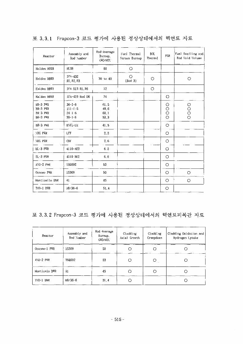
fi 3.3.1 Frapcon-3 3.^
Reactor
Halden HBWR
Halden HBWR
Halden HBWR
Halden HBWR
BR-3 PWRBR-3 PWRBR-3 PWRBR-3 PWR
BR-3 PWR
NRX PWR
NRX PWR
EL-3 PWR
EL-3 PWR
ANO-2 PWR
Oconee PWR
Monticello BWR
TVO-1 BWR
Assembly andRod Number
HUHB
IFA-432Rl, R2, R3
1FA-513 R1.R6
IFA-429 Rod DH
36-1-8111-1-524-1-638-1-6
BNFL-DE
LFF
CBF
411O-AE2
4110-BE2
TSQ002
15309
Al
H8/36-6
Rod-AverageBurnup,GWD/MTU
80
30 to 40
12
74
61.548.660.153.3
41.5
2.2
2.6
6.2
6.6
53
50
45
51.4
Fuel ThermalVersus Burnup
oo
(Rod 3)
BOLThermal
O
O
FGR
O
OOOO
ooooooooo
Fue1 Swe11i ng andRod Void Volume
O
oooo
oo
13 ,3 .2 Frapcon-3 3.H
Reactor
0conee-l PWR
ANO-2 PWR
Monticelo BWR
TVO-1 BWR
Assembly andRod Number
15309
TSQ002
Al
H8/36-6
Rod-AverageBurnup,GWD/MTU
50
53
45
51.4
CladdingAxial Growth
O
O
o
o
CladdingCreepdown
o
o
o
Cladding Oxidation andHydrogen Uptake
o
o
o
o
- 515-
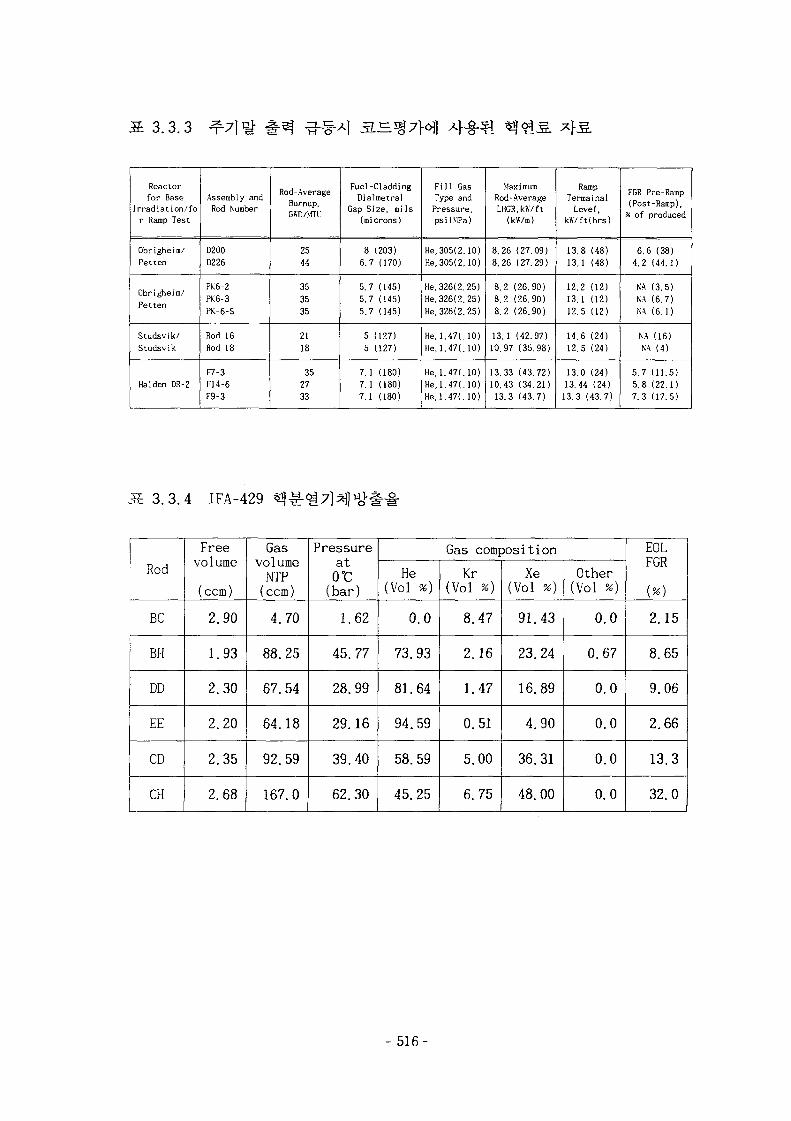
3.3.3
Reactorfor Base
Irradiation/for Ramp Test
Obrigheim/Pet ten
Obrigheim/Pet ten
Studsvik/Studsvik
Hal den DR-2
Assembly andRod Number
D200D226
PK6-2PK6-3PK-6-S
Rod 16Rod 18
F7-3F14-6F9-3
Rod-AverageBurnup,GTO/MTf
2544
353535
2118
352733
Fuel-CladdingDialmetral
Gap Size, mils(microns)
8 (203)6.7 (170)
5.7 (145)5.7 (145)5.7 (145)
5 (127)5 (127)
7.1 (180)7.1 (180)7.1 (180)
Fil l GasType andPressure,psi(MPa)
He, 305(2.10)He,305(2.10)
He,326(2. 25)He, 326(2. 25)He, 326(2.25)
He,1.47(.10)He,1.47(.10)
He,1.47(.10)He,1.47(,10)He,1.47(,10)
MaximumRod-AverageLHGR,k«/ft
(MV/m)
8.26 (27.09)8.26 (27.29)
8.2 (26.90)8.2 (26.90)8.2 (26.90)
13.1 (42.97)10.97 (35.98)
13.33 (43.72)10.43 (34.21)13.3 (43.7)
RampTermainal
Level,kW/ft(hrs)
13.8 (48)13.1 (48)
12.2 (12)13.1 (12)12.5 (12)
14.6 (24)12.5 (24)
13.0 (24)13.44 (24)13.3 (43.7)
FGR Pre-Ramp(Post-Ramp),
% of produced
6.6 (38)4.2 (44.1)
N'A (3.5)NA (6.7)NA (6.1)
NA (16)NA (4)
5.7 (11.5)5.8 (22.1)7.3 (17.5)
3.3.4 IFA-429
Rod
BC
BH
DD
EE
CD
CH
Freevo1ume
(ccm)
2.90
1.93
2.30
2.20
2.35
2.68
Gasvolume
NTP(ccm)
4.70
88.25
67.54
64.18
92.59
167.0
Pressureator
(bar)
1.62
45.77
28.99
29.16
39.40
62.30
Gas composition
He(Vol %)
0.0
73.93
81.64
94.59
58.59
45.25
Kr(Vol *)
8.47
2.16
1.47
0.51
5.00
6.75
Xe(Vol %)
91.43
23.24
16.89
4.90
36.31
48.00
Other(Vol %)
0.0
0.67
0.0
0.0
0.0
0.0
E0LFGR
{%)
2.15
8.65
9.06
2.66
13.3
32.0
- 516-
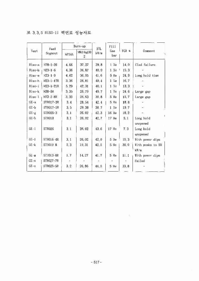
3.3.5 RISO-II
Test
Riso-a
Riso-b
Riso-e
Riso-h
Riso-i
Riso-k
Riso-1
GE-a
GE-b
GE-g
GE-h
GE-i
GE-1
GE-k
GE-m
GE-n
GE-o
FuelSegment
M78-1-39
M23-1-6
M23-1-9
M23-1-17R
M23-1-21R
M38-8R
M73-2-8R
STR017-3R
STR017-5R
STR025-3
STR018
STR026
STR016-4R
STR019-8
STR013-8R
STR027-7R
STR025-5R
Burn-up
%FIMA
4.66
4.36
4.62
3.36
5.29
3.35
3.33
3.4
3.5
3.1
3.1
3.1
3.1
2.3
1.7
-
3.2
MWd/kgUO2
37.27
34.87
36.95
26.81
42.31
26.79
26.63
28.54
29.38
26.02
26.02
26.02
26.02
19.31
14.27
-
26.86
BTLkW/m
39.8
40.0
41.6
40.4
40.1
40.7
39.8
42.4
38.7
42.3
42.7
43.6
42.0
42.5
41.7
-
44.5
FillGasbar
1 Xe
1 Xe
5 He
1 Xe
1 Xe
1 Xe
5 He
5 He
1 Xe
16 He
17 He
17 He
5 He
5 He
5 He
-
5 He
FGR %
14.0
15.3
24.9
16.7
13.3
24.6
15.7
18.8
19.7
18.2
5.1
7.3
19.3
30.0
11.1
-
33.8
Comment
Clad failure
-
Long hold time
-
-
Large gap
Large gap
-
-
-
Long hold
unopened
Long hold
unopened
With power dips
With peaks to 50
kW/m
With power dips
Failed
-
- 517-
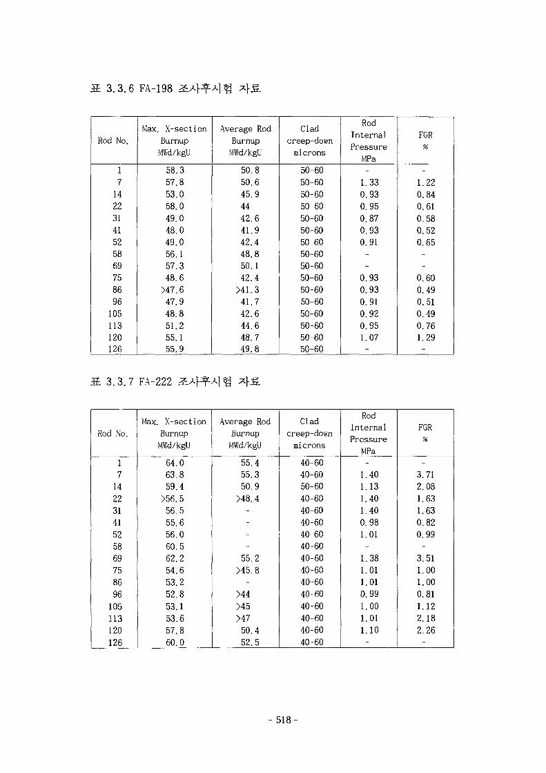
3,3.6 FA-198
Rod No.
1714223141525869758696105113120126
Max. X-section
Burnup
MWd/kgU
58.3
57.8
53.0
58.0
49.0
48.0
49.0
56.1
57.3
48.6
>47.6
47.9
48.8
51.2
55.1
55.9
Average Rod
Burnup
MWd/kgU
50.8
50.6
45.9
4442.6
41.9
42.4
48.8
50.1
42.4
>41.3
41.7
42.6
44.6
48.7
49.8
Clad
creep-down
microns
50-60
50-60
50-60
50-60
50-60
50-60
50-60
50-60
50-60
50-60
50-60
50-60
50-60
50-60
50-60
50-60
Rod
Internal
Pressure
MPa
-1.33
0.93
0.95
0.87
0.93
0.91--
0.93
0.93
0.91
0.92
0.95
1.07
-
FGR
%
-1.22
0.84
0.61
0.58
0.52
0.65--
0.60
0.49
0.51
0.49
0.76
1.29-
3.3.7 FA-222
Rod No.
1714223141525869758696105113120126
Max. X-section
Burnup
MWd/kgU
64.0
63.8
59.4
>56.5
56.5
55.6
56.0
60.5
62.2
54.6
53.2
52.8
53.1
53.6
57.8
60.0
Average Rod
Burnup
MWd/kgU
55.4
55.3
50.9
>48.4----55.2
>45.8-
>44>45>4750.4
52.5
Clad
creep-down
microns
40-60
40-60
50-60
40-60
40-60
40-60
40-60
40-60
40-60
40-60
40-60
40-60
40-60
40-60
40-60
40-60
Rod
Internal
Pressure1 A ^S *mj ±J **H. ^^
MPa-1.401.131.401.400.981.01-1.381.011.010.991.001.011.10-
FGR
-3.712.081.631.630.820.99-3.511.001.000.811.122.182.26-
- 518
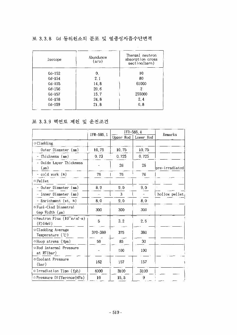
3.3.8 Gd
Isotope
Gd-152Gd-154Gd-155Gd-156Gd-157Gd-158Gd-159
Abundunce(a/o)
0.
2.1
14.8
20.6
15.7
24.8
21.8
Thermal neutronabsorption crosssection(barn)
10
80
61000
2
255000
2.4
0.8
1 3 . 3 , 9
oCladding
- Outer Diameter (mm)
- Thickness (mm)
- Oxide Layer Thickness(/an)
- cold work {%)
oPel let
- Outer Diameter (mm)
- Inner Diameter (mm)
- Enrichment (wt. %)
oFuel-Clad Diametral
Gap Width (/m)
oNeutron Flux (10"n/irf-s)
(E>lMeV)
oCladding AverageTemperature (°C)
oHoop stress (Mpa)
oRod Internal Pressure
at RT(bar)
oCoolant Pressure(bar)
oIrradiation Time (fph)
oPressure Difference(MPa)
IFR-585.1
10.75
0.73
-
76
8.9
-
8.0
300
5
370-380
50
-
162
4000
10
IFR-585.4
Upper Rod
10.75
0.725
26
76
9.0
3
9.0
300
3.2
375
85
100
157
3100
15.5
Lower Rod
10.75
0.725
26
76
9.0
-
8.0
300
2.5
380
30
100
157
3100
9
Remarks
pre-irradiated
hollow pellet
- 519-
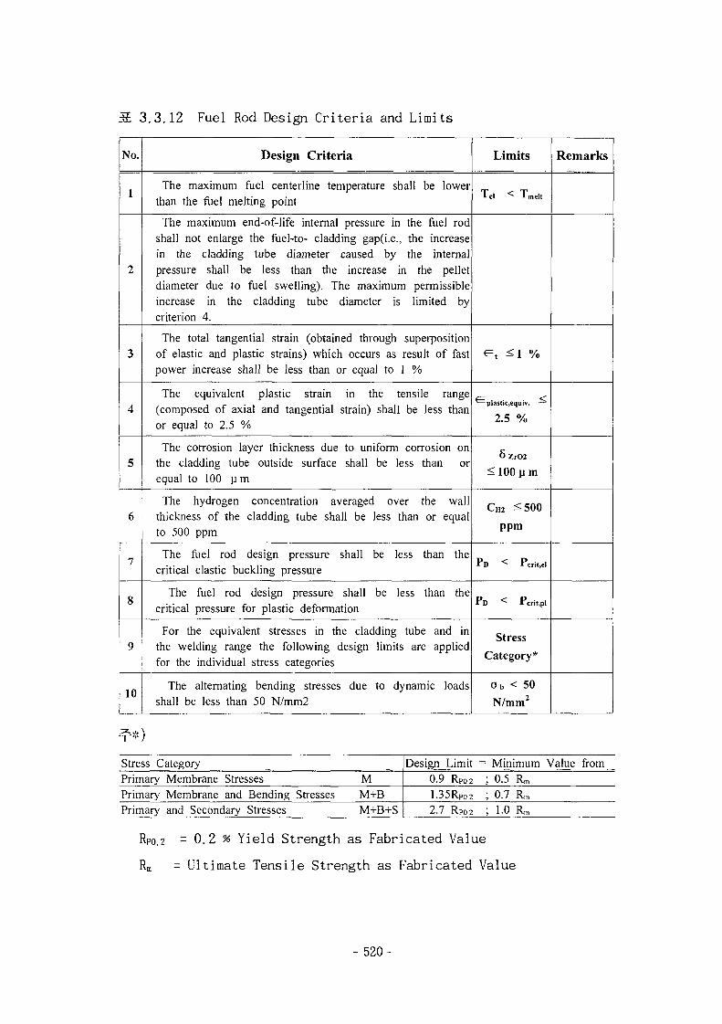
3.3.12 Fuel Rod Design Criteria and Limits
No.
1
2
3
4
5
6
7
8
9
10
Design Criteria
The maximum fuel centerline temperature shall be lowerthan the fuel melting point
The maximum end-of-life internal pressure in the fuel rodshall not enlarge the fuel-to- cladding gap(i.e., the increasein the cladding tube diameter caused by the internalpressure shall be less than the increase in the pelletdiameter due to fuel swelling). The maximum permissibleincrease in the cladding tube diameter is limited bycriterion 4.
The total tangential strain (obtained through superpositionof elastic and plastic strains) which occurs as result of fastpower increase shall be less than or equal to 1 %
The equivalent plastic strain in the tensile range(composed of axial and tangential strain) shall be less thanor equal to 2.5 %
The corrosion layer thickness due to uniform corrosion onthe cladding tube outside surface shall be less than orequal to 100 um
The hydrogen concentration averaged over the wallthickness of the cladding tube shall be less than or equalto 500 ppm
The fuel rod design pressure shall be less than thecritical elastic buckling pressure
The fuel rod design pressure shall be less than thecritical pressure for plastic deformation
For the equivalent stresses in the cladding tube and inthe welding range the following design limits are appliedfor the individual stress categories
The alternating bending stresses due to dynamic loadsshall be less than 50 N/mm2
Limits
Tel < Tmelt
e t =si %
^ plastic,equiv. —
2.5 %
6zrO2
< 100 pm
CH2 ^500ppm
P D < Pcri.,el
P D < Pcrit.pl
Stress
Category*
o b < 50
N/mm2
Remarks
Stress CategoryPrimaryPrimaryPrimary
Membrane StressesMembrane and Bending Stressesand Secondary Stresses
MM+BM+B+S
Design Limit0.9 Rpo.2
1.35RPo22.7 RPO.2
= Minimum Value from; 0.5; 0.7; 1.0
Rm
Rm
Rm
RPO.2 = 0.2 % Yield Strength as Fabricated Value
Rm = Ultimate Tensile Strength as Fabricated Value
- 520-

3.3.13 Summary of Reactor Thermal Hydraulic Data in SMART
Parameter
o System pressure
o Coolant inlet temperature
o Mass flow rate
o Heat transfer coefficient
between coolant and fuel
rod
o Core average LHGR
o Heat production outside the
fuel rod
o Maximum possible LHGR
o Peaking factor due to fuel
rod tolerances
Unit
bar
°C
kg/s
W/K/m2
W/cm
%
W/cm
SMART
150
270
0.09446
14,300
120.05
2.6
420
1.03
Remarks
- 521-
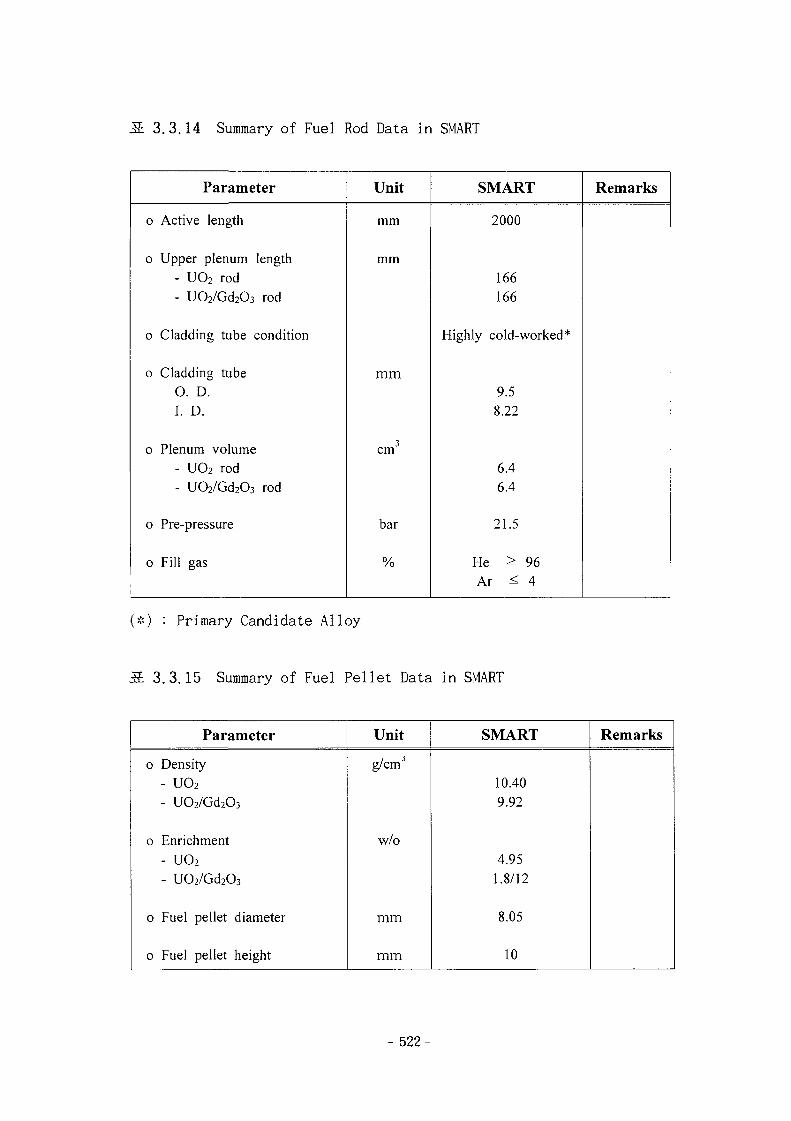
3.3.14 Summary of Fuel Rod Data in SMART
Parameter
o Active length
o Upper plenum length- UO2 rod- U02/Gd203 rod
0 Cladding tube condition
0 Cladding tube0. D.I. D.
0 Plenum volume- U02 rod- UO2/Gd2O3 rod
0 Pre-pressure
0 Fill gas
Unit
mm
mm
mm
cm
bar
%
SMART
2000
166166
Highly cold-worked*
9.58.22
6.46.4
21.5
He > 96Ar < 4
Remarks
(*) : Primary Candidate Alloy
3.3.15 Summary of Fuel Pellet Data in SMART
Parameter
0 Density- UO2
- U02/Gd203
0 Enrichment- UO2
- U02/Gd203
0 Fuel pellet diameter
0 Fuel pellet height
Unit
g/cmJ
w/o
mm
mm
SMART
10.409.92
4.951.8/12
8.05
10
Remarks
- 522-
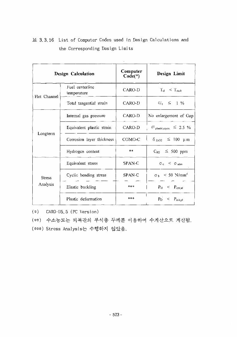
.3. 3.3.16 List of Computer Codes used in Design Calculations and
the Corresponding Design Limits
Design Calculation
Hot Channel
Longterm
Stress
Analysis
Fuel centerlinetemperature
Total tangential strain
Internal gas pressure
Equivalent plastic strain
Corrosion layer thickness
Hydrogen content
Equivalent stress
Cyclic bending stress
Elastic buckling
Plastic deformation
ComputerCode(*)
CARO-D
CARO-D
CARO-D
CARO-D
COMO-C
**
SPAN-C
SPAN-C
**#
***
Design Limit
Tel < Tmeli
e , < l %
No enlargement of Gap
*— plastic.equiv. — 2..J / o
6zrO2 ^ 100 lira
C H 2 ^ 5 0 0 p p m
O e < 0 adm.
ob < 50 N/nW
P D < Pcrii,el
P D < Pcril.pl
(>:<) CAR0-D5. 5 (PC Version)
(***) Stress Analysis-b o•a. •
- 523-
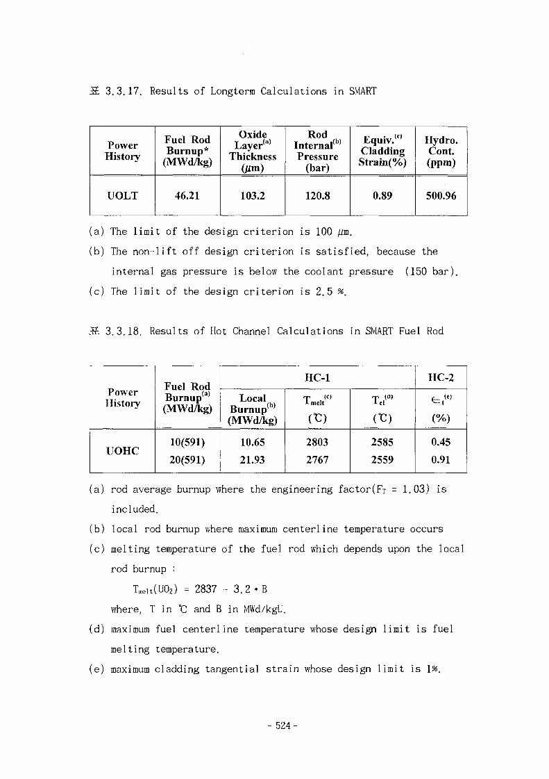
3.3.17. Results of Longterm Calculations in SMART
PowerHistory
UOLT
Fuel RodBurnup*
(MWd/kg)
46.21
OxideT (a)
LayerThickness
Oim)
103.2
RodInternal^Pressure
(bar)
120.8
Equiv.w
CladdingStrain(%)
0.89
Hydro.Cont.(ppm)
500.96
(a) The limit of the design criterion is 100 jUm.
(b) The non-lift off design criterion is satisfied, because the
internal gas pressure is below the coolant pressure (150 bar).
(c) The limit of the design criterion is 2.5 %.
S 3.3.18. Results of Hot Channel Calculations in SMART Fuel Rod
PowerHistory
UOHC
Fuel RodBurnup(a)
(MWd/kg)
10(591)
20(591)
HC-1
LocalBurnup(b)
(MWd/kg)
10.65
21.93
* melt
m2803
2767
m2585
2559
HC-2
e, w
(%)
0.45
0.91
(a) rod average burnup where the engineering factor(Fr = 1.03) is
included.
(b) local rod burnup where maximum centerline temperature occurs
(c) melting temperature of the fuel rod which depends upon the local
rod burnup :
Tmeit(U02) = 2837 - 3.2 «B
where, T in °C and B in MWd/kgU.
(d) maximum fuel centerline temperature whose design limit is fuel
melting temperature.
(e) maximum cladding tangential strain whose design limit is 1%.
- 524-
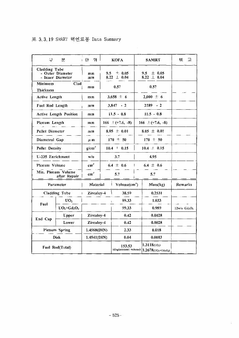
S. 3.3.19 SMART Data Summary
Cladding Tube- Outer Diameter- Inner Diameter
Minimum Clad
Thickness
Active Length
Fuel Rod Length
Active Length Position
Plenum Length
Pellet Diameter
Diametral Gap
Pellet Density
U-235 Enrichment
Plenum Volume
Min. Plenum Volumeafter Repair
Parameter
Cladding Tube
Fuel
End Cap
UO2
UO2+Gd2O3
Upper
Lower
Plenum Spring
Disk
Fuel Rod(Total)
mmmm
mm
mm
mm
mm
mm
mm
ft m
g/cm'*
w/o
cmJ
cmJ
KOFA
9.5 ± 0.058.22 ± 0.04
0.57
3,658 ± 6
3,847 - 2
11.5 - 0.8
166 ±(+7.6, -8)
8.05 ± 0.01
170 ± 50
10.4 ± 0.15
3.7
6.4 ± 0.6
5.7
Material
Zircaloy-4
Zircaloy-4
Zircaloy-4
1.4568(DIN)
1.4541(DIN)
SAMRT
9.5 ± 0.058.22 ± 0.04
0.57
2,000 ± 6
2189 - 2
11.5 - 0.8
166 ±(+7.6, -8)
8.05 ± 0.01
170 ± 50
10.4 ± 0.15
4.95
6.4 ± 0.6
5.7
Volumefcm3)
38.59
99.33
99.33
0.42
0.42
2.33
0.04
153.53(displacement volume)
Mass(kg)
0.2531
1.033
0.989
0.0028
0.0028
0.018
0.0003
1.3118(uo2)1.2678(uo2+Gd2o3)
ti\ H
Remarks
12w/o Gd.Oj
- 525-
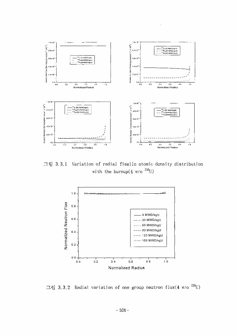
""U (0 MWD/XgU)•""polOMWD-kgU):t>u(O MWD/kgU)
0.2 0 4 0.6 0.8 1,0
Normalized Radius
o
x_ 8.0x10* "
E
| e.oxio"*-
J;| 4.0.10--
Ato
mic
Nu
mb
er
b
"SU (30 MWD/XgU)-"'Pu(30 MWD'kgU)
:"Pu(30 MWD/kgU) |
//
0 0 0.2 0.4 0.6 0.8 1.0
Normalized Radius
:J )U (60 MWD'kgU)- : l*Pu{60 MWD/kgU)
. . . . ;"Pu|60 MWD/kgU)
0.0 0.2 0 4 0.6 t
Normalized Radius
8 0x10"*-
6.0x10'*-
4.0x10''-
2.0x10'-
I1SU (90 MWD/kgU)-:>BPu(90 MWO/kgU)
. . . . !"Pu(90 MWD/kgU)
0 0 0.2 0,6 0,8 1.0
Normalized Radius
3.3.1 Variation of radial fissile atomic density distribution
with the burnup(4 w/o 5U)
o.o 0.2
1 0
X3 0.8 -
1
ron
1
•5 0.6 -
2:
Q) 0.4 -
aliz
E0 0 . 2 -
z
0.0 -1
. . . . . .
n M\A^n/knl 1
30 MWD/kgU
60 MWD/kgU
90 MWD/kgU
- - 120 MWD/kgU
150 MWD/kgU
0.4 0.6 0.8
Normalized Radius
1.0
235,n.^1 3.3.2 Radial variation of one group neutron flux(4 w/o U)
- 526-
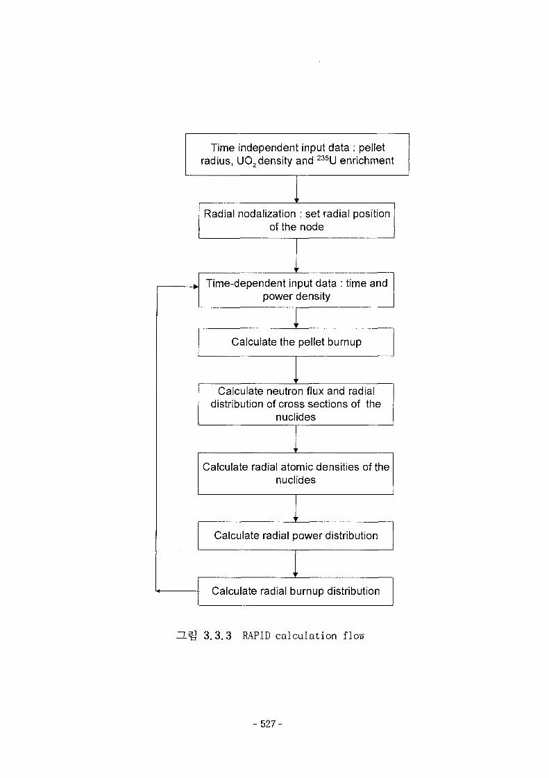
Time independent input data : pelletradius, U02 density and 235U enrichment
Radial nodalization : set radial positionof the node
r
Time-dependent input data : time andpower density
Calculate the pellet burnup
r
Calculate neutron flux and radialdistribution of cross sections of the
nuclides
Calculate radial atomic densities of thenuclides
Calculate radial power distribution
- Calculate radial burnup distribution
3.3.3 RAPID calculation flow
- 527-
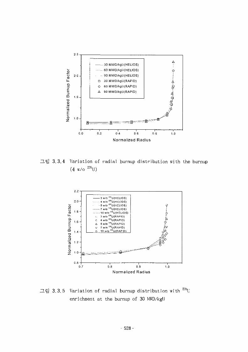
2.5
oroLJ_
Q.C
CQ
"D<DN
EO
1.5 -
1.0 -
0.0
Normalized Radius
3.3.4 Variation of radial burnup distribution with the burnup
(4 w/o 235U)
o(0Q.3C
Eo
0.8 0.9
Normalized Radius1.0
235,H ^ 3.3.5 Variation of radial burnup distribution with U
enrichment at the burnup of 30 MWD/kgU
- 528-
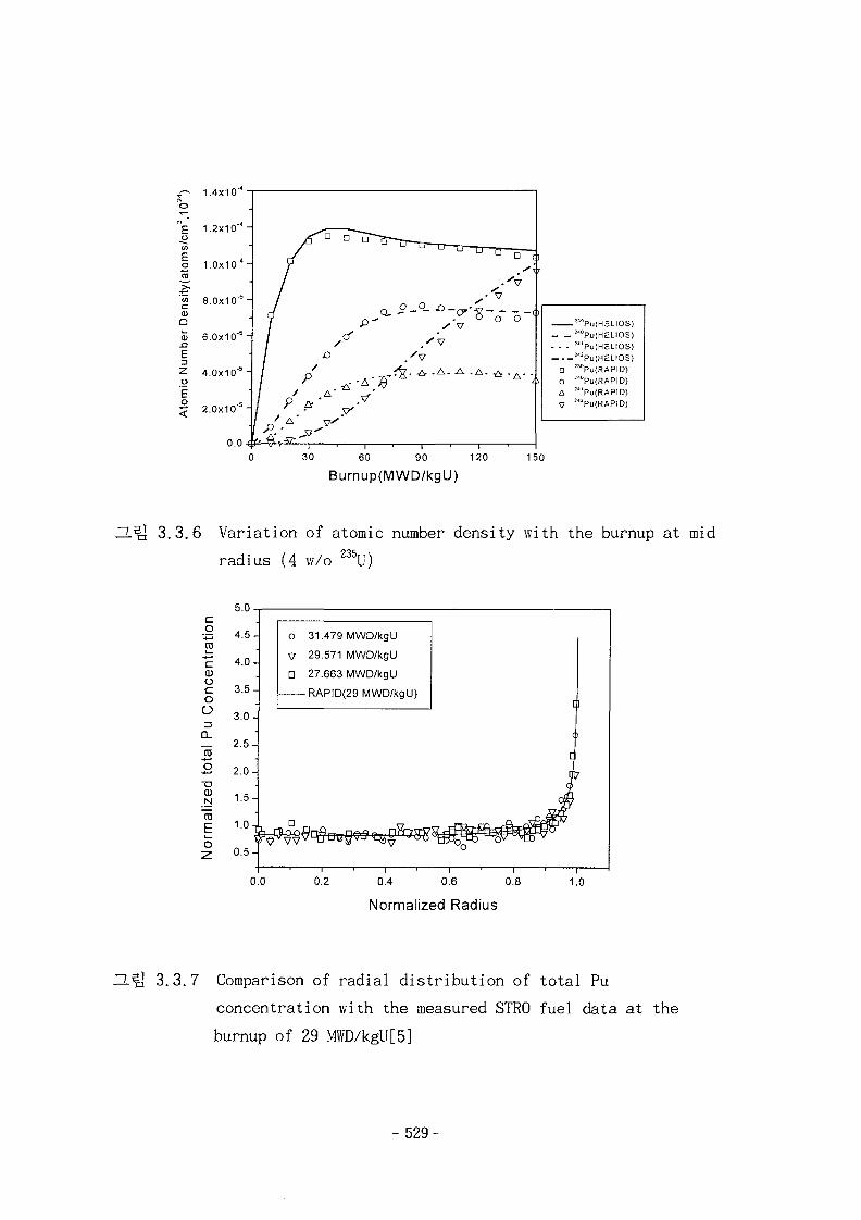
1.4x10
E. 0CO
(ato
rris
ity
<DQ
0)
£
Z0
E0
1.2x10
1.0x10""
8.0x10"5
6.0x1 0"5
4.0X10"5
.c-£ 2.0x10 "
0.0
30 60 90 120
Burnup(MWD/kgU)
— —. . .
D
0
A
"8Pu(HELI0S)""PufHELIOS)!"Pu(HELI0S)!<!Pu(HELIOS)"'Pu(RAPID)!<°Pu(RAPID)!J'Pu(RAPID)'"Pu(RAPID)
150
3.3.6 Variation of atomic number density with the burnup at mid
radius (4 w/o 235U)
5.0
O
CD
C(1)
ooO13CL
CDN
E
4.5-
4.0-
3.5-
3.0-
2.5-
2.0-
1.5-
1.0-
o
V
•
31
29
27
479
571
663
MWD/kgU
MWD/kgU
MWD/kgU
-RAPID(29 MWD/kgll)
0.2 0.4 0.6 O.i
Normalized Radius
1.0
3.3.7 Comparison of radial distribution of total Pu
concentration with the measured STRO fuel data at the
burnup of 29 MWD/kgU[5]
-529-
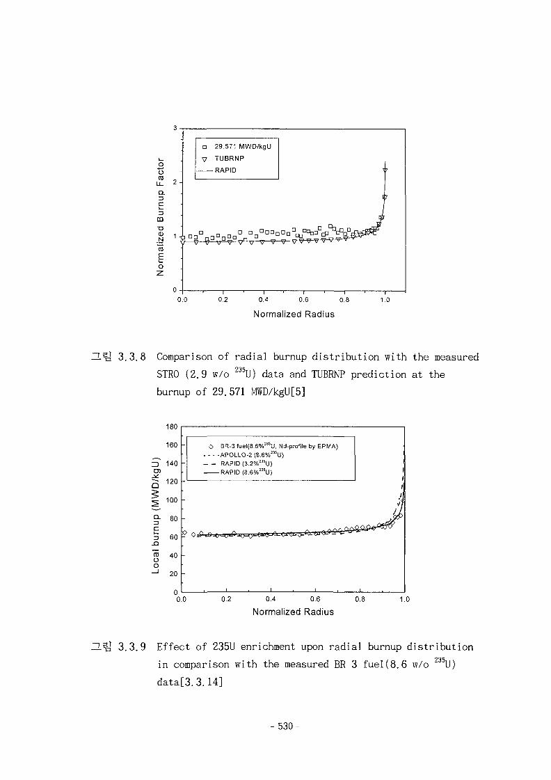
o
(0
Q.
cCO"O
Ni
"toEo
2 -
0 -
D 29.571 MWD/kgU
V TUBRNP
RAPID
i
J
f
0.0 0.2 0.4 0.6 0.8
Normalized Radius
1.0
3.3.8 Comparison of radial burnup distribution with the measured
STR0 (2.9 w/o 235U) data and TUBRNP prediction at the
burnup of 29.571 MWD/kgU[5]
180
O BR-3 fuel(8.6%"'U, Nd-profile by EPMA)- - - -APOLLO-2 (B.6%235U)
RAPID (3.2%235U)RAPID (8.6%23SU)
0.0 0.4 0.6
Normalized Radius
^1^3 3.3.9 Effect of 235U enrichment upon radial burnup distribution235,in comparison with the measured BR-3 fuel(8.6 w/o U)
data[3.3.14]
- 530-
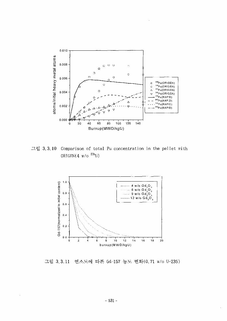
0.010
•£ 0.008-
Eo
0.006-
"S3E>
03
— 0.004-
D D
o.ooo M ' T ' T i
' ——
^ - i —. — -*
A '
v - • - - . . .
a 2MPu(ORIGEN)O 240Pu(ORIGEN)C, 24'Pu(ORIGEN)V 242Pu(ORIGEN)
23sPu(RAPID)24°Pu(RAPlD)
- - - -^'PutRAPID)242Pu(RAPID)
20 40 60 80 100 120
Burnup(MWD/kgU)140
O-Q 3.3.10 Comparison of total Pu concentration in the pellet with
0RIGEN(4 w/o 235,, >
4 w/o Gd 2 O,
6 w/o Gd 2O 3
9 w/o Gd2O3
12 w/o Gd 2 O,
6 8 10 12 14
burnup(MWD/kgU)
16 18 20
O.^ 3.3.11 } ^ Gd-157 w/o U-235)
- 531-
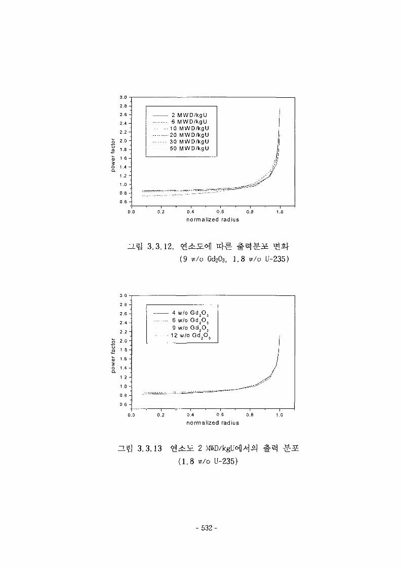
3.0
2 MWD/kgU6 MWD/kgU10 MWD/kgU20 MWD/kgU30 MWD/kgU50 MWD/kgU
0.0 0.2 0.4 0.6
normalized radius0.8 1.0
ZL^ 3.3.12.
(9 w/o Gd2O3, 1.8 w/o U-235)
3.0
2.8 -
2.6 -
2.4 -
2 2 -
o 2 . 0 -
» 1 8 ~
S 1-6 -
o 1.4 -
1.2 -
1.0
0.8 -
0.6 -
4 w/o Gd2O3
6 w/o Gd2O3
9 w/o Gd2O3
12 w/o Gd2O3
0.0 0.2 0.4 0.6
normalized radius0.8 1.0
ILiQ 3.3.13
(1.8 vv/o U-235)
- 532-
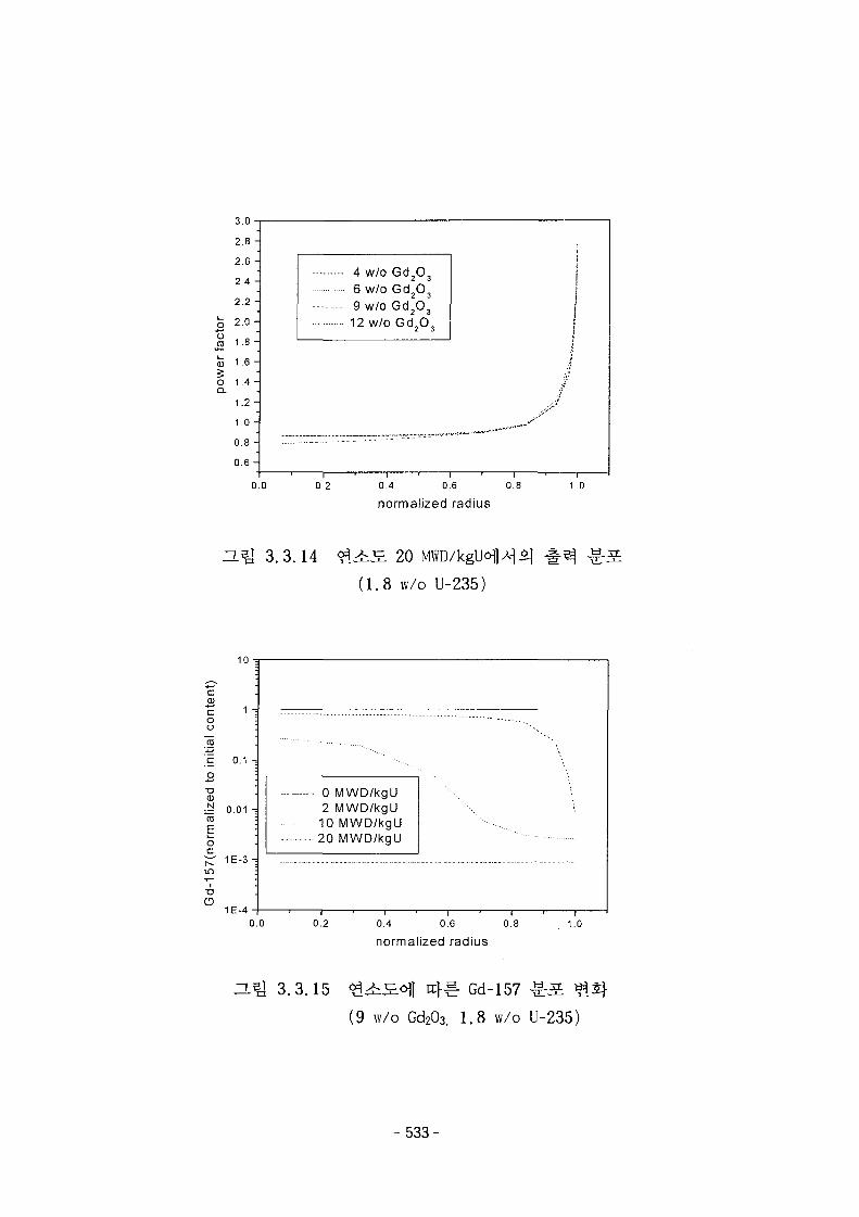
3.0
2.8 -
2.6 -
2.4 -
2.2 -
3 2 - ° ~Jj 1.8 -
S 16 -O 1.4 -Q.
1.2 -
1.0 -
0.8 -
0 . 6 -
4 w/o Gd2O3
6 w/o Gd2O3
9 w/o Gd2O3
12 w/o Gd2O3
0.0 0.2 0.4 0.6
normalized radius0.8 1.0
T.5] 3.3.14 20
(1.8 w/o U-235)
10
c.22coo
1 -
.E oi -o
<D~ 0.01 -=raEor - 1E-3-
CD1E-4
• 0 MWD/kgU2 MWD/kgU10 MWD/kgU20 MWD/kgU
0.0 0.2 0.4 0.6
normalized radius0.8 1.0
3.3.15 ^ S . o f l tcf^ Gd-157 ^ S
(9 w/o Gd2O3, 1.8 w/o U-235)
- 533-
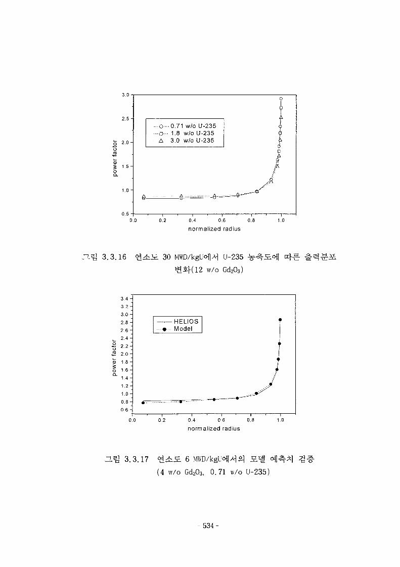
0.71 w/o U-235•o- 1.8 w/o U-235A 3.0 w/o U-235
0.5
o.o 0.4 0.6
normalized radius0.8 1.0
3.3.16 30 U-235
w/o Gd2O3)
oCD
oQ.
3.4 -
3 . 2 -
3.0 -
O Q2..O -
2.6 -2.4 -
2.2 -
2.0 -
1.8 -
1.6 -
1.4 -
1 .2 -
1 .0-
).8 -0.6 -
• - • - -
HFI IOS—-#—• Model
t
•
•
/
0.0 0.2 0.4 0.6 0.8
normalized radius1.0
H ^ 3.3.17 6
(4 w/o Gd2O3, 0.71 w/o U-235)
- 534-
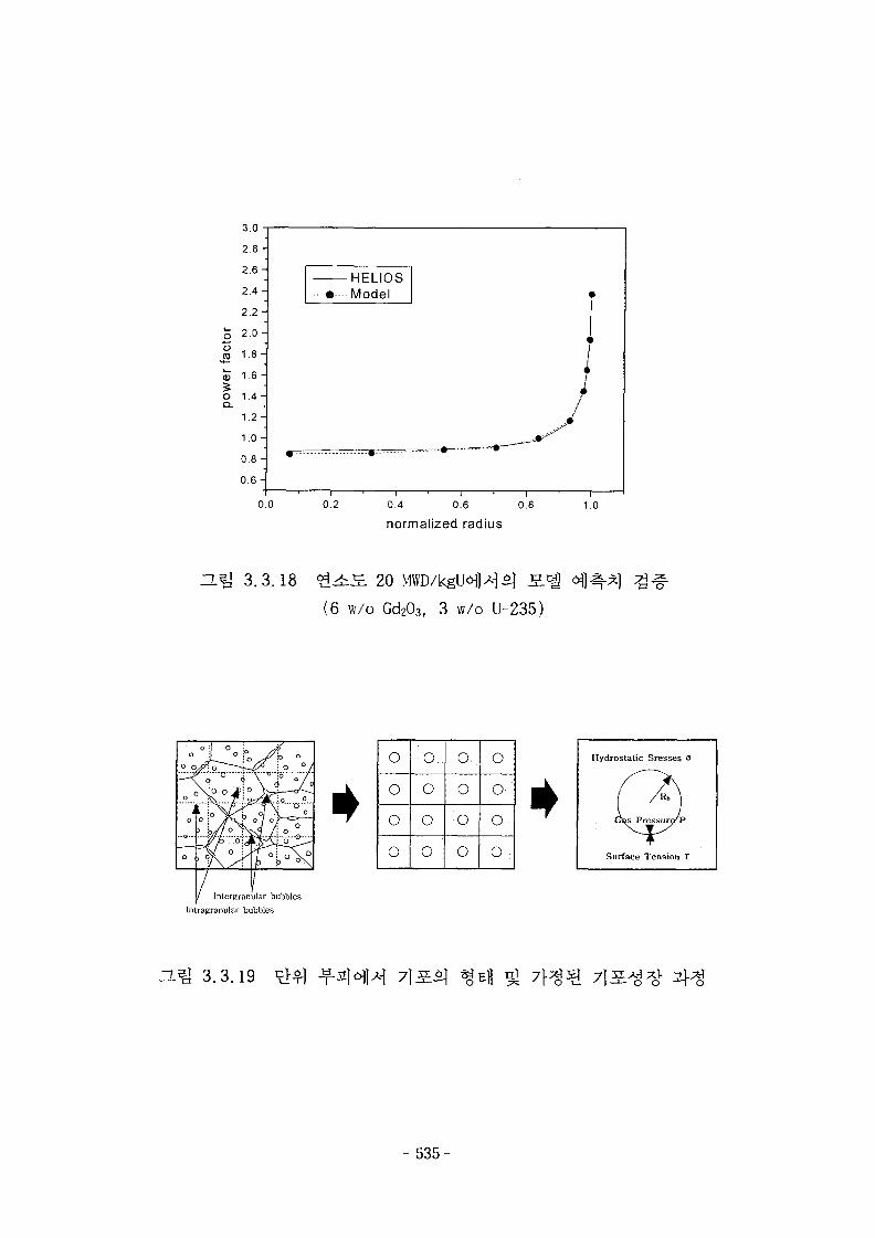
tact
orpo
wer
2 . 8 -
2.6 -
2.4 -
2.2 -
2.0 -
1.8 -
1.6 -
1.4-
1.2-
1.0-
0 . 8 -
0 . 6 -
0. 0
upi m^
-••••--Model
•
i • i • i • i
0.2 0.4 0.6 0.8
normalized radius
<
[
\
}1 0
3.3.18 <*[^£ 20
(6 w/o Gd203> 3 w/o U-235)
o
i0
o
/
ly
InLergran
0 •/ O,
fc3 /
<
oi O
o
/jlar bubbles
o
o
o
o
o
o
o
o
o
o
o
o
o
o
o
Hydrostatic Sresses
Surface Tension T
Intxagranular bubbles
H5J 3.3.19
- 535-
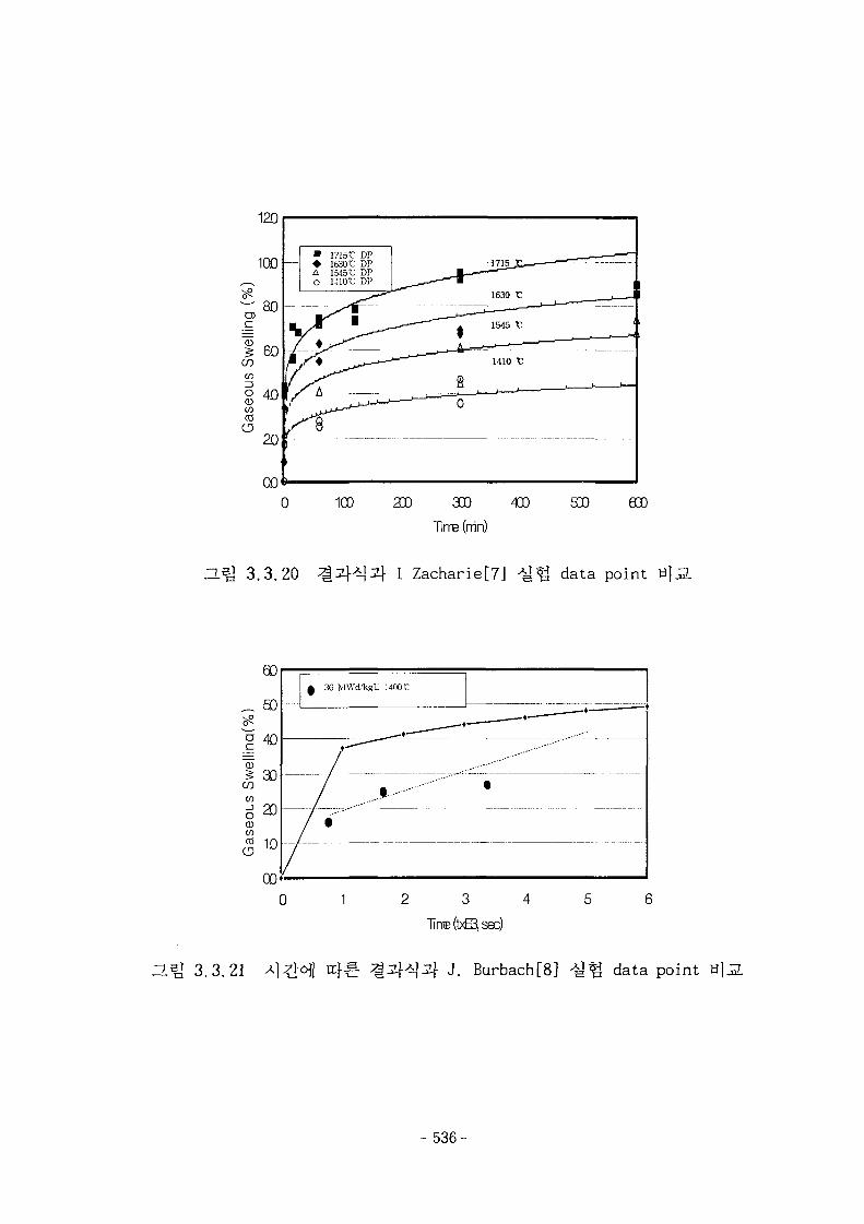
ZL5] 3.3.20
200 330
Tlnre (nin)
I Zacharie[7] data point
"CD
COCO
8CDCO
CD
a)40
30
20
00
A 36 MWd/kgU 14001
• • "
• — '
/ - - • - • • • " " " " "
•
t
— •—•
Zim 3.3.21
2 3 4
Tirre(txE3isec)
r}^3} J. Burbach[8] data point
- 5 3 6 -
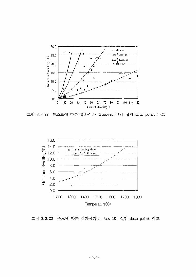
30.0
25.0
ZLQ 3.3.22
13*) K DP
•1600-—1900K-DP
/ / A
0 10 20 30 40 50 60 70 80 90 100 110 120
Burnup(MWd/kgU)
Zimmermann[9] data point H}J2.
\0
cz
"Q3
COCO
oCDCO
CO(3
16.0
14.0
12.0
10.0
8.0
6.0
4.0
2.0
0.0
BJ lhr
A P
•
annealing
: 72 ~ 86timeMPa X
/ • - - —
1200 1300 1400 1500 1600 1700 1800
Temperature(C)
H.Q 3.3.23 K. Une[10] data point
- 537-
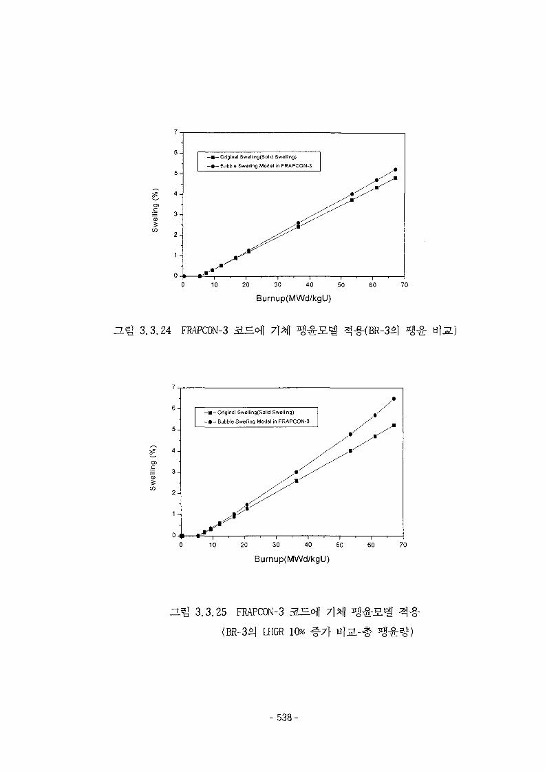
CD
6 -
5 -
4 -
3 -
2 -
1 -
—•— Original Swetling(Solid Swelling)
—#— Bubble Swelling Model in FRAPCON-3
10 20 30 40 50
Burnup(MWd/kgU)
60 70
3.3.24 FRAPCON-3
7-,
5-
5? 4 -
O)
= 3 -
W 2 -
1 -
OH
- 1 - Original Swelling(Solid Swelling)
- • - Bubble Swelling Model in FRAPCON-3
/
MI * = - , , , , , , r—
•
•
10 20 30 40 50
Burnup(MWd/kgU)
60 70
H^J 3.3.25 FRAPCON-3 3_E.<H
(BR-3^ LHGR 10% # 7 } «
- 538-
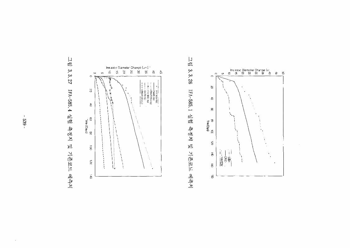
enCOD
uCO
CO
enooen
fl3t
4*
xa
tin
Inelastic Diameter Change (um) '
ro ro co
uCO
CO
tsiO5
Ion00cn
rah
in
Inelastic Diameter Chanae (ur
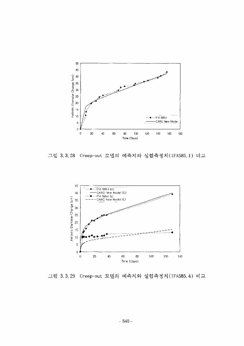
50
"g 40ZJ
£,35
g30
S 2 0
o
_roCD
£ 10
5
0
IFA 585.1
CARO New Model
20 40 60 80 100 120 140 160 180
Time (Days)
ZlQ 3.3.28 Creep-out 1 (IFA585.1)
Z)
octa
rCf
"SECO
bau>
45
40
35
30
25
20
15
10
__
_
*-•• IFA 585.4 (U)
• • - • I F A 585.4 (L)CARO New Model (L) ^
»•••*•••• Z**-
K
.-=r-.r.T «
20 40 60 80
Time (Days)
100 120 140
ZL^ 3.3.29 Creep-out IFA585.4)
- 540-
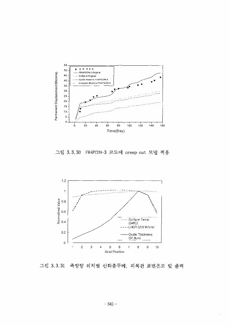
c<DE<uo
_rao.
55
50-
45 -
40-
35-
30-
25-
20-
15-
10-
5 -
0
U B ? S *l
- FRAPCON-3 Original
CARO-D Original
CARO Model in FRAPCON-3
Creepoul Model in FRAPCON-3
20 40 60 80 100
Time(Day)120 140 160
ZL5] 3.3.30 FRAPCON-3 3.^°]] creep-out
1.2
^ 0.8CO
I 0.6(0
EI 0.4
0.2
Surface Temp.(348C)LHGR(219W/cm)
Oxide Thickness(97.9um)
1 2 3 4 5 6 7
Axial Position10
IL^ 3.3.31
- 541 -
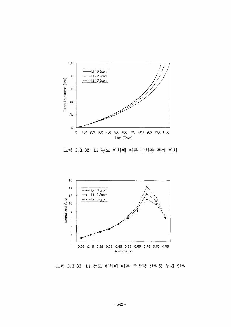
0 100 2 0 0 3 0 0 4 0 0 5 0 0 6 0 0 700 800900 1000 1100
Time (Days)
ZL& 3.3.32 Li
16
14
12
;§ 10
CD
^ 8CO
I 64
2
0
Li : 0.5ppmLi : 2.2ppmLi : 3.5ppm
0.05 0.15 0.25 0.35 0.45 0.55 0.65 0.75 0.85 0.95
A<ial Position
D-^ 3.3.33 Li
- 542-
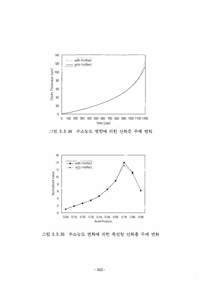
140
120
mes
s
o!cf—CD
X
O
80
60
40
20
with H effectw/o H effect
100 200 300 400 500 600 700 800 900 1000 11001200
Time (Day)
16
14
12
«10
1 8CD
I 6
—«— with H effect...A... w/o Heffect
0.05 0.15 0.25 0.35 0.45 0.55 0.65 0.75 0.85 0.95Axial Position
n i l 3.3.35
- 543-
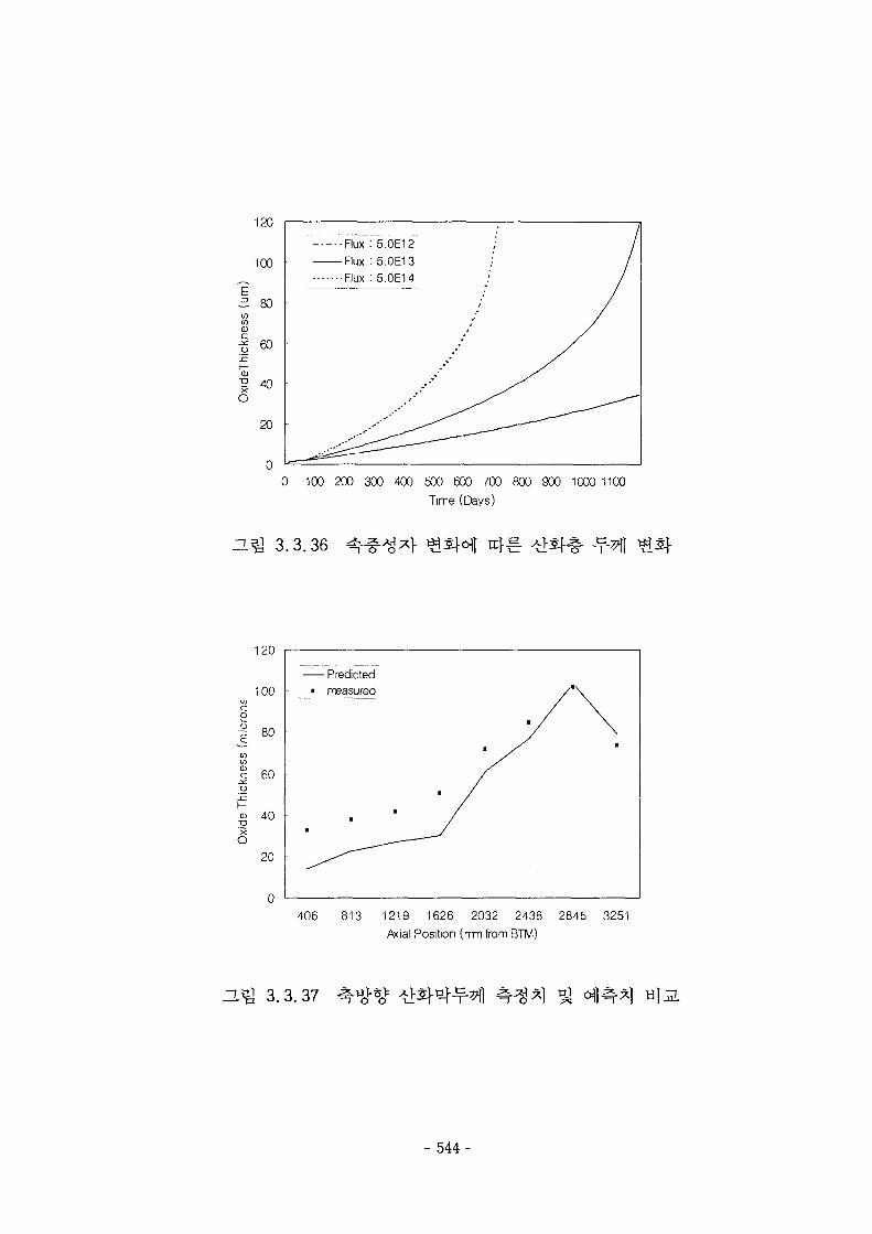
120
100
CD
I0)•IO
60
20
-Flux : 5.0E12-Flux : 5.0E13•Flux : 5.0E14
0 100 200 300 400 500 600 700 800 900 1000 1100
Time (Days)
3.3.36
120
100
•? 80
co|
£ 60
4 0
20
Predicted• measured
406 813 1219 1626 2032 2438 2845 3251
Axial Position (mm from BTM)
H ^ 3.3.37
- 544-
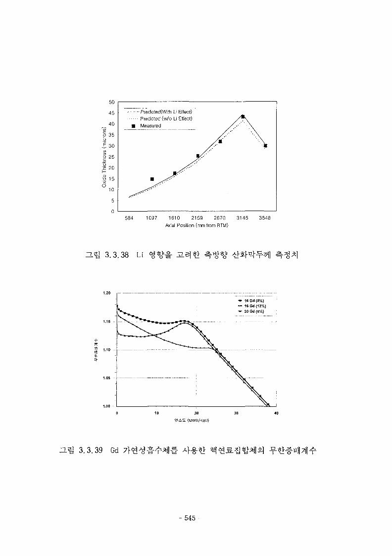
50
45
_. 4 0
o 35o
J 30CO
S 2 5
xO
15
10
5
0
Predicted(With Li Effect)
Predicted (w/o Li Effect)
• Measured
584 1097 1610 2159 2670 3145
Acial Position (rrm from BTM)
3548
ZL^ 3.3.38 Li *<>*•§•
1.20
wo
1.15
•» 1SGd{8%)— 16Gd(12%)•*• 20Gd(8%)
20
(MWO/KgU)
40
3.3.39 Gd A}-§-*>
- 545-
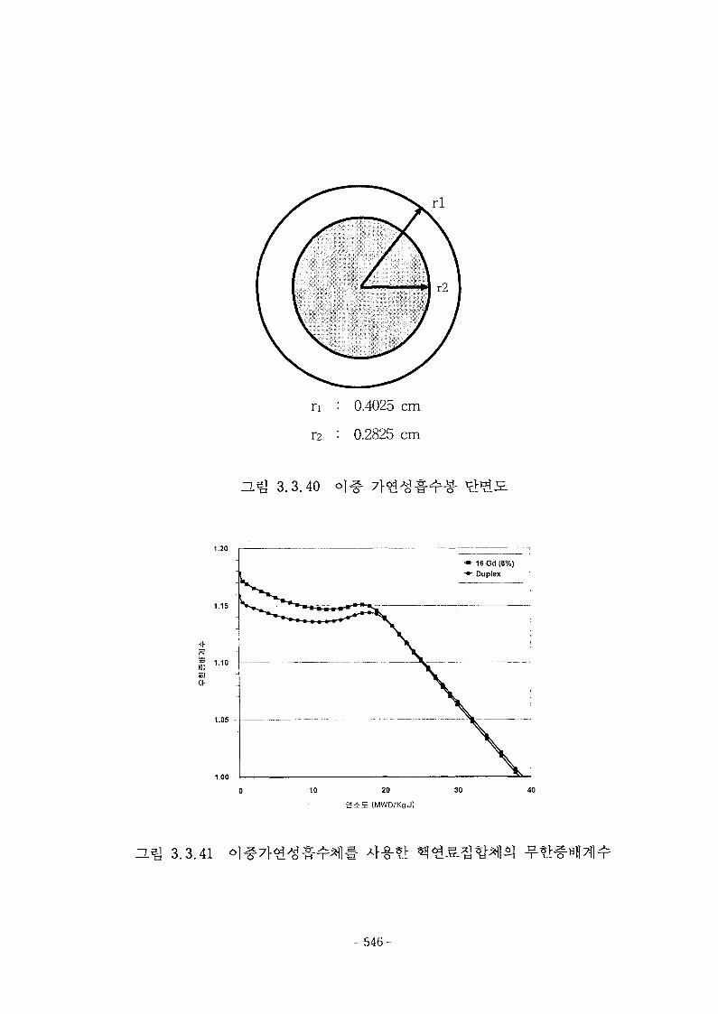
rl
n : 0.4025 cm
r2 : 0.2825 cm
=L^ 3.3.40
1.20
1.15 -
«JOh
1.10
1.05
1.00
10 20
2 i E (MWD/KgU)
30 40
H ^ 3.3.41
- 546-
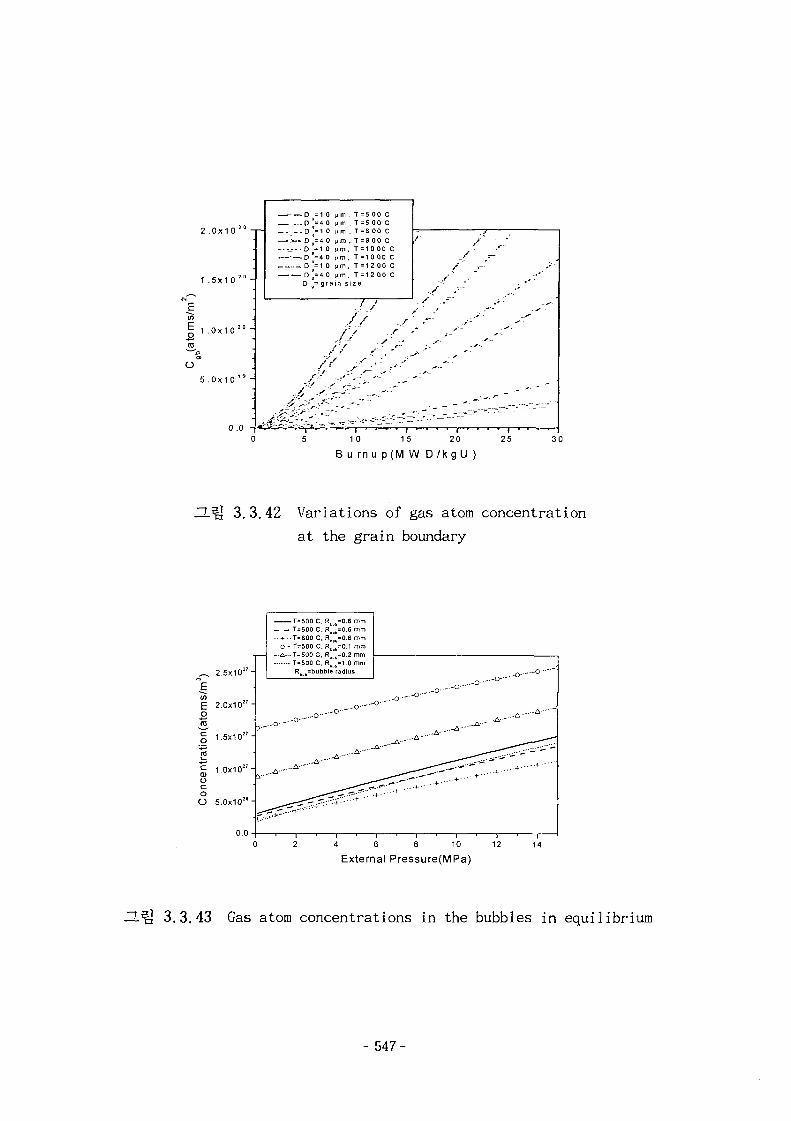
E75Eo•2-
2
1
1
5
.0x1 0
.5x10
.0x1 0
.0x10
0
2 0
2 0 _
:
2 0 _
1 9 _
Q
—Z — D
_ .; _ . D— >—• D. . -_-- . D
; D...-. 0
D
• • ! .
- • - • £ " '
= 1 0= 40= 1 0= 40= 1 0= 40= 1 0
ji m\i mt> rn
ii mt i m
P m= 4 0 jim= g r a i n s
/ ' . •
y"
/
> ' s?
. , /
. T = 5 0 0 C
. T = 5 0 0 C
. T = 8 00 C
. T = 8 0 0 CT = 10 00 CT = 10 00 CT = 1 2 00 CT = 12 00 C
ize
•
/ -••' ; . r '
/./ sz ^ -// / / ^' ^"
- - ' • • \ 'r
f .-• /.---<- —;
10 15 20
B u rn u p ( M W D / k g U )25 30
ZL^J 3.3.42 Variations of gas atom concentration
at the grain boundary
.
ms/
m"
o
o
1Ec0oco
O
2.5x10"-
2.0x10""
1.5x10" "
1.0x10""
5.0x10" "
0.0 -
T=500CT=600 C
.. + .. T=800 C- O - T = 5 0 0 C
^. . . T=500 CT=500 C
RBu6=0.6 mmReub=0.6 mmRoub=0.6 mmRc b=0.1 mm
R =1.0 mmRb]]=bubble radius
o-
_..-A-. ^
.-o-—°'""'
- a - - - * " " ' * " " "
- • * - - " ^ ^ ^ ^ ^ ^
— ^ ^ • " • • ' " 1 • • - • • + • • "
-^Z-'W—•*•
A 6 8 10 12
External Pressure(MPa)14
— =i 3.3.43 Gas atom concentrations in the bubbles in equilibrium
- 547-

180
Q.
a
grain size = 1 0 mm, F = 1.e19 fiss/m .sgrain size = 20 mm, F = 1.e19 fiss/m3.sgrain size = 10 mm, F = 2,e19 dss/m'.sgrain size = 20 mm, F = 2.e19 fi55/mJ.s
40500 600 700 800 900 1000
Temperature(C)1100 1200
3.3.44 HBS initiation local burnup as a function of
temperature, grain size and fission density
2500 -
£ 2000-
E° 1500-
o£ iooo--a
500 -
0 -
•
•
• • •
•
/BK-365
BSH-06
40 50 60 70 80
Pellet average bumup(MWD/kgU)90
3.3.45 Measured data of HBS width in the HBEP irradiation
tests
- 548-
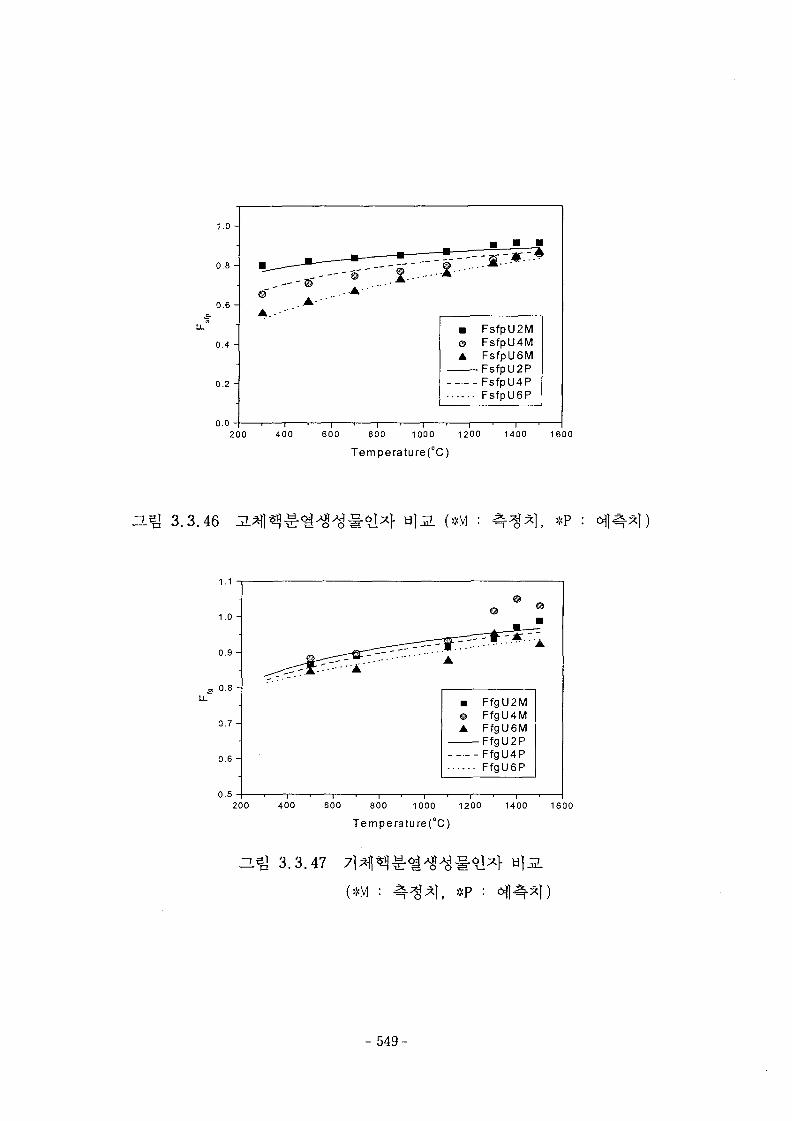
LL
1.0 -
0.8 -
0.6 -
0.4 -
0.2 -
0.0
• FsfpU2M© FsfplUM• FsfpU6M
FsfpU2PFsfpU4PFsfpU6P
200 400 600 800 1000 1200 1400 1600
Temperature(°C)
3.3.46 (*M : . *P
1.1
1.0 -
0.9 -
0.8 -
0.7 -
0.6 -
0.5
FfgU2MFfgU4MFfgU6M
•FfgU2PFfgU4PFfgU6P
200 400 600 800 1000 1200 1400 1600
Temperature(°C)
ZL^ 3.3.47
(*M , *P
- 549-
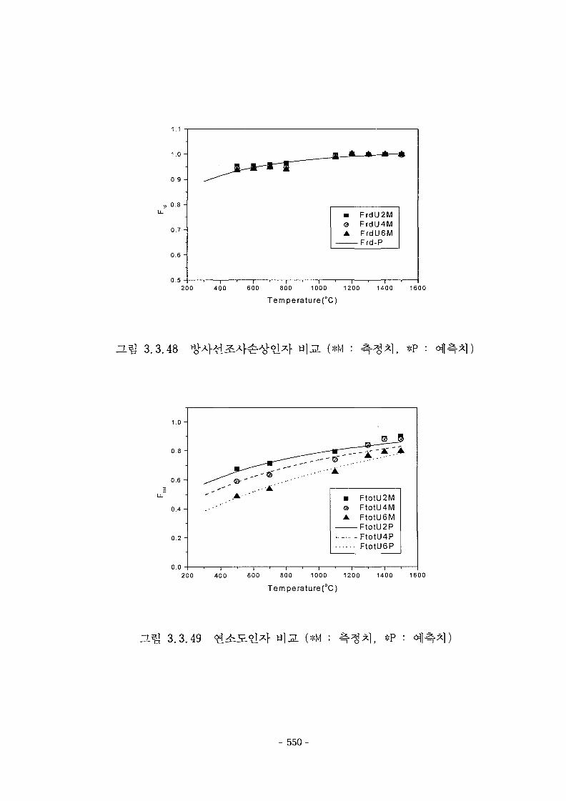
1.1
1.0 -
0.9 -
0.8 -
0.7 -
0.6 -
0.5
• FrdU2M© FrdU4MA FrdU6M
Frd-P
200 400 600 800 1000 1200
Temperature(°C)1400 1600
3.Q 3.3.48 (*M : , *P :
1.0 -
0.8 -
0.6 -
0.4 -
0.2 -
0.0
• FtotU2Me FtotU4MA FtotU6M
FtotU2PFtotU4PFtotU6P
200 400 600 800 1000 1200 1400 1600
Temperature{°C)
3 3 4 9 (*M : *P : afl<%
- 550-
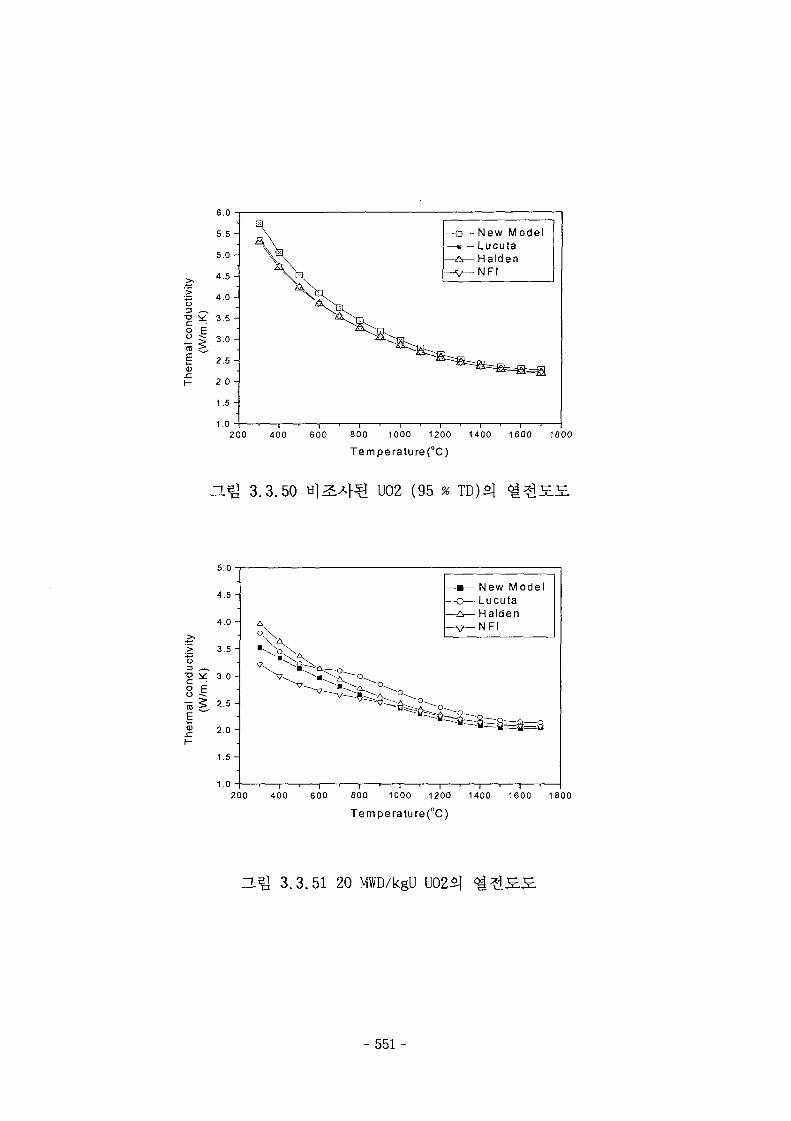
6.0
5.5 -
5.0 -
4.5 -
•5 4.0 -
3.5 -
3.0 -
2.5 -
2.0 -
1.5 -
1.0
ra
• New ModelLucuta
•HaldenNFI
200 400 600 800 1000 1200 1400
Temperature (°C)1600 1800
3.Q 3.3.50 U02 (95
5.0
>T5
5Esz
4.5 -
4.0 -
3.5 -
3.0 -
2.5 -
2.0 -
1.5 -
1.0
• New Model• Lucuta- HaldenNFI
200 400 600 800 1000 1200 1400 1600 1800
Temperature(°C)
HQ 3.3.51 20 MWD/kgU U02£]
- 551 -
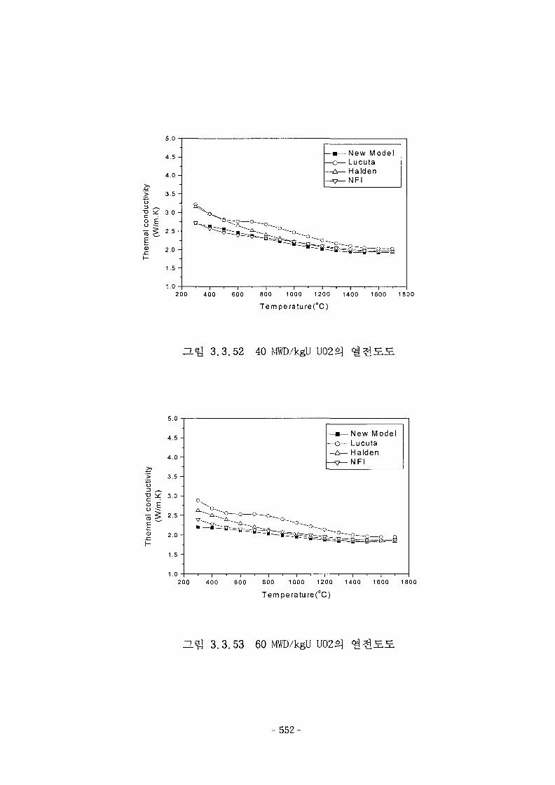
t>
•a
1-
5.0
4.5 -
4.0 -
3.5 -
3.0 -
2.5 -
2.0 -
1.5 -
1.0
New ModelLucutaHaldenNFl
200 400 600 800 1000 1200 1400 1600 1800
Temperature(°C)
3.1& 3 .3 .52 40 MWD/kgU
E
I -
5.0
4.5
4.0
3.5
3.0
2.0
1.5
1.0
^
- New ModelLucutaHaldenNFl
200 400 600 800 1000 1200 1400 1600 1800
Temperature(°C)
H^ 3.3.53 60 MWD/kgU U02S]
- 552-
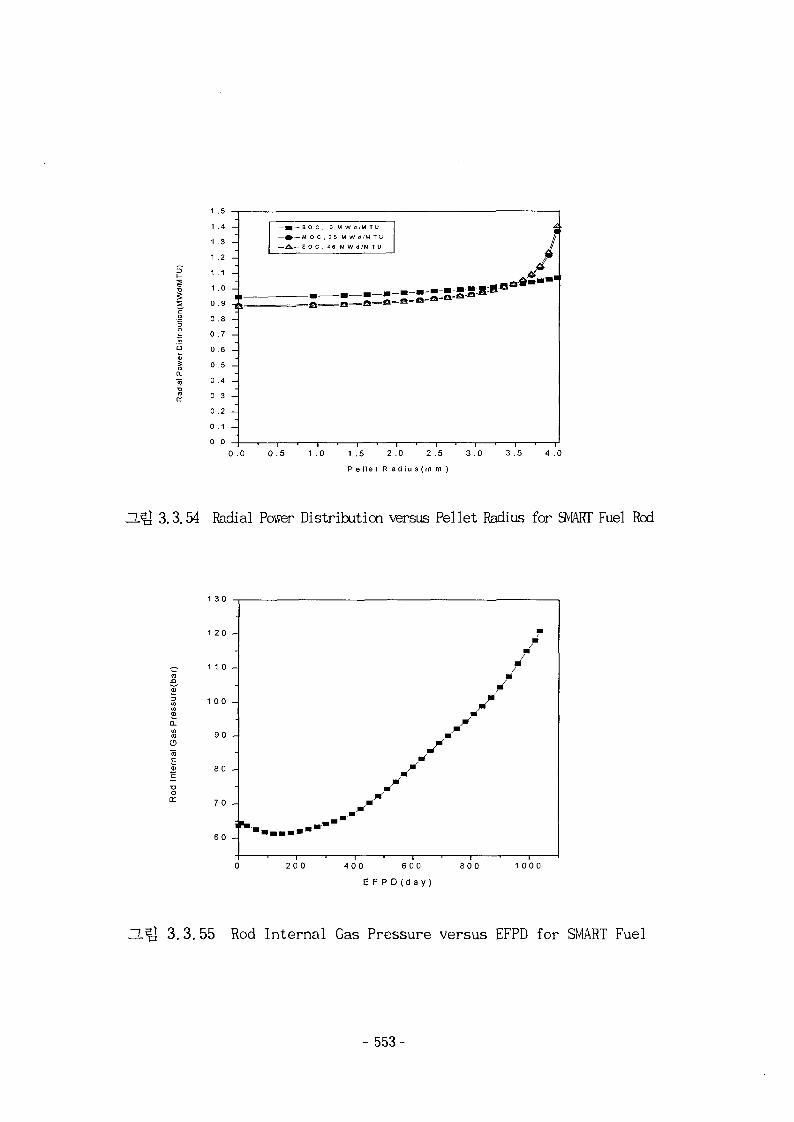
1.3 —
1 .4 -
1 .3 -
1 .2 -
1 . 1 -
1 .0 -
0.9 -j0 . 8 -
0 . 7 -
0 . 6 -
0 . 5 -
0 . 4 -
0 . 3 -
0 . 2 -
0 . 1 -
0 0
1
- • - B O C . 0 M W d / M T U
— » — M O C . 2 S M W d ^ W T U
— ^ — E O C . 1 6 M W d ' M T U f1
0 .0 0 . 5 1 . 0 1 .5 2 .0 2 .5 3 . 0
P e l l e t R a d i u s ( m m )
3 .5
ZUg 3.3.54 Radial Power Distribution versus Pellet Radius for SMART Fuel Rod
oa:
1 2 0 -
1 1 0 -
1 0 0 -
90 -
80 -
70 -
i60 -
fm.m • • - • • " " " '" • • • • • "
\
1 ' 1
200 400 600
E F P D (day)
800 1000
3.3.55 Rod Internal Gas Pressure versus EFPD for SMART Fuel
- 553-
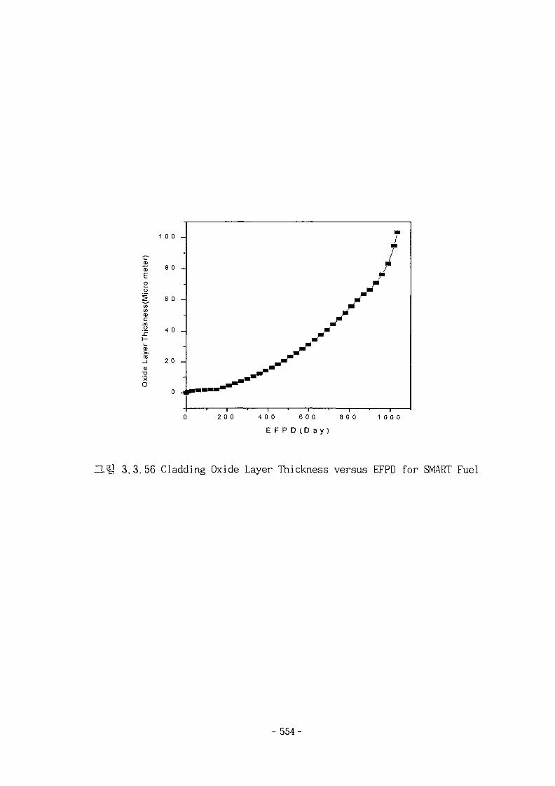
eter
)
Eoo
iess
i
O
sz
e La
yer
X
1 0 0 -
8 0 -
6 0 -
4 0 -
2 0 -
-
0 H
J
Itm
2 0 0 4 0 0 6 0 0 8 0 0 1 0 0 0
E F P D (D a y )
3.3.56 Cladding Oxide Layer Thickness versus EFPD for SMART Fuel
- 554-
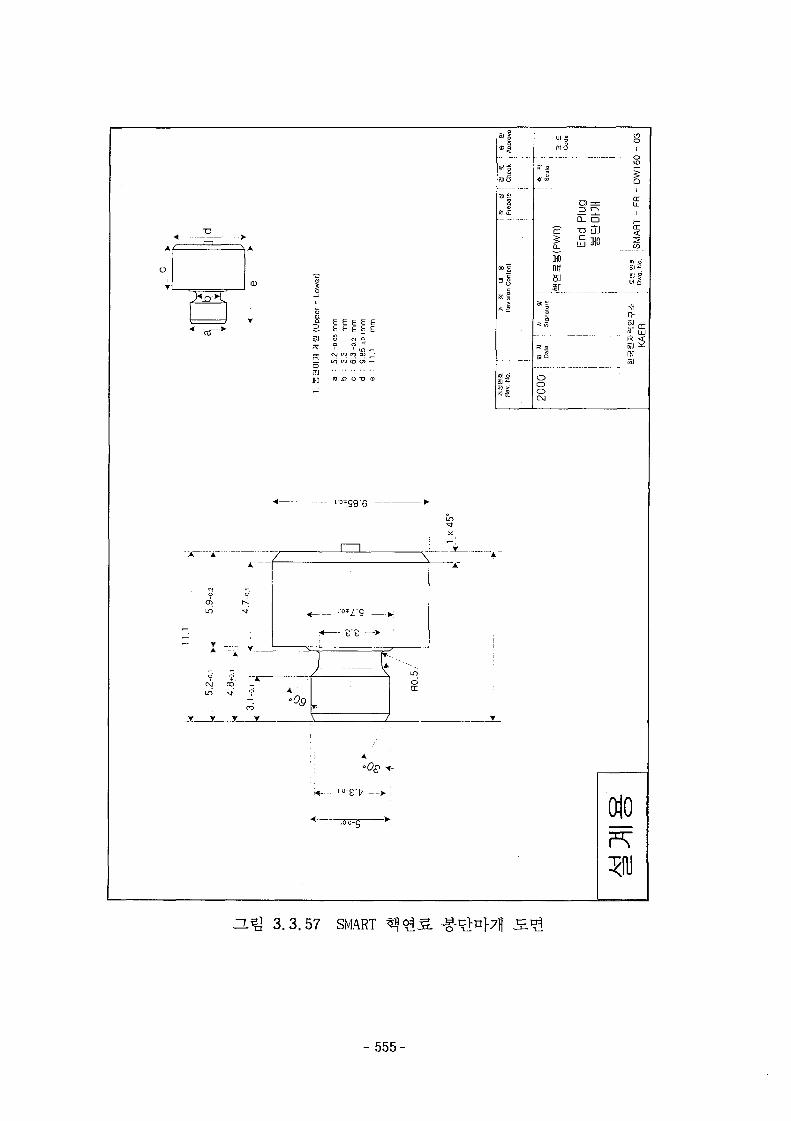
E £ E E E£ E E E £
— IT) CD (£> O) r~
oo-g
~L^ 3 .3 .57 SMART
- 555-
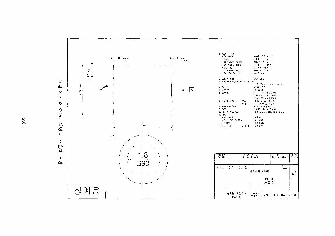
S. 0.03- 0.05
*;•« 0.05.0.03j - 0.05
ononO
uCO
toenooCO
>•
50
[n
10±
1. i S Jll M S!- Diameter- Length- Chamber Length- Dishing Volume- Density- Chamber Height- Dishing Depth
2 " Qj12J 3= s
3. Sim Homogenization Lot S
4. O/U HI5. U a'B6. fe^E
7. § 3 l * i S&( Max.Avg.
8. S^?IM a1 if9. iJE
10. l i i g SE §5111. OIAII^S
- 1SSJ 3 31
- SIMS12. H3£!EH ^ I P I
8.05 ±0.01 mm10 ± 1 mm0.6 ±0.2 mm1 1 ± 3 mm10.4 ±0.15 mm0.02 +0.06 mm0.23 min
AUC ga!?l
£ 2300kg ol UO2 Powder2.00 ±0.012 88 %< 1% : ±0.015%1%~2%: ±0.020%2% ~ 5% : ±0.050%< 20 mm3/g-UO2< 12 mm3/g-UO2< 40 mm3/g-UO210.40 ±0.15 g/cm3<0.15g/cm3(1700t:.2hrs)
> 5 m
< 300 m< 2.0 m
31 S U 8Revision Content Prepare ! Check
2000 « » ! «t W U Dale | Sionalu
KAERI
Pelletilill
-^ ! S M A R T - F R - D W 1 6 ° - ° 2
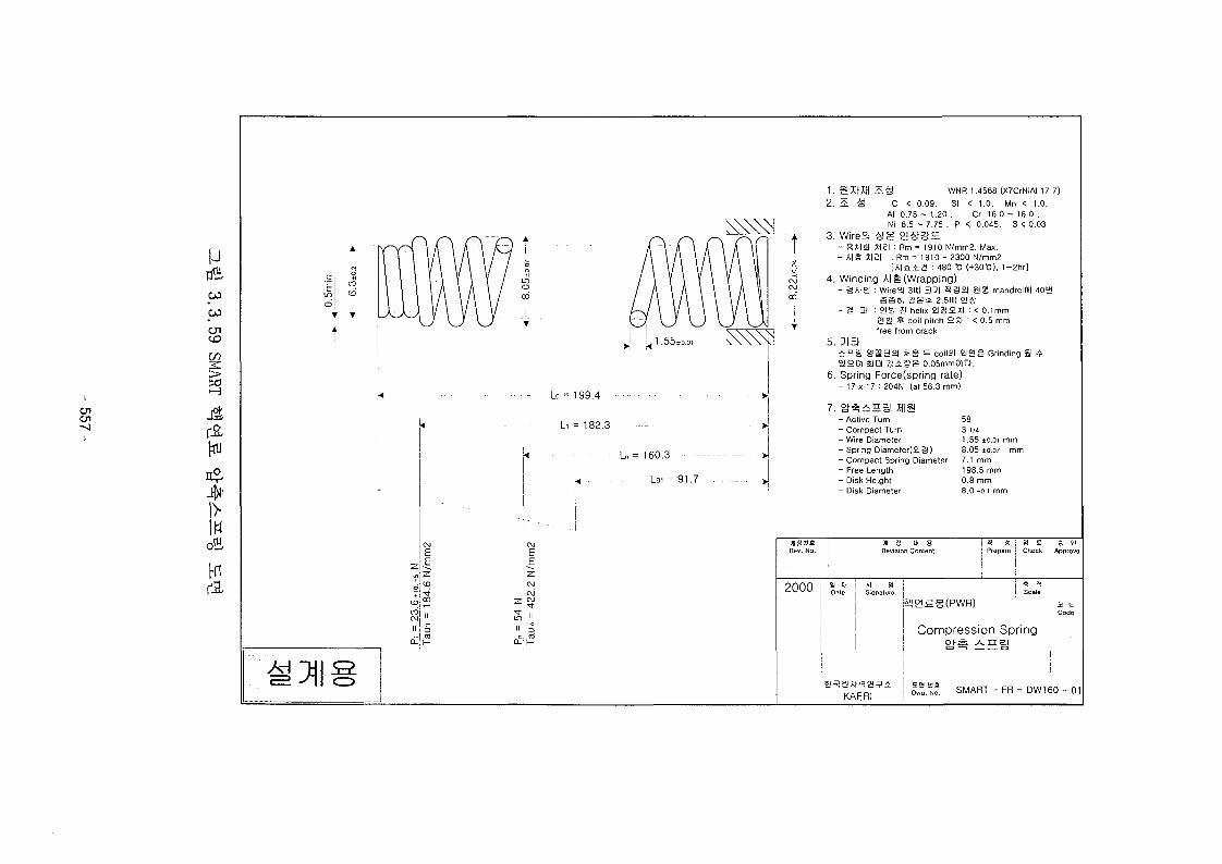
enen-j
i
urfECO
CO0 1to
l>IW
krfl,
Ezi£
<pi i,
j
1 . S WXH 2E& WNR 1.4568 (X7CrNiAI 17 7)2. £ -S C < 0.09. SI < 1.0. Mn < 1.0.
Al 0.75 - 1.20 . Cr 16.0 - 18.0 .Ni 6 . 5 - 7 . 7 5 . P < 0.045. S < 0.03
3. Wire°l &8 e!S&E- S S a US] : Rm = 1910 N/mm2. Max.- Ala JI2I : Rm= 1810 - 2300 N/mm2
[AIS52J : 480 -C (+30-C). 1~2hr]4. Winding A|g (Wrapping)
- SAIg : WireSI 3UH 33I 3 2 ) S!g mandrelOII 40EHSS8I a g » 2.5UB 2!S
- § a : 2!SJ S helix 2 IS2H : < 0.1mm£!&' * coil pilch 2X1 : < 0.5 mmfree from crack
5. J iai S B gfgga MS = coiiei 2I2S Grinding B *S11201 i l l ] S i g g 0.05mm0ia.
6. Spring Force(spring rate)- 1 7 x 1 7 : 204N (at 56.3 mm)
- Active Turn- Compact Turn- Wire Diameter- Spring Diameter(£|£3)- Compact Spring Diameter- Free Length- Disk Height- Disk Diameter
583 1/41.55 ±o.oi mm8.05 ±0.07 mm7.1 mm198.5 mm0.8 mm8.0 -o.t mm
Revision Content I Prepare j Check ; Approve
! i I
? 0 0 0 i * " i *• s
' - U I - " J ! Oale i Sionatu.e
i a E
! Code
Compression Spring Ioj-a A n ai j
KAERIS M A R T - F R - D W 1 6 ° - 0
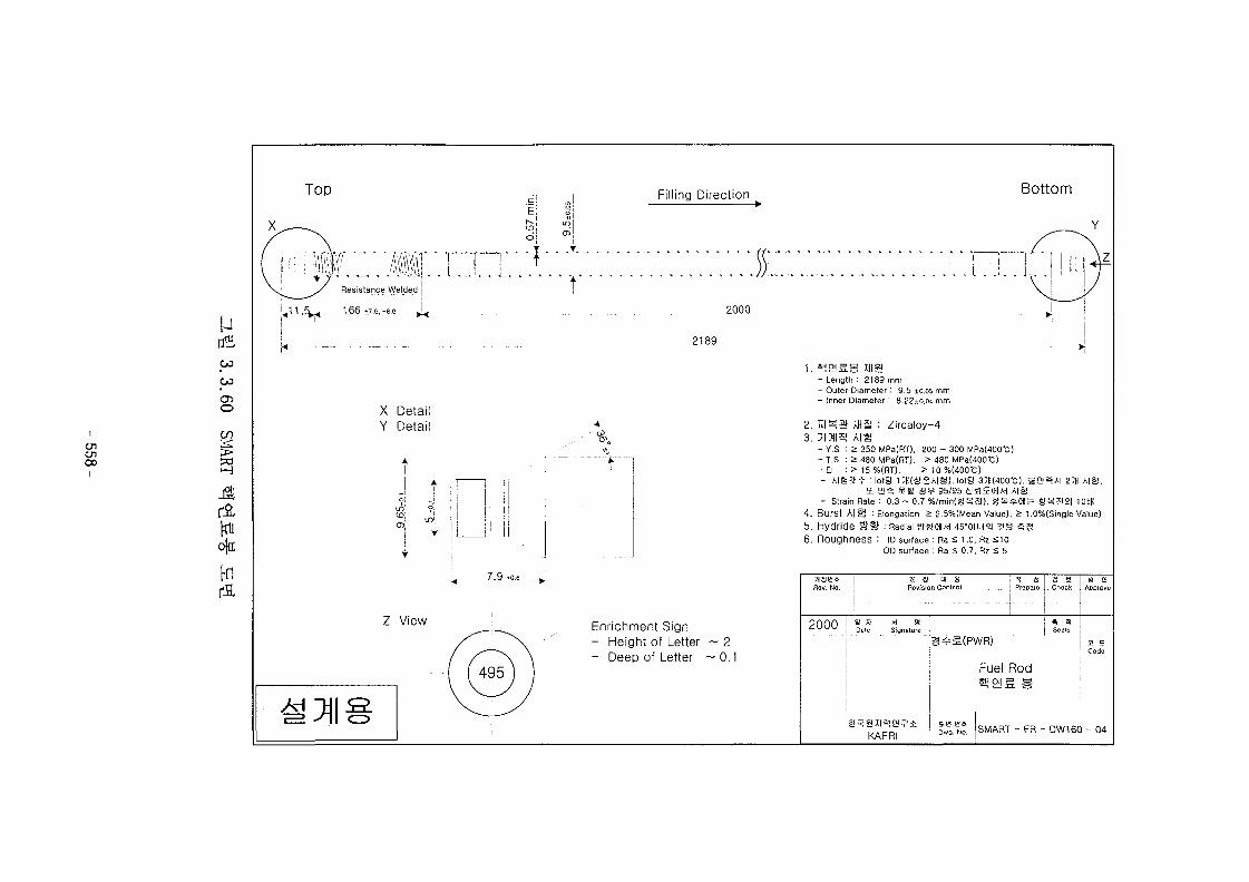
Top Filling Direction Bottom
enooi
uCO
CO
CT5O
in>so
rao|a:
ftril
X DetailY Detail
Z View
Oj. Y
2000
2189
7.9 .0.6,
Enrichment Sign- Height of Letter ~ 2- Deep of Letter ~ 0.1
1. s j ^ g g XHia- Length : 2189 mm- Outer Diameter : 9.5 ±0.05 mm- Inner Diameter : 8.22±o.o<t mm
2. V.m& IHB : Zircaloy-43. ;>i?ii3 A I S
- Y.S : £ 350 MPa(RT). 200 - 300 MPa(400-C)- T.S : a 480 MPa(RT). £ 480 MPa(400'C)- El : 2 15 %(RT). ^ 10 %(4001C)- A I S ^ ^ M o t i J l 3 » ( a S A | g ) . l o t g 35«(400-C). B e i ^ A I 23H A ia .
£E S!i§ ¥ S S 9 95/95 4!SIEOil/H A|g- Strain Rate : 0.3 ~ 0.7 %/min (g^H) , g^^O l l f e S ^ a 2 | lObK
4. Burst A [ g : Elongation 2 2.5%(Mean Value). 2 1.0%(Single Value)5. Hydride g f l f : Radial SSOIIAH 45-01LH21 ? § » g
6. ROUghneSS : ID surface : Ra S 1.0, Rz £10OD surface : Ra £ 0.7. Rz s 5
I a u gRevision Contcnl
! =1 S | 3 i! Prepare | _ Chech ADDIOve
2000 " | " a' w u j Dale I Slonalure
i ii
^ 5 IScale
KAERI
Fuel RodSjpjg g
SMART - FR - DW160 - 04
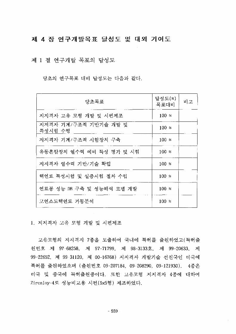
xjxi^x} a-S- s ^ 7fl^ si ^ 1 ^ 4 ^
- f i ^ * ^ ^ * l « i ^ ^ oflH] ^ ^ ^ 7 } gl A ] ^
gS-g- ^ ^ DB -7--% ^ ^ * B ^ S i 7flt
100 %
100 %
100 %
100 %
100 %
100 %
100 %
100 %
i. AAAA
97-68258, ^] 97-71799, ^ 98-313351, *fl 99-20633,
99-22652, ^1 99-31120, afl 00-16768) ^ | ^ 1 ^ 4 7fl^7l^- ^d?I^*l
09-207184, 09-208290, 09-121930).
Zircaloy-4S.
- 559-
2.
7\.
FIV
. D.B]JL FIV
( FIV
uf.
(1) SUSS *H2L& JL^-3.^ x]xm*}(3& 3x3%) ^ K0FA%
(2) Zircaloy-4S.
(3) Zircaloy-4S
- 5 6 0 -
(4)
ejoj ^.efl*] «0FA^ ^ S
(5)
(6)
head)
2.0
(7)
- 561-
. o| 7 | ^ ^
40 ms7>*|t- Bfl 2ms
(8)
^- ^ 7M ^ ^
3.7)if *> ^
3 7 ] CH]
time-history) -?•
fe ° 1 1 - <£ -^:
7111-
SL3
At^, oj
- 562-
4^17j]( angular transducer)^. ^ / J L ^ * } ^- *}£.(>]}
^(re lease)** ^ aitrjL ^ f ^ a SffnH ii
1^ ii(furnace)
^ 4,Uf.
( l )
-g.
- 5 6 3 -
A] 44
(2)
Uf. -i-^(collapse)
-^-S. 5x5
# Laser beam
Zircaloy-45. 4 ^ ^ i 5x5%
o]
(3) a*>^l 4 4 3 4 ^ ^ 5 o ^ ^
4434 ^
concave*} conformal contactol 5 ] ^
- 564-

3.
7}.
41 Hi 4^ 7\
icBf~fh§- (KAERI/TR-1460/00).
6 1 - 3X3
4
4(Hl
4.
- 565-
7]
CFD
(KAERI/TR-1296/99),
^1§)}^ (KAERI/TR-1451/99).
CFX
l- : 4 4 SCI
5.
6.
7}. DB
- 566-
alfe Siemens/KWU4 gj ABB-CE^ A ^ ^ S . «.
, OECD/NEAi}- IAEA7} ^-%-&.S. V}JL $1^ IFPE DB
(International Fuel Performance Experiments Data Base)
*}£-2.*}, HDJ^f- Reactor P r o j e c t ^
^-nl, FRAPCON-3 3 H
^.A^ol ^ ^ f e rim effect^ ^ ^ #
U02 ^ ^ ^ ] 3 ] « > ^ ^ ^ : <£^r: ^ S s . 7}|A>^|.^ ^5.^5,5 RAPID#
RAPID-GDI- 7Hyi*l-$i4. ^ < ^ 5 . ^ £ 7 } ^-7}^o]} rcfef
creep-out^] ^ - ^ ^ ^ $1^-2.$. o]M. c$4ff>}7] ^ t l creep-out S.1!^- 7{)
h 2-^i^S. U02
RIM ^-£ High Burnup Structure (HBS)£)
- 567-
71-7- *A HBS5] ^ o f l cfl*]: S ^ o ] ^ J S J ^ J L of*]
2*} ^£.3} &$#*l°1l tH*l:
7.
engineering *K5.# ^ ^ 1 " ^ ^ - ^ , t«<g^.^-^] cfl^f^ hot
channel ^ long term ^ - ^ ^ ^ # ^ r W & i } . 3E.Q <£?%% &*}£.!>] ^ ^ i
- 568-
2.
7}.
FIV s .
i f e FEM
- 569-
FIV
uf.
JL
4.
- 570-
Hot-Wirel-
ii
DB
DB
- 571 -
U02 RAPID H^.ZL
RAPID-GD H £ l
572-
o]
r:}^-
o]
steam generator*] n}
DB
, RAPID RAPID-GD 5 S 2 ^ n]
- 573-
3.1.1 ^
z**}-*]]", ^-g-i?4 4 97-7179931, 1997.
3.1.2 •&%$.$) 6*1, "^4^r ^ M " *lt> ^ #
^ *]*134*fl", -^1#^ 4 99-31120X, 1999.
3.1.3 ^ ^ ^ i | 6 1, "°J*fl
KAERI/TR-1147/98, 1998.
3.1.4 ^ ^ 5 : ^ 1 4<&, a5Lft2S.i§ ^ ^ ^ ^ ^Q*mn$) '98 ^tv^cf[5] ^«.^ f 1998.
3.1.5 A, Premount, "On the Vibrational Behavior of Pressurized Water
Reactor Fuel Rods," Nuclear Technology, Vol.58, pp. 483 - 491,
1982.
3.1.6 F. S. Tse, "Mechanical Vibrations-Theory and Applications,"
Allyn and Bacon Inc., pp. 268-270, 1978.
3.1.7 ^^$] 4*1, "Sl*i ^ ^ i^soi 71^5. <^^. xlx]^ ^^.-a
^ ^£-7-," tl^-^-g-^l^^-n^ 1998 ^ ^ l n ^ ^ ^ t ^ ^ , PP.
454-460,1988.
3.1.8 J. W. Miles, "Vibration of Beams on Many Supports," J. of
Engineering Mechanics Division: Proceedings of the America
Society of Civil Engineers, paper 863, 1956.
3.1.9 Y. K. Lin, "Free vibration of Continuous Beam on Elastic
Supports," Int. J. Mech. Sci., Vol. 4, pp. 409-423, 1962.
3.1.10 H. Chung, "Analysis Method for Calculating Vibration
Characteristics of Beams with Intermediate Supports," Nuclear
Engineering and Design, Vol. 63, pp. 55-80, 1981.
3.1.11 ^ A l i ] 36], "^^S. ^<$.g.J§^ icvfl *]*] £ ^ sfl*
^ l ^ W 1998 M l ^ t f l ^ l t ^ ] , PP. 177-183,1997.3.1.12 %%-*\$] 3*1, "
- 574-
98 ^ W ^ f i S ] , Vol.2,
pp. 297-302, 1998.
3.1.13 G. M. Corcos, "The Structure of the Turbulent Pressure Field in
Boundary Layer Flows," J. of Fluid Mechanics, Vol.18,
pp.353-358, 1964.
3.1.14 H. P. Bakewell Jr., "Wall Pressure Fluctuation in Turbulence
Pipe Flow," U.S. Navy Underwater Sound Lab. Report No. 559,
1962.
3.1.15 M. W. Wambsganss and P. L. Zaleski, "Measurement,
Interpretation and Characterization of Near-field Flow Noise,"
Proceedings Conf. on Flow-induced Vibration in Reactor System
Components, Argonne, IIlinoise, May 14-15, ANL-7685, pp.
112-140, 1970.
3.1.16 S. S. Chen and M. W. Wambsganss, "Parallel Flow-induced
Vibration of Fuel Rods," Nuclear Engineering and Deisgn, Vol.
18, pp. 253-278, 1972.
3.1.17 R. M. Kanazawa, "Hydroelastic Vibration of Rods in Parallel
Flow, Ph. D. Dissertation, University of Illinois, 1969.
3.1.18 ° 1 ^ £ ] 40*1, 3.el 23171 | 7/8^7] g- H><g.S. Q°A
^ 92 £VL *&*! ^H^, KAERI/TR-387/93, tl^-^^f^^^^i, 1993.
3.1.19 D. Nowell and D.A. Hills, Contact Problems incorporating
Elastic Layers, Int. J. Solids Structures, Vol. 24, No. 1, pp.
105-115, 1988.
3.1.20 H. Sohngen, Zur Theorie der endlichen Hilbert Transformation,
Math. Zeitschrift, 60(30), 30, 1954.
3.1.21 F. Erdogan, G.D. Gupta and T.S. Cook, Numerical solution of
singular integral equations in Method of Analysis and Solutions
of Crack Problems (edited by G. C. Sih), Noordhoff, Leyden,
1973.
3.1.22 H.K. Kim, Behaviour of a Surface Oblique Crack in Fretting
- 575-
Fatigue, Ph.D. Thesis, KAIST, 1997.
3.1.23 K.L. Johnson, Contact Mechanics, ISBN 0-521-25576-7, Cambridge
Univ. Press, 1989.
3.1.24 R. D. Mindlin, Compliance of elastic bodies in contact, J. Appl.
Mech., 16, pp. 259-268, 1949.
3.1.25 C. Cattaneo, Sul contatto di due corpi elastici: distribuzione
locale degli sforzi. Rendiconti dell' Accademia nazionale dei
Lincei, 27, Ser.6, pp. 342, 434, 474, 1938.
3.1.26 D.A. Hills and D. Nowell, Mechanics of Fretting Fatigue, ISBN
0-7923-2866-3, Kluwer Academic Publishers, 1994.
3.1.27 J. Dunders, Discussion of edge-bonded dissimilar orthogonal
elastic wedges under normal and shear loading, J. Appl. Mech.,
36, pp. 650-652, 1969.
3.1.28 P.L. Ko, The significance of shear and normal force components
on tube wear due to fretting and periodic impacting, Wear, 106,
pp. 261-281, 1985.
3.1.29 J.F. Archard, Contact and rubbing of flat surfaces, J. Appl.
Physics, 24(8), 981-988, 1953.
3.1.30 S. S. Iyer and P.L. Ko, Finite element modeling of plastic
deformation, crack growth and wear particle formation for
sliding wear of power plant components, Flow-Induced Vibration,
PVP-Vol. 328, ASME, pp. 369-377, 1996.
3.1.31 R.B. Waterhouse, Fretting Corrosion, Pergamon Press, 1975.
3.1.32 ^«g-M 3<y, SUl^ofl 21 *> £B|^n}£6flAlfil n l^o^*] *#«§•
7\%, W 7 1 W 3 1 '99 ^A^^m, fe-g^A, pp. 821-826,
1999.
3.1.33 N.P. Suh et al., Trans. ASME, J. Lubrication Technology, 96,
pp. 631-637, 1974.
3.1.34 N.P. Suh, Wear, 44. pp. 1-16, 1977.
3.1.35 J.R. Fleming and N.P. Suh, Wear, 44, pp. 39-56, 1977.
- 576-
3.1.36 G.C. Sih et al., Methods of Analysis and Solutions of Crack
Problems, Mechanics of Fracture 1, G.C. Sih ed. , Noordhoff
International Publishing, Leiden, 1973.
3.1.37 D. Nowell and D. A. Hills, J. Strain Analysis, 22(3), pp.
177-185, 1987.
3.1.38 H.K. Kim and S.B. Lee, Theoretical and Applied Fracture
Mechanics, 25(2), pp. 147-154, 1996.
3.1.39 J. Dunders and G.P. Sendeckyj, J. Applied Physics, 36, pp.
3353-3354, 1965.
3.1.40 S. Krenk, Quarterly Applied Mathematics, 32, pp. 479-484, 1975.
3.1.41 £%^-£] 491, *9&§.-§-/*!*13*l-afl ^ # ^ -8-US-^ *1H,
KAERI/TR-1193/98, th^*}^<£^-^, 1999.
3.1.42 W. Elber, Engineering Fracture Mechanics, 2, pp. 37-45 1970.
3.1.43 G.R. Irwin et al., Proceeding of ASTM, 58, pp. 640-657, 1958.
3.1.44 ASME Code Section III, Appendix A, 1986.
3.1.45 ^ J L £) 2*1, "3*1- # ^ 1 H l ^ ^^s-ofl cfftl -8-S>J3L4i
*1M", tfl*>7l^I4]-^ '99 ^Tfl^tflSl^g:^, Paper No. 99F077,
1999.
3.1.46 K. H. Yoon et al., "FE Analysis of Nonlinear Buckling Behavior
of a Spacer Grid in Fuel Assembly", SMiRT-15, Paper No. C02/3,
1999.
3.2.1 n] -s.tr] 4692302, DeMario et al., Coolant flow mixer grid for a
nuclear reactor fuel assembly, Sep. 8, 1987.
3.2.2 n] - --5r] 5440599, Rodack et al., Spacer grid with integral
side-supported flow directing vanes, Aug. 8, 1995.
3.2.3 *m^ # ^ *fl 98-313331, m <t) 7*1, S
7M *%<&3.$%I;H 1^]^^}, Feb. 4, 1998.
3.2.4 -&3^M # ^ Xft 2000-167685., 9l%7] Si] 7*1,
^Vi #^1# lt> ^ ^ ^^o^y-^B, March 31, 2000.
3.2.5 Rowe D. S. and Johnson B.M., 1974, Implications Concerning Rod
- 577-
Bundle Crossflow Mixing based on Measurements of Turbulent Flow
Structure, Int. J. Heat Mass Transfer, Vol. 17, pp. 407-419.
3.2.6 Moller S.V., 1991, On phenomena of turbulent flow through rod
bundles, Exp. Thermal and Fluid Science, Vol. 4, pp. 25-35.
3.2.7 Rehme K., 1992, The structure of turbulence in rod bundles and
the implications on natural mixing between the subchannels,
Int. J. Heat Mass Transfer, Vol. 35, pp. 567-581.
3.2.8 Shen Y. F., Cao Z.D. and Lu Q. G, 1991, An investigation of
crossflow mixing effect caused by grid spacer with mixing
blades in a rod bundle, Nuclear Engineering and Design., Vol.
125, pp. 111-119.
3.2.9 Karoutas Z. , Gu C.Y. and Scholin B. , 1995, 3-D flow analyses
for design of nuclear fuel spacer, Proc. of the 7 th Int.
Meeting on Nuclear Reactor Thermal-Hydraulics, New York, United
Sates, September.
3.2.10 Yang S.K. and Chung M. K., 1996, Spacer grid effects on
turbulent flow in rod bundles, J. of the Korean Nuclear
Science, Vol. 28, pp. 56-71.
3.2.11 <>J%7l, SL&q, % i W , &*m, 1998,
^ ^ s . vHf-fr^ CFD q, '^^nn3.2.12 In W.K. , Oh D.S. , Chun T. H. and Jung Y. H. , 1998, CFD
application to turbulent flows in rod bundles with mixing
blades, NTHAS98'- First Korea-Japan Symposium on Nuclear Thermal
Hydraulics and Safety, Pusan, Korea, 1998.
3.2.13 In W.K., Oh D.S. , Chun T.H. and Jung Y.H., 1999, CFD analysis
of turbulent flows in rod bundles for nuclear fuel spacer
design, Trans, of the 15th International Conf. on Structural
Mechanics in Reactor Technology (SMiRT-15), Seoul, Korea,
August.
3.2.14 <?]%7], 1999,
- 578-
3.2.15 IAEA Technology, CFX-4.2 Solver, Harwell Laboratory Oxford
shire, UK, 1997.
3.2.16 Launder B.E. and Spalding D. B. , 1974, The Numerical Computation
of Turbulent Flows, Computational Methods in Applied Mechanics
and Engineering, Vol. 3, pp. 269-289.
3.2.17 Rehme K., 1978, The Structure of Turbulent Flow Through a Wall
Subchannel of a Rod Bundle, Nuclear Engineering and Design,
Vol. 45, pp. 311-323.
3.2.18 Speziale, C. G. , 1987, On Nonlinear k-1 and k-e Models of
Turbulence, J. Fluid Mech. , Vol. 178, pp. 459-475.
3.2.19 Durret R. P., Stevenson, W. H., Thompson H. D. , 1988, Radial
and Axial Turbulent Flow Measurements with an LDV in an
Axisymmetric Sudden Expansion Air Flow, J, of Fluids
Engineering, Vol. 110, pp. 367-372.
3.2.20 Neti, S., Eichhorn, R. , Hahn, 0. J. , 1982, Laser Doppler
Measurements of Flow in a ^§ Bundle, Nuclear Engineering and
Design, Vol. 74, pp. 105-116.
3.2.21 Kjellstrom B. , Transport Process in Turbulent Channel Flow,
AE-RL-1344, Aktiebolaget Atom- energi, Studsvik (1971)
3.2.22 Trupp A. C. and Azad R. S., The Structure of Turbulent Flow in
Triangular Array Rod Bundles, Nuclear Engineering and Design,
Vol. 32, 47-84 (1975)
3.2.23 Rowe D. S., Implications Concerning Rod Bundle Crossflow Mixing
Based on Measurements of Turbulent Flow Structure, Int. J. Heat
and Mass Transfer, Vol. 17, 407-419 (1979)
3.2.24 Hooper J. D. and Rehme K., Large-scale Structural Effects in
Developed Turbulent Flow through Closely-spaced Rod Arrays, J.
Fluid Mech., Vol. 145, 305-337 (1984)
3.2.25 Shen Y. F., Cao Z. D. and Lu Q G, An Investigation of Crossflow
- 579-
Mixing Effect Caused by Grid Spacer with Mixing Blades in a Rod
Bundle, Nuclear Engineering and Design, Vol. 125, 111-119
(1991)
3.2.26 Yang S. K. and Chung M. K., Spacer Grid Effects on Turbulent
Flow in Rod Bundles, J. KNS, Vol. 28, 56-71 (1996)
3.2.27 Ingesson L. and Hedberg S. , Heat Transfer between Subchannels
in a Rod Bundle, Heat Transfer, Paris, Vol. 3, Fc 7. 11,
Elsevier (1970)
3.2.28 Hejna J. et al., Measurement Program for the Structure of
Turbulent Flows in a Square Rod Lattice Part 2. Experimental
Investigations of Flow in a Model of PWR- Type Fuel Assembly
Spaced by Systematical Vaned Grids, Nuclear Research Institute
Rez pic, 1994
3.2.29 In, W. K., Numerical Analysis of Turbulent Flow Characteristics
in Nuclear Fuel Subchannel with Flow Mixing Promoters, KSME,
Pusan, vol. B, pp. 608-613 (1999)
3.2.30 AEA Technology, CFX-4.2 Solver, Harwell Laboratory,
Oxfordshire, UK, (1997)
3.2.31 Launder B.E. and Spalding D.B., The numerical computation of
turbulent flows, Computational Methods in Applied Mechanics and
Engineering, Vol. 3, 269-289 (1974)
3.2.32 Yang S. K. and Chung M. K., "Spacer Grid Effects on Turbulent
Flow in Rod Bundles, " J. KNS, Vol. 28, 56-71 (1996)
3.2.33 Z. Karoutas, C.Y. Gu, B. Scholin, "3-D Flow Analysis for Design
of Nuclear Fuel Spacer, " NURETH-7, New York, 1995.
3.2.34 W.K. In, " CFD Simulation of crossflow mixing in a rod bundle
with mixing blades," Proc. KNS, Spring Meeting, 1999.
3.2.35 J.B. Chung, W.P. Baek, S.H. Chang," Effects of the spacer and
mixing vanes on Critical Heat Flux for low pressure and water
at low velocities, " Int. Comm. Heat Mass Transfer, Vol 23, No
- 580-
6, pp. 757-765, 1996.
3.2.36 T.H. Chun et al., "Fuel assembly spacer grid with swirl
deflectors and hydraulic pressure springs," 09/121,930, 1998
3.2.37 Katto, Y., 1978, "A Generalized Correlation of Critical Heat
Flux of Forced Convection Boiling in Vertical Uniformly Heated
Tubes," Int. J Heat Mass Transfer, Vol. 21, pp. 783-794.
3.2.38 De Stordeur, A. N. (1961), Nucleonics, 19, 74-79.
3.2.39 Rehme K. (1973), Nuclear Technology, 17, 15-23.
3.2.40 Cevolani, S. (1995) ,IAEA 1st Research Co-ordination Meeting of
CRP on Thermal Hydraulic Relationships for Advanced Water
Cooled Reactors, Vienna.
3.2.41 Kim, N. H. , Lee S. K. and Moon K. S. (1992), Nuclear
Technology, 98, 349- 353.
3.2.42 Hoerner, S. F. (1965), Fluid Dynamic Drag, 2nd edition
Published by the Author.
3.2.43 White, F. M. (1979), Viscous Fluid Flow, McGraw-Hill Book
Company, New York.
3.2.44 Todreas, Neil E. and Kazimi, Mujid S. (1989), Nuclear Systems
I, Hemisphere Publishing Corporation.
3.2.45 Bruch, G., et al (1988), 1st KSME-JSME Thermal Engineering
Conference, Seoul.
3.2.46 Weisman, J., 1992, The current status of theoretically based
approaches to the prediction of the critical heat flux in flow
boiling, Nucl. Tech., 99, 1-21.
3.2.47 Lee, C.H., Mudawar, I., 1988, A mechanistic critical heat flux
model for subcooled flow boiling based on local bulk flow
conditions, Int. J. Multi Phase Flow , 14, 711-728.
3.2.48 Katto, Y. , 1990, A physical approach to critical heat flux of
subcooled flow boiling in round tubes, Int. J. Heat Mass
- 581-
Transfer, 33, 611-620.
3.2.49 Celata, G.P. , Cumo, M. , Mariani, A., Simoncini, M. , Zummo, G.,
1994, Rationalization of existing mechanistic models for the
prediction of water subcooled flow boiling critical heat flux,
Int. J. Heat Mass Transfer, 37, 347-360.
3.2.50 Weisman, J., Pei, B.S., 1983, Prediction of critical heat flux
in flow boiling at low quality, Int. J. Heat Mass Transfer, 26,
1463-1477.
3.2.51 Weisman, J., Ying, S.H., 1985, Theoretically based critical
heat flux prediction for rod bundles at PWR condition, Nucl.
Eng. Des., 85, 239-250.
3.2.52 Weisman, J., Ying, Y. , 1985, A theoretically Based Critical
heat flux prediction for rod bundles at PWR conditions, Nucl.
Eng. Des. 85.
3.2.53 Lin, W., et al., 1989, A theoretical critical heat flux model
for rod bundles under pressurized water reactor conditions,
Nuclear Technology, 85.
3.2.54 Lin, W. , Lee, C.H., Pei, B.S., 1989, An improved theoretical
critical heat flux model for low quality flow, Nuclear
Technology, 88.
3.2.55 Lee, S.C., Dorra, H., Bankoff, S. G., 1992, A critical review of
predictive models for the onset of significant void in forced
convection subcooled boiling, Fundamentals of subcooled Flow
Boiling, HTD-Vol.217, 33-39, ASME Winter Ann. Mtg, Anaheim, CA,
Nov.
3.2.56 Saha, P., Zuber, N., 1974, Point of net vapor generation and
vapor void fraction in subcooled boiling, Proc. 5th Int. Heat
Transfer Conf. , 4, Tokyo.
3.2.57 Haramura, Y., Katto, Y., 1983, A new hydrodynamic model of
critical heat flux, applicable widely to both poll and forced
- 582-
convention boiling on submerged bodies in saturated liquids,
Int. J. Heat Mass Transfer, 26, 389-399.
3.2.58 Shah, M.M., 1977, A general correlation for heat transfer
during subcooled boiling in pipes and annuli, ASHRAE Trans.,
83, 202-217.
3.2.59 White, F. M. , 1979, Viscous Fluid Flow, Chap. 6-5.2,
McGraw-Hill Book Company, New York.
3.2.60 Tong, L.S., 1975, Boiling Heat Transfer and Two-Phase Flow,
Robert E. Krieger Pub. Co, New York, pp 140-144.
3.2.61 Thompson, B., Macbeth, R.V. , 1964, Boiling water heat transfer
in uniformly heated round tubes: A compilation of world data
with accurate correlations, AEEW-R-356.
3.2.62 Zenkevich, A., 1974, Analysis and generalization of
experimental data on heat transfer crisis associated with
forced convection of cooling water in tubes, AECL-Tr-Misc-304.
3.2.63 Chang, S.H., et al., 1996, The KAIST CHF data bank (Rev. 3),
KAIST-NUSCOL-9601, KAIST, Taejon, Korea.
3.2.64 Bowring, R.W., 1972, A simple but accurate round tube uniform
heat flux, dryout correlation over the pressure range 0.7-17
MN/m2 (100-2500 psia), AEEW-R789, United Kingdom Atomic Energy
Authority.
3.2.65 Groeneveld, D. C., et al., 1996, The 1995 look-up table for
critical heat flux in tubes, Nucl. Eng. Des., 163.
3.2.66 Coller, J.G., Thome, J.R., 1994, Convective Boiling and
Condensation 3rd Edn, Clarendon Press, Oxford, Britain.
3.2.67 Levy, S. , 1967, Forced convective subcooled boiling prediction
of vapor volumetric fraction, Int. J. Multiphase Flow, 10,
951-965.
3.2.68 Cof field, R. D. Jr., Rohrer, W.M. Jr., Tong, L.S. , 1969, A
subcooled DNB investigation of Freon 113 and its similarity to
- 583-
to subcooled water DNB data, Nucl. Eng. Des., 11, 143-153.
3.2.69 Chang, S.H., Lee, K.W., 1989, A mechanistic critical heat flux
model for subcooled flow boiling based on local bulk flow
conditions, Nucl. Eng. Des. , 113, 35-50.
3.2.70 Launder, B.E. & Spalding, D. B. 1974 The Numerical Computation
of Turbulent Flows. Computer Methods in Applied Mechanics and
Engineering3, pp.269-289.
3.2.71 Jones, W. P. & Launder, B. E. 1972 The Prediction of
Laminarization with a Two-Equation Model of Turbulence. Int.
J. Heat and Mass Transfer, 15, pp.301-314.
3.2.72 Launder, B. E. & Sharma, B. I. 1974 Application of the
Energy-Dissipation Model of Turbulence to the Calculation of
Flow near a Spinning Disc. Letters in Heat and Mass Transfer.
1, pp.131-138.
3.2.73 Lam, C. K. G. & Bremhorst, K. A. 1981 A Modified Form of the
k— E Model for Predicting Wall Turbulence. ASME Journal of
Fluids Engineering. 103, pp.456-460.
3.2.74 Chien, K. Y. 1982 Predictions of Channel and Boundary-Layer
Flows with a Low-Reynolds-Number Turbulence Model. AIAA
Journal, 20, pp.33-38.
3.2.75 Nagano, Y. & Hishida, M. 1987 Improved Form of the k-e Model
for Wall Turbulent Shear Flows. ASME Journal of Fluids
Engineering. 109, pp. 156-160.
3.2.76 Myong, H. K. & Kasagi, N. 1990 A New Approach to Improved k- e
Turbulence Model for Wall-Bounded Shear Flows. JSME
International Journal, Ser.II, 33, pp.63-72.
3.2.77 Nagano, Y. & Tagawa, M. 1990 An Improved k— e Model forBoundary
Layer Flows. ASME Journal of Fluids Engineering, 112, pp.33-39.
3.2.78 Chang, K. C., Hsieh, W. D. & Chen, C. S. 1995 A Modified
Low-Reynolds-Number Turbulence Model Applicable to
- 584-
Recirculating Flow in Pipe Expansion. ASME Journal of Fluids
Engineering, 117, pp.417-423.
3.2.79 Patel, V. C., Rodi, W. & Scheuerer, G. 1985 Turbulence Models
for Near-Wall and Low Reynolds Number Flows:A Review. A1AA J.,
23, pp.1308-1319.
3.2.80 Jang, D. S., Jetli, R & Acharya, S. 1986 Comparison of the
PISO, SIMPLER and S1MPLEC algorithms for the treatment of the
pressure-velocity coupling in steady flow problems. Numerical
heat Transfer, 10, pp. 209-228.
3.2.81 Patankar, S. V. 1980 Numerical Heat transfer and Fluid Flow.
McGRAW-HILL Book Company.
3.2.82 Ferziger, J. H. & Peric, M. 1996 Computational Methods for
Fluid Dynamics. Springer-Verlag.
3.2.83 Nallasamy, M. 1987 Turbulence Models and Their Applications to
the Prediction of Internal Flows: A Review. Computers and
Fluids, 3, pp.151-194.
3.2.84 Gosman, A. D & Ideriah, F. J. K. 1976 TEACH-2E: A General
computer Program For 2-D, Turbulent, Recirculating Flows.
Department of Mechanical Engineering, Imperial College.
3.2.85 Han, T., Humphrey, J. A. C. & Launder, B. E. 1981 A Comparison
of Hybrid and Quadratic-Lfpstream Differencing in High Reynolds
Number Elliptic Flows. Comput. Methods Appl. Mech. Eng. 29,
PP.81-95.
3.2.86 Hsieh, W. D. & Chang, K. C. 1996 Turbulent Flow Calculation
with Orthodox QUICK scheme. Numerical Heat Transfer, Part A.
30, pp.589-604.
3.2.87 Hayase, T., Humphrey, J. A. C. & Grief, R. 1992 A Consistently
Formulated QUICK scheme for Fast and Stable Convergence Using
Finite-Volume iterative Calculation Procedures. J. Comput.
Phys. 98, pp.108-118.
- 585
3.2.88 * g ? R , 1999 ##g-#v*jj^SA Jjhg;^, Korea, ISBN 89-7393-105-9
93550
3.2.89 Schildknecht, M. , Miller, J. A. & Meier, G. E. 1979 The
influence of suction on the structure of turbulence in fully
developed pipe flow. J. Fluid Mech. 90, pp.67-107.
3.2.90 Laufer, J. 1954 The Structure of Turbulence in Fully Developed
Pipe Flow. NACA Report 1174.
3.2.91 Eckelmann, H. 1974 The structure of the viscous sublayer and
the adjacent wall region in a turbulent channel flow. J. Fluid
Mech. 65, pp. 439-459.
3.2.92 Durret, R. P., Stevenson, W. H. & Thompson, H. D. 1988 Radial
and Axial Turbulent Flow Measurements with an LDV in an
Axisymmetrical Sudden Expansion Air Flow. ASME Journal of
Fluids Engineering. 110, pp.367-372.
3.2.93 y 4 ^ , *I%7l, ^m, 3-^. 2000, o]
TFC2D 7HH, * K ^ * } ^ <£^L, 7l -JiJLA-](TR-1488), 101p.
3.3.1 P.M. Chantoin, E. Sartori, J.A. Turnbull, "The Compilation of A
Public Domain Database on Nuclear Fuel Performance for the
Purpose of Code Development and Validation", 1FPE Database ver.
June 1997.
3.3.2 D. D. Lanning, C. E. Beyer and G.A. Berna, "FRAPCON-3: Integral
Assessment", NUREG/CR-6534, Vol.3, PNNL-11513, Dec. 1997.
3.3.3 A.T. Donaldson' "In-Reactor Creep Behaviour of Zircaloy Under
Variable Loading Conditionss In IFA-585", HWR-413, October,
1994.
3.3.4 M. A. McGrath, "In-Reactor Creep Behaviour of Pre-Irradiated
Zircaloy-4 Under Tensile Hoop Stresses (IFA-585.4)", HWR-532,
Jan. 1998.
3.3.5 M. V. Polley and H.E. Evans, "Effect of Lithium Hydroxide on
- 586-
Zircaloy Corrosion in the Ringhals-3 PWR Plant", EPRI
TR-100389, Mar. 1992.
3.3.6 P.M. Gilmore, J.C. Gills, H.H. Klepfer and J.M. Sorensen, "EPRI
PWR Fuel Cladding Corrosion (PFCC) Model", Vol. 2, EPRI
TR-105387-V2, Dec. 1996.
3.3.7 T. Kido and K. Ranta-Puska, "Zircaloy Corrosion at High Li
Concentration under PWR Conditions (IFA-568.1 Final Report),
HWR-333, Oct. 1992.
3.3.8 K. Lassmann, C.T. Walker, J. van de Laar,F. Lindstrom, J. Nucl.
Mater. 226 (1995) 1.
3.3.9 C.B. Lee, J.S. Song.D.H. Kim, J.G. Bang, Y. H. Jung, "RAPID
program to predict radial power and burnup distribution in UO2
fuel", KAERI/TR-1217/99, KAERI, 1999.
3.3.10 I.D. Palmer, K.W. Hesketh, P. A. Jackson, "A model for
predicting the radial power profile in a fuel pin", Water
Reactor Fuel Element Performance Computer Modelling, ed. J.
Gittus, Applied Science, Barking, UK, p.321, 1983.
3.3.11 K. Lassmann, C. O'carroll, J. van de Laar, C.T. Walker, J.
Nucl. Mater. 208 (1994) 223.
3.3.12 E. A. Villarino, R.J.J. Stammler, A.A. Ferri, J.J. Casal, Nucl.
Sci. and Eng. 112 (1992) 16.
3.3.13 J. Spino, D. Baron, M. Coquerelle, A. D. Stalios, J. Nucl.
Mater. 256(1998) 189.
3.3.14 M. J. Ball, "ORIGEN : The ORNL isotope generation and depletion
code", ORNL Report, ORNL-4628, 1973.
3.3.15 D. S. Sohn, et al, Fuel Design Report for 17 x 17 Assembly,
KAERI, 1987.
3.3.16 J. H. Baik, et al., Fuel Design Report for CE Type 16 x 16
Assembly, KAERI/TR-547/95, KAERI, 1995.
3.3.17 E.A. Villarino, et al., "HELIOS : Angularly dependent collision
- 587-

probabilities", Nucl. Sci. and Eng., 112, p.16-31, 1992.
3.3.18 °]#^ £J, RAPID Program to Predict Radial Power and Burnup
Distribution in U02 Fuel, KAERI/TR-1217/99, KAERI, 1999.
3.3.19 I. Zacharie, et. al., Thermal Treatment of U02 in PWR :
Swelling and Release of Fission Gases, J. of Nucl. Mater., 255
(1998) 85-91
3.3.20 W. B. Beere and G. L. Reynolds, J. Nucl. Mater. 45 (1972)10
3.3.21 D. Olander, Fundamental Aspects of Nuclear Reactor Fuel
Elements, TID26711-PI,(1976)
3.3.22 G. L. Reynolds, W. B. Beere and P.T. Sawbridge, J. of Nucl.
Mater., 41 (1971) 112
3.3.23 T. Kogai, Modelling of Fission Gas Release and Gaseous Swelling
of LWR Fuels, J. of Nucl. Mater., 244 (1997) 134
3.3.24 M. 0. Tucker and J. A. Turnbull, The Morphology of Interlinked
Porosity in Nuclear Fuels, Proc. Roy. Soc. Lond. A.343 (1975)
299-314
3.3.25 I. Zacharie, et. al., Microstructural Analysis and Modelling of
Intergranular Swelling of an Irradiated UO2 Fuel Treated at
High Temperature, J. of Nucl. Mater., 255 (1998)92-104
3.3.26 J. Burbach and H. Zimmermann, KfK 3997 (1985)
3.3.27 H zimmermann, Investigations on Swelling and Fission Gas
Behaviour in U02, J. of Nucl. Mater., 75 (1978) 154-161
3.3.28 S. Kashibe & K.Une, Effect of External Restraint on Bubble
Swelling in U02 Fuels, J. of Nucl. Mater., 247 (1997) 140
3.3.29 D. Schrire, F. Sontheimer, G.Lysell, "ROPE-I: The Studsvik BWR
Rod Overpressure Experiment", Int'l Topical Meeting on LWR Fuel
Performance, West Palm Beach, Florida, April 16-19, 1994.
3.3.30 F. Sontheimer, M.R. Billaux, "Mechanical Analysis for the
Siemens Rods During ROPE-II Start-up with a New Advanced
SiemensFuel Rod Code", HPR-347 Volume I, Loen, 1996.
- 588-
3.3.31 K.L. Nissen, A.T. Donaldson, "Measurements of Zirclaoy
In-Reactor Creep Behavior under Variable Loading Conditions in
IFA-585", HWR-358, March 1993.
3.3.32 A.T. Donaldson' "In-Reactor Creep Behaviour of Zircaloy Under
Variable Loading Conditionss In IFA-585", HWR-413, Oct. 1994.
3.3.33 M. A. McGrath, "In-Reactor Creep Behaviour of Pre-Irradiated
Zircaloy-4 Under Tensile Hoop Stresses (IFA-585.4)", HWR-532,
Jan. 1998.
3.3.34 D. G. Franklin, G.E. Lucas, A.L. Bement, "Creep of Zirconium
Alloys in Nuclear Reactors," ASTM STP-815, Philadelphia, 1983.
3.3.35 Garzarolli, F. , Jung, W. , Shoenfeld, H., et al. "Waterside
Corrosion of Zircaloy Fuel Rods," EPRI NP-2789, Research
Project 1250-1, Kraftwerk Union, AG and Combustion engineering,
Inc., Electric Power Research Institute, Palo, CA, Dec. 1982.
3.3.36 Billot, P. and Giordano, A. , "Comparison of Zircaloy Corrosion
Models from the Evaluation of In-Reactor and Out-of-Pile Loop
Performance," Zirconium in the Nuclear Industry : Ninth
International Symposium, ASTM STP 1132, American Society for
Testing Materials, West Conshohocken, PA, 1991, pp. 539-565.
3.3.37 Garde, A. M. , "Enhancement of Aqueous Corrosion of Zircaloy-4
Due to Hydride Precipitation at the Metal-Oxide Interface,"
Zirconium in the Nuclear Industry : Ninth International
Symposium, ASTM STP 1132, C. M. Eucken and A. M. Garde, Eds.,
American Society for Testing Materials, West Conshohocken, PA,
1991, pp. 566-594.
3.3.38 Kim, Y. S., Rheem, K. S., and Min, D. K. , "Phenomenol ogi cal
Study of In-Reactor Corrosion of Zircaloy-4 in Pressurized
Water Reactors, " Zirconium in the Nuclear Industry •' Tenth
International Symposium, ASTM STP 1245, A. M. Garde and E. R.
Bradley, Eds., American Society for Testing Materials, West
- 589-
Conshohocken, PA, 1994, pp. 745-759.
3.3.39 ^ ^ H , £ 3 X ^^, ^^^, ^^^, "Zircaloy-4
ofl *]*l-b Li OH ^ Hydride^) <£%\" '97 M ] ^ ^
t > ^ - ^ 4 ^ ^ - 5 ] , 1997, pp. 75-80.
3.3.40 Cheng, B. , Kruger, R. M., and Adamson, R. B. , "Corrosion
Behavior of Irradiated Zircaloy," Zirconium in the Nuclear
Industry : Tenth International Symposium, ASTM STP 1245, A. M.
Garde and E. R. Bradley, Eds., American Society for Testing
Materials, West Conshohocken, PA, 1994, pp. 400-418.
3.3.41 Cheng, B., Gilmore P. M., and Klepfer H.H., "PWR Zircaloy Fuel
Cladding Corrosion Performance, Mechanics, and Modeling,"
Zirconium in the Nuclear Industry : Eleventh International
Symposium, ASTM STP 1295, E. R. Bradley and G. P. Sabol, Eds.,
American Society for Testing Materials, Garmisch-Partenkirchen,
Germanym 1995, pp. 137-160.
3.3.42 Billot, P. and Giordano, A.,"Comparison of Zircaloy Corrosion
Models from the Evaluation of In-Reactor and Out-of-Pile Loop
Performance," Zirconium in the Nuclear Industry :Ninth
International Symposium, ASTM STP 1132, AmericanSociety for
Testing Materials, West Conshohocken, PA, 1991, pp. 539-565.
3.3.43 M.E. Cunningham, M.D. Freshley, D.D. Lanning, J. Nucl. Mater.
188 (1992) 19.
3.3.44 K. Une, K. Nogita, S. Kashibe, M. Imamura, J. Nucl. Mater. 188
(1992) 65.
3.3.45 J. Spino, K. Vennix, M. Coquerelle, J. Nucl. Mater. 231 (1996)
179.
3.3.46 J. Spino, D. Baron, M. Coquerelle, A.D. Stalios, J. Nucl.
Mater. 256 (1998) 189.
3.3.47 M. Mogensen, J.H. Pearce, C. T. Walker, J. Nucl. Mater. 264
(1999) 99.
- 590-
3.3.48 M.V. Speight, Nucl. Sci. Eng., 37 (1969) 180.
3.3.49 A.H. Booth, AECL-496, AECL, 1957.
3.3.50 K. Lassmann, C.T. Walker, J. Van der Laar, F. Lindstrom, J.
Nucl. Mater. 226 (1995) 1.
3.3.51 C.B. Lee, et al., KAERI/TR-1217/99, KAERI, 1999.
3.3.52 J.A. Turnbull, J. Nucl. Mater. 38 (1971) 203.
3.3.53 D. R. Olander, Fundamental aspects of nuclear reactor fuel
elements, ERDA, 1976.
3.3.54 I. Matsson and H. Teshima, Proc. of Enlarged Halden Program
Group Meeting, HPR-349, Norway, 1998.
3.3.55 C. Beyer and D. Lanning, Review of fuel thermal conductivity
data and model, Seminar on Thermal Performance of high burnup
LWR Fuel, Cadarache, France, 2-6 March, 1998.
3.3.56 D. G. Martin, A Re-appraisal of the thermal conductivity of UO2
and mixed (U,Pu) oxide fuel, J. Nucl. Mater. 110(1982)73.
3.3.57 K. Bakker, et al., Determination of a porosity correction
factor for the thermal conductivity of irradiated UO2 fuel by
means of the finite element method, J. Nucl. Mater.
226(1995)128.
3.3.58 H. Kleykamp, The chemical state of the fission products in
oxide fuels, J. Nucl. Mater. 131(1985)221.
3.3.59 P.G. Lucuta, et al., Modelling of U02-based SIMFUEL thermal
conductivity : The effect of the burnup, J. Nucl. Mater.
217(1994)279.
3.3.60 P.G. Lucuta, et al., A pragmatic approach to modeling thermal
conductivity of irradiated U02 fuel : review and
recommendations, J. Nucl. Mater. 232(1996)166.
3.3.61 W. Wiesenack, Assessment of UO2 conductivity degradation based
upon in-pile temperature data, Proc. of Int. Top. Mtg. on LWR
Fuel Performance, Portland, Oregon, 1997.
- 591 -
3.3.62 K. Ohira and N. Itaki, Thermal conductivity measurements of
high burnup UO2 pellet and a benchmark calculation of fuel
temperature, Proc. of Int. Top. Mtg. on LWR Fuel Performance,
Portland, Oregon, 1997.
3.3.63 M. Amaya and M. Hirai, Recovery behavior of thermal
conductivity in irradiated UO2 pellets, J. Nucl. Mater. 247
(1997)76.
3.3.64 R. C. Daniel and I. Cohen, In-pile effective thermal
conductivity of oxide fuel elements to high burnup depletion,
WAPD-246, 1964.
3.3.65 J.H. Harding and D. G. Martin, Recommendation for the thermal
conductivity of U02, J. Nucl. Mater. 166(1989)166.
3.3.66 S. Yagnik, Thermal conductivity recovery phenomenon in
irradiated U02 and (U,Gd)O2, Proc. of Int. Top. Mtg. on LWR Fuel
Performance, Parkcity, Utah, 2000.
3.3.67 M. Lippens and L. Mertens, High burnup UO2 and (U,Gd)02 thermal
diffusivity measurements and post-irradiation
characterizations, EPRI Report TR-106501, 1996.
3.3.68 J. Spino, et al., Detailed characterization of the rim
microstructure in PWR fuels in the burnup range 40-67 GWd/tM,
J. Nucl. Mater. 231(1996)179.
3.3.69 J. Spino, et al., High burnup rim structure : evidences that
xenon-depletion, pore formation and grain subdivision strat at
different local burnups, J. Nucl. Mater. 256(1998)189.
3.3.70 USNRC, "USNRC Standard Review Plan 4.2 Fuel System Design",
NUREG- 0800, 1981.
3.3.71 D.S. Sohn, et al., "Fuel Design Report for 17X17 Assembly",
KAERI, 1987.
3.3.72 D.S. Sohn and Reschabek, "Fuel Rod Design Manual", KAERI/KWU,
1987.
- 592-
3.3.73 °l^*h "SMART -g-^-^ 3g7}-§- « ^ X | *}.§.", SMART-CA-97009, 1997.
3.3.74 Siemens/KWU, "Code Manual - CARO, Version D5.5", 1995
- 593-

INIS ^Ml 2 £
KAERI/RR-2015/99
<?!
2000
O) 670 p. 0 EL 7} 29 Cm.
0 ),
<&%-%•
zj-
L, A 3x3^ ^ 5x5^
?)%••£
10
4s,, Rim Effect,
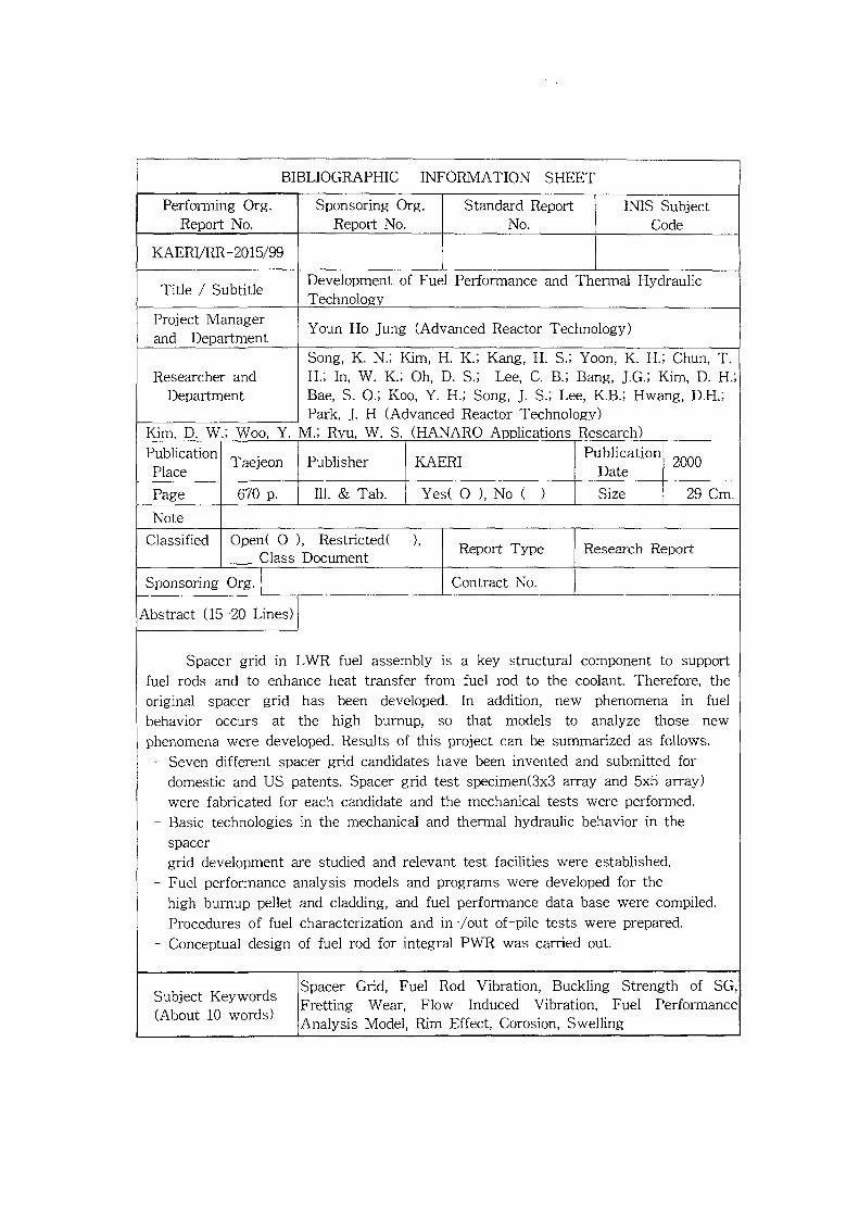
BIBLIOGRAPHIC INFORMATION SHEET
Performing Org.Report No.
Sponsoring Org.Report No.
Standard ReportNo.
IMS SubjectCode
KAERI/RR-2015/99
Title / Subtitle Development of Fuel Performance and Thermal HydraulicTechnology
Project Managerand Department
Youn Ho Jung (Advanced Reactor Technology)
Song, K. N.; Kim, H. K.; Kang, H. S.; Yoon, K. H.; Chun, T.H.; In, W. K.; Oh, D. S.; Lee, C. B.; Bang, J.G.; Kim, D. H.Bae, S. O.; Koo, Y. H.; Song, J. S.; Lee, K.B.; Hwang, D.H.;Park, J. H (Advanced Reactor Technology)
Kim, D. W.; Woo, Y. M.; Ryu, W. S. (HANARO Applications Research)
Researcher andDepartment
PublicationPlace
Taejeon Publisher KAERI PublicationDate
2000
Page 670 p. 111. & Tab. Yes( O ), No ( ) Size 29 Cm.
Note
Classified Open( OClass
, Restricted(Document
Report Type Research Report
Sponsoring Org. Contract No.
Abstract (15-20 Lines)
Spacer grid in LWR fuel assembly is a key structural component to supportfuel rods and to enhance heat transfer from fuel rod to the coolant. Therefore, theoriginal spacer grid has been developed. In addition, new phenomena in fuelbehavior occurs at the high burnup, so that models to analyze those newphenomena were developed. Results of this project can be summarized as follows.
- Seven different spacer grid candidates have been invented and submitted fordomestic and US patents. Spacer grid test specimen(3x3 array and 5x5 array)were fabricated for each candidate and the mechanical tests were performed.
- Basic technologies in the mechanical and thermal hydraulic behavior in thespacergrid development are studied and relevant test facilities were established.
- Fuel performance analysis models and programs were developed for thehigh burnup pellet and cladding, and fuel performance data base were compiled.
- Procedures of fuel characterization and in-/out of-pile tests were prepared.- Conceptual design of fuel rod for integral PWR was carried out.
Subject Keywords(About 10 words)
Spacer Grid, Fuel Rod Vibration, Buckling Strength of SG,Fretting Wear, Flow Induced Vibration, Fuel PerformanceAnalysis Model, Rim Effect, Corosion, Swelling