GEO222 STATICS and STRENGTH of MATERIALS
22
Ankara University Department of Geological Engineering GEO222 STATICS and STRENGTH of MATERIALS Lecture Notes Assoc. Prof. Dr. Koray ULAMIŞ
-
Upload
khangminh22 -
Category
Documents
-
view
0 -
download
0
Transcript of GEO222 STATICS and STRENGTH of MATERIALS

Ankara UniversityDepartment of Geological Engineering
GEO222 STATICS and STRENGTH of MATERIALS
Lecture Notes
Assoc. Prof. Dr. Koray ULAMIŞ

When a beam is loaded by forces and couples, internal stresses arise as normal and shear. In order todetermine the magnitude of stresses at any section of the beam, it is necessary to know the resultantforce and moment acting at that section by applying the equations of static equilibrium.
Resisting MomentThe magnitude of “M” which states that the sum of moments of all forces about an axis andperpendicular to the plane of the page is zero. The resisting moment M is due to stresses that aredistributed over the vertical section.
Resisting ShearThe vertical force is called the resisting shear. For equilibrium of forces in the vertical direction, this forceis actually the resultant of shearing stresses distributed over the vertical section on a beam.
Bending MomentThe algebraic sum of the moments of external forces to one side of the vertical section of a beamabout an axis. Bending moment is opposite in direction to the resisting moment with same magnitude.Bending moment rather than the resisting moment is used in calculations because it can be representeddirectly in terms of the external loads.
Shear ForceThe algebraic sum of all the vertical forces to one side is called the shearing force at that section. Shearforce is opposite in direction to the resisting shear but of the same magnitude. It is ordinarily used incalculations, rather than the resisting shear.
CHAPTER 5. SHEAR FORCE and BENDING MOMENT in BEAMS
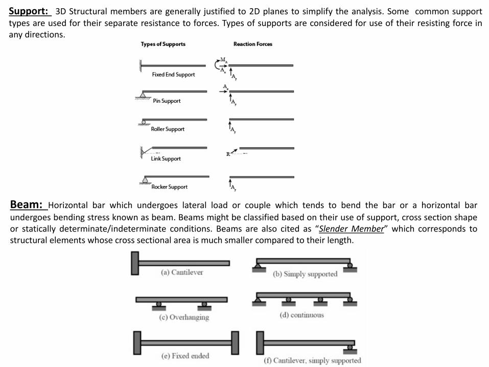
Support: 3D Structural members are generally justified to 2D planes to simplify the analysis. Some common supporttypes are used for their separate resistance to forces. Types of supports are considered for use of their resisting force inany directions.
Beam: Horizontal bar which undergoes lateral load or couple which tends to bend the bar or a horizontal bar
undergoes bending stress known as beam. Beams might be classified based on their use of support, cross section shapeor statically determinate/indeterminate conditions. Beams are also cited as “Slender Member” which corresponds tostructural elements whose cross sectional area is much smaller compared to their length.

Concentrated (Single, Point) Loads on Beams
In case a single beam is loaded, “Shear Forces” will act on supports in opposite direction. Any shear force from “A” point in “X” distance turns out to be;
Vx=FA-F1-F2
Moreover, due to the magnitude(s) of load(s), the beam might be subjected to “Bending Moment” on “m-n” cross section that is;
Mx=FAX-F1(X-a1)-F2(X-a2)
Vx
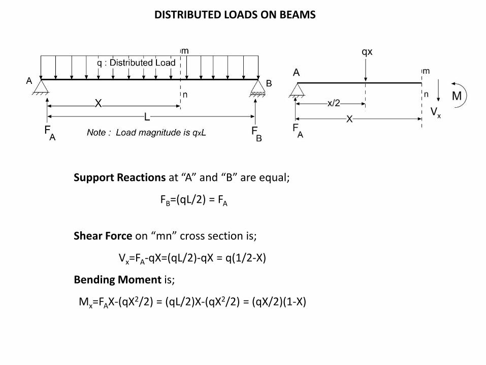
DISTRIBUTED LOADS ON BEAMS
Support Reactions at “A” and “B” are equal;
FB=(qL/2) = FA
Shear Force on “mn” cross section is;
Vx=FA-qX=(qL/2)-qX = q(1/2-X)
Bending Moment is;
Mx=FAX-(qX2/2) = (qL/2)X-(qX2/2) = (qX/2)(1-X)
Vx

SIGN CONVENTIONS
Due to the magnitude, type and location of loading, beams tend to bend in upward or downward direction. Figure (a): Concave bending (say in direction of gravity) of the beam . Positive bending leads to produce Positive Bending. Figure (c): Left portion of the beam is sheared upwards with respect to right portion is “Positive Shear”

If the bending moment are positive, forces at the left of mn cross-section have CW and forces on the right of mn have CCW moment directions.
VVV V
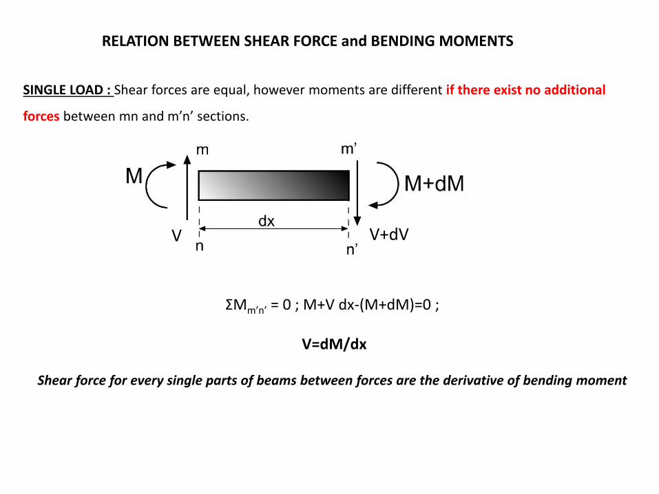
RELATION BETWEEN SHEAR FORCE and BENDING MOMENTS
SINGLE LOAD : Shear forces are equal, however moments are different if there exist no additional
forces between mn and m’n’ sections.
ƩMm’n’ = 0 ; M+V dx-(M+dM)=0 ;
V=dM/dx
Shear force for every single parts of beams between forces are the derivative of bending moment
V+dVV

DISTRIBUTED LOAD : Derivative of shear force equals to the negative magnitude of distributed load
without any additional loading between mn and m’n’ cross sections.
Resultant of vertical loads must be zero; Ʃx = 0 ; T-q dx – (T+dT)=0 ;
q=(-)dV/dx
Moment on m’n’ section must be zero; M-(M+dM)+V dx – (q dx2/2)=0 ;
V=dM/dx
Note: dx is negligible, dx2/2 is even smaller to be accepted as zero
V+dVV

SINGLE LOAD: In case there is another “F” load between mn and m’n’, the shear force will be different
by the magnitude of “F” just nearby the application point of the “F” force. Due, the derivative of
(dM/dx) will also change.
-q = dV/dx = d2M/dx2
-∫q dx = (dM/dx) = V
-∫∫q dx dx = ∫ V dx = M
V+dVV
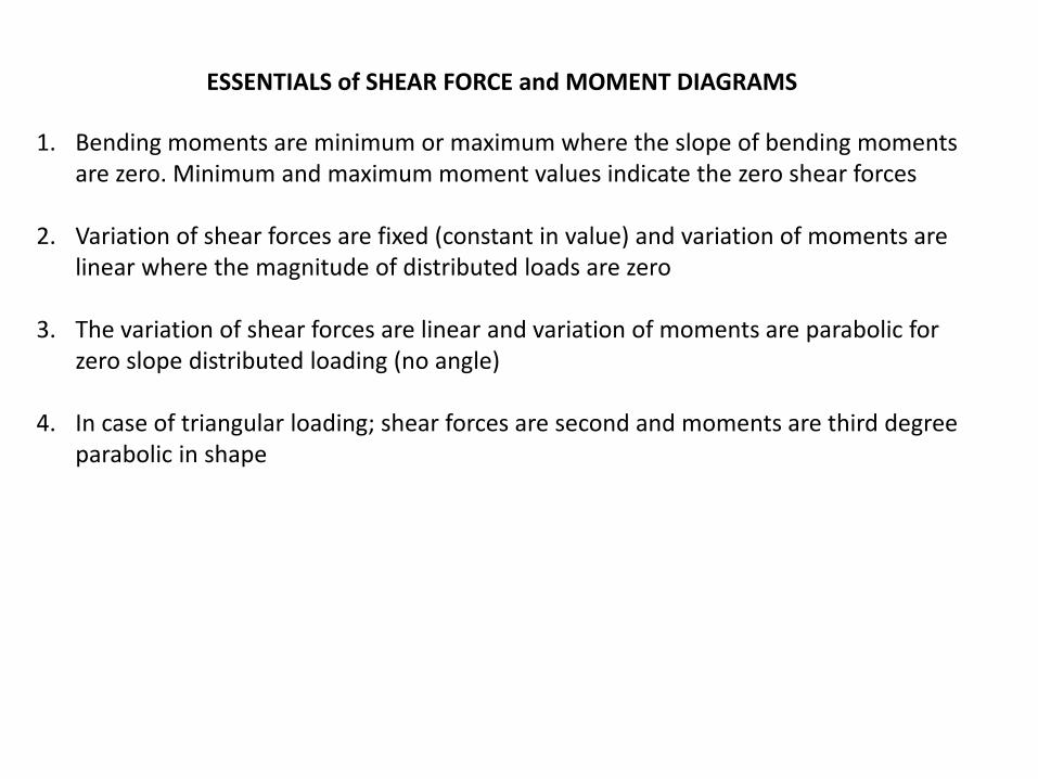
ESSENTIALS of SHEAR FORCE and MOMENT DIAGRAMS
1. Bending moments are minimum or maximum where the slope of bending moments are zero. Minimum and maximum moment values indicate the zero shear forces
2. Variation of shear forces are fixed (constant in value) and variation of moments are linear where the magnitude of distributed loads are zero
3. The variation of shear forces are linear and variation of moments are parabolic for zero slope distributed loading (no angle)
4. In case of triangular loading; shear forces are second and moments are third degree parabolic in shape

ESSENTIALS of SHEAR FORCE and MOMENT DIAGRAMS
Total moment at “B” : (FAxL)-(Fxb)=0; FA=(Fxb/L)
Total moment at “A” : FBxL-Fxa=0; FB=(Fxa/L)
Section I :
Moment about mn section-FAxX = Mx; Mx = [(Fxb)/L]x
Shear Force;Vx = (dMx/dx) = FA = (Fxb)/L
Boundary ConditionsX = 0; Mx= [(Fxb)/L]x =0 and Vx=(Fxb)/L
X=a; Mx = [(Fxb)/L]a and Vx = (Fxb)/L
Vx

Section II :
Moment about mn section
M’x= FAxX’ – F (X’-a) = [(Fxb)/L]x’-F(X’-a)
Boundary Conditions
X’ = a; M= [(Fxb)/L]a – F(a-a) = (Fxbxa)/L
X’ = L; M = [(Fxb)/L]L – (F (L-a) =Fxb-Fxb = 0
Shear Force;
Vx’ = (Mx’/dx’) = [(Fxb)/L] – F = [(Fxb-FxL)/L] = -F(a/L)
The area of shear force and moment diagram parts are equal, their total should be zero;B B B
∫dM = ∫Vdx ; ∫ dM= MB – MAA A A
Shear and Moment Diagram
Vx

Distributed Load: A simply supported beam has a distributed load applied over its entire length. The distributed load w(x) varies in intensity (height) with position x. The load intensity w(x) has units of force/length (lb/ft or kN/m).
x dxx = L
w(x)
dw = w(x)dx R
x’
To find R, the original load is broken into strips of width dx with a small force dw = w(x)dx centered oneach strip. Equivalent force R is the sum of all small dw’s. As dx , there are more and more dw’s to add upand the sum becomes an integral. The equation to find R is then;
0 0
( )
L L
R dw w x dx
The location x’ is found based on the principle of moments. Each small dw has a moment about some point (say x = 0). The total moment of all the dw’s about this point must equal the moment of R about the same point. x’ is;
0 0
' ( )
L L
x R xdw xw x dx
The equivalent force R is equal to the area under the distributed load curve. The location of the force (given by the distance x’) is at the centroid of the distributed load area.

a
w0
a/2w0a
a
w0
2a/3 w0a/2
a
w2 a/2
w1a
a/3
(w2- w1)a/2
w1
Common Types of Distributed Load
Uniform
Triangular
Trapezoid
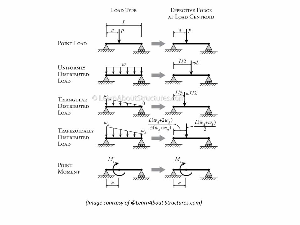
(Image courtesy of ©LearnAbout Structures.com)

Example 14. Determine the support reactions of A and B pin supports
2 ton 3ton 4ton
∑Fx=0; Since the forces are acting along “y” axis, no reactions will develop
∑Fy=0; RA+RB=2+3+4 = 9 t
∑MA=0; (RBx9)=(2x1.5)+(3x3)+(4x4.5); RB=5 t, RA= 4t
Example 15. Determine the support reaction on the cantilever beam
∑Fx=0; Since the forces are acting along “y” axis, no reactions will develop
∑Fy=0; RA=(2x1.8)+2.5; RA=6.1 t
The beam is fixed at “A” and no other support reactions will occur
Distributed load: The area of the rectangle = (1.8x2)=3.6 t

Example 16. Determine the support reactions.
Free body diagram
Moment at “B”;∑MB=0(RAx9)-(20x7)-(40x4)=0, RA=33.3 kN; RB=26.7 kN
∑FY=0; RA+RB=20+40=60 kN
Example 17. Determine the support reactions.
Concentrated load: 15x3=45 kN
1.5 m
1.5 m
Free body diagram
A noktasına göre moment alınırsa; ∑MA=0(RBx7)-(45x5.5)-(20x9)=0, RB=61.07 kN; RA=3.93 kN
∑FY=0; RA+RB=20+(15x3)=65 kN

Example 18. Please construct the shear force-bending moment diagram.
20 kN
3 m 3 m
Free body diagram
∑FY=0; RA+RB=20 kN
Moment at “A”; ∑MA=0(RBx6)-(20x3)=0, RB= RA=10 kN
Point A, (x=0)V1-10=0, V1=10 kN; M1=0 X=3mV2+20-10=0, V2=-10 kN; M2=-10x3=-30 kN.mPoint B (x=6 m)V3+20-10-10=0, V3=0 kN; M3=(-10x6)+(20x3)=0 kN.m
(-)
V1 V2 V3
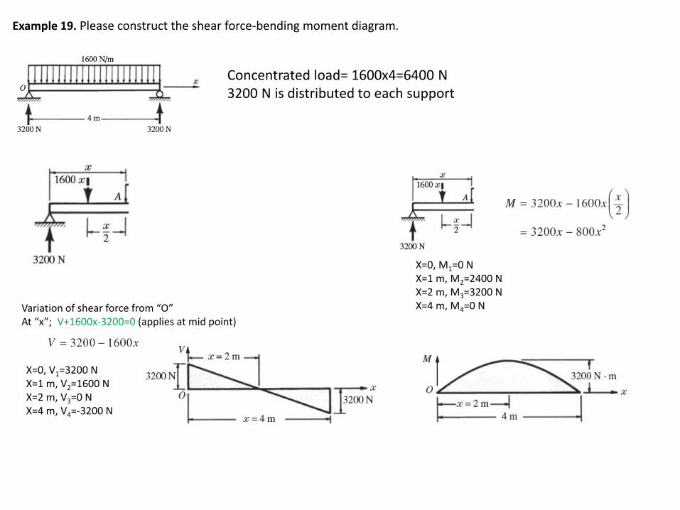
Example 19. Please construct the shear force-bending moment diagram.
Concentrated load= 1600x4=6400 N3200 N is distributed to each support
Variation of shear force from “O” At “x”; V+1600x-3200=0 (applies at mid point)
X=0, V1=3200 NX=1 m, V2=1600 NX=2 m, V3=0 NX=4 m, V4=-3200 N
X=0, M1=0 NX=1 m, M2=2400 NX=2 m, M3=3200 NX=4 m, M4=0 N

Free body diagram
∑FY=0; RA+RB=15 kN
Moment at “A”∑MA=0(RBx3)-(15x1.5)=0, RB=7.5 kN RA=7.5 kN
5x3=15 kNAt point “A” (x=0)V1-7.5=0, V1=7.5 kN
X=0.5.mV2+(5x0.5)-7.5=0, V2= 5 kN
X=1.0.mV3+(5x1)-7.5=0, V3= 2.5 kN
X=1.5.mV4+(5x1.5)-7.5=0, V3= 0 kN
At point “B” (x=3 m)V4+(5x3)-7.5=0, V4=-7.5 kN
Distributed load, 5 kN per meter
7.5 kN
5x
V+5x-7.5=0; V=7.5-5x
V
Example 20. Please construct the shear force-bending moment diagram.

7.5 kN
5x
X=0, M1=0 kNX=0.5 m, M2=3.125 kNX=1 m, M3=5.0 kNX=1.5 m, M4=5.625 kNX=3 m, M5=0 kN
Bending moment diagram
Shear force diagram
1.5 m
3.0 m5
2.5
0.5m 1.0m