Beams (cont.) CE 6320 – Advanced Strength of Materials
21
Beams (cont.) CE 6320 – Advanced Strength of Materials Lecture 7 Dr. Héctor J. Cruzado
Transcript of Beams (cont.) CE 6320 – Advanced Strength of Materials
Beams (cont.)
CE 6320 – Advanced Strength of Materials
Lecture 7
Dr. Héctor J. Cruzado
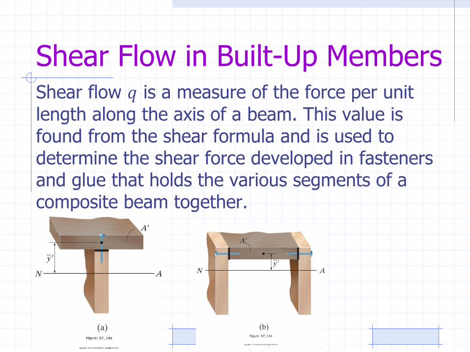
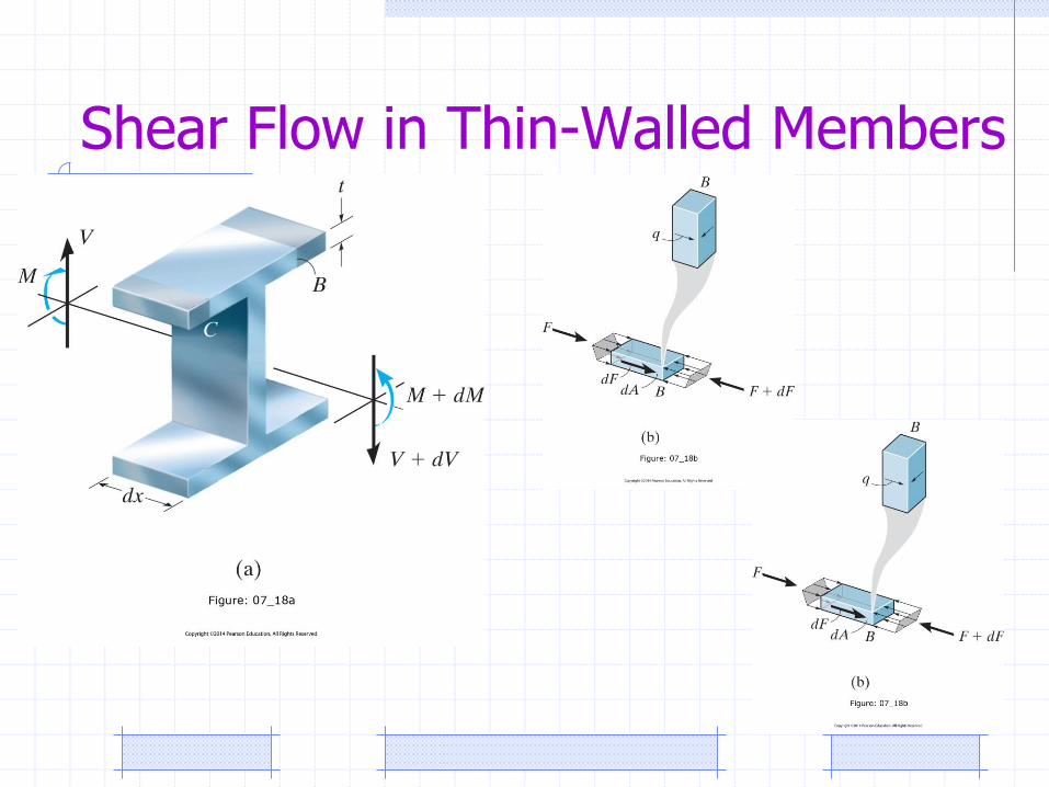
Shear Flow in Built-Up MembersShear flow 𝑞 is a measure of the force per unit
length along the axis of a beam. This value is found from the shear formula and is used to determine the shear force developed in fasteners and glue that holds the various segments of a composite beam together.
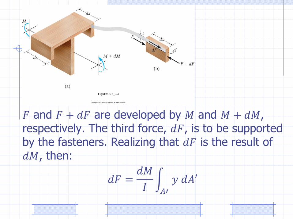
𝐹 and 𝐹 + 𝑑𝐹 are developed by 𝑀 and 𝑀 + 𝑑𝑀, respectively. The third force, 𝑑𝐹, is to be supported by the fasteners. Realizing that 𝑑𝐹 is the result of 𝑑𝑀, then:
𝑑𝐹 =𝑑𝑀
𝐼 𝐴′
𝑦 𝑑𝐴′
𝑑𝐹 =𝑑𝑀
𝐼 𝐴′
𝑦 𝑑𝐴′
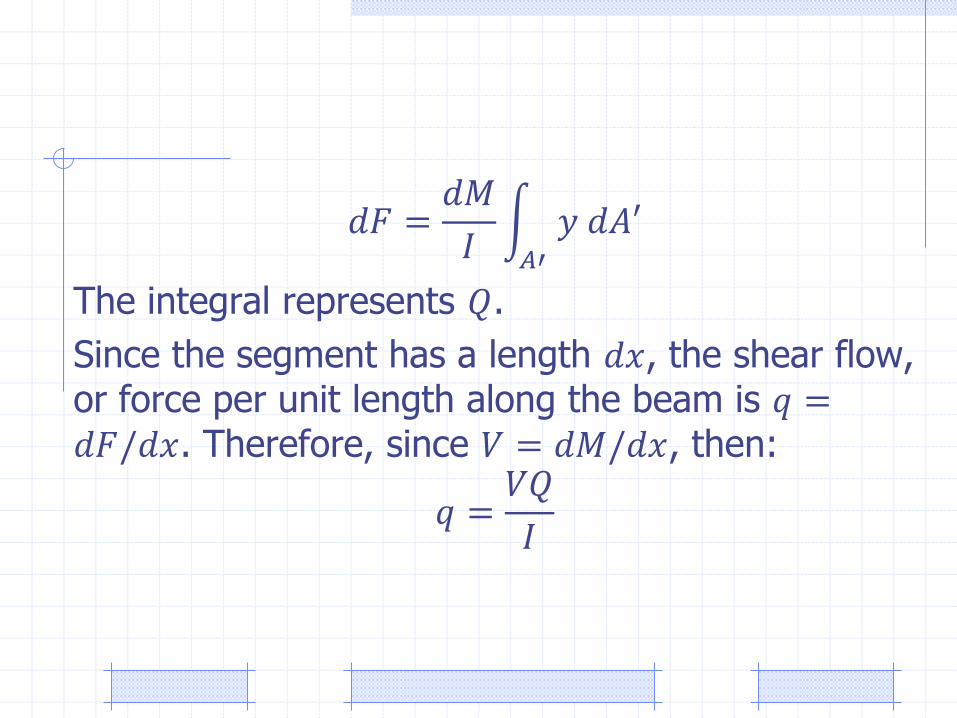
The integral represents 𝑄.
Since the segment has a length 𝑑𝑥, the shear flow, or force per unit length along the beam is 𝑞 =𝑑𝐹/𝑑𝑥. Therefore, since 𝑉 = 𝑑𝑀/𝑑𝑥, then:
𝑞 =𝑉𝑄
𝐼
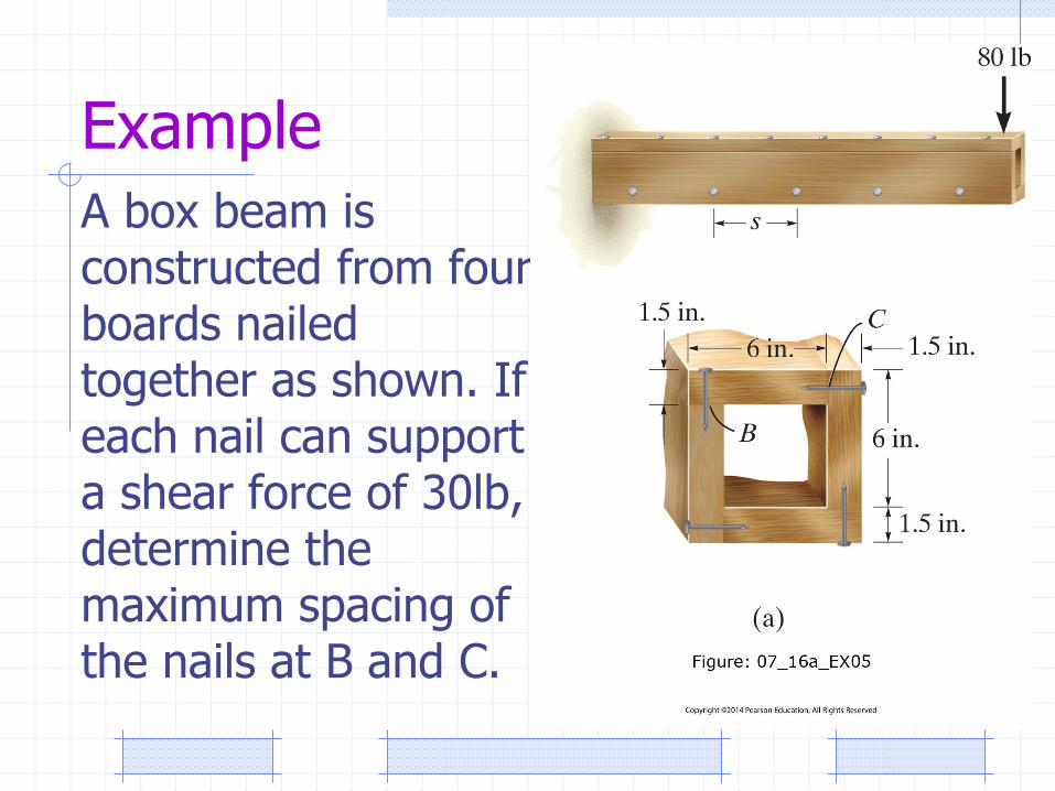
Example
A box beam is constructed from four boards nailed together as shown. If each nail can support a shear force of 30lb, determine the maximum spacing of the nails at B and C.
Shear Flow in Thin-Walled Members
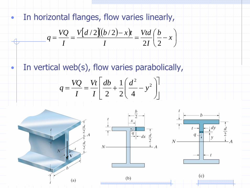
• In horizontal flanges, flow varies linearly,
• In vertical web(s), flow varies parabolically,
x
b
I
Vtd
I
txbdV
I
VQq
22
2/2/
2
2
42
1
2y
ddb
I
Vt
I
VQq
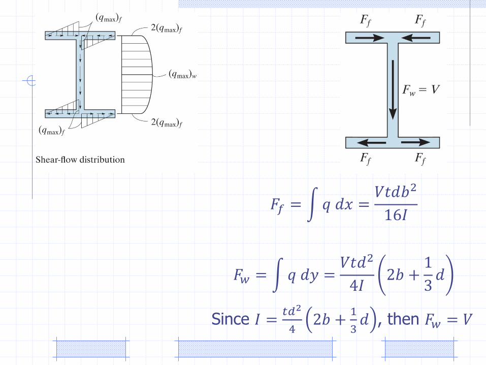
𝐹𝑓 = 𝑞 𝑑𝑥 =𝑉𝑡𝑑𝑏2
16𝐼
𝐹𝑤 = 𝑞 𝑑𝑦 =𝑉𝑡𝑑2
4𝐼2𝑏 +
1
3𝑑
Since 𝐼 =𝑡𝑑2
42𝑏 +
1
3𝑑 , then 𝐹𝑤 = 𝑉
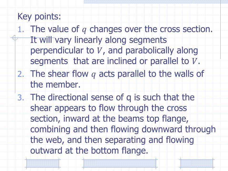
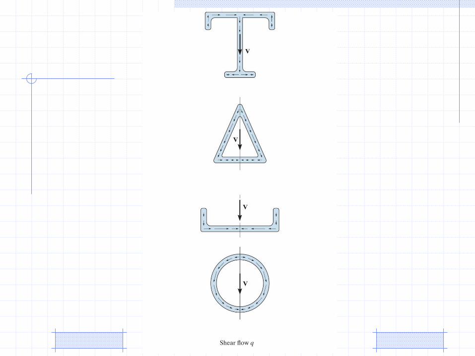
Key points:
1. The value of 𝑞 changes over the cross section. It will vary linearly along segments perpendicular to 𝑉, and parabolically along segments that are inclined or parallel to 𝑉.
2. The shear flow 𝑞 acts parallel to the walls of the member.
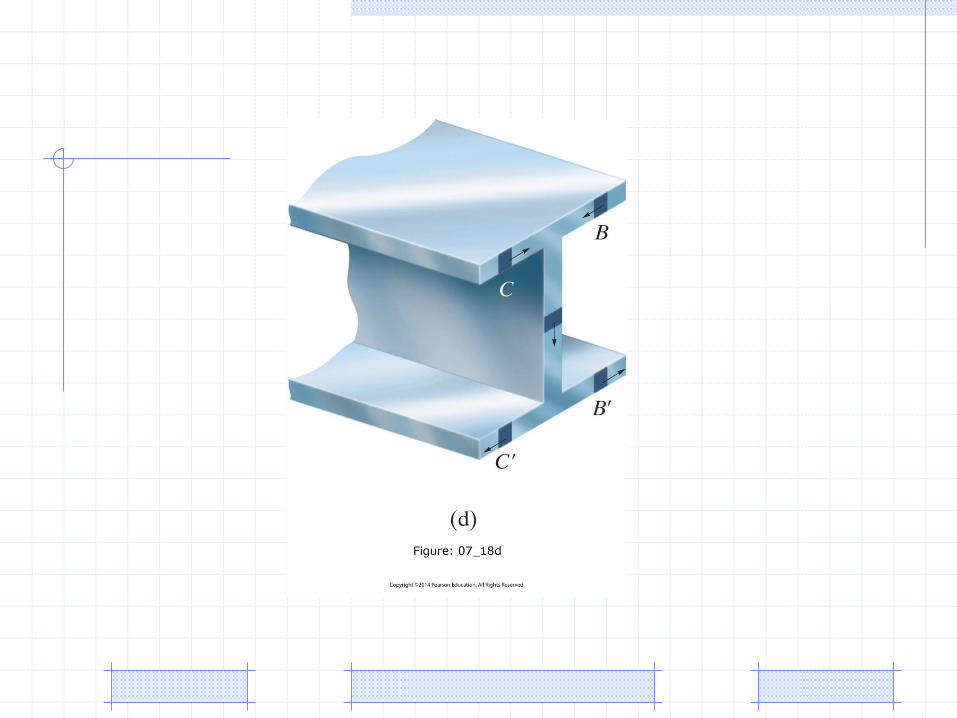
3. The directional sense of q is such that the shear appears to flow through the cross section, inward at the beams top flange, combining and then flowing downward through the web, and then separating and flowing outward at the bottom flange.
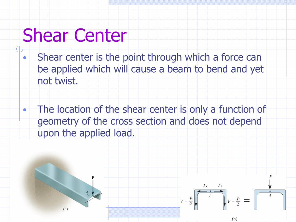
Shear Center• Shear center is the point through which a force can
be applied which will cause a beam to bend and yet not twist.
• The location of the shear center is only a function of geometry of the cross section and does not depend upon the applied load.
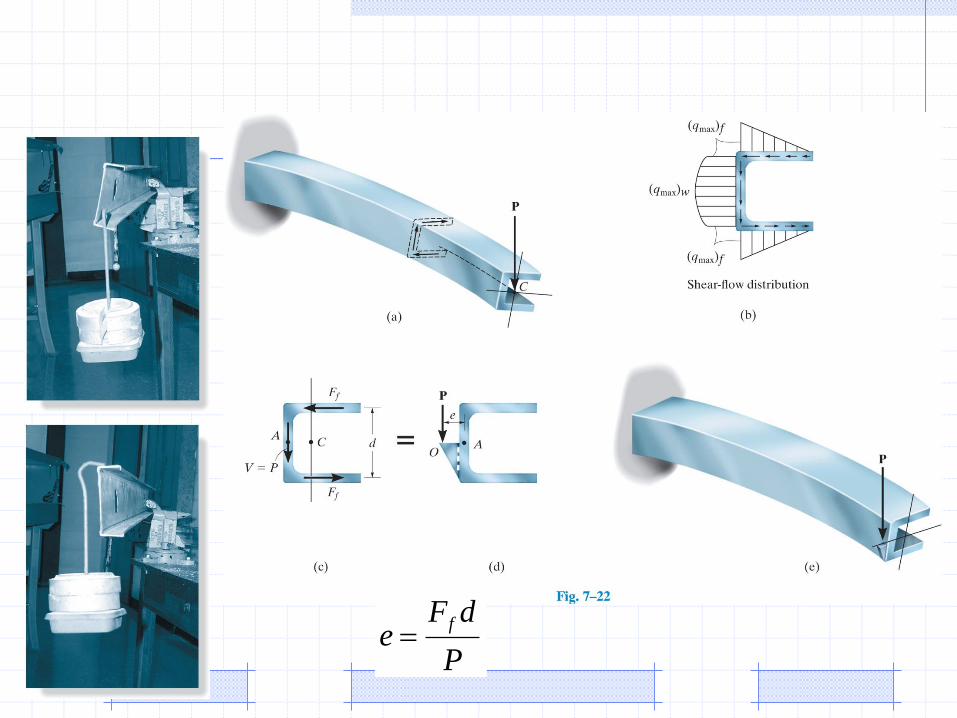
P
dFe
f
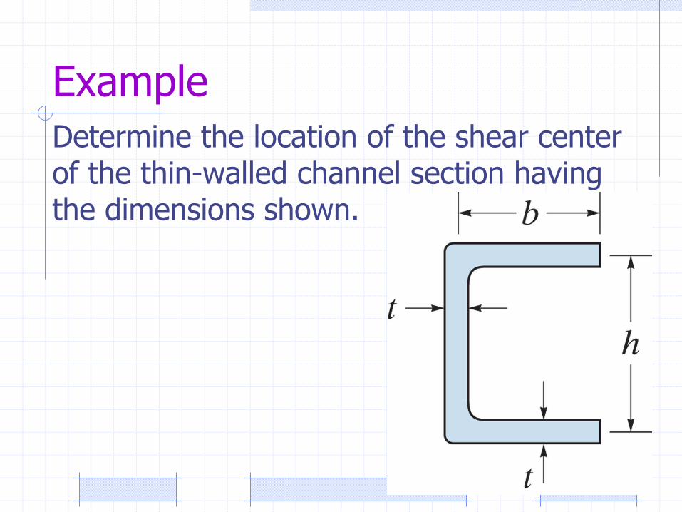
Example
Determine the location of the shear center of the thin-walled channel section having the dimensions shown.
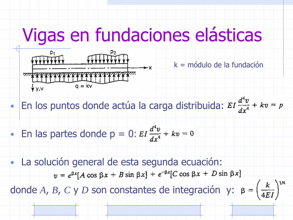
Vigas en fundaciones elásticas
• En los puntos donde actúa la carga distribuida:
• En las partes donde p = 0:
• La solución general de esta segunda ecuación:
donde A, B, C y D son constantes de integración y:
k = módulo de la fundación
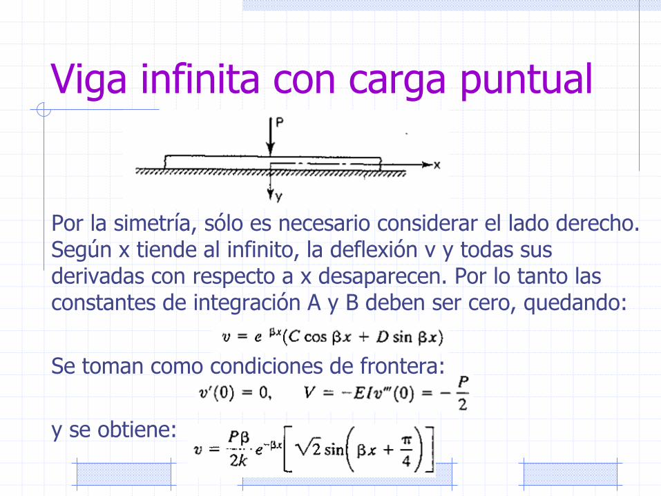
Viga infinita con carga puntual
Por la simetría, sólo es necesario considerar el lado derecho. Según x tiende al infinito, la deflexión v y todas sus derivadas con respecto a x desaparecen. Por lo tanto las constantes de integración A y B deben ser cero, quedando:
Se toman como condiciones de frontera:
y se obtiene:
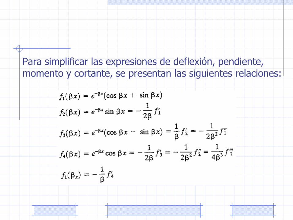
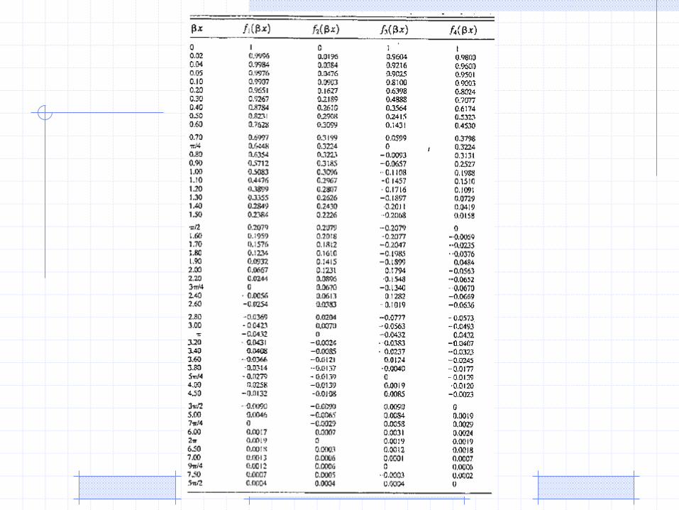
Para simplificar las expresiones de deflexión, pendiente, momento y cortante, se presentan las siguientes relaciones:
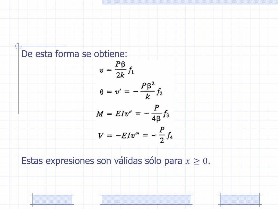
De esta forma se obtiene:
Estas expresiones son válidas sólo para 𝑥 ≥ 0.
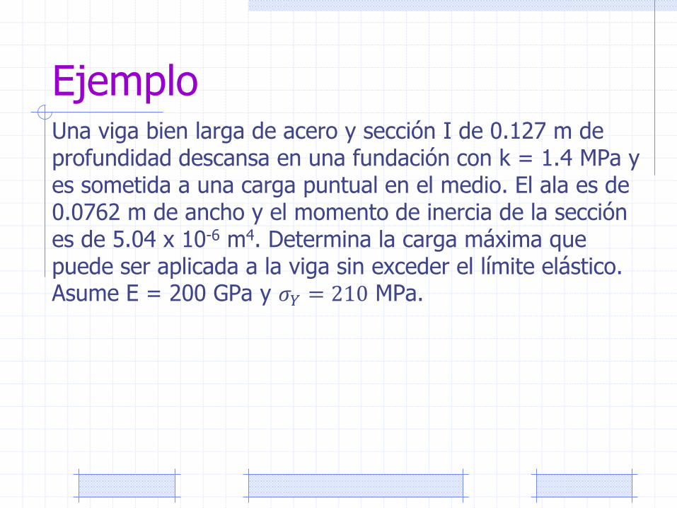
EjemploUna viga bien larga de acero y sección I de 0.127 m de profundidad descansa en una fundación con k = 1.4 MPa y es sometida a una carga puntual en el medio. El ala es de 0.0762 m de ancho y el momento de inercia de la sección es de 5.04 x 10⁻⁶ m4. Determina la carga máxima que puede ser aplicada a la viga sin exceder el límite elástico. Asume E = 200 GPa y 𝜎𝑌 = 210 MPa.
Assignment
Problem 9.5