General operating manual for valves - müller co-ax gmbh
17
General operating manual for valves Updated: July, 2021 All rights to these documents are owned by müller co-ax gmbh. Modifications to the documents are strictly prohibited. müller co-ax gmbh Friedrich-Müller-Str. 1 74670 Forchtenberg Germany Tel. +49 7947 828-0 Fax +49 7947 828-11 E-mail [email protected] Website www.co-ax.com
-
Upload
khangminh22 -
Category
Documents
-
view
5 -
download
0
Transcript of General operating manual for valves - müller co-ax gmbh
General operating manual for valves
Updated: July, 2021
All rights to these documents are owned by müller co-ax gmbh.
Modifications to the documents are strictly prohibited.
müller co-ax gmbh
Friedrich-Müller-Str. 1
74670 Forchtenberg
Germany
Tel. +49 7947 828-0
Fax +49 7947 828-11
E-mail [email protected]
Website www.co-ax.com

General operating manual for valves
Updated: 07/2021
Page 2/17
Contents
1.0 General 3
1.1 Target group 3
1.2 Structure of the documentation 3
1.3 Storage 4
2.0 Product description 4
2.1 Important information on the valve 4
2.2 Technical data 5
3.0 Safety instructions 6
3.1 Representation 6
3.2 Product safety 6
3.3 Organizational matters, personnel 6
3.4 Product-specific hazards 7
3.5 Information for emergencies 9
4.0 Mode of operation 9
5.0 Installation / commissioning 9
5.1 Measures and considerations before installation 9
5.2 Installation of the valve 10
5.3 Electrical connection 11
5.4 Connecting pneumatics / hydraulics 12
5.6 Commissioning 12
6.0 Maintenance / servicing 12
8.0 Storage 14
9.0 Packaging 14
10.0 Transport 14
11.0 Disposal 14
12.0 Replacement parts 15
13.0 Declaration of conformity 15
The latest declarations of conformity can be viewed and downloaded from the website at
www.co-ax.com. 15
14.0 Nameplate 16
15.0 Manufacturer and inquiries 17

General operating manual for valves
Updated: 07/2021
Page 3/17
1.0 General
To ensure the successful and safe use of our valves, the entire operating manual must have been read
and understood before installation and commissioning. Furthermore, particular attention is to be paid to
the safety instructions.
Read and observe the safety instructions before using our valves.
Should any difficulties arise which cannot be resolved with the aid of the operating manual, please
contact the supplier/manufacturer.
This operating manual covers the following areas: installation/commissioning, maintenance, servicing,
storage, packaging, transport and disposal. The operating manual has been compiled in accordance
with the regulations of Directive 2014/68/EU on pressure equipment.
The operating company is also responsible for ensuring that personnel tasked with installation comply
with local security regulations. If the valve is used outside the Federal Republic of Germany, the
operating company or the party responsible for the design of the system must ensure that prevailing
national regulations are complied with.
At all times, the manufacturer reserves the right to make technical changes and improvements. In order
to use this operating manual and directly handle the valves, users must fulfill the qualification
requirements described in section 1.1.
1.1 Target group
The operating manual is intended for persons who are entrusted with the installation planning,
installation, commissioning or maintenance/servicing and who possess the corresponding qualifications
for their duties and roles, i.e. who, on the basis of their technical training, knowledge and experience,
as well as their knowledge of the relevant standards, are able to assess the tasks they are assigned and
recognize possible dangers.
This also includes knowledge of the relevant accident prevention regulations, generally recognized
safety rules, EU directives, and country-specific standards and regulations.
1.1.1 Qualification of persons
Transport, assembly, commissioning, maintenance, and repair are only to be carried out by trained or
instructed personnel.
Electrical installations: Any work on the electrical equipment of the device is only to be carried out by a
qualified electrician or by instructed persons under the guidance and supervision of a qualified electrician
in accordance with good technical practices.
1.2 Structure of the documentation
The operating manual for our valves generally consists of two main modules with additional
supplementary modules for Ex valves, control valves and the Quadax series.
1.2.1 General operating manual
This manual contains important basic information and safety instructions for the safe handling of all
valves from müller co-ax gmbh.
WARNING

General operating manual for valves
Updated: 07/2021
Page 4/17
1.2.2 Data sheets
These contain the necessary additional information and technical data for the corresponding specific
valve types. The data sheets are only to be used in combination with the general operating manual. In
particular, the safety instructions in the general operating manual must be observed!
1.2.3 Supplementary specific operating manuals for Ex valves
These contain the necessary supplementary operating instructions for individual Ex valves which are
not found in the general operating manual or the data sheet. The supplementary specific operating
manuals for Ex valves are only to be used in combination with the general operating manual. In
particular, the safety instructions in the general operating manual must be observed!
1.2.4 Supplementary specific operating manuals for control valves
These contain the necessary supplementary operating instructions for individual control valves which
are not found in the general operating manual or the data sheet. The supplementary specific operating
manuals for control valves are only to be used in combination with the general operating manual. In
particular, the safety instructions in the general operating manual must be observed!
1.2.5 Supplementary specific operating manuals for the Quadax series
These contain the necessary supplementary operating instructions for the Quadax series which are not
found in the general operating manual or the data sheet.
1.3 Storage
Access to the full operating manual must be guaranteed at all times at the operation site of the valve.
2.0 Product description
2.1 Important information on the valve
2.1.1 Intended use
After installation in a pipeline system (e.g. between flanges, couplings, or screw connections) and after
the actuator is connected to the control system, the valves are intended exclusively for shutting off,
conveying, or regulating the flow of media within the permitted pressure and temperature limits.
It must be ensured that the usual flow rates (e.g. 4 m/s for liquids) are not exceeded in this pipeline
system during continuous operation and abnormal operating conditions, such as vibrations, water
hammer, erosion (e.g. due to wet steam), cavitation and larger than negligible amounts of solids in the
medium – particularly abrasive ones – are clarified with the manufacturer.
The nature of the medium agreed upon during placement of the order (chemical, abrasive and corrosive
effects), must be complied with. Any other or additional use shall be considered improper.
The valve's scope of application is the responsibility of the designer of the installation. Special markings
on the valve must be observed.
2.1.2 Valves for oxygen
During the goods inwards inspection, it is to be checked whether the valves supplied are furnished with
appropriate certificates for oxygen cleaning and whether the valves have packaging suitable for oxygen
(see oxygen identification – "Clean for Oxygen Service"). The packaging is to be checked for damage.
If there is damage, such valves may not be employed for oxygen applications, as there is a strong
suspicion that the valves are contaminated, which could lead to oxygen combustion.
General operating manual for valves
Updated: 07/2021
Page 5/17
When it has been ensured that the packaging has suffered absolutely no damage during transport, the
valves are to be removed from the packaging in a room suitable for this purpose. The room must be free
of oil and grease and it must also be ensured that the room has no aliphatic atmosphere. Staff who
remove the valves from the packaging and/or install the valves in the pipeline must wear suitable
protective clothing (grease- and oil-free gloves, grease- and lubricant-free clothing etc.).
The valves removed from the packaging are to be checked once again for damage. An optical visual
check under UV light is the minimum requirement. The valves, which have now been checked for
possible contamination and which have been confirmed to be in perfect condition, are to be taken without
delay to the installation site, whereby it is to be ensured that the valves have not come into contact with
oil and grease or contaminated in any other manner while en route.
During the installation of the valves, the usual safety regulations and the instructions of this operating
and maintenance manual are to be followed. In addition, it must be ensured that the pipelines, the
flanges opposite the valve, and the seals in particular are suitable for oxygen and free of any impurities,
especially oil and grease.
Failure to comply with these regulations may result in danger to life and limb, as
the combustion of oxygen equates to an explosion!
2.1.3 Precautionary measures
For the use of the valves, prevailing laws (e.g. EU directives and national regulations) and good technical
practices must be observed, e.g. DIN standards, DVGW fact sheets and worksheets, VDI directives,
VDMA standard sheets, etc.
In the case of systems requiring monitoring, the relevant laws and regulations are to be observed, e.g.
trade regulations, accident prevention regulations, steam boiler regulations, regulations on high-
pressure gas lines, regulations for flammable liquids, as well as the technical standards VDE, ATEX,
TAB, TRD, TRG, TRbF, TRGL, TRAC, AD fact sheets, etc.
Furthermore, general installation and safety regulations for pipeline and installation construction apply,
as do local safety and accident prevention regulations.
During all work on the valve and any handling of the valve, the instructions in the operating manual must
always be complied with.
Failure to comply with the operating manual may result in serious injuries or
material damages (e.g. due to mechanical, chemical or electrical effects).
2.1.4 Conformity
Valves from müller co-ax gmbh are state of the art and comply with Directive 2014/68/EU on pressure
equipment.
2.1.5 Labeling of the valve
Valves bear a nameplate which contains all the required information in accordance with the Pressure
Equipment Directive. This nameplate is explained in section 14.
2.2 Technical data
The materials of the housing and the seals are selected according to the operating conditions specified
by the customer when placing the order. These operating conditions significantly influence the service
life of the valve, e.g. due to abrasion, chemical reactions with, or corrosive effects on the materials. The
valves are designed without a wear allowance and structurally with a 1.5x safety margin against nominal
pressure at the max. permissible temperature.
DANGER
WARNING
General operating manual for valves
Updated: 07/2021
Page 6/17
For the technical data (also electrical data) and the primary permissible limit values, in particular for
media pressure and temperature, please consult the data sheet, and for Ex and control valves, please
also consult the supplementary specific operating manual.
3.0 Safety instructions
This section contains important general safety instructions. In addition, the special safety instructions in
the other sections must also be complied with.
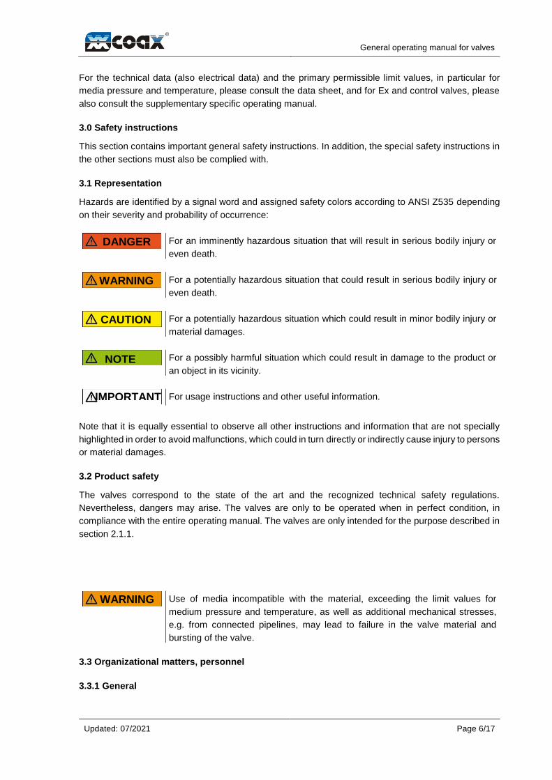
3.1 Representation
Hazards are identified by a signal word and assigned safety colors according to ANSI Z535 depending
on their severity and probability of occurrence:
For an imminently hazardous situation that will result in serious bodily injury or
even death.
For a potentially hazardous situation that could result in serious bodily injury or
even death.
For a potentially hazardous situation which could result in minor bodily injury or
material damages.
For a possibly harmful situation which could result in damage to the product or
an object in its vicinity.
For usage instructions and other useful information.
Note that it is equally essential to observe all other instructions and information that are not specially
highlighted in order to avoid malfunctions, which could in turn directly or indirectly cause injury to persons
or material damages.
3.2 Product safety
The valves correspond to the state of the art and the recognized technical safety regulations.
Nevertheless, dangers may arise. The valves are only to be operated when in perfect condition, in
compliance with the entire operating manual. The valves are only intended for the purpose described in
section 2.1.1.
Use of media incompatible with the material, exceeding the limit values for
medium pressure and temperature, as well as additional mechanical stresses,
e.g. from connected pipelines, may lead to failure in the valve material and
bursting of the valve.
3.3 Organizational matters, personnel
3.3.1 General
DANGER
WARNING
CAUTION
NOTE
IMPORTANT
WARNING

General operating manual for valves
Updated: 07/2021
Page 7/17
The recognized rules for occupational health and safety must be observed. Persons who are entrusted
with installation planning, installation, commissioning or maintenance/servicing must possess the
corresponding qualifications for their duties and roles.
They must, based on their technical training, knowledge and experience, as well as their knowledge of
the relevant standards, be able to assess the tasks they are assigned, the mutual interactions between
the valve and installation, and recognize possible hazards.
They must also possess knowledge of the relevant accident prevention regulations, generally accepted
safety rules, EC directives, and country-specific standards and regulations, as well as all operational,
regional and in-house regulations and requirements.
They require qualifications or instruction in accordance with safety engineering standards for the care
and use of appropriate safety and work protection equipment, as well as training in first aid, etc. (see
also TRB 700).
They must have read and understood the entire operating manual.
No modifications, additions or conversions are permitted to be made without the approval of the
manufacturer or supplier.
3.3.2 Transport / Installation / Commissioning / Maintenance / Repair
These are only to be performed by trained or instructed personnel. For reasons of safety, a final check
is to be performed before work commences to ensure that all necessary measures have been taken for
the protection of persons. Valves which have come into contact with media that is hazardous to health
must be decontaminated before work can commence.
3.3.3 Electrical installations
Hazards due to electrical energy are to be eliminated. Any work on the electrical equipment of the device
is only to be carried out by a qualified electrician or by instructed persons under the guidance and
supervision of a qualified electrician in accordance with good technical practices.
3.4 Product-specific hazards
Hazards which may arise due to the media conveyed, the control pressure, and from moving parts are
to be prevented by taking appropriate measures.
Furthermore, it must be ensured that the valves are only operated in situations where the type of
medium, operating pressure, and temperatures correspond to the design criteria used as the basis for
the order and which are specified on the nameplate. Proper transport and storage of the valve are also
to be ensured.
The following sections list a number of product-specific hazards and measures for preventing them:
3.4.1 Use of media unsuitable for the valve
The valve materials are only compatible with certain media. When using them with media which require
particular materials or are incompatible with certain materials, it is essential that you consult the
manufacturer.
When used with media not intended for the valve, the materials in the valve may
be damaged or even combust explosively, with fatal consequences. Hence, only
use media for which the valve is approved.
Valves for oxygen are to be kept free of oil and grease. Use non-ferrous metal
valves for ammonia. For flammable, aggressive or toxic media, use valves made
of suitable materials.
DANGER

General operating manual for valves
Updated: 07/2021
Page 8/17
3.4.2 Wall thickness falling below minimum value due to corrosion or abrasion
Regular inspections are required to verify the safety and proper condition of the
inner walls.
3.4.3 Exceedance of permissible pressure with danger of bursting
Reasons for excessive pressure include water hammer effects (impact when closing) and cavitation. A
water hammer causes pressure peaks which result when a pipe is shut off using a valve. Put simply,
the reason for this is the force with which the column of media being conveyed impacts the closing valve.
Pressure peaks which occur during the closing of the valve may reach several
times the pressure at rest. Users must select the operating pressure rating of the
valve such that the pressure peaks which occur in a specific installation situation
do not exceed the maximum permissible operating pressure of the valve.
For the flow, the static pressure of a liquid medium must also always exceed the
vapor pressure of the medium in order to prevent cavitation.
3.4.4 Excessive stress on valves
Valves may be subjected to excessive stress when they experience additional stresses, such as being
stepped on, from other connected pipes, or high ambient temperatures.
The valve is only designed for use at the permissible medium pressure load.
Hence, install the valve such that no stress forces are acting on it and ensure
that no additional stresses occur, e.g. from pipelines or being stepped on.
Furthermore, no welding or heat treatment is to be carried out on pressure-bearing walls, and no holes
are to be drilled for attachments. Install the valve and the electrical and pneumatic lines in such a manner
that they cannot be damaged and such that no moisture-induced short circuit can occur at electrical plug
connections.
3.4.5 Opening of screw connections when valve is under pressure
Opening screw connections when valves are under pressure leads to medium leakage and damage to
the valve.
Opening valves under pressure is life-threatening!
Before performing any work on the valve:
The valve and all lines which are connected must be depressurized. Ensure that
the valve is electrically de-energized. Allow the valve and medium to cool down.
Allow the medium to cool until it is below its vaporization temperature to prevent
scalding. In the case of media which is e.g. corrosive, flammable, aggressive or
toxic, flush and ventilate the piping system, wear protective goggles or a
protective mask with eye protection, or take other necessary protective
measures.
3.4.6 Leakage of hazardous substances
Hazardous substances may escape e.g. at relief holes or when dismantling the valve.
WARNING
WARNING
WARNING
DANGER
WARNING
WARNING
General operating manual for valves
Updated: 07/2021
Page 9/17
Hazardous media (e.g. leakage at relief holes or medium residue in the valve
when disassembling it) must be collected and disposed of in such a manner that
poses no danger to persons or the environment. Statutory regulations are to be
complied with.
3.4.7 Exposed valve outlet
When nothing is connected to the outlet of the valve, the medium that exits the opening when the valve
is (unintentionally) opened may pose a hazard.
To rule out hazards at the outlet of the valve, the valve outlet should be diverted
in a controlled manner, or sealed in a pressure-tight fashion with a blind plug/blind
flange.
3.4.8 Failure of actuator power
In the event the actuator is no longer supplied with energy, the valve may enter a state that is unsafe
for its intended purpose.
Pay attention to selecting the correct valve function (NC/NO) such that the valve
enters an operational state that is safe for the intended purpose should the
actuator no longer be supplied with energy.
3.4.9 Painting work
When performing painting work, the valve could also be painted over, thereby affecting the heat radiation
of the magnet or clogging the relief hole.
Cover up the valves effectively if work is to be done in the area around the valves
which could lead to dirt/soiling, e.g. involving cement, bricklaying, painting work,
or sandblasting.
3.5 Information for emergencies
In case of fire, use only extinguishing agents suitable for extinguishing the relevant electrical equipment.
Ensure that the extinguishing agent does not cause a dangerous reaction with any medium that
escapes.
4.0 Mode of operation
For information on the mode of operation of your specific valve, please refer to the relevant data sheet
or, in the case of Ex and control valves, also to the specific operating instructions.
5.0 Installation / commissioning
Before installation or commissioning, the general safety instructions in section
3.0 and the relevant sections of the supplementary specific operating manuals
are to be read and observed. Always comply with prevailing accident prevention
regulations when handling the valves.
5.1 Measures and considerations before installation
WARNING
CAUTION
NOTE
WARNING
WARNING

General operating manual for valves
Updated: 07/2021
Page 10/17
For installation, observe the TRB 700 (Technical Rules for the Operation of Pressure Vessels) as well
as the following:
Compare the material, pressure and temperature specifications of the valves with the operating
conditions of the piping system to verify the material resistance and load capacity. Any pressure
surges that occur must not exceed the maximum permissible pressure of the valve.
Pressure peaks may reach several times the pressure at rest. For the flow, the
static pressure of a liquid medium must also always exceed the vapor pressure
of the medium in order to prevent cavitation.
Install the valve such that it is easily accessible for any necessary connection and maintenance tasks in
the future (e.g. connections to actuator, sensors, and control units, replacement of cartridge valves etc.).
Unless otherwise specified, the orientation of installation can be chosen at will.
Suitable dirt traps should be installed upstream of the valve to ensure trouble-free operation of the valve.
The installation of hand-operated shut-off valves upstream of the dirt trap and downstream of the valve
is recommended. This allows maintenance work to be carried out on the dirt trap and the valve without
needing to drain the entire system.
If the plant is to remain in operation without any interruption, provide for a bypass line at the design
stage of the installation.
If it is installed outdoors, protect the valve against the direct influence of the weather. In the case of
flanged connections, the connecting flanges must match.
Install the valve in a manner such that no mechanical loads are exerted on the valve during and after
installation. The valve is only to be subjected to the intended internal medium pressure, without any
additional mechanical stress.
Additional mechanical stresses can lead to malfunctions or to excessive stress
and bursting, especially in the valve subjected to the media pressure.
For installation free of stress forces, the connecting lines must be axially aligned with the connections
of the valve and have the correct clearance. Thermal expansion of the piping must be compensated for
with the use of expansion joints. The transmission of vibrations must be prevented with the use of flexible
vibration compensators where necessary.
5.2 Installation of the valve
Before installation, inspect the valve for any transport damage. Damaged valves
may no longer meet the safety requirements, and therefore are not to be installed.
Before installing the valve, ensure that the pipe system is absolutely clean to
prevent any residue from the assembly of the pipe or other foreign objects from
being flushed into the valve during commissioning. If it is not possible to establish
a safe conductive connection (low-resistance) to the connecting parts when
installing the valve, the valve must be included in the equipotential bonding. The
connection point provided is to be used for this purpose. Do not remove
protective caps from the connections until immediately before installation.
WARNING
WARNING
CAUTION
NOTE

General operating manual for valves
Updated: 07/2021
Page 11/17
Remove them without damaging any sealing surfaces or screw threads which
may be present. The sealing surfaces must be in a technically flawless condition.
Only permissible connecting elements (e.g. in accordance with DIN EN 1515-1) and permissible sealing
elements (e.g. in accordance with DIN EN 1514) are to be used.
In addition, the following also applies for high-temperature valves (HT series): Where possible, the
valves are to be installed with a horizontal actuator. If this is not possible, the actuator should be installed
such that it is as far from vertical as possible. Ensure that the insulation of the actuator, including the
connecting cables and lines, are installed properly. The connecting cables and lines must be suitable
and approved for the corresponding temperature range and intended purpose.
5.2.1 Installation with threaded connection
Pay attention to the direction of flow specified on the valve so that the valve can fulfill its intended
function.
Use a suitable sealant.
The piping will need to be installed in such a way that the flow of forces does not take place along the
longitudinal axis of the valve.
After installation, check for leakage and proper functioning.
5.2.2 Installation with flange connection
Pay attention to the direction of flow specified on the valve so that the valve can fulfill its intended
function.
Insert the bolts as specified. Use all the holes provided for this purpose in the flange.
Install a suitable seal and center it between the flange.
Tighten bolts evenly crosswise to avoid distortion. When doing so, ensure that the pipe is never pulled
up to the valve. Finally, tighten the bolts up to the prescribed torque. Ensure that the seal is correctly
seated.
After installation, check for leakage and proper functioning.
5.3 Electrical connection
Any work on the electrical equipment of the valve is only to be carried out by a qualified electrician or by
instructed persons under the guidance and supervision of a qualified electrician in accordance with good
technical practices and in compliance with DIN EN 60204-1 (Electrical equipment of machines), VDE
regulations, including the safety regulations, accident prevention regulations, and operating manual.
The electrical cables are to be laid in a permanent fashion and protected from external influences. Cable
bushings are not considered as strain relief. Hence, the customer will need to provide appropriate strain
relief for the connecting cables.
The electrical connection is established after unscrewing the terminal box cover or at the respective plug
connection. Before carrying out any electrical work on the valve, disconnect it from the power supply
and secure it accordingly. Ground the valve in accordance with local regulations.
No protective measures are specified in the connection diagrams. When connecting the valve, these
must be provided for additionally in accordance with VDE 0100 and the regulations of the responsible
power supply company.
When connecting any electrical equipment, always ensure that only the specified voltage is applied and
in the correct polarity in order to prevent damage or hazards.

General operating manual for valves
Updated: 07/2021
Page 12/17
If the valve is equipped with additional devices such as limit switches or explosion protection etc., always
observe the associated / additional instructions, corresponding data sheets, and/or connection values.
Valves with an AC connection, which are designed for higher temperatures, are supplied with a separate
rectifier in accordance with the state of the art. In order to prevent overheating, it should be installed
outside the heating zone. Corresponding instructions can be found on our high-temperature valves.
For all DC solenoids, a voltage tolerance of +5% and -10% for the nominal voltage applies, as well as a
permissible residual ripple of 20%.
For the electrical parameters or a connection diagram, please consult the data sheet. In the case of Ex
and control valves, also refer to the supplementary specific operating instructions.
5.4 Connecting pneumatics / hydraulics
In the case of pneumatically actuated valves, use conditioned air (if necessary, connect an air treatment
unit upstream). For hydraulically actuated valves, observe the recognized rules for handling hydraulics.
For further information on connecting control air or control hydraulics, please consult the data sheet. In
the case of Ex and control valves, also refer to the supplementary specific operating instructions.
5.5 Protection against burns / frostbite
Valves and pipelines which are operated at high (> 50 °C) or low temperatures (< 0 °C) must
be suitably protected against contact, or the dangers of possible contact must be indicated
through appropriate labeling. In the case of electromagnetically actuated valves, the contact
protection must not impair the cooling of the valve due to the risk of overheating. If there is a risk of
condensation or ice formation in air-conditioning, cooling and refrigeration systems, professional,
diffusion-tight insulation of the entire valve is necessary. Should ice form, there is a risk that the actuator
will stall.
Electromagnetically actuated valves must not be insulated due to the risk of overheating. In this case,
only protection against dripping and splashing water is required, which must not impair the cooling of
the valve.
5.6 Commissioning
Read and observe the safety instructions in section 3.0 before commissioning.
Before commissioning the valve, the customer is obliged to check the operating parameters such as the
nominal diameter, pressure rating, medium, operating temperature, control characteristics, Ex design
or, in the case of a version with an additional safety valve, the trigger pressure.
Before each commissioning of a new installation or the recommissioning of an installation after repairs
or modifications, ensure the following:
The TRB 700 is observed. All installation and assembly tasks have been completed properly.
Commissioning is performed exclusively by qualified personnel as described in section 3.3.
The piping system has been thoroughly flushed with the valves fully open to ensure that any
contaminants harmful to the sealing surfaces have been removed. The valve is in the correct functional
position.
Any existing protective devices have been reinstalled or put into operation.
6.0 Maintenance / servicing
WARNING

General operating manual for valves
Updated: 07/2021
Page 13/17
Before performing any work on the valve, the general safety instructions in
section 3.0 and the corresponding passages from the additional manuals are to
be read and observed.
Opening valves under pressure is life-threatening!
Our valves are largely maintenance-free. For reasons of operational safety, the leakage holes on valves
must be checked for leaks. The external condition of the valve must also be inspected, including
accessories and connections. In addition, the specifications in the specific operating instructions are to
be observed.
Valves should generally be actuated regularly to ensure that the proper functioning of all moving parts
has not been affected by long downtimes.
Maintenance and servicing intervals are to be determined by the operating company in accordance with
the operating conditions (see also TRB 700).
Before carrying out any work on the valve, the general safety instructions in
section 3.0, including the corresponding sections in the specific operating
instructions, must be read and observed. Valves which have come into contact
with media hazardous to health at the customer's premises must be
decontaminated prior to servicing.
Opening valves under pressure is life-threatening!
The valve and the pipes connected may be very cold or very hot due to the
temperature of the medium. Valves with magnetic actuators may also exhibit high
temperatures due to the electrical power dissipation of the actuator. This
constitutes an injury risk. See section 5.5 Burns / frostbite.
Before performing any work on the valve, ensure the following:
The valve and all lines which are connected must be depressurized. Allow the
installation and the medium to cool down to prevent scalding.
Ensure that the actuator is in a de-energized state and that unintentional
movements of the actuator cannot take place. Bear in mind that the valve still
contains strongly preloaded springs (possibility of serious injuries).
In the case of media which is e.g. corrosive, flammable, aggressive or toxic, flush
and ventilate the piping system, wear protective goggles or a protective mask
with eye protection, or take other necessary protective measures.
Medium residue in the valve when disassembling it must be collected and
disposed of in such a manner that poses no danger to persons or the
environment. Statutory regulations are to be complied with. Valves which have
come into contact with media that is hazardous to health must be decontaminated
before work can commence.
The valve must be returned to the manufacturer for servicing tasks. After consultation with and approval
from the manufacturer, such work may – in exceptional cases – be carried out on site by qualified and
WARNING
DANGER
WARNING
DANGER
CAUTION
WARNING
General operating manual for valves
Updated: 07/2021
Page 14/17
specially trained personnel. The valves must not be dismantled without the prior approval of the
manufacturer.
When dismantling the valve, observe the generally applicable assembly guidelines and the TRB 700.
Assembly and disassembly work is only be carried out by qualified personnel (see section 3.3) in
accordance with the manufacturer's instructions. Always use new spare parts after the
dismantling/conversion of parts. Use only original spare parts from the manufacturer müller co-ax gmbh.
Before recommissioning, read and observe section 5.5 Commissioning. After
servicing, the valves must undergo a strength and leak test in accordance with
DIN EN 12266 before being put back into operation.
8.0 Storage
During storage, protect the valves against external influences and contamination. Avoid the formation
of condensed water through sufficient ventilation, using desiccant, or installing heating. Protect
connection openings against the ingress of dirt.
The valves must be stored in such a way that their proper function is maintained even after prolonged
storage. In particular, the guidelines for the storage of elastomers (DIN 7716) are also to be observed:
The storage room should be dry, dust-free and moderately ventilated. Storage temperatures are to be
frost-free and not exceed +25°C. Existing inventory should be used up first in order to achieve the
shortest possible storage times. Store spare parts so that no sunlight or UV light from other sources can
reach elastomers.
9.0 Packaging
Valves which have come into contact with media hazardous to health at the
customer's premises must be decontaminated prior to packaging.
Pack the valves in such a way that any coatings or accessories such as plugs, regulators and sensors
cannot be damaged by subsequent transport. Protect connection openings against the ingress of dirt.
Choose a packaging class in accordance with applicable regulations and observe country-specific
regulations.
10.0 Transport
Valves which have come into contact with media hazardous to health at the
customer's premises must be decontaminated prior to transport. Always comply
with prevailing accident prevention regulations when handling the valves.
Valves that can no longer be moved by hand must be transported using lifting equipment that is suitable
for the weight to be moved.
Transport valves properly on this equipment using eyebolts or eyelets. Do not attach lifting gear to
accessories such as handwheels, control lines, pressure gauges or to flange holes. When using
retaining straps, lay them around the valve body, provide edge protection, and ensure an even weight
distribution. Transport temperature: -20°C to +65°C. Protect valves against external forces (impact,
shock, vibration, etc.). Protect any sealing surfaces at the connections against damage. Be sure not to
damage the anti-corrosion coating.
11.0 Disposal
Valves which have come into contact with media hazardous to health at the
customer's premises must be decontaminated prior to disposal.
CAUTION
WARNING
WARNING
WARNING
General operating manual for valves
Updated: 07/2021
Page 15/17
For proper, environmentally friendly disposal, observe all applicable statutory regulations.
12.0 Replacement parts
If spare parts are required, please contact the supplier/manufacturer.
13.0 Declaration of conformity
The latest declarations of conformity can be viewed and downloaded from the website at www.co-
ax.com.
General operating manual for valves
Updated: 07/2021
Page 16/17
14.0 Nameplate
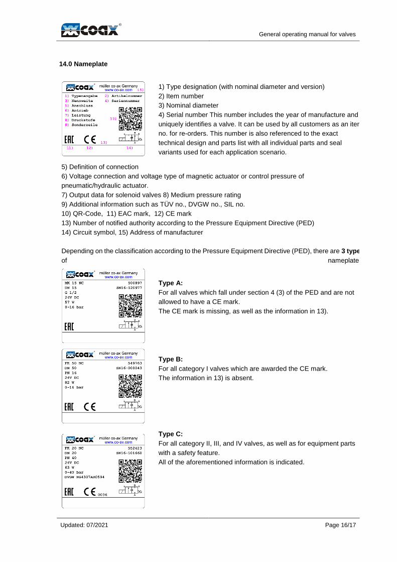
1) Type designation (with nominal diameter and version)
2) Item number
3) Nominal diameter
4) Serial number This number includes the year of manufacture and
uniquely identifies a valve. It can be used by all customers as an item
no. for re-orders. This number is also referenced to the exact
technical design and parts list with all individual parts and seal
variants used for each application scenario.
5) Definition of connection
6) Voltage connection and voltage type of magnetic actuator or control pressure of
pneumatic/hydraulic actuator.
7) Output data for solenoid valves 8) Medium pressure rating
9) Additional information such as TÜV no., DVGW no., SIL no.
10) QR-Code, 11) EAC mark, 12) CE mark
13) Number of notified authority according to the Pressure Equipment Directive (PED)
14) Circuit symbol, 15) Address of manufacturer
Depending on the classification according to the Pressure Equipment Directive (PED), there are 3 types
of nameplates:
Type A:
For all valves which fall under section 4 (3) of the PED and are not
allowed to have a CE mark.
The CE mark is missing, as well as the information in 13).
Type B:
For all category I valves which are awarded the CE mark.
The information in 13) is absent.
Type C:
For all category II, III, and IV valves, as well as for equipment parts
with a safety feature.
All of the aforementioned information is indicated.

General operating manual for valves
Updated: 07/2021
Page 17/17
15.0 Manufacturer and inquiries
müller co-ax gmbh
Friedrich-Müller-Str. 1
74670 Forchtenberg
Germany
Tel. +49 7947 828-0
Fax +49 7947 828-11
E-mail [email protected]
Website www.co-ax.com
For all inquiries related to directional valves, please provide the following information:
Order number, item number, or serial number
Type designation
Pressure level
Medium pressure before and after valve
Medium flowing through
Medium temperature
Flow rate in m³/h
Installation sketch and/or actual operating conditions
For all inquiries related to control valves, please provide the following information:
Order number, item number, or serial number
Type designation
Pressure level
Medium pressure before and after valve
Medium flowing through
Medium temperature
Flow rate in m³/h
Control accuracy
Setpoint inputs
Installation sketch and/or actual operating conditions