Marine transmissions List of lubricants TE-ML 04 ... - Maritimus
Upload
independentCategory
view
0download
0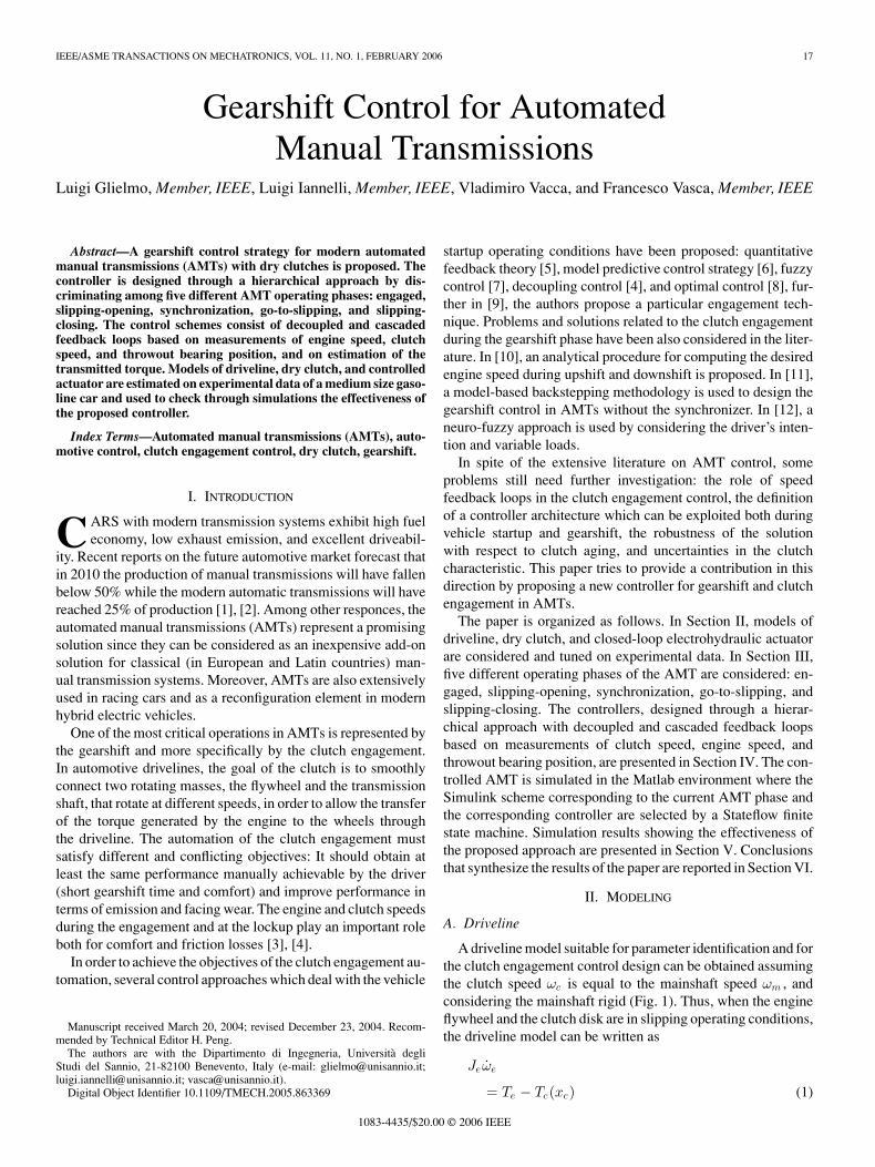
IEEE/ASME TRANSACTIONS ON MECHATRONICS, VOL. 11, NO. 1, FEBRUARY 2006 17
Gearshift Control for AutomatedManual Transmissions
Luigi Glielmo, Member, IEEE, Luigi Iannelli, Member, IEEE, Vladimiro Vacca, and Francesco Vasca, Member, IEEE
Abstract—A gearshift control strategy for modern automatedmanual transmissions (AMTs) with dry clutches is proposed. Thecontroller is designed through a hierarchical approach by dis-criminating among five different AMT operating phases: engaged,slipping-opening, synchronization, go-to-slipping, and slipping-closing. The control schemes consist of decoupled and cascadedfeedback loops based on measurements of engine speed, clutchspeed, and throwout bearing position, and on estimation of thetransmitted torque. Models of driveline, dry clutch, and controlledactuator are estimated on experimental data of a medium size gaso-line car and used to check through simulations the effectiveness ofthe proposed controller.
Index Terms—Automated manual transmissions (AMTs), auto-motive control, clutch engagement control, dry clutch, gearshift.
I. INTRODUCTION
CARS with modern transmission systems exhibit high fueleconomy, low exhaust emission, and excellent driveabil-
ity. Recent reports on the future automotive market forecast thatin 2010 the production of manual transmissions will have fallenbelow 50% while the modern automatic transmissions will havereached 25% of production [1], [2]. Among other responces, theautomated manual transmissions (AMTs) represent a promisingsolution since they can be considered as an inexpensive add-onsolution for classical (in European and Latin countries) man-ual transmission systems. Moreover, AMTs are also extensivelyused in racing cars and as a reconfiguration element in modernhybrid electric vehicles.
One of the most critical operations in AMTs is represented bythe gearshift and more specifically by the clutch engagement.In automotive drivelines, the goal of the clutch is to smoothlyconnect two rotating masses, the flywheel and the transmissionshaft, that rotate at different speeds, in order to allow the transferof the torque generated by the engine to the wheels throughthe driveline. The automation of the clutch engagement mustsatisfy different and conflicting objectives: It should obtain atleast the same performance manually achievable by the driver(short gearshift time and comfort) and improve performance interms of emission and facing wear. The engine and clutch speedsduring the engagement and at the lockup play an important roleboth for comfort and friction losses [3], [4].
In order to achieve the objectives of the clutch engagement au-tomation, several control approaches which deal with the vehicle
Manuscript received March 20, 2004; revised December 23, 2004. Recom-mended by Technical Editor H. Peng.
The authors are with the Dipartimento di Ingegneria, Universita degliStudi del Sannio, 21-82100 Benevento, Italy (e-mail: [email protected];[email protected]; [email protected]).
Digital Object Identifier 10.1109/TMECH.2005.863369
startup operating conditions have been proposed: quantitativefeedback theory [5], model predictive control strategy [6], fuzzycontrol [7], decoupling control [4], and optimal control [8], fur-ther in [9], the authors propose a particular engagement tech-nique. Problems and solutions related to the clutch engagementduring the gearshift phase have been also considered in the liter-ature. In [10], an analytical procedure for computing the desiredengine speed during upshift and downshift is proposed. In [11],a model-based backstepping methodology is used to design thegearshift control in AMTs without the synchronizer. In [12], aneuro-fuzzy approach is used by considering the driver’s inten-tion and variable loads.
In spite of the extensive literature on AMT control, someproblems still need further investigation: the role of speedfeedback loops in the clutch engagement control, the definitionof a controller architecture which can be exploited both duringvehicle startup and gearshift, the robustness of the solutionwith respect to clutch aging, and uncertainties in the clutchcharacteristic. This paper tries to provide a contribution in thisdirection by proposing a new controller for gearshift and clutchengagement in AMTs.
The paper is organized as follows. In Section II, models ofdriveline, dry clutch, and closed-loop electrohydraulic actuatorare considered and tuned on experimental data. In Section III,five different operating phases of the AMT are considered: en-gaged, slipping-opening, synchronization, go-to-slipping, andslipping-closing. The controllers, designed through a hierar-chical approach with decoupled and cascaded feedback loopsbased on measurements of clutch speed, engine speed, andthrowout bearing position, are presented in Section IV. The con-trolled AMT is simulated in the Matlab environment where theSimulink scheme corresponding to the current AMT phase andthe corresponding controller are selected by a Stateflow finitestate machine. Simulation results showing the effectiveness ofthe proposed approach are presented in Section V. Conclusionsthat synthesize the results of the paper are reported in Section VI.
II. MODELING
A. Driveline
A driveline model suitable for parameter identification and forthe clutch engagement control design can be obtained assumingthe clutch speed ωc is equal to the mainshaft speed ωm , andconsidering the mainshaft rigid (Fig. 1). Thus, when the engineflywheel and the clutch disk are in slipping operating conditions,the driveline model can be written as
Jeωe
= Te − Tc(xc) (1)
1083-4435/$20.00 © 2006 IEEE

18 IEEE/ASME TRANSACTIONS ON MECHATRONICS, VOL. 11, NO. 1, FEBRUARY 2006
Fig. 1. Driveline scheme.
[Jc + Jeq (ig , id)]ωc
= Tc(xc) −1
ig id
[ktw ∆θcw + βtw
(ωc
ig id− ωw
)](2)
Jw ωw
= ktw ∆θcw + βtw
(ωc
ig id− ωw
)− TL (ωw ) (3)
∆θcw
=ωc
ig id− ωw (4)
where J’s are inertias; ω’s speeds; T ’s torques; xc the throwoutbearing position; and the subscripts e, c, t, and w indicate engine,clutch, transmission, and wheels, respectively. Moreover, ig isthe gear ratio, id is the differential ratio, Jeq (ig , id) = Jm +(1/i2g )(Js1 + Js2 + (Jt/i2d)), Js1 and Js2 are the inertias of thetwo disks connected to the synchronizer, Jm is the mainshaftinertia, TL is the load torque, θ’s are angles, k’s are elasticstiffness coefficients, and β’s are friction coefficients. When theclutch is engaged, the engine speed ωe and the clutch disk speedωc are equal. The corresponding engaged model can be obtainedby adding (1) and (2) with the assumption ωe ≡ ωc . For moredetails see [13], where a more complex model that also takesinto account the flexibility of the mainshaft has been derived.
A further reduction of the model can be obtained by alsoconsidering the driveshaft to be rigid. By assuming ωc ≡ ωm ≡ig idωw and by reporting the vehicle inertia to the mainshaft, oneobtains the following model:
Jeωe = Te − Tc(xc) (5)
Jv (ig , id)ωc = Tc(xc) − TL
(ωc
ig id
)(6)
where Jv (ig id) = Jc + Jeq (ig id) + (Jw /i2g i2d). The corre-
sponding engaged model can be obtained by adding (5) and(6) with ωe ≡ ωc .
The model (1)–(4) provides a good compromise betweendescription of the driveline dynamics and model complex-ity. The parameters of (1)–(4) have been tuned from exper-imental data carried out on a FIAT STILO 2.4 gasoline carwith Je = 0.2 kg·m2, id = 3.94, and the set of gear ratiosig = [3.08, 2.23, 1.52, 1.16, 0.91] from the first gear to the fifthgear, respectively. The signals ωe, ωc , ωw , and Te have beenacquired with a sampling frequency of 100 Hz during tests inwhich a series of upshifts were carried out with different accel-
eration pedal positions and vehicle speeds. The clutch torquehas been estimated by an offline inversion of (1):
Tc = Te − Jeˆωe (7)
where ˆωe is obtained through the so-called dirty derivative,i.e., a filtered incremental ratio on the measured engine speed.The model parameters have been identified by using the leastsquare method and the corresponding results have been found asfollows: Jc + Jeq = 0.004 kg·m2, Jw = 133 kg·m2, βtw = 295N·m/(rad/s), and ktw = 6200 N·m/rad. Note that in the sumJc + Jeq , the dependence of Jeq on the gear ratio is negligible.It can be also verified that, as typical for the type of drivelineand car under investigation, the first resonance in the frequencyresponse of the model appears at a few hertz.
B. Dry Clutch
From a physical point of view, the dry clutch consists of twodisks (the clutch disk connected to the mainshaft and the fly-wheel disk connected to the engine) covered with a high frictionmaterial and a mechanism which presses the disks against eachother (clutch closed or engaged) or keeps them apart (clutchopen or disengaged). During an engagement phase, the clutchdisk is moved towards the flywheel disk until the friction dueto their contact allows the torque transmission. The throwoutbearing position xc determines the pressure between the fly-wheel disk and the clutch disk and, therefore, the transmittedtorque during the slipping phases. The nonlinear characteristicTc(xc) that relates the throwout bearing position xc to the torquetransmitted by the clutch is not easy to model. The clutch weardrastically influences such a characteristic and thus the torquetransmission. Moreover, the clutch characteristic is also influ-enced by the dependence of the friction coefficient on both tem-perature [14] and slip speed. In particular, the negative variationsof the friction coefficient with slip speed can induce torsionalself-excited vibrations of the driveline [15], [16].
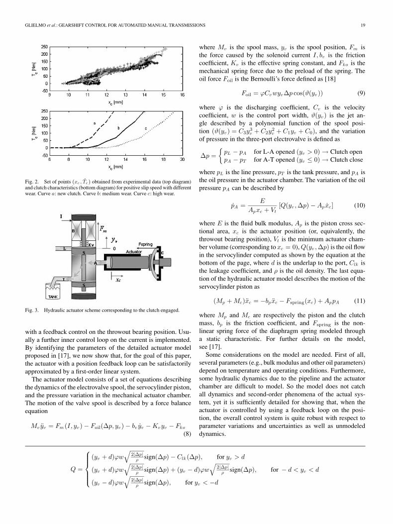
The nominal nonlinear characteristic Tc(xc) has been identi-fied from the experimental tests described above. By represent-ing the estimated values of the clutch torque obtained through(7) as a function of the corresponding values of the signal xc ,the set of points reported in Fig. 2 (top diagram) is obtained.The absolute value of the clutch torque has been modeled byusing the interpolation curve reported in bottom diagram ofFig. 2 (curve b), and its variations (curves a and c) which modeldifferent clutch wear and have been used to test the controllerrobustness. Note that the wear changes the bearing position, sayxc , at which the two disks come in contact and the transmittedtorque becomes different from zero.
C. Clutch Actuator
In AMTs, the electrohydraulic actuator is mainly composedof a hydraulic piston connected to a system of springs thatkeep the clutch closed when the piston does not apply any force(see Fig. 3). The piston is controlled by a three-port electrovalvethat regulates the oil flow through the hydraulic circuit and thendetermines the force on the mechanical actuator. In standardcommercial applications, the electrohydraulic actuator is used
GLIELMO et al.: GEARSHIFT CONTROL FOR AUTOMATED MANUAL TRANSMISSIONS 19
Fig. 2. Set of points (xc , Tc ) obtained from experimental data (top diagram)and clutch characteristics (bottom diagram) for positive slip speed with differentwear. Curve a: new clutch. Curve b: medium wear. Curve c: high wear.
Fig. 3. Hydraulic actuator scheme corresponding to the clutch engaged.
with a feedback control on the throwout bearing position. Usu-ally a further inner control loop on the current is implemented.By identifying the parameters of the detailed actuator modelproposed in [17], we now show that, for the goal of this paper,the actuator with a position feedback loop can be satisfactorilyapproximated by a first-order linear system.
The actuator model consists of a set of equations describingthe dynamics of the electrovalve spool, the servocylinder piston,and the pressure variation in the mechanical actuator chamber.The motion of the valve spool is described by a force balanceequation
Mv yv = Fm (I, yv ) − Foil(∆p, yv ) − bv yv − Kvyv − Fko
(8)
where Mv is the spool mass, yv is the spool position, Fm isthe force caused by the solenoid current I, bv is the frictioncoefficient, Kv is the effective spring constant, and Fko is themechanical spring force due to the preload of the spring. Theoil force Foil is the Bernoulli’s force defined as [18]
Foil = ϕCvwyv∆p cos(ϑ(yv )) (9)
where ϕ is the discharging coefficient, Cv is the velocitycoefficient, w is the control port width, ϑ(yv ) is the jet an-gle described by a polynomial function of the spool posi-tion (ϑ(yv ) = C3y
3v + C2y
2v + C1yv + C0), and the variation
of pressure in the three-port electrovalve is defined as
∆p =
pL − pA for L-A opened (yv > 0) → Clutch openpA − pT for A-T opened (yv ≤ 0) → Clutch close
where pL is the line pressure, pT is the tank pressure, and pA isthe oil pressure in the actuator chamber. The variation of the oilpressure pA can be described by
pA =E
Apxc + Vt[Q(yv ,∆p) − Apxc ] (10)
where E is the fluid bulk modulus, Ap is the piston cross sec-tional area, xc is the actuator position (or, equivalently, thethrowout bearing position), Vt is the minimum actuator cham-ber volume (corresponding to xc = 0), Q(yv ,∆p) is the oil flowin the servocylinder computed as shown by the equation at thebottom of the page, where d is the underlap to the port, Clk isthe leakage coefficient, and ρ is the oil density. The last equa-tion of the hydraulic actuator model describes the motion of theservocylinder piston as
(Mp + Mc)xc = −bp xc − Fspring(xc) + AppA (11)
where Mp and Mc are respectively the piston and the clutchmass, bp is the friction coefficient, and Fspring is the non-linear spring force of the diaphragm spring modeled througha static characteristic. For further details on the model,see [17].
Some considerations on the model are needed. First of all,several parameters (e.g., bulk modulus and other oil parameters)depend on temperature and operating conditions. Furthermore,some hydraulic dynamics due to the pipeline and the actuatorchamber are difficult to model. So the model does not catchall dynamics and second-order phenomena of the actual sys-tem, yet it is sufficiently detailed for showing that, when theactuator is controlled by using a feedback loop on the posi-tion, the overall control system is quite robust with respect toparameter variations and uncertainties as well as unmodeleddynamics.
Q =
(yv + d)ϕw√
2|∆p |ρ sign(∆p) − Clk (∆p), for yv > d
(yv + d)ϕw√
2|∆p |ρ sign(∆p) + (yv − d)ϕw
√2|∆p |
ρ sign(∆p), for − d < yv < d
(yv − d)ϕw√
2|∆p |ρ sign(∆p), for yv < −d
20 IEEE/ASME TRANSACTIONS ON MECHATRONICS, VOL. 11, NO. 1, FEBRUARY 2006
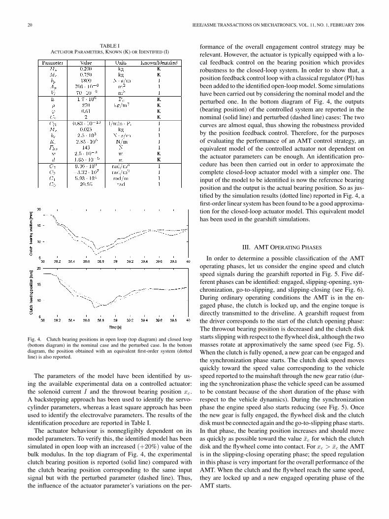
TABLE IACTUATOR PARAMETERS, KNOWN (K) OR IDENTIFIED (I)
Fig. 4. Clutch bearing positions in open loop (top diagram) and closed loop(bottom diagram) in the nominal case and the perturbed case. In the bottomdiagram, the position obtained with an equivalent first-order system (dottedline) is also reported.
The parameters of the model have been identified by us-ing the available experimental data on a controlled actuator:the solenoid current I and the throwout bearing position xc .A backstepping approach has been used to identify the servo-cylinder parameters, whereas a least square approach has beenused to identify the electrovalve parameters. The results of theidentification procedure are reported in Table I.
The actuator behaviour is nonnegligibly dependent on itsmodel parameters. To verify this, the identified model has beensimulated in open loop with an increased (+20%) value of thebulk modulus. In the top diagram of Fig. 4, the experimentalclutch bearing position is reported (solid line) compared withthe clutch bearing position corresponding to the same inputsignal but with the perturbed parameter (dashed line). Thus,the influence of the actuator parameter’s variations on the per-
formance of the overall engagement control strategy may berelevant. However, the actuator is typically equipped with a lo-cal feedback control on the bearing position which providesrobustness to the closed-loop system. In order to show that, aposition feedback control loop with a classical regulator (PI) hasbeen added to the identified open-loop model. Some simulationshave been carried out by considering the nominal model and theperturbed one. In the bottom diagram of Fig. 4, the outputs(bearing position) of the controlled system are reported in thenominal (solid line) and perturbed (dashed line) cases: The twocurves are almost equal, thus showing the robustness providedby the position feedback control. Therefore, for the purposesof evaluating the performance of an AMT control strategy, anequivalent model of the controlled actuator not dependent onthe actuator parameters can be enough. An identification pro-cedure has been then carried out in order to approximate thecomplete closed-loop actuator model with a simpler one. Theinput of the model to be identified is now the reference bearingposition and the output is the actual bearing position. So as jus-tified by the simulation results (dotted line) reported in Fig. 4, afirst-order linear system has been found to be a good approxima-tion for the closed-loop actuator model. This equivalent modelhas been used in the gearshift simulations.
III. AMT OPERATING PHASES
In order to determine a possible classification of the AMToperating phases, let us consider the engine speed and clutchspeed signals during the gearshift reported in Fig. 5. Five dif-ferent phases can be identified: engaged, slipping-opening, syn-chronization, go-to-slipping, and slipping-closing (see Fig. 6).During ordinary operating conditions the AMT is in the en-gaged phase, the clutch is locked up, and the engine torque isdirectly transmitted to the driveline. A gearshift request fromthe driver corresponds to the start of the clutch opening phase:The throwout bearing position is decreased and the clutch diskstarts slipping with respect to the flywheel disk, although the twomasses rotate at approximatively the same speed (see Fig. 5).When the clutch is fully opened, a new gear can be engaged andthe synchronization phase starts. The clutch disk speed movesquickly toward the speed value corresponding to the vehiclespeed reported to the mainshaft through the new gear ratio (dur-ing the synchronization phase the vehicle speed can be assumedto be constant because of the short duration of the phase withrespect to the vehicle dynamics). During the synchronizationphase the engine speed also starts reducing (see Fig. 5). Oncethe new gear is fully engaged, the flywheel disk and the clutchdisk must be connected again and the go-to-slipping phase starts.In that phase, the bearing position increases and should moveas quickly as possible toward the value xc for which the clutchdisk and the flywheel come into contact. For xc > xc the AMTis in the slipping-closing operating phase; the speed regulationin this phase is very important for the overall performance of theAMT. When the clutch and the flywheel reach the same speed,they are locked up and a new engaged operating phase of theAMT starts.

GLIELMO et al.: GEARSHIFT CONTROL FOR AUTOMATED MANUAL TRANSMISSIONS 21
Fig. 5. Engine speed and clutch speed signals during a gearshift; the five operating phases are highlighted.
Fig. 6. Finite-state diagram of the AMT operating phases.
IV. GEARSHIFT CONTROL
A. Controller Objectives
During a gearshift, the clutch engagement should be carriedout as quickly as possible and with strict constraints on driv-ing comfort and engine operating conditions. The fundamentalconstraint on the clutch engagement is the so-called no-kill con-ditions, i.e., one must avoid the engine stall. This condition canbe modeled by imposing that
ωe(t) ≥ ωmine ∀t. (12)
A further important condition to be satisfied during the en-gagement is the so-called no-lurch condition. A nonsmooth en-gagement process determines a mechanical oscillation of thepower train, which should be avoided in order to preserve thepassengers comfort. To gain some insight into the phenomenon,we first point out that at the time of engagement, e.g., t, the
system switches between two different configurations: one inwhich ωe and ωc are different velocities and one in which theycoincide. Such a switch excites the system dynamics and it is notdifficult to realize that a rough measure of the extent of excita-tion is given by the discontinuity ωc(t+) − ωc(t−). To computethis discontinuity, let us assume, for simplicity’s sake that theengine torque is continuous at t. Now, we add (1) and (2) anduse the fact that ωe ≡ ωc after lockup to obtain
ωc(t+) =1
Je + Jc
[Te(t+) − Ω(t+)] (13)
where
Ω =1
ig id
[ktw ∆θcw + βtw
(ωc
ig id− ωw
)]. (14)
By assuming the state and the engine torque to be continuous atlockup one obtains
ωc(t+) =1
Je + Jc
[Te(t−) − Tc(t−)]
+1
Je + Jc
[Tc(t−) − Ω(t−)]
=Je
Je + Jc
ωe(t−) +Jc
Je + Jc
ωc(t−) (15)
which leads to
ωc(t+) − ωc(t−) =Je
Je + Jc
ωsl(t−). (16)
Thus, the engagement smoothness is somehow related to theslip acceleration at lockup and, hence, we will consider thisquantity as a quantitative performance criterion.

22 IEEE/ASME TRANSACTIONS ON MECHATRONICS, VOL. 11, NO. 1, FEBRUARY 2006
Fig. 7. General closed-loop scheme during the slipping-closing phase. Except for the gearshift controller, the scheme is also the same for the other phases.
Another control objective consists of maintaining as low aspossible the energy dissipated during the engagement, whichcan be written as
Ed =∫ t
0
ωsl(t)Tc(t) dt. (17)
In our approach, the control objectives are met by ensuringthat the engine speed ωe and the clutch speed ωc (or the slippingspeed ωsl) track desired reference signals. In what follows, thecontrollers of the different AMT phases are described, startingfrom the critical slipping-closing phase, which is also the mostimportant phase during the vehicle launch, i.e., starting from astandstill. The input signals for the controllers are measurementsof the engine speed and clutch speed, and the estimation ofthe transmitted torque during the slipping phases. At a lowerhierarchical level, which is only ideally modeled in this paper,measurements of the throwout bearing position and estimationof the engine torque are also needed.
B. Slipping-Closing Controller
In this phase, a new gear has already been engaged, thethrowout bearing position has reached xc , and the clutch hasstarted transmitting torque to the driveline. The general architec-ture of the controlled system is reported in Fig. 7. The drivelinemodel to be considered is (1)–(4). The controller output signalsare the reference engine torque T ref
e and the reference throwoutbearing position xref
c , and are generated from the gearshift con-troller on the basis of the reference speeds ωref
e and ωrefc . The
signal T refe is actuated by the engine control unit, which is here
assumed to be ideal, i.e., Te = T refe . The reference signal xref
c isactuated by the closed-loop electrohydraulic actuator approxi-mated by the first-order system presented in the previous section.Finally, xc is converted to the transmitted torque Tc through theclutch characteristic.
A block diagram of the gearshift controller is shown in Fig. 8.The controller C1 realizes a feedforward action obtained bycomputing the left-hand side of (1) after replacing the actual en-gine speed with the corresponding reference signal. The feed-back loop on the clutch speed provides the reference clutchtorque T ref
c . The loop on the engine speed, together with thecorresponding feedforward compensation, provides the desireddifference between the engine torque and the clutch torque.By adding to this signal the transmitted torque [estimated byusing (7)], the reference engine torque T ref
e is obtained. Thisscheme can be viewed as a decoupling controller (see [4]) andthus the two controllers C2 and C3 are PI designed by applying
Fig. 8. Block diagram of the gearshift controller during the slipping-closingphase.
TABLE IIGEAR-RATIO-DEPENDENT PARAMETERS OF THE PI CONTROLLERS
to the model (1)–(4) classical single-input single-output linearcontroller design techniques. Furthermore, the controllers’ pa-rameters are designed (and then scheduled at run-time) for eachgear so as to obtain the same closed-loop decoupled transfermatrix and, hence, the same performance. By assuming for C2
and C3 the transfer function form KP + KI /s, the resulting pa-rameters are KI = 1.9 and KI = 25, respectively, for C2 andC3, and proportional gains, are reported in Table II.
An inner feedback loop on the clutch torque is introducedin order to compensate for the uncertainties on the static torquecharacteristic (see Fig. 2). The nonlinearities in the clutch modelTc(xc) make it difficult to design the controller C4 through ananalytical procedure. Here, C4 has been chosen as a PI controllerwhose parameters have been manually tuned (KP4 = 0.01 andKI4 = 0.5). Robustness of the closed-loop system with respectto different C4 parameters have been checked in simulationsshowing that such parameters are not critical for the closed-loop performance.
C. Engaged Controller
In this phase, the clutch is fully engaged and the transmittedtorque is directly supplied by the engine to the mainshaft. The

GLIELMO et al.: GEARSHIFT CONTROL FOR AUTOMATED MANUAL TRANSMISSIONS 23
driveline model is obtained from (1)–(4) by adding (1) and(2) with the assumption ωe ≡ ωc . Since the clutch is completelyclosed, i.e., not controlled, the only control signal is the referenceengine torque, which is regulated by the engine control unit.
D. Slipping-Opening Controller
When a new gearshift is requested, it is necessary to openthe clutch and, thus, a new slipping phase starts. The drivelinemodel is (1)–(4). The controller output signals are T ref
e and xrefc .
The reference torque is obtained with the engine speed controlloop of the scheme reported in Fig. 8. The signal ωref
e is constantfor comfort reasons (see Fig. 5). The throwout bearing referenceposition xref
c is selected in open loop as a decreasing ramp. Thisphase is concluded when the engine flywheel disk and the clutchdisk are completely separated.
E. Synchronization Controller
During this phase, the clutch disk is completely separatedfrom the flywheel disk and, therefore, Tc = 0. Since during thisphase the vehicle speed can be assumed constant, e.g., ωw , thedriveline model can be obtained from (5) and (6) with Tc = 0and the load torque replaced by the synchronization torque Ts .The controller output signals are the reference engine torqueand the reference synchronization torque. Such control signalscan be obtained with two independent single-input single-outputfeedback loops designed by using classical control methods onthe linear model described above. The reference clutch speed isassumed to vary linearly from the speed at which the synchro-nization phase starts and the speed corresponding to the wheelspeed transformed by the new gear ratio, i.e., ωc = ωw /(ig id),within a desired time interval.
F. Go-to-Slipping Controller
The main aim of this phase is to reach the bearing positionxc at which the friction between the flywheel and the clutchdisk, and hence the torque transmission, starts. The drivelinemodel is (1)–(4). Since in this phase xc < xc , the clutch torqueis zero (see Fig. 2). The control signals are T ref
e and xrefc . The
reference engine torque is obtained with the same controllerused in the slipping-opening phase. The throwout bearing refer-ence position xref
c is set (without clutch speed feedback) to theconstant value xc . The value xc can be obtained by exploitingthe clutch torque estimator and averaging the throwout bearingpositions at which torque started to be transmitted in the mostrecent gearshifts.
V. SIMULATION RESULTS
The simulation results have been obtained by implementingthe driveline model and the controllers of the different AMTphases in the Matlab environment. The parts of the model thatchange with the AMT phases are implemented with differ-ent Simulink schemes; the model corresponding to the activephase is selected by a Stateflow finite state machine similar tothat shown in Fig. 6. For instance, the commutation from theslipping-closing phase to the engaged phase is obtained with
Fig. 9. Engine, clutch, and vehicle speeds for a sequence of upshifts withmedium wear of the clutch.
TABLE IIIPERFORMANCE FOR A SEQUENCE OF UPSHIFTS
a state-dependent condition, i.e., ωe = ωc , whereas an externalevent (the driver gearshift request) determines the commuta-tion from the engaged phase to the slipping-opening phase.Another state-dependent event (xc = xc) determines the com-mutation from the go-to-slipping phase to the slipping-closingphase. The commutation among the different controllers is doneby setting their initial conditions so that bumpless transfer isensured.
Figs. 9 and 10 show the simulation results of the controlledAMT for a sequence of consecutive upshifts. The behaviors ofthe engine speed and clutch speed, and those of the throwoutbearing position and engine torque, are presented. In particular,Table III shows some performance indexes of the simulation test:dissipated energy, gearshift time duration, and slip accelerationat lockup are all within acceptable limits and testify the validityof the proposed control strategy. Dealing with driving comfort inparticular, by assuming that the lockup phenomenon has a finitetime duration, the left-hand side of (16) can also be interpretedas an incremental ratio and, therefore, as an approximation ofthe jerk caused by the lockup of the clutch.
We wish to remark that the controller structure for theslipping-closing phase can also be used both during gearshiftand when the clutch must be locked up from standstill. Fig. 11shows that the control strategy also ensures a smooth clutchengagement during the vehicle startup, which is one of the mostcritical situations for AMTs. It is apparent that the bearing posi-tion and the engine torque have similar shapes. This is due to thefact that in the main part of the slipping-closing phase the clutch

24 IEEE/ASME TRANSACTIONS ON MECHATRONICS, VOL. 11, NO. 1, FEBRUARY 2006
Fig. 10. Zoom of the upshift from gear 2 to gear 3 with medium wear of the clutch. (a) Engine speed (solid line), clutch speed (dashed line), desired engine speed(dashed-dotted), and desired clutch speed (dotted line). (b) Throwout bearing position. (c) Engine torque.
Fig. 11. Zoom of the startup phase with medium wear of the clutch. (a) Engine speed (solid line), clutch speed (dashed line), desired engine speed (dashed-dotted),and desired clutch speed (dotted line). (b) Throwout bearing position. (c) Engine torque.
is operating in an approximately linear region of the transmittedtorque characteristic reported in Fig. 2 and the engine speed isvarying slowly, from (1) Te ≈ Tc(xc). The proposed controlleris also effective for downshifts as shown in Fig. 12.
The simulation results reported in Fig. 13 show the robustnessof the proposed control strategy in the presence of uncertaintiesor variations of the clutch static characteristics Tc(xc). Dur-ing the slipping-opening phase, corresponding to the first part

GLIELMO et al.: GEARSHIFT CONTROL FOR AUTOMATED MANUAL TRANSMISSIONS 25
Fig. 12. Downshift from gear 5 to gear 4 in the presence of a clutch with medium wear (curve b in Fig. 2). (a) Engine speed (solid line), clutch speed (dashedline), desired engine speed (dashed-dotted), and desired clutch speed (dotted line). (b) Throwout bearing position. (c) Engine torque.
Fig. 13. Upshift from 2 gear to 3 gear in the presence of a clutch with high wear (curve c in Fig. 2). (a) Engine speed (solid line), clutch speed (dashed line),desired engine speed (dashed-dotted), and desired clutch speed (dotted line). (b) Throwout bearing position. (c) Engine torque.
of Fig. 13, the engine speed has an overshoot due to the factthat for this simulation xc is larger than in the previous case(see curves b and c in Fig. 2). By comparing Figs. 10 and 13during the slipping-closing phase, analogous considerations jus-tify the fact that the controller imposes larger values of xc in thelatter simulation in order to obtain similar performance.
VI. CONCLUSION
The analysis of the existing literature on AMT control strate-gies shows that a generally recognized good solution to theproblem of the gearshift control in AMT with dry clutch isstill missing. In this paper, a solution based on cascaded anddecoupled speed and torque control loops is proposed. Dynamic

26 IEEE/ASME TRANSACTIONS ON MECHATRONICS, VOL. 11, NO. 1, FEBRUARY 2006
models of the driveline, the static characteristic of the torquetransmitted by the dry clutch during the slipping phases, andan equivalent model of the controlled electrohydraulic actuatorhave, been tuned on experimental data and used for the con-trollers design. The control strategy exploits the hybrid natureof the AMT by discriminating among five different operatingphases and by designing dedicated controllers for each phase.Simulation results show the effectiveness of the proposed so-lution during startups, upshifts, and downshifts. Performanceis evaluated in terms of duration of gearshift, comfort, dissi-pated energy, and robustness with respect to uncertainties ofthe clutch characteristic. The low computational load neededto implement the proposed controller allows its realization oncommercial electronic control units.
REFERENCES
[1] Knibb-Gormezano and Partners. (2000) Trasmissions in Europe 2000–2010: A decade of significant change. [Online]. Available: http://www.kgpauto.com/Initiatives/Transmissions%20Press%20Release.pdf
[2] Just-Auto.com Editorial Team (2001, Jan.) The global transmission mar-ket. [Online]. Available: http://www.just-auto.com/features detail.asp?art=417&c=1
[3] Y. Lei, M. Niu, and A. Ge, “A research on starting control strategy ofvehicle with AMT,” in Proc. FISITA World Automotive Congress, Seoul,Korea, 2000.
[4] F. Garofalo, L. Glielmo, L. Iannelli, and F. Vasca, “Smooth engagement forautomotive dry clutch,” in Proc. 40th IEEE Conf. Decision and Control,Orlando, FL, 2001, pp. 529–534.
[5] J. Slicker and R. N. K. Loh, “Design of robust vehicle launch controlsystem,” IEEE Trans. Contr. Syst. Technol., vol. 4, no. 4, pp. 326–335, Jul.1996.
[6] A. Bemporad, F. Borrelli, L. Glielmo, and F. Vasca, “Hybrid control ofdry clutch engagement,” in Proc. European Control Conf., Porto, Portugal,2001.
[7] H. Tanaka and H. Wada, “Fuzzy control of clutch engagement for au-tomated manual transmission,” Veh. Syst. Dyn., vol. 24, pp. 365–376,1995.
[8] L. Glielmo and F. Vasca, “Optimal control of dry clutch engagement,”SAE Trans., J. Passenger Cars: Mech. Syst., vol. 6, no. 2000-01-0837,2000.
[9] A. Szadkowski and R. B. Morford, “Clutch engagement simulation: En-gagement without throttle,” SAE Tech. Paper Series, no. 920766, 1992.
[10] F. Amisano, G. Serra, and M. Velardocchia, “Engine control strategy tooptimize a shift transient during clutch engagement,” SAE Tech. PaperSeries, no. 2001-01-0877, pp. 115–120, 2001.
[11] J. Fredriksson and B. Egardt, “Nonlinear control applied to gearshiftingin automated manual transmission,” in Proc. 39th IEEE Conf. Decisionand Control, Sydney, Australia, 2000, pp. 444–449.
[12] K. Hayashi, Y. Shimizu, S. Nakamura, Y. Dote, A. Takayama, andA. Hirako, “Neuro fuzzy optimal transmission control for automobilewith variable loads,” in Proc. IEEE Industrial Electronics, Control, andInstrumentation Conf., Maui, HI, 1993, vol. 1, pp. 430–434.
[13] L. Glielmo, L. Iannelli, V. Vacca, and F. Vasca, “Speed control for auto-mated manual transmission with dry clutch,” in Proc. 43th IEEE Conf.Decision and Control, Atlantis, Bahamas, 2004, pp. 1709–1714.
[14] F. Amisano, R. Flora, and M. Velardocchia, “A linear thermal modelfor an automotive clutch,” SAE Tech. Paper Series, no. 2000-01-0834,2000.
[15] D. Centea, H. Rahnejat, and M. T. Menday, “The influence of the in-terface coefficient of friction upon the propensity to judder in automo-tive clutches,” Proc. Inst. Mech. Eng., vol. 213, pt. D, pp. 245–268,1999.
[16] E. M. A. Rabeih and D. A. Crolla, “Intelligent control of clutch judder andshunt phenomena in vehicle drivelines,” Int. J. Veh. Des., vol. 17, no. 3,pp. 318–332, 1996.
[17] M. Montanari, F. Ronchi, C. Rossi, A. Tilli, and A. Tonielli, “Control andperformance evaluation of a clutch servo system with hydraulic actuation,”Control Eng. Practice, vol. 12, pp. 1369–1379, 2004.
[18] H. Meritt, Hydraulic Control Systems. New York: Wiley, 1967.
Luigi Glielmo (S’87–M’90) was born in 1960. Hereceived the Laurea degree in electronic engineeringand the Ph.D. degree in automatic control from theUniversita di Napoli Federico II, Naples Italy.
Currently, he is a Professor of Automatic Con-trol in the School of Engineering of the Universitadegli Studi del Sannio, Benevento, Italy, where he isalso Head of the Dipartimento di Ingegneria. In 1989and 1990, he was a Visiting Scholar at the School ofAeronautics and Astronautics, Purdue University, anda Visiting Scientist at the NET Team, Max-Planck-
Institut fur Plasmaphysik, Germany, in 1990. In 2002, he was Visiting Professorat the Johannes Kepler Universitat, Linz, Austria. His research interests includesingular perturbation methods, analysis and control of uncertain systems, dy-namic positioning of ships, plasma control in (Tokamak) fusion reactors, Kalmanfiltering, nonlinear system analysis, automotive control, manufacturing systemssimulation, modeling, and control of wine production. He has coauthored morethan 70 papers published in international archival journals and proceedings ofinternational conferences, and edited Robust Control via Variable Structure andLyapunov Techniques (Springer-Verlag, 1996).
Dr. Glielmo has participated in scientific committees of various interna-tional conferences and organized an international workshop. He proposed theestablishment of and chaired for four years the IEEE Control Systems Soci-ety Technical Committee on Automotive Controls. He is a member of ASME,SIAM, and SAE and is an Associate Editor of the IEEE TRANSACTIONS ON
AUTOMATIC CONTROL.
Luigi Iannelli (S’01–M’03) was born in 1975 inBenevento, Italy. He received the Laurea degree incomputer engineering from the Universita degli Studidel Sannio, Benevento, Italy, in 1999, and the Ph.D.degree in information engineering from the Univer-sita di Napoli Federico II, Naples, Italy, in 2003.
During 2002 and 2003, he was a Guest Researcherin the Department of Signals, Sensors, and Systems,Royal Institute of Technology (KTH), Stockholm,Sweden. In 2003, he was a Research Assistant in theDipartimento di Informatica e Sistemistica, Univer-
sita di Napoli Federico II. He is currently an Assistant Professor of AutomaticControl in the Dipartimento di Ingegneria, Universita degli Studi del Sannio. Hiscurrent research interests include analysis and control of switched and hybridsystems, automotive control, and applications of control theory to electronicsystems.
Dr. Iannelli is member of the IEEE Control Systems Society, IEEE Circuitsand Systems Society, and SIAM.
Vladimiro Vacca was born in 1975 in Naples, Italy.He received the Laurea degree in computer engi-neering with orientation toward industrial automationfrom the Universita di Napoli Federico II, Naples,Italy, in 2002. He is currently working toward thePh.D. degree in control engineering, sponsored byCarlo Gavazzi Space, in the Dipartimento di Ingeg-neria, Universita degli Studi del Sannio, Benevento,Italy.
From July 2002 to June 2003, he was involvedin modeling and clutch control for automated man-
ual transmissions during a collaboration with the ELASIS research center. Hiscurrent research interests include automotive control, satellite formation flying,wireless monitoring systems, and real-time control in avionics. He is currentlyworking on the ESA project (Fluid Science Laboratory).
Francesco Vasca (S’94–M’95) was born in Naples,Italy, in 1967. He received the Laurea degree in elec-tronic engineering and the Ph.D. degree in automaticcontrol from the Universita di Napoli Federico II,Naples, Italy, in 1991 and 1995, respectively.
Since 2000, he has been an Associate Professorof Automatic Control in the Dipartimento di Ingeg-neria, Universita degli Studi del Sannio, Benevento,Italy. His research interests include automated man-ual transmissions, energy management of hybrid ve-hicles, battery state of charge estimation, nonlinear
dynamics and control techniques for power converters, averaging of nonsmoothsystems through dithering, and formation control of multiagent systems.
Copyright © 2022 FDOKUMEN