AUTOMATED TEMPORARY STRUCTURE SAFETY ...
149
AUTOMATED TEMPORARY STRUCTURE SAFETY PLANNING USING BUILDING INFORMATION MODELING (BIM) A Thesis Presented to The Academic Faculty by Kyungki Kim In Partial Fulfillment of the Requirements for the Degree Doctor of Philosophy in the School of Civil and Environmental Engineering Georgia Institute of Technology May 2016 Copyright c 2016 by Kyungki Kim
-
Upload
khangminh22 -
Category
Documents
-
view
1 -
download
0
Transcript of AUTOMATED TEMPORARY STRUCTURE SAFETY ...

AUTOMATED TEMPORARY STRUCTURE SAFETYPLANNING USING BUILDING INFORMATION
MODELING (BIM)
A ThesisPresented to
The Academic Faculty
by
Kyungki Kim
In Partial Fulfillmentof the Requirements for the Degree
Doctor of Philosophy in theSchool of Civil and Environmental Engineering
Georgia Institute of TechnologyMay 2016
Copyright c© 2016 by Kyungki Kim

AUTOMATED TEMPORARY STRUCTURE SAFETYPLANNING USING BUILDING INFORMATION
MODELING (BIM)
Approved by:
Dr. Yong K. Cho, AdvisorSchool of Civil and EnvironmentalEngineeringGeorgia Institute of Technology
Professor Charles M. EastmanCollege of ArchitectureGeorgia Institute of Technology
Dr. Iris TienSchool of Civil and EnvironmentalEngineeringGeorgia Institute of Technology
Dr. John R. HaymakerCollege of ArchitectureGeorgia Institute of Technology
Dr. Pardis Pishdad-BozorgiCollege of ArchitectureGeorgia Institute of Technology
Date Approved: December 15, 2015

Dedicated to my mother, father, sister, and fiance for their
unwavering support.

ACKNOWLEDGEMENTS
I would like to express my deepest gratitude to my advisor Dr. Yong K. Cho dur-
ing my doctoral study at Georgia Institute of Technology. I acknowledge Dr. Cho
for his patience, motivation, enthusiasm, and immense knowledge as wells as con-
tinuous support and mentorship that were critical in all the time of reserach and
writing of this thesis. I cannot imagine having my Ph.D research completed without
Dr. Cho’s insightful guidance and warm encouragement. Also, I would like to thank
other members of my doctoral thesis committee: Professor Eastman, Dr. Tien, Dr.
Pishdad-Bozorgi, and Dr. Haymaker for their time and efforts to give me constructive
comments and hard questions.
Much of my success in graduate school at the Georgia Institute of Technology can
be attributed to my fellow colleagues. To my accomplishments, the support of the
members including Jay Park, Jun Wang, Yihai Fang, Siamak Safarzadegan Gilan,
Pileun Kim, Nipesh Pradhananga, Sijie Zhang, Tao Cheng, and Soumitry Jagadev
Ray was critical. I would like to give my special thanks to my mentor Sihyun Kim
for his kind and thoughtful advice that greatly helped me to survive intensive times
of doctoral study.
My sincere thanks also goes to Holder Construction, especially Michael Hasamoh
Alex Edgar, for an interest in my research and a year-long collaboration that greatly
helped me to accomplish my research achievement.
My friends have helped me stay balanced through these difficult years. Their support
and care helped me overcome setbacks and stay focused on my graduate study. I
greatly value their friendship and I deeply appreciate their belief in me.
iv

Most importantly, none of these could have been possible without the love and pa-
tience of my family and fiance. They have been a constant source of love, concern,
support, and strength all these years.
v

TABLE OF CONTENTS
ACKNOWLEDGEMENTS . . . . . . . . . . . . . . . . . . . . . . . . . . iv
LIST OF TABLES . . . . . . . . . . . . . . . . . . . . . . . . . . . . . . . ix
LIST OF FIGURES . . . . . . . . . . . . . . . . . . . . . . . . . . . . . . x
SUMMARY . . . . . . . . . . . . . . . . . . . . . . . . . . . . . . . . . . . . xiii
I INTRODUCTION . . . . . . . . . . . . . . . . . . . . . . . . . . . . . 1
1.1 Construction safety planning . . . . . . . . . . . . . . . . . . . . . . 1
1.2 Current status of planning temporary structures . . . . . . . . . . . 2
1.3 Current status of planning scaffolds . . . . . . . . . . . . . . . . . . 4
II RESEARCH GOAL AND OBJECTIVES . . . . . . . . . . . . . . . 6
2.1 Research goal . . . . . . . . . . . . . . . . . . . . . . . . . . . . . . 6
2.2 Research objectives . . . . . . . . . . . . . . . . . . . . . . . . . . . 6
2.2.1 Objective 1: Temporary structure object creation in BIM forsafety planning . . . . . . . . . . . . . . . . . . . . . . . . . . 7
2.2.2 Objective 2: Automated identification of potential safety haz-ards related to temporary structures . . . . . . . . . . . . . . 9
2.2.3 Objective 3: Temporary structure plan optimization . . . . . 10
III LITERATURE REVIEW . . . . . . . . . . . . . . . . . . . . . . . . . 12
3.1 Computer-assisted approaches of temporary structure planning . . . 12
3.2 Point of departure: the need for an automated system for temporarystructures . . . . . . . . . . . . . . . . . . . . . . . . . . . . . . . . . 16
IV METHODOLOGY . . . . . . . . . . . . . . . . . . . . . . . . . . . . . 18
4.1 Objective #1: Temporary structure object creation in BIM for safetyplanning . . . . . . . . . . . . . . . . . . . . . . . . . . . . . . . . . 18
4.2 Objective #2: Automated identification of potential safety hazardsrelated to temporary structures through safety simulation . . . . . . 19
4.3 Objective #3: Temporary structure plan optimization by case enu-meration, manual selection, and refinement . . . . . . . . . . . . . . 19
4.4 Validation of research . . . . . . . . . . . . . . . . . . . . . . . . . . 20
vi

V AUTOMATED PLACEMENT OF SCAFFOLDING IN BIM . . 21
5.1 Introduction . . . . . . . . . . . . . . . . . . . . . . . . . . . . . . . 21
5.2 Objective and scope . . . . . . . . . . . . . . . . . . . . . . . . . . . 22
5.3 Framework for automated scaffolding placement . . . . . . . . . . . 22
5.4 Development of Scaffolding Placement Engine . . . . . . . . . . . . . 23
5.4.1 Overview . . . . . . . . . . . . . . . . . . . . . . . . . . . . . 23
5.4.2 Details to the development of Scaffolding Placement Engine . 26
5.5 Implementation of scaffolding placement algorithms . . . . . . . . . 45
5.6 Conclusions and discussion . . . . . . . . . . . . . . . . . . . . . . . 50
VI AUTOMATED CHECKING OF SCAFFOLDING-RELATED SAFETYHAZARDS IN BIM . . . . . . . . . . . . . . . . . . . . . . . . . . . . 51
6.1 Introduction . . . . . . . . . . . . . . . . . . . . . . . . . . . . . . . 51
6.2 Objective and scope . . . . . . . . . . . . . . . . . . . . . . . . . . . 53
6.3 Development of BIM-based safety analysis automation . . . . . . . . 54
6.3.1 Framework of BIM-based safety analysis automation . . . . . 54
6.3.2 Technical details of BIM-safety platform . . . . . . . . . . . . 56
6.4 Case study for validation . . . . . . . . . . . . . . . . . . . . . . . . 72
6.5 Discussions and conclusions . . . . . . . . . . . . . . . . . . . . . . . 78
VII OPTIMIZATION OF SCAFFOLDING PLAN FOR SAFETY . . 80
7.1 Introduction . . . . . . . . . . . . . . . . . . . . . . . . . . . . . . . 80
7.2 Objective and scope . . . . . . . . . . . . . . . . . . . . . . . . . . . 83
7.3 Development of the proposed scaffolding optimization engine . . . . 84
7.4 Implementation and case study . . . . . . . . . . . . . . . . . . . . . 90
7.5 Results and discussion . . . . . . . . . . . . . . . . . . . . . . . . . . 103
VIIIVALIDATION OF SCAFFOLDING PLACEMENT, SAFETY PLAN-NING, OPTIMIZATION . . . . . . . . . . . . . . . . . . . . . . . . . 105
8.1 Case study introduction . . . . . . . . . . . . . . . . . . . . . . . . . 105
8.2 System preparation for simulation and optimization . . . . . . . . . 108
8.2.1 4D BIM preparation . . . . . . . . . . . . . . . . . . . . . . 108
vii

8.2.2 Optimization input preparation . . . . . . . . . . . . . . . . 111
8.2.3 Objective functions . . . . . . . . . . . . . . . . . . . . . . . 116
8.3 Implementation results . . . . . . . . . . . . . . . . . . . . . . . . . 118
8.3.1 Scaffolding placement . . . . . . . . . . . . . . . . . . . . . . 118
8.3.2 Scaffolding-related hazard recognition . . . . . . . . . . . . . 119
8.3.3 Enumerative generation of scaffolding plan alternatives . . . 121
8.3.4 Performance-based selection and review in 4D BIM . . . . . 121
8.3.5 Selection of final scaffolding plan . . . . . . . . . . . . . . . . 126
8.4 Conclusions and discussion . . . . . . . . . . . . . . . . . . . . . . . 126
IX CONCLUSIONS AND LIMITATIONS . . . . . . . . . . . . . . . . 128
9.1 Summary of works performed . . . . . . . . . . . . . . . . . . . . . . 128
9.2 Contributions and impacts . . . . . . . . . . . . . . . . . . . . . . . 129
9.3 Limitations and future research . . . . . . . . . . . . . . . . . . . . . 130
REFERENCES . . . . . . . . . . . . . . . . . . . . . . . . . . . . . . . . . . 132
VITA . . . . . . . . . . . . . . . . . . . . . . . . . . . . . . . . . . . . . . . . 136
viii

LIST OF TABLES
1 Computer-assisted approaches for temporary structure planning (M:manual, I: insufficiently automated, A: automated) . . . . . . . . . . 15
2 Scores for different hazard types . . . . . . . . . . . . . . . . . . . . . 93
3 Safety hazard score calculation functions . . . . . . . . . . . . . . . . 117
ix

LIST OF FIGURES
1 Framework for proposed research on temporary structure safety planning 7
2 Framework for BIM-based scaffolding placement . . . . . . . . . . . . 24
3 Identified scaffolding design and planning workflow . . . . . . . . . . 28
4 A general contractors masonry wall paths in a real construction project 30
5 Geometric features recognized to plan scaffolding for a short masonrywall . . . . . . . . . . . . . . . . . . . . . . . . . . . . . . . . . . . . 32
6 Geometric features recognized to plan scaffolding for a large masonrywall package . . . . . . . . . . . . . . . . . . . . . . . . . . . . . . . . 32
7 Simplified representation of a scaffolding object . . . . . . . . . . . . 34
8 Scaffolding objects associated with schedule information . . . . . . . 35
9 Design details created in a scaffolding space . . . . . . . . . . . . . . 36
10 Scaffolding placement process . . . . . . . . . . . . . . . . . . . . . . 37
11 Shape of a scaffolding space . . . . . . . . . . . . . . . . . . . . . . . 39
12 Analytical view of scaffolding and workspace . . . . . . . . . . . . . . 42
13 Masonry walls and user-defined work directions . . . . . . . . . . . . 43
14 Plane-face intersection for each inspection point . . . . . . . . . . . . 44
15 Plane-face intersections of rectangular walls . . . . . . . . . . . . . . 46
16 Plane-face intersections of walls with varying heights . . . . . . . . . 46
17 Scaffolding and workspace instances created along the path . . . . . . 47
18 Daily workspaces created along the work direction . . . . . . . . . . . 48
19 Scaffolding space created based on maximum work face heights . . . . 48
20 Scaffolding objects and workspaces incorporated into day 3 of 4D BIM 49
21 Scaffolding objects and workspaces incorporated into day 5 of 4D BIM 49
22 Framework for automated BIM-safety platform . . . . . . . . . . . . 55
23 BIM-safety platform system architecture . . . . . . . . . . . . . . . . 57
24 BIM-safety platform system architecture . . . . . . . . . . . . . . . . 58
25 Workspace generation for activities . . . . . . . . . . . . . . . . . . . 60
x

26 Automated detail generation based on input work sequence and as-sumptions . . . . . . . . . . . . . . . . . . . . . . . . . . . . . . . . . 62
27 Scaffolding space, workspace, and limited access zones . . . . . . . . . 62
28 4D BIM with on-going construction tasks highlighted . . . . . . . . . 63
29 Workspace generation for the building model . . . . . . . . . . . . . . 64
30 4D BIM with spatial information integrated . . . . . . . . . . . . . . 64
31 Daily workspace movement and scaffolding installation . . . . . . . . 65
32 Conflict between a workspace and a scaffolding space . . . . . . . . . 67
33 Falling objects from scaffolding . . . . . . . . . . . . . . . . . . . . . 68
34 Falling objects to scaffolding . . . . . . . . . . . . . . . . . . . . . . . 69
35 Safety simulation graphical user interface . . . . . . . . . . . . . . . . 71
36 BIM for a real building construction project . . . . . . . . . . . . . . 73
37 Zoning and work path plans . . . . . . . . . . . . . . . . . . . . . . . 73
38 Workspaces, scaffolding spaces generated during BIM-safety simulation 74
39 User interface with potential safety hazard list and site condition visu-alization . . . . . . . . . . . . . . . . . . . . . . . . . . . . . . . . . . 75
40 Scaffolding installation schedule visualization . . . . . . . . . . . . . . 75
41 Safety hazards identified in a high risk area . . . . . . . . . . . . . . . 77
42 A schedule of potential hazards . . . . . . . . . . . . . . . . . . . . . 78
43 Framework of the proposed Scaffolding Optimization Engine . . . . . 84
44 Work paths planned for three masonry construction tasks using scaf-folding . . . . . . . . . . . . . . . . . . . . . . . . . . . . . . . . . . . 86
45 An example of scaffolding planning seed . . . . . . . . . . . . . . . . 87
46 Workflow of the proposed scaffolding optimization engine . . . . . . . 89
47 Schedule and task detail setup . . . . . . . . . . . . . . . . . . . . . . 92
48 Hazard type 1 and type 2 . . . . . . . . . . . . . . . . . . . . . . . . 94
49 Hazard type 3 . . . . . . . . . . . . . . . . . . . . . . . . . . . . . . . 94
50 Hazard type 4 and type 5 . . . . . . . . . . . . . . . . . . . . . . . . 95
51 Hazard type 6 . . . . . . . . . . . . . . . . . . . . . . . . . . . . . . . 96
52 Options and objective values of 144 scaffolding alternatives . . . . . . 97
xi

53 144 scaffolding plan alternatives in duration-cost plot . . . . . . . . . 98
54 3D scatterplot of 144 scaffolding plan alternatives . . . . . . . . . . . 99
55 Performance-based selection of alternatives . . . . . . . . . . . . . . . 101
56 Original schedule with detected unsafety zones visualized . . . . . . . 102
57 Scheduling alternative 69, 138, and 140 with detected unsafety zonesvisualized . . . . . . . . . . . . . . . . . . . . . . . . . . . . . . . . . 102
58 Scheduling alternative 43, 46, and 114 with detected unsafety zonesvisualized . . . . . . . . . . . . . . . . . . . . . . . . . . . . . . . . . 103
59 Building model of five-story campus residential building . . . . . . . 106
60 Original construction sequences for structural parts . . . . . . . . . . 107
61 Sequence for building skin construction . . . . . . . . . . . . . . . . . 108
62 Scaffolding location line input . . . . . . . . . . . . . . . . . . . . . . 109
63 Work zones specified in the original construction plan . . . . . . . . . 110
64 Partitioning of work zones for the safety simulation . . . . . . . . . . 110
65 Scaffolding placement with width limitation . . . . . . . . . . . . . . 112
66 Sequences for one crew for Building A and Building B option . . . . . 113
67 Reversed task order option . . . . . . . . . . . . . . . . . . . . . . . . 114
68 Reversed paths in a task . . . . . . . . . . . . . . . . . . . . . . . . . 115
69 Reversed structural sequences . . . . . . . . . . . . . . . . . . . . . . 115
70 Result of plane-face intersection analysis . . . . . . . . . . . . . . . . 118
71 Mast climber scaffolding and structural work zones in 4D BIM . . . . 119
72 Report and visualization of entire safety hazards . . . . . . . . . . . . 120
73 Hazard visualization in 4D environment . . . . . . . . . . . . . . . . . 120
74 Graphic user interface of optimization . . . . . . . . . . . . . . . . . . 121
75 Five alternative scaffolding plans were selected based on the performances123
76 Sequence and safety hazard highlights of original plan . . . . . . . . . 124
77 Scaffolding plan summary for alternative 1 and 2 . . . . . . . . . . . 124
78 Scaffolding plan summary for alternative 3 and 4 . . . . . . . . . . . 125
79 Scaffolding plan summary for alternative 3 and 4 . . . . . . . . . . . 125
xii

SUMMARY
The primary objective of this research is to create and test a framework to
assist in the creation of temporary structure plans that are executable and optimized
for safety. Temporary structures, such as scaffolding, formwork, and shoring, are
frequently used in construction sites impacting the safety of workers and the entire
construction project. However, temporary structures are often installed in construc-
tion sites without sufficient consideration on their impacts on safety. One of the major
causes of the problem is heavy reliance on manual efforts and subjective judgment
of engineers in planning and managing temporary structures. Due to complex and
changing nature of construction, it can be extremely challenging to manually plan and
analyze temporary structures. Capabilities of existing technologies, such as Building
Information Modeling (BIM) and temporary structure designing software tools, are
limited to creatiing and visualizing temporary structures. Thus, it can be seen that
there is a need for an approach that can assist in front-end planning, analysis, and
optimization of temporary structures in a way that the reliance on manual efforts is
reduced and eventually overall safety can be improved.
This research integrates temporary structures in BIM, analyzes their impact on safety,
and optimizes the original temporary structure plan into a safer plan. The scope of
temporary structures is limited to scaffolding that provides elevated work platform for
construction activities. Automation algorithms were created and tested in real-world
construction projects. The validation demonstrated that the proposed approach can
contribute to the creation of safe construction plans by automatically planning, ana-
lyzing, and optimizing temporary structures.
xiii

CHAPTER I
INTRODUCTION
The intent of this chapter is to introduce an overview of the status of safety hazards
occuring in construction industry, safety planning practices, and safety issues related
to temporary structures. Existing drawbacks and research needs are derived from this
chapter.
1.1 Construction safety planning
Construction is considered as a hazardous industry that can potentially expose work-
ers to fatal hazards. According to the Occupational Safety and Health Administration
(OSHA), the construction industry is responsible for 796 (more than 20%) incidents
out of 3,929 worker fatalities in the US private industry [31]. Falls from elevation,
struck by objects, electrocutions, and caught-in/between are among the leading causes
of fatal hazards. Accidents related to temporary structures also account for a large
proportion of the causes of the safety hazards. In 2009, there were 54 fatalities from
scaffolding and staging [5]. Especially, falls from scaffolds form one of the leading
causes of the entire fall fatalities and injuries [42]. Besides falling, improper planning
and usages of scaffolds can cause other types of hazards, such as falling objects from
scaffolds, electrocution, and spatial conflicts with construction activities.
It is optimal in safety planning and management to identify most of the poten-
tial safety hazards early in the design and planning stages and prepare preventive
measures. However, actual safety planning practices in the construction industry
have several drawbacks that prohibit effective front-end safety planning. Currently,
construction safety planning is often conducted separately from the earlier planning
efforts [3]. Accordingly, in many construction projects, the roles of safety experts
1

are limited to inspecting construction plans instead of actively participating in the
process of establishing construction plans. Secondly, construction jobsite hazard anal-
ysis (JHA) and pretask planning rely heavily on manual efforts of individual safety
manager or superintendent to recognize potential safety hazards. Due to compli-
cated and changing nature of construction projects, manual safety checking is usually
labor-intensive and error-prone. Furthermore, limited attention has been given to
safety during the design phase since designers often do not understand the impact
their work has on safety [44]. Currently, the cooperation and communication among
project stakeholders related to safety is still limited [4].
1.2 Current status of planning temporary structures
Safety planning becomes even more challenging when temporary structures are con-
sidered. Temporary structures are structures used to assist in the construction of
the permanent part of a construction project. Common examples include scaffold-
ing, formwork, shoring systems, etc. Most construction projects frequently utilize
several types of temporary structures. The entire construction safety, quality, speed,
and profitability are impacted by how temporary structures are used [34]. Tempo-
rary structures can cause spatial and temporal conflicts between other temporary
structures or workspaces which then can lead to unsafe site conditions and loss of
productivity [2]. According to Ratay [35], many construction disasters occur due to
the failures of temporary structures during construction. The Construction Industry
Institute (CII) highlighted in a recent research study that temporary structures form
one of the top four primary cost categories belonging to indirect construction costs
which deserve more attention [11].
Despite the significant impact of temporary structures on a construction project,
existing safety planning practices fail to effectively address safety problems associated
2

with temporary structures. First, temporary structures lack effective front-end plan-
ning and management. Architectural drawings, bid drawings, BIM, and construction
schedules typically do not include plans for temporary structures except for excep-
tionally complex temporary structures, such as cofferdams [18,34]. Due to the lack of
time and understanding, calculations and drawings of temporary structures submit-
ted by temporary structure subcontractors are reviewed only to assess the impacts on
the permanent part of the building [34]. Considering the reality of most construction
projects that are short of human resources for construction planning [17], the man-
ual processes of modeling temporary structures in BIM and detecting/addressing all
related potential safety issues can be extremely labor-intensive.
Along with the lack of front-end planning and management, the current industry
practices suffer from heavy reliance on the knowledge and experiences of individual
engineers. Even though there have been successful approaches of using advanced
technology to enable effective planning and management of construction safety, few
of them presented methods to address safety problems associated with temporary
structures. While software programs exist that are specialized in designing tempo-
rary structures (e.g., formwork, scaffolding), mostly they focus on creating detailed
designs of temporary structures. In current construction and safety planning prac-
tices, negative impacts of temporary structures on safety can only be minimized by
manual construction site condition analysis of individual engineers. Due to poten-
tially imperfect human judgment, there exist chances of making erroneous decisions
related to temporary structures.
As it will be discusses in the literature review section, capabilities of existing
state-of-the-art technologies are often limited to generating temporary structure de-
signs and visualizing them. They are lack of capabilities to automatically analyze
construction site conditions and identify potential safety hazards associated with the
temporary structures. Therefore, the reliance on error-prone manual efforts remains
3

the same even with utilization of visualization technologies. Taking into account
the importance of temporary structures and the deficiencies of the current industry
practices and technology in addressing associated safety issues, there is a need for ad-
vanced approaches that enable automated safety planning for temporary structures in
a way that reduce the reliance on manual efforts. There is also a need for approaches
to refine and optimize a temporary structure plan into a safer and more productive
temporary structure plan.
1.3 Current status of planning scaffolds
Among various types of temporary structures, there are wide-spread concerns over
safety hazards associated with scaffolds. Scaffolds are also insufficiently planned, pro-
cured, and managed in construction projects. Safety regulations related to scaffolds
are still one of the most frequently violated regulations [32]. According to OSHA,
approximated 65% of the construction workers are frequently on scaffolding systems.
Preventing accidents associated with scaffolds can exclusively protect workers from
about 4,500 injuries and 50 deaths annually. Proper scaffolding design and construc-
tion planning has the potential to prevent American employers spending annual $90
million on lost workdays [30]. These statistics indicate that there is a need for en-
hanced methods and tools for temporary structure safety planning, especially related
to scaffolds.
Even though there exist regulations and practices, most of them provide general
instructions that are directly related to individual elements of temporary structures,
such as missing guardrails and improper planking of scaffolds [15, 30]. However, oc-
currences of safety hazards can be more strongly tied to underlying causes, such as
inappropriate construction planning, inappropriate construction control, inappropri-
ate construction operation, etc [40]. Similarly, safety hazards related to temporary
4

structures can be triggered as a result of unsuccessful safety planning and manage-
ment [42]. Simple safety and inspection checklist tools widely used today are not
effective in addressing safety problems in the early design and planning stages [42].
In order to overcome the drawbacks and meet the needs discussed above, this re-
search attempts to improve construction safety by addressing safety hazards related
to temporary structures in the construction planning stage. This research integrates
capabilities of temporary structure object creation, automated safety checking, and
optimization into BIM. Core computational algorithms developed in this research
identify safety hazards associated with temporary structures automatically by an-
alyzing project information contained in BIM and schedule. This research focuses
on planning of scaffolds due to their frequent uses in construction and wide-spread
concerns over scaffold-related safety hazards.
5

CHAPTER II
RESEARCH GOAL AND OBJECTIVES
This chapter defines the research goals and specific objectives. For each objective,
research questions, scope, and expected deliverables are discussed.
2.1 Research goal
The goal of this research is to create and test a framework to assist in the creation of
temporary structure plans that are executable and optimized for safety.
2.2 Research objectives
To achieve the research goal, three research objectives related to temporary structure
planning, analysis, and optimization were formulated as illustrated in Figure 1.
• Planning: The first objective is to identify workflows of planning temporary struc-
tures to automatically create temporary structures.
• Analysis: The second objective is to define temporary structure safety hazards
and create methods to automatically detect the potential safety hazards.
• Optimization: The third objective is to define a process to assist in the decision
making to create optimal temporary structure plans.
6

Figure 1: Framework for proposed research on temporary structure safety planning
2.2.1 Objective 1: Temporary structure object creation in BIM for safetyplanning
The first objective of this research is to enable the creation of temporary structure
objects in BIM that can be used for computer-driven tasks, such as automated con-
struction safety analysis and optimization. Related research questions are:
1. How are temporary structures planned in practice? How are potential safety
hazards identified?
2. How can temporary structures be planned as part of a construction plan? How
can the process be automated?
Currently available BIM and construction planning technologies have highly lim-
ited capabilities to assist in temporary structure planning and detection of associated
7

safety hazards. While temporary structure objects can be inserted into BIM and
4D BIM for visualization and quantity takeoff, incidents of potential safety hazards
caused by temporary structures can only be identified by labor-intensive manual anal-
ysis of engineers. Similarly, refinements to the temporary structure plan to achieve
greater safety can also be made relying on manual efforts of trial-and-error.
In order to address the drawbacks, this research enables automated creation of
temporary structure objects in BIM. Industry knowledge in construction and safety
is embedded into the process of creating temporary structure objects in BIM. Cre-
ation of detailed temporary structure designs will be not included in the scope of the
research. This research attempts to address safety hazards that can be prevented
through better placement of temporary structures and construction site coordina-
tion, rather than accurate designs. Significant progresses have already been made
regarding automated creation of design details of temporary structures [21,25,38]. In
real-world applications, incorporating the detailed temporary structure designs and
utilizing them for benchmark for installation and inspection would make the safety
management using BIM more comprehensive. In this research, important features
of temporary structures impacting construction safety, such as basic shapes and lo-
cations of temporary structure, will be incorporated. Also, the types of temporary
structures will be limited to scaffolding due to widespread concerns on scaffolding
safety and current lack of planning efforts.
The deliverables of this objective include (1) information requirement for scaffold-
ing objects, (2) scaffolding placement process in human language and (3) its transla-
tion into computational algorithms. The scaffolding information requirement explains
a scaffolding object’s information needed for scaffolding visualization, placement, and
safety analysis in BIM. The scaffolding placement process is a structured description
on how scaffolds are planned by the practitioners. The scaffolding placement algo-
rithms are algorithms that implement the logic of the placement process in BIM and
8

4D BIM. By applying the developed algorithms, temporary structure objects can be
integrated into BIM and construction schedule in a way that can be used for further
analysis and optimization.
2.2.2 Objective 2: Automated identification of potential safety hazardsrelated to temporary structures
Even after inserting temporary structure objects in BIM and construction sched-
ule, potential safety hazards related to temporary structures need to be identified
without excessive manual efforts. Due to complex and changing construction envi-
ronment, manual hazard recognition can be extremely labor-intensive and error-prone
especially when temporary structures are considered. Since current industry practices
and technologies do not present an effective method to analyze the impact of tem-
porary structures on safety, many potential safety hazards are not identified in the
construction planning stage. In order to address this deficiency, this research attempts
to identify potential safety hazards related to temporary structures automatically in
BIM. Related research questions are:
1. What information is needed to identify potential safety hazards related to tem-
porary structures?
2. How safety hazards can be defined for temporary structures?
3. How such definitions of safety hazards or safety knowledge can be used to auto-
matically identify potential safety hazards?
By answering this research question, potential safety incidents that occur related
to temporary structures can be automatically detected. The deliverables of this ob-
jective include a set of scaffolding-related safety checking rules and computational
algorithms that execute the rules. As a result of the analysis, a schedule of potential
safety hazards can be automatically created. The generated safety hazard schedule
9

with visualization in 4D BIM environment can provide detailed hazard information
including location, time, and related crews of the hazards.
2.2.3 Objective 3: Temporary structure plan optimization
When establishing a plan for temporary structures, many decisions are made by stake-
holders, such as general contractors, specialty contractors, and temporary structure
subcontractors. For example, proper types of scaffolding, quantities of scaffolding
installation at a time, and work directions of crews using scaffolding need to be de-
cided. These decisions made in the planning stages can potentially impact the safety
of the entire construction project. Therefore, there is a need to optimize the original
temporary structure plan based on the results of safety analysis. In the optimization,
factors other than safety, such as cost and duration, may need to be considered to
support informed decision making. The third objective of this research is to opti-
mize the original temporary structure plan into a safer plan without sacrificing other
important goals. Related research questions are:
1. What decisions are made when temporary structure plans are established? How
can the decisions be made to ensure the temporary structure plans are safe and
executable?
2. What criteria need to be considered in the optimization?
3. How can temporary structure plans quantitatively assessed based on the criteria?
4. What are the relationships among the criteria, such as cost, time and safety?
5. If the relationships are different by project by project, can a deterministic rela-
tionship be identified per project?
6. How can the relationships or tradeoffs among criteria used for decision making?
7. How optimal decisions can be flexibly made based on project-specific situations?
10
By answering this research question, a temporary structure plan can be converted
into an executable plan that minimizes worker exposures to potential safety hazards.
The deliverables of this objective include a framework and computational algorithms
for temporary structure optimization. Temporary structure-loaded BIM generated in
the previous steps will be used as the input for this algorithm. As a result of applying
the proposed optimization, an original temporary structure plan can be refined into
a safer temporary structure plan.
11

CHAPTER III
LITERATURE REVIEW
Following section presents a review of current computer-assisted technologies in plan-
ning temporary structures. A point of departure was derived based on the learning
from the literature review.
3.1 Computer-assisted approaches of temporary structureplanning
Many approaches exist that take advantage of advanced information technology to
assist in planning of temporary structures. In this section, existing computer-assisted
approaches for planning temporary structures were reviewed to identify existing prob-
lems and limitations. In order to take advantage of the power of modern computers
to plan temporary structures and address related safety hazards, it is desired that
spatial-temporal conditions of construction sites are automatically analyzed without
excessive human intervention. Currently, few approach automatically conducts such a
reasoning task that analyzes spatial-temporal conditions in digital building models to
assist in the creation and analysis of temporary structures. In most of the approaches,
site condition analysis is manually conducted based on visual observation of 3D and
4D BIM. The safety management tool developed by Kim and Ahn [18] is one of few
attempts that automatically analyze geometric information in BIM to automatically
create scaffolding objects around the building perimeter. This research, however, did
not present sufficient algorithm or systematic approach that can be used to analysis
the spatial and temporal conditions. There are research studies that attempt to an-
alyze buildings geometric conditions to assist in construction planning. [26] proposes
a set of specialized queries to support construction planning. The queries include
12

component intersection and penetration queries, locations queries, spacing queries,
alignment queries, design uniformity queries, etc. However, most of their queries
function in 2D geometry and under an assumption that building components (walls
and columns) are aligned parallel with the x- or y-axis. Considering the alignments of
building components that can vary depending on the design intents, their queries can
be used to assess highly simple geometric conditions. Also, the queries have a limited
potential to be extended to construction safety analysis. [44] presented a rule-based
construction safety checking system focusing on fall protection. The safety planning
system detects potential fall-related hazards from BIM models and suggests preven-
tive actions. However, this research does not consider temporary structures as part of
safety planning. Also, the safety planning system does not incorporate movements of
work crews which is crucial for analyzing the site safety. [21] automatically analyzes
the spatial relationships between wall faces and slab faces to automatically gener-
ate scaffolding objects in 4D BIM. This research focuses on identification of required
scaffolding and creation of scaffolding designs according to safety regulations. [14] pre-
sented a BIM-based schedule optimization system that generates erection sequences
considering cost, time, and jobsite movements. This research used stability rela-
tionships between building components to optimize erection sequences, it does not
evaluate the impact of the decisions on worker safety.
Kim and Fischer [20] presents a theoretical foundation to enable automated scaf-
folding type selection. This research suggests a method to analyze the models geomet-
ric condition based on the relationship between the work face and the base surface.
While their approach enables automated selection of temporary structure types, the
work face and base surface of each situation should still be specified manually by
a user. [37] developed an optimization tool for the aluminum formwork layout sys-
tem with the objective of maximizing the area of standardized formwork elements
compared to the area of customized formwork elements. The results show increased
13

relative portion of standardized formwork elements compared to the customized ele-
ments. However, the main focus of analyzing the building geometry in this research is
to optimize formwork designs. Furthermore, the major drawback of this system is the
need for manual user input to specify corners of the formwork elements to recognize
the geometric information of the building objects.
Some of other approaches support the generation of temporary structure designs
automatically or manually. The tool developed by Kim and Ahn [18] automatically
designs scaffolding systems around a building model perimeter. SmartScaffolder [38]
automatically generates scaffolding systems of pre-defined types around walls. While
these two approaches assist in users to generate scaffolding systems rapidly, they
design scaffolding systems exclusively for walls and do not integrate scaffolding objects
to construction schedules. Scia scaffolding [25] provides functions in its user-interface
that assist users to design scaffolding systems manually. It also provides automated
code-compliance and structural stability checking for scaffolding systems. Sulankivi et
al. [39] and Kim and Ahn [18] incorporate safety features, such as guardrails, into the
temporary structure models. Several approaches incorporate the temporary structure
models into the main models and 4D construction simulations. Some of them used the
temporary structure-loaded models and simulations for enhanced visualization and
analysis of construction sites [16, 21]. Akinci et al. [2] specifies the space occupied
by a scaffolding to analyze the spatial conflicts between spaces occupied by other
construction activities or temporary structures.
14

Table 1: Computer-assisted approaches for temporary structure planning (M: manual, I:insufficiently automated, A: automated)
Objective Areas of concern
Kim
andFischer
[20]
Kim
andAhn[18]
Sulankiviet
al.[39]
Akinci
etal.[2]
Jongelinget
al.[16]
Sciascaffolding[25]
SmartScaffolder
[38]
Sattigari
etal.[37]
Pro
posed
research
Objective #1Planning
Spatial-temporalcondition analysis
M I I M A
Temporary structuredesign generation
I A M M M A A I
Temporary structuretype selection
A
Structural stability oftemporary structures
A
Objective #2Analysis
Impacton safety
M A A A
Impact onproductivity and duration
A A
Impacton cost
A A A
Objective #3Optimization
Possible when planning andanalysis are integrated
A
Table 1 summarizes the capabilities of existing approaches organized based on
the objectives of this research. In general, it can be seen that there are few re-
search study that enables automated analysis of spatial-temporal conditions to plan
temporary structures and analyze associated safety hazards. On the other hand, sev-
eral successful approaches were found that generate detailed designs of temporary
structures. Even though certain types of safety hazards can be prevented by prop-
erly designing and inspecting temporary structures, this research aims to address
potential safety hazards that can be prevented by better and systematic planning of
temporary structures. Thus, generation of detailed temporary structure designs is
not included in the scope of this research. Also, some of the research studies pre-
sented automated analysis of the impact of temporary structures on site safety and
15

productivity. However, most of the analysis depend on manually created temporary
structure plans or require extensive user input. To summarize, higher degree of au-
tomation in temporary structure planning and safety analysis is required to reduce
excessive manual efforts. Also, planning and analysis of temporary structures need to
be integrated systematically to enable computer-assisted optimization of temporary
structure plans. Any of the reviewed computer-assisted approaches has not suggested
a method to optimize temporary structure plans for safety.
3.2 Point of departure: the need for an automated systemfor temporary structures
Model-based technology, such as BIM, is considered as one of the solutions to im-
prove construction and safety planning [13]. In many construction projects, tempo-
rary structures are integrated into the main building models to realistically visualize
the construction progresses. However, the main benefit is often limited to visualiza-
tion of the temporary structures. The crucial tasks for planning temporary structures
and addressing associated safety problems have not taken full advantage of the ad-
vanced information modeling technology. They still rely on inefficient manual efforts.
Remaining technical limitations are summarized as follows:
• Lack of systematic integration between temporary structure planning and analysis
to enable temporary structure safety optimization
• Lack of methods to support decision making to create optimized temporary struc-
ture plans and minimize associated safety hazards
• Consequently, exhaustive trial-and-errors are still needed to create, analyze, modify
temporary structure plans
Overall, current state of technology does not suggest a methodology that over-
comes these drawbacks. Little research has been conducted to enable placement of
16

temporary structure objects in BIM for computer-driven safety analysis using the
temporary structure objects. Since planning and optimizing temporary structure uti-
lization still requires experienced engineers to understand complex building geometry
and schedule, potential exists to assist them for optimal decision making. Further-
more, an integrated tool that utilizes the rich and precise information available from
digital building models, assesses the project conditions, and develops a safe and pro-
ductive temporary structure plan automatically does not exist.
17

CHAPTER IV
METHODOLOGY
This chapter provides descriptions about the reserach methodologies for the three re-
search objectives and validation of the research. In this research, the scope of tempo-
rary structures will be limited to scaffolding. Specific tasks to achieve each research
objective are presented.
4.1 Objective #1: Temporary structure object creation inBIM for safety planning
The first objective of this research is to create temporary structure objects in BIM
that can be used for computer-driven safety analysis and optimization. As a result,
a prototype software program called “Scaffolding Placement Engine” is developed.
Related tasks are:
1. Establishing scaffolding placement process: This research first identifies
industry practices in planning scaffolds in construction projects. In-depth inter-
views with industry professionals, including general contractors, subcontractors,
and scaffolding subcontractors, are conducted to identify a scaffolding placement
process.
2. Converting placement process into computer-readable algorithms: The
planning process is converted into computational algorithms for automated
placement of scaffolding objects in BIM.
18

4.2 Objective #2: Automated identification of potential safetyhazards related to temporary structures through safetysimulation
This objective is to automatically identify potential safety hazards related to tempo-
rary structures (scaffolding) by analyzing daily construction site conditions. A pro-
totype software program called “Safety Simulation Engine” is developed and tested
in a real-world construction project. Related tasks are:
1. Work path integration: Spatial movements of crews using scaffolds are inte-
grated into 4D BIM in order to account for dynamically changing spatial and
temporal conditions in a construction iste.
2. Space generation: Various types of spaces, such as workspace, scaffolding
space, scaffolding installation space, are integrated for automated safety analy-
sis.
3. Hazard identification and reporting: For selected safety hazards, auto-
mated safety checking algorithms are developed. After identifying potential
safety hazards in 4D BIM, the results are communicated by visual reports and
a schedule of potential safety hazards.
4.3 Objective #3: Temporary structure plan optimizationby case enumeration, manual selection, and refinement
Object 1 and 2 are expected to generate scaffolding objects in 4D BIM and detect po-
tential safety hazards related to the scaffolding. The third objective of this research
is to optimized the original scaffolding plan to achieve greater safety. “Optimiza-
tion Engine” is developed and tested in a real-world construction project. As the
optimization approach, this research uses following approach.
19

1. Enumerative generation of alternative scaffolding plans: Based on user-
input for optimization, multiple alternatives of scaffolding plans are automati-
cally generated by enumerating all the cases. Each alternative is quantitatively
evaluated by the developed Safety Simulation Engine.
2. Project-specific hazard weighting: For quantitative evaluation of safety
hazards, project-specific hazard weights are prepared.
3. Performance-based selection and review: The quantitative evaluations of
the alternatives were used to select candidate plans for further review in 4D
BIM environment.
4.4 Validation of research
This research will be validated by applying the developed software prototype to a
scaffolding planning of a real-world construction project. The scaffolding utilization
plan, site sequencing plans, BIM, and construction schedules have been obtained from
the case study project. In the test, an original scaffolding plan created by the general
contractor is used as the input for the automated safety analysis and optimization.
Then, the scaffolding plans generated as a result will be compared with the original
plan. As a result, it is expected that the proposed approach can create scaffolding
plans that are safer than the original plan. In addition to project-specific hazard
weighting, professional judgments of construction and safety managers of the project
were used for comprison between alternative scaffolding plans.
20

CHAPTER V
AUTOMATED PLACEMENT OF SCAFFOLDING IN BIM
This chapter presents an automated placement of scaffolding objects in BIM. Based
on in-depth interviews with industry professionals, a scaffolding placement process
was identified and converted into computational algorithms for scaffoldign object cre-
ation in BIM. As a result, a prototype software program called “Scaffolding Placement
Engine” was developed. The framework, methodology, and a case study are presented.
5.1 Introduction
Temporary structures are frequently used in most construction projects impacting
the overall project safety and productivity. Among various types of temporary struc-
tures, scaffolding is considered as one of the most challenging and wasteful part of a
construction project [10]. Despite the importance and prevalent concerns, safety reg-
ulations related to temporary structures, scaffolds especially, are still one of the most
frequently violated safety regulations [31, 32]. Many worker fatalities and associated
financial losses can be avoided by preventing accident related to scaffolding [30].
While there are safety regulations and industry practices related to scaffolding,
most of the instructions are limited to requirements for design and inspection of
elements of scaffolds, such as guardrails and boards. Few study has been conducted
to figure out how to plan and analyze scaffolding as part of construction and safety
plan. Previous studies indicate that many of direct causes of scaffolding accidents,
such as missing guardrails and improper planking, can be triggered as a result of
unsuccessful safety planning and construction management [42].
In current practices, scaffolding objects are not available in most construction
21

project drawings, building models, and schedules. There have been research stud-
ies [39] that incorporate scaffolding objects into 4D BIM. Even though these ap-
proaches demonstrate the benefits of realistic visualization of scaffolding objects in
BIM, potential safety hazards related to scaffolding need to be identified by manual
observation of the digital construction models over the construction duration. Safety
hazard recognition based on visual and manual observation can be inherently imper-
fect and highly dependent on subjective judgment of engineers. Possible human errors
can lead to failures to recognize safety hazards related to scaffolds. While there are
methods to take advantage of advanced BIM technology for automated safety hazard
identification and prevention [44], there are few studies that incorporate temporary
structures into the safety planning.
5.2 Objective and scope
The objective of this research is to enable the creation of temporary structure objects
in BIM that can be used for automated safety hazard recognition and temporary
structure plan optimization. An automated system called Scaffolding Placement En-
gine was developed. Based on BIM, construction schedule, and basic input from
users, Scaffolding Placement Engine analyzes spatial-temporal conditions in a digital
building model and creates scaffolding objects in BIM. Temporary structures will be
limited to scaffolding used for masonry wall construction.
5.3 Framework for automated scaffolding placement
In order to minimize or remove human intervention, the Scaffolding Placement En-
gine conducts activities to plan scaffolds that are manually conducted these days.
Therefore, the process for planning scaffolding needs to be identified first based on
existing regulations and industry practices. The identified process is interpreted into
computer-readable algorithms, and then the algorithms are embedded in BIM soft-
ware program for automated placement of scaffolding objects. Three major tasks
22

are:
• Establishing scaffolding placement process: Unlike explicit safety rules that
are directly extractable from regulations, most of the process of planning tempo-
rary structures, including scaffolds, are conducted based on practices, implicit
knowledge, and experience of practitioners. This task identifies the process
of planning scaffolds and formulates the process into a scaffolding placement
process in the form of natural language.
• Defining scaffolding information requirements: This research proposes an
approach to use temporary structure objects in 4D BIM to enable automated
safety planning and further optimization. Thus, the scaffolding objects need
to contain information that is used to enable visualization, safety checking,
and optimization of scaffolding. This task defines the information requirements
based on the scaffolding placement process and further in-depth interviews with
practitioners.
• Converting placement process into computer-readable algorithms: In or-
der to assist in the creation of scaffolding objects that contain all necessary
information without excessive manual efforts, the scaffolding placement process
in human language need to be converted into computer-readable algorithms.
5.4 Development of Scaffolding Placement Engine
This section presents an overview of the proposed scaffolding placement and details
about the development of the algorithms.
5.4.1 Overview
Figure 2 presents an overview of the scaffolding placement in BIM. By implement-
ing the scaffolding placement algorithms, project information in BIM, construction
schedules, and other user input can be analyzed automatically to create scaffolding
23

objects. The scaffolding objects are expected to be linked to BIM and construction
schedules properly so that they can be used for time-based visualization and analysis.
Details to required steps of the development of Scaffolding Placement Engines are
explained.
Figure 2: Framework for BIM-based scaffolding placement
1. Step 1: Analyze scaffolding-related practices and regulations
Many safety regulations provide explicit rules for safety checking. For example,
the OSHA’s construction fall protection rules contain explicit descriptions on
how to analyze the site conditions (dimensions of holes) and how to prevent
associated safety hazards (install fall protection system).
“Hole means a gap or void 2 inches (5.1 cm) or more in its least dimension,
24

in a floor, roof, or other walking/working surface.”, “Each employee on
walking/working surfaces shall be protected from falling through holes
(including skylights) more than 6 feet (1.8 m) above lower levels, by personal
fall arrest systems, covers, or guardrail systems erected around such holes.”
However, unlike the safety regulation containing explicit instructions, safety
regulations related to scaffolds provides highly general instructions about how
to design and plan scaffolds. In practice, scaffolds are often planned based
on intuitive understanding about the construction site conditions relying on
experience and knowledge of individual engineers. Below shows an example of
existing safety requirements for scaffolding in 1910.29(a)(1).
“Scaffolds shall be furnished and erected in accordance with this standard for
persons engaged in work that cannot be done safely from the ground or from
solid construction.”
As such, implicit knowledge and practices of scaffolding placement need to be
investigated to identify the process of planning scaffolds which do not explicitly
exist in written form. The placement process will eventually enable the automa-
tion or semi-automation of scaffolding planning and following safety analysis.
2. Step 2: Establish scaffolding placement process
Based on the investigation into existing practices and regulations, scaffolding
placement process can be established. The placement process in human lan-
guage provides step-by-step instructions on how a practitioner analyzes con-
struction site conditions and makes decisions related to scaffolding placement.
3. Step 3: Automated building model interpretation
The established scaffolding placement algorithms are developed and imple-
mented in this step. The placement process in human language is converted
25

into computational algorithms that implement the process in BIM. The algo-
rithms receive user-input and conduct tasks of analyzing the spatial- temporal
conditions presented in digital building models. Project information can be
found from BIM, construction schedule, and other documents developed for
construction planning.
4. Step 4: Scaffolding object insertion
As a result of implementing scaffolding placement algorithms in BIM, scaffold-
ing objects can be created and inserted into BIM and 4D BIM. Each scaffolding
object contains necessary information used as the input for further safety anal-
ysis and optimization tasks. The breadth of information in a scaffolding object
can be identified during earlier stages (step 1 and step 2).
5.4.2 Details to the development of Scaffolding Placement Engine
5.4.2.1 Interview round 1: Identification of overall scaffolding planning process
This section present works related to step 1 and step 2 in the proposed framework.
As discussed earlier, due to lack of explicit rules, not only regulations but also im-
plicit knowledge of industry professionals needed to be organized into a scaffolding
placement process. This task was conducted mainly by literature review and in-
depth interviews with construction professionals. The results were formulated into a
sequence of actions to analyze construction site conditions and plan scaffolds.
Two general contractors, two subcontractors, and three scaffolding subcontrac-
tors participated in the interviews. In this research, the type of subcontractors was
limited to masonry construction subcontractors that use scaffolds extensively. Three
rounds of interviews were conducted. In the first round, interviewees were asked open-
ended questions about how scaffolds are planned and how important construction site
conditions are analyzed while planning scaffolds. Open-ended questions included:
• Central question: How are scaffolds planned in practice?
26

• How do you determine if a scaffolding is required?
• Why is the need for scaffolding identified in the planning stage?
(e.g. quantity takeoff, safety analysis)
• Who identifies the needs for scaffolding?
(e.g. General contractors, subcontractors)
• When are the needs for scaffolding identified?
(e.g. design, construction planning, construction stage)
• How do you acquire information to identify needed scaffolding?
(e.g. site visit, drawing, schedule, verbal description)
• How are the scaffolds designed and by whom?
• How potential safety hazards related to scaffolding are identified?
• How site conditions are analyzed for scaffolding installation, utilization, and demo-
lition?
5.4.2.2 Interview round 2: Identification of major tasks in scaffolding planning
The results were qualitatively analyzed and organized into a form of a process chart.
The process chart was reviewed by the interviewees in the second round and refined
based on the feedbacks for the validity of the process. As a result, a detailed work-
flow for scaffolding design and planning was created (Figure 3). By analyzing the
workflow, important tasks needed to plan scaffolds were identified. Major tasks are:
27

Figure 3: Identified scaffolding design and planning workflow
1. Work order by general contractor
In the construction planning stage, work packages are identified by the gen-
eral contractor and request for quote (RFQ) is sent to subcontractors along
with project information, such as bid documents and general contractors safety
requirements.
2. Site condition analysis and work planning by subcontractor
Upon acceptance of the request, subcontractors analyze construction site con-
ditions by conducting site visits and reviewing bid drawings. In this stage, the
subcontractors create work plans to complete the work packages. If the need
for scaffolding is identified, RFQ is sent to scaffolding subcontractors. Project
information from the general contractor and the subcontractor’s work plans are
provided to the scaffolding subcontractor.
28

3. Site condition analysis and work planning by scaffolding subcon-
tractor
Upon acceptance of the RFQ, the scaffolding subcontractor conducts site con-
dition analysis by site visits or documents from the general contractor and the
work plan of the subcontractor are utilized. The scaffolding subcontractor es-
tablishes detailed plan to supply scaffolding to subcontractors. The scaffolding
plan needs to ensure that scaffolding is installed when it is need by the masonry
crews.
4. Updated subcontractor work plan
The work plan created by the scaffolding subcontractor is combined with the
work plan of the subcontractor using the scaffolding.
5. Site coordination planning by general contractor
Overall construction site coordination planning is conducted by the general
contractor based on the work plans submitted by multiple subcontractors.
5.4.2.3 Interview round 3: Details about major activities of planning scaffolding
In the third round of interview, additional in-depth interviews were conducted to iden-
tify details about how the practitioners conduct the major tasks related to planning
scaffolds.
• Work package recognition and rough work planning by general contrac-
tors
Even with the availability of 3D visualization in BIM, the general contractors
participated in the interviews tend to describe work packages using simplified
2D representations, such as work areas and directions. Figure 4 shows a realistic
masonry wall construction plan that comprise three work packages expressed
by work directions. While the general contractors recognized that scaffolds
29
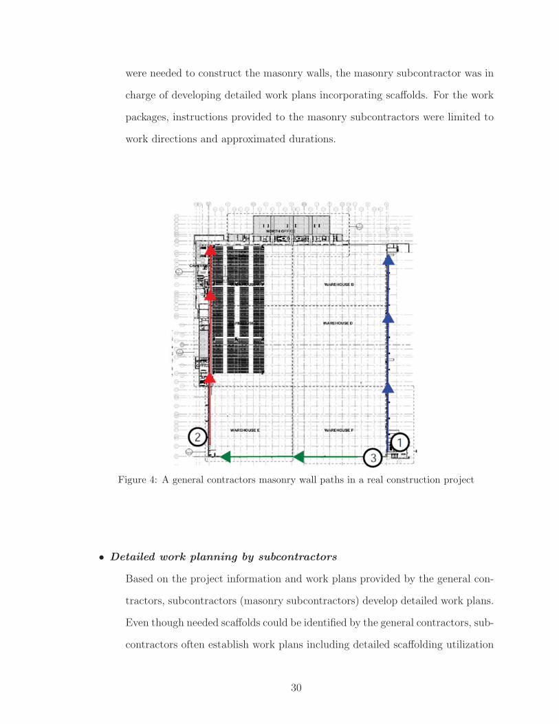
were needed to construct the masonry walls, the masonry subcontractor was in
charge of developing detailed work plans incorporating scaffolds. For the work
packages, instructions provided to the masonry subcontractors were limited to
work directions and approximated durations.
Figure 4: A general contractors masonry wall paths in a real construction project
• Detailed work planning by subcontractors
Based on the project information and work plans provided by the general con-
tractors, subcontractors (masonry subcontractors) develop detailed work plans.
Even though needed scaffolds could be identified by the general contractors, sub-
contractors often establish work plans including detailed scaffolding utilization
30

plans. Compared to general contractors’ site condition analysis, the subcon-
tractors tend to analyze construction site conditions more comprehensively and
predict potential safety and productivity issues.
During the interviews, masonry subcontractors were asked to plan scaffolding
for masonry wall construction based on a given BIM model. When the sub-
contractors were planning scaffolding for the given project, the steps taken to
analyze geometric conditions and plan scaffolds were recorded and organized.
1. Identify masonry work faces
The masonry subcontractors first recognized the building components to be
constructed. Figure 5 illustrates a masonry wall work package. This work
package is composed of two walls that need masonry exterior finishing. The
work face for this work package is the integration of the faces of Wall 1 and
Wall 2. Even though this can be expressed by multiple wall components
in BIM, the construction workers in real world perceive this as one work
package that can be constructed without discontinuation. Figure 6 shows
a larger work package that is composed of four wall components.
31

Figure 5: Geometric features recognized to plan scaffolding for a short masonry wall
Figure 6: Geometric features recognized to plan scaffolding for a large masonry wall package
2. Identify work scope and directions
Then, the masonry subcontractors identify the scope of the work package
and decide the work pattern they will implement to complete the work.
32

Work patterns can be decided by the general contractors or the subcon-
tractors. In Figure 5 and Figure 6, the work directions are shown by
arrows.
3. Identify the height of the workface
The masonry subcontractor identified heights of work locations along the
masonry wall. The heights of work locations determine if scaffolding is re-
quired. If the height changes along the work face, different sizes of scaffolds
may be installed to support the activities of the subcontractors.
4. Establish subcontractors work plan
After the geometric condition is analyzed, the subcontractors establish the
plans to construct the subcontracted work packages.
(a) The number of work crews is decided to meet the deadline set by the
general contractor. Historical productivity data is commonly used to
calculate the required work force.
(b) The work package is subdivided into daily or weekly work packages
(c) Scaffolding required to support daily or weekly work is identified. Even
though scaffolding types can be determined in this step, it is out of the
scope of this research. Figure 7 and Figure 8 visualize the simplified
scaffolding representations. As well as identifying the spaces and rough
geometry of a scaffold, the expected progress of masonry activity can
be associated as shown in Figure 8.
(d) Daily or weekly construction site conditions are analyzed to identify
safety hazards that can occur related to scaffolding. Specific tasks
conducted by the subcontractors include:
i. Identify other crews working under or over the scaffolding used by
the masonry crews
33

ii. Identify adjacent loading and lifting activities that can cause falling
objects to scaffolding and masonry crews
iii. Evaluate accesses to scaffolds for workers and material delivery
iv. Identify areas for material storage and evaluate its spatial rela-
tionship with scaffolds
v. Identify power lines adjacent to the scaffolds that can cause elec-
trocution
Figure 7: Simplified representation of a scaffolding object
34

Figure 8: Scaffolding objects associated with schedule information
(e) Provide the work plan to the scaffolding subcontractors
The work plans established by the masonry subcontractors are pro-
vided to the scaffolding subcontractors to develop detailed scaffolding
designs.
• Detailed scaffolding design creation by scaffolding subcontractors
After basic shapes and related schedule dates were determined by the masonry
subcontractors, scaffolding subcontractors refine the rough scaffolding plan into
detailed scaffolding designs that can be used as benchmark for field installation
( Figure 9). The developed designs need to comply with safety regulations. In
addition to the rough geometric properties already obtained (scaffolding height,
start point, end point, etc.), additional information added to refine the scaffold-
ing space. The information include ground condition, work face-to-scaffolding
distance, width of the scaffolding space, and connections between walls and
scaffolding.
35

Figure 9: Design details created in a scaffolding space
5.4.2.4 Summary of scaffolding placement process and its implementation in BIM
As a result of conducting three rounds of interviews and analyzing the outcomes,
scaffolding placement process and information requirement for scaffolding were es-
tablished. The important activities of planning scaffolds were organized as shown in
Figure 10.
36

Figure 10: Scaffolding placement process
1. Recognize work packages
4D BIM is established by creating virtual links between building objects and
37

schedule activities. By establishing 4D BIM, recognition of work packages can
be conducted in BIM. Thus, the proposed scaffolding placement approach re-
quires 4D BIM readily created by the users.
2. Analyze geometric shapes of work packages
Then, the geometric properties of scaffolding are analyzed. Important features,
such as end points and heights of the work faces, are identified.
3. Identify location and times requiring scaffolds
After analyzing geometric conditions of the work packages, the locations and
times requiring scaffolds are identified.
4. Decide crew sizes and work patterns/directions
Since installation and utilization of scaffolds are directly impacted by the char-
acteristics of work plans, work plans need to be established before basic shapes
of scaffolds are determined. In this step, several decisions, such as crew size,
work directions, and work pattern, are made.
5. Determine scaffolding shapes
After establishing the work plan, shapes of scaffolds are determined and the
location and time of scaffolding installation and utilization are decided. In this
step, scaffolding objects are inserted into 4D BIM.
6. Develop scaffolding design details
Detailed scaffolding designs can be created in the scaffolding boundary. How-
ever, this is out of the scope of this research.
7. Evaluate work/scaffolding plans (Chapter 6)
The 4D BIM incorporating scaffolding objects can provide more realistic visu-
alization of construction progresses. Potential safety hazards in the plan can be
identified. In addition to safety, other important goals of construction (such as
38

cost and duration) can be evaluated. In this research, objective 2 accomplishes
this task automatically.
8. Refine work/scaffolding plans (Chapter 7)
Based on the evaluation in terms of safety and other goals, scaffolding plans
can be refined into safer and more productive plan. Objective 3 of this research
accomplishes this task.
5.4.2.5 Scaffolding information requirements
Required properties of a scaffolding instance have been organized into three categories.
These properties are needed for visualization and safety analysis of scaffolding in BIM.
1. Geometric properties
(a) geometric properties are used to visualize the shape of a scaffolding in-
stance in BIM.
Figure 11: Shape of a scaffolding space
39

(b) Scaffolding space (Figure 11): A space occupied by a scaffolding can
represent the scaffolding instance required for the purpose of this research.
A bounding box can be created based on start and end points, width and
height of a scaffolding. The distance between the bounding box and a wall
can be decided based on the regulations and characteristics of activities
using the scaffolding. This rough representation of scaffolding shape can
potentially include detailed scaffolding design even though it is not in the
scope of current research.
2. Scheduling properties
(a) Visualization and safety analysis of scaffolding require both spatial and
temporal conditions of a construction site properly represented in 4D BIM.
Thus, a scaffolding instance needs to contain following information.
(b) Task information: A scaffolding instance has to be linked to a schedule
task that utilizes the scaffolding. Start date and finish date of the task
can be used to determine when the scaffolding instance will appear and
disappear from both visualization and analysis.
(c) Crew information: Information about work crews using the scaffolding
need to be available too. A work direction to complete a task may need
to be specified since it determines the spatial flow of the work crew using
the scaffolding. Depending on the spatial flow, daily workspace in the
scaffolding instance can change. The number of crews also need to be
specified since daily work productivity and the size of workspace can change
depending on the crew size.
40

3. Properties for safety analysis
(a) In addition to geometric and schedule information, it was found that ad-
ditional information is needed for safety analysis related to scaffolding.
Scaffolding instances need to contain properties that are needed to con-
duct safety hazard analysis.
(b) Limited access zone: In case of masonry wall construction, limited access
zones are defined prior to the construction. No other employees except
those actively participating in the wall construction are permitted to enter
the zone.
(c) Workspace (Figure 27): The space occupied by a work crew needs to be
included too. If the scaffolding size is large, a work crew may use only
a small portion of the scaffolding. In order to conduct daily construction
site safety condition analysis, workspaces of each day need to be identified.
In Figure 27, a workspace of a crew has been visualized as part of the
scaffolding space.
(d) Ground condition: Ground condition may also need to be incorporated
since it impacts how the scaffolding can be installed.
(e) Adjacent power lines: Power lines adjacent to scaffolding need to be de-
tected so that the placement plan for the scaffolding can be changed or
other protective action can be taken.
41

Figure 12: Analytical view of scaffolding and workspace
5.4.2.6 Translation of scaffolding placement process into computer-readable al-gorithms
As a result of three rounds of interviews, scaffolding placement process and scaffold-
ing information requirement have been established. In this chapter, the scaffolding
placement process is translated into algorithms that can be implemented in BIM.
The algorithms utilize information in 4D BIM and user input related to scaffolding
placement in order to create scaffolding objects. By implementing the algorithms,
scaffolding objects are expected to be created that can be used for automated safety
checking and optimization.
1. Recognize work packages
Recognition of work packages is conducted by using 4D BIMs virtual links
between building components and tasks in construction schedules. Building
components (e.g. walls) composing a work package need to be linked to a task
42

(e.g. masonry wall construction) in a construction schedule before the scaffold-
ing placement algorithms are implemented. In addition to basic information of
4D BIM, work directions have to be specified by users as shown in Figure 13.
The work direction represents the planned spatial flow of a work crew which is
essential in simulating daily construction site condition in BIM.
Figure 13: Masonry walls and user-defined work directions
2. Analyze geometric shapes of work packages
Based on properly constructed 4D BIM and user input, geometric conditions
of the work packages are automatically analyzed in this step. Both building
geometry and work directions are used as the input for computer-driven geo-
metric condition analysis. To account for heights work faces that may change,
the heights need be checked along the work directions.
In order to enable automated checking, inspection points are created along the
43

paths of work directions. While the inspection points were created every 3 feet
in Figure 14, this can be adjusted by users based on the geometric character-
istics of the project. The inspection points are 4 feet offset of the wall faces to
account for an existing safety regulation. The inspection points are used then
to identify the heights of the work faces along the path. To identify bottom and
top of the wall surface, plane-face intersection analysis was conducted for each
inspection point.
Figure 14: Plane-face intersection for each inspection point
44
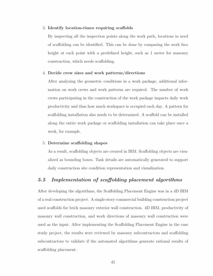
3. Identify location-times requiring scaffolds
By inspecting all the inspection points along the work path, locations in need
of scaffolding can be identified. This can be done by comparing the work face
height at each point with a predefined height, such as 1 meter for masonry
construction, which needs scaffolding.
4. Decide crew sizes and work patterns/directions
After analyzing the geometric conditions in a work package, additional infor-
mation on work crews and work patterns are required. The number of work
crews participating in the construction of the work package impacts daily work
productivity and thus how much workspace is occupied each day. A pattern for
scaffolding installation also needs to be determined. A scaffold can be installed
along the entire work package or scaffolding installation can take place once a
week, for example.
5. Determine scaffolding shapes
As a result, scaffolding objects are created in BIM. Scaffolding objects are visu-
alized as bounding boxes. Task details are automatically generated to support
daily construction site condition representation and visualization.
5.5 Implementation of scaffolding placement algorithms
After developing the algorithms, the Scaffolding Placement Engine was in a 4D BIM
of a real construction project. A single-story commercial building construction project
used scaffolds for brick masonry exterior wall construction. 4D BIM, productivity of
masonry wall construction, and work directions of masonry wall construction were
used as the input. After implementing the Scaffolding Placement Engine in the case
study project, the results were reviewed by masonry subcontractors and scaffolding
subcontractors to validate if the automated algorithms generate rational results of
scaffolding placement.
45

Figure 15 and Figure 16 illustrate the results of plane-face intersection for simple
and complex work faces, respectively. For the simple walls, the height of the work
face can be acquired by evaluating one inspection point. However, to plan scaffolds
for the work face of geometrically complex shape, all the inspection points need to be
evaluated.
Figure 15: Plane-face intersections of rectangular walls
Figure 16: Plane-face intersections of walls with varying heights
46

After evaluating the heights of work faces, scaffolding objects and workspace ob-
jects are created.Figure 26 shows daily scaffolding spaces and workspaces placed
along the masonry wall. The size of daily workspace is equivalent to the daily output
of the crew. Therefore, if the crew size increases, the daily workspace size increases
linearly. This represents the planned progress of the masonry subcontractor. Based
on the masonry subcontractors plan, scaffolding plan is created. In this case (Figure
26), scaffolding is installed every five days. Thus, one scaffolding space encompasses
five daily workspaces.
Figure 17: Scaffolding and workspace instances created along the path
47

Figure 18: Daily workspaces created along the work direction
Figure 19: Scaffolding space created based on maximum work face heights
Shapes of daily workspaces change according to the geometric shapes of the wall
faces. Scaffolding spaces were created for every five days. The height of a scaffolding
space was set as the greatest height of the workspaces.
Finally, all the scaffolding objects, workspaces, and analytical geometry (limited
access zones and work directions) have been incorporated into 4D BIM. Figure 20
and Figure 21 illustrate 4D simulation of day three and five, respectively. Since
scaffolding installation takes place every five workdays, installation of new scaffolding
is planned on day five (Figure 21).
48

Figure 20: Scaffolding objects and workspaces incorporated into day 3 of 4D BIM
Figure 21: Scaffolding objects and workspaces incorporated into day 5 of 4D BIM
49

5.6 Conclusions and discussion
Scaffolding placement process was established by based on in-depth interviews with
industry practitioners who have participated in planning of scaffolds. The identified
placement process was then converted into computational algorithms that can im-
plemented in digital building models. The developed Scaffolding Placement Engine
was tested in a real construction project model and the results were reviewed by the
interviewees. The results indicate that the developed system can create scaffolding
objects in BIM without excessive reliance manual efforts. When directions of work
crews using the scaffolds were provided, the algorithms could create simplified scaf-
folding objects, workspaces occupied by work crews on each day. In addition to the
geometric shapes, the algorithms created properties important for construction and
safety analysis, such as limited access zones, scheduled start and finish dates, the
name of the crew using the scaffold, etc. In the following chapter, an automated
safety hazard checking approach will be introduced that uses the accomplishment of
this chapter. There are limitations of the proposed approach that need to be solved.
Theses are: (1) For different types of tasks other than masonry wall construction,
scaffolding placement process may need to be identified. As discussed, planning and
analyzing temporary structures rely heavily on implicit knowledge and reasoning ca-
pabilities of engineers instead of following explicit rules. Therefore, there could be
many types of processes of planning scaffolding. However, this task may require
intensive investigation into patterns of work tasks. (2) The scaffolding placement
algorithms require work directions as an essential user input for automated analysis.
In order to achieve a greater level of automation, possible work directions can be
automatically derived from the building geometry. However, in this research, work
directions planned by general contractors and subcontractors were simply used and
focused on the creation of scaffolding and workspace objects.
50

CHAPTER VI
AUTOMATED CHECKING OF
SCAFFOLDING-RELATED SAFETY HAZARDS IN BIM
This chapter introduces an automated safety hazard analysis to identify potential
safety hazards related to scaffolding. Safety Simulation Engine integrates safety knowl-
edge and scaffolding objects into a BIM-based site condition simulation. By integrating
spatial-temporal flows of construction crews and scaffolds, current construction plan-
ning using BIM can be extended from plain visualization toward automated knowledge-
based analysis of construction safety that can alert construction planners of potential
safety hazards and sources of productivity losses. A case study using a real world
construction project information demonstrates the capabilities and effectiveness of the
developed Safety Simulation Engine.
6.1 Introduction
Despite various efforts, still construction is a hazardous industry that can potentially
expose construction workers to fatal hazards. Falls from elevation, struck by objects,
electrocutions, and caught-in/between were identified as leading causes prevention of
which could save more than 400 lives of US workers. These potential safety issues
need to be addressed in early design and construction planning stages.
However, in current construction industry, safety planning processes are often sep-
arated from the design and construction planning. Despite the significant impacts
on the project, construction safety planning usually takes place after important parts
of a construction plan are already established. In order words, safety communica-
tions do not occur among project participants early in a way that contributes to the
51

creation of safe construction strategies. Instead, the responsibility of construction
safety planning is often limited to identifying potential safety issues from the existing
construction plans. Also, the current safety planning relies on labor-intensive and
time-consuming manual efforts, which is often error-prone and inconsistent.
There has been advances in BIM and sensing technologies to address safety prob-
lems in the construction industry. Recent research studies pointed out the need for
automated planning of construction safety to overcome the deficiencies of manual
efforts. One of the approaches is the rule-based safety planning system [44]. This
system automatically identifies potential fall hazards and suggests preventive mea-
sures. Even though existing BIM-safety integration approaches attempt to address
safety issues automatically by analyzing project information in BIM and schedule,
many of critical aspects of construction are deficient from those approaches. The
aspects can include:
• Temporary structures: Temporary structures, such as scaffolds, are frequently
used by work crews along the spatial flows impacting the entire safety and
productivity. These temporary structures are rarely planned or analyzed for
safety.
• Spatial flows of work crews: The number of crews and their spatial movements
within the construction jobsite is critical for safety. In practice, spatial flows of
important crews are created
• Other movements: Within construction sites, there are various spatial flows (e.g.
site or building entrances and material delivery) that can cause spatial conflicts.
While these are important construction planning components impacting the entire
safety and productivity of the project, either industry practices or existing innovations
fail to integrate these into BIM-based automation which can lead to improved safety.
52

This whitepaper proposes an innovative approach to BIM-safety that integrates the
spatial-temporal dynamics created by movements in the construction site.
The original construction plan will be used as the input information for the safety
checking system. A rule-based safety checking algorithms identify potentially unsafe
conditions from the plan based on predefined safety rules. The rules are established
based on the safety knowledge obtained from comprehensive interviews with con-
struction and safety experts. As a result, the rule-based safety checking system will
automatically identify safety hazards and visualize them to facilitate safety commu-
nications among construction participants.
6.2 Objective and scope
To overcome the technical limitations, this research proposes a new approach that
integrates work sequences and temporary structures into the automated safety check-
ing system using BIM. There are two tasks for the development of Safety Simulation
Engine.
1. BIM-safety platform: Create a platform that incorporates work path plans of
crews and their temporary structure utilization to simulate and analyze con-
struction site conditions automatically and realistically.
2. Safety checking algorithms: Create computational algorithms in the platform
to identify temporary structure-related safety hazards automatically during the
construction simulation.
In this research, the scope of temporary structure type is limited to scaffolding.
Automated safety checking also focuses on identification of safety hazards related to
scaffolding and visualization of the hazards in 3D and 4D. Although this research does
not focus on creating detailed designs of scaffolds, the outcome of this research can be
further integrated into automated scaffolding design generation approaches [21] and
53
other software programs specialized in designing scaffolds. In addition, the end user
manually defines worker paths and automatic path generation is not the focus of this
research.
6.3 Development of BIM-based safety analysis automation
The purpose of embedding automated safety analysis capabilities to BIM is to apply
the safety regulations, best practices, and safety knowledge during the construction
planning stage. This section presents the details of proposed BIM-based safety anal-
ysis automation that includes the framework and technical details and algorithms.
6.3.1 Framework of BIM-based safety analysis automation
Figure 22 illustrates the framework of the automated safety hazard analysis proposed
in this research. There are three major capabilities that are combining, analyzing,
and sharing:
54

Figure 22: Framework for automated BIM-safety platform
1. Combining: Construction site conditions are created by complex interactions
between several participants. To properly analyze construction site safety, ac-
tivities of several subcontractors need to be presented in the construction plan.
The combining function of the proposed BIM-safety platform integrates the
activities of subcontractors as the user-input for the automated safety hazard
analysis. In addition to project information in BIM and schedule, work paths
and temporary structure utilization of multiple subcontractors are inserted man-
ually in the platform as user-input.
2. Analyzing: The analyzing function creates activity details and simulates
55

construction site conditions. To analyze construction site safety realistically,
daily work plans for all the major subcontractors need to be available. However,
work plans of such details are rarely available due to the shortage of human
resource for construction planning and complexity of projects. Thus, based on
the user-input, the analyzing function automatically generates details of crews
activities. By doing so, daily construction site conditions can be simulated and
unsafe conditions can be accurately identified. Spatial conflicts between work
crews, potential hazards related to scaffolds, such as falling from elevation,
and falling objects from scaffolds, are examples of automatically identifiable
hazards. Upcoming scaffold installation, utilization/inspection/ demolition can
be automatically identified and distributed as well.
3. Sharing: The sharing function disseminates the results of activity detail gener-
ation and safety analysis to construction stakeholders (such as superintendents,
field workers, safety inspectors, etc.). This allows potential safety issues iden-
tified in the previous step to be communicated and proactively resolved before
the construction begins.
6.3.2 Technical details of BIM-safety platform
The technical details of the BIM-safety platform are presented in this section. Figure
23 illustrates the proposed system architecture of the platform. Autodesk Revit
(BIM), Microsoft Project (schedule), and their Application Programming Interfaces
(APIs) were used for the prototype development.
56

Figure 23: BIM-safety platform system architecture
6.3.2.1 User-input preparation and combining
The first step is to prepare user-input needed for the simulation. As shown in the
system architecture, the BIM-safety platform utilizes BIM, schedule, and work paths
as the essential inputs. While BIM and construction schedule are basic resources
used to create a 4D BIM simulation, this research incorporates paths of work crews
in order to account for the movements of crews using scaffolds. In practice, work
path plans are established commonly for major construction activities by drawing
arrows on 2D drawings to represent the crews work directions as show in Figure 24
(a). In this research, the users are prompted to insert the paths in 3D environment
of BIM. Figure 24 (a) shows the masonry wall paths in a real construction plan.
Figure 24 (b) shows a work path generated in our system. A path instance created
in BIM contains a 3D start point, an end point, and a related task (e.g. painting).
To define scaffolding requirements, a task instance contains information on what type
and height of scaffold is needed (See task and path in Figure 23).
57

After preparing the user-input, XML files for tasks and paths are generated and
combined using plug-ins we developed for this step. In addition to building model
information, the task and path XML files are essential inputs for the automated safety
simulation.
Figure 24: BIM-safety platform system architecture
6.3.2.2 Analyzing and sharing
The proposed approach uses workspaces as the basic spatial elements for safety anal-
ysis. For activities not linked to any path plan, workspaces are created based on the
zoning plans. For activities linked to work paths, daily crew workspaces and scaffold-
ing spaces are generated along the paths. The workspaces and scaffolding spaces are
then used for safety analysis. Further details are presented below.
1. Workspace generation
58

Creating workspaces as part of construction planning has been proposed by
several research studies in the past. Methods have been developed to create
workspaces based on building objects [2] or characteristics of tasks [24]. In
our approach, workspaces are automatically created by taking advantage of
zoning plans commonly existing as essential part of construction strategies.
Since construction zones provide boundaries of work packages and sequences
among them, the proposed BIM-safety platform uses the geometry of zones to
create workspaces occupied by work crews. Figure 25 illustrates workspaces
generated for different zones. The green box in Figure 25 (a) shows a workspace
for foundation in Zone 1 and the green box in Figure 25 (b) presents a workspace
for skylight installation in Zone 2. In addition to the zone boundaries, the
workspace has been created below each skylight to account for the potential
falling objects from above hazard (see Figure 25 (c)).
59

Figure 25: Workspace generation for activities
2. Activity detail generation
Work paths of major activities are generally planned by the superintendents
as part of the construction strategy. Conventional path plans in 2D drawings
do not contain enough details to day-to-day activities of crews. For example,
the path in Figure 24 (a) presents the planned direction of the masonry crew
along the wall. When the amount of brick masonry installation is large, this
work package can be completed in multiple days depending on the productivity
and number of work crews. Unlike workspace generation using zoning plans,
60

activity details thus need to be generated before creating workspaces for activ-
ities that contain paths. Figure 26 shows activity details related to a brick
masonry wall construction automatically generated by our system. Estimated
crew productivity and the size of scaffolding installation were used to subdivide
the entire space in front of the masonry walls. The work paths specified during
the user-input preparation were used to determine the movement directions of
the workspaces and scaffolding spaces during the simulation. As shown in Fig-
ure 27, crew workspaces, scaffolding spaces, and limited access zones on both
sizes of scaffolding and workspaces can be created automatically. A workspace
is a space occupied by a crew on a certain day and this space is in the scaf-
folding space when the crew is using a scaffolding. Limited access zones are
created according to a safety regulation. [1, 41] presents a research study on
object splitting to support the creation of realistic 4D BIM.
61

Figure 26: Automated detail generation based on input work sequence and assumptions
Figure 27: Scaffolding space, workspace, and limited access zones
62

Figure 28, Figure 29, Figure 30 illustrate an example of daily activity detail
generation. In Figure 28, a building model is shown and a roof and a wall
to be constructed are highlighted. The wall will be constructed following the
planned work direction. As a result of applying the space generation algorithm,
scaffolding and work crew spaces were generated for the wall construction, and
a workspace for a roof construction was generated by extending the boundary
of the roof (Figure 29). The spatial elements were integrated into the 4D BIM
as shown in Figure 30. In this way, daily schedules of crews and scaffold-
ing installation/utilization/dismantlement can be generated without excessive
manual efforts. Figure 31 shows that workspaces and scaffolding spaces for
each day can be generated automatically.
Figure 28: 4D BIM with on-going construction tasks highlighted
63

Figure 29: Workspace generation for the building model
Figure 30: 4D BIM with spatial information integrated
64

Figure 31: Daily workspace movement and scaffolding installation
3. Safety simulation and hazard identification
After details including workspaces, scaffolds, and safety components (e.g. lim-
ited access zones) are created for each activity, construction site conditions of
each day are simulated. This utilizes the scaffolding safety knowledge that ex-
plains what types of safety hazards can potentially occur in certain situations.
The knowledgebase can be found from safety regulations or stricter industry
practices of construction companies.
As discussed in the introduction section, scaffolding can cause many types of
safety hazards including falls from scaffolding, falling objects from scaffolding,
electrocution, spatial conflicts, and structural failure of scaffolding. Some of
the hazards can be prevented by properly designing and inspecting scaffolds
according to safety regulations. However, causes of struck by objects hazards,
such as spatial conflicts and falling objects, can be prevented through better
planning rather than focusing on scaffolding designs and inspections. Between
65

1992 and 2010, being struck by an object was the third leading cause of fatalities
responsible for more than 2,000 deaths and the first leading cause of non-fatal
injuries [12]. Even though statistics of struck by object hazards related to scaf-
folding cannot be found, a certain proportion of the hazards can be prevented
by properly planning scaffolds. In this research, we conducted interviews with
general contractors, scaffolding subcontractors, and masonry subcontractors to
define a list of conditions related to scaffolding that can cause struck-by safety
hazards. As shown below, three types of conditions were defined and converted
into computer-readable codes. Even though scaffolding design generation is
not in the scope of this research, incorporating detailed scaffolding designs and
utilizing them for benchmark for installation and inspection would make the
system to address most of safety hazards related to scaffolding.
(a) Workspace-scaffolding space conflict (Figure 32)
Condition: if a scaffold is installed in a workspace of a crew not using the
scaffolding
Hazard: there is a potential of safety hazards caused by spatial conflicts
between the spaces
Detection criteria: (1) Polygon A and Polygon B intersect (2) Height dif-
ference between Polygon A and Polygon B is within a predefined tolerance
(e.g. 2 meter)
66

Figure 32: Conflict between a workspace and a scaffolding space
(b) Falling objects from scaffolds (Figure 33)
Condition: if a workspace of a crew is below a limited access zone of a
scaffolding
Hazard: the crew is under the risk of falling objects from scaffolding in-
stallation, utilization, and dismantlement
Detection criteria: (1) Polygon A and Polygon B intersect (2) The height
of Polygon A is greater than the height of Polygon B for more than a
predefined distance (e.g. 2 meter)
67

Figure 33: Falling objects from scaffolding
(c) Falling objects to scaffolds (Figure 34)
Condition: if a workspace of a crew horizontally intersects with a limited
access zone of a scaffold and the workspace is higher than the height of the
scaffold
Hazard: the crew using the scaffold is under the risk of falling objects to
the scaffold.
Detection criteria: (1) Polygon A and Polygon B intersect (2) The height
of Polygon B is greater than the height of Polygon A for more than a
predefined distance (e.g. 2 meter)
68

Figure 34: Falling objects to scaffolding
Then, the hazard identification algorithms automatically detect the conditions
along the safety simulation. Figure 35 shows the graphical user-interface of the
4D safety simulation, which includes the following main components:
• XML files: XML files for tasks and paths created during user-input prepara-
tion step are imported to the simulation.
• 4D calendar: 4D calendar allows the users to choose a day to apply hazard
identification algorithms.
• Assumptions: Assumptions about work crews and scaffolds are defined here
and used as simulation setting.
• Active tasks: This shows a list of ongoing activities on the day chosen in 4D
calendar.
• Safety hazards: Potential safety hazards related to the ongoing tasks are
69

identified by the algorithms are listed here.
• Inspections: In addition to safety hazards, required scaffolding inspections
are listed.
• Prevention methods: In addition to safety hazards, commonly used forms and
Job Hazard Analysis (JHA) manual can be incorporated into the system
as in Zhang et al. [43].
70

Figure 35: Safety simulation graphical user interface
4. Scaffolding-related report creation
In addition to the simulation results directly viewed from the graphical user
interface, various documents and reports can be created to assist in commu-
nication between stakeholders. As identified by CII [9, 10], there are several
71

paper-based tools widely used for planning and managing scaffolds. Most of
the tools, such as estimating worksheet, scaffolding utilization report, and in-
stallation/dismantlement request forms, can be integrated into the BIM-safety
platform. This can eliminate the needs for manual and repeated data input.
6.4 Case study for validation
The BIM-safety platform was developed using commercially available software tools
and their APIs (Autodesk Revit and Microsoft Project) and applied in a real con-
struction project. The single-story commercial building construction project shown
in Figure 36 needed scaffolds to assist in brick masonry exterior wall construction.
The general contractor of the project created a construction schedule, zoning and
path plans for subcontractors including foundation, steel structures, masonry wall
construction, roofing and skylight, exterior wall window installation, etc. For this
case study, the construction planning information (BIM, construction schedule, and
path plans for major activities) were provided by the general contractor of the project.
Figure 37 illustrates zoning and work path plans for the major activities. As dis-
cussed in the previous section, workspaces were created for activities with zoning
plans and daily details were created for activities with work path plans.
72

Figure 36: BIM for a real building construction project
Figure 37: Zoning and work path plans
Firstly, a conventional 4D BIM was created in the platform by linking activities in
the construction schedule and building objects in BIM. Zoning and work path plans
were incorporated. Then, the following estimated assumptions for masonry brick
installation were made:
73

• Daily output: two installation crews (1,350 square feet per day)
• Scaffolding: supported scaffolds used, install 8,000 square feet of scaffold at a time,
a scaffolding installation take one day before the scaffold is required
Based on the project planning information and assumptions provided from the
contractors, the BIM-safety platform simulated the construction site conditions. Safety
hazards identified during the simulation were listed in the “Safety hazard identified”
section in the user interface. Figure 38 shows visualizations of changing construction
site conditions using workspaces, scaffolding spaces, and limited access zones during
the simulation. For each day, safety hazards were identified and the list was shown in
the user interface (Figure 39). A scaffolding installation schedule was also visualized
which can assist in timely scaffolding material delivery and installation (Figure 40).
Figure 38: Workspaces, scaffolding spaces generated during BIM-safety simulation
74

Figure 39: User interface with potential safety hazard list and site condition visualization
Figure 40: Scaffolding installation schedule visualization
75

As a result of the simulation, potential safety issues were detected automatically.
Many of the potential hazards found from simulation were not identified or even
discussed by the construction and safety managers. Even though the safety experts
conducted daily safety analysis during construction, they did not document the results
of their manual safety analysis. Falling objects to scaffolds from activities above were
detected many times from the construction plan. In Figure 39, the masonry crew
using the scaffolds is under the risk of falling objects from both roofing and skylight
installation activities. In particular, the work zone in Figure 41 shows a situation
that requires attentions by construction and safety managers. Potential of multiple
safety hazards were detected from activities around the work zone.
• Spatial conflict: The masonry wall construction crew (and a scaffolding) is sharing
the same space with a roofing crew on the same level.
• Falling objects from above: Both roofing and masonry crew on the same level are
exposed to falling objects from roofing and skylight installation activities above.
Manual safety planning actually conducted by the safety managers did not identify
the work zone to be a high risk area needing particular attentions. The construction
and safety managers agreed that these situations could become hazardous to the
crews depending on the construction methods. For example, if the roofing crew han-
dles heavy materials and equipment without awareness about the locations of masonry
crew and scaffolds, falling objects can directly injure workers or damage the scaffolds
that eventually threat the workers. If this result can be communicated by superin-
tendents and related subcontractors before they start daily tasks, the possibility of
accidents can potentially be reduced by the increased situation awareness.
76

Figure 41: Safety hazards identified in a high risk area
Finally, the safety hazards identified during the simulation were summaries au-
tomatically. While the summary exists in the user interface, a schedule of identified
hazards was automatically created to assist in effective safety communication as shown
in Figure 42.
77

Figure 42: A schedule of potential hazards
6.5 Discussions and conclusions
This paper presented a framework and algorithms to integrate temporary structures
to the automated safety analysis. While previous efforts in computer-assisted safety
planning did not account for temporary structures, the developed BIM-safety simula-
tion platform integrated scaffolds and spatial movements of crews using the scaffolds
as an essential part of automated safety analysis. Eventually, this platform combines
work plans of multiple subcontractors and detects potential safety hazards. The re-
sults show that the hazard detection algorithms can identify safety hazards that were
not noticed by project and safety managers participating in the case study. Further,
this study successfully demonstrated that the construction visualization incorporating
workspaces and temporary structures and the hazard schedule as an example of result
reporting can potentially facilitate timely safety communications by construction and
safety managers.
While the test results were promising, several limitations of the proposed approach
were recognized. Even though we created workspaces for activities with path plans,
this may over-simplify the details of those activities (e.g. roofing and skylight). This
78

problem can be overcome by applying predefined patterns. However, this may need
a comprehensive investigation into the behaviors and spatial flows of those activities.
Also, the current path creation mechanism requires a user to specify work paths of
crew manually. When we consider building geometric conditions that can be complex,
there needs to be an additional automation method to assist users to generate work
paths based only on the directions of the crews. For example, a work package of a
masonry crew can comprise multiple walls that are not aligned straight. In such case,
the path creation presented in this paper needs multiple times of user input which can
be labor intensive. Also, the implementation and case study in this paper focused on
supported scaffolds used by masonry crews only. To apply the proposed approach to
more complicated construction projects, various types of scaffolds, such as suspended
scaffolds and mast climber, need to be added in the system.
Future research may overcome the discussed limitations and attempt more prag-
matic safety and productivity analysis by integrating important construction site
components, such as stair towers and material storage areas. For example, the loca-
tions of stair towers and storages areas can be analyzed and optimized to ensure short
material delivery paths to the workspaces. Further improvements can be achieved by
optimizing the construction planning decisions made by general contractors and sub-
contractors. A set of simulation assumptions was made for the simulation in this re-
search. The optimization in the future research can automatically apply various crew
and temporary structure setting to generate a set of solutions with optimum perfor-
mances in terms of safety and productivity. Different number of crews, scaffolding
installation quantity, and directions of work paths are the examples of optimization
parameters that can be adjusted automatically.
79

CHAPTER VII
OPTIMIZATION OF SCAFFOLDING PLAN FOR
SAFETY
This chapter introduces an approach to optimize a scaffolding plan for safety. The re-
search presented in this chapter utilizes the accomplishments of previous two chapters:
BIM-enabled scaffolding object placement and automated scaffolding-related safety
checking. The proposed optimization approach first automatically generates multi-
ple scaffolding planning alternatives. Among the alternatives, users select candidate
scaffolding plans that will be reviewed and refined. Finally, users can select one scaf-
folding plan that will be implemented. By testing all the combinations of decisions
related to planning scaffolding, safer scaffolding plans can be generated. Framework,
computational algorithms, and case study results are presented.
7.1 Introduction
Construction is conducted by complex interactions of multiple stakeholders. One of
the primary goals of construction planning is to coordinate the efforts of the stake-
holders toward achieving the maximum productivity without sacrificing worker safety.
To establish a safe construction plan, various construction resources, such as work
crews, equipment, and temporary structures, need to be considered early in the con-
struction planning stages. It is desirable that potential safety problems are identified
in the planning stage so that measures to protect workers can be prepared in advance.
It would be optimal to minimize the potential of worker exposures to hazardous con-
ditions through better construction planning. However, creating a safe construction
plan can be highly challenging and exhaustive since a construction plan is composed
80

of many decisions that are impacting each other. Furthermore, it is difficult to es-
tablish commonly acceptable rules due to the unique situation of each construction
project.
Building Information Modeling (BIM) is widely accepted as a standard of prac-
tice in construction industry and is changing the way construction and safety is ap-
proached [13]. Utilization of BIM can facilitate accurate constructability analysis [23],
collaborations between multiple project stakeholders, and enable better safety plan-
ning [39]. Also, there are advanced approaches that use BIM for automated safety
hazard checking [44]. However, despite the benefits, there still are several limitations
that prohibit the achievement of the full potential of BIM for safety planning.
One of the critical limitations is the absence of temporary structures as part of
construction and safety planning. The entire construction safety and productivity
are greatly impacted by temporary structures, such as scaffolding, formwork, and
shoring [34]. Temporary structures need to be planned carefully in a way that avoids
any safety hazard or loss of productivity. However, in most construction projects,
temporary structures do not appear in drawings, construction schedules, or BIM [18].
Even though many construction projects manually insert temporary structure objects
in BIM, they can only be used for the purpose of visualization. The need for man-
ual efforts for safety planning remains existing. It can be extremely labor-intensive
and error-prone to establish an optimized temporary structure plan that minimizes
potential worker exposures to safety hazards. Among many types of temporary struc-
tures, scaffolding is considered as one of the most challenging and wasteful elements
of construction management [9, 10]. Like other temporary structures, scaffolds are
installed in construction sites without sufficient planning efforts [34]. There are a
lot of safety, productivity, constructability, and site coordination problems related to
scaffolds [30].
Automated safety hazard checking approaches have the potential to eliminate the
81

current need for excessive manual efforts for safety checking. However, the capa-
bility of such safety hazard checking approaches is often limited to identification of
potential safety hazards in a given construction plan. A construction plan still needs
to be prepared without precise prediction about how each decision (such as zoning,
construction method, and temporary structure plan) impacts construction site safety.
Since it is impossible to create alternative plans considering all possible combinations
of decisions, only a few alternatives of construction plans can be prepared and tested.
Related to planning of temporary structures, similar limitations can be identified.
When scaffolding plans are established, several decisions are made by general contrac-
tors, subcontractors, and scaffolding subcontractors. Common examples of decisions
directly or indirectly related with scaffolds include work sequences, crew size, scaf-
folding type, etc. Most of these decisions are made based on subjective judgment of
engineers and precise calculation of the impact of the decisions are rarely made in
the planning stage. Construction planners can mentally simulate only a few plans for
scaffolding utilization. As such, current industry practices and existing technology
are lacking in methods to enable the creation of safe scaffolding plan by assisting in
the planners to make better decisions. As discussed in literature review, optimization
of temporary structure plans requires both planning and analysis of temporary struc-
tures to be systematically integrated and the objective has been achieve by previous
approaches.
In order to address the need for optimization of scaffolding plans, this research
develops a temporary structure optimization engine. The optimization engine was
developed to assist in construction planners to generate, evaluate, and refine multiple
scaffolding planning alternatives. The research introduced in this chapter utilizes the
outcomes from the previous chapters to identify potential safety hazards automati-
cally from all the alternatives without the reliance on manual efforts of engineers. The
process is presented that comprises an automated generation of alternative plans and
82

manual selection and refinement of candidate plans. A case study has been conducted
to demonstrate that the proposed optimization approach can assist in construction
planners to create scaffolding plans that are better than the manually created orig-
inal scaffolding plan. The criteria included safety hazards, cost, and duration. The
expected result of applying the optimization approach would be to create safer and
more productive scaffolding plans without excessive manual efforts.
7.2 Objective and scope
The objective of this research is to enable optimization of temporary structure plans.
This research integrates temporary structures into automated safety planning and
optimization using BIM as the integration platform. Among various types of tempo-
rary structures, this research focuses on preventing potential safety hazards related
to scaffolding. Selection of proper scaffolding types is not included in the scope of
this research. To optimize the scaffolding plan, optimization engine was created that
generates multiple alternatives of scaffolding plans and to assist in decision mak-
ing. In order to incorporate scaffolds and simulate daily construction site conditions,
the simulation engine was used as part of the optimization engine. The developed
optimization engine uses a scaffolding plan as the input to automatically generate
multiple alternative scaffolding plans. Then, a user selects a few alternatives that
satisfy predefined criteria and refined the plans manually.
Following section presents the framework and methodology for the scaffolding op-
timization. Case study section presents the implementation of the proposed approach
to optimize a scaffolding plan of a real-world construction project. The conclusion
section presents the conclusion, limitations, and suggestions for future research stud-
ies.
83

7.3 Development of the proposed scaffolding optimizationengine
This section presents the development of the proposed scaffolding optimization ap-
proach and computational algorithms to enable the optimization. The section first
introduces the optimization framework and then present the development of the com-
putational algorithms.
The frameworks and methodology for the proposed temporary structure safety
optimization and simulation engines are presented in this section. Figure 43 shows
the framework for the scaffolding safety optimization. The optimization engine is used
to generate multiple alternatives of planning scaffolding. As a part of the optimization
engine, the safety simulation engine simulates daily construction site conditions and
evaluates a scaffolding plans performances on predefined criteria. Details to the five
steps are explained.
Figure 43: Framework of the proposed Scaffolding Optimization Engine
1. Optimization input preparation
84

The first step is to prepare user input for the optimization. In addition to cre-
ating a 4D BIM and establishing an original scaffolding plan in it, users need
to define options for the decisions made while the original scaffolding plan is
created (e.g. scaffolding types, sizes, crew sizes, work directions of crews using
the scaffolding, etc.). For example, the options for the number of work crews
using the scaffolding can be two, three, or four. Work direction for each task can
be reversed. Scaffolding can also be installed and demolished more frequently
(1 installation per 4 days, 5 days, or 6 days). Depending on the characteristics
of different scaffolding types and tasks using the scaffolding, different types of
optimization input can be prepared.
Figure 44 illustrates an example scaffolding plan with optimization input infor-
mation. The work plan in the figure includes three masonry wall construction
tasks that need extensive utilization of scaffolding. Arrows along the masonry
walls show planned work directions. In the original plan, the masonry crews
are required to sequentially complete the construction of masonry walls of East
side, South side, and West side. Three crews work at the same time and scaf-
folding is installed every five days.
Optimization input preparation is done by defining different options for the
decisions made for the original scaffolding plan. For example, the number of
crews can be two or four instead of three. Work direction for each task can be
reversed. Scaffolding can also be installed and demolished more frequently (1
installation per 4 days). The sequence between the three tasks can be reversed
(Task 2, Task 3, Task 1).
85

Figure 44: Work paths planned for three masonry construction tasks using scaffolding
2. Creation of scaffolding planning seeds
After the optimization input has been prepared. The user input needs to be
converted into a computer-readable code called scaffolding planning seed. One
scaffolding planning seed contains information to create and simulate one scaf-
fold planning alternative. Figure 45 shows an example of scaffolding planning
seed created for the plan shown in Figure 44.
Task order switch cell (cell 1) shows if the sequence between three masonry
tasks will be reversed or not. False means the original sequence will be used.
Crew size cell (cell 2) shows the number of crews that will work at the same
time. Cell 3 shows scaffolding installation pattern. Given that there are five
86

work days in a week, 5 in Cell 3 means a decision to install scaffolds one a
week. Cell 4, Cell 5, and Cell 6 represent decisions to switch work directions.
The example scaffolding planning seed has three cells for direction switch since
there are three masonry construction tasks. If there are many work packages,
the number of cells will increase automatically. Scaffolding planning seeds are
generated until all possible options are enumerated.
In the next step of scaffolding evaluation, the result cells (Result 1, Result 2,
and Result 3) are filled with the simulation results.
Figure 45: An example of scaffolding planning seed
3. Automated safety checking using simulation engine
After a set of scaffolding planning seeds are created, scaffolding plans associ-
ated with the seeds are generated automatically by the simulation engine. The
87

framework for the safety simulation engine is shown in the previous chapter. The
simulation engine read information in the seeds to create scaffolding objects in
BIM and then potential safety hazards related to scaffolding are detected. The
simulation engine measures performances of a scaffolding plan for criteria other
than safety hazards to assist into better decision making of users. The criteria
may include scaffolding cost, durations of tasks using scaffolds, etc.
4. Manual selection and visualization
After all possibilities for planning scaffolds are created and evaluated quantita-
tively, a few scaffolding plans can be selected manually by the users for further
review. Each of the selected options can be visualized in 4D BIM environment
where detected safety hazards are visualized.
5. Final selection, refinement, and implementation
Based on the manual selection and review, a final selection of a scaffolding plan
can be made. Then, if needed, the scaffolding plan can be refined before the
plan is implemented in the construction project.
88

Figure 46: Workflow of the proposed scaffolding optimization engine
Figure 46 illustrates the workflow of the proposed scaffolding optimization engine
that incorporates scaffolding placement engine and safety simulation engine. Depend-
ing on information in scaffolding planning seeds, both placement of scaffolding and
safety simulation are impacted. For example, if the sizes and installation frequency of
scaffolding change, shapes and sizes of scaffolding objects created by placement engine
89

are changes. Accordingly, different safety hazards can be detected by the simulation
engine. Operations of scaffolding placement engine and simulation engine continue
until all possibilities of scaffolding plans are analyzed.
7.4 Implementation and case study
Computational algorithms for simulation and optimization were developed and em-
bedded into 4D BIM system developed for this research. Then, the proposed opti-
mization approach was tested in a real world single-story commercial building con-
struction project that used scaffolds for brick masonry exterior wall construction. The
case study was conducted based on close collaboration with the general contractor of
the project.
1. Schedule and task detail setup
Figure 47 shows a graphic user interface of the 4D BIM system where the
optimization engine was implemented. BIM and construction schedule of the
case study project are imported into the system and optimization input can be
prepared in the user interface. Input for optimization included work direction,
masonry crew size, work order, and scaffolding installation pattern.
(a) Work direction: Work directions are planned spatial flows of work crews
using the scaffolds. Since daily workspaces occupied by the crews and
scaffolds can change depending on different work directions, construction
site conditions and thus potential safety hazards change. Alternative de-
cisions are automatically created by flipping the directional vectors of the
directions.
(b) Masonry crew size: Given that the productivity of each crew is the same,
the speed of masonry work is determined by the number of crews. Loca-
tions of daily workspaces and sizes of the workspaces are impacted by this
90

decision. Actual crew size in the project was three. In the optimization,
crew sizes of two, three, and four have been used.
(c) Work order: Work order is the sequence among three masonry wall con-
struction tasks. In the original construction schedule, brick masonry con-
struction is completed following the order of East, South, and West exterior
walls. During the optimization, a reversed order (West, South, and East)
is simulated.
(d) Scaffolding installation pattern: Scaffolding installation pattern determines
how frequently scaffolding is installed in the construction site. If the value
is four, a scaffolding is used for four days once it is installed. In other
words, the size of the scaffolding needs to be equivalent to five workspaces.
For optimization, three, four, and five were used as options for scaffolding
installation.
91

Figure 47: Schedule and task detail setup
2. Safety hazard rating setup
Also, in collaboration with safety managers of the project, different scores were
prepared for different types of safety hazards related to temporary structures.
The purpose is to evaluate the overall score for a schedule. Therefore, a score
needs to be assigned to each type of safety hazard. By doing so, detected safety
hazards can be quantitatively evaluated and summed up during the simulation.
With the safety experts, scores have been decided based on their professional
judgment and understanding about the project (0-2= Minimal/Low Safety Ex-
posure, 9= High/Extreme Safety Exposure). These scores (Table 2) were used
to evaluate the overall safety level of a scaffolding plan by a single digit.
92

Table 2: Scores for different hazard typesHazard type Hazard description Score
Type 1 Falling objects to workspace 8Type 2 Falling objects to scaffolding 6
Type 3Falling objects to scaffolding installation
workspace7
Type 4 Spatial conflicts between workspaces 5
Type 5Spatial conflicts between scaffolding space
and other workspace3
Type 6Spatial conflicts between scaffolding
installation workspace and other worker space4
Six types of hazards related to scaffolds were detected automatically. Descrip-
tions are provided.
• Hazard type 1
• Name: falling objects to workspace
• Description: falling objects from a vertically higher workspace to a lower
workspace occupied by another work crew
• Score: 8
• Hazard type 2
• Name: falling objects to scaffolding
• Description: falling objects from a vertically higher workspace to a scaf-
folding used by another work crew
• Score: 6
93

Figure 48: Hazard type 1 and type 2
• Hazard type 3
• Name: falling objects to scaffolding installation workspace
• Description: falling objects from a vertically higher workspace to a
workspace used for scaffolding installation
• Score: 7
Figure 49: Hazard type 3
94

• Hazard type 4
• Name: spatial conflicts between workspaces
• Description: workspaces of multiple work crews overlapping
• Score: 5
• Hazard type 5
• Name: spatial conflicts between scaffolding space and other workspace
• Description: a crew needs to work when there is a scaffold in the workspace,
equivalent to falling objects from scaffold
• Score: 3
Figure 50: Hazard type 4 and type 5
• Hazard type 6
• Name: spatial conflicts between scaffolding installation workspace and
other worker space
• Description: the same space is used for scaffolding installation and an-
other work crew
95

• Score: 4
Figure 51: Hazard type 6
3. Objective function setup
The project team intended to evaluate each scaffolding plan options based on
multiple criteria not limited to safety hazard score. Total cost for masonry wall
construction and the total number of days required to complete all the masonry
wall construction were evaluated based on the following methods.
• Masonry construction cost
Masonry cost = Scaffolding cost + Crew labor & material cost
Scaffolding cost = Scaffolding length× $200 + Cost for site visits
Cost for site visits = $100 per visit
Crew labor & material cost = ($2.5+$3.5×crew size)×masonry quantity
• Masonry duration
The total days needed to complete tasks using scaffolds is calculated during
the simulation.
96

• Total safety hazard score
Safety hazard score is calculated when potential safety hazards are detected
during the simulation using hazard score.
4. Run simulation
Based on the optimization input prepared by the construction managers and
safety inspectors of the project, the optimization system created the total of 144
scaffolding planning options (Figure 52). The project team used three criteria
(scaffolding cost, duration, and hazard score) to select candidate scaffolding
plans. Figure 53 shows the scaffolding plan alternatives in duration-cost plot.
Due to many alternatives having similar performances in cost and duration,
diversity of the alternatives were able to be better shown in a 3D scatterplot
(Figure 54).
Figure 52: Options and objective values of 144 scaffolding alternatives
97

Figure 53: 144 scaffolding plan alternatives in duration-cost plot
98
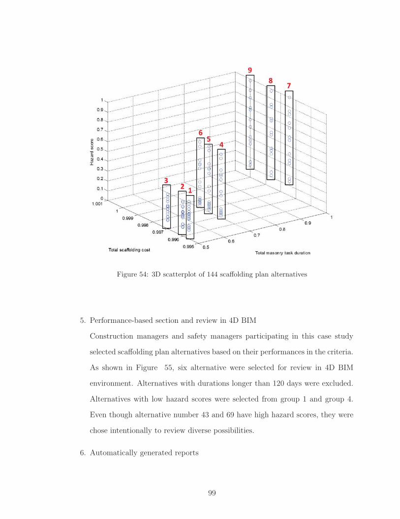
Figure 54: 3D scatterplot of 144 scaffolding plan alternatives
5. Performance-based section and review in 4D BIM
Construction managers and safety managers participating in this case study
selected scaffolding plan alternatives based on their performances in the criteria.
As shown in Figure 55, six alternative were selected for review in 4D BIM
environment. Alternatives with durations longer than 120 days were excluded.
Alternatives with low hazard scores were selected from group 1 and group 4.
Even though alternative number 43 and 69 have high hazard scores, they were
chose intentionally to review diverse possibilities.
6. Automatically generated reports
99

For each alternative, a performance review report can be generated automati-
cally. Figure 56 shows a report for the original scaffolding plan. In the plan
view of the report, all the locations with potential hazards are highlighted by red
boxes to give an instant insight into the potential hazards associated with the
scaffolding plan. Also, daily safety hazard reports can be generated as shown
on the left. Figure 57 and Figure 58 summarize the scaffolding utilization
strategies and performances of the six selected alternatives.
7. Professional review of selected alternatives
In this way, construction managers and safety managers reviewed the selected
alternatives using the reports and simulation in 4D BIM environment. While
reviewing the alternatives, subjective judgment of the managers were used to
re-evaluate the selected scaffolding plans. Based on the review of the six alter-
natives, plans (alternative 43, 46, 69, and original plan) with a reversed order
(West, South, and East) had lower hazard scores than the plans (alternative
114, 138, and 140) with an original order (East, South, and West). Depending
on the work directions, sizes of scaffolding, and number of work crews, there
were slight hazard score differences among the plans with lower scores. Con-
structability review of the construction managers concluded that the reversed
work order can implemented without any significant changes to plans for other
tasks. As a result, alternative 140 was selected as the optimal scaffolding plan
suitable for this project. Among alternative 114, 138, and 140, alternative 140
was selected because of the continuity of the work paths that movement of
masonry crews along the walls can be minimized.
Most of the hazards were falling objects to scaffolding and workspaces from
roofing crews. Potential for these hazards can be minimized by controlling the
workflows of roofing crews within their workspaces. Potential falling objects
to scaffolding can be prevented by limiting any activity around and above the
100

installation crews.
Figure 55: Performance-based selection of alternatives
101

Figure 56: Original schedule with detected unsafety zones visualized
Figure 57: Scheduling alternative 69, 138, and 140 with detected unsafety zones visualized
102

Figure 58: Scheduling alternative 43, 46, and 114 with detected unsafety zones visualized
7.5 Results and discussion
This paper presented a method to integrate temporary structures into automated
safety planning and optimization in BIM. The framework, algorithms, and a case
study were presented. Implementation of this approach in a real world construction
project demonstrated its capabilities to generate a wide range of scaffolding planning
alternatives based on the user input and eventually to assist in informed decision
making for scaffolding safety planning. Construction and safety managers agreed on
the potential benefits of the proposed optimization of scaffolding plans. The original
masonry wall construction plan incorporating scaffolding utilization has been opti-
mized into a plan that contains a different work order, work directions, scaffolding
sizes, and the number of work crews. According to the professionals who partici-
pated in the case study, the optimized plan clearly is a safer scaffolding plan that
expose workers to less hazardous conditions compared to the original plan developed
by them. However, their testimonials show that it is extremely challenging to explore
103

and evaluate various possibilities of planning scaffolds in the real world construction
planning. The case study demonstrated the capability of the proposed optimiza-
tion approach to assist in planners to have a clearer insight into available ways to
construct the same structure and make informed decisions for safety. Even though
this research focused on safety hazards associated with scaffolding used for masonry
contractors only, future research would be needed to comprise various types of tasks
and other temporary structures into the automated safety hazard analysis. Further
research can be conducted to integrate more sofisticated optimization algorithms. In
this research, available alternatives were created by enumerating all possible combina-
tions. However, exhaustive enumeration can be computationally expensive when the
simulation becomes more complex by integrating other types of temporary structures
and incorporating scheduling and contructability logics. Multi-objective optimization
approaches, such as [22], can be integrated to the research in this thesis.
104

CHAPTER VIII
VALIDATION OF SCAFFOLDING PLACEMENT,
SAFETY PLANNING, OPTIMIZATION
In this chapter, the developed systems for scaffolding placement, safety checking and
optimization are tested in a case study for validity of the approach. Based on a real-
world construction plan, the case study was designed and validated. Construction
managers of the project participated in the preparation for the test and validation of
the results.
8.1 Case study introduction
Systems developed throughout this thesis was tested in a five-story campus residential
building construction project. BIM, construction schedules, and work sequences were
used as the input for the developed systems for scaffolding placement, safety checking,
and optimization. The project comprises constructions of three parts: Building A,
Building B, and Building C (Figure 59).
105

Figure 59: Building model of five-story campus residential building
Figure 60 and Figure 61 present the original construction sequence plans estab-
lished by the general contractor. Figure Figure 60 shows the construction sequences
for structural parts, such as slabs, columns, roofs, etc. In general, Building A is
constructed first and then Building B and Building C follow. Building A and Build-
ing B have two work zones and Building C has one work zone. Red arrows present
the workflows within the work zones. For each floor, work zones and work flows are
equally assigned.
106

Figure 60: Original construction sequences for structural parts
In addition to the structural part construction, building skin construction se-
quences were created by the general contractor as shown in Figure 61. Building skin
construction is completed by nine sequential tasks including (1) hang exterior sheath-
ing, (2) install fluid applied waterproofing, (3) waterproofing at punched openings,
(4) install cornice framing, (5) install Windows, (6) caulk window to waterproofing,
(7) stucco at cornice, (8) install brick masonry, and (9) caulk Exterior of Windows.
Estimated productivities per crew for the tasks are: (1) hang exterior sheathing (640
sqft/day), (2) install fluid applied waterproofing (640 sqft/day), (3) waterproofing
at punched openings (640 sqft/day), (4) install cornice framing (1160 sqft/day), (5)
install Windows (1450 sqft/day), (6) caulk window to waterproofing (2890 sqft/day),
(7) stucco at cornice (1100 sqft/day), (8) install brick masonry (300 sqft/day), and
(9) caulk Exterior of Windows (1450 sqft/day). To assist in the tasks of skin construc-
tion, all required mast climber scaffolds were installed and maintained until the entire
exterior finishing was completed. Figure Figure 61 presents the general contractors
plan for skin construction. Each of the yellow line segments presents a location of a
107

scaffolding installed in front of the building skin. As shown in red arrows, two crews
were assigned to each Building A and Building B. Skin construction of Building C
was conducted by another crew independently from Building A and Building B.
Figure 61: Sequence for building skin construction
8.2 System preparation for simulation and optimization
8.2.1 4D BIM preparation
Based on the original construction plan and BIM of the general contractor, the simu-
lation and optimization were prepared. As the first step, 4D BIM was constructed by
linking tasks in a construction schedule and building components, such as walls and
slabs. As shown in Figure 62, location lines for scaffoldings were manually created
according to the general contractors skin construction plan. The scaffolding location
lines were also linked to tasks of skin construction. The location lines were used as
108

the essential input to automatically generate scaffolding objects. To ensure the sim-
ulation to properly present the planned construction sequences, constructed 4D BIM
has been revised based on the review by the construction managers.
Figure 62: Scaffolding location line input
Also, the system has been refined to meet the need for simulating construction
site conditions in finer details. The work zones of the original construction plan were
created in the system as shown in Figure 63. Since large sizes of work zones could not
properly represent the movements of work crews, each work zones was automatically
divided into four sub-work zones (Figure 64).
109
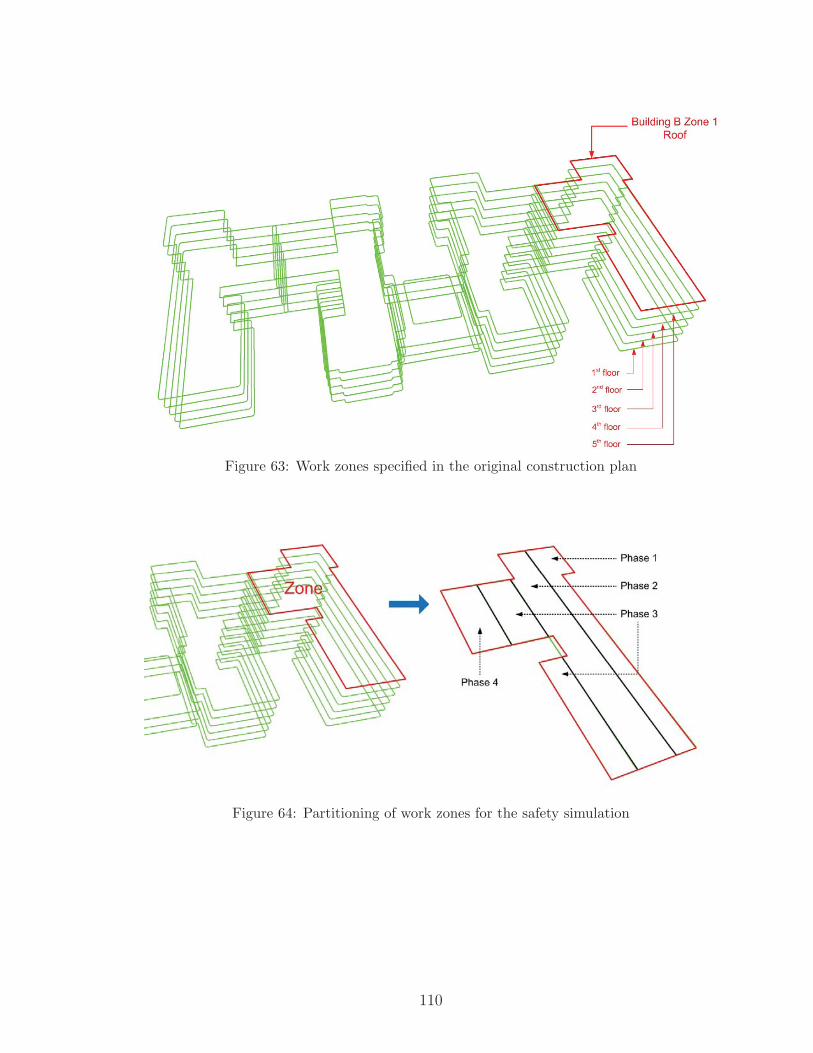
Figure 63: Work zones specified in the original construction plan
Figure 64: Partitioning of work zones for the safety simulation
110

8.2.2 Optimization input preparation
After 4D BIM has been constructed, the input for optimization was prepared. Op-
timization input preparation was conducted by defining multiple options for the de-
cisions made for the original scaffolding plan. The input types included scaffolding
size, number of crews per building, skin task order switch, skin task path switch, and
structural part work sequence switch. Details are explained below.
1. Scaffolding sizes
The scaffolding size option limits the width of individual scaffolds by splitting
the scaffolds of widths greater than a predefined maximum width. This option
has been prepared to allow more crews to work at different levels at the same
time. As shown in Figure 65, two scaffolding objects can be created instead of
one scaffolding as planned in the original skin construction plan. If additional
mast climbers are installed, greater expense is expected due to installation and
maintenance of electric-powered lifting units. Related cost calculation is in-
cluded in the objective function. There are two (true and false) alternatives
related to this options.
111

Figure 65: Scaffolding placement with width limitation
2. Number of crews per building
This option changes the number of crews for skin construction for each Building
A and Building B. In the original skin construction plan, there are two crews for
each building. This option allows simulations based on one-crew and two-crew
assumptions. Figure 66 illustrates work sequences when one crew is assigned
to a building. There are two (one and two) alternatives related to this options.
112

Figure 66: Sequences for one crew for Building A and Building B option
3. Skin task order switch
Skin task order switch is to reverse the sequence of skin construction tasks. As
illustrated in Figure 67, there are eight skin construction tasks for each Building
A and Building B. The original sequence for crew 1 of Building A is 1, 2, 3, and
4. After reversing the sequence, construction is conducted following the reversed
order which is 4, 3, 2, and 1. There are two (true and false) alternatives related
to this options.
113

Figure 67: Reversed task order option
4. Skin task path switch
Task path switch option determines if a work direction in a task follows the
preplanned sequence or if the sequence is reversed. If a task is linked to only
one scaffolding object, this option does not make any change. However, the
work direction changes if a task has two or more scaffolding objects. Figure
68 compares the work directions when the order was switch and not switched.
There are four (true and false for Building A and Building B) alternatives re-
lated to this options.
114

Figure 68: Reversed paths in a task
5. Structural part work sequence switch
This reverses the work directions of structural part construction in a building.
Since there are three buildings (Building A, Building B, and Building C), each
of them can be reversed as shown in Figure 69. There are eight (true and false
for three buildings) alternatives related to this options.
Figure 69: Reversed structural sequences
115

As a result of enumerating all the combinations, 256 total alternatives were auto-
matically generated.
8.2.3 Objective functions
Objective functions are required to quantitatively evaluate each scaffolding alterna-
tive. In addition to safety hazards, the total duration for skin construction and the
total cost for scaffolding were calculated to provide an insight into performances of
alternatives. The objective functions have been created based on a discussion with
construction and safety managers of the project. Even though simplistic methods
were used for this case study, more realistic calculations of subcontractors can be
integrated into the system.
1. Safety hazard score
Safety hazard score was calculated by multiplying weights to identified safety
hazards and summing the results for all safety hazards identified by the sys-
tem. The maximum score for an incident was 10 and the minimum score was
0. Two types of safety hazards were checked by the system: falling objects
from scaffolding and falling objects to scaffolding. Table 3 shows the objective
functions for each task of skin construction. There is no activity occurring at
the locations where scaffolds are installed and all there is no additional scaf-
folding installation once the skin construction starts. Therefore, other types
of scaffolding-related safety hazards, such as spatial conflicts with other tasks,
falling objects to scaffolding installation spaces, were not included in this case
study.
116
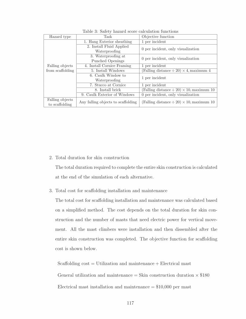
Table 3: Safety hazard score calculation functionsHazard type Task Objective function
Falling objectsfrom scaffolding
1. Hang Exterior sheathing 1 per incident2. Install Fluid Applied
Waterproofing0 per incident, only visualization
3. Waterproofing atPunched Openings
0 per incident, only visualization
4. Install Cornice Framing 1 per incident5. Install Windows (Falling distance÷ 20)× 4,maximum 46. Caulk Window to
Waterproofing1 per incident
7. Stucco at Cornice 1 per incident8. Install brick (Falling distance÷ 20)× 10,maximum 10
9. Caulk Exterior of Windows 0 per incident, only visualizationFalling objectsto scaffolding
Any falling objects to scaffolding (Falling distance÷ 20)× 10,maximum 10
2. Total duration for skin construction
The total duration required to complete the entire skin construction is calculated
at the end of the simulation of each alternative.
3. Total cost for scaffolding installation and maintenance
The total cost for scaffolding installation and maintenance was calculated based
on a simplified method. The cost depends on the total duration for skin con-
struction and the number of masts that need electric power for vertical move-
ment. All the mast climbers were installation and then dissembled after the
entire skin construction was completed. The objective function for scaffolding
cost is shown below.
Scaffolding cost = Utilization and maintenance + Electrical mast
General utilization and maintenance = Skin construction duration× $180
Electrical mast installation and maintenance = $10,000 per mast
117

8.3 Implementation results
The performance of the system was evaluated for scaffolding placement, potential
safety hazard recognition, and optimization of the original scaffolding plan.
8.3.1 Scaffolding placement
Based on the information in BIM and user input, the system successfully created
scaffolding objects in 4D BIM environment. Figure 70 illustrates the result of plane-
face intersection analysis. The intersection analysis identified bottom and top points
along the work package and determines the shapes of scaffolding objects. Scaffolding
objects and workspaces for structural construction tasks were created and incorpo-
rated into 4D BIM as shown in Figure 71.
Figure 70: Result of plane-face intersection analysis
118

Figure 71: Mast climber scaffolding and structural work zones in 4D BIM
8.3.2 Scaffolding-related hazard recognition
The scaffolding objects were used to identify potential safety hazard and each of the
safety hazard incidents was quantitatively assessed based on the objective functions.
Figure 72 shows the report and visualization for all safety hazard incidents identified
by the system. The hazard report available in the graphical user interface provide
detailed hazard information, such as hazard types, dates, and related construction
tasks. In the 4D BIM environment, locations for detected safety hazards were visu-
alized to facilitate effective communication about the detected hazards.
119

Figure 72: Report and visualization of entire safety hazards
Figure 73: Hazard visualization in 4D environment
In the 4D environment of the system, construction site conditions can be visualized
120

more realistically by incorporating scaffolding objects, workspaces, and safety hazards
(Figure 73).
8.3.3 Enumerative generation of scaffolding plan alternatives
Based on the optimization input, all possible alternative scaffolding plans were cre-
ated and quantitatively evaluated. For each alternative, the safety simulation system
analyzed daily construction site conditions and evaluated the plans according to the
objective functions. As shown in Figure 74, the scaffolding plans were summarized
in the graphic user interface.
Figure 74: Graphic user interface of optimization
8.3.4 Performance-based selection and review in 4D BIM
The quantitative evaluations of the alternatives were used to select a few candidate
plans to be reviewed thoroughly in the 4D BIM environment. To provide a clear
121

insight into the expected performances of the alternatives, three ways of result visu-
alization were used. (1) First, 2D and 3D scatterplots were used to select candidates
as shown in Figure 75. Five alternatives were selected based mainly on the tradeoff
between skin construction duration and hazard score was presented. From the five
alternatives, alternative 5 was excluded from further review due to excessively long
skin construction duration. (2) For other four alternatives, summary reports were
presented to construction managers of the general contractor to assist in their de-
cision making (Figure 77 and Figure 79). (3) Finally, 4D simulation was used to
review the four alternatives and make the final decision.
In general, all four alternatives were considered as safer plans that can be actually
implemented without significant constructability problems. Also, skin construction
can be extended up to 300 days that allows alternative 4 to be a qualified option.
1. Alternative 1, 2: Expected skin construction durations and scaffolding costs of
alternative 1 and 2 were almost identical to those of the original plan. Even
though the hazard scores were slightly lower, alternative 1 and 2 were not con-
sidered as the preferred plans since the work sequence of original plan was simple
and easier to implement.
2. Alternative 3: Alternative 3 required about 50 more days to complete the skin
construction and needed excessive cost for scaffolding installation and main-
tenance due to more electric-powered lifting units needed. However, this al-
ternative was selected as one of preferred solutions due to its clear benefit in
safety.
3. Alternative 4: Alternative 4 was also selected as a preferred solution even with
a duration more than 100 days longer than the original plan. Construction
managers opinion was that this plan exposes workers to significantly lower level
of safety risks compared to the original plan.
122

Figure 75: Five alternative scaffolding plans were selected based on the performances
123

Figure 76: Sequence and safety hazard highlights of original plan
Figure 77: Scaffolding plan summary for alternative 1 and 2
124

Figure 78: Scaffolding plan summary for alternative 3 and 4
Figure 79: Scaffolding plan summary for alternative 3 and 4
125

8.3.5 Selection of final scaffolding plan
Alternative 3 and 4 were considered as scaffolding plans that show clear benefits over
the original plan. Safety risks associated with alternative 1 and 2 were not considered
significantly lower than the original plan. Even with significantly lower level of safety
risk of alternative 5, the expected duration for skin construction was excessively longer
than the original plan. Thus, the original plan, alternative 3, and alternative 4 were
selected as optimal solutions.
8.4 Conclusions and discussion
In this chapter, the overall approach including scaffolding placement, safety simula-
tion, and optimization was tested in a real-world case study. The construction project
information in BIM, construction schedules, and sequences were used as the input for
the system. Construction managers of the project participated in the entire process
of validation, from 4D BIM creation to assessment of the results of simulation and
optimization. In the optimization process, a wide range of scaffolding plans were
automatically created based on user input and the construction managers actively
participated in the selection process. In addition to the quantitative evaluation of al-
ternatives, professional judgment of the construction managers were used to evaluate
the constructability and effectiveness of the plans. As a result, multiple alternative
scaffolding plans were identified that were considered safer than the original plan.
Thus, this case study validates that manually generated original plan for temporary
structures can be evaluated and optimized into safer temporary structure plans by
the proposed automation approach.
The limitations of this case study include: (1) Hazard weighting required multiple
rounds of adjustments. Since experts participated in the test had different opinions
126

about the risks of safety hazards, discussions were required to setup the hazard weight-
ing. (2) Other user-input, such as reversing sequences and directions, also required
multiple adjustments based on preliminary 4D reviews of construction managers. (3)
Performance-based selection needs an additional function to select alternatives based
on certain criteria. In this case study, five alternatives were selected mainly based
on skin construction durations and hazard scores. For example, creating functions to
select alternatives with hazard score lower than 500 and one crew per building can
be helpful in reducing the need for manual efforts for selection and review.
Real-world application of this approach expected to be achieved by overcoming
these limitations.
127

CHAPTER IX
CONCLUSIONS AND LIMITATIONS
This chapter summarizes the findings and concludes the thesis. Limitations of the
current reserach and future research needs are discussed.
9.1 Summary of works performed
This research presents a BIM-based automatic system to address potential safety
hazards related to temporary structures in the planning stage. Focusing on scaffold-
ing, this research attempts to improve the construction safety by (1) automatically
incorporating temporary structure objects in a 4D BIM, (2) automatically identify-
ing potential safety hazard incidents related to the temporary structures, and (3)
optimizing the original temporary structure plans into safer scaffolding plans.
As the first step, a process for scaffolding planning was established based on
in-depth interviews with industry professionals. The scaffolding placement process
was then converted into a set of computational algorithms. Scaffolding objects were
automatically created in 4D BIM by analyzing spatial-temporal condition in BIM.
The BIM containing scaffolding objects were used to identify potential safety haz-
ards related to scaffolding. To enable an automated hazard identification, a safety
simulation engine was developed. The safety simulation engine created daily require-
ments for workspaces and scaffolding objects to accurately analyze construction sites
on each day. The safety simulation engine demonstrated its capabilitiy to identify po-
tential safety hazards without excessive manual efforts and to effectively communicate
the results.
The scaffolding optimization is create optimized scaffolding plans that are safe
128

and executable. This optimization has been accomplished by automatically creat-
ing alternative scaffolding plans and quantatively evaluating them. Quantitatively
evaluated performances of scaffolding plans assisted in construction planners to make
informed decision making based on the predicted performances on safety and other
criteria, such as cost and duration.
The proposed approach for scaffolding planning, analysis, and optimization was
validated in another real-world construction project. Construction and safety man-
agers of the case study project actively participated in the process from preparation
of the simulation to the validation of the final results. In this case study, scaffolding
objects were successfully created in a 4D BIM environment and potential safety haz-
ards were automatically identified. Based on the user-input, alternative scaffolding
plans were automatically created and evaluated. Finally, the construction managers
selected a few alternatives based on the expected performances. As a result of re-
viewing the selected alternatives, multiple alternative scaffolding plans were found to
be executable and safer than the original scaffolding plan.
9.2 Contributions and impacts
The major contributions and impacts of this reseach are presented. (1) The first con-
tribution of this reserach would be that safe temporary structure plans can be created
without excessive manual efforts. Time-consuming and error-prone tasks of identi-
fying and addressing temporary structure-related safety hazards were automatically
conducted in this research. (2) Construction site safety can be improved by recog-
nizing and addressing potential hazards related to temporary structures before the
construction begins. The overall approach proposed in this research can assist con-
struction and safety planners in preparing preventive actions in the planning stages.
(3) A wide range of possibilities to plan temporary structures can be explored to
129

assist in the informed decision making. A method for automated generation of tem-
porary structure plan alternatives and quantitative assessment of the alternatives was
proposed. Through the enumerative generation of alternative plans and quantitative
evaluation, construction planners can have a clearer insight into possible ways of
planning temporary structures. (4) Safety communications can be facilitated using
hazard schedules, hazard-specific reports, and hazard visualization. Various hazard
visualization methods presented in this research can greatly improve safety communi-
cations between superintendents, safety managers, inspectors, and workers. (5) Better
safety training can be provided to workers through hazard visualization and reports.
(6) Workers can obtain ease-of-mind by clearly recognizing potential hazards around
them. All these eventually contribute to the creation of safe construction plans that
minimize worker exposures to safety hazards.
9.3 Limitations and future research
One of the fundamental limitations of this research is the heavy reliance on the ac-
curacy of geometric information in BIM and construction schedules. If the project
information is incorrect, the temporary structure planning is directly impacted. This
requires BIM and construction schedules to be continuously updated to contain ac-
curate geometric and non-geometric information. The performance of the approach
can also be impacted by the level of details and quality of 4D BIM and construction
schedules because it attempts to simulate daily construction site conditions.
The current research dealt with building models with relatively simple geometric con-
ditions. Planar faces of walls, slabs, and roofs were used for automated construction
site conditions analysis. In order to develop a practical application software program,
the geometric condition analysis algorithms need to be able to analyze various types
of geometry such as curved walls.
Development of algorithms in this research focused on selected construction tasks,
130

such as masonry wall construction and building skin construction tasks. Depending
on the charatecterstics of tasks, required functions of algorithms can vary widely. In
order to overcome this limitation, a comprehensive study to computationally gen-
erate work sequences and patterns of tasks using scaffolding is required. Patterns
of spatial movement of workers have been studied in the past research studies [36].
Automatically creating various work patterns in BIM and matching the patterns to
construction tasks would be one of the solutions to this limitation.
During the optimization process, the selection process can be enhanced by creating
selection algorithms and filters. Since hundreds of alternatives were automatically
created, it was challenging to review enough number of alternatives manually.
Also, the optimization was conducted by adjusting parameters related to temporary
structures. A future research can enable an optimization in the earlier stages when
zoning plans and construction schedules are established. By incorporating automated
generation and analysis approaches in the earliest stage in constructino planning,
wider range of construction planning alternatives can be explored and construction
plans can be established based on a clearer insight into possible ways of construction.
Integration of a wider range of temporary structures can be considered in future
studies. This research focused mainly on scaffolding. However, for more realistic vi-
sualization and analysis, other important temporary structures such as formwork may
need to be incorporated. Interactions between different types of temporary structures
may also be considerd in the analysis.
131

REFERENCES
[1] Akbas, R., Fischer, M., Kunz, J., and Schwegler, B., “Formalizing Do-main Knowledge for Construction Zone Generation,” pp. 1–16.
[2] Akinci, B., Fischer, M., and Kunz, J., “Automated Generation of WorkSpaces Required by Construction Activities,” Journal of Construction Engineer-ing and Management, vol. 128, no. August, pp. 306–315, 2002.
[3] Bansal, V. K., “Application of geographic information systems in constructionsafety planning,” International Journal of Project Management, vol. 29, no. 1,pp. 66–77, 2011.
[4] Behm, M., “Linking construction fatalities to the design for construction safetyconcept,” 2005.
[5] BLS, “Fatal occupational injuries by event or exposure for all fatalities andmajor private industry sector, All United States,” 2009.
[6] Borrmann, a. and Beetz, J., “Towards spatial reasoning on building infor-mation models,” Proc. of the 8th European Conference on Product and ProcessModeling (ECPPM), 2010.
[7] Borrmann, A. and Rank, E., “Specification and implementation of direc-tional operators in a 3D spatial query language for building information models,”Advanced Engineering Informatics, vol. 23, no. 1, pp. 32–44, 2009.
[8] Borrmann, A. and Rank, E., “Topological analysis of 3D building modelsusing a spatial query language,” Advanced Engineering Informatics, vol. 23, no. 4,pp. 370–385, 2009.
[9] CII, “Playbook of Leading Industry Practices for Estimating , Controlling , andManaging Indirect Construction Costs CII Member Companies,” tech. rep.
[10] CII, “Leading Industry Practices for Estimating, Controlling, and ManagingIndirect Construction Costs,” tech. rep., The University of Texas at Austin,2012.
[11] Construction Industry Institute, “Leading Industry Practices for Esti-mating, Controlling, and Managing Indirect Construction Cost,” tech. rep., TheUniversity of Texas at Austin, 2012.
[12] CPWR, “The Construction Chart Book,” tech. rep., Center for ConstructionResearch and Training, Silver Spring, MD, 2013.
132

[13] Eastman, C., Teicholz, P., Sacks, R., and Liston, K., BIM Handbook:A Guide to Building Information Modeling for Owners, Managers, Designers,Engineers and Contractors, vol. 2. 2011.
[14] Faghihi, V., Reinschmidt, K. F., and Kang, J. H., “Construction schedul-ing using Genetic Algorithm based on Building Information Model,” Expert Sys-tems with Applications, vol. 41, no. 16, pp. 7565–7578, 2014.
[15] Halperin, K. M. and McCann, M., “An evaluation of scaffold safety atconstruction sites,” Journal of Safety Research, vol. 35, no. 2, pp. 141–150, 2004.
[16] Jongeling, R. and Olofsson, T., “A method for planning of work-flow bycombined use of location-based scheduling and 4D CAD,” Automation in Con-struction, vol. 16, pp. 189–198, 2007.
[17] Kelsey, J., Winch, G. M., and Penn, A., “Understanding the Project Plan-ning Process: Requirements Capture for the Virtual Construction Site,” BartlettResearch Papers, no. 15, 2001.
[18] Kim, H. and Ahn, H., “Temporary Facility Planning of a Construction ProjectUsing BIM (Building Information Modeling),” Journal of Computing in CivilEngineering, pp. 627–634, 2011.
[19] Kim, J. and Fischer, M., “Formalization of the features of activities and clas-sification of temporary structures to support an automated temporary structureplanning,” pp. 338–346, 2007.
[20] Kim, J., Fischer, M., John, K., and Raymond, L., “Semiautomated Scaf-folding Planning: Development of the Feature Lexicon for Computer Applica-tion,” Journal of Computing in Civil Engineering, vol. 29, no. 5, 2014.
[21] Kim, K. and Teizer, J., “Automatic design and planning of scaffolding sys-tems using building information modeling,” Advanced Engineering Informatics,vol. 28, no. 1, pp. 66–80, 2014.
[22] Kim, K.,Walewski, J., andCho, Y. K., “Multiobjective Construction Sched-ule Optimization Using Modified Niched Pareto Genetic Algorithm,” Journal ofManagement in Engineering, p. 04015038, jul 2015.
[23] Koo, B. and Fischer, M., “Feasibility Study of 4D CAD in CommercialConstruction,” Journal of Construction Engineering and Management, vol. 126,no. 4, pp. 251–260, 2000.
[24] Moon, H., Dawood, N., and Kang, L., “Development of workspace conflictvisualization system using 4D object of work schedule,” Advanced EngineeringInformatics, vol. 28, no. 1, pp. 50–65, 2014.
[25] Nemetschek, “Scia Scaffolding: providing an accurate design and time-savingworkflow.”
133

[26] Nepal, M. P., Staub-French, S., Pottinger, R., and Webster, A.,“Querying a building information model for construction-specific spatial infor-mation,” Advanced Engineering Informatics, vol. 26, no. 4, pp. 904–923, 2012.
[27] OSHA, “Safety and Health Regulations for Construction - Fall Protection.”
[28] OSHA, “Safety and Health Regulations for Construction - Safety requirementsfor scaffolding.”
[29] OSHA, “A Guide to Scaffolding Use in the Construction Industry,” 2002.
[30] OSHA, “Scaffolding eTool,” 2003.
[31] OSHA, “Commonly Used Statistics,” 2014.
[32] OSHA, “Top 10 Most Frequently Cited Standards,” 2014.
[33] Ratay, R., “Temporary structures in construction operations,” in Proceedingsof a Session Sponsored by the Construction Division of the American Societyof Civil Engineers in conjunction with the ASCE Convention in Atlantic City,pp. 1–8, 1987.
[34] Ratay, R., Handbook of temporary structures in construction. McGraw-HillProfessional, 1996.
[35] Ratay, R. T., “Temporary structures in construction - USA practices,” Struc-tural Engineering International: Journal of the International Association forBridge and Structural Engineering (IABSE), vol. 14, pp. 292–295, 2004.
[36] Riley, D. R. and Sanvido, V. E., “Patterns of Construction-Space Use inMultistory Buildings,” Journal of Construction Engineering and Management,vol. 121, pp. 464–473, 1995.
[37] Sattigari, R. N., Thomas, T., and Mahalingam, A., “Automation ofscheme preparation and BOQ calculation for L&T-aluform,” in 24th Interna-tional Symposium on Automation & Robotics in Construction, pp. 273–280, 2007.
[38] Smart Scaffolder, “Exploit the benefits of BIM (Building Information Mod-elling)ss.”
[39] Sulankivi, K. and Kahkonen, K., “4D-BIM for construction safety plan-ning,” Proceedings of W099- . . . , p. 117, 2010.
[40] Suraji, A., Duff, A., and Peckitt, S., “Development of causal model of con-struction accident causation,” Journal of construction engineering . . . , vol. 127,no. 4, pp. 337–344, 2001.
[41] Tulke, J., Nour, M., and Beucke, K., “Decomposition of BIM objects forscheduling and 4D simulation,” Ework and Ebusiness in Architecture Engineeringand Construction, pp. 653–660 736, 2009.
134

[42] Whitaker, S. M., Graves, R. J., James, M., and McCann, P., “Safetywith access scaffolds: Development of a prototype decision aid based on accidentanalysis,” 2003.
[43] Zhang, S., Boukamp, F., and Jochen, T., “Ontology-based semantic model-ing of construction safety knowledge: Towards automated safety planning for jobhazard analysis (JHA),” Automation in Construction, vol. 52, pp. 29–41, 2015.
[44] Zhang, S., Teizer, J., Lee, J. K., Eastman, C. M., and Venugopal, M.,“Building Information Modeling (BIM) and Safety: Automatic Safety Checkingof Construction Models and Schedules,” Automation in Construction, vol. 29,pp. 183–195, 2013.
135

VITA
Kyungki Kim received his B.S. in Architectural Engineering from Dongguk Univer-
sity, Seoul Korea in Februray 2008. He received M.S. in Civil Engineering from Texas
AM University in August 2011. He joined Georgia Institute of Technology in 2011
where he is working towards his Ph.D. His primary research efforts are directed to-
ward leveraging innovations in Information Communications Technologies (ICT) for
addressing industry-wide problems in construction safety and health.
136