A Safety-centered Planning-time Framework for Automated ...
151
A Safety-centered Planning-time Framework for Automated Process Compliance Checking Julieth Patricia Castellanos Ardila Mälardalen University Doctoral Dissertation 337
-
Upload
khangminh22 -
Category
Documents
-
view
1 -
download
0
Transcript of A Safety-centered Planning-time Framework for Automated ...
ISBN 978-91-7485-511-1ISSN 1651-4238
Address: P.O. Box 883, SE-721 23 Västerås. SwedenAddress: P.O. Box 325, SE-631 05 Eskilstuna. SwedenE-mail: [email protected] Web: www.mdh.se
A Safety-centered Planning-time Framework for Automated Process Compliance CheckingJulieth Patricia Castellanos Ardila
Mälardalen University Doctoral Dissertation 337
Julie
th Pa
tricia
Ca
stella
no
s Ard
ila A
SAFETY-C
ENTER
ED PLA
NN
ING
-TIME FR
AM
EWO
RK
FOR A
UTO
MA
TED P
RO
CESS C
OM
PLIAN
CE C
HEC
KIN
G
2021
Mälardalen University Press DissertationsNo. 337
A SAFETY-CENTERED PLANNING-TIME FRAMEWORKFOR AUTOMATED PROCESS COMPLIANCE CHECKING
Julieth Patricia Castellanos Ardila
2021
School of Innovation, Design and Engineering
Mälardalen University Press DissertationsNo. 337
A SAFETY-CENTERED PLANNING-TIME FRAMEWORKFOR AUTOMATED PROCESS COMPLIANCE CHECKING
Julieth Patricia Castellanos Ardila
2021
School of Innovation, Design and Engineering
11

Copyright © Julieth Patricia Castellanos Ardila, 2021 ISBN 978-91-7485-511-1ISSN 1651-4238Printed by E-Print AB, Stockholm, Sweden
Copyright © Julieth Patricia Castellanos Ardila, 2021 ISBN 978-91-7485-511-1ISSN 1651-4238Printed by E-Print AB, Stockholm, Sweden
22
Mälardalen University Press DissertationsNo. 337
A SAFETY-CENTERED PLANNING-TIME FRAMEWORKFOR AUTOMATED PROCESS COMPLIANCE CHECKING
Julieth Patricia Castellanos Ardila
Akademisk avhandling
som för avläggande av teknologie doktorsexamen i datavetenskap vid Akademin förinnovation, design och teknik kommer att offentligen försvaras onsdagen den 29 september
2021, 13.15 i Delta och on-line via Zoom/Teams, Mälardalens högskola, Västerås.
Fakultetsopponent: Professor Ricardo Colomo Palacios, Østfold University College
Akademin för innovation, design och teknik
33
AbstractSafety-critical systems, whose failure could lead to catastrophic consequences, are everywhere. Notonly environments with high-risk functions, e.g., nuclear power plants, are safety-critical systems. Ourvehicles, medical devices that perform different kinds of treatments, airplanes, and industrial robots,are also safety-critical systems. The more harm the system can cause, the more careful the systemhas to be designed, implemented, and maintained. By following practices of reasonable care, typicallycollected within industry standards, manufacturers demonstrate that they aim at preventing safety-critical systems from failing or causing various types of damage. Thus, compliance with standards,especially safety standards, is a must-do for manufacturers of safety-critical systems.
Industry standards often adopt a prescriptive approach, which focuses on process-related requirements.To comply with such standards, manufacturers have to carefully prepare process plans that properlyaddress the applicable requirements. A compliant process plan should include the sequence of tasksmandated by applicable standards as well as the resources allocated to such tasks, e.g., personnel, workproducts, required tools, and methods, which are also framed with key properties. The planning taskcould be supported by checking that planned processes fulfill the properties set down by standards atgiven points.
Compliance checking of process plans is rarely done for just one standard. In automotive, for instance,it is recommended that manufacturers follow at least standards for functional safety, cybersecurity, andsoftware process improvements. Manufacturers also need to perform tailoring, i.e., select and modifyrequirements depending on the individual project. In safety standards, tailoring is often performed bytaking into account existing safety criticality levels. Moreover, new versions of the standards, which arefrequently released, demand recertification. In addition, compliance checking is not only done to oneprocess plan. Companies commonly need to plan several processes simultaneously. Consequently, it isnot easy to manually check that process plans comply with the requirements of standards.
Automated compliance checking could help process engineers in such organizations to detectcompliance violations and enforce compliance at planning time. Thus, the main goal of this dissertationis to facilitate automated compliance checking of the process plans used to engineer safety-criticalsystems against the standards mandated (or recommended) in the safety-critical context. To reach ourgoal, we adopt modern methods and tools, adapt them by mainly focusing on software and risk analysisprocess plans, and contribute to the state-of-the-art as follows:
1. We identify aspects that make compliance checking of process plans demanding and formulaterequirements for a technical solution to these problems.
2. We introduce ACCEPT (Automated Compliance Checking of Engineering Process plans againstsTandards), an iterative and comprehensible framework for supporting process engineers to check andenforce process plan compliance.
3. We propose mechanisms for facilitating the creation and reuse of the specifications required to checkprocess plan compliance.
4. We investigate the significance of our proposed solutions by applying different validationmechanisms. As a result, our solutions show to be useful to support process engineers in the compliancechecking tasks required during process planning.
This dissertation's contributions aim at planting the seeds for the future development of tools that support process engineers moving towards automated compliance checking practices.
ISBN 978-91-7485-511-1ISSN 1651-4238
44

Popularvetenskapligsammanfattning
Sakerhetskritiska system, som vid eventuella funktionsfel skulle kunna fa katas-trofala konsekvenser for oss, finns overallt. Det ar inte bara miljoer medhogriskfunktioner, som t ex karnkraftverk, som ar sakerhetskritiska system.Vara fordon, medicinsk utrustning som utfor olika typer av behandlingar, flyg-plan och industrirobotar, ar ocksa sakerhetskritiska system. Ju mer skada sys-temet kan orsaka, desto noggrannare maste systemet designas, implementerasoch underhallas. Genom att med rimlig noggrannhet folja den praxis som van-ligtvis finns i branschstandarder, kan tillverkare visa att de anvander metodersom forhindrar att de sakerhetskritiska systemen har brister eller ger upphovtill olika typer av skador. Av denna anledning ar det ett maste, for tillverkare avsakerhetskritiska system, att folja dessa standarder, sarskilt sakerhetsstandarder.
Branschstandarder har ofta ett normativt upplagg som fokuserar pa pro-cessrelaterade krav. For att folja sadana standarder maste tillverkare noggrantforbereda processplaner som korrekt uppfyller gallande krav. En lamplig pro-cessplan maste inkludera ordningsfoljden av de arbetsuppgifter som ingar igallande standarder samt de resurser som kravs for dessa uppgifter, t.ex. per-sonal, arbetsmaterial, nodvandiga verktyg och metoder, samt viktiga egen-skaper hos dem. En sadan arbetsuppgift kan stodjas genom att kontrollera attprocessplanerna uppfyller de krav som stalls pa aktuella punkter i standarden.
Det racker ofta inte att en sadan kontroll gors for bara en standard. Inomfordonsindustrin till exempel, rekommenderas tillverkare att atminstone foljastandarder for funktionssakerhet, cybersakerhet och forbattringar av mjukvaru-processer. Tillverkare maste aven utfora anpassningar av standarder, dvs. valjaoch andra krav beroende pa det enskilda projektet. I sakerhetsstandarder utforsofta anpassningar i enlighet med befintliga sakerhetskritiska nivaer. Dessutom
i
55
ii
kravs omcertifiering nar nya versioner av standarderna slapps, vilket sker ofta.Det ar dessutom inte bara en enskild projektplan som kontrolleras. Foretagbehover ofta planera flera processer parallellt. Det ar darfor inte latt att manuelltkontrollera att processplanerna foljer kraven i dessa standarder
Automatiserad kontroll av den typen av overensstammelse skulle kunnahjalpa processingenjorer i sakerhetskritiska sammanhang att upptacka overtra-delser samt sakra att overensstammelsen foljs under planeringstiden. Huvud-malet for denna avhandling ar darfor att underlatta automatisk kontroll av ove-rensstammelsen av processplaner som anvands for att konstruera sakerhetskri-tiska system i enlighet med de standarder som ar obligatoriska (eller rekom-menderade) i sakerhetskritiska sammanhang. For att na vart mal utgar vi franmoderna metoder och verktyg, anpassar dem genom att huvudsakligen fokuserapa mjukvara- och riskanalysprocessplaner samt bidrar till den senaste teknikenenligt foljande:
1. Vi identifierar aspekter som forsvarar kontrollen av processplanens ove-rensstammelse med standarders fordrande och formulerar detaljerade kravpa en teknisk losning pa dessa problem.
2. Vi introducerar ACCEPT (Automated Compliance Checking of Engineer-ing Process plans against sTandards), ett iterativt och begripligt ram- verksom assisterar processingenjorer med att kontrollera och sakerstalla att pro-cessreglerna efterfoljs.
3. Vi foreslar mekanismer for att underlatta skapandet och ateranvandningenav de specifikationer som kravs for att kontrollera processplanens overens-stammelse med standarderna.
4. Vi undersoker betydelsen av vara foreslagna losningar genom att anvandaolika valideringsmekanismer. I och med detta visar vi att vara losningar kanvara anvandbara for att stodja processingenjorer i de kontrolluppgifter somkravs for planering av processer i sakerhetskritiska sammanhang.
Avhandlingens bidrag syftar till att plantera fron for framtida utvecklingav verktyg som stoder processingenjorers anvandning sig av automatiserademetoder for kontroll av processplaners overensstammelse med standarder.
66
Abstract
Safety-critical systems, whose failure could lead to catastrophic consequences,are everywhere. Not only environments with high-risk functions, e.g., nuclearpower plants, are safety-critical systems. Our vehicles, medical devices thatperform different kinds of treatments, airplanes, and industrial robots, are alsosafety-critical systems. The more harm the system can cause, the more care-ful the system has to be designed, implemented, and maintained. By follow-ing practices of reasonable care, typically collected within industry standards,manufacturers demonstrate that they aim at preventing safety-critical systemsfrom failing or causing various types of damage. Thus, compliance with stan-dards, especially safety standards, is a must-do for manufacturers of safety-critical systems.
Industry standards often adopt a prescriptive approach, which focuses onprocess-related requirements. To comply with such standards, manufacturershave to carefully prepare process plans that properly address the applicablerequirements. A compliant process plan should include the sequence of tasksmandated by applicable standards as well as the resources allocated to suchtasks, e.g., personnel, work products, required tools, and methods, which arealso framed with key properties. The planning task could be supported bychecking that planned processes fulfill the properties set down by standards atgiven points.
Compliance checking of process plans is rarely done for just one standard.In automotive, for instance, it is recommended that manufacturers follow atleast standards for functional safety, cybersecurity, and software process im-provements. Manufacturers also need to perform tailoring, i.e., select andmodify requirements depending on the individual project. In safety standards,tailoring is often performed by taking into account existing safety criticalitylevels. Moreover, new versions of the standards, which are frequently released,demand recertification. In addition, compliance checking is not only done to
iii
77
iv
one process plan. Companies commonly need to plan several processes simul-taneously. Consequently, it is not easy to manually check that process planscomply with the requirements of standards.
Automated compliance checking could help process engineers in such or-ganizations to detect compliance violations and enforce compliance at planningtime. Thus, the main goal of this dissertation is to facilitate automated com-pliance checking of the process plans used to engineer safety-critical systemsagainst the standards mandated (or recommended) in the safety-critical con-text. To reach our goal, we adopt modern methods and tools, adapt them bymainly focusing on software and risk analysis process plans, and contribute tothe state-of-the-art as follows:
1. We identify aspects that make compliance checking of process plans de-manding and formulate requirements for a technical solution to these prob-lems.
2. We introduce ACCEPT (Automated Compliance Checking of EngineeringProcess plans against sTandards), an iterative and comprehensible frame-work for supporting process engineers to check and enforce process plancompliance.
3. We propose mechanisms for facilitating the creation and reuse of the speci-fications required to check process plan compliance.
4. We investigate the significance of our proposed solutions by applying dif-ferent validation mechanisms. As a result, our solutions show to be useful tosupport process engineers in the compliance checking tasks required duringprocess planning.
This dissertation’s contributions aim at planting the seeds for the futuredevelopment of tools that support process engineers moving towards automatedcompliance checking practices.
88
DEDICATED TO MY FAMILY DEDICATED TO MY FAMILY
99

1010
Acknowledgments
First, I would like to express my appreciation to my principal supervisor, Bar-bara Gallina, who has supported me during the whole duration of my studies.Thanks to her guidance, I have been able to fulfill all the research goals. I willalso thank my assistant supervisor, Faiz Ul Muram, for her contributions to myresearch. Special thanks to Guido Governatori, leader of the Software SystemsResearch Group at CSIRO’s Data61, for sharing his knowledge and expertise.
I also want to thank the head of our division, Radu Dobrin, and the studentrepresentatives Viktorija Badasjane and Rachael Berglund for their support.Special thanks to Thomas Nolte, Federico Ciccozzi, Jenny Hagglund and Car-ola Ryttersson for facilitating the MDH routines. My gratitude is also for thepeople who are or have been colleagues at MDH. In particular, I thank Jan Carl-son, Antonio Cicchetti, Luciana Provenzano, Soheila Sheikh Bahaei, RobbertJongeling, Filip Markovic, Asha Kiran, Mirgita Frasheri, Irfan Sljivo, SiminCai, LanAnh Trinh, Gabriel Campeanu, Omar Jaradat, Inmaculada Ayala, andZulqarnain Haider, for taking their time to answer my countless questions, andfor sharing their interests. Special thanks to Cristina Seceleanu for reviewingmy thesis and giving me valuable comments.
I also want to give special thanks to my mother, Mercedes, who fromColombia is encouraging me to finish everything I start. Finally, and mostimportantly, I would like to express my gratitude and love to my husband Olaand my son Gabriel. Their company, patience, hugs, unconditional support,and love have strengthened me through this challenging experience.
The work in this Ph.D. thesis has been partially supported by EU and VIN-NOVA via the ECSEL JU project AMASS (No. 692474) [1].
Julieth Patricia Castellanos ArdilaVasteras, September, 2021
vii
1111

1212
List of Publications
Papers Included in the Licentiate Thesis1
Paper A: Facilitating Automated Compliance Checking of Processes in theSafety-critical Context, Julieth Patricia Castellanos Ardila, Barbara Gallina andFaiz Ul Muram. Journal of Electronic Communications of the EASST. vol 78.2019.
Paper B: Separation of Concerns in Process Compliance Checking: Divide-and-Conquer, Julieth Patricia Castellanos Ardila and Barbara Gallina. In Pro-ceedings of the European Systems, Software & Service Process Improvement& Innovation. EuroAsiaSPI 2020. Communications in Computer and Informa-tion Science, vol 1251. Springer, Cham. 2020.
Paper C: A Personal Opinion Survey on Process Compliance Checking in theSafety Context, Julieth Patricia Castellanos Ardila and Barbara Gallina. In Pro-ceedings of the 13th International Conference on the Quality of Informationand Communications Technology. QUATIC 2020. Communications in Com-puter and Information Science, vol 1266. Springer, Cham. 2020.
Paper D: Compliance-aware Engineering Process Plans: The case of SpaceSoftware Engineering Processes, Julieth Patricia Castellanos Ardila, BarbaraGallina, and Guido Governatori. In Journal of Artificial Intelligence and Law.2021.
Paper E: Reusing (Safety-oriented) Compliance Artifacts while Recertifying,Julieth Patricia Castellanos Ardila and Barbara Gallina. In Proceedings of the
1The included papers have been reformatted to comply with the thesis layout
ix
1313
x
9th International Conference on Model-Driven Engineering and Software De-velopment. Scitepress Digital Library - Volume 1: Modelsward. 2021.
Paper F: Systematic Literature Review of Compliance Checking Approachesfor Software Processes, Julieth Patricia Castellanos Ardila, Barbara Gallinaand Faiz Ul Muram. Technical Report, ISRN MDH-MRTC-336/2021-1-SE.Malardalen Real-Time Research Center, Malardalen University, June 2021. Aversion is submitted to a journal.
Additional Peer-reviewed Publications Related to theThesis2
Paper 1: Towards Increased Efficiency and Confidence in Process Compli-ance, Julieth Patricia Castellanos Ardila and Barbara Gallina. In Proceedingsof the 24th European Conference on Software Process Improvement (EuroAsi-aSPI), Ostrava, Czech Republic, September 2017.
Paper 2: Towards Efficiently Checking Compliance Against Automotive Se-curity and Safety Standards Julieth Patricia Castellanos Ardila and BarbaraGallina. In Proceedings of the 7th IEEE International Workshop on SoftwareCertification (WoSoCer), Toulouse, France, October 2017.
Paper 3: Formal Contract Logic Based Patterns for Facilitating ComplianceChecking against ISO 26262, Julieth Patricia Castellanos Ardila and BarbaraGallina. In Proceedings of the 1st Workshop on Technologies for RegulatoryCompliance (TeReCom), Luxembourg, Luxemburg, December 2017.
Paper 4: Compliance of Agilized (Software) Development Processes with SafetyStandards: a Vision, Barbara Gallina, Faiz Ul Muram and Julieth PatriciaCastellanos Ardila. In Proceedings of the 4th international workshop on AgileDevelopment of Safety-Critical Software (ASCS), Porto, Portugal, May 2018.
Paper 5: Enabling Compliance Checking against Safety Standards from SPEM2.0 Process Models, Julieth Patricia Castellanos Ardila, Barbara Gallina andFaiz Ul Muram. In Proceedings of the 44th Euromicro Conference on Soft-ware Engineering and Advanced Applications (SEAA), Prague, Czech Repub-
2These papers are not included in this thesis
1414
xi
lic, August 2018.
Paper 6: Transforming SPEM 2.0-compatible Process Models into ModelsCheckable for Compliance, Julieth Patricia Castellanos Ardila, Barbara Gallinaand Faiz Ul Muram. In Proceedings of the 18th International Software Pro-cess Improvement and Capability Determination Conference (SPICE), Thes-saloniki, Greece, October 2018.
Paper 7: Lessons Learned while Formalizing Functional Safety Standards forCompliance Checking, Julieth Patricia Castellanos Ardila, Barbara Gallina andGuido Governatori. In Proceedings of the 2nd Workshop on Technologies forRegulatory Compliance (TeReCom), Groningen, The Netherlands, December2018.
Paper 8: Process Compliance Re-Certification Efficiency Enabled by EPF-C◦ BVR-T, Barbara Gallina, Aleksander Pulla, Antonela Bregu and Julieth Patri-cia Castellanos Ardila. In Proceedings of the 13th International Conference onthe Quality of Information and Communications Technology. QUATIC 2020.Communications in Computer and Information Science, vol 1266. Springer,Cham. 2020.
Licentiate ThesisFacilitating Automated Compliance Checking of Processes against SafetyStandards, Julieth Patricia Castellanos Ardila. Malardalen University PressLicentiate Theses, ISSN 1651-9256; 277. p. 170. March 28th 2019.
1515

1616

Contents
I Thesis 1
1 Introduction 31.1 Thesis Outline . . . . . . . . . . . . . . . . . . . . . . . . . . 9
2 Background and Prior Work 152.1 Compliance Assessment of Processes Plans . . . . . . . . . . 16
2.1.1 ISO 26262 . . . . . . . . . . . . . . . . . . . . . . . 172.1.2 SAE J3061 . . . . . . . . . . . . . . . . . . . . . . . 182.1.3 ECSS-E-ST-40C . . . . . . . . . . . . . . . . . . . . 192.1.4 ISO 14971 and Its Evolution . . . . . . . . . . . . . . 20
2.2 Process Models . . . . . . . . . . . . . . . . . . . . . . . . . 202.2.1 The Process Engineer . . . . . . . . . . . . . . . . . . 212.2.2 SPEM 2.0 . . . . . . . . . . . . . . . . . . . . . . . . 222.2.3 EPF-C . . . . . . . . . . . . . . . . . . . . . . . . . . 23
2.3 Process Variability Management . . . . . . . . . . . . . . . . 252.3.1 SoPLE . . . . . . . . . . . . . . . . . . . . . . . . . 262.3.2 The Integration of EPF-C and BVR-T . . . . . . . . . 27
2.4 Process-based Compliance by Design . . . . . . . . . . . . . 292.4.1 Normative Representation . . . . . . . . . . . . . . . 302.4.2 Formal Contract Logic . . . . . . . . . . . . . . . . . 312.4.3 Regorous . . . . . . . . . . . . . . . . . . . . . . . . 35
2.5 Design Hints and Patterns . . . . . . . . . . . . . . . . . . . . 382.5.1 Separation of Concerns: Divide-and-conquer Strategy 382.5.2 Property Specification Patterns . . . . . . . . . . . . . 38
2.6 Empirical Research Aspects . . . . . . . . . . . . . . . . . . 392.6.1 Design Science Methodology . . . . . . . . . . . . . 392.6.2 Personal Opinion Surveys . . . . . . . . . . . . . . . 41
xiii
1717
xiv CONTENTS
2.6.3 Systematic Literature Review . . . . . . . . . . . . . 422.6.4 Technology Acceptance Model . . . . . . . . . . . . . 422.6.5 Qualitative Criteria to Assess Compliance Approaches 422.6.6 Reuse Measurement . . . . . . . . . . . . . . . . . . 43
3 Research Summary 453.1 Research Process . . . . . . . . . . . . . . . . . . . . . . . . 453.2 Problem Formulation . . . . . . . . . . . . . . . . . . . . . . 47
3.2.1 Problem context . . . . . . . . . . . . . . . . . . . . 483.2.2 Research Motivation . . . . . . . . . . . . . . . . . . 49
3.3 Research Goals . . . . . . . . . . . . . . . . . . . . . . . . . 493.3.1 Main Goal . . . . . . . . . . . . . . . . . . . . . . . 493.3.2 Research Sub-Goals . . . . . . . . . . . . . . . . . . 50
4 Thesis Contributions 514.1 Requirements for Automated Process Compliance Checking . 51
4.1.1 Compliance Reasons . . . . . . . . . . . . . . . . . . 524.1.2 The Process Plan . . . . . . . . . . . . . . . . . . . . 534.1.3 Compliance Checking Challenges . . . . . . . . . . . 534.1.4 Requirements for a Technical Solution . . . . . . . . . 55
4.2 ACCEPT . . . . . . . . . . . . . . . . . . . . . . . . . . . . 564.2.1 Conditions for Automatically Checking Compliance . 564.2.2 Tool-supported Methodological Approaches . . . . . . 574.2.3 Compliance Checking Framework . . . . . . . . . . . 594.2.4 Methodological Steps . . . . . . . . . . . . . . . . . 60
4.3 Process Compliance Hints and Patterns . . . . . . . . . . . . 664.3.1 Process Compliance Hints . . . . . . . . . . . . . . . 664.3.2 Process Compliance Patterns . . . . . . . . . . . . . . 69
4.4 Systematic Reuse of Compliance Artifacts . . . . . . . . . . . 734.4.1 SoPLE&Logic-basedCM . . . . . . . . . . . . . . . . 734.4.2 Tool-supported Methodological Framework . . . . . . 76
4.5 Solutions Validation . . . . . . . . . . . . . . . . . . . . . . . 794.5.1 Personal Opinion Survey . . . . . . . . . . . . . . . . 794.5.2 The case of Space Software Engineering Processes . . 804.5.3 Reuse Measurement within the Evolution of ISO 14971 834.5.4 SLR of Compliance Checking Approaches for Soft-
ware Processes . . . . . . . . . . . . . . . . . . . . . 89
1818
CONTENTS xv
5 Related Work 955.1 Automated Compliance Checking . . . . . . . . . . . . . . . 955.2 Requirements Specification . . . . . . . . . . . . . . . . . . . 975.3 Reuse of Proofs . . . . . . . . . . . . . . . . . . . . . . . . . 99
6 Epilogue 1016.1 Conclusions . . . . . . . . . . . . . . . . . . . . . . . . . . . 101
6.1.1 Research Goals Revisited . . . . . . . . . . . . . . . 1036.2 Limitations . . . . . . . . . . . . . . . . . . . . . . . . . . . 1066.3 Future Work . . . . . . . . . . . . . . . . . . . . . . . . . . . 107
Bibliography 109
II Included Papers 127
7 Paper A:Facilitating Automated Compliance Checking of Processes in theSafety-critical Context 1297.1 Introduction . . . . . . . . . . . . . . . . . . . . . . . . . . . 1317.2 Background . . . . . . . . . . . . . . . . . . . . . . . . . . . 132
7.2.1 Process-based Compliance . . . . . . . . . . . . . . . 1327.2.2 Safety Standard ISO 26262 . . . . . . . . . . . . . . . 1327.2.3 SPEM 2.0 . . . . . . . . . . . . . . . . . . . . . . . . 1337.2.4 Safety-oriented Process Line Engineering . . . . . . . 1347.2.5 Defeasible Logic . . . . . . . . . . . . . . . . . . . . 1347.2.6 Formal Contract Logic . . . . . . . . . . . . . . . . . 1357.2.7 Compliance by Design Approach . . . . . . . . . . . 1357.2.8 Regorous . . . . . . . . . . . . . . . . . . . . . . . . 1367.2.9 Specification Patterns . . . . . . . . . . . . . . . . . . 136
7.3 Related work . . . . . . . . . . . . . . . . . . . . . . . . . . 1377.4 Proposed Research . . . . . . . . . . . . . . . . . . . . . . . 139
7.4.1 Research Methodology . . . . . . . . . . . . . . . . . 1397.4.2 Motivation . . . . . . . . . . . . . . . . . . . . . . . 1407.4.3 Research Goals . . . . . . . . . . . . . . . . . . . . . 141
7.5 Preliminary Results . . . . . . . . . . . . . . . . . . . . . . . 1417.5.1 Conditions for Checking Compliance . . . . . . . . . 1417.5.2 Automated Compliance Checking Vision . . . . . . . 1437.5.3 ISO 26262-related Compliance Patterns Definition . . 144
1919
xvi CONTENTS
7.5.4 Methodological Guidelines for Formalizing ISO 26262 1467.5.5 Logic-based Framework for Enabling Reuse of Com-
pliance Proofs . . . . . . . . . . . . . . . . . . . . . . 1477.6 Conclusions and Next Steps . . . . . . . . . . . . . . . . . . 148
7.6.1 Conclusions . . . . . . . . . . . . . . . . . . . . . . . 1487.6.2 Next steps . . . . . . . . . . . . . . . . . . . . . . . . 149
Bibliography . . . . . . . . . . . . . . . . . . . . . . . . . . . . . 151
8 Paper B:Separation of Concerns in Process Compliance Checking: Divide-and-Conquer 1578.1 Introduction . . . . . . . . . . . . . . . . . . . . . . . . . . . 1598.2 Background . . . . . . . . . . . . . . . . . . . . . . . . . . . 160
8.2.1 Standards in the Safety-critical Context . . . . . . . . 1608.2.2 CENELEC EN 50128 . . . . . . . . . . . . . . . . . 1618.2.3 Software Processes and SPEM 2.0 . . . . . . . . . . . 1628.2.4 Formal Contract Logic . . . . . . . . . . . . . . . . . 1628.2.5 Automatic Compliance Checking Method . . . . . . . 1628.2.6 Separation of Concerns: Divide-and-conquer Strategy 163
8.3 Separation of Concerns within the Regulatory Space . . . . . 1648.4 Illustrative Example . . . . . . . . . . . . . . . . . . . . . . . 1668.5 Discussion . . . . . . . . . . . . . . . . . . . . . . . . . . . . 168
8.5.1 Compliance-related Process Information . . . . . . . 1688.5.2 Software Process Diversity . . . . . . . . . . . . . . . 1698.5.3 Relation with the SPI Manifesto . . . . . . . . . . . . 169
8.6 Related Work . . . . . . . . . . . . . . . . . . . . . . . . . . 1708.7 Conclusions and Future Work . . . . . . . . . . . . . . . . . . 170Bibliography . . . . . . . . . . . . . . . . . . . . . . . . . . . . . 173
9 Paper C:A Personal Opinion Survey on Process Compliance Checking inthe Safety Context 1779.1 Introduction . . . . . . . . . . . . . . . . . . . . . . . . . . . 1799.2 Background . . . . . . . . . . . . . . . . . . . . . . . . . . . 179
9.2.1 Facilitating Process Compliance Checking . . . . . . 1809.2.2 Personal Opinion Surveys . . . . . . . . . . . . . . . 1819.2.3 Technology Acceptance Model . . . . . . . . . . . . . 181
9.3 Research Method . . . . . . . . . . . . . . . . . . . . . . . . 1839.3.1 Research Questions . . . . . . . . . . . . . . . . . . . 183
2020
CONTENTS xvii
9.3.2 Survey Design . . . . . . . . . . . . . . . . . . . . . 1839.3.3 Instrument Evaluation and Data Collection . . . . . . 1849.3.4 Subject Characteristics and Data Analysis . . . . . . . 1859.3.5 Survey Validity . . . . . . . . . . . . . . . . . . . . . 185
9.4 Survey Results . . . . . . . . . . . . . . . . . . . . . . . . . 1859.4.1 Current Practices (RQ1) . . . . . . . . . . . . . . . . 1869.4.2 Challenges (RQ2) . . . . . . . . . . . . . . . . . . . . 1879.4.3 Automatic Process Compliance Checking (RQ3) . . . 188
9.5 Discussion . . . . . . . . . . . . . . . . . . . . . . . . . . . . 1919.6 Related Work . . . . . . . . . . . . . . . . . . . . . . . . . . 1939.7 Conclusions and Future Work . . . . . . . . . . . . . . . . . . 193Bibliography . . . . . . . . . . . . . . . . . . . . . . . . . . . . . 195
10 Paper D:Compliance-aware Engineering Process Plans: The case of SpaceSoftware Engineering Processes 19710.1 Introduction . . . . . . . . . . . . . . . . . . . . . . . . . . . 19910.2 Background . . . . . . . . . . . . . . . . . . . . . . . . . . . 201
10.2.1 Compliance with Industry Standards . . . . . . . . . . 20110.2.2 SPEM 2.0 . . . . . . . . . . . . . . . . . . . . . . . . 20510.2.3 FCL . . . . . . . . . . . . . . . . . . . . . . . . . . . 20610.2.4 Regorous . . . . . . . . . . . . . . . . . . . . . . . . 20710.2.5 Process Compliance Hints and Patterns . . . . . . . . 20910.2.6 ACCEPT . . . . . . . . . . . . . . . . . . . . . . . . 213
10.3 Case Study Design . . . . . . . . . . . . . . . . . . . . . . . 21610.3.1 Rationale for the Case Study . . . . . . . . . . . . . . 21610.3.2 Goal and Research Questions of the Case Study . . . . 21710.3.3 Unit of Analysis and Method . . . . . . . . . . . . . . 21810.3.4 Validity of the study . . . . . . . . . . . . . . . . . . 218
10.4 Data Collection . . . . . . . . . . . . . . . . . . . . . . . . . 22010.4.1 Formalization of ECSS-E-ST-40C requirements . . . . 22010.4.2 Modeling of Process Elements . . . . . . . . . . . . . 22510.4.3 Annotation of Process Tasks . . . . . . . . . . . . . . 22510.4.4 Modeling of Process Workflow . . . . . . . . . . . . . 22610.4.5 Checking and Analysis of Compliance . . . . . . . . . 227
10.5 Case Study Analysis . . . . . . . . . . . . . . . . . . . . . . 22910.5.1 Effort designing a CAEPP for software development
(RQ1) . . . . . . . . . . . . . . . . . . . . . . . . . . 229
2121

xviii CONTENTS
10.5.2 Coverage level of a CaEPP for software development(RQ2) . . . . . . . . . . . . . . . . . . . . . . . . . . 231
10.6 Discussion . . . . . . . . . . . . . . . . . . . . . . . . . . . . 23310.6.1 Case study insights . . . . . . . . . . . . . . . . . . . 23410.6.2 Challenges and Potential Improvements . . . . . . . . 235
10.7 Related Work . . . . . . . . . . . . . . . . . . . . . . . . . . 23710.8 Conclusions and Future Work . . . . . . . . . . . . . . . . . . 239Bibliography . . . . . . . . . . . . . . . . . . . . . . . . . . . . . 243
11 Paper E:Reusing (Safety-oriented) Compliance Artifacts while Recertifying25111.1 Introduction . . . . . . . . . . . . . . . . . . . . . . . . . . . 25311.2 Background . . . . . . . . . . . . . . . . . . . . . . . . . . . 254
11.2.1 ISO 14971 and its evolution . . . . . . . . . . . . . . 25411.2.2 Automated Compliance Checking . . . . . . . . . . . 25511.2.3 Compliance Proofs Reuse . . . . . . . . . . . . . . . 25811.2.4 EPF-C ◦ BVR-T . . . . . . . . . . . . . . . . . . . . 26011.2.5 Reuse Measurement . . . . . . . . . . . . . . . . . . 260
11.3 Compliance Artifacts Reusability . . . . . . . . . . . . . . . . 26111.3.1 Compliance Analysis . . . . . . . . . . . . . . . . . . 26111.3.2 Systematic reuse of compliance artifacts . . . . . . . . 263
11.4 Reuse within ISO 14971 evolution . . . . . . . . . . . . . . . 26411.4.1 ISO 14971 evolved artifacts . . . . . . . . . . . . . . 26411.4.2 Reuse Measurement . . . . . . . . . . . . . . . . . . 269
11.5 Discussion . . . . . . . . . . . . . . . . . . . . . . . . . . . . 27011.6 Related Work . . . . . . . . . . . . . . . . . . . . . . . . . . 27111.7 Conclusions and Future Work . . . . . . . . . . . . . . . . . . 272Bibliography . . . . . . . . . . . . . . . . . . . . . . . . . . . . . 275
12 Paper F:Systematic Literature Review of Compliance Checking Approachesfor Software Processes 27912.1 Introduction . . . . . . . . . . . . . . . . . . . . . . . . . . . 28112.2 Background . . . . . . . . . . . . . . . . . . . . . . . . . . . 283
12.2.1 Compliance Checking of Software Processes . . . . . 28312.2.2 Software Processes . . . . . . . . . . . . . . . . . . . 28412.2.3 Software Process-related Normative Frameworks . . . 286
12.3 Research Method . . . . . . . . . . . . . . . . . . . . . . . . 28812.3.1 Plan the Review . . . . . . . . . . . . . . . . . . . . 289
2222
CONTENTS xix
12.3.2 Perform the Review . . . . . . . . . . . . . . . . . . 29612.4 Results . . . . . . . . . . . . . . . . . . . . . . . . . . . . . . 303
12.4.1 Summary of the Primary Studies . . . . . . . . . . . . 30312.4.2 Analysis . . . . . . . . . . . . . . . . . . . . . . . . 317
12.5 Discussion . . . . . . . . . . . . . . . . . . . . . . . . . . . . 32712.5.1 The use of software process modeling languages . . . 32712.5.2 Language suitability for normative requirements . . . 32812.5.3 Towards a generic and domain-agnostic method . . . . 32912.5.4 The need for diverse abilities . . . . . . . . . . . . . . 32912.5.5 Increase the level of automation and tool support . . . 32912.5.6 Going beyond technological dilemmas . . . . . . . . . 330
12.6 Validity of the results . . . . . . . . . . . . . . . . . . . . . . 33112.7 Related Work . . . . . . . . . . . . . . . . . . . . . . . . . . 33212.8 Conclusions and Future Work . . . . . . . . . . . . . . . . . . 333Bibliography . . . . . . . . . . . . . . . . . . . . . . . . . . . . . 337
2323

2424
I
Thesis
1
I
Thesis
1
2525

2626
Chapter 1
Introduction
Manufacturers of safety-critical systems1 have the duty of care2 [4]. Duty ofcare does not imply that the production of safety-critical systems is zero risks3
but responsible. As such, manufacturers should follow accepted practices ofreasonable care, usually found in industry standards [6]. Industry standardsoffer frameworks that encompass adequate practices refined by experts fromhistorically successful experiences [7]. Standards also include knowledge andawareness of public policy, societal norms, and preferences [8]. Consequently,compliance with industry standards, particularly safety standards, is an essen-tial requirement when performing safety-related engineering activities [9].
For industries developing safety-critical systems, safety considerations aresometimes less important than the economic ones [10]. Consequently, a ma-jor strand of social control has involved the imposition of standards [11]. Forinstance, in the UK, the HSE4 has used compliance with IEC 61508 [12] asa guideline for bringing legal actions if harm is caused by safety-critical sys-tems [4]. In the US, the NHTSA5 has also the authority to subject manufac-turers who fail to comply with the Federal motor vehicle safety standard to
1Safety-critical systems are those whose failure could lead to unacceptable consequences, e.g.,death, injury, loss of property, or environmental harm [2]
2The obligation imposed on an individual or organization requiring adherence to a standard ofreasonable care while performing any acts that could foreseeably harm others [3].
3There is not such a thing as zero risks. The reason is that no physical item has zero failure rate,no human being makes zero errors, and no piece of software design can foresee every operationalpossibility. Thus, the concept of tolerable risk prevails. [5]
4Health and Safety Executive https://www.hse.gov.uk/5National Highway Traffic Safety Administration https://www.nhtsa.gov/
3
2727
4 Chapter 1. Introduction
civil penalties [13]. We can also see that more and more knowledgeable cus-tomers individually demand the use of standards to influence responsible be-havior among industry practices [14]. As a consequence, failure or inadequatecompliance with industry standards could not only lead to unexpected acci-dents (see, for example, the inadequate compliance of the reconfigured MCAS6
included in the Boeing 737 MAX 8, that allows the airplanes into market, caus-ing 346 people died in two crashes7) but also legal risks, i.e., penalties [18] andprosecutions [19] (see, again, the case of Boeing8).
Given the previous considerations, it is clear that compliance with indus-try standards is not a voluntary choice (even though in some contexts it is notmandatory) but is a must-do for manufacturers of safety-critical systems. How-ever, there are many normative frameworks, which aim at preventing harm andunder-performance of safety-critical systems. In addition, for manufacturersacting in multiple jurisdictions (different regions with specific regulations andlaws), the compliance risk increases due to the diversity and complexity of thenormative frameworks that should be applied. Consequently, manufacturersmay fail in ensuring the required compliance [20].
Demonstrating compliance with industry standards requires evidence fromthe object of conformity [21]. In particular, prescriptive standards, which as-sure the system technical properties by heavily commanding a rigorous devel-opment process [22], demand documented evidence of responsibilities, agree-ments, and established processes [23]. For this reason, an essential part ofprocess assessments is the compliance of requirements related to the planningpart of such processes [24]. The rationale is that every work product that amanufacturer provides is the outcome of a process [25]. Thus, normative im-peratives should be designed into the system and not added later on.
The planning of the processes also servers safety-critical manufacturers toproceed in a systematic way [26] increasing predictability and transparency [27].A compliant process plan can demonstrate intentional compliance [28], i.e.,“the design-time distribution of responsibilities, such that if every actor ful-
6MCAS (Maneuvering Characteristics Augmentation System) is a software application usedto adjust the angle-of-attack of the nose of the Boeing 737 MAX 8. MCAS was certified by theFAA (Federal Aviation Administration) based on an earlier ”system safety analysis” provided byBoeing to the regulators. Thus, FAA technical staff had not been fully aware of the latest detailsof MCAS functions [15]
7Lion Air Flight 610 in October 29, 2018 [16], and Ethiopian Airlines Flight 302 in March10, 2019 [17]
8Boeing estimated US$20 billion in direct cost from the grounding, US$100 million in victimcompensation fund, and legal liability to the families of the first 11 victims, at least US$1.2 millioneach https://edition.cnn.com/2020/11/17/business/boeing-737-max-grounding-cost/index.html
2828
5
fills its goals, then the compliance is ensured.” Thus, manufacturers of safety-critical systems can use process plans to set agreements at the initial stages ofthe development process with certification bodies and partners (for example,the certification liaison process, explicitly defined in DO-178C [29]).
Adjusting process plans in compliance with applicable standards is a mat-ter of decision-making, in which managers should consider the selection of astrategy that fits within the boundaries allowed by the norms [28]. In partic-ular, process plans should provide information regarding the types of compli-ance evidence that will be used and how and when it will be produced [30].Such information is related to the sequencing of tasks, the resources requiredand produced (e.g., personnel, work products, and tools), and recommendedtechniques. Moreover, all these elements are framed with different properties.Standards also set down the points at which different sorts of compliance arti-facts should be established [31]. For this reason, a common practice during theplanning of the processes is to perform compliance checks.
Compliance checking reports can provide the right level of abstraction sothat the conditions for compliance can be easily evaluated [28]. Such reportshelp to identify compliance errors, assist in creating process specifications, andprevent non-compliance tasks from being performed [32]. However, manuallychecking the compliance of process plans is a challenging task. In particular,compliance checking is rarely done for just one standard. For example, in au-tomotive, manufacturers need to manage the introduction of guidelines aimedat providing a base to address cybersecurity (e.g., SAE J3061 [33]) besidesalready established normative documents such as standards for safety (i.e.,ISO 26262 [34]) and process improvement (i.e., Automotive SPICE9 [35]).Consequently, manufacturers need to face process diversity [36], which is themanagement of the multiple reference models within single projects.
Manufacturers also need to perform tailoring. Tailoring requires selectingapplicable requirements, performing their eventual modifications, and explain-ing their implementation according to the project’s particular circumstances.There are several drivers for tailoring [37], e.g., aspects regulated by standards(e.g., safety criticality levels), development constraints, product quality, andbusiness objectives. Moreover, new versions of the standards are frequently re-leased. For instance, the different versions of the standard ISO 14971-processfor risk analysis and evaluation10 make it challenging for the medical domainto gain approval for products within and outside Europe [41]. Standards evolu-tion, process diversity, and tailoring involve dynamic complexity [42], which
9Software Process Improvement and Capability Determination10ISO 14971:2007 [38], EN ISO 14971:2012 [39] and ISO 14971:2019 [40]
2929
6 Chapter 1. Introduction
implies considering adequate means for handling change management.Process-based assessments supported by tools, which can provide auto-
mated checks [43], could be a solution for permitting organizations to controltheir procedures and avoid compliance risk. In particular, it is crucial to sup-port the process engineer in such organizations, who is the role responsible forselecting, composing, and documenting adequate process elements [44]. Au-tomated compliance checking could help such engineers to detect complianceviolations and enforce compliance at planning time. Thus, the main goal ofthis dissertation is to facilitate automated compliance checking of the pro-cess plans used to engineer safety-critical systems against the standardsmandated (or recommended) in the safety-critical context. To reach ourgoal, we define four subgoals and fulfil them by adopting and adapting modernmethods and tools. The subgoals and contributions are presented below.
1. Elicit the requirements to be met to support the automated compli-ance checking of the process plans used in the safety-critical context.This subgoal focuses on establishing the requirements for a technical solu-tion that alleviates the compliance challenges that manufacturers of safety-critical systems have in terms of prescriptive standards, specifically at plan-ning time. The desired solution shall facilitate: 1) the management of theartifacts required for compliance checking with prescriptive standards, i.e.,the standards themselves, their requirements, the processes plans, and thecompliance means; 2) keeping track of the applicable requirements; 3) therecognition of contradictions and ambiguities between applicable require-ments; 4) managing the changing nature associated with requirements di-versity.
2. Identify mechanisms for supporting automated compliance checking ofthe process plans used in the safety-critical context. This subgoal focuseson discovering how existing tools and methodologies can be appropriatelycombined to provide the support required for automated compliance check-ing of process plans. In particular, we adopt compliance by design [45], anapproach aimed at integrating compliance requirements at design time, per-mitting to resolve compliance violations in engineering process plans beforethey are executed. As a result, we introduce ACCEPT (Automated Compli-ance Checking of Engineering Process plans against sTandards). ACCEPTis an iterative and comprehensible framework that allows the creation ofengineering process plans checkable for compliance, i.e., process elementsenriched with compliance information through annotations representing for-malized standards requirements in FCL (Formal Contract Logic) [46]. FCL
3030
7
is a language created to represent and reason upon normative knowledge.In particular, FCL permits to represent obligations (which are mandatorysituations), prohibitions (which are situations to avoid), and permissions(which are allowed situations). Engineering processes checkable for com-pliance can be formally verified. ACCEPT is supported by the tool-chainconstituted of Eclipse Process Framework Composer (EPF-C) [47], whichhas good coverage of SPEM 2.0 (Systems & Software Process Engineer-ing Metamodel) [48] concepts, and the compliance checker Regorous [49],which provides automatic reasoning with FCL rules. We also define a set ofmethodological steps that facilitate the use of ACCEPT.
3. Facilitate the creation of reusable specifications required for automatedcompliance checking of the process plans. This subgoal focuses on dis-covering adequate means to model the concepts included in the specifica-tions, as well as the necessary support for enabling systematic reuse. Forthis, we propose three mechanisms.
• Process compliance hints, which are resources designed to support thecreation of separated concepts included in the FCL specification based onprocess structure and the concepts supported by SPEM 2.0. (i.e., tasks,roles, work product, guidance, tools, and their relationships).
• Process compliance patterns, which indicate common structures that anFCL designer is likely to encounter when formalizing standards (clausesin a standard commonly have title, prerequisites, mandated tools/tech-niques, work products, tailoring rules, and guidance).
• Systematic reuse and automatic generation of process compliance check-ing artifacts through a solution that combines the reuse capabilities pro-vided by SoPLE (Safety-oriented Process Line Engineering) [50] andthe support provided by the tool-chain composed by EPF-C and BVR-T (Base Variability Resolution Tool) [51] (proposed in the context of theEuropean AMASS Project [52, 53]). This solution offers the opportunityto specify constraints that reduce the selection of reusable process-relatedcompliance checking artifacts for its subsequent composition.
4. Investigate the significance of a solution for automated compliance check-ing of process plans in the safety-critical context. This subgoal focuseson objectively analyze our solutions’ pros and cons and define elements thatpermit their future improvement and usage. In particular, we investigatethe significance of our proposed solutions by applying different validationmechanisms, with the results presented below.
3131
8 Chapter 1. Introduction
• First, we investigate the degree of acceptance of methods for automatedcompliance checking via a personal opinion survey. In total, we obtained15 valid responses from practitioners who participate in process compli-ance checking, mainly from the European consultatory branch. The prac-titioners show a favorable position regarding our solutions and indicatedusability aspects to be improved.
• Second, we evaluate ACCEPT, via a standard-based case study, consider-ing specific qualitative usefulness criteria described in [54]. In particular,we study the standard ECSS-E-ST-40C [55], which provides baseline cri-teria for software process planning in space projects. Initial observationsshow that the effort determined by task demand required to model com-pliance checking artifacts is significant. However, the effort is reducedin the long term since models are, to some extend, reusable and flexible.Reusing artifacts may simplify the work that process engineers need toperform in every process planning. Such a gain could be interpreted asa benefit in terms of resource savings since professionals’ time is costly.We also analyzed the coverage level of the models based on design deci-sions. In our opinion, such a coverage level is adequate since it respondsto the information needs required by the standard studied.
• Third, we measure the reuse permitted by our solutions when showingprocess plan adherence with new versions of standards. In particular, weconsider three versions of the standard ISO 14971 [56]-process for riskmanagement to medical devices, model the artifacts required for compli-ance checking of process plans by using our solutions and measure theenabled reuse by taking into account a metric for reuse measurement pro-posed by [57] (which is expressed in terms of percentage by consideringthe proportion of the number of new objects built and the total number ofobjects used). The reuse extent in the context of medical devices com-plying with the evolution of the standard ISO 14971 is significant. Weconclude that processes and standards that evince low levels of variationcould benefit from using our methodological framework during the mod-eling task required for compliance checking.
• Fourth, we position our work with respect to the state-of-the-art and thestate-of-the-practice. First, we characterize the existent approaches forcompliance checking of software processes by performing a systematicliterature review. Second, we test our assumptions regarding compliancechecking current practices and challenges with a set of questions that wereanswered in the personal opinion survey that was previously mentioned.
3232
1.1 Thesis Outline 9
As a result, we find that our solutions provide a broader set of character-istics that seamlessly integrate with current practices. We also identifiedaspects that permit our solutions to improve in the future.
The resulting research efforts aim at planting the seeds for the future de-velopment of tools that support process engineers moving towards automatedcompliance checking practices.
1.1 Thesis OutlineWe organize this thesis in two parts. In the first part, we summarize the re-search as follows: In Chapter 2, we recall essential background and prior work.In Chapter 3, we present the research summary. In Chapter 4, we describe thespecific research contributions of this thesis. In Chapter 5, we discuss relatedwork. Finally, in Chapter 6, we present conclusions and future work. The sec-ond part is a collection of the papers included in this thesis. We present a briefoverview of the included papers.
Paper A: Facilitating Automated Compliance Checking of Processes in theSafety-critical Context, Julieth Patricia Castellanos Ardila, Barbara Gallina,and Faiz Ul Muram. Journal of Electronic Communications of the EASST. vol78. 2019.
Abstract: In some domains, the applicable safety standards prescribe process-related requirements. Essential pieces of evidence for compliance assessmentwith such standards are the compliance justifications of the process plans usedto engineer systems. These justifications should show that the process plansare produced in accordance with the prescribed requirements. However, pro-viding the required evidence may be time-consuming and error-prone sincesafety standards are large, natural language-based documents with hundredsof requirements. Besides, a company may have many safety-critical-relatedprocesses to be examined. In this paper, we propose a novel approach thatcombines process modeling and compliance checking capabilities. Our ap-proach aims at facilitating the analysis required to conclude whether the modelof a process plan corresponds to a model with compliant states. Hitherto, ourproposed methodology has been evaluated with academic examples that showthe potential benefits of its use.
My contribution: This paper summarizes the work done during the first two
3333

10 Chapter 1. Introduction
years of the Doctoral tenure. I was the primary driver of the paper. The coau-thors, who are my Ph.D. supervisors, were highly involved in this research byproviding all kinds of advice, ideas, reviews, comments, and more. This pa-per was initially presented as a research abstract in the Doctoral Symposium atISOLA 201811.
Paper B: Separation of Concerns in Process Compliance Checking: Divide-and-Conquer, Julieth Patricia Castellanos Ardila and Barbara Gallina. In Pro-ceedings of the European Systems, Software & Service Process Improvement& Innovation. EuroAsiaSPI 2020. Communications in Computer and Informa-tion Science, vol 1251. Springer, Cham. 2020.
Abstract: Compliance with multiple standard’s reference models has the po-tential to improve process quality but is a challenging task faced by manufac-turers in the safety-critical context. To facilitate this task, we propose a methodfor automated process compliance checking that can be used as a basis fordecision making. Our method requires users to create a knowledge base of for-malized requirements and processes checkable for compliance. In this paper,we exploit the natural separation of concerns in the state of practice to offeradequate means to facilitate the creation of the required concepts by using adivide and conquer strategy. For this, we discuss the impact of process factorsin compliance assessment and provide separation of concerns based on SPEM2.0 (Systems and Software Process Engineering Metamodel). Then, we illus-trate the defined concerns and discuss our findings.
My contribution: I was the primary driver of the paper under the supervi-sion of the coauthor. My specific contribution included the description of themethod. I also illustrated the method by creating a model checkable for com-pliance from the rail sector, and I wrote the paper. The coauthor contributed tothe design of the paper, idea for the title, reviews, and comments for improvingthe paper.
Paper C: A Personal Opinion Survey on Process Compliance Checking inthe Safety Context, Julieth Patricia Castellanos Ardila and Barbara Gallina. InProceedings of the 13th International Conference on the Quality of Informa-tion and Communications Technology. QUATIC 2020. Communications inComputer and Information Science, vol 1266. Springer, Cham. 2020.
11https://www.isola-conference.org/isola2018/docsymp.html
3434
1.1 Thesis Outline 11
Abstract: Manually checking the compliance of process plans against the re-quirements of applicable standards is a common practice in the safety-criticalcontext. We hypothesize that automating this task could be of interest. To testour hypothesis, we conducted a personal opinion survey among practitionerswho participate in process compliance checking. In this paper, we present theresults of this survey. Practitioners indicated the methods used and their chal-lenges, as well as their interest in a novel method that could permit them tomove from manual to automated practices via compliance checking.
My contribution: I was the primary driver of the paper under the supervi-sion of the coauthor. My specific contribution included the creation of a set ofinitial questions. The second author helped to structure and design the surveyby providing comments for cleaning ambiguity and a more in-depth analysisthat led to the formulation of further questions. The final evaluation was per-formed by both authors, improving textual explanations and questions. I alsoapply the survey, analyse the data and wrote the paper.
Paper D: Compliance-aware Engineering Process Plans: The case of SpaceSoftware Engineering Processes, Julieth Patricia Castellanos Ardila, BarbaraGallina, and Guido Governatori. In Journal of Artificial Intelligence and Law.2021.
Abstract: Safety-critical systems manufacturers have the duty of care, i.e.,they should take correct steps while performing acts that could foreseeablyharm others. Commonly, industry standards prescribe reasonable steps in theirprocess requirements, which regulatory bodies trust. Manufacturers performcareful documentation of compliance with each requirement to show that theyact under acceptable criteria. To facilitate this task, a safety-centered planning-time framework, called ACCEPT, has been proposed. Based on compliance-by-design, ACCEPT capabilities (i.e., processes and standards modeling, andautomatic compliance checking) permit to design Compliance-aware Engineer-ing Process Plans (CaEPP), which are able to show the planning-time alloca-tion of standard demands, i.e., if the elements set down by the standard require-ments are present at given points in the engineering process plan.
In this paper, we perform a case study to understand if the ACCEPT pro-duced models could support the planning of space software engineering pro-cesses. Space software is safety and mission-critical, and it is often the resultof industrial cooperation. Such cooperation is coordinated through compliance
3535
12 Chapter 1. Introduction
with relevant standards. In the European context, ECSS-E-ST-40C is the de-facto standard for space software production. The planning of processes incompliance with project-specific ECSS-E-ST-40C applicable requirements ismandatory during contractual agreements. Our analysis is based on qualita-tive criteria targeting the effort dictated by task demands required to create aCaEPP for software development with ACCEPT. Initial observations show thatthe effort required to model compliance and processes artifacts is significant.However, such an effort pays off in the long term since models are, to some ex-tend, reusable and flexible. The coverage level of the models is also analyzedbased on design decisions. In our opinion, such a level is adequate since it re-sponds to the information needs required by the ECSS-E-ST-40C framework.
My contribution: I was the primary writer of the paper, and the coauthorscontributed with reviews and comments to improve the paper.
Paper E: Reusing (Safety-oriented) Compliance Artifacts while Recertify-ing, Julieth Patricia Castellanos Ardila and Barbara Gallina. In Proceedings ofthe 9th International Conference on Model-Driven Engineering and SoftwareDevelopment. Scitepress Digital Library - Volume 1: Modelsward. 2021.
Abstract: Revisions of safety-related standards lead to the release of new ver-sions. Consequently, products and processes need to be recertified. To supportthat need, product line-oriented best practices have been adopted to system-atize reuse at various levels, including the engineering process itself. As aresult, Safety-oriented Process Line Engineering (SoPLE) is introduced to sys-tematize reuse of safety-oriented process-related artifacts. To systematize reuseof artifacts during automated process compliance checking, SoPLE was con-ceptually combined with a logic-based framework. However, no integrated andtool-supported solution was provided. In this paper, we focus on process recer-tification (interpreted as the need to show process plan adherence with the newversion of the standard) and propose a concrete technical and tool-supportedmethodological framework for reusing (safety-oriented) compliance artifactswhile recertifying. We illustrate the benefits of our methodological frameworkby considering ISO 14971 versions, and measuring the enabled reuse.
My contribution: I was the primary driver of the paper under the supervi-sion of the coauthor. My specific contribution included the specification of theapproach presented in this paper and its illustration. I also wrote the paper. Thecoauthor proposed the idea and title of the paper as well as the example that
3636
1.1 Thesis Outline 13
was used in the illustration of the method. The coauthor also helped to shapethe contribution and commented on it to improve the paper.
Paper F: Systematic Literature Review of Compliance Checking Approachesfor Software Processes, Julieth Patricia Castellanos Ardila, Barbara Gallinaand Faiz Ul Muram. Technical Report, ISRN MDH-MRTC-336/2021-1-SE.Malardalen Real-Time Research Center, Malardalen University, June 2021. Aversion is submitted to a journal.
Abstract: Context: Software processes have increased demands coming fromnormative requirements. Organizations developing software comply with suchdemands to be in line with the market and the law. The state-of-the-art pro-vides means to automatically check whether a software process complies witha set of normative requirements. However, no comprehensive and systematicreview has been conducted to characterize such works. Objective: We char-acterize the current research on this topic, including an account of the usedtechniques, their potential impacts, and challenges. Method: We undertake aSystematic Literature Review (SLR) of primary studies reporting techniquesfor automated compliance checking of software processes. Results: We iden-tify 41 papers reporting solutions focused on limited normative frameworks.Such solutions use specific languages for the processes and normative repre-sentation. Thus, the artifacts represented vary from one solution to the other.The level of automation, which in most methods requires tool-support con-cretization, focuses mostly on the reasoning process and requires human in-tervention, e.g., for creating the inputs for such reasoning. In addition, onlya few contemplate agile environments and standards evolution. Conclusions:Our findings outline compelling areas for future research. In particular, thereis a need to consolidate existing languages for process and normative represen-tation, compile efforts in a generic and normative-agnostic solution, increaseautomation and tool support, and incorporate a layer of trust to guarantee thatrules are correctly derived from the normative requirements.
My contribution: I was the primary driver of the paper under the supervisionof the coauthors, who contributed with reviews and comments.
3737

3838
Chapter 2
Background and Prior Work
Safety-critical systems are primarily identified in environments that have toperform high-risk functions [58], for example, nuclear power systems, petro-chemical plants, aircraft and airways, space systems, weapons, and DNA tech-nology. Failure in these systems can quickly lead to severe consequences forhumans (death or injury), the damage of the environment (e.g., oil spill), prop-erty or physical equipment (e.g., an spacecraft), and even situations where themission is critical (e.g., electric power systems) [59]. A closer look reveals thatthere are many new types of systems that have the potential for very high con-sequences of failure [60]. The main reason is the increasing use of software forcontrolling almost everything (i.e., from home applications to warning systemsin safety-critical applications) [61]. Such increment is closely related to thegrowing occurrence of systematic failures, which can lead to accidents [62].
As a counteract, proved strategies are at hand to support the production ofsafety-critical systems and facilitate their safer deployment into society. One ofthese strategies is compliance with industry standards, which consist of a set ofrequirements created to protect customers from poor quality products and baddesign practices [63]. In some industries (e.g., civil aviation), manufacturersare subject to mandatory compliance. In those cases, a delegated agency (e.g.,FAA in the USA) performs compliance assessments and issue some kind ofapproval (certification/licensing) that allows the system into market [59]. Notall industries are forced to comply with standards. However, there are societalfactors that impose such compliance. We list some of those factors.
1. Consumers are demanding more and more information about the impacts oftheir acquired goods at all stages of the product lifecycle [14].
15
3939

16 Chapter 2. Background and Prior Work
2. In some countries, showing compliance with standards is relevant evidencefor a jury to consider in a product liability action [64], since compliance isa sign of reasonable care [6].
3. Safety-critical systems production is frequently the result of industrial coop-eration. Meeting the highest levels of industry standards helps to coordinatelead firms and their suppliers on a global scale [65].
Demonstrating compliance with standards requires evidence regarding theobject of conformity (e.g., products, and processes) [21]. To ground our in-vestigation, we focus on compliance assessment of processes plans, a commonand accepted procedure carried out in the safety-critical context. In this chap-ter, we introduce essential background and prior work related to the object ofour study. In particular, we present aspects regarding compliance assessmentof process plans (see Section 2.1), process models (see Section 2.2), processvariability management (see Section 2.3), the process-based compliance by de-sign approach (see Section 2.4), design hints and patterns (see Section 2.5), andempirical research aspects (see Section 2.6).
2.1 Compliance Assessment of Processes Plans
Prescriptive standards assure the technical properties of a system by com-manding a rigorous development process [22]. For instance, standards forsafety, such as RTCA DO-178C [29], RTCA/DO-330 [66], IEC 61508 [12],ISO 26262 [34], EN 50128 [67], ECSS series [68], ISO 14971 [56], cyber-security guidelines SAE J3061 [33], software processes (e.g., ISO/IEC/IEEE12207 [69]), and quality, process improvement and capability maturity frame-works such as ISO 9000 [70], ISO/IEC 15504 [71] and derivatives such asAutomotive SPICE [35], and CMMI [72], are conceived to focus on processes.Safety-critical systems manufacturers use such standards to demonstrate thattheir products and services are created using acceptable criteria.
In particular, the planning of the processes servers safety-critical manufac-turers to proceed in a systematic way [26] increasing predictability and trans-parency [27]. Consequently, one of the routine activities during complianceassessment is the evaluation of process plans. For instance, the standard DO-178C [29] defines the so-called certification liaison process, where the first in-teraction between the applicant and the certification body is expected to occurafter the planning phase to ensure plan’s approval [73].
4040
2.1 Compliance Assessment of Processes Plans 17
A compliant process plan should be able to demonstrate intentional com-pliance [28], i.e., “the design-time distribution of responsibilities, such that ifevery actor fulfills its goals, then the compliance is ensured.” Thus, completeprocess plans should show not only the planning of tasks but also the resourcesrequired and produced, e.g., personnel, work products, and tools, which areadditionally framed with essential properties. Furthermore, as recalled in [74],traceability between the requirements and the evidence provided in the processplan is also demanded by many normative frameworks. Thus, it is necessaryto include a model connected with the original legal texts that can justify theoutcomes of compliance checking activities [75].
In addition, compliance justifications, which are expected to be scrutinizedby an auditor, should also be provided. A compliance justification is a docu-ment given in terms of either a checklist, an argument, or proof (e.g., a verifica-tion report) that can show/argue/prove that the process plan complies with theapplicable requirements [73]. Compliant process plans should be agreed uponat the beginning of the project between regulatory bodies and applicants [30].In the remaining parts of this section, we recall the process related standardsISO 26262 (see Section 2.1.1), SAE J3061 (see Section 2.1.2), ECSS-E-ST-40C (see Section 2.1.3) and ISO 14971 (see Section 2.1.4).
2.1.1 ISO 26262
ISO 26262 [34] is a standard that addresses functional safety in automotive.ISO 26262 introduces the notion of Automotive Safety Integrity Level (ASIL),which represent a criterion to specify the item’s necessary safety requirements,needed to ensure a certain level of confidence. In particular, ASIL corre-spond with one of four levels to specify the item’s necessary requirements ofISO 26262 and safety measures to apply for avoiding an unreasonable resid-ual risk, which range from A (the milder) to D (the most stringent). Func-tional safety is influenced by the development lifecycle process. Therefore,ISO 26262 specifies a safety lifecycle that comprises the entirety of phasesfrom concept through decommissioning of the system. Planning, coordinat-ing and documenting the safety activities of all phases of the safety lifecycleare key management tasks during the implementation of ISO 26262. For ISO26262, each requirement shall be fulfilled unless:
1. tailoring of the safety activities has been planned, or
2. an assessed rationale is available that the non-compliance is acceptable.
4141
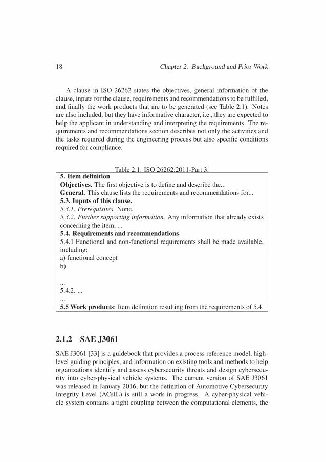
18 Chapter 2. Background and Prior Work
A clause in ISO 26262 states the objectives, general information of theclause, inputs for the clause, requirements and recommendations to be fulfilled,and finally the work products that are to be generated (see Table 2.1). Notesare also included, but they have informative character, i.e., they are expected tohelp the applicant in understanding and interpreting the requirements. The re-quirements and recommendations section describes not only the activities andthe tasks required during the engineering process but also specific conditionsrequired for compliance.
Table 2.1: ISO 26262:2011-Part 3.5. Item definitionObjectives. The first objective is to define and describe the...General. This clause lists the requirements and recommendations for...5.3. Inputs of this clause.5.3.1. Prerequisites. None.5.3.2. Further supporting information. Any information that already existsconcerning the item, ...5.4. Requirements and recommendations5.4.1 Functional and non-functional requirements shall be made available,including:a) functional conceptb)
...5.4.2. ......5.5 Work products: Item definition resulting from the requirements of 5.4.
2.1.2 SAE J3061
SAE J3061 [33] is a guidebook that provides a process reference model, high-level guiding principles, and information on existing tools and methods to helporganizations identify and assess cybersecurity threats and design cybersecu-rity into cyber-physical vehicle systems. The current version of SAE J3061was released in January 2016, but the definition of Automotive CybersecurityIntegrity Level (ACsIL) is still a work in progress. A cyber-physical vehi-cle system contains a tight coupling between the computational elements, the
4242
2.1 Compliance Assessment of Processes Plans 19
physical elements of the system, and the environment around the system. Cy-bersecurity is an attribute of cyber-physical systems that should be built into thedesign. Thus, an appropriate lifecycle, which addresses threats from conceptto decommissioning, is required. SAE J3061 proposes a lifecycle for handlingcybersecurity which is based on ISO 26262’s safety lifecycle. The lifecyclecan be integrated into a safety process tailored from ISO 26262 by includingthe cybersecurity activities for each product lifecycle phase, with the relatedactivities for each product lifecycle phase described in the safety process.
2.1.3 ECSS-E-ST-40C
The European Cooperation for Space Standardization (ECSS) developed a setof standards for use in all European space activities. The ECSS standard systemincludes three branches, i.e., Management (M), Engineering (E), and ProductAssurance (Q). Handbooks (HB) guide the application of the requirements.The software engineering handbook, ECSS-E-HB-40A [37], states that in aspace software project, a customer-supplier business agreement should be es-tablished. The customer shall produce the project requirements documentation,which could be produced by using the ECSS Applicability Requirements Ma-trix (EARM). The EARM should have the list of applicable ECSS requirementswith identifiers, applicability condition, i.e., applicable without change (A), ap-plicable with modification (M), not applicable (D), and new generated require-ment (N). The supplier responds with the ECSS Compliance Matrix (ECM),indicating the compliance for each requirement provided in the EARM. Partialcompliance needs to be detailed, such that the customer can assess the extent towhich the objective of the ECSS is covered. Non-compliance also needs to beinvestigated in terms of feasibility and acceptability in the scope of the project.When a space project starts, the supplier has to identify a suitable softwarelifecycle process. Thus, discussions about the technical specifications basedon the requirements baseline must start early in the lifecycle process [76].
In space software development, the requirements prescribed by the stan-dard ECSS-E-ST-40C [55], which determines mission (non-safety) require-ments on how the goals can be achieved, should be applied. Such require-ments could be tailored, i.e., adapted for the characteristics of the project. Forexample, ECSS-E-ST-40C-Annex R, provides a pretailoring based on safetycriticality categories, which rank from catastrophic to negligible (prescribed inECSS-Q-ST-40C [77]). Thus, mission requirements have an inherent relation-ship with safety issues. Further tailoring should be analyzed in the scope ofthe project and its consequences assessed and documented. If requirements are
4343

20 Chapter 2. Background and Prior Work
tailored out, the associated expected outputs are also tailored out.
2.1.4 ISO 14971 and Its Evolution
ISO 14971 [56] specifies the process required to identify hazards, estimate,evaluate, control, and monitor the risk of medical devices during its lifecy-cle. The content of ISO 14971 has been evolving over the years [78]. Whenpublished, ISO 14971:2007 [38] was internationally endorsed. In contrast,EN ISO 14971:2012 [39] is harmonized with EU directives (90/385/EEC [79],93/42/EEC [80], and 98/79/EC [81]) for the European market. As a conse-quence of the new release, recertification was mandatory. The latest version,ISO 14971:2019 [40], is internationally endorsed again. This situation is par-ticularly challenging for manufacturers of medical devices that need approvalfrom the different regulatory bodies within and outside the EU.
The risk analysis phase in ISO 14971:2007 and EN ISO 14971:2012 cor-responds to clause 4 and requires the planning of three tasks, i.e., 1) De-fine use/safety characteristics, 2) Estimate risks and 3) Identify hazards. Incontrast, the same phase corresponds to clause 5 in ISO 14971:2019 and thetask Define use/safety characteristics should be divided into two. For ISO14971:2007, the manufacturer shall discard the negligible risk. Annexes ofEN ISO 14971:2012 and ISO 14971:2019 provide a deviation, i.e., the manu-facturer shall consider all risks. In all versions, the manufacturer is the rolein charge, the risk management plan is the prerequisite of the clause, and thework products are the risk analysis document and the risk management file.The risk analysis document requires information regarding the medical devicedescription and identification, the identification of the person and organiza-tion, the scope, date, the intended use, and reasonably foreseeable misuse, thequalitative/quantitative safety characteristics of the medical device, known andforeseeable hazards associated with the medical device, fault conditions, rea-sonably foreseeable sequences of events, and the resulting hazardous situation.Additional information is prescribed by ISO 14971:2019, i.e., intended med-ical indication, patient population, part of the body/tissue, user profile, andoperating principle.
2.2 Process ModelsProcess models are the main artifacts used for supporting the management ofthe processes, as they provide an explicit representation of the process knowl-
4444
2.2 Process Models 21
edge [25]. A process is a sequence of units of work (phases, activities, tasks,and steps) that consume resources (employee energy and time, infrastructure)to transform inputs (data, material) into value-added outputs (products, ser-vices, or information) [82]. For this reason, an appropriate representation of aprocess serves several purposes [27]. For example, a process model can pro-vide support for analyzing and improving complex organizational processes.Moreover, as presented in Section 2.1, the model of a process plan can be oftenused as a mechanism to convince third parties (regulatory bodies, customers)about certain qualities of a product. A process model should [83]:
1. be described with rigorous notations;
2. be detailed enough;
3. be semantically broad; and
4. be clear and understandable to facilitate communication.
For example, a process description that does not indicate roles in charge oftasks is not likely to be of much value in supporting reasoning about how toimprove team coordination. Process modeling languages (PMLs) are availableto give process engineers the means to create process models and managementtools to control them [84]. PMLs have been created from different perspec-tives, such as programming-based languages, Petri net-based languages, andrule-based languages [85]. In the remaining parts of this section, we presentthe process engineers, an actor in charge of the creation of processes (see Sec-tion 2.2.1). We also recall essential features of SPEM 2.0 (see Section 2.2.2),and EPF-C (see Section 2.2.3)
2.2.1 The Process EngineerThe process engineer is the role responsible for eliciting process knowledge,capturing this knowledge in a model, analyzing its execution, performing anddisseminating process changes, and implementing systems to provide auto-mated support to the process users [86]. Process engineers may adopt two dif-ferent attitudes [87]: descriptive or prescriptive. A descriptive attitude requiresthe study of existing processes to characterize how they have been performed.A prescriptive attitude is instead related to the definition of a process to seehow it should be developed. Commonly, a process engineer should adopt bothapproaches to deal with existing process representations and analyze processbehavior, guide process users, enforce the rules (such as the ones prescribed bystandards), or automate process steps [86].
4545
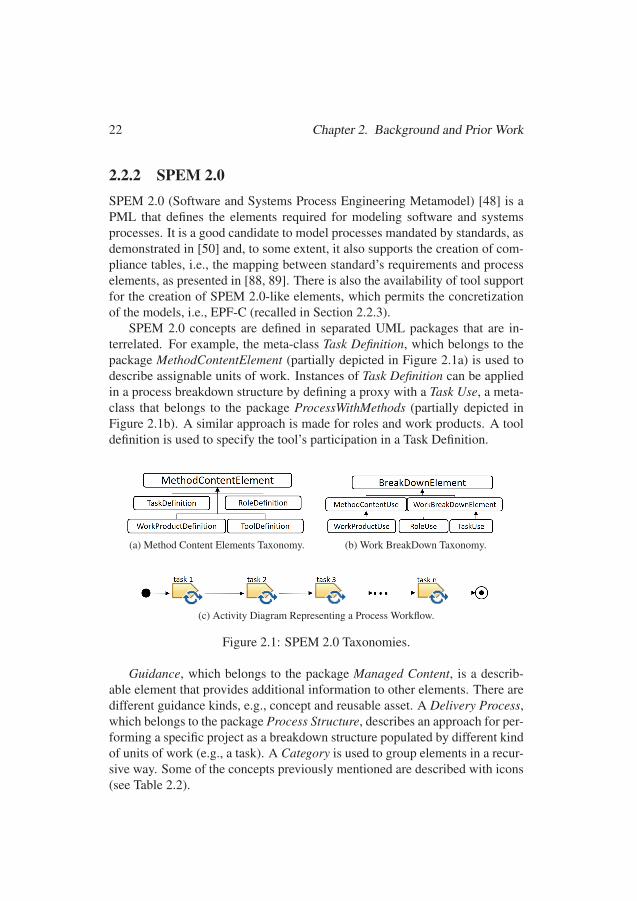
22 Chapter 2. Background and Prior Work
2.2.2 SPEM 2.0SPEM 2.0 (Software and Systems Process Engineering Metamodel) [48] is aPML that defines the elements required for modeling software and systemsprocesses. It is a good candidate to model processes mandated by standards, asdemonstrated in [50] and, to some extent, it also supports the creation of com-pliance tables, i.e., the mapping between standard’s requirements and processelements, as presented in [88, 89]. There is also the availability of tool supportfor the creation of SPEM 2.0-like elements, which permits the concretizationof the models, i.e., EPF-C (recalled in Section 2.2.3).
SPEM 2.0 concepts are defined in separated UML packages that are in-terrelated. For example, the meta-class Task Definition, which belongs to thepackage MethodContentElement (partially depicted in Figure 2.1a) is used todescribe assignable units of work. Instances of Task Definition can be appliedin a process breakdown structure by defining a proxy with a Task Use, a meta-class that belongs to the package ProcessWithMethods (partially depicted inFigure 2.1b). A similar approach is made for roles and work products. A tooldefinition is used to specify the tool’s participation in a Task Definition.
(a) Method Content Elements Taxonomy. (b) Work BreakDown Taxonomy.
(c) Activity Diagram Representing a Process Workflow.
Figure 2.1: SPEM 2.0 Taxonomies.
Guidance, which belongs to the package Managed Content, is a describ-able element that provides additional information to other elements. There aredifferent guidance kinds, e.g., concept and reusable asset. A Delivery Process,which belongs to the package Process Structure, describes an approach for per-forming a specific project as a breakdown structure populated by different kindof units of work (e.g., a task). A Category is used to group elements in a recur-sive way. Some of the concepts previously mentioned are described with icons(see Table 2.2).
4646
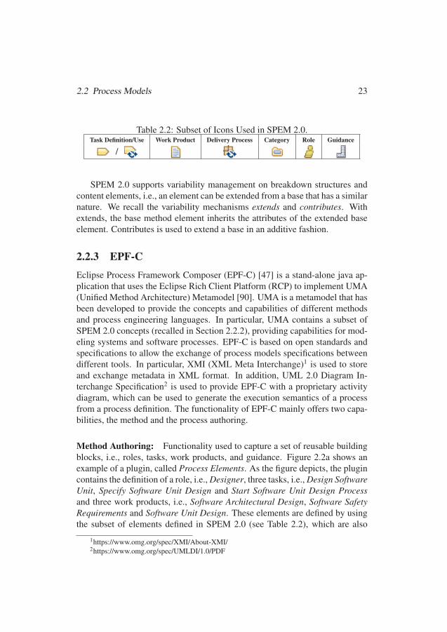
2.2 Process Models 23
Table 2.2: Subset of Icons Used in SPEM 2.0.Task Definition/Use Work Product Delivery Process Category Role Guidance
/
SPEM 2.0 supports variability management on breakdown structures andcontent elements, i.e., an element can be extended from a base that has a similarnature. We recall the variability mechanisms extends and contributes. Withextends, the base method element inherits the attributes of the extended baseelement. Contributes is used to extend a base in an additive fashion.
2.2.3 EPF-CEclipse Process Framework Composer (EPF-C) [47] is a stand-alone java ap-plication that uses the Eclipse Rich Client Platform (RCP) to implement UMA(Unified Method Architecture) Metamodel [90]. UMA is a metamodel that hasbeen developed to provide the concepts and capabilities of different methodsand process engineering languages. In particular, UMA contains a subset ofSPEM 2.0 concepts (recalled in Section 2.2.2), providing capabilities for mod-eling systems and software processes. EPF-C is based on open standards andspecifications to allow the exchange of process models specifications betweendifferent tools. In particular, XMI (XML Meta Interchange)1 is used to storeand exchange metadata in XML format. In addition, UML 2.0 Diagram In-terchange Specification2 is used to provide EPF-C with a proprietary activitydiagram, which can be used to generate the execution semantics of a processfrom a process definition. The functionality of EPF-C mainly offers two capa-bilities, the method and the process authoring.
Method Authoring: Functionality used to capture a set of reusable buildingblocks, i.e., roles, tasks, work products, and guidance. Figure 2.2a shows anexample of a plugin, called Process Elements. As the figure depicts, the plugincontains the definition of a role, i.e., Designer, three tasks, i.e., Design SoftwareUnit, Specify Software Unit Design and Start Software Unit Design Processand three work products, i.e., Software Architectural Design, Software SafetyRequirements and Software Unit Design. These elements are defined by usingthe subset of elements defined in SPEM 2.0 (see Table 2.2), which are also
1https://www.omg.org/spec/XMI/About-XMI/2https://www.omg.org/spec/UMLDI/1.0/PDF
4747

24 Chapter 2. Background and Prior Work
described by UMA metamodel. Conceptually, a task can be represented as asynergy between different process elements (see Figure 2.2b). Therefore, atask may have an used tool, mandatory input/output, a role that performs thetask, and it is guided by guidance elements.
(a) EPF-C Plugin Structure. (b) Elements relationships.
Figure 2.2: EPF-C Method Authoring.
Process Authoring: Functionality used to organize reusable process buildingblocks into processes by defining Work Breakdown Structures. As depictedin Figure 2.3a, a work breakdown structure describes the order of the unitsof work. With this functionality, we can also create process workflows. Theworkflow is represented as an Activity Diagram as depicted in Figure 2.3b.
(a) Work Breakdown Structure. (b) Activity Diagram.
Figure 2.3: EPF-C Process Authoring.
EPF-C implements the method plugin package, which defines the capa-bilities of modularization and extensibility. With these capabilities, processesand process elements defined in previous projects can be reused. EPF-C wasrecently ported from Eclipse Galileo 3.5.2 to Eclipse Neon 4.6.3 [91]).
4848
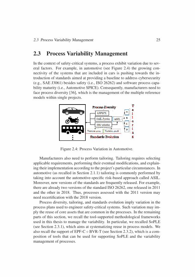
2.3 Process Variability Management 25
2.3 Process Variability ManagementIn the context of safety-critical systems, a process exhibit variation due to sev-eral factors. For example, in automotive (see Figure 2.4) the growing con-nectivity of the systems that are included in cars is pushing towards the in-troduction of standards aimed at providing a baseline to address cybersecurity(e.g., SAE J3061) besides safety (i.e., ISO 26262) and software process capa-bility maturity (i.e., Automotive SPICE). Consequently, manufacturers need toface process diversity [36], which is the management of the multiple referencemodels within single projects.
Figure 2.4: Process Variation in Automotive.
Manufacturers also need to perform tailoring. Tailoring requires selectingapplicable requirements, performing their eventual modifications, and explain-ing their implementation according to the project’s particular circumstances. Inautomotive (as recalled in Section 2.1.1) tailoring is commonly performed bytaking into account the automotive-specific risk-based approach called ASIL.Moreover, new versions of the standards are frequently released. For example,there are already two versions of the standard ISO 26262, one released in 2011and the other in 2018. Thus, processes assessed with the 2011 version mayneed recertification with the 2018 version.
Process diversity, tailoring, and standards evolution imply variation in theprocess plans used to engineer safety-critical systems. Such variation may im-ply the reuse of core assets that are common in the processes. In the remainingparts of this section, we recall the tool-supported methodological frameworksused in this thesis to manage the variability. In particular, we recalled SoPLE(see Section 2.3.1), which aims at systematizing reuse in process models. Wealso recall the support of EPF-C ◦ BVR-T (see Section 2.3.2), which is a com-position of tools that can be used for supporting SoPLE and the variabilitymanagement of processes.
4949
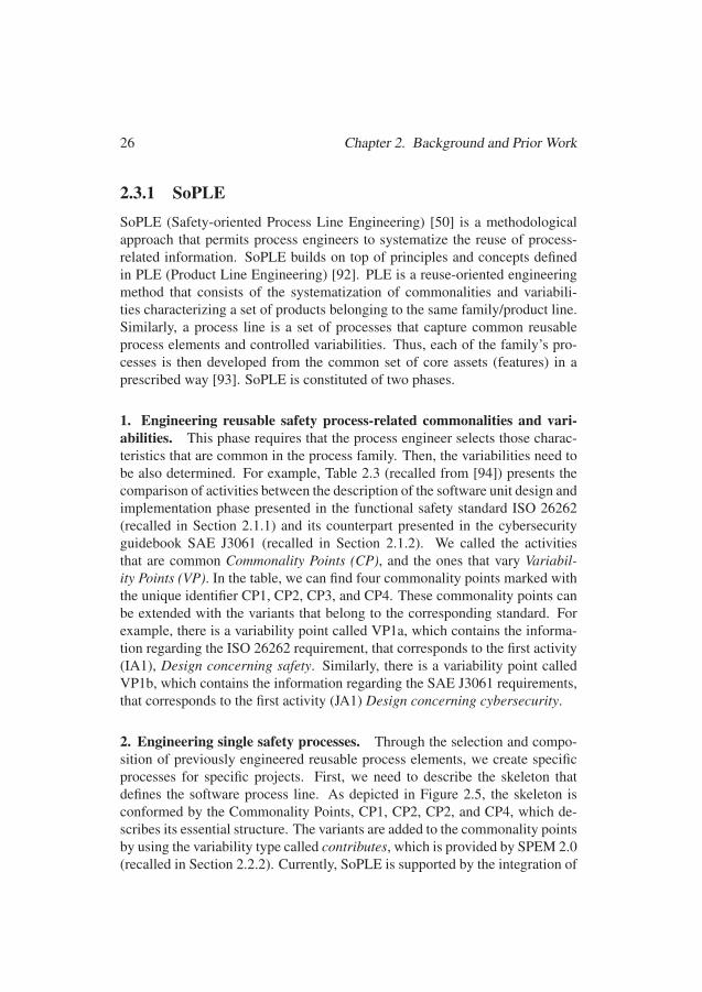
26 Chapter 2. Background and Prior Work
2.3.1 SoPLESoPLE (Safety-oriented Process Line Engineering) [50] is a methodologicalapproach that permits process engineers to systematize the reuse of process-related information. SoPLE builds on top of principles and concepts definedin PLE (Product Line Engineering) [92]. PLE is a reuse-oriented engineeringmethod that consists of the systematization of commonalities and variabili-ties characterizing a set of products belonging to the same family/product line.Similarly, a process line is a set of processes that capture common reusableprocess elements and controlled variabilities. Thus, each of the family’s pro-cesses is then developed from the common set of core assets (features) in aprescribed way [93]. SoPLE is constituted of two phases.
1. Engineering reusable safety process-related commonalities and vari-abilities. This phase requires that the process engineer selects those charac-teristics that are common in the process family. Then, the variabilities need tobe also determined. For example, Table 2.3 (recalled from [94]) presents thecomparison of activities between the description of the software unit design andimplementation phase presented in the functional safety standard ISO 26262(recalled in Section 2.1.1) and its counterpart presented in the cybersecurityguidebook SAE J3061 (recalled in Section 2.1.2). We called the activitiesthat are common Commonality Points (CP), and the ones that vary Variabil-ity Points (VP). In the table, we can find four commonality points marked withthe unique identifier CP1, CP2, CP3, and CP4. These commonality points canbe extended with the variants that belong to the corresponding standard. Forexample, there is a variability point called VP1a, which contains the informa-tion regarding the ISO 26262 requirement, that corresponds to the first activity(IA1), Design concerning safety. Similarly, there is a variability point calledVP1b, which contains the information regarding the SAE J3061 requirements,that corresponds to the first activity (JA1) Design concerning cybersecurity.
2. Engineering single safety processes. Through the selection and compo-sition of previously engineered reusable process elements, we create specificprocesses for specific projects. First, we need to describe the skeleton thatdefines the software process line. As depicted in Figure 2.5, the skeleton isconformed by the Commonality Points, CP1, CP2, CP2, and CP4, which de-scribes its essential structure. The variants are added to the commonality pointsby using the variability type called contributes, which is provided by SPEM 2.0(recalled in Section 2.2.2). Currently, SoPLE is supported by the integration of
5050
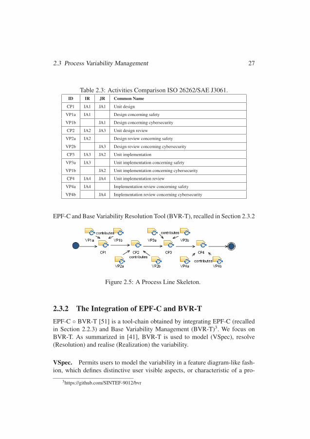
2.3 Process Variability Management 27
Table 2.3: Activities Comparison ISO 26262/SAE J3061.ID IR JR Common Name
CP1 IA1 JA1 Unit design
VP1a IA1 Design concerning safety
VP1b JA1 Design concerning cybersecurity
CP2 IA2 JA3 Unit design review
VP2a IA2 Design review concerning safety
VP2b JA3 Design review concerning cybersecurity
CP3 IA3 JA2 Unit implementation
VP3a IA3 Unit implementation concerning safety
VP1b JA2 Unit implementation concerning cybersecurity
CP4 IA4 JA4 Unit implementation review
VP4a IA4 Implementation review concerning safety
VP4b JA4 Implementation review concerning cybersecurity
EPF-C and Base Variability Resolution Tool (BVR-T), recalled in Section 2.3.2
Figure 2.5: A Process Line Skeleton.
2.3.2 The Integration of EPF-C and BVR-TEPF-C ◦ BVR-T [51] is a tool-chain obtained by integrating EPF-C (recalledin Section 2.2.3) and Base Variability Management (BVR-T)3. We focus onBVR-T. As summarized in [41], BVR-T is used to model (VSpec), resolve(Resolution) and realise (Realization) the variability.
VSpec. Permits users to model the variability in a feature diagram-like fash-ion, which defines distinctive user visible aspects, or characteristic of a pro-
3https://github.com/SINTEF-9012/bvr
5151
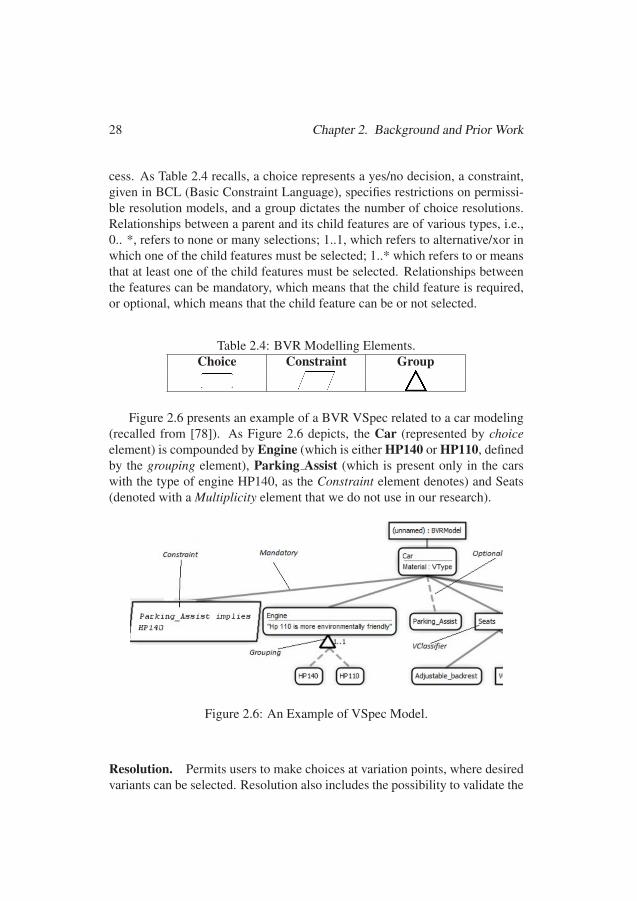
28 Chapter 2. Background and Prior Work
cess. As Table 2.4 recalls, a choice represents a yes/no decision, a constraint,given in BCL (Basic Constraint Language), specifies restrictions on permissi-ble resolution models, and a group dictates the number of choice resolutions.Relationships between a parent and its child features are of various types, i.e.,0.. *, refers to none or many selections; 1..1, which refers to alternative/xor inwhich one of the child features must be selected; 1..* which refers to or meansthat at least one of the child features must be selected. Relationships betweenthe features can be mandatory, which means that the child feature is required,or optional, which means that the child feature can be or not selected.
Table 2.4: BVR Modelling Elements.Choice Constraint Group
Figure 2.6 presents an example of a BVR VSpec related to a car modeling(recalled from [78]). As Figure 2.6 depicts, the Car (represented by choiceelement) is compounded by Engine (which is either HP140 or HP110, definedby the grouping element), Parking Assist (which is present only in the carswith the type of engine HP140, as the Constraint element denotes) and Seats(denoted with a Multiplicity element that we do not use in our research).
Figure 2.6: An Example of VSpec Model.
Resolution. Permits users to make choices at variation points, where desiredvariants can be selected. Resolution also includes the possibility to validate the
5252

2.4 Process-based Compliance by Design 29
choices. Erroneous choices violating the cross-variation points requirementscan be detected. Figure 2.7 illustrates the same example provided in Figure2.6, but generated from the Resolution editor. Because of the constraint thatwas put in the VSpec model (as Figure 2.6 illustrates), the choice of HP110 isset to ’false’, while the Parking Assist choice is ’true’.
Figure 2.7: An Example of Resolution Model.
Realization. Permits users to bind conceptual resolutions with the concreteelements in the base model. In particular, it requires that users establish therelationship between placements and replacements within the fragment substi-tutions and the triggering of these substitution in the within the VSpec features.
2.4 Process-based Compliance by Design
Compliance assessment of process plans can be understood as the consistencybetween a specified process and the reference model embedded in a prescrip-tive standard [31]. There are two main approaches towards achieving processcompliance [95]. The first one is called Compliance by Detection (CbDt).CbDt is an approach that entails a conformity check during or after the runtimestage (in the execution environment). In CbDt, the detection of non-compliantsituations is problematic since it complicates the reconstruction of a process ina compliant form after the process has been executed. The second one is calledCompliance by Design (CbD). CbD means that the set of applicable require-ments are considered in the design stage of the process. In CbD, the conformitycheck takes place in advance when the process is planned. This approach hasseveral advantages, as presented in [96].
5353
30 Chapter 2. Background and Prior Work
1. The approach is flexible as the generation can be repeated when rules areadded, removed, or changed.
2. Compliance is not only detected but actually enforced. Thus, CbD is con-sidered a preventive approach.
In CbD, the requirements prescribed in a normative system are propagatedinto process plans [45]. For such propagation, the normative requirements haveto be represented in a machine-readable form. In the remaining parts of thissection, we present theoretical assumptions regarding normative representation(see Section 2.4.1). Then, we present Formal Contract Logic (FCL) (see Sec-tion 2.4.2), a language explicitly created for the representation or norms in legaland business compliance. Finally, we present Regorous (see Section 2.4.3), acompliance checker able to do reasoning with FCL rules.
2.4.1 Normative RepresentationNormative documents contain principles of behavior used to regulate targetsubjects by defining what is legal and what is not [97]. Such documentsarise from different sources, e.g., regulations, laws, standards, branch-specificguidelines, internal code of conduct, social and moral rules [98]. In particular,normative documents contain the conditions under which they are applicable(i.e., the meaning of the terms or concepts where the norms are valid), andthe normative provisions they cause when applied [99]. Normative provisionscorrespond to the legally binding notions that are anchored to the structure oflegislative text, laws, and regulations [100].
Normative documents are usually represented in natural language, whichcan freely describe a wide range of concepts of the real, abstract, and imagi-nary worlds [101]. Natural language is very expressive, but it has problems ofambiguity, subjectivity, inconsistency, and inaccuracy [102]. For this reason,formal models, which are a set of domain theorems that are amenable to for-mal proving through reasoning, are of growing interest for compliance check-ing [103]. Moreover, using formal methods provides rigorous methodologiesthat facilitate compliance tasks [94]. However, the analysis of compliance withnormative frameworks is as good as the models used for such analysis [104].
In particular, the normative provisions of importance for process compli-ance are those notions regarding the obligations, the permissions, and the pro-hibitions [105] (see Figure 2.8). Obligations and prohibitions are constraintsthat limit the behavior of processes. The difference between obligations andprohibitions and other types of normative provisions is that they can finish in
5454
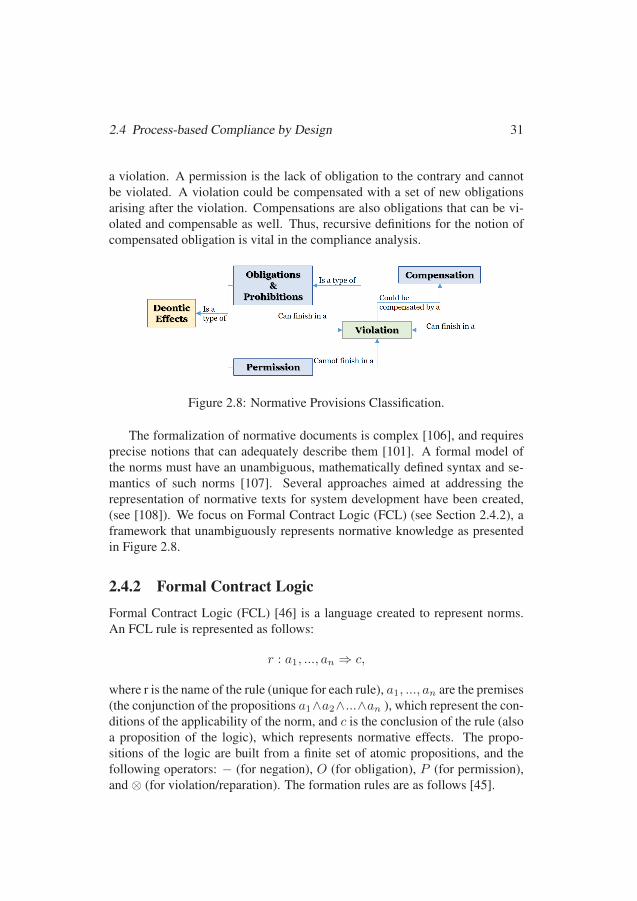
2.4 Process-based Compliance by Design 31
a violation. A permission is the lack of obligation to the contrary and cannotbe violated. A violation could be compensated with a set of new obligationsarising after the violation. Compensations are also obligations that can be vi-olated and compensable as well. Thus, recursive definitions for the notion ofcompensated obligation is vital in the compliance analysis.
Figure 2.8: Normative Provisions Classification.
The formalization of normative documents is complex [106], and requiresprecise notions that can adequately describe them [101]. A formal model ofthe norms must have an unambiguous, mathematically defined syntax and se-mantics of such norms [107]. Several approaches aimed at addressing therepresentation of normative texts for system development have been created,(see [108]). We focus on Formal Contract Logic (FCL) (see Section 2.4.2), aframework that unambiguously represents normative knowledge as presentedin Figure 2.8.
2.4.2 Formal Contract LogicFormal Contract Logic (FCL) [46] is a language created to represent norms.An FCL rule is represented as follows:
r : a1, ..., an ⇒ c,
where r is the name of the rule (unique for each rule), a1, ..., an are the premises(the conjunction of the propositions a1∧a2∧...∧an ), which represent the con-ditions of the applicability of the norm, and c is the conclusion of the rule (alsoa proposition of the logic), which represents normative effects. The propo-sitions of the logic are built from a finite set of atomic propositions, and thefollowing operators: − (for negation), O (for obligation), P (for permission),and ⊗ (for violation/reparation). The formation rules are as follows [45].
5555
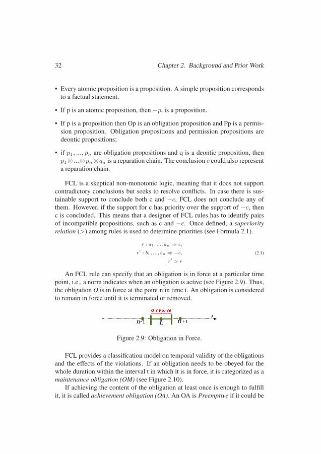
32 Chapter 2. Background and Prior Work
• Every atomic proposition is a proposition. A simple proposition correspondsto a factual statement.
• If p is an atomic proposition, then −p, is a proposition.
• If p is a proposition then Op is an obligation proposition and Pp is a permis-sion proposition. Obligation propositions and permission propositions aredeontic propositions;
• if p1, ..., pn are obligation propositions and q is a deontic proposition, thenp1⊗ ...⊗pn⊗qn is a reparation chain. The conclusion c could also representa reparation chain.
FCL is a skeptical non-monotonic logic, meaning that it does not supportcontradictory conclusions but seeks to resolve conflicts. In case there is sus-tainable support to conclude both c and −c, FCL does not conclude any ofthem. However, if the support for c has priority over the support of −c, thenc is concluded. This means that a designer of FCL rules has to identify pairsof incompatible propositions, such as c and −c. Once defined, a superiorityrelation (>) among rules is used to determine priorities (see Formula 2.1).
r : a1, ..., an ⇒ c,
r′: b1, ..., bn ⇒ −c,
r′> r
(2.1)
An FCL rule can specify that an obligation is in force at a particular timepoint, i.e., a norm indicates when an obligation is active (see Figure 2.9). Thus,the obligation O is in force at the point n in time t. An obligation is consideredto remain in force until it is terminated or removed.
Figure 2.9: Obligation in Force.
FCL provides a classification model on temporal validity of the obligationsand the effects of the violations. If an obligation needs to be obeyed for thewhole duration within the interval t in which it is in force, it is categorized as amaintenance obligation (OM) (see Figure 2.10).
If achieving the content of the obligation at least once is enough to fulfillit, it is called achievement obligation (OA). An OA is Preemptive if it could be
5656
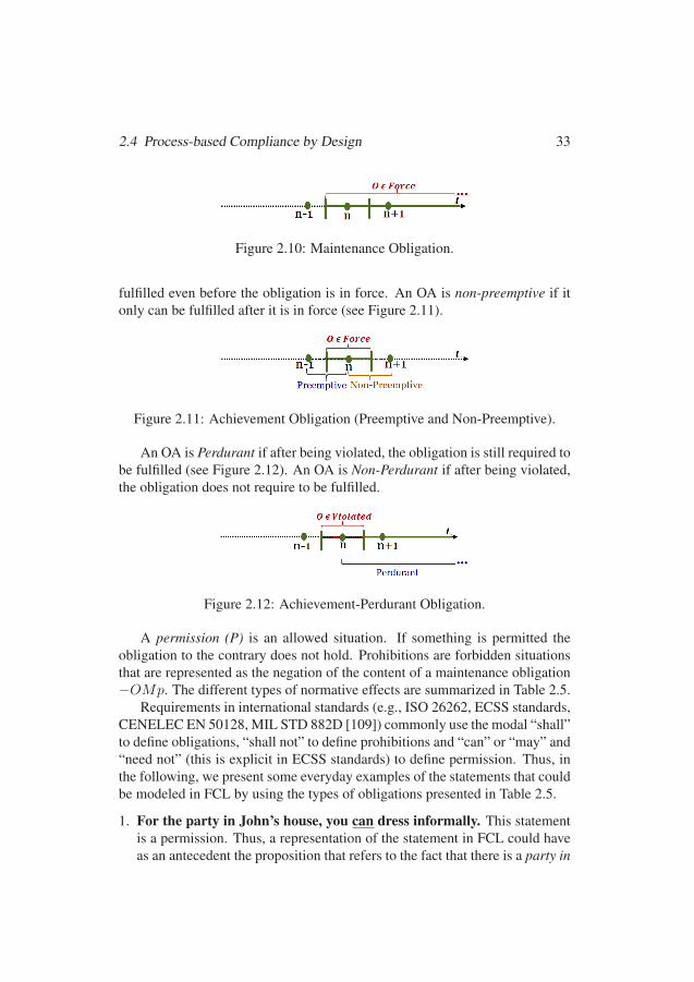
2.4 Process-based Compliance by Design 33
Figure 2.10: Maintenance Obligation.
fulfilled even before the obligation is in force. An OA is non-preemptive if itonly can be fulfilled after it is in force (see Figure 2.11).
Figure 2.11: Achievement Obligation (Preemptive and Non-Preemptive).
An OA is Perdurant if after being violated, the obligation is still required tobe fulfilled (see Figure 2.12). An OA is Non-Perdurant if after being violated,the obligation does not require to be fulfilled.
Figure 2.12: Achievement-Perdurant Obligation.
A permission (P) is an allowed situation. If something is permitted theobligation to the contrary does not hold. Prohibitions are forbidden situationsthat are represented as the negation of the content of a maintenance obligation−OMp. The different types of normative effects are summarized in Table 2.5.
Requirements in international standards (e.g., ISO 26262, ECSS standards,CENELEC EN 50128, MIL STD 882D [109]) commonly use the modal “shall”to define obligations, “shall not” to define prohibitions and “can” or “may” and“need not” (this is explicit in ECSS standards) to define permission. Thus, inthe following, we present some everyday examples of the statements that couldbe modeled in FCL by using the types of obligations presented in Table 2.5.
1. For the party in John’s house, you can dress informally. This statementis a permission. Thus, a representation of the statement in FCL could haveas an antecedent the proposition that refers to the fact that there is a party in
5757

34 Chapter 2. Background and Prior Work
Table 2.5: FCL Rule Notations.Notation Description[P]P A proposition P is permitted
[OM]P There is a maintenance obligation for the proposition P
[OM]-P There is a prohibition for proposition P
[OAPP]P There is an achievement, preemptive, and perdurant obligation for the proposition P
[OANPP]P There is an achievement, non-preemptive and perdurant obligation for the proposition P
[OAPNP]P There is an achievement, preemptive and non-perdurant obligation for the proposition P
[OANPNP]P There is an achievement, non-preemptive and non-perdurant obligation for proposition P
John’s house, which conclusion is that there is a permit for dressing infor-mally (see Formula 2.2).
r : PartyInJohn′sHouse⇒ [P ]dressInformally (2.2)
2. You shall not walk the dog in the avenue. This statement is a prohibition.In FCL a prohibition is represented as the negation of the content of an OM.Thus, a representation of the statement in FCL could have as an antecedentthe proposition that refers to the action walk the dog, whereas the conclusionis negation of the content of the obligation walk the dog in the avenue (seeFormula 2.3).
r : walkTheDog ⇒ [OM ]− walkTheDogInAvenue (2.3)
3. You shall pay the loan fee every month. This statement is an OA becausedoing it once in the month is enough. It is also a preemptive because thefee could even be paid before the deadline. It is also perdurant becausethe no payment on time does not mean that should be not paid. Thus, arepresentation of the statement in FCL have as an antecedent the fact thatthe month starts, which conclusion is the OAPP to pay the loan fee(seeFormula 2.4).
r : theMonthStarts⇒ [OAPP ]payLoanFee (2.4)
4. The package shall be registered once it arrives. This statement is an OAsince the package shall be registered only once. The OA is non-preemptivesince you cannot register it before it arrives. In addition, if the packageis not registered as soon as it arrives, there is a violating, but it does not
5858
2.4 Process-based Compliance by Design 35
mean that the packages should not be registered anyway. Thus, the OA isalso perdurant. A representation of the statement in FCL is presented inFormula 2.5.
r : PackageArrives⇒ [OANPP ]registerPackage (2.5)
5. You shall buy the machine with discount. Discounts are only today. Inthis case, buying the machine only once is enough. However, you cannotbuy before today, so, it is a OA that is non-preemptive. Moreover, if youdo not buy today, you cannot buy tomorrow with discount. Thus the OA isalso non-perdurant. A representation of the statement in FCL is presentedin Formula 2.6.
r : BuyMachine⇒ [OANPNP ]buyingWtihDiscount (2.6)
6. You shall buy the machine with discount. The discounts finish nextweek. In this case, buying the machine only once is enough to fulfil theobligation. Moreover, you can buy the machine before the discount timefinish, so, it is a OA that is preemptive. If you do not buy the machinebefore the discounts finish, you cannot buy it with discount. Thus the OA isalso non-perdurant. A representation of the statement in FCL is presentedin Formula 2.7.
r : BuyMachine⇒ [OAPNP ]buyingWtihDiscount (2.7)
2.4.3 RegorousRegorous [49] is a checker that permits the automatic analysis of complianceof a process against a set of regulations formalized in FCL (recalled in Sec-tion 2.4.2). For this, the process should be enriched with semantic annotations.Unlike classic text annotation (used by humans to read associated informa-tion), machines can use semantic annotations to refer to and compute informa-tion. Annotations on process elements are literals that record data, resources,and other information representing compliance effects. The annotated processis taken by Regorous and converted in a logical state representation that iscompared with the set of FCL rules containing the standards information (seeFigure 2.13). The procedure executed by Regorous is the following:
5959
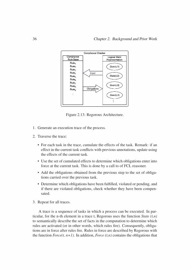
36 Chapter 2. Background and Prior Work
Figure 2.13: Regorous Architecture.
1. Generate an execution trace of the process.
2. Traverse the trace:
• For each task in the trace, cumulate the effects of the task. Remark: if aneffect in the current task conflicts with previous annotations, update usingthe effects of the current task.
• Use the set of cumulated effects to determine which obligations enter intoforce at the current task. This is done by a call to of FCL reasoner.
• Add the obligations obtained from the previous step to the set of obliga-tions carried over the previous task.
• Determine which obligations have been fulfilled, violated or pending, andif there are violated obligations, check whether they have been compen-sated.
3. Repeat for all traces.
A trace is a sequence of tasks in which a process can be executed. In par-ticular, for the n-th element in a trace t, Regorous uses the function State (t,n)to semantically describe the set of facts in the computation to determine whichrules are activated (or in other words, which rules fire). Consequently, obliga-tions are in force after rules fire. Rules in force are described by Regorous withthe function Force(t, n+1). In addition, Force (t,n) contains the obligations that
6060
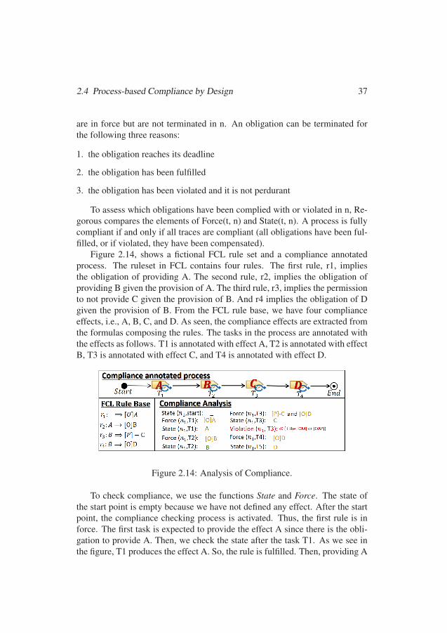
2.4 Process-based Compliance by Design 37
are in force but are not terminated in n. An obligation can be terminated forthe following three reasons:
1. the obligation reaches its deadline
2. the obligation has been fulfilled
3. the obligation has been violated and it is not perdurant
To assess which obligations have been complied with or violated in n, Re-gorous compares the elements of Force(t, n) and State(t, n). A process is fullycompliant if and only if all traces are compliant (all obligations have been ful-filled, or if violated, they have been compensated).
Figure 2.14, shows a fictional FCL rule set and a compliance annotatedprocess. The ruleset in FCL contains four rules. The first rule, r1, impliesthe obligation of providing A. The second rule, r2, implies the obligation ofproviding B given the provision of A. The third rule, r3, implies the permissionto not provide C given the provision of B. And r4 implies the obligation of Dgiven the provision of B. From the FCL rule base, we have four complianceeffects, i.e., A, B, C, and D. As seen, the compliance effects are extracted fromthe formulas composing the rules. The tasks in the process are annotated withthe effects as follows. T1 is annotated with effect A, T2 is annotated with effectB, T3 is annotated with effect C, and T4 is annotated with effect D.
Figure 2.14: Analysis of Compliance.
To check compliance, we use the functions State and Force. The state ofthe start point is empty because we have not defined any effect. After the startpoint, the compliance checking process is activated. Thus, the first rule is inforce. The first task is expected to provide the effect A since there is the obli-gation to provide A. Then, we check the state after the task T1. As we see inthe figure, T1 produces the effect A. So, the rule is fulfilled. Then, providing A
6161
38 Chapter 2. Background and Prior Work
forces the provision of B in T2. In the figure, we can see that T2 provides ef-fect B. So, the second rule is also fulfilled. After B is provided, it implies twonormative effects. The first one is the permission to not providing C in T3. Sec-ond, it implies the obligation of providing D in T3. When checking T3, we cansee that it provides the effect C. However, having C as the produced effect doesnot imply a violation of rule r3 because the force function has a permit, not anobligation. However, in T3, we should have D, and the tasks T3 is not provid-ing E. If the obligation of providing D is a OM or OA-preemptive, we have aviolation. A violation means that the process is not compliant. If the obliga-tion is OA-non-preemptive, it can be fulfilled in T4. In this case, there is noviolation, and the process is compliant.
2.5 Design Hints and PatternsDesign hints and patterns are two kinds of resources used in computationalthinking [110]. Hints are rules of thumb used to solve a problem, while pat-terns indicate common situations that are likely to be encounter. Our researchuses hints and patterns to facilitate creating the specifications required for au-tomated compliance checking of process plans. In the remaining parts of thissection, we present a hint widely used in computer science, namely the divideand conquer strategy (see Section 2.5.1). We also recall the notion of propertyspecification patterns (see Section 2.5.2).
2.5.1 Separation of Concerns: Divide-and-conquer StrategyThe Romans had a strategy called divide-and-conquer, which considers thatone power breaks another power into more manageable pieces to easier takecontrol. In software engineering, this strategy is adopted as a principle to man-age complexity [111]. Particularly, divide-and-conquer is seen in the principleof separation of concerns [112], which refers to the ability to separate and orga-nize only those parts (or properties) of a system that are relevant to a particularconcept or to a particular goal. A concern may be defined as a functional notionor more broadly as any piece of interest or focus.
2.5.2 Property Specification PatternsThe property specification patterns, formulated by Dwyer et al.’s [113], are“generalized descriptions of commonly occurring requirements on the permis-
6262

2.6 Empirical Research Aspects 39
sible state sequence of a finite state model of a system.” A selected set ofDwyer et al.’s patterns4 is presented in Table 2.6. Each pattern has a scope,which is the extent of the program execution over which the pattern must hold.The types of scope that we consider in this thesis are: global, which repre-sent the entire program execution, before, which includes the execution up to agiven state, and after which includes the execution after a given state.
Table 2.6: Dwyer’s Specification Patterns.Name Description
Absence A given state P does not occur within a scope
Existence A given state P must occur within a scope
Universality A given state P must occur throughout a scope
Precedence A state P must always be preceded by a state Q within a scope
Response A state P must always be followed by a state Q within a scope
2.6 Empirical Research AspectsIn this section, we recall the aspects related to empirical research in computerscience that we use in this thesis. First, we present an overview of the designscience methodology for information systems and software engineering (seeSection 2.6.1). Then, we present the methods used in this thesis to validateour research outputs. In particular, we present the methodology for performingpersonal opinion surveys (see Section 2.6.2), systematic literature review (seeSection 2.6.3), the technology acceptance model (see Section 2.6.4), the qual-itative criteria to assess compliance approaches usefulness (see Section 2.6.5),and a metric called reuse measurement (See Section 2.6.6).
2.6.1 Design Science MethodologyThe design science methodology for information systems and software engi-neering [114] aims at designing and investigating treatments (an artifact im-proving something in a problem context) used in software and informationsystems. Research problems in design science contain design problems (whichcall for a change in the real world) interacting with knowledge challenges (re-quest understanding about the world as it is). Research problems also have a
4https://matthewbdwyer.github.io/psp/
6363
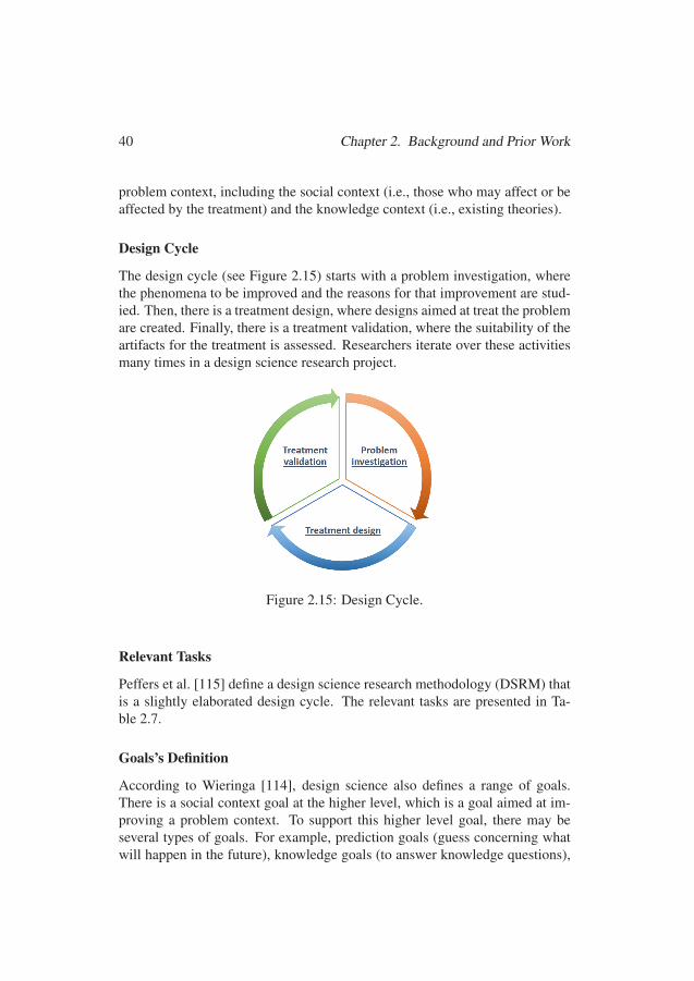
40 Chapter 2. Background and Prior Work
problem context, including the social context (i.e., those who may affect or beaffected by the treatment) and the knowledge context (i.e., existing theories).
Design Cycle
The design cycle (see Figure 2.15) starts with a problem investigation, wherethe phenomena to be improved and the reasons for that improvement are stud-ied. Then, there is a treatment design, where designs aimed at treat the problemare created. Finally, there is a treatment validation, where the suitability of theartifacts for the treatment is assessed. Researchers iterate over these activitiesmany times in a design science research project.
Figure 2.15: Design Cycle.
Relevant Tasks
Peffers et al. [115] define a design science research methodology (DSRM) thatis a slightly elaborated design cycle. The relevant tasks are presented in Ta-ble 2.7.
Goals’s Definition
According to Wieringa [114], design science also defines a range of goals.There is a social context goal at the higher level, which is a goal aimed at im-proving a problem context. To support this higher level goal, there may beseveral types of goals. For example, prediction goals (guess concerning whatwill happen in the future), knowledge goals (to answer knowledge questions),
6464
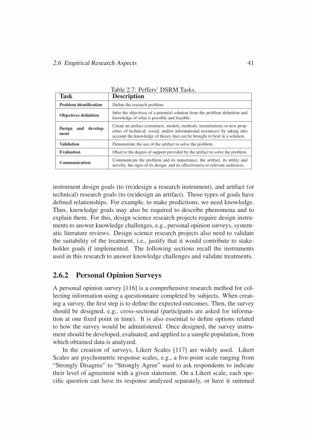
2.6 Empirical Research Aspects 41
Table 2.7: Peffers’ DSRM Tasks.Task DescriptionProblem identification Define the research problem.
Objectives definition Infer the objectives of a potential solution from the problem definition andknowledge of what is possible and feasible.
Design and develop-ment
Create an artifact (constructs, models, methods, instantiations or new prop-erties of technical, social, and/or informational resources) by taking intoaccount the knowledge of theory that can be brought to bear in a solution.
Validation Demonstrate the use of the artifact to solve the problem.
Evaluation Observe the degree of support provided by the artifact to solve the problem.
Communication Communicate the problem and its importance, the artifact, its utility andnovelty, the rigor of its design, and its effectiveness to relevant audiences.
instrument design goals (to (re)design a research instrument), and artifact (ortechnical) research goals (to (re)design an artifact). Those types of goals havedefined relationships. For example, to make predictions, we need knowledge.Thus, knowledge goals may also be required to describe phenomena and toexplain them. For this, design science research projects require design instru-ments to answer knowledge challenges, e.g., personal opinion surveys, system-atic literature reviews. Design science research projects also need to validatethe suitability of the treatment, i.e., justify that it would contribute to stake-holder goals if implemented. The following sections recall the instrumentsused in this research to answer knowledge challenges and validate treatments.
2.6.2 Personal Opinion SurveysA personal opinion survey [116] is a comprehensive research method for col-lecting information using a questionnaire completed by subjects. When creat-ing a survey, the first step is to define the expected outcomes. Then, the surveyshould be designed, e.g., cross-sectional (participants are asked for informa-tion at one fixed point in time). It is also essential to define options relatedto how the survey would be administered. Once designed, the survey instru-ment should be developed, evaluated, and applied to a sample population, fromwhich obtained data is analyzed.
In the creation of surveys, Likert Scales [117] are widely used. LikertScales are psychometric response scales, e.g., a five-point scale ranging from“Strongly Disagree” to “Strongly Agree” used to ask respondents to indicatetheir level of agreement with a given statement. On a Likert scale, each spe-cific question can have its response analyzed separately, or have it summed
6565
42 Chapter 2. Background and Prior Work
with other related items to create a score for a group of statements. Individualresponses are generally treated as ordinal data because although the responselevels do have a relative position, we cannot presume that participants perceivethe difference between adjacent levels to be equal.
2.6.3 Systematic Literature ReviewA Systematic Literature Review (SLR) [118] is a review methodology usedfor identifying, evaluating, and interpreting all available research relevant toa particular research question. The first activity in a SLR is planning the re-view. This activity includes the identification of the need for the SLR, thespecification of the research questions, and the design of the review protocol.In the second activity, conducting the review, the researchers apply the reviewprotocol and answer the questions. In the last activity, reporting the review,the researchers define the means to illustrate the findings. The guidelines, de-scribed by Wohlin [119], consider a technique called snowballing, which canbe used to reach more relevant primary studies. Snowballing can be backward(search of relevant studies by taking into account the reference list of an initialset of primary studies) or forward (identifying more relevant studies based onthose papers citing the paper being examined).
2.6.4 Technology Acceptance ModelThe Technology Acceptance Model (TAM) [120] provides general determi-nants of computer acceptance. TAM is capable of explaining user behavioracross a broad range of end-user computing technologies and user populations,while at the same time being theoretically justified. TAM focuses on three mainfacets of user acceptance. The first is the degree to which a person believes thatusing a particular method will be free of effort (Perceived Usability). The sec-ond is related to a person’s subjective probability that using a particular systemwould enhance his/her job (Perceived Usefulness). The third is the extent towhich a person intends to use a particular system (Intention to Use).
2.6.5 Qualitative Criteria to Assess Compliance ApproachesThe usefulness of compliance management approaches can be qualitatively as-sessed taking into account specific criteria in terms of effort and level of cov-erage [54].
1. Effort to model needed to establish a model for managing compliance.
6666

2.6 Empirical Research Aspects 43
2. Effort to comprehend processes and regulations models.
3. Effort to document compliance, i.e., verify whether processes model com-ply with a legislation model.
4. Effort to manage evolution needed to find potential instances of non-compliance in the models when regulatory documents are amended or whentheir policies change.
5. Level of coverage for the model, how much of the policies and processescan be modeled.
6. Level of coverage for compliance documentation, i.e., approach’s suc-cess in terms of documenting the compliance and ensuring compliance to thelegislation.
7. Level of coverage for the evolution management, i.e., approach’s successin handling the changes and assessing their overall impact.
The effort, according to to [121], is a variable that could be estimated dur-ing task performance in two ways: the actual effort (determined by task de-mands) and the perception of effort (relative to a subject’s capacity to recog-nize the effort). In theory, the actual effort can be used to determine the intentto complete a task a priori, independently of any conscious actor. In this thesis,we use actual effort to gain a deeper understanding of our methods.
2.6.6 Reuse Measurement
A metric for reuse measurement is proposed by [57] (see below).
% Reuse = (1− Number of new objects builtTotal number of objects used
) ∗ 100
The metric can be applied in hierarchical structures that permit the identifi-cation of the objects and the applications to which they were originally created.This metric is expressed in terms of percentage by considering the proportionof the number of new objects built (created from scratch) and the total num-ber of objects used (in the absence of reuse). Besides, it focuses on the totalbenefit attributable to reuse. Thus, objects that are reused multiple times areconsidered to represent multiple instances of reuse.
6767

6868
Chapter 3
Research Summary
In this chapter, we present a summary of the research addressed in this the-sis. In particular, we present the research process used (See Section 3.1), theproblem formulation (see Section 3.2) and the research goals (see Section 3.3).
3.1 Research ProcessThe research process used in this thesis is based on the methodology for designscience research for information systems and software engineering, describedin Section 2.6.1. We adapt the design cycle presented in Figure 2.15 by includ-ing the tasks presented in Table 2.7. As a result, we have a research processthat encompasses three stages. A. Research Initiation and C. Research Final-ization are carried out once at a global scale, while B. Research Developmentis a cyclic stage of research aimed at fulfilling the general research goal
A. Research initiation. In this stage, we perform the problem investigation(first activity in the research cycle in Figure 2.15) at a global scale. We includetwo tasks described in DSRM (see Table 2.7).
1. Problem identification. In this task, we define the overall problem. Forthis, we require the state-of-the-practice (design problems which call for achange in the real world), and state-of-the-art (design problems must in-teract with knowledge challenges). The output is the problem formulation,which includes the problem context and the research motivation.
45
6969
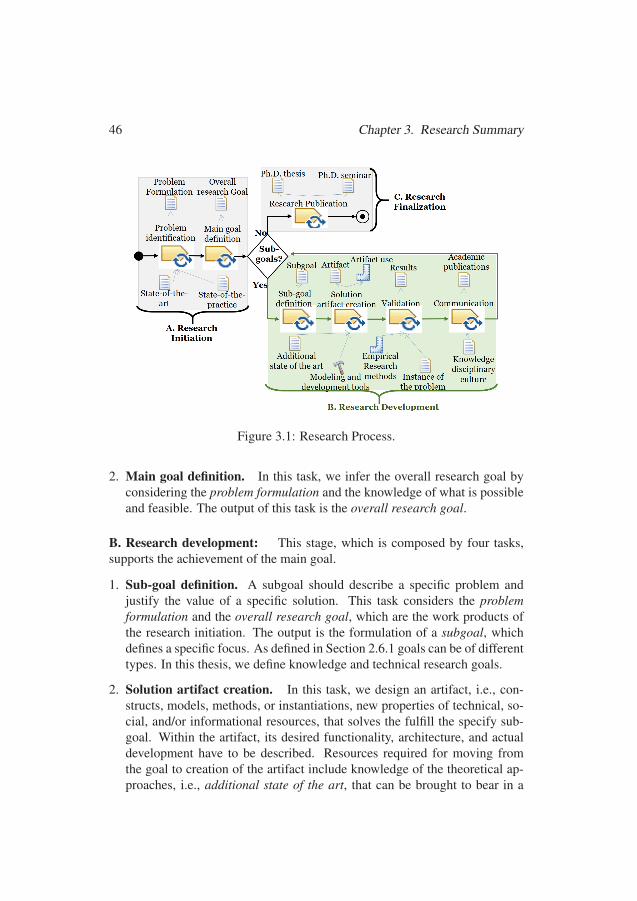
46 Chapter 3. Research Summary
Figure 3.1: Research Process.
2. Main goal definition. In this task, we infer the overall research goal byconsidering the problem formulation and the knowledge of what is possibleand feasible. The output of this task is the overall research goal.
B. Research development: This stage, which is composed by four tasks,supports the achievement of the main goal.
1. Sub-goal definition. A subgoal should describe a specific problem andjustify the value of a specific solution. This task considers the problemformulation and the overall research goal, which are the work products ofthe research initiation. The output is the formulation of a subgoal, whichdefines a specific focus. As defined in Section 2.6.1 goals can be of differenttypes. In this thesis, we define knowledge and technical research goals.
2. Solution artifact creation. In this task, we design an artifact, i.e., con-structs, models, methods, or instantiations, new properties of technical, so-cial, and/or informational resources, that solves the fulfill the specify sub-goal. Within the artifact, its desired functionality, architecture, and actualdevelopment have to be described. Resources required for moving fromthe goal to creation of the artifact include knowledge of the theoretical ap-proaches, i.e., additional state of the art, that can be brought to bear in a
7070
3.2 Problem Formulation 47
solution and the tools required for modeling and development. The outputof this task is the produced artifact and the guidance required for it use.
3. Validation. In this task, the solution artifact is used to solve a specific in-stance of the problem. We also observe the degree of support provided bythe artifact when solving such a problem instance. The validation could in-volve the use of examples or other appropriate actions. Resources requiredfor the validation include adequate knowledge of how to use the artifact,which is given by the artifact use guidance, and the actual artifact. Besides,the description of the specific instance of the problem and guidance relatedempirical research methods that would be used. In our research, we useddifferent research methods for validation. In particular, we use methodolo-gies for gathering data such as personal opinion survey (recalled in Sec-tion 2.6.2) and systematic literature reviews (recalled in Section 2.6.3). Forthe validation of the artifacts created, we used the technology acceptancemodel (recalled in Section 2.6.4), qualitative criteria to assess complianceapproaches (recalled in Section 2.6.5) and the reuse measurement metric(recalled in Section 2.6.6). The output of this task is the validation results.These three steps are repeated for every research goal.
4. Communication. In this task, the problem and its importance, artifact,utility, novelty, its design, and capability to solve the problem (validationresults) are communicated to the research community and practitioners. Theknowledge of the disciplinary culture is a basic input for this task.
C. Research finalization: A Ph.D. position is a research tenure that is con-strained by a time period. Results of this tenure should be visible at the end ofsuch a period. For this reason, we define the stage research finalization, whichis a communication activity as described in Table 2.7. In this stage, the activityresearch publication is performed. In this activity, we compile all the par-tial results obtained during the research development. The inputs of this stageare all the work products resulting from the research initiation and researchdevelopment. The outputs are Ph.D thesis and the Ph.D seminar.
3.2 Problem FormulationIn this section, we formulate the problem to be tackled in this thesis. In partic-ular, we define the problem context (see Section 3.2.1) and the research moti-vation (see Section 3.2.2).
7171
48 Chapter 3. Research Summary
3.2.1 Problem context
Manufacturers of safety-critical systems (see introduction of Chapter 2) haveto comply with industry standards to show that they act under acceptable crite-ria. Compliance requires that manufacturers adapt their practices and provideevidence regarding the object of conformity (e.g., products, processes). In thisthesis, we focus on the process used to engineer safety-critical systems as anobject of conformity. In particular, adjusting process plans in compliance withapplicable standards is a common, accepted, and mandatory procedure whenproducing safety-critical systems (see Section 2.1). However, selecting a strat-egy that fulfills business objectives in the process plan within the boundaries al-lowed by all the requirements included in the applicable normative documentsis challenging (e.g., many standards, with different purposes and frequentlychanging). Therefore, there is a need to provide mechanisms for supportingthe modeling of compliant processes at planning time. In the remaining partsof this section, we describe the object of study and the target stakeholder.
The Object of Study
Prescriptive standards, as recalled in Section 2.1, include requirements that de-mand the planning of tasks, the resources required and produced, and the use ofspecific techniques, which are framed with different properties. Such standardsalso set down the points at which different sorts of compliance artifacts shouldbe established. For this reason, compliance checking is a common practiceduring the creation of process plans. Thus, the object of study in this researchis the compliance checking of process plans against industry standards.
Target Stakeholder
One key consideration when conducting compliance assessment is that regula-tions are obligations on the licensee to fulfill in order to get authorizations. Assuch, there are two different sides: the industry side and the regulatory bodyside. Both sides involve different practitioners, i.e., process engineers, con-sultants, auditors, and evaluators. When process-related compliance is usedto support contractual obligations between companies acting as customer andsupplier, respectively, lawyers may also be involved. However, the main re-sponsible for the processes in a company is the process engineer (as recalledin Section 2.2.1). We focus on such a role since a process engineer is respon-sible for selecting, composing, and correctly documenting adequate process
7272

3.3 Research Goals 49
elements and workflows to achieve the required process goals according to theapplicable standards.
3.2.2 Research Motivation
Process-related compliance responds to a cycle of activities that start with se-lecting applicable standards to the demonstration of compliance with the se-lected standards. Such activities are very complex. In particular, compliancechecking is typically considered time-consuming since standards contain hun-dreds of requirements, which usually reference each other. Compliance check-ing is also considered error-prone since there is much variation in process plan-ning (see, for instance, Figure 2.4). Finally, compliance checking is a repeti-tive job since industries commonly manage multiple process plans. Given suchcomplexity, errors in process-related compliance checking reports may arise.Such errors may endanger the compliance process, leading to delays in theproduction of safety-critical systems and, thus, economical losses.
The provision of solutions for automatizing compliance checking are im-perative to permit organizations to have more control over their process plansand avoid compliance risk, by:
1. detecting compliance violations, and
2. enforcing compliance at planning time.
3.3 Research GoalsIn this section, we identify the main research goal (see Section 3.3.1) and thederived research subgoals (see Section 3.3.2).
3.3.1 Main Goal
As presented in Section 3.2.1, we aim at addressing process compliance atplanning time to help process engineers do their job. As presented in Sec-tion 3.2.2, we consider the provision of solutions that facilitate the automationof compliance checking of processes so that compliance violations are detectedand compliance is enforced at planning time. With this, a process engineercan demonstrate intentional compliance, i.e., the planning-time allocation ofresponsibilities, such that if every actor fulfills its duties, then compliance is
7373
50 Chapter 3. Research Summary
ensured. Based on the previous reasoning, we define a social context (main)goal that drives this thesis as follows:
Facilitate automated compliance checking of the process plansused to engineer safety-critical systems against the standardsmandated (or recommended) in the safety-critical context
3.3.2 Research Sub-GoalsIn order to address the main goal (presented in Section 3.3.1), we define fourconcrete sub-goals. As recalled in Section 2.6.1, different kinds of goals canbe defined in the design science methodology. In particular, we defined knowl-edge goals, which help us explain the phenomena under study and the impactof the proposed solution (subgoals 1 and 4). We also define technical goalssince we aim at proposing a technological solution (subgoals 2 and 3).
1. Elicit the requirements to be met to support the automated compliancechecking of the process plans used in the safety-critical context. This sub-goal focuses on establishing the requirements for a technical solution that al-leviate the compliance challenges that manufacturers of safety-critical systemshave in terms of prescriptive standards, specifically at planning time.
2. Identify mechanisms for supporting automated compliance checking ofthe process plans used in the safety-critical context. This subgoal focuseson discovering how existing tools and methodologies can be appropriatelycombined to provide the support required for automated compliance checkingof process plans.
3. Facilitate the creation of reusable specifications required for automatedcompliance checking of the process plans. This subgoal focuses on discov-ering adequate means to model the concepts included in the specifications, aswell as to include the necessary support for enabling systematic reuse.
4. Investigate the significance of a solution for automated compliancechecking of process plans in the safety-critical context. This subgoal fo-cuses on objectively analyze our solutions’ pros and cons and define elementsthat permit their future improvement and usage.
7474

Chapter 4
Thesis Contributions
In this chapter, we present the technical contributions presented this thesis. Thecontributions are matched with the subgoals in Table 4.1.
Table 4.1: Contributions and Research Subgoals.No. Contribution Goal addressed
1 Requirements for Automated ProcessCompliance Checking (see Section 4.1)
Elicit the requirements to be met to support the auto-mated compliance checking of the process plans usedin the safety-critical context
2 ACCEPT (see Section 4.2)Identify mechanisms for supporting automated com-pliance checking of the process plans used in thesafety-critical context
3Process Compliance Hints and Patterns(see Section 4.3) Facilitate the creation of reusable specifications
required for automated compliance checking of theprocess plans.Systematic reuse of compliance artifacts
(see Section 4.4)
4 Solutions validation (see Section 4.5)Investigate the significance of a solution for auto-mated compliance checking of process plans in thesafety-critical context.
4.1 Requirements for Automated Process Compli-ance Checking
In this section, we establish the requirements for a technical solution that allevi-ates the challenges that manufacturers of safety-critical systems have regarding
51
7575
52 Chapter 4. Thesis Contributions
prescriptive standards. In particular, in Section 4.1.1, we consider the compli-ance reasons of a manufacturer of safety-critical systems. In Section 4.1.2, wehighlight the process plan. In Section 4.1.3, we emphasize the challenges re-garding compliance checking of process plans. Finally, in Section 4.1.4, wepresent the requirements for a technical solution.
4.1.1 Compliance ReasonsWhen producing safety-critical systems, manufacturers seek to fulfill the com-pliance requirements provided by a set of applicable normative frameworks(e.g., standards, policies, regulations) to demonstrate that they act under pub-licly accepted criteria. For example, compliance with functional safety stan-dards represents that the risks associated with the safety-critical system opera-tion have been considered, analyzed, and mitigated to a sufficient level for theirconfident deployment into a specific context in the society.
For some industries, compliance is not a simple voluntary act. For ex-ample, software aspects of airborne systems and equipment need to complywith airworthiness requirements described in DO-178C. Conversely, in auto-motive, compliance certifications with a specific regulatory framework are notde rigueur. However, since its inception in 2011, ISO 26262 has been consid-ered the state-of-the-art automotive safety engineering. Thus, self-assessmentwith ISO 26262 is essential in the production and commercialization of cars.In any case, compliance with industry standards grants several benefits to man-ufacturers involved in the production of safety-critical systems. For example:
1. Compliance requirements provide manufacturers a reference point for theirproduction operations based on expertise and best practices. For instance,the functional safety standard ISO 26262 prescribes the specific actions tobe taken into consideration by a car manufacturer to achieve acceptablesafety levels in their fabricated or assembled vehicles.
2. Compliance requirements help to realize the ever more globalized safety-critical systems production more confidently. For example, in the Europeanspace context, the ECSS standards provide baseline requirements that spaceagencies use to formulate the project-specific needs and requirements thathave to be met by their worldwide distributed suppliers.
3. A compliance stamp is a mark that customers trust. For instance, the CEmarking 1, which is the declaration that a product meets European standards1https://ec.europa.eu/growth/single-market/ce-marking en
7676
4.1 Requirements for Automated Process Compliance Checking 53
for health, safety, and environmental protection, is commonly preferred byEuropean consumers.
4. A standard-compliant safety-critical system support manufacturer in legalactions if the product causes harm. For example, compliance with IEC 61508,which is the functional safety of electrical/electronic/programmable elec-tronic safety-related systems, is relevant evidence for a jury to consider in aproduct liability action in England.
4.1.2 The Process PlanIndustry standards demand documented evidence of responsibilities and agree-ments. Commonly, standards adopt a highly prescriptive approach where thedecision-making process is facilitated by integrating desired attributes, e.g.,safety, security, and quality, into the development lifecycle of the safety-criticalsystems. For this reason, manufacturers should plan the fulfillment of stan-dards requirements at the beginning of the engineering activities. By follow-ing such an approach, manufacturers can ensure that a rigorous process hasbeen designed to build the system. For example, safety standards demand asafety plan, which contains the planning of activities related to the assuranceof the system’s safety. Compliant engineering process plans are used to coordi-nate and track engineering progress, and in some contexts, e.g., avionics, theyshould get initial approval from regulatory bodies.
Rigorous compliant process plans should include the sequence of tasksmandated by standards (i.e., the process behavior) and the resources ascribedto such tasks, e.g., personnel, work products, tools, and methods, which arealso framed with essential properties (i.e., the process structure). Task, re-sources, and properties outside of the standards prescriptions are also possibleto plan, but they require a rationale in which compliance should be justified.Consequently, a process plan is a detailed proposal of action that demonstratesthe planning-time allocation of responsibilities. Given these characteristics,process-related compliance management could be supported by checking atdesign time that processes planned to engineer safety-critical systems fulfillthe properties set down by standards at given points.
4.1.3 Compliance Checking ChallengesThe process reference frameworks included in prescriptive standards focus onwhat needs to be done, who should be involved in the process, and the recom-mended techniques to be used to achieve desirable results. In some contexts,
7777
54 Chapter 4. Thesis Contributions
tool qualification is also required, e.g., in avionics, the standard annex DO-330defines that tool qualification is in itself a process necessary to obtain qualifica-tion credit. Still, standards do not restrict organizations from using a particulardevelopment process, e.g., organizations can develop safety-critical softwareby using plan-driven or agile methodologies if they consider it appropriate.
The standards may outline some guidance that organizations can use intheir application. However, a concrete plan of action or exact specification onhow the process should be done is usually not provided. Thus, a process en-gineer is responsible for selecting, composing, and documenting process plansaimed at achieving the organization’s goals while complying with the applica-ble standards’ requirements.
The creation of compliance checklists facilitates this job. An accuratelyfilled-in compliance checklist highlights missed requirements providing hintsto improve the compliance of a process plan. However, manually checkingcompliance of process plans could be challenging. We identify five aspectsthat contribute to making this task difficult.
1. Requirements Volume. Standards contain a sheer volume of requirements.For instance, the ECSS compliance matrix V. 0.8 contains 38569 require-ments2.
2. Interlaced Requirements. Requirements in one standard usually refer toother requirements in the same standard or other standards. For example,the standard CENELEC EN 50128 also refers to quality management andcontinuous improvement of the systems, usually described in the SoftwareProcess Improvement and Capability Determination (SPICE).
3. Contradictory/Ambiguos Requirements. Normative frameworks arewritten in natural language by people who have a specific context in theirminds. Requirements in one part of the standard may contradict require-ments in another part of the same standard or other applicable standards.Sometimes, there may also be ambiguities derived from the difficulty thatinterpreting natural language involves. Contradictory/Ambiguous require-ments are challenging to highlight due to the requirements volume (chal-lenge 1) and interlaced requirements (challenge 2).
4. Requirements diversity. Requirements from the same or different stan-dards may apply to one or several projects at different times and jurisdic-tions. See, the following cases.
2See https://ecss.nl/standards/downloads/earm/
7878
4.1 Requirements for Automated Process Compliance Checking 55
• Standards evolve, i.e., there is a continuous release of new versions ofthe standards. For example, the content of ISO 14971 (recalled in Sec-tion 2.1.4), which defines the process for risk management of medicaldevices, has been evolving over the years resulting in different versionsthat apply to different jurisdictions.
• To apply standards, a tailoring process is usually required. Tailoring isthe activity of selecting applicable requirements from relevant standards,performing their eventual modifications, and explaining their implemen-tation according to the project’s particular circumstances. For example,ISO 26262 (recalled in Section 2.1.1) required tailoring requirements ac-cording to integrity levels of safety, which could be different for differentdeveloped artifacts.
• Simultaneous use of multiple reference processes within a single projectis commonplace. For instance, in automotive, it is recommended to man-ufacturers to comply with the functional safety standard ISO 26262, theprocess improvement framework ASPICE, and cybersecurity guidelines,such as SAE J3061 (see Figure 2.4).
5. Repetitive work. Industries commonly manage multiple process plans and,thus, perform compliance checking repeatedly. In each case, if there is no amechanism to manage appropriately the information regarding standards re-quirements, (re)interpretations may be needed (e.g., when the expert leavesthe company).
4.1.4 Requirements for a Technical SolutionA technical solution that alleviates the challenges described in Section 4.1.3could support the process engineer when planning of compliant processes inthe safety-critical context. In particular, the desired solution:
1. shall facilitate the management of the artifacts required for compliance check-ing with prescriptive standards, i.e., the standards themselves, their require-ments, the processes plans and the compliance means (challenge 1 and 5),
2. shall facilitate keeping track of the applicable requirements (challenge 2),
3. shall facilitate the recognition of contradictions and ambiguities betweenapplicable requirements (challenge 3), and
4. shall facilitate managing the changing nature associated with requirementsdiversity (challenge 4).
7979
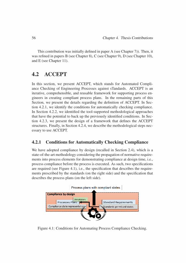
56 Chapter 4. Thesis Contributions
This contribution was initially defined in paper A (see Chapter 7)). Then, itwas refined in papers B (see Chapter 8), C (see Chapter 9), D (see Chapter 10),and E (see Chapter 11).
4.2 ACCEPTIn this section, we present ACCEPT, which stands for Automated Compli-ance Checking of Engineering Processes against sTandards. ACCEPT is aniterative, comprehensible, and reusable framework for supporting process en-gineers in creating compliant process plans. In the remaining parts of thisSection, we present the details regarding the definition of ACCEPT. In Sec-tion 4.2.1, we identify the conditions for automatically checking compliance.In Section 4.2.2, we identified the tool-supported methodological approachesthat have the potential to back up the previously identified conditions. In Sec-tion 4.2.3, we present the design of a framework that defines the ACCEPTstructures. Finally, in Section 4.2.4, we describe the methodological steps nec-essary to use ACCEPT.
4.2.1 Conditions for Automatically Checking Compliance
We have adopted compliance by design (recalled in Section 2.4), which is astate-of-the-art methodology considering the propagation of normative require-ments into process elements for demonstrating compliance at design time, i.e.,process compliance before the process is executed. As such, two specificationsare required (see Figure 4.1), i.e., the specification that describes the require-ments prescribed by the standards (on the right side) and the specification thatdescribes the process plans (on the left side).
Figure 4.1: Conditions for Automating Process Compliance Checking.
8080

4.2 ACCEPT 57
The propagation of normative requirements is possible via the annotation ofcompliance effects. Compliance effects correspond to the standard-permittedstates, which are extracted from the specification corresponding to the standardrequirements. Unlike other effects caused by process elements, complianceeffects should correlate with the standard-permitted states. For this reason, theannotation process is an alignment between the states exhibited by the processelements and the standard-permitted states. Properly annotated complianceeffects allow the generation of a compliance state representation of the process,which can be used to perform the automatic analysis of compliance. A processengineer can iteratively apply automated compliance checking to reach processplans with compliant states.
4.2.2 Tool-supported Methodological ApproachesThe identified tool-supported methodological approaches that have the poten-tial to back up the conditions presented in Figure 4.1 are defined as follows.
Process Modeling and Annotation Capabilities.
A process engineer (as recalled in Section 2.2.1) is the person who deals withrepresenting of the processes used to engineer safety-critical systems. How-ever, a process representation can be composed of hundreds of entities. Processmodeling languages (see Section 2.2) have been developed to provide processengineers more control over their processes. We chose SPEM 2.0 (recalled inSection 2.2.2), as opposed to other process modeling notations, because:
1. SPEM 2.0 is a standardized language, based on the UML;
2. SPEM 2.0 has the ability to capture several types of information;
3. SPEM 2.0-like artifacts can be captured via Eclipse Process FrameworkComposer (EPF-C) (recalled in Section 2.2.3). EPF-C models can be portedto other tools, via model-driven transformations.
4. SPEM 2.0 provides variability mechanisms that can be exploited for flexibleprocess derivation. Such mechanisms are currently tool-supported via thecomposition of EPC-C with BVR (recalled in Section 2.3.2).
5. SPEM 2.0 elements can also be customized to permit the definition of arti-facts beyond process elements. e.g., standards, requirements, rules and theircompliance effects. In addition, EPF-C is an environments that provides hi-erarchal structures that facilitates keeping track of such artifacts.
8181
58 Chapter 4. Thesis Contributions
6. SPEM 2.0 is widely accepted by the research community and industry.
Normative Representation Capabilities
Norms typically describe the conditions under which they are applicable, i.e.,the meaning of the terms or concepts where the norms are valid. Norms alsodescribe the normative effects they produce when applied, i.e., legally-bindingeffects. From a compliance perspective, the normative effects of importanceare deontic, which have intrinsic relations (as depicted in Figure 2.8).
There are three primary deontic effects. First, we have the obligations andprohibitions, which are situations to which the bearer is legally bounded, orthat should avoid. In industry standards, obligations and prohibitions are com-monly defined by the modal “shall”, and “shall not,” respectively. Second, wehave permissions, which are allowed situations. Industry standards commonlyuse “can” or “may” or “need not” to define that something is permitted. It isalso essential to provide reasoning about normative violations and exceptions.Normative violations correspond to the failure in fulfilling the requirements,while exceptions are conditions that emerge in situations not considered by thestandard. In particular, exceptions defeat the established normative provisions.Thus, we need to be able to represent also this type of information.
The normative provisions included in industry standards can be encodedas implications. A normative implication has an antecedent, which is read asa property of a state of affairs, while the conclusion has a deontic nature. Ifone rule defeats another rule (i.e., rules contradict each other, as in the caseof exceptions), there must be a mechanism that permits plausible conclusions.Giving these circumstances, we argue that deontic defeasible reasoning for-malisms, such as Formal Contract Logic (FCL) (recalled in Section 2.4.2), canbe used to generate automatic support to reason from standard’s requirementsand the description of the process they regulate.
Reasoning Capabilities
As recalled in Section 2.4.3, Regorous is a tool-supported methodology forcompliance checking designed and implemented in the legal and business con-text. Regorous is of particular interest since it implements compliance by de-sign, which, as described in Section 4.2.1, is a methodology that is adequatefor facilitating the planning-time allocation of mandatory pieces of evidencerequired by the majority of industry standards. In the process of compliancechecking, Regorous provides constructive proofs (a proof from which it is pos-
8282
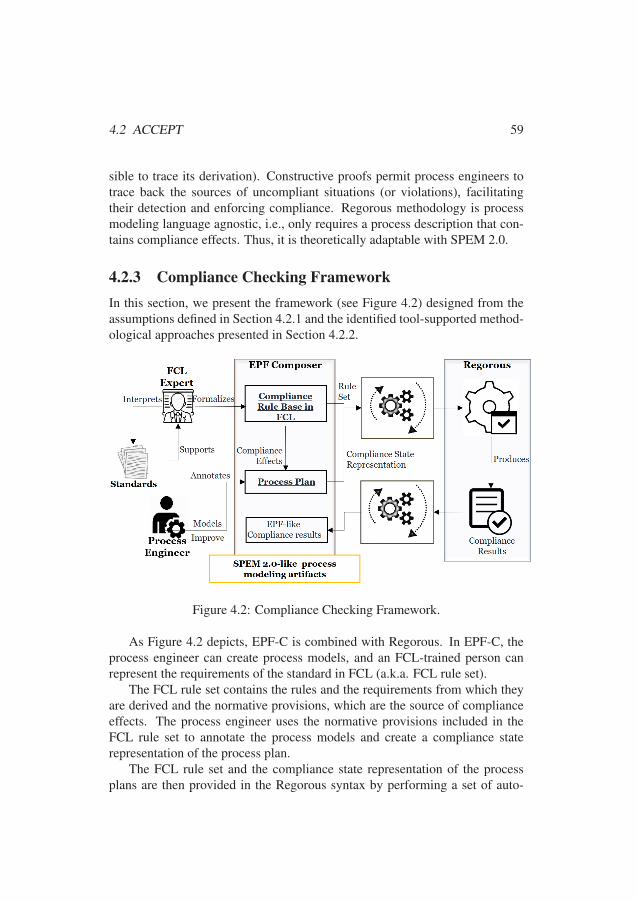
4.2 ACCEPT 59
sible to trace its derivation). Constructive proofs permit process engineers totrace back the sources of uncompliant situations (or violations), facilitatingtheir detection and enforcing compliance. Regorous methodology is processmodeling language agnostic, i.e., only requires a process description that con-tains compliance effects. Thus, it is theoretically adaptable with SPEM 2.0.
4.2.3 Compliance Checking FrameworkIn this section, we present the framework (see Figure 4.2) designed from theassumptions defined in Section 4.2.1 and the identified tool-supported method-ological approaches presented in Section 4.2.2.
Figure 4.2: Compliance Checking Framework.
As Figure 4.2 depicts, EPF-C is combined with Regorous. In EPF-C, theprocess engineer can create process models, and an FCL-trained person canrepresent the requirements of the standard in FCL (a.k.a. FCL rule set).
The FCL rule set contains the rules and the requirements from which theyare derived and the normative provisions, which are the source of complianceeffects. The process engineer uses the normative provisions included in theFCL rule set to annotate the process models and create a compliance staterepresentation of the process plan.
The FCL rule set and the compliance state representation of the processplans are then provided in the Regorous syntax by performing a set of auto-
8383

60 Chapter 4. Thesis Contributions
mated transformations. With this information, Regorous automatically checkscompliance and produces compliance results that include the violations occur-ring concerning the FCL rule set provided and the possible resolutions. Suchresults are aimed at being backpropagated into EPF-C to facilitate analysis andimprovement of process plans.
4.2.4 Methodological StepsPerforming compliance checking with ACCEPT requires the application of thefive methodological steps shown in Figure 4.3. In the remaining part of thissection, we explain each step.
Figure 4.3: Methodological Steps.
Step 1: Formalization of Requirements. Standard requirements are formal-ized in FCL by the person(s) with FCL and domain knowledge (e.g., processengineers). This step has two inputs. The first input is the normative docu-ment (i.e., industry standard) from which the rules are derived. The secondinput is the list of customized compliance elements that we have designed tofacilitate the representations of requirements in EPC-C (see Figure 4.4). In par-ticular, those artifacts are SPEM 2.0-like elements that represent the elementsrequired for modeling compliance information, i.e., compliance effects, rulesets, requirements, and rules. The output is the FCL-based ruleset captured inan EPF-C plugin.
8484
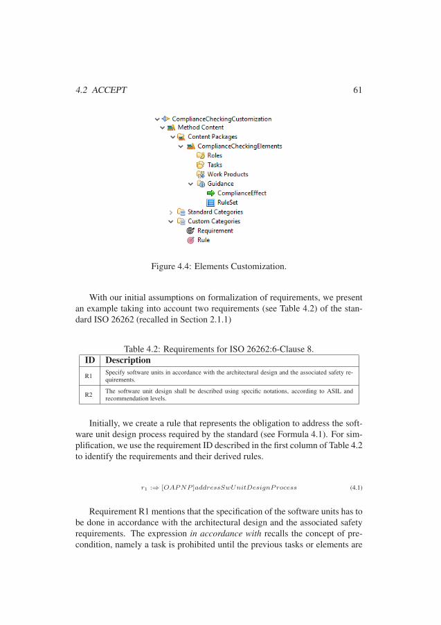
4.2 ACCEPT 61
Figure 4.4: Elements Customization.
With our initial assumptions on formalization of requirements, we presentan example taking into account two requirements (see Table 4.2) of the stan-dard ISO 26262 (recalled in Section 2.1.1)
Table 4.2: Requirements for ISO 26262:6-Clause 8.ID Description
R1 Specify software units in accordance with the architectural design and the associated safety re-quirements.
R2 The software unit design shall be described using specific notations, according to ASIL andrecommendation levels.
Initially, we create a rule that represents the obligation to address the soft-ware unit design process required by the standard (see Formula 4.1). For sim-plification, we use the requirement ID described in the first column of Table 4.2to identify the requirements and their derived rules.
r1 :⇒ [OAPNP ]addressSwUnitDesignProcess (4.1)
Requirement R1 mentions that the specification of the software units has tobe done in accordance with the architectural design and the associated safetyrequirements. The expression in accordance with recalls the concept of pre-condition, namely a task is prohibited until the previous tasks or elements are
8585
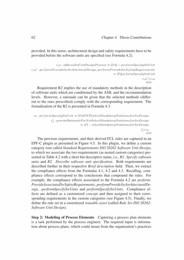
62 Chapter 4. Thesis Contributions
provided. In this sense, architectural design and safety requirements have to beprovided before the software units are specified (see Formula 4.2).
r1a : addressSwUnitDesignProcess⇒ [OA]− performSpecifySwUnit
r1a′: performProvideSwArchitecturalDesign, performProvideSwSafetyRequirements
⇒ [P ]performSpecifySwUnit
r1a′>r1a
(4.2)
Requirement R2 implies the use of mandatory methods in the descriptionof software units which are conditioned by the ASIL and the recommendationlevels. However, a rationale can be given that the selected methods (differ-ent to the ones prescribed) comply with the corresponding requirement. Theformalization of the R2 is presented in Formula 4.3.
r2 : performSpecifySwUnit⇒ [OAPNP ]selectMandatoryNotationsforSwDesign
r′2 : provideRationaleForNotSelectMandatoryNotationsforSwDesign
⇒ [P ]− selectMandatoryNotationsforSwDesign
r′2>r2
(4.3)
The previous requirements, and their derived FCL rules are captured in anEPF-C plugin as presented in Figure 4.5. In this plugin, we define a customcategory root called Standard Requirements ISO 26262 Software Unit Design,to which we associate the two requirements (as nested custom categories) pre-sented in Table 4.2 with a short but descriptive name, i.e., R1. Specify softwareunits and R2. Describe software unit specification. Both requirements aredescribed further in their respective Brief description field. Then, we extractthe compliance effects from the Formulas 4.1, 4.2 and 4.3. Recalling, com-pliance effects correspond to the conclusions that compound the rules. Forexample, the compliance effects associated to the Formula 4.2 are perform-ProvideAssociatedSwSafetyRequirements, performProvideSwArchitecturalDe-sign, -performSpecifySwUnits and performSpecifySwUnits. Compliance ef-fects are defined as a customized concept and then assigned to their corre-sponding requirements in the custom categories (see Figure 4.5). Finally, wedefine the rule set in a customized reusable asset (called Rule Set-ISO 26262-Software Unit Design).
Step 2: Modeling of Process Elements Capturing a process plan elementsis a task performed by the process engineer. The required input is informa-tion about process plans, which could steam from the organization’s practices
8686

4.2 ACCEPT 63
Figure 4.5: Standard’s Requirements Plugin.
and previous process plans. The output is the representation of the processelements in EPF Composer. In this example, the definition of the process ele-ments is based on our interpretations of the standard’s requirements providedin Table 4.2. From R1, we deduce that there is one task called Specify SoftwareUnit. These tasks should be preceded by a task called Start Software Unit De-sign Process, in which the requirements for the process is collected, namely,the Software Architectural Design and its corresponding Software Safety re-quirements, which are work products resulting from previous phases. FromR2, we deduce that we have a task called Design Software Unit and a workproduct called Software Unit Design. Work products are associated to theircorresponding tasks. The modeling of the tasks and the work products is de-picted in Figure 4.6.
Step 3: Annotation of Process Tasks The annotation is a task performedby a process engineer. Previous process plans, as well as compliance effectscontained in the FCL rule set, and process elements, are the inputs of this
8787

64 Chapter 4. Thesis Contributions
Figure 4.6: Process Elements Plugin.
step. The output is the annotated process tasks in EPF Composer. The an-notation process consists of assigning the compliance effects to the tasks thatfulfill them. For example, the task Start Software Unit Design Process (seeFigure 4.7b) is performed and has two inputs, i.e., architectural design andsafety requirements. Thus, the annotated compliance effects (see Figure 4.7a)are addressSwUnitDesignProcess, performProvideSwArchitecturalDesign andperformProvideSwSafetyRequirements.
(a) (b)
Figure 4.7: Compliance Annotated Process Plugin.
Step 4: Modeling of Process Workflow For modeling the process workflow,the process engineer uses the compliance annotated process elements defined instep 3. The output is the delivery process in EPF Composer, which contains theprocess plan checkable for compliance, i.e., the compliance state representationof the process plan (as depicted in Figure 4.8).
8888
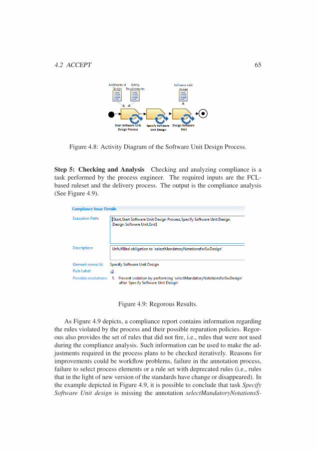
4.2 ACCEPT 65
Figure 4.8: Activity Diagram of the Software Unit Design Process.
Step 5: Checking and Analysis Checking and analyzing compliance is atask performed by the process engineer. The required inputs are the FCL-based ruleset and the delivery process. The output is the compliance analysis(See Figure 4.9).
Figure 4.9: Regorous Results.
As Figure 4.9 depicts, a compliance report contains information regardingthe rules violated by the process and their possible reparation policies. Regor-ous also provides the set of rules that did not fire, i.e., rules that were not usedduring the compliance analysis. Such information can be used to make the ad-justments required in the process plans to be checked iteratively. Reasons forimprovements could be workflow problems, failure in the annotation process,failure to select process elements or a rule set with deprecated rules (i.e., rulesthat in the light of new version of the standards have change or disappeared). Inthe example depicted in Figure 4.9, it is possible to conclude that task SpecifySoftware Unit design is missing the annotation selectMandatoryNotationsS-
8989
66 Chapter 4. Thesis Contributions
wDesign. With this information, we can revise such a task and understand thereasons for the failure in the annotation, e.g., guidance regarding mandatorynotations is probably missing in the task.
4.3 Process Compliance Hints and PatternsSkillful FCL rule set design can be reached by applying computational think-ing resources, in particular, process compliance hints and patterns (as recalledin Section 2.5). Hints are rules of thumb found in previous FCL formaliza-tion experiences, while patterns indicate common situations an FCL designeris likely to encounter. Both process compliance hints and patterns aim at fa-cilitating the formalization of process-related requirements into FCL rules. InSection 4.3.1, we present the process compliance hints. In Section 4.3.2, wepresent the process compliance patterns.
4.3.1 Process Compliance Hints
The relationship between the requirements imposed by prescriptive standardsand the targeted processes is complex. The reason is that a single require-ment may be impacting one element in the process, causing effects to severalelements. Moreover, each element in a process may be impacted by severalrequirements. In addition, process diversity (i.e., the application of severalnormative process reference frameworks in a single project) may lead to prob-lems in the understanding of what is needed for managing process compliance.Thus, we have a compact set of requirements, which we need to manage ap-propriately.
The divide-and-conquer strategy (recalled in Section 2.5.1) is a design hintthat can be applied in the formalization of process-related requirements. Byapplying the divide-and-conquer strategy, we could break down such complex-ity and provide a more comprehensible view of the requirements. In particular,the aspects that requirements in prescriptive standards regulate are the tasks,their specific order, the mandatory in/outputs of the tasks, roles performing thetasks, and the tools/recommended techniques used to do the tasks. Thus, theconcept of a task is central, to which properties such as the definition of roles,inputs, outputs, tools, and techniques must apply.
However, requirements not only define the properties of the tasks. For ex-ample, roles and tools should be qualified. This kind of requirements does notdirectly affect the tasks. They directly affect other elements, which in turn have
9090
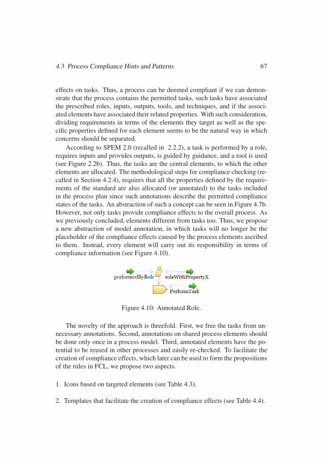
4.3 Process Compliance Hints and Patterns 67
effects on tasks. Thus, a process can be deemed compliant if we can demon-strate that the process contains the permitted tasks, such tasks have associatedthe prescribed roles, inputs, outputs, tools, and techniques, and if the associ-ated elements have associated their related properties. With such consideration,dividing requirements in terms of the elements they target as well as the spe-cific properties defined for each element seems to be the natural way in whichconcerns should be separated.
According to SPEM 2.0 (recalled in 2.2.2), a task is performed by a role,requires inputs and provides outputs, is guided by guidance, and a tool is used(see Figure 2.2b). Thus, the tasks are the central elements, to which the otherelements are allocated. The methodological steps for compliance checking (re-called in Section 4.2.4), requires that all the properties defined by the require-ments of the standard are also allocated (or annotated) to the tasks includedin the process plan since such annotations describe the permitted compliancestates of the tasks. An abstraction of such a concept can be seen in Figure 4.7b.However, not only tasks provide compliance effects to the overall process. Aswe previously concluded, elements different from tasks too. Thus, we proposea new abstraction of model annotation, in which tasks will no longer be theplaceholder of the compliance effects caused by the process elements ascribedto them. Instead, every element will carry out its responsibility in terms ofcompliance information (see Figure 4.10).
Figure 4.10: Annotated Role.
The novelty of the approach is threefold. First, we free the tasks from un-necessary annotations. Second, annotations on shared process elements shouldbe done only once in a process model. Third, annotated elements have the po-tential to be reused in other processes and easily re-checked. To facilitate thecreation of compliance effects, which later can be used to form the propositionsof the rules in FCL, we propose two aspects.
1. Icons based on targeted elements (see Table 4.3).
2. Templates that facilitate the creation of compliance effects (see Table 4.4).
9191
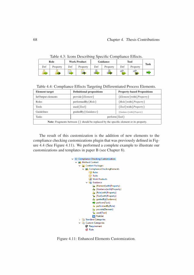
68 Chapter 4. Thesis Contributions
Table 4.3: Icons Describing Specific Compliance Effects.Role Work Product Guidance Tool
TaskDef Property Def Property Def Property Def Property
Table 4.4: Compliance Effects Targeting Differentiated Process Elements.Element target Definitional propositions Property-based Propositions
In/Output elements provide{Element} {Element}with{Property}
Roles performedBy{Role} {Role}with{Property}
Tools used{Tool} {Tool}with{Property}
Guidelines guidedBy{Guidance} {Guidance}with{Property}
Tasks perform{Task}
Note: Fragments between {} should be replaced by the specific element or its property.
The result of this customization is the addition of new elements to thecompliance checking customizations plugin that was previously defined in Fig-ure 4.4 (See Figure 4.11). We performed a complete example to illustrate ourcustomizations and templates in paper B (see Chapter 8).
Figure 4.11: Enhanced Elements Customization.
9292
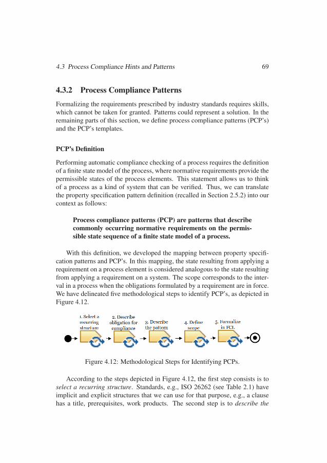
4.3 Process Compliance Hints and Patterns 69
4.3.2 Process Compliance Patterns
Formalizing the requirements prescribed by industry standards requires skills,which cannot be taken for granted. Patterns could represent a solution. In theremaining parts of this section, we define process compliance patterns (PCP’s)and the PCP’s templates.
PCP’s Definition
Performing automatic compliance checking of a process requires the definitionof a finite state model of the process, where normative requirements provide thepermissible states of the process elements. This statement allows us to thinkof a process as a kind of system that can be verified. Thus, we can translatethe property specification pattern definition (recalled in Section 2.5.2) into ourcontext as follows:
Process compliance patterns (PCP) are patterns that describecommonly occurring normative requirements on the permis-sible state sequence of a finite state model of a process.
With this definition, we developed the mapping between property specifi-cation patterns and PCP’s. In this mapping, the state resulting from applying arequirement on a process element is considered analogous to the state resultingfrom applying a requirement on a system. The scope corresponds to the inter-val in a process when the obligations formulated by a requirement are in force.We have delineated five methodological steps to identify PCP’s, as depicted inFigure 4.12.
Figure 4.12: Methodological Steps for Identifying PCPs.
According to the steps depicted in Figure 4.12, the first step consists is toselect a recurring structure. Standards, e.g., ISO 26262 (see Table 2.1) haveimplicit and explicit structures that we can use for that purpose, e.g., a clausehas a title, prerequisites, work products. The second step is to describe the
9393

70 Chapter 4. Thesis Contributions
obligation for compliance, which is to find the deontic (the mandatory or per-missible) nature of the structure to be defined. The third step is describe thepattern, based on similar (or a combination of) behaviors of the property spec-ification patterns described in Section 2.5.2. This description is contextualizedto process compliance based on the mapping previously done. In this step, wealso assign a name for the PCP, reflecting the related obligation for compliance.The fourth step is to define the scope of the pattern, which we also based onthe scopes defined to the property specification patterns. The fifth step is toformalize in FCL (we present this step below).
FCL-based PCP’s Templates
The PCP template description is based on similar (or a combination of) behav-iors described for the property specification patterns, which are mapped to thenotations provided in FCL (see Table 2.5), as follows:
• A global scope, which represents the entire process model execution, is de-fined as a [OM]P.
• A before scope, which includes the execution of the process model up to agiven state, is mapped to a partial [OAP ].
• An after scope, which includes the execution of the process model after agiven state, is mapped to a partial [OANP ].
• If an obligation admits an exception, e.g., tailoring, the part of the patterncorresponding to the exception is described as [P] since if something is per-mitted, the obligation to the contrary does not hold. The excepted obliga-tion is modeled as non-perdurant, since the permission is not a violation ofthe obligation. Thus, the obligation does not persist after the permission isgranted.
In principle, the requirements included in standards can be tailored. Thus,the achievement obligations are modeled as non-perdurant, i.e., [OAPNP] or[OANPNP]. In this case, obligation and permission have contradictory conclu-sions, but the permission is superior since it represents an exception.
In the remaining part of this section, we present the templates of the iden-tified PCPs. In all templates, {#} should be replaced with the number thatidentifies the requirement in the standard. When it is described as {#.i}, thei should be replaced by a, b, ..., n, where n is the number of sub-items, e.g., ifthere is a requirement with two parts that is identified with the number 5, therules’ identifiers are 5.a and 5.b.
9494
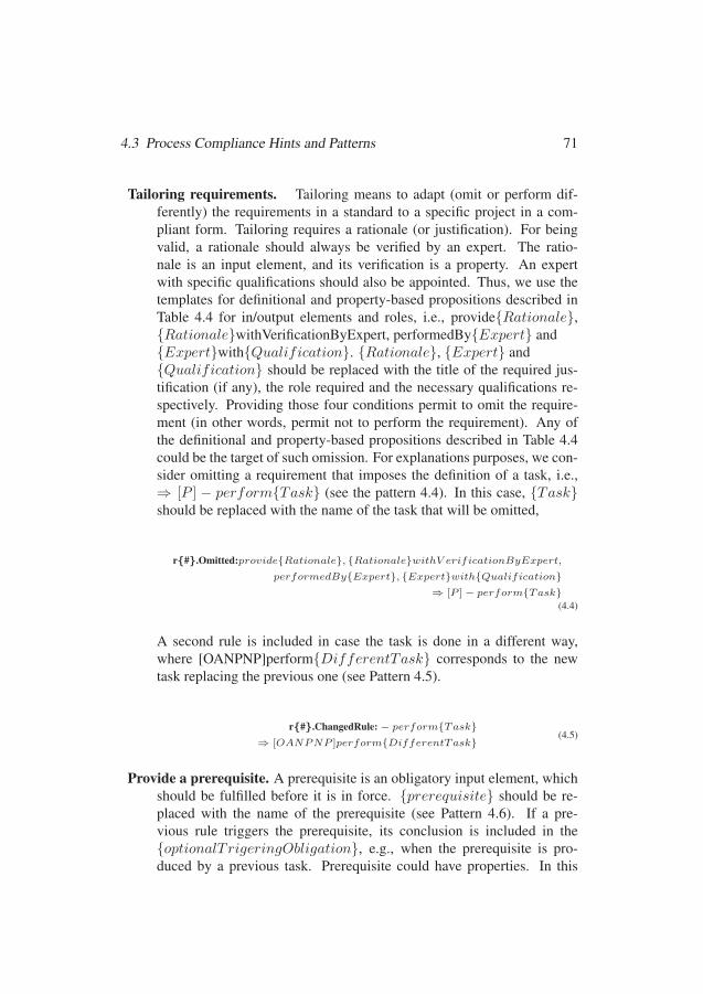
4.3 Process Compliance Hints and Patterns 71
Tailoring requirements. Tailoring means to adapt (omit or perform dif-ferently) the requirements in a standard to a specific project in a com-pliant form. Tailoring requires a rationale (or justification). For beingvalid, a rationale should always be verified by an expert. The ratio-nale is an input element, and its verification is a property. An expertwith specific qualifications should also be appointed. Thus, we use thetemplates for definitional and property-based propositions described inTable 4.4 for in/output elements and roles, i.e., provide{Rationale},{Rationale}withVerificationByExpert, performedBy{Expert} and{Expert}with{Qualification}. {Rationale}, {Expert} and{Qualification} should be replaced with the title of the required jus-tification (if any), the role required and the necessary qualifications re-spectively. Providing those four conditions permit to omit the require-ment (in other words, permit not to perform the requirement). Any ofthe definitional and property-based propositions described in Table 4.4could be the target of such omission. For explanations purposes, we con-sider omitting a requirement that imposes the definition of a task, i.e.,⇒ [P ] − perform{Task} (see the pattern 4.4). In this case, {Task}should be replaced with the name of the task that will be omitted,
r{#}.Omitted:provide{Rationale}, {Rationale}withV erificationByExpert,
performedBy{Expert}, {Expert}with{Qualification}⇒ [P ]− perform{Task}
(4.4)
A second rule is included in case the task is done in a different way,where [OANPNP]perform{DifferentTask} corresponds to the newtask replacing the previous one (see Pattern 4.5).
r{#}.ChangedRule:− perform{Task}⇒ [OANPNP ]perform{DifferentTask}
(4.5)
Provide a prerequisite. A prerequisite is an obligatory input element, whichshould be fulfilled before it is in force. {prerequisite} should be re-placed with the name of the prerequisite (see Pattern 4.6). If a pre-vious rule triggers the prerequisite, its conclusion is included in the{optionalTrigeringObligation}, e.g., when the prerequisite is pro-duced by a previous task. Prerequisite could have properties. In this
9595

72 Chapter 4. Thesis Contributions
case, the {optionalTrigeringObligation} could be a list of such prop-erties, using the template {Element}with{Property}. Otherwise, it isleft empty.
r{#.i}:{optionalTrigeringObligation}⇒ [OAPNP ]provide{prerequisite.i}
(4.6)
Perform a unit of work. Pattern 4.7 represents the prescription of a unit ofwork in a process (i.e., phase/activity/task). It considers the prerequi-sites, if any, as the conditions of the applicability of the rule, which nor-mative conclusion is performing a unit of work (e.g., a phase). It couldbe preemptive ([OAPNP]), if the prerequisites and the task are providedat the same time the task is performed.
r{#}:provide{Prerequisite1}..., provide{Prerequisite.i}⇒ [OAPNP ]perform{TitleClause}
(4.7)
It can be non-preemptive ([OANPNP]) as in Pattern 4.8, if the prereq-uisite is another task, that have to be done first. In the example in Pat-tern 4.8, {TitleClause} should be replaced with the specific clause title.
r{#}:perform{Task}⇒ [OANPNP ]perform{FollowingTask}
(4.8)
Provide guidance. Guidance elements may not be required during stan-dards compliance auditing. However, internal policies in a companymay impose guidance elements. In that case, guidance elements shouldbe provided at the moment the element guided is created. We createthe propositions by using the template for guidance provided Table 4.4,i.e., guidedBy{Guidance} and {Guidance}with{Property}. Guid-ance can be defined for any element in the process (tasks, work product,tool, or role). For explanation purposes, we consider perform{Task}(see Pattern 4.9).
{#.i}:perform{Task}, {Guidance}with{Property}⇒ [OAPNP ]guidedBy{Guidance}
(4.9)
Provide a work product. Work products are the result of certain require-ments. Thus, these requirements are presented as antecedents that oblige
9696
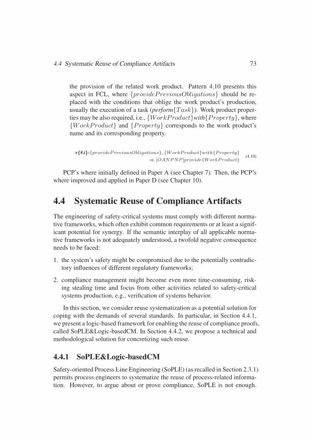
4.4 Systematic Reuse of Compliance Artifacts 73
the provision of the related work product. Pattern 4.10 presents thisaspect in FCL, where {providePreviousObligations} should be re-placed with the conditions that oblige the work product’s production,usually the execution of a task (perform{Task}). Work product proper-ties may be also required, i.e., {WorkProduct}with{Property}, where{WorkProduct} and {Property} corresponds to the work product’sname and its corresponding property.
r{#.i}:{providePreviousObligations}, {WorkProduct}with{Property}⇒ [OANPNP ]provide{WorkProduct}
(4.10)
PCP’s where initially defined in Paper A (see Chapter 7). Then, the PCP’swhere improved and applied in Paper D (see Chapter 10).
4.4 Systematic Reuse of Compliance ArtifactsThe engineering of safety-critical systems must comply with different norma-tive frameworks, which often exhibit common requirements or at least a signif-icant potential for synergy. If the semantic interplay of all applicable norma-tive frameworks is not adequately understood, a twofold negative consequenceneeds to be faced:
1. the system’s safety might be compromised due to the potentially contradic-tory influences of different regulatory frameworks;
2. compliance management might become even more time-consuming, risk-ing stealing time and focus from other activities related to safety-criticalsystems production, e.g., verification of systems behavior.
In this section, we consider reuse systematization as a potential solution forcoping with the demands of several standards. In particular, in Section 4.4.1,we present a logic-based framework for enabling the reuse of compliance proofs,called SoPLE&Logic-basedCM. In Section 4.4.2, we propose a technical andmethodological solution for concretizing such reuse.
4.4.1 SoPLE&Logic-basedCMSafety-oriented Process Line Engineering (SoPLE) (as recalled in Section 2.3.1)permits process engineers to systematize the reuse of process-related informa-tion. However, to argue about or prove compliance, SoPLE is not enough.
9797
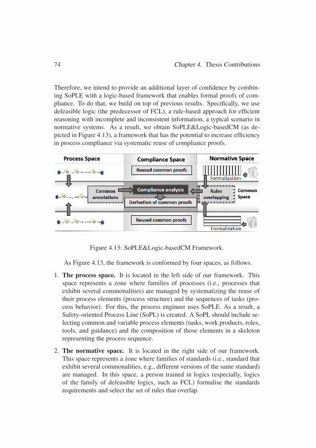
74 Chapter 4. Thesis Contributions
Therefore, we intend to provide an additional layer of confidence by combin-ing SoPLE with a logic-based framework that enables formal proofs of com-pliance. To do that, we build on top of previous results. Specifically, we usedefeasible logic (the predecessor of FCL), a rule-based approach for efficientreasoning with incomplete and inconsistent information, a typical scenario innormative systems. As a result, we obtain SoPLE&Logic-basedCM (as de-picted in Figure 4.13), a framework that has the potential to increase efficiencyin process compliance via systematic reuse of compliance proofs.
Figure 4.13: SoPLE&Logic-basedCM Framework.
As Figure 4.13, the framework is conformed by four spaces, as follows.
1. The process space. It is located in the left side of our framework. Thisspace represents a zone where families of processes (i.e., processes thatexhibit several commonalities) are managed by systematizing the reuse oftheir process elements (process structure) and the sequences of tasks (pro-cess behavior). For this, the process engineer uses SoPLE. As a result, aSafety-oriented Process Line (SoPL) is created. A SoPL should include se-lecting common and variable process elements (tasks, work products, roles,tools, and guidance) and the composition of those elements in a skeletonrepresenting the process sequence.
2. The normative space. It is located in the right side of our framework.This space represents a zone where families of standards (i.e., standard thatexhibit several commonalities, e.g., different versions of the same standard)are managed. In this space, a person trained in logics (especially, logicsof the family of defeasible logics, such as FCL) formalise the standardsrequirements and select the set of rules that overlap.
9898
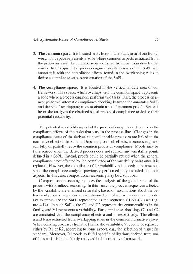
4.4 Systematic Reuse of Compliance Artifacts 75
3. The common space. It is located in the horizontal middle area of our frame-work. This space represents a zone where common aspects extracted fromthe processes meet the common rules extracted from the normative frame-works. In this space, the process engineer needs to analyze the SoPL andannotate it with the compliance effects found in the overlapping rules toderive a compliance state representation of the SoPL.
4. The compliance space. It is located in the vertical middle area of ourframework. This space, which overlaps with the common space, representsa zone where a process engineer performs two tasks. First, the process engi-neer performs automatic compliance checking between the annotated SoPLand the set of overlapping rules to obtain a set of common proofs. Second,he or she analyzes the obtained set of proofs of compliance to define theirpotential reusability.
The potential reusability aspect of the proofs of compliance depends on thecompliance effects of the tasks that vary in the process line. Changes in thecompliance status of the derived standard-specific processes are linked to thenormative effect of the variant. Depending on such effects, a process engineercan fully or partially reuse the common proofs of compliance. Proofs may befully reused when the derived process does not replace any variability pointsdefined in a SoPL. Instead, proofs could be partially reused when the generalcompliance is not affected by the compliance of the variability point once it isreplaced. However, the compliance of the variability point needs to be assessedsince the compliance analysis previously performed only included commonaspects. In this case, compositional reasoning may be a solution.
Compositional reasoning replaces the analysis of the global state of theprocess with localized reasoning. In this sense, the process sequences affectedby the variability are analyzed separately, based on assumptions about the be-havior of process sequences already deemed compliant by the common proofs.For example, see the SoPL represented as the sequence C1-V1-C2 (see Fig-ure 4.14). In such SoPL, the C1 and C2 represent the commonalities in thefamily, and V1 represents a variability. For compliance checking, C1 and C2are annotated with the compliance effects a and b, respectively. The effectsa and b are extracted from overlapping rules in the common normative space.When deriving processes from the family, the variability, V1, could be replacedeither by R1 or R2, according to some aspect, e.g., the selection of a specificstandard. Moreover, R1 needs to fulfill specific obligations derived from oneof the standards in the family analyzed in the normative framework.
9999
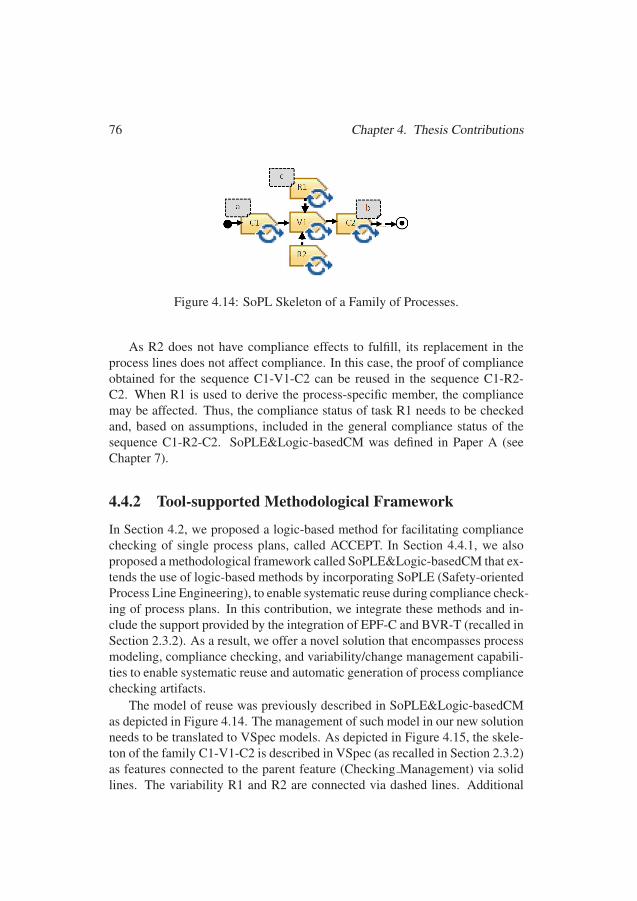
76 Chapter 4. Thesis Contributions
Figure 4.14: SoPL Skeleton of a Family of Processes.
As R2 does not have compliance effects to fulfill, its replacement in theprocess lines does not affect compliance. In this case, the proof of complianceobtained for the sequence C1-V1-C2 can be reused in the sequence C1-R2-C2. When R1 is used to derive the process-specific member, the compliancemay be affected. Thus, the compliance status of task R1 needs to be checkedand, based on assumptions, included in the general compliance status of thesequence C1-R2-C2. SoPLE&Logic-basedCM was defined in Paper A (seeChapter 7).
4.4.2 Tool-supported Methodological Framework
In Section 4.2, we proposed a logic-based method for facilitating compliancechecking of single process plans, called ACCEPT. In Section 4.4.1, we alsoproposed a methodological framework called SoPLE&Logic-basedCM that ex-tends the use of logic-based methods by incorporating SoPLE (Safety-orientedProcess Line Engineering), to enable systematic reuse during compliance check-ing of process plans. In this contribution, we integrate these methods and in-clude the support provided by the integration of EPF-C and BVR-T (recalled inSection 2.3.2). As a result, we offer a novel solution that encompasses processmodeling, compliance checking, and variability/change management capabili-ties to enable systematic reuse and automatic generation of process compliancechecking artifacts.
The model of reuse was previously described in SoPLE&Logic-basedCMas depicted in Figure 4.14. The management of such model in our new solutionneeds to be translated to VSpec models. As depicted in Figure 4.15, the skele-ton of the family C1-V1-C2 is described in VSpec (as recalled in Section 2.3.2)as features connected to the parent feature (Checking Management) via solidlines. The variability R1 and R2 are connected via dashed lines. Additional
100100
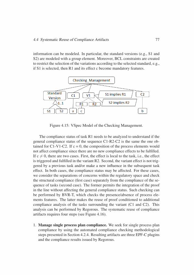
4.4 Systematic Reuse of Compliance Artifacts 77
information can be modeled. In particular, the standard versions (e.g., S1 andS2) are modeled with a group element. Moreover, BCL constraints are createdto restrict the selection of the variations according to the selected standard, e.g.,if S1 is selected, then R1 and its effect c become mandatory features.
Figure 4.15: VSpec Model of the Checking Management.
The compliance status of task R1 needs to be analyzed to understand if thegeneral compliance status of the sequence C1-R2-C2 is the same the one ob-tained for C1-V1-C2. If c = 0, the composition of the process elements wouldnot affect compliance since there are no new compliance effects to be fulfilled.If c 6= 0, there are two cases. First, the effect is local to the task, i.e., the effectis triggered and fulfilled in the variant R2. Second, the variant effect is not trig-gered by a previous task and/or make a new influence in the subsequent taskeffect. In both cases, the compliance status may be affected. For these cases,we consider the separations of concerns within the regulatory space and checkthe structural compliance (first case) separately from the compliance of the se-quence of tasks (second case). The former permits the integration of the proofin the line without affecting the general compliance status. Such checking canbe performed by BVR-T, which checks the presence/absence of process ele-ments features. The latter makes the reuse of proof conditioned to additionalcompliance analysis of the tasks surrounding the variant (C1 and C2). Thisanalysis can be performed by Regorous. The systematic reuse of complianceartifacts requires four steps (see Figure 4.16).
1. Manage single process plan compliance. We seek for single process plancompliance by using the automated compliance checking methodologicalsteps presented in Section 4.2.4. Resulting artifacts are three EPF-C pluginsand the compliance results issued by Regorous.
101101
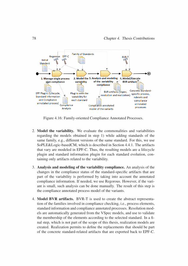
78 Chapter 4. Thesis Contributions
Figure 4.16: Family-oriented Compliance Annotated Processes.
2. Model the variability. We evaluate the commonalities and variabilitiesregarding the models obtained in step 1) while adding standards of thesame family, e.g., different versions of the same standard. For this, we useSoPLE&Logic-basedCM, which is described in Section 4.4.1. The artifactsthat vary are modeled in EPF-C. Thus, the resulting models are a lifecycleplugin and standard information plugin for each standard evolution, con-taining only artifacts related to the variability.
3. Analysis and modeling of the variability compliance. An analysis of thechanges in the compliance status of the standard-specific artifacts that arepart of the variability is performed by taking into account the annotatedcompliance information. If needed, we use Regorous. However, if the vari-ant is small, such analysis can be done manually. The result of this step isthe compliance annotated process model of the variants.
4. Model BVR artifacts. BVR-T is used to create the abstract representa-tion of the families involved in compliance checking, i.e., process elements,standard information and compliance annotated processes. Resolution mod-els are automatically generated from the VSpec models, and use to validatethe membership of the elements according to the selected standard. In a fi-nal step, which is not part of the scope of this thesis, realization models arecreated. Realization permits to define the replacements that should be partof the concrete standard-related artifacts that are exported back to EPF-C.
102102
4.5 Solutions Validation 79
Thus, in this step we use the tool-chain integrated by EPF-C and BVR-T.This contribution is presented in Paper E (see Chapter 11).
4.5 Solutions ValidationIn this section, we present the validation performed to our proposed solu-tions. In Section 4.5.1, we present the results of a personal opinion surveyapplied among practitioners who participate in safety-related process compli-ance checking. In Section 4.5.2, we present a case of compliance-aware spacesoftware engineering processes. In Section 4.5.3, we present the benefits ofour methodological framework by measuring the enabled reuse. Finally, InSection 4.5.4, we position our research in the context of existing research ef-forts realized for compliance checking of software processes against differentnormative frameworks.
4.5.1 Personal Opinion SurveyWe design and apply a cross-sectional web-based personal opinion survey (asrecalled in Section 2.6.2). This survey goal is twofold. First, it aims at gath-ering information about current industrial practices and challenges in processcompliance checking. For tackling this part of the survey, we used multipleoption questions. Second, it focuses on evaluating the acceptance level of AC-CEPT (recalled in Section 4.2). For addressing this part of the survey, wepresent an example of our solution applied to automotive, i.e., ISO 26262 (re-called in Section 2.1.1). Then, we present a series of claims regarding such amethod from which we seek practitioners’ degree of acceptance about the as-pects described in the TAM model (recalled in Section 2.6.4), i.e., the methodusefulness, usability, and user’s intention to use it. To collect the answers, weuse a five-point Likert Scale ranging from Strongly Agree to Strongly Disagree.
Our survey was answered by practitioners who participate in safety-relatedprocess compliance checking mostly in the European context. The valid an-swers were obtained from practitioners mostly working in the consultatorybranch and have experience demonstrating process compliance checking in 13different countries, predominantly Europe. The practitioners have experiencein different safety-related domains and standards where automotive is the mostrepresented. Our findings are described in three categories.
1. Current practices in process compliance checking. For the practitioners,process compliance checking is not only the way towards a safety certifi-
103103
80 Chapter 4. Thesis Contributions
cate but also a mechanism for process improvement. Their current practicesinclude the checking of a variety of process plans, reuse of previous pro-cess models and the use of software tools for supporting their practices.Thus, process compliance checking is an important factor in compliancemanagement in the safety-critical context, which can benefit from the useof frameworks that permit automation and reuse.
2. Process compliance checking challenges. In general, practitioners con-sider that compliance checking is prone-to-error. For them, it is possibleto miss requirements. Moreover, they consider that it is not easy to de-termine the kind of information that should be provided as evidence, andthat there are different possible interpretations provided by the assessors.In addition, practitioners consider that compliance checking is time- andresource-consuming since it requires many hours of work, several iterationsand many people involved. Thus, there is a need for solutions that providemore confidence and efficiency in process compliance checking.
3. Acceptance level of the compliance checking method. Practitioners con-sider that, in general, there are advantages regarding the method proposedfor automated process compliance checking. In particular, there is a gooddegree of acceptance for the characteristics provided by FCL, for require-ments representation. Moreover, the ability to represent processes graphi-cally is seen as an advantage. In addition, practitioners consider that it iseasy to trace uncompliant situations. For this reasons, practitioners showa willingness to use the method, which could be helpful for evolving fromthe current manual practices to automated practices via compliance check-ing. However, there is some hesitation regarding its usage, as expected withformal methods. Thus, it is necessary to explain further the formalizationpart of the method by providing more guidance and examples. We alsoneed to provide mechanisms for improving the tool’s usability in terms ofcompliance information representation, which appears to be not easy to useby practitioners. For facilitating this aspects, we consider to provide morespecific graphical representations of the compliance artifacts.
This contribution is presented in Paper C (see Chapter 9).
4.5.2 The case of Space Software Engineering ProcessesWe perform a case study to understand if the ACCEPT (presented in Sec-tion 4.2) produced models could support the planning of space software engi-
104104
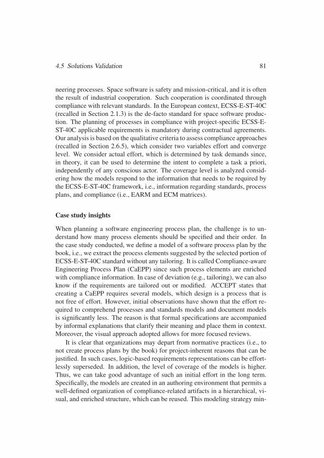
4.5 Solutions Validation 81
neering processes. Space software is safety and mission-critical, and it is oftenthe result of industrial cooperation. Such cooperation is coordinated throughcompliance with relevant standards. In the European context, ECSS-E-ST-40C(recalled in Section 2.1.3) is the de-facto standard for space software produc-tion. The planning of processes in compliance with project-specific ECSS-E-ST-40C applicable requirements is mandatory during contractual agreements.Our analysis is based on the qualitative criteria to assess compliance approaches(recalled in Section 2.6.5), which consider two variables effort and convergelevel. We consider actual effort, which is determined by task demands since,in theory, it can be used to determine the intent to complete a task a priori,independently of any conscious actor. The coverage level is analyzed consid-ering how the models respond to the information that needs to be required bythe ECSS-E-ST-40C framework, i.e., information regarding standards, processplans, and compliance (i.e., EARM and ECM matrices).
Case study insights
When planning a software engineering process plan, the challenge is to un-derstand how many process elements should be specified and their order. Inthe case study conducted, we define a model of a software process plan by thebook, i.e., we extract the process elements suggested by the selected portion ofECSS-E-ST-40C standard without any tailoring. It is called Compliance-awareEngineering Process Plan (CaEPP) since such process elements are enrichedwith compliance information. In case of deviation (e.g., tailoring), we can alsoknow if the requirements are tailored out or modified. ACCEPT states thatcreating a CaEPP requires several models, which design is a process that isnot free of effort. However, initial observations have shown that the effort re-quired to comprehend processes and standards models and document modelsis significantly less. The reason is that formal specifications are accompaniedby informal explanations that clarify their meaning and place them in context.Moreover, the visual approach adopted allows for more focused reviews.
It is clear that organizations may depart from normative practices (i.e., tonot create process plans by the book) for project-inherent reasons that can bejustified. In such cases, logic-based requirements representations can be effort-lessly superseded. In addition, the level of coverage of the models is higher.Thus, we can take good advantage of such an initial effort in the long term.Specifically, the models are created in an authoring environment that permits awell-defined organization of compliance-related artifacts in a hierarchical, vi-sual, and enriched structure, which can be reused. This modeling strategy min-
105105

82 Chapter 4. Thesis Contributions
imizes the distance between the specification of the requirements’ normativeintention and the process elements that should respond to such requirements.
We could also include the possible exceptions that are derived from thedeviations. Once the models are created, the process plans’ validity can beestablished by doing automatic reasoning about the standard conditions. Inparticular, compliance violations could be drafted better since failure to re-quirements is connected to textual sources. Therefore, the comprehension ofprocesses, standards, and their relationships is more natural, and the documen-tation of compliance and the management of evolution get better support thanin manual checklists. These features are a valuable gain since once industrystandards and process plans are formalized, process engineers do not need toexpend valuable hours on reading regulatory documentation to infer the actionsthat must be taken to maintain compliance.
Challenges and Potential Improvements
A key challenge in the use of ACCEPT is that standards are currently writtenin natural language, and formalizing them is an intimidating and fairly sophis-ticated task. The reason is that the number of requirements in a standard issignificant and context-specific. Thus, their interpretation requires expertise.However, FCL has a limited set of constructs, which provide the expressivityrequired for formalizing requirements. Such constructs also provide a frame-work for thinking about the requirements in terms of deontic notions and ex-ceptions, which could simplify their interpretation. Therefore, showing processengineers the FCL potential and its easy to use aspect may strive the interestfor its exploitation.
The work to be done when creating a CaEPP for software projects in thespace context has the tendency to be repetitive. Repetition could cause a dropin a subject’s capacity to perform the modeling task (i.e., disinterest, bore-dom, fatigue), making relative task demands greater than necessary. Furtherautomation of such tasks might reduce the absolute demands, and thus the ac-tual effort. For example, the manual creation of the compliance effects is arepetitive task that has to be done for each effect. It was also prone to er-ror since the effects’ names have similarities (e.g., almost all the tasks’ effectshave the word design). Thus, we needed to review our design several times andmanually track the information we were writing in EPF-C. However, this taskis systematic and supported by templates. As such, it could be automatized byusing a domain-specific language that permits an adequate characterization ofthe specific compliance effects and their production.
106106
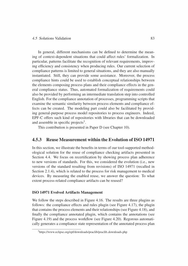
4.5 Solutions Validation 83
In general, different mechanisms can be defined to determine the mean-ing of context-dependent situations that could affect rules’ formalization. Inparticular, patterns facilitate the recognition of relevant requirements, improv-ing efficiency and consistency when producing rules. Our current selection ofcompliance patterns is limited to general situations, and they are also manuallyinstantiated. Still, they can provide some assistance. Moreover, the processcompliance hints could be used to establish conceptual relationships betweenthe elements composing process plans and their compliance effects in the gen-eral compliance status. Thus, automated formalization of requirements couldalso be provided by performing an intermediate translation step into controlledEnglish. For the compliance annotation of processes, programming scripts thatexamine the semantic similarity between process elements and compliance ef-fects can be created. The modeling part could also be facilitated by provid-ing general-purpose process model repositories to process engineers. Indeed,EPF-C offers such kind of repositories with libraries that can be downloadedand assemble in specific projects3.
This contribution is presented in Paper D (see Chapter 10).
4.5.3 Reuse Measurement within the Evolution of ISO 14971
In this section, we illustrate the benefits in terms of our tool-supported method-ological solution for the reuse of compliance checking artifacts presented inSection 4.4. We focus on recertification by showing process plan adherenceto new versions of standards. For this, we considered the evolution (i.e., newversions of the standard resulting from revisions) of ISO 14971 (recalled inSection 2.1.4), which is related to the process for risk management to medicaldevices. By measuring the enabled reuse, we answer the question: To whatextent process-related compliance artifacts can be reused?
ISO 14971 Evolved Artifacts Management
We follow the steps described in Figure 4.16. The results are three plugins asfollows: the compliance effects and rules plugin (see Figure 4.17), the pluginthat contains the process elements and their relationships (see Figure 4.18), andfinally the compliance annotated plugin, which contains the annotations (seeFigure 4.19) and the process workflow (see Figure 4.20). Regorous automati-cally generates a compliance state representation of the annotated process plan
3https://www.eclipse.org/epf/downloads/praclib/praclib downloads.php
107107

84 Chapter 4. Thesis Contributions
and analyses compliance against the FCL rule set. When no counterexamplesexist, Regorous defines that the process is compliant (see Figure 4.21).
(a) (b)
Figure 4.17: ISO 14971:2007-Compliance Effects and Rules.
The second step consist of modeling the variability, i.e., we perform a gapanalysis and model the additional artifacts imposed by the new standard ver-sions. In particular, a new process element is additionally required for com-pliance with EN ISO 14971:2012, i.e., the guidance related to the inclusionof all risks for the treatment of negligible risk (see Figure 4.22a). In con-trast, four new elements are required for compliance with ISO 14971:2019,i.e., two guidance elements (ISO 14871 clause 5 and the treatments of negli-gible risk), and two additional tasks, which are the result of splitting the taskDefine/use safety characteristics (see Figure 4.22b). In Step 3, the complianceanalysis of the variability is performed. In our case, we found that the com-pliance with EN ISO 14971:2012 requires that one new element, specifically aguidance called Treatment of Negligible Risk-Take all Risks is annotated with acompliance effect called guidedByTakeIntoAccountAllRisks. A more complexanalysis is performed in the case of ISO 14971:2019 (see Table 4.5).
We model the compliance effects. Figure 4.23 shows compliance effects
108108

4.5 Solutions Validation 85
(a) (b)
Figure 4.18: ISO 14971:2007-Process Elements.
Figure 4.19: Compliance Effects Annotations.
Figure 4.20: Compliance Annotated Process Plan.
Figure 4.21: Regorous Results.
extracted from ISO 14971:2007 (on the left side) and the variations (highlightwith different colors) respect the other two standards (on the right side).
109109
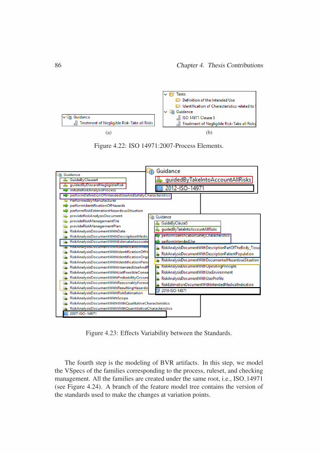
86 Chapter 4. Thesis Contributions
(a) (b)
Figure 4.22: ISO 14971:2007-Process Elements.
Figure 4.23: Effects Variability between the Standards.
The fourth step is the modeling of BVR artifacts. In this step, we modelthe VSpecs of the families corresponding to the process, ruleset, and checkingmanagement. All the families are created under the same root, i.e., ISO 14971(see Figure 4.24). A branch of the feature model tree contains the version ofthe standards used to make the changes at variation points.
110110
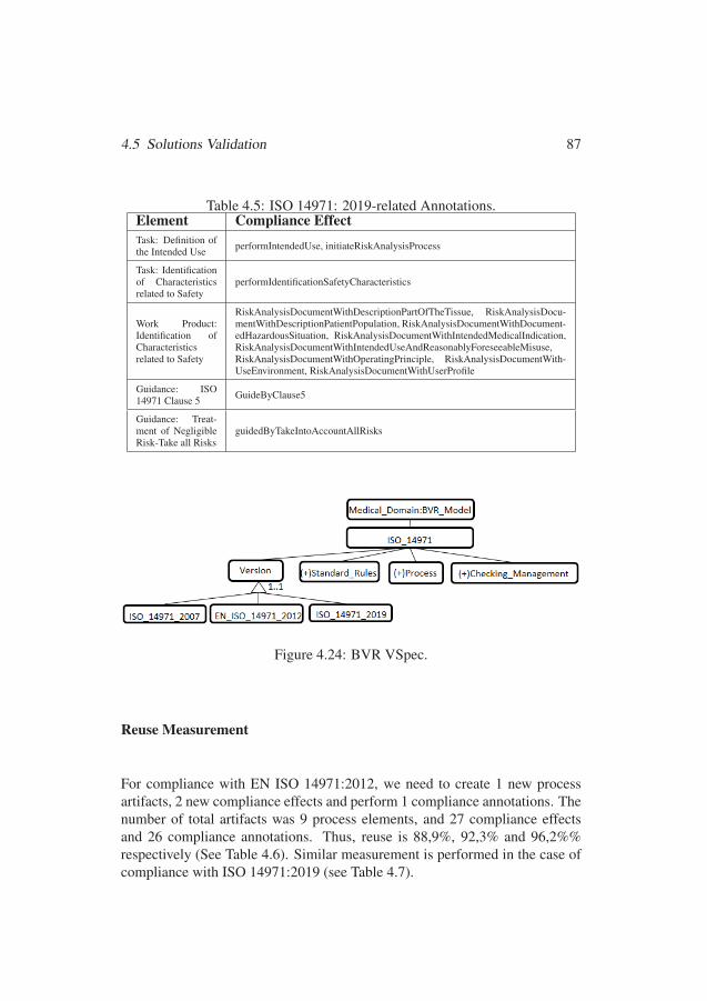
4.5 Solutions Validation 87
Table 4.5: ISO 14971: 2019-related Annotations.Element Compliance EffectTask: Definition ofthe Intended Use performIntendedUse, initiateRiskAnalysisProcess
Task: Identificationof Characteristicsrelated to Safety
performIdentificationSafetyCharacteristics
Work Product:Identification ofCharacteristicsrelated to Safety
RiskAnalysisDocumentWithDescriptionPartOfTheTissue, RiskAnalysisDocu-mentWithDescriptionPatientPopulation, RiskAnalysisDocumentWithDocument-edHazardousSituation, RiskAnalysisDocumentWithIntendedMedicalIndication,RiskAnalysisDocumentWithIntendedUseAndReasonablyForeseeableMisuse,RiskAnalysisDocumentWithOperatingPrinciple, RiskAnalysisDocumentWith-UseEnvironment, RiskAnalysisDocumentWithUserProfile
Guidance: ISO14971 Clause 5 GuideByClause5
Guidance: Treat-ment of NegligibleRisk-Take all Risks
guidedByTakeIntoAccountAllRisks
Figure 4.24: BVR VSpec.
Reuse Measurement
For compliance with EN ISO 14971:2012, we need to create 1 new processartifacts, 2 new compliance effects and perform 1 compliance annotations. Thenumber of total artifacts was 9 process elements, and 27 compliance effectsand 26 compliance annotations. Thus, reuse is 88,9%, 92,3% and 96,2%%respectively (See Table 4.6). Similar measurement is performed in the case ofcompliance with ISO 14971:2019 (see Table 4.7).
111111
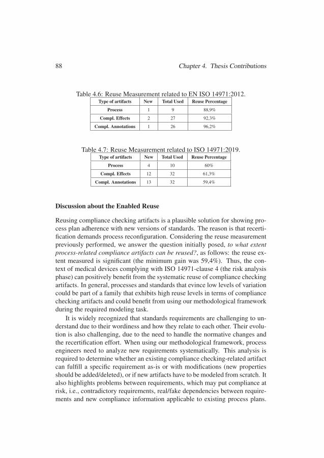
88 Chapter 4. Thesis Contributions
Table 4.6: Reuse Measurement related to EN ISO 14971:2012.Type of artifacts New Total Used Reuse Percentage
Process 1 9 88,9%
Compl. Effects 2 27 92,3%
Compl. Annotations 1 26 96,2%
Table 4.7: Reuse Measurement related to ISO 14971:2019.Type of artifacts New Total Used Reuse Percentage
Process 4 10 60%
Compl. Effects 12 32 61,3%
Compl. Annotations 13 32 59,4%
Discussion about the Enabled Reuse
Reusing compliance checking artifacts is a plausible solution for showing pro-cess plan adherence with new versions of standards. The reason is that recerti-fication demands process reconfiguration. Considering the reuse measurementpreviously performed, we answer the question initially posed, to what extentprocess-related compliance artifacts can be reused?, as follows: the reuse ex-tent measured is significant (the minimum gain was 59,4%). Thus, the con-text of medical devices complying with ISO 14971-clause 4 (the risk analysisphase) can positively benefit from the systematic reuse of compliance checkingartifacts. In general, processes and standards that evince low levels of variationcould be part of a family that exhibits high reuse levels in terms of compliancechecking artifacts and could benefit from using our methodological frameworkduring the required modeling task.
It is widely recognized that standards requirements are challenging to un-derstand due to their wordiness and how they relate to each other. Their evolu-tion is also challenging, due to the need to handle the normative changes andthe recertification effort. When using our methodological framework, processengineers need to analyze new requirements systematically. This analysis isrequired to determine whether an existing compliance checking-related artifactcan fulfill a specific requirement as-is or with modifications (new propertiesshould be added/deleted), or if new artifacts have to be modeled from scratch. Italso highlights problems between requirements, which may put compliance atrisk, i.e., contradictory requirements, real/fake dependencies between require-ments and new compliance information applicable to existing process plans.
112112
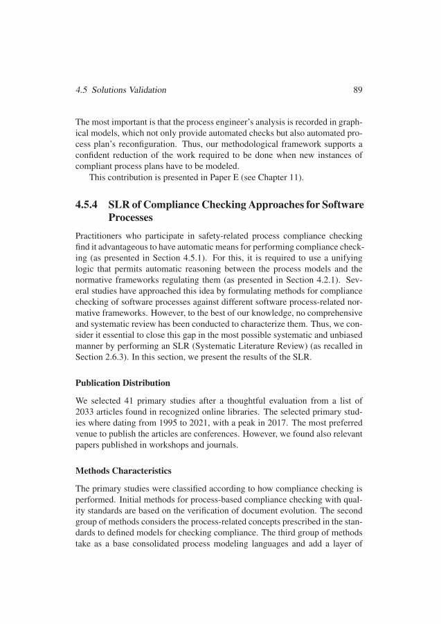
4.5 Solutions Validation 89
The most important is that the process engineer’s analysis is recorded in graph-ical models, which not only provide automated checks but also automated pro-cess plan’s reconfiguration. Thus, our methodological framework supports aconfident reduction of the work required to be done when new instances ofcompliant process plans have to be modeled.
This contribution is presented in Paper E (see Chapter 11).
4.5.4 SLR of Compliance Checking Approaches for SoftwareProcesses
Practitioners who participate in safety-related process compliance checkingfind it advantageous to have automatic means for performing compliance check-ing (as presented in Section 4.5.1). For this, it is required to use a unifyinglogic that permits automatic reasoning between the process models and thenormative frameworks regulating them (as presented in Section 4.2.1). Sev-eral studies have approached this idea by formulating methods for compliancechecking of software processes against different software process-related nor-mative frameworks. However, to the best of our knowledge, no comprehensiveand systematic review has been conducted to characterize them. Thus, we con-sider it essential to close this gap in the most possible systematic and unbiasedmanner by performing an SLR (Systematic Literature Review) (as recalled inSection 2.6.3). In this section, we present the results of the SLR.
Publication Distribution
We selected 41 primary studies after a thoughtful evaluation from a list of2033 articles found in recognized online libraries. The selected primary stud-ies where dating from 1995 to 2021, with a peak in 2017. The most preferredvenue to publish the articles are conferences. However, we found also relevantpapers published in workshops and journals.
Methods Characteristics
The primary studies were classified according to how compliance checking isperformed. Initial methods for process-based compliance checking with qual-ity standards are based on the verification of document evolution. The secondgroup of methods considers the process-related concepts prescribed in the stan-dards to defined models for checking compliance. The third group of methodstake as a base consolidated process modeling languages and add a layer of
113113
90 Chapter 4. Thesis Contributions
analysis by using formal languages. The fourth group of methods is aimed atchecking compliance from role-based access controls. The final group usesdifferent methods, i.e., workflow engines, model refinements, model checking,and process mining. The five types of approaches use 14 different languages torepresent the process elements and structures. Similarly, 14 different languagesare used to represent the requirements prescribed by the standards.
The automation part claimed in the studies is related to compliance reason-ing, namely the automatic comparison between the process and the normativedocuments. Frameworks composed of chained tools also automatically trans-form the information between the interrelated tools. Those that perform pro-cess mining also provide an automatic mining procedure. However, require-ments formalization is mainly performed manually, in some cases, by usingformalization patterns. The state of the tool support is also variable. In partic-ular, the majority of the methods provide prototypes that are used as proof ofconcept.
Few primary studies present means for addressing software process recon-figuration in the light of standards evolution (i.e., the release of a new version ofstandards), tailoring (i.e., the selection, eventual modification, and implemen-tation rationale), and process diversity (application of several standards in thesame project). Some studies show specific structures that permit the deletionand modification of products and activities according to the project’s character-istics, such as the integrity levels prescribed by safety standards. In others, thereuse of process elements and the use of methodologies such as process linesare also implemented to manage process diversity and standards evolution
Potential Impact
Several application domains are addressed in the primary studies. The mostrepresented application domain is characterized by the safety-critical systemscontext (defined by the application of safety standards). There are also methodsaddressing specific aspects of software process improvement (SPI) and quality,data protection, software process verification, Cybersecurity and Health care.Different standards have been modeled and used in the experimentations orillustration results provided in the primary studies. The most represented isISO 26262, which is a functional safety standard used in automotive.
The illustrative scenarios are also variable. It is important to highlight that,in total, 19 of the 41 studies used data extracted from industrial settings toevaluate their methods There are few studies that also addressed the problem ofcompliance checking in agile environments. Such approaches are mainly based
114114

4.5 Solutions Validation 91
on mining techniques. Thus, they are not applicable in the case of seekingcompliance checking of process plans since process minign requires processlogs, which is information resulting after executing the process.
Discussion about Existing Methods
Existing literature related explicitly to compliance checking of software pro-cesses is scarce and scattered. The publication’s irregularity in the initial yearsand the reduced amount of journal papers published may indicate that the topichas taken a long time to establish itself as a research subject. We found mostof the studies after 2017, which may mean that automated compliance check-ing of software processes has started to be a consolidated topic in the researchagenda. In our opinion, these are relevant news since compliance checking isnot optional nor either an easy task.
1. The use of software process modeling languages. New languages (meta-models, and ontologies) with limited scope have been created. The contin-uous creation of ad-hoc software process-related modeling solutions couldbe a disadvantage, especially when there are already well-defined processmodeling languages that could be reused and extend according to specificneeds. In addition, the creation of many new languages is a sign of researchefforts done in silos. Such independence may result in wasted research ef-forts since languages are always created from scratch.
We consider that new research efforts in automatic compliance checking,specifically for software processes, could take into account existing processmodeling languages to accelerate results in the topic and standardize thetechniques and tool support. For this, we could perform comparative stud-ies between existing process modeling languages and case studies showingtheir capabilities.
2. Language suitability for addressing normative requirements. Com-pliance is a relationship between permissions (what you are allowed to do),obligations (what you have to do), and prohibitions (what you should avoid).In the case of compliance with standards, the concept of tailoring is alsorelevant. Tailoring allows organizations to adapt normative requirements tospecific project conditions. However, in the tailoring process, the provisionof a justification (called rationales) is a must-do task aimed at legitimizingchanges.
Tailoring can be seen as a sort of justified exception handling in softwareprocess compliance checking. Thus, the language selected to represent nor-
115115
92 Chapter 4. Thesis Contributions
mative frameworks should be able to provide explicit means that facilitatethe description of the mentioned concepts since they are not only necessarybut also sufficient to tackle the compliance checking problem of softwareprocesses. In our analysis of the languages used in the primary studies, wefound such exploitable characteristics in FCL.
3. Towards a generic and domain-agnostic method. The methods describedin the primary studies provide a set of interesting, applicable, and usefulaspects contributing to the automation of compliance checking of softwareprocesses. However, in most cases, normative documents have been con-sidered in isolation resulting in ad-hoc solutions. In reality, process engi-neers have to deal with process diversity, tailoring, and standards evolution.Moreover, software organizations are moving towards agile, even in heav-ily regulated domains, such as the safety-critical. Thus, the narrow focus ofthe methods reported may be a factor that also hinders their application inpractice.
In our opinion, it is crucial to spread out research results regarding com-pliance checking of software processes by consolidating a method that canhandle the different concepts, structures, and scenarios. In that sense, wewill continue investigating how to combine existing languages. The goal isto contribute with a well-defined (set of) logical structure(s) that works har-moniously in all the aspects required for software process-related compli-ance checking: reasoning capabilities, means for variability management,support for agile environments, and process execution conformance.
4. The need for diverse abilities. In today’s methods for compliance check-ing, diverse abilities are required from their potential users. In particular,there is the need for knowledge regarding process modeling and the abilityto formalize natural language in a specific formal language. As potentialusers, we have process engineers who may already have some expertise inprocess modeling. However, different tools may approach modeling in dif-ferent ways. Besides, the formalization of natural language in which therequirements are commonly specified is always perceived as demanding.Such perception may hinder the interest of the potential users and, thus, themethods’ use.
A key point for introducing any formal language in the industry is the us-ability aspects. We need to avoid the case of a new person feeling confusedand frustrated with such formalisms. In particular, it could be interesting todevelop short, straight-forward expressions (i.e., syntactic sugar) that make
116116
4.5 Solutions Validation 93
it easier to read or to express normative frameworks, especially when thecomplexity (and size) of the compliance checking tasks grows
5. Increase the level of automation and tool support. It is difficult to guar-antee industrial adoption when there is nonexistent or loosely coupled toolsupport. Thus, it is crucial to provide adequate and complete tool support forautomatically perform compliance checking. This aspect can be facilitatedby integrating existing development tools like Rational Method Composer,which is are already used in industry. It is also essential to increase the au-tomation means for easing the creation of rules, i.e., rule editors and processmodels, since formalizing requirements still needs human intervention.
6. Going beyond technological dilemmas. In this point, we have two partsto discuss.
(a) Article 22 of the GDPR stipulates that whenever a decision that legallyor significantly affects an individual relies solely on automated pro-cessing, the right to contest the decision must be guaranteed. Thus,there is a need to clearly explain the automatic compliance checkingresults that guarantee organizations and individuals’ rights. Conse-quently, means for transparency have to build in the methods. Trans-parency can be achieved by implementing data provenance and trace-ability mechanisms. Data provenance is associated with data regardingorigin, changes, and details supporting confidence or validity. Trace-ability is related to the relationships between compliance results, soft-ware process elements, and normative frameworks. We also considerthat informal explanations should always accompany formal specifica-tions to clarify the rules’ meaning and place them in context.
(b) Assuming that the method for compliance checking and the tool sup-port are correctly designed, good results may be expected. However,correct answers depend on the quality of the inputs that the tool re-ceives. Unfortunately, the use of mathematical methods for compli-ance checking, as presented in the studies, are no guarantee of cor-rectness since humans apply them. Cognitive biases, which are devia-tions from the rational way we expect our brains to work, may appearwhen we formalize normative documents. Therefore, there must bea layer of trust in the methods, which guarantees that there is no re-quirement poisoning, i.e., rules incorrectly derived from the normativeframeworks. This aspect can be reached in the future by using tech-nological means. However, a shorter-term solution could be to contact
117117
94 Chapter 4. Thesis Contributions
standardization/regulatory bodies to investigate the possibility of re-leasing process models and formal representations of the requirementswithin the release of new versions of the standards. With this strategy,we could reduce undesired room for interpretation of the normativetexts.
This contribution is presented in Paper F (see Chapter 12).
118118
Chapter 5
Related Work
In this chapter, we discuss the related work. In particular, we discuss ap-proaches for automated compliance checking (see Section 5.1), approaches forfacilitating requirements specification (see Section 5.2), and approaches for fa-cilitating the reuse of proofs (see Section 5.3).
5.1 Automated Compliance Checking
Means for compliance checking of processes have been provided in previousresearch. In [122], the authors propose a semi-automatic compliance processto support the formal verification of software requirements. In [102], the au-thors present an approach to reason about the correctness of the process struc-ture, which is based on the combination of CTN (Composition Tree Nota-tions) [123] and Description Logic (DL). In [124], the authors extend the workdone in [102] to include the capability levels proposed in ISO/IEC 15504 [71].Similarly, in [125] and [126], authors present models to enable the definitionprocess capability levels, according to ISO/IEC 15504 and CMMI (Capabil-ity Maturity Model Integration) v1.3 [72]. In [127], the author presents aformalization of data usage policies in a fragment of OWL (Web OntologyLanguage) [128], which is a DL-based modeling language. All the previousapproaches consider the use of DL to reason about the compliance of the pro-cess structure against specific normative frameworks (i.e., ISO/IEC 15504 andCMMI). As presented in [129], DL has relative expressiveness, which makesit more difficult to model certain concepts. Besides, the previous approaches
95
119119
96 Chapter 5. Related Work
only consider the analysis of the process structure. Instead, our frameworkconsiders the information that represents the effects caused by the tasks (a.k.a.compliance effects annotation), which is used to check the compliance of aprocess structure and its behavior. Our framework is not tied to specific nor-mative frameworks and uses SPEM 2.0 concepts, which offers a standardizedstructure for modeling processes and their related information.
SPEM 2.0 community is also interested in addressing compliance check-ing and monitoring. In [130] and [131], the authors propose a framework thatuses LTL (Linear Temporal Logics) on top of SPEM 2.0 to monitor and controlprocess instances according to its defined process model. The work presentedin [132] and [133] aim at facilitating the checking of constraints that can be de-fined as part of a specific process model (e.g., standards requirements, metrics)by using SWRL (Semantic Web Rule Language) [134]. In [135], the authorspresent an approach for representing SPEM 2.0 process models in DL to pro-vide consistency checks. In [136], the authors provide an approach in OWLfor tailoring processes, in which outputs are transformed into SPEM 2.0 pro-cess models. Approaches to systematically exploit the modeling capabilitiesof SPEM 2.0 for collecting the compliance elements required by specific stan-dards are also part of the state-of-the-art. Examples of those approaches arepresented in [137], which collects compliance information for EN 50128 [67],and in [138], which collects evidence for supporting compliance with DO-178C [29]. Models for representing Deployment Packages and ImplementationGuides for the Standard ISO/IEC 29110 [139] in EPF-C are presented in [140].
The use of SPEM 2.0 in the previous approaches is limited to modelingthe elements required to create the process structure. In addition to the processstructure, other approaches use concepts provided by SPEM 2.0 for modelingadditional elements required for compliance. For instance, in [89] customiza-tion of the elements defined in SPEM 2.0 is performed to give the possibil-ity to generate compliance tables. The modeling of standards requirements inSPEM 2.0 presented in [141] is used to detect whether the process model con-tains sufficient evidence for supporting the requirements, providing feedback tothe safety engineers regarding detected fallacies and recommendations to solvethem. As in [89] and in [141], our approach combines the modeling capabilitiesfor modeling standard’s requirements, plus customization of preexisting mod-eling concepts to generate a centralized compliance-related knowledge base.In addition, we add a layer of confidence by considering the use of methods toderive proof of compliance. However, we do not use semantic web methods oflogics from the temporal logics family for deriving our proofs since they arenot expressive enough for modeling compliance notions [75]. Semantic web
120120
5.2 Requirements Specification 97
methods, in particular, are computational methods that deal with ontologiesand rules, whose combination could be undecidable [142].
Approaches for compliance checking have been widely studied in the busi-ness context. In [143], the authors propose a metamodel called REALM (Regu-lations Expressed As Logical Models), which uses Real-time Temporal ObjectLogic [144], for the representation of norms. In [145], the authors proposean SOA (Service Oriented Architecture)-based compliance governance, calledCOMPAS, to define compliant process fragments. In [146], authors proposea compliance checking method for business process models, in which normsare expected to be modeled in BPSL (Business Property Specification Lan-guage) and then formalized in LTL (Linear Temporal Logic). Once the twoformal specifications are given, model checking via the NuSMV2-based OpenProcess Analyser is performed for checking compliance. In [147], the authorspropose a solution for ensuring compliance by using a formal specification ofbusiness rules. There is also compliance checking frameworks that combinethe modeling capabilities provided by BPMN (Business Process Model andNotations) [148] and Temporal Logics for the modeling of regulations. Exam-ples of these kind of frameworks can be found in [149], [150], and [151]. Ourframework uses a similar methodology, i.e., we define formal specifications ofthe normative requirements and the processes. The main difference regardingthe previous approaches is the use of the modeling languages. In particular,we use FCL and not any language derived from the family of Temporal Logicsfor creating the formal specification of the requirements of the standards. Thereason for not using TL is that this logic cannot provide conceptually soundrepresentations of the regulatory requirements governing a process [152].
5.2 Requirements Specification
One of the significant challenges associated with the formalization of norma-tive texts is requirements interpretation. Currently, research in this area aimsat bridging the gap between the normative expertise required to interpret theregulatory text and the modeling skills required to build the knowledge base.In particular, in [153], the authors focus on the representation of constitutiverules in a machine-readable form. In [154], the authors propose a frameworkfor identifying terms and refining the goals proposed by privacy legislation.In [155], the authors present a pattern-based approach to capture the knowl-edge of domain experts. In [156], the authors present a methodology to for-malize norms as logic programs. In [157], the authors use SBVR (Semantics
121121
98 Chapter 5. Related Work
of Business Vocabulary and Business Rules), a controlled natural language,to develop business vocabulary and business rules. In [158], the authors usehigh-Level methodological approaches for the extraction and representation ofcompliance objectives, rules, and constraints by using semantic web technolo-gies. In [159], the authors also use conceptual models to extract informationfrom standards that apply to agricultural production. In [160], the authors de-scribe a methodology for requirements formalization for flight-critical systemsverification. Like the previous works, our goal is to facilitate the formal speci-fication of requirements by considering specific normative concepts. We focus,mainly, on processes and provide a mechanism for facilitating the formaliza-tion of process-related requirements prescribed by the standards in FCL basedon a standardized language, i.e., SPEM 2.0.
Separation of concerns within the normative space in FLC has also beenproposed in the state-of-the-art. In [161], four types of control tags are definedfor compliance checking of business processes. These control tags consist ofthe state and operations of propositions about the conditions to be checkedon a task and are typed-linked, namely control tags represent compliance ef-fects. Such tags are: the flow tag, which represents a control that would im-pact the flow of the process activities; data tag, which identifies the data reten-tion and lineage requirements; the resource tag, which represent access, rolemanagement, and authorization; finally, time tag, which represents controlsfor meeting time constraints such as deadlines and maximum durations. Asin [161], our work describes the compliance effects based on the type of ele-ments present in a process. However, contrary to [161], we further separate thedefinition of the elements from the properties allocated to these elements, i.e.,we propose definitional and property-oriented compliance effects. Moreover,we provide a template for creating the compliance effect and icons that facili-tate their description and subsequent annotation in process elements. In [162],the concept of data tag described in [161] is revisited to create a methodol-ogy that permits their extraction from business process logs. The extraction ofour compliance effects, as opposite the work presented in [162], is performeddirectly from the standards requirements since we aim at having a faithful rep-resentation of the requirements prescribed by the standard at design time.
Guidelines are also widely used to spread the used of novel methods in en-gineering tasks. In [163], the authors describe the Oracle Policy Modeling bestpractices guidelines for business rules modeling. Similarly, in [164], the au-thors describe a methodology to guide companies to establish Cyber-PhysicalSocial System data subjects’ consent and data usage policies. In [103], theauthors present guidelines for supporting the formal representation of safety
122122
5.3 Reuse of Proofs 99
regulatory requirements. In [165], the authors present the use of tabular ex-pressions to generate formal models of system requirements. The authors ofFCL have also published explicative examples of the modeling of FCL ruleswithin the business context, e.g., [166, 49], which can be used as a guide-line for learning the language. In [167], the authors present a methodologyfor extracting models from ISO 26262, called “snowball”, in which high-levelrequirements (objectives section of the standard) are modeled first, and thenthe low-level requirements (requirements and recommendations) are added asrolling a snowball in the snow. The use of FCL for supporting compliancemanagement tasks in safety-related processes is a novelty. We did not find spe-cific examples or guidelines that apply to the domain yet. Thus, the guidelinesprovided by this thesis may be of interest for process engineers involved in thedifferent industries manufacturing safety-critical systems. We also considerthat our guidelines can be used to derive domain-specific guidance applicableto process-based standards beyond the ones tackled in this thesis.
5.3 Reuse of Proofs
“State explosion phenomenon” [168] refers to the exponential growth of thestate space required to be verified by automatic checking methods. Essentially,research impacting the reduction of this phenomenon is studied in software ver-ification. In [169], the authors present an approach for exploiting the evolution-ary nature of programs for reusability of proofs, in which a tree of connectedproved fragments of a program is built. In [170], the authors present a reusemethod that uses incremental proof construction for reusing correctness proofsof Java programs. In [171], the authors give an overview of techniques forreusing information obtained in verifications results from past trials. In [172],the authors present a family-based strategy for minimizing the efforts in verify-ing product lines. In particular, this verification can be achieved by combiningall code of all features in a single product simulator, which checks all products’valid execution paths without generating and checking any individual product.These approaches are focused on products, while our focus is the processes toachieve such products.
The change triggered by updated standards for the software process is atopic tackled from different perspectives. In [173], the authors propose amethod that permits the attachment of change information to process docu-ments to facilitate change understandability. However, no systematic methodsto reuse modeling artifacts facilitating the changes are proposed as we do in our
123123

100 Chapter 5. Related Work
work. Methods for modeling the change/variation and reuse of processes re-sult from applying software process lines methodologies, as recently surveyedin [174]. In particular, SoPLE [50] has been exploited to provide a represen-tation of family members with safety information, e.g., reusable process argu-ments used in safety cases [175] and tailoring of process models according tosafety integrity levels of products [176]. In our work, we also use SoPLE toprovide mechanisms to support variation knowledge reuse regarding compli-ance checking artifacts, which has not been yet addressed in other approaches.
In the area of process compliance, only a few approaches that consider thereuse of proofs are presented in the state-of-the-art. In [145], the authors con-sider that after doing many customization steps, which can include techniques,such as abstraction or parametrization, the functionality of a process chunkcan be reused. However, for performing the compliance checking of processchunks, special formalizations have to be performed. Some researchers tack-led reuse by defining building blocks that implement compliance requirements,e.g., compliance scopes [177], and compliance fragments [178, 179]. Reuse isalso approached with the use of process patterns [180], and rule patterns [149].In [150], business processes are augmented with reusable fragments, calledprocess fragments for compliance, stored in a fragment repository that sup-ports versioned storage and retrieval. The intention is to ensure process com-pliance to the corresponding compliance requirements. In contrast ot the pre-vious works, we propose a holistic modeling framework for safety-related pro-cess compliance checking that permits modeling artifacts, which can be auto-matically interleaved with evolutionary/changing artifacts originated from newversions of standards. In that way, building blocks that implement compliancerequirements are reusable and process models and rulesets denoting formalizedrequirements from standards.
124124
Chapter 6
Epilogue
In this chapter, we present the final remarks of this thesis. In particular, wepresent conclusions (see Section 6.1), limitations of the study (see Section 6.2)and future work (see Section 6.3).
6.1 Conclusions
Industry standards, especially safety standards, establish requirements that serveas a baseline for developing safety-critical systems. For instance, compliancewith ISO 26262, the functional safety standard targeting automotive, representsthat the risks associated with the safety-critical system operation installed in avehicle have been considered, analyzed, and mitigated to a sufficient level fortheir confident deployment into society. In some industries, compliance withspecific normative frameworks is mandatory (see, for instance, the certificationof airworthiness, which is based on standards applied by national aviation au-thorities), while in others, the same procedure is not de rigueur (for instance,the application of the standard ISO 26262 in automotive is voluntary).
Mandatory or not, compliance with industry standards serves as a bench-mark to design, implement, maintain and evaluate technical products. It alsogrants several benefits to manufacturers. For example, compliance require-ments provide a reference point for production optimization. Moreover, com-pliance requirements help manufacturers to formulate contractual obligationswith their partners in a globalized sphere. In addition, a compliance stamp,which is a mark that consumers generally trust, could make manufacturers
101
125125
102 Chapter 6. Epilogue
gain a lead against competitors. A standard-compliant safety-critical systemis also, to some extent, ”backed up” in legal actions if it unexpectedly causesharm since compliance with standards is a sign of reasonable care. Given theprevious considerations, is it clear that compliance with standards is a must-dofor manufacturers of safety-critical systems.
Commonly, industry standards adopt a highly prescriptive approach, whichfocuses on process reference models and process-related requirements. Suchan approach also demands that normative imperatives are planned at the begin-ning of the development process and not added later on. A process plan cor-rectly designed is a detailed proposal of action that demonstrates the planning-time allocation of responsibilities. If every actor fulfills his/her duties, com-pliance at execution time can also be guaranteed. Consequently, planning pro-cesses is an essential requirement for manufacturers of safety-critical systems.
Compliance of process at planning time requires that process engineersinclude the sequence of tasks mandated by standards (i.e., the process behav-ior) and the resources ascribed to such tasks, e.g., personnel, work products,tools, and methods, which are also framed with essential properties (i.e., theprocess structure). Process elements and their features are described in thestandards and mandated to be achieved at certain points of the developmentprocess. Thus, process-related compliance management can be supported bychecking that the processes planned to engineer safety-critical systems havesuch elements and characteristics at the specific times they are required.
Manually checking process plan compliance is a complex task since stan-dards contain a sheer volume of requirements. Requirements also have an in-tricate nature, i.e., requirements in one standard usually refer to other require-ments in the same standard or other standards. Moreover, requirements in onepart of the standard may contradict requirements in another part of the samestandard or other applicable standards. In addition, requirements from one ordifferent standards may apply to one or several processes at different times andjurisdictions. Last but not less, manufacturers commonly manage multiple pro-cess plans and, thus, perform compliance checking repeatedly. In each case,if there are no mechanisms to manage the information regarding standards re-quirements appropriately and the processes they regulate, (re)interpretationsand rework may be needed (e.g., when the process expert leaves the company),and compliance risks may become commonplace.
Process management tasks supported by tools, which can provide auto-mated checks, could be a plausible solution. Indeed, automated compliancechecking could help process engineers to detect compliance violations and en-force compliance at planning time when allocating the resources for engineer-
126126
6.1 Conclusions 103
ing safety-critical systems. Tools can also help the process engineers managethe changing conditions required to comply with standards (new versions ofthe standards, tailoring) and provide means for tracking such changes. Thus,the main goal of our thesis is to facilitate automated compliance checkingof the process plans used to engineer safety-critical systems against thestandards mandated (or recommended) in the safety-critical context. Forreaching this goal, we defined four subgoals and provided contributions dis-tributed in six papers (see Section 6.1.1).
6.1.1 Research Goals RevisitedIn this section, we present the relationship between the research goals proposedin Section 3.3, the contributions discussed in Chapter 4, and the included pa-pers presented in Chapters 7 to 11 (see Figure 6.1).
Contribution 1. We identified challenges that manufacturers of safety-critical systems have regarding compliance with prescriptive standards at plan-ning time. Based on them, we specified requirements for a suitable techni-cal solution that shall facilitate: 1) the management of the artifacts requiredfor compliance checking with prescriptive standards, i.e., the standards them-selves, their requirements, the processes plans, and the compliance means;2) keeping track of the applicable requirements; 3) the recognition of con-tradictions and ambiguities between applicable requirements; and 4) managingthe changing nature associated with requirements diversity. With this contri-bution, we fulfilled our first subgoal, namely, elicit the requirements to be metto support the automated compliance checking of the process plans used inthe safety-critical context. This contribution, which was summarized in Sec-tion 4.1, is found throughout the articles A, B, C, D, and E.
Contribution 2. We adopted compliance by design and introduced ACCEPT(Automated Compliance Checking of Engineering Process plans against sTan-dards). ACCEPT is an iterative and comprehensible framework that allows thecreation and management of the artifacts required for compliance checking,i.e., the standards themselves, their requirements, the processes plans, and thecompliance means. It also permits the creation of engineering process planscheckable for compliance, i.e., process elements enriched with compliance in-formation through annotations representing formalized standards requirementsin FCL. FCL is a language based on defeasible logic, which permit to managethe contradictory and ambiguous nature present in the normative documents.
127127

104 Chapter 6. Epilogue
Figure 6.1: Relationships between Research Goals, Contributions and Papers.
ACCEPT is supported by the tool-chain constituted of EPF-C, which has goodcoverage of SPEM 2.0 concepts, and the compliance checker Regorous, whichcan perform automatic analysis of FCL rules. EPF-C is an environments thatprovides hierarchal structures that facilitates keeping track of the applicablerequirements. ACCEPT is equipped with a set of methodological steps thatfacilitate its use. ACCEPT provides a baseline for fulfilling the requirements1, 2 and 3 elicited in contribution 1. With this contribution, we fulfilled oursecond subgoal, namely, identify mechanisms for supporting automated com-pliance checking of the process plans used in the safety-critical context. Thiscontribution was summarized in Section 4.2 and found in papers A and D.
128128
6.1 Conclusions 105
Contribution 3. We proposed three mechanisms for facilitating the creationand reuse of the specifications required to check compliance of process plansautomatically, which is the four requirement elicited in contribution 1. Thefirst two mechanisms are called process compliance hints and patterns. Pro-cess compliance hints (summarized in Section 4.3.1) are resources designedto support the creation of separated concepts included in the FCL specifica-tion based on process structure and the concepts supported by SPEM 2.0. (i.e.,tasks, roles, work product, guidance, tools, and their relationships). Processcompliance patterns (summarized in Section 4.3.2) indicate common situa-tions an FCL designer is likely to encounter when formalizing standards. Bothprocess compliance hints and patterns provide reusable means for facilitatingthe formalization of process-related requirements into FCL rules. The thirdmechanism (summarized in Section 4.4) is the systematic reuse of compliancechecking artifacts. This solution is based on the reuse capabilities providedby SoPLE and the support provided by the integration of the tools EPF-C andBVR-T. With these contributions, we fulfilled our third subgoal, namely, facil-itate the creation of reusable specifications required for automated compliancechecking of the process plans. These contributions are found in the papers asfollows. The process compliance hints are found in paper B. The process com-pliance patterns are found in papers A and D. Finally, the systematic reuse ofcompliance artifacts is found in papers A and E.
Contribution 4. Finally, we validated our proposed solutions. First, weinvestigated the degree of acceptance of methods for automated compliancechecking via a personal opinion survey, which was applied to practitionerswho participate in safety-related process compliance checking. Second, we as-sessed ACCEPT, via a standard-based case study applicable to space softwareengineering processes, considering a specific set of qualitative usefulness cri-teria. Third, we measured the reuse permitted by our solutions when showingprocess plan adherence with new versions of standards related to the medi-cal domain. Fourth, we positioned our work with respect to the state-of-the-artand the state-of-the-practice by characterizing the existent approaches for com-pliance checking of software processes and testing our assumptions regardingcompliance checking current practices and challenges. We found that our so-lutions provide a set of characteristics that seamlessly integrate with currentpractices. We also identified aspects that permit our solutions to improve inthe future. With this contribution, we fulfilled our fourth subgoal, namely, in-vestigate the significance of a solution for automated compliance checking ofprocess plans in the safety-critical context. This last contribution, which was
129129
106 Chapter 6. Epilogue
summarized in Section 4.5, is found in papers C, D, E, and F.
6.2 LimitationsOur solutions focus on compliance checking of the process plans used to engi-neer safety-critical systems. The findings of this study have to be seen in lightof some limitations.
1. Manufacturers of safety-critical systems commonly make use of differentstrategies to meet their needs regarding process compliance management.In particular, this thesis address one of these strategies, i.e., compliancechecking of processes at planning time. In general, process compliancecan also be checked at runtime or post-execution time. Our framework canprovide a static view of the compliance status of the process at a specificexecution point that could support the decision-making process. However,it cannot help the process engineers enforce compliance in the same way itis done at planning time since activities already executed cannot be changed.
2. SPI frameworks, in addition to the process reference framework, also con-sider the process outcomes/attributes ratings to determine the capabilitylevel of the process (i.e., how well a manufacturer performs its processes).Our framework provides the status of the process compliance to the processreference framework provided by such standards, i.e., whether the tasks andwork products are achieved. The compliance reports obtained from ourframework can only be used as a baseline to manually determine the capa-bility levels of the checked process.
3. The annotation of the compliance effects for the tasks, roles, work products,tools, and guidance, is done manually, i.e., the process engineers, based ontheir own experience, deduce the effects that the process elements can even-tually cause. This procedure could pose some challenges when the processplans are extensive, i.e., the manual annotation could be time-consuming.
4. Process compliance hints, which are our rule of thumb to address sepa-rated concerns within the compliance information of a process, are onlyconceptually achieved in our contribution. For this reason, such separationof concerns is not still taken into account in practice by the checker.
5. The compliance checking methodology used in our approach is processmodeling language agnostic. However, the tool support lacks agnosticism,
130130
6.3 Future Work 107
i.e., it depends on a specific modeling tool to provide compliance checkingresults. This characteristic is currently impeding the back-propagation ofthe compliance results in our selected process modeling language.
6.3 Future WorkWe believe that the work needed to be done by a process engineer regardingcompliance management will benefit from the contributions achieved in thisdissertation since they provide a baseline for automation and systematic reuse.We also consider that there are research directions that could increase the scopeof our current results, as presented below.
1. Validation. With the time we had at hand, we have performed a limitedevaluation of our achieved contributions. Thus, future work will includemore empirical research with the use of interviews and observations to see,for instance, how practitioners carry out their compliance checking prac-tices with our solutions in natural settings, i.e., industrial environments. Inparticular, the experience of effort (or perception of effort) is a factor thatis very important to analyze since it can provide feedback on task diffi-culty. With these evaluation results, we can revisit usability aspects andimprove our models’ representation if needed. In addition, we consider in-cluding more elaborated measurement frameworks (e.g., metrics) to provideevidence concerning our solution’s efficiency in terms of time and cost re-duction (manual vs. automatic work). Finally, we could generate fitnessfunctions that facilitate calculations regarding the adequacy of the informa-tion coverage level provided by the models, the compliance documentation,and the evolution management (number of artifacts modeled vs. number ofartifacts required by the normative framework).
2. Automation. In general, the methodologies defined in our solution are sys-tematic and can be further automated. For example, extensions to the cur-rent algorithm used for compliance checking must be designed and imple-mented to permit the inclusion of co-occurrent compliance effects (effectsthat coincide in a task), which are annotated in process elements ascribed totasks. In addition, we consider that algorithms that automatically enable thecreation of process elements from the definitional compliance effects shouldbe investigated. We also need to find strategies to represent the compliancechecking results in an agnostic way to permit their automatic backpropaga-tion in our selected process modeling tool. We also consider the creation
131131

108 Chapter 6. Epilogue
of rule editors that facilitate the use of templates for process compliancehints and patterns. Finally, algorithms that facilitate the automation of theformalization of requirements, based on natural language processing, couldbe proposed.
3. Impact. A trust mechanism to guarantee that rules are correctly derivedfrom the normative frameworks, i.e., it validates that requirements are notlost or poisoned during formalization processes, is required. A solution forthis aspect could be to contact standardization/regulatory bodies to investi-gate the possibility of releasing process models and formal representationsof the requirements within the release of new standards or new versionsof already positioned standards. With this strategy, we could reduce unde-sired room for interpretation of the normative texts. In addition, our solu-tions should be integrated into the platform created by the European projectAMASS (Architecture-driven, Multi-concern and Seamless Assurance andCertification of Cyber-Physical Systems) [181]. With this strategy, we aimat concretizing our work in terms of tool support.
4. Extension. Additional mechanisms for supporting compliance at runtimeor post-execution time (e.g., automated alerts, task post-execution analysis,and recommendations systems) can be provided to manage compliance is-sues once violations are detected in static compliance checks. These mech-anisms could be beneficial in agile environments, which can make use ofstatic checks after each process iteration to support subsequent iterationsin a compliant-informed fashion. Algorithms that consider the ratings re-quired for process capability determination could also be designed and im-plemented for fully automated support regarding process improvement stan-dards.
5. Generalization. We consider it essential to provide case studies by con-sidering a broader range of standards in contexts beyond the ones alreadyevaluated.
132132
Bibliography
[1] AMASS., “Architecture-driven, Multi-concern and Seamless Assur-ance and Certification of Cyber-Physical Systems.” http://www.amass-ecsel.eu/.
[2] N. Leveson, “Safety : Why, What, and How,” ACM Computing Surveys(CSUR), vol. 18, no. 2, pp. 125–163, 1986.
[3] V. Icheku, Understanding Ethics and Ethical Decision-Making. XlibrisCorporation, 2011.
[4] P. B. Ladkin, “Duty of Care and Engineering Functional Safety Stan-dards,” Digital Evidence & Elec. Signature L. Rev., vol. 16, p. 51, 2019.
[5] D. J. Smith and K. G. Simpson, The Safety Critical Systems Handbook:A Straightforward Guide to Functional Safety: IEC 61508 (2010 Edi-tion), IEC 61511 (2015 Edition) and Related Guidance. Butterworth-Heinemann, 2020.
[6] M. Generowicz, “The Easy Path to Functional Safety Compliance.”https://www.iesystems.com.au/wp-content/uploads/2015/04/Duty-of-Care-Article.pdf, 2013.
[7] J. Knight and J. Rowanhill, “The Indispensable Role of Rationalein Safety Standards,” in 35th International Conference SAFECOMP,vol. 2788, pp. 39–50, Springer, 2016.
[8] N. G. Leveson, Engineering a Safer World: Systems Thinking Appliedto Safety. The MIT Press, 2016.
[9] S. O. Hansson, “Safe Design,” Techne: Research in Philosophy andTechnology, vol. 10, no. 1, pp. 45–52, 2006.
109
133133
110 BIBLIOGRAPHY
[10] J. Bowen, “The Ethics of Safety-critical Systems,” Communications ofthe ACM, vol. 43, no. 4, pp. 91–97, 2000.
[11] G. T. Marx, “Technology and Social Control,” 2015.
[12] International Electrotechnical Commission, “IEC 61508-FunctionalSafety of Electrical/Electronic/Programmable Electronic Safety-relatedSystems,” 2010.
[13] J. Finch, “Toyota Sudden Acceleration: A Case Study of the NationalHighway Traffic Safety Administration - Recalls for Change,” Loy. Con-sumer L. Rev., vol. 22, p. 472, 2009.
[14] M. M. Rahim and S. O. Idowu, Social Audit Regulation: Development,Challenges and Opportunities. Springer, 2015.
[15] P. A. Defazio and R. Larsen, “Final Committe Report - The Design,Development & Certification of the Boeing 737 MAX ,” Tech. Rep.September, The House Committe on Transportation & Infrastructure,2020.
[16] Komite Nasional Keselamatan Transportasi (KNKT), West Java, Repub-lic of Indonesia, “Final KNKT.18.10.35.04 Aircraft Accident Investiga-tion Report, PT. Lion Mentari Airlines, Boeing 737-8 (MAX),” Tech.Rep. October 29, 2019.
[17] Federal Democratic Republic of Ethiopia, Ministry of Transport, Air-craft Accident Investigation Bureau, “Interim Investigation Reporton Accident to the B737-8(MAX) Registered ET-AVJ operated byEthiopian Airlines on 10 March 2019,” Tech. Rep. March 9, 2020.
[18] M. A. Cusumano, “Who is Liable for Bugs and Security Flaws in Soft-ware?,” Communications of the ACM, vol. 47, no. 3, pp. 25–27, 2004.
[19] S. Ingolfo, A. Siena, and J. Mylopoulos, “Establishing Regulatory Com-pliance for Software Requirements,” in International Conference onConceptual Modeling, pp. 47–61, Springer, 2011.
[20] A. Tiron-Tudor and C. Bota-Avram, “New Challenges for Internal Au-dit: Corporate Social Responsibility Aspects,” in Social Audit Regula-tion, pp. 15–31, Springer, 2015.
134134
BIBLIOGRAPHY 111
[21] International Organization for Standardization/International Elec-trotechnical Commission, “ISO/IEC 17000:2020 - Conformity Assess-ment — Vocabulary and General Principles,” 2020.
[22] R. Kemp, “Regulating the Safety of Autonomous Vehicles using Artifi-cial Intelligence,” Communications Law, vol. 24, no. 1, pp. 24–33, 2019.
[23] F. Moyon, D. Mendez, K. Beckers, and S. Klepper, “How to IntegrateSecurity Compliance Requirements with Agile Software Engineering atScale?,” in International Conference on Product-Focused Software Pro-cess Improvement, pp. 69–87, Springer, 2020.
[24] A. Ruiz, G. Juez, H. Espinoza, J. de la Vara, and X. Larrucea, “Reuseof Safety Certification Artefacts across Standards and Domains: A Sys-tematic Approach,” Reliability Engineering & System Safety, vol. 158,pp. 153–171, 2016.
[25] C. Di Ciccio, A. Marrella, and A. Russo, “Knowledge-intensive Pro-cesses: Characteristics, Requirements and Analysis of ContemporaryApproaches,” Journal on Data Semantics, vol. 4, no. 1, pp. 29–57, 2015.
[26] G. Cugola and C. Ghezzi, “Software Processes: a Retrospective and aPath to the Future,” Software Process: Improvement and Practice, vol. 4,no. 3, pp. 101–123, 1998.
[27] R. Kneuper, Software Processes and Life Cycle Models. An Introduc-tion to Modelling, Using and Managing Agile, Plan-Driven and HybridProcesses. Springer, Cham, 2018. ISBN 978-3-319-98845-0.
[28] A. Siena, J. Mylopoulos, A. Perini, and A. Susi, “From Laws to Require-ments,” in 2008 Requirements Engineering and Law, pp. 6–10, IEEE,2008.
[29] Radio Technical Commission for Aeronautics (RTCA) & EuropeanOrganisation for Civil Aviation Equipment (EUROCAE), “RTCA/DO-178C - Software Considerations in Airborne Systems and EquipmentCertification.,” 2011.
[30] Swedish Ratiation Safety Authority, “Licensing of Safety Critical Soft-ware for Nuclear Reactors,” tech. rep., 2018.
135135
112 BIBLIOGRAPHY
[31] W. Emmerich, A. Finkelstein, C. Montangero, S. Antonelli, S. Ar-mitage, and R. Stevens, “Managing Standards Compliance,” IEEETransactions on Software Engineering, vol. 25, no. 6, pp. 836–851,1999.
[32] P. Chung, L. Cheung, and C. Machin, “Compliance Flow-Managing theCompliance of Dynamic and Complex Processes,” Knowledge-BasedSystems, vol. 21, no. 4, pp. 332–354, 2008.
[33] SAE, “Surface Vehicle Recommended Practice,” tech. rep., 2016.
[34] International Organization for Standardization, “ISO 26262:2018 - Roadvehicles – Functional safety,” 2018.
[35] VDA QMC Working Group 13 / Automotive SIG, “Automotive SPICEProcess Assessment – Reference Model,” 2015.
[36] N. Ramasubbu, A. Bharadwaj, and G. K. Tayi, “Software Process Di-versity: Conceptualization, Measurement, and Analysis of impact onProject Performance,” Management Information Systems, vol. 39, no. 4,pp. 787–807, 2015.
[37] European Space Agency, “ECSS-E-HB-40C – Space engineering - Soft-ware engineering handbook,” 2013. https://ecss.nl/hbstms/ecss-e-hb-40a-software-engineering-handbook-11-december-2013/.
[38] International Organization for Standardization, “ISO 14971:2007 – Ap-plication of Risk Management to Medical Devices,” Mar. 2007.
[39] EN International Organization for Standardization, “ISO 14971:2012 -Medical Devices – Application of Risk Management to Medical Devices(ISO 14971:2007, Corrected version 2007-10-01),” July 2012.
[40] International Organization for Standardization , “ISO 14971:2019 -Medical Devices – Application of Risk Management to Medical De-vices,” Dec. 2019.
[41] B. Gallina, A. Pulla, A. Bregu, and J. P. Castellanos Ardila, “ProcessCompliance Re-Certification Efficiency Enabled by EPF-C ◦ BVR-T: ACase Study,” in International Conference on the Quality of Informationand Communications Technology, pp. 211–219, Springer, 2020.
136136
BIBLIOGRAPHY 113
[42] N. Leveson, Engineering a Safer World: Systems Thinking Applied toSafety. The MIT Press, 2011.
[43] R. O’Connor and C. Laporte, An Innovative Approach to the Develop-ment of an International Software Process Lifecycle Standard for VerySmall Entities, vol. III. IGI Global, 2018.
[44] B. Gallina, E. Gomez-Martınez, and C. Benac-Earle, “Promoting MBAin the Rail Sector by Deriving Process-related Evidence via MDSafe-Cer,” Computer Standards & Interfaces, vol. 54, pp. 119–128, 2017.
[45] R. Lu, S. Sadiq, and G. Governatori, “Compliance Aware Business Pro-cess Design,” in International Conference on Business Process Manage-ment, pp. 120–131, 2007.
[46] G. Governatori, “Representing Business Contracts in RuleML,” Interna-tional Journal of Cooperative Information Systems, vol. 14, no. 02n03,pp. 181–216, 2005.
[47] “Eclipse Process Framework (EPF) Composer.”http://www.eclipse.org/epf/.
[48] Object Management Group Inc., “Software & Systems Process En-gineering Meta-Model Specification. Version 2.0.,” OMG Std., Rev,p. 236, 2008.
[49] G. Governatori, “The Regorous Approach to Process Compliance,” in19th International Enterprise Distributed Object Computing Workshop,pp. 33–40, IEEE, 2015.
[50] B. Gallina, I. Sljivo, and O. Jaradat, “Towards a Safety-oriented ProcessLine for Enabling Reuse in Safety Critical Systems Development andCertification,” in 35th Annual IEEE Software Engineering Workshop,pp. 148–157, 2012.
[51] M. Javed and B. Gallina, “Safety-oriented Process Line Engineering viaSeamless Integration between EPF Composer and BVR Tool,” in 22ndInternational Systems and Software Product Line Conference, pp. 23–28, ACM, 2018.
[52] A. Ruiz, B. Gallina, J. L. de la Vara, S. Mazzini, and H. Es-pinoza, “AMASS: Architecture-driven, Multi-concern, Seamless,
137137

114 BIBLIOGRAPHY
Reuse-Oriented Assurance and Certification of CPSs,” in 5th Interna-tional Workshop on Next Generation of System Assurance Approachesfor Safety-Critical Systems (SASSUR). SafeComp, International confer-ence on computer safety, reliability and security, Trondheim, 2016.
[53] J. Luis de la Vara, A. Ruiz Lopez, B. Gallina, G. Blondelle, E. Alana,J. Herrero, F. Warg, M. Skoglund, and R. Bramberger, “The AMASSApproach for Assurance and Certification of Critical Systems,” in Em-bedded world 2019 ewC-2019, 26 Feb 2019, Nuremberg, Germany,2019.
[54] S. Ghanavati, D. Amyot, and L. Peyton, “Comparative Analysis be-tween Document-based and Model-based Compliance Management Ap-proaches,” in Requirements Engineering and Law, pp. 35–39, 2008.
[55] European Space Agency, “ECSS-E-ST-40C – Space Engineering Soft-ware,” 2009. https://ecss.nl/standard/ecss-e-st-40c-software-general-requirements/.
[56] International Organization for Standardization, “ISO 14971:2000 – Ap-plication of Risk Management to Medical Devices,” Dec. 2000.
[57] R. Banker, R. Kauffman, and D. Zweig, “Repository Evaluation ofSoftware Reuse,” IEEE Transactions on Software Engineering, vol. 19,no. 4, pp. 379–389, 1993.
[58] C. Perrow, Normal accidents: Living with High Risk Technologies -Updated edition. Princeton university press, 2011.
[59] N. Leveson, “SAFETY III: A Systems Approach to Safety and Re-silience,” 2020.
[60] J. C. Knight, “Safety Critical Systems: Challenges and Directions,” in24rd International Conference on Software Engineering, pp. 547 – 550,ACM, 2002.
[61] J. Hatcliff, A. Wassyng, T. Kelly, C. Comar, and P. Jones, “CertifiablySafe Software-dependent Systems: Challenges and Directions,” Pro-ceedings of the on Future of Software Engineering, pp. 182–200, 2014.
[62] N. G. Leveson, “System Safety in Computer-Controlled AutomotiveSystems,” SAE transactions, vol. 109, pp. 287–294, 2000.
138138
BIBLIOGRAPHY 115
[63] N. Fenton and M. Neil, “A Strategy for Improving Safety Related Soft-ware Engineering Standards,” IEEE Transactions on Software Engineer-ing, vol. 24, no. 11, pp. 1002–1013, 1998.
[64] A. Schwartz, “Statutory Interpretation, Capture, and Tort Law: The Reg-ulatory Compliance Defense,” American Law and Economics Review,vol. 2, no. 1, pp. 1–57, 2000.
[65] N. Brunsson and B. Jacobsson, A World of Wtandards. Oxford Univer-sity Press, 2010.
[66] Radio Technical Commission for Aeronautics, “RTCA/DO-330-Software Tool Qualification Considerations,” 2012.
[67] European Committee for Electrotechnical Standardization, “CENELEC- EN 50128 - Railway Applications – Communication, Signaling andProcessing Systems Software for Railway Control and Protection Sys-tems,” 2011.
[68] European Space Agency, “European Cooperation for Space Standard-ization,” 1993. https://ecss.nl/.
[69] International Organization for Standardization/International Elec-trotechnical Commission, “ISO/IEC/IEEE 12207 - Systems and Soft-ware Engineering — Software Life Cycle Processes,” 2017.
[70] International Organization for Standardization, “ISO 9000 - QualityManagement Systems-Fundamentals and Vocabulary,” 2005.
[71] International Organization for Standardization (ISO) and InternationalElectrotechnical Commission , “IEC ISO/IEC 15504 - Information Tech-nology – Process assessment - An Exemplar Software Life Cycle ProcessAssessment model,” 2012.
[72] Software Engineering Institute, Carnegie Mellon, “CMMI® for Devel-opment, Version 1.3 CMMI-ACQ, V1.3,” Tech. Rep. November, Soft-ware Engineering Institute, Carnegie Mellon, 2010.
[73] B. Gallina, F. U. Muram, and J. P. Castellanos Ardila, “Compliance ofAgilized (Software) Development Processes with Safety Standards: AVision,” in Proceedings of the 19th International Conference on AgileSoftware Development: Companion, pp. 1–6, 2018.
139139
116 BIBLIOGRAPHY
[74] G. Regan, M. Biro, F. Mc Caffery, K. Mc Daid, and D. Flood, “A Trace-ability Process Assessment Model for the Medical Device Domain,” inEuropean Conference on Software Process Improvement, pp. 206–216,Springer, 2014.
[75] M. Palmirani and G. Governatori, “Modelling Legal Knowledge forGDPR Compliance Checking,” Frontiers in Artificial Intelligence andApplications, vol. 313, pp. 101–110, 2018.
[76] E. Ahmad, B. Raza, R. Feldt, and T. Nordeback, “ECSS Standard Com-pliant Agile Software Development: An Industrial Case Study,” in Na-tional Software Engineering Conference, pp. 1–6, 2010.
[77] European Space Agency, “ECSS-Q-ST-40C – Space Product Assurance- Safety,” 2017. https://ecss.nl/standard/ecss-q-st-40c-rev-1-safety-15-february-2017/.
[78] A. Pulla and A. Bregu, “Master Thesis: Evaluating the Compliance Re-Certification Efficiency Enabled by the AMASS Platform for MedicalDevices, Malardalen University, School of Innovation, Design and En-gineering, Vasteras, Sweden,” 2020.
[79] Council of the European Union, “Council Directive 90/385/EEC of 20June 1990 on the approximation of the laws of the Member States relat-ing to active implantable medical devices,” June 1990.
[80] The Council of the European Communities, “Council Directive93/42/EEC of 14 June 1993 concerning medical devices,” June 1993.
[81] European Parliament & Council of the European Union, “Directive98/79/EC of the European Parliament and of the Council of 27 Octo-ber 1998 on in vitro diagnostic medical devices,” Oct. 1998.
[82] T. Boutros and T. Purdie, The Process Improvement Handbook: ABlueprint for Managing Change and Increasing Organizational Perfor-mance. 2014.
[83] L. Osterweil, “Software Processes are Software Too,” Engineering ofSoftware, pp. 323–344, Springer, 2011.
[84] A. Fuggetta and E. Di Nitto, “Software Process,” in Future of SoftwareEngineering, pp. 1–12, 2014.
140140
BIBLIOGRAPHY 117
[85] L. Garcıa-Borgonon, M. Barcelona, J. Garcıa-garcıa, M. Alba, andM. Escalona, “Software Process Modeling Languages : A systematicLiterature Review,” Information and Software Technology, vol. 56, no. 2,pp. 103–116, 2014.
[86] U. Becker-Kornstaedt, D. Hamann, R. Kempkens, P. Rosch, M. Ver-lage, R. Webby, and J. Zettel, “Support for the Process Engineer: TheSpearmint Approach to Software Process Definition and Process Guid-ance,” International Conference on Advanced Information Systems En-gineering, pp. 119–133, 1999.
[87] J. Lonchamp, “A Structured Conceptual and Terminological Frameworkfor Software Process Engineering,” 2nd International Conference on theSoftware Process, pp. 41–53, 1993.
[88] B. McIsaac, “IBM Rational Method Composer: Standards Mapping.,”tech. rep., IBM Developer Works, 2015.
[89] ECSEL Research and Innovation actions (RIA) - AMASS, “D6.5 Pro-totype for Cross/Intra-Domain Reuse (b),” 2017.
[90] IBM Corporation, “Key Capabilities of the Unified Method Architecture(UMA).” http://deg.egov.bg/LP/core.base concepts/guidances/concept-s/introduction to uma 931F5B93.html.
[91] M. Javed and B. Gallina, “Get EPF Composer Back to the Future: ATrip from Galileo to Photon After 11 Years,” in EclipseCon, 2018.
[92] P. Clements and L. Northrop, Software Product Lines: Practices andPatterns. Addison-Wesley Reading, 2002.
[93] T. Ternite, “Process Lines : A Product Line Approach designed for Pro-cess Model Development,” in 35th Euromicro Conference on SoftwareEngineering and Advanced Applications (SEAA)., pp. 173–180, 2009.
[94] J. P. Castellanos Ardila and B. Gallina, “Towards Efficiently CheckingCompliance Against Automotive Security and Safety Standards,” in The7th IEEE International Workshop on Software Certification, 2017.
[95] P. Casanovas, J. Gonzalez-Conejero, and L. De Koker, “Legal Compli-ance by Design (LCbD) and through Design (LCtD): Preliminary Sur-vey,” in 1st Workshop on Technologies for Regulatory Compliance Le-gal, pp. 33–49, 2017.
141141
118 BIBLIOGRAPHY
[96] S. Sadiq and G. Governatori, “A Methodological Framework for Align-ing Business Processes and Regulatory Compliance,” Handbook ofBusiness Process Management’, Springer, 2009.
[97] G. Governatori, M. Hashmi, H. Lam, S. Villata, and M. Palmirani, “Se-mantic Business Process Regulatory Compliance Checking using Legal-RuleML,” in European Knowledge Acquisition Workshop, pp. 746–761,Springer, 2016.
[98] F. Koetter, M. Kochanowski, T. Renner, C. Fehling, and F. Leymann,“Unifying Compliance Management in Adaptive Environments throughVariability Descriptors,” 6th International Conference on Service-Oriented Computing and Applications, pp. 214–219, 2013.
[99] M. Hashmi, G. Governatori, and M. Wynn, “Normative Requirementsfor Regulatory Compliance: An Abstract Formal Framework,” Informa-tion Systems Frontiers., vol. 18, no. 3, pp. 429–455, 2016.
[100] E. Francesconi, “Semantic Model for Legal Resources: Annotation andReasoning over Normative Provisions,” Semantic Web, vol. 7, no. 3,pp. 255–265, 2016.
[101] L. Lucio, S. Rahman, C.-H. Cheng, and A. Mavin, “Just FormalEnough? Automated Analysis of EARS Requirements,” NASA FormalMethods Symposium, pp. 427–434, Springer, 2017.
[102] E. Kabaale, L. Wen, Z. Wang, and T. Rout, “Representing Software Pro-cess in Description Logics: An Ontology Approach for Software Pro-cess Reasoning and Verification,” in Software Process Improvement andCapability Determination, pp. 362–376, Springer, 2016.
[103] S. Vilkomir, J. Bowen, and A. Ghose, “Formalization and Assessment ofRegulatory Requirements for Safety-critical Software,” Innovations inSystems and Software Engineering, vol. 2, no. 3-4, pp. 165–178, 2006.
[104] J. Munoz-Gama, “Conformance Checking and its Challenges,” Confor-mance Checking and Diagnosis in Process Mining Comparing Observedand Modeled Processes, pp. 11–18, 2016.
[105] M. Hashmi, Evaluating Business Process Compliance ManagementFrameworks. Doctoral dissertation, Queensland University of Technol-ogy (QUT), 2015.
142142
BIBLIOGRAPHY 119
[106] A. Toval, A. Olmos, and M. Piattini, “Legal Requirements Reuse: ACritical Success Factor for Requirements Quality and Personal DataProtection,” in IEEE Joint International Conference on RequirementsEngineering, pp. 95–103, IEEE, 2002.
[107] D. Brown, H. Delseny, K. Hayhurst, and V. Wiels, “Guidance for UsingFormal Methods in a Certification Context,” ERTS2 2010, EmbeddedReal Time Software & Systems, 2010.
[108] P. N. Otto and A. I. Anton, “Addressing Legal Requirements in Require-ments Engineering,” in 15th IEEE international requirements engineer-ing conference (RE 2007), pp. 5–14, IEEE, 2007.
[109] Department of Defense Standard Practice, “MIL-STD-882E-SystemSafety,” 2012.
[110] P. J. Denning and M. Tedre, Computational Thinking. MIT Press, 2019.
[111] D. Smith, “The Design of Divide and Conquer Algorithms,” Science ofComputer Programming, vol. 5, pp. 37–58, 1985.
[112] I. Sommerville, “Software Processes,” in Software Engineering, ch. 2,pp. 43–55, Addison-Wesley, 9th editio ed., 2011.
[113] M. Dwyer, G. Avrunin, and J. Corbett, “Property Specification forFinite-State Verification,” in International Conference on Software En-gineering., pp. 411–420, 1998.
[114] R. J. Wieringa, Design Science Methodology for Information Systemsand Software Engineering. Springer, Berlin, Heidelberg, 2014.
[115] K. Peffers, T. Tuunanen, M. Rothenberger, and S. Chatterjee, “A DesignScience Research Methodology for Information Systems Research,”Journal of Management Information Systems, vol. 24, no. 3, pp. 45–77,2007.
[116] B. Kitchenham and S. Pfleeger, “Personal Opinion Surveys,” in Guide toAdvanced Empirical Software Engineering, ch. 3, pp. 63–92, SpringerScience & Business Media, 2008.
[117] D. Bertram, “Likert Scales Are the Meaning of Life. CPSC 681-Topic Report,” 2006. http://poincare.matf.bg.ac.rs/ kristina/topic-dane-likert.pdf.
143143
120 BIBLIOGRAPHY
[118] B. Kitchenham and S. Charters, “Guidelines for performing SystematicLiterature reviews in Software Engineering,” Tech. Rep. 4ve, 2007.
[119] C. Wohlin, “Guidelines for Snowballing in Systematic Literature Stud-ies and a Replication in Software Engineering,” 18th International Con-ference on Evaluation and Assessment in Software Engineering, pp. 1–10, 2014.
[120] F. Davis, “A Technology Acceptance Model for Empirically Test-ing New End-user Information Systems: Theory and Results.,” Mas-sachusetts Institute of Technology, 1985.
[121] J. Steele, “What is (Perception of) Effort? Objective and Subjective Ef-fort during Task Performance,” PsyArXiv, doi: 10.31234/osf.io/kbyhm,2020.
[122] P. Engiel, J. Sampaio do Prado Leite, and J. Mylopoulos, “A Tool-Supported Compliance Process for Software Systems,” in 2017 11th In-ternational Conference on Research Challenges in Information Science(RCIS), pp. 66–76, IEEE, 2017.
[123] L. Wen, D. Tuffley, and T. Rout, “Using Composition Trees to Modeland Compare,” in International Conference on Software Process Im-provement and Capability Determination, no. March 2014, pp. 1–15,Springer, 2011.
[124] E. Kabaale, L. Wen, Z. Wang, and T. Rout, “Ensuring Conformance toProcess Standards Through Formal Verification,” in International Con-ference on Software Process Improvement and Capability Determina-tion, vol. 2, pp. 248–262, Springer International Publishing, 2018.
[125] D. Proenca and J. Borbinha, “Formalizing ISO/IEC 15504-5 and SEICMMI v1.3 – Enabling Automatic Inference of Maturity and CapabilityLevels,” Computer Standards and Interfaces, 2018.
[126] G. Soydan and M. Kokar, “A Partial Formalization of the CMMI-DEV— A Capability Maturity Model for Development,” Journal of SoftwareEngineering and Applications, vol. 5, no. 10, pp. 777–788, 2012.
[127] P. Bonatti, “Fast Compliance Checking in an OWL2 Fragment,” in 27thInternational Joint Conferences on Artificial Intelligence Organization,pp. 1746–1752, 2018.
144144
BIBLIOGRAPHY 121
[128] W3C, “Web Ontology Language (OWL),” 2012.https://www.w3.org/2001/sw/wiki/OWL.
[129] A. Borgida, “On the Relative Expressiveness of Description Logics andPredicate Logics,” Artificial intelligence, vol. 82, no. 1-2, pp. 353–367,1996.
[130] R. Bendraou, B. Combemale, X. Cregut, and M. Gervais, “Definitionof an Executable SPEM 2.0,” in 14th Asia-Pacific Software EngineeringConference., pp. 390–397, 2007.
[131] F. Golra, F. Dagnat, R. Bendraou, and A. Beugnard, “Continuous Pro-cess Compliance Using Model Driven Engineering,” in InternationalConference on Model and Data Engineering, pp. 42–56, Springer, 2017.
[132] D. Rodrıguez, E. Garcia, S. Sanchez, and C. Rodrıguez-Solano, “Defin-ing Software Process Model Constraints with Rules using OWL andSWRL,” International Journal of Software Engineering and KnowledgeEngineering, vol. 20, no. 4, pp. 533–548, 2010.
[133] M. Valiente, E. Garcıa-Barriocanal, and M. Sicilia, “ApplyingOntology-Based Models for Supporting Integrated Software Develop-ment and IT Service,” IEEE Transactions on Systems, Man and Cyber-netics, vol. 42, no. 1, pp. 61–74, 2012.
[134] I. Horrocks, P. Patel-schneider, H. Boley, S. Tabet, B. Grosof, andM. Dean, “SWRL: A Semantic Web Rule Language Combining OWLand RuleML,” W3C Member submission, vol. 21, no. 79, pp. 1–31, 2004.
[135] S. Wang, L. Jin, and C. Jin, “Represent Software Process EngineeringMetamodel in Description Logic,” in World Academy of Science, Engi-neering and Technology, vol. 11, pp. 109–113, 2006.
[136] H. Jost, S. Kohler, and F. Koster, “Towards a Safer Development ofDriver Assistance Systems by Applying Requirements-Based Methods,”in 14th International IEEE Conference on Intelligent TransportationSystems (ITSC), pp. 1144–1149, IEEE, 2011.
[137] B. Gallina, E. Gomez-Martınez, and C. Earle, “Deriving Safety CaseFragments for Assessing MBASafe ’ s Compliance with EN 50128,” inInternational Conference on Software Process Improvement and Capa-bility Determination, vol. 1, pp. 3–16, 2016.
145145
122 BIBLIOGRAPHY
[138] A. Gannous, A. Andrews, and B. Gallina, “Toward a Systematic andSafety Evidence Productive Verification Approach for Safety-CriticalSystems,” The 29th IEEE International Symposium on Software Reli-ability Engineering (ISSRE 2018), pp. 329–336, 2018.
[139] International Organization for Standardization (ISO) and InternationalElectrotechnical Commission , “(IEC) ISO/IEC 29110:2016 - Systemsand software engineering – Lifecycle profiles for Very Small Entities(VSEs),” 2016.
[140] Ecole de technologie superieure of Canada., “Deployment Packages forthe Generic Profile Group for VSEs Developing Systems and/or Soft-ware,” 2010.
[141] F. Ul Muram, B. Gallina, and L. Gomez Rodriguez, “Preventing Omis-sion of Key Evidence Fallacy in Process-based Argumentations,” in 11thInternational Conference on the Quality of Information and Communi-cations Technology (QUATIC), 2018.
[142] P. Hitzler, M. Krotzsch, and S. Rudolph, Foundations of Semantic WebTechnologies. Chapman & Hall/CRC,, 2009.
[143] C. Giblin, S. Muller, and B. Pfitzmann, “From Regulatory Policies toEvent Monitoring Rules: Towards Model-Driven Compliance Automa-tion,” tech. rep., IBM Research Laboratory, Zurich, 2006.
[144] C. Giblin, A. Liu, S. Muller, B. Pfitzmann, and X. Zhou, “RegulationsExpressed As Logical Models (REALM),” tech. rep., IBM China Re-search Lab, 2005.
[145] F. Daniel, F. Casati, E. Mulo, U. Zdun, S. Strauch, D. Schumm, F. Ley-mann, S. Sebahi, F. De Marchi, and M. S. Hacid, “Business ComplianceGovernance in Service-oriented Architectures,” in International Con-ference on Advanced Information Networking and Applications (AINA),pp. 113–120, 2009.
[146] A. Awad, G. Decker, and M. Weske, “Efficient Compliance Check-ing Using BPMN-Q and Temporal Logic,” International Conference onBusiness Process Management, pp. 326–341, 2008.
[147] L. Ly, K. Goser, S. Rinderle-ma, and P. Dadam, “Compliance of Se-mantic Constraints – A Requirements Analysis for Process Management
146146
BIBLIOGRAPHY 123
Systems,” in 1st International Workshop on Governance, Risk and Com-pliance - Applications in Information Systems, 2008.
[148] Object Management Group, “Business Process Model and Notation Ver-sion 2.0,” 2011.
[149] A. Elgammal, O. Turetken, W. van den Heuvel, and M. Papazoglou,“Formalizing and Applying Compliance Patterns for Business ProcessCompliance,” Software and Systems Modeling., pp. 119–146, 2016.
[150] D. Schumm, O. Turetken, N. Kokash, A. Elgammal, F. Leymann, andW. van den Heuvel, “Business Process Compliance through ReusableUnits of Compliant Processes,” in International Conference on Web En-gineering, pp. 325–337, 2010.
[151] M. El Kharbili, “Business Process Regulatory Compliance ManagementSolution Frameworks: A Comparative Evaluation,” in 8th Asia-PacificConference on Conceptual Modelling., pp. 23–32, 2012.
[152] G. Governatori and M. Hashmi, “No Time for Compliance,” no. SectionII, 2015.
[153] M. Ceci, T. Butler, L. Brien, and F. Al Khalil, “Legal Patterns for Dif-ferent Constitutive Rules,” AI Approaches to the Complexity of LegalSystems, pp. 105–123, 2015.
[154] S. Islam, H. Mouratidis, and S. Wagner, “Towards a Framework to Elicitand Manage Security and Privacy Requirements from Laws and Regula-tions,” in International Working Conference on Requirements Engineer-ing: Foundation for Software Quality, pp. 255–261, 2010.
[155] S. Faßbender and M. Heisel, “A Computer-Aided Process from Prob-lems to Laws in Requirements Engineering,” in Software Technologies,pp. 215–234, Springer Berlin Heidelberg, 2014.
[156] B. Akinkunmi and M. Babalola, “Knowledge Representation for High-Level Norms and Violation Inference in Logic Programming,” arXivpreprint arXiv:1801.06740, 2018.
[157] K. Bouzidi, C. Faron-Zucker, B. Fies, and N. Le Thanh, “An Ontologi-cal Approach for Modeling Technical Standards for Compliance Check-ing,” in International Conference on Web Reasoning and Rule Systems,pp. 244–249, Springer, 2011.
147147
124 BIBLIOGRAPHY
[158] S. Bala, C. Cabanillas, A. Haselbock, G. Havur, J. Mendling, S. Sperl,and S. Steyskal, “A Framework for Safety-Critical Process Managementin Engineering Projects,” in International Symposium on Data-DrivenProcess Discovery and Analysis, vol. 1, pp. 1–27, 2015.
[159] E. Nash, J. Wiebensohn, R. Nikkila, A. Vatsanidou, S. Fountas, andR. Bill, “Towards Automated Compliance Checking based on a FormalRepresentation of Agricultural Production Standards,” Computers andElectronics in Agriculture, vol. 78, no. 1, pp. 28–37, 2011.
[160] G. Brat, D. Bushnell, M. Davies, D. Giannakopoulou, F. Howar, andK. Temesghen, “Verifying the Safety of a Flight-Critical System,” inInternational Symposium on Formal Methods, pp. 308–324, Springer,2015.
[161] S. Sadiq, G. Governatori, and K. Namiri, “Modeling Control Objec-tives for Business Process Compliance,” Business Process Management,pp. 149–164, 2007.
[162] M. Hashmi, G. Governatori, and M. Wynn, “Business Process DataCompliance,” in International Workshop on Rules and Rule MarkupLanguages for the Semantic Web, vol. 7438 LNCS, pp. 32–46, 2012.
[163] J. Lee, “Oracle Policy Automation (OPA). Best Practice Guide forpolicy Modelers.,” 2018. https://www.oracle.com/technetwork/apps-tech/policy-automation/learnmore/opabestpracticeguidev12-3697709.pdf.
[164] J. Fernandez, “Deliverable 6.1: Privacy Policy Formalization (v. 1),”2018. http://cityspin.net/wp-content/uploads/2017/10/D6.1-Privacy-policy-formalization.pdf.
[165] N. Singh, M. Lawford, T. Maibaum, and A. Wassyng, “Use of TabularExpressions for Refinement Automation,” in International Conferenceon Model and Data Engineering, pp. 167–182, 2017.
[166] G. Governatori, “Practical Normative Reasoning with Defeasible De-ontic Logic Practical Normative Reasoning with Defeasible DeonticLogic,” no. September, 2018.
148148
BIBLIOGRAPHY 125
[167] Y. Luo, M. Van Den Brand, L. Engelen, J. Favaro, M. Klabbers, andG. Sartori, “Extracting Models from ISO 26262 for Reusable Safety As-surance,” Lecture Notes in Computer Science, vol. 7925 LNCS, pp. 192–207, 2013.
[168] D. Giannakopoulou, K. Namjoshi, and K. Pasareanu, “CompositionalReasoning,” in Handbook of logic and language, pp. 345–383, Springer,2018.
[169] W. Reif and K. Stenzel, “Reuse of Proofs in Software Verification,” inInternational Conference on Foundations of Software Technology andTheoretical Computer Science (FSTTCS), pp. 284–293, Lecture Notesin Computer Science, 1993.
[170] B. Beckert and V. Klebanov, “Proof Reuse for Deductive Program Verifi-cation,” in Proceedings of the Second International Conference on Soft-ware Engineering and Formal Methods, pp. 77–86, IEEE, 2004.
[171] D. Beyer and P. Wendler, “Reuse of verification results conditionalmodel checking, precision reuse, and verification witnesses,” ModelChecking Software, vol. 7976, pp. 1–17, 2013.
[172] S. Apel, A. Von Rhein, P. Wendler, A. Groslinger, and D. Beyer, “Strate-gies for Product-line Verification: Case Studies and Experiments,” Inter-national Conference on Software Engineering, pp. 482–491, 2013.
[173] A. Ocampo and J. Munch, “Rationale Modeling for Software Pro-cess Evolution Alexis,” Software Process: Improvement and Practice,vol. 14, no. 2, pp. 85–105, 2009.
[174] E. N. Teixeira, F. A. Aleixo, F. D. de Sousa Amancio, E. OliveiraJr,U. Kulesza, and C. Werner, “Software Process Line as an Approachto Support Software Process Reuse: A Systematic Literature Review,”Information and Software Technology, vol. 116, p. 106175, 2019.
[175] H. Martin, M. Krammer, R. Bramberger, and E. Armengaud, “Process-and Product-based Lines of Argument for Automotive Safety Cases,” in7th International Conference on Cyber-Physical Systems, 2016.
[176] L. Bressan, A. L. de Oliveira, F. Campos, Y. Papadopoulos, andD. Parker, “An Integrated Approach to Support the Process-Based Cer-tification of Variant-Intensive Systems,” in International Symposium onModel-Based Safety and Assessment, pp. 179–193, 2020.
149149
[177] D. Schleicher, S. Grohe, F. Leymann, P. Schneider, D. Schumm, andT. Wolf, “An Approach to Combine Data-related and Control-flow-related Compliance Rules,” in International Conference on Service-Oriented Computing and Applications, pp. 1–8, 2011.
[178] K. Gorlach, O. Kopp, F. Leymann, and D. Schumm, “WS-BPEL Exten-sion for Compliance Fragments (BPEL4CFrags),” tech. rep., Institute ofArchitecture of Application Systems, University of Stuttgart., 2011.
[179] Z. Ma, Process Fragments: Enhancing Reuse of Process Logic inBPEL Process Models. Ph.d. dissertation, University of Stuttgart, 2012.http://elib.uni-stuttgart.de/opus/volltexte/2013/8075/.
[180] M. Kabir, Z. Xing, P. Chandrasekaran, and S. Lin, “Process Patterns:Reusable Design Artifacts for Business Process Models,” InternationalComputer Software and Applications Conference, vol. 1, pp. 714–721,2017.
[181] J. L. de la Vara, E. P. Corredor, A. R. Lopez, and B. Gallina, “TheAMASS Tool Platform: An Innovative Solution for Assurance andCertification of Cyber-Physical Systems,” in 26th International Work-ing Conference on Requirements Engineering: Foundation for SoftwareQuality, 2020.
150150