Domain-Centered Product Line Testing
123
Domain-Centered Product Line Testing DISSERTATION zur Erlangung des akademischen Grades doctor rerum naturalium (Dr. rer. nat.) im Fach Informatik eingereicht an der Mathematisch-Naturwissenschaftlichen Fakult¨ at der Humboldt-Universit¨ at zu Berlin von Dipl.-Inf. Hartmut Lackner Pr¨ asident der Humboldt-Universit¨ at zu Berlin Prof. Dr. Jan-Hendrik Olbertz Dekan der Mathematisch-Naturwissenschaftlichen Fakult¨ at Prof. Dr. Elmar Kulke Gutachter 1. Prof. Dr. Bernd-Holger Schlingloff 2. Prof. Dr. Ina Sch¨ afer. 3. Prof. Dr. Alexander Knapp Tag der Verteidigung: 13.07.2016
-
Upload
khangminh22 -
Category
Documents
-
view
0 -
download
0
Transcript of Domain-Centered Product Line Testing

Domain-Centered Product Line Testing
DISSERTATION
zur Erlangung des akademischen Gradesdoctor rerum naturalium (Dr. rer. nat.)
im Fach Informatik
eingereicht an derMathematisch-Naturwissenschaftlichen Fakultat
der Humboldt-Universitat zu Berlin
vonDipl.-Inf. Hartmut Lackner
Prasident der Humboldt-Universitat zu Berlin
Prof. Dr. Jan-Hendrik Olbertz
Dekan der Mathematisch-Naturwissenschaftlichen Fakultat
Prof. Dr. Elmar Kulke
Gutachter
1. Prof. Dr. Bernd-Holger Schlingloff
2. Prof. Dr. Ina Schafer.
3. Prof. Dr. Alexander Knapp
Tag der Verteidigung: 13.07.2016

ii
Abstract
Consumer expectations of (software-)products are growing continuously. Theydemand products that fit their exact needs, so they pay only for necessary function-alities. Producers react to those demands by offering more variants of a product.Product customization has reached a level where classically mass produced goods,like cars, can be configured to unique items. New paradigms facilitate the engineer-ing of such variant-rich systems and reduce costs for development and production.While development and production became more efficient, quality assurance suffersfrom treating each variant as a distinct product. In particular, test effort is affected,since each variant must be tested sufficiently prior to production. For variant-richsystems this testing approach is not feasible anymore.
The methods for test design presented in this thesis overcome this issue byintegrating variability into the test design process. The resulting test cases includerequirements for variants, which must be fulfilled to execute the test successfully.Hence multiple variants may fulfill these requirements, each test case may beapplicable to more than only one variant.
Having test cases with requirements enables sampling subsets of variants forthe purpose of testing. Under the assumption that each test case must be executedonce, variants can be sampled to meet predefined test goals, like testing a minimalor diverse subset of variants. In this thesis, five goals are defined and evaluated byassessing the tests for their fault detection potential. For this purpose, new criteriafor assessing the fault detection capability of product line tests are established.These criteria enable quantitative as well as qualitative assessment of such test casesfor the first time.
The results of the presented methods are compared with each other andfurthermore with state of the art methods for product line testing. This comparisonis carried out on four examples of different sizes, from small to industry-grade.

Zusammenfassung
Die Anspruche von Kunden an neue (Software-)Produkte wachsen stetig. Produktesollen genau auf die einzelnen Kundenwunsche zugeschnitten sein, sodass der Kundegenau die Funktionalitt erhalt und bezahlt die er benotigt. Hersteller reagieren aufdiese gestiegenen Anspruche mit immer mehr Varianten in denen sie ihre Produkteihren Kunden anbieten. Die Variantenvielfalt hat in solchem Maß zugenommen, dassselbst in Massen gefertigte Produkte heute als Unikate produziert werden konnen.Neue Methoden wie Produktlinienentwicklung unterstutzen die Entwicklung sol-cher variantenreicher Systeme. Wahrend der Aufwand fur die Entwicklung neuerVarianten nun sinkt, profitiert die Qualitatssicherung nicht vom Effizienzgewinnder Entwicklung. Im Gegenteil: Insbesondere beim Test wird zunachst jede Vari-ante wie ein einzelnes Produkt behandelt. Bei variantenreichen Systemen ist diesaufwandsbedingt jedoch nicht mehr moglich.
Die in dieser Arbeit vorgestellten Testentwurfsmethoden berucksichtigen dieVariantenvielfalt in besonderem Maße. Bisher wurden, nach einer Stichprobenauswahlzur Reduktion des Testaufwands, die Testfalle auf Basis der konkreten Produkteentworfen. Statt nun auf Basis konkreter Produkte werden in dieser Arbeit zweiAnsatze vorgestellt, die die Phase des Testentwurfs auf die Produktlinienebeneheben. Die bei Anwendung dieser Methoden entstehenden Testfalle enthalten, jenach Inhalt, Freiheitsgrade bzgl. ihrer Anforderungen an eine Variante, sodass einTestfall auf ein oder mehrere Varianten angewendet werden.
Ausgehend von solchen Testfallen werden in dieser Arbeit neue Kriterien zurStichprobenauswahl entwickelt. Mit diesen Kriterien kann der Umfang der Stichpro-be, aber auch Eigenschaften der zu testenden Varianten bzgl. eines gegebenes Testzieloptimiert werden. So ist es moglich, z.B. sehr wenige oder sehr unterschiedlicheVarianten zum Test auszuwahlen. Insgesamt werden in dieser Arbeit funf Kriteri-en definiert und auf ihr Fehleraufdeckungspotenzial untersucht. Zu diesem Zweckwerden neue Bewertungskriterien zur Fehleraufdeckungswahrscheinlichkeit von Pro-duktlinientests etabliert. Somit ist erstmalig eine quantitative sowie qualitativeBewertung von Produktlinientests moglich.
Die Ergebnisse der vorgestellten Methoden und Auswahlkriterien werden sowohluntereinander evaluiert, als auch konventionellen Testmethoden fur Produktlinien-systeme gegenubergestellt. An vier Beispielen unterschiedlicher Grosse werden diein dieser Arbeit vorgestellten Methoden evaluiert.


v
Contents
1 Introduction 1
1.1 Problem Statement . . . . . . . . . . . . . . . . . . . . . . . . . . . . 31.2 Approach . . . . . . . . . . . . . . . . . . . . . . . . . . . . . . . . . 4
1.3 Assumptions . . . . . . . . . . . . . . . . . . . . . . . . . . . . . . . 5
1.4 Contributions . . . . . . . . . . . . . . . . . . . . . . . . . . . . . . . 51.5 Structure . . . . . . . . . . . . . . . . . . . . . . . . . . . . . . . . . 7
I Preliminaries 9
2 Background 11
2.1 Model-Based Product Line Engineering . . . . . . . . . . . . . . . . 112.1.1 Feature-Oriented Design . . . . . . . . . . . . . . . . . . . . . 11
2.1.2 Variability Modeling . . . . . . . . . . . . . . . . . . . . . . . 14
2.1.3 A Basic Variability Language . . . . . . . . . . . . . . . . . . 152.1.4 Summary . . . . . . . . . . . . . . . . . . . . . . . . . . . . . 16
2.2 Model-Based Testing . . . . . . . . . . . . . . . . . . . . . . . . . . . 162.2.1 Summary . . . . . . . . . . . . . . . . . . . . . . . . . . . . . 19
2.3 Test Assessment . . . . . . . . . . . . . . . . . . . . . . . . . . . . . 192.3.1 Mutation Analysis . . . . . . . . . . . . . . . . . . . . . . . . 20
2.3.2 Error Design . . . . . . . . . . . . . . . . . . . . . . . . . . . 20
2.4 Examples . . . . . . . . . . . . . . . . . . . . . . . . . . . . . . . . . 212.4.1 Ticket Machine . . . . . . . . . . . . . . . . . . . . . . . . . . 22
2.4.2 Alarm System . . . . . . . . . . . . . . . . . . . . . . . . . . 242.4.3 eShop . . . . . . . . . . . . . . . . . . . . . . . . . . . . . . . 26
2.4.4 Body Comfort System . . . . . . . . . . . . . . . . . . . . . . 26
2.4.5 Summary . . . . . . . . . . . . . . . . . . . . . . . . . . . . . 28
3 Assessment of Product Line Tests 333.1 Potential Errors in Model-Based Product Line Engineering . . . . . 33
3.2 Product Line Test Assessment . . . . . . . . . . . . . . . . . . . . . . 37
3.2.1 Mutation System for Product Lines . . . . . . . . . . . . . . 373.2.2 Product Line Mutation Operators . . . . . . . . . . . . . . . 37
vi Contents
3.3 Evaluation . . . . . . . . . . . . . . . . . . . . . . . . . . . . . . . . . 41
3.3.1 Setup . . . . . . . . . . . . . . . . . . . . . . . . . . . . . . . 41
3.3.2 Results . . . . . . . . . . . . . . . . . . . . . . . . . . . . . . 42
3.3.3 Threats to Validity . . . . . . . . . . . . . . . . . . . . . . . . 45
3.4 Related Work . . . . . . . . . . . . . . . . . . . . . . . . . . . . . . . 45
3.5 Conclusions . . . . . . . . . . . . . . . . . . . . . . . . . . . . . . . . 45
II Model-based Testing for Product Lines 47
4 Automated Test Design for Product Lines 49
4.1 Model-based Testing for Product Lines . . . . . . . . . . . . . . . . . 49
4.1.1 Application-Centered Test Design . . . . . . . . . . . . . . . 50
4.1.2 Domain-Centered Test Design . . . . . . . . . . . . . . . . . . 51
4.2 Evaluation of both Approaches . . . . . . . . . . . . . . . . . . . . . 56
4.2.1 Tool Chain SPLTestbench . . . . . . . . . . . . . . . . . . . . 56
4.2.2 Experiment Settings . . . . . . . . . . . . . . . . . . . . . . . 58
4.2.3 Results . . . . . . . . . . . . . . . . . . . . . . . . . . . . . . 58
4.3 Related Work . . . . . . . . . . . . . . . . . . . . . . . . . . . . . . . 60
4.4 Conclusion, Discussion, and Future Work . . . . . . . . . . . . . . . 61
5 Test-driven Product Sampling 63
5.1 Reusable Test Cases . . . . . . . . . . . . . . . . . . . . . . . . . . . 64
5.2 Sampling Configurations from Reusable Test Cases . . . . . . . . . . 64
5.2.1 General Sampling . . . . . . . . . . . . . . . . . . . . . . . . 65
5.2.2 Targeted Sampling . . . . . . . . . . . . . . . . . . . . . . . . 65
5.3 Example and Evaluation . . . . . . . . . . . . . . . . . . . . . . . . . 68
5.3.1 Tool Chain SPLTestbench . . . . . . . . . . . . . . . . . . . . 68
5.3.2 Setup . . . . . . . . . . . . . . . . . . . . . . . . . . . . . . . 68
5.3.3 Results . . . . . . . . . . . . . . . . . . . . . . . . . . . . . . 69
5.3.4 Discussion . . . . . . . . . . . . . . . . . . . . . . . . . . . . . 73
5.4 Related Work . . . . . . . . . . . . . . . . . . . . . . . . . . . . . . . 73
5.5 Conclusion . . . . . . . . . . . . . . . . . . . . . . . . . . . . . . . . 74
6 Testing Product Boundaries 77
6.1 Testing Boundaries of Products . . . . . . . . . . . . . . . . . . . . . 77
6.1.1 Boundary Transitions . . . . . . . . . . . . . . . . . . . . . . 78
6.1.2 Turning Open Boundaries into Test Goals . . . . . . . . . . . 79
6.2 Evaluation . . . . . . . . . . . . . . . . . . . . . . . . . . . . . . . . . 84
6.2.1 Setup . . . . . . . . . . . . . . . . . . . . . . . . . . . . . . . 84
6.2.2 Results . . . . . . . . . . . . . . . . . . . . . . . . . . . . . . 84

Contents vii
6.2.3 Discussion . . . . . . . . . . . . . . . . . . . . . . . . . . . . . 846.3 Related Work . . . . . . . . . . . . . . . . . . . . . . . . . . . . . . . 856.4 Conclusion & Future Work . . . . . . . . . . . . . . . . . . . . . . . 86
III Closure 87
7 Conclusion 897.1 Contributions . . . . . . . . . . . . . . . . . . . . . . . . . . . . . . . 897.2 Impact . . . . . . . . . . . . . . . . . . . . . . . . . . . . . . . . . . . 897.3 Future Work . . . . . . . . . . . . . . . . . . . . . . . . . . . . . . . 91
Bibliography 93
List of Figures 107
List of Tables 109


1
Chapter 1.
Introduction
A trend of our time is the mass production of customized products to satisfycustomers’ individual needs. An illustrative example for this are the German carmanufacturers who have recognized that customers enjoy to customize the purchasedcar to their needs. The manufacturers have therefore established platforms fromwhich different variants of cars like sedans, station wagons, hatchbacks, or SUVscan be easily derived from. The idea of a platform is not limited to a car’s bodyand extends to choices over any user-visible characteristic, like exterior and interiordesign, the engine, as well as countless comfort, infotainment, and assistance systems.
At the core of engineering such kind of platforms, lies planned reuse of (software)artifacts to efficiently derive new variants. A method established to particularlyfacilitate planned reuse is product line engineering (PLE) [PBL05]. In PLE, aplatform is defined as a product line (PL), which specifies a core common to allvariants (commonalities) and a managed set of features satisfying specific needs of aparticular market (variabilities). PLE also prescribes the possible combinations offeatures to configure and subsequently derive new variants.
For the German car manufacturers, PLE has increased engineering capabilitiesdramatically (cf. Chap. 2 in [PBL05]). Modern mid-size car models can be configuredto the degree that within one year any variant is not configured and bought twice,although hundred thousands of cars of this model are shipped. Furthermore, featuresare indeed shared across models of different classes. Hence the amount of offeredmodels and variants was never greater than today.
The success of PLE is due to the separation of domain and application en-gineering as depicted in Figure 1.1. During domain engineering, the domain – bymeans of the common core, features, and their combinations – is analyzed, designed,and implemented. The analysis in this phase differs from traditional requirementsanalysis, since the result of this phase is not a static product but a platform toconfigure and build products from. PLE addresses this issue by considering theplatforms variability through planned reuse in the early phases of the developmentlife cycle. Design and implementation are also tailored to reflect the earlier definedvariability.
Later in application engineering, requirements of a particular product are

2 Chapter 1. Introduction
Domain Engineering
Application Engineering
Domain Analysis
Domain Design
Product Configuration
ProductImplementation
Resolution
Domain Implementation
Product Design
Figure 1.1.: Process of product line engineering (PLE)
specified by providing a configuration. Subsequently, the respective designs andimplementations are derived according to the configuration from the domain-levelartifacts created earlier. In PLE, the derivation of application artifacts is calledresolution. This phase is sought to be highly automated, particularly in variant-richsystems development as we discuss them in this thesis.
With more capable engineering processes, also quality assurance has to adaptto achieve and maintain product and process quality in a PL environment. Thereare many well-known quality assurance techniques. In industry, testing is mostwide-spread when it comes to measure product quality. For software systems, thecosts for testing range between 30 and 50 percent of overall development costs andincrease up to 80 percent when the system under test (SUT) has a safety-criticalpurpose [Jon91, Lin05]. To increase efficiency, testing becomes a more and moreautomated process. A first practical measure is the automation of test execution toavoid manual regression testing. Upon that, the next logical step is to automatetest design.
Like many methods, also test design can be supported by models. Model-based testing (MBT) is considered one of the most mature automated test designtechniques. Here, models are used to describe only the test-relevant aspects ofthe SUT, its environment, or both. There are several reports about the successfulapplication of MBT in industrial practice [WS14,For12,LSW+10].
Although MBT increases efficiency of testing, it does not scale for PLE underthe premise that every variant must be tested individually as in static systemsdevelopment. Hence, methods were proposed to systematically sample variantsin order to select a subset for testing [OG05,ER11,OZML11,LSKL12]. Then foreach variant test design is performed. This is an approach to which we refer asapplication-centered (AC) test design, since the test design is based on individualproduct models in the application engineering-level (cf. Fig 1.2).

1.1. Problem Statement 3
Domain Engineering
Application Engineering
DomainModel
Domain Test Cases
Product Model Application-centered
test design
Resolution
Domain-centeredtest design
Product Test Cases
Figure 1.2.: Approaches to product line (PL) testing
In this thesis, we investigate methods for domain-centered (DC) test designwhich, in contrast, are based on models from the domain engineering-level. Thisapproach should inherently reduce redundant test cases, while maintaining a highlevel of test quality. From the resulting domain test cases, products for testing aresystematically sampled, resolved, and eventually tested. The methods presented inthis thesis are supported by example software product lines (SPL) and compared tocompeting application-centered methods.
1.1. Problem Statement
Although test efficiency benefits from less redundancy, there is no test design methodproposed on the domain-level that takes advantage of the information stored indomain artifacts. One reason for this is the inability of current testing techniques todeal with variability to create test cases for actual products. Models created duringdomain design are enhanced for variability: they may contain non-deterministicbehavior due to multiple variants of the same component, duplicate declarationsand initializations that are mapped to different variants, or other inconsistenciesthat are resolved at a later stage, e.g. resolution, to create valid product models.
For example, for most car models in Germany two engine options are offered:gasoline and diesel. On the domain engineering-level, models for both engines existalthough only one of them can be deployed into a product model. In this case,conventional test methods will force the test designer to make a decision towards aparticular variant. Of course, this decision must be made, if one of the engines is atest goal of the currently built test case. But if not, the decision on which engine touse for this test case can be postponed until test execution planning takes place.
The purpose of test execution planning is to assign test cases to products for

4 Chapter 1. Introduction
later execution. The planning can be performed with several intents, like testingonly a minimal amount of products for early smoke tests or testing a large numberof products for building confidence, either for internal purposes or to convinceauthorities. Hence, the test effort for executing a particular test suite can beadapted to the current test intents.
Concluding, domain-centered test design touches upon several challenges:
– Levels of test design: On which levels of PLE can test design for variant-richsystems be performed? What are the main advantages of the individualmethods? Is any method superior?
– Reusability of tests: Can reusability be expressed on the level of tests so thateach test can be reused for testing more than one variant?
– Test planning for PL systems: For which subset of products should testingbe performed? By which measure can products be systematically selected fortesting if reusable test cases are provided?
– Fault detection capability of PL tests: Are there new kinds of faults to bemade in PLE? Must tests be adapted to find such faults?
– Applicability of standard test generators: Can commercial off-the-shelf (COTS)test generators for non-variant systems be reused to design tests for variant-richsoftware systems within reasonable effort? Can they generate reusable tests?
1.2. Approach
In this thesis, we propose novel methods for designing, planning, and assessing testsin a PL context. A main goal is to define these methods on the domain engineering-level in PLE. The reason for this is as follows: During domain engineering, we findabstract representations of the application level to reduce the design’s complexity.For example, instead of enumerating all valid configurations, feature models areused during domain engineering to represent the set of valid configurations. Forthe same reason, we want test artifacts to be domain artifacts until it is decided onwhich products should be tested. Hence, the key idea and hypothesis is:
Leverage test design to the domain engineering-level.
Furthermore, we leverage established methods for assessing non-variant systemtests to draw conclusions on how thoroughly the overall PL is tested. These methodsare important to measure, compare, and discuss the quality of the presented results.We achieve this by leveraging established concepts and introducing traceabilityrelations between test artifacts of the application and domain engineering-level.

1.3. Assumptions 5
1.3. Assumptions
One major improvement in the last fifteen years in software development is MDE(model-driven engineering). It closes the gap between requirements and implementa-tion by refining the requirements until code can be derived manually or automatically.Further benefits are improved communication within and across developer teamsand other stake holders, and many more [KWB03].
As many development methods, PLE can be supported by model-based abstrac-tions [KCH+]. Furthermore, automated test design can be supported by model-basedapproaches as well [UPL,BDG+07]. We take up on this development and tailor thepresented methods towards model-based PLE and test design. Hence, providingsystem and test models for the presented approaches is vital and considered aprerequisite.
1.4. Contributions
The contributions of this thesis are centered around test design, test planning, andtest quality. Parts of the results of this thesis have been published in [LTWW14,LS14,LS15,Lac15,WWL15]. This thesis summarizes and extends these results. Thework presented can be grouped into the following four categories.
Contribution 1: Domain-Centered Test Design
As pointed out, test design can be performed on different levels in PLE. This thesisinvestigates test design processes on varying levels. As a first contribution, wedefine a novel class of processes and propose two approaches for implementing suchprocesses. The resulting tests carry on variability information and are thus reusablefor testing one or more variants. We define test design processes and notions forreusable test cases, which provide the fundamentals for this thesis:
– Test Design Processes. We combine variability specifications by means offeature models and feature mapping models with behavioral specificationsto enable automated model-based test design. The main contribution is thedefinition of a test generation approach on the domain-engineering level, i.e.,it does not depend on resolving single product variants during the test designphase. We establish the two DC approaches pre-configuration and step-by-step. Both approaches are defined over feature models, mapping models, andsoftware models. Furthermore, we present the main differences of establishedtest design processes to the defined novel test design processes.
– Reusable Tests. As a result of DC test design methods, we receive reusabletest cases. Each test case is reusable for a subset of variants in the PL. We

6 Chapter 1. Introduction
provide notions for reusability of test cases in regard to both of the presentedDC test design methods.
Contribution 2: Test Planning for Reusable Tests
Testing a PL is performed to fulfill prescribed test intents, e.g. system test, perfor-mance test or smoke tests, defined by the test plan as in any system testing process.However depending on the test goals defined by the chosen intent, choices for testdesign strategy, amount of tested variants and the variants’ characteristics must bemade. With the test design processes presented in this thesis, we enable standardtest design strategies for generating reusable test cases.
Reusable test cases play a crucial role for planning tests in a PL context. Thechoice of variants for testing and planning their execution against sets of testsdirectly affects the test plan’s adequacy to fulfill the test intents. Thus in this thesis,we propose and evaluate the combinations of the following aspects on selectingvariants and assigning them to tests:
– Probe Size. The effort for testing variant-rich systems increases with theamount of variants selected for testing. Under the premise that every testcase is executed once, test managers have a degree of freedom when it comesto choosing the variants for testing. A manager may choose a minimal set ofvariants to minimize test effort or on the other hand may choose a maximalset for increased confidence in the test’s results.
– Product Properties. The selection of products can be driven by individualproperties of the variants. We identify properties inherent to sets of variants,like the diversity of the variants’ individual configurations or their size bymeans of the amount of selected and unselected features. In addition, weconsider costs for building the variant and setting it up for testing.
– Feature Combination. The combinatorial selection of features was investigatedintensively [LOGS12,PSK+10]. In this thesis, we analyze the effects of featurecombinations on test quality in the context of test-based product selection.
Contribution 3: Product Line Test Quality
Quality of tests has many aspects. Since a test’s purpose is to find faults, one majoraspect is fault detection capability. The methods presented in this thesis enable testassessment of PL tests by raising mutation analysis to the domain engineering-level.
– Mutation Process. A mutation system for product lines was proposed in [LS14].We present a mutation process for mutating mapping models and behavioral

1.5. Structure 7
specifications. Test execution is performed on products and mutation scoresare propagated to domain artifacts.
– Faults in Variability Models. Variability and domain engineering are split intodifferent phases and models. Hence of new modeling languages used in PLE,more kinds of errors can be made on the model-level than in non-variablesystems engineering. We observe new errors in mapping models. From these,we derive domain-based mutation operators.
Contribution 4: Tool Support and Experimental Results
All algorithms presented in this thesis are implemented in several software tools. Incombination they make up the SPLTestbench which is integrated into the EclipseFramework as plug-ins. In particular, the following tools were developed in thecourse of this thesis.
– Valerie: Variability Injection. is a set of model transformations that inject avariability specification into a behavioral specification, here software models.This transformation enables COTS software for DC test design. In particular,it provides support for the test generators Conformiq Test Designer and RTTester.
– Cosa: Configuration Sampler. is a tool for sampling product configurationsfrom incomplete configurations. The process of sampling is implemented as aconstraint problem. For solving the problem it employs the Java ConstraintProgramming solver (JaCoP).
– Muse: SPL Mutation System. performs test assessment by means of fault de-tection capability for product line tests. It implements the presented mutationprocess and mutation operators.
– Emol: Executable UML. generates executable Java code from a given SPLmodel and a set of configurations.
Although all tools are implemented as proof of concept, experimental resultsdemonstrate the general feasibility of the presented methods and the overall ap-proach.
1.5. Structure
The remainder of this dissertation is organized as follows:

8 Chapter 1. Introduction
– In Chap. 2, we define our terminology and present the foundations of our work.We introduce model-based PLE and PL testing, as well as methods for testassessment, and examples used throughout this thesis.
– In Chap. 3, we survey potential faults specific to model-based PLE and meansto evaluate the fault detection capability of PL test suites. The results fromthis chapter facilitate the evaluation in the remaining chapters.
– In Chap. 4, we present automated test design based on artifacts from thedomain engineering-level. Furthermore, we compare the results to AC testdesign methods.
– In Chap. 5, we present our approach of sampling configurations for testing andplanning test execution. We discuss possible sampling criteria, combinationsthereof, and compare the results with AC test design methods.
– In Chap. 6, we show how the presented DC test design method can be improvedfor detecting PL-specific faults.
– We conclude and summarize this dissertation in Chap. 7.

9
Part I.
Preliminaries


11
Chapter 2.
Background
In this chapter, we introduce and summarize basic concepts and recent findings inresearch used in the remainder of this thesis. In particular, we present the conceptsof PLE (product line engineering) in Section 2.1 as well as MBT (model-basedtesting) and its application to PLE as discussed in literature so far in Section 2.2.
The evaluation of the methods for DC test design and product samplingpresented in Part II of this thesis are facilitated by mutation analysis. Since theapplication of mutation analysis to PLE is a contribution of this thesis, we provide ageneral introduction to this point in Section 2.3 and present the contribution-specificparts in Chapter 3.
Furthermore, four examples are introduced to illustrate and support the findingsof this thesis.
2.1. Model-Based Product Line Engineering
Individual customer expectations and the reuse of existing assets in a product’sdesign are two driving factors for the emergence of PLE: increasing the numberof product features while keeping system engineering costs at a reasonable level.In terms of software engineering, a SPL is a set of related software products thatshare a common core of software assets (commonalities), but can be distinguished(variabilities) [PBL05].
The definition and realization of commonalities and variabilities is the processof domain engineering. Actual products are built during application engineering.Here, products are built by reusing domain artifacts and exploiting the productline’s variability.
2.1.1. Feature-Oriented Design
Like many methodologies, PLE can be supported by model-based abstractions suchas feature models. Feature models offer a way to overcome the aforementionedchallenges by facilitating the explicit design of global system variation points [KCH+].
12 Chapter 2. Background
Search
eShop
Catalog
Credit Card eCoinsBank Transfer
Payment Security
High Standard
Mandatory Requires
Optional ExcludesAlternative
Or
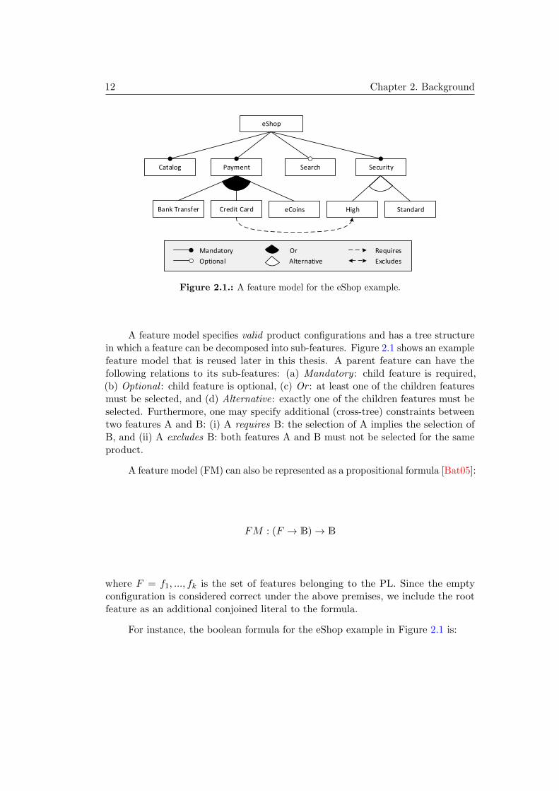
Figure 2.1.: A feature model for the eShop example.
A feature model specifies valid product configurations and has a tree structurein which a feature can be decomposed into sub-features. Figure 2.1 shows an examplefeature model that is reused later in this thesis. A parent feature can have thefollowing relations to its sub-features: (a) Mandatory : child feature is required,(b) Optional : child feature is optional, (c) Or : at least one of the children featuresmust be selected, and (d) Alternative: exactly one of the children features must beselected. Furthermore, one may specify additional (cross-tree) constraints betweentwo features A and B: (i) A requires B: the selection of A implies the selection ofB, and (ii) A excludes B: both features A and B must not be selected for the sameproduct.
A feature model (FM) can also be represented as a propositional formula [Bat05]:
FM : (F → B)→ B
where F = f1, ..., fk is the set of features belonging to the PL. Since the emptyconfiguration is considered correct under the above premises, we include the rootfeature as an additional conjoined literal to the formula.
For instance, the boolean formula for the eShop example in Figure 2.1 is:

2.1. Model-Based Product Line Engineering 13
FM = eShop ∧ (¬eShop ∨ Catalog)
∧ (¬eShop ∨ Payment) ∧ (¬eShop ∨ Security)
∧ (¬Payment ∨ CreditCard
∨ BankTransfer ∨ eCoins)
∧ (¬Security ∨ (High ∧ ¬Standard)
∨ (Standard ∧ ¬High))
∧ (¬Catalog ∨ eShop)
∧ (¬Payment ∨ eShop)
∧ (¬CreditCard ∨ Payment)
∧ (¬BankTransfer ∨ Payment)
∧ (¬eCoins ∨ Payment)
∧ (¬Security ∨ eShop)
∧ (¬High ∨ Security) ∧ (¬Standard ∨ Security)
∧ (¬Search ∨ eShop) ∧ (¬CreditCard ∨High))
The assignment of a value to a literal indicates whether the correspondingfeature is selected (true) or deselected (false). Any variable assignment that satisfiesthe formula is a valid product configuration pc for the PL:
pc = F → B
A product configuration is valid, iff FM (pc) = true holds.For instance, the following formula is a valid pc for the eShop feature model
presented in Figure 2.1.
P =eShop,Catalog ,Payment ,BankTransfer ,
¬CreditCard ,¬eCoins ,¬Search,Security ,
High,¬Standard
We define the set of all valid product configurations specified by a featuremodel FM to be:
PC = {pc : F → B|FM (pc) = true}
To facilitate the design of such models, we provide a feature model language de-fined in Ecore with the Eclipse Modeling Framework (EMF) as depicted in Figure 2.2.The feature model language is similar to other standard feature languages [BAC04].

14 Chapter 2. Background
Figure 2.2.: Feature model language diagram.
It offers basic functionalities, for designing mandatory, optional, or, alternative, andbinary cross-tree-constraints (CTC) between features. Extended functionalities, e.g.cardinalities or attributes, are not supported.
2.1.2. Variability Modeling
Although a feature model captures the system’s variation points in a concise form itselements are only symbols [CA05]. Their semantics has to be provided by mappingthem to a model with semantics: a base model. Such a mapping can be definedusing an explicit mapping model or extending the base model’s language [GV07].
An explicit mapping model consists of relations from feature model elementsto base model elements. We refer to a domain model as the triple of feature model,mapping model, and base model. From such a domain model, product models orcode can be resolved for a given pc. In the following, we introduce the three majorparadigms for variability modeling as depicted in [GV07]:
Annotative Modeling In this case, the base model is designed in terms of a socalled 150% model. A 150% model contains every element that is used in at leastone product configuration and, thus, subsumes every possible product [GKPR08](Fig. 2.3a). Subsequently, model elements are removed to resolve a valid variant.
Compositional Modeling In contrast to annotative languages, compositional lan-guages start from a minimal core that contains features that are common to allpossible products. From this starting point additional features will be added by adesigner (Fig. 2.3b).

2.1. Model-Based Product Line Engineering 15
- Feature A
- Feature B
- Feature C
- Feature D
+ Feature A
+ Feature B
+ Feature C
a) b)
c) + Feature A
+ Feature B
- Feature C
- Feature D
in�uenced by
Delta modules
Figure 2.3.: Annotative (a), compositional (b) variability (based on [GV07])and delta modeling (c)
Transformational Modeling Lastly, there are methods that combine compositionaland annotative methods, where model elements can be removed and added to resolvea variant. A well-known approach for this is delta modeling (also delta-orientedprogramming) [Sch10]. Delta modeling consists of two parts: The first one is a coreproduct comprised of a set of feature selections that represent a valid product. Thesecond part is a set of delta modules which specify changes to the core module.These changes can either be the construction (add) or destruction (remove) ofelements from the product model (Fig. 2.3c). Each delta module is associated toone or more features. Whenever a feature is selected or deselected the associateddeltas are applied to the product model, resulting in a new product model.
2.1.3. A Basic Variability Language
For the examples applied in this thesis, we use a custom annotative modelinglanguage. This language is a subset of the Common Variability Language (CVL).The standardization process of the CVL specification is still an ongoing process andthe language specification might be subject to change [HMPO+08]. For consistencyover all experiments carried out during the period of this thesis, we apply onlythe here described language features. In particular, our language does only featureannotative modeling capabilities, while CVL also includes features transformationalmodeling.
A mapping model in our mapping language, consists of mappings, where eachmapping maps a single feature to a set of elements in the base model. For designingbase models, we employ the Unified Modeling Language (UML), which is commonly

16 Chapter 2. Background
Figure 2.4.: Implementation of the mapping model language in Ecore.
applied in software engineering. Multiple features mapping to the same base modelelement are interpreted as a conjunction of features. Additionally, each mappinghas a Boolean flag that indicates whether the mapped model elements are part ofthe product when the feature is selected (true) or unselected (false).
In Figure 2.4, we depict the mapping model language as implemented for thisthesis with Ecore. The language refers to concepts of elements from the UML andto features from our feature model language. Figure 2.5 shows an excerpt of theeShop specification, where parts of the feature model are depicted in the upper halfand parts of the state machine’s payment process are shown in the lower half. Inbetween, we find a mapping, denoted by a dotted edge, from feature Credit Card tothe transition labeled as “SelectCreditCard[]/”.
2.1.4. Summary
Separation of concerns is a key paradigm in PLE. There is a variety of languages andmethods to support PLE in model-based environments. Here, we present a smallportion of relevant languages. Although many standards are proposed, no commonstandard was established to this point, partly due to the diversity of availablelanguages provided by academia and industry.
2.2. Model-Based Testing
Testing is a common approach to quality assurance. The idea is to systematicallycompare the observed system behavior with the expected one. The quality of tests

2.2. Model-Based Testing 17
Base Model (excerpt)
Credit Card High
... ...
Mapping: TRUE
Standard
Feature Model (excerpt)
SelectCreditCard [ ]/
Choose Payment Method Credit Card
Figure 2.5.: SPL design with annotative variability.
is often measured in terms of requirements and code coverage. Satisfying a coveragecriterion can result in big test suites with corresponding efforts in test design and testexecution. There are various approaches and tools to automate the test executionin order to reduce testing costs. The biggest issue of this approach is change. Achange of requirements or customer demands may result in far more effort for testdesign adaptation than for manual test execution. In the worst case, these testdesign adaptation costs outweigh the costs saved by automated test execution. Inorder to solve this issue, test design also needs to be automated.
There are a few techniques called MBT: some refer to test case models, like usecases, which are used as templates to facilitate test case implementation [HGB08].Others generate test data from test data models, like CTE [GG93]. In this thesis,we interpret MBT as the automation of test design, where a test suite is generatedfrom a dedicated test model. The test model contains test-relevant informationabout the intended behavior of the SUT and/or the behavior of its environment.
The resulting test suite is a set of test cases and possibly more test suites.Each test case consists of a sequence of stimuli and expected reactions to thesestimuli. Especially test generators we use throughout this thesis for our statemachine examples, we receive such sequences as outputs. For non-deterministicsystems a test case may also be a tree or graph of stimuli and reactions. A testcase may also pose prerequisites on the system’s state or configuration that must befulfilled, before the test case can be executed.
We depict a generic MBT process in Figure 2.6 as presented by Utting etal. in [UPL12]: First (1), the test model is created. Typically, it is created fromtextual requirements or formal specifications. Its level of abstraction depends on

18 Chapter 2. Background
Figure 2.6.: MBT process by Utting et al. [UPL12]
the intended test level and test target. MBT is suitable for various kinds of testtargets like full or partial functionality, quality of service, performance, and others.
Test models can be designed in many notations like abstract state machines,timed automata, and UML state machines [LS12], or Event-B [WBC14], Calculusof Communicating Systems (CCS) [BK05], communicating sequential processes(CSP) [MLL09], Markov Chains [Pro05], Petri Nets [Xu11], Z [LS05], and manyothers. Ultimately, the chosen notation must be suited to express the relevant testaspects and must be supported by the employed test generator.
Second (2), the test generator must be configured to select tests that achieve thetest targets adequately. Hence, test selection criteria were defined to approximate thenotion of a “good” test case. Typical selection criteria are coverage metrics based onmodel element and/or traced requirements. For transition-based notations, commoncoverage criteria are defined over the test model’s control flow, data flow, conditionalbranching, use cases, requirements, or stochastic characterizations [CM94].
In a third step (3), test selection criteria are transformed into test case specifi-cations. This is a necessary step, since test selection criteria must be formalized forthe particular test generator to make them operational.
Test case generation can start whenever the model and the test case specificationare defined (4). Before a test can be run by the test driver against the SUT, testscripts must be generated (5-1). Due to the diversity of test drivers, test generatorsare built to generate test cases that are agnostic of the intended test driver. Hence,
2.3. Test Assessment 19
the resulting test cases must be transformed into platform-specific test scripts. Theremaining abstraction-gap between test model and SUT can be handled either byanother transformation process or by an adaptor. Finally in (5-2), the test verdictis received and evaluated. In this step, an adaptor or transformation may againabstract the test verdict to the test model’s level. From this on, further actions areplanned as in any other test process.
2.2.1. Summary
In this thesis, we apply UML state machines as models for automated test design.UML state machines are a common modeling language to express behavioral test mod-els and they are supported by commercial and academic tools: IBM ATG [IBM09],Conformiq TestDesigner [Con], JUMBL [Pro03], Sepp.med MBTSuite [SKK13],Verified RT-Tester [Pel], ParTeG [Wei09], CertifyIt Smartesting [BLPT05], andothers. Typical test targets for state machines are criteria for control flow, dataflow, conditional branching, use cases, and requirements [CM94]. Test designerscreate a test suite that fulfills a prescribed set of criteria to a certain degree. Theresulting tests can then be adapted to the interface of the SUT and executed.
2.3. Test Assessment
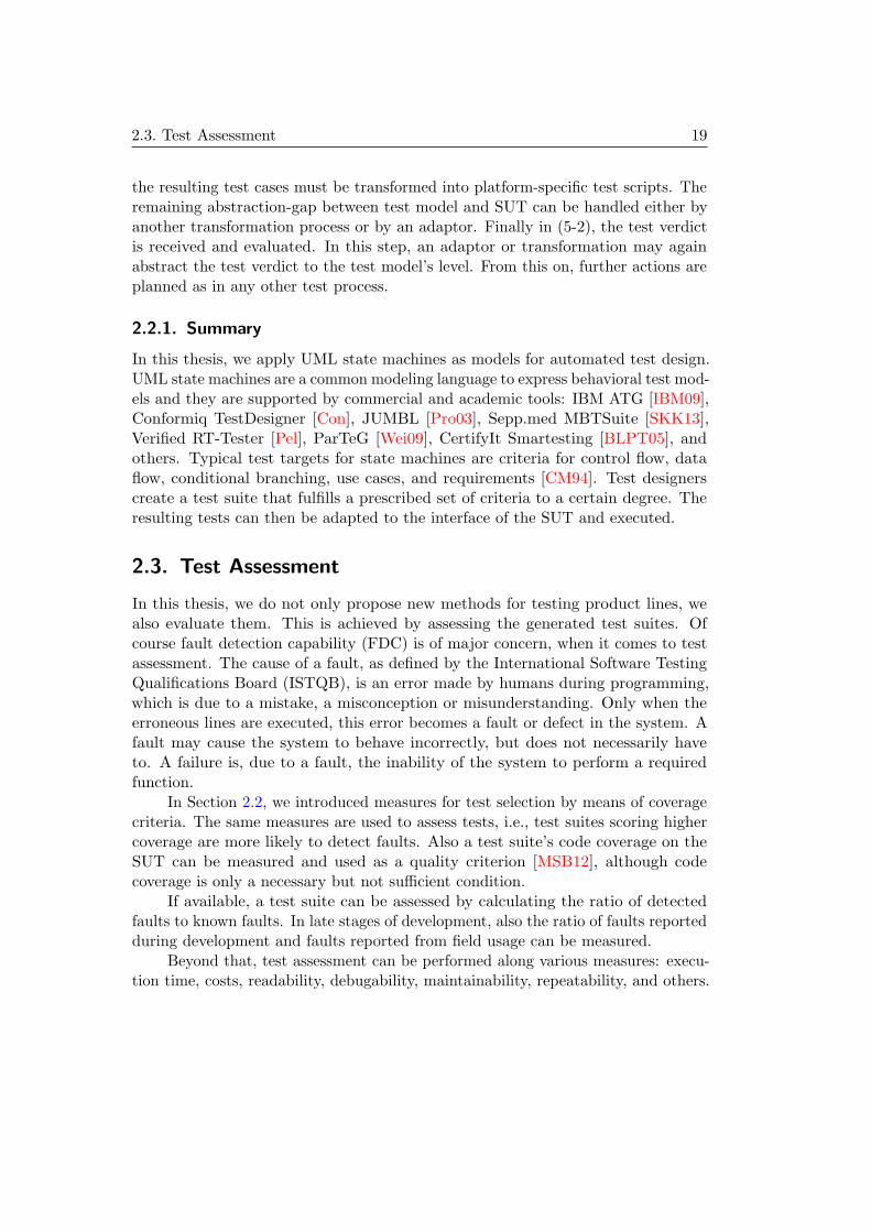
In this thesis, we do not only propose new methods for testing product lines, wealso evaluate them. This is achieved by assessing the generated test suites. Ofcourse fault detection capability (FDC) is of major concern, when it comes to testassessment. The cause of a fault, as defined by the International Software TestingQualifications Board (ISTQB), is an error made by humans during programming,which is due to a mistake, a misconception or misunderstanding. Only when theerroneous lines are executed, this error becomes a fault or defect in the system. Afault may cause the system to behave incorrectly, but does not necessarily haveto. A failure is, due to a fault, the inability of the system to perform a requiredfunction.
In Section 2.2, we introduced measures for test selection by means of coveragecriteria. The same measures are used to assess tests, i.e., test suites scoring highercoverage are more likely to detect faults. Also a test suite’s code coverage on theSUT can be measured and used as a quality criterion [MSB12], although codecoverage is only a necessary but not sufficient condition.
If available, a test suite can be assessed by calculating the ratio of detectedfaults to known faults. In late stages of development, also the ratio of faults reportedduring development and faults reported from field usage can be measured.
Beyond that, test assessment can be performed along various measures: execu-tion time, costs, readability, debugability, maintainability, repeatability, and others.

20 Chapter 2. Background
Typically execution time, costs, and repeatability are easier to assess, while theother criteria are subjective to the individual testers.
2.3.1. Mutation Analysis
Mutation analysis (also mutation testing) as introduced by DeMillo et al. [DeM80]is a fault-based testing technique with the intended purpose to assess the quality oftests that will be applied to a system.
The process of mutation analysis introduces errors into software by creatingmultiple versions of the original software, where each created version contains oneerror. After that, existing test cases are used to execute the erroneous versions(mutants) with the goal to distinguish the faulty ones (to kill a mutant) from theoriginal software. The ratio of killed mutants to generated mutants is called mutationscore, that is computed after the execution of all test cases. The main goal of thetest designer is to achieve a mutation score of 100 percent, that indicates that allmutants (i.e., all faults) have been detected [OU01,JH11].
Regarding to [JH09] we can distinguish multiple kinds of mutants that can becreated. The simplest one are first-order mutants that, regarding to the mutationoperators, only have one introduced error. Even if first-order mutants can be killedduring the process of mutation testing, this does not guarantee that a combinationof two (or even more) mutants will also be detected by the test suite. Such combinedmutants are referred as higher-order mutants.
Though mutation operators are applied to fit in errors, there is the chance,that the resulting mutant offers the same behavior as the original. This type ofmutants are referred as hidden mutants. Hidden mutants are not easily detectable(undecidable), but supposed to be killed if detected during the mutation analysisprocess [JH11].
2.3.2. Error Design
In mutation analysis, defective software versions are derived from a set of poten-tial errors a human can make during software development. Potential errors areimplemented as mutation operators, which are applied to the original software forintroducing errors. The mutation operator’s design affects the validity of the result-ing mutation scores and the costs for testing by means of the amount of mutantsto create and the number of tests to execute against them. Thus, we apply thefollowing four guiding principles for creating mutation operators [BOY00,Woo93]:
1. Mutation categories should model potential error. It is important to recognizedifferent types of error. In fact, each mutation operator is designed to modelerrors belonging to the corresponding error class.

2.4. Examples 21
2. Only simple, first-order mutants should be generated. These mutants areproduced by making exactly one syntactic change to the original specifica-tion. This restriction is justified by the coupling effect hypothesis which saysthat the test sets that detect simple mutants will also detect more complexmutants [Off92].
3. Only syntactically and semantically correct mutants should be generated.Some mutations may result in an illegal expression, such as division by 0.Such mutants should not be generated.
4. Do not produce too many mutants. This includes some practical restrictions.For example, do not replace a relational connector with its opposite, if forother mutants a term negation operator is applied, since both mutants aresemantically equivalent.
From other mutation systems presented in [BHP11, ALN13, FDMM94], weidentify the following general categories for model-based mutation operators:
1. Model element deletion: a model designer forgets to add a model element, e.g.a feature, a mapping, or a transition.
2. Model element insertion: a model designer inserts a superfluous model element,e.g. a feature, a mapping, or a transition.
3. Property change: a model designer chooses a wrong value for a property of amodel element, e.g. mandatory feature instead of optional, inverse value for afeature’s status, or wrong transition target.
For each model element-type, like mappings, transitions, guards, etc., one can checkfor applicable categories and implement mutation operators accordingly.
2.4. Examples
To evaluate the methods presented in this thesis, we employ four model examples:An embedded ticket machine, an alarm system, an e-commerce webshop, and acar’s body comfort system. All of the model examples conform to the previouslypresented requirements for applying SPLTestbench.
As presented in Section 2.1 we use a model-based PLE approach to specify themodels. The domain analysis is performed with feature models, while for definingvariability, we use annotative concepts as defined earlier by the presented mappingmodel language in Section 2.1.3. The base models are specified with UML, inparticular state machines and classes. Each example consists of at least one state

22 Chapter 2. Background
machine diagram. Each state machine has a context class, which holds attributesused in the state machine and ports for sending and receiving messages.
We apply syntax and semantics as defined in the UML standard. For sendingmessages from the SUT to the environment we use the following notation:
(1) <SignalType> <signalIdentifier>;
(2) <portname>.send(<signalIdentifier>);
First (1), we declare an identifier of the signal’s type. Then (2), we call the sendmethod of the outbound port from which we intend to send the signal. Furthermore,the signal’s identifier is passed as a parameter to the port’s send method.
In the following we present an example for sending a signal of type “Text” overa port named “out”. We choose to declare the signal’s identifier as “letter”. Ifthe signal has a property, e.g. “content” of type String, we may also set the valueof this property before sending the signal. The corresponding effect is:
(1) Text letter;
( ) letter.content = "Hello World";
(2) out.send(letter);
2.4.1. Ticket Machine
The Ticket Machine is a simple case study and is adopted from Cichos et al. [CLOS12].The functionality is as follows: a customer may select tickets, pay for them, receivethe tickets, and collect change. The feature model has a root feature with threesub-features attached to it; all of them are optional. Depending on the selectedfeatures, the machine offers reduced tickets, accepts not only coins but also bills,and/or will dispense change.
The feature model is depicted in Figure 2.7, while the base model is shown inFigure 2.8. The features are mapped as follows:
– Bills to transitions labeled “bill[paid=costs]/ paid+=5;” at state“Payment” and “bill[paid>=5]/ paid-=5;”, “bill[paid>0 && paid<5]/
paid--;” at state “MoneyChange”.
– Not Bills to transition labeled “coin[paid>0]paid--;” at state“MoneyChange”.
– Change to transition labeled “change[tDay==0 && tShort==0 && tRed==0]”from state “TicketEjection” to “MoneyChange”.
– Not Change to transition labeled “change[tDay==0 && tShort==0 &&
tRed==0]/ paid=0; costs=0; success o; Out.send(o);” from state“TicketEjection” to “MoneyChange”.

2.4. Examples 23
Reduced fareBills Change
Ticket Machine
Figure 2.7.: Feature model of the Ticket Machine example.
Figure 2.8.: Base model of the Ticket Machine example.

24 Chapter 2. Background
– Reduced Fare to transition labeled “redT/ tRed++; costs+=3;” at state“TicketSelection”.
2.4.2. Alarm System
The Alarm System example is also adopted from Cichos et al. [CH11] and morecomplex. The alarm may be set off manually or automatically by a vibrationdetector. Both features are part of an or-group and, thus, at least one of the twofeatures must be present in every product. In the event of an alarm, a siren ora warning light will indicate the security breach. When the vibration does notstop after a predefined period of time, the system optionally escalates the alarmby calling police authorities and/or sending photos of evidence. Additionally to itsalarming functionality, the Alarm System SPL provides a feature for taking a photoof any operator that configures the system for security measures.
We adopted the Alarm System models by removing manual timers that wereimplemented as guard conditions. Furthermore, we added cross-tree-constraints(CTC) and more features to the feature model for exercising the SPLTestbench’sfunctionalities more thoroughly.
The feature model is depicted in Figure 2.9, while the base model is shown inFigure 2.10. The features are mapped as follows:
– User Interface, Storage and Online Access are mandatory and need no map-ping.
– Camera to state “Camera”.
– Photo to transition labeled “photo/ makePhoto o; Out.send(o);
storePhoto p; Out.send(p); data = true;” at state “Camera”.
– Video to transition labeled “video/ makeVideo o; Out.send(o);
storeVideo p; Out.send(p); data = true;” at state “Camera”.
– Manual Release to transition labeled “manStart/ m=true;” from state“StandBy” to “EnsureDanger”.
– Vibration Detector to transition labeled “vibrating” from state “StandBy”to “EnsureDanger”.
– Warning Light to transition “startWarning / flashFast o;
Out.send(o);” from state “Ensure Danger” to “AlarmSignal”.
– Siren to transition “startSiren / loudSound o; Out.send(o);” from state“Ensure Danger” to “AlarmSignal”.

2.4. Examples 25
Camera StorageVibration Detector
VideoPhoto High Standard
Manual Release
Warning Light
SirenUser Inteface
Online Access
Alarm System
Figure 2.9.: Feature model of the Alarm System example.
Figure 2.10.: Base model of the Alarm System example.

26 Chapter 2. Background
– High and Standard are not mapped to model elements, since they have noinfluence on any resulting product model.
2.4.3. eShop
The eShop example is a fictional e-commerce Webshop designed for this thesis. Acustomer can browse the catalog of items, or if provided, use the search function.Once the customer put items into the cart, he can checkout and may choose fromup to three different payment options, depending on the eShop’s configuration. Thetransactions are secured by either a standard or high security server. A CTC ensuresthat credit card payment is only offered if the eShop also implements a high securityserver. While we show the base model in Figure 2.11, its feature model was alreadypresented in Figure 2.1. The features are mapped to the state machine’s elementsas follows:
– Catalog, Payment and Security are mandatory and need no mapping.
– Bank Transfer to all transitions connected to state “Bank Transfer”.
– eCoins to all transitions connected to state “eCoins”.
– Credit Card to all transitions connected to state “Credit Card”.
– High to attribute secureConnection with its default value set to true.
– Standard to attribute secureConnection with its default value set to false.
– Search to any transitions connected to state “Search”.
2.4.4. Body Comfort System
This example is an actual case study created by Lity et al. and documented astechnical report in [LLLS]. The case study stems from a cooperation between theInstitute for Programming and Reactive Systems, Institute for Software Engineeringand Automotive Informatics, Real-Time Systems Lab, and their partners fromthe German automotive industry. The system comprises the following (variable)functionality:
– Power Windows with Finger Protection
– Exterior Mirrors with Heating
– Controls (Human Machines Interface) with Status LEDs
– Alarm System with Interior Monitoring

2.4. Examples 27
Figure 2.11.: Base model of the eShop example.

28 Chapter 2. Background
– Central Locking System with Automatic Locking
– Remote Control Key with Safety Function and controls for Alarm System andPower Windows.
The case study’s feature model is depicted in Figure 2.12 and an overviewof the system’s compositions is shown in Figure 2.13. In the technical report, thebase model consists of 21 state machine models and the variability is given by 15delta-models.
For the purpose of the evaluations performed within this thesis, the modelswere transformed to mapping models and state machines with annotated variability.For annotation, we employ the mapping language as introduced in Section 2.1.3.As a result of this transformation we gain 21 state machines and 20 mappings to 357state machine elements (each mapping can refer to multiple base model elements).Neither the state machine models nor the mapping model are presented individuallyin this thesis.
2.4.5. Summary
The presented examples vary in complexity of variability and behavior. Table 2.1and 2.2 summarize the individual models on structural level. Besides of the BodyComfort System Case Study, the Alarm System example is the most variable SPL inthis comparison by means of possible configurations (CNF), offering 42, followed bythe eShop with 20, and the Ticket Machine with only 8 configurations. Although theAlarm System has only two features more than the eShop, it offers twice as manyconfigurations. This is a typical effect observable in variable systems, where addingonly a few features can drastically increase the amount of configurations. There arefurther metrics for feature models available to measure analyzability, changeability,and understandability, which we did not apply so far [BG11].
Similar to feature models, UML models are of different complexity by meansof states, transitions, sub-machines, and signals. Here, the eShop case study is themost complex example. The Alarm System and the Ticket Machine are graduallyless complex.

2.4. Examples 29
Figure 2.12.: Feature model of the Body Comfort System. [LLLS]

30 Chapter 2. Background
Figure 2.13.: Overview of the Body Comfort System’s architecture. [LLLS]

2.4. Examples 31
Table 2.1.: Feature model summary for Ticket Machine (TM), Alarm System(AS), eShop (ES), and Body Comfort System (BCS).
Example TM AS ES BCS
Features 4 12 10 27
Core features 1 3 4 7
Grouped features 0 8 5 8
Cross-tree constraints 0 2 1 6
Configurations 8 42 20 11,616
Table 2.2.: Base model summary for Ticket Machine (TM), Alarm System (AS),eShop (ES), and Body Comfort System (BCS).
Example TM AS ES BCS
States 4 5 16 235
Transitions 19 19 28 369
Levels of Hierarchy 0 0 2 0
Sub-Machines 0 0 3 0
Signals 10 19 26 102


33
Chapter 3.
Assessment of Product Line Tests
Test assessment is an integral part for evaluation of the concepts presented in Part IIof this thesis. This chapter builds the foundations for assessing the quality of PLtest suites by means of fault detection capability (FDC). Though there are manymethods proposed for testing a PL, until now, quality assessment of tests waslimited to measuring code, model and/or requirements coverage [Mv03, CDS06].Mutation analysis is a major approach to investigate a test suite’s FDC. So farmutation analysis for PLE is constrained to mutating individual products of a PL.This approach has two major drawbacks: first, developers can introduce errors onall kinds of artifacts, not only on product models, leading to new kinds of faults.For better understanding, we analyze different design paradigms for model-basedPLE as presented in Section 2.1 and errors that can occur during the respectivedesign processes. From the results, we develop mutation operators for variabilitymodels and base models to mimic possible faults in these models.
Secondly, the selection of products and subsequently its mutations is biased bythe products selected for testing. Therefore, mutation analysis assesses the qualityof the tests for particular products, but not for the whole PL. In contrast, we definea mutation system and operators on the domain engineering-level. This enables usto assess the test quality independently from the tested products. Subsequently, thetest suite’s quality by means of FDC can be assessed for the complete PL.
The remainder of this chapter is structured as follows: In Section 3.1 we defineand classify kinds of errors. We present our PL test assessment system and itsevaluation with three of the four examples introduced in Section 3.2. Eventually,we show related work in Section 3.4 and conclude in Section 3.5.
3.1. Potential Errors in Model-Based Product LineEngineering
The feature mapping has a major impact on the outcome of the resolved products ina PL, however, the design is complex and error-prone. We identify potential errorsin a systematic way by checking each modeling paradigm for possibilities to add

34 Chapter 3. Assessment of Product Line Tests
superfluous or omit necessary elements or change the value of an element’s attribute.For each potential error we discuss its effects onto the resolved products.
Annotative Variability
In the annotative variability paradigm, we identify the following model elements forpotential errors from the feature mapping model: mappings, their attribute featurevalue, mapped feature, and the set of mapped elements. The errors which can bemade on these model elements and their effects are as follows:
N1) Omitted mapping: a necessary mapping is left out by its entirety. Subsequently,mapped elements will be part of every product unless they are restricted by otherfeatures. As a result, some or all products unrelated to the particular featurewill include superfluous behavior. Products including the mapped feature are notaffected, since the behavior was enabled anyway.
N2) Superfluous mapping: a superfluous mapping is added, such that a previouslyunmapped feature is now mapped to some base model elements. This may alsoinclude adding a mapping for an already mapped feature, but with inverted featurevalue. Adding a mapping with feature value set to true results in the removalof elements from products unrelated to the mapped feature. Contrary, adding amapping with feature value set to false removes elements from any product whichthe mapped feature is part of. In any case the behavior of at least some products isreduced.
N3) Omitting a mapped element: a mapped model element is missing from the setof mapped elements in a mapping. Subsequently, a previously mapped elementwill not only be available in products which the said feature is part of, but also inproducts unrelated to this feature. As a result, some products offer more behaviorthan they should or contain unreachable model elements.
N4) Superfluously mapped element: an element is mapped although it should notbe related to the feature it is currently mapped to. As a result the element becomesunavailable in products which do not include the associated feature. The product’sbehavior is hence reduced.
N5) Swapped feature: the associated features of two mappings are mutually ex-changed. Subsequently, behavior is exchanged among the two features and thus,affected products offer different behavior than expected. The result is the same asexchanging all mapped elements among two mappings.
N6) Inverted feature status: the binary-value of the feature value attribute is flipped.The mapped elements of the affected mapping become available to products where

3.1. Potential Errors in Model-Based Product Line Engineering 35
they should not be available. At the same time, the elements become unavailablein products where they should be. For example, if the feature value is true and isswitched to false, the elements become unavailable to products with the associatedfeature and available to any product not including the said feature. Of course, otherfeature mappings to the same element(s) must still be considered.
Compositional Variability
In PL modeling with compositional variability, a mapping is a bijection betweenfeatures and modules composed from domain elements. Potential errors in thefeature mapping models can be made at: mappings, mapped feature, and mappedmodule. We identify the following potential errors:
P1) Omitted mapping: a necessary mapping is missing in its entirety. This appearsto us to be an unrealistic scenario, since one can automatically check for all modulesbeing mapped to some feature. But if we consider the case of a missing mapping,products with the associated feature would be missing the modules’ functionality.
P2) Superfluous mapping: a superfluous mapping is added. Similar to the above,this is an unrealistic scenario for the same reason: all modules should be mappedexactly once. In a model-based environment, this check should be easily automatable.However, if adding a superfluous mapping is possible, more behavior becomes enabledin products containing the mapping’s feature.
P3) Swapped modules: the associated modules of two mappings are mutually ex-changed. As a result, all products containing one of the two features, but not theother, do not offer the expected behavior. Subsequently, all products containingnone or both features behave as expected.
P4) Swapped features: the associated features of two mappings are mutuallyexchanged. The result is the same as above for swapped modules.
Transformational Variability
For other paradigms, like delta-modeling [Sch10], we make similar observations. Incontrast to compositional variability models, delta-oriented variability models startfrom an actual core product, instead of a base module. From this on, only thedifferences from one product to another are defined by deltas. In delta-modeling,mapping multiple features to the same delta is allowed. A delta may add elementsto and remove elements from the core product at the same time. As potential pointsof errors in delta-modeling we identify deltas, a delta’s set of mapped features, itsset of removed elements from the base product, and its set of added elements.

36 Chapter 3. Assessment of Product Line Tests
D1) Omitted delta: the domain model misses an entire delta definition. Productscontaining features of the missing delta may lack behavior or offer too much of it.This depends on whether the delta removes and/or adds elements from/to the baseproduct.
D2) Superfluous delta: an unnecessary delta is added. As a result, productscontaining the associated feature(s) will offer additional behavior. Also, affectedproducts might lack behavior if the delta removes elements.
D3) Omitted feature: a necessary feature from the set of mapped features is missing.If no feature is left, the delta is not mapped at all which can be statically verified.If otherwise the set still contains at least one feature, any product containing thecurrent set of mapped features but not the missing feature, offers too much or toofew behavior. In some cases, the set of mapped features and the affected elementsmay collide with another delta, which is again statically verifiable.
D4) Superfluous feature: an additional feature is added to a delta’s already completeset of mapped features. As a result, the delta will be available in less products. Ifthe added feature mutually excludes one of the already mapped features, the deltawill be applicable to no product at all. A static check can be used to validate that aset of features is satisfiable by some product. Only products containing the correctset of features, but not the superfluous ones, are affected by this error. Affectedproducts may offer more or less behavior.
D5) Omitted base element: a delta’s set of base elements is missing an element. Inconsequence, too few elements are removed from the core product by this delta tomatch the product’s model. Thus any product containing the features from thisdelta offers too much behavior.
D6) Superfluous base element: a delta’s set of base elements contains additionalelements. This will remove more elements than necessary from the products affectedby this delta. Hence, these products offer too few behavior.
D7) Omitted delta element: an element from the set of delta elements in a delta ismissing. As a result, all products containing the delta’s features offer more or lessbehavior than specified - depending on whether the delta element adds or removeselements.
D8) Superfluous delta element: an element from a delta’s set of delta elements ismissing. In consequence, the products containing the delta’s features offer more orless behavior than specified. Again, this depends on whether the delta element addsor removes elements.

3.2. Product Line Test Assessment 37
3.2. Product Line Test Assessment
As laid out in section 3.1, new kinds of errors can be made in model-based PLEthan in contrast to single systems engineering. Current test design methods andcoverage criteria are not prepared to deal with these errors and resulting faults. Wepropose a mutation system for PL systems. It is specifically designed to assess testquality, by means of FDC, for the whole product line rather than for single systems.
Mutation systems for PL need novel mutation operators. The reason for this isthe separation of concerns in PLE, where variability and domain engineering are splitinto different phases and models. Mutation operators defined for non-variant systemscannot infer mutants including modules from other products, since this informationis only available during domain engineering. However, we expect a high-quality testsuite to detect such faults. Hence, we also propose new mutation operators based onthe potential errors, we identified in Section 3.1. For conciseness, we only considerpotential errors from annotative variability modeling for implementation.
3.2.1. Mutation System for Product Lines
Performing mutation analysis on PL tests is different from non-variant system tests,since in contrast to conventional mutation systems, a mutated domain model isnot executable per se. Thus, testing cannot be performed until a decision is madetowards a set of products for testing. This decision depends on the PL test suiteitself, since each test is applicable to just a subset of products.
In Figure 3.1, we depict a mutation process for assessing PL test suites, whichaddresses this issue. Independently from each other, we gain (a) a set of domainmutants by applying mutation operators to the domain model and identify (b)a set of configurations describing the applicable products for testing. We applyevery configuration in (b) to every mutant in (a), which returns a new set ofproduct model mutants. Any mutant structurally equivalent to the original productmodel is immediately removed and does not participate in the scoring. The mutantproduct models are easily resolved to product mutants and finally, tests are executed.Our mutation scores are based on the domain model mutants, hence we establishbidirectional traceability from any mutant domain model to all its associated productmutants and back again. If a product mutant is killed by a test, we backtrackits domain model mutant and flag it as killed. The final mutation score is thencalculated from the killed and the overall number of domain models mutants.
3.2.2. Product Line Mutation Operators
Here, we present mutation operators for feature mapping models with annotativevariability. Furthermore, we enrich the mutation system by standard state machine

38 Chapter 3. Assessment of Product Line Tests
Domain Model
Domain Model Mutants ( a )
Product Model Mutants
Product Mutants
Apply Mutation Operators
Generate products
Configurations ( b )
Test Suite
Extract Configurations for Testing
SPL Mutation Score Backtrace Product Mutants to Product Lines Specification Mutants
Apply configurations & resolve product models
Execute Tests and Calculate Mutation Score
Figure 3.1.: Mutation process for PL systems
operators and apply them on domain-level as well. For systematic identificationof mutation operators, we apply the guidelines presented in Chapter 2.3.2 andcategorize each identified operator. Also, we discuss potentially invalid and hiddenmutants resulting from each operator. Still there is no guarantee that the followinglist is complete.
Feature Mapping
We design the mutation operators according to the potential errors identified inSection 3.1. We do not consider inserting superfluous mappings as in this case itremains unclear which and how many UML elements should be selected for themapping. We assume that this, if not carefully crafted, will lead to mostly invalidmutants.
Delete Mapping (DMP) The deletion of a mapping will permanently enable themapped elements, if they are not associated to other features that constrain theirenabledness otherwise. In our examples, no invalid mutants were created. However,for product lines that make heavy use of mutual exclusion (Xor and excludes) this

3.2. Product Line Test Assessment 39
does not apply. The reason for this are competing UML elements like transitionsthat would otherwise never be part of the same product. Multiple enabled andotherwise excluding transitions are possibly introducing non-determinism or at leastunexpected behavior.
Some product mutants created with this operator might behave equivalent to anoriginal product. This is the case for all products that include the feature for whichthe mapping was deleted. Since these mutants are structurally equivalent to theoriginal product model, they are easy to detect.
Delete Mapped Element (DME) This operator deletes a UML element referencefrom a mapping in the feature mapping model. It resembles the case, where amodeler forgot to map a UML element that should have been mapped.
Similar to the delete mapping operator, this operator may yield non-deterministicmodels, where otherwise excluding transitions are concurrently enabled. Productmutants equivalent to the original product model can be derived, if the featureassociated to the deleted UML reference is part of the product. Again, this is resultsin structural equivalence to the original product.
Insert Mapped Element (IME) This operator inserts a new UML element referenceto the mapping. This is the contrary case to the operators defined before, wheremappings and UML elements were removed. However, inserting additional elementsis more difficult than deleting them, since a heuristic must be provided for creatingsuch an additional element. We decided to copy the first UML element referencefrom the subsequent mapping. If there are no more mappings, we take the firstmapping. This operator is not applicable if there is just one mapping in the featuremapping model.
Again, there is a chance of creating invalid mutants: If a UML element reference iscopied from a mutually excluded mapping, the resulting model may be invalid dueto non-determinism.
Also structurally equivalent mutants are created, when the features from the subse-quent mapping, which acts as source for the copied element, and the target mappingare simultaneously activated in a product.
Swap Feature (SWP) Swapping features exchanges the mapped behavior amongeach other. This operator substitutes a mapping’s feature by the following mapping’sfeature and vice versa. The last feature to swap is exchanged with the very first ofthe model.
Non-deterministic behavior and thus invalid models may be designed by this operator.This is due to the fact that the mutation operator may exchange a feature from agroup of mutually exclusive features by an unrestricted feature. In consequence, the

40 Chapter 3. Assessment of Product Line Tests
previously restricted feature is now independent, while the unrestricted feature joinsthe mutual exclusive group. This may concurrently enable transitions which resultsin non-deterministic behavior.
We gain structurally equivalent mutants, if the two swapped features are simultane-ously activated.
Change Feature Value (CFV) This operator flips the feature value of a mapping.A modeler may have selected the wrong value for this boolean property of eachmapping.
The operator must not be applied to a mapping, if there is a second mapping withthe same feature, but different feature value. Otherwise, there will be two mappingsfor the same feature with the same feature value, which is not allowed for our featuremapping models.
This operator may yield invalid mutants, if it is applied to a mapping that excludesanother feature. In that case, two otherwise excluding UML elements can be presentat the same time, which may result in invalid models, e.g. two default valuesassigned to a single variable or concurrently enabled transitions.
UML State Machine
In the past 20 years, many mutation operators for transition-based systems weredefined [FDMM94,OLAA03,BBW06,BH08]. Here, we limit ourselves to the designof operators based on transitions as these may have the strongest impact on thebehavior of the SUT. We do not design operators that can be mimicked by thecombination of two of them. In particular, we do not consider the exchange of anelement by another, since this can easily be mimicked by removing and insertingthe removed element at another point in the model.
We identified five targets for mutation: (i) remove the entire transition, changeits (ii) target state, as well as mutating its (iii) triggers, (iv) guard, and (v) effect.The latter three can be mutated according to the three defined categories delete,add and change.
For all mutants created by the here presented operators, there is a chance ofmaterializing mutants behaving equivalent to the original product. This is the case,when the mutated element is part of a disabled feature. Of course, hidden mutants –if detected – will be excluded from the scoring.
In general, we will not apply any class mutation to our UML state ma-chines [KCM00]. The system’s logic is designed in the state machine diagrams, whilethe classes are merely containers for variables and diagrams.
Delete Transition (DTR) Deletes a transition from a region in a UML state machine.This operator might create invalid UML models, if not enough transitions remain

3.3. Evaluation 41
on a pseudo-state (fork, join, junction, and choice) [OMG, p.555].
Change Transition Target (CTT) Changes the target of a transition to anotherstate of the target state’s region. This operator is only applicable if the region hasmore than one state.
Delete Effect (DEF) Deletes the entire effect from a transition. We consider sendingsignals to the environment or other components to be part of a transition’s effect,hence they are deleted as well.
Delete Trigger (DTI) Deletes a transition’s trigger. Only a single trigger is deletedat a time and every trigger is deleted once.
Insert Trigger (ITG) Copies an additional trigger to a transition. The trigger iscopied from another transition within the same region. This may lead to non-deterministic behavior if both transitions, the source transition of the trigger andthe mutated transition, are outgoing transitions of the same state.
Delete Guard (DGD) Deletes the entire guard of a transition. This may lead tonon-deterministic behavior of the state machine, if another transition is enabledsimultaneously. Furthermore, in the case of transitions without triggers and wheresource and target are the same state, this operator leads to infinite looping ofthe state machine over the mutated transition. The reason for this behavior isUML’s run-to-completion semantic, where an enabled transition without triggers isimmediately traversed.
Change Guard (CGD) Changes a guard’s term by exchanging operators or substi-tuting boolean literals by their inverse. Our CGD operator supports 30 differentarithmetic, relational, bitwise, compound assignment, and logic operators. Further-more, literal ”null” is exchanged by ”this”.
This may cause mutants with non-deterministic behavior, whenever two transitionbecome concurrently enabled due to the manipulation of one of their guards.
3.3. Evaluation
3.3.1. Setup
We employ the three example product lines introduced in Section 2.4 for performing amutation analysis on them. We designed the test suite for each example automaticallyby applying model-based testing techniques. We chose all-transitions coverage forselecting the tests. A test generator then automatically designed the tests andoutputs XML-documents. From the tests, SPLTestbench selected variants for testingand resolved mutated product models from the mutated domain model.

42 Chapter 3. Assessment of Product Line Tests
Since our examples lack implementations, we decided to generate code from themutated product models and run the tests against them. Therefore, we developedand employed a code generator for transforming individual product models intoJava. Another transformator generates executable JUnit code from the tests whichwe gained from the test generator. The mutation system then collects all thecode artifacts, executes the tests against the product code, and finally reportsthe mutation scores for all tests and for every operator individually. All of thetransformations above and the mutation system are integrated into SPLTestbench.
Generating code and tests from the same basis for testing the code is notfeasible in productive environments, since errors propagate from the basis to codeand tests. However in our case, tests are executed against code derived from mutatedartifacts, while the test cases were generated from the original model.
3.3.2. Results
We were able to assess the test quality for all three test suites derived from theexamples. Here, we present the results. For each mutation operator we measured theamount of detected mutants based on the domain model. In addition, we assessedaccumulated mutation scores for each example over all mutation operators and viceversa, the accumulated results for each mutation operator over all examples. Thedetailed results for feature mapping operators can be read from Table 3.1 and forUML operators from Table 3.2.
For every example we tracked the number of original products selected fortesting, generated domain model mutants, and resolved product mutants. Test-wisewe counted tests, test steps by means of stimuli and expected reactions in all tests,tests executed against all product mutants, and the number of failed tests duringtest execution.
For the eShop example, SPLTestbench selected four products for testing.Independent from this, the mutation system generated 30 domain model mutantsand 96 product mutants for the mapping mutation operators. For the state machinemutation operators it generated 122 domain model mutants and 478 product mutants.Every test case from the 13 test cases for this example was executed against everysuitable mutant. This results in 302 test executions for the mutants created by themapping mutation operator and 1,553 test executions for state machine mutationoperators. Ultimately, 20 tests for mapping operators and 283 tests for state machineoperators failed, killing 69.67% and 36.67% of the mutants.
For the Ticket Machine example, we executed 1332 tests for state machineoperators, executed them against 296 product mutants, and eventually 272 testsfailed, killing 66.89% of the PL mutants. Analog to the eShop, we executed less testsand generated less product mutants for the feature mapping operators: 252 testswere executed against 56 product mutants, which were resolved from 28 domain

3.3. Evaluation 43
Table 3.1.: Mapping operator scores per mutation operator in % and Accum-lated Scores (Acc)
Op. eShop Ticket Machine Alarm System Acc
DMP 0.00 (4) 0.00 (5) 0.00 (8) 0.00DME 0.00 (14) 0.00 (8) 0.00 (21) 0.00IME 75.00 (4) 40.00 (5) 50.00 (8) 52.94SWP 100.00 (4) 60.00 (5) 62.5 (8) 70.59CFV 100.00 (4) 100.00 (5) 87.50 (8) 94.12
Acc 36.67 (30) 35.71 (28) 30.19 (53) 33.33
Table 3.2.: UML operator scores per mutation operator in % and AccumlatedScores (Acc)
Op. eShop Ticket Machine Alarm System Acc
DTR 89.29 (28) 84.21 (19) 63.16 (19) 80.30CTT 64.29 (28) 63.16 (19) 36.84 (19) 56.06DEF 100.00 (16) 82.35 (17) 61.54 (13) 82.61DTI 82.61 (23) 100.00 (13) 94.12 (17) 90.57ITG 20.83 (24) 27.78 (18) 16.67 (18) 21.67DGD 0.00 (1) 42.86 (14) 50.00 (2) 41.18CGD 100.00 (2) 68.75 (48) 90.00 (10) 73.33
Acc 69.67 (122) 66.89 (148) 57.17 (98) 65.21
model mutants. The tests yield an even lower mutation score of 35.71% than forthe eShop case study.
In case of the Alarm System, we executed 537 tests against 278 product mutantscreated by the mapping mutation operators and 1,168 tests against 585 productmutants created by the state machine mutation operators. Eventually, 37 and 123tests failed, killing 30.19% and 57.17% of the mutants, respectively. The results aresummarized in Table 3.3 and 3.4.
The table shows some interesting effects. For most of the operators we gainmutation scores between 60% and 100%. This is in the expected range for testsuites generated with the all-transitions coverage on random mutants [Wei09,LS12].However, there are some notable exceptions: DMP (0%) and DME (0%) on featuremappings, ITG (21.67%) and DGD (41.18%) on base models. The reason is thatthese operators add superfluous behavior to the product. Errors consisting ofadditional (unspecified) behavior are notoriously hard to find by specification-basedtesting methods. Specification-based testing checks whether the specified behavior is

44 Chapter 3. Assessment of Product Line Tests
Table 3.3.: Summarized Results for Mapping Operators
eShop Ticket Machine Alarm System
Products for testing 4 4 6Product line mutants 30 28 53Product mutants 96 56 278Test cases 13 9 12Test steps 103 68 62Tests executed 302 252 537Failed tests 20 30 37
Table 3.4.: Mutation Results for State Machine Operators
eShop Ticket Machine Alarm System
Products for testing 4 4 6Product line mutants 122 148 98Product mutants 478 296 585Test cases 13 9 12Test steps 103 68 62Tests executed 1,553 1,332 1,168Failed tests 283 272 123
implemented; it cannot find unspecified program behaviors (e.g. viruses). Program-code-based testing checks whether the implemented behavior is correct with respectto the specification; it cannot find unimplemented requirements (e.g. missingfeatures).
To solve this problem, we must not only check whether a required feature isimplemented, but also whether a deselected feature is really absent. One possibilityfor this is to add product boundary tests, which are automatically generated fromthe domain model. An detailed elaboration of this idea can be found in [WWL15].Another possibility is to admit so-called “negative tests”, which are constructedmanually and test whether a certain behaviour is absent. This idea will be followedin section 6. Another method for detecting superfluous behavior is code coverage.Metrics, such as branch coverage, will easily detect superfluous behavior in separatemodules. Discovering superfluous behavior hidden within production code is muchharder, since this would require high efforts for test generation, e.g. to achievemetrics such as multiple condition/decision coverage (MC/DC).

3.4. Related Work 45
3.3.3. Threats to Validity
A general concern regarding mutation analysis is the likeliness of the mutationoperators representing actual errors a developer can make. Hence, we decided todesign the operators in a systematic way and followed the general guidelines fordesigning errors in section 2.3.2. Due to the systematic way, we disregard thelikelihood of an error being made. In consequence, errors that are unrealistic inpractice and hard to discover by the tests yield bad mutation scores, although theyare negligible due to their unlikeliness to appear. This could lead to investing intoimproved fault detection capability, where the impact might be low, when the effortscould be spend more efficiently elsewhere.
3.4. Related Work
Mutation analysis for PL systems seems to be a rather new topic. To our knowledge,there is no publication dealing with mutation operators on all model artifacts of adomain model. Though, Henard et al. proposed two mutation operators for featuremodels based on propositional formulas in [HPP+13]. They employ their mutationsystem for showing the effectiveness of dissimilar tests, in contrast to similar tests.For calculating dissimilarity, the authors provide a distance metric to evaluate thedegree of similarity between two given products.
In contrast, mutation analysis for behavioral system models, e.g. finite statemachines, is established since two decades. Fabbri et al. introduced mutationoperators for finite state machines in [FDMM94]. In addition to our operators, theyalso consider adding states and the exchange of elements (event, guard, effect) byanother. Belli and Hollmann provide mutation operators for multiple formalisms:directed graphs, event sequence graphs [BBW06], finite state machines [OLAA03],and basic state charts [BH08]. They conclude, that there are two basic operationsfrom which most operations can be derived: omission and insertion. Also for timedautomata, mutation operators can be found in [ALN13].
In [SZCM04] Stephenson et al. propose the use of mutation testing for priori-tizing test cases from a test suite in a PL environment. Unfortunately, the authorsprovide no evaluation of their approach.
3.5. Conclusions
In this contribution, we lifted mutation analysis to the domain engineering-level. Wedefined and investigated mutation operators for feature models, mapping models,and UML state machine models. As opposed to product-based mutation analysis,our mutation operators are based on the domain model. This allows us to mimic

46 Chapter 3. Assessment of Product Line Tests
realistic errors made by humans during modeling a PL. To our knowledge, this isthe first step towards a qualitative evaluation of PL tests, which is based on thedomain model.
Our results for the three examples are as expected for most of the mutationoperators. As predicted, mutation operators contributing superfluous behavior arehard to detect for conformance tests. Such mutations are DMP (0%) and DME(0%) on feature mappings and ITG (21.67%) on base models. For most of the otheroperators we gain scores above 70%, which is in the expected range for all-transitionscoverage [Wei09]. For DGD and CTT mutations the tests score surprisingly lowresults. Here, further investigations seem necessary.
In conclusion, we identified a lack of fault detection capability in standardtest procedures for PL systems. Even simple faults are not detectable, neither byall-transitions, MC/DC as for safety-critical systems, nor any other conformancetest procedure. As indicated, the results are applicable to at least the here surveyedPLE paradigms with annotative, compositional, and transformational variability.We assume, other paradigms suffer from this lack as well. Unfortunately, currentprocedures for negative testing, which could potentially detect such faults are stillnot enabled for PL systems. Thus, future work will proceed to enable negativetesting procedures for PL systems.

47
Part II.
Model-based Testing for ProductLines


49
Chapter 4.
Automated Test Design for Product Lines
Testing is a costly and repetitive task, therefore automation is implemented wherepossible. We have already introduced the principles of automated test designby model-based testing (MBT) in Section 2.2 in Part I of this thesis. In thiscontribution, we deal with test design automation for PL systems. We presentthe intuitive approach of resolving a representative set of products from a PL forthe purpose of testing, introduce an improved approach that works on the domainengineering-level, and compare them. Both approaches are implemented in theprototype implementation SPLTestbench and evaluated using several examples.
This contribution is structured as follows: In Section 4.1, we define bothmentioned automated test design approaches for product lines. We present theevaluation and the comparison of both approaches in Section 4.2. Eventually, weshow the related work in Section 4.3 and conclude in Section 4.4.
4.1. Model-based Testing for Product Lines
Tests for PL systems face two challenges: covering a significant subset of productsand covering a significant subset of the test focus on the domain-level. As theproducts share commonalities, some test cases may be applicable to more than oneproduct.
Domain models consist of a base model, in our case UML state machines,a feature model explicitly expressing the PL’s variation points, and a featuremapping model that connects the two former. This is essentially the view of domainengineering, where commonalities and variabilities are specified. Of course, this viewis also applicable from the point of testing. From the domain artifacts, applicationartifacts can be derived, i.e. products and tests. Based on this, we define twoapproaches to automated test design for PL systems as depicted in Figure 4.1:application-centered (AC) and domain-centered (DC).
The AC approach consists of first selecting a representative set of products(test models) and second generating test cases from each of these models. Thisapproach is focused on satisfying a defined coverage on each test model, which alsoleads to an overlap of the resulting test cases. In contrast, the DC approach directly

50 Chapter 4. Automated Test Design for Product Lines
Domain Engineering
Application Engineering
DomainModel
Domain Test Cases
Product Model Application-centered
test design
Resolution
Domain-centeredtest design
Product Test Cases
Figure 4.1.: Product line testing.
applies the domain model for designing tests. This second approach is focusedon the behavior defined at the domain-level and does not focus on covering singleproducts. Instead, there is still variability in the choice of the concrete productsfor which the test cases will be executed. Both approaches are investigated in moredetail in the following paragraphs.
4.1.1. Application-Centered Test Design
We call any test design method that binds the variability by selecting productsbefore the test design phase AC (see Figure 4.2). In this approach, product modelsare selected from the domain model according to a predefined feature coveragecriterion first. Since testing all products individually is usually not feasible, thesecriteria are applied to gain a representative set of configurations from the PL fortesting. Criteria like n-wise are presented in [OZML11,PSK+10,JHF12].
From the selected product models, tests are designed according to a given modelcoverage criterion. In our example, this may be any coverage criterion applicable toUML state machines.
Since each test case is generated only for a single configuration, the resultingtest suite will be specific to its respective product. Therefore, the test generation willresult in application-specific test suites. Due to the commonalities of the productsof a PL, a test case that was generated for a single configuration may be applicableto other configurations as well. Consequently, test cases that aim for the samegoals are executed over and over again. Still, test cases must be generated for allselected configurations and then a model coverage criterion is applied to all of theircorresponding models.

4.1. Model-based Testing for Product Lines 51
Feature Model Base ModelMapping Model
Select Products
Feature Coverage Criterion
Product Models
Generate Testcases
Product-Specific Test Suites
Model Coverage Criterion
Execute Tests
Products
Domain Model
Figure 4.2.: Detailed application-centered (AC) test design process.
4.1.2. Domain-Centered Test Design
In this approach, we use only domain engineering level artifacts for test generation.DC test design preserves variability until a product under test has been selected fortest execution.
A major advantage of this approach is the focus on the test aspects of thedomain model without deriving single products first. This allows to focus only onthe test aspects without the overlap of the results from independently generatingtests for similar products. This approach maximizes the coverage of the test targetsand thus should lead to high-quality test cases, while at the same time it classifiesthe products into sets that are most test-worthy due to their diverse behavior.
Though, using the base model as the only input for test design is not sufficientas it lacks information about the model element’s associations to the features andthe features itself, since they impose additional constraints on the system’s behav-ior. Also, the base model may include contradictory requirements and syntacticalviolations. Thus, the main challenge of this approach is to merge the domain model,consisting of a feature model, mapping model and a base model, into a single modelartifact that a standard test generator will accept as valid input (Fig. 4.3). Weidentified two solutions to this problem: 1) the step-by-step approach: sequentiallyexcluding non-conforming configurations during test design-time, and 2) the pre-

52 Chapter 4. Automated Test Design for Product Lines
Domain Model
Base ModelMapping Model
Generate Testcases
Model Coverage Criterion
Merge Models
Domain Model
Select Products
Execute Tests
Domain Test Suite
Products
Feature Coverage Criterion
Feature Model
Figure 4.3.: Detailed domain-centered (DC) test design process.
configuration approach: choosing a valid configuration before designing individualtest cases.
The Step-by-Step Approach
The key idea of the step-by-step approach is to sustain the variability until itbecomes necessary to bind it. Therefore, at the beginning of each test case designthe assumption is made that the test case is applicable to any valid product of thePL. Since not necessarily all valid paths in the base model are applicable to allproducts, the test designer must take account of test steps that bind variability. Atest step must bind variability if not all products do conform. Subsequently, theset of valid products for this particular test case must be reduced by the set ofnon-conforming products. Hence, each test case is valid for any of the remainingproducts that do conform.
We implemented the step-by-step approach for state machines as follows. Thetracking of the excluded products can be achieved by introducing a Boolean variable

4.1. Model-based Testing for Product Lines 53
into the system class for each feature that is not a core feature (feature variable).This variable is set whenever a transition added to a test case forces the mappedfeature to be present (true) or prohibits its presence (false). For preventing repeatedassigning to such a feature variable, an additional control variable is necessary.Therefore, another Boolean variable is added for each non-core feature to the systemclass (control variable) and must be initialized with false. Each of these variablestracks whether the corresponding feature has not yet been set and is thus free (false)or was already set (true). In the latter case, no further assignments to the featurevariable are allowed as the feature is bound to the value of the corresponding featurevariable.
The guards and effects on the transitions of the respective state machine canthen be instrumented with these variables to include variability information inthe state machine. For each feature fi that is mapped by a mapping mfi,t to atransition t its partial feature formula pffi,t is derived. Since we have now derivedall features that have to be accounted for before taking transition t, we collect themin a single conjunction:
Gt =
n∧i=1
pf fi,t
We still have to incorporate the protection against repeated writings by substi-tuting each feature literal in Gt with the following expression: (¬fc ∨ (fv == mf,v)),where fc is the control variable of feature f , fv is the feature variable of f , and mf,t
is the value of the feature mapping’s flag associated with transition t. The resultingexpression can safely be conjoined with t’s original guard.
Finally, t’s effect must bind the variability of all associated features. This ispossible by setting the control variable fc to true and the feature variable fv to thevalue of its mapping’s flag for each feature that appeared in Gt. Thus, for eachfeature f in Gt we append the following code to the effect of transition t:
if ¬fc thenfc ← >fv ← mf,t
Once the test generator executes this code, the feature is bound and it is notpossible to change the binding for this test case anymore. Figure 4.4 shows theresult of merging the domain model into a single UML state machine for the excerptof the eShop introduced in Figure 2.5.
After test generation has finished, the valid configurations for a particulartest case can be read from the feature variables in each test case. Since the testcases may contain variability we obtain an incomplete configuration from each testcase. An incomplete configuration is a configuration that supports a three-valued
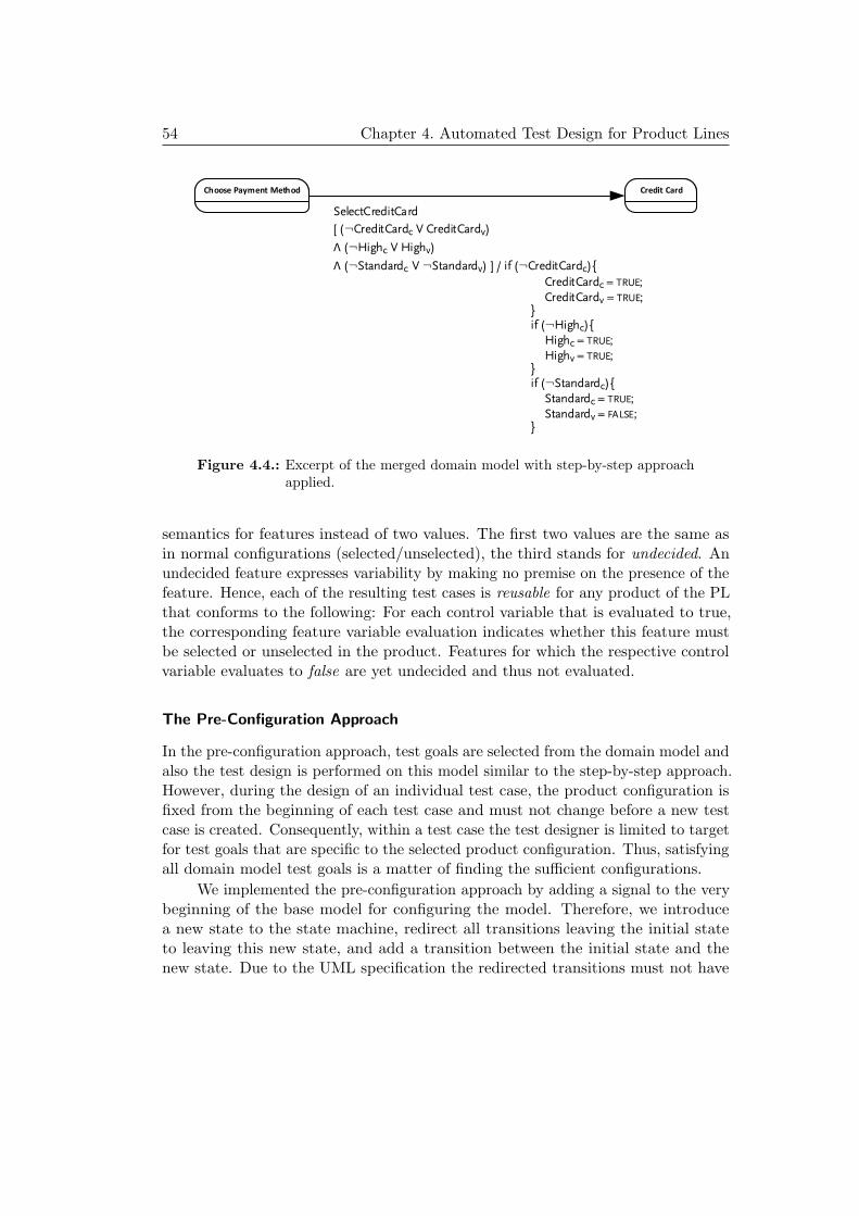
54 Chapter 4. Automated Test Design for Product Lines
SelectCreditCard
[ (¬CreditCardc V CreditCardv)
Λ (¬Highc V Highv)
Λ (¬Standardc V ¬Standardv) ] / if (¬CreditCardc){
CreditCardc = TRUE;
CreditCardv = TRUE;}if (¬Highc){
Highc = TRUE;
Highv = TRUE;}if (¬Standardc){
Standardc = TRUE;
Standardv = FALSE;}
Choose Payment Method Credit Card
Figure 4.4.: Excerpt of the merged domain model with step-by-step approachapplied.
semantics for features instead of two values. The first two values are the same asin normal configurations (selected/unselected), the third stands for undecided. Anundecided feature expresses variability by making no premise on the presence of thefeature. Hence, each of the resulting test cases is reusable for any product of the PLthat conforms to the following: For each control variable that is evaluated to true,the corresponding feature variable evaluation indicates whether this feature mustbe selected or unselected in the product. Features for which the respective controlvariable evaluates to false are yet undecided and thus not evaluated.
The Pre-Configuration Approach
In the pre-configuration approach, test goals are selected from the domain model andalso the test design is performed on this model similar to the step-by-step approach.However, during the design of an individual test case, the product configuration isfixed from the beginning of each test case and must not change before a new testcase is created. Consequently, within a test case the test designer is limited to targetfor test goals that are specific to the selected product configuration. Thus, satisfyingall domain model test goals is a matter of finding the sufficient configurations.
We implemented the pre-configuration approach by adding a signal to the verybeginning of the base model for configuring the model. Therefore, we introducea new state to the state machine, redirect all transitions leaving the initial stateto leaving this new state, and add a transition between the initial state and thenew state. Due to the UML specification the redirected transitions must not have

4.1. Model-based Testing for Product Lines 55
SelectCreditCard [CreditCard Λ High Λ ¬Standard]/
Choose Payment Method Credit Card
Figure 4.5.: Excerpt of the merged domain model with the pre-configurationapproach applied.
a trigger, which is why we can add a trigger for configuration purposes to each ofthem. The trigger listens to a configuration signal that carries a valuation for allnon-core features. The guard of these transitions must protect the state machineto be configured with invalid configurations and thus contains the propositionalformula corresponding to the PL’s feature model. Since any configuration that isprovided by the signal must satisfy the guard’s condition, only valid configurationsare accepted.
After validating the configuration, the parameter values of the signal will beassigned to system class variables by the transition’s effect. Hence, for each non-corefeature a boolean variable indicating whether the feature is selected or not is addedto the system class. Again, transitions specific to a set of products are protected bythese variables, like in the step-by-step approach to limit the base model behavior toa behavior an actual product can conform to. However, control variables need notto be checked during test design, since the configuration is fixed and valid from thebeginning of each test case. Therefore, it is sufficient to derive the partial featureformulas pf for all features fn that are mapped to a transition t by a mapping mfi,t
and construct a conjunction from these formulas:
Gt =n∧
i=1pf fi,t.
For conjoining Gt with t’s guard, of course, the feature literals must be ex-changed by the corresponding feature variables from the class. Figure 4.5 depictsthe resulting merged domain model for this approach. As a result, no productcan conform to any test case’s first step, since it was used to set the configurationand presents not the real system’s behavior. In a simple post-processing actionthis configuration step must be removed from the test cases before testing can beperformed.
With these transformations made to the base model, a test designer canalready create test cases for the PL. However, each test case will be specific toone configuration. As pointed out, a generalization is possible, though is not yetimplemented it. The necessary model transformation for this generalization issketched as follows: The additional transformation steps consist of adding Booleancontrol variables for each non-core feature to the system class and initializing themwith false and effects on transitions for setting these variables to true when traversedby the test generator. More precisely, for every transition t that is mapped to a

56 Chapter 4. Automated Test Design for Product Lines
feature f by a mapping mf,t, the following code needs to be appended to t’s effectfor every mapped feature f .
if ¬fc thenfc ← >
A test generator will set every control variable for all features associated withthat transition, when this transition is added as a step to a test case. Hence, eachcontrol feature that is still false at the end of a test case indicates a free variationpoint. This result can be captured in a reusable test case for a subsequent selectionof variants for testing.
4.2. Evaluation of both Approaches
In this section, we present the implementation of both DC test design approaches,step-by-step and pre-configuration. Furthermore, we apply them to the threeexamples introduced in Section 2.4 to compare these approaches to AC test designmethods.
4.2.1. Tool Chain SPLTestbench
The SPLTestbench is composed of five major components: (i) the feature injector tomerge domain models as introduced in section 4.1.2, (ii) a model printer that exportsthe model to a test generator-specific format, (iii) a third-party test generator - in thiscase Conformiq, (iv) a configuration extractor that collects incomplete configurationsfrom the generated test cases, and (v) domain-specific languages [Voe13] (DSLs)that facilitate design and data processing of a) feature models, b) feature mappingmodels, and c) configuration models. Figure 4.6 depicts the SPLTestbench workflow.
As defined in 4.1.2, the first step towards a domain-level test suite is to mergethe individual models of a domain model into one. This task is performed by thefeature injector by limiting the behavior in the base model according to featureand mapping model. We created two libraries for this purpose: the first librarygenerates propositional formulas for a given feature model and for individual featuresas discussed in the preliminaries in Section 2.1. The latter library consists of typicaltransformations on UML models for facilitating the creation and manipulation ofstates, transitions, guards, triggers, effects, and signals. Eventually, the newly gainedmodel must be exported into a format for a particular test generator. Therefore, weimplemented a model printer that reuses the UML model transformations library toprepare the model to be exported and then prints it into the target file format. Thismeans, no adaptations to test generators are necessary, since the output format ofthis transformation complies to the expected input of the test generator.
When coupled with Conformiq, SPLTestbench currently supports UML models

4.2. Evaluation of both Approaches 57
(v).a (v).b
Feature Injector
Model Printer
Propositional Formulas
UML Model Transformations
Conformiq Export
Configuration Extractor
Base Model[State Machine + Class]
Feature Model[DSL]
Feature Mapping[DSL]
Domain Test Suite Model
ConformiqTM
Conformiq Model[SM + Class]
Domain Model*[SM + Class]
Incomplete Configurations [DSL]
(i)
(ii)
(iii)
(iv)
(v).c
Figure 4.6.: Workflow of the SPLTestbench.
that have a single class and one or more state machines that specify the class’behavior. The class has to provide at least two ports, one for receiving signals fromand the other for sending signals to the environment. One state machine must beselected as the class’ classifierBehavior and must own at most one region, whileeach region must own an initial state. A transition may own a trigger, a guard,and/or an effect. This far, only SignalEvents are supported. Signals, SignalEvents,
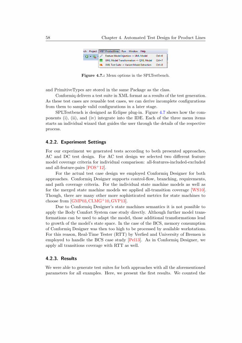
58 Chapter 4. Automated Test Design for Product Lines
Figure 4.7.: Menu options in the SPLTestbench.
and PrimitiveTypes are stored in the same Package as the class.
Conformiq delivers a test suite in XML format as a results of the test generation.As these test cases are reusable test cases, we can derive incomplete configurationsfrom them to sample valid configurations in a later stage.
SPLTestbench is designed as Eclipse plug-in. Figure 4.7 shows how the com-ponents (i), (ii), and (iv) integrate into the IDE. Each of the three menu itemsstarts an individual wizard that guides the user through the details of the respectiveprocess.
4.2.2. Experiment Settings
For our experiment we generated tests according to both presented approaches,AC and DC test design. For AC test design we selected two different featuremodel coverage criteria for individual comparison: all-features-included-excludedand all-feature-pairs [POS+12].
For the actual test case design we employed Conformiq Designer for bothapproaches. Conformiq Designer supports control-flow, branching, requirements,and path coverage criteria. For the individual state machine models as well asfor the merged state machine models we applied all-transition coverage [WS10].Though, there are many other more sophisticated metrics for state machines tochoose from [GMP03,CLMG+10,GVP13].
Due to Conformiq Designer’s state machines semantics it is not possible toapply the Body Comfort System case study directly. Although further model trans-formations can be used to adapt the model, those additional transformations leadto growth of the model’s state space. In the case of the BCS, memory consumptionof Conformiq Designer was then too high to be processed by available workstations.For this reason, Real-Time Tester (RTT) by Verfied and University of Bremen isemployed to handle the BCS case study [Pel13]. As in Conformiq Designer, weapply all transitions coverage with RTT as well.
4.2.3. Results
We were able to generate test suites for both approaches with all the aforementionedparameters for all examples. Here, we present the first results. We counted the

4.2. Evaluation of both Approaches 59
Table 4.1.: Test cases, test steps, and configuration for each of the presentedapproaches.
ExampleApproach
AC-IX AC-PW DC-Pre DC-Step
Tests Ticket Machine 13 50 9 9
Alarm System 21 57 12 12
eShop 20 71 13 13
Steps Ticket Machine 33 56 48 39
Alarm System 55 165 62 50
eShop 135 486 48 39
Conf. Ticket Machine 2 6 5 1
Alarm System 3 9 6 2
eShop 2 7 4 2
number of test cases and test steps that were generated by the test generator. Ofcourse, the amount of configurations that is necessary to execute the test cases is ofequal interest.
The results for these measures are shown in Table 4.1 for each individualapproach: AC with all-features-included-excluded (AC-IX) as well as with pair-wise(AC-PW) coverage and DC with pre-configuration (DC-Pre) as well as with step-by-step (DC-Step). The AC-PW approach scores the highest values for all measuressince it applies the strongest feature coverage criterion and thus covers a maximumof configurations. Consequently, more test cases and test steps are generated thanfor any other approach. In contrast, the DC-Step yields the lowest scores for anymeasure except for tests steps on the Ticket Machine, while at the same time — asstated in section 4.1.2 — it is focused on covering every reachable transition. Wetake this as an indicator for DC test design to scale better than AC approaches.
For the BCS case study, no final results are available yet. So far, RTT generated13 tests and covered 284 of 369 transitions. The researchers at University of Bremenare confident that RTT is able to cover the remaining transitions, although this willneed some optimization of RTT’s configuration.
Concluding, DC test design produces test suites with a significantly lowernumber of tests and test steps than AC test design. Thus, test execution effortsare much lower for these test suites. As we will see in Chapter 5, this does notnecessarily lead to a lower error detection capability.

60 Chapter 4. Automated Test Design for Product Lines
4.3. Related Work
Testing is one of the most important quality assurance techniques in industry. Sincetesting often consumes a high percentage of project budget, there are approaches toautomate repeating activities like, e.g., regression tests. Some of these approachesare data-driven testing, keyword-driven testing, and model-based testing. There aremany books that provide surveys of conventional standard testing [AO08, Bin99,MSB12] and model-based testing [BJK+05, UL06, ZSM11]. Here, we use MBTtechniques and apply them to PL systems. Modeling languages like the UML havebeen often used to create test models. We apply UML state machines.
Feature models are commonly used to describe the variation points in PLsystems. There are several approaches to apply feature models in quality assurance.For instance, Olimpiew and Gomaa [OG05] deal with test generation from PLsystems and sequence diagrams. However, we focus on UML state machines anddescribe different approaches for combining both. In contrast to sequence diagrams,state machines are commonly used to describe a higher number of possible behaviors,which makes the combination with feature models more complex than combiningfeature models and sequence diagrams. As another example, McGregor [McG] showsthe importance of a well defined SPL testing process. Just like McGregor, thefocus of this contribution is to investigate the process of creating tests rather thandefining the structurally possible relations of feature models and state machines.Pohl and Metzger [PM06] emphasize the preservation of variability in test artifactsof SPL testing. As we derive test case design from models automatically, this vari-ability is preserved. Lochau et al. [LSKL12] also focus on test design with featuremodels. In contrast to our work, they focus on defining and evaluating coveragecriteria that can be applied to feature models. In the presented AC approaches, westrive for using such coverage criteria on feature models for the automation of testdesign. Furthermore, Lochau et al. recently proposed an extension for AC testingto decrease its efforts by omitting common test goals that were already exercisedfor other products of the PL [LOGS12].
The contribution that is most relatable to the DC approach is presented byCichos et al. in [COLS11]. They merge feature models into the behavioral modelin a different way than presented here. Then they select a set of configurations fortesting, e.g. by applying pair-wise selection. One after another, each configurationis passed to the test generator until all test targets are covered. Consequently,each resulting test case is applicable to the configuration it was generated for. Nopost-processing, e.g. model-checking, takes place to identify features the test case isagnostic to. In conclusion, they use domain-centered infrastructure (domain-model)to generate test cases in an application-centered manner. In contrast, DC test designas presented above, needs no predefined set of configurations and yields reusable testcases from which configurations can be sampled. Furthermore Cichos et al. state, no

4.4. Conclusion, Discussion, and Future Work 61
standard test generator can be applied for their method due their approach to mergedomain models. In contrast, DC test design is easily integrated with commercial offthe shelf test generators and existing tool chains - as demonstrated with ConformiqDesigner and Real-time Tester.
4.4. Conclusion, Discussion, and Future Work
In this contribution, we presented different approaches to the automatic test designfor PL systems. We presented two approaches to use feature models and mappingmodels for automatic test design from base models. Our main contributions are thedefinition and evaluation of test design approaches using three examples.
Methodically, the main difference of both presented approaches lies in the orderin which test targets by means of coverage criteria are applied. In the AC approaches,first a feature model coverage criterion and then a test model coverage criterionis applied. In contrast, for DC approaches only a test model coverage criterionis applied. As our results show, this leads to very different test suites for bothapproaches. Test suites created with DC test design approaches have significantlyfewer test steps, but also cover all transitions of the model. We conclude that DCtest design scales better w.r.t. system size than AC methods by means of teststeps and the amount of products to test. Although we have not yet carried out amature performance analysis, the same argument should hold for test generationand execution time, as tests are generated only for a single model and executed onless products.
Currently, the approaches are limited to mapping features to transitions. Inlarger systems, not only transitions, but also variables, default values, classes, wholecomponents, and other behavioral or structural elements are potential targets formappings. This need further investigation as one cannot simply apply our approachto these kinds of elements. For example, to allow a variable to have multiple defaultvalues is a non-trivial problem, not only because most UML editors will not allowto create a second default value for a single variable. But also test generators willnot accept a model with two variables that have the same name. Hence, efficientsolutions must be found to deal with such syntactically incorrect base models.
Furthermore, we showed that DC test design opens the fields for new featurecoverage criteria. Since this test design method preserves variability throughoutthe test design process, products can be selected with other intentions, e.g., thefewest configurations for executing all tests, or the largest configurations by meansof activated features. This kind of criteria is investigated in the next chapter.


63
Chapter 5.
Test-driven Product Sampling
With the introduction of domain-centered (DC) test design in Chapter 4, productconfigurations can be sampled from the PL’s test cases. So far, the only criterion forwhich sampling was performed is minimizing the amount of configurations. A validreason for employing this criterion is to minimize the amount of tested products,and subsequently reduce test effort. However, its fault detection capability (FDC)has not yet been assessed.
In this contribution, we address the question whether coverage criteria forsampling configurations from test cases affect the FDC of a test. We set up ourexperiment to reuse the same test suite for every sampling, thus we can measure theeffects of different sampling criteria in isolation. The assessment of fault detectioncapability is facilitated by the PL mutation framework as presented in Chapter 3.We do expect the FDC to vary by altering the following conditions:
a) Sampling as much configurations as possible.
b) Sampling large products by means of activated features.
c) Sampling diverse products.
The reasoning behind this is the following: Testing many products decreases thechance to miss some fault which is specific for a particular combination of features.A selection of large products for testing should expose faults when some or manyfeatures combined do not interact as planned. Finally, research indicates that testingdiverse products is beneficial to FDC than rather testing similar products [HPP+13].
The remainder of the contribution is structured as follows: In Section 5.1 weformally define the concept of reusable test cases as introduced in Section 4.1.2 inthe previous chapter. Section 5.2 presents sampling methods and Section 5.3 showsthe experimental setup and initial results achieved so far. Section 5.4 covers relatedwork and finally Section 5.5 concludes this contribution.

64 Chapter 5. Test-driven Product Sampling
5.1. Reusable Test Cases
Testing a PL faces two major challenges: first, the behavioral test goals must besufficiently covered and secondly, a meaningful subset of products should be sampledfor testing. MBT of PL systems allows the application of behavioral coverage criteriaas well as the usage of structural coverage criteria like t-wise coverage of features.As presented in Chapter 4, we distinguish testing processes for PL systems intoapplication-centered (AC) and domain-centered (DC) testing processes.
In the first process, a set of configurations is selected by a structural criterionfor the purpose of testing, then corresponding products are resolved from the domainmodel and tests are designed from the individual product models. In contrast, inthe latter process tests are designed from the domain model in the first place. Henceproducts in a PL share commonalities, PL test cases are not necessarily limited tobe assigned to a single product anymore. Instead, a test case is reusable for a set ofproducts.
This is achieved by keeping track of the features that must be selected ordeselected for each test case. However, for some features such a decision is unnec-essary, if a particular test case is agnostic to said feature. In this case, we markthe feature for this test as undecided. Therefore, we introduce incomplete productconfigurations, which extend the concept of product configurations by a third valueto be assigned to a feature, here X:
ic = F → B ∪ {X}
Now, a test designer can create an incomplete product configuration and store itwith the test case.
After test creation, product configurations are sampled from the incompleteconfigurations by a coverage criterion. We can sample a product configuration froman incomplete product configuration by making decisions for undecided featureswhether to select or deselect them. This must be done for every undecided featurein every incomplete configuration, until no feature is assigned undecided anymore.From the resulting product configurations, products can be resolved and finallythe tests can be executed against their associated product. In the next section, wepresent coverage criteria for sampling configurations from such reusable test cases.
5.2. Sampling Configurations from Reusable Test Cases
A main challenge in DC testing, is to sample product configurations from the testcases’ incomplete configurations such that every test case can be executed at leastonce. The product configurations are sampled with the target to maximize thelikelihood of detecting faults in the PL during testing, while keeping the test effort

5.2. Sampling Configurations from Reusable Test Cases 65
reasonably low. Such sampling of product configurations is facilitated by coveragecriteria. In the following, we present novel coverage criteria for sampling productconfigurations so that each test case can be executed once.
5.2.1. General Sampling
Due to the nature of feature models being representable as propositional formulas,the problem of sampling configurations can be viewed as boolean satisfiabilityproblem. Hence we search for an optimal solution to a coverage criterion, we presentthe individual coverage criteria as constraint problems. As a first step, we modelthe problem of sampling a product configuration from an incomplete configuration.On this basis, we define mini-/maximization criteria to sample large, small, few,many, and diverse variants from a set of incomplete configurations.
Problem 1 Complete a given incomplete configuration.
Solution The first step is to declare variables for each feature in F and theirdomains. The domain varies depending on the feature’s assignment:
– f = true then the corresponding variable’s domain is {1}
– f = undecided then the corresponding variable’s domain is {0, 1}
– f = false then the corresponding variable’s domain is {0}
Finally, we define the propositional formula of the feature model as constraints forthe variables. A constraint solver is now able to make assignments to undecidedfeatures and check its solution for validity against the propositional formula.
The solution of Problem 1 can easily be extended to sample product configura-tions for all test cases in a test suite.
Problem 2 Complete all incomplete configurations in a test suite with m test cases.
Solution The method to solve problem 1, can be repeated individually for ev-ery incomplete configuration in the given test suite. Eventually, all incompleteconfigurations of the test suite are complete.
5.2.2. Targeted Sampling
In the following, we define coverage criteria for sampling product configurationsfrom test cases. We denote the coverage criteria as optimization problems, so thatan optimization engine can automatically find optimal solutions for a given samplingtarget.

66 Chapter 5. Test-driven Product Sampling
Problem 3 Optimize the set of m-test cases for constraints. In particular:
a) Few/many configurations not exceeding m,
b) Small/large configurations by means of selected features,
c) Diverse configurations,
d) Combinations thereof
Solutions
a) Optimizing the Amount of Distinct Configurations. The aim is to select eitherfew or many products to execute every test case in the given test suite at leastonce. The optimization problem here is to achieve a minimal or maximal numberof distinct product configurations. We model the constraint problem as follows: Aproduct configuration can be interpreted as a binary number b, when we interpretselected features as binary value “1” and deselected features as “0” respectively.Hence a product configuration pcn with features Fn : f1, . . . , fk is interpreted as thenumber:
bn = (f1f2 . . . fk−1fk)2
For a test suite with m test cases, we derive bn for every product configurationpcn, where 1 ≤ n ≤ m. We collect all bi in the set Z:
Z = {b1, b2, . . . , bm−1, bm}
For receiving a minimal set of concrete configurations we have to minimizethe cardinality of Z. Vice versa, we maximize the cardinality of Z, if we want tomaximize the number of configurations for testing:
max /min costa = |Z|
In terms of optimization, we refer to the cardinality of Z as costs, here costa.The expected costs for the criteria of maximizing or minimizing the amount ofconfigurations are in the range of 1 to the number of test cases m. The selection ofthe same product for all test cases results in costs of 1. The upper limit is m, sincewe require each test case to be assigned to only one product.
b) Optimizing the Size of all Configurations. We define the size of a configurationas the sum of all selected features. For constraint solving, we interpret selected asnumerical value “1” and deselected as “0” respectively. Therefore, we can definethe size of a product configuration pcn as follows:
sn =∑k
i=1 fi

5.2. Sampling Configurations from Reusable Test Cases 67
When we accumulate sizes of all product configurations, we can optimizetowards either a minimal or maximal overall size:
max /min costb =∑m
n=1 sn
where maximization achieves large product configurations and minimization smallproduct configurations. The costs of the smallest solution is 2 ×m where the rootfeature and only one other feature is enabled (hence 2) and multiply these by theamount of test cases m. The highest cost for solution is k ×m, where every featurek is selected in every test case m, which is the result of assigning a single productwith all features activated to all test cases.
c) Optimizing the Diversity of Configurations We define diversity over a set of mtest cases and k features. First we establish a relation between a single feature i overall configurations. The goal is to have each feature as often selected as deselected,hence we gain most different assignments.
We achieve this by calculating the diversity di of each feature fn,i, where1 ≤ n ≤ m and 1 ≤ i ≤ k:
di =∑m
n=1 fn,i
Next, we calculate the deviation from optimal diversity, which is m/2, becausewe want a feature to be equally often selected and deselected over all n configurations.Subsequently, the deviation of a feature fi from its optimal diversity is calculatedby |di − (m/2)|. Finally, we achieve maximal diversity by minimizing the sum of alldeviations:
min costc =∑k
i=1 |di − (m/2)|
The minimal costs for a solution to this problem is 0 with product configurationsbeing maximally diversified. The highest cost are (m/2) × k, where the sameconfiguration is sampled for every test case.
We note that this approach does not maximize the amount of sampled productconfigurations, but their diversity. Inherently, this approach leads to solutions withfewer unique product configurations, if the calculated diversity is higher than foranother solutions with more product configurations and less diversity. An approachto increase the amount of product configurations is the combination of the twocriteria diversity and maximization of the amount of product configurations.
d) Combinations In general, all combinations of the previously defined constraintsare valid with the exception of:
– few with many product configurations,

68 Chapter 5. Test-driven Product Sampling
– small with large product configurations.
Any other combination is valid, e.g. many with large and diverse configurations.For making a preference towards one or more criteria, weights can be added to thecosts.
Of course, costs cannot be summed up directly if the optimization targets areopposing, e.g. if large and diverse should be combined, the targets are minimizationand maximization. In this case, a decision for an overall optimization target mustbe made (min or max) and the costs of the criterion not fitting that target must beinverted. Costs are inverted by subtracting the solution’s costs from the expectedmaximal costs. The result of this subtraction are the inverted costs.
5.3. Example and Evaluation
In this section, we assess the fault detection capability of an example test suite inrespect to sampled configurations. First, we introduce the example and setup, thenwe present the results.
5.3.1. Tool Chain SPLTestbench
For the purpose of evaluating the here proposed methods, we extended SPLTestbenchto support coverage-driven product sampling from incomplete product configurations.We implemented the coverage criteria as presented in this contribution by constraintprogramming. As constraint programming environment JaCoP is employed [KS13].The sampling process is supported by Eclipse plug-ins to configure sampling andstart the sampling process as depicted in Figure 5.1.
The whole process domain model to sampling of product configurations isdepicted in Figure 5.2. This includes the test generation from a domain model forgiven coverage criteria. As discussed in Chapter 4, the result of the test generationprocess is a suite of reusable test cases. From these test cases, the feature model,and a given set of sampling criteria, product configurations will be sampled. As aresult of the sampling, product configurations are mapped to test cases. Then testexecution can take place.
5.3.2. Setup
In the previous Chapter 4, we have already designed test cases for the three exampleseShop, Ticket Machine, and Alarm System with AC as well as DC test approaches.Here, we reuse these test cases generated with the step-by-step method to measurethe effects of sampling for different criteria on the test case’s FDC and comparethem to include/exclude-all-features and pair-wise combinatorial testing from AC

5.3. Example and Evaluation 69
Figure 5.1.: Project options in SPLTestbench for sampling products.
test design. However, the Ticket Machine example is not assessed here, since itsvariance is too low and the base model is too small for providing credible results.
For assessing the FDC, we employ the PL mutation framework presented inChapter 3. For the current experiment, we apply both of the supported types ofmutation operators: behavioral operators, which mutate the state machine model,and variability operators, which mutate the feature mapping model. However, we donot apply the following operators which in most cases add behavior: delete mapping,delete mapped element, and copy trigger. The reason for this is the test cases’inefficiency to detect additional behavior, since we perform conformance-testingwhen we apply all-transitions coverage. Still, we apply the excluded operators inChapter 6 when testing for enabled features.
5.3.3. Results
We performed mutation analysis for all examples and their test suites with differentsampling criteria and their combinations. Since the test suite stays the same forall samplings, this procedure assesses the impact of the different sampling criteriaon the test suite’s FDC. For a first experiment, we sampled configurations for allsampling criteria in isolation and in combination as shown Table 5.1. To reduce theamount of samplings, we chose four representative combinations: Few+Small+Div,Few+Large+Div, Many+Small+Div, and Many+Large+Div. Furthermore, we seethe configurations sampled for AC test design in the last two rows. There, weshow the configurations for include/exclude-all-features and two-pair combinatorialsampling [LSKL12,PSK+10].

70 Chapter 5. Test-driven Product Sampling
Figure 5.2.: Sampling process in SPLTestbench.
Additionally, we present necessary test executions for achieving selected sam-pling criteria in Figure 5.2. As discussed earlier, every test case for a given DCsampling is executed only once in this evaluation. Hence we reuse the same testsuite for different samplings, the overall amount of test executions is the same forany DC sampling regardless of being an isolated or a combined one. In contrast, forAC test design we generated the test cases individually for each variant. From this,we gain more test cases and subsequently more test executions. Due to the setup,AC test cases contain redundancy, since the common core and repeatedly activated

5.3. Example and Evaluation 71
Table 5.1.: Distinct configurations sampled.
Isolated DC samplings eShop Alarm System
Few 1 3Many 13 12Small 4 7Large 1 3
Div 7 8
Combined DC samplings eShop Alarm System
Few+Small+Div 4 7Few+Large+Div 4 7
Many+Small+Div 10 11Many+Large+Div 10 11
AC samplings eShop Alarm System
Include/exclude-all 2 3Two-pair 7 9
Table 5.2.: Test executions
eShop Alarm System
Any DC sampling 13 9Include/exclude-all 20 19
Two-pair 71 54
features are tested over and over again for each tested variant.
Next, we proceeded with the results of our mutation analysis. The assessmentprocess is as follows: During sampling, we received an assignment of productconfigurations to test cases. The mutation system generates mutants and derivesproduct code from the mutated domain model. Then it executes the test cases forevery mutated product according to the assignment of the original products. Wepresent the mutation scores in two parts. First, we assess the sampling criterion’seffect on the FDC for base models. The results of this first assessment are presentedin Table 5.3. In the second part, we assess the FDC for mapping models and presentthe results in Table 5.4.

72 Chapter 5. Test-driven Product Sampling
Table 5.3.: Mutation scores for detected faults in base models in %.
Isolated DC samplings eShop Alarm System
Few 77.6 66.3Many 76.5 65.0Small 76.5 65.0Large 77.6 66.3
Div 77.6 65.0
Combined DC samplings eShop Alarm System
Few+Small+Div 76.5 65.0Few+Large+Div 77.5 66.3
Many+Small+Div 76.5 65.0Many+Large+Div 77.5 65.0
AC samplings eShop Alarm System
Include/exclude-all 76.5 57.5Two-pair 77.5 71.3
Table 5.4.: Mutation scores for detected faults in mapping models in %.
Isolated DC samplings eShop Alarm System
Few 33.3 54.2Many 91.7 66.7Small 91.7 66.7Large 33.3 43.5
Div 66.7 66.7
Combined DC samplings eShop Alarm System
Few+Small+Div 91.7 70.8Few+Large+Div 66.7 62.5
Many+Small+Div 91.7 70.8Many+Large+Div 66.7 70.8
AC samplings eShop Alarm System
Include/exclude-all 66.7 54.2Two-pair 100.0 79.2

5.4. Related Work 73
5.3.4. Discussion
The FDC of the test suite varies with the applied sampling criterion. However, themutation scores for the base models exposes only marginal variance. This is due tothe DC test design approach where all-transitions as test selection is applied to thebase model in the first place and product sampling afterwards. Hence we do notfurther discuss FDC of test cases towards faults in the base model.
More variance is found in the FDC of the test cases for errors in the mappingmodels: the highest FDC of isolated criteria are achieved by maximized amount ofproducts (Many) and small products (Small). However, we expected larger productsto contain more components and thus be more likely to expose faulty behavior dueto more possible interactions. Instead, large products led to testing too few productsfor having a positive impact on fault detection. Though Many and Small havethe same FDC in this example, Small is more efficient when we evaluate the testeffort based on the amount of tested products. Small yields always less products fortesting than Many (cf. Table 5.1).
For combined sampling criteria the variance of the mutation scores declines. Thehighest scores in the group of combined criteria are achieved by the following two com-binations: maximized amount with small and diverse products (Max+Small+Div)and by minimized amount with small and diverse products (Min+Small+Div).In this case, fault detection efficiency is higher for Min+Small+Div than forMax+Small+Div, since less products are sampled for testing. In general, com-bined criteria scored equal or lower to the top scoring isolated criteria, but neverbetter.
In comparison to the AC testing methods, DC lies in between the two presentedAC criteria. DC testing achieves at least include/exclude all features in all cases,while at the same time it needs less test executions. In comparison to two-paircombinatorial testing, DC testing is only as good as in one case and otherwise 5 to8.4 points behind. This advantage over DC testing comes with a price: two-pairtesting needs at least five times more test executions than any DC test in thisevaluation.
Summing up, application-centered and domain-centered testing differs onlyif errors in the variability model are of concern. Within different DC methods,sampling few, small and diverse products seems to be most advantageous.
5.4. Related Work
Sampling product configurations for testing is an ongoing challenge. Most work isfocused on structural coverage criteria for feature models and hence is agnostic to theinteractions in behavioral models [PSK+10,OZML11]. Still, the test effort is high,since feature interactions are selected for testing where no behavioral interaction is

74 Chapter 5. Test-driven Product Sampling
present.
Lochau et al. present incremental test design methods to subsequently testevery specified behavior [LSKL12]. Here, configurations are sampled as needed toachieve the next test goal. The result is a set of test cases where each is limited toa single product configuration. In contrast, the here presented coverage criteria forsampling configurations rely on reusable test cases.
Similar to the notion of incremental test design Beohar et al. propose spinaltest suites [BM14]. A spinal test suite allows one to test the common features ofa PL once and for all, and subsequently, only focus on the specific features whenmoving from one product configuration to another. This is different from the notionof reusable test cases, where there is no such thing as progressing through productconfigurations.
Baller et al. present optimization criteria and a supplementing formal frame-work for optimizing product line tests in [BLLS14]. In general, their approach isbased on product-centered test design, where redundant test cases were designed.By applying additional efforts for optimizing the test suite, they eliminate someredundant test cases and subsequently reduce efforts for test execution.
Under constrained budgets for testing, it is useful to prioritize the productsselected for testing. Al-Hajjaji et al. present such an approach in [AHTM+14] thatcan be applied after variants are sampled for testing.
5.5. Conclusion
In this contribution, we presented five novel coverage criteria for sampling productconfigurations from a test suite consisting of reusable test cases. This is the firstassessment of a single test suite with varying product configurations so that everytest case can be executed exactly once. We assessed the coverage criteria in isolationand additionally in combination with each other. Our experiment was conducted onthree PL examples. The FDC of the test suites was assessed by mutation analysis.Faults were injected into the behavioral models as well as into variability models ofthe examples.
We found that testing many products (Many) or rather small products bymeans of enabled features (Small) increases the test’s FDC in our case. This isparticularly true for faults located in the variability model. Fault detection forfaults in the behavioral model remained almost equal over all sampling criteria. Wealso assessed combinations of the defined sampling criteria, which increases the testsuites’ FDC further.
In future, further experiments based on larger examples and industrial casestudies are scheduled. This will provide more confidence on the current findings.Furthermore, the current sampling approach can be extended to allow multiple

5.5. Conclusion 75
test executions. The reasoning behind this is the following: since all sampledconfigurations are built anyways, the effort for executing all compatible test cases,rather than only the assigned products, might not be much higher after all. Theefficiency of this approach is dependent on the costs for building products in respectto additional effort for test executions and the setup/tear down phases. Also, thisextension might close the gap between DC and two-pair’s FDC.


77
Chapter 6.
Testing Product Boundaries
So far, the contributions of this thesis focused on covering the selected behavior of aproduct, i.e., they check if everything that should be in the product is implemented.In this contribution, we focus on covering the deselected behavior by checking whethereverything that should not be in the product variant is actually not implemented.Common test design approaches cannot be used for this, because they are focusedon cutting away all deselected behavior for a variant, and thus the model for thevariant does not contain deselected behavior, anymore. To overcome this issue, weintroduce model transformations that create new model elements describing thenon-existence of deselected behavior.
The contribution is structured as follows. In Section 6.1 we describe theapproach. The implementation and experiments are described in Section 6.2. Sec-tion 6.3 contains an analysis of the related work. In Section 6.4, we conclude anddiscuss the presented approach including threats to validity.
6.1. Testing Boundaries of Products
MBT is focused on creating test cases from behavioral models. In MBT, test casesare typically designed for performing positive testing by means of checking the SUTfor conformance to the test models. For testing a PL, the information about featuresand parts being explicitly excluded, however, is valuable too. A test designer canmake use of this information by creating tests that actively try to invoke excludedbehavior. We think of this as an attempt of breaching the boundaries of a productunder test (PUT), where the boundary is predefined by the PUT’s configuration. Aboundary is overcome if an excluded behavior is invoked and executed as specifiedin the domain model.
In this contribution, we refer to the Ticket Machine as running example. InFigure 6.1, we depict an excerpt of the Ticket Machine’s domain model, consistingof a feature model and a UML state machine as base model. In this excerpt, thesystem waits for coins or bills to be inserted until the costs for the selected ticketsare covered. The dotted arrow maps the feature Bills to the transition t6 in the statemachine: If the Ticket Machine’s configuration includes the feature Bills, then the

78 Chapter 6. Testing Product Boundaries
Bills ReducedFair Change
Base Model: UML State Machine (excerpt)
Ticket Machine
Feature Model
Payment
coin [paid < costs] /paid++;credit o;o.sum=costs;out.send(o);
bill [paid < costs] /paid+=5;credit o;o.sum=costs;out.send(o);
t5 t6
t4
t7
Mapping: TRUE
Figure 6.1.: Excerpt of the product line model for the Ticket Machine.
mapped transition t6 must be present in the corresponding product. If the featureis not selected, this transition is not part of the corresponding product and henceleaving the customer’s only payment option to be coins as denoted in transition t5.
6.1.1. Boundary Transitions
Inside the PUT’s boundaries is the PL’s core and all included features declared by theconfiguration. Outside its boundaries lie the excluded features. Figure 6.2 depictsan excerpt of a Ticket Machine product, in which the feature Bills is deactivated.Here, the state “Payment” and the transitions t4, t5, t7 lie within the boundaries ofthe product. Transition t6 as shown in the excerpt of Figure 6.1 is not part of thisproduct. We overcome this boundary, if we make the product process a bill in thisstate as defined in the domain model.
More formally speaking, we define a product’s boundary by boundary transitionsover UML state machines. We define a boundary transition bt, where S is the setof states and T is the set of transitions in a base model and t(s, s′) is a transitionfrom state s to s′ as:
bt(s, s′) ∈ T ⇔ s, s′ ∈ S ∧ s ∈ productmodel
∧bt 6∈ productmodel
Hence, a boundary transition is not part of the particular product. We call a product

6.1. Testing Boundaries of Products 79
Payment
coin [paid < costs] /paid++;credit o;o.sum=costs;out.send(o);
t5
t4
t7
Figure 6.2.: Ticket Machine prod-uct w/o feature Bills.
Payment
coin [paid < costs] /paid++;credit o;o.sum=costs;out.send(o);
t5
t4
t7
bill [paid < costs] /
t20
Figure 6.3.: Same product withcomplementary transition added.
to have an open boundary, if behavior from an excluded feature can be invoked atsome point of the PUT’s execution.
In general, it is possible to detect open boundaries by stimulating the PUTwith unexpected events in every state. This resembles sneak-path-analysis and iscostly [HTBH12]. Here, we propose a method to reduce test effort by stimulatingthe PUT with unexpected events only if its active state has at least one boundarytransition. In particular, we stimulate the PUT with only those events that couldpossibly trigger one of its boundary transitions attached to this state.
6.1.2. Turning Open Boundaries into Test Goals
We choose transition-based coverage criteria for selecting test goals. Our approachcomprises introducing a transition for each boundary transition to which we referto as complementary transition. The intention of this is to create transitionsspecifying that the PUT should stay in its current state and with events that arenot expected to trigger product behavior. Hence, for every boundary transition, weadd a complementary transition with its source state as target and source. For thepresented Ticket Machine product without feature Bills, Figure 6.3 shows the sameexcerpt of the product as in Figure 6.2, but with the additional complementarytransition t20, which complements boundary transition t6 of this product. Thecomplementary transition must have no effect, since in the state “Payment” noreaction is expected for any product that does not include feature Bills. However,we should not add a complementary transition, if there is an explicitly specifiedbehavior for processing the signal event when feature Bills is excluded as in state“Selection”.
So far, we defined boundary transitions for a given product and outlined how toadd complementary transitions. For DC test design we must raise these concepts tothe domain engineering-level, in order to set complementary transitions as test goals.Particularly, we define a transformation for adding complementary transitions to

80 Chapter 6. Testing Product Boundaries
Bills ReducedFair Change
150% UML State Machine (excerpt)
Optional
Mapping: TRUE
Feature Model
Payment
coin [paid < costs] /paid++;credit o;o.sum=costs;out.send(o);
bill [paid < costs] /paid+=5;credit o;o.sum=costs;out.send(o);
t5 t6
t4
t7
bill [paid < costs] /
t20
Mapping: FALSE
Figure 6.4.: PL Model Example: Ticket Machine with Complementary Transi-tion.
the domain model whenever there is a boundary transition of any product available.This enables DC test design methods to consider complementary transition as testgoals during test design. Also, AC test design methods benefit from this approach,since the complementary transitions are propagated during the resolution processto the application-level.
In Figure 6.4, we depict the desired outcome of the transformation: we added acomplementary transition t20 to state Payment for transition t6, which is a boundarytransition for any product not including the feature Bills. Hence, the complementarytransition is mapped to feature Bills with the mapping’s flag set to false, denotingthe transition is only to be included when the feature Bills is deselected.
We present the pseudo code to achieve the result shown in Figure 6.4 inAlgorithm 1. Let SM(S, T ) be a state machine, where S is the set of states and Tthe set of transitions. For each transition t ∈ T we define:
• source(t) as the source state of t,
• target(t) as the target state of t,
• triggers(t) as the triggers of t,

6.1. Testing Boundaries of Products 81
• triggers ∗(t) as the triggers from all transitions leaving target(t), if triggers(t)is empty, and triggers(t) otherwise. Since this is a recursive definition,triggers ∗(t) must stop once all t ∈ T are traversed.
• features(e) as the set of feature selections mapped to a UML element e ∈ SM .A feature selection states whether a feature must be selected or deselected toinclude e.
• concurrentGuards(t) as a conjunction of guard conditions. The conditionsare collected from transitions that can be concurrently enabled with t.
First a set of transitions for storing complementary transitions during this procedureis initialized. Then for all transitions of the state machine the following actions areperformed: the algorithm checks in lines 4–7 if current transition b is a boundarytransition for some product. This is achieved by checking whether b has differentfeature mapping selections than its source state. The selections from b, which arenot shared by its source state are stored in difference. When difference is notempty, b is a boundary transition and creation of a complementary transition begins.Otherwise, the for-loop continues with the next b.
From line 8 to 12, the complementary transition c is added to C and isinitialized with source(b) as target and source state, and triggers ∗(b) as triggers.The complementary transition’s guard is built from the original boundary transition’sguard and, to prevent non-deterministic behavior, conjoined with the negated guardconditions of concurrently enabled transitions. Lastly in this if-block, c is mappedto the negated difference of feature selections unified with the selections of b’s sourcestate, so c is included in every product when b’s source state is, but b is not. Line14 concludes the procedure by adding the set of complementary transitions C tothe state machine’s set of transitions T .
The outcome of this procedure when applied to the Ticket Machine’s domainmodel is depicted in Figure 6.5. We denote the mappings from the feature modelby feature formulas in the transition’s guards analog to Featured Transition System(FTS) introduced by Classen [CHSL11]. We use the following acronyms: B forBills, C for Change, and R for ReducedFare. The complementary transitions addedby our transformation procedure are denoted by dotted arcs (transitions t19–t22).Beginning from the initial state, we find the first state with at least one boundarytransition to be “Selection”. The boundary transition here is t3, which is enabledwhen the feature ReducedFare is part of a product. Hence, t19 is added to thestate machine for serving as an additional test goal to any product not includingReducedFare. To achieve all-transition coverage, a test case must include sendingthe signal event “reducedTicket” when the feature ReducedFare is disabled while thestate machine is supposed to stay in state “Selection”. Analog to this, transition t20is added for boundary transition t6 in state “Payment”.

82 Chapter 6. Testing Product Boundaries
Selection
Payment
TicketIssue
shortTicket [] /tShort++;costs+=2;total o;o.sum=costs;out.send(o);
dayTicket [] /tDay++;costs+=4;total o;o.sum=costs;out.send(o);
reducedTicket [R] /tRed++;costs+=3;total o;o.sum=costs;out.send(o);
next [costs > 0]
t0
coin [paid < costs] /paid++;credit o;o.sum=costs;out.send(o);
bill [B && paid < costs] /paid+=5;credit o;o.sum=costs;out.send(o);
[paid >= costs] / paid-=costs;
[R && tRed>0] /tRed-=1;
[tShort>0 && tRed ==0] /tShort-=1;
[tDay>0 && tShort==0 && tRed==0] /tDay-=1;
cancel [paid<costs]tShort=0;tDay=0;tRed=0;
Selection
[B && paid>0 && paid<5] /paid--;credit o;o.sum=paid;out.send(o);
[B && paid >=5] /paid-=5;credit o;o.sum=paid;out.send(o);
[paid ==0] / costs=0;success o; out.send(o);
change [C && tDay==0 && tShort==0 && tRed==0] /processChange o;out.send(o);
noChange [!C && tDay==0 && tShort==0 && tRed==0] /processChange o;out.send(o);
t1 t2 t3
t4
t5 t6
t7
t8
t9 t10 t11
t12
t13
t14 t15 t16
t17
[!B && paid > 0] /paid--;credit o;o.sum=paid;out.send(o);
reducedTicket [!R] /t18
cancel [] /tShort=0;tDay=0;tRed=0;
t19
bill [!B && paid < costs] /
t20
change, noChange [!R && tRed>0&& !(tDay==0 && tShort==0 && tRed==0)] /
noChange [C && tDay==0 && tShort==0 && tRed==0] /
change [!C && tDay==0 && tShort==0 && tRed==0] /
t21t22
t23
Figure 6.5.: Domain Model: Ticket Machine with added feature formulas andcomplementary transitions.
Selection
Payment
TicketIssue
shortTicket [] /tShort++;costs+=2;total o;o.sum=costs;out.send(o);
dayTicket [] /tDay++;costs+=4;total o;o.sum=costs;out.send(o);
next [costs > 0]
t0
coin [paid < costs] /paid++;credit o;o.sum=costs;out.send(o);
[paid >= costs] / paid-=costs;
[tShort>0 && tRed ==0] /tShort-=1;
[tDay>0 && tShort==0 && tRed==0] /tDay-=1;
cancel [paid<costs]tShort=0;tDay=0;tRed=0;
Selection[paid ==0] / costs=0;success o; out.send(o);
noChange [tDay==0 && tShort==0 && tRed==0] /processChange o;out.send(o);
t1 t2
t4
t5
t7
t8
t10 t11
t13
t14
t17
[paid > 0] /paid--;credit o;o.sum=paid;out.send(o);
reducedTicket [] /t18
cancel [] /tShort=0;tDay=0;tRed=0;
t19
bill [paid < costs] /
t20
change, noChange [tRed>0&& !(tDay==0 && tShort==0 && tRed==0)] /
change [tDay==0 && tShort==0 && tRed==0] /
t21t22
Figure 6.6.: Product: State machine model of a Ticket Machine without Bills,Change, and ReducedFare.

6.1. Testing Boundaries of Products 83
Algorithm 1 Adds Complementary Transitions to a Region
1: procedure addComplementaryTransitions2: C ← ∅3: for all b ∈ T do4: incoming←
⋃features(s ∈ S|s = source(b))
5: difference← features(b)− incoming6: if difference 6= ∅ then7: C ← C ∪ c8: source(c)← source(b)9: target(c)← source(b)
10: guard(c)← guard(b) ∧ ¬(concurrentGuards(b))11: triggers(c)← triggers ∗(b)12: features(c)← incoming ∧ ¬ difference
13: T ← T ∪ C
State “TicketIssue” shows three boundary transitions t9, t12, and t13. Transitiont9 has no trigger, hence its target state must be checked for outgoing transitionswith triggers. The transformation’s check for further transitions in t9’s targetstate delivers t9 to t13. Since t9 is currently under investigation it will not bechecked for triggers again. Transitions t10 and t11 are untriggered and thus theirtarget state must be evaluated for further triggers. Since their target state is also“TicketIssue”, for which this check is currently performed, there are no further checksat this point. For each of the triggered transitions t12 and t13 one self-loop must becreated. Each of them includes the copied trigger, negated feature constrained forthe currently investigated feature ReducedFare and its guard constraint, the copiedfeature mapping (C) from the transition at the target state, and its negated guardconstraint:
t12 : change[¬R ∧ tRed > 0 ∧ C
∧¬(tDay == 0 ∧ tShort == 0 ∧ tRed == 0
)]/
t13 : noChange[¬R ∧ tRed > 0 ∧ ¬C
∧¬(tDay == 0 ∧ tShort == 0 ∧ tRed == 0
)]/
We combine both transitions to create t21 with both triggers and reduced guards,where constraint C and ¬C cancel each other out. Unfortunately, t21 is unreachable,since the condition tRed > 0 never holds for any product that does not includet3. Transitions t22 and t23 are added accordingly. Finally, no further boundarytransitions exists and therefore the procedure ends here.

84 Chapter 6. Testing Product Boundaries
6.2. Evaluation
In this section, we present the evaluation of the product line’s test suites, with andwithout the presented model transformations. We assess all tests by means of faultdetection capability (FDC). First, we introduce the test setup and then, present theresults.
6.2.1. Setup
We assess two test suites for each of the examples presented in Section 2.4 inChapter 2. As a first test suite we use the test suite generated by DC test designas presented in Chapter 4. In particular, we apply the step-by-step method. Forthe second, we apply our transformations as presented in this contribution andgenerate the test cases with the step-by-step test design method. For test generation,Real-Time Tester by Verified is employed [Pel13]. For all test suites, we appliedall-transition coverage for test selection.
From the test cases, SPLTestbench sampled configurations for testing fewproducts. The assessment of the test cases’ FDC was carried out by mutationanalysis. Here, we applied all mutation operators for mapping models as defined inChapter 3.
6.2.2. Results
In Table 6.1, we show the test assessment results of test suites, that were designedwith the original models. In each row, we show the mutation results for all examplesin the form of killed mutants/all mutants. As supposed, mutations with behaviorthat is not described by the test model (DME, DMP) are not detected. For theother two mutation types which alter specified behavior (IME, CFV), we receivemixed results in the range of 40% to 100%.
In contrast, Table 6.2 depicts the assessment results for the test suites that werecreated from our transformed models. Again in each row, we show the mutationresults for all examples in the form of killed mutants/all mutants. We observeincreased scores for every mutation operator on any of our examples. In the lastrow of each table, we show the overall results for each example. Furthermore, in thelast column we present the accumulated scores of every mutation operator over allexamples.
6.2.3. Discussion
Our results support the recommendation of Binder [Bin99] and the conclusionsdrawn by Mouchawrab et al. [MBLD11] and Holt et al. [HTBH12]: Testing sneakpaths (in our case as boundaries of product line variants) is an essential component of

6.3. Related Work 85
Table 6.1.: Mutation Scoresfor Regular Tests
Op. TM eShop AS p.Op.
DMP 20.0 0.0 0.0 5.9DME 12.5 0.0 0.0 2.3IME 40.0 25.0 25.0 29.4CFV 100.0 100.0 75.0 88.2SWP 60.0 50.0 37.5 47.1
per Ex. 42.8 23.3 20.8
Table 6.2.: Mutation Scoresfor Tests withTransformations
Op. TM eShop AS p.Op.
DMP 60.0 100.0 62.5 70.6DME 37.5 28.6 38.1 34.9IME 60.0 100.0 25.0 52.9CFV 100.0 100.0 87.5 94.1SWP 80.0 100.0 50.0 70.6
per Ex. 64.3 66.7 49.1
state-based testing and drastically increases FDC. Furthermore the results indicatethat sneak path testing is a necessary step in state-based testing due to the sameobservations made by Holt et al. [HTBH12]: 1) The proportion of sneak paths inthe collected fault data was high (61,5 %), and 2) the presence of sneak paths isundetectable by conformance testing.
We were able to increase the amount of killed mutants by a significant amountthrough our model transformations but were not able to kill all mutants. Especiallythe mutation score for the DME operator is still below 50% of killed mutants. Thisis partly the result of unreachable behavior, e.g. in the case when a UML element(e.g. a transition) that was mapped to a feature (and thus is now permanentlyenabled) has preceding elements mapped to the same feature. In that case, theelement is always enabled but only reachable if its preceding elements are present,which is only true if the feature is present. A fundamental question here is if thisindicates an issue of the test design or an unrealistic mutation operator.
This leads to the consideration of the threats to validity. The first point wasalready mentioned: The introduced mutation operators are new and depend on amodel-based PLE. Further analysis with well-known mutation operators need to bedone. Concerning the validity of our examples: we are aware that the used examplesare rather small. A larger case study with realistic background would be necessaryto underline the advantages of our approach and also the assumed conditions like,e.g., the application of feature models.
6.3. Related Work
In recent years MBT emerged as an efficient test design method that yields a numberof improvements compared to conventional test design such as higher test coverageor earlier defect detection. There are several surveys on the effectiveness of MBT in

86 Chapter 6. Testing Product Boundaries
general [ZSM11,BJK+05,UL06] and MBT of SPL systems [OWES11]. In contrastto this, we combine the application of model-based software product line testingwith a product line-specific sneak path analysis. To our knowledge, this combinationhas not been covered before.
An early evaluation of the mutation scores suggests that our generated testsuites satisfying all-transitions coverage are capable of detecting many seeded faultsexcept unspecified behavior, so-called sneak paths [Bin99]. In safety-critical systems,an unintentional sneak path may have catastrophic consequences. Sneak path testingaims at verifying the absence of sneak paths and at showing that the software undertest handles them in a correct way. Several studies showed that sneak path testingimproves the fault detection capabilities [BDL04, MBLD11, HTBH12]. However,the effort spent for sneak path testing is considerably high. Here, we present anovel, more efficient approach for detecting unspecified behavior in product lineengineering: We define boundary transitions that stimulate the product under testwith only those events that could possibly trigger a transition that would invokeexcluded behavior. To our knowledge, this approach has not been applied in thecontext of software product line engineering before.
6.4. Conclusion & Future Work
In this contribution, we combined MBT for product lines with boundary tran-sition analysis. We extended our previous work on DC test design with modeltransformations that increase the FDC of the generated test suites.
We were able to increase the mutation score in each of our three examples andfor each of the proposed mutation operators significantly by using the proposedmodel transformation. The scores increased for the eShop by 43%, for the TicketMachine by 24% and for the Alarm System by 29%. As for the operators thenumbers increased by 63% for the DMP operator, by 33% for the DME operator,by 24% for the IME operator, and by 6% for the CFV operator (which were alreadyvery high), and for the SWP operator by 23%.

87
Part III.
Closure


89
Chapter 7.
Conclusion
This chapter concludes this thesis. Herein, we reflect on the scientific achievementscontributed by this thesis and look at the achievement’s impact on the scientificcommunity. Furthermore, we discuss more general future work derived from theopen leads in this thesis.
7.1. Contributions
In this thesis, we proved the Hypothesis initially stated in Section 1.2:
Leverage test design to the domain engineering-level.
For this, we provided methods and concepts as solutions. In particular, we makethe following contributions to leverage testing to the domain-level:
1. Enable automated test design on domain-level by model transformations.
2. Product sampling from reusable test cases.
3. Adapt established test coverage criteria for PL systems.
4. Enable test assessment on domain-level.
The contributions are implemented as proof of concept prototypes within theSPLTestbench.
7.2. Impact
The contributions are published as multiple scientific articles and were presented oninternational conferences and workshops. All articles are peer-reviewed by leadingscientists and experts in the field of software testing and PLE. In the following,we list the contributing article’s title, authors, venue, and where it contributes towithin this thesis:

90 Chapter 7. Conclusion
• Model-based Product Line Testing: Sampling Configurations for Optimal FaultDetection. Hartmut Lackner. SDL Forum 2015: Chapter 5 Test-driven ProductSampling
• Automated Test Design for Boundaries of Product Line Variants. StephanWeißleder, Florian Wartenberg, and Hartmut Lackner. ICTSS 2015. Chapter 6Testing Product Boundaries
• Potential Errors and Test Assessment in Software Product Line Engineering.Hartmut Lackner and Martin Schmidt. MBT 2015. Chapter 3 Assessment ofProduct Line Tests
• Model-Based Test Design of Product Lines: Raising Test Design to the ProductLine Level. Hartmut Lackner, Martin Thomas, Florian Wartenberg, andStephan Weißleder. ICST 2014. Chapter 4 Automated Test Design forProduct Lines
• Assessment of Software Product Line Tests. Hartmut Lackner and MartinSchmidt. SPLat 2014. Chapter 3 Assessment of Product Line Tests
• Top-Down and Bottom-Up Approach for Model-Based Testing of Product Lines.Stephan Weißleder and Hartmut Lackner. MBT 2013. Chapter 4 AutomatedTest Design for Product Lines
Our concept of domain-level test design and reusable test cases attracted attentionof both, the community of MBT and PLE. Notably, Aitor Arrieta et al. present atest architecture for configurable cyber-physical systems [ASE14b,ASE14a]. Theauthors identify test efficiency as one of the major challenges and derive from theconcepts presented in this thesis a domain-level test design and product samplingprocess for Simulink environments. For this purpose, the authors introduce testfeature models to support reusable test cases throughout the test process.
Our approaches for test design and fault detection are also recognized byDevroey et al. [DPL+15]. Their most recent vision is to have dissimilar test caseselection for testing PL systems. For measuring fault detection capability they alsoresearch in the fields of mutation analysis. Since they have chosen other notations tomodel variability and behavior, the results in this thesis are not directly transferable.
A general confirmation of the relevance of the discussed topics in this thesisis the fact that Østein Haugen, who is a leading expert on the standardization ofthe Common Variability Language, is also researching on solutions for samplingproducts from reusable test cases [SH15]. So far, the findings presented by him andhis colleagues are limited to sampling configurations for testing a minimal amountof products. In contrast, in Chapter 5 of this thesis, we presented five differentsampling criteria - sampling for minimal amount of products being one of them -

7.3. Future Work 91
and additionally measured the individual criterion’s fault detection capability anddiscussed their implications.
7.3. Future Work
Although we found answers in this thesis for leveraging testing to the domain-level,there are still open questions and we raised new ones.
The examples in this thesis employed for carrying out the evaluations aretypical for small and isolated systems. However in the industry, we can find morecomplex systems not only by size in states, transitions, signals, or features. TheBody Comfort System case study, which is currently under investigation, couldprovide more confidence in the findings.
Other aspects of complexity, which we have not dealt with in this thesis butare widely spread, are distributed system or cyber-physical systems or internet ofthings. A large-scale study with these kinds of systems would significantly improveconfidence in the feasibility and reliability of the current findings.
Furthermore, a case study of a real system that is already in use could supplyknown errors from test or field reports. With this knowledge the FDC of versionsexposing the documented errors could be tested with domain-level tests. The aim isto measure the tests accuracy to find such known errors. Whether this kind of testassessment is independent from the employed modeling languages, is still arguable,since each language may promote different kinds of errors.
In industry, we can also observe other notations for model-based PLE for both,variability and behavior modeling. In Chapter 3, we showed that errors in differentvariability notations, like annotative, compositional, or transformational variabilitymodeling effectively lead to similar faults at runtime.


93
Bibliography
[AHTM+14] Al-Hajjaji, Mustafa; Thum, Thomas; Meinicke, Jens; Lochau, Malte;Saake, Gunter: Similarity-based prioritization in software product-linetesting. In: Gnesi, Stefania; Fantechi, Alessandro, editors, the 18thInternational Software Product Line Conference, pp. 197–206. 2014.doi:10.1145/2648511.2648532.
[ALN13] Aichernig, Bernhard K.; Lorber, Florian; Nickovic, Dejan: Time forMutants — Model-Based Mutation Testing with Timed Automata. In:Hutchison, David; Kanade, Takeo; Kittler, Josef; Kleinberg, Jon M.;Mattern, Friedemann; Mitchell, John C.; Naor, Moni; Nierstrasz,Oscar; Pandu Rangan, C.; Steffen, Bernhard; Sudan, Madhu; Ter-zopoulos, Demetri; Tygar, Doug; Vardi, Moshe Y.; Weikum, Gerhard;Veanes, Margus; Vigano, Luca, editors, Tests and Proofs, volume 7942of Lecture Notes in Computer Science, pp. 20–38. Springer BerlinHeidelberg, Berlin, Heidelberg, 2013. ISBN 978-3-642-38915-3. doi:10.1007/978-3-642-38916-0{\textunderscore}2.
[AO08] Ammann, Paul E.; Offutt, Jeff: Introduction to Software Testing.Cambridge University Press, New York, NY, USA, 2008. ISBN9780521880381.
[ASE14a] Arrieta, Aitor; Sagardui, Goiuria; Etxeberria, Leire: A configurabletest architecture for the automatic validation of variability-intensivecyber-physical systems. In: Mannaert, Herwig, editor, ICSEA 2014.Curran, Red Hook, NY, 2014. ISBN 9781634394697.
[ASE14b] Arrieta, Aitor; Sagardui, Goiuria; Etxeberria, Leire: A model-basedtesting methodology for the systematic validation of highly configurablecyber-physical systems. In: Kanstren, Teemu, editor, VALID 2014,pp. 66–73. Curran, Red Hook, NY, 2014. ISBN 9781634394727.
[BAC04] Burke, Michael G.; Antkiewicz, Michal; Czarnecki, Krzysztof: Feature-Plugin. In: Vlissides, John M.; Schmidt, Douglas C., editors, OOPSLA2004, volume v. 39, no. 10 (Oct. 2004) of ACM SIGPLAN notices, pp.67–72. Association for Computing Machinery, New York, NY, 2004.ISBN 1-58113-831-8.

94 Bibliography
[Bat05] Batory, Don: Feature models, grammars, and propositional formulas.In: Proceedings of the 9th international conference on Software ProductLines, SPLC’05, pp. 7–20. Springer-Verlag, Berlin, Heidelberg, 2005.ISBN 3-540-28936-4. doi:10.1007/11554844{\textunderscore}3. URLhttp://dx.doi.org/10.1007/11554844_3.
[BBW06] Belli, Fevzi; Budnik, Christof J.; White, Lee: Event-based modelling,analysis and testing of user interactions: approach and case study. In:Software Testing, Verification and Reliability, volume 16(1):pp. 3–32,2006. ISSN 0960-0833. doi:10.1002/stvr.335.
[BDG+07] Baker, Paul; Dai, Zhen Ru; Grabowski, Jens; Haugen, Øystein;Schieferdecker, Ina; Williams, Clay: Model-Driven Testing: Usingthe UML Testing Profile. Springer, Berlin, 1st edition, 2007.
[BDL04] Briand, Lionel C.; Di Penta, M.; Labiche, Yvan: Assessing and im-proving state-based class testing: a series of experiments. In: SoftwareEngineering, IEEE Transactions on, volume 30(11):pp. 770–783, 2004.doi:10.1109/TSE.2004.79.
[BG11] Bagheri, Ebrahim; Gasevic, Dragan: Assessing the maintainabilityof software product line feature models using structural metrics. In:Software Quality Journal, volume 19(3):pp. 579–612, 2011. ISSN0963-9314. doi:10.1007/s11219-010-9127-2.
[BH08] Belli, Fevzi; Hollmann, Axel: Test generation and minimization withbasic statecharts. In: Delp, Edward J.; Wong, Ping Wah, editors,the 2008 ACM symposium, volume vol. 5681, p. 718. SPIE and IS&T,Bellingham, Wash and Springfield, Va, 2008. ISBN 978-1-59593-753-7.doi:10.1145/1363686.1363856.
[BHP11] Belli, Fevzi; Hollmann, Axel; Padberg, Sascha: Model-Based Inte-gration Testing with Communication Sequence Graphs. In: Zander,Justyna; Schieferdecker, Ina; Mosterman, Pieter J., editors, Model-based testing for embedded systems, Computational analysis, synthesis,and design of dynamic systems. CRC Press, Boca Raton, 2011. ISBN1439818452.
[Bin99] Binder, Robert V.: Testing Object-Oriented Systems: Models, Patterns,and Tools. Addison-Wesley Longman Publishing Co., Inc, Boston, MA,USA, 1999. ISBN 0-201-80938-9.
[BJK+05] Broy, Manfred; Jonsson, Bengt; Katoen, Joost-Pieter; Leucker, Martin;Pretschner, Alexander, editors: Model-based testing of reactive systems:

Bibliography 95
Advanced lectures, volume 3472 of Lecture Notes in Computer Science.Springer, Berlin, 2005. ISBN 978-3-540-26278-7. doi:10.1007/b137241.
[BK05] Berkenkotter, Kirsten; Kirner, Raimund: Real-Time and Hybrid Sys-tems Testing. In: Broy, Manfred; Jonsson, Bengt; Katoen, Joost-Pieter;Leucker, Martin; Pretschner, Alexander, editors, Model-based testingof reactive systems, volume 3472 of Lecture Notes in Computer Sci-ence, pp. 355–387. Springer, Berlin, 2005. ISBN 978-3-540-26278-7.doi:10.1007/11498490{\textunderscore}16.
[BLLS14] Baller, Hauke; Lity, Sascha; Lochau, Malte; Schaefer, Ina: Multi-objective Test Suite Optimization for Incremental Product FamilyTesting. In: ICST’ 14: International Conference on Software Testing,Verification, and Validation. IEEE, 2014. ISBN 9781479957910.
[BLPT05] Bouquet, Fabrice; Legeard, Bruno; Peureux, Fabien; Torreborre, Eric:Mastering Test Generation from Smart Card Software Formal Models.In: Barthe, Gilles; Burdy, Lilian; Huisman, Marieke; Lanet, Jean-Louis;Muntean, Traian, editors, Construction and Analysis of Safe, Secure,and Interoperable Smart Devices, volume 3362 of Lecture Notes inComputer Science, pp. 70–85. Springer Berlin Heidelberg, 2005. ISBN978-3-540-24287-1. doi:10.1007/978-3-540-30569-9{\textunderscore}4.URL http://dx.doi.org/10.1007/978-3-540-30569-9_4.
[BM14] Beohar, Harsh; Mousavi, Mohammad Reza: Spinal Test Suitesfor Software Product Lines France, 6 April 2014. In: Schlin-gloff, Holger; Petrenko, Alexander K., editors, Proceedings NinthWorkshop on Model-Based Testing, MBT 2014, Grenoble, France,6 April 2014, volume 141 of EPTCS, pp. 44–55. 2014. doi:10.4204/EPTCS.141.4. URL http://dx.doi.org/10.4204/EPTCS.141.
4,TitelanhanddieserDOIinCitavi-Projektbernehmen.
[BOY00] Black, Paul E.; Okun, Vadim; Yesha, Y.: Mutation operators forspecifications. In: ASE 2000 15th IEEE International AutomatedSoftware Engineering Conference, pp. 81–88. 2000.
[CA05] Czarnecki, Krzysztof; Antkiewicz, Michal: Mapping Features toModels: A Template Approach Based on Superimposed Variants.In: Gluck, Robert, editor, Generative programming and compo-nent engineering, volume 3676 of Lecture Notes in Computer Sci-ence, pp. 422–437. Springer, Berlin [u.a.], 2005. ISBN 3-540-29138-5. doi:10.1007/11561347{\textunderscore}28,. URL http://dblp.
uni-trier.de/db/conf/gpce/gpce2005.html#CzarneckiA05.

96 Bibliography
[CDS06] Cohen, Myra B.; Dwyer, Matthew B.; Shi, Jiangfan: Coverage andadequacy in software product line testing. In: ROSATEA 2006,pp. 53–63. Association for Computing Machinery, Inc., New York,NY, 2006. ISBN 1-59593-459-6. doi:10.1145/1147249.1147257. URLhttp://portal.acm.org/citation.cfm?id=1147249.1147257&
coll=Portal&dl=GUIDE&CFID=65839091&CFTOKEN=21681387.
[CH11] Cichos, Harald; Heinze, Thomas S.: Efficient Reduction of Model-Based Generated Test Suites Through Test Case Pair Prioritization.In: Proceedings of the 7th International Workshop on Model-DrivenEngineering, Verification and Validation (MoDeVVa 10), pp. 37–42.IEEE Computer Society Press, Los Alamitos, 2011.
[CHSL11] Classen, Andreas; Heymans, Patrick; Schobbens, Pierre-Yves; Legay,Axel: Symbolic Model Checking of Software Product Lines. In:33rd International Conference on Software Engineering, ICSE 2011,May 21-28, 2011, Waikiki, Honolulu, Hawaii, Proceedings, pp. 321–330. ACM, 2011. ISBN 978-1-4419-4888-5. URL http://2011.
icse-conferences.org/.
[CLMG+10] Cruz-Lemus, Jose A.; Maes, Ann; Genero, Marcela; Poels, Geert;Piattini, Mario: The impact of structural complexity on the un-derstandability of UML statechart diagrams. In: Information Sci-ences, volume 180(11):pp. 2209–2220, 2010. ISSN 00200255. doi:10.1016/j.ins.2010.01.026.
[CLOS12] Cichos, Harald; Lochau, Malte; Oster, Sebastian; Schurr, Andy: Re-duktion von Testsuiten fur Software-Produktlinien. In: Jahnichen,Stefan; Kupper, Axel; Albayrak, Sahin, editors, Software Engineering2012: Fachtagung des GI-Fachbereichs Softwaretechnik, 27. Februar- 2. Marz 2012 in Berlin, volume 198 of LNI, pp. 143–154. GI, 2012.ISBN 978-3-88579-292-5.
[CM94] Chilenski, John Joseph; Miller, Steven P.: Applicability of modi-fied condition/decision coverage to software testing. In: SoftwareEngineering Journal, volume 9(5):p. 193, 1994. ISSN 02686961. doi:10.1049/sej.1994.0025.
[COLS11] Cichos, Harald; Oster, Sebastian; Lochau, Malte; Schurr, Andy:Model-Based Coverage-Driven Test Suite Generation for SoftwareProduct Lines. In: Hutchison, David; Kanade, Takeo; Kittler, Josef;Kleinberg, Jon M.; Mattern, Friedemann; Mitchell, John C.; Naor,

Bibliography 97
Moni; Nierstrasz, Oscar; Pandu Rangan, C.; Steffen, Bernhard; Su-dan, Madhu; Terzopoulos, Demetri; Tygar, Doug; Vardi, Moshe Y.;Weikum, Gerhard; Whittle, Jon; Clark, Tony; Kuhne, Thomas, edi-tors, Model Driven Engineering Languages and Systems, volume 6981of Lecture Notes in Computer Science, pp. 425–439. Springer BerlinHeidelberg, Berlin, Heidelberg, 2011. ISBN 978-3-642-24484-1. doi:10.1007/978-3-642-24485-8{\textunderscore}31.
[Con] Conformiq Qtronic: Semantics and Algorithms for Test Generation:a Conformiq Software Whitepaper. URL http://www.verifysoft.
com/ConformiqQtronicSemanticsAndAlgorithms-3.
[DeM80] DeMillo, Richard A.: Mutation Analysis as a Tool for Software Test-ing. In: 4th IEEE Computer Software and Application Conference(COMPSAC), pp. 390–393. IEEE Press, New York, 1980.
[DPL+15] Devroey, Xavier; Perrouin, Gilles; Legay, Axel; Schobbens, Pierre-Yves; Heymans, Patrick: Covering SPL Behaviour with SampledConfigurations. In: Schmid, Klaus; Haugen, Øystein; Muller, Johannes,editors, the Ninth International Workshop, pp. 59–66. 2015. doi:10.1145/2701319.2701325.
[ER11] Engstrom, Emelie; Runeson, Per: Software product line testing – Asystematic mapping study. In: Information and Software Technology,volume 53(1):pp. 2–13, 2011. ISSN 09505849. doi:10.1016/j.infsof.2010.05.011.
[FDMM94] Fabbri, Sandra C. P. F.; Delamaro, M. E.; Maldonado, J. C.; Masiero,P. C.: Mutation analysis testing for finite state machines. In: 1994IEEE International Symposium on Software Reliability Engineering,pp. 220–229. 1994.
[For12] Forrester Research Inc.: The Total Economic Impact of ConformiqTool Suite, 2012.
[GG93] Grochtmann, Matthias; Grimm, Klaus: Classification trees for par-tition testing. In: Software Testing, Verification and Reliability,volume 3(2):pp. 63–82, 1993. ISSN 1099-1689. doi:10.1002/stvr.4370030203. URL http://dx.doi.org/10.1002/stvr.4370030203.
[GKPR08] Gronniger, Hans; Krahn, Holger; Pinkernell, Claas; Rumpe, Bernhard:Modeling Variants of Automotive Systems using Views. In: Kuhne,Thomas; Reisig, Wolfgang; Steimann, Friedrich, editors, Tagungsband

98 Bibliography
zur Modellierung 2008 (Berlin-Adlershof, Deutschland, 12-14. Marz2008), LNI. Gesellschaft fur Informatik, Bonn, 2008.
[GMP03] Genero, Marcela; Miranda, David; Piattini, Mario: Defining Metricsfor UML Statechart Diagrams in a Methodological Way. In: Goos,Gerhard; Hartmanis, Juris; Leeuwen, Jan; Jeusfeld, Manfred A.; Pastor,Oscar, editors, Conceptual Modeling for Novel Application Domains,volume 2814 of Lecture Notes in Computer Science, pp. 118–128.Springer Berlin Heidelberg, Berlin, Heidelberg, 2003. ISBN 978-3-540-20257-8. doi:10.1007/978-3-540-39597-3{\textunderscore}12.
[GV07] Groher, Iris; Voelter, Markus: Expressing Feature-Based Variability inStructural Models. In: Workshop on Managing Variability for SoftwareProduct Lines. 2007.
[GVP13] Guo, Liangpeng; Vincentelli, Alberto Sangiovanni; Pinto, Alessandro:A complexity metric for concurrent finite state machine based em-bedded software. In: 2013 8th IEEE International Symposium onIndustrial Embedded Systems (SIES), pp. 189–195. 2013.
[HGB08] Hasling, Bill; Goetz, Helmut; Beetz, Klaus: Model Based Testing ofSystem Requirements using UML Use Case Models. In: 1st Interna-tional Conference on Software Testing, Verification and Validation,2008, pp. 367–376. IEEE, Piscataway, NJ, 2008. ISBN 978-0-7695-3127-4. doi:10.1109/ICST.2008.9.
[HMPO+08] Haugen, Øystein; Møller-Pedersen, Birger; Oldevik, Jon; Olsen,Gøran K.; Svendsen, Andreas: Adding Standardized Variability toDomain Specific Languages. In: SPLC 2008, pp. 139–148. IEEE Com-puter Society, Los Alamitos, Calif, 2008. ISBN 978-0-7695-3303-2.doi:10.1109/SPLC.2008.25.
[HPP+13] Henard, Christopher; Papadakis, Mike; Perrouin, Gilles; Klein,Jacques; Le Traon, Yves: Assessing Software Product Line TestingVia Model-Based Mutation: An Application to Similarity Testing. In:ICSTW ’13: IEEE 6th International Conference On Software Testing,Verification and Validation Workshops 2013, pp. 188–197. 2013. ISBN978-1-4799-1324-4.
[HTBH12] Holt, Nina Elisabeth; Torkar, Richard; Briand, Lionel C.; Hansen, Kai:State-Based Testing: Industrial Evaluation of the Cost-Effectiveness ofRound-Trip Path and Sneak-Path Strategies ISSRE 2012, Dallas, TX,USA, November 27-30, 2012. In: 23rd IEEE International Symposium

Bibliography 99
on Software Reliability Engineering, ISSRE 2012, Dallas, TX, USA,November 27-30, 2012, pp. 321–330. IEEE, 2012. ISBN 978-1-4673-4638-2. doi:10.1109/ISSRE.2012.17. URL http://dx.doi.org/10.
1109/ISSRE.2012.17.
[IBM09] IBM: Telelogic Rhapsody (IBM) – Official homepage, 2009. URLhttp://www.telelogic.com/products/rhapsody/index.cfm.
[JH09] Jia, Yue; Harman, Mark: Higher Order Mutation Test-ing. In: Inf. Softw. Technol., volume 51(10):pp. 1379–1393, 2009. ISSN 0950-5849. doi:10.1016/j.infsof.2009.04.016. URL http://dx.doi.org/10.1016/j.infsof.2009.04.016,
TitelanhanddieserDOIinCitavi-Projektbernehmen.
[JH11] Jia, Yue; Harman, Mark: An Analysis and Survey of the Developmentof Mutation Testing. In: IEEE Transactions on Software Engineering,volume 37(5):pp. 649–678, 2011. ISSN 0098-5589. doi:10.1109/TSE.2010.62.
[JHF12] Johansen, Martin Fagereng; Haugen, Øystein; Fleurey, Franck: Analgorithm for generating t-wise covering arrays from large featuremodels. In: Santana de Almeida, Eduardo; Schwanninger, Christa;Benavides, David, editors, the 16th International Software ProductLine Conference, pp. 46–55. 2012. ISBN 978-1-4503-1094-9. doi:10.1145/2362536.2362547.
[Jon91] Jones, Capers: Applied software measurement: assuring productivityand quality. McGraw-Hill, Inc, New York, NY, USA, 1991. ISBN0-07-032813-7.
[KCH+] Kang, K. C.; Cohen, S. G.; Hess, J. A.; Novak, W. E.; Peter-son, A. S.: Feature-Oriented Domain Analysis (FODA) Feasibil-ity Study. URL http://www.sei.cmu.edu/library/abstracts/
reports/90tr021.cfm.
[KCM00] Kim, S.; Clark, John A.; Mcdermid, J. A.: Class Mutation: MutationTesting for Object-Oriented Programs. In: FMES, pp. 9–12. 2000.
[KS13] Kuchcinski, Krzysztof; Szymanek, Radoslaw: JaCoP - Java ConstraintProgramming Solver. In: , 2013. URL http://lup.lub.lu.se/
record/4092008/file/4092009.pdf.
[KWB03] Kleppe, Anneke G.; Warmer, Jos B.; Bast, Wim: MDA explained:The model driven architecture : practice and promise. The Addison-
http://dx.doi.org/10.1016/j.infsof.2009.04.016, Titel anhand dieser DOI in Citavi-Projekt übernehmen

100 Bibliography
Wesley object technology series. Addison-Wesley, Boston, 2003. ISBN978-0321194428.
[Lac15] Lackner, Hartmut: Model-Based Product Line Testing: SamplingConfigurations for Optimal Fault Detection. In: Fischer, Joachim;Scheidgen, Markus; Schieferdecker, Ina; Reed, Rick, editors, SDL 2015:Model-Driven Engineering for Smart Cities, volume 9369, pp. 238–251.Springer International Publishing, Cham, 2015. ISBN 978-3-319-24911-7. doi:10.1007/978-3-319-24912-4{\textunderscore}17.
[Lin05] Linz, Andreas: Basiswissen Softwaretest: Aus- und Weiterbildung zumCertified Tester - Foundation Level nach ISTQB-Standard. DpunktVerlag, 2005. ISBN 3898643581.
[LLLS] Lity, Sascha; Lachmann, R.; Lochau, Malte; Schaefer, Ina: Delta-oriented Software Product Line Test Models: The Body ComfortSystem Case Study.
[LOGS12] Lochau, Malte; Oster, Sebastian; Goltz, Ursula; Schurr, Andy: Model-based pairwise testing for feature interaction coverage in softwareproduct line engineering. In: Software Quality Journal, volume 20(3-4):pp. 567–604, 2012. ISSN 0963-9314. doi:10.1007/s11219-011-9165-4.
[LS05] Lucio, Levi; Samer, Marko: Technology of Test-Case Generation.In: Broy, Manfred; Jonsson, Bengt; Katoen, Joost-Pieter; Leucker,Martin; Pretschner, Alexander, editors, Model-based testing of reactivesystems, volume 3472 of Lecture Notes in Computer Science, pp. 323–354. Springer, Berlin, 2005. ISBN 978-3-540-26278-7. doi:10.1007/11498490{\textunderscore}15.
[LS12] Lackner, Hartmut; Schlingloff, Holger: Modeling for automated testgeneration - a comparison. In: Giese, Holger; Huhn, Michaela; Phillips,Jan; Schatz, Bernhard, editors, Dagstuhl-Workshop MBEES: Mod-ellbasierte Entwicklung eingebetteter Systeme VIII, Schloss Dagstuhl,Germany, 2012, Tagungsband Modellbasierte Entwicklung eingebetteterSysteme, pp. 57–70. fortiss GmbH, Munchen, 2012.
[LS14] Lackner, Hartmut; Schmidt, Martin: Towards the assessment of soft-ware product line tests: a mutation system for variable systems. In:Gnesi, Stefania; Fantechi, Alessandro; Maurice H. ter Beek; Botterweck,Goetz; Becker, Martin, editors, 18th International Software ProductLines Conference - Companion Volume for Workshop, Tools and Demopapers, SPLC ’14, Florence, Italy, September 15-19, 2014, pp. 62–69.

Bibliography 101
ACM, 2014. ISBN 978-1-4503-2739-8. doi:10.1145/2647908.2655968.URL http://doi.acm.org/10.1145/2647908.2655968.
[LS15] Lackner, Hartmut; Schmidt, Martin: Potential Errors and Test Assess-ment in Software Product Line Engineering. In: Pakulin, Nikolay V.;Petrenko, Alexander K.; Schlingloff, Bernd-Holger, editors, ProceedingsTenth Workshop on Model Based Testing, MBT 2015, London, UK,18th April 2015, volume 180 of EPTCS, pp. 57–72. 2015. doi:10.4204/EPTCS.180.4. URL http://dx.doi.org/10.4204/EPTCS.180.4.
[LSKL12] Lochau, Malte; Schaefer, Ina; Kamischke, Jochen; Lity, Sascha: In-cremental Model-Based Testing of Delta-Oriented Software ProductLines. In: Hutchison, David; Kanade, Takeo; Kittler, Josef; Kleinberg,Jon M.; Mattern, Friedemann; Mitchell, John C.; Naor, Moni; Nier-strasz, Oscar; Pandu Rangan, C.; Steffen, Bernhard; Sudan, Madhu;Terzopoulos, Demetri; Tygar, Doug; Vardi, Moshe Y.; Weikum, Ger-hard; Brucker, Achim D.; Julliand, Jacques, editors, Tests and Proofs,volume 7305 of Lecture Notes in Computer Science, pp. 67–82. SpringerBerlin Heidelberg, Berlin, Heidelberg, 2012. ISBN 978-3-642-30472-9.doi:10.1007/978-3-642-30473-6{\textunderscore}7.
[LSW+10] Lackner, Hartmut; Svacina, Jaroslav; Weißleder, Stephan; Aigner,Mirko; Kresse, Marina: Introducing Model-Based Testing in IndustrialContext - An Experience Report. In: MoTiP’10: Workshop on Model-Based Testing in Practice. 2010.
[LTWW14] Lackner, Hartmut; Thomas, Martin; Wartenberg, Florian; Weißleder,Stephan: Model-Based Test Design of Product Lines: Raising TestDesign to the Product Line Level. In: Seventh IEEE InternationalConference on Software Testing, Verification and Validation, ICST2014, March 31 2014-April 4, 2014, Cleveland, Ohio, USA, pp. 51–60.IEEE Computer Society, 2014. ISBN 978-0-7695-5185-2. doi:10.1109/ICST.2014.16. URL http://dx.doi.org/10.1109/ICST.2014.16.
[MBLD11] Mouchawrab, Samar; Briand, Lionel C.; Labiche, Yvan; Di Penta,Massimiliano: Assessing, Comparing, and Combining State Machine-Based Testing and Structural Testing: A Series of Experiments. In:IEEE Trans. Softw. Eng., volume 37(2):pp. 161–187, 2011. ISSN0098-5589. doi:10.1109/TSE.2010.32.
[McG] McGregor, John D.: Testing a Software Product Line.URL http://www.bibsonomy.org/api/users/ist_spl/posts/
aec593ff707ee5e036253d36633a414e.

102 Bibliography
[MLL09] Malik, Qaisar A.; Lilius, Johan; Laibinis, Linas: Model-Based Test-ing Using Scenarios and Event-B Refinements. In: Butler, Michael;Jones, Cliff; Romanovsky, Alexander; Troubitsyna, Elena, editors,Methods, Models and Tools for Fault Tolerance, volume 5454 of Lec-ture Notes in Computer Science, pp. 177–195. Springer Berlin Hei-delberg, Berlin, Heidelberg, 2009. ISBN 978-3-642-00866-5. doi:10.1007/978-3-642-00867-2{\textunderscore}9.
[MSB12] Myers, Glenford J.; Sandler, Corey; Badgett, Tom: The art of softwaretesting. John Wiley & Sons, Hoboken, N.J, 3rd edition, 2012. ISBN1118133153.
[Mv03] Muccini, H.; van der Hoek, A.: Towards Testing Product LineArchitectures. In: Electronic Notes in Theoretical Computer Sci-ence, volume 82(6):pp. 99–109, 2003. ISSN 15710661. doi:10.1016/S1571-0661(04)81029-6.
[Off92] Offutt, A. Jefferson: Investigations of the Software Testing CouplingEffect. In: ACM Trans. Softw. Eng. Methodol., volume 1(1):pp. 5–20, 1992. ISSN 1049-331X. doi:10.1145/125489.125473. URL http:
//doi.acm.org/10.1145/125489.125473.
[OG05] Olimpiew, Erika Mir; Gomaa, Hassan: Model-Based Testing for Ap-plications Derived from Software Product Lines. In: ACM SIGSOFTSoftware Engineering Notes, volume 30(4):pp. 1–7, 2005. ISSN 0163-5948. doi:10.1145/1082983.1083279.
[OLAA03] Offutt, Jeff; Liu, Shaoying; Abdurazik, Aynur; Ammann, Paul: Gen-erating test data from state-based specifications. In: The Journal ofSoftware Testing, Verification and Reliability, volume 13:pp. 25–53,2003.
[OMG] OMG: UML 2.4.1 Superstructure Specification.
[OU01] Offutt, A. Jefferson; Untch, Roland H.: Mutation 2000: Uniting theOrthogonal. In: Wong, W. Eric, editor, Mutation Testing for theNew Century, pp. 34–44. Springer US, Boston, MA, 2001. ISBN978-1-4419-4888-5. doi:10.1007/978-1-4757-5939-6{\textunderscore}7.
[OWES11] Oster, Sebastian; Wubbeke, Andreas; Engels, Gregor; Schurr, Andy:A Survey of Model-Based Software Product Lines Testing. In: Zander,Justyna; Schieferdecker, Ina; Mosterman, Pieter J., editors, Model-based testing for embedded systems, Computational analysis, synthesis,

Bibliography 103
and design of dynamic systems, pp. 339–384. CRC Press, Boca Raton,2011. ISBN 1439818452.
[OZML11] Oster, Sebastian; Zorcic, Ivan; Markert, Florian; Lochau, Malte: MoSo-PoLiTe: tool support for pairwise and model-based software productline testing. In: VaMoS ’11, pp. 79–82. 2011.
[PBL05] Pohl, Klaus; Bockle, Gunter; Linden, Frank J. van der: SoftwareProduct Line Engineering: Foundations, Principles and Techniques.Springer-Verlag New York, Inc, Secaucus, NJ, USA, 2005. ISBN3540243720.
[Pel] Peleska, Jan: RT-Tester Model-Based Test Case and Test Data Gener-ator: User Manual: Version 9.0-1.0.0.
[Pel13] Peleska, Jan: Industrial-Strength Model-Based Testing - State of theArt and Current Challenges. In: Electronic Proceedings in TheoreticalComputer Science, volume 111:pp. 3–28, 2013. ISSN 2075-2180. doi:10.4204/EPTCS.111.1.
[PM06] Pohl, Klaus; Metzger, Andreas: Software Product Line Testing. In:Communications of the ACM, volume 49(12):pp. 78–81, 2006. ISSN0001-0782. doi:10.1145/1183236.1183271.
[POS+12] Perrouin, Gilles; Oster, Sebastian; Sen, Sagar; Klein, Jacques; Baudry,Benoit; Traon, Yves: Pairwise testing for software product lines: com-parison of two approaches. In: Software Quality Journal, volume 20(3-4):pp. 605–643, 2012. ISSN 0963-9314. doi:10.1007/s11219-011-9160-9.
[Pro03] Prowell, S. J.: JUMBL: a tool for model-based statistical testing. In:36th Annual Hawaii International Conference on System Sciences.2003. doi:10.1109/HICSS.2003.1174916.
[Pro05] Prowell, S. J.: Using Markov Chain Usage Models to Test ComplexSystems. In: Sprague, Ralph H., editor, Proceedings of the 38th AnnualHawaii International Conference on System Sciences, p. 318c. IEEEComputer Society Press, Los Alamitos, Calif, 2005. ISBN 0-7695-2268-8. doi:10.1109/HICSS.2005.663.
[PSK+10] Perrouin, Gilles; Sen, Sagar; Klein, J.; Baudry, B.; Le Traon, Yves:Automated and Scalable T-wise Test Case Generation Strategies forSoftware Product Lines. In: ICST ’10: International Conferenceon Software Testing, Verification and Validation, pp. 459–468. IEEEComputer Society and IEEE, Los Alamitos, Calif and Piscataway, N.J,

104 Bibliography
2010. ISBN 978-1-4244-6435-7. doi:10.1109/ICST.2010.43. URL http:
//ieeexplore.ieee.org/stamp/stamp.jsp?arnumber=5477055.
[Sch10] Schaefer, Ina: Variability Modelling for Model-Driven Developmentof Software Product Lines Systems, Linz, Austria, January 27-29,2010. Proceedings. In: Benavides, David; Batory, D.; Grunbacher,Paul, editors, Fourth International Workshop on Variability Modellingof Software-Intensive Systems, Linz, Austria, January 27-29, 2010.Proceedings, volume 37 of ICB-Research Report, pp. 85–92. UniversitatDuisburg-Essen, 2010.
[SH15] Shimbara, Daisuke; Haugen, Øystein: Generating Configurations forSystem Testing with Common Variability Language. In: Fischer,Joachim; Scheidgen, Markus; Schieferdecker, Ina; Reed, Rick, edi-tors, SDL 2015: Model-Driven Engineering for Smart Cities, volume9369 of Lecture Notes in Computer Science, pp. 221–237. SpringerInternational Publishing, Cham, 2015. ISBN 978-3-319-24911-7. doi:10.1007/978-3-319-24912-4{\textunderscore}16.
[SKK13] Schoffler, Jennifer; Kramer, Anne; Kastner, Norbert: Parameter-ized Generation of Process Variants and Project-Specific Operat-ing Procedures from Business Process Models. In: Woronowicz,Tanja; Rout, Terry; O’Connor, RoryV.; Dorling, Alec, editors,Software Process Improvement and Capability Determination, vol-ume 349 of Communications in Computer and Information Science,pp. 261–266. Springer Berlin Heidelberg, 2013. ISBN 978-3-642-38832-3. doi:10.1007/978-3-642-38833-0{\textunderscore}27. URLhttp://dx.doi.org/10.1007/978-3-642-38833-0_27.
[SZCM04] Stephenson, Zoe; Zhan, Yuan; Clark, John; McDermid, John: TestData Generation for Product Lines - A Mutation Testing Approach.In: Geppert, Birgit; Krueger, Charles; Li, Jenny, editors, SPLiT’04: Proceedings of the International Workshop on Software ProductLine Testing, pp. 13–18. Boston, MA, 2004.
[UL06] Utting, Mark; Legeard, Bruno: Practical model-based testing: A toolsapproach. Morgan Kaufmann Publishers Inc., San Francisco, CA, USA,1st edition, 2006. ISBN 0123725011.
[UPL] Utting, Mark; Pretschner, Alexander; Legeard, Bruno: A taxonomyof model-based testing. URL http://www.cs.waikato.ac.nz/pubs/
wp/2006/uow-cs-wp-2006-04.pdf.

Bibliography 105
[UPL12] Utting, Mark; Pretschner, Alexander; Legeard, Bruno: A Taxonomyof Model-Based Testing Approaches. In: Softw. Test. Verif. Reliab.,volume 22(5):pp. 297–312, 2012. ISSN 0960-0833. doi:10.1002/stvr.456.URL http://dx.doi.org/10.1002/stvr.456.
[Voe13] Voelter, Markus: DSL engineering: Designing, implementing andusing domain-specific languages. CreateSpace Independent PublishingPlatform, 2013. ISBN 1481218581.
[WBC14] Wilkinson, Toby; Butler, Michael; Colley, John: A Systematic Ap-proach to Requirements Driven Test Generation for Safety CriticalSystems. In: Ortmeier, Frank; Rauzy, Antoine, editors, Model-BasedSafety and Assessment, volume 8822 of Lecture Notes in Computer Sci-ence, pp. 43–56. Springer International Publishing, Cham, 2014. ISBN978-3-319-12213-7. doi:10.1007/978-3-319-12214-4{\textunderscore}4.
[Wei09] Weißleder, Stephan: Influencing Factors in Model-Based Testing withUML State Machines: Report on an Industrial Cooperation. In:Hutchison, David; Kanade, Takeo; Kittler, Josef; Kleinberg, Jon M.;Mattern, Friedemann; Mitchell, John C.; Naor, Moni; Nierstrasz, Oscar;Pandu Rangan, C.; Steffen, Bernhard; Sudan, Madhu; Terzopoulos,Demetri; Tygar, Doug; Vardi, Moshe Y.; Weikum, Gerhard; Schurr,Andy; Selic, Bran, editors, Model Driven Engineering Languages andSystems, volume 5795 of Lecture Notes in Computer Science, pp. 211–225. Springer Berlin Heidelberg, Berlin, Heidelberg, 2009. ISBN 978-3-642-04424-3. doi:10.1007/978-3-642-04425-0{\textunderscore}16.
[Woo93] Woodward, M. R.: Errors in algebraic specifications and an exper-imental mutation testing tool. In: Software Engineering Journal,volume 8(4):p. 211, 1993. ISSN 02686961. doi:10.1049/sej.1993.0027.
[WS10] Weißleder, Stephan; Sokenou, Dehla: ParTeG - A Model-Based TestingTool. In: Softwaretechnik-Trends, volume 30(2), 2010.
[WS14] Weißleder, Stephan; Schlingloff, Holger: An Evaluation of Model-Based Testing in Embedded Applications. In: ICST’ 14: InternationalConference on Software Testing, Verification, and Validation. IEEE,2014. ISBN 9781479957910.
[WWL15] Weißleder, Stephan; Wartenberg, Florian; Lackner, Hartmut: Au-tomated Test Design for Boundaries of Product Line Variants. In:El-Fakih, Khaled; Barlas, Gerassimos; Yevtushenko, Nina, editors,Testing Software and Systems, volume 9447, pp. 86–101. Springer

106 Bibliography
International Publishing, Cham, 2015. ISBN 978-3-319-25944-4. doi:10.1007/978-3-319-25945-1{\textunderscore}6.
[Xu11] Xu, Dianxiang: A Tool for Automated Test Code Generation fromHigh-Level Petri Nets. In: Hutchison, David; Kanade, Takeo; Kittler,Josef; Kleinberg, Jon M.; Mattern, Friedemann; Mitchell, John C.;Naor, Moni; Nierstrasz, Oscar; Pandu Rangan, C.; Steffen, Bern-hard; Sudan, Madhu; Terzopoulos, Demetri; Tygar, Doug; Vardi,Moshe Y.; Weikum, Gerhard; Kristensen, Lars M.; Petrucci, Laure,editors, Applications and Theory of Petri Nets, volume 6709 of Lec-ture Notes in Computer Science, pp. 308–317. Springer Berlin Hei-delberg, Berlin, Heidelberg, 2011. ISBN 978-3-642-21833-0. doi:10.1007/978-3-642-21834-7{\textunderscore}17.
[ZSM11] Zander, Justyna; Schieferdecker, Ina; Mosterman, Pieter J.: A Tax-onomy of Model-Based Testing for Embedded Systems from MultipleIndustry Domains. In: Zander, Justyna; Schieferdecker, Ina; Moster-man, Pieter J., editors, Model-based testing for embedded systems,Computational analysis, synthesis, and design of dynamic systems.CRC Press, Boca Raton, 2011. ISBN 1439818452.

107
List of Figures
1.1 Process of product line engineering (PLE) . . . . . . . . . . . . . . . 21.2 Approaches to product line (PL) testing . . . . . . . . . . . . . . . . 3
2.1 A feature model for the eShop example. . . . . . . . . . . . . . . . . 122.2 Feature model language diagram. . . . . . . . . . . . . . . . . . . . . 142.3 Annotative (a), compositional (b) variability (based on [GV07]) and
delta modeling (c) . . . . . . . . . . . . . . . . . . . . . . . . . . . . 152.4 Implementation of the mapping model language in Ecore. . . . . . . 162.5 SPL design with annotative variability. . . . . . . . . . . . . . . . . . 172.6 MBT process by Utting et al. [UPL12] . . . . . . . . . . . . . . . . . 182.7 Feature model of the Ticket Machine example. . . . . . . . . . . . . 232.8 Base model of the Ticket Machine example. . . . . . . . . . . . . . . 232.9 Feature model of the Alarm System example. . . . . . . . . . . . . . 252.10 Base model of the Alarm System example. . . . . . . . . . . . . . . . 252.11 Base model of the eShop example. . . . . . . . . . . . . . . . . . . . 272.12 Feature model of the Body Comfort System. [LLLS] . . . . . . . . . 292.13 Overview of the Body Comfort System’s architecture. [LLLS] . . . . 30
3.1 Mutation process for PL systems . . . . . . . . . . . . . . . . . . . . 38
4.1 Product line testing. . . . . . . . . . . . . . . . . . . . . . . . . . . . 504.2 Detailed application-centered (AC) test design process. . . . . . . . . 514.3 Detailed domain-centered (DC) test design process. . . . . . . . . . . 524.4 Excerpt of the merged domain model with step-by-step approach
applied. . . . . . . . . . . . . . . . . . . . . . . . . . . . . . . . . . . 544.5 Excerpt of the merged domain model with the pre-configuration
approach applied. . . . . . . . . . . . . . . . . . . . . . . . . . . . . . 554.6 Workflow of the SPLTestbench. . . . . . . . . . . . . . . . . . . . . . 574.7 Menu options in the SPLTestbench. . . . . . . . . . . . . . . . . . . 58
5.1 Project options in SPLTestbench for sampling products. . . . . . . . 695.2 Sampling process in SPLTestbench. . . . . . . . . . . . . . . . . . . . 70
6.1 Excerpt of the product line model for the Ticket Machine. . . . . . . 78

108 List of Figures
6.2 Ticket Machine product w/o feature Bills. . . . . . . . . . . . . . . 796.3 Same product with complementary transition added. . . . . . . . . . 796.4 PL Model Example: Ticket Machine with Complementary Transition. 806.5 Domain Model: Ticket Machine with added feature formulas and
complementary transitions. . . . . . . . . . . . . . . . . . . . . . . . 826.6 Product: State machine model of a Ticket Machine without Bills,
Change, and ReducedFare. . . . . . . . . . . . . . . . . . . . . . . . . 82

109
List of Tables
2.1 Feature model summary for Ticket Machine (TM), Alarm System(AS), eShop (ES), and Body Comfort System (BCS). . . . . . . . . . 31
2.2 Base model summary for Ticket Machine (TM), Alarm System (AS),eShop (ES), and Body Comfort System (BCS). . . . . . . . . . . . . 31
3.1 Mapping operator scores per mutation operator in % and AccumlatedScores (Acc) . . . . . . . . . . . . . . . . . . . . . . . . . . . . . . . . 43
3.2 UML operator scores per mutation operator in % and AccumlatedScores (Acc) . . . . . . . . . . . . . . . . . . . . . . . . . . . . . . . . 43
3.3 Summarized Results for Mapping Operators . . . . . . . . . . . . . . 443.4 Mutation Results for State Machine Operators . . . . . . . . . . . . 44
4.1 Test cases, test steps, and configuration for each of the presentedapproaches. . . . . . . . . . . . . . . . . . . . . . . . . . . . . . . . . 59
5.1 Distinct configurations sampled. . . . . . . . . . . . . . . . . . . . . 715.2 Test executions . . . . . . . . . . . . . . . . . . . . . . . . . . . . . . 715.3 Mutation scores for detected faults in base models in %. . . . . . . . 725.4 Mutation scores for detected faults in mapping models in %. . . . . . 72
6.1 Mutation Scores for Regular Tests . . . . . . . . . . . . . . . . . . . 856.2 Mutation Scores for Tests with Transformations . . . . . . . . . . . . 85


111

112 List of Tables
List of Publications
Articles2015 Model-Based Product Line Testing: Sampling Configurations for Op-
timal Fault Detection, Hartmut Lackner, 17th International SDL Forum:Model-Driven Engineering for Smart Cities.Potential Errors and Test Assessment in Software Product Line Engi-neering, Hartmut Lackner and Martin Schmidt, Proceedings of the TenthWorkshop on Model Based Testing (MBT).Automated Test Design for Boundaries of Product Line Variants, Ste-phan Weißleder, Florian Wartenberg, and Hartmut Lackner, Proceedings ofthe 27th International Conference on Testing Software and Systems (ICTSS).
2014 Towards the assessment of software product line tests: a mutationsystem for variable systems, Hartmut Lackner and Martin Schmidt, Procee-dings of the 18th International Software Product Line Conference: CompanionVolume for Workshops, Demonstrations and Tools (SPLC).Model-Based Test Design of Product Lines: Raising Test Design to theProduct Line Level, Hartmut Lackner, Martin Thomas, Florian Wartenberg,Stephan Weißleder, IEEE Seventh International Conf. on Software Testing,Verification and Validation (ICST).
2013 Top-Down and Bottom-Up Approach for Model-Based Testing of Pro-duct Lines, Stephan Weißleder and Hartmut Lackner, Proceedings of theEighth Workshop on Model-Based Testing (MBT).Zwei Ansätze zur automatischen modellbasierten Generierung vonTestfällen fÃijr variantenreiche Systeme, Stephan Weißleder and HartmutLackner, in Softwaretechnik-Trends 33.
2012 Modeling for automated test generation - a comparison, Hartmut Lack-ner and Holger Schlingloff, 8th Dagstuhl-Workshop on Modellbasierte Ent-wicklung eingebetteter Systeme (MBEES).
2010 Introducing Model-Based Testing in Industrial Context, Hartmut Lack-ner, Jaroslav Svacina, Stephan Weißleder et al., 3rd Workshop on Model-basedTesting in Practice (MoTiP).System Models vs. Test Models -Distinguishing the Undistinguisha-ble?, Stephan Weißleder and Hartmut Lackner, GI Jahrestagung (LNI).
2009 Test Case Generation from workflow-based Requirement Specificati-ons, Hartmut Lackner, Jaroslav Svacina, and Holger Schlingloff, Workshopon Concurrency, Specification and Programming (CSP).

List of Tables 113
Book Chapters2012 Software Platform Embedded Systems 2020: Application and Evalua-
tion in the Healthcare Domain, Hendrik Heinze, Khalid Kallow, HartmutLackner et al., in Model-Based Engineering of Embedded Systems (ISBN978-3642-346149).
Magazines2011 Nicht kapitulieren, sondern automatisieren, Hartmut Lackner and Salko
Tahirbegovic, in medizin & technik Ausgabe 5/11.


Selbstandigkeitserklarung
Hiermit erklare ich, Hartmut Lackner, geboren am 06.12.1982 in Berlin, dass
• ich die vorliegende Dissertationsschrift “Domain-Centered Product Line Tes-ting” selbststandig und ohne unerlaubte Hilfe angefertigt sowie nur die ange-gebene Literatur verwendet habe,
• ich mich nicht bereits anderwarts um einen Doktorgrad beworben habe odereinen solchen besitze und
• mir die Promotionsordnung der Mathematisch-Naturwissenschaftlichen Fa-kultat II der Humboldt-Universitat zu Berlin bekannt ist gemaß des AmtlichenMitteilungsblattes Nr. 34/2006.
Berlin, den