Proximity Perception in Human-Centered Robotics - arXiv
29
1 Proximity Perception in Human-Centered Robotics: A Survey on Sensing Systems and Applications Stefan Escaida Navarro * , Stephan M¨ uhlbacher-Karrer * , Hosam Alagi * , Hubert Zangl, Keisuke Koyama, Bj¨ orn Hein, Christian Duriez, and Joshua R. Smith Abstract—Proximity perception is a technology that has the potential to play an essential role in the future of robotics. It can fulfill the promise of safe, robust, and autonomous systems in industry and everyday life, alongside humans, as well as in remote locations in space and underwater. In this survey paper, we cover the developments of this field from the early days up to the present, with a focus on human-centered robotics. Here, proximity sensors are typically deployed in two scenarios: first, on the exterior of manipulator arms to support safety and interaction functionality, and second, on the inside of grippers or hands to support grasping and exploration. Starting from this observation, we propose a categorization for the approaches found in the literature. To provide a basis for understanding these approaches, we devote effort to present the technologies and different measuring principles that were developed over the years, also providing a summary in form of a table. Then, we show the diversity of applications that have been presented in the literature. Finally, we give an overview of the most important trends that will shape the future of this domain. Index Terms—Perception for Grasping and Manipulation; Collision Avoidance; Reactive and Sensor-Based Planning; Object Detection, Segmentation and Categorization I. I NTRODUCTION I N the current robotics research landscape, a lot of effort is still dedicated to overcoming the challenges posed by unstructured environments. Areas, such as medicine, health care, agriculture, Industry 4.0, and exploration endeavors in space as well as underwater are awaiting to profit from the robotics technologies currently in development. Furthermore, in terms of unstructured environments or situations, one of the main challenges is to develop robotics technologies that enable a safe and reliable interaction with the human. At the same * These authors contributed equally. Stefan Escaida Navarro and Christian Duriez are with Inria Lille-Nord Europe, France, e-mail: [email protected] Stephan M¨ uhlbacher-Karrer is with JOANNEUM RESEARCH ROBOTICS, Institute for Robotics and Mechatronics, Klagenfurt, Austria, e-mail: [email protected] Hosam Alagi is with Karlsruhe Institute of Technology, Institute for Anthropomatics and Robotics - Intelligent Process Automation and Robotics Lab (IAR - IPR), Karlsruhe, Germany, e-mail: [email protected] Bj¨ orn Hein is with Karlsruhe Institute of Technology, IAR - IPR, Karl- sruhe, Germany, e-mail: [email protected] and with University of Applied Sciences Karlsruhe, Germany, e-mail: [email protected] Hubert Zangl is with Alpen-Adria-Universit¨ at Klagenfurt, Institute of Smart System Technologies, Sensors and Actuators, Klagenfurt, Austria, e-mail: [email protected] Keisuke Koyama is with Osaka University, Department of Systems In- novation, Graduate School of Engineering Science, Osaka, Japan, e-mail: [email protected] Josuha R. Smith is with University of Washington, Allen School of Computer Science and Engineering, Department of Electrical Engineering, Seattle, United States of America, e-mail: [email protected] Fig. 1. A robot skin with proximity sensing capability can be deployed in scenarios with intense human-robot interaction and collaboration. The skin helps closing the gap between vision-based perception and tactile/force perception. time, the functionality and intelligence provided by the robot system must justify the investment, meaning its autonomous behavior, oftentimes in environments made for humans, must contribute real value. A hallmark of robust and efficient robot behavior is that task execution does not need to be interrupted in the presence of emergent events. A technology that is capable of addressing these challenges is proximity perception. It has been developed over the years, with first, impactful applications being shown in the late 1980s and early 1990s, which were sparked by seminal developments in robot control. Proximity perception is complementary to the main robotics perceptive modalities of vision and touch. Its use is often motivated by closing the perception gap left by occlusions and blind spots as well as by dealing with pose uncertainty of the robot with respect to objects and its environment. Therefore, one of the big challenges in this domain is to find sensor designs that can coexist with the main existing modalities of vision and touch. In human-centered robotics, the typical applications of prox- imity perception can be broadly divided into two categories: the first one is pertaining a sensitive skin covering the links of a robot manipulator for safety and interaction functionality, which we call applications of type I (AT-I). The second one is where a robot gripper or hand is equipped with sensors to support grasping and exploration tasks, which we call applications of type II (AT-II). In Fig. 1, a typical scenario of human-robot interaction and collaboration is illustrated arXiv:2108.07206v2 [cs.RO] 17 Aug 2021
-
Upload
khangminh22 -
Category
Documents
-
view
0 -
download
0
Transcript of Proximity Perception in Human-Centered Robotics - arXiv

1
Proximity Perception in Human-Centered Robotics:A Survey on Sensing Systems and ApplicationsStefan Escaida Navarro∗, Stephan Muhlbacher-Karrer∗, Hosam Alagi∗, Hubert Zangl, Keisuke Koyama,
Bjorn Hein, Christian Duriez, and Joshua R. Smith
Abstract—Proximity perception is a technology that has thepotential to play an essential role in the future of robotics. Itcan fulfill the promise of safe, robust, and autonomous systemsin industry and everyday life, alongside humans, as well as inremote locations in space and underwater. In this survey paper,we cover the developments of this field from the early daysup to the present, with a focus on human-centered robotics.Here, proximity sensors are typically deployed in two scenarios:first, on the exterior of manipulator arms to support safety andinteraction functionality, and second, on the inside of grippersor hands to support grasping and exploration. Starting fromthis observation, we propose a categorization for the approachesfound in the literature. To provide a basis for understandingthese approaches, we devote effort to present the technologiesand different measuring principles that were developed over theyears, also providing a summary in form of a table. Then, weshow the diversity of applications that have been presented inthe literature. Finally, we give an overview of the most importanttrends that will shape the future of this domain.
Index Terms—Perception for Grasping and Manipulation;Collision Avoidance; Reactive and Sensor-Based Planning; ObjectDetection, Segmentation and Categorization
I. INTRODUCTION
IN the current robotics research landscape, a lot of effortis still dedicated to overcoming the challenges posed by
unstructured environments. Areas, such as medicine, healthcare, agriculture, Industry 4.0, and exploration endeavors inspace as well as underwater are awaiting to profit from therobotics technologies currently in development. Furthermore,in terms of unstructured environments or situations, one of themain challenges is to develop robotics technologies that enablea safe and reliable interaction with the human. At the same
* These authors contributed equally.Stefan Escaida Navarro and Christian Duriez are with Inria Lille-Nord
Europe, France, e-mail: [email protected] Muhlbacher-Karrer is with JOANNEUM RESEARCH
ROBOTICS, Institute for Robotics and Mechatronics, Klagenfurt, Austria,e-mail: [email protected]
Hosam Alagi is with Karlsruhe Institute of Technology, Institute forAnthropomatics and Robotics - Intelligent Process Automation and RoboticsLab (IAR - IPR), Karlsruhe, Germany, e-mail: [email protected]
Bjorn Hein is with Karlsruhe Institute of Technology, IAR - IPR, Karl-sruhe, Germany, e-mail: [email protected] and with University of AppliedSciences Karlsruhe, Germany, e-mail: [email protected]
Hubert Zangl is with Alpen-Adria-Universitat Klagenfurt, Institute of SmartSystem Technologies, Sensors and Actuators, Klagenfurt, Austria, e-mail:[email protected]
Keisuke Koyama is with Osaka University, Department of Systems In-novation, Graduate School of Engineering Science, Osaka, Japan, e-mail:[email protected]
Josuha R. Smith is with University of Washington, Allen School ofComputer Science and Engineering, Department of Electrical Engineering,Seattle, United States of America, e-mail: [email protected]
Fig. 1. A robot skin with proximity sensing capability can be deployedin scenarios with intense human-robot interaction and collaboration. Theskin helps closing the gap between vision-based perception and tactile/forceperception.
time, the functionality and intelligence provided by the robotsystem must justify the investment, meaning its autonomousbehavior, oftentimes in environments made for humans, mustcontribute real value. A hallmark of robust and efficient robotbehavior is that task execution does not need to be interruptedin the presence of emergent events. A technology that iscapable of addressing these challenges is proximity perception.It has been developed over the years, with first, impactfulapplications being shown in the late 1980s and early 1990s,which were sparked by seminal developments in robot control.Proximity perception is complementary to the main roboticsperceptive modalities of vision and touch. Its use is oftenmotivated by closing the perception gap left by occlusions andblind spots as well as by dealing with pose uncertainty of therobot with respect to objects and its environment. Therefore,one of the big challenges in this domain is to find sensordesigns that can coexist with the main existing modalities ofvision and touch.
In human-centered robotics, the typical applications of prox-imity perception can be broadly divided into two categories:the first one is pertaining a sensitive skin covering the linksof a robot manipulator for safety and interaction functionality,which we call applications of type I (AT-I). The second oneis where a robot gripper or hand is equipped with sensorsto support grasping and exploration tasks, which we callapplications of type II (AT-II). In Fig. 1, a typical scenarioof human-robot interaction and collaboration is illustrated
arX
iv:2
108.
0720
6v2
[cs
.RO
] 1
7 A
ug 2
021

©2021 IEEE. Personal use of this material is permitted. Permission from IEEE must be obtained for all other uses, in any current or future media, includingreprinting/republishing this material for advertising or promotional purposes, creating new collective works, for resale or redistribution to servers or lists, or reuse of anycopyrighted component of this work in other works.
Fig. 2. Reactive preshaping to an object based on proximity perception hasthree characteristic phases: (1) object detection by vision and approaching ofthe hand to the object, (2) detection of the object by the hand’s proximitysensors, start of closed-loop control and occlusion of the object in the cameraview, and (3) finalized preshaping control, where the fingers and palm of thehand are aligned with the object.
(AT-I). As the human approaches the robot, the view of thecamera monitoring the robot and its workspace will becomeincreasingly occluded. A tactile skin covering the robot is notadequate to handle this perception gap in general. This isbecause detecting the human or the environment only whencontact is established, implies operating the robot at very lowvelocities, thus undermining the purpose of installing such asystem in the first place. To address scenarios like these, asensitive skin with proximity perception capabilities has beenproposed by several authors. In Fig. 2, a typical scenario forgrasping supported by proximity perception shown (AT-II).Since the robotic hand can detect an object’s surface beforetouch is established, a pre-touch closed-loop control can beimplemented to adjust the hand posture during this phase. Thisis called reactive preshaping and can also have a diversity ofuse-cases. In Fig. 2, the three typical phases of this procedureare shown. Proximity perception also has the potential to playan important role in robotic solutions that are compliant withnorms and standards, such as ISO/TS 15066 for the operationof collaborative robots.
In this paper, we want to provide an up-to-date perspec-tive on the field of proximity perception in human-centeredrobotics as well as an introduction to the principles andtechnologies developed. Proximity perception in areas suchas autonomous vehicles or unmanned aerial vehicles (UAVs)usually aim at autonomous driving or flying and thus addresslarger distances and speeds and avoidance of contact andinteraction with objects and humans. Recent surveys thatinclude discussions on proximity perception in these domainsare [1] (millimeter wave Radar), [2] (sensor fusion), both forautonomous driving, and [3] for indoor localization of UAVs.In human-centered robotics, proximity perception is related
to short distances between humans and robots and aimingfor improving human-robot interaction as well as safety.Nonetheless, many ideas presented in this paper can be validin the automotive domain and for UAVs as well, especiallythose about the sensing principles and their applicability. Wehope to give the readers a starting point to understand theprinciples and applications of proximity perception that havebeen developed in human-centered robotics. Furthermore, wewant to provide a perspective on what, in our opinion, are theimportant trends that will shape the developments within thenext years.
The main contributions of this paper are as follows:
• We provide an introduction to the concept of proximityperception and an overview of the possible use-cases.We provide a categorization according to the applicationtypes and the complexity of the implemented behavior(Sec. II). We use this categorization throughout the paperto organize the different works found in the literature.
• We give an introduction to the working principles ofthe most important proximity sensor designs (capacitive,optical, radar, etc.) and give a review of the related workin the context of robotics (Sec. III).
• We cover what use-cases for proximity perception havebeen studied in robotics research and industrial robotics.Here, we give a detailed account of the two most im-portant basic applications, AT-I and AT-II (Sec. IV, seealso Figs. 1, 2, and 4). We start by giving a historicalaccount and cover the basic forms of behavior possibleto the more advanced, cognitive approaches.
• We provide a systematic comparison of the technologiesfrom the field summarized in Table I
• Finally, we project the current developments into thefuture and finish the paper with concluding remarks(Sec. V and VI).
II. PROXIMITY SENSOR: CHARACTERIZATION,APPLICATIONS AND SAFETY CONSIDERATIONS
A. Characterization
Providing a concise characterization of proximity sensorsis challenging. One thing common to all proximity sensorsis that they detect objects without physical contact. However,this alone does not distinguish them from cameras, which isproblematic, as both modalities are considered to be comple-mentary. To address this, we propose a series of attributes thatgenerally characterize proximity sensor designs. At the sametime, not all of the attributes need to be present at once in aparticular case. Thus, proximity sensors provide non-contactdetection of objects and more often than not
• use active measurement principles, i. e. they probe thenearby environment to detect an object’s presence, itemprovide limited sensing range and even small detectionranges can be considered to be useful,
• are skinlike, i. e. they can be deployed on surfaces suchas robot arm segments as well as fingers where they canform a network of sensing elements,

©2021 IEEE. Personal use of this material is permitted. Permission from IEEE must be obtained for all other uses, in any current or future media, includingreprinting/republishing this material for advertising or promotional purposes, creating new collective works, for resale or redistribution to servers or lists, or reuse of anycopyrighted component of this work in other works.
d (cm)500 100
Mid-range
Pre-touch
TactileSensing
Sensing
SensingProximitySensing
Fig. 3. Definition of the proximity sensing range.
• are suitable for being highly integrated into the sensory-motor functionality of the robot, enabling reflex-likebehaviors due to low latency measurements,
• are used to handle occlusions in vision systems, i. e. arecomplementary to vision,
• are used to supervise approaching objects which arebound to enter in contact with the robot, i. e. are comple-mentary to tactile sensing.
In Fig. 3, we propose a definition for the sensing range ofa proximity sensor. Any detection distance below 50 cm canbe considered to be within the proximity range. This limit isnot strict, but in human-robot interaction (HRI) and human-robot collaboration (HRC), this is an approximate distanceat which visual occlusions begin to become problematic. Asdiscussed later in Sec. II-C, this is a similar range in whichmonitoring of separation distance is relevant for compliancewith safety standards. At larger distances, i. e. mid-rangeand long-range perception, other technologies (LIDAR, long-range stereo vision, etc.) can provide better performance inworkspace surveillance or for providing HRI functionality.This is especially true here because the requirements onreactivity can be relaxed at larger distances. Furthermore, itis interesting to consider the contributions by anthropologistEdward T. Hall, who describes the intimate space of humansas part of his studies on proxemics [4]. The intimate spacestarts at a distance of typically 45 cm, which is also closeto the range proposed above. Therefore, proximity sensing iseasy to understand from the perspective of humans, as theycan intuitively relate this perception to the “intimate space” ofthe robot by analogy.
Finally, a distinction can also be made for a range below10 cm that we call pre-touch-range. This is the type of sensingthat precedes contact interactions, for instance during grasping.Here it is especially important to have uninterrupted sensinguntil contact. Some sensor designs might not feature a longdetection range, but the sensing capabilities provided are stilluseful for closed-loop control of finger and hand posture,which is executed until touch is established. A more in-depthdiscussion of the available proximity sensing technologies isprovided in Sec. III. In Fig. 5, an example of a modernhumanoid robot covered in a multi-modal skin is shown,displaying many of the characteristics discussed in this section.
Cognitive or Model-based Behavior (BT-II)
Reactive or Reflex-like Behavior (BT-I)
Reactive
Preshaping
Reactive
Collision Avoidance
Object Exploration
Safety Stop
Safety Norm Relevant
Gesture-based HRI
Teleoperation
Beh
avio
r C
ompl
exit
y
Safety and HRI
Applications (AT-I, Fig. 1)
Preshaping and Grasping
Applications (AT-II, Fig. 2)
Fig. 4. Categorization of some use-cases for proximity sensors in roboticsaccording to the possible application types (AT-I and AT-II) and behaviortypes (BT-I and BT-II) .
B. Application and Behavior Types
To talk about proximity sensors in human-centered roboticsas a whole, it is useful to consider first a categorizationof the possible applications and desired behaviors. In theintroduction, we already mentioned that a broad classificationof applications into two categories is possible: the ones relatingto safety and HRI/HRC and the ones relating to preshapingand grasping (Figs. 1 and 2). Beyond this, automated behaviorsbased on proximity sensors can be organized according totheir conceptual complexity and how instantaneous their effectis on the movement of the robot. One example for a low-complexity behavior is a safety stop, i. e. enabling the brakesof the robot based on a sensor signal surpassing a thresholdvalue. This behavior is closely tied to the update-rate of thesensors and the low-level robot controller. In that sense, it canbe called reactive or reflex-like. Modern collaborative robots,e. g. the Franka Emika Panda [5] or the KUKA LBR iiwa [6]have control loop cycles of tcl = 1 ms. Thus, the closerthe response time of the proximity sensor is to tr < tcl,the better. An example of high-complexity behavior is objectexploration. It involves managing an object model as well asa planner to complete this model with purposeful explorationsteps, resulting in a robot behavior that is executed in severalphases and over a longer time compared to the basic controlloop cycle times. This behavior is also characterized by beingexecuted at different layers, reaching, as mentioned, up to theplanning and cognitive components in the robot’s architecture.Fig. 4 illustrates the categorizing of applications and behaviorswe propose as well as providing some examples (not anexhaustive list). As a result, we have a broad classificationof applications into two types, AT-I (left) and AT-II (right),and behaviors into two types, reactive or reflex-like behavior(low complexity) (BT-I) (bottom) and cognitive or model-based behavior (high complexity) (BT-II) (top). In general,BT-I will appear as subsystems of BT-II.
C. Safety Considerations and Norm Compliance
From the safety perspective, a proximity sensor deployedon a collaborative robot in an industrial environment has

©2021 IEEE. Personal use of this material is permitted. Permission from IEEE must be obtained for all other uses, in any current or future media, includingreprinting/republishing this material for advertising or promotional purposes, creating new collective works, for resale or redistribution to servers or lists, or reuse of anycopyrighted component of this work in other works.
Fig. 5. Left: Researchers at the Technical University of Munich, Chair forCognitive Systems, have developed a multi-modal, modular skin, which theyhave deployed on their robot H-1. Right: A single cell of the multi-modalsensor. (Copyright left picture. A. Eckert / TU Munchen. Right picture ©2019IEEE) [7]. Both reprinted with kind permission of the authors.)
to fulfill the requirements of the ISO/TS 15066 complyingwith the ISO 10218 for robots and robotic devices, as wellas the performance level defined in the safety of machineryISO 13849. Proximity sensing hardware is very well suitedto operate a collaborative robot in the speed and separationmonitoring mode as defined in the ISO/TS 15066 to monitorthe protective separation distance Sp between a human anda robot’s surface. According to the standard, the followingequation has to be fulfilled during the operation mode:
Sp(t = t0) = vh(Tr + Ts) + vrTr + Ss + Ci + Zd + Zr, (1)
where vh is the human speed (if not monitored, vh = 1.6 ms )
Tr is the reaction time of the robot, Ts is the robot stoppingtime, vr is the robot speed, Ss is the robot stopping distance,Ci is the intrusion distance, Zd is the position uncertainty ofthe human and Zr is the position uncertainty of the robot.
To provide an illustrative example for a state of the artcollaborative robot, we look at the UR10e series. It has acontrol loop cycle of 500 Hz and the safety parameters canbe configured vr = 5 m
s (max end-effector speed) Tr = 4 ms(two control loop cycles), Ts = 100 ms, Ss = 50 mm, Zr =0.05 mm. This configuration results in separation distance ofSp = 0.236 m excluding the uncertainty of the position ofthe human and the intrusion distance, as this depends on thesensor parameters monitoring the area.
III. MEASUREMENT PRINCIPLES FOR PROXIMITYSENSING
In this section, we will give an introduction to the mainphysical principles available to implement proximity sensing.The idea is to be able to ease the process of reviewing articlesby starting with an explanation of the basics. This will alsohelp us in the systematization in Table I. There, we use theabbreviations introduced in this section. Here, we will alreadydo a review of some representative works in the field focusingon how the proximity sensing technology is implemented.This section is closely linked to Sec. IV, where the details of
the implemented applications are discussed. We try to cross-reference the most relevant relationships. However, favoringreadability, cross-referencing is not exhaustive.
A. Capacitive Sensing
In this section, we provide a short introduction to capacitivesensing, its measurement techniques as well as the work donededicated to capacitive proximity sensing in robotics. Thecapacitive measurement principle has been widely adoptedin various other fields and has well-established applicationsin research and industry, [8] gives an overview on basicprinciples and applications. A recent survey paper reviewingcapacitive sensing for human-computer interaction (HCI) isdue to Grosse-Poppendahl et al. [9]. In this section, we willconcentrate on the technologies related to robotics.
The capacitive proximity sensing principle uses electricallyconductive elements (electrodes) to generate and measureelectric fields. Objects interfere with this electric field whenthey approach the electrodes and the observed changes areutilized to estimate their distance as well as properties of theobject, such as its material. Therefore, capacitive sensing iscalled electric field sensing in some literature. Essentially, thecapacitance between the sensor and an object depends on thegeometry of an object, its relative pose to the electrode(s), itscoupling to electrical ground, and its material. The nonlinearrelation between the relative pose and the material of theobject to the measured signal presents a significant challengefor developing signal processing for and applications basedon capacitive sensing. However, its ubiquitous use for HCI isexplained by the fact that humans can be detected reliably.
Commonly, alternating electric potentials are used to gen-erate the electrical field and displacement currents that areproportional to the capacitances are measured. Another pop-ular approach is measuring the oscillation frequency in anoscillator-circuit based on the capacitance of interest. Typi-cally, the alternating frequency is rather low, i. e. not muchlarger than 1 MHz, and thus the corresponding wavelengthis long compared to the size of the electrodes such thatwave-propagation effects can be neglected and the quasi-staticassumption can be used.
Mainly two different modes of operations are distinguishedfor capacitive sensors: The first mode, called capacitive single-ended mode (C-SE), uses the influence of an object on thecapacitance between sensor electrodes and distant ground (seeFig. 6, left). This mode is also called self-capacitive modeor shunt mode in literature. The second mode, called mutual-capacitance mode (C-M), sometimes also differential mode,uses the influence of an object on the capacitances betweenelectrodes of the sensor (see Fig. 6, right). Both modes arewidely used. An advantage of the single-ended mode is atypically higher capacitance and thus a higher signal to noiseratio. The mutual capacitance mode has the advantage ofproviding more independent measurements, as all the combi-nations between electrodes can be measured. Therefore, elec-trical capacitance tomography (ECT) (e. g. [10]) that allowsobtaining images of material distributions usually utilize thelatter, sometimes in combination with the single-ended mode.

©2021 IEEE. Personal use of this material is permitted. Permission from IEEE must be obtained for all other uses, in any current or future media, includingreprinting/republishing this material for advertising or promotional purposes, creating new collective works, for resale or redistribution to servers or lists, or reuse of anycopyrighted component of this work in other works.
~E
φ1
Tx
Groundφ0
Z
Ground
~E
φ1
φ0
Rx Tx
φ′0
Z
Fig. 6. Capacitive single-ended mode (C-SE) (left): The electrode is drivenwith an electrical potential and generating an electrical field between the mea-surement electrode and the object. Mutual-capacitance mode (C-M) (right):the right electrode transmitter (Tx) is driven, generating an electrical field,which ends at receiver (Rx). A conductive object within the measurementrange can block/shield the field lines (green) between the electrodes.
Fig. 6 (left) shows the self-capacitance mode and illustratesthe electrical field between a transmitter electrode and an ob-ject. Some electrical field lines end in the ground representingunwanted coupling to the environment, also called parasiticeffects. A second layer can be used as an active guard, whichhas the same electrical potential as the transmitter. This isa popular method to reduce parasitic effects and to activelyshape the measurement lobe of the electrode. In this mode,approaching objects in general increase the measured capaci-tance. Conductive objects with strong coupling to ground showa strong sensing effect. Having reasonable conductivity andbody parts that offer large areas, humans behave like suchobjects and are thus well recognized, achieving a high couplingcapacitance in the range of 100 pF. Small conductive objectsand non-conductive objects show lower sensing effects and aremore difficult to detect. In case that the sensors are intendedto detect humans, the low sensitivity with respect to smallobjects can be an advantage as this implies that contaminationof the electrode surface e. g. with water due to condensationor accumulation of dirt will have little impact on the sensorperformance.
Fig. 6 (right) shows the mutual capacitance mode andillustrates the electrical field between a transmitter electrode,an object, and a receiver electrode. Conductive objects withhigh coupling to ground (such as humans) can partially shieldthe field and thus – in contrast to the single-ended mode –reduce the capacitance between the electrodes. If couplingto ground is low, then the opposite effect can occur and thecoupling increases due to polarization within the object. Thisis in particular common for non-conductive objects as well asfor higher frequencies of the excitation frequencies. In mutualcapacitance mode, shaping of the field can be achieved usingpassive ground electrodes.
Using the electrostatic representation, the relation betweencharges Q on the electrodes and the potentials Φ on theelectrodes can be described as
Q1
...Qn
=
C1,1 · · · −CN,1
.... . .
...−C1,N · · · CN,N
Φ1
...Φn
= C
Φ1
...Φn
(2)
where Ci,j represents the capacitance between electrode iand electrode j and the diagonal elements represent the capac-itances between the electrode i, ground (reference potential)
and all other electrodes. The self-capacitance mode typicallydetermines the diagonal elements, whereas the mutual capaci-tance mode determines off-diagonal elements. To perform theinversion and obtain the capacitances, linearly independentexcitation patterns are needed to determine the full matrix C.
1) Early Capacitive Technologies in Robotics: One of thefirst applications of proximity (and tactile) sensor for robotsgoes back to 1988 presented by Yamada at el. [11]. Two linksof a manipulator are equipped with mutual-capacitance sensors(C-M) and the capability of detecting conductive and insulat-ing approaching obstacles is demonstrated. It is establishedthat conductive objects are detected more reliably than non-conductive objects. In the 1990s, with the same motivation ofavoiding obstacles, other groups worked on capacitive sensing,for instance focusing on the electrode design, like Vranish etal. in [12]. This technology was evaluated for use in collisionavoidance by Wegerif et al. [13], but was dropped in favorof infrared (IR) sensing (see also Secs. III-B1 and IV-A1).However, authors like Novak and Feddema favored capacitivesensing for these kinds of approaches, developing large sensorarrays to cover greater areas on robot arms [14] [15] (see alsoSec. IV-A1).
2) Capacitive Sensing for AT-I: Since the first develop-ments, many groups in the robotics community have workedon capacitive based proximity sensing. On the one hand,capacitive sensing has been further investigated to cover robotlinks (AT-I, see Sec. IV-A). In [16] and [10], the authorspropose a mutual-capacitance sensor (C-M) having severalelectrodes for detecting obstacles on robot links. In [16], theability to detect non-conductive materials due to the mutual-capacitance sensing principle is highlighted. Collision avoid-ance on a mobile robot based on capacitive proximity sensingfor a variety of materials was shown in [17]. Covering robotlinks with modular single-ended capacitive proximity (C-SE)skins for collision avoidance and HRI is proposed in [18], [19],[20], [21]. These works show the potential for these technolo-gies, especially for HRI. However, for example in [19], it isdiscussed that C-SE is not suitable enough to detect insulatingmaterials for the intended application of collision avoidance.As a solution, in [20], [21], a combination with time-of-flight(O-ToF) sensing (see Sec. III-B4) is proposed to compensatefor the shortcomings of C-SE sensors. Capacitive proximitysensing has also been adopted by some robotics companiesto implement safety-features, especially in HRI. Examples areBOSCH APAS [22], [23], FOGALE Robotics [24], [25] aswell as MRK-Systeme [26] (see Sec. IV-D).
3) Capacitive Sensing in AT-II: While the first develop-ments in capacitive proximity sensing in robotics were focusedon AT-I, more recently, AT-II have started to gain interest.Smith et al. showed the use of multi-transmitter and receiver inrobotic grippers [27], [28], [29]. The placement of transmitterand receiver electrodes allows covering diverse sensing rangesfor the different aspects of reactive preshaping, i. e. short,mid, and long-range sensing for adjusting the poses of thefingers and the palm. Furthermore, they show it is possible todetect the grounding state of an object as it changes due to ahuman holding on to it. Goger et al. show the integration ofa tactile proximity sensor into fingertips [30]. In [31], [32],

©2021 IEEE. Personal use of this material is permitted. Permission from IEEE must be obtained for all other uses, in any current or future media, includingreprinting/republishing this material for advertising or promotional purposes, creating new collective works, for resale or redistribution to servers or lists, or reuse of anycopyrighted component of this work in other works.
Escaida Navarro et al. show the integration of the sensorpresented in [33] into a two-jaw gripper for reactive preshapingand telemanipulation with force-feedback. In [31], [32], thelimitations of self-capacitance sensing with regards to materialproperties are on display. This is addressed to some extentin [34] with mutual-capacitance sensing and flexible spatialresolution. In [35], sensors are integrated into the fingersof a humanoid robot, which help in finding an object’s fillstate. These works have shown the feasibility of integratingcapacitive sensors into the fingertips of robot hands. However,the reduced size of the electrodes remains a challenge. Asmaller size is desirable for integration and spatial resolutionbut is attained at the cost of reduced electrode surface area,which limits the possible sensing range/sensitivity. A furtherinteresting use-case for capacitive sensing is introduced byErickson et al. in [36], [37]. Using off-the-shelf electronics(MPR121 and the Teensy-board respectively), they implementa capacitive end-effector for the PR2 that is capable of detect-ing human limbs for dressing and washing tasks in health-carescenarios. The mechanical robustness of capacitive sensorsalso makes them suitable for harsh industrial environments,like investigated in [38] for a grasper of an autonomousforestry crane.
4) Further Aspects of Capacitive Proximity Sensing Tech-nologies in Robotics: As the capacitive measurement principleis suitable for implementing both tactile and proximity sensors,there have been efforts to realize both modalities in a singlesensor design, e. g. [39], [33], [30], [40], [41]. This is a specialcase of multi-modal sensors (see Sec. III-E). Other works havemade use of the material dependency and investigated materialrecognition using multi-exciter frequencies [42], [43], and[44]. Moreover, tomographic measurements using capacitivesensors were also studied including side effects and materialdependencies [17], [45] and the potential for flexible spatialresolution was explored [41], [34], [46]. The possible appli-cations are further discussed in Sec. IV.
In contrast to optical proximity sensors (see Sec. III-B), itis not as common for researchers to use off-the-shelf solutionsfor implementing capacitive proximity sensors. More oftenthan not, capacitive sensor circuits have been developed bythe robotics researchers themselves. Another difference tooptical sensing is the attainable sensing rate. The typical ratesreported fall in the range of 20-125 Hz (with some exceptionsup to several kilohertz) for capacitive sensing, whereas recentoptical sensing approaches report update rates > 1 kHz (seeSec. III-B). The difference can be explained by the fact thatthe effect an object has on an electric field is often quite weak,leading to low signal to noise ratios and the comparatively low-frequency carrier frequencies for the measurement circuitry.Stronger excitation signals might compensate for the lowsensitivity but this is limited due to increasing costs and higherpower consumption. Also, often a single sensing front-endis addressing several sensing elements in a time-multiplexedmanner, further decreasing the update rate.
A somewhat unique domain in robotics, where capacitive-like sensing plays an important role, is in bio-inspired under-water robots. Here, mimicry of weakly electric fish, that is,fishes that use this sensing modality for navigation, preying,
(a) (b)
Fig. 7. (a) The freshwater elephantfish native to Africa feature an electricorgan and electroreceptors, creating a mutual impedance system, for sensingtheir surroundings, and for communication. This makes them attractivesubjects for studying bio-inspired proximity sensing approaches. (b) Anillustration of the electric field generated by the freshwater elephantfish[47].(Sensing type: similar to C-M), images courtesy of Frederic Boyer andVincent Lebastard ©2013 IEEE)
and communication, is studied (see Fig. 7). The electric fishlive in low-visibility and cluttered environments where theelectrosense becomes a crucial tool. They use an electric organto generate voltage pulses or oscillations and have voltagereceptors on their skin to detect disturbances of the field, i. e.they implement a mutual impedance system in water similar toa capacitive system (C-M) in air. Examples are the research byBoyer and Lebastard et al. [48] as well as MacIver et al. [49].Both groups have published an important number of articleson this research topic.
5) Spatial Resolution and Sensing Range for CapacitiveSensors: Regarding spatial resolution, capacitive sensing ishighly adaptable. Reducing the electrode size is not necessarilya problem in terms of fabrication, but sensitivity becomes morechallenging as the size decreases. While using cells of size1×1 mm2 for tactile sensing is no problem [39], an area of≈ 15×25 mm2 is needed for detecting conductive objects at adistance of about 40 mm for a sensor mounted on a finger (AT-II) in [30]. However, sensing range is also determined by thedistance of the electrodes in mutual-capacitive mode [29] (AT-II) as well as the circuit design. In [25], a detection distanceof about 30 cm for electrodes of size between 50×50 mm2
and 100×100 mm2 is reported for HRI (AT-I). Finally, as thesensing range increases, self-influence becomes an issue thatneeds to be addressed [11], [50].
B. Optical Sensing
In this section, we describe the principles, research back-ground, and the latest research in optical sensing technology.Optical sensing is one of the most popular and traditionalforms of proximity sensing in robotics. The main principles,as shown in Fig. 8, are:
• Reflected light intensity (O-RLI),• Time-of-flight (O-ToF),• Triangulation (O-Tri) and• Break-beam (O-BB).
In the cases of O-RLI, O-ToF, and O-Tri, a light emitter anda receiver are placed next to each other on the same surface.Then, the proximity of an object is measured based on thereflected light intensity, return time of reflected light, or lightincident position (or angle) respectively. Especially for O-RLI,a paired set of an IR LED and a photodiode can be called
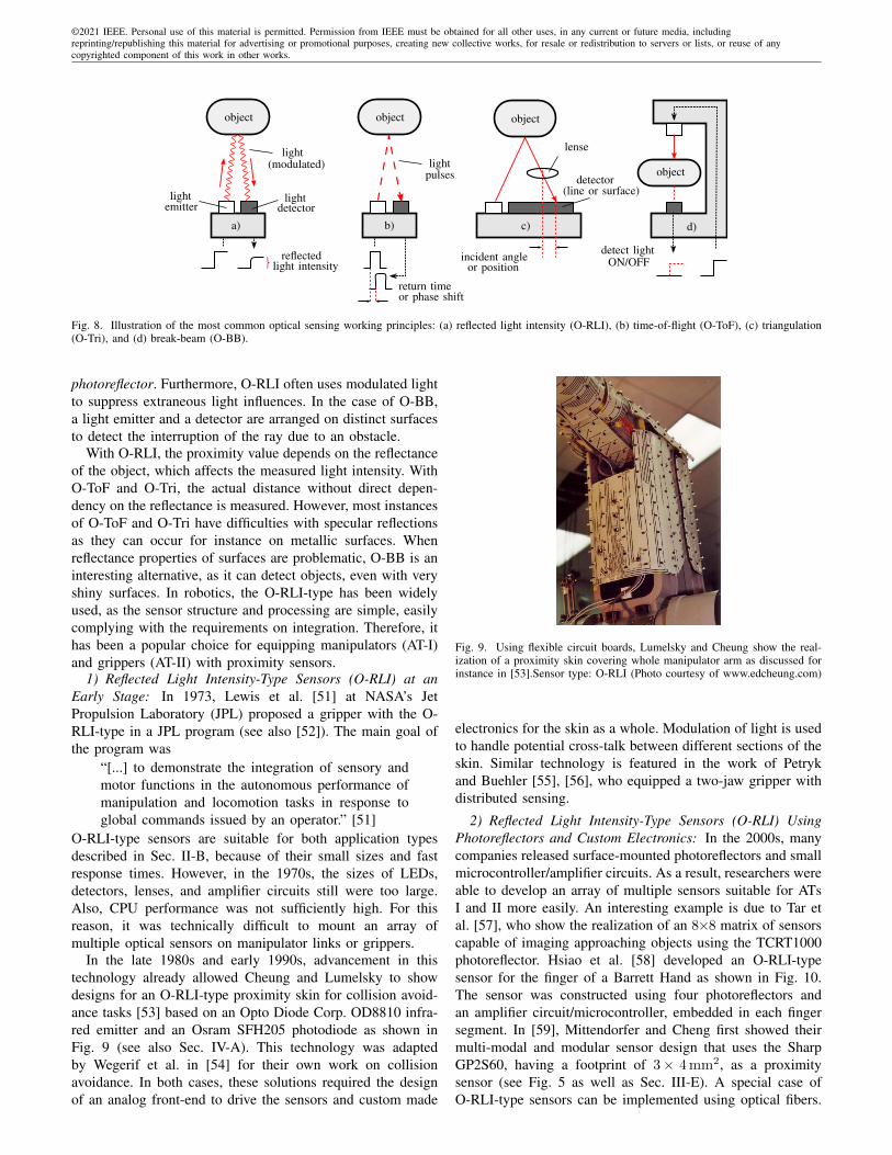
©2021 IEEE. Personal use of this material is permitted. Permission from IEEE must be obtained for all other uses, in any current or future media, includingreprinting/republishing this material for advertising or promotional purposes, creating new collective works, for resale or redistribution to servers or lists, or reuse of anycopyrighted component of this work in other works.
object
d)
return time
reflectedlight intensity
object
a)
lightdetector
(modulated)light
lightemitter
or phase shift
incident angleor position
detect lightON/OFF
b)
lightpulses
object
c)
lense
detector(line or surface)
object
Fig. 8. Illustration of the most common optical sensing working principles: (a) reflected light intensity (O-RLI), (b) time-of-flight (O-ToF), (c) triangulation(O-Tri), and (d) break-beam (O-BB).
photoreflector. Furthermore, O-RLI often uses modulated lightto suppress extraneous light influences. In the case of O-BB,a light emitter and a detector are arranged on distinct surfacesto detect the interruption of the ray due to an obstacle.
With O-RLI, the proximity value depends on the reflectanceof the object, which affects the measured light intensity. WithO-ToF and O-Tri, the actual distance without direct depen-dency on the reflectance is measured. However, most instancesof O-ToF and O-Tri have difficulties with specular reflectionsas they can occur for instance on metallic surfaces. Whenreflectance properties of surfaces are problematic, O-BB is aninteresting alternative, as it can detect objects, even with veryshiny surfaces. In robotics, the O-RLI-type has been widelyused, as the sensor structure and processing are simple, easilycomplying with the requirements on integration. Therefore, ithas been a popular choice for equipping manipulators (AT-I)and grippers (AT-II) with proximity sensors.
1) Reflected Light Intensity-Type Sensors (O-RLI) at anEarly Stage: In 1973, Lewis et al. [51] at NASA’s JetPropulsion Laboratory (JPL) proposed a gripper with the O-RLI-type in a JPL program (see also [52]). The main goal ofthe program was
“[...] to demonstrate the integration of sensory andmotor functions in the autonomous performance ofmanipulation and locomotion tasks in response toglobal commands issued by an operator.” [51]
O-RLI-type sensors are suitable for both application typesdescribed in Sec. II-B, because of their small sizes and fastresponse times. However, in the 1970s, the sizes of LEDs,detectors, lenses, and amplifier circuits still were too large.Also, CPU performance was not sufficiently high. For thisreason, it was technically difficult to mount an array ofmultiple optical sensors on manipulator links or grippers.
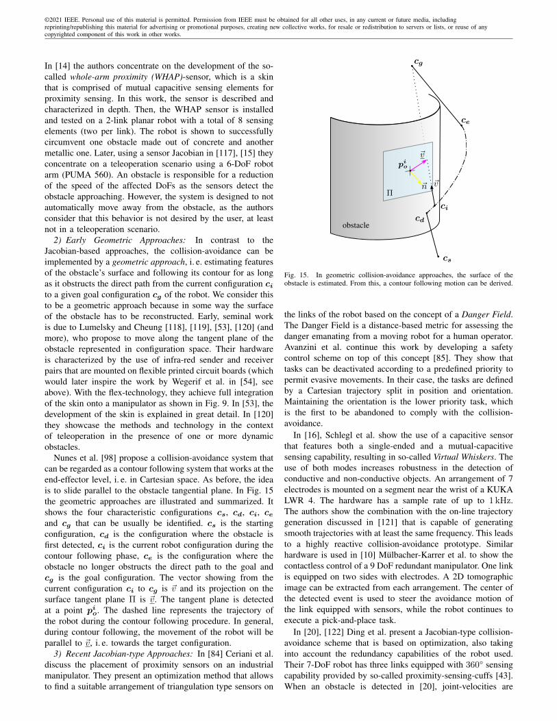
In the late 1980s and early 1990s, advancement in thistechnology already allowed Cheung and Lumelsky to showdesigns for an O-RLI-type proximity skin for collision avoid-ance tasks [53] based on an Opto Diode Corp. OD8810 infra-red emitter and an Osram SFH205 photodiode as shown inFig. 9 (see also Sec. IV-A). This technology was adaptedby Wegerif et al. in [54] for their own work on collisionavoidance. In both cases, these solutions required the designof an analog front-end to drive the sensors and custom made
Fig. 9. Using flexible circuit boards, Lumelsky and Cheung show the real-ization of a proximity skin covering whole manipulator arm as discussed forinstance in [53].Sensor type: O-RLI (Photo courtesy of www.edcheung.com)
electronics for the skin as a whole. Modulation of light is usedto handle potential cross-talk between different sections of theskin. Similar technology is featured in the work of Petrykand Buehler [55], [56], who equipped a two-jaw gripper withdistributed sensing.
2) Reflected Light Intensity-Type Sensors (O-RLI) UsingPhotoreflectors and Custom Electronics: In the 2000s, manycompanies released surface-mounted photoreflectors and smallmicrocontroller/amplifier circuits. As a result, researchers wereable to develop an array of multiple sensors suitable for ATsI and II more easily. An interesting example is due to Tar etal. [57], who show the realization of an 8×8 matrix of sensorscapable of imaging approaching objects using the TCRT1000photoreflector. Hsiao et al. [58] developed an O-RLI-typesensor for the finger of a Barrett Hand as shown in Fig. 10.The sensor was constructed using four photoreflectors andan amplifier circuit/microcontroller, embedded in each fingersegment. In [59], Mittendorfer and Cheng first showed theirmulti-modal and modular sensor design that uses the SharpGP2S60, having a footprint of 3× 4 mm2, as a proximitysensor (see Fig. 5 as well as Sec. III-E). A special case ofO-RLI-type sensors can be implemented using optical fibers.

©2021 IEEE. Personal use of this material is permitted. Permission from IEEE must be obtained for all other uses, in any current or future media, includingreprinting/republishing this material for advertising or promotional purposes, creating new collective works, for resale or redistribution to servers or lists, or reuse of anycopyrighted component of this work in other works.
Fig. 10. a) Barrett hand equipped with finger-size optical proximity sensors b)Design criteria leading to a final concept of sensor integration in the fingertipsof the Barrett hand. [58] Sensor type: O-RLI (Figures reprinted with kindpermission of the authors ©2009 IEEE)
Fig. 11. (a) High-speed proximity sensor [65], [66], [67]. (b) High-speed,high-precision proximity sensor [70], [71]. Both sensors detect tilt angles anddistance of an object’s surface. The measurement time of both sensors is lessthan 1ms. The distance resolution of the sensor (b) is less than 51 µm. Sensortype: O-RLI (©2013 and 2019 IEEE)
Since the fibers are easy to integrate into confined spaces, thissolution has been proposed by Espiau and Catros [60], Walkeret al. [61], and Konstantinova et al. [62], [63], [64]. In [61],the authors integrate 32 fibers, having a diameter of 1 mm,into a disc-like end-effector. The fibers route the reflected lightcaptured around 360° to a 4×8-display. The intensity valueson the display are then recorded by a camera. In [62], [63],[64] optical fibers are similarly routed from the tip of a fingerto a signal processing module (KEYENCE) for O-RLI-typesensing.
In [65], [66], [67], Koyama et al. developed finger-sized,high-speed proximity sensors mounting twelve photoreflectorson a fingertip as shown in Fig. 11 (a). The sampling timeof the sensor outputs is < 1 ms, and the sensor size isthin and compact [68]. As the outputs of the photoreflectorswere processed in a grid of resistors, a proximity event canbe localized. The same principle is adopted by Arita andSuzuki in [69] for a linear array of sensors. The authorsalso proposed a simple calibration method using changes infingertip positioning and reflected light intensity. However,simple calibration methods, e. g. [58], [67], have relativelylarge errors (with millimeter or sub-millimeter accuracy) dueto fingertip position errors or circuit noise. Therefore, reactivepreshaping methods (see Sec. IV-B) have not yet reached ahigh level of accuracy using these calibration schemes.
3) Reflected Light Intensity-Type Sensors (O-RLI) UsingSensing Modules): More recently, some companies have
Fig. 12. (a) Gripper-type proximity sensor that can detect contact, force, anddistance, (b) Robot skin type. Sensor type: O-RLI (Figures reprinted withkind permission of the authors (a) [72] ©2018 Springer and (b) [73] ©2018IEEE)
released compact-sized, low-noise proximity sensors withbuilt-in amplifier circuits and I2C bus connectivity. Multi-ple sensors can be daisy-chained using the I2C bus. Re-searchers can develop fingertip-size proximity sensors androbot skins equipped with multiple ranging sensors. In partic-ular, Vishay Semiconductors released the O-RLI-type sensor,the VCNL4010. The footprint of the VCNL4010 is 3.95×3.95 mm2, and can measure a range of 1–200 mm within 4 ms(minimum time setting). Although the sensor output is affectedby the reflectance of object surfaces, the development of a thinproximity sensor is easily attainable.
Patel et al. [72] have developed a finger-size sensor(Fig. 12 (a)) that can detect distance, contact, and force withthe VCNL4010. The sensor consists of multiple VCNL4010devices covered with a transparent rubber (PDMS silicone).When there is no contact between the sensor and an object,the sensor can measure distance based on the reflected lightintensity from an object’s surface. The sensor can also detectcontact with an object triggered by a sharp change of reflectedlight intensity. After contact, the contact force can be alsoestimated by measuring the reflected light from the objectsurface to the rubber surface. Hughes et al. [73] have proposedflexible robot skin modules (Fig. 12 (b)) using the samesensor structure as in [72]. They realized gesture recognitionby combining distance values with a random forest classifier.Originally conceived for oxymetry, the MAX30105 by MaximIntegrated is used for implementing wireless multi-modalsensor for the hand of a humanoid robot (Robonaut 2) in [74].
In [75], the authors repurpose a mouse sensor (ADNS-9500)in a fingertip for proximity sensing, as O-RLI is used in thesensing element. In this case, it is even possible to use the30×30-pixel delivered by the sensor for further processing(e. g. texture recognition and slip detection).
4) Time-of-Flight-Type (O-ToF) Sensors: One popular O-ToF sensor is the VL6180X proximity sensor, released bySTMicroelectronics. The VL6180X can measure 10–100 mmwith 1 mm resolution and a repeat measurement error of±1–2 mm. The measurement time for one sensor is 7 msto several tens of ms, depending on the settings. Lancasteret al. [76], [77] developed a fingertip-sized sensor for aparallel jaw gripper on the PR2 and demonstrated a robustmanipulation of a Rubik’s Cube. They also developed afingertip-sized sensor comprised of transparent rubber and aO-ToF sensor, which uses reflected light intensity for force

©2021 IEEE. Personal use of this material is permitted. Permission from IEEE must be obtained for all other uses, in any current or future media, includingreprinting/republishing this material for advertising or promotional purposes, creating new collective works, for resale or redistribution to servers or lists, or reuse of anycopyrighted component of this work in other works.
measurement [78]. They designed and evaluated differentrubber shapes and optical configurations (flat rubber, roundedrubber, and light blocker configurations). It is reported thata rounded configuration improves the sensitivity of forcedetection. Sasaki et al. [79] developed a multi-modal proximitysensor, employing both O-RLI and O-ToF sensing. The O-RLI-type detects distance and posture for an object on a table,and O-ToF type measures the distance from the table surface.The robot can adjust the configurations of the fingertips andthe end-effector (the hand base) simultaneously using sensorfeedback. Tsuji et al. [80] developed a proximity sensor skinusing O-ToF sensors for a collaborative robot, which in itslayout is comparable to the work by Cheung and Lumelsky(see Fig. 9). In [43], [20], Ding et al. show their developmentsof a multi-modal proximity sensor, the proximity sensingcuffs, featuring capacitive and O-ToF technology for materialrecognition and collision avoidance.
Recently, the use of O-ToF has also been proposed for SoftRobotics devices [81], [82]. Even though the module used isthe already mentioned VL6180X, which is not deformable, theauthors show its integration in a soft circuit, featuring tracesof copper wetted with eutectic gallium indium (EGaIn) insidea thin PDMS sheet. The circuit features other sensors ICs:an IMU, barometric pressure, and temperature sensors. Thesoft sheet is then used to equip a two-jaw gripper with thesesensing capabilities.
5) Triangulation-Type Sensors (O-Tri): An early examplefor an O-Tri-Type proximity sensor is due to Fuhrman andKanade [83]. Using a chip capable of localizing a light spot,they realize several light sources that are evaluated in a time-multiplexed manner, resulting in an object’s proximity valueas well as orientation and curvature. However, this setup canprobably be considered to be too bulky, i. e. not skinlike,for modern applications. In [84], [85], the Ceriani et al.and Avanzini et al. report using the Sharp GP2Y0A02YK0Fmodule, that guarantees a consistent distance output acrossdifferent reflectivity of surfaces. In their work, they explorethe optimal distribution of sensing elements for safe HRI(see also Sec. IV-A3). To measure distance and posture moreprecisely, Koyama et al. [70], [71] developed a high-speed,high-precision proximity sensor, as shown in Fig. 11 (b). Thesensor has the size of a human fingertip (18×28.5×38.5 mm3),and it can detect the distance to and postures of an objectsurface with a distance error of fewer than 31 µm and ameasuring time less than 1 ms. A similar sensor design wasexplored by Bonen et al. [86], who propose a single emitterand multi-detector architecture for detecting distance as wellas object orientation.
6) Break-Beam-Type Sensors (O-BB): Teichmann etal. [87] mounted a light-emitting diode at one end of aparallel jaw gripper and detectors at the other end, andswitched to reactive motions based on light blocking dueto an object. They also describe the application of thisapproach to a three-fingered hand. In [88] Guo et al. showthe integration of an array of O-BB-Type sensors in the jawsof PR2’s parallel gripper for reactive preshaping and graspingchallenging objects, where other approaches would fail, suchas semi-transparent tissues.
7) Discussion on Optical Sensors: The devices implement-ing optical sensing are small in size and have a high-speedresponse. These advantages are suitable for sensor/actuatorintegration and automatic grasping using a robot hand, al-though the sensing has difficulty detecting transparent, black,and shiny objects. To detect all these objects, it is necessaryto introduce multi-modal sensing, such as a combination ofoptical and capacitance sensing.
In terms of spatial resolution, optical sensing elements canbe quite small. For example, the Sharp GP2S60 photoreflectorused by Mittendorfer et al. [59] has a footprint of 3×4 mm2,potentially allowing a density of a few elements per cm2.However, on large-area skin (AT-I) such high densities can beimpractical in terms of the electronic effort needed (wiring,signaling, etc.). Regarding sensing range, O-RLI-types havebeen reported to produce a relatively large detection distanceof about 300 mm [53] (AT-I), but these sensors are also oftenused for lower ranges, e. g. [70], where a maximum detectionrange of 20 mm is reported (AT-II). In both cases, there isa small dead spot near the sensing element. Typical O-ToF-technology used, e. g. [20], [21], can work up to a distanceof 4 m, depending on the component used, but this extendedrange has the cost of having a relatively large dead spot of10 cm in front of the sensing element. Similarly, the O-Tri-Type sensor used in [84], [85] has a detection range of 1.5 mand a dead spot of 20 cm.
C. Radar
In recent years, radar sensing technology has become pop-ular in human-centered technologies due to the developmentof system on chip radar systems reducing the size, whichalso makes them very attractive for integration on roboticplatforms. Recent developments are driven in big part by theautomotive industry (see also [1]). Radar sensors withstandharsh weather environments and can augment widely usedoptical sensor technologies, meaning they have crucial traitsfor enabling highly automated driving. An important aspectfor radar sensors in human-robot interaction is that it is atechnology that is widely used in safety related applicationsin the automotive domain. Consequently, existing expertisefrom the automotive domain can potentially be utilized to-wards robotic applications (e. g. [89]). A recent survey byvan Berlo et al. summarizes the current application fields ofradar technologies [90], including the aforementioned domainof automotive and HCI (tracking, gesture recognition, etc.).
Recently, in a joint effort, Google and the chip manufacturerInfineon boosted this technology as they introduced a 60 GHzradar chip with integrated transmitter and receiver antennasfor fine gesture interaction based on frequency modulatedcontinuous wave (FMCW) [91]. The principle of FMCWradars is illustrated in Figure 13. A more detailed descriptioncan be found e. g. in [89].
Advantages of FMCW-radar are that they provide dis-tance and velocity measurements simultaneously with a highresolution for close ranges, which makes them suitable forproximity perception, collision avoidance, and HRI, e. g. ges-ture control, in the field of robotics. In [92], a simulation

©2021 IEEE. Personal use of this material is permitted. Permission from IEEE must be obtained for all other uses, in any current or future media, includingreprinting/republishing this material for advertising or promotional purposes, creating new collective works, for resale or redistribution to servers or lists, or reuse of anycopyrighted component of this work in other works.
Chirp Generation
Mixer
Low-pass Filter
Tx
Rx
AD
Chirp 1 Chirp N
Time
Freq
uenc
yTi
me
Chirps
Converter
Radar
FFT
over time
FFT
over chirps
Range
Velo
city
Fig. 13. Principle of FMCW Radar: A transmitter (Tx) sends out a chirp signal (red), which gets reflected at object boundaries, e. g. a human. The reflectedsignal (green) at the receiver (Rx) is a delayed, attenuated copy of transmitter signal. The time delay corresponds to the distance and thus the frequencydifference between transmitter and receiver is proportional to the distance. This frequency is obtained by mixing the transmitter and receiver signal. For asequence of chirps, the phases of the received signal changes due to the Doppler shift. An FFT over the time extracts the frequencies, a subsequent FFT overchirps extracts the velocity, such that a 2D range distance map is obtained.
approach for FMCW-radar is proposed and evaluated forcollaborative robotics. The simulation approach aims at fastdevelopment and evaluation of signal processing algorithms aswell as machine learning approaches for FMCW-radar beforedeploying it on a robot (sim-to-real learning). Multi-modaltactile and radar sensing for grasping applications and objectclassification was introduced in [93].
Further manufacturers, such as SiliconRadar, Texas Instru-ments, etc. also provide system on chip radar solutions. In [94],the integration of a multiple antenna radar sensor based on160 GHz with flexible waveguides for collaborative robotswas studied. Another operation mode for radar technologyis synthetic aperture radar (SAR). In robotics, it is utilizedfor instance for mobile robot navigation. In [95] SAR basedradar imaging was investigated on a PR2 robot system for 2Dand 3D imaging of objects in close proximity to show thepotential of radar sensing to complement optical sensors inrobot perception and manipulation.
Besides proximity and distance sensing, radar systems canbe applied to exploring and constructing subsurface 3D maps[96]. Those radars are known as ground penetration radar(GPR) and are applied in different fields such as assessment ofdense underground utilities in urban areas, evaluation of thesubsurface for energy and mineral production operations orthe detection of buried objects, on earth or potentially on otherplanets. Its sensing principle is based on emitting radar pulsesand evaluating the propagation velocity into the subsurface andthe soil utilities [97].
D. Other Sensing Principles
In this section, we introduce further sensing principles thatcan be used for proximity sensing, i. e. acoustic, inductive, andwhiskers. As of 2021, they can still be considered to be lessmainstream in human-centered robotics than the capacitive,optical, or radar ones. However, they offer interesting alterna-tives and can outperform other principles discussed so far insome scenarios.
1) Acoustic: The widest spread technique for ranging basedon acoustic wave propagation is ultrasound (A-US), whichcan be found in many domains, particularly for under-water
ranging. In robotics, this technology is easily available for theenthusiast and professional use, such as the MaxSonar-seriesby MaxBotix. Higher-end solutions, featuring 3D echolocationare also available, for instance by Toposens. Nunes et al.proposed the use of ultrasound in [98] for 3D ranging in1994. Even though Dario et al. [99] propose an ultrasoundsensor for integration into a fingertip, the sensors usually havea non-negligible offset or dead-spot for sensing around thesensing element. Therefore, many of the available solutions arenon-practical for pre-touch applications, i. e. close proximity(see Fig. 3). Integration is also challenging because sensingelements do not scale down easily. Thus, oftentimes use-casesof A-US are more similar to laser-range finders, i. e. mid-rangeand long-range sensing. In [100], Fang et al. circumvent thementioned difficulties by mounting the sensor at a distanceand tilted while bouncing the waves off a parabolic mirror.However, the integration remains limited to one acousticsensing element. Ultrasound is also widely used in parkingsensors. An example of a combination with capacitive sensorsto overcome detection limitations at short distances is providedin [101]. The group of Prof. Steckel at University Antwerp hasa strong focus on 3D A-US for robotic applications, e. g. [102],[103]. The group has achieved remarkable results in areas suchas SLAM for the navigation of mobile platforms. However,as with other designs, the ultrasound sensing platform is notvery skinlike, thus limiting the pre-touch applications in favorof longer-range sensing. Furthermore, the authors often makea point to establish this technology as an alternative to LIDARand other mid-range or long-range sensing options for groundvehicles but also for UAVs. The use of A-US in air-bornevehicles puts in evidence that this type of sensing can beconsidered to be bio-inspired by bats and their echolocationcapabilities.
Another type of acoustic sensing has been proposed byJiang et al. [104], [105], which the authors call the seashelleffect (A-S). A microphone is placed inside a cavity that isworked into the structure of a finger. As a surface approachesthe opening, the resonance frequency of the cavity changes.By analyzing the differences in the spectrum between anexternal microphone and the microphone inside the cavity, the

©2021 IEEE. Personal use of this material is permitted. Permission from IEEE must be obtained for all other uses, in any current or future media, includingreprinting/republishing this material for advertising or promotional purposes, creating new collective works, for resale or redistribution to servers or lists, or reuse of anycopyrighted component of this work in other works.
distance can be estimated. This works for very close range(up to ≈ 4 mm). In their work, this modality is explored,because it does not suffer from detection difficulties related totransparency or reflections (optical sensing) or low dielectriccontrast (capacitive sensing).
2) Inductive: Inductive sensors utilize alternating magneticfields to detect objects, as they disturb the generated magneticfield, which can be detected as a change of inductance ofa coil, a change of the mutual inductance between severalcoils or directly by measuring the magnetic field. The objectsdo not need to be ferromagnetic. In particular, objects withhigh conductivity such as metals, strongly affect an alter-nating magnetic field as eddy currents near the surface ofsuch objects prevent deep penetration of the materials by themagnetic fields. Inductive proximity sensors are very robustand commercial sensors provided by a variety of manufacturesare widely used in industry as proximity switches, typicallydetecting conductive objects. However, as these commercialor industrial sensors are not found in robotics, they are notincluded in this survey. The capabilities of inductive sensorsfor non-metallic objects are more limited and inductive sensorshave therefore been used in combination with other approachesto classify materials, for example.
The sensing system proposed in [40] is stated to combinecapacitive force and inductive proximity sensing with a rangeof up to 150 mm for conductive materials with the help ofa layer of carbon micro coils (CMC). The sensor was thenenhanced and in [106], having a higher detection range andspatial resolution. The CMC layer was used to form an LCRcircuit and enable both tactile and proximity sensing. In arelated work [107], an electromagnetic field was formed byexciting a combined co-planar plate capacitor and a coilembedded in a flexible circuit board. The impedance of theresulting LCR circuit was analyzed and the relationship tothe distance of different objects was presented as proximitymeasurement, with a sensing range of up to 300 mm.
In [108] the combination of capacitive and inductive sensingis used to distinguish between humans and other objects suchas (grounded) laptops. While the capacitive signals for humansand grounded laptops are very similar, the inductive signalis much different, as the laptop comprises highly conductivemetallic parts and thus has a stronger influence on the magneticfield. Even though the setup is not intended for proximitysensing, a range of up to 150 mm is reported. Consequently,the system can also be used to detect non-conductive andconductive objects and offers a very high measurement rate of25 kHz. With multiple coils, inductive sensors can not only beused to obtain a distance estimate but full 6 DoF information,as discussed in [109].
3) Whiskers: Finally, on the fringe of the domain of prox-imity perception, we can find artificial whiskers that are in-spired by mammals, such as rodents, who use them to navigateand explore their environment [110], [111]. These whiskersare beams that bend due to external forces (contacts withwalls, wind, etc.) and usually, the resulting force/deformationat the base is measured. These approaches are often featuredas part of the tactile perception community, as sensing isactually contact-based, but they are used to probe the nearby
environment much in the same way a proximity sensor is used.
E. Multi-modal and Modular Sensors
The possibility of deploying proximity sensors alongsideother sensing modalities on robots (vision, touch, etc.) is akey aspect of the success of this technology. Only if theycoexist with the other modalities, can they fill the perceptiongap that is left by them. This challenge is evidenced by themany existing realizations of multi-modal sensors, especiallyby designs that include the tactile modality alongside theproximity one. Furthermore, it is common to find that thesedesigns are conceived in a modular manner. The HEX-o-Skinby Mittendorfer et al. [59] is a prominent example of thistrend. It is a modular design, which is suited for coveringlarge areas of the robot (see Fig. 5) and includes proximity,tactile, inertial, and temperature sensing in each unit.
The most generic approach for implementing multi-modalsensing is to use a specialized measurement principle foreach desired modality. The work by Mittendorfer et al. [59],again, is an example of this approach. Proximity detection isimplemented by O-RLI and tactile events are detected witha capacitive sensing element. Stiehl et al. [18], who imple-ment capacitive proximity (C-SE, provided by the MC33794),force and temperature measurement in a pseudo-modular skin,which the authors argue helps in distinguishing social contactsfrom collisions with the environment. Another, less modularexample is due to Guan et al. [112]. In their work, they equipthe gripper of a climbing robot with a range finder sensor, twoultrasound modules, and a camera.
In [40], Han et al. show a tactile proximity sensor where theproximity modality principle is inductive and the tactile modal-ity is capacitive. In [62], [63], [64] proximity sensing andtactile (force) sensing is implemented using optical fibers. Inproximity sensing, the O-RLI-type is used, for tactile sensing,the reflection that changes inside a movable part is measured.As explained in Sec. III-B3, in [72] the authors show theimplementation of a tactile proximity sensor based on O-RLI-type sensing alone. As stated before in Sec. III-A, capacitivesensing is especially attractive for joint tactile and proximitydesigns. Example designs are shown in [39], [33], [30], [41].Designs also have been proposed outside of robotics litera-ture, which are nonetheless potentially relevant, e. g. [113].Finally, there is a subset of approaches that utilize differentmeasurement principles for redundant proximity sensing. Thisis the case with Ding et al. [43], [20], and Tsuji et al. [21]that use both an O-ToF and C-SE for robustness. Markvickaet al. propose the joint use of O-ToF and O-RLI in [74].
IV. APPLICATIONS AND METHODS IN THE RESEARCH ANDINDUSTRY DOMAINS
In this section, we will review the contributions from thefield focusing on the applications and methods presented. Wewill follow the organization presented in Sec. II-B and Fig. 4,i. e. focusing separately on AT-I and AT-II and going fromlow-complexity behaviors (BT-I) to high-complexity behaviors(BT-II).

©2021 IEEE. Personal use of this material is permitted. Permission from IEEE must be obtained for all other uses, in any current or future media, includingreprinting/republishing this material for advertising or promotional purposes, creating new collective works, for resale or redistribution to servers or lists, or reuse of anycopyrighted component of this work in other works.
end-effector
base~x
~y
cg
xo
xe
q0a
qia
qna
obstaclepo
Fig. 14. A redundant robot, equipped with proximity sensors on its links,can move towards a target end-effector configuration while simultaneouslymoving some of the links of the robot away from an obstacle. (Figure adaptedfrom [115])
A. Reactive collision-avoidance and Contour Following (AT-I,BT-I)
Collision-avoidance is regarded as a fundamental skill forautonomous robots as well as for safe human-robot interaction.To start this section, we want to motivate with a quote byNovak et al. from their 1992 work on whole-arm collision-avoidance, which is an elegant statement of this problem:
“[...] since it is desirable to continue purposefulmotion in the presence of obstacles, the sensorsystem must be able to deliver spatially-resolvedproximity data, which reflects the distance to theobstacle, as well as the location along the robotand corresponding robot surface normal. This vectorinformation may then be used to modify trajectoriesto permit (if possible) continued progress toward thefinal destination.” [14]
The first important wave of interest surrounding proxim-ity perception for collision-avoidance was sparked in thelate 1980s and early 1990s [114]. At that time, getting 3Dinformation of the surroundings of the robot via cameraswas challenging from a technological point of view, on theaccounts of the lack of hardware and lack of performance ofthe CPUs. Proximity sensors, having desirable properties (lowlatency, skinlike), were considered an attractive alternative forthis challenge.
1) Early Jacobian-type Approaches: A good portion ofearly works on collision-avoidance get inspiration from thework of Maciejewski and Klein [115], published in 1985. Thiswork introduces the notion of the “obstacle avoidance pointJacobian”, which is analogous to the end-effector Jacobian,i. e. it relates the instantaneous joint velocity to the velocity ofan obstacle point on the robot (see Fig. 14). In this figure, weuse the following notation: qia are the degrees of freedom of themanipulator arm in joint-space. xe and xo are the end-effectorconfiguration and the obstacle point in task-space respectively(boldface indicates these are vector quantities), whereas cgis the goal configuration established for the end-effector andpo is the point on the obstacle nearest to the manipulator
arm (also vector quantities). Following this notation, the end-effector Jacobian Je relates the velocities in the configurationspace to the velocities in the task space by:
xe = Jeqa. (3)
Using the obstacle Jacobian Jo, The relation in the case ofthe obstacle-point is likewise:
xo = Joqa. (4)
Applying the same principles of using the (pseudo-) inverseof the end-effector Jacobian J+
e for finding desired jointvelocities, one can invert the obstacle point Jacobian to findthe joint motions to follow a desired trajectory with respectto the obstacle point. In the case of collision-avoidance, thenatural choice is a motion away from the obstacle, as indicatedby xo in Fig. 14. Also, in the presence of redundancies, thisapproach allows projecting the avoidance motion into the null-space of a higher-order task, e. g. following a desired end-effector trajectory:
qa = J+e xe + (I − J+
e Je)J+o xo. (5)
Since xo represents the desired motion away from the obstaclein task space, qa = J+
o xo is the joint-motion that movesthe obstacle-point away from the obstacle. (I − J+
e Je) isthe expression that projects this motion into the null-space ofthe higher-order task, i. e. the desired end-effector trajectory.In this framework, the tasks can be ordered in a differenthierarchy as well, i. e. prioritizing the collision-avoidance taskover the desired end-effector trajectory.
Among the firsts to apply these ideas to proximity sensorstreams were Wegerif et al. [54], [13] as well as Tamasyin [116] at Merrit Systems Inc. in the early 1990s. Wegerifet al. studied the use of several proximity sensing technologies(IR, ultrasound, capacitive), but they ultimately covered threelinks of a PUMA 600 robot with a total of about 120 IRsender and receiver pairs. They modified the kinematics ofthe PUMA 600 to have three rotational joints in one plane,introducing a kinematic redundancy in an otherwise non-redundant robot. In their collision-avoidance algorithm, theygave the highest priority to the collision-avoidance task. Theyreport successfully testing the system in an autonomous anda teleoperated scenario with static and dynamic obstacles. Inthe work by Tamasy [116], the previous work is extended bypresenting the realization of a smart sensor network. Thesekinds of networks provide the base for equipping whole armswith proximity sensors, implementing a bus-system. IR, ultra-sound and capacitive sensors can be readily connected to thesystem, provided they offer digitized data streams. The NASApayload inspection and processing robot (PIPR), featuring 18DoFs, is shown as an application. A whole control architectureis discussed, with a GUI for user inputs, the generation oflow-level commands, as well as a collision-avoidance systembased on the previous developments, together with a quadraticprogramming approach for finding the optimal joint velocities.
Other authors that were inspired by the approach of Ma-ciejewski and Klein are Novak and Feddema [117], [15]. Aprior work by the authors that leads up to these results is [14].
©2021 IEEE. Personal use of this material is permitted. Permission from IEEE must be obtained for all other uses, in any current or future media, includingreprinting/republishing this material for advertising or promotional purposes, creating new collective works, for resale or redistribution to servers or lists, or reuse of anycopyrighted component of this work in other works.
In [14] the authors concentrate on the development of the so-called whole-arm proximity (WHAP)-sensor, which is a skinthat is comprised of mutual capacitive sensing elements forproximity sensing. In this work, the sensor is described andcharacterized in depth. Then, the WHAP sensor is installedand tested on a 2-link planar robot with a total of 8 sensingelements (two per link). The robot is shown to successfullycircumvent one obstacle made out of concrete and anothermetallic one. Later, using a sensor Jacobian in [117], [15] theyconcentrate on a teleoperation scenario using a 6-DoF robotarm (PUMA 560). An obstacle is responsible for a reductionof the speed of the affected DoFs as the sensors detect theobstacle approaching. However, the system is designed to notautomatically move away from the obstacle, as the authorsconsider that this behavior is not desired by the user, at leastnot in a teleoperation scenario.
2) Early Geometric Approaches: In contrast to theJacobian-based approaches, the collision-avoidance can beimplemented by a geometric approach, i. e. estimating featuresof the obstacle’s surface and following its contour for as longas it obstructs the direct path from the current configuration cito a given goal configuration cg of the robot. We consider thisto be a geometric approach because in some way the surfaceof the obstacle has to be reconstructed. Early, seminal workis due to Lumelsky and Cheung [118], [119], [53], [120] (andmore), who propose to move along the tangent plane of theobstacle represented in configuration space. Their hardwareis characterized by the use of infra-red sender and receiverpairs that are mounted on flexible printed circuit boards (whichwould later inspire the work by Wegerif et al. in [54], seeabove). With the flex-technology, they achieve full integrationof the skin onto a manipulator as shown in Fig. 9. In [53], thedevelopment of the skin is explained in great detail. In [120]they showcase the methods and technology in the contextof teleoperation in the presence of one or more dynamicobstacles.
Nunes et al. [98] propose a collision-avoidance system thatcan be regarded as a contour following system that works at theend-effector level, i. e. in Cartesian space. As before, the ideais to slide parallel to the obstacle tangential plane. In Fig. 15the geometric approaches are illustrated and summarized. Itshows the four characteristic configurations cs, cd, ci, ceand cg that can be usually be identified. cs is the startingconfiguration, cd is the configuration where the obstacle isfirst detected, ci is the current robot configuration during thecontour following phase, ce is the configuration where theobstacle no longer obstructs the direct path to the goal andcg is the goal configuration. The vector showing from thecurrent configuration ci to cg is ~v and its projection on thesurface tangent plane Π is ~v. The tangent plane is detectedat a point pi
o. The dashed line represents the trajectory ofthe robot during the contour following procedure. In general,during contour following, the movement of the robot will beparallel to ~v, i. e. towards the target configuration.
3) Recent Jacobian-type Approaches: In [84] Ceriani et al.discuss the placement of proximity sensors on an industrialmanipulator. They present an optimization method that allowsto find a suitable arrangement of triangulation type sensors on
cs
cg
ce
cd
ci
~v
~vΠ
~n
pio
obstacle
Fig. 15. In geometric collision-avoidance approaches, the surface of theobstacle is estimated. From this, a contour following motion can be derived.
the links of the robot based on the concept of a Danger Field.The Danger Field is a distance-based metric for assessing thedanger emanating from a moving robot for a human operator.Avanzini et al. continue this work by developing a safetycontrol scheme on top of this concept [85]. They show thattasks can be deactivated according to a predefined priority topermit evasive movements. In their case, the tasks are definedby a Cartesian trajectory split in position and orientation.Maintaining the orientation is the lower priority task, whichis the first to be abandoned to comply with the collision-avoidance.
In [16], Schlegl et al. show the use of a capacitive sensorthat features both a single-ended and a mutual-capacitivesensing capability, resulting in so-called Virtual Whiskers. Theuse of both modes increases robustness in the detection ofconductive and non-conductive objects. An arrangement of 7electrodes is mounted on a segment near the wrist of a KUKALWR 4. The hardware has a sample rate of up to 1 kHz.The authors show the combination with the on-line trajectorygeneration discussed in [121] that is capable of generatingsmooth trajectories with at least the same frequency. This leadsto a highly reactive collision-avoidance prototype. Similarhardware is used in [10] Mulbacher-Karrer et al. to show thecontactless control of a 9 DoF redundant manipulator. One linkis equipped on two sides with electrodes. A 2D tomographicimage can be extracted from each arrangement. The center ofthe detected event is used to steer the avoidance motion ofthe link equipped with sensors, while the robot continues toexecute a pick-and-place task.
In [20], [122] Ding et al. present a Jacobian-type collision-avoidance scheme that is based on optimization, also takinginto account the redundancy capabilities of the robot used.Their 7-DoF robot has three links equipped with 360° sensingcapability provided by so-called proximity-sensing-cuffs [43].When an obstacle is detected in [20], joint-velocities are

©2021 IEEE. Personal use of this material is permitted. Permission from IEEE must be obtained for all other uses, in any current or future media, includingreprinting/republishing this material for advertising or promotional purposes, creating new collective works, for resale or redistribution to servers or lists, or reuse of anycopyrighted component of this work in other works.
calculated according to a mixture of criteria, which are si-multaneously optimized: distance to the target, manipulability,deviation from desired task motion, and total magnitude ofjoint-velocities. This results in a reflex-like collision-avoidancesystem, including movement parallel to the obstacle tangentplane. This can avoid getting stuck in front of obstacles, whichis a possible failure mode of potential field approaches, likethe one proposed by Khatib et al. [123]. Also following upon the Jacobian-type approaches is the work presented byM’Colo et al. in [25]. The capacitive sensing technology ofFOGALE robotics [24] is featured in a robotic system thathas been extensively covered with electrodes to implement askin. Using the skin, the robot can avoid static and dynamicobstacles. Finally, Arita and Suzuki show progress towardsan approach that allows using force control for the seamlesstransition between pre-touch and touch states and for achievingdesired contact forces [69].
4) Recent Geometric Approaches: For what concerns con-tour following scenarios, the literature proposes to includecurvature estimates to improve the performance by using apredictive component, for instance by Baeten and De Schutter[124]. Relying on the spatial resolution of the sensor, theycan be estimated directly from the current sensor values, asproposed in the work by Walker et al. [61]. This work usesan optical proximity sensor attached to an end-effector andfeaturing 360° vision in a plane. In [19], these ideas aregeneralized by Escaida Navarro et al. for contour following in3D, i. e. by detecting the 2D curvature of the obstacle surface.
B. Reactive Preshaping and Grasping (AT-II, BT-I)
In this section, we describe reactive preshaping using prox-imity sensor feedback, i. e. closed-loop control (AT-II). Theconcept of preshaping has been proposed in psychology inthe context of studies on human grasping, e. g. in [125],before it was adopted in robotics. In robotics terms, preshap-ing describes the (preliminary) motions of adjusting fingerjoint poses qh of a robot hand and end-effector pose xe
before grasping, as shown in Figs. 2 and 16. Preshaping isusually based on visual cues, such as global object shapeor the detection of affordances, as is the case for the hu-man. However, proximity sensing opens an opportunity inrobotics to implement this behavior by closing the perceptionloop to increase robustness and performance, i. e. an ad-hocsolution. In fact, the traditional, human-like preshaping canbe considered to be a high-level behavior (BT-II) and isthe result of grasp synthesis or grasp planning, which isan active research field [126]. In contrast, preshaping usingfeedback from proximity sensors is often reflex-like, i. e. BT-I. We, therefore, call it reactive preshaping (see also Fig. 4).Reactive preshaping has significant potential for HRI, becausethe automatic adaption of the robot hand to the object posegeneralizes naturally to the case when the object is not static,for instance during handover tasks.
Reactive preshaping enhances grasping robustness and per-formance, from reaching to grasping motions, for the followingreasons (see also Fig. 2):
object
Reactive Controller
Arm Controller
Hand Controller
qa
qh
end-effector
hand joints
xe
qih
proximity sensor outputs
Fig. 16. Reactive control for preshaping is implemented by feeding back theoutputs obtained from the proximity sensors mounted on a robot hand, i. e.its palm and fingers, to controllers that affect the pose qih of each finger andthe end-effector xe.
• The contact area after grasping is increased and thegrasping becomes stable by aligning the normals of theobject and fingertip surfaces before establishing contact.
• “[...] ensuring that the fingers contact the object simul-taneously can improve the probability of successfullygrasping the object” [29], i. e. unwanted object motionis avoided.
• A robot can move fast without moving or damaging anobject because sensing is without contact.
• A robot can continuously adjust the end-effector andfinger joint poses even when occlusion occurs in thevision sensor.
1) Reactive Preshaping Control: To implement reactivepreshaping, poses or torques of finger joints are controlleddirectly based on the signals detected by proximity sensors onthe surface of the finger, as illustrated by Fig. 16. An earlycontribution in this area is due to Espiau and Catros [60],who show closed-loop control of a two-jaw gripper. Maytonet al. [29] realized finger reactive preshaping using the BarrettHand with mid/short-range electric field (capacitive) sensors.Each finger was controlled independently by PID control of themotor current in the hand using a target proximity sensor targetvalue. They demonstrated reactive preshaping on a banana anda juice bottle on a table, as well as grasping these objects. Thedeveloped method also allowed the robust handover of objectswith the human and detection of the co-manipulation statefrom the capacitive signals.
Hsiao et al. [58] proposed a reactive grasping controller, in-cluding a finger distance controller, with real-time calibrationusing optical proximity sensor outputs (see also Fig. 10). Todetect the actual distance and posture of an object’s surface,they proposed a calibration method based on a probabilisticmodel using fingertip positions and reflected light intensityvalues. The average distance sensing error was reported as4 mm, the posture error of pitch rotation was 5.3°, and theposture error of roll rotation was 17.7° degrees for commonobjects. At the beginning of the procedure, the fingertips arecontrolled using the raw sensor output as a target value. Thetarget value is then switched from raw value to estimateddistance and posture once the estimated values are calculated.
Escaida Navarro et al. [31], [32] installed capacitive tactile

©2021 IEEE. Personal use of this material is permitted. Permission from IEEE must be obtained for all other uses, in any current or future media, includingreprinting/republishing this material for advertising or promotional purposes, creating new collective works, for resale or redistribution to servers or lists, or reuse of anycopyrighted component of this work in other works.
Fig. 17. Independent joint angle control for preshaping using a high-speedproximity sensor as shown by Koyama et al. [67]. (©2019 Sage Publications)
proximity sensors on a parallel jaw gripper, and they realizedsimultaneous control of six DoF of a two-jaw gripper basedon a proximity-feedback control. In [31], there are 2 × 2sensor areas per finger of the gripper, and the posture andposition information of the object are detected simultaneouslyby comparing the intensity of the sensor values in each area.Somewhat similar is the work of Guan et al. [112], who usereactive preshaping in translation and orientation of a gripperto a pole the robot is climbing. In a sensor arrangementcomparable to [31], [32], Guo et al. also use a 2×2 of O-BBsensor arrangement for reactive preshaping in [88].
Koyama et al. [65], [66], [67] realized independent controlof joint poses of an 8-DoF robot hand (three fingers) usinga high-speed optical proximity sensor. They demonstratedreactive preshaping for an apple, a banana, and moving objectson a conveyor or during handover, with simple joint-anglecontrols (see Fig. 17), updating the sensor value and controlevery 5 ms. In these preshaping controls [29], [67], the targetvalue is set in advance from experimental data of an objectset.
Furthermore, Koyama et al. [127] realized velocity con-trol of fingers without relying on a previously establishedcalibration. The control uses time-to-contact (TTC) valuescalculated using proximity values from the sensor. TTC isthe remaining time until a collision between an object andthe sensor. TTC is a bio-inspired calculation that does notdepend on the surface characteristics of an object. Therefore,the relative speed between the fingertip and an object canbe controlled without prior reflectance data. The authors alsorealized high-speed catching of soft objects using a high-speed,high-precision proximity sensor in [70]. As the proposeddesign has impressive distance resolution, it is possible toutilize this value to estimate the contact condition of an object.Elastic pads of 3 mm-thickness in front of the photodiodeprovide deformable spacers (see Fig. 11 b)). Any distancemeasurement that is equal or closer to the offset providedby the elastic pads is thus indicative of a contact situation.A contact situation with a soft object can be detected withvery low contact force. The contact detection enabled thecatching of very soft objects, namely a marshmallow and apaper balloon, with negligible deformation [71].
In [36], [37] Erickson et al. apply the principles of reactive
Fig. 18. Complementing a pointcloud obtained by the MS-Kinect with O-ToFsensor inside the gripper PR-2, as shown by Lancaster et al. [128]. (©2017IEEE)
preshaping/contour following to the scenario of dressing andwashing of patients. In [37], a 2×3 array on the end-effector isused to align the end-effectors distance and orientation to thepatient’s limbs, also following their contour. They show thisis a viable approach to automated caregiving tasks (dressing,washing), as visual occlusions are amortized and the detectionof the human is reliable.
C. Higher Complexity Methods and Behaviors (Towards BT-II)
In this subsection, we discuss what contributions can befound in the literature regarding cognitive and model-basedmethods and behaviors (BT-II, see Sec. II-B and Fig. 4).
1) Pre-touch Exploration (AT-II): Proximity perceptionopens the opportunity of aggregating information to an ob-ject model without mechanical contact. Pre-touch explorationmeans executing a systematic strategy using the robot’s toolto acquire and aggregate pre-touch data into an object model.Jiang et al. present an exploration strategy for completing apoint cloud obtained from an RGB-D camera in [104], [105].The object point clouds originating from these cameras areincomplete on two accounts, i. e. the occluded backside ofthe object and due to translucency. These perception gapsundermine grasp-planning algorithms that have to rely onobject geometry knowledge. In their approach, the unknownregions of the objects are explored until stable grasp planningis possible. A similar approach is due to Maldonado et al. [75]who, in addition to completing point clouds for grasp planningtasks, take advantage of the imaging capability of a proposedsensor for the classification of surfaces (textures). In [88], Guoet al. realized a reactive pre-touch control using an opticalproximity sensor. First, in the control loop, the bounding boxof the object was detected from Kinect point cloud informa-tion, and the initial grasping point was determined. Second, theobject shape information was refined by detecting the edge ofthe object while tracing it with the proximity sensor. Finally, abetter grasping position was determined by repeatedly execut-ing grasp planning and pre-touch detection. The researchersrealized grasping of tissue paper, a difficult task with onlyvision/depth and tactile sensor feedback. In [128], Lancasteret al. study the use of deep learning to guide a proximity-based exploration strategy. It yields an improved object modelas well as an improved estimate of the object’s pose. Fig. 18shows an example of a point cloud that is being complementedby pre-touch exploration. In [72], Patel et al. use their optical

©2021 IEEE. Personal use of this material is permitted. Permission from IEEE must be obtained for all other uses, in any current or future media, includingreprinting/republishing this material for advertising or promotional purposes, creating new collective works, for resale or redistribution to servers or lists, or reuse of anycopyrighted component of this work in other works.
proximity sensors inside a two jaw gripper to scan objectsby moving the gripper around them. The robot’s kinematicsallows the easy aggregation of the data to point cloud data.A similar result is shown by Markvicka et al. in [74], wherethey discuss the scanning of a model space shuttle with a robothand with enough details to capture its most important features(fuselage, wings, etc.).
In [31], Escaida Navarro et al. show object exploration asan application of proximity servoing. Edges can be exploredcontinuously by adjusting the gripper pose as the explorationprogresses. To obtain the precise location of corners, thestrategy is complemented by the acquisition of tactile sam-ples, iteratively, in the regions where corner candidates aredetected in proximity mode. In [129] and [130], Kaboli etal. use a multi-modal sensor skin (see [59]) to explore andclassify objects according to haptic properties. The numberand location of objects on a table in the workspace of the robotare determined by a Bayesian pre-touch exploration strategy. Asimilar approach for scanning a table workspace for graspableobjects, using O-ToF, is followed by Yin et al. in [82]. In [35],Mulbacher-Karrer et al. investigate how capacitive sensing canbe used to sense the fill state of bottles using a hand equippedwith sensors. The fill state is explored by tilting the bottle withthe hand, whereby the decision (full or empty) is decided ina Bayesian framework. Finally, in [64] it is proposed to useproximity sensing is used for increasing robustness in crackdetection, although the exploration procedure itself is contact-based.
2) Bio-inspired Sensing and Behavior (AT-I, AT-II): Inrobotics, the mimicry of the behavior of weakly electric fishhas delivered interesting results, which can be considered to bean inspiration for proximity sensing in general. In [48], Boyeret al. study basic control laws of a cylindrical under-waterprobe, featuring capacitive-like sensing based on a dipole-typearrangement, i. e. a voltage imposed on the tail and currentmeasured on the tip. A model for the electrosense yieldsjustification for a set of basic, reflex-like control laws thatgovern the behavior of the probe (AT-I, BT-I). In a relatedwork [131], Bazeille et al. show results for recognition ofelliptical objects (AT-II, BT-II). A sequence of measurementsof an object is obtained as the probe passes by. The ma-terial properties (conductive or insulating) and geometricalproperties (ellipse parameters, location, and orientation) arefound in an optimization framework. The optimization uses aforward model of the electrosense to find the parameter setthat best explains the measured sequence. Tackling a similarproblem, Bai et al. use active alignment and machine learningto identify spheroids with a biomimetic probe [49] (AT-II,BT-II). In 2013, Neveln et al. presented a survey paper onthe subject of biomimetic robotics related to weakly electricfish that significantly goes beyond the scope of what we cansummarize here [132].
3) Teleoperation and VR (AT-I, AT-II): As discussed inSec. IV-A, teleoperation has been seen as an application ofproximity sensing from early on [120], [13], [15]. In none ofthese approaches, however, did the authors rely on a master-device with force or tactile displaying capability. In morerecent approaches, using haptic cues that are originating from
proximity sensors has been investigated. As Huang et al. put itin [77]: “Thus it (the haptic feedback) provides the perceptualbenefits of touch interaction to the operator, without relyingon the negative consequences of the robot actually contactingunknown geometrical structures.” In [77] by Huang et al., pointcloud data collected from a finger-tip sensor is used to generatevirtual fixtures. It is also shown that proximity sensing pro-motes the teleoperation-based exploration of moving objects.
Stoelen et al. [133], [134] presented their approaches usingwhole-arm sensitive robots. The application is a teleoperatedrobot arm with shared autonomy, which is based on the signalsof the proximity sensors. The authors use machine learning toenable the robot to predict collisions from proximity sensorvalues based on prior experience. Therefore, the velocity ofthe robot is limited and force feedback through a PHANTOMOmni is provided to the operator in [133]. After three days ofexperiments based on a virtual environment, the authors showthat the completion time of tasks, as well as the workload es-timated by the users, decreased using the aid of the controller.In further works, authors have extended the visual perceptioninstalled on end-effectors with capacitive proximity sensors.In [32], Escaida Navarro et al. generate 6D force-feedbackfrom the proximity signals to aid the user in exploration tasksand Alagi et al. use tactile feedback with spatial resolution tohelp users in detecting shape cues in [46]. Both works showhow proximity sensing can close the perception gap caused byvisual distortions or occlusions in teleoperation.
In [135], remote gesture-based control of a mobile manip-ulator, based on capacitive proximity sensors, was presented.Different operation modes such as control of the end-effectoror the mobile platform were demonstrated. Advantages of thecapacitive interface acting as a virtual 3D mouse to control therobot are the robustness of the sensor against water, occlusionsor even objects covering parts of the sensor interface (this workdoes not feature force-feedback).
Finally, the new advances in augmented and virtual realitytheologies provide a new kind of representation of proximityinformation. Beyond the visual augmentation, one can com-bine it with force, tactile, audio [136], or even with transcuta-neous electrical stimulation [137], addressing different humansensation to increase the level of presence in teleoperation.
4) Material Classification (AT-II): Beyond object explo-ration based on its geometry, the internal properties, suchas the material or electrical properties, are very valuableknowledge for reliable grasping robust object manipulation.For example, using capacitive sensing, the relative permittivityεr of an object can be estimated. It is then possible to classifyit according to its material. The exciter frequency dependencyof εr(ω) can be then utilized to identify the material. Kirchneret al. presented an approach to identify material by performingmulti-frequency capacitive sensing [42]. The researchers drovethe circuit with three different frequencies and were ableto classify 7 different materials. A similar approach waspresented in [43], driving the electrodes with 290 exciterfrequencies between 10 kHz and 300 kHz and analyzing boththe amplitude and the phase of the corresponding signals.This method is also known as capacitive spectroscopy, re-ferring to the different exciter frequencies used to perform

©2021 IEEE. Personal use of this material is permitted. Permission from IEEE must be obtained for all other uses, in any current or future media, includingreprinting/republishing this material for advertising or promotional purposes, creating new collective works, for resale or redistribution to servers or lists, or reuse of anycopyrighted component of this work in other works.
the measurements. Furthermore, in [44], another approach formaterial recognition using the flexible spatial resolution ofa capacitive sensor array was presented. The sensors weredriven with two excitation frequencies at different electrodeconfigurations, in which the size of the electrodes changed.Using GPR, automated mapping of material layers for inves-tigation of soil composition is possible [97]. Based on pulse-echo ultrasound and optoacoustic effects, Fang et al. reportedin [100] the feasibility of integrating optical and acousticalmeasurement systems into a fingertip of a robotic gripper.A preliminary study showed successful material classificationwith an accuracy over of 87% for three materials (steel, rubber,and acrylic). It is worth mentioning that estimating materialproperties also plays a big role in the bio-inspired approachespreviously addressed (Sec. IV-C2).
5) Tracking (AT-I, AT-II): Profiting from distributed sens-ing, object tracking from proximity sensing streams also hasbeen investigated to some extent in the literature. In [55],[56], Petryk and Buehler install four O-RLI-type sensors ina gripper and show that an extended Kalman filter can serveto track the 2D-position of a cylindrical object with respect tothe gripper. Furthermore, the reflectance of the object is alsoestimated. The potential for AT-II is discussed. In [138], theauthors show an approach for tracking objects detected on a3×16 array of capacitive sensors. The task is handled likean image processing problem. Also using a Kalman filter, theauthors show the capability of tracking two hands and handlingocclusions, i. e. targeting HRI tasks (AT-I).
D. Industrial Technologies and Solutions
In recent years, proximity sensing technology emerged onthe market mainly driven by the industry to deploy collabora-tive robots in production lines, for instance in the automotiveindustry. The engineering and technology company BOSCHintroduced BOSCH APAS for flexible human-robot collabo-ration (HRC), which is a mobile robot system for industrialapplications. The sensor skin of the manipulator utilizes ca-pacitive based proximity sensor technology (C-M) to enablesafe HRC in an industrial manufacturing environment [22],[23]. Also recently, FOGALE Robotics [24] presented a smartskin for robots based on capacitive proximity sensing tech-nology (C-SE). The capacitive based multi-modal (tactile andproximity) robot skin reaches a sensor range of up to 300 mm,where the electrodes are arranged in a matrix structure on thesurface of the robot manipulator. In [25], the skin was utilizedtogether with a control framework to avoid obstacles for HRI.The KUKA system partner MRK-Systeme provides a sensorskin solely based on capacitive sensor technology for KUKArobots for industrial HRC applications. In [26] MRK-Systemepresented capacitive based proximity perception for HRI (C-SE) in industrial environments, utilizing a sensor front-endwith an electrode configuration able to achieve up to 350 mmof sensing range on a KUKA KR6 manipulator.
V. FUTURE PERSPECTIVES: GRAND CHALLENGES
In this section, we provide an outlook for the domain ofhuman-centered proximity perception in robotics. We have
highlighted what we think are grand challenges at the endof each the three sub-sections.
A. Human-robot interaction in the industry and service do-mains
Proximity perception technology is mature enough to bedeployed under strict safety requirements, as discussed inSec. IV-D. However, today, collaborative automation stillstruggles to be an interesting value proposition, i. e. providinga large increase in efficiency that will justify the cost ofinvesting in this technology. A value proposition that is morelikely to be attractive in the near future is that of fencelessautomation. Here, humans and robots coexist in the samespace but do not necessarily share a task. Value is addedfor instance by the fact that real-estate on the shop-floor issaved or because robotic automation is now possible in spacesthat were previously considered to be too small. Nonetheless,safety certification is still a major challenge that is preventingwide-spread use of proximity perception. Today, technologiessuch as the ones discussed in IV-D need to be certified ona solution level. Certification at the modular sensor level isnot yet possible. Therefore, technologies such as radar (seeSec. III-C) can be attractive alternatives for HRI in industrialautomation. Radar is more likely to achieve a safety rating onmodular level soon, also profiting from all the prior experiencecoming from the developments in autonomous driving.
Areas such as medical robotics face similar issues forcommercialization. The process of certifying the solutionsis long and costly. However, we think that the market forautomated solutions in health care or service robotics basedon proximity perception is there, especially in scenarios wherethe human is very close to the robot, preventing the sole useof cameras. In this survey, we discussed examples such asgrasping of moving objects and handover [29], [66], [67],dressing and washing of patient [36], [37], or assistive roboticsbased on teleoperation [134], [133]. Overall, we think thatmedical and service robotics is a promising field for proximityperception, but more research is needed to establish use-casesand the corresponding methods before commercial exploita-tion appears on the horizon.Furthermore, the study of highlyredundant robotic systems that use proximity sensing is scarce.Meanwhile, the exploitation of kinematic redundancy based onproximity sensor feeds is natural, as discussed in Secs. IV-A1and IV-A3. This includes the use of proximity perception inunusual areas, such as on the legs or feet of robots. Moreresearch, like the one done in the group of Prof. Cheng [7],is needed. In summary, we can say the following about thechallenges in these domains:
• Lowering the difficulties in achieving safety ratings forproximity sensing technologies will significantly expandthe market for fenceless or collaborative automation. Aneffective procedure for safety certification, elaborated byindustrial stakeholders and certification organizations, isneeded.
• Modularized technologies, such as radar chips, can havesignificant advantages in a certification procedure becausesolutions can be based on safety rated components.

©2021 IEEE. Personal use of this material is permitted. Permission from IEEE must be obtained for all other uses, in any current or future media, includingreprinting/republishing this material for advertising or promotional purposes, creating new collective works, for resale or redistribution to servers or lists, or reuse of anycopyrighted component of this work in other works.
a) b)
c) d) e)
Regions explored in
proximity mode
Regions explored
by touch
contactless exploratory
movements
Visually occluded
region of work space
Fill levelMaterial: ceramic
Completed object model
Grasping regions
Fig. 19. Proximity perception can play an important role in multi-modalexploration: a) Shows a typical scene with objects as captured by an RGBD-camera. b) A perspective shift reveals considerable gaps in the visual percep-tion, having occluded elements that could be explored contactless and contact-based exploration steps, c) and d) respectively. A multi-modal cognitive modelcontrols the exploration and aggregates the information to the object model,which includes geometric, material property, fill-level information as well aspotential grasping regions obtained from the exploration steps in c) and d).This aggregated information is illustrated in e). The yellow and red colors onthe mug (in c)-d)) illustrate regions that are extracted from the proximity andtouch-based perception, respectively.
• In the service, medical and active assisted living domainsproximity perception allows for new ways of interactionbetween humans and robots yet more research is neededbefore commercially viable applications are established.
• A better understanding of how highly redundant roboticsystems can profit from proximity perception is needed.
• The potential of proximity perception for increasingrobustness of grasping of moving objects, for instanceduring handover tasks or in teleoperation, needs to beestablished further, for example with conclusive userstudies.
B. Cognitive Robotics
One of the hallmarks of cognitive robotics is active per-ception. It is the paradigm in which perception is enabledby purposeful actions, i. e. exploration). The active perceptionprinciple has been studied in many robotics research papers,as discussed in a survey by Bohg et al. [139]. Machinelearning is essential in active perception for tasks such asobject pose estimation or scene labeling, which can be basedon proximity perception, e. g. [128]. Currently, a trend inactive perception is the combined perception of vision andtouch. We think that extending this trend to include proximitysensing will be a relevant research question in the near future.Therefore, we will see haptic exploration strategies that will beable to explore occluded regions of the workspace combiningtouch-based and touch-less exploratory movements. We haveillustrated this possible multi-modal exploration approach inFig. 19. Some aspects of it have already been addressed in theliterature discussed in this paper, e. g. [75], [35], [140], [128].
Another important domain in this area is the multi-modalmodeling of the human for safe interaction and collaboration.In summary, regarding the major challenges we can say that:
• As we mentioned throughout the paper, there is a needfor proximity sensing technologies that can easily becombined with vision and/or touch so they can be de-ployed together. This will make it attractive to includeproximity sensing in established and novel active percep-tion/cognitive approaches.
• It can be expected that the trend regarding sim-to-reallearning is going to prevail for the next years. Therefore,it is a challenge to implement realistic simulation modelsfor the different measurement principles discussed inSec. III. In most cases, current approaches to model themare not viable in terms of their temporal performance.Overcoming this is an important challenge.
C. Soft Robotics
We think that a good portion of the topics relevant forproximity perception will eventually transfer to Soft Robotics.In this way, soft manipulators equipped with proximity sensorscan perform collision avoidance in an analogous way as de-scribed in Sec. IV-A, i. e. respecting task hierarchies. Similarly,soft robots will be able to execute reactive preshaping, grasp-ing, and exploration tasks using proximity sensors. Arguablymore so than in other areas, in Soft Robotics it is of interestto study how to purposefully engage in contacts to achievethe desired task. Proximity perception can help in findingand reaching desired contact states. Overall, the support ofsimulation frameworks for model-based control and sensing,such as SOFA [141], will also be relevant. Therefore, regardingthe major challenges in this domain, we can say that:
• New control methods must be found for soft robotsto integrate the information provided by the proximitysensors and adapt the actuation strategy adequately.
• Integration of proximity sensors in deformable structuresrepresents an important challenge. A significant cross-talk between the global deformation and the detectionof tactile and proximity events has to be expected. Asstated in the previous section, appropriate models forproximity sensors are needed for sim-to-real learning orfor interpreting their signals correctly under deformationusing interactive simulations [142], [141].
• Except for capacitive sensing, the realization of proximitysensors having deformable or stretchable sensing ele-ments is challenging. Shrinking the size of rigid compo-nents, such as ICs, within a stretchable substrate may stillallow the realization of deformable circuits, as describede. g. in [143], [81].
VI. SUMMARY AND CONCLUSIONS
In this paper, we have given an overview of the main aspectsof proximity sensing in today’s robotic landscape. Consideringthat the field has not had a significant formalization over theyears, we provide a basic scheme for categorization of therobotic applications and technologies based on proximity sen-sors and we propose a set of traits that characterize proximity

©2021 IEEE. Personal use of this material is permitted. Permission from IEEE must be obtained for all other uses, in any current or future media, includingreprinting/republishing this material for advertising or promotional purposes, creating new collective works, for resale or redistribution to servers or lists, or reuse of anycopyrighted component of this work in other works.
sensors in human-centered robotics. We give an account ofthe existing technologies and the main measurement principlesreported by authors since the early 1970s and have organizedthe technologies in Table I, including characteristics such assensing range, update rate, sensing element size, etc. We thenproceeded to detail how the technologies have been used forimplementing applications such as collision avoidance andhuman-robot interaction (AT-I) as well as preshaping andgrasping (AT-II). We start with the seminal developments ofthe early years in these domains and cover the progress upto today (2021). The tight integration into the sensory-motorfunctionality has received constant attention over the years inorder to realize highly reactive behavior of robotic systems(BT-I). Meanwhile, as the area of robotics progresses as awhole, we report that more and more approaches begin to havecognitive aspects in them (BT-II). BT-II includes areas such asteleoperation, where the human is in the loop, autonomous ob-ject exploration and even bio-inspired approaches that mimicweakly electric fish.
Finally, Sec. V is dedicated to summarizing our projectionsfor the field regarding the grand challenges we have identified.We think that as the technology of proximity sensors is reach-ing the maturity to coexist with tactile and visual perceptionin terms of integration, costs, and norm conformity, it will beadopted for a variety of solutions, especially those involvinginteraction with humans.
ACKNOWLEDGMENT
This work was supported by the Region Hauts-de-France,the project COMOROS (ANR-17-ERC2-0029), the EuropeanRegional Development Fund (ERDF) and the project Inventor(I-SITE ULNE, le programme d’Investissements d’Avenir,Metropole Europeenne de Lille).
This work has received funding from the ”KarntnerWirtschaftsforderung Fonds” (KWF) and the ”European Re-gional Development Fund” (EFRE) within the CapSize project26616/30969/44253.
This work also was supported by the Federal Ministry ofEducation and Research (Bundesministerium fur Bildung undForschung, BMBF) within the project (Verbundprojekt-Nr.:16SV7823K:).
The authors would like to thank cartoonist Adriana Filippinifor the illustrations.
REFERENCES
[1] T. Zhou, M. Yang, K. Jiang, H. Wong, and D. Yang, “MMW radar-based technologies in autonomous driving: A review,” Sensors, vol. 20,no. 24, p. 7283, 2020.
[2] Z. Wang, Y. Wu, and Q. Niu, “Multi-sensor fusion in automateddriving: A survey,” IEEE Access, vol. 8, pp. 2847–2868, 2019.
[3] M. Perez, D. Gualda, J. Vicente, J. Villadangos, and J. Urena, “Reviewof uav positioning in indoor environments and new proposal based onus measurements,” in Proceedings of the 10th International Confer-ence on Indoor Positioning and Indoor Navigation—Work-in-Progress(IPIN-WiP) Papers, Pisa, Italy, 2019, pp. 267–274.
[4] E. Hall, The Hidden Dimension. Anchor Books, 1992.[5] Panda - Datasheet, Franka Emika, 2019.[6] LBR iiwa, Datasheet, KUKA, 2017.[7] G. Cheng, E. Dean-Leon, F. Bergner, J. R. G. Olvera, Q. Leboutet, and
P. Mittendorfer, “A comprehensive realization of robot skin: Sensors,sensing, control, and applications,” Proceedings of the IEEE, vol. 107,no. 10, pp. 2034–2051, 2019.
[8] L. K. Baxter, Capacitive sensors: design and applications, 1st ed., ser.IEEE Press series on electronics technology. New York, NY: IEEEPress, 1997.
[9] T. Grosse-Puppendahl, C. Holz, G. Cohn, R. Wimmer, O. Bechtold,S. Hodges, M. S. Reynolds, and J. R. Smith, “Finding commonground: A survey of capacitive sensing in human-computer interaction,”in Proceedings of the 2017 CHI Conference on Human Factors inComputing Systems, 2017, pp. 3293–3315.
[10] S. Muhlbacher-Karrer, M. Brandstotter, D. Schett, and H. Zangl,“Contactless control of a kinematically redundant serial manipulatorusing tomographic sensors,” IEEE Robotics and Automation Letters,vol. 2, no. 2, pp. 562–569, April 2017.
[11] Y. Yamada, N. Tsuchida, and M. Ueda, “A Proximity-Tactile Sensorto Detect Obstacles for a Cylindrical Arm,” Journal of the RoboticsSociety of Japan, vol. 6, no. 4, pp. 292–300, 1988.
[12] J. M. Vranish, R. L. McConnell, and S. Mahalingam, ““Capaciflector”collision avoidance sensors for robots,” Computers & Electrical Engi-neering, vol. 17, no. 3, pp. 173–179, Jan. 1991. [Online]. Available:http://www.sciencedirect.com/science/article/pii/004579069190033V
[13] D. Wegerif, D. Rosinski, and W. Parton, “Whole arm proximitycontrol system for articulated robots working near space vehicles andflight hardware,” in Space Programs and Technologies Conference andExhibit, 1993, p. 4158.
[14] J. L. Novak and J. Feddema, “A Capacitance-based Proximity Sensorfor Whole arm Obstacle Avoidance,” in Robotics and Automation,1992. Proceedings., 1992 IEEE International Conference on, May1992, pp. 1307–1314 vol.2.
[15] J. Feddema and J. L. Novak, “Whole Arm Obstacle Avoidance forTeleoperated Robots,” in Robotics and Automation, 1994. Proceedings.,1994 IEEE International Conference on, May 1994, pp. 3303–3309vol.4.
[16] T. Schlegl, T. Kroger, A. Gaschler, O. Khatib, and H. Zangl, “Vir-tual Whiskers – Highly Responsive Robot Collision Avoidance,” inIntelligent Robots and Systems (IROS), 2013 IEEE/RSJ InternationalConference on, Nov 2013, pp. 5373–5379.
[17] S. Muhlbacher-Karrer and H. Zangl, “Object detection based onelectrical capacitance tomography,” in IEEE Sensors Applications Sym-posium, 2015.
[18] W. Stiehl and C. Breazeal, “A Sensitive Skin for Robotic CompanionsFeaturing Temperature, Force, and Electric Field Sensors,” in IntelligentRobots and Systems, 2006 IEEE/RSJ International Conference on, Oct2006, pp. 1952–1959.
[19] S. Escaida Navarro, S. Koch, and B. Hein, “3D Contour Following fora Cylindrical End-Effector Using Capacitive Proximity Sensors,” inIntelligent Robots and Systems (IROS), 2016 IEEE/RSJ InternationalConference on, 2016.
[20] Y. Ding, F. Wilhelm, L. Faulhammer, and U. Thomas, “With proximityservoing towards safe human-robot-interaction,” in 2019 IEEE/RSJInternational Conference on Intelligent Robots and Systems (IROS).IEEE, 2019, pp. 4907–4912.
[21] S. Tsuji and T. Kohama, “Proximity and contact sensor for humancooperative robot by combining time-of-flight and self-capacitancesensors,” IEEE Sensors Journal, 2020.
[22] BOSCH, “APAS Human-robot collaboration.” [Online]. Available:https://www.bosch-apas.com/en/human-robot-collaboration/
[23] J. Frangen, “Sensorsystem zur umfelduberwachung an einem mecha-nischen bauteil und ein verfahren zur ansteuerung und auswertung dessensorsystems,” DE Patent DE102 009 029 021A1, 2009.
[24] FOGALE robotics, “Sensitive surfaces for human-robot interactionsand cooperation,” accessed: 2019-12-10. [Online]. Available: http://www.fogale-robotics.com/
[25] K.-E. M’Colo, B. Luong, A. Crosnier, C. Neel, and P. Fraisse, “Obsta-cle avoidance using a capacitive skin for safe human-robot interaction,”in 2019 IEEE/RSJ International Conference on Intelligent Robots andSystems (IROS). IEEE, 2019, pp. 6742–6747.
[26] A. Hoffmann, A. Poeppel, A. Schierl, and W. Reif, “Environment-aware proximity detection with capacitive sensors for human-robot-interaction,” in 2016 IEEE/RSJ International Conference on IntelligentRobots and Systems (IROS). IEEE, 2016, pp. 145–150.
[27] J. R. Smith, E. Garcia, R. Wistort, and G. Krishnamoorthy, “Electricfield imaging pretouch for robotic graspers,” in 2007 IEEE/RSJ Inter-national Conference on Intelligent Robots and Systems. IEEE, 2007,pp. 676–683.
[28] R. Wistort and J. R. Smith, “Electric field servoing for robotic manip-ulation,” in IEEE International Conference on Intelligent Robots andSystems, September 2008, pp. 494 – 499.

©2021 IEEE. Personal use of this material is permitted. Permission from IEEE must be obtained for all other uses, in any current or future media, includingreprinting/republishing this material for advertising or promotional purposes, creating new collective works, for resale or redistribution to servers or lists, or reuse of anycopyrighted component of this work in other works.
[29] B. Mayton, L. LeGrand, and J. R. Smith, “An Electric Field PretouchSystem for Grasping and Co-Manipulation,” in Robotics and Automa-tion (ICRA), 2010 IEEE International Conference on. IEEE, 2010,pp. 831–838.
[30] D. Goger, H. Alagi, and H. Worn, “Tactile proximity sensors for roboticapplications,” in 2013 IEEE International Conference on IndustrialTechnology (ICIT), Feb 2013, pp. 978–983.
[31] S. Escaida Navarro, M. Schonert, B. Hein, and H. Worn, “6D ProximityServoing for Preshaping and Haptic Exploration using CapacitiveTactile Proximity Sensors,” in Intelligent Robots and Systems (IROS),2014 IEEE/RSJ International Conference on, 2014, pp. 7–14.
[32] S. Escaida Navarro, F. Heger, F. Putze, T. Beyl, T. Schultz, and B. Hein,“Telemanipulation with Force-based Display of Proximity Fields,” inIntelligent Robots and Systems (IROS), 2015 IEEE/RSJ InternationalConference on, 2015, pp. 4578–4574.
[33] D. Goger, M. Blankertz, and H. Worn, “A Tactile Proximity Sensor,”in IEEE Sensors 2010, 2010, pp. 589 –594.
[34] S. Escaida Navarro, H. Alagi, A. Heilig, M. Mende, and B. Hein,“Flexible Spatial Resolution for Preshaping with a Modular CapacitiveTactile Proximity Sensor,” in See, Touch, and Hear: 2nd Workshop onmultimodal sensor-based robot control for HRI and soft manipulationat IROS 2016, 2016.
[35] S. Muhlbacher-Karrer, A. Gaschler, and H. Zangl, “Responsive fin-gers - capacitive sensing during object manipulation,” in IEEE/RSJInternational Conference on Intelligent Robots and Systems, Hamburg,Germany, September 28 - October 02 2015.
[36] Z. Erickson, M. Collier, A. Kapusta, and C. C. Kemp, “Trackinghuman pose during robot-assisted dressing using single-axis capacitiveproximity sensing,” IEEE Robotics and Automation Letters, vol. 3,no. 3, pp. 2245–2252, 2018.
[37] Z. Erickson, H. M. Clever, V. Gangaram, G. Turk, C. K. Liu, andC. C. Kemp, “Multidimensional capacitive sensing for robot-assisteddressing and bathing,” in 2019 IEEE 16th International Conference onRehabilitation Robotics (ICORR), 2019, pp. 224–231.
[38] L. Faller, C. Stetco, and H. Zangl, “Design of a novel gripper systemwith 3d and inkjet-printed multimodal sensors for automated graspingof a forestry robot,” in IEEE IROS 2019, Macau, CN, 2019.
[39] H.-K. Lee, S.-I. Chang, and E. Yoon, “Dual-Mode Capacitive ProximitySensor for Robot Application: Implementation of Tactile and ProximitySensing Capability on a Single Polymer Platform Using Shared Elec-trodes,” Sensors Journal, IEEE, vol. 9, no. 12, pp. 1748–1755, 2009.
[40] H. S. Han, J. Park, T. D. Nguyen, U. Kim, C. T. Nguyen, H. Phung,and H. R. Choi, “A highly sensitive dual mode tactile and proximitysensor using carbon microcoils for robotic applications,” in 2016 IEEEInternational Conference on Robotics and Automation (ICRA). IEEE,2016, pp. 97–102.
[41] H. Alagi, S. Escaida Navarro, M. Mende, and B. Hein, “A Versatile andModular Capacitive Tactile Proximity Sensor,” in Haptics Symposium2016, 2016, pp. 290–206.
[42] N. Kirchner, D. Hordern, D. Liu, and G. Dissanayake, “Capacitivesensor for object ranging and material type identification,” Sensors andActuators A: Physical, vol. 148, no. 1, pp. 96 – 104, 2008.
[43] Y. Ding, H. Zhang, and U. Thomas, “Capacitive proximity sensor skinfor contactless material detection,” in 2018 IEEE/RSJ InternationalConference on Intelligent Robots and Systems (IROS). IEEE, 2018,pp. 7179–7184.
[44] H. Alagi, A. Heilig, S. Escaida Navarro, T. Kroeger, and B. Hein,“Material Recognition Using a Capacitive Proximity Sensor withFlexible Spatial Resolution,” in Intelligent Robots and Systems (IROS),2018 IEEE/RSJ International Conference on, 2018.
[45] S. Muhlbacher-Karrer and H. Zangl, “Electrical capacitance tomogra-phy with a variable topology,” in 2015 9th International Conferenceon Sensing Technology (ICST), Dec 2015, pp. 565–569.
[46] H. Alagi, S. Escaida Navarro, J. Hergenhan, S. Music, and B. Hein,“Teleoperation with tactile feedback based on a capacitive proximitysensor array,” in IEEE International Instrumentation and MeasurementTechnology Conference, May 2020.
[47] F. Boyer and V. Lebastard, “Electric sensing for underwater naviga-tion,” Living machines: a handbook of research in biomimetics andbiohybrid systems. Oxford University Press, Oxford, 2018.
[48] F. Boyer, V. Lebastard, C. Chevallereau, and N. Servagent, “Underwaterreflex navigation in confined environment based on electric sense,”IEEE transactions on robotics, vol. 29, no. 4, pp. 945–956, 2013.
[49] Y. Bai, J. B. Snyder, M. Peshkin, and M. A. MacIver, “Finding andidentifying simple objects underwater with active electrosense,” TheInternational Journal of Robotics Research, vol. 34, no. 10, pp. 1255–1277, 2015.
[50] A. Poeppel, A. Hoffmann, M. Siehler, and W. Reif, “Robust distance es-timation of capacitive proximity sensors in hri using neural networks,”in 2020 Fourth IEEE International Conference on Robotic Computing(IRC). IEEE, 2020, pp. 344–351.
[51] R. A. Lewis and A. K. Bejczy, “Planning Considerations for a RovingRobot with Arm,” in The 3rd international joint conference on Artificialintelligence. IJCAI, 1973, p. 308–316.
[52] A. R. Johnson, “Optical proximity sensors for manipulators,” NASA,Tech. Rep., 1973. [Online]. Available: https://ntrs.nasa.gov/search.jsp?R=19740005038
[53] E. Cheung and V. Lumelsky, “A Sensitive Skin System for MotionControl of Robot Arm Manipulators,” Robotics and AutonomousSystems, vol. 10, no. 1, pp. 9 – 32, 1992. [Online]. Available:http://www.sciencedirect.com/science/article/pii/092188909290012N
[54] D. G. Wegerif and D. J. Rosinski, “Sensor-based whole-arm obstacleavoidance for kinematically redundant robots,” in Sensor Fusion V,vol. 1828. International Society for Optics and Photonics, 1992, pp.417–427.
[55] G. Petryk and M. Buehler, “Dynamic object localization via a proximitysensor network,” in 1996 IEEE/SICE/RSJ International Conference onMultisensor Fusion and Integration for Intelligent Systems. IEEE,1996, pp. 337–341.
[56] ——, “Robust estimation of pre-contact object trajectories,” IFACProceedings Volumes, vol. 30, no. 20, pp. 793–799, 1997.
[57] A. Tar, M. Koller, and G. Cserey, “3D geometry reconstruction usingLarge Infrared Proximity Array for Robotic Applications,” in Mecha-tronics, 2009. ICM 2009. IEEE International Conference on, April2009, pp. 1–6.
[58] K. Hsiao, P. Nangeroni, M. Huber, A. Saxena, and A. Ng, “ReactiveGrasping using Optical Proximity Sensors,” in Robotics and Automa-tion, 2009. ICRA ’09. IEEE International Conference on, 2009, pp.2098–2105.
[59] P. Mittendorfer and G. Cheng, “Humanoid Multimodal Tactile-SensingModules,” Robotics, IEEE Transactions on, vol. 27, no. 3, pp. 401–410,June 2011.
[60] B. Espiau, C. JY et al., “Use of optical reflectance sensors in roboticsapplications,” IEEE Transactions on Systems, Man, and Cybernetics,pp. 903–912, 1980.
[61] S. Walker, K. Loewke, M. Fischer, C. Liu, and K. Salisbury, “AnOptical Fiber Proximity Sensor for Haptic Exploration,” in Roboticsand Automation, 2007 IEEE International Conference on, April 2007,pp. 473–478.
[62] J. Konstantinova, A. Stilli, and K. Althoefer, “Force and proximityfingertip sensor to enhance grasping perception,” in 2015 IEEE/RSJInternational Conference on Intelligent Robots and Systems (IROS).IEEE, 2015, pp. 2118–2123.
[63] J. Konstantinova, A. Stilli, A. Faragasso, and K. Althoefer, “Fingertipproximity sensor with realtime visual-based calibration,” in 2016IEEE/RSJ International Conference on Intelligent Robots and Systems(IROS). IEEE, 2016, pp. 170–175.
[64] F. Palermo, J. Konstantinova, S. Poslad, K. Althoefer, and I. Farkhat-dinov, “Automatic fracture characterization using tactile and proximityoptical sensing,” Frontiers in Robotics and AI, 2020.
[65] K. Koyama, H. Hasegawa, Y. Suzuki, A. Ming, and M. Shimojo, “Pre-shaping for various objects by the robot hand equipped with resistornetwork structure proximity sensors,” in 2013 IEEE/RSJ InternationalConference on Intelligent Robots and Systems. IEEE, 2013, pp. 4027–4033.
[66] K. Koyama, Y. Suzuki, A. Ming, and M. Shimojo, “Integrated controlof a multi-fingered hand and arm using proximity sensors on thefingertips,” in 2016 IEEE International Conference on Robotics andAutomation (ICRA). IEEE, 2016, pp. 4282–4288.
[67] K. Koyama, M. Shimojo, A. Ming, and M. Ishikawa, “Integratedcontrol of a multiple-degree-of-freedom hand and arm using a reactivearchitecture based on high-speed proximity sensing,” The InternationalJournal of Robotics Research, vol. 38, no. 14, pp. 1717–1750, 2019.
[68] H. Hasegawa, Y. Suzuki, A. Ming, K. Koyama, M. Ishikawa,and M. Shimojo, “Net-Structure Proximity Sensor: High-Speed andFree-Form Sensor With Analog Computing Circuit,” Mechatronics,IEEE/ASME Transactions on, vol. 20, no. 6, pp. 3232–3241, 2015.
[69] H. Arita and Y. Suzuki, “Contact transition control by adjustingemitting energy of proximity sensor,” Advanced Robotics, vol. 35, no. 2,pp. 93–107, 2021.
[70] K. Koyama, M. Shimojo, T. Senoo, and M. Ishikawa, “High-speedhigh-precision proximity sensor for detection of tilt, distance, andcontact,” IEEE Robotics and Automation Letters, vol. 3, no. 4, pp.3224–3231, 2018.

©2021 IEEE. Personal use of this material is permitted. Permission from IEEE must be obtained for all other uses, in any current or future media, includingreprinting/republishing this material for advertising or promotional purposes, creating new collective works, for resale or redistribution to servers or lists, or reuse of anycopyrighted component of this work in other works.
[71] K. Koyama, K. Murakami, T. Senoo, M. Shimojo, and M. Ishikawa,“High-speed, small-deformation catching of soft objects based onactive vision and proximity sensing,” IEEE Robotics and AutomationLetters, vol. 4, no. 2, pp. 578–585, 2019.
[72] R. Patel, R. Cox, and N. Correll, “Integrated proximity, contactand force sensing using elastomer-embedded commodity proximitysensors,” Autonomous Robots, pp. 1–16, Apr. 2018. [Online]. Available:https://link.springer.com/article/10.1007/s10514-018-9751-4
[73] D. Hughes, J. Lammie, and N. Correll, “A Robotic Skin for CollisionAvoidance and Affective Touch Recognition,” IEEE Robotics andAutomation Letters, vol. 3, no. 3, pp. 1386–1393, Jul. 2018.
[74] E. J. Markvicka, J. M. Rogers, and C. Majidi, “Wireless electronicskin with integrated pressure and optical proximity sensing,” in 2020IEEE/RSJ International Conference on Autonomous Robots and Sys-tems (IROS). IEEE, 2020, pp. 8882–8888.
[75] A. Maldonado, H. Alvarez-Heredia, and M. Beetz, “Improving RobotManipulation Through Fingertip Perception,” in Intelligent Robots andSystems (IROS), 2012 IEEE/RSJ International Conference on, oct.2012, pp. 2947 –2954.
[76] B. Yang, P. Lancaster, and J. R. Smith, “Pre-touch sensing for sequen-tial manipulation,” in 2017 IEEE International Conference on Roboticsand Automation (ICRA), May 2017, pp. 5088–5095.
[77] K. Huang, P. Lancaster, J. R. Smith, and H. J. Chizeck, “Visionlesstele-exploration of 3d moving objects,” in 2018 IEEE InternationalConference on Robotics and Biomimetics (ROBIO). IEEE, 2018, pp.2238–2244.
[78] P. E. Lancaster, J. R. Smith, and S. S. Srinivasa, “Improved proximity,contact, and force sensing via optimization of elastomer-air interfacegeometry,” in 2019 International Conference on Robotics and Automa-tion (ICRA). IEEE, 2019, pp. 3797–3803.
[79] K. Sasaki, K. Koyama, A. Ming, M. Shimojo, R. Plateaux, and J.-Y. Choley, “Robotic grasping using proximity sensors for detectingboth target object and support surface,” in 2018 IEEE/RSJ InternationalConference on Intelligent Robots and Systems (IROS). IEEE, 2018,pp. 2925–2932.
[80] S. Tsuji and T. Kohama, “Proximity Skin Sensor Using Time-of-Flight Sensor for Human Collaborative Robot,” IEEE Sensors Journal,vol. 19, no. 14, pp. 5859–5864, 2019.
[81] T. Hellebrekers, K. B. Ozutemiz, J. Yin, and C. Majidi, “Liquid metal-microelectronics integration for a sensorized soft robot skin,” in 2018IEEE/RSJ International Conference on Intelligent Robots and Systems(IROS). IEEE, 2018, pp. 5924–5929.
[82] J. Yin, T. Hellebrekers, and C. Majidi, “Closing the loop with liquid-metal sensing skin for autonomous soft robot gripping,” in 2020 3rdIEEE International Conference on Soft Robotics (RoboSoft). IEEE,2020, pp. 661–667.
[83] M. Fuhrman, , and T. Kanade, “Optical Proximity Sensor UsingMultiple Cones Of Light For Measuring Surface Shape,” OpticalEngineering, vol. 23, no. 5, pp. 9 – 32, 1984.
[84] N. M. Ceriani, G. B. Avanzini, A. M. Zanchettin, L. Bascetta, andP. Rocco, “Optimal placement of spots in distributed proximity sensorsfor safe human-robot interaction,” in 2013 IEEE International Confer-ence on Robotics and Automation. IEEE, 2013, pp. 5858–5863.
[85] G. B. Avanzini, N. M. Ceriani, A. M. Zanchettin, P. Rocco, andL. Bascetta, “Safety control of industrial robots based on a distributeddistance sensor,” IEEE Transactions on Control Systems Technology,vol. 22, no. 6, pp. 2127–2140, 2014.
[86] A. Bonen, R. E. Saad, K. C. Smith, and B. Benhabib, “A novelelectrooptical proximity sensor for robotics: calibration and activesensing,” in IEEE Transactions on Robotics and Automation, vol. 13,no. 3, pp. 377 – 386, 1997.
[87] M. Teichmann and B. Mishra, “Reactive robotics i: Reactive graspingwith a modified gripper and multifingered hands.” The InternationalJournal of Robotics Research, vol. 19, no. 7, p. 697–708, 2000.
[88] D. Guo, P. Lancaster, L.-T. Jiang, F. Sun, and J. R. Smith, “Trans-missive Optical Pretouch Sensing for Robotic Grasping,” in IntelligentRobots and Systems (IROS), 2015 IEEE/RSJ International Conferenceon. IEEE, 2015, pp. 5891–5897.
[89] M. Gerstmair, A. Melzer, A. Onic, and M. Huemer, “On the safe roadtoward autonomous driving: Phase noise monitoring in radar sensorsfor functional safety compliance,” IEEE Signal Processing Magazine,vol. 36, no. 5, pp. 60–70, 2019.
[90] B. van Berlo, A. Elkelany, T. Ozcelebi, and N. Meratnia, “Millimeterwave sensing: A review of application pipelines and building blocks,”arXiv preprint arXiv:2012.13664, 2020.
[91] J. Lien, N. Gillian, M. E. Karagozler, P. Amihood, C. Schwesig,E. Olson, H. Raja, and I. Poupyrev, “Soli: Ubiquitous gesture
sensing with millimeter wave radar,” ACM Trans. Graph., vol. 35,no. 4, pp. 142:1–142:19, Jul. 2016. [Online]. Available: http://doi.acm.org/10.1145/2897824.2925953
[92] C. Stetco, B. Ubezio, S. Muhlbacher-Karrer, and H. Zangl, “RadarSensors in Collaborative Robotics: Fast Simulation and ExperimentalValidation,” in Accepted for publication in IEEE International Confer-ence on Robotics and Automation (ICRA). IEEE, 2020.
[93] Z. Flintoff, B. Johnston, and M. Liarokapis, “Single-grasp, model-free object classification using a hyper-adaptive hand, google soli,and tactile sensors,” in 2018 IEEE/RSJ International Conference onIntelligent Robots and Systems (IROS). IEEE, 2018, pp. 1943–1950.
[94] M. Geiger and C. Waldschmidt, “160-ghz radar proximity sensor withdistributed and flexible antennas for collaborative robots,” IEEE Access,vol. 7, pp. 14 977–14 984, 2019.
[95] C. M. Watts, P. Lancaster, A. Pedross-Engel, J. R. Smith, and M. S.Reynolds, “2d and 3d millimeter-wave synthetic aperture radar imagingon a pr2 platform,” in 2016 IEEE/RSJ International Conference onIntelligent Robots and Systems (IROS). IEEE, 2016, pp. 4304–4310.
[96] “Ground Penetrating Radar (GPR) Equipment | GSSI Inc. | Georadar.”[Online]. Available: https://www.geophysical.com/
[97] G. Kouros, I. Kotavelis, E. Skartados, D. Giakoumis, D. Tzovaras,A. Simi, and G. Manacorda, “3d underground mapping with a mobilerobot and a gpr antenna,” in 2018 IEEE/RSJ International Conferenceon Intelligent Robots and Systems (IROS). IEEE, 2018, pp. 3218–3224.
[98] U. Nunes, P. Faia, and A. de Almeida, “Sensor-based 3-D AutonomousContour-Following Control,” in Intelligent Robots and Systems ’94.’Advanced Robotic Systems and the Real World’, IROS ’94. Proceed-ings of the IEEE/RSJ/GI International Conference on, vol. 1, Sep 1994,pp. 172–179 vol.1.
[99] P. Dario, A. Sabatini, B. Allotta, M. Bergamasco, and G. Buttazzo, “AFingertip Sensor with Proximity, Ttactile and Force Sensing Capabili-ties,” in Intelligent Robots and Systems ’90. ’Towards a New Frontierof Applications’, Proceedings. IROS ’90. IEEE International Workshopon, 1990, pp. 883–889 vol.2.
[100] C. Fang, D. Wang, D. Song, and J. Zou, “Toward fingertip non-contactmaterial recognition and near-distance ranging for robotic grasping,”in 2019 International Conference on Robotics and Automation (ICRA).IEEE, 2019, pp. 4967–4974.
[101] T. Schlegl, T. Bretterklieber, M. Neumayer, and H. Zangl, “Combinedcapacitive and ultrasonic distance measurement for automotive appli-cations,” IEEE Sensors Journal, vol. 11, no. 11, pp. 2636–2642, 2011.
[102] J. Steckel and H. Peremans, “Acoustic flow-based control of a mobileplatform using a 3d sonar sensor,” IEEE Sensors Journal, vol. 17,no. 10, pp. 3131–3141, 2017.
[103] T. Verellen, R. Kerstens, and J. Steckel, “High-resolution ultrasoundsensing for robotics using dense microphone arrays,” IEEE Access,vol. 8, pp. 190 083–190 093, 2020.
[104] L.-T. Jiang and J. R. Smith, “Seashell Effect Pretouch Sensing forRobotic Grasping,” in Robotics and Automation (ICRA), 2012 IEEEInternational Conference on. IEEE, 2012, pp. 2851–2858.
[105] ——, “A Unified Framework for Grasping and Shape Acquisition viaPretouch Sensing,” in Robotics and Automation (ICRA), 2013 IEEEInternational Conference on. IEEE, 2013, pp. 999–1005.
[106] T. D. Nguyen, H. S. Han, H.-Y. Shin, C. T. Nguyen, H. Phung, H. V.Hoang, and H. R. Choi, “Highly sensitive flexible proximity tactilearray sensor by using carbon micro coils,” Sensors and ActuatorsA: Physical, vol. 266, pp. 166–177, Oct. 2017. [Online]. Available:https://www.sciencedirect.com/science/article/pii/S0924424717303837
[107] T. D. Nguyen, T. Kim, J. Noh, H. Phung, G. Kang, and H. R. Choi,“Skin-type proximity sensor by using the change of electromagneticfield,” IEEE Transactions on Industrial Electronics, vol. 68, no. 3, pp.2379–2388, 2020.
[108] B. George, H. Zangl, T. Bretterklieber, and G. Brasseur, “A combinedinductive–capacitive proximity sensor for seat occupancy detection,”IEEE Transactions on Instrumentation and Measurement, vol. 59, no. 5,pp. 1463–1470, 2010.
[109] H. Gietler, H. Ammari, and H. Zangl, “Robust electromagnetic poseestimation for robotic applications,” IEEE Transactions on Instrumen-tation and Measurement, pp. 1–1, 2019.
[110] R. A. Russell and J. A. Wijaya, “Object location and recognitionusing whisker sensors,” in Australasian Conference on Robotics andAutomation. Citeseer, 2003, pp. 761–768.
[111] N. F. Lepora, M. Pearson, and L. Cramphorn, “Tacwhiskers:Biomimetic optical tactile whiskered robots,” in 2018 IEEE/RSJ Inter-national Conference on Intelligent Robots and Systems (IROS). IEEE,2018, pp. 7628–7634.

©2021 IEEE. Personal use of this material is permitted. Permission from IEEE must be obtained for all other uses, in any current or future media, includingreprinting/republishing this material for advertising or promotional purposes, creating new collective works, for resale or redistribution to servers or lists, or reuse of anycopyrighted component of this work in other works.
[112] Y. Guan, Z. Xiao, W. Wu, J. Wu, H. Zhu, M. Su, and H. Li, “Gripperself-alignment for autonomous pole-grasping with a biped climbingrobot,” in Robotics and Biomimetics (ROBIO), 2012 IEEE InternationalConference on. IEEE, 2012, pp. 181–186.
[113] B. Zhang, Z. Xiang, S. Zhu, Q. Hu, Y. Cao, J. Zhong, Q. Zhong,B. Wang, Y. Fang, B. Hu, J. Zhou, and Z. Wang, “Dual FunctionalTransparent Film for Proximity and Pressure Sensing,” Nano Research,vol. 7, no. 10, pp. 1488–1496, 2014.
[114] C. Samson and B. Espiau, “Application of the task-function approachto sensor-based control of robot manipulators,” IFAC ProceedingsVolumes, vol. 23, no. 8, pp. 269–274, 1990.
[115] A. A. Maciejewski and C. A. Klein, “Obstacle avoidance for kinemat-ically redundant manipulators in dynamically varying environments,”The international journal of robotics research, vol. 4, no. 3, pp. 109–117, 1985.
[116] G. J. Tamasy, “Smart sensor networks for robotic sensor skins,” SensorReview, vol. 17, no. 3, pp. 232–239, 1997.
[117] J. L. Novak, J. T. Feddema, N. E. Miner, and S. A. Stansfield, “Colli-sion avoidance during teleoperation using whole-arm proximity sensorscoupled to a virtual environment,” in Telemanipulator Technology andSpace Telerobotics, vol. 2057. International Society for Optics andPhotonics, 1993, pp. 2–10.
[118] E. Cheung and V. Lumelsky, “Motion planning for robot arm manipula-tors with proximity sensing,” in Proceedings. 1988 IEEE InternationalConference on Robotics and Automation. IEEE, 1988, pp. 740–745.
[119] ——, “Development of sensitive skin for a 3d robot arm operating in anuncertain environment,” in Proceedings, 1989 International Conferenceon Robotics and Automation. IEEE, 1989, pp. 1056–1061.
[120] V. J. Lumelsky and E. Cheung, “Real-Time Collision Avoidance inTeleoperated Whole-Sensitive Robot Arm Manipulators,” Systems, Manand Cybernetics, IEEE Transactions on, vol. 23, no. 1, pp. 194–203,Jan 1993.
[121] T. Kroger, On-Line Trajectory Generation in Robotic Systems: BasicConcepts for Instantaneous Reactions to Unforeseen (Sensor) Events.Springer, 2010, vol. 58.
[122] Y. Ding and U. Thomas, “Collision avoidance with proximity servoingfor redundant serial robot manipulators,” in 2020 IEEE InternationalConference on Robotics and Automation (ICRA). IEEE, 2020.
[123] O. Khatib, “Real-time obstacle avoidance for manipulators and mobilerobots,” in Autonomous robot vehicles. Springer, 1986, pp. 396–404.
[124] J. Baeten and J. De Schutter, “Improving force controlled planarcontour following using online eye-in-hand vision based feedfor-ward,” in Advanced Intelligent Mechatronics, 1999. Proceedings. 1999IEEE/ASME International Conference on. IEEE, 1999, pp. 902–907.
[125] J. W. Pellegrino, R. L. Klatzky, and B. P. McCloskey, “Timecourseof preshaping for functional responses to objects,” Journal of MotorBehavior, vol. 21, no. 3, pp. 307–316, 1989.
[126] J. Bohg, A. Morales, T. Asfour, and D. Kragic, “Data-driven graspsynthesis—a survey,” IEEE Transactions on Robotics, vol. 30, no. 2,pp. 289–309, 2013.
[127] K. Koyama, Y. Suzuki, A. Ming, and M. Shimojo, “Grasping controlbased on time-to-contact method for a robot hand equipped withproximity sensors on fingertips,” in 2015 IEEE/RSJ InternationalConference on Intelligent Robots and Systems (IROS). IEEE, 2015,pp. 504–510.
[128] P. Lancaster, B. Yang, and J. R. Smith, “Improved object pose esti-mation via deep pre-touch sensing,” in 2017 IEEE/RSJ InternationalConference on Intelligent Robots and Systems (IROS). IEEE, 2017,pp. 2448–2455.
[129] M. Kaboli, D. Feng, K. Yao, P. Lanillos, and G. Cheng, “A tactile-based framework for active object learning and discrimination usingmultimodal robotic skin,” IEEE Robotics and Automation Letters,vol. 2, no. 4, pp. 2143–2150, 2017.
[130] M. Kaboli, D. Feng, and G. Cheng, “Active tactile transfer learning forobject discrimination in an unstructured environment using multimodalrobotic skin,” International Journal of Humanoid Robotics, vol. 15,no. 01, p. 1850001, 2018.
[131] S. Bazeille, V. Lebastard, S. Lanneau, and F. Boyer, “Model basedobject localization and shape estimation using electric sense on un-derwater robots,” IFAC-PapersOnLine, vol. 50, no. 1, pp. 5047–5054,2017.
[132] I. D. Neveln, Y. Bai, J. B. Snyder, J. R. Solberg, O. M. Curet, K. M.Lynch, and M. A. MacIver, “Biomimetic and bio-inspired roboticsin electric fish research,” Journal of experimental Biology, vol. 216,no. 13, pp. 2501–2514, 2013.
[133] M. F. Stoelen, V. F. Tejada, A. Jardon, F. Bonsignorio, and C. Balaguer,“Adaptive Aid on Targeted Robot Manipulator Movements in Tele-Assistance,” Paladyn, Journal of Behavioral Robotics, vol. 7, no. 1,Jan. 2016. [Online]. Available: https://www.degruyter.com/view/j/pjbr.2016.7.issue-1/pjbr-2016-0002/pjbr-2016-0002.xml
[134] M. F. Stoelen, V. F. Tejada, J. G. Victores, A. J. Huete, F. Bonsigno-rio, and C. Balaguer, “Adaptive collision-limitation behavior for anassistive manipulator,” in 2013 IEEE/RSJ International Conference onIntelligent Robots and Systems, Nov. 2013, pp. 1143–1148.
[135] C. Stetco, S. Muhlbacher-Karrer, M. Lucchi, M. Weyrer, L. Faller, andH. Zangl, “Gesture-based contactless control of mobile manipulatorsusing capacitive sensing,” in IEEE International Instrumentation andMeasurement Technology Conference, May 2020.
[136] A. Marquardt, E. Kruijff, C. Trepkowski, J. Maiero, A. Schwandt,A. Hinkenjann, W. Stuerzlinger, and J. Schoning, “Audio-tactileproximity feedback for enhancing 3D manipulation,” in Proceedingsof the 24th ACM Symposium on Virtual Reality Software andTechnology, ser. VRST ’18. New York, NY, USA: Association forComputing Machinery, Nov. 2018, pp. 1–10. [Online]. Available:https://doi.org/10.1145/3281505.3281525
[137] Z. Zhao, M. Yeo, S. Manoharan, S. C. Ryu, and H. Park,“Electrically-Evoked Proximity Sensation Can Enhance Fine FingerControl in Telerobotic Pinch,” Scientific Reports, vol. 10, no. 1, p. 163,Jan. 2020, number: 1 Publisher: Nature Publishing Group. [Online].Available: https://www.nature.com/articles/s41598-019-56985-9
[138] S. Escaida Navarro, M. Marufo, Y. Ding, S. Puls, D. Goger, B. Hein,and H. Worn, “Methods for Safe Human-Robot-Interaction Using Ca-pacitive Tactile Proximity Sensors,” in Intelligent Robots and Systems(IROS), 2013 IEEE/RSJ International Conference on, 2013, pp. 1149–1154.
[139] J. Bohg, K. Hausman, B. Sankaran, O. Brock, D. Kragic, S. Schaal,and G. S. Sukhatme, “Interactive perception: Leveraging action inperception and perception in action,” IEEE Transactions on Robotics,vol. 33, no. 6, pp. 1273–1291, 2017.
[140] J. Varley, C. DeChant, A. Richardson, J. Ruales, and P. Allen, “Shapecompletion enabled robotic grasping,” in 2017 IEEE/RSJ InternationalConference on Intelligent Robots and Systems (IROS). IEEE, 2017,pp. 2442–2447.
[141] S. Escaida Navarro, S. Nagels, H. Alagi, L.-M. Faller, O. Goury,T. Morales-Bieze, H. Zangl, B. Hein, R. Ramakers, W. Deferme et al.,“A model-based sensor fusion approach for force and shape estimationin soft robotics,” IEEE Robotics and Automation Letters, vol. 5, no. 4,pp. 5621–5628, 2020.
[142] H.-S. Shin and S. Bergbreiter, “Effect of finger geometries on strainresponse of interdigitated capacitor based soft strain sensors,” AppliedPhysics Letters, vol. 112, no. 4, p. 044101, Jan. 2018. [Online].Available: http://aip.scitation.org/doi/10.1063/1.4998440
[143] S. Nagels, R. Ramakers, K. Luyten, and W. Deferme, “Silicone devices:A scalable diy approach for fabricating self-contained multi-layeredsoft circuits using microfluidics,” in Proceedings of the 2018 CHIConference on Human Factors in Computing Systems, 2018, pp. 1–13.
[144] F. Boyer, P. B. Gossiaux, B. Jawad, V. Lebastard, and M. Porez, “Modelfor a sensor inspired by electric fish,” IEEE transactions on robotics,vol. 28, no. 2, pp. 492–505, 2011.
Stefan Escaida Navarro received his diploma incomputer science (Dipl.-Informatiker) from Karl-sruhe Institute of Technology (KIT), Germany in2010. He obtained is PhD degree (Dr.-Ing.) fromthe same institution in 2016. During his doctoralphase he researched on haptic object recognition andgrasping as well as the technology and the applica-tions for capacitive tactile proximity sensors, suchas preshaping, collision avoidance and teleoperation.He is currently a postdoctoral researcher at InriaLille - Nord Europe, France, where he is working
on model-based force and shape sensing for Soft Robotics.

©2021 IEEE. Personal use of this material is permitted. Permission from IEEE must be obtained for all other uses, in any current or future media, includingreprinting/republishing this material for advertising or promotional purposes, creating new collective works, for resale or redistribution to servers or lists, or reuse of anycopyrighted component of this work in other works.
Stephan Muhlbacher-Karrer received theDipl.Ing. degree in telematics from the GrazUniversity of Technology (TUG), Graz, Austria, in2012, where he focused on Autonomous Robotsand Telecommunications. In 2017 he received hisDr. tech. degree in information and communicationsengineering from the Alpen-Adria-Universit¨atKlagenfurt, Klagenfurt, Austria, focusing oncapacitive sensing for robotic applications. From2012 to 2013, he was with Gigatronik IngolstadtGmbH, Gaimersheim, Germany, working for Audi
Electronics Venture GmbH, Gaimersheim, where he was involved in thepre-development for autonomous driving. Since 2017 he is a senior researcherwith JOANNEUM RESEARCH ROBOTICS, Institute for Robotics andMechatronics in Klagenfurt Austria. His current research interests includenear field sensor technology, signal processing, and autonomous robots.
Hosam Alagi received his M.Sc. degree in electri-cal engineering and information technology at theKarlsruhe Institute of Technology in Germany witha specialization in System-on-Chip. Since August2015 he is working as a research assistant at theInstitute for Anthropomatics and Robotics (IAR) atIntelligent Process Automation and Robotics Lab(IPR). Focusing on human-robot interaction, he de-velops capacitive multi-modal sensors and evaluatesmethods that allow robots to perceive their nearenvironment. Within the scope of the PhD Studies
both the sensors and sensor applications are being implemented, addressingthe industrial and domestic domains.
Bjorn Hein studied electrical engineering with afocus on control theory and received his PhD in 2003concerning automatic collision-free path planning atthe Karlsruhe Institute of Technology (KIT). May2010 he finished his post-doctoral lecture qualifi-cation for computer science with stress on human-robot interaction. 2012-2018 he was professor forInteraction Technologies for Robot Systems at theInstitute for Anthropomatics and Robotics (IAR) -Intelligent Process Automation and Robotics Lab(IPR). Currently he holds a professorship at the
University of Applied Sciences in Karlsruhe. His research focus comprises:algorithms for collision free motion planning and path optimization, methodsfor intuitive and automatic programming of robots, human-robot interaction,novel sensor-technologies for enhancing capabilities of robot systems.
Hubert Zangl received the Dipl.Ing. degree intelematics, the Dr. Tech. degree in electrical engi-neering, and the Venia Docendi degree in sensorsand instrumentation from the Graz University ofTechnology (TUG), Graz, Austria, in 2001, 2005,and 2009, respectively. From 2010 to 2013, he wasan Associate Professor of Sensors and Instrumen-tation with the Institute of Electrical Measurementand Measurement Signal Processing, TUG. Since2013, he has been a Professor chairing Sensorsand Actuators with the Institute of Smart System
Technologies, Alpen-Adria-Universitat Klagenfurt, Klagenfurt, Austria. Hiscurrent research interests include the design and optimization of smart sensorsand actuators, robustness, and reliability of sensors and actuators, sensorsignal processing, autarkic wireless sensors, and energy harvesting with targetapplications in the field of IoT and robotics.
Keisuke Koyama received the B.E., M.E. and Ph.D.in Eng. degrees in mechanical engineering and in-telligent Systems from the University of Electro-Communications (UEC), in 2013, 2015 and 2017,respectively. He was a research fellow of JapanSociety for the Promotion of Science (JSPS) from2015 to 2017. He researched on high-speed proxim-ity sensor for pre-grasping and integrated control ofmulti-degree-of-freedom robot hand and arm. From2017 to 2019, he was project Assistant Professor,Department of Information Physics and Computing,
Graduate School of Information Science and Technology, The University ofTokyo. Since 2019, he has been Assistant Professor, Department of SystemsInnovation, Graduate School of Engineering Science, Osaka University. And,he has been Visiting Researcher, Department of Information Physics andComputing, Graduate School of Information Science and Technology, TheUniversity of Tokyo. His current research focuses on high-speed, high-precision proximity sensing for high-speed robotic manipulation and assembly.
Christian Duriez is Research Director at Inria Lille- Nord Europe. He received the engineering degreefrom the Institut Catholique d’Arts et Metiers ofLille, France and a PhD degree in robotics fromUniversity of Evry and CEA in France in 2004. Hehad a postdoctoral position at the CIMIT SimGroupin Boston. He arrived at INRIA in 2006 and workedon interactive simulation of deformable objects andhaptic rendering with focus on surgical simulation.He is now the head of DEFROST team, created inJanuary 2015. In 2018 he was invited researcher at
Stanford University. His research topics are Soft Robot models and control,Fast Finite Element Methods, simulation of contact response, new algorithmsfor haptics. . . He participated to the creation of the open-source SOFAframework. He was also one of the founders of the start-up company InSimo.
Joshua R. Smith is the Milton and Delia ZeutschelProfessor, jointly appointed in the Allen School ofComputer Science and Engineering, and the Depart-ment of Electrical Engineering, at the Universityof Washington, Seattle. He received BA degrees inComputer Science and Philosophy from WilliamsCollege in 1991, an MA in Physics from the Uni-versity of Cambridge in 1997, and SM and PhDdegrees in 1995 and 1999 from the MIT MediaLab’s Physics and Media Group, where he beganworking on Electric Field Sensing for input device
applications. He began applying these techniques to robotics while he wasa researcher at Intel Labs Seattle, between 2004 and 2010. In recent yearshis group at UW has developed a number of new approaches to proximityperception for robotics.

©2021 IEEE. Personal use of this material is permitted. Permission from IEEE must be obtained for all other uses, in any current or future media, includingreprinting/republishing this material for advertising or promotional purposes, creating new collective works, for resale or redistribution to servers or lists, or reuse of anycopyrighted component of this work in other works.
Appendix

©2021
IEE
E.Personal
useof
thism
aterialis
permitted.Perm
issionfrom
IEE
Em
ustbe
obtainedfor
allother
uses,inany
currentor
futurem
edia,includingreprinting/republishing
thism
aterialfor
advertisingor
promotional
purposes,creatingnew
collectivew
orks,forresale
orredistribution
toservers
orlists,or
reuseof
anycopyrighted
component
ofthis
work
inother
works.
Overview - Sorted by year - Table I
MeasurementPrinciple
Reference Year Reported Min.Working Dis-tance [mm]
Reported Max.Range [mm]
Field of View[degree]
MeasurementRate [Hz]
Sensing Element Dimen-sion [mm / mm2 /mm3 ]
Multiple-Obstacles
Commercially Available Core Com-ponents
Categorization Basis reference
1 O-Tri [52] 1973 2 20 n/s n/s 3x5x5 not considered no AT-II, Manipulation and Grasping -
2 O-Tri [51] 1973 2 20 n/s n/s 3x5x5 not considered no AT-II, Grasping, Teleoperation [52]
4 O-Tri [83] 1984 n/s v1: focal point4.5 +-0.56 cm,v2: focal poin...
13 1000 110 no no AT-II, measure distance, orientation andcurva...
-
7 O-RLI [118] 1988 n/s 250 60 16 whole skin min. one sensor pair yes no AT-I, Collision Avoidence [53]
6 C-M [11] 1988 40 100 n/s n/s 80x210 not tested no AT-I Obstacle Detection -
8 O-RLI [119] 1989 n/s 250 60 16 whole skin min. one sensor pair yes no AT-I, Collision Avoidence [53]
9 A-US [99] 1990 n/s 200-300 180 n/s 20x20x20 n/s n/s AT-II -
10 C-M [12] 1991 0 304.8 humanand alu, 127grafite lead
n/s n/s 355,6x190,5 no n/s AT-I, Collision Avoidence -
13 O-RLI [53] 1992 n/s 250 60 16 whole skin min. one sensor pair yes OD8810 and SFH205 AT-I, Collision Avoidence -
14 O-RLI [54] 1992 n/s 200 n/s 30 whole skin n/s n/s no AT-I, Collision Avoidence -
12 C-M [14] 1992 n/s 400 n/s 100 n/s not tested n/s AT-I, Collision Avoidance -
16 O-RLI [13] 1993 n/s 200 n/s 30 whole skin n/s n/s no AT-I, Collision Avoidance [54]
17 O-RLI [120] 1993 n/s 250 60 16 whole skin min. one sensor pair yes no AT-I, Collision Avoidence [53]
15 C-M [117] 1993 n/s 400 n/s 100 n/s not tested n/s AT-I, Collision Avoidance [14]
19 C-M [15] 1994 n/s 400 n/s 100 n/s not tested n/s AT-I, Collision Avoidance [14]
18 A-US [98] 1994 n/s n/s n/s n/s n/s n/s n/s AT-II, Contour Following -
20 O-RLI [55] 1996 5 75 100 (+-50) 300 5x5x13 no STM AT-II, Manipulation and Grasping -
22 O-RLI [86] 1997 n/s 40 60 (+-30) 10000 32 no no AT-II, Manipulation and Grasping -
24 O-RLI [56] 1997 n/s 200 130 (+-65) n/s 2020-08-07 00:00:00 no no AT-II, Object Tracking for Grasping -
23 A-US,O-RLI [116] 1997 25 (A-US), 50(O-RLI)
3000 (A-US),450 (O-RLI)
n/s 40 (A-US), 100(O-RLI)
63.5x44.5x20 yes no AT-I, Sensor Skin -
25 O-BB [87] 2000 n/s n/s n/s n/s n/s no no AT-II, BT-I, Sensing for Preshaping -
27 C-SE [18] 2006 0 n/s n/s 200 15x5 no MC33794 AT-I, Sensor Skin -
29 O-RLI [61] 2007 0 50 360 48 1 yes no AT-I, BT-I, Contour Following -
28 C-M [27] 2007 n/s 50 180 n/s 50 no no AT-II, Sensing for Preshaping -
31 C-M [42] 2008 n/s n/s n/s 500 n/s n/s no AT-II, Material recognition -
32 C-M [28] 2008 n/s 190 n/s 30 50 n/s no AT-II, Proximity Servoing -
33 O-Tri [57] 2009 10 60 n/s 224 90 x 90 yes TCRT1000 AT-I, AT-II, Sensor Array -
36 O-RLI [58] 2009 2 40 4 alnaog sen-sors per finger= 90
n/s 6x3.7x3.7 n/s Vishay TCND5000 AT-II, Preshaping and Grasping -
35 C-M [39] 2009 n/s 170 n/s n/s 22x22 no no AT-I, AT-II, Sensor -
38 C-SE, C-M [33] 2010 n/s 100 n/s 30-100 40x40 yes no Preshaping, Grasping, Exploration, Tele-operati...
-
37 C-M [29] 2010 0 150 n/s 20 (update cyclefor control)
Fingertip of Barret Hand not tested no AT-II, Preshaping, Grasping and Co-manipulation
-
40 C-M [23] 2010 n/s n/s n/s n/s n/s yes BOSCH (complete solution) AT-I, Sensor -
42 C-M [108] 2010 0 160 180 25000 220x150 no no Automotive Seat Occupancy -
43 O-RLI [59] 2011 n/s 3 n/s (180) 1000 3x4 n/s GP2S60 AT-I, AT-II, Modular Multi-Modal Skin -
44 C-M [144] 2011 0 25 360 1000 whole body n/s no AT-I, AT-II, bioinspired -
46 C-M [101] 2011 0 2000 360 n/s 30 x 570 yes AD7143 Automotive parking -
48 O-RLI [75] 2012 1 10 narrow n/s 15x15 no ADNS-9500 AT-II, Slip Detection, Object Rreconstruc-tion,...
-
49 A-US [112] 2012 20 400 15 40 45 x 20 x 15 no HC-SR04 AT-II legged climbing robot -
47 A-S [104] 2012 n/s 2020-04-0300:00:00
n/s 20 6 no yes AT-II, Reactive Grasping, Object Exploration -
57 O-Tri [84] 2013 200 1500 n/s 250 (20 sensors) 20 x 40 not tested Sharp GP2Y0A02YK AT-I, Collision Avoidance -
52 O-RLI [134] 2013 10 400 10 50 simulated yes TCND5000,GP2D120 AT-I, AT-II, Teleoperation, Shared Autonomy,S...
-
Continued on next page
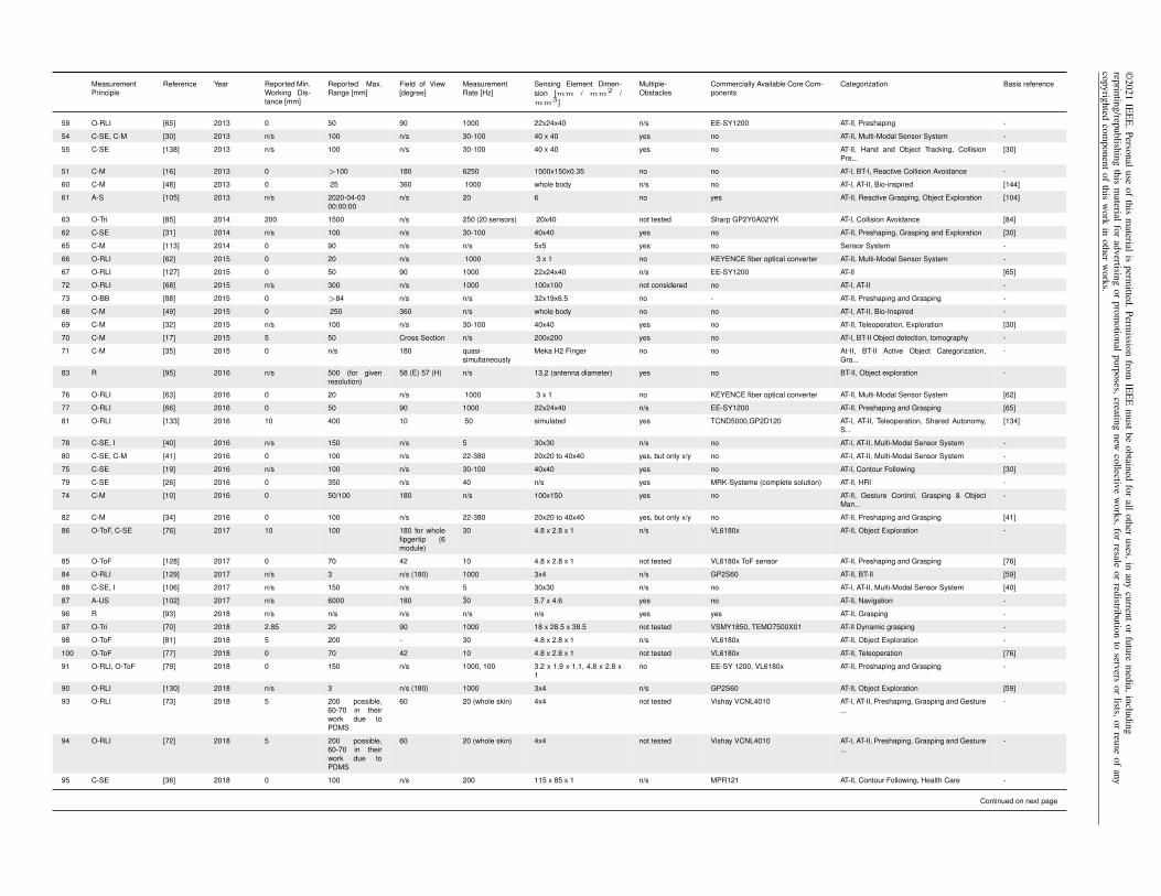
©2021
IEE
E.Personal
useof
thism
aterialis
permitted.Perm
issionfrom
IEE
Em
ustbe
obtainedfor
allother
uses,inany
currentor
futurem
edia,includingreprinting/republishing
thism
aterialfor
advertisingor
promotional
purposes,creatingnew
collectivew
orks,forresale
orredistribution
toservers
orlists,or
reuseof
anycopyrighted
component
ofthis
work
inother
works.
MeasurementPrinciple
Reference Year Reported Min.Working Dis-tance [mm]
Reported Max.Range [mm]
Field of View[degree]
MeasurementRate [Hz]
Sensing Element Dimen-sion [mm / mm2 /mm3 ]
Multiple-Obstacles
Commercially Available Core Com-ponents
Categorization Basis reference
59 O-RLI [65] 2013 0 50 90 1000 22x24x40 n/s EE-SY1200 AT-II, Preshaping -
54 C-SE, C-M [30] 2013 n/s 100 n/s 30-100 40 x 40 yes no AT-II, Multi-Modal Sensor System -
55 C-SE [138] 2013 n/s 100 n/s 30-100 40 x 40 yes no AT-II, Hand and Object Tracking, CollisionPre...
[30]
51 C-M [16] 2013 0 >100 180 6250 1500x150x0.35 no no AT-I, BT-I, Reactive Collision Avoidance -
60 C-M [48] 2013 0 25 360 1000 whole body n/s no AT-I, AT-II, Bio-inspired [144]
61 A-S [105] 2013 n/s 2020-04-0300:00:00
n/s 20 6 no yes AT-II, Reactive Grasping, Object Exploration [104]
63 O-Tri [85] 2014 200 1500 n/s 250 (20 sensors) 20x40 not tested Sharp GP2Y0A02YK AT-I, Collision Avoidance [84]
62 C-SE [31] 2014 n/s 100 n/s 30-100 40x40 yes no AT-II, Preshaping, Grasping and Exploration [30]
65 C-M [113] 2014 0 90 n/s n/s 5x5 yes no Sensor System -
66 O-RLI [62] 2015 0 20 n/s 1000 3 x 1 no KEYENCE fiber optical converter AT-II, Multi-Modal Sensor System -
67 O-RLI [127] 2015 0 50 90 1000 22x24x40 n/s EE-SY1200 AT-II [65]
72 O-RLI [68] 2015 n/s 300 n/s 1000 100x100 not considered no AT-I, AT-II -
73 O-BB [88] 2015 0 >84 n/s n/s 32x19x6.5 no - AT-II, Preshaping and Grasping -
68 C-M [49] 2015 0 250 360 n/s whole body no no AT-I, AT-II, Bio-Inspired -
69 C-M [32] 2015 n/s 100 n/s 30-100 40x40 yes no AT-II, Teleoperation, Exploration [30]
70 C-M [17] 2015 5 50 Cross Section n/s 200x200 yes no AT-I, BT-II Object detection, tomography -
71 C-M [35] 2015 0 n/s 180 quasi-simultaneously
Meka H2 Finger no no At-II, BT-II Active Object Categorization,Gra...
-
83 R [95] 2016 n/s 500 (for givenresolution)
58 (E) 57 (H) n/s 13,2 (antenna diameter) yes no BT-II, Object exploration -
76 O-RLI [63] 2016 0 20 n/s 1000 3 x 1 no KEYENCE fiber optical converter AT-II, Multi-Modal Sensor System [62]
77 O-RLI [66] 2016 0 50 90 1000 22x24x40 n/s EE-SY1200 AT-II, Preshaping and Grasping [65]
81 O-RLI [133] 2016 10 400 10 50 simulated yes TCND5000,GP2D120 AT-I, AT-II, Teleoperation, Shared Autonomy,S...
[134]
78 C-SE, I [40] 2016 n/s 150 n/s 5 30x30 n/s no AT-I, AT-II, Multi-Modal Sensor System -
80 C-SE, C-M [41] 2016 0 100 n/s 22-380 20x20 to 40x40 yes, but only x/y no AT-I, AT-II, Multi-Modal Sensor System -
75 C-SE [19] 2016 n/s 100 n/s 30-100 40x40 yes no AT-I, Contour Following [30]
79 C-SE [26] 2016 0 350 n/s 40 n/s yes MRK-Systeme (complete solution) AT-II, HRI -
74 C-M [10] 2016 0 50/100 180 n/s 100x150 yes no AT-II, Gesture Control, Grasping & ObjectMan...
-
82 C-M [34] 2016 0 100 n/s 22-380 20x20 to 40x40 yes, but only x/y no AT-II, Preshaping and Grasping [41]
86 O-ToF, C-SE [76] 2017 10 100 180 for wholefipgertip (6module)
30 4.8 x 2.8 x 1 n/s VL6180x AT-II, Object Exploration -
85 O-ToF [128] 2017 0 70 42 10 4.8 x 2.8 x 1 not tested VL6180x ToF sensor AT-II, Preshaping and Grasping [76]
84 O-RLI [129] 2017 n/s 3 n/s (180) 1000 3x4 n/s GP2S60 AT-II, BT-II [59]
88 C-SE, I [106] 2017 n/s 150 n/s 5 30x30 n/s no AT-I, AT-II, Multi-Modal Sensor System [40]
87 A-US [102] 2017 n/s 6000 180 30 5.7 x 4.6 yes no AT-II, Navigation -
96 R [93] 2018 n/s n/s n/s n/s n/s yes yes AT-II, Grasping -
97 O-Tri [70] 2018 2.85 20 90 1000 18 x 28.5 x 38.5 not tested VSMY1850, TEMD7500X01 AT-II Dynamic grasping -
98 O-ToF [81] 2018 5 200 - 30 4.8 x 2.8 x 1 n/s VL6180x AT-II, Object Exploration -
100 O-ToF [77] 2018 0 70 42 10 4.8 x 2.8 x 1 not tested VL6180x AT-II, Teleoperation [76]
91 O-RLI, O-ToF [79] 2018 0 150 n/s 1000, 100 3.2 x 1.9 x 1.1, 4.8 x 2.8 x1
no EE-SY 1200, VL6180x AT-II, Preshaping and Grasping -
90 O-RLI [130] 2018 n/s 3 n/s (180) 1000 3x4 n/s GP2S60 AT-II, Object Exploration [59]
93 O-RLI [73] 2018 5 200 possible,60-70 in theirwork due toPDMS
60 20 (whole skin) 4x4 not tested Vishay VCNL4010 AT-I, AT-II, Preshaping, Grasping and Gesture...
-
94 O-RLI [72] 2018 5 200 possible,60-70 in theirwork due toPDMS
60 20 (whole skin) 4x4 not tested Vishay VCNL4010 AT-I, AT-II, Preshaping, Grasping and Gesture...
-
95 C-SE [36] 2018 0 100 n/s 200 115 x 85 x 1 n/s MPR121 AT-II, Contour Following, Health Care -
Continued on next page
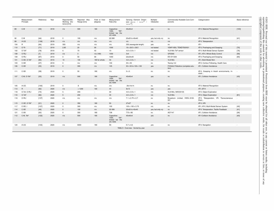
©2021
IEE
E.Personal
useof
thism
aterialis
permitted.Perm
issionfrom
IEE
Em
ustbe
obtainedfor
allother
uses,inany
currentor
futurem
edia,includingreprinting/republishing
thism
aterialfor
advertisingor
promotional
purposes,creatingnew
collectivew
orks,forresale
orredistribution
toservers
orlists,or
reuseof
anycopyrighted
component
ofthis
work
inother
works.
MeasurementPrinciple
Reference Year Reported Min.Working Dis-tance [mm]
Reported Max.Range [mm]
Field of View[degree]
MeasurementRate [Hz]
Sensing Element Dimen-sion [mm / mm2 /mm3 ]
Multiple-Obstacles
Commercially Available Core Com-ponents
Categorization Basis reference
89 C-M [43] 2018 n/s 500 180 Capacitive:1000, ToF:limited bei thei2C 400k
40x40x4 yes no AT-II, Material Recognition [103]
92 C-M [44] 2018 0 100 n/s 22-380 20x20 to 40x40 yes, but only x/y no AT-II, Material Recognition [41]
99 A-US [136] 2018 n/s n/s n/s n/s n/s n/s n/s AT-II, Teleoperation -
104 R [94] 2019 300 n/s n/s n/s 300 (waveguide length) yes no AT-I -
110 O-Tri [71] 2019 2.85 20 90 1000 18 x 28.5 x 38.5 not tested VSMY1850, TEMD7500X01 AT-II, Preshaping and Grasping [70]
102 O-ToF [78] 2019 0 70 42 10 4.8 x 2.8 x 1 not tested VL6180x ToF sensor AT-II, Multi-Modal Sensor System [76]
108 O-RLI [7] 2019 n/s 3 n/s (180) 1000 3x4 n/s GP2S60 AT-I, AT-II, Whole-Body Control [59]
109 O-RLI [67] 2019 0 50 90 1000 22x24x40 n/s EE-SY1200 AT-II, Preshaping and Grasping [65]
101 C-SE, O-ToF [80] 2019 10 100 180 for whole 30 4.8 x 2.8 x 1 n/s VL6180x AT-I, Multi-Modal Skin -
103 C-SE [37] 2019 0 n/s n/s 100 30 x 30 no Teensy 3.2 AT-II, Contour Following, Health Care -
106 C-SE [25] 2019 0 300 n/s 125 50 x 50 to 100 x 100 yes FOGALE Robotics (complete solu-tion)
AT-I, Collision Avoidance -
111 C-SE [38] 2019 0 50 180 n/s 5 x 5 no no AT-II, Grasping in Harsh environments, In-dustr...
-
107 C-M, O-ToF [20] 2019 n/s 500 180 Capacitive:1000, ToF:limited bei thei2C 400k
40x40x4 yes no AT-I, Collision Avoidance [43]
105 A-US [100] 2019 0 8 n/s n/s 30x14x14 no no AT-II, Material Recognition -
113 R [92] 2020 n/s >1200 160 40 9x13 yes yes AT-I, BT-II -
118 O-Tof, O-RLI [74] 2020 5 200 - 30 4.8 x 2.8 x 1 n/s VL6180x, MAX30105 AT-II, Object Exploration -
116 O-ToF [82] 2020 5 200 - 30 4.8 x 2.8 x 1 n/s VL6180x AT-II, Object Exploration [81]
119 O-RLI [137] 2020 n/s n/s n/s n/s 7.1 x 2.75 x 2.7 no Broadcom Limited, HSDL-9100-021
AT-II, Teleoperation, VR, TranscutaneousElect...
-
115 C-SE, O-ToF [21] 2020 0 350 180 50 27x27 no no AT-II, HRI -
117 C-SE, I [107] 2020 0 300 n/s 100 100 x 100 x 2.75 n/s no AT-I, AT-II, Multi-Modal Sensor System [40]
114 C-SE [46] 2020 0 100 n/s 22-380 20x20 to 40x40 yes, but only x/y no AT-II, Teleoperation, Tactile Feedback [41]
121 C-SE [50] 2020 0 350 180 108 175 x 80 no AD7147 AT-I, Collision Avoidance [26]
112 C-M, ToF [122] 2020 n/s 500 180 Capacitive:1000, ToF:limited bei thei2C 400k
40x40x4 yes no AT-I Collision Avoidance [43]
120 A-US [103] 2020 n/s 6000 180 30 5.7 x 4.6 yes no AT-II, Navigation -
TABLE I: Overview - Sorted by year

©2021 IEEE. Personal use of this material is permitted. Permission from IEEE must be obtained for all other uses, in any current or future media, includingreprinting/republishing this material for advertising or promotional purposes, creating new collective works, for resale or redistribution to servers or lists, or reuse of anycopyrighted component of this work in other works.
CONTENTS
I Introduction 1
II Proximity Sensor: Characterization, Applications and Safety Considerations 2II-A Characterization . . . . . . . . . . . . . . . . . . . . . . . . . . . . . . . . . . . . . . . . . . . . . . . . 2II-B Application and Behavior Types . . . . . . . . . . . . . . . . . . . . . . . . . . . . . . . . . . . . . . . 3II-C Safety Considerations and Norm Compliance . . . . . . . . . . . . . . . . . . . . . . . . . . . . . . . . 3
III Measurement Principles for Proximity Sensing 4III-A Capacitive Sensing . . . . . . . . . . . . . . . . . . . . . . . . . . . . . . . . . . . . . . . . . . . . . . 4
III-A1 Early Capacitive Technologies in Robotics . . . . . . . . . . . . . . . . . . . . . . . . . . . . 5III-A2 Capacitive Sensing for AT-I . . . . . . . . . . . . . . . . . . . . . . . . . . . . . . . . . . . . 5III-A3 Capacitive Sensing in AT-II . . . . . . . . . . . . . . . . . . . . . . . . . . . . . . . . . . . . 5III-A4 Further Aspects of Capacitive Proximity Sensing Technologies in Robotics . . . . . . . . . . 6III-A5 Spatial Resolution and Sensing Range for Capacitive Sensors . . . . . . . . . . . . . . . . . 6
III-B Optical Sensing . . . . . . . . . . . . . . . . . . . . . . . . . . . . . . . . . . . . . . . . . . . . . . . . 6III-B1 Reflected Light Intensity-Type Sensors (O-RLI) at an Early Stage . . . . . . . . . . . . . . . 7III-B2 Reflected Light Intensity-Type Sensors (O-RLI) Using Photoreflectors and Custom Electronics 7III-B3 Reflected Light Intensity-Type Sensors (O-RLI) Using Sensing Modules) . . . . . . . . . . . 8III-B4 Time-of-Flight-Type (O-ToF) Sensors . . . . . . . . . . . . . . . . . . . . . . . . . . . . . . 8III-B5 Triangulation-Type Sensors (O-Tri) . . . . . . . . . . . . . . . . . . . . . . . . . . . . . . . . 9III-B6 Break-Beam-Type Sensors (O-BB) . . . . . . . . . . . . . . . . . . . . . . . . . . . . . . . . 9III-B7 Discussion on Optical Sensors . . . . . . . . . . . . . . . . . . . . . . . . . . . . . . . . . . 9
III-C Radar . . . . . . . . . . . . . . . . . . . . . . . . . . . . . . . . . . . . . . . . . . . . . . . . . . . . . . 9III-D Other Sensing Principles . . . . . . . . . . . . . . . . . . . . . . . . . . . . . . . . . . . . . . . . . . . 10
III-D1 Acoustic . . . . . . . . . . . . . . . . . . . . . . . . . . . . . . . . . . . . . . . . . . . . . . 10III-D2 Inductive . . . . . . . . . . . . . . . . . . . . . . . . . . . . . . . . . . . . . . . . . . . . . . 11III-D3 Whiskers . . . . . . . . . . . . . . . . . . . . . . . . . . . . . . . . . . . . . . . . . . . . . . 11
III-E Multi-modal and Modular Sensors . . . . . . . . . . . . . . . . . . . . . . . . . . . . . . . . . . . . . . 11
IV Applications and Methods in the Research and Industry Domains 11IV-A Reactive collision-avoidance and Contour Following (AT-I, BT-I) . . . . . . . . . . . . . . . . . . . . . 12
IV-A1 Early Jacobian-type Approaches . . . . . . . . . . . . . . . . . . . . . . . . . . . . . . . . . 12IV-A2 Early Geometric Approaches . . . . . . . . . . . . . . . . . . . . . . . . . . . . . . . . . . . 13IV-A3 Recent Jacobian-type Approaches . . . . . . . . . . . . . . . . . . . . . . . . . . . . . . . . 13IV-A4 Recent Geometric Approaches . . . . . . . . . . . . . . . . . . . . . . . . . . . . . . . . . . 14
IV-B Reactive Preshaping and Grasping (AT-II, BT-I) . . . . . . . . . . . . . . . . . . . . . . . . . . . . . . . 14IV-B1 Reactive Preshaping Control . . . . . . . . . . . . . . . . . . . . . . . . . . . . . . . . . . . 14
IV-C Higher Complexity Methods and Behaviors (Towards BT-II) . . . . . . . . . . . . . . . . . . . . . . . . 15IV-C1 Pre-touch Exploration (AT-II) . . . . . . . . . . . . . . . . . . . . . . . . . . . . . . . . . . . 15IV-C2 Bio-inspired Sensing and Behavior (AT-I, AT-II) . . . . . . . . . . . . . . . . . . . . . . . . 16IV-C3 Teleoperation and VR (AT-I, AT-II) . . . . . . . . . . . . . . . . . . . . . . . . . . . . . . . 16IV-C4 Material Classification (AT-II) . . . . . . . . . . . . . . . . . . . . . . . . . . . . . . . . . . 16IV-C5 Tracking (AT-I, AT-II) . . . . . . . . . . . . . . . . . . . . . . . . . . . . . . . . . . . . . . . 17
IV-D Industrial Technologies and Solutions . . . . . . . . . . . . . . . . . . . . . . . . . . . . . . . . . . . . 17
V Future Perspectives: Grand Challenges 17V-A Human-robot interaction in the industry and service domains . . . . . . . . . . . . . . . . . . . . . . . 17V-B Cognitive Robotics . . . . . . . . . . . . . . . . . . . . . . . . . . . . . . . . . . . . . . . . . . . . . . 18V-C Soft Robotics . . . . . . . . . . . . . . . . . . . . . . . . . . . . . . . . . . . . . . . . . . . . . . . . . 18
VI Summary and Conclusions 18
References 19

©2021 IEEE. Personal use of this material is permitted. Permission from IEEE must be obtained for all other uses, in any current or future media, includingreprinting/republishing this material for advertising or promotional purposes, creating new collective works, for resale or redistribution to servers or lists, or reuse of anycopyrighted component of this work in other works.
Biographies 22Stefan Escaida Navarro . . . . . . . . . . . . . . . . . . . . . . . . . . . . . . . . . . . . . . . . . . . . . . . . . 22Stephan Muhlbacher-Karrer . . . . . . . . . . . . . . . . . . . . . . . . . . . . . . . . . . . . . . . . . . . . . . . 23Hosam Alagi . . . . . . . . . . . . . . . . . . . . . . . . . . . . . . . . . . . . . . . . . . . . . . . . . . . . . . . 23Bjorn Hein . . . . . . . . . . . . . . . . . . . . . . . . . . . . . . . . . . . . . . . . . . . . . . . . . . . . . . . . 23Hubert Zangl . . . . . . . . . . . . . . . . . . . . . . . . . . . . . . . . . . . . . . . . . . . . . . . . . . . . . . . 23Keisuke Koyama . . . . . . . . . . . . . . . . . . . . . . . . . . . . . . . . . . . . . . . . . . . . . . . . . . . . . 23Christian Duriez . . . . . . . . . . . . . . . . . . . . . . . . . . . . . . . . . . . . . . . . . . . . . . . . . . . . . 23Joshua R. Smith . . . . . . . . . . . . . . . . . . . . . . . . . . . . . . . . . . . . . . . . . . . . . . . . . . . . . 23