Optical Line Recognition Sensors for Line Follower - Acta ...
6
16 VOLUME 17, No. 4, 2013 Optical Line Recognition Sensors for Line Follower František Šimčák, Michal Kelemen *, Ivan Virgala, Ľubica Miková Technical University of Košice, Faculty of Mechanical Engineering, Letná 9, 042 00 Košice BIOGRAPHICAL NOTES František Šimčák, prof. Ing. CSc. He is a professor of applied mechanics, head of the department of Applied Mechanics and Mechatronics. He is author of 8 monographs, 4 university textbooks, 11 university books and more than 200 publications in journals and conference proceedings at Slovakia and abroads. He received several prizes due to his scientific results. Michal Kelemen, doc. Ing. PhD. He received M.S. degree in mechanical engineering from Technical University of Košice, Slovakia in 1998 and Ph.D. degree in Mechatronics from Technical University of Košice, Slovakia in 2002.He is an associated professor of the Department of Applied Mechanics and Mecharonics at the Faculty of Mechanical Engineering at the Technical University of Košice, Slovakia. He has been awarded the 1998 “Price of the VolksBank” for the best M.S. graduate and 2007 Price “Scienist of the year”. His research interests include mechatronic systems, intelligent robotic systems, dust mass concentration measurement, measurement of non-electric quantities, and microcomputer systems. He has authored more than 180 journal and conference pa- pers on these topics. Ivan Virgala, Ing. PhD. He received M.Sc. degree in Mechatronics from Technical Uni- versity of Košice, Slovakia in 2009 and PhD. degree in Mechatronics from Technical University of Košice, Slovakia in 2012. He is a researcher in Department of Applied Me- chanics and Mechatronics at Faculty of Mechanical Engineering at Technical University of Košice, Slovakia. He has been awarded by “medal of dean” for excellent study. He is an editorial board member of 3 foreign scientific journals. His research field is design, modeling and control of manipulators, mobile robots, snake robots, humanoid robots and embedded systems. He has authored more than 50 journal and conference pa- pers on these topics. Ľubica Miková, Ing. PhD. She received M.S. degree in mechatronics from Technical University of Košice in 2007 and Ph.D. degree in Mechatronics from Technical Uni- versity of Košice, Slovakia in 2011. She is a researcher of the Department of Applied Mechanics and Mecharonics at the Faculty of Mechanical Engineering at the Techni- cal University of Košice, Slovakia. Her research interests include mechatronics systems and robotics. She has authored more than 45 journal and conference papers on these topics. KEY WORDS Robot, wheeled locomotion, sensor, mechatronics. ABSTRACT Paper deals with optical line recognition sensors, which are useful for line follower robots. Line follower is the category of robotic contests. The basic idea is to locomote with robot and follows the black line on white surface. Robot design is very frequently
-
Upload
khangminh22 -
Category
Documents
-
view
5 -
download
0
Transcript of Optical Line Recognition Sensors for Line Follower - Acta ...
16 VOLUME 17, No. 4, 2013
Optical Line Recognition Sensors for Line Follower
František Šimčák, Michal Kelemen *, Ivan Virgala, Ľubica Miková
Technical University of Košice, Faculty of Mechanical Engineering, Letná 9, 042 00 Košice
BIOGRAPHICAL NOTESFrantišek Šimčák, prof. Ing. CSc. He is a professor of applied mechanics, head of the department of Applied Mechanics and Mechatronics. He is author of 8 monographs, 4 university textbooks, 11 university books and more than 200 publications in journals and conference proceedings at Slovakia and abroads. He received several prizes due to his scientific results.Michal Kelemen, doc. Ing. PhD. He received M.S. degree in mechanical engineering from Technical University of Košice, Slovakia in 1998 and Ph.D. degree in Mechatronics from Technical University of Košice, Slovakia in 2002.He is an associated professor of the Department of Applied Mechanics and Mecharonics at the Faculty of Mechanical Engineering at the Technical University of Košice, Slovakia. He has been awarded the 1998 “Price of the VolksBank” for the best M.S. graduate and 2007 Price “Scienist of the year”. His research interests include mechatronic systems, intelligent robotic systems, dust mass concentration measurement, measurement of non-electric quantities, and microcomputer systems. He has authored more than 180 journal and conference pa-pers on these topics.Ivan Virgala, Ing. PhD. He received M.Sc. degree in Mechatronics from Technical Uni-versity of Košice, Slovakia in 2009 and PhD. degree in Mechatronics from Technical University of Košice, Slovakia in 2012. He is a researcher in Department of Applied Me-chanics and Mechatronics at Faculty of Mechanical Engineering at Technical University of Košice, Slovakia. He has been awarded by “medal of dean” for excellent study. He is an editorial board member of 3 foreign scientific journals. His research field is design, modeling and control of manipulators, mobile robots, snake robots, humanoid robots and embedded systems. He has authored more than 50 journal and conference pa-pers on these topics.Ľubica Miková, Ing. PhD. She received M.S. degree in mechatronics from Technical University of Košice in 2007 and Ph.D. degree in Mechatronics from Technical Uni-versity of Košice, Slovakia in 2011. She is a researcher of the Department of Applied Mechanics and Mecharonics at the Faculty of Mechanical Engineering at the Techni-cal University of Košice, Slovakia. Her research interests include mechatronics systems and robotics. She has authored more than 45 journal and conference papers on these topics.
KEY WORDSRobot, wheeled locomotion, sensor, mechatronics.
ABSTRACTPaper deals with optical line recognition sensors, which are useful for line follower robots. Line follower is the category of robotic contests. The basic idea is to locomote with robot and follows the black line on white surface. Robot design is very frequently
Acta Mechanica SlovacaJournal published by Faculty of Mechanical Engineering - Technical University of Košice
17
based on two wheeled differentially driven under-carriage with third supporting support wheel. The locomotion of the robot is controlled via using of microcontroller on the base of information from line recognition sensors. Selection of these sensors has a big role in robot design for this category of robot contest.
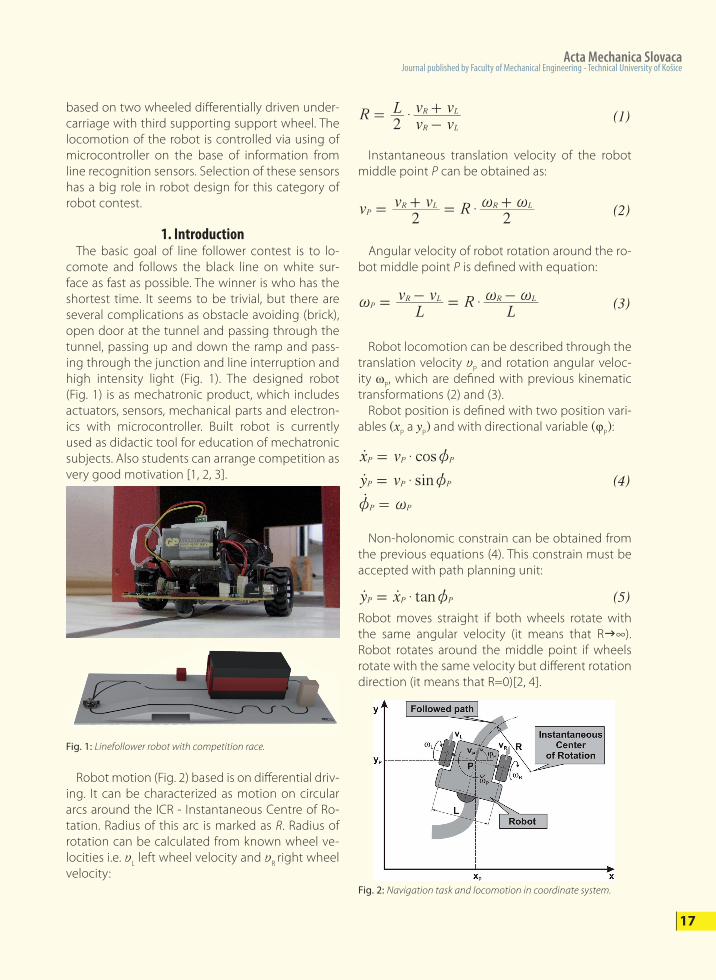
1. Introduction The basic goal of line follower contest is to lo-comote and follows the black line on white sur-face as fast as possible. The winner is who has the shortest time. It seems to be trivial, but there are several complications as obstacle avoiding (brick), open door at the tunnel and passing through the tunnel, passing up and down the ramp and pass-ing through the junction and line interruption and high intensity light (Fig. 1). The designed robot (Fig. 1) is as mechatronic product, which includes actuators, sensors, mechanical parts and electron-ics with microcontroller. Built robot is currently used as didactic tool for education of mechatronic subjects. Also students can arrange competition as very good motivation [1, 2, 3].
Fig. 1: Linefollower robot with competition race.
Instantaneous translation velocity of the robot middle point P can be obtained as:
Angular velocity of robot rotation around the ro-bot middle point P is defined with equation:
Robot locomotion can be described through the translation velocity y
P and rotation angular veloc-
ity ωP, which are defined with previous kinematic
transformations (2) and (3). Robot position is defined with two position vari-ables (x
P a y
P) and with directional variable (φ
P):
Non-holonomic constrain can be obtained from the previous equations (4). This constrain must be accepted with path planning unit:
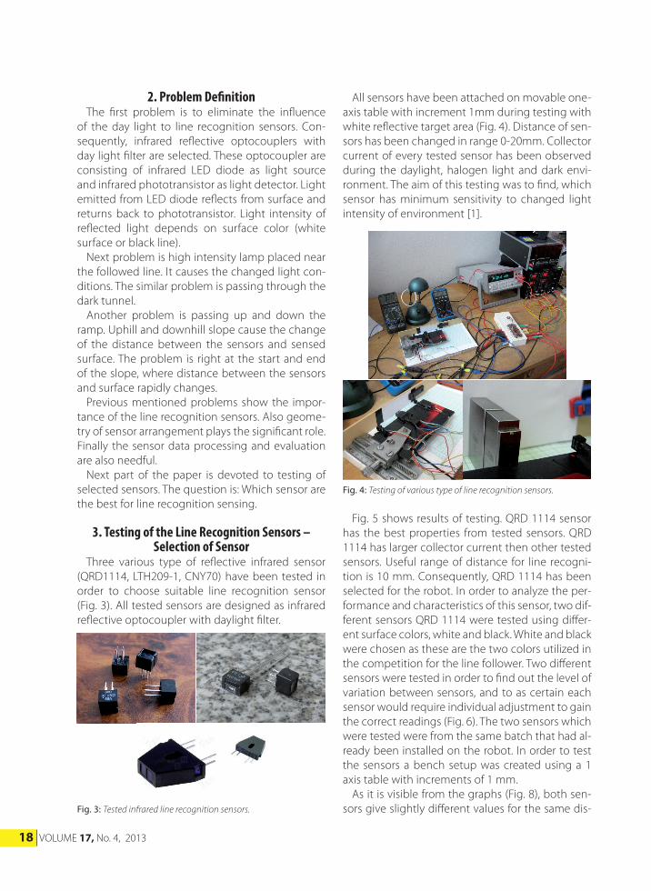
Robot moves straight if both wheels rotate with the same angular velocity (it means that Rg∞). Robot rotates around the middle point if wheels rotate with the same velocity but different rotation direction (it means that R=0)[2, 4].
Robot motion (Fig. 2) based is on differential driv-ing. It can be characterized as motion on circular arcs around the ICR - Instantaneous Centre of Ro-tation. Radius of this arc is marked as R. Radius of rotation can be calculated from known wheel ve-locities i.e. y
L left wheel velocity and y
R right wheel
velocity:
R Lv vv v
2 R L
R L$=-+
(1)
v v v R2 2
PR L R L$ ~ ~= + = +
(2)
Lv v R
LP
R L R L$~ ~ ~= - = -(3)
cos
sin
x v
y v
P P P
P P P
P P
$
$
z
z
z ~
=
=
=
o
oo
(4)
tany xP P P$ z=o o (5)
Fig. 2: Navigation task and locomotion in coordinate system.
18 VOLUME 17, No. 4, 2013
Fig. 3: Tested infrared line recognition sensors.
Fig. 4: Testing of various type of line recognition sensors.
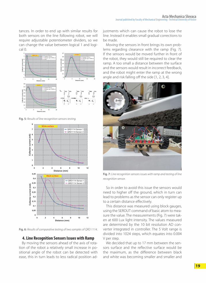
2. Problem Definition The first problem is to eliminate the influence of the day light to line recognition sensors. Con-sequently, infrared reflective optocouplers with day light filter are selected. These optocoupler are consisting of infrared LED diode as light source and infrared phototransistor as light detector. Light emitted from LED diode reflects from surface and returns back to phototransistor. Light intensity of reflected light depends on surface color (white surface or black line). Next problem is high intensity lamp placed near the followed line. It causes the changed light con-ditions. The similar problem is passing through the dark tunnel. Another problem is passing up and down the ramp. Uphill and downhill slope cause the change of the distance between the sensors and sensed surface. The problem is right at the start and end of the slope, where distance between the sensors and surface rapidly changes. Previous mentioned problems show the impor-tance of the line recognition sensors. Also geome-try of sensor arrangement plays the significant role. Finally the sensor data processing and evaluation are also needful. Next part of the paper is devoted to testing of selected sensors. The question is: Which sensor are the best for line recognition sensing.
3. Testing of the Line Recognition Sensors – Selection of Sensor
Three various type of reflective infrared sensor (QRD1114, LTH209-1, CNY70) have been tested in order to choose suitable line recognition sensor (Fig. 3). All tested sensors are designed as infrared reflective optocoupler with daylight filter.
All sensors have been attached on movable one-axis table with increment 1mm during testing with white reflective target area (Fig. 4). Distance of sen-sors has been changed in range 0-20mm. Collector current of every tested sensor has been observed during the daylight, halogen light and dark envi-ronment. The aim of this testing was to find, which sensor has minimum sensitivity to changed light intensity of environment [1].
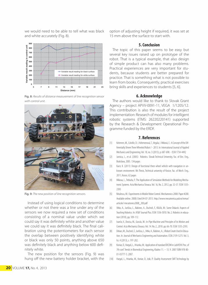
Fig. 5 shows results of testing. QRD 1114 sensor has the best properties from tested sensors. QRD 1114 has larger collector current then other tested sensors. Useful range of distance for line recogni-tion is 10 mm. Consequently, QRD 1114 has been selected for the robot. In order to analyze the per-formance and characteristics of this sensor, two dif-ferent sensors QRD 1114 were tested using differ-ent surface colors, white and black. White and black were chosen as these are the two colors utilized in the competition for the line follower. Two different sensors were tested in order to find out the level of variation between sensors, and to as certain each sensor would require individual adjustment to gain the correct readings (Fig. 6). The two sensors which were tested were from the same batch that had al-ready been installed on the robot. In order to test the sensors a bench setup was created using a 1 axis table with increments of 1 mm. As it is visible from the graphs (Fig. 8), both sen-sors give slightly different values for the same dis-
Acta Mechanica SlovacaJournal published by Faculty of Mechanical Engineering - Technical University of Košice
19
0
1
2
3
4
5
6
7
8
0 5 10 15 20Distance (mm)
Col
lect
or c
urre
nt (m
A)
Daylight 500LuxHalogen light 10000LuxDark
QRD1114
0
0,1
0,2
0,3
0,4
0,5
0,6
0,7
0 5 10 15 20Distance (mm)
Col
lect
or c
urre
nt (m
A)
Daylight 500LuxHalogen light 10000LuxDark
LTH209-1
0
0,1
0,2
0,3
0,4
0,5
0,6
0,7
0,8
0 5 10 15 20Distance (mm)
Col
lect
or c
urre
nt (m
A)
Daylight 500LuxHalogen light 10000LuxDark
CNY70
Fig. 5: Results of line recognition sensors testing.
tances. In order to end up with similar results for both sensors on the line following robot, we will require adjustable potentiometer dividers, so we can change the value between logical 1 and logi-cal 0.
0
1
2
3
4
5
6
7
8
0 2 4 6 8 10 12Distance (mm)
Colle
ctor
cur
rent
(mA)
QRD1114 Sensor 1QRD1114 Sensor 2
White surface
0
0,05
0,1
0,15
0,2
0,25
0,3
0,35
0,4
0,45
0 2 4 6 8 10 12Distance (mm)
Col
lect
or c
urre
nt (m
A)
QRD1114 Sensor 1QRD1114 Sensor 2
Black surface
Fig. 6: Results of comparative testing of two samples of QRD 1114.
4. Line Recognition Sensors Issues with Ramp By moving the sensors ahead of the axis of rota-tion of the robot a relatively small increase in po-sitional angle of the robot can be detected with ease, this in turn leads to less radical position ad-
justments which can cause the robot to lose the line. Instead it enables small gradual corrections to be made. Moving the sensors in front brings its own prob-lems regarding clearance with the ramp (Fig. 7). If the sensors would be moved further in front of the robot, they would still be required to clear the ramp. A too small a distance between the surface and the sensors would result in incorrect feedback, and the robot might enter the ramp at the wrong angle and risk falling off the side [1, 2, 3, 4].
Fig. 7: Line recognition sensors issues with ramp and testing of line
recognition sensor.
So in order to avoid this issue the sensors would need to higher off the ground, which in turn can lead to problems as the sensor can only register up to a certain distance effectively. This distance was measured using block gauges, using the SEROUT command of basic atom to mea-sure the value. The measurements (Fig. 7) were tak-en at 600 Lux light intensity. The values measured are determined by the 10 bit resolution AD con-verter integrated in controller. The 5 Volt range is divided into 1024 steps, which equates into 0.004 V per step. We decided that up to 17 mm between the sen-sors surface and the reflective surface would be the maximum, as the difference between black and white was becoming smaller and smaller and
20 VOLUME 17, No. 4, 2013
0
100
200
300
400
500
600
700
800
900
5 7 9 11 13 15 17 19 21 23
Distance (mm)
Varia
ble
resu
lt re
adin
g in
con
trol
uni
t
Variable result reading for black surface
Variable result reading for white surface
Fig. 8: Results of distance measurement of line recognition sensor
with control unit.
Fig. 9: The new position of line recognition sensors.
we would need to be able to tell what was black and white accurately (Fig. 8).
Instead of using logical conditions to determine whether or not there was a line under any of the sensors we now required a new set of conditions consisting of a nominal value under which we could say it was definitely white and another value we could say it was definitely black. The final cali-bration using the potentiometers for each sensor the overlap between positively identifying white or black was only 50 points, anything above 650 was definitely black and anything below 600 defi-nitely white. The new position for the sensors (Fig. 9) was hung off the new battery holder bracket, with the
option of adjusting height if required, it was set at 15 mm above the surface to start with.
5. Conclusion The topic of this paper seems to be easy but several key issues raised up on prototype of the robot. That is a typical example, that also design of simple product can has also many problems. Practical experiences are very important for stu-dents, because students are better prepared for practice. That is something what is not possible to learn from books. Consequently, practical exercises bring skills and experiences to students [5, 6].
6. Acknowledge The authors would like to thank to Slovak Grant Agency – project APVV-0091-11, VEGA 1/1205/12. This contribution is also the result of the project implementation: Research of modules for intelligent robotic systems (ITMS: 26220220141) supported by the Research & Development Operational Pro-gramme funded by the ERDF.
7. References[1] Kelemen, M., Colville, D. J. Kelemenová, T., Virgala, I. Miková, Ľ.: A Concept of the Dif-
ferentially Driven Three Wheeled Robot / - 2013. In: International Journal of Applied
Mechanics and Engineering. Vol. 18, no. 3 (2013), p. 687-698. - ISSN 1734-4492
[2] Jurisica, L., et al. (2005): Robotics. Slovak Technical University, Fac. of Elec. Eng.,
Bratislava, 2005. 134 pages
[3] Kacir, K. (2011): Design of functional three wheel vehicle with navigation in un-
known environment. Ms Thesis, Technical university of Kosice, Fac. of Mech. Eng.,
2011, Kosice, 62 pages
[4] Mikova, L., Trebuňa, F.: The Application of Simulation Methods for Modeling Mecha-
tronic Systems. Acta Mechanica Slovaca. Vol. 16, No. 2, 2012, pp. 32-37. ISSN 1335-
2393
[5] Nitulescu, M.: Experiments in Mobile Robot Control. Mechatronics 2008. Paper #200.
Available online. 2008) Cited 04-07-2013. http://www.mecatronica.pub.ro/romar/
articole/ mecatronics2008_200.pdf
[6] Vitko, A., Jurišica, L., Babinec, A., Duchoň, F., Kľúčik, M.: Some Didactic Aspects of
Teaching Robotics. In: AT&P Journal Plus. ISSN 1336-5010. No. 2. Robotics in educa-
tion (2010), pp. 109-112.
[7] Ivančo, V., Dovica, M., Gorzás, M.: In-Pipe Machine and Principles of its Motion and
Control. Acta Mechanica Slovaca. Vol. 14. No. 2., 2010. pp. 66-70. ISSN 1335-2393.
[8] Dekan, M., Duchoň, F., Jurišica, L., Vitko, A., Babinec, A.,: iRobot Create Used in Educa-
tion. In: Journal of Mechanics Engineering and Automation. ISSN 2159-5275. Vol. 3,
Iss. 4 (2013), s. 197-202.
[9] Koniar, D., Hargaš, L., Hrianka, M.: Application of standard DICOM in LabVIEW. Proc. of
7th conf. Trends in Biomedical Engineering, Kladno 11. – 13. 9. 2007 ISBN 978-80-
01-03777-5. 2007.
[10] Hargaš, L., Hrianka, M., Koniar, D., Izák, P.: Quality Assessment SMT Technology by
Acta Mechanica SlovacaJournal published by Faculty of Mechanical Engineering - Technical University of Košice
21
Virtual Instrumentation. Applied Electronics 2007, Pilsen, 5. – 6. 9. 2007, ISBN 987-
80-7043-537-3, 2007.
[11] Gmiterko, A., Virgala, I., Vacková, M.: Dynamic Analysis of Two-Mass System to Imi-
tate Rectilinear Motion of a Snake. Acta Mechanica Slovaca. Vol. 14. No. 2. pp. 74-81.
ISSN 1335-2393.
[12] Duchoň, F., Dekan, M., Jurišica, L., Vitko, A.: Some Applications of Laser Rangefinder
in Mobile Robotics. In: Journal of Control Engineering and Applied Informatics. - ISSN
1454-8658. - Vol. 14, No. 2 (2012), s. 50-57
[13] Gmiterko, A., Kelemen, M., Kelemenová, T., Miková, L.: Adaptable Mechatronic Lo-
comotion System. Acta Mechanica Slovaca. Vol. 14. No. 2. 2010. pp. 102-108. ISSN
1335-2393.
[14] Trebuňa, F., Šimčák, F., Handbook of experimental mechanics. 1st edition. Košice : TU
of Kosice, Fac. Of Mech. Eng. 2007. 1526 pages. ISBN 970-80-8073-816-7.
[15] Hanzel, J., Duchoň, F., Rodina, J., Pásztó, P.: Global Navigation Systems for Mobile
Robots. In: International Journal of Systems Applications, Engineering & Develop-
ment. - ISSN 2074-1308. - Vol. 7, Iss. 5 (2013), s. 279-285.
[16] Ostertag, O., Ostertagová, E.: Measurement of tensions for 2-D orthotropic environ-
ment with the photostress method. 2006. In: Acta Mechanica Slovaca. Vol. 10, No. 1
(2006), pp. 369-376. ISSN 1335-2393.
[17] Tölgyessy, Michael - Chovanec, Ľuboš - Pásztó, Peter - Hubinský, Peter: A Plane Based
Real-Time Algorithm for Controlling a Semi-Autonomous Robot with Hand Gestures
Using the Kinect. In: International Journal of Imaging and Robotics. - ISSN 2231-
525X. - Vol. 13, Iss. 2 (2014), s. 126-133.
[18] V. Baláž, , E. Ostertagová, , D. Palaščáková. Using of e-learning for teaching extension
at KVTaR Acta Mechanica Slovaca. Vol.. 10, No. 2-A (2006), pp. 47-50. - ISSN 1335-
2393. 2006.