GDS SERS 1.1, User Volume 1 - AVESİS
245
Page 1 / 245 GDS Engineering R&D | GDS Mühendislik ARGE San. Tic. Ltd. Şti TEKNOPARK ISTANBUL. Sanayi Mah. Teknopark Bulvarı. No: 1/2C, Blok: 4 34906, Pendik – Istanbul Tel: +90 216 395-0506; Mobile : +90 535 515-3030; E-mail : [email protected]; Web: www.GlobalDynamicSystems.com GDS Mühendislik ARGE San. Tic. Ltd. Şti / TEKNOPARK ISTANBUL Global Dynamic Systems (GDS) SHIP ENGINE ROOM SIMULATOR (SERS) Version 1.1 USER MANUAL VOLUME I: SOFTWARE DESCRIPTION GDS Engineering R&D, Inc. (GDS Mühendislik ARGE San. Tic. Ltd. Sti.) 1 December 2020
-
Upload
khangminh22 -
Category
Documents
-
view
1 -
download
0
Transcript of GDS SERS 1.1, User Volume 1 - AVESİS
Page 1 / 245 GDS Engineering R&D | GDS Mühendislik ARGE San. Tic. Ltd. Şti
TEKNOPARK ISTANBUL. Sanayi Mah. Teknopark Bulvarı. No: 1/2C, Blok: 4 34906, Pendik – Istanbul Tel: +90 216 395-0506; Mobile : +90 535 515-3030;
E-mail : [email protected]; Web: www.GlobalDynamicSystems.com
GDS Mühendislik ARGE San. Tic. Ltd. Şti / TEKNOPARK ISTANBUL Global Dynamic Systems (GDS)
SHIP ENGINE ROOM SIMULATOR (SERS) Version 1.1
USER MANUAL
VOLUME I: SOFTWARE DESCRIPTION
GDS Engineering R&D, Inc.
(GDS Mühendislik ARGE San. Tic. Ltd. Sti.)
1 December 2020
Page 2 / 245 GDS Engineering R&D | GDS Mühendislik ARGE San. Tic. Ltd. Şti
TEKNOPARK ISTANBUL. Sanayi Mah. Teknopark Bulvarı. No: 1/2C, Blok: 4 34906, Pendik – Istanbul Tel: +90 216 395-0506; Mobile : +90 535 515-3030;
E-mail : [email protected]; Web: www.GlobalDynamicSystems.com
GDS Mühendislik ARGE San. Tic. Ltd. Şti / TEKNOPARK ISTANBUL Global Dynamic Systems (GDS)
IMPORTANT NOTICE
License agreements describe the users of the GDS SERS Users. The User Manual is part of the software and license; therefore, the SERS User Manual may not be disclosed to third party persons, company or organizations.
Page 3 / 245 GDS Engineering R&D | GDS Mühendislik ARGE San. Tic. Ltd. Şti
TEKNOPARK ISTANBUL. Sanayi Mah. Teknopark Bulvarı. No: 1/2C, Blok: 4 34906, Pendik – Istanbul Tel: +90 216 395-0506; Mobile : +90 535 515-3030;
E-mail : [email protected]; Web: www.GlobalDynamicSystems.com
GDS Mühendislik ARGE San. Tic. Ltd. Şti / TEKNOPARK ISTANBUL Global Dynamic Systems (GDS)
FOREWORD
This document is for use along with the GDS Ship Engine Room Simulator (SERS). We encourage students using this document while running the simulator to have a better understanding of the engine room systems, operations and other specifics. This manual applies to the version 1.1 of the SERS software.
Please send your inquiries or questions to GDS Engineering R&D about the use of this document:
GDS Engineering R&D
SERS Team
www.GlobalDynamicSystems.com
Environmental Awareness Notice
GDS Team would be very pleased if the user manual used electronically and not printed to a hardcopy paper in order to reduce the environmental issues that we encounter more than any other times in
this century.

Page 4 / 245 GDS Engineering R&D | GDS Mühendislik ARGE San. Tic. Ltd. Şti
TEKNOPARK ISTANBUL. Sanayi Mah. Teknopark Bulvarı. No: 1/2C, Blok: 4 34906, Pendik – Istanbul Tel: +90 216 395-0506; Mobile : +90 535 515-3030;
E-mail : [email protected]; Web: www.GlobalDynamicSystems.com
GDS Mühendislik ARGE San. Tic. Ltd. Şti / TEKNOPARK ISTANBUL Global Dynamic Systems (GDS)
DOCUMENT CHANGELOG
Document Change Log
Date Version Number Information
1 March 2020 1.0 Initial version.
1 May 2020 1.0.1 Includes changes requested by Class NK
12 Nov 2020 1.1 Includes changes requested by Class NK
1 Dec 2020 1.1.1 Includes changes requested by Class NK
Page 5 / 245 GDS Engineering R&D | GDS Mühendislik ARGE San. Tic. Ltd. Şti
TEKNOPARK ISTANBUL. Sanayi Mah. Teknopark Bulvarı. No: 1/2C, Blok: 4 34906, Pendik – Istanbul Tel: +90 216 395-0506; Mobile : +90 535 515-3030;
E-mail : [email protected]; Web: www.GlobalDynamicSystems.com
GDS Mühendislik ARGE San. Tic. Ltd. Şti / TEKNOPARK ISTANBUL Global Dynamic Systems (GDS)
TABLE OF CONTENTS IMPORTANT NOTICE ............................................................................................................................................... 2
FOREWORD ............................................................................................................................................................. 3
DOCUMENT CHANGELOG ....................................................................................................................................... 4
TABLE OF CONTENTS ............................................................................................................................................... 5
1. INTRODUCTION .............................................................................................................................................. 9
1.1 SCOPE ...................................................................................................................................................... 9 1.2 OVERVIEW OF THE SERS USER MANUALS ....................................................................................................... 9
2. STARTING THE SERS ...................................................................................................................................... 11
2.1 INITIALIZATION AND LOGIN ......................................................................................................................... 11 2.2 STARTING THE SERS WITH THE SHIP’S INITIAL CONDITIONS............................................................................... 13
3. SIMULATED PLATFORM ................................................................................................................................ 17
3.1 THE SHIP................................................................................................................................................. 18 3.2 SHIP CONSTRUCTION ................................................................................................................................. 19 3.3 THE MAIN ENGINE (ME) ........................................................................................................................... 20 3.4 ENGINE ROOM SYSTEMS ............................................................................................................................ 22 3.5 ELECTRICAL POWER GENERATORS ................................................................................................................ 24 3.6 SHAFT GENERATOR ................................................................................................................................... 26 3.7 ABOUT THE SIMULATOR DEVELOPER ............................................................................................................ 28 3.8 MACHINERY AND EQUIPMENT SIMULATED IN THE SERS SOFTWARE ................................................................... 29
3.8.1 Shaft Level / ME Pumps Level – Item’s List and General Arrangement .......................................... 29 3.8.2 ME Upper Section / Generators Level – Item’s List and General Arrangement: ............................. 31 3.8.3 Combined Boiler / Separate Compartment Level – Item’s List and General Arrangement: ........... 33 3.8.4 Fore Castle Level ............................................................................................................................. 35
3.9 SPECIFICATIONS OF THE EQUIPMENT USED IN THE SERS .................................................................................. 36 3.9.1 Pumps & Compressors .................................................................................................................... 36 3.9.2 Heat Exchangers Specifications ....................................................................................................... 40 3.9.3 Tanks ............................................................................................................................................... 42 3.9.4 Emergency Generator ..................................................................................................................... 43 3.9.5 Combined Boiler .............................................................................................................................. 44 3.9.6 Propeller .......................................................................................................................................... 45 3.9.7 Steering Gear ................................................................................................................................... 46 3.9.8 Other Machinery and Components in the Engine Room ................................................................ 47 3.9.9 Fire Fighting Equipment .................................................................................................................. 47 3.9.10 Deck Machinery and Systems ..................................................................................................... 48
4. SERS GRAPHICAL USER INTERFACE (GUI) PANELS ........................................................................................ 52
4.1 MAIN USER PANEL (GUI PANEL #1000) ................................................................................................ 52 4.1.1 Description of Screen Objects ......................................................................................................... 53 4.1.2 SERS GUI Panels List and Codes ...................................................................................................... 56
4.2 ME CONTROL (BRIDGE) (GUI PANEL # 2000) ........................................................................................ 57 4.2.1 Table of Screen Objects ................................................................................................................... 58
4.3 ENGINE CONTROL ROOM (GUI PANEL # 2100) ..................................................................................... 60 4.3.1 Table of Screen Objects ................................................................................................................... 61
4.4 MAIN ENGINE LOCAL SYSTEMS & CONTROL (GUI PANEL # 2200) ........................................................ 64 4.4.1 Table of Screen Objects ................................................................................................................... 65

Page 6 / 245 GDS Engineering R&D | GDS Mühendislik ARGE San. Tic. Ltd. Şti
TEKNOPARK ISTANBUL. Sanayi Mah. Teknopark Bulvarı. No: 1/2C, Blok: 4 34906, Pendik – Istanbul Tel: +90 216 395-0506; Mobile : +90 535 515-3030;
E-mail : [email protected]; Web: www.GlobalDynamicSystems.com
GDS Mühendislik ARGE San. Tic. Ltd. Şti / TEKNOPARK ISTANBUL Global Dynamic Systems (GDS)
4.4.2 Valve Numbering ............................................................................................................................. 67 4.5 MAIN ENGINE PROCESS (GUI PANEL # 4000) ....................................................................................... 68
4.5.1 Table of Screen Objects ................................................................................................................... 69 4.6 MAIN ENGINE TIMING DIAGRAM PANEL (GUI PANEL # 4590) ............................................................. 71
4.6.1 Table of Screen Objects ................................................................................................................... 72 4.7 MAIN ENGINE FUEL SYSTEM (GUI PANEL # 3500) ................................................................................ 73
4.7.1 Table of Screen Objects ................................................................................................................... 74 4.7.2 Valve Numbering ............................................................................................................................. 76
4.8 MAIN ENGINE LUBRICATING OIL SYSTEM (GUI PANEL # 3400) ............................................................ 77 4.8.1 Table of Screen Objects ................................................................................................................... 78 4.8.2 Valve Numbering ............................................................................................................................. 79
4.9 MAIN ENGINE FRESH WATER COOLING (HTFW & LTFW) SYSTEM (GUI PANEL # 3100) ........................ 80 4.9.1 Table of Screen Objects ................................................................................................................... 81 4.9.2 Valve Numbering ............................................................................................................................. 83
4.10 MAIN ENGINE BEARINGS MONITORING (GUI PANEL # 4700) .............................................................. 84 4.10.1 Table of Screen Objects .............................................................................................................. 85
4.11 MAIN ENGINE MANIFOLDS & TURBOCHARGERS (GUI PANEL # 4650) ................................................. 86 4.11.1 Table of Screen Objects .............................................................................................................. 87
4.12 EXHAUST GAS DENOXIFICATION SYSTEM (GUI PANEL # 4750) ............................................................ 88 4.12.1 Table of Screen Objects .............................................................................................................. 89 4.12.2 Valve Numbering ........................................................................................................................ 90
4.13 FRESH WATER GENERATOR (FWG) (GUI PANEL # 4750)....................................................................... 91 4.13.1 Table of Screen Objects .............................................................................................................. 92 4.13.2 Valve Numbering ........................................................................................................................ 93
4.14 SHIP PROPULSION SYSTEM & SHAFT GENERATOR (GUI PANEL # 4600) ............................................... 94 4.14.1 Table of Screen Objects .............................................................................................................. 95
4.15 ELECTRICAL POWER PLANT (GUI PANEL # 5000) .................................................................................. 97 Table of Screen Objects ................................................................................................................................ 98
4.16 DIESEL GENERATOR 1 SYSTEMS & LOCAL CONTROL (GUI PANEL # 5100) .......................................... 102 4.16.1 Table of Screen Objects ............................................................................................................ 103 4.16.2 Valve Numbering ...................................................................................................................... 107
4.17 DIESEL GENERATOR 2 SYSTEMS & LOCAL CONTROL (GUI PANEL # 5200) .......................................... 108 4.17.1 Table of Screen Objects ............................................................................................................ 109 4.17.2 Valve Numbering ...................................................................................................................... 111
4.18 DIESEL GENERATOR 3 (GUI PANEL # 5300) ......................................................................................... 112 4.18.1 Table of Screen Objects ............................................................................................................ 113 4.18.2 Valve Numbering ...................................................................................................................... 115
4.19 GENERATOR CONTROL PANELS (GUI PANEL # 5400).......................................................................... 116 4.19.1 Table of Screen Objects ............................................................................................................ 117
4.20 ECR: PUMPS & COMPRESSORS: REMOTE PANEL (GUI PANEL # 5450) ................................................ 121 4.20.1 Table of Screen Objects ............................................................................................................ 122
4.21 ELECTRICAL DISTRIBUTION SYSTEM: CIRCUIT BREAKERS (GUI PANEL # 5500) ................................... 125 4.21.1 Table of Screen Objects ............................................................................................................ 126
4.22 ELECTRICAL DISTRIBUTION: 440 V POWER NETWORK (GUI PANEL # 5600) ....................................... 129 Table of Screen Objects .............................................................................................................................. 130
4.23 ELECTRICAL DISTRIBUTION: 440 V EMERGENCY NETWORK (GUI PANEL # 5600) ............................... 131 Table of Screen Objects .............................................................................................................................. 132
4.24 ELECTRICAL DISTRIBUTION: 220 V NETWORK (GUI PANEL # 5700) .................................................... 133 Table of Screen Objects .............................................................................................................................. 134
4.25 ELECTRICAL DISTRIBUTION: 24 V DC POWER NETWORK (GUI PANEL # 5750) .................................... 136 4.25.1 Table of Screen Objects ............................................................................................................ 137
4.26 REEFERS POWER DISTRIBUTION (GUI PANEL # 5800) ........................................................................ 138
Page 7 / 245 GDS Engineering R&D | GDS Mühendislik ARGE San. Tic. Ltd. Şti
TEKNOPARK ISTANBUL. Sanayi Mah. Teknopark Bulvarı. No: 1/2C, Blok: 4 34906, Pendik – Istanbul Tel: +90 216 395-0506; Mobile : +90 535 515-3030;
E-mail : [email protected]; Web: www.GlobalDynamicSystems.com
GDS Mühendislik ARGE San. Tic. Ltd. Şti / TEKNOPARK ISTANBUL Global Dynamic Systems (GDS)
4.26.1 Table of Screen Objects ............................................................................................................ 139 4.27 HIGH VOLTAGE BUS BAR / TRANSFORMER (GUI PANEL # 5850) ........................................................ 140
4.27.1 Table of Screen Objects ............................................................................................................ 141 4.28 VACUUM CIRCUIT BREAKER (VCB) PANEL (GUI PANEL # 5860) .......................................................... 142
4.28.1 Table of Screen Objects ............................................................................................................ 143 4.29 MANAGE ELECTRICAL CONSUMERS (GUI PANEL # 5900) ................................................................... 144
4.29.1 Table of Screen Objects ............................................................................................................ 145 4.30 SEA WATER MAIN COOLING SYSTEM (GUI PANEL # 3000) ................................................................. 146
4.30.1 Table of Screen Objects ............................................................................................................ 147 4.30.2 Valve Numbering ...................................................................................................................... 149
4.31 COMPRESSED AIR SYSTEM (GUI PANEL # 3200) ................................................................................. 150 4.31.1 Table of Screen Objects ............................................................................................................ 151 4.31.2 Valve Numbering ...................................................................................................................... 153
4.32 COMBINED BOILER (GUI PANEL # 3300) ............................................................................................. 154 4.32.1 Table of Screen Objects ............................................................................................................ 155 4.32.2 Valve Numbering ...................................................................................................................... 158
4.33 MAIN FIRE FIGHTING SYSTEM (GUI PANEL # 7500) ............................................................................ 159 4.33.1 Table of Screen Objects ............................................................................................................ 160 4.33.2 Valve Numbering ...................................................................................................................... 161
4.34 CO2 FIRE EXTINGUISHING INSTALLATION (GUI PANEL # 7600) .......................................................... 162 4.34.1 Table of Screen Objects ............................................................................................................ 163 4.34.2 Valve Numbering ...................................................................................................................... 164
4.35 LUBRICATING OIL SEPARATOR (GUI PANEL # 6000) ........................................................................... 165 4.35.1 Table of Screen Objects ............................................................................................................ 166 4.35.2 Valve Numbering ...................................................................................................................... 167
4.36 LUBRICATING OIL TANKS & TRANSFER SYSTEM (GUI PANEL # 6100) ................................................. 168 4.36.1 Table of Screen Objects ............................................................................................................ 169 4.36.2 Valve Numbering ...................................................................................................................... 170
4.37 HFO TANKS & TRANSFER SYSTEM (GUI PANEL #6300) ....................................................................... 171 4.37.1 Table of Screen Objects ............................................................................................................ 172 4.37.2 Valve Numbering ...................................................................................................................... 173
4.38 HFO SEPARATORS (GUI PANEL #6400) ............................................................................................... 174 4.38.1 Table of Screen Objects ............................................................................................................ 175 4.38.2 Valve Numbering ...................................................................................................................... 176
4.39 MARINE DIESEL OIL TANKS, SEPARATOR & TRANSFER SYSTEM (GUI PANEL #6200) .......................... 177 4.39.1 Table of Screen Objects ............................................................................................................ 178 4.39.2 Valve Numbering ...................................................................................................................... 179
4.40 OILY WATER SEPARATOR (GUI PANEL #6500) .................................................................................... 180 4.40.1 Table of Screen Objects ............................................................................................................ 181 4.40.2 Valve Numbering ...................................................................................................................... 182
4.41 BALLAST TANKS & TRANSFER SYSTEM (GUI PANEL #7000) ................................................................ 183 4.41.1 Table of Screen Object .............................................................................................................. 184 4.41.2 Valve Numbering ...................................................................................................................... 185
4.42 STEERING GEAR SYSTEM (GUI PANEL #3700) ..................................................................................... 186 4.42.1 Table of Screen Objects ............................................................................................................ 187 4.42.2 Valve Numbering ...................................................................................................................... 188
4.43 STERN TUBE SYSTEM (GUI PANEL #3600) ........................................................................................... 189 4.43.1 Table of Screen Objects ............................................................................................................ 190 4.43.2 Valve Numbering ...................................................................................................................... 191
4.44 BOW THRUSTER SYSTEM (GUI PANEL #7100) .................................................................................... 192 4.44.1 Table of Screen Objects ............................................................................................................ 193
4.45 FRESH WATER HYDROPHORE SYSTEM (GUI PANEL #4900) ................................................................ 195

Page 8 / 245 GDS Engineering R&D | GDS Mühendislik ARGE San. Tic. Ltd. Şti
TEKNOPARK ISTANBUL. Sanayi Mah. Teknopark Bulvarı. No: 1/2C, Blok: 4 34906, Pendik – Istanbul Tel: +90 216 395-0506; Mobile : +90 535 515-3030;
E-mail : [email protected]; Web: www.GlobalDynamicSystems.com
GDS Mühendislik ARGE San. Tic. Ltd. Şti / TEKNOPARK ISTANBUL Global Dynamic Systems (GDS)
4.45.1 Table of Screen Objects ............................................................................................................ 196 4.45.2 Valve Numbering ...................................................................................................................... 197
4.46 GRAY WATER & SEWAGE TREATMENT (GUI PANEL #6600) ............................................................... 198 4.46.1 Table of Screen Objects ............................................................................................................ 199 4.46.2 Valve Numbering ...................................................................................................................... 201
4.47 REFRIGERATION PLANT (GUI PANEL #6700) ...................................................................................... 202 4.47.1 Table of Screen Objects ............................................................................................................ 203 4.47.2 Valve Numbering ...................................................................................................................... 204
4.48 EMERGENCY RESPONSE PANEL (GUI PANEL #7400) .......................................................................... 205 Table of Screen Objects .............................................................................................................................. 206
4.49 SHIP PARAMETERS (GUI PANEL #1600) .............................................................................................. 207 Table of Screen Objects .............................................................................................................................. 208
4.50 GRAPHS & PLOTS (GUI PANEL #9000) ................................................................................................ 210 4.50.1 Table of Screen Objects ............................................................................................................ 211
4.51 ENERGY MANAGEMENT MONITORING (GUI PANEL #8800) .............................................................. 215 4.51.1 Table of Screen Objects ............................................................................................................ 216
4.52 IDENTIFY & ACKNOWLEDGE MALFUNCTIONING COMPONENETS (GUI PANEL #8500) ...................... 218 4.52.1 Table of Screen Objects ............................................................................................................ 219
4.53 CREATE & INJECT MALFUNCTIONS (GUI PANEL #8200) ..................................................................... 225 4.53.1 Table of Screen Objects ............................................................................................................ 226
4.54 ALARMS LOG & MONITORING PANEL (SERS GUIP # 8000) ................................................................. 227 4.54.1 Locations (GUI Panels) for all Alarm Controls and Indicator Used in SERS ............................... 227 4.54.2 Alarms Page Screen Objects (GUI Panel #8000) ....................................................................... 228 4.54.3 Alarms Log Page ........................................................................................................................ 230 4.54.4 Alarm Pages /or Tabs ................................................................................................................ 231 4.54.5 Alarms Lists ............................................................................................................................... 232
4.55 MALFUNCTION IDENTIFICATION PANEL ............................................................................................ 239 4.55.1 Access to the Identify Malfunctions Panel ................................................................................ 239 4.55.2 GUI Panel View (Panel #8500) .................................................................................................. 240 4.55.3 Operating Instructions .............................................................................................................. 241 4.55.4 Identify Root-Cause .................................................................................................................. 241 4.55.5 Associated Maintenance Actions .............................................................................................. 242
4.56 SERS SYMBOLS I: PIPING & ILLUSTRATION DIAGRAM SYMBOLS & OBJECTS (GUI PANEL #9100) ....... 243 4.57 SERS SYMBOLS II: ELECTRIC SYSTEMS DIAGRAM SYMBOLS & ILLUSTRATION OBJECTS (GUI PANEL
#9100) 244 4.58 SERS UNITS, ACRONYMS AND ABBREVIATIONS (GUI PANEL #9100) .................................................. 245

Page 9 / 245 GDS Engineering R&D | GDS Mühendislik ARGE San. Tic. Ltd. Şti
TEKNOPARK ISTANBUL. Sanayi Mah. Teknopark Bulvarı. No: 1/2C, Blok: 4 34906, Pendik – Istanbul Tel: +90 216 395-0506; Mobile : +90 535 515-3030;
E-mail : [email protected]; Web: www.GlobalDynamicSystems.com
GDS Mühendislik ARGE San. Tic. Ltd. Şti / TEKNOPARK ISTANBUL Global Dynamic Systems (GDS)
1. INTRODUCTION 1.1 Scope
Maritime training institutions all over the world started recognizing the value of simulation systems as training as well as evaluation of competence level tool. The International Maritime Organization (IMO), the highest international maritime body, has officially promoted the use of simulators since 2000s. Maritime Training & Education (MET) institutions globally started using various type of Engine Room Simulators (ERS).
GDS Engineering R&D is a research and development company, established by the academicians employed at Istanbul Technical University Maritime Faculty, Tuzla, Istanbul.
The aim of the GDS Ship Engine Room Simulator aim is to provide a simulation plaform including all required engines, systems, machinary and components for use by the Maritime Education and Training (MET) in their IMO STCW Trainings. SERS is developed to meet the simulator training requirements as specified by the IMO STCW, updated in 2010 (with Manila Amendments). Do not hesitate to contact with the SERS Development Team on how to arrange Training Curricula to meet the IMO requirements.
1.2 Overview of the SERS User Manuals
This document, SERS User Manual Vol I (Software Description), describes the SERS software with the SERS Graphical User Interface (GUI) Panels accessed from the SERS Main Graphical User Interface (GUI) Panel. This manual assumes that the software is installed and the users are created following the instructions described in SERS User Manual Vol III. All software functions are described using GUI panels in this document.
SERS User Manual Volume II (Engine Room Operations), includes the operational instructions on how to operate the engine room systems and machinery using the SERS.
SERS User Manual Vol III (Installation & Configuration) describes the installation and the configuration of the software and hardware items
SERS User Manual Volume IV (Instructor’s Manual) includes guides and information for the instructors to utilize SERS in their trainings according to their specific training objectives.
Refer to “SERS Philosophy Document” for selecting the configuration of the SERS for your training objectives. Then use Vol. III for the proper installation of the SERS and reading the configuration guidelines.

Page 10 / 245 GDS Engineering R&D | GDS Mühendislik ARGE San. Tic. Ltd. Şti
TEKNOPARK ISTANBUL. Sanayi Mah. Teknopark Bulvarı. No: 1/2C, Blok: 4 34906, Pendik – Istanbul Tel: +90 216 395-0506; Mobile : +90 535 515-3030;
E-mail : [email protected]; Web: www.GlobalDynamicSystems.com
GDS Mühendislik ARGE San. Tic. Ltd. Şti / TEKNOPARK ISTANBUL Global Dynamic Systems (GDS)
This page intentionally left blank

Page 11 / 245 GDS Engineering R&D | GDS Mühendislik ARGE San. Tic. Ltd. Şti
TEKNOPARK ISTANBUL. Sanayi Mah. Teknopark Bulvarı. No: 1/2C, Blok: 4 34906, Pendik – Istanbul Tel: +90 216 395-0506; Mobile : +90 535 515-3030;
E-mail : [email protected]; Web: www.GlobalDynamicSystems.com
GDS Mühendislik ARGE San. Tic. Ltd. Şti / TEKNOPARK ISTANBUL Global Dynamic Systems (GDS)
2. STARTING THE SERS 2.1 Initialization and Login
Initialization Page
• Start the software from the desktop/start menu icon. • Simulator will check the license status at this step. • This manual assumes that the registration and licensing steps, described in
SERS User Manual Vol. III, completed successfully.
Login Page
• After loading, the SERS software displays the Login Page. • Select your profile under SERS USERS list. • Type your password. • Click LOGIN TO SIMULATOR.

Page 12 / 245 GDS Engineering R&D | GDS Mühendislik ARGE San. Tic. Ltd. Şti
TEKNOPARK ISTANBUL. Sanayi Mah. Teknopark Bulvarı. No: 1/2C, Blok: 4 34906, Pendik – Istanbul Tel: +90 216 395-0506; Mobile : +90 535 515-3030;
E-mail : [email protected]; Web: www.GlobalDynamicSystems.com
GDS Mühendislik ARGE San. Tic. Ltd. Şti / TEKNOPARK ISTANBUL Global Dynamic Systems (GDS)
User Options and Starting Page
• If logged in as Administrator, User Options Page is displayed. Follow the steps described in User Manual Vol. III for adding or removing the users.
• If not logged in as Administrator, the software will display the Initial Ship Conditions Page.

Page 13 / 245 GDS Engineering R&D | GDS Mühendislik ARGE San. Tic. Ltd. Şti
TEKNOPARK ISTANBUL. Sanayi Mah. Teknopark Bulvarı. No: 1/2C, Blok: 4 34906, Pendik – Istanbul Tel: +90 216 395-0506; Mobile : +90 535 515-3030;
E-mail : [email protected]; Web: www.GlobalDynamicSystems.com
GDS Mühendislik ARGE San. Tic. Ltd. Şti / TEKNOPARK ISTANBUL Global Dynamic Systems (GDS)
2.2 Starting the SERS with the Ship’s Initial Conditions

Page 14 / 245 GDS Engineering R&D | GDS Mühendislik ARGE San. Tic. Ltd. Şti
TEKNOPARK ISTANBUL. Sanayi Mah. Teknopark Bulvarı. No: 1/2C, Blok: 4 34906, Pendik – Istanbul Tel: +90 216 395-0506; Mobile : +90 535 515-3030;
E-mail : [email protected]; Web: www.GlobalDynamicSystems.com
GDS Mühendislik ARGE San. Tic. Ltd. Şti / TEKNOPARK ISTANBUL Global Dynamic Systems (GDS)
Initial Condition Page
The simulator start button will lead you to this page. There are three consecutively ordered section exist on this page as the following:
• Select SERS Configuration • Select Ship’s Initial Condition • Starting Training Session or Reset
1. If this is an individual training, set the Training Setup to “Workstation”. “Team Training” requires SERS configuration with hardware and distributed displays configuration. Refer to SERS User Manual Vol III (Installation & Configuration) for setting the SERS system to work as in either “Workstation” or “Team Training” configuration.
Page 15 / 245 GDS Engineering R&D | GDS Mühendislik ARGE San. Tic. Ltd. Şti
TEKNOPARK ISTANBUL. Sanayi Mah. Teknopark Bulvarı. No: 1/2C, Blok: 4 34906, Pendik – Istanbul Tel: +90 216 395-0506; Mobile : +90 535 515-3030;
E-mail : [email protected]; Web: www.GlobalDynamicSystems.com
GDS Mühendislik ARGE San. Tic. Ltd. Şti / TEKNOPARK ISTANBUL Global Dynamic Systems (GDS)
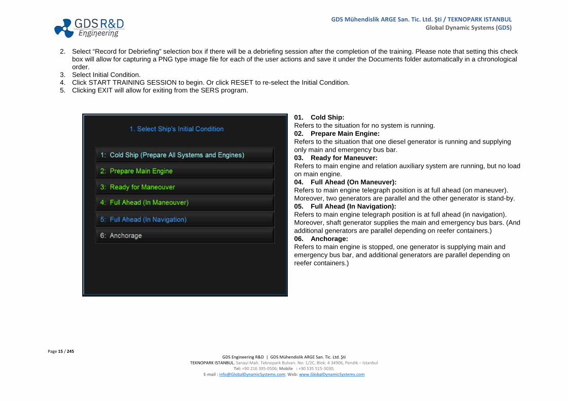
2. Select “Record for Debriefing” selection box if there will be a debriefing session after the completion of the training. Please note that setting this check box will allow for capturing a PNG type image file for each of the user actions and save it under the Documents folder automatically in a chronological order.
3. Select Initial Condition. 4. Click START TRAINING SESSION to begin. Or click RESET to re-select the Initial Condition. 5. Clicking EXIT will allow for exiting from the SERS program.
01. Cold Ship: Refers to the situation for no system is running. 02. Prepare Main Engine: Refers to the situation that one diesel generator is running and supplying only main and emergency bus bar. 03. Ready for Maneuver: Refers to main engine and relation auxiliary system are running, but no load on main engine. 04. Full Ahead (On Maneuver): Refers to main engine telegraph position is at full ahead (on maneuver). Moreover, two generators are parallel and the other generator is stand-by. 05. Full Ahead (In Navigation): Refers to main engine telegraph position is at full ahead (in navigation). Moreover, shaft generator supplies the main and emergency bus bars. (And additional generators are parallel depending on reefer containers.) 06. Anchorage: Refers to main engine is stopped, one generator is supplying main and emergency bus bar, and additional generators are parallel depending on reefer containers.)

Page 16 / 245 GDS Engineering R&D | GDS Mühendislik ARGE San. Tic. Ltd. Şti
TEKNOPARK ISTANBUL. Sanayi Mah. Teknopark Bulvarı. No: 1/2C, Blok: 4 34906, Pendik – Istanbul Tel: +90 216 395-0506; Mobile : +90 535 515-3030;
E-mail : [email protected]; Web: www.GlobalDynamicSystems.com
GDS Mühendislik ARGE San. Tic. Ltd. Şti / TEKNOPARK ISTANBUL Global Dynamic Systems (GDS)
This page intentionally left blank

Page 17 / 245 GDS Engineering R&D | GDS Mühendislik ARGE San. Tic. Ltd. Şti
TEKNOPARK ISTANBUL. Sanayi Mah. Teknopark Bulvarı. No: 1/2C, Blok: 4 34906, Pendik – Istanbul Tel: +90 216 395-0506; Mobile : +90 535 515-3030;
E-mail : [email protected]; Web: www.GlobalDynamicSystems.com
GDS Mühendislik ARGE San. Tic. Ltd. Şti / TEKNOPARK ISTANBUL Global Dynamic Systems (GDS)
3. SIMULATED PLATFORM This version of the SERS simulates machinery and systems for a typical container ship. For that reason, following are included:
• Reefers Panel • 3 Diesel Generators • One Shaft Generator • One Bow Thruster with High Voltage System
as additional to typical Engine Room machinery and systems.
Also, notice that the following training functions are excluded in this version of the SERS:
• Marine Steam Turbines • Marine Gas Turbines • Electrical Propulsion
Page 18 / 245 GDS Engineering R&D | GDS Mühendislik ARGE San. Tic. Ltd. Şti
TEKNOPARK ISTANBUL. Sanayi Mah. Teknopark Bulvarı. No: 1/2C, Blok: 4 34906, Pendik – Istanbul Tel: +90 216 395-0506; Mobile : +90 535 515-3030;
E-mail : [email protected]; Web: www.GlobalDynamicSystems.com
GDS Mühendislik ARGE San. Tic. Ltd. Şti / TEKNOPARK ISTANBUL Global Dynamic Systems (GDS)
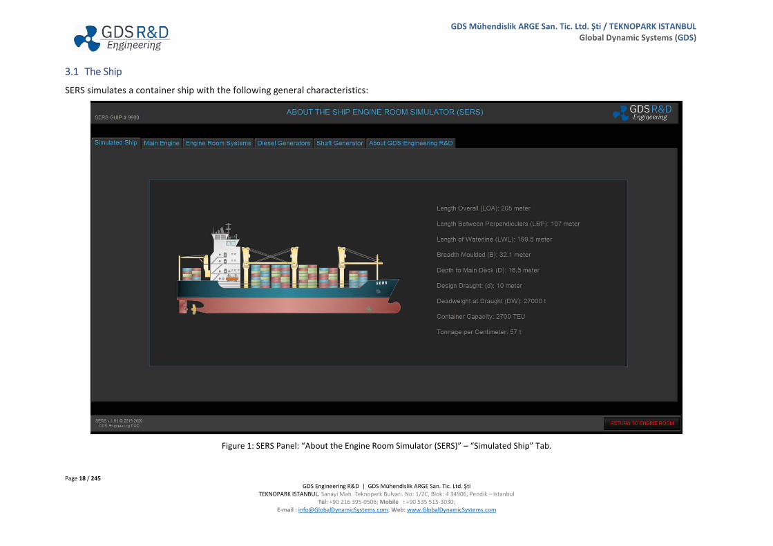
3.1 The Ship
SERS simulates a container ship with the following general characteristics:
Figure 1: SERS Panel: “About the Engine Room Simulator (SERS)” – “Simulated Ship” Tab.
Page 19 / 245 GDS Engineering R&D | GDS Mühendislik ARGE San. Tic. Ltd. Şti
TEKNOPARK ISTANBUL. Sanayi Mah. Teknopark Bulvarı. No: 1/2C, Blok: 4 34906, Pendik – Istanbul Tel: +90 216 395-0506; Mobile : +90 535 515-3030;
E-mail : [email protected]; Web: www.GlobalDynamicSystems.com
GDS Mühendislik ARGE San. Tic. Ltd. Şti / TEKNOPARK ISTANBUL Global Dynamic Systems (GDS)
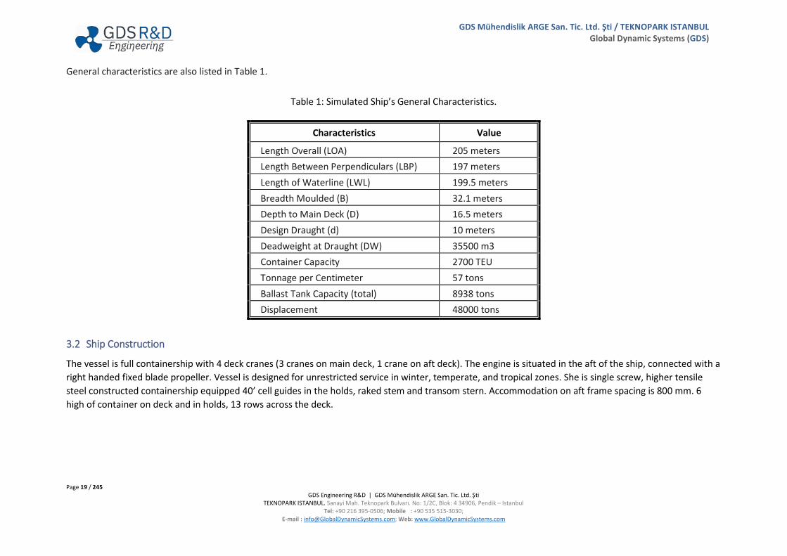
General characteristics are also listed in Table 1.
Table 1: Simulated Ship’s General Characteristics.
Characteristics Value
Length Overall (LOA) 205 meters Length Between Perpendiculars (LBP) 197 meters Length of Waterline (LWL) 199.5 meters Breadth Moulded (B) 32.1 meters Depth to Main Deck (D) 16.5 meters Design Draught (d) 10 meters Deadweight at Draught (DW) 35500 m3 Container Capacity 2700 TEU Tonnage per Centimeter 57 tons Ballast Tank Capacity (total) 8938 tons Displacement 48000 tons
3.2 Ship Construction
The vessel is full containership with 4 deck cranes (3 cranes on main deck, 1 crane on aft deck). The engine is situated in the aft of the ship, connected with a right handed fixed blade propeller. Vessel is designed for unrestricted service in winter, temperate, and tropical zones. She is single screw, higher tensile steel constructed containership equipped 40’ cell guides in the holds, raked stem and transom stern. Accommodation on aft frame spacing is 800 mm. 6 high of container on deck and in holds, 13 rows across the deck.
Page 20 / 245 GDS Engineering R&D | GDS Mühendislik ARGE San. Tic. Ltd. Şti
TEKNOPARK ISTANBUL. Sanayi Mah. Teknopark Bulvarı. No: 1/2C, Blok: 4 34906, Pendik – Istanbul Tel: +90 216 395-0506; Mobile : +90 535 515-3030;
E-mail : [email protected]; Web: www.GlobalDynamicSystems.com
GDS Mühendislik ARGE San. Tic. Ltd. Şti / TEKNOPARK ISTANBUL Global Dynamic Systems (GDS)
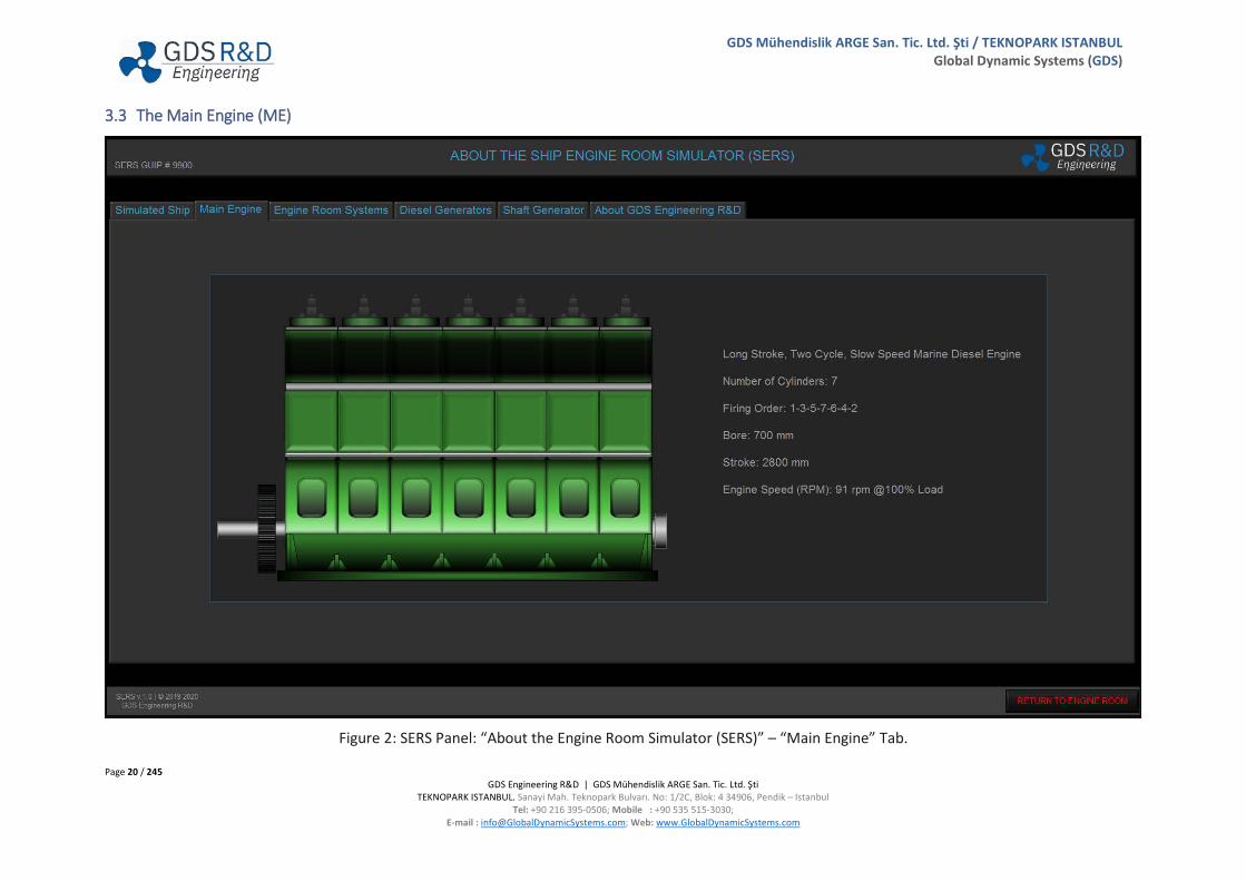
3.3 The Main Engine (ME)
Figure 2: SERS Panel: “About the Engine Room Simulator (SERS)” – “Main Engine” Tab.

Page 21 / 245 GDS Engineering R&D | GDS Mühendislik ARGE San. Tic. Ltd. Şti
TEKNOPARK ISTANBUL. Sanayi Mah. Teknopark Bulvarı. No: 1/2C, Blok: 4 34906, Pendik – Istanbul Tel: +90 216 395-0506; Mobile : +90 535 515-3030;
E-mail : [email protected]; Web: www.GlobalDynamicSystems.com
GDS Mühendislik ARGE San. Tic. Ltd. Şti / TEKNOPARK ISTANBUL Global Dynamic Systems (GDS)
The main engine is a two stroke marine diesel engine with seven cylinders, two turbochargers and two auxiliary blowers. Main engine also coupled with a shaft generator for generating electricity in navigation speeds.
General characteristics of the main engine is as follows:
Long Stroke Slow Speed Marine Diesel Engine Number of Cylinders : 7 Firing Order : 1-3-5-7-6-4-2 Bore : 700 mm Stroke : 2800 mm Engine rpm : 91.5 rpm @100% load
Some other important characteristics of the main engine is as follows:
Fuel Oil Consumption (kg/h) : 3875.90 kg/h @100% load Specific Fuel Oil Consumption (SFOC) : 187.45 g/kW-h @100% load Maximum Combustion Pressure (Pmax) : 150.74 bar @100% load Compression Pressure (Pcomp) : 135.08 bar @100% load Mean Effective Pressure : 18.5 bar @100% load Fuel Pump Index : 91.30 mm @100% load Exhaust Temperature Cylinder Outlet (Average) : 371.80 °C @100% load Turbochargers Exhaust Inlet Temperature : 437.20 °C @100% load Turbochargers Exhaust Outlet Temperature : 245.21 °C @100% load Turbocharger 1 Speed : 15500 rpm @100% load Turbocharger 2 Speed : 15500 rpm @100% load Scavenge Air Temperature : 44.70 °C @100% load Scavenge Air Pressure : 2.88 bar @100% load Turbocharger Gas Inlet Pressure : 2.60 bar @100% load
Page 22 / 245 GDS Engineering R&D | GDS Mühendislik ARGE San. Tic. Ltd. Şti
TEKNOPARK ISTANBUL. Sanayi Mah. Teknopark Bulvarı. No: 1/2C, Blok: 4 34906, Pendik – Istanbul Tel: +90 216 395-0506; Mobile : +90 535 515-3030;
E-mail : [email protected]; Web: www.GlobalDynamicSystems.com
GDS Mühendislik ARGE San. Tic. Ltd. Şti / TEKNOPARK ISTANBUL Global Dynamic Systems (GDS)
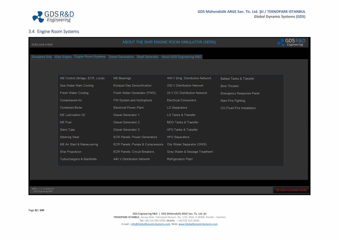
3.4 Engine Room Systems

Page 23 / 245 GDS Engineering R&D | GDS Mühendislik ARGE San. Tic. Ltd. Şti
TEKNOPARK ISTANBUL. Sanayi Mah. Teknopark Bulvarı. No: 1/2C, Blok: 4 34906, Pendik – Istanbul Tel: +90 216 395-0506; Mobile : +90 535 515-3030;
E-mail : [email protected]; Web: www.GlobalDynamicSystems.com
GDS Mühendislik ARGE San. Tic. Ltd. Şti / TEKNOPARK ISTANBUL Global Dynamic Systems (GDS)
Engine Room Systems simulated in SERS are listed below. Each of these systems has its own Graphical User Interface (GUI) Panels, all accessed from the SERS Main GUI Panel. Each of the following GUI windows is titled with a specific GUI Panel (GUIP) number.
• 2000: ME Control (Bridge) • 2100: ME Control (ECR) • 2200: ME Local Control & Systems • 3000: Sea Water Main Cooling • 3100: Fresh Water Cooling • 3200: Compressed Air • 3300: Combined Boiler • 3400: ME Lubrication Oil • 3500: ME Fuel • 3600: Stern Tube • 3700: Steering Gear • 3800: ME Air Start & Maneuvering • 4000: Main Engine (ME) • 4600: Ship Propulsion • 4650: Turbochargers & Manifolds • 4700: ME Bearings • 4750: Exhaust Gas Denoxification • 4800: FW Generator (FWG) • 4900: FW System and Hydrophore • 5000: Electrical Power Plant • 5100: Diesel Generator 1 • 5200: Diesel Generator 2 • 5300: Diesel Generator 3 • 5400: ECR Panels: Generators • 5450: ECR Panels: Pumps & Compressors • 5500: ECR Panels: Circuit Breakers
• 5600: 440 V Distribution Network • 5650: 440 V Emg. Distribution Network • 5700: 220 V Distribution Network • 5750: 24 VDC Distribution Network • 5800: Reefer Sections Power Panel • 5900: Electrical Consumers List • 6000: LO Separator • 6100: LO Tanks & Transfer • 6200: MDO Tanks & Transfer • 6300: HFO Tanks & Transfer • 6400: HFO Separators • 6500: Oily Water Separator (OWS) • 6600: Gray Water & Sewage Treatment • 7000: Ballast Tanks and Transfer • 7100: Bow Thruster • 7200: Refrigeration Plant • 7400: Emergency Response Panel • 7500: Main Fire Fighting • 7600: CO2 Fixed Fire Installation • 1600: Ship Parameters • 8000: Alarms Panel • 9000: Parameter Plots • 9100: Symbols, Units and Acronyms • 9900: About SERS • 1500: Instructor’s Station GUI Panel
Note: Section 4 of this manual describes each of these GUI Panels with a captured picture of a panel view.

Page 24 / 245 GDS Engineering R&D | GDS Mühendislik ARGE San. Tic. Ltd. Şti
TEKNOPARK ISTANBUL. Sanayi Mah. Teknopark Bulvarı. No: 1/2C, Blok: 4 34906, Pendik – Istanbul Tel: +90 216 395-0506; Mobile : +90 535 515-3030;
E-mail : [email protected]; Web: www.GlobalDynamicSystems.com
GDS Mühendislik ARGE San. Tic. Ltd. Şti / TEKNOPARK ISTANBUL Global Dynamic Systems (GDS)
3.5 Electrical Power Generators

Page 25 / 245 GDS Engineering R&D | GDS Mühendislik ARGE San. Tic. Ltd. Şti
TEKNOPARK ISTANBUL. Sanayi Mah. Teknopark Bulvarı. No: 1/2C, Blok: 4 34906, Pendik – Istanbul Tel: +90 216 395-0506; Mobile : +90 535 515-3030;
E-mail : [email protected]; Web: www.GlobalDynamicSystems.com
GDS Mühendislik ARGE San. Tic. Ltd. Şti / TEKNOPARK ISTANBUL Global Dynamic Systems (GDS)
There are three Diesel Generators (DGs) with the following specifications
Medium Speed, Two Stroke, 7-cylinders, Supercharged Engines
1760 kW/2200 kVA @720 rpm and 100% Load

Page 26 / 245 GDS Engineering R&D | GDS Mühendislik ARGE San. Tic. Ltd. Şti
TEKNOPARK ISTANBUL. Sanayi Mah. Teknopark Bulvarı. No: 1/2C, Blok: 4 34906, Pendik – Istanbul Tel: +90 216 395-0506; Mobile : +90 535 515-3030;
E-mail : [email protected]; Web: www.GlobalDynamicSystems.com
GDS Mühendislik ARGE San. Tic. Ltd. Şti / TEKNOPARK ISTANBUL Global Dynamic Systems (GDS)
3.6 Shaft Generator
Page 27 / 245 GDS Engineering R&D | GDS Mühendislik ARGE San. Tic. Ltd. Şti
TEKNOPARK ISTANBUL. Sanayi Mah. Teknopark Bulvarı. No: 1/2C, Blok: 4 34906, Pendik – Istanbul Tel: +90 216 395-0506; Mobile : +90 535 515-3030;
E-mail : [email protected]; Web: www.GlobalDynamicSystems.com
GDS Mühendislik ARGE San. Tic. Ltd. Şti / TEKNOPARK ISTANBUL Global Dynamic Systems (GDS)
Shaft Generator System utilized in SERS is a Power Take-Off (PTO) with a Constant Frequency Electrical (CFE) type, which is suitable for ships with Fixed Pitch Propeller (FPP).
The PTO/CFE slow running alternator is installed as a tank-top mounted aft end SMG/CFE solution with the rotor integrated on the intermediate propeller shaft.
The PTO/CFE generates electric power with constant electrical frequency over a wide engine speed range. The shaft generators can be used in combination with fixed pitch propellers and continuous operation in parallel with Diesel Generators. The alternator generates a three-phase alternating current with a varying frequency that corresponds to the propeller speed.
DMG/CFE is able to operate in parallel with the Diesel Generators and serve full rated electrical power output when the speed of the Main Engine is between 75% and 105%.
The total efficiency of the slow running is 90%
Page 28 / 245 GDS Engineering R&D | GDS Mühendislik ARGE San. Tic. Ltd. Şti
TEKNOPARK ISTANBUL. Sanayi Mah. Teknopark Bulvarı. No: 1/2C, Blok: 4 34906, Pendik – Istanbul Tel: +90 216 395-0506; Mobile : +90 535 515-3030;
E-mail : [email protected]; Web: www.GlobalDynamicSystems.com
GDS Mühendislik ARGE San. Tic. Ltd. Şti / TEKNOPARK ISTANBUL Global Dynamic Systems (GDS)
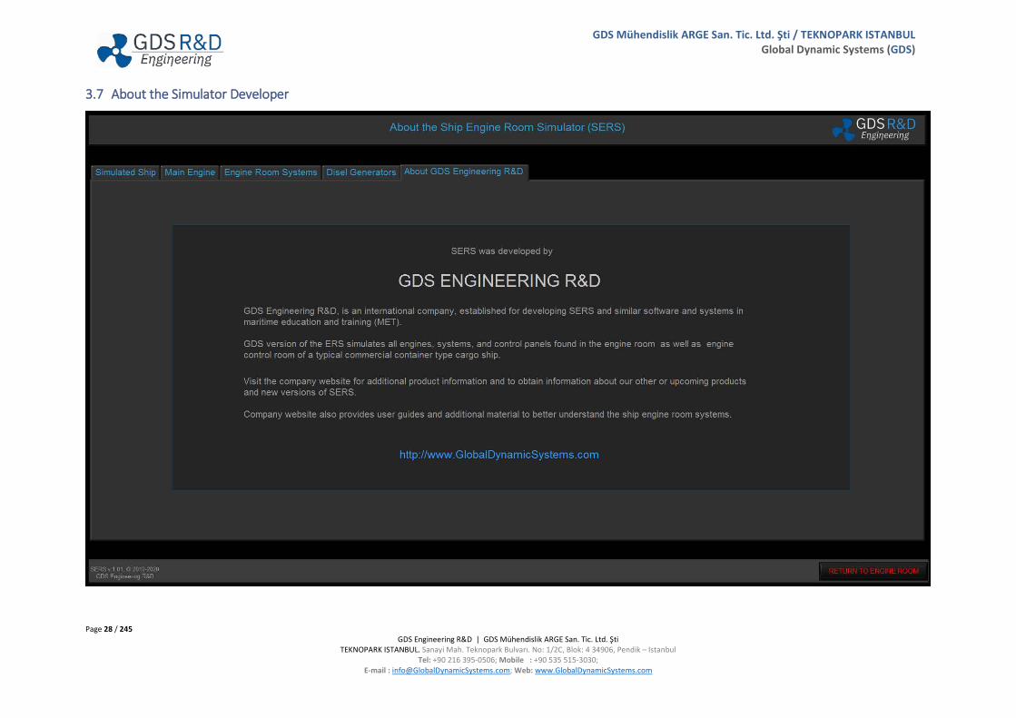
3.7 About the Simulator Developer

Page 29 / 245 GDS Engineering R&D | GDS Mühendislik ARGE San. Tic. Ltd. Şti
TEKNOPARK ISTANBUL. Sanayi Mah. Teknopark Bulvarı. No: 1/2C, Blok: 4 34906, Pendik – Istanbul Tel: +90 216 395-0506; Mobile : +90 535 515-3030;
E-mail : [email protected]; Web: www.GlobalDynamicSystems.com
GDS Mühendislik ARGE San. Tic. Ltd. Şti / TEKNOPARK ISTANBUL Global Dynamic Systems (GDS)
3.8 Machinery and Equipment Simulated in the SERS Software
3.8.1 Shaft Level / ME Pumps Level – Item’s List and General Arrangement

Page 30 / 245 GDS Engineering R&D | GDS Mühendislik ARGE San. Tic. Ltd. Şti
TEKNOPARK ISTANBUL. Sanayi Mah. Teknopark Bulvarı. No: 1/2C, Blok: 4 34906, Pendik – Istanbul Tel: +90 216 395-0506; Mobile : +90 535 515-3030;
E-mail : [email protected]; Web: www.GlobalDynamicSystems.com
GDS Mühendislik ARGE San. Tic. Ltd. Şti / TEKNOPARK ISTANBUL Global Dynamic Systems (GDS)

Page 31 / 245 GDS Engineering R&D | GDS Mühendislik ARGE San. Tic. Ltd. Şti
TEKNOPARK ISTANBUL. Sanayi Mah. Teknopark Bulvarı. No: 1/2C, Blok: 4 34906, Pendik – Istanbul Tel: +90 216 395-0506; Mobile : +90 535 515-3030;
E-mail : [email protected]; Web: www.GlobalDynamicSystems.com
GDS Mühendislik ARGE San. Tic. Ltd. Şti / TEKNOPARK ISTANBUL Global Dynamic Systems (GDS)
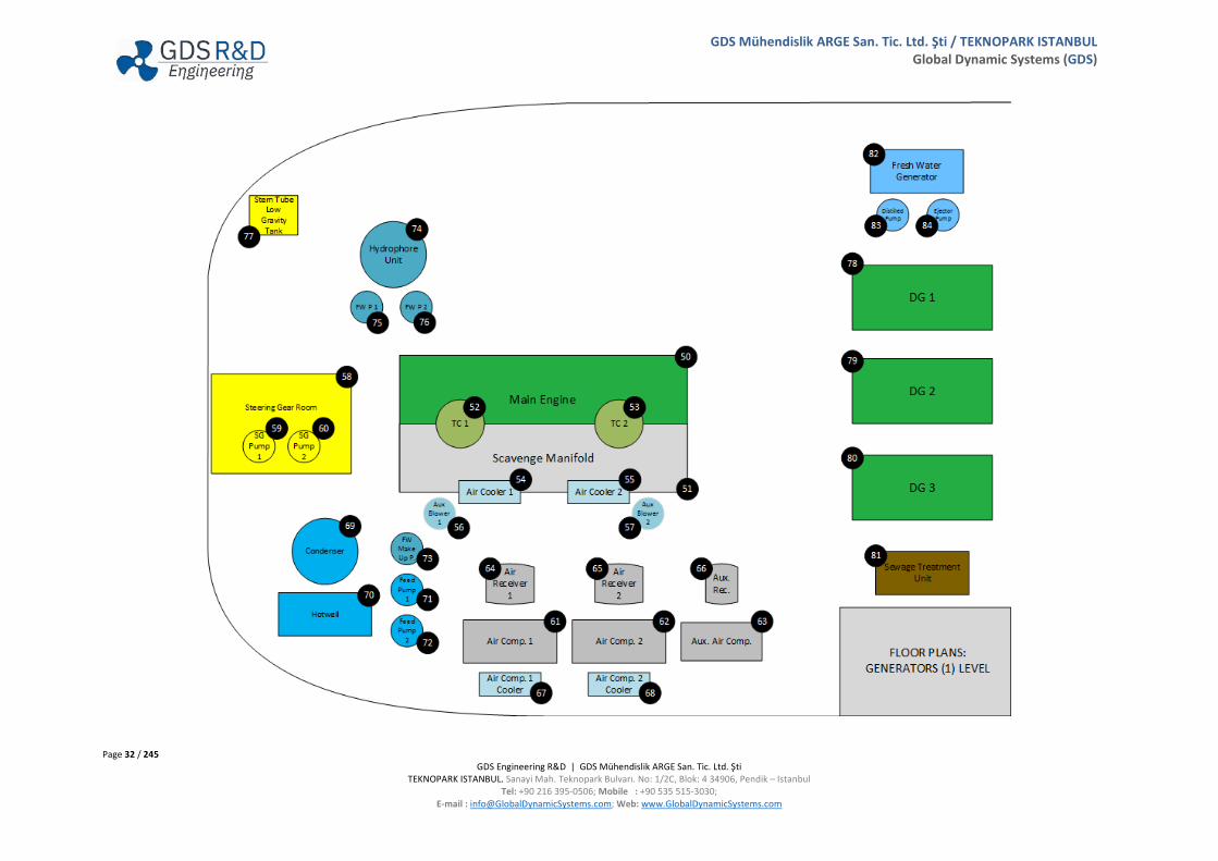
3.8.2 ME Upper Section / Generators Level – Item’s List and General Arrangement:
Page 32 / 245 GDS Engineering R&D | GDS Mühendislik ARGE San. Tic. Ltd. Şti
TEKNOPARK ISTANBUL. Sanayi Mah. Teknopark Bulvarı. No: 1/2C, Blok: 4 34906, Pendik – Istanbul Tel: +90 216 395-0506; Mobile : +90 535 515-3030;
E-mail : [email protected]; Web: www.GlobalDynamicSystems.com
GDS Mühendislik ARGE San. Tic. Ltd. Şti / TEKNOPARK ISTANBUL Global Dynamic Systems (GDS)

Page 33 / 245 GDS Engineering R&D | GDS Mühendislik ARGE San. Tic. Ltd. Şti
TEKNOPARK ISTANBUL. Sanayi Mah. Teknopark Bulvarı. No: 1/2C, Blok: 4 34906, Pendik – Istanbul Tel: +90 216 395-0506; Mobile : +90 535 515-3030;
E-mail : [email protected]; Web: www.GlobalDynamicSystems.com
GDS Mühendislik ARGE San. Tic. Ltd. Şti / TEKNOPARK ISTANBUL Global Dynamic Systems (GDS)
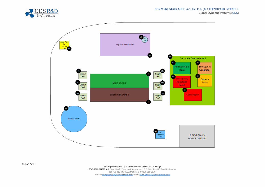
3.8.3 Combined Boiler / Separate Compartment Level – Item’s List and General Arrangement:
Page 34 / 245 GDS Engineering R&D | GDS Mühendislik ARGE San. Tic. Ltd. Şti
TEKNOPARK ISTANBUL. Sanayi Mah. Teknopark Bulvarı. No: 1/2C, Blok: 4 34906, Pendik – Istanbul Tel: +90 216 395-0506; Mobile : +90 535 515-3030;
E-mail : [email protected]; Web: www.GlobalDynamicSystems.com
GDS Mühendislik ARGE San. Tic. Ltd. Şti / TEKNOPARK ISTANBUL Global Dynamic Systems (GDS)
Page 35 / 245 GDS Engineering R&D | GDS Mühendislik ARGE San. Tic. Ltd. Şti
TEKNOPARK ISTANBUL. Sanayi Mah. Teknopark Bulvarı. No: 1/2C, Blok: 4 34906, Pendik – Istanbul Tel: +90 216 395-0506; Mobile : +90 535 515-3030;
E-mail : [email protected]; Web: www.GlobalDynamicSystems.com
GDS Mühendislik ARGE San. Tic. Ltd. Şti / TEKNOPARK ISTANBUL Global Dynamic Systems (GDS)
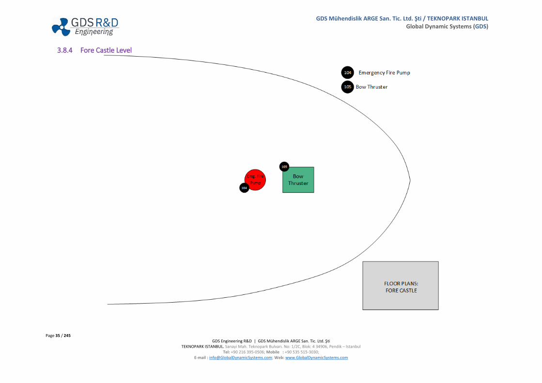
3.8.4 Fore Castle Level
Page 36 / 245 GDS Engineering R&D | GDS Mühendislik ARGE San. Tic. Ltd. Şti
TEKNOPARK ISTANBUL. Sanayi Mah. Teknopark Bulvarı. No: 1/2C, Blok: 4 34906, Pendik – Istanbul Tel: +90 216 395-0506; Mobile : +90 535 515-3030;
E-mail : [email protected]; Web: www.GlobalDynamicSystems.com
GDS Mühendislik ARGE San. Tic. Ltd. Şti / TEKNOPARK ISTANBUL Global Dynamic Systems (GDS)
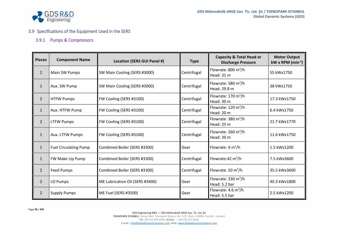
3.9 Specifications of the Equipment Used in the SERS
3.9.1 Pumps & Compressors
Pieces Component Name Location (SERS GUI Panel #) Type Capacity & Total Head or
Discharge Pressure Motor Output
kW x RPM (min-1)
2 Main SW Pumps SW Main Cooling (SERS #3000) Centrifugal Flowrate: 800 m3/h Head: 31 m 55 kWx1750
1 Aux. SW Pump SW Main Cooling (SERS #3000) Centrifugal Flowrate: 580 m3/h Head: 29.8 m 38 kWx1750
2 HTFW Pumps FW Cooling (SERS #3100) Centrifugal Flowrate: 170 m3/h Head: 30 m 17.3 kWx1750
1 Aux. HTFW Pump FW Cooling (SERS #3100) Centrifugal Flowrate: 120 m3/h Head: 20 m 6.4 kWx1750
2 LTFW Pumps FW Cooling (SERS #3100) Centrifugal Flowrate: 380 m3/h Head: 25 m 21.7 kWx1770
1 Aux. LTFW Pumps FW Cooling (SERS #3100) Centrifugal Flowrate: 260 m3/h Head: 20 m 11.6 kWx1750
1 Fuel Circulating Pump Combined Boiler (SERS #3300) Gear Flowrate: 4 m3/h 1.5 kWx1200
1 FW Make Up Pump Combined Boiler (SERS #3300) Centrifugal Flowrate:42 m3/h 7.5 kWx3600
2 Feed Pumps Combined Boiler (SERS #3300) Centrifugal Flowrate: 50 m3/h 35.5 kWx3600
2 LO Pumps ME Lubrication Oil (SERS #3400) Gear Flowrate: 330 m3/h Head: 5.2 bar 40.3 kWx1800
2 Supply Pumps ME Fuel (SERS #3500) Gear Flowrate: 4.6 m3/h Head: 5.5 bar
2.5 kWx1200
Page 37 / 245 GDS Engineering R&D | GDS Mühendislik ARGE San. Tic. Ltd. Şti
TEKNOPARK ISTANBUL. Sanayi Mah. Teknopark Bulvarı. No: 1/2C, Blok: 4 34906, Pendik – Istanbul Tel: +90 216 395-0506; Mobile : +90 535 515-3030;
E-mail : [email protected]; Web: www.GlobalDynamicSystems.com
GDS Mühendislik ARGE San. Tic. Ltd. Şti / TEKNOPARK ISTANBUL Global Dynamic Systems (GDS)
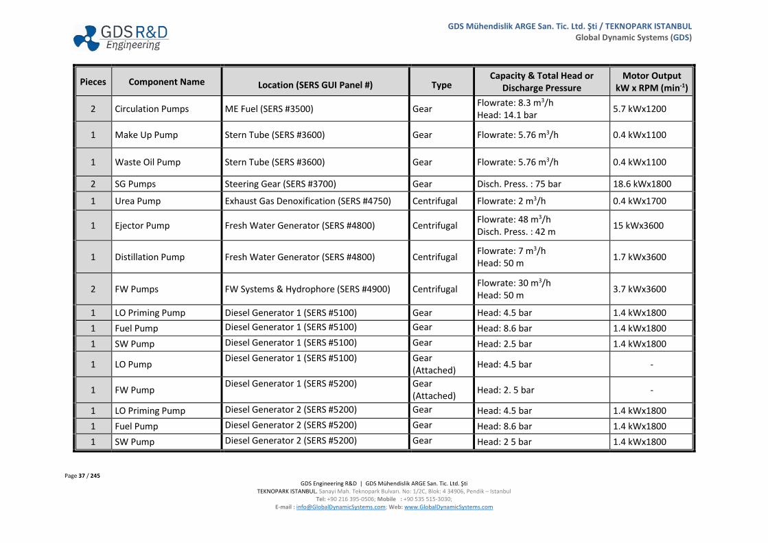
Pieces Component Name Location (SERS GUI Panel #) Type Capacity & Total Head or
Discharge Pressure Motor Output
kW x RPM (min-1)
2 Circulation Pumps ME Fuel (SERS #3500) Gear Flowrate: 8.3 m3/h Head: 14.1 bar 5.7 kWx1200
1 Make Up Pump Stern Tube (SERS #3600) Gear Flowrate: 5.76 m3/h 0.4 kWx1100
1 Waste Oil Pump Stern Tube (SERS #3600) Gear Flowrate: 5.76 m3/h 0.4 kWx1100
2 SG Pumps Steering Gear (SERS #3700) Gear Disch. Press. : 75 bar 18.6 kWx1800
1 Urea Pump Exhaust Gas Denoxification (SERS #4750) Centrifugal Flowrate: 2 m3/h 0.4 kWx1700
1 Ejector Pump Fresh Water Generator (SERS #4800) Centrifugal Flowrate: 48 m3/h Disch. Press. : 42 m 15 kWx3600
1 Distillation Pump Fresh Water Generator (SERS #4800) Centrifugal Flowrate: 7 m3/h Head: 50 m 1.7 kWx3600
2 FW Pumps FW Systems & Hydrophore (SERS #4900) Centrifugal Flowrate: 30 m3/h Head: 50 m 3.7 kWx3600
1 LO Priming Pump Diesel Generator 1 (SERS #5100) Gear Head: 4.5 bar 1.4 kWx1800 1 Fuel Pump Diesel Generator 1 (SERS #5100) Gear Head: 8.6 bar 1.4 kWx1800 1 SW Pump Diesel Generator 1 (SERS #5100) Gear Head: 2.5 bar 1.4 kWx1800
1 LO Pump Diesel Generator 1 (SERS #5100) Gear (Attached) Head: 4.5 bar -
1 FW Pump Diesel Generator 1 (SERS #5200) Gear
(Attached) Head: 2. 5 bar -
1 LO Priming Pump Diesel Generator 2 (SERS #5200) Gear Head: 4.5 bar 1.4 kWx1800 1 Fuel Pump Diesel Generator 2 (SERS #5200) Gear Head: 8.6 bar 1.4 kWx1800 1 SW Pump Diesel Generator 2 (SERS #5200) Gear Head: 2 5 bar 1.4 kWx1800

Page 38 / 245 GDS Engineering R&D | GDS Mühendislik ARGE San. Tic. Ltd. Şti
TEKNOPARK ISTANBUL. Sanayi Mah. Teknopark Bulvarı. No: 1/2C, Blok: 4 34906, Pendik – Istanbul Tel: +90 216 395-0506; Mobile : +90 535 515-3030;
E-mail : [email protected]; Web: www.GlobalDynamicSystems.com
GDS Mühendislik ARGE San. Tic. Ltd. Şti / TEKNOPARK ISTANBUL Global Dynamic Systems (GDS)
Pieces Component Name Location (SERS GUI Panel #) Type Capacity & Total Head or
Discharge Pressure Motor Output
kW x RPM (min-1)
1 LO Pump Diesel Generator 2 (SERS #5200) Gear (Attached) Head: 4.5 bar -
1 FW Pump Diesel Generator 2 (SERS #5200) Gear (Attached) Head: 2.5 bar -
1 LO Priming Pump Diesel Generator 3 (SERS #5300) Gear Head: 4.5 bar 1.4 kWx1800
1 Fuel Pump Diesel Generator 3 (SERS #5300) Gear Head: 8.6 bar 1.4 kWx1800
1 SW Pump Diesel Generator 3 (SERS #5300) Gear Head: 2.5 bar 1.4 kWx1800
1 LO Pump Diesel Generator 3 (SERS #5300) Gear (Attached) Head: 4.5 bar -
1 FW Pump Diesel Generator 3 (SERS #5300) Gear
(Attached) Head: 2.5 bar -
1 Feed Pump LO Separator (SERS #6000) Gear Flowrate: 2.5 m3/h
Disch. Press. :3.5 bar 1.5 kWx1200
1 LO Transfer Pump LO Tanks & Transfer (SERS #6100) Gear Flowrate: 10 m3/h Head: 4 bar 3.7 kWx1200
1 Cyl. Oil Transfer Pump LO Tanks & Transfer (SERS #6100) Gear Flowrate: 10 m3/h
Head: 2.6 bar 2.9 kWx1200
1 MDO Transfer Pump MDO Tanks & Transfer (SERS #6200) Gear Flowrate: 5 m3/h
Head: 4 bar 3.7 kWx1200
1 Feed Pump MDO Tanks & Transfer (SERS #6200) Gear Flowrate: 2.3 m3/h
Disch. Press. : 3.5 bar 2 kWx1200
1 HFO Transfer Pump HFO Tanks & Transfer (SERS #6300) Gear Flowrate: 35 m3/h Head: 4 bar 15.7 kWx1200
2 Feed Pumps HFO Separators (SERS #6400) Gear Flowrate: 2.3 m3/h
Disch. Press. : 3.5 bar 2.5 kWx1200
Page 39 / 245 GDS Engineering R&D | GDS Mühendislik ARGE San. Tic. Ltd. Şti
TEKNOPARK ISTANBUL. Sanayi Mah. Teknopark Bulvarı. No: 1/2C, Blok: 4 34906, Pendik – Istanbul Tel: +90 216 395-0506; Mobile : +90 535 515-3030;
E-mail : [email protected]; Web: www.GlobalDynamicSystems.com
GDS Mühendislik ARGE San. Tic. Ltd. Şti / TEKNOPARK ISTANBUL Global Dynamic Systems (GDS)
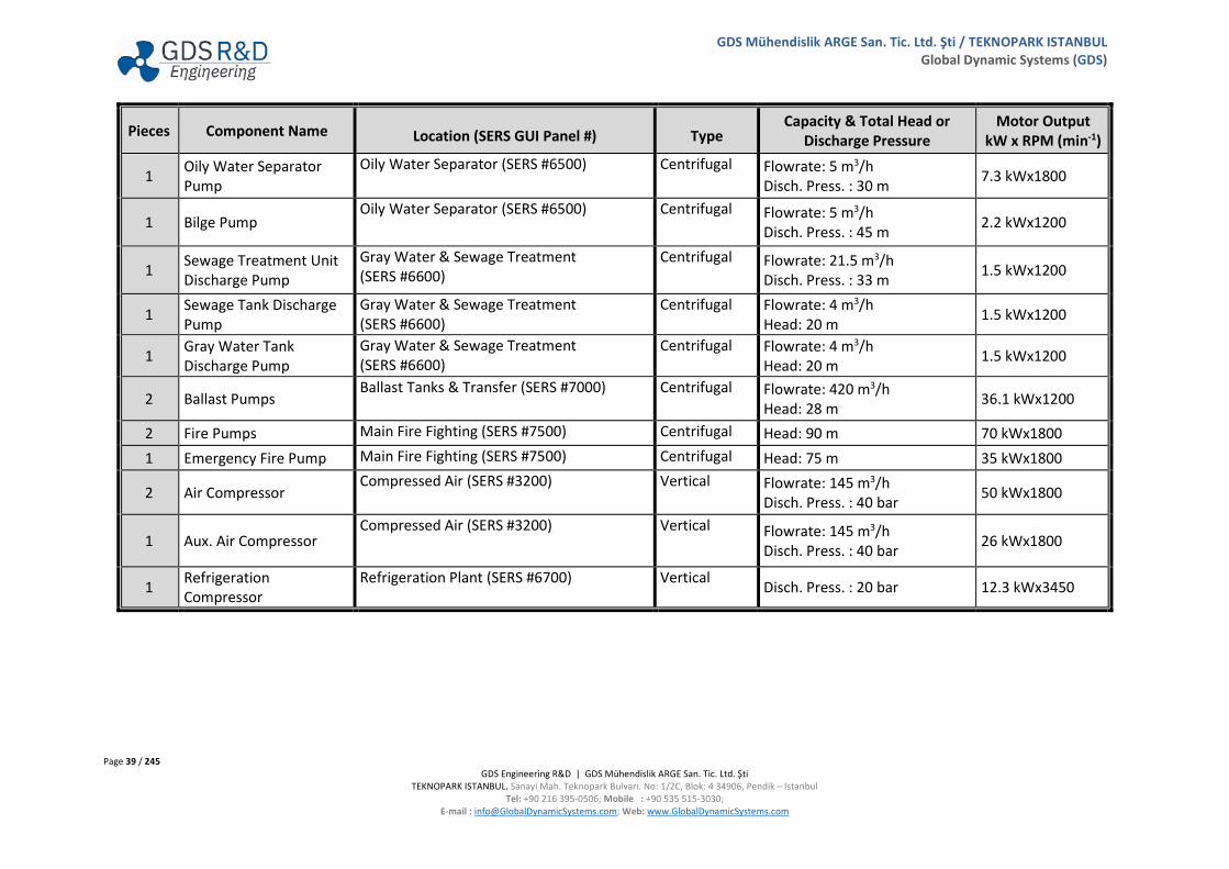
Pieces Component Name Location (SERS GUI Panel #) Type Capacity & Total Head or
Discharge Pressure Motor Output
kW x RPM (min-1)
1 Oily Water Separator Pump
Oily Water Separator (SERS #6500) Centrifugal Flowrate: 5 m3/h Disch. Press. : 30 m 7.3 kWx1800
1 Bilge Pump Oily Water Separator (SERS #6500) Centrifugal Flowrate: 5 m3/h
Disch. Press. : 45 m 2.2 kWx1200
1 Sewage Treatment Unit Discharge Pump
Gray Water & Sewage Treatment (SERS #6600)
Centrifugal Flowrate: 21.5 m3/h Disch. Press. : 33 m 1.5 kWx1200
1 Sewage Tank Discharge Pump
Gray Water & Sewage Treatment (SERS #6600)
Centrifugal Flowrate: 4 m3/h Head: 20 m 1.5 kWx1200
1 Gray Water Tank Discharge Pump
Gray Water & Sewage Treatment (SERS #6600)
Centrifugal Flowrate: 4 m3/h Head: 20 m 1.5 kWx1200
2 Ballast Pumps Ballast Tanks & Transfer (SERS #7000) Centrifugal Flowrate: 420 m3/h
Head: 28 m 36.1 kWx1200
2 Fire Pumps Main Fire Fighting (SERS #7500) Centrifugal Head: 90 m 70 kWx1800 1 Emergency Fire Pump Main Fire Fighting (SERS #7500) Centrifugal Head: 75 m 35 kWx1800
2 Air Compressor Compressed Air (SERS #3200) Vertical Flowrate: 145 m3/h
Disch. Press. : 40 bar 50 kWx1800
1 Aux. Air Compressor Compressed Air (SERS #3200) Vertical Flowrate: 145 m3/h
Disch. Press. : 40 bar 26 kWx1800
1 Refrigeration Compressor
Refrigeration Plant (SERS #6700) Vertical Disch. Press. : 20 bar 12.3 kWx3450
Page 40 / 245 GDS Engineering R&D | GDS Mühendislik ARGE San. Tic. Ltd. Şti
TEKNOPARK ISTANBUL. Sanayi Mah. Teknopark Bulvarı. No: 1/2C, Blok: 4 34906, Pendik – Istanbul Tel: +90 216 395-0506; Mobile : +90 535 515-3030;
E-mail : [email protected]; Web: www.GlobalDynamicSystems.com
GDS Mühendislik ARGE San. Tic. Ltd. Şti / TEKNOPARK ISTANBUL Global Dynamic Systems (GDS)
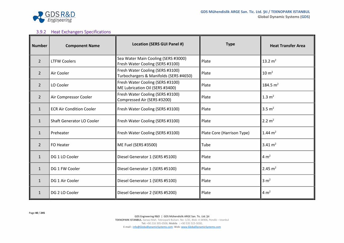
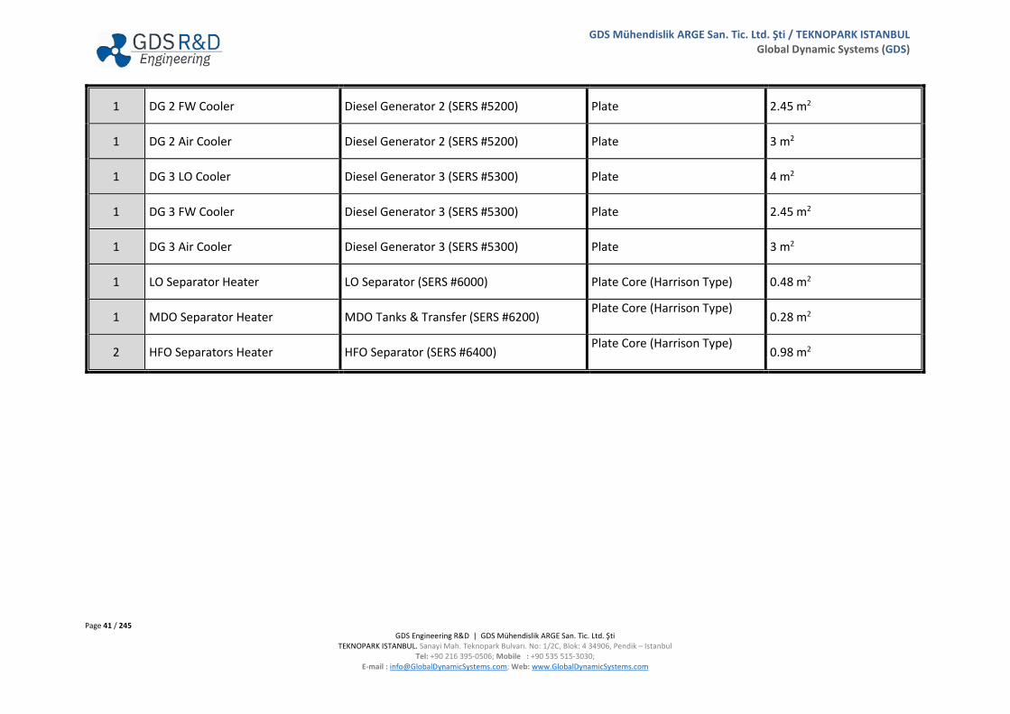
3.9.2 Heat Exchangers Specifications
Number Component Name Location (SERS GUI Panel #) Type Heat Transfer Area
2 LTFW Coolers Sea Water Main Cooling (SERS #3000) Fresh Water Cooling (SERS #3100) Plate 13.2 m2
2 Air Cooler Fresh Water Cooling (SERS #3100) Turbochargers & Manifolds (SERS #4650) Plate 10 m2
2 LO Cooler Fresh Water Cooling (SERS #3100) ME Lubrication Oil (SERS #3400) Plate 184.5 m2
2 Air Compressor Cooler Fresh Water Cooling (SERS #3100) Compressed Air (SERS #3200) Plate 1.3 m2
1 ECR Air Condition Cooler Fresh Water Cooling (SERS #3100) Plate 3.5 m2
1 Shaft Generator LO Cooler Fresh Water Cooling (SERS #3100) Plate 2.2 m2
1 Preheater Fresh Water Cooling (SERS #3100) Plate Core (Harrison Type) 1.44 m2
2 FO Heater ME Fuel (SERS #3500) Tube 3.41 m2
1 DG 1 LO Cooler Diesel Generator 1 (SERS #5100) Plate 4 m2
1 DG 1 FW Cooler Diesel Generator 1 (SERS #5100) Plate 2.45 m2
1 DG 1 Air Cooler Diesel Generator 1 (SERS #5100) Plate 3 m2
1 DG 2 LO Cooler Diesel Generator 2 (SERS #5200) Plate 4 m2
Page 41 / 245 GDS Engineering R&D | GDS Mühendislik ARGE San. Tic. Ltd. Şti
TEKNOPARK ISTANBUL. Sanayi Mah. Teknopark Bulvarı. No: 1/2C, Blok: 4 34906, Pendik – Istanbul Tel: +90 216 395-0506; Mobile : +90 535 515-3030;
E-mail : [email protected]; Web: www.GlobalDynamicSystems.com
GDS Mühendislik ARGE San. Tic. Ltd. Şti / TEKNOPARK ISTANBUL Global Dynamic Systems (GDS)
1 DG 2 FW Cooler Diesel Generator 2 (SERS #5200) Plate 2.45 m2
1 DG 2 Air Cooler Diesel Generator 2 (SERS #5200) Plate 3 m2
1 DG 3 LO Cooler Diesel Generator 3 (SERS #5300) Plate 4 m2
1 DG 3 FW Cooler Diesel Generator 3 (SERS #5300) Plate 2.45 m2
1 DG 3 Air Cooler Diesel Generator 3 (SERS #5300) Plate 3 m2
1 LO Separator Heater LO Separator (SERS #6000) Plate Core (Harrison Type) 0.48 m2
1 MDO Separator Heater MDO Tanks & Transfer (SERS #6200) Plate Core (Harrison Type)
0.28 m2
2 HFO Separators Heater HFO Separator (SERS #6400) Plate Core (Harrison Type)
0.98 m2
Page 42 / 245 GDS Engineering R&D | GDS Mühendislik ARGE San. Tic. Ltd. Şti
TEKNOPARK ISTANBUL. Sanayi Mah. Teknopark Bulvarı. No: 1/2C, Blok: 4 34906, Pendik – Istanbul Tel: +90 216 395-0506; Mobile : +90 535 515-3030;
E-mail : [email protected]; Web: www.GlobalDynamicSystems.com
GDS Mühendislik ARGE San. Tic. Ltd. Şti / TEKNOPARK ISTANBUL Global Dynamic Systems (GDS)
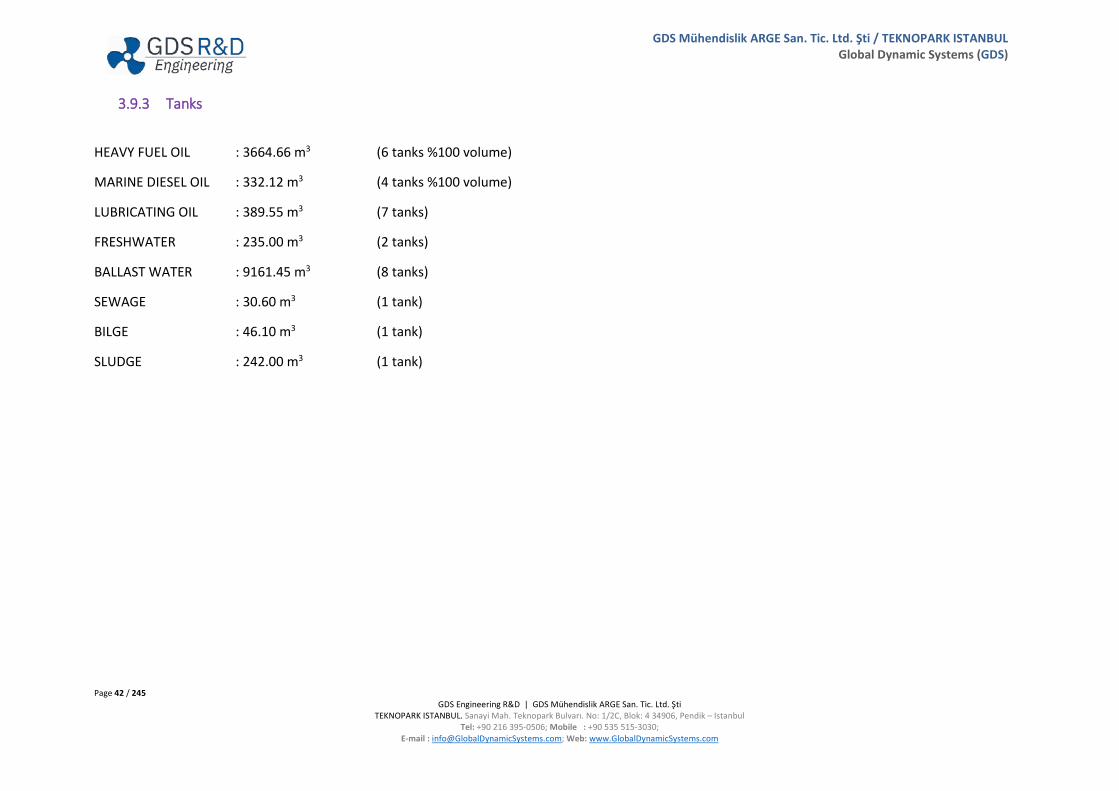
3.9.3 Tanks
HEAVY FUEL OIL : 3664.66 m3 (6 tanks %100 volume)
MARINE DIESEL OIL : 332.12 m3 (4 tanks %100 volume)
LUBRICATING OIL : 389.55 m3 (7 tanks)
FRESHWATER : 235.00 m3 (2 tanks)
BALLAST WATER : 9161.45 m3 (8 tanks)
SEWAGE : 30.60 m3 (1 tank)
BILGE : 46.10 m3 (1 tank)
SLUDGE : 242.00 m3 (1 tank)
Page 43 / 245 GDS Engineering R&D | GDS Mühendislik ARGE San. Tic. Ltd. Şti
TEKNOPARK ISTANBUL. Sanayi Mah. Teknopark Bulvarı. No: 1/2C, Blok: 4 34906, Pendik – Istanbul Tel: +90 216 395-0506; Mobile : +90 535 515-3030;
E-mail : [email protected]; Web: www.GlobalDynamicSystems.com
GDS Mühendislik ARGE San. Tic. Ltd. Şti / TEKNOPARK ISTANBUL Global Dynamic Systems (GDS)
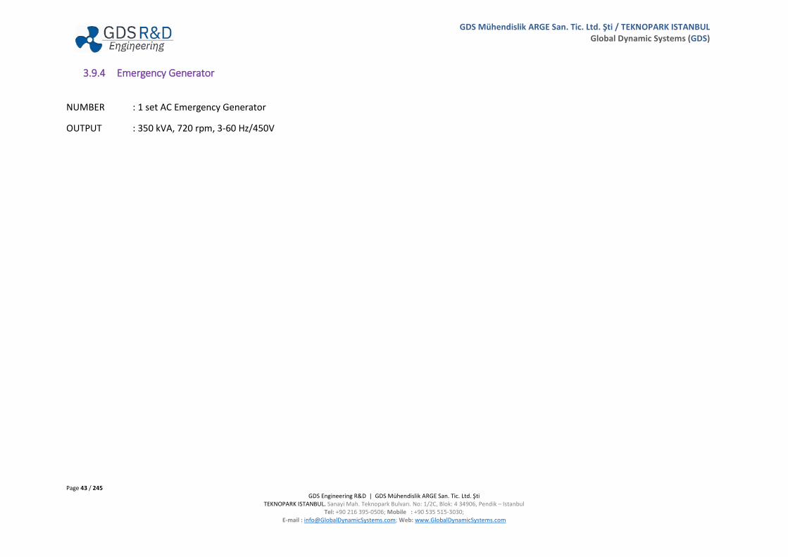
3.9.4 Emergency Generator
NUMBER : 1 set AC Emergency Generator
OUTPUT : 350 kVA, 720 rpm, 3-60 Hz/450V
Page 44 / 245 GDS Engineering R&D | GDS Mühendislik ARGE San. Tic. Ltd. Şti
TEKNOPARK ISTANBUL. Sanayi Mah. Teknopark Bulvarı. No: 1/2C, Blok: 4 34906, Pendik – Istanbul Tel: +90 216 395-0506; Mobile : +90 535 515-3030;
E-mail : [email protected]; Web: www.GlobalDynamicSystems.com
GDS Mühendislik ARGE San. Tic. Ltd. Şti / TEKNOPARK ISTANBUL Global Dynamic Systems (GDS)
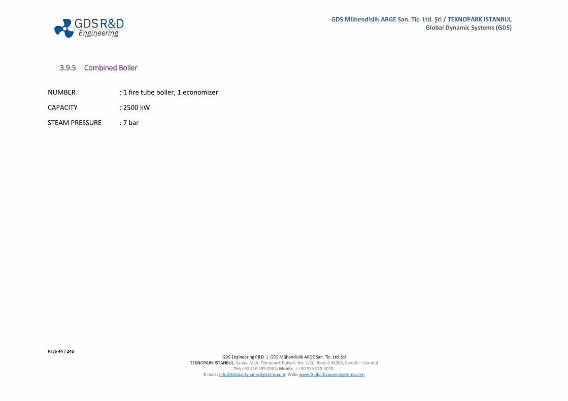
3.9.5 Combined Boiler
NUMBER : 1 fire tube boiler, 1 economizer
CAPACITY : 2500 kW
STEAM PRESSURE : 7 bar

Page 45 / 245 GDS Engineering R&D | GDS Mühendislik ARGE San. Tic. Ltd. Şti
TEKNOPARK ISTANBUL. Sanayi Mah. Teknopark Bulvarı. No: 1/2C, Blok: 4 34906, Pendik – Istanbul Tel: +90 216 395-0506; Mobile : +90 535 515-3030;
E-mail : [email protected]; Web: www.GlobalDynamicSystems.com
GDS Mühendislik ARGE San. Tic. Ltd. Şti / TEKNOPARK ISTANBUL Global Dynamic Systems (GDS)
3.9.6 Propeller
TYPE : Fixed 5 blades propeller
DIMENSIONS : Diameter: 7600 mm. Weight: 42400 kg
MATERIAL : Special Nickel Aluminum Bronze
Page 46 / 245 GDS Engineering R&D | GDS Mühendislik ARGE San. Tic. Ltd. Şti
TEKNOPARK ISTANBUL. Sanayi Mah. Teknopark Bulvarı. No: 1/2C, Blok: 4 34906, Pendik – Istanbul Tel: +90 216 395-0506; Mobile : +90 535 515-3030;
E-mail : [email protected]; Web: www.GlobalDynamicSystems.com
GDS Mühendislik ARGE San. Tic. Ltd. Şti / TEKNOPARK ISTANBUL Global Dynamic Systems (GDS)
3.9.7 Steering Gear
TYPE : Electrohydraulic Rotary Type Steering Gear
RUDDER ANGLE : 45 degrees max.
TORQUE : 2500 kNm
PRESSURE : 75 bar
MOMENT : 2000 kNm
Page 47 / 245 GDS Engineering R&D | GDS Mühendislik ARGE San. Tic. Ltd. Şti
TEKNOPARK ISTANBUL. Sanayi Mah. Teknopark Bulvarı. No: 1/2C, Blok: 4 34906, Pendik – Istanbul Tel: +90 216 395-0506; Mobile : +90 535 515-3030;
E-mail : [email protected]; Web: www.GlobalDynamicSystems.com
GDS Mühendislik ARGE San. Tic. Ltd. Şti / TEKNOPARK ISTANBUL Global Dynamic Systems (GDS)
3.9.8 Other Machinery and Components in the Engine Room
Fresh Water Generator:
CAPACITY : 20 m3 / day at full load
Engine Room Fans
TYPE : Vertical, Axial Flow (4 sets)
CAPACITY : 1200 m3/min x 0.4 kPa x 1800 rpm
OUTPUT : 5.9 kW
3.9.9 Fire Fighting Equipment
CO2 Fixed Fire Installation:
• For Engine Room High Pressure CO2 System • Main Engine pistons undersides, Separator room, steering gear room are protected by CO2 systems
Main Fire Fighting System:
Main firefighting system includes:
• 2 Fire Pumps which supplies the Fire Line and General Service Line • Emergency Fire Pump with Emergency Suction Sea Chest
Page 48 / 245 GDS Engineering R&D | GDS Mühendislik ARGE San. Tic. Ltd. Şti
TEKNOPARK ISTANBUL. Sanayi Mah. Teknopark Bulvarı. No: 1/2C, Blok: 4 34906, Pendik – Istanbul Tel: +90 216 395-0506; Mobile : +90 535 515-3030;
E-mail : [email protected]; Web: www.GlobalDynamicSystems.com
GDS Mühendislik ARGE San. Tic. Ltd. Şti / TEKNOPARK ISTANBUL Global Dynamic Systems (GDS)
3.9.10 Deck Machinery and Systems
Cargo Capacity:
Designed to carry containers of ISO types, container nominal intake capacity 2764 TEU’s and 14 tons’ homogenous container intake capacity 2054 TEU’s 45% VCG.
IN HOLDS : 1000 TEU’s (484x40’ + 32x20’)
ON DECK : 1764 TEU’s (866x40’ + 32x20’)
TOTAL CAPACITY : 2764 TEU’s (1350x40’ + 64x20’)
Holds are suitable for heights of 2 HC + 4 BX
45’ container capacity: 484x45’ + 72 FUE
Total 400 pcs reefer container (300 on deck, 100 in holds)
4.5 KVA of each reefer with 0.85 power factor.
Holds and Hatch Covers:
Numbers of Holds 5 Holds with 10 Hatches. Holds are fully fitted with 408 cell guides. Maximum weight of panel including twist locks and turnbuckles is 33.5 tones.
Deck Cranes
NUMBERS : Total 4 sets
POWER CONSUMPTION : 60 kW max/each
CRANE NO 1, 2, AND 3 (3 Sets) : KL 45 t/40 t-27.5 m / 30 m

Page 49 / 245 GDS Engineering R&D | GDS Mühendislik ARGE San. Tic. Ltd. Şti
TEKNOPARK ISTANBUL. Sanayi Mah. Teknopark Bulvarı. No: 1/2C, Blok: 4 34906, Pendik – Istanbul Tel: +90 216 395-0506; Mobile : +90 535 515-3030;
E-mail : [email protected]; Web: www.GlobalDynamicSystems.com
GDS Mühendislik ARGE San. Tic. Ltd. Şti / TEKNOPARK ISTANBUL Global Dynamic Systems (GDS)
Electro-Hydraulic driven cranes with luffing wire
Min-Max Outreach : 3.5 meters to 30 meters
Lifting Capacity : 45 T at 27.5 m/40 T at 30 m
CRANE NO 4 (1 Set) : HL 35 t/30 t-27 m/29.5 m
Electro-Hydraulic driven crane with hydraulic cylinders
Min-Max Outreach : 3.5 meters to 29.5 meters
Lifting Capacity : 35 T at 27 m/30 T at 29.5 m
Bow Thruster / High Voltage System:
TYPE : Driven by electrical motor and hydraulic system, Controllable Pitch Propeller (CPP) type
POWER : 1100 kW
PROPELLER SPEED : 270 RPM
INTERNAL GEAR RATIO : 11/48
ELECTRIC MOTOR/DRIVE SYSTEM : AUTO TRANSFORMER STARTER UNIT
• Voltage: 6600 V. • 3 Phase, 60 Hz. • Number of Poles: 6 • Efficiency: %94.5 • Power Factor: 0.86 • Speed: 1178 RPM • Insulation Class: F, Nema Design: B
VACUUM CIRCUIT BREAKER : 11-33 kV, 10-4 Torr.
TRANSFORMER : 3 Phase, 60 Hz., 440 V / 6600 V, Efficiency: %96, C: 0.9

Page 50 / 245 GDS Engineering R&D | GDS Mühendislik ARGE San. Tic. Ltd. Şti
TEKNOPARK ISTANBUL. Sanayi Mah. Teknopark Bulvarı. No: 1/2C, Blok: 4 34906, Pendik – Istanbul Tel: +90 216 395-0506; Mobile : +90 535 515-3030;
E-mail : [email protected]; Web: www.GlobalDynamicSystems.com
GDS Mühendislik ARGE San. Tic. Ltd. Şti / TEKNOPARK ISTANBUL Global Dynamic Systems (GDS)
Anchors & Equipment:
ANCHOR : 2 sets of bower anchors 7884 kg
CHAIN : 78 mm 2x (12x27.5 meters), Grade K3
SHACKLES : 12 shackles at Starboard/12 shackles at port
SPEED : 9 meters/min, shackle/3 min
Anchor Winches & Wrappings:
FORECASTLE DECK
• 2 sets of anchoring and mooring winches each with two split of drums and warping head for 78mm chain cable • 289 kN nominal pull
POOP DECK
• 2 sets of mooring winches with 2 split drums • 15-30 m/min mooring drum speed • 200 kN nominal pull

Page 51 / 245 GDS Engineering R&D | GDS Mühendislik ARGE San. Tic. Ltd. Şti
TEKNOPARK ISTANBUL. Sanayi Mah. Teknopark Bulvarı. No: 1/2C, Blok: 4 34906, Pendik – Istanbul Tel: +90 216 395-0506; Mobile : +90 535 515-3030;
E-mail : [email protected]; Web: www.GlobalDynamicSystems.com
GDS Mühendislik ARGE San. Tic. Ltd. Şti / TEKNOPARK ISTANBUL Global Dynamic Systems (GDS)
Navigation Units:
• Autopilot • Gyro • Echo
Sounder • Speed
Log • Radars
(2 sets) • Radar
Pilot • VDR • GPS • Inmarsat-
C (2 pcs)
• DSC VHF (2 sets) • Inmarsat Comm. • Navtex • MF/HF • AIS • Weather Fax • SSAS
Life Saving Equipment
• Vessel is SOLAS type survival equipped for 30 persons • One totally closed GRP Motor Lifeboat and Rescue Boat on portside, for 30 persons • One totally closed GRP Motor Lifeboat and Rescue Boat on starboard side, for 30 persons • Four sets of inflatable life raft for 16 persons/each life raft, two at each side at 2nd deckhouse deck. • One inflatable life raft for 6 persons on forecastle deck
Page 52 / 245 GDS Engineering R&D | GDS Mühendislik ARGE San. Tic. Ltd. Şti
TEKNOPARK ISTANBUL. Sanayi Mah. Teknopark Bulvarı. No: 1/2C, Blok: 4 34906, Pendik – Istanbul Tel: +90 216 395-0506; Mobile : +90 535 515-3030;
E-mail : [email protected]; Web: www.GlobalDynamicSystems.com
GDS Mühendislik ARGE San. Tic. Ltd. Şti / TEKNOPARK ISTANBUL Global Dynamic Systems (GDS)
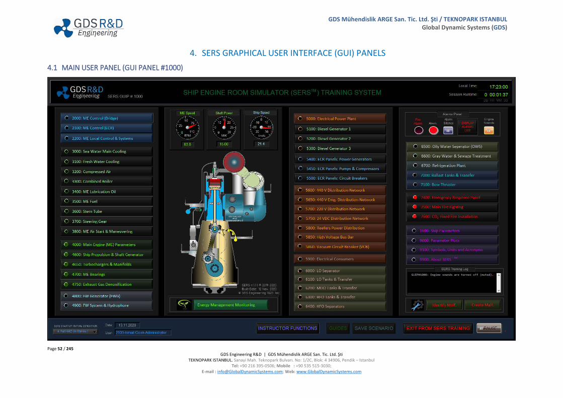
4. SERS GRAPHICAL USER INTERFACE (GUI) PANELS 4.1 MAIN USER PANEL (GUI PANEL #1000)

Page 53 / 245 GDS Engineering R&D | GDS Mühendislik ARGE San. Tic. Ltd. Şti
TEKNOPARK ISTANBUL. Sanayi Mah. Teknopark Bulvarı. No: 1/2C, Blok: 4 34906, Pendik – Istanbul Tel: +90 216 395-0506; Mobile : +90 535 515-3030;
E-mail : [email protected]; Web: www.GlobalDynamicSystems.com
GDS Mühendislik ARGE San. Tic. Ltd. Şti / TEKNOPARK ISTANBUL Global Dynamic Systems (GDS)
4.1.1 Description of Screen Objects
Time: Provides the current (local) time information.
Session Runtime: Indicates the time passed since the start of the current session.
Company Logo
Represents the company logo:
English: GDS Engineering R&D, Inc.
Turkish: GDS Mühendislik ARGE San Tic. Ltd. Şti.
where GDS stands for Global Dynamic Systems
SERS GUI Panel Number
Each of the SERS GUI panels provide a unique identifier on top left corner of the panel. User manuals refer to the GUI panel with this number.
Status Log
The Status Log (or SERS Training Log) indicates the initial condition at first, then displays the name of the last accessed GUI Panel. Training Log details are recorded into a text file, which can be found in the following user directory: “\Documents\LabVIEW Data\SERSData\Reports”. The log file is recorded for each user for each day and includes all user activities, recorded in a historic time order with timestamp. This feature allow for performing a detail analysis of the user actions when recorded for specific exercises.
Page 54 / 245 GDS Engineering R&D | GDS Mühendislik ARGE San. Tic. Ltd. Şti
TEKNOPARK ISTANBUL. Sanayi Mah. Teknopark Bulvarı. No: 1/2C, Blok: 4 34906, Pendik – Istanbul Tel: +90 216 395-0506; Mobile : +90 535 515-3030;
E-mail : [email protected]; Web: www.GlobalDynamicSystems.com
GDS Mühendislik ARGE San. Tic. Ltd. Şti / TEKNOPARK ISTANBUL Global Dynamic Systems (GDS)
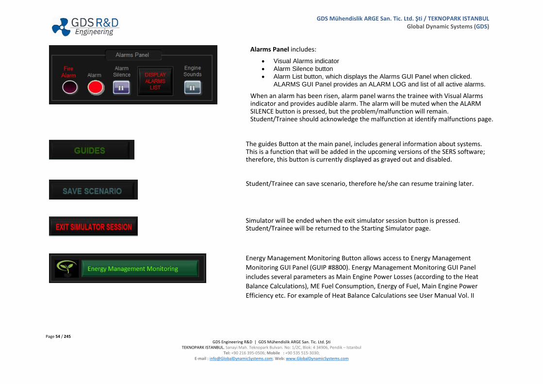
Alarms Panel includes:
• Visual Alarms indicator • Alarm Silence button • Alarm List button, which displays the Alarms GUI Panel when clicked.
ALARMS GUI Panel provides an ALARM LOG and list of all active alarms.
When an alarm has been risen, alarm panel warns the trainee with Visual Alarms indicator and provides audible alarm. The alarm will be muted when the ALARM SILENCE button is pressed, but the problem/malfunction will remain. Student/Trainee should acknowledge the malfunction at identify malfunctions page.
The guides Button at the main panel, includes general information about systems. This is a function that will be added in the upcoming versions of the SERS software; therefore, this button is currently displayed as grayed out and disabled.
Student/Trainee can save scenario, therefore he/she can resume training later.
Simulator will be ended when the exit simulator session button is pressed. Student/Trainee will be returned to the Starting Simulator page.
Energy Management Monitoring Button allows access to Energy Management Monitoring GUI Panel (GUIP #8800). Energy Management Monitoring GUI Panel includes several parameters as Main Engine Power Losses (according to the Heat Balance Calculations), ME Fuel Consumption, Energy of Fuel, Main Engine Power Efficiency etc. For example of Heat Balance Calculations see User Manual Vol. II

Page 55 / 245 GDS Engineering R&D | GDS Mühendislik ARGE San. Tic. Ltd. Şti
TEKNOPARK ISTANBUL. Sanayi Mah. Teknopark Bulvarı. No: 1/2C, Blok: 4 34906, Pendik – Istanbul Tel: +90 216 395-0506; Mobile : +90 535 515-3030;
E-mail : [email protected]; Web: www.GlobalDynamicSystems.com
GDS Mühendislik ARGE San. Tic. Ltd. Şti / TEKNOPARK ISTANBUL Global Dynamic Systems (GDS)
Create Malfunction / Identify Malfunction Buttons
Malfunctions can be created or identified using these buttons. Create Malfunction Button allows access to Create & Inject Malfunctions GUI Panel (GUIP #8200). Identify Malfunction Button allows access to Identify & Acknowledge Malfunctioning Components GUI Panel (GUIP #8500).
Version Description
Version Description area that is placed beside the ME animation provides information about the SERS version and built date for configuration and quality management.
Instructor Functions Button
Instructor Functions Button allows access to SERS Instructor Functions GUI Panel (GUIP #8100). Instructor can monitor and inject malfunction at the trainee’s stations.
Page 56 / 245 GDS Engineering R&D | GDS Mühendislik ARGE San. Tic. Ltd. Şti
TEKNOPARK ISTANBUL. Sanayi Mah. Teknopark Bulvarı. No: 1/2C, Blok: 4 34906, Pendik – Istanbul Tel: +90 216 395-0506; Mobile : +90 535 515-3030;
E-mail : [email protected]; Web: www.GlobalDynamicSystems.com
GDS Mühendislik ARGE San. Tic. Ltd. Şti / TEKNOPARK ISTANBUL Global Dynamic Systems (GDS)
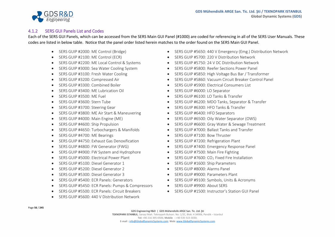
4.1.2 SERS GUI Panels List and Codes Each of the SERS GUI Panels, which can be accessed from the SERS Main GUI Panel (#1000) are coded for referencing in all of the SERS User Manuals. These codes are listed in below table. Notice that the panel order listed herein matches to the order found on the SERS Main GUI Panel.
• SERS GUIP #2000: ME Control (Bridge) • SERS GUIP #2100: ME Control (ECR) • SERS GUIP #2200: ME Local Control & Systems • SERS GUIP #3000: Sea Water Cooling System • SERS GUIP #3100: Fresh Water Cooling • SERS GUIP #3200: Compressed Air • SERS GUIP #3300: Combined Boiler • SERS GUIP #3400: ME Lubrication Oil • SERS GUIP #3500: ME Fuel • SERS GUIP #3600: Stern Tube • SERS GUIP #3700: Steering Gear • SERS GUIP #3800: ME Air Start & Maneuvering • SERS GUIP #4000: Main Engine (ME) • SERS GUIP #4600: Ship Propulsion • SERS GUIP #4650: Turbochargers & Manifolds • SERS GUIP #4700: ME Bearings • SERS GUIP #4750: Exhaust Gas Denoxification • SERS GUIP #4800: FW Generator (FWG) • SERS GUIP #4900: FW System and Hydrophore • SERS GUIP #5000: Electrical Power Plant • SERS GUIP #5100: Diesel Generator 1 • SERS GUIP #5200: Diesel Generator 2 • SERS GUIP #5300: Diesel Generator 3 • SERS GUIP #5400: ECR Panels: Generators • SERS GUIP #5450: ECR Panels: Pumps & Compressors • SERS GUIP #5500: ECR Panels: Circuit Breakers • SERS GUIP #5600: 440 V Distribution Network
• SERS GUIP #5650: 440 V Emergency (Emg.) Distribution Network • SERS GUIP #5700: 220 V Distribution Network • SERS GUIP #5750: 24 V DC Distribution Network • SERS GUIP #5800: Reefer Sections Power Panel • SERS GUIP #5850: High Voltage Bus Bar / Transformer • SERS GUIP #5860: Vacuum Circuit Breaker Control Panel • SERS GUIP #5900: Electrical Consumers List • SERS GUIP #6000: LO Separator • SERS GUIP #6100: LO Tanks & Transfer • SERS GUIP #6200: MDO Tanks, Separator & Transfer • SERS GUIP #6300: HFO Tanks & Transfer • SERS GUIP #6400: HFO Separators • SERS GUIP #6500: Oily Water Separator (OWS) • SERS GUIP #6600: Gray Water & Sewage Treatment • SERS GUIP #7000: Ballast Tanks and Transfer • SERS GUIP #7100: Bow Thruster • SERS GUIP #7200: Refrigeration Plant • SERS GUIP #7400: Emergency Response Panel • SERS GUIP #7500: Main Fire Fighting • SERS GUIP #7600: CO2 Fixed Fire Installation • SERS GUIP #1600: Ship Parameters • SERS GUIP #8000: Alarms Panel • SERS GUIP #9000: Parameters Plant • SERS GUIP #9100: Symbols, Units & Acronyms • SERS GUIP #9900: About SERS • SERS GUIP #1500: Instructor’s Station GUI Panel

Page 57 / 245 GDS Engineering R&D | GDS Mühendislik ARGE San. Tic. Ltd. Şti
TEKNOPARK ISTANBUL. Sanayi Mah. Teknopark Bulvarı. No: 1/2C, Blok: 4 34906, Pendik – Istanbul Tel: +90 216 395-0506; Mobile : +90 535 515-3030;
E-mail : [email protected]; Web: www.GlobalDynamicSystems.com
GDS Mühendislik ARGE San. Tic. Ltd. Şti / TEKNOPARK ISTANBUL Global Dynamic Systems (GDS)
4.2 ME CONTROL (BRIDGE) (GUI PANEL # 2000)

Page 58 / 245 GDS Engineering R&D | GDS Mühendislik ARGE San. Tic. Ltd. Şti
TEKNOPARK ISTANBUL. Sanayi Mah. Teknopark Bulvarı. No: 1/2C, Blok: 4 34906, Pendik – Istanbul Tel: +90 216 395-0506; Mobile : +90 535 515-3030;
E-mail : [email protected]; Web: www.GlobalDynamicSystems.com
GDS Mühendislik ARGE San. Tic. Ltd. Şti / TEKNOPARK ISTANBUL Global Dynamic Systems (GDS)
4.2.1 Table of Screen Objects
Number Description Number Description
1 Indicators Panel 4 Control Responsibility and Bridge Order 2 Throttle Lever 5 Steering Wheel Panel 3 Emergency Stop Panel, Telegraph Mismatch & Slow Turn 6 Set Environmental Parameters Button
1. Indicators Panel includes: a. Ship Speed and ME Speed Indicator b. Start Air Pressure Gauge and Shaft Power Indicator
2. Commands the ship speed via increasing/decreasing main engine rpm. 3. Emergency Stop: The emergency stop can be activated from Bridge or Engine Control Room. This button should only be pressed when normal ways
(i.e. by using telegraph) is not responding. However, do not have the impression that the button must be pressed just there is an emergency like imminent, grounding, allusion or collision etc. If the engine cannot be stopped by normal ways and is required to be stopped, then the emergency stop button can be pressed. Manual emergency shutdown can be operated from any position (Bridge or ECR) regardless of the control position for operating the main engine. Telegraph Mode Mismatch indicator lits when the Bridge and Engine Control Room Telegraphs are not in the same position. Slow Turn button provides to check the engine start system by slow turning the Main Engine. Slow turning bypasses, the main air start valve and provides sufficient air and therefore turns to engine slowly to prevent damage in case of water or fuel accumulated on the piston due to leakage. The process for Slow Turn is depicted and shown in detail in User Manual Vol. II Section 6.2.
4. Choices of main engine control. There are three place to control the main engine: a. Local Control b. ECR Control c. Bridge Control
Bridge order panel provides communication between bridge and engine control room for main engine status. Three status of the main engine: a. Stand-by means that the main engine is ready for maneuvering. b. Navigation (NAV) indicates the main engine is ready for navigation. c. Finished with Engine means that the main engine operation is no longer required when ship anchored or approached the port.
5. Steering wheel panel includes: a. Follow up Steering Controller b. Steering Control Mode Switch
i. Follow up (FU) This is the normal method of steering and involves the feedback of steering angle to the helm. This is suited to both manual and automatic operation. The ship heading may be set into the autopilot, which can compare the actual to desired heading and adjust the rudder angle to suit.

Page 59 / 245 GDS Engineering R&D | GDS Mühendislik ARGE San. Tic. Ltd. Şti
TEKNOPARK ISTANBUL. Sanayi Mah. Teknopark Bulvarı. No: 1/2C, Blok: 4 34906, Pendik – Istanbul Tel: +90 216 395-0506; Mobile : +90 535 515-3030;
E-mail : [email protected]; Web: www.GlobalDynamicSystems.com
GDS Mühendislik ARGE San. Tic. Ltd. Şti / TEKNOPARK ISTANBUL Global Dynamic Systems (GDS)
ii. Autopilot It is a method used in ships at navigation, after the new route of the ship is piloted with an electronic device, the steering gear system turns the ship to the port or the starboard to bring the ship to the desired route.
iii. Non Follow up (NFU) Normally used for back up purposes only. Consists of a single lever per steering gear unit, by moving
the lever in on direction the rudder will begin to turn, the rudder will continue to turn until the lever is released or it reaches the limit of its operation
c. Rudder Indicator d. Non Follow up Steering Controller
6. Environmental Parameters can be changed with this GUI.

Page 60 / 245 GDS Engineering R&D | GDS Mühendislik ARGE San. Tic. Ltd. Şti
TEKNOPARK ISTANBUL. Sanayi Mah. Teknopark Bulvarı. No: 1/2C, Blok: 4 34906, Pendik – Istanbul Tel: +90 216 395-0506; Mobile : +90 535 515-3030;
E-mail : [email protected]; Web: www.GlobalDynamicSystems.com
GDS Mühendislik ARGE San. Tic. Ltd. Şti / TEKNOPARK ISTANBUL Global Dynamic Systems (GDS)
4.3 ENGINE CONTROL ROOM (GUI PANEL # 2100)

Page 61 / 245 GDS Engineering R&D | GDS Mühendislik ARGE San. Tic. Ltd. Şti
TEKNOPARK ISTANBUL. Sanayi Mah. Teknopark Bulvarı. No: 1/2C, Blok: 4 34906, Pendik – Istanbul Tel: +90 216 395-0506; Mobile : +90 535 515-3030;
E-mail : [email protected]; Web: www.GlobalDynamicSystems.com
GDS Mühendislik ARGE San. Tic. Ltd. Şti / TEKNOPARK ISTANBUL Global Dynamic Systems (GDS)
4.3.1 Table of Screen Objects
Number Description Number Description
1 Aux. Blowers, ER Fans, and ME Indicators Panel 7 Telegraph Mismatch, Wrong Way & Crash Astern 2 Main Engine Load and Fuel Index Indicator 8 Thermal Load Program Panel 3 Main Engine RPM Control Panel 9 Gas Lever Control Switch Panel 4 Control Responsibility Panel and Bridge Order Indicator 10 Display Alarms List Button & Alarm Indicators 5 Control Mode Selection and RPM Limiter Panel 11 Main Engine Status Panel 6 Emergency Stop, Camshaft Position, Turning Gear Panel 12 Main Engine Shut/Slow Down Alarms
1. Auxiliary Blowers, Engine Room Fans, and Indicators Panel includes: a. Ship Speed Indicator b. Propeller RPM Indicator c. Shaft Power Indicator d. Scavenge Air Pressure Gauge e. Start Air Pressure Gauge f. Control Air Pressure Gauge g. Main Engine LO Inlet Pressure Gauge h. Main Engine LO Inlet Temperature Gauge i. Main Engine FO Inlet Pressure Gauge j. Main Engine FO Inlet Temperature Gauge k. Fuel Oil Flowmeter l. Engine Room Supply and Exhaust Fans Control Panel m. Main Engine HTFW Inlet Temperature Gauge n. Main Engine HTFW Outlet Temperature Gauge o. Auxiliary Blower Control Panel controls auxiliary blowers in manual and auto mode. When the user clicks the start button, auxiliary blowers
will start at manual mode. They cut in/cut out automatically in auto mode. 2. Main engine load is a function of efficiency. Load factor also correlate with Specific Fuel Oil Consumption (SFOC), so that load indicator is important
for efficient operation of main engine. The indicator shows fuel rack position. Fuel rack adjust the fuel pump plunger which determines the amount of fuel going to the cylinder. Angle of the plunger helix adjusted by the rack, determines amount of fuel to be injected.
3. Sets and commands the ship speed via increasing or decreasing of main engine rpm. When the gas lever at requested 91,5 RPM (MCR) position, user can use Speed Adjustment Buttons.
Page 62 / 245 GDS Engineering R&D | GDS Mühendislik ARGE San. Tic. Ltd. Şti
TEKNOPARK ISTANBUL. Sanayi Mah. Teknopark Bulvarı. No: 1/2C, Blok: 4 34906, Pendik – Istanbul Tel: +90 216 395-0506; Mobile : +90 535 515-3030;
E-mail : [email protected]; Web: www.GlobalDynamicSystems.com
GDS Mühendislik ARGE San. Tic. Ltd. Şti / TEKNOPARK ISTANBUL Global Dynamic Systems (GDS)
4. Choices of main engine control. There are three places to control the main engine: a. Local Control b. ECR Control c. Bridge Control
Bridge order panel provides communication between bridge and engine control room for main engine status. Three status of main engine: a. Stand-by means that the main engine is ready for maneuvering. b. Navigation (NAV) indicates the main engine is ready for navigation. c. Finished with engine means that the main engine operation is no longer required when ship anchored or approached the port.
5. Control Mode consists: a. RPM Control Main Engine RPM can be controlled. In this mode, RPM will remain constant, and changes in Weather Conditions,
Shaft Generator Status etc. will affect the Main Engine Load. RPM set value can be changed from RPM Limiter Panel. b. Load Control Main Engine Load can be controlled. In this mode, load will remain constant, and changes in Weather Conditions,
Shaft Generator Status etc. will affect the Main Engine RPM. 6. Stops the main engine at emergency situations. Enable button provides pushing of the emergency stop button. Camshaft position determines the
rotation of main engine. Turning Gear Indicator Panel shows Turning Gear is ENGAGED or DISENGAGED. Turning Gear can be engaged or disengaged from the ME Local Control & Systems (GUI Panel #2200).
7. Telegraph Mode Mismatch indicator is lit when the Bridge and Engine Control Room Telegraphs are not in the same position. Wrong Way indicator is lit when the camshaft is in the wrong direction while telegraph is set in the opposite direction. Crash Astern indicator indicates the ME operation mode is changed to Crash Astern mode. In this mode, ME control system sequentially implements slowing down, stopping, and running the engine at Full Astern speeds. Perform Crash-Maneuvering procedure to avoid risk of the ship colliding in emergencies. In this type of maneuvering, the ME assumes high loads applying high level of stresses to the structural elements, such as piston pin, camshaft, and bearings. For the details of the Crash-Maneuvering process, review Section 6.4 of the User Manual Vol. II.
8. “Thermal Load Program” has two objects as follows: a. “Active” indicator is lit when thermal load program is activated by the ME control system. b. Override” control is activated by the user to override the thermal load program.
9. ME Gas Lever may be controlled from Software (SERS GUI Panel #2100) or from a hardware gas lever component. SERS allows for addition of ME Control Console hardware set. For further information about the addition and use of the ME Control Console hardware, refer to SERS User Manual Volume III Installation & Configuration.
10. The user can access Alarms GUI Panel via Display Alarm List Button. Alarm Indicators show whether Alarm and Fire Alarm occur. 11. Main Engine Status Panel includes:
a. Engine Ready b. Engine Running c. Main Engine Slow Down d. Main Engine Shut Down e. Main Engine Failed f. Main Engine Slow Down Prewarning g. Main Engine Shut Down Prewarning
Page 63 / 245 GDS Engineering R&D | GDS Mühendislik ARGE San. Tic. Ltd. Şti
TEKNOPARK ISTANBUL. Sanayi Mah. Teknopark Bulvarı. No: 1/2C, Blok: 4 34906, Pendik – Istanbul Tel: +90 216 395-0506; Mobile : +90 535 515-3030;
E-mail : [email protected]; Web: www.GlobalDynamicSystems.com
GDS Mühendislik ARGE San. Tic. Ltd. Şti / TEKNOPARK ISTANBUL Global Dynamic Systems (GDS)
12. The malfunctions that may cause Main Engine shut down are listed below: a. LO Pressure Low b. Thrust Bearing Temperature High c. Overspeed
The malfunctions that may cause Main Engine slow down are listed below:
a. LO Pressure Low b. LO Temperature High c. Cooling Water Outlet Temperature High d. Exhaust Temperature Deviation High e. Oil Mist f. Thrust Bearing Temperature High g. Main Bearing Temperature High

Page 64 / 245 GDS Engineering R&D | GDS Mühendislik ARGE San. Tic. Ltd. Şti
TEKNOPARK ISTANBUL. Sanayi Mah. Teknopark Bulvarı. No: 1/2C, Blok: 4 34906, Pendik – Istanbul Tel: +90 216 395-0506; Mobile : +90 535 515-3030;
E-mail : [email protected]; Web: www.GlobalDynamicSystems.com
GDS Mühendislik ARGE San. Tic. Ltd. Şti / TEKNOPARK ISTANBUL Global Dynamic Systems (GDS)
4.4 MAIN ENGINE LOCAL SYSTEMS & CONTROL (GUI PANEL # 2200)
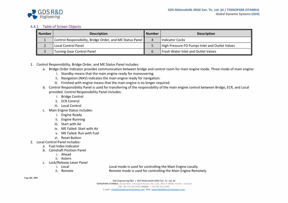
Page 65 / 245 GDS Engineering R&D | GDS Mühendislik ARGE San. Tic. Ltd. Şti
TEKNOPARK ISTANBUL. Sanayi Mah. Teknopark Bulvarı. No: 1/2C, Blok: 4 34906, Pendik – Istanbul Tel: +90 216 395-0506; Mobile : +90 535 515-3030;
E-mail : [email protected]; Web: www.GlobalDynamicSystems.com
GDS Mühendislik ARGE San. Tic. Ltd. Şti / TEKNOPARK ISTANBUL Global Dynamic Systems (GDS)
4.4.1 Table of Screen Objects
Number Description Number Description
1 Control Responsibility, Bridge Order, and ME Status Panel 4 Indicator Cocks 2 Local Control Panel 5 High Pressure FO Pumps Inlet and Outlet Valves 3 Turning Gear Control Panel 6 Fresh Water Inlet and Outlet Valves
1. Control Responsibility, Bridge Order, and ME Status Panel includes: a. Bridge Order Indicator provides communication between bridge and control room for main engine mode. Three mode of main engine:
i. Standby means that the main engine ready for maneuvering. ii. Navigation (NAV) indicates the main engine ready for navigation.
iii. Finished with engine means that the main engine is no longer required. b. Control Responsibility Panel is used for transferring of the responsibility of the main engine control between Bridge, ECR, and Local
provided. Control Responsibility Panel includes: i. Bridge Control
ii. ECR Control iii. Local Control
c. Main Engine Status includes: i. Engine Ready
ii. Engine Running iii. Start with Air iv. ME Failed: Start with Air v. ME Failed: Run with Fuel
vi. Reset Button 2. Local Control Panel includes:
a. Fuel Index Indicator b. Camshaft Position Panel
i. Ahead ii. Astern
c. Lock/Release Lever Panel i. Local Local mode is used for controlling the Main Engine Locally.
ii. Remote Remote mode is used for controlling the Main Engine Remotely.
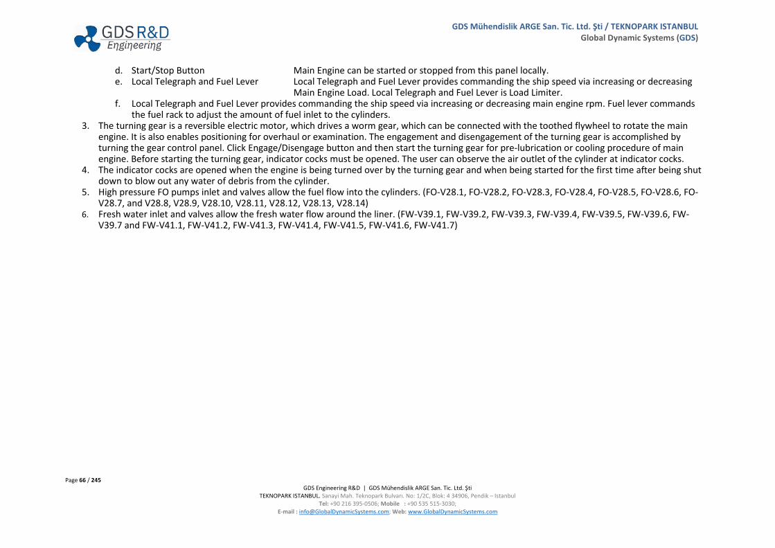
Page 66 / 245 GDS Engineering R&D | GDS Mühendislik ARGE San. Tic. Ltd. Şti
TEKNOPARK ISTANBUL. Sanayi Mah. Teknopark Bulvarı. No: 1/2C, Blok: 4 34906, Pendik – Istanbul Tel: +90 216 395-0506; Mobile : +90 535 515-3030;
E-mail : [email protected]; Web: www.GlobalDynamicSystems.com
GDS Mühendislik ARGE San. Tic. Ltd. Şti / TEKNOPARK ISTANBUL Global Dynamic Systems (GDS)
d. Start/Stop Button Main Engine can be started or stopped from this panel locally. e. Local Telegraph and Fuel Lever Local Telegraph and Fuel Lever provides commanding the ship speed via increasing or decreasing
Main Engine Load. Local Telegraph and Fuel Lever is Load Limiter. f. Local Telegraph and Fuel Lever provides commanding the ship speed via increasing or decreasing main engine rpm. Fuel lever commands
the fuel rack to adjust the amount of fuel inlet to the cylinders. 3. The turning gear is a reversible electric motor, which drives a worm gear, which can be connected with the toothed flywheel to rotate the main
engine. It is also enables positioning for overhaul or examination. The engagement and disengagement of the turning gear is accomplished by turning the gear control panel. Click Engage/Disengage button and then start the turning gear for pre-lubrication or cooling procedure of main engine. Before starting the turning gear, indicator cocks must be opened. The user can observe the air outlet of the cylinder at indicator cocks.
4. The indicator cocks are opened when the engine is being turned over by the turning gear and when being started for the first time after being shut down to blow out any water of debris from the cylinder.
5. High pressure FO pumps inlet and valves allow the fuel flow into the cylinders. (FO-V28.1, FO-V28.2, FO-V28.3, FO-V28.4, FO-V28.5, FO-V28.6, FO-V28.7, and V28.8, V28.9, V28.10, V28.11, V28.12, V28.13, V28.14)
6. Fresh water inlet and valves allow the fresh water flow around the liner. (FW-V39.1, FW-V39.2, FW-V39.3, FW-V39.4, FW-V39.5, FW-V39.6, FW-V39.7 and FW-V41.1, FW-V41.2, FW-V41.3, FW-V41.4, FW-V41.5, FW-V41.6, FW-V41.7)

Page 67 / 245 GDS Engineering R&D | GDS Mühendislik ARGE San. Tic. Ltd. Şti
TEKNOPARK ISTANBUL. Sanayi Mah. Teknopark Bulvarı. No: 1/2C, Blok: 4 34906, Pendik – Istanbul Tel: +90 216 395-0506; Mobile : +90 535 515-3030;
E-mail : [email protected]; Web: www.GlobalDynamicSystems.com
GDS Mühendislik ARGE San. Tic. Ltd. Şti / TEKNOPARK ISTANBUL Global Dynamic Systems (GDS)
4.4.2 Valve Numbering
Number Description Number Description
Ind-C1 No.1 Cylinder Indicator Cock FO-V28.12 No.5 High Pressure FO Pump Outlet Valve
Ind-C2 No.2 Cylinder Indicator Cock FO-V28.13 No.6 High Pressure FO Pump Outlet Valve
Ind-C3 No.3 Cylinder Indicator Cock FO-V28.14 No.7 High Pressure FO Pump Outlet Valve
Ind-C4 No.4 Cylinder Indicator Cock FW-V39.1 No.1 Cylinder FW Inlet Valve
Ind-C5 No.5 Cylinder Indicator Cock FW-V39.2 No.2 Cylinder FW Inlet Valve
Ind-C6 No.6 Cylinder Indicator Cock FW-V39.3 No.3 Cylinder FW Inlet Valve
Ind-C7 No.7 Cylinder Indicator Cock FW-V39.4 No.4 Cylinder FW Inlet Valve
FO-V28.1 No.1 High Pressure FO Pump Inlet Valve FW-V39.5 No.5 Cylinder FW Inlet Valve
FO-V28.2 No.2 High Pressure FO Pump Inlet Valve FW-V39.6 No.6 Cylinder FW Inlet Valve
FO-V28.3 No.3 High Pressure FO Pump Inlet Valve FW-V39.7 No.7 Cylinder FW Inlet Valve
FO-V28.4 No.4 High Pressure FO Pump Inlet Valve FW-V41.1 No.1 Cylinder FW Outlet Valve
FO-V28.5 No.5 High Pressure FO Pump Inlet Valve FW-V41.2 No.2 Cylinder FW Outlet Valve
FO-V28.6 No.6 High Pressure FO Pump Inlet Valve FW-V41.3 No.3 Cylinder FW Outlet Valve
FO-V28.7 No.7 High Pressure FO Pump Inlet Valve FW-V41.4 No.4 Cylinder FW Outlet Valve
FO-V28.8 No.1 High Pressure FO Pump Outlet Valve FW-V41.5 No.5 Cylinder FW Outlet Valve
FO-V28.9 No.2 High Pressure FO Pump Outlet Valve FW-V41.6 No.6 Cylinder FW Outlet Valve
FO-V28.10 No.3 High Pressure FO Pump Outlet Valve FW-V41.7 No.7 Cylinder FW Outlet Valve
FO-V28.11 No.4 High Pressure FO Pump Outlet Valve
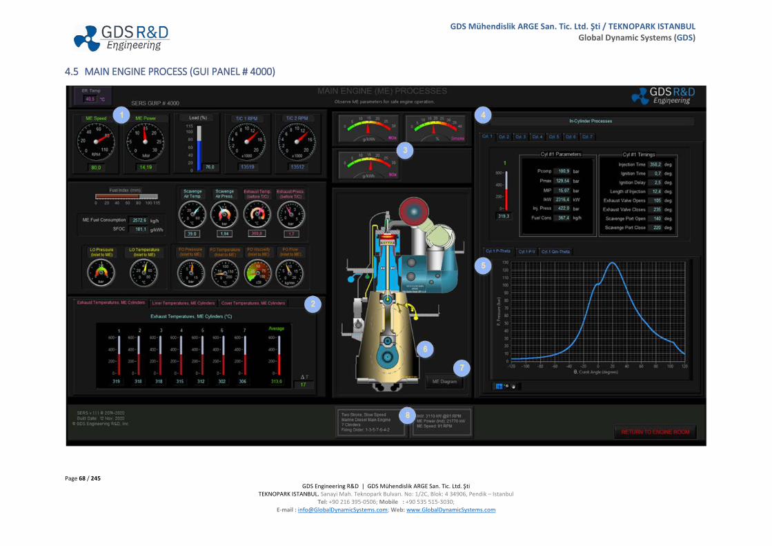
Page 68 / 245 GDS Engineering R&D | GDS Mühendislik ARGE San. Tic. Ltd. Şti
TEKNOPARK ISTANBUL. Sanayi Mah. Teknopark Bulvarı. No: 1/2C, Blok: 4 34906, Pendik – Istanbul Tel: +90 216 395-0506; Mobile : +90 535 515-3030;
E-mail : [email protected]; Web: www.GlobalDynamicSystems.com
GDS Mühendislik ARGE San. Tic. Ltd. Şti / TEKNOPARK ISTANBUL Global Dynamic Systems (GDS)
4.5 MAIN ENGINE PROCESS (GUI PANEL # 4000)
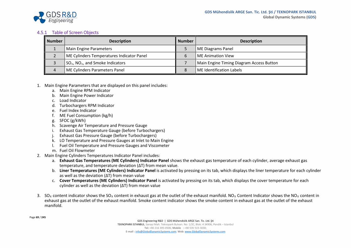
Page 69 / 245 GDS Engineering R&D | GDS Mühendislik ARGE San. Tic. Ltd. Şti
TEKNOPARK ISTANBUL. Sanayi Mah. Teknopark Bulvarı. No: 1/2C, Blok: 4 34906, Pendik – Istanbul Tel: +90 216 395-0506; Mobile : +90 535 515-3030;
E-mail : [email protected]; Web: www.GlobalDynamicSystems.com
GDS Mühendislik ARGE San. Tic. Ltd. Şti / TEKNOPARK ISTANBUL Global Dynamic Systems (GDS)
4.5.1 Table of Screen Objects
Number Description Number Description
1 Main Engine Parameters 5 ME Diagrams Panel 2 ME Cylinders Temperatures Indicator Panel 6 ME Animation View 3 SOx, NOx, and Smoke Indicators 7 Main Engine Timing Diagram Access Button 4 ME Cylinders Parameters Panel 8 ME Identification Labels
1. Main Engine Parameters that are displayed on this panel includes: a. Main Engine RPM Indicator b. Main Engine Power Indicator c. Load Indicator d. Turbochargers RPM Indicator e. Fuel Index Indicator f. ME Fuel Consumption (kg/h) g. SFOC (g/kWh) h. Scavenge Air Temperature and Pressure Gauge i. Exhaust Gas Temperature Gauge (before Turbochargers) j. Exhaust Gas Pressure Gauge (before Turbochargers) k. LO Temperature and Pressure Gauges at Inlet to Main Engine l. Fuel Oil Temperature and Pressure Gauges and Viscometer m. Fuel Oil Flowmeter
2. Main Engine Cylinders Temperatures Indicator Panel includes: a. Exhaust Gas Temperatures (ME Cylinders) Indicator Panel shows the exhaust gas temperature of each cylinder, average exhaust gas
temperature, and temperature deviation (ΔT) from mean value. b. Liner Temperatures (ME Cylinders) Indicator Panel is activated by pressing on its tab, which displays the liner temperature for each cylinder
as well as the deviation (ΔT) from mean value c. Cover Temperatures (ME Cylinders) Indicator Panel is activated by pressing on its tab, which displays the cover temperature for each
cylinder as well as the deviation (ΔT) from mean value
3. SOX content indicator shows the SOX content in exhaust gas at the outlet of the exhaust manifold. NOX Content Indicator shows the NOX content in exhaust gas at the outlet of the exhaust manifold. Smoke content indicator shows the smoke content in exhaust gas at the outlet of the exhaust manifold.

Page 70 / 245 GDS Engineering R&D | GDS Mühendislik ARGE San. Tic. Ltd. Şti
TEKNOPARK ISTANBUL. Sanayi Mah. Teknopark Bulvarı. No: 1/2C, Blok: 4 34906, Pendik – Istanbul Tel: +90 216 395-0506; Mobile : +90 535 515-3030;
E-mail : [email protected]; Web: www.GlobalDynamicSystems.com
GDS Mühendislik ARGE San. Tic. Ltd. Şti / TEKNOPARK ISTANBUL Global Dynamic Systems (GDS)
4. In a cylinder, some parameters indicate main engine’s condition and performance. It is important to optimize the engine’s fuel efficiency and verification of the optimization’s effect. In-cylinder process panel shows the parameters and timing of each cylinder.
a. Cylinder Parameters: i. Pcomp Compression Pressure refers to the pressure before ignition.
ii. Pmax Maximum Pressure refers to the pressure after ignition. iii. MIP Mean Indicated Pressure, which on acting upon the piston performs the same works as the actual pressure
on the operating cycle. iv. IkW Indicated kilowatt is the generated indicated power from a cylinder. v. Inj. Press. Injection Pressure is the pressure during an injection.
vi. Fuel Cons. Fuel consumption of the cylinder kilograms per hour. b. Cylinder Timings:
i. Injection Time is the time of when the fuel is injected into the cylinder, which alters when the combustion takes place. Injection timing is usually balanced to get as much power as possible, while still remaining in legal limits for emissions.
ii. Ignition Time refers to the time, relative to the current piston position and crankshaft angle, of the starting controlled combustion in the combustion chamber.
iii. Ignition Delay is the time of the lag between start of injection and start of the combustion. The ignition delay is too important for the combustion process, thermal performance, and emissions of the main engine.
iv. Length of Injection means the interval of injection between starting and endings. v. Exhaust valve opens refers to the crankshaft position, as degree, and the time of exhaust valve opens.
vi. Exhaust valve closes refers to the crankshaft position, as degree, and the time of exhaust valve closes. vii. Scavenge Port Open refers timing, relative to the current piston position and crankshaft angle, of the scavenge port opens.
viii. Scavenge Port Close refers timing, relative to the current piston position and crankshaft angle, of the inlet scavenge closes. 5. Main Engine Diagram Panel shows the P-θ, P-V, and Qin- θ diagram for each cylinder.
a. P-θ diagram which is used to describe corresponding changes in pressure and crank angle for each cylinder. b. P-V diagram which is used to describe corresponding changes in pressure and crank angle for each cylinder. c. Qin- θ diagram which is used to describe corresponding changes in energy input and crank angle for each cylinder.
6. Main Engine’s animation is displayed in this area. The turn speed is in synchronization with the actual ME RPM. 7. Main engine diagram button access to the two-stroke diesel engine process simulation demonstration screen. Main engine process screen shows
timing diagram and cylinder process of main engine. Crank angle and rpm switch either to run in controlled rpm mode or crank angle mode. Crank angle mode allows for turning crank 30 degrees of crank angle.
8. ME Identification Labels displays the specifics to the main engine modeled in the SERS software. ME Identification Labels include: a. Main Engine Description b. Number of Cylinder and firing order c. Indicated Power of each cylinder and main engine d. ME Speed
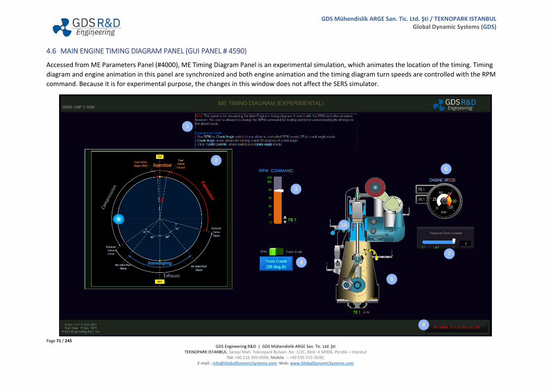
Page 71 / 245 GDS Engineering R&D | GDS Mühendislik ARGE San. Tic. Ltd. Şti
TEKNOPARK ISTANBUL. Sanayi Mah. Teknopark Bulvarı. No: 1/2C, Blok: 4 34906, Pendik – Istanbul Tel: +90 216 395-0506; Mobile : +90 535 515-3030;
E-mail : [email protected]; Web: www.GlobalDynamicSystems.com
GDS Mühendislik ARGE San. Tic. Ltd. Şti / TEKNOPARK ISTANBUL Global Dynamic Systems (GDS)
4.6 MAIN ENGINE TIMING DIAGRAM PANEL (GUI PANEL # 4590)
Accessed from ME Parameters Panel (#4000), ME Timing Diagram Panel is an experimental simulation, which animates the location of the timing. Timing diagram and engine animation in this panel are synchronized and both engine animation and the timing diagram turn speeds are controlled with the RPM command. Because it is for experimental purpose, the changes in this window does not affect the SERS simulator.
1
10
2
3
4
5
6
7
8

Page 72 / 245 GDS Engineering R&D | GDS Mühendislik ARGE San. Tic. Ltd. Şti
TEKNOPARK ISTANBUL. Sanayi Mah. Teknopark Bulvarı. No: 1/2C, Blok: 4 34906, Pendik – Istanbul Tel: +90 216 395-0506; Mobile : +90 535 515-3030;
E-mail : [email protected]; Web: www.GlobalDynamicSystems.com
GDS Mühendislik ARGE San. Tic. Ltd. Şti / TEKNOPARK ISTANBUL Global Dynamic Systems (GDS)
4.6.1 Table of Screen Objects
Number Description Number Description
1 Instructions 5 ME Animation 2 Timing Diagram 6 RPM Gauge 3 RPM Command 7 Response Time Constant 4 Control Type 8 RETURN TO ENGINE ROOM button
1. Instructions area displays the general information on how to use this experimental timing diagram simulation in this panel. 2. Timing Diagram shows the opening and closing time of; air inlet port, fuel and exhaust valves. 3. RPM Command is a control for changing the speed of both timing diagram and engine animation. 4. Control Type allows for selecting the control to be for RPM or Crank Angle. When switched to Crank Angle, timing diagram and engine animations
stop and they both move 30 degrees of angle for each click on Turn Crank Angle button. 5. ME Animation shows a turning animation of engine depending on the ME RPM or crank angle selected. 6. RPM Gauge show the RPM command and actual RPM of the animated timing diagram and engine. 7. Response Time Constant changes the response dynamics of the animation speeds to the controlled variable change. 8. RETURN TO ENGINE ROOM button allows for quitting from this panel and displays the SERS Main GUI Window (#1000).
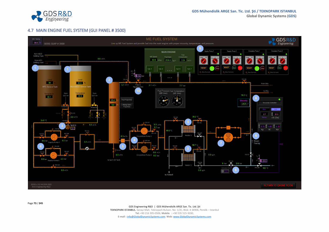
Page 73 / 245 GDS Engineering R&D | GDS Mühendislik ARGE San. Tic. Ltd. Şti
TEKNOPARK ISTANBUL. Sanayi Mah. Teknopark Bulvarı. No: 1/2C, Blok: 4 34906, Pendik – Istanbul Tel: +90 216 395-0506; Mobile : +90 535 515-3030;
E-mail : [email protected]; Web: www.GlobalDynamicSystems.com
GDS Mühendislik ARGE San. Tic. Ltd. Şti / TEKNOPARK ISTANBUL Global Dynamic Systems (GDS)
4.7 MAIN ENGINE FUEL SYSTEM (GUI PANEL # 3500)

Page 74 / 245 GDS Engineering R&D | GDS Mühendislik ARGE San. Tic. Ltd. Şti
TEKNOPARK ISTANBUL. Sanayi Mah. Teknopark Bulvarı. No: 1/2C, Blok: 4 34906, Pendik – Istanbul Tel: +90 216 395-0506; Mobile : +90 535 515-3030;
E-mail : [email protected]; Web: www.GlobalDynamicSystems.com
GDS Mühendislik ARGE San. Tic. Ltd. Şti / TEKNOPARK ISTANBUL Global Dynamic Systems (GDS)
4.7.1 Table of Screen Objects
Number Description Number Description
1 HFO and MDO Service Tanks 6 Steam Control Valve and Steam Tracing Line 2 Mixing Tank 7 Automatic Backflushing Filter 3 HFO/MDO Mixing Valve 8 Viscosity Controller Panel 4 Fuel Supply and Circulating Pumps 9 Fuel Oil Pumps Control Panel 5 Filter and Heaters 10 Pressure Regulating Valve
1. HFO and MDO service tanks contain only the required quality of fuel ready for immediate use. HFO and MDO Service Tanks used onboard, necessary for propulsion and generator systems, are to be provided.
2. Then the fuel passes to the mixing tank where it mixes with fuel returned from the engine. The mixing tank is fitted drain line which is sending fuel to spill oil tank. Fuel properties button shows temperature-dependent graph of fuel viscosity and density. Mixing tank properties button shows the time-dependent graph of the temperature, density and viscosity of the fuel in the mixing tank.
3. HFO/MDO mixing valve allows the mixing of HFO and MDO. Mixing valve uses during change-over operation. 4. Fuel passes through the mixing valve before suction by supply pumps. Supply pumps supply the fuel through the mixing tank. Fuel circulating pumps
provide a reliable supply of fuel. Circulating pumps take suction, pumping the fuel through the heaters and then automatic backflushing filter to the main engine fuel system.
5. The filter usually employs a mesh screen, an assembly of closely packed metal plates or wire coils which effectively block all the smallest particles. It is fitted on the outlet of the mixing tank. The fuel oil heater is used to heat fuel oils to a desired operating temperature. Heaters includes fuel oil inlet/outlet lines and steam inlet/outlet lines. Fuel oil is heated by steam supply at heater.
6. Steam control valve regulates steam flow according to fuel viscosity. While Heavy Fuel Oil (HFO) is used as fuel in the ME Fuel System lines, as addition to the HFO Heaters, HFO can also be heated up using the steam tracing lines. This will help storing the heat losses in the FO pipes and mixing tank. Also, in case of the HFO existing in the pipes before lining up the FO Systems, steam tracing lines must be used to heat up the HFO existing in the FO pipes to lower its viscosity before the FO Pumps are started. Steam Tracing Line supplies below components and lines (pipes):
a. HFO Service Tank Outlet Line b. Supply Pumps Suction Lines c. By-pass Line d. Supply Pumps Discharge Lines e. Mixing Tank Inlet Line f. Mixing Tank
g. Circulation Pumps Suction Lines h. Circulation Pumps Discharge Lines i. FO Heaters Inlet and Outlet Lines j. Backflushing Filter Outlet Line k. Main Engine FO Inlet Line l. Recirculation Line

Page 75 / 245 GDS Engineering R&D | GDS Mühendislik ARGE San. Tic. Ltd. Şti
TEKNOPARK ISTANBUL. Sanayi Mah. Teknopark Bulvarı. No: 1/2C, Blok: 4 34906, Pendik – Istanbul Tel: +90 216 395-0506; Mobile : +90 535 515-3030;
E-mail : [email protected]; Web: www.GlobalDynamicSystems.com
GDS Mühendislik ARGE San. Tic. Ltd. Şti / TEKNOPARK ISTANBUL Global Dynamic Systems (GDS)
7. Automatic Backflushing filter, when the pressure difference increases, an indication of filter getting clogged, the auto system disables one of the filters for cleaning process, rest of the filters will continue the filtering process and this cycle repeats on. The automatic backflushing filter takes place with the help of the electric motor connected to the shaft, which cleans the filter by compressed air.
8. Viscometer takes continuous sample of the fuel at a constant rate through a fine capillary tube. As the flow through the tube is laminar, pressure drop across the tube is proportional to viscosity. Viscosity controller regulates the supply of fuel heating steam through a control valve.
9. Fuel Oil Pumps can be operated from the control panel. Power light indicates whether electrical supply reaches the panel. If switch position is at “0” position, pumps will not operate. If switch position is at “MANUAL” pumps can be operated if user click the start button. If switch position is at “AUTO” pumps operate according to the system pressure in-line. If pressure decrease, pumps will operate automatically.
10. Pressure regulating valve ensures a constant pressure supply to the engine. Pressure regulating valve setting value can be changed from control unit. Thus, tension of spring will be changed.
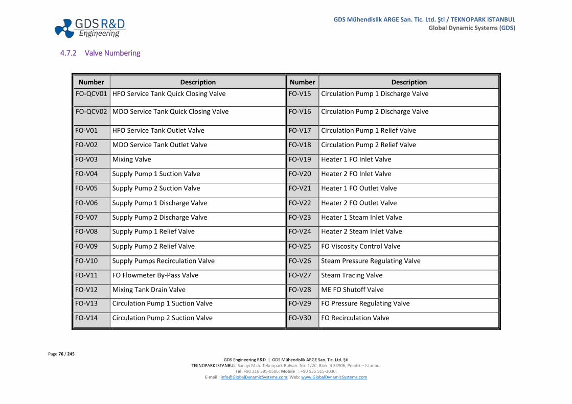
Page 76 / 245 GDS Engineering R&D | GDS Mühendislik ARGE San. Tic. Ltd. Şti
TEKNOPARK ISTANBUL. Sanayi Mah. Teknopark Bulvarı. No: 1/2C, Blok: 4 34906, Pendik – Istanbul Tel: +90 216 395-0506; Mobile : +90 535 515-3030;
E-mail : [email protected]; Web: www.GlobalDynamicSystems.com
GDS Mühendislik ARGE San. Tic. Ltd. Şti / TEKNOPARK ISTANBUL Global Dynamic Systems (GDS)
4.7.2 Valve Numbering
Number Description Number Description FO-QCV01 HFO Service Tank Quick Closing Valve FO-V15 Circulation Pump 1 Discharge Valve
FO-QCV02 MDO Service Tank Quick Closing Valve FO-V16 Circulation Pump 2 Discharge Valve
FO-V01 HFO Service Tank Outlet Valve FO-V17 Circulation Pump 1 Relief Valve
FO-V02 MDO Service Tank Outlet Valve FO-V18 Circulation Pump 2 Relief Valve
FO-V03 Mixing Valve FO-V19 Heater 1 FO Inlet Valve
FO-V04 Supply Pump 1 Suction Valve FO-V20 Heater 2 FO Inlet Valve
FO-V05 Supply Pump 2 Suction Valve FO-V21 Heater 1 FO Outlet Valve
FO-V06 Supply Pump 1 Discharge Valve FO-V22 Heater 2 FO Outlet Valve
FO-V07 Supply Pump 2 Discharge Valve FO-V23 Heater 1 Steam Inlet Valve
FO-V08 Supply Pump 1 Relief Valve FO-V24 Heater 2 Steam Inlet Valve
FO-V09 Supply Pump 2 Relief Valve FO-V25 FO Viscosity Control Valve
FO-V10 Supply Pumps Recirculation Valve FO-V26 Steam Pressure Regulating Valve
FO-V11 FO Flowmeter By-Pass Valve FO-V27 Steam Tracing Valve
FO-V12 Mixing Tank Drain Valve FO-V28 ME FO Shutoff Valve
FO-V13 Circulation Pump 1 Suction Valve FO-V29 FO Pressure Regulating Valve
FO-V14 Circulation Pump 2 Suction Valve FO-V30 FO Recirculation Valve

Page 77 / 245 GDS Engineering R&D | GDS Mühendislik ARGE San. Tic. Ltd. Şti
TEKNOPARK ISTANBUL. Sanayi Mah. Teknopark Bulvarı. No: 1/2C, Blok: 4 34906, Pendik – Istanbul Tel: +90 216 395-0506; Mobile : +90 535 515-3030;
E-mail : [email protected]; Web: www.GlobalDynamicSystems.com
GDS Mühendislik ARGE San. Tic. Ltd. Şti / TEKNOPARK ISTANBUL Global Dynamic Systems (GDS)
4.8 MAIN ENGINE LUBRICATING OIL SYSTEM (GUI PANEL # 3400)

Page 78 / 245 GDS Engineering R&D | GDS Mühendislik ARGE San. Tic. Ltd. Şti
TEKNOPARK ISTANBUL. Sanayi Mah. Teknopark Bulvarı. No: 1/2C, Blok: 4 34906, Pendik – Istanbul Tel: +90 216 395-0506; Mobile : +90 535 515-3030;
E-mail : [email protected]; Web: www.GlobalDynamicSystems.com
GDS Mühendislik ARGE San. Tic. Ltd. Şti / TEKNOPARK ISTANBUL Global Dynamic Systems (GDS)
4.8.1 Table of Screen Objects
Number Description Number Description
1 Cylinder Oil Day Tank and Flow Regulating Valve 5 Automatic Backflushing Filter 2 LO Sump Tank 6 Main Engine Parameters 3 LO Pumps and Control Panels 7 Mixing Valve 4 LO Coolers 8 Temperature Control Panel
1. Cylinder oil day tank contains cylinder oil for ready to use in main engine cylinders. Cylinder oil day tank contains a digital level gauge, air vent, and oil spill pipe. Cylinder oil day tank can be filled up from cylinder oil service tank at Lubricating Oil Tanks and Transfer System. Cylinder oil flow regulating controller actuates regulating valve for regulating of cylinder oil flow.
2. Sump tank is located under the main engine in the double bottom and is surrounded by cofferdams. Sump tank consists of a digital level gauge, sounding pipe, air vent, temperature indicator, and oil spill pipe.
3. The main lubricating oil system is supplied by two pumps, one of them will be operating and the other is on standby, set for “AUTO” mode at control panel. LO Pumps can be operated from the control panel. Power light, indicates whether electrical supply reaches the panel. If switch position is at “0” position, pumps will not operate. If switch position is at “MANUAL” pumps can be operated if user click the start button. If switch position is at “AUTO” pumps operate according to the system pressure in-line. If pressure decrease, pumps will operate automatically. Local/Remote switch determines the pumps mode. If switch position at “LOCAL” Mode, pumps can be started locally from the local control panel. If switch position is at “REMOTE (RT)” Mode, pumps can be started remotely from ECR Panels: Pumps & Compressor GUI Panel (GUIP#5450).
4. LO is cooled with LTFW at coolers. Main LO Coolers include lubricating oil inlet/outlet valves and LTFW inlet/outlet lines. (LTFW Inlet and Outlet Valves can be opened or closed from Main Engine Fresh Water Cooling System GUI Panel #3100.)
5. Automatic Backflushing filter, when the pressure difference increases, an indication of filter getting clogged, the auto system disables one of the filters for cleaning process, rest of the filters will continue the filtering process and this cycle repeats on. The automatic backflushing filter takes place with the help of the electric motor connected to the shaft, which cleans the filter by compressed air.
6. Main Engine Parameters includes: a. Main Engine rpm b. LO Pressure and Temperature at inlet of Main Engine.
7. Control panel actuates mixing valve. Mixing valve allows the flows from bypass line or coolers outlet lines. In this way lubricating oil temperature can have kept constant in the system.
8. Temperature of lubricating oil can be controlled with control panel. Control panel includes KP, Ki, and Kd controller parameters. The gain values; KP, Ki, and Kd, proportional, integrative, and derivative, respectively, affect how fast or slow the system is controlled and the system responds to the controller. Large values may give instable response, therefore, these parameters should be changed with caution.

Page 79 / 245 GDS Engineering R&D | GDS Mühendislik ARGE San. Tic. Ltd. Şti
TEKNOPARK ISTANBUL. Sanayi Mah. Teknopark Bulvarı. No: 1/2C, Blok: 4 34906, Pendik – Istanbul Tel: +90 216 395-0506; Mobile : +90 535 515-3030;
E-mail : [email protected]; Web: www.GlobalDynamicSystems.com
GDS Mühendislik ARGE San. Tic. Ltd. Şti / TEKNOPARK ISTANBUL Global Dynamic Systems (GDS)
4.8.2 Valve Numbering
Number Description Number Description LO.CylV01 Cyl. Oil Day Tank Outlet Valve LO-V11 LO Pump 1 Relief Valve LO.CylV02 Cyl. Oil Adjustment Valve LO-V12 LO Pump 2 Relief Valve LO-V01 Sump Tank Separator Outlet Valve LO-V13 LO Cooler 1 Inlet Valve LO-V02 Sump Tank Fill-Up Valve LO-V14 LO Cooler 2 Inlet Valve LO-V03 Sump Tank Inlet Valve (from Tanks) LO-V15 LO Cooler 1 Outlet Valve LO-V04 Sump Tank Transfer System Outlet Valve LO-V16 LO Cooler 2 Outlet Valve LO-V05 LO Separator Feed Valve LO-V17 LO By-Pass Valve LO-V06 LO Sump Tank Outlet Valve LO-V18 LO Temperature Control Valve LO-V07 LO Pump 1 Suction Valve LO-V19 LO By-Pass Filter Inlet Valve LO-V08 LO Pump 2 Suction Valve LO-V20 LO Backflushing Inlet Valve LO-V09 LO Pump 1 Discharge Valve LO-V21 LO By-Pass Filter Outlet Valve LO-V10 LO Pump 2 Discharge Valve LO-V22 LO Backflushing Outlet Valve
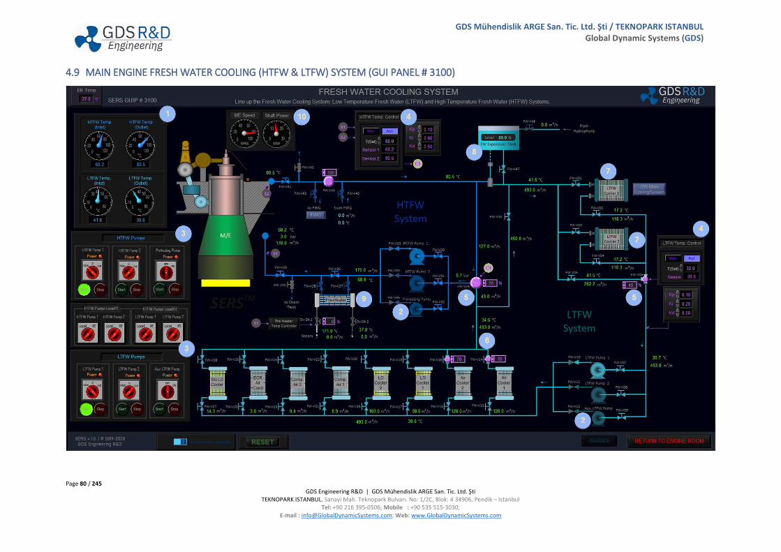
Page 80 / 245 GDS Engineering R&D | GDS Mühendislik ARGE San. Tic. Ltd. Şti
TEKNOPARK ISTANBUL. Sanayi Mah. Teknopark Bulvarı. No: 1/2C, Blok: 4 34906, Pendik – Istanbul Tel: +90 216 395-0506; Mobile : +90 535 515-3030;
E-mail : [email protected]; Web: www.GlobalDynamicSystems.com
GDS Mühendislik ARGE San. Tic. Ltd. Şti / TEKNOPARK ISTANBUL Global Dynamic Systems (GDS)
4.9 MAIN ENGINE FRESH WATER COOLING (HTFW & LTFW) SYSTEM (GUI PANEL # 3100)
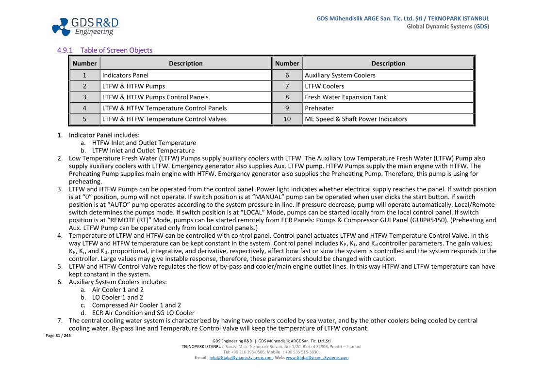
Page 81 / 245 GDS Engineering R&D | GDS Mühendislik ARGE San. Tic. Ltd. Şti
TEKNOPARK ISTANBUL. Sanayi Mah. Teknopark Bulvarı. No: 1/2C, Blok: 4 34906, Pendik – Istanbul Tel: +90 216 395-0506; Mobile : +90 535 515-3030;
E-mail : [email protected]; Web: www.GlobalDynamicSystems.com
GDS Mühendislik ARGE San. Tic. Ltd. Şti / TEKNOPARK ISTANBUL Global Dynamic Systems (GDS)
4.9.1 Table of Screen Objects
Number Description Number Description
1 Indicators Panel 6 Auxiliary System Coolers 2 LTFW & HTFW Pumps 7 LTFW Coolers 3 LTFW & HTFW Pumps Control Panels 8 Fresh Water Expansion Tank 4 LTFW & HTFW Temperature Control Panels 9 Preheater 5 LTFW & HTFW Temperature Control Valves 10 ME Speed & Shaft Power Indicators
1. Indicator Panel includes: a. HTFW Inlet and Outlet Temperature b. LTFW Inlet and Outlet Temperature
2. Low Temperature Fresh Water (LTFW) Pumps supply auxiliary coolers with LTFW. The Auxiliary Low Temperature Fresh Water (LTFW) Pump also supply auxiliary coolers with LTFW. Emergency generator also supplies Aux. LTFW pump. HTFW Pumps supply the main engine with HTFW. The Preheating Pump supplies main engine with HTFW. Emergency generator also supplies the Preheating Pump. Therefore, this pump is using for preheating.
3. LTFW and HTFW Pumps can be operated from the control panel. Power light indicates whether electrical supply reaches the panel. If switch position is at “0” position, pump will not operate. If switch position is at “MANUAL” pump can be operated when user clicks the start button. If switch position is at “AUTO” pump operates according to the system pressure in-line. If pressure decrease, pump will operate automatically. Local/Remote switch determines the pumps mode. If switch position is at “LOCAL” Mode, pumps can be started locally from the local control panel. If switch position is at “REMOTE (RT)” Mode, pumps can be started remotely from ECR Panels: Pumps & Compressor GUI Panel (GUIP#5450). (Preheating and Aux. LTFW Pump can be operated only from local control panels.)
4. Temperature of LTFW and HTFW can be controlled with control panel. Control panel actuates LTFW and HTFW Temperature Control Valve. In this way LTFW and HTFW temperature can be kept constant in the system. Control panel includes KP, Ki, and Kd controller parameters. The gain values; KP, Ki, and Kd, proportional, integrative, and derivative, respectively, affect how fast or slow the system is controlled and the system responds to the controller. Large values may give instable response, therefore, these parameters should be changed with caution.
5. LTFW and HTFW Control Valve regulates the flow of by-pass and cooler/main engine outlet lines. In this way HTFW and LTFW temperature can have kept constant in the system.
6. Auxiliary System Coolers includes: a. Air Cooler 1 and 2 b. LO Cooler 1 and 2 c. Compressed Air Cooler 1 and 2 d. ECR Air Condition and SG LO Cooler
7. The central cooling water system is characterized by having two coolers cooled by sea water, and by the other coolers being cooled by central cooling water. By-pass line and Temperature Control Valve will keep the temperature of LTFW constant.
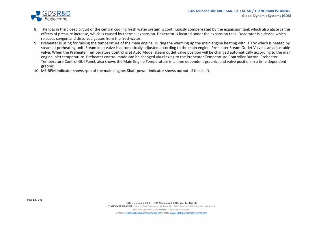
Page 82 / 245 GDS Engineering R&D | GDS Mühendislik ARGE San. Tic. Ltd. Şti
TEKNOPARK ISTANBUL. Sanayi Mah. Teknopark Bulvarı. No: 1/2C, Blok: 4 34906, Pendik – Istanbul Tel: +90 216 395-0506; Mobile : +90 535 515-3030;
E-mail : [email protected]; Web: www.GlobalDynamicSystems.com
GDS Mühendislik ARGE San. Tic. Ltd. Şti / TEKNOPARK ISTANBUL Global Dynamic Systems (GDS)
8. The loss in the closed circuit of the central cooling fresh water system is continuously compensated by the expansion tank which also absorbs the effects of pressure increase, which is caused by thermal expansion. Deaerator is located under the expansion tank. Deaerator is a device which releases oxygen and dissolved gasses from the freshwater.
9. Preheater is using for raising the temperature of the main engine. During the warming up the main engine heating with HTFW which is heated by steam at preheating unit. Steam inlet valve is automatically adjusted according to the main engine. Preheater Steam Outlet Valve is an adjustable valve. When the Preheater Temperature Control is at Auto Mode, steam outlet valve position will be changed automatically according to the main engine inlet temperature. Preheater control mode can be changed via clicking to the Preheater Temperature Controller Button. Preheater Temperature Control GUI Panel, also shows the Main Engine Temperature in a time dependent graphic, and valve position in a time dependent graphic.
10. ME RPM indicator shows rpm of the main engine. Shaft power indicator shows output of the shaft.
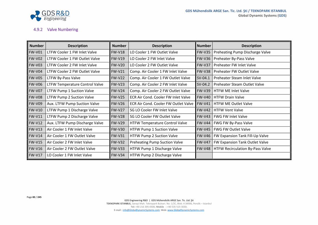
Page 83 / 245 GDS Engineering R&D | GDS Mühendislik ARGE San. Tic. Ltd. Şti
TEKNOPARK ISTANBUL. Sanayi Mah. Teknopark Bulvarı. No: 1/2C, Blok: 4 34906, Pendik – Istanbul Tel: +90 216 395-0506; Mobile : +90 535 515-3030;
E-mail : [email protected]; Web: www.GlobalDynamicSystems.com
GDS Mühendislik ARGE San. Tic. Ltd. Şti / TEKNOPARK ISTANBUL Global Dynamic Systems (GDS)
4.9.2 Valve Numbering
Number Description Number Description Number Description FW-V01 LTFW Cooler 1 FW Inlet Valve FW-V18 LO Cooler 1 FW Outlet Valve FW-V35 Preheating Pump Discharge Valve FW-V02 LTFW Cooler 1 FW Outlet Valve FW-V19 LO Cooler 2 FW Inlet Valve FW-V36 Preheater By-Pass Valve FW-V03 LTFW Cooler 2 FW Inlet Valve FW-V20 LO Cooler 2 FW Outlet Valve FW-V37 Preheater FW Inlet Valve FW-V04 LTFW Cooler 2 FW Outlet Valve FW-V21 Comp. Air Cooler 1 FW Inlet Valve FW-V38 Preheater FW Outlet Valve FW-V05 LTFW By-Pass Valve FW-V22 Comp. Air Cooler 1 FW Outlet Valve SV-04.1 Preheater Steam Inlet Valve FW-V06 LTFW Temperature Control Valve FW-V23 Comp. Air Cooler 2 FW Inlet Valve SV-04.2 Preheater Steam Outlet Valve FW-V07 LTFW Pump 1 Suction Valve FW-V24 Comp. Air Cooler 2 FW Outlet Valve FW-V39 HTFW ME Inlet Valve FW-V08 LTFW Pump 2 Suction Valve FW-V25 ECR Air Cond. Cooler FW Inlet Valve FW-V40 HTFW Drain Valve FW-V09 Aux. LTFW Pump Suction Valve FW-V26 ECR Air Cond. Cooler FW Outlet Valve FW-V41 HTFW ME Outlet Valve FW-V10 LTFW Pump 1 Discharge Valve FW-V27 SG LO Cooler FW Inlet Valve FW-V42 HTFW Vent Valve FW-V11 LTFW Pump 2 Discharge Valve FW-V28 SG LO Cooler FW Outlet Valve FW-V43 FWG FW Inlet Valve FW-V12 Aux. LTFW Pump Discharge Valve FW-V29 HTFW Temperature Control Valve FW-V44 FWG FW By-Pass Valve FW-V13 Air Cooler 1 FW Inlet Valve FW-V30 HTFW Pump 1 Suction Valve FW-V45 FWG FW Outlet Valve FW-V14 Air Cooler 1 FW Outlet Valve FW-V31 HTFW Pump 2 Suction Valve FW-V46 FW Expansion Tank Fill-Up Valve FW-V15 Air Cooler 2 FW Inlet Valve FW-V32 Preheating Pump Suction Valve FW-V47 FW Expansion Tank Outlet Valve FW-V16 Air Cooler 2 FW Outlet Valve FW-V33 HTFW Pump 1 Discharge Valve FW-V48 HTFW Recirculation By-Pass Valve FW-V17 LO Cooler 1 FW Inlet Valve FW-V34 HTFW Pump 2 Discharge Valve

Page 84 / 245 GDS Engineering R&D | GDS Mühendislik ARGE San. Tic. Ltd. Şti
TEKNOPARK ISTANBUL. Sanayi Mah. Teknopark Bulvarı. No: 1/2C, Blok: 4 34906, Pendik – Istanbul Tel: +90 216 395-0506; Mobile : +90 535 515-3030;
E-mail : [email protected]; Web: www.GlobalDynamicSystems.com
GDS Mühendislik ARGE San. Tic. Ltd. Şti / TEKNOPARK ISTANBUL Global Dynamic Systems (GDS)
4.10 MAIN ENGINE BEARINGS MONITORING (GUI PANEL # 4700)
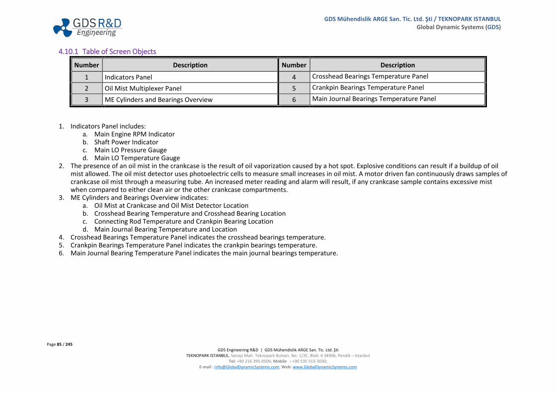
Page 85 / 245 GDS Engineering R&D | GDS Mühendislik ARGE San. Tic. Ltd. Şti
TEKNOPARK ISTANBUL. Sanayi Mah. Teknopark Bulvarı. No: 1/2C, Blok: 4 34906, Pendik – Istanbul Tel: +90 216 395-0506; Mobile : +90 535 515-3030;
E-mail : [email protected]; Web: www.GlobalDynamicSystems.com
GDS Mühendislik ARGE San. Tic. Ltd. Şti / TEKNOPARK ISTANBUL Global Dynamic Systems (GDS)
4.10.1 Table of Screen Objects
Number Description Number Description
1 Indicators Panel 4 Crosshead Bearings Temperature Panel
2 Oil Mist Multiplexer Panel 5 Crankpin Bearings Temperature Panel
3 ME Cylinders and Bearings Overview 6 Main Journal Bearings Temperature Panel
1. Indicators Panel includes: a. Main Engine RPM Indicator b. Shaft Power Indicator c. Main LO Pressure Gauge d. Main LO Temperature Gauge
2. The presence of an oil mist in the crankcase is the result of oil vaporization caused by a hot spot. Explosive conditions can result if a buildup of oil mist allowed. The oil mist detector uses photoelectric cells to measure small increases in oil mist. A motor driven fan continuously draws samples of crankcase oil mist through a measuring tube. An increased meter reading and alarm will result, if any crankcase sample contains excessive mist when compared to either clean air or the other crankcase compartments.
3. ME Cylinders and Bearings Overview indicates: a. Oil Mist at Crankcase and Oil Mist Detector Location b. Crosshead Bearing Temperature and Crosshead Bearing Location c. Connecting Rod Temperature and Crankpin Bearing Location d. Main Journal Bearing Temperature and Location
4. Crosshead Bearings Temperature Panel indicates the crosshead bearings temperature. 5. Crankpin Bearings Temperature Panel indicates the crankpin bearings temperature. 6. Main Journal Bearing Temperature Panel indicates the main journal bearings temperature.

Page 86 / 245 GDS Engineering R&D | GDS Mühendislik ARGE San. Tic. Ltd. Şti
TEKNOPARK ISTANBUL. Sanayi Mah. Teknopark Bulvarı. No: 1/2C, Blok: 4 34906, Pendik – Istanbul Tel: +90 216 395-0506; Mobile : +90 535 515-3030;
E-mail : [email protected]; Web: www.GlobalDynamicSystems.com
GDS Mühendislik ARGE San. Tic. Ltd. Şti / TEKNOPARK ISTANBUL Global Dynamic Systems (GDS)
4.11 MAIN ENGINE MANIFOLDS & TURBOCHARGERS (GUI PANEL # 4650)

Page 87 / 245 GDS Engineering R&D | GDS Mühendislik ARGE San. Tic. Ltd. Şti
TEKNOPARK ISTANBUL. Sanayi Mah. Teknopark Bulvarı. No: 1/2C, Blok: 4 34906, Pendik – Istanbul Tel: +90 216 395-0506; Mobile : +90 535 515-3030;
E-mail : [email protected]; Web: www.GlobalDynamicSystems.com
GDS Mühendislik ARGE San. Tic. Ltd. Şti / TEKNOPARK ISTANBUL Global Dynamic Systems (GDS)
4.11.1 Table of Screen Objects
Number Description Number Description
1 Indicators Panel 4 Exhaust Manifold 2 Turbochargers 5 Scavenge Air Manifold 3 Air Coolers 6 Auxiliary Blowers
1. Indicators Panel includes: a. Main Engine RPM Indicator b. Shaft Power Indicator
2. The Turbine is driven by exhaust gases from the engine and rigidly coupled to a centrifugal air compressor. Thus main engine efficiency and power increases. Following parameters are shown with indicators for Turbochargers (TCs):
a. Internal Lubricating Oil Level and Temperature Indicators b. TC RPM indicators c. Pressure Drop across Compressor (ΔP) Indicator d. Exhaust Gas Pressure Drop on Turbochargers (ΔP) Indicator
3. Air coolers (charge air cooler) uses to cool and therefore, increase the specific density of air prior to combustion in main engine. Air Coolers LTFW Inlet and Outlet Valves can be opened or closed from the Main Engine Fresh Water Cooling System GUI Panel (GUIP #3100).
4. Exhaust Line to Economizer provides the following variables displayed on top of this GUI Panel: a. Flow Rate b. Temperature c. Pressure d. Exhaust Line Backpressure
5. Scavenge section provides the following parameters indicators: a. Flow Rate b. Charge Air temperature c. Temperatures (FW and Charge Air inlets and outlets) for Air Coolers. d. Scavenge Air Manifold Pressure e. Scavenge Air Manifold Temperature.
6. Auxiliary Blowers: On two-stroke diesels, electrical-driven auxiliary blowers are usually provided because the exhaust gas-driven turbocharger cannot provide enough air at low engine speed. Auxiliary blowers are internal parts of the main engine. Auxiliary Blowers can be operated from the ME Control (ECR) GUI Panel (GUIP #2100).

Page 88 / 245 GDS Engineering R&D | GDS Mühendislik ARGE San. Tic. Ltd. Şti
TEKNOPARK ISTANBUL. Sanayi Mah. Teknopark Bulvarı. No: 1/2C, Blok: 4 34906, Pendik – Istanbul Tel: +90 216 395-0506; Mobile : +90 535 515-3030;
E-mail : [email protected]; Web: www.GlobalDynamicSystems.com
GDS Mühendislik ARGE San. Tic. Ltd. Şti / TEKNOPARK ISTANBUL Global Dynamic Systems (GDS)
4.12 EXHAUST GAS DENOXIFICATION SYSTEM (GUI PANEL # 4750)
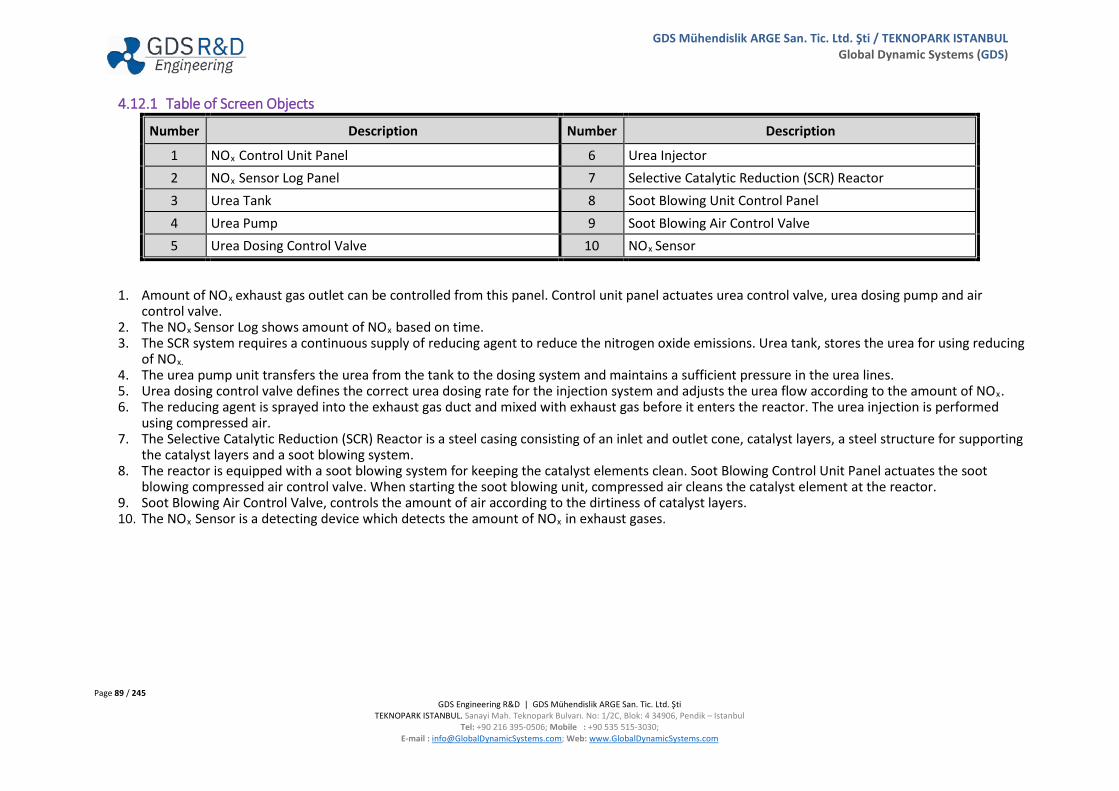
Page 89 / 245 GDS Engineering R&D | GDS Mühendislik ARGE San. Tic. Ltd. Şti
TEKNOPARK ISTANBUL. Sanayi Mah. Teknopark Bulvarı. No: 1/2C, Blok: 4 34906, Pendik – Istanbul Tel: +90 216 395-0506; Mobile : +90 535 515-3030;
E-mail : [email protected]; Web: www.GlobalDynamicSystems.com
GDS Mühendislik ARGE San. Tic. Ltd. Şti / TEKNOPARK ISTANBUL Global Dynamic Systems (GDS)
4.12.1 Table of Screen Objects
Number Description Number Description
1 NOx Control Unit Panel 6 Urea Injector 2 NOx Sensor Log Panel 7 Selective Catalytic Reduction (SCR) Reactor 3 Urea Tank 8 Soot Blowing Unit Control Panel 4 Urea Pump 9 Soot Blowing Air Control Valve 5 Urea Dosing Control Valve 10 NOx Sensor
1. Amount of NOx exhaust gas outlet can be controlled from this panel. Control unit panel actuates urea control valve, urea dosing pump and air control valve.
2. The NOx Sensor Log shows amount of NOx based on time. 3. The SCR system requires a continuous supply of reducing agent to reduce the nitrogen oxide emissions. Urea tank, stores the urea for using reducing
of NOx. 4. The urea pump unit transfers the urea from the tank to the dosing system and maintains a sufficient pressure in the urea lines. 5. Urea dosing control valve defines the correct urea dosing rate for the injection system and adjusts the urea flow according to the amount of NOx. 6. The reducing agent is sprayed into the exhaust gas duct and mixed with exhaust gas before it enters the reactor. The urea injection is performed
using compressed air. 7. The Selective Catalytic Reduction (SCR) Reactor is a steel casing consisting of an inlet and outlet cone, catalyst layers, a steel structure for supporting
the catalyst layers and a soot blowing system. 8. The reactor is equipped with a soot blowing system for keeping the catalyst elements clean. Soot Blowing Control Unit Panel actuates the soot
blowing compressed air control valve. When starting the soot blowing unit, compressed air cleans the catalyst element at the reactor. 9. Soot Blowing Air Control Valve, controls the amount of air according to the dirtiness of catalyst layers. 10. The NOx Sensor is a detecting device which detects the amount of NOx in exhaust gases.
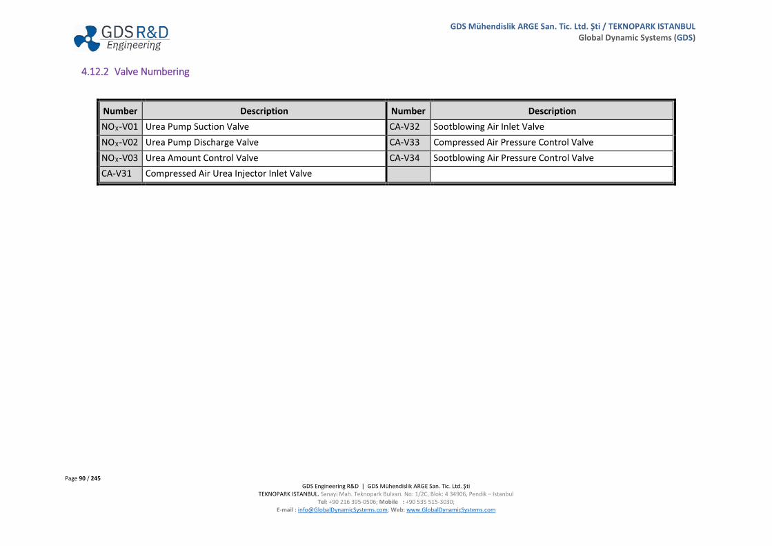
Page 90 / 245 GDS Engineering R&D | GDS Mühendislik ARGE San. Tic. Ltd. Şti
TEKNOPARK ISTANBUL. Sanayi Mah. Teknopark Bulvarı. No: 1/2C, Blok: 4 34906, Pendik – Istanbul Tel: +90 216 395-0506; Mobile : +90 535 515-3030;
E-mail : [email protected]; Web: www.GlobalDynamicSystems.com
GDS Mühendislik ARGE San. Tic. Ltd. Şti / TEKNOPARK ISTANBUL Global Dynamic Systems (GDS)
4.12.2 Valve Numbering
Number Description Number Description NOX-V01 Urea Pump Suction Valve CA-V32 Sootblowing Air Inlet Valve NOX-V02 Urea Pump Discharge Valve CA-V33 Compressed Air Pressure Control Valve NOX-V03 Urea Amount Control Valve CA-V34 Sootblowing Air Pressure Control Valve CA-V31 Compressed Air Urea Injector Inlet Valve
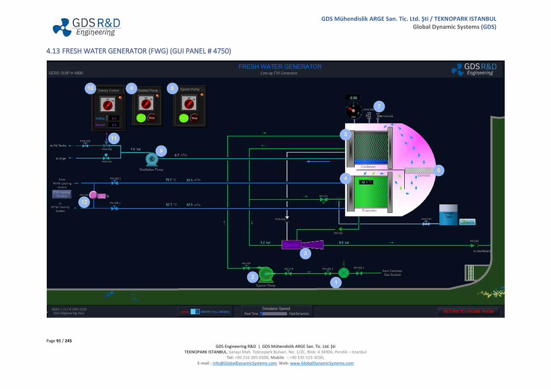
Page 91 / 245 GDS Engineering R&D | GDS Mühendislik ARGE San. Tic. Ltd. Şti
TEKNOPARK ISTANBUL. Sanayi Mah. Teknopark Bulvarı. No: 1/2C, Blok: 4 34906, Pendik – Istanbul Tel: +90 216 395-0506; Mobile : +90 535 515-3030;
E-mail : [email protected]; Web: www.GlobalDynamicSystems.com
GDS Mühendislik ARGE San. Tic. Ltd. Şti / TEKNOPARK ISTANBUL Global Dynamic Systems (GDS)
4.13 FRESH WATER GENERATOR (FWG) (GUI PANEL # 4750)
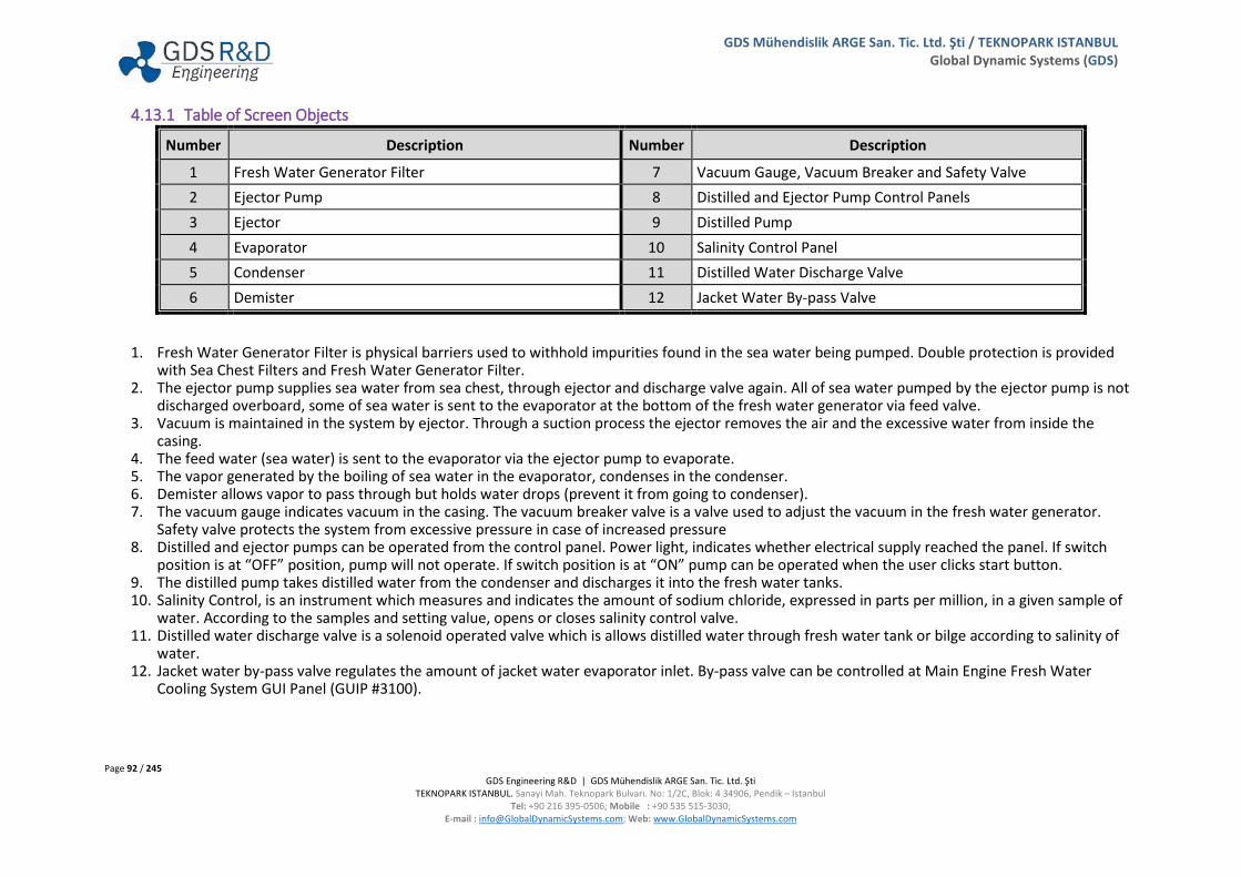
Page 92 / 245 GDS Engineering R&D | GDS Mühendislik ARGE San. Tic. Ltd. Şti
TEKNOPARK ISTANBUL. Sanayi Mah. Teknopark Bulvarı. No: 1/2C, Blok: 4 34906, Pendik – Istanbul Tel: +90 216 395-0506; Mobile : +90 535 515-3030;
E-mail : [email protected]; Web: www.GlobalDynamicSystems.com
GDS Mühendislik ARGE San. Tic. Ltd. Şti / TEKNOPARK ISTANBUL Global Dynamic Systems (GDS)
4.13.1 Table of Screen Objects
Number Description Number Description
1 Fresh Water Generator Filter 7 Vacuum Gauge, Vacuum Breaker and Safety Valve 2 Ejector Pump 8 Distilled and Ejector Pump Control Panels 3 Ejector 9 Distilled Pump 4 Evaporator 10 Salinity Control Panel 5 Condenser 11 Distilled Water Discharge Valve 6 Demister 12 Jacket Water By-pass Valve
1. Fresh Water Generator Filter is physical barriers used to withhold impurities found in the sea water being pumped. Double protection is provided with Sea Chest Filters and Fresh Water Generator Filter.
2. The ejector pump supplies sea water from sea chest, through ejector and discharge valve again. All of sea water pumped by the ejector pump is not discharged overboard, some of sea water is sent to the evaporator at the bottom of the fresh water generator via feed valve.
3. Vacuum is maintained in the system by ejector. Through a suction process the ejector removes the air and the excessive water from inside the casing.
4. The feed water (sea water) is sent to the evaporator via the ejector pump to evaporate. 5. The vapor generated by the boiling of sea water in the evaporator, condenses in the condenser. 6. Demister allows vapor to pass through but holds water drops (prevent it from going to condenser). 7. The vacuum gauge indicates vacuum in the casing. The vacuum breaker valve is a valve used to adjust the vacuum in the fresh water generator.
Safety valve protects the system from excessive pressure in case of increased pressure 8. Distilled and ejector pumps can be operated from the control panel. Power light, indicates whether electrical supply reached the panel. If switch
position is at “OFF” position, pump will not operate. If switch position is at “ON” pump can be operated when the user clicks start button. 9. The distilled pump takes distilled water from the condenser and discharges it into the fresh water tanks. 10. Salinity Control, is an instrument which measures and indicates the amount of sodium chloride, expressed in parts per million, in a given sample of
water. According to the samples and setting value, opens or closes salinity control valve. 11. Distilled water discharge valve is a solenoid operated valve which is allows distilled water through fresh water tank or bilge according to salinity of
water. 12. Jacket water by-pass valve regulates the amount of jacket water evaporator inlet. By-pass valve can be controlled at Main Engine Fresh Water
Cooling System GUI Panel (GUIP #3100).

Page 93 / 245 GDS Engineering R&D | GDS Mühendislik ARGE San. Tic. Ltd. Şti
TEKNOPARK ISTANBUL. Sanayi Mah. Teknopark Bulvarı. No: 1/2C, Blok: 4 34906, Pendik – Istanbul Tel: +90 216 395-0506; Mobile : +90 535 515-3030;
E-mail : [email protected]; Web: www.GlobalDynamicSystems.com
GDS Mühendislik ARGE San. Tic. Ltd. Şti / TEKNOPARK ISTANBUL Global Dynamic Systems (GDS)
4.13.2 Valve Numbering
Number Description Number Description SW-V01.1 Fresh Water Generator Filter Inlet Valve FW-45.1 Jacket Water Outlet Valve SW-V02.1 Fresh Water Generator Filter Outlet Valve FWG-V01 Distillation Pump Discharge Valve to FW Tanks SW-V19 Ejector Pump Suction Valve FWG-V02 Distillation Pump Discharge Valve to Bilge Tank SW-V20 Ejector Pump Discharge Valve FWG-V03 FW Tanks Fill-Up Valve SW-V21 Evaporator SW Inlet Valve FWG-V04 Vacuum Valve SW-V22 Evaporator SW Outlet Valve FWG-V05 Safety Valve SW-V23 Overboard Valve FWG-V06 Vacuum Breaker Valve FW-V43.1 Jacket Water Inlet Valve FWG-V07 Dosage Tank Outlet Valve FW-V44 FWG FW By-Pass Valve

Page 94 / 245 GDS Engineering R&D | GDS Mühendislik ARGE San. Tic. Ltd. Şti
TEKNOPARK ISTANBUL. Sanayi Mah. Teknopark Bulvarı. No: 1/2C, Blok: 4 34906, Pendik – Istanbul Tel: +90 216 395-0506; Mobile : +90 535 515-3030;
E-mail : [email protected]; Web: www.GlobalDynamicSystems.com
GDS Mühendislik ARGE San. Tic. Ltd. Şti / TEKNOPARK ISTANBUL Global Dynamic Systems (GDS)
4.14 SHIP PROPULSION SYSTEM & SHAFT GENERATOR (GUI PANEL # 4600)

Page 95 / 245 GDS Engineering R&D | GDS Mühendislik ARGE San. Tic. Ltd. Şti
TEKNOPARK ISTANBUL. Sanayi Mah. Teknopark Bulvarı. No: 1/2C, Blok: 4 34906, Pendik – Istanbul Tel: +90 216 395-0506; Mobile : +90 535 515-3030;
E-mail : [email protected]; Web: www.GlobalDynamicSystems.com
GDS Mühendislik ARGE San. Tic. Ltd. Şti / TEKNOPARK ISTANBUL Global Dynamic Systems (GDS)
4.14.1 Table of Screen Objects
Number Description Number Description
1 Main Engine Parameters 3 Ship Propulsion Parameters
2 Rudder Indicator & Steering Gear System Status 4 Shaft Generator System (PTO/CFE) Control Panel
1. Main Indicators Panel shows parameters such as: • ME Fuel Consumption (kg/h) • Specific Fuel Oil Consumption (SFOC) • Ship Speed (knots) • ME Speed (RPM) • ME Power (MW)
2. Rudder indicator indicates the actual rudder position. Steering Gear system status indicates which steering gear pump is operating. 3. Ship Operational Parameters collected two different title:
a. Ship Conditions i. Ship Load
ii. Ship Draft iii. Ship Trim iv. Ship Heel v. Air Temperature
vi. Relative Humidity vii. Wind Speed (Beaufort)
viii. Wind Direction b. Ship Operations
i. Ship Speed ii. Propulsion RPM
iii. Propulsion Power iv. Propulsion Thrust v. Ship Resistance
vi. Slip Rate vii. Shaft Torque
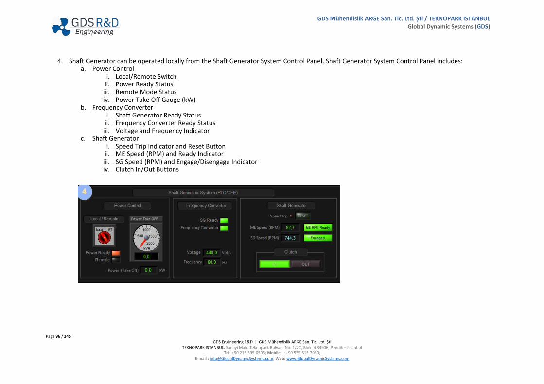
Page 96 / 245 GDS Engineering R&D | GDS Mühendislik ARGE San. Tic. Ltd. Şti
TEKNOPARK ISTANBUL. Sanayi Mah. Teknopark Bulvarı. No: 1/2C, Blok: 4 34906, Pendik – Istanbul Tel: +90 216 395-0506; Mobile : +90 535 515-3030;
E-mail : [email protected]; Web: www.GlobalDynamicSystems.com
GDS Mühendislik ARGE San. Tic. Ltd. Şti / TEKNOPARK ISTANBUL Global Dynamic Systems (GDS)
4. Shaft Generator can be operated locally from the Shaft Generator System Control Panel. Shaft Generator System Control Panel includes: a. Power Control
i. Local/Remote Switch ii. Power Ready Status
iii. Remote Mode Status iv. Power Take Off Gauge (kW)
b. Frequency Converter i. Shaft Generator Ready Status
ii. Frequency Converter Ready Status iii. Voltage and Frequency Indicator
c. Shaft Generator i. Speed Trip Indicator and Reset Button
ii. ME Speed (RPM) and Ready Indicator iii. SG Speed (RPM) and Engage/Disengage Indicator iv. Clutch In/Out Buttons

Page 97 / 245 GDS Engineering R&D | GDS Mühendislik ARGE San. Tic. Ltd. Şti
TEKNOPARK ISTANBUL. Sanayi Mah. Teknopark Bulvarı. No: 1/2C, Blok: 4 34906, Pendik – Istanbul Tel: +90 216 395-0506; Mobile : +90 535 515-3030;
E-mail : [email protected]; Web: www.GlobalDynamicSystems.com
GDS Mühendislik ARGE San. Tic. Ltd. Şti / TEKNOPARK ISTANBUL Global Dynamic Systems (GDS)
4.15 ELECTRICAL POWER PLANT (GUI PANEL # 5000)
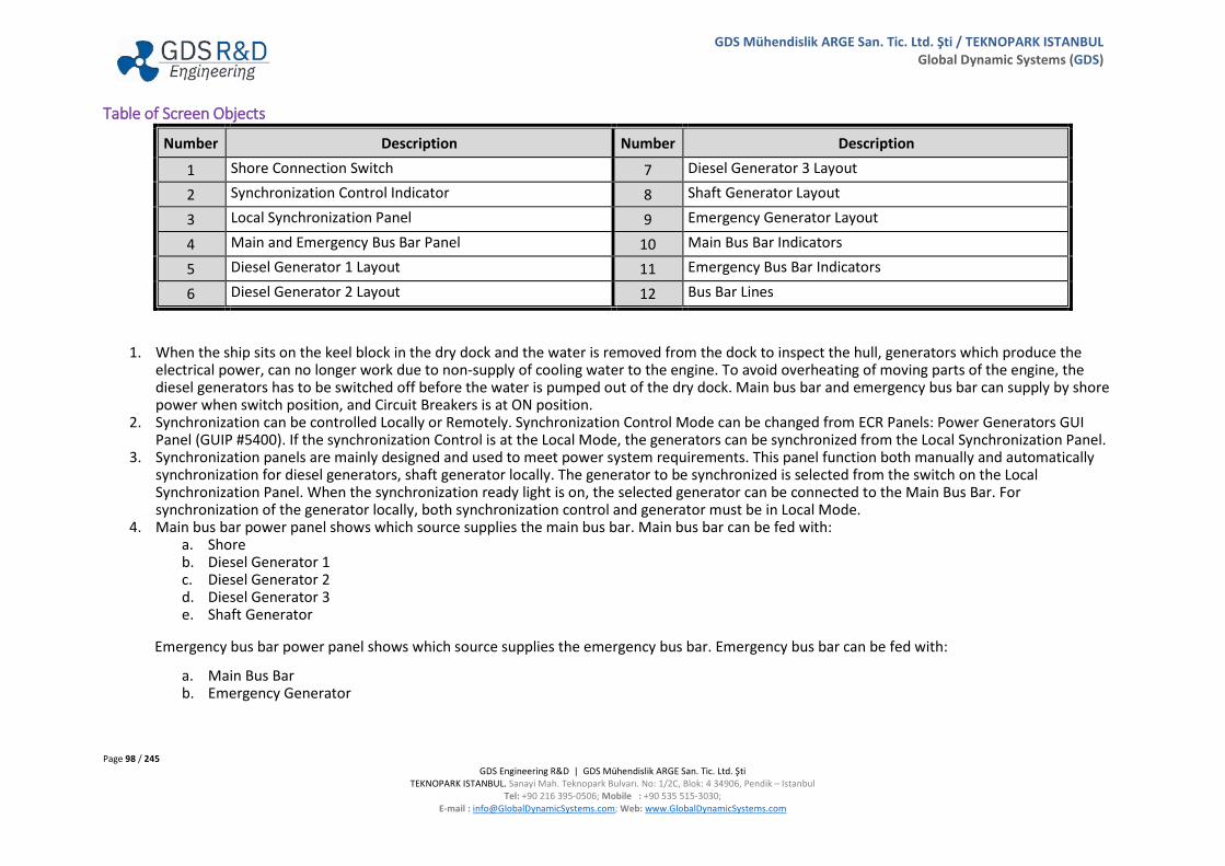
Page 98 / 245 GDS Engineering R&D | GDS Mühendislik ARGE San. Tic. Ltd. Şti
TEKNOPARK ISTANBUL. Sanayi Mah. Teknopark Bulvarı. No: 1/2C, Blok: 4 34906, Pendik – Istanbul Tel: +90 216 395-0506; Mobile : +90 535 515-3030;
E-mail : [email protected]; Web: www.GlobalDynamicSystems.com
GDS Mühendislik ARGE San. Tic. Ltd. Şti / TEKNOPARK ISTANBUL Global Dynamic Systems (GDS)
Table of Screen Objects
Number Description Number Description
1 Shore Connection Switch 7 Diesel Generator 3 Layout
2 Synchronization Control Indicator 8 Shaft Generator Layout
3 Local Synchronization Panel 9 Emergency Generator Layout
4 Main and Emergency Bus Bar Panel 10 Main Bus Bar Indicators
5 Diesel Generator 1 Layout 11 Emergency Bus Bar Indicators
6 Diesel Generator 2 Layout 12 Bus Bar Lines
1. When the ship sits on the keel block in the dry dock and the water is removed from the dock to inspect the hull, generators which produce the electrical power, can no longer work due to non-supply of cooling water to the engine. To avoid overheating of moving parts of the engine, the diesel generators has to be switched off before the water is pumped out of the dry dock. Main bus bar and emergency bus bar can supply by shore power when switch position, and Circuit Breakers is at ON position.
2. Synchronization can be controlled Locally or Remotely. Synchronization Control Mode can be changed from ECR Panels: Power Generators GUI Panel (GUIP #5400). If the synchronization Control is at the Local Mode, the generators can be synchronized from the Local Synchronization Panel.
3. Synchronization panels are mainly designed and used to meet power system requirements. This panel function both manually and automatically synchronization for diesel generators, shaft generator locally. The generator to be synchronized is selected from the switch on the Local Synchronization Panel. When the synchronization ready light is on, the selected generator can be connected to the Main Bus Bar. For synchronization of the generator locally, both synchronization control and generator must be in Local Mode.
4. Main bus bar power panel shows which source supplies the main bus bar. Main bus bar can be fed with: a. Shore b. Diesel Generator 1 c. Diesel Generator 2 d. Diesel Generator 3 e. Shaft Generator
Emergency bus bar power panel shows which source supplies the emergency bus bar. Emergency bus bar can be fed with:
a. Main Bus Bar b. Emergency Generator
Page 99 / 245 GDS Engineering R&D | GDS Mühendislik ARGE San. Tic. Ltd. Şti
TEKNOPARK ISTANBUL. Sanayi Mah. Teknopark Bulvarı. No: 1/2C, Blok: 4 34906, Pendik – Istanbul Tel: +90 216 395-0506; Mobile : +90 535 515-3030;
E-mail : [email protected]; Web: www.GlobalDynamicSystems.com
GDS Mühendislik ARGE San. Tic. Ltd. Şti / TEKNOPARK ISTANBUL Global Dynamic Systems (GDS)
5. Diesel Generator 1 Layout consists: a. Diesel Generator 1 Circuit Breaker The diesel generator 1 fed the bus bar and the circuit breaker is used
to draw off the supply. b. Diesel Generator 1 Trip Indicator Panel
i. Overload If occur, which is in excess of the rated capacity of diesel generator, overload protection device interrupts the current flow.
ii. Low Voltage Ensure that if the input voltage drops below certain value, or it will be cut off completely.
iii. Low Frequency Under the frequency protection is used to protect the generator when the frequency drops below the operating frequency.
c. Diesel Generator 1 Speed Control Panel The speed control panel controls the rpm of the diesel generator 1. In this way, diesel generator 1 frequency and load can be controlled.
d. Diesel Generator 1 Automatic Voltage Regulator Switch Panel The function of the Automatic Voltage Regulator (AVR) is to maintain constant voltage and power line conditioning to the equipment under a wide variety of conditions, even when the utility input voltage, frequency or system load vary widely.
e. Engine Status Indicator Panel and RPM Indicator The engine status indicator panel shows whether diesel generator 1 working or not or tripped. RPM indicator shows the rpm of the diesel generator 1.

Page 100 / 245 GDS Engineering R&D | GDS Mühendislik ARGE San. Tic. Ltd. Şti
TEKNOPARK ISTANBUL. Sanayi Mah. Teknopark Bulvarı. No: 1/2C, Blok: 4 34906, Pendik – Istanbul Tel: +90 216 395-0506; Mobile : +90 535 515-3030;
E-mail : [email protected]; Web: www.GlobalDynamicSystems.com
GDS Mühendislik ARGE San. Tic. Ltd. Şti / TEKNOPARK ISTANBUL Global Dynamic Systems (GDS)
f. Local/Remote Indicator Local/Remote indicator indicates whether diesel generator is at LOCAL or REMOTE Mode.
6. Diesel Generator 2 Layout consists: a. Diesel Generator 2 Circuit Breaker b. Diesel Generator 2 Trip Indicator Panel c. Diesel Generator 2 Speed Control Panel d. Diesel Generator 2 Automatic Voltage Regulator Switch Panel e. Engine Status Indicator Panel and RPM Indicator f. Local/Remote Indicator
7. Diesel Generator 3 Layout consists: a. Diesel Generator 3 Circuit Breaker b. Diesel Generator 3 Trip Indicator Panel c. Diesel Generator 3 Speed Control Panel d. Diesel Generator 3 Automatic Voltage Regulator Switch Panel e. Engine Status Indicator Panel and RPM Indicator f. Local/Remote Indicator
8. Shaft Generator Layout consists: a. Shaft Generator Circuit Breaker b. Shaft Generator Trip Indicator Panel c. Shaft Generator Load Control Panel d. Shaft Generator Voltage Control Panel The function of the Voltage Control is to maintain constant voltage and power line
conditioning to the equipment under a wide variety of conditions, even when the utility input voltage, frequency or system load vary widely.
e. Shaft Generator Local/Remote Indicator f. Shaft Generator Status Indicator Panel Shaft generator status indicator panel shows whether shaft generator working or not or
tripped.
9. Emergency Generator (EG) Layout consists: a. Emergency Generator Circuit Breaker Emergency generator feds the emergency bus bar and circuit breaker are used to draw off
the supply.
Page 101 / 245 GDS Engineering R&D | GDS Mühendislik ARGE San. Tic. Ltd. Şti
TEKNOPARK ISTANBUL. Sanayi Mah. Teknopark Bulvarı. No: 1/2C, Blok: 4 34906, Pendik – Istanbul Tel: +90 216 395-0506; Mobile : +90 535 515-3030;
E-mail : [email protected]; Web: www.GlobalDynamicSystems.com
GDS Mühendislik ARGE San. Tic. Ltd. Şti / TEKNOPARK ISTANBUL Global Dynamic Systems (GDS)
b. Emergency Generator Trip Indicator Panel c. Start Battery Percentage Indicator d. Emergency Generator Voltage Control Panel e. Emergency Generator Engine Control Panel The emergency generator can be started or be stopped from this panel in auto or manual
mode. If control mode is at AUTO, emergency generator will be started automatically when emergency bus bar is not feed by any source.
f. Emergency Generator RPM Indicator The emergency generator rpm indicator indicates the revolution per minute of emergency generator shaft.
g. Emergency Generator Fuel Tank EG fuel tank contains fuel ready for immediate use on emergency generator. 10. Main bus bar indicators panel includes:
a. Voltmeter The voltmeter shows the voltage on the Main Bus Bar in Volt unit. b. Frequency Indicator The frequency indicator shows the frequency of the Main Bus Bar in Hertz unit c. Power Indicator The power indicator shows the power on the Main Bus Bar in kilovolt-ampere unit.
11. Emergency bus bar indicators panel includes: a. Voltmeter The voltmeter shows the voltage on the Emergency Bus Bar in Volt unit. b. Power Indicator The power indicator shows the power on the Emergency Bus Bar in kilovolt-ampere unit.
12. Electrical power is conducted to the circuit breaker via bus bar lines. Electrical consumers are supplied with electrical power via electrical distribution networks. Bus bar lines are divided into:
a. 440 V Main Bus Bar 440 V, 220 V, and 24 VDC consumers are supplied with electrical power via 440 V Main Bus Bar. Electrical distribution network of the 440 V, 220 V, and 24 VDC consumers are depicted on GUIP #5600, GUIP #5700, and #5750
b. 440 V Reefers Bus Bar Reefers (Refrigerated Containers) are supplied with electrical power via 440 V Reefers Bus Bar. Reefers power distribution are depicted on GUIP #5800.
c. High Voltage Bus Bar Bow Thruster is supplied with electrical power via High Voltage Bus Bar. High Voltage Bus Bar is depicted on GUIP #5850.
d. 440 V Emergency Bus Bar 440 V, 220 V, and 24 VDC emergency consumers are supplied with electrical power via 440 V Emergency Bus Bar. Electrical distribution network of the 440 V, 220 V, and 24 VDC consumers are depicted on GUIP #5650, GUIP #5700, and GUIP #5750.

Page 102 / 245 GDS Engineering R&D | GDS Mühendislik ARGE San. Tic. Ltd. Şti
TEKNOPARK ISTANBUL. Sanayi Mah. Teknopark Bulvarı. No: 1/2C, Blok: 4 34906, Pendik – Istanbul Tel: +90 216 395-0506; Mobile : +90 535 515-3030;
E-mail : [email protected]; Web: www.GlobalDynamicSystems.com
GDS Mühendislik ARGE San. Tic. Ltd. Şti / TEKNOPARK ISTANBUL Global Dynamic Systems (GDS)
4.16 DIESEL GENERATOR 1 SYSTEMS & LOCAL CONTROL (GUI PANEL # 5100)
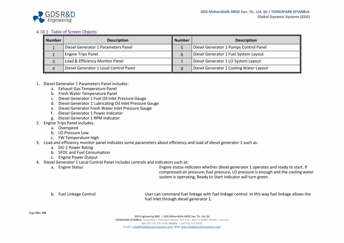
Page 103 / 245 GDS Engineering R&D | GDS Mühendislik ARGE San. Tic. Ltd. Şti
TEKNOPARK ISTANBUL. Sanayi Mah. Teknopark Bulvarı. No: 1/2C, Blok: 4 34906, Pendik – Istanbul Tel: +90 216 395-0506; Mobile : +90 535 515-3030;
E-mail : [email protected]; Web: www.GlobalDynamicSystems.com
GDS Mühendislik ARGE San. Tic. Ltd. Şti / TEKNOPARK ISTANBUL Global Dynamic Systems (GDS)
4.16.1 Table of Screen Objects
Number Description Number Description
1 Diesel Generator 1 Parameters Panel 5 Diesel Generator 1 Pumps Control Panel
2 Engine Trips Panel 6 Diesel Generator 1 Fuel System Layout
3 Load & Efficiency Monitor Panel 7 Diesel Generator 1 LO System Layout
4 Diesel Generator 1 Local Control Panel 8 Diesel Generator 1 Cooling Water Layout
1. Diesel Generator 1 Parameters Panel includes: a. Exhaust Gas Temperature Panel b. Fresh Water Temperature Panel c. Diesel Generator 1 Fuel Oil Inlet Pressure Gauge d. Diesel Generator 1 Lubricating Oil Inlet Pressure Gauge e. Diesel Generator Fresh Water Inlet Pressure Gauge f. Diesel Generator 1 Power Indicator g. Diesel Generator 1 RPM Indicator
2. Engine Trips Panel includes: a. Overspeed b. LO Pressure Low c. FW Temperature High
3. Load and efficiency monitor panel indicates some parameters about efficiency and load of diesel generator 1 such as: a. DG-1 Power Rating b. SFOC and Fuel Consumption c. Engine Power Output
4. Diesel Generator 1 Local Control Panel includes controls and indicators such as: a. Engine Status Engine status indicates whether diesel generator 1 operates and ready to start. If
compressed air pressure, fuel pressure, LO pressure is enough and the cooling water system is operating, Ready to Start indicator will turn green.
b. Fuel Linkage Control User can command fuel linkage with fuel linkage control. In this way fuel linkage allows the fuel inlet through diesel generator 1.
Page 104 / 245 GDS Engineering R&D | GDS Mühendislik ARGE San. Tic. Ltd. Şti
TEKNOPARK ISTANBUL. Sanayi Mah. Teknopark Bulvarı. No: 1/2C, Blok: 4 34906, Pendik – Istanbul Tel: +90 216 395-0506; Mobile : +90 535 515-3030;
E-mail : [email protected]; Web: www.GlobalDynamicSystems.com
GDS Mühendislik ARGE San. Tic. Ltd. Şti / TEKNOPARK ISTANBUL Global Dynamic Systems (GDS)
c. Local/Remote Switch If switch position is at “LOCAL” diesel generator 1 can be started from local panel. If switch position is at “REMOTE (RT)” diesel generator 1 can be started from ECR Panels: Power Generators (GUIP #5400)
d. Engine Start Diesel generator can be started or stopped from this panel locally.
5. Diesel Generator 1 Pumps Control Panel includes: a. LO Priming Pump Control Panel LO Priming Pump control panel, controls lubricating oil priming pump. Power light,
indicates whether electrical supply reached the panel. If switch position is at “0” position, LO Priming Pump will not operate. If switch position is at “MANUAL” LO Priming Pump can be operated if user click the start button. If switch position is at “AUTO” LO Priming Pump will be operated with timer.
b. Fuel Oil Pump Control Panel The FO Pump control panel, controls the fuel oil pump. If the panel supplied with electricity and switch is at ON position, fuel pump will start. If switch is at OFF position, pump will stop.
c. SW Pump Control Panel Sea water Pump control panel, controls the sea water pump. If the panel supplied with electricity and switch is at ON position, pump will start. If switch is at OFF position, pump will stop.
6. Diesel Generator 1 Fuel Oil System Layout includes: a. Fuel Changeover Panel Two buttons allow the user to control which type of fuel will be used in Diesel
Generator 1. Fuel change-over panel controls inlet and outlet lines via three-way valves.
b. Diesel Generator 1 Fuel Inlet Lines Diesel generator can be supplied with Marine Diesel Oil or Heavy Fuel Oil. Mixing Valve allows the fuel flow.

Page 105 / 245 GDS Engineering R&D | GDS Mühendislik ARGE San. Tic. Ltd. Şti
TEKNOPARK ISTANBUL. Sanayi Mah. Teknopark Bulvarı. No: 1/2C, Blok: 4 34906, Pendik – Istanbul Tel: +90 216 395-0506; Mobile : +90 535 515-3030;
E-mail : [email protected]; Web: www.GlobalDynamicSystems.com
GDS Mühendislik ARGE San. Tic. Ltd. Şti / TEKNOPARK ISTANBUL Global Dynamic Systems (GDS)
c. Diesel Generator 2 Fuel Outlet Lines Fuel returns Marine Diesel Oil Service Tank or Fuel Oil System in this line. Mixing Valve at inlet and outlet lines, regulates the fuel flow.
d. Diesel Generators Isolation Valve Diesel Generators Isolation valve (DG’s V01) is an emergency shut off valve in case of
fire situation. When the Isolation Valve is closed, the fuel to the Diesel Generator 1, Diesel Generator 2, and Diesel Generator 3 is cut off.
e. Diesel Generator 1 Fuel Pump is supplying fuel to diesel generator high pressure fuel pumps.
f. Diesel Generator 1 Pressure Regulating Valve, ensures a constant pressure supply to diesel generator 1.
7. Diesel Generator 1 Lubricating Oil System Layout consists: a. Diesel Generator 1 Lubricating Oil Pump Unit Diesel generator 1 lubricating oil pump unit supplies lubricating oil to the engine
bearings, and cooling oil to the pistons. Lubricating oil is pumped from sump tank to the LO Cooler. Pump Unit includes priming pump and gear driven pump.
b. Duplex Filter Duplex filters are combined of two simplex filter. One filter is in use while the other is ready. When the filter in use becomes dirty, the clean one is operated and the dirty one is removed.
c. Lubricating Oil Cooler Low Temperature Fresh Water (LTFW) cools the Lubricating oil at LO Cooler.

Page 106 / 245 GDS Engineering R&D | GDS Mühendislik ARGE San. Tic. Ltd. Şti
TEKNOPARK ISTANBUL. Sanayi Mah. Teknopark Bulvarı. No: 1/2C, Blok: 4 34906, Pendik – Istanbul Tel: +90 216 395-0506; Mobile : +90 535 515-3030;
E-mail : [email protected]; Web: www.GlobalDynamicSystems.com
GDS Mühendislik ARGE San. Tic. Ltd. Şti / TEKNOPARK ISTANBUL Global Dynamic Systems (GDS)
8. Diesel Generator 1 Cooling Water System Layout: a. Diesel Generator 1 Fresh Water Pump After cooling the diesel generator 1, the fresh water passes to a sea water
circulated cooler and then into the jacket water pump. It is then pumped around the cylinder jackets and cylinder heads.
b. Diesel Generator 1 Sea Water Pump Sea water cools Fresh water, which cools the diesel generator 1, lubricating oil and diesel generator 1 charge air. Sea water pump pumps the sea water through FW Main Cooler.
c. Diesel Generator 1 FW Cooler Fresh water is cooled by sea water at fresh water cooler. After the cooling of fresh water, sea water discharged overboard. Fresh water cools air cooler and lubricating oil cooler.
d. Temperature Control Valve The temperature control valve provides a constant Fresh Water temperature.
e. Diesel Generator 1 Air Cooler Air cooler, (or the charge air cooler) is a heat exchanger is used for cooling. The specific density of air will increase with air cooler.
f. Diesel Generator 1 Expansion Tank The expansion tank, which maintains a static head in the system in this way prevents the pumps from cavitation. Expansion tank supplies liquid to make up for system losses. Deaerator is located under the expansion tank. Deaerator is a device which releases oxygen and dissolved gasses from the freshwater.
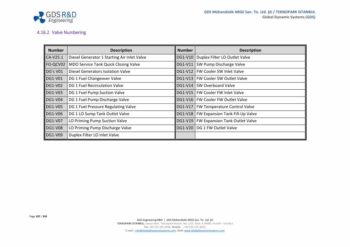
Page 107 / 245 GDS Engineering R&D | GDS Mühendislik ARGE San. Tic. Ltd. Şti
TEKNOPARK ISTANBUL. Sanayi Mah. Teknopark Bulvarı. No: 1/2C, Blok: 4 34906, Pendik – Istanbul Tel: +90 216 395-0506; Mobile : +90 535 515-3030;
E-mail : [email protected]; Web: www.GlobalDynamicSystems.com
GDS Mühendislik ARGE San. Tic. Ltd. Şti / TEKNOPARK ISTANBUL Global Dynamic Systems (GDS)
4.16.2 Valve Numbering
Number Description Number Description CA-V25.1 Diesel Generator 1 Starting Air Inlet Valve DG1-V10 Duplex Filter LO Outlet Valve FO-QCV02 MDO Service Tank Quick Closing Valve DG1-V11 SW Pump Discharge Valve DG’s V01 Diesel Generators Isolation Valve DG1-V12 FW Cooler SW Inlet Valve DG1-V01 DG 1 Fuel Changeover Valve DG1-V13 FW Cooler SW Outlet Valve DG1-V02 DG 1 Fuel Recirculation Valve DG1-V14 SW Overboard Valve DG1-V03 DG 1 Fuel Pump Suction Valve DG1-V15 FW Cooler FW Inlet Valve DG1-V04 DG 1 Fuel Pump Discharge Valve DG1-V16 FW Cooler FW Outlet Valve DG1-V05 DG 1 Fuel Pressure Regulating Valve DG1-V17 FW Temperature Control Valve DG1-V06 DG 1 LO Sump Tank Outlet Valve DG1-V18 FW Expansion Tank Fill-Up Valve DG1-V07 LO Priming Pump Suction Valve DG1-V19 FW Expansion Tank Outlet Valve DG1-V08 LO Priming Pump Discharge Valve DG1-V20 DG 1 FW Outlet Valve DG1-V09 Duplex Filter LO Inlet Valve

Page 108 / 245 GDS Engineering R&D | GDS Mühendislik ARGE San. Tic. Ltd. Şti
TEKNOPARK ISTANBUL. Sanayi Mah. Teknopark Bulvarı. No: 1/2C, Blok: 4 34906, Pendik – Istanbul Tel: +90 216 395-0506; Mobile : +90 535 515-3030;
E-mail : [email protected]; Web: www.GlobalDynamicSystems.com
GDS Mühendislik ARGE San. Tic. Ltd. Şti / TEKNOPARK ISTANBUL Global Dynamic Systems (GDS)
4.17 DIESEL GENERATOR 2 SYSTEMS & LOCAL CONTROL (GUI PANEL # 5200)

Page 109 / 245 GDS Engineering R&D | GDS Mühendislik ARGE San. Tic. Ltd. Şti
TEKNOPARK ISTANBUL. Sanayi Mah. Teknopark Bulvarı. No: 1/2C, Blok: 4 34906, Pendik – Istanbul Tel: +90 216 395-0506; Mobile : +90 535 515-3030;
E-mail : [email protected]; Web: www.GlobalDynamicSystems.com
GDS Mühendislik ARGE San. Tic. Ltd. Şti / TEKNOPARK ISTANBUL Global Dynamic Systems (GDS)
4.17.1 Table of Screen Objects
Number Description Number Description
1 Diesel Generator 2 Parameters Panel 5 Diesel Generator 2 Pumps Control Panel
2 Engine Trips Panel 6 Diesel Generator 2 Fuel System Layout
3 Load & Efficiency Monitor Panel 7 Diesel Generator 2 LO System Layout
4 Diesel Generator 2 Local Control Panel 8 Diesel Generator 2 Cooling Water Layout
1. Diesel Generator 2 Parameters Panel includes: a. Exhaust Gas Temperature Panel b. Fresh Water Temperature Panel c. Diesel Generator 2 Fuel Oil Inlet Pressure Gauge d. Diesel Generator 2 Lubricating Oil Pressure Gauge e. Diesel Generator Cooling Water Inlet Pressure Gauge f. Diesel Generator 2 RPM Indicator g. Diesel Generator 2 Power Indicator
2. Engine Trips Panel includes: a. Overspeed b. LO Pressure Low c. FW Temperature High
3. Load and efficiency monitor panel indicates some parameters about efficiency and load of diesel generator 1 such as: a. DG-2 Power Rating b. SFOC and Fuel Consumption c. Engine Power Output
Page 110 / 245 GDS Engineering R&D | GDS Mühendislik ARGE San. Tic. Ltd. Şti
TEKNOPARK ISTANBUL. Sanayi Mah. Teknopark Bulvarı. No: 1/2C, Blok: 4 34906, Pendik – Istanbul Tel: +90 216 395-0506; Mobile : +90 535 515-3030;
E-mail : [email protected]; Web: www.GlobalDynamicSystems.com
GDS Mühendislik ARGE San. Tic. Ltd. Şti / TEKNOPARK ISTANBUL Global Dynamic Systems (GDS)
4. Diesel Generator 2 Local Control Panel includes controls and indicators such as: a. Engine Status b. Fuel Linkage Control c. Local/Remote Switch: d. Engine Start/Stop Buttons
5. Diesel Generator 2 Pumps Control Panel includes: a. LO Priming Pump Control Panel b. Fuel Oil Pump Control Panel c. SW Pump Control Panel
6. Diesel Generator 2 Fuel Oil System Layout includes: a. Fuel Changeover Panel b. Diesel Generator 2 Fuel Inlet Lines c. Diesel Generator 2 Fuel Outlet Lines d. Diesel Generator 2 Fuel Pump e. Diesel Generators Isolation Valve f. Diesel Generator 2 Pressure Regulating Valve
7. Diesel Generator 2 Lubricating Oil System Layout consists: a. Diesel Generator 2 Lubricating Oil Pump Unit b. Duplex Filter c. Lubricating Oil Cooler
8. Diesel Generator 2 Cooling Water System Layout: a. Diesel Generator 2 Fresh Water Pump b. Diesel Generator 2 Sea Water Pump c. Diesel Generator 2 FW Cooler d. Temperature Control Valve e. Diesel Generator 2 Air Cooler f. Diesel Generator 2 Expansion Tank

Page 111 / 245 GDS Engineering R&D | GDS Mühendislik ARGE San. Tic. Ltd. Şti
TEKNOPARK ISTANBUL. Sanayi Mah. Teknopark Bulvarı. No: 1/2C, Blok: 4 34906, Pendik – Istanbul Tel: +90 216 395-0506; Mobile : +90 535 515-3030;
E-mail : [email protected]; Web: www.GlobalDynamicSystems.com
GDS Mühendislik ARGE San. Tic. Ltd. Şti / TEKNOPARK ISTANBUL Global Dynamic Systems (GDS)
4.17.2 Valve Numbering
Number Description Number Description CA-V26.1 Diesel Generator 2 Starting Air Inlet Valve DG2-V10 Duplex Filter LO Outlet Valve FO-QCV02 MDO Service Tank Quick Closing Valve DG2-V11 SW Pump Discharge Valve DG’s V01 Diesel Generators Isolation Valve DG2-V12 FW Cooler SW Inlet Valve DG2-V01 DG 2 Fuel Changeover Valve DG2-V13 FW Cooler SW Outlet Valve DG2-V02 DG 2 Fuel Recirculation Valve DG2-V14 SW Overboard Valve DG2-V03 DG 2 Fuel Pump Suction Valve DG2-V15 FW Cooler FW Inlet Valve DG2-V04 DG 2 Fuel Pump Discharge Valve DG2-V16 FW Cooler FW Outlet Valve DG2-V05 DG 2 Fuel Pressure Regulating Valve DG2-V17 FW Temperature Control Valve DG2-V06 DG 2 LO Sump Tank Outlet Valve DG2-V18 FW Expansion Tank Fill-Up Valve DG2-V07 LO Priming Pump Suction Valve DG2-V19 FW Expansion Tank Outlet Valve DG2-V08 LO Priming Pump Discharge Valve DG2-V20 DG 2 FW Outlet Valve DG2-V09 Duplex Filter LO Inlet Valve

Page 112 / 245 GDS Engineering R&D | GDS Mühendislik ARGE San. Tic. Ltd. Şti
TEKNOPARK ISTANBUL. Sanayi Mah. Teknopark Bulvarı. No: 1/2C, Blok: 4 34906, Pendik – Istanbul Tel: +90 216 395-0506; Mobile : +90 535 515-3030;
E-mail : [email protected]; Web: www.GlobalDynamicSystems.com
GDS Mühendislik ARGE San. Tic. Ltd. Şti / TEKNOPARK ISTANBUL Global Dynamic Systems (GDS)
4.18 DIESEL GENERATOR 3 (GUI PANEL # 5300)

Page 113 / 245 GDS Engineering R&D | GDS Mühendislik ARGE San. Tic. Ltd. Şti
TEKNOPARK ISTANBUL. Sanayi Mah. Teknopark Bulvarı. No: 1/2C, Blok: 4 34906, Pendik – Istanbul Tel: +90 216 395-0506; Mobile : +90 535 515-3030;
E-mail : [email protected]; Web: www.GlobalDynamicSystems.com
GDS Mühendislik ARGE San. Tic. Ltd. Şti / TEKNOPARK ISTANBUL Global Dynamic Systems (GDS)
4.18.1 Table of Screen Objects
Number Description Number Description
1 Diesel Generator 3 Parameters Panel 5 Diesel Generator 3 Pumps Control Panel
2 Engine Trips Panel 6 Diesel Generator 3 Fuel System Layout
3 Load & Efficiency Monitor Panel 7 Diesel Generator 3 LO System Layout
4 Diesel Generator 3 Local Control Panel 8 Diesel Generator 3 Cooling Water Layout
1. Diesel Generator 3 Parameters Panel includes: a. Exhaust Gas Temperature Panel b. Fresh Water Temperature Panel c. Diesel Generator 3 Fuel Oil Inlet Pressure Gauge d. Diesel Generator 3 Lubricating Oil Pressure Gauge e. Diesel Generator Cooling Water Inlet Pressure Gauge f. Diesel Generator 3 RPM Indicator g. Diesel Generator 3 Power Indicator
2. Engine Trips Panel includes: a. Overspeed b. LO Pressure Low c. FW Temperature High
3. Load and efficiency monitor panel indicates some parameters about efficiency and load of diesel generator 1 such as: a. DG-3 Power Rating b. SFOC and Fuel Consumption c. Engine Power Output

Page 114 / 245 GDS Engineering R&D | GDS Mühendislik ARGE San. Tic. Ltd. Şti
TEKNOPARK ISTANBUL. Sanayi Mah. Teknopark Bulvarı. No: 1/2C, Blok: 4 34906, Pendik – Istanbul Tel: +90 216 395-0506; Mobile : +90 535 515-3030;
E-mail : [email protected]; Web: www.GlobalDynamicSystems.com
GDS Mühendislik ARGE San. Tic. Ltd. Şti / TEKNOPARK ISTANBUL Global Dynamic Systems (GDS)
4. Diesel Generator 3 Local Control Panel includes controls and indicators such as: a. Engine Status b. Fuel Linkage Control c. Local/Remote Switch: d. Engine Start
5. Diesel Generator 3 Pumps Control Panel includes: a. LO Priming Pump Control Panel b. Fuel Oil Pump Control Panel c. SW Pump Control Panel
6. Diesel Generator 3 Fuel Oil System Layout includes: a. Fuel Changeover Panel b. Diesel Generator 3 Fuel Inlet Lines c. Diesel Generator 3 Fuel Outlet Lines d. Diesel Generator 3 Fuel Pump e. Diesel Generators Isolation Valve f. Diesel Generator 3 Pressure Regulating Valve
7. Diesel Generator 3 Lubricating Oil System Layout consists: a. Diesel Generator 3 Lubricating Oil Pump Unit b. Duplex Filter c. Lubricating Oil Cooler
8. Diesel Generator 3 Cooling Water System Layout: a. Diesel Generator 3 Fresh Water Pump b. Diesel Generator 3 Sea Water Pump c. Diesel Generator 3 FW Cooler d. Temperature Control Valve e. Diesel Generator 3 Air Cooler f. Diesel Generator 3 Expansion Tank

Page 115 / 245 GDS Engineering R&D | GDS Mühendislik ARGE San. Tic. Ltd. Şti
TEKNOPARK ISTANBUL. Sanayi Mah. Teknopark Bulvarı. No: 1/2C, Blok: 4 34906, Pendik – Istanbul Tel: +90 216 395-0506; Mobile : +90 535 515-3030;
E-mail : [email protected]; Web: www.GlobalDynamicSystems.com
GDS Mühendislik ARGE San. Tic. Ltd. Şti / TEKNOPARK ISTANBUL Global Dynamic Systems (GDS)
4.18.2 Valve Numbering
Number Description Number Description CA-V27.1 Diesel Generator 3 Starting Air Inlet Valve DG3-V10 Duplex Filter LO Outlet Valve FO-QCV02 MDO Service Tank Quick Closing Valve DG3-V11 SW Pump Discharge Valve DG’s V01 Diesel Generators Isolation Valve DG3-V12 FW Cooler SW Inlet Valve DG3-V01 DG 3 Fuel Changeover Valve DG3-V13 FW Cooler SW Outlet Valve DG3-V02 DG 3 Fuel Recirculation Valve DG3-V14 SW Overboard Valve DG3-V03 DG 3 Fuel Pump Suction Valve DG3-V15 FW Cooler FW Inlet Valve DG3-V04 DG 3 Fuel Pump Discharge Valve DG3-V16 FW Cooler FW Outlet Valve DG3-V05 DG 3 Fuel Pressure Regulating Valve DG3-V17 FW Temperature Control Valve DG3-V06 DG 3 LO Sump Tank Outlet Valve DG3-V18 FW Expansion Tank Fill-Up Valve DG3-V07 LO Priming Pump Suction Valve DG3-V19 FW Expansion Tank Outlet Valve DG3-V08 LO Priming Pump Discharge Valve DG3-V20 DG 3 FW Outlet Valve DG3-V09 Duplex Filter LO Inlet Valve

Page 116 / 245 GDS Engineering R&D | GDS Mühendislik ARGE San. Tic. Ltd. Şti
TEKNOPARK ISTANBUL. Sanayi Mah. Teknopark Bulvarı. No: 1/2C, Blok: 4 34906, Pendik – Istanbul Tel: +90 216 395-0506; Mobile : +90 535 515-3030;
E-mail : [email protected]; Web: www.GlobalDynamicSystems.com
GDS Mühendislik ARGE San. Tic. Ltd. Şti / TEKNOPARK ISTANBUL Global Dynamic Systems (GDS)
4.19 GENERATOR CONTROL PANELS (GUI PANEL # 5400)

Page 117 / 245 GDS Engineering R&D | GDS Mühendislik ARGE San. Tic. Ltd. Şti
TEKNOPARK ISTANBUL. Sanayi Mah. Teknopark Bulvarı. No: 1/2C, Blok: 4 34906, Pendik – Istanbul Tel: +90 216 395-0506; Mobile : +90 535 515-3030;
E-mail : [email protected]; Web: www.GlobalDynamicSystems.com
GDS Mühendislik ARGE San. Tic. Ltd. Şti / TEKNOPARK ISTANBUL Global Dynamic Systems (GDS)
4.19.1 Table of Screen Objects
Number Description Number Description
1 Main Bus & Earth Leakage Panels 4 Diesel Generator 2 Remote Control Panel
2 Diesel Generator 1 Remote Control Panel 5 Diesel Generator 3 Remote Control Panel
3 Synchronization Panel 6 Shaft Generator Panel
1. Main Bus and Earth Leakage Panels: a. Main bus supplies all consumers with diesel generators and shaft generator. Main bus panel includes voltage, frequency, power, current and
power factor indicators. b. The user toggles the switch to 440 V, 220 V, or 24 V DC. Then toggles the phase switch to R, S, or, T to check the ship’s electrical consumers
insulation resistance to earth. Thus, the resistance in the selected line is observed. 2. Diesel generator 1 remote control panel provides control ability of diesel generator 1 remotely. Diesel generator 1 remote control panel includes:
a. Diesel Generator 1 Parameters i. Engine RPM Indicator
ii. Frequency Indicator iii. Voltmeter iv. Power (kW) Indicator v. Power (kVA) Indicator
vi. Current Indicator. b. Engine Control Mode
i. Manual Diesel Generator 1 can be connected or disconnected to the Main Bus Bar manually. If the Diesel Generator 1 is at Local Mode, connection/disconnection to the Main Bus Bar is provided from the Electrical Power Plant GUI Panel (GUIP #5000) via DG 1 Circuit Breaker. If the Diesel Generator 1 is at Remote Mode, connection/disconnection to the Main Bus Bar is provided from ECR Panels: Power Generation GUI Panel (GUIP #5400) via Connect/Disconnect Buttons on the Diesel Generator 1 Remote Panel.
ii. Auto Diesel Generator 1 can be connected or disconnected to the Main Bus Bar automatically. If the Diesel
Generator 1 is at AUTO Mode, (regardless of the Load Control Mode) will be connected to the Main Bus Bar automatically in case of Black Out. If the Diesel Generator 1 is at AUTO and Load Control Mode is at OPTIMUM LOAD, Diesel Generator 1 will be connected or disconnected to the Main Bus Bar according to the power on the Main Bus Bar. (For instance, if the power on the main bus bar is too high, diesel generator 1 will be connected to the main bus bar for prevention of Black Out situation. If the power on the main bus bar is too low, diesel generator 1 will be disconnected from the main bus bar for energy saving.)

Page 118 / 245 GDS Engineering R&D | GDS Mühendislik ARGE San. Tic. Ltd. Şti
TEKNOPARK ISTANBUL. Sanayi Mah. Teknopark Bulvarı. No: 1/2C, Blok: 4 34906, Pendik – Istanbul Tel: +90 216 395-0506; Mobile : +90 535 515-3030;
E-mail : [email protected]; Web: www.GlobalDynamicSystems.com
GDS Mühendislik ARGE San. Tic. Ltd. Şti / TEKNOPARK ISTANBUL Global Dynamic Systems (GDS)
c. Engine Status Indicator includes: i. Ready to Start Diesel Generator 1 is ready to start.
ii. Running Diesel Generator 1 is running but power is not ready. iii. Power Ready Diesel Generator 1 is ready for connecting to the Main Bus Bar. iv. Power Supplied Diesel Generator 1 is connected to the Main Bus Bar. v. Tripped Diesel Generator 1 is tripped.
d. Automatic Voltage Regulator (AVR), automatic voltage regulator can be ON remotely by the switch. e. Engine Start/Stop Buttons, diesel generator 1 can be started or stopped from this panel remotely. f. Speed Control Switch
i. Speed control switch controls the rpm of the diesel generator 1. In this way, diesel generator 1 frequency and load can be controlled remotely.
ii. If switch position is at RAISE, rpm of the diesel generator 1 will be increased. If switch position is at LOWER, rpm of the diesel generator will be decreased.
g. Circuit Breaker Connect/Disconnect Button h. Diesel Generator 1 Trips Indicator i. Diesel Generator 1 Priority Selection Buttons (Note: Priority selection is available for the Diesel Generators. Shaft Generator is not included
priority selection.) (Note: Priority Selection is available when the Diesel Generators Load Control Mode is at “Optimum Load”. Priority Selection is not available when the Diesel Generators Load Control Mode is at “Equal Load”.)
i. Priority 1 The Generator is connected to the Main Bus Bar should be Priority 1. ii. Priority 2 In case of a power increase in the Main Bus Bar, the generator to be connected to the main bus bar should
be Priority 2. iii. Priority 3 The Generator which is not Priority 1 or Priority 2, should be Priority 3.
3. Generator synchronization is the process of matching parameters such as voltage, frequency, phase angle, phase sequence and waveform of the alternator (generator). This is done before the generator is reconnected to the main bus bar. Once a generator is synchronized with the parameters of another generator, alternator, or bus bar, the system can run smoothly again
a. Synchroscope is used to synchronize alternators. Synchronize means that the machine of equal frequency and voltage are operating parallel to each other. Synchroscopes are instruments that show relative frequency (speed) difference and the phase angle between the engine to be synchronized and the system voltage.
b. Power supply can be synchronized Locally or Remotely. First, choose a power supply to synchronize with the previously supplied main bus already. Then, select the location of synchronization. If the switch position is at LOCAL, system can be synchronized locally from Electrical Power Plant GUI Panel (GUIP #5000). If the switch position is at REMOTE, system can be synchronized remotely from ECR Panels: Power Generators GUI Panel (GUIP #5400). Finally, select the way of synchronization. If the switch is at MANUAL position, power supply can be synchronized manually by speed control or load control. If the switch is at AUTO positon, power supply can be synchronized automatically.
c. User can select between load control modes such as: i. Equal Load Control Generator sets cannot operate stable with other sources unless the loading on the
generator set is controlled. When generator sets are operating together on the bus bar, they are

Page 119 / 245 GDS Engineering R&D | GDS Mühendislik ARGE San. Tic. Ltd. Şti
TEKNOPARK ISTANBUL. Sanayi Mah. Teknopark Bulvarı. No: 1/2C, Blok: 4 34906, Pendik – Istanbul Tel: +90 216 395-0506; Mobile : +90 535 515-3030;
E-mail : [email protected]; Web: www.GlobalDynamicSystems.com
GDS Mühendislik ARGE San. Tic. Ltd. Şti / TEKNOPARK ISTANBUL Global Dynamic Systems (GDS)
commonly provided with equipment to allow each diesel generators to operate at the same percentage of load of load on the total system. This is termed a “load sharing control system”
ii. Optimum Load Control Optimum Load Control optimizes the power of the Diesel Generators which is connected to the Main Bus Bar. If the power of the Main Bus Bar decreases, optimum load control provides disconnection of the one of the diesel generator. If the power of the Main Bus Bar increases, optimum load control provides connection of the one of the diesel generator according to the priority order and the load is being shared equally.
4. Diesel generator 2 remote control panel provides control ability for diesel generator 2 remotely. Diesel generator 2 remote control panel includes: a. Diesel Generator 2 Parameters b. Engine Control Mode Switches c. Engine Status Indicator d. Automatic Voltage Regulator (AVR) e. Engine Start/Stop Buttons f. Speed Control Switch g. Circuit Breaker Connect/Disconnect Button h. Priority Selection Buttons i. Diesel Generator 2 Trips Indicator
5. Diesel Generator 3 remote control panel provides control ability for diesel generator 3 remotely. Diesel Generator 3 remote control panel includes: a. Diesel Generator 3 Parameters b. Engine Control Mode Switches c. Engine Status Indicator d. Automatic Voltage Regulator (AVR) e. Engine Start/Stop Buttons f. Speed Control Switch g. Circuit Breaker Connect/Disconnect Button h. Priority Selection Buttons i. Diesel Generator 3 Trips Indicator
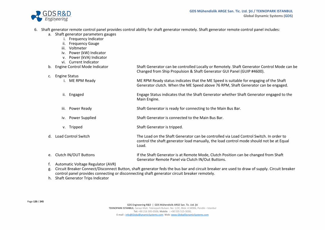
Page 120 / 245 GDS Engineering R&D | GDS Mühendislik ARGE San. Tic. Ltd. Şti
TEKNOPARK ISTANBUL. Sanayi Mah. Teknopark Bulvarı. No: 1/2C, Blok: 4 34906, Pendik – Istanbul Tel: +90 216 395-0506; Mobile : +90 535 515-3030;
E-mail : [email protected]; Web: www.GlobalDynamicSystems.com
GDS Mühendislik ARGE San. Tic. Ltd. Şti / TEKNOPARK ISTANBUL Global Dynamic Systems (GDS)
6. Shaft generator remote control panel provides control ability for shaft generator remotely. Shaft generator remote control panel includes: a. Shaft generator parameters gauges
i. Frequency Indicator ii. Frequency Gauge
iii. Voltmeter iv. Power (kW) Indicator v. Power (kVA) Indicator
vi. Current Indicator b. Engine Control Mode Indicator Shaft Generator can be controlled Locally or Remotely. Shaft Generator Control Mode can be
Changed from Ship Propulsion & Shaft Generator GUI Panel (GUIP #4600). c. Engine Status
i. ME RPM Ready ME RPM Ready status indicates that the ME Speed is suitable for engaging of the Shaft Generator clutch. When the ME Speed above 76 RPM, Shaft Generator can be engaged.
ii. Engaged Engage Status indicates that the Shaft Generator whether Shaft Generator engaged to the Main Engine.
iii. Power Ready Shaft Generator is ready for connecting to the Main Bus Bar.
iv. Power Supplied Shaft Generator is connected to the Main Bus Bar.
v. Tripped Shaft Generator is tripped.
d. Load Control Switch The Load on the Shaft Generator can be controlled via Load Control Switch. In order to control the shaft generator load manually, the load control mode should not be at Equal Load.
e. Clutch IN/OUT Buttons If the Shaft Generator is at Remote Mode, Clutch Position can be changed from Shaft Generator Remote Panel via Clutch IN/Out Buttons.
f. Automatic Voltage Regulator (AVR) g. Circuit Breaker Connect/Disconnect Button, shaft generator feds the bus bar and circuit breaker are used to draw of supply. Circuit breaker
control panel provides connecting or disconnecting shaft generator circuit breaker remotely. h. Shaft Generator Trips Indicator
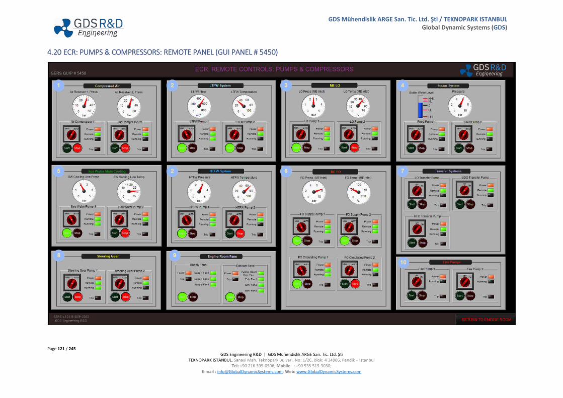
Page 121 / 245 GDS Engineering R&D | GDS Mühendislik ARGE San. Tic. Ltd. Şti
TEKNOPARK ISTANBUL. Sanayi Mah. Teknopark Bulvarı. No: 1/2C, Blok: 4 34906, Pendik – Istanbul Tel: +90 216 395-0506; Mobile : +90 535 515-3030;
E-mail : [email protected]; Web: www.GlobalDynamicSystems.com
GDS Mühendislik ARGE San. Tic. Ltd. Şti / TEKNOPARK ISTANBUL Global Dynamic Systems (GDS)
4.20 ECR: PUMPS & COMPRESSORS: REMOTE PANEL (GUI PANEL # 5450)

Page 122 / 245 GDS Engineering R&D | GDS Mühendislik ARGE San. Tic. Ltd. Şti
TEKNOPARK ISTANBUL. Sanayi Mah. Teknopark Bulvarı. No: 1/2C, Blok: 4 34906, Pendik – Istanbul Tel: +90 216 395-0506; Mobile : +90 535 515-3030;
E-mail : [email protected]; Web: www.GlobalDynamicSystems.com
GDS Mühendislik ARGE San. Tic. Ltd. Şti / TEKNOPARK ISTANBUL Global Dynamic Systems (GDS)
4.20.1 Table of Screen Objects
Number Description Number Description
1 Compressed Air Remote Panel 6 ME FO Remote Panel
2 LTFW & HTFW Systems Remote Panels 7 Transfer Systems Remote Panel
3 ME LO Remote Panel 8 Steering Gear Remote Panel
4 Steam System Remote Panel 9 Engine Room Fans Remote Panel
5 Sea Water Main Cooling Remote Panel 10 Fire Pumps Remote Panel
1. Compressed Air Remote Panel includes: a. Air Receiver 1 and 2 Pressure Gauges The user can observe the pressure of air receivers 1 and 2 remotely. b. Air Compressor 1 and 2 Remote Control Section:
i. MAN/AUTO Switch When in MANUAL mode, compressors work until it stopped by operators. When in AUTO mode, compressors work according to the pressure of air receivers and previously arranged value of pressure switch.
ii. Compressor Status: 1. Power Power light indicates whether compressor fed with power. 2. Remote Remote light indicates whether compressor at remote or local mode. 3. Running Running light indicates whether compressor running or not. 4. Trip Trip light indicates whether occurred any trip or not at the compressors.
iii. Start/Stop Button If the compressor at REMOTE mode, compressors can be started from the remote panel.
2. LTFW and HTFW Systems Remote Panels include: a. LTFW and HTFW Pressure Gauge b. LTFW and HTFW Temperature Gauge c. LTFW and HTFW Pumps Remote Control Section:
i. MAN/AUTO Switch ii. Pumps Status:
1. Power 2. Remote 3. Running 4. Trip
iii. Start/Stop Button
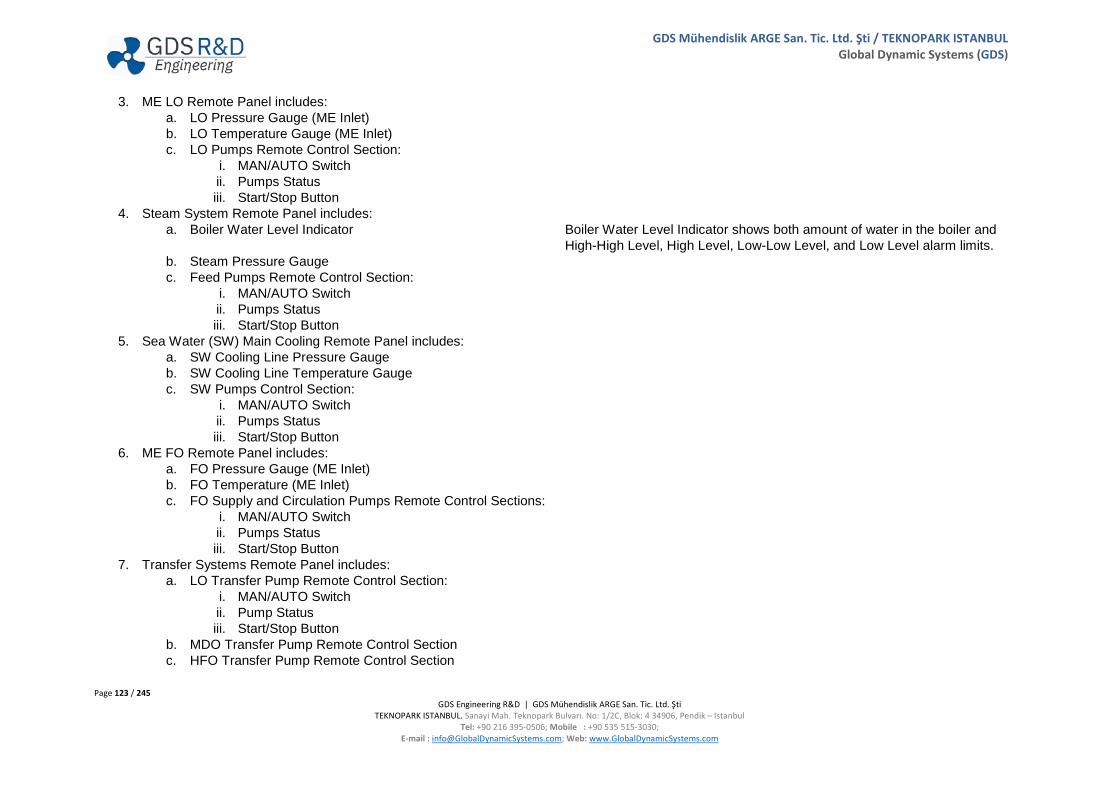
Page 123 / 245 GDS Engineering R&D | GDS Mühendislik ARGE San. Tic. Ltd. Şti
TEKNOPARK ISTANBUL. Sanayi Mah. Teknopark Bulvarı. No: 1/2C, Blok: 4 34906, Pendik – Istanbul Tel: +90 216 395-0506; Mobile : +90 535 515-3030;
E-mail : [email protected]; Web: www.GlobalDynamicSystems.com
GDS Mühendislik ARGE San. Tic. Ltd. Şti / TEKNOPARK ISTANBUL Global Dynamic Systems (GDS)
3. ME LO Remote Panel includes: a. LO Pressure Gauge (ME Inlet) b. LO Temperature Gauge (ME Inlet) c. LO Pumps Remote Control Section:
i. MAN/AUTO Switch ii. Pumps Status iii. Start/Stop Button
4. Steam System Remote Panel includes: a. Boiler Water Level Indicator Boiler Water Level Indicator shows both amount of water in the boiler and
High-High Level, High Level, Low-Low Level, and Low Level alarm limits. b. Steam Pressure Gauge c. Feed Pumps Remote Control Section:
i. MAN/AUTO Switch ii. Pumps Status iii. Start/Stop Button
5. Sea Water (SW) Main Cooling Remote Panel includes: a. SW Cooling Line Pressure Gauge b. SW Cooling Line Temperature Gauge c. SW Pumps Control Section:
i. MAN/AUTO Switch ii. Pumps Status iii. Start/Stop Button
6. ME FO Remote Panel includes: a. FO Pressure Gauge (ME Inlet) b. FO Temperature (ME Inlet) c. FO Supply and Circulation Pumps Remote Control Sections:
i. MAN/AUTO Switch ii. Pumps Status iii. Start/Stop Button
7. Transfer Systems Remote Panel includes: a. LO Transfer Pump Remote Control Section:
i. MAN/AUTO Switch ii. Pump Status iii. Start/Stop Button
b. MDO Transfer Pump Remote Control Section c. HFO Transfer Pump Remote Control Section

Page 124 / 245 GDS Engineering R&D | GDS Mühendislik ARGE San. Tic. Ltd. Şti
TEKNOPARK ISTANBUL. Sanayi Mah. Teknopark Bulvarı. No: 1/2C, Blok: 4 34906, Pendik – Istanbul Tel: +90 216 395-0506; Mobile : +90 535 515-3030;
E-mail : [email protected]; Web: www.GlobalDynamicSystems.com
GDS Mühendislik ARGE San. Tic. Ltd. Şti / TEKNOPARK ISTANBUL Global Dynamic Systems (GDS)
8. Steering Gear Remote Panel includes: a. Steering Gear Pump 1 Remote Control Section:
i. MAN/AUTO Switch ii. Pump Status iii. Start/Stop Button
b. Steering Gear Pump 2 Remote Control Section 9. Engine Room Fans Remote Panel includes:
a. Supply Fans Remote Control Section: i. ON/OFF Switch ii. Fans Status iii. Start/Stop Button
b. Exhaust Fans Remote Control Section 10. Fire Pumps Remote Panel includes:
a. Fire Pump 1 Remote Control Section: i. ON/OFF Switch ii. Pump Status iii. Start/Stop Button
b. Fire Pump 2 Remote Control Section

Page 125 / 245 GDS Engineering R&D | GDS Mühendislik ARGE San. Tic. Ltd. Şti
TEKNOPARK ISTANBUL. Sanayi Mah. Teknopark Bulvarı. No: 1/2C, Blok: 4 34906, Pendik – Istanbul Tel: +90 216 395-0506; Mobile : +90 535 515-3030;
E-mail : [email protected]; Web: www.GlobalDynamicSystems.com
GDS Mühendislik ARGE San. Tic. Ltd. Şti / TEKNOPARK ISTANBUL Global Dynamic Systems (GDS)
4.21 ELECTRICAL DISTRIBUTION SYSTEM: CIRCUIT BREAKERS (GUI PANEL # 5500)
21 3
5
4 6 7
8
9

Page 126 / 245 GDS Engineering R&D | GDS Mühendislik ARGE San. Tic. Ltd. Şti
TEKNOPARK ISTANBUL. Sanayi Mah. Teknopark Bulvarı. No: 1/2C, Blok: 4 34906, Pendik – Istanbul Tel: +90 216 395-0506; Mobile : +90 535 515-3030;
E-mail : [email protected]; Web: www.GlobalDynamicSystems.com
GDS Mühendislik ARGE San. Tic. Ltd. Şti / TEKNOPARK ISTANBUL Global Dynamic Systems (GDS)
4.21.1 Table of Screen Objects
Number Description Number Description
1 Power Panel 5 440 V Auxiliaries III Circuit Breaker Panel 2 440 V ME Pumps and Compressors Panel 6 440 V Emergencies Circuit Breaker Panel 3 440 V Auxiliaries I Circuit Breaker Panel 7 220 V Equipment Circuit Breaker Panel 4 440 V Auxiliaries II Circuit Breaker Panel 8 24 V DC Equipment Panel 9 High Voltage Panel
1. Power Panel includes; 440 V Bus Indicators, 440 V Emergency Bus Indicators, 220 V Bus Indicators, and 24 V DC Bus Indicators.
2. 440 V Main Engine Pumps and Compressors Circuit Breaker (CB) Panel includes: a. ME Systems Main CB b. Sea Water Cooling Pumps Circuit Breakers allows electrical supply to the main sea water pumps. If circuit breaker is at ON position, sea
water pumps can be started. c. Air Compressor 1 CB d. LTFW Pumps CB e. HTFW Pumps CB f. FO Supply Pumps CB g. FO Circulation Pumps CB h. Main LO Pumps CB i. Main Engine Turning Gear CB j. Auxiliary Blowers CB
3. 440 V Auxiliaries I Circuit Breaker Panel includes:
a. Auxiliaries I Main CB b. Steering Gear Pump 1 CB c. Air Compressor 2 CB d. Separators (HFO, MDO, LO) CB e. Fresh Water Generator CB f. Transfer Pumps (LO, Cyl. Oil, HFO, MDO) CBs g. Bilge Pump, Sludge Pump, Sewage Treatment Plant, and Hydrophore Unit CBs h. Refrigeration and Air Condition Plant CBs i. Ballast Pumps CB

Page 127 / 245 GDS Engineering R&D | GDS Mühendislik ARGE San. Tic. Ltd. Şti
TEKNOPARK ISTANBUL. Sanayi Mah. Teknopark Bulvarı. No: 1/2C, Blok: 4 34906, Pendik – Istanbul Tel: +90 216 395-0506; Mobile : +90 535 515-3030;
E-mail : [email protected]; Web: www.GlobalDynamicSystems.com
GDS Mühendislik ARGE San. Tic. Ltd. Şti / TEKNOPARK ISTANBUL Global Dynamic Systems (GDS)
4. 440 V Auxiliaries II (Boiler Pumps) Circuit Breakers Panel includes: Boiler Pumps circuit breakers which is stated at 440 V Auxiliaries II circuit breaker panel allows electrical supply to the boiler pumps. If circuit breaker is at ON position, Boiler Pumps can be started. 440 V Auxiliaries II Circuit Breaker Panel includes:
a. Auxiliaries II Main CB b. Fuel Circulation Pump CB c. Feed Water Pump 1 and 2 CBs d. Fresh Water Make up Pump CB e. Burner CB
5. 440 V Auxiliaries III Circuit Breaker Panel includes:
a. Auxiliaries III Main CB b. Main Fire Pumps CB c. ER Supply and Exhaust Fans CBs d. Deck Machinery CB e. Bridge Systems CB f. Deck Miscellaneous CB
6. 440 V Emergencies Circuit Breaker Panel includes:
a. 440 V Emergencies Main CB b. Auxiliary Air Compressor CB c. Auxiliary SW Pump CB d. Auxiliary LTFW Pump CB e. Preheating Pump CB f. Generators Electrical Pumps g. Steering Gear Pump 2 CB h. ER Supply and Exhaust Fans CB i. 220 V and 24 V DC Emergency Transformers CB j. Oily Water Separator CB k. Emergency Fire Pump CB l. Deck/Bridge Emergencies CB

Page 128 / 245 GDS Engineering R&D | GDS Mühendislik ARGE San. Tic. Ltd. Şti
TEKNOPARK ISTANBUL. Sanayi Mah. Teknopark Bulvarı. No: 1/2C, Blok: 4 34906, Pendik – Istanbul Tel: +90 216 395-0506; Mobile : +90 535 515-3030;
E-mail : [email protected]; Web: www.GlobalDynamicSystems.com
GDS Mühendislik ARGE San. Tic. Ltd. Şti / TEKNOPARK ISTANBUL Global Dynamic Systems (GDS)
7. 220 V Equipment Circuit Breaker Panel includes: a. 440/220V Transformer CB b. 220 V Main CB c. Lights and Galley CB d. Consoles and Electronic CB e. Bridge Equipment CB f. 220 V Emergencies CB for Deck, Navigation Equipment, and Emergency Lights.
8. 24 V DC Equipment Circuit Breaker Panel includes:
a. 440/24VDC Transformer CB b. ER Control Systems CB c. Navigation Equipment CB d. Deck Systems CB e. 24 V DC Emergencies CBs for Battery Charger and Safety Instruments
9. High Voltage Panel includes: a. High Voltage Main CB High voltage transformer and high voltage bus bar (GUIP
#5850) are supplied with electrical power via high voltage main circuit breaker.
b. Vacuum Circuit Breaker (VCB) Panel (GUIP #5860) Quick Access Button

Page 129 / 245 GDS Engineering R&D | GDS Mühendislik ARGE San. Tic. Ltd. Şti
TEKNOPARK ISTANBUL. Sanayi Mah. Teknopark Bulvarı. No: 1/2C, Blok: 4 34906, Pendik – Istanbul Tel: +90 216 395-0506; Mobile : +90 535 515-3030;
E-mail : [email protected]; Web: www.GlobalDynamicSystems.com
GDS Mühendislik ARGE San. Tic. Ltd. Şti / TEKNOPARK ISTANBUL Global Dynamic Systems (GDS)
4.22 ELECTRICAL DISTRIBUTION: 440 V POWER NETWORK (GUI PANEL # 5600)
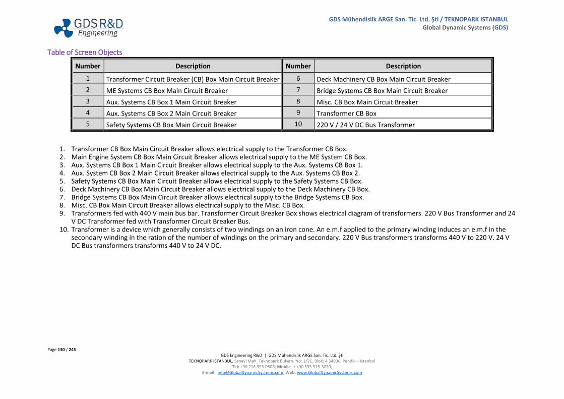
Page 130 / 245 GDS Engineering R&D | GDS Mühendislik ARGE San. Tic. Ltd. Şti
TEKNOPARK ISTANBUL. Sanayi Mah. Teknopark Bulvarı. No: 1/2C, Blok: 4 34906, Pendik – Istanbul Tel: +90 216 395-0506; Mobile : +90 535 515-3030;
E-mail : [email protected]; Web: www.GlobalDynamicSystems.com
GDS Mühendislik ARGE San. Tic. Ltd. Şti / TEKNOPARK ISTANBUL Global Dynamic Systems (GDS)
Table of Screen Objects
Number Description Number Description
1 Transformer Circuit Breaker (CB) Box Main Circuit Breaker 6 Deck Machinery CB Box Main Circuit Breaker 2 ME Systems CB Box Main Circuit Breaker 7 Bridge Systems CB Box Main Circuit Breaker 3 Aux. Systems CB Box 1 Main Circuit Breaker 8 Misc. CB Box Main Circuit Breaker 4 Aux. Systems CB Box 2 Main Circuit Breaker 9 Transformer CB Box 5 Safety Systems CB Box Main Circuit Breaker 10 220 V / 24 V DC Bus Transformer
1. Transformer CB Box Main Circuit Breaker allows electrical supply to the Transformer CB Box. 2. Main Engine System CB Box Main Circuit Breaker allows electrical supply to the ME System CB Box. 3. Aux. Systems CB Box 1 Main Circuit Breaker allows electrical supply to the Aux. Systems CB Box 1. 4. Aux. System CB Box 2 Main Circuit Breaker allows electrical supply to the Aux. Systems CB Box 2. 5. Safety Systems CB Box Main Circuit Breaker allows electrical supply to the Safety Systems CB Box. 6. Deck Machinery CB Box Main Circuit Breaker allows electrical supply to the Deck Machinery CB Box. 7. Bridge Systems CB Box Main Circuit Breaker allows electrical supply to the Bridge Systems CB Box. 8. Misc. CB Box Main Circuit Breaker allows electrical supply to the Misc. CB Box. 9. Transformers fed with 440 V main bus bar. Transformer Circuit Breaker Box shows electrical diagram of transformers. 220 V Bus Transformer and 24
V DC Transformer fed with Transformer Circuit Breaker Bus. 10. Transformer is a device which generally consists of two windings on an iron cone. An e.m.f applied to the primary winding induces an e.m.f in the
secondary winding in the ration of the number of windings on the primary and secondary. 220 V Bus transformers transforms 440 V to 220 V. 24 V DC Bus transformers transforms 440 V to 24 V DC.

Page 131 / 245 GDS Engineering R&D | GDS Mühendislik ARGE San. Tic. Ltd. Şti
TEKNOPARK ISTANBUL. Sanayi Mah. Teknopark Bulvarı. No: 1/2C, Blok: 4 34906, Pendik – Istanbul Tel: +90 216 395-0506; Mobile : +90 535 515-3030;
E-mail : [email protected]; Web: www.GlobalDynamicSystems.com
GDS Mühendislik ARGE San. Tic. Ltd. Şti / TEKNOPARK ISTANBUL Global Dynamic Systems (GDS)
4.23 ELECTRICAL DISTRIBUTION: 440 V EMERGENCY NETWORK (GUI PANEL # 5600)

Page 132 / 245 GDS Engineering R&D | GDS Mühendislik ARGE San. Tic. Ltd. Şti
TEKNOPARK ISTANBUL. Sanayi Mah. Teknopark Bulvarı. No: 1/2C, Blok: 4 34906, Pendik – Istanbul Tel: +90 216 395-0506; Mobile : +90 535 515-3030;
E-mail : [email protected]; Web: www.GlobalDynamicSystems.com
GDS Mühendislik ARGE San. Tic. Ltd. Şti / TEKNOPARK ISTANBUL Global Dynamic Systems (GDS)
Table of Screen Objects
Number Description Number Description
1 Emergency Consumers CB Box 1 3 Emergency Consumers CB Box 3 2 Emergency Consumers CB Box 2 4 220 V / 24 V DC Emergency Transformer
1. Emergency Consumers CB Box 1 fed with both 440 V main and 440 V emergency bus bar. Circuit Breaker Box shows electrical diagram of emergency consumers. Emergency Consumers Circuit Breaker Box 1 includes:
a. 220 V Emergency Transformer b. Emergency Fire Pump c. 24 V DC Emergency Transformer
2. Emergency Consumers Circuit Breaker Box 2 includes: a. Steering Gear Pump 2 b. Auxiliary Air Compressor c. Lifeboat Winches d. Navigation Equipment e. Elevator System
3. Emergency Consumers Circuit Breaker Box 3 includes: a. Diesel Generator 1 LO Priming Pump b. Diesel Generator 2 LO Priming Pump c. Shaft Generator LO Priming Pump d. Engine Room Air Supply Fans e. Engine Room Air Exhaust Fans f. Auxiliary Sea Water Pump g. Auxiliary LTFW Pump h. Auxiliary HTFW Pump i. Bilge Water Separator
4. Transformer is a device which generally consists of two windings on an iron cone. An emf applied to the primary winding induces an e.m.f in the secondary winding in the ratio of the number of windings on the primary and secondary. 220 V Emergency Bus transformers transforms 440 V to 220 V for supplying Emergency Bus Bar. 24 V DC Emergency Bus transformers transforms 440 V to 24 V DC for supplying Emergency Bus Bar.

Page 133 / 245 GDS Engineering R&D | GDS Mühendislik ARGE San. Tic. Ltd. Şti
TEKNOPARK ISTANBUL. Sanayi Mah. Teknopark Bulvarı. No: 1/2C, Blok: 4 34906, Pendik – Istanbul Tel: +90 216 395-0506; Mobile : +90 535 515-3030;
E-mail : [email protected]; Web: www.GlobalDynamicSystems.com
GDS Mühendislik ARGE San. Tic. Ltd. Şti / TEKNOPARK ISTANBUL Global Dynamic Systems (GDS)
4.24 ELECTRICAL DISTRIBUTION: 220 V NETWORK (GUI PANEL # 5700)
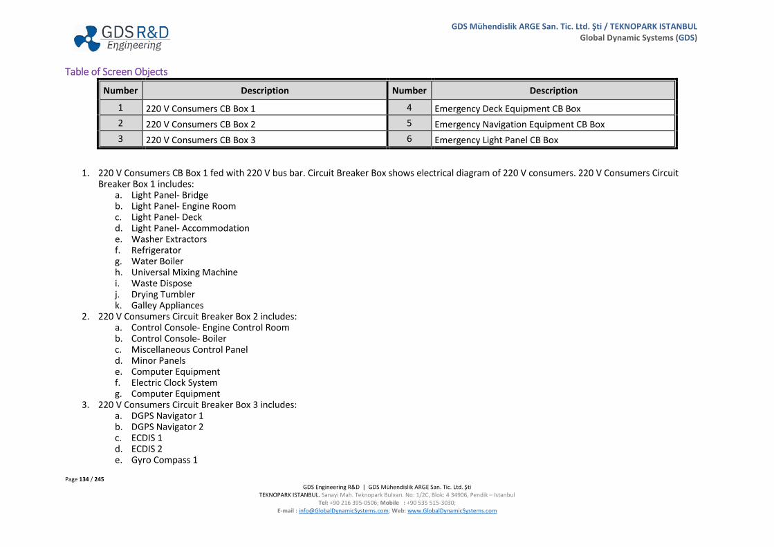
Page 134 / 245 GDS Engineering R&D | GDS Mühendislik ARGE San. Tic. Ltd. Şti
TEKNOPARK ISTANBUL. Sanayi Mah. Teknopark Bulvarı. No: 1/2C, Blok: 4 34906, Pendik – Istanbul Tel: +90 216 395-0506; Mobile : +90 535 515-3030;
E-mail : [email protected]; Web: www.GlobalDynamicSystems.com
GDS Mühendislik ARGE San. Tic. Ltd. Şti / TEKNOPARK ISTANBUL Global Dynamic Systems (GDS)
Table of Screen Objects
Number Description Number Description
1 220 V Consumers CB Box 1 4 Emergency Deck Equipment CB Box 2 220 V Consumers CB Box 2 5 Emergency Navigation Equipment CB Box 3 220 V Consumers CB Box 3 6 Emergency Light Panel CB Box
1. 220 V Consumers CB Box 1 fed with 220 V bus bar. Circuit Breaker Box shows electrical diagram of 220 V consumers. 220 V Consumers Circuit Breaker Box 1 includes:
a. Light Panel- Bridge b. Light Panel- Engine Room c. Light Panel- Deck d. Light Panel- Accommodation e. Washer Extractors f. Refrigerator g. Water Boiler h. Universal Mixing Machine i. Waste Dispose j. Drying Tumbler k. Galley Appliances
2. 220 V Consumers Circuit Breaker Box 2 includes: a. Control Console- Engine Control Room b. Control Console- Boiler c. Miscellaneous Control Panel d. Minor Panels e. Computer Equipment f. Electric Clock System g. Computer Equipment
3. 220 V Consumers Circuit Breaker Box 3 includes: a. DGPS Navigator 1 b. DGPS Navigator 2 c. ECDIS 1 d. ECDIS 2 e. Gyro Compass 1

Page 135 / 245 GDS Engineering R&D | GDS Mühendislik ARGE San. Tic. Ltd. Şti
TEKNOPARK ISTANBUL. Sanayi Mah. Teknopark Bulvarı. No: 1/2C, Blok: 4 34906, Pendik – Istanbul Tel: +90 216 395-0506; Mobile : +90 535 515-3030;
E-mail : [email protected]; Web: www.GlobalDynamicSystems.com
GDS Mühendislik ARGE San. Tic. Ltd. Şti / TEKNOPARK ISTANBUL Global Dynamic Systems (GDS)
f. Gyro Compass 2 g. GMDSS h. Window Wipers
4. Emergency Deck Equipment CB Box fed with both 220 V and 220 V Emergency bus bar. Circuit Breaker Box shows electrical diagram of emergency deck equipment. Emergency Deck Equipment Circuit Breaker Box includes:
a. Lifeboat Battery Charger b. Engine Room Deadman Alarm c. Auto Telephone Exchanger
5. Emergency Navigation Equipment Circuit Breaker Box includes: a. Nautical Distribution Panel b. Radar System Panel c. Radio Equipment Panel
6. Emergency Light Panel Circuit Breaker Box includes: a. Light Panel- Bridge b. Light Panel- Engine Room c. Light Panel- Deck d. Light Panel- Accommodation e. Signal Lights Column
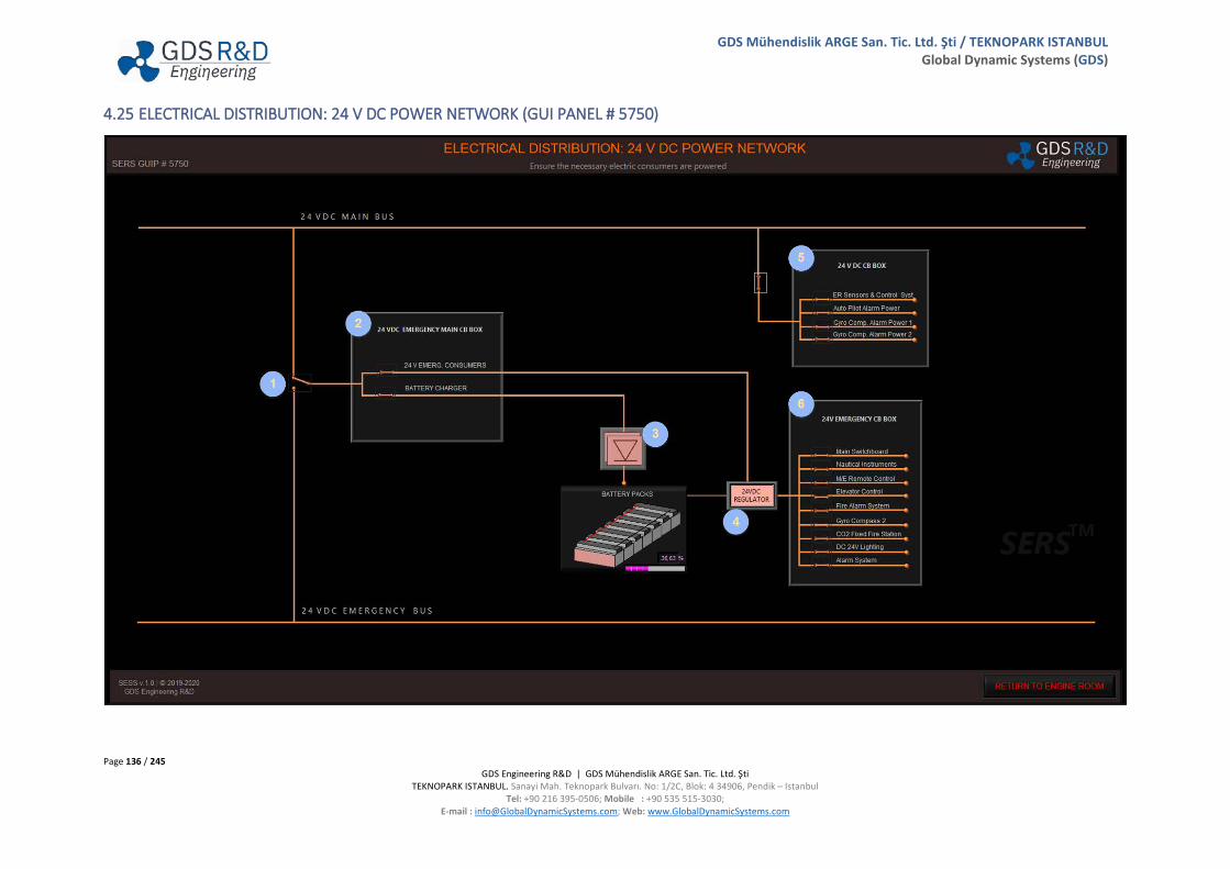
Page 136 / 245 GDS Engineering R&D | GDS Mühendislik ARGE San. Tic. Ltd. Şti
TEKNOPARK ISTANBUL. Sanayi Mah. Teknopark Bulvarı. No: 1/2C, Blok: 4 34906, Pendik – Istanbul Tel: +90 216 395-0506; Mobile : +90 535 515-3030;
E-mail : [email protected]; Web: www.GlobalDynamicSystems.com
GDS Mühendislik ARGE San. Tic. Ltd. Şti / TEKNOPARK ISTANBUL Global Dynamic Systems (GDS)
4.25 ELECTRICAL DISTRIBUTION: 24 V DC POWER NETWORK (GUI PANEL # 5750)

Page 137 / 245 GDS Engineering R&D | GDS Mühendislik ARGE San. Tic. Ltd. Şti
TEKNOPARK ISTANBUL. Sanayi Mah. Teknopark Bulvarı. No: 1/2C, Blok: 4 34906, Pendik – Istanbul Tel: +90 216 395-0506; Mobile : +90 535 515-3030;
E-mail : [email protected]; Web: www.GlobalDynamicSystems.com
GDS Mühendislik ARGE San. Tic. Ltd. Şti / TEKNOPARK ISTANBUL Global Dynamic Systems (GDS)
4.25.1 Table of Screen Objects
Number Description Number Description
1 24 V DC Main/Emergency Breaker 4 24 V DC Regulator 2 24 V DC Emergency Main CB Box 5 24 V DC CB Box 3 Battery Charger 6 24 V DC Emergency CB Box
1. 24 V DC Emergency Main CB Box and 24 V DC Emergency CB Box can be supplied with 24 V DC Main and Emergency Bus. Emergency generator, if it is working and is at auto position, will supply the emergency bus bar and breaker position will be changed automatically in case of a black out situation.
2. 24 V DC Emergency Main CB Box fed with both 24 V DC and 24 V DC Emergency bus bar. Circuit Breaker Box shows electrical diagram of 24 V emergency consumers and battery charger. 24 V DC Emergency Main Circuit Breaker Box includes:
a. 24 V DC Emergency Consumers b. Battery Charger
3. Battery Charger charges the battery packs. Battery chargers is fed with 24 V DC Main or Emergency Bus Bar. 4. 24 V DC Regulator regulates the voltage which comes from battery packs. 5. 24 V DC Consumers Circuit Breaker Box includes:
a. Engine Room Sensors & Control Systems b. Auto-Pilot Alarm Panel c. Gyro Compass Alarm Power 1 d. Gyro Compass Alarm Power 2
6. 24 V DC Emergency Circuit Breaker Box includes: a. Main Switchboard b. Nautical Instruments c. Main Engine Remote Control d. Elevator Control e. Fire Alarm System f. Gyro Compass 2 g. CO2 Fixed Fire Station h. DC 24 V Lighting
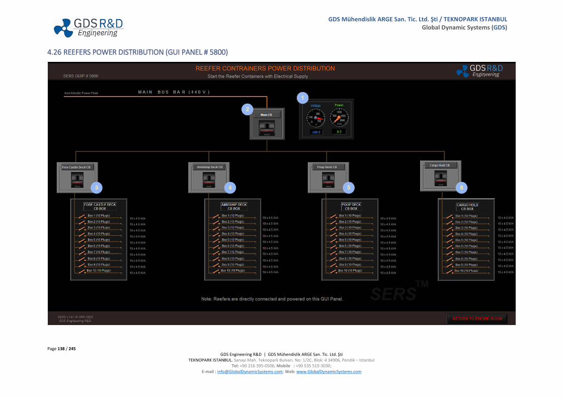
Page 138 / 245 GDS Engineering R&D | GDS Mühendislik ARGE San. Tic. Ltd. Şti
TEKNOPARK ISTANBUL. Sanayi Mah. Teknopark Bulvarı. No: 1/2C, Blok: 4 34906, Pendik – Istanbul Tel: +90 216 395-0506; Mobile : +90 535 515-3030;
E-mail : [email protected]; Web: www.GlobalDynamicSystems.com
GDS Mühendislik ARGE San. Tic. Ltd. Şti / TEKNOPARK ISTANBUL Global Dynamic Systems (GDS)
4.26 REEFERS POWER DISTRIBUTION (GUI PANEL # 5800)

Page 139 / 245 GDS Engineering R&D | GDS Mühendislik ARGE San. Tic. Ltd. Şti
TEKNOPARK ISTANBUL. Sanayi Mah. Teknopark Bulvarı. No: 1/2C, Blok: 4 34906, Pendik – Istanbul Tel: +90 216 395-0506; Mobile : +90 535 515-3030;
E-mail : [email protected]; Web: www.GlobalDynamicSystems.com
GDS Mühendislik ARGE San. Tic. Ltd. Şti / TEKNOPARK ISTANBUL Global Dynamic Systems (GDS)
4.26.1 Table of Screen Objects
Number Description Number Description
1 Reefers Voltage & Power Indicators Panel 4 Amidship Deck Reefers CB Box 2 Reefers Main Circuit Breaker 5 Poop Deck Reefers CB Box 3 Fore Castle Deck Reefers CB Box 6 Cargo Hold Deck Reefers CB Box
1. Reefers are supplied with the 440 V Main Bus Bar. Reefers Voltage & Power Indicators Panel includes: a. Voltage Gauge, which indicates the voltage of the 440 V Main Bus Bar. b. Power Gauge, which indicates the reefer power in units of kVA.
2. Reefers Main Circuit Breaker allows Fore Castle, Amidship, Poop Deck, and Cargo Hold Sections Circuit Breakers supplying with electric. 3. Fore Castle Deck CB Box Circuit Breaker allows electrical supply to the Fore Castle Deck Reefers. Fore Castle Deck Reefers capacity is a total of
hundred plugs and the plugs of reefers was collected ten different boxes. Every box feeds ten reefer plugs and every plug power is rated at 4.5 kVA. 4. Amidship Deck CB Box Circuit Breaker allows electrical supply to the Amidship Deck Reefers. Amidship Deck Reefers capacity is a total of hundred
plugs and the plugs of reefers was collected ten different boxes. Every box feeds ten plugs and every plug power is 4.5 kVA. 5. Poop Deck CB Box Circuit Breaker allows electrical supply to the Poop Deck Reefers. Poop Deck Reefers capacity is a total of hundred plugs and the
plugs of reefers was collected ten different boxes. Every box feeds ten plugs and every plug power is 4.5 kVA. 6. Cargo Hold CB Box Circuit Breaker allows electrical supply to the Cargo Hold Reefers. Cargo Hold capacity is a total of hundred plugs and the plugs of
reefers was collected ten different boxes. Every box feeds ten plugs and every plug power is 4.5 kVA.
(Important Note: Reefers are directly connected and powered on the Reefers Containers Power Distribution GUI Panel. So, the user must check Diesel Generators and Shaft Generator status before supplying of the Reefers with electric for safe operation.)

Page 140 / 245 GDS Engineering R&D | GDS Mühendislik ARGE San. Tic. Ltd. Şti
TEKNOPARK ISTANBUL. Sanayi Mah. Teknopark Bulvarı. No: 1/2C, Blok: 4 34906, Pendik – Istanbul Tel: +90 216 395-0506; Mobile : +90 535 515-3030;
E-mail : [email protected]; Web: www.GlobalDynamicSystems.com
GDS Mühendislik ARGE San. Tic. Ltd. Şti / TEKNOPARK ISTANBUL Global Dynamic Systems (GDS)
4.27 HIGH VOLTAGE BUS BAR / TRANSFORMER (GUI PANEL # 5850)
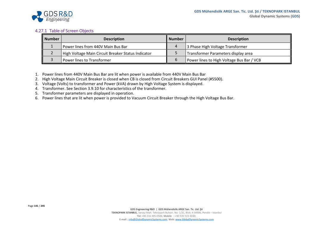
Page 141 / 245 GDS Engineering R&D | GDS Mühendislik ARGE San. Tic. Ltd. Şti
TEKNOPARK ISTANBUL. Sanayi Mah. Teknopark Bulvarı. No: 1/2C, Blok: 4 34906, Pendik – Istanbul Tel: +90 216 395-0506; Mobile : +90 535 515-3030;
E-mail : [email protected]; Web: www.GlobalDynamicSystems.com
GDS Mühendislik ARGE San. Tic. Ltd. Şti / TEKNOPARK ISTANBUL Global Dynamic Systems (GDS)
4.27.1 Table of Screen Objects
Number Description Number Description
1 Power lines from 440V Main Bus Bar 4 3 Phase High Voltage Transformer 2 High Voltage Main Circuit Breaker Status Indicator 5 Transformer Parameters display area 3 Power lines to Transformer 6 Power lines to High Voltage Bus Bar / VCB
1. Power lines from 440V Main Bus Bar are lit when power is available from 440V Main Bus Bar 2. High Voltage Main Circuit Breaker is closed when CB is closed from Circuit Breakers GUI Panel (#5500). 3. Voltage (Volts) to transformer and Power (kVA) drawn by High Voltage System is displayed. 4. Transformer. See Section 3.9.10 for characteristics of the transformer. 5. Transformer parameters are displayed in operation. 6. Power lines that are lit when power is provided to Vacuum Circuit Breaker through the High Voltage Bus Bar.
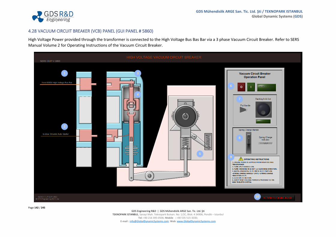
Page 142 / 245 GDS Engineering R&D | GDS Mühendislik ARGE San. Tic. Ltd. Şti
TEKNOPARK ISTANBUL. Sanayi Mah. Teknopark Bulvarı. No: 1/2C, Blok: 4 34906, Pendik – Istanbul Tel: +90 216 395-0506; Mobile : +90 535 515-3030;
E-mail : [email protected]; Web: www.GlobalDynamicSystems.com
GDS Mühendislik ARGE San. Tic. Ltd. Şti / TEKNOPARK ISTANBUL Global Dynamic Systems (GDS)
4.28 VACUUM CIRCUIT BREAKER (VCB) PANEL (GUI PANEL # 5860)
High Voltage Power provided through the transformer is connected to the High Voltage Bus Bas Bar via a 3 phase Vacuum Circuit Breaker. Refer to SERS Manual Volume 2 for Operating Instructions of the Vacuum Circuit Breaker.
2
1 3
6
5
7
8
9
10
4
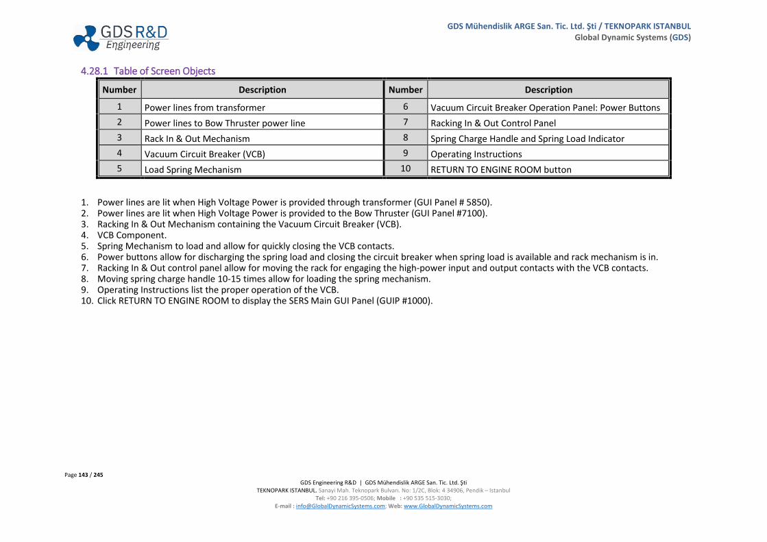
Page 143 / 245 GDS Engineering R&D | GDS Mühendislik ARGE San. Tic. Ltd. Şti
TEKNOPARK ISTANBUL. Sanayi Mah. Teknopark Bulvarı. No: 1/2C, Blok: 4 34906, Pendik – Istanbul Tel: +90 216 395-0506; Mobile : +90 535 515-3030;
E-mail : [email protected]; Web: www.GlobalDynamicSystems.com
GDS Mühendislik ARGE San. Tic. Ltd. Şti / TEKNOPARK ISTANBUL Global Dynamic Systems (GDS)
4.28.1 Table of Screen Objects
Number Description Number Description
1 Power lines from transformer 6 Vacuum Circuit Breaker Operation Panel: Power Buttons 2 Power lines to Bow Thruster power line 7 Racking In & Out Control Panel 3 Rack In & Out Mechanism 8 Spring Charge Handle and Spring Load Indicator 4 Vacuum Circuit Breaker (VCB) 9 Operating Instructions 5 Load Spring Mechanism 10 RETURN TO ENGINE ROOM button
1. Power lines are lit when High Voltage Power is provided through transformer (GUI Panel # 5850). 2. Power lines are lit when High Voltage Power is provided to the Bow Thruster (GUI Panel #7100). 3. Racking In & Out Mechanism containing the Vacuum Circuit Breaker (VCB). 4. VCB Component. 5. Spring Mechanism to load and allow for quickly closing the VCB contacts. 6. Power buttons allow for discharging the spring load and closing the circuit breaker when spring load is available and rack mechanism is in. 7. Racking In & Out control panel allow for moving the rack for engaging the high-power input and output contacts with the VCB contacts. 8. Moving spring charge handle 10-15 times allow for loading the spring mechanism. 9. Operating Instructions list the proper operation of the VCB. 10. Click RETURN TO ENGINE ROOM to display the SERS Main GUI Panel (GUIP #1000).

Page 144 / 245 GDS Engineering R&D | GDS Mühendislik ARGE San. Tic. Ltd. Şti
TEKNOPARK ISTANBUL. Sanayi Mah. Teknopark Bulvarı. No: 1/2C, Blok: 4 34906, Pendik – Istanbul Tel: +90 216 395-0506; Mobile : +90 535 515-3030;
E-mail : [email protected]; Web: www.GlobalDynamicSystems.com
GDS Mühendislik ARGE San. Tic. Ltd. Şti / TEKNOPARK ISTANBUL Global Dynamic Systems (GDS)
4.29 MANAGE ELECTRICAL CONSUMERS (GUI PANEL # 5900)
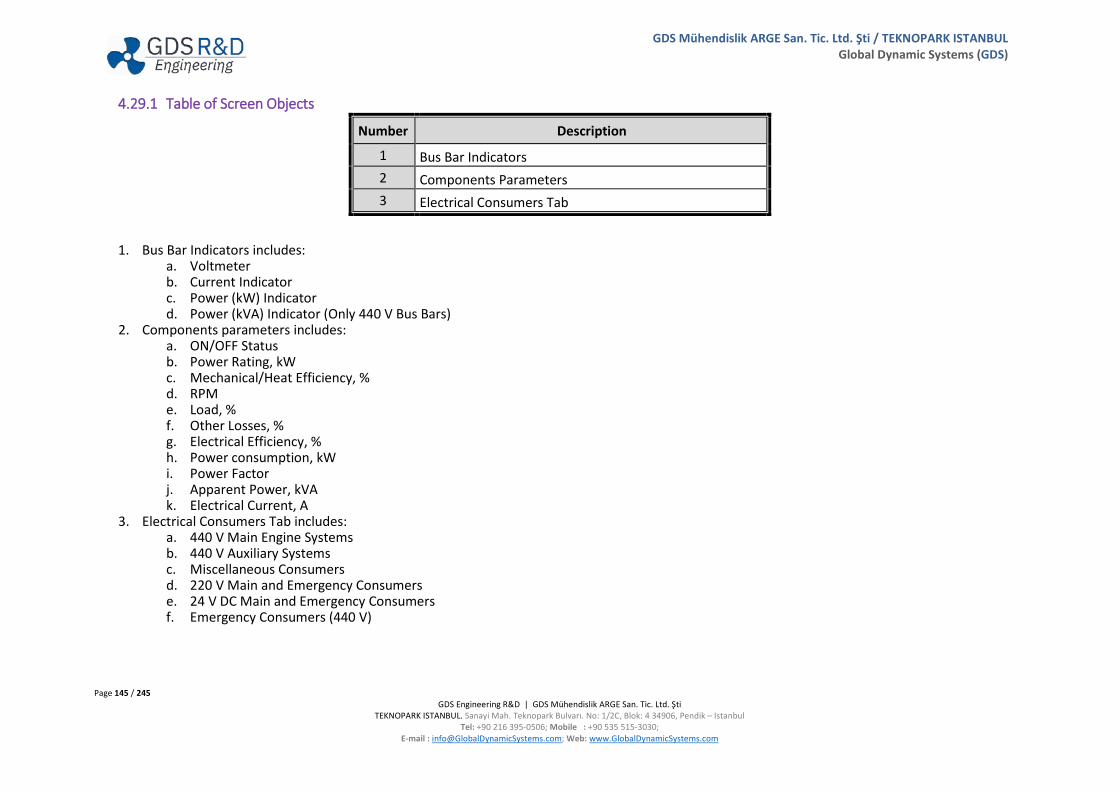
Page 145 / 245 GDS Engineering R&D | GDS Mühendislik ARGE San. Tic. Ltd. Şti
TEKNOPARK ISTANBUL. Sanayi Mah. Teknopark Bulvarı. No: 1/2C, Blok: 4 34906, Pendik – Istanbul Tel: +90 216 395-0506; Mobile : +90 535 515-3030;
E-mail : [email protected]; Web: www.GlobalDynamicSystems.com
GDS Mühendislik ARGE San. Tic. Ltd. Şti / TEKNOPARK ISTANBUL Global Dynamic Systems (GDS)
4.29.1 Table of Screen Objects
Number Description
1 Bus Bar Indicators 2 Components Parameters 3 Electrical Consumers Tab
1. Bus Bar Indicators includes: a. Voltmeter b. Current Indicator c. Power (kW) Indicator d. Power (kVA) Indicator (Only 440 V Bus Bars)
2. Components parameters includes: a. ON/OFF Status b. Power Rating, kW c. Mechanical/Heat Efficiency, % d. RPM e. Load, % f. Other Losses, % g. Electrical Efficiency, % h. Power consumption, kW i. Power Factor j. Apparent Power, kVA k. Electrical Current, A
3. Electrical Consumers Tab includes: a. 440 V Main Engine Systems b. 440 V Auxiliary Systems c. Miscellaneous Consumers d. 220 V Main and Emergency Consumers e. 24 V DC Main and Emergency Consumers f. Emergency Consumers (440 V)

Page 146 / 245 GDS Engineering R&D | GDS Mühendislik ARGE San. Tic. Ltd. Şti
TEKNOPARK ISTANBUL. Sanayi Mah. Teknopark Bulvarı. No: 1/2C, Blok: 4 34906, Pendik – Istanbul Tel: +90 216 395-0506; Mobile : +90 535 515-3030;
E-mail : [email protected]; Web: www.GlobalDynamicSystems.com
GDS Mühendislik ARGE San. Tic. Ltd. Şti / TEKNOPARK ISTANBUL Global Dynamic Systems (GDS)
4.30 SEA WATER MAIN COOLING SYSTEM (GUI PANEL # 3000)
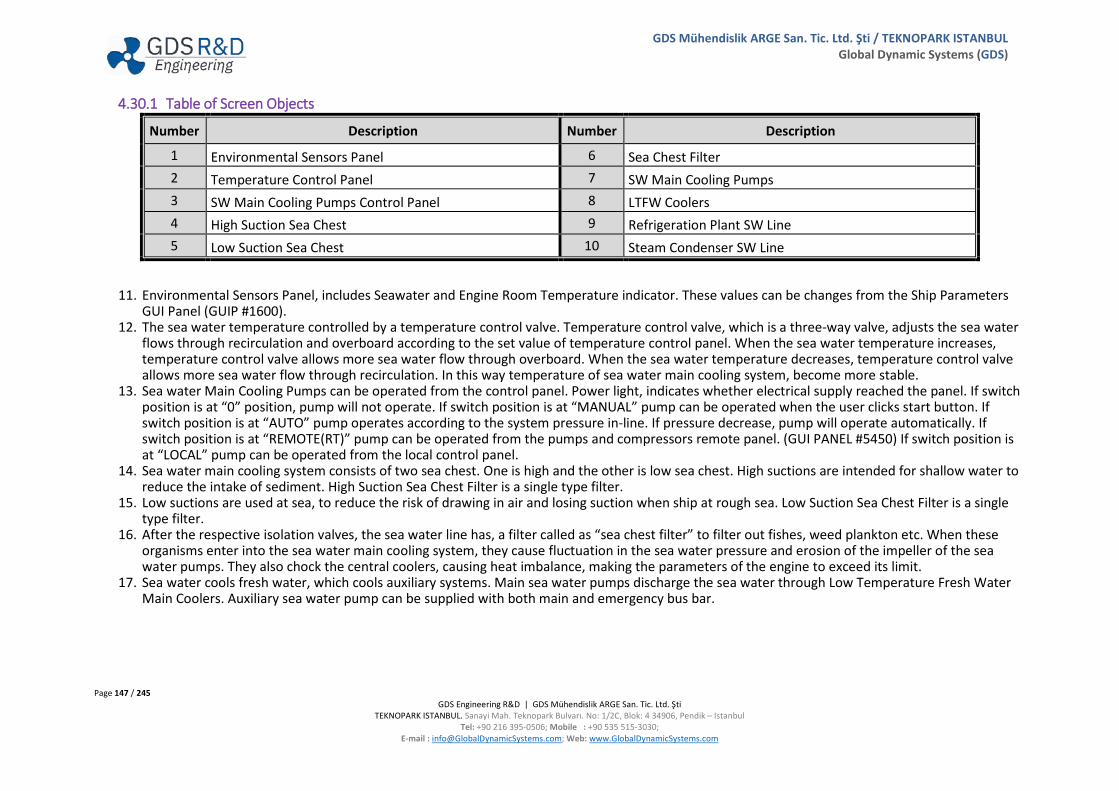
Page 147 / 245 GDS Engineering R&D | GDS Mühendislik ARGE San. Tic. Ltd. Şti
TEKNOPARK ISTANBUL. Sanayi Mah. Teknopark Bulvarı. No: 1/2C, Blok: 4 34906, Pendik – Istanbul Tel: +90 216 395-0506; Mobile : +90 535 515-3030;
E-mail : [email protected]; Web: www.GlobalDynamicSystems.com
GDS Mühendislik ARGE San. Tic. Ltd. Şti / TEKNOPARK ISTANBUL Global Dynamic Systems (GDS)
4.30.1 Table of Screen Objects
Number Description Number Description
1 Environmental Sensors Panel 6 Sea Chest Filter 2 Temperature Control Panel 7 SW Main Cooling Pumps 3 SW Main Cooling Pumps Control Panel 8 LTFW Coolers 4 High Suction Sea Chest 9 Refrigeration Plant SW Line 5 Low Suction Sea Chest 10 Steam Condenser SW Line
11. Environmental Sensors Panel, includes Seawater and Engine Room Temperature indicator. These values can be changes from the Ship Parameters GUI Panel (GUIP #1600).
12. The sea water temperature controlled by a temperature control valve. Temperature control valve, which is a three-way valve, adjusts the sea water flows through recirculation and overboard according to the set value of temperature control panel. When the sea water temperature increases, temperature control valve allows more sea water flow through overboard. When the sea water temperature decreases, temperature control valve allows more sea water flow through recirculation. In this way temperature of sea water main cooling system, become more stable.
13. Sea water Main Cooling Pumps can be operated from the control panel. Power light, indicates whether electrical supply reached the panel. If switch position is at “0” position, pump will not operate. If switch position is at “MANUAL” pump can be operated when the user clicks start button. If switch position is at “AUTO” pump operates according to the system pressure in-line. If pressure decrease, pump will operate automatically. If switch position is at “REMOTE(RT)” pump can be operated from the pumps and compressors remote panel. (GUI PANEL #5450) If switch position is at “LOCAL” pump can be operated from the local control panel.
14. Sea water main cooling system consists of two sea chest. One is high and the other is low sea chest. High suctions are intended for shallow water to reduce the intake of sediment. High Suction Sea Chest Filter is a single type filter.
15. Low suctions are used at sea, to reduce the risk of drawing in air and losing suction when ship at rough sea. Low Suction Sea Chest Filter is a single type filter.
16. After the respective isolation valves, the sea water line has, a filter called as “sea chest filter” to filter out fishes, weed plankton etc. When these organisms enter into the sea water main cooling system, they cause fluctuation in the sea water pressure and erosion of the impeller of the sea water pumps. They also chock the central coolers, causing heat imbalance, making the parameters of the engine to exceed its limit.
17. Sea water cools fresh water, which cools auxiliary systems. Main sea water pumps discharge the sea water through Low Temperature Fresh Water Main Coolers. Auxiliary sea water pump can be supplied with both main and emergency bus bar.

Page 148 / 245 GDS Engineering R&D | GDS Mühendislik ARGE San. Tic. Ltd. Şti
TEKNOPARK ISTANBUL. Sanayi Mah. Teknopark Bulvarı. No: 1/2C, Blok: 4 34906, Pendik – Istanbul Tel: +90 216 395-0506; Mobile : +90 535 515-3030;
E-mail : [email protected]; Web: www.GlobalDynamicSystems.com
GDS Mühendislik ARGE San. Tic. Ltd. Şti / TEKNOPARK ISTANBUL Global Dynamic Systems (GDS)
18. Low Temperature Fresh Water is cooled by sea water at LTFW Coolers. Low Temperature Fresh Water Cooler consists: a. Sea water Inlet and Outlet Lines and Valves b. LTFW Inlet and Outlet Lines and Valves (LTFW Coolers Inlet and Outlet Valves (FW-V01, FW-V02 and FW-V03, FW-V04 can opened or closed
from the Fresh Water Cooling GUI Panel #3100) 19. Refrigeration Plant (GUIP #6700) Condenser & Receiver can be fed with Main SW Cooling System. Refrigeration Plant SW Inlet Valve (SW-V12) is an
adjustable valve. So that, Refrigeration Plant seawater flow rate can be controlled. 20. Combined Boiler (GUIP #3300) Steam Condenser can be fed with Main SW Cooling System. Steam Condenser SW Inlet Valve (SW-V11) is an
adjustable valve. So that, Steam Condenser seawater flow rate can be controlled.

Page 149 / 245 GDS Engineering R&D | GDS Mühendislik ARGE San. Tic. Ltd. Şti
TEKNOPARK ISTANBUL. Sanayi Mah. Teknopark Bulvarı. No: 1/2C, Blok: 4 34906, Pendik – Istanbul Tel: +90 216 395-0506; Mobile : +90 535 515-3030;
E-mail : [email protected]; Web: www.GlobalDynamicSystems.com
GDS Mühendislik ARGE San. Tic. Ltd. Şti / TEKNOPARK ISTANBUL Global Dynamic Systems (GDS)
4.30.2 Valve Numbering
Number Description Number Description SW-V01 Low Suction Sea Chest Filter Inlet Valve SW-V13 LTFW Cooler 1 SW Inlet Valve SW-V02 Low Suction Sea Chest Filter Outlet Valve SW-V14 LTFW Cooler 2 SW Inlet Valve SW-V03 High Suction Sea Chest Filter Inlet Valve SW-V15 LTFW Cooler 1 SW Outlet Valve SW-V04 High Suction Sea Chest Filter Outlet Valve SW-V16 LTFW Cooler 2 SW Outlet Valve SW-V05 SW Pump 1 Suction Valve FW-V01 LTFW Cooler 1 FW Inlet Valve SW-V06 SW Pump 2 Suction Valve FW-V02 LTFW Cooler 1 FW Outlet Valve SW-V07 Aux. SW Pump Suction Valve FW-V03 LTFW Cooler 2 FW Inlet Valve SW-V08 SW Pump 1 Discharge Valve FW-V04 LTFW Cooler 2 FW Outlet Valve SW-V09 SW Pump 2 Discharge Valve SW-V17 SW Temperature Control Valve SW-V10 Aux. SW Pump Discharge Valve SW-V18 Circulating Valve SW-V11 Steam Condenser SW Inlet Valve SW-V19 Overboard Valve SW-V12 Refrigeration Plant SW Inlet Valve

Page 150 / 245 GDS Engineering R&D | GDS Mühendislik ARGE San. Tic. Ltd. Şti
TEKNOPARK ISTANBUL. Sanayi Mah. Teknopark Bulvarı. No: 1/2C, Blok: 4 34906, Pendik – Istanbul Tel: +90 216 395-0506; Mobile : +90 535 515-3030;
E-mail : [email protected]; Web: www.GlobalDynamicSystems.com
GDS Mühendislik ARGE San. Tic. Ltd. Şti / TEKNOPARK ISTANBUL Global Dynamic Systems (GDS)
4.31 COMPRESSED AIR SYSTEM (GUI PANEL # 3200)

Page 151 / 245 GDS Engineering R&D | GDS Mühendislik ARGE San. Tic. Ltd. Şti
TEKNOPARK ISTANBUL. Sanayi Mah. Teknopark Bulvarı. No: 1/2C, Blok: 4 34906, Pendik – Istanbul Tel: +90 216 395-0506; Mobile : +90 535 515-3030;
E-mail : [email protected]; Web: www.GlobalDynamicSystems.com
GDS Mühendislik ARGE San. Tic. Ltd. Şti / TEKNOPARK ISTANBUL Global Dynamic Systems (GDS)
4.31.1 Table of Screen Objects
Number Description Number Description
1 Compressors Control Panel 5 Filter Regulator Lubricator (FRL) 2 Air Receivers Pressure Control Panel 6 Auxiliary Air Compressor 3 Main Air Compressors 7 Auxiliary Air Receiver 4 Main Air Receivers 8 Engine Room Temp. Indicator
1. Air Compressors can be started from the control panel. When in MANUAL mode, compressors work until it stopped by operators. When in AUTO mode, compressors work according to the pressure of air receivers and previously arranged value of pressure switch. Temperature, oil pressure and over current trip can be reset from control panel. If switch position is at “REMOTE(RT)” compressor can be operated from the Pumps and Compressors Remote Panel. (GUI PANEL #5450) If switch position is at “LOCAL” compressor can be operated from the local control panel.
2. Air receivers pressure control panel controls the pressure switch of the air compressor. Pressure switch is an electromechanical device that relies on air pressure to control the operation of air compressor. Simultaneously, the motor starts and the air compressor begins to pressurize the air. When the specified system pressure is reached, a diaphragm or piston inside the pressure switch pushes against the mechanism, which forces electrical contacts apart, breaking the circuit and stopping the compressor. At the same time, the pressure relief valve opens and relieves excessive pressure. As air is used and receiver drops to a specified, ‘cut-in’ and ‘cut-out’ settings, the contacts close or open for compressor starting/stopping.
3. Air compressors, two-stage, two-crank machine used aboard ship to supply compressed air. The air compressed in the first stage, cooled and compressed to higher pressure in the next stage. Compressors must always be started at the unloaded condition since otherwise pressures build up rapidly producing very high starting torques.
4. Main air receivers are reservoir to store compressed air supplied by the main air compressor of the ship at high pressure. Main air receivers supply: a. Main Engine Start Air b. Main Engine Maneuvering System c. Control Systems d. Diesel Generator 1 Start Air e. Diesel Generator 2 Start Air f. Diesel Generator 3 Start Air g. Engine Room Systems h. Deck Systems i. Miscellaneous Systems
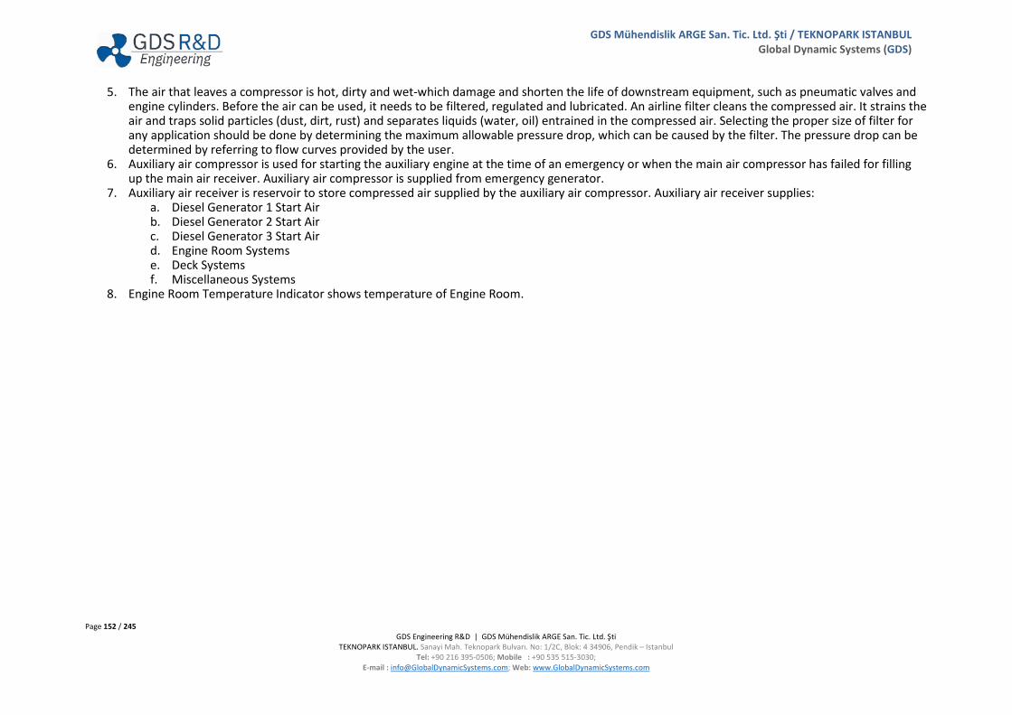
Page 152 / 245 GDS Engineering R&D | GDS Mühendislik ARGE San. Tic. Ltd. Şti
TEKNOPARK ISTANBUL. Sanayi Mah. Teknopark Bulvarı. No: 1/2C, Blok: 4 34906, Pendik – Istanbul Tel: +90 216 395-0506; Mobile : +90 535 515-3030;
E-mail : [email protected]; Web: www.GlobalDynamicSystems.com
GDS Mühendislik ARGE San. Tic. Ltd. Şti / TEKNOPARK ISTANBUL Global Dynamic Systems (GDS)
5. The air that leaves a compressor is hot, dirty and wet-which damage and shorten the life of downstream equipment, such as pneumatic valves and engine cylinders. Before the air can be used, it needs to be filtered, regulated and lubricated. An airline filter cleans the compressed air. It strains the air and traps solid particles (dust, dirt, rust) and separates liquids (water, oil) entrained in the compressed air. Selecting the proper size of filter for any application should be done by determining the maximum allowable pressure drop, which can be caused by the filter. The pressure drop can be determined by referring to flow curves provided by the user.
6. Auxiliary air compressor is used for starting the auxiliary engine at the time of an emergency or when the main air compressor has failed for filling up the main air receiver. Auxiliary air compressor is supplied from emergency generator.
7. Auxiliary air receiver is reservoir to store compressed air supplied by the auxiliary air compressor. Auxiliary air receiver supplies: a. Diesel Generator 1 Start Air b. Diesel Generator 2 Start Air c. Diesel Generator 3 Start Air d. Engine Room Systems e. Deck Systems f. Miscellaneous Systems
8. Engine Room Temperature Indicator shows temperature of Engine Room.

Page 153 / 245 GDS Engineering R&D | GDS Mühendislik ARGE San. Tic. Ltd. Şti
TEKNOPARK ISTANBUL. Sanayi Mah. Teknopark Bulvarı. No: 1/2C, Blok: 4 34906, Pendik – Istanbul Tel: +90 216 395-0506; Mobile : +90 535 515-3030;
E-mail : [email protected]; Web: www.GlobalDynamicSystems.com
GDS Mühendislik ARGE San. Tic. Ltd. Şti / TEKNOPARK ISTANBUL Global Dynamic Systems (GDS)
4.31.2 Valve Numbering
Number Description Number Description CA-V01 Air Compressor 1 Outlet Valve CA-V16 Air Receiver 1 Drain Valve CA-V02 Air Compressor 2 Outlet Valve CA-V17 Air Receiver 2 Drain Valve CA-V03 Aux. Air Compressor Outlet Valve CA-V18 Aux. Air Receiver Drain Valve CA-V04 Air Receivers Main Inlet Valve CA-V19 Aux. Air Receiver Check-Valve CA-V05 Air Receiver 1 Inlet Valve CA-V20 ME Airs Main Inlet Valve CA-V06 Air Receiver 2 Inlet Valve CA-V21 Service Airs Main Inlet Valve CA-V07 Aux. Air Receiver Inlet Valve CA-V22 ME Start Air Inlet Valve CA-V08 Air Receiver 1 Outlet Valve for ME Systems CA-V23 ME Maneuver System Inlet Valve CA-V09 Air Receiver 2 Outlet Valve for ME Systems CA-V24 Control Systems Inlet Valve CA-V10 Aux. Air Receiver Outlet Valve CA-V25 DG 1 Start Air Inlet Valve CA-V11 Air Receiver 1 Outlet Valve for DG’s and Systems CA-V26 DG 2 Start Air Inlet Valve CA-V12 Air Receiver 2 Outlet Valve for DG’s and Systems CA-V27 DG 3 Start Air Inlet Valve CA-V13 Air Receiver 1 Safety Valve CA-V28 Engine Room Systems Inlet Valve CA-V14 Air Receiver 2 Safety Valve CA-V29 Deck Systems Inlet Valve CA-V15 Aux. Air Receiver Safety Valve CA-V30 Misc. Systems Inlet Valve

Page 154 / 245 GDS Engineering R&D | GDS Mühendislik ARGE San. Tic. Ltd. Şti
TEKNOPARK ISTANBUL. Sanayi Mah. Teknopark Bulvarı. No: 1/2C, Blok: 4 34906, Pendik – Istanbul Tel: +90 216 395-0506; Mobile : +90 535 515-3030;
E-mail : [email protected]; Web: www.GlobalDynamicSystems.com
GDS Mühendislik ARGE San. Tic. Ltd. Şti / TEKNOPARK ISTANBUL Global Dynamic Systems (GDS)
4.32 COMBINED BOILER (GUI PANEL # 3300)
43
5
6
7
2
8
10
12
11
9
1
7
13
14
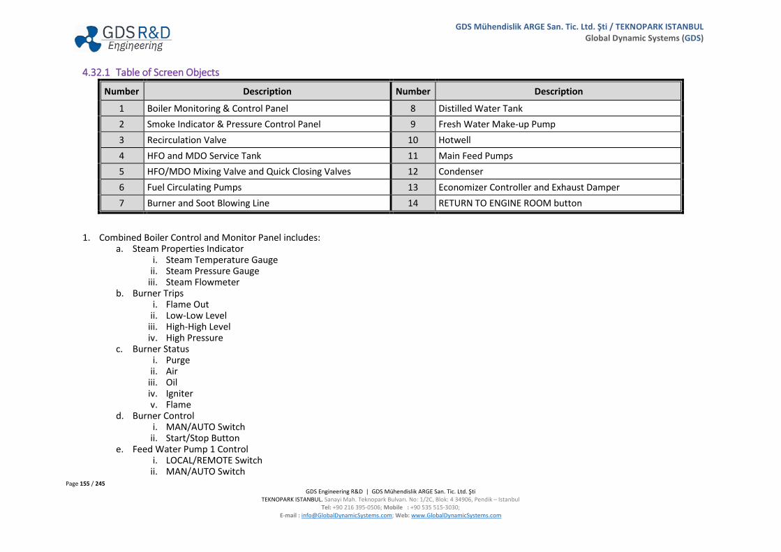
Page 155 / 245 GDS Engineering R&D | GDS Mühendislik ARGE San. Tic. Ltd. Şti
TEKNOPARK ISTANBUL. Sanayi Mah. Teknopark Bulvarı. No: 1/2C, Blok: 4 34906, Pendik – Istanbul Tel: +90 216 395-0506; Mobile : +90 535 515-3030;
E-mail : [email protected]; Web: www.GlobalDynamicSystems.com
GDS Mühendislik ARGE San. Tic. Ltd. Şti / TEKNOPARK ISTANBUL Global Dynamic Systems (GDS)
4.32.1 Table of Screen Objects
Number Description Number Description
1 Boiler Monitoring & Control Panel 8 Distilled Water Tank 2 Smoke Indicator & Pressure Control Panel 9 Fresh Water Make-up Pump 3 Recirculation Valve 10 Hotwell 4 HFO and MDO Service Tank 11 Main Feed Pumps 5 HFO/MDO Mixing Valve and Quick Closing Valves 12 Condenser 6 Fuel Circulating Pumps 13 Economizer Controller and Exhaust Damper 7 Burner and Soot Blowing Line 14 RETURN TO ENGINE ROOM button
1. Combined Boiler Control and Monitor Panel includes: a. Steam Properties Indicator
i. Steam Temperature Gauge ii. Steam Pressure Gauge
iii. Steam Flowmeter b. Burner Trips
i. Flame Out ii. Low-Low Level
iii. High-High Level iv. High Pressure
c. Burner Status i. Purge
ii. Air iii. Oil iv. Igniter v. Flame
d. Burner Control i. MAN/AUTO Switch
ii. Start/Stop Button e. Feed Water Pump 1 Control
i. LOCAL/REMOTE Switch ii. MAN/AUTO Switch

Page 156 / 245 GDS Engineering R&D | GDS Mühendislik ARGE San. Tic. Ltd. Şti
TEKNOPARK ISTANBUL. Sanayi Mah. Teknopark Bulvarı. No: 1/2C, Blok: 4 34906, Pendik – Istanbul Tel: +90 216 395-0506; Mobile : +90 535 515-3030;
E-mail : [email protected]; Web: www.GlobalDynamicSystems.com
GDS Mühendislik ARGE San. Tic. Ltd. Şti / TEKNOPARK ISTANBUL Global Dynamic Systems (GDS)
iii. Start/Stop Button f. Feed Water Pump 2 Control g. Electrical Heater Control (On/Off Buttons) h. Fuel Circulating Pumps Control i. Fresh Water Make-up Pump Control
2. Smoke indicator shows the amount of smoke at exhaust gas of boiler. Steam Pressure can be controlled from the Pressure Control Panel, either manually or automatically. When the pressure control is at Manual Mode, user can control the steam pressure manually via stopping/starting of the burner. When the pressure control is at Auto Mode, burner will be started/stopped according to the High Pressure and Low Pressure set value.
3. Fuel returns to MDO or HFO Service Tanks via recirculation valve. Recirculation valve is a three-way valve and allows the fuel flow into MDO or HFO Service Tank.
4. HFO and MDO Service Tank contains only the required quality of fuel ready for immediate use. Service Tank used on board, necessary for propulsion, boiler and generator systems.
5. HFO/MDO changeover valve allows changing over of HFO and MDO. Quick closing valve is fitted outline of the HFO and MDO Service Tanks which is remotely closed from the Emergency Response Panel. (GUI PANEL #7400) When the valve is closed, the user must click to RESET button for re-opening.
6. Fuel Circulating Pumps supply the fuel through the burner. 7. Sootblowing: Combined Boiler is operated by either with Oil Fired Burner or the heat from the exhaust gases supplied from the ME exhaust line. The
pipes of the boiler are covered with soot in time and this decrease the boiler's efficiency. For this reason, Sootblowing is performed to clear the soot on the pipes and near surfaces inside the boiler. This operation helps increase the heat transfer and therefore the efficiency of the boiler. Sootblowing can be performed using either compressed air or steam.
8. Distilled water tank preparing feed water for steam boilers, collecting condensate, adding chemicals, and preheating of feed water. Distilled Water Tank can be filled up from Fresh Water Generator GUI Panel (GUIP #4800) and FW System & Hydrophore GUI Panel (GUIP #4900).
9. Fresh Water Make-up Pump supplies the feed water into hotwell. 10. Hotwell recollects the steam after the work is done and it is condensed. Boiler water tank is known as the hotwell because boiler feed pump takes
suction from the hotwell and gives it to the boiler through feed valves. If any traces of oil are found in the system, it indicates that there is a crack in the steam heating line inside the fuel oil tanks. If oil is present in the system then it forms coating tubes of the boiler, which may lead to lesser heat transfer to the water in the boiler.
11. Main Feed Pumps are used to pump feed water into the boiler. The water may be freshly supplied or condensate produced as a result of the condensation of the steam produced by the boiler. The Boiler Water Level is controlled via water supply from Main Feed Pump 1 and 2. When the Main Feed Pumps are set AUTO, they start or stop depending on the Boiler Water Level, adjusting the Boiler Water Level automatically. In this system, there is no recirculation of feed water supply is required.
12. The condenser is a heat exchanger, which removes the latent heat from exhaust steam so that it condenses and can be pumped back into the boiler. This condensing should be achieved with the minimum of undercooling, i.e. reduction of condensate temperature below the steam temperature. A condenser is also arranged so that gases and vapors from the condensing steam are removed.
13. Economizer Control System, when in AUTO position, adjust the Exhaust Damper based on the temperature of the exhaust gases. Additionally, it has a alarm detection system for fires in the economizer and controls the damper status accordingly.
14. RETURN TO ENGINE ROOM button allows for quitting from this panel and displays the SERS Main GUI Panel (#1000).

Page 157 / 245 GDS Engineering R&D | GDS Mühendislik ARGE San. Tic. Ltd. Şti
TEKNOPARK ISTANBUL. Sanayi Mah. Teknopark Bulvarı. No: 1/2C, Blok: 4 34906, Pendik – Istanbul Tel: +90 216 395-0506; Mobile : +90 535 515-3030;
E-mail : [email protected]; Web: www.GlobalDynamicSystems.com
GDS Mühendislik ARGE San. Tic. Ltd. Şti / TEKNOPARK ISTANBUL Global Dynamic Systems (GDS)
NOTE:
FIRE IN ECONOMIZER
When there is fire in economizer, an audible fire alarm is activated along with the activation of the fire alarm indicator on Main GUI Panel (#1000). Additionally, a fire image on economizer appears. Fire in Economizer malfunction is activated by the instructor from the Instructor Panel or by the Trainee for using the Malfunctions GUI Panel (#8200) for exercising. Refer to SERS User Manual Volume II for description of the malfunctions with several examples shown.

Page 158 / 245 GDS Engineering R&D | GDS Mühendislik ARGE San. Tic. Ltd. Şti
TEKNOPARK ISTANBUL. Sanayi Mah. Teknopark Bulvarı. No: 1/2C, Blok: 4 34906, Pendik – Istanbul Tel: +90 216 395-0506; Mobile : +90 535 515-3030;
E-mail : [email protected]; Web: www.GlobalDynamicSystems.com
GDS Mühendislik ARGE San. Tic. Ltd. Şti / TEKNOPARK ISTANBUL Global Dynamic Systems (GDS)
4.32.2 Valve Numbering
Number Description Number Description FO-QCV01 HFO Service Tank Quick Closing Valve FW-V54 Combined Boiler Feed Valve 1 FO-QCV02 MDO Service Tank Quick Closing Valve FW-V55 Combined Boiler Feed Valve 2 FO-V31 Fuel Recirculation Valve FW-V56 Blow Down Valve FO-V32 MDO Service Tank Boiler Outlet Valve FW-V57 Scum Valve FO-V33 HFO Service Tank Boiler Outlet Valve SW-V11.1 Condenser SW Inlet Valve FO-V34 Fuel Changeover Valve SW-V11.2 Condenser SW Outlet Valve FO-V35.1 Fuel Circulating Pump 1 Suction Valve FW-V79.4 Distilled Water Tank Fill Up Valve (from Hydrophore) FO-V36.1 Fuel Circulating Pump 1 Discharge Valve FWG-03.1 Distilled Water Tank Fill Up Valve (from FWG) FO-V35.2 Fuel Circulating Pump 2 Suction Valve CA-V28.3 Soot Blowing Compressed Air Inlet Valve FO-V36.2 Fuel Circulating Pump 2 Discharge Valve CB-V01 Combined Boiler Safety Valve FO-V37 Burner Fuel Inlet Valve CB-V02 Combined Boiler Vent Valve FW-V48 FW Make Up Pump Suction Valve SV-01 Main Stop Valve FW-V49 FW Make Up Pump Discharge Valve SV-02 Separators Steam Inlet Valve FW-V50 Feed Pump 1 Suction Valve SV-03 Tanks Steam Inlet Valve FW-V51 Feed Pump 2 Suction Valve SV-04 Misc. Steam Inlet Valve FW-V52 Feed Pump 1 Discharge Valve SV-05 Misc. Steam Inlet Valve FW-V53 Feed Pump 2 Discharge Valve SV-06 Soot Blowing Steam Inlet Valve

Page 159 / 245 GDS Engineering R&D | GDS Mühendislik ARGE San. Tic. Ltd. Şti
TEKNOPARK ISTANBUL. Sanayi Mah. Teknopark Bulvarı. No: 1/2C, Blok: 4 34906, Pendik – Istanbul Tel: +90 216 395-0506; Mobile : +90 535 515-3030;
E-mail : [email protected]; Web: www.GlobalDynamicSystems.com
GDS Mühendislik ARGE San. Tic. Ltd. Şti / TEKNOPARK ISTANBUL Global Dynamic Systems (GDS)
4.33 MAIN FIRE FIGHTING SYSTEM (GUI PANEL # 7500)

Page 160 / 245 GDS Engineering R&D | GDS Mühendislik ARGE San. Tic. Ltd. Şti
TEKNOPARK ISTANBUL. Sanayi Mah. Teknopark Bulvarı. No: 1/2C, Blok: 4 34906, Pendik – Istanbul Tel: +90 216 395-0506; Mobile : +90 535 515-3030;
E-mail : [email protected]; Web: www.GlobalDynamicSystems.com
GDS Mühendislik ARGE San. Tic. Ltd. Şti / TEKNOPARK ISTANBUL Global Dynamic Systems (GDS)
4.33.1 Table of Screen Objects
Number Description
1 Fire Pumps Control Panel 2 Fire Pumps 3 Emergency Fire Pump
1. Fire Pumps Control Panel includes: a. Fire Pump 1 Control Panel, Fire Pump 1 can be operated from the control panel. Power light, indicates whether electrical supply reaches at
the panel. If switch is at ON position, pump can be operated when the user clicks start button. b. Fire Pump 2 Fire Pump 2 can be operated from the control panel. Power light, indicates whether electrical supply reaches at the panel. If
switch is at ON position, pump can be operated when the user clicks start button. c. Emergency Fire Pump Control Panel, Emergency Fire Pump can be operated from the control panel. Power light, indicates whether electrical
supply reaches at the panel. If switch is at ON position, pump can be operated when the user clicks start button. 2. Fire Pumps are the centrifugal pumps with flat curves. Such pumps are capable of supplying maximum flow rates without creating excessive and
dangerous pressures, yet are also capable of providing large flow rates while maintaining the required pressures. 3. Emergency Fire Pump which supply the fire line and general service line when the main fire and general service pumps are not available. Emergency
Fire Pump fitted at forecastle. Emergency Fire Pump is also supplied from the 440 V Emergency Bus Bar.
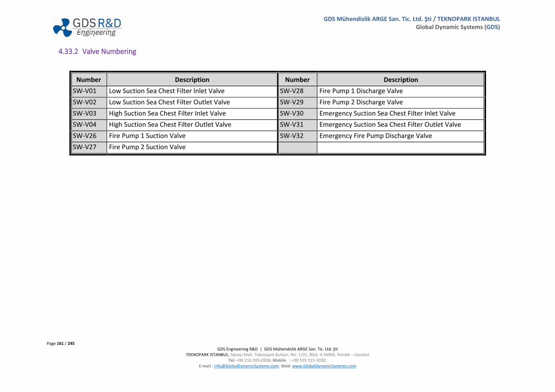
Page 161 / 245 GDS Engineering R&D | GDS Mühendislik ARGE San. Tic. Ltd. Şti
TEKNOPARK ISTANBUL. Sanayi Mah. Teknopark Bulvarı. No: 1/2C, Blok: 4 34906, Pendik – Istanbul Tel: +90 216 395-0506; Mobile : +90 535 515-3030;
E-mail : [email protected]; Web: www.GlobalDynamicSystems.com
GDS Mühendislik ARGE San. Tic. Ltd. Şti / TEKNOPARK ISTANBUL Global Dynamic Systems (GDS)
4.33.2 Valve Numbering
Number Description Number Description SW-V01 Low Suction Sea Chest Filter Inlet Valve SW-V28 Fire Pump 1 Discharge Valve SW-V02 Low Suction Sea Chest Filter Outlet Valve SW-V29 Fire Pump 2 Discharge Valve SW-V03 High Suction Sea Chest Filter Inlet Valve SW-V30 Emergency Suction Sea Chest Filter Inlet Valve SW-V04 High Suction Sea Chest Filter Outlet Valve SW-V31 Emergency Suction Sea Chest Filter Outlet Valve SW-V26 Fire Pump 1 Suction Valve SW-V32 Emergency Fire Pump Discharge Valve SW-V27 Fire Pump 2 Suction Valve

Page 162 / 245 GDS Engineering R&D | GDS Mühendislik ARGE San. Tic. Ltd. Şti
TEKNOPARK ISTANBUL. Sanayi Mah. Teknopark Bulvarı. No: 1/2C, Blok: 4 34906, Pendik – Istanbul Tel: +90 216 395-0506; Mobile : +90 535 515-3030;
E-mail : [email protected]; Web: www.GlobalDynamicSystems.com
GDS Mühendislik ARGE San. Tic. Ltd. Şti / TEKNOPARK ISTANBUL Global Dynamic Systems (GDS)
4.34 CO2 FIRE EXTINGUISHING INSTALLATION (GUI PANEL # 7600)

Page 163 / 245 GDS Engineering R&D | GDS Mühendislik ARGE San. Tic. Ltd. Şti
TEKNOPARK ISTANBUL. Sanayi Mah. Teknopark Bulvarı. No: 1/2C, Blok: 4 34906, Pendik – Istanbul Tel: +90 216 395-0506; Mobile : +90 535 515-3030;
E-mail : [email protected]; Web: www.GlobalDynamicSystems.com
GDS Mühendislik ARGE San. Tic. Ltd. Şti / TEKNOPARK ISTANBUL Global Dynamic Systems (GDS)
4.34.1 Table of Screen Objects
Number Description Number Description
1 CO2 Release Locker 7 Air Supply 2 CO2 Pilot Cylinders 8 Test Valve 3 Activation Handle 9 CO2 Flooding Area 4 CO2 Locker Door 10 Main Common CO2 Line 5 Delay Timer 11 CO2 Release Panel 6 CO2 Cylinder Room 12 Buzzer
1. As soon as the CO2 release locker door is opened, a micro switch is activated. The micro switch will ensure the activation of CO2 warning alarms and ventilation shut off. CO2 release locker consists of two pilot CO2 cylinders containing CO2 gas inside.
2. CO2 pilot cylinders activate the master valve. When master valve has been activated, timer delay will start the countdown. 3. Activation handle, activates the CO2 pilot cylinders. 4. CO2 locker door activates CO2 System Relay Box. CO2 locker door consists locker door valve, which is supplied with compressed air. 5. CO2 from the pilot cylinders in release cabinet reaches main CO2 cylinders head assembly through a time delay unit. Function of time delay unit is to
delay the supply of CO2 to the head assembly for 60-90 seconds. When valve release the cabinet is opened, CO2 reaches only 60 to 90 seconds to the head assembly. Reasons for providing such as delay in CO2 Fire Extinguishing Installation is:
a. As soon as CO2 release cabinet opens, alarm is sounded in the protected space. A time delay of 60 to 90 seconds gives sufficient time for any personnel in the protected space to escape, even after the operation of both valves in the release cabinet.
b. If CO2 is released from main cylinders to common manifold before opening master valve, there may be difficulty in opening master valve because of the bulk CO2 pressure acting on it. Because of time delay, positive opening of the master valve is ensured before releasing CO2.
6. CO2 cylinder room stores the CO2 cylinders ready to use in case of fire situations. 7. CO2 Fire Extinguishing Installation valves operated pneumatically. Pneumatic valves are supplied with air receiver. Also, CO2 horn actuates by
compressed air. 8. Test valve provides testing of CO2 Fire Extinguishing Installation operating condition 9. CO2 Fire Extinguish Installation consists three flooding area:
a. Pump Room b. Engine Room c. Separator Room
10. CO2 flows through CO2 flooding area by main common CO2 line.

Page 164 / 245 GDS Engineering R&D | GDS Mühendislik ARGE San. Tic. Ltd. Şti
TEKNOPARK ISTANBUL. Sanayi Mah. Teknopark Bulvarı. No: 1/2C, Blok: 4 34906, Pendik – Istanbul Tel: +90 216 395-0506; Mobile : +90 535 515-3030;
E-mail : [email protected]; Web: www.GlobalDynamicSystems.com
GDS Mühendislik ARGE San. Tic. Ltd. Şti / TEKNOPARK ISTANBUL Global Dynamic Systems (GDS)
11. CO2 release panel includes fire alarm and CO2 alarm indicators, reset alarm button and CO2 Fire Extinguishing Installation status such as: a. CO2 Pilot Cylinders Are Active b. Main Cylinders CO2 Level Low c. CO2 Main Cylinders Are Empty d. CO2 Pilot Cylinders Are Empty
12. Buzzer gives audible warning for evacuation of the Engine Room.
4.34.2 Valve Numbering
Number Description Number Description CA-V28.2 Compressed Air Inlet Valve CO2-V05 Delay Timer By-Pass Valve CO2-V01 Locker Door Valve CO2-V06 Safety Valve CO2-V02 CO2 Outlet Valve CO2-V07 Test Valve CO2-V03 CO2 Pilot Cylinder 1 Head Assembly Valve CO2-V08 CO2 Engine Room Inlet Valve CO2-V04 CO2 Pilot Cylinder 2 Head Assembly Valve
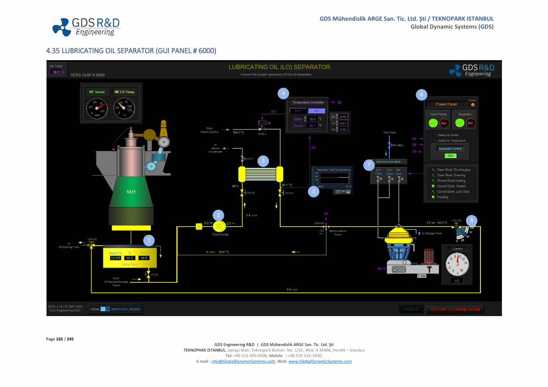
Page 165 / 245 GDS Engineering R&D | GDS Mühendislik ARGE San. Tic. Ltd. Şti
TEKNOPARK ISTANBUL. Sanayi Mah. Teknopark Bulvarı. No: 1/2C, Blok: 4 34906, Pendik – Istanbul Tel: +90 216 395-0506; Mobile : +90 535 515-3030;
E-mail : [email protected]; Web: www.GlobalDynamicSystems.com
GDS Mühendislik ARGE San. Tic. Ltd. Şti / TEKNOPARK ISTANBUL Global Dynamic Systems (GDS)
4.35 LUBRICATING OIL SEPARATOR (GUI PANEL # 6000)
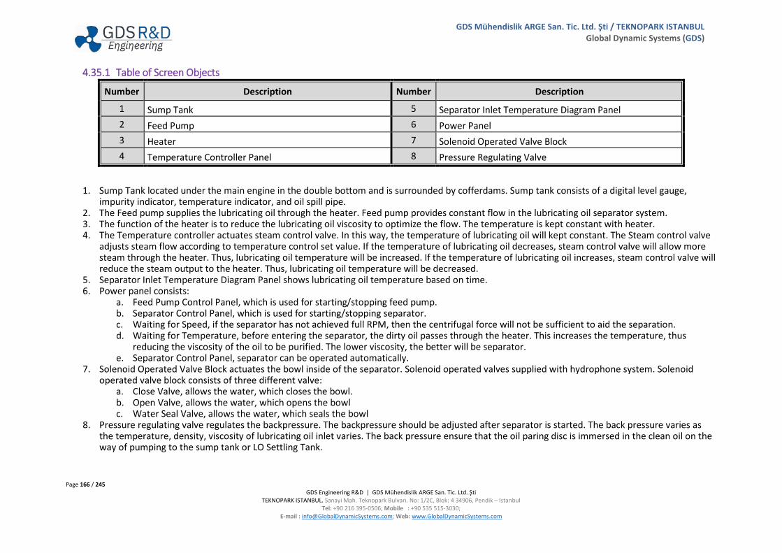
Page 166 / 245 GDS Engineering R&D | GDS Mühendislik ARGE San. Tic. Ltd. Şti
TEKNOPARK ISTANBUL. Sanayi Mah. Teknopark Bulvarı. No: 1/2C, Blok: 4 34906, Pendik – Istanbul Tel: +90 216 395-0506; Mobile : +90 535 515-3030;
E-mail : [email protected]; Web: www.GlobalDynamicSystems.com
GDS Mühendislik ARGE San. Tic. Ltd. Şti / TEKNOPARK ISTANBUL Global Dynamic Systems (GDS)
4.35.1 Table of Screen Objects
Number Description Number Description
1 Sump Tank 5 Separator Inlet Temperature Diagram Panel 2 Feed Pump 6 Power Panel 3 Heater 7 Solenoid Operated Valve Block 4 Temperature Controller Panel 8 Pressure Regulating Valve
1. Sump Tank located under the main engine in the double bottom and is surrounded by cofferdams. Sump tank consists of a digital level gauge, impurity indicator, temperature indicator, and oil spill pipe.
2. The Feed pump supplies the lubricating oil through the heater. Feed pump provides constant flow in the lubricating oil separator system. 3. The function of the heater is to reduce the lubricating oil viscosity to optimize the flow. The temperature is kept constant with heater. 4. The Temperature controller actuates steam control valve. In this way, the temperature of lubricating oil will kept constant. The Steam control valve
adjusts steam flow according to temperature control set value. If the temperature of lubricating oil decreases, steam control valve will allow more steam through the heater. Thus, lubricating oil temperature will be increased. If the temperature of lubricating oil increases, steam control valve will reduce the steam output to the heater. Thus, lubricating oil temperature will be decreased.
5. Separator Inlet Temperature Diagram Panel shows lubricating oil temperature based on time. 6. Power panel consists:
a. Feed Pump Control Panel, which is used for starting/stopping feed pump. b. Separator Control Panel, which is used for starting/stopping separator. c. Waiting for Speed, if the separator has not achieved full RPM, then the centrifugal force will not be sufficient to aid the separation. d. Waiting for Temperature, before entering the separator, the dirty oil passes through the heater. This increases the temperature, thus
reducing the viscosity of the oil to be purified. The lower viscosity, the better will be separator. e. Separator Control Panel, separator can be operated automatically.
7. Solenoid Operated Valve Block actuates the bowl inside of the separator. Solenoid operated valves supplied with hydrophone system. Solenoid operated valve block consists of three different valve:
a. Close Valve, allows the water, which closes the bowl. b. Open Valve, allows the water, which opens the bowl c. Water Seal Valve, allows the water, which seals the bowl
8. Pressure regulating valve regulates the backpressure. The backpressure should be adjusted after separator is started. The back pressure varies as the temperature, density, viscosity of lubricating oil inlet varies. The back pressure ensure that the oil paring disc is immersed in the clean oil on the way of pumping to the sump tank or LO Settling Tank.
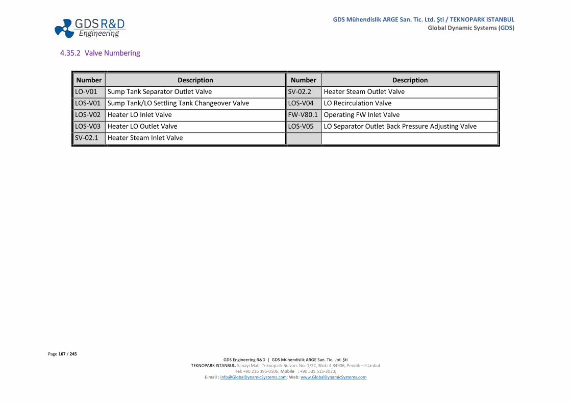
Page 167 / 245 GDS Engineering R&D | GDS Mühendislik ARGE San. Tic. Ltd. Şti
TEKNOPARK ISTANBUL. Sanayi Mah. Teknopark Bulvarı. No: 1/2C, Blok: 4 34906, Pendik – Istanbul Tel: +90 216 395-0506; Mobile : +90 535 515-3030;
E-mail : [email protected]; Web: www.GlobalDynamicSystems.com
GDS Mühendislik ARGE San. Tic. Ltd. Şti / TEKNOPARK ISTANBUL Global Dynamic Systems (GDS)
4.35.2 Valve Numbering
Number Description Number Description LO-V01 Sump Tank Separator Outlet Valve SV-02.2 Heater Steam Outlet Valve LOS-V01 Sump Tank/LO Settling Tank Changeover Valve LOS-V04 LO Recirculation Valve LOS-V02 Heater LO Inlet Valve FW-V80.1 Operating FW Inlet Valve LOS-V03 Heater LO Outlet Valve LOS-V05 LO Separator Outlet Back Pressure Adjusting Valve SV-02.1 Heater Steam Inlet Valve

Page 168 / 245 GDS Engineering R&D | GDS Mühendislik ARGE San. Tic. Ltd. Şti
TEKNOPARK ISTANBUL. Sanayi Mah. Teknopark Bulvarı. No: 1/2C, Blok: 4 34906, Pendik – Istanbul Tel: +90 216 395-0506; Mobile : +90 535 515-3030;
E-mail : [email protected]; Web: www.GlobalDynamicSystems.com
GDS Mühendislik ARGE San. Tic. Ltd. Şti / TEKNOPARK ISTANBUL Global Dynamic Systems (GDS)
4.36 LUBRICATING OIL TANKS & TRANSFER SYSTEM (GUI PANEL # 6100)

Page 169 / 245 GDS Engineering R&D | GDS Mühendislik ARGE San. Tic. Ltd. Şti
TEKNOPARK ISTANBUL. Sanayi Mah. Teknopark Bulvarı. No: 1/2C, Blok: 4 34906, Pendik – Istanbul Tel: +90 216 395-0506; Mobile : +90 535 515-3030;
E-mail : [email protected]; Web: www.GlobalDynamicSystems.com
GDS Mühendislik ARGE San. Tic. Ltd. Şti / TEKNOPARK ISTANBUL Global Dynamic Systems (GDS)
4.36.1 Table of Screen Objects
Number Description Number Description
1 Diesel Generator LO Service Tank 1 6 Cylinder Oil Storage Tank 2 Diesel Generator LO Service Tank 2 7 Cylinder Oil Service Tank 3 Main LO Settling Tank 8 Cylinder Oil & Hand Pump 4 Main LO Storage Tank 9 LO Transfer Pump Control Panel 5 LO Transfer Pump 10 Cylinder Oil Transfer Pump Control Panel
1. DG LO Service Tank 1 contains the lubricating oil ready for using at diesel generators. DG Service Tank 1 contains of a digital level gauge, air vent, oil spill pipe, and quick closing valve. Quick closing valve is fitted outline of the LO Tanks which is remotely closed from the Emergency Response Panel. (GUI PANEL #7400) When the valve is closed, the user must click to RESET button for re-opening.
2. DG LO Service Tank 2 contains the required quality of lubricating oil ready for using at diesel generators. DG Service Tank 2 contains of a digital level gauge, air vent, oil spill pipe, and quick closing valve.
3. Main Lubricating Oil Settling Tank used for pre-cleaning of the Main Lubricating Oil by gravity or LO Separator. Main Lubricating Oil Settling Tank contains of a digital level gauge, air vent, oil spill pipe, and quick closing valve.
4. Main Lubricating Oil Storage Tank contains lubricating oil after bunkering. Main lubricating oil storage tank contains of a digital level gauge, air vent, oil spill pipe, and quick closing valve.
5. LO Transfer Pump can transfer diesel generator lubricating oil or main lubricating oil to service tanks, shore connection, incinerator or sludge tank. 6. Cylinder Oil Storage Tanks contain cylinder oil after bunkering. Cylinder Oil Storage Tank contains of a digital level gauge, air vent, oil spill pipe, and
quick closing valve. 7. Cylinder Oil Service tank contains cylinder oil ready for using at main engine cylinders. Cylinder Oil Service Tank contains of a digital level gauge, air
vent, oil spill pipe, and quick closing valve. 8. Cylinder Oil can be pumped from Cylinder Oil Storage Tank to the Cylinder Oil Day Tank via Cylinder Oil Pump. If cylinder oil pump cannot be
operated, hand pump can be used to pump cylinder oil storage tank to the cylinder oil day tank. 9. LO Transfer Pump can be operated from the control panel. Power light indicates whether electrical supply reaches at the panel. If switch is at ON
position pumps can be operated when user clicks the start button. If the LO Transfer Pump at Local Mode, the pump can be operated from the local control panel. If the LO Transfer Pump at Remote Mode (RT), the pump can be operated from the ECR Panels: Pumps & Compressors GUI Panel (GUIP #5450).
10. Cylinder Oil Transfer Pump can be operated from the control panel. Power light indicates whether electrical supply reaches at the panel. If switch is at ON position, pumps can be operated when user clicks the start button. If the Cyl. Oil Transfer Pump at Local Mode, the pump can be operated from the local control panel. If the Cyl. Oil Transfer Pump at Remote (RT) Mode, the pump can be operated from the ECR Panels: Pumps & Compressor GUI Panel (GUIP #5450).
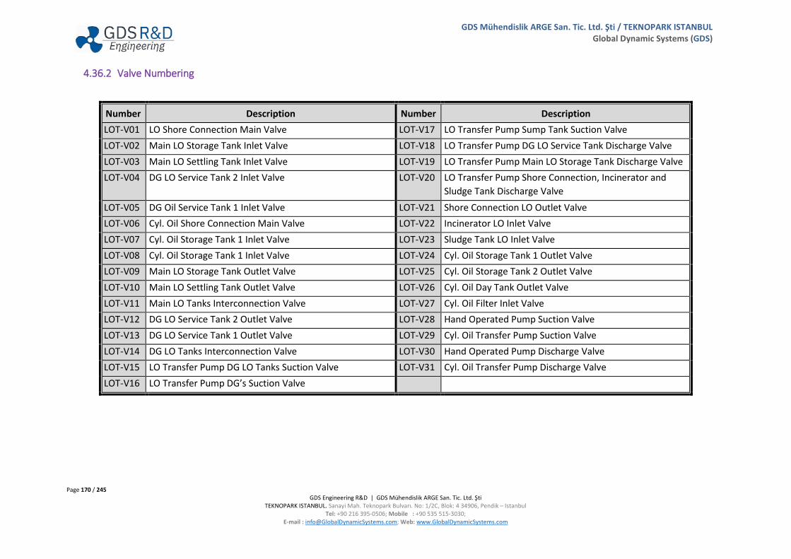
Page 170 / 245 GDS Engineering R&D | GDS Mühendislik ARGE San. Tic. Ltd. Şti
TEKNOPARK ISTANBUL. Sanayi Mah. Teknopark Bulvarı. No: 1/2C, Blok: 4 34906, Pendik – Istanbul Tel: +90 216 395-0506; Mobile : +90 535 515-3030;
E-mail : [email protected]; Web: www.GlobalDynamicSystems.com
GDS Mühendislik ARGE San. Tic. Ltd. Şti / TEKNOPARK ISTANBUL Global Dynamic Systems (GDS)
4.36.2 Valve Numbering
Number Description Number Description LOT-V01 LO Shore Connection Main Valve LOT-V17 LO Transfer Pump Sump Tank Suction Valve LOT-V02 Main LO Storage Tank Inlet Valve LOT-V18 LO Transfer Pump DG LO Service Tank Discharge Valve LOT-V03 Main LO Settling Tank Inlet Valve LOT-V19 LO Transfer Pump Main LO Storage Tank Discharge Valve LOT-V04 DG LO Service Tank 2 Inlet Valve LOT-V20 LO Transfer Pump Shore Connection, Incinerator and
Sludge Tank Discharge Valve LOT-V05 DG Oil Service Tank 1 Inlet Valve LOT-V21 Shore Connection LO Outlet Valve LOT-V06 Cyl. Oil Shore Connection Main Valve LOT-V22 Incinerator LO Inlet Valve LOT-V07 Cyl. Oil Storage Tank 1 Inlet Valve LOT-V23 Sludge Tank LO Inlet Valve LOT-V08 Cyl. Oil Storage Tank 1 Inlet Valve LOT-V24 Cyl. Oil Storage Tank 1 Outlet Valve LOT-V09 Main LO Storage Tank Outlet Valve LOT-V25 Cyl. Oil Storage Tank 2 Outlet Valve LOT-V10 Main LO Settling Tank Outlet Valve LOT-V26 Cyl. Oil Day Tank Outlet Valve LOT-V11 Main LO Tanks Interconnection Valve LOT-V27 Cyl. Oil Filter Inlet Valve LOT-V12 DG LO Service Tank 2 Outlet Valve LOT-V28 Hand Operated Pump Suction Valve LOT-V13 DG LO Service Tank 1 Outlet Valve LOT-V29 Cyl. Oil Transfer Pump Suction Valve LOT-V14 DG LO Tanks Interconnection Valve LOT-V30 Hand Operated Pump Discharge Valve LOT-V15 LO Transfer Pump DG LO Tanks Suction Valve LOT-V31 Cyl. Oil Transfer Pump Discharge Valve LOT-V16 LO Transfer Pump DG’s Suction Valve

Page 171 / 245 GDS Engineering R&D | GDS Mühendislik ARGE San. Tic. Ltd. Şti
TEKNOPARK ISTANBUL. Sanayi Mah. Teknopark Bulvarı. No: 1/2C, Blok: 4 34906, Pendik – Istanbul Tel: +90 216 395-0506; Mobile : +90 535 515-3030;
E-mail : [email protected]; Web: www.GlobalDynamicSystems.com
GDS Mühendislik ARGE San. Tic. Ltd. Şti / TEKNOPARK ISTANBUL Global Dynamic Systems (GDS)
4.37 HFO TANKS & TRANSFER SYSTEM (GUI PANEL #6300)
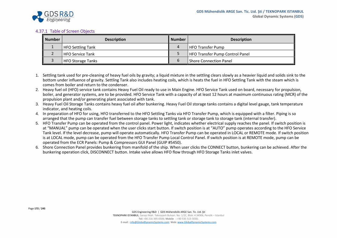
Page 172 / 245 GDS Engineering R&D | GDS Mühendislik ARGE San. Tic. Ltd. Şti
TEKNOPARK ISTANBUL. Sanayi Mah. Teknopark Bulvarı. No: 1/2C, Blok: 4 34906, Pendik – Istanbul Tel: +90 216 395-0506; Mobile : +90 535 515-3030;
E-mail : [email protected]; Web: www.GlobalDynamicSystems.com
GDS Mühendislik ARGE San. Tic. Ltd. Şti / TEKNOPARK ISTANBUL Global Dynamic Systems (GDS)
4.37.1 Table of Screen Objects
Number Description Number Description
1 HFO Settling Tank 4 HFO Transfer Pump 2 HFO Service Tank 5 HFO Transfer Pump Control Panel 3 HFO Storage Tanks 6 Shore Connection Panel
1. Settling tank used for pre-cleaning of heavy fuel oils by gravity; a liquid mixture in the settling clears slowly as a heavier liquid and solids sink to the bottom under influence of gravity. Settling Tank also includes heating coils, which is heats the fuel in HFO Settling Tank with the steam which is comes from boiler and return to the condenser.
2. Heavy fuel oil (HFO) service tank contains Heavy Fuel Oil ready to use in Main Engine. HFO Service Tank used on board, necessary for propulsion, boiler, and generator systems, are to be provided. HFO Service Tank with a capacity of at least 12 hours at maximum continuous rating (MCR) of the propulsion plant and/or generating plant associated with tank.
3. Heavy Fuel Oil Storage Tanks contains heavy fuel oil after bunkering. Heavy Fuel Oil storage tanks contains a digital level gauge, tank temperature indicator, and heating coils.
4. In preparation of HFO for using, HFO transferred to the HFO Settling Tanks via HFO Transfer Pump, which is equipped with a filter. Piping is so arranged that the pump can transfer fuel between storage tanks to settling tank or storage tank to storage tank (internal transfer).
5. HFO Transfer Pump can be operated from the control panel. Power light, indicates whether electrical supply reaches the panel. If switch position is at “MANUAL” pump can be operated when the user clicks start button. If switch position is at “AUTO” pump operates according to the HFO Service Tank level. If the level decrease, pump will operate automatically. HFO Transfer Pump can be operated in LOCAL or REMOTE mode. If switch position is at LOCAL mode, pump can be operated from the HFO Transfer Pump Local Control Panel. If switch position is at REMOTE mode, pump can be operated from the ECR Panels: Pump & Compressors GUI Panel (GUIP #5450).
6. Shore Connection Panel provides bunkering from manifold of the ship. When user clicks the CONNECT button, bunkering can be achieved. After the bunkering operation click, DISCONNECT button. Intake valve allows HFO flow through HFO Storage Tanks inlet valves.

Page 173 / 245 GDS Engineering R&D | GDS Mühendislik ARGE San. Tic. Ltd. Şti
TEKNOPARK ISTANBUL. Sanayi Mah. Teknopark Bulvarı. No: 1/2C, Blok: 4 34906, Pendik – Istanbul Tel: +90 216 395-0506; Mobile : +90 535 515-3030;
E-mail : [email protected]; Web: www.GlobalDynamicSystems.com
GDS Mühendislik ARGE San. Tic. Ltd. Şti / TEKNOPARK ISTANBUL Global Dynamic Systems (GDS)
4.37.2 Valve Numbering
Number Description Number Description FO-V38 Port Shore Connection Inlet Valve FO-V49 HFO Transfer Pump HFO Service Tank Suction Valve FO-V39 Starboard Shore Connection Inlet Valve FO-V50 HFO Transfer Pump Suction Valve FO-V40 1P HFO Storage Tank Inlet Valve FO-V51 HFO Transfer Pump Discharge Valve FO-V41 2P HFO Storage Tank Inlet Valve FO-V52 HFO Settling Tank Fill up Valve FO-V42 1S HFO Storage Tank Inlet Valve FO-V53 Internal Transfer Valve FO-V43 2S HFO Storage Tank Inlet Valve FO-V54 HFO Settling Tank Inlet Valve FO-V44 1P HFO Storage Tank Outlet Valve FO-V55 HFO Service Tank Inlet Valve FO-V45 2P HFO Storage Tank Outlet Valve FO-V56 HFO Service Tank Inlet Valve (from HFO Separators) FO-V46 1S HFO Storage Tank Outlet Valve FO-V57 HFO Settling Tank Separators Outlet Valve FO-V47 2P HFO Storage Tank Outlet Valve FO-V58 HFO Settling Tank Outlet Valve SV-03.1 1P HFO Storage Tank Steam Inlet Valve FO-V59 HFO Service Tank Outlet Valve SV-03.2 1P HFO Storage Tank Steam Outlet Valve SV-03.9 HFO Settling Tank Steam Inlet Valve SV-03.3 2P HFO Storage Tank Steam Inlet Valve SV-03.10 HFO Settling Tank Steam Outlet Valve SV-03.4 2P HFO Storage Tank Steam Outlet Valve SV-03.11 HFO Service Tank Steam Inlet Valve SV-03.5 1S HFO Storage Tank Steam Inlet Valve SV-03.12 HFO Service Tank Steam Outlet Valve SV-03.6 1S HFO Storage Tank Steam Outlet Valve FO-QCV01 HFO Service Tank Quick Closing Valve SV-03.7 2S HFO Storage Tank Steam Inlet Valve FO-V01 HFO Service Tank Outlet Valve SV-03.8 2S HFO Storage Tank Steam Outlet Valve FO-V33 HFO Service Tank Boiler Outlet Valve FO-V48 HFO Transfer Pump HFO Settling Tank Suction Valve

Page 174 / 245 GDS Engineering R&D | GDS Mühendislik ARGE San. Tic. Ltd. Şti
TEKNOPARK ISTANBUL. Sanayi Mah. Teknopark Bulvarı. No: 1/2C, Blok: 4 34906, Pendik – Istanbul Tel: +90 216 395-0506; Mobile : +90 535 515-3030;
E-mail : [email protected]; Web: www.GlobalDynamicSystems.com
GDS Mühendislik ARGE San. Tic. Ltd. Şti / TEKNOPARK ISTANBUL Global Dynamic Systems (GDS)
4.38 HFO SEPARATORS (GUI PANEL #6400)

Page 175 / 245 GDS Engineering R&D | GDS Mühendislik ARGE San. Tic. Ltd. Şti
TEKNOPARK ISTANBUL. Sanayi Mah. Teknopark Bulvarı. No: 1/2C, Blok: 4 34906, Pendik – Istanbul Tel: +90 216 395-0506; Mobile : +90 535 515-3030;
E-mail : [email protected]; Web: www.GlobalDynamicSystems.com
GDS Mühendislik ARGE San. Tic. Ltd. Şti / TEKNOPARK ISTANBUL Global Dynamic Systems (GDS)
4.38.1 Table of Screen Objects
Number Description Number Description
1 Feed Pump 4 Recirculating Valve 2 Heater 5 Solenoid Operated Valve Block 3 Temperature Controller Panel 6 HFO Separator Control and Status Panels
1. The Feed pump supplies the heavy fuel oil through the heater. Feed pump provides constant flow in the heavy fuel oil separator system. 2. The function of the heater is to reduce the heavy fuel oil viscosity. The temperature is kept in constant with heater. 3. Temperature controller actuates steam control valve. In this way, temperature of heavy fuel oil is kept in constant. Steam control valve adjusts
steam flow according to temperature control set value. If temperature of heavy fuel oil decrease, steam control valve will more steam through the heater. Thus, heavy fuel oil temperature will be increased. If temperature of heavy fuel oil increase, steam control valve reduces the steam amount through the heater. Thus, heavy fuel oil temperature will be decreased.
4. Recirculation valve allows heavy fuel oil through recirculation line or separator line. If separator waiting for speed or waiting for temperature, fuel oil flows through recirculation line. If separator speed and fuel oil temperature reach sufficient values, recirculation valve position will be changed and fuel oil flows through separator.
5. Solenoid operated valve block actuates the bowl inside of the separator. Solenoid operated valve is supplied with hydrophone system. Solenoid operated valve block consists of three different valve:
a. Close Valve, allows the water, which closes the bowl. b. Open Valve, allows the water, which opens the bowl. c. Water Seal Valve, allows the water, which seals the bowl
6. HFO Separator Control Panel consists: a. Feed Pump Control Panel, which is used for starting/stopping operation of the feed pump. b. Separator Control Panel, which is used for starting/stopping operation of the separator. c. Waiting for Speed, if the separator has not achieved full rpm, then the centrifugal force will not be sufficient to aid the separation. d. Separator Control Switch, separator can be operated automatically. e. Separator current indicator indicates current of separator electric motor
Separator Status Panel consists:
a. Open Bowl, Discharging b. Open Bowl, Draining c. Closed Bowl, Sealing d. Closed Bowl, Sealed e. Closed Bowl Lost Seal f. Low Speed, Stopped

Page 176 / 245 GDS Engineering R&D | GDS Mühendislik ARGE San. Tic. Ltd. Şti
TEKNOPARK ISTANBUL. Sanayi Mah. Teknopark Bulvarı. No: 1/2C, Blok: 4 34906, Pendik – Istanbul Tel: +90 216 395-0506; Mobile : +90 535 515-3030;
E-mail : [email protected]; Web: www.GlobalDynamicSystems.com
GDS Mühendislik ARGE San. Tic. Ltd. Şti / TEKNOPARK ISTANBUL Global Dynamic Systems (GDS)
4.38.2 Valve Numbering
Number Description Number Description FO-V74 HFO Separator 1 Feed Pump Suction Valve SV-02.11 HFO Separator 2 Heater Steam Outlet Valve FO-V74.1 HFO Separator 1 Feed Pump Discharge Valve FO-V78 HFO Separator 1 Recirculation Valve FO-V75 Recirculation Line Inlet Valve 1 FO-V79 HFO Separator 2 Recirculation Valve FO-V76 HFO Separator 2 Feed Pump Suction Valve FO-V80 HFO Separator 1 Back Pressure Adjusting Valve FO-V76.1 HFO Separator 2 Feed Pump Discharge Valve FO-V81 HFO Separator 2 Back Pressure Adjusting Valve FO-V77 Recirculation Line Inlet Valve 2 FO-V82 Recirculation Line Outlet Valve 1 SV-02.6 HFO Separator 1 Heater Steam Inlet Valve FO-V83 Recirculation Line Outlet Valve 2 SV-02.7 HFO Separator 1 Heater Steam Adjustment Valve FO-V84 HFO Separator 1 Outlet Valve SV-02.8 HFO Separator 1 Heater Steam Outlet Valve FO-V85 HFO Separator 2 Outlet Valve SV-02.9 HFO Separator 2 Heater Steam Inlet Valve FW-V80.3 HFO Separator 1 Operating Water Inlet Valve SV-02.10 HFO Separator 2 Heater Steam Adjustment Valve FW-V80.4 HFO Separator 2 Operating Water Inlet Valve

Page 177 / 245 GDS Engineering R&D | GDS Mühendislik ARGE San. Tic. Ltd. Şti
TEKNOPARK ISTANBUL. Sanayi Mah. Teknopark Bulvarı. No: 1/2C, Blok: 4 34906, Pendik – Istanbul Tel: +90 216 395-0506; Mobile : +90 535 515-3030;
E-mail : [email protected]; Web: www.GlobalDynamicSystems.com
GDS Mühendislik ARGE San. Tic. Ltd. Şti / TEKNOPARK ISTANBUL Global Dynamic Systems (GDS)
4.39 MARINE DIESEL OIL TANKS, SEPARATOR & TRANSFER SYSTEM (GUI PANEL #6200)

Page 178 / 245 GDS Engineering R&D | GDS Mühendislik ARGE San. Tic. Ltd. Şti
TEKNOPARK ISTANBUL. Sanayi Mah. Teknopark Bulvarı. No: 1/2C, Blok: 4 34906, Pendik – Istanbul Tel: +90 216 395-0506; Mobile : +90 535 515-3030;
E-mail : [email protected]; Web: www.GlobalDynamicSystems.com
GDS Mühendislik ARGE San. Tic. Ltd. Şti / TEKNOPARK ISTANBUL Global Dynamic Systems (GDS)
4.39.1 Table of Screen Objects
Number Description Number Description
1 MDO/MGO Settling Tank 7 MDO Separator Panel 2 Feed Pump 8 MDO/MGO Service Tank 3 Heater 9 MDO/MGO Storage Tanks 4 Temperature Controller Panel 10 MDO Transfer Pump 5 Recirculation Valve 11 MDO Transfer Pump Control Panel 6 Solenoid Operated Valve Block 12 Shore Connection Panel
1. Settling tank used for pre-cleaning of marine diesel oils by gravity; a liquid mixture in the settling clears slowly as a heavier liquid and solids sink to the bottom under influence of gravity.
2. The feed pump supplies the marine diesel oil through the heater. Feed pump provides constant flow to the marine diesel oil separator system. 3. The function of the heater is to reduce (via steam) the marine diesel oil viscosity. The temperature is kept in constant with heater. 4. Temperature controller actuates steam control valve. In this way, temperature of marine diesel oil is kept constant. Steam control valve adjusts
steam flow according to temperature control set value. If temperature of marine diesel oil decrease, steam control valve will more steam through the heater. Thus, marine diesel oil temperature will be increased. If temperature of marine diesel oil increase, steam control valve reduces the steam amount through the heater. Thus, marine diesel oil temperature will be decreased.
5. Recirculation valve allows marine diesel oil through recirculation line or separator line. If separator waiting for speed or waiting for temperature, marine diesel oil flows through recirculation line. If separator speed and fuel oil temperature reach sufficient values, recirculation valve position will be changed and fuel oil flows through separator.
6. Solenoid valve block actuates the bowl inside of the separator. Solenoid operated valve is supplied with hydrophone. Solenoid valve block consists of three different valve:
a. Close Valve b. Open Valve c. Water Seal Valve
7. MDO Separator Control Panel consists: a. Feed Pump Control Panel b. Separator Control Panel c. Waiting for Speed d. Separator Control Switch (Manual/Auto) e. Separator Current Indicator

Page 179 / 245 GDS Engineering R&D | GDS Mühendislik ARGE San. Tic. Ltd. Şti
TEKNOPARK ISTANBUL. Sanayi Mah. Teknopark Bulvarı. No: 1/2C, Blok: 4 34906, Pendik – Istanbul Tel: +90 216 395-0506; Mobile : +90 535 515-3030;
E-mail : [email protected]; Web: www.GlobalDynamicSystems.com
GDS Mühendislik ARGE San. Tic. Ltd. Şti / TEKNOPARK ISTANBUL Global Dynamic Systems (GDS)
8. Marine Diesel Oil (MDO)/Marine Gas Oil (MGO) Service Tank contains fuel ready to use in Main Engine. MDO/MGO Service Tank used on board, necessary for propulsion, boiler and generator systems, are to be provided. MDO Service Tank with a capacity of at least 12 hours at maximum continuous rating (MCR) of the propulsion plant and/or generating plant associated.
9. MDO/MGO Storage Tanks contain marine diesel oil after bunkering. MDO/MGO Tanks contain of a digital level gauge, tank temperature indicator. 10. In preparation of MDO/MGO for using, MDO/MGO transferred to the MDO/MGO Settling Tanks via MDO Transfer Pump, which is equipped with a
filter. Piping is arranged that the pump can transfer fuel between storage tanks to settling tank. 11. MDO Transfer Pump can be operated from the control panel. Power light, indicates whether electrical supply reaches the panel. If switch position is
at “MANUAL” pump can be operated when the user clicks start button. If switch position is at “AUTO” pump operates according to the MDO/MGO Settling Tank Level. If the level decreases, pump will operate automatically. MDO Transfer Pump can be operated in LOCAL or REMOTE mode. If switch position is at LOCAL mode, pump can be operated from the MDO Transfer Pump Local Control Panel. If switch position is at REMOTE mode, pump can be operated from the ECR Panels: Pump & Compressors GUI Panel (GUIP #5450).
12. Shore Connection Panel provides bunkering from manifold of the ship. When user clicks the CONNECT button, bunkering can be achieved. After the bunkering operation, click the DISCONNECT button. Intake valve allows MDO flow through MDO Storage Tank inlet valve.
4.39.2 Valve Numbering
Number Description Number Description FO-V60 Port Shore Connection Inlet Valve SV-02.3 Heater Steam Inlet Valve FO-V61 Starboard Shore Connection Inlet Valve SV-02.4 Heater Steam Adjustment Valve FO-V62 3P MDO Storage Tank Inlet Valve SV-02.5 Heater Steam Outlet Valve FO-V63 3S MDO Storage Tank Inlet Valve FO-V71 Feed Pump Suction Valve FO-V64 3P MDO Storage Tank Outlet Valve FO-V72 Recirculation Valve FO-V65 3S MDO Storage Tank Outlet Valve FW-80.2 MDO Separator Operating Water Inlet Valve FO-V66 MDO Transfer Pump Suction Valve FO-V73 MDO Separator Back Pressure Adjusting Valve FO-V67 MDO Transfer Pump Discharge Valve FO-QCV02 MDO Service Tank Quick Closing Valve FO-V68 MDO Settling Tank Inlet Valve FO-V02 MDO Service Tank Main Engine Outlet Valve FO-V69 MDO Service Tank Inlet Valve FO-V32 MDO Service Tank Boiler Outlet Valve FO-V70 MDO Settling Tank Outlet Valve DG’s V01 MDO Service Tank Diesel Generators Outlet Valve

Page 180 / 245 GDS Engineering R&D | GDS Mühendislik ARGE San. Tic. Ltd. Şti
TEKNOPARK ISTANBUL. Sanayi Mah. Teknopark Bulvarı. No: 1/2C, Blok: 4 34906, Pendik – Istanbul Tel: +90 216 395-0506; Mobile : +90 535 515-3030;
E-mail : [email protected]; Web: www.GlobalDynamicSystems.com
GDS Mühendislik ARGE San. Tic. Ltd. Şti / TEKNOPARK ISTANBUL Global Dynamic Systems (GDS)
4.40 OILY WATER SEPARATOR (GUI PANEL #6500)

Page 181 / 245 GDS Engineering R&D | GDS Mühendislik ARGE San. Tic. Ltd. Şti
TEKNOPARK ISTANBUL. Sanayi Mah. Teknopark Bulvarı. No: 1/2C, Blok: 4 34906, Pendik – Istanbul Tel: +90 216 395-0506; Mobile : +90 535 515-3030;
E-mail : [email protected]; Web: www.GlobalDynamicSystems.com
GDS Mühendislik ARGE San. Tic. Ltd. Şti / TEKNOPARK ISTANBUL Global Dynamic Systems (GDS)
4.40.1 Table of Screen Objects
Number Description Number Description
1 Separator, Pumps Control, and OWS System Trips Panel 6 Oily Water Separator (Internal) Pump 2 Sludge Tank 7 Absorber Filter 3 Port Side and Starboard Aft Well 8 Oil Monitoring Device (OMD) 4 Bilge Pump 9 Oil Monitoring Device Control Panel 5 Bilge Tank 10 Outlet Valve
1. Oily Water Separator (OWS) pump and bilge pump can be started from the separator control panel. Power light, indicates whether electrical supply reaches at the panel. If switch is at ON position pumps can be operated when the user clicks the start button. Separator control panel includes:
a. High ppm, if the parts of per million (ppm) is higher than 15 in the oily water, high ppm alarm light will be lit. b. Oil High, if the oil is high, oil high alarm limit will be lit.
OWS System Trips Panel includes:
c. Control Air Low Pressure d. Flushing Water Low Pressure
2. Sludge tank is provided to receive oily residues coming from the oily water filtering or separating equipment and from the purification of fuel and lubricating oils.
3. Bilge well is a space in the bottom of the ship to drain the bilge water and to pump the bilge water overboard. 4. Bilge pump, pumps the bilge water through bilge tank. 5. Bilge tank is the lower part of holds and machinery spaces where bilge water may accumulate. 6. Oily water separator pump (internal pump) pumps the oily water through absorber filter. 7. In case of chemical emulsion in oily water in the bilge, the component used to break this emulsion is called an absorber filter. 8. Operations in oily water separator is controlled by Oil Monitoring Device (OMD). If the oil content of the oily water after the Coalescer package is
equal or higher than 14 ppm, the oily water sent to the absorber filter. If the oil content is less than 15 ppm, oily water is discharged to sea. 9. Oil Monitoring Device Control Panel, indicates the ppm of the oily water. Power light, indicates whether electrical supply reaches at the panel. 10. If ppm of the oily water is less than 15 ppm, outlet three way valve will change position and oily water will be discharged.
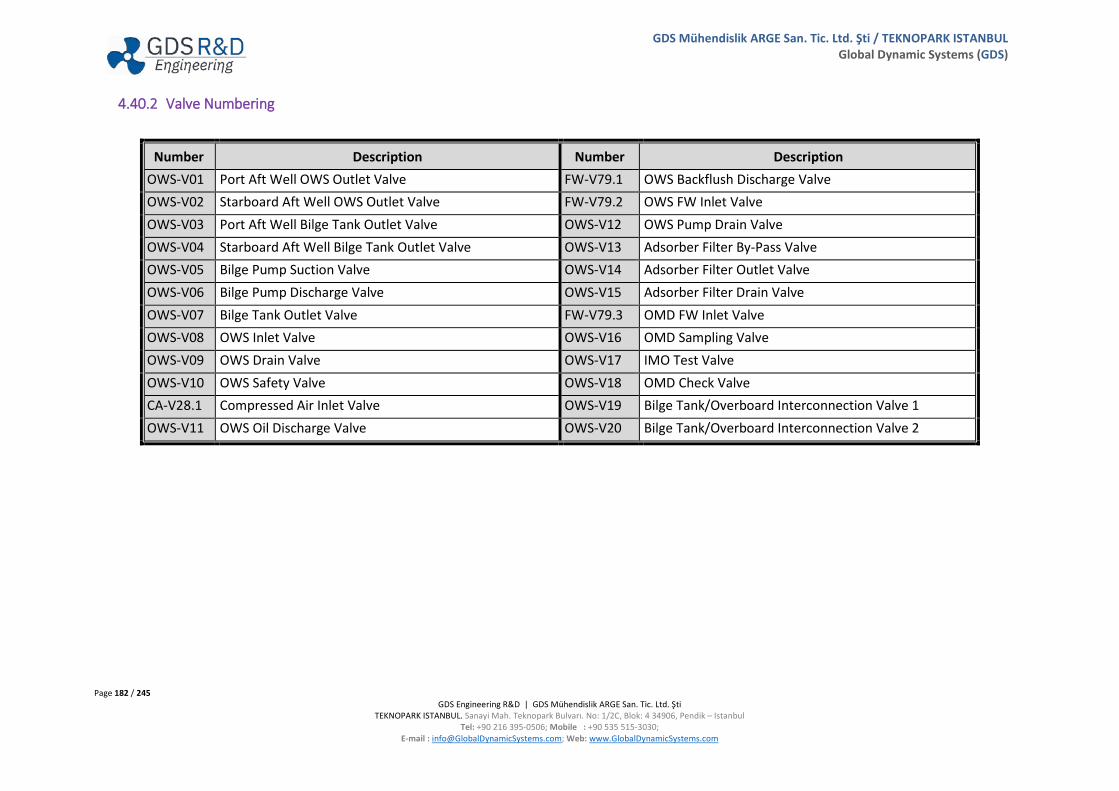
Page 182 / 245 GDS Engineering R&D | GDS Mühendislik ARGE San. Tic. Ltd. Şti
TEKNOPARK ISTANBUL. Sanayi Mah. Teknopark Bulvarı. No: 1/2C, Blok: 4 34906, Pendik – Istanbul Tel: +90 216 395-0506; Mobile : +90 535 515-3030;
E-mail : [email protected]; Web: www.GlobalDynamicSystems.com
GDS Mühendislik ARGE San. Tic. Ltd. Şti / TEKNOPARK ISTANBUL Global Dynamic Systems (GDS)
4.40.2 Valve Numbering
Number Description Number Description OWS-V01 Port Aft Well OWS Outlet Valve FW-V79.1 OWS Backflush Discharge Valve OWS-V02 Starboard Aft Well OWS Outlet Valve FW-V79.2 OWS FW Inlet Valve OWS-V03 Port Aft Well Bilge Tank Outlet Valve OWS-V12 OWS Pump Drain Valve OWS-V04 Starboard Aft Well Bilge Tank Outlet Valve OWS-V13 Adsorber Filter By-Pass Valve OWS-V05 Bilge Pump Suction Valve OWS-V14 Adsorber Filter Outlet Valve OWS-V06 Bilge Pump Discharge Valve OWS-V15 Adsorber Filter Drain Valve OWS-V07 Bilge Tank Outlet Valve FW-V79.3 OMD FW Inlet Valve OWS-V08 OWS Inlet Valve OWS-V16 OMD Sampling Valve OWS-V09 OWS Drain Valve OWS-V17 IMO Test Valve OWS-V10 OWS Safety Valve OWS-V18 OMD Check Valve CA-V28.1 Compressed Air Inlet Valve OWS-V19 Bilge Tank/Overboard Interconnection Valve 1 OWS-V11 OWS Oil Discharge Valve OWS-V20 Bilge Tank/Overboard Interconnection Valve 2
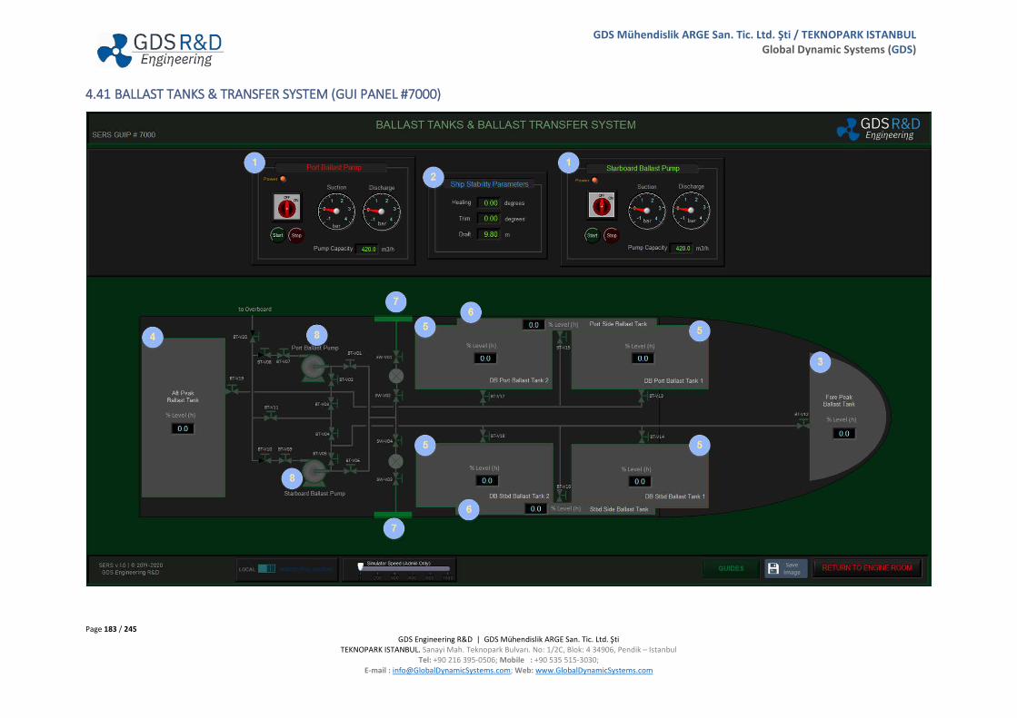
Page 183 / 245 GDS Engineering R&D | GDS Mühendislik ARGE San. Tic. Ltd. Şti
TEKNOPARK ISTANBUL. Sanayi Mah. Teknopark Bulvarı. No: 1/2C, Blok: 4 34906, Pendik – Istanbul Tel: +90 216 395-0506; Mobile : +90 535 515-3030;
E-mail : [email protected]; Web: www.GlobalDynamicSystems.com
GDS Mühendislik ARGE San. Tic. Ltd. Şti / TEKNOPARK ISTANBUL Global Dynamic Systems (GDS)
4.41 BALLAST TANKS & TRANSFER SYSTEM (GUI PANEL #7000)

Page 184 / 245 GDS Engineering R&D | GDS Mühendislik ARGE San. Tic. Ltd. Şti
TEKNOPARK ISTANBUL. Sanayi Mah. Teknopark Bulvarı. No: 1/2C, Blok: 4 34906, Pendik – Istanbul Tel: +90 216 395-0506; Mobile : +90 535 515-3030;
E-mail : [email protected]; Web: www.GlobalDynamicSystems.com
GDS Mühendislik ARGE San. Tic. Ltd. Şti / TEKNOPARK ISTANBUL Global Dynamic Systems (GDS)
4.41.1 Table of Screen Object
Number Description Number Description
1 Ballast Pumps Control Panels 5 Double Bottom (DB)Ballast Tanks 2 Ship Stability Parameters 6 Side Ballast Tanks 3 Fore Peak Ballast Tank 7 Sea Chests 4 Aft Peak Ballast Tank 8 Ballast Pumps
1. Ballast Pumps can be operated from the control panel. Power light, indicates whether electrical supply reaches at the panel. If switch is at ON position, pump can be operated when user clicks the start button. Control Panels also includes:
a. Ballast Pump Suction Pressure Gauge b. Ballast Pump Discharge Pressure Gauge c. Ballast Pump Capacity
2. Ship Stability Parameters Panel includes: a. Healing, a steady angle of heel created by an external force, such as wind or waves. b. Trim, the difference of the drafts between forward and aft. c. Draft, the vertical distance from the moulded base line amidships to the actual waterline.
3. Fore peak ballast tank, the watertight compartment situated forward of collision bulkhead. 4. Aft peak ballast tank, the compartment in the narrow part of stern aft of the aft peak bulkhead. 5. Double bottom ballast tank, watertight compartment for holding water ballast. 6. Side ballast tanks used for ballast and stability when carrying cargo. 7. The sea chest provides an intake reservoir from which piping systems draw raw water. Sea chest are protected by removable grating, and contain
baffle plates to dampen the effect of vessel speed or sea state. 8. Ballast pump is used for transferring or discharging water ballast. Together with the tank, pipe, valves, it is composited of the ballast system.

Page 185 / 245 GDS Engineering R&D | GDS Mühendislik ARGE San. Tic. Ltd. Şti
TEKNOPARK ISTANBUL. Sanayi Mah. Teknopark Bulvarı. No: 1/2C, Blok: 4 34906, Pendik – Istanbul Tel: +90 216 395-0506; Mobile : +90 535 515-3030;
E-mail : [email protected]; Web: www.GlobalDynamicSystems.com
GDS Mühendislik ARGE San. Tic. Ltd. Şti / TEKNOPARK ISTANBUL Global Dynamic Systems (GDS)
4.41.2 Valve Numbering
Number Description Number Description SW-V01 Low Suction Sea Chest Filter Inlet Valve BT-V09 Starboard Ballast Pump Discharge Valve SW-V02 Low Suction Sea Chest Filter Outlet Valve BT-V10 Starboard Ballast Pump Discharge Check Valve SW-V03 High Suction Sea Chest Filter Inlet Valve BT-V11 Main Interconnection Valve SW-V04 High Suction Sea Chest Filter Outlet Valve BT-V12 Fore Peak Ballast Tank Valve BT-V01 Port Ballast Pump SW Suction Valve BT-V13 DB Port Ballast Tank 1 Valve BT-V02 Port Ballast Pump Tank Suction Valve BT-V14 DB Starboard Ballast Tank 1 Valve BT-V03 Port Interconnection Valve BT-V15 Port Side Ballast Tank Valve BT-V04 Starboard Interconnection Valve BT-V16 Starboard Side Ballast Tank Valve BT-V05 Starboard Ballast Pump Tank Suction Valve BT-V17 DB Port Ballast Tank 2 Valve BT-V06 Starboard Ballast Pump SW Suction Valve BT-V18 DB Starboard Ballast Tank Valve BT-V07 Port Ballast Pump Discharge Valve BT-V19 Aft Peak Ballast Tank Valve BT-V08 Port Ballast Pump Discharge Check Valve BT-V20 Overboard Valve

Page 186 / 245 GDS Engineering R&D | GDS Mühendislik ARGE San. Tic. Ltd. Şti
TEKNOPARK ISTANBUL. Sanayi Mah. Teknopark Bulvarı. No: 1/2C, Blok: 4 34906, Pendik – Istanbul Tel: +90 216 395-0506; Mobile : +90 535 515-3030;
E-mail : [email protected]; Web: www.GlobalDynamicSystems.com
GDS Mühendislik ARGE San. Tic. Ltd. Şti / TEKNOPARK ISTANBUL Global Dynamic Systems (GDS)
4.42 STEERING GEAR SYSTEM (GUI PANEL #3700)
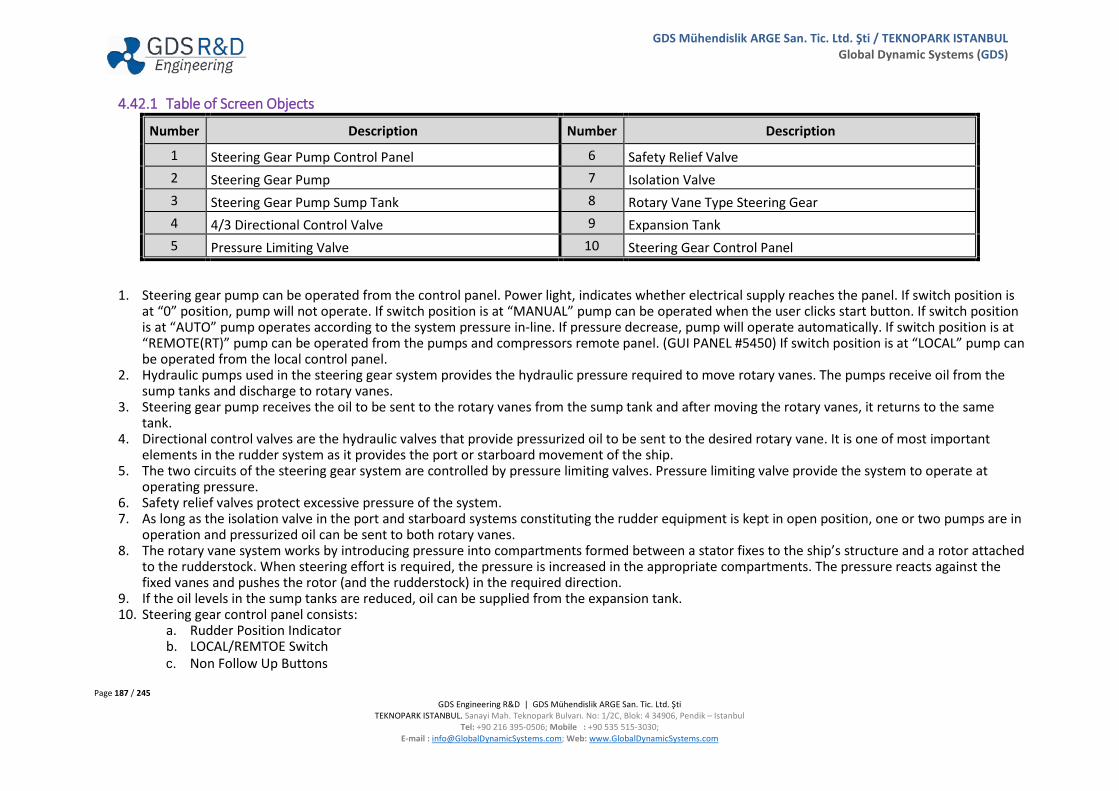
Page 187 / 245 GDS Engineering R&D | GDS Mühendislik ARGE San. Tic. Ltd. Şti
TEKNOPARK ISTANBUL. Sanayi Mah. Teknopark Bulvarı. No: 1/2C, Blok: 4 34906, Pendik – Istanbul Tel: +90 216 395-0506; Mobile : +90 535 515-3030;
E-mail : [email protected]; Web: www.GlobalDynamicSystems.com
GDS Mühendislik ARGE San. Tic. Ltd. Şti / TEKNOPARK ISTANBUL Global Dynamic Systems (GDS)
4.42.1 Table of Screen Objects
Number Description Number Description
1 Steering Gear Pump Control Panel 6 Safety Relief Valve 2 Steering Gear Pump 7 Isolation Valve 3 Steering Gear Pump Sump Tank 8 Rotary Vane Type Steering Gear 4 4/3 Directional Control Valve 9 Expansion Tank 5 Pressure Limiting Valve 10 Steering Gear Control Panel
1. Steering gear pump can be operated from the control panel. Power light, indicates whether electrical supply reaches the panel. If switch position is at “0” position, pump will not operate. If switch position is at “MANUAL” pump can be operated when the user clicks start button. If switch position is at “AUTO” pump operates according to the system pressure in-line. If pressure decrease, pump will operate automatically. If switch position is at “REMOTE(RT)” pump can be operated from the pumps and compressors remote panel. (GUI PANEL #5450) If switch position is at “LOCAL” pump can be operated from the local control panel.
2. Hydraulic pumps used in the steering gear system provides the hydraulic pressure required to move rotary vanes. The pumps receive oil from the sump tanks and discharge to rotary vanes.
3. Steering gear pump receives the oil to be sent to the rotary vanes from the sump tank and after moving the rotary vanes, it returns to the same tank.
4. Directional control valves are the hydraulic valves that provide pressurized oil to be sent to the desired rotary vane. It is one of most important elements in the rudder system as it provides the port or starboard movement of the ship.
5. The two circuits of the steering gear system are controlled by pressure limiting valves. Pressure limiting valve provide the system to operate at operating pressure.
6. Safety relief valves protect excessive pressure of the system. 7. As long as the isolation valve in the port and starboard systems constituting the rudder equipment is kept in open position, one or two pumps are in
operation and pressurized oil can be sent to both rotary vanes. 8. The rotary vane system works by introducing pressure into compartments formed between a stator fixes to the ship’s structure and a rotor attached
to the rudderstock. When steering effort is required, the pressure is increased in the appropriate compartments. The pressure reacts against the fixed vanes and pushes the rotor (and the rudderstock) in the required direction.
9. If the oil levels in the sump tanks are reduced, oil can be supplied from the expansion tank. 10. Steering gear control panel consists:
a. Rudder Position Indicator b. LOCAL/REMTOE Switch c. Non Follow Up Buttons

Page 188 / 245 GDS Engineering R&D | GDS Mühendislik ARGE San. Tic. Ltd. Şti
TEKNOPARK ISTANBUL. Sanayi Mah. Teknopark Bulvarı. No: 1/2C, Blok: 4 34906, Pendik – Istanbul Tel: +90 216 395-0506; Mobile : +90 535 515-3030;
E-mail : [email protected]; Web: www.GlobalDynamicSystems.com
GDS Mühendislik ARGE San. Tic. Ltd. Şti / TEKNOPARK ISTANBUL Global Dynamic Systems (GDS)
4.42.2 Valve Numbering
Number Description Number Description SG-V01 SG Pump 1 Discharge Valve SG-V10 Outlet Valve of the Isolation Valve 2 SG-V02 Oil Recirculation Valve SG-V11 Expansion Tank Fill Up Valve SG-V03 Safety Valve 1 SG-V12 Expansion Tanks SG Tank 1 Outlet Valve SG-V04 Safety Valve 2 SG-V13 Expansion Tanks SG Tank 2 Outlet Valve SG-V05 SG Pump 2 Discharge Valve SG-V14 Expansion Tanks Drain Valve SG-V06 Oil Recirculation Valve SG-V15 Expansion Tanks Drain Valve SG-V07 Inlet Valve of the Isolation Valve 1 SG-V16 SG Tank 1 Drain Valve SG-V08 Outlet Valve of the Isolation Valve 1 SG-V17 SG Tank 2 Drain Valve SG-V09 Inlet Valve of the Isolation Valve 2
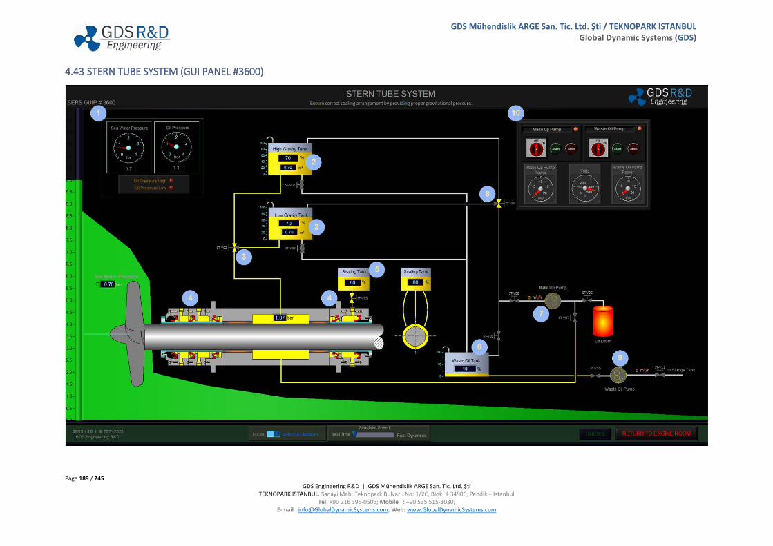
Page 189 / 245 GDS Engineering R&D | GDS Mühendislik ARGE San. Tic. Ltd. Şti
TEKNOPARK ISTANBUL. Sanayi Mah. Teknopark Bulvarı. No: 1/2C, Blok: 4 34906, Pendik – Istanbul Tel: +90 216 395-0506; Mobile : +90 535 515-3030;
E-mail : [email protected]; Web: www.GlobalDynamicSystems.com
GDS Mühendislik ARGE San. Tic. Ltd. Şti / TEKNOPARK ISTANBUL Global Dynamic Systems (GDS)
4.43 STERN TUBE SYSTEM (GUI PANEL #3600)

Page 190 / 245 GDS Engineering R&D | GDS Mühendislik ARGE San. Tic. Ltd. Şti
TEKNOPARK ISTANBUL. Sanayi Mah. Teknopark Bulvarı. No: 1/2C, Blok: 4 34906, Pendik – Istanbul Tel: +90 216 395-0506; Mobile : +90 535 515-3030;
E-mail : [email protected]; Web: www.GlobalDynamicSystems.com
GDS Mühendislik ARGE San. Tic. Ltd. Şti / TEKNOPARK ISTANBUL Global Dynamic Systems (GDS)
4.43.1 Table of Screen Objects
Number Description Number Description
1 Indicator Panel 6 Waste Oil Tank 2 High & Low Gravity Tanks 7 Make-up Pump 3 Gravity Tanks Outlet Valve 8 Gravity Tanks Inlet Valve 4 Aft and Low Stern Tube Seals 9 Waste Oil Pump 5 Sealing Tank 10 Make-up & Waste Oil Pump Control Panel
1. Indicator Panel includes: a. Sea Water Pressure Gauge b. Oil Pressure Gauge c. Alarm Indicator
2. In order to prevent sea water entering to the engine room from where the propeller shaft passes through stern tube, oil is supplied from the high and low gravity tank with gravity force. The user must decide which tank will be supplied (high and low gravity tank) the system according to the draft by means that static pressure of sea water.
3. Gravity tanks outlet valve allows oil flow through the stern tube from high gravity tank or low gravity tank. 4. Aft and low stern tube seals prevent entering sea water to engine room and oil to sea. 5. Sealing tank provides the seals of forward seal unit. 6. Waste oil tank collect waste oil from the system. The waste oil can be transferred to sludge tank with waste oil pump. 7. Oil is added into the stern tube system by make-up pump. 8. Gravity tanks inlet valve allows oil flow through high gravity tank or low gravity tank. 9. Waste oil pump transfer the waste oil to waste oil tank to sludge tank. 10. Make-up and Waste Oil Pumps can be operated from the control panel. Power light, indicates whether electrical supply reaches at the panel. If
switch is at ON position, pumps can be operated when user clicks the start button. Control panel also includes: a. Make-up Pump Power Gauge b. Voltmeter c. Waste Oil Pump Power Gauge

Page 191 / 245 GDS Engineering R&D | GDS Mühendislik ARGE San. Tic. Ltd. Şti
TEKNOPARK ISTANBUL. Sanayi Mah. Teknopark Bulvarı. No: 1/2C, Blok: 4 34906, Pendik – Istanbul Tel: +90 216 395-0506; Mobile : +90 535 515-3030;
E-mail : [email protected]; Web: www.GlobalDynamicSystems.com
GDS Mühendislik ARGE San. Tic. Ltd. Şti / TEKNOPARK ISTANBUL Global Dynamic Systems (GDS)
4.43.2 Valve Numbering
Number Description Number Description ST-V01 High Gravity Tank Outlet Valve ST-V07 Make-Up Pump Stern Tube Suction Valve ST-V02 Low Gravity Tank Outlet Valve ST-V08 Make-Up Pump Discharge Valve ST-V03 High/Low Gravity Tank Changeover Valve ST-V09 Waste Oil Tank Inlet Valve ST-V04 Recirculation Valve ST-V10 Waste Oil Pump Suction Valve ST-V05 Sealing Tank Outlet Valve ST-V11 Waste Oil Pump Discharge Valve ST-V06 Make-Up Pump Oil Drum Suction Valve

Page 192 / 245 GDS Engineering R&D | GDS Mühendislik ARGE San. Tic. Ltd. Şti
TEKNOPARK ISTANBUL. Sanayi Mah. Teknopark Bulvarı. No: 1/2C, Blok: 4 34906, Pendik – Istanbul Tel: +90 216 395-0506; Mobile : +90 535 515-3030;
E-mail : [email protected]; Web: www.GlobalDynamicSystems.com
GDS Mühendislik ARGE San. Tic. Ltd. Şti / TEKNOPARK ISTANBUL Global Dynamic Systems (GDS)
4.44 BOW THRUSTER SYSTEM (GUI PANEL #7100)

Page 193 / 245 GDS Engineering R&D | GDS Mühendislik ARGE San. Tic. Ltd. Şti
TEKNOPARK ISTANBUL. Sanayi Mah. Teknopark Bulvarı. No: 1/2C, Blok: 4 34906, Pendik – Istanbul Tel: +90 216 395-0506; Mobile : +90 535 515-3030;
E-mail : [email protected]; Web: www.GlobalDynamicSystems.com
GDS Mühendislik ARGE San. Tic. Ltd. Şti / TEKNOPARK ISTANBUL Global Dynamic Systems (GDS)
4.44.1 Table of Screen Objects
Number Description Number Description
1 Compass 7 Bow Thruster Emergency Stop 2 Bow Thruster Electrical Indicator Panel 8 Bow Thruster Pitch Controller 3 Bow Thruster Failure Indicator Panel 9 Bow Thruster CPP Hydraulic Oil Layout 4 Bow Thruster Operation Indicator Panel 10 Auto Starter Layout 5 Bow Thruster Control Mode Panel 11 High Voltage Line 6 Bow Thruster Operation Panel 12 Bow Thruster View
1. An instrument using either a magnet or a gyroscope for steering or taking navigational bearings. 2. Bow thruster electrical indicator panel consists:
a. Voltmeter, which indicates the control panel supply electrical voltage. b. Current Indicator, which indicates how much current is drawn by the pump. c. RPM Indicator, which indicates the rpm of the bow thruster speed.
3. Bow thruster failure indicator panel consists: a. AC Source Failure b. DC Source Failure c. Controller Abnormal d. Oil Low Level e. Oil Low Pressure f. Pump Overload
4. Bow thruster operation indicator panel consists: a. Main Source b. Power Available c. Fan Run d. Ready to Start e. Motor Full Load
5. Bow thruster control mode panel consists: a. Follow Up b. Non-Follow Up
6. Bow thruster operation panel provides operating of bow thruster. Bow thruster operation panel includes: a. Pump Start and Stop Buttons
Page 194 / 245 GDS Engineering R&D | GDS Mühendislik ARGE San. Tic. Ltd. Şti
TEKNOPARK ISTANBUL. Sanayi Mah. Teknopark Bulvarı. No: 1/2C, Blok: 4 34906, Pendik – Istanbul Tel: +90 216 395-0506; Mobile : +90 535 515-3030;
E-mail : [email protected]; Web: www.GlobalDynamicSystems.com
GDS Mühendislik ARGE San. Tic. Ltd. Şti / TEKNOPARK ISTANBUL Global Dynamic Systems (GDS)
b. Control Power On and Off Buttons c. Thruster Start and Stop Buttons
7. Stops the bow thruster at emergency situations. Reset button provides bow thruster re-starting via thruster run button. 8. Bow thruster speed can be controlled from bow thruster pitch controller panel. Bow thruster pitch controller panel also includes motor load
indicator which is indicates load of the bow thruster. 9. Bow thruster speed is changing via changing of pitch angle. Bow thruster controllable pitch propeller hydraulic oil layout consists:
a. Hydraulic Oil Tank b. Hydraulic Oil Pump c. Filter and valves
10. Auto starter system protect the bow thruster motor from high voltage and high inrush current. Automatic starter system consists of 3 different resistance levels. The resistance levels changing automatically for protecting the bow thruster motor from high inrush current. When the current reaches normal level, high voltage line connected to the bow thruster motor automatically.
11. Electrical power which is transformed 440 V to 6600 V from High Voltage Bus Bar / Transformer GUI Panel (GUIP #5850), is supplied to high voltage line via Vacuum Circuit Breaker (GUIP #5860).
12. The bow thruster gains maneuvering ability of the ship by rotating with electrical motor. The bow thruster is supplied with 6660 V which means high voltage operation.
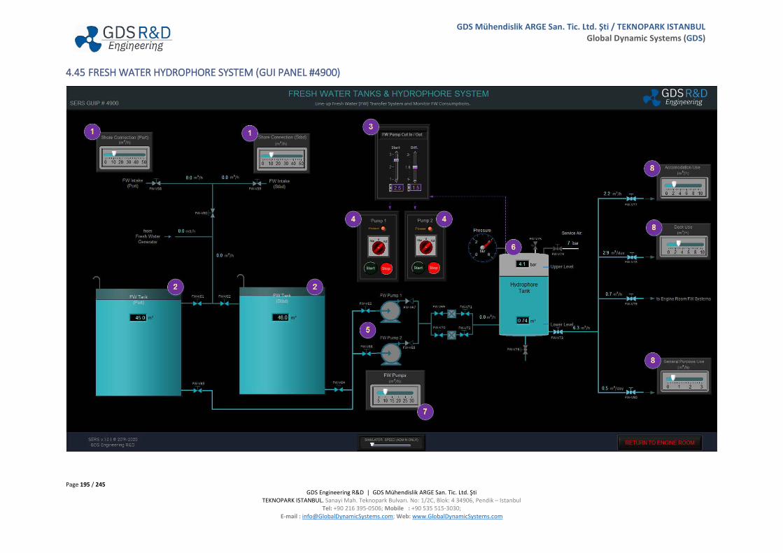
Page 195 / 245 GDS Engineering R&D | GDS Mühendislik ARGE San. Tic. Ltd. Şti
TEKNOPARK ISTANBUL. Sanayi Mah. Teknopark Bulvarı. No: 1/2C, Blok: 4 34906, Pendik – Istanbul Tel: +90 216 395-0506; Mobile : +90 535 515-3030;
E-mail : [email protected]; Web: www.GlobalDynamicSystems.com
GDS Mühendislik ARGE San. Tic. Ltd. Şti / TEKNOPARK ISTANBUL Global Dynamic Systems (GDS)
4.45 FRESH WATER HYDROPHORE SYSTEM (GUI PANEL #4900)
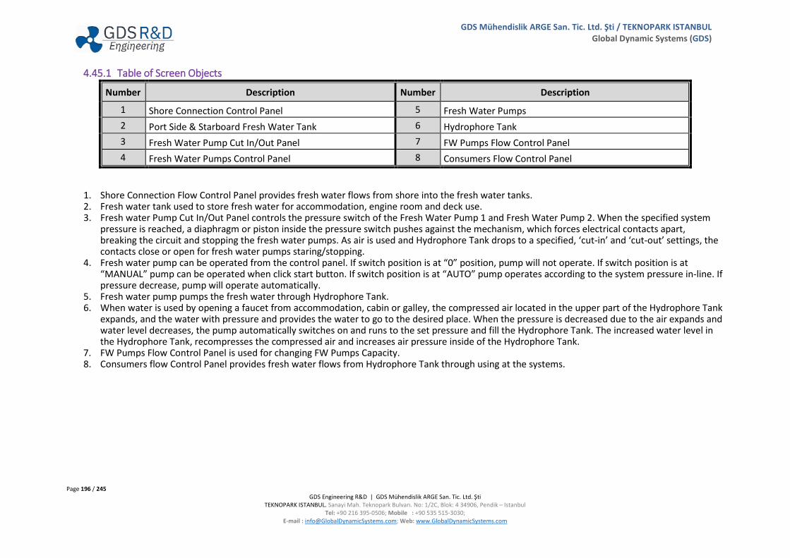
Page 196 / 245 GDS Engineering R&D | GDS Mühendislik ARGE San. Tic. Ltd. Şti
TEKNOPARK ISTANBUL. Sanayi Mah. Teknopark Bulvarı. No: 1/2C, Blok: 4 34906, Pendik – Istanbul Tel: +90 216 395-0506; Mobile : +90 535 515-3030;
E-mail : [email protected]; Web: www.GlobalDynamicSystems.com
GDS Mühendislik ARGE San. Tic. Ltd. Şti / TEKNOPARK ISTANBUL Global Dynamic Systems (GDS)
4.45.1 Table of Screen Objects
Number Description Number Description
1 Shore Connection Control Panel 5 Fresh Water Pumps 2 Port Side & Starboard Fresh Water Tank 6 Hydrophore Tank 3 Fresh Water Pump Cut In/Out Panel 7 FW Pumps Flow Control Panel 4 Fresh Water Pumps Control Panel 8 Consumers Flow Control Panel
1. Shore Connection Flow Control Panel provides fresh water flows from shore into the fresh water tanks. 2. Fresh water tank used to store fresh water for accommodation, engine room and deck use. 3. Fresh water Pump Cut In/Out Panel controls the pressure switch of the Fresh Water Pump 1 and Fresh Water Pump 2. When the specified system
pressure is reached, a diaphragm or piston inside the pressure switch pushes against the mechanism, which forces electrical contacts apart, breaking the circuit and stopping the fresh water pumps. As air is used and Hydrophore Tank drops to a specified, ‘cut-in’ and ‘cut-out’ settings, the contacts close or open for fresh water pumps staring/stopping.
4. Fresh water pump can be operated from the control panel. If switch position is at “0” position, pump will not operate. If switch position is at “MANUAL” pump can be operated when click start button. If switch position is at “AUTO” pump operates according to the system pressure in-line. If pressure decrease, pump will operate automatically.
5. Fresh water pump pumps the fresh water through Hydrophore Tank. 6. When water is used by opening a faucet from accommodation, cabin or galley, the compressed air located in the upper part of the Hydrophore Tank
expands, and the water with pressure and provides the water to go to the desired place. When the pressure is decreased due to the air expands and water level decreases, the pump automatically switches on and runs to the set pressure and fill the Hydrophore Tank. The increased water level in the Hydrophore Tank, recompresses the compressed air and increases air pressure inside of the Hydrophore Tank.
7. FW Pumps Flow Control Panel is used for changing FW Pumps Capacity. 8. Consumers flow Control Panel provides fresh water flows from Hydrophore Tank through using at the systems.

Page 197 / 245 GDS Engineering R&D | GDS Mühendislik ARGE San. Tic. Ltd. Şti
TEKNOPARK ISTANBUL. Sanayi Mah. Teknopark Bulvarı. No: 1/2C, Blok: 4 34906, Pendik – Istanbul Tel: +90 216 395-0506; Mobile : +90 535 515-3030;
E-mail : [email protected]; Web: www.GlobalDynamicSystems.com
GDS Mühendislik ARGE San. Tic. Ltd. Şti / TEKNOPARK ISTANBUL Global Dynamic Systems (GDS)
4.45.2 Valve Numbering
Number Description Number Description FW-V58 Port Shore Connection FW Valve FW-V70 FW Filter 2 Inlet Valve FW-V59 Starboard Shore Connection FW Valve FW-V71 FW Filter 1 Outlet Valve FW-V60 FW Tanks Main Inlet Valve FW-V72 FW Filter 2 Outlet Valve FW-V61 Port FW Tank Inlet Valve FW-V73 Hydrophore Tank Outlet Valve FW-V62 Starboard FW Tank Inlet Valve FW-V74 Service Air Inlet Valve FW-V63 Port FW Tank Outlet Valve FW-V75 Hydrophore Tank Safety Valve FW-V64 Starboard FW Tank Outlet Valve FW-V76 Hydrophore Tank Drain Valve FW-V65 FW Pump 1 Suction Valve FW-V77 Accommodation Use FW Inlet Valve FW-V66 FW Pump 2 Suction Valve FW-V78 Deck Use FW Inlet Valve FW-V67 FW Pump 1 Discharge Valve FW-V79 ER Systems FW Inlet Valve FW-V68 FW Pump 2 Discharge Valve FW-V80 Separators FW Inlet Valve FW-V69 FW Filter 1 Inlet Valve

Page 198 / 245 GDS Engineering R&D | GDS Mühendislik ARGE San. Tic. Ltd. Şti
TEKNOPARK ISTANBUL. Sanayi Mah. Teknopark Bulvarı. No: 1/2C, Blok: 4 34906, Pendik – Istanbul Tel: +90 216 395-0506; Mobile : +90 535 515-3030;
E-mail : [email protected]; Web: www.GlobalDynamicSystems.com
GDS Mühendislik ARGE San. Tic. Ltd. Şti / TEKNOPARK ISTANBUL Global Dynamic Systems (GDS)
4.46 GRAY WATER & SEWAGE TREATMENT (GUI PANEL #6600)
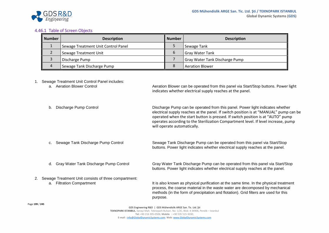
Page 199 / 245 GDS Engineering R&D | GDS Mühendislik ARGE San. Tic. Ltd. Şti
TEKNOPARK ISTANBUL. Sanayi Mah. Teknopark Bulvarı. No: 1/2C, Blok: 4 34906, Pendik – Istanbul Tel: +90 216 395-0506; Mobile : +90 535 515-3030;
E-mail : [email protected]; Web: www.GlobalDynamicSystems.com
GDS Mühendislik ARGE San. Tic. Ltd. Şti / TEKNOPARK ISTANBUL Global Dynamic Systems (GDS)
4.46.1 Table of Screen Objects
Number Description Number Description
1 Sewage Treatment Unit Control Panel 5 Sewage Tank 2 Sewage Treatment Unit 6 Gray Water Tank 3 Discharge Pump 7 Gray Water Tank Discharge Pump 4 Sewage Tank Discharge Pump 8 Aeration Blower
1. Sewage Treatment Unit Control Panel includes: a. Aeration Blower Control Aeration Blower can be operated from this panel via Start/Stop buttons. Power light
indicates whether electrical supply reaches at the panel.
b. Discharge Pump Control Discharge Pump can be operated from this panel. Power light indicates whether electrical supply reaches at the panel. If switch position is at “MANUAL” pump can be operated when the start button is pressed. If switch position is at “AUTO” pump operates according to the Sterilization Compartment level. If level increase, pump
will operate automatically.
c. Sewage Tank Discharge Pump Control Sewage Tank Discharge Pump can be operated from this panel via Start/Stop buttons. Power light indicates whether electrical supply reaches at the panel.
d. Gray Water Tank Discharge Pump Control Gray Water Tank Discharge Pump can be operated from this panel via Start/Stop buttons. Power light indicates whether electrical supply reaches at the panel.
2. Sewage Treatment Unit consists of three compartment:
a. Filtration Compartment It is also known as physical purification at the same time. In the physical treatment process, the coarse material in the waste water are decomposed by mechanical methods (in the form of precipitation and flotation). Grid filters are used for this purpose.

Page 200 / 245 GDS Engineering R&D | GDS Mühendislik ARGE San. Tic. Ltd. Şti
TEKNOPARK ISTANBUL. Sanayi Mah. Teknopark Bulvarı. No: 1/2C, Blok: 4 34906, Pendik – Istanbul Tel: +90 216 395-0506; Mobile : +90 535 515-3030;
E-mail : [email protected]; Web: www.GlobalDynamicSystems.com
GDS Mühendislik ARGE San. Tic. Ltd. Şti / TEKNOPARK ISTANBUL Global Dynamic Systems (GDS)
b. Bio-filter Compartment The removal of organic and partially inorganic pollutants from sewage by using bacteria as energy and nutrient sources is called biological treatment. Aerobic biological treatment method; the organic substances in the aerated waste water are used by the microorganisms as nutrients and decomposed into carbon dioxide and water products to form new microorganisms. Since the aerobic biological treatment method is carried out in an aerated environment, air must be supplied to bio-filter compartment.
c. Sterilization Compartment Chemical treatment is a process for the destruction of pathogenic microorganisms. Because chlorine is a good oxidizer, it destroys bacteria. At last stage, there is no harm in discharging the chlorinated water overboard.
3. The discharge pump is mounted on the sterilization compartment of the sewage treatment unit. The pump is running at AUTO mode controlled by the
level switches installed in the sterilization compartment. The pump is usually runs at MANUAL mode when taking out the sludge from the compartments after the cleaning of the tank insides.
4. Sewage Tank Discharge Pump pumps the sewage through overboard. 5. Sewage Tanks is used for collection and storage of sewage. 6. Gray Water Tank is used for collection and storage of gray water. 7. Gray Water Tank Discharge Pump pumps the gray water through overboard. 8. Aeration Blower provides air for the microorganisms.

Page 201 / 245 GDS Engineering R&D | GDS Mühendislik ARGE San. Tic. Ltd. Şti
TEKNOPARK ISTANBUL. Sanayi Mah. Teknopark Bulvarı. No: 1/2C, Blok: 4 34906, Pendik – Istanbul Tel: +90 216 395-0506; Mobile : +90 535 515-3030;
E-mail : [email protected]; Web: www.GlobalDynamicSystems.com
GDS Mühendislik ARGE San. Tic. Ltd. Şti / TEKNOPARK ISTANBUL Global Dynamic Systems (GDS)
4.46.2 Valve Numbering
Number Description Number Description STU-V01 Starboard Gray Water Line Tank Inlet Valve STU-V11 Filtration Compartment Outlet Valve STU-V02 Port Gray Water Line Tank Inlet Valve STU-V12 Bio-Filter Compartment Outlet Valve STU-V03 Starboard Gray Water Line Outlet Valve STU-V13 Sterilization Compartment Outlet Valve STU-V04 Starboard Gray Water Line Overboard Valve STU-V14 STU Discharge Pump Suction Valve STU-V05 Port Gray Water Line Outlet Valve STU-V15 STU Discharge Pump Discharge Valve STU-V06 Port Gray Water Line Overboard Valve STU-V16 Sewage Tank Discharge Pump Suction Valve STU-V07 Gray Water Tank Discharge Pump Overboard Discharge Valve STU-V17 Sewage Tank Discharge Pump Discharge Valve STU-V08 Gray Water Tank Discharge Pump Suction Valve STU-V18 Sewage Tank Inlet Valve STU-V09 Gray Water Tank Discharge Pump Barge Discharge Valve STU-V19 STU Overboard Valve STU-V10 Sewage Treatment System Inlet Valve SW-V33 SW Inlet Valve STU-V10.1 Soil Main Line Sewage Tank Inlet Valve
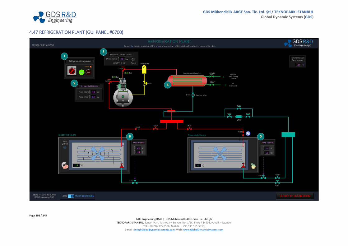
Page 202 / 245 GDS Engineering R&D | GDS Mühendislik ARGE San. Tic. Ltd. Şti
TEKNOPARK ISTANBUL. Sanayi Mah. Teknopark Bulvarı. No: 1/2C, Blok: 4 34906, Pendik – Istanbul Tel: +90 216 395-0506; Mobile : +90 535 515-3030;
E-mail : [email protected]; Web: www.GlobalDynamicSystems.com
GDS Mühendislik ARGE San. Tic. Ltd. Şti / TEKNOPARK ISTANBUL Global Dynamic Systems (GDS)
4.47 REFRIGERATION PLANT (GUI PANEL #6700)
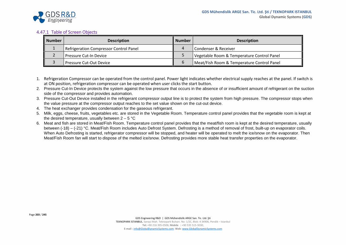
Page 203 / 245 GDS Engineering R&D | GDS Mühendislik ARGE San. Tic. Ltd. Şti
TEKNOPARK ISTANBUL. Sanayi Mah. Teknopark Bulvarı. No: 1/2C, Blok: 4 34906, Pendik – Istanbul Tel: +90 216 395-0506; Mobile : +90 535 515-3030;
E-mail : [email protected]; Web: www.GlobalDynamicSystems.com
GDS Mühendislik ARGE San. Tic. Ltd. Şti / TEKNOPARK ISTANBUL Global Dynamic Systems (GDS)
4.47.1 Table of Screen Objects
Number Description Number Description
1 Refrigeration Compressor Control Panel 4 Condenser & Receiver 2 Pressure Cut-In Device 5 Vegetable Room & Temperature Control Panel 3 Pressure Cut-Out Device 6 Meat/Fish Room & Temperature Control Panel
1. Refrigeration Compressor can be operated from the control panel. Power light indicates whether electrical supply reaches at the panel. If switch is at ON position, refrigeration compressor can be operated when user clicks the start button.
2. Pressure Cut-In Device protects the system against the low pressure that occurs in the absence of or insufficient amount of refrigerant on the suction side of the compressor and provides automation.
3. Pressure Cut-Out Device installed in the refrigerant compressor output line is to protect the system from high pressure. The compressor stops when the value pressure at the compressor output reaches to the set value shown on the cut-out device.
4. The heat exchanger provides condensation for the gaseous refrigerant. 5. Milk, eggs, cheese, fruits, vegetables etc. are stored in the Vegetable Room. Temperature control panel provides that the vegetable room is kept at
the desired temperature, usually between 2 – 5 °C 6. Meat and fish are stored in Meat/Fish Room. Temperature control panel provides that the meat/fish room is kept at the desired temperature, usually
between (-18) – (-21) °C. Meat/Fish Room includes Auto Defrost System. Defrosting is a method of removal of frost, built-up on evaporator coils. When Auto Defrosting is started, refrigerator compressor will be stopped, and heater will be operated to melt the ice/snow on the evaporator. Then Meat/Fish Room fan will start to dispose of the melted ice/snow. Defrosting provides more stable heat transfer properties on the evaporator.

Page 204 / 245 GDS Engineering R&D | GDS Mühendislik ARGE San. Tic. Ltd. Şti
TEKNOPARK ISTANBUL. Sanayi Mah. Teknopark Bulvarı. No: 1/2C, Blok: 4 34906, Pendik – Istanbul Tel: +90 216 395-0506; Mobile : +90 535 515-3030;
E-mail : [email protected]; Web: www.GlobalDynamicSystems.com
GDS Mühendislik ARGE San. Tic. Ltd. Şti / TEKNOPARK ISTANBUL Global Dynamic Systems (GDS)
4.47.2 Valve Numbering
Number Description Number Description R-V01 Refrigeration Compressor Suction Valve R-V08 Vegetable Room Refrigerant Inlet Valve R-V02 Refrigeration Compressor Discharge Valve R-V09 Meat/Fish Room Refrigerant Inlet Valve R-V03 Oil Separator Outlet Valve R-V10 Vegetable Room Temperature Control Valve SW-V24 Condenser SW Inlet Valve R-V11 Meat/Fish Room Temperature Control Valve SW-V25 Condenser SW Outlet Valve R-V12 Vegetable Room Back Pressure Check Valve R-V04 Coolant Inlet Valve R-V13 Meat/Fish Room Check Valve R-V05 Dryer Inlet Valve R-V14 Vegetable Room Refrigerant Outlet Valve R-V06 Dryer Outlet Valve R-V15 Meat/Fish Room Refrigerant Outlet Valve R-V07 Dryer By-Pass Valve

Page 205 / 245 GDS Engineering R&D | GDS Mühendislik ARGE San. Tic. Ltd. Şti
TEKNOPARK ISTANBUL. Sanayi Mah. Teknopark Bulvarı. No: 1/2C, Blok: 4 34906, Pendik – Istanbul Tel: +90 216 395-0506; Mobile : +90 535 515-3030;
E-mail : [email protected]; Web: www.GlobalDynamicSystems.com
GDS Mühendislik ARGE San. Tic. Ltd. Şti / TEKNOPARK ISTANBUL Global Dynamic Systems (GDS)
4.48 EMERGENCY RESPONSE PANEL (GUI PANEL #7400)

Page 206 / 245 GDS Engineering R&D | GDS Mühendislik ARGE San. Tic. Ltd. Şti
TEKNOPARK ISTANBUL. Sanayi Mah. Teknopark Bulvarı. No: 1/2C, Blok: 4 34906, Pendik – Istanbul Tel: +90 216 395-0506; Mobile : +90 535 515-3030;
E-mail : [email protected]; Web: www.GlobalDynamicSystems.com
GDS Mühendislik ARGE San. Tic. Ltd. Şti / TEKNOPARK ISTANBUL Global Dynamic Systems (GDS)
Table of Screen Objects
Number Description Number Description
1 Fire Pumps Control Panel 3 Pumps Emergency Stop Panel 2 Fans & Dampers Emergency Stop Panel 4 Quick Closing Valves
1. Fire Pumps Control Panel includes: a. Fire Pump 1 Control Panel, Fire Pump 1 can be operated remotely from the control panel. Power light, indicates whether electrical supply
reaches at the panel. If switch is at ON position, pump can be operated when the user clicks start button. b. Fire Pump 2 Fire Pump 2 can be operated remotely from the control panel. Power light, indicates whether electrical supply reaches at the
panel. If switch is at ON position, pump can be operated when the user clicks start button. c. Emergency Fire Pump Control Panel, Emergency Fire Pump can be operated remotely from the control panel. Power light, indicates whether
electrical supply reaches at the panel. If switch is at ON position, pump can be operated when the user clicks start button. 2. Fans and dampers can be stopped remotely from this panel. Enable button provides pushing of the emergency stop buttons. Fans and dampers
emergency stop panel includes remote control for: a. ER Supply Fans b. ER Exhaust Fans c. Emergency Supply Fans d. Emergency Exhaust Fans e. Auxiliary Blowers f. Boiler Fan
3. Pumps which are pumping dangerous fluids (fuel, sludge, oil etc.) in the engine room, can be stopped remotely from this panel. Enable button provides the activation of the emergency stop button and then the Emergency Stop can be accessed for stopping the fuel and LO pumps in the engine room.
4. Pneumatic quick closing valves are controlled from this panel. The control cabinet consists of a control panel with air receiver and quick closing control valves. Quick closing valves includes:
a. HFO Tanks b. MDO Tanks c. LO Tanks d. Air Dampers
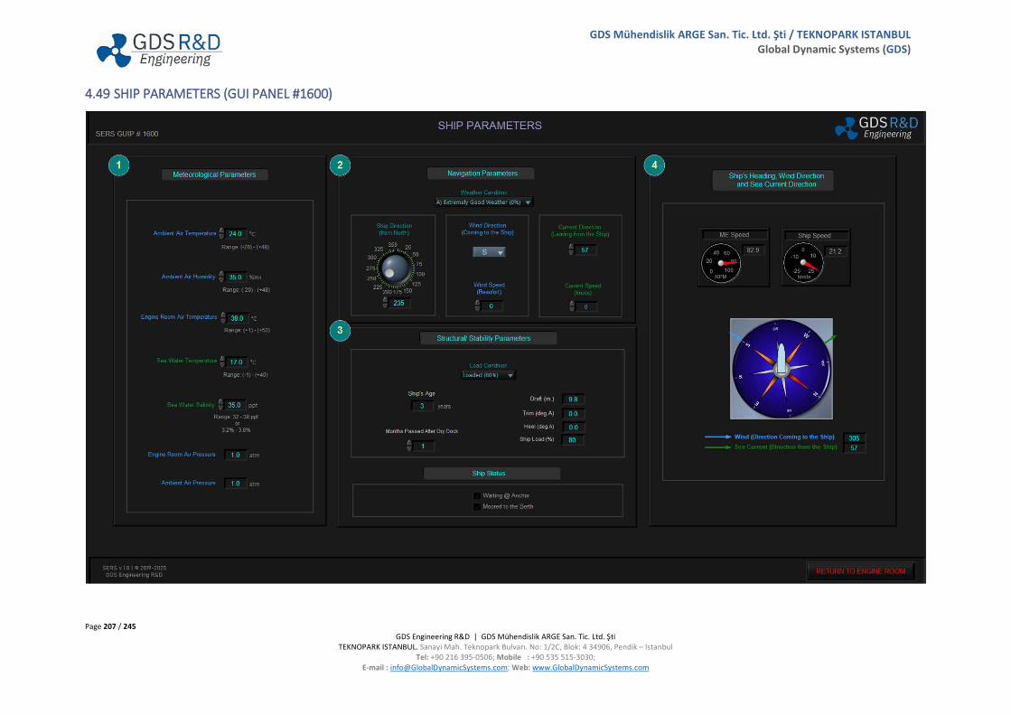
Page 207 / 245 GDS Engineering R&D | GDS Mühendislik ARGE San. Tic. Ltd. Şti
TEKNOPARK ISTANBUL. Sanayi Mah. Teknopark Bulvarı. No: 1/2C, Blok: 4 34906, Pendik – Istanbul Tel: +90 216 395-0506; Mobile : +90 535 515-3030;
E-mail : [email protected]; Web: www.GlobalDynamicSystems.com
GDS Mühendislik ARGE San. Tic. Ltd. Şti / TEKNOPARK ISTANBUL Global Dynamic Systems (GDS)
4.49 SHIP PARAMETERS (GUI PANEL #1600)

Page 208 / 245 GDS Engineering R&D | GDS Mühendislik ARGE San. Tic. Ltd. Şti
TEKNOPARK ISTANBUL. Sanayi Mah. Teknopark Bulvarı. No: 1/2C, Blok: 4 34906, Pendik – Istanbul Tel: +90 216 395-0506; Mobile : +90 535 515-3030;
E-mail : [email protected]; Web: www.GlobalDynamicSystems.com
GDS Mühendislik ARGE San. Tic. Ltd. Şti / TEKNOPARK ISTANBUL Global Dynamic Systems (GDS)
Table of Screen Objects
Number Description Number Description
1 Meteorological Parameters 3 Structure & Stability Parameters 2 Navigation Parameters 4 Ship’s Heading, Wind Direction & Sea Current Direction
1. Meteorological parameters can be changed from this panel. The changes affect the related engine room systems parameters. Meteorological parameters include:
a. Ambient Air Temperature b. Ambient Air Humidity c. Ambient Air Pressure d. Engine Room Air Temperature e. Engine Room Air Pressure f. Sea Water Temperature g. Sea Water Salinity
2. Navigation parameters can be changed from this panel. The changes affect the related engine room systems parameters. Navigation parameters include:
a. Weather Condition: Weather condition maybe selected as follows: A: Extremely Good Weather B: Light Weather C: Heavy Weather Refer to User Manual Vol II, Section 7.2.14, which shows the effect of the weather on the engine parameters.
b. Ship Direction c. Wind Direction and Speed d. Current Direction and Speed
3. Structure and stability parameters can be changed from this panel. The changes affect the engine room systems parameters. Structure and stability parameters include:
a. Ship’s Age b. Month Passed After Dry Dock c. Draft, Trim, Heel and Ship Load d. Ship Status
Page 209 / 245 GDS Engineering R&D | GDS Mühendislik ARGE San. Tic. Ltd. Şti
TEKNOPARK ISTANBUL. Sanayi Mah. Teknopark Bulvarı. No: 1/2C, Blok: 4 34906, Pendik – Istanbul Tel: +90 216 395-0506; Mobile : +90 535 515-3030;
E-mail : [email protected]; Web: www.GlobalDynamicSystems.com
GDS Mühendislik ARGE San. Tic. Ltd. Şti / TEKNOPARK ISTANBUL Global Dynamic Systems (GDS)
4. Also this panel includes the following navigational parameters: a. Ship’s Heading b. Wind Direction and Speed c. Sea Current Direction and Speed d. ME RPM Indicator e. Ship Speed Indicator f. Compass

Page 210 / 245 GDS Engineering R&D | GDS Mühendislik ARGE San. Tic. Ltd. Şti
TEKNOPARK ISTANBUL. Sanayi Mah. Teknopark Bulvarı. No: 1/2C, Blok: 4 34906, Pendik – Istanbul Tel: +90 216 395-0506; Mobile : +90 535 515-3030;
E-mail : [email protected]; Web: www.GlobalDynamicSystems.com
GDS Mühendislik ARGE San. Tic. Ltd. Şti / TEKNOPARK ISTANBUL Global Dynamic Systems (GDS)
4.50 GRAPHS & PLOTS (GUI PANEL #9000)

Page 211 / 245 GDS Engineering R&D | GDS Mühendislik ARGE San. Tic. Ltd. Şti
TEKNOPARK ISTANBUL. Sanayi Mah. Teknopark Bulvarı. No: 1/2C, Blok: 4 34906, Pendik – Istanbul Tel: +90 216 395-0506; Mobile : +90 535 515-3030;
E-mail : [email protected]; Web: www.GlobalDynamicSystems.com
GDS Mühendislik ARGE San. Tic. Ltd. Şti / TEKNOPARK ISTANBUL Global Dynamic Systems (GDS)
4.50.1 Table of Screen Objects
Number Description
1 Reference Graphs Section 2 Time Graphs Section (Two Identical Time Plot Areas) 3 X-Y Graphs Section
1. Reference Graphs Section includes the following graphs, presented as reference for comparison during training: a. ME Speed (RPM) vs. Engine Shaft Power (MW) b. ME Index and ME Speed (RPM) vs. Engine Load (%) c. Engine Speed vs. Engine Power in Different Weather Conditions d. ME Power Draft Changes e. ME Load Draft Changes f. Pcomp vs. Psca g. Scavenge Pressure vs. Turbine Speed h. Pressures: ME Speed (RPM) vs. Pcomp (bar), Pmax (bar), Pmean (bar) (eff., ind.) Values (Average) i. Pmax (bar) vs. ME Load (%) j. Charge Air Temperature, Tsca (before Air Cooler) vs. TC Speed (RPM) k. ME Exhaust Temperatures: Cylinder Outlets (Average), Exhaust Manifold @ TC Inlet, Exhaust Outlet (to Economizer) l. Exhaust Manifold Pressure (bar) vs. Load (%) m. Turbocharger Speed (RPM) vs. Exhaust Manifold Temperature n. Fuel Consumption (kg/h) vs. Load (%) o. Specific Fuel Oil Consumption (SFOC) vs. ME Shaft Power (MW) p. Specific Fuel Oil Consumption (SFOC) vs. ME Speed (RPM) q. Mechanical Efficiency (%) vs. Engine Load (%) r. NOx (g/kWh) vs. ME Power (MW) s. Smoke (%) vs. ME Power (MW) t. SOx (g/kWh) vs. ME Power (MW)
2. Time Graphs Section provides two time graph areas that can display parameters simultaneously.
a. Parameters Selection: Click on “Select Parameter for Time Plot (Trend Data)” menu ring button, located on top of this section. SERS provides with a selection of the following parameters, plotted on a time graph:

Page 212 / 245 GDS Engineering R&D | GDS Mühendislik ARGE San. Tic. Ltd. Şti
TEKNOPARK ISTANBUL. Sanayi Mah. Teknopark Bulvarı. No: 1/2C, Blok: 4 34906, Pendik – Istanbul Tel: +90 216 395-0506; Mobile : +90 535 515-3030;
E-mail : [email protected]; Web: www.GlobalDynamicSystems.com
GDS Mühendislik ARGE San. Tic. Ltd. Şti / TEKNOPARK ISTANBUL Global Dynamic Systems (GDS)
b. Select one of the parameters to display the time plot on the graph section. Opening and closing this GUI does not stop the recording; therefore, the other training operations can continue while the software is recording the selected trend data.
c. Export Data: Right click on the graph area provides the following options for exporting the data: i. Export Data to Clipboard ii. Export Data to Excel iii. Export Simplified Image
3. Parameter X-Y Graph Section
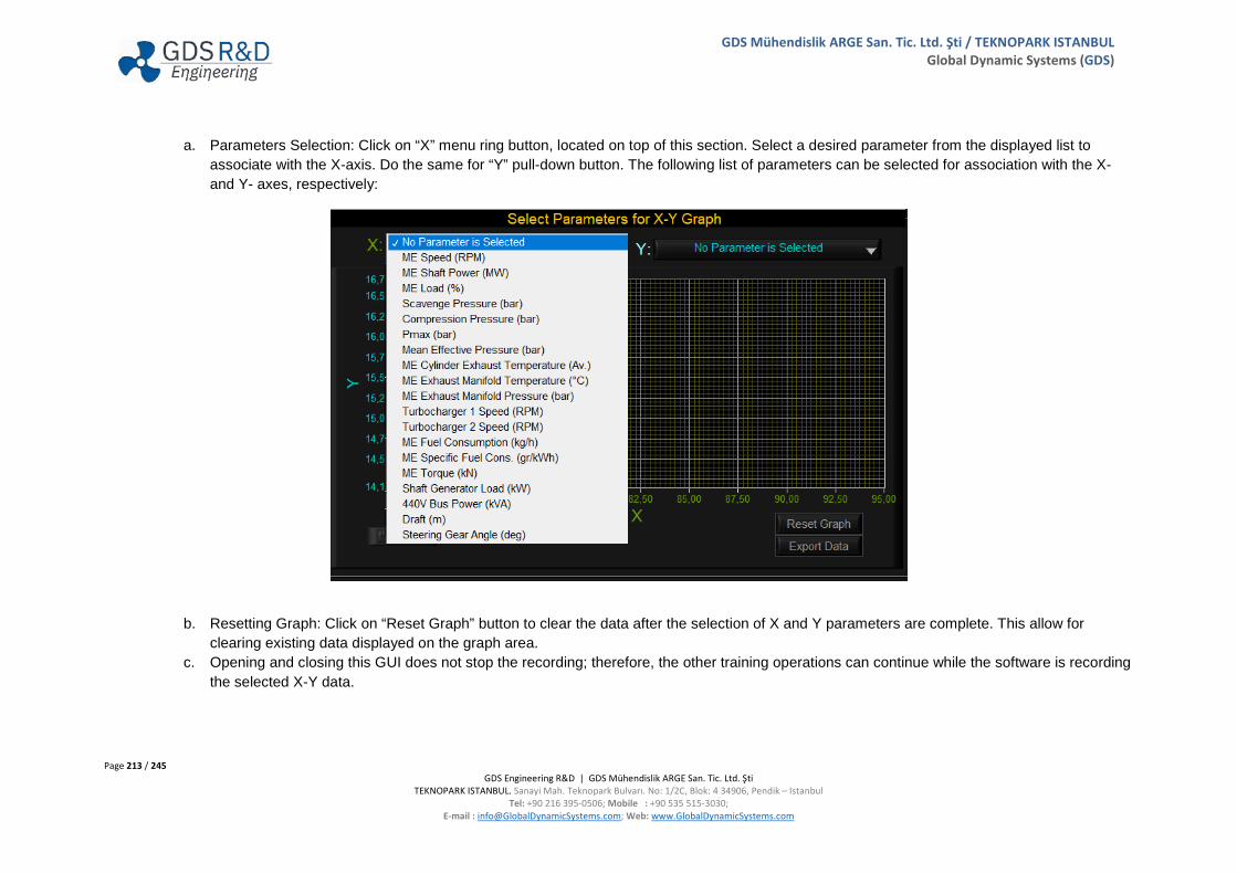
Page 213 / 245 GDS Engineering R&D | GDS Mühendislik ARGE San. Tic. Ltd. Şti
TEKNOPARK ISTANBUL. Sanayi Mah. Teknopark Bulvarı. No: 1/2C, Blok: 4 34906, Pendik – Istanbul Tel: +90 216 395-0506; Mobile : +90 535 515-3030;
E-mail : [email protected]; Web: www.GlobalDynamicSystems.com
GDS Mühendislik ARGE San. Tic. Ltd. Şti / TEKNOPARK ISTANBUL Global Dynamic Systems (GDS)
a. Parameters Selection: Click on “X” menu ring button, located on top of this section. Select a desired parameter from the displayed list to associate with the X-axis. Do the same for “Y” pull-down button. The following list of parameters can be selected for association with the X- and Y- axes, respectively:
b. Resetting Graph: Click on “Reset Graph” button to clear the data after the selection of X and Y parameters are complete. This allow for
clearing existing data displayed on the graph area. c. Opening and closing this GUI does not stop the recording; therefore, the other training operations can continue while the software is recording
the selected X-Y data.
Page 214 / 245 GDS Engineering R&D | GDS Mühendislik ARGE San. Tic. Ltd. Şti
TEKNOPARK ISTANBUL. Sanayi Mah. Teknopark Bulvarı. No: 1/2C, Blok: 4 34906, Pendik – Istanbul Tel: +90 216 395-0506; Mobile : +90 535 515-3030;
E-mail : [email protected]; Web: www.GlobalDynamicSystems.com
GDS Mühendislik ARGE San. Tic. Ltd. Şti / TEKNOPARK ISTANBUL Global Dynamic Systems (GDS)
d. Exporting the Data: Click “Export Data” to save the file on disc. The file saved with this method is a standard CVS file with columns divided by a tab space. The data then can be opened using any spreadsheet software. Alternatively, right click on the graph area provides the following options for exporting the data:
i. Export Data to Clipboard ii. Export Data to Excel iii. Export Simplified Image
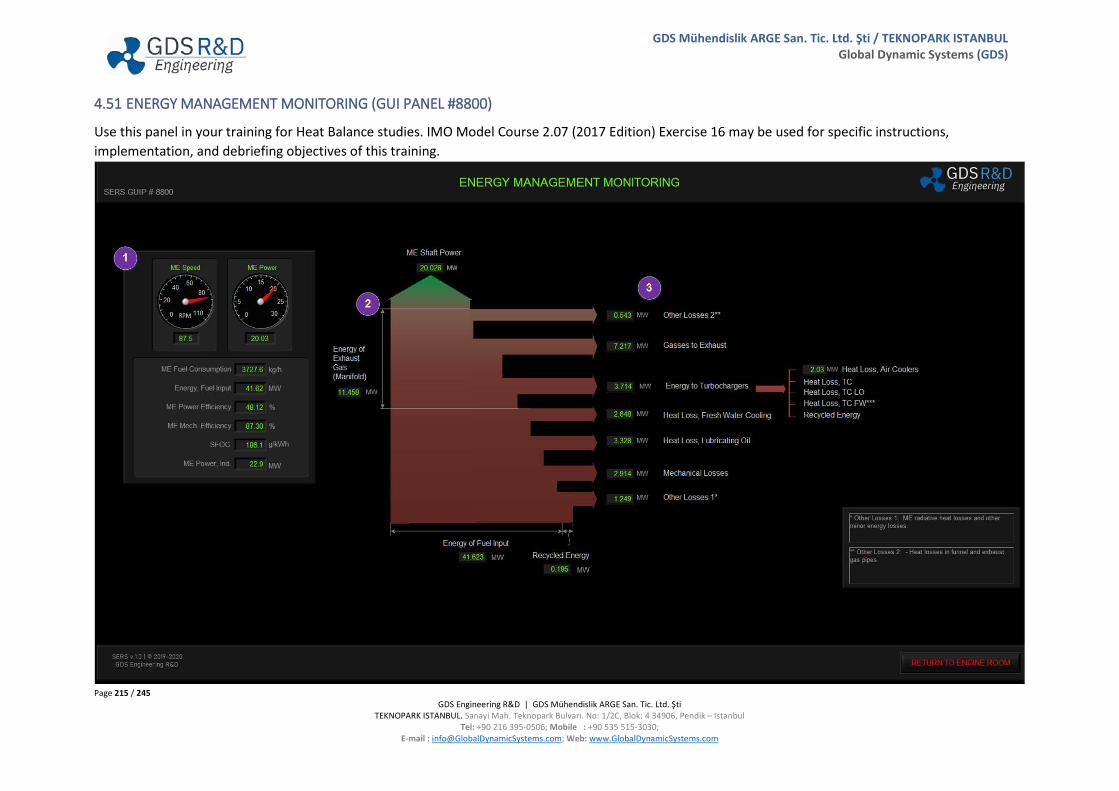
Page 215 / 245 GDS Engineering R&D | GDS Mühendislik ARGE San. Tic. Ltd. Şti
TEKNOPARK ISTANBUL. Sanayi Mah. Teknopark Bulvarı. No: 1/2C, Blok: 4 34906, Pendik – Istanbul Tel: +90 216 395-0506; Mobile : +90 535 515-3030;
E-mail : [email protected]; Web: www.GlobalDynamicSystems.com
GDS Mühendislik ARGE San. Tic. Ltd. Şti / TEKNOPARK ISTANBUL Global Dynamic Systems (GDS)
4.51 ENERGY MANAGEMENT MONITORING (GUI PANEL #8800)
Use this panel in your training for Heat Balance studies. IMO Model Course 2.07 (2017 Edition) Exercise 16 may be used for specific instructions, implementation, and debriefing objectives of this training.

Page 216 / 245 GDS Engineering R&D | GDS Mühendislik ARGE San. Tic. Ltd. Şti
TEKNOPARK ISTANBUL. Sanayi Mah. Teknopark Bulvarı. No: 1/2C, Blok: 4 34906, Pendik – Istanbul Tel: +90 216 395-0506; Mobile : +90 535 515-3030;
E-mail : [email protected]; Web: www.GlobalDynamicSystems.com
GDS Mühendislik ARGE San. Tic. Ltd. Şti / TEKNOPARK ISTANBUL Global Dynamic Systems (GDS)
4.51.1 Table of Screen Objects
Number Description
1 Main Engine Parameters Panel 2 ME Heat Balance Sankey Diagram 3 ME Heat Balance Losses
1. Main Engine Parameters Panel includes: a. ME Speed Gauge b. ME Power Gauge c. ME Fuel Consumption indicator d. Energy of Fuel Input indicator e. ME Power Efficiency indicator f. ME Mechanical Efficiency g. SFOC indicator h. ME Indicated Power indicator
2. Main Engine Heat Balance Sankey Diagram shows parametric power losses, power provided to the Economizer, and Turbochargers Consumed Power in MW, according to the energy of fuel Main Engine Input.
3. ME Heat Balance Losses includes: a. Other Losses (Exhaust gas heat (radiative) and kinetic energy losses at Exhaust Manifold & TC Inlet and Outlets, other minor losses to urea
when SCR is active.) b. Gases to Exhaust c. Energy to Turbocharges
i. Heat Loss at Air Coolers ii. Heat Loss at TC
iii. Heat Loss at TC LO iv. Heat Loss at TC FW (TC FW Cooling is provided by the HTFW cooling system, which is internal in the ME Cooling System.)

Page 217 / 245 GDS Engineering R&D | GDS Mühendislik ARGE San. Tic. Ltd. Şti
TEKNOPARK ISTANBUL. Sanayi Mah. Teknopark Bulvarı. No: 1/2C, Blok: 4 34906, Pendik – Istanbul Tel: +90 216 395-0506; Mobile : +90 535 515-3030;
E-mail : [email protected]; Web: www.GlobalDynamicSystems.com
GDS Mühendislik ARGE San. Tic. Ltd. Şti / TEKNOPARK ISTANBUL Global Dynamic Systems (GDS)
v. Recycled Energy d. Heat Loss at Fresh Water Cooling e. Heat Loss at Lubricating Oil f. Mechanical Losses g. Heat Dissipation and Other Losses (Exhaust gas heat (radiative) and kinetic energy losses (ME Outlet), and other minor energy losses.)

Page 218 / 245 GDS Engineering R&D | GDS Mühendislik ARGE San. Tic. Ltd. Şti
TEKNOPARK ISTANBUL. Sanayi Mah. Teknopark Bulvarı. No: 1/2C, Blok: 4 34906, Pendik – Istanbul Tel: +90 216 395-0506; Mobile : +90 535 515-3030;
E-mail : [email protected]; Web: www.GlobalDynamicSystems.com
GDS Mühendislik ARGE San. Tic. Ltd. Şti / TEKNOPARK ISTANBUL Global Dynamic Systems (GDS)
4.52 IDENTIFY & ACKNOWLEDGE MALFUNCTIONING COMPONENETS (GUI PANEL #8500)
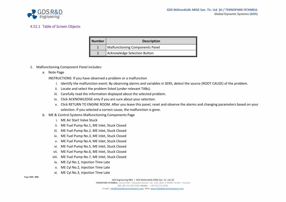
Page 219 / 245 GDS Engineering R&D | GDS Mühendislik ARGE San. Tic. Ltd. Şti
TEKNOPARK ISTANBUL. Sanayi Mah. Teknopark Bulvarı. No: 1/2C, Blok: 4 34906, Pendik – Istanbul Tel: +90 216 395-0506; Mobile : +90 535 515-3030;
E-mail : [email protected]; Web: www.GlobalDynamicSystems.com
GDS Mühendislik ARGE San. Tic. Ltd. Şti / TEKNOPARK ISTANBUL Global Dynamic Systems (GDS)
4.52.1 Table of Screen Objects
Number Description
1 Malfunctioning Components Panel 2 Acknowledge Selection Button
1. Malfunctioning Component Panel includes: a. Note Page
INSTRUCTIONS: If you have observed a problem or a malfunction i. Identify the malfunction event: By observing alarms and variables in SERS, detect the source (ROOT CAUSE) of the problem.
ii. Locate and select the problem listed (under relevant TABs). iii. Carefully read the information displayed about the selected problem. iv. Click ACKNOWLEDGE only if you are sure about your selection. v. Click RETURN TO ENGINE ROOM. After you leave this panel, reset and observe the alarms and changing parameters based on your
selection. If you selected a correct cause, the malfunction is gone. b. ME & Control Systems Malfunctioning Components Page
i. ME Air Start Valve Stuck ii. ME Fuel Pump No.1, ME Inlet, Stuck Closed
iii. ME Fuel Pump No.2, ME Inlet, Stuck Closed iv. ME Fuel Pump No.3, ME Inlet, Stuck Closed v. ME Fuel Pump No.4, ME Inlet, Stuck Closed
vi. ME Fuel Pump No.5, ME Inlet, Stuck Closed vii. ME Fuel Pump No.6, ME Inlet, Stuck Closed
viii. ME Fuel Pump No.7, ME Inlet, Stuck Closed ix. ME Cyl No.1, Injection Time Late x. ME Cyl No.2, Injection Time Late
xi. ME Cyl No.3, Injection Time Late

Page 220 / 245 GDS Engineering R&D | GDS Mühendislik ARGE San. Tic. Ltd. Şti
TEKNOPARK ISTANBUL. Sanayi Mah. Teknopark Bulvarı. No: 1/2C, Blok: 4 34906, Pendik – Istanbul Tel: +90 216 395-0506; Mobile : +90 535 515-3030;
E-mail : [email protected]; Web: www.GlobalDynamicSystems.com
GDS Mühendislik ARGE San. Tic. Ltd. Şti / TEKNOPARK ISTANBUL Global Dynamic Systems (GDS)
xii. ME Cyl No.4, Injection Time Late xiii. ME Cyl No.5, Injection Time Late xiv. ME Cyl No.6, Injection Time Late xv. ME Cyl No.7, Injection Time Late
xvi. ME Cyl No.1, Injection Nozzle Wear xvii. ME Cyl No.2, Injection Nozzle Wear
xviii. ME Cyl No.3, Injection Nozzle Wear xix. ME Cyl No.4, Injection Nozzle Wear xx. ME Cyl No.5, Injection Nozzle Wear
xxi. ME Cyl No.6, Injection Nozzle Wear xxii. ME Cyl No.7, Injection Nozzle Wear
xxiii. ME Cyl. No.1, Injection Nozzle Clogged xxiv. ME Cyl. No.2, Injection Nozzle Clogged xxv. ME Cyl. No.3, Injection Nozzle Clogged
xxvi. ME Cyl. No.4, Injection Nozzle Clogged xxvii. ME Cyl. No.5, Injection Nozzle Clogged
xxviii. ME Cyl. No.6, Injection Nozzle Clogged xxix. ME Cyl. No.7, Injection Nozzle Clogged xxx. ME Cyl. No.1, Piston Ring Wear
xxxi. ME Cyl. No.2, Piston Ring Wear xxxii. ME Cyl. No.3, Piston Ring Wear
xxxiii. ME Cyl. No.4, Piston Ring Wear xxxiv. ME Cyl. No.5, Piston Ring Wear xxxv. ME Cyl. No.6, Piston Ring Wear
xxxvi. ME Cyl. No.7, Piston Ring Wear xxxvii. ME Cyl. No.1, Exhaust Valve Closes Late
xxxviii. ME Cyl. No.2, Exhaust Valve Closes Late xxxix. ME Cyl. No.3, Exhaust Valve Closes Late
xl. ME Cyl. No.4, Exhaust Valve Closes Late

Page 221 / 245 GDS Engineering R&D | GDS Mühendislik ARGE San. Tic. Ltd. Şti
TEKNOPARK ISTANBUL. Sanayi Mah. Teknopark Bulvarı. No: 1/2C, Blok: 4 34906, Pendik – Istanbul Tel: +90 216 395-0506; Mobile : +90 535 515-3030;
E-mail : [email protected]; Web: www.GlobalDynamicSystems.com
GDS Mühendislik ARGE San. Tic. Ltd. Şti / TEKNOPARK ISTANBUL Global Dynamic Systems (GDS)
xli. ME Cyl. No.5, Exhaust Valve Closes Late xlii. ME Cyl. No.6, Exhaust Valve Closes Late
xliii. ME Cyl. No.7, Exhaust Valve Closes Late xliv. ME Cyl. No.1, Exhaust Valve Leakage xlv. ME Cyl. No.2, Exhaust Valve Leakage
xlvi. ME Cyl. No.3, Exhaust Valve Leakage xlvii. ME Cyl. No.4, Exhaust Valve Leakage
xlviii. ME Cyl. No.5, Exhaust Valve Leakage xlix. ME Cyl. No.6, Exhaust Valve Leakage
l. ME Cyl. No.7, Exhaust Valve Leakage li. ME Cyl. No.1, Liner Crack
lii. ME Cyl. No.2, Liner Crack liii. ME Cyl. No.3, Liner Crack liv. ME Cyl. No.4, Liner Crack lv. ME Cyl. No.5, Liner Crack
lvi. ME Cyl. No.6, Liner Crack lvii. ME Cyl. No.7, Liner Crack
lviii. ME Cyl. No.1, Score in ME Bearing lix. ME Cyl. No.2, Score in ME Bearing lx. ME Cyl. No.3, Score in ME Bearing
lxi. ME Cyl. No.4, Score in ME Bearing lxii. ME Cyl. No.5, Score in ME Bearing
lxiii. ME Cyl. No.6, Score in ME Bearing lxiv. ME Cyl. No.7, Score in ME Bearing lxv. ME Cyl. No.1, Oil Mist Detector, Sensor Failure
lxvi. ME Cyl. No.2, Oil Mist Detector, Sensor Failure lxvii. ME Cyl. No.3, Oil Mist Detector, Sensor Failure
lxviii. ME Cyl. No.4, Oil Mist Detector, Sensor Failure lxix. ME Cyl. No.5, Oil Mist Detector, Sensor Failure

Page 222 / 245 GDS Engineering R&D | GDS Mühendislik ARGE San. Tic. Ltd. Şti
TEKNOPARK ISTANBUL. Sanayi Mah. Teknopark Bulvarı. No: 1/2C, Blok: 4 34906, Pendik – Istanbul Tel: +90 216 395-0506; Mobile : +90 535 515-3030;
E-mail : [email protected]; Web: www.GlobalDynamicSystems.com
GDS Mühendislik ARGE San. Tic. Ltd. Şti / TEKNOPARK ISTANBUL Global Dynamic Systems (GDS)
lxx. ME Cyl. No.6, Oil Mist Detector, Sensor Failure lxxi. ME Cyl. No.7, Oil Mist Detector, Sensor Failure
lxxii. ME Crosshead Bearing No.7, Temperature is High c. Electricity Generation & Distribution Plant Malfunctioning Components Page
i. Diesel Generator 1 Lub. Oil Filter Dirty ii. Diesel Generator 1 Lub. Oil Filter Clogged
iii. Diesel Generator 2 Lub. Oil Filter Dirty iv. Diesel Generator 2 Lub. Oil Filter Clogged v. Diesel Generator 3 Lub. Oil Filter Dirty
vi. Diesel Generator 3 Lub. Oil Filter Clogged vii. ECR Control Systems Panel, Circuit Breaker Failure
viii. Seawater Pump No.1 Overload ix. Seawater Pump No.2 Overload x. ME Systems Main CB Overload
xi. Aux. Seawater Pump Overload xii. LTFW Pump No.1 Overload
xiii. LTFW Pump No.2 Overload xiv. HTFW Pump No.1 Overload xv. HTFW Pump No.2 Overload
xvi. FO Supply Pump No.1 Overload xvii. FO Supply Pump No.2 Overload
xviii. FO Circulation Pump No.1 Overload xix. FO Circulation Pump No.2 Overload xx. LO Pump No.1 Overload
xxi. LO Pump No.2 Overload xxii. Air Compressor 1 Overload
xxiii. Air Compressor 2 Overload xxiv. ME Turning Gear Overload xxv. Auxiliary I Circuit Breaker Overload
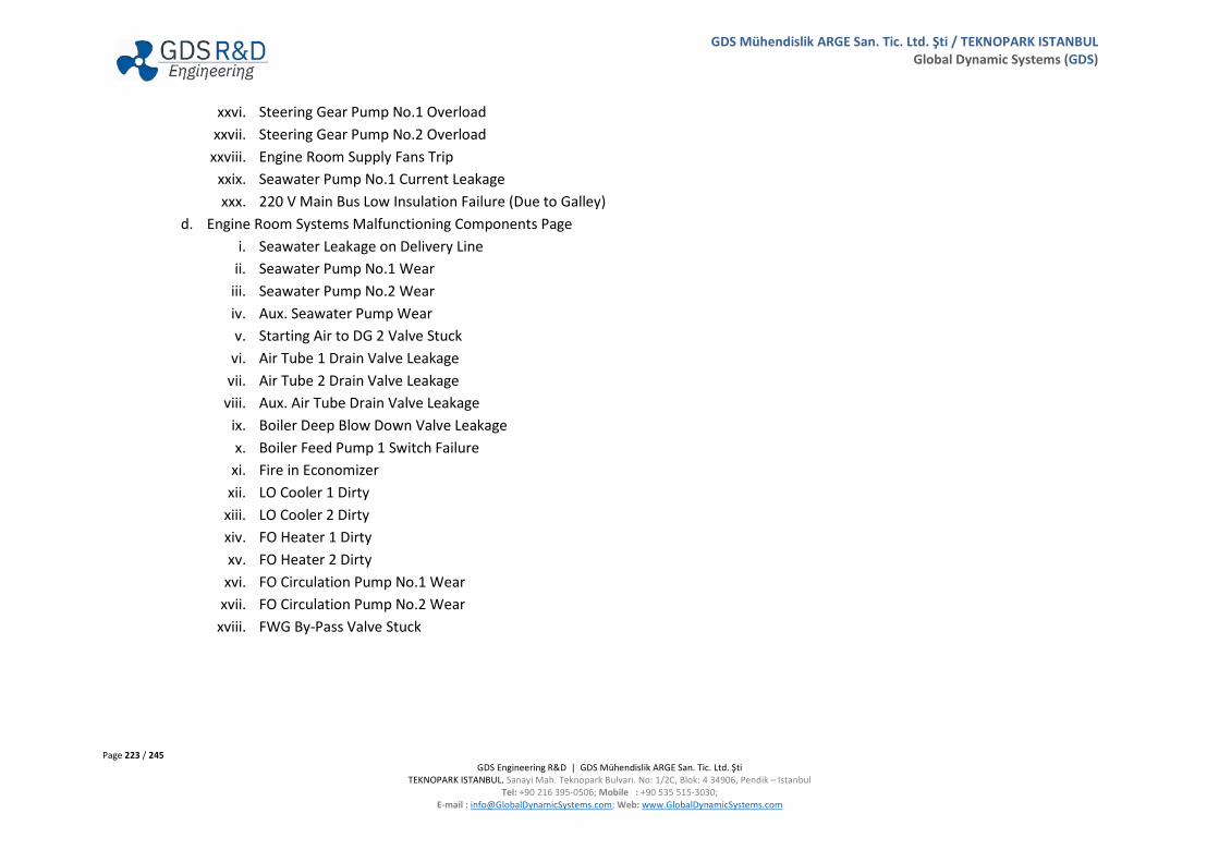
Page 223 / 245 GDS Engineering R&D | GDS Mühendislik ARGE San. Tic. Ltd. Şti
TEKNOPARK ISTANBUL. Sanayi Mah. Teknopark Bulvarı. No: 1/2C, Blok: 4 34906, Pendik – Istanbul Tel: +90 216 395-0506; Mobile : +90 535 515-3030;
E-mail : [email protected]; Web: www.GlobalDynamicSystems.com
GDS Mühendislik ARGE San. Tic. Ltd. Şti / TEKNOPARK ISTANBUL Global Dynamic Systems (GDS)
xxvi. Steering Gear Pump No.1 Overload xxvii. Steering Gear Pump No.2 Overload
xxviii. Engine Room Supply Fans Trip xxix. Seawater Pump No.1 Current Leakage xxx. 220 V Main Bus Low Insulation Failure (Due to Galley)
d. Engine Room Systems Malfunctioning Components Page i. Seawater Leakage on Delivery Line
ii. Seawater Pump No.1 Wear iii. Seawater Pump No.2 Wear iv. Aux. Seawater Pump Wear v. Starting Air to DG 2 Valve Stuck
vi. Air Tube 1 Drain Valve Leakage vii. Air Tube 2 Drain Valve Leakage
viii. Aux. Air Tube Drain Valve Leakage ix. Boiler Deep Blow Down Valve Leakage x. Boiler Feed Pump 1 Switch Failure
xi. Fire in Economizer xii. LO Cooler 1 Dirty
xiii. LO Cooler 2 Dirty xiv. FO Heater 1 Dirty xv. FO Heater 2 Dirty
xvi. FO Circulation Pump No.1 Wear xvii. FO Circulation Pump No.2 Wear
xviii. FWG By-Pass Valve Stuck
Page 224 / 245 GDS Engineering R&D | GDS Mühendislik ARGE San. Tic. Ltd. Şti
TEKNOPARK ISTANBUL. Sanayi Mah. Teknopark Bulvarı. No: 1/2C, Blok: 4 34906, Pendik – Istanbul Tel: +90 216 395-0506; Mobile : +90 535 515-3030;
E-mail : [email protected]; Web: www.GlobalDynamicSystems.com
GDS Mühendislik ARGE San. Tic. Ltd. Şti / TEKNOPARK ISTANBUL Global Dynamic Systems (GDS)
e. Events f. End Note
i. If you ACKNOWLEDGED your selection, SERS software have already recorded. ii. Click RETURN TO ENGINE ROOM.
iii. After you leave this panel: 1. Reset the alarms in the ALARM Panel (GUIP #8000). 2. Observe the alarms and changing parameters based on your selection. 3. If you are selected correct problem, the parameters should be restored. 4. If nothing changed, probably you have made wrong selection. The you may be want to change your selection?

Page 225 / 245 GDS Engineering R&D | GDS Mühendislik ARGE San. Tic. Ltd. Şti
TEKNOPARK ISTANBUL. Sanayi Mah. Teknopark Bulvarı. No: 1/2C, Blok: 4 34906, Pendik – Istanbul Tel: +90 216 395-0506; Mobile : +90 535 515-3030;
E-mail : [email protected]; Web: www.GlobalDynamicSystems.com
GDS Mühendislik ARGE San. Tic. Ltd. Şti / TEKNOPARK ISTANBUL Global Dynamic Systems (GDS)
4.53 CREATE & INJECT MALFUNCTIONS (GUI PANEL #8200)
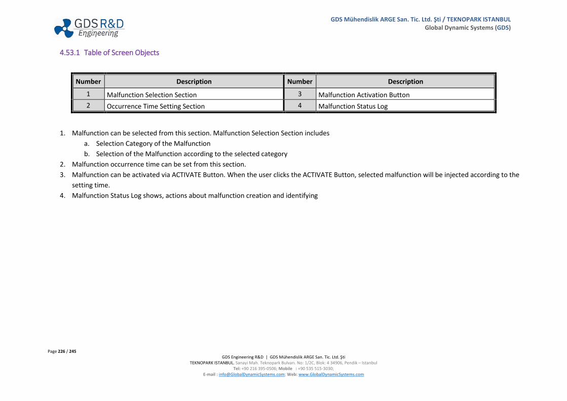
Page 226 / 245 GDS Engineering R&D | GDS Mühendislik ARGE San. Tic. Ltd. Şti
TEKNOPARK ISTANBUL. Sanayi Mah. Teknopark Bulvarı. No: 1/2C, Blok: 4 34906, Pendik – Istanbul Tel: +90 216 395-0506; Mobile : +90 535 515-3030;
E-mail : [email protected]; Web: www.GlobalDynamicSystems.com
GDS Mühendislik ARGE San. Tic. Ltd. Şti / TEKNOPARK ISTANBUL Global Dynamic Systems (GDS)
4.53.1 Table of Screen Objects
Number Description Number Description
1 Malfunction Selection Section 3 Malfunction Activation Button 2 Occurrence Time Setting Section 4 Malfunction Status Log
1. Malfunction can be selected from this section. Malfunction Selection Section includes a. Selection Category of the Malfunction b. Selection of the Malfunction according to the selected category
2. Malfunction occurrence time can be set from this section. 3. Malfunction can be activated via ACTIVATE Button. When the user clicks the ACTIVATE Button, selected malfunction will be injected according to the
setting time. 4. Malfunction Status Log shows, actions about malfunction creation and identifying
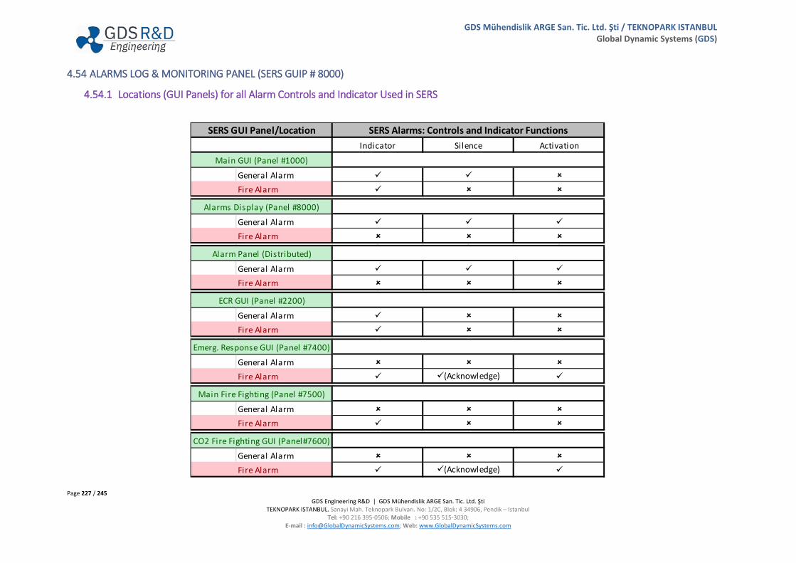
Page 227 / 245 GDS Engineering R&D | GDS Mühendislik ARGE San. Tic. Ltd. Şti
TEKNOPARK ISTANBUL. Sanayi Mah. Teknopark Bulvarı. No: 1/2C, Blok: 4 34906, Pendik – Istanbul Tel: +90 216 395-0506; Mobile : +90 535 515-3030;
E-mail : [email protected]; Web: www.GlobalDynamicSystems.com
GDS Mühendislik ARGE San. Tic. Ltd. Şti / TEKNOPARK ISTANBUL Global Dynamic Systems (GDS)
4.54 ALARMS LOG & MONITORING PANEL (SERS GUIP # 8000)
4.54.1 Locations (GUI Panels) for all Alarm Controls and Indicator Used in SERS
General AlarmFire Alarm
General AlarmFire Alarm
General AlarmFire Alarm
General AlarmFire Alarm
General AlarmFire Alarm
General AlarmFire Alarm
General AlarmFire Alarm
SERS GUI Panel/Location SERS Alarms: Controls and Indicator Functions
CO2 Fire Fighting GUI (Panel#7600)
Indicator Silence Activation
Main GUI (Panel #1000)
Alarms Display (Panel #8000)
Alarm Panel (Distributed)
ECR GUI (Panel #2200)
Emerg. Response GUI (Panel #7400)
Main Fire Fighting (Panel #7500)
(Acknowledge)
(Acknowledge)
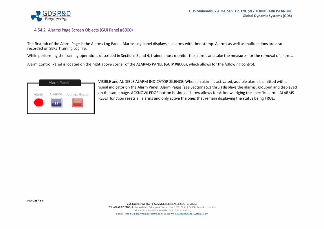
Page 228 / 245 GDS Engineering R&D | GDS Mühendislik ARGE San. Tic. Ltd. Şti
TEKNOPARK ISTANBUL. Sanayi Mah. Teknopark Bulvarı. No: 1/2C, Blok: 4 34906, Pendik – Istanbul Tel: +90 216 395-0506; Mobile : +90 535 515-3030;
E-mail : [email protected]; Web: www.GlobalDynamicSystems.com
GDS Mühendislik ARGE San. Tic. Ltd. Şti / TEKNOPARK ISTANBUL Global Dynamic Systems (GDS)
4.54.2 Alarms Page Screen Objects (GUI Panel #8000)
The first tab of the Alarm Page is the Alarms Log Panel. Alarms Log panel displays all alarms with time stamp. Alarms as well as malfunctions are also recorded on SERS Training Log file.
While performing the training operations described in Sections 3 and 4, trainee must monitor the alarms and take the measures for the removal of alarms.
Alarm Control Panel is located on the right above corner of the ALARMS PANEL (GUIP #8000), which allows for the following control:
VISIBLE and AUDIBLE ALARM INDICATOR SILENCE: When an alarm is activated, audible alarm is emitted with a visual indicator on the Alarm Panel. Alarm Pages (see Sections 5.1 thru ) displays the alarms, grouped and displayed on the same page. ACKNOWLEDGE button beside each row allows for Acknowledging the specific alarm. ALARMS RESET function resets all alarms and only active the ones that remain displaying the status being TRUE.

Page 229 / 245 GDS Engineering R&D | GDS Mühendislik ARGE San. Tic. Ltd. Şti
TEKNOPARK ISTANBUL. Sanayi Mah. Teknopark Bulvarı. No: 1/2C, Blok: 4 34906, Pendik – Istanbul Tel: +90 216 395-0506; Mobile : +90 535 515-3030;
E-mail : [email protected]; Web: www.GlobalDynamicSystems.com
GDS Mühendislik ARGE San. Tic. Ltd. Şti / TEKNOPARK ISTANBUL Global Dynamic Systems (GDS)
ALARM visually indicates an existing alarm continuing.
An Audible ALARM (being sound) sounds unless SILENCE is pressed.
ALARMS RESET function resets all alarms. When pressed, only the active alarms are indicated.
All alarms displayed on ALARMS PANEL is shown in the following pages.
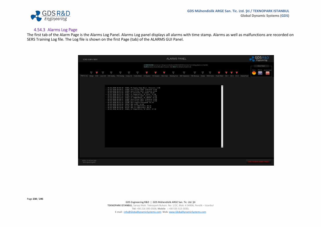
Page 230 / 245 GDS Engineering R&D | GDS Mühendislik ARGE San. Tic. Ltd. Şti
TEKNOPARK ISTANBUL. Sanayi Mah. Teknopark Bulvarı. No: 1/2C, Blok: 4 34906, Pendik – Istanbul Tel: +90 216 395-0506; Mobile : +90 535 515-3030;
E-mail : [email protected]; Web: www.GlobalDynamicSystems.com
GDS Mühendislik ARGE San. Tic. Ltd. Şti / TEKNOPARK ISTANBUL Global Dynamic Systems (GDS)
4.54.3 Alarms Log Page The first tab of the Alarm Page is the Alarms Log Panel. Alarms Log panel displays all alarms with time stamp. Alarms as well as malfunctions are recorded on SERS Training Log file. The Log file is shown on the first Page (tab) of the ALARMS GUI Panel.

Page 231 / 245 GDS Engineering R&D | GDS Mühendislik ARGE San. Tic. Ltd. Şti
TEKNOPARK ISTANBUL. Sanayi Mah. Teknopark Bulvarı. No: 1/2C, Blok: 4 34906, Pendik – Istanbul Tel: +90 216 395-0506; Mobile : +90 535 515-3030;
E-mail : [email protected]; Web: www.GlobalDynamicSystems.com
GDS Mühendislik ARGE San. Tic. Ltd. Şti / TEKNOPARK ISTANBUL Global Dynamic Systems (GDS)
4.54.4 Alarm Pages /or Tabs Alarms are classified according to the systems and shown on Alarm Tabs in groups. When a malfunction occurred, alarm will be triggered related to the malfunction. An example of an ALARM Page is shown in Figure below.

Page 232 / 245 GDS Engineering R&D | GDS Mühendislik ARGE San. Tic. Ltd. Şti
TEKNOPARK ISTANBUL. Sanayi Mah. Teknopark Bulvarı. No: 1/2C, Blok: 4 34906, Pendik – Istanbul Tel: +90 216 395-0506; Mobile : +90 535 515-3030;
E-mail : [email protected]; Web: www.GlobalDynamicSystems.com
GDS Mühendislik ARGE San. Tic. Ltd. Şti / TEKNOPARK ISTANBUL Global Dynamic Systems (GDS)
4.54.5 Alarms Lists
Following tables provide the list of alarms exist in the SERS.
A Codes Alarm Name Low High Low High Low HighBridge A2011 Steering Gear Remote System Failure INACTIVE - - - - - - -
A2103 Overspeed 0-91 rpm - 98,5 - - - -
A2108 ECR Control Panel, Power Out INACTIVE - - - - - - -
A2109 ME Shut Down Pre-warning INACTIVE - - - - - - -
A2110 ME Shut Down INACTIVE - - - - - - -
A2111 ME Slow Down Pre-warning INACTIVE - - - - - - -
A2112 ME Slow Down INACTIVE - - - - - - -
A2113 ME Wrong Way INACTIVE - - - - - - -
A2201 Air Pressure, ME Air Start System >15 bar 15 - - - - -
A3001 Sea Water No.1 Pump Trip INACTIVE - - - - - - -
A3002 Sea Water No.2 Pump Trip INACTIVE - - - - - - -
A3003 Aux Sea Water Pump Trip INACTIVE - - - - - - -
A3004 SW Main Cooling System Line Press. 2,5 bar - - - - - -
A3005 SW Main Cooling System Outlet Temp. >20 °C 19
A3101 LTFW Line Pressure 2,5 barA3102 LTFW Temperature, Coolers Inlet 45 °C - 57 - - - -
A3103 LTFW Temperature, Pumps Inlet 28-35 °C - 40 - - - -
A3111 HTFW Pressure, ME Inlet 3 bar - - - - - -
A3112 HTFW Temperature, ME Inlet 68 °C 60 78 - - - -
A3113 HTFW Temperature, ME Outlet 78 °C - 92 - 95 - -
A3131 FW Expansion Tank Level 80 % 30 95 - - - -
ME Control
SW Main Cooling System
FW Cooling System
Shut DownAlarmNormal Val.Alarm Page
NameUnit
SERS Slow Down

Page 233 / 245 GDS Engineering R&D | GDS Mühendislik ARGE San. Tic. Ltd. Şti
TEKNOPARK ISTANBUL. Sanayi Mah. Teknopark Bulvarı. No: 1/2C, Blok: 4 34906, Pendik – Istanbul Tel: +90 216 395-0506; Mobile : +90 535 515-3030;
E-mail : [email protected]; Web: www.GlobalDynamicSystems.com
GDS Mühendislik ARGE San. Tic. Ltd. Şti / TEKNOPARK ISTANBUL Global Dynamic Systems (GDS)
A Codes Alarm Name Low High Low High Low HighShut DownAlarmNormal Val.
Alarm Page Name
UnitSERS Slow Down
A3201 Air Receiver 1, Pressure 15-30 bar 14,5 - - - - -
A3202 Air Receiver 2, Pressure 15-30 bar 14,5 - - - - -
A3203 Aux Air Receiver, Pressure 12-30 bar 11 - - - - -
A3204 ME Maneuvering System Air Pressure 7 bar 5,5 - - - - -
A3205 ME Start Air Pressure >15 bar 15 - - - - -
A3206 Start Air Pressure, DG 1 Inlet >15 bar 15 - - - - -
A3207 Start Air Pressure, DG 2 Inlet >15 bar 15 - - - - -
A3211 Air Compressor 1, Temperature <60 °C - 65 - - - -
A3212 Air Compressor 2, Temperature <60 °C - 65 - - - -
A3213 Aux Air Compressor, Temperature <55 °C - 60 - - - -
A3221 Air Compressor 1 Trip INACTIVE - - - - - - -
A3222 Air Compressor 2 Trip INACTIVE - - - - - - -
A3223 Aux Compressor Trip INACTIVE - - - - - - -
A3231 Air Tube 1 Press Sensor Failure INACTIVE - - - - - - -
A3232 Air Tube 2 Press Sensor Failure INACTIVE - - - - - - -
A3233 Aux Air Tube Press Sensor Failure INACTIVE -A3301 Boiler Level 100 % 80 120 - - - -
A3302 Boiler Low Low Level 70 % 70 - - - - -
A3303 Boiler High High Level 130 % 130
A3310 Boiler Pressure 6.5 bar 4.0 7.5 - - - -
A3311 Smoke Density 25 % - 35 - - - -
A3321 Boiler Flame Out INACTIVE - - - - - - -
A3330 Burner Trip INACTIVE - - - - - - -
Compressed Air System
Combined Boiler

Page 234 / 245 GDS Engineering R&D | GDS Mühendislik ARGE San. Tic. Ltd. Şti
TEKNOPARK ISTANBUL. Sanayi Mah. Teknopark Bulvarı. No: 1/2C, Blok: 4 34906, Pendik – Istanbul Tel: +90 216 395-0506; Mobile : +90 535 515-3030;
E-mail : [email protected]; Web: www.GlobalDynamicSystems.com
GDS Mühendislik ARGE San. Tic. Ltd. Şti / TEKNOPARK ISTANBUL Global Dynamic Systems (GDS)
A3401 LO Pressure, ME Inlet 2,0 - 2,9 bar 1,9 - 1,7 - 1,3 -
A3402 LO Temperature, ME Inlet 40-52 °C 35 55 - 60 - -
A3403 LO Temperature, ME Outlet 48-60 °C - 64,5 - - - -
A3404 Aut. Backflushing Filter Diff. Press. 0,2 bar - 0,5 - - - -
A3405 ME LO Sump Tank Level >50 % 20 -
A3406 ME Cyl. Oil Day Tank Level >50 % 20 -
A3501 FO Pressure, ME Inlet 7-8 bar 6,5 - - - - -
A3502 FO Viscosity, ME Inlet 13-15 cSt 10 20 - - - -
A3503 FO Supply Pump Discharge Pressure 4-5 bar 2,8 - - - - -
Stern Tube A3601 Stern Tube, Diff. Oil Pressure 0,2-0,4 bar 0,2 0,4 - - - -
A3701 SG System, Expansion Tank Low Level 50-90 % 50 - - - - -
A3711 SG System, Expansion Tank 1 Low Level 50-90 % 30 - - - - -
A3712 SG System, Expansion Tank 1 Low Low Level 50-90 % 10
A3721 SG System, Expansion Tank 2 Low Level 50-90 % 30 - - - - -
A3722 SG System, Expansion Tank 2 Low Low Level 50-90 % 10 - - - - -
A4111 Exhaust Temperature, Cyl. No.1 250-350 °C 200 430 - 450 - -
A4112 Exhaust Temperature, Cyl. No.2 250-350 °C 200 430 - 450 - -
A4113 Exhaust Temperature, Cyl. No.3 250-350 °C 200 430 - 450 - -
A4114 Exhaust Temperature, Cyl. No.4 250-350 °C 200 430 - 450 - -
A4115 Exhaust Temperature, Cyl. No.5 250-350 °C 200 430 - 450 - -
A4116 Exhaust Temperature, Cyl. No.6 250-350 °C 200 430 - 450 - -
A4117 Exhaust Temperature, Cyl. No.7 250-350 °C 200 430 - 450 - -
A4118 Exhaust Temperature, Average <380 °C - 380 - - - -
A4119 Exhaust Temperature Deviation ±30 °C - 50 50 - 60 60 - -
ME LO System
ME FO System
Steering Gear
ME Parameters
A Codes Alarm Name Low High Low High Low HighShut DownAlarmNormal Val.
Alarm Page Name
UnitSERS Slow Down

Page 235 / 245 GDS Engineering R&D | GDS Mühendislik ARGE San. Tic. Ltd. Şti
TEKNOPARK ISTANBUL. Sanayi Mah. Teknopark Bulvarı. No: 1/2C, Blok: 4 34906, Pendik – Istanbul Tel: +90 216 395-0506; Mobile : +90 535 515-3030;
E-mail : [email protected]; Web: www.GlobalDynamicSystems.com
GDS Mühendislik ARGE San. Tic. Ltd. Şti / TEKNOPARK ISTANBUL Global Dynamic Systems (GDS)
A Codes Alarm Name Low High Low High Low HighShut DownAlarmNormal Val.
Alarm Page Name
UnitSERS Slow Down
A4651 Scavenge Manifold Air Pressure 0 - 3.1 bar 2 - - - - -
A4652 Scavenge Manifold Air Temperature 35-50 °C - 55 - - - -
A4653 Exhaust Manifold Air Pressure 2 bar - 3
A4654 Exhaust Manifold Air Temperature 250-350 °C - 430
A4655 Scavenge Air Temp., AC Inlet 200 °C - 220
A4656 Scavenge Air Temp., AC Outlet 40 °C - 55
A4657 Turbocharger 1, RPM 7000-15500 rpmA4658 Turbocharger 2, RPM 7000-15500 rpmA4701 Oil Mist, No.1 1-10 % - 30 - 60 - -
A4702 Oil Mist, No.2 1-10 % - 30 - 60 - -
A4703 Oil Mist, No.3 1-10 % - 30 - 60 - -
A4704 Oil Mist, No.4 1-10 % - 30 - 60 - -
A4705 Oil Mist, No.5 1-10 % - 30 - 60 - -
A4706 Oil Mist, No.6 1-10 % - 30 - 60 - -
A4707 Oil Mist, No.7 1-10 % - 30 - 60 - -
A4708 Main Bearing Temperature, No.1 50-70 °C - 75 - 80 - -
A4709 Main Bearing Temperature, No.2 50-70 °C - 75 - 80 - -
A4710 Main Bearing Temperature, No.3 50-70 °C - 75 - 80 - -
A4711 Main Bearing Temperature, No.4 50-70 °C - 75 - 80 - -
A4712 Main Bearing Temperature, No.5 50-70 °C - 75 - 80 - -
A4713 Main Bearing Temperature, No.6 50-70 °C - 75 - 80 - -
A4714 Main Bearing Temperature, No.7 50-70 °C - 75 - 80 - -
A4715 Thrust Bearing Temperature 55-65 °C - 70 - 75 - 85
A4751 Air Pressure 7 bar 6 - - - - -
A4752 Urea Pump Failure INACTIVE - - - - - - -
FWG A4801 Salinity <4,5 ppm - 4,5
ME Manifold and TCs
ME Bearings
Denox
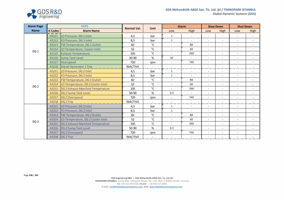
Page 236 / 245 GDS Engineering R&D | GDS Mühendislik ARGE San. Tic. Ltd. Şti
TEKNOPARK ISTANBUL. Sanayi Mah. Teknopark Bulvarı. No: 1/2C, Blok: 4 34906, Pendik – Istanbul Tel: +90 216 395-0506; Mobile : +90 535 515-3030;
E-mail : [email protected]; Web: www.GlobalDynamicSystems.com
GDS Mühendislik ARGE San. Tic. Ltd. Şti / TEKNOPARK ISTANBUL Global Dynamic Systems (GDS)
A Codes Alarm Name Low High Low High Low HighShut DownAlarmNormal Val.
Alarm Page Name
UnitSERS Slow Down
A5111 LO Pressure, DG 1 Inlet 4,5 bar 1 - - - - -
A5112 FO Pressure, DG 1 Inlet 8,5 bar 1 - - - - -
A5113 FW Temperature, DG 1 Outlet 82 °C - 88 - - - -
A5114 LO Temperature, Cooler Inlet 52 °C - 60 - - - -
A5115 Exhaust Temperature 335 °C - 390 - - - -
A5116 Sump Tank Level 50-90 % 30 - - - - -
A5117 Overspeed 720 rpm - 740 - - - -
A5118 Diesel Generator 1 Trip INACTIVE - - - - - - -
A5211 LO Pressure, DG 2 Inlet 4,5 bar 1 - - - - -
A5212 FO Pressure, DG 2 Inlet 8,5 bar 1 - - - - -
A5213 FW Temperature, DG 2 Outlet 82 °C - 88 - - - -
A5214 LO Temperature, DG 2 Cooler Inlet 52 °C - 60 - - - -
A5215 DG 2 Exhaust Manifold Temperature 335 °C - 390 - - - -
A5216 DG 2 Sump Tank Level 50-90 % 0.3 - - - - -
A5217 DG 2 Overspeed 720 rpm - 740 - - - -
A5218 DG 2 Trip INACTIVE - - - - - - -
A5311 LO Pressure, DG 2 Inlet 4,5 bar 1 - - - - -
A5312 FO Pressure, DG 2 Inlet 8,5 bar 1 - - - - -
A5313 FW Temperature, DG 2 Outlet 82 °C - 88 - - - -
A5314 LO Temperature, DG 2 Cooler Inlet 52 °C - 60 - - - -
A5315 DG 2 Exhaust Manifold Temperature 335 °C - 390 - - - -
A5316 DG 2 Sump Tank Level 50-90 % 0.3 - - - - -
A5317 DG 2 Overspeed 720 rpm - 740 - - - -
A5318 DG 2 Trip INACTIVE - - - - - - -
DG 3
DG 1
DG 2
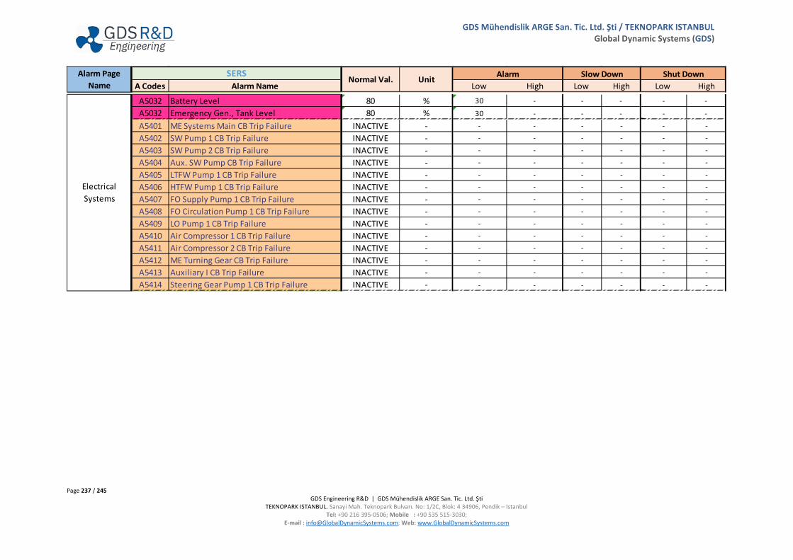
Page 237 / 245 GDS Engineering R&D | GDS Mühendislik ARGE San. Tic. Ltd. Şti
TEKNOPARK ISTANBUL. Sanayi Mah. Teknopark Bulvarı. No: 1/2C, Blok: 4 34906, Pendik – Istanbul Tel: +90 216 395-0506; Mobile : +90 535 515-3030;
E-mail : [email protected]; Web: www.GlobalDynamicSystems.com
GDS Mühendislik ARGE San. Tic. Ltd. Şti / TEKNOPARK ISTANBUL Global Dynamic Systems (GDS)
A Codes Alarm Name Low High Low High Low HighShut DownAlarmNormal Val.
Alarm Page Name
UnitSERS Slow Down
A5032 Battery Level 80 % 30 - - - - -
A5032 Emergency Gen., Tank Level 80 % 30 - - - - -
A5401 ME Systems Main CB Trip Failure INACTIVE - - - - - - -
A5402 SW Pump 1 CB Trip Failure INACTIVE - - - - - - -
A5403 SW Pump 2 CB Trip Failure INACTIVE - - - - - - -
A5404 Aux. SW Pump CB Trip Failure INACTIVE - - - - - - -
A5405 LTFW Pump 1 CB Trip Failure INACTIVE - - - - - - -
A5406 HTFW Pump 1 CB Trip Failure INACTIVE - - - - - - -
A5407 FO Supply Pump 1 CB Trip Failure INACTIVE - - - - - - -
A5408 FO Circulation Pump 1 CB Trip Failure INACTIVE - - - - - - -
A5409 LO Pump 1 CB Trip Failure INACTIVE - - - - - - -
A5410 Air Compressor 1 CB Trip Failure INACTIVE - - - - - - -
A5411 Air Compressor 2 CB Trip Failure INACTIVE - - - - - - -
A5412 ME Turning Gear CB Trip Failure INACTIVE - - - - - - -
A5413 Auxiliary I CB Trip Failure INACTIVE - - - - - - -
A5414 Steering Gear Pump 1 CB Trip Failure INACTIVE - - - - - - -
Electrical Systems

Page 238 / 245 GDS Engineering R&D | GDS Mühendislik ARGE San. Tic. Ltd. Şti
TEKNOPARK ISTANBUL. Sanayi Mah. Teknopark Bulvarı. No: 1/2C, Blok: 4 34906, Pendik – Istanbul Tel: +90 216 395-0506; Mobile : +90 535 515-3030;
E-mail : [email protected]; Web: www.GlobalDynamicSystems.com
GDS Mühendislik ARGE San. Tic. Ltd. Şti / TEKNOPARK ISTANBUL Global Dynamic Systems (GDS)
A Codes Alarm Name Low High Low High Low HighShut DownAlarmNormal Val.
Alarm Page Name
UnitSERS Slow Down
A6001 LO Temperature, Heater Outlet 88 °C 80 98 - - - -
A6002 Separator Outlet Pressure bar 0,8 2,5 - - - -
A6003 FW Pressure bar 1 - - - - -
A6201 3P MDO Storage Tank Level >90 % - 90 - - - -
A6202 3P MDO Storage Tank Temperature Ambient °C - - - - -
A6203 3S MDO Storage Tank Level >90 % - 90 - - - -
A6204 3S MDO Storage Tank Temperature Ambient °C - - - - -
A6205 MDO Settling Tank Level >95 % - 95 - - - -
A6206 MDO Settling Tank Temperature Ambient °C - - - - -
A6207 MDO Service Tank Level >98 % 25 98 - - - -
A6208 MDO Service Tank Temperature Ambient °C - - - - -
A6301 1P HFO Storage Tank Level >90 % - 90 - - - -
A6302 1P HFO Storage Tank Temperature 35-45 °C - 80 - - - -
A6303 1S HFO Storage Tank Level >90 % - 90 - - - -
A6304 1S HFO Storage Tank Temperature 35-45 °C - 80 - - - -
A6305 2P HFO Storage Tank Level >90 % - 90 - - - -
A6306 2P HFO Storage Tank Temperature 35-45 °C - 80 - - - -
A6307 2S HFO Storage Tank Level >90 % - 90 - - - -
A6308 2S HFO Storage Tank Temperature 35-45 °C - 80 - - - -
A6309 HFO Settling Tank Level >95 % - 95 - - - -
A6310 HFO Settling Tank Temperature 65-80 °C - 110 - - - -
A6311 HFO Service Tank Level >98 % 25 98 - - - -
A6312 HFO Service Tank Temperature 80-90 °C - 110 - - - -
A6501 FW Tank Level, Portside <30 % 30 - - - - -
A6502 FW Tank Level, Starboard <30 % 30 - - - - -
A6503 Hydrophore Tank Level <30 % 30 - - - - -
LO Separator
MDO Separator and Tanks
HFO Separator and Tanks
FW and Hydrophore
System

Page 239 / 245 GDS Engineering R&D | GDS Mühendislik ARGE San. Tic. Ltd. Şti
TEKNOPARK ISTANBUL. Sanayi Mah. Teknopark Bulvarı. No: 1/2C, Blok: 4 34906, Pendik – Istanbul Tel: +90 216 395-0506; Mobile : +90 535 515-3030;
E-mail : [email protected]; Web: www.GlobalDynamicSystems.com
GDS Mühendislik ARGE San. Tic. Ltd. Şti / TEKNOPARK ISTANBUL Global Dynamic Systems (GDS)
4.55 MALFUNCTION IDENTIFICATION PANEL
4.55.1 Access to the Identify Malfunctions Panel
Clicking on IDENTIFY MALFUNCTION on SERS MAIN panel display the IDENTIFY AND ACKNOWLEDGE MALFUNCTIONS panel.
When malfunctions are created and injected from Instructor Panel, by understanding the root cause of the problem from alarms and changing parameters, the Trainee must open this panel and ensure to select the root cause of the malfunction/problem. Otherwise, the malfunction will continue resulting in more damage on the systems and components. Notice that the reaction times are recorded at the Instructor Station with the malfunction and SERS Workstation ID as well as User ID for the Trainee logged in to the SERS Workstation.
Figure on next page is displayed when IDENTIFY MALFUNCTION is clicked on SERS MAIN panel.

Page 240 / 245 GDS Engineering R&D | GDS Mühendislik ARGE San. Tic. Ltd. Şti
TEKNOPARK ISTANBUL. Sanayi Mah. Teknopark Bulvarı. No: 1/2C, Blok: 4 34906, Pendik – Istanbul Tel: +90 216 395-0506; Mobile : +90 535 515-3030;
E-mail : [email protected]; Web: www.GlobalDynamicSystems.com
GDS Mühendislik ARGE San. Tic. Ltd. Şti / TEKNOPARK ISTANBUL Global Dynamic Systems (GDS)
4.55.2 GUI Panel View (Panel #8500)

Page 241 / 245 GDS Engineering R&D | GDS Mühendislik ARGE San. Tic. Ltd. Şti
TEKNOPARK ISTANBUL. Sanayi Mah. Teknopark Bulvarı. No: 1/2C, Blok: 4 34906, Pendik – Istanbul Tel: +90 216 395-0506; Mobile : +90 535 515-3030;
E-mail : [email protected]; Web: www.GlobalDynamicSystems.com
GDS Mühendislik ARGE San. Tic. Ltd. Şti / TEKNOPARK ISTANBUL Global Dynamic Systems (GDS)
4.55.3 Operating Instructions
• Identify the malfunction event (What is the ROOT-CAUSE of the problem?) o By observing alarms and variables in the simulator, understand the source of the malfunction causing parameters change.
• Read the displayed maintenance actions associated with the selected issue. Read carefully! • Locate and select the event in the list. • If you agree with the displayed issue and maintenance actions, click ACKNOWLEDGE MAINTENANCE ACTION.
o Note 1: If the correct method is selected for corresponding malfunction event, the software will assume the appropriate maintenance actions are approved and the issue will be resolved.
o Note 2: If the correct cause is not selected, the problem will not be fixed. Note that the problem may grow and other alarms may be displayed if the problem persist.
• Click RETURN TO ENGINE ROOM to show the Main Display Frame.
4.55.4 Identify Root-Cause
After identifying the root cause, user now can select correct root cause from this screen. Issues are separated related to systems. Student/Trainee can select the proper root-cause according to alarms and changes of parameters.

Page 242 / 245 GDS Engineering R&D | GDS Mühendislik ARGE San. Tic. Ltd. Şti
TEKNOPARK ISTANBUL. Sanayi Mah. Teknopark Bulvarı. No: 1/2C, Blok: 4 34906, Pendik – Istanbul Tel: +90 216 395-0506; Mobile : +90 535 515-3030;
E-mail : [email protected]; Web: www.GlobalDynamicSystems.com
GDS Mühendislik ARGE San. Tic. Ltd. Şti / TEKNOPARK ISTANBUL Global Dynamic Systems (GDS)
4.55.5 Associated Maintenance Actions • Displayed maintenance actions will be performed by the student/trainee. Read carefully, acknowledge maintenance operation and actions as
described, and select ACKNOWLEDGE.

Page 243 / 245 GDS Engineering R&D | GDS Mühendislik ARGE San. Tic. Ltd. Şti
TEKNOPARK ISTANBUL. Sanayi Mah. Teknopark Bulvarı. No: 1/2C, Blok: 4 34906, Pendik – Istanbul Tel: +90 216 395-0506; Mobile : +90 535 515-3030;
E-mail : [email protected]; Web: www.GlobalDynamicSystems.com
GDS Mühendislik ARGE San. Tic. Ltd. Şti / TEKNOPARK ISTANBUL Global Dynamic Systems (GDS)
4.56 SERS SYMBOLS I: PIPING & ILLUSTRATION DIAGRAM SYMBOLS & OBJECTS (GUI PANEL #9100)
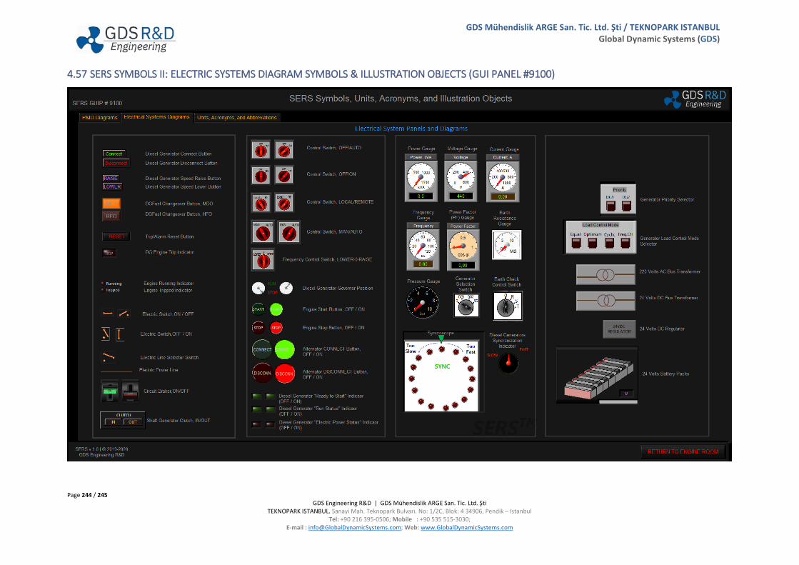
Page 244 / 245 GDS Engineering R&D | GDS Mühendislik ARGE San. Tic. Ltd. Şti
TEKNOPARK ISTANBUL. Sanayi Mah. Teknopark Bulvarı. No: 1/2C, Blok: 4 34906, Pendik – Istanbul Tel: +90 216 395-0506; Mobile : +90 535 515-3030;
E-mail : [email protected]; Web: www.GlobalDynamicSystems.com
GDS Mühendislik ARGE San. Tic. Ltd. Şti / TEKNOPARK ISTANBUL Global Dynamic Systems (GDS)
4.57 SERS SYMBOLS II: ELECTRIC SYSTEMS DIAGRAM SYMBOLS & ILLUSTRATION OBJECTS (GUI PANEL #9100)

Page 245 / 245 GDS Engineering R&D | GDS Mühendislik ARGE San. Tic. Ltd. Şti
TEKNOPARK ISTANBUL. Sanayi Mah. Teknopark Bulvarı. No: 1/2C, Blok: 4 34906, Pendik – Istanbul Tel: +90 216 395-0506; Mobile : +90 535 515-3030;
E-mail : [email protected]; Web: www.GlobalDynamicSystems.com
GDS Mühendislik ARGE San. Tic. Ltd. Şti / TEKNOPARK ISTANBUL Global Dynamic Systems (GDS)
4.58 SERS UNITS, ACRONYMS AND ABBREVIATIONS (GUI PANEL #9100)