Netlist to GDS IC flow using Mentor Graphics Toolset
18
AUTOCELL | Nireekshan Kumar Sodavaram Sodavaram Nireekshan Kumar Network to GDS using Mentor Toolset ASIC Synthesis using Leonardo Spectrum: RTL VHDL/Verilog design is converted into foundry specific verilog gate level netlist using Leonardo Spectrum. Follow are the steps: 1. Open Leonardo Spectrum in Level-3 option. 2. Perform the following steps in the command prompt of Leonardo spectrum a. Move to the netlist folder. prompt% cd <netlist_dir> b. Load the technology library. prompt% load_library $ADK/technology/leonardo/tsmc035_typ.syn c. Read in the RTL design. prompt% read <netlist_dir>/counter.vhd d. Set the optimization option prompt% optimize e. Finally write out the Verilog netlist prompt% write counter_035.v In summary, this would load the technology library we have given with the data. Then load the counter.vhd netlist and optimize it for the library that is loaded. The last step writes out a gate level verilog netlist which can be taken inside ICStation. P.S: The gate level netlist has to be in verilog format since IC Station accepts only verilog. Hence whether your RTL is in VHDL or Verilog, write out a verilog gate level netlist from Leonardo Spectrum
Transcript of Netlist to GDS IC flow using Mentor Graphics Toolset

AUTOCELL | Nireekshan Kumar Sodavaram
Sodavaram Nireekshan Kumar
Network to GDS using Mentor Toolset
ASIC Synthesis using Leonardo Spectrum:
RTL VHDL/Verilog design is converted into foundry specific verilog gate
level netlist using Leonardo Spectrum. Follow are the steps:
1. Open Leonardo Spectrum in Level-3 option.
2. Perform the following steps in the command prompt of Leonardo
spectrum
a. Move to the netlist folder.
prompt% cd <netlist_dir>
b. Load the technology library. prompt% load_library $ADK/technology/leonardo/tsmc035_typ.syn
c. Read in the RTL design.
prompt% read <netlist_dir>/counter.vhd
d. Set the optimization option
prompt% optimize
e. Finally write out the Verilog netlist
prompt% write counter_035.v
In summary, this would load the technology library we have given with the
data. Then load the counter.vhd netlist and optimize it for the library that is
loaded. The last step writes out a gate level verilog netlist which can be
taken inside ICStation.
P.S: The gate level netlist has to be in verilog format since IC Station
accepts only verilog. Hence whether your RTL is in VHDL or Verilog, write
out a verilog gate level netlist from Leonardo Spectrum
AUTOCELL | Nireekshan Kumar Sodavaram
Sodavaram Nireekshan Kumar
Place and Route using IC Station and ICBlocks:
1. Source the IC Station setup file
Prompt% source <install_dir>ic.cshrc
2. Change directory
Prompt% cd <install_dir>/work
3. Invoke IC Station using the following command
Prompt% ic &
Note : You should be having a verilog netlist ready by this time.
4. Read in the verilog netlist.
a. Goto Session Palette:
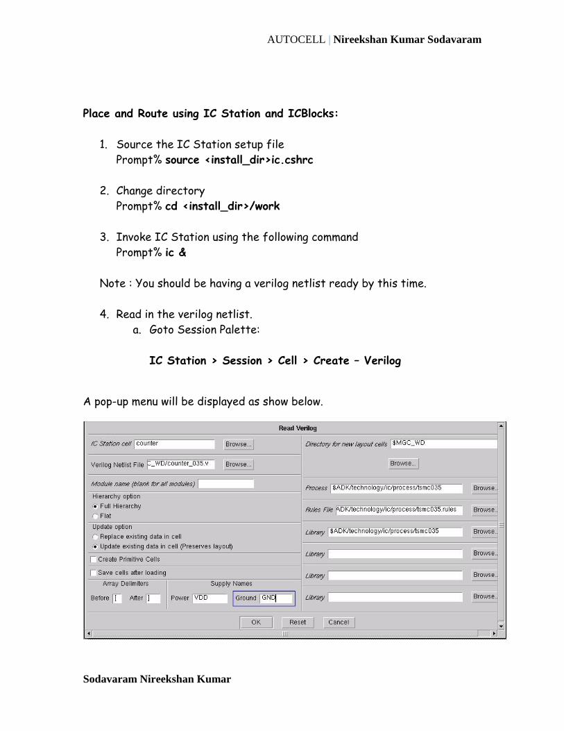
IC Station > Session > Cell > Create – Verilog
A pop-up menu will be displayed as show below.

AUTOCELL | Nireekshan Kumar Sodavaram
Sodavaram Nireekshan Kumar
Fill in the information as given below and press OK tab.
Cell name: counter
Verilog netlist: <netlist_dir>/counter_035.v
Process: $ADK/technology/ic/process/tsmc035
Library: $ADK/technology/ic/process/tsmc035
Rules File: $ADK/technology/ic/process/tsmc035.rules
On successful read in of the Verilog netlist, layout window with name
counter opens up as shown below.
b. On your right is the IC Palettes. Click on “Floorplan” under IC
Blocks.
IC Palettes > IC Blocks > Floorplan

AUTOCELL | Nireekshan Kumar Sodavaram
Sodavaram Nireekshan Kumar
c. This opens the Floorplan palette. Click on “Autofp”.
Floorplan > Autofp

AUTOCELL | Nireekshan Kumar Sodavaram
Sodavaram Nireekshan Kumar
d. The Auto Floorplan pop-up menu will be displayed as show above.
Click on “OK” with the default settings.
e. Floor plan for the design will be displayed in the layout window
as shown below.

AUTOCELL | Nireekshan Kumar Sodavaram
Sodavaram Nireekshan Kumar
f. Click on “P & R” tab under Palette section.
Floorplan > Palette > P & R
This opens the Place and Route palette.
Now you are ready to place the Standard Cells & Route the
nets.
Goto the AutoPlace section of this palette and click the StdCel
tab.
Place and Route > Autoplace > StdCel

AUTOCELL | Nireekshan Kumar Sodavaram
Sodavaram Nireekshan Kumar
This places the Standard Cells in the layout window.
The Yellow Lines you see on the layout are called “Fly Lines”.
It indicates the connectivity between the Cells.
The next step will be to Route these Fly Lines (nets).
Goto the Auto Route section of this palette and click the All tab.
Place and Route > Auto Route > All

AUTOCELL | Nireekshan Kumar Sodavaram
Sodavaram Nireekshan Kumar
Click “OK” for default settings.
AUTOCELL | Nireekshan Kumar Sodavaram
Sodavaram Nireekshan Kumar
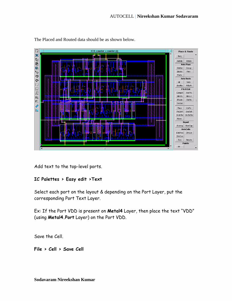
The Placed and Routed data should be as shown below.
Add text to the top-level ports.
IC Palettes > Easy edit >Text
Select each port on the layout & depending on the Port Layer, put the
corresponding Port Text Layer.
Ex: If the Port VDD is present on Metal4 Layer, then place the text “VDD”
(using Metal4.Port Layer) on the Port VDD.
Save the Cell.
File > Cell > Save Cell
AUTOCELL | Nireekshan Kumar Sodavaram
Sodavaram Nireekshan Kumar
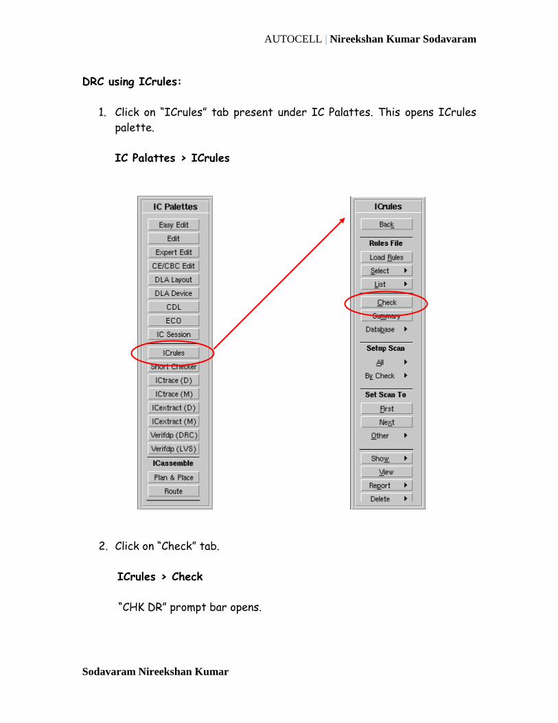
DRC using ICrules:
1. Click on “ICrules” tab present under IC Palattes. This opens ICrules
palette.
IC Palattes > ICrules
2. Click on “Check” tab.
ICrules > Check
“CHK DR” prompt bar opens.

AUTOCELL | Nireekshan Kumar Sodavaram
Sodavaram Nireekshan Kumar
Press “OK” to run DRC over the whole design.
3. The following options helps in debugging the DRC errors.
Using the above options rectify all the DRC errors.
Now move to the next section.
This opens the DRC Summary Report
Highlights the first DRC error
Highlights the next DRC errors one by one

AUTOCELL | Nireekshan Kumar Sodavaram
Sodavaram Nireekshan Kumar
LVS using Ictrace:
1. Click on “ICtrace(M)” tab present under IC Palattes. This opens
ICtrace palette.
Note: ICtrace(M) is for a hierarchical design and ICtrace(D) is for a
flat design.
IC Palattes > ICtrace(M)
2. Load the LVS rule file. Click “Load Rules” tab on the ICtrace palatte.
ICtrace (M) > Load Rules
This opens the Load Rules dialog box. Fill in the following information.
Rule File: $ADK/technology/ic/tsmc035.rules

AUTOCELL | Nireekshan Kumar Sodavaram
Sodavaram Nireekshan Kumar
Press “OK” to execute the dialog box.
3. Click “LVS” tab on the ICtrace palatte. This opens the LVS dialog box.
ICtrace (M) > LVS
Fill in the following information:
Report Name: counter_lvs.rep
Source Name: counter_035.spi
Source Type: spice
Subckt Name: counter
Press “OK” to run LVS.
AUTOCELL | Nireekshan Kumar Sodavaram
Sodavaram Nireekshan Kumar
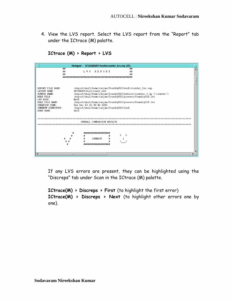
4. View the LVS report. Select the LVS report from the “Report” tab
under the ICtrace (M) palatte.
ICtrace (M) > Report > LVS
If any LVS errors are present, they can be highlighted using the
“Discreps” tab under Scan in the ICtrace (M) palatte.
ICtrace(M) > Discreps > First (to highlight the first error)
ICtrace(M) > Discreps > Next (to highlight other errors one by
one).
AUTOCELL | Nireekshan Kumar Sodavaram
Sodavaram Nireekshan Kumar
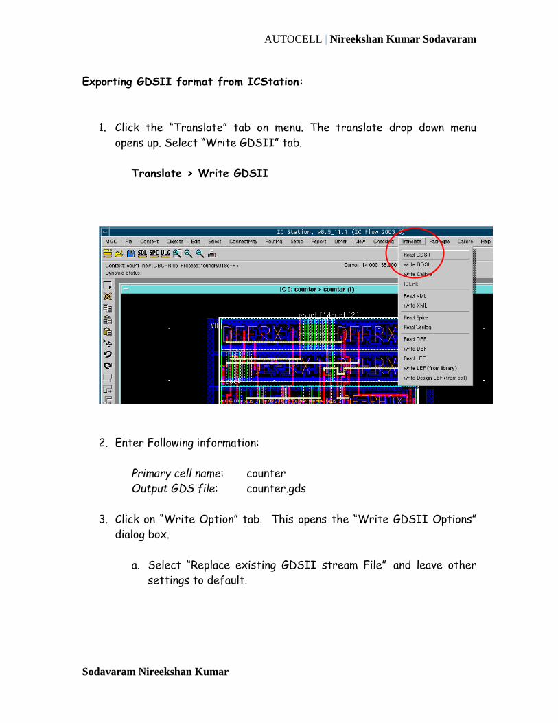
Exporting GDSII format from ICStation:
1. Click the “Translate” tab on menu. The translate drop down menu
opens up. Select “Write GDSII” tab.
Translate > Write GDSII
2. Enter Following information:
Primary cell name: counter
Output GDS file: counter.gds
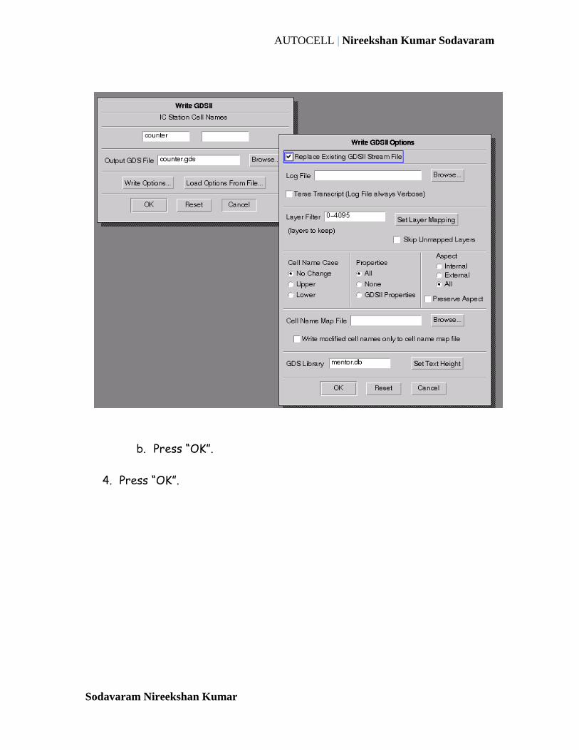
3. Click on “Write Option” tab. This opens the “Write GDSII Options”
dialog box.
a. Select “Replace existing GDSII stream File” and leave other
settings to default.
AUTOCELL | Nireekshan Kumar Sodavaram
Sodavaram Nireekshan Kumar
b. Press “OK”.
4. Press “OK”.

AUTOCELL | Nireekshan Kumar Sodavaram
Sodavaram Nireekshan Kumar
Parasitic Extraction using Calibre xRC
1. Invoke Calibre PEX
Click Calibre > Run PEX in the ICstation Menu
In the Path to Calibre Menu, type $CAL_HOME. If Calibre
doesn’t invoke, then browse and select the path to Calibre
Installation Directory.
Click OK
2. Click “Cancel” in “Load Runset File” dialog box.
3. Fill in the following information
In the Rule tab:
a. Calibre-PEX Rule File: $ADK/technology/ic/tsmc035.rules
b. Calibre-PEX Run Directory: <install.dir>/work
In the Inputs tab:
In Layout tab fill in the following information
a. Select “Import layout database from layout viewer”
b. Primary Cell: counter
c. Leave the File tab as it is.
In Netlist tab fill in the following information
a. Files: counter.v
b. Netlist: Verilog
c. Unselect “import netlist from schematic viewer”
d. Primary Cell: counter
In H-Cells tab fill in the following information
1. Unselect “Match cells by name (automatch)”
2. Select Use LVS H-cells file
3. File: $ADK/technology/adk.hcell
4. PEX X-cell: $ADK/technology/adk.hcell
5. From Setup Menu Invoke Verilog Translator
Setup -> Verilog Translator

AUTOCELL | Nireekshan Kumar Sodavaram
Sodavaram Nireekshan Kumar
Enter following information
In Libraries Tab
a. SPICE Library Files: $ADK/technology/adk.spi
b. Include SPICE Files: $ADK/technology/adk.spi
c. Click OK
In Strings Tab
a. Connect pins with 0 value to net: GND
b. Connect pins with 1 value to net: VDD
4. In the output tab:
Extraction Type: Gate Level & RCC
In Netlist tab fill in the following information
i. Format: ELDO
ii. Use Name FROM : Source
iii. File: counter.eldo
iv. Select "View netlist after PEX finishes”
In "Extract parasitics for" section
a. Select "All nets,except" : VDD GND
You have completed this lab.