Gas hydrate petroleum systems: what constitutes the "seal"?
18
Gas hydrate petroleum systems: What constitutes the “seal”? Junbong Jang 1 , William F. Waite 2 , and Laura A. Stern 3 Abstract The gas hydrate petroleum system (GHPS) approach, which has been used to characterize gas hydrates in nature, uses three distinct components: a methane source, a methane migration pathway, and a reservoir that not only contains gas hydrate, but also acts as a seal to prevent methane loss. Unlike GHPS, a traditional petroleum system (PS) approach further distinguishes between the reservoir, a unit with generally coarser sediment grains, and a separate overlying seal unit with generally finer sediment grains. Adopting this tradi- tional PS distinction in the GHPS approach facilitates assessments of reservoir growth and production po- tential. The significance of the seal for the formation of a gas hydrate reservoir as well as for efficiency in methane extraction from the reservoir as an energy resource is evident in findings from recent offshore field expeditions, such as India’s second National Gas Hydrate Program expedition (NGHP-02). In regard to gas hydrate-bearing reservoir formations, the NGHP-02 gas chemistry data indicate a primarily microbial methane source. Fine-grained seal sediment in contact with coarser grained reservoir sediment can facilitate that mi- crobial methane production. Logging-while-drilling and sediment core data also indicate that the overlying fine-grained seal sediment is less permeable than the underlying, highly gas hydrate-saturated reservoir sediment. The overlying seal’s capacity to act as a low-permeability boundary is important not only for preventing methane migration out of the reservoir over time, but also for preventing water invasion into the reservoir during methane extraction from the reservoir. Ultimately, the presence of an overlying, fine- grained, low-permeability “seal” influences how gas hydrate initially forms in a coarse-grained reservoir and dictates how efficiently methane can be extracted as an energy resource from the gas hydrate reservoir via depressurization. Introduction Methane gas hydrate is a naturally occurring solid formed from methane and water (Sloan and Koh, 2007) that is stable at the moderate temperatures and elevated pressures found primarily in marine continental slope sediments and within or beneath permafrost-associated sediments (Kvenvolden, 1993; Collett et al., 2009). Methane gas hydrate, referred to here as gas hydrate, is inferred to exist in quantities large enough to re- present a potential global energy resource (Boswell and Collett, 2011; Johnson, 2011; Wallmann et al., 2012). Like other hydrocarbon energy resources, gas hydrate occurrences have been described in terms of the petro- leum system (PS) approach, albeit with a modification described below (Collett, 1995; Frye, 2008; Collett et al., 2009; Max and Johnson, 2014). The traditional PS approach has four elements (Ma- goon, 1988): (1) a source or sediment interval in which hydrocarbons are generated; (2) migration pathways, which are permeable conduits through which hydrocar- bons can migrate from a source into a reservoir sedi- ment unit; (3) a reservoir, generally a coarse-grained sediment unit with a permeable pore-space network capable of holding hydrocarbons; and (4) an overlying seal of generally fine-grained, impermeable sediment capable of retaining the hydrocarbons within the reser- voir unit (Ulmishek, 1988). In contrast, the modified gas hydrate petroleum system (GHPS) has commonly been considered to have only three distinct elements, differ- ing from the traditional PS in that the gas hydrate res- ervoir unit is itself considered to be the seal (Collett and Kvenvolden, 1988; Max and Johnson, 2014). This modi- fication reflects the significant permeability reduction that occurs as solid gas hydrate forms and builds to higher gas hydrate saturations within the reservoir unit (Rempel and Buffett, 1997; Nimblett and Ruppel, 2003). High gas hydrate saturations in a coarse-grained reser- voir can unquestionably cause the effective permeability 1 Integrated Statistics Inc., Contracted to U.S. Geological Survey, Woods Hole, Massachusetts, USA; presently Department of Civil Engineering, Dong-A University, Busan, South Korea. E-mail: [email protected]. 2 U.S. Geological Survey, Woods Hole, Massachusetts, USA. E-mail: [email protected]. 3 U.S. Geological Survey, Menlo Park, California, USA. E-mail: [email protected]. Manuscript received by the Editor 20 February 2019; revised manuscript received 4 December 2019; published ahead of production 09 January 2020; published online 2 March 2020. This paper appears in Interpretation, Vol. 8, No. 2 (May 2020); p. T231–T248, 11 FIGS. http://dx.doi.org/10.1190/INT-2019-0026.1. © 2020 Society of Exploration Geophysicists and American Association of Petroleum Geologists. All rights reserved. t Technical papers Interpretation / May 2020 T231 Interpretation / May 2020 T231 Downloaded from https://pubs.geoscienceworld.org/interpretation/article-pdf/doi/10.1190/INT-2019-0026.1/4960317/int-2019-0026.1.pdf?casa_token=CeuYDf8A8V4AAAAA:dcWyYhgKtzGllWkcLSwDi9X2CCPeCCKpldR4zPs by USGS Library user on 07 April 2020
-
Upload
khangminh22 -
Category
Documents
-
view
4 -
download
0
Transcript of Gas hydrate petroleum systems: what constitutes the "seal"?
Gas hydrate petroleum systems: What constitutes the “seal”?
Junbong Jang1, William F. Waite2, and Laura A. Stern3
Abstract
The gas hydrate petroleum system (GHPS) approach, which has been used to characterize gas hydrates innature, uses three distinct components: a methane source, a methane migration pathway, and a reservoir thatnot only contains gas hydrate, but also acts as a seal to prevent methane loss. Unlike GHPS, a traditionalpetroleum system (PS) approach further distinguishes between the reservoir, a unit with generally coarsersediment grains, and a separate overlying seal unit with generally finer sediment grains. Adopting this tradi-tional PS distinction in the GHPS approach facilitates assessments of reservoir growth and production po-tential. The significance of the seal for the formation of a gas hydrate reservoir as well as for efficiency inmethane extraction from the reservoir as an energy resource is evident in findings from recent offshore fieldexpeditions, such as India’s second National Gas Hydrate Program expedition (NGHP-02). In regard to gashydrate-bearing reservoir formations, the NGHP-02 gas chemistry data indicate a primarily microbial methanesource. Fine-grained seal sediment in contact with coarser grained reservoir sediment can facilitate that mi-crobial methane production. Logging-while-drilling and sediment core data also indicate that the overlyingfine-grained seal sediment is less permeable than the underlying, highly gas hydrate-saturated reservoirsediment. The overlying seal’s capacity to act as a low-permeability boundary is important not only forpreventing methane migration out of the reservoir over time, but also for preventing water invasion intothe reservoir during methane extraction from the reservoir. Ultimately, the presence of an overlying, fine-grained, low-permeability “seal” influences how gas hydrate initially forms in a coarse-grained reservoirand dictates how efficiently methane can be extracted as an energy resource from the gas hydrate reservoirvia depressurization.
IntroductionMethane gas hydrate is a naturally occurring solid
formed from methane and water (Sloan and Koh, 2007)that is stable at the moderate temperatures and elevatedpressures found primarily in marine continental slopesediments and within or beneath permafrost-associatedsediments (Kvenvolden, 1993; Collett et al., 2009).Methane gas hydrate, referred to here as gas hydrate,is inferred to exist in quantities large enough to re-present a potential global energy resource (Boswell andCollett, 2011; Johnson, 2011; Wallmann et al., 2012).Like other hydrocarbon energy resources, gas hydrateoccurrences have been described in terms of the petro-leum system (PS) approach, albeit with a modificationdescribed below (Collett, 1995; Frye, 2008; Collett et al.,2009; Max and Johnson, 2014).
The traditional PS approach has four elements (Ma-goon, 1988): (1) a source or sediment interval in whichhydrocarbons are generated; (2) migration pathways,
which are permeable conduits through which hydrocar-bons can migrate from a source into a reservoir sedi-ment unit; (3) a reservoir, generally a coarse-grainedsediment unit with a permeable pore-space networkcapable of holding hydrocarbons; and (4) an overlyingseal of generally fine-grained, impermeable sedimentcapable of retaining the hydrocarbons within the reser-voir unit (Ulmishek, 1988). In contrast, the modified gashydrate petroleum system (GHPS) has commonly beenconsidered to have only three distinct elements, differ-ing from the traditional PS in that the gas hydrate res-ervoir unit is itself considered to be the seal (Collett andKvenvolden, 1988; Max and Johnson, 2014). This modi-fication reflects the significant permeability reductionthat occurs as solid gas hydrate forms and builds tohigher gas hydrate saturations within the reservoir unit(Rempel and Buffett, 1997; Nimblett and Ruppel, 2003).
High gas hydrate saturations in a coarse-grained reser-voir can unquestionably cause the effective permeability
1Integrated Statistics Inc., Contracted to U.S. Geological Survey, Woods Hole, Massachusetts, USA; presently Department of Civil Engineering,Dong-A University, Busan, South Korea. E-mail: [email protected].
2U.S. Geological Survey, Woods Hole, Massachusetts, USA. E-mail: [email protected]. Geological Survey, Menlo Park, California, USA. E-mail: [email protected] received by the Editor 20 February 2019; revised manuscript received 4 December 2019; published ahead of production 09 January
2020; published online 2 March 2020. This paper appears in Interpretation, Vol. 8, No. 2 (May 2020); p. T231–T248, 11 FIGS.http://dx.doi.org/10.1190/INT-2019-0026.1. © 2020 Society of Exploration Geophysicists and American Association of Petroleum Geologists. All rights reserved.
t
Technical papers
Interpretation / May 2020 T231Interpretation / May 2020 T231
Downloaded from https://pubs.geoscienceworld.org/interpretation/article-pdf/doi/10.1190/INT-2019-0026.1/4960317/int-2019-0026.1.pdf?casa_token=CeuYDf8A8V4AAAAA:dcWyYhgKtzGllWkcLSwDi9X2CCPeCCKpldR4zPs5Z3fBrfSSCNyblDKbiK58XFgArOdUXwby USGS Library useron 07 April 2020

(permeability to water in the presence of gas hydrate keff )to be orders of magnitude lower than the intrinsic per-meability (the permeability to water in the absence of gashydrate kint). Values of keff in naturally occurring, coarse-grained, gas hydrate reservoir sediments recovered aspressure cores have been found to range between ap-proximately 1 and 100 mD (mD ¼ millidarcy ¼ 9.869 ×10⁻¹⁶ m2), with corresponding kint values of approxi-mately 1000–10,000 mD (Konno et al., 2015; Priest et al.,2015, 2019; Santamarina et al., 2015; Boswell et al., 2019b;Yoneda et al., 2019).
In spite of the capacity for gas hydrate to dramati-cally reduce permeability within the coarse-grained res-ervoir unit, overlying fine-grained sediment is likelyproviding the limiting permeability for fluid flow. Forexample, the permeability of fine-grained sedimentoverlying a significant gas hydrate reservoir in theKrishna-Godavari (KG) Basin, offshore eastern India(Moridis et al., 2019; Waite et al., 2019a), was measuredby three different laboratories using a range of directand inferred measurement techniques and found torange between 0.012 and 0.052 mD (Dai et al., 2019;Jang et al., 2019a; Priest et al., 2019), two orders of mag-nitude below the lowest typical keff measured on gashydrate-bearing pressure cores in the NGHP-02 pro-gram (Yoneda et al., 2019).
The low permeability of an overlying, fine-grainedlayer relative to an underlying, highly gas hydrate-satu-rated reservoir points to the importance of consideringthe overlying sediment as the functional seal element ina GHPS approach. The present study uses examplesfrom the NGHP-02 expedition to illustrate the impor-tance of the overlying sediment’s seal characteristicsin facilitating the accumulation of gas hydrate in the res-ervoir and the efficiency with which methane can beextracted from the reservoir as an energy resource.This study recommends specifically testing and charac-terizing the overlying sediment as a traditional seal unitfor the underlying gas hydrate reservoir.
Geologic settingThis study used field data from India’s second Na-
tional Gas Hydrate Program expedition (NGHP-02),which collected seismic, logging, and coring data to in-vestigate natural gas hydrate in the KG Basin in the In-dian Ocean as a potential gas resource (Kumar et al.,2019; Shukla et al., 2019b). The NGHP-02 expeditionfound thick, highly gas hydrate-saturated reservoirs.Based on remote sensing and core measurement datacollected during the expedition, reservoir formationprocesses have been inferred (Dixit et al., 2019; Ijiriet al., 2019; Kinoshita et al., 2019; Saito et al., 2019;Collett et al., 2019), and reservoir production has beenmodeled to estimate the potential gas production rates(Konno et al., 2019; Moridis et al., 2019; Myshakinet al., 2019).
Among the NGHP-02 study locations (Figure 1), twodistinct geologic structures in the KG Basin were se-lected as sites for this work to show the significance
of the overlying fine-grained sediment’s role as a sealfor the underlying coarser grained gas hydrate-bearingreservoir. As can be seen from the seismic data inFigures 2 and 3, the selected sites show strong seismicreflections (e.g., 3.7–3.8 ms two-way traveltime, ap-proximately 270–290 mbsf in Figure 2; 210–270 mbsfin Figure 3) indicating coarse-grained units hostinggas hydrate, but the geologic structures differ in thetwo areas (Collett et al., 2019; Jang et al., 2019b; Shuklaet al., 2019a, 2019b; Waite et al., 2019a). Detailed de-scriptions of the geologic history that created the gashydrate reservoir structures are provided by Collettet al. (2019), Radhakrishna et al. (2012), and Singh(2014). For the purpose of this study, only the geometryand characteristics of the system structures themselvesare discussed: Area B has an anticline and synclinestructure (Figure 2), whereas Area C has a channel-levee system (Figure 3). In each case, the primarycoarse-grained gas hydrate reservoir underlies a finergrained interval. As discussed in this work, differencesin the overlying sediment composition, depositionalenvironment, and deformational history combine tocause intersite variations in the sealing properties ofthe sediment overlying the primary gas hydrate-satu-rated reservoir layers.
MethodsDownhole and laboratory studies on material col-
lected from sites NGHP-02-16 and -23 in Area B (Fig-ure 2) and sites NGHP-02-08 and -09 in Area C(Figure 3) are used to compare the impact of overlyingfine-grained sediment seals on two gas hydrate reser-voir structures.
Field measurementsNGHP-02 was a comprehensive project, from which
several insights can be drawn from regional seismicdata to establish the geologic structure (Collett et al.,2019; Shukla et al., 2019a, 2019b). More insights can bedrawn from geochemical analyses of gas and porewater recovered from gas hydrate-bearing pressurecores to infer the methane source for the systems stud-ied here (Holland et al., 2019; Ijiri et al., 2019; Kida et al.,2019). Additionally, logging-while-drilling (LWD) dataand core-based measurements collected during NGHP-02are used to identify and characterize the fine-grainedseal layers and the underlying primary gas hydrate-bearing reservoirs. The downhole LWD profiles usedin this work are the calculated density-porosity, nuclearmagnetic resonance (NMR) estimates of permeability,P-wave velocity VP, resistivity-based gas hydrate satu-ration estimates, and clay mineral, quartz-feldspar-mica(QFM) content (Jang et al., 2019b; Waite et al., 2019a).
Although the LWD gamma ray log is often used tocharacterize the downhole lithology, Areas B and Care characterized by anomalous gamma results that ob-scure the in situ lithology. Typically, fine-grained sedi-ment is characterized by higher gamma ray responsesbecause those lithologies have higher concentrations of
T232 Interpretation / May 2020
Downloaded from https://pubs.geoscienceworld.org/interpretation/article-pdf/doi/10.1190/INT-2019-0026.1/4960317/int-2019-0026.1.pdf?casa_token=CeuYDf8A8V4AAAAA:dcWyYhgKtzGllWkcLSwDi9X2CCPeCCKpldR4zPs5Z3fBrfSSCNyblDKbiK58XFgArOdUXwby USGS Library useron 07 April 2020
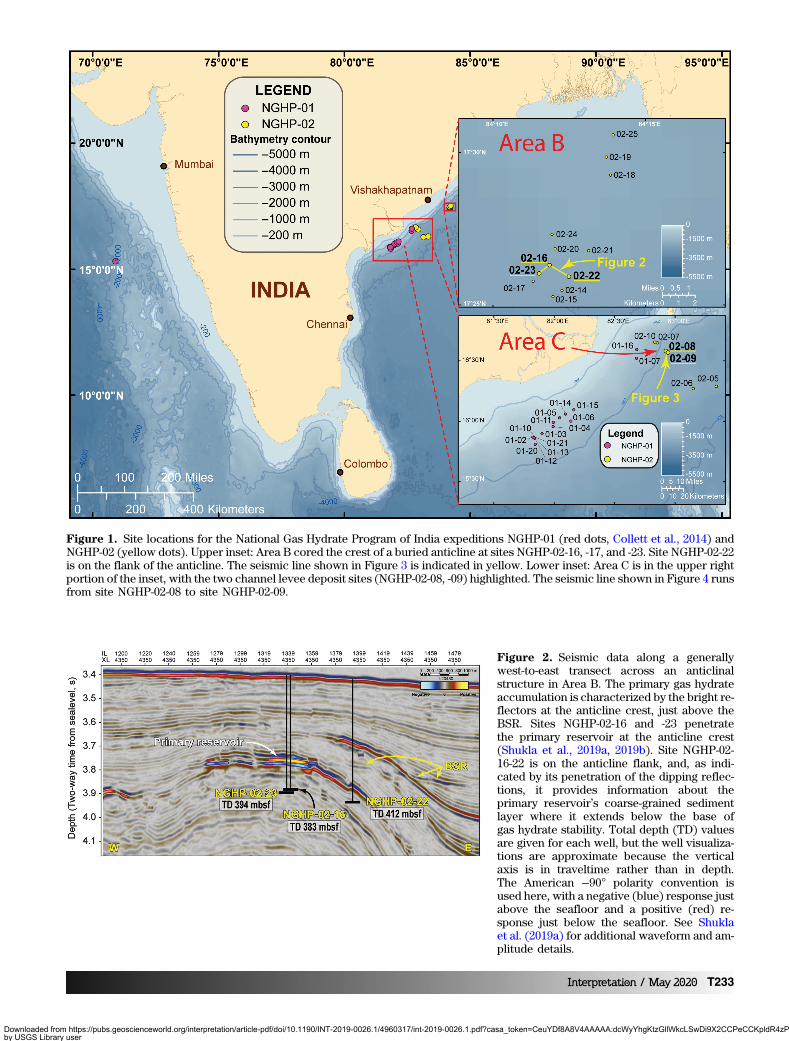
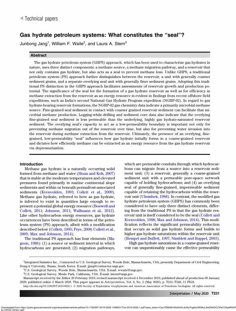
Figure 1. Site locations for the National Gas Hydrate Program of India expeditions NGHP-01 (red dots, Collett et al., 2014) andNGHP-02 (yellow dots). Upper inset: Area B cored the crest of a buried anticline at sites NGHP-02-16, -17, and -23. Site NGHP-02-22is on the flank of the anticline. The seismic line shown in Figure 3 is indicated in yellow. Lower inset: Area C is in the upper rightportion of the inset, with the two channel levee deposit sites (NGHP-02-08, -09) highlighted. The seismic line shown in Figure 4 runsfrom site NGHP-02-08 to site NGHP-02-09.
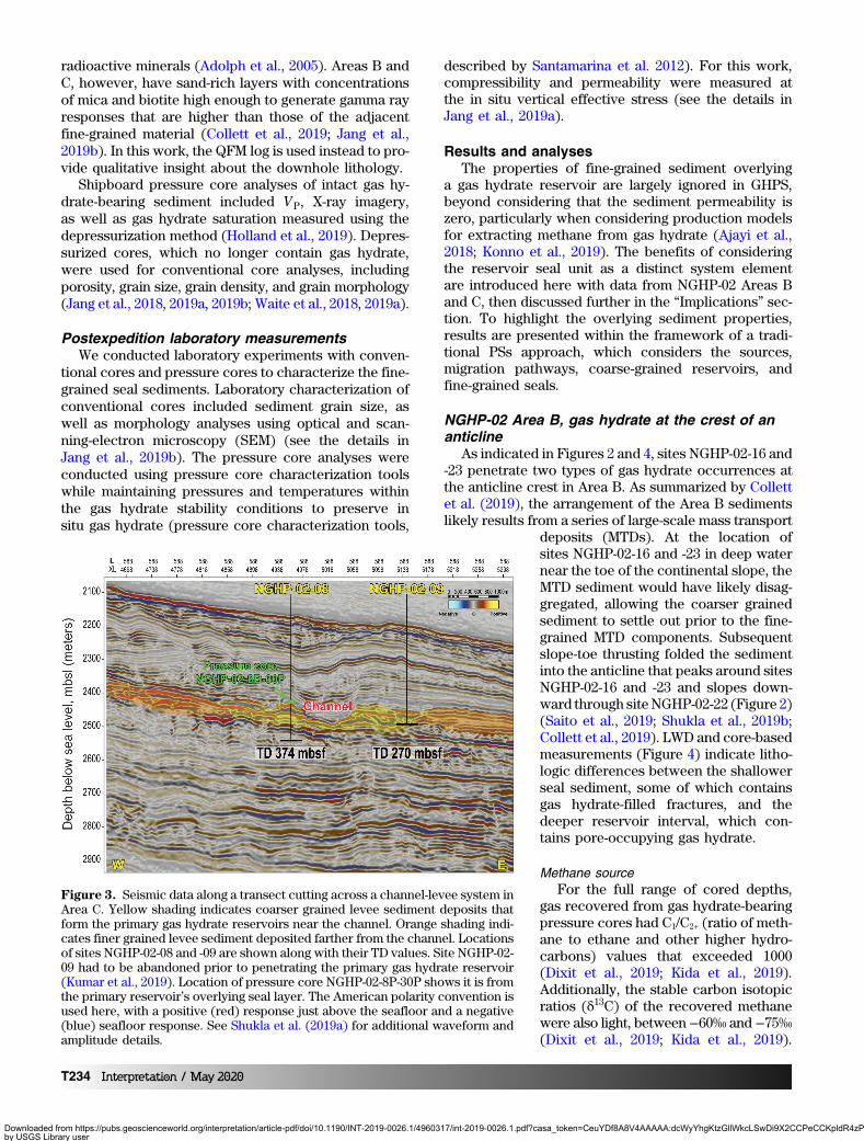
Figure 2. Seismic data along a generallywest-to-east transect across an anticlinalstructure in Area B. The primary gas hydrateaccumulation is characterized by the bright re-flectors at the anticline crest, just above theBSR. Sites NGHP-02-16 and -23 penetratethe primary reservoir at the anticline crest(Shukla et al., 2019a, 2019b). Site NGHP-02-16-22 is on the anticline flank, and, as indi-cated by its penetration of the dipping reflec-tions, it provides information about theprimary reservoir’s coarse-grained sedimentlayer where it extends below the base ofgas hydrate stability. Total depth (TD) valuesare given for each well, but the well visualiza-tions are approximate because the verticalaxis is in traveltime rather than in depth.The American −90° polarity convention isused here, with a negative (blue) response justabove the seafloor and a positive (red) re-sponse just below the seafloor. See Shuklaet al. (2019a) for additional waveform and am-plitude details.
Interpretation / May 2020 T233
Downloaded from https://pubs.geoscienceworld.org/interpretation/article-pdf/doi/10.1190/INT-2019-0026.1/4960317/int-2019-0026.1.pdf?casa_token=CeuYDf8A8V4AAAAA:dcWyYhgKtzGllWkcLSwDi9X2CCPeCCKpldR4zPs5Z3fBrfSSCNyblDKbiK58XFgArOdUXwby USGS Library useron 07 April 2020
radioactive minerals (Adolph et al., 2005). Areas B andC, however, have sand-rich layers with concentrationsof mica and biotite high enough to generate gamma rayresponses that are higher than those of the adjacentfine-grained material (Collett et al., 2019; Jang et al.,2019b). In this work, the QFM log is used instead to pro-vide qualitative insight about the downhole lithology.
Shipboard pressure core analyses of intact gas hy-drate-bearing sediment included VP, X-ray imagery,as well as gas hydrate saturation measured using thedepressurization method (Holland et al., 2019). Depres-surized cores, which no longer contain gas hydrate,were used for conventional core analyses, includingporosity, grain size, grain density, and grain morphology(Jang et al., 2018, 2019a, 2019b; Waite et al., 2018, 2019a).
Postexpedition laboratory measurementsWe conducted laboratory experiments with conven-
tional cores and pressure cores to characterize the fine-grained seal sediments. Laboratory characterization ofconventional cores included sediment grain size, aswell as morphology analyses using optical and scan-ning-electron microscopy (SEM) (see the details inJang et al., 2019b). The pressure core analyses wereconducted using pressure core characterization toolswhile maintaining pressures and temperatures withinthe gas hydrate stability conditions to preserve insitu gas hydrate (pressure core characterization tools,
described by Santamarina et al. 2012). For this work,compressibility and permeability were measured atthe in situ vertical effective stress (see the details inJang et al., 2019a).
Results and analysesThe properties of fine-grained sediment overlying
a gas hydrate reservoir are largely ignored in GHPS,beyond considering that the sediment permeability iszero, particularly when considering production modelsfor extracting methane from gas hydrate (Ajayi et al.,2018; Konno et al., 2019). The benefits of consideringthe reservoir seal unit as a distinct system elementare introduced here with data from NGHP-02 Areas Band C, then discussed further in the “Implications” sec-tion. To highlight the overlying sediment properties,results are presented within the framework of a tradi-tional PSs approach, which considers the sources,migration pathways, coarse-grained reservoirs, andfine-grained seals.
NGHP-02 Area B, gas hydrate at the crest of ananticline
As indicated in Figures 2 and 4, sites NGHP-02-16 and-23 penetrate two types of gas hydrate occurrences atthe anticline crest in Area B. As summarized by Collettet al. (2019), the arrangement of the Area B sedimentslikely results from a series of large-scale mass transport
deposits (MTDs). At the location ofsites NGHP-02-16 and -23 in deep waternear the toe of the continental slope, theMTD sediment would have likely disag-gregated, allowing the coarser grainedsediment to settle out prior to the fine-grained MTD components. Subsequentslope-toe thrusting folded the sedimentinto the anticline that peaks around sitesNGHP-02-16 and -23 and slopes down-ward through siteNGHP-02-22 (Figure 2)(Saito et al., 2019; Shukla et al., 2019b;Collett et al., 2019). LWD and core-basedmeasurements (Figure 4) indicate litho-logic differences between the shallowerseal sediment, some of which containsgas hydrate-filled fractures, and thedeeper reservoir interval, which con-tains pore-occupying gas hydrate.
Methane sourceFor the full range of cored depths,
gas recovered from gas hydrate-bearingpressure cores had C1/C2+ (ratio of meth-ane to ethane and other higher hydro-carbons) values that exceeded 1000(Dixit et al., 2019; Kida et al., 2019).Additionally, the stable carbon isotopicratios (δ13C) of the recovered methanewere also light, between−60‰ and −75‰(Dixit et al., 2019; Kida et al., 2019).
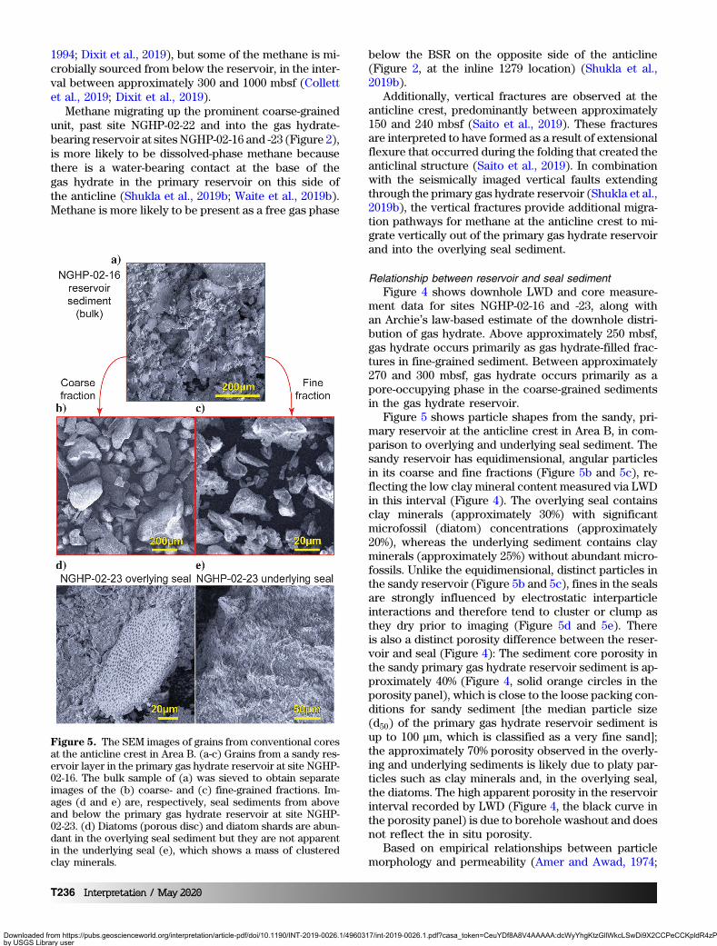
Figure 3. Seismic data along a transect cutting across a channel-levee system inArea C. Yellow shading indicates coarser grained levee sediment deposits thatform the primary gas hydrate reservoirs near the channel. Orange shading indi-cates finer grained levee sediment deposited farther from the channel. Locationsof sites NGHP-02-08 and -09 are shown along with their TD values. Site NGHP-02-09 had to be abandoned prior to penetrating the primary gas hydrate reservoir(Kumar et al., 2019). Location of pressure core NGHP-02-8P-30P shows it is fromthe primary reservoir’s overlying seal layer. The American polarity convention isused here, with a positive (red) response just above the seafloor and a negative(blue) seafloor response. See Shukla et al. (2019a) for additional waveform andamplitude details.
T234 Interpretation / May 2020
Downloaded from https://pubs.geoscienceworld.org/interpretation/article-pdf/doi/10.1190/INT-2019-0026.1/4960317/int-2019-0026.1.pdf?casa_token=CeuYDf8A8V4AAAAA:dcWyYhgKtzGllWkcLSwDi9X2CCPeCCKpldR4zPs5Z3fBrfSSCNyblDKbiK58XFgArOdUXwby USGS Library useron 07 April 2020

These characteristics indicate that gas at the anticlinehas a microbial origin (Collett et al., 2019; Dixit et al.,2019; Kida et al., 2019), which is supported by elevatedmethanogen concentrations culturedfrom sediments associated with the pri-mary Area B gas hydrate reservoir byTripathi et al. (2019).
Methane migration pathwaysAlthough LWD permeability measure-
ments were not made at sites NGHP-02-16 or -23, physical properties from LWDand recovered sediments (Figure 4) in-dicate that the coarsest material at thesetwo sites corresponds to the primary gashydrate reservoir (approximately 270–300 meters below seafloor, mbsf). Thiscoarse interval has the highest intrinsicpermeability in the system, discussedfurther in the next section. As indicatedin Figure 2, the bright seismic reflec-tions signifying this coarse-grained sedi-ment layer follow the geologic structuredown the flank of the anticline. Datafrom site NGHP-02-22, an LWD and cor-ing site located on the anticline flank,verified that this coarse-grained intervaldid in fact extend below the bottom-simulating reflector (BSR) (Jang et al.,2019b; Kumar et al., 2019).
Considering the higher permeabilityof this coarse-grained layer relative tothe adjacent fine-grained sediments,along with its anticlinal geometry, thecoarse-grained layer has been inter-preted as an advective pathway formethane to migrate from below the BSRup into the primary gas hydrate reser-voir at the anticline crest (Jang et al.,2019b; Saito et al., 2019). This interpre-tation is supported by the pore-water de-crease of Cl- with depth to near constantvalues (Ijiri et al., 2019). The profileshape is due to upward migration oflow-Cl- fluid into and through theprimary gas hydrate reservoir at theanticline crest (Ijiri et al., 2019). Mass-balance calculations by Ijiri et al. (2019)based on pore-water Cl- concentrationsand isotopic measurements of oxygenand deuterium from above and belowthe primary coarse-grained gas hydratereservoir indicate only 10%–20% of theupward advecting fluid is trapped in thereservoir interval.
The advecting fluid carries micro-bially sourced methane up to the pri-mary gas hydrate-bearing reservoir atthe Area B anticline crest (Dixit et al.,
2019). Some of that methane is recycled from gas hy-drate that was previously pushed below the base ofgas hydrate stability due to sedimentation (Paull et al.,
Figure 4. Physical properties from LWD and sediment core measurements forsites NGHP-02-16 and -23 in (a and b), respectively. Downhole traces are fromLWD, whereas point data (open and filled circles) are from laboratory measure-ments of recovered conventional and pressure cores. Green curves and opencircles represent fines (which are also represented by the clay mineral contentin the rightmost panel), and orange curves and solid circles represent sand(which is also represented by the QFM content in the rightmost panel). TheLWD porosity (black curve) is a density-based porosity calculated from theLWD bulk density log and grain density measurements on the recovered sedi-ment. The Archie-based gas hydrate saturation (calculation parameters for eachsite are given in Table 3 of Collett et al., 2019) use Ecoscope P40H phase resis-tivity data. In combination with the VP and mineral content results, the LWDresistivity data indicate two gas hydrate morphologies: generally pore-occupyinghydrate in the primary coarse-grained reservoir (the dark blue curve, which cor-relates with VP well above the background values and with reduced clay con-tent) and primarily gas hydrate-filled fractures in fine-grained sediment (the lightblue curve, which is not correlated with VP or with reduced clay content). Asnoted by Collett et al. (2019), gas hydrate saturations in the gas hydrate-filledfracture intervals are likely overestimated due to the vertically oriented fractures(Cook et al., 2010). The red horizontal line is the base of the gas hydrate occur-rence zone (Waite et al., 2019b). Figure modified from Jang et al. (2019b).
Interpretation / May 2020 T235
Downloaded from https://pubs.geoscienceworld.org/interpretation/article-pdf/doi/10.1190/INT-2019-0026.1/4960317/int-2019-0026.1.pdf?casa_token=CeuYDf8A8V4AAAAA:dcWyYhgKtzGllWkcLSwDi9X2CCPeCCKpldR4zPs5Z3fBrfSSCNyblDKbiK58XFgArOdUXwby USGS Library useron 07 April 2020
1994; Dixit et al., 2019), but some of the methane is mi-crobially sourced from below the reservoir, in the inter-val between approximately 300 and 1000 mbsf (Collettet al., 2019; Dixit et al., 2019).
Methane migrating up the prominent coarse-grainedunit, past site NGHP-02-22 and into the gas hydrate-bearing reservoir at sites NGHP-02-16 and -23 (Figure 2),is more likely to be dissolved-phase methane becausethere is a water-bearing contact at the base of thegas hydrate in the primary reservoir on this side ofthe anticline (Shukla et al., 2019b; Waite et al., 2019b).Methane is more likely to be present as a free gas phase
below the BSR on the opposite side of the anticline(Figure 2, at the inline 1279 location) (Shukla et al.,2019b).
Additionally, vertical fractures are observed at theanticline crest, predominantly between approximately150 and 240 mbsf (Saito et al., 2019). These fracturesare interpreted to have formed as a result of extensionalflexure that occurred during the folding that created theanticlinal structure (Saito et al., 2019). In combinationwith the seismically imaged vertical faults extendingthrough the primary gas hydrate reservoir (Shukla et al.,2019b), the vertical fractures provide additional migra-tion pathways for methane at the anticline crest to mi-grate vertically out of the primary gas hydrate reservoirand into the overlying seal sediment.
Relationship between reservoir and seal sedimentFigure 4 shows downhole LWD and core measure-
ment data for sites NGHP-02-16 and -23, along withan Archie’s law-based estimate of the downhole distri-bution of gas hydrate. Above approximately 250 mbsf,gas hydrate occurs primarily as gas hydrate-filled frac-tures in fine-grained sediment. Between approximately270 and 300 mbsf, gas hydrate occurs primarily as apore-occupying phase in the coarse-grained sedimentsin the gas hydrate reservoir.
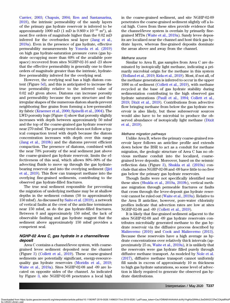
Figure 5 shows particle shapes from the sandy, pri-mary reservoir at the anticline crest in Area B, in com-parison to overlying and underlying seal sediment. Thesandy reservoir has equidimensional, angular particlesin its coarse and fine fractions (Figure 5b and 5c), re-flecting the low clay mineral content measured via LWDin this interval (Figure 4). The overlying seal containsclay minerals (approximately 30%) with significantmicrofossil (diatom) concentrations (approximately20%), whereas the underlying sediment contains clayminerals (approximately 25%) without abundant micro-fossils. Unlike the equidimensional, distinct particles inthe sandy reservoir (Figure 5b and 5c), fines in the sealsare strongly influenced by electrostatic interparticleinteractions and therefore tend to cluster or clump asthey dry prior to imaging (Figure 5d and 5e). Thereis also a distinct porosity difference between the reser-voir and seal (Figure 4): The sediment core porosity inthe sandy primary gas hydrate reservoir sediment is ap-proximately 40% (Figure 4, solid orange circles in theporosity panel), which is close to the loose packing con-ditions for sandy sediment [the median particle size(d50) of the primary gas hydrate reservoir sediment isup to 100 μm, which is classified as a very fine sand];the approximately 70% porosity observed in the overly-ing and underlying sediments is likely due to platy par-ticles such as clay minerals and, in the overlying seal,the diatoms. The high apparent porosity in the reservoirinterval recorded by LWD (Figure 4, the black curve inthe porosity panel) is due to borehole washout and doesnot reflect the in situ porosity.
Based on empirical relationships between particlemorphology and permeability (Amer and Awad, 1974;
Figure 5. The SEM images of grains from conventional coresat the anticline crest in Area B. (a-c) Grains from a sandy res-ervoir layer in the primary gas hydrate reservoir at site NGHP-02-16. The bulk sample of (a) was sieved to obtain separateimages of the (b) coarse- and (c) fine-grained fractions. Im-ages (d and e) are, respectively, seal sediments from aboveand below the primary gas hydrate reservoir at site NGHP-02-23. (d) Diatoms (porous disc) and diatom shards are abun-dant in the overlying seal sediment but they are not apparentin the underlying seal (e), which shows a mass of clusteredclay minerals.
T236 Interpretation / May 2020
Downloaded from https://pubs.geoscienceworld.org/interpretation/article-pdf/doi/10.1190/INT-2019-0026.1/4960317/int-2019-0026.1.pdf?casa_token=CeuYDf8A8V4AAAAA:dcWyYhgKtzGllWkcLSwDi9X2CCPeCCKpldR4zPs5Z3fBrfSSCNyblDKbiK58XFgArOdUXwby USGS Library useron 07 April 2020
Carrier, 2003; Chapuis, 2004; Ren and Santamarina,2018), the intrinsic permeability of the sandy layersof the primary gas hydrate reservoir is inferred to beapproximately 1000 mD (1 mD is 9.869 × 10⁻¹⁶ m2), al-most five orders of magnitude higher than the 0.02 mDinferred for the overburden seal layer (Jang et al.,2019a). Even in the presence of gas hydrate, effectivepermeability measurements by Yoneda et al. (2019)on high gas hydrate-saturation pressure cores (gas hy-drate occupying more than 60% of the available porespace) recovered from sites NGHP-02-16 and -23 showthat the effective permeability is generally one to threeorders of magnitude greater than the intrinsic, hydrate-free permeability inferred for the overlying seal.
However, the overlying seal has a high diatom con-tent (Figure 5d), and this is anticipated to increase thetrue permeability relative to the inferred value of0.02 mD given above. Diatoms can increase porosityand permeability because the open structure and theirregular shapes of the numerous diatom shards preventneighboring fine grains from forming a low-permeabil-ity fabric (Kraemer et al., 2000; Spinelli et al., 2004). TheLWD porosity logs (Figure 4) show that porosity slightlyincreases with depth between approximately 50 mbsfand the top of the coarse-grained gas hydrate reservoirnear 270 mbsf. The porosity trend does not follow a typ-ical compaction trend with depth because the diatomconcentration increases with depth over this range(Jang et al., 2019b) and the diatoms prevent efficientcompaction. The presence of diatoms, combined withthe near 70% porosity of the seal sediment just abovethe coarse-grained gas hydrate reservoir, limits the ef-fectiveness of this seal, which allows 80%–90% of theadvecting fluids to move up through the gas hydrate-bearing reservoir and into the overlying sediment (Ijiriet al., 2019). This flow can transport methane into theoverlying fine-grained sediments, contributing to theobserved gas hydrate-filled fractures.
The true seal sediment responsible for preventingthe migration of underlying methane may be at shallowdepths in the sediment column (50 to approximately150 mbsf). As discussed by Saito et al. (2019), a networkof vertical faults at the crest of the anticline terminatesnear 150 mbsf, as do the gas hydrate-filled fractures.Between 0 and approximately 150 mbsf, the lack ofobservable faulting and gas hydrate suggest that thesediment above approximately 150 mbsf provides acompetent seal.
NGHP-02 Area C, gas hydrate in a channel/leveedeposit
Area C contains a channel/levee system, with coarse-grained levee sediment deposited near the channel(Figure 3) (Collett et al., 2019). These coarse-grainedsediments are potentially significant, energy-resource-quality gas hydrate reservoirs (Moridis et al., 2019;Waite et al., 2019a). Sites NGHP-02-08 and -09 are lo-cated on opposite sides of the channel. As indicatedby Figure 3, site NGHP-02-08 penetrates a local high
in the coarse-grained sediment, and site NGHP-02-09penetrates the coarse-grained sediment slightly off a lo-cal high. Cores from these sites provide evidence thatthe channel/levee system is overlain by primarily fine-grained MTDs (Waite et al., 2019a). Sandy levee depos-its are localized near the channel and host thick gas hy-drate layers, whereas fine-grained deposits dominatethe areas above and away from the channel.
Methane sourceSimilar to Area B, gas samples from Area C are do-
minated by isotopically light methane, indicating a pri-marily microbial origin for the methane in this system(Holland et al., 2019; Kida et al., 2019). Most, if not all, ofthe methane generation is inferred to occur in the upper1000 m of sediment (Collett et al., 2019), with methanerecycled at the base of gas hydrate stability duringsedimentation contributing to the high observed gashydrate saturations (Paull et al., 1994; Collett et al.,2019; Dixit et al., 2019). Contributions from advectiveflow bringing methane from below the gas hydrate res-ervoir is also likely, but these subreservoir sourceswould also have to be microbial to produce the ob-served abundance of isotopically light methane (Dixitet al., 2019).
Methane migration pathwaysUnlike Area B, where the primary coarse-grained res-
ervoir layer follows an anticline profile and extendsdown below the BSR to act as a conduit for methanemigration, the geologic structure of Area C has no ob-vious methane conduit into the localized, coarse-grained levee deposits. Moreover, based on the seismicreflection data (Figure 3), Shukla et al. (2019a) con-clude that sites NGHP-02-08 and -09 have little to no freegas below the primary gas hydrate reservoirs.
Though faults were not specifically identified nearthese sites (Shukla et al., 2019a, 2019b), vertical meth-ane migration through permeable fractures or faultsthat cross through the levee-deposit gas hydrate reser-voir cannot be ruled out (Waite et al., 2019a). Relative tothe Area B anticline, however, pore-water chlorinityprofiles indicate that advection rates are low at sitesNGHP-02-08 and -09 (Collett et al., 2019).
It is likely that fine-grained sediment adjacent to thesites NGHP-02-08 and -09 gas hydrate reservoirs con-tributes microbially generated methane to the gas hy-drate reservoir via the diffusive process described byMalinverno (2010) and Cook and Malinverno (2013).Because these reservoirs have a high average as hy-drate concentrations over relatively thick intervals (ap-proximately 25 m, Waite et al., 2019a), it is unlikely thatthe reservoirs were gas hydrate filled purely throughdiffusive methane transport. As modeled by Nole et al.(2017), diffusive methane transport cannot uniformlyfill sands in excess of approximately 10 m thicknessto high gas hydrate saturations, so some level of advec-tion is likely required to generate the observed gas hy-drate distributions.
Interpretation / May 2020 T237
Downloaded from https://pubs.geoscienceworld.org/interpretation/article-pdf/doi/10.1190/INT-2019-0026.1/4960317/int-2019-0026.1.pdf?casa_token=CeuYDf8A8V4AAAAA:dcWyYhgKtzGllWkcLSwDi9X2CCPeCCKpldR4zPs5Z3fBrfSSCNyblDKbiK58XFgArOdUXwby USGS Library useron 07 April 2020

Relationship between reservoir and seal sedimentAs shown in Figure 6, most of the gas hydrate in Area
C is concentrated in the primary coarse-grained reser-voir (NGHP-02-08: approximately 250–270 mbsf, 30%–70% gas hydrate saturation; NGHP-02-09: approximately210–270 mbsf, which was the deepest logging depth, ap-proximately 50%–75% gas hydrate saturation). The res-ervoir sediment is generally much coarser at these sitesthan was found within Area B (compare Figures 5 and7). Like in the sediment above the primary Area B gashydrate reservoir, gas hydrate occurs as gas hydrate-
filled fractures in the fine-grained seal sediment of siteNGHP-02-08 (e.g., approximately 80–100 mbsf). Thesegas hydrate-filled fractures occur to a lesser extent atsite NGHP-02-08 than in Area B, and these featuresare absent in the site NGHP-02-09 seal sediment.Differences in the gas hydrate distributions betweenAreas B and C can be linked in part to the local seal-sediment lithology and in part to the seal sediment dep-ositional history: The Area C sites contain clay-rich, di-atom-free seal sediment (compare Figures 5 and 7), andunlike the Area B anticline sediment, the Area C sedi-
ments have not been extensively de-formed since their deposition.
The clay-rich fines above the levee-deposit gas hydrate reservoirs havemore classically shaped compactioncurves (Figure 6) than those that wereobserved at the Area B anticline (Fig-ure 4), and the seal porosity is below50% where the seal contacts the gas hy-drate reservoir. As observed in Area B,the core-derived porosity results arelower than the LWD measurement (Fig-ure 6, the solid orange circles and blackcurve in the porosity panel, respec-tively), indicating borehole washoutduring the LWD run that occurred inthe gas hydrate reservoir interval.
As shown in Figure 6, the LWD datafor Area C include permeability esti-mates based on the nuclear magneticresonance (NMR) tool. The NMRpermeability profiles show that thepermeability is higher, even in thecoarse-grained levee sediment wheregas hydrate is present and the LWD re-sults are not compromised by boreholewashout (Waite et al., 2019a), than it isin the hydrate-free overlying seal.
At site NGHP-02-09, the gas hydratesaturation profile shows gas hydratebeing constrained within the coarse-grained, low-clay-content reservoir sedi-ment in a pore-occupying morphologythat causes VP values to increase in cor-relation with the resistivity-based gashydrate saturation. At site NGHP-02-08, however, the gas hydrate saturationprofile indicates that gas hydrate alsofills fractures in the seal layer (Figure 6a,the light blue curve). As anticipated fora fracture-filling gas hydrate interval,VP is not correlated with the gas hydratesaturation, nor do grain sizes or claycontent vary from their backgroundvalues (Figure 6).
These observations indicate potentialdifferences in the quality of the seal sedi-ments overlying the coarse-grained gas
Figure 6. Physical properties from LWD and sediment core measurements forsites NGHP-02-08 and -09 in (a and b), respectively. The legend is identical toFigure 4, with the addition of LWD permeability measurements in the secondpanel: Downhole traces are from the LWD NMR tool, processed either accordingto the Timur-Coates approach (KT-C, black) or Schlumberger Doll Research ap-proach (kSDR, red) (described by Fujii et al., 2015). Permeability results for bothsites indicate that the fine-grained overlying seal has a lower permeability thanthe coarse-grained, primary gas hydrate-bearing reservoir. Gas hydrate-filledfractures appear in the seal sediment (light blue in [a]) overlying the primarygas hydrate reservoir at site NGHP-02-08 (dark blue in [a]), but no gas hy-drate-filled fractures are apparent in the site NGHP-02-09 overburden (dark bluein [b]). Figure modified from Waite et al. (2019a).
T238 Interpretation / May 2020
Downloaded from https://pubs.geoscienceworld.org/interpretation/article-pdf/doi/10.1190/INT-2019-0026.1/4960317/int-2019-0026.1.pdf?casa_token=CeuYDf8A8V4AAAAA:dcWyYhgKtzGllWkcLSwDi9X2CCPeCCKpldR4zPs5Z3fBrfSSCNyblDKbiK58XFgArOdUXwby USGS Library useron 07 April 2020

hydrate reservoirs in Area C. The site NGHP-02-08 sealis slightlymore permeable than the site NGHP-02-09 seal(Figure 6). Specifically, the NMR-derived kSDR estimateof the overlying seal permeability for site NGHP-02-08 is26 mD near the gas hydrate reservoir and 0.25 mD at103–212 mbsf, whereas that of site NGHP-02-09 is0.16 mD. The site NGHP-02-08 seal appears to allowmethane to migrate upward and form gas hydrate-filledfractures in the overlying fine-grained sediment.
The NMR-based permeability estimate, though usefulfor capturing the permeability change across the tran-sition between the reservoir and seal sediment, over-predicts the seal sediment permeabilities comparedwith the permeabilities measured directly on recoveredsediment (Fujii et al., 2015; Dai et al., 2017). As de-scribed below, two suggested sources — measurementtechnique and measurement resolution — likely con-tribute in this instance.
NMR-based permeability measurements have noflow direction associated with them, unlike direct,water-flow-based techniques, meaning that the NMRresults can be misleading where the permeability isanisotropic. For example, the horizontal permeabilitymeasured by water-flow-based techniques is one orderof magnitude greater than the vertical permeability forthe site NGHP-02-08 fine-grained seal (Dai et al., 2019).If the NMR result provides an average permeability overthe various flow directions, it should be higher than theflow-based vertical permeability results.
Vertical measurement resolution is another potentialsource of the discrepancy between NMR and directpermeability measurements. Though the seal sedimentis generally uniform in grain size, thin, mm-to-cm-scalecoarser grained layers are also present in Area C(Figure 8). The X-ray and microscopeimages in Figure 8 show a localizednonuniformity in the pressure-coredsediment. The thin layer near 247.6 mbsfcorresponds to a VP peak and a low-density (white) interval in the X-ray,the combination of which indicates gashydrate. Microscope images also indi-cate a distinct discrepancy between thelow- and high-VP sediment. The low-VPsediment contains fines, such as clayminerals, that cluster during the dryingprocess, rather than remaining as sepa-rate grains. The high-VP sediment con-tains equidimensional, angular grainsthat tend to form fabrics with largerpore spaces, which are critical for gashydrate formation (Uchida et al., 2009;Malinverno, 2010).
Because the core’s initial shipboardX-ray and VP scans located the seal sedi-ment’s nonuniformity (Holland et al.,2019; Jang et al., 2019a), the direct flowmeasurements by Jang et al. (2019a),which used 5–6 cm core subsections,
Figure 7. Shipboard natural-light images of depressurizedsediments from pressure cores collected from the coarse-grained levee interval from Area C. Scale beneath each imageis in centimeters. (a) Site NGHP-02-08, 269.6 mbsf: d50 was notmeasured, but it is visually estimated to be on the order of1 cm (10;000 μm). (b) Site NGHP-02-09, 257.3 mbsf: d50 is0.11 cm (1100 μm), with a clay content of only 0.3% (Waiteet al., 2019a). By comparison, d50 is of the order of 100 μmfor the coarse-grained reservoir at the crest of the Area B anti-cline (Jang et al., 2019b).
Figure 8. Shipboard P-wave velocity and X-ray image of pressure core NGHP-02-8B-30P, along with microscope images of subsections from the pressure core.The high-velocity anomaly at 247.6 mbsf is taken as an indicator of a thin, gashydrate-bearing layer. This layer corresponds to the low-density band (lightercolor) in the X-ray, and to coarser, lower clay-content sediment. Based onSEM-EDS (energy dispersive spectroscopy) of the thin interbed, the clear grainsare quartz, and black grains contain titanium and iron (possibly ilmenite or amember of the pyroxene group).
Interpretation / May 2020 T239
Downloaded from https://pubs.geoscienceworld.org/interpretation/article-pdf/doi/10.1190/INT-2019-0026.1/4960317/int-2019-0026.1.pdf?casa_token=CeuYDf8A8V4AAAAA:dcWyYhgKtzGllWkcLSwDi9X2CCPeCCKpldR4zPs5Z3fBrfSSCNyblDKbiK58XFgArOdUXwby USGS Library useron 07 April 2020
could be positioned specifically to avoid the coarse-grained interval. The NMR resolution, however, is120 cm in the vertical direction (Collett et al., 2015;Waite et al., 2019a), providing the average permeabilityof the bulk sediment. The NMR-based technique istherefore susceptible to having thin, coarse-grainedlayers increase the permeability estimate for the sur-rounding low-permeability, fine-grained sediment.
As described by Malinverno (2010), the presence ofthese thin, coarser grained layers embedded in fine-grained sediment may contribute to the presence ofgas hydrate observed in the shallower sediment column(Figure 6, the light-blue gas hydrate saturation curve).In the short-range methane migration process describedby Malinverno (2010), methane generated microbiallyin the fine-grained sediment diffuses into adjacentcoarse-grained sediment where the lower methanesolubility allows gas hydrate to accumulate. Cooler tem-peratures within the shallower coarser grained layerdrive the methane solubility lower than it is near thedeeper, warmer reservoir (Zatsepina and Buffett, 1997;Xu and Ruppel, 1999). This enables more of the dis-solved methane to be used for gas hydrate formation.Once hydrate forms in localized coarser grained lithol-ogies, gas hydrate-filled fractures such as those ob-served at site NGHP-02-08 (approximately 80–100 mbsf)can form in the surrounding fine-grained sedimentvia gas hydrate-induced heave (Daigle and Dugan,2010). In this interpretation, methane is being sourcedlocally at the gas hydrate-filled fracture depths, mean-ing that the seal sediment overlying the primary reser-voir at site NGHP-02-08 is not necessarily allowingmethane to migrate up and out of the primary gashydrate reservoir to supply the gas hydrate-filledfractures.
ImplicationsThe GHPS approach essentially ignores the charac-
teristics of sediment overlying a coarse-grained gas hy-drate reservoir. This section builds on data from the“Results” section to indicate the insights that are pos-sible by instead applying the traditional PS approachto testing and analyzing gas hydrate reservoirs. Thecharacteristics of fine-grained sediment that overliesor contacts coarse-grained reservoir sediment have im-plications for gas hydrate formation in the reservoir, aswell as for the efficiency of extracting methane as anenergy resource from the reservoir.
Gas hydrate formationGas hydrate reservoirs are commonly formed from
primarily methane (Kvenvolden and Barnard, 1983;Ryu et al., 2009; Yoshioka et al., 2010; Katayama et al.,2016), and microbially derived methane was the domi-nant guest molecule in the gas hydrate recovered duringNGHP-02 (Dixit et al., 2019; Kida et al., 2019). How thatmicrobial methane is sourced into the gas hydrateoccurrence interval is site-dependent (Hyndman andDavis, 1992; Marchesi et al., 2001; Malinverno, 2010;
Yoshioka et al., 2010), and the exact depths, processes,and rates by which microbial methane generation andsubsequent gas hydrate formation occur are activelybeing investigated (Flemings et al., 2017; Daigle et al.,2018; Grundger et al., 2019; Tripathi et al., 2019; Youet al., 2019). Conceptually, however, the presence offine-grained sediment in contact with coarser grainedsediment can facilitate microbial methane formation(D’Hondt et al., 2004), increasing the pore-water meth-ane saturation in the coarse-grained sediment andthereby enhancing the growth of gas hydrate (Malin-verno, 2010).
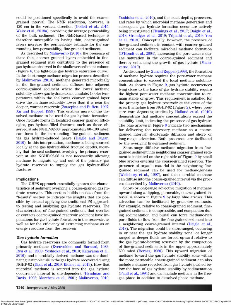
As discussed by Xu and Ruppel (1999), the formationof methane hydrate requires the pore-water methaneconcentration to exceed the local methane solubilitylimit. As shown in Figure 9, gas hydrate occurrenceslying close to the base of gas hydrate stability requirethe highest pore-water methane concentration to re-main stable or grow. This requirement is satisfied forthe primary gas hydrate reservoir at the crest of theArea B anticline from NGHP-02 (Figure 2), where pres-sure core degassing studies by Holland et al. (2019)demonstrate that methane concentrations exceed thesolubility limit, indicating the presence of gas hydrate.The blue arrows in Figure 9 indicate two mechanismsfor delivering the necessary methane to a coarse-grained interval: short-range diffusion and short- orlong-range advection. Both processes are facilitatedby the overlying fine-grained sediment.
Short-range diffusive methane migration from fine-grained sediment into neighboring coarser grained sedi-ment is indicated on the right side of Figure 9 by smallblue arrows entering the coarse-grained reservoir. Thepresence of organic material in the neighboring fine-grained sediment can be used for methanogenesis(Wellsbury et al., 1997), and this microbial methanecan diffuse into the coarse-grained interval via the proc-ess described by Malinverno (2010).
Short- or long-range advective migration of methaneupward along a dipping, permeable, coarse-grained in-terval is shown in Figure 9 by large blue arrows. Thisadvection can be facilitated by grain-size contrasts.For example, relative to coarse-grained sediment, fine-grained sediment is compressible, and compaction dur-ing sedimentation and burial can force methane-richpore fluids to flow from the fine-grained sediment intoa neighboring coarse-grained interval (Daigle et al.,2018). The migration could be short-ranged, occurringin or near the gas hydrate stability zone, or longerranged as deeper fluids are forced upward relative tothe gas hydrate-bearing reservoir by the compactionof fine-grained sediments in the upper approximately500 mbsf (Berner, 1980). This upward migration ofmethane toward the gas hydrate stability zone withinthe more permeable coarse-grained sediment can alsoinclude methane recycled from gas hydrate pushed be-low the base of gas hydrate stability by sedimentation(Paull et al., 1994) and can include methane in the free-gas phase in addition to dissolved-phase methane.
T240 Interpretation / May 2020
Downloaded from https://pubs.geoscienceworld.org/interpretation/article-pdf/doi/10.1190/INT-2019-0026.1/4960317/int-2019-0026.1.pdf?casa_token=CeuYDf8A8V4AAAAA:dcWyYhgKtzGllWkcLSwDi9X2CCPeCCKpldR4zPs5Z3fBrfSSCNyblDKbiK58XFgArOdUXwby USGS Library useron 07 April 2020
The comparatively high methane concentrations andlow permeability of a fine-grained overburden relativeto an underlying coarse-grained interval limits the dif-fusion and advection of methane out of the coarse-grained layer (Clennell et al., 1999; Henry et al., 1999;Malinverno, 2010). Consequently, the pore-water meth-ane concentration can be enhanced in the coarse-grained interval, promoting gas hydrate growth whenthe methane concentration reaches the solubility limit(Figure 9, right side, the solid yellow and white curves,respectively).
If the fine-grained overburden permeability is high,perhaps due to fractures, faulting, or high concentra-tions of diatoms as observed at the Area B anticlinecrest, the capability to restrict methane migration outof the coarse-grained sediment can be limited (Figure 9,the left side, small blue arrows). As a consequence, themethane concentration may not be able to reach thesolubility limit in the coarse-grained interval, resultingin no gas hydrate generation (Figure 9, the left side,dashed yellow curve).
Though much of the discussion here is centered on aseal’s interaction with dissolved-phase methane, anoverlying fine-grained layer can also act as a free-gasseal because the relatively small pore-throat sizes infine-grained sediment require larger gas pressures forgas to invade the pores than is required in the underly-ing coarse-grained interval (Clennell et al., 1999; Henryet al., 1999; Liu and Flemings, 2011; Meyer et al., 2018).Gas hydrate formation from free methane gas trappedin a coarse-grained reservoir is thought to have createdmany of the Arctic permafrost-associated gas hydrateoccurrences (Boswell et al., 2011; Collett et al., 2011;Dai et al., 2011) and may also contribute to marinegas hydrate accumulations (Liu and Flemings, 2006;You and Flemings, 2018).
As the trapped gas pressure increases below a fine-grained seal, however, gas can fracture and invade theoverlying seal (Liu and Flemings, 2007; Jain and Juanes,2009), forming gas- and hydrate-filled chimneys (Liuand Flemings, 2007). However, with a potential excep-tion offshore western Japan (Matsumoto et al., 2017),gas chimneys are not thought to be as likely as gashydrate-bearing coarse-grained reservoirs to be eco-nomically viable as energy resources (Boswell andCollett, 2011).
For simplicity, Figure 9 shows only the fine-grainedsediment above and below the coarse-grained interval.As indicated in Figure 4 for NGHP-02 Area B, the pri-mary coarse-grained, gas hydrate-bearing interval isinterbedded with additional fine-grained units (Janget al., 2019b). These fine-grained interbeds can contrib-ute to the generation of methane that can diffuse intothe coarse-grained intervals and can be used for gashydrate formation. As suggested by D’Hondt et al.(2004), the interfaces between fine- and coarse-grainedmaterial can be particularly active regions for methano-genesis. This is because pore water at and near the in-terfaces is well-suited for hosting electron donors (such
as acetate) from the fine-grained sediment and electronacceptors (such as hydrogen [Marchesi et al., 2001] anddissolved iron and manganese species [D’Hondt et al.,2004]) from fluid flow through the more permeablecoarse-grained sediment. Within this methane transportprocess, gas hydrate formation can act as a methanesink, sequestering a microbial product (methane) toallow methanogenesis to continue more efficiently(Chong et al., 2002).
Even after gas hydrate forms, the seal’s capacity tolimit methane loss from the reservoir is critical to thecontinued existence of the gas hydrate. If the seal iscompromised, methane can escape the reservoir, porewater methane concentrations will drop below the solu-bility limit, and gas hydrate within the reservoir will dis-solve. As an extreme example, gas hydrate in pressure
Figure 9. Idealized anticlinal coarse-grained reservoir (thestippled arch), bounded by permeable, low-clay-content,low-quality seal sediment (the left-hand side), or by low-permeability, fine-grained, high-quality seal sediment (theright-hand side). For a poor seal, compromised perhaps byfaults, fractures, or high diatom concentrations (the left-handreservoir), methane is not well-confined (the blue arrowsindicate methane loss from the reservoir), so the pore-watermethane concentration (the yellow dashed curve) does notreach the methane solubility limit (the white curve) withinthe reservoir unit and gas hydrate cannot form. In the caseof a good seal (the right-hand reservoir), the reservoir can re-ceive methane from the adjacent fines via diffusion (the smallblue arrows) or by short- or long-range advection (the largeblue arrow). The methane influx (the blue arrows) elevatesthe pore-water methane concentration (the yellow curve)in the reservoir such that the solubility limit is reached nearthe base of gas hydrate stability, and gas hydrate can formin the coarse-grained reservoir. Above the reservoir, wherethe methane concentration meets the solubility limit andeffective stresses are lower, gas hydrate-filled fractures canoccur in fine-grained sediment. The stepwise solubility changeat the coarse-grained/fine-grained interface at the reservoirboundary occurs due to the small pore size in the seal relativeto the reservoir (Henry et al., 1999).
Interpretation / May 2020 T241
Downloaded from https://pubs.geoscienceworld.org/interpretation/article-pdf/doi/10.1190/INT-2019-0026.1/4960317/int-2019-0026.1.pdf?casa_token=CeuYDf8A8V4AAAAA:dcWyYhgKtzGllWkcLSwDi9X2CCPeCCKpldR4zPs5Z3fBrfSSCNyblDKbiK58XFgArOdUXwby USGS Library useron 07 April 2020
cores that have had their pressure maintained by meth-ane-free water has been observed to dissolve and dis-appear (Jang et al., 2019a). At site NGHP-02-09(Figure 6b), an interval of coarse-grained, reservoir-quality sediment that is seemingly free of gas hydrate(242–248 mbsf) exists between two thick, gas hy-drate-filled reservoir sediment intervals. A similar ar-rangement is noted by Boswell et al. (2012) at GreenCanyon Site 955 (GC955) in the Gulf of Mexico. Theprocess by which mid-reservoir bands of limited gas hy-drate in coarse-grained sediment occur are not well-known, but Boswell et al. (2012) and Collett et al.(2019) suggest that these water-bearing sands may indi-cate intervals through which the flow of methane-poorfluid either hampers additional gas hydrate formationor actively dissolves the existing gas hydrate. The con-tinuous presence of methane at or above equilibriumsolubility concentrations is critical for gas hydrate topersist.
Extracting methane from a gas hydrate-bearingreservoir
For effective depressurization, the pore-water supplyinto the production interval has to be limited. In ex-treme cases, such as what Reagan et al. (2008) defineas a “class 2” reservoir where the gas hydrate-bearingreservoir interval is in contact with a permeable,water-bearing sand, water extracted at the well can
be largely replaced via flow from the water-bearingsand. This inflow limits the pressure reduction imposedon the reservoir; hence, it slows down gas hydrate dis-sociation and the gas production rate (Reagan et al.,2008; Boswell et al., 2009). As noted by Myshakin et al.(2019), site NGHP-02-16 also appears to have water-bearing sand at the base of the gas hydrate-bearingreservoir. This would limit gas production unless theproduction interval is isolated from the water-bearinglayer.
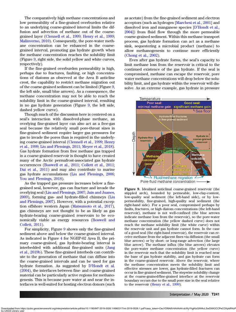
Even if the site NGHP-02-16 production interval isisolated from the underlying water-bearing layer, the ef-fectiveness of depressurization is limited by the per-meability of the overburden seal (Konno et al., 2019).As shown in Figure 10, a permeable overburden canbe a source of water entering the reservoir in responseto reservoir depressurization, particularly for the largedepressurizations (up to 25 MPa) proposed for siteNGHP-02-16 (Boswell et al., 2019a; Konno et al., 2019;Myshakin et al., 2019). Based on the site NGHP-02-16reservoir model by Konno et al. (2019), the peak gasproduction drops by 25% when the overburden sealpermeability is assumed to be 0.1 mD rather than0.01 mD. Reservoir modeling by Ajayi et al. (2018)for the permafrost gas hydrate reservoir at the PrudhoeBay “L-pad” indicates that the peak gas production ratedrops nearly in half when the overburden seal per-meability is assumed as 1 mD rather than the more com-monly assumed impermeable limit of 0 mD. Thus,a reliable prediction of a reservoir’s gas productionrates requires credible properties of the seal sediment,particularly the permeability (Ajayi et al., 2018). Theseproperties can be measured using laboratory experi-ments with in situ samples. To avoid the sediment-fabric disruption that occurs during gas exsolution evenin the absence of gas hydrate, pressure coring and pres-sure core analysis are recommended for geotechnicaltesting of in situ seal sediment.
By extension, it is also important to test fine-grainedlayers that are interbedded in the primary coarse-grained reservoir. These intrareservoir “seals” can helpisolate production in particularly favorable portions ofthe reservoir (Konno et al., 2019; Myshakin et al., 2019)and can help focus depressurization within the coarsergrained sediments. Slight variations in clay content maybe all that is needed to dramatically alter the gas hy-drate saturation in reservoir sediment, or even form es-sentially gas hydrate-free, intrareservoir interbedswhere adjacent layers have significantly different gashydrate saturations.
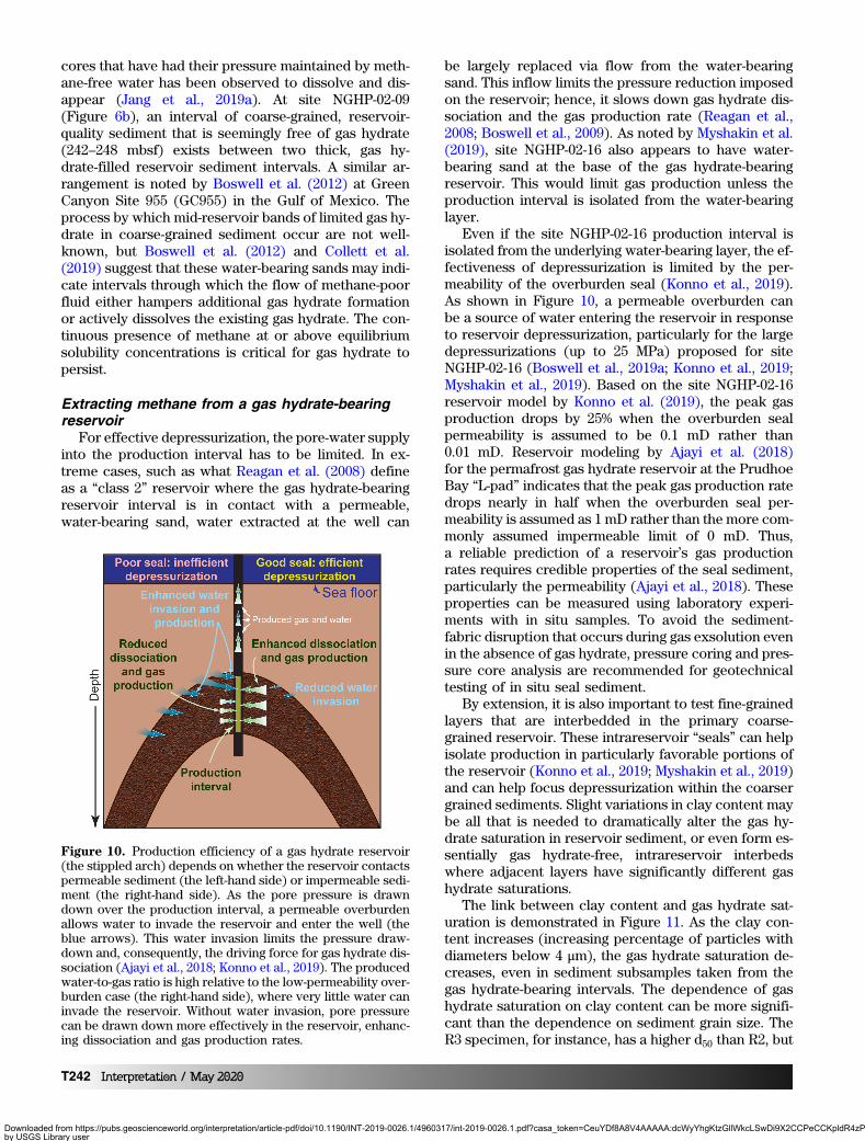
The link between clay content and gas hydrate sat-uration is demonstrated in Figure 11. As the clay con-tent increases (increasing percentage of particles withdiameters below 4 μm), the gas hydrate saturation de-creases, even in sediment subsamples taken from thegas hydrate-bearing intervals. The dependence of gashydrate saturation on clay content can be more signifi-cant than the dependence on sediment grain size. TheR3 specimen, for instance, has a higher d50 than R2, but
Figure 10. Production efficiency of a gas hydrate reservoir(the stippled arch) depends on whether the reservoir contactspermeable sediment (the left-hand side) or impermeable sedi-ment (the right-hand side). As the pore pressure is drawndown over the production interval, a permeable overburdenallows water to invade the reservoir and enter the well (theblue arrows). This water invasion limits the pressure draw-down and, consequently, the driving force for gas hydrate dis-sociation (Ajayi et al., 2018; Konno et al., 2019). The producedwater-to-gas ratio is high relative to the low-permeability over-burden case (the right-hand side), where very little water caninvade the reservoir. Without water invasion, pore pressurecan be drawn down more effectively in the reservoir, enhanc-ing dissociation and gas production rates.
T242 Interpretation / May 2020
Downloaded from https://pubs.geoscienceworld.org/interpretation/article-pdf/doi/10.1190/INT-2019-0026.1/4960317/int-2019-0026.1.pdf?casa_token=CeuYDf8A8V4AAAAA:dcWyYhgKtzGllWkcLSwDi9X2CCPeCCKpldR4zPs5Z3fBrfSSCNyblDKbiK58XFgArOdUXwby USGS Library useron 07 April 2020
also has a higher clay content and, consequently, alower gas hydrate saturation. Quantifying the clay con-tent is important for understanding the gas hydrate res-ervoir system behavior such as gas hydrate saturationand morphology as well as reservoir permeability andproduction efficiency. Additional parameters that de-scribe the shape of the grain size distribution curve,such as sorting and the coefficient of uniformity, arealso valuable to document.
ConclusionThis study emphasizes the additional system insights
that can be gained from considering the fine-grainedsediment overlying a coarse-grained gas hydrate-bear-ing reservoir as a distinct PSs seal element (traditionalPS approach), rather than assuming the gas hydrate-bearing reservoir sediment is its own seal (commonGHPSs approach). The overlying seal sediment can re-strict methane migration out of the coarse-grained res-ervoir and even contribute methane to help raise themethane concentration enough to form gas hydratein the coarse sediment. For gas production, the sealsediment can accentuate depressurization in the targetreservoir interval and reduce water production duringdepressurization. Based on the significant, site-specificinfluences that fine-grained sediments have on the evo-lution and behavior of the underlying coarse-grainedgas hydrate reservoir, a reservoir’s overlying fine-grained sediment merits consideration and testing asa distinct seal element in the modified GHPS.
AcknowledgmentsThis work was supported by the U.S. Geological Sur-
vey’s Gas Hydrates Project, the Survey’s Coastal/MarineHazards and Resources Program, and by interagencyagreements between the U.S. Geological Survey andthe Department of Energy (DE-FE0026166 and DE-
FE0023495). This report was prepared as an accountof work sponsored by an agency of the U.S. govern-ment. Any use of trade, firm, or product name is fordescriptive purposes only and does not imply endorse-ment by the U.S. government. The authors thank A.Cook, S. Phillips, C. Ruppel, M. Santra, and an anony-mous reviewer for constructive comments on the manu-script. The experimental data are available online in theUSGS science database at Jang et al. (2018) and Waiteet al. (2018).
Data and materials availabilityData associated with this research are available and
can be accessed via the following URL: https://doi.org/10.5066/P91XJ7DP; https://doi.org/10.5066/P97RL4X4.
ReferencesAdolph, B., C. Stoller, M. Archer, D. Codazzi, T. el-Halawani,
P. Perciot, G. Weller, M. Evans, J. Grant, R. Griffiths, D.Hartman, G. Sirkin, M. Ichikawa, G. Scott, I. Tribe, and D.White, 2005, Nomore waiting: Formation evolutionwhiledrilling: Oilfield Review, 17, 4–21.
Ajayi, T., B. J. Anderson, Y. Seol, R. Boswell, and E. M.Myshakin, 2018, Key aspects of numerical analysisof gas hydrate reservoir performance: Alaska NorthSlope Prudhoe Bay Unit “L-Pad” hydrate accumulation:Journal of Natural Gas Science and Engineering, 51,37–43, doi: 10.1016/j.jngse.2017.12.026.
Amer, A. M., and A. A. Awad, 1974, Permeability of cohe-sionless soils: Journal of Geotechnical EngineeringDivision, American Society of Civil Engineers, 100,1309–1326.
Berner, R. A., 1980, Early diagenesis: A theoretical ap-proach: Princeton University Press.
Boswell, R., and T. S. Collett, 2011, Current perspectiveson gas hydrate resources: Energy & EnvironmentalScience, 4, 1206–1215, doi: 10.1039/c0ee00203h.
Boswell, R., T. S. Collett, M. Frye, W. Shedd, D. R.McConnell, and D. Shelander, 2012, Subsurface gashydrates in the northern Gulf of Mexico: Marine andPetroleum Geology, 34, 4–30, doi: 10.1016/j.marpetgeo.2011.10.003.
Boswell, R., E. Myshakin, G. Moridis, Y. Konno, T. S.Collett, M. Reagan, T. Ajayi, and Y. Seol, 2019a, IndiaNational Gas Hydrate Program Expedition 02 summaryof scientific results: Numerical simulation of reservoirresponse to depressurization: Marine and PetroleumGeology, 108, 154–166, doi: 10.1016/j.marpetgeo.2018.09.026.
Boswell, R., K. Rose, T. S. Collett, M. Lee, W. Winters, K. A.Lewis, and W. Agena, 2011, Geologic controls on gashydrate occurrence in the Mount Elbert prospect,Alaska North Slope: Marine and Petroleum Geology,28, 589–607, doi: 10.1016/j.marpetgeo.2009.12.004.
Boswell, R., D. Shelander, M. Lee, T. Latham, T. Collett, G.Guerin, G. Moridis, M. Reagan, and D. Goldberg, 2009,Occurrence of gas hydrate in Oligocene Frio sand:
Figure 11. Particle size distributions from site NGHP-02-09showing the dependence of gas hydrate saturation (Sh) onthe content of clay (percentage of particles less than 4 μmin diameter). The clay content can be more important thanthe median grain size (percent finer = 50, d50) in limitingSh, as evidenced by comparing R2 and R3. Seal (the blackcurve): 90.15 mbsf, 36.6% clay, d50 ¼ 6.9 μm, Sh ¼ 0%. R1(the dashed red curve): 201.02 mbsf, 15.4% clay,d50 ¼ 58.9 μm, Sh ¼ 11%. R2 (the solid red curve): 257.26mbsf,0.3% clay, d50 ¼ 1112.9 μm, Sh ¼ 79%. R3 (the dotted redcurve): 232.03 mbsf, 4.7% clay, d50 ¼ 1695.2 μm, Sh ¼ 41%.Data are from Waite et al. (2019a, 2019b).
Interpretation / May 2020 T243
Downloaded from https://pubs.geoscienceworld.org/interpretation/article-pdf/doi/10.1190/INT-2019-0026.1/4960317/int-2019-0026.1.pdf?casa_token=CeuYDf8A8V4AAAAA:dcWyYhgKtzGllWkcLSwDi9X2CCPeCCKpldR4zPs5Z3fBrfSSCNyblDKbiK58XFgArOdUXwby USGS Library useron 07 April 2020
Alaminos Canyon Block 818: Northern Gulf of Mexico:Marine and Petroleum Geology, 26, 1499–1512, doi: 10.1016/j.marpetgeo.2009.03.005.
Boswell, R., J. Yoneda, and W. F. Waite, 2019b, IndiaNational Gas Hydrate Program Expedition 02 summaryof scientific results: Evaluation of natural gas hydrate-bearing pressure cores: Marine and Petroleum Geology,108, 143–153, doi: 10.1016/j.marpetgeo.2018.1010.1020.
Carrier, W. D., 2003, Goodbye, Hazen; Hello, Kozeny-Car-man: Journal of Geotechnical and GeoenvironmentalEngineering, 129, 1054–1056, doi: 10.1061/(Asce)1090-0241(2003)129:11(1054).
Chapuis, R. P., 2004, Predicting the saturated hydraulicconductivity of sand and gravel using effective diameterand void ratio: Canadian Geotechnical Journal, 41,787–795, doi: 10.1139/T04-022.
Chong, S. C., Y. T. Liu, M. Cummins, D. L. Valentine, andD. R. Boone, 2002, Methanogenium marinum sp nov.,a H-2-using methanogen from Skan Bay, Alaska, andkinetics of H-2 utilization: Antonie Van LeeuwenhoekInternational Journal of General and MolecularMicrobiology, 81, 263–270, doi: 10.1023/A:1020535222281.
Clennell, M. B., M. Hovland, J. S. Booth, P. Henry, andW. J. Winters, 1999, Formation of natural gas hydratesin marine sediments — 1: Conceptual model of gas hy-drate growth conditioned by host sediment properties:Journal of Geophysical Research-Solid Earth, 104,22985–23003, doi: 10.1029/1999jb900175.
Collett, T. S., 1995, Gas hydrate resources of the UnitedStates, in D. L. Gautier, G. L. Dolton, K. I. Takahashi,and K. L. Varnes, eds., National Assessment of UnitedStates Oil and Gas Resources: USGS Digital Data Series30, CD-ROM.
Collett, T. S., R. Boswell, J. R. Cochran, P. Kumar, M. Lall,A. Mazumdar, M. V. Ramana, T. Ramprasad, M. Riedel,K. Sain, A. V. Sathe, and K. Vishwanath, and NGHPExpedition 01 Science Party, 2014, Geologic implica-tions of gas hydrates in the offshore of India: Resultsof the National Gas Hydrate Program Expedition 01:Marine and Petroleum Geology, 58, 3–28, doi: 10.1016/j.marpetgeo.2014.07.021.
Collett, T. S., R. Boswell, W. F. Waite, P. Kumar, S. K. Roy,K. Chopra, S. K. Singh, Y. Yamada, N. Tenma, J. Pohl-man, and M. Zyrianova, and the NGHP Expedition02 Scientific Party, 2019, India National Gas HydrateProgram Expedition 02 summary of scientific results:Gas hydrate systems along the eastern continentalmargin of India: Marine and Petroleum Geology, 108,39–142, doi: 10.1016/j.marpetgeo.2019.05.023.
Collett, T. S., A. H. Johnson, C. C. Knapp, and R. Boswell,2009, Natural gas hydrates: A review, in T. S. Collett, A.H. Johnson, C. C. Knapp, and R. Boswell, eds., Naturalgas hydrates — Energy resource potential and associ-ated geologic hazards: AAPG Memoir 89, 146–219.
Collett, T. S., and K. Kvenvolden, 1988, Natural gas hydrate,in L. B. Magoon, ed., Petroleum systems of the UnitedStates: U.S. Geological Survey Bulletin 1870, 46–47.
Collett, T. S., M. W. Lee, W. F. Agena, J. J. Miller, K. A.Lewis, M. V. Zyrianova, R. Boswell, and T. L. Inks, 2011,Permafrost-associated natural gas hydrate occurrenceson the Alaska North Slope: Marine and PetroleumGeology, 28, 279–294, doi: 10.1016/j.marpetgeo.2009.12.001.
Collett, T. S., M. Riedel, R. Boswell, J. Presley, P. Kumar,A. Sathe, A. Sethi, and M. Lall, and NGHP ExpeditionScientists, 2015, Indian National Gas Hydrate ProgramExpedition 01 report: U.S. Geological Survey, 2012-5054.
Cook, A. E., B. I. Anderson, A. Malinverno, S. Mrozewski,and D. S. Goldberg, 2010, Electrical anisotropy due togas hydrate-filled fractures: Geophysics, 75, no. 6,F173–F185, doi: 10.1190/1.3506530.
Cook, A. E., and A. Malinverno, 2013, Short migration ofmethane into a gas hydrate-bearing sand layer at WalkerRidge, Gulf of Mexico: Geochemistry Geophysics Geo-systems, 14, 283–291, doi: 10.1002/ggge.20040.
D’Hondt, S., B. B. Jorgensen, D. J. Miller, A. Batzke, R.Blake, B. A. Cragg, H. Cypionka, G. R. Dickens, T. Fer-delman, K. U. Hinrichs, N. G. Holm, R. Mitterer, A. Spiv-ack, G. Z. Wang, B. Bekins, B. Engelen, K. Ford, G.Gettemy, S. D. Rutherford, H. Sass, C. G. Skilbeck, I.W. Aiello, G. Guerin, C. H. House, F. Inagaki, P. Meister,T. Naehr, S. Niitsuma, R. J. Parkes, A. Schippers, D. C.Smith, A. Teske, J. Wiegel, C. N. Padilla, and J. L. S.Acosta, 2004, Distributions of microbial activities indeep subseafloor sediments: Science, 306, 2216–2221,doi: 10.1126/science.1101155.
Dai, S., R. Boswell, W. F. Waite, J. Jang, J. Y. Lee, and Y.Seol, 2017, What has been learned from pressure cores:9th International Conference on Gas Hydrates.
Dai, S., J. Kim, Y. Xu, W. F. Waite, J. Jang, T. S. Collett, andP. Kumar, 2019, Permeability anisotropy and relativepermeability in sediments from the National Gas Hy-drate Program Expedition 02, offshore India: Marineand Petroleum Geology, 108, 705–713, doi: 10.1016/j.marpetgeo.2018.08.016.
Dai, S., C. Lee, and J. C. Santamarina, 2011, Formationhistory and physical properties of sediments fromthe Mount Elbert gas hydrate stratigraphic test well,Alaska North slope: Marine and Petroleum Geology,28, 427–438, doi: 10.1016/j.marpetgeo.2010.03.005.
Daigle, H., A. Cook, and A. Malinverno, 2018, Formation ofmassive hydrate deposits in Gulf of Mexico sand layers:Fire in the Ice, 18, 1–3.
Daigle, H., and B. Dugan, 2010, Origin and evolution offracture-hosted methane hydrate deposits: Journal ofGeophysical Research-Solid Earth, 115, B11103, doi:10.1029/2010jb007492.
Dixit, G., H. Ram, and P. Kumar, 2019, Origin of gas ingas hydrates as interpreted from geochemistry dataobtained during the National Gas Hydrate ProgramExpedition 02, Krishna Godavari Basin, offshore India:Marine and Petroleum Geology, 108, 389–396, doi: 10.1016/j.marpetgeo.2018.11.047.
T244 Interpretation / May 2020
Downloaded from https://pubs.geoscienceworld.org/interpretation/article-pdf/doi/10.1190/INT-2019-0026.1/4960317/int-2019-0026.1.pdf?casa_token=CeuYDf8A8V4AAAAA:dcWyYhgKtzGllWkcLSwDi9X2CCPeCCKpldR4zPs5Z3fBrfSSCNyblDKbiK58XFgArOdUXwby USGS Library useron 07 April 2020
Flemings, P. B., R. Boswell, T. S. Collett, A. E. Cook,D. Divins, M. Frye, G. Guerin, D. S. Goldberg, A.Malinverno, K. Meazell, J. Morrison, T. Pettigrew,S. C. Phillips, M. Santra, D. E. Sawyer, W. Shedd, C.Thomas, and K. You, 2017, GOM2: Prospecting, drillingand sampling coarse-grained hydrate reservoirs in thedeepwater Gulf of Mexico: 9th International Conferenceon Gas Hydrates (ICGH9).
Frye, M., 2008, Preliminary evaluation of in-place gashydrate resources: Gulf of Mexico Outer ContinentalShelf, Minerals Management Service, OCS ReportMMS 2008-004, https://www.boem.gov/sites/default/files/documents//MMS2008-004.pdf, accessed 11 February 2020.
Fujii, T., K. Suzuki, T. Takayama, M. Tamaki, Y. Komatsu, Y.Konno, J. Yoneda, K. Yamamoto, and J. Nagao, 2015,Geological setting and characterization of a methanehydrate reservoir distributed at the first offshore produc-tion test site on the Daini-Atsumi Knoll in the easternNankai Trough, Japan: Marine and Petroleum Geology,66, 310–322, doi: 10.1016/j.marpetgeo.2015.02.037.
Grundger, F., V. Carrier, M. M. Svenning, G. Panieri, T. R.Vonnahme, S. Klasek, and H. Nieman, 2019, Methane-fuelled biofilms predominantly composed of methano-trophic ANME-1 in Arctic gas hydrate-related sediments:Scientific Reports, 9, 9725, doi: 10.1038/s41598-019-46209-5.
Henry, P., M. Thomas, and M. B. Clennell, 1999, Formationof natural gas hydrates in marine sediments — 2:Thermodynamic calculations of stability conditions inporous sediments: Journal of Geophysical Research-Solid Earth, 104, 23005–23022, doi: 10.1029/1999jb900167.
Holland, M., P. Schultheiss, and J. Roberts, 2019, Gashydrate concentration and morphology from analysisof pressure cores acquired in the Bay of Bengal duringExpedition NGHP-02, offshore India: Marine and Petro-leum Geology, 108, 407–423, doi: 10.1016/j.marpetgeo.2018.07.018.
Hyndman, R. D., and E. E. Davis, 1992, A mechanism forthe formation of methane hydrate and sea-floor bottom-simulating reflectors by vertical fluid expulsion: Journalof Geophysical Research-Solid Earth, 97, 7025–7041,doi: 10.1029/91jb03061.
Ijiri, A., S. Haraguchi, F. J. Jimenez-Espejo, N. Komai,H. Suga, M. Kinoshita, F. Inagaki, and Y. Yamada,2019, Origin of low-chloride fluid in sediments from theeastern continental margin of India, results from theNational Gas Hydrate Program Expedition 02: Marineand Petroleum Geology, 108, 377–388, doi: 10.1016/j.marpetgeo.2018.06.014.
Jain, A. K., and R. Juanes, 2009, Preferential mode of gasinvasion in sediments: Grain-scale mechanistic modelof coupled multiphase fluid flow and sediment mechan-ics: Journal of Geophysical Research-Solid Earth, 114,B08101, doi: 10.1029/2008jb006002.
Jang, J., S. Dai, J. Yoneda, W. F. Waite, T. S. Collett, and P.Kumar, 2018, Pressure core characterization tool mea-surements of compressibility, permeability, and shear
strength of fine-grained sediment collected from area C,Krishna-Godavari Basin, during India’s National GasHydrate Program Expedition NGHP-02, https://doi.org/10.5066/P91XJ7DP, accessed 31 December 2018.
Jang, J., S. Dai, J. Yoneda, W. F. Waite, L. Stern, L. Boze,T. S. Collett, and P. Kumar, 2019a, Pressure core analy-sis on geomechanical and fluid flow properties of a seallayer from the Krishna-Godavari Basin, offshore India:Marine and Petroleum Geology, 108, 537–550, doi: 10.1016/j.marpetgeo.2018.08.015.
Jang, J., W. F. Waite, L. Stern, T. S. Collett, and P. Kumar,2019b, Physical property characteristics of gas hydrate-bearing reservoir and associated seal sediments col-lected during NGHP-02 in the Krishna-Godavari Basin,in the offshore of India: Marine and Petroleum Geology,108, 249–271, doi: 10.1016/j.marpetgeo.2018.09.027.
Johnson, A. H., 2011, Global resource potential of gashydrate — A new calculation: 7th InternationalConference on Gas Hydrates (ICGH 2011).
Katayama, T., H. Yoshioka, H. A. Takahashi, M. Amo, T.Fujii, and S. Sakata, 2016, Changes in microbial com-munities associated with gas hydrates in subseafloorsediments from the Nankai Trough: Fems MicrobiologyEcology, 92, fiw093, doi: 10.1093/femsec/fiw093.
Kida, M., Y. Jin, J. Yoneda, M. Oshima, A. Kato, Y. Konno,J. Nagao, and N. Tenma, 2019, Crystallographic andgeochemical properties of natural gas hydrates accumu-lated in the National Gas Hydrate Program Expedition02 drilling sites in the Krishna-Godavari Basin off India:Marine and Petroleum Geology, 108, 471–481, doi: 10.1016/j.marpetgeo.2018.10.012.
Kinoshita, M., A. Ijiri, S. Haraguchi, F. J. Jimenez-Espejo,N. Komai, H. Suga, T. Sugihara, W. Tanikawa, T. Hirose,Y. Hamada, L. P. Gupta, N. Ahagon, Y. Masaki, N. Abe,H. Y. Wu, S. Nomura, W. Lin, Y. Yamamoto, and Y.Yamada, 2019, Constraints on the fluid supply rate intoand through gas hydrate reservoir systems as inferredfrom pore-water chloride and in situ temperature profiles,Krishna-Godavari Basin, India: Marine and PetroleumGeology, 108, 368–376, doi: 10.1016/j.marpetgeo.2018.12.049.
Konno, Y., A. Kato, J. Yoneda, M. Oshima, M. Kida, Y. Jin, J.Nagao, and N. Tenma, 2019, Numerical analysis of gasproduction potential from a gas-hydrate reservoir atsite NGHP-02-16, the Krishna-Godavari basin offshoreIndia — Feasibility of depressurization method for ultra-deepwater environment: Marine and Petroleum Geology,108, 731–740, doi: 10.1016/j.marpetgeo.2018.08.001.
Konno, Y., J. Yoneda, K. Egawa, T. Ito, Y. Jin, M. Kida, K.Suzuki, T. Fujii, and J. Nagao, 2015, Permeability ofsediment cores from methane hydrate deposit in theEastern Nankai Trough: Marine and Petroleum Geol-ogy, 66, 487–495, doi: 10.1016/j.marpetgeo.2015.02.020.
Kraemer, L. M., R. M. Owen, and G. R. Dickens, 2000, Lith-ology of the upper gas hydrate zone, Blake Outer Ridge:A link between diatoms, porosity, and gas hydrate, inC. K. Paull, R. Matsumoto, P. J. Wallace, and W. P.
Interpretation / May 2020 T245
Downloaded from https://pubs.geoscienceworld.org/interpretation/article-pdf/doi/10.1190/INT-2019-0026.1/4960317/int-2019-0026.1.pdf?casa_token=CeuYDf8A8V4AAAAA:dcWyYhgKtzGllWkcLSwDi9X2CCPeCCKpldR4zPs5Z3fBrfSSCNyblDKbiK58XFgArOdUXwby USGS Library useron 07 April 2020
Dillon, eds., Proceedings of the Ocean Drilling Program,Scientific Results 164, 229–236.
Kumar, P., T. S. Collett, K. M. Shukla, U. S. Yadav, M. V.Lall, and K. Vishwanath, and NGHP-02 ExpeditionScientific Party, 2019, India National Gas HydrateProgram Expedition-02: Operational and technical sum-mary: Marine and Petroleum Geology, 108, 3–38, doi: 10.1016/j.marpetgeo.2018.11.021.
Kvenvolden, K. A., 1993, Gas hydrates — Geological per-spective and global change: Reviews of Geophysics, 31,173–187, doi: 10.1029/93rg00268.
Kvenvolden, K. A., and L. A. Barnard, 1983, Gas hydratesof the Blake Outer Ridge. Site 533. Deep Sea DrillingProject Leg 76, in R. E. Sheridan and F. M. Gradstein,eds., Initial Reports of the Deep Sea Drilling Project:Deep Sea Drilling Project Reports and Publications,353–365.
Liu, X. L., and P. B. Flemings, 2006, Passing gas throughthe hydrate stability zone at southern Hydrate Ridge,offshore Oregon: Earth and Planetary Science Letters,241, 211–226, doi: 10.1016/j.epsl.2005.10.026.
Liu, X. L., and P. B. Flemings, 2007, Dynamic multiphaseflow model of hydrate formation in marine sediments:Journal of Geophysical Research-Solid Earth, 112,B03101, doi: 10.1029/2005jb004227.
Liu, X. L., and P. B. Flemings, 2011, Capillary effectson hydrate stability in marine sediments: Journal ofGeophysical Research-Solid Earth, 116, B07102, doi:10.1029/2010jb008143.
Magoon, L. B., 1988, The petroleum system — A classifi-cation scheme for research, exploration, and resource as-sessment, in L. B. Magoon, ed., Petroleum systems of theUnited States: U.S. Geological Survey Bulletin 1870, 2–15.
Malinverno, A., 2010, Marine gas hydrates in thin sandlayers that soak up microbial methane: Earth andPlanetary Science Letters, 292, 399–408, doi: 10.1016/j.epsl.2010.02.008.
Marchesi, J. R., A. J. Weightman, B. A. Cragg, R. J. Parkes,and J. C. Fry, 2001, Methanogen and bacterial diversityand distribution in deep gas hydrate sediments from theCascadia margin as revealed by 16S rRNA molecularanalysis: FEMS Microbiology Ecology, 34, 221–228,doi: 10.1016/S0168-6496(00)00099-4.
Matsumoto, R., M. Tanahashi, Y. Kakuwa, G. Snyder, S.Ohikawa, H. Tomaru, and S. Morita, 2017, Recoveryof thick deposits of massive hydrates from gas chimneystructures, eastern margin of Japan Sea: Japan sea shal-low gas hydrate project: Fire in the Ice, 17, 1–6.
Max, M. D., and A. H. Johnson, 2014, Hydrate petroleumsystem approach to natural gas hydrate exploration:Petroleum Geoscience, 20, 187–199, doi: 10.1144/petgeo2012-049.
Meyer, D. W., P. B. Flemings, D. DiCarlo, K. H. You, S. C.Phillips, and T. J. Kneafsey, 2018, Experimental investi-gation of gas flow and hydrate formation within the hy-drate stability zone: Journal of Geophysical Research-Solid Earth, 123, 5350–5371, doi: 10.1029/2018jb015748.
Moridis, G. J., M. T. Reagan, A. F. Queiruga, and R. Bos-well, 2019, Evaluation of the performance of the oce-anic hydrate accumulation at site NGHP-02-09 in theKrishna-Godavari Basin during a production test andduring single and multi-well production scenarios:Marine and Petroleum Geology, 108, 660–696, doi: 10.1016/j.marpetgeo.2018.12.001.
Myshakin, E., J. S. Lin, S. Uchida, Y. Seol, T. Collett, and R.Boswell, 2019, Numerical simulation of depressurization-induced gas production from an interbedded turbiditehydrate-bearing sedimentary section in the offshore ofIndia: Site NGHP-02-16 (Area-B): Marine and PetroleumGeology, 108, 619–638, doi: 10.1016/j.marpetgeo.2018.10.047.
Nimblett, J., and C. Ruppel, 2003, Permeability evolutionduring the formation of gas hydrates in marine sedi-ments: Journal of Geophysical Research, 108, 2420,doi: 10.1029/2001JB001650.
Nole, M., H. Daigle, A. E. Cook, J. I. T. Hillman, and A.Malinverno, 2017, Linking basin-scale and pore-scalegas hydrate distribution patterns in diffusion-dominatedmarine hydrate systems: Geochemistry GeophysicsGeosystems, 18, 653–675, doi: 10.1002/2016gc006662.
Paull, C. K., W. Ussler, III, and W. S. Borowski, 1994,Sources of biogenic methane to form marine gas hy-drate: Annals of the New York Academy of Science,715, 392–409, doi: 10.1111/j.1749-6632.1994.tb38852.x.
Priest, J. A., M. Druce, J. Roberts, P. Schultheiss, Y.Nakatsuka, and K. Suzuki, 2015, PCATS Triaxial: A newgeotechnical apparatus for characterizing pressure coresfrom the Nankai Trough, Japan: Marine and PetroleumGeology, 66, 460–470, doi: 10.1016/j.marpetgeo.2014.12.005.
Priest, J. A., J. L. Hayley, W. E. Smith, P. Schultheiss, and J.Roberts, 2019, PCATS triaxial testing: Geomechanicalproperties of sediments from pressure cores recoveredfrom the Bay of Bengal during expedition NGHP-02:Marine and Petroleum Geology, 108, 424–438, doi: 10.1016/j.marpetgeo.2018.07.005.
Radhakrishna, M., D. Twinkle, S. Nayak, R. Bastia, and G.S. Rao, 2012, Crustal structure and rift architectureacross the Krishna-Godavari basin in the central easterncontinental margin of India based on analysis of gravityand seismic data: Marine and Petroleum Geology, 37,129–146, doi: 10.1016/j.marpetgeo.2012.05.005.
Reagan, M. T., G. Moridis, and K. Zhang, 2008, Sensitivityanalysis of gas production from Class 2 and Class 3hydrate deposits: Offshore Technology Conference.
Rempel, A. W., and B. A. Buffett, 1997, Formation andaccumulation of gas hydrate in porous media: Journal ofGeophysical Research-Solid Earth, 102, 10151–10164,doi: 10.1029/97jb00392.
Ren, X. W., and J. C. Santamarina, 2018, The hydraulicconductivity of sediments: A pore size perspective: Engi-neering Geology, 233, 48–54, doi: 10.1016/j.enggeo.2017.11.022.
Ryu, B. J., M. Riedel, J. H. Kim, R. D. Hyndman, Y. J. Lee,B. H. Chung, and I. S. Kim, 2009, Gas hydrates in the
T246 Interpretation / May 2020
Downloaded from https://pubs.geoscienceworld.org/interpretation/article-pdf/doi/10.1190/INT-2019-0026.1/4960317/int-2019-0026.1.pdf?casa_token=CeuYDf8A8V4AAAAA:dcWyYhgKtzGllWkcLSwDi9X2CCPeCCKpldR4zPs5Z3fBrfSSCNyblDKbiK58XFgArOdUXwby USGS Library useron 07 April 2020
western deep-water Ulleung Basin, East Sea of Korea:Marine and Petroleum Geology, 26, 1483–1498, doi: 10.1016/j.marpetgeo.2009.02.004.
Saito, S., K. H. Hsiung, Y. Sanada, K. Moe, Y. Hamada, Y.Nakamura, H. Y. Wu, Y. Shinmoto, and Y. Yamada, andNGHP Expedition 02 JAMSTEC Science Team, 2019,Gas hydrate occurrence and distribution controlled byregional geological structure off eastern India: Estimatesfrom logging-while-drilling in Area-B, National GasHydrate Program Expedition 02 (NGHP-02): Marineand Petroleum Geology, 108, 216–225, doi: 10.1016/j.marpetgeo.2018.12.050.
Santamarina, J. C., S. Dai, J. Jang, and M. Terzariol, 2012,Pressure core characterization tools for hydrate-bearingsediments: Scientific Drilling Journal, 14, 44–48, doi: 10.2204/iodp.sd.14.06.2012.
Santamarina, J. C., S. Dai, M. Terzariol, J. Jang, W. F. Waite,W. J. Winters, J. Nagao, J. Yoneda, Y. Konno, T. Fujii,and K. Suzuki, 2015, Hydro-bio-geomechanical proper-ties of hydrate-bearing sediments from Nankai Trough:Marine and Petroleum Geology, 66, 434–450, doi: 10.1016/j.marpetgeo.2015.02.033.
Shukla, K. M., P. Kumar, and U. S. Yadav, and NGHP-02Science Team, 2019a, Gas hydrate reservoir identifica-tion, delineation, and characterization in the Krishna-Godavari basin using subsurface geologic and geophysicaldata from the National Gas Hydrate Program 02 expedi-tion, offshore India: Marine and Petroleum Geology, 108,185–205, doi: 10.1016/j.marpetgeo.2018.10.019.
Shukla, K. M., U. S. Yadav, P. Kumar, T. S. Collett, R. Boswell,M. Frye, M. Riedel, I. Kaur, and K. Vishwanath, 2019b,National Gas Hydrate Program Expedition 02: Identifica-tion of gas hydrate prospects in the Krishna-GodavariBasin, offshore India: Marine and Petroleum Geology,108, 167–184, doi: 10.1016/j.marpetgeo.2018.11.013.
Singh, R. J., 2014, Exploration application of seismic am-plitude analysis in the Krishna-Godavari Basin, eastcoast of India: Interpretation, 2, no. 4, SP5–SP20, doi:10.1190/INT-2013-0197.1.
Sloan, E. D., and C. A. Koh, 2007, Clathrate hydrates ofnatural gases: CRC Press, Taylor & Francis Group, LLC.
Spinelli, G. A., E. R. Giambalvo, and A. Fisher, 2004, Sedi-ment permeability, distribution, and influence on fluxesin oceanic basement, in E. E. Davis and H. Elderfield,eds., Hydrogeology of the oceanic lithosphere: Cam-bridge University Press, 151–188.
Tripathi, R., P. Kumar, S. Ghosh, J. Nagalingam, and H.Singh, 2019, Culture based investigations of key micro-bial functional groups in gas hydrate bearing sedimentsof the Krishna-Godavari Basin in offshore India: Marineand Petroleum Geology, 108, 397–406, doi: 10.1016/j.marpetgeo.2019.01.034.
Uchida, T., A. Waseda, and T. Namikawa, 2009, Methaneaccumulation and high concentration of gas hydratein marine and terrestrial sandy sediments, in T. Collett,A. Johnson, C. Knapp, and R. Boswell, eds., Natural gas
hydrates — Energy resource potential and associatedgeologic hazard: AAPG Memoir 89, 401–413.
Ulmishek, G. F., 1988, Types of seals as related to migra-tion and entrapment of hydrocarbons, in L. B. Magoon,ed., Petroleum systems of the United States: U.S. Geo-logical Survey, 39–40.
Waite, W. F., J. Jang, T. S. Collett, and P. Kumar, 2018,Grain-size data from India’s National Gas Hydrate Pro-gram NGHP-02 expedition in the Krishna-Godavari Ba-sin offshore eastern India, 2015: U. S. Geological Surveydata release, https://doi.org/10.5066/P97RL4X4, ac-cessed 31 December 2018.
Waite, W. F., J. Jang, T. S. Collett, and P. Kumar, 2019a,Downhole physical properties-based description of agas hydrate petroleum system in NGHP-02 Area C: Achannel, levee, fan complex in the Krishna-GodavariBasin offshore eastern India: Marine and Petroleum Geol-ogy, 108, 272–295, doi: 10.1016/j.marpetgeo.2018.05.021.
Waite, W. F., C. D. Ruppel, T. S. Collett, P. Schultheiss,M. Holland, K. M. Shukla, and P. Kumar, 2019b, Multi-measurement approach for establishing the base of gashydrate stability in the Krishna-Godavari Basin, off-shore India, for sites cored during expedition NGHP-02:Marine and Petroleum Geology, 108, 296–320, doi: 10.1016/j.marpetgeo.2018.07.026.
Wallmann, K., E. Pinero, E. Burwicz, M. Haeckel, C. Hen-sen, A. Dale, and L. Ruepke, 2012, The global inventoryof methane hydrate in marine sediments: A theoreticalapproach: Energies, 5, 2449–2498, doi: 10.3390/en5072449.
Wellsbury, P., K. Goodman, T. Barth, B. A. Cragg, S. P.Barnes, and R. J. Parkes, 1997, Deep marine biospherefuelled by increasing organic matter availability duringburial and heating: Nature, 388, 573–576, doi: 10.1038/41544.
Xu, W. Y., and C. Ruppel, 1999, Predicting the occurrence,distribution, and evolution of methane gas hydratein porous marine sediments: Journal of GeophysicalResearch-Solid Earth, 104, 5081–5095, doi: 10.1029/1998jb900092.
Yoneda, J., M. Oshima, M. Kida, A. Kato, Y. Konno, Y. Jin,J. Jang, W. F. Waite, P. Kumar, and N. Tenma, 2019,Permeability variation and anisotropy of gas hydrate-bearing pressure-core sediments recovered from theKrishna–Godavari Basin, offshore India: Marine andPetroleum Geology, 108, 524–536, doi: 10.1016/j.marpetgeo.2018.07.006.
Yoshioka, H., A. Maruyama, T. Nakamura, Y. Higashi,H. Fuse, S. Sakata, and D. H. Bartlett, 2010, Activitiesand distribution of methanogenic and methane-oxidizingmicrobes in marine sediments from the Cascadia Margin:Geobiology, 8, 223–233, doi: 10.1111/j.1472-4669.2009.00231.x.
You, K., P. B. Flemings, A. Malinverno, T. S. Collett, andK. Darnell, 2019, Mechanisms of methane hydrate for-mation in geological systems: Reviews of Geophysics,57, 1146–1196, doi: 10.1029/2018rg000638.
Interpretation / May 2020 T247
Downloaded from https://pubs.geoscienceworld.org/interpretation/article-pdf/doi/10.1190/INT-2019-0026.1/4960317/int-2019-0026.1.pdf?casa_token=CeuYDf8A8V4AAAAA:dcWyYhgKtzGllWkcLSwDi9X2CCPeCCKpldR4zPs5Z3fBrfSSCNyblDKbiK58XFgArOdUXwby USGS Library useron 07 April 2020
You, K. H., and P. B. Flemings, 2018, Methane hydrateformation in thick sand reservoirs — 1: Short-rangemethane diffusion: Marine and Petroleum Geology, 89,428–442, doi: 10.1016/j.marpetgeo.2017.10.011.
Zatsepina, O. Y., and B. A. Buffett, 1997, Phase equilibriumof gas hydrate: Implications for the formation of hydrate
in the deep sea floor: Geophysical Research Letters, 24,1567–1570, doi: 10.1029/97gl01599.
Biographies and photographs of the authors are notavailable.
T248 Interpretation / May 2020
Downloaded from https://pubs.geoscienceworld.org/interpretation/article-pdf/doi/10.1190/INT-2019-0026.1/4960317/int-2019-0026.1.pdf?casa_token=CeuYDf8A8V4AAAAA:dcWyYhgKtzGllWkcLSwDi9X2CCPeCCKpldR4zPs5Z3fBrfSSCNyblDKbiK58XFgArOdUXwby USGS Library useron 07 April 2020