Fabric Defect Detection based on GLCM and Gabor filter: A Comparison
Upload
independentCategory
view
1download
0
1
Gabor Feature Constrained Statistical Model for Efficient Landmark Localization and Face Recognition
Sanqiang Zhao a,*, Yongsheng Gao a, and Baochang Zhang a,b a School of Engineering, Griffith University, Nathan Campus, Brisbane, QLD 4111, Australia
b School of Automation Science and Electrical Engineering, Beihang University, Beijing 100083, China
Abstract: Feature extraction and classification using Gabor wavelets have proven to be
successful in computer vision and pattern recognition. Gabor feature based Elastic Bunch
Graph Matching (EBGM), which demonstrated excellent performance in the FERET
evaluation test, has been considered as one of the best algorithms for face recognition due
to its robustness against expression, illumination and pose variations. However, EBGM
involves considerable computational complexity in its rigid and deformable matching
process, preventing its use in many real-time applications. This paper presents a new
Constrained Profile Model (CPM), in cooperation with Flexible Shape Model (FSM) to
form an efficient localization framework. Through Gabor feature constrained local
alignment, the proposed method not only avoids local minima in landmark localization, but
also circumvents the exhaustive global optimization. Experiments on CAS-PEAL and
FERET databases demonstrated the effectiveness and efficiency of the proposed method.
Keywords: Face recognition, Elastic Bunch Graph Matching, Flexible Shape Model,
Constrained Profile Model, Gabor wavelet.
1. Introduction
Over the past few decades, the issue of automatic face recognition, where computers are
still inferior to humans, has attracted great attention in the research community (Zhao et al.,
* Corresponding author. Tel.: +61 7 3735 3652; fax: +61 7 3735 5198.
E-mail address: [email protected] (S. Zhao).

2
2003). This is in large due to its extensive applications in various areas such as law enforcement,
identity authentication, video surveillance and human-computer interfaces.
Existing technologies for face recognition can be roughly classified into holistic approaches
and feature-based approaches. Using information derived from the whole face image, holistic
approaches, such as Eigenface (Turk and Pentland, 1991) and Fisherface (Belhumeur et al., 1997),
are conceptually simple and easy to implement, but their performance is affected by facial
expression, pose and illumination changes in practice. On the other hand, feature-based
approaches, such as Elastic Bunch Graph Matching (EBGM) (Lades et al., 1993; Wiskott et al.,
1997), Line Edge Map (LEM) (Gao and Leung, 2002) and Directional Corner Point (DCP) (Gao
and Qi, 2005), extract local information from salient facial features to distinguish faces.
Represented by a set of low dimensional local feature vectors, these methods have the advantage
of robustness to environmental variations.
The EBGM algorithm showed good identification accuracy in the FERET evaluation
(Phillips et al., 2000), demonstrating the successful application of Gabor wavelets for face
representation (Shen and Bai, 2006). In EBGM, face geometry is represented by an
object-adapted (elastic) topology graph, where each node refers to a predefined fiducial point (or
landmark). Local features are modeled by a set of Gabor coefficients (known as a jet) and labeled
on each node. The comparison of different individuals is conducted through a graph matching
strategy. As matching with each model graph is inefficient for large galleries, Wiskott et al.
(1997) developed a stack-like structure, called Face Bunch Graph (FBG), to avoid such a process.
A bunch is a set of jets taken from the same node over a small number of model graphs. To build
the representing graph for a test face image, a model graph is first placed at an initial location and
then is iteratively matched using Gabor jets to optimize its similarity with FBG, instead of with
all the model graphs in the gallery. This matching process consists of two consecutive stages: 1)
rigid matching: a model graph is scaled and shifted inside the test image while keeping its grid

3
rigid, which aims to account for global transformations; and 2) deformable matching: local
distortions due to rotations in depth or expression variations are encoded by deforming individual
nodes and evaluated by a graph similarity function within a topological constraint. To ensure
accurate landmark localization, the time-consuming Gabor convolution is conducted on all the
nodes and iteratively repeated in both stages. Although attractive identification accuracy was
reported, the expensive computational cost prevents the use of EBGM in many applications.
Many efforts have been made to improve the accuracy and robustness of EBGM. Würtz
(1997) presented a system in which several practical procedures were integrated to increase the
robustness of elastic graph matching against translations, deformations and changes in
background. Tefas et al. (2001) employed support vector machines to derive optimal coefficients
that weigh the local similarity values at the nodes of an elastic graph according to their
discriminatory power. Zafeiriou et al. (2007) applied discriminant analysis techniques at multiple
phases of elastic graph matching for face verification. Shin et al. (2007) extended elastic graph
matching to a generalized EGM (G-EGM) to obtain enhanced performance on globally
misaligned faces. Although attractive identification accuracies were reported, the expensive
computational cost makes EBGM not suitable to many real-time applications. However, the
efficiency issue of EBGM received less attention in the research community. Considering that
most computationally expensive work of EBGM comes from Gabor convolution, Jiao et al.
(2003) utilized E-M algorithm to model the Gabor feature distribution for landmark localization.
The method achieved a performance better than Active Shape Model (ASM) (Cootes et al., 1995),
but inferior to EBGM. Choi et al. (2008) presented a simplified version of Gabor wavelets
(SGWs) and an efficient (but non-EBGM) algorithm for face recognition. Since the SGW was
generated through quantizing its corresponding Gabor wavelet, there was a trade-off between
computation time and approximation accuracy.
In this paper, we present a new Constrained Profile Model (CPM) to reduce the
4
computation time of face landmark localization and recognition. The landmarks are separated
into several groups according to the distribution of salient facial features. Two control points are
selected from each group to constrain other non-control points in the same group, preventing
them from sticking into local minima during optimization. In CPM, each control point is modeled
by a Gabor bunch, while all the non-control points are modeled by Normalized Derivative Profile
(NDP) (Cootes et al., 1994). Employing both CPM and Flexible Shape Model (FSM) (Lanitis et
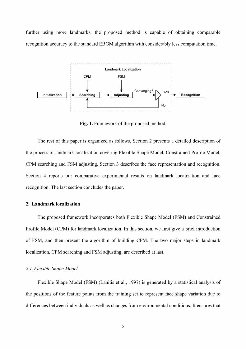
al., 1997), we form an efficient localization framework (see Fig. 1), in which landmarks can be
localized iteratively via two major steps, searching and adjusting. Based on a rough face
detection result, the mean shape model of FSM is placed in a test image as the initial state. In the
first searching step, a new suggested movement for each landmark is computed. Gabor jets are
utilized to find the movements of control points, while the movements of non-control points are
calculated by an efficient searching method based on NDP along the normal of the shape
boundary (Cootes et al., 1994). Because NDP is a unidirectional texture model and has less
accurate localization characteristics than Gabor jets, an extra procedure, called Gabor feature
constrained local alignment, is conducted to refine the positions of non-control points in each
group. In the second adjusting step, the pose parameters (i.e., scaling, rotation and translation)
and shape parameters of FSM are adjusted in order to move each landmark as close as possible to
the new suggested position. With the new parameters this process is repeated until the shape
difference from two consecutive cycles of iteration is less than a predefined threshold. Different
from EBGM, Gabor convolution in the proposed method applies only to a few control points, not
to non-control points. Therefore the computational cost is significantly reduced.
Finally, face recognition is conducted using Gabor jets of control points as these jets have
been calculated previously in the localization process. Gabor features from other landmarks, such
as non-control points and interpolated locations, may be introduced into recognition to yield a
higher recognition rate with extra computation. However, our experiments revealed that without
5
further using more landmarks, the proposed method is capable of obtaining comparable
recognition accuracy to the standard EBGM algorithm with considerably less computation time.
Fig. 1. Framework of the proposed method.
The rest of this paper is organized as follows. Section 2 presents a detailed description of
the process of landmark localization covering Flexible Shape Model, Constrained Profile Model,
CPM searching and FSM adjusting. Section 3 describes the face representation and recognition.
Section 4 reports our comparative experimental results on landmark localization and face
recognition. The last section concludes the paper.
2. Landmark localization
The proposed framework incorporates both Flexible Shape Model (FSM) and Constrained
Profile Model (CPM) for landmark localization. In this section, we first give a brief introduction
of FSM, and then present the algorithm of building CPM. The two major steps in landmark
localization, CPM searching and FSM adjusting, are described at last.
2.1. Flexible Shape Model
Flexible Shape Model (FSM) (Lanitis et al., 1997) is generated by a statistical analysis of
the positions of the feature points from the training set to represent face shape variation due to
differences between individuals as well as changes from environmental conditions. It ensures that
Initialization Searching Adjusting Converging? Yes
Recognition
No
CPM FSM
Landmark Localization

6
the instances of the shape model can only deform in ways found in a training set.
Mathematically, given a set of training images, the labeled N landmarks in each face image
can be represented as a vector
[ ]1 1 2 2, , , , , , TN Nx y x y x y=x . (1)
These shape vectors are first aligned using an iterative modified Procrustes algorithm (Gower,
1975). Principal Component Analysis (PCA) (Jolliffe, 1986) is then applied to get a set of
orthogonal bases P to capture the statistics of the aligned landmarks. Each aligned shape can be
approximated as
≈ +x x Pb , (2)
where b is the vector of eigenvalues, representing the shape parameters of each object. By
modifying the values in b, new instances of the shape model can be manipulated. When the
elements of b are kept within certain limits (typically three times of the standard deviation), the
new shape instance remains similar to those of the training set (Cootes et al., 1995). The shape
parameters b can be retrieved from a given aligned shape x via
( )T≈ −b P x x . (3)
2.2. Constrained Profile Model
As we employ an iterative process to obtain the optimized landmark locations, a suggested
movement for each landmark has to be calculated based on the current shape estimate in each
cycle of iteration. To find a suggested movement for each landmark, a proper local appearance
modeling is required. Cootes et al. (1994) proposed a Normalized Derivative Profile (NDP) to
model local gray-level information around each landmark in the training set of images, and
suggested movements could be made along the normal of the shape boundary. NDP modeling is
considerably fast. However, subsequent research (Wang et al., 2002) demonstrated that when the
object class is inconsistent in shape and intensity appearance, this modeling method does not

7
perform well due to its ambiguous local-texture model and unidirectional searching strategy.
Based on the observation that Gabor features are robust against illumination change, distortion
and scaling (Kamarainen et al., 2006), Wiskott et al. (1997) proposed a stack-like Face Bunch
Graph (FBG) to perform the coarse-to-fine Elastic Bunch Graph Matching (EBGM) and obtained
noticeable localization accuracy. Each node of FBG is attached with a Gabor bunch to cover the
local appearance variations. The representing graph is iteratively extracted from a test face image
until a maximum similarity with FBG is reached. Although EBGM exhibits robustness against
expression, illumination and pose variations, it involves considerable computational cost, as the
optimized image graph is obtained through iteratively computing Gabor jets of all the nodes and
distorting FBG in various sizes and positions over the entire image area.
2.2.1.Face landmark grouping
The proposed CPM is also a local appearance model obtained from the neighborhood of
each landmark. It is represented by Gabor bunches on the control points and statistical
descriptions of NDP on the non-control points. Specifically, the landmarks are classified into
several groups based on the distribution of salient features in a face area (Zhao et al., 2004). Two
control points are selected from each group for Gabor feature extraction. Because Gabor features
are robust against local distortions, control points are able to constrain other non-control points in
the same group, preventing them from sticking into local minima during optimization. Fig. 2
illustrates examples of face landmark grouping on two faces. Each face has seven groups of
landmarks corresponding to two eyebrow regions, two eye regions, one nose region, one mouth
region and one contour region. Landmarks in different groups are marked with different colors,
while control points in all groups are identified by red color. Note that only one control point in
the nose region is selected (Fig. 2) as the mid point of the two inner eye corners (the 45th and 49th
control points in Fig. 6(a)) is calculated and used as the other control point.

8
Fig. 2. Face landmark grouping.
2.2.2.Gabor feature extraction
Gabor wavelets are biologically motivated convolution kernels in the shape of plane waves
restricted by a Gaussian envelope function. The 2D Gabor kernel functions used for feature
extraction are
( ) ( )2 2 2 2
2 2exp exp exp2 2
j jj j
k k zi σψ
σ σ⎛ ⎞ ⎡ ⎤⎛ ⎞
= − − −⎜ ⎟ ⎢ ⎥⎜ ⎟⎝ ⎠⎣ ⎦⎝ ⎠
z k z , (4)
where
22
cos, 2 ,
sin 8jx
jjy
k kk
k k
νν μ
ν μν μ
ϕ ππ ϕ μϕ
+−⎛ ⎞ ⎛ ⎞
= = = =⎜ ⎟ ⎜ ⎟⎝ ⎠ ⎝ ⎠
k . (5)
The index 8j μ ν= + covers a discrete set of five different frequencies 0, , 4ν = and eight
orientations 0, ,7μ = . The width of the Gaussian is controlled by the parameter 2σ π= . A
jet J is defined as the set { }jJ of 40 convolution coefficients for kernels of different frequencies
and orientations obtained at one image pixel ( , )x y=z in an image ( )I z :
( ) ( ) ( ) 2j jJ I dψ′ ′ ′= −∫z z z z z . (6)
The set of jets referring to one feature point over a small number of model faces is called a bunch.
Fig. 3 illustrates the visualized magnitudes and phases of the 40 Gabor kernel functions.

9
Fig. 3. Visualization of 40 Gabor kernels. (a) Gabor Magnitude. (b) Gabor Phase.
2.2.3.Building CPM
Different from EBGM where all the landmarks are modeled by Gabor features, the
proposed CPM extracts Gabor features from control points only. Because the number of the
control points is very small (13 in our experiments), the overall computational effort is
significantly reduced. For the non-control points, the efficient NDP modeling is utilized.
Eventually, each control point is modeled by a Gabor bunch to represent a range of possible
variations in the local appearance of facial features; and each non-control point is modeled by a
mean and a covariance matrix of NDP over all the training images. Algorithm 1 demonstrates the
detailed process of building CPM. Note that when extracting a Gabor bunch from each control
point, we only store the Gabor jet that is less similar to the current bunch, i.e., its magnitude
similarity with all the existing jets in the current bunch is less than a predefined similarity
threshold ( ( , ) max{ ( , )}ik jk bkmag k mag Jb
S J G S J J T= < ). This ensures that the extracted bunch
includes jets from various conditions and hence covers different local distortions. The magnitude
similarity function magS for measuring two jets will be introduced in the next subsection.
(a) (b)

10
Algorithm 1. Building Constrained Profile Model
Notations:
iI — the thi image, 1, ,i M=
ikz — the thk landmark in the thi image, 1, ,k N= ikJ — jet extracted from the thk landmark in the thi image
kG — Gabor bunch of the thk landmark composed of a set of jets { }, 1, ,bkJ b B=
JT — magnitude similarity threshold of two jets
ikp — NDP of the thk landmark in the thi image Input: M training images and each labeled with N predefined landmarks. Output: CPM (Gabor bunches from control points; means and covariance matrices of NDP
from non-control points). Procedures:
0b = for 1: control pointk N=
kG =∅ end for for 1:i M=
for 1:k N= if ikz is control point
if b B< 2( ) ( ) ( )j ik j ikJ I dψ′ ′ ′= −∫z z z z z ; { ( )}, 0, ,39ik
j ikJ J j= =z
if 0b == || max{ ( , )}jk bkmag Jb
S J J T<
{ }ikkG J+ = ; b + +
end if end if
else Calculate ikp
end if end for
end for for 1:k N=
if ikz is non-control point
11 M
k ikiM == ∑p p ;
11 ( )( )M T
k ik ikiM == − −∑C p p p p
end if
end for

11
2.3. CPM searching
After having obtained CPM and FSM from the training set of images, landmark localization
is implemented in an iterative two-step framework: CPM searching and FSM adjusting. The
efficiency of CPM searching is realized through modeling Gabor bunches from a small number of
control points. The accuracy of CPM searching is enhanced through conducting an extra
procedure called Gabor feature constrained local alignment, which utilizes Gabor feature’s
accurate localization characteristics to refine the positions of non-control points. By increasing
the number of control points, the localization accuracy can be improved with a cost of more time.
To suit different circumstances in practice, one can adjust the number of control points to balance
the computational efficiency and localization accuracy.
2.3.1.Individual landmark searching
Given initial positions of face landmarks, two different algorithms are employed to
compute the suggested movements. The movement of non-control point is calculated by an
efficient searching method based on NDP along the normal of the shape boundary; while the
movement of control point is calculated by a Gabor jet localization algorithm. The jet localization
algorithm performs displacement estimation based on jet phase information. For a test face image,
a test jet is first extracted at the position of control point, and then compared one by one with all
the model jets contained in the control point’s Gabor bunch from CPM. The most similar model
jet is selected using jet magnitude similarity for measurement:
( )2 2
,j j
jmag
j jj j
a aS J J
a a
′′ =
′
∑
∑ ∑, (7)
where two jets J and J ′ are represented in the polar form exp( )j j jJ a iφ= . The magnitude
similarity function is used here because jet magnitudes ( )ja z vary slowly with spatial position,

12
which provides robustness to small position variation.
With the selected model jet and the test jet, the Gabor jet localization algorithm is
conducted to find the suggested movement of the current control point. Since jet phases ( )jφ z
vary quickly with location and rotate with a rate set by the spatial frequency jk of the kernels,
they provide a way of accurate displacement estimation (Wiskott et al., 1997). The jet
displacement estimation is based on a displacement-compensated phase similarity function
( )( )
2 2
cos ( , ),
j j j j jj
pha
j jj j
a a J JS J J
a a
φ φ′ ′ ′− − ⋅′ =
′
∑
∑ ∑
d k, (8)
where ( , ) ( , )Tx yJ J d d′ =d is the relative displacement between two locations that jets J and
J ′ refer to. The term ( , ) jJ J ′ ⋅d k is used to compensate for the phase shifts. The cosine terms
cos( ( , ) )j j jJ Jφ φ′ ′− − ⋅d k in Equation (8) can be approximated by a two-term Taylor expansion:
( )( )2
2 2
1 0.5( ( , ) ),
j j j j jj
pha
j jj j
a a J JS J J
a a
φ φ′ ′ ′− − − ⋅′ ≈
′
∑
∑ ∑
d k. (9)
By maximizing Equation (9) via setting / / 0pha x pha yS d S d∂ ∂ = ∂ ∂ = , we obtain the following
equation for ( , )J J ′d :
1( , ) x yy yx x
y xy xx yxx yy xy yx
dJ J
dΓ −Γ Φ⎛ ⎞ ⎛ ⎞⎛ ⎞
′ = =⎜ ⎟ ⎜ ⎟⎜ ⎟−Γ Γ ΦΓ Γ −Γ Γ⎝ ⎠ ⎝ ⎠⎝ ⎠d , if 0xx yy xy yxΓ Γ −Γ Γ ≠ (10)
where ( )x j j jx j jja a k φ φ′ ′Φ = −∑ , ( )y j j jy j jj
a a k φ φ′ ′Φ = −∑ , xx j j jx jxja a k k′Γ =∑ ,
xy j j jx jyja a k k′Γ =∑ , yx j j jy jxj
a a k k′Γ =∑ and yy j j jy jyja a k k′Γ =∑ . This yields a
straightforward calculation for estimating the suggested movements of all the control points using
the selected model jet and the test jet.
2.3.2.Gabor feature constrained local alignment

13
When the new suggested positions of two control points in each group are identified, an
affine transformation is conducted to constrain non-control points in the same group. This
process is considered as a local alignment between two sets of positions (one set before and one
set after the local alignment), and is defined as a scaling (s), a rotation (θ) and a translation
( ( , )x yt t=xt ) which minimize the sum of squared distances between pairs of positions. Such a
coordinate transformation ( , , )[ ]A s θ xt can be represented as
( )[ ] cos sin, ,
sin cos1
x x
y y
xt a b tx s s x
A s yt b a ty s s y
θ θθ
θ θ
⎛ ⎞−′ − ⎛ ⎞ ⎛ ⎞⎛ ⎞ ⎛ ⎞⎛ ⎞ ⎜ ⎟= = + =⎜ ⎟ ⎜ ⎟⎜ ⎟ ⎜ ⎟⎜ ⎟ ⎜ ⎟′⎝ ⎠ ⎝ ⎠⎝ ⎠ ⎝ ⎠ ⎝ ⎠⎜ ⎟
⎝ ⎠xt x . (11)
Since we have obtained two pairs of coordinates from control points (before and after the jet
displacement estimation respectively), the parameters of the affine transformation in Equation
(11) can be calculated through
1 1 1
1 1 1
2 2 2
2 2 2
1 00 11 00 1
x
y
ax y xby x ytx y xty y y
′− ⎛ ⎞⎛ ⎞ ⎛ ⎞⎜ ⎟⎜ ⎟ ⎜ ⎟′⎜ ⎟⎜ ⎟ ⎜ ⎟=⎜ ⎟⎜ ⎟ ⎜ ⎟′−⎜ ⎟⎜ ⎟ ⎜ ⎟⎜ ⎟ ′⎝ ⎠ ⎝ ⎠⎝ ⎠
. (12)
Using the affine parameters from control points in each group, non-control points in the same
group are locally aligned through Equation (11). Fig. 4 illustrates the effectiveness of Gabor
feature constrained local alignment on landmarks in different regions.
Fig. 4. Gabor feature constrained local alignment. (a) Before alignment. (b) After alignment.
(a) (b)

14
2.4. FSM adjusting
When a test face image is presented to the proposed algorithm with a rough face detection
result, the mean shape model x of FSM is placed in the image as the initial state. Starting from
the mean shape model ( )i =x x , all the landmarks are first moved to a better location ( )i id+x x
individually from their current locations ( )ix through CPM searching. Using a least-squared
approximation method (Cootes et al., 1995), these shape deformations are then transformed into
adjustments to the pose parameters ( (1 )i is ds+ , i idθ θ+ , i id+x xt t ) and the shape parameters
( )i id+b b of FSM such that the new estimated shape
ˆ ( (1 ), , )[ ( )]i i i i i i i i iA s ds d d dθ θ= + + + + +x xx t t x P b b moves the landmarks as close as possible to
the previous local deformations, i.e. ˆ i i id≈ +x x x , while still satisfying the shape constraints of
FSM ( 3 3 )k k
i ik kdσ σ− ≤ + ≤b bb b . With the estimated shape ˆ ix , the above process is repeated
1 ˆ( )i i+ =x x until the shape difference from two consecutive cycles of iteration is less than a
threshold 1ˆ ˆ(|| || )i i T−− < xx x . This dynamic shape-fitting process is summarized in Algorithm 2.

15
Algorithm 2. Landmark localization
Notations: x — mean face shape vector in FSM P — principal components matrix in FSM
ix — initial face shape for the thi iteration idx — suggested movement for ix
ib — initial weighting vector for ix idb — additional weighting change for ib
kσb — standard deviation of kb in FSM, 1, , principal componentk N=
ˆ ix — estimated face shape from the thi iteration Tx — shape difference threshold for two adjacent iterations
Input: One test face image with rough detection result. Output: N landmark locations of the test image. Procedures:
0 =b 0 0ˆ =x x
0i = do
i + + 1ˆi i−=x x
Individual landmark searching from ix Search each control point using Gabor jet localization algorithm Search each non-control point using NDP method
Gabor feature constrained local alignment for each group and get idx FSM adjusting such that ( (1 ), , )[ ( )]i i i i i i i i i iA s ds d d d dθ θ+ + + + + ≈ +x xt t x P b b x x
1i is ds∗ = + ; i idθ θ+ = ; i id+ =x xt t for 1: principal componentk N=
if 3k
i ik kd σ+ > bb b
3k
ik σ= bb
else if 3k
i ik kd σ+ < − bb b
3k
ik σ= − bb
else i ik kd+ =b b
end if end for ˆ ( , , )[ ]i i i i iA s θ= +xx t x Pb
while 1ˆ ˆ|| ||i i T−− ≥ xx x return ˆ ix

16
3. Face representation and recognition
For the simplicity of labeling images in the training process, most landmark are placed on
the borders of facial features, such as eye corners, mouth corners and face contour. These features
have clear and exact meaning and refer to the same positions across different faces. Besides, with
homogeneous background the face contour is easier to be localized. The selection of control
points is based on two basic principles. First, one control point should stay apart from the other in
each group to avoid Gabor feature overlapping; and second, the neighborhood of two control
points should contain rich feature information for better representation. In Davies et al. (2002), an
automatic method for building statistical shape models was proposed, which can be used for
automatic landmark selection.
In this study, a face image is represented by Gabor features of control points. This is mainly
due to the fact that 1) most control points are located in the interior of a face where the most
stable and informative features reside; 2) Gabor features of control points have been computed
previously in the landmark localization process; and 3) selecting a small number of control points
for representation reduces storage space and increases executive speed of the algorithm.
Exceptionally, the centers of two eyes are also added into the representation landmark set,
considering their importance for face recognition. For a test face image TI with N ′ Gabor jets
TkJ , 1, ,k N ′= , a classification function between the test image TI and a model image MI is
defined as the average over the magnitude similarity measures between pairs of corresponding
jets:
( ) ( )1
1, ,N
T M T Mmag k k
kS I I S J J
N
′
=
=′∑ . (13)
Face recognition is performed through calculating the classification function between the test
face and each model face in the database. The model with maximum average similarity is
considered as the correct match. Fig. 5 illustrates all the landmarks for face representation and

17
recognition in our experiments.
Fig. 5. Landmarks used for face representation and recognition.
Introducing Gabor features from more landmarks, such as some non-control points or
interpolated locations, into recognition may yield a better performance with extra computational
cost. However, our experiments in Section 4 demonstrate that, without further employing more
landmarks, the proposed algorithm is able to obtain equivalent recognition accuracy to the
standard EBGM method with significantly less computation time.
4. Experimental results
In order to validate the proposed algorithm, we separated our experiments into two parts:
localization and recognition. Landmark localization is a critical step in a feature-based face
recognition approach and is also important to achieve successful results in other applications such
as expression analysis and face animation. Two publicly available face databases, CAS-PEAL
database (Gao, et al., 2008) and FERET database (Phillips et al., 2000), were used to evaluate
localization and recognition performance respectively.
4.1. Landmark localization performance
CAS-PEAL-R1 face database (Gao, et al., 2008) contains 9,060 frontal images of 1,040
subjects, with different expressions, accessories, illuminations, etc. The first 500 frontal faces
under neutral expression and controlled lighting condition were used in this experiment to
evaluate the landmark localization performance. Each image was manually labeled with 96

18
landmark points (see Fig. 6). Among these images, the first 300 images were used for training
FSM and CPM, and the rest 200 images were used for localization testing. The manually labeled
landmarks served as ground truth to assess the accuracy of the automatically located positions.
As shown in Fig. 6, only 13 control points were selected for Gabor feature extraction. For each
control point, the Gabor bunch size was 70. The length of NDP was 10 pixels, which is slightly
longer than that (8 pixels) in Cootes et al. (1994) for a wider-range image search. The number of
principal components in FSM was 45, which represents 95% of the variation in the training set,
the same percentage as used in Lanitis et al. (1997). The jet magnitude similarity threshold for
selecting models jets in each Gabor bunch was 0.95. The average shape difference threshold for
two adjacent iterations was 1 pixel.
Fig. 6. Manually labeled landmarks on a face image from CAS-PEAL-R1 database. Control points are marked with red color. (a) 96 indexed landmarks. (b) A face shape defined by connecting landmarks.
Similar to Jiao et al. (2003), Lanitis et al. (1997) and Wang et al. (2002), the mean of
point-to-point Euclidean distances between automatically located positions and the ground truth
(a) (b)

19
landmarks was calculated to evaluate the accuracy of a localization algorithm on each test image.
This mean distance provides a quantitative description of the localization error of the algorithm.
The average localization error on all the test images is represented as
2 2
1 1
1 1 ( ) ( )P N
ij ij ij iji j
E x x y yP N= =
⎛ ⎞′ ′= − + −⎜ ⎟
⎝ ⎠∑ ∑ , (14)
where P is the number of the test images, N is the number of the landmarks in each image,
( , )ij ijx y and ( , )ij ijx y′ ′ are the thj ground truth landmark and the thj automatically located
position in the thi test image, respectively. Based on Equation (14), the average localization
error of the proposed CPM algorithm was compared with that of ASM method. A factor
100%ASM CPM
ASM
E EmE−
= × (15)
was calculated to measure the improvement percentage of the proposed algorithm over ASM.
When m is positive, the proposed algorithm outperforms ASM.
To evaluate the system localization performance under good and rough initialization
conditions, we conducted the comparative experiments twice, with initialization using manually
labeled two eye positions and Viola-Jones face detector (Viola and Jones, 2001) respectively. We
used the Viola-Jones face detector in OpenCV library (OpenCV, 2008). When a face was
detected, a bounding box containing the approximate location and size of the face was used for
the initialization of our system. Table 1 shows the comparative localization performances on 200
test images. When manually labeled eye locations are used for initialization, the average
localization error of ASM is 3.72 pixels, while CPM localization error is only 1.95 pixels. The
47.6% improvement of the proposed method indicates that CPM modeling and searching have
the capability of obtaining much more accurate landmark localization than ASM. When rough
automatic face detection results are used for initialization, the localization performance of ASM
becomes noticeably worse with an average error of 11.63 pixels. Nevertheless, the performance

20
improvement of CPM over ASM increases from 47.6% to 54.5%, indicating the proposed method
has better landmark localization ability than ASM under rough initialization condition.
4.2. Face recognition performance
The experiment of face recognition was performed on the FERET face database (Phillips et
al., 2000), which consists of a total of 14,051 gray-level face images representing 1,199
individuals. The images contain variations in lighting, facial expressions, pose angle, etc. Only
frontal faces were considered in this experiment. These frontal images are divided into five sets,
with details listed in Table 2. The FERET database provides locations of two eyes of all the
images, which were used for the algorithm initialization. The CPM and FSM obtained from
CAS-PEAL-R1 database were employed in this experiment. A training process conducted on
another database can provide objective evaluation of the algorithm performance on the FERET
database. Face recognition was performed using Gabor features of 15 landmarks (13 control
points plus 2 eye centers).
Table 1. Landmark localization performance
Method ASM Proposed CPM Improvement Average localization error using manually labeled two eyes (pixels) 3.72 1.95 47.6%
Average localization error using Viola-Jones face detector (pixels) 11.63 5.29 54.5%

21
To conduct an objective comparison, the performances of the proposed algorithm were
compared with the published results of the Colorado State University (CSU) Face Identification
Evaluation System (Beveridge et al., 2005; CSU Face Identification Evaluation System, 2007),
which is obtained on the FERET database as well. The CSU results provide identification
accuracies of four face recognition algorithms, i.e., EBGM, Principal Component Analysis (PCA),
Linear Discriminant Analysis (LDA) and Bayesian intrapersonal/extrapersonal image difference
classifier.
The cumulative match scores of these methods are plotted in Fig. 7, and the top-one
recognition rates are listed in Table 3. Compared with standard EBGM, the proposed method
yields slightly inferior top-one recognition accuracy on FERET FB and Dup I probe sets, each
dropped by 3% and 5% respectively. This is not unexpected because our method makes use of
Gabor features from only 15 landmarks, while the CSU implementation involves a total of 80
landmarks for identification (Beveridge et al., 2005; CSU Face Identification Evaluation System,
2007). On the other hand, our results on FC and Dup II sets are noticeably higher than EBGM,
increased by 29% and 7% respectively. This is an interesting result especially in the sense of a
small number of landmarks used for face recognition. This may be because when the test images
are of significant detrimental quality (FC and Dup II are taken from different illumination and
Table 2. FERET datasets
Datasets Image Number Description
FA 1,196 Regular facial expression, used as a gallery set.
FB 1,195 Alternative facial expression to FA.
FC 194 Different lighting conditions.
Dup I 722 Aging of subjects, i.e. images taken later in time.
Dup II 234 Difficult subset of Dup I. Taken at least one year later.

22
after a considerable time respectively), Gabor feature based recognition performed on more
landmarks could be worse than that from fewer reliable landmarks. The average recognition
results revealed that the proposed method not only is capable of obtaining comparable
recognition accuracy to the standard EBGM algorithm, but also outperforms the other three
algorithms contained in CSU system, i.e. PCA, LDA and Bayesian algorithms. Through training
of CPM and FSM on the FERET gallery set FA, the performance of the proposed method could
be further improved.
Fig. 7. The cumulative match scores of the proposed CPM method and CSU implementations of four algorithms performed on the (a) FB, (b) FC, (c) Dup I and (d) Dup II probe sets.
0 5 10 15 20 25 30 35 40 45 500.6
0.65
0.7
0.75
0.8
0.85
0.9
0.95
1
Rank
Cum
ulat
ive
mat
ch s
core
CPM MethodEBGM StandardBayesian MAPLDA EuclideanPCA Euclidean
0 5 10 15 20 25 30 35 40 45 500
0.1
0.2
0.3
0.4
0.5
0.6
0.7
0.8
0.9
1
Rank
Cum
ulat
ive
mat
ch s
core
CPM MethodEBGM StandardBayesian MAPLDA EuclideanPCA Euclidean
(a) (b)
0 5 10 15 20 25 30 35 40 45 500.3
0.4
0.5
0.6
0.7
0.8
0.9
1
Rank
Cum
ulat
ive
mat
ch s
core
CPM MethodEBGM StandardBayesian MAPLDA EuclideanPCA Euclidean
0 5 10 15 20 25 30 35 40 45 500.1
0.2
0.3
0.4
0.5
0.6
0.7
0.8
0.9
1
Rank
Cum
ulat
ive
mat
ch s
core
CPM MethodEBGM StandardBayesian MAPLDA EuclideanPCA Euclidean
(c) (d)

23
4.3. Computational efficiency
Table 4 lists the average computation time consumed in one cycle of iteration in our
experiments. These results were obtained on a Windows-platform PC with 2.8GHz CPU and
1GB RAM. Operating on 96 landmarks, the NDP searching method spends less than 1ms to
finish a cycle, while the EBGM method needs more than 1 second. With the computation time of
131ms, the proposed CPM method dramatically reduces the time of EBGM by 90.9%. This result
indicated that with equivalent recognition performance, the proposed method can be around 10
times faster than EBGM. The implementation of our method converged within less than 6 cycles.
The total computation time for one match is less than 1 second in average.
5. Conclusions
Gabor wavelets have demonstrated outstanding localizability, orientation selectivity and
spatial frequency characteristics in image processing and pattern recognition. Gabor feature based
Table 4. Average computation time in one cycle of iteration
Method EBGM Standard CPM Method Time Saved
Average Time (ms) 1440 131 90.9%
Table 3. The top-one face recognition rates
Method FB FC Dup I Dup II Average
CPM Method 0.84 0.68 0.38 0.29 0.55
EBGM Standard 0.87 0.39 0.43 0.22 0.48
Bayesian MAP 0.82 0.37 0.52 0.32 0.51
LDA Euclidean 0.61 0.19 0.38 0.14 0.33
PCA Euclidean 0.74 0.05 0.34 0.14 0.32

24
EBGM algorithm is one of the most successful approaches for face recognition due to its
robustness against local distortions caused by variance of expression, illumination and pose.
However, its considerable complication and computation prevents it from extensive applications
in practice. We have presented an efficient Gabor feature constrained algorithm which can be
used for locating facial features as well as identifying the individual in an image. Experimental
results for both landmark localization and face recognition are promising. The recognition
performance of the proposed method is comparable to the standard EBGM algorithm, and its
computation time per cycle of iteration is 90.9% less than EBGM. We expect this method could
be extended to non-rigid object recognition and applied to other HCI-related applications in the
future.
Acknowledgements
This research was partially supported by the Australian Research Council (ARC) under
Discovery Grants DP0451091 and DP0877929.
References
Belhumeur, P.N., Hespanha, J.P., Kriegman, D.J., 1997. Eigenfaces vs. Fisherfaces: recognition
using class specific linear projection. IEEE Transactions on Pattern Analysis and Machine
Intelligence, 19(7): 711-720.
Beveridge, J.R., Bolme, D., Draper, B.A., Teixeira, M., 2005. The CSU Face Identification
Evaluation System: its purpose, features, and structure. Machine Vision and Applications,
16(2): 128-138.
CSU (Colorado State University) Face Identification Evaluation System, 2007.
http://www.cs.colostate.edu/evalfacerec/index.html.
Choi, W.P., Tse, S.H., Wong, K.W., Lam, K.M., 2008. Simplified Gabor wavelets for human face
recognition. Pattern Recognition, 41(3): 1186-1199.

25
Cootes, T.F., Hill, A., Taylor, C.J., Haslam, J., 1994. Use of active shape models for locating
structures in medical images. Image and Vision Computing, 12(6): 355-365.
Cootes, T.F., Taylor, C.J., Cooper, D.H., Graham, J., 1995. Active shape models—Their training
and application. Computer Vision and Image Understanding, 61(1): 38-59.
Davies, R.H., Twining, C.J., Cootes, T.F., Waterton, J.C., Taylor, C.J., 2002. A minimum
description length approach to statistical shape modeling. IEEE Transactions on Medical
Imaging, 21(5): 525-537.
Gao, W., Cao, B., Shan, S., Chen, X., Zhou, D., Zhang, X., Zhao, D., 2008. The CAS-PEAL
large-scale Chinese face database and baseline evaluations. IEEE Transactions on Systems,
Man, and Cybernetics—Part A: Systems and Humans, 38(1): 149-161.
Gao, Y., Leung, M.K.H., 2002. Face recognition using line edge map. IEEE Transactions on
Pattern Analysis and Machine Intelligence, 24(6): 764-779.
Gao, Y., Qi, Y., 2005. Robust visual similarity retrieval in single model face databases. Pattern
Recognition, 38(7): 1009-1020.
Gower, J.C., 1975. Generalized procrustes analysis. Psychometrika, 40(1): 33-51.
Jiao, F., Li, S., Shum, H.-Y., Schuurmans, D., 2003. Face alignment using statistical models and
wavelet features. In: Proceedings of the IEEE International Conference on Computer
Vision and Pattern Recognition, pp. 321-327.
Jolliffe, I.T., 1986. Principal Component Analysis. Springer.
Kamarainen, J.K., Kyrki, V., Kälviäinen, H., 2006. Invariance properties of Gabor filter-based
features—Overview and applications. IEEE Transactions on Image Processing, 15(5):
1088-1099.
Lades, M., Vorbrüggen, J.C., Buhmann, J., Lange, J., von der Malsburg, C., Würtz, R.P., Konen,
W., 1993. Distortion invariant object recognition in the dynamic link architecture. IEEE
Transactions on Computers, 42(3): 300-311.

26
Lanitis, A., Taylor, C.J., Cootes, T.F., 1997. Automatic interpretation and coding of face images
using flexible models. IEEE Transactions on Pattern Analysis and Machine Intelligence,
19(7): 743-756.
OpenCV (Open Computer Vision Library), 2008. http://sourceforge.net/projects/opencvlibrary/.
Phillips, P.J., Moon, H., Rizvi, S.A., Rauss, P.J., 2000. The FERET evaluation methodology for
face-recognition algorithms. IEEE Transactions on Pattern Analysis and Machine
Intelligence, 22(10): 1090-1104.
Shen, L., Bai, L., 2006. A review on Gabor wavelets for face recognition. Pattern Analysis and
Applications, 9(2-3): 273-292.
Shin, H., Kim, S.D., Choi, H.C., 2007. Generalized elastic graph matching for face recognition.
Pattern Recognition Letters, 28(9): 1077-1082.
Tefas, A., Kotropoulos, C., Pitas, I., 2001. Using support vector machines to enhance the
performance of elastic graph matching for frontal face authentication. IEEE Transactions
on Pattern Analysis and Machine Intelligence, 23(7): 735-746.
Turk, M., Pentland, A., 1991. Eigenfaces for recognition. Journal of Cognitive Neuroscience,
3(1): 71-86.
Viola, P., Jones, M., 2001. Rapid object detection using a boosted cascade of simple features, In:
Proceedings of the IEEE International Conference on Computer Vision and Pattern
Recognition, pp. 511-518.
Wang, W., Shan, S., Gao, W., Cao, B., Yin, B., 2002. An improved active shape model for face
alignment, In: Proceedings of the IEEE International Conference on Multimodal Interfaces,
pp. 523-528.
Wiskott, L., Fellous, J.M., Krüger, N., von der Malsburg, C., 1997. Face recognition by elastic
bunch graph matching. IEEE Transactions on Pattern Analysis and Machine Intelligence,
19(7): 775-779.

27
Würtz, R.P., 1997. Object recognition robust under translations, deformations, and changes in
background. IEEE Transactions on Pattern Analysis and Machine Intelligence, 19(7):
769-775.
Zafeiriou, S., Tefas, A., Pitas, I., 2007. The discriminant elastic graph matching algorithm applied
to frontal face verification. Pattern Recognition, 40(10): 2798-2810.
Zhao, S., Gao, W., Shan, S., Yin, B., 2004. Enhance the Alignment Accuracy of Active Shape
Models Using Elastic Graph Matching, In: Proceedings of the International Conference on
Biometric Authentication, pp. 52-58.
Zhao, W., Chellappa, R., Phillips, P.J., Rosenfeld, A., 2003. Face recognition: a literature survey.
ACM Computing Surveys, 35(4): 399-459.
Copyright © 2022 FDOKUMEN