G-router GSM/GPRS to RS-232 and Ethernet Gateway Quick ...
21
G-router GSM/GPRS to RS-232 and Ethernet Gateway Quick Installation Guide Author RFI Support Team Revision A0 Quick Install Guide Version QIG_G-router_1.2.2 Date 12-01-2012 Covering Product code G-router, RE.40.QGSM
-
Upload
khangminh22 -
Category
Documents
-
view
2 -
download
0
Transcript of G-router GSM/GPRS to RS-232 and Ethernet Gateway Quick ...
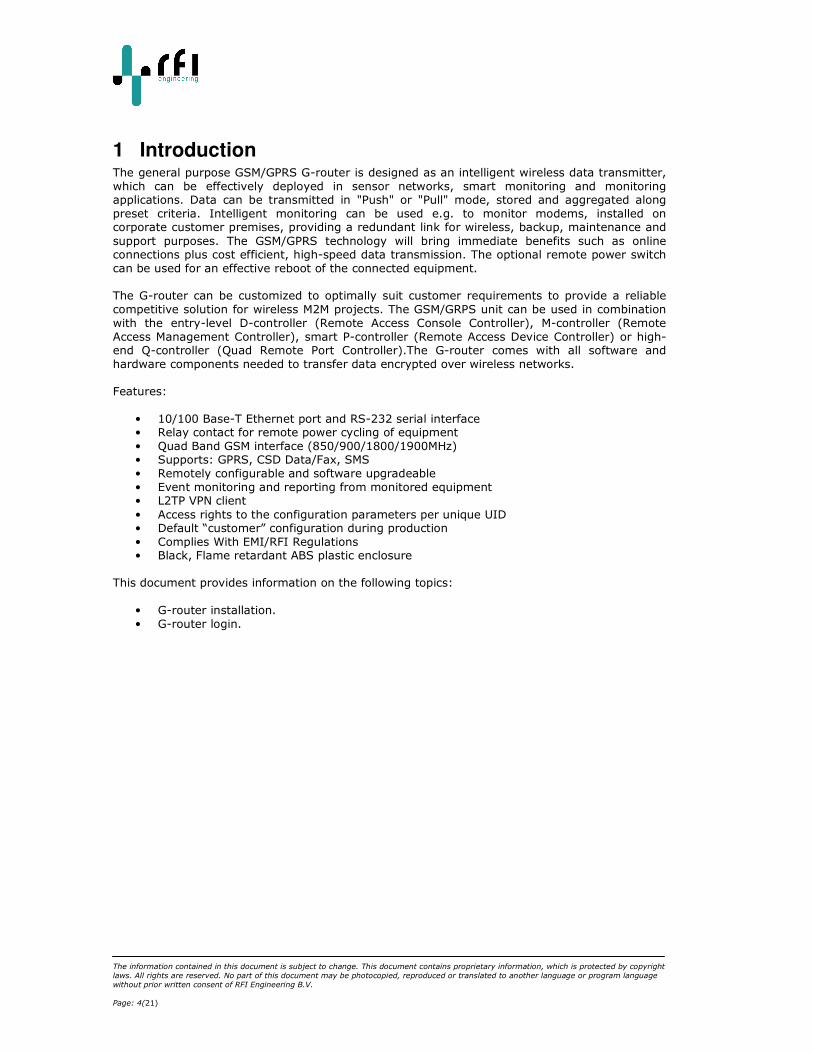
G-router
GSM/GPRS to RS-232 and Ethernet Gateway
Quick Installation Guide
Author RFI Support Team
Revision A0 Quick Install Guide Version QIG_G-router_1.2.2
Date 12-01-2012
Covering Product code G-router, RE.40.QGSM
Contents 1 Introduction ......................................................................................................... 4
1.1 Check Your Package Contents ............................................................................ 5
2 Connectors and status LEDs on the G-router Unit ........................................................ 6
2.1 Ethernet and 802.3af (Power over Ethernet) Pin Assignments ................................. 7
2.2 RS-232 Pin Assignments ................................................................................... 7
2.3 Relay connections............................................................................................ 8
3 Installation Overview ............................................................................................. 9
3.1 Inserting the SIM card ..................................................................................... 9
3.2 Connecting the G-router Unit to your network .................................................... 10
4 Accessing the G-router configuration, user ‘admin’ .................................................... 11
4.1 Console login via SSH and the Ethernet port (CLI) .............................................. 11
4.2 Logging out (CLI) .......................................................................................... 12
4.3 Changing your password (CLI) ......................................................................... 12
4.4 Console login via browser and the Ethernet port (web) ........................................ 14
4.5 Console login via GSM dial-in........................................................................... 15
4.6 Disconnect the GSM dial-in connection .............................................................. 16
5 Advanced configuration, user ‘root’ ......................................................................... 17
5.1 Retrieving the GSM configuration ..................................................................... 18
5.2 Setting the GSM PIN ...................................................................................... 18
5.3 Getting the GSM PIN ...................................................................................... 18
5.4 Retrieving the GSM status: ............................................................................. 18
5.5 Setting idle-timer timeout ............................................................................... 19
6 LED status and patterns of the G-router .................................................................. 20
6.1 Power LED ................................................................................................... 20
6.2 Modem status LED ......................................................................................... 20
6.3 Status LED ................................................................................................... 20
6.4 Call status LED ............................................................................................. 21
6.5 GPRS status LED ........................................................................................... 21
6.6 Relay status LED ........................................................................................... 21

The information contained in this document is subject to change. This document contains proprietary information, which is protected by copyright
laws. All rights are reserved. No part of this document may be photocopied, reproduced or translated to another language or program language
without prior written consent of RFI Engineering B.V.
QIG_G-router_1.2.2 Page: 3(21)
Revision History
Revision Reason Author Date
00010 First version IVL 16-01-2008
00011 Updated after an initial product presentation.
Updated and added functionality:
- Configurable password settings.
- Configurable idle timer, default set to 5 minutes
- Configurable escape sequence to take control of the GSM modem. Default set to “^^^”.
- Relay LED + “toggle_relais” command
- Synchronize the Linux clock to the Vodafone
GSM network - Possibility to remotely update the G-router
via dial in connection and ppp. - Implemented hardware “carrier detect” so
that the unit disconnects the call when the
remote side drops the carrier (disconnects).
IVL 28-01-2008
00012 Updated to include latest hardware version 026C and added functionality:
- Web user interface - Configurable users with user permissions
IVL 10-06-2008
00013 Cleanup the document FRK 22-04-2011
00014 Insert SIM card requirement PAC 12-01-2012
References
Reference Description Code
0
The information contained in this document is subject to change. This document contains proprietary information, which is protected by copyright
laws. All rights are reserved. No part of this document may be photocopied, reproduced or translated to another language or program language
without prior written consent of RFI Engineering B.V.
Page: 4(21)
1 Introduction The general purpose GSM/GPRS G-router is designed as an intelligent wireless data transmitter,
which can be effectively deployed in sensor networks, smart monitoring and monitoring applications. Data can be transmitted in "Push" or "Pull" mode, stored and aggregated along
preset criteria. Intelligent monitoring can be used e.g. to monitor modems, installed on corporate customer premises, providing a redundant link for wireless, backup, maintenance and
support purposes. The GSM/GPRS technology will bring immediate benefits such as online connections plus cost efficient, high-speed data transmission. The optional remote power switch
can be used for an effective reboot of the connected equipment.
The G-router can be customized to optimally suit customer requirements to provide a reliable
competitive solution for wireless M2M projects. The GSM/GRPS unit can be used in combination
with the entry-level D-controller (Remote Access Console Controller), M-controller (Remote
Access Management Controller), smart P-controller (Remote Access Device Controller) or high-end Q-controller (Quad Remote Port Controller).The G-router comes with all software and
hardware components needed to transfer data encrypted over wireless networks.
Features:
• 10/100 Base-T Ethernet port and RS-232 serial interface • Relay contact for remote power cycling of equipment
• Quad Band GSM interface (850/900/1800/1900MHz) • Supports: GPRS, CSD Data/Fax, SMS
• Remotely configurable and software upgradeable
• Event monitoring and reporting from monitored equipment • L2TP VPN client
• Access rights to the configuration parameters per unique UID • Default “customer” configuration during production
• Complies With EMI/RFI Regulations • Black, Flame retardant ABS plastic enclosure
This document provides information on the following topics:
• G-router installation.
• G-router login.
The information contained in this document is subject to change. This document contains proprietary information, which is protected by copyright
laws. All rights are reserved. No part of this document may be photocopied, reproduced or translated to another language or program language
without prior written consent of RFI Engineering B.V.
QIG_G-router_1.2.2 Page: 5(21)
1.1 Check Your Package Contents
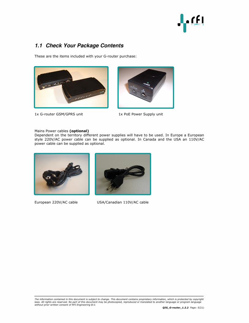
These are the items included with your G-router purchase:
1x G-router GSM/GPRS unit 1x PoE Power Supply unit
Mains Power cables (optional) Dependent on the territory different power supplies will have to be used. In Europe a European
style 220V/AC power cable can be supplied as optional. In Canada and the USA an 110V/AC power cable can be supplied as optional.
European 220V/AC cable USA/Canadian 110V/AC cable
The information contained in this document is subject to change. This document contains proprietary information, which is protected by copyright
laws. All rights are reserved. No part of this document may be photocopied, reproduced or translated to another language or program language
without prior written consent of RFI Engineering B.V.
Page: 6(21)
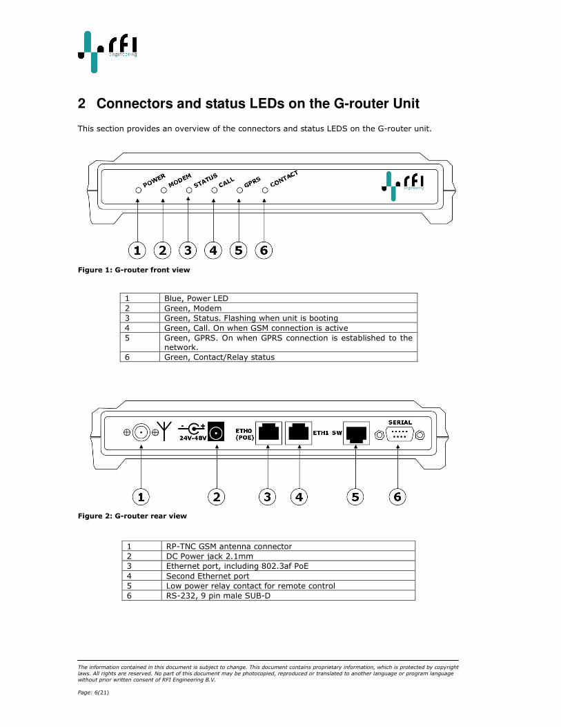
2 Connectors and status LEDs on the G-router Unit
This section provides an overview of the connectors and status LEDS on the G-router unit.
Figure 1: G-router front view
1 Blue, Power LED
2 Green, Modem
3 Green, Status. Flashing when unit is booting
4 Green, Call. On when GSM connection is active
5 Green, GPRS. On when GPRS connection is established to the network.
6 Green, Contact/Relay status
Figure 2: G-router rear view
1 RP-TNC GSM antenna connector
2 DC Power jack 2.1mm
3 Ethernet port, including 802.3af PoE
4 Second Ethernet port
5 Low power relay contact for remote control
6 RS-232, 9 pin male SUB-D
The information contained in this document is subject to change. This document contains proprietary information, which is protected by copyright
laws. All rights are reserved. No part of this document may be photocopied, reproduced or translated to another language or program language
without prior written consent of RFI Engineering B.V.
QIG_G-router_1.2.2 Page: 7(21)
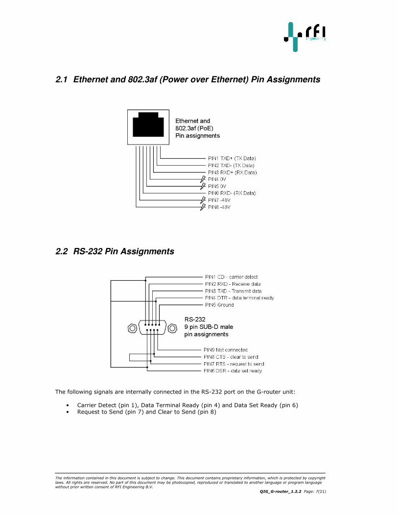
2.1 Ethernet and 802.3af (Power over Ethernet) Pin Assignments
2.2 RS-232 Pin Assignments
The following signals are internally connected in the RS-232 port on the G-router unit:
• Carrier Detect (pin 1), Data Terminal Ready (pin 4) and Data Set Ready (pin 6) • Request to Send (pin 7) and Clear to Send (pin 8)
The information contained in this document is subject to change. This document contains proprietary information, which is protected by copyright
laws. All rights are reserved. No part of this document may be photocopied, reproduced or translated to another language or program language
without prior written consent of RFI Engineering B.V.
Page: 8(21)
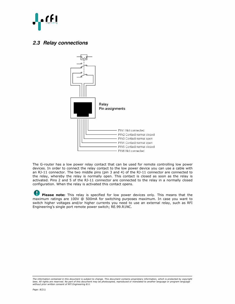
2.3 Relay connections
The G-router has a low power relay contact that can be used for remote controlling low power devices. In order to connect the relay contact to the low power device you can use a cable with
an RJ-11 connector. The two middle pins (pin 3 and 4) of the RJ-11 connector are connected to
the relay, whereby the relay is normally open. This contact is closed as soon as the relay is
activated. Pins 2 and 5 of the RJ-11 connector are connected to the relay in a normally closed configuration. When the relay is activated this contact opens.
Please note: This relay is specified for low power devices only. This means that the
maximum ratings are 100V @ 500mA for switching purposes maximum. In case you want to
switch higher voltages and/or higher currents you need to use an external relay, such as RFI
Engineering’s single port remote power switch; RE.99.R1NC.
The information contained in this document is subject to change. This document contains proprietary information, which is protected by copyright
laws. All rights are reserved. No part of this document may be photocopied, reproduced or translated to another language or program language
without prior written consent of RFI Engineering B.V.
QIG_G-router_1.2.2 Page: 9(21)
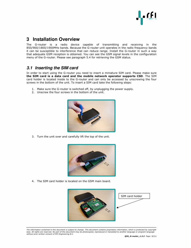
3 Installation Overview The G-router is a radio device capable of transmitting and receiving in the 850/900/1800/1900MHz bands. Because the G-router unit operates in the radio frequency bands
it can be susceptible to interference that can reduce range. Install the G-router in such a way that adequate GSM reception is obtained. You can see the GSM signal levels in the configuration
menu of the G-router. Please see paragraph 5.4 for retrieving the GSM status.
3.1 Inserting the SIM card In order to start using the G-router you need to insert a miniature SIM card. Please make sure the SIM card is a data card and the mobile network operator supports CSD. The SIM
card holder is located inside to the G-router and can only be accessed by unscrewing the four screws in the bottom of the unit. To insert a SIM card take the following steps:
1. Make sure the G-router is switched off, by unplugging the power supply.
2. Unscrew the four screws in the bottom of the unit.
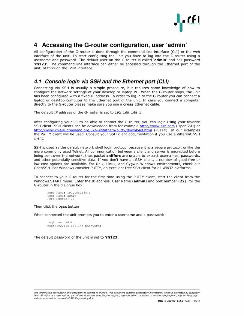
3. Turn the unit over and carefully lift the top of the unit.
4. The SIM card holder is located on the GSM main board.
SIM card holder

The information contained in this document is subject to change. This document contains proprietary information, which is protected by copyright
laws. All rights are reserved. No part of this document may be photocopied, reproduced or translated to another language or program language
without prior written consent of RFI Engineering B.V.
Page: 10(21)
5. Insert the SIM card with the connections facing downwards into the SIM card holder. Pay attention to the correct position. The SIM card has a small cut off corner which located
on the top left corner in the picture below.
6. Re-assemble the unit, taking the above steps in reverse order.
After insertion of the SIM card and reassembly of the unit you can start configuring the unit.
3.2 Connecting the G-router Unit to your network
A. Connect an Ethernet cable to the port labeled “Eth0(POE)” on the RFI G-router.
B. Connect the other end of the Ethernet cable to the port labeled “J1 Data & PWR” on the
Power-over-Ethernet (PoE) power supply.
C. Connect the port labeled “SERIAL” to the WAN router you want to monitor.
D. Connect the power cable to the back of Power-over-Ethernet (PoE) and power the unit on.
When you have completed the above steps the connected network should look like this:
Figure 3: G-router Connections
Cut-off corner
The information contained in this document is subject to change. This document contains proprietary information, which is protected by copyright
laws. All rights are reserved. No part of this document may be photocopied, reproduced or translated to another language or program language
without prior written consent of RFI Engineering B.V.
QIG_G-router_1.2.2 Page: 11(21)
4 Accessing the G-router configuration, user ‘admin’ All configuration of the G-router is done through the command line interface (CLI) or the web
interface of the unit. To start configuring the unit you have to log into the G-router using a username and password. The default user on the G-router is called ‘admin’ and has password
‘rfi123’. The command line interface can either be accessed through the Ethernet port of the unit, of through the GSM interface.
4.1 Console login via SSH and the Ethernet port (CLI) Connecting via SSH is usually a simple procedure, but requires some knowledge of how to
configure the network settings of your desktop or laptop PC. When the G-router ships, the unit has been configured with a fixed IP address. In order to log in to the G-router you can connect a
laptop or desktop computer to the Ethernet port of the unit. In case you connect a computer directly to the G-router please make sure you use a cross Ethernet cable.
The default IP address of the G-router is set to 192.168.168.1
After configuring your PC to be able to contact the G-router, you can login using your favorite SSH client. SSH clients can be downloaded from for example http://www.ssh.com (OpenSSH) or
http://www.chiark.greenend.org.uk/~sgtatham/putty/download.html (PuTTY). In our examples the PuTTY client will be used. Consult your SSH client documentation if you use a different SSH
client.
SSH is used as the default network shell login protocol because it is a secure protocol, unlike the more commonly used Telnet. All communication between a client and server is encrypted before
being sent over the network, thus packet sniffers are unable to extract usernames, passwords,
and other potentially sensitive data. If you don't have an SSH client, a number of good free or
low-cost options are available. For Unix, Linux, and Cygwin Windows environments, check out OpenSSH. For Windows consider PuTTY, an excellent free SSH client for all Win32 platforms.
To connect to your G-router for the first time using the PuTTY client, start the client from the
Windows START menu. Enter the IP address, User Name (admin) and port number (22) for the G-router in the dialogue box:
Host Name: 192.168.168.1 User Name: admin Port Number: 22
Then click the Open button
When connected the unit prompts you to enter a username and a password:
login as: admin
[email protected]'s password:
The default password of the unit is set to ‘rfi123’.
The information contained in this document is subject to change. This document contains proprietary information, which is protected by copyright
laws. All rights are reserved. No part of this document may be photocopied, reproduced or translated to another language or program language
without prior written consent of RFI Engineering B.V.
Page: 12(21)
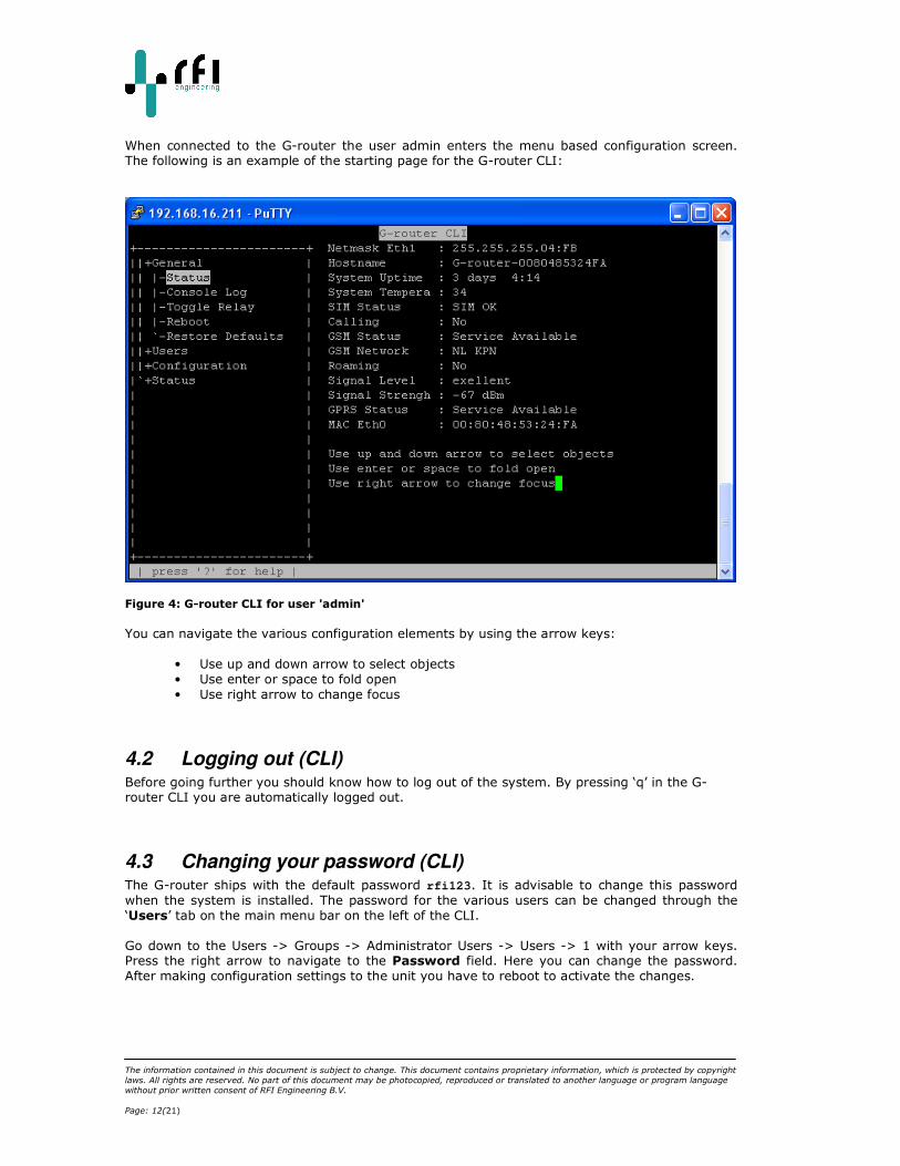
When connected to the G-router the user admin enters the menu based configuration screen. The following is an example of the starting page for the G-router CLI:
Figure 4: G-router CLI for user 'admin'
You can navigate the various configuration elements by using the arrow keys:
• Use up and down arrow to select objects
• Use enter or space to fold open
• Use right arrow to change focus
4.2 Logging out (CLI) Before going further you should know how to log out of the system. By pressing ‘q’ in the G-router CLI you are automatically logged out.
4.3 Changing your password (CLI) The G-router ships with the default password rfi123. It is advisable to change this password
when the system is installed. The password for the various users can be changed through the
‘Users’ tab on the main menu bar on the left of the CLI.
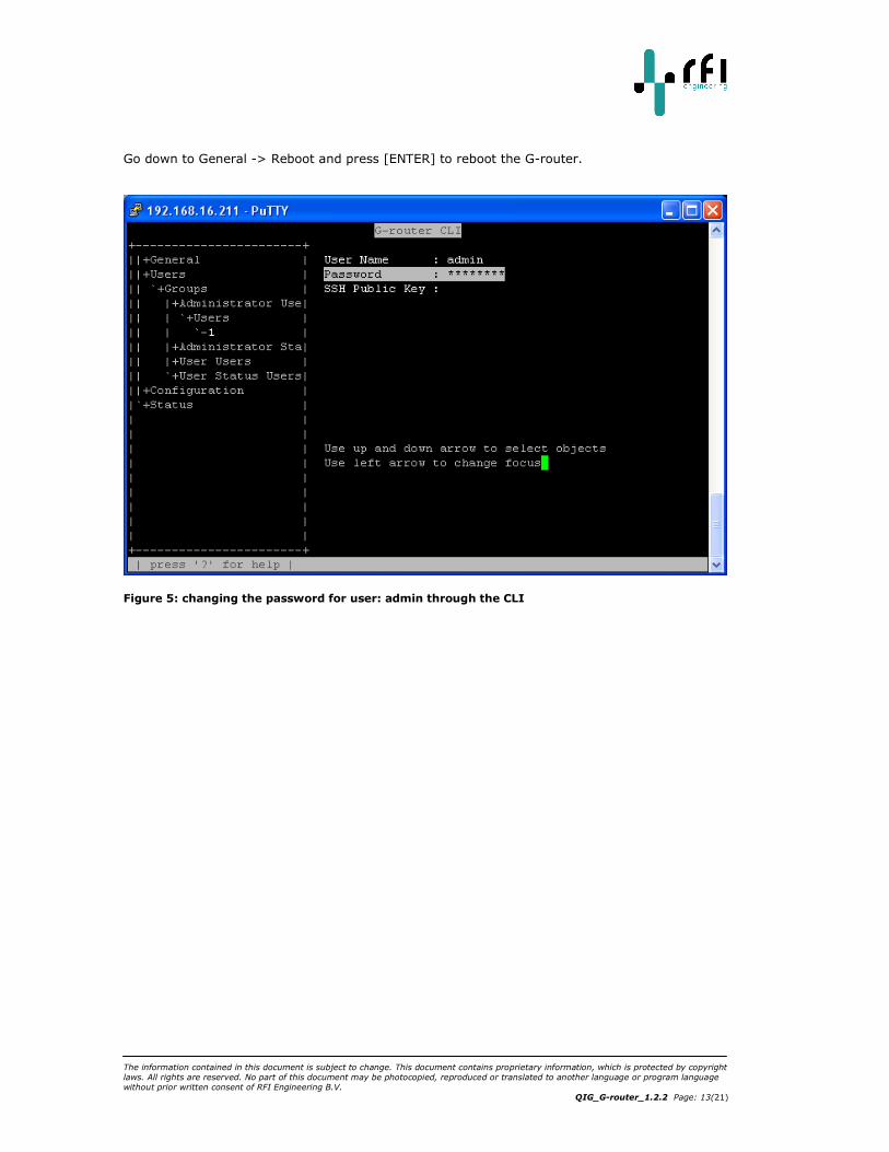
Go down to the Users -> Groups -> Administrator Users -> Users -> 1 with your arrow keys. Press the right arrow to navigate to the Password field. Here you can change the password.
After making configuration settings to the unit you have to reboot to activate the changes.
The information contained in this document is subject to change. This document contains proprietary information, which is protected by copyright
laws. All rights are reserved. No part of this document may be photocopied, reproduced or translated to another language or program language
without prior written consent of RFI Engineering B.V.
QIG_G-router_1.2.2 Page: 13(21)
Go down to General -> Reboot and press [ENTER] to reboot the G-router.
Figure 5: changing the password for user: admin through the CLI
The information contained in this document is subject to change. This document contains proprietary information, which is protected by copyright
laws. All rights are reserved. No part of this document may be photocopied, reproduced or translated to another language or program language
without prior written consent of RFI Engineering B.V.
Page: 14(21)
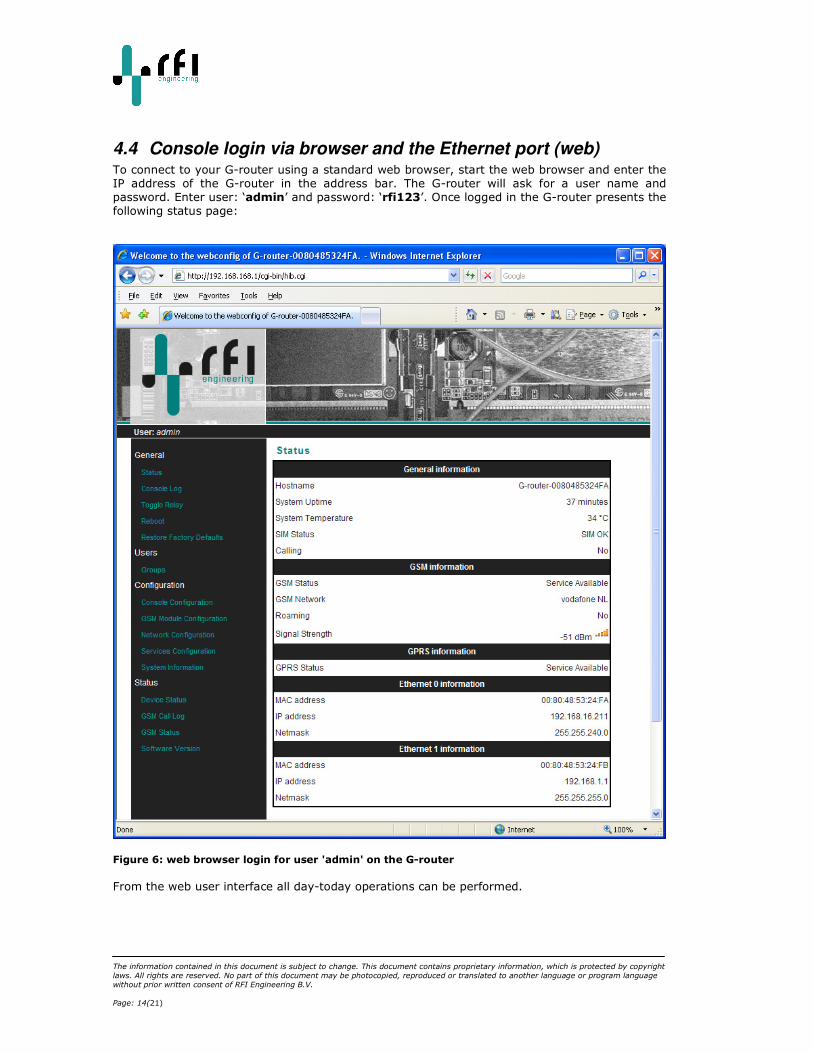
4.4 Console login via browser and the Ethernet port (web) To connect to your G-router using a standard web browser, start the web browser and enter the
IP address of the G-router in the address bar. The G-router will ask for a user name and
password. Enter user: ‘admin’ and password: ‘rfi123’. Once logged in the G-router presents the
following status page:
Figure 6: web browser login for user 'admin' on the G-router
From the web user interface all day-today operations can be performed.

The information contained in this document is subject to change. This document contains proprietary information, which is protected by copyright
laws. All rights are reserved. No part of this document may be photocopied, reproduced or translated to another language or program language
without prior written consent of RFI Engineering B.V.
QIG_G-router_1.2.2 Page: 15(21)
4.5 Console login via GSM dial-in During normal operation the G-router connects the GSM modem directly to the RS-232 port on
the back of the G-router unit. For this example we assume that the G-router is connected to the
console port of the (Cisco) WAN router as shown in Figure 3. Dialing in to the unit connects the
dial-in session directly to the console port of the Cisco router. When you use a dialer to connect
to the G-router typing the dial string should get you connected to the unit.
For example:
atd 06158xxxxx
CONNECT 115200
Online 00:00
================================================================================
+ Welcome RFI Engineering RFIos (Rose)...
+ Hostname : G-router-0080485324FA
+ System Name : unknown
+ System Location : unknown
+ System Contact : unknown
================================================================================
+ Version : G-router (buildnr:0400)
+ Buildtag : DEVELOPMENT
+ Flavour : VZ0
+ Build on : 06/16/2008 15:07:41
================================================================================
Escape usage: <ESC> character is <CTRL>\ or 0x1c
--------------------------------------------------
<ESC><ESC> -> Send escape sequence
<ESC>. -> Disconnect
<ESC>l -> Login to GSM device
<ESC>h -> Show this usage
<ESC>b -> Send BREAK command to console
Before the GSM modem is connected to the console port of the WAN router the G-router displays
a menu with options. These options can be accessed during the dial in session by giving an escape sequence. For example to show the menu again you can type “<CTRL>\“followed by “h”.
Pressing RETURN connects you directly to the console port of the connected WAN router. You will see the output of the WAN router scroll by followed by the router prompt.
For example:
*Mar 1 00:00:11.051: %LINK-3-UPDOWN: Interface Ethernet0, changed state to up
*Mar 1 00:00:11.055: %LINK-3-UPDOWN: Interface Serial0, changed state to down
*Mar 1 00:00:11.423: %LINK-3-UPDOWN: Interface Serial1, changed state to down
*Mar 1 00:00:29.663: %LINEPROTO-5-UPDOWN: Line protocol on Interface Ethernet0,
changed state to down
*Mar 1 00:00:31.687: %LINK-5-CHANGED: Interface BRI0, changed state to
administratively down
*Mar 1 00:00:32.723: %SYS-5-CONFIG_I: Configured from memory by console
*Mar 1 00:00:32.731: %LINEPROTO-5-UPDOWN: Line protocol on Interface BRI0, changed
state to down
*Mar 1 00:00:33.271: %LINK-5-CHANGED: Interface Serial0, changed state to
administratively down
*Mar 1 00:00:33.275: %LINK-5-CHANGED: Interface Serial1, changed state to
administratively down
*Mar 1 00:00:35.955: %LINEPROTO-5-UPDOWN: Line protocol on Interface Serial0,
changed state to down
*Mar 1 00:00:35.959: %LINEPROTO-5-UPDOWN: Line protocol on Interface Serial1,
changed
Router>
By pressing “<CTRL>\“ followed by “l” (Lower case L) escapes you out of the connection with the
WAN router and gives a login prompt of the G-router router itself. By logging in (analog to the examples in paragraph 4.1) you get access to the configuration of the unit.

The information contained in this document is subject to change. This document contains proprietary information, which is protected by copyright
laws. All rights are reserved. No part of this document may be photocopied, reproduced or translated to another language or program language
without prior written consent of RFI Engineering B.V.
Page: 16(21)
When connected the unit prompts you to enter a username and a password:
login as: root
password:
================================================================================
+ Welcome RFI Engineering RFIos (Rose)...
+ Version : G-router (buildnr:0235)
+ Build on : 01/28/2008 15:51:05
================================================================================
root@G-router-00804855565C:~$
The default password for the unit is set to: rfi123
At the shell prompt use the command exit to log out. This returns you to the logging function
and returns you to the WAN router prompt.
As an example,
root@G-router-00804855565C:~$ exit Router>
to logout.
4.6 Disconnect the GSM dial-in connection You can disconnect the dial-in connection by giving the escape sequence: “<CTRL>\“ followed by
“.” (dot). As an example:
Router>
Going to hangup now, Good Bye
NO CARRIER
The information contained in this document is subject to change. This document contains proprietary information, which is protected by copyright
laws. All rights are reserved. No part of this document may be photocopied, reproduced or translated to another language or program language
without prior written consent of RFI Engineering B.V.
QIG_G-router_1.2.2 Page: 17(21)
5 Advanced configuration, user ‘root’ All configuration of the G-router is stored in and retrieved from the Hierarchical Information Base
(HIB). The HIB is a database for storing configuration and run-time information for (embedded) RFI products. All manipulation of configuration elements of the unit is done through the
command line interface tool called the HIB client (hipc). Only user ‘root’ has access through all configuration settings of the G-router. Normal day-to-day operation should always be performed
by the user ‘admin’ or any of its sub-users. Root access is only applicable in case you want to make upgrades to the software.
The HIB uses a tree-shaped hierarchical data structure for storing objects. A schema defines the hierarchical relations of the objects in the tree, and describes the properties of each object.
The schema-tree is built from the following node types:
• Group: A group is a container for holding other 'child' nodes.
• Object: An object is the 'leaf' of the tree, which contains the actual data. • Array: An array is a container which can hold zero or more copies of its sub-tree.
Every entry in an array is identified by an integer index, starting from 0. The following diagram
is an example of a simple schema:
-- config (group)
|-- network (group)
| |-- interface (array)
| | |-- ifname (object)
| | |-- ip_address (object)
| | `-- netmask (object)
`-- hostname (object)
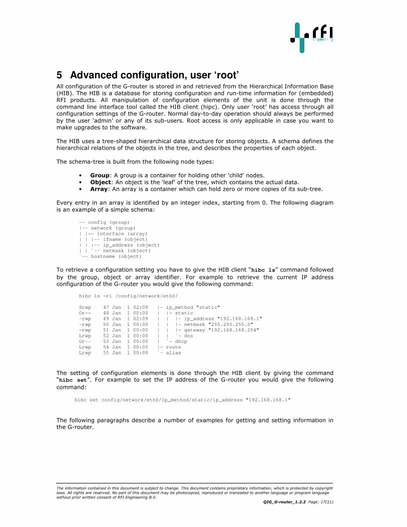
To retrieve a configuration setting you have to give the HIB client “hibc ls” command followed
by the group, object or array identifier. For example to retrieve the current IP address configuration of the G-router you would give the following command:
hibc ls -rl /config/network/eth0/
Srwp 47 Jan 1 02:09 |- ip_method "static"
Or-- 48 Jan 1 00:00 | |- static
-rwp 49 Jan 1 02:09 | | |- ip_address "192.168.168.1"
-rwp 50 Jan 1 00:00 | | |- netmask "255.255.255.0"
-rwp 51 Jan 1 00:00 | | |- gateway "192.168.168.254"
Lrwp 52 Jan 1 00:00 | | `- dns
Or-- 53 Jan 1 00:00 | `- dhcp
Lrwp 54 Jan 1 00:00 |- route
Lrwp 55 Jan 1 00:00 `- alias
The setting of configuration elements is done through the HIB client by giving the command “hibc set”. For example to set the IP address of the G-router you would give the following
command:
hibc set config/network/eth0/ip_method/static/ip_address "192.168.168.1"
The following paragraphs describe a number of examples for getting and setting information in the G-router.
The information contained in this document is subject to change. This document contains proprietary information, which is protected by copyright
laws. All rights are reserved. No part of this document may be photocopied, reproduced or translated to another language or program language
without prior written consent of RFI Engineering B.V.
Page: 18(21)
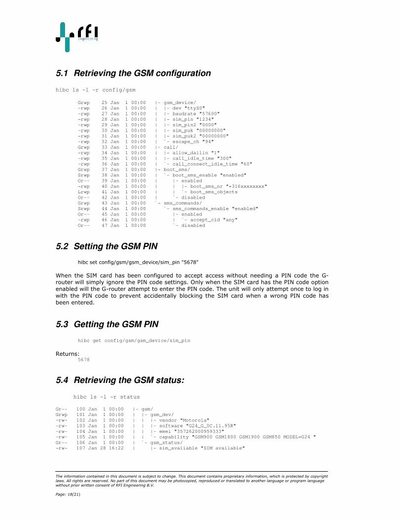
5.1 Retrieving the GSM configuration hibc ls -l -r config/gsm
Grwp 25 Jan 1 00:00 |- gsm_device/
-rwp 26 Jan 1 00:00 | |- dev "ttyS0"
-rwp 27 Jan 1 00:00 | |- baudrate "57600"
-rwp 28 Jan 1 00:00 | |- sim_pin "1234"
-rwp 29 Jan 1 00:00 | |- sim_pin2 "0000"
-rwp 30 Jan 1 00:00 | |- sim_puk "00000000"
-rwp 31 Jan 1 00:00 | |- sim_puk2 "00000000"
-rwp 32 Jan 1 00:00 | `- escape_ch "94"
Grwp 33 Jan 1 00:00 |- call/
-rwp 34 Jan 1 00:00 | |- allow_dailin "1"
-rwp 35 Jan 1 00:00 | |- call_idle_time "300"
-rwp 36 Jan 1 00:00 | `- call_connect_idle_time "60"
Grwp 37 Jan 1 00:00 |- boot_sms/
Srwp 38 Jan 1 00:00 | `- boot_sms_enable "enabled"
Or-- 39 Jan 1 00:00 | |- enabled
-rwp 40 Jan 1 00:00 | | |- boot_sms_nr "+316xxxxxxxx"
Lrwp 41 Jan 1 00:00 | | `- boot_sms_objects
Or-- 42 Jan 1 00:00 | `- disabled
Grwp 43 Jan 1 00:00 `- sms_commands/
Srwp 44 Jan 1 00:00 `- sms_commands_enable "enabled"
Or-- 45 Jan 1 00:00 |- enabled
-rwp 46 Jan 1 00:00 | `- accept_cid "any"
Or-- 47 Jan 1 00:00 `- disabled
5.2 Setting the GSM PIN
hibc set config/gsm/gsm_device/sim_pin "5678"
When the SIM card has been configured to accept access without needing a PIN code the G-router will simply ignore the PIN code settings. Only when the SIM card has the PIN code option
enabled will the G-router attempt to enter the PIN code. The unit will only attempt once to log in
with the PIN code to prevent accidentally blocking the SIM card when a wrong PIN code has
been entered.
5.3 Getting the GSM PIN
hibc get config/gsm/gsm_device/sim_pin
Returns:
5678
5.4 Retrieving the GSM status:
hibc ls -l -r status
Gr-- 100 Jan 1 00:00 |- gsm/
Grwp 101 Jan 1 00:00 | |- gsm_dev/
-rw- 102 Jan 1 00:00 | | |- vendor "Motorola"
-rw- 103 Jan 1 00:00 | | |- software "G24_G_0C.11.95R"
-rw- 104 Jan 1 00:00 | | |- emei "357262000959333"
-rw- 105 Jan 1 00:00 | | `- capability "GSM900 GSM1800 GSM1900 GSM850 MODEL=G24 "
Gr-- 106 Jan 1 00:00 | `- gsm_status/
-rw- 107 Jan 28 16:22 | |- sim_avaliable "SIM available"
The information contained in this document is subject to change. This document contains proprietary information, which is protected by copyright
laws. All rights are reserved. No part of this document may be photocopied, reproduced or translated to another language or program language
without prior written consent of RFI Engineering B.V.
QIG_G-router_1.2.2 Page: 19(21)
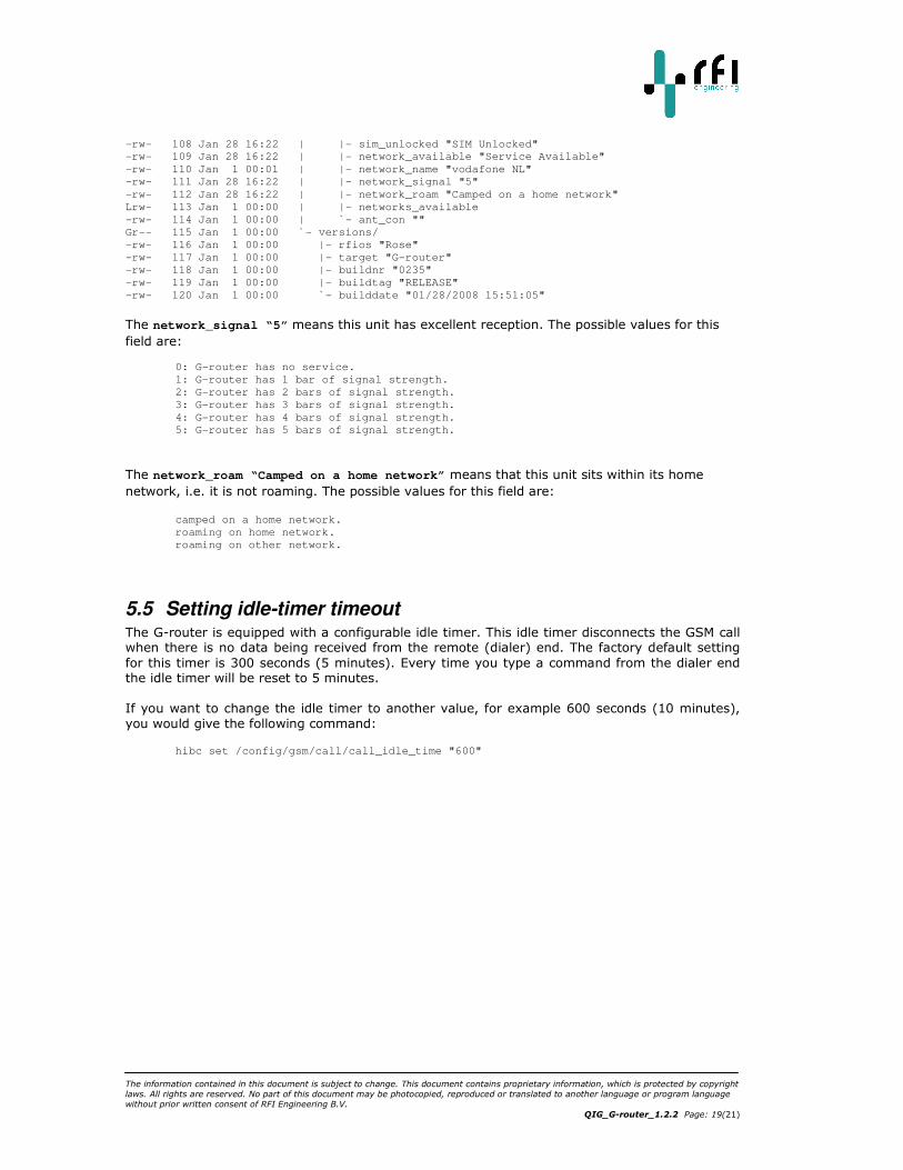
-rw- 108 Jan 28 16:22 | |- sim_unlocked "SIM Unlocked"
-rw- 109 Jan 28 16:22 | |- network_available "Service Available"
-rw- 110 Jan 1 00:01 | |- network_name "vodafone NL"
-rw- 111 Jan 28 16:22 | |- network_signal "5"
-rw- 112 Jan 28 16:22 | |- network_roam "Camped on a home network"
Lrw- 113 Jan 1 00:00 | |- networks_available
-rw- 114 Jan 1 00:00 | `- ant_con ""
Gr-- 115 Jan 1 00:00 `- versions/
-rw- 116 Jan 1 00:00 |- rfios "Rose"
-rw- 117 Jan 1 00:00 |- target "G-router"
-rw- 118 Jan 1 00:00 |- buildnr "0235"
-rw- 119 Jan 1 00:00 |- buildtag "RELEASE"
-rw- 120 Jan 1 00:00 `- builddate "01/28/2008 15:51:05"
The network_signal “5” means this unit has excellent reception. The possible values for this
field are:
0: G-router has no service.
1: G-router has 1 bar of signal strength.
2: G-router has 2 bars of signal strength.
3: G-router has 3 bars of signal strength.
4: G-router has 4 bars of signal strength.
5: G-router has 5 bars of signal strength.
The network_roam “Camped on a home network” means that this unit sits within its home
network, i.e. it is not roaming. The possible values for this field are:
camped on a home network.
roaming on home network.
roaming on other network.
5.5 Setting idle-timer timeout The G-router is equipped with a configurable idle timer. This idle timer disconnects the GSM call when there is no data being received from the remote (dialer) end. The factory default setting
for this timer is 300 seconds (5 minutes). Every time you type a command from the dialer end the idle timer will be reset to 5 minutes.
If you want to change the idle timer to another value, for example 600 seconds (10 minutes),
you would give the following command:
hibc set /config/gsm/call/call_idle_time "600"
The information contained in this document is subject to change. This document contains proprietary information, which is protected by copyright
laws. All rights are reserved. No part of this document may be photocopied, reproduced or translated to another language or program language
without prior written consent of RFI Engineering B.V.
Page: 20(21)
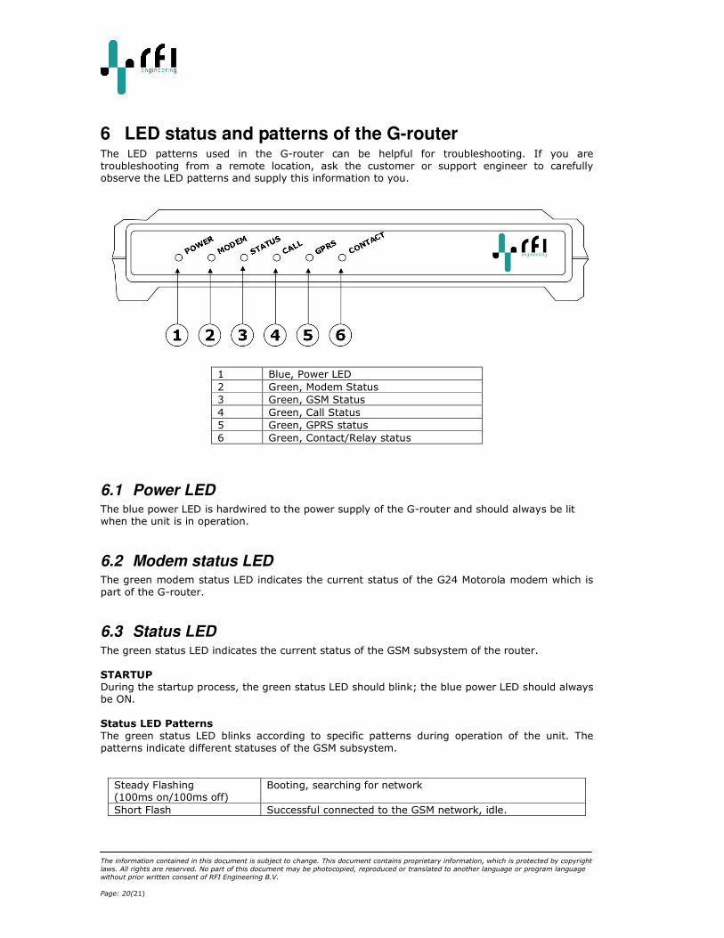
6 LED status and patterns of the G-router The LED patterns used in the G-router can be helpful for troubleshooting. If you are
troubleshooting from a remote location, ask the customer or support engineer to carefully observe the LED patterns and supply this information to you.
1 Blue, Power LED
2 Green, Modem Status
3 Green, GSM Status
4 Green, Call Status
5 Green, GPRS status
6 Green, Contact/Relay status
6.1 Power LED The blue power LED is hardwired to the power supply of the G-router and should always be lit when the unit is in operation.
6.2 Modem status LED The green modem status LED indicates the current status of the G24 Motorola modem which is
part of the G-router.
6.3 Status LED The green status LED indicates the current status of the GSM subsystem of the router.
STARTUP
During the startup process, the green status LED should blink; the blue power LED should always be ON.
Status LED Patterns
The green status LED blinks according to specific patterns during operation of the unit. The
patterns indicate different statuses of the GSM subsystem.
Steady Flashing (100ms on/100ms off)
Booting, searching for network
Short Flash Successful connected to the GSM network, idle.

The information contained in this document is subject to change. This document contains proprietary information, which is protected by copyright
laws. All rights are reserved. No part of this document may be photocopied, reproduced or translated to another language or program language
without prior written consent of RFI Engineering B.V.
QIG_G-router_1.2.2 Page: 21(21)
(50ms on/2s off)
Long Flash
(2s on/50ms off)
Incoming call to G-router
Steady ON The G-router answered the incoming call, call in progress
Hyper Active Flashing (50ms on/50ms off)
Error connecting to GSM network, network can not be found or no network coverage.
Please note: When the unit is being upgraded with new software the GSM LED is steady
flashing. Do not unplug the unit whilst upgrading.
6.4 Call status LED The green call status LED indicates if there is a GSM call ongoing. When there is no call the LED
will be off. Once a GSM call is in progress, i.e. someone has contact with the modem over the GSM network the LED will be lit.
6.5 GPRS status LED The green GPRS status LED indicates when the G-router has successfully connected to the GPRS
network of the GSM operator. When there is no GPRS coverage possible the LED will be off.
6.6 Relay status LED The G-router already has a relay status LED but NO relay contact is present in the current
hardware. Please note that the relay itself will be placed upon the following release of the
hardware. This relay can be used to reset the remote WAN by disconnecting the mains power supply. In other words, the WAN router can be remotely power cycled.
The relay is activated from the command line using the toggle_relay command. The command
itself gives helpful in formation when you type toggle_relay –h.
As an example:
root@G-router-00804855565C:~$ toggle_relay -h
usage: toggle_relay
-t <timeout> Toggle delay
-c Close contact (device off)
-f Open contact (device on)
-h Show this help
To toggle the relay to initiate a power cycle you give the following command:
root@G-router-00804855565C:~$ toggle_relay
In which case the relay is activated for 5 seconds. Other timeout values can be specified on the
command line by specifying a timeout value (in seconds) behind the command
Permanently activating the relay is done as follows:
root@G-router-00804855565C:~$ toggle_relay -c
Permanently de-activating the relay is done as follows:
root@G-router-00804855565C:~$ toggle_relay -f