Fuzzy control and simulation of boiler drum water level
8
Fuzzy control and simulation of boiler drum water level Fansheng Meng 1 , Xuefei Zhang 2 , Yan Zheng 1 , Xi Cheng 1 , and Zhi Weng 1,* 1 College of Electronic Information Engineering, Inner Mongolia University, Hohhot 010021, China 2 Inner Mongolia Guangna Information Technology Co., Ltd, Wuhai 016030, China Keywords: Boiler drum water level, PID control, Fuzzy control, Simulation. Abstract. Boiler drum water level control system is hard to develop practical mathematical model and has nonlinear, stable and delay characteristics. The traditional boiler drum water level control often uses three impulse PID control method. The existing problem of ordinary PID control strategy is: once good parameter setting, it is hard to adapt to the change of the operation of the system dynamic greatly. In order to solve the problems of the above, the research object of the subject is a certain 120 t/h boiler steam capacity, the boiler drum water level control system is designed, and the control strategies are studied. In order to obtain better contrast, the ordinary PID controller and Fuzzy controller are designed, and the control strategies of the simulation are analyzed. 1 Introduction Boiler drum water level control is very important in boiler automatic control system; the control effect is directly affecting the quality of the boiler water. Supply and ultimately affect the boiler’s safe production. Boiler drum water level control plays an important role in quality and reducing energy consumption and safety production, it is one of the important indicators of the normal operation of boiler. If water level is too high, the normal work of the separation device would be damaged, it will caused steam of water, increase the scale and impact on the super heater pipe steam quality. If water level is too low, the water cycle is destroyed, it leads the bursting of water wall tube, and easy to burn dry pot or steam drum damage. Thus, improve the level of boiler drum water level automatic control is urgent problem, to reduce the labor intensity of operators, has the vital significance to the safe operation of boiler. The traditional PID control principle is simple, easy to implement, it has been widely used in boiler drum level, it has certain limitations, there are so large overshoot that can not achieve precise control of nonlinear systems. Fuzzy control can adapt to the nonlinear boiler drum water level control system and uncertain characteristics, comparing with the traditional * Corresponding author: [email protected] CSCNS2019 MATEC Web of Conferences 309, 05003 (2020) https://doi.org/10.1051/matecconf/202030 905003 © The Authors, published by EDP Sciences. This is an open access article distributed under the terms of the Creative Commons Attribution License 4.0 (http://creativecommons.org/licenses/by/4.0/).
-
Upload
khangminh22 -
Category
Documents
-
view
1 -
download
0
Transcript of Fuzzy control and simulation of boiler drum water level

Fuzzy control and simulation of boiler drum water level
Fansheng Meng1, Xuefei Zhang2, Yan Zheng1, Xi Cheng1, and Zhi Weng1,* 1College of Electronic Information Engineering, Inner Mongolia University, Hohhot 010021, China 2Inner Mongolia Guangna Information Technology Co., Ltd, Wuhai 016030, China
Keywords: Boiler drum water level, PID control, Fuzzy control, Simulation.
Abstract. Boiler drum water level control system is hard to develop practical mathematical model and has nonlinear, stable and delay characteristics. The traditional boiler drum water level control often uses three impulse PID control method. The existing problem of ordinary PID control strategy is: once good parameter setting, it is hard to adapt to the change of the operation of the system dynamic greatly. In order to solve the problems of the above, the research object of the subject is a certain 120 t/h boiler steam capacity, the boiler drum water level control system is designed, and the control strategies are studied. In order to obtain better contrast, the ordinary PID controller and Fuzzy controller are designed, and the control strategies of the simulation are analyzed.
1 Introduction Boiler drum water level control is very important in boiler automatic control system; the
control effect is directly affecting the quality of the boiler water. Supply and ultimately affect the boiler’s safe production. Boiler drum water level control plays an important role in quality and reducing energy consumption and safety production, it is one of the important indicators of the normal operation of boiler. If water level is too high, the normal work of the separation device would be damaged, it will caused steam of water, increase the scale and impact on the super heater pipe steam quality. If water level is too low, the water cycle is destroyed, it leads the bursting of water wall tube, and easy to burn dry pot or steam drum damage. Thus, improve the level of boiler drum water level automatic control is urgent problem, to reduce the labor intensity of operators, has the vital significance to the safe operation of boiler.
The traditional PID control principle is simple, easy to implement, it has been widely used in boiler drum level, it has certain limitations, there are so large overshoot that can not achieve precise control of nonlinear systems. Fuzzy control can adapt to the nonlinear boiler drum water level control system and uncertain characteristics, comparing with the traditional
* Corresponding author: [email protected]
CSCNS2019MATEC Web of Conferences 309, 05003 (2020) https://doi.org/10.1051/matecconf/202030905003
© The Authors, published by EDP Sciences. This is an open access article distributed under the terms of the CreativeCommons Attribution License 4.0 (http://creativecommons.org/licenses/by/4.0/).

PID control has strong robustness and easy to use, flexibility, adaptability, control precision and strong advantages such as simple principle, conventional control system. In order to obtain better contrast, the ordinary PID controller and Fuzzy controller are designed, and the control strategies of the simulation are analyzed [1].
2 The mathematical model of the object
2.1 The main parameters and control indicators
The diameter of Boiler drum is 1460 mm, length is 6500 mm. The standard values of Boiler drum water level is1000 mm, the scope of change for 920-1080 mm. Measurable range of Boiler drum water level change is ±300 mm. Steam and water can be measured, steam decided by external load. Steam flow cannot be controlled; feed water flow can be controlled by water supply valve [2].
Fig. 1. Main process flow diagram of boiler.
When the actual value of the drum water level is different from the normal value 30-50 mm, it is asked to quickly return to normal. When the water level value is not more than 30mm, it can be considered normal, then the water supply valve should be as little as possible to extend the service time of the valve.
The standard current signal received by the actuator and controller is 0-l0 mA. The standard current signal output from the pressure detection device in the drum is 0-l0 mA [3].
2.2 Dynamic analysis of control system
According to the dynamic characteristics of boiler drum water level, the automatic regulation of drum water level is designed; the step change of water supply and steam volume is the main factor causing the change of water level. The regulator controls the opening of the feed valve according to the deviation between the measured value and the set value to regulating the water level. The water level is not only affected by the balance between water supply and steam flow, but also by the change of the volume of steam and water in the steam water mixture. The drum water level H not only reflects the volume of bubbles under the water surface, but also reflects the storage volume of the drum (including the water circulation
CSCNS2019MATEC Web of Conferences 309, 05003 (2020) https://doi.org/10.1051/matecconf/202030905003
2
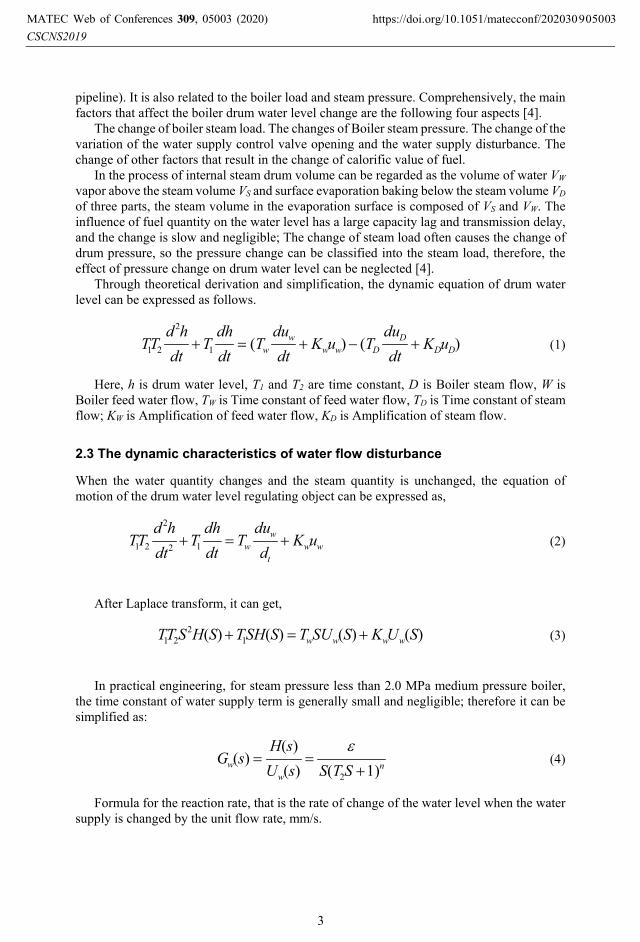
pipeline). It is also related to the boiler load and steam pressure. Comprehensively, the main factors that affect the boiler drum water level change are the following four aspects [4].
The change of boiler steam load. The changes of Boiler steam pressure. The change of the variation of the water supply control valve opening and the water supply disturbance. The change of other factors that result in the change of calorific value of fuel.
In the process of internal steam drum volume can be regarded as the volume of water VW vapor above the steam volume VS and surface evaporation baking below the steam volume VD of three parts, the steam volume in the evaporation surface is composed of VS and VW. The influence of fuel quantity on the water level has a large capacity lag and transmission delay, and the change is slow and negligible; The change of steam load often causes the change of drum pressure, so the pressure change can be classified into the steam load, therefore, the effect of pressure change on drum water level can be neglected [4].
Through theoretical derivation and simplification, the dynamic equation of drum water level can be expressed as follows.
)()(1
2
21 DDD
Dwww
w uKdt
duTuK
dtdu
Tdtdh
Tdt
hdTT +−+=+ (1)
Here, h is drum water level, T1 and T2 are time constant, D is Boiler steam flow, W is Boiler feed water flow, TW is Time constant of feed water flow, TD is Time constant of steam flow; KW is Amplification of feed water flow, KD is Amplification of steam flow.
2.3 The dynamic characteristics of water flow disturbance
When the water quantity changes and the steam quantity is unchanged, the equation of motion of the drum water level regulating object can be expressed as,
wwt
ww uK
ddu
Tdtdh
Tdt
hdTT +=+ 12
2
21 (2)
After Laplace transform, it can get,
)()()()( 12
21 SUKSSUTSSHTSHSTT wwww +=+ (3)
In practical engineering, for steam pressure less than 2.0 MPa medium pressure boiler,
the time constant of water supply term is generally small and negligible; therefore it can be simplified as:
nw
w STSsUsH
sG)1()(
)()(
2 +==
ε (4)
Formula for the reaction rate, that is the rate of change of the water level when the water supply is changed by the unit flow rate, mm/s.
CSCNS2019MATEC Web of Conferences 309, 05003 (2020) https://doi.org/10.1051/matecconf/202030905003
3

2.4 Dynamic characteristics of steam disturbance
If the feed water flow rate remains unchanged, the step change of steam flow rate, (such as the sudden increase of a value), The differential equation of dynamic characteristics of drum water level can be expressed as,
)(12
2
21 DDD uKdtdh
Tdtdh
Tdt
hdTT +−=+ (5)
After Laplace transform, it can get,
)]()([)()( 12
21 SUKSSUTSSHTSHSTT DDDD +−=+ (6)
The transfer function of the drum water level regulation object under steam flow disturbance:
)1()()(
)(21 +
+−==
STSTKST
sUsH
sG DD
DD (7)
It can be changed the following expression.
nD
D STK
ST
sUsH
sG)1()(
)()(
2
2
++−==
α (8)
2.5 Mathematical model
Under the feed water flow unit step disturbance, The water level soaring speed response curve, The change speed of water level ξ=0.0529 mm/s. In order to improve the simulation speed, n=1. Obtained by measuring that the time constant of the first order lag T2=8.5 s. Therefore, the transfer function of water supply W and water level H is [5],
)15.8(0529.0
)()(
)(1 +==
sssWsH
sG (9)
In the steam flow unit step disturbance, the water level change of the response speed of Kf=0.0747 mm/s, namely Ta=0.0747 mm/s, gain coefficient K2=2.613, time constant T2=6.7 s, delay n=2, the transfer function of steam flow H and water level D is,
sssDsH
sG0747.0
)17.6(613.2
)()(
)( 22 −+
== (10)
CSCNS2019MATEC Web of Conferences 309, 05003 (2020) https://doi.org/10.1051/matecconf/202030905003
4

3 Design of PID controller
3.1 Controller design
PID is a negative feedback closed loop controller, which is usually connected with objects in series, and set on the forward channel of negative feedback closed loop. The definition of error signal is,
)()()( scsrse −= (11)
e(s) is the system deviation signal, r(s) is the signal of input; and c(s) is the actual value. Then PID adjusting instrument can calculation by proportion, integral, differential with e(s).
The PID algorithm is described by,
])(
)(1
)([)(dt
tdeTdtte
Ttektu d
ip ∫ += (12)
u(t) is the input signal of PID controller, which is sent to the objects, kp is the proportion coefficient of PID controller, Ti is the integration time constant of PID controller and Td is the differentiating time constant of PID controller [5].
The transfer function of PID controller is,
]1
1[)()(
)( sTsT
ksEsU
sG di
p ++== (13)
3.2 Parameter setting
It is ideal to determine the parameters of PID by using the method of theory, which is used to adjust the parameters, but the system selected in this paper can not find the ideal parameters of the PID controller by using the theoretical method. In practice, the trial and error method, this paper tries to use, is widely used to determine the parameters of the PID controller [6]. The setting steps are as follows.
a) Setting proportion coefficient. Before running the system, the integral coefficient ki and the differential coefficient kd of the controller should be set to zero, then adjust coefficient kp from the large to small scale, observing the response curve of the system, until the two peak overshoot ratio of about 4:1 of the decay curve.
b) Setting integral coefficient. The diameter of Boiler drum is 1460mm, length is 6500mm. In order to compensate for the loss of system stability caused by the addition of integral, first adjust the kp reduced by 20%. And then adjust the integral coefficient ki from small to large, until the system can maintain good dynamic performance in the case of static error can be eliminated.
c) Setting differential coefficient. In order to improve the stability of the system due to the addition of differential. On the basis of the second step setting, the differential coefficient kd is increased from zero, and the coefficient of kp is gradually increased, until the satisfactory
CSCNS2019MATEC Web of Conferences 309, 05003 (2020) https://doi.org/10.1051/matecconf/202030905003
5
adjustment effect is obtained.Through a lot of repeated adjustments, and finally get a set of ideal PID parameters are as follows, kp=9, ki=0.0045 and kd=0.
4 Design of fuzzy controller
4.1 The component of fuzzy system
a) Fuzzy Controller: Fuzzy Controller is takes advantage of computer program supporting Fuzzy Controller to complete its rhythm. This controller is a language controller being the core of the whole system and based on the knowledge expressing and the rule inference.
b) Input interface/output interface: The digital signals of controller target being transformed by sensor through input interface will be transported to Fuzzy Controller. Processed by the interior of the Fuzzy Controller, the signal will be transformed into analog signal and then being sent to actuator to control the target [7].
c) Sensor: It is a device transforming the controlled volume of the target into electrical signal (analog signal or digital). The controlled volume is usually non-electrical quantity such as the temperature, the potency and the rate of flow and so on. The precision of the whole system playing a critical role in the control system depends on the sensibility of the sensor. Therefore, it is necessary to choose a high sensitivity and stable sensor in application.
d) Controlled device: It is a kind of device or equipment and the combination of them, which could be univariate or multivariable as well, it also can be linear or un-linear. The most reasonable choice is to choose Fuzzy Control when controlled device lacks of accurate mathematical model.
e) Actuator: It including various servomotor, AC and DC motor, pneumatic control value, stepper motor and hydraulic mechanism and so on.
4.2 Determination of membership function
The setting of water level error [-1.67 mA, 1.67 mA], fuzzy domain [-6, 6], fuzzy subset {NB, NM, NS, NO, PO, PS, PM, PB}; The settlement of error rate of change ec [0.19, 0.19], fuzzy domain [-6,6], fuzzy subset {NB, NM, NS, NO, PO, PS, PM, PB}; output fuzzy domain [-7, 7], fuzzy subset {NB, NM, NS, O, PS, PM, B}; Systemic maxi error is an approximately 4mm waterspout owing to false water level under steam disturbance. Due to conversion coefficient of differential pressure transmission 10 / 300=0.0333, the scale of error e is 4 × 0.0333=0.1332 mA, that is the basic domain of e is {-0.1332, 0.1332}.
The quantization of error e is ke=6 / 0.1332=45. Quantization factor of deviation rate is kec=6 / 0.0568=104.The coefficient k of output variable u is ascertained according to the scale of input signal belonging to actuator. Because of the adoption of DDZII instrument, its signal scale is 0-10 mA, thus ku=5 / 7=0.7142.The shape of membership function has a little influence on the control effect; however, the performance is significantly affected by its width size (Namely the size of every fuzzy set in the whole integer domain coverage.). In light of this, compared with other membership function, the triangle membership function is benefit to sensibility when the figure of input changes.
CSCNS2019MATEC Web of Conferences 309, 05003 (2020) https://doi.org/10.1051/matecconf/202030905003
6

5 The analysis of simulink Setting the water level as 1, as can been seen from the graph the system is stable in 300 second, moreover the Fuzzy control curve and PID control curve. According to system step simulation curve: compared with PID control, the Fuzzy control has several advantages such as sensitive response, overshoot is small and high control precision, which can basically satisfy the demand of boiler drum water level control.
Fig. 2. Simulation structure of Fuzzy control and PID control.
a
CSCNS2019MATEC Web of Conferences 309, 05003 (2020) https://doi.org/10.1051/matecconf/202030905003
7
b
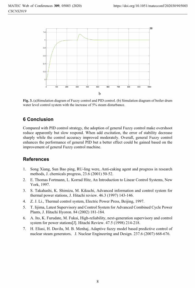
Fig. 3. (a)Simulation diagram of Fuzzy control and PID control. (b) Simulation diagram of boiler drum water level control system with the increase of 5% steam disturbance.
6 Conclusion Compared with PID control strategy, the adoption of general Fuzzy control make overshoot reduce apparently but slow respond. When add excitation, the error of stability decrease sharply while the control accuracy improved moderately. Overall, general Fuzzy control enhances the performance of general PID but a better effect could be gained based on the improvement of general Fuzzy control machine.
References
1. Song Xiang, Sun Bao ping, RU-ling were, Anti-caking agent and progress in research methods, J. chemicals progress, 23.6 (2001) 50-52.
2. E. Thomas Fortmann, L. Korrad Hitz, An Introduction to Linear Control Systems, New York, 1997.
3. S. Takahashi, K. Shimizu, M. Kikuchi, Advanced information and control system for thermal power stations, J. Hitachi review. 46.3 (1997) 143-146.
4. Z. J. Li., Thermal control system, Electric Power Press, Beijing, 1997. 5. T. Iijima, Latest Supervisory and Control System for Advanced Combined Cycle Power
Plants, J. Hitachi Hyoron. 84 (2002) 181-184. 6. A. Ito, K. Furudate, M. Fukai, High-reliability, next-generation supervisory and control
system for power stations[J]. Hitachi Review. 47.5 (1998) 214-218. 7. H. Eliasi, H. Davilu, M. B. Menhaj, Adaptive fuzzy model based predictive control of
nuclear steam generators, J. Nuclear Engineering and Design. 237.6 (2007) 668-676.
CSCNS2019MATEC Web of Conferences 309, 05003 (2020) https://doi.org/10.1051/matecconf/202030905003
8