FUSION YEARBOOK - VTT
145
ESPOO 2004 VTT PUBLICATIONS 530 FUSION YEARBOOK Association Euratom-Tekes Annual Report 2003
-
Upload
khangminh22 -
Category
Documents
-
view
6 -
download
0
Transcript of FUSION YEARBOOK - VTT
VTT PU
BLICATION
S 530FU
SION Yearbook. A
ssociation Euratom-Tekes. A
nnual Report 2003
Tätä julkaisua myy Denna publikation säljs av This publication is available from
VTT TIETOPALVELU VTT INFORMATIONSTJÄNST VTT INFORMATION SERVICEPL 2000 PB 2000 P.O.Box 2000
02044 VTT 02044 VTT FIN–02044 VTT, FinlandPuh. (09) 456 4404 Tel. (09) 456 4404 Phone internat. + 358 9 456 4404Faksi (09) 456 4374 Fax (09) 456 4374 Fax + 358 9 456 4374
ISBN 951–38–6379–4 (soft back ed.) ISBN 951–38–6380–8 (URL: http://www.vtt.fi/inf/pdf/)ISSN 1235–0621 (soft back ed.) ISSN 1455–0849 (URL: http://www.vtt.fi/inf/pdf/)
ESPOO 2004 VTT PUBLICATIONS 530
This report summarises the results of the Tekes FUSION technologyprogramme and the fusion research activities by the Association Euratom-Tekes in 2003. The research areas are fusion physics, plasma engineering,fusion technology and a smaller effort to socio-economic studies. Fusiontechnology research is carried out in close collaboration with Finnishindustry.
The emphasis in fusion physics and plasma engineering is intheoretical and computational studies on transport, physics of radio-frequency heating and plasma edge phenomena related to Europeanfusion experiments. Experimental work on plasma-wall interactionscovers erosion, re-deposition and material transport studies in the edgeregion. A major part of the work is devoted to the EFDA JETWorkprogramme in collaboration with other European Associations.
The work in fusion technology for the EFDA Technology Programmeand ITER is strongly focused into vessel/in-vessel materials coveringresearch and characterisation of first wall materials, joining methods,manufacturing of multi-metal components and surface physics studies onplasma facing materials. A second domain of fusion technology consistsof remote handling systems including water hydraulic tools andmanipulators for the ITER divertor maintenance and prototyping ofintersector welding and cutting robot. Virtual modelling is an essentialelement in the remote handling engineering. Several EFDA technologytasks were successfully completed in 2003.
FUSION YEARBOOKAssociation Euratom-TekesAnnual Report 2003
NATIONAL TECHNOLOGY AGENCYP.O. Box 69, FIN-00101 Helsinki, Finland
Tel. +358 105 2151, Fax +358 105215905
www.tekes.fi
VTT TECHNICAL RESEARCH CENTRE OF FINLANDVTT PROCESSES
P.O. Box 1608, FIN-02044 VTT, FinlandTel. +358 9 4561, Fax +358 9 456 6390
www.vtt.fi


VTT PUBLICATIONS 530
FUSION YEARBOOK
Association Euratom-Tekes Annual Report 2003
Seppo Karttunen & Karin Rantamäki (Eds.)
VTT Processes

2
ISBN 951�38�6379�4 (soft back ed.) ISSN 1235�0621 (soft back ed.) ISBN 951�38�6380�8 (URL: http://www.vtt.fi/inf/pdf/) ISSN 1455�0849 (URL: http://www.vtt.fi/inf/pdf/) Copyright © VTT 2004
JULKAISIJA � UTGIVARE � PUBLISHER
VTT, Vuorimiehentie 5, PL 2000, 02044 VTT puh. vaihde (09) 4561, faksi (09) 456 4374
VTT, Bergsmansvägen 5, PB 2000, 02044 VTT tel. växel (09) 4561, fax (09) 456 4374
VTT Technical Research Centre of Finland, Vuorimiehentie 5, P.O.Box 2000, FIN�02044 VTT, Finland phone internat. + 358 9 4561, fax + 358 9 456 4374
VTT Prosessit, Otakaari 3 A, PL 1608, 02044 VTT puh. vaihde (09) 4561, faksi (09) 456 6390
VTT Processer, Otakaari 3 A, PB 1608, 02044 VTT tel. växel (09) 4561, fax (09) 456 6390
VTT Processes, Otakaari 3 A, P.O.Box 1608, FIN�02044 VTT, Finland phone internat. + 358 9 4561, fax + 358 9 456 6390
Keywords Fusion, fusion reactors, reactor materials, fusion physics, remote
handling, testing, Joint European Torus, modelling, control Cover: Background ITER, Metso Powdermet, TUT IHA, UH Edita Prima Oy, Helsinki 2004

3
FOREWORD The FUSION technology programme provides the national frame for fusion research activities of the Association Euratom-Tekes and it is fully integrated into the European Fusion Programme in the 6th Euratom Framework Programme. The emphasis of the Tekes programme is in technology research and development work, which represents about two thirds of the FUSION activities. Technology development work is clearly focused and it is carried out in close collaboration with Finnish industry. The international fusion scene in 2003 was dominated by the ITER negotiations. The United States rejoined and the People�s Republic of China joined the ITER process in early 2003 and a few months later the Republic of Korea was invited to the negotiation table. Negotiations progressed well and most issues were agreed among the parties. These include, e.g. the ITER organisation, the joint implementing agreement, cost sharing and procurement allocations. A most crucial open question is the ITER site. In Europe, the Council of Ministers agreed to offer Cadarache in France as the European site to compete with Rokkasho-mura, the Japanese candidate. The Ministerial Meeting of the ITER Parties in Washington was unanimous on the importance of ITER, but unfortunately was not able to find consensus on its site and the situation has stayed unresolved since then. The fusion community around the world is waiting eagerly for a decision on a project which will be important and challenging for mankind. Research activities by the Tekes Association were further focused on two areas: work for EFDA JET and vessel/in-vessel field of the EFDA Technology programme. Tekes contributions to the EFDA JET Workprogramme 2003 covered radio-frequency heating including trace-tritium experiments, modelling of the real time control of transport barriers, predictive integrated modelling of tokamak plasmas, diagnostics and studies on material transport in the scrape of layer supported by surface analysis of the JET divertor and limiter tiles. Technology work in the vessel/in-vessel field included in-situ mechanical testing of reactor materials under neutron irradiation, characterisation of irradiated Copper- and Titanium-alloys and Cu/SS joints, beam welding, welding robots for ITER and development of water hydraulic tools and manipulators for ITER divertor maintenance. Some effort was also devoted to molecular dynamic simulations of plasma-surface interactions, fusion neutronics and socio-economic studies. The Association Euratom-Tekes hosted the 10th European Fusion Theory Conference, Helsinki, 8-10 September 2003. This was the fourth fusion related international meeting held in Finland since September 2001. Finally, I would like to express my sincere thanks to the personnel of the Finnish Fusion Research Unit and companies involved for the dedicated and successful work and valuable contributions to the European Fusion Programme in 2003. Seppo Karttunen Head of the Research Unit Association Euratom-Tekes

4
CONTENTS
FOREWORD.....................................................................................................................3
CONTENTS ......................................................................................................................3
1 INTRODUCTION ........................................................................................................7
2 OBJECTIVES OF THE PROGRAMME .....................................................................9
3 FUSION PROGRAMME ORGANISATION..............................................................9 3.1 Association Euratom-Tekes ................................................................................9 3.2 Fusion Research Unit ..........................................................................................9 3.3 Association Steering Committee .......................................................................10 3.4 National Steering Committee ............................................................................10 3.5 The Finnish Members in the EU Fusion Committees .......................................11 3.6 Public Information and Media...........................................................................12 3.7 Funding and Research Volume 2003 ................................................................13
4 PHYSICS PROGRAMME � FUSION PHYSICS .....................................................15 4.1 EFDA JET Workprogramme 2003....................................................................15 4.2 ITER Physics.....................................................................................................35 4.3 Co-Operation with IPP Garching: AUG Experiments ......................................38 4.4 Other Collaboration...........................................................................................45 4.5 Code Development ............................................................................................46
5 VESSEL/IN-VESSEL TECHNOLOGY � MATERIALS .........................................50 5.1 In reactor fatigue testing of copper alloys .........................................................50 5.2 Characterisation of the CuCrZr/SS Joint Strength for Different Blanket
Manufacturing Conditions.................................................................................55 5.3 Effect of Low Dose Neutron Irradiation on Ti Alloy Mechanical Properties...55 5.4 Qualification Testing of New CuCrZr/SS Tube Joint .......................................56 5.5 Ultrasonic Testing of Primary First Wall Mock-Ups and Panels (Contract
EFDA 01-602)...................................................................................................56 5.6 Rules for Design, Fabrication and Inspection ...................................................57 5.7 Flaking of Carbon Films....................................................................................60 5.8 Deuterium Mobility in Divertor Material..........................................................61 5.9 Experimental Investigation of Hydrogen Containing Carbon Layers...............62 5.10 Blistering ...........................................................................................................62 5.11 MD Simulation of Sticking Processes...............................................................63 5.12 Erosion under Simultaneous H and Noble Gas Bombardment .........................64 5.13 TW2-TVV/EBROOT � Controlling root welding made by electron beam
with adaptive system, ART 5.1(A)....................................................................64 5.14 TW2-TVV/ROBOT - Construction and testing of a high precision
intersector welding robot (IWR) test rig for vv sector field joining, ART 5.1(A) ................................................................................................................71
5.15 Further development of e-beam welding process with filler wire and through beam control.........................................................................................72

5
6 VESSEL/IN-VESSEL TECHNOLOGY � REMOTE HANDLING..........................74 6.1 Divertor maintenance equipment, Tasks TW3-TVR-MOVER and TW3-
TVR-WHMAN..................................................................................................74 6.2 Tasks TW3-TVR-MOVER ...............................................................................74 6.3 Manipulator on CMM - tasks during the divertor maintenance........................79 6.4 MAM design......................................................................................................82 6.5 Design and Development towards a Parallel Water Hydraulic Weld/Cut
Robot for Machining Processes in ITER Vacuum Vessel ................................84
7 FUSION TECHNOLOGY � SYSTEM STUDIES ....................................................89 7.1 Socio-Economic Studies � External Costs of Fusion; New Evaluation
Methodologies ...................................................................................................89 7.2 Task TRP-PPCS4: Power plant conceptual studies � safety assessment ..........91 7.3 TW3-TTMI-003: IFMIF Test Facility Neutronics: support for preparing an
improved geometry model and calculation of nuclear response in test cell structure .............................................................................................................92
8 UNDERLYING TECHNOLOGY..............................................................................94 8.1 Development of in-situ mechanical test methods..............................................94 8.2 Dynamic straining effect on passivity of copper...............................................94
9 SUMMARY OF EFDA TECHNOLOGY AND JET ACTIVITIES..........................96
10 CONFERENCES, VISITS AND VISITORS.............................................................98 10.1 Conferences, Workshops and Meetings ............................................................98 10.2 Visits................................................................................................................100 10.3 Visitors ............................................................................................................102 10.4 STAFF MOBILITY visits in 2003..................................................................104
11 PUBLICATIONS AND REPORTS 2003 ................................................................108 11.1 Fusion Physics and Plasma Engineering .........................................................108 11.2 Fusion Technology � Materials.......................................................................120 11.3 Fusion Technology � Remote Handling..........................................................125 11.4 Fusion Technology � System Studies .............................................................125 11.5 General Articles and Annual Reports..............................................................126 11.6 Doctoral and Graduate Theses ........................................................................127
Appendix A: Introduction to fusion Appendix B: Industrial participation Appendix C: Contact Information

6

7
1 INTRODUCTION The new �FUSION� technology programme for 2003�2006 is the national frame for the fusion research activities of the Association Euratom-Tekes. The FUSION programme is fully integrated into the European Fusion Programme in the 6th Euratom Framework Programme which provides part of the financing. National funding is provided by Tekes (National Technology Agency of Finland), Finnish Academy, participating institutes and industry. The Association Euratom-Tekes was established in 1995 and the present Contract of Association between Euratom and Tekes extends to the end of 2005. The total budget of the Fusion Research Unit is about 3.5 M� corresponding to the manpower over 35 pmy. Other agreements of the EU Fusion Programme include the multilateral European Fusion Development Agreement (EFDA), JET Implementing Agreement (JIA) and the Staff Mobility Agreement. The Research Unit of the Association Euratom-Tekes covers research groups from
• Technical Research Centre of Finland (VTT), • Helsinki University of Technology (HUT), • Tampere University of Technology (TUT), • Lappeenranta University of Technology (LUT) and • University of Helsinki (UH).
This Annual Report summarises the research activities of the Finnish Research Unit in 2003. The programme consists of two main elements: 1) fusion physics and plasma engineering and 2) fusion technology mainly for the next step fusion device ITER. Some work is devoted to long-term materials technology, safety studies and socio-economic aspects of fusion energy. The physics programme is being carried out at VTT, HUT and UH. The research areas in fusion physics are:
• Theoretical and computational studies on plasma confinement and transport • Radio-frequency heating and plasma diagnostics • Surface physics related to plasma-wall interaction
The emphasis of the physics programme is on participation in the EFDA JET Workprogramme with other Associations. The contribution by the Tekes Association to the scientific output from JET experiments is clearly visible, resulting from the strong focusing of our limited resources. The EFDA JET frame provides an excellent opportu-nity for a small Association, without its own experiment, to participate in research at the leading fusion facility in the world. Tekes was involved in the S/T Order and Notification work related to the Task Forces H (heating), S1 (confinement), S2 (advanced scenarios), M (MHD), E (edge plasma) and FT (fusion technology). The contribution included the Deputy Task Force Leader (H), scientific co-ordination of several experiments, analysis of JET divertor and limiter tiles, development of NPA diagnostics and computational modelling and analysis of heating and transport experiments. A part of the JET work is carried out by the Tekes� JOC secondees (three persons) in the UKAEA operating team.

8
Asdex Upgrade tokamak at IPP Garching is the other important experiment in which the Association Euratom-Tekes participates actively. The work covers similar topics as in the JET co-operation. Some collaboration related to radio-frequency heating and diagnostics took place with IPP Greifswald, CEA Cadarache, IPP-CZ Prague, ENEA Frascati, CRPP Lausanne and University of Latvia. The Association Euratom-Tekes hosted the 9th European Fusion Theory Conference, Helsinki, 8�10 September 2003. The fusion technology programme is carried out at VTT, HUT, TUT, LUT and UH, in close collaboration with Finnish industry. The technology research in 2003 was focused on the field:
• Vessel/In-Vessel including first wall components, materials and joining techniques, remote handling and assembly tooling.
• Physics Integration including plasma facing materials and development of coaxial gyrotrons for ITER.
In addition, some smaller effort was devoted to the European Blanket Project under the long-term technology, neutronics calculation for the International Fusion Materials Irradiation Facility (IFMIF) and socio-economic research. The underlying technology activities included further development of fracture resistance test methods, the verification of specimen size effects and the development of non-destructive examination (NDE) techniques applicable to the inspection of primary wall modules. Technology collaboration was active with Euratom Associations FZK Karlsruhe (IFMIF, ITER neutronics and gyrotrons), Risø Roskilde and SCK-CEN Mol (In-reactor materials testing), UKAEA Culham (JET Technology), CEA Cadarache and ENEA Brasimone (Divertor maintenance tools and manipulators), Two new secondees (project control and magnets) started at the EFDA CSU Garching in 2003. They replaced the two Tekes secondees, whose term came to the end after three years service in CSU Garching. Three physicists were seconded to UKAEA JET Operators Team in 2003.

9
2 OBJECTIVES OF THE PROGRAMME The Finnish Fusion Programme, under the Association Euratom-Tekes, is fully integrated into the European Programme, which has set the long-term aim of the joint creation of prototype reactors for power stations to meet the needs of society: operational safety, environmental compatibility and economic viability. The objectives of the Finnish programme (FUSION) is to carry out high-level scientific and technological research and to make a valuable and visible contribution to the European Fusion Programme and to the international ITER Project in our focus areas. This can be achieved by close collaboration between the Research Unit and Finnish industry, and by strong focusing the R&D effort on a few competitive areas. Active participation in the EU Fusion Programme and ITER provides challenging opportunities for the technology R&D and Finnish high-tech industry increasing know-how and beneficial technology transfer.
3 FUSION PROGRAMME ORGANISATION
3.1 Association Euratom-Tekes The National Technology Agency of Finland (Tekes) funds and co-ordinates technological research and development activities in Finland. The Association Euratom-Tekes was established on 13 March 1995 when the Contract of Association between Euratom and Tekes was signed. Other agreements of the Association Euratom-Tekes include multilateral European Fusion Development Agreement (EFDA), JET Implementing Agreement (JIA) and Staff Mobility Agreement. Tekes was a member of the JET Joint Undertaking from 7 May 1996 until its end December 1999. The fusion research co-ordinator in Tekes is Juha Lindén.
3.2 Fusion Research Unit The Research Unit of the Association Euratom-Tekes consists of several research groups from VTT and universities. The Head of the Research Unit is Seppo Karttunen from VTT Processes. The following institutes and universities participated in the fusion research during 2003. 1. VTT - Technical Research Centre of Finland:
VTT Processes (co-ordination, physics, materials, socio-economics) VTT Industrial Systems (materials)
2. Helsinki University of Technology (HUT): Department of Engineering Physics and Mathematics (physics, system studies)
3. University of Helsinki (UH): Accelerator Laboratory (physics, materials)
4. Tampere University of Technology (TUT): Institute of Hydraulics and Automation (remote handling)
5. Lappeenranta University of Technology (LUT): Institute of Mechatronics and Virtual Engineering (remote handling)

10
The following industrial companies collaborated with the Fusion Research Unit: Fortum Nuclear Services (Fortum is the Finnish EFET partner), Outokumpu Poricopper, Metso Powdermet, Metso Engineering, Diarc Technology, Creanex, Hytar, Advatec, Hollming Works, Mekarita, Patria Finavitec, PI-Rauma, Mäntyluoto Works, Platom, Delfoi, Solving and Rocla. The industrial activities were co-ordinated by Prizztech. The contact persons and addresses of the participating research institutes and companies can be found in the Appendix.
3.3 Association Steering Committee The research activities of the Finnish Association Euratom-Tekes are directed by the Steering Committee, which comprises the following members in 2001: Chairman 2003: Mr. Reijo Munther, Tekes, Members: Prof. Markku Auer, VTT Processes Prof. Hardo Bruhns, EU Commission, Research DG Mr. Johannes Spoor, EU Commission, Research DG Dr. Harri Tuomisto, Fortum Nuclear Services Oy Head of Research Unit: Dr. Seppo Karttunen, VTT Processes Secretary: Dr. Jukka Heikkinen, VTT Processes The Steering Committee had one meeting in 2003, this time in Brussels, on 21 October.
3.4 National Steering Committee The FUSION programme national steering committee advises on the strategy and planning of the national research effort and promotes collaboration with Finnish industry. It sets also priorities for the Finnish activities in the EU Fusion Programme. The national steering committee had the following members in 2003: Chairman: Dr. Harri Tuomisto, Fortum Nuclear Services Oy Members: Mr. Iiro Andersson, Prizztech Oy Mr. Juha Lindén, Tekes Mr. Reijo Munther, Tekes Mr. Olli Naukkarinen, Outokumpu Poricopper Oy Prof. Rainer Salomaa, Helsinki University of Technology Dr. Pentti Pulkkinen, Finnish Academy Dr. Jouko Pullianen, Metso Powdermet Oy Prof. Rauno Rintamaa, VTT Industrial Systems Dr. Arto Timperi, Creanex Oy Head of Reseach Unit: Dr. Seppo Karttunen, VTT Processes Secretary: Dr. Tuomas Tala, VTT Processes The FUSION national steering committee had three meetings in 2003. Mr. Olli Naukkarinen was replaced by Mr. Ben Karlemo (Outokumpu Poricopper Oy) since the beginning 2004.

11
3.5 The Finnish Members in the EU Fusion Committees Consultative Committee for the Euratom Specific Research and Training Programme in the Field of Nuclear Energy � Fusion (CCE-FU)
Seppo Karttunen, VTT Reijo Munther, Tekes
Fusion Industry Committee (CFI) Juho Mäkinen, Outokumpu Oyj
EFDA Steering Committee Seppo Karttunen, VTT Reijo Munther, Tekes
Administration and Financing Advisory Committee (AFAC) Juha Lindén, Tekes Rainer Salomaa, HUT
Science and Technology Advisory Committee (STAC) Seppo Karttunen, VTT Rauno Rintamaa, VTT Rainer Salomaa, HUT
EFDA Public Information Committee (CPI) Seppo Karttunen, VTT (CPI Chairman)
Finnish representatives in the following fusion committees and expert groups:
Reijo Munther is a member of the IEA Fusion Power Co-ordinating Committee (FPCC). Jukka Heikkinen is a member of the Co-ordinating Committee for Fast Waves (CCFW). Seppo Karttunen is a member of the Co-ordinating Committee for Lower Hybrid Waves (CCLH). Karin Rantamäki represented Tekes Association in the CCLH meetings in 2003. Olgierd Dumbrajs is a member of the international expert commission on Electron Cyclotron Wave Systems. Rainer Salomaa is the Tekes administrative contact person in EFDA JET matters Seppo Tähtinen is a Materials Liaison Officer in the European Blanket Project (EBP). Harri Tuomisto is a member of the International Organising Committee, of the Symposium on Fusion Technology (SOFT). Rainer Salomaa was a member of the Programme Committee of the 30th EPS Conference on Controlled Fusion and Plasma Physics, St. Petersburg, Russia. Jukka Heikkinen is a member of the Scientific Committee of the European Fusion Theory Conference and he was the Chairman of the Local Organising Committee of the 10th European Fusion Theory Conference held in Helsinki, September 2003. Seppo Karttunen represented EFDA as an EIROforum partner in the Conference on the Role of Science in the Information Society, Geneva, 8�9 December 2003.
12
3.6 Public Information and Media The summary seminar of the FFusion 2 technology programme, covering the activities of the Association Euratom-Tekes during the years 1999�2002, was held in the Congress Centre Dipoli in Espoo, in February 2003. The invited talk �Recent Progress on EFDA JET Experiments� was given by the acting EFDA Leader Jerome Pamela from EFDA JET. The second day of the seminar �ITER � the Challenge for Industry� was devoted to ITER. Invited talks were given by the ITER Director Robert Aymar, the Field Coordinator Wolfgang Dänner (EFDA CSU Garching) and by EFDA CSU experts Lawrence Jones, Patrick Lorenzetto and Jim Palmer. Fusion MiniExpo decorated the summary seminar in Dipoli, Espoo and was moved to the Tampere University of Technology, where it stayed over one month in February and March 2003. Karttunen and Salomaa presented the European Fusion Programme and the ITER project to Lithuanian researchers at the Kaunas University of Technology and Institute of Physics in Vilnus. The FFusion 2 Technology Programme 1999�2002, Final Report was published in the summary seminar. It has been widely distributed to various interest groups and to all Euratom Associations. Fusion and ITER received a lot of interest in Finnish media, mostly treated in a positively manner. The ITER Cadarache meeting for media generated a big article on fusion and ITER, which led to an interview in the morning TV show on the channel TV1 and a science magazine programme �Prisma Studio� on TV1. The European ITER site selection in November and the Ministerial Meeting in Washington in December generated several newspaper articles and one more TV interview. A Finnish FUSION Newsletter appeared three times in 2003. The Newsletter tells the main news and stories on the national, EU and ITER research activities as well as the important political news related fusion research. A Finnish version of the Fusion Brochure on the Tekes fusion activities was prepared and will be published in early 2004. A Finnish industry delegation led by Prof. J. Routti and Ambassador P. Salolainen (the Embassy of Finland in GB) visited JET and UKAEA in September 2003. Lecture series in fusion technology and plasma physics at the Helsinki University of Technology and a lecture in the Plasma heating and Current Drive Course at Culham Science Centre were given by the Association�s staff. All the physics textbooks used in the secondary and high schools in Finland were reviewed to find out how much and at what level fusion is taught in schools today. The variation was found to be rather large, but all books did discuss fusion both as an energy source and as an astrophysical phenomenon.
13
HUT supervised the construction of the �fusion and plasma physics� section of the Environment and Technology CD-ROM. The project was part of the Science03 theme year of the Academy of Finland and was carried out at the Department of Computer Science in the University of Tampere. The purpose of the CD is to inform the general public about science and to popularise it. A particular goal is to get high school students to take interest in natural sciences and technology. The CD was published during the Science03 -fair in the Science Centre Heureka, 7.�9.11.2003. It can be previewed at http://www.cs.uta.fi/tiede03. European PI material such as brochures on Fusion by EFDA, Spin-offs by the Commission and EFDA Newsletters, JET Bulletin and Fusion CD-Rom are very welcome complementing well to the material produced at the national level. The www-pages of the Finnish fusion research activities can be found from the two web-addresses: http://www.vtt.fi/pro/research/fusion2003_06/indexe.htm http://akseli.tekes.fi/Resource.phx/enyr/fusion/en/index.htx
Fusion in Finnish Press The following articles concerning fusion appeared in various Finnish press: 1. �Suomalainen teknologia maistuu tulevalle fuusioreaktorille�, Tekniikan Näköalat,
2/2003, May 21, 2003.
2. �Ranska hinkuu ITERiä itselleen�, Tekniikka ja Talous, August 7, 2003.
3. �Auringon plasmaa roihusi fuusiokammiossa�, Helsingin Sanomat, November 18, 2003.
4. �Ranska ehdolla fuusioreaktorin sijoituspaikaksi�, Helsingin Sanomat, November 27, 2003.
5. �Fuusioreaktorin sijoituspaikasta odotetaan päätöstä jouluksi�, Turun Sanomat, December 4, 2003.
6. �Fuusiovoimalan paikka ratkeaa Washingtonissa�, Tekniikka ja Talous, December 18, 2003.
7. �Fuusioenergiaa kohti hitain askelin�, Kaleva, December 28, 2003.
3.7 Funding and Research Volume 2003 In 2003, the estimated expenditure of the Association Euratom-Tekes was about 3.566 Mio Euro including Staff Mobility actions. The major part of the national funding about 1.630 MioEuro comes from Tekes. The estimated Euratom support is 1.074 Mio Euro. The rest of the funding comes from other national institutions, such as the Finnish Academy, research institutes participating in the fusion research (VTT, HUT, TUT, UH, LUT) and industry. The funding was allocated as following: (1) fusion plasma physics

14
35% including EFDA JET activities, (2) EFDA Technology Tasks (Art. 5.1a) 54%, EFDA Art. 5.1b Contracts and EFDA CSU Secondments together 7%, and Underlying Technology 4%. The hot cell work, capital investments and co-operation with other Associations under the Preferential Support exceeded � 846.000 and the expenditure on the Staff Mobility actions were � 40.350. The total volume of the 2003 activities was about 35 professional man-years.
00,5
11,5
22,5
33,5
4
1995
1996
1997
1998
1999
2000
2001
2002
2003
Cntr, Ord, PSATT TasksU-TechPhysics
Figure 3.1: Breakdown of the expenditures of the Association Euratom-Tekes in 1995�2003. Numbers are based on Annual Accounts (1995�2002) and estimated expenditures in 2003. Categories are from bottom: Physics Programme, Underlying Technology, EFDA Technology Tasks, EFDA Contracts, and Orders together with work and items under Preferential Support.
15
4 PHYSICS PROGRAMME � FUSION PHYSICS Institute: VTT Processes Research scientists: Dr. S.J. Karttunen (Head), Dr. J.A. Heikkinen,
Dr. S. Lehto, Dr. J. Likonen, Dr. K.M. Rantamäki, Mr. T. Renvall, Dr. T.J.J Tala, Dr. E. Vainonen-Ahlgren, LicSc. F. Wasastjerna Mr. O. Asunta, Mr. M. Nora (students)
Institute: Helsinki University of Technology
Department of Engineering Physics and Mathematics Laboratory of Advanced Energy Systems
Research scientists: Prof. R. Salomaa (Head); Dr. P. Aarnio, MSc. M. Airila,
Prof. O. Dumbrajs, Dr. T. Kiviniemi, Dr. T. Kurki-Suonio, MSc. J. Lönnroth (seconded to JOC), Dr. M. Mantsinen (Deputy Task Force Leader at JET), LicSc. S. Saarelma, MSc. A. Salmi (seconded to JOC), Dr. M. Santala (seconded to JOC), Dr. S. Sipilä, MSc G. Zemulis Mr. V. Hynönen, Mr. S. Janhunen, Ms. P. Kåll, Mr. R Oja, Mr. J. Virtanen (students)
Collaboration: EFDA JET, IPP Garching and Greifswald, UKAEA
Culham, IPP Prague, CEA Cadarache, ENEA Frascati, FZK Karlsruhe, and Ioffe Institute St. Petersburg.
4.1 EFDA JET Workprogramme 2003
4.1.1 Overview The following experts were seconded to JET to participate in the campaign C7b-C10 of the EFDA JET Work Programme 2003: J. Heikkinen (TF H), J. Likonen (TF E and FT), J. Lönnroth (TF S1 and T), M. Mantsinen (TF H, M and S2), K. Rantamäki (TF H), S. Saarelma (TF M), A. Salmi (TF H), M. Santala (TF D), S. Sipilä (TF E) and T. Tala (TF S2 and T). Scientific co-ordination of the following physics experiments within TF H, S2 and E:
• H-7.1-1 ICRF mode conversion in ITB plasmas with RTC of 3He concentration; (M.J. Mantsinen)
• H-9.1-1 ICRF current drive in the mode conversion regime with RTC of 3He concentration (M.J. Mantsinen)
• H-9.2-1 Low tritium fraction ICRH physics experiments: Investigation of pT fusion with hydrogen minority heating; (M.J. Mantsinen)
• H-9.2-2/3 Low tritium fraction ICRH physics experiments: fundamental heating of tritium; (M.J. Mantsinen)
• H-9.2-3 Low tritium fraction ICRH physics experiments: second harmonic heating of tritium; (M.J. Mantsinen)

16
• H-9.3-2 Study of fast particles generated via parasitic absorption of LH power at the grill mouth; (K.M. Rantamäki)
• H-9.5-1 Study of finite-Larmor-radius effects with second harmonic ICRF heating of hydrogen, (M.J. Mantsinen)
• H-10.5.1 ICRF Phasing in H-mode Control and Phasing Effects on Core/Edge ICRF Interaction; (J. Heikkinen)
• H-12.1 Assessment of current drive and ICRF-induced plasma rotation in the mode conversion regime; (M.J. Mantsinen)
• S2-7.2-5 ICRF mode conversion in ITB plasmas; (M.J. Mantsinen) • E-12.4.1-2 Methane screening an investigation of SOL flow in reversed B
discharges (J. Likonen) • JET-FT-3.10: Material transport and erosion/deposition in JET torus
(J. Likonen) Tekes provided a session leader (M.J. Mantsinen) for the following experiments at JET:
• H-4.1-1 FW-IBW mode conversion off-axis with the aim to induce ponderomotive E×B sheared flow in JET.
• H-9.2/3 FWCD experiments on JET ITB discharges • H-9.5-1 Study of finite-Larmor-radius effects with second harmonic ICRF
heating of hydrogen, Dr M. Mantsinen also participated in several other JET experiments as an ICRF and fast ion expert. Acknowledgements: The work reported in this Section has been carried out in collaboration with other Associations. All contributors to EFDA JET Workprogrammes 2003 are gratefully acknowledged.
4.1.2 Investigation of low concentration tritium ICRF heating on JET
The 2003 JET Trace Tritium experimental (TTE) campaign provided a rare opportunity to study ion cyclotron resonance frequency (ICRF) heating of tritium (T) at low concentrations in deuterium plasmas. Accelerating the T minority at its fundamental cyclotron frequency (ω=ωcT) is an attractive though technically challenging heating scenario, which is currently outside the ITER RF system frequency range but would have particular advantages during its commissioning. It requires on JET the highest equilibrium magnetic fields (3.9 to 4T) and the lowest available generator frequency (23MHz), at which only modest levels of ICRF power are available. In TTE, tritium was introduced either by gas puffs of ~5mg per discharge, or by beam injection (~0.2mg in 300ms). Although tritium increments per shot were small, after a sequence of discharges tritium concentration could be built up to levels ~ 1%. ICRF powers of 1 to 1.5MW were coupled, producing energetic tails in the triton distribution with effective temperatures between 80 and 120keV, as derived from the neutron emission spectroscopy data. Such energies are close to the maximum of the D-T fusion reaction rate. Increases in the suprathermal neutron emission by about three orders of magnitude were accordingly observed during the RF pulses (up to 2.9×10¹⁶/s with gas puff, and 5×10¹⁶/s with beam injection). The neutron emission profiles show an emission peak a few centimetres on the low field

17
side of the T cyclotron layer, consistent with fast trapped or non-standard triton orbits grazing the latter. Comparison was made between non-directive and directive phasings (i.e. dipole, +90 and �90 phasings) of the antenna arrays, which exhibited differences in neutron emission and evidence of opposite fast ion toroidal rotation. Discharges were also devoted to accelerating tritium at its second cyclotron harmonic (ω=2ωcT), yielding fast tritons above 700keV (deduced from gamma ray spectra).
4.1.3 Proton-Tritium fusion by RF-heated protons in JET trace tritium discharges
The 2003 JET Trace Tritium Experiment provided also new results on neutron emissivity from tritium-doped deuterium plasmas with high-power H-minority ICRF heating. It such plasmas, the total neutron yield was expected to be significantly higher than the yield from the DT and DD fusion reactions alone due to endothermic pT fusion reactions p+T → 3He+n, having a centre-of-mass threshold of 760 keV, and producing a broad low-energy neutron spectrum (Figure 4.1). Such excess neutron yield had been observed in ICRF heated tritium-rich plasma discharges in the first JET D-T experimental campaign.
10
1
10–1
10–2
10–3
10–4
10 102 103 104
JG00
.324
/2c
Projectile energy (keV)
Cro
ss-s
ectio
n (b
arns
)
DT
D-D
T-T
p-T
Figure 4.1: Cross section of p-T, D-D, D-T and T-T fusion reactions.
The TTE experiments confirmed that pT fusion could also be detected in plasmas with a small tritium fraction (≤1%). The pT yield was deduced from the difference between the total neutron yield and yields from DD and DT fusion reactions. The presence of the MeV-energy range protons was established by gamma-ray diagnostic which detected characteristic gamma-rays of the threshold nuclear reaction 12C(p,p�γ)12C. The neutral particle spectra also showed the presence of a hot proton population. Only in plasmas with high-power (5�8 MW) ICRF heating of protons, large neutron excess, typically 30%, was found. By varying the amount of extra tritium introduced by puffing from 0 to 6 mg, the estimated pT yield increased from 1.2 to 3.0×10¹⁴ in

18
otherwise identical discharges. The actual pT yield is likely to be higher because the total yield measurement has a reduced detection efficiency for low-energy neutrons. The results show that it is important to take the possible contribution from pT fusion into account in the analysis of neutron emission from tritiated plasmas having energetic proton populations.
4.1.4 Comparison of monochromatic and polychromatic ICRH on JET
Differences between multiple and single frequency ICRH operation have been investigated experimentally on the JET tokamak with ICRH power in the range of 3 to 8 MW using H and 3He minority heating. High-energy neutral particle analysis and gamma-ray emission tomography have been used to measure fast ions, including their radial localisation (Figure 4.2). For 3 MW of 3He minority heating, the fast 3He ion profile is broader according to the gamma emission data and the fast ion tail temperature Ttail and energy content Wfast are lower with polychromatic ICRH than monochromatic ICRH. Polychromatic ICRH has the advantage of producing smaller-amplitude and shorter-period sawteeth, consistent with a lower fast ion pressure inside q = 1, and higher Ti/Te ratios (i.e. similar Ti at lower Te). At high powers with resonances in the centre and/or on the low field side, the data indicates a larger fraction of trapped ions and a lower Ttail for polychromatic ICRH. This change is consistent with the expected increase in the average energy of the fast ions above the energy at which pitch-angle scattering becomes weak, with a concomitant increase in the fraction of trapped ions. With monochromatic ICRH, the maximum gamma emission is located on the low-field side of the resonance, but closer to it than with polychromatic ICRH, and the intensity of the emission increases with PICRH. This suggests a larger fraction of fast non-standard (co-passing and potato) orbits on the low-field of the resonance with monochromatic ICRH.
0
1
2
-1
0
1
2
3
5
4
2.0 2.5 3.0 3.5
Z (m
)
R (m)
JG03
.177
-7c
Pulse No: 57252(Polychromatic, P = 3.1MW)
(1011m
-3s
-1)
0
1
2
-1
0
1
2
3
4
2.0 2.5 3.0 3.5
Z (m
)
R (m)
JG03
.177
-5c
Pulse No: 57300(Polychromatic, P = 4.5MW)
(1012m
-3s
-1)
0
1
2
-1
0
1
2
3
4
5
6
7
2.0 2.5 3.0 3.5
Z (m
)
R (m)
JG03
.177
-9c
Pulse No: 57301(Monochromatic, P = 4.5MW)
(1012m
-3s
-1)
Figure 4.2: Gamma emissivity in the poloidal plane for three discharges with 3He minority heating. Gamma emission is dominantly from reactions between fast 3He and 9Be which take place when E(3He) > 0.9 MeV. The vertical bars indicate the relative fraction of total PICRH applied at a given Rres.
Gamma-ray data for discharges with high-power H minority heating show similar trends as for discharges with lower-power 3He minority heating, but the peak gamma emissivity is located further to the low-field side and the profile of the gamma

19
emission is broader, consistent with larger fast ions orbits. Measurements with high-energy NPA during H minority heating indicate about a 25% higher Ttail for fast protons with monochromatic ICRH than with polychromatic ICRH.
4.1.5 Experimental verification of the role of finite ion Larmor radius effects on the shape of ICRF-resonant fast ion distribution
The distribution function, f, of ions resonant with ICRF waves, is governed by a Fokker-Planck equation
( ) ( )fQfCdtdf
+= ,
where C is a collision operator and Q is a quasi linear RF diffusion operator. The RF diffusion coefficient in the latter is proportional to
( ) ( ) 222⊥⊥ +−−+ +∝ λ
πρλπρ
nnnRF JEJED ,
where E+/E- are the amplitudes of the electric field components rotating in the co/counter direction of the ion Larmor motion, ρ is the Larmor radius of the ion and λ⊥ is the perpendicular wave length of the ICRF wave. Figure 4.3 shows a typical shape of the RF diffusion coefficient. It can be seen that at certain energies E*, the wave particle interaction becomes very weak and almost no net energy is transferred between the wave and the ions. This implies that it might be difficult to accelerate particles beyond energies E*.
0 0.5 1 1.50
1
ρ/λ⊥
DR
F
(2H)D
f = 51 MHz k
⊥ = 60 m−1
E* ≈ 1.25 MeV
Figure 4.3: ICRF diffusion coefficient for 2nd harmonic hydrogen minority heating with typical JET parameters.
Previous experiments on the JET tokamak have shown that the weak interaction can effectively prevent particles from reaching higher energies, thus clamping the tail of the fast ion distribution around E=E*. New JET experiments and their analysis have confirmed the previous assessment of the importance of the FLR effects on the shape of ICRF-heated fast hydrogen distributions during second harmonic ICRH on JET. The fast proton distribution functions, measured with a high-energy neutral particle analyser, for discharges with varying E*, are found to be in good agreement with the simulated distribution functions when taking into account finite Larmor radius effects. Other possible explanations for the shape of the distribution function have also been studied and excluded. Thus, the results presented here provide further evidence for the important role that FLR effects can have on the form of the resonating ion velocity distribution.

20
4.1.6 Power modulation experiments in JET ITB plasmas Power modulation experiments are a well known tool to investigate electron heat transport and have been widely used in conventional L-mode or H-mode plasmas. In recent experiments on the JET tokamak this tool has been extended plasmas characterized by strong electron and ion Internal Transport Barriers (ITB). The modulated source was ICRH power in the mode conversion scheme, applied to D plasmas with a 3He concentration of 10�20%. This provides a source of localized and controllable power to electrons, suitable for transport studies. The plasma scenario was characterized by a reverse magnetic shear configuration, which leads to the formation of an electron and ion ITB in the negative shear region, sustained mainly by NBI power. When the RF is deposited inside the ITB, the good localization of power allows to reach outstanding plasma performance, with a central ion temperature of ~24 keV and central electron temperature of ~13 keV at a central plasma density of ~5×10¹⁹ m-3, at an additional power level of 15 MW.
4.1.7 Study of Fast Particles Generated via Parasitic Absorption of LH Power at the Grill Mouth
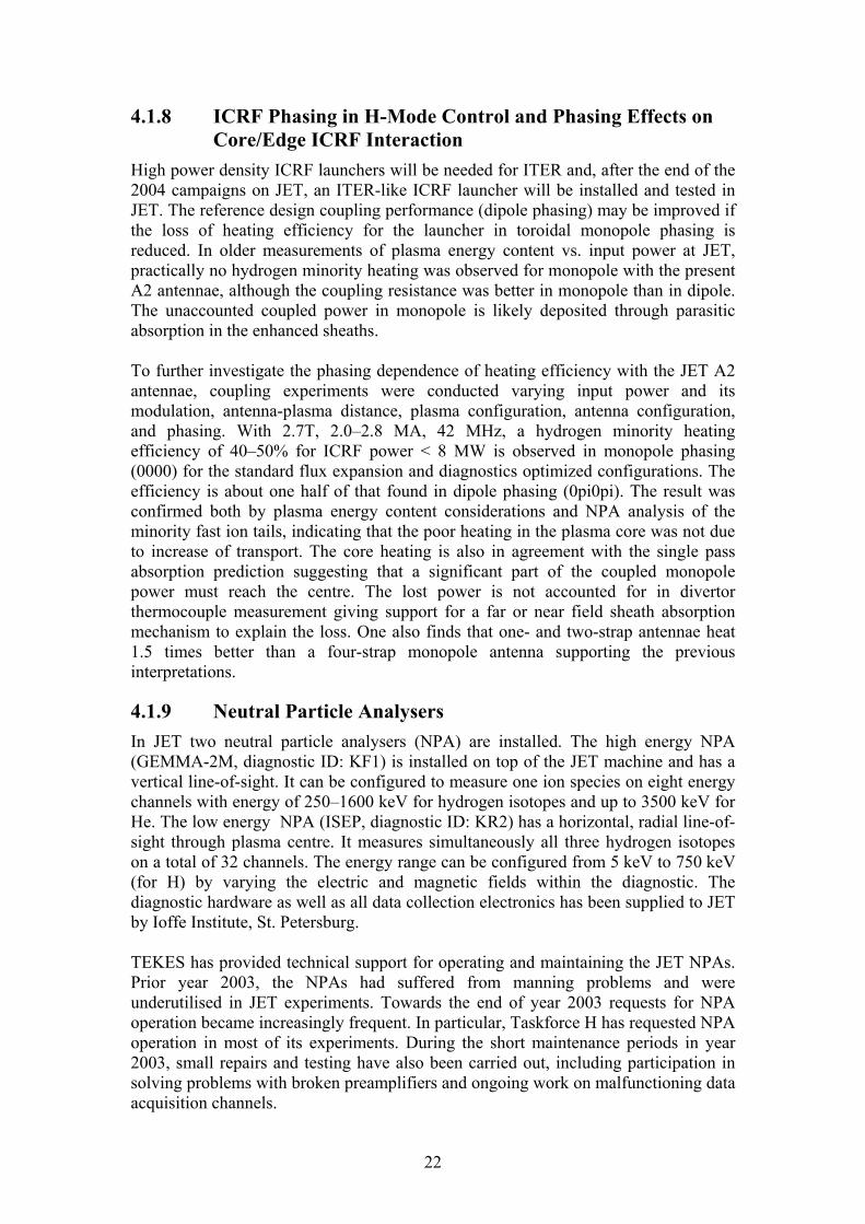
Parasitic absorption and the resulting fast electron generation at the grill mouth may limit the lower hybrid (LH) power at high power densities, since the fast particle beam may cause impurity influx from hot spots on the wall structures. Hot spots in the divertor region have been observed on JET during lower hybrid current drive (CD) experiments. The most probable reason is the fast electron generation by parasitic absorption of LH power in front of the grill, as observed in LHCD experiments on Tore Supra and TdeV tokamaks. In recent JET experiments, series of hot spots were detected on the inner and outer divertor apron, which are magnetically connected to the LH grill region. The LH power level in these experiments was between PLH=1 and 3 MW and strong gas injection near the grill was used to improve the coupling. However, in some cases excess of gas in front of the grill may increase the heat flux to the magnetically connected components. A CCD camera was used to observe hot spots on the divertor aprons with good spatial resolution. Since the line of sight of the CCD camera is fixed, the hot spots can only be seen at specific q95-values. Consequently, the best possibility to see hot spots is in the current ramp up or down phases with changing edge q-values. The q95-value is important because it defines the magnetic field line connection from the LH grill to the divertor region. The magnetic field varied between B=3 and 3.5 T. The grill position was varied from 1 to 2 cm behind the limiter and the distance from the wall to the last closed flux surface (LCFS) varied from 4 to 8.5 cm. The Infra Red Movie Analyser, IRMA software was used to analyse the CCD videos of the pulses that showed hot spots on the divertor apron. Figure 4.4 shows the measuring points and the result of the analysis for a recent JET pulse. The analysis shows clear increases in the brightness of the measuring points in the second phase of the shots. Shots 58666 to 58668 show clearly three peaks in the brightness on the inner apron. There is a clear correlation with the termination of the brightness of the hot spots and the end of LH power at t=52.5 s. A comparison to the q95-values is also shown in the figure. In these shots, three windows with spots are seen. In each of the three shots, these windows are roughly at the same values. The first window is q95= 5.1 to 4.5, the second one at q95= 4.1 to 3.8 and the last one around q95=3.8 just before
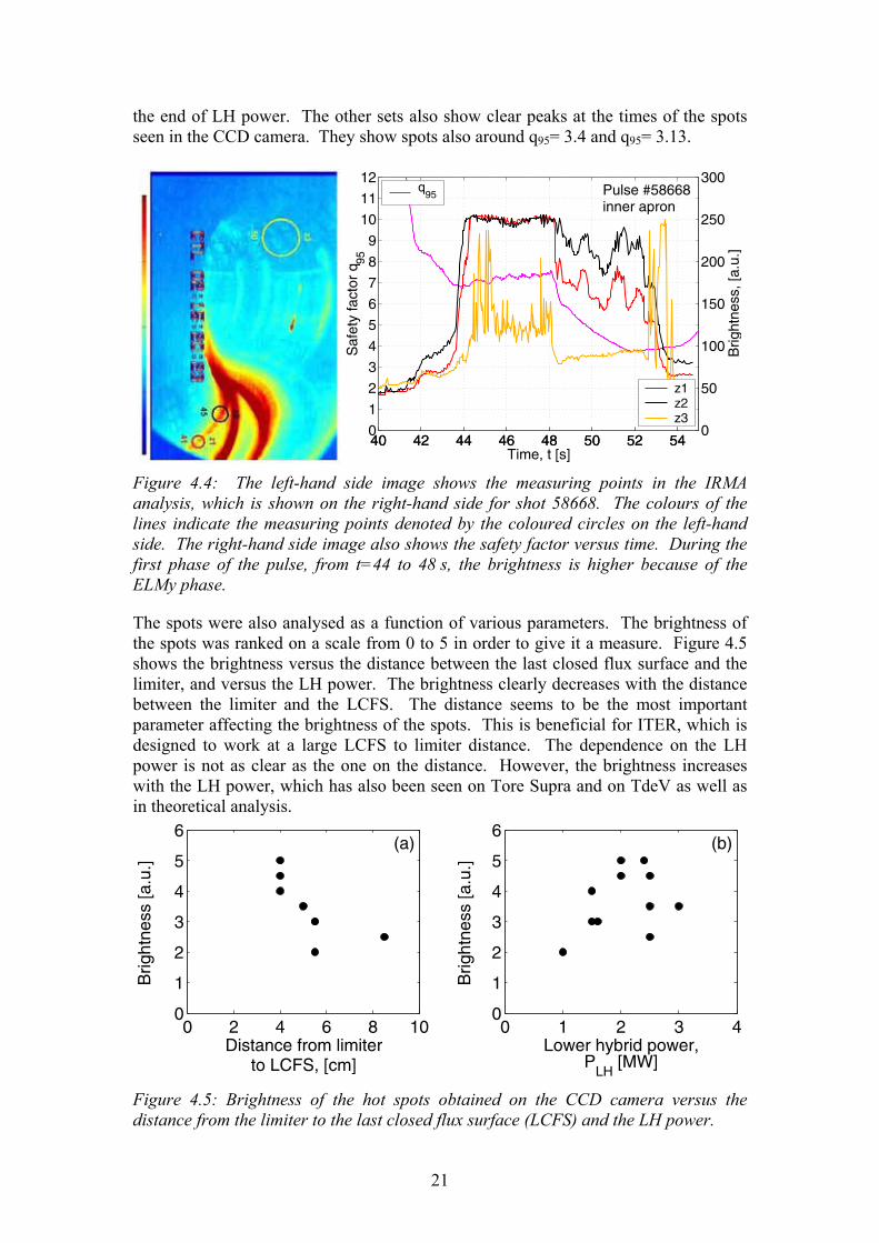
21
the end of LH power. The other sets also show clear peaks at the times of the spots seen in the CCD camera. They show spots also around q95= 3.4 and q95= 3.13.
40 42 44 46 48 50 52 540
1
2
3
4
5
6
7
8
9
10
11
12
Time, t [s]
Saf
ety
fact
or q
95
Pulse #58668inner apron
q95
40 42 44 46 48 50 52 540
50
100
150
200
250
300
Brig
htne
ss, [
a.u.
]
z1z2z3
Figure 4.4: The left-hand side image shows the measuring points in the IRMA analysis, which is shown on the right-hand side for shot 58668. The colours of the lines indicate the measuring points denoted by the coloured circles on the left-hand side. The right-hand side image also shows the safety factor versus time. During the first phase of the pulse, from t=44 to 48 s, the brightness is higher because of the ELMy phase.
The spots were also analysed as a function of various parameters. The brightness of the spots was ranked on a scale from 0 to 5 in order to give it a measure. Figure 4.5 shows the brightness versus the distance between the last closed flux surface and the limiter, and versus the LH power. The brightness clearly decreases with the distance between the limiter and the LCFS. The distance seems to be the most important parameter affecting the brightness of the spots. This is beneficial for ITER, which is designed to work at a large LCFS to limiter distance. The dependence on the LH power is not as clear as the one on the distance. However, the brightness increases with the LH power, which has also been seen on Tore Supra and on TdeV as well as in theoretical analysis.
0 2 4 6 8 100
1
2
3
4
5
6
Distance from limiterto LCFS, [cm]
Brig
htne
ss [a
.u.]
(a)
0 1 2 3 40
1
2
3
4
5
6
Lower hybrid power,P
LH [MW]
Brig
htne
ss [a
.u.]
(b)
Figure 4.5: Brightness of the hot spots obtained on the CCD camera versus the distance from the limiter to the last closed flux surface (LCFS) and the LH power.
22
4.1.8 ICRF Phasing in H-Mode Control and Phasing Effects on Core/Edge ICRF Interaction
High power density ICRF launchers will be needed for ITER and, after the end of the 2004 campaigns on JET, an ITER-like ICRF launcher will be installed and tested in JET. The reference design coupling performance (dipole phasing) may be improved if the loss of heating efficiency for the launcher in toroidal monopole phasing is reduced. In older measurements of plasma energy content vs. input power at JET, practically no hydrogen minority heating was observed for monopole with the present A2 antennae, although the coupling resistance was better in monopole than in dipole. The unaccounted coupled power in monopole is likely deposited through parasitic absorption in the enhanced sheaths. To further investigate the phasing dependence of heating efficiency with the JET A2 antennae, coupling experiments were conducted varying input power and its modulation, antenna-plasma distance, plasma configuration, antenna configuration, and phasing. With 2.7T, 2.0�2.8 MA, 42 MHz, a hydrogen minority heating efficiency of 40�50% for ICRF power < 8 MW is observed in monopole phasing (0000) for the standard flux expansion and diagnostics optimized configurations. The efficiency is about one half of that found in dipole phasing (0pi0pi). The result was confirmed both by plasma energy content considerations and NPA analysis of the minority fast ion tails, indicating that the poor heating in the plasma core was not due to increase of transport. The core heating is also in agreement with the single pass absorption prediction suggesting that a significant part of the coupled monopole power must reach the centre. The lost power is not accounted for in divertor thermocouple measurement giving support for a far or near field sheath absorption mechanism to explain the loss. One also finds that one- and two-strap antennae heat 1.5 times better than a four-strap monopole antenna supporting the previous interpretations.
4.1.9 Neutral Particle Analysers In JET two neutral particle analysers (NPA) are installed. The high energy NPA (GEMMA-2M, diagnostic ID: KF1) is installed on top of the JET machine and has a vertical line-of-sight. It can be configured to measure one ion species on eight energy channels with energy of 250�1600 keV for hydrogen isotopes and up to 3500 keV for He. The low energy NPA (ISEP, diagnostic ID: KR2) has a horizontal, radial line-of-sight through plasma centre. It measures simultaneously all three hydrogen isotopes on a total of 32 channels. The energy range can be configured from 5 keV to 750 keV (for H) by varying the electric and magnetic fields within the diagnostic. The diagnostic hardware as well as all data collection electronics has been supplied to JET by Ioffe Institute, St. Petersburg. TEKES has provided technical support for operating and maintaining the JET NPAs. Prior year 2003, the NPAs had suffered from manning problems and were underutilised in JET experiments. Towards the end of year 2003 requests for NPA operation became increasingly frequent. In particular, Taskforce H has requested NPA operation in most of its experiments. During the short maintenance periods in year 2003, small repairs and testing have also been carried out, including participation in solving problems with broken preamplifiers and ongoing work on malfunctioning data acquisition channels.

23
Software for processing NPA data has also been improved. The initial data processing code that runs automatically after every pulse for have been largely rewritten for KR2. Entirely new tools have been developed for easy viewing of the data in Matlab environment, replacing cumbersome command-line oriented Fortran codes. Post-processing codes are also being developed for deeper analysis of the atom flux data.
4.1.10 Predictive Transport Modelling of Advanced Tokamak Scenarios with ITBs in the Multi-tokamak Database
The main aim in this study has been to test two transport models, the semi-empirical Bohm/GyroBohm and the first principle-based Weiland models in plasmas with Internal Transport Barriers (ITBs). In order to obtain a consistent picture over a large plasma parameter and geometry regimes, a multi-machine experimental tokamak ITB database, called the ITPA ITB database, has been employed. The emphasis has been in the ITB formation and dynamics, in particular investigating the timing of the onset of the ITB and the radial location of the ITB. The question of the ITB formation and dynamics is assessed with fully predictive transport modelling. By fully predictive transport modelling we mean that all the five transport equations (electron and ion heat, q, density and toroidal rotation) are solved. In order to obtain the most realistic and consistent understanding of the ITB behaviour, it is very important to predict also the density and toroidal rotation which are often taken from the experiments. Three pairs of high performance discharges from JET, JT-60U and DIII-D are simulated with the Bohm/GyroBohm and Weiland transport models using the JETTO transport code. One of the discharges in each pair has a low positive or zero magnetic shear (s) whereas the other one has a negative s. The ITB formation in the semi-empirical Bohm/GyroBohm model is based on turbulence suppression by the combined effects of the magnetic shear and ωE×B flow shear whereas the Weiland model, in addition, includes also turbulence suppression by the Shafranov shift (α-stabilisation) and density peaking. The experimental and simulated electron density, electron and ion temperatures and toroidal rotation for one of the six simulated discharges are illustrated in Figure 4.6. The Bohm/GyroBohm model predicts the radial location of the ITB very well (as shown by the ion temperature profile) whereas the Weiland model does not predict the ITB. Both models predict the average density well, but the electron temperature is overestimated. The Bohm/GyroBohm model reproduces the toroidal rotation also reasonably well. In general with the Bohm/GyroBohm model, the agreement with respect to the onset and radial location of the ITB between the experiments and transport simulations is good in JET and JT-60U, but not as good in DIII-D. This suggests that the mechanisms that govern the physics of the ITB may be different in DIII-D from those in JET and JT-60U, where the combined effect of the magnetic shear and ωE×B flow shear seems to be enough to explain the behaviour of ITBs. The statistical analysis of the prediction errors shows that the agreement between the experimental and simulated data is better in discharges with a positive magnetic shear. This may indicate that the dynamics of the ITB in plasmas with negative s is not necessarily governed by the similar combination of the magnetic shear and ωE×B flow shear.

24
0.5 0
1
2
3
4
5
n e [1019
m−
3 ]
0.50
2
4
6
8
10
12
14
Te [k
eV]
0 0.2 0.4 0.6 0.8 1 0
5
10
15
20
25
Ti [k
eV]
ρ0 0.2 0.4 0.6 0.8 1
0
100
200
300
400
500
600
700
v φ [km
/s]
ρ Figure 4.6: The experimental (solid), predicted by the Bohm/GyroBohm model (dashed) and by the Weiland model (dotted) density, electron and ion temperatures and toroidal rotation at the high performance phase at t=6.0s for JET discharge No. 46664.
In most discharges, the Weiland model does not predict an ITB. It forms an ITB only in one of the six discharges with the triggering mechanism being a strong density gradient together with the negative magnetic shear. However, the effect of the magnetic shear on transport seems to be too weak, much weaker than experimentally observed or in the Bohm/GyroBohm model. The ωE×B shearing rate is inefficient to suppress the turbulence because the growth rate of the Ion Temperature Gradient (ITG) and Trapped Electron Modes (TEMs) are larger than the shearing rate.
4.1.11 Real-time Control of q in Fully Predictive Closed-loop JETTO Simulations
In order to simultaneously control the current and pressure profiles in high performance tokamak plasmas with internal transport barriers, a multi-variable model-based technique has been proposed. New algorithms using a truncated singular value decomposition of a linearized model operator and retaining the distributed nature of the system have been implemented in the JET control system. In order to be able to control the ITBs (electron temperature gradient) and the q-profile, the feedback or response matrix must be identified either with experimental data or with open-loop simulation predictions. The main objective in this work has been to find and optimise the linear response matrix and use it in predictive closed-loop transport simulations. The linear response matrix, i.e. the feedback matrix, has been calculated from the open-loop predictive transport simulations where the LH, ICRH and NBI powers have had step-ups/downs. JETTO transport code with the Bohm/GyroBohm transport

25
model has been used to perform the predictive simulations. The optimum linear response matrix can be found best in steady-state conditions (steady-state of current) and as a consequence, the open-loop transport simulations have been extended beyond the experimental length of the ITB discharges. This is required because the steady-state current profile is not reached on JET during the experimental length of the ITB discharges. For the first time predictive transport simulations with a non-linear plasma model (Bohm/GyroBohm transport model) have been used in closed-loop simulations to control the q-profile. All the five transport equations (Te, Ti, q, ne, vΦ) are solved and the power levels of LHCD, NBI and ICRH are controlled by the feedback matrix and the difference between the set-point (target) and simulated values of q. The predictive closed-loop simulations with JETTO real-time control algorithms are able to approach and sustain various set-point q-profiles from monotonic to deeply reversed ones as presented in Figure 4.7. In particular in the plasma centre, the set-point values of q are reached very well. Around mid-radius at ρ=0.5�0.6, the LHCD driven current at mid-radius, needed to obtain the reversed q-profile, is so strong that the system cannot reach the set-point values very well in that region. In the outer plasma at ρ=0.8, the total plasma current, which fixes the value of q at the edge, restricts the possible values of q significantly. In any case, the first, closed-loop, non-linear transport simulations are rather encouraging.
50 55 60 65
2
3
4
q(ρ=
0.2)
50 55 60 652.12.5
3
q(ρ=
0.4)
50 55 60 652
2.5
3
q(ρ=
0.5)
50 55 60 652.2
2.7
3.2
q(ρ=
0.6)
45 50 55 60 65 703.5
4
4.5
q(ρ=
0.8)
Time (s) Figure 4.7: The simulated q-profiles as a function of time at five set-point radii ρ=0.2, ρ=0.4, ρ=0.5, ρ=0.6 and ρ=0.8. In the red reference case (open-loop simulation), no real-time control was applied. For the other, closed-loop simulations, different target (set-point) values of q at ρ=0.2 and ρ=0.4 are illustrated by the dashed lines using the following colour scheme: green (strongly reversed q), magenta (weakly reversed q), blue (flat q) and yellow (monotonic q). At outer radii at ρ=0.5, ρ=0.6 and ρ=0.8, the set-point values of q (indicated by the dashed black curve) were the same for each simulation.
26
What is different between the experimental and simulated results is the time when the control reaches the set-point values of q � the time in the simulations being a factor of 2 slower. This suggests that there are maybe some ingredients in the experimental current diffusion or the behaviour of the LHCD driven current that are faster or different than predicted by the neo-classical theory. The resistivity in JETTO is calculated by the neo-classical transport code NCLASS. The simultaneous control of q and ρt
* with JETTO remains to be demonstrated (ρt* is the ratio between the Larmor
radius and the electron temperature length and is used as an indication of the strength and location of the ITB).
4.1.12 Predictive Transport Simulations of Electron Temperature Modulation Experiments on JET
Transient transport studies are a valuable complement to steady-state transport analyses for understanding of many transport mechanisms and also for the validation and tests of transport models. In this study, the JETTO transport code has been used to simulate ICRH power modulation discharges with mode conversion scheme (electron heating). Both the Weiland and the Bohm/GyroBohm transport models have been tested in order to see whether they can reproduce the experimental results and the simulation results calculated with the empirical critical gradient model. In this study, the main emphasis is in analysing the amplitude and phase of the electron heat wave, i.e., the perturbative electron heat diffusion coefficient χe
pert and stiffness. The experiments have shown that the stiffness of the electrons is highly sensitive to the repartition of heating between the electron and ion channels. This issue has been paid attention to especially in the interpretation of the simulation results by the Weiland model. Two discharges, both with L-mode plasma edge but at different Te/Ti, have been studied. Both the models reproduce the steady-state ion and electron temperature profiles fairly well when Te/Ti ≈ 1, but in the case of Te/Ti ≈ 2 they predicted too high ion temperature. The Weiland model also predicts slightly too peaked density profiles whereas the Bohm/GyroBohm model predicts the shape of the density profile well. However more importantly, the amplitudes and phases predicted by the Weiland model are in much better (and very good) agreement with the experimental ones than those calculated by the Bohm/GyroBohm model. It tended to overestimate the magnitude of the amplitude of the simulated heat wave by a factor of 1.3�2. In addition, the gradients of the amplitude and phase were too small, both of these leading to an underestimation of the perturbative transport and stiffness. Thus, although the steady-state transport is better reproduced by the Bohm/GyroBohm model, the perturbative transport, which is the main aim of this study, is better predicted by the Weiland model which can be regarded as the better transport model to produce the stiffness and perturbative transport. Interestingly, even though the electron/ion temperature ratio was not predicted right in the simulations, the perturbative transport was found to coincide quite well with the experimental results. This indicates that although the Te/Ti ratio does not play quite the expected role in modelling, there are other ingredients in the Weiland model, so far unrecognised factors to us, affecting the electron stiffness and perturbative transport in a way similar to the experiments.

27
Figure 4.8: The amplitudes (up) and phases (low) for the first (black curves) and the third harmonic (red curves) of the heat waves in the two studied discharges, pulses no. 53822 (left-hand side) and 55809 (right-hand side). The dots correspond to the experimental data, the solid lines to the predictions by the Weiland model with collisions and electromagnetic effects included and the dashed curves to the predictions by the critical gradient model.
4.1.13 Integrated Predictive Transport Modelling of ELMy H-Mode JET Plasmas
Plasmas with mixed type I�II ELMs Simple ELM models making use of the often expressed idea that type I and type II ELMs are associated with medium and high n ballooning modes, respectively, have been introduced. Type I ELMs are proposed to be caused by violations of the finite n ballooning stability limit, whereas type II ELMs are suggested to occur when high n ballooning stability is violated at the very edge of the plasma. The models for type I and type II ELMs have been combined into an improved scheme for modelling of mixed type I�II ELMy H-mode, which has been implemented into the 1.5D core transport code JETTO. Specifically, the edge transport barrier (ETB) has been divided into an inner and an outer region, in which stability for type I and type II ELMs, respectively, is evaluated using appropriate limits for the pressure gradient derived from MHD stability analysis. Transport during the ELMs is enhanced by edge-localized radially Gaussian-shaped perturbations to the transport coefficients and type I and type II ELMs are represented by perturbations with different widths and

28
amplitudes. The approach has been given some justification from theory and numerical analysis. The model is capable of qualitatively reproducing the experimental dynamics of mixed type I�II ELMy in predictive transport simulations, as illustrated in Figure 4.9, which shows the characteristic signature with small and frequent type II ELMs interrupted by occasional large type I ELMs.
05
10152025
61.0 61.2 61.4 61.6 61.8 62.0t [s]
χ [m
s]
2-1
i
Figure 4.9: Ion thermal conductivity as a function of time in a typical simulation with the model for mixed type I�II ELMy H-mode.
The ELM model also provides a plausible way to explain why some special effects and situations such as strong gas puffing, a quasi double null magnetic configuration, high poloidal β (ratio of the total pressure to the kinetic pressure) and combinations of high edge safety factor and high triangularity can be favourable for mixed type I�II and pure type II ELMy H-mode. By performing MHD stability analysis on interpretative and predictive JETTO simulations, it has been shown that these situations lead to a strong increase in magnetic shear at the very edge of the plasma, which can cause this outermost region to become high n ballooning unstable, thereby effectively returning the operational point back to the first ballooning stability region.
Theory-motivated ballooning model for type I ELMy H-mode An analytical ELM model based on linear ballooning stability theory has been developed. The model can be written as a linear differential equation for the amplitude of an unstable ballooning mode in a system with a background noise. The growth rate of the mode is controlled by a term incorporating the characteristic ballooning mode growth rate and differing from zero upon the violation of a critical pressure gradient. Introducing this discontinuity accounts for the fact that there is no growing or damping solution below the stability threshold in ideal MHD. A second term in the differential equation describes the decay rate of the mode due to non-ideal MHD effects towards the level of background fluctuations. The equation is averaged over the whole ETB in order to account for the fact that ballooning modes are global rather than localized to a specific radius. The ELM model has been coupled into the JETTO transport code. At each time step, the mode amplitude is evaluated using plasma parameters calculated by JETTO. Transport in the ETB is enhanced with Gaussian-shaped perturbations, the amplitudes of which scale linearly with the calculated mode amplitude, consistent with the quasilinear approximation. Simulations with the modelling scheme can qualitatively reproduce the experimental dynamics of type I ELMy H-mode, as shown in Figure 4.10. In particular, the simulations reproduce a type I ELM frequency that increases with the external heating power, as in experiments. It has been demonstrated that in the first place the onset of discrete oscillations is related to how the radial profiles of the transport coefficients are perturbed in the transport simulations and to how the pressure gradient evolves as a result of this.
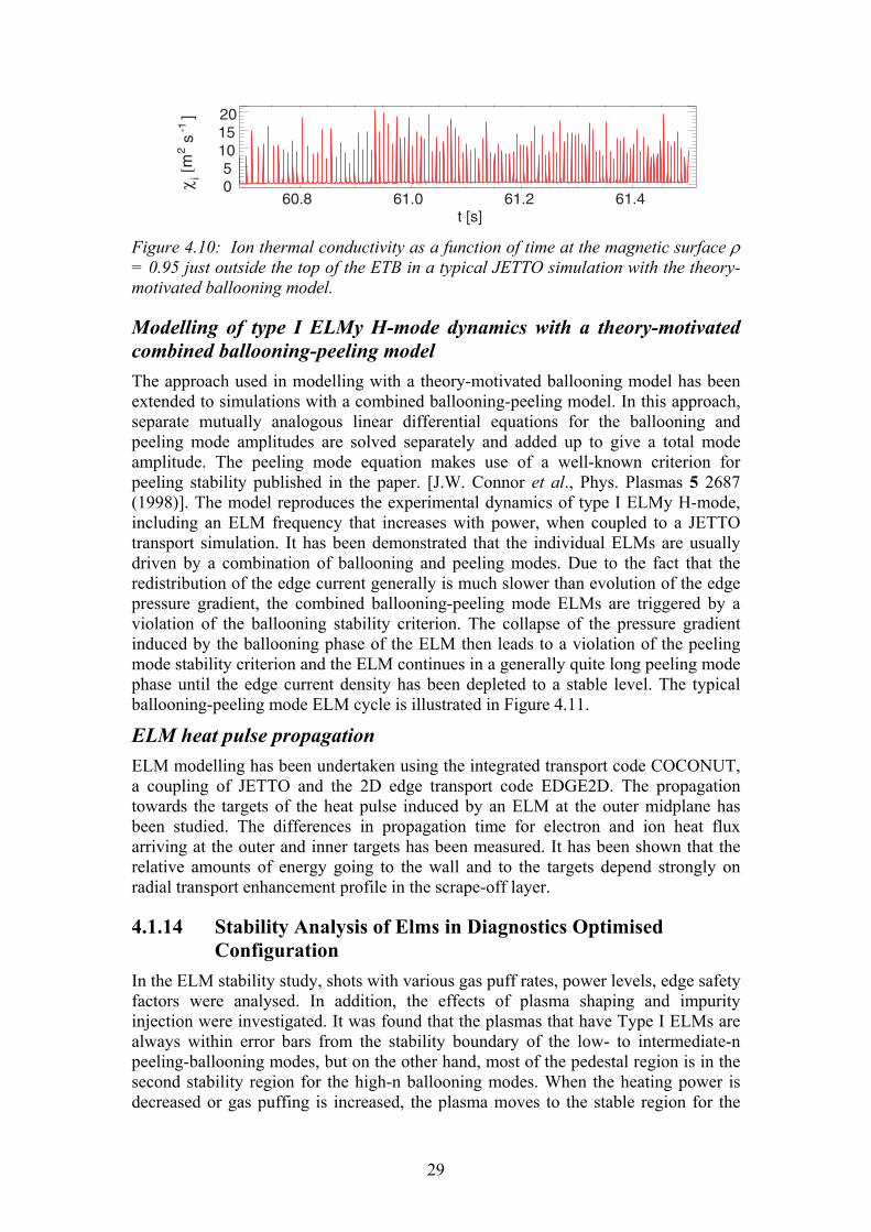
29
05
1015
60.8 61.0 61.2 61.4χ
[ms
]2
-1i
t [s]
20
Figure 4.10: Ion thermal conductivity as a function of time at the magnetic surface ρ = 0.95 just outside the top of the ETB in a typical JETTO simulation with the theory-motivated ballooning model.
Modelling of type I ELMy H-mode dynamics with a theory-motivated combined ballooning-peeling model The approach used in modelling with a theory-motivated ballooning model has been extended to simulations with a combined ballooning-peeling model. In this approach, separate mutually analogous linear differential equations for the ballooning and peeling mode amplitudes are solved separately and added up to give a total mode amplitude. The peeling mode equation makes use of a well-known criterion for peeling stability published in the paper. [J.W. Connor et al., Phys. Plasmas 5 2687 (1998)]. The model reproduces the experimental dynamics of type I ELMy H-mode, including an ELM frequency that increases with power, when coupled to a JETTO transport simulation. It has been demonstrated that the individual ELMs are usually driven by a combination of ballooning and peeling modes. Due to the fact that the redistribution of the edge current generally is much slower than evolution of the edge pressure gradient, the combined ballooning-peeling mode ELMs are triggered by a violation of the ballooning stability criterion. The collapse of the pressure gradient induced by the ballooning phase of the ELM then leads to a violation of the peeling mode stability criterion and the ELM continues in a generally quite long peeling mode phase until the edge current density has been depleted to a stable level. The typical ballooning-peeling mode ELM cycle is illustrated in Figure 4.11.
ELM heat pulse propagation ELM modelling has been undertaken using the integrated transport code COCONUT, a coupling of JETTO and the 2D edge transport code EDGE2D. The propagation towards the targets of the heat pulse induced by an ELM at the outer midplane has been studied. The differences in propagation time for electron and ion heat flux arriving at the outer and inner targets has been measured. It has been shown that the relative amounts of energy going to the wall and to the targets depend strongly on radial transport enhancement profile in the scrape-off layer.
4.1.14 Stability Analysis of Elms in Diagnostics Optimised Configuration
In the ELM stability study, shots with various gas puff rates, power levels, edge safety factors were analysed. In addition, the effects of plasma shaping and impurity injection were investigated. It was found that the plasmas that have Type I ELMs are always within error bars from the stability boundary of the low- to intermediate-n peeling-ballooning modes, but on the other hand, most of the pedestal region is in the second stability region for the high-n ballooning modes. When the heating power is decreased or gas puffing is increased, the plasma moves to the stable region for the

30
low- to intermediate modes, but at the same time the second stability access is closed and the pressure gradient becomes limited by the high-n ballooning modes. In the experiment, this is seen as a transition to Type III ELMs. Increasing the edge safety factor allowed higher pressure gradient at the edge and seemed to allow plasma to enter deeper into the unstable region before the ELM is triggered. The impurity seeding had the same effect as gas puffing and made the edge more stable against the low- to intermediate-n peeling-ballooning modes.
0 0.2 0.4 0.6 0.8 1.0 1.2 1.4 1.60
0.5
1.0
1.5
2.0
2.5
3.0
3.5
4.0
α
j z [10
2]
ballo
onin
g un
stab
le
peelingunstable
Am
5
Figure 4.11: The path traced in the αs operational space during one ELM cycle in a typical simulation with the combined ballooning-peeling model. Consecutive points in the trace are separated by 0.1 ms.
4.1.15 Comparison of ECE temperature data for He and D reference discharges at L-H transition conditions, theoretical modelling of corresponding electric fields
In helium (He) experiments in JET the power threshold for He was observed to be 50 % higher than for deuterium (D) while in experiments using H, D and T plasmas, the power threshold was observed to be inversely proportional to mass implying a possible strong dependence of threshold power on charge number Z. The transition temperature scales only weakly as a function of mass number but the Z dependence is not well known. Here, experimental electron temperature data for He discharges and corresponding data for D reference discharges are compared. Also, the corresponding electric fields simulated from the neoclassical radial current balance using the 5D orbit following Monte Carlo code ASCOT are shown. In Figure 4.12a, the ECE electron temperature at the time of the L-H transition at pedestal is plotted for five different cases with different q95 and toroidal magnetic field. 'Helium' in the figures means discharges with a significant fraction of helium (40% to 100%) and 'Deuterium' means discharges with less than 5% of helium. In general the critical temperature for L-H transition here seems to be higher for helium than for deuterium. In Figure 4.12b, the same pedestal temperature is normalized to the recent experimental scaling of threshold temperature which includes the weak
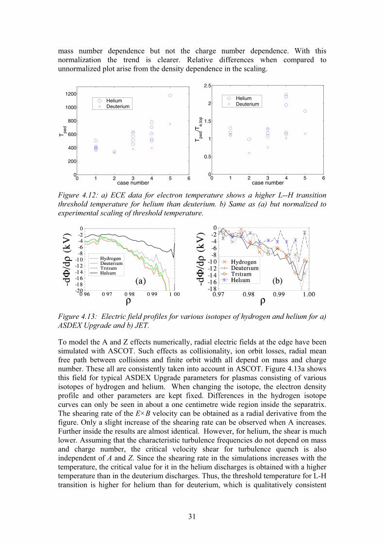
31
mass number dependence but not the charge number dependence. With this normalization the trend is clearer. Relative differences when compared to unnormalized plot arise from the density dependence in the scaling.
0 1 2 3 4 5 60
200
400
600
800
1000
1200
case number
Tpe
d
HeliumDeuterium
0 1 2 3 4 5 6
0
0.5
1
1.5
2
2.5
case number
Tpe
d/Te,
top
HeliumDeuterium
Figure 4.12: a) ECE data for electron temperature shows a higher L--H transition threshold temperature for helium than deuterium. b) Same as (a) but normalized to experimental scaling of threshold temperature.
Figure 4.13: Electric field profiles for various isotopes of hydrogen and helium for a) ASDEX Upgrade and b) JET.
To model the A and Z effects numerically, radial electric fields at the edge have been simulated with ASCOT. Such effects as collisionality, ion orbit losses, radial mean free path between collisions and finite orbit width all depend on mass and charge number. These all are consistently taken into account in ASCOT. Figure 4.13a shows this field for typical ASDEX Upgrade parameters for plasmas consisting of various isotopes of hydrogen and helium. When changing the isotope, the electron density profile and other parameters are kept fixed. Differences in the hydrogen isotope curves can only be seen in about a one centimetre wide region inside the separatrix. The shearing rate of the E×B velocity can be obtained as a radial derivative from the figure. Only a slight increase of the shearing rate can be observed when A increases. Further inside the results are almost identical. However, for helium, the shear is much lower. Assuming that the characteristic turbulence frequencies do not depend on mass and charge number, the critical velocity shear for turbulence quench is also independent of A and Z. Since the shearing rate in the simulations increases with the temperature, the critical value for it in the helium discharges is obtained with a higher temperature than in the deuterium discharges. Thus, the threshold temperature for L-H transition is higher for helium than for deuterium, which is qualitatively consistent

32
with the experimental results shown above. In Figure 4.13b, the same simulation is shown for JET data and the conclusions are the same showing weaker shear for the helium. In simulations, the main origin of E×B shear is ion orbit losses. Essential parameters are the mean free path, enabling ions to proceed over the separatrix, and the processes, which prevent the particles coming back. These non-standard extra losses increase Er when compared to conventional neoclassical theory. The main difference between the helium and the other species is that helium cases are always in the collisional regime, whereas the other species are in collisionless parameter regime.
4.1.16 Material Transport and Erosion/Deposition in JET Torus Institutes: VTT Processes (VTT PRO)
Helsinki University, Accelerator Laboratory (UH AL) JET/UKAEA
Company: DIARC Technology Oy Research Scientists: Dr. J. Likonen (VTT PRO, Project Manager),
Dr. E. Vainonen-Ahlgren (VTT PRO), Mr. T. Renvall (VTT PRO), MSc. R. Zilliacus (VTT PRO), Dr. S. Lehto (VTT PRO), Prof. J. Keinonen (UH AL), Dr. K. Arstila (UH AL), Dr. T. Sajavaara (UH AL), Dr. P. Coad (JET/UKAEA), MSc. J. Kolehmainen (Diarc).
Background Experiments with the Mk I divertor in JET in 1994�95 demonstrated that much of the carbon responsible for co-deposition in the divertor is sputtered from the walls of the main chamber, even though the primary plasma contact areas are in the divertor. Notably, using a divertor comprising only Be tiles, the principal plasma impurity was generally carbon, and heavy deposition of carbon occurred on the Be tiles at the inner divertor. However, the main areas of, and the amounts of, erosion around the chamber walls have not been ascertained. Also, it is not known how much erosion takes place in the outer divertor where erosion is expected, and to where such eroded material is transported. To study these queries, a set of special tiles were installed in the Mk IIGB divertor during the 1999 shutdown. The tiles were accurately machined and measured, so that large-scale erosion or deposition (>20 µm) over a campaign could be determined. To look for smaller amounts of erosion/deposition, the tiles were also coated with poloidal stripes of a C+10% B layer on a Re interlayer. A small amount of erosion results in thinning of these layers, and for regions of deposition, the Re layer acts as a marker to determine the original surface when profiling through the deposits. These tiles were removed in the 2001 shutdown, and analysed to determine the erosion/deposition profile over the entire divertor cross-section. Prior to the 2001 shutdown at JET, an experiment was devised to provide specific information on material transport and scrape-off layer (SOL) flows observed at JET. 13CH4 and SiH4 were injected into the plasma boundary in the last day of discharges using one type of discharge only. 13C and silicon profiles were acquired to evaluate the puffing experiments where 13CH4 was puffed from the top of the vessel and silane

33
from the outer divertor wall to determine how 13C and Si are transported around the SOL, and where they are eventually deposited.
Surface analysis of JET tiles and sample handling The batch of limiter tiles delivered to VTT contained two specially fabricated CFC outer poloidal limiter (OPL) tiles 2B01 and 8B21. Each OPL tile is mounted as one of a pair and each outer poloidal limiter comprises 46 pairs. Analysed tile 2B01 is from Octant 2, sector B and position number 01 (from the top). In addition to OPL tiles, full poloidal set of divertor tiles including two septum tiles have been analysed under this task. Hardware design of the secondary ion mass spectrometry (SIMS) instrument and the tandem accelerator used in the characterisation work require the sample size be below 20 mm in diameter. So, the CFC tiles were sampled in a glove box using a drill saw to cut cylinders of 17 mm diameter at the marker stripe. Pieces of about 10 mm high were cut from the core samples. SIMS analysis was made with a double focussing magnetic sector instrument (VG Ionex IX-70S). A 5 keV O2
+ primary ion beam was used. The current of the primary beam was typically 500 nA during depth proÞling and the ion beam was raster-scanned over an area of 300 ×430 µm2. 13C and 28Si were profiled separately using a higher mass resolution of 2000 (m/∆m at m/z 28) to separate the element peaks from the interfering isobars. Some selected SIMS samples were measured with time-of-flight elastic recoil detection analysis (TOF-ERDA) technique to obtain elementary concentrations at the near surface region. In the measurements, the 5 MV tandem accelerator EGP-10-II with a 53 MeV beam of 127I10+ ions was used. The detector angle was 40o with respect to ion beam and the samples were tilted relative to the beam direction by 20o. TOF-ERDA gives quantitative amounts of elements up to a depth of about 900 nm when a density of 2.0 g/cm3 is assumed. Tiles have also been analysed by nuclear reaction analysis (NRA) and Rutherford backscattering spectrometry (RBS) methods with 2.5 MeV H+ ions at the University of Sussex. Beryllium content in some selected samples was analysed using inductively coupled plasma mass spectrometer (ICP-MS).
Erosion and deposition Analysed OPL tiles have areas of net deposition and erosion. Thicknesses of the deposits were obtained to be about 1 µm. However, inner wall guard limiter (IWGL) and OPL tiles analysed under previous contract have areas with very thick deposits (thicknesses up to 80 µm). There is heavy deposition at the inner divertor (see Figure 4.14). The SIMS depth profiles from centre of inner divertor wall tile 3 shows a double layer structure which was observed also in tiles exposed in 1999�2001. The surface layers (approx. 10�30 µm thick on tile 3) contain mostly C and D together with B and Ni of the Inconel steel which is used in the JET vessel wall and for internal metal fittings, bolts etc. RBS and TOF-ERDA analyses show that B and Ni contents are low (< 1 at.%). The films underneath the surface layer are very rich in beryllium, and nickel peaks in this region. The reason for the change in the composition of the deposit is still somewhat open question. It may be related to a reduction of the temperature of the JET vessel walls from 320 oC to 200 oC in December 2000. This reduced the average temperatures of tiles 1 and 3 and may have �switched off� chemical erosion of carbon. Another possibility is the He phase towards the end of C4 campaign. The

34
thickness of the deposits at the inner divertor is larger on tiles exposed in 1998�2001 than on tiles exposed in 1999�2001. Double layer structure in the deposits was observed on inner divertor tiles 1 and 3.
Depth (µm)0 10 20 30 40 50 60 70
Inte
nsity
(s-1
)
100
101
102
103
104
105 1H2D9Be10B12C13C29Si58Ni
Figure 4.14: SIMS depth profiles from centre of inner divertor wall tile 3.
Ion beam and SIMS analyses have shown in previous tasks that Be/C ratio in the deposits on IWGL tiles is clearly lower than at the inner divertor wall tiles and no double layer structure in the deposits was observed. The double layer structure and high Be content in the deposits on the inner divertor wall tiles are thus specific for the divertor. If the temperature is responsible for the outer layer, then there should only be a single Be-rich layer on earlier divertors such as the Mk IIA. Therefore analysis of Mk IIA inner divertor wall tiles in 2004 will be very important and will give new information on the composition of the co-deposited layers, because this divertor was operated at high wall temperature.
Material transport in SOL SIMS and TOF-ERDA results show that 13C from the puffing experiment is clearly deposited at the inner divertor wall tiles, but it is not found at the outer divertor and inner floor tile. Integrating the amounts of 13C through inner divertor wall tiles and extrapolating to the entire inner divertor wall of JET (assuming uniform concentrations toroidally), gives ~ 50% of the injected amount of 13C. This confirms the drift of impurities from outboard to inboard, the 13C injected from the top of the vessel is swept towards the inner divertor. The injection of a silicon containing species was supposed to show whether material from the outer divertor is transported all the way round the SOL to the inner divertor. However, the amount of silicon injected as silane in a D2 carrier gas for safety reasons was too small, and SIMS and ion beam measurements have shown that CFC material contains silicon as an impurity, at a concentration comparable to the amount redistributed by the plasma interaction. Thus no conclusions may be drawn on this specific point.
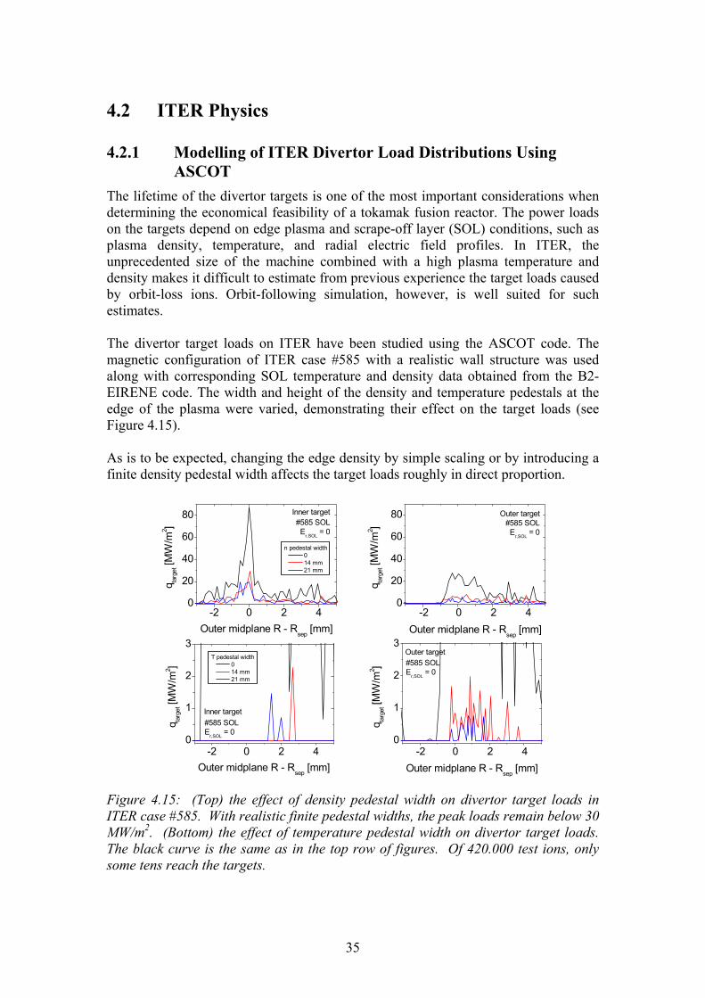
35
4.2 ITER Physics
4.2.1 Modelling of ITER Divertor Load Distributions Using ASCOT
The lifetime of the divertor targets is one of the most important considerations when determining the economical feasibility of a tokamak fusion reactor. The power loads on the targets depend on edge plasma and scrape-off layer (SOL) conditions, such as plasma density, temperature, and radial electric field profiles. In ITER, the unprecedented size of the machine combined with a high plasma temperature and density makes it difficult to estimate from previous experience the target loads caused by orbit-loss ions. Orbit-following simulation, however, is well suited for such estimates. The divertor target loads on ITER have been studied using the ASCOT code. The magnetic configuration of ITER case #585 with a realistic wall structure was used along with corresponding SOL temperature and density data obtained from the B2-EIRENE code. The width and height of the density and temperature pedestals at the edge of the plasma were varied, demonstrating their effect on the target loads (see Figure 4.15). As is to be expected, changing the edge density by simple scaling or by introducing a finite density pedestal width affects the target loads roughly in direct proportion.
-2 0 2 40
20
40
60
80
-2 0 2 40
20
40
60
80#585 SOL Er,SOL = 0
n pedestal width 0 14 mm 21 mm
Inner target
q targ
et [M
W/m
2 ]
Outer midplane R - Rsep [mm]
#585 SOL Er,SOL = 0
q targ
et [M
W/m
2 ]
Outer midplane R - Rsep [mm]
Outer target
-2 0 2 40
1
2
3
-2 0 2 40
1
2
3
#585 SOLE
r,SOL = 0
T pedestal width 0 14 mm 21 mm
Inner target
q targ
et [M
W/m
2 ]
Outer midplane R - Rsep
[mm]
#585 SOLE
r,SOL = 0
q targ
et [M
W/m
2 ]
Outer midplane R - Rsep [mm]
Outer target
Figure 4.15: (Top) the effect of density pedestal width on divertor target loads in ITER case #585. With realistic finite pedestal widths, the peak loads remain below 30 MW/m2. (Bottom) the effect of temperature pedestal width on divertor target loads. The black curve is the same as in the top row of figures. Of 420.000 test ions, only some tens reach the targets.

36
In ITER, the distance from the separatrix to the divertor target along the magnetic field lines is of the order of tens of meters. The collisionality of escaping ions along the way to the targets may affect the target loads considerably. The target loads were indeed found to be very sensitive to the temperature of the escaping ions due to the effect this has on their collisionality in the SOL and in the divertor region. With the parameters if ITER case #585, SOL Coulomb and CX collisions very efficiently scatter and slow down orbit-loss ions, preventing them from reaching the targets. With realistic finite temperature pedestal widths, the target loads were reduced to well below 30 MW/m2. In reality, both the density and the temperature pedestals have a finite width simultaneously, and their combined effect can be expected to further diminish the orbit-loss ion loads on the divertor targets. Although orbit-loss ions contribute the most localized loads on the targets, other sources of power and particle loading exist which are omitted in the present work.
4.2.2 Gyrotron theory High-power high-frequency gyrotrons play an essential role as microwave sources for plasma heating and current drive in modern magnetic fusion machines. As the size and performance of experimental devices is increased towards a commercial reactor, also the requirements for frequency and unit output power of gyrotrons tighten. It is therefore important to know the operational limits of such gyrotrons. One significant group of limitations may arise from chaos, whose onset becomes more likely with increasing output power. At HUT, chaos in gyrotrons has been investigated for several years. Recently, these studies were completed by including in the analysis the effects of electron beam misalignment and microwave reflections. Also hysteresis effects have been investigated using the gyrotron theory.
Figure 4.16: Maximum tolerable electron beam displacement relative to the wavelength as a function of the azimuthal index of the mode. The operating parameters of the gyrotron are such that the output efficiency reaches its optimal value.
The two-dimensional self-consistent time-dependent theory of beam-wave interaction in gyrotron resonators was modified to account for eccentricity of the electron beam. It was known from earlier studies that there exists a critical value of the azimuthal index of the mode (which depends on the resonator dimensions) above which

37
stationary single-mode operation becomes impossible. Numerical analysis shows that increasing misalignment tends to lower this threshold. Figure 4.16 shows the maximum tolerable beam misalignment as a function of the azimuthal mode number. It is seen that for mode number exceeding 40, the gyrotron is very sensitive to misalignment. Together with high-order mode operation it should therefore always be considered how precisely the beam can be directed into its correct position in the resonator. To describe reflections of microwave power from plasma, transmission lines, or other components back to the resonator, we have developed an extension of the one-dimensional self-consistent time-dependent theory of nonstationary processes in gyrotrons. Different mathematical descriptions of partial reflection of the output signal were compared (see Figure 4.17), and numerical algorithms for analyzing them were given. Using a novel description, we computed a map of gyrotron oscillations, which identifies the regimes of stationary, periodically modulated and chaotic oscillations in the plane of generalized gyrotron variables when reflection is present. Our findings can therefore be exploited in the development of high-power gyrotrons, which should provide a stationary signal even in the case of accidental reflections. By identifying in the operating parameter plane those regions where chaotic oscillations may be obtained, the results also ease the design of gyrotrons for applications that require broad bandwidth.
a) no reflection
em wavee
b) reflection by geometric obstacles
d) reflection by boundary condition; delayed
e) external reflected wave
c) reflection by boundarycondition; no delay
Figure 4.17: Illustration of different ways to describe reflections in gyrotrons. (a) In the reflectionless case the whole electromagnetic wave exits the resonator. (b) Reflections have been modeled in a previous study with the help of an iris located at a distance comparable to the length of the interaction space. (c) A reflective boundary condition can be applied at the resonator end, using the phase of the reflection coefficient to simulate delay. (d) The iris can be replaced by the reflective boundary condition at the same location. (e) The reflected wave can be actively launched after a delay.
Special experiments devoted to studying hysteresis in gyrotron oscillations were performed for the first time in collaboration with Forschungszentrum Karlsruhe (FZK) and Fukui University. Clear hysteresis-like effects with respect to the variation of the cathode voltage were observed in the mode competition scenario of the FZK coaxial gyrotron and with respect to the variation of the magnetic field and voltage in single-mode operation of the Fukui IV gyrotron. Theoretical explanations for the observed phenomena were given.
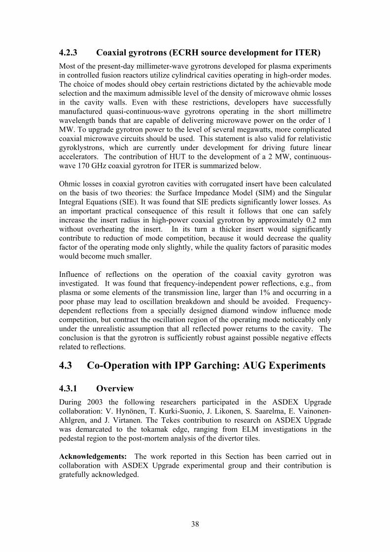
38
4.2.3 Coaxial gyrotrons (ECRH source development for ITER) Most of the present-day millimeter-wave gyrotrons developed for plasma experiments in controlled fusion reactors utilize cylindrical cavities operating in high-order modes. The choice of modes should obey certain restrictions dictated by the achievable mode selection and the maximum admissible level of the density of microwave ohmic losses in the cavity walls. Even with these restrictions, developers have successfully manufactured quasi-continuous-wave gyrotrons operating in the short millimetre wavelength bands that are capable of delivering microwave power on the order of 1 MW. To upgrade gyrotron power to the level of several megawatts, more complicated coaxial microwave circuits should be used. This statement is also valid for relativistic gyroklystrons, which are currently under development for driving future linear accelerators. The contribution of HUT to the development of a 2 MW, continuous-wave 170 GHz coaxial gyrotron for ITER is summarized below. Ohmic losses in coaxial gyrotron cavities with corrugated insert have been calculated on the basis of two theories: the Surface Impedance Model (SIM) and the Singular Integral Equations (SIE). It was found that SIE predicts significantly lower losses. As an important practical consequence of this result it follows that one can safely increase the insert radius in high-power coaxial gyrotron by approximately 0.2 mm without overheating the insert. In its turn a thicker insert would significantly contribute to reduction of mode competition, because it would decrease the quality factor of the operating mode only slightly, while the quality factors of parasitic modes would become much smaller. Influence of reflections on the operation of the coaxial cavity gyrotron was investigated. It was found that frequency-independent power reflections, e.g., from plasma or some elements of the transmission line, larger than 1% and occurring in a poor phase may lead to oscillation breakdown and should be avoided. Frequency-dependent reflections from a specially designed diamond window influence mode competition, but contract the oscillation region of the operating mode noticeably only under the unrealistic assumption that all reflected power returns to the cavity. The conclusion is that the gyrotron is sufficiently robust against possible negative effects related to reflections.
4.3 Co-Operation with IPP Garching: AUG Experiments
4.3.1 Overview During 2003 the following researchers participated in the ASDEX Upgrade collaboration: V. Hynönen, T. Kurki-Suonio, J. Likonen, S. Saarelma, E. Vainonen-Ahlgren, and J. Virtanen. The Tekes contribution to research on ASDEX Upgrade was demarcated to the tokamak edge, ranging from ELM investigations in the pedestal region to the post-mortem analysis of the divertor tiles. Acknowledgements: The work reported in this Section has been carried out in collaboration with ASDEX Upgrade experimental group and their contribution is gratefully acknowledged.

39
4.3.2 MHD stability analysis of ASDEX Upgrade H-modes The ELMs cause problems in a tokamak operating in H-mode because the energy and particles that are lost from the plasma and arrive to the plates in short bursts instead of a continuous flow. Therefore, operation with small ELMs or elimination of ELMs altogether would be preferable for ITER as long as the confinement properties are not sacrificed and the impurity accumulation and density peaking can be avoided.
ELM suppression in quiescent H-mode It is possible to find an operating mode where the ELMs are suppressed while keeping good confinement at stationary plasma density and avoiding impurity accumulation. The so-called quiescent H-mode (QHM) was first observed in DIII-D and, more recently, also in ASDEX Upgrade. From the fusion reactor operation point of view, a low effective charge (Zeff) is required to avoid dilution of the D-T fuel. Counter-neutral beam injection, which so far has been found necessary to achieve QH-mode, leads to increased influx of light impurities from sputtering by the increased number of injected ions on loss orbits. However, it is found that the effective charge in QH-mode can be as low as in ELMy H-mode with counter-injection, indicating that a significant level of impurity transport across the H-mode barrier can be obtained without ELMs.
0.94 0.95 0.96 0.97 0.98 0.99 10
0.2
0.4
0.6
0.8
1
1.2
1.4
1.6
<j.B
>bs
[MA
T/m
2 ]
ρ
QHM−plasmaELMy plasma
Figure 4.18: Bootstrap current in the edge region for ELMy and QHM plasmas with same edge pressure gradient.
To study the reason for the ELM suppression two plasmas were compared using MHD stability analysis. One of the plasmas had ELMs while the other operated in QHM. The QHM plasma profiles are characterised by high ion temperature at the edge as well as high Zeff. In the two discharges compared, the QH-mode case has higher Zeff and higher bootstrap current than in the compared ELMy H-mode case, which leads to a reduced bootstrap current, as is shown in Figure 4.18. The differences in the plasma equilibrium between ELMy and QHM plasmas cause their stability properties of the edge region to be different too. The stability of the plasma is studied using the GATO code. Since the ELMs are triggered by bootstrap current

40
driven instabilities, reduction of the bootstrap current, makes the plasma more stable. This can be seen in Figure 4.19, where the growth rate of n=3 mode (n is the toroidal mode number of the instability) is plotted as a function of the maximum normalised pressure gradient for the QHM and ELMy plasma. The QHM plasma requires significantly higher edge pressure gradient to be destabilised. It should be noted that the edge current determined by equilibrium reconstruction in QH-modes is often not lower than in ELMy H-modes, and hence a reduction of the edge bootstrap current is not a universal explanation for the suppression of ELMs. The mechanism for ELM suppression is still under investigation
Improved edge stability with increasing global βp In tokamak experiments, it has been observed that higher edge pressure and smaller ELMs can be achieved as the global βp (ratio between plasma pressure and the toroidal current) is increased. In the stability analysis, it was found that the increasing βp indeed improves the low-n edge stability by reducing the toroidal current in the edge region. At the same time, the plasma moves closer to the high-n stability boundary. The shift in the mode number causes the mode structure of the instability to become narrower. Assuming that the ELM size is proportional to the depth of the triggering instability, the narrowing of the mode should result smaller ELMs as has been observed experimentally.
1 1.2 1.4 1.6 1.80
0.02
0.04
0.06
0.08
0.1
αmax
γ/ω
A
unscaled αm
ax
QHM plasmaELMy plasma
Figure 4.19: The growth rate of n=3 peeling-ballooning mode as a function of the maximum edge pressure gradient for ELMy and QHM plasmas.
4.3.3 The role of counter-injected NBI-ions in QHM The Quiescent H-mode regime, as studied in DIII-D and ASDEX Upgrade (see also previous Section) combines high performance with the absence of possibly hazardous Edge Localised Modes In 2003, a dedicated campaign to investigate the properties of QHM was carried out. To this end, the plasma current was reversed in order to achieve neutral beam

41
injection opposite to the plasma current. In this configuration and without boronisation, high radiation levels from heavy impurities were observed in predominantly neutral beam heated plasmas. It was suspected that the counter-injection of the neutral beams, needed for producing QHM, was responsible for the increased radiation because it produces a lot of very energetic ions that escape the plasma in tens of microseconds and hit the wall structures. Using ASCOT code the exact orbits of the ions born from the neutral beams were traced to find where their trajectories would intersect the wall, see Figure 4.20. Taking into account such relevant physics as the toroidal ripple, collisions and radial electric field in the scrape-off layer, it was found that the fast NBI-ions were most likely to hit the wall structures at a location where new, Tungsten-covered elements had been installed after the previous campaign. Also, unprotected diagnostics assemblies were placed in the regions where immediately lost ions impinge on the wall. ASCOT calculations of the particle orbits showed which regions are affected by immediate fast particle losses. The calculations agree with the observations of hot spots in wide-angle camera views, where available. This has led to installation of protective tiles for the diagnostics structures concerned. The ASDEX Upgrade counter-injection campaign continued after a fresh boronisation. QH-mode was readily achieved and lowest values of the effective charge (Zeff=2.5) in QH-mode so far were obtained. The radiation level and influx from heavy impurities was significantly reduced. This result indicates the important role of light impurities such as carbon and oxygen for the production of heavy impurity fluxes. ASCOT was also used to find the realistic fast ion distribution in the pedestal region where the ELMs are suppressed and other form of MHD activity observed. Such data is needed in order to assess the role of fast ions in the MHD calculations. Unfortunately these simulations where hampered by inaccuracies in the ASDEX Upgrade magnetic background data that produced numerical drifts that were large enough to render the distributions unreliable. Work to improve the accuracy of the equilibrium reconstruction is ongoing, after which the distributions will be simulated.
Figure 4.20: Left: ASCOT-calculated NBI-ion trajectories under the influence of a toroidal magnetic ripple, Right: A photograph of the hot spots during the QHM discharge #17623 (Courtesy of ASDEX Upgrade).

42
4.3.4 Chaos studies of ELM dynamics Deterministically chaotic dynamical systems are, by definition, sensitive to initial conditions, and their behaviour is recurrent but non-periodic: a description, which the dynamics of ELMs matches. Evidence for deterministic chaos is carried by the so-called unstable periodic orbits (UPOs), solutions of the dynamical system that are both periodic and unstable. All chaotic systems have many UPOs, but they are hidden in the seemingly random behaviour. Even so, chaos need not be disorderly. It can be even beautiful like the Rössler attractor, shown in Figure 4.21.
Figure 4.21: An example of chaos, the Rössler attractor.
The aim of chaos studies of ELMs is to map the chaotic operating regimes of ELMs if indeed any such regimes can be found or even exist. Chaotic ELMs could then be controlled by applying small perturbations on some available plasma parameters. Chaos control has already been achieved on many physical systems, e.g. solid state lasers. The dynamics of ELMs was studied by investigating time series of intervals between successive ELMs. Recurrence method and fixed point transform method were used to detect UPOs, or simply unstable fixed points in this particular case, from ELM time series from TCV and ASDEX Upgrade tokamaks. Statistical tests were used to tell apart real UPOs and chance occurrences. In an earlier analysis, the ELMs in TCV tokamak had been found chaotic, and this result was reproduced. However, in ASDEX Upgrade time series chaos was not observed with the exception of five individual discharges. Thus it was not possible to find the dependencies of the unstable fixed point on plasma parameters, which otherwise would have been part of the work. However, chaotic ELM dynamics on ASDEX Upgrade could not be ruled out because the analysed data set (236 type-I and 44 type-III ELM time series) was small compared to the total number of ELMy discharges in the ASDEX Upgrade database, and because of the five individual discharges that were found chaotic. Fixed point transform results for one of these, discharge # 17457, are shown in Figure 4.22.
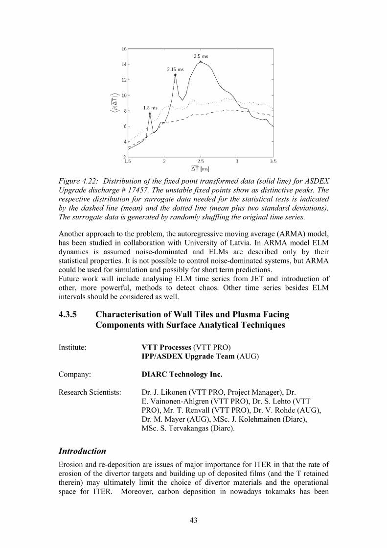
43
Figure 4.22: Distribution of the fixed point transformed data (solid line) for ASDEX Upgrade discharge # 17457. The unstable fixed points show as distinctive peaks. The respective distribution for surrogate data needed for the statistical tests is indicated by the dashed line (mean) and the dotted line (mean plus two standard deviations). The surrogate data is generated by randomly shuffling the original time series.
Another approach to the problem, the autoregressive moving average (ARMA) model, has been studied in collaboration with University of Latvia. In ARMA model ELM dynamics is assumed noise-dominated and ELMs are described only by their statistical properties. It is not possible to control noise-dominated systems, but ARMA could be used for simulation and possibly for short term predictions. Future work will include analysing ELM time series from JET and introduction of other, more powerful, methods to detect chaos. Other time series besides ELM intervals should be considered as well.
4.3.5 Characterisation of Wall Tiles and Plasma Facing Components with Surface Analytical Techniques
Institute: VTT Processes (VTT PRO)
IPP/ASDEX Upgrade Team (AUG) Company: DIARC Technology Inc. Research Scientists: Dr. J. Likonen (VTT PRO, Project Manager), Dr.
E. Vainonen-Ahlgren (VTT PRO), Dr. S. Lehto (VTT PRO), Mr. T. Renvall (VTT PRO), Dr. V. Rohde (AUG), Dr. M. Mayer (AUG), MSc. J. Kolehmainen (Diarc), MSc. S. Tervakangas (Diarc).
Introduction Erosion and re-deposition are issues of major importance for ITER in that the rate of erosion of the divertor targets and building up of deposited films (and the T retained therein) may ultimately limit the choice of divertor materials and the operational space for ITER. Moreover, carbon deposition in nowadays tokamaks has been

44
observed to be much higher at the inner than outer divertor. The reason for this asymmetry is unclear. A possible explanation might be a drift in the scrape-off layer (SOL) from outboard to inboard side. This work is a close collaboration with IPP under the Task Force IV (Divertor Physics and First Wall Materials), and focuses on experimental investigation of material transport in SOL and the study of in/out asymmetries in divertor deposition. For the operational campaign in 2003 a set of AUG divertor tiles were coated with poloidal carbon stripes on the top of marker rhenium layer. This set of tiles was installed in the AUG divertor during the shutdown in end of 2002. The stripes were deposited by the company DIARC Technology Inc. using the DIARC plasma method (Figure 4.23). A carbon and rhenium beams were created by plasma generators and masked tiles were exposed to it while being rotated in a rack. The deposition was carried out in vacuum at room temperature.
Results The poloidal carbon stripes on rhenium interlayer were deposited on 11 AUG tiles by DIARC Technology Inc. using the Diarc® method and sent to IPP Garching for ion beam analysis. The thickness of the coating (3µm) has been determined using profilometry. The major impurities (Fe, Cr, Ni) have been analysed using various ion beam techniques.
Figure 4.23: Carbon-coated AUG divertor tiles.
Preliminary Rutherford backscattering spectrometry (RBS) measurements on coated AUG tiles have been carried out to demonstrate the capability of the analysis techniques for erosion and re-deposition studies. With RBS and SIMS the carbon and the rhenium layer in the marker sample can be detected easily. A drilling method, developed earlier for JET tiles, was used for extracting samples from the region where the marker stripe on the tile is deposited. The resulting 10 mm thick cylinders are 16 mm in diameter, a size well suited for sample holders of SIMS and ion beam analysis instruments. Cylinders positions were chosen the way that SIMS measurements were performed nearby to the places where RBS analyses was done.

45
4.4 Other Collaboration
4.4.1 Numerical Simulation of Alfvén Instabilities and NBI Ion Velocity Distributions on Wendelstein 7-X
Alfvén instabilities (AI) caused by energetic ions have been observed in many experiments on tokamaks and stellarators. On the other hand, theory predicts that AIs in stellarators have a number of pecularities because, first, there are more gaps in the Alfvén continuum of stellarators, where specific eigenmodes can reside, and, second, there exist specific non-axisymmetric resonances in the wave-particle interaction. In collaboration with the Institute for Nuclear Research, Kiev, some AIs observed in NBI experiments on Wendelstein 7-AS (W7-AS) were numerically studied with the Alfvén mode stability codes developed at Kiev. With the revised stellarator adaptive ASCOT version, NBI injected fast ion trajectories have been simulated in a stellarator configuration calculated for the Wendelstein 7-X. The required accuracy in orbit following has been achieved with the developed interpolation and orbit tracking algorithms for the magnetic data read from the equilibrium code run at IPP Garching. The ASCOT code is capable to treat collisions and models the NBI injection geometry. From the orbit trajectories, the fast ion distributions are sampled and used for the stability analysis of Alfvén eigenmodes in Wendelstein stellarators using the stability codes of the Kiev group.
4.4.2 Diagnostics development for Wendelstein 7-X A multichannel CO2 laser interferometer is planned for electron density profile measurements in the Wendelstein 7-X stellarator under construction. Interferometry is the standard method to measure the line integrated electron density in a plasma. Its particular diagnostic potential is that information on the electron density is obtained with a high temporal resolution and without absolute calibration of the signal intensity. A collaboration between HUT and IPP was set up to develop mathematical methods for finding the optimum orientation of the interferometer sightlines. The problem of reconstructing local densities from line integrated density measurements can be formulated as a matrix inversion. The quality of the reconstruction is largely determined by the condition number of the matrix describing the problem, which has to be minimized, i.e., the sightlines have to be chosen such that the information content of different channels is maximally distinct. For the W7-X interferometer four- and eight-sightline arrangements were investigated and their orientations were optimized for standard conditions of magnetic configuration and density profile. The optimized arrangements were tested by simulating the inversion of hypothetical reference density profiles in a number of different magnetic configurations. The robustness of the optimization was demonstrated by a variation of the magnetic coordinate system. It was found that the error of a reconstruction using four sightlines is typically a few times larger than that with eight sightlines. Also the influence of noisy phase data on the reconstructed profiles was investigated.

46
4.4.3 Super-Sonic Poloidal Flow and ITB Generation in FT-2 In FT-2 tokamak experiments, the spontaneous transition into an improved confinement mode has been found during 100 kW, 930 MHz lower hybrid heating of low current discharges. This mode is characterized by a gradually decreasing Hβ radiation, suppression of turbulence (measured by the enhanced scattering technique), prolonged energy confinement time, and a large pressure gradient in the plasma interior. Through careful numerical Monte Carlo modelling of the NPA signals from the heated ion distributions, one can deduce that the ions are well confined in the low current case, and no orbit loss mechanism can play any role in the radial current balance and ITB generation. Neither can one see a clear change in the magnetic shear when the current is reduced from 88 kA to 22 kA. To study the effect of plasma current on radial electric field, numerical Monte Carlo ASCOT simulations based on radial ion current balance in a collisional plasma were carried out for the experimental conditions of FT-2 tokamak. One can find that the field rapidly increases to strongly sheared negative values over a large region around the steep pressure gradient. The time scale for this is tens of microseconds, i.e., the ion bounce time scale, and is initiated after the temperature has grown above 150 eV at around the steep pressure gradient. Before this, the field closely follows the neoclassical prediction. To study the origin and existence of such strong radial electric fields for the ITB conditions of FT-2, a new gyrokinetic code ELMFIRE has been developed to model both the neoclassical and turbulent mechanisms at the same time.
4.5 Code Development
4.5.1 Gyrokinetic Simulation Environment In modern fusion experiments the observed rate of energy and particle transport exceeds the neo-classical (collisionally produced) prediction by a factor of two decades. This transport has been coined anomalous, although it is the prevailing mode of transport in most experiments. During the last two decades, the nature of anomalous transport has been the object of intensive research. It is widely believed that anomalous transport is caused by marginally stable drift modes in the presence of temperature and density gradients. Such convective modes saturate in a state of drift wave micro-turbulence, which is very effective in transporting energy and particles across magnetic flux surfaces whenever the convective cells correlate with each other. The modes have a short wavelength (hence, microturbulence) and they may be very localised, which imposes difficulties on the experimental investigation of such modes. In some experimental set-ups development of transport barriers in the edge and bulk plasma are observed, and currently it is believed that the barriers form because of locally sheared flows which reduce the correlation between the convective cells. Although neo-classical theory does not explain the observed transport, collisional transport mechanisms are known to create sheared flows, which in turn can participate in the suppression of turbulent structures. Turbulent viscosity may also play an important part in the evolution of neo-classical processes.

47
Numerical models which include both drift wave turbulence and neo-classical flows are scarce, so such a model needs to be developed for investigating confinement mode transitions, internal transport barriers (ITB) and scrape-off layer (SOL) plasmas. These are the primary motivations for developing the ELMFIRE code.
The Numerical Model The ELMFIRE is an implicit full f gyro-kinetic particle code for simulating electrostatic drift-wave turbulence in the presence of particle to particle collisions. It is a gyrokinetic version of ASCOT, which solves the five dimensional equations of motion of particles in gyro-centre coordinates (two velocity components) and evaluates the radial electric field via neo-classical current balance. In the ELMFIRE, however, the electric field is solved in three dimensional space using one of the following methods: the analytical Lin-Lee averaging operator, a stochastic averaging operator which is collected during the simulation from the particle distribution, or an exactly quasi-neutrality preserving stochastic operator. All methods are non-linear and non-local, and the latter two allow significant deviations from the equilibrium distribution as well. The guiding-center equations adopted, implementation of binary collisions to conserve momentum and energy between the particles, the fixed magnetic configuration, and the quiescent particle initialization method are as in ASCOT thus making possible to simulate neoclassical physics avoiding the particular limitations of fluid and particle-in-cell (PIC) models to turbulence analysis. The finite Larmor-radius effects necessitate the use of a very fine grid for the evaluation of the electric field, which in turn causes the code to use large amounts of memory and CPU time for this very integral part of the simulation. Thus, the code has been parallelised, which allows simulations with larger numbers of particles and improved statistics. New gyrokinetic methods have been developed for the evaluation of the electric field, and a new method has been developed to allow simulations with kinetic electrons. The electrons are treated either adiabatically, keeping a fixed electron distribution, or following their orbits in drift-kinetic approximation. The code is able to simulate turbulent effects such as ion temperature gradient modes (ITG) and trapped electron modes (TEM) same time consistently simulating the neoclassical electric field affecting these modes.
Turbulence Analysis of the FT2 Tokamak As an example, the developed particle code has been applied in the TEM and ITG instability simulations for the FT-2 tokamak (Ioffe Institute), where the wide ion orbits with respect to the plasma radius and steep density and temperature gradients pose a challenge for gyrokinetic particle simulations of turbulence. Here, the simulations are carried out both in the presence and absence of steep density and temperature gradients to investigate the effect of profiles on the instabilities. In Figure 4.24, the square Fourier amplitude of the fastest growing mode both for runs with adiabatic and kinetic electrons is followed in time. In the kinetic run with both gradients, the fastest growing mode (corresponding to TEM) reaches its saturation

48
level in 10 µs while in the adiabatic run with only the temperature gradient the fastest growing mode (ITG) still grows after 35 µs. Fairly good agreement with analytic theory was obtained thus showing that the full f sampling of the gyrokinetic ion polarization term in the gyrokinetic polarization equation can be successfully applied in the simulation of electrostatic turbulence, even for the steep plasma density and temperature gradients often observed at the tokamak plasma edge.
0 5 10 15 20 25 30 3510
−11
10−10
10−9
10−8
10−7
10−6
10−5
10−4
10−3
10−2
adiabatic n=0 m=13
time [µs]
|F(n
,m)|
2
∇n≠0 ∇T≠0∇n=0 ∇T≠0∇T=0 ∇n=0
0 5 10 15 20 25 30 35
10−10
10−9
10−8
10−7
10−6
10−5
10−4
10−3
10−2
kinetic n=0 m=20
time [µs]
|F(n
,m)|
2
∇n≠0 ∇T≠0∇n=0 ∇T≠0∇n=0 ∇T=0
Figure 4.24: Fastest growing mode a) in adiabatic simulation and b) in kinetic simulation.
4.5.2 Upgrades on ASCOT NBI initialisation routine In 2003 two major upgrades of the NBI initialisation routine were carried out:
1. Particles can now be initialized using FAFNER data 2. The analytical model for NBI was completely reconstructed.
The Monte Carlo code FAFNER, operated at IPP, calculates the birth places of NBI ions for a given discharge. It thus has the accurate geometry of the neutral beam injectors, all the energy components, and the correct plasma profiles for that discharge. This initialization method allows realistic simulations of a specific discharge. The drawback of the method is that it doesn�t allow exploring parameter dependencies. Analytical NBI models, on the other hand, have complete freedom in adjusting the beam parameters. The major weakness of the analytical NBI initialisation routine used until now is that the test particles are generated only on the low field side of the plasma. Consequently, the fast ion velocity distribution will not be realistic. Additionally, the generic routine can handle only horizontal beams. Therefore a truly generic routine based on realistic beam geometry was needed. The newly developed generic routine splits the beam into nx times ny strands, where z-direction is parallel to the beam. Beam attenuation due to ionization is then simulated separately for each strand of the beam which are further divided into evenly spaced cells in the z-direction. The strands are attenuated exponentially according to the local mean free path. To this end the inverse of the mean free path is integrated numerically along the strand. The weight factor of a test particle initialised in a given cell is proportional to the number of ions deposited in the cell due to ionization. The pitch value of the test particle corresponds to the direction of the beam strand.

49
The new routine accommodates also the vertical inclination of the beam in addition to horizontal tilt. The algorithm has already been integrated into ASCOT, and it is currently being benchmarked.
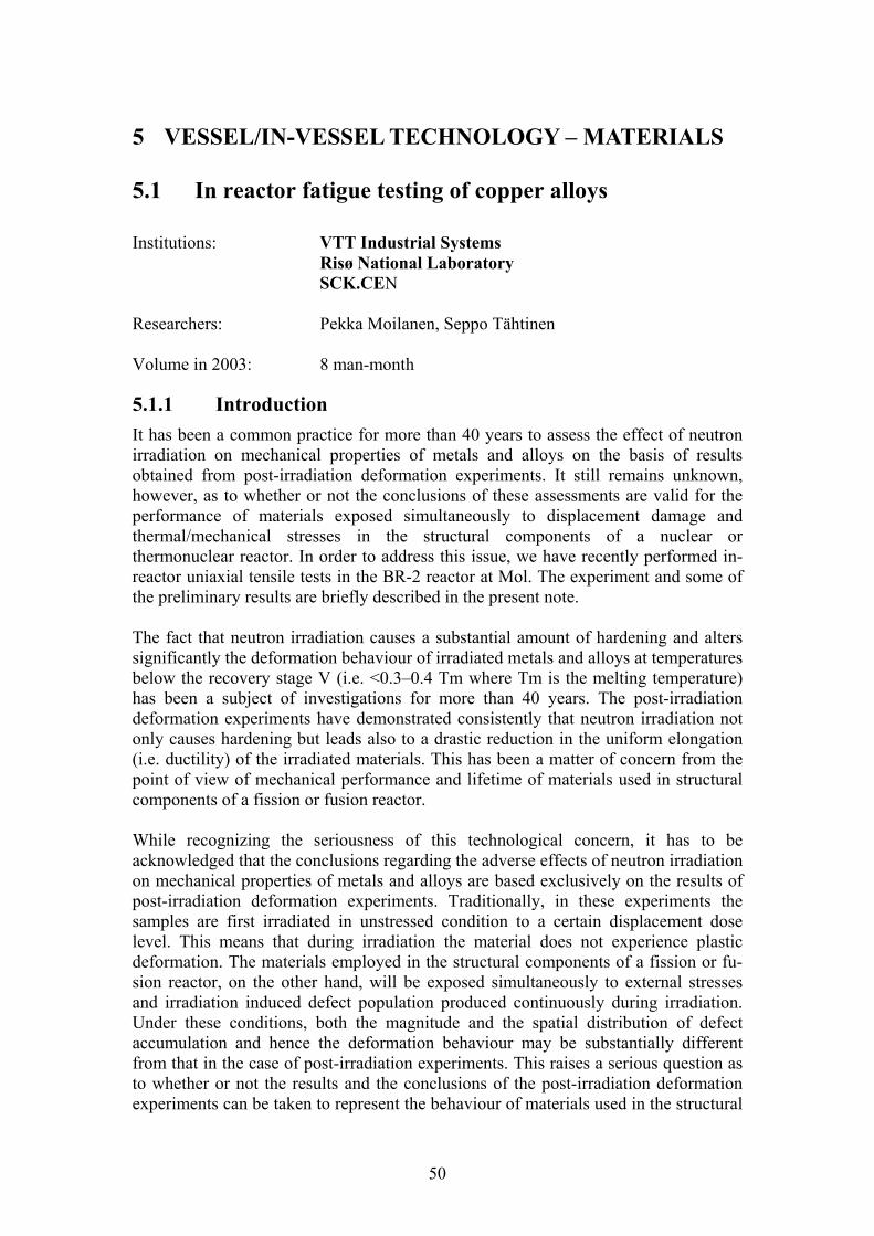
50
5 VESSEL/IN-VESSEL TECHNOLOGY � MATERIALS
5.1 In reactor fatigue testing of copper alloys Institutions: VTT Industrial Systems
Risø National Laboratory SCK.CEN
Researchers: Pekka Moilanen, Seppo Tähtinen Volume in 2003: 8 man-month
5.1.1 Introduction It has been a common practice for more than 40 years to assess the effect of neutron irradiation on mechanical properties of metals and alloys on the basis of results obtained from post-irradiation deformation experiments. It still remains unknown, however, as to whether or not the conclusions of these assessments are valid for the performance of materials exposed simultaneously to displacement damage and thermal/mechanical stresses in the structural components of a nuclear or thermonuclear reactor. In order to address this issue, we have recently performed in-reactor uniaxial tensile tests in the BR-2 reactor at Mol. The experiment and some of the preliminary results are briefly described in the present note. The fact that neutron irradiation causes a substantial amount of hardening and alters significantly the deformation behaviour of irradiated metals and alloys at temperatures below the recovery stage V (i.e. <0.3�0.4 Tm where Tm is the melting temperature) has been a subject of investigations for more than 40 years. The post-irradiation deformation experiments have demonstrated consistently that neutron irradiation not only causes hardening but leads also to a drastic reduction in the uniform elongation (i.e. ductility) of the irradiated materials. This has been a matter of concern from the point of view of mechanical performance and lifetime of materials used in structural components of a fission or fusion reactor. While recognizing the seriousness of this technological concern, it has to be acknowledged that the conclusions regarding the adverse effects of neutron irradiation on mechanical properties of metals and alloys are based exclusively on the results of post-irradiation deformation experiments. Traditionally, in these experiments the samples are first irradiated in unstressed condition to a certain displacement dose level. This means that during irradiation the material does not experience plastic deformation. The materials employed in the structural components of a fission or fu-sion reactor, on the other hand, will be exposed simultaneously to external stresses and irradiation induced defect population produced continuously during irradiation. Under these conditions, both the magnitude and the spatial distribution of defect accumulation and hence the deformation behaviour may be substantially different from that in the case of post-irradiation experiments. This raises a serious question as to whether or not the results and the conclusions of the post-irradiation deformation experiments can be taken to represent the behaviour of materials used in the structural
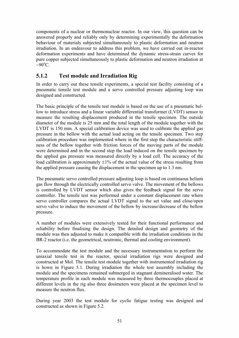
51
components of a nuclear or thermonuclear reactor. In our view, this question can be answered properly and reliably only by determining experimentally the deformation behaviour of materials subjected simultaneously to plastic deformation and neutron irradiation. In an endeavour to address this problem, we have carried out in-reactor deformation experiments and have determined the dynamic stress-strain curves for pure copper subjected simultaneously to plastic deformation and neutron irradiation at ~90oC.
5.1.2 Test module and Irradiation Rig In order to carry out these tensile experiments, a special test facility consisting of a pneumatic tensile test module and a servo controlled pressure adjusting loop was designed and constructed. The basic principle of the tensile test module is based on the use of a pneumatic bel-low to introduce stress and a linear variable differential transformer (LVDT) sensor to measure the resulting displacement produced in the tensile specimen. The outside diameter of the module is 25 mm and the total length of the module together with the LVDT is 150 mm. A special calibration device was used to calibrate the applied gas pressure in the bellow with the actual load acting on the tensile specimen. Two step calibration procedure was implemented where in the first step the characteristic stiff-ness of the bellow together with friction forces of the moving parts of the module were determined and in the second step the load induced on the tensile specimen by the applied gas pressure was measured directly by a load cell. The accuracy of the load calibration is approximately ±1% of the actual value of the stress resulting from the applied pressure causing the displacement in the specimen up to 1.3 nm. The pneumatic servo controlled pressure adjusting loop is based on continuous helium gas flow through the electrically controlled servo valve. The movement of the bellows is controlled by LVDT sensor which also gives the feedback signal for the servo controller. The tensile test was performed under a constant displacement rate where servo controller compares the actual LVDT signal to the set value and close/open servo valve to induce the movement of the bellow by increase/decrease of the bellow pressure. A number of modules were extensively tested for their functional performance and reliability before finalising the design. The detailed design and geometry of the module was then adjusted to make it compatible with the irradiation conditions in the BR-2 reactor (i.e. the geometrical, neutronic, thermal and cooling environment). To accommodate the test module and the necessary instrumentation to perform the uniaxial tensile test in the reactor, special irradiation rigs were designed and constructed at Mol. The tensile test module together with instrumented irradiation rig is hown in Figure 5.1. During irradiation the whole test assembly including the module and the specimens remained submerged in stagnant demineralised water. The temperature profile in each module was measured by three thermocouples placed at different levels in the rig also three dosimeters were placed at the specimen level to measure the neutron flux. During year 2003 the test module for cyclic fatigue testing was designed and constructed as shown in Figure 5.2.
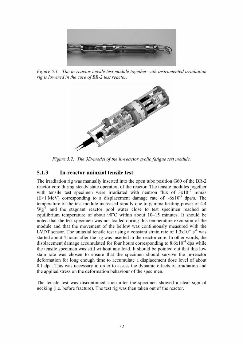
52
Figure 5.1: The in-reactor tensile test module together with instrumented irradiation rig is lowered in the core of BR-2 test reactor.
Figure 5.2: The 3D-model of the in-reactor cyclic fatigue test module.
5.1.3 In-reactor uniaxial tensile test The irradiation rig was manually inserted into the open tube position G60 of the BR-2 reactor core during steady state operation of the reactor. The tensile modules together with tensile test specimen were irradiated with neutron flux of 3x10¹⁷ n/m2s (E>1 MeV) corresponding to a displacement damage rate of ~6x10⁻⁸ dpa/s. The temperature of the test module increased rapidly due to gamma heating power of 4.4 Wg-1 and the stagnant reactor pool water close to test specimen reached an equilibrium temperature of about 90oC within about 10�15 minutes. It should be noted that the test specimen was not loaded during this temperature excursion of the module and that the movement of the bellow was continuously measured with the LVDT sensor. The uniaxial tensile test using a constant strain rate of 1.3x10⁻⁷ s-1 was started about 4 hours after the rig was inserted in the reactor core. In other words, the displacement damage accumulated for four hours corresponding to 8.6x10⁻⁴ dpa while the tensile specimen was still without any load. It should be pointed out that this low stain rate was chosen to ensure that the specimen should survive the in-reactor deformation for long enough time to accumulate a displacement dose level of about 0.1 dpa. This was necessary in order to assess the dynamic effects of irradiation and the applied stress on the deformation behaviour of the specimen. The tensile test was discontinued soon after the specimen showed a clear sign of necking (i.e. before fracture). The test rig was then taken out of the reactor.

53
5.1.4 Experimental Results Before presenting the actual results of the in-reactor tensile testing experiment it is only appropriate to clarify the experimental conditions under which the materials response has been determined. Furthermore, this clarification is crucially important in order to understand and appreciate fundamental differences between the traditional post-irradiation tensile tests and the present in-reactor tensile test. The post-irradiation tensile test is performed, for instance, on a specimen which has been already irradiated (in the absence of any applied stress) at a certain temperature and to a certain displacement dose level. In other words, the specimen, prior to the commencement of the tensile test has a given defect microstructure which has evolved in response to the irradiation temperature and the dose level. The stress-strain response measured during a post-irradiation test must reflect, therefore, the deformation behaviour of the frozen-in irradiation-induced microstructure. In the case of the in-reactor tensile test, on the other hand, the situation is entirely different. Here, the tensile specimen is loaded in the fully annealed condition and begins to deform when it has none or only a few irradiation-induced defect clusters. Hence, the material will begin to deform in a manner similar to the unirradiated virgin material with a characteristic low yield stress. However, as test continues with a constant damage rate and strain rate, the density of both the irradiation-induced clusters (interstitial loops and clusters and vacancy SFTs) and deformation-induced dislocations will increase with increasing displacement dose. Thus, the increase in the stress level at a given plastic strain value is due not only to the increase in dislocation density and dislocation-dislocation interactions (i.e. work hardening) but also includes the effect of increase in cluster density as well as of the cluster-dislocation interactions (i.e. radiation hardening). It is, therefore, rather complicated to make a direct comparison between the stress-strain curves obtained during the post-irradiation tensile tests and those determined during the in-reactor dynamic tensile experiment. Figure 5.3 shows the result of the in-reactor uniaxial tensile tests performed at ~90oC as a function of strain. It should be noted here that the stress response of the specimens includes the contribution of increasing dislacement damage level as a function of irradiation time. As indicated earlier, this effective hardening must be a combined effect of the conventional work hardening due to increasing strain and the radiation hardening due to an increasing amount of irradiation induced defect clusters. As can be seen the increase in hardening decreases with increasing strain and irradiation dose level and finally saturates. The level of saturation seems to depend on initial irradiation dose prior to plastic deformation. The higher the initial dose prior to plastic deformation the lower the total strain of the specimen. Main features in deformation behaviour:
• Yield drop in the post-irradiation reference test and in the in-reactor test where deformation was started after irradiation to 10-2 dpa without applied stress.
• The dose dependence of the yield stress is the same both in the post-irradiation test and in the in-reactor test.

54
• The flow stress at a given strain (i.e. at a given dose level) decreases with decreasing dose level at which the load was applied and reaches a saturation level at a lower stress than that in the post-irradiation test.
• The pre-irradiation to 10-2 dpa shortens the lifetime of the specimen.
0
50
100
150
200
250
300
350
0 5 10 15 20 25 30STRAIN (%)
STR
ESS
(MPa
)
PURE COPPERIn-reactor testsTirr = Ttest = 90 - 120oC
δε/δt = 1.3 x 10⁻⁷ s-1
Unirradiated
(1)(2)
(3)
Post-irradiated0.066 dpaδε / δt = 1.2 x 10⁻³ s-
1
100
150
200
250
300
0 1 2 3 4 5STRAIN (%)
STR
ES
S (M
Pa)
Post-irradiated
In-reactor
(2)
In-reactor Dose (NRT dpa)test no. yield point end of test
1 0.0038 0.0662 0.011 0.0463 0.0008 0.03
Figure 5.3: Stress-strain curves for (a) in-reactor dynamic tensile tests (curves 1, 2 and 3), (b) for out of pile reference test and (c) out of pile post-irradiation (to 0.066 dpa) test. Note that the in-reactor tensile tests were carried out at different pre-deformation dose level: Curve 1 at 0.0038 dpa, curve 2 at 0.011 dpa and curve 3 at 0.0008 dpa. The pre-irradiation to 0.011 dpa (curve 2) leads to a small yield drop.
Important differences in evolution of dislocation microstructure:
• Unlike in the case of unirradiated test where dislocation walls and cell structure evolves already at a strain level of 4%, no such evolution was found in specimens tested in the reactor either to 9% or 13% strain. In other words, the long range transport of dislocations and the resulting interactions are prevented in the in-reactor tests.
• Cleared channels are observed in the in-reactor tested specimens in a fashion similar to that in the case of post-irradiated tensile tested specimens. From the present experiments, it is not possible to determine as to when the flow localisation becomes the dominant mechanism of deformation.
5.1.5 Conclusions The present work has demonstrated that technically it is feasible to carry out well defined and controlled in-reactor dynamic tensile tests. This makes it possible to investigate the intrinsic role of the applied stress and the displacement damage acting concurrently in determining the global deformation behaviour of the material under dynamic irradiation conditions. The deformation behaviour in the in-reactor dynamic test is significantly different from that in the case of post-irradiation tests. Both the strain rate and displacement dose rate may play significant role in determining the lifetime of the specimens. The limitations of the present experiments do not allow to draw any firm conclusion

55
regarding the role of continuous production of dislocations and defect clusters on dislocation generation and propagation behaviour. Nor is it possible to determine as to when the plastic flow localisation becomes the dominant mechanism of plastic deformation and the life controlling factor. Clearly, more experiments are necessary to clarify
5.2 Characterisation of the CuCrZr/SS Joint Strength for Different Blanket Manufacturing Conditions.
Institutions: VTT Industrial Systems
CEA Grenoble Researchers: Seppo Tähtinen, Pekka Moilanen Volume in 2003: 0.5 man-month
5.2.1 Objective The copper alloys in ITER are used due to their good heat conduction properties in the first wall and divertor components. Copper alloys are bonded in between stainless steel structure material and Beryllium or CfC armour materials. The joint interfaces are subject to thermal and mechanical loads under neutron irradiation. In the present manufacturing rules there is no clear quality or strength criteria for the Cu/SS or SS/SS joint interfaces. Particularly the strength of CuCrZr alloy is very sensitive to heat treatments during manufacturing cycle and consequently also the strength of Cu/SS joints. This task is delayed due to late delivery of test materials. The characterisation of the joint specimens is scheduled by the beginning of the year 2004.
5.3 Effect of Low Dose Neutron Irradiation on Ti Alloy Mechanical Properties
Institutions: VTT Industrial Systems Researchers: Seppo Tähtinen, Pekka Moilanen Volume in 2003: 0.5 man-month
5.3.1 Objective Recent experiments have shown that the irradiation of (α+β) alloy at 350oC to 0.3 dpa leads to a very significant increase in the yield strength and a corresponding decrease in the uniform elongation. This effect seems to be related to the appearance of a very high density of irradiation-induced precipitates in this alloy. Surprisingly, these changes do not appear to have any noticeable effect on the low cycle fatigue behaviour of this alloy irradiated at 350oC to 0.3 dpa. The main objective of the present task is to investigate the effect of irradiation on the microstructure and

56
mechanical properties of these alloys (i.e. both α and (α+β)) at about 200oC which is closer to the expected service temperature in ITER. Fracture mechanical testing of the irradiated specimens is scheduled during the year 2004.
5.4 Qualification Testing of New CuCrZr/SS Tube Joint Institutions: VTT Industrial Systems Researchers: Seppo Tähtinen, Pekka Moilanen Volume in 2003: 1.0 man-month The extremely high surface heat loads expected in the divertor of the ITER require that the cooling tube of divertor and port limiter is made of CuCrZr alloy. This leads to the need of a CuCrZr/SS tube joint to enable the connection to the main cooling circuit of the high heat flux components. This task is delayed due to late test material delivery. The slow strain rate testing in simulated cooling water environment is scheduled by the beginning of the year 2004.
5.5 Ultrasonic Testing of Primary First Wall Mock-Ups and Panels (Contract EFDA 01-602)
Institutions: VTT Industrial Systems Researchers: Seppo Tähtinen, Harri Jeskanen, Pentti Kauppinen Volume in 2003: 2.0 man-month
5.5.1 Objective A Research and Development programme for the Blanket-shield of ITER has been implemented to provide input for the design and manufacture of the full-scale production components. It involves in particular the manufacturing and testing of Primary First Wall Mock-ups and Panels. These mock-ups and panels consist of plane layers of 316L Stainless Steel (SS) plate joined to Copper (Cu) alloy plates with the addition of a Beryllium (Be) layer. Non Destructive Examination has to be performed during manufacturing by the manufacturers. In particular, all the Be/Cu alloy and Cu alloy/SS joints have to be examined by ultrasonic technique after each joining operation to check the quality of the joints. The aim of this contract is to ask a Third Party to perform independent NDE and inspect the mock-ups and panels before and after thermal fatigue testing. Several Primary First Wall Mock-ups and Panels have been examined during year 2003 by using ultrasonic techniques. Figure 5.4 shows an example of ultrasonic examination of beryllium to copper interface of small scale mock-up PH/S-24IR.

57
Ultrasonic images indicate that echo amplitude from the interface changes due to applied ultrasonic frequency. It seems that the higher the applied frequency the more sensitive the ultrasonic examination is to surface condition and properties of beryllium.
Figure 5.4: The small scale mock-up PH/S-24IR and corresponding ultrasonic images of beryllium to copper interface using different frequencies of 25 MHz, 15 MHz and 10 MHz (from left to right).
5.6 Rules for Design, Fabrication and Inspection Institutions: VTT Industrial Systems Researchers: Anssi Laukkanen, Pekka Nevasmaa, Kim Wallin, Tapio
Planman, Seppo Tähtinen. Volume in 2003: 2.0 man-month
5.6.1 Objectives The use of fracture mechanics in design and failure assessment is in some practices impeded by the difficulties in quantifying the structure related constraint and transferability properties of experimental test data. It is well known that specimen size, crack depth and loading conditions may effect the materials fracture toughness. Transferability of small specimen toughness data to real structures has long been the key issue in fracture mechanics research. Methods based on the Weibull statistic, such as the "Master Curve" methodology and local approach methods of fracture have been developed and are able to characterise the scatter of fracture toughness test results and the effects of specimen dimensions on the data distribution, making it possible to define fracture toughness parameters for a given probability of failure and develop scaling models for toughness transferability. Ongoing development of local approach methods for cleavage fracture has led to the introduction of several different types of material models and parameter calibration procedures. The feasibility of these methods to practical purposes has usually been demonstrated by performing parameter inference on the basis of attainable experimental data and in many cases it can be argued that even limited generality of the used methods is doubtful. It can be stated that qualitative descriptive potential of local approach and damage mechanics models has been well authenticated, but quantitative properties are a completely different matter.

58
The current work contributes to the matter by analysing a relatively extensive fracture toughness data set using a modified Beremin model. This collection of fracture toughness data in the ductile to brittle transition region consists of both irradiated and reference data of A533B Cl. 1 (JRQ) over a wide temperature range and with different size bend type fracture mechanics specimens. The experimental results are processed using the Master Curve method and two fundamentally differing local approach parameter calibration methods are applied on the basis of the data set. Dependencies in the calibrated parameters are describes and discussed, and on the basis of the results, a calibration methodology producing the widest range of property transferability is presented.
5.6.2 Discussion The calibration of modified Beremin model parameters on the basis of point wise fracture toughness data produced results with considerable scatter. Since in many cases the number of different temperatures was considerably higher than typically in such analyses, a synthesis on probable parameter values and their trends could be made, but on the other hand, several cases persisted which would have led to ill-mannered conclusions. Such situations occurred in particular when approaching temperatures lower than the reference temperature for a specific case. This is not to be inferred as a theoretical deficiency of the used local approach model, but rather a consequence of sample scatter, which in such cases were attributed to scarcity in number of data and the values of fracture toughness. In some cases when using the collocation type of an approach this led to severe ill conditioning when the analyses were performed at a low temperature (with respect to T0) combined to large scatter of fracture toughness and a limited sample size. Overall, it can be stated that reliable analyses can be performed for a typical fracture toughness data set (which the current data was to establish and present) but calibrations performed for inhomogeneous data sets or at temperatures significantly differing from the reference temperature may produce unexpected problems. This can be interpreted such that the calibration ought to be performed where the fundamentals of weakest link principles apply best. In using the calibrated collocation data specific to temperature, the calibration naturally produces a decent estimate in terms of cumulative failure probability. This is primarily related to the corresponding values for the Weibull scale parameter, which adjusts accordingly to produce a description of the failure probability. The calibration using stochastic inference produced clearly defined trends with minimal scatter, the remaining inaccuracies primarily related to the numerical modelling process as a whole. The Weibull shape parameter had a consistently decreasing trend with temperature, which obeys its understanding as a damage rate parameter, i.e. as the temperature and the associated fracture toughness decrease, the demands set to initiating a cleavage crack decrease, overcoming the threshold for initiation with a lower value of the shape parameter. The scale parameter can be treated as the normalisation Weibull stress, and in a sense, is a ductility property for the sample at a specific temperature. As such, its decrease as a function of temperature was clearly defined even for the collocation type of results. As a scaling parameter it also adjusts the calibration such that independently of m a decent fit for the specific sample in question results. The temperature dependency of this parameter has been observed. The calibrated parameters displayed specimen size dependencies, which in the current work were apparent as specimen ligament size was considered. By considering the trends exhibited as a function of normalisation fracture toughness it became apparent that for typical process zone definitions smaller specimens produce higher estimates
59
for the Weibull shape. This is logical if one considers the differences associated with near crack-tip fields in the studied 3PBs, reported in published literature. If the states of constraint in the different specimens are inferred by using e.g. Q-trajectories for characterisation, it becomes apparent that the smallest of the 3PB specimens have a much more local and steeper stress field than that of the 10-10-55 mm specimen (i.e. a lower state of constraint). As such, the failure process zone becomes smaller necessitating an increase in the damage rate as the normalisation toughness is decreasing with temperature. In such terms, there are differences between the predicted measuring capacities of the modified Beremin model and those of experimental findings, even though quantitatively the correspondence of the results may be satisfactory. The same analogy applies to explaining process zone dependencies, except that in some cases a 'too large' process zone can suffocate all trends in general and decrease evaluation performance. As it was noted the use of stochastically generated fracture data and the temperature dependency of the normalisation fracture toughness to produce the parameter calibration was able to produce clearly defined dependencies between the parameters and temperature. This has much to do with the underlying Master Curve method, i.e. the superiority of using the scatter expression in the calibration is explained by the fact that the Master Curve analysis eliminates the uncertainties in analysis of the experimental fracture toughness results, while the large sample generated using a Monte-Carlo method takes care of the rest. With respect to the parameters of the modified Beremin model, this evidently appears to be the most robust and statistically sound approach. The problem relies in analysis of the normalisation fracture toughness. The experimental data of the current study barely enabled such an evaluation, and the number of fracture toughness experiments typically performed to specify the reference temperature can be too stringent to enable sound determination. The evaluations using specific temperature dependent modified Beremin model parameters and those averaged over a range of temperatures enabled quantification of transferability properties as a function of temperature. Except for the far ends in the studied temperature ranges the results were proven quite satisfactory with respect to cumulative failure probability. This was witnessed by the comparison of simulated fracture toughness temperature dependency and scatter to those of the Master Curve method. At the far ends, in particular towards the increasing end of the temperature range, the temperature independence of the parameters of the modified Beremin model started to lose their hold. This was seen as significant differences in failure probabilities erupted and can be expected since any temperature related effects are neglected. The range of application was, however, quite large, and for the 3-4-27 mm and 5-5-27 mm specimens studied in detail one can conclude that approximately 50°C was covered by a single mean valued set of parameters using stochastic inference. Relying on the temperature dependency of the normalisation fracture toughness is crucial in this matter for the performance of the modified Beremin model, otherwise the explicit dependencies on temperature and stress need to be modified.
5.6.3 Summary and Conclusions Master Curve analyses of experimental fracture toughness results were assessed using a modified Beremin model. The model parameters were calibrated using two fundamentally differing methods and transferability of the results evaluated. Simulated fracture toughness transition Curves were compared to the Master Curve ones. The results of the work can be concluded as follows:
60
• Calibration of modified Beremin model parameters was reliably performed using methodology based on stochastic inference.
• Pointwise collocation type of an approach suffered from intrinsic scatter of the fracture toughness samples. This lead to uncertainties in calibration results, unidentifiable trends and some ill-conditioned estimates highlighted in small sample statistics.
• The Weibull shape and scale parameter temperature dependencies were identified for the current fracture toughness results. In general, both were found nearly linearly dependent on temperature, whereas the temperature dependency can be expected in the used local approach model.
• Process zone definitions and states of near crack tip constraint produce a 'ligament' dependency on calibration results. For typically used process zones lower state of constraint necessitates a higher value for the shape parameter, vice versa for larger process zones. Too large of a process zone can decrease the accuracy of the estimates by adding 'bulk' stress fields to the prediction of failure event, decreasing prediction performance and the requirements set to the scale parameter and/or normalisation fracture toughness.
• The reference temperature itself does not have a primary effect on the calibration results, but rather defines suitable surroundings for the temperatures where most reliable results are attained.
• Using the temperature dependency of the normalisation fracture toughness and stochastic generation of the calibration sample reliable estimates of failure behaviour in the ductile to brittle transition behaviour can be attained. In the current study the range of feasible use of a determined parameter set was approximately 50°C, where the results were practically identical to those produced by the Master Curve method.
5.7 Flaking of Carbon Films CFC, W and Mo are good candidates for divertor material in the next step fusion device ITER. CFC is used in regions with extreme temperature loads whereas W and Mo elsewhere. Eroded carbon particles redeposit on other parts of the divertor and form rigid diamond-like carbon (DLC) films. These films hold large stresses, which can lead to flaking of the film. Flakes can contain large amounts of hazardous tritium, which increase the total amount of tritium in the fusion device. Several sets of C thin film samples with different deposition parameters were prepared to study the adhesion and flaking mechanism. Samples were manufactured by DIARC-Technology Inc. using the DIARC Method. C film thicknesses were 250 and 500 nm on both W and Mo substrates and in addition 750, 1000 and 1250 nm films on Mo. Films were grown at three different temperatures Tdep (room tempera-ture, 100 and 300°C) and methane partial pressures PCH4 (none, 10�4 and 10�3 mbar). Secondary ion mass spectrometry (SIMS) and Raman spectroscopy was used to determine hydrogen concentrations CH and carbon sp3/sp2 bonding ratio in the films, respectively. CH was constant throughout the films (with PCH4 = 10�4 mbar CH was 1.6�2.0 at.% and with PCH4 = 10�3 mbar approx. 6 at.%). Scanning electron microscopy (SEM) and 3D stylus profilometer were used in analysing topographies of the samples and dimensions of the stress relief patterns therein.

61
In general, C films had good adhesion, but delamination occurred in some samples. Various stress relief patterns were seen, e.g. straight-sided and sinusoidal patterns, see Figure 5.5. Increasing film thickness or Tdep decreased the film adhesion to the substrate. Flaking was strongly dependent on CH . At low Tdep film adhesion decreased with increasing CH. At 300°C increasing CH decreased the film flaking. This dynamic effect of codeposited H stands for a competing behaviour of the residual stress evolution in the film (see publication for details).
Figure 5.5: Sinusoidal and straight-sided stress relief patterns on 250 nm carbon film seen with SEM. Film was deposited on Mo at RT in methane pressure of 10-4 mbar.
5.8 Deuterium Mobility in Divertor Material During fusion device operation fuel accumulates in the walls and recycles back to the plasma. The exact mechanisms of hydrogen behaviour in these wall material candidates are not fully understood, especially when impurities like oxygen and carbon are present. The accurate hydrogen recycling, retention and diffusion parameters in tungsten and its composites are not known, due to the dominant role of absorption and desorption of hydrogen at the surface. To study this, pure tungsten samples were implanted with deuterium to a maximum concentration of 5 at.% (high concentration) and 0.5 at.% (low concentration). The samples will be annealed at different temperatures to induce deuterium diffusion. The desorbed deuterium molecules will be monitored in situ by quadrupole mass spectrometer (QMS) to give a dynamic view of the thermal process. Another set of tungsten samples were implanted with carbon with ion energies ranging from 35 keV to 500 keV. These samples will be implanted with deuterium and diffusion studies will be carried out to see the effect of carbon impurities to deuterium migration in tungsten. This task is underway and preliminary results will be available in the beginning of 2004.

62
5.9 Experimental Investigation of Hydrogen Containing Carbon Layers
Task was to measure a-C:H layers prepared at MPI für Plasmaphysik in Berlin. The samples were hydrogen containing carbon films grown on silicon. The thicknesses of the a-C:H films were measured in situ by optical method. Our task was to determine the density and the C/H ratio in the films. The time-of-flight elastic recoil detection analysis (TOF-ERDA) of elementary concentration profiles was performed with the 5-MV tandem accelerator EGP-10-II of the University of Helsinki. In the measurements, a 53-MeV beam of 127I10+ ions was used. The detector angle was 40o, and the samples were tilted relative to the beam direction by 20o. The detector solid angle was 0.11 msr. The elementary concentrations were calculated using known geometry and stopping powers in energy loss calculations. Tables 5.1 and 5.2 show the main results.
Table 5.1: Time-of-flight-ERDA results for hydrogen containing carbon layers.
Sample Injection of
Working gas
Thickness measured in-situ [nm]
Density by TOF-erda [g/cm3]
C/H ratio by TOF-erda
1. C2H4 + H2 Ar 86 1.4 ± 0.2 1.044 2. C2H4 Ar 83 1.5 ± 0.2 1.109 3. CH4 Ar 83 1.3 ± 0.2 1.067 4. C2H4 H2 100 1.6 ± 0.2 0.935
Table 5.2: Concentrations of all elements detected in the films. The concentration values given in atoms/cm2 have an uncertainy of about 5% due to the uncertainty in the stopping powers.
Sample 1. 2. 3. 4. Conc. Conc. Conc. Conc.
at/cm2 at/cm2 at/cm2 at/cm2 at.% *1016 at.% *1016 at.% *1016 at.% *1016
H 46±2 45 46±2 43 45±2 41 46±2 63 C 48±4 47 51±4 47 48±4 43 43±3 57 N 1.5±1 1.5 0.5±0.5 0.4 0.6±0.5 0.6 0.6±0.5 0.8 O 5±2 4.7 0.8±0.5 0.7 7.0±1.5 6.1 11±1.5 14 Ar - - 1.6±1.0 1.4 - - - -
5.10 Blistering The initial stages of blistering in W due to low-energy He implantation have been investigated by molecular dynamics simulations. The calculations were carried out on a block of (001) W at 0 K, for 100 eV He ions impinging on it. This energy is far below the threshold energy needed to create lattice displacements by He projectiles in W, which is about 0.50 keV. By visual inspection of the motion of W atoms during implantation, we found that an important mechanism for growth of small He bubbles (containing up to about 10 atoms) is the formation of (111) self-interstitial crowdion atoms. The formation of the interstitial relieves the high internal pressure in the He
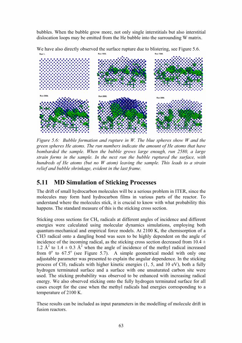
63
bubbles. When the bubble grow more, not only single interstitials but also interstitial dislocation loops may be emitted from the He bubble into the surrounding W matrix. We have also directly observed the surface rupture due to blistering, see Figure 5.6.
Figure 5.6: Bubble formation and rupture in W. The blue spheres show W and the green spheres He atoms. The run numbers indicate the amount of He atoms that have bombarded the sample. When the bubble grows large enough, run 2580, a large strain forms in the sample. In the next run the bubble ruptured the surface, with hundreds of He atoms (but no W atom) leaving the sample. This leads to a strain relief and bubble shrinkage, evident in the last frame.
5.11 MD Simulation of Sticking Processes The drift of small hydrocarbon molecules will be a serious problem in ITER, since the molecules may form hard hydrocarbon films in various parts of the reactor. To understand where the molecules stick, it is crucial to know with what probability this happens. The standard measure of this is the sticking cross section. Sticking cross sections for CHx radicals at different angles of incidence and different energies were calculated using molecular dynamics simulations, employing both quantum-mechanical and empirical force models. At 2100 K, the chemisorption of a CH3 radical onto a dangling bond was seen to be highly dependent on the angle of incidence of the incoming radical, as the sticking cross section decreased from 10.4 ± 1.2 Å2 to 1.4 ± 0.3 Å2 when the angle of incidence of the methyl radical increased from 0o to 67.5o (see Figure 5.7). A simple geometrical model with only one adjustable parameter was presented to explain the angular dependence. In the sticking process of CH3 radicals with higher kinetic energies (1, 5, and 10 eV), both a fully hydrogen terminated surface and a surface with one unsaturated carbon site were used. The sticking probability was observed to be enhanced with increasing radical energy. We also observed sticking onto the fully hydrogen terminated surface for all cases except for the case when the methyl radicals had energies corresponding to a temperature of 2100 K. These results can be included as input parameters in the modelling of molecule drift in fusion reactors.

64
Figure 5.7: Angular dependence of sticking of small hydrocarbon molecules on a carbon-based fusion reactor first wall material.
5.12 Erosion under Simultaneous H and Noble Gas Bombardment
The divertor region of modern tokamaks include in addition to H and He a small amount of noble gas atoms. These may change the erosion and T retention properties of the reactor first wall material. We have started to study this by simulation of simultaneous H and noble gas bombardment of C-based fusion reactor first wall materials. We created a-C:H cells with an sp3/sp2 ratio of about 0.4, and an H/C ratio of 0.4, both typical of fusion reactors conditions after prolonged irradiation. We then started irradiating the samples by successive H and Ar recoils (even at fusion reactor fluxes, the H and Ar impacts at the same sample region are well separated in time). The initial results indicate that the presence of Ar does affect the erosion, but not at levels which would be a serious problem for the reactor operation.
5.13 TW2-TVV/EBROOT � Controlling root welding made by electron beam with adaptive system, ART 5.1(A)
Institutions: VTT Industrial systems Researchers: Tommi Jokinen, Miikka Karhu, Veli Kujanpää Volume in 2003: 5.5 man-months
5.13.1 Introduction Enormous size and complexity of the structure of ITER vacuum vessel will set certain restrictions and demands to welding processes to be applied for assembling. The major ones are stringent fabrication tolerances, on-site field assembly with positional welding demand and a demand of one-side welding. In the case of ITER, this one-side welding demand means that welding must be done from inside only and there is no chance visually to inspect root side of the weld. Therefore it is essential to develop applied welding process control to such level that uniform quality and penetration of the root side could be sustained and secured during actual welding of vacuum vessel.

65
Electron beam welding has proposed to be one alternative welding process to be used in the assembly of vacuum vessel. The EB-process has thought to be modified such a way that welding will be carried out using multi-pass technique together with a filler wire addition and a narrow groove. It means that the root pass with penetration of around 10 mm is welded autogenously or with filler wire and then the whole upper partially bevelled groove is filled with multi-pass welding with filler addition. This welding procedure is thought to be beneficial because it could lighten fit-up tolerance requirements and could make it easier to control molten pool against gravity when welding at overhead position. Like above mentioned, when the root pass is being welded, sufficient penetration and a smooth, uniform root has to be secured. In this task research and development work has been concentrated on process control of electron beam welding to overcome that requirement. Work of this task has been carried out between year 2003 and 2004.
5.13.2 Objectives In this task, the main objective was to develop and build up the system, which enables to control root penetration in electron beam welding by using an adaptive system. Adaptation was meant to be carried out by using closed loop feed-back connection system, which measures simultaneously both the electrons which will pass through the work piece (pass-through current) and adjusts beam current in proportion to measured pass-through current during the welding.
5.13.3 Control system Electron beam is formed from electrons, which possess an electrical charge and as a resultant of those charges, the beam current (mA) is formed. When contemplated in a reduced manner the full penetrating welding sequence on behalf of the beam current, at first comes impinging beam current as a form of focused beam to the surface of the work piece. After that, most of the electron beam current is conducted into a work piece and got grounded whereas a smaller proportion is transmitted through the work piece via an open keyhole (through-current). In previous studies, it is confirmed that there is a good correlation between a sufficient amount of transmitted through-current and a proper penetration and therefore this through-current plays a very important role. Under the circumstances, there was a strong need to develop and build a suitable system which measures the through-current as input and is capable of responding simultaneously (in tens of milliseconds) to the through-current changes by adjusting the beam current according to this feed-back. PC-based measuring and control system was developed and a high level modular programming language was used for programming. Required data acquisition hardware to PC was purchased from National Instruments, which is also distributor for LabVIEW programming language used in software development. A principle illustration of developed measurement/control system is shown in Figure 5.8. A detector made of 5 mm thick copper plate is situated approx. 10 mm under the work piece to be welded. The detector is insulated from the working table with using ceramic insulators and wired to the PC-system (Figure 5.9). The welding operator could set from program menu a rate of desired value of through-current in advance of welding. During the welding through coming stream of electrons impinge to the
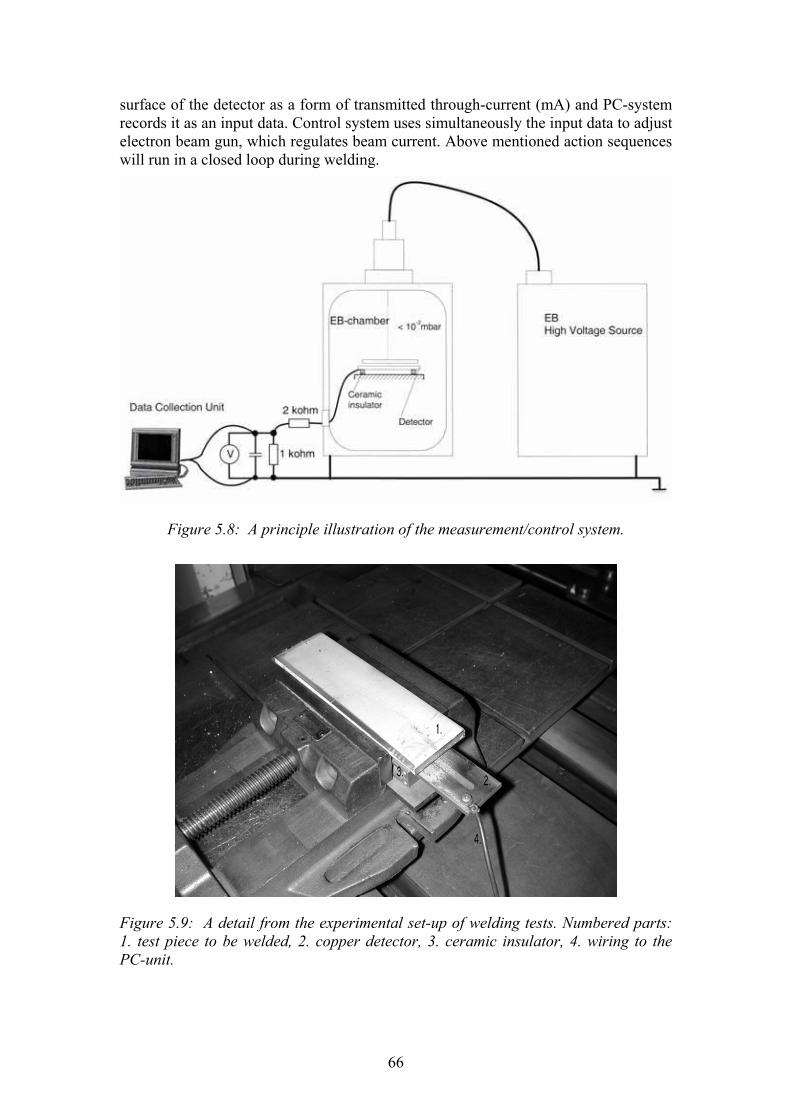
66
surface of the detector as a form of transmitted through-current (mA) and PC-system records it as an input data. Control system uses simultaneously the input data to adjust electron beam gun, which regulates beam current. Above mentioned action sequences will run in a closed loop during welding.
Figure 5.8: A principle illustration of the measurement/control system.
Figure 5.9: A detail from the experimental set-up of welding tests. Numbered parts: 1. test piece to be welded, 2. copper detector, 3. ceramic insulator, 4. wiring to the PC-unit.

67
5.13.4 Main Results
Welding tests of the closed loop control system During the work of this task, closed loop feed back control system was developed and connected to the EB-welding machine. The performance of developed control system was checked with welding tests. The purpose of the welding tests was to find out if control system could be capable of perform when thickness of the welded material is being varied during welding. The evaluations of welding tests were made visually from the test welds and from the welding data derived from PC�s data collection unit. Welding tests of the control system were carried out in flat position and with bead-on-plate runs. The length of the test welds were 170mm. Test pieces were austenitic stainless steel plates which thickness was whether linearly increased or decreased in ratio of 1:40 in the middle part of the test piece. An increment and a decrement of thickness was chosen to be altered within 2 mm which will simulate possible thickness alteration of root face, resulted from manufacturing of very large-size work piece. The cross-sections of those test pieces (test piece 10D12 and 10D8) can be seen in Figure 5.10.
Figure 5.10: The cross-sections of the test pieces used in the welding tests. Above: (1) test piece 10D12. Below: (2) test piece10D8.
In Figure 5.11 it is shown principle presentation of welding procedure including start and finish point of welding together with welding direction.
Figure 5.11: Presentation of welding procedure. Above: test piece 10D12. Below: test piece10D8.
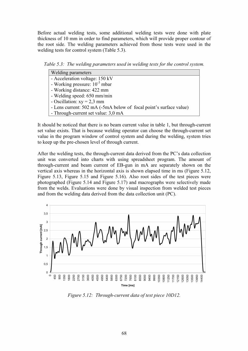
68
Before actual welding tests, some additional welding tests were done with plate thickness of 10 mm in order to find parameters, which will provide proper contour of the root side. The welding parameters achieved from those tests were used in the welding tests for control system (Table 5.3).
Table 5.3: The welding parameters used in welding tests for the control system.
Welding parameters - Acceleration voltage: 150 kV - Working pressure: 10-3 mbar - Working distance: 422 mm - Welding speed: 650 mm/min - Oscillation: xy = 2,3 mm - Lens current: 502 mA (-5mA below of focal point�s surface value) - Through-current set value: 3,0 mA
It should be noticed that there is no beam current value in table 1, but through-current set value exists. That is because welding operator can choose the through-current set value in the program window of control system and during the welding, system tries to keep up the pre-chosen level of through current. After the welding tests, the through-current data derived from the PC�s data collection unit was converted into charts with using spreadsheet program. The amount of through-current and beam current of EB-gun in mA are separately shown on the vertical axis whereas in the horizontal axis is shown elapsed time in ms (Figure 5.12, Figure 5.13, Figure 5.15 and Figure 5.16). Also root sides of the test pieces were photographed (Figure 5.14 and Figure 5.17) and macrographs were selectively made from the welds. Evaluations were done by visual inspection from welded test pieces and from the welding data derived from the data collection unit (PC).
0
0,5
1
1,5
2
2,5
3
3,5
4
0
450
900
1350
1800
2250
2700
3150
3600
4050
4500
4950
5400
5850
6300
6750
7200
7650
8100
8550
9000
9450
9900
1035
0
1080
0
1125
0
1170
0
1215
0
1260
0
1305
0
1350
0
1395
0
1440
0
Time [ms]
Thro
ugh
curr
ent [
mA
]
Figure 5.12: Through-current data of test piece 10D12.

69
0
10
20
30
40
50
60
70
0
450
900
1350
1800
2250
2700
3150
3600
4050
4500
4950
5400
5850
6300
6750
7200
7650
8100
8550
9000
9450
9900
1035
0
1080
0
1125
0
1170
0
1215
0
1260
0
1305
0
1350
0
1395
0
1440
0
Time [ms]
Bea
m c
urre
nt [m
A]
Figure 5.13: Beam current data of test piece 10D12.
Figure 5.14: Appearance from the root side of test piece 10D12.
0
0,5
1
1,5
2
2,5
3
3,5
4
4,5
0
450
900
1350
1800
2250
2700
3150
3600
4050
4500
4950
5400
5850
6300
6750
7200
7650
8100
8550
9000
9450
9900
1035
0
1080
0
1125
0
1170
0
1215
0
1260
0
1305
0
1350
0
1395
0
1440
0
Time [ms]
Thro
ugh
curr
ent [
mA
]
Figure 5.15: Through-current data of test piece 10D8.

70
0
5
10
15
20
25
30
35
40
45
50
0
450
900
1350
1800
2250
2700
3150
3600
4050
4500
4950
5400
5850
6300
6750
7200
7650
8100
8550
9000
9450
9900
1035
0
1080
0
1125
0
1170
0
1215
0
1260
0
1305
0
1350
0
1395
0
1440
0
Time [ms]
Bea
m c
urre
nt [m
A]
Figure 5.16: Beam current data of test piece 10D8.
Figure 5.17: Appearance from the root side of test piece 10D8.
Conclusions Welding tests showed that control system managed to respond quite well as thickness of test piece was grown from 10 mm to 12 mm. The system raised the amount of beam current quite linearly in relation to the growth of the plate thickness. When thickness of the test piece decreased linearly from 10 mm to 8 mm, control system kept beam current values in quite a constant level during welding. The explanation to the latter case may be that the level of pre-chosen through-current (3mA) is so high that it widens the parameter window where a successful welding can be taken place. When thickness of test piece is decreasing like in above case, no remarkable changes in beam current is needed because process stands inside the parameter window. During the additional welding tests and development work of control system, it was found that the welding machine was tended to be quite sensitive at the start of the welding sequence. If the beam current request of the control system (mA/second) is too high at the start, the safety system of the welding machine will shut the beam off. A beam current rise ramp was implemented to the control system in order to prevent this instability occurred between the welding machine and control system. As a whole, the carried welding tests gave promising results on the functionality of the control system, as well as the applicability of the concept itself. For a proposal of further developments it can be mentioned that it may be advisable to improve the reliability of system with switching from the current PC-based implementation to an embedded, microcontroller based control system. In addition, it would be useful to carry out further welding tests, where control system is tested with longer weld lengths and at different welding positions.
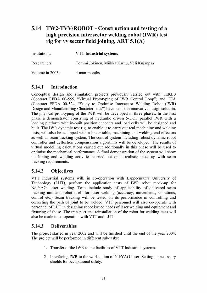
71
5.14 TW2-TVV/ROBOT - Construction and testing of a high precision intersector welding robot (IWR) test rig for vv sector field joining, ART 5.1(A)
Institutions: VTT Industrial systems Researchers: Tommi Jokinen, Miikka Karhu, Veli Kujanpää Volume in 2003: 4 man-months
5.14.1 Introduction Conceptual design and simulation projects previously carried out with TEKES (Contract EFDA 00-555, �Virtual Prototyping of IWR Control Loop�) and CEA (Contract EFDA 00-524, �Study to Optimise Intersector Welding Robot (IWR) Design and Manufacturing Characteristics�) have led to an innovative design solution. The physical prototyping of the IWR will be developed in three phases. In the first phase a demonstrator consisting of hydraulic driven 5-DOF parallel IWR with a loading platform with in-built position encoders and load cells will be designed and built. The IWR dynamic test rig, to enable it to carry out real machining and welding tests, will also be equipped with a linear table, machining and welding end-effectors as well as seam tracking system. The control system including robust dynamic robot controller and deflection compensation algorithms will be developed. The results of virtual modelling calculations carried out additionally in this phase will be used to optimise the mechanical performance. A final demonstration of the system will show machining and welding activities carried out on a realistic mock-up with seam tracking requirements.
5.14.2 Objectives VTT Industrial systems will, in co-operation with Lappeenranta University of Technology (LUT), perform the application tests of IWR robot mock-up for Nd:YAG- laser welding. Tests include study of applicability of delivered seam tracking unit and robot itself for laser welding (accuracy, movements, vibrations, control etc.) Seam tracking will be tested on its performance in controlling and correcting the path of joint to be welded. VTT personnel will also co-operate with personnel of LUT in designing robot issued needs of laser welding and equipment and fixturing of those. The transport and reinstallation of the robot for welding tests will also be made in co-operation with VTT and LUT.
5.14.3 Deliverables The project started in year 2002 and will be finished until the end of the year 2004. The project will be performed in different sub-tasks:
1. Transfer of the IWR to the facilities of VTT Industrial systems.
2. Interfacing IWR to the workstation of Nd:YAG-laser. Setting up necessary shields for occupational safety.
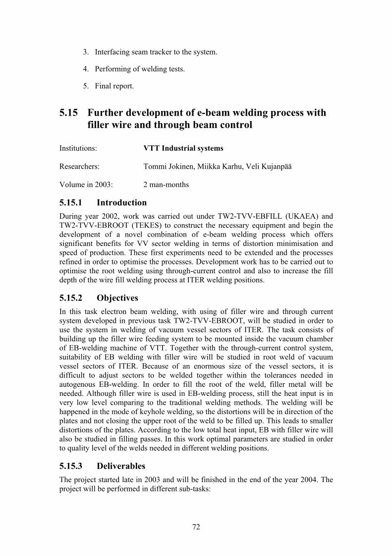
72
3. Interfacing seam tracker to the system.
4. Performing of welding tests.
5. Final report.
5.15 Further development of e-beam welding process with filler wire and through beam control
Institutions: VTT Industrial systems Researchers: Tommi Jokinen, Miikka Karhu, Veli Kujanpää Volume in 2003: 2 man-months
5.15.1 Introduction During year 2002, work was carried out under TW2-TVV-EBFILL (UKAEA) and TW2-TVV-EBROOT (TEKES) to construct the necessary equipment and begin the development of a novel combination of e-beam welding process which offers significant benefits for VV sector welding in terms of distortion minimisation and speed of production. These first experiments need to be extended and the processes refined in order to optimise the processes. Development work has to be carried out to optimise the root welding using through-current control and also to increase the fill depth of the wire fill welding process at ITER welding positions.
5.15.2 Objectives In this task electron beam welding, with using of filler wire and through current system developed in previous task TW2-TVV-EBROOT, will be studied in order to use the system in welding of vacuum vessel sectors of ITER. The task consists of building up the filler wire feeding system to be mounted inside the vacuum chamber of EB-welding machine of VTT. Together with the through-current control system, suitability of EB welding with filler wire will be studied in root weld of vacuum vessel sectors of ITER. Because of an enormous size of the vessel sectors, it is difficult to adjust sectors to be welded together within the tolerances needed in autogenous EB-welding. In order to fill the root of the weld, filler metal will be needed. Although filler wire is used in EB-welding process, still the heat input is in very low level comparing to the traditional welding methods. The welding will be happened in the mode of keyhole welding, so the distortions will be in direction of the plates and not closing the upper root of the weld to be filled up. This leads to smaller distortions of the plates. According to the low total heat input, EB with filler wire will also be studied in filling passes. In this work optimal parameters are studied in order to quality level of the welds needed in different welding positions.
5.15.3 Deliverables The project started late in 2003 and will be finished in the end of the year 2004. The project will be performed in different sub-tasks:

73
1. Set-up of filler wire feeder test facilities inside to the vacuum chamber of EB- welding machine of VTT. Modification of through beam current control system for welding with filler wire developed in previous task TW2-TVV-EB-ROOT.
2. Preliminary welding tests for usability of the system.
3. Experimental investigation on root welding using modified rest current control and filler wire feeder.
4. Experimental investigations on filling weld in narrow gap using filler wire with austenitic stainless steel thickness of 60 mm.
5. Final report on auxiliary systems and welding tests.

74
6 VESSEL/IN-VESSEL TECHNOLOGY � REMOTE HANDLING
6.1 Divertor maintenance equipment, Tasks TW3-TVR-MOVER and TW3-TVR-WHMAN
Institute: Tampere University of Technology, Institute of hydraulics and automation (TUT/IHA)
Research Scientists: Siuko M., Pitkäaho M., Karjalainen R, Kopperoinen A,
Verho S, Koivisto H, Kunttu P, Raneda A., Poutanen J, Tammisto J., Toivo M, Tuominen M, Virvalo M, Vilenius M.
6.1.1 Background Due to the erosion of the plasma facing components and possible need for improving the design of critical items, replacement of the divertor and its refurbishment in the hot-cell is foreseen 4 times during the ITER lifetime. The divertor consists of 54 cassettes, which can be replaced through three RH ports. Each of the cassettes weights over ten tons. The cassette multifunctional mover (CMM) with a set of end effectors and the cassette toroidal mover (CTM) are needed to transport these cassettes from the reactor to the transportation cask. The CMM and CTM together with a manipulator arm (MAM) are used to carry out some other tasks related to the cassette and port handling.
6.1.2 IHAs contribution IHA has been involved in divertor maintenance procedures since 1994. First tasks were related to divertor cassette refurbishment in the Hot-cell environment. IHA has designed and produced prototypes for two different tool systems used for plasma-facing component (PFC) replacement. These systems were delivered year 1997 and 1999. Tool systems included water hydraulic tools for aligning the heavy components and for producing and disassembling joints between the PFC�s and the cassette bodies. During 2003 IHA was developing and designing the cassette multifunctional mover (CMM) and manipulator arm (MAM) assisting CMM operation. The tasks, which are presented here, were respectively TW3-TVR-MOVER and TW3-TVR-WHMAN.
6.2 Tasks TW3-TVR-MOVER During the year 2003 IHA has been designing the cassette replacement procedure in co-operation with EFDA. The whole divertor replacement cycle involving all CMM tasks has been studied and based on these studies the second cassette handling has been determined as the most demanding task. Therefore IHA has been designing the CMM and the second cassette end effector (SCEE) for the second cassette replacement. Based on this design mock-ups of the CMM and the SCEE are going to be built and tested at divertor test platform two (DTP2) in order to verify the operations.

75
6.2.1 CMM tasks The CMM carries heavy components to and from the reactor using a set of end effectors. Current proposal includes five end effectors to be used for replacement of: primary closure plate, diagnostic rack, central cassette, second cassettes and standard cassettes. The removal of the standard cassettes is done together with cassette toroidal mover which transports the standard cassettes along toroidal rails to the RH port. CMM operates only by the port. The CMM moves along rails running radially from the reactor to the cask which is docked on the RH port (~12m travel). The second cassette replacement is considered the most difficult of all the CMM tasks. It is the only CMM task that includes cassette toroidal motion; moving cassettes toroidally from the second cassette position which is next to the RH port opening (see Figure 6.1).
6.2.2 Second cassette replacement The second cassette handling includes cassette transportation along a radial path, transportation toroidally and lowering of the cassette on the rails (or lifting the cassette from the rails). These tasks are carried out by the CMM and the SCEE. The CMMs lifting, tilting and radial drives are used synchronously while the cassette is introduced into the vessel. When the cassette is moved along the toroidal rails the two SCEE joints and the radial drive are used synchronously to generate the wanted trajectory. The accuracy requirements are assumed to be the highest with the SCEE since the arm length, thus also amplification factors, are the highest. The second cassette weight is 10.7 tons. At the end of the toroidal trajectory (6.66 degrees away from the RH port centerline), most of the weight of the second cassette is resting on the wheels of one corner of CMM. Also the torsion force generated has to be taken by the CMM body, lifting mechanisms and the SCEE. Therefore, the loading conditions are also the most difficult during the second cassette handling.
6.2.3 Operational requirements The space limitations in the reactor make the task quite difficult. The heavy loads need to be handled in a cantilevered manner because of the lack of space below the cassette. The RH duct is curved so that in order to fit the cassette in the reactor the cassette has to be tilted. The space margins are quite limited in the tunnel there is only about ±20mm vertical gap between the cassette and the tunnel. The cassette connection to the reactor started with ±2,5mm vertical gap but during the design process reactor design has changed so that accuracy requirement has decreased in a way that ±20mm should be enough in the reactor as well as in the tunnel. Despite the recent changes in reactor design the positioning accuracy is very demanding taking into account the high loads and the way the cassettes are carried in the cantilevered manner. The divertor maintenance starts two weeks after reactor shutdown. The CMM has to withstand gamma radiation up to 100Gy/h. During the ITER lifetime accumulated dose for the CMM is estimated to be over 1MGy. The CMM components have to be radiation proof to this level (or be easily replaceable in hot-cell). The structure has to be easy to clean and is not allowed to contaminate the reactor (drops of oil, grease or other deposit).

76
Figure 6.1: CMM in RH port reaching for the second cassette.
Because of the requirements above, especially because of the high loads and the limited space available water hydraulic actuators were the only possibility for the CMM actuators.
6.2.4 Design process The design started based on the conceptual design made by the Framatom�Siemens. Based on the conceptual design simulation model including flexibility of the structure and the hydraulics was made in co-operation with LUT. These simulations indicated that the task is possible. These simulations were made by integrating the mechanical structure models made with Adams and hydraulic models made with Matlab-Simulink simulation programs. The work cycles of the CMM are studied with Igrip simulations in order to check the space limitations. These simulations proved to be valuable tool finding out potential difficulties in the cycle as well as for presenting the work cycles in several different occasions. As a result of these simulations some design changes were seen necessary in the reactor and the cask design. The sizing and selection of the CMM and the SCEE components was done based on calculations and Adams simulations. Parallel to the design process there has been radiation testing of the hydraulic components in co-operation with CIEMAT and SCK. The seals of the water hydraulic cylinders are tested to verify radiation hardness but also to find out suitable mechanical properties. Based on mechanical design, hydraulics and electric components have been selected taking into account the defined environmental and task requirements. The design has proceeded to the level that mock-ups can be build and tested at DTP2. The final design of the CMM and the SCEE will be established based on the experience and data to be gathered during the DTP2 tests.

77
6.2.5 CMM+SCEE design
Degrees of freedom CMM has three degrees of freedom. The radial drive is a rack and pinion system driven by servomotors. Lift and tilt producing cassette alignment inside the duct have hydraulic cylinder actuators. The cylinders are position controlled by servo valves. SCEE has two rotational degrees of freedom: cantilever arm rotation and hook plate rotation. These two rotations align the second cassette in horizontal plane while it is moved toroidally. These two rotations are also driven with servo valve controlled hydraulic cylinders.
Figure 6.2: CMM+ SCEE structure.
Mechanical structure The CMM body is a welded stainless steel structure which rigidity is maximized within the available space. The mechanical backlashes are minimized by bearing selections. The bearings are tapered roller bearings which need to be grease lubricated. The bearings are sealed so that the risk contaminating the reactor is minimized and the CMM can be washed after use in order to reduce the radiation during the maintenance and storage of the tools. The design aims to modularity so that the tools can be disassembled for maintenance. The modularity allows also testing of different modifications during the DTP2 mock-up tests.
Interfaces The SCEE has an interface plate that allows connection to the cassette in the limited space in the reactor. Between the CMM and the SCEE is an adapter plate that allows swift changes of end effectors in the hot cell. This interface has integrated multi coupling to connect the hydraulic lines and the electrical signals of the end effectors to the CMM.

78
Sensors Position is measured using resolvers. Dual speed revolvers are mounted in the rotational joints measuring the rotation angle. These sensors produce superior measuring accuracy compared to linear position measurement. Resolvers are also preferred because of their radiation hardness. The CMM radial position is as well measured using a resolver with built-in reduction gear and pinion running on radial drive rack. The radial drive resolver rotates one full turn during the travel from the cask to the reactor.
Wheels The weight of the CMM and the component it is supporting in a cantilevered manner is lying on CMM wheels. Wheel loading is high especially when the second cassettes are moved toroidally. During the toroidal movement weight is divided unevenly between the left and right hand side wheels of the CMM. CMM needs to be guided also horizontally. Side wheels are holding the CMM sideways on the centreline of the duct. The modular construction of the wheel mechanism allows introduction of more advanced wheel adjustment mechanisms during the DTP2 testing. Based on the DTP2 test results the most suitable wheel mechanisms can be selected for the final CMM design.
Hydraulics The hydraulic system consists of water hydraulic power unit, control valves, cylinders, stainless steel piping, corrugated metal hoses and accessories like connectors etc. The accurate position control of the cylinders is based on servo valves on of type solenoid valves are used for the safety and the added redundancy systems. All the control valves for the CMM and the SCEE are mounted onboard CMM. The hydraulic power unit is mounted in the cask. The hydraulic power unit includes electric motor driven piston pump, filters, radiator, tank etc.
Umbilical CMM umbilical needs to supply hydraulic pressure and return lines, and the electric signals for the valves. The umbilical guides also the electrical supply for the radial drive motors and all the sensor cables. Since the CMM movement from the cask to reactor is linear cable chain �type umbilical provides simple and well-known concept for the umbilical construction. Two commercially available stainless steel cable chains running on both sides of the CMM can guide all the required cabling within the available space.
6.2.6 Conclusions Most of the components are selected for the CMM and the design is ready to be finalised for mock-up manufacturing. The Second cassette replacement will be verified at DTP2 with these mock-ups. During these tests the CMM and SCEE design will be optimised and finalised before the manufacturing of the final ITER equipment.

79
6.3 Manipulator on CMM - tasks during the divertor maintenance
The aim of this study was to define the tasks to be carried out by a manipulator arm (MAM) installed on top of the CMM. The MAM tasks include the maintenance tunnel preparations at the beginning of the maintenance period, assisting operators when releasing the diagnostic rack, the central cassette and the second cassette and operations when closing the maintenance tunnel. The tasks MAM has to perform were clarified, modelled and tested in a virtual environment (IGRIP 3D software) in order to get an estimate of the required envelope of the manipulator. The reactor and the maintenance tunnel models were obtained from EFDA in CATIA format. The exact locations of e.g. bolts and electrical connectors are still unknown, and for these parts the tests are based on an assumptions of their location. Also because the dimensions of the MAM tools are still unknown, the reach was analysed without a tool. The divertor maintenance operations are proceeding roughly following way:
- The maintenance port is prepared outside manually to open the port hatch and to provide access to the CMM and the Cassette transportation cask.
- The Cask is docked to the port and the heavy port hatch is replaced with casks twin-door which can be opened and closed with simple cask operations. The heavy port door is carried to the hot cell by the cask.
- The cask returns to the port and the diagnostic rack is removed by the CMM assisted by the MAM and transported to the hot cell by the cask.
- The cask returns to the port, the CMM is driven into the tunnel and the MAM makes necessary operations to move the cassette cooling pipes aside. The CMM carries central cassette into the cask. The cassette is transported to the hot cell by the cask.
- The cask returns to the port, the CMM is driven into the tunnel and the second cassette is released with the assistance of the MAM and carried into the cask. The cassette is transported to the hot cell by the cask.
- The cask returns to the port, the CMM carries the Cassette toroidal mover (CTM) into the reactor. The MAM assists these operations by connecting CTM umbilical etc. After that, rest of the cassettes are carried out with the co-operation of the CTM, CMM, the MAM on CMM and a MAM placed on CTM. The cassettes are transported to the hot cell by the cask.
- After the cassettes removal, the replacements are placed respectively and finally the port is closed oppositely it was opened.
In following are discussed the tasks where the MAM on the CMM are included.
6.3.1 The diagnostic rack removal MAM unlocks the 7 locking bolts connecting the diagnostic rack to the reactor. All the bolts are located in the front plate of the diagnostic rack (see Figure 6.3). MAM also disconnects electrical connectors, which are also on the diagnostic rack front plate. The diagnostic rack is carried into the cask by the CMM.
6.3.2 The central cassette removal MAM uses two pipe retraction devices (see Figure 6.4.) to bend the cooling pipes and then makes them secure. After that the CMM can attach the central cassette. When the
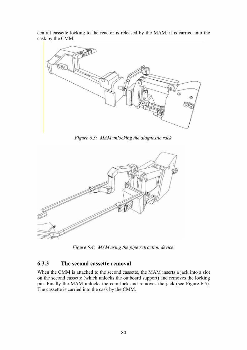
80
central cassette locking to the reactor is released by the MAM, it is carried into the cask by the CMM.
Figure 6.3: MAM unlocking the diagnostic rack.
Figure 6.4: MAM using the pipe retraction device.
6.3.3 The second cassette removal When the CMM is attached to the second cassette, the MAM inserts a jack into a slot on the second cassette (which unlocks the outboard support) and removes the locking pin. Finally the MAM unlocks the cam lock and removes the jack (see Figure 6.5). The cassette is carried into the cask by the CMM.
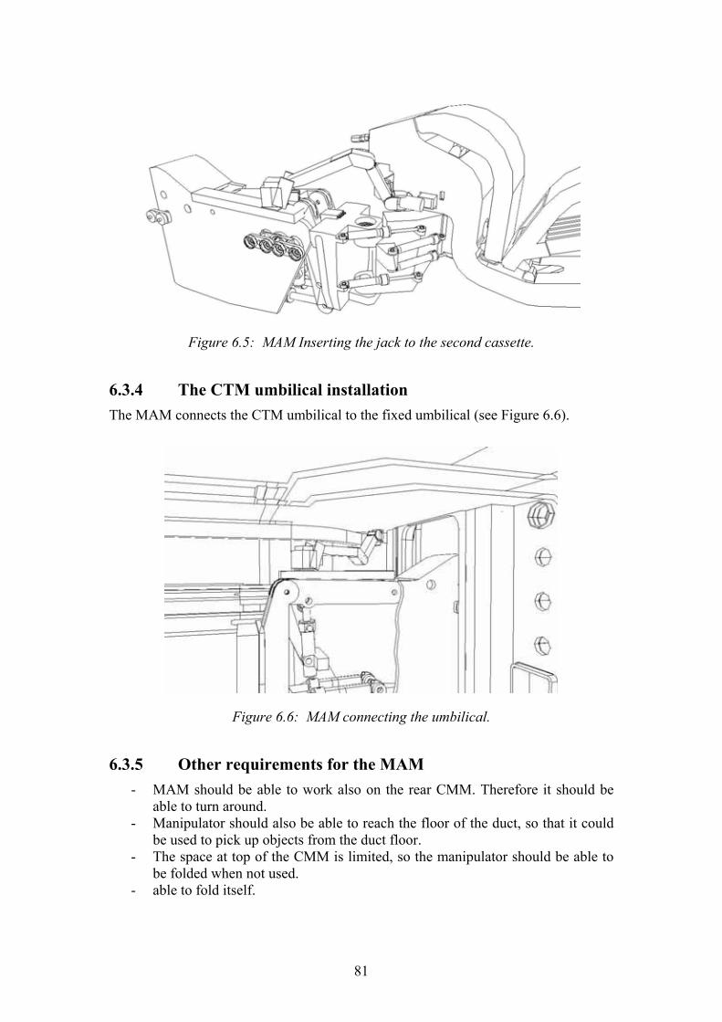
81
Figure 6.5: MAM Inserting the jack to the second cassette.
6.3.4 The CTM umbilical installation The MAM connects the CTM umbilical to the fixed umbilical (see Figure 6.6).
Figure 6.6: MAM connecting the umbilical.
6.3.5 Other requirements for the MAM - MAM should be able to work also on the rear CMM. Therefore it should be
able to turn around. - Manipulator should also be able to reach the floor of the duct, so that it could
be used to pick up objects from the duct floor. - The space at top of the CMM is limited, so the manipulator should be able to
be folded when not used. - able to fold itself.

82
6.4 MAM design
6.4.1 MAM dimensions MAM dimensions have been selected by testing the tasks described in the previous chapter. The maximum reach is needed when the MAM reaches the floor (see Figure 6.7). Because this is the only task where the maximum reach is needed, the first arm of the MAM was selected to be telescopic. This will make the performing of the other tasks easier, since the manipulator size can be reduced. Especially in the CTM umbilical installation, the space is limited. The dimensions of the manipulator are presented in Figure 6.8. The joint limits that were used on the tests are based on typical commercial manipulator. The values are presented in Table 6.1, and envelopes in Figure 6.9.
Figure 6.7: MAM touching the duct floor (left) and MAM in folded position (right).
Table 6.1: MAM joint limits.
Min Max
Joint 1 -45 deg 225 deg
Joint 2 -68 deg 52 deg
Joint 3 0 mm 400 mm
Joint 4 -95 deg 180 deg
Joint 5 -90 deg 90 deg
Joint 6 -90 deg 90 deg
Joint 7 -180 deg 180 deg
6.4.2 MAM tools The tools MAM uses are presented on the Table 6.2. MAM does not have to generate force to operate the tools since the tool itself generates the required force. The heaviest object MAM has to handle is the cassette releasing jack, which weight is evaluated to be ~75kg (size 555x130x165, 80% of the weight of solid stainless steel). Assuming the jack is operated with the gripper, total maximum load of the

83
manipulator is evaluated to be ~80kg. From the figures presented in Figure 6.8 and in Table 6.2, the MAM joint lengths, the actuator rotation angles and the required actuator forces are obtained.
Table 6.2: MAM tools.
Tool Weight
Bolting tool <30kg
Pipe cutting tool <30kg
Gripper <30kg
Jack <80kg
Figure 6.8: MAM minimum (top) and maximum (bottom) dimensions.

84
Figure 6.9: MAM envelope.
Conclusion By simulating the manipulator arm in its actual working environment the joint configuration, the dimensions and the actuator angles and torques were obtained. Also simulation helped to better understand and to simplify tasks to be performed. The study results will be evaluated in real environment when the DTP2 platform is built and the manipulator task can be studied with the information from the real-like conditions. Besides that, also the information got from radition hardness tests will be used as input when designing the MAM prototype.
6.5 Design and Development towards a Parallel Water Hydraulic Weld/Cut Robot for Machining Processes in ITER Vacuum Vessel
Institution: Lappeenranta University of Technology
Institute of Mechatronics and Virtual Engineering (IMVE) Researchers: Heikki Handroos, Huapeng Wu, Janne Kovanen, Pekka
Pessi, Yong Liu
6.5.1 Introduction In task Task TW2-TVV-ROBOT; Dynamic Test Rig for Intersector Welding Robot (IWR) for VV Sector Field Joining a demonstrator consisting of an oilhydraulic driven 5-DOF paraller robot with a loading platform is designed and built. The mechanical parts and hydraulic cylinders with in-built position encoders are manufactured by local small companies. The control system including robust dynamic robot controller is developed by LUT by employing universal control system development hardware and software (dSpace). The behaviour and accuracy of robot in various conditions over the whole work space is measured and analysed. A novel calibration method based on differential evolution algorithm is developed and successfully applied. Some technical problems such as vibration and backlash occurred in the accuracy tests of the robot. This led to redesign of the most critical

85
mechanical parts and replacements of some components such as control valves. In task Task TW3-TVV-ROBASS; Upgrade Robot to Include Water Hydraulics and a Linear Track the 5DOF oilhydraulic parallel-robot Penta-WH developed in TW2-TVV-ROBOT will be converted into water hydraulic. A short linear track, carriage and clamping system is designed according to concepts proposed in EFDA 00-524. The design of carriage is almost completed and most of the waterhydraulic components dimensioned and selected. Careful FE-analyses and virtual prototype analyses are carried out to find a final constructions of parts and the whole assembly to satisfy the load capacity and precision requirements of the robotic system.
6.5.2 Control structure and dynamic tests of oil-hydraulic IWR Figure 6.10 shows the control hardware of robot. The system mainly consist of the PC-computer, dSpace-control board, terminal strip, electrical supply system, robot and 55 kW hydraulic power unit. Dspace control board was selected as the prototyping environment for the robot because it supports Matlab/Simulink software. This makes it possible to model the control systems in block diagram form. The Simulink model is converted into C-code by means of RealTime Workshop provided by the manufacturer of Matlab Simulink. This environment makes it easy and quick to modify the control system and vary its parameters. The I/O-board includes A/D and D/A�converters as well as incremental encoder standard inputs. The position control systems of the robot rams include the hydraulic cylinders, incremental encoders, servo valves, pressure sensors and locking valves.
Figure 6.10: Control hardware of IWR.
Figure 6.11 shows the structure of developed control program. The program consists of following functions (1) Data reading and analysis
The robot can work as a CNC machine. It should understand both programs written in robot language and G code. It includes language check, explanation, and translation of the data into the format that robot can execute.
(2) Trajectory planning This function increases acceleration or decreases acceleration section in the beginning of motion and end of motion. It also optimizes the path of end tip.
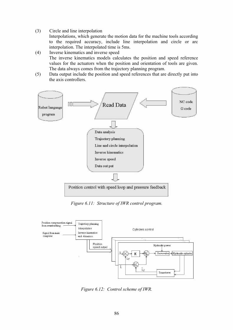
86
(3) Circle and line interpolation Interpolations, which generate the motion data for the machine tools according to the required accuracy, include line interpolation and circle or arc interpolation. The interpolated time is 5ms.
(4) Inverse kinematics and inverse speed The inverse kinematics models calculates the position and speed reference values for the actuators when the position and orientation of tools are given. The data always comes from the trajectory planning program.
(5) Data output include the position and speed references that are directly put into the axis controllers.
Figure 6.11: Structure of IWR control program.
Figure 6.12: Control scheme of IWR.
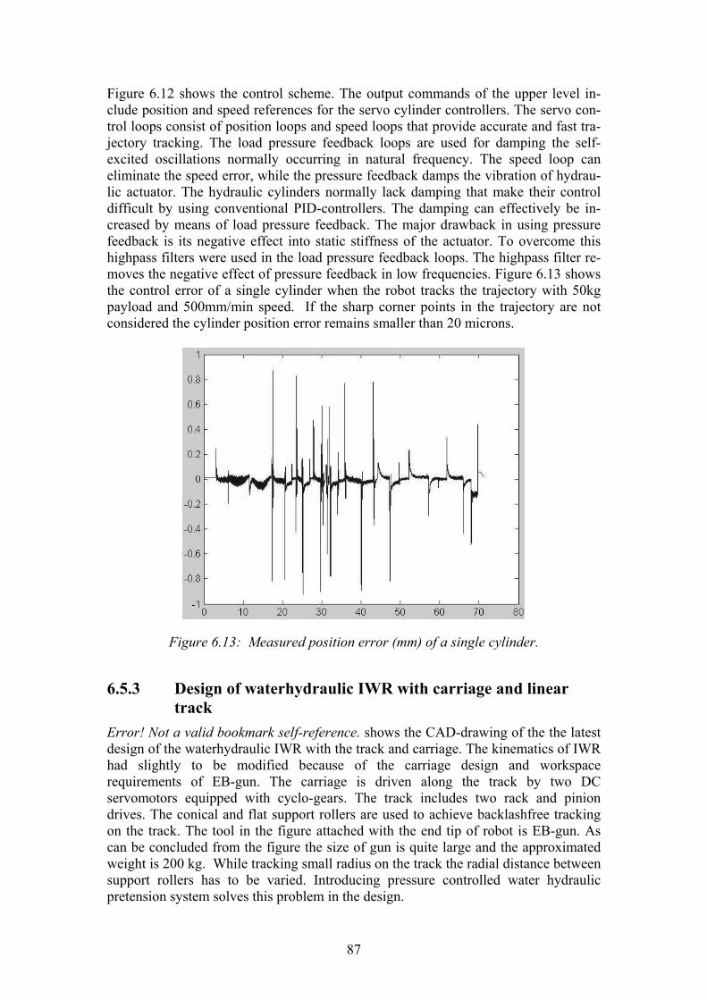
87
Figure 6.12 shows the control scheme. The output commands of the upper level in-clude position and speed references for the servo cylinder controllers. The servo con-trol loops consist of position loops and speed loops that provide accurate and fast tra-jectory tracking. The load pressure feedback loops are used for damping the self-excited oscillations normally occurring in natural frequency. The speed loop can eliminate the speed error, while the pressure feedback damps the vibration of hydrau-lic actuator. The hydraulic cylinders normally lack damping that make their control difficult by using conventional PID-controllers. The damping can effectively be in-creased by means of load pressure feedback. The major drawback in using pressure feedback is its negative effect into static stiffness of the actuator. To overcome this highpass filters were used in the load pressure feedback loops. The highpass filter re-moves the negative effect of pressure feedback in low frequencies. Figure 6.13 shows the control error of a single cylinder when the robot tracks the trajectory with 50kg payload and 500mm/min speed. If the sharp corner points in the trajectory are not considered the cylinder position error remains smaller than 20 microns.
Figure 6.13: Measured position error (mm) of a single cylinder.
6.5.3 Design of waterhydraulic IWR with carriage and linear track
Error! Not a valid bookmark self-reference. shows the CAD-drawing of the the latest design of the waterhydraulic IWR with the track and carriage. The kinematics of IWR had slightly to be modified because of the carriage design and workspace requirements of EB-gun. The carriage is driven along the track by two DC servomotors equipped with cyclo-gears. The track includes two rack and pinion drives. The conical and flat support rollers are used to achieve backlashfree tracking on the track. The tool in the figure attached with the end tip of robot is EB-gun. As can be concluded from the figure the size of gun is quite large and the approximated weight is 200 kg. While tracking small radius on the track the radial distance between support rollers has to be varied. Introducing pressure controlled water hydraulic pretension system solves this problem in the design.
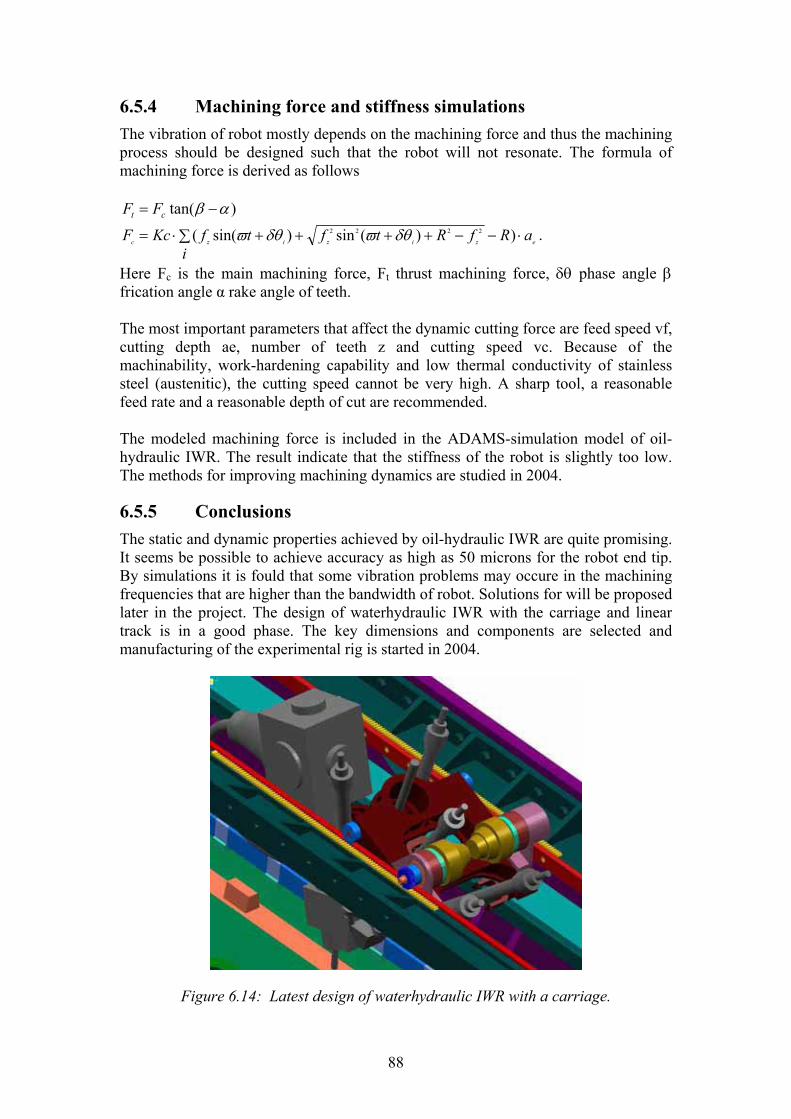
88
6.5.4 Machining force and stiffness simulations The vibration of robot mostly depends on the machining force and thus the machining process should be designed such that the robot will not resonate. The formula of machining force is derived as follows
)tan( αβ −= ct FF
ezizizc ai
RfRtftfKcF ⋅∑ −−++++⋅= ))(sin)sin(( 2222 δθϖδθϖ .
Here Fc is the main machining force, Ft thrust machining force, δθ phase angle β frication angle α rake angle of teeth. The most important parameters that affect the dynamic cutting force are feed speed vf, cutting depth ae, number of teeth z and cutting speed vc. Because of the machinability, work-hardening capability and low thermal conductivity of stainless steel (austenitic), the cutting speed cannot be very high. A sharp tool, a reasonable feed rate and a reasonable depth of cut are recommended. The modeled machining force is included in the ADAMS-simulation model of oil-hydraulic IWR. The result indicate that the stiffness of the robot is slightly too low. The methods for improving machining dynamics are studied in 2004.
6.5.5 Conclusions The static and dynamic properties achieved by oil-hydraulic IWR are quite promising. It seems be possible to achieve accuracy as high as 50 microns for the robot end tip. By simulations it is fould that some vibration problems may occure in the machining frequencies that are higher than the bandwidth of robot. Solutions for will be proposed later in the project. The design of waterhydraulic IWR with the carriage and linear track is in a good phase. The key dimensions and components are selected and manufacturing of the experimental rig is started in 2004.
Figure 6.14: Latest design of waterhydraulic IWR with a carriage.

89
7 FUSION TECHNOLOGY � SYSTEM STUDIES
7.1 Socio-Economic Studies � External Costs of Fusion; New Evaluation Methodologies
Institutions: VTT Processes Researchers: Riitta Korhonen To be socially justified energy production is required to be safe and clean. Actually it is of course not possible to find any absolutely safe and clean energy alternative. Fusion might be a future long term energy source, as resources of fusion fuel are rather unlimited and environmental impacts are estimated to be relatively small. Fusion is, however, rather expensive to develop and also production costs (m�/kWh) are so far estimated to be relatively high. Environmental costs (m�/kWh) estimated in SERF-studies are estimated to be lower than for most alternatives. Therefore total costs of fusion including environmental costs are estimated to be competitive. The study (Identification and comparative evaluation of environmental impacts of fusion and other possible future energy production technologies) was performed in the framework of the Socio-Economic Research of Fusion (SERF). Assessments of monetarised external impacts of the fusion fuel-cycle (m�/kWh) have been performed in the SERF studies. In the SERF 3 three power plant designs assuming to produce 1500 MW during the life-time of 35 years were studied. Silicon carbide was assumed to be the structural material in the plant designs. Fusion power plants were assumed to be installed around 2050. Occupational accidents, road accidents and impacts of emissions were studied during the whole fuel cycle. Final reporting of SERF 3 continued in 2003. Planning of SERF 4 (2003�2004) progressed during 2003 somewhat slowly. SERF 4 is titled Fusion as a part of energy systems. VTT participates in SERF 4 (TW3-TRE-FESAC) in co-operation with Studsvik by evaluating comparison of fusion with advanced fission concepts and also by continuing the work with long time horizons in the estimation of environmental impacts. One important aim is to evaluate the possible contradiction between the results of SERF-studies and PPCS-studies (Power Plant Conceptual studies) in the importance of long term dose impacts. The SERF 3 study was divided into subtasks between partners (Ciemat Madrid, IPP Garching, NFR Studsvik, UKAEA Culham and CEA Cadarache). VTT evaluated external costs of waste disposal and re-evaluated environmental impacts of C-14 in the future environment in SERF 3. The SERF 4 study (TW3-TRE-FESAC) includes co-operation with Studsvik in comparison of fusion with fission. The inventories of C-14 were considered to be important from the point of view of external costs in SERF. This was the basic finding in SERF 1. Waste due to fusion energy production includes higher amounts of C-14 than waste due to fission energy production, of the order 1 PBq in the considered plant model cases. In SERF 3 study external costs (Model plants having silicon carbide structures) were relatively low due

90
to higher thermodynamic efficiency, lower inventories and considered barriers in disposal. The considered higher efficiency (1500 MW instead of 1000 MW in SERF 2 Model plants) is considered to be realistic in plants using silicon carbide structures. Also recycling was considered as an alternative (Studsvik). As long term dose impacts are not assumed to be caused due to recycled materials, external costs are low also in this alternative. Waste disposal strategies can be divided into two conceptual approaches (ICRP 2000): 1) Dilute and Disperse and 2) Concentrate and Retain. In SERF the main concern has been in the strategy Concentrate and Retain. The principle Dilute and Disperse realises then � also when disposal strategy has been Concentrate and retain - on the global scale when radionuclides are diluted to large volumes and individual doses and risks will therefore be minimal. Individual dose and risk limits are important especially on the local scale. The principle Concentrate and Retain is important as limitation of individual doses and risks requires that the (potential) annual releases to the local environment are small. But then the strategy Dilute and Disperse in the environment might give very low individual doses, if instead of dilution on the local scale volumes, global scale volumes can be considered. In the recycling alternative radionuclides are then not evaluated to reach biosphere. So actually this alternative includes the assumption of very long term retention. In SERF2 and SERF3 retention times about 20000 years were considered to be necessary in waste disposal, when ExternE methodologies are used in the estimation of environmental costs. In Power Plant Conceptual Studies the possibility of clearing or recycling into the next generation fusion power plants is considered to be the relevant alternative for all fusion material after 100 years cooling in the cases in many Model plant cases. These materials are then not considered to cause long term doses. Recycling has also been considered in SERF 3 to be an alternative which gives very low external costs. It has been estimated in PPCS-studies that after times of order tens to a hundred years total radiotoxicity of the fusion material decays to a similar level to that of the ash from a coal power station. It seems that radiotoxicity indices and C-14 studies in SERF externalities not give similar weight to the radionuclide C-14. This will be evaluated in the SERF4 study. This is important also from the point of view of optimal materials. It has been earlier concluded in SERF-studies, that it is important to develop materials, which have very low activation into C-14 by neutrons. One essential question is then, how long term impacts should be evaluated. This includes the question, when it is relevant not to consider them at all. It might be evaluated to be sufficient, that concentrations (or �radiotoxicity�) of man-made radionuclides is lower than some natural concentration or e.g. concentrations in coal ash. In ExternE global small doses are integrated over long time spans. Also UNSCEAR (UNSCEAR 2000) gives similar relatively high dose factors for globally dispersing radionuclides. ICRP (ICRP 2000) states that �the role of potential exposure in risk assessment for long-lived radionuclides is not yet clear�. Time horizons are often quite different, when radionuclides and other emissions are considered. Development of �cleaner� energy obviously causes that many short term environmental impacts can be avoided in the future. Global warming is an important

91
issue, which is rather generally accepted to cause great risks to mankind. Emissions of greenhouse gases, especially carbon dioxide, are important to be restricted. In the production of electricity by fusion power, radionuclides will be produced due to the bombardment of materials by neutrons. On the basis of the study it seems evident that if comparable time horizons are used in the estimation of radiation and global warming impacts, retention of the releases of radionuclides might be considered to be very unimportant. Results of SERF 4 studies will be reported during 2004.
7.2 Task TRP-PPCS4: Power plant conceptual studies � safety assessment
Institute: Helsinki University of Technology Company: Fortum Nuclear Services Researchers: Prof. Rainer Salomaa, MSc Gintaras Zemulis The Subtask 4 of the Power Plant Conceptual Studies involved thermohydraulic analysis of various accident scenarios in a tokamak reactor concept with water cooling and lithium-lead breeding blanket (Model A). Within the APROS simulation environment we have built a thermo-hydraulic model for such a fusion power plant including the relevant first-wall and breeding blanket structures, vacuum vessel, the primary and secondary cooling circuits together with the pressure suppression systems and the drainage tanks. We have performed several accident simulations to assess the safety of this kind of reactor concept and to properly dimension the safety systems. One assumed accident sequence starts from a loss of coolant flow, then leads to first wall breach and pressurisation of the vacuum vessel (LOFA + In-vessel LOCA). Chemical reactions of liquid lithium-lead with steam and tungsten were taken into account. Simulations revealed strong pressure transients, which called for design changes. One goal was to verify the adequacy of the containment design: it remained intact at least 14 h without any mitigating efforts. Estimates for radioactive releases were also obtained. Another accident analysis involved the loss of the secondary heat sink (e.g. loss of condenser). This was described in a simplified fashion by modeling the secondary circuit with heat structures. The results obtained were incorporated into the final report �Power Plant Conceptual Study, Final Report on Safety Assessment of PPCS Plant Models A and B� by L. Di Pace (PPCS/ENEA/TW1-TRP-PPCS4/7 Rev. 0, EFDA Task TW1 TRP PPCS4, Deliverable 9) and reported during the 4th Baltic Heat Transfer Conference in Kaunas, Lithuania, August 25�27, 2003. The European studies on the conceptual fusion power plant presently concentrate only on the helium-cooled option (Model B) and thus the Model A studies have stopped for a moment.

92
7.3 TW3-TTMI-003: IFMIF Test Facility Neutronics: support for preparing an improved geometry model and calculation of nuclear response in test cell structure
Institutions: VTT Processes Researchers: Frej Wasastjerna A geometry model of the IFMIF test cell was prepared for neutron and gamma flux calculations with McDeLicious, a modified version of MCNP4C with the capability of treating the D-Li reaction that IFMIF will use to produce a high flux of fast neutrons. The geometry of the test cell is shown in Figure 7.1. The coordinate system used in this model is the same as in the earlier model by Marina Sokcic-Kostic, with the x axis pointing to the right, the y axis downward and the z axis in the beam propagation direction. The beam and target subsystem in the model comprises the deuteron beam tubes, a couple of vacuum chambers and the target and backplate. The beam tubes were modelled with rectangular cross sections, and the backplate was modelled based on the Japanese proposal. The lithium handling subsystem consists of the feed pipe feeding Li to the injector, the injector itself, the duct carrying Li from the target to the quench tank, the quench tank itself and the drain pipe running downward from the bottom of the quench tank. The lithium in contact with the target backplate was considered part of the target subsystem, and the lithium handling equipment below the test cell falls outside the scope of this model. In the High Flux Test Module, the actual samples, with characteristic dimensions of the order of millimetres, were homogenized with the surrounding NaK, with this homogenization performed separately for each of three types of test rigs. Otherwise the model is quite detailed. The medium flux part of the test cell contains three subsystems in this model: The Universal Testing Machine (creep fatigue test module), the tungsten spectral shifter and the In-Situ Tritium Release Experiment. Each of these was modelled in considerable detail, with some simplifications in locations where they would not be important to the neutronics. The low flux / very low flux module, also known as the Vertical Insertion Tubes, was modelled in a relatively cursory fashion, since very little information was available about it. The walls and floor were modelled as heavy concrete with full density in the outer parts and reduced density, corresponding to homogenized helium-filled cooling ducts, in the innermost 20 to 50 cm, depending on the location. A steel liner, with a thickness of 3 cm in most places, was included in the model.

93
The different parts of the cover, separated by narrow gaps, were modelled according to the available drawings, but very little information was available concerning the ducts through this cover, so they were modelled as upward extensions of ducts present in the test modules, with some bends to limit neutron and gamma streaming. In the case of the VIT module, an exception was made. To limit streaming, the ducts through the cover were made thinner in the beam propagation direction. If it is desired to extend the model to regions outside the test cell itself, this can be done without trouble. A circumstance which may conceivably sometimes cause difficulties when expanding an MCNP/McDeLicious model is that cell and surface numbers cannot be greater than 99999, but in preparing this model, care was taken to leave the range from 10100 to 99999 available for expansion.
Figure 7.1: Elevation view of the test cell.

94
8 UNDERLYING TECHNOLOGY Institutions: VTT Industrial Systems Researchers: Seppo Tähtinen, Matti Valo, Kim Wallin, Pekka Moilanen,
Timo Saario, Pentti Kauppinen Volume in 2003: 8 man-month Further development of fracture resistance test methods and verification of specimen size effects The objectives is to generate fracture mechanical data on candidate fusion materials by using three point bend and to verify effect of the specimen type and size on fracture mechanical properties in order to utilise miniature specimens used in irradiation test programs. An important aspect of the method development is to make it possible to test small activated specimens in simulated coolant water environment.
8.1 Development of in-situ mechanical test methods The pneumatic servo-controlled in-reactor tensile test module was further developed to cyclic loading conditions. In order to initiate the design of the in-reactor cyclic loading module several preconditions e.g. loading principle, cycle frequency, control principles, data acquisition, etc., had to be evaluated. This work was performed using existing loading frames and control programmes.
8.2 Dynamic straining effect on passivity of copper The objective is to understand the effect of vacancies on dynamic strength of copper. Vacancies can be generated in copper under neutron irradiation but also in connection to oxidation and corrosion. In creep tests it has been shown that elongation rate can be increased by anodic current accelerating corrosion on specimen surface simultaneously. The effects of strain rate on interactions between copper and oxide layer growing on its surface has been studied. The electrochemical oxidation process of copper in an neutral electrolyte at room temperature is accompanied with generation of vacancies at the copper-Cu2O interface, at potentials when CuO oxide layer starts to build- up on the Cu2O oxide. Diffusive flow of vacancies into the metal or annihilation by dislocation reactions is required to continue oxidation with a high current density. Slow enough staining without breaking the passive film on copper result in re-arrangements in the dislocation structure, which helps to consume the oxidation generated vacancies. Maintaining this kind of equilibrium between straining and oxidation can result in environmentally assisted plasticity and accelerated corrosion and vice versa. Strain-induced cracking of the passive film and following re-passivation may result in lower oxidation rate than slow straining, i.e., strain rate <10-8 s-1, without film rupture. Without straining oxidation ceases. The effects of slow straining rates on copper corrosion will be studied at room temperature using high purity copper specimens strained with various straining rates

95
down to 10-10 s-1. The electrochemical oxidation behaviour of copper has been recorded using polarisation measurement during specimen straining. The influence of oxidation process on dislocation structures in surface layers of copper will be studied by TEM observations. The obtained results will be discussed in connection to a TGSCC model (SDVC, Selective Dissolution � Vacancy Creep model) related to the electrochemical oxidation of copper. Idea of the key influence of vacancies generated in the process of oxidation on stress corrosion crack growth under stress is the basis for the TGSCC model development.

96
9 SUMMARY OF EFDA TECHNOLOGY AND JET ACTIVITIES
The EFDA Technology Tasks (EFDA Art. 5.1a), which were completed or which are underway are summarised in Table 9.1 below. Industry is involved in many of the Association Technology Tasks.
Table 9.1: Tekes Technology Tasks (Art. 5.1a and Art. 5.1b) for the EFDA Technology Workprogramme 2003.
EFDA Reference Task Title Institute TW3-THHE-CCGDS1 Coaxial cavity gyrotron, 170 GHz, 2 MW, CW, analysis on
the selection of the operating mode HUT
TW3-TVM-COFAT In reactor fatigue copper alloys VTT TW3-TVM-JOINT Characterisation of the CuCrZr/SS joint strength for
different blanket manufacturing conditions VTT
TW3-TVM-TICRFA Effect of low dose neutron irradiation on Ti alloy mechanical properties
VTT
TW3-TVM-COMOW Characterisation of the material properties of high Z plasma facing material: effect of carbon and oxygen impurities on hydrogen retention and diffusion
UH
TW3-TVD-CUSS Qualification testing of new CuCrZr/SS tube joint VTT TW3-TVV-EBEAMS Further Development of e-beam welding process with filler
wire and through beam control VTT
TW3-TVV-ROBASS Upgrade of robot to include water hydraulics and linear track
LUT
TW3-TVR-MOVER Design and specification of the cassette multi-functional mover (CMM)
TUT
TW3-TVR-WHMAN Design and specification of a water hydraulic manipulator TUT TW3-TTMI-003 IFMIF neutronics VTT TW3-JET-FT-3.10 Material transport and erosion/deposition in the JET torus VTT TW3-TRE/FESA Identification and comparative evaluation of fusion and
other possible future energy production alternatives VTT
TW4-TPP-CARWMOD Molecular dynamics simulations of carbon and tungsten sputtering
UH
EFDA/01-602 (Supl. 1) Ultrasonic tests of primary first wall panels and mock-ups (Art. 5.1b Contract)
VTT
Regarding the EFDA JET activities, Association Euratom-Tekes participated in the data analysis and publishing the results of the experimental campaigns C5�C12 of EFDA JET Workprogrammes 2002 and 2003. S/T Order and Notification work in Task Forces S1 and S2 (Confinement), H (Heating), E (Edge), T (Transport) and FT (Fusion Technology) was performed. These studies were related to ELMy H-mode physics, integrated transport modelling, advanced tokamak scenarios, transport barriers, real time control, ICRF heating, trace-tritium experiments and edge/SOL physics including plasma-wall interactions. Mervi Mantsinen served as Task Force H Deputy Leader, Session Leader and scientific coordinator of several ICRH experiments. Jukka Heikkinen and Karin Rantamäki acted as scientific coordinator in TF H experiments related ICRF antenna phasing and LHCD experiments.

97
The following scientists participated in the EFDA S/T Order work at JET: Jukka Heikkinen, Jari Likonen, Johnny Lönnroth, Mervi Mantsinen, Karin Rantamäki, Samuli Saarelma, Antti Salmi, Marko Santala and Tuomas Tala. The secondment actions to the UKAEA Operators Team and EFDA Close Support Units in 2003 were: UKAEA JET Operators Team, secondment of Antti Salmi (HUT) from 1 January � 31 December 2003 (code development, rf physics). UKAEA JET Operators Team, secondment of Johnny Lönnroth (HUT) from 1 January � 31 December 2003 (code development, code integration). UKAEA JET Operators Team, secondment of Marko Santalah (HUT) from 1 January � 31 December 2003 (diagnostics, NPA). EFDA Technology Close Support Unit (CSU) � Garching, secondment of Hannu Kaikkonen (Fortum) from 1 February � 31 December 2003 (head of project control). EFDA Technology Close Support Unit (CSU) � Garching, secondment of Hannu Rajainmäki (Outokumpu Research) from 1 October � 31 December 2003 (magnets). Remote access to JET and ASDEX UG computers and databases from VTT and HUT is well established. Teleconferencing facilities between JET and the Association have been installed and successfully used. Remote participation tools are being further developed.
98
10 CONFERENCES, VISITS AND VISITORS
10.1 Conferences, Workshops and Meetings S. Karttunen and S. Tähtinen participated in meeting on the Role of the Associations During the Procurement of Plasma Facing Components for ITER, EFDA Close Support Unit, Garching, Germany, 20�21 January 2003. S. Tähtinen participated in Materials Monitoring Meeting, EFDA Close Support Unit, Garching, Germany, 22�24 January and 8�9 April 2003. P. Pale and M. Siuko participated in meeting on the Role of the Associations during the Procurement of Remote Handling Equipment for ITER, EFDA Close Support Unit, Garching, Germany, 29�30 January 2003. J. Likonen participated in Workshop on In-Vessel Tritium Inventory, Culham Science Centre, 19�21 March 2003. T. Ahlgren, K. Heinola K. Henriksson, J. Keinonen (chairman of the conference), T. Kiviniemi, K. Nordlund, W. Rydman and P. Träskelin participated in the XXXXVII Annual Conference of the Finnish Physical Society, Helsinki, 20�22 March 2003. V. Hynönen participated in the AUG seminar on ELM dynamics in Garching, Germany, 26 March 2003 S. Tähtinen and P. Moilanen participated in Task TW3-TVM-COFAT project meeting, SCK-CEN, Mol, Belgium, 26�29 March 2003. J. Keinonen participated in a Fusion Activity Planning Meeting arranged by the Max-Planck-Institute für Plasmaphysik, Berlin, Germany, 29�31 March 2003. J. Lönnroth participated in the 2003 Joint US-European Transport Task Force Meeting, Madison, Wisconsin, USA, 2�5 April 2003. K. Rantamäki participated in the CCLH meeting in Culham, UK, 28�30 April 2003. M. Mantsinen participated in the 15th Topical Conference on Radio Frequency Power in Plasmas, Moran, Wyoming, USA, 19�21 May, 2003. V. Kujanpää and T. Jokinen participated JOIN03 Conference in Lappeenranta, Finland, 20�22 May 2003. S. Tähtinen participated in IT/EU PT Bilateral Meeting on Shield and PFW Panel Design and R&D, ENEA Research Centre of Brasimone, Italy, 6 June 2003. M. Siuko, A. Kopperoinen and M. Pitkäaho participated in ITER Divertor RH meeting in Garching, Germany, 17�18 June, 28�30 July and 16�17 September 2003.
99
V. Kujanpää and A. Jansson participated in LASER2003 conference in Munich, Germany, 23�26 June 2003. S. Karttunen participated in the Derek Robinson Memorial Seminar, Culham, UK, 25 June 2003. T. Ahlgren, K. Heinola, K. Henriksson J. Keinonen (Chairman of the Conference), K. Nordlund, W. Rydman, P. Träskelin and E. Vainonen-Ahlgren participated in the Workshop on Hydrogen in Condensed Matter 2003, Helsinki, Finland, 25�28 June 2003. K. Heinola participated in the 16th International Conference on Ion Beam Analysis, June 29 � July 4, 2003, Albuquerque, New Mexico, USA. V. Kujanpää participated International Institute of Welding Annual meeting in Bucharest, Romania, 7�10 July 2003. J. Heikkinen, T. Kiviniemi, T. Kurki-Suonio, M. Mantsinen, K. Rantamäki, S. Saarelma and R. Salomaa participated in the 30th EPS Conference on Controlled Fusion and Plasma Physics, St Petersburg, Russia, 7�11 July 2003. R. Salomaa and J.A. Heikkinen attended a special Finnish-Russian Minisymposium, organised within the context of the 300 Years Anniversary of St. Petersburg, at the EPS Conference site, St. Petersburg, Russia, 9 July 2003. A. Raneda and M. Siuko participated in working meeting on TW3 in EFDA, Garching, Germany, 1�2 August, 2002 V. Kujanpää participated in the NOLAM9 Conference in Trondheim, Norway, 4�6 August 2003. K. Nordlund participated in the Radiation Effects in Insulators Conference, Gramado, Brazil, 1�5 September 2003. A. Salmi participated in the sixth Carolus Magnus Summer School for Plasma Physics in Brussels, Belgium, 1�12 September 2003. J. Heikkinen participated in the 9th International Plasma Edge Workshop, San Diego USA, 3�5 September 2003. O. Dumbrajs, J. Heikkinen, S. Janhunen, S. Karttunen, T. Kiviniemi, K. Rantamäki, S. Saarelma, R. Salomaa, S. Sipilä and T. Tala participated in the 10th European Fusion Theory Conference, Helsinki, Finland, 8�10 September 2003. K. Heinola, W. Rydman and P. Träskelin participated in the 10th Carbon Workshop in Jülich, Germany, 16�19 September 2003. J. Lönnroth participated in the 9th IAEA Technical Meeting on H-Mode Physics and Transport Barriers, San Diego, California, USA, 23�29 September 2003.

100
J.A. Heikkinen, V. Hynönen, S. Janhunen, T. Kiviniemi, T. Kurki-Suonio, K. Rantamäki, S. Saarelma, and R. Salomaa attended the 11th Finnish-Russian Symposium on Fusion Research and Plasma Physics, Espoo, 11 September 2003. S. Tähtinen participated in the European Copper Meeting at Risø National Laboratory, Roskilde, Denmark, 7�8 October 2003. V. Kujanpää, T. Jokinen and M. Karhu participated in the ICALEO2003 Conference in Jacksonville, FL, USA, 13�16 October 2003. E. Vainonen-Ahlgren and J. Likonen participated in the AUG Seminar in Ringberg, Germany, 26 October � 2 November 2003. V. Kujanpää and T. Jokinen participated in the VV manufacture and Design meeting in Chaloun, France, 12�14 November 2003. K. Rantamäki participated in the CCLH Meeting in Cadarache, France, 13�14 November 2003. R. Korhonen participated in SERF 4 Meeting in Garching, Germany, 19 November 2003. K. Heinola, T. Jokinen, S. Karttunen, J. Kolehmainen J. Koskinen, J. Likonen, P. Pale and E. Vainonen-Ahlgren participated in the Workshop on �New Coating Development for ITER and Other Demanding Applications�, Siuntio, Finland, 19�20 November 2003. A. Raneda participated in 1st International Conference on Computational Method in Fluid Power Technology, Methods for solving practical problems in Design and Control, Melbourne, Australia, 26�28 November 2003. S. Tähtinen and P. Moilanen participated in the 11th International Conference on Fusion Reactor Materials, Kyoto, Japan, 7 �12 December 2003. K. Nordlund and E. Vainonen-Ahlgren participated in the 11th European Fusion Physics Workshop, Heraklion, Greece, 8�10 December 2003.
10.2 Visits Staff Mobility visit (see Section 10.4) J. Lönnroth seconded to UKAEA JOC 1 January � 31 December 2003. A. Salmi was seconded to UKAEA JOC 1 January � 31 December 2003. M. Santala was seconded to UKAEA JOC 1 January � 31 December 2003. M. Mantsinen visited EFDA-JET under S/T Order 13 January � 16 May, 2 June � 3 July, 12 August � 19 December 2003.
101
S. Saarelma visited EFDA-JET under S/T Order on 30 September � 11 October 2002, 18�29 November 2002, and 17 March � 11 April 2003. K. Rantamäki visited EFDA-JET under S/T Order on 17 February � 28 March and 28 April �16 May, 2003. J. Heikkinen visited EFDA-JET under S/T Order on 10 March � 4 April 2003. T. Tala visited EFDA-JET under S/T Order on JET 29 September � 1 November 2003. J. Likonen visited EFDA-JET 19�21 March, 7�16 May and 23 June � 11 July 2003. V. Kujanpää visited Risø Institute, Roskilde, Denmark, 16�17 January 2003. S. Karttunen visited Max-Planck-Institut für Plasmaphysik, Garching, Germany 21�22 January 2003 in a meeting planning EFDA technology programme. M. Airila visited Max-Planck-Institut für Plasmaphysik, Garching, Germany on 27�28 January 2003. V. Kujanpää and T. Savinainen visited companies Galktika, MacroOptika, Altech, and Precision Electromechanics, Moscow, 30�31 January 2003. F. Wasastjerna visited FZK Karlsruhe, Germany 23 February � 24 May and 6 �10 October 2003. O. Dumbrajs visited the Institute of Solid State Physics, University of Latvia, on 17�25 March 2003. V. Hynönen visited Max-Planck-Institut für Plasmaphysik, Garching, Germany on 25�28 March 2003. O. Dumbrajs visited Fukui University/Research Center for Development of Far-Infrared Region, Fukui, Japan, on 1 April � 30 June 2003. V. Kujanpää visited Force Institutes, Bröndby, Denmark on 7�8 April 2003. M. Siuko visited EFDA-JET on 2nd May 2003 S. Tähtinen, M. Asikainen and R. Rintamaa visited RFX, Padova, Italy, 9 May 2003. T. Kurki-Suonio visited Max-Planck-Institut für Plasmaphysik, Garching, Germany on 15�24 May and 23 October � 11 November 2003. S. Karttunen and R. Salomaa visited Kaunas University of Technology, Kaunas and Institute of Theoretical Physics and Astronomy, Vilnius, Lithuania, on 3�4 June 2003. J. Likonen visited Max-Planck-Institut für Plasmaphysik, Garching, Germany on 28 July � 6 August 2003.

102
E. Vainonen-Ahlgren visited Max-Planck-Institut für Plasmaphysik, Garching, Germany, on 30�31 July 2003. O. Dumbrajs visited Forschungszentrum Karlsruhe on 1 September � 31 December 2003. I. Andersson, S. Karttunen, J. Routti, R. Salo, P. Salolainen, H. Tuomisto visited EFDA JET, UKAEA Fusion and Oxford Magnets 15�16 September 2003. J. Heikkinen visited the Centre for Energy Research, Fusion Energy Division, University of California, USA, 2 September 2003. S. Karttunen visited IPP Greifswald, 6�7 October 2003. V. Kujanpää visited companies Convergent Prima, Trumph, Laserfare and Resonetics in Connecticut and Pennsylvania in USA, 9�10 October 2003. V. Kujanpää visited companies Laserline, Germany and Fisba Optik, Switzerland, 21�23 October 2003. V. Kujanpää visited INETI, Lisboa, Portugal, 13�14 November 2003. M. Siuko visited Framatom, Erlangen, Germany, 11 December 2003
10.3 Visitors Paul Coad (UKAEA) visited VTT Processes 13�21 January and 11�15 August 2003. Bernd Lange (LPKF) visited VTT in Lappeenranta, 28 January 2003 Jerome Pamela (acting EFDA Leader) gave an invited talk in the Final Seminar of the FFusion 2 Technology Programme 1999�2002, Espoo, 3 February 2003. Robert Aymar (ITER Director), Wolfgang Dänner, Lawrence Jones, P. Lorenzetto and Jim Palmer (EFDA CSU Garching) gave invited talks at the seminar �ITER � a Challenge for Industry, Espoo, 4 February 2003. Wolfgang Dänner, Jim Palmer (EFDA CSU Garching) and Alex Tesini (ITER IT) visited TUT/IHA on 4�5 February 2003. Wolfgang Dänner, Lawrence Jones and Jim Palmer (EFDA CSU Garching) visited VTT and Lappeenranta University of Technology, 5�6 February 2003. A. Peacock, P. Jaquet, J. Dekeyser (SCK-CEN) and B.N. Singh (RISØ) participated in project meeting TW3-TVM-COFAT in Reactor Fatigue of Copper Alloys at VTT Industrial Systems, 30�31 February 2003. V. Karkhin (St. Petersburg University of Technology) visited VTT Industrial Systems in Lappeenranta, 25 March 2003.

103
S. Fournier (Coherent, Paris) visited VTT and Lappeenranta University of Technology on 1 April 2003. Lawrence Jones (EFDA CSU Garching) visited VTT and Lappeenranta University of Technology on 2 April 2003. G. Shepelev (Galaktika, Moscow) visited VTT and Lappeenranta University of Technology on 3 April 2003. Georg Oldeshausen (Lambda Physik, Germany) visited VTT and Lappeenranta University of Technology on 15 April 2003. Oleg Scherbinin (A.F. Ioffe Physico-Technical Institute, St. Petersburg) visited Helsinki University of Technology on 7�11 April 2003. Alexander Andreev (S.I. Vavilov State Optical Institute, St. Petersburg) visited Helsinki University of Technology on 9 May�29 June 2003. Vladimir Fuchs (IPP Prague) visited Helsinki University of Technology and VTT Processes on 22�24 May 2003. P. Hilton (TWI, England) C. Boisseau (IS, France), S. Kaierle (Fraunhofen Institute, Germany), P. Andersen (Risø Institute, Denmark) and W. Knapp (CLFA, France) visited Lappeenranta University and VTT on 12�13 June 2003. Mathias Groth (LLNL, USA) visited Helsinki University of Technology on 4 July 2003. S. Mellemans, G. Engelen, and P. Jacquet (SCK-CEN) participated in project meeting TW3-TVM-COFAT in Reactor Fatigue of Copper Alloys at VTT Industrial Systems, 8�11 July 2003. W. Fundamenski (UKAEA) visited Helsinki University of Technology and VTT Processes on 17�18 July 2003. Gennadi Zaginaylov (Kharkiv National University, Department of Physics and Technology) visited Helsinki University of Technology on 1�7 August 2003. Jim Palmer (EFDA) visited TUT/IHA on 11�15 August 2003 Evgeni Gusakov, Mikhail Irzak, Alexader Popov, Elena Tregubova, Boris Yakovlev (A.F. Ioffe Physico-technical Institute, St. Petersburg) visited Helsinki University of Technology and VTT Processes on 11 September 2003. Dafni Strinzi (IPP Garching) visited Helsinki University of Technology, 11�12 September 2003. Vadym Lutsenko (Institute for Nuclear Research, Kiev) visited Helsinki University of Technology and VTT Processes on 11�12 September 2003.

104
Guntars Zvejnieks (Institute of Solid State Physics, University of Latvia) visited Helsinki University of Technology on 15 September � 14 October 2003. Lawrence Jones (EFDA CSU Garching), Philippe Aubert and Guillaume de Dinechin (CEA) visited Lappeenranta University of Technology and VTT, 17 September 2003. Wolfgang Suttrop (IPP Garching) visited Helsinki University of Technology 30 September � 17 October 2003. Lawrence Jones (EFDA CSU Garching), Philippe Aubert, Guillaume de Dinechin and Didier Sabourin (CEA) visited VTT and Lappeenranta University of Technology on 17 December 2003. Alexander Saveliev (A.F. Ioffe Physico-technical Institute, St. Petersburg) visited Helsinki University of Technology and VTT Processes on 15�19 December 2003.
10.4 STAFF MOBILITY visits in 2003
10.4.1 In-situ investigations of the mechanical performance and lifetime of copper in neutron environment
Visiting scientist: Pekka Moilanen, VTT Industrial Systems Visited institution: SCK-CEN Mol Visit: 4 November � 18 December 2002, 6 weeks The visit periods were 28�31.10.2002 and 18.11�13.12.2002. The first visiting period consisted of the assemble work for the pneumatic material testing unit. The pneumatic servo controlled pressure adjusting loops and the load frames for tensile specimen were pre-assembled and calibrated at VTT in Finland. Then the pneumatic material testing system with main parts was sent to SCK-CEN company. During my visiting week all parts and programs of the pneumatic material testing system were checked. Furthermore, VTT devices and SCK devices were connected together by electrically and pneumatically and tested according to safety regulations. The second visit period started at 18.11.2002. During the second visit week the system was moved to the laboratory at SCK and connected and tested it again. In addition on assembly work the rig with pneumatic loading units was built up. The rig consists of two loading units with tensile specimens and the pneumatic loading units, bellows. Furthermore, the dose meters, thermocouples, LVDTs (Linear Variable Differential Transformer) etc. were installed to the rig. End of week number 47 the first tensile test by using reactor setup was made at laboratory. During week number 48 the system with all parts was moved to the reactor hall and connected it by pneumatically to Helium supply and electrically to Bidasse system which is the data collection system of the re-actor. Furthermore, all security tests for the pneumatic servo controlled material testing system was performed with security people of reactor. The first tensile test was started on 28.11.2002 inside the reactor core. The second tensile test was started on 29.11.2002. The test type was constant displacement rate test i.e. linear displacement rate was 0.00005 mm/min. The pneumatic servo controlled material testing system worked nicely under reactor core environment and the displacement accuracy was around ± 1.5 µm through out the test. During the both tensile tests the maximum load for the speci-

105
mens was achieved i.e. full stress and strain curve was obtained by using dynamic feed back controlled tests inside the reactor core. The tests finished on 11.12.2002. After the test the load frames were moved to hot sell and the specimens were disconnected by using cutting machine and all electronic and pneumatic connections were pre-checked for the next test. All objectives for In-situ investigations of the mechanical performance and lifetime of copper in a neutron environment project were reached.
10.4.2 Co-ordination of Activities of the EFDA Technology Workprogramme
Visiting engineer: Herkko Plit, Association Euratom-Tekes Visited institution: EFDA Close Support Unit, Garching Visit: 1 January � 30 April 2003 Objective The objectives of this contract and related staff mobility visit were to assist the EFDA Garching CSU in the planning, monitoring and co-ordination of activities of the EFDA Technology Workprogramme. The work included co-ordination between European Associations and industry, and different groups within EFDA, ITER and the Commission, to ensure coherent and effective coverage of all key activities of EFDA. Scope of the work The work consisted of several sub-items which all were indented to guide the Project Control Unit personnel to get more knowledge on various project control items and to be prepared independently to perform the activities in the future.
• Support in administrative management including calls for tenders • Support in the assignment of tasks and contracts to be placed by the EFDA CSU
Garching. • Co-operation in the preparation of the Workplan and Workprogramme of the
EFDA Technology Programme • Advice in the interaction with the European Commission • Advice in the interaction with the EFET consortium on contractual issues • Provision of technical and managerial support to EFDA Associate Leader for
Technology • Advice in the supervision of the EFDA CSU Garching Project Control Unit
Conclusions As a summary, the activities performed under this contract have provided a good basis for the next generation of the Project Control Unit to continue the Project Control work successfully in the future.
10.4.3 Preparation of geometry model for IFMIF test cell Visiting scientist: Frej Wasastjerna, VTT Processes Visited institution: Forschungszentrum Karlsruhe, Institut für Reaktorsicherheit Visit: 23 February � 24 May 2003, 6 weeks Work Plan Preparation of a sufficiently detailed geometry model of the entire test cell including all test modules, shield plugs and test cell walls for subsequent neutron transport calculations. This �reference geometry model� will be based on recent design

106
improvements during the KEP phase and will serve as basis for detailed 3D neutron response calculations to be performed together with FZK [most of the actual calculations were outside the scope of this work, constituting a separate deliverable]. Report The geometry model was completed as planned. The required calculations were performed after the secondment. Due to insufficient design information, the model had to be based partly on guesswork and will need to be updated when better information becomes available.
10.4.4 Erosion/deposition and material transport studies under JET Task Force Fusion Technology
Visiting scientist: Dr. Jari Likonen, VTT Processes Visited institution: EFDA JET / UKAEA Culham, UK Visit: 7�17 May and 21 June � 13 July 2003 First Visit 2003: Milestone 1 (measurement of SOL flows during reversed B experiments) was not achieved because of lack of time. Instead of milestone 1, Rutherford backscattering (RBS) and Nuclear Reaction Analysis (NRA) measurements were made at the University of Sussex on 13.�14.5. Two septum tiles were analysed with the ion beam techniques. The septum tiles have a darker colouration visible across each tile. These are the regions that interact most strongly with the plasma. RBS analyses show that there is a significant concentration of D in the surface region in these darker areas and some low levels of Be contamination. In all cases, however, the D and Be are restricted to the near surface (~1 micron) layer. The septum tiles will be analysed later at VTT using secondary mass ion spectrometry. Deposition at the inner divertor at JET can be measured during discharges with a quartz microbalance (QMB). During the reversed field experiment in 12/5/03�16/5/03 it was observed that deposition depends strongly on the strikepoint position. Moreover, the amount of deposition was lower than during normal operation at JET. This was an expected result because normally the inner divertor has deposition whereas outer divertor is mainly eroded. During the reversed field operation the role of inner and outer divertor changes thus decreasing the amount of deposition at the inner divertor. Analysis of results is in progress (milestone 2). Second Visit: During the visit to JET RBS experimental spectra were simulated using SIMNRA code. IBA analyses of tile 1 from different campaigns show that the 1998�2001 and 1999�2001 tiles are similar, which is what would be predicted from the ion fluxes to these tiles, since there was very little flux in 1998�1999. It is thus unlikely that analysis statistics from tile 1 will be good enough to determine whether toroidal spreading of deposits occurs here. Accordingly, samples have been cut from tile 3 where the largest differences should occur, since there were approximately equal fluxes to this position in 1998�1999 and 1999�2001 (milestone 1). Some JET tiles were analysed using RBS technique at the University of Sussex in Brighton. Analysis of the RBS spectra is in progress (milestone 2).
107
During the last day of the C4 campaign, a 1% SiH4/99% D2 mixture and pure 13CH4 were injected into the torus from the outer divertor wall and from the top of the vessel, respectively, in order to study material transport and scrape-off layer (SOL) flows. The total numbers of Si and 13C atoms introduced were 3.2x10²¹ and 1.3x10²³, respectively. 13C and Si have been analysed using SIMS and time-of-flight elastic recoil detection analysis (TOF-ERDA) techniques. Integrating the amounts of 13C at this poloidal section through tiles 1 and 3 and extrapolating to the entire inner divertor wall of JET (assuming uniform concentrations toroidally), gives ~ 50% of the injected amount of 13C. This estimate may be considered accurate to not better than a factor of 2, but it does demonstrate that most of the 13C transported to the inner divertor is remaining at the surface of tiles 1 and 3. All this confirms that the 13C injected from the top of the vessel is swept towards the inner divertor, which is consistent with the drift of impurities from outboard to inboard (milestones 3�4).
10.4.5 Fast ions in quiescent H-mode and divertor load asymmetries in high performance H-mode
Visiting scientist: Dr. Taina Kurki-Suonio, Helsinki University of Technology Visited institution: Max-Planck-Institut für Plasmaphysik, Garching Visit: 15�24 May (2 weeks) and 23 October � 9 November 2003 The mission visits are part of the European experimental programme carried out at ASDEX Upgrade tokamak. The physics issues require experiments with reversed toroidal magnetic field, and the campaign was carried out at ASDEX Upgrade in the end of May 2003. Work Plan The aim was to experimentally test the role of the NBI ions in generating HFO (High Frequency Oscillations) observed in QHM (Quiescent H-mode). Discharges in which beams with different injection angles and incident energies are used should display quantitatively different MHD behaviour. The difference should be even more transparent when part of the heating is replaced by ICRH. Report The campaign in May, however, was plagued by excessive radiation losses, amounting up to 100% of the input power. Consequently, obtaining QHM failed. After returning to Finland, the guiding center orbit following Monte Carlo code ASCOT was used to simulate the NBI ions for different NB sources, and it was found that the ill-confined orbits of the energetic ions hit recently installed components in the vacuum vessel that have Tungsten coating. This constituted a reasonable source of impurities and could explain the excessive radiation levels. The machine was then boronized, and in June a successful campaign with QHM operation was carried out. Since the characteristic features of HFO suggest that it is a fast particle-driven instability, the guiding center orbit following Monte Carlo code ASCOT is used to simulate the fast ion dynamics in each discharge to determine the frequencies relevant for the MHD activity. Dr. Suttrop from IPP will visit HUT during 30.9.�17.10. to collaborate in this project. In the second part of my mission, 23.10.�9.11., the analysis of the experiments is continued and new campaigns for 2004 are planned.
108
11 PUBLICATIONS AND REPORTS 2003
11.1 Fusion Physics and Plasma Engineering
11.1.1 Publications in Scientific Journals � Fusion Plasma Physics 1. O. Dumbrajs, �A Novel Method of Improving Performance of Coaxial Gyrotron
Resonators�, IEEE Transactions on Plasma Science 30 (2002) 836�839
2. M.I. Airila and O. Dumbrajs, �Spatio-Temporal Chaos in the Transverse Section of Gyrotron Resonators�, IEEE Transactions on Plasma Science 30 (2002) 846�850.
3. J.A. Heikkinen and K.M. Rantamäki, �Plasma Coupling and Near Field of a Modular Recessed ICRF Antenna�, IEEE Transactions on Plasma Science 30 (2002) 1350�1365.
4. O. Dumbrajs and D. Teychenné, �Electron trajectories in gyrotron resonators with realistic RF field profiles. Hamiltonian approach�, Journal of Communications Technology and Electronics 47 (2002) 1364�1372.
5. S. Lashkul, V. Budnikov, V. Dyachenko, L. Esipov, E. Its, M. Kantor, D. Kouprienko, A. Popov, P. Goncharov, S. Shatalin, V. Yermolaev, E. Vekshina, T. Kurki-Suonio and J. Heikkinen, �Formation of Transport Barriers in Lower Hybrid Experiment at FT-2�, Journal of Plasma and Fusion Research 4 (2002) 229�233.
6. S. Saarelma, S. Günter, L.D. Horton and the ASDEX Upgrade Team, �MHD stability analysis of type II ELMs in ASDEX Upgrade�, Nuclear Fusion 43 (2003) 262�267.
7. M.I. Airila and O. Dumbrajs, �Stochastic processes in gyrotrons�, Nuclear Fusion 43 (2003) 1446�1453.
8. M.I. Airila, O. Dumbrajs, P. Kåll and B. Piosczyk, �Influence of reflections on the operation of the 2 MW, CW 170 GHz coaxial cavity gyrotron for ITER�, Nuclear Fusion 43 (2003) 1454�1457.
9. M.J. Mantsinen, L.-G. Eriksson, E. Gauthier, G.T. Hoang, E. Joffrin, R. Koch, X. Litaudon, A. Lyssoivan, P. Mantica, M.F.F. Nave, J.-M. Noterdaeme, C.C. Petty, O. Sauter and S.E. Sharapov, �Application of ICRF waves in tokamaks beyond heating�, Plasma Physics and Controlled Fusion 45 (2003) A445�A456.
10. J.S. Lönnroth, V.V. Parail, G. Corrigan, D. Heading, G. Huysmans, A. Loarte, G. Saibene, S. Saarelma, G. Saibene, S. Sharapov and J. Spence, �Integrated predictive modeling of the effect of neutral gas puffing in ELMy H-mode plasmas�, Plasma Physics and Controlled Fusion 45 (2003) 1689�1711.
11. M.I. Airila, �Degradation of operation mode purity in a gyrotron with an off-axis electron beam�, Physics of Plasmas 10 (2003) 296�299.

109
12. O. Dumbrajs, T. Idehara, Y. Iwata, S. Mitsudo, I. Ogawa and B. Piosczyk, �Hysteresis-like effects in gyrotron oscillators�, Physics of Plasmas 10 (2003) 1183�1186.
13. T.P. Kiviniemi, S.K. Sipilä, V.A. Rozhansky, S.P. Voskoboynikov, E.G. Kaveeva, J.A. Heikkinen, D.P. Coster, R. Schneider and X. Bonnin, �Neoclassical nature of radial electric field at L-H transition�, Physics of Plasmas 10 (2003) 2604�2607.
14. M.I. Airila and P. Kåll, �Effect of reflections on nonstationary gyrotron oscillations�, IEEE Transactions on Microwave Theory and Techniques 52 (2004) 522�528.
15. W. Fundamenski, S. Sipilä and contributors to the EFDA-JET Work Programme, �Boundary plasma energy transport in JET ELMy H-modes� Nuclear Fusion 43 (2003) 20�32.
16. S. Günter, G. Gantenbein, A. Gude, V. Igochine, M. Maraschek, A. Muck, S. Saarelma, O. Sauter, A.C.C. Sips, H. Zohm and the ASDEX Upgrade Team, �Neoclassical tearing modes on ASDEX Upgrade: improved scaling laws, high confinement at high βN and new stabilization experiments�, Nuclear Fusion 43 (2003) 161�167.
17. J.-M. Noterdaeme, R. Budny, A. Cardinali, C. Castaldo, R. Cesario, F. Crisanti, J. deGrassie, D.A. D�Ippolito, F. Durodié, A. Ekedahl, A. Figueiredo, C. Ingesson, E. Joffrin, D. Hartmann, J. Heikkinen, T. Hellsten, T. Jones, V. Kiptily, Ph. Lamalle, X. Litaudon, F. Nguyen, J. Mailloux, M. Mantsinen, M. Mayoral, D. Mazon, F. Meo, I. Monakhov, J.R. Myra, J. Paméla, V. Pericoli, Yu. Petrov, O. Sauter, Y. Sarazin, S.E. Sharapov, A.A. Tuccillo, D. Van Eester and JET EFDA Contributors, �Heating, current drive and energetic particle studies on JET in preparation of ITER operation�, Nuclear Fusion 43 (2003) 202�209
18. J.-M. Noterdaeme, E. Righi, V. Chan, J. deGrassie, K. Kirov, M. Mantsinen, M.F.F.Nave, D. Testa, K-D. Zastrow, R. Budny, R. Cesario, A. Gondhalekar, N. Hawkes, T. Hellsten, Ph. Lamalle, F. Meo, F. Nguyen and contributors to the EFDA-JET workprogramme, �Spatially Resolved Toroidal Plasma Rotation with ICRF on JET�, Nuclear Fusion 43 (2003) 274�289.
19. X. Litaudon, A. Bécoulet, F. Crisanti, R.C. Wolf, Yu.F. Baranov, E. Barbato, M. Bécoulet, R. Budny, C. Castaldo, R. Cesario, C.D. Challis, G.D. Conway, M.R. De Baar, P. De Vries, R. Dux, L.G. Eriksson, B. Esposito, R. Felton, C. Fourment, D. Frigione, X. Garbet, R. Giannella, C. Giroud, G. Gorini, N.C. Hawkes, T. Hellsten, T.C. Hender, P. Hennequin, G.M.D. Hogeweij, G.T.A. Huysmans, F. Imbeaux, E. Joffrin, P.J. Lomas, Ph Lotte, P. Maget, J. Mailloux, P. Mantica, M.J. Mantsinen, D. Mazon, D. Moreau, V. Parail, V. Pericoli, E. Rachlew, M. Riva, F. Rimini, Y. Sarazin, B.C. Stratton, T.J.J. Tala, G. Tresset, O. Tudisco, L. Zabeo, K.-D. Zastrow and JET-EFDA contributors �Progress Towards Steady-State Operation and Real-Time Control of Internal Transport Barriers in JET�, Nuclear Fusion 43 (2003) 565�572.
110
20. D. Moreau, F. Crisanti, X. Litaudon, D. Mazon, P. De Vries, R. Felton, E. Joffrin, L. Laborde, M. Lennholm, A. Murari, V. Pericoli-Ridolfini, M. Riva, T. Tala, G. Tresset, L. Zabeo, K.D. Zastrow and contributors to the EFDA-JET workprogramme, �Real-time control of the q-profile in JET for steady state advanced tokamak operation�, Nuclear Fusion 43 (2003) 870�882.
21. X. Garbet, Y. Baranov, G. Bateman, S. Benkadda, P. Beyer, R. Budny, F. Crisanti, B. Esposito, C. Figarella, C. Fourment, P. Ghendrih, F. Imbeaux, E. Joffrin, J. Kinsey, A. Kritz, X. Litaudon, P. Maget, P. Mantica, D. Moreau, Y. Sarazin, A. Pankin, V. Parail, A. Peeters, T. Tala, G. Tardini, A. Thyagaraja, I. Voitsekhovitch, J. Weiland, R. Wolf and JET EFDA contributors �Micro-stability and Transport Modelling of Internal Transport Barriers on JET�, Nuclear Fusion 43 (2003) 975�981.
22. P.T. Lang, J. Neuhauser, L.D. Horton, T. Eich, L. Fattorini, J.C. Fuchs, O. Gehre, A. Herrmann, P. Ignácz, M. Jakobi, S. Kálvin M. Kaufmann, G. Kocsis, B. Kurzan, C. Maggi, M.E. Manso, M. Maraschek, V. Mertens, A. Mück, H.D. Murmann, R. Neu, I. Nunes, D. Reich, M. Reich, S. Saarelma, W. Sandmann, J. Stober, U. Vogl and the ASDEX Upgrade Team, �ELM frequency control by continuous small pellet injection in ASDEX Upgrade�, Nuclear Fusion 43 (2003) 1110�1120.
23. M.F.F. Nave, J. Rapp, T. Bolzonella, R. Dux, M.J. Mantsinen, R. Budny, P. Dumortier, M. von Hellermann, S. Jachmich, H.R. Koslowski, G. Maddison, A. Messiaen, P. Monier-Garbet, J. Ongena, M.E. Puiatti, J. Strachan, G. Telesca, B. Unterberg, M. Valisa, P. de Vries and contributors to the JET-EFDA Workprogramme, �Role of sawtooth in avoiding impurity accumulation and maintaining good confinement in JET radiative mantle discharges�, Nuclear Fusion 43 (2003) 1204�1213.
24. H. Zohm, et al. (168 authors including T. Kurki-Suonio and S. Saarelma), �Overview of ASDEX Upgrade results�, Nuclear Fusion 43 (2003) 1570�1582.
25. W. Suttrop, M. Maraschek, G.D. Conway, H.-U. Fahrbach, G. Haas, L.D. Horton, T. Kurki-Suonio, C.J. Lasnier, A.W. Leonard, C.F. Maggi, H. Meister, A. Muck, R. Neu, L. Nunes, Th. Putterich, M. Reich, A.C.C. Sips and the ASDEX Upgrade Team, �ELM-free stationary H-mode plasmas in ASDEX Upgrade tokamak�, Plasma Physics and Controlled Fusion 45 (2003) 1399�1416.
26. R.C. Wolf, Y. Baranov, X. Garbet, N. Hawkes, A.G. Peeters, C. Challis, M. de Baar, C. Giroud, E. Joffrin, M. Mantsinen, D. Mazon, H. Meister, W. Suttrop, K.-D. Zastrow and the ASDEX Upgrade team and contributors to the EFDA-JET workprogramme, �Characterisation of ion heat conduction in JET and ASDEX Upgrade plasmas with and without internal transport barriers�, Plasma Physics and Controlled Fusion 45 (2003) 1757�1778
27. B. Piosczyk, A. Arnold, H. Budig, G. Dammertz, O. Dumbrajs, O. Drumm, M.V. Kartikeyan, M. Kuntze, M. Thumm and X. Yang, �Towards a 2 MW, CW, 170 GHz coaxial cavity gyrotron for ITER�, Fusion Engineering and Design 66�68 (2003) 481�485

111
28. Ph. Bibet, F. Mirizzi, P. Bosia, L. Doceul, S. Kuzikov, K. Rantamäki, A.A. Tuccillo and F. Wasastjerna, �Overview of the ITER-FEAT LH system�, Fusion Engineering and Design 66�68 (2003) 525�529
29. W. Fundamenski, S. Sipilä, T. Eich, T. Kiviniemi, T. Kurki-Suonio, G. Matthews, V. Riccardo and the contributors to the EFDA-JET work programme, �Narrow power profiles seen at JET and their relation to ion orbit losses�, Journal of Nuclear Materials 313�316 (2003) 787�795.
30. D.P. Coster et al. incl. S. Sipilä, �An overview of JET edge modelling activities�, Journal of Nuclear Materials 313�316 (2003) 868�872.
31. G.F. Matthews, G. Corrigan, S.K. Erents, W. Fundamenski, A. Kallenbach, T. Kurki-Suonio, S. Sipilä, J. Spence and contributors to the EFDA-JET Workprogramme �The effect of ion orbit losses on JET edge plasma simulations�, Journal of Nuclear Materials 313�316 (2003) 986�989.
32. B. Piosczyk, A. Arnold, G. Dammertz, O. Dumbrajs, M. Kuntze and M. Thumm �Coaxial cavity gyrotron - recent experimental results�, IEEE Transactions on Plasma Science 30 (2002) 819�827.
33. V.G. Kiptily, S. Popovichev, S.E. Sharapov, L. Bertalot, F. E. Cecil, S. Conroy, M.J. Mantsinen and contributors to the EFDA-JET workprogramme, �Gamma-diagnostics of alpha particles in 4He and D-T plasmas�, Review of Scientific Instruments 43 (2003) 1753�1756.
34. V. Parail, G. Bateman, M. Becoulet, G. Corrigan, D.Heading, J. Hogan, W. Houlberg, G.T.A. Huysmans, J. Kinsey, A. Korotkov, A. Kritz, A. Loarte, J. Lönnroth, D. McDonald, P. Monier-Garbet, T. Onjun, G. Saibene, R. Sartori, S.E. Sharapov and H.R. Wilson, �Integrated predictive modelling of JET H-mode plasmas with type-I and type-III ELMs�, Plasma Physics Reports 7 (2003) 539�544.
35. M. Bécoulet, G. Huysmans, Y. Sarazin, X. Garbet, Ph. Ghendrih, F. Rimini, E. Joffrin, X. Litaudon, P. Monier-Garbet, J-M. Ané, P. Thomas, A. Grosman, V. Parail, H. Wilson, P. Lomas, P. deVries, K-D. Zastrow, G.F. Matthews, J. Lonnroth, S. Gerasimov, S. Sharapov, M. Gryaznevich, G. Counsell, A. Kirk, M. Valovic, R. Buttery, A. Loarte, G. Saibene, R. Sartori, A. Leonard, P. Snyder, L.L. Lao, P. Gohil, T.E. Evans, R.A. Moyer, Y. Kamada, A. Chankin, N. Oyama, T. Hatae, N. Asakura, O. Tudisco, E. Giovannozzi, F. Crisanti, C.P. Perez, H.R. Koslowski, T. Eich, A. Sips, L. Horton, A. Hermann, P. Lang, J. Stober, W. Suttrop, P. Beyer, S. Saarelma and contributors to JET-EFDA Workprogramme �Edge localized mode physics and operational aspects in tokamaks�, Plasma. Physics and Control. Fusion 45 (2003) A93�A113.
36. E. Joffrin, F. Crisanti, R. Felton, X. Litaudon, D. Mazon, D. Moreau, L. Zabeo, R. Albanese, M. Ariola, D. Alves, O. Barana, V. Basiuk, M. Becoulet, J. Blum, T. Bolzonella, K. Bosak, J.M. Chareau, M. de Baar, P. de Vries, P. Dumortier, D. Elbeze, J. Farthing, H. Fernandes, C. Fenzi, R. Giannella, K. Guenther, J. Hardling, N. Hawkes, T.C. Hender, D.F. Howell, P. Heesterman, F. Imbeaux, P. Innocente, L. Laborde, G. Lloyd, P.J. Lomas, D. MacDonald, J. Mailloux, M. Mantsinen, A. Messiaen, A. Murari, J. Ongena, F. Orsitto, V. Pericoli-
112
Ridolfini, M. Riva, J. Sanchez, F. Sartori, O. Sauter, A.C.C. Sips, T. Tala, A. Tuccillo, D. Van Ester, K.-D. Zastrow, M. Zerbini and contributors to the JET EFDA programme, �Integrated scenarios in JET using real time profile control�, Plasma Physics and Controlled Fusion 45 (2003) A367�A383.
37. O. Dumbrajs and V. Hynönen, �Methods of detecting unstable periodic orbits in chaotic ELM experimetal data�, accepted for publication in Computer Modelling and New Technologies (2002) (in print).
38. M.J. Mantsinen, M.-L. Mayoral, D. Van Eester, B. Alper, R. Barnsley, P. Beaumont, J. Bucalossi, I. Coffey, S. Conroy, M. de Baar, P. de Vries, K. Erents, A. Figueiredo, A. Gondhalekar, C. Gowers, T. Hellsten , E. Joffrin, V. Kiptily, P.U. Lamalle , K. Lawson, A. Lyssoivan, J. Mailloux, P. Mantica, F. Meo, F. Milani, I. Monakhov, A. Murari, F. Nguyen, J.-M. Noterdaeme , J. Ongena, Yu. Petrov, E. Rachlew, V. Riccardo, E. Righi, F. Rimini, M. Stamp, A.A. Tuccillo, K.-D. Zastrow, M. Zerbini and JET EFDA contributors, �Localised Bulk Electron Heating with ICRF Mode Conversion in the JET Tokamak,� accepted to Nuclear Fusion (2003).
39. A. Ekedahl, G. Granucci, J. Mailloux, Y. Baranov, K. Erents, E. Joffrin, X. Litaudon, P. Lomas, M. Mantsinen, D. McDonald, J.-M. Noterdaeme, V. Petrzilka, K. Rantamäki, C. Silva, A.A. Tuccillo and EFDA-JET Contributors, Long Distance Coupling of Lower Hybrid Waves in JET Plasmas with Edge and Core Transport Barriers�, submitted to Physical Review Letters (2003).
40. L.-G. Eriksson, A. Mueck, O. Sauter, S. Coda, M.J. Mantsinen, M.L. Mayoral, E. Westerhof, R.J. Buttery, D. McDonald, T. Johnson, J.-M. Noterdaeme, P. de Vries and JET-EFDA contributors, �Destabilisation of Fast Ion Induced Long Sawteeth by Localised Current Drive in the JET Tokamak�, submitted to Physical Review Letters (2003).
41. L.-G. Eriksson, T. Johnson, T. Hellsten, C. Giroud, V.G. Kiptily, K. Kirov, J. Brzozowski, M. DeBaar, J. DeGrassie, M. Mantsinen, A. Meigs, J.-M. Noterdaeme, A. Staebler, A. Tuccillo, H. Weisen, K.-D. Zastrow and JET-EFDA contributors, �Plasma Rotation induced by directed waves in the ion cyclotron range of frequencies�, submitted to Physical Review Letters (2003).
42. F. Nguyen, J.-M. Noterdaeme, I. Monakhov, F. Meo, H.-U. Fahrbach, C.F. Maggi, R. Neu, A. Stäbler, W. Suttrop, T. Kurki-Suonio, S.K. Sipilä, M. Brambilla, D. Hartmann, F. Wesner and the ASDEX Upgrade Team, �ICRF heating with mode converted ion Bernstein wave at 3/s D cyclotron harmonic on the tokamak ASDEX Upgrade�, submitted to Physical Review Letters (2003).
43. J.-S. Lönnroth, V.V. Parail, G. Huysmans, G. Saibene, H. Wilson, S. Sharapov, G. Corrigan, D. Heading, R. Sartori and M. Becoulét, �Predictive transport modelling of H-mode plasmas with type II ELMs�, submitted to Plasma Physics and Controlled Fusion (2003).
44. J.-S. Lönnroth, V.V. Parail, C. Figarella, X. Garbet, G. Corrigan and D. Heading, �Predictive modelling of ELMy H-modes with a new theory-based model for ELMs�, submitted to Plasma Physics and Controlled Fusion (2003).
113
45. S. Saarelma and S. Günter, �Edge stability analysis of high βp plasmas�, submitted to Plasma Physics and Controlled Fusion (2003).
46. J.A. Heikkinen, S. Janhunen, T.P. Kiviniemi and P. Kåll, �Full-f Particle Simulation Method for Solution of Transient Edge Phenomena�, to appear in Contributions to Plasma Physics (2003).
47. Yu.F. Baranov, X. Garbet, N.C. Hawkes, B. Alper, R. Barnsley, C.D. Challis, C. Giroud, E. Joffrin, M. Mantsinen, F. Orsitto, V. Parail S.E. Sharapov and the JET EFDA Contributors, �On the link between q-profile and Internal Transport Barriers�, submitted to Plasma Physics and Controlled Fusion (2003).
48. F. Nabais, D. Borba, M. Mantsinen, M.F.F. Nave, S. E. Sharapov and JET-EFDA contributors, �Numerical analysis of sawtooth stabilization by high energy ICRH driven fast ions�, submitted to Plasma Physics and Controlled Fusion (2003).
49. G. Saibene, T. Hatae, D.J. Campbell, J.C. Cordey, E. de la Luna, K. Guenther, Y. Kamada, M.A.H. Kempenaars, A. Loarte, P.J. Lomas, J. Lönnroth, D. McDonald, M.F. Nave, N. Oyama, V.V. Parail, R. Sartori, J. Stober, T. Suzuki, M. Tacheki and K. Toi, �Dimensionless pedestal identity experiments in JT-60U and JET in ELMy H-mode plasmas�, submitted to Plasma Physics and Controlled Fusion (2003).
50. M-L. Mayoral, R. Buttery, T.T.C. Jones, V. Kiptily, S. Sharapov, M.J. Mantsinen, S. Coda, O. Sauter, L.-G. Eriksson, F. Nguyen, D.N. Borba, A. Mück, S.D. Pinches, J.-M. Noterdaeme and JET-EFDA Contributors, �Studies of burning plasma physics in the Joint European Torus�, submitted to Physics of Plasmas (2003).
51. T. Onjun, A.H. Kritz, G. Bateman, V. Parail, H. Wilson, A. Dnestrovski, J. Lönnroth and G. Huysmans, �H-mode pedestal and ELMs stability analysis in JET power scan�, submitted to Physics of Plasmas (2003).
52. M.I. Airila, O. Dumbrajs, J. Geiger, H.-J. Hartfuss, M. Hirsch and U. Neuner, �Sightline optimization of the multichannel laser interferometer for W7-X�, submitted to Review of Scientific Instruments (2003).
53. O. Dumbrajs and G.I. Zaginaylov, �Ohmic Losses in Coaxial Gyrotron Cavities with Corrugated Insert� Submitted to the 10th Special Issue of IEEE Trans. Plasma Science
54. O. Dumbrajs and G.S. Nusinovich, �Coaxial gyrotrons: past, present and future�, invited review paper to appear in IEEE Trans. Plasma Science (10th Special Issue on High-Power Microwave Generation).
11.1.2 Conference Articles � � Fusion Plasma Physics 1. A. Andreev, K. Platonov and R. Salomaa, �Nonlinear Compression of High
Intensity Short Laser Pulse by Plasma,� paper Tu-CP/P3 in Proc. of the XXVII European Conference on Laser Interaction with Matter (ECLIM2002), 7-11 October 2002, Moscow, Russia.
114
2. V. Kiptily, O.N. Jarvis, L. Bertalot, S.W. Conroy, S. Popovichev, M.J. Mantsinen and contributors to the EFDA-JET workprogramme, �Gamma-ray measurements at JET and diagnostics development�, Proc. 6th International Conference on Advanced Diagnostics for Magnetic and Inertial Fusion, Villa Monastero, Varenna, Italy, 2001, Ed. D. Batani, (Kluwer Academic/Plenum Publishers,2002), pp. 141�144.
3. T.P. Kiviniemi, J.A. Heikkinen and S.J. Janhunen, �Elmfire Code for Simulation of Plasma Turbulence�, Proceedings of XXXVII Annual Conference of the Finnish Physical Society, 20 22 March, 2003, Helsinki, Finland, Report Series in Physics, HU-P-265, (2003) 257.
4. L.-G. Eriksson, J.-M. Noterdaeme, S. Assas, C. Giroud, J. DeGrassie, T. Hellsten, T. Johnson, V.G. Kiptlily, K. Kirov, M. Mantsinen, K.-D. Zastrow, M. De Baar, J. Brzozowski, R. Budney, R. Cesario, V. Chan, C. Fenzi-Bonizec, A. Gondhalekar, N. Hawkes, G.T. Hoang, Ph. Lamalle, A. Meigs, F. Meo, F. Nguyen, E. Righi, A. Staebler, D. Testa, A. Tuccillo, H. Weisen and JET-EFDA contributors, �Bulk Plasma Rotation in the presence of Waves in the Ion Cyclotron Range of Frequencies�, in Radio-Frequency Power in Plasmas (Proc. 15th Topical Conference on Radio Frequency Power in Plasmas 19�21 May, 2003, Moran, Wyoming, USA), AIP, New York, p. 41�49.
5. D. Van Eester, F. Imbeaux, P. Mantica, M. Mantsinen, M. de Baar, P. de Vries, L.-G. Eriksson, R. Felton, A. Figueiredo, J. Harling, E. Joffrin, K. Lawson, H. Leggate, X. Litaudon, V. Kiptily, J.-M. Noterdaeme, V. Pericoli, E. Rachlew, A.Tuccillo, K.-D. Zastrow and JET-EFDA contributors, �Recent 3He Radio Frequency Heating Experiments on JET�, in Radio-Frequency Power in Plasmas (Proc. 15th Topical Conference on Radio Frequency Power in Plasmas 19�21 May, 2003, Moran, Wyoming, USA), AIP, New York, p. 66�73.
6. M. Laxåback, T. Johnson, T. Hellsten and M. Mantsinen, �Self-consistent modelling of polychromatic ICRH in tokamaks�, in Radio-Frequency Power in Plasmas (Proc. 15th Topical Conference on Radio Frequency Power in Plasmas 19-21 May, 2003, Moran, Wyoming, USA), AIP, New York, p. 126�129.
7. A. Lyssoivan, M.J. Mantsinen, D. Van Eester, R. Koch, A. Salmi, J.-M. Noterdaeme, I. Monakhov and JET EFDA Contributors, �Effect of ICRF Mode Conversion at the Ion-Ion Hybrid Resonance on Plasma Confinement in JET�, in Radio-Frequency Power in Plasmas (Proc. 15th Topical Conference on Radio Frequency Power in Plasmas 19�21 May, 2003, Moran, Wyoming, USA), AIP, New York, p. 130�133.
8. M.J. Mantsinen, M. Laxåback, A. Salmi, V. Kiptily, D. Testa, Yu. Baranov, R. Barnsley, P. Beaumont, S. Conroy, P. de Vries, C. Giroud, C. Gowers, T. Hellsten, L.C. Ingesson, T. Johnson, H. Leggate, M.-L. Mayoral, I. Monakhov, J.-M. Noterdaeme, S. Podda, S. Sharapov, A.A. Tuccillo, D. Van Eester and EFDA JET contributors, �Comparison of monochromatic and polychromatic ICRH on JET�, in Radio-Frequency Power in Plasmas (Proc. 15th Topical Conference on Radio Frequency Power in Plasmas 19�21 May, 2003, Moran, Wyoming, USA), AIP, New York, p. 138�141.

115
9. T. Hellsten, M. Laxåback, T. Johnson, M. Mantsinen, G. Matthews, P. Beaumont, C. Challis, D. van Eester, E. Rachlew, T. Bergkvist, C. Giround, E. Joffrin, A. Huber, V. Kiptily, F. Nguyen, J.-M. Noterdaeme, J. Mailloux, M-L. Mayoral, F. Meo, I. Monakhov, F. Sartori, A. Staebler, E. Tennfors, A. Tuccillo, A. Walden, B. Volodymyr and JET- EFDA contributors, �Fast Wave Current Drive in JET ITB-Plasmas�, in Radio-Frequency Power in Plasmas (Proc. 15th Topical Conference on Radio Frequency Power in Plasmas 19�21 May, 2003, Moran, Wyoming, USA), AIP, New York, p. 197�200.
10. A. Ekedahl, G. Granucci, J. Mailloux, V. Petrzilka, K. Rantamäki, Y. Baranov, K. Erents, M. Goniche, E. Joffrin, P.J. Lomas, M.J. Mantsinen, D. McDonald, J.-M. Noterdaeme, V. Pericoli, R. Sartori, C. Silva, M. Stamp, A.A. Tuccillo, F. Zacek and EFDA-JET Contributors, �Long Distance Coupling of Lower Hybrid Waves in ITER Relevant Edge Conditions in JET Reversed Shear Plasmas�, in Radio-Frequency Power in Plasmas (Proc. 15th Topical Conference on Radio Frequency Power in Plasmas 19�21 May, 2003, Moran, Wyoming, USA), AIP, New York, p. 227�234.
11. D. Moreau, F. Crisanti, X. Litaudon, D. Mazon, P. De Vries, R. Felton, E. Joffrin, L. Laborde, M. Lennholm, A. Murari, V. Pericoli-Ridolfini, M. Riva, T. Tala, G. Tresset, L. Zabeo and K.-D. Zastrow, �Real-Time Control of the Current Profile in JET�, 15th Topical Conference on Radio Frequency Power in Plasmas, 19�21 May, 2003, Moran, Wyoming, USA.
12. B. Piosczyk, H. Budig, G. Dammertz, O. Dumbrajs, O. Drumm, S. Illy, W. Leonhardt, M. Schmid and M. Thumm, �A 2 MW, 170 GHz coaxial cavity gyrotron�, International Conf. Plasma Science, Jeju, Korea, June 2�5 2003, p. 259.
13. G. Saibene, P.J. Lomas, R. Sartori, P. Andrew, Y. Andrew, M. Becoulet, G.D. Conway, K. Guenther, L.C. Ingesson, M.A.H. Kempenaars, A. Korotkov, H.R. Koslowski, A. Loarte, J.S. Lönnroth, D. McDonald, A.G. Meigs, P. Monier-Garbet, M.F. Nave, J. Ongena, V.V. Parail, C.P. Perez, F.G. Rimini, S. Saarelma, S. Sharapov, J. Stober and P.R. Thomas, �Pedestal and ELM characterisation of highly shaped Single Null and Quasi Double Null plasmas in JET�, 30th EPS Conference on Controlled Fusion and Plasma Physics, July 7�11, 2003, St Petersburg, Russia, European Conference Abstracts 27A (2003) P-1.92.
14. J.A. Heikkinen, T.P. Kiviniemi, S.J. Janhunen and P. Kåll, �Implicite Full f Particle Model for Simulations of Trapped Electron Modes�, 30th EPS Conference on Controlled Fusion and Plasma Physics, July 7�11, 2003, St Petersburg, Russia, European Conference Abstracts 27A (2003) P-1.99.
15. Yu.F. Baranov, X. Garbet, N.C. Hawkes, B. Alper, R. Barnsley, C.D. Challis, C. Giroud, E. Joffrin, M. Mantsinen, F. Orsitto, V. Parail, S.E. Sharapov and the JET EFDA contributors, �On the link between q-profile and ITBs�, 30th EPS Conference on Controlled Fusion and Plasma Physics, July 7�11, 2003, St Petersburg, Russia, European Conference Abstracts 27A (2003) P-1.104.
16. S. Saarelma, S. Günter, L. Horton, T. Kurki-Suonio, P. Lang, W. Suttrop and ASDEX Upgrade Team, �MHD Stability Analysis of ASDEX Upgrade H-mode Plasmas in Various ELMy and ELM-Free Regimes�, 30th EPS Conference on

116
Controlled Fusion and Plasma Physics, July 7�11, 2003, St Petersburg, Russia, European Conference Abstracts 27A (2003) P-1.122.
17. Yong-Su Na, A.C.C. Sips, X. Garbet, J. Hobirk, X. Litaudon, D. Moreau, T.J.J. Tala, W. Treutterer and the ASDEX Upgrade Team and the EFDA JET contributors, �Modelling of the Current Profile Control with Neutral Beam Injection at ASDEX Upgrade and Comparison to JET�, 30th EPS Conference on Controlled Fusion and Plasma Physics, July 7�11, 2003, St Petersburg, Russia, European Conference Abstracts 27A (2003) P-1.124.
18. W. Suttrop, M. Maraschek, G.D. Conway, H.-U. Fahrbach, G. Haas, L.D. Horton, S. Klose, T. Kurki-Suonio, C.F. Maggi, P.J. McCarthy, H. Meister, A. Mück, R. Neu, I. Nunes, Th. Pütterich, M. Reich, A.C.C. Sips and the ASDEX Upgrade Team, �ELM-free stationary H-mode plasmas in ASDEX Upgrade�, 30th EPS Conference on Controlled Fusion and Plasma Physics, July 7�11, 2003, St Petersburg, Russia, European Conference Abstracts 27A (2003) P-1.125.
19. T.P. Kiviniemi, J.A. Heikkinen, D. McDonald, R. Sartori, S.K. Sipilä, Y. Andrew and contributors to the EFDA � JET work programme, �L-H transition threshold temperature for helium discharges in JET�, 30th EPS Conference on Controlled Fusion and Plasma Physics, July 7�11, 2003, St Petersburg, Russia, European Conference Abstracts 27A (2003) P-1.162.
20. J.-S. Lönnroth, V.V. Parail, G. Corrigan, C. Figarella, X. Garbet, D. Heading, G.T.A. Huysmans, A. Loarte, G. Saibene, R.R.E. Salomaa, R. Sartori, S. Sharapov and J. Spence, �Predictive transport modelling with theory-based and semi-empirical models for different ELMy H-mode scenarios�, 30th EPS Conference on Controlled Fusion and Plasma Physics, July 7�11, 2003, St Petersburg, Russia, European Conference Abstracts 27A (2003) P-1.184
21. K.M. Rantamäki, A.T. Salmi and S.J. Karttunen, �Particle-in-Cell Simulations for Lower Hybrid Coupling near Cut-Off Density�, 30th EPS Conference on Controlled Fusion and Plasma Physics, July 7�11, 2003, St Petersburg, Russia, European Conference Abstracts 27A (2003) P-1.189.
22. K.M. Rantamäki, V. Petr�ílka, A. Ekedahl, K. Erents, V. Fuchs, M. Goniche, G. Granucci, S.J. Karttunen, J. Mailloux, M.-L. Mayoral, F. �áček and contributors to the EFDA � JET work programme, �Hot Spots Generated by Lower Hybrid Waves on JET�, 30th EPS Conference on Controlled Fusion and Plasma Physics, July 7�11, 2003, St Petersburg, Russia, European Conference Abstracts 27A (2003) P-1.190.
23. G. Granucci, A. Ekedahl, J. Mailloux, K. Erents, M. Hron, E. Joffrin, P.J. Lomas, M. Mantsinen, J.-M. Noterdaeme, V. Pericoli-Ridolfini, V. Petrzilka, K. Rantamäki, R. Sartori, C. Silva, A.A. Tuccillo, D. McDonald and JET EFDA contributors, �Recent Results of LHCD Coupling Experiments with Near Gas Injection in JET�, 30th EPS Conference on Controlled Fusion and Plasma Physics, July 7�11, 2003, St Petersburg, Russia, European Conference Abstracts 27A (2003) P-1.191.

117
24. V. Petrzilka, V. Fuchs, L. Krlin, F. Zacek, M. Goniche, A. Ekedahl, J. Gunn, D. Tskhakaya, S. Kuhn and K. Rantamäki, �LH Driven Plasma Density Variations and Flows in Front of LH Grills and Resulting Reflection Coefficient Changes and Thermal Loads�, 30th EPS Conference on Controlled Fusion and Plasma Physics, July 7�11, 2003, St Petersburg, Russia, European Conference Abstracts 27A (2003) P-1.195.
25. F. Crisanti, E. Barbato, P. DeVries, R. Felton, E. Joffrin, M. Lennholm, D. Mazon, X. Litaudon, D. Moreau, M. Riva, T. Tala and L. Zabeo, �Active control of the plasma current profile on JET Experiments�, 30th EPS Conference on Controlled Fusion and Plasma Physics, July 7�11, 2003, St Petersburg, Russia, European Conference Abstracts 27A (2003) P-2.88.
26. A.H. Kritz, T. Onjun, V. Parail, G. Bateman, J. Lönnroth, G. Huysmans, H. Wilson and A. Dnestrovskij, �Investigation of Instabilities that Trigger ELMs in JET Discharges�, 30th EPS Conference on Controlled Fusion and Plasma Physics, July 7�11, 2003, St Petersburg, Russia, European Conference Abstracts 27A (2003) P2-97.
27. N.N. Gorelenkov, M.J. Mantsinen, S.E. Sharapov, C.Z. Cheng and the JET-EFDA contributors, �Modeling of ICRH H-minority driven n = 1 resonant modes in JET�, 30th EPS Conference on Controlled Fusion and Plasma Physics, July 7�11, 2003, St Petersburg, Russia, European Conference Abstracts 27A (2003) P-2.100.
28. P. Mantica, X. Garbet, F. Imbeaux, M. Mantsinen, D. Van Eester, M. de Baar, P. Knight, V. Parail, F. Ryter, G. Saibene, R. Sartori, C. Sozzi, A. Thyagaraja and JET EFDA Contributors, �Heat wave propagation experiments and modelling at JET: L-mode, H-mode and ITBs�, 30th EPS Conference on Controlled Fusion and Plasma Physics, July 7�11, 2003, St Petersburg, Russia, European Conference Abstracts 27A (2003) O-3.1A.
29. D. Testa, A. Fasoli, A. Jaun, M. Mantsinen, P. Beaumont and JET-EFDA contributors, �Alfven wave stability and fast ion distributions in ITER relevant scenarios�, 30th EPS Conference on Controlled Fusion and Plasma Physics, July 7�11, 2003, St Petersburg, Russia, European Conference Abstracts 27A (2003) P-3.141.
30. S. Sipilä and W. Fundamenski, �Orbit-Following Monte Carlo Simulations of Divertor Target Loads in ITER�, 30th EPS Conference on Controlled Fusion and Plasma Physics, July 7�11, 2003, St Petersburg, Russia, European Conference Abstracts 27A (2003) P-3.144.
31. T. Kurki-Suonio, J.A. Heikkinen and S.I. Lashkul, �Global Monte Carlo Simulations of Generation of Radial Electric Field in a Low Current Tokamak�, 30th EPS Conference on Controlled Fusion and Plasma Physics, July 7�11, 2003, St Petersburg, Russia, European Conference Abstracts 27A (2003) P-3.145.
32. W. Fundamenski, S. Sipilä and JET-EFDA Contributors, �Classical vs. Anomalous SOL Transport in JET ELMy H-modes�, 30th EPS Conference on Controlled Fusion and Plasma Physics, July 7�11, 2003, St Petersburg, Russia, European Conference Abstracts 27A (2003) O-4.3C.
118
33. B. Piosczyk, S. Alberti, A. Arnold, D. Bariou, A. Beunas, H. Budig, G. Dammertz, O. Dumbrajs, O. Drumm, D. Fasel, T. Goodman, M. Henderson, J.P. Hogge, S. Illy, J. Jin, C. Lievein, M. Thumm, M.Q. Tran, D. Wagner and I. Yovchev, �A 2 MW, CW, 170 GHz coaxial cavity gyrotron for ITER.� IAEA Technical Meeting on ECRH physics and technology for ITER, Kloster Seeon, Germany, July 14�16, 2003. CD-disc.
34. G. �emulis, A. Adomavičius, and R. Salomaa, �Loss of flow accident analysis of a water-cooled fusion reactor�, 4th Baltic Heat Transfer Conference, August 25�27, 2003, Kaunas, Lithuania.
35. O. Dumbrajs, �Chaos in ELM Dynamics�, 10th European Fusion Theory Conference, Helsinki, Finland, September 8�10, 2003, Book of Abstracts, Report TKK-A-823 (2003) paper I-6.
36. K.M. Rantamäki, A.T. Salmi and S.J. Karttunen, �PIC Simulations of LH Wave Coupling around the Cut-off Density�, 10th European Fusion Theory Conference, Helsinki, Finland, September 8�10, 2003, Book of Abstracts, Report TKK-A-823 (2003) paper O-4.
37. T.J.J. Tala, V. Parail, G. Corrigan, D. Heading and the contributors to the JET-EFDA Workprogramme, �Predictive Transport Modelling of Discharges with Internal Transport Barriers from JET, JT-60U and DIII-D�, 10th European Fusion Theory Conference, September 8�10, 2003, Helsinki, Finland, Book of Abstracts, Report TKK-A-823 (2003) paper O-7.
38. Ya.I. Kolesnichenko, V.V. Lutsenko, Yu.V. Yakovenko, A. Weller , A. Werner, H. Wobig and J. Heikkinen �Numerical Simulation of Alfvén Instabilities in NBI Experiments on Wendelstein 7-AS� , 10th European Fusion Theory Conference, September 8�10, 2003, Helsinki, Finland, Book of Abstracts, Report TKK-A-823 (2003) paper O-12.
39. T.P. Kiviniemi, J.A. Heikkinen, S. Janhunen and P. Kåll, �Implicit full-f particle simulation of turbulence�, 10th European Fusion Theory Conference, September 8�10, 2003, Helsinki, Finland, Book of Abstracts, Report TKK-A-823 (2003) paper P2�16.
40. T.P. Kiviniemi, S.K. Sipilä, V.A. Rozhansky, S.P. Voskoboynikov, E.G. Kaveeva, J.A. Heikkinen, D.P. Coster, R. Schneider and X. Bonnin, �ASCOT and B2SOLPS5.0 Simulations of the Radial Electric Field at Tokamak Plasma Edge�, 10th European Fusion Theory Conference, September 8�10, 2003, Helsinki, Finland, Book of Abstracts, Report TKK-A-823 (2003) paper P2�17
41. S. Saarelma, S.Günter, W. Suttrop and the ASDEX Upgrade Team, �MHD Stability Analysis of ASDEX Upgrade Quiescent H-Mode�, 10th European Fusion Theory Conference, September 8�10, 2003, Helsinki, Finland, Book of Abstracts, Report TKK-A-823 (2003) paper P2�24.

119
42. S.K. Sipilä, and W. Fundamenski, �ITER Divertor Target Load Simulations with Orbit-Following Monte Carlo Code ASCOT�, 10th European Fusion Theory Conference, September 8�10, 2003, Helsinki, Finland, Book of Abstracts, Report TKK-A-823 (2003) paper P2�25.
43. J.A. Heikkinen, S. Janhunen and T.P. Kiviniemi, �Full-f particle simulation method for solution of zonal flows�, 10th European Fusion Theory Conference, September 8�10, 2003, Helsinki, Finland, Book of Abstracts, Report TKK-A-823 (2003) paper P2�29.
44. D. Mazon, F. Crisanti, X. Litaudon, D. Moreau, P. De Vries, R. Felton, E. Joffrin, L. Laborde, M. Lennholm, A. Murari, M. Riva, T. Tala, L. Zabeo and contributors to the EFDA-JET workprogramme �Real-time control of the current density profile in JET� 9th IAEA Technical Meeting on H-mode Physics and Transport Barriers, 24�26 September 2003, San Diego, USA, Submitted for publication (2003).
45. X. Litaudon, A. Bécoulet, E.J. Doyle, T. Fujita, P. Gohil, F. Imbeaux, G. Sips; for the ITPA Group on Transport and ITB Physics: J. Connor, E.J. Doyle, Yu. Esipchuk, T. Fujita, T. Fukuda, P. Gohil, J. Kinsey, N. Kirneva, S. Lebedev, X. Litaudon, V. Mukhovatov, J. Rice, E. Synakowski, K. Toi, B. Unterberg, V. Vershkov, M. Wakatani; and for the International ITB DatabaseWorking Group: T. Aniel, Yu.F. Baranov, E. Barbato, A. Bécoulet, C. Bourdelle, G. Bracco, R.V. Budny, P. Buratti, E.J. Doyle, Yu. Esipchuk, B. Esposito, T. Fujita, T. Fukuda, P. Gohil, C. Greenfield, M. Greenwald, T. Hahm, T. Hoang, D. Hogeweij, S. Ide, F. Imbeaux, E. Joffrin, Y. Kamada, J. Kinsey, N. Kirneva, X. Litaudon, V. Parail, K. Razumova, F. Ryter, Y. Sakamoto, H. Shirai, G. Sips, T. Suzuki, E. Synakowski, T. Takizuka, T. Tala and J. Weiland, �Status of and prospects for Advanced Tokamak regimes from multi-machine comparisons� 9th IAEA Technical Meeting on H-mode Physics and Transport Barriers, 24�26 September 2003, San Diego, USA, Submitted for publication (2003).
46. M.I. Airila, G. Dammertz, O. Dumbrajs, T. Idehara, P. Kåll, La Agusu, S. Mitsudo and B. Piosczyk, �Reflections in gyrotrons with radial and axial outputs. A comparison�, 28th International Conference on Infrared and Millimeter Waves, September 29 � October 2, 2003, Otsu, Japan
47. B. Piosczyk, H. Budig, G. Dammertz, O. Dumbrajs, S. Drumm, S. Illy and M. Thumm, �Coaxial cavity gyrotron - recent results and ongoing development work�, 28th International Conference on Infrared and Millimeter Waves, September 29 � October 2, 2003, Otsu, Japan, pp. 167�168.
48. D. Moreau, F. Crisanti, X. Litaudon, D. Mazon, R. Albanese, M. Ariola, P. De Vries, R. Felton, E. Joffrin, L. Laborde, M. Lennholm, A. Murari, A. Pironti, V. Pericoli-Ridolfini, M. Riva, T. Tala, G. Tresset, L. Zabeo, K.-D. Zastrov and contributors to the EFDA-JET workprogramme, �Real-Time Control of the Current Density Profile in JET�, abstract in APS DPP 2003 � 45th Annual Meeting of the Division of Plasma Physics, Albuquerque New Mexico USA, 27�31 October 2003.
120
11.1.3 Other Reports 1. P. Norajitra, L. Bühler, A. Buenaventura, E. Diegele, U. Fischer, S. Gordeev,
E. Hutter, R. Kruessmann, S. Malang, A. Orden, G. Reiman, J. Reiman, G. Vieider, D. Ward and F. Wasastjerna, �Conceptual Design of the Dual-Coolant Blanket within the Framework of the EU Power Plant Conceptual Study (TW2-TRP-PPCS12), Final Report, Forschungszentrum Karlsruhe Wissenschaftliche Berichte FZKA 6780, Karlsruhe, May 2003.
2. Frej Wasastjerna, �User�s manual for the global IFMIF test cell neutronics model�, Final Report on the EFDA Task TW3-TTMI-003,D9, Report IRS-Nr 09/03 �FUSION NR 205, Karlsruhe, June 2003.
3. Y. Chen, U. Fischer, P. Pereslavtsev and F. Wasastjerna, �The EU power plant conceptual study - neutronic design analyses for near term and advanced reactor models� Forschungszentrum Karlsruhe Wissenschaftliche Berichte FZKA 6763, Karlsruhe 2003.
4. J.S. Janhunen, T.P. Kiviniemi and J.A. Heikkinen, "Transport processes in magnetically confined fusion plasmas", CSC Report on Scientific Computing 2001�2003, edited by K. Kotila et al., pp. 80�83, 2003.
5. T.P. Kiviniemi, J.A. Heikkinen, T. Kurki-Suonio, S.K. Sipilä, W. Fundamenski and A.G. Peeters, Monte Carlo Guiding-Centre Simulations of Edge Radial Electric Field and Divertor Load, abstract for the invited paper in the book "Advances in Plasma Physics".
11.2 Fusion Technology � Materials
11.2.1 Publications in Scientific Journals � Fusion Materials 1. S. Tähtinen, P. Moilanen, B. Singh and D. J. Edwards, �Tensile and fracture
toughness properties of unirradiated and neutron irradiated titanium alloys�, Journal of Nuclear Materials 307�313 (2002) 416�420.
2. S. Tähtinen, A. Laukkanen, B. Singh and P. Toft, �Properties of copper-stainless steel HIP joints before and after neutron irradiation�, Journal of Nuclear Materials 307�311 (2002) 1547�1553.
3. P. Träskelin, E. Salonen, K. Nordlund, A.V. Krasheninnikov, J. Keinonen and C. H. Wu, �Chemisorption of CH3 radicals on carbon first wall structures�, Journal Nuclear Materials 313�316 (2003) 52.
4. E. Salonen, K. Nordlund, J. Keinonen and C. H. Wu, �Molecular dynamics studies of the sputtering of divertor materials�, Journal of Nuclear Materials 313�316 (2003) 404.
5. J.P. Coad, P. Andrew, D.E. Hole, S. Lehto, J. Likonen, G.F. Matthews, M. Rubel and Contributors to the EFDA-JET work-programme, �Erosion/deposition in JET during the period 1999�2001�, Journal of Nuclear Materials 313�316 (2003) 419�423.
121
6. B.N. Singh, S. Tähtinen, P. Moilanen, P. Jacquet and J. Dekeyser, �In-reactor Uniaxial Tensile Testing of Pure Copper at a Constant Strain Rate at 90oC�, Journal of Nuclear Materials 320 (2003) 299�304.
7. J. Likonen, S. Lehto, J.P. Coad, T. Renvall, T. Sajavaara, T. Ahlgren, D.E. Hole, G.F. Matthews, J. Keinonen and contributors to the EFDA-JET work-programme, �Studies of impurity deposition/implantation in JET divertor tiles using SIMS and ion beam techniques�, Fusion Engineering and Design 66�68 (2003) 219�224.
8. S. Lehto, J. Likonen, J.P. Coad, T. Ahlgren, D.E. Hole, M. Mayer, H. Maier, J. Kolehmainen and contributors to the EFDA-JET work-programme, �Tungsten coating on JET divertor tiles for erosion/deposition studies�, Fusion Engineering and Design 66�68 (2003) 241�245.
9. J. Pitkänen, P. Kauppinen, H. Jeskanen, S. Tähtinen and S. Sandlin, �Ultrasonic Studies on ITER Divertor and First Wall Modules�, Fusion Engineering and Design 66�68 (2003) 359�364.
10. R. Lässer, N. Bekris, A.C. Bell, C. Caldwell-Nichols, I. Cristescu, S. Ciattaglia, P. Coad, Ch. Day, M. Glugla, J. Likonen, D.K. Murdoch, S. Rosanvallon and F. Scaffidi-Argentina, �Tritium Related Studies at the JET Facilities�, Fusion Engineering and Design 69 (2003) 75�80.
11. L.P. Jones, P. Aubert, F. Coste, W. Daenner, T. Jokinen, K.R. Nightingale and M. Wykes, �Towards Advanced Welding Methods for the ITER Vacuum Vessel Sectors�, Fusion Engineering and Design 69 (2003) 215�220.
12. T. Jokinen and V. Kujanpää, �High Power Nd:YAG Laser Welding in Manufacturing of Vacuum Vessel of Fusion Reactor�, Fusion Engineering and Design 69 (2003) 349�353.
13. P. Träskelin, E. Salonen, K. Nordlund, A.V. Krasheninnikov, J. Keinonen and C. H. Wu, �Molecular dynamics simulations of CH3 sticking on carbon surfaces�, Journal of Applied Physics 93 (2003) 1826.
14. A.S. Salminen and V.P. Kujanpää, �Effect of wire feed position on laser welding with filler wire�, Journal of Laser Application 15 (2003) 2�10.
15. T. Jokinen, M. Karhu and V. Kujanpää, �Welding of thick austenitic stainless steel using Nd:YAG laser with filler wire and hybrid process�, Journal of Laser Applications 15 (2003) 220�224.
16. E. Salonen, �Overview of the atomistic modeling of the chemical erosion of carbon�, Journal of Nuclear Materials (2003), accepted for publication.
17. E. Salonen, T. Järvi, K. Nordlund and J. Keinonen, �Effects of the surface structure and cluster bombardment on the self-sputtering of molybdenum�, J. Phys. Cond. Matt. (2003), accepted for publication.
18. K.O.E. Henriksson, K. Nordlund, J. Keinonen, D. Sundholm and M. Patzschke, �Simulations of the initial stages of blistering in helium implanted tungsten�, Physica Scripta (2003), accepted for publication.

122
19. K. Heinola, T. Ahlgren, W. Rydman, J. Likonen, L. Khriachtchev, J. Keinonen and C.H. Wu, �Effect of hydrogen on flaking of carbon films on Mo and W�, Physica Scripta (2003), accepted for publication.
20. M. Warrier, R. Schneider, E. Salonen and K. Nordlund, �Modelling of the diffusion of hydrogen in porous graphite�, Physica Scripta (2003), accepted for publication.
21. K. Nordlund, �Atomistic simulation of radiation effects in carbon-based materials and nitrides�, Nucl. Instr. Meth. Phys. Res. B (2003), accepted for publication.
22. A. Laukkanen, K. Wallin, P. Nevasmaa and S. Tähtinen, �Transferability Properties of Local Approach Modelling in the Ductile to Brittle Transition region� Journal of ASTM International 1 (2004) 26pp. submitted for publication.
11.2.2 Conference Articles � Fusion Materials 1. V. Kujanpää, P.Maaranen and T. Kostamo, �Effect of parameters in diode laser
welding of steel sheets�, First Int. Symposium on High-power laser macroprocessing (LAMP2002), May 27�31, 2002, Osaka, Japan, Proceedings of SPIE. Volume 4831, SPIE (2003) pp. 38�43.
2. T. Jokinen, P. Jernström, M. Karhu, I. Vanttaja and V. Kujanpää, �Optimisation of parameters in hybrid welding of aluminium alloy�, First Int. Symposium on High-power laser macroprocessing (LAMP2002), May 27�31, 2002, Osaka, Japan, Proceedings of SPIE. Volume 4831, SPIE (2003) pp. 307�312.
3. A. Jansson, J. Ion and V. Kujanpää, �CO2 and Nd:YAG laser cladding using Stellite 6�, First Int. Symposium on High-power laser macroprocessing (LAMP2002), May 27�31, 2002, Osaka, Japan, Proceedings of SPIE. Volume 4831, SPIE (2003) pp. 475�480.
4. A. Salminen, A. Jansson and V. Kujanpää, �Effect of welding parameters on high-power diode laser welding on thin sheet�, Photonics West, Laser 2003, Conference 4973, 25�31 January, 2003, SPIE, San Jose, CA, USA, pp. 106�115.
5. K. Heinola, T. Ahlgren, W. Rydman, J. Likonen and J. Keinonen, �Flaking mechanism of carbon films on Mo�, Proceedings of XXXVII Annual Conference of the Finnish Physical Society, 20�22 March, 2003, Helsinki, Finland, Report Series in Physics, HU-P-265, (2003) 38.
6. T. Jokinen and V. Kujanpää, �High power Nd:YAG -laser welding in manufacturing of vacuum vessel of fusion reactor�, JOIN 2003-conference, May 21�22, 2003, Lappeenranta, Finland.
7. A. Fellman, P. Jernström and V. Kujanpää, �The Effect of Shielding Gas Composition in Hybrid Welding�, JOIN 2003-conference, May 21�22, 2003, Lappeenranta, Finland.
8. V. Kujanpää and A. Salminen, �Absorption phenomena in laser welding�, (invited lecturer), JOIN 2003-conference, May 21�22, 2003, Lappeenranta, Finland.
123
9. A. Salminen, A. Jansson and V. Kujanpää, �High power diode laser welding of thin steel sheet�, JOIN 2003-conference, May 21�22, 2003, Lappeenranta, Finland.
10. G.F. Matthews, J.P. Coad, J. Likonen, M. Rubel, V. Philipps, M. Stamp, J.D. Strachan and JET EFDA Contributors, �Material Migration in JET�, 30th EPS Conference on Controlled Fusion and Plasma Physics, July 7�11, 2003, St Petersburg, Russia, European Conference Abstracts 27A (2003) P-3.198.
11. A. Fellman, P. Jernström and V. Kujanpää, �The Effect of Shielding Gas Composition in Hybrid Welding of Carbon Steel�, Nordic Laser Material Processing Conference (NOLAMP 9), August 4�6, 2003, Trondheim, Norway, (ed. E.Halmöy), pp. 103�112.
12. H. Pantsar and V. Kujanpää, �The hardness and depth of the martensitic layer in laser transformation hardened steel 42CrMo4�, Nordic Laser Material Processing Conference (NOLAMP 9), August 4�6, 2003, Trondheim, Norway, (ed. E.Halmöy), pp. 159�166.
13. A.Salminen, H. Pantsar, A. Jansson and V. Kujanpää, �Manufacturing Procedure of Laser Welded All Steel Sandwich Panels�, Nordic Laser Material Processing Conference (NOLAMP 9), August 4�6, 2003, Trondheim, Norway, (ed. E.Halmöy), pp. 259�270.
14. A. Salminen, A. Jansson and V. Kujanpää, �High Power Diode Laser Welding of Steel with Different Joint Configurations�, Nordic Laser Material Processing Conference (NOLAMP 9), August 4�6, 2003, Trondheim, Norway, (ed. E.Halmöy), pp. 345�355.
15. K. Heinola, T. Ahlgren, W. Rydman, J. Likonen, L. Khriachtchev, J. Keinonen and C.H. Wu, �Effect of hydrogen on flaking of carbon films on Mo and W�, presented at 10th International Workshop on Carbon Materials for Fusion Application, September 17�19, 2003, Jülich, Germany.
16. A. Fellman, P. Jernström and V. Kujanpää, �CO2-GMA Hybrid Welding of Carbon Steel�, 22nd Int. Congress on Applications of Lasers and Electro-Optics (ICALEO 2003), Jacksonville, FL, USA, 13�16 October 2003, CD-ROM, Laser Institute of America (LIA), 2003, pp. A56�A65.
17. T. Jokinen, M. Karhu and V. Kujanpää, �Narrow gap hybrid welding of thick stainless steel�, 22nd Int. Congress on Applications of Lasers and Electro-Optics (ICALEO 2003), Jacksonville, FL, USA, 13�16 October 2003, CD-ROM, Laser Institute of America (LIA), 2003, pp. A66�A75.
124
18. M. Karhu, T. Jokinen and V. Kujanpää, �Welding experiments using vacuum environment with Nd:YAG laser�, 22nd Int. Congress on Applications of Lasers and Electro-Optics (ICALEO 2003), Jacksonville, FL, USA, 13�16 October 2003, CD-ROM, Laser Institute of America (LIA), 2003, pp. A255�A263.
19. H. Pantsar and V. Kujanpää, �Comparison of diode laser transformation hardening of heat treatable steels and martensitic stainless steels�, 22nd Int. Congress on Applications of Lasers and Electro-Optics (ICALEO 2003), Jacksonville, FL, USA, 13�16 October 2003, CD-ROM, Laser Institute of America (LIA), 2003, pp. D29�D36.
20. A. Salminen, J. Siltanen, A. Jansson and V. Kujanpää, �Effect of joint configuration on high power diode laser welding of steel�, 22nd Int. Congress on Applications of Lasers and Electro-Optics (ICALEO 2003), Jacksonville, FL, USA, 13�16 October 2003, CD-ROM, Laser Institute of America (LIA), 2003, pp. D37�D46.
21. M. Warrier, R. Schneider, E. Salonen and K. Nordlund, �Multi-scale plasma-wall interaction modelling�, Contrib. Plasma Phys. (2003), PET-2003 conference paper, accepted for publication.
22. B.N. Singh, S. Tähtinen, P. Moilanen, P. Jacquet, J. Dekeyser and D.J. Edwards, �Deformation Behaviour of Pure Copper During In-reactor tensile tests at 90oC�, 11th International Conference on Fusion reactor Materials ICFRM-11, Kyoto, Japan, December 7�12 (2003).
23. A.T. Peacock, V. Barabash, W. Dänner, M. Rödig, P. Lorenzetto, P. Marmy, M. Merola, B.N. Singh, S. Tähtinen and J. van d Laan, �Overview of Recent European Materials R&D for ITER�, 11th International Conference on Fusion reactor Materials ICFRM-11, Kyoto, Japan, December 7�12 (2003).
11.2.3 Research Reports � Fusion Technology 1. S. Tähtinen, �Manufacturing of ITER Primary First Wall panel by powder HIP
method - Status report September 2003�, VTT Technical Research Centre of Finland, Research Report BTUO73-031175, Espoo, 2003.
2. M. Moilanen, S. Tähtinen and B.N. Singh, �Design and construction of a tensile loading module for in-reactor tests in BR-2 test reactor�, VTT Technical Research Centre of Finland, Research Report BTUO76-031127, Espoo, 2003.
3. D.J. Edwards, B.N. Singh, S. Tähtinen, P. Moilanen, P. Jacquet and J. Dèkeyser, �Status of in-reactor tensile straining of pure copper at a constant strain rate�, Fusion materials, Semi-annual progress report for the period ending June 30, 2003. DOE/ER-0313/34 (2003) p. 79�84.

125
11.3 Fusion Technology � Remote Handling 1. M. Siuko, M. Pitkäaho, A. Raneda, J. Poutanen, J. Tammisto, J. Palmer and
M. Vilenius, �Water hydraulic actuators for ITER maintenance devices�, Fusion Engineering and Design 69 (2003) 141�145.
2. P. Gravez, C. Leroux, M. Irving, L. Galbiati, A. Raneda, M. Siuko, D. Maisonnier and J. Palmer, �Model-based remote handling with the MAESTRO hydraulic manipulator�, Fusion Engineering and Design 69 (2003) 147�152.
3. A.Raneda, P. Pessi, M. Siuko, H. Handroos, J. Palmer and M. Vilenius, �Utilization of virtual prototyping in development of CMM�, Fusion Engineering and Design 69 (2003) 183�186.
4. H. Wu, H. Handroos, J. Kovanen, A. Rouvinen, P. Hannukainen, T. Saira and L. Jones, �Design of Parallel Intersector Weld/Cut Robot for Machining Processes in ITER Vacuum Vessel�, Fusion Engineering and Design 69 (2003) 327�331.
5. S. Esqué, A. Raneda and A. Ellman, �Techniques for studying a mobile hydraulic crane in virtual reality�, International Journal of Fluid Power 4, Fluid Power Net International � FPNI, (2003) 25�34.
6. K. Dufva, J. Kovanen, H. Wu, H. Handroos and T. Saira, �On the Force Transmission Capability of the Penta-WH the Parallel Weld/Cut Robot for Fusion Reactor�, Proceedings of the 8th Scandinavian International Conference on Fluid Power, Tampere, Finland May 7�9, 2003.
7. Y. Liu and H. Handroos, �Control of Penta-WH the Parallel Weld/Cut Robot for Fusion Reactor�, Proceedings of the 8th Scandinavian International Conference on Fluid Power, Tampere, Finland May 7�9, 2003.
8. H. Wu, H. Handroos and L. Jones, �On the Design of Hydraulically Driven Parallel Intersector Weld/Cut Robot in ITER Vacuum Vessel�, Proceedings of the International Symposium on Fluid Power Transmission and Control (ISFP� 03), Wuhan, China, April 8�10, 2003.
9. A. Raneda, J. Vilenius, M. Hyvönen and K. Huhtala, �Virtual Prototype of a Remote Controlled Hydraulic Mobile Machine for Teleoperation Control Development�, in Proceedings of 1st International Conference on Computational Method in Fluid Power Technology, Methods for solving practical problems in Design and Control 26�28 November 2003, Melbourne, Australia, Stecki, J.S. (Ed.) 13 p.
11.4 Fusion Technology � System Studies 1. T. Eurajoki, M.P. Frias and S. Orlandi, �Trends in radiation protection: possible
effects on fusion power plant design�, Fusion Engineering and Design 69 (2003) 621�624.

126
2. Y. Lechon, H. Cabal, R.M. Saez, B. Hallberg, K. Aquilonius, T. Schneider, S. Lepicard, D. Ward, T. Hamacher and R. Korhonen, �External costs of silicon carbide fusion power plants compared to other advanced generation technologies�, Fusion Engineering and Design 69 (2003) 683�688.
3. B. Hallberg, K. Aquilonius, Y. Lechon, H. Cabal, R.M. Saez, T. Schneider, S. Lepicard, D. Ward, T. Hamacher and R. Korhonen, �External costs of material recycling strategies for fusion power plants�, Fusion Engineering and Design 69 (2003) 699�703.
4. T. Eurajoki and M. Ek, �Feasibility of L/ILW fission waste repository concepts for fusion waste�, Fusion Engineering and Design 69 (2003) 739�742.
5. V. Suolanen and S. Vuori, �Complementary study of environmental impact taking into account optimisation�, EISS Technical Document SL4-DEL-2002-2, (2003) 20 p.
6. R. Korhonen, �External costs due to disposal of fusion waste�, Task Deliverable D2, part: Externalities of waste disposal, Long term disposal of fusion waste, in External Costs of Fusion, Final Report of SERF3 Externalities, CIEMAT 2003, 33 p.
7. R.Korhonen, �Global environmental impacts of fusion � Impacts and transfer of C-14 releases in the future environment�, Task Deliverable D3 report: Re-evaluation of C-14 impacts in the future environment, in External Costs of Fusion, Final Report of SERF3 Externalities, CIEMAT 2003, 23 p.
8. G. Zemulis, A. Adomavicius and R. Salomaa, �Loss of flow accident analysis of a water-cooled fusion reactor�, Proc. of the 4th Baltic Heat Transfer Conference, Kaunas, Lithuania, August 25�27, 2003. http://www.lei.lt/4thBaltic/index.htm
11.5 General Articles and Annual Reports 1. S. Tähtinen, M. Asikainen, R. Rintamaa and H. Tuomisto, Guest Editors in
�Proceeding of the 22nd Symposium on Fusion Technology (SOFT-22), Helsinki, Finland, September 9�13, 2002,� Fusion Engineering and Design 66�68 Issues 1�4 (2003) 1-1236 and 69 1-828.
2. S. Tähtinen, M. Asikainen, R. Rintamaa and H. Tuomisto, �Preface�, Fusion Engineering and Design 66�68 (2003) 1�2.
3. M. Siuko, �Tampereen teknillisessä yliopistossa suunnitellaanfuusioreaktorin huoltolaitteita�, Prizz.Uutiset, 4/2003, 12 p. (in finnish).
4. S. Karttunen and Karin Rantamäki (Eds.), FFusion 2 Technology Programme � Final Report, Technology Programme Report 1/2003, Tekes, Helsinki 2003, 152 p.
5. S.K. Sipilä and J.A. Heikkinen (eds.) 10th European Fusion Theory Conference, Book of Abstracts, Helsinki University of Technology, Espoo 2003.

127
6. T. Kurki-Suonio and S. Janhunen, �Iteristä ensimmäinen fuusioreaktori�, Tiede 1/2003 (in Finnish).
7. T. Kurki-Suonio, �Energia kaipaa fuusiota�, Suomen Kuvalehti 40/2003, 3.10.2003, pp. 36�39(in Finnish).
11.6 Doctoral and Graduate Theses 1. K. Rantamäki, �Particle-in-Cell Simulations of the Near-Field of a Lower Hybrid
Grill�, VTT Publications 493, Espoo 2003 (Doctorate Thesis at Helsinki University of Technology).
2. M. Airila, �Chaos in high-power high-frequency gyrotrons�, Helsinki University of Technology, Espoo 2003 (Doctorate Thesis at Helsinki University of Technology), submitted for examination.
3. P. Kemppainen, �Effect of specimen size and geometry on fracture resistance behaviour of metals�, Helsinki University of Technology, 2003, 90 p. + appendices (Master's Thesis at the Helsinki University of Technology).
4. V. Hynönen, �Chaos in Edge Localized Modes in Tokamaks: Detection of Unstable Periodic Orbits�, Diploma Thesis, Master of Science, Helsinki University of Technology 2003 (Master�s Thesis at the Helsinki University of Technology).
5. M. Karhu, �Paksun austeniittisen ruostumattoman teräksen kapearailohybridihitsaus�, Lappeenrannan teknillinen yliopisto, Diplomityö, Lappeenranta 2003, 116 p. (Master�s Thesis at the Lappeenranta University of Technology, in Finnish)


A1
APPENDIX A INTRODUCTION TO FUSION
A.1 Energy Demand Is Increasing Most projections show world energy demand doubling or trebling in the next 50 years. This derives from population growth and rapid economic development. Energy sources that are not yet fully tapped include biomass, hydropower, geo-thermal, wind, solar, nuclear fission and fusion. All of them must be developed to meet future needs. Each alternative has its advantages and disadvantages regarding the availability of the resource, its distribution globally, environmental impact, and public acceptability. Fusion is a good candidate for supplying base load electricity on a large scale. Fusion has practically unlimited fuel resources, and it is safe and environmentally sound.
Figure A.1: A design model for the experimental fusion reactor ITER.
A.2 What Is Fusion Energy? Fusion is the energy source of the sun and other stars, and all life on Earth is based on fusion energy. The fuels burned in a fusion reactor are hydrogen isotopes, deuterium and tritium. Deuterium resources are practically unlimited, and tritium can be produced from lithium, which is abundant. The fusion reactions occur only at very high temperatures. For the deuterium-tritium reaction, temperatures over 100 million °C are required for sufficient fusion burn. At these temperatures, the fuel gas is fully ionised plasma. High temperatures can be achieved by injecting energetic particle beams or radio-frequency (RF) waves into the plasma. The hot plasma can be thermally isolated from the material walls by strong magnetic fields, which form a
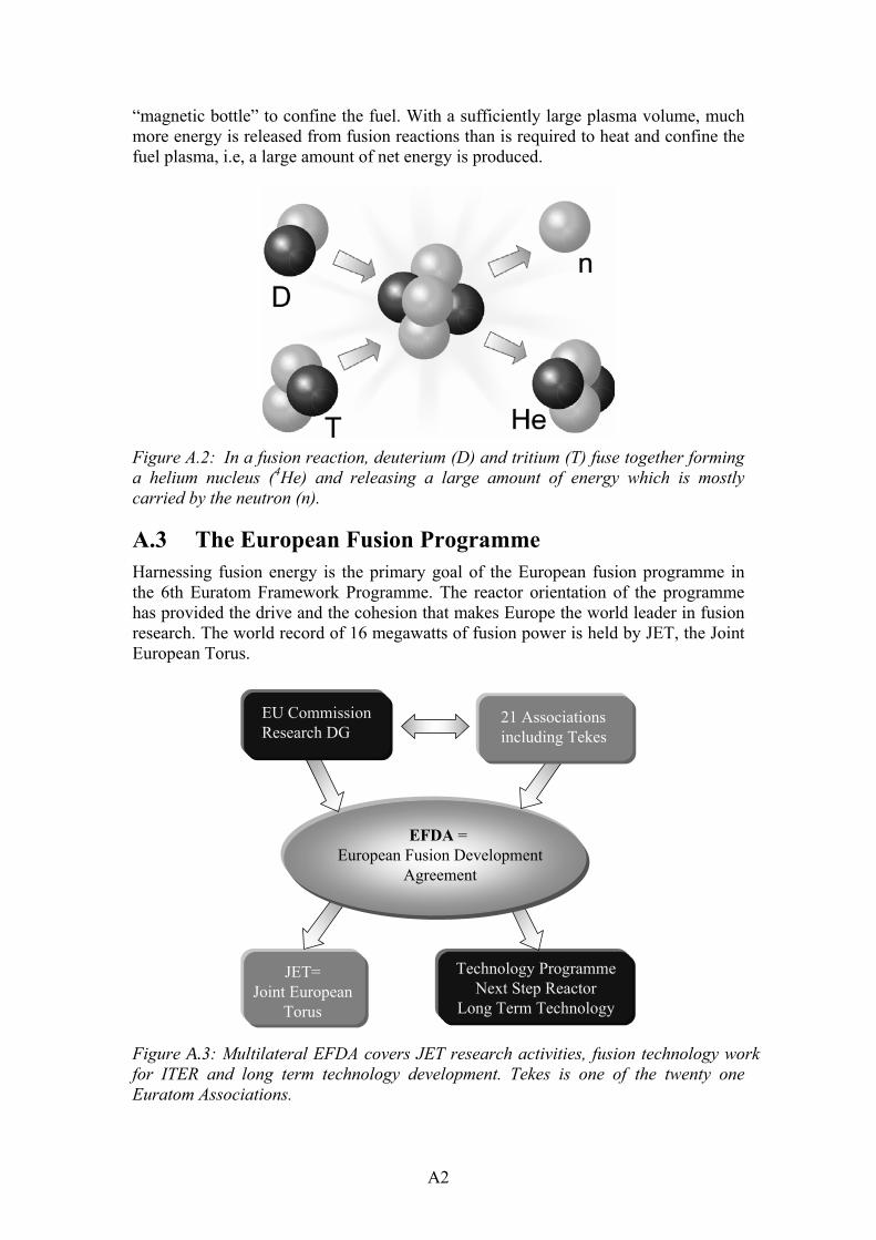
A2
�magnetic bottle� to confine the fuel. With a sufficiently large plasma volume, much more energy is released from fusion reactions than is required to heat and confine the fuel plasma, i.e, a large amount of net energy is produced.
Figure A.2: In a fusion reaction, deuterium (D) and tritium (T) fuse together forming a helium nucleus (4He) and releasing a large amount of energy which is mostly carried by the neutron (n).
A.3 The European Fusion Programme Harnessing fusion energy is the primary goal of the European fusion programme in the 6th Euratom Framework Programme. The reactor orientation of the programme has provided the drive and the cohesion that makes Europe the world leader in fusion research. The world record of 16 megawatts of fusion power is held by JET, the Joint European Torus.
Technology ProgrammeNext Step Reactor
Long Term Technology
JET=Joint European
Torus
EFDA = European Fusion Development
Agreement
EU CommissionResearch DG
21 Associationsincluding Tekes
Figure A.3: Multilateral EFDA covers JET research activities, fusion technology work for ITER and long term technology development. Tekes is one of the twenty one Euratom Associations.

A3
The multilateral European Fusion Development Agreement (EFDA) between all the Associations and Euratom facilitates the joint exploitation of the JET facilities and the fusion technology programme, which covers ITER related R&D and long-term technology.
A.4 ITER International Fusion Energy Organisation To advance significantly beyond the present generation of fusion devices, a next step device, enabling the investigation of burning plasma in near-reactor conditions, is needed. The detailed design and the extensive technical preparations have been completed and permitting to start the construction within the next few years. ITER tokamak would be the smallest tokamak enabling an investigation of burning plasmas at fusion power levels of 400�500 megawatts with energy amplification exceeding 10. Latest results from various tokamaks indicate that even larger amplification factors migh be attained in this device.


B1
APPENDIX B INDUSTRIAL PARTICIPATION Three industrial groups are qualified for ITER EDA activities and they are participating in the European Fusion Programme: (1) The Finnish Remote Handling Group consisting of Advatec Oy, Fortum Power and Heat Oy, Hytar Oy, PI-Rauma Oy, Platom Oy, Creanex Oy, Rocla Oy and Delfoi Oy. (Technology: 11. Qualification of Standards and Tools) (2) The Finnish Blanket Group consisting of Technip Offshore Finland, Diarc Technology Oy, Fortum Power and Heat Oy, Hollming Works Oy, High Speed Tech Oy, Kankaanpää Works Oy, Metso Powdermet Oy, Outokumpu Poricopper Oy and PI-Rauma Oy. (Technologies: 5. Plasma Facing Component Mock-Ups, 6. Vacuum Vessel, Shield and Tritium Breeding Blanket Segment Mock-Ups) (3) Outokumpu Poricopper Oy / Superconductors. (Technology: 7. Strand) Company: PrizzTech Oy Role: Co-ordination of the industry participation in the Fusion Programme Contact: PrizzTech Oy, Teknologiakeskus Pripoli, Tiedepuisto 4, FIN-28600
Pori, Tel. +358 2 620 5330; fax +358 2 620 5399 www.prizz.fi Iiro Andersson [email protected]
Company: Fortum Power and Heat Oy Technology: Nuclear Engineering Contact: Fortum Nuclear Services Oy, Rajatorpantie 8, Vantaa, P.O. Box 10,
FIN-00048 Fortum, Tel. + 358 10 4511; fax. +358 10 453 3403 www.fortum.com Harri Tuomisto [email protected]
Company: Metso Powdermet Oy Technology: Special stainless steels, powder metallurgy, component technology/
engineering, design, production and installation Contact: Metso Powdermet Oy, P.O.Box 1100, FIN-33541 Tampere,
Tel. +358 20 484 120; fax +358 20 484 121 www.metsopowdermet.com Jari Liimatainen [email protected]
Company: Hollming Works Oy Technology: Mechanical engineering, fabrication of heavy stainless steel
structures Contact: Hollming Works Oy, Puunaulakatu 3, P.O.Box 96, FIN-28101 Pori,
Tel. +358 20 486 5040; fax +358 20 486 5041 www.hollmingworks.com Jari Mattila [email protected]

B2
Company: Outokumpu Poricopper Oy Technology: Superconducting strands and copper products. Contact: Outokumpu Poricopper Oy, Kuparitie, P.O Box 60, FIN-28101 Pori,
Tel. +358 2 626 6111; fax +358 2 626 5314 Antti Kilpinen [email protected] Rauno Liikamaa [email protected] Ben Karlemo [email protected]
Company: Adwatec Oy Technology: Remote handling, water hydraulics, actuators and drives Contact: Adwatec Oy, Polunmäenkatu 39 H 9, FIN-33720 Tampere,
Tel. +358 3 389 0860; fax. +358 3 389 0861 www.adwatec.com Arto Verronen [email protected]
Company: Aspocomp Oy Technology: Electronics manufacturing, thick film technology, component
mounting (SMT), and mounting of chips (COB) in mechanical and electrical micro systems (MEMS) and multi-chip modules (MCM), PWB (or also called PCB), sheet metal manufacturing and assembly.
Contact: Aspocomp Oy, Yrittäjäntie 13, FIN-01800 Klaukkala, Tel. +358 9 878 01244; Fax. +358 9 878 01200 www.aspocomp.com Markku Palmu [email protected]
Company: Corrotech Oy Technology: Clean rooms, sheet metal production, mechanical engineering and
surface treatment Contact: Corrotech Oy, Teollisuuskatu 8, FIN-95420 Tornio,
Mobile: +358-40 777 9441; Fax +358 16 446 462 www.corrotech.fi Esko Hilden [email protected]
Company Creanex Oy Technology: Remote handling, teleoperation and walking platforms. Contact: Creanex Oy, Perkiöntie 41, FIN-33960 Pirkkala,
Tel. +358 3 3683 244 www.creanex.com Erkki Kare [email protected]
Company: Delfoi Oy Technology: Telerobotics, task level programming Contact: Delfoi Oy, Vänrikinkuja 2, FIN-02600 Espoo, Finland
Tel. +358 9 4300 70; Fax. +358 9 4300 7277 www.delfoi.com Heikki Aalto [email protected]

B3
Company: DIARC Technology Technology: Diamond like DLC and DLC (Si, D) doped carbon coatings plus
other coatings with potential plasma facing material in thermonuclear fusion machines.
Contact: Diarc Technology, Olarinluoma 15, FIN-02200 Espoo, Tel. +358 9 2517 6130; fax +358 9 2517 6140 www.diarc.fi Jukka Kolehmainen [email protected]
Company: Ellego Powertec Oy Technology: Power electronics, transformers, power sources, rectifiers based on
modern chopper and thyristor technology Contact: Ellego Powertec Oy, P.O.Box 93, FIN-24101 Salo,
Tel: +358 2 737 250, Fax +358 2 737 2530 www.trafotek.fi Pasi Lauri [email protected]
Company: Exel Oyj Technology: Composite profiless, glass-, carbon- or aramid-fibres combined with
polyester, vinylester or epoxy resins, superconducting current leads isolation profiles
Contact: Exel Oyj, Muovilaaksontie 2, FIN-82110, Heinävaara, Tel. +358 13 73711, Fax. +358 13 7371500 www.exel.fi Matti Suominen [email protected]
Company High Speed Tech Oy Technology: Copper to stainless steel bonding by explosive welding Contact: High Speed Tech Oy, Tekniikantie 4 D, FIN-02150 Espoo,
Fax. +358 9 455 5267 www.highspeedtech.fi Jaakko Säiläkivi [email protected]
Company: Hytar Oy Technology: Remote handling, water hydraulics Contact: Hytar Oy, Ilmailukatu 13, P.O. Box 534, FIN-33101 Tampere,
Tel. +358 3 389 9340; fax +358 3 389 9341 Olli Pohls [email protected]
Company: Kankaanpää Works Oy Technology: Mechanical engineering, fabrication of heavy stainless steel
structures including 3D cold forming of stainless steel Contact: Kankaanpää Works Oy, P.O.Box 56, FIN-38701 Kankaanpää, Tel. +358 20 486 5034; fax +358 20 486 5035 www.hollmingworks.com
Jarmo Huttunen [email protected]

B4
Company: Mansner Oy Hienomekaniikka Technology: Precision mechanics: milling, turning, welding, and assembling.
From stainless steels to copper. Contact: Mansner Oy Hienomekaniikka, Yrittäjäntie 73, FIN-03620 Karkkila,
Tel. +358 9 2248 7323; Fax +358 9 2248 7341 www.mansner.com Sami Mansner [email protected]
Company: Marioff Corporation Oy Technology: Mist fire protection systems Contact: Marioff Corporation Oy, P.O.Box 25, FIN-01511 Vantaa,
Tel. +358 9 8708 5342; Fax. +358 9 8708 5399 www.hi-fog.com Pekka Saari [email protected]
Company: PI-Rauma Oy Technology: Computer aided engineering with CATIA. Contact: PI-Rauma Oy, Mäntyluoto, FIN-28880 Pori,
Tel. +358 2 528 2521; fax +358 2 528 2500 www.pi-rauma.fi Matti Mattila [email protected]
Company: Platom Oy Technology: Remote handling, thermal cutting tools and radioactive waste
handling. Contact: Platom Oy, Graanintie 5, P.O.Box 300, FIN-50101 Mikkeli,
Tel. +358 44 5504 300; fax. +358 15 369 270 www.platom.fi Miika Puukko [email protected]
Company: Polartest Oy Technology: 3-party inspection, NDT, documentation and receiving inspection. Contact: Polartest Oy, Laajaniityntie 3, P.O.Box 41, FIN-01620 Vantaa,
Tel. +358 9 878 020; Fax. +358 9 878 6653 www.polartest.fi Matti Andersson [email protected]
Company: Rados Technology Oy Technology: Dosimetry, waste & contamination monitoring and environmental
monitoring. Contact: Rados Technology Oy, P.O.Box 506, FIN-20101 Turku,
Tel. +358 2 4684 600; Fax +358 2 4684 601 www.rados.fi Timo Salomaa [email protected]
Company: Rejlers Oy Technology: System and subsystem level design, FE modelling and analysis with
ANSYS, studies and technical documentation, installation and maintenance instructions, 3D modelling and visualisation of machines and components.

B5
Contact: Rejlers Oy, Myllykatu 3, FIN-05840 Hyvinkää, Tel: +358 19 2660 600; Fax. +358 19 2660 601 www.rejlers.fi Jouni Vidqvist [email protected]
Company: Rocla Oyj Technology: Heavy Automated guided vehicles Contact: Rocla Oyj, P.O.Box 88, FIN- 04401 Järvenpää,
Tel +358 9 271 471, Fax +358 09 271 47 430 www.rocla.fi Pekka Joensuu [email protected]
Company: Selmic Oy Technology: Microelectronics design and manufacturing, packaging technologies
and contract manufacturing services. Contact: Selmic Oy, Vanha Porvoontie 229, FIN-01380 Vantaa,
Tel: +358 9 2706 3911; Fax +358 9 2705 2602 www.selmic.com Patrick Sederholm [email protected]
Company: Solving Oy Technology: Heavy automated guided vehicles
Equipment for heavy assembly and material handling based on air film technology for weights up to hundreds of tons.
Contact: Solving Oy, P.O.Box 98, FIN-68601 Pietarsaari, Tel. +358 6 781 7500; Fax. +358 6 781 7510 www.solving.fi Bo-Goran Eriksson [email protected]
Company: Technip Offshore Finland (earlier Mäntyluoto Works Oy) Technology: Fabrication of Heavy Steel constructions by using an effective
modulus technology, pressure vessels and piping Contact: Mäntyluoto Works Oy, FIN-28880 Pori,
Tel. +358 2 528 2411; fax +358 2 528 2419 www.coflexipstenaoffshore.com
Company: TVO Nuclear Services Oy Technology: Nuclear power technologies; service, maintenance, radiation
protection and safety. Contact: TVO Nuclear Services Oy, FIN-27160 Olkiluoto,
Tel. + 358 2 83 811; Fax. +358 2 8381 2109 www.tvo.fi Juha Pernu [email protected]
Company: Veslatec Oy Technology: Micro cutting-laser welding-laser drilling-laser marking Contact: Veslatec Oy, Strömbergin puistotie 4D, FIN-65320 Vaasa,
Tel +358 6 315 89 00; Fax +358 6 315 28 77 www.veslatec.com Olli Saarniaho [email protected]

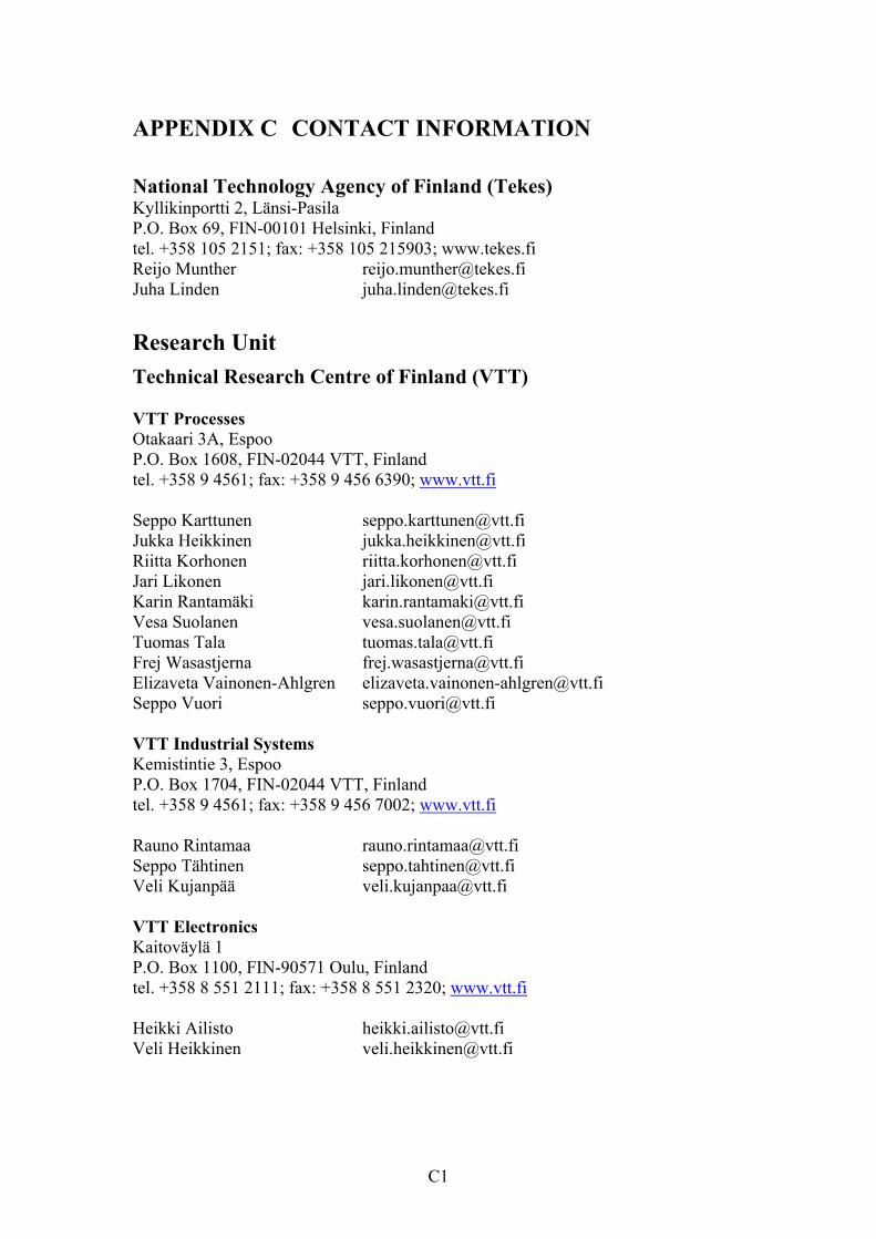
C1
APPENDIX C CONTACT INFORMATION National Technology Agency of Finland (Tekes) Kyllikinportti 2, Länsi-Pasila P.O. Box 69, FIN-00101 Helsinki, Finland tel. +358 105 2151; fax: +358 105 215903; www.tekes.fi Reijo Munther [email protected] Juha Linden [email protected]
Research Unit Technical Research Centre of Finland (VTT) VTT Processes Otakaari 3A, Espoo P.O. Box 1608, FIN-02044 VTT, Finland tel. +358 9 4561; fax: +358 9 456 6390; www.vtt.fi Seppo Karttunen [email protected] Jukka Heikkinen [email protected] Riitta Korhonen [email protected] Jari Likonen [email protected] Karin Rantamäki [email protected] Vesa Suolanen [email protected] Tuomas Tala [email protected] Frej Wasastjerna [email protected] Elizaveta Vainonen-Ahlgren [email protected] Seppo Vuori [email protected] VTT Industrial Systems Kemistintie 3, Espoo P.O. Box 1704, FIN-02044 VTT, Finland tel. +358 9 4561; fax: +358 9 456 7002; www.vtt.fi Rauno Rintamaa [email protected] Seppo Tähtinen [email protected] Veli Kujanpää [email protected] VTT Electronics Kaitoväylä 1 P.O. Box 1100, FIN-90571 Oulu, Finland tel. +358 8 551 2111; fax: +358 8 551 2320; www.vtt.fi Heikki Ailisto [email protected] Veli Heikkinen [email protected]
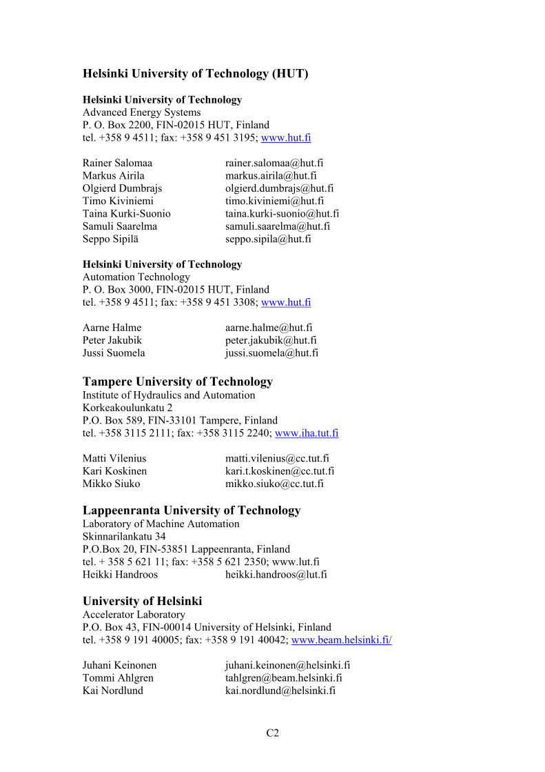
C2
Helsinki University of Technology (HUT) Helsinki University of Technology Advanced Energy Systems P. O. Box 2200, FIN-02015 HUT, Finland tel. +358 9 4511; fax: +358 9 451 3195; www.hut.fi Rainer Salomaa [email protected] Markus Airila [email protected] Olgierd Dumbrajs [email protected] Timo Kiviniemi [email protected] Taina Kurki-Suonio [email protected] Samuli Saarelma [email protected] Seppo Sipilä [email protected] Helsinki University of Technology Automation Technology P. O. Box 3000, FIN-02015 HUT, Finland tel. +358 9 4511; fax: +358 9 451 3308; www.hut.fi Aarne Halme [email protected] Peter Jakubik [email protected] Jussi Suomela [email protected] Tampere University of Technology Institute of Hydraulics and Automation Korkeakoulunkatu 2 P.O. Box 589, FIN-33101 Tampere, Finland tel. +358 3115 2111; fax: +358 3115 2240; www.iha.tut.fi Matti Vilenius [email protected] Kari Koskinen [email protected] Mikko Siuko [email protected] Lappeenranta University of Technology Laboratory of Machine Automation Skinnarilankatu 34 P.O.Box 20, FIN-53851 Lappeenranta, Finland tel. + 358 5 621 11; fax: +358 5 621 2350; www.lut.fi Heikki Handroos [email protected] University of Helsinki Accelerator Laboratory P.O. Box 43, FIN-00014 University of Helsinki, Finland tel. +358 9 191 40005; fax: +358 9 191 40042; www.beam.helsinki.fi/ Juhani Keinonen [email protected] Tommi Ahlgren [email protected] Kai Nordlund [email protected]

Published by
Series title, number and report code of publication
VTT Publications 530 VTT�PUBS�530
Author(s) Karttunen, Seppo & Rantamäki, Karin (eds.) Title
FUSION Yearbook Association Euratom-Tekes. Annual Report 2003 Abstract This report summarises the results of the Tekes FUSION technology programme and the fusion research activities by the Association Euratom-Tekes in 2003. The research areas are fusion physics, plasma engineering, fusion technology and a smaller effort to socio-economic studies. Fusion technology research is carried out in close collaboration with Finnish industry. The emphasis in fusion physics and plasma engineering is in theoretical and computational studies on transport, physics of radio-frequency heating and plasma edge phenomena related to European fusion experiments. Experimental work on plasma-wall interactions covers erosion, re-deposition and material transport studies in the edge region. A major part of the work is devoted to the EFDA JET Workprogramme in collaboration with other European Associations. The work in fusion technology for the EFDA Technology Programme and ITER is strongly focused into vessel/in-vessel materials covering research and characterisation of first wall materials, joining methods, manufacturing of multi-metal components and surface physics studies on plasma facing materials. A second domain of fusion technology consists of remote handling systems including water hydraulic tools and manipulators for the ITER divertor maintenance and prototyping of intersector welding and cutting robot. Virtual modelling is an essential element in the remote handling engineering. Several EFDA technology tasks were successfully completed in 2003. Keywords fusion, fusion reactors, reactor materials, fusion physics, remote handling, testing, Joint European Torus, modelling, control
Activity unit VTT Processes, Otakaari 3 A, P.O.Box 1608, FIN�02044 VTT, Finland
ISBN Project number 951�38�6379�4 (soft back ed.) 951�38�6380�8 (URL: http://www.vtt.fi/inf/pdf/)
Date Language Pages Price May 2004 English 127 p. + app. 10 p. C
Name of project Commissioned by
Series title and ISSN Sold by VTT Publications 1235�0621 (soft back edition) 1455�0849 (URL: http://www.vtt.fi/inf/pdf/)
VTT Information Service P.O.Box 2000, FIN�02044 VTT, Finland Phone internat. +358 9 456 4404 Fax +358 9 456 4374


VTT PU
BLICATION
S 530FU
SION Yearbook. A
ssociation Euratom-Tekes. A
nnual Report 2003
Tätä julkaisua myy Denna publikation säljs av This publication is available from
VTT TIETOPALVELU VTT INFORMATIONSTJÄNST VTT INFORMATION SERVICEPL 2000 PB 2000 P.O.Box 2000
02044 VTT 02044 VTT FIN–02044 VTT, FinlandPuh. (09) 456 4404 Tel. (09) 456 4404 Phone internat. + 358 9 456 4404Faksi (09) 456 4374 Fax (09) 456 4374 Fax + 358 9 456 4374
ISBN 951–38–6379–4 (soft back ed.) ISBN 951–38–6380–8 (URL: http://www.vtt.fi/inf/pdf/)ISSN 1235–0621 (soft back ed.) ISSN 1455–0849 (URL: http://www.vtt.fi/inf/pdf/)
ESPOO 2004 VTT PUBLICATIONS 530
This report summarises the results of the Tekes FUSION technologyprogramme and the fusion research activities by the Association Euratom-Tekes in 2003. The research areas are fusion physics, plasma engineering,fusion technology and a smaller effort to socio-economic studies. Fusiontechnology research is carried out in close collaboration with Finnishindustry.
The emphasis in fusion physics and plasma engineering is intheoretical and computational studies on transport, physics of radio-frequency heating and plasma edge phenomena related to Europeanfusion experiments. Experimental work on plasma-wall interactionscovers erosion, re-deposition and material transport studies in the edgeregion. A major part of the work is devoted to the EFDA JETWorkprogramme in collaboration with other European Associations.
The work in fusion technology for the EFDA Technology Programmeand ITER is strongly focused into vessel/in-vessel materials coveringresearch and characterisation of first wall materials, joining methods,manufacturing of multi-metal components and surface physics studies onplasma facing materials. A second domain of fusion technology consistsof remote handling systems including water hydraulic tools andmanipulators for the ITER divertor maintenance and prototyping ofintersector welding and cutting robot. Virtual modelling is an essentialelement in the remote handling engineering. Several EFDA technologytasks were successfully completed in 2003.
FUSION YEARBOOKAssociation Euratom-TekesAnnual Report 2003
NATIONAL TECHNOLOGY AGENCYP.O. Box 69, FIN-00101 Helsinki, Finland
Tel. +358 105 2151, Fax +358 105215905
www.tekes.fi
VTT TECHNICAL RESEARCH CENTRE OF FINLANDVTT PROCESSES
P.O. Box 1608, FIN-02044 VTT, FinlandTel. +358 9 4561, Fax +358 9 456 6390
www.vtt.fi


![Emersonian : [Emerson College yearbook]](https://static.fdokumen.com/doc/165x107/6321be5e117b4414ec0b98a5/emersonian-emerson-college-yearbook.jpg)