
FUSION YEARBOOK. ASSOCIATION EURATOM-TEKES ...
184
VTT PUBLICATIONS 764 FUSION YEARBOOK ASSOCIATION EURATOM-TEKES Annual Report 2010
-
Upload
khangminh22 -
Category
Documents
-
view
1 -
download
0
Transcript of FUSION YEARBOOK. ASSOCIATION EURATOM-TEKES ...

VTTPUBLICATIONS764
FUSIONYEARBOOKASSOCIATIONEURATOM-TEKESAnnualReport2010


VTT PUBLICATIONS 764
FUSION YEARBOOK
ASSOCIATION EURATOM-TEKES Annual Report 2010
Edited by
Seppo Karttunen & Markus Airila

2
ISBN 978-951-38-7738-5 (soft back ed.) ISSN 1235-0621 (soft back ed.)
ISBN 978-951-38-7739-2 (URL: http://www.vtt.fi/publications/index.jsp) ISSN 1455-0849 (URL: http://www.vtt.fi/publications/index.jsp)
Copyright © VTT 2011
JULKAISIJA – UTGIVARE – PUBLISHER
VTT, Vuorimiehentie 5, PL 1000, 02044 VTT puh. vaihde 020 722 111, faksi 020 722 4374
VTT, Bergsmansvägen 5, PB 1000, 02044 VTT tel. växel 020 722 111, fax 020 722 4374
VTT Technical Research Centre of Finland, Vuorimiehentie 5, P.O. Box 1000, FI-02044 VTT, Finland phone internat. +358 20 722 111, fax + 358 20 722 4374
Cover: Jyrki Hokkanen, CSC (Data: SimIter-project) Text formatting: Tarja Haapalainen Edita Prima Oy, Helsinki 2011

3
FOREWORD ITER construction is gradually speeding up as the contracts for the major components on the critical path, such as magnets and vacuum vessel are signed and work started. At the ITER site in Cadarache the first buildings are under construction and excavation of the tokamak building is completed. The ITER baseline was finally adopted in July 2010. The new management of ITER IO and Fusion for Energy (F4E) are working hard to meet the baseline schedule and are firmly committed to cost containment measures. In 2010, the emphasis of the Association Euratom-Tekes programme was in the EFDA work programme. Several tasks of the Task Forces PWI (plasma-wall interactions) and ITM (integrated tokamak modelling) were carried out by the Research Unit of the Tekes Association. Both topics are in the core of our research activities. In diagnostics, a feasibility study for the magnetic diagnostics based on micro-mechanical sensors gave promising results and the development will continue as F4E Grant work. Tekes was very active in the JET 2010 work programme in spite of the shut down for ITER-like-Wall (ILW). Upgraded NPA diagnostics was completed and is now under installation. Post-mortem analysis of the JET first wall and divertor tiles and related plasma-wall studies continued under JET Technology Task Force. Two Tekes scientists were nominated to deputy task force leaders (E2 and FT) for the ITER-like-wall (ILW) experiments. In addition, Tekes provided two JOC secondees, one working in the remote handling operations for ILW and the other doing modelling and JET code integration plus a member to HLST (high level support team for high performance computing). Collaboration with the AUG team at IPP Garching continued in 2010 and has been very important and productive activity for several years. Scientific work at JET and AUG covers transport experiments and modelling, energetic particle physics, NPA diagnostics and plasma-wall and post-mortem surface studies of divertor tiles. International activities included and large tokamak experiments in US and Japan under IEA Implementing Agreement and ITPA work in two ITPA groups. Regarding the F4E activities, ITER divertor maintenance development and testing in DTP2 test facility at VTT Tampere has progressed well. Remote handling equipment and operations have been developed and tested, and new tools and methods have been designed. A new F4E Grant for further DTP2 activities started in 2010. Finally, I would like to express my most sincere thanks to Tekes and the scientists and engineers of the Finnish and Estonian Research Units their excellent and dedicated work in fusion physics and technology R&D. In my opinion, we provide a valuable contribution to the Euratom Fusion Programme, F4E and ITER. Seppo Karttunen Head of Research Unit Association Euratom-Tekes

4
Contents FOREWORD ............................................................................................................................ 3
EXECUTIVE SUMMARY ........................................................................................................... 7
1. OVERVIEW OF 2010 ACTIVITIES .................................................................................... 13
2. FUSION PROGRAMME ORGANISATION ........................................................................ 15 2.1 Programme Objectives .......................................................................................................... 15 2.2 Association Euratom-Tekes ................................................................................................... 15 2.3 Research Unit ....................................................................................................................... 16 2.4 Association Steering Committee ............................................................................................ 16 2.5 National Steering Committee ................................................................................................. 17 2.6 The Finnish Members in the European Fusion Committees .................................................... 18 2.7 Public Information Activities ................................................................................................... 19 2.8 Funding and Research Volume 2010 ..................................................................................... 20
3. EFDA FUSION PHYSICS AND MATERIALS RESEARCH ................................................ 21 3.1 Introduction .......................................................................................................................... 22 3.2 Energy and Particle Confinement and Transport .................................................................... 22
3.2.1 NBI modulation experiments to study the collisionality dependence of momentum
transport on JET ...................................................................................................... 22 3.2.2 NBI torque in presence of magnetic field ripple: experiments and modelling for JET ... 24 3.2.3 Effect of magnetic ripple on intrinsic rotation ............................................................. 25 3.2.4 ITER test blanket module experiment on DIII-D tokamak to study plasma
confinement and toroidal rotation .............................................................................. 27 3.2.5 Calculating NBI torque and plasma rotation in AUG, DIII-D and ITER ........................ 28 3.2.6 Physics of L-H transition ........................................................................................... 30 3.2.7 Quiescent H-Mode operation at AUG ........................................................................ 31
3.3 Energetic Particle Physics ..................................................................................................... 32 3.3.1 Feasibility study of an active NPA system on AUG to study NBI current drive............. 32 3.3.2 The effect of in-vessel coils on power loads to the PFCs due to NBI ions in AUG ....... 33 3.3.3 ASCOT simulations of the TBM mock-up experiments on DIII-D ................................ 34 3.3.4 Simulating the NBCD experiments at AUG................................................................ 35 3.3.5 Validation/Benchmark of ASCOT against experiments and VENUS on TEXTOR ....... 36
3.4 Power and Particle Exhaust, Plasma-Wall Interactions ........................................................... 36 3.4.1 Overview ................................................................................................................. 36 3.4.2 Material transport and erosion/deposition in the JET torus ......................................... 36 3.4.3 Experimental erosion and deposition studies in AUG................................................. 39 3.4.4 Effect of field reversal on 13C deposition in the ASDEX Upgrade outer divertor ........... 42 3.4.5 Erosion of W, Al, and mixed W-Al coatings exposed to Pilot-PSI plasma.................... 44 3.4.6 Fundamental mechanisms of plasma-wall interactions .............................................. 45 3.4.7 Hydrogen migration in high Z plasma-facing materials ............................................... 46 3.4.8 Arc-discharge cleaning of plasma-facing components ............................................... 48 3.4.9 Predictive EDGE2D/EIRENE and SOLPS simulations of radiation, and
particle and heat loads in JET and DIII-D .................................................................. 50 3.4.10 Local carbon deposition in JET tracer injection experiments ...................................... 52 3.4.11 Development of an EMC3/Eirene data pre-processor for ERO ................................... 53 3.4.12 Implementation of molecular dynamics based sputtering data for Be and
Be2C in the ERO code.............................................................................................. 54

5
3.4.13 Update on DIVIMP modelling of 13C transport and deposition in AUG ....................... 56 3.4.14 DIVIMP simulations of tungsten transport in JET ELMy H-mode plasmas
particle and heat loads in JET and DIII-D .................................................................. 57 3.4.15 Comparison of 13C transport modelling with DIVIMP and ASCOT .............................. 59 3.4.16 Assessment of the validity of the basic two-point model using SOLPS ....................... 61 3.4.17 Simulations of the trace-element experiments at AUG using DIVIMP and ASCOT-PWI ........ 62
3.5 Theory and Modelling for ITER .............................................................................................. 63 3.5.1 Fast ion distribution in ITER Scenario-2 in the presence of NTM-type island structures ......... 63 3.5.2 Full-orbit effects on fast ion confinement in ITER Scenario-4 ..................................... 64 3.5.3 Alpha and NBI simulations for sawtooth control in ITER ............................................ 65 3.5.4 The effect of turbulent diffusion on fusion alphas and NBI ions in ITER ...................... 66 3.5.5 Simulating NBCD in ITER......................................................................................... 66
3.6 Code Development and Integration ....................................................................................... 67 3.6.1 ELMFIRE gyrokinetic transport code development and simulation results .................. 67 3.6.2 Integrated modelling by JINTRAC code at JET ......................................................... 70 3.6.3 High Level Support Team Activities (HLST) .............................................................. 72 3.6.4 Development of the ASCOT code ............................................................................. 72 3.6.5 EFDA HPC-resources for ASCOT ............................................................................ 75 3.6.6 Adapting the edge code ERO to ITM standards ........................................................ 75
3.7 Plasma Diagnostics .............................................................................................................. 76 3.7.1 Upgrading JET NPA detectors .................................................................................. 76 3.7.2 Active NPA for localized measurements of NBI ions in AUG ...................................... 79 3.7.3 Development of micromechanical magnetometer for ITER ........................................ 79 3.7.4 Development of data analysis and interpretation tools for spectroscopic flow
measurements in ASDEX Upgrade ........................................................................... 82 3.8 Emerging Technology – Materials Research .......................................................................... 84
3.8.1 Radiation damage in structural materials .................................................................. 84 3.8.2 Strain rate effects in Fe and FeCr alloy ..................................................................... 85
4. ACTIVITIES OF THE ESTONIAN RESEARCH UNIT ........................................................ 87 4.1 Applying LIBS in Studying Erosion/Deposition of Low-Z Materials........................................... 87
4.1.1 Averaging technique of LIBS signals over different sites of a sample ......................... 87 4.1.2 Exposition of marker samples to plasma ................................................................... 89
4.2 Attenuation of Radiation Damage in Dielectric and Composite Materials of Interest
for a Fusion Reactor ............................................................................................................. 91 4.3 Tritium Depth Profile Measurements of JET Divertor Tiles by AMS ......................................... 93
5. JOC SECONDMENTS, STAFF MOBILITY AND TRAINING .............................................. 96 5.1 CCFE JOC Secondments ..................................................................................................... 96
5.1.1 JET remote handling for ILW experiment .................................................................. 96 5.1.2 JET code development and modelling ...................................................................... 96 5.1.3 JET Secondment for DTFL ....................................................................................... 97
5.2 Staff Mobility Visits and Reports ............................................................................................ 97 5.2.1 Framework Agreement between Tekes and IPP Associations ................................... 97 5.2.2 Ion beam analysis of JET samples ........................................................................... 98 5.2.3 Ion-beam analysis of ASDEX Upgrade marker tiles ................................................... 99 5.2.4 Material transport in JET torus ................................................................................ 100 5.2.5 Laboratory tests of NPA electronics chain ............................................................... 101 5.2.6 Measuring a set of limiter tiles using a surface profiler developed at JET–A ............. 102 5.2.7 Benchmarking ASCOT and OFMC codes ............................................................... 103 5.2.8 Ion-beam analysis of ASDEX Upgrade tiles and samples ........................................ 103

6
5.2.9 Measuring a set of limiter tiles using a surface profiler developed at JET–B ............. 105 5.2.10 MHD modes in ASCOT code .................................................................................. 105 5.2.11 Measuring a set of limiter tiles using a surface profiler developed at JET–C ............. 106 5.2.12 Exposing ITER-relevant test samples to Pilot-PSI plasma ....................................... 107 5.2.13 Modelling the scrape-off layer and local migration of carbon in ASDEX Upgrade ...... 109 5.2.14 Spectroscopic and video measurements of Tokamak impurities .............................. 110 5.2.15 Scrape-off layer modelling using SOLPS ................................................................ 111 5.2.16 Final design of NPA electronics .............................................................................. 112
5.3 Euratom and EFDA Fusion Training Scheme ....................................................................... 112 5.3.1 EFDA goal oriented training in fusion theory and modelling – GOTiT ....................... 112 5.3.2 EFDA goal oriented training in remote handling – GOTRH ...................................... 113 5.3.3 EFDA Fellowship in Fusion Reseach ...................................................................... 115
6. OTHER ACTIVITIES ....................................................................................................... 117 6.1 Conferences, Workshops and Meetings ............................................................................... 117 6.2 Visits .................................................................................................................................. 121 6.3 Visitors ............................................................................................................................... 122
7. FUSION FOR ENERGY AND ITER ACTIVITIES ............................................................. 124 7.1 2008–2010 Host Activities Related to DTP2 Test Facility Operation and Upgrade Preparation ...... 124
7.1.1 Objectives ............................................................................................................. 124 7.1.2 Task 1: RH trials .................................................................................................... 124 7.1.3 Task 2: Waterhydraulic manipulator WHMAN.......................................................... 127 7.1.4 Task 3: End-effector designs .................................................................................. 129 7.1.5 Task 4: Design of toroidal extension and upgrade ................................................... 130 7.1.6 Task 5: Design of Cassette toroidal mover .............................................................. 131 7.1.7 Task 6: DTP2 supervisory system .......................................................................... 132
7.2 Divertor RH Design Updates and DTP2 Phase 2 Testing ..................................................... 135 7.2.1 Objectives ............................................................................................................. 135 7.2.2 Grant description and main results in 2010 ............................................................. 136
7.3 Tests of the divertor cassette inboard locking ....................................................................... 138
8. PUBLICATIONS 2010 ..................................................................................................... 141 8.1 Fusion Physics and Plasma Engineering ............................................................................. 141
8.1.1 Publications in scientific journals ............................................................................ 141 8.1.2 Conference articles – physics and plasma engineering............................................ 147
8.2 Fusion Technology ............................................................................................................. 156 8.2.1 Publications in scientific journals ............................................................................ 156 8.2.2 Conference articles – fusion technology .................................................................. 156 8.2.3 Research reports ................................................................................................... 159
8.3 General Articles .................................................................................................................. 163 8.4 Doctoral and Graduate Theses ............................................................................................ 163 8.5 Publications of Estonian Research Unit ............................................................................... 164
8.5.1 Publications in scientific journals ............................................................................ 164 8.5.2 Research reports ................................................................................................... 164 8.5.3 Conference articles ................................................................................................ 164
Appendices
APPENDIX A: INTRODUCTION TO FUSION ENERGY APPENDIX B: INSTITUTES AND COMPANIES
7
EXECUTIVE SUMMARY Highlights of fusion research carried out by the Association Euratom-Tekes in 2010 are given below. The main activities are experimental work, modelling with related code development and diagnostics related to the main European magnetic fusion facilities JET and AUG. The emphasis in the EFDA work by Tekes was in the Task Forces PWI and ITM. Other EFDA activities in 2010 were carried out within EU Topical Groups, Emerging Technology and in Goal Oriented Training. Confinement and Transport
Momentum pinch number and Prandtl number has been found not to depend on collisionality on JET. This experimental result is consistent with momentum transport theory and gyro-kinetic simulations. Toroidal magnetic ripple affects significantly the intrinsic plasma rotation on JET. With large ripple, intrinsic rotation becomes counter-current directed over the whole plasma radius. The torque calculation in ASCOT code induced by the fast ion losses due to enhanced ripple has been successfully benchmarked against experimental data from JET. The DIII-D TBM mock-up experiment to simulate ITER Test Blanket Modules (TBM) showed that the plasma rotation is reduced up to 60% with the TBM amplitude 3 times higher than on ITER. The TBM effect on plasma confinement was 10–15% smaller [ITPA, IEA LT, WP10-TRA-04]. The present work related to L-H transition included both code development work and simulations with gyrokinetic code ELMFIRE. The main code development effort was to include new scrape-off-layer (SOL) model to the code to study edge-core coupling which according to experiments plays an important role in obtaining L-H transition [WP10-TRA-01]. One of the runs including the SOL, appeared to indicate some kind of pedestal formation. Main effect seen in the simulation was strong modification of the radial electric field profile within one orbit width from last closed flux surface, simultaneous reduction of heat diffusion coefficient (when compared to runs without the SOL) and formation of edge pedestal in temperature profile. No such pedestal appears in the simulation without the SOL, when other parameters were kept constant. Thus, key ingredient is assumed to be the newly developed scrape-off-layer but more work is needed both to assure the present findings and to test the parametric dependence of the observed phenomenon [WP10-TRA-05]. NBI-generated torque and plasma rotation was simulated for AUG, DIII-D and ITER with ASCOT. The toroidal torque on the plasma has two parts: a collisional transfer of toroidal momentum from the beam particles to the plasma, and the jxB torque resulting from the finite orbit widths and the radial excursion of the beam ions. In AUG this was analyzed for each beam separately, and it was found that the jxB torque, particularly that due to the radial current generated by the finite orbit widths of the beam particles, gives a significant contribution to the torque profile. In DIII-D, the torque was calculated in the presence and absence of the mock TBM module. Here the effect of jxB was not as dramatic In ITER, the torque was evaluated for both the off- and on-axis

8
beams. The torque values were very similar for both beam dropping to a small negative value inside = 0.6 and to a large negative value for > 0.95 [WP10-HCD-01-06]. Energetic particle physics
ASCOT has a synthetic NPA-diagnostic that allows predicting the NPA signal from a real experiment. The feasibility study suggest that such a diagnostic would be useful in monitoring the population of neutral beam ions intended for driving off-axis current. A scaled mock-up of an ITER TBM module was built and operated on DIII-D. In the experiments, a significant temperature rise was measured on the wall tiles in front of the TBM module when the TBM error field was turned on. The ASCOT code was used to simulate the NBI ion losses due to the TBM module and to determine whether the observed temperature rise could be explained. The TBM mock-up module was found to create a strong local ripple allowing fast ions escape to create a hot spot on the tiles in front of the TBM. However, including limiter structures were found to significantly decrease the fast ion load to the TBM tiles. These results strongly encourage the use of limiters in ITER [ITPA-EPP Activity]. A set of ASCOT simulations was carried out to assess the effect of the newly installed in-vessel coils to the confinement of NBI-generated fast ions in AUG. The coils were found to have little effect on the confinement of perpendicular beams, but to increase the wall load due to parallel beams by a factor of 2–3. However, since the absolute contribution from the parallel beams is insignificant compare to perpendicular beams, this causes no alarm as far as the integrity of the wall components is concerned. Plasma-Wall Interactions
In 2010 erosion, material migration and deposition in the JET torus were investigated by analysing a set of CFC divertor tiles removed during the last shutdown. The inner divertor tiles showed typical deposition pattern whereas the outer divertor was in the erosion region. Heavy deposition was found in the shadowed areas of the floor tiles. In addition, global 13C migration was investigated. 13CH4 methane was puffed at the end of 2009 campaign and the 13C deposition pattern on the divertor tiles was determined. The highest 13C amounts were found near the puffing location [JW10-FT-3.61]. Erosion of tungsten and nickel were studied in AUG with the help of marker tiles, produced by Diarc-Technology Inc. For nickel the amount of erosion was larger by a factor of 5–10, indicating that steel might not be a suitable plasma-facing material in ITER, especially not in the divertor region most heavily affected by plasma [WP10-PWI-04]. Cleaning of deposited layers from plasma facing surfaces is a key safety issue in ITER. The feasibility of an arc-discharge based technique in removing deposited layers from the wall structures of ITER was investigated. The cleaned surfaces were homogeneous and smooth, and the first tests indicate that the cleaning rate for an A4 size object would be 2–10 minutes. A preliminary design for the cleaner head was also made during the project [WP09-DTM-Triti-R].

9
PWI Modelling
Validation of fluid codes EDGE2D/EIRENE and SOLPS was carried out by simulating the scrape-off layer plasma conditions in well-diagnosed JET and AUG discharges, and comparing experimental and predicted profiles. The SOL plasmas produced by these codes are instrumental, since they provide the necessary basis for detailed trace-impurity simulations with DIVIMP, ERO, and ASCOT.
For JET, EDGE2D/Eirene simulations reproduce the total power to the high field side target obtained in a upstream density scan reasonably well, but underestimate the total radiated power by a factor-of-two when using the Roth-2003 chemical sputtering yields for carbon. While in the simulations the plasma temperature falls below 2 eV at the highest upstream densities, the particle currents to both low field side and high field side do not drop to zero as observed in experiments [JET Notifications].
For AUG, magnetic field reversal was observed to considerably change the re-deposition of 13C injected into the outer divertor scrape-off layer. SOLPS5.0-ERO simulations show that the differences can be attributed to the combination of the E×B drift reversal directly influencing the transport of carbon and changes in local plasma conditions due to the drift reversal [WP10-PWI-04].
Material transport and migration was modelled with the DIVIMP and ERO codes. The W transport studies with DIVIMP show that sufficient plasma fuelling is important in limiting the migration of eroded tungsten from divertor targets into the core. The 13C simulations with DIVIMP lead to a proposal of a new imaging diagnostic AUG to measure the flow of low charge state carbon species in the SOL at the high field side [WP10-PWI-04]. A new tool for impurity transport studies was developed: the domestic test particle code ASCOT allows routine simulations with full 3D features in both magnetic background and wall structures. ASCOT simulations of the 2007 13C puffing experiments revealed the importance of including realistic wall structures in particular in determining the deposition patterns. Comprehensive code-code and code-theory comparisons of the basic models used in ASCOT, SOLPS and OEDGE were carried out to identify principal differences in their predictions of SOL properties and material transport. For instance, OEDGE and ASCOT agree in their 13C migration predictions if the temperature gradient force is disabled in OEDGE [WP10-PWI-04]. Diagnostics
During 2010, Phase II to upgrade the KF1 diagnostic was launched. The work concentrated on detailed design and procurement of the components necessary for the upgrade. Tekes has provided the detectors bonded to PCBs, the torus hall electronics and 8-channel bias power supply. Upgraded JET NPA diagnostics are under installation and will be ready for testing in 2011 campaigns [JW10-OEP-TEKE-20]. Irradiation tests of micromechanical magnetometer sensors were continued. Neutron fluence of 1017 n/cm2 was found to damage the sensor glass cap. Cadmium shielding

10
improved sensor radiation hardness but glass has to be replaced by silicon in the next-generation sensors. First measurements with 30 m long cables indicate that the specified magnetic field resolution can be met. Magnetic diagnostics work will continue as a F4E Grant in 2011 [WP10-DIA-03]. Theory and modelling for ITER
ITER plasmas cannot be expected to be MHD quiescent. In particular, ITER is expected to be prone to neoclassical tearing modes (NTM) that exhibit slowly rotating island structures. We simulated the thermonuclear alphas in ITER Scenario-2 for four different cases: pure neoclassical transport, with only a (2,1) island added, with only a (3,2) island added, and including both a (2,1) and a (3,2) island. All NTM’s were found to increase the peak power load, and the effect is strongest for the (2,1) mode that is closer to the plasma edge. The increase in power load is about a factor of two [WP10-DIA-01-01 and 02]. The large Larmor radius of energetic ions can affect both their radial transport in a non-axisymmetric magnetic background and the location where they collide with the vessel wall. With its added full orbit capability, ASCOT was applied to study these effects for thermonuclear alphas in ITER Scenario-4 which is especially vulnerable to ripple losses. In the full-orbit simulations, it was found that ripple-related full orbit transport mechanisms affect the wall load distribution for both the unmitigated ripple case. [WP10-DIA-01-01 and 02]. Sawtooth control remains an important unresolved issue for the ITER Scenario 2 operation. Such ELMy H-mode plasmas are expected to be unstable to the internal kink mode. In order to study the stabilizing effect of fast particles, populations of fusion-born alpha particles and neutral beam injected (NBI) particles in ITER were simulated with ASCOT. Conclusion was that maintaining the q = 1 surface close to the magnetic axis would make sawtooth control easier to achieve [ITPA-MHD-WG3 Activity]. The neutral beam current drive (NBCD) was simulated for both ITER and AUG. In ITER, both on- and off-axis 1MeV beams were simulated in Scenario-2. The on-axis produced a strong centrally peaked current density profile reaching the value of about 1MA/m2 in the centre, while the off-axis beam produced a broad maximum in the region of 0.2 < < 0.4. The simulations were carried out both with and without the turbulent diffusion. The only observable difference in the distributions was a slight outward shift of the maximum in the driven current, but this change is so small that it is certainly within experimental uncertainty [WP10-HCD-01-06-01]. Code Development and Integration
ELMFIRE is a full-f nonlinear global gyrokinetic transport code for electrostatic simulations for tokamak plasma, in 2010, effort was taken to extend the simulation region to the scrape-off layer. At the same time, the principles of the ambient gyrokinetic equations, energy and momentum conservation laws as solved by ELMFIRE and based on Dirac’s constrained Hamiltonian and inverse Kruskal iteration were finalized and published. The incorporation of the SOL into the gyrokinetic edge

11
calculations had numerous beneficial effects; density and heat pile-up at the separatrix observed with the earlier ELMFIRE version due to profile relaxation by turbulent transport was prevented and fluent particle and heat exchange between the edge and SOL was produced. This provided a remarkable result (not found with the earlier version without the SOL) of pedestal formation, and by sufficient core heating an onset of strong shearing of the radial electric field with the concomitant reduction of turbulence across the pedestal [WP10-TRA-05]. The domestic Monte Carlo based orbit following code ASCOT has been developed to the point that it is currently probably the most comprehensive fast ion simulation tool in the world: it features 3D magnetic backgrounds and wall structures and now offers not only guiding centre formalism but also full orbit following. In addition, ASCOT is equipped with theory-based models for both turbulent transport of fast ions and slowly rotating islands, such as NTMs. Furthermore, ASCOT has now been refurbished to include atomic physics as well as background plasma rotation/flow, so that it suits studies of impurities in the energy range of 1–100 eV in the open field lines of the scrape-off-layer and halo regions [WP10-ITM-IMP5; WP10-HCD-01]. In the framework of the ITM Task Force, the ASCOT and ERO codes were adapted to use Consistent Physical Objects (CPOs) in their input and output operations, allowing the inclusion of these codes as modules in a Kepler simulation workflow. Moreover, the surface model of ERO was upgraded to deal with the ITER-relevant Be/W/C issues. The use of the model was demonstrated by applying it with new MD based data for Be2C to a previous ITER tritium retention and target lifetime calculation. The predictions remain similar within a ±25% range, but other Be/W/C compounds may change the result more [WP10-ITM-IMP3; WP10-PWI-06]. Emerging Technology – Materials Research
Ferritic/martensitic steels are considered candidate structural materials for fusion reactors, as they are known to be resistant to swelling and defect accumulation due to irradiation compared to other steels. The new developed potential is now used to simulate different possible compounds involved in stainless steels subjected to irradiation. Initial results show that even low-energy recoils in cementite can produce substantial amounts of damage. This is because cementite is a ceramic compound, where damage recombination in a cascade is not as pronounced as in pure metals such as ferrite or austenite Fe [WP10-MAT-REMEV]. Fusion for Energy and ITER
In support of Fusion for Energy (F4E), activities at VTT and TUT continued for ITER divertor maintenance development and testing at the DTP2 test facility in Tampere. Remote handling equipment and operations have been developed and tested, and new tools and methods have been designed. Second cassette operations with Cassette Multifunctional Mover (CMM) have been performed fully remotely from the control room using virtual models. Supervisory and control systems have been upgraded so that the CMM operations can be safely performed from the control room. Water hydraulic manipulator (WHMAN) to provide assistance to CMM during Second Cassette

12
installation and removal operations was further developed and tested on top of CMM during last year. Conceptual design of Cassette Toroidal Mover (CTM) and Divertor region mock-up extension were finished during 2010 [F4E Grant]. ITER IO contract work on the Divertor Cassette locking system was completed. A new cassette inner attachment was manufactured and its behaviour during locking and unlocking was tested on DTP2. A new version of the cassette outer locking system is under development and will be manufactured and tested during 2011 [ITER Contract]

13
1. OVERVIEW OF 2010 ACTIVITIES This Annual Report summarises the fusion research activities of the Finnish and Estonian Research Units of the Association Euratom-Tekes in 2010. The Estonian Research Unit was established by the Agreement between Tekes and the University of Tartu in 2007. The emphasis of the new EFDA is in exploiting JET and co-ordinating physics research in the Associations. In addition, emerging technology and goal oriented training activities are under EFDA. ITER related technology R&D is now under the responsibility of F4E – the European Domestic Agency for ITER (Joint European Undertaking for ITER and the Development of Fusion Energy – Fusion for Energy, Barcelona). The activities of the Research Unit are divided in the fusion physics under the Contract of Association and EFDA. New R&D Grant work on remote handling for ITER divertor maintenance launched by “Fusion for Energy” started in 2008 and is running to 2010 and the second DTP2 Grant started in autumn 2010. A new Grant for magnetic diagnostics was under preparation in 2010 and the work will start in 2011. The volume of the CoA (Contract of Association) and EFDA activities has decreased, but the total R&D volume increased slightly due to F4E Grant for DTP2 and some ITER contracts. The Physics Programme is carried out at VTT Technical Research Centre of Finland, Aalto University (AU), University of Helsinki (UH) and University of Tartu (UT, Estonia). The research areas of the Physics and EFDA Programme are:
Heat and particle transport, MHD physics and plasma edge phenomena Plasma-wall interactions and material transport in SOL region Code development Diagnostics.
Association Euratom-Tekes participated actively in the EFDA JET Workprogramme 2010 analysing and reporting the results of the JET experimental campaigns C20-C27 highlighting an oral plenary talk at the IEAE Fusion Energy Conference in Daejeon, South Korea. Two persons were seconded to the UKAEA operating team, a physicist in codes & modelling and an engineer in remote handling. Tekes provided a Task Force Leader in TF T (transport) and a new Deputy TFL started in 2010. Practically all physics activities of the Research Unit are carried out in co-operation with other Associations with the focus on EFDA JET work. In addition to EFDA JET activities, the Tekes Association participated in the 2010 experimental programme of ASDEX Upgrade (AUG).

14
Several staff mobility visits of total 628 days took place in 2010. The visits were hosted by the Associations IPP Garching (250 days, MA Art. 1.2.b collaboration), JET/CCFE Culham (176 days), Risø Roskilde (26) and FOM Rijnhuizen (14 days). Other staff mobility actions were EFDA meetings (PWI, ITM, FT, TGs), ITPA meetings (15 days), LLNL US (26 days) and JAEA Naka (9 days) for IEA Large Tokamak experiments. Tekes (Aalto University hosted visits of 56 days from the Slovakian Association and 12 days from IPP Association). The Technology work is carried out at VTT, Tampere University of Technology (TUT) and Lappeenranta University of Technology (LUT) in close collaboration with Finnish industry. Industrial participation is co-ordinated by Tekes. The technology research and development is focused on the remote handling, materials characterisation and fabrication methods for vessel/in-vessel components plus some activities in physics integration and JET Technology:
Divertor Test Platform (DTP2) at VTT in Tampere for remote handling of divertor maintenance and development of water hydraulic tools and manipulators
Development of advanced welding methods and IWR cutting/welding robot
Application of powder HIP method for fabrication of ITER vessel/in-vessel components
Plasma facing materials issues, erosion/re-deposition and material transport studies and developing coating techniques
In-reactor mechanical testing and characterisation of materials under neutron irradiation
Modelling of ripple losses and wall loadings for ITER
Upgrading of the NPA diagnostics for JET
Feasibility study for micromechanical magnetometers. The main PI/PR occasion was the Annual Fusion Seminar of the Association Euratom-Tekes with several participants from Fusion for Energy, ITER IO and industrial companies from France, Italy, Spain, UK and Finland. The first day of the seminar was devoted to remote and robotic handling systems including industrial views and experience including a visit to the DTP2 facility. Invited speakers were Dr. Alessandro Tessini from ITER and Dr. Carlo Damiani from Fusion for energy. The second day covered the Tekes Association´s fusion physics and materials research under the European Fusion Development Agreement (EFDA). The seminar was well presented in the Finnish media including newspapers, radio and TV. An Euratom-Tekes stand promoting the collaboration between the Tekes Associate and industry was at the Symposium of Fusion Technology in Porto, Portugal and at IAEA Fusion Energy Conference, in Daejeon, South Korea.

15
2. FUSION PROGRAMME ORGANISATION
2.1 Programme Objectives
The Finnish Fusion Programme, under the Association Euratom-Tekes, is fully integrated into the European Programme, which has set the long-term aim of the joint creation of prototype reactors for power stations to meet the needs of society: operational safety, environmental compatibility and economic viability. The objectives of the Finnish programme are:
To develop fusion technology for the ITER project in collaboration with Finnish industry
To provide a high-level scientific contribution to the accompanying Euratom Fusion Programme.
This can be achieved by close collaboration between the Research Unit and Finnish industry, and by strong focusing the R&D effort on a few competitive areas. Active participation in the JET and EFDA Work Programmes and accomplishing ITER technology development Grants by Fusion for Energy provide challenging opportunities for top level science and technology R&D work in research institutes and Finnish industry.
2.2 Association Euratom-Tekes
The Finnish Funding Agency for Technology and Innovation (Tekes) is funding and co-ordinating technological research and development activities in Finland. The Association Euratom-Tekes was established on 13 March 1995 when the Contract of Association between Euratom and Tekes was signed. Other agreements of the European Fusion Programme involving Tekes are the multilateral agreements: European Fusion Development Agreement (EFDA), JET Implementing Agreement (JIA) and Staff Mobility Agreement. In 2007, Tekes and the University of Tartu (Estonia) signed an Agreement to establish the Estonian Research Unit under the Association Euratom-Tekes offering for Estonia a full participation in the European Fusion Programme. The fusion programme officer in Tekes is Mr. Juha Lindén. The fusion related industrial activities were co-ordinated by Tekes. The Finnish Industry Liaison Officer (ILO) is Mr. Hannu Juuso from Tekes.
16
2.3 Research Unit
The Finnish Research Unit of the Association Euratom-Tekes consists of several research groups from VTT and universities. The Head of the Research Unit is Mr. Seppo Karttunen from VTT. The following institutes and universities participated in the fusion research during 2010: 1. VTT Technical Research Centre of Finland
VTT Materials and Buildings (co-ordination, physics, materials, diagnostics) VTT Industrial Systems (remote handling, beam welding, DTP2) VTT Microtechnologies and Sensors (diagnostics)
2. Aalto University (AU) Department of Applied Physics
3. University of Helsinki (UH) Accelerator Laboratory (physics, materials)
4. Tampere University of Technology (TUT) Institute of Hydraulics and Automation (remote handling, DTP2)
5. Lappeenranta University of Technology (LUT) Institute of Mechatronics and Virtual Engineering (remote handling).
The Estonian Research Unit of the Association Euratom-Tekes consists of research groups from the University of Tartu. The Head of the Estonian Research Unit is Mr. Madis Kiisk from University of Tartu. There are three Finnish persons in the ITER IO team, in Cadarache and two Finns in the F4E staff in Barcelona.
2.4 Association Steering Committee
The research activities of the Finnish Association Euratom-Tekes are directed by the Steering Committee, which comprises the following members in 2009: Chairman 2010 Mr. Yvan Capouet, EU Commission, Research DG Members Mr. Marc Pipeleers, EU Commission, Research DG Mr. Vito Marchese, EU Commission, Research DG Mr Juha Lindén, Tekes Mr. Pentti Kauppinen, VTT Mr. Harri Tuomisto, Fortum Oy Head of Research Unit Mr. Seppo Karttunen, VTT Head of Estonian RU Mr. Madis Kiisk, UT, Estonia Finnish ILO Mr. Hannu Juuso, Tekes Secretary Mr. Jukka Heikkinen, VTT

17
The Association Steering Committee (ASC) had a meeting in Espoo, 29 October 2010. Vito Marchese from the Commission was present and Yvan Capouet and Marc Pipeleers participated from Brussels through the video link. Danilo Pacella from EFDA CSU Garching provided written comments concerning the Tekes´ EFDA activities.
2.5 National Steering Committee
The national steering committee advises on the strategy and planning of the national research effort and promotes collaboration with Finnish industry. It sets also priorities for the Finnish activities in the EU Fusion Programme. The research activities are steered by three Topical Advisory Groups for 1) physics and diagnostics chaired by Seppo Nenonen Oxford Instruments Analytical, 2) for materials research chaired by Ilkka Vuoristo, Luvata Oy and 3) for remote handling systems chaired by Olli Pohl, Hytar Oy. In 2010, the national steering committee consisted from the members of the three advisory groups. Chairmen Seppo Nenonen, Oxford Instruments Analytical Oy, Olli
Pohls, Hytar, Ilkka Vuoristo, Luvata Oy
Members Henrik Immonen, Abilitas Group Janne Ignatius, CSC Hannu Juuso, Tekes Juhani Keinonen, HY Jukka Kolehmainen, Diarc Oy Mika Korhonen, Hollming Works Oy Risto Kuivanen, VTT Juha Lindén, Tekes/ELY Pasi Latva-Pukkila, Sandvik Underground Technology Timo Laurila, Tekes Pertti Pale, PPF Projects Pentti Pulkkinen, Suomen Akatemia Reko Rantamäki, Fortum Solveig Roschier, Tekes Rainer Salomaa, Aalto University Pekka Siitonen, Metso Powdermet Oy Sisko Sipilä, Tekes Arto Timperi, Norrhydro Oy Pekka Tuunanen, Teknologiateollisuus ry Matti Vilenius, TTY/IHA
Head of Research Unit Seppo Karttunen, VTT
Secretary Tuomas Tala The national steering committee had one meeting and the topical advisory groups had one meeting each in 2010.

18
2.6 The Finnish Members in the European Fusion Committees
Euratom Science and Technology Committee (STC) Rainer Salomaa, Aalto University
Consultative Committee for the Euratom Specific Research and Training Programme in the Field of Nuclear Energy – Fusion (CCE-FU) Reijo Munther, Tekes Seppo Karttunen, VTT Juha Lindén, Tekes Marco Kirm, UT, Estonia Madis Kiisk, UT, Estonia
EFDA Steering Committee Juha Lindén, Tekes Seppo Karttunen, VTT Madis Kiisk, UT, Estonia
Science and Technology Advisory Committee (STAC) Rainer Salomaa, Aalto University
Governing Board for the Joint European Undertaking for ITER and the Development of Fusion Energy, “Fusion for Energy” (F4E GB) Reijo Munther and Juha Lindén, Tekes Seppo Karttunen, VTT Rein Kaarli, MER, Estonia Ergo Nõmmiste, UT, Estonia
Executive Committee for the Joint European Undertaking for ITER and the Development of Fusion Energy, “Fusion for Energy” (F4E ExCo) Kari Törrönen, Energywave Other international duties and Finnish representatives in the following fusion committees and expert groups in 2010:
Seppo Karttunen and Reijo Munther are members of the IEA Fusion Power Co-ordinating Committee (FPCC). Jukka Heikkinen, Chairman of the International Programme Committee of the Plasma Edge Theory Workshop (PET). Taina Kurki-Suonio is the Chairman of the Local Organisation Committee on the 40th EPS Conference on Plasma Physics, Helsinki, Finland, July 2013.
Tuomas Tala is a member of the International Programme Committee of the 38th EPS Conference on Plasma Physics, Strasbourg, France, June 2011.
Harri Tuomisto is a member of the International Organising Committee of the Symposium on Fusion Technology (SOFT).

19
Tuomas Tala is a member of the ITPA expert group on transport and confinement. Taina Kurki-Suonio is a member of the ITPA expert group on energetic particles. Seppo Karttunen was a member of the Ad-Hoc Group for the selection of the EFDA Leader. Taina Kurki-Suonio is a member of the Programme Committee of the ASDEX Upgrade project, Max-Planck-Institut für Plasmaphysik. Salomon Janhunen is a member of the High Level Support Team for HPC-FF
Jukka Heikkinen is a Comments Editor of Physica Scripta. Markus Airila is the Tekes administrative contact person in EFDA JET matters.
Hannu Juuso is an Industry Liaison Officer for F4E and Pertti Pale is a consultant for Fusion-Industry matters.
2.7 Public Information Activities
The main PI/PR occasion was the Annual Fusion Seminar of the Association Euratom-Tekes with several participants from Fusion for Energy, ITER IO and industrial companies from France, Italy, Spain, UK and Finland. The first day of the seminar was devoted to remote and robotic handling systems including industrial views and experience including a visit to the DTP2 facility. Invited speakers were Dr. Alessandro Tessini from ITER and Dr. Carlo Damiani from Fusion for energy. The second day covered the fusion physics and materials research by the Association Euratom-Tekes under the European Fusion Development Agreement (EFDA). The seminar was well presented in the Finnish media and several newspaper articles and interviews were published in 2010. An Euratom-Tekes stand promoting the collaboration between the Tekes Associate and industry was at the Symposium of Fusion Technology in Porto, Portugal and at IAEA Fusion Energy Conference, in Daejeon, South Korea. A brochure “Collaboration with Industry since 1995” presenting the collaboration with industry and Tekes Association was published for the Annual Fusion Seminar. The Fusion Yearbook 2009, Annual Report of the Association Euratom-Tekes, VTT Publication 738 (2010) 149 p. was published for the Annual Seminar and distributed to Head of Reasearch Units and key persons of the Euratom Associations, EFDA and F4E. A Talk “Fuusiopalosta ehtymätöntä perusvoimaa” by M. Airila was given in Tekniikan Päivät (Technology Days) in Espoo, Finland. “Tekniikan Päivät” is the main technology related public event in Finland arranged alternately with “Science Days”. A related article was published in a Finnish general science journal “Tieteessä Tapahtuu”. Lecture course “Fusion Technology” (S. Karttunen, J. Heikkinen, and R. Salomaa) were given in the Spring Semester 2010 at the Aalto University.

20
The Aalto University and VTT Technical Research Centre of Finland will host the 40th EPS Conference on Plasma Physics in Finland in July 2013. The venue is Dipole Congress Centre in Otaniemi Campus just a few kilometres from the downtown Helsinki. The chair person of the Local Organising Committee is Mrs Taina Kurki-Suonio (Aalto University).
2.8 Funding and Research Volume 2010
In 2010, the expenditure of the Association Euratom-Tekes was about € 5,34 million including Staff Mobility actions and F4E & ITER contracts (see Fig 2.1). A clear reduction in the CoA and EFDA expenditure is compensated by one large F4E Grant (DTP2) plus a few smaller ITER Contracts.
0
2
4
6
2003 2004 2005 2006 2007 2008 2009 2010
Phys, ITM, PWI EFDA JET S/T U-Tech / E-Tech
EFDA 5.1a, TGs EFDA 5.1b, PS, CSU F4E/ITER
Figure 2.1. Expenditures (in Mio €) of the Association Euratom-Tekes for different physics and technology R&D activities in 2003–2010. The total expenditure was € 5.34 million.
The major part of the national funding comes from Tekes. The rest of the national funding comes from other national institutions, such as the Finnish Academy, research institutes and universities participating in the fusion research (VTT, Aalto, TUT, UH, LUT and UT) and from industry. The total research volume of the 2010 activities was about 50 professional man-years.

21
3. EFDA FUSION PHYSICS AND MATERIALS RESEARCH Institute: VTT Technical Research Centre of Finland Research scientists: Dr. Seppo Karttunen (Head of Research Unit),
MSc. Leena Aho-Mantila, Dr. Markus Airila, Dr. Antti Hakola, Dr. Jukka Heikkinen (Project Manager), MSc. Seppo Koivuranta, Dr. Jari Likonen (Project Manager), Dr. Pekka Moilanen, MSc. Antti Salmi, Dr. Tuomas Tala (TFL transport), and MSc. Seppo Tähtinen (Project Manager)
Students: Mikko Matikainen and Paavo Niskala Institute: Aalto University (AU) School of Science and Technology
Research scientists: Prof. Rainer Salomaa (Head of Laboratory),
Dr. Pertti Aarnio, MSc. Otto Asunta, Dr. Mathias Groth (Deputy TFL), MSc. Eero Hirvijoki, MSc. Salomon Janhunen, Dr. Timo Kiviniemi, MSc. Tuomas Korpilo, MSc. Tuomas Koskela, Dr. Taina Kurki-Suonio, MSc. Susan Leerink, Dr. Johnny Lönnroth (JOC Secondee), MSc. Toni Makkonen, Dr. Marko Santala, Dr. Seppo Sipilä, MSc. Antti Snicker, and MSc. Simppa Äkäslompolo Students: Aaro Järvinen, Toni Kaltiaisenaho, Ville Lindholm, and Juho Miettunen
Institute: University of Helsinki (UH) Accelerator Laboratory Research scientists: Dr. Tommy Ahlgren, Dr. Carolina Björkas,
Dr. Flyura Djurabekova, Dr. Kalle Heinola, Dr. Niklas Juslin, Prof. Juhani Keinonen (Head of Laboratory), MSc. Ane Lasa, MSc. Mooses Mehine, MSc. Andrea Meinander, Prof. Kai Nordlund (Project Manager), Dr. Helga Timko, and MSc. Katharina Vörtler
Companies: Diarc Technology, Oxford Instruments Analytical Collaborators: UKAEA, IPP Garching, SCK-CEN, University of Tartu
and EFDA JET Contributors

22
3.1 Introduction
The fusion physics work has been performed in close co-operation between VTT Technical Research Centre of Finland and the School for Science and Technology of the Aalto University (AU). Participation in the EFDA JET and EFDA Workprogrammes is the first priority in the fusion physics activities of the Association Euratom-Tekes. Physics emphasis in the Notification work related to the analysis of the results from the last experimental campaigns C26–C27 and in the AUG programme at IPP Garching. JET and AUG work are carried out in co-operation with other Euratom Associations. Main topics were transport and MHD studies, plasma-wall interactions and diagnostics. Two persons were seconded to the UKAEA JOC team one for the code development work and one for remote handling operations during the shutdown for the ITER-like Wall installation. The fusion plasma simulation groups at VTT and Aalto University provide an important modelling and support centre in fusion physics, code development & integration and plasma engineering for the EFDA, F4E and ITER. The second focus activity covers particle exhaust and plasma-wall interaction, related experiments at JET and ASDEX Upgrade (AUG), surface analyses of plasma facing materials and samples supported by computer modelling of erosion and material transport in scrape-off-layer (SOL). Advanced coatings, wall diagnostics with smart tiles and plasma processing of materials are carried out in collaboration with industry.
3.2 Energy and Particle Confinement and Transport
3.2.1 NBI modulation experiments to study the collisionality dependence of momentum transport on JET
EFDA JET Activity: JW8-O-TEKE-17 and JW8-N-TEKE-20 Principal Tekes scientist: T. Tala, Tekes – VTT Collaboration: EFDA-JET Contributors Plasma rotation and momentum transport are currently very active areas of research, both experimentally and theoretically. It is well-known that sheared plasma rotation can stabilise turbulence while the rotation itself has beneficial effects on MHD modes, such as resistive-wall modes or neo-classical tearing modes. Although the importance of rotation has been recently recognised, predicting or extrapolating the toroidal rotation profile has turned out to be extremely challenging and several key issues remain, such as momentum transport (topic in this section), effect of magnetic ripple on rotation and torque sources (discussed in Section 3.2.2) and the effect of ripple on intrinsic rotation (topic of Section 3.2.3). The effect of Test Blanket Module (TBM) on rotation is discussed in Section 3.2.4. A 3-point collisionality scan to study momentum transport coefficients has been performed on JET. The standard method to carry out the dimensionless similarity experiment to scan the collisionality has been exploited in this experiment. The main idea is to vary collisionality while keeping the other dimensionless quantities, such as
*, N, q and Ti/Te, as constant as possible. The collisionality is varied by changing the

23
electron temperature using the NBI power at constant density; * and N are kept constant by changing the magnetic field Bt and finally q kept constant by a relevant correction in the plasma current Ip. Within the 3-point scan, collisionality spans over almost a factor of 4. The volume averaged * and N are changing within the scan by about 10% and 20%, respectively. The NBI power modulation technique has been exploited to extract the diffusive and convection components of momentum transport, i.e. the Prandtl number and pinch number separately. The two key profiles to be matched among the different pulses within the scan in view of momentum transport studies are the density profile and the q-profile. These are both believed to play a major role in determining the magnitude of the momentum pinch in theory and therefore, in order to obtain as clean as possible collisionality scan, any variations in these profiles are to be minimised. The resulting Prandtl number and momentum pinch number profiles from the detailed transport analysis are shown in Fig. 3.1. It is relatively straightforward to conclude from Fig. 3.1 that neither the Prandtl nor the momentum pinch number depends on collisionality. The magnitude of the momentum pinch numbers, ranging between 3 and 5 in the core region (0.3 < < 0.8), in these L-mode plasmas are of the same order as found earlier for most JET H-mode plasmas. On the other hand, the Prandtl numbers tend to be some 20 40% higher in these L-mode plasmas than those of H-mode plasmas. There is also a strong radial dependence for the Prandtl numbers, typically an increase of a about factor 2 occurring when going from r/a = 0.3 to r/a = 0.8.
Figure 3.1. Prandtl number (upper frame) and pinch number (lower frame) profiles for the discharges forming the 3-point collisionality scan as a function of normalised toroidal flux co-ordinate .
The dependence of momentum pinch and Prandtl number on collisionality was also studied in linear gyro-kinetic simulations using the GS2 code. The GS2 runs have been performed using the actual data from each shot. The most important conclusion is that
24
neither momentum pinch nor the Prandtl number depends on collisionality. This result is very consistent with the experimental results. The GS2 simulations also find the radially increasing Prandtl number profiles. However, while the simulated collisionality independence and radial dependencies are in good agreement with the experimental ones, the simulated values of both Rvpinch and Pr are lower than the experimental ones by a factor of 1.2 2. The reason for this quantitative difference in the magnitude of the pinch and Pr numbers between the GS2 runs and the experiments has not yet been identified.
3.2.2 NBI torque in presence of magnetic field ripple: experiments and modelling for JET
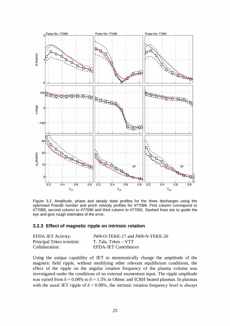
EFDA JET Activity: JW8-O-TEKE-17 and JW8-N-TEKE-20 Principal Tekes scientist: T. Tala, Tekes – VTT Collaboration: EFDA-JET Contributors Accurate and validated tools for calculating toroidal momentum sources are necessary to make reliable predictions of toroidal rotation for current and future experiments. In this work we present the first experimental validation of torque profile calculation from neutral beam injection under toroidal field ripple. We use discharges from a dedicated experimental session on JET where neutral beam modulation technique is used together with time dependent torque calculations from ASCOT code for making the benchmark. Good agreement between simulations and experimental results is found. While ripple diffusion and trapping are well understood in theory, the rigorous validation of fast ion ripple torque calculations against experimental data have so far been lacking. For validating the torque calculations dedicated experiments are required in which both the diffusive and convective momentum transport and the effect of ripple on NBI torque can be resolved simultaneously. Figure 3.2 shows the comparison between the simulated toroidal rotation and the experimental measurements for each discharge. Experimentally an effort was made to keep all the plasmas as identical as possible in order to have the same momentum transport across the discharges. This allowed to obtain the transport properties from the reference discharge without ripple using already validated torque calculations for non-ripple cases so that the only experimentally unknown parameter with the ripple discharges was the torque. The analysis of the rotation response in the rippled discharges using the torque from ASCOT shows good agreement with the experimental data thus confirming that the torque evaluation is consistent with the measurements.
25
Figure 3.2. Amplitude, phase and steady state profiles for the three discharges using the optimised Prandtl number and pinch velocity profiles for #77089. First column correspond to #77089, second column to #77090 and third column to #77091. Dashed lines are to guide the eye and give rough estimates of the error.
3.2.3 Effect of magnetic ripple on intrinsic rotation
EFDA JET Activity: JW8-O-TEKE-17 and JW8-N-TEKE-20 Principal Tekes scientist: T. Tala, Tekes – VTT Collaboration: EFDA-JET Contributors Using the unique capability of JET to monotonically change the amplitude of the magnetic field ripple, without modifying other relevant equilibrium conditions, the effect of the ripple on the angular rotation frequency of the plasma column was investigated under the conditions of no external momentum input. The ripple amplitude was varied from = 0.08% to = 1.5% in Ohmic and ICRH heated plasmas. In plasmas with the usual JET ripple of = 0.08%, the intrinsic rotation frequency level is always

26
smaller than < ±10 krad/s. Furthermore, the edge is always co-rotating while the core can be either counter- or co-rotating depending on the plasma current, the rotation usually increasing in co-direction with increasing Ip. Ripple affects both the edge rotation by lowering it typically close to zero or to small counter-rotation values and also core rotation where it becomes counter-rotating as illustrated in Fig. 3.3 (left frame). It also shows that there is a clear difference between type I and III ELMs; core counter-rotation was observed to be larger in phases with type III ELMs. However, it is not yet clear if this is a pedestal, density or collisionality effect. In these plasmas, the magnetic axis is at R0 = 3.02m, and the ICRH resonance location is slightly off-axis on the high-field side at Rres = 2.71m. Furthermore, the largest edge and core counter rotation was observed when the ICRH resonance location is on the low-field side, where the ripple amplitude is larger, as shown in Fig. 3.3 (right frame). This correlation between the magnitude of intrinsic rotation and ICRH resonance position indicates that the interaction between fast ions and ripple creates torque in the counter rotation.
Figure 3.3. (Left frame) Toroidal angular rotation profiles for ICRF heated H-mode plasmas with Ip = 1.5 MA, BT = 2.2 T, PICRH = 3 MW for the two ripple levels. Top pulse (dashed blue curve) #74688 with = 0.08% and PICRF = 3.1 MW; bottom pulse (blue and red solid curves) #74686 = 1.5% and PICRF = 2.9MW, including both the type I and type III ELM phase. (Right frame)
Toroidal angular rotation profiles for L-mode pulses with = 1.5%, Ip = 1.5 MA, PICRH = 2 MW, for three different resonance positions: (1) #77010 with Rres = 2.38 m, (2) #77014 with Rres = 2.71 m, (3) #77009 with Rres = 3.13 m. The resonance positions with respect to the magnetic axis R0 = 2.95 m are shown in the inset. Both in the case of plasmas with no momentum input (ICRH) and then even without any fast ions (Ohmic), increasing ripple was found to cause counter rotation. This indicates a strong torque due to non-ambipolar transport of thermal ions and in the case of ICRH also fast ions as the central rotation was significantly modified due to ripple. It is also clear that the effect of ripple on rotation originates from different physics in ICRH and Ohmic plasmas in experiments with NBI heating. In the latter case, ripple reduced rotation is mainly located at the edge region, originating dominantly from the torque caused by the ripple lost fast NBI ions.

27
3.2.4 ITER test blanket module experiment on DIII-D tokamak to study plasma confinement and toroidal rotation
ITPA Activity: IEA Large Tokamaks Implementing Agreement Principal Tekes scientist: T. Tala, Tekes – VTT Collaboration: DIII-D Team The proposed ITER tritium-breeding Test Blanket Modules (TBMs) are each expected to contain about 1 tonne of high-temperature and neutron tolerant martensitic steel. The contemplated steel alloys are ferromagnetic and will perturb the nearby plasma with ~1% local magnetic field reductions in addition to the usual toroidal field (TF) coil ripple. Serious deleterious effects, especially on H-mode performance, were feared based on past experience with toroidal field ripple from discrete TF coils on tokamak plasmas. However, whereas TF coil ripple is periodic, the TBM field consists of a few localized periodic magnetic “bumps”. Because the TBM field lacks a simple symmetry about the torus, it contains n = 1 harmonics (n = number of toroidal periods). n = 1 harmonics are of special concern, because some of them couple strongly to n = 1 tokamak MHD modes and are associated with plasma rotation braking, locked modes and the formation of large magnetic islands with serious loss of plasma confinement. It is important to understand the nature of magnetic perturbations produced by small (relative to the plasma) ferromagnetic objects close to the plasma boundary, such as a TBM. The effects of TBM perturbations on ITER plasmas cannot be predicted with confidence from present theory. Therefore, at the request of the ITER Organization (IO), a TBM error field mock-up was designed and temporarily installed in an equatorial port at DIII-D to assess TBM effects experimentally. The experiments were planned and performed in November 2009 by DIII-D staff and collaborators, plus a specially nominated international team of scientists including T. Tala and A. Salmi from Association Euratom-Tekes, and a thorough analysis of the experiments was carried out in 2010. In ITER the local ripple from the TBMs plus the corrected TF coil is expected to be ~ 1.2%. The DIII-D mock-up was designed to reach > 3% at full toroidal field. Reduction of the plasma toroidal velocity vT was the largest observed effect of the TBM mock-up perturbation experiments. Stable relative velocity reductions – vT/vT0 up to ~60% were observed at the highest local ripples ( ~ 4%) in ELMing H-mode plasmas for the maximum available neutral beam injected torque/power ratio. Here vT0 is the quasi-steady toroidal velocity just before application of the perturbation. Fig. 3.4 shows such data for a variation of over a range from about 1 to 3 times the local ripple that is expected in front of a TBM port. In ELMy H-mode plasmas, the relative toroidal velocity reductions were roughly 3 times greater than the corresponding relative reductions of the normalized energy confinement factor H98. At present it is not well understood how to confidently extrapolate from the experiments and predict the consequences for ITER.

28
Figure 3.4. Relative changes of vT and H98 as a function of local ripple as the mock-up coil current was varied. This parameter scan was performed with the shot #140149 parameters, except Rmidout = 2.32 m, and N 2.1–2.4. The ITER Organisation goal for in front of one ITER TBM port is 1.2%.
3.2.5 Calculating NBI torque and plasma rotation in AUG, DIII-D and ITER
EFDA Task: WP10-HCD-01-06 Research scientists: O. Asunta, T. Koskela, T. Kurki-Suonio, and
S. Äkäslompolo, Tekes – Aalto University Collaboration: AUG Team, IPP, Garching;
G. Kramer, PPPL, Princeton; DIII-D team, GA, San Diego Plasma rotation has become a focus of increasing attention because, over the past couple of years, it has been found to have a crucial role not only in the MHD activity related to the global stability of the plasma but also in the edge stability issues. Since edge stability is directly related to ELMs, the physics of rotation and its interplay with MHD should be understood in order to guarantee a successful operation and optimized utilization of ITER. The two components of toroidal torque (i) the collisional transfer of toroidal momentum from the beam particles to the plasma, and (ii) the jxB torque resulting from the finite orbit widths and the radial excursion of the beam ions, were studied with ASCOT. In AUG they were analyzed for each beam separately. It was found that the jxB torque contributes significantly to the torque profile at the edge where ions can be thrown on loss orbits, as well as at the outer plasma region where a given beam exhibits trapped orbits. Due to low radial excursion of beam particles deeper in the plasma, the radial current generated by the finite orbit widths of the beam particles dominates the jxB torque. All eight neutral beam sources of AUG were simulated using the plasma data of discharge #25820 at 3.05 s. When looking at the torque density deposited into the plasma via collisions, beams 3 and 8 were found to give most central deposition, as expected. Also beam 4 gave significant contribution in the centre, < 0.2. The maximum for beams 2 and 5 was found somewhat further out, 0.2 < < 0.4, while the

29
current drive beams 6 and 7 gave their contribution further out: the maximum for beam 6 was in the region 0.6 < < 0.8, while for beam 7 it was at around = 0.3. However, torque density can be misleading due to the tokamak geometry and, therefore, we also looked at the actual torque values, in the units of Nm. There the situation is somewhat different. While in torque density the beams 3, 4 and 8 were dominating, looking at the torque value it is the NBCD beams 6 and 7 that give values much higher than for the other beams. Particularly beam 7 gives a significant contribution (0.04 Nm) in the entire range 0.3 < < 0.9, while in a narrower region of 0.5 < < 0.9 beam 6 gives even higher values. All the other beams give a contribution that is at most half of the values given by beams 6 and 7, and they exhibit a double structure of having one maximum at around = 0.3 and another one at = 0.9. The minimum in between these maxima is due to the return legs of the co-injected banana orbits. Including the jxB effect due to the finite orbit widths of the fast ions changed this picture dramatically, particularly at the edge, where the most perpendicular beams 1 and 4 now give a very large contribution of up to 0.1Nm. This is understandable since these beams produce predominantly trapped ions and are thus likely to contribute to direct orbit losses. In the region 0.4 < < 0.9 the jxB effect reverses the sign of the torque for all but the NBCD beams 6 and 7. This effect is strongest for beams 2 and 3, and the torque turns negative even for the NBCD beams for > 0.7. The reason for the negative torque is that due to low radial excursion of beam particles, the radial current generated by the finite orbit widths of the beam particles dominates the jxB torque. Also the effect of turbulent transport is visible in jxB torque: including the turbulent transport, beam 6 gives a small negative torque all across the plasma cross section with a maximum absolute value at around = 0.5, i.e., closer to the magnetic axis than before. The total torque due to NBI ranged from about 0.36 Nm (beam 1) to 1.3 Nm (beam 6). The torque was calculated in the presence and absence of the mock TBM module in DIII-D. The simulations were carried out for discharge #14014 at 2.850 s when beams 30L, 150R, 330, and 330R were on. Here the effect of jxB was not as dramatic, and the torque was reasonably uniform across the plasma at quite a high value of about 0.1Nm due to the large number of beams. The effect of the mock TBM module was at noise level. The total torque for these plasma conditions / beams was about 3.5 Nm. The torque was evaluated also for the off- and on-axis beams in ITER. The torque densities in the deep core, < 0.3, are very different, but due to the small volumes the integrated values for the torque were very similar for both beam orientations: the torque reaches high value of about 2Nm at around = 0.9, but drops to a small negative value inside = 0.6 and to a large negative value down to -3 Nm for > 0.95. The total torque was about -2.1 Nm for the off-axis beam and -4.7 Nm for the on-axis beam.

30
3.2.6 Physics of L-H transition
EFDA Activity: WP10-TRA-01 Research scientists: T. Kiviniemi, S. Janhunen, and S. Leerink,
Tekes – Aalto University, J. Heikkinen, Tekes – VTT Collaboration: Francisco Ogando, UNED
S. Zoletnik, HAS A. Kramer-Flecken, FZJ
The present work included both code development work and simulations with gyrokinetic code ELMFIRE which solves full distribution of kinetic ions and electrons in presence of Coulomb collisions between the test particles allowing for simultaneous solution of neoclassical and turbulent physics. Such multi-scale simulation requires resolving gyroradius over several orbit widths in space and kinetic motion of electrons in transport timescale in time which makes the simulations very CPU consuming. The production runs were carried out in HECTOR (EPCC) and JUROPA (FZJ), provided by DEISA, and, also, at facilities of CSC–IT Center for Science Ltd. The main code development effort done during the task was to include new scrape-off-layer (SOL) model to the code to study edge-core coupling which according to experiments plays an important role in obtaining L-H transition. This model is now tested using Textor geometry and parameters. Several test runs (typically 6 000 CPUh each) including SOL zone were carried out in order to analyze the stability of the numerical method. The production runs (typically 24 000 CPUh each) consist of several simulations where TEXTOR plasma edge (6 cm) was simulated for 1 ms and inner edge of simulations regime was heated up during the simulation with simple heating operator. This was done in three phases, first phase having no heating. During the middle phase, temperature at the inner boundary was gradually doubled, and at the end phase temperature at the inner edge was maintained at higher level without further heating. Such simulations were done with and without SOL. Exact experimental parameters were not used but, rather, Textor-like parameters were used for proof-of-principle simulations of L-H transition. One of the production runs with SOL appeared to indicate some kind of pedestal formation. Main effect seen in the simulation was the strong modification of the radial electric field profile within one orbit width from last closed flux surface (see Fig. 3.5), simultaneous reduction of heat diffusion coefficient (when compared to runs without SOL) and, also, formation of edge pedestal in temperature profile. No such pedestal appears in the simulation without SOL, when other parameters were kept constant. Thus, key ingredient is assumed to be the newly developed scrape-off-layer but more work is needed both to assure the present findings and to test the parametric dependence of the observed phenomenon.

31
Figure 3.5. Radial electric field at the plasma edge in a heated simulation, with and without the developed SOL model. New model shows to have drastic effect on Er.
3.2.7 Quiescent H-Mode operation at AUG
AUG Programme 2010 Principal Tekes scientist: T. Kurki-Suonio, Tekes – Aalto University Collaboration: W. Suttrop and AUG Team, IPP Garching In the so-called Quiescent H-mode (QHM), a continuous, benign MHD behaviour called Edge Harmonic Oscillations (EHO) replaces the detrimental ELMs. This MHD activity has all the desired properties: it appears to facilitate density control and impurity exhaust while leaving the good core confinement intact. It is not clear what triggers the EHO, neither is it understood what suppresses the ELMs. Fast ions may play a role because, until 2008, QHM together with EHO was only achieved with counter-injection of the neutral beams, which creates enhanced orbit losses that might be the driver for the observed enhanced radial electrical field. However, orbit losses also create large power loads on plasma facing components and therefore might be considered counter-productive if one is to look for a way to protect the material surfaces. However, in May 2008, DIII-D stumbled on QHM operation with co-injected beams when heating the edge with ECRH. Later this year, in dedicated experiments, it was found that edge ECRH was actually detrimental and that it is high edge rotation (or edge rotation shear) that is the prerequisite for the QHM operation. Already same year an attempt to produce QHM operation with co-injected neutral beams on AUG was made. ELM-free phases were observed, but these were of the classical type with uncontrollable density rise. However, in a couple of ELM-free phases EHO-type MHD activity was observed. In fall 2009, several more attempts on co-injection QHM were made, with a lot of effort on bringing the edge density down. The results were similar to those of 2008, and by this time it became clear that even

32
with careful boronisation the density could not be brought down to levels measured in DIII-D. The failure to obtain QHM in a device as similar to DIII-D as AUG is immediately suggests that the reason lies in the different wall materials – carbon having stronger fuel retention. At the ITPA pedestal group meeting in Naka (21–23 April 2010) Andrea Garofalo pointed out that in DIII-D QHM had recently been obtained by application of n = 3 non-resonant magnetic error fields in co-injection heated discharges. The plasma is found to spin up towards a non-zero “offset” rotation velocity which can be larger than without error fields. The introduction of the in-vessel saddle coils in AUG leads to the new possibility to test the hypothesis that it is not the density per se that is important but, rather, the amount of rotation that can be driven in the plasma edge. An edge magnetic perturbation is known to affect the plasma rotation and, thus, gives us the much desired additional knob on controlling the rotation. Therefore, together with Dr. W. Suttrop (IPP), we created a proposal to address the following questions at ASDEX Upgrade:
1. Is the edge plasma rotation actually increasing if a non-resonant perturbation is applied?
2. Can the edge rotation speed be increased to the level observed in the DIII-experiment (20 km/s at ~ 0.8)?
3. Will QH-mode be obtained with a non-resonant perturbation?
4. What happens with a resonant perturbation? 5. Is rotation the QH-mode trigger? Control experiment: If error fields cause the
plasma to spin up in co-direction, will in counter-NBI QH-mode shots the counter-rotation be decreased, and will this cause ELMs to re-appear.
3.3 Energetic Particle Physics
3.3.1 Feasibility study of an active NPA system on AUG to study NBI current drive
Research scientists: E. Hirvijoki, T. Kurki-Suonio, and S. Äkäslompolo, Tekes – Aalto University
Collaboration: AUG Team, IPP Garching Measuring confined fast ions in tokamaks is very difficult and is one of the big diagnostic challenges for ITER that will boast a very large fast ion population due to fusion reactions. Collective Thomson Scattering (CTS) system is under testing at ASDEX Upgrade, as is FIDA (Fast Ion D Alpha) diagnostic that has been found promising at DIII-D. We have participated in the development of yet another alternative for fast ion detection: an ‘active’ NPA system capable of localized measurements of fast

33
ions. This work has been carried out in close collaboration with Dr. Francois Ryter at ASDEX Upgrade. A traditional NPA system relies on the neutralization of fast ion due to the thermal background. Therefore the signal is inherently line-integrated and does not provide any localized information on the fast ion population. However, since the neutral beam injection does not provide only fast ions but, primarily, fast neutrals, there is also a finite probability for the fast ions to experience a charge exchange within the NBI-neutral cloud. With ASCOT refurbished with a 3D neutral cloud due to neutral beams, we have carried out simulations to determine the potential of such an active NPA system based on neutrals generated from beam-beam interactions. ASCOT has a synthetic NPA-diagnostic that allows predicting the NPA signal from a real experiment. The code uses accurate beam geometry to calculate the beam density: both the ionisation distribution and now also the neutral density. The model also takes into account the gyro-motion of fast ions and the strongly non-isotropic velocity distribution of the beam neutrals. With one test-particle simulation one can study a large number of sightlines. They were arranged in a 20 x 20 array, hence producing a synthetic low resolution “NPA-camera” with app. 10° vertical view and 15° horizontal view. The simulation were carried out for true-to-life plasma kinetic profiles and magnetic backgrounds (shot #19913), and indicated that with a proper change in the location and orientation of the present NPA system, information on the fast ions from CD beams could be obtained from the plasma interior. The results were presented in the 37th EPS Conference in Dublin.
3.3.2 The effect of in-vessel coils on power loads to the PFCs due to NBI ions in AUG
Research scientists: T. Kurki-Suonio and S. Äkäslompolo, Tekes – Aalto University
Collaboration: AUG Team, IPP Garching A set of ASCOT simulations was carried out to assess the effect of the newly installed in-vessel coils to the confinement of NBI-generated fast ions. Any magnetic perturbation breaking the axisymmetry of the magnetic field can, in principle, affect the fast ion distribution and, together with the finite toroidal ripple, provide an escape channel to the plasma-facing components. The simulations used the data from discharge #25820 and were carried out both in the absence of the coils and with four different phasings of the coils. The coils were found to have little effect on the confinement of perpendicular beams, but to increase the wall load due to parallel beams by a factor of 2–3. However, since the absolute contribution from the parallel beams is insignificant compare to perpendicular beams, this causes no alarm as far as the integrity of the wall components is concerned. The change in the wall power loads is illustrated in Fig. 3.6. The results were reported in the ITPA-EP meeting in Seoul, South-Korea.

34
Figure 3.6. An illustration of Sectors 6 to 8 in ASDEX Upgrade (left), illustrating the in-vessel coils indicated in red, and beam induced power loads in the same region as calculated by ASCOT. The hot spots present in the absence of the coils are indicated by green circles, while the blue circle contains an additional hot spot obtained only when the coils are activated.
3.3.3 ASCOT simulations of the TBM mock-up experiments on DIII-D
ITPA-EPP Activity Research scientists: T. Koskela and T. Kurki-Suonio, Tekes – Aalto University Collaboration: G. Kramer, PPPL, Princeton; DIII-D team, GA, San Diego The testing of ferritic material in reactor conditions in ITER Test Blanket Modules (TBMs) magnifies the magnetic field ripple at three equatorial ports. Although the effect of periodic TF coil ripple has been fairly well studied both experimentally and theoretically, the effects of local ripples lacked experimental study until late 2009 when a scaled mock-up of an ITER TBM module was built and operated on DIII-D. In the experiments, a significant temperature rise was measured on the wall tiles in front of the TBM module when the TBM error field was turned on. The ASCOT code was used to simulate the fast Neutral Beam Injected (NBI) ion losses due to the TBM module and to determine whether the observed temperature rise could be explained by increased fast ion losses. The ASCOT simulations were benchmarked with several codes, and the results were first presented in the IAEA conference in Daejeon and in the ITPA-EP meeting in Seoul, South Korea and will be published in G. J. Kramer et al., Nucl. Fus. The TBM mock-up module in DIII-D was found to create a strong local ripple bending field lines outwards. We have found in simulations that the field line bending allows fast ions to escape confinement, which creates a hot spot on the wall tiles in front of the TBM. However, limiters were found to significantly decrease the fast ion power flux to the TBM tiles by absorbing power to themselves, see Fig. 3.7. These results strongly encourage the use of limiters in ITER.

35
Figure 3.7. The fast ion power distribution on the DIII-D wall in TBM mock-up experiments as given by ASCOT simulations.
3.3.4 Simulating the NBCD experiments at AUG
EFDATask: WP10-HCD-01-06-01 Research scientists: O. Asunta, T. Koskela, T. Kurki-Suonio, and
S. Äkäslompolo, Tekes – Aalto University Collaboration: S. Günter and F. Jenko, IPP, Garching The most tangential current drive beam, injector 2 at 93 kV, beam 6, was simulated using the plasma data of discharge #25820 at 3.05s. For comparison, also the radial beam 1 from injector 1 at 60 keV was simulated. The simulations were carried out both with and without the turbulent diffusion, and the radial distribution of the fast ion current was compared for these two cases. The only observable difference in the distributions was an ever so slight outward shift of the maximum in the driven current, but this change is so small that it is certainly within experimental uncertainty. The total ion current driven by NBI ranged from about 10 kA (beam 1) to 50 kA (beam 6). The present model for turbulent diffusion does not seem sufficient in explaining the anomalous redistribution of fast ions in the NBCD experiments in AUG. Furthermore, the turbulent parameters used in the simulations are very high compared to recent gyrokinetic simulations [M. Albergante, private communication]. Therefore it looks unlikely that turbulent diffusion, if reliably described by the present model, is responsible for the anomalous redistribution of NBI ions in AUG. However, the model still has up to four parameters that have to be obtained from gyrokinetic simulations. Over the year or so these numbers have changed over three orders of magnitude, so this work has to be continued in order to confirm the significance/irrelevance of turbulence for NBCD.
36
3.3.5 Validation/Benchmark of ASCOT against experiments and VENUS on TEXTOR
Research scientists: O. Asunta, T. Koskela, and T. Kurki-Suonio, Tekes – Aalto University
Collaboration: D. Moseev, Risø, and M. Albergante, CRPP Lausanne We have compared fast ion velocity distribution functions inferred from collective Thomson scattering (CTS) measurements on the TEXTOR tokamak with velocity distribution functions simulated using the Monte-Carlo codes ASCOT and VENUS. The measurements agree well with the simulations for on-axis scattering volumes but not for measurements with off-axis scattering volumes. An article detailing the work will be submitted soon to Plasma Physics and Controlled Fusion.
3.4 Power and Particle Exhaust, Plasma-Wall Interactions
3.4.1 Overview
Research activities in 2010 in the field of power and particle exhaust and plasma-wall interaction cover the co-ordination of ASDEX Upgrade (AUG) experiments, surface analyses of plasma-exposed long-term, tracer injection and erosion samples as well as computer modelling of erosion, global and local material migration in plasma. We begin this section with task reports focusing on surface analyses of plasma-exposed samples from JET, ASDEX Upgrade and Pilot-PSI (including specific modelling) and continue with more modelling-intensive task reports.
3.4.2 Material transport and erosion/deposition in the JET torus
EFDA-JET task: JW10-FT-3.61 Research scientists: J. Likonen, A. Hakola, S. Koivuranta, and M. Airila,
Tekes – VTT J. Keinonen and K. Mizohata, Tekes-UH P. Coad and A. Widdowson, JET-CCFE J. Kolehmainen, T. Haikola, and S. Tervakangas,
DIARC-Technology Inc. Collaboration: EFDA JET Contributors Background: Since 2001 an extensive analysis program has been going on under the JET Task Force Fusion Technology to investigate erosion, material transport and deposition in the JET torus using various surface analysis techniques. Several sets of divertor and wall tiles have been studied in three different divertor geometries: MkII-GB (Gas Box, 1998–2001), MkII-SRP (Septum Replacement Plate, 2001–2004) and MkII-HD (High Delta, 2005–2009). During these different configurations, JET has been operated with CFC as the plasma-facing material. Deposition in the divertor region has been highly asymmetric during each case, with heavy deposition at the inner divertor but just small net erosion at the outer divertor. Analyses of the tiles removed from the

37
vessel during every shutdown form the basis of our knowledge on the plasma-wall interaction mechanisms at JET. Main results in 2010: In 2010, a set of divertor and inner wall guard limiter tiles (IWGL) removed in 2010, were characterized using Secondary Ion Mass Spectrometry (SIMS) and optical microscopy. In addition, global migration of 13C in the Scrape-Off Layer (SOL) was investigated. The analysed outer divertor tiles 7 and 8 turned out to be clean indicating that they had clearly been eroded by plasma. The analysed tiles were not coated with a marker layer before exposure so determination of the amount of erosion was not possible. The inner divertor tiles 1, 3 and 4 showed a typical deposition pattern which has been observed after each experimental campaign. Tile 1 had a co-deposited layer on the plasma facing surface with a thickness varying between 6 µm (at the centre of the tile) and 16 µm (at the top of the tile). The apron of tile 1 had an even thicker film with a thickness of 52 µm. The co-deposited layer had a high Be/C ratio and was enriched also in nickel originating from the inconel steel in the JET vessel wall and from internal metal fittings, bolts etc. (see Fig. 3.8). Layers rich in metallic impurities have also been found in previous studies. Fig. 3.8 also shows an optical microscope image for the same sample. Tile 3 had somewhat thicker co-deposited layers than tile 1 with thickness varying in the range of 15–26 µm. The films had also high Be/C ratio but deuterium content was clearly less than on tile 1.
Figure 3.8. SIMS depth profiles (left) and optical microscope image (right) for a sample from the bottom of tile 1.

38
Figure 3.9. Optical microscope image for a sample from the shadowed area of tile 4.
The floor tiles 4 and 6 have always shown heavy deposition and high deuterium retention especially in the shadowed regions. In 2010, only tile 4 exposed in 1998–2010 was analysed. Fig. 3.9 shows an optical microscope image from a sample in the shadowed region of tile 4. The thickness of the co-deposited film is ~ 530 µm. A set of IWGL tiles located at the top, centre and bottom of the limiter were investigated with optical microscopy, but only 13C was measured with SIMS in 2010. Optical microscopy of the IWGL tiles showed similar deposition patterns as those observed for the IWGL tiles removed in 2001 and 2004. Tile 6X2L located near the top of the limiter was in the erosion zone. The right-hand side tile 6X2R showed heavy deposition along the tile surface. Tile 2X11L from near the centre of the limiter exhibited net erosion on the tangency region but there is an area of strong deposition further away from the centre. Tile 2X11R showed deposition near the tangency region. Deposition was clearly found to have taken place on the left-hand side near the bottom of the limiter (2X17L), whereas the right-hand side tile 2X17R was located in a net erosion zone.
Figure 3.10. Surface density of 13C (at/cm2) on the divertor tiles as a function of the poloidal s coordinate and measured with SIMS and RBS.

39
At the end of the C27 campaign in 2009, Task Force E carried out an experiment to provide specific information on material transport and SOL flows observed at JET. 13CH4 was injected into the plasma boundary through 24 holes in a number of outer floor tiles 6 in the last day of discharges using one type of discharge only. 13C deposition pattern was measured both with SIMS and Rutherford backscattering Spectroscopy (RBS) at CCFE. We observed that 13C was deposited mainly on tiles 6, 7 and 8, and the amount of 13C on the inner divertor tiles 1, 3 and 4 was clearly smaller (see Fig. 3.10). On tile 6, a local toroidal deposition band with high 13C amount was observed. The highest amount of 13C on the outer divertor was found at the bottom of tile 7 and at the top of tile 8. Local 13C deposition on tile 6 will be investigated using the ERO code and the simulations at VTT have been initiated. For global 13C migration the EDGE2D/EIRENE codes will be used at Aalto University and CCFE.
3.4.3 Experimental erosion and deposition studies in AUG
EFDA Task Force PWI: WP10-PWI-01-02, WP10-PWI-04-01, WP10-PWI-04-02 Research scientists: A. Hakola, J. Likonen, M. Airila, and S. Koivuranta,
Tekes – VTT K. Krieger, M. Mayer, R. Neu, V. Rohde, and K. Sugiyama,
IPP Garching T. Haikola, J. Kolehmainen, and S. Tervakangas, DIARC-Technology Inc.
Introduction: Our group has studied erosion of plasma-facing components and deposition of material on them in ASDEX Upgrade since 2002. For these investigations, special marker coatings have been prepared on selected divertor and main-chamber tiles, and the tiles have been exposed to plasma during a whole experimental campaign. The erosion of the coatings and the composition of layers deposited on them have been determined using post-mortem ion-beam techniques Nuclear Reaction Analysis (NRA), Rutherford Backscattering Spectroscopy (RBS), and Secondary Ion Mass Spectrometry (SIMS), both at VTT and at IPP Garching. In addition, the migration of carbon has been studied with the help of global 13C injection experiments, thus far carried out at the end of four experimental campaigns in ASDEX Upgrade. The poloidal deposition profile of 13C on the marker tiles or on standard tungsten-coated wall tiles of ASDEX Upgrade has been determined using SIMS. Modelling of the obtained results has been going on since 2008. During the last few years, the erosion/deposition investigations have been supplemented by producing special graphite probes with thin marker coatings on them and by exposing these probes to a pre-selected number of plasma discharges in ASDEX Upgrade. Main results in 2010: In 2010, a set of marker tiles (tiles 4, 4B, 1, 3B-I, and 3B-II, see Fig. 3.11), removed from the AUG torus after the 2009 experimental campaign, was analyzed using SIMS, RBS, and NRA. The main goals were to study erosion and re-deposition of W and Ni as well as deposition of D, 12C, and B on poloidal W, Ni, and graphite marker stripes of the tiles. In addition, modelling of the 2009 probe experiment with the ERO code was continued. The third major task in 2010 was analyzing three outer strike-point tiles (tile 1) using SIMS and determining the 13C distribution on them.

40
The tiles had been taken out from the AUG vessel right after a local 13C injection experiment with reversed Bt and Ip had been carried out in December 2009. All the three elements – D, 12C, and B – exhibited similar deposition profiles on the studied tiles. The largest deposition peak was observed in the private flux region vertically below the inner strike point (tiles 4 and 4B) where the layers were rich in carbon and deuterium. Somewhat smaller deposition peaks were also measured close to the outer strike point (tile 1). The layers in this zone contained mainly boron and carbon. Typically, deposition was the largest on graphite. Furthermore, the retention of D was larger on W than on Ni whereas 12C and B showed similar deposition behaviour on the two metallic substrates. Erosion of W reached its maximum (of the order of 500–1 000 nm) in the outer strike-point region and then gradually decreased poloidally towards the 3B tiles. The inner strike-point tile 4, on the other hand, was generally located in a deposition-dominated region. The erosion profile for Ni was very similar to that for W but the amount of erosion was larger by a factor of 5–10. The poloidal erosion profiles of both W and Ni can be found in Fig. 3.12. Simulations of the 2009 probe experiment were able to qualitatively explain the experimentally obtained, exponentially decaying erosion patterns for W and Ni at the low field side midplane. However, the simulated erosion rates were smaller than the experimental ones, in the case of W by several orders of magnitude as Fig. 3.13 shows. Fast ions can explain part of the discrepancy and also the addition of C and other impurities has been noticed to drive the results into the direction of measurements. The SIMS results obtained after the reversed-field 13C experiment in 2009 revealed that the deposition was the largest in the direction downstream of the puffing valves. Also the deposition efficiency was a factor of 2 smaller than what was observed after a forward-field experiment in 2007. These results could well be explained by the effect of the E×B drift. A more detailed discussion can be found in Section 3.5.6. For the 2010 ASDEX Upgrade campaign, altogether six new marker tiles have been produced by DIARC-Technology Inc. Four of the tiles have poloidal regions with different surface roughnesses and either a Mo or W coating. The fifth tile has been equipped with poloidal Al, Cr, Mo, and W marker stripes, and the last one with poloidal W and 5-% Ta-doped W marker coatings. The thickness of the coatings is 2–5 m. In addition, six new erosion probes have been coated with 50–100 nm thick W+C, Al, Ni, and W marker stripes for new experiments during the 2011 and 2012 experimental operations.

41
Figure 3.11. Locations of the marker tiles removed for ion-beam analyses in 2010.
Erosion/deposition of W coatings, 2009
-7000
-6000
-5000
-4000
-3000
-2000
-1000
0
1000
350 550 750 950 1150 1350 1550 1750
s (mm)
W th
ickn
ess
chan
ge (1
E15
at/c
m2 )
Tile 4
Tile 1, W2
Tile 1, W1
Tile 3B-I
Tile 3B-II
Erosion/deposition of Ni stripe, 2009
-45000
-40000
-35000
-30000
-25000
-20000
-15000
-10000
-5000
0
1000 1100 1200 1300 1400 1500 1600 1700 1800
s (mm)
Ni t
hick
ness
cha
nge
(1E1
5 at
/cm
2 )
Tile 1
Tile 3B-I
Tile 3B-II
(a)
(b)
Figure 3.12. Poloidal erosion profiles of (a) W and (b) Ni on the studied marker tiles.

42
Figure 3.13. Left: experimentally determined erosion profile for the different marker stripes (W, Ni, and Al) on the probe. The tip of the probe is the closest to plasma and corresponds to a distance of 45 mm. Right: ERO results for the gross and net erosion and gross deposition of the different marker stripes (C, Al, Ni, and W). The cell number 20 corresponds to the tip of the probe.
3.4.4 Effect of field reversal on 13C deposition in the ASDEX Upgrade outer divertor
EFDA Task Force PWI: WP10-PWI-04-02 Principal Tekes scientist: L. Aho-Mantila, Tekes – VTT Collaboration: M. Wischmeier, D. Coster, and K. Krieger,
AUG Team, IPP Garching A. Kirschner and D. Borodin, FZJ Jülich Introduction: A series of 13CH4 injection experiments have been performed in the 2007–2009 ASDEX Upgrade campaigns to investigate carbon migration in well-diagnosed, attached L-mode plasmas. The tracer was injected into several locations in the outer divertor plasma, and well-resolved 2D patterns of local 13C deposition were obtained using post-mortem ion-beam measurements. The effects of plasma conditions and cross-field drifts on 13C migration were investigated in 2009 by reversing the toroidal magnetic field and plasma current compared to the normal field configuration in 2007. The experiments have been modelled using the SOLPS5.0 code package to calculate the divertor conditions and the ERO code to calculate the tracer trajectories and the re-deposition and re-erosion of 13C at the target. Main results in 2010: The local 13C deposition in the 2009 reversed field experiment was measured using nuclear reaction analysis, NRA, and secondary ion mass spectrometry, SIMS. The results are shown in Fig. 3.14. Compared to forward field, the measured re-deposition efficiency in reversed field is a factor of 2 smaller, the deposition is more localized and shows transport towards the outer scrape-off layer. Numerical modelling focused on understanding the differences in the 2007 (forward field) and 2009 (reversed field) experiments. The SOLPS5.0 forward field plasma solutions were further developed based on additional experimental data obtained in

43
2009, and a good agreement with the measured outer divertor conditions was obtained. Completely new reversed field plasma solutions were derived, with a reasonable agreement to the experimental data obtained in 2009. The ERO simulations were carefully adjusted according to most recent advances in the field in understanding of hydrocarbon reflection and re-erosion probabilities. The integrated SOLPS5.0-ERO simulations reproduce the main characteristics of the deposition patterns in the two field directions, see Fig. 3.15. In forward field, low-recycling conditions allow for migration toroidally upstream, whereas the E×B drift increases local 13C deposition by a factor of 2 and results in migration towards the private flux region. The field reversal leads to a cooler and denser plasma, in which both upstream transport and deposition due to the E×B drift are suppressed [L. Aho-Mantila et al., J. Nucl. Mat., in press].
Figure 3.14. Local 13C deposition pattern in AUG 2009 experiment measured with NRA (K. Krieger / IPP Garching) and SIMS (A. Hakola / VTT). Most of the SIMS measurements were carried out for the rightmost tile. The vertical black lines represent the tile gaps.
Figure 3.15. Modelled 13C deposition patterns in the AUG 2007 and 2009 experiments, from SOLPS5.0-ERO simulations (reproduced from [L. Aho-Mantila et al., J. Nucl. Mat., in press]).

44
3.4.5 Erosion of W, Al, and mixed W-Al coatings exposed to Pilot-PSI plasma
EFDA Task Force PWI: WP10-PWI-04-04 Research scientits: A. Hakola and J. Likonen, Tekes – VTT P. Paris, M. Laan, and M. Aints, University of Tartu J. Rapp and G. de Temmerman, FOM-Rijnhuizen
T. Haikola, J. Kolehmainen, and S. Tervakangas, DIARC-Technology Inc.
Introduction: The research units VTT and University of Tartu have recently established collaboration between the FOM Institute for Plasma Physics Rijnhuizen, the Netherlands, in the field of plasma-surface interactions. The main research theme within this collaboration is studying erosion of ITER-relevant materials when exposed to plasma in Pilot-PSI and Magnum-PSI. For the experiments, test samples consisting of a few m thick coatings have been produced by DIARC-Technology Inc, and the samples have been analyzed before and after their plasma exposure at VTT and in Tartu. In this section, the ion-beam results taken from the samples are summarized. Results from the other analyses of the samples can be found in Section 4.1. Main results in 2010: In 2010, test samples of W, Al, and mixed W-Al compounds (approximately 60% of W and 30% of Al), deposited on Ti substrates, were exposed to the Pilot-PSI plasma. The nominal thickness of the samples was 5 m except for two W-Al samples whose goal thickness was 2 m. All the coatings had been deposited at a deuterium partial pressure such that they contained 0.5–1 at. % of D. The samples were exposed to deuterium plasma, which also included neon to enhance erosion. The particle flux ranged between 1023 and 1024 m-2s in the experiments, while the exposure time (corresponding to different fluences, in J/m-2) and the ion energy were varied from sample to sample. The electron density and temperature were ne 2.5 × 10²⁰ m-3 and Te 1.6 eV, respectively. The surface temperature of the W samples was kept in the range 800–900 C, for the W-Al samples the temperature was 600–700 C, and for the Al samples around 350 C. The ion-beam techniques SIMS, RBS, and NRA were used to determine erosion of the coatings and changes in their elemental composition. All the samples had been noticeably eroded as a result of the plasma treatment: the W(D) samples by 500 nm, the W-Al(D) samples by up to 2–3 m, and the Al(D) samples by some 1.5 m. In addition, major differences were observed in the depth profiles of different elements when comparing the curves obtained at different distances from the centre of the plasma spot. Examples of SIMS depth profiles in the case of a W(D) film, exposed during 1000 s, can be found in Fig. 3.16. The profiles have been taken at distances of 2 mm and 6 mm from the centre of the plasma spot. Also SIMS profiles measured before the plasma exposure can be seen in the figure. Particularly in the case of the 2 mm profiles, there is a thick deposited layer (500 nm) on the surface, and generally D has practically disappeared from the film matrix – except for the deposited layer where the D atoms have originated from the plasma.

45
Figure 3.16. SIMS depth profiles measured from a W(D) sample (a) before and (b,c) after its plasma exposure. In (b), the measurement spot has been located at 2 mm and in (c) 6 mm from the centre of the plasma spot.
3.4.6 Fundamental mechanisms of plasma-wall interactions
EFDA tasks: WP10-PWI-06-03 Principal investigators: K. Nordlund, C. Björkas, A. Meinander, A. Lasa, and
K. Vörtler, Tekes – University of Helsinki
Current and future tokamak-like fusion reactors include the three elements Be, C, and W as the plasma-facing materials. During reactor operation, also mixtures of all these elements will form. Hence it is important to understand the atom-level mechanisms of physical and chemical sputtering in these materials. To enable simulation studies of the chemical sputtering effects, it is crucial to have a coherent set of interatomic potentials for all the elements Be, C, W and H as well as their most important compounds. In 2010, we developed a bond-order interatomic potential for the beryllium-tungsten system. This potential was the final piece of the potential puzzle that now contains all possible interactions between the four plasma-facing fusion reactor materials. The full potential is suitable for plasma-wall interaction simulations and can describe well all the pure elements, as well as the intermetallic Be2C, WC, W2C, Be2W and Be12W phases. The potential is now applied to determine sputtering and reflection yields by plasma bombardment in the full materials mixture, for direct linking with plasma simulations. Among many other studies, we examined in 2010 the erosion of Be2C by deuterium using molecular dynamics simulations. This is significant because redeposition of
0 500 1000 1500 2000 2500 3000 3500 40001
10
100
1000
10000
100000 D
12
C Ti W
In
ten
sity
(1/
s)
Depth (nm)
W/Ti sample
0 500 1000 1500 2000 2500 3000 35001
10
100
1000
10000
100000 D
12C Ti Al
(+Cr+Fe) W
Inte
nsi
ty (
1/s)
Depth (nm)
W(D)/Ti, exposed 1000 sx = 2 mm
0 500 1000 1500 2000 2500 3000 35001
10
100
1000
10000
100000 W(D)/Ti, exposed 1000 sx = 6 mm
D
12
C Ti Al
(+Cr+Fe) W
Inte
nsi
ty (
1/s)
Depth (nm)
30 mm
(a
(b)
(c)

46
beryllium eroded from the main chamber in the ITER plasma facing components onto the divertor material carbon creates a mixed material, beryllium carbide Be2C, whose interaction with the plasma is not well known. For our simulations, we constructed a beryllium carbide antifluorite cell consisting of about 4300 atoms. We then bombarded this cell cumulatively with deuterium ions where all projectiles had the same initial energy, either 10, 15, 20, 50, 75 or 100 eV. We performed up to 4000 bombardments for each energy. The impact point of the cell and the bombarding deuterium ion was randomized by shifting the cell in the x and y direction after every run while keeping the deuterium initial position constant, in the middle of the xy-plane and 5 Å above the cell surface. We found that beryllium sputters preferentially over carbon and identified the sputtering mechanism in the ion energy range 10–100 eV to be both physical and swift chemical sputtering. In addition to single atoms, many different types of molecules were sputtered, the most frequently occurring molecules being BeD, Be2D and CD, see Table 3.1. below. The sputtering threshold was found to lie between 10 and 15 eV. The quantitative sputtering yields were used as input for plasma simulations with the ERO code.
Table 3.1. Molecules sputtered during bombardment of Be2C by D at various energies for Be and C-terminated surfaces. The results illustrate that a plethora of different kinds of molecules can be sputtered from BeC compounds in a fusion reactor. These have different stability and transport properties in the fusion plasma, and describing all of these forms a challenge for plasma simulation codes.
3.4.7 Hydrogen migration in high Z plasma-facing materials
EFDA tasks: WP10-MAT-WWALLOY-05 Principal investigators: K. Nordlund, K. Heinola, T. Ahlgren, and K. Vörtler,
Tekes –University of Helsinki
In our earlier experimental work we have implanted deuterium (D) into polycrystalline tungsten (W) and studied its trapping into implantation induced defects with various experimental methods, i.e. secondary ion mass spectrometry (SIMS) for measuring the D depth profile, nuclear reaction analysis (NRA) for deducing the total number of

47
trapped D and quadrupole mass spectrometry (QMS) for measuring the dynamics of out-diffused D2 gas. This work has revealed the existence of at least four different defect types in W that can trap deuterium. In 2010 we developed a computational tool for determining the hydrogen implantation, trapping and out-gassing applicable in real length and time scales. The developed computing tool was validated by simulating the mentioned implantation experiment in its whole.
Figure 3.17. Experimental (marker) and simulated (solid line) deuterium distributions in W with implantation energies of 5, 15 and 30 keV/D to a fluence of 5.8 x 10¹⁶ D/cm2. There is an excellent agreement between the simulated and experimental profiles.
Figure 3.18. Details for the 5 keV/D implantation. The total simulated D profile (solid line) consists mainly of D trapped in monovacancies, while the concentration of D trapped in larger vacancy clusters, decreases along with the cluster size. G is for grain boundary, dislocation and C is carbon impurity. The SRIM simulation shows the D profile in case the implantation would have been done at temperature where D is immobile.

48
The computational method relies on solving a set of analytical Rate Theory Equations (RE) describing processes taking place in the bulk and on the surface of the material. Each examined process involves the knowledge on the energetics of the event and on the rate, i.e., the speed of the event occurring. The energetics and rates were obtained using electronic density functional theory (DFT) calculations and molecular dynamics (MD) simulations. The processes included in the simulations were diffusion of impurities and defects, annihilation, clustering, trapping and detrapping. The advantage of the RE method is that it is an analytical method and therefore computationally economical, simulations can be done in real time and length scales and there is limitations in the number particles. This method of combining the results from DFT and MD into RE calculations forms the basis of state-of-the-art Multiscale Modelling. In Fig. 3.17 is presented the simulated results compared to the experimental implantation D profiles in W. Implantation time in the RE calculations was 30 mins and the samples were annealed at room temperature for 24 hrs. As a result, a perfect agreement is found when compared to the experimentally obtained D profiles. Since the RE method includes detailed information on the processes taking place in the course of implantation, the D trapping defect types can be determined specifically. In Fig. 3.18 is presented the D trapping into different trap types in the course of 5 keV/D implantation. It is evident, that the majority is trapped in monovacancies but there are also larger vacancy clusters present near the surface. These larger clusters are implantation induced defects. The RE method is an efficient computational tool for determining hydrogen retention and recycling and therefore clearly suitable to be used in determining the hydrogen retention parameters in tokamak experiments.
3.4.8 Arc-discharge cleaning of plasma-facing components
EFDA ET Task: WP09-DTM-TritI-R Research scientists: A. Hakola and J. Likonen, Tekes – VTT
T. Haikola, J. Kolehmainen, and S. Tervakangas, DIARC-Technology Inc.
Main results in 2010: The feasibility of an arc-discharge based technique in removing deposited layers from the wall structures of ITER was studied during the period 2009–2010. For this purpose, deuterium- or hydrogen-doped test samples of W, Al, and mixed W-Al and W-C compounds, simulating the co-deposited layers on the ITER walls, were produced and the parameters of the arc discharges were tuned to optimize the cleaning efficiency of the samples. For the ignition of the discharges, both a pulsed laser and a contact ignitor were tested and the necessary parameters of the ignition system were optimized. The most promising results were obtained by using the contact-ignition approach, and examples of samples cleaned with this method are shown in Fig. 3.19. In part (a), the surface of an Al sample after 50 and 100 discharges can be seen, part (b) illustrates the surface of a W-C sample after 100 and 400 discharges, and in part (c) a W sample after 100 and 800 pulses is shown. One observes that the cleaning efficiency depends largely on the material: it is much easier to remove Al than W. In the case of W, even 800 pulses were not enough to completely remove the film from the surface. Also mixed W-C layers required hundreds of pulses, most likely because of the W constituent, before the substrate was reached.

49
The cleaned surfaces were rather homogenous and smooth which indicated that the arc-discharge method does not damage critical plasma-facing components. By visual inspection, the mirror-like shining of the original surface had disappeared but the average roughness of, e.g., a cathode exposed to 20 000 arc discharges had increased only from 1.25 m to 3.36 m. From our results, we also made estimates for the effective cleaning rates in ITER. As an example, a 10 m thick Al-W film with an area of 20 × 30 cm2 (size of an A4) could be cleaned in 120 s if the cleaning rate was an optimistic 5 ×10⁻⁹ m3/s. With a pessimistic value of 8 × 10⁻¹⁰ m3/s, the cleaning time would be 750 s which is still a reasonable value. During the project, a preliminary design for the cleaner head was also made by DIARC-Technology Inc. The head has been designed to be mounted onto the multipurpose deployment arm of the ITER robot. A schematic drawing of the cleaner head and its positioning on the remote-handling system are shown in Fig. 3.20.
Figure 3.19. Surface of (a) an Al sample after 50 and 100 discharges, (b) a W-C sample after 100 and 400 discharges and (c) a W sample after 100 and 800 discharges.
50 pls 100 pls 100 pls
100 pls 400 pls 800 pls
(a) (b) (c)

50
Figure 3.20. Schematic illustration of the DIARC cleaning head (top) and its integration into a remote-handling system (bottom).
3.4.9 Predictive EDGE2D/EIRENE and SOLPS simulations of radiation, and particle and heat loads in JET and DIII-D
EFDA Fellowship: WP08-FRF-Tekes/Groth IEA Large Tokamaks Implementing Agreement EFDA Fellow: Mathias Groth, Tekes – Aalto University Collaboration: T. Makkonen, V. Lindholm, and A. Järvinen,
Tekes – Aalto University M. Airila, Tekes – VTT
S. Wiesen and D. Harting, JET/FZJ Jülich D. Coster and M. Wischmeier, IPP Garching Introduction: Validation of predictions from fluid edge codes, such as EDGE2D/EIRENE, SOLPS, and UEDGE, against experimental data from the principal tokamaks ASDEX Upgrade, DIII-D, and JET is one of the high-priority tasks within the ITPA-DSOL group. Sufficiently reliable predictions are needed to aid the design of the ITER divertor and to develop plasma scenarios compatible with ITER’s plasmas-facing components. Furthermore, numerical solutions from fluid codes typically serve as background plasmas for impurity Monte-Carlo codes, including ASCOT, DIVIMP, and ERO. All of these codes are utilised by the fusion group at Aalto University and VTT to simulate carbon migration in ASDEX Upgrade and JET, and to interpret surface deposition measurements carried out at VTT. Given the recent shift from carbon-based

51
plasma-facing materials to tungsten and beryllium, both fluid and kinetic Monte-Carlo edge codes are adapted to predict tungsten erosion due to sputtering off beryllium, and the core tungsten content. Main results in 2010: Upstream density scans were carried out with EDEG2D/EIRENE on a magnetic configuration corresponding to JET pulse 78647, and compared to experimental data and UEDGE predictions. In these scans, the radial transport coefficients were determined at the lowest upstream density, and held constant, while the upstream density was raised up to the density limit. Different chemical sputtering models were tested to determine their impact on radiated power, and particle current and power to the target plates: (a) a fixed yield model at 1%, (b) the Haasz-Davis 1997 database without flux dependence, and (c) the Roth 2003 database including flux dependence. The EDGE2D/EIRENE-predicted radiated power underestimates the measured power by a factor 2–3 (Fig. 3.21). While the particle current to the low field side (LFS) target reproduces the functional dependence on upstream density within the investigated density range, the simulations underestimate the particle current to the high field side (HFS) target by a factor 2–3. The simulations reproduce the total power to the HFS target reasonably well, while they underestimate the total power to the LFS target, by a factor of 2 at the lowest upstream density. Based on SOLPS cases for DIII-D run by M. Wischmeier for PSI 2008, these cases were re-visited and continued as part of the training process on SOLPS. Variations of the radial transport model, wall pumping, and chemical sputtering yields were applied to the lowest density case, and their order-of-magnitude effect on the upstream and target plasma parameters investigated. For each variation a scan of the upstream density was performed to examine detachment of the HFS and LFS divertor plasmas. Next steps include comparison of the simulation results to experimental measurements, and building of synthetic diagnostics within SOLPS for DIII-D’s spectroscopic and imaging systems.

52
Figure 3.21. Measured and predicted radiated power, and particle currents and total power to HFS and LFS targets in JET. The closed black symbols denote measurements and the lines predictions from EDGE2D/EIRENE for three different chemical sputtering models: red – fixed yield at 1%, blue – Haasz-Davis 1997 without flux dependence, and green – Roth 2003 with flux dependence.
3.4.10 Local carbon deposition in JET tracer injection experiments
EFDA JW10-FT- 3.61 Research scietists: M. Airila, Tekes – VTT M. Groth and T. Makkonen, Tekes – Aalto University P. Coad and A. Widdowson, CCFE Culham S. Brezinsek, FZJ Jülich Collaboration JET EFDA Contributors Introduction: During detachment experiments of JET in 2007, a known amount of 12CD4 gas was injected into L-mode plasma. The injection was done at the outer strike point in the centre of the horizontal target. The experiment was executed close to the end of the experimental campaign just before the usual 13C global tracer experiment was carried out. The affected Tile 5 was not exposed to outer strike zone after the experiment. The deposited layers were analyzed post mortem after the removal of tiles. In the absence of isotopically labelled carbon, the deposited amount was deduced from measured deuterium. A toroidal profile and several poloidal profiles were measured over the deposition area. The heaviest local D deposition density was found immediately upstream of the gas inlet, but downstream the deposition is found over a larger area. If the mean D/C in the deposits is assumed to be 0.4, then about 10% of the injected carbon was locally deposited. Main results in 2010: In 2010, modelling of the local carbon deposition in the injection experiment was carried out. We set up a model based on the DIVIMP and ERO codes to simulate and attempt to explain the local migration. We initiated the deposition modelling with ERO by assuming a uniform plasma background and scanning density and temperature over the relevant ranges suggested by the uncertainties in the local

53
measurements. This simplified model does not reproduce the deposited fraction and a correct toroidal distribution simultaneously. Therefore we applied the onion-skin model (OSM) of the DIVIMP code to produce a more realistic plasma background for ERO modelling. Locally deposited fraction is reproduced with ERO but the distribution not satisfactorily. In particular the poloidal transport of carbon is several times weaker than measured, see Fig. 3.22.
Figure 3.22. Left: Simulated toroidal carbon surface concentration profile after the deposition phase (detached plasma) and after the erosion phase (attached plasma). Right: Simulated poloidal carbon surface concentration profiles after the deposition phase. The profiles change only little during the erosion phase. In comparison to the measurement it is assumed that the D/C ratio in the deposit is 0.4.
3.4.11 Development of an EMC3/Eirene data pre-processor for ERO
EFDA PWI Task: WP10-PWI-04-03 Principal Tekes scientist: M. Airila, Tekes – VTT Collaboration: T. Lunt, IPP Garching Main results in 2010: The 3D fluid plasma/kinetic neutrals code EMC3-Eirene can output the 3D plasma data in binary and ASCII formats. In 2010 we developed a Matlab pre-processor to read the binary file (more compact) and produce an output in a 3D Cartesian grid, a format that is accepted by ERO (see below). Since the EMC3-Eirene grid does not fully adapt to a curved limiter surface, the heat and particle fluxes cannot be derived accurately from plasma data alone. They must be imported separately, but this part has not yet been done. The input format of 3D data is a column format similar to the established 2D fluid plasma data with a third coordinate added. The handling of EMC3-Eirene plasma data in ERO was implemented such that it can be activated by defining a pre-processor macro with a compiler option. Because of the yet missing implementation of fluxes, test simulations have been performed only with dummy input data. The modified source files have been submitted to the CVS repository maintained by FZJ and are available to the ERO user/developer community.

54
3.4.12 Implementation of molecular dynamics based sputtering data for Be and Be2C in the ERO code
EFDA Task Force PWI: WP10-PWI-01-02 Research scientists: M. Airila, Tekes – VTT K. Nordlund, C. Björkas, K. Vörtler, and M. Mehine,
Tekes – University of Helsinki Collaboration: A. Kirschner and D. Borodin, FZ Jülich Introduction: This work is a step further in a theoretical understanding of the erosion of mixed materials formed in ITER. It adds to the plasma impurity code ERO an improved surface model that can be later augmented with data for other compounds/mixtures in the Be/C/W system. The work is related to the investigation of the erosion of Be and Be2C by deuterium ions using molecular dynamics simulations, carried out at University of Helsinki. There it was found that beryllium sputters preferentially over carbon and the sputtering mechanism in the ion energy range 10–100 eV was identified to be both physical and swift chemical sputtering. In this task the MD sputtering yields were used in plasma impurity simulations, serving as a replacement for input data obtained with TRIM. Sputtering data for Be2C cannot be directly used in the so-called homogeneous material mixing (HMM) surface model of ERO. The model is based on the assumption that all substrate and impurity materials mixing takes place in an interaction layer of user-defined thickness. The concentrations of various atom species in the interaction layer of each surface cell evolve during the simulation. At any time moment, sputtering yields, and reflection probabilities are calculated as concentration-weighted averages from the data for pure elements. Main results in 2010: We modified the surface model so that data for Be2C – and later for other compounds/mixtures in the ITER-relevant Be/W/C system – can be added as intermediate data points for interpolation between Be and C (and W). This approach can be motivated by the experimental observation that complex binary phase diagrams for compounds with inter-metallic phases frequently can be interpreted as combinations of simpler phase diagrams between the pure elements and inter-metallic phases. In the model we assume that the maximum stoichiometrically possible amount of Be2C is formed. Then the data interpolation is done between Be2C and the remaining Be or C. Fig. 3.23 illustrates this approach for 100 eV incoming deuterium ions. We demonstrate the use and significance of the new data set by applying the data to a previous ITER tritium retention and target lifetime calculation. In this reference case simultaneous erosion of CFC divertor targets and beryllium deposition from the plasma has been estimated using ERO simulations. Due to the main wall erosion, it is assumed that the deuterium plasma flowing onto the divertor targets contains 0.1% beryllium. To separate the effects of new data for beryllium self sputtering and the description for Be2C formation, we applied them both separately and together to the reference case. Only using the pure beryllium data is denoted as ”case 1” and the Be2C model is ”case 2”. Resulting surface concentration profiles are illustrated in Fig. 3.24. With new data for pure Be sputtering and/or with the new Be2C model the accumulation rate of

55
impurity beryllium from plasma to the divertor target changes within a ±25% range compared to the estimate given using the homogeneous material mixing model. Such changes are modest in the view that the tritium retention rate based on this estimate has been later raised by about 50%. Extension of the data set to the full ITER material mix is foreseen.
Figure 3.23. The elemental sputtering yield for surface layers of different concentration. The point for Be2C is obtained in this work (using the Be terminated surface data), and linear interpolations to the pure C sputtering (TRIM.SP data) and pure Be sputtering are done.
Figure 3.24. Surface concentration profile of Be along outer target of ITER after 15 s in different ERO simulation cases.
56
3.4.13 Update on DIVIMP modelling of 13C transport and deposition in AUG
EFDA Task Force PWI: WP10-PWI-04 Research scientists: T. Makkonen, T. Kurki-Suonio, and M. Groth,
Tekes – Aalto University L. Aho-Mantila, A. Hakola, and J. Likonen, Tekes – VTT
K. Krieger, H.-W. Müller, and D. Coster, IPP Garching Collaboration: AUG Team, IPP Garching OEDGE simulations were carried out during 2009 and 2010 of the 2007 13C injection experiment in ASDEX Upgrade. The OEDGE code consists of the onion-skin method (OSM) solver and the trace-impurity Monte-Carlo code DIVIMP. The poloidal flow profile of deuterium was identified to be the most crucial factor in determining impurity transport. This is an alarming fact since fluid codes do not give consistent results with the measured flows in the SOL. With OEDGE we observed that the experimental deposition could only be reproduced when assuming an ad-hoc poloidal flow profile, mimicking the measured flow profile. This work was already reported in the Euratom-Tekes Annual Report 2009 Yearbook and also presented in the PSI 19 conference in San Diego. Although the flow profile was identified as being the most crucial component, other limitations in the code exist: the radially limited computational domain, lack of drifts, lack of 3D effects, and re-erosion and migration. Work has been carried out in 2010 to investigate the effects of these limitations and to prepare the OEDGE code for the upcoming 2011 global 13C experiment. In 2010, the effect of the SOL dwell time on the 13C deposition was further investigated. Already in 2009, it was observed that the effect of various simulation parameters can be described by the SOL dwell time. This means that even with a large number of uncertain simulation parameters, it is possible to do reliable scans. Further simulations were carried out, including modification of the wall geometry in the divertor to allow for a radially more extended computational grid. The resulting 13C deposition profiles were found to be consistent with the results reported in the 2009 Yearbook, see Fig. 3.25. In order to further validate the 13C simulations, a new imaging diagnostic has been proposed to ASDEX Upgrade to measure the flow of low charge state carbon species in the SOL at the high field side (see Section 3.7.4)

57
Figure 3.25. The deposition in 4 different simulations. All the simulations had different simulation parameters (perpendicular diffusion coefficient, radial injection location, etc.) but the parameters were chosen so that cases A1 and A2, as well as B1 and B2, have roughly the same SOL dwell time.
3.4.14 DIVIMP simulations of tungsten transport in JET ELMy H-mode plasmas particle and heat loads in JET and DIII-D
Research scientists: A. Järvinen, M. Groth, and T. Makkonen, Tekes – Aalto University
Collaboration: S. Wiesen and D. Harting, JET/FZ Jülich, Germany C. Giroud and D. Moulton, JET, CCFE, Culham
Introduction: Divertor plasma-facing components made of tungsten are presently foreseen in ITER for the activated operational phase due to the low fuel retention in the bulk material and the absence of co-deposition. Erosion of W due to physical sputtering by impurities, in particular during edge-localised modes, however, may lead to significant W accumulation of the core plasma, strong radiation, and thus to reduction of plasma performance. In reactor relevant plasmas, the tungsten concentration (nw/ne) should be kept below 10-5 to avoid excessive cooling of the core plasma. Understanding W transport in the scrape-off layer is therefore necessary to guide reduction of the core W concentration and to optimise the W retention in the divertor. JET is installing the ITER-like wall and dedicated experimental work has been done in order to compatible with the full W divertor. In this study, the kinetic code DIVIMP is used to calculate tungsten sputtering and transport in a JET ELMy H-mode plasma (#76666) for one of the reference plasma configurations in high triangularity: Ip = 2.5 MA, Bt = 2.7T, = 0.4, Pin = 16 MW. DIVIMP calculations are performed on a steady-state inter-ELM
H-mode plasma background. The background plasma solutions are provided by 2-D fluid code EDGE2D/EIRENE. The main goal is to calculate the core tungsten concentration in different plasma density cases.

58
Main results in 2010: Altogether three different core density background plasmas are studied. The lowest density case was used to match the measurements of electron density and temperature at the outer divertor target. The higher density cases are obtained from the low-density case by scaling hydrogen fuelling at the inner divertor target. Contour plots of tungsten concentration in these three different background plasmas are shown in Fig. 3.26. For the lowest density case, the peak target temperature was above 90 eV and the tungsten concentration remained above 10-5 on the entire computational domain. For the medium density case, the peak target temperature was around 9 eV and the tungsten concentration remained below 10-7. For the highest density case, the peak target temperature was around 5 eV and the tungsten concentration remained below 10-10 almost on the entire computational domain. Increasing the density from lowest density case to medium density case leads to a factor-of-4 reduction in the tungsten source, whereas the upstream tungsten concentration is reduced by three orders of magnitude. Thus, the tungsten leakage from divertor is reduced significantly. Increasing the density from medium density case to high-density case reduces tungsten concentration dominantly by reducing the primary tungsten sputtering.
Figure 3.26. Tungsten concentration CW in the different plasma density cases (low, medium, and high).
In conclusion, a sufficient plasma fuelling is needed to achieve peak target temperatures below 10 eV in order to maintain efficient tungsten retention at the targets. Reducing the peak target temperature further below 5 eV, leads to significant reduction of the primary tungsten sputtering.

59
3.4.15 Comparison of 13C transport modelling with DIVIMP and ASCOT
Principal investigators: T. Makkonen, J. Miettunen, E. Hirvijoki, and T. Kurki-Suonio, Tekes – Aalto University
Collaboration: K. Krieger, IPP Garching Using OEDGE, we observed that the experimental deposition could only be reproduced assuming an ad-hoc (but closer to measurements) poloidal flow profile. Although, the flow profile was identified as being the most crucial component, other limitations in the code exist: a radially limited computational domain, lack of drifts, lack of 3D effects, and re-erosion. The OEDGE results were compared to predictions with the ASCOT code, which does not suffer from the first three limitations. ASCOT is a Monte Carlo gyro-orbit following code that includes drifts and 3D effects originally developed at Helsinki University of Technology. Its main advantage over OEDGE is that ASCOT’s computational domain extends all the way to the wall. The net drifts and diffusion calculated by the ASCOT Coulomb collision operator were compared to the fluid forces used in OEDGE. Here, the Reiser model was used as a reference case. We observed that non-Maxwellian effects need to be taken into account: the background plasma distribution is non-Maxwellian in the presence of parallel temperature gradients. Predictions of the particle trajectory derived from fluid model in OEDGE using the Reiser model is in qualitative agreement with ASCOT predictions. As an example, the particle distribution along a single flux tube is shown in Fig. 3.27. The two codes produce very different results for a test case similar to the 13C injection experiment. Only after removing the temperature gradient force for the OEDGE fluid model a match between OEDGE and ASCOT was found. This is shown in Fig. 3.28. Consequently, the Reiser model is currently being implemented into ASCOT.

60
Figure 3.27. OEDGE particle distribution assuming a point source and a temperature gradient along the magnetic field line.
Figure 3.28. Carbon-13 deposition for OEDGE (blue), OEDGE using the Reiser model (green), and ASCOT (red). The black line is OEDGE assuming no temperature gradient forces.

61
3.4.16 Assessment of the validity of the basic two-point model using SOLPS
Principal investigator: V. Lindholm and M. Groth, Tekes – Aalto University Collaboration: D. Coster and M. Wischmeier, IPP Garching
X. Bonnin, University of Paris Introduction: In this work, parameter scans have been performed with the edge fluid code SOLPS for equilibrium in AUG. The parameters in question are core density, core power, the electron cross-field heat transport coefficient e, and the flux limits for parallel-B electron and ion heat transport. Where possible, SOLPS results are compared to results predicted by the two-point model. Other codes (EDGE2D/EIRENE and UEDGE) have previously also been compared to the two-point model, and those results are qualitatively compared to the results of SOLPS. Main results in 2010: It has become clear, through the works of Chankin, Hill and these studies, that the basic two-point model is insufficient to capture the complexity of the SOL, even for pure deuterium plasmas. In most comparisons in this work, agreement has been poor, and often differs by orders of magnitude. The heat flux density predicted by the model fails just outside the separatrix in all cases, for two different codes (SOLPS and EDGE2D/EIRENE) (Fig. 3.29). Likewise, the collision parameters are significantly different from the predicted values, usually by a factor of 4 (as high as 6 for high collisionality). The best agreement with the two-point model can be found when comparing the power flux and temperature decay lengths of the fluid neutral simulations, where the two-point model gives a relationship between the decay lengths ( q = 2/7 Te), and standalone SOLPS gives q > 1/2 Te. The same behaviour is evident in simulations done with UEDGE. However, it could be argued that the fluid neutral model (used both in SOLPS standalone and in UEDGE) is less accurate than EIRENE, which gives a different solution ( q Te). Corrections to the two-point model may alleviate the issues exhibited in this work. Especially energy losses from radiation and charge exchange need to be taken into account, while 2D effects like cross-field transport could prove hard to incorporate into the model. On the other hand, these corrections should be derived from theory and not just be “fudge factors”. This would be an interesting study to do in the future. When comparing SOLPS to EDGE2D/EIRENE and UEDGE, the general pattern seems to be that the codes produce quite similar results as long as the neutral model is similar. However, quantitative agreement between cases is incidental, since the geometry and plasma parameters are different. Code-to-code validation, which is not in the scope of this work, would require near-identical conditions. Possible future work that could be done along the lines of this report is to perform simulations with impurities, which is expected to deviate from the two-point model even further. Also, re-doing some of the simulations in a newer version of EIRENE (e.g., EIRENE ‘99) would give some further insight into the significance of the neutral model.

62
Figure 3.29. Target power flux density profile as a function of radial distance from the separatrix at the OMP, with components of the total flux density shown. The dashed green curves are predictions made by the 2PM. Three cases with different pedestal densities are shown.
3.4.17 Simulations of the trace-element experiments at AUG using DIVIMP and ASCOT-PWI
EFDA Task Force PWI: WP10-PWI-04-02 Principal Tekes scientists: J. Miettunen, T. Kurki-Suonio, S. Äkäslompolo,
T. Makkonen, and M. Groth, Tekes – Aalto University Collaboration: K. Krieger, IPP Garching In ITER, co-deposition of plasma fuel with carbon, if CFC is used in the divertor during the DT operation, may lead to substantial retention of tritium on the plasma-facing components. Thus, the atomic and molecular physics of carbon and other impurities as well as their migration in a tokamak environment have to be understood. A new simulation tool has been developed that avoids the shortcomings of the fluid approach usually applied to the impurity migration problem. In 2007 in ASDEX Upgrade, 13CH4 (methane) was injected into the torus and a set of wall tiles was removed for surface analyses with secondary ion mass spectrometry. Less than 10% of the injected carbon could be accounted for by assuming toroidally symmetric deposition. In simulations with the DIVIMP code, deposition in the inner divertor was only achieved by imposing a scrape-off-layer (SOL) flow pattern suggested by experimental measurements. The significance of the DIVIMP results was also limited by other weaknesses: the simulation grid did not extend all the way to the first wall, the ion drifts were not yet implemented in the code, and both first wall structures and the magnetic field were assumed toroidally symmetric. To overcome these shortcomings, the ASCOT code has been upgraded to permit impurity transport studies in SOL, including imposed plasma background flow and atomic physics for carbon. According to the preliminary results of simulations using this enhanced code temporarily dubbed ASCOT-PWI, the assumption of a toroidally symmetric wall is particularly insufficient for predicting locations of high deposition in the main chamber.

63
In particular, protruding wall structures, such as port limiters near the injection location, are found to cause very localized deposition patterns in toroidal direction. However, it should be noted that at this stage no re-erosion was included in the simulations. Implementing models for finite sticking probability and re-erosion are currently being worked on. The results will be presented in the 13th PFMC meeting in 2011, and the ASCOT-PWI work more generally in the 38th EPS Conference.
3.5 Theory and Modelling for ITER
3.5.1 Fast ion distribution in ITER Scenario-2 in the presence of NTM-type island structures
EFDA Task: WP10-DIA-01-01 and WP10-DIA-01-02 Research scientists: O. Asunta, T. Kurki-Suonio, and A. Snicker,
Tekes – Aalto University Collaboration: E. Poli, IPP Garching ITER plasmas cannot be expected to be MHD quiescent. In particular, ITER is expected to be prone to neoclassical tearing modes (NTM) that exhibit slowly rotating island structures. Such islands can redistribute fast ions and, consequently, affect both the heating profile and current drive properties. Furthermore, the islands, even if in the core plasma, can even have an effect on the wall power loads if they provide a mechanism that extends the energetic ion population to the edge regions where the toroidal ripple can convey them to the plasma facing components. ASCOT is now equipped with a numerical model for such islands. We simulated the thermonuclear alphas in ITER Scenario-2 for four different cases: pure neoclassical transport, with only a (2,1) island added, with only a (3,2) island added, and including both a (2,1) and a (3,2) island. In these simulations we also evaluated the toroidally averaged wall load. These simulations were carried out using the ITER wall design with 18 limiters, so the toroidally averaged power load should also give a good indication of the peak power fluxes to the wall. All NTM’s were found to increase the peak power load, and the effect is strongest for the (2,1) mode that is closer to the plasma edge than the (3,2) mode. By adding both modes to the plasma together, the wall load is not increased from the (2,1)-only case, which is a clear sign of uncoupled modes. The increase in power load is around a factor of two. It is, however, very difficult to deduce from these results how the magnetic ripple and NTM’s will interplay, since the axisymmetric Boozer coordinates are a prerequisite for the present island model. The preliminary results were reported at the ITPA-EP meeting in Seoul, South Korea, and a full length manuscript has been submitted to Nuclear Fusion. Benchmark efforts against simulation results by Strumberger using different approach are still on-going.

64
3.5.2 Full-orbit effects on fast ion confinement in ITER Scenario-4
EFDA Task: WP10-DIA-01-01 and WP10-DIA-01-02 (Part of ITPA-EPP Activity)
Research scientists: T. Kurki-Suonio, S. Sipilä, and A. Snicker, Tekes – Aalto University
The large Larmor radius of energetic ions has effects on both their radial transport in a nonaxisymmetric magnetic background and the location where they collide with the vessel wall. These effects are omitted in pure guiding-centre simulation that is commonly used in orbit-following wall load studies. With its added full orbit capability, ASCOT has been applied to study these effects for ITER Scenario-4 which is especially vulnerable to ripple losses. In unprecedented full orbit simulations of slowing-down time scale, it was found that ripple-related full orbit transport mechanisms strongly affect the wall load distribution for both the unmitigated ripple case and the ripple-optimized case, as shown in Fig. 3.30. While pure full orbit simulation is 70–100 times more CPU-intensive than guiding-centre simulation, it was found that taking full orbit effects into account only near the wall (see Fig. 3.31) produces more realistic wall load distributions than pure guiding-centre simulation with minimal increase in computing time.
Figure 3.30. Toroidally averaged fusion alpha wall load vs. poloidal angle for ITER Scenario 4. a) Unmitigated ripple case. b) ripple-optimized case.

65
Figure 3.31. The effect of the orbit following method on the wall collision location of a 3.5 MeV alpha particle (ITER Scenario 4). Green: pure guiding center method. Blue: pure full orbit method. Red: guiding center method with near-wall full orbit simulation.
3.5.3 Alpha and NBI simulations for sawtooth control in ITER
ITPA-MHD-WG3 Activity Research scientist: O. Asunta, Tekes – Aalto University Collaboration: I. Chapman, CCFE Sawtooth control remains an important unresolved issue for Scenario 2 operation of ITER. Such ELMy H-mode plasmas are expected to be unstable to the internal kink mode. Furthermore, the energetic trapped particles are predicted to lead to significant stabilisation of the internal kink mode, resulting in very long sawtooth periods. Long sawtooth periods have been observed to result in triggering NTMs at lower plasma beta, which in turn can significantly degrade plasma confinement. Consequently, there is an urgent need to assess whether sawtooth control will be achievable in ITER, and how much power is required from the actuators at our disposal to attain an acceptable sawtooth period. In order to study the stabilizing effect of fast particles, populations of fusion-born alpha particles and neutral beam injected (NBI) particles in ITER were simulated with ASCOT. The NBI simulations were performed for both on- and off-axis injection cases. Using the obtained slowing-down distributions in further analysis resulted in a conclusion that maintaining the q = 1 surface close to the magnetic axis would make sawtooth control easier to achieve. Under such conditions both the alphas and the beam-induced fast ions would be less stabilising for the internal kink mode, and the NBI could even be used as a control tool in its most off-axis orientation.

66
3.5.4 The effect of turbulent diffusion on fusion alphas and NBI ions in ITER
EFDA Task: WP10-HCD-01-06-01 Research scientists: O. Asunta, T. Koskela, and T. Kurki-Suonio,
Tekes – Aalto University A theory-based anomalous diffusion model [Hauff et al.] has been implemented into ASCOT in order to get more realistic values for the neutral beam driven current. In the diffusion model of Hauff et al. [PRL 102 (2009) 075004], the diffusion coefficients derive their values from the properties of the plasma background and the resulting microturbulence. The diffusion coefficients due to electrostatic and magnetic turbulence, DE and DB, are calculated separately for strongly trapped and strongly passing orbits. According to the model, the effect of turbulence does not fall off with energy as rapidly as previously thought. Furthermore, while the energy scaling of the anomalous diffusion due to magnetic turbulence is more worrisome, its absolute values generally remain small compared to that due to electrostatic turbulence. In ITER, the anomalous diffusion is clearly more significant for the NBI deuterons than for the fusion alphas. Another interesting observation is that the anomalous diffusion is strongest for passing orbits. This numerical diffusion model is now a part of ASCOT, and preliminary results given by the model have been reported in ITPA EP meetings and at IAEA FEC 2010.
3.5.5 Simulating NBCD in ITER
EFDA Task: WP10-HCD-01-06-01 Research scientists: O. Asunta, T. Koskela, T. Kurki-Suonio, and
S. Äkäslompolo, Tekes – Aalto University The ion current driven by ITER on- and off-axis 1 MeV negative neutral beams were simulated in Scenario-2. As expected, the on-axis beams were found to produce a strong centrally peaked current density profile reaching the value of about 1 MA/m2 in the centre, while the off-axis beam produced a broad maximum in the region of 0.2 < < 0.4. Looking at the actual current in kA in different parts of the plasma, the situation reverses due to the volume effect: the off-axis beam produces most current at around = 0.4 with a well defined maximum of about 80 kA, while the on-axis beam produces
a fairly broad region up to = 0.6 with reasonably high current of about 50 kA. The maximum value of 70 kA is reached at = 0.15.

67
3.6 Code Development and Integration
3.6.1 ELMFIRE gyrokinetic transport code development and simulation results
EFDA Tasks: WP10-TRA-05-01, WP10-TRA-05-03, WP10-ITM-IMP4-ACT1, WP10-ITM-IMP4-ACT3 and WP10-ITM-IMP4-ACT6
Research Scientists: J. Heikkinen, Tekes – VTT S. Janhunen, T. Kiviniemi, and S. Leerink,
Tekes – Aalto University Collaboration: A. Gurchenko and E. Gusakov, Ioffe Institute
V. Bulanin and E. Kaveeva, St. Petersburg Polytechnical University F. Ogando, UNED F. Parra, MIT HPC-FF Users
Introduction: ELMFIRE is a full f nonlinear global gyrokinetic transport code for electrostatic simulations for tokamak plasma. The development started some seven years ago at TKK (now Aalto University) and VTT, and presently the code is applied for predictive transport simulations up to various middle-sized tokamaks. The code was originally developed for simple quasi-toroidal magnetic configurations with inclusion of impurities, Ohmic heating, recycling, and full transport relaxation. In 2010 effort was taken to extend the simulation region to the plasma edge SOL region. At the same time, the principles of the ambient gyrokinetic equations, energy and momentum conservation laws as solved by ELMFIRE and based on Dirac’s constrained Hamiltonian and inverse Kruskal iteration were finalized and published. The explicit expressions were derived for the conserving energy and total angular momentum within the formalism. Extending ELMFIRE to the SOL: In order to incorporate the SOL region to the simulation domain two parallel code development lines were launched, one with a complete revision of the grid structure of the earlier ELMFIRE version to adapt to the available grid constructions from magnetic equilibrium codes for the divertor SOL including the X-point configuration and another one devoted to the limiter SOL accessible by the grid structure of the present ELMFIRE version. Due to an unexpected instability with the momentum conserving interpolation for the plasma electric field E arising from the numerically produced nonzero curl of E, new interpolation routines had to be developed. That prevented the first development line to be finished by 2010 but the second line with the limiter bounded SOL extension was successfully developed. Appropriate sheath and plasma-wall interaction boundary conditions were developed and discussed with ÖAW Association (David Tskhakaya) and were adopted in the developed SOL model. The main issue was how to recycle the particles lost to the limiter and wall. This involved a series of development phases to incorporate the contributions of neutrals (and impurities and radiation) to the code with consequent validation tests with the FT-2 tokamak diagnostics (Ioffe Institute, St. Petersburg). The

68
incorporation of the SOL into the gyrokinetic edge calculations had numerous beneficial effects; density and heat pile-up at the separatrix observed with the earlier Elmfire version due to profile relaxation by turbulent transport was prevented and fluent particle and heat exchange between the edge and SOL was produced. This provided a remarkable result (not found with the earlier version with no SOL) of pedestal formation, and by sufficient core heating an onset of strong shearing of the radial electric field with the concomitant reduction of turbulence across the pedestal [WP10-TRA-05-01]. Validation of turbulence, plasma flows and rotation: Main emphasis within the Tasks, WP10-TRA-05-03-Tekes-01 and WP10-TRA-04-02-Tekes, was then turned to validate the observed turbulence, plasma flows and rotation in simulations. The code was used with a synthetic Doppler reflectometry diagnostics package to compare the Doppler shift and spectrum width from the TEM density fluctuations at the outer radial (with closed magnetic surfaces) plasma layers of FT-2 tokamak (Ioffe institute, St. Petersburg) in L-mode. The synthetic spectrum was found to agree with a high accuracy with the experimental one at several DR frequencies covering a wide radial range. The DR shift was found to agree with the poloidal ExB rotation explained well with the neoclassical prediction. The spectral width was found to originate from the GAM oscillations, supported also by a separate enhanced microwave scattering diagnostics. The inclusion of the SOL was necessary to find proper density radial profile relaxation. The new momentum conserving interpolation was found as necessary in ELMFIRE to accurately produce the neoclassical behaviour. Extensive comparison of the ELMFIRE turbulence characterization to GS2 simulation results was performed, supporting the ELMFIRE results and conclusions for the origin of the plasma flow variations. Several exchange of scientists between the Ioffe institute and Aalto University and VTT were conducted. Leerink did several visits to USA and England. Significant effort was made to prepare the code for petascale computing, and planning and study for the requirements and tools needed in exascale computing have started. S. Janhunen and S. Leerink participated at the ITM workshop/code camp at Risø. At this meeting several aspects of the project were worked on, such as debugging of the code to port it onto the HPC-FF infrastructure, subroutine forming of the code, and clarification of the requirements with respect to ACT1 and ACT3. Cross verification of IMP4 turbulence codes on specified standard cases: Improvement of the diagnostic capabilities of ELMFIRE is an important utility in estimating the conservation properties and physical relevance of simulation results. As such, most of the work over the first quarter of 2010 has consisted mostly of the following: implementation of the TF-ITM IMP #4 diagnostics, including radial heat flux and vorticity spectra, which were earlier calculated during the post-processing phase by hand. A non-equidistant FFT was found to be needed to be used in ELMFIRE and the associated package of diagnostic programs. This problem arises most probably because in true coordinates the metric involves a deviation which tends to mix adjacent modes together when proper toroidal Fourier transforms are performed. This way, each solved Fourier mode can be unambiguously

69
connected to a correct perpendicular wave number and as a result, the power spectra calculated by using nonequispaced Fourier transform are less noisy than the ones using conventional Fourier transform. In addition to the diagnostics mentioned above, diagnostic capabilities of ELMFIRE now include plasma rotation and toroidal momentum drive, convective and conductive fluxes (also separable for different drifts), histogram for the phase-space distribution sampled in user defined grid over space, vorticity and bootstrap current. Most of the parameters are assembled on a grid directly from the particle distribution function as velocity moments but some parameters, such as vorticity, are constructed from fluid moments of the 5D phase space. The bootstrap current diagnostic, which has been made in addition to the ITM requirements, enables comparison between the parallel current profile produced by ELMFIRE and the analytical neoclassical models, i.e, Sauter model and Hirshman-Sigmar full matrix formulation together with Shaing viscosity coefficients. Preliminary results show good agreement for the bootstrap current between ELMFIRE simulations and the neoclassical models. The IMP\#4 impetus for the improvement of diagnostics and interest in the theoretical aspects of the ELMFIRE model has motivated investigations to the conservation properties of momentum and energy, which have been investigated in parallel to the developments given in ACTs 1, 3 and 6. An important result of this investigation is that the so-called "energy conserving method" for PIC interpolation introduces a self-force to the particle motion, which can be viewed as a force that arises from a phase change to the particle charge by the solution-interpolation process for the field. Therefore, the "momentum conserving" PIC interpolation has been adopted, with modifications to remove the unwanted compressibility in the E×B motion. Implementation of CPO/Kepler compatible interfaces into IMP4 codes: Implementation of the ITM work flow is underway, and during the first ITM Code Camp requirements for the IMP\#4 benchmark were made much clearer. The profiles for density, temperature and current are required to be input as an array of radial values, which entails changes to how these have been implemented earlier in ELMFIRE (all profiles have been analytic up to now). During the WS/CC, subroutine forming for invocation from Kepler was begun by S. Leerink, but currently for the purpose of the benchmark of CT 1 we have progressed further on the CPO inputs and the code is invoked in the parallel environment as before. The option building the code as a library is however included in the GNU makefile of the code. Input of the code parameters has now been changed in the ITM version of ELMFIRE (on HPC-FF) so that temperature and density data are input from the CPO read/write file routines. These have been incorporated into the ITM version of the code as a Fortran module, which can be included or excluded by the make parameter ITM. The particle distribution is then initialized with these profiles as read from IMP4Init, and the simulation proceeds with the code-dependent parameters input from icri.inp, which is

70
the ELMFIRE input file. Some of ELMFIRE philosophy has to be changed with respect to parameters, such as separating physical parameters from the simulation parameters. At the time of writing this report, the current profile is still an analytical one and being set from icri.inp, but is one of the first things to be changed during the first part of 2011 to be able to use this aspect of the inputs. Because the current has been an analytic function up to now, is very frequently called in ELMFIRE, and interpolation routines need to be very optimized to be efficient, this aspect has unfortunately lagged behind. Validation of neoclassical and turbulence codes against experimental data: Spectra of turbulent density fluctuations measured with the Doppler reflectometer diagnostic at the FT-2 tokamak are compared by means of a synthetic Doppler reflectometry diagnostic to nonlinear gyrokinetic simulations including both fully kinetic ions and electrons. For the core region the experimental and synthetic power spectrum of the Doppler reflectometer show good agreements in both the Doppler shift as well as the width of the power spectrum, indicating comparable rotation and spreading of the density fluctuations. A SOL limiter model has been implemented in the code to prevent particle accumulation near the outer boundary. After this implementation the experimental and synthetic power spectrum of the Doppler reflectometer showed good agreements for the SOL [S. Leerink et al., Contrib. Plasma Phys. 50 (2010) 245] region. There is an extended paper being prepared of this work.
3.6.2 Integrated modelling by JINTRAC code at JET
EFDA Activity: JW10-O-TEKE-23 Principal Tekes scientist: J. Lönnroth, Tekes – Aalto University Collaboration: EFDA-JET Contributors Various types of modelling work have been carried out with the state-of-the-art integrated transport code JINTRAC at JET. JETTO modelling of current ramp-down: The H-L transition, which typically occurs when the external heating power and plasma current are ramped down towards the end of a plasma discharge, is going to be one of the most challenging parts of ITER operation. The reason for this is that the H-L transition leads to a very fast reduction of plasma energy content, something that is further exacerbated by the loss of fusion power. This fast change in stored thermal energy tends to push the plasma towards the inner wall and may cause a disruption, if the poloidal field coil system cannot react promptly enough. Therefore, being able to accurately model the H-L transition in existing devices is important, so that confident predictions for ITER can be made. The current ramp-down phase in a number of JET discharges has been modelled with the 1.5D core transport code JETTO. The purpose of the work has been to show that JETTO has the capability to accurately model the H-L transition during current ramp-down, with predictions for ITER in mind. In this work, the H-L transition has been modelled by a sudden increase of the transport coefficients in the edge pedestal triggered by a loss of external heating power. Plasma transport has been modelled with

71
the semi-empirical Bohm/gyro-Bohm model. ELMs have been simulated with a simple ad hoc model, in which the transport coefficients in the edge pedestal are temporarily increased to enhanced levels upon the violation of a pre-specified critical pressure gradient. Three JET plasmas with different current ramp-down rates have been modelled: #72209 (0.14 MA/s), #72242 (0.28 MA/s) and #72249 (0.50 MA/s). Systematic MHD stability analysis with the MHD stability codes HELENA and MISHKA-1 has been carried out on a series of JETTO simulations of these plasmas in order to establish the marginally stable level of pressure gradient at different stages of the current ramp-down in them. A critical pressure gradient corresponding to the level of marginal stability has been used in the predictive transport simulations. Generally, the transport simulations reproduce the experimental evolution of the plasmas very well. The time evolution of the thermal energy content during the current ramp-down is reproduced accurately in all the plasmas, even during the H-L transition and beyond. The time evolution of the internal inductance is best reproduced in the plasma with the fastest ramp-down rate. In the other plasmas, the internal inductance evolves somewhat faster in the simulations than in the experiment; a discrepancy of up to 20% building up over a 10 s time span in the worst comparison, compared to almost no discrepancy in the best case. The experimentally observed increase in ELM frequency during the current-ramp down is also difficult to reproduce with the simplistic ad hoc ELM model used in the study. Taken as a whole, the results show that the predictive capability of the JETTO model is very satisfactory, implying that it could be used for modelling current ramp-down and the H-L transition in ITER. EDGE2D boundary condition modelling: The separatrix temperature and density are important parameters in predictive modelling, because they are frequently used as boundary conditions in predictive transport simulations. Accurately determining the temperature and density at the separatrix is, on the other hand, generally beyond the capability of present-day diagnostic systems. To a large extent this is due to the difficulty of determining the position of the separatrix itself. Because of this, predictive modelling tends to rely on ad hoc assumptions for the boundary conditions, something that can influence the results in unpredictable ways. A modelling project has been launched with the aim to explore and parameterise how the separatrix temperature and density in JET H-mode plasmas vary as a function of certain plasma parameters, notably the external heating power and q95, the safety factor at the 95% flux surface. A range of JET discharges forming scans in power and q95 are modelled with the 2D edge transport code EDGE2D/EIRENE. For each shot, the intention is to obtain as good a match as possible between the calculated mid-plane and target profiles (temperature, density, ion saturation current etc.) and experimental measurements. If a good match in profiles can be found, one can have reasonable confidence in the calculated separatrix values. This technique makes it possible to estimate the separatrix temperature and density, which cannot be determined accurately using experimental diagnostics. The work is still ongoing and will, ideally, result in a parameterization for the separatrix boundary conditions that can be used in predictive transport modelling.

72
3.6.3 High Level Support Team Activities (HLST)
EFDA: WP10-HPC-HLST Research scientist: S. Janhunen, Tekes – Aalto University Collaboration: HCP-FF Users The ELMFIRE has been ported to the HPC-FF infrastructure successfully during 2010, the last issues (namely, file locking in MPI-IO) having been identified in May and resolved during autumn of 2010. Many new diagnostics according to the ITM standards have been added to the code in addition to the early diagnostics (such as total energy, density, temperature and potential). Now 3D diagnostics and Fourier spectra of TF-ITM diagnostics such as heat flux, particle flux, vorticity etc. are available. The diagnostics have opened an important verification process, which has been undertaken also within the confines of this project. Numerical aspects, such as differencing of the electric field, have been investigated from the viewpoint of conservable quantities (such as momentum), and have been remedied to improved accuracy. Especially toroidal momentum investigations were undertaken. Advanced filtering techniques have been investigated for noise control. The HELENA code was obtained from Dr. Huysmans and was successfully run on the CSC machines. Equilibrium quantities were investigated from the viewpoint of conserved quantities, and preliminary work towards incorporating a more generalized equilibrium was undertaken. ITM work flow implementation has been begun, and ELMFIRE can read in a consistent physical object (CPO) definition, use profile data for runs, and produce formatted output. Code specific parameters are input from an input file as before. Meetings of the HLST were held on 14.1.2010 and 29.9.2010, both of which were attended by Salomon Janhunen.
3.6.4 Development of the ASCOT code
EFDA Tasks: WP10-ITM-IMP3-ACT3/ACT4, WP10-ITM-EDRG-ACT3 WP10-ITM-IMP5-ACT1/ACT2/ACT3 Research scientists: O. Asunta, E. Hirvijoki, T. Koskela, T. Kurki-Suonio,
J. Miettunen, A. Salmi, S. Sipilä, A. Snicker, and S. Äkäslompolo, Tekes – Aalto University
Collaborations: E. Poli and P. Lauber, and K. Krieger, IPP, Garching M. O’Mullane, CCFE, Culham
Originally, ASCOT followed the guiding centres of charged minority particles in axisymmetric tokamak geometry taking into account Coulomb collisions with a stationary background plasma as well as interaction with possible RF-waves, and the simulations were confined inside the separatrix. Today, ASCOT simulations carry over the entire vessel volume and account for arbitrary 3D magnetic perturbations that are due to either structural materials (such as ferritic inserts and test blanket modules in

73
ITER) or additional coils (such as the ELM mitigation coils installed in ASDEX Upgrade during 2010). Over the past years, the most important application of ASCOT has been simulations of fast (100 keV – MeV range) ions both in the existing devices (due to external heating) and in burning plasmas (fusion-born alpha particles in ITER. Today, ASCOT appears to be the most complete fast ion simulation code in Europe. During 2010, we have carried out several improvements and enhancements not only to make ASCOT the leading fast ion code in the entire world, but also to provide the Plasma-Wall-Interaction community a new, complementary simulation tool for impurity migration studies:
An algorithm for following the full gyro motion of the charged particles has been implemented. It is not necessary to follow the gyro motion all the time but, rather, in a situation where finite Larmor effects are expected to be so significant that the guiding-centre approximation does not necessarily properly account for them, ASCOT switches full orbit following.
A model for the 3D neutral cloud created by neutral beam injection has been implemented and can be used to calculate the neutral fluxes due to beam-beam interaction.
ASCOT can now been applied to situations with rotating plasmas and SOL flows. This was accomplished by carrying out Lorentz transformations into the rotating frame when performing collisions with the background plasma.
The ADAS database for Deuterium and Carbon has been implemented, so that carbon migration in the SOL and the beam-beam CX reactions can be simulated.
A numerical model for slowly rotating magnetic islands, such as NTMs, has been implemented in ASCOT. Since the accuracy and smoothness of the magnetic background has been found to be of primary importance [Kurki-Suonio et al. NF 49 (2009) 095001], we decided not to incorporate the island structures directly into the components of the magnetic background field but, instead, adopted another approach. We use a relativistic Hamiltonian formalism in deriving the equation of motion in magnetic coordinates and add the effect of magnetic islands as a perturbation in the magnetic vector potential as in [Pinches et al., Comp. Phys. Comm. 111 (1998) 133]. The parameters of the model are fixed so that the island width, measured by electron cyclotron emission (ECE), the island position (from ECE or SXR) and the radial perturbation field strength (from Mirnov coils) correspond to the ones obtained from experimental data or, in the case of ITER, numerical estimates. The model has been tested and found to give physically reasonable island structures that are observable in particle orbits. This model is now part of ASCOT, and preliminary results on fast ion confinement using the model were reported in EPS 2010. The first version is applicable only in axisymmetric fields, but work to generalize the model to non-axisymmetric fields is on-going in collaboration with IPP-TOK.
A stand-alone neutral beam injection code BBNBI was created from the sophisticated beamlet-based NBI model of the particle guiding-centre

74
following code ASCOT. It was then ported to Gateway and successfully adapted to the ITM framework. Due to the amount of input parameters, the CPO I/O turned out to be quite a bit of work, but it was completed in December. The pinnacle of 2010 was finishing the year by turning BBNBI into a Kepler actor using ITM data structures 4.08b. BBNBI is already under Subversion (SVN) at IPP-Garching and instructions to read-only access to the repository can be found from the SVN-tab of BBNBI’s GFORGE project. Plans for 2011 include testing the Kepler actor and creating a test workflow for it, as well as documentation, verification, and validation of BBNBI.
New NBI geometries added: DIII-D, TEXTOR, FAST and MAST
The ASDEX Upgrade wall, including ports, limiters and individual tiles, was constructed from CAD drawings. Fig. 3.32 shows a part of the the first wall as a photograph and as seen by test ions in ASCOT simulations. The work was part of ITM activities.
Also as part of our ITM activities, ASCOT is being prepared to operate under KEPLER. In 2010 this work involved adding the capability to use CPO input and output without sacrificing any old functionality. Code-specific input can now be given in XML format, in accordance with the ITM standards. ASCOT has its own GForge project on the Gateway, and its SVN repository (at IPP Garching) can be accessed from there.
In collaboration with CSC, preliminary studies on the applicability of ELMER to plasma equilibrium calculations were carried out.
parallel to these enhancements, a complete revision of ASCOT, dubbed ASCOT4, has been under work. As a result, the structure of ASCOT4 will be up to modern programming conventions and its documentation is fully covered by Doxygen. This work is carried out in collaboration with HLST and Åbo Akademi.
In addition, we have had a very active role in developing JINTRAC: the neutral beam code BBNBI is now implemented as the beam ion source for transport simulations where ASCOT serves as the NBI module. Further benchmarking of the NBI model with NUBEAM on JET is on-going.

75
Figure 3.32. A photograph of a sector of the first wall in ASDEX Upgrade (right) and the same sector implemented in ASCOT simulations.
3.6.5 EFDA HPC-resources for ASCOT
EFDA: HLST project ASCOT-10 and HPCFF project FSNSCOT Principal scientists: S. Äkäslompolo and T. Kurki-Suonio,
Tekes – Aalto University Collaboration: N. Hariharan and R. Hatzky, EFDA HLST team ASCOT group received 9 ppm of professional consultation in High Performance Computing from the EFDA High Level Support Team. Hariharan visited Aalto University for two weeks and then worked on the code from her post in Garching in collaboration with Äkäslompolo. Her primary contributions were a new histogram module for ASCOT and preparation of introducing shared memory parallelism to ASCOT. In addition, Hariharan completed porting ASCOT to the HPCFF facility and ran benchmarks there, among other things. Hatzky and Äkäslompolo implemented a particle sorting algorithm to enhance the cache utilization of ASCOT. The ASCOT group received an allotment of 740 000 CPU-hours at the HPC-FF supercomputing facility in FZJ Jülich for the time period June 2010 – May 2011. The computing time has been used for various fast ion studies with the ASCOT code. For production runs up to 1024 parallel processes were used, while a test run with up to 4096 CPUs was also successfully completed.
3.6.6 Adapting the edge code ERO to ITM standards
EFDA Task Force ITM: WP10-ITM-IMP3 Principal Tekes scientist: M. Airila, Tekes – VTT Collaboration: A. Galonska, D. Borodin, and A. Kirschner, FZ Jülich

76
Introduction: The 3D Monte Carlo plasma-wall interaction / impurity transport code ERO is running on Gateway. Various transformation routines exist for reading and interpolating 2D fluid code plasma parameters into ERO e.g., from SOLPS and EDGE2D output formats. As output, impurity densities and emission intensities can be provided in a 3D Cartesian grid over the simulation volume. Surface related quantities (e.g. net and gross erosion and deposition rates, composition changes) are output in a 2D Cartesian grid over the surface. Main results in 2010: The pre-processor of 2D fluid code data was upgraded to connect to the ITM database and interpret input CPO’s into ERO plasma background input format. All other input data are code-specific. The user can select which input method is used for the plasma background. An output routine for edge CPO containing 3D impurity density distributions was implemented. The use of fluid plasma data from the “edge” CPO and 2D magnetic field from the “equilibrium” CPO has been implemented. Testing will continue when first actual edge CPO instances become available in the ITM database. The CPO outputs that have been implemented thus far are written to an “edge” CPO.
3.7 Plasma Diagnostics
3.7.1 Upgrading JET NPA detectors
EFDA JET Activity: JW10-OEP-TEKE-20 and JW10-NEP-TEKE-27 Principal Tekes scientist: M. Santala, Tekes – Aalto University Collaboration: Helsinki Institute of Physics, VTT Microelectronics, Jyväskylä University, Ioffe Institute, St. Petersburg, and CCFE Culham Neutral particle analysers (NPAs) detect atoms (i.e., neutralised ions) which escape plasma. As neutral atoms are not bound by the magnetic field they may escape the plasma and give information on the ion population even deep inside plasma. The NPAs measure the escaping atom flux in terms of atom species and energy as function of time. There are two NPAs at JET. The high energy NPA (GEMMA-2M, diagnostic ID: KF1) is installed on top of the JET machine and has a vertical line-of-sight. It can be configured to measure one ion species on eight energy channels with energy of 250–1 600 keV for hydrogen isotopes and up to 3.5 MeV for He. The low energy NPA (ISEP, diagnostic ID: KR2) has a horizontal, radial line-of-sight through plasma centre. It measures simultaneously all three hydrogen isotopes on a total of 32 channels. The energy range can be configured from 5 keV to 750 keV (for H) by varying the electric and magnetic fields within the diagnostic. The existing diagnostic hardware as well as all data collection electronics has been supplied to JET by Ioffe Institute, St. Petersburg. Presently, thin CsI(Tl) detectors coupled to photomultipliers are used to detect the ions in the NPAs. These detectors are limited due to slow response of CsI(Tl), their background sensitivity and poor energy resolution. Major drawbacks are that it is not possible to distinguish between alphas and deuterons in a single detector, and that in high fusion power experiments it is difficult to distinguish between signal and background. JET EP2 diagnostic project: NPA detector upgrade: In the JET EP2

77
project, thin silicon detectors have been developed using SOI technology. Earlier, the detectors have been designed and prototypes manufactured and their performance has been proven in extensive testing. Tekes is the leading Association in this project and the collaboration has involved Helsinki Institute of Physics, VTT Microelectronics, Jyväskylä University, Helsinki University of Technology and Ioffe Institute in St. Petersburg. During 2010, Phase II to upgrade the KF1 diagnostic was launched. The work concentrated on detailed design and procurement of the components necessary for the upgrade. Tekes has provided the detectors bonded to PCBs, the torus hall electronics and 8-channel bias power supply. CCFE had provided the major mechanical assemblies, in particular the new flange with e-beam welded ceramic feedthroughs, detector support and housing for the electronics. Furthermore CCFE has provided additional cabling for signal transmission and off-the-shelf data acquisition hardware. Torus hall electronics has been custom-designed for the application although a commercial preamplifier module (Cremat) is used for detector readout (Fig. 3.33). In summer 2010, tests were carried out at JET to select the most suitable module and to verify the operation of the entire data acquisition chain. An alpha source was used to irradiate detectors mounted on PCBs (like shown in Fig. 3.34). Prototype electronics PCB was used to read the detector and drive the signal along a 16-pair twisted-pair cable and the signals were finally acquired using the CODAS data acquisition PC (Fig. 3.35). Based on the test results, Cremat preamplifiers were selected and the electronics design was finalised (Fig. 3.34).
Figure 3.33. Completed NPA torus hall electronics PCB. The board controls three detector channels which are connected to the PCB through the 25-pin connector on left. The sockets for preamplifier modules are next, followed by gain stages and differential final amplifiers. Bias currents are monitored by circuitry at the lower part of the PCB.

78
Figure 3.34. Detector PCB incorporating bias supply filtering and AC coupled readout in three bundles.
Figure 3.35. Signal from an alpha source measured using the entire JET data acquisition chain. Individual alphas detected with Amptek and Cremat preamplifiers (left), showing signal (blue) and processing with peak detection algorithm. Pulse height spectrum from the multi-isotope source (right).

79
3.7.2 Active NPA for localized measurements of NBI ions in AUG
EFDA Task: WP10-DIA-01 and AUG Programme Principal invertigators: E. Hirvijoki and S. Äkäslompolo, Tekes – Aalto University Collaboration: AUG Team
Measuring confined fast ions in tokamaks is very difficult and is one of the big diagnostic challenges for ITER that will boast a very large fast ion population due to fusion reactions. Collective Thomson Scattering (CTS) system is under testing at ASDEX Upgrade, as is FIDA (Fast Ion D Alpha) diagnostic that has been found promising at DIII-D. We have participated in the development of yet another alternative for fast ion detection: an ‘active’ NPA system capable of localized measurements of fast ions. This work has been carried out in close collaboration with Dr. Francois Ryter at ASDEX Upgrade. A traditional NPA system relies on the neutralization of fast ion due to the thermal background. Therefore the signal is inherently line-integrated and does not provide any localized information on the fast ion population. However, since the neutral beam injection does not provide only fast ions but, primarily, fast neutrals, there is also a finite probability for the fast ions to experience a charge exchange within the NBI-neutral cloud. With ASCOT refurbished with a 3D neutral cloud due to neutral beams, we have carried out simulations to determine the potential of such an active NPA system based on neutrals generated from beam-beam interactions. ASCOT has a synthetic NPA-diagnostic that allows predicting the NPA signal from a real experiment. The code uses accurate beam geometry to calculate the beam density: both the ionisation distribution and now also the neutral density. The model also takes into account the gyro-motion of fast ions and the strongly non-isotropic velocity distribution of the beam neutrals. With one test-particle simulation one can study a large number of sightlines. They were arranged in a 20 x 20 array, hence producing a synthetic low resolution “NPA-camera” with app. 10° vertical view and 15° horizontal view. The simulation were carried out for true-to-life plasma kinetic profiles and magnetic backgrounds (shot #19913), and indicated that with a proper change in the location and orientation of the present NPA system, information on the fast ions from CD beams could be obtained from the plasma interior. The results were presented in the 37th EPS Plasma Physics Conference in Dublin.
3.7.3 Development of micromechanical magnetometer for ITER
EFDA TG Taskt: WP10-DIA-03-02 Research scientists: J. Kyynäräinen, I. Marttila, H. Rimminen, T. Seren, and
P. Holmlund, Tekes – VTT Background: Micromechanical magnetometers, originally developed for measuring the Earth’s magnetic field in portable devices, could be utilized to measure the static poloidal magnetic field in ITER. The sensors have been demonstrated to exhibit good radiation hardness but more tests with even higher neutron fluences are still needed. ITER environment will pose a tremendous challenge not only to the sensor but also to

80
the readout electronics owing to radiation, temperature, cable length, and the non-serviceability of the sensors. Goals: 1) Development of the sensors to a stage where they can actually be implemented in a present fusion device. 2) Irradiation of the sensors with higher neutron fluence. 3) Testing and development of the readout electronics for the magnetometer. Progress in 2010: Neutron irradiation of the sensors in 2009 showed that a fast neutron fluence of 2.2 1016 n/cm2 resulted in about 50 % decrease of the resonator Q-values, measured a week after the irradiation. This fluence corresponds to the estimated maximum neutron fluence in half of sensor locations in ITER over its lifetime. The Q-values of the irradiated sensors were re-measured 6 months after the irradiation. Surprisingly, the Q-values had recovered almost to the original values. This effect can be understood by radiation-induced gas production in the vacuum cavity inside the sensor chip. Desorption of gas molecules from cavity surfaces can occur due to radiation but the titanium getter would quickly re-adsorb the molecules. Another source of gas may be due to neutron capture reactions as the sensor cap contains borosilicate glass and 10B is a strong absorber of thermal neutrons. A simple calculation shows that the observed drop of the Q-value can be explained if even a small fraction of the created alpha particles diffuse into the sensor vacuum cavity to produce helium. According to this hypothesis, re-improvement of the Q-value is due to out-diffusion of helium in the vacuum cavity. Silicon in the sensor chip also contains boron as the dopant but its amount is much smaller than in the glass. In 2010, sensor mounting was improved by using alumina bonding substrates and three different radiation-hard adhesives. After irradiation, it was observed that sensors glued with a ceramic alumina-based had mostly detached from the substrate whereas sensors glued with epoxy or cyanate ester based adhesives had mostly survived the irradiation. Sensor Q-values were measured before irradiation and the sensors for the irradiation in 2010 were split in three groups. The first group was placed in the irradiation ring, the second one also in the irradiation ring but inside a cadmium shield and the third one in the reactor central tube. Unfortunately, the irradiation capsule of group 3 sensors, immersed in water during the irradiation, leaked again despite of triple epoxy sealing, resulting in corrosion. The irradiation time was 17 hours, corresponding to fast neutron (> 1 eV) fluences of 6.9 1016 n/cm2, 5.3 1016 n/cm2 and 8.7 1017 n/cm2, respectively. The purpose of the Cd shield was to filter out thermal neutrons. After irradiation, the sensors were re-characterized and it was observed that only sensors in group 2 had survived the irradiation. The Q-values of group 2 sensors were unchanged after the irradiation as were the coil resistances. In contrast, no electrical contact to group 1 and 3 sensors could be made after irradiation. The reason for this became clear after microscope inspection of the sensors (Fig. 3.36). The glass cap had cracks and in many cases the cap had detached from the silicon base (Fig. 3.36 b). The silicon part itself looked intact (Fig. 3.36 c). Thermal neutrons have been shown to induce dimensional changes in borosilicate glass which explains the observed cracking as high stresses are created at the glass-silicon interfaces.

81
Measurements were performed in a magnetic flux density of 0.4 T to test the readout electronics with 30 m long cables between the sensor and the preamplifiers. This particular flux density was produced by permanent magnets to simplify the measurements. The measurement set-up is shown in Fig. 3.37. Coaxial or shielded twisted pair cables were employed. The sensor capacitance was sensed by a half-bridge configuration, driven by a 400 kHz carrier. The excitation coil current frequency was swept over the resonance frequency of 54 kHz. A transconductance amplifier was used as the preamplifier in order to compensate the cable capacitance. Test results show that the measured resolution of 4.7 mT with a measurement bandwidth of 26 Hz is near to meet the specification of ±4 mT at 20 Hz bandwidth. Resolution can be further improved in next-generation sensors by increasing coil area and the number of turns, by lowering the spring constant and by increasing sense electrode capacitance. To conclude, the irradiation results suggest that the silicon sensor structure itself has good radiation hardness but the vacuum encapsulation technique should be improved. The work has been started within another project to replace the glass cap by silicon cap. Aluminum diffusion bonding will be used instead of silicon-glass anodic bonding.
Figure 3.36. Microscope images of the magnetometers after neutron irradiation. a) Fast neutron fluence of 5.3·1016 n/cm2 with thermal neutrons filtered out; b) Fast neutron fluence of 8.7·1017 n/cm2. The glass cap has detached from the silicon base and cracks in the glass are clearly visible; c) Sensor silicon structure after irradiation with a neutron fluence of 8.7·1017 n/cm2.
Figure 3.37. Figure shows readout electronics schematic diagram. 30 m long cables were used between the sensor and the preamplifier.

82
3.7.4 Development of data analysis and interpretation tools for spectroscopic flow measurements in ASDEX Upgrade
AUG Programme Research scientists: T. Makkonen, M. Groth, and T. Kurki-Suonio, Tekes – Aalto University T. Lunt, T. Pütterich, A. Janzer, and R. Bauer, IPP Garching OEDGE simulations were carried out during 2009 and 2010 to model the experimental results of the 2007 13C injection experiment in ASDEX Upgrade. The poloidal flow profile was identified to be the most crucial factor determining impurity transport. With OEDGE the experimental deposition could only be reproduces assuming an ad-hoc poloidal flow profile closely modelled to measurements. In order to verify the results, work has been carried out to provide an actual flow measurement utilising an imaging diagnostics in ASDEX Upgrade. The flow velocity of deuterons and low charge state carbon ions will be measured at the high-field-side SOL, in a region typically under-characterised, yet important for carbon dynamics. Two complementary approaches are pursued. In the first approach, neutral deuterium gas is injected from valves in sector 1. Several spectroscopic lines-of-sight tangentially view the gas injection, while a few lines-of-sight observe the background emission (Fig. 3.38). These neutrals then provide a charge exchange signal that can be analyzed for Doppler shift and broadening to infer the flow velocity and the ion temperature, respectively. Emission from deuterium molecules will be accounted for. Work was started in 2010 and still continuing to develop software to systematically analyze the acquired spectrum in the SOL. First tests of the system will be carried during the 2011 experimental campaign at ASDEX Upgrade. If successful, this would provide a new diagnostic to ASDEX Upgrade that could be used in many other plasma conditions. The second approach is to inject methane or other impurity gases from the same valve. A camera with a high time resolution and equipped with the appropriate filters will record the time evolution and steady state of the emission cloud. This information can be compared to OEDGE simulation to deduce a background flow velocity, checked against previous 13C simulation results for consistency. Work started in 2010 and is continuing in developing software to access and analyze data provided by fast cameras. Besides serving the needs of this particular experiment, it is designed to be a multi-platform, usable tool that can be used to acquire and partially analyze any video data gathered in ASDEX Upgrade. Fig. 3.39 shows a screen shot of the software.

83
Figure 3.38. Geometry of the injection location. The red line is the separatrix. The blue lines are the spectroscopic lines of sight.
Figure 3.39. Screen shot of fast camera software in development.

84
3.8 Emerging Technology – Materials Research
3.8.1 Radiation damage in structural materials
EFDA MAT Task: WP10-MAT-REMEV-03 Principal investigators: K. Nordlund, C. Björkas, N. Juslin, K.O.E. Henriksson,
and K. Vörtler, Tekes – University of Helsinki Collaboration: SCK-CEN, CCFE Ferritic/martensitic steels are considered candidate structural materials for fusion reactors, as they are known to be resistant to swelling and defect accumulation due to irradiation compared to other steels. The EFDA MAT-REMEV task is leading a systematic international effort to understand and predict radiation damage in steels with a multi-scale approach, including density functional theory, Molecular dynamics (MD) and Monte Carlo simulations. MD simulations are well suited for the length and time scales of primary damage formation due to collision cascades. Modelling stainless steels with up to dozens of different elements was until recently out of reach for MD simulations. To overcome this, we developed in 2008–2010 the first interatomic potential that can model stainless steel. The standard definition for a stainless steel is that it contains Fe, between 0.008 and 2.14 weight-% C, and at least 11 weight-% Cr. Moreover, most stainless steels contain iron and chromium carbides, and may contain regions of pure carbon. Hence an interatomic potential for stainless steel needs to describe at least these three elements and all their significant compounds. We developed a bond-order (Tersoff-like) potential for the full Fe-Cr-C system, based on existing and tested parametrisations for Fe-Fe and C-C. The developed Cr-Cr potential gives reasonable properties for simple defects, and the Fe-Cr potential qualitatively reproduces the mixing energy curve. The Fe-C and Cr-C potentials are fitted to carbides, including cementite Fe3C, Hägg carbide Fe5C2, and Cr23C6, with good agreement with findings obtained from experiments and density functional theory calculations, especially concerning the formation energies. Point defects involving single C atoms are well reproduced in the case of bulk Fe, but not so well for bulk Cr. The developed potential is now used to simulate different possible compounds involved in stainless steels subjected to irradiation. Initial results are illustrated in Fig. 3.40, which shows that even low-energy recoils in cementite can produce substantial amounts of damage. This is because cementite is a ceramic compound, where damage recombination in a cascade is not as pronounced as in pure metals such as ferrite or austenite Fe.

85
Figure 3.40. Production of Frenkel pairs by a 1 keV Fe recoil in cementite as a function of time. Such recoils can be produced by fusion neutrons moving in structural steels. Red atoms are Fe and green C. The damage remaining after the cascade is much more than one would have in pure Fe.
3.8.2 Strain rate effects in Fe and FeCr alloy
Emerging Technologies: WP09-MAT-ODSFS and WP10-MAT-REMEV-03 Principal investigator: S. Tähtinen, Tekes – VTT In this work Fe, Fe9%Cr and IF (interstitial free) steel samples have been tensile tested using strain rates from 10-4 down to 10-8 s-1 at test temperature of 55°C. It has been shown that Fe samples exhibited a market increase in work hardening rate when strain rate is decreased from 10-4 to 10-7 s-1. This unexpected negative strain rate dependency was not observed in Fe9%Cr or IF steel alloys which showed only a minor decrease in flow stress with decreasing strain rate as indicated in Fig. 3.41. It is also noted that when applied the strain rate decreased four orders of magnitude the observed yield stress was practically constant although the work hardening rate increased markedly as can be seen in Fig 3.42.

86
0
50
100
150
200
250
300
350
0 5 10 15 20 25STRAIN (%)
STR
ESS
(MPa
)
Strain rate 1.3x10⁻⁴ s-1
Ttest = 55oCFe9Cr
IF-steel
Fe
0
50
100
150
200
250
300
350
0 5 10 15 20 25
STRAIN (%)
STR
ESS
(MPa
)
Fe
Fe9Cr
IF-steel
Strain rate 1.3x10⁻⁷ s-1
Ttest = 55oC
Figure 3.41. Stress strain curves of Fe, Fe9Cr and IF steels at 55oC (a) strain rate 1.3 x 10⁻⁴ s-1 and (b) 1.3 x 10⁻⁷ s-1.
0
50
100
150
200
250
300
STRAIN (%)
STRE
SS (M
Pa)
1.2x10⁻⁷s-1 strain 1%
Pure IronUnirradiated
Ttest = 55oC
1.9x10⁻⁸s-1 1.3x10⁻⁶s-1
1.3x10⁻⁵s-1
1.3x10⁻⁴s-1
Figure 3.42. Stress strain curves of Fe with various strain rate from 1.3 x 10⁻⁴ to 1.9 x 10⁻⁸ s-1.
TEM characterisation of the Fe samples indicated that the microstructure changed from a typical band dominant structure to a dislocation cluster dominant structure with decreasing strain rate. Dislocation clusters formed already at early state of deformation and cluster density seemed to increase with increasing amount of strain. No dislocation cells or bands were observed in Fe samples after low strain rate tensile testing. On the other hand, the deformation structure of the Fe9%Cr alloy showed a typical band and cell dominated dislocation structure with no effects of strain rate.

87
4. ACTIVITIES OF THE ESTONIAN RESEARCH UNIT
4.1 Applying LIBS in Studying Erosion/Deposition of Low-Z Materials
EFDA JET Technology: JW10-FT-1.17 EFDA Task Force: WP10-PWI-04-04 Institute: Gas Discharge Laboratory (GDL),
Institute of Physics, University of Tartu Research Scientists: M. Laan, M. Aints, A. Haljaste, P. Paris, and J. Raud Collaboration: Tekes – VTT and FOM, The Netherlands The task is connected to the LIBS (Laser Induced Breakdown Spectroscopy) research being done at the University of Tartu. Our main partners were VTT (Finland) and FOM (the Netherlands). In 2010 the goals of the task were: (i) developing of LIBS technology for in situ diagnostics and (ii) carrying out experiments with marker samples exposed to plasma in linear machine PILOT-PSI.
4.1.1 Averaging technique of LIBS signals over different sites of a sample
At the previous stage of studies we used for characterisation of layers deposited at the sample surface the average of normalized intensities of several spectral lines of an element. This technique gave LIBS profiles which correlate well with the depth profiles. However, the data processing was time consuming and it was not applicable for the detection of deuterium as we were able to detect only the D line. In a new system a scanning mirror led to changing of the KrF laser (wavelength 248 nm) beam position at the sample surface. During a full cycle the laser beam hits the sample surface at N different sites. The N spectra recorded during the first cycle characterize the effect of the first laser shot. During the next cycle the laser beam hits the same sites and again spectra are recorded etc. A photo of a sample surface with 16 craters is presented in Fig. 4.1. Craters at each site are formed from the exposure of the surface to 10 laser shots.

88
To test the multisite recording technique, samples with deuterium-doped Al coating on Ti substrate were used. Al coating was used assuming that its response to laser irradiation should be rather similar to that of Be. The samples were prepared, using the DIARC® plasma coating method. Detailed depth profiles for D, Al, and Ti were measured with SIMS (Fig. 4.2).
0
200
400
600
800
1000
0.E+00
1.E+04
2.E+04
3.E+04
4.E+04
5.E+04
0 2 4 6 8 10
Coun
ts (1
/s)
Coun
ts (1
/s)
Depth ( m)
DTi
Al (x20)
Figure 4.1. Sample with 16 craters. Figure 4.2. Depth profiles measured with LIBS. LIBS spectra belonging to single laser shots were recorded with temporal resolution which minimized the effect of Stark broadening. However, the intensity of a spectral line varied with the site by a factor 2–3. Our analyses showed that there are three main reasons for the fluctuations. The first one is related to the noise caused by the recording system and photon statistics of signals at low intensities. The second reason is the fluctuations in the continuous component of the spectrum. The third reason is related to the surface roughness: on sites where cavities are present, the laser radiation is absorbed more efficiently, which finally leads to higher intensities of spectral lines. Fig. 4.3 (upper frame) gives the dependence of the intensities of analytic lines of Al and Ti both on the site and on the laser shot number. The comparison of site-to-site fluctuations corresponding to different cycles showed that that an apparent correlation between the intensity and the site number was missing. Averaging over sites gave considerably smoother intensity versus laser shot number profiles and the difference between the averaged profiles of two samples was negligible. Because the intensity of D line was at least an order of magnitude lower than that of Ti and Al lines, the relative variations in its intensity were remarkably large. In spite of big site-to-site intensity fluctuations, averaging over sites gave rather smooth profiles, see Fig. 4.3 (lower frame).

89
0.0E+00
4.0E+04
8.0E+04
1.2E+05
1.6E+05
0.E+00
1.E+04
2.E+04
3.E+04
4.E+04
0 16 32 48 64 80 96 112 128 144 160
Inte
nsity
(cou
nts)
Inte
nsity
(cou
nts)
Recording (site N x cycle n) number R
Ti(453.35 nm)Al
(466.3 nm)
Laser shot (cycle) number n1 2 3 4 5 6 7 8 9 10
0
1000
2000
3000
4000
5000
6000
0 16 32 48 64 80 96 112 128 144 160
Inte
nsity
(cou
nts)
Recording (site N x cycle n) number R
Laser shot (cycle) number n1 2 3 4 5 6 7 8 9 10
Figure 4.3. (upper frame) Intensity versus laser shot number n (lower frame) D intensity versus laser shot number.
4.1.2 Exposition of marker samples to plasma
The substrate material for all the samples was titanium. Two of the samples had a 5 m thick W coating and one sample a pure Al coating with a thickness of 5 m. The coating on the remaining four samples had a mixed composition of W and Al (approximately 60% of W and 30% of Al). All the samples were exposed to deuterium plasma, the particle flux ranged between 1023 and 1024 m-2s-1 in the experiments, while the exposure time (corresponding to different fluences, in Jm-2) and the ion energy were varied from sample to sample. Morphological changes occurring on targets due to the plasma action was studied with SEM. The surface elemental composition was found by X-ray microanalyses. X-ray spectra were recorded from 8 places along the beam diameter (dashed line in Fig. 4.4). In the X-ray spectrum of a coating the relative intensities of elements depend on the exposition conditions.
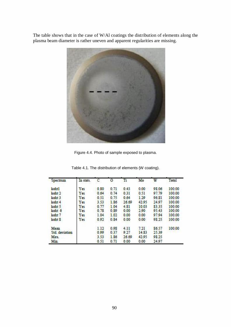
90
The table shows that in the case of W/Al coatings the distribution of elements along the plasma beam diameter is rather uneven and apparent regularities are missing.
Figure 4.4. Photo of sample exposed to plasma.
Table 4.1. The distribution of elements (W coating).

91
4.2 Attenuation of Radiation Damage in Dielectric and Composite Materials of Interest for a Fusion Reactor
Institute: Laboratory of Physics of Ionic Crystal (LPIC), Institute of Physics, Tekes – University of Tartu
Research Scientists: A. Lushchik, S. Dolgov, I. Kudryavtseva, T. Kärner, F. Savikhin, and E. Vasil’chenko
PhD Students: E. Shablonin and A. Shugai Backrgound: It is widely believed that one of the significant obstacles impeding the development of nuclear and especially thermonuclear energetics is insufficient radiation resistance of various construction materials: primarily metals and alloys, and also semiconductors, wide-gap dielectrics and superconducting materials. In particular, the radiation resistance of wide-gap materials (WGMs, Eg = 7–15 eV - Al2O3, MgO, MgAl2O4, Y2O3, Y3Al5O12, SiO2, Li-containing materials, etc) promising for future industrial high-temperature heat ( 1 000 C) fusion stations should be substantially enhanced. It is obvious that this complicated task can be solved only on the basis of subsequent basic research. In 2010 our main attention was paid to the separation of novel non-impact mechanisms of radiation damage in MgO and Lu3Al5O12 crystals. It was found that, besides the universal for solids impact (knock-out) mechanism, stable Frenkel defects (FDs, F centres and oxygen interstitials) in these materials are also created due to the recombination of hot (non-relaxed) electrons and holes, the efficiency of which sharply increases under the irradiation forming extremely high density of electronic excitations (electron-hole pair, e-h). The energy released at such hot recombination exceeds the threshold for the creation of FDs (EFD). According to our suggestion, the efficiency of FD creation via hot recombination could be significantly reduced or enhanced by doping the materials with definite impurity ions. The suppression is caused by the fact that the energy excess of hot carriers is partly spent on the direct excitation of these impurity centres resulting in impurity luminescence emission or heat release. Main Results in 2010: The investigation of the contribution of the recombination of hot conduction electrons with self-trapped holes to the creation of FDs in highly pure NaCl crystals, where the formation energy of a pair of FDs EFD > Eg at 5–80 K, has been finished. It is shown that only the energy released at the recombination of a hot conduction electron with a self-trapped hole is sufficient for the creation of FDs at low temperatures. However, the efficiency of FD creation decreases in NaCl doped with definite impurity ions hot electrons transfer a part of their energy to impurity centres. In 2010, our main efforts were concentrated on a detail investigation of hot e-h recombination in two very different wide-gap metal oxides. In the bulk of MgO crystals with cubic lattice structure and melting point about 3100 K, neither highly mobile excitons nor conduction electrons and valence holes undergo transformation into the self-trapped state. On the other hand, molecular-type self-trapped excitons are typical of Lu3Al5O12 (LuAG) single crystals with a complex structure and about 160 atoms per unit cell. So, near-surface losses with the creation of FDs in LuAG are not so important as in MgO.

92
A detail analysis of the influence of different impurity ions on the creation efficiency of FDs in MgO has been performed. The efficiency of the radiation damage via hot e-h recombination under the conditions of high-dense irradiation significantly increases in the vicinity of impurity centres serving as hole traps and possessing large recombination cross-section with hot electrons. Be2+ and Ca2+ ions as well as deformation-induced bivacancies belong to these “negative” impurities. So, to reach a high radiation resistance, Be2+ and Ca2+ ions (in addition to OH- and H ) should be removed from MgO crystals. On the other hand, our recent cathodoluminescence measurements have shown that certain impurity centres or deformation-induced defects transform the energy excess of hot charge carriers into luminescence thus decreasing the efficiency of radiation damage via hot e-h recombination. The creation processes of radiation defects have been investigated in Lu3Al5O12:Ce3+ and Lu3Al5O12 (5N purity) single crystals. The irradiation of these crystals by swift heavy ions (SHIs, 2.14-GeV, U238) at 300 K has been performed at GSI, Darmstadt for the first time. About 99% of SHIs energy is spent on electronic energy losses, while small nuclear losses are maximum at the end of ion range (46.2 m). After fast (<10-13 s) intermediate processes there arise an extremely high density of different electronic excitations (EEs, 10-12–10-2 s), including hot and relaxed e-h pairs, excitons etc. The energy of EEs either is transferred to Ce3+ luminescence centres, as grown anti-site defects etc., or is spent on the creation of Frenkel defects in oxygen sublattice and their various nano- and micro-associations. It is established that in contrast to more resistant Al2O3 crystals the irradiation of LuAG with SHIs at fluence of 1012 U/cm2 causes mechanical stresses, related expansion of a lattice in the direction perpendicular to SHI tracks and even the beginning of crystal cracking. Similar to Al2O3, ion-irradiation of LuAG causes the creation of F+, F and some other defects absorbing close to the energy gap, Eg = 8.2 eV. In Lu3Al5O12 with the complex and wide valence band, the interaction of EEs with lattice vibrations is significantly stronger than that in MgO. Therefore, unusual self-trapped excitons of a molecular type are formed in LuAG and there is the efficient energy transfer from these excitons to some luminescent impurity ions (e.g., Ce3+ ions). The presence of 1–2% of Ce3+ ions provides the suppression of FD creation via hot e-h recombination. In ionic-covalent WGMs, the mobility of excitons is sow and the energy transport to the surface with FD creation is impeded. Hot e-h recombinations are undoubtedly responsible for the creation of FDs in the materials, where the formation energy of a Frenkel pair exceeds Eg. In MgO, Al2O3 and Lu3Al5O1, a relative contribution of impact and nonimpact mechanisms depends on the radiation type (Au swift ion, an electron beam, X-rays).

93
4.3 Tritium Depth Profile Measurements of JET Divertor Tiles by AMS
EFDA JET Technolgy: JW10-FT-3.60 Research Scientist: M. Kiisk, Tekes – UT Collaboration C. Stan-Sion, M. Enachescu, and M. Dogaru,
MEdC J. Likonen, Tekes – VTT Background: Accelerator mass spectrometry (AMS) is a highly sensitive analysing method that provides complementary information to other conventional methods used to analyse or diagnose fusion experiments, but is the only method capable to determine low concentrations of Tritium in different substrates. AMS, due to its principal functioning way, is able to scan the depth of the material and deliver the depth profile information of the T concentration. By measuring the depth of the implanted Tritium into the bulk of pure materials (e.g. C, W, Be) it determines the energy of the incident particles and therefore, can be applied as an efficient diagnose tool for fusion experiments in Tokamaks (AUG, JET). In this way, AMS is able to characterize the plasma confinement and stability, the quality of neutral beam injector and its perturbing interaction produced on the plasma confinement. It is able to localize the plasma disruption phenomenon and provides the dosimetry of the energetic tritium in the Tokamak. The research work has been carried out as a continuation of the JET fusion technology task JET JW9-FT-3.50, in which the main goals were to set-up the T-AMS system and perform T depth profile AMS test experiments for the selected divertor tiles from JET. Specific objectives: The main goals of the JET Fusion Technology task JW10-FT-3.60 in 2010 were the following:
Continuation of AMS measurements on selected JET divertor tiles
AMS sensitive measurement of the T concentration and penetration depth in mixed/coated materials (after detritiation), such as Be/C, C/W, Be/W, with perspective of the ITER –like Wall project and for ITER.
Determination of erosion and re-deposition in the Tokamak vessel. Results: due to cancellation of the JET Fusion Technology task by the collaboration partner MEdC during 2010, only parts of the objectives have been achieved. For the AMS analysis samples with lower T activity concentration from divertor tiles from following JET campaigns have been selected:
a) 1998–2007 – 4 samples from tiles G6D and G8A. b) 2004–2007 – 8 samples from tiles G1A, G3A and G7A.
Samples were cut like narrow straps due to lack of sample material left by the time AMS measurements started.

94
Figure 4.5. (a–d). Some examples of tritium depth profiles of JET divertor samples from Campaigns 1998–2007 and 2004–2007. The reference date of the Tritium concentrations is 10 June 2010.
2IWG1A-10
0
5E+17
1E+18
0 20 40 60 80 100depth ( m)
T (a
tom
s/cm
3 )a)
2IWG3A-8
0,E+00
1,E+17
2,E+17
3,E+17
0 20 40 60 80 100
depth ( m)
T (a
tom
s/cm
3 )
c)
2ONG7A-5
0,0E+00
1,0E+17
2,0E+17
0 20 40 60 80 100
depth ( m)
T (a
tom
s/cm
3 )
d)
2IWG1A-2
1
2E+14
4E+14
6E+14
0 25 50 75 100 125 150 175
depth ( m)
T (a
tom
s/cm
3 )
b)

95
Same examples of measured depth profiles are shown in Fig. 4.5(a-d). All data were corrected for the background value of T during the measurements. For the entire experiment, the background level was 103 lower than the smallest measured concentration. The averaged concentration of T does not exceed 1017 atoms/cm3. Taking into account the possible wide incidence angles of the colliding particles and the fast diffusion T in CFC, wide peaks are expected for the maximum values of the power ranges. The decisive contribution to the widening of the peak distribution can be due to the CFC structure of the divertor tiles at JET. Therefore, the peaking of the DP at a depth of about 0.25 µm corresponds to the implant of tritium removed at temperatures close to the plasma temperature. However, the measured samples showed different depth profiles and deviated in most cases from expected 0.25 µm depth peak. Currently, there is no information of the history available on the tiles measured. Therefore, any further conclusions of the obtained depth profiles cannot be drawn. However, a factor that may be affecting the variation of the T depth profiles and peak widening is constant deposition on tile surfaces. In opposite cases, in areas dominant by erosion, the implanted T will be continuously peeled off from near surface volume. Therefore, in cases the initial particles energy is of importance, additional information is required about the surfaces to be depth profiled, e.g., how the area to be analyzed is subjected to the deposition and erosion processes. This additional information, if provided beforehand, helps to plan the depth scale to be measured and measurement time spent on a sample as well may help to interpret obtained data. Integrating the depth profiles down to the measured depth one obtains the amount of T trapped per unit area (atoms/cm2). In Fig. 4.6, integrated values of T deposition up to about 500 µm depth are indicated according to their locations on the JET divertor. The work will be continued in 2011 within JET FT task JW11-FT-1.19.
Figure 4.6. AMS integrated concentration values (atoms/cm2) of T in CFC tiles at different locations on the JET divertor 2007.

96
5. JOC SECONDMENTS, STAFF MOBILITY AND TRAINING Several staff mobility visits of total 628 days took place in 2010. The visits were hosted by the Associations IPP Garching (250 days, MA Art. 1.2.b collaboration), JET/CCFE Culham (176 days), Risø Roskilde (26) and FOM Rijnhuizen (14 days). Other staff mobility actions were EFDA meetings (PWI, ITM, FT, TGs), ITPA meetings (15 days), LLNL US (26 days) and JAEA Naka (9 days) for IEA Large Tokamak experiments. Tekes (Aalto University) hosted visits of 56 days from the Slovakian Association and 12 days from IPP Association. One physicists and one engineer were seconded to the CCFE JET Operating Team, Johnny Lönnroth (code development and modelling) and Ville Takalo (remote handling).
5.1 CCFE JOC Secondments
5.1.1 JET remote handling for ILW experiment
JOC secondee: V. Takalo, Tekes – TUT/IHA Period: 1 January – 31 December 2010 Ville Takalo is a remote handling expert from IHA/TUT seconded in CCFE Engineering Department Remote Handling Group at JET. The EP2 2010-2011 shutdown converts the wall to be more ITER like with new design, new materials, new diagnostic and enhanced power. Majority in-vessel work is carried out remotely and work comprises over 8 000 components to be handled remotely. During the EP2 shutdown Ville Takalo acts as Remote Handling Operations Responsible Officer.
5.1.2 JET code development and modelling
JOC secondee: J. Lönnroth Period: 1 January – 31 December 2010 The main activity was the JET code integration and ITM work. Modelling covered JETTO transport simulations and MISHKA-1 MHD analysis related to the pedestal stability. The following issues are described in more detail in Section 3.
Dependence of plasma performance on the characteristics of the H-mode pedestal

97
Implications of pedestal MHD stability limits on the performance of ITER Scenario 2
ELM module to JETTO
ASCOT-JETTO integration.
5.1.3 JET Secondment for DTFL
EFDA JET Secondee: M. Groth, Deputy Task Force Leader Development of the JET experimental campaigns for 2011 and 2012, and organising the 2010 JET edge modelling meeting were the primary activities of the secondee during two 3-week long visits of JET. These included preparation of and participation in the second General Planning Meeting in November 2010. By the end of 2010, a prioritised experimental plan was presented to the EFDA association to address (a) reduced hydrogen retention in, and (b) plasma operation at high performance with the new beryllium/tungsten wall in JET. The secondee’s responsibilities also included organisation of the JET modelling activities in support of the JET ILW within the European Associations. In September 2010, he held a 2-week modelling meeting at JET to bring together scientists with different modelling expertise to address the issues of particle and heat flux to plasma-facing components, and material migration and hydrogen retention in JET.
5.2 Staff Mobility Visits and Reports
5.2.1 Framework Agreement between Tekes and IPP Associations
Tekes secondees: L. Aho-Mantila, M. Groth, A. Hakola, E. Hirvijoki, T. Kurki-Suonio, T. Makkonen, J. Miettunen, and S. Äkäslompolo
In 2010, TEKES contributed to the research efforts at IPP on two distinct frontiers: fast ion physics and plasma-wall interactions (PWI). In PWI, A. Hakola carried out SIMS measurements at VTT, Finland, and RBS and NRA measurements at IPP to determine the deposition profiles from 13C puffing experiments. These experiments were also modelled using DIVIMP, ERO and ASCOT-PWI codes (Makkonen, Aho-Mantila, Miettunen, Groth, Kurki-Suonio), and the results were reported in 3 different contributions at PSI 2010 and published in PPCF and JNM. For this purpose, the ASCOT code, lately used mainly for fast ion physics, was upgraded to include background flows essential in impurity migration resulting in ASCOT-PWI capable of impurity studies using 3D magnetic and wall geometries (Miettunen, Kurki-Suonio). Both the toroidal ripple and 3D wall elements were found to affect the 13C deposition. For fast ions, ASCOT simulations to determine the potential of an ‘active’ NPA system utilizing neutrals generated from beam-beam interactions were carried out after developing an NBI neutral cloud model for ASCOT (Hirvijoki, Äkäslompolo, Kurki-

98
Suonio). In this context, also the ADAS database was adopted in ASCOT (Hirvijoki). The simulations indicated that a refurbished NPA could be used to monitor the fast ion population from CD beams. Äkäslompolo completed the task of converting CAD drawings of AUG wall into 3D wall structure usable by ASCOT. Using this new capability, we were already able to show that C-13 simulations using a 2D wall profile give misleading results. In collaboration with TOK, ASCOT was also enhanced with a numerical model for NTM-type islands, so that their effect on NBCD can be studied. A. Snicker has started generalizing this model to 3D magnetic fields during his extended (6 months) visit to TOK.
5.2.2 Ion beam analysis of JET samples
Name of seconded person: J. Likonen Sending Institution: VTT – Association Euratom-Tekes Host Institution: Instituto Tecnológico e Nuclear (ITN) –
Association Euratom-IST Dates of secondment / Mission: 16–20 February 2010 Work Plan / milestones:
1) Simulation and comparison of data obtained from various analysis techniques used in project JW9-FT-3.47
2) Formulation of detailed research topics and synergies with on going research effort on the laboratories participating on TF-FT Task for 2010
3) List of samples to be supplied to IST for analysis. Report: This visit is connected to the collaboration between Tekes and IST in the field of ion beam analysis of JET samples. A combination of ion beam techniques is available at ITN and they have been used to extract the maximum information possible and establish the depth profiles of the elements present in the tiles (RBS, NRA, ERDA and PIXE). The surface topography has been studied with SEM to get a deeper understanding of the erosion and re-deposition processes in the tokamak. Milestone #1: Samples from JET divertor tiles 4 and 6 (in total 8 samples), and from outer poloidal limiters (in total 12 samples) were delivered in 2009 to ITN for ion beam analyses. Tiles 4 and 6 were exposed from 1998 to 2007 and the OPL tiles from 2004–2007. OPL tiles had a thin W marker layer (thickness < 100 nm) and a C marker layer (thickness 10 µm). Samples from tiles 4 and 6 were located on the sloping part and on the shadowed area of the tile. The results obtained at ITN agree with the ion beam results obtained at the University of Sussex. A program for simulation of ion beam spectra (WiNDF) has been developed at ITN and University of Surrey. This program was installed onto my laptop and Dr. N. Barradas showed how to use it. WiNDF program turned out to be very powerful especially when simulating complex RBS spectra from JET tiles. Earlier a program developed at IPP Garching has been used, but the main problem with this program is that usually it does not find the global minimum in the least square fitting.

99
Milestone #2: JET has used the accelerator at the University of Sussex, but this facility will be closed down in 2010 and JET is looking for other facilities where the ion beam analysed could be made. ITN is interesting to continue the collaboration and preliminary planning for future work was made. One feasible idea could be to move the analysis chamber with the detectors from Univ. of Sussex to ITN. This would require only slight modifications to the analysis chamber and to the beam line. JET can provide a new glove box. Milestone #3: Tekes will provide samples from other OPL tiles not yet delivered to ITN. In addition, Tekes will send samples from the load bearing tile that was exposed in 2004–2007. This tile had three marker layers (1.5 and 3 µm thick W layers and 10 µm thick C marker layer). All the milestones were reached.
5.2.3 Ion-beam analysis of ASDEX Upgrade marker tiles
Name of seconded persons: A. Hakola and S. Koivuranta Sending Institution: Aalto University, VTT – Association Euratom-Tekes Host Institution: Association Euratom-IPP, Garching Dates of secondment / Mission: 28 February – 13 March 2010 Work Plan / milestones:
1. Analyzing a set of lower-divertor marker tiles using NRA and RBS
2. Determining erosion of the W and Ni marker layers and deposition of different elements (W, Ni, C, D) on different parts of the tiles.
Report: This visit was part of active collaboration between the Finnish research units Aalto University and VTT (under Tekes) and Max-Planck-Institut für Plasmaphysik (IPP) in the field of plasma-wall interaction. Our joint projects are closely connected to the research done in ASDEX Upgrade, and the focus areas are studying erosion of first-wall tiles, deposition of material on them, retention of plasma fuel, and migration of material in the torus. Since 2002, erosion and deposition in ASDEX Upgrade have been studied with the help of special marker coatings produced by the Finnish coating company DIARC-Technology Inc. for selected divertor and limiter tiles. To determine erosion, the thicknesses of the marker layers are measured before and after their plasma exposure, whereas for the deposition studies, the depth profiles of different elements and the total amount of each of them on the coatings are determined. The analyses are done using secondary ion mass spectrometry (SIMS) at VTT and Rutherford backscattering (RBS) and nuclear reaction analysis (NRA) at IPP. Milestones #1 and #2: During the present visit, altogether six lower-divertor marker tiles, exposed to plasma discharges during the whole 2009 experimental campaign of ASDEX Upgrade, was analyzed using both RBS and NRA. The tiles in question were removed from the inner and outer strike-point areas (tiles 4, 4B, and 1) and from the horizontal uppermost part of the outer divertor (tile 3B). The inner-divertor tiles 4 and 4B had 1 µm thick W coatings and 15 mm wide uncoated poloidal stripes in the middle of the tiles. Two neighbouring outer strike-point tiles, for their part, had been equipped with 1.5 µm thick W coatings, 15 mm wide uncoated stripes and 15 mm wide and 5 µm

100
thick Ni stripes. Two different 3B tiles had been produced with a similar marker construction as the outer strike-point tiles but the thicknesses of the Ni and W coatings were 1 µm and 2 µm, respectively. One of these tiles was located in a region magnetically connected to the ICRH heating sources of ASDEX Upgrade while for the other tile no such a direct connection existed. The goals of the analyses were to study erosion of the W and Ni coatings and to determine the deposition of B, C and D on them. In addition, the uncoated stripes made it possible to study deposition of B, D, and W on graphite. Along with the general erosion and deposition investigations, the measurements aimed at providing poloidal erosion/deposition profiles for all the different materials. The RBS and NRA analyses were performed at the accelerator lab of IPP. The measurements were made in the Bombardino analysis chamber using either protons with energies of 2.5–3 MeV (RBS) or 2.5 MeV 3He+ ions (NRA). The step between adjacent measurement points was 5–10 mm in the poloidal direction along every marker stripe or coating area. The obtained RBS spectra will be simulated with the SIMNRA program, which gives the thickness and composition of each layer on the tiles, i.e., those of the coatings and deposited films on top of them. The amounts of different elements deposited on the surface can, for their part, be extracted from the peaks in the measured NRA spectra. The simulation work and other data analysis was started during the visit and it will be continued in Finland. Preliminary analyses of NRA results from one of the outer strike-point tiles already indicate that there are three different poloidal deposition regimes on the tile. In addition, the deposition pattern appears to be different for the different materials. The measurements were made, analysis of the results was started and the milestones were reached.
5.2.4 Material transport in JET torus
Name of seconded person: J. Likonen Sending Institution: VTT – Association Euratom-Tekes Host Institution: EFDA JET / Associations Euratom-CCFE Dates of secondment / Mission: 25 April – 1 May 2010 Work Plan / milestones:
1) The evaluation and comparison of SIMS, RBS and NRA data 2) JET tile analysis using tile profiler 3) Preparation of PSI paper.
Report: This visit is connected to the collaboration between Tekes and JET/CCFE in the field of material transport studies at JET. Milestone #1 and 3: For PSI conference (May 24–28, 2010) 13C migration at JET has been investigated. 13C was puffed into JET torus in 2007 and a set of divertor tiles has been analysed both with SIMS at Tekes and with ion beam techniques at JET/CCFE.

101
The evaluation of the ion beam data has been made at Tekes using a computer code SIMNRA. During this staff mobility visit to JET, the final comparison of the SIMS and ion beam data was made. Agreement between SIMS and ion beam data is excellent and it provides a excellent data set for further computer simulation studies. Preparation of the PSI paper was initiated during the staff mobility visit. In addition, a new and very powerful computer code WinNDF for the analysis of ion beam data was installed onto a computer at JET during the staff mobility visit. This computer code has been developed at the University of Surrey and at ITN in Portugal. Milestone #2: Main aim of the visit was to measure a set of limiter tiles using a surface profiler developed at JET. The purpose of the measurements is to measure the surface profile of the tile before installation at JET. The tiles will be exposed at JET typically for few years and after this the tiles will be removed and the tile measurements will be repeated. By comparing the results before and after plasma exposure, erosion/deposition pattern can be determined. The tile profiler system has been moved to controlled area in spring 2010, but the laboratory was not yet licensed for contaminated tiles. During this staff mobility visit, the laboratory got licensing for Be tiles. A set of inner wall guard limiter tiles was measured during the visit. These tiles will be installed at JET during summer 2010. All the milestones were reached.
5.2.5 Laboratory tests of NPA electronics chain
Name of seconded person: M. Santala Sending Institution: Tekes – Aalto University Host Institution: EFDA-JET Dates of secondment / Mission: 14–23 June 2010 Work Plan/milestones: The purpose of the visit is to evaluate the conceptual design of electronics for the JET NPA upgrade by carrying out laboratory tests using the planned equipment or equipment closely approximating it. The aim of this testing is to verify the viability of the proposed scheme as well as to identify potential problems early. It is planned to test the entire electronics chain in stages: a detector connected for AC coupling, prototype of torus hall electronics consisting of one preamplifier module, gain stage and differential cable driver, a realistic length of the actual cable to be used for transmission and a BAD2 data acquisition card on a Linux PC. The testing can be started using a signal generator and an oscilloscope to monitor the performance of various stages of the electronics. Eventually the BAD2 card should be used for monitoring and recording the signals. First, one should confirm if any grossly adverse behaviour like oscillations, large ringing or reflections are present. Second, the performance needs to be evaluated at least in terms of linearity, dynamic range, count rate capability and any adverse attenuation in cabling should be identified.

102
After the visit, one should have a firm understanding of the performance of the electronics concept. One should have identified areas that need to be further addressed, if any. Report: During the visit, the entire data acquisition chain was set-up in a laboratory at JET. Detectors as well as prototype preamplifier PCB were evaluated and the signals were trasnmitted over 100 m of cable and eventually acquired by the planned data acquisition card on a PC. The tests proved in principle the viability of the planned DAQ electronics. However, further tests were deemed necessary to test the detector performance with a radiation source, compare different preamplifier modules and try to reduce sensitivity to external noise.
5.2.6 Measuring a set of limiter tiles using a surface profiler developed at JET–A
Name of seconded person: J. Likonen Sending Institution: VTT – Association Euratom-Tekes Host Institution: EFDA JET / Associations Euratom-CCFE Dates of secondment / Mission: 23 June – 20 July 2010 Work Plan / milestones:
1. participation in the JET tiles analysis under the FT task JW10-FT-3.61 using tile profiler
2. evaluation and comparison of SIMS and ion beam results. Report: Main aim of the visit was to measure a set of limiter tiles using a surface profiler developed at JET (Milestone 1). The purpose of the measurements is to measure the surface profile of the tile before installation at JET. The tiles will be exposed at JET typically for few years and after this the tiles will be removed and the tile measurements will be repeated. By comparing the results before and after plasma exposure, erosion/deposition pattern can be determined. The tile profiler system has been moved to a controlled area in spring 2010, but the laboratory was not yet licensed for contaminated tiles. During this staff mobility visit, the laboratory got licensing for Be tiles. A set of inner and outer wall limiter tiles was measured during the visit. These tiles will be installed at JET in 2010 and remeasured after 2–3 years of exposure. The aim is then to compare the tile profiler results for unexposed and exposed tiles and to determine erosion/deposition pattern. During the last day of the C27 campaign in 2009, pure 13CH4 was injected into the torus from the outer divertor. So far divertor floor tiles 4, LBT and 6 have been analysed with ion beam techniques (milestone 2). SIMS analyses will be carried out later in 2010. Analysis of the RBS spectra was started during the visit using a new program called WiNDF that has been developed at the Univ. of Surrey in England and IST in Portugal. Some 13C was found on tiles 4 and 6, whereas 13C amount on the LBT tile was clearly less. Data analysis is still in progress.
103
5.2.7 Benchmarking ASCOT and OFMC codes
Name of seconded person: A. Salmi Sending Institution: EFDA-JET, Aalto University-Association Euratom-Tekes Host Institution: JAEA-Naka, Japan Dates of secondment / Mission: 12–16 July 2010 Work Plan / milestones: Benchmarking the ASCOT and OFMC codes especially concentrating on the verification and validation of the newly implemented OFMC diagnostics for toroidal torque from NBI. Report: The implementation of the torque diagnostics was discussed in detail prior to the visit and based on those discussions JAEA side implemented the diagnostics. During the visit ASCOT and OFMC codes were run on identical configurations to verify and validate the newly implemented OFMC torque diagnostics. The benchmarking was very successful and showed good agreement between the codes thereby giving assurance that both codes were operating as desired. Dr Honda-san included parts of the activity in his IAEA NF article 2010.
5.2.8 Ion-beam analysis of ASDEX Upgrade tiles and samples
Name of seconded person: A. Hakola Sending Institution: Aalto University, VTT – Association Euratom-Tekes Host Institution: Association Euratom-IPP, Garching Dates of secondment / Mission: 13–28 July 2010 Work Plan / milestones:
1. Analyzing a set of lower-divertor marker tiles and silicon samples with NRA and RBS
2. Participating in a SEWG meeting on gas balance and fuel retention. Report: This visit was part of active collaboration between the Finnish research units Aalto University and VTT (under Tekes) and Max-Planck-Institut für Plasmaphysik (IPP) in the field of plasma-wall interaction. Our joint projects are closely connected to the research done in ASDEX Upgrade, and the focus areas are studying erosion of first-wall tiles, deposition of material on them, retention of plasma fuel, and migration of material in the torus. Since 2002, erosion and deposition in ASDEX Upgrade have been studied with the help of special marker coatings produced by the Finnish coating company DIARC-Technology Inc. for selected divertor and main-chamber tiles. To determine erosion, the thicknesses of the marker layers are measured before and after their plasma exposure, whereas for the deposition studies, the depth profiles of different elements and the total amount of each of them on the coatings are determined. The analyses are done using secondary ion mass spectrometry (SIMS) at VTT and Rutherford backscattering (RBS) and nuclear reaction analysis (NRA) at IPP.

104
Milestone #1: During the present visit, altogether six outer strike-point marker tiles (type “tile 1”), produced by DIARC-Technology Inc. in early 2010, were analyzed using RBS. The measurements had been scheduled to be made just before mounting the tiles into the ASDEX Upgrade torus, where they will be exposed to plasma discharges during the 2010 experimental campaign. The same tiles will be re-analyzed with RBS after the campaign and the erosion of the marker coatings will be determined by comparing the two obtained RBS data sets. In four of the analyzed tiles, three poloidal regions with different surface roughnesses had been produced, and these regions had been coated either with a Mo (2 tiles) or a W layer (2 tiles). One of the tiles had equally wide, poloidal W and W+5%Ta stripes, and the last tile had been coated with four poloidal stripes of W, Mo, Cr, and Al. The nominal thickness of the coatings is 2–4 µm. The RBS analyses of the tiles were performed in the accelerator lab of IPP. The measurements were made in the Bombardino analysis chamber using protons with energy of 3 MeV. The step between adjacent measurement points along each marker stripe or region was 20–30 mm in the poloidal direction. In addition to the marker tiles, 50 silicon samples (size 0.5–2 cm2) were investigated with NRA and/or RBS during the visit. Five of these were calibration samples, produced by DIARC-Technology Inc. for experiments at University of Tartu, CEA, and FOM, and they consisted of a 2–5 µm thick W, Al, or W-Al coating on the Si substrate. The coatings had been deposited under different partial pressures of deuterium, which had resulted in an approximately 0.5–2 at % D concentration in the films. Other Si samples had been removed from remote areas of the ASDEX Upgrade torus after the 2009 campaign, and by visual inspection each of them had a deposited layer on them. All the samples were measured in the RKS analysis chamber. For the DIARC samples, RBS analyses with 3 MeV protons were carried out, as well as NRA measurements with 2.5 MeV 3He+ ions. The ASDEX Upgrade Si samples were investigated only with NRA. From the RBS data, the composition of the films (excluding deuterium) and the thickness of the layers were extracted with the help of the SIMNRA program while the NRA measurements provided information on the deuterium, carbon, and boron content of the layers. All the planned measurements were carried out and the analysis of the obtained RBS and NRA spectra has been started. This milestone was thus reached. Milestone #2: The mid-year monitoring meeting of the Special Expert Working Group (SEWG) of Gas Balance and Fuel Retention under the EFDA PWI Task Force was arranged from 19 to 20 July at IPP. I participated in the meeting and gave a presentation titled “Characterization of retention mechanisms in AUG using post mortem surface analyses”. This milestone was reached.

105
5.2.9 Measuring a set of limiter tiles using a surface profiler developed at JET–B
Name of seconded person: J. Likonen Sending Institution: VTT – Association Euratom-Tekes Host Institution: EFDA JET / Associations Euratom-CCFE Dates of secondment / Mission: 8–17 September 2010 Work Plan / milestones:
1. participation in JET TFE1/E2 review meeting 2. participation in the JET tiles analysis under the FT task JW10-FT-3.61 using tile
profiler 3. evaluation and comparison of SIMS and ion beam results.
Report: Main aim of the visit was to measure a set of limiter tiles using a surface profiler developed at JET (Milestone 2). The purpose of the measurements is to measure the surface profile of the tile before installation at JET. The tiles will be exposed at JET typically for few years and after this the tiles will be removed and the tile measurements will be repeated. By comparing the results before and after plasma exposure, erosion/deposition pattern can be determined. This activity could not be performed at all, because the laboratory where the tile profiler is located, was used for the assembly of the JET Be-wall tiles and no other work in the lab was allowed. Instead, samples from JET divertor tiles 1, 3, 7 and 8 were measured using ion beam techniques (NRA, RBS and PIXE) at the University of Brighton. The tiles were exposed in 2007–2009 at JET. Main emphasis was to analyse the composition of the co-deposited layers and the distribution of 13C, that was puffed at the end of 2009 operations. Same samples are analysed using SIMS. In addition, mirror holders and a rotating collector was analysed. Analysis of the RBS spectra and comparison with SIMS results is now in progress (Milestone 3).
5.2.10 MHD modes in ASCOT code
Name of seconded person: A. Snicker Sending Institution: Aalto University – Association Euratom-Tekes Institution: Association Euratom-IPP, Garching Dates of secondment / Mission: 4 October – 31 December 2010 Work Plan / milestones: ASCOT is a guiding centre orbit following code used for computational studies of mainly fast ion physics in tokamaks. It has the inside track relative to other similar codes thanks to its modern features, i.e. realistic 3D magnetic field structure, realistic 3D wall design, pitch/energy collision operators and inclusion of finite Larmor radius effects, just to name a few. It describes very accurately neoclassical physics and has been a tool for a various studies during its lifetime.

106
During recent years ASCOT has been a vital part in understanding the fast ion distribution, e.g. plasma heating, and fast ion caused wall loads in ITER. However, ASCOT together with the other similar codes, as far as we know, does not take into account a couple of important non-neoclassical issues that comes with ITER tokamak. ASCOT development for a few years aims to solve at least following issues: Anomalous diffusion caused by the microturbulence, certainly present in ITER will not be MHD-quiescent large scale magnetic perturbations, i.e., magnetic islands, caused by e.g., NTM’s can appear. Large number of fusion born alpha-particles will induce rich spectrum of Alfvénic eigenmodes (AE’s) Microturbulence motivated anomalous diffusion coefficient is already included in ASCOT and detailed studies will be reported in future. The purpose of the visit is to proceed the work with a magnetic island model within ASCOT. The model has already been implemented and used for preliminary simulations of fast ion wall loads in ITER. The main goal is to benchmark the model to earlier experiments/simulations of ASDEX Upgrade (AUG) and continue studies with ITER. Main improvement will be inclusion of magnetic ripple, since so far model has been able to simulate axisymmetric magnetic fields. In case of ITER, the ripple will certainly be an important factor. Moreover, this visit will support further collaboration between IPP Garching and Aalto University. It also provides a possibility to attend weekly AUG seminars, contributing to visitors PhD studies. Report: The benchmark exercise was accomplished. As the results, a bit surprisingly, disagreed, more work is still needed to fully understand why the different codes produce different results for fast ion losses. The work to extend the island model to non-axisymmetric backgrounds was found to be more difficult than was thought. However, a numerical model was created and it is now under a various tests. During the stay a solid interaction to the experiments was created by attending to AUG Monday-meetings. These meetings revealed a couple of interesting discharges that can be used to further validate our island model. A first version of a numerical model for Alfvénic modes were discussed with Dr. Lauber and Dr. Pinches.
5.2.11 Measuring a set of limiter tiles using a surface profiler developed at JET–C
Name of seconded person: Jari Likonen Sending Institution: VTT – Association Euratom-Tekes Host Institution: EFDA JET, Associations Euratom-CCFE Dates of secondment / Mission: 13–20 October 2010 Work Plan / milestones:
1. participation in the JET tiles analysis under the FT task JW10-FT-3.61 using tile profiler
2. evaluation and comparison of SIMS and ion beam results.

107
Report: Main aim of the visit was to measure a set of limiter tiles using a surface profiler developed at JET. The purpose of the measurements is to measure the surface profile of the tile before installation at JET. The tiles will be exposed at JET typically for few years and after this the tiles will be removed and the tile measurements will be repeated. By comparing the results before and after plasma exposure, erosion/deposition pattern can be determined. During this visit 5 inner wall guard limiter (IWGL) tiles were measured with the tile profiler. Each tile contains 5 separate sections so the total number of components measured was 25. During previous visit samples from JET divertor tiles 1, 3, 7 and 8 were measured using ion beam techniques (NRA, RBS and PIXE) at the University of Brighton. The tiles were exposed in 2007–2009 at JET. Main emphasis was to analyse the composition of the co-deposited layers and the distribution of 13C that was puffed at the end of 2009 operations. Simulation of the RBS spectra and comparison with the SIMS results was continued during this visit.
5.2.12 Exposing ITER-relevant test samples to Pilot-PSI plasma
Name of seconded person: A. Hakola and P. Paris Sending Institution: VTT / University of Tartu –
Association Euratom-Tekes Host Institution: Association Euatom-FOM, Rijnhuizen Dates of secondment / Mission: 24–30 October 2010 Work Plan / milestones:
1. Exposing a set of deuterium-doped W, Al, and W-Al samples to Pilot-PSI plasmas
2. Obtaining necessary diagnostics data for modelling purposes. Report: This visit was related to the recently established collaboration between the FOM Institute for Plasma Physics Rijnhuizen and the research units VTT and University of Tartu from Tekes in the field of plasma-surface interactions. The main research topic within this collaboration is studying erosion of ITER-relevant materials when exposed to different plasmas in the linear devices Pilot-PSI and Magnum-PSI. For the experiments, test samples consisting of a few µm thick coatings on proper substrates are produced by the Finnish company DIARC-Technology Inc, and the samples are analyzed before and after their plasma exposure at VTT and in Tartu. Different ion-beam and laser-based techniques are used to determine erosion of the coatings and re-deposition of material on them, as well as investigate how the composition of the samples and depth profiles of different elements in them are changed. The main workhorses are Secondary Ion Mass Spectrometry (SIMS), Rutherford Backscattering (RBS), Nuclear Reaction Analysis (NRA), and Laser-Induced Breakdown Spectroscopy (LIBS). Particularly the LIBS experiments provide a good basis to further develop the technique such that in situ determination of erosion/deposition of plasma-facing components, e.g., in ITER would be possible.

108
The experiments described here are part of the EFDA PWI tasks WP10-PWI-04-04-01/TEKES/BS and WP10-PWI-04-04-02/TEKES/BS. Milestone #1: During the visit, altogether seven test samples were exposed to the Pilot-PSI plasma. The substrate material of all the samples was titanium. Two of the samples had a 5 µm thick W coating and one sample a pure Al coating with a thickness of 5 µm. The coatings on the remaining four samples had a mixed composition of W and Al (approximately 60% of W and 30% of Al). The thickness was either 2 µm (2 samples) or 5 µm (2 samples). All the coatings contained 0.5–1 atomic % of D. The samples were exposed to deuterium plasma, which also included neon to enhance erosion. The particle flux ranged from 1023 to 1024 m-2s in the experiments, while the exposure time (corresponding to different fluences, in J/m2) and the ion energy were varied from sample to sample. Special attention was paid to the surface temperature of the samples during the plasma discharges. The plasma jet had an approximately Gaussian shape with a diameter of 10–15 mm so that the exposed area showed a smoothly varying temperature profile with the primary maximum occurring close to the edge of the sample (where the water-cooling system was not efficient anymore) and the secondary maximum at the center of the plasma spot. The first W sample was exposed to 40 eV D ions and the maximum value of the surface temperature was approximately 800–900 C. The exposure time was 1 000 s consisting of 100 s long shots. The electron density and temperature were typically ne 2.5 × 10²⁰ m-3 and Te 1.6 eV, respectively, during a discharge. For the second W sample, 70 eV ions were used, and the exposure time was shortened to 300 s. The W-Al samples were exposed under smaller ion fluxes, and also the other plasma parameters were adjusted such that the maximum surface temperature would not exceed 650 C. For two of the samples, 150 s long shots were applied with the total duration of 1 000 s, while for the two other samples the exposure time was 2 000 s. In the case of one 1 000 s and one 2 000 s sample, the ion energy was 40 eV; the other samples were subjected to 70 eV ions. The Al sample was exposed only for 100 s (consisting of 15 s long pulses), by using the lower ion energy of 40 eV, and by keeping the maximum surface temperature around 350 C. All the planned experiments were carried out and the samples will now be analyzed with SIMS and LIBS, possibly also with NRA and RBS, in early 2011. This milestone was reached. Milestone #2: During the experiments, a Thomson scattering system was used to evaluate ne and Te for every applied plasma discharge. In addition, a fast IR camera recorded the temperature profile of the samples during the discharges and also the ion saturation current Isat was measured. When exposing the first W sample to plasma, a Mechelle optical spectrometer was measuring the light emitted by the plasma jet. This data is important for the ERO modelling of the experiments. This work will be carried out at FOM in late 2010 and early 2011. During the visit, details of the experiments were discussed with the people in charge of the modelling work and new collaboration was established also in this front. This milestone was thus reached.

109
5.2.13 Modelling the scrape-off layer and local migration of carbon in ASDEX Upgrade
Name of seconded person: L. Aho-Mantila Sending Institution: VTT – Association Euratom-Tekes Host Institution: Association Euratom-IPP, Garching Dates of secondment / Mission: 7 November – 5 December 2010 Work Plan/milestones: Local 13C methane injection experiments have been conducted in the divertor region of ASDEX Upgrade tokamak in 2007–2009, and the locally re-deposited carbon layers have been analysed by surface analysis techniques. The focus of this mobility visit is on the numerical modelling of these experiments. The numerical tools are the SOLPS fluid plasma / Monte Carlo neutrals code package and the Monte Carlo impurity following code ERO. The modelling is a PhD thesis project and contributes to the EFDA PWI and ITM taskforces and ITPA. It is done in close collaboration with the IPP theory, experimental and materials divisions. The purpose of this visit is to discuss the interpretation of the AUG diagnostics data and code validation issues with the local experts. Particular emphasis will be given to improve understanding of the effects of magnetic field reversal on SOL conditions and impurity transport. A journal publication is being prepared and the manuscript will be discussed during the visit. Also, future experiments and modelling efforts will be planned. Goals:
1. Discussion of experimental data obtained from 13C injection experiments in 2007, 2008 (normal Bt+Ip) and 2009 (reversed Bt+Ip) campaigns.
2. Validation of SOLPS simulations in forward and reversed field. 3. Preparation of a journal article on the effect of field reversal on SOL conditions
and local impurity transport. 4. Planning of discharges for reversed field operation in the AUG 2010–2011
campaign. 5. Planning of a new 13C injection experiment, to be carried out at the end of the
AUG 2010-11 campaign. 6. Discussion of a 2-chamber experiment to investigate discrepancies in the various
methane injection rate calibration methods.
Report: Data from the reversed field experiment in 2009 was discussed extensively. The divertor plasma conditions were found to be very sensitive to the level of deuterium gas puff and recycling at the walls. Suitable time intervals with steady discharge conditions could be identified for detailed benchmarking of the SOLPS simulations (goals 1+2). The diagnostic setup for the upcoming experiment in 2011 was planned, in order to further investigate the physical mechanisms leading to the observed divertor conditions (goal 4). The discharges in 2008 were found to have several time intervals in which the SOL conditions were changed. These changes were observed to follow directly the small

110
changes in the ECRH source. Causes for these observations and their implications on the related experiments in 2007 and 2009 were discussed (goals 1+2). Recent modifications in the SOLPS5.0 source code were discussed and investigation of the effects of the model upgrades was initialized (goal 2). The selection of measurement data for SOLPS validation that will be included in the upcoming journal article was discussed (goal 3). The requirements for divertor 13CH4 injection were discussed and it was made sure that the relevant gas injection systems are installed for the new campaign (goal 5). Results from the 2-chamber experiment were compiled for later interpretation (goal 6). The milestones of this visit were completed.
5.2.14 Spectroscopic and video measurements of Tokamak impurities
Name of seconded person: T. Makkonen Sending Institution: Aalto University – Association Euratom-Tekes Host Institution: Association Euratom-IPP, Garching Dates of secondment / Mission: 24 November 2010 – 8 December 2010 Work Plan / milestones: Understanding impurity transport is crucial for future fusion reactor design. Impurity transport in the scrape off layer (SOL) of current tokamaks is dominated by the parallel background plasma flow in typical scenarios. Unfortunately, there are not many measurements of the flow profile in the SOL, and current fluid code results do not always seem to be consistent with these measurements. Further work in this field is needed. It has been envisioned to do a flow measurement at the high field side in ASDEX Upgrade using spectroscopic and/or video diagnostics. Using spectroscopic measurement, the Doppler shift of impurity radiation lines can be used to deduce the impurity flow velocity. As for the video measurements, the time evolution or steady state of an impurity cloud produced by a gas injection can be compared against simulations in order to deduce the background flow velocity. During my visit, I wish to explore the experimental capabilities of ASDEX Upgrade for these types of measurements and possibly also help installing and maintaining new or existing diagnostics. This includes locating 1) gas injection locations, 2) spectroscopic lines of sights looking at the high field side, and 3) video camera locations looking at the right area. I would also like to discuss about the possibility of having these spectroscopic and video diagnostics available in the upcoming global carbon-13 injection experiment at the end of the current experimental campaign. Scientific software are often difficult to use, and if possible, I would like to gain insight to a few application used at ASDEX Upgrade. The key persons for this visit are Dr. Krieger, Dr. Lunt, Dr. Pütterich, and Dr. Coster. Report: The experimental capabilities of ASDEX Upgrade were mapped out during the visit and possible experimental windows were identified. There is valve at the HFS in sector 1 of ASDEX Upgrade that can be used to inject deuterium or methane gas. There are spectroscopic lines-of-sight looking close to the valve and lines looking slightly above that are used for background reduction. These lines-of-sight cross the plane set by

111
the valve at different radial locations. Some are in the SOL and some are in the plasma core. Also, there is a fast camera location that can see the valve and appropriate filters exist to only see light from example C1+ or C2+. Two approaches are pursued for the flow measurement. The first one is the systematic analysis of CXRS signals from the SOL. Normally, neutral D gas in injected from the valves which then triggers a CXRS signal that can be seen by the spectroscopic lines-of-sight. Unfortunately, the signal is disturbed in the SOL by molecular emissions. Work is in progress to systematically analyse, and develop tools for this purpose, the SOL signal to see if, under some circumstances, a good signal is acquired from the SOL. This work is being done with Dr. Pütterich. The second approach is to inject methane from the valves and image the cloud with a fast video camera equipped with appropriate filters. The time evolution and steady state of the could can possibly be used to deduce a background flow. If nothing else, it can be used as consistency check to previous carbon migration simulations. Also, the spectroscopic lines-of-sight can be used gain information about the injected impurity cloud. This experimental window was identified during the visit. If carried out, this measurement would be the first of its kind in ASDEX Upgrade. Also, work was started during the visit to develop tools to acquire and analyse the data provided by the fast cameras. This work is already well under way when writing this report. This work is being done with Dr. Lunt. Also, the use of various scientific software were studied with Dr. Krieger and Dr. Coster.
5.2.15 Scrape-off layer modelling using SOLPS
Name of seconded person: M. Groth Sending Institution: Aalto University – Association Euratom-Tekes Host Institution: Lawrence Livermore National Laboratory, USA and
General Atomics/DIII-D, USA Dates of secondment / Mission: 1–26 December 2010 Work Plan / milestones:
Presentation of data analyses of DIII-D, AUG, and JET L-mode plasmas. Discussion of UEDGE, SOLPS, and EDGE2D/EIRENE modelling results. Seminar presentations to boundary groups at LLNL and General Atomics Further collaboration between DIII-D and AUG/JET.
Report:
1. Verification of DIII-D data with responsible officers, discussion of entire data sets with LLNL and DIII-D boundary groups. Comparison of results with similar data sets from AUG and JET.
2. Discussion of associated UEDGE modelling of DIII-D, AUG, and JET plasmas with LLNL and DIII-D boundary groups: Tom Rognlien/LLNL and Tony Leonard/GA. Setup of further investigations and parameter changes. Comparison of UEDGE versus SOLPS results (fluid neutral models)

112
3. Presentations at LLNL Edge Group Meeting and DIII-D Science Meeting. Further discussion of results and ramification individually
4. Discussion with Tom Rognlien and Tony Leonard on further collaboration for UEDGE/SOLPS and DIII-D/AUG /JET, respectively under auspices of the ITPA-DSOL group.
5.2.16 Final design of NPA electronics
Name of seconded person: M. Santala Sending Institution: Tekes – Aalto University Host Institution: EFDA-JET Dates of secondment / Mission: 7–15 December 2010 Work Plan / milestones: The purpose of the visit is to report on the status of the NPA upgrade project to the project board, make final assessment results of earlier testing and to complete the electronics design. The final report on electronics testing has been submitted to the operator and CSU as well as a tentative electronics design document. These will be reviewed with the operator and the design will be finalised. The necessary details of interfacing with JET systems will be defined. After the visit, it is expected to have the final electronics design ready so that the procurement of electronics can proceed immediately. Report: During the visit, the status of the NPA upgrade project was reported to the project board. The final test results were reviewed with the operator and the electronics design was refined and defined in a meeting held on 13th December. After the visit, the final electronics design documents were submitted to the operator.
5.3 Euratom and EFDA Fusion Training Scheme
5.3.1 EFDA goal oriented training in fusion theory and modelling – GOTiT
EFDA GOT: WP08-GOT-GOTiT Tekes trainees: L. Aho-Mantila, VTT O. Asunta, S. Janhunen, and S. Leerink, Aalto University Tekes mentors: J. Heikkinen, VTT, T. Kurki-Suonio, Aalto University The EFDA Goal Oriented Traning in Theory, GOTiT for short, started its third and final year during 2010. Within Tekes we have four GOTiT trainees: L. Aho-Mantila, O. Asunta, S. Janhunen, and S. Leerink. The monthly e-seminar series was coordinated by Tekes (T. Kurki-Suonio and S. Leerink) and it consisted of the following presentations:
January 20: Qaisar Mukhtar (trainee, KTH): ‘Solving Singular Diffusion Equations with Monte Carlo Methods’.

113
Leena Aho-Mantila (trainee, VTT): ‘Simulation of Carbon Transport and Deposition with SOLPS5.0 and ERO’. February 24: Otto Asunta (trainee, Aalto): ‘Beamlet-based NBI model for ASCOT’.
George Breyiannis (trainee, ENEA): ‘Lattice Kinetic Schemes’. April 14: Nicolay J. Hammer, HLST team: ‘Combining Runge-Kutta discontinuous Galerkin methods with various limiting methods’. May 18: Jyrki Hokkanen, CSC: ‘Visualizing Science’.
July 15: Susan Leerink, (trainee, Tekes – Aalto University): ‘Full-f Gyrokinetic Simulation of Tokamak Plasma Turbulence using the ELMFIRE code’.
October 20: Fulvio Zonca, ENEA: ‘The general fishbone–like dispersion relation: a unified description for shear Alfven mode excitations and their consequences on MHD and micro–turbulence’. November 9: Prof. Hanna Vehkamäki, University of Helsinki: ‘Molecular modelling of atmospheric clusters’. December 15: Nitya Hariharan, HLST Team: ‘HPC-FF, Overview and Experience’.
GOTiT also offered three high-level intense courses during 2010 and extensive lecture material in this field was prepared and distributed by the organizing associations:
Anomalous Transport in Fusion Plasmas, Brussels (March 3–12) Transport in Tokamaks, Culham Science Centre (May 17–28) Modern Programming and Visualization Techniques, Garching (October 18–29).
These courses were attended by not only our trainees but also by other advanced graduate students from the Aalto University.
5.3.2 EFDA goal oriented training in remote handling – GOTRH
EFDA GOT: WP10-GOT-GOTRH Project Coordinator: J. Mattila, TUT TEKES Trainees: P. Alho and J. Väyrynen, TUT,
R. Sibois, VTT TEKES Mentors: J. Mattila, TUT, K. Salminen, VTT Objectives: The EFDA’s European Goal Oriented Training programme on Remote Handling (RH) “GOT RH “ aim is to train engineers for activities to support the ITER project and the long-term fusion programme in European Associations, associates, Fusion for Energy and in the ITER organization and Industry. The major objective is to implement a structured remote handling system design and development oriented training task that is carried out in a multidisciplinary Systems Engineering (SE) framework by using ITER/F4E task and QA processes and available documents, document templates and ITER-relevant software products. Special emphasis is on top-down engineering approach with multidisciplinary design requirements considerations on reliability, availability; maintainability and inspectability (cf. RAMI

114
approach). Within this SE framework, each GOT RH trainee will work within the context of a multi-site collaborative design team on an RH system design task, facilitated by mentors with ITER remote handling and general engineering experience. The activity will increase the coherence in European RH activities, networking in training activities, the transfer of knowledge and will connect engineering from other disciplines (viz. plug engineering) to the remote handling community. The GOT RH project serves as practical level project for increasing the coherence within RH context of collaborative training project between 5 participating European Associations. ITER will consist of around 10 million parts (roughly 10 times more than the largest airplane in production) and hundreds of systems with thousands of interfaces among them that must be identified and controlled [1]. A key requirement for the success of such a large project is that a systematic and standardized approach is adopted to ensure the consistency of the design with the required performance. In its own part, the S&T objective of this project is to develop common standards and tools for ITER design and development activities. Common standards and tools are necessary to guide ITER development while ensuring that ITER is properly designed to make it affordable to build, operate and maintain. GOT RH project has five EURATOM partners with 10 trainees
Association Euratom-Tekes, Finland (3) Association Euratom-CEA, France (2) Association Euratom-FOM, Netherlands (2) Association Euratom-KIT, Germany (1) Association Euratom-CIEMAT, Spain (2).
The EFDA GOT project is coordinated by Prof. Jouni Mattila (TUT) from Association Euratom-Tekes. EFDA Responsible Officer is Artur Malaquias. Main results in 2010: Project was started 1st of October 2010 and the kick-off meeting was held 28 September 2010 at SOFT (Symposium on Fusion Technology) conference, in Porto, Portugal. Both TUT trainees started 1 October 2010. They are working in the projects “RAMI requirements assessment of ITER remote handling equipment components for their future procurement and life-cycle management” and “Fault Tolerant device control system architectures for ITER RH system”. VTT trainee started 18th of October. His project is “Verification and validation of RH System Requirement using Digital Mock-ups”.

115
5.3.3 EFDA Fellowship in Fusion Reseach
EFDA Fellowship: WP08-FRF-TEKES/Groth Fellow: M. Groth, Tekes – Aalto University During the course of the two-year appointment as an EFDA Fellow in Fusion Research at Tekes – Aalto University M. Groth accomplished and well exceeded the goals originally set in the work contract: (i) he completed analyses of experimental data from DIII-D, ASDEX Upgrade, and JET L-mode plasmas critical for fluid edge modelling, (ii) he completed simulations of these plasmas utilising the fluid edge code UEDGE, and became familiar with the two primary European fluid edge codes, SOLPS and EDGE2D/EIRENE, and (iii) he coordinated research activities at Helsinki University of Technology/Aalto University, Finland, and VTT Technical Research Centre of Finland. During the two-year project period data analyses of lower single-null L-mode plasmas in DIII-D, AUG, and JET were completed. These analyses provided the basis of extensive fluid edge code validation utilising the three main fluid edge codes: UEDGE, EDGE2D/EIRENE, and SOLPS. As the first step, the measured profiles of total radiation, and particle and heat fluxes to the target plates were reduced to zero-dimensional quantities: Prad,SOL, Idiv, and Pdiv. The simulations were run on magnetic configurations and vessel geometries resembling the experiments, and their predictions for Prad,SOL, Idiv, and Pdiv were compared to the measurements. UEDGE simulations excluding drifts and assuming published Haasz-Davis chemical sputtering yields (Ychem) are insufficient to reproduce Prad,SOL, and to some extent, Idiv and Pdiv. Including drifts and enhancing Ychem by a factor of 2 significantly improves the agreement between the measurements and predictions from UEDGE (Fig. 5.1.). However, validated against carbon spectroscopy and imaging, and 2-D profiles of electron density and temperature in the LFS divertor leg in DIII-D, UEDGE shows that enhancing Ychem does not necessarily reproduce the strongly detached plasmas observed in the experiments; higher upstream densities are necessary to produce such a result (Fig. 5.2.). Work on re-visiting SOLPS simulations for DIII-D has been started and will continue beyond the end of the fellowship project. As part of Mathias Groth’s appointment at Helsinki University of Technology/Aalto University, he successfully integrated the experimental and edge programmes between the university and VTT Technical Research Centre of Finland by coordinating physics discussions and providing lecturers to undergraduate and graduate students. He took the responsibility for three students at post-graduate, graduate, and undergraduate level and successfully guided two students through their summer internship. He also prepared several applications for external funding through EFDA-PWI, Tekes and the Finnish Academy. One highlight of his fellowship was the appointment as a JET Deputy Task Force Leader (E2). In this position he was actively involved in developing the experimental campaign for 2011 and 2012 with the new ITER-like wall, while also coordinating edge modelling across Europe in support of the JET experimental programme.

116
Figure 5.1. Measured and predicted radiated power in the SOL and pedestal region for DIII-D (a), AUG (b), and JET (c). The black circles represent the measured power, the red points the predicted power from UEDGE including cross-field drifts, and the blue points from UEDGE simulations without drifts. The closed symbols open symbols denote simulations assuming enhanced Ychem (Ychem as published and multiplied by factor 2).
Figure 5.2. Measured and UEDGE-predicted particle currents and total power to high field side and low field side targets in DIII-D. The symbols and colour coding are the same as in Fig. 5.1.
The primary publications during the two-year fellowship period include two papers on scrape-off layer flow measurements and UEDGE simulations in Nuclear Fusion and UEDGE simulations of particle and heat fluxes in DIII-D, ASDEX Upgrade, and JET in Journal of Nuclear Materials. In 2009, Mathias Groth successfully edited and re- submitted a paper to Journal of Nuclear Materials on DIVIMP modelling of C13 transport and deposition studies in ASDEX Upgrade (JNM 396 (2010) 228). Furthermore, he is one of the principal or secondary co-authors of eight publications, including publication in Journal of Nuclear Materials as part of PSI 2010 meeting.

117
6. OTHER ACTIVITIES
6.1 Conferences, Workshops and Meetings
Association Euratom-Tekes staff members participated in the following conferences, workshops and meetings in 2010.
Seppo Karttunen participated in the 13th F4E Governing Board Meeting, Barcelona, Spain, 7 January 2010.
Tuomas Tala participated in the STAC Ad-Hoc group meeting on satellite tokamaks, Cadarache, France, 14 January 2010.
Markus Airila gave a presentation “Fuusiopalosta ehtymätöntä perusvoimaa” (Fusion power for baseload electricity) in Tekniikan Päivät (Technology Days) in Espoo, Finland, on 14 January 2010.
Seppo Karttunen participated in the 14th F4E Governing Board Meeting, Barcelona, Spain, 27 January 2010.
Seppo Karttunen participated in the 48th CCE-FU Meeting, Brussels, Belgium, 28 January 2010.
Seppo Karttunen participated in the 43rd (extraordinary) EFDA SC Meeting, Brussels, Belgium, 28 January 2010.
Mart Aints, Antti Hakola, Seppo Karttunen, Madis Kiisk, Matti Laan, Jari Likonen and Peeter Paris participated in the collaboration meeting VTT-University of Tartu, Tallinn, Estonia, 3–4 February 2010.
Kalle Heinola participated in the EFDA Monitoring Meeting on the W&WAlloy task in Garching, Germany, 3–4 February 2010.
Johnny Lönnroth, Antti Salmi and Tuomas Tala participated in the annual TF-T workhop, Culham, UK, 15–17 February 2010.
Carolina Björkas and Kai Nordlund participated in a Materials and Plasma-Wall Interaction workshop, Bratislava, Slovakia, 18–19 February 2010.
Markus Airila and Mathias Groth participated in EFDA-JET Task Force E General Meeting, Culham, UK, 22–26 February 2010.
Mathias Groth, Jari Likonen and Tuomas Tala participated in the 1st JET General Planning Meeting, Culham, UK, 1–5 March 2010.

118
Matti Laan and Peeter Paris participated oin the EFDA TGS-01-04 meeting, ENEA, Frascati, 8–9 March 2010.
Tuomas Tala participated in the 4th ITPA TC meeting, Culham, UK, 22–25 March 2010.
Seppo Karttunen participated in the 44th EFDA SC Meeting, Madrid, Spain, 23 March 2010.
Leena Aho-Mantila participated in the ITM Code Camp at IPP Garching, Germany, 22–26 March 2010.
Seppo Karttunen and Juha Lindén participated in the 15th F4E Governing Board Meeting, Barcelona, Spain, 30–31 March 2010.
Madis Kiisk, Jukka Kyynäräinen, Peeter Paris and Marko Santala participated in the meeting of the EFDA Diagnostics Topical Group, Garching, Germany, 30–31 March 2010.
Kai Nordlund participated and gave an invited talk at the Spring MRS meeting, symposium Materials for Nuclear Applications and Extreme Environments, San Francisco, USA, 5–9 April 2010.
Markus Airila, Jukka Heikkinen and Taina Kurki-Suonio participated in the Opening Seminar of the Research Programme on Computational Sciences (Lastu), Helsinki, Finland, 8 April 2010.
Kai Nordlund participated and gave an invited talk at the CECAM workshop on Interatomic potentials for transition metals and their compounds, Zurich, Switzerland, 12–14 April 2010.
Markus Airila participated in the SimITER consortium seminar, Espoo, Finland, 12–13 April 2010.
Madis Kiisk and Juha Lindén participated in the 49th CCE-FU Meeting, Brussels, Belgium, 15 April 2010.
Seppo Karttunen participated in the 1st F4E-Euratom Associations Meeting, Barcelona, 29 April 2010.
Kai Nordlund acted as Chairman of the ‘Breakdown Physics Workshop’, CERN, Switzerland, May 2010.
Mikko Siuko attended Dassault Systemes Nordics PLM Forum, Gothenburg, Sweden, 5 May 2010.
Seppo Karttunen and Siiri Suursoo participated in the Public Information Group Meeting, Risø National Laboratory, Roskilde, Denmark, 6–7 May 2010.
Leena Aho-Mantila, Markus Airila, Carolina Brörkas, Mathias Groth, Antti Hakola, Seppo Koivuranta, Jari Likonen and Toni Makkonen participated in the 19th International Conference on Plasma Surface Interactions, San Diego, USA, 24–28 May 2010. (Oral Aho-Mantila, several posters)
Opportunities for Industry – Annual Meeting of the Association Euratom-Tekes, Tampere, 2–3 June 2010. (75 participants from seven coutries, F4E and ITER)

119
Antti Hakola participated in the Joint Meeting of the EFDA EMT and PWI SEWGs on Dust and Tritium Inventory and Removal, Garching, Germany, 7–11 June 2010.
Seppo Karttunen and Juha Lindén participated in the 16th F4E Governing Board Meeting, Barcelona, Spain, 9–10 June 2010.
Kai Nordlund participated and gave an invited talk at CIMTEC 2010 – 12th International Ceramics Congress & 5th Forum on New Materials, Montecatini Terme, Italy, 14–18 June 2010.
Carolina Björkas visited Prof. Maria Caturla at the University of Alicante, 20–30 June 2010.
Mikko Siuko attended INTRA Workshop, Fontevraud, France, 23–24 June 2010.
Seppo Karttunen, Antti Snicker, and Simppa Äkäslompolo participated in the 37th EPS Plasma Physics Conference, Dublin, Ireland, 21–25 June 2010. (Several posters)
Seppo Karttunen and Madis Kiisk participated in the 45th EFDA SC Meeting, Dublin, Ireland, 23 June 2010.
Kalle Heinola and Kai Nordlund participated in the EFDA Monitoring Meeting on the W&WAlloy and MAT-REMEV tasks in San Sebastian, Spain, 28 June – 2 July 2010.
Leena Aho-Mantila, Markus Airila and Katharina Vörtler participated in the EFDA SEWG meeting on Material Migration at Forschungszentrum Jülich, Germany, 30 June – 2 July 2010.
Seppo Karttunen and Hannu Juuso participated in the Fusion Industry Innovation Forum, Brussels, Belgium, 6 July 2010.
Tuomas Tala participated in the TF-T meeting in JET, Culham, UK, 7–9 July 2010.
A. Lushchik participated in the 11th Europhysical Conference on Defects in Insulating Materials (EURODIM 2010), Pecs, Hungary, July 12–16, 2010. (Oral talk)
Antti Hakola participated in the EFDA PWI SEWG meeting on Gas Balance and Fuel Retention, Garching, Germany, 19–20 July 2010.
Kai Nordlund participated and gave an oral presentation at the international conference for ion beam modification of materials (IBMM) Montreal, Canada, 23–27 August 2010.
Mart Aints, Antti Hakola, Seppo Karttunen, Madis Kiisk, Matti Laan, Jari Likonen and Peeter Paris participated in the collaboration meeting VTT-University of Tartu, Tallinn, Estonia, 30–31 August 2010.
Seppo Karttunen participated in the preparation meeting for Power Plant Physics & Technology Activities within EFDA, Garching, Germany, 3 September 2010.
120
Leena Aho-Mantila, Markus Airila and Carolina Björkas participated in the EFDA Taskforce PWI meeting of the PWI related modelling activities at JET, Culham, England, 7–8 September 2010.
Peeter Paris participated in the: International. Conference on LIBS 2010, Memphis, US, 13–18 September 2010. (Poster)
Markus Airila, Otto Asunta, Salomon Janhunen, Johnny Lönnroth and Seppo Sipilä participated in ITM Task Force General Meeting and training, Lisbon, Portugal, 13–16 September 2010.
Kai Nordlund participated in an IAEA meeting on plasma-wall interactions, Vienna, Austria, 13–15 September 2010.
Seppo Karttunen participated in the 50th CCE-FU Meeting, Brussels, Belgium, 14 September 2010.
M. Siuko, J. Järvenpää, and H. Mäkinen visited ITER, Cadarache, France, on 15–16 September 2010.
Mathias Groth, Kalle Heinola and Aaro Järvinen participated in the JET Edge Modelling Meeting in Culham Science Center, Abingdon, United Kingdom, 20 September – 2 October 2010.
M. Siuko, J. Järvenpää, H. Mäkinen, K. Salminen, H. Saarinen, A. Muhammad, L. Aha, T. Kivelä, J. Mattila, A. Hahto, Z. Ziaei, J. Väyrynen, P. Valkama, L. Heikkilä, J. Tuominen, L. Zhai, F. Amjad, Matti Laan, Hannu Juuso and Pertti Pale participated in the 26th Symposium on Fusion Technology SOFT 2010, 27 September – 1 October, Porto, Portugal. (Several posters and Tekes stand)
Kai Nordlund participated and gave a plenary talk at the 18th International Workshop on Inelastic Ion-Surface Collisions (II SC-18), Gatlinburg, Tennessee, USA, 27 September – 1 October 2010.
Seppo Karttunen participated in the 17th F4E Governing Board Meeting, Barcelona, Spain, 5 October 2010.
Seppo Karttunen and Madis Kiisk participated in the 46th EFDA SC Meeting, Lisbon, Portugal, 6–7 October 2010.
Seppo Karttunen, Hannu Juuso, Pertti Pale and Tuomas Tala participated in the 23th IAEA Fusion Energy Conference, Daejeonissa, South Korea, 11–16 October 2010. (Oral plenary talk by Tala, poster, association stand)
M. Siuko, J. Järvenpää, J. Mattila, L. Aha, K. Salminen visited F4E, Barcelona, Spain, 19–20 October 2010.
Seppo Karttunen and Mikko Siuko participated in the 2nd F4E-Euratom Associations Meeting, Barcelona, 21 October 2010.
Antti Hakola participated in the 9th Annual Meeting of the EFDA PWI Task Force, Vienna, Austria, 3–5 November 2010.

121
Mathias Groth, Jari Likonen, and Tuomas Tala participated in the 2nd JET General Planning Meeting, Culham, UK, 15–19 November 2010.
Katharina Vörtler participated in the MAT-REMEV task meeting, Paris, France, 21–22 November 2010.
Antti Hakola participated in the Annual ASDEX Upgrade Program Seminar, Ringberg, Germany, 21–26 November 2010.
Tuomas Tala participated in the EPS program committee meeting, Madrid, Spain, 25 November 2010.
Jukka Kyynäräinen participated in the Conceptual Design Review of the ITER Magnetic Diagnostic System-Level Design and of the Outer Vessel, Discrete Equilibrium Sensors, 30 November – 2 December 2010.
Seppo Karttunen and Juha Lindén participated in the 18th F4E Governing Board Meeting, Barcelona, Spain, 1–2 December 2010.
Antti Salmi and Tuomas Tala participated in the 18th European Fusion Physics Workshop, Mayrhofen, Tyrol, Austria, 6–8 December 2010.
Madis Kiisk participated in the Task Force Fusion Technology 2010 semi-Annual Monitoring and 2011 Kick-off meeting, JET/CCFE, Culham Science Centre, UK, 8–10 December 2010.
6.2 Visits
The following visit to European and US laboratories took place in 2010. The Staff Mobility actions are given in Section 5.
Johnny Lönnroth was seconded to EFDA-JET, Culham, UK under the auspices of the JET Operating Contract on 1 January – 31 December 2010.
Ville Takalo was seconded to EFDA-JET, Culham, UK under the auspices of the JET Operating Contract on 1 January – 31 December 2010.
Toni Makkonen worked at Max-Planck-Institut für Plasmaphysik, Garching, Germany, 29 April – 5 May and 24 November – 8 December 2010.
Seppo Karttunen visited in the Risø National Laboratory, Roskilde, Denmark, 6 May 2010.
Leena Aho-Mantila and Markus Airila visited Forschungszentrum Jülich, Germany, 28–29 June 2010.
Antti Salmi visited JAEA-Naka, Naka, Japan, 12–16 July 2010.
Antti Hakola worked at Max-Planck-Institut für Plasmaphysik, Garching, Germany, from 28 February to 13 March and on 13–28 July 2010.
Antti Hakola visited the Gas Discharge Laboratory of University of Tartu on 7–8 October 2010.

122
Seppo Karttunen, Hannu Juuso, Pertti Pale and Tuomas Tala visited KSTAR Tokamak at National Fusion Research Institute (NFRI), Daejeon, South Korea, 13 October 2010.
Antti Hakola worked at the FOM Institute for Plasma Physics Rijnhuizen on 24–30 October 2010.
Leena Aho-Mantila worked at Max-Planck-Institut für Plasmaphysik, Garching, Germany, 8 November – 3 December 2010.
Mathias Groth visited Lawrence Livermore National Laboratory and DIII-D/General Atomics (all California, USA), 1–25 December 2010.
6.3 Visitors
M. Alatalo, A. Satonen, and H. Jaskari from Finnish parliament visited VTT (DTP2) on 11 January 2010.
Dr. Karl Krieger from IPP Garching, Germany, visited Aalto University on 11–15 January 2010.
CEA-VTT Security R&D Meeting: H. Bernard, A. Merle, L. Olmedo, F. Simonet and J.-L. Szabo from CEA and C. Sainte Catherine from French Embassy in Helsinki visited VTT (DTP2) on 21 January 2010.
L. Semeraro and S. Esque from F4E, Spain visited VTT (DTP2) on 16–17 February 2010.
M. Merola, L. Ferrand, S. Gicquel, and T. Jokinen from ITER, France visited VTT (DTP2) on 10 March 2010.
L. Semeraro and S. Esque from F4E, Spain visited VTT (DTP2) on 22–23 April 2010.
L. Semeraro, S. Esque, and C. Annino from F4E, Spain, visited VTT (DTP2) on 18–19 May 2010.
Dr Georgi Dimitrov from European Commission visited VTT (DTP2) on 9 June 2010.
L. Semeraro, S. Esque, C. Demiani, B. Riccardi, P. Gavila, J. Palmer, S. Rajendran, and T. Jokinen from F4E and ITER visited VTT (DTP2) on 15–16 June 2010.
SIAS 2010 conference participants (15 people from Japan, Germany, Canada, Poland and Finland) visited VTT (DTP2) on 16 June 2010.
Security Research Group (12 people from Norway, France, Italy, Germany and Finland) visited VTT (DTP2) on 29 June 2010.
L. Semeraro, S. Esque, and I. Piacentini from F4E, Spain, visited VTT (DTP2) on 10–11 August 2010.
Participants of ICOTECH – Ticcih-Worklab conference (about 50 people) visited VTT (DTP2) on 12 August 2010.

123
Participants of BONITA – Baltic Organisation and Network of Innovation Transfer Associations meeting from Lithuania, Denmark, Sweden, Germany and Finland visited VTT (DTP2) on 5 October 2010.
Vito Marchese from European Commission visited VTT (DTP2) on 28 October 2010.
Participants of St. Petersburg Business Campus (64 people) visited VTT (DTP2) on 29 October 2010.
D. Hamilton from ITER and R. Ranz from F4E visited VTT (DTP2) on 19. November 2010.
Nobuto Matrsuhira from Toshiba, Japan visited VTT (DTP2) on 13. December 2010.
Tommi Jokinen from ITER visited VTT (DTP2) on 16. December 2010.
Dr. Marco Wischmeier from IPP Garching, Germany, visited Aalto University and VTT on16–27 August, 2010.

124
7. FUSION FOR ENERGY AND ITER ACTIVITIES
7.1 2008–2010 Host Activities Related to DTP2 Test Facility Operation and Upgrade Preparation
F4E Grant Contract: F4E-2008-GRT-MS-RH-01 Principal Investigators: M. Siuko and J. Järvenpää, VTT
J. Mattila, TUT/IHA
7.1.1 Objectives
The main purpose of the Divertor Test Platform (DTP2) facility, located at VTT in Tampere, Finland, is to allow operational testing of prototypes of the Remote Handling (RH) movers, manipulators and tooling required for removal/replacement of divertor cassettes from ITER. Research in Grant F4E-2008-GRT-MS-RH-01 was conducted 2008–2010, and the objectives were:
Test, verify and develop further the ITER divertor maintenance scheme and devices
The exploitation of the existing DTP2 hardware/software, with a series of handling tests on the cassette mock-up
Provision and exploitation of new DTP2 hardware/software related to operations with a manipulator arm (WHMAN)
Preparation of hardware procurement related to operation with a Cassette Toroidal Mover (CTM) and additional cassette end-effectors.
Grant F4E-2008-GRT-MS-RH-01 was finished in summer 2010, and the conclusions and main results of the six tasks are presented here.
7.1.2 Task 1: RH trials
Scope of the task: The scope of this task is to implement and report on a series of remote handling trials of increasing complexity to demonstrate that radial transport and positioning of a second cassette can be safely and effectively achieved using the reference equipment in the ITER design despite the low clearances between cassette and radial duct and complex trajectories to be executed in a fully cantilevered handling mode.

125
Task description: This activity is broken down into a series of trials with increasing complexity and with a particular objective with respect to providing confidence in the ITER divertor remote replacement strategy. In support of this activity, it will be necessary to integrate and commission a “trials environment” (involving hardware, software and ancillary services). For each stage of the trials activity, the trials environment will become necessarily more complex to reflect the transition from “hands-on” operation of the prototype RH equipment to fully remote operations in the latter stages. The trials programme related to this task was broken down into 3 steps as follows: 1. To develop preparations for the CMM trials Objectives: Outputs: This task identifies the issues found during CMM testing and CMM integration with the Control System (developed independently). A number of hardware and software modifications have been made and documented. Integration of the system:
Digital and analogue I/Os, testing at system level
Resolvers, software drivers and offsets for joints
Safety and CCS ES circuit Limit switches and soft limits Tuning of the controllers Kinematic calibration DRM cabling CCS-IWC-CMM, pin
by pin tests Operational behaviour verification:
Effect of load to the CMM/SCEE structure
Effect of load to Cantilever joint resolver
Accuracy of CMM/SCEE
Summary on the preparations for the CMM trials: Solution of hardware non-conformities
and modifications (Control System Cabinet, IWC, HPU, Resolvers, Bearing of SCEE joints, set range of motion in limit switches and in soft limits, resolver offsets, etc…)
Control Software modifications (to motion controllers, to HLC, Safety Categories, I/O readings, acquiring resolver values, etc.)
Calibration of CMM/SCEE zero joint position
Tuning of controllers Kinematic calibrations of CMM/SCEE Effect of load on CMM/SCEE structure Assessment of CMM/SCEE accuracy Effect of load to Cantilever joint resolver Procedures to search and engage the Test
Load with CMM/SCEE Reporting and solutions to non-
conformities Testing of I/O signals, limit switches,
soft limits, ES circuit, safety features

126
2. Semi-remote second cassette trials (from factory floor) Objectives: Outputs: Formal second cassette installation & removal trials (mainly remote operations, some access to field equipment) To develop formal procedures To give early operation timing To assess the complexity of the RH
operations
Summary on the semi-remote second cassette trials: Early operation timing Development of formal procedures Performance and accuracy measurements Virtual model calibration of the Divertor
Region mock-up 3. Remote second cassette trials (from control room) Objectives: Outputs: Remote execution of formal second cassette installation & removal operations following procedures developed during the semi-remote trials (all remote operations, no access to field equipment) To specify reached operation timing
Remote second cassette trials (results and lessons learned): Operation timing Formal remote procedures Summary of trials, results and lessons
learned The High-Level Control software development related to this task shall be broken down into 3 steps as following the three phases of the trials programme: 1. High-Level Control Software v.3.0 Objectives: Outputs: Developing and verifying of the software, which supports operations during the CMM trials preparation phase
High-Level Control Software v.3.0: HLC v.3.0 functional requirement
specification HLC v.3.0 test plan and results
2. High-Level Control Software v.4.0 Objectives: Outputs: Developing and verifying of the software, which supports operations during the CMM trials preparation phases
High-Level Control Software v.4.0: HLC v.4.0 functional requirement
specification HLC v.4.0 test plan and results
3. High-Level Control Software v.5.0 Objectives: Outputs: Developing and verifying of the software, which supports operations during the CMM trials preparation phases
High-Level Control Software v.5.0: HLC v.5.0 functional requirement
specification HLC v.5.0 test plan and results

127
Furthermore this task included updating of the FMECA-analysis of the CMM+SCEE Updating the FMECA-analysis of the CMM+SCEE Objectives: Outputs: The first version of the FMECA analysis was made for CMM+SCEE in the year 2007. The final technical documentation was not available when this analysis was done. Updated FMECA-analysis is done based on documentation and practical experience about CMM+SCEE device.
FMECA analysis of CMM+SCEE
7.1.3 Task 2: Waterhydraulic manipulator WHMAN
Scope of the task: The scope of this task is to implement and report on the development of WHMAN related activities. The goal of the development activities is to prepare WHMAN, CMM and DTP2 environment so that the WHMAN can be utilized to provide assistance to CMM during second cassette installation and removal operations. Task description
1 Testing of WHMAN, HPU and instrumentation Objectives: Outputs: Development and testing of WHMAN along with its HPU and control system. The WHMAN is installed on a test stand with a hydraulic linear slide. The functionality of components such as valves, resolvers, force and pressure sensors, etc. is verified.
Testing of WHMAN, HPU and instrumentation
2 Installation of WHMAN on top of CMM Objectives: Outputs: Installation of WHMAN on top of CMM. A sliding table is designed and manufactured to form a mechanical interface between CMM and WHMAN. Also, the modifications are made in CMM and DRM to provide electrical and hydraulic interfaces for the functionality of WHMAN on DRM.
Installation of WHMAN on top of CMM: Design of Sliding Table Manufacturing drawing of Sliding Table Photographs taken during operation of
WHMAN on CMM Developments and modification in
CMM, DRM and DTP2 3 Development of WHMAN-HLC and related tools Objectives: Outputs: Development of WHMAN High Level Controller (WHMAN-HLC) and related software tools. Three versions of WHMAN-HLC are developed. Each version is incrementally modified to meet the demands
Development of WHMAN-HLC and related tools: Specification, validation and verification
of WHMAN-HLC 2.0

128
of new hardware development. WHMAN-HLC 2.0 is designed to control and operate the WHMAN on the test stand. WHMAN-HLC 3.0 expands the basic functionality of the control system by allowing WHMAN to be used on top of the linear slide. WHMAN HLC 4.0 expands the functionality of the software by allowing use of the manipulator on top of CMM, while CMM is mounted on DRM.
Specification, validation and verification of WHMAN-HLC 3.0
Specification, validation and verification of WHMAN-HLC 4.0
4 Study for the possible design improvements in WHMAN Objectives: Outputs: A feasibility study of various possible design improvements in Water Hydraulic Manipulator (WHMAN) and WHMAN Control System (WCS) and the related components such as the Hydraulic Power Unit (HPU) and the WHMAN Instrumentation is carried.
Study for the possible design improvements in WHMAN
5 Specification of WHMAN future trials Objectives: Outputs: In parallel to the development of WHMAN a set of trials is specified for WHMAN to be conducted in future.
Specification of WHMAN future trials
Figure 7.1. WHMAN manipulator on the top of the mover CMM.

129
7.1.4 Task 3: End-effector designs
Scope of the task: The scope of this task is to develop a conceptual design for Standard Cassette End-Effector and for the Central Cassette End-Effector. Task description: In the initial phase a Systems Requirements Documentation (SRD) and initial Task Definitions (TD) are gathered for both EE’s. The conceptual design of the RH-equipment is based on the said documents. The concept design description documentation includes; TD:s for installation and removal of the target plant and preliminary structural analysis of the designed equipment. While designing the Central Cassette Outer Rail and Dummy Rail were not in the scope of this task, some modifications to the reference designs were presented. Modifications aimed to increase the reliability of the RH-tasks within the maintenance tunnel. Additionally a new concept for Central Cassette locking was introduced and a suitable End-Effector was developed based on the new concept. The conceptual design work related to this task was broken down into 5 steps as follows: 1 Develop baseline SRD and TD for both EE Objectives: Outputs: The baseline documentation was established for creating a set of boundary conditions and guidelines to the initial concept design phase.
Baseline documentation, STCEE Systems Requirement Document, StCEE Task Definition, StCEE
Baseline documentation, CCEE Systems Requirement Document, CCEE
Task Definition, CCEE 2 Develop initial concept designs of the EEs Objectives: Outputs: Conceptual design RH-Simulations Structural analysis
Initial concept design, STCEE Initial concept design, CCEE
3 Finalize the conceptual design of the EEs Objectives: Outputs: Conceptual design RH-Simulations and Task Definitions Structural analysis
Design Description Document, StCEE Conceptual Design, StCEE RH-Task Definition, StCEE Structural Analysis, StCEE Technical specification, StCEE
Design Description Document, CCEE Conceptual Design, StCEE RH-Task Definition, StCEE Structural Analysis, StCEE Technical Specification, StCEE

130
4 Additional concept design for Central Cassette locking Objectives: Outputs: Conceptual design of the Central Cassette Locking System Conceptual design of additional Central Cassette End-Effector RH-Simulations and Task Definitions Structural analysis
Concept design for Central Cassette locking system Additional concept design for Central Cassette End-Effector
5 Provide CAD-models of the designed RH-equipment Objectives: Outputs: CAD-models of the designed RH-equipment CAD-models of the designed End-Effectors
Figure 7.2. End-Effector designs.
7.1.5 Task 4: Design of toroidal extension and upgrade
Scope of the task: The scope of this task is to design DRM toroidal extension and upgrade. Task description: In the initial phase information was gathered from the ITER IDM. Current DRM design was compared to the latest ITER divertor design. Different DRM structures were studied and suitable one was selected.

131
Detailed design process of the DRM was started. The following phases were included: interface for new components were developed, new support structures were designed, cover plates and other safety related structures were designed and updated. Detailed design was reviewed and manufacturing drawings of the DRM was produced. The detailed design process related to task 4 was broken down into 3 steps as follows: 1 Detailed design phase Objectives: Outputs: Design Description Document of design of DRM toroidal
extension and upgrade 2 Provide CAD-models of the DRM extension and upgrade Objectives: Outputs: Catia models of the DRM extension and upgrade 3 Provide manufacturing drawings of the DRM extension and upgrade Objectives: Outputs: Manufacturing drawings of the DRM extension and upgrade
7.1.6 Task 5: Design of Cassette toroidal mover
Scope of the task: The scope of this task is to develop a conceptual design of Cassette Toroidal Mover. Task description: In the initial phase a Systems Requirements Documentation (SRD) and initial Task Definitions (TD) are gathered for CTM. The conceptual design of the RH equipment is based on the said documents. The design description documentation (DDD) of the CTM includes TDs for installation and removal of the Standard Cassette. Preliminary structural analysis of the critical parts of the CTM concept, preliminary Failure Mode Effect Analysis and System requirement document are included in DDD. Drawings of the CTM concept are also attached.

132
The conceptual design work related to task 5 was broken down into 6 steps as follows: 1 Develop baseline SRD and TD for CTM concept Objectives: Outputs: Baseline SRD and TD for CTM concept Baseline documentation, CTM:
Systems Requirement Document, CTM Task Definitions, CTM
2 Develop initial concept design of CTM Objectives: Outputs:
Conceptual design Delmia Simulations Structural analyses
Catia models of the DRM extension and upgrade
3 Finalize the concept design of CTM Objectives: Outputs:
Conceptual design Delmia Simulations Structural analyses FMEA Documentation of the design
Design Description Document, CTM: Conceptual design Delmia Simulations Structural analyses FMEA
4 Optional solution of CTM concept modules Objectives: Outputs:
Lifting systems Drives
Optional solution of CTM concept modules Lifting systems Drives
5 Provide CAD-models of the CTM concept Objectives: Outputs: Catia format models of CTM CAD-models of the CTM concept 6 Provide drawings of the CTM concept Objectives: Outputs: Catia format PDF format
Drawings of the CTM concept
7.1.7 Task 6: DTP2 supervisory system
Scope of the task: The scope of this task is to incrementally develop the DTP2 supervisory system. In the first phase goal is that Virtual model of the CMM-SCEE can be controlled from the Control room. After the second phase the real CMM-SCEE hardware can be remotely handled from the Control room. Finally in the third phase system is developed in order to control also WHMAN on top of the CMM.

133
Task description: The task 6 was broken down into 3 steps as follows: 1 Integration of Control room sub-systems build in EFDA project TW6-TVR-DTP2DEV Objectives: Outputs: Sub-system Software functionality updates
Definition of new requirements for the DTP2 Supervisory system
Design and Implementation of the new requirements
Upgrade on the virtual reality model used in the test stand environment
Updated CMM CAD model (Solidworks) simplification and conversion to correct format
Building up the updated 3D model in Visualization system
Hardware and control room infrastructure upgrades
Possible needs for new hardware procurement are specified
New hardware items procurement process Integration of new hardware items and infrastructure upgrades
Integration of Control room sub-systems: Updating the Virtual model Upgrading the Control room hardware Defining the DTP2 Supervisory system v.1 requirements
2 Upgrades in order to control CMM from the Control room Objectives: Outputs: Definition of the Supervisory system responsibilities
Definition of the responsibilities of all operators (controlling sub-systems)
Definition of Supervisor tasks view/access to functionality and versus operator tasks.
Design of the CMM operation sequence and tasks database.
Specification of Methods and guidelines of the sequence planning development
Sub-system Software functionality updates Analysing the requirements for Remote Handling Control system defined in SRD-23-07
Definition software interfaces (communication) between sub-systems and database
Definition of new requirements for each sub-systems
Design and Implementation of the new requirements
Upgrades in order to control CMM from the Control room:
Definition of responsibilities Development of operation procedures for CMM
Updating the Virtual model Upgrading the Control room hardware Defining the DTP2 Supervisory system v.2 requirements

134
Upgrade on the virtual reality model used in the control room
CMM 3D model (Solidworks) simplification and conversion to correct format
Building up the updated 3D model in Visualization system
Hardware and control room infrastructure upgrades
Possible needs for new hardware procurement are specified
New hardware items procurement process Integration of new hardware items and infrastructure upgrades
3 Upgrades in order to control CMM and WHMAN from the Control room Objectives: Outputs: Definition of the Supervisory system responsibilities
Design of the WHMAN operation sequence and tasks database
Supervisor can send relevant information to all operators
Sub-system Software functionality updates Definition software interfaces (communication) between sub-systems and database
Definition of new requirements for each sub-systems
Design and Implementation of the new requirements
Upgrade on the virtual reality model used in the control room.
CMM and WHMAN 3D model (Solidworks) simplification and conversion to correct format
Building up the updated 3D model in Visualization system
Hardware and control room infrastructure upgrades.
Possible needs for new hardware procurement are specified
New hardware items procurement process
Integration of new hardware items and infrastructure upgrades
Upgrades in order to control CMM and WHMAN from the Control room:
Defining the DTP2 Supervisory system v.3 requirements
Development of the Virtual Reality System
Development of the Trajectory plugin Development of the Augmented Reality System
Updating the Virtual model Upgrading the Control room hardware Definition of responsibilities Development of operation procedures for WHMAN
Updating the operation procedures for CMM
Studying bending and flexibility

135
Figure 7.3. Upgraded control room.
7.2 Divertor RH Design Updates and DTP2 Phase 2 Testing
F4E Grant Contract: F4E-GRT-143 Principal Investigators: M. Siuko and J. Järvenpää, VTT
J. Mattila, TUT/IHA
7.2.1 Objectives
The main objectives of the activities foreseen in this Grant are: 1. To continue the campaign of operational CMM and WHMAN trials started in
the previous Contract (F4E-2008-GRT-MS-RH-01) and to assess the performance and robustness of the RH equipment when performing under non-nominal operating conditions.
2. To identify, implement and test a series of modifications and upgrades to the RH equipment and its Control System as a result of the experiences acquired in previous Trials campaigns and in order to add new functionalities required for the execution of further RH Trials with new RH equipment.
3. To upgrade DTP2 facility with new prototypes (end-effectors) in order to demonstrate and validate conceptual designs and RH operations, previously defined in the previous Contract.

136
The Grant F4E-GRT-143 started in September 2010, and it is divided in three tasks:
1. DTP2 trials and control system updates 2. Design and procurement activities 3. Development of RH Control system using DTP2 platform.
7.2.2 Grant description and main results in 2010
The Grant started in the end of 2010, and during the first months of the Grant the detailed plans for three tasks and their deliverables were defined, and the Quality Plan defining the implementation and practises of the Grant was written. Writing the first deliverables, which include the test and implementation plans, was started in 2010. Also the preliminary designs and first measurements were started in 2010. Plans for each task are explained in the next chapters. Task 1: Task 1 is divided in:
1.1. Second Cassette replacement with misalignments
The purpose is to find the system robustness by assessing the CMM/SCEE capability to perform the cassette removal even the pose of the cassette varies. 1.2. CMM/SCEE recoverability tests
An experimental campaign is aiming at demonstrating the possibility to recover the CMM/SCEE from the vacuum vessel. The campaign will be focused on those faults that will probably prevent the CMM to exit the VV following the standard procedure. Probable potential faults to be considered can be:
Out-Vessel Faults: Operator faults, Software faults, Hardware faults
In-Vessel Faults: Wiring problems, Sensor Faults, Mechanical problems, Control hardware
Facts about the rescue ability of the CMM will also be investigated in the case that the Radial Drive unit is pulled out and CMM is dragged back. 1.3. Full replacement sequence of second cassette Preparations to execute the replacement sequence include the planning and preparation of WHMAN and CMM working together on the DRM, i.e. the availability of DRM and CMM and CMM team. Demonstration of the replacement sequence semi-remotely (from DTP2 factory floor), and demonstration of the replacement sequence full-remotely (from DTP2 control room). 1.4. CMM and WHMAN Control system software updates
The control system software of both CMM and WHMAN will be updated or further developed based on the experiences and new requirements of the trials at DTP2.

137
1.5. WHMAN Trials
The plan will include the evaluation of WHMAN performance during the execution of cassette locking and unlocking procedure using the Cassette Locking System (CLS) mock up present at DTP2. Series of tests to assess the performance of WHMAN according to agreed plan.
Task 2: Task 2 is divided in:
2.1 Second Cassette end-effector improvements
Collect information of the problems in SCEE, design SCEE improvements, installation and tests. Dismantle of SCEE and send parts to the machine shop (HRO, CRO, Hydraulic cylinders). Assembly of modified SCEE and calibration of modified SCEE. 2.2 Concept design of the Diagnostic Rack end-effector
Collecting design data from F4E & ITER and writing System Requirements Document. After SRD designing diagnostics rack EE (3D model of the rack and DELMIA simulation of assembling). 2.3 Concept design of the CTM tunnel Umbilical and its End-effector Collecting design data from F4E and ITER and writing System Requirements Document of the CTM tunnel umbilical and its end-effector. After SRD designing CTM tunnel umbilical and its end-effector (3D model of tunnel umbilical and DELMIA simulation of assembling, failure modes, recovery/rescue). 2.4 Management of requirements Actions are mainly included in the design tasks, especially tasks 2.2 and 2.3. Utilising of the software tools is studied, and the suitability of using standardized system engineering processes is investigated. Management of Requirements is demonstrated on a case scenario.
Task 3: Task 3 is divided in:
3.1 Analysis and Design The RH Control system requirements shall be analyzed in the context of the ITER RH Control System architectural model ITER_D_35FE6M. The requirements applicable for the DTP2 demonstrations will be considered in the development. Other possible requirements specific to the DTP2 supervisory system can be also specified. A top-level design for each of the sub-system is made including the communication interface definition. This design should follow the ITER RH control system architectural model whenever applicable. Possible deviations shall be discussed with F4E. The defined sub-systems are:
Operation Management System Command and Control Input Device

138
Virtual Reality Structural Simulator Equipment Controller Remote Diagnostics Viewing Computer Assisted Teleoperation.
3.2 Implementation
Implementation of the sub-systems as defined in the Implementation plan written in the analysis and design phase. Implementation of the 9 sub-systems is leading to the Interim Report on progress of control system implementation. 3.3 Demonstration Demonstration of
Integrated Operations Accurate Virtual Reality Condition Monitoring Optimized Viewing Standard Controller.
3.4 Reporting Demonstration Reporting: Each of the demonstrations shall be made against a test procedure that measures the performance against the requirements. The conditions of the demonstration and the test results shall be combined into the reports. Specification Reporting: The specification of the control system modules used in the demonstrations is a major deliverable for this R&D activity. The specification shall cover functionality of the modules and interface specification. The reporting shall include suggestions for further development/improvement.
7.3 Tests of the divertor cassette inboard locking
ITER Contract: ITER/CT/07/400 and ITER/CT/10/4300000179 Principal Investigators: H. Mäkinen and J. Järvenpää, VTT ITER divertor consists of 54 cassettes which are locked on reactor toroidal rails. The locking system should be such that it can be locked and released by RH divertor maintenance equipment, and the locking system shall keep the cassette on its position during the reactor operation. The operation conditions are very exceptional. Even the dead weight (DW) of whole divertor cassette is about 10 tons, the level of electromagnetic (EM) loads applied to cassette during fast transient EM events (including plasma disruptions and vertical displacements of plasma) is relatively high comparing with the DW of cassette.

139
For example, the module of EM forces applied to whole cassette could be within 0.4–1.8 MN, depending on the concrete considered EM event, which is in 5–18 times more than DW of cassette. Also, the module of EM moments applied to cassette could be within 0.3–2.4 MN*m (again depending on concrete considered EM events). Also, the cassette has to stay correctly aligned despite of the deformations caused by thermal expansion. When considering operational requirements and RH-maintenance requirements, the cassette locking system is very critical component. ITER Organization Divertor Section analyses the operation conditions and designs the locking system such that it can take all the operational loads. VTTs contract is to develop test arrangements for analysing the locking system RH-compatibility on DTP2 test platform. The locking of the Divertor cassettes is made by compressing them with hydraulic tool, then locking the cassette in compressed state. During the compression the cassette is bending about 20mm and positioning itself to its final locked position, which means also lifting few mm. apart from the rails. During the cassette replacing operation the cassette compression is released and the cassette slides down on the rails to the transportation position by its own weight. (Fig. 7.4.) Aims of the work are:
Can the cassette with the locking systems be transported with RH devices into the reactor and positioned to be locked. And same opposite when replaced.
How does the cassette locking operation work with RH tools and how much forces are needed
Does the jacking operation align the cassette reliably to its final locked position
Does the cassette releasing reliably lower the cassette to the position so that it can be grabbed and transported out.
The functionality of the interface between the cassette inboard attachment and the inner rail cover were tested during 2010 project. Some modifications were required the existing cassette mock-up and Divertor Region Mock-up (DRM), like the inner rail cover mock-up and the inboard hook of the cassette. Mock-ups and modifications were designed, manufactured and assembled on DRM. Based on the results of the tests it could be concluded that the sliding down function of the divertor cassette was uncertain. Main factor which causes the problem was the friction force between the sliding pairs. As a result of these tests the design of the divertor cassette locking system was slightly modified. The work is continued with a contract work where a new modular cassette mock-up is designed and manufactured. The new mock up is designed in the way that the inner and outer locking systems can be replaced if other locking components are used.

140
Figure 7.4. Test arrangements in the Divertor cassette locking tests.

141
8. PUBLICATIONS 2010
8.1 Fusion Physics and Plasma Engineering
8.1.1 Publications in scientific journals
1. M.F.F. Nave, T. Johnson, L.-G. Eriksson, C. Giroud, M.-L. Mayoral, J. Ongena, A. Salmi, T. Tala, and JET-EFDA Contributors. The influence of magnetic field ripple on JET intrinsic rotation. Physical Review Letters 105 (2010) 105005.
2. M. García-Muñoz, N. Hicks, R. van Voornveld, I. G. J. Classen, R. Bilato, V. Bobkov, M. Bruedgam, H.-U. Fahrbach, V. Igochine, S. Jämsä, M. Maraschek, and K. Sassenberg. Convective and diffusive energetic particle losses induced by shear Alfvén waves in the ASDEX Upgrade tokamak. Physical Review Letters 104 (2010) 185002.
3. S. Janhunen, J.A. Heikkinen, T.P. Kiviniemi, T. Korpilo, S. Leerink, M. Nora, and F. Ogando. Recent advances in gyrokinetic full-f particle simulation of medium sized tokamaks with ELMFIRE. Contributions to Plasma Physics 50 (2010) 252–255.
4. S. Leerink, V.V. Bulanin, E.Z. Gusakov, J.A. Heikkinen, S.J. Janhunen, T.P. Kiviniemi, T. Korpilo, M. Nora, and F. Ogando. Synthetic Doppler refectometer diagnostic for nonlinear global gyrokinetic simulations. Contributions to Plasma Physics 50 (2010) 242–245.
5. T.W. Versloot, P.C. de Vries, C. Giroud, M.-D. Hua, M.N.A. Beurskens, M. Brix, T. Eich, E. de la Luna, T. Tala, V. Naulin, K.D. Zastrow, and JET-EFDA Contributors. Effect of ELMs on rotation and momentum confinement in H-mode discharges in JET. Plasma Physics and Controlled Fusion 52 (2010) 045014.
6. Y. Sun, Y. Liang, H.R. Koslowski, S. Jachmich, A. Alfier, O. Asunta, G. Corrigan, C. Giroud, M.P. Gryaznevich, D. Harting, T. Hender, E. Nardon, V. Naulin, V. Parail, T. Tala, C. Wiegmann, S. Wiesen, and JET-EFDA contributors. Toroidal rotation braking with n = 1 magnetic perturbation fields on JET. Plasma Physics and Controlled Fusion 52 (2010) 105007.
7. P.C. de Vries, T.W. Versloot, A. Salmi, M.-D. Hua, D.H. Howell, C. Giroud, V. Parail, G. Saibene, T. Tala, and JET EFDA Contributors. Momentum transport studies in JET H-mode discharges with an enhanced toroidal field ripple. Plasma Physics and Controlled Fusion 52 (2010) 065004.

142
8. W.M. Solomon, K.H. Burrell, A.M. Garofalo, S.M. Kaye, R.E. Bell, A.J. Cole, J.S. deGrassie, P.H. Diamond, T.S. Hahm, G.L. Jackson, M.J. Lanctot, C.C. Petty, H. Reimerdes, S.A. Sabbagh, E.J. Strait, T. Tala, and R.E. Waltz. Mechanisms for generating toroidal rotation in tokamaks without external momentum input. Physics of Plasmas 17 (2010) 056108.
9. A. Xuereb, M. Groth, K. Krieger, O. Asunta, T. Kurki-Suonio, J. Likonen, D.P. Coster, and the ASDEX Upgrade Team: DIVIMP-B2-EIRENE modelling of 13C migration and deposition in ASDEX Upgrade L-mode plasmas. Journal of Nuclear Materials 396 (2010) 228–233.
10. L. Aho-Mantila, M. Wischmeier, M.I. Airila, A.V. Chankin, D.P. Coster, Ch. Fuchs, M. Groth, A. Kirschner, K. Krieger, H.W. Müller, E. Wolfrum, and the ASDEX Upgrade Team. Modelling of carbon transport in the outer divertor plasma of ASDEX Upgrade. Contributions to Plasma Physics 50 (2010) 439–444.
11. A. Hakola, J. Likonen, L. Aho-Mantila, M. Groth, S. Koivuranta, K. Krieger, T. Kurki-Suonio, T. Makkonen, M. Mayer, H.W. Müller, R. Neu, V. Rohde, and ASDEX Upgrade Team. Migration and deposition of 13C in the full-tungsten ASDEX Upgrade tokamak. Plasma Physics and Controlled Fusion 52 (2010) 065006.
12. V. Kekkonen, A. Hakola, T. Kajava, E. Sahramo, J. Malm, M. Karppinen, and R.H.A. Ras. Self-erasing and rewritable wettability patterns on ZnO thin films. Applied Physics Letters 97 (2010) 44102.
13. J.A. Heikkinen and D. Morozov. Preface: Contributions to Plasma Physics 3–5/2010, Contributions to Plasma Physics 50 (2010) 217.
14. P. Petersson, H. Bergsåker, G. Possnert, J.P. Coad, S. Koivuranta, and J. Likonen, Ion beam micro analysis of deposits at tokamak divertor surfaces, Nuclear Instruments and Methods in Physics Research B 268 (2010) 1838–1841.
15. R. Niemi, A. Mahiout, J. Siivinen, R. Mahlberg, J. Likonen, J. Nikkola, J. Mannila, T. Vuorio, L.-S. Johansson, O. Söderberg, and S.-P. Hannula, Surface pretreatment of austenitic stainless steel and copper by chemical, plasma electrolytic or CO2 cryoblasting techniques for sol–gel coating, Surface & Coatings Technology 204 (2010) 2424–2431.
16. M. Garcìa-Muñoz, N. Hicks, R. van Voornveld, I.G.J. Classen, R. Bilato, V. Bobkov, M. Brambilla, M. Bruedgam, H.-U. Fahrbach, V. Igochine, S. Jämsä, M. Maraschek, K. Sassenberg, and the ASDEX Upgrade Team. Fast-ion losses induced by ACs and TAEs in the ASDEX Upgrade tokamak. Nuclear Fusion 50 (2010) 084004.
17. M. Salewski, F. Meo, M. Stejner, O. Asunta, H. Bindslev, V. Furtula, S. Korsholm, T. Kurki-Suonio, F. Leipold, F. Leuterer, P. Michelsen, D. Moseev, S. Nielsen, J. Stober, G. Tardini, D. Wagner, P. Woskov, and the ASDEX Upgrade team. Comparison of fast ion collective Thomson scattering measurements at ASDEX upgrade with numerical simulations. Nuclear Fusion 50 (2010) 035012.

143
18. P. Mantica, T. Tala, J.S. Ferreira, A.G. Peeters, A. Salmi, D. Strintzi, J. Weiland, M. Brix, C. Giroud, G. Corrigan, V. Naulin, G. Tardini, K.-D. Zastrow, and JET EFDA contributors. Perturbative studies of toroidal momentum transport using NBI modulation in JET: experimental results, analysis methodology and first principle modelling. Physics of Plasmas 17 (2010) 092505.
19. C.P.V. Thun, A. Perona, T. Johnson, S.E. Sharapov, M. Reich, V.G. Kiptily, M. Cecconello, A. Salmi, V.Y. Goloborod’ko, S.D. Pinches, M. García-Muñoz, D. Darrow, M. Brix, I. Voitseknhovich, and JET EFDA Contributors. MeV-range fast ion losses induced by fishbones on JET. Nuclear Fusion 50 (2010) 084009.
20. A. Snicker, T. Kurki-Suonio, and S.K. Sipilä. Realistic simulations of fast-ion wall distribution including effects due to finite Larmor radius. IEEE Transactions on Plasma Science 38 (2010) 2177–2184.
21. A. Hakola, T. Hakkarainen, R. Tommila, and T. Kajava. Energetic Bessel-Gauss pulses from diode-pumped solid-state lasers. Journal of the Optical Society of America B27 (2010) 2342–2349.
22. M. Rubel, J.P. Coad, G. de Temmerman, A. Hakola, D. Hole, J. Likonen, I. Uytdenhouwen, A. Widdowson, and JET-EFDA Contributors. First mirrors test in JET for ITER: and overview of optical performance and surface morphology. Nuclear Instruments and Methods in Physics Research A 623 (2010) 818–822.
23. T. Ahlgren, K. Heinola, N. Juslin, and A. Kuronen. Bond order potential for point and extended defect simulations in tungsten. Journal of Applied Physics 107 (2010) 113531.
24. K. Heinola and T. Ahlgren. First-principles study of H on reconstructed W(100) surface, Physical Review B 81 (2010) 073409.
25. L. Malerba, M.C. Marinica, N. Anento, C. Björkas, H. Nguyen, C. Domain, F. Djurabekova, P. Olsson, K. Nordlund, A. Serra, D. Terentyev, F. Willaime, and C. Becquart. Comparison of empirical interatomic potentials for iron applied to radiation damage studies. Journal of Nuclear Materials 406 (2010) 19.
26. F. Djurabekova, L. Malerba, R.C. Pasianot, P. Olsson, and K. Nordlund. Kinetics versus thermodynamics in materials modelling: the case of the di-vacancy in iron. Phil. Mag. A 90 (2010) 2585.
27. K. Vörtler and K. Nordlund. Molecular dynamics simulations of deuterium trapping and re-emission in tungsten-carbide. Journal of Physical Chemistry C 114 (2010) 5382.
28. N. Juslin, V. Jansson, and K. Nordlund. Simulation of cascades in W-He. Philosophical Magazine A 90 (2010) 3581.
29. K. Heinola and T. Ahlgren. Diffusion of hydrogen in bcc tungsten studied with first principle methods. Journal of Applied Physics 107 (2010) 113531.

144
30. K. Heinola, T. Ahlgren, K. Nordlund, and J. Keinonen. Hydrogen interaction with point defects in tungsten. Physical Review B 82 (2010) 094102.
31. K. Vörtler, C. Björkas, and K. Nordlund. The effect of plasma impurities on the sputtering of tungsten carbide. Journal of Physics, Condensed Matter 23 (2010) 085002.
32. F. Djurabekova, S. Parviainen, A. Pohjonen, and K. Nordlund. Atomistic modeling of metal surfaces under electric fields: Direct coupling of electric fields to a molecular dynamics algorithm. Physical Review E 83 (2010) 026704.
33. F.E. Cecil, V. Kiptily, A. Salmi, A. Horton, K. Fullard, A. Murari, D. Darrow, K. Hill, and JET EFDA Contributors. The anomalous currents in the front foils of the JET lost alpha diagnostic KA-2. Review of Scientific Instruments 81 (2010) 10D326.
34. C. Björkas, K.O.E. Henriksson, M. Probst, and K. Nordlund. A Be-W interatomic potential. J. Phys., Condensed Matter (fast track communication) 22 (2010) 352206.
35. F. Ryter, R. Dux, P. Mantica, and T. Tala. “Perturbative Studies of Transport Phenomena in Fusion Devices”. Plasma Physics and Controlled Fusion 52 (2010) 124043.
36. A.D. Gurchenko, E.Z. Gusakov, D.V. Kouprienko, S. Leerink, A.B. Altukhov, J.A. Heikkinen, S.I. Lashkul, A.B. Altukhov, L.A. Esipov, and A. Yu. Stepanov. Observation of turbulence exponential wave number spectra at ion sub-Larmor scales in FT-2 tokamak. Accepted for publication Plasma Physics and Controlled Fusion 52 (2010) 035010.
37. S. Leerink, F.I. Parra, and J.A. Heikkinen. Comment on Nonlinear gyrokinetic theory with polarization drift. Physics of Plasmas 17 (2010) 082304.
38. A. Hakola, J. Likonen, S. Koivuranta, K. Krieger, M. Mayer, R. Neu, V. Rohde, K. Sugiyama, and ASDEX Upgrade Team. Global Transport of Light Elements Boron and Carbon in the Full-W ASDEX Upgrade. Accepted for publication in Journal of Nuclear Materials (2010).
39. L. Aho-Mantila, M. Wischmeier, K. Krieger, V. Rohde, H.W. Müller, D.P. Coster, M. Groth, A. Kirschner, R. Neu, S. Potzel, B. Sieglin, E. Wolfrum, and ASDEX Upgrade Team. Effect of ExB Driven Transport on the Deposition of Carbon in the Outer Divertor of ASDEX Upgrade. Accepted for publication in Journal of Nuclear Materials (2010).
40. T. Makkonen, M. Groth, T. Kurki-Suonio, K. Krieger, L. Aho-Mantila, A. Hakola, J. Likonen, and H.W. Mueller. DIVIMP Simulations of C-13 Puffing Experiments in ASDEX Upgrade L-mode Plasma. Accepted for publication in Journal of Nuclear Materials (2010).
145
41. C. Björkas and K. Nordlund. Heat of formation based method for calculating defect formation energies in a binary compound of arbitrary stoichiometry. Accepted for publication in Nuclear Instruments and Methods in Physics Research B (2009).
42. M. Rieth, J.L. Boutard, S.L. Dudarev, T. Ahlgren, S. Antusch, N. Baluc, M.-F. Barthe, C.S. Becquart, L. Ciupinski, J.B. Correia, C. Domain, J. Fikar, E. Fortuna, C.-C. Fu, E. Gaganidze, T.L. Galán, C. García-Rosales, B. Gludovatz, K. Heinola, N. Holstein, N. Juslin, F. Koch, W. Krauss, K.J. Kurzydlowski, J. Linke, C. Linsmeier, N. Luzginova, H. Maier, M.S. Martínez, J.M. Missiaen, A. Muños, M. Muzyk, K. Nordlund, D. Nguyen-Manh, P. Norajitra, G. Pintsuk, R. Pippan, G. Ritz, L. Romaner, D. Rupp, R. Schäublin, J. Schlosser, I. Uytdenhouwen, J. van der Laan, L. Veleva, L. Ventelon, S. Wahlberg, F. Willaime, S. Wurster, and M.A. Yar. Review on the EFDA Programme on Divertor Materials Technology and Science. Accepted for publication in Journal of Nuclear Materials (2009).
43. P. Paris, M. Aints, A. Hakola, M. Kiisk, J. Kolehmainen, M. Laan, J. Likonen, C. Ruset, K. Sugiyama, and S. Tervakangas. Determination of deuterium depth profiles by multisite LIBS spectra. Accepted for publication in Fusion Engineering and Design (2010).
44. V. Rohde, N. Endstrasser, M. Balden, T. Lunt, R. Neu, A. Hakola, J. Bucalossi, and the ASDEX Upgrade Team. Tungsten erosion by arcs in ASDEX Upgrade. Accepted for publication in Journal of Nuclear Materials (2010).
45. J. Likonen, A. Hakola, J.P. Coad, A. Widdowson, J. Strachan, S. Koivuranta, D.E. Hole, M. Rubel, S. Jachmich, and JET- EFDA Contributors. Deposition of 13C tracer at the JET MKII-HD divertor. Accepted for publication in Journal of Nuclear Materials (2010).
46. P. Petersson, H. Bergsåker, G. Possnet, J.P. Coad, J. Likonen, S. Koivuranta, A. Hakola, and EFDA JET Contrubutors, Cross sections of deposited layers investigated by micronuclear reaction analysis. Accepted for publication in Journal of Nuclear Materials (2010).
47. M.I. Airila, J.P. Coad, S. Brezinsek, P. Belo, M. Groth, A. Kirschner, J.D. Strachan, T. Makkonen, A.M. Widdowson, S. Wiesen, and JET EFDA Contributors. Induced carbon deposition by local hydrocarbon injection into detached divertor plasmas in JET. Accepted for publication in Journal of Nuclear Materials (2010).
48. M. Groth, G.D. Porter, M.E. Rensink, T.D Rognlien, S. Wiesen, M. Wischmeier, T. Eich, A. Herrmann, C.J. Lasnier, S. Jachmich, H.W. Müller, J.G. Watkins, M.N.A. Beurskens, B.D. Bray, S. Brezinsek, N.H. Brooks, M.E. Fenstermacher, C. Fuchs, A. Huber, A. Kallenbach, A.W. Leonard, A. Meigs, D.L. Rudakov, and the DIII-D and ASDEX Upgrade teams, and JET EFDA Contributors: Simulations of particle and heat loads in Ohmic and L-mode plasmas in DIII-D, ASDEX Upgrade, and JET using UEDGE. Accepted for publication in Journal of Nuclear Materials (2010).

146
49. M. Wischmeier, M. Groth, S. Wiesen, S. Potzel, L. Aho-Mantila, D.P. Coster, R. Dux, C. Fuchs, A. Kallenbach, H.W. Müller, D. Reiter, A. Scarabosio, and the ASDEX Upgrade team: Assessment of edge modeling in support of ITER. Accepted for publication in Journal of Nuclear Materials (2010).
50. S. Wiesen, W. Fundamenski, M. Wischmeier, M. Groth, S. Brezinsek, V. Naulin, and the JET EFDA Contributors: Relevance of collisionality in the transport model assumptions for divertor detachment multi-fluid modelling on JET. Accepted for publication in Journal of Nuclear Materials (2010).
51. A.V. Chankin, W. Fundamenski, M. Groth, D. Moulton, and the JET EFDA Contributors: Effect of neutrals on the power decay length at the divertor target. Accepted for publication in Journal of Nuclear Materials (2010).
52. J. Lönnroth, V. Parail, D.C. McDonald, S. Saarelma, E. de la Luna, M. Beurskens, Dependence of pedestal performance on the characteristics of the H-mode pedestal. Submitted for publication in Nuclear Fusion (2010).
53. M. Mehine, C. Björkas, K. Vörtler, K. Nordlund, and M.I. Airila. Modelling the erosion of beryllium carbide surfaces. Accepted for publication in Journal of Nuclear Materials (2010).
54. T. Dittmar, E. Tsitrone, B. Pégourié, I. adež, P. Pelicon, E. Gauthier, P. Languille, J. Likonen, A. Litnovsky, S. Markelj, C. Martin, M. Mayer, J.Y. Pascal, C. Pardanaud, V. Philipps, J. Roth, P. Roubin, and P. Vavpeti . DITS (Deuterium Inventory in Tore Supra): 2nd post-mortem analysis campaign and fuel retention in the gaps. Accepted for publication in Journal of Nuclear Materials (2010).
55. E. Tsitrone, C. Brosset, J. Bucalossi, T. Dittmar, E. Gauthier, P. Languille, F. Linez, T. Loarer, B. Pégourié, Y. Marandet, C. Martin, P. Roubin, A. Kallenbach, K. Krieger, M. Mayer, R. Neu, V. Rohde, J. Roth, M. Rubel, S. Brezinsek, A. Kirschner, A. Kreter, A. Litnovsky, V. Philipps, P. Wienhold, J. Likonen, P. Coad, B. Lipschultz, and R. Doerner. Multi machine scaling of fuel retention in carbon dominated tokamaks. Submitted for publication in Journal of Nuclear Materials (2010).
56. M. Rubel, I. Uytdenhouwen, J.P. Coad, G. De Temmerman, D. Hole, J. Likonen, A. Widdowson, and JET-EFDA Contributors. Surface structure and composition of first mirrors tested in JET for ITER. Submitted for publication in Physica Scripta (2009).
57. I. Tiseanu, M. Mayer, T. Craciunescu, A. Hakola, S. Koivuranta, J. Likonen, C. Ruset, C. Dobrea, and ASDEX Upgrade Team. X-ray microbeam transmission/ fluorescence method for non-destructive characterization of tungsten coated carbon materials. Submitted for publication in Surface and Coatings Technology (2010).

147
58. H. Timko, F. Djurabekova, L. Costelle, K. Nordlund, K. Matyash, R. Schneider, A. Toerklep, G. Arnau-Izquierdo, A. Descoeudres, S. Calatroni, M. Taborelli, and W. Wuensch. Mechanism of surface modification from the arc plasma-surface interaction in Cu. (2009). Submitted for publication.
59. D. Terentyev, K. Vörtler, C. Björkas, K. Nordlund, and L. Malerba. Primary radiation damage in bcc Fe and Fe-Cr crystals containing dislocation loops. Submitted for publication in Journal of Nuclear Materials (2009).
60. J.A. Heikkinen and M. Nora. Gyrokinetic equations and full f solution method based on Dirac’s constrained Hamiltonian and inverse Kruskal iteration. Submitted for publication in Physics of Plasmas.
8.1.2 Conference articles – physics and plasma engineering
61. J. Ongena, Yu. Baranov, V. Bobkov, C.D. Challis, L. Colas, S. Conroy, F. Durodié, A. Ekedahl, G. Ericsson, L.-G. Eriksson, Ph. Jacquet, I. Jenkins, T. Johnson, L. Giacomelli, M. Goniche, G. Granucci, C. Hellesen, T. Hellsten, A. Hjalmarsson, K. Holmström, S. Huygen, J. Källne, V. Kiptily, K. Kirov, A. Krasilnikov, M. Laxåback, E. Lerche, J. Mailloux, M.L. Mayoral, I. Monakhov, M. Nave, M. Nightingale, J.M. Noterdaeme, M. Lennholm, V. Petrzilka, K. Rantamäki, A. Salmi, M. Santala, E. Solano, D. Van Eester, M. Vervier, M. Vrancken, A. Walden, and JET EFDA Contributors. ITER-relevant Heating and Current Drive Studies on JET. 22nd IAEA Fusion Energy Conference, Geneva, Switzerland, October 13–18, 2008: Paper EX/P6-33.
62. M. Goniche, A. Ekedahl, K. Rantamäki, J. Mailloux, V. Petrzilka, G. Arnoux, Y. Baranov, L. Delpech, K. Erents, P. Jacquet, K. Kirov, M.-L. Mayoral, J. Ongena, F. Piccolo, A. Sirinelli, M. Stamp, K.-D. Zastrow, and JET EFDA contributors. Lower Hybrid Current Drive Experiments on JET in ITER-Relevant Coupling Conditions. 22nd IAEA Fusion Energy Conference, Geneva, Switzerland, October 13–18, 2008. Paper EX/P6-22.
63. P.C. de Vries, E. Joffrin, M. Brix, C. Challis, K. Crombé, B. Esposito, N.C. Hawkes, C. Giroud, J. Hobirk, J. Lönnroth, P. Mantica, T. Tala, and JET-EFDA Contributors to the Work Programme. Internal transport barrier dynamics with plasma rotation in JET. 22nd IAEA Fusion Energy Conference, Geneva, Switzerland, October 13–18, 2008. Paper EX/8-3.
64. P. Mantica, F. Ryter, D. Strintzi, T. Tala, C. Giroud, T. Johnson, E. Lerche, T. Loarer, A.G. Peeters, S. Sharapov, D. Van Eester, P.C. de Vries, L. Zabeo, K.-D. Zastrow, and JET-EFDA Contributors. Experimental Study of the Ion Critical Gradient Length and Stiffness Level and the Impact of Rotational Shear in JET. 22nd IAEA Fusion Energy Conference, Geneva, Switzerland, October 13–18, 2008. Paper EX/2-4.

148
65. V. Parail, P. Belo, P. Boerner, X. Bonnin, G. Corrigan, J. Ferreira, A. Foster, L. Garzotti, G.M.D. Hogeweij, W. Houlberg, F. Imbeaux, J. Johner, F. Kochl, V. Kotov, L. Lauro-Taroni, X. Litaudon, J. Lonnroth, G. Pereverzev, G. Saibene, R. Sartori, M. Schneider, G. Sips, P. Strand, G. Tardini, M. Valovic, S. Wiesen, M. Wischmeier, and R. Zagorski. Integrated Modelling for ITER in EU. 22nd IAEA Fusion Energy Conference, Geneva, Switzerland, 13–18 October 2008.
66. G. Saibene, R. Sartori, D.C. McDonald, M. Beurskens, A. Salmi, J. Lönnroth, V. Parail, P. de Vries, Y. Andrew, R. Budny, A. Boboc, I. Coffey, E. de la Luna, A. Loarte, P.J. Lomas, S. Gerasimov, C. Giroud, J. Hobirk, S. Hotchin, T. Johnson, C. Lescure, I. Nunes, N. Oyama, V. Riccardo, and H. Urano. Results of the Variable Toroidal Field Ripple Experiments in JET. 22nd IAEA Fusion Energy Conference, Geneva, Switzerland, 13–18 October 2008.
67. P.B. Snyder, N. Aiba, M. Beurskens, R.J. Groebner, L.D. Horton, A. Hubbard, J. Hughes, G.T.A. Huysmans, Y. Kamada, A. Kirk, C. Konz, A.W. Leonard, J. Lönnroth, C.F. Maggi, R. Maingi, T.H. Osborne, N. Oyama, A. Pankin, S. Saarelma, G. Saibene, J. Terry, H. Urano, and H.R. Wilson. Pedestal Stability Comparison and ITER Pedestal Prediction. 22nd IAEA Fusion Energy Conference, Geneva, Switzerland, 13–18 October 2008.
68. Y. Sakamoto, X. Litaudon, P.C. de Vries, M.N.A. Beurskens, M. Brix, K. Crombe, T. Fujita, C. Giroud, N.C. Hawkes, N. Hayashi, E. Joffrin, P. Mantica, G. Matsunaga, N. Oyama, V. Parail, A. Salmi, K. Shinohara, D. Strintzi, T. Suzuki, M. Takechi, H. Takenaga, T. Tala, M. Tsalas, H. Urano, I. Voitsekhovitch, M. Yoshida, and JET EFDA contributors and the JT-60 team. Transport Properties of Internal Transport Barriers in JET/JT-60U Identity Experiments. 12th International Workshop on “H-mode Physics and Transport Barriers”. Princeton University, Plasma Physics Laboratory, USA, 30 September – 2 October 2009.
69. T. Tala, J. Ferreira, P. Mantica, D. Strintzi, M. Brix, G. Corrigan, C. Giroud, L. Hackett, I. Jenkins, T. Johnson, J. Lönnroth, V. Naulin, V. Parail, A.G. Peeters, A. Salmi, G. Tardini, M. Tsalas, T. Versloot, P.C. de Vries, K.-D. Zastrow, and JET-EFDA contributors. NBI Modulation Experiments to Study Momentum Transport on JET. 12th International Workshop on “H-mode Physics and Transport Barriers”. Princeton University, Plasma Physics Laboratory, USA, 30 September – 2 October 2009.
70. K. Nordlund, K. Vörtler, and C. Björkas. Atomistic simulations of plasma-wall interactions on the first wall of fusion reactors. Proceedings of the 2009 Ion-Solid Interactions Conference (Moscow aviation institute publisher, Moscow, Russia, 2009).
71. T.W. Versloot, P.C. de Vries, C. Giroud, M. Brix, M.-D. Hua, V. Naulin, A. Salmi, T. Tala, K.D. Zastrow, and JET EFDA contributors. Plasma Rotation and Momentum Transport in JET Fusion Plasmas, 15th International Congress on Plasma Physics (ICPP 2010), Santiago, Chile, August, 8–13, 2010 (2010).

149
72. P.C. de Vries, T.W. Versloot, A. Salmi, M-D. Hua, D.H. Howell, C. Giroud, V. Parail, G. Saibene, T. Tala, and JET EFDA Contributors. Momentum transport studies in JET H-mode discharges with an enhanced toroidal field ripple, 37th European Physical Society Conference on Plasma Physics, Dublin, Ireland, June 21–25, 2010 (2010) P1.1023.
73. T.W. Versloot, P.C. de Vries, C. Giroud, M. Brix, M.G. von Hellermann, M. O’ Mullane, A. Salmi, T. Tala, I. Voitsekhovich, K.D. Zastrow, and JET EFDA contributors. Momentum losses by charge exchange friction with neutral particles in H-mode discharges at JET, 37th European Physical Society Conference on Plasma Physics, Dublin, Ireland, June 21–25, 2010 (2010) P1.1100.
74. E. Joffrin, J.F. Artaud, C. Challis, J. Citrin, F. Imbeaux, I. Jenkins, X. Litaudon, P. Mantica, M. Schneider, T. Tala, and JET-EFDA contributors. Extrapolation of JET hybrid scenario fusion performance to larger device, 37th European Physical Society Conference on Plasma Physics, Dublin, Ireland, June 21–25, 2010 (2010) P1.1047.
75. Y. Lin, P. Mantica, T. Hellsten, E. Lerche, M.F.F. Nave, J.E. Rice, D. Van Eester, C. Giroud, P. de Vries, T. Tala, and JET EFDA contributors. ICRF mode conversion flow drive in JET D(3He) plasmas and comparison with results from Alcator C-Mod, 37th European Physical Society Conference on Plasma Physics, Dublin, Ireland, June 21–25, 2010 (2010) P5.164.
76. H. Nordman, A. Skyman, P. Strand, C. Giroud, F. Jenko, F. Merz, M. Valisa, P. Belo, G. Corrigan, V. Naulin, V. Parail, T. Tala, and the JET-EFDA Contributors. Modelling of impurity transport experiments at the Joint European Torus, 37th European Physical Society Conference on Plasma Physics, Dublin, Ireland, June 21–25, 2010 (2010) P1.1074.
77. J. Weiland, T. Tala, V. Naulin, K. Crombe, P. Mantica, and the JET-EFDA Contributors. Simulations of the formation of a transport barrier in four channels including turbulent poloidal momentum, spinup, 37th European Physical Society Conference on Plasma Physics, Dublin, Ireland, June 21–25, 2010 (2010) P1.1103.
78. J.A. Snipes, M.J. Schaffer, P. Gohil, P. de Vries, M.E. Fenstermacher, T.E. Evans, X. Gao, A.M. Garofalo, D.A. Gates, C.M. Greenfield, W.W. Heidbrink, G.J. Kramer, S. Liu, A. Loarte, M.F.F. Nave, N. Oyama, J-K. Park, N. Ramasubramanian, H. Reimerdes, G. Saibene, A. Salmi, K. Shinohara, D.A. Spong, W.M. Solomon, T. Tala, J.A. Boedo, R. Budny, V. Chuyanov, E.J. Doyle, M. Jakubowski, H. Jhang, R.M. Nazikian, V.D. Pustovitov, O. Schmitz, T.H. Osborne, R. Srinivasan, T.S. Taylor, M.R. Wade, K-I. You, L. Zeng,, and the DIII-D Team. Results of ITER Test Blanket Module Mock-Up Experiments on DIII-D, 37th European Physical Society Conference on Plasma Physics, Dublin, Ireland, June 21–25, 2010 (2010) P1.1093.
150
79. M.F.F. Nave, T. Johnson, L.-G. Eriksson, C. Giroud, T. Hellsten, M.-L. Mayoral, J. Ongena, R. Sartori, F. Rimini, T. Tala, M. Tsalas, P. de Vries, and JET-EFDA Contributors. Toroidal rotation in JET ICRF heated H-mode plasmas, 37th European Physical Society Conference on Plasma Physics, Dublin, Ireland, June 21–25, 2010 (2010) O4.122.
80. S. Äkäslompolo, E. Hirvijoki, T. Kurki-Suonio, and the ASDEX Upgrade Team. Implementing beam-beam CX-reactions in the ASCOT-code and prediction of active NPA measurement, 37th European Physical Society Conference on Plasma Physics, Dublin, Ireland, June 21–25, 2010 (2010) P5.113.
81. T. Koskela, O. Asunta, G.J. Kramer, T. Kurki-Suonio, A. Salmi, M. Schaffer, T. Tala, and the DIII-D experimental team. ASCOT modeling of fast ion losses in DIII-D TBM experiments, 37th European Physical Society Conference on Plasma Physics, Dublin, Ireland, June 2–25, 2010 (2010) P5.161.
82. D. Moseev, S.B. Korsholm, F. Meo, S. K. Nielsen, H. Bindslev, A. Buerger, E. Delabie, V. Furtula, M. Kantor, T. Koskela, F. Leipold, P. K. Mikhelsen, M. Salewski, O. Schmits, M. Stejner, R. Uhlemann, and E. Westerhof. Localized measurements of the fast ion velocity distribution of TEXTOR plasmas using collective Thomson scattering and comparison with numerical simulations. 37th European Physical Society Conference on Plasma Physics, Dublin, Ireland, June 21–25, 2010 (2010) P5.123.
83. S. Sipilä, A. Snicker, and T. Kurki-Suonio. Orbit-following fusion alpha wall load simulations with full-orbit wall collisions. 37th European Physical Society Conference on Plasma Physics, Dublin, Ireland, June 21–25, 2010 (2010) P2.159.
84. A. Snicker, E. Poli, and T. Kurki-Suonio. Neoclassical tearing modes in ASCOT code. 37th European Physical Society Conference on Plasma Physics, Dublin, Ireland, June 21–25, 2010 (2010) P5.187.
85. M.F.F. Nave, T. Johnson, L.-G. Eriksson, C. Giroud, M.-L. Mayoral, J. Ongena, R. Sartori, F. Rimini, T. Tala, M. Tsalas, P. de Vries, A. Salmi, JET-EFDA Contributors. JET Intrinsic Rotation Studies and predictions for ITER, 3rd EFDA Transport Topical Group Meeting / 15th EU-US Transport Task Force Meeting, Cordoba, Spain, September 7–10, 2010 (2010).
86. M. Valisa, L. Carraro, I. Predebon, M.E. Puiatti, C. Angioni, I. Coffey, C. Giroud, L. Lauro Taroni, B. Alper, M. Baruzzo, P. Belo daSilva, P. Buratti, L. Garzotti, D. Van Eester, E. Lerche, P. Mantica, V. Naulin, T. Tala, M. Tsalas, and JET-EFDA contributors. Metal Impurity transport control in JET H-mode plasmas with central Ion Cyclotron Radiofrequency Heating, 3rd EFDA Transport Topical Group Meeting / 15th EU-US Transport Task Force Meeting, Cordoba, Spain, September 7–10, 2010 (2010).

151
87. T.W. Versloot, P.C. de Vries, C. Giroud, M. Brix, M.G. von Hellermann, D. Moulton, M. O’Mullane, A. Salmi, T. Tala, I. Voitsekhovitch, K.D. Zastrow, and JET EFDA contributors. Momentum losses by charge exchange friction with neutral particles in JET, 3rd EFDA Transport Topical Group Meeting / 15th EU-US Transport Task Force Meeting, Cordoba, Spain, September 7–10, 2010 (2010).
88. P.C. de Vries, T.W. Versloot, A. Salmi, M.-D. Hua, D.H. Howell, C. Giroud, V. Parail, G. Saibene, T. Tala, and JET EFDA Contributors. Momentum transport studies in JET H-mode discharges with an enhanced toroidal field ripple, 3rd EFDA Transport Topical Group Meeting / 15th EU-US Transport Task Force Meeting, Cordoba, Spain, September 7–10, 2010 (2010).
89. F.E. Cecil, V. Kiptily, A. Salmi, A. Horton, K. Fullard, A. Murari, D. Darrow, K. Hill. Analysis of and proposed solution for the anomalous currents in the front foils of the JET lost alpha particle diagnostic KA-2. 18th High Temperature Plasma Diagnostics, Wildwood, NJ, USofA, May 16, 2010.
90. P. Mantica, J. Ferreira, A. Salmi, T. Tala et al., and JET-EFDA contributors. Methodology used at JET to analyze NBI modulation experiments and derive momentum diffusivity and pinch. ITPA Transport & Confinement Topical Group Meeting, Culham, UK, March 22, 2010.
91. P. Mantica, B. Baiocchi, C. Challis, J. Citrin, X. Garbet, T. Johnson, A. Salmi, D. Strintzi, T. Tala, P.C. de Vries, M. Baruzzo, M. Beurskens, J. Bizarro, P. Buratti, F. Crisanti, C. Giroud, N. Hawkes, J. Hobirk, G.M.D. Hogeweij, E. Joffrin, E. Lerche, D. McDonald, V. Naulin, A.G. Peeters, D. Van Eester, T. Versloot, J. Weiland, and JET-EFDA contributors. Ion stiffness mitigation due to combined high rotation and flat q: a key to improved ion core confinement in JET hybrid and ITB plasmas. ITPA Transport & Confinement Topical Group Meeting, Culham, UK, March 22, 2010.
92. V. Rohde, N. Endstrasser, M. Balden, T. Lunt, R. Neu, A. Hakola, J. Bucalossi, and the ASDEX Upgrade Team. Tungsten erosion by arcs in ASDEX Upgrade, PSI19 – 19th International Conference on Plasma Surface Interactions in Controlled Fusion Devices, San Diego, USA, May 24–28, 2010 (2010).
93. A. Hakola, J. Likonen, L. Aho-Mantila, M. Groth, S. Koivuranta, K. Krieger, T. Kurki-Suonio, T. Makkonen, M. Mayer, R. Neu, and V. Rohde. Determining Global Transport of Light Elements in the Full-W ASDEX Upgrade, PSI19 – 19th International Conference on Plasma Surface Interactions in Controlled Fusion Devices, San Diego, USA, May 24–28, 2010 (2010).
94. C. Björkas, M. Mehine, K. Vörtler, K. Nordlund, and M.I. Airila. Simulations of Sputtering in the Mixed Materials Be-C and Be-W, PSI19 – 19th International Conference on Plasma Surface Interactions in Controlled Fusion Devices, San Diego, USA, May 24–28, 2010 (2010).

152
95. E. Tsitrone, C. Brosset, J. Bucalossi, T. Dittmar, E. Gauthier, P. Languille, F. Linez, T. Loarer, B. Pégourié, Y. Marandet, C. Martin, P. Roubin, A. Kallenbach, K. Krieger, M. Mayer, R. Neu, V. Rohde, J. Roth, M. Rubel, S. Brezinsek, A. Kirschner, A. Kreter, A. Litnovsky, V. Philipps, P. Wienhold, J. Likonen, P. Coad, B. Lipschultz, and R. Doerner. Multi machine scaling of fuel retention in carbon dominated tokamaks, PSI19 – 19th International Conference on Plasma Surface Interactions in Controlled Fusion Devices, San Diego, USA, May 24–28, 2010 (2010).
96. J. Likonen, A. Hakola, J.P. Coad, A. Widdowson, J. Strachan, S. Koivuranta, D.E. Hole, M. Rubel, S. Jachmich, and JET- EFDA Contributors. Deposition of 13C tracer at the JET MKII-HD divertor, PSI19 – 19th International Conference on Plasma Surface Interactions in Controlled Fusion Devices, San Diego, USA, May 24–28, 2010 (2010).
97. L. Aho-Mantila, M. Wischmeier, D. Coster, M. Groth, A. Kirschner, K. Krieger, H.W. Mueller, V. Rohde, R.L. Neu, S. Potzel, B. Sieglin, E. Wolfrum, and the ASDEX Upgrade Team. Effect of ExB Driven Transport on the Deposition of Carbon in the Outer Divertor of ASDEX Upgrade, PSI19 – 19th International Conference on Plasma Surface Interactions in Controlled Fusion Devices, San Diego, USA, May 24–28, 2010 (2010).
98. M.I. Airila, J.P. Coad, S. Brezinsek, P. Belo, M. Groth, A. Kirschner, J.D. Strachan, A.M. Widdowson, S. Wiesen, and JET EFDA Contributors. Induced carbon deposition by local hydrocarbon injection into detached divertor plasmas in JET, PSI19 – 19th International Conference on Plasma Surface Interactions in Controlled Fusion Devices, San Diego, USA, May 24–28, 2010 (2010).
99. T. Makkonen, M. Groth, T. Kurki-Suonio, K. Krieger, L. Aho-Mantila, A. Hakola, J. Likonen, and W. Mueller. DIVIMP Simulations of Global Carbon Transport in ASDEX Upgrade and comparison to measurements, PSI19 – 19th International Conference on Plasma Surface Interactions in Controlled Fusion Devices, San Diego, USA, May 24–28, 2010 (2010).
100. M. Groth, G.D. Porter, M.E. Rensink, T.D Rognlien, S. Wiesen, M. Wischmeier, T. Eich, A. Herrmann, C.J. Lasnier, S. Jachmich, H.W. Müller, J.G. Watkins, M.N.A. Beurskens, B.D. Bray, S. Brezinsek, N.H. Brooks, M.E. Fenstermacher, C. Fuchs, A. Huber, A. Kallenbach, A.W. Leonard, A. Meigs, D.L. Rudakov, and the DIII-D and ASDEX Upgrade teams, and JET EFDA Contributors. Simulations of particle and heat loads in Ohmic and L-mode plasmas in DIII-D, ASDEX Upgrade, and JET using UEDGE, PSI19 – 19th International Conference on Plasma Surface Interactions in Controlled Fusion Devices, San Diego, USA, May 24–28, 2010 (2010).
101. M. Wischmeier, M. Groth, S. Wiesen, S. Potzel, L. Aho-Mantila, D.P. Coster, R. Dux, C. Fuchs, A. Kallenbach, H.W. Müller, D. Reiter, A. Scarabosio, and the ASDEX Upgrade team. Assessment of edge modeling in support of ITER, PSI19 – 19th International Conference on Plasma Surface Interactions in Controlled Fusion Devices, San Diego, USA, May 24–28, 2010 (2010).

153
102. S. Wiesen, W. Fundamenski, M. Wischmeier, M. Groth, S. Brezinsek, V. Naulin, and the JET EFDA Contributors. Relevance of collisionality in the transport model assumptions for divertor detachment multi-fluid modelling on JET, PSI19 – 19th International Conference on Plasma Surface Interactions in Controlled Fusion Devices, San Diego, USA, May 24–28, 2010 (2010).
103. S. Wiesen, W. Fundamenski, M. Wischmeier, M. Groth, S. Brezinsek, V. Naulin, and the JET EFDA Contributors. Relevance of collisionality in the transport model assumptions for divertor detachment multi-fluid modelling on JET, PSI19 – 19th International Conference on Plasma Surface Interactions in Controlled Fusion Devices, San Diego, USA, May 24–28, 2010 (2010).
104. A.V. Chankin, W. Fundamenski, M. Groth, D. Moulton, and the JET EFDA Contributors, Effect of neutrals on the power decay length at the divertor target, PSI19 – 19th International Conference on Plasma Surface Interactions in Controlled Fusion Devices, San Diego, USA, May 24–28, 2010 (2010).
105. T.W. Versloot, P.C. de Vries, C. Giroud, M. Brix, M.-D. Hua, V. Naulin, A. Salmi, T. Tala, K.D. Zastrow, and JET EFDA contributors. Plasma Rotation and Momentum Transport in JET Fusion Plasmas. Submitted for publication in 15th International Congress on Plasma Physics (ICPP 2010), Santiago, Chile, August 8–13, 2010 (2010).
106. M. Rubel, G. De Temmerman, J.P. Coad, D. Hole, J. Likonen, M. Rödig, A. Schmidt, I. Uytedhouwen, A. Widdowson, A. Hakola, A. Semerok, M. Stamp, P. Sundelin, J. Vince, and JET EFDA Contributors. Comprehensive First Mirror Test for ITER at JET with a Carbon Wall. Submitted for publication in 23rd IAEA Fusion Energy Conference, Daejon, Republic of Korea, October 10–16, 2010, paper FTP/P6-34.
107. X. Litaudon, Y. Sakamoto, P.C. de Vries, A. Salmi, T. Tala, C. Angioni, M.N.A. Beurskens, M. Brix, K. Crombé, T. Fujita, S. Futatani, X. Garbet, C. Giroud, N.C. Hawkes, N. Hayashi, G.T. Hoang, G. Matsunaga, N. Oyama, V. Parail, K. Shinohara, T. Suzuki, M. Takechi, H. Takenaga, T. Takizuka, H. Urano, I. Voitsekhovitch, M. Yoshida, ITPA Transport Group, the JT-60 team, and JET EFDA contributors. Core Transport Properties in JT-60U and JET Identity Plasmas. Submitted for publication in 23rd IAEA Fusion Energy Conference, Daejon, Republic of Korea, October 10–16, 2010, paper EXC/P4-12.
108. Y. Sun, Y. Liang, H.R. Koslowski, S. Jachmich, A. Alfier, O. Asunta, G. Corrigan, E. Delabie, C. Giroud, M. P. Gryaznevich, D. Harting, T. Hender, E. Nardon, V. Naulin, V. Parail, T. Tala, C. Wiegmann, S. Wiesen, T. Zhang, and JET-EFDA contributors. Non-resonant magnetic braking on JET and TEXTOR. Submitted for publication in 23rd IAEA Fusion Energy Conference, Daejon, Republic of Korea, October 10–16, 2010, paper EXS/P3-06.

154
109. E. Joffrin, J. Hobirk, M. Beurskens, M. Brix, P. Buratti, C. Challis, F. Crisanti, C. Giroud, F. Imbeaux, D.C. McDonald, P. Maget, P. Mantica, F. Rimini, A.C.C. Sips, T. Tala, I. Voitsekovitch, JET-EFDA Contributors. High confinement hybrid scenario in JET and its significance for ITER. 23rd IAEA Fusion Energy Conference, Daejon, Republic of Korea, October 10–16, 2010, paper EXC/1-1.
110. T. Tala, Y. Lin, P. Mantica, M.F.F. Nave, Y. Sun, T. Versloot, P.C. de Vries, O. Asunta, G. Corrigan, C. Giroud, J. Ferreira, T. Hellsten, T. Johnson, H. Koslowski, E. Lerche, Y. Liang, J. Lönnroth, V. Naulin, A.G. Peeters, J.E. Rice, A. Salmi, W. Solomon, D. Strintzi, M. Tsalas, D. van Eester, J. Weiland, K.-D. Zastrow, and JET-EFDA contributors. JET Rotation Experiments towards the Capability to Predict the Toroidal Rotation Profile. 23rdth IAEA Fusion Energy Conference, Daejon, Republic of Korea, October 10–16, 2010, paper EXC/3-1.
111. P. Mantica, B. Baiocchi, C. Challis, T. Johnson, A. Salmi, D. Strintzi, T. Tala, M. Tsalas, T. Versloot, P.C. deVries, M. Baruzzo, M. Beurskens, J. Bizarro, P. Buratti, J. Citrin, F. Crisanti, C. Giroud, N. Hawkes, J. Hobirk, G. Hogeweij, F. Imbeaux, E. Joffrin, E. Lerche, D. Mc Donald, V. Naulin, A.G. Peeters, C. Sozzi, D. Van Eester, J. Weiland, and JET-EFDA contributors. A Key to Improved Ion Core Confinement in JET Tokamak: Ion Stiffness Mitigation due to Combined Plasma Rotation and Low Magnetic Shear. 23rd IAEA Fusion Energy Conference, Daejon, Republic of Korea, October 10–16, 2010, paper EXC/9-2.
112. A.G. Peeters, C. Angioni, A. Bortolon, Y. Camenen, F.J. Casson, B. Duval, L. Fiederspiel, W.A. Hornsby, N. Kluy, P. Mantica, A.P. Snodin, G. Szepesi, D. Strintzi, T. Tala, G. Tardini, P. de Vries, and J. Weiland. Overview of anomalous toroidal momentum transport. 23rd IAEA Fusion Energy Conference, Daejon, Republic of Korea, October 10–16, 2010, paper OV/5-4.
113. M.J. Schaffer, J.A. Snipes, P. Gohil, P. de Vries, M.E. Fenstermacher, T.E. Evans, X. Gao, A.M. Garofalo, D.A. Gates, C.M. Greenfield, W.W. Heidbrink, G.J. Kramer, S. Liu, A. Loarte, M.F.F. Nave, N. Oyama, J.-K. Park, N. Ramasubramanian, H. Reimerdes, G. Saibene, A. Salmi, K. Shinohara, D.A. Spong, W.M. Solomon, T. Tala, J.A. Boedo, R. Budny, V. Chuyanov, E.J. Doyle, M. Jakubowski, H. Jhang, R.M. Nazikian, V.D. Pustovitov, O. Schmitz, T.H. Osborne, R. Srinivasan, T.S. Taylor, M.R. Wade, K.-I. You, L. Zeng, and the DIII-D Team. ITER Test Blanket Module Error Field Experiments at DIII–D. 23rd IAEA Fusion Energy Conference, Daejon, Republic of Korea, October 10–16, 2010, paper ITR/1-3.
114. G. Calabrò, P. Mantica, B. Baiocchi, L. Lauro-Taroni, O. Asunta, M. Baruzzo, A. Cardinali, G. Corrigan, F. Crisanti, D. Farina, L. Figini, G. Giruzzi, F. Imbeaux, T. Johnson, M. Marinucci, V. Parail, A. Salmi, M. Schneider, and M. Valisa. Physics based modelling of H-mode and advanced tokamak scenarios for FAST: Analysis of the role of rotation in predicting core transport in future machines. 23rd IAEA Fusion Energy Conference, Daejon, Republic of Korea, October 10–16, 2010, paper THC/P2-05.

155
115. F. Crisanti, R. Albanese, F. Artaud, O. Asunta, B. Baiocchi, M. Baruzzo, V. Basiuk, A. Bierwage, R. Bilato, T. Bolzonella, M. Brambilla, G. Breyiannis, S. Briguglio, G. Calabrò, A. Cardinali, G. Corrigan, A. Cucchiaro, C.D. Troia, D. Farina, L. Figini, G. Fogaccia, G. Giruzzi, G. Granucci, F. Imbeaux, T. Johnson, L.L. Taroni, G. Maddaluno, R. Maggiora, P. Mantica, M. Marinucci, D. Milanesio, V. Parail, V. Pericoli-Ridolfini, A. Pizzuto, S. Podda, G. Ramogida, A. Salmi, M. Santinelli, M. Schneider, A. Tuccillo, M. Valisa, R. Villari, B. Viola, G. Vlad, X. Wang, R. Zagrski, F. Zonca, and FTP/2-4. Scenario development for FAST in the view of ITER and DEMO. 23rd IAEA Fusion Energy Conference, Daejon, Republic of Korea, October 10–16, 2010, paper FTP/2-4.
116. G.J. Kramer, B. Budny, R. Ellis, W.W. Heidbrink, T. Kurki-Suonio, R. Nazikian, A. Salmi, M. Schaffer, K. Shinohara, J. Snipes, D. Spong, T. Koskela, and M.V. Zeeland. Fast ion effects during test blanket module simulation experiments in DIII-D. 23rd IAEA Fusion Energy Conference, Daejon, Republic of Korea, October 10–16, 2010, paper EXW/P7-10.
117. T. Kurki-Suonio, O. Asunta, T. Koskela, A. Snicker, T. Hauff, F. Jenko, E. Poli, and S. Sipilä. Fast ion power loads on ITER first wall structures in the presence of NTMs and microturbulence. 23rd IAEA Fusion Energy Conference, Daejon, Republic of Korea, October 10–16, 2010, paper THW/P3-01.
118. K. Shinohara, T. Kurki-Suonio, D. Spong, O. Asunta, K. Tani, E. Strumberger, S. Briguglio, S. Gnter, T. Koskela, G. Kramer, S. Putvinski, K. Hamamatsu, and I. T. G. on Energetic Particles. 3D effect of ferromagnetic materials on alpha particle power loads on first wall structures and equilibrium on ITER. 23rd IAEA Fusion Energy Conference, Daejon, Republic of Korea, October 10–16, 2010, paper ITR/P1-36.
119. H. Urano, G. Saibene, N. Oyama, V. Parail, P. de Vries, R. Sartori, Y. Kamada, K. Kamiya, A. Loarte, J. Lönnroth, Y. Sakamoto, A. Salmi, K. Shinohara, H. Takenaga, M. Yoshida, The JT-60 Team and JET EFDA Contributors. Comparison of Pedestal Characteristics in JET & JT-60U Similarity Experiments under Variable Toroidal Field Ripple. 23rd IAEA Fusion Energy Conference, Daejon, Republic of Korea, October 10–16, 2010, paper EXC/P8-17.
120. M. García-Muñoz, I.G.J. Classen, M.A. Van Zeeland, B. Geiger, R. Bilato, V. Bobkov, M. Brüdgam, S. da Graça, W.W. Heidbrink, N. Hicks, V. Igochine, S. Äkäslompolo, Ph. Lauber, M. Maraschek,, F. Meo, K. Sassenberg, R. van Voornveld, and the ASDEX Upgrade Team. Fast-Ion Transport Induced by Alfvén Eigenmodes in ASDEX Upgrade. 23rd IAEA Fusion Energy Conference, Daejon, Republic of Korea, October 10–16, 2010, paper EXW/P7-07.
121. D.C. McDonald, G. Calabrò, M. Beurskens, I. Day, E. de la Luna, T. Eich, N. Fedorczak, O. Ford, W. Fundamenski, C. Giroud, P. Gohil, M. Lennholm, J. Lonnroth, P.J. Lomas, G.P. Maddison, C.F. Maggi, I. Nunes, G. Saibene, R. Sartori, W. Studholme, E. Surrey, I. Voitsekhovitch, K.-D. Zastrow, and JET EFDA Contributors. “JET Helium-4 ELMy H-mode studies”. 23rd IAEA Fusion Energy Conference, Daejon, Republic of Korea, October 11–16, 2010, paper EXC/2-4Rb.

156
122. C. Giroud, G. Maddison, K. McCormick, M. Beurskens, S. Brezinsek, S. Devaux, T. Eich, L. Frassinetti, M. Groth, A. Huber S. Jachmich, A. Järvinen, A. Kallenbach, K. Krieger, S. Lisgo, D. Moulton, S. Saarelma, G. Telesca, H. Thomsen, S. Wiesen, A. Alonso, B. Alper, G. Arnoux, P. Belo, A. Boboc, A. Brett, M. Brix, I. Coffey, E. de la Luna, D. Dodt, P. De Vries, R. Felton, W. Fundamenski, E. Giovanozzi, J. Harling, D. Harting, N. Hawkes, J. Hobirk, I. Jenkins, E. Joffrin, M. Kempenaars, M. Lehnen, T. Loarer, P. Lomas, J. Mailloux, D. McDonald, A. Meigs, P. Morgan, I. Nunes, C. Perez van Thun, V. Riccardo, F. Rimini, A. Sirinnelli, M. Stamp, I. Voitsekhovitch, and JET-EFDA contributors. “Integration of a radiative divertor for heat load control into JET operational scenarios”. 23rd IAEA Fusion Energy Conference, Daejon, Republic of Korea, October 11–16, 2010, paper EXC/P3-02.
123. S. Leerink, J.A. Heikkinen, S. Janhunen, T. Kiviniemi, T. Korpilo. ” Full f nonlinear gyrokinetic simulations including polarization drift”. 52nd Annual Meeting of the APS Division of Plasma Physics, Chicago, USA, November 8–12, 2010, paper TO6.00014.
124. J.D. Strachan, J. Likonen, A. Hakola, J.P. Coad, A. Widdowson, S. Koivuranta, D.E. Hole, M. Rubel, and JET- EFDA Contributors. “Modeling the 2007 JET 13C migration experiments”. 52nd Annual Meeting of the APS Division of Plasma Physics, Chicago, USA, November 8–12, 2010, paper P1.030.
8.2 Fusion Technology
8.2.1 Publications in scientific journals
125. L. Zhai, T. Virvalo, J. Mattila, and H. Saarinen. Analysis and control of a water hydraulic manipulator for ITER divertor remote maintenance. International Journal of Fluid Power 11 (2010) 47–59.
126. K.O.E. Henriksson and K. Nordlund. Simulations of cementite: An analytical potential for the Fe-C system. Phys. Rev. B (2008). Accepted for publication.
127. P. Pessi, H. Wu, and H. Handroos. A mobile robot with parallel kinematics to meet the requirements for assembling and machining of the ITER vacuum vessel. Accepted for publication in Fusion Engineering and Design (2007).
128. T. Hirai, H. Maier, M. Rubel, Ph. Mertens, R. Neu, E. Gauthier, J. Likonen, C. Lungu, G. Maddaluno, G.F. Matthews, R. Mitteau, O. Neubauer, G. Piazza, V. Philipps, B. Riccardi, and C. Ruset. I. Uytdenhouwen and JET EFDA contributors. R&D on full tungsten divertor and beryllium wall for JET ITER-like Wall Project. Submitted for publication in Fusion Engineering and Design (2007).
8.2.2 Conference articles – fusion technology
129. A. Muhammad, J. Mattila, T. Virvalo, and M. Vilenius. 2009. Force-based and position-based impedance control of hydraulic manipulators. The 11th Scandinavian

157
International Conference on Fluid Power SICFP’09, Linköping, Sweden, June 2–4 2009. 15 p.
130. L. Zhai, T. Virvalo, J. Mattila, and H. Saarinen. 2009. Analysis and control of a high precision water hydraulic manipulator. The 11th Scandinavian International Conference on Fluid Power SICFP’09, Linköping, Sweden, June 2–4 2009. 11 p.
131. S. Tähtinen, P. Moilanen, and B.N. Singh. Results of in-reactor deformation experiments and their implications. Presented at 14th International Conference on Fusion Reactor Materials, Sapporo, Japan 6–11th September 2009.
132. L. Aha, K. Salminen, A. Hahto, H. Saarinen, J. Mattila, M. Siuko, and L. Semeraro. 2010. DTP2 Control Room Operator and Remote Handing Operation Designer Responsibilities and Information Available to Them. 26th Symposium on Fusion Technology, Porto, Portugal, September 27 – October 1, 2010, paper P4-144.
133. F. Amjad, J. Mattila, P. Valkama, J. Väyrynen, M. Vilenius, M. Siuko, L. Semeraro, and S. Esque. 2010. Requirements Development, Verification and Validation for Central Cassette and Standard Cassette End-Effectors. 26th Symposium on Fusion Technology, Porto, Portugal, September 27 – October 1, 2010, paper P2-165.
134. A. Hahto, L. Aha, T. Nurminen, A. Aaltonen, L. Heikkilä, J. Mattila, M. Siuko, H. Saarinen, and L. Semeraro. 2010. Supervisory System for DTP2 Remote Handling Operations. 26th Symposium on Fusion Technology, Porto, Portugal, September 27 – October 1, 2010, paper P4-143.
135. L. Heikkilä, H. Saarinen, L. Aha, M. Viinikainen, J. Mattila, A. Hahto, M. Siuko, and L. Semeraro. 2010. Analysis of the New Architecture Proposal for the CMM Control System. 26th Symposium on Fusion Technology, Porto, Portugal, September 27 – October 1, 2010, paper P4-142.
136. T. Kivelä, H. Saarinen, J. Mattila, V. Hämäläinen, M. Siuko, and L. Semeraro. Calibration and Compensation of Deflections and Compliances in Remote Handling Equipment Configurations. 26th Symposium on Fusion Technology, Porto, Portugal, September 27 – October 1, 2010, paper P3-155.
137. J. Tuominen, A. Muhammad, J. Mattila, L. Aha, H. Saarinen, M. Siuko, D. Hamilton, and L. Semeraro. Command and Control Application Framework for Interoperable Heterogeneous ITER Remote Handling Devices. 26th Symposium on Fusion Technology, Porto, Portugal, September 27 – October 1, 2010, paper 4-140.
138. P. Valkama, J. Mattila, F. Amjad, J. Väyrynen, M. Vilenius, M. Siuko, L. Semeraro, and S. Esque. On Design and Development of Additional End-Effectors for the Cassette Multifunctional Mover. 26th Symposium on Fusion Technology, Porto, Portugal, September 27 – October 1, 2010, paper P3-154.
139. J. Väyrynen, J. Mattila, M. Vilenius, P. Valkama, M. Siuko, and L. Semeraro. Predicting the Runtime Reliability of the ITER RH Maintenance Equipment. 26th

158
Symposium on Fusion Technology, Porto, Portugal, September 27 – October 1, 2010, paper P3-153.
140. L. Zhai, J. Mattila, H. Saarinen, and T. Virvalo. Robust Control of Cassette Multi-functional Mover for ITER Remote Handing Tasks. 26th Symposium on Fusion Technology, Porto, Portugal, September 27 – October 1, 2010, paper P3-175.
141. Z. Ziaei, A. Hahto, J. Mattila, M. Siuko, and L. Semeraro. Online Markerless Augmented Reality for Remote Handling System in Bad Viewing Conditions. 26th Symposium on Fusion Technology, Porto, Portugal, September 27 – October 1, 2010, paper P4-141.
142. I. Ribeiro, C. Damiani, A. Tesini, S. Kakudate, M. Siuko, and C. Neri. The remote handling systems for ITER. 26th Symposium on Fusion Technology, Porto, Portugal, September 27 – October 1, 2010, paper IT07.
143. M. Siuko, H. Saarinen, J. Järvenpää, H. Mäkinen, K. Salminen, J. Mattila, A. Muhammad, P. Valkama, L. Aha, C. Damiani, L. Semeraro, S. Esque, and J. Palmer. Status of DTP2 – development platform for ITER. 26th Symposium on Fusion Technology, Porto, Portugal, September 27 – October 1, 2010, paper O13.
144. A. Muhammad, J. Mattila, M. Vilenius, M. Siuko, and L. Semeraro. Advantage of redundancy in the controllability of remote handling manipulator. 26th Symposium on Fusion Technology, Porto, Portugal, September 27 – October 1, 2010, paper P3-152.
145. K. Salminen, L. Aha, M. Siuko, J. Mattila, and L. Semeraro. Categorization of ITER Remote Handling Operations. 26th Symposium on Fusion Technology, Porto, Portugal, September 27 – October 1, 2010, paper 3-174.
146. J. Ricardo, R. Patrício, M. Siuko, S. Esque, and B. Gonçalves. System requirements and design for the gripper and sliding table of the DTP2 cassette mover manipulator. 26th Symposium on Fusion Technology, Porto, Portugal, September 27 – October 1, 2010, paper P4-070.
147. H. Saarinen, T. Kivelä, L. Zhai, V. Hämäläinen, J. Karjalainen, L. Aha, L. Heikkilä, H. Mäkinen, J. Järvenpää, S. Kiviranta, B. Krassi, M. Viinikainen, M. Siuko, J. Mattila, S. Esqué, L. Semeraro. Results of CMM standalone tests at DTP2. 26th Symposium on Fusion Technology, Porto, Portugal, September 27 – October 1, 2010, paper P4-167.
148. H. Mäkinen, J. Järvenpää, P. Valkama, J. Väyrynen, F. Amjad, M. Siuko, J. Mattila, L. Semeraro, and S. Esque. Concept design of the cassette toroidal mover. 26th Symposium on Fusion Technology, Porto, Portugal, September 27 – October 1, 2010, paper P4-168.
149. S. Kiviranta, H. Saarinen, H. Mäkinen, B. Krassi. A method for enabling real-time structural deformation in remote handling control system by utilizing offline

159
simulation results and 3D model morphing. 26th Symposium on Fusion Technology, Porto, Portugal, September 27 – October 1, 2010, paper P4-166.
150. A.-C. Ritschkoff, T. Lindroos, S. Holmström, P. Kauranen, P. Kauppinen, S. Karttunen, and S. Tähtinen. Material solutions for energy technologies – VTT perspective. 3rd Worlds Materials Research Institute Forum, General Assembly; Symposium on Materials Challenge for Clean Energy, June 21–25, 2009, NIST, Gaithersburg, Maryland, USA.
8.2.3 Research reports
151. S. Karttunen and M. Airila (Eds.). Fusion Yearbook – 2009 Annual Report of Association Euratom-Tekes. VTT Publications 738. Espoo 2010. 149 p.
152. J. Kyynäräinen and E. Kuisma. MEMS Magnetometer for ITER Magnetic Diagnostics: Final Report of EFDA Task TW6-TPDS-DIASUP3, VTT Report VTT-R-02351-10, Espoo 2010. 43 p.
153. J. Pakarinen. Quantitative analysis of irradiation defects of in-reactor tested copper by weak beam method in TEM. Research report VTT-R-07064-10, VTT, Espoo. 2010. 18 p.
154. J. Pakarinen. Deformation microstructures of in-reactor tested copper studied by TEM. Research report VTT-R-07099-10, VTT, Espoo. 2010. 21 p.
155. P. Kinnunen, P. Valkama, M. Viinikainen. Design Description Document, WHMAN Sliding Table. 2008–2009 host activities related to DTP2 test facility operation and upgrade preparation. Tampere 2010. 68 p.
156. M. Viinikainen and P. Valkama. Design Description Document, WHMAN Sliding Table. 2008–2009 host activities related to DTP2 test facility operation and upgrade preparation. Tampere 2009. 63 p.
157. J. Tuominen. Verification and Validation Report, WHMAN-HLC 4.0. 2008–2009 host activities related to DTP2 test facility operation and upgrade preparation. Tampere 2010. 73 p.
158. J. Tuominen and M. Viinikainen. Verification and Validation Report, WHMAN-HLC 2.0. 2008–2009 host activities related to DTP2 test facility operation and upgrade preparation. Tampere 2009. 89 p.
159. J. Tuominen and M. Viinikainen. Functional Requirement Specification, WHMAN-HLC 3.0. 2008–2009 host activities related to DTP2 test facility operation and upgrade preparation. Tampere 2010. 64 p.
160. J. Tuominen. Verification and Validation Planning, WHMAN-HLC 3.0. 2008–2009 host activities related to DTP2 test facility operation and upgrade preparation. Tampere 2010. 70 p.

160
161. J. Tuominen. Verification and Validation Report, WHMAN-HLC 3.0. 2008–2009 host activities related to DTP2 test facility operation and upgrade preparation. Tampere 2010. 70 p.
162. P. Kinnunen, M. Viinikainen. Design Description Document, Design and installation of WHMAN on top of CMM. 2008–2009 host activities related to DTP2 test facility operation and upgrade preparation. Tampere 2010. 55 p.
163. A. Muhammad. Specifications, WHMAN Trials. 2008–2009 host activities related to DTP2 test facility operation and upgrade preparation. Tampere 2010. 35 p.
164. J. Tuominen and J. Pulakka. Functional Requirement Specification, WHMAN-HLC 2.0. 2008–2009 host activities related to DTP2 test facility operation and upgrade preparation. Tampere 2009. 45 p.
165. J. Tuominen. Verification and Validation Planning, WHMAN-HLC 2.0. 2008–2009 host activities related to DTP2 test facility operation and upgrade preparation. Tampere 2009. 58 p.
166. J. Tuominen, M. Viinikainen. Functional Requirement Specification, WHMAN-HLC 4.0. 2008–2009 host activities related to DTP2 test facility operation and upgrade preparation. Tampere 2010. 71 p.
167. J. Tuominen. Verification and Validation Planning, WHMAN-HLC 4.0. 2008–2009 host activities related to DTP2 test facility operation and upgrade preparation. Tampere 2010. 49 p.
168. F. Amjad and J. Väyrynen. Systems Requirement Document, Central Cassette End-Effector. 2008–2009 host activities related to DTP2 test facility operation and upgrade preparation. Tampere 2009. 48 p.
169. P. Valkama, J. Väyrynen, P. Kinnunen, and F. Amjad. Final Design Report of Standard Cassette EndEffector. 2008–2009 host activities related to DTP2 test facility operation and upgrade preparation. Tampere 2010. 117 p.
170. P. Valkama, J. Väyrynen, P. Kinnunen, and F. Amjad. Final Design Report, Design Description of CCEE and RH operations. 2008–2009 host activities related to DTP2 test facility operation and upgrade preparation. Tampere 2010. 176 p.
171. F. Amjad and J. Väyrynen. Systems Requirement Document, Standard Cassette End-Effector. 2008–2009 host activities related to DTP2 test facility operation and upgrade preparation. Tampere 2010. 67 p.
172. H. Mäkinen and J. Järvenpää. System Requirements Document, Divertor Region Mock-up extension and upgrade (DRM). 2008–2009 host activities related to DTP2 test facility operation and upgrade preparation. Tampere 2009. 42 p.

161
173. J. Väyryn and F. Amjad. System Requirements Document, Cassette Toroidal Mover (CTM). 2008–2009 host activities related to DTP2 test facility operation and upgrade preparation. Tampere 2009. 39 p.
174. L. Aha et al. DTP2 Supervisory System updates v 1.0. 2008–2009 host activities related to DTP2 test facility operation and upgrade preparation. Tampere 2008. 180 p.
175. L. Aha et al. DTP2 Supervisory System updates v 2.0. 2008–2009 host activities related to DTP2 test facility operation and upgrade preparation. Tampere 2009. 264 p.
176. L. Aha et al. DTP2 Supervisory System updates v 3.0. 2008–2009 host activities related to DTP2 test facility operation and upgrade preparation. Tampere 2010. 310 p.
177. H. Saarinen, V. Hämäläinen, and J. Karjalainen. Repetition Accuracy of the CRO joint. 2008–2009 host activities related to DTP2 test facility operation and upgrade preparation. Tampere 2009. 26 p.
178. H. Saarinen, V. Hämäläinen, and J. Karjalainen. Mechanical Flexibilities of the CMM-SCEE. 2008–2009 host activities related to DTP2 test facility operation and upgrade preparation. Tampere 2009. 13 p.
179. H. Saarinen, V. Hämäläinen, and J. Karjalainen. Effects of toroidal movement to the CMM mechanics. 2008–2009 host activities related to DTP2 test facility operation and upgrade preparation. Tampere 2009. 16 p.
180. H. Saarinen, V. Hämäläinen, J. Karjalainen, and T. Kivelä. Accuracy of the CMM. 2008–2009 host activities related to DTP2 test facility operation and upgrade preparation. Tampere 2009. 15 p.
181. H. Saarinen, V. Hämäläinen, and J. Karjalainen. Searching and Picking of the Test Load. 2008–2009 host activities related to DTP2 test facility operation and upgrade preparation. Tampere 2009. 20 p.
182. T. Kivelä. CMM-SCEE joint initial positions. 2008–2009 host activities related to DTP2 test facility operation and upgrade preparation. Tampere 2009. 15 p.
183. T. Kivelä. CMM-SCEE Kinematic calibration. 2008–2009 host activities related to DTP2 test facility operation and upgrade preparation. Tampere 2009. 16 p.
184. L. Zhai. CMM-SCEE Controller Design and Tuning. 2008–2009 host activities related to DTP2 test facility operation and upgrade preparation. Tampere 2009. 39 p.
185. L. Aha, H. Saarinen, and J. Tiitinen. CMM HLC v.3.0 Software Requirements Specification. 2008–2009 host activities related to DTP2 test facility operation and upgrade preparation. Tampere 2009. 78 p.

162
186. H. Saarinen. Location of CMM-SCEE Limit Switches. 2008–2009 host activities related to DTP2 test facility operation and upgrade preparation. Tampere 2009. 9 p.
187. L. Aha and H. Saarinen. CCS Emergency Stop circuit, Test specification. 2008–2009 host activities related to DTP2 test facility operation and upgrade preparation. Tampere 2009. 9 p.
188. L. Aha and H. Saarinen. CMM-SCEE Limits Switch Testing, Test Specification. 2008–2009 host activities related to DTP2 test facility operation and upgrade preparation. Tampere 2009. 13 p.
189. L. Aha. CMMSCEE Soft Limit Testing, Test Specification. 2008–2009 host activities related to DTP2 test facility operation and upgrade preparation. Tampere 2009. 14 p.
190. H. Saarinen. Trials preparation on the test stand and DRM. 2008–2009 host activities related to DTP2 test facility operation and upgrade preparation. Tampere 2009. 82 p.
191. H. Saarinen. CMM-HLC v3.0 test plan. 2008–2009 host activities related to DTP2 test facility operation and upgrade preparation. Tampere 2009. 36 p.
192. H. Saarinen. CMM stand-alone tests, Floor Trials. 2008–2009 host activities related to DTP2 test facility operation and upgrade preparation. Tampere 2010. 16 p.
193. H. Saarinen, V. Hämäläinen, and J. Karjalainen. Searching and Picking of the 2nd Cassette. 2008–2009 host activities related to DTP2 test facility operation and upgrade preparation. Tampere 2010. 24 p.
194. H. Saarinen, V. Hämäläinen, and J. Karjalainen. Installing the 2nd Cassette. 2008–2009 host activities related to DTP2 test facility operation and upgrade preparation. Tampere 2010. 13 p.
195. H. Saarinen, V. Hämäläinen, and J. Karjalainen. Removing the 2nd Cassette. 2008–2009 host activities related to DTP2 test facility operation and upgrade preparation. Tampere 2010. 11 p.
196. H. Saarinen, V. Hämäläinen, J. Karjalainen, and T. Kivelä. CMM-SCEE –Performance criteria and related tests. 2010. 51 p.
197. T. Kivelä and H. Saarinen. CMM-SCEE Kinematic Calibration on DRM. 2008–2009 host activities related to DTP2 test facility operation and upgrade preparation. Tampere 2010. 28 p.
198. T. Kivelä, H. Saarinen, and V. Hämäläinen. DRM Calibration. 2008–2009 host activities related to DTP2 test facility operation and upgrade preparation. Tampere 2010. 40 p.

163
199. H. Saarinen. CMM-HLC v.4.0 Software Requirements Specification. 2008–2009 host activities related to DTP2 test facility operation and upgrade preparation. Tampere 2010. 74 p.
200. H. Saarinen. CMM-HLC v4.0 test plan and report. 2008–2009 host activities related to DTP2 test facility operation and upgrade preparation. Tampere 2010. 179 p.
201. H. Saarinen and J. Karjalainen. CMM stand-alone tests, Control Room Trials. 2008–2009 host activities related to DTP2 test facility operation and upgrade preparation. Tampere 2010. 37 p.
202. H. Saarinen and L. Heikkilä. CMM-HLC v.5.0 Software Requirements Specification. 2008–2009 host activities related to DTP2 test facility operation and upgrade preparation. Tampere 2010. 74 p.
203. L. Heikkilä. CMM-HLC software architecture. 2008–2009 host activities related to DTP2 test facility operation and upgrade preparation. Tampere 2010. 17 p.
204. J. Nurmi. CMM-HLC v5.0 User access control implementation. 2008–2009 host activities related to DTP2 test facility operation and upgrade preparation. Tampere 2010. 18 p.
205. H. Saarinen and L. Heikkilä. CMM-HLC v5.0 test plan and report. 2008–2009 host activities related to DTP2 test facility operation and upgrade preparation. Tampere 2010. 179 p.
8.3 General Articles
206. J. Likonen. Sekundaari-ionimassaspektrometri (SIMS), in book: Raimo Ketola, Risto Kostiainen, Tapio Kotiaho and Pirjo Vainiotalo (eds), Massaspektrometrian perusteet (2010) 231–238.
207. M. Airila and S. Karttunen. Fuusiopalosta ehtymätöntä perusvoimaa, Tieteessä tapahtuu 28 (4–5) (2010) 3.
208. S. Tähtinen and U. Ehrnstén. Materiaalit ratkaisevat fuusioenergian hyödyntämisen. Tekniikan päivät 2010. Technology Academy Finland.
209. A. Hakola. Kiinteä aine ja kuuma plasma kohtaavat: ITERin ensiseinä ja materiaalit. ATS Ydintekniikka 39(4) (2010) 9. The author was awarded the Erkki Laurila Prize 2010 for the best article in ATS Ydintekniikka.
8.4 Doctoral and Graduate Theses
210. K. Heinola. Multiscale study on hydrogen mobility in metallic fusion divertor material. PhD thesis, Report Series in Physics, HU-P-D172, University of Helsinki.

164
211. L. Montagne. Conceptual Study of the Storage and Maintenance Room for Divertor Remote Handling in ITER. M.Sc. Thesis, Tampere University of Technology, Tampere, 2009.
212. E. Kuisma. Microelectromechanical magnetometer for fusion reactor diagnostics. M.Sc. Thesis, Aalto University School for Science and Technology, Espoo 2010.
213. T. Korpilo. Numerical diagnostics in gyrokinetic particle simulations. M.Sc. Thesis, Helsinki University of Technology, Espoo 2009.
214. T. Makkonen. Modeling Carbon-13 Migration in ASDEX Upgrade with OEDGE. M.Sc. Thesis, Aalto University School for Science and Technology, Espoo 2010.
8.5 Publications of Estonian Research Unit
8.5.1 Publications in scientific journals
215. A. Lushchik, Ch. Lushchik, T. Kärner, P. Liblik, and V. Nagirnyi, E. Shablonin, A. Shugai, and E. Vasil’chenko. Franck-Hertz effect in cathodo- and photo-luminescence of wide-gap materials. Radiation Measurements 45 (2010) 268–272.
216. S. Dolgov, T. Kärner, A. Lushchik, S. Nakonechnyi, and . Shablonin, Trapped-hole centers in MgO single crystals, Phys. Solid State (Fizika Tverdogo Tela) (2010) accepted for publication.
217. P. Paris, M. Aints, A. Hakola, M. Kiisk, J. Kolehmainen, M. Laan, J. Likonen, C. Ruset, K. Sugiyama, and S. Tervakangas. Determination of elemental depth profiles by multi-spot averaging technique of LIBS spectra, Fusion Engineering and Design (2010) accepted for publication.
8.5.2 Research reports
218. M. Kiisk. Final Report of Task JW9-FT-3.50, Tritium depth profile measurements of JET divertor tiles by AMS, Fusion Technology Task Force at JET, 2010.
8.5.3 Conference articles
219. M. Aints, M. Kiisk, M. Laan, and P. Paris. Laser induced plasma spectroscopy for surface studies. Third Central European Symposium on Plasma Chemistry, Kyiv, Book of abstracts: invited lecture. 2009. Pp. 17–18.
220. M. Laan and P. Paris. Aints Testing of multilayer coatings by UV laser, 5th Euro Mediterranian Symposium on Laser Induced Spectroscopy, Tivoli, Abstracts. 2009. O16.

165
221. E. Shablonin, T. Kärner, P. Liblik, A. Lushchik, A. Maaroos, V. Nagirnyi, F. Savikhin, and E. Vasil’chenko. Electron and hole processes in MgO crystals. International Baltic Sea Region conference, Functional materials and nanotechnologies, Riga, March 31 – April 3, 2009. (Poster)
222. A. Lushchik, Ch. Lushchik, T. Kärner, P. Liblik, V. Nagirnyi, E. Shablonin, A. Shugai, and E. Vasil’chenko. Franck-Hertz effect in cathodo- and photo-luminescence of wide-gap materials, 7th International Conference on Luminescent Detectors and Transformers of Ionizing Radiation, Krakow, Poland, July 12–17, 2009. (Invited lecture)
223. A. Lushchik, Ch. Lushchik, T. Kärner, V. Nagirnyi, E. Shablonin, and E. Vasil’chenko. Impact and nonimpact creation mechanisms of radiation defects in ionic crystals. 14th International Conference on Radiation Physics and Chemistry of Inorganic Materials (RPC-14), Astana, Kazakhstan, October 6–10, 2009. (Invited lecture)
224. A. Lushchik, A. Baimakhanuly, A. Kotlov, V. Nagirnyi, E. Shablonin, E. Vasil’chenko, “Defect creation via hot carriers recombination or decay of cation excitons in NaCl and MgO at 6–12 K”, 11th Europhysical Conference on Defects in Insulating Materials (EURODIM 2010), Pecs, Hungary, July 12–16, 2010. (Oral talk)


A1
APPENDIX A: INTRODUCTION TO FUSION ENERGY
A.1 Energy Demand Is Increasing Most projections show world energy demand doubling or trebling in the next 50 years. This derives from fast population growth and rapid economic development. Energy sources that are not yet fully tapped include biomass, hydropower, geo-thermal, wind, solar, nuclear fission and fusion. All of them must be developed to meet future needs. Each alternative has its advantages and disadvantages regarding the availability of the resource, its distribution globally, environmental impact, and public acceptability. Fusion is a good candidate for supplying baseload electricity on a large scale. Fusion has practically unlimited fuel resources, and it is safe and environmentally sound.
Figure A1. A design model for the experimental fusion reactor ITER, which is under construction in Europe (Cadarache, France) as world wide collaboration.

A2
A.2 What Is Fusion Energy? Fusion is the energy source of the sun and other stars, and all life on Earth is based on fusion energy. The fuels burned in a fusion reactor are hydrogen isotopes, deuterium and tritium. Deuterium resources are practically unlimited, and tritium can be produced from lithium, which is abundant. The fusion reactions occur only at very high temperatures. For the deuterium-tritium reaction, fuel temperatures over 100 million °C are required for sufficient fusion burn. At these temperatures, the fuel gas is fully ionised plasma. High temperatures can be achieved by injecting energetic particle beams or high power radio-frequency (RF) waves into the plasma. The hot plasma can be thermally isolated from the material walls by strong magnetic fields, which form a “magnetic bottle” to confine the fuel plasma. With a sufficiently large plasma volume, much more energy is released from fusion reactions than is required to heat and confine the fuel plasma, i.e., a large amount of net energy is produced.
Figure A2. In a fusion reaction, Deuterium (D) and Tritium (T) fuse together forming a Helium nucleus (4He) and releasing a large amount of energy which is mostly carried by a neutron (n).
A.3 The European Fusion Programme Harnessing fusion energy is the primary goal of the Euratom Fusion Programme in the 7th Framework Programme. The reactor orientation of the programme has provided the drive and the cohesion that makes Europe the world leader in fusion research. The world record of 16 megawatts of fusion power is held by JET device, the Joint European Torus. Euratom Fusion Associations are the backbone of the European Fusion Programme. There are 27 Associations from the EU countries and Switzerland. The multilateral European Fusion Development Agreement (EFDA) between all the Associations and Euratom takes care of overall physics co-ordination in Europe, facilitates the joint exploitation of the JET facilities and the emerging fusion technologies. A new organisation “The Joint European Undertaking for ITER and the Development of Fusion Energy, “Fusion for Energy” (F4E) was established in 2007 and came fully operational in 2008. The main task of “Fusion for Energy” is to provide European in-

A3
kind contributions for ITER including component and system procurements, services and technology R&D for ITER. In addition, “Fusion for Energy” manages DEMO design activities and the European Broader Approach activities in collaboration with Japan.
A.4 ITER International Fusion Energy Organisation To advance significantly beyond the present generation of fusion devices, a next step device, enabling the investigation of burning plasma in near-reactor conditions, is needed. This will be done in the global ITER project ("iter" is "way" in latin), which is the joint project of EU, Japan, Russian Federation, United States, China, India and South Korea. The ITER parties agreed in 2005 to site ITER in Europe (Cadarache, France) and the ITER International agreement was signed by the parties in Elysée Palace hosted by the President of France Jacques Chirac, Paris, on 21 November 2006. ITER started as an international legal entity from 27 November 2007. The director general of ITER is Osamu Motojima and head of the ITER project is Remmelt Haange. In the end of 2010 the project staff was about 470 persons. The total number of personnel will be close to 600.
Figure A3. Lay-out of the ITER site and buildings at Cadarache.


B1
APPENDIX B: INSTITUTES AND COMPANIES
B.1 Research Institutes and Companies Tekes – The Finnish Funding Agency for Technology and Innovation Kyllikinportti 2, Länsi-Pasila P.O. Box 69, FIN-00101 Helsinki, Finland tel. +358 10 191 480; fax: +358 9694 9196 www.tekes.fi Juha Linden juha.linden(at)tekes.fi Hannu Juuso hannu.juuso(at)tekes.fi
B.2 Finnish Fusion Research Unit of the Association Euratom-Tekes VTT Technical Research Centre of Finland VTT Materials for Power Engineering Otakaari 3A, Espoo and Kemistintie 3, Espoo P.O. Box 1000, FIN-02044 VTT, Finland tel. +358 20 722 111; fax: +358 20 722 6390 www.vtt.fi Seppo Karttunen seppo.karttunen(at)vtt.fi Jukka Heikkinen jukka.heikkinen(at)vtt.fi Jari Likonen jari.likonen(at)vtt.fi Seppo Tähtinen seppo.tahtinen(at)vtt.fi VTT Production Systems Tuotantokatu 2 P.O. Box 17021, FIN-53851 Lappeenranta, Finland tel. +358 20 722 111; fax: +358 20 722 2893 Veli Kujanpää veli.kujanpaa(at)vtt.fi VTT System Engineering Tekniikankatu 1 P.O. Box 1300, FIN-33101 Tampere, Finland tel. +358 20 722 111; fax: +358 20 722 3495 Jorma Järvenpää jorma.jarvenpaa(at)vtt.fi Mikko Siuko mikko.siuko(at)vtt.fi VTT Sensors Tietotie 3, Espoo P.O. Box 1000, FIN-02044 VTT, Finland tel. +358 20 722 111; fax: +358 20 722 7012 Jukka Kyynäräinen jukka.kyynarainen(at)vtt.fi

B2
Aalto University (AU) School for Science Department of Applied Physics P.O. Box 14100, FIN-00076 AALTO, Finland tel. +358 9 4511; fax: +358 9 451 3195 www.hut.fi Rainer Salomaa rainer.salomaa(at)tkk.fi Taina Kurki-Suonio taina.kurki-suonio(at)tkk.fi Tampere University of Technology (TUT) Tampere University of Technology Institute of Hydraulics and Automation Korkeakoulunkatu 2, P.O. Box 589, FIN-33101 Tampere, Finland tel. +358 3115 2111; fax: +358 3115 2240 www.iha.tut.fi Matti Vilenius matti.vilenius(at)tut.fi Jouni Mattila jouni.mattila(at)tut.fi Lappeenranta University of Technology (LUT) Laboratory of Machine Automation Skinnarilankatu 34, P.O. Box 20, FIN-53851 Lappeenranta, Finland tel. +358 5 621 11; fax: +358 5 621 2350 www.lut.fi Heikki Handroos heikki.handroos(at)lut.fi University of Helsinki (UH) Accelerator Laboratory P.O. Box 43, FIN-00014 University of Helsinki, Finland tel. +358 9 191 40005; fax: +358 9 191 40042 www.beam.helsinki.fi Juhani Keinonen juhani.keinonen(at)helsinki.fi Kai Nordlund kai.nordlund(at)helsinki.fi

B3
B.3 Estonian Research Unit of the Association Euratom-Tekes University of Tartu (UT) Institute of Physics Riia 142 51014 Tartu, Estonia tel. +372 742 8493; fax +372 738 3033 www.fi.tartu.ee Madis Kiisk madis.kiisk(at)fi.tartu.ee Marco Kirm marco.kirm(at)ut.ee
B.5 Industrial Companies Company: ABB Oy Technology: Power and automation Contact: ABB Oy, P.O. Box 184, FIN-00381 Helsinki, Finland
tel. +358-10-2211; fax. +358-10-2222 287 Ralf Granholm ralf.granholm(at)fi.abb.com
Company: Adwatec Oy Technology: Close loop water cooling systems for high power electronics applications Contact: Adwatec Oy, Artturintie 14H, FIN-36220 Tampere, Finland
tel. +358 3 389 0860; fax. +358 3 389 0861 www.adwatec.com Arto Verronen arto.verronen(at)adwatec.com
Company: Aspocomp Oy Technology: Electronics manufacturing, thick film technology, component mounting
(SMT), and mounting of chips (COB) in mechanical and electrical micro systems (MEMS) and multi-chip modules (MCM), PWB (or also called PCB), sheet metal manufacturing and assembly
Contact: Aspocomp Oy, Yrittäjäntie 13, FIN-01800 Klaukkala, Finland tel. +358 9 878 01244; fax. +358 9 878 01200 www.aspocomp.com Markku Palmu markku.palmu(at)aspocomp.com
Company Creanex Oy Technology: Remote handling, teleoperation and walking platforms Contact: Creanex Oy, Nuolialantie 62, FIN-33900 Tampere, Finland
fax. +358 33683 244; GSM +358 50 311 0300 www.creanex.com Timo Mustonen timo.mustonen(at)creanex.com

B4
Company: Delfoi Oy Technology: Telerobotics, task level programming Contact: Delfoi Oy, Vänrikinkuja 2, FIN-02600 Espoo, Finland
tel. +358 9 4300 70; fax. +358 9 4300 7277 www.delfoi.com Heikki Aalto heikki.aalto(at)delfoi.com
Company: DIARC Technology Oy Technology: Diamond like DLC and DLC (Si, D) doped carbon coatings plus other
coatings with potential plasma facing material in thermonuclear fusion machines
Contact: Diarc Technology, Olarinluoma 15, FIN-02200 Espoo, Finland tel. +358 9 2517 6130; fax +358 9 2517 6140 www.diarc.fi Jukka Kolehmainen jukka.kolehmainen(at)diarc.fi
Company: Elektrobit Microwave Oy Technology: Product development, test solutions and manufacturing for microwave
and RF- technologies, high-tech solutions ranging from space equipment to commercial telecommunication systems
Contact: Teollisuustie 9A, FIN-02700 Kauniainen, Finland tel. +358 40 344 2000; fax. +358 9 5055 547 www.elektrobit.com Marko.Koski marko.koski(at)elektrobit.com
Company: Enprima Oy Technology: Design, engineering, consulting and project management services in
the field of power generation and district heating. EPCM services Contact: P.O. Box 61, FIN-01601 Vantaa, Finland
tel. +358 40 348 5511; fax. +358 9 3487 0810 www.enprima.com Jarmo Raussi jarmo.raussi(at)enprima.com
Company: Etteplan Oyj Technology: Etteplan is a specialist in industrial equipment engineering and technical
product information solutions and services. Our customers are global leaders in their fields and operate in areas like the automotive, aerospace and defence industries as well as the electricity generation and power transmission sectors, and material flow management
Contact: Terveystie 18, FI-15860 Hollola, Finland tel. +358 10 307 1010

B5
Company: Fortum Power & Heat Oy Technology: Nuclear Engineering Contact: Power Solutions, Piispanportti 10, Espoo,
FIN-00048 Fortum, Finland tel. +358 10 4511; fax. +358 10 453 2770 www.fortum.com Herkko Plit herkko.plit(at)fortum.com
Company High Speed Tech Oy Technology: Copper to stainless steel bonding by explosive welding Contact: High Speed Tech Oy, Tekniikantie 4 D, FIN-02150 Espoo, Finland
fax. +358 9 455 5267 www.highspeedtech.fi Jaakko Säiläkivi jaakko.sailakivi(at)highspeed.sci.fi
Company: Hollming Works Oy Technology: Mechanical engineering, fabrication of heavy stainless steel structures,
design for manufacturing Contact: Puunaulakatu 3, P.O. Box 96, FIN-28101 Pori, Finland
tel. +358 20 486 5040; fax +358 20 486 5041 www.hollmingworks.com Mika Korhonen mika.korhonen(at)hollmingworks.com
Company: Hytar Oy Technology: Remote handling, water hydraulics Contact: Hytar Oy, Ilmailukatu 13, P.O. Box 534, FIN-33101 Tampere, Finland
tel. +358 3 389 9340; fax +358 3 389 9341 Olli Pohls olli.pohls(at)avs-yhtiot.fi
Company: Instrumentti-Mattila Oy Technology: Designs and manufacturing of vacuum technology devices Contact: Valpperintie 263, FIN-21270 Nousiainen, Finland
tel. +358-2-4353611; fax. +358-2-431 8744 www.instrumentti-mattila.fi Veikko Mattila veikko.mattila(at)instrumentti-mattila.fi
Company: Japrotek Oy Technology: Designs and manufacturing of stainless steel process equipment such
as columns, reactors and heat exchangers Contact: Japrotek Oy, P.O. Box 12, FIN-68601 Pietarsaari, Finland
Tel. +358-20 1880 511; fax. +358-20 1880 415 www.vaahtogroup.fi Ulf Sarelin ulf.sarelin(at)vaahtogroup.fi

B6
Company: Jutron Oy Technology: Versatile electronics manufacturing services Contact: Jutron Oy, Konekuja 2, FIN-90630 Oulu, Finland
tel. +358-8-555 1100; fax. +358-8-555 1110 www.jutron.fi Keijo Meriläinen keijo.merilainen(at)jutron.fi
Company: Kankaanpää Works Oy Technology: Mechanical engineering, fabrication of heavy stainless steel structures
including 3D cold forming of stainless steel Contact: Kankaanpää Works Oy, P.O. Box 56, FIN-38701 Kankaanpää, Finland
tel. +358 20 486 5034; fax +358 20 486 5035 www.hollmingworks.com Jarmo Huttunen jarmo.huttunen(at)hollmingworks.com
Company: Kempower Oy Technology: Designs and manufacturing of standard and customised power sources
for industrial and scientific use Contact: Hennalankatu 39, P.O. Box 13, FIN-15801 Lahti, Finland
tel. +358-3-899 11; fax. +358-3-899-417 www.kempower.fi Petri Korhonen petri.korhonen(at)kempower.fi
Company: Luvata Oy Technology: Superconducting strands and copper products Contact: Luvata Oy, Kuparitie, P.O. Box 60, FIN-28101 Pori, Finland
tel. +358 2 626 6111; fax +358 2 626 5314 Ben Karlemo ben.karlemo(at)luvata.com
Company: Mansner Oy Precision Mechanics Technology: Precision mechanics: milling, turning, welding, and assembling. From
stainless steels to copper Contact: Mansner Oy, Yrittäjäntie 73, FIN-03620 Karkkila, Finland
tel. +358 20 7862 367; fax +358 20 7862 363 www.mansner.com Sami Mansner sami.mansner(at)mansner.fi
Company: Marimils Oy Technology: Dynamic and intelligent evacuation systems Contact: Marimils Oy, Pohjantähdentie 17, FIN-01451 Vantaa, Finland
tel. +358 2 07 508 615; fax. +358 207 508 601 www.marimils.com Juha Huovilainen juha.huovilaineni(at)marimils.fi

B7
Company: Marioff Corporation Oy Technology: Mist fire protection systems Contact: Marioff Corporation Oy, P.O. Box 25, FIN-01511 Vantaa, Finland
tel. +358 9 8708 5342; fax. +358 9 8708 5399 www.hi-fog.com Pekka Saari pekka.saari(at)marioff.fi
Company: Metso Oyj
Metso Engineered Materials and Components Technology: Steel castings, special stainless steels, powder metallurgy, component
technology/ engineering, design, production and installation Contact: Metso Engineered Materials and Components,
P.O. Box 306, FIN-33101 Tampere, Finland tel. +358 20 484 120; fax +358 20 484 121 www.metsomaterialstechnology.com Jari Liimatainen jari.liimatainen(at)metso.com
Company: Oxford Instruments Analytical Technology: Plasma diagnostics, vacuum windows Contact: Nihtisillankuja, P.O. Box 85, FIN-02631 Espoo, Finland
tel. +358 9 329411; fax. +358 9 23941300 www.oxford-instruments.com
Seppo Nenonen seppo.nenonen(at)oxinst.fi
Company: Patria Oyj Technology: Defence and space electronics hardware and engineering Contact: Patria Oyj, Kaivokatu 10, FIN-00100 Helsinki, Finland
tel. +358-2-435 3611; fax. +358-2-431 8744 www.patria.fi Tapani Nippala tapani.nippala(at)patria.fi
Company: Platom Oy Technology: UF6 handling equipment, process modelling and radioactive waste
management Contact: Platom Oy, Jääkärinkatu 33, FIN-50130 Mikkeli, Finland
tel. +358 44 5504 300; fax +358 15 369 270 www.platom.fi Miika Puukko miika.puukko(at)platom.fi
Company: PPF Products Oy Service: Industry activation and support Contact. Portaantie 548, FIN-31340 Porras, Finland
tel. +358 3 434 1970, +358 50 40 79 799 Pertti Pale pertti.pale(at)surffi.net

B8
Company: Prizztech Oy Role: Industry activation and support Contact: Teknologiakeskus Pripoli, Tiedepuisto 4, FIN-28600 Pori, Finland
tel. +358 2 620 5330; fax +358 2 620 5399 www.prizz.fi Jouko Koivula jouko.koivula(at)prizz.fi
Company: Pöyry Finland Oy Technology: Global consulting and engineering expert within the Pöyry Group
serving the energy sector. Core areas: nuclear energy, hydropower, oil & gas, renewable energy, power & heat, transmission & distribution
Contact: P.O. Box 93, Tekniikantie 4 A, FIN-02151 Espoo, Finland tel. +358 10 3311 www.poyry.com Miko Olkkonen miko.olkkonen(at)poyry.com
Company: Rados Technology Oy Technology: Dosimetry, waste & contamination and environmental monitoring Contact: Rados Technology Oy, P.O. Box 506, FIN-20101 Turku, Finland
tel. +358 2 4684 600; fax. +358 2 4684 601 www.rados.fi Erik Lehtonen erik.lehtonen(at)rados.fi
Company: Rejlers Oy Technology: System and subsystem level design, FE modelling and analysis with
ANSYS, studies and technical documentation, installation and maintenance instructions, 3D modelling and visualisation of machines and components
Contact: Rejlers Oy, Myllykatu 3, FIN-05840 Hyvinkää, Finland tel. +358 19 2660 600; fax. +358 19 2660 601 www.rejlers.fi Jouni Vidqvist jouni.vidqvist(at)rejlers.fi
Company: Rocla Oyj Technology: Heavy Automated guided vehicles Contact: Rocla Oyj, P.O. Box 88, FIN- 04401 Järvenpää, Finland
tel. +358 9 271 471; fax. +358 9 271 47 430 www.rocla.fi Pekka Joensuu pekka.joensuu(at)rocla.com
Company: Selmic Oy Technology: Microelectronics design and manufacturing, packaging technologies
and contract manufacturing services Contact: Selmic Oy, Vanha Porvoontie 229, FIN-01380 Vantaa, Finland
tel. +358 9 2706 3911; fax. +358 9 2705 2602 www.selmic.com Patrick Sederholm patrick.sederholm(at)selmic.com

B9
Company: Space Systems Finland Ltd. Technology: Safety critical systems development; safety assessments and
qualification of systems for use in nuclear power plants Contact: Space Systems Finland Ltd, Kappelitie 6 B, FIN-02200 Espoo, Finland
tel. +358 9 6132 8600; fax +358 9 6132 8699 www.ssf.fi Bo-Göran Eriksson timo.latvala(at)ssf.fi
Company: Solving Oy Technology: Heavy automated guided vehicles. Equipment for heavy assembly and
material handling based on air film technology for weights up to hundreds of tons
Contact: Solving Oy, P.O. Box 98, FIN-68601 Pietarsaari, Finland tel. +358 6 781 7500; fax. +358 6 781 7510 www.solving.fi Bo-Göran Eriksson bo-goran.eriksson(at)solving.fi
Company: SWECO Industry Oy Technology: Consulting and engineering company operating world-wide, providing
consulting, engineering and project management services for industrial customers in plant investments, product development and production
Contact: Valimotie 9, P.O. Box 75, FIN-00381 HELSINKI, Finland tel. +358 20 752 6000 Kari Harsunen kari.harsunen(at)sweco.fi
Company: Tampereen Keskustekniikka Oy Technology: Product development, design, production, marketing, and sales of
switchgear and controlgear assemblies Contact: Hyllilänkatu 15, P.O. Box 11, FIN-33731 Tampere, Finland
tel. +358 3 233 8331 www.keskustekniikka.fi Reijo Anttila reijo.anttila(at)keskustekniikka.fi
Company: Tankki Oy Technology: Production and engineering of stainless steel tanks and vessels for use
in different types of industrial installations Contact: Oikotie 2, FIN-63700 Ähtäri, Finland
tel. +358 6 510 1111; fax. +358 6 510 1200 Jukka Lehto jukka.lehto(at)tankki.fi
Company: TVO Nuclear Services Oy Technology: Nuclear power technologies; service, maintenance, radiation protection
and safety Contact: Olkiluoto, FIN-27160 Eurajoki, Finland
tel. +358 2 83 811; fax. +358 2 8381 2109 www.tvons.fi Mikko Leppälä mikko.leppala(at)tvo.fi

B10
Company: TP-Konepajat Oy / Arelmek Oy Technology: Heavy welded and machined products, DTP2 structure Contact: TP-Konepajat Oy / Arelmek Oy, PL 23, FIN-33701 Tampere, Finland
tel. +358 40 8318001 www.tpyhtio.fi
Jorma Turkki jorma.turkki(at)tpyhtio.fi Company: Woikoski Oy Technology: Production, development, applications and distribution of gases and
liquid helium Contact: Voikoski, P.O. Box 1, FIN-47901 Vuohijärvi, Finland
tel. +358-15-7700700 fax. +358-15-7700720 www.woikoski.fi Kalevi Korjala kalevi.korjala(at)woikoski.fi

Series title, number and report code of publication
VTT Publications 764 VTT-PUBS-764
Author(s) Seppo Karttunen & Markus Airila
Title
FUSION YEARBOOK ASSOCIATION EURATOM-TEKES Annual Report 2010 Abstract This Annual Report summarises the fusion research activities of the Finnish and Estonian Research Units of the Association Euratom-Tekes in 2010. The emphasis of the new EFDA is in exploiting JET and co-ordinating physics research in the Associations. In addition, emerging technology and goal oriented training activities are under EFDA. The first R&D Grant for the Joint Undertaking “Fusion for Energy” on remote handling for ITER divertor maintenance was completed successfully in 2010 and the second Grand started. The activities of the Research Unit are divided in the fusion physics under the Contract of Association and EFDA. The physics work is carried out at VTT Technical Research Centre of Finland, Aalto University, University of Helsinki and University of Tartu (Estonia). The research areas of the EFDA Workprogramme are:
Heat and particle transport and plasma edge phenomena Plasma-wall interactions and material transport in SOL region Code development and diagnostics.
Association Euratom-Tekes participated in the EFDA JET Workprogramme 2010 in diagnostics development, code integration and analysis of the results from the experimental campaigns C20–C27. Two persons were seconded to the JET operating team, one physicist (codes & modelling) and one engineer (remote handling) in preparation of the ITER-like-Wall. In addition, the Tekes Association participated in the 2010 experimental programme of ASDEX Upgrade at IPP. The Technology work is carried out at VTT, Aalto University, Tampere University of Technology and Lappeenranta University of Technology in close collaboration with Finnish industry. Industrial participation is co-ordinated by Tekes. The technology research and development is focused on the remote handling, materials and joining techniques, vessel/in-vessel components plus some activities in JET Technology:
Divertor Test Platform (DTP2) at VTT in Tampere for remote handling of divertor maintenance and development of water hydraulic tools and manipulators
Magnetic diagnostics by micromechanical magnetometers for ITER
Upgrading of the JET NPA diagnostics
Plasma facing materials issues, erosion/re-deposition and material transport studies and developing coating techniques
Development of advanced welding methods and IWR cutting/welding robot
Application of powder HIP method for fabrication of ITER vessel/in-vessel components
In-reactor mechanical testing and characterisation of materials under neutron irradiation. The Association Euratom-Tekes is involved in two Goal Oriented Training projects: GOTiT for theory and modelling GOTRH for remote handling which started in late 2010. GOTRH is coordinated by the Tampere University of Technology.
ISBN 978-951-38-7738-5 (soft back ed.) 978-951-38-7739-2 (URL: http://www.vtt.fi/publications/index.jsp)
Series title and ISSN Project number
VTT Publications 1235-0621 (soft back ed.) 1455-0849 (URL: http://www.vtt.fi/publications/index.jsp)
73399
Date Language Pages May 2011 English 164 p. + app. 13 p.
Name of project Commissioned by FU-KOORD10 Tekes, Euratom
Keywords Publisher Nuclear fusion, fusion energy, fusion research, fysion physics, fusion technology, fusion reactors, fusion reactor materials, ITER remote handling, Euratom
VTT Technical Research Centre of Finland P.O. Box 1000, FI-02044 VTT, Finland Phone internat. +358 20 722 4520 Fax +358 20 722 4374

VTT CREATES BUSINESS FROM TECHNOLOGY Technology and market foresight • Strategic research • Product and service development • IPR and licensing • Assessments, testing, inspection, certification • Technology and innovation management • Technology partnership
• • • VTT PUB
LICA
TION
S 764 FU
SION
YEAR
BO
OK. A
SSOC
IATIO
N EU
RA
TOM
-TEKES. AN
NU
AL R
EPOR
T 2010
ISBN 978-951-38-7738-5 (soft back ed.) ISBN 978-951-38-7739-2 (URL: http://www.vtt.fi/publications/index.jsp)ISSN 1235-0621 (soft back ed.) ISSN 1455-0849 (URL: http://www.vtt.fi/publications/index.jsp)
This Annual Report summarises the fusion research activities of the Finnish and Estonian Research Units of the Association Euratom-Tekes in 2010. The emphasis of the new EFDA is in exploiting JET and co-ordinating physics research in the Associations. In addition, emerging technology and goal oriented training activities are under EFDA. The first R&D Grant for the Joint Undertaking “Fusion for Energy” on remote handling for ITER divertor maintenance was completed successfully in 2010 and the second Grand started.
The activities of the Research Unit are divided in the fusion physics under the Contract of As-sociation and EFDA. The physics work is carried out at VTT Technical Research Centre of Finland, Aalto University, University of Helsinki and University of Tartu (Estonia). The research areas of the EFDA Workprogramme are:
• Heat and particle transport and plasma edge phenomena• Plasma-wall interactions and material transport in SOL region • Code development and diagnostics.
Association Euratom-Tekes participated in the EFDA JET Workprogramme 2010 in diagnostics de-velopment, code integration and analysis of the results from the experimental campaigns C20–C27. Two persons were seconded to the JET operating team, one physicist (codes & modelling) and one engineer (remote handling) in preparation of the ITER-like-Wall. In addition, the Tekes Association participated in the 2010 experimental programme of ASDEX Upgrade at IPP.
The Technology work is carried out at VTT, Aalto University, Tampere University of Technology and Lappeenranta University of Technology in close collaboration with Finnish industry. Industrial participation is co-ordinated by Tekes. The technology research and development is focused on the remote handling, materials and joining techniques, vessel/in-vessel components plus some activities in JET Technology:
• Divertor Test Platform (DTP2) at VTT in Tampere for remote handling of divertor mainte-nance and development of water hydraulic tools and manipulators
• Magnetic diagnostics by micromechanical magnetometers for ITER• Upgrading of the JET NPA diagnostics • Plasma facing materials issues, erosion/re-deposition and material transport studies and
developing coating techniques• Development of advanced welding methods and IWR cutting/welding robot • Application of powder HIP method for fabrication of ITER vessel/in-vessel components • In-reactor mechanical testing and characterisation of materials under neutron irradiation.
The Association Euratom-Tekes is involved in two Goal Oriented Training projects: GOTiT for theo-ry and modelling GOTRH for remote handling which started in late 2010. GOTRH is coordinated by the Tampere University of Technology.


![Emersonian : [Emerson College yearbook]](https://static.fdokumen.com/doc/165x107/6321be5e117b4414ec0b98a5/emersonian-emerson-college-yearbook.jpg)