Fundamentals of Mechanical Engineering – SMEA1203
176
1 SCHOOL OF MECHANICAL ENGINEERING DEPARTMENT OF MECHANICAL ENGINEERING UNIT – I – Fundamentals of Mechanical Engineering – SMEA1203
-
Upload
khangminh22 -
Category
Documents
-
view
1 -
download
0
Transcript of Fundamentals of Mechanical Engineering – SMEA1203

1
SCHOOL OF MECHANICAL ENGINEERING
DEPARTMENT OF MECHANICAL ENGINEERING
UNIT – I – Fundamentals of Mechanical Engineering – SMEA1203

2
1. CONCEPTS OF DESIGN
ENGINEERING DESIGN
What is design? If you search the literature for an answer to that question, you will
find about as any definitions as there are designs. Perhaps the reason is that the process of
design is such a common human experience. Webster’s dictionary says that to design is “to
fashion after a plan,” but that leaves out the essential fact that to design is to create something
that has never been. Certainly an engineering designer practices design by that definition, but
so does an artist, a sculptor, a composer, a playwright, or many another creative member of
our society.
THE ENGINEERING DESIGN PROCESS
The engineering design process can be used to achieve several different outcomes.
One is the design of products, whether they be consumer goods such as refrigerators, power
tools, or DVD players, or highly complex products such as a missile system or a jet transport
plane. Another is a complex engineered system such as an electrical power generating station
or a petrochemical plant, while yet another is the design of a building or a bridge. However,
the emphasis in this text is on product design because it is an area in which many engineers
will apply their design skills.
Moreover, examples taken from this area of design are easier to grasp without
extensive specialized knowledge. This chapter presents the engineering design process from
three perspectives. The design method is contrasted with the scientific method, and design is
presented as a five-step problem-solving methodology.
Figure 1.1 Product cost commitment during phases of the design process.

3
TOTAL LIFE CYCLE
The total life cycle of a part starts with the conception of a need and ends with the
retirement and disposal of the product. Material selection is a key element in shaping the total
life cycle. In selecting materials for a given application, the first step is evaluation of the
service conditions. Next, the properties of materials that relate most directly to the service
requirements must be determined. Except in almost trivial conditions, there is never a simple
relation between service performance and material properties.
The design may start with the consideration of static yield strength, but properties that
are more difficult to evaluate, such as fatigue, creep, toughness, ductility, and corrosion
resistance may have to be considered. We need to know whether the material is stable under
the environmental conditions. Does the microstructure change with temperature and therefore
change the properties? Does the material corrode slowly or wear at an unacceptable rate?
Material selection cannot be separated from manufacturability. There is an intimate
connection between design and material selection and the manufacturing processes.
The objective in this area is a trade-off between the opposing factors of minimum cost
and maximum durability. Durability is the amount of use one gets from a product before it is
no longer useable. Current societal issues of energy conservation, material conservation, and
protection of the environment result in new pressures in the selection of materials and
manufacturing processes. Energy costs, once nearly ignored in design, are now among the
most prominent design considerations. Design for materials recycling also is becoming an
important consideration.
The life cycle of production and consumption that is characteristic of all products is
illustrated by the materials cycle shown in Figure. This starts with the mining of a mineral or
the drilling for oil or the harvesting of an agricultural fiber such as cotton. These raw
materials must be processed to extract or refine a bulk material (e.g., an aluminum ingot) that
is further processed into a finished engineering material (e.g., an aluminum sheet).
At this stage an engineer designs a product that is manufactured from the material,
and the part is put into service. Eventually the part wears out or becomes obsolete because a
better product comes on the market. At this stage, one option is to junk the part and dispose
of it in some way that eventually returns the material to the earth. However, society is
becoming increasingly concerned with the depletion of natural resources and the haphazard
disposal of solid materials. Thus, we look for economical ways to recycle waste materials
(e.g., aluminum beverage cans).

4
Figure 1.2 The total materials cycle
DESCRIPTION OF DESIGN PROCESS
Morris Asimow was among the first to give a detailed description of the complete
design process in what he called the morphology of design. His seven phases of design are
described below, with slight changes of terminology to conform to current practice. Figure
1.7 shows the various activities that make up the first three phases of design: conceptual
design, embodiment design, and detail design. This eight-step set of design activities is our
representation of the basic design process. The purpose of this graphic is to remind you of the
logical sequence of activities that leads from problem definition to the detail design.
Phase I. Conceptual Design
Conceptual design is the process by which the design is initiated, carried to the point
of creating a number of possible solutions, and narrowed down to a single best concept. It is
sometimes called the feasibility study. Conceptual design is the phase that requires the
greatest creativity, involves the most uncertainty, and requires coordination among many
functions in the business organization. The following are the discrete activities that we
consider under conceptual design.
Identification of customer needs: The goal of this activity is to completely understand
the customers’ needs and to communicate them to the design team.
Problem definition: The goal of this activity is to create a statement that describes
what has to be accomplished to satisfy the needs of the customer. This involves
analysis of competitive products, the establishment of target specifications, and the
listing of constraints and trade-offs. Quality function deployment (QFD) is a valuable
tool for linking customer needs with design requirements. A detailed listing of the

5
product requirements is called a product design specification (PDS). Problem
definition, in its full scope, is treated..
Gathering information: Engineering design presents special requirements over
engineering research in the need to acquire a broad spectrum of information.
Conceptualization: Concept generation involves creating a broad set of concepts that
potentially satisfy the problem statement. Team-based creativity methods, combined
with efficient information gathering, are the key activities.
Concept selection: Evaluation of the design concepts, modifying and evolving into a
single preferred concept, are the activities in this step. The process usually requires
several iterations.
Refinement of the PDS: The product design specification is revisited after the concept
has been selected. The design team must commit to achieving certain critical values of
design parameters, usually called critical-to-quality (CTQ) parameters, and to living
with trade-offs between cost and performance.
Design review: Before committing funds to move to the next design phase, a design
review will be held. The design review will assure that the design is physically
realizable and that it is economically worthwhile. It will also look at a detailed
product development schedule. This is needed to devise a strategy to minimize
product cycle time and to identify the resources in people, equipment, and money
needed to complete the project.
Phase II. Embodiment Design
Structured development of the design concept occurs in this engineering design phase.
It is the place where flesh is placed on the skeleton of the design concept. An embodiment of
all the main functions that must be performed by the product must be undertaken. It is in this
design phase that decisions are made on strength, material selection, size, shape, and spatial
compatibility. Beyond this design phase, major changes become very expensive. This design
phase is sometimes called preliminary design. Embodiment design is concerned with three
major tasks—product architecture, configuration design, and parametric design.
Product architecture: Product architecture is concerned with dividing the overall
design system into subsystems or modules. In this step we decide how the physical
components of the design are to be arranged and combined to carry out the functional
duties of the design.
Configuration design of parts and components: Parts are made up of features like
holes, ribs, splines, and curves. Configuring a part means to determine what features
will be present and how those features are to be arranged in space relative to each
other. While modeling and simulation may be performed in this stage to check out
function and spatial constraints, only approximate sizes are determined to assure that
the part satisfies the PDS. Also, more specificity about materials and manufacturing is
given here
Parametric design of parts : Parametric design starts with information on the
configuration of the part and aims to establish its exact dimensions and tolerances.
Final decisions on the material and manufacturing processes are also established if
this has not been done previously. An important aspect of parametric design is to
examine the part, assembly, and system for design robustness. Robustness refers to
how consistently a component performs under variable conditions in its service
environment
6
Phase III. Detail Design
In this phase the design is brought to the stage of a complete engineering description
of a tested and producible product. Missing information is added on the arrangement, form,
dimensions, tolerances, surface properties, materials, and manufacturing processes of each
part. This results in a specification for each special-purpose part and for each standard part
to be purchased from suppliers.
Phase IV. Planning for Manufacture
A great deal of detailed planning must be done to provide for the production of the
design. A method of manufacture must be established for each component in the system. As a
usual first step, a process sheet is created; it contains a sequential list of all manufacturing
operations that must be performed on the component. Also, it specifies the form and
condition of the material and the tooling and production machines that will be used.
The information on the process sheet makes possible the estimation of the production
cost of the component. High costs may indicate the need for a change in material or a basic
change in the design. Close interaction with manufacturing, industrial, materials, and
mechanical engineers is important at this step.
Phase V. Planning for Distribution
Important technical and business decisions must be made to provide for the effective
distribution to the consumer of the products that have been produced. In the strict realm of
design, the shipping package may be critical. Concepts such as the shelf life of the product
may also be critical and may need to be addressed in the earlier stages of the design process.
A system of warehouses for distributing the product may have to be designed if none
exists. The economic success of the design often depends on the skill exercised in marketing
the product. If it is a consumer product, the sales effort is concentrated on advertising in print
and video media, but highly technical products may require that the marketing step be a
technical activity supported by specialized sales brochures, performance test data, and
technically trained sales engineers.
Phase VI. Planning for Use
The use of the product by the consumer is all-important, and considerations of how
the consumer will react to the product pervade all steps of the design process. The following
specific topics can be identified as being important user-oriented concerns in the design
process: ease of maintenance, durability, reliability, product safety, and convenience in use
(human factors engineering), aesthetic appeal, and economy of operation.
Obviously, these consumer-oriented issues must be considered in the design process
at its very beginning. They are not issues to be treated as afterthoughts. Phase VI of design is
less well defined than the others, but it is becoming increasingly important with the growing
concerns for consumer protection and product safety. More strict interpretation of product
liability laws is having a major impact on design. An important phase VI activity is the
acquisition of reliable data on failures, service lives, and consumer complaints and attitudes
to provide a basis for product improvement in the next design cycle.
Phase VII. Planning for Retirement of the Product

7
The final step in the design process is the disposal of the product when it has reached
the end of its useful life. Useful life may be determined by actual deterioration and wear to
the point at which the design can no longer function, or it may be determined by
technological obsolescence, in which a competing design performs the product’s functions
either better or cheaper. In consumer products, it may come about through changes in fashion
or taste.
PRODUCT DEVELOPMENT PROCESS
This text emphasizes the design of consumer and engineered products. Having
defined the engineering design process in considerable detail, we now turn to the
consideration of the product development process. The engineering design of a product is a
vital part of this process, but product development involves much more than design. The
development of a product is undertaken by a company to make a profit for its shareholders.
There are many business issues, desired outcomes, and accompanying strategies that
influence the structure of the product development process (PDP). The influence of business
considerations, in addition to engineering performance, is seen in the structure of the PDP
A generally accepted model of the product development process is shown in Figure.
The six phases shown in this diagram generally agree with those proposed by Asimow for the
design process (see Sec.1.5) with the exception of the Phase 0, Planning, and the omission of
Asimow’s Phases VI and VII. Note that each phase in Fig. 2.1 narrows down to a point. This
symbolizes the “ gate ” or review that the project must successfully pass through before
moving on tothe next stage or phase of the process. This stage-gate product development
process is used by many companies in order to encourage rapid progress in developing a
product and to cull out the least promising projects before large sums of money have been
spent. The amount of money to develop a project increases exponentially from Phase 0 to
Phase 5. However, the money spent in product development is small compared to what it
would cost in sunk capital and lost brand reputation if a defective product has to be recalled
from the market. Thus, an important reason for using the stage-gate process is to “get it
right.”
Phase 0 is the planning that should be done before the approval of the product development
project. Product planning is usually done in two steps. The first step is a quick investigation
and scoping of the project to determine the possible markets and whether the product is in
alignment with the corporate strategic plan. It also involves a preliminary engineering
assessment to determine technical and manufacturing feasibility. This preliminary assessment
usually is completed in a month. If things look promising after this quick examination, the
planning operation goes into a detailed investigation to build the business case for the project.
This could take several months to complete and involves personnel from marketing, design,
manufacturing, finance, and possibly legal. In making the business case, marketing completes
a detailed marketing analysis that involves market segmentation to identify the target market,
the product positioning, and the product benefits.
Design digs more deeply to evaluate their technical capability, possibly including
some proof-of-concept analysis or testing to validate some very preliminary design concepts,
while manufacturing identifies possible production constraints, costs, and thinks about a
supply chain strategy. A critical part of the business case is the financial analysis, which uses
sales and cost projections from marketing to predict the profitability of the project.

8
Typically this involves a discounted cash flow analysis (see Chap. 15) with a
sensitivity analysis to project the effects of possible risks. The gate at the end of Phase 0 is
crucial, and the decision of whether to proceed is made in a formal and deliberate manner, for
costs will become considerable once the project advances to Phase 1.
The review board makes sure that the corporate policies have been followed and that
all of the necessary criteria have been met or exceeded. High among these is exceeding a
corporate goal for return on investment (ROI). If the decision is to proceed, then a
multifunctional team with a designated leader is established. The product design project is
formally on its way.
Phase 1 , Concept Development, considers the different ways the product and each
subsystem can be designed. The development team takes what is known about the potential
customers from Phase 0, adds its own knowledge base and fashions this into a carefully
crafted product design specification (PDS). This process of determining the needs and wants
of the customer is more detailed than the initial market survey done in Phase 0.
Figure 1.3 The product development process
Phase 2 , System-Level Design is where the functions of the product are examined, leading
to the division of the product into various subsystems. In addition, alternative ways of
arranging the subsystems into product architecture are studied. The interfaces between
subsystems are identified and studied. Successful operation of the entire system relies on
careful understanding of the interface between each subsystem. Phase 2 is where the form
and features of the product begin to take shape, and for this reason it is often called
embodiment design.
Selections are made for materials and manufacturing processes, and the configuration
and dimensions of parts are established. Those parts whose function is critical to quality are
identified and given special analysis to ensure design robustness.
Phase 3 , Detail Design, is the phase where the design is brought to the state of a complete
engineering description of a tested and producible product. Missing information is added on
the arrangement, form, dimensions, tolerances, surface properties, materials, and
manufacturing of each part in the product. This result in a specification for each special-
purpose part to be manufactured, and the decision whether it will be made in the factory of
the corporation or outsourced to a supplier. At the same time the design engineers are
wrapping up all of these details, the manufacturing engineers are finalizing a process plan for
each part, as well as designing the tooling to make these parts.
Phase 4 , Testing and Refinement, is concerned with making and testing many preproduction
versions of the product. The first (alpha) prototypes are usually made with production-intent
parts. These are working models of the product made from parts with the same dimensions
and using the same materials as the production version of the product but not necessarily

9
made with the actual processes and tooling that will be used with the production version. This
is done for speed in getting parts and to minimize the cost of product development.
The purpose of the alpha test is to determine whether the product will actually work
as designed and whether it will satisfy the most important customer needs. The beta tests are
made on products made from parts made by the actual production processes and tooling.
They are extensively tested inhouse and by selected customers in their own use environments.
The purpose of these tests is to satisfy any doubts about the performance and reliability of the
product, and to make the necessary engineering changes before the product is released to the
general market.
PRODUCT AND PROCESS CYCLES
Every product goes through a cycle from birth, into an initial growth stage, into a
relatively stable period, and finally into a declining state that eventually ends in the death of
the product. Since there are challenges and uncertainties any time a new product is brought to
market, it is useful to understand these cycles.
Stages of Development of a Product
In the introductory stage the product is new and consumer acceptance is low, so sales
are low. In this early stage of the product life cycle the rate of product change is rapid as
management tries to maximize performance or product uniqueness in an attempt to enhance
customer acceptance. When the product has entered the growth stage, knowledge of the
product and its capabilities has reached an increasing number of customers,
Figure 1.4 Product life cycle
and sales growth accelerates. There may be an emphasis on custom tailoring the product by
making accessories for slightly different customer needs. At the maturity stage the product is
widely accepted and sales are stable and are growing at the same rate as the economy as a
whole.

10
When the product reaches this stage, attempts should be made to rejuvenate it by the
addition of new features or the development of still new applications. Products in the
maturity stage usually experience considerable competition. Thus, there is great emphasis on
reducing the cost of a mature product. At some point the product enters the decline stage.
Sales decrease because a new and better product has entered the market to fulfill the same
societal need.
During the product introduction phase, where the volume of production is modest,
expensive to operate but flexible manufacturing processes are used and product cost is high.
As we move into the period of product market growth, more automated, higher-volume
manufacturing processes can be justified to reduce the unit cost.
In the product maturity stage, emphasis is on prolonging the life of the product by
modest product improvement and significant reduction in unit cost. This might result in
outsourcing to a lower-labor-cost location. If we look more closely at the product life cycle,
we will see that the cycle is made up of many individual processes. In this case the cycle has
been divided into the premarket and market phases.
The former extends back to the product concept and includes the research and
development and marketing studies needed to bring the product to the market phase. This is
essentially the product development phases shown in Figure.
The investment (negative profits) needed to create the product is shown along with
the profit. The numbers along the profit versus time curve correspond to the processes in the
product life cycle. Note that if the product development process is terminated prior to
entering the market, the company must absorb the PDP costs.
Technology Development and Insertion Cycle
The development of a new technology follows an S-shaped growth curve similar to that for
the growth of sales of a product. In its early stage, progress in technology tends to be limited
by the lack of ideas. A single good idea can make

11
Figure 1.5 Product life cycle
several other good ideas possible, and the rate of progress becomes exponential as indicated
by a steep rise in performance that creates the lower steeply rising curve of the S.
During this period a single individual or a small group of individuals can have a
pronounced effect on the direction of the technology. Gradually the growth becomes more
nearly linear when the fundamental ideas are in place, and technical progress is concerned
with filling in the gaps between the key ideas. This is the period when commercial
exploitation flourishes. Specific designs, market applications, and manufacturing occur
rapidly in a field that has not yet settled down. Smaller entrepreneurial firms can have a large
impact and capture a dominant share of the market.
However, with time the technology begins to run dry, and improvements come with
greater difficulty. Now the market tends to become stabilized, manufacturing methods
become fixed in place, and more capital is expended to reduce the cost of manufacturing. The
business becomes capital-intensive; the emphasis is on production know-how and financial
expertise rather than scientific and technological expertise.
The maturing technology grows slowly, and it approaches a limit asymptotically. The
limit may be set by a social consideration, such as the fact that the legal speed of automobiles
is set by safety and fuel economy considerations, or it may be a true technological limit, such
as the fact that the speed of sound defines an upper limit for the speed of a propeller-driven
aircraft.

12
Figure 1.6 Technology development cycle
The success of a technology-based company lies in recognizing when the core
technology on which the company’s products are based is beginning to mature and, through
an active R&D program, transferring to another technology growth curve that offers greater
possibilities (To do so, the company must manage across a technological discontinuity (the
gap between the two S-curves), and a new technology must replace the existing one). Past
examples of technological discontinuity are the change from vacuum tubes to transistors and
from the three- to the two-piece metal can.
Changing from one technology to another may be difficult because it requires
different kinds of technical skills, as in the change from vacuum tubes to transistors. A word
of caution. Technology usually begins to mature before profits top out, so there is often is a
management reluctance to switch to a new technology, with its associated costs and risks,
when business is doing so well. Farsighted companies are always on the lookout for the
possibility for technology insertion because it can give them a big advantage over the
competition.
Process Development Cycle
Most of the emphasis in this text is on developing new products or existing products.
However, the development process shown in Fig. 2.1 can just as well be used to describe the
development of a process rather than a product. Similarly, the design process described in
Sec. 1.5 pertains to process design as well as product design. One should be aware that there
may be differences in terminology when dealing with processes instead of products. For
example in product development we talk about the prototype to refer to the early physical
embodiment of the product, while in process design one is more likely to call this the pilot
plant or semi works .
Process development is most important in the materials, chemicals, or food processing
industries. In such businesses the product that is sold may be a coil of aluminum to be made
into beverage cans or a silicon microchip containing hundreds of thousands of transistors and
other circuit elements. The processes that produced this product create most of its value.
When focusing on the development of a manufacturing process for a discrete product, as

13
opposed to a continuous fl ow process like sheet steel or gasoline, it is convenient to identify
three stages in the development of the manufacturing process. Production systems are
generally classified as job shop, batch fl ow, assembly line, or continuous fl ow. Generally
these classes are differentiated based on the number of parts that can be handled in a batch
1. Uncoordinated development : The process is composed of general-purpose equipment
with a high degree of flexibility, similar to a batch process. Since the product is new
and is developing, the process must be kept flexible.
2. Segmental : The manufacturing system is designed to achieve higher levels of
efficiency in order to take advantage of increasing product standardization. This
results in a high level of automation and process control. Some elements of the
process are highly integrated; others are still loose and flexible.
3. Systemic : The product has reached such a high level of standardization that every
process step can be described precisely, as on an assembly line. Now that there is a
high degree of predictability in the product, a very specialized and integrated process
can be developed.
Process innovation is emphasized during the maturity stage of the product life cycle.
In the earlier stages the major emphasis is on product development, and generally only
enough process development is done to support the product. However, when the process
development reaches the systemic stage, change is disruptive and costly. Thus, process
innovations will be justified only if they offer large economic advantage. We also need to
recognize that process development often is an enabler of new products. Typically, the role of
process development is to reduce cost so that a product becomes more competitive in the
market. However, revolutionary processes can lead to remarkable products. An outstanding
example is the creation of micro electromechanical systems (MEMS) by adapting the
fabrication methods from integrated circuits.
SEQUENTIAL ENGINEERING
The traditional product development process at the prototype development stage is
sequential. It includes product design, development of manufacturing process and supporting
quality and testing activities, all carried out one after another. This situation assumes that
there is no interaction among the major departments involved in product manufacturing
during the initial development process. Often the need for engineering changes is discovered
during planning or manufacturing or assembly.
Design department in a typical sequential product development process finalizes the
design without consulting the manufacturing, quality or purchase departments. Planning
might feel it necessary to request design changes based on a number of reasons like the
procurement or facility limitations. Changes in design may be called for when the
manufacturing department is unable to meet design specifications or there are problems in
assembly. These changes are however to be incorporated in design. The design documents
are therefore sent back to the design department for incorporating the changes. The
design/redesign path is shown in Figure. The design documents are passed on back and forth
to incorporate design changes as illustrated. This will lead to inevitable conflicts, each
department sticking to their own decisions and may often require intervention of senior
management to resolve conflicts or differences in opinion. Design changes will involve both
material and time wastages.

14
In such a situation, time taken to product development is usually more than what is
anticipated and correspondingly the response to the market requirements will be slow
compared to a competing company which can create an error free design at the first instance.
In an age of reduced product life cycles as we witness today the time delay between market
demand and introduction of product in the market has to be as short as possible. Sequential
product development process, therefore, may not suit the present global scenario.
Figure 1.7 Design and Redesign path
aEven after the prototype development stage is over, the need for design change may
arise during service. Such changes are usually few in number, but are very costly. Thus in the
traditional manufacturing, the design documents move sequentially through the various
departments of the organization. The R & D group completes the design task and passes the
data to planning, which in turn passes the information to manufacturing and so on. If any
downstream department wants to introduce any change, the process has to backtrack and this
often involves additional expenditure as well as inevitable delay in realizing the product.
Figure 1.8 Across the wall approach in sequential engineering
Sequential Engineering is often called “across the wall” method illustrates the
insulated way each department may function in sequential approach. Each segment of the
product development team (Design, Planning, Manufacturing etc.) completes its task in
isolation and passes over the documents to the next segment. There is no interaction among
the groups before the design is finalized. If a serious mistake in the product is detected during
testing, the revision process has to start from design, resulting in materials wastage and loss
of time. In the context of extensive outsourcing, there is also need for intensive consultation
between vendors and manufacturers

15
CONCURRENT ENGINEERING
Concurrent engineering or Simultaneous Engineering is a methodology of
restructuring the product development activity in a manufacturing organization using a cross
functional team approach and is a technique adopted to improve the efficiency of product
design and reduce the product development cycle time. This is also sometimes referred to as
Parallel Engineering. Concurrent Engineering brings together a wide spectrum of people from
several functional areas in the design and manufacture of a product. Representatives from R
& D, engineering, manufacturing, materials management, quality assurance, marketing etc.
develop the product as a team. Everyone interacts with each other from the start, and they
perform their tasks in parallel.
The team reviews the design from the point of view of marketing, process, tool design
and procurement, operation, facility and capacity planning, design for manufacturability,
assembly, testing and maintenance, standardization, procurement of components and sub-
assemblies, quality assurance etc as the design is evolved. Even the vendor development
department is associated with the prototype development. Any possible bottleneck in the
development process is thoroughly studied and rectified. All the departments get a chance to
review the design and identify delays and difficulties.
The departments can start their own processes simultaneously. For example, the tool
design, procurement of material and machinery and recruitment and training of manpower
which contributes to considerable delay can be taken up simultaneously as the design
development is in progress. Issues are debated thoroughly and conflicts are resolved
amicably.
Concurrent Engineering (CE) gives marketing and other groups the opportunity to
review the design during the modeling, prototyping and soft tooling phases of development.
CAD systems especially 3D modelers can play an important role in early product
development phases. In fact, they can become the core of the CE. They offer a visual check
when design changes cost the least. Intensive teamwork between product development,
production planning and manufacturing is essential for satisfactory implementation of
concurrent engineering.
The teamwork also brings additional advantages ; the co-operation between various
specialists and systematic application of special methods such as QFD (Quality Function
Deployment), DFMA (Design for Manufacture and Assembly) and FMEA (Failure Mode and
Effect Analysis) ensures quick optimization of design and early detection of possible faults
in product and production planning. This additionally leads to reduction in lead time which
reduces cost of production and guarantees better quality.

16
Figure 1.9 Concurrent Engineering
Figure 1.10 Concept generation method

1
SCHOOL OF MECHANICAL ENGINEERING
DEPARTMENT OF MECHANICAL ENGINEERING
UNIT – II – Fundamentals of Mechanical Engineering – SMEA1203

2
2. FOUNDRY, FORMING AND JOINING PROCSSES
2.1 INTRODUCTION
Manufacturing is the backbone of any industrialized nation. Manufacturing
and technical staff in industry must know the various manufacturing processes,
materials being processed, tools and equipments for manufacturing different
components or products with optimal process plan using proper precautions and
specified safety rules to avoid accidents. Beside above, all kinds of the future
engineers must know the basic requirements of workshop activities in term of
man, machine, material, methods, money and other infrastructure facilities
needed to be positioned properly for optimal shop layouts or plant layout and
other support services effectively adjusted or located in the industry or plant
within a well planned manufacturing organization.
The complete understanding of basic manufacturing processes and workshop
technology is highly difficult for anyone to claim expertise over it. The study deals
with several aspects of workshops practices also for imparting the basic working
knowledge of the different engineering materials, tools, equipments,
manufacturing processes, basic concepts of electro- mechanical controls of
machine tools, production criteria’s, characteristics and uses of various testing
instruments and measuring or inspecting devices for checking components or
products manufactured in various manufacturing shops in an industrial
environment. It also describes and demonstrates the use of different hand tools
(measuring, marking, holding and supporting tools, cutting etc.), equipments,
machinery and various methods of manufacturing that facilitate shaping or
forming the different existing raw materials into suitable usable forms.
It deals with the study of industrial environment which involves the
practical knowledge in the area of ferrous and non ferrous materials, their
properties and uses. It should provide the knowledge of basic workshop processes
namely bench work and fitting, sheet metal, carpentry, pattern making, mould
making, foundry, smithy, forging, metal working and heat treatment, welding,
fastening, machine shop, surface finishing and coatings, assembling inspection
and quality control. It emphasizes on basic knowledge regarding composition,
properties and uses of different raw materials, various production processes,
replacement of or improvement over a large number of old processes, new and
compact designs, better accuracy in dimensions, quicker methods of
production, better surface finishes, more alternatives to the existing materials
and tooling systems, automatic and numerical control systems, higher
mechanization and greater output.
2.2 MANUFACTURING ENGINEERING
Manufacturing is derived from the Latin word manufactus, means made by hand.
In modern context it involves making products from raw material by using various
processes, by making use of hand tools, machinery or even computers. It is
therefore a study of the proesses required to make parts and to assemble
them in machines.
3
Process Engineering, in its application to engineering industries, shows
how the different problems related to development of various machines may be
solved by a study of physical, chemical and other laws governing the
manufacturing process. The study of manufacturing reveals those parameters
which can be most efficiently being influenced to increase production and raise
its accuracy. Advance manufacturing engineering involves the following
concepts—
a. Process planning.
b. Process sheets.
c. Route sheets.
d. Tooling.
e. Cutting tools, machine tools (traditional, numerical control (NC), and
computerized numerical control (CNC).
f. Jigs and Fixtures.
g. Dies and Moulds.
h. Manufacturing Information Generation.
i. CNC part programs.
j. Robot programmers.
k. Flexible Manufacturing Systems (FMS), Group Technology (GT) and
Computer integrated manufacturing (CIM).
2.3 PRODUCTION PROCESS
It is the p r o c e s s followed in a plant for converting semi- f i n i s he d products or
raw ma t e r ia l s into finished products or raw materials into finished products.
The art of converting raw material into finished goods with application of
different types of tools, equipments, machine tools, manufacturing set ups and
manufacturing processes, is known as production. Generally there are t h r e e
basic t y p e s of production system that are given as under.
1. Job product ion
2. Batch production
3. Mass p r o duc t io n
Job production comprises of an operator or group of operators to work upon
a single job and complete it before proceeding to the next similar or different job.
The production requirement in the job production system is extremely low. It
requires fixed type of layout for developing same products.
Manufacturing of products (less in number say 200 to 800) with variety of
similar parts with very little variation in size and shape is called batch
production. Whenever the production of batch is over, the same manufacturing
facility is used for production of other batch product or items. The batch may be
for once or of periodical type or of repeated kinds after some irregular interval.
Such manufacturing concepts are leading to GT and FMS technology.
Manufacturing of products in this case requires process or functional layout.

4
Whereas mass production involves production of large number of identical
products (say more than 50000) that needs line layout type of plant layout
which is highly rigid type and involves automation and huge amount of
investment in special purpose machines to increase the production.
2.4 PROCESS PLANNING
Process planning consists of selection of means of production (machine-
tools, cutting tools, presses, jigs, fixtures, measuring tools etc.), establishing the
efficient sequence of operation, determination of changes in form, dimension or
finish of the machine tools in addition to the specification of the actions of the
operator. It includes the calculation of the machining time, as well as the
required skill of the operator.
It also establishes an efficient sequence of manufacturing steps for
minimizing material handling which ensures that the work will be done at the
minimum cost and at maximum productivity. The basic concepts of process
planning are generally concerned with the machining only. Although these
concepts may also be extended to other processes such as casting, forging, sheet
metal forming, assembling and heat treatment as well.
2.5 MANUFACTURING PR OCESS
Manufacturing process is that part of the production process which is
directly concerned with the c h a n g e of form o r dimensions of the p a r t being
p r o d u c e d . It does not include the transportation, handling or storage of
parts, as they are not directly concerned with the changes into the form or
dimensions of the part produced.
2.5.1 CLASSIFICATION OF MANUFACTURING PROCESSES

5
Figure 2.1 Classification of manufacturing processes
For producing of products materials are needed. It is therefore important to
know the characteristics of the available engineering materials. Raw materials
used manufacturing of products, tools, machines and equipments in factories or
industries are extracted from ores. The ores are suitably converted the metal into a
molten form by reducing or refining processes in foundries. This molten metal is
poured into moulds for providing commercial castings, called ingots. Such ingots
are then processed in rolling mills to obtain market form of material supply in
form of bloom, billets, slabs and rods.
These forms of material supply are further subjected to various
manufacturing processes for getting usable metal products of different shapes
and sizes in various manufacturing shops. All these processes used in
manufacturing concern for changing the ingots into usable products may be
classified into six major groups as primary shaping processes, secondary

6
machining processes, metal forming processes, joining processes, surface
finishing processes and processes effecting change in properties. These are
discussed as under.
Primary Shaping Processes
Primary shaping processes are manufacturing of a product from
an amorphous material. Some processes produces finish products or articles into
its usual form whereas others do not, and require further working to finish
component to the desired shape and size. Castings need re-melting of scrap and
defective ingots in cupola or in some other melting furnace and then pouring of
the molten metal into sand or metallic moulds to obtain the castings. Thus the
intricate shapes can be manufactured. Typical examples of the products that are
produced by casting process are machine beds, automobile engines, carburetors,
flywheels etc. The parts produced through these processes may or may not
require to undergo further operations. Some of the important primary shaping
processes is:
(1) Casting, (2) Powder metallurgy, (3) Plastic technology, (4) Gas cutting, (5)
Bending and (6) Forging.
Secondary or Machining Processes
As large number of components require further processing after the
primary processes. These components are subjected to one or more number of
machining operations in machine shops, to obtain the desired shape and
dimensional accuracy on flat and cylindrical jobs. Thus, the jobs undergoing
these operations are the roughly finished products received through primary
shaping processes. The process of removing the undesired or unwanted
material from the workpiece or job or component to produce a required shape
using a cutting tool is known as machining. This can be done by a manual
process or by using a machine called machine tool (traditional machines namely
lathe, milling machine, drilling, shaper, planner, slotter).
In many cases these operations are performed on rods, bars and flat
surfaces in machine shops. These secondary processes are mainly required for
achieving dimensional accuracy and a very high degree of surface finish. The
secondary processes require the use of one or more machine tools, various
single or multi-point cutting tools (cutters), job holding devices, marking and
measuring instruments, testing devices and gauges etc. for getting desired
dimensional control and required degree of surface finish on the workpieces. The
example of parts produced by machining processes includes hand tools machine
tools instruments, automobile parts, nuts, bolts and gears etc. Lot of material
is wasted as scrap in the secondary or machining process. Some of the
common secondary or machining processes are—
(1) Turning, (2) Threading, (3) Knurling, (4) Milling, (5) Drilling, (6) Boring, (7)
Planning, (8) Shaping, (9) Slotting, (10) Sawing, (11) Broaching, (12) Hobbing,
(13) Grinding, (14) Gear cutting, (15) Thread cutting and (16) Unconventional
machining processes namely machining with Numerical Control (NC) machines

7
tools or Computer Numerical Control (CNC) machines tools using ECM, LBM,
AJM, USM setups etc.
Metal Forming Processes
Forming processes encompasses a wide variety of techniques, which
make use of suitable force, pressure or stresses, like compression, tension and
shear or their combination to cause a permanent deformation of the raw
material to impart required shape. These processes are also known as
mechanical working processes and are mainly classified into two major categories
i.e., hot working processes and cold working processes. In these processes, no
material is removed; however it is deformed and displaced using suitable
stresses like compression, tension, and shear or combined stresses to cause
plastic deformation of the materials to produce required shapes. Such
processes lead to production of directly usable articles which include kitchen
utensils, rods, wires, rails, cold drink bottle caps, collapsible tubes etc. Some of
the important metal forming processes are:
Hot working Processes
(1) Forging, (2) Rolling, (3) Hot spinning, (4) Extrusion, (5) Hot drawing and (6) Hot
spinning.
Cold working processes
(1) Cold forging, (2) Cold rolling, (3) Cold heading, (4) Cold drawing, (5) Wire
drawing, (6) Stretch forming, (7) Sheet metal working processes such as
piercing, punching, lancing, notching, coining, squeezing, deep drawing,
bending etc.
Joining Processes
Many products observed in day-to-day life, are commonly made by putting
many parts together may be in subassembly. For example, the ball pen consists
of a body, refill, barrel, cap, and refill operating mechanism. All these parts are
put together to form the product as a pen. More than 800 parts are put
together to make various subassemblies and final assembly of car or aero-plane.
A complete machine tool may also require to assemble more than 100 parts in
various sub assemble or final assembly.
The process of putting the parts together to form the product, which
performs the desired function, is called assembly. An assemblage of parts may
require some parts to be joined together using various joining processes. But
assembly should not be confused with the joining process. Most of the products
cannot be manufactured as single unit they are manufactured as different
components using one or more of the above manufacturing processes, and these
components are assembled to get the desired product. Joining processes are
widely used in fabrication and assembly work.
In these process two or more pieces of metal parts are joined together
to produce desired shape and size of the product. The joining processes are

8
carried out by fusing, pressing, rubbing, riveting, screwing or any other means
of assembling. These processes are used for assembling metal parts and in
general fabrication work. Such requirements usually occur when several pieces
are to be joined together to fabricate a desired structure of products. These
processes are used developing steam or water-tight joints. Temporary, semi-
permanent or permanent type of fastening to make a good joint is generally
created by these processes. Temporary joining of components can be achieved by
use of nuts, screws and bolts. Adhesives are also used to make temporary joints.
Some of the important and common joining processes are:
(1) Welding (plastic or fusion), (2) Brazing, (3) Soldering, (4) Riveting, (5)
Screwing, (6) Press fitting, (7) Sintering, (8) Adhesive bonding, (9) Shrink fitting,
(10) Explosive welding, (11) Diffusion welding, (12) Keys and cotters joints, (13)
Coupling and (14) Nut and bolt joints.
Surface Finishing Processes
Surface finishing processes are utilized for imparting intended surface
finish on the surface of a job. By imparting a surface finishing process, dimension
of part is not changed functionally; either a very negligible amount of material is
removed from the certain material is added to the surface of the job. These
processes should not be misunderstood as metal removing processes in any
case as they are primarily intended to provide a good surface finish or a
decorative or protective coating on to the metal surface. Surface cleaning
process also called as a surface finishing process. Some of the commonly used
surface finishing processes are:
(1) Honing, (2) Lapping, (3) Super finishing, (4) Belt grinding, (5) Polishing, (6)
Tumbling, (7) Organic finishes, (8) Sanding, (9) deburring, (10) Electroplating,
(11) Buffing, (12) Metal spraying, (13) Painting, (14) Inorganic coating, (15)
Anodizing, (16) Sheradising, (17) Parkerizing, (18) Galvanizing, (19) Plastic coating,
(20) Metallic coating, (21) Anodizing and (22) Sand blasting.
Processes Effecting Change in Properties
Processes effecting change in properties are generally employed to
provide certain specific properties to the metal work pieces for making them
suitable for particular operations or use. Some important material properties like
hardening, softening and grain refinement are needed to jobs and hence are
imparted by heat treatment. Heat treatments affect the physical properties
and also make a marked change in the internal structure of the metal.
Similarly the metal forming processes effect on the physical properties of work
pieces Similarly shot peening process, imparts fatigue resistance to work pieces.
A few such commonly used processes are given as under:
(1) Annealing, (2) Normalising, (3) Hardening, (4) Case hardening, (5) Flame
hardening, (6) Tempering, (7) Shot peeing, (8) Grain refining and (9) Age
hardening.

9
In addition, some allied manufacturing activities are also required to produce the
finished product such as measurement and assembly.
PRODUCT SIMPLIFICATION AND STANDARDISATION
The technique of simplification and standardization of product is closely inter-
related that leads to higher efficiency in production, better quality and reduced
production cost. Simplification is a process of determining limited number of
grades, types and sizes of a components or products or parts in order to achieve
better quality control, minimize waste, simplify production and, thus, reduce cost
of production.
By eliminating unnecessary varieties, sizes and designs, simplification
leads to manufacture identical components or products for interchangeability
and maintenance purposes of assembly of parts. Standardization is the important
step towards interchangeable manufacture, increased output and higher
economy. The technique of standardization comprises of determining optimal
manufacturing processes, identifying the best possible engineering material, and
allied techniques for the manufacture of a product and adhering to them very
strictly so long as the better standards for all these are not identified. Thus
definite standards are set up for a specified product with respect to its quality,
required equipment, machinery, labor, material, process of manufacture and
the cost of production
INSPECTION AND QUALITY CONTROL
A product is manufactured to perform desired functions. It must have a
specified dimension such as length, width, height, diameter and surface
smoothness to perform or accomplish its intended function. It means that each
product requires a defined size, shape and other characteristics as per the
design specifications. For manufacturing the product to the specified size, the
dimensions should be measured and checked during and after the
manufacturing process. It involves measuring the size, smoothness and other
features, in addition to their checking. These activities are called measurement
and inspection respectively.
In the era of globalization, every industry must pay sufficient attention
towards maintaining quality because it is another important requirement or
function of a production unit. If a manufacturing concern wants to survive for
longer time and to maintain its reputation among the users, it should under all
condition apply enough efforts not only to keep up the standard of quality of its
products once established but to improve upon the same from time to time.
For this, every manufacturing concern must maintain a full-fledged
inspection and quality control department which inspects the product at
different stages of its production. Vigilant inspection of raw materials and
products depends upon the entire process of standardization. The production
unit of manufacturing concern must produce identical products. However a
minor variation may be allowed to a predetermined amount in their finished
dimensions of the products. The two extremities of dimensions of the product are
10
called limits. All the parts of which the finished dimensions lie within these
limits are acceptable parts. This facilitates easy and quicker production, easy
inspection, requires less skill on the part of worker and accommodates a slight
inaccuracy in the machine as well, resulting in an overall reduction in the
production cost of the part.
MECHANIZATION AND AUTOMATION
Mechanization means something is done or operated by machinery
and not by hand. Mechanization of the manufacturing means is milestone
oriented trend towards minimizing the human efforts to the extent of its
possibility, by adopting mechanical and electrical means or methods for
automating the different manufacturing processes. Such a trend may be in the
area of automating and mechanizing the processes of material handling, loading
and unloading of components, actual operations performed on the job or
transportation, etc. But, no feedback is provided by the process, operation or
machinery. Extension of mechanization of the production process is termed as
automation and it is controlled by a closed loop system in which feedback is
provided by the sensors. It controls the operations of different machines
automatically. The automatic control may be applied for some operations or for
all the operations of a machine or group of machines. Accordingly the machine
will be known as semi-automatic or fully automatic. The term was identified
shortly after the World War II at the Ford Motor Company to describe the
automatic handling of materials and parts between the process operations. The
word ‘automation’ is derived from the Greek word automatos meaning self-
acting. Automation can also be defined as the process of following a
predetermined sequence of operations with little or no human intervention,
using specialized equipment and devices that perform and control the
manufacturing process. Automation is a word that has many meanings in the
industry today. Automatic machines of all kinds existed long before the term
automation was conceived. But, it should be noted that all automatic machines
do not come under the category of automation. Automation is a technology
concerned with the application mechanical, electronic, and computer based
systems to operate and control production.
Every machine should involve some automation, may be to a lesser degree or to a
higher extent to which is mainly governed by economic considerations.
Automation means a system in which many or all of the processes in the
production, movement, and inspection of parts and material are performed
under control by the self-operating devices called controllers. This implies that the
essential elements of automation comprise of mechanization, sensing, feedback,
and control devices. The reasons why one should go for automation are:
1. Increased productivity
2. Reduced cost of labor and dependence on labor shortages
3. Improved quality
4. Reduced in-process inventory

11
5. Reduced manufacturing time
6. Reduced dependence on operator skills
7. Increased safety or reduced risk of humans.
Automation can be classified into three categories, viz.
1. Fixed automation
2. Programmable automation
3. Flexible automation.
Fixed Automation
It is also known as hard automation which is utilized to produce a
standardized product such as gears, nuts and bolts, etc. Even though the
operating conditions can be changed, fixed automation is used for very large
quantity production of one or few marginally different components. Highly
specialized tools, devices, equipment, special purpose machine tools, are utilized
to produce a product or a component of a product very efficiently and at high
production rates with as low unit costs as possible relative to other alternative
methods of manufacturing.
Programmable Automation
In programmable automation, one can change the design of the product
or even change the product by changing the program. Such technique is
highly useful for the low quantity production of large number of different
components. The equipments used for the manufacturing are designed to be
flexible or programmable. The production normally carried out in batches.
Flexible Automation
There is a third category possible between fixed automation and
programmable automation that is called flexible automation using Computer
Aided Design (CAD) and Computer Aided Manufacturing (CAD/CAM) activities.
This is also called as flexible manufacturing system (FMS). It allows producing
different products on the same equipment in any order or mix. One important
example of programmable automation, in discrete manufacturing, is
numerical control. Robot is another example of programmable automation. Robot
being integral part of FMS and Computer Integrated Manufacturing (CIM)
system can do a large number of manufacturing tasks for replacing the
human labor.
COMPUTER AIDED MANUFACTURING (CAM)
The computer aided manufacturing implies manufacturing itself, aided or
controlled by computers. In a wider sense, it denotes all the activities in the

12
manufacturing environment like use of computers in inventory control, project
management, material requirement planning, data acquisition, testing and
quality control. Improved reliability in view of the better manufacturing
methods and controls at the manufacturing stage, the products thus
manufactured as well as of the manufacturing system would be highly reliable.
Since most of the components of a CAM system would include
integrated diagnostics and monitoring facilities, they would require less
maintenance compared to the conventional manufacturing methods. Because of
the Computer Numerical Control (CNC) machines used in production and the
part programs being made by the stored geometry from the design stage, the
scrap level would be reduced to the minimum possible and almost no rework
would be necessary. Since all the information and controlling functions are
attempted with the help of the computer, a better management control on the
manufacturing activity is possible
1. Greater design freedom
Any changes that are required in design can be incorporated at any design
stage without worrying about any delays, since there would hardly be any in an
integrated CAM environment.
2. Increased productivity
In view of the fact that the total manufacturing activity is completely
organized through the computer, it would be possible to increase the
productivity of the plant.
3. Greater operating flexibility
CAM enhances the flexibility in manufacturing methods and changing of
product lines.
4. Shorter lead time
Lead times in manufacturing would be greatly reduced.
The integration of CAD and CAM systems is called Computer Integrated
Manufacturing (CIM) system. The role of computer in manufacturing may be in
two major groups namely computer monitoring and control of the
manufacturing process and manufacturing support applications, which deal
essentially with the preparations for act of manufacturing and post manufacture
operations. Computers are used in controlling machine tools and other material
handling equipments.
MANUFACTURING SYSTEM
Manufacturing basically implies making of goods or articles and
providing services to meet the needs of mankind. It creates value by useful
application of physical and mental-labor in the process. It is a chain of

13
interrelated activities of production process and other support services
activities of an manufacturing environment such as order processing, product
design, design and manufacturing of tools, die, mould, jigs, fixtures and gauges,
selection of material, planning, managing and maintaining control of the
processes, production, and reliable quality of processed product in a
systematic and sequential manner with proper coordination, cooperation and
integration of the whole manufacturing system that will lead to economical
production and effective marketing of proposed product in the minimum
possible time. It is, therefore, evident that manufacturing today is not a one
man activity as it was in the initial stages, wherein all the physical and mental
inputs were applied by a single craftsman.
Manufacturing system requires a large number of activities, few
independent and rests mostly interrelated. The manufacturing activities in a
manufacturing system jointly contribute towards economic and qualitatively
acceptable production of desired articles in minimum possible time. As per the
need of the customer, the products are identified and their demands are
determined roughly for market forecast by considering present and future
competition. Products that may render the desired service over its expected
life satisfactorily as per requirement of customers are identified in terms of
their demand, conceived and developed for securing orders by the sales
department. Once the product design activity is over and the design finalized
from all angles, functional, aesthetic, material selection, safety, economy, etc., it is
followed by preparation of production drawings of the product assembly and its
components including a bill of materials. This is the stage where a make or buy
decision has to be taken in order to decide as to which components are to be
bought from outside and which are to be manufactured within the concern. It
is followed by process planning i.e. selection of the best process and an its
parameters, design of jigs, fixtures and dies, selection of tooling,
programming of tool path as per need, for the components to be produced
in-house. An important activity in process planning within the organization is
also to involve latest research and development findings, through which the old
processes are improved and new one’s are developed in order to ensure better
quality and economic production. The interaction of different manufacturing
activities in a manufacturing system can also be further enhanced by the use of
computer and hence leading CIM. The real manufacturing or production
activity is carried out on the shop. The layout of the shop floor has a significant
influence on the tools required to be coordinated in order to an economical and
high quality production of various components. It should be such that it
ensures timely movement of raw materials, dies moulds, jigs and fixtures
and finished components, adequate safety to men, material and machinery,
enables timely inspection and quality control and minimizes handling time
for material and parts, etc. During actual manufacturing a lot of different
activities are called management function. Various engineers play an important
role in the organizational function of a manufacturing concern. They are
required to ensure proper movement of the material, tools and parts as per
their specialized jobs in industry.
SHEET METAL WORK

14
Products made through the sheet metal processing include automobile
bodies, utensils, almirah, cabinet’s appliances, electronic components,
electrical parts, aerospace parts, refrigeration and air conditioning parts
etc. Sheet metal is generally considered to be a plate with thickness less
than about 5 mm. Articles made by sheet metal work are less expensive and
lighter in weight. Sheet metal forming work started long back 5000 BC. As
compared to casting and forging, sheet-metal parts offer advantages of
lightweight and versatile shapes. Because of the good strength and
formability characteristics, low carbon steel is the most commonly utilized in
sheet-metal processing work. The metal stampings have now replaced many
components, which were earlier made by casting or machining. In few cases
sheet metal products are used for replacing the use of castings or forgings.
Sheet metal work has its own significance in the engineering work. Sheet
metal processing has its own significance as a useful trade in
engineering works to meet our day-to-day requirements. Many products,
which fulfill the household needs, decoration work and various engineering
articles, are produced from sheet meta1s. A good product properly
developed may lead to saving of time and money.
In sheet-metal working, there is no need for further machining as
required for casting and forging works. The time taken in sheet-metal
working is approximately half of that required in the machining process. For
carrying out sheet metal work, the knowledge of geometry, mensuration and
properties of metal is most essential because nearly all patterns come from the
development of the surfaces of a number of geometrical models such as
cylinder, prism, cone, and pyramid. In sheet metal work, various operations such
as shearing, blanking, piercing, trimming, shaving, notching, forming,
bending, stamping, coining, embossing etc. are to be performed on sheet
metal using hand tools and press machines to make a product of desired shape
and size. Generally metals used in sheet metal work are black iron,
galvanized iron, stainless steel, copper, brass, zinc, aluminium, tin plate and
lead.
METALS USED IN SHEET METAL WORK
The following metals are generally used in sheet metal work:
Black Iron Sheet
It is probably the cheapest of all the metal used for sheet metal work.
It is bluish black in appearance and is used generally in form of
uncoated sheet. It can be easily rolled into the desired thickness. Since
it is uncoated it corrodes rapidly. Hence to increase its life it can be
painted or enameled. This metal is generally used in the making or
roofs, food containers, stove pipes, furnace fittings, dairy equipments,
tanks, cans and pans, etc.
Galvanized Iron (G.I.)
It is popularly known as G.I. sheets. It is soft steel coated with molten zinc.
This coating resists rust formation on surface and improves appearance and
water resistance. Articles such as pans, furnaces, buckets, cabinets etc. are
made from GI sheets.
15
Stainless Steel
It is an alloy of steel with nickel, chromium and small percentages of
other metals. It has good corrosion resistance. It is costlier but tougher than GI
sheets. 1t is used in kitchenware, food processing equipments, food handling
articles, tools and instruments for surgery work in hospitals and components
of chemical plants etc.
Other metal sheets used for sheet metal work are made up of copper,
aluminum, tin, and lead.
SHEET METAL TOOLS
The following tools are commonly used for sheet-metal work:
(i) Hand shears or snips
(ii) Hammers
(iii) Stakes and stake holder
(iv) Cutting tools
(v) Measuring tools
(vi) Miscellaneous hand tools such as chisels, groovers, seamers, rivet sets and
hand punches. Some of the important sheet metal tools are described as
under.
HAND SHEARS OR SNIPS
Fig 18.1 shows the types of hand shears or snips. They resemble with
pair of scissors and are used like them to cut thin soft metal sheets of 20 gauge
or thinner. They are required to size and shape the sheets. They can make
straight or circular cuts. Different types of hand shears are:
(1) Straight hand shear: It is used for general purpose cutting, making
straight cuts and trimming away extra metal.
(2) Universal shear: Its blades are designed for universal cutting
straight line or internal and external cutting of contours. It may be of
right hand or left hand type, easily identifiable, as the top blade is
either on the right of on the left.
(3) Curved hand shear: It is used for cutting circular or irregular
curved shapes ranging from 20 to 35 cm

16
Figure 2.2 Hand shear
HAMMERS
Figure shows the various types of hammers used in sheet metal work for forming
shapes. The uses of different kind of hammers are given as under:

17
Figure 2.3 Hammer
a) Smoothing hammer. Smoothing hammer is used for leveling and smoothing a sheet
metal joint.
b) Stretching hammer. Stretching hammer is used for stretching sheet.
c) Creasing hammer. Creasing hammer is used to close down joint edges of sheets
metal part.
d) Hollowing hammer. Hollowing hammer is used for hollowing sheet metal part. It is
used for generating sharp radii also.
e) Riveting hammer. Riveting hammer is used for forming riveted heads.
f) Planishing hammer. Planishing hammer is used for removing smallmarks or
indentations from the sheet metal job surface and to true the shape of the work. It
smoothens off the finished sheet metal work.
g) Soft hammer or Mallets. Mallets used during working with soft metal sheets. They
may be of wood, rubber or raw hide. A mallet strikes a blow with theminimum
damage to the surface. In sheet metal work, the commonly used mallets are bossing
mallet, tinman’s mallet (Fig. 18.3(h)) and rawhide mallet .
The uses of hammers for some sheet metal operations are depicted through following figures

18
Figure 2.4 Hammer
Stakes
Stakes are used to form the metal sheets into various shapes. It is a sort of anvil,
which supports the sheet for sheet metal work. It consists of a shank and a head or horn. The
shank of stake is designed to fit into a tapered bench socket. The head or horn of stake is
available in a number of varieties of sizes and shapes. Their working faces of stakes are
machined or ground to needed shape. With the help of a hammer, operations such as bending,
seaming or forming can be easily performed on these stakes. Some stakes are made of forged
mild steel faced with cast steel. Whereas the better class stakes are made either of cast iron or
cast steel. Fig 18.4 shows the various types of stakes, which are discussed below:
1. Beak horn stake. Beak horn is basically used for forming, riveting and seaming
articles made of sheet metal part. It is not much suitable like blow horn stake. It has a
thick tapered horn at one end and a rectangularly shaped horn at the other.
2. Funnel stake. Funnel stake is commonly used for planishing tapered work and hand
forming of funnels and similar conical shapes of sheet metal.
3. Half moon stake. Half moon stake is basically used for throwing up edges of curved
sheet metal work and for preliminary stages of wiring curved edges.
4. Round bottom stake. Round bottom stake is commonly used for squaring up edges
and setting up the bottom of cylindrical jobs made up of sheets.
5. Bick iron. Bick iron stake is mainly used for forming taper handles, spouts and
tubular work in general. The narrow flat anvil end of bick iron is very useful on
rectangular work.
6. Hatchet stake. Hatchet stake is generally used for making sharp bends, bending
edges and forming boxes and pans of sheet metal by hand. This stake has a sharp
straight edge beveled along one side.
7. Creasing with horn stake. Creasing horn stake has a round horn used for forming
conical shaped pieces in sheets. The other end has a tapering square horn with
grooved slots for wiring and beading.
8. Needle case stake. Needle case stake is generally used for bending of sheets. It has a
round slender horn for forming wire rings and tubes.
9. Candle mold stake. Candle mold stake has two horns for different tapers when
forming, seaming and riveting long flaring articles made up of sheet metal.

19
Figure 2.5 Candle mold stake
Stake Holder
Figure shows the stake holder, which is a rectangular cast iron plate that has conveniently
arranged tapered holes so that the various stakes may fit in and may be used in different
positions for tackling the sheet metal job for a particular work.
Figure 2.6 Stake holder
Cutting Tools
Commonly used cutting tools involve types of files, chisels, scraper and hacksaws.
Some of the commonly used cutting tools are discussed as under.
1. Files. These are flat, square, round, triangular, knife, pillar, needle and mill types.
2. Chisels. The flat chisel and round nose chisel are most widely used in sheet metal
work.
3. Scrapers. These are flat, hook; triangular, half round types.
4. Hacksaws. Hacksaw used in sheet metal shop may be hand hacksaw or power
hacksaw.
Measuring Tools
There are a fairly large number of measuring tools used in sheet metal shop, which are
described in detail along with relevant figures in chapter 19 dealing with fitting work. The
most commonly used measuring tools are given as under.
1. Folding rule
2. Circumference rule
3. Steel rule
4. Vernier caliper
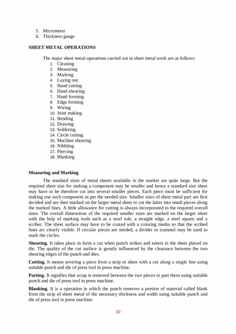
20
5. Micrometer
6. Thickness gauge
SHEET METAL OPERATIONS
The major sheet metal operations carried out in sheet metal work are as follows:
1. Cleaning
2. Measuring
3. Marking
4. Laying out
5. Hand cutting
6. Hand shearing
7. Hand forming
8. Edge forming
9. Wiring
10. Joint making
11. Bending
12. Drawing
13. Soldering
14. Circle cutting
15. Machine shearing
16. Nibbling
17. Piercing
18. Blanking
Measuring and Marking
The standard sizes of metal sheets available in the market are quite large. But the
required sheet size for making a component may be smaller and hence a standard size sheet
may have to be therefore cut into several smaller pieces. Each piece must be sufficient for
making one such component as per the needed size. Smaller sizes of sheet metal part are first
decided and are then marked on the larger metal sheet to cut the latter into small pieces along
the marked lines. A little allowance for cutting is always incorporated to the required overall
sizes. The overall dimensions of the required smaller sizes are marked on the larger sheet
with the help of marking tools such as a steel rule, a straight edge, a steel square and a
scriber. The sheet surface may have to be coated with a coloring media so that the scribed
lines arc clearly visible. If circular pieces are needed, a divider or trammel may be used to
mark the circles.
Shearing. It takes place in form a cut when punch strikes and enters in the sheet placed on
die. The quality of the cut surface is greatly influenced by the clearance between the two
shearing edges of the punch and dies.
Cutting. It means severing a piece from a strip or sheet with a cut along a single line using
suitable punch and die of press tool in press machine.
Parting. It signifies that scrap is removed between the two pieces to part them using suitable
punch and die of press tool in press machine.
Blanking. It is a operation in which the punch removes a portion of material called blank
from the strip of sheet metal of the necessary thickness and width using suitable punch and
die of press tool in press machine.

21
Punching. It is the operation of producing circular holes on a sheet metal by a punch and die.
The material punched out is removed as waste. Piercing, on the other hand, is the process of
producing holes of any desired shape in the part or sheet using suitable punch and die of press
tool in press machine.
Notching. It is a process to cut a specified shape of metal from the side or edge of the stock
using suitable punch and die.
Slitting. When shearing is conducted along a line, the process is referred to as slitting. It cuts
the metal sheet lengthwise using suitable punch and die of press tool in press machine.
Lancing. It makes a cut part way across a sheet and creates a bend along the cut using
suitable punch and die.
Nibbling. It is an operation of cutting any shape from sheet metal without special tools. It is
done on a nibbling machine.
Trimming. It is the operation of cutting away excess metal in a flange or flash from a sheet
metal part using suitable punch and die of press tool in press machine.
Bending. Bending is the operation of deforming a sheet around a straight axis. The neutral
plane lies on this straight axis. In bending all sheet material are stressed beyond the elastic
limit in tension on the outside and in compression on the inside of the bend. There is only one
line, the natural line that retains its original length. The neutral axis lies at a distance of 30 to
50% of thickness of the sheet from the inside of the bend. Stretching of the sheet metal on the
outside makes the stock thinner. Bending is sometimes called as forming, which involves
angle bending, roll bending, roll forming, seaming and spinning.
METAL JOINING PROCESS
Welding is a process for joining two similar or dissimilar metals by fusion. It joins
different metals/alloys, with or without the application of pressure and with or without the
use of filler metal. The fusion of metal takes place by means of heat. The heat may be
generated either from combustion of gases, electric arc, electric resistance or by chemical
reaction. During some type of welding processes, pressure may also be employed, but this is
not an essential requirement for all welding processes.
Welding provides a permanent joint but it normally affects the metallurgy of the
components. It is therefore usually accompanied by post weld heat treatment for most of the
critical components. The welding is widely used as a fabrication and repairing process in
industries. Some of the typical applications of welding include the fabrication of ships,
pressure vessels, automobile bodies, off-shore platform, bridges, welded pipes, sealing of
nuclear fuel and explosives, etc. Most of the metals and alloys can be welded by one type of
welding process or the other. However, some are easier to weld than others. To compare this
ease in welding term ‘weldability’ is often used.
The weldability may be defined as property of a metal which indicates the ease with
which it can be welded with other similar or dissimilar metals. Weldability of a material
depends upon various factors like the metallurgical changes that occur due to welding,
changes in hardness in and around the weld, gas evolution and absorption, extent of
oxidation, and the effect on cracking tendency of the joint. Plain low carbon steel (C-0.12%)
has the best weldability amongst metals. Generally it is seen that the materials with high
castability usually have low weldability.

22
Welding Positions
As shown in Figure, there are four types of welding positions, which are given as:
Figure 2.7 Welding postions
Welding joints

23
Figure 2.8 Welding joints
ADVANTAGES AND DISADVANTAGES OF WELDING
Advantages
1. Welding is more economical and is much faster process as compared to other
processes (riveting, bolting, casting etc.)
2. Welding, if properly controlled results permanent joints having strength equal or
sometimes more than base metal.
3. Large number of metals and alloys both similar and dissimilar can be joined by
welding.
4. General welding equipment is not very costly.
5. Portable welding equipments can be easily made available. Welding permits
considerable freedom in design.

24
6. Welding can join welding jobs through spots, as continuous pressure tight seams, end-
to-end and in a number of other configurations.
7. Welding can also be mechanized.
Disadvantages
1. It results in residual stresses and distortion of the workpieces.
2. Welded joint needs stress relieving and heat treatment.
3. Welding gives out harmful radiations (light), fumes and spatter.
4. Jigs, and fixtures may also be needed to hold and position the parts to be welded
5. Edges preparation of the welding jobs are required before welding
6. Skilled welder is required for production of good welding
7. Heat during welding produces metallurgical changes as the structure of the welded
joint is not same as that of the parent metal.
CLASSIFICATION OF WELDING AND ALLIED PROCESSES
There are different welding, brazing and soldering methods are being used in
industries today. There are various ways of classifying the welding and allied processes. For
example, they may be classified on the basis of source of heat, i.e., blacksmith fire, flame,
arc, etc. and the type of interaction i.e., liquid / liquid (fusion welding) or solid/solid (solid
state welding). Welding processes may also be classified in two categories namely plastic
(forge) and fusion. However, the general classification of welding and allied processes is
given as under
Welding Processes
1. Oxy-Fuel Gas Welding Processes
1. Air-acetylene welding
2. Oxy-acetylene welding
3. Oxy-hydrogen welding
4. Pressure gas welding
2. Arc Welding Processes
1. Carbon Arc Welding
2. Shielded Metal Arc Welding
3. Submerged Arc Welding
4. Gas Tungsten Arc Welding
5. Gas Metal Arc Welding
6. Plasma Arc Welding
7. Atomic Hydrogen Welding
8. Electro-slag Welding
9. Stud Arc Welding
10. Electro-gas Welding
3. Resistance Welding
1. Spot Welding
2. Seam Welding
3. Projection Welding
4. Resistance Butt Welding

25
5. Flash Butt Welding
6. Percussion Welding
7. High Frequency Resistance Welding
8. High Frequency Induction Welding
4. Solid-State Welding Processes
1. Forge Welding
2. Cold Pressure Welding
3. Friction Welding
4. Explosive Welding
5. Diffusion Welding
6. Cold Pressure Welding
7. Thermo-compression Welding
5. Thermit Welding Processes
1. Thermit Welding
2. Pressure Thermit Welding
6. Radiant Energy Welding Processes
1. Laser Welding
2. Electron Beam Welding
Allied Processes
1. Metal Joining or Metal Depositing Processes
1. Soldering
2. Brazing
3. Braze Welding
4. Adhesive Bonding
5. Metal Spraying
6. Surfacing
2. Thermal Cuting Processes
1. Gas Cutting
2. Arc Cutting
ARC WELDING PROCESSES
The process, in which an electric arc between an electrode and a workpiece or between
two electrodes is utilized to weld base metals, is called an arc welding process. The basic
principle of arc welding is shown in Fig 17.9(a). However the basic elements involved in
arc welding process are shown in Figure Most of these processes use some shielding gas
while others
employ coatings or fluxes to prevent the weld pool from the surrounding atmosphere. The
various arc welding processes are:
1. Carbon Arc Welding
2. Shielded Metal Arc Welding
3. Flux Cored Arc Welding
4. Gas Tungsten Arc Welding

26
5. Gas Metal Arc Welding
6. Plasma Arc Welding
7. Atomic Hydrogen Welding
8. Electroslag Welding
9. Stud Arc Welding
10. Electrogas Welding
Figure 2.8 Arc welding processes
Arc Welding Equipment

27
Arc welding equipment, setup and related tools and accessories are shown in Fig.
However some common tools of arc welding are shown separately through Fig. Few of the
important components of arc welding setup are described as under.
1. Arc welding power source
Both direct current (DC) and alternating current (AC) are used for electric arc
welding, each having its particular applications. DC welding supply is usually obtained from
generators driven by electric motor or if no electricity is available by internal combustion
engines. For AC welding supply, transformers are predominantly used for almost all arc
welding wheremains electricity supply is available. They have to step down the usual supply
voltage (200- 400 volts) to the normal open circuit welding voltage (50-90 volts). The
following factors influence the selection of a power source:
1. Type of electrodes to be used and metals to be welded
2. Available power source (AC or DC)
3. Required output
4. Duty cycle
5. Efficiency
6. Initial costs and running costs
7. Available floor space
8. Versatility of equipment
Figure 2.9 Tools

28
2. Welding cables
Welding cables are required for conduction of current from the power source through
the electrode holder, the arc, the workpiece and back to the welding power source. These are
insulated copper or aluminium cables.
3. Electrode holder
Electrode holder is used for holding the electrode mannually and conducting current
to it. These are usually matched to the size of the lead, which in turn matched to the amperage
output of the arc welder. Electrode holders are available in sizes that range from 150 to 500
Amps.
4. Welding Electrodes
An electrode is a piece of wire or a rod of a metal or alloy, with or without coatings.
An arc is set up between electrode and workpiece. Welding electrodes are classified into
following types-
(1) Consumable Electrodes
a. Bare Electrodes
b. Coated Electrodes
(2) Non-consumable Electrodes
a. Carbon or Graphite Electrodes
b. Tungsten Electrodes
Consumable electrode is made of different metals and their alloys. The end of this
electrode starts melting when arc is struck between the electrode and workpiece. Thus
consumable electrode itself acts as a filler metal. Bare electrodes consist of a metal or alloy
wire without any flux coating on them. Coated electrodes have flux coating which starts
melting as soon as an electric arc is struck. This coating on melting performs many functions
like prevention of joint from atmospheric contamination, arc stabilizers etc.
Non-consumable electrodes are made up of high melting point materials like carbon,
pure tungsten or alloy tungsten etc. These electrodes do not melt away during welding. But
practically, the electrode length goes on decreasing with the passage of time, because of
oxidation and vaporization of the electrode material during welding. The materials of
nonconsumable electrodes are usually copper coated carbon or graphite, pure tungsten,
thoriated or zirconiated tungsten.
5. Hand Screen
Hand screen used for protection of eyes and supervision of weld bead.
6. Chipping hammer
Chipping Hammer is used to remove the slag by striking.
7. Wire brush
Wire brush is used to clean the surface to be weld.
8. Protective clothing
Operator wears the protective clothing such as apron to keep away the exposure of direct heat
to the body.
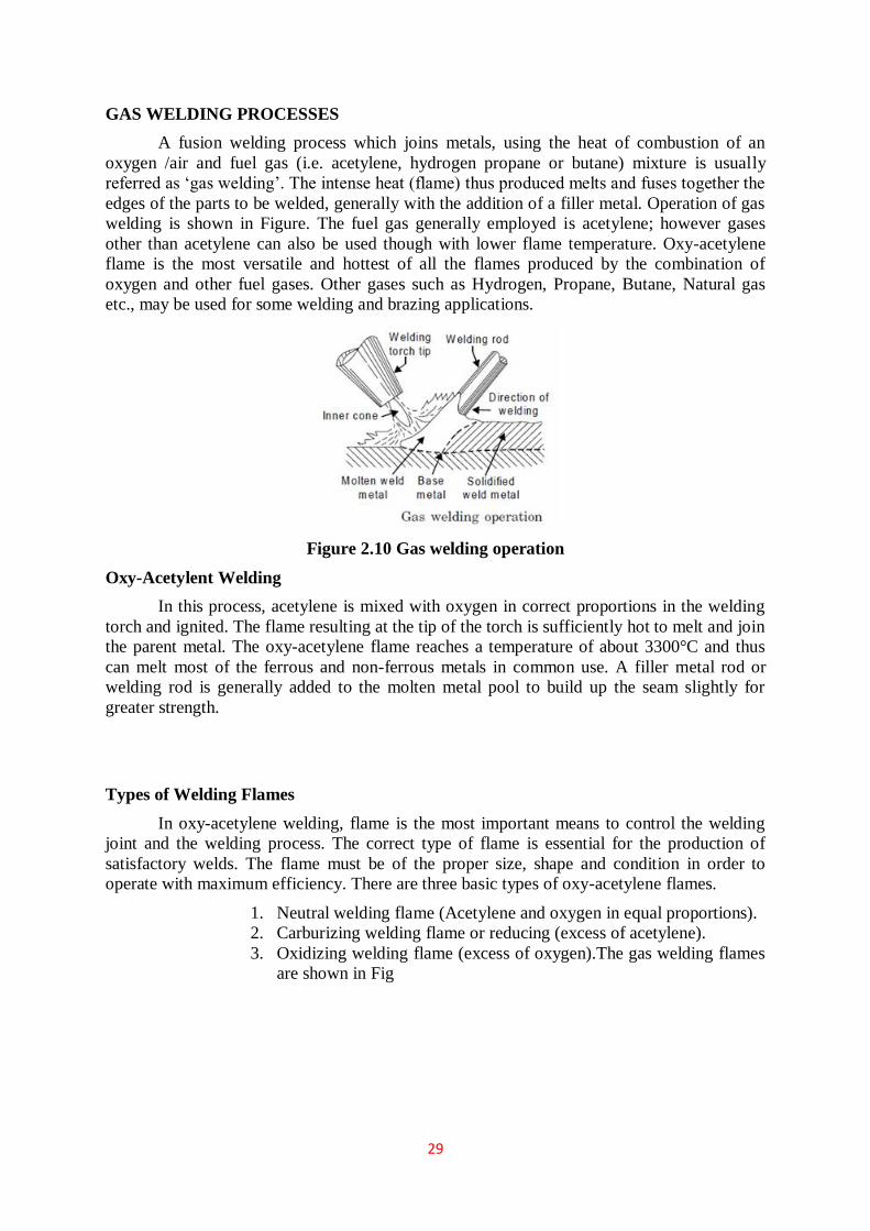
29
GAS WELDING PROCESSES
A fusion welding process which joins metals, using the heat of combustion of an
oxygen /air and fuel gas (i.e. acetylene, hydrogen propane or butane) mixture is usually
referred as ‘gas welding’. The intense heat (flame) thus produced melts and fuses together the
edges of the parts to be welded, generally with the addition of a filler metal. Operation of gas
welding is shown in Figure. The fuel gas generally employed is acetylene; however gases
other than acetylene can also be used though with lower flame temperature. Oxy-acetylene
flame is the most versatile and hottest of all the flames produced by the combination of
oxygen and other fuel gases. Other gases such as Hydrogen, Propane, Butane, Natural gas
etc., may be used for some welding and brazing applications.
Figure 2.10 Gas welding operation
Oxy-Acetylent Welding
In this process, acetylene is mixed with oxygen in correct proportions in the welding
torch and ignited. The flame resulting at the tip of the torch is sufficiently hot to melt and join
the parent metal. The oxy-acetylene flame reaches a temperature of about 3300°C and thus
can melt most of the ferrous and non-ferrous metals in common use. A filler metal rod or
welding rod is generally added to the molten metal pool to build up the seam slightly for
greater strength.
Types of Welding Flames
In oxy-acetylene welding, flame is the most important means to control the welding
joint and the welding process. The correct type of flame is essential for the production of
satisfactory welds. The flame must be of the proper size, shape and condition in order to
operate with maximum efficiency. There are three basic types of oxy-acetylene flames.
1. Neutral welding flame (Acetylene and oxygen in equal proportions).
2. Carburizing welding flame or reducing (excess of acetylene).
3. Oxidizing welding flame (excess of oxygen).The gas welding flames
are shown in Fig

30
Figure 2.11 Gas welding flames
Neutral Welding Flame
A neutral flame results when approximately equal volumes of oxygen and acetylene
are mixed in the welding torch and burnt at the torch tip. The temperature of the neutral flame
is of the order of about 5900°F (3260°C). It has a clear, well defined inner cone, indicating
that the combustion is complete. The inner cone is light blue in color. It is surrounded by an
outer flame envelope, produced by the combination of oxygen in the air and superheated
carbon monoxide and hydrogen gases from the inner cone. This envelope is Usually a much
darker blue than the inner cone. A neutral flame is named so because it affects no chemical
change on the molten metal and, therefore will not oxidize or carburize the metal. The
neutral flame is commonly used for the welding of mild steel, stainless steel, cast Iron,
copper, and aluminium.
Carburising or Reducing Welding Flame
The carburizing or reducing flame has excess of acetylene and can be recognized by
acetylene feather, which exists between the inner cone and the outer envelope. The outer
flame envelope is longer than that of the neutral flame and is usually much brighter in color.
With iron and steel, carburizing flame produces very hard, brittle substance known as iron
carbide. A reducing flame may be distinguished from carburizing flame by the fact that a
carburizing flame contains more acetylene than a reducing flame. A reducing flame has an
approximate temperature of 3038°C.
A carburizing-flame is used in the welding of lead and for carburizing (surface
hardening) purpose. A reducing flame, on the other hand, does not carburize the metal; rather
it ensures the absence of the oxidizing condition. It is used for welding with low alloy steel
rods and for welding those metals, (e.g., non-ferrous) that do not tend to absorb carbon. This
flame is very well used for welding high carbon steel.
Oxidising Welding flame
The oxidizing flame has an excess of oxygen over the acetylene. An oxidizing flame
can be recognized by the small cone, which is shorter, much bluer in color and more pointed
than that of the neutral flame. The outer flame envelope is much shorter and tends to fan out
at the end. Such a flame makes a loud roaring sound. It is the hottest flame (temperature as

31
high as 6300°F) produced by any oxy-fuel gas source. But the excess oxygen especially at
high temperatures tends to combine with many metals to form hard, brittle, low strength
oxides. Moreover, an excess of oxygen causes the weld bead and the surrounding area to
have a scummy or dirty appearance. For these reasons, an oxidizing flame is of limited use in
welding. It is not used in the welding of steel.
A slightly oxidizing flame is helpful when welding (i) Copper-base metals (ii) Zinc-
base metals and (iii) A few types of ferrous metals such as manganese steel and cast iron. The
oxidizing atmosphere in these cases, create a basemetal oxide that protects the base metal.
GAS WELDING EQUIPMENTS
Acetylene and oxygen gas is stored in compressed gas cylinders. These gas cylinders
differ widely in capacity, design and colour code. However, in most of the countries, the
standard size of these cylinders is 6 to 7 m3 and is painted black for oxygen and maroon for
acetylene. An acetylene cylinder is filled with some absorptive material, which is saturated
with a chemical solvent acetone.
Acetone has the ability to absorb a large volume of acetylene and release it as the
pressure falls. If large quantities of acetylene gas are being consumed, it is much cheaper to
generate the gas at the place of use with the help of acetylene gas generators. Acetylene gas is
generated by carbide-to-water method. Oxygen gas cylinders are usually equipped with about
40 litres of oxygen at a pressure of about 154 Kgf/cm2 at 21°C. To provide against
dangerously excessive pressure, such as could occur if the cylinders were exposed to fire,
every valve has a safety device to release the oxygen before there is any danger of rupturing
the cylinders. Fragile discs and fusible plugs are usually provided in the cylinders valves in
case it is subjected to danger.
Figure 2.11 Gas welding equipments
Gas pressure regulators

32
Gas pressure regulators are employed for regulating the supply of acetylene and
oxygen gas from cylinders. A pressure regulator is connected between the cylinder and hose
leading to welding torch. The cylinder and hose connections have left-handed threads on the
acetylene regulator while these are right handed on the oxygen regulator. A pressure regulator
is fitted with two pressure gauges, one for indication of the gas pressure in the cylinder and
the other for indication of the reduced pressure at which the gas is going out.
Welding torch
Figure shows the construction of the welding torch. It is a tool for mixing oxygen and
acetylene in correct proportion and burning the mixture at the end of a tip. Gas flow to the
torch is controlled with the help of two needle valves in the handle of the torch. There are two
basic types of gas welding torches:
(1) Positive pressure (also known as medium or equal pressure), and
(2) Low pressure or injector type
The positive pressure type welding torch is the more common of the two types of
oxyacetylene torches.
Figure 2.12 Welding torch
Torch tips
It is the portion of the welding apparatus through which the gases pass just prior to
their ignition and burning. A great variety of interchangeable welding tips differing in size,
shape and construction are available commercially. The tip sizes are identified by the
diameter of the opening. The diameter of the tip opening used for welding depends upon the
type of metal to be welded.
Hose pipes
The hose pipes are used for the supply of gases from the pressure regulators. The most
common method of hose pipe fitting both oxygen and acetylene gas is the reinforced rubber
hose pipe. Green is the standard color for oxygen hose, red for acetylene, and black hose for
other industrially available welding gases.
Goggles

33
These are fitted with colored lenses and are used to protect the eyes from harmful heat
and ultraviolet and infrared rays.
Gloves
These are required to protect the hands from any injury due to the heat of welding
process.
Spark-lighter
It is used for frequent igniting the welding torch.
Filler rods
Gas welding can be done with or without using filler rod. When welding with the
filler rod, it should be held at approximately 900 to the welding tip. Filler rods have the same
or nearly the same chemical composition as the base metal. Metallurgical properties of the
weld deposit can be controlled by the optimum choice of filler rod. Most of the filler rods for
gas welding also contain deoxidizers to control the oxygen content of weld pool.
Fluxes
Fluxes are used in gas welding to remove the oxide film and to maintain a clean
surface. These are usually employed for gas welding of aluminium, stainless steel, cast iron,
brass and silicon bronze. They are available in the market in the form of dry powder, paste, or
thick solutions
Safety Recommendations for Gas Welding
1. Never hang a torch with its hose on regulators or cylinder valves.
2. During working, if the welding tip becomes overheated it may be cooled by
plungingthe torch into water; close the acetylene valve but leave a little oxygen
flowing.
3. Always use the correct pressure regulators for a gas. Acetylene pressure regulator
should never be used with any other gas.
4. Do not move the cylinder by holding the pressure regulator and also handle pressure
regulators carefully.
5. Use pressure regulator only at pressures for which it is intended.
6. Open cylinder valves slowly to avoid straining the mechanism of pressure regulator.
7. Never use oil, grease or lubricant of any kind on regulator connections
BRAZING
Like soldering, brazing is a process of joining metals without melting the base metal.
Filler material used for brazing has liquidus temperature above 450°C and below the solidus
temperature of the base metal. The filler metal is drawn into the joint by means of capillary
action (entering of fluid into tightly fitted surfaces). Brazing is a much widely used joining
process in various industries because of its many advantages. Due to the higher melting point
of the filler material, the joint strength is more than in soldering.
Almost all metals can be joined by brazing except aluminum and magnesium which
cannot easily be joined by brazing. Dissimilar metals, such as stainless steel to cast iron can
be joined by brazing. Because of the lower temperatures used there is less distortion in brazed

34
joints. Also, in many cases the original heat treatment of the plates being joined is not
affected by the brazing heat. The joint can be quickly finished without much skill. Because of
the simplicity of the process it is often an economical joining method with reasonable joint
strength.
The brazed joints are reasonably stronger, depending on the strength of the filler metal
used. But the brazed joint is generally not useful for high temperature service because of the
low melting temperature of the filler metal. The color of the filler metal in the brazed joint
also, may not match with that of the base metal. Because the filler metal reaches the joint by
capillary action, it is essential that the joint is designed properly. The clearance between the
two parts to be joined should be critically controlled. Another important factor to be
considered is the temperature at which the filler metal is entering the joint.
During brazing, the base metal of the two pieces to be joined is not melted. An
important requirement is that the filler metal must wet the base metal surfaces to which it is
applied. The diffusion or alloying of the filler metal with the base metal place even though
the base metal does not reach its solidus temperature. The surfaces to be joined must be
chemically clean before brazing. However, fluxes are applied to remove oxides from the
surfaces. Borax is the most widely used flux during the process of brazing. It will dissolve the
oxides of most of the common metals.
Methods of Brazing
Torch Brazing
It is the most widely used brazing method. Heat is produced, generally, by burning a
mixture of oxy-acetylene gas, as in the gas welding. A carbonizing flame is suitable for this
purpose as it produces sufficiently high temperature needed for brazing.
Furnace Brazing
It is suitable for brazing large number of small or medium parts. Usually brazing filler
metal in the granular or powder form or as strips is placed at the joint, and then the assembly
is placed in the furnace and heated. Large number of small parts can be accommodated in a
furnace and simultaneously brazed.
Braze Welding
In welding processes where the joint of the base metal is melted and a joint is
prepared having higher joint strength, it is likely to cause metallurgical damage by way of
phase transformations and oxide formation. In this process, the base metal is not melted, but
the joint is obtained by means of a filler metal.
SOLDERING
Soldering is a method of joining similar or dissimilar metals by heating them to a
suitable temperature and by means of a filler metal, called solder, having liquidus
temperuatre not exceeding 450°C and below the solidus of the base material. Though
soldering obtains a good joint between the two plates, the strength of the joint is limited by
the strength of the filler metal used.
Solders are essentially alloys of lead and tin. To improve the mechanical properties
and temperature resistance, solders are added to other alloying elements such as zinc,

35
cadmium and silver in various proportions. Soldering is normally used for obtaining a neat
leak proof joint or a low resistance electrical joint. The soldered joints are not suitable for
high temperature service because of the low melting temperatures of the filler metals used.
The soldering joints also need to be cleaned meticulously to provide chemically clean
surfaces to obtain a proper bond. Solvent cleaning, acid pickling and even mechanical
cleaning are applied before soldering. To remove the oxides from the joint surfaces and to
prevent the filler metal from oxidizing, fluxes are generally used in soldering.
Rosin and rosin plus alcohol based fluxes are least active type and are generally used
for electrical soldering work. Because of the content of acids, these are corrosive at soldering
temperature. They can be easily cleaned after the soldering. The organic fluxes such as zinc
chloride and ammonium chloride are quick acting and produce efficient joints. But because of
their corrosive nature the joint should be thoroughly cleaned of the entire flux residue from
the joint. These are to be used for only non-electrical soldering work.
Fluxes are normally available in the form of powder, paste, liquid or in the form of
core in the solder metal. It is necessary that the flux should remain in the liquid form at the
soldering temperature and be reactive to be of proper use. The most commonly used
soldering methods include soldering iron (flame or electrically heated), dip soldering, and
wave soldering. A soldering iron is a copper rod with a thin tip which can be used for
flattening the soldering material. The soldering iron can be heated by keeping in a furnace or
by means of an internal electrical resistance whose power rating may range from 15 W for the
electronic applications to 200 W for sheet metal joining.
This is the most convenient method of soldering but somewhat slower compared to
the other methods.In dip soldering, a large amount of solder is melted in a tank which is
closed. The parts that are to be soldered are first cleaned properly and dipped in a flux bath as
per the requirement. These are then dipped into the molten solder pool and lifted with the
soldering complete.
The wave soldering is a variant of this method wherein the part to be soldered (e.g.”
an electronic printed circuit board, PCB) is not dipped into the solder tank, but a wave is
generated in the tank so that the solder comes up and makes a necessary joint.
Basic Operations in Soldering
For making soldered joints, following operations are required to be performed
sequentially.
1. Shaping and fitting of metal parts together
Filler metal on heating flows between the closely placed adjacent surfaces due to
capillary action, thus, closer the parts the more is solder penetration. This means that the two
parts should be shaped to fit closely so that the space between them is extremely small to be
filled completely with solder by the capillary action. If a large gap is present, capillary action
will not take place and the joint will not be strong.
2. Cleaning of surfaces
This is done to remove dirt, grease or any other foreign material from the surface
pieces to be soldered, in order to get a sound joint. If surfaces are not clean, strong atomic
bonds will not form.
3. Flux application

36
Soldering cannot be done without a flux. Even if a metal is clean, it rapidly acquires
an oxide film of submicroscopic thickness due to heat and this film insulates the metal from
the solder, preventing the surface to get wetted by solder. This film is broken and removed by
the flux. The flux is applied when parts are ready for joining.
4. Application of heat and solder
The parts must be held in a vice or with special work holding devices so that they do
not move while soldering. The parts being soldered must be heated to solder-melting and
solder-alloying temperature before applying the solder for soldering to take place the
assembly so that the heat is most effectively transmitted to the being soldered. As soon as the
heat is applied, the flux quickly breaks down the oxide film (the insulating oxide layer barrier
between the surface and solder). Now solder is applied which immediately melts and metal to
metal contact is established through the medium of molten solder. Finally, the surplus solder
is removed and the joint is allowed to cool. Blow torches dipping the parts in molten solder or
other methods are also used for soldering.
Solders
Solders are alloys of lead and tin. Solder may also contain certain other elements like
cadmium, and antimony in small quantities. The percentage composition of tin and lead
determines the physical and mechanical properties of the solder and the joint made. Most
solder is available in many forms-bar, stick, fill, wire, strip, and so on. It can be obtained in
circular or semi-circular rings or any other desired shape. Sometimes the flux is included with
the solder. For example, a cored solder wire is a tube of solder filled with flux.
Solder Fluxes
The flux does not constitute a part of the soldered joint. Zinc chloride, ammonium chloride,
and hydrochloric acid are the examples of fluxes commonly used in soldering. The function
of fluxes in soldering is to remove oxides and other surface compounds from the surfaces to
be soldered by displacing or dissolving them. Soldering fluxes may be classified into four
groups-
(1) Inorganic fluxes (most active)
(2) Organic fluxes (moderately active)
(3) Rosin fluxes (least active), and
(4) Special fluxes for specific applications
FOUNDARY
There are large number of tools and equipments used in foundry shop for carrying out
different operations such as sand preparation, molding, melting, pouring and casting. They
can be broadly classified as hand tools, sand conditioning tool, flasks, power operated
equipments, metal melting equipments and fettling and finishing equipments. Different kinds
of hand tools are used by molder in mold making operations. Sand conditioning tools are
basically used for preparing the various types of molding sands and core sand. Flasks are
commonly used for preparing sand moulds and keeping molten metal and also for handling
the same from place to place. Power operated equipments are used for mechanizing processes
in foundries. They include various types of molding machines, power riddles, sand mixers

37
and conveyors, grinders etc. Metal melting equipment includes various types of melting
furnaces such as cupola, pit furnace, crucible furnaces etc. Fettling and finishing equipments
are also used in foundry work for cleaning and finishing the casting. General tools and
equipment used in foundry are discussed as under.
Hand Tools Used In Foundry Shop
The common hand tools used in foundry shop are fairly numerous. A brief description
of the following foundry tools (used frequently by molder is given as under.
Figure 2.13 Hand riddle
Hand riddle
Hand riddle is shown in Figure. It consists of a screen of standard circular wire mesh
equipped with circular wooden frame. It is generally used for cleaning the sand for
removing foreign material such as nails, shot metal, splinters of wood etc. from it. Even
power operated riddles are available for riddling large volume of sand.
Figure 2.14 Shovel
Shovel
Shovel is shown in Figure. It consists of an steel pan fitted with a long wooden
handle. It is used in mixing, tempering and conditioning the foundry sand by hand. It is
also used for moving and transforming the molding sand to the container and molding
box or flask. It should always be kept clean.

38
Figure 2.15 Sprue pin
Sprue pin
Sprue pin is shown in Figure. It is a tapered rod of wood or iron which is placed or
pushed in cope to join mold cavity while the molding sand in the cope is being rammed. Later
its withdrawal from cope produce a vertical hole in molding sand, called sprue through which
the molten metal is poured into the mould using gating system. It helps to make a passage for
pouring molten metal in mold through gating system
Strike off bar
Strike off bar is a flat bar having straight edge and is made of wood or iron. It is used
to strike off or remove the excess sand from the top of a molding box after completion of
ramming thereby making its surface plane and smooth. Its one edge is made beveled and the
other end is kept perfectly smooth and plane.
Figure 2.16 Strike off bar
Mallet

39
Mallet is similar to a wooden hammer and is generally as used in carpentry or sheet
metal shops. In molding shop, it is used for driving the draw spike into the pattern and then
rapping it for separation from the mould surfaces so that pattern can be easily withdrawn
leaving the mold cavity without damaging the mold surfaces.
Draw spike
Draw spike is shown Figure. It is a tapered steel rod having a loop or ring at its one
end and a sharp point at the other. It may have screw threads on the end to engage metal
pattern for it withdrawal from the mold. It is used for driven into pattern which is embedded
in the molding sand and raps the pattern to get separated from the pattern and finally draws
out it from the mold cavity
Figure 2.17 Draw spike
Vent rod
Vent rod is shown in Figure. It is a thin spiked steel rod or wire carrying a pointed
edge at one end and a wooden handle or a bent loop at the other. After ramming and striking
off the excess sand it is utilized to pierce series of small holes in the molding sand in the cope
portion. The series of pierced small holes are called vents holes which allow the exit or
escapeof steam and gases during pouring mold and solidifying of the molten metal for getting
a sound casting.
Figure 2.18 Vent rod
Lifters
Lifters are shown in Fig. 11.1(h, i, j and k). They are also known as cleaners or finishing tool
which are made of thin sections of steel of various length and width with one end bentat right
angle. They are used for cleaning, repairing and finishing the bottom and sides of deep and
narrow openings in mold cavity after withdrawal of pattern. They are also used for removing
loose sand from mold cavity.

40
Figure 2.19 Lifters
Trowels
Trowels are shown in Figures. They are utilized for finishing flat surfaces and joints
and partings lines of the mold. They consist of metal blade made of iron and are equipped
with a wooden handle. The common metal blade shapes of trowels may be pointed or
contoured or rectangular oriented. The trowels are basically employed for smoothing or
slicking the surfaces of molds. They may also be used to cut in-gates and repair the mold
surfaces.
Figure 2.20 Trowels
Slicks
Slicks are shown in Figures. They are also recognized as small double ended mold
finishing tool which are generally used for repairing and finishing the mold surfaces and their
edges after withdrawal of the pattern. The commonly used slicks are of the types of heart and
leaf, square and heart, spoon and bead and heart and spoon. The nomenclatures of the slicks
are largely due to their shapes.

41
Figure 2.21 Slicks
Smoothers
Smothers are shown in Figures. According to their use and shape they are given
different names. They are also known as finishing tools which are commonly used for
repairing and finishing flat and round surfaces, round or square corners and edges of molds.
Figure 2.22 Smoothers
Swab
Swab is shown in Figure. It is a small hemp fiber brush used for moistening the edges
of sand mould, which are in contact with the pattern surface before withdrawing the pattern.
It is used for sweeping away the molding sand from the mold surface and pattern. It is also
used for coating the liquid blacking on the mold faces in dry sand molds.
Figure 2.23 Swab
Spirit level

42
Spirit level is used by molder to check whether the sand bed or molding box is
horizontal or not.
Gate cutter
Gate cutter (Fig. 11.1(v)) is a small shaped piece of sheet metal commonly used to cut
runners and feeding gates for connecting sprue hole with the mold cavity.
Figure 2.24 Gate cutter
Gaggers
Gaggers are pieces of wires or rods bent at one or both ends which are used for
reinforcing the downward projecting sand mass in the cope are known as gaggers. They
support hanging bodies of sand. They possess a length varying from 2 to 50 cm. A gagger is
always used in cope area and it may reach up to 6 mm away from the pattern. It should be
coated with clay wash so that the sand adheres to it. Its surface should be rough in order to
have a good grip with the molding sand. It is made up of steel reinforcing bar.
Spray-gun
Spray gun is mainly used to spray coating of facing materials etc. on a mold or core
surface.
Nails and wire pieces
They are basically used to reinforce thin projections of sand in the mold or cores.
Wire pieces, spring and nails
They are commonly used to reinforce thin projections of sand in molds or cores. They
are also used to fasten cores in molds and reinforce sand in front of an in-gate.
Bellows
Bellows gun is shown in Figure. It is hand operated leather made device equipped
with compressed air jet to blow or pump air when operated. It is used to blow away the loose
or unwanted sand from the surfaces of mold cavities.
Figure 2.25 Bellows

43
Clamps, cotters and wedges
They are made of steel and are used for clamping the molding boxes firmly together during
pouring.
MOLDING SAND
The general sources of receiving molding sands are the beds of sea, rivers, lakes,
granulular elements of rocks, and deserts. The common sources of molding sands available in
India are as follows:
1. Batala sand ( Punjab)
2. Ganges sand (Uttar Pradesh)
3. Oyaria sand (Bihar)
4. Damodar and Barakar sands (Bengal- Bihar Border)
5. Londha sand (Bombay)
6. Gigatamannu sand (Andhra Pradesh) and
7. Avadi and Veeriyambakam sand (Madras)
Molding sands may be of two types namely natural or synthetic. Natural molding
sands contain sufficient binder. Whereas synthetic molding sands are prepared artificially
using basic sand molding constituents (silica sand in 88-92%, binder 6-12%, water or
moisture content 3-6%) and other additives in proper proportion by weight with perfect
mixing and mulling in suitable equipments.
KINDS OF MOULDING SAND
Molding sands can also be classified according to their use into number of varieties
which are described below.
Green sand
Green sand is also known as tempered or natural sand which is a just prepared
mixture of silica sand with 18 to 30 percent clay, having moisture content from 6 to 8%. The
clay and water furnish the bond for green sand. It is fine, soft, light, and porous. Green sand
is damp, when squeezed in the hand and it retains the shape and the impression to give to it
under pressure. Molds prepared by this sand are not requiring backing and hence are known
as green sand molds. This sand is easily available and it possesses low cost. It is commonly
employed for production of ferrous and non-ferrous castings.
Dry sand
Green sand that has been dried or baked in suitable oven after the making mold and
cores, is called dry sand. It possesses more strength, rigidity and thermal stability. It is mainly
suitable for larger castings. Mold prepared in this sand are known as dry sand molds.
Loam sand
Loam is mixture of sand and clay with water to a thin plastic paste. Loam sand
possesses high clay as much as 30-50% and 18% water. Patterns are not used for loam
molding and shape is given to mold by sweeps. This is particularly employed for loam
molding used for large grey iron castings.
Facing sand

44
Facing sand is just prepared and forms the face of the mould. It is directly next to the
surface of the pattern and it comes into contact molten metal when the mould is poured.
Initial coating around the pattern and hence for mold surface is given by this sand. This sand
is subjected severest conditions and must possess, therefore, high strength refractoriness. It is
made of silica sand and clay, without the use of used sand. Different forms of carbon are used
to prevent the metal burning into the sand. A facing sand mixture for green sand of cast iron
may consist of 25% fresh and specially prepared and 5% sea coal. They are sometimes mixed
with 6-15 times as much fine molding sand to make facings. The layer of facing sand in a
mold usually ranges from 22-28 mm. From 10 to 15% of the whole amount of molding sand
is the facing sand.
Backing sand
Backing sand or floor sand is used to back up the facing sand and is used to fill the
whole volume of the molding flask. Used molding sand is mainly employed for this purpose.
The backing sand is sometimes called black sand because that old, repeatedly used molding
sand is black in color due to addition of coal dust and burning on coming in contact with the
molten metal.
System sand
In mechanized foundries where machine molding is employed. A so-called system
sand is used to fill the whole molding flask. In mechanical sand preparation and handling
units, no facing sand is used. The used sand is cleaned and re-activated by the addition of
water and special additives. This is known as system sand. Since the whole mold is made of
this system sand, the properties such as strength, permeability and refractoriness of the
molding sand must be higher than those of backing sand.
Parting sand
Parting sand without binder and moisture is used to keep the green sand not to stick to
the pattern and also to allow the sand on the parting surface the cope and drag to separate
without clinging. This is clean clay-free silica sand which serves the same purpose as parting
dust.
Core sand
Core sand is used for making cores and it is sometimes also known as oil sand. This is
highly rich silica sand mixed with oil binders such as core oil which composed of linseed oil,
resin, light mineral oil and other bind materials. Pitch or flours and water may also be used in
large cores for the sake of economy.
PROPERTIES OF MOULDING SAND
Refractoriness
Refractoriness is defined as the ability of molding sand to withstand high
temperatures without breaking down or fusing thus facilitating to get sound casting. It is a
highly important characteristic of molding sands. Refractoriness can only be increased to a
limited extent. Molding sand with poor refractoriness may burn on to the casting surface and
no smooth casting surface can be obtained. The degree of refractoriness depends on the SiO2
i.e. quartz content, and the shape and grain size of the particle. The higher the SiO2 content
and the rougher the grain volumetric composition the higher is the refractoriness of the

45
molding sand and core sand. Refractoriness is measured by the sinter point of the sand rather
than its melting point.
Permeability
It is also termed as porosity of the molding sand in order to allow the escape of any
air, gases or moisture present or generated in the mould when the molten metal is poured into
it. All these gaseous generated during pouring and solidification process must escape
otherwise the casting becomes defective. Permeability is a function of grain size, grain shape,
and moisture and clay contents in the molding sand. The extent of ramming of the sand
directly affects the permeability of the mould. Permeability of mold can be further increased
by venting using vent rods
Cohesiveness
It is property of molding sand by virtue which the sand grain particles interact and
attract each other within the molding sand. Thus, the binding capability of the molding sand
gets enhanced to increase the green, dry and hot strength property of molding and core sand.
Green strength
The green sand after water has been mixed into it, must have sufficient strength and
toughness to permit the making and handling of the mould. For this, the sand grains must be
adhesive, i.e. thev must be capable of attaching themselves to another body and. therefore,
and sand grains having high adhesiveness will cling to the sides of the molding box. Also, the
sand grains must have the property known as cohesiveness i.e. ability of the sand grains to
stick to one another. By virtue of this property, the pattern can be taken out from the mould
without breaking the mould and also the erosion of mould wall surfaces does not occur
during the flow of molten metal. The green strength also depends upon the grain shape and
size, amount and type of clay and the moisture content.
Dry strength
As soon as the molten metal is poured into the mould, the moisture in the sand layer
adjacent to the hot metal gets evaporated and this dry sand layer must have sufficient strength
to its shape in order to avoid erosion of mould wall during the flow of molten metal. The dry
strength also prevents the enlargement of mould cavity cause by the metallostatic pressure of
the liquid metal.
Flowability or plasticity
It is the ability of the sand to get compacted and behave like a fluid. It will flow
uniformly to all portions of pattern when rammed and distribute the ramming pressure evenly
all around in all directions. Generally sand particles resist moving around corners or
projections. In general, flowability increases with decrease in green strength, an, decrease in
grain size. The flowability also varies with moisture and clay content.
Adhesiveness
It is property of molding sand to get stick or adhere with foreign material such
sticking of molding sand with inner wall of molding box
Collapsibility
After the molten metal in the mould gets solidified, the sand mould must be
collapsible so that free contraction of the metal occurs and this would naturally avoid the
tearing or cracking of the contracting metal. In absence of this property the contraction of the

46
metal is hindered by the mold and thus results in tears and cracks in the casting. This property
is highly desired in cores
Miscellaneous properties
In addition to above requirements, the molding sand should not stick to the casting
and should not chemically react with the metal. Molding sand should be cheap and easily
available. It should be reusable for economic reasons. Its coefficients of expansion should be
sufficiently low.
PATTERNS
Patterns are replicas of the casting required. It is similar in shape and size to the final
product, but not exactly. Usually, the mould is prepared in wet sand, to which some binder is
added to hold sand particles together. The pattern is then withdrawn from inside the sand
mould in such a manner that the impression cavity made in the mould is not damaged or
broken in anyway. Finally molten metal is poured into this cavity and allowed to solidify and
cool down to room temperature.
PATTERN MATERIALS
Wood
Wood is the most popular and commonly used material for pattern making. It is
cheap, easily available in abundance, repairable and easily fabricated in various forms using
resin and glues. It is very light and can produce highly smooth surface. Wood can preserve its
surface by application of a shellac coating for longer life of the pattern. But, in spite of its
above qualities, it is susceptible to shrinkage and warpage and its life is short because of the
reasons that it is highly affected by moisture of the molding sand. After some use it warps
and wears out quickly as it is having less resistance to sand abrasion. It can not withstand
rough handily and is weak in comparison to metal. In the light of above qualities, wooden
patterns are preferred only when the numbers of castings to be produced are less. The main
varieties of woods used in pattern-making are shisham, kail, deodar, teak and mahogany.
Metal
Metallic patterns are preferred when the number of castings required is large enough
to justify their use. These patterns are not much affected by moisture as wooden pattern. The
wear and tear of this pattern is very less and hence posses longer life. Moreover, metal is
easier to shape the pattern with good precision, surface finish and intricacy in shapes. It can
withstand against corrosion and handling for longer period. It possesses excellent strength to
weight ratio. The main disadvantages of metallic patterns are higher cost, higher weight and
tendency of rusting. It is preferred for production of castings in large quantities with same
pattern. The metals commonly used for pattern making are cast iron, brass and bronzes and
aluminum alloys.
Cast Iron
It is cheaper, stronger, tough, and durable and can produce a smooth surface finish. It
also possesses good resistance to sand abrasion. The drawbacks of cast iron patterns are that
they are hard, heavy, brittle and get rusted easily in presence of moisture.
Brasses and Bronzes

47
These are heavier and expensive than cast iron and hence are preferred for
manufacturing small castings. They possess good strength, machinability and resistance to
corrosion and wear. They can produce a better surface finish. Brass and bronze pattern is
finding application in making match plate pattern
Aluminum Alloys
Aluminum alloy patterns are more popular and best among all the metallic patterns
because of their high light ness, good surface finish, low melting point and good strength.
They also possesses good resistance to corrosion and abrasion by sand and there by
enhancing longer life of pattern. These materials do not withstand against rough handling.
These have poor repair ability and are preferred for making large castings.
Plastic
Plastics are getting more popularity now a days because the patterns made of these
materials are lighter, stronger, moisture and wear resistant, non sticky to molding sand,
durable and they are not affected by the moisture of the molding sand. Moreover they impart
very smooth surface finish on the pattern surface. These materials are somewhat fragile, less
resistant to sudden loading and their section may need metal reinforcement. The plastics used
for this purpose are thermosetting resins. Phenolic resin plastics are commonly used. These
are originally in liquid form and get solidified when heated to a specified temperature. To
prepare a plastic pattern, a mould in two halves is prepared in plaster of paris with the help of
a wooden pattern known as a master pattern. The phenolic resin is poured into the mould and
the mould is subjected to heat. The resin solidifies giving the plastic pattern. Recently a new
material has stepped into the field of plastic which is known as foam plastic. Foam plastic is
now being produced in several forms and the most common is the expandable polystyrene
plastic category. It is made from benzene and ethyl benzene.
Plaster
This material belongs to gypsum family which can be easily cast and worked with
wooden tools and preferable for producing highly intricate casting. The main advantages of
plaster are that it has high compressive strength and is of high expansion setting type which
compensate for the shrinkage allowance of the casting metal. Plaster of paris pattern can be
prepared either by directly pouring the slurry of plaster and water in moulds prepared earlier
from a master pattern or by sweeping it into desired shape or form by the sweep and strickle
method. It is also preferred for production of small size intricate castings and making core
boxes.
Wax
Patterns made from wax are excellent for investment casting process. The materials
used are blends of several types of waxes, and other additives which act as polymerizing
agents, stabilizers, etc. The commonly used waxes are paraffin wax, shellac wax, bees-wax,
cerasin wax, and micro-crystalline wax. The properties desired in a good wax pattern include
low ash content up to 0.05 per cent, resistant to the primary coat material used for investment,
high tensile strength and hardness, and substantial weld strength. The general practice of
making wax pattern is to inject liquid or semi-liquid wax into a split die. Solid injection is
also used to avoid shrinkage and for better strength. Waxes use helps in imparting a high
degree of surface finish and dimensional accuracy castings. Wax patterns are prepared by
pouring heated wax into split moulds or a pair of dies. The dies after having been cooled
down are parted off. Now the wax pattern is taken out and used for molding. Such patterns
need not to be drawn out solid from the mould. After the mould is ready, the wax is poured

48
out by heating the mould and keeping it upside down. Such patterns are generally used in the
process of investment casting where accuracy is linked with intricacy of the cast object.
TYPES OF PATTERN
The types of the pattern and the description of each are given as under.
1. One piece or solid pattern
2. Two piece or split pattern
3. Cope and drag pattern
4. Three-piece or multi- piece pattern
5. Loose piece pattern
6. Match plate pattern
7. Follow board pattern
8. Gated pattern
9. Sweep pattern
10. Skeleton pattern
11. Segmental or part pattern
1. Single-piece or solid pattern
Solid pattern is made of single piece without joints, partings lines or loose pieces. It is
the simplest form of the pattern.
2. Two-piece or split pattern
When solid pattern is difficult for withdrawal from the mold cavity, then solid pattern
is splited in two parts. Split pattern is made in two pieces which are joined at the parting line
by means of dowel pins. The splitting at the parting line is done to facilitate the withdrawal of
the pattern. A typical example is shown in Figure.
Figure 2.26 Two-piece or split pattern
3. Cope and drag pattern
In this case, cope and drag part of the mould are prepared separately. This is done
when the complete mould is too heavy to be handled by one operator. The pattern is made up
of two halves, which are mounted on different plates. A typical example of match plate
pattern is shown in Figure.

49
Figure 2.27 Cope and drag pattern
4. Three-piece or multi-piece pattern
Some patterns are of complicated kind in shape and hence cannot be made in one or
two pieces because of difficulty in withdrawing the pattern. Therefore these patterns are made
in either three pieces or in multi-pieces. Multi molding flasks are needed to make mold from
these patterns.
5. Loose-piece Pattern
Loose piece pattern is used when pattern is difficult for withdrawl from the mould.
Loose pieces are provided on the pattern and they are the part of pattern. The main pattern is
removed first leaving the loose piece portion of the pattern in the mould. Finally the loose
piece is withdrawal separately leaving the intricate mould.
Figure 2.28 Loose-piece Pattern
6. Match plate pattern
This pattern is made in two halves and is on mounted on the opposite sides of a
wooden or metallic plate, known as match plate. The gates and runners are also attached to
the plate. This pattern is used in machine molding. A typical example of match plate pattern
is shown in Figure.
Figure 2.29 Match plate pattern
7. Follow board pattern

50
When the use of solid or split patterns becomes difficult, a contour corresponding to
the exact shape of one half of the pattern is made in a wooden board, which is called a follow
board and it acts as a molding board for the first molding operation as shown in Figure.
Figure 2.30 Follow board pattern
8. Gated pattern
In the mass production of casings, multi cavity moulds are used. Such moulds are
formed by joining a number of patterns and gates and providing a common runner for the
molten metal, as shown in Fig. 10.7. These patterns are made of metals, and metallic pieces
to form gates and runners are attached to the pattern.
Figure 2.31 Gated pattern
9. Sweep pattern
Sweep patterns are used for forming large circular moulds of symmetric kind by
revolving a sweep attached to a spindle as shown in Fig. 10.8. Actually a sweep is a template
of wood or metal and is attached to the spindle at one edge and the other edge has a contour
depending upon the desired shape of the mould. The pivot end is attached to a stake of metal
in the center of the mould.

51
Figure 2.32 Sweep pattern
10. Skeleton pattern
When only a small number of large and heavy castings are to be made, it is not
economical to make a solid pattern. In such cases, however, a skeleton pattern may be used.
This is a ribbed construction of wood which forms an outline of the pattern to be made. This
frame work is filled with loam sand and rammed. The surplus sand is removed by strickle
board. For round shapes, the pattern is made in two halves which are joined with glue or by
means of screws etc.
11. Segmental pattern
Patterns of this type are generally used for circular castings, for example wheel rim,
gear blank etc. Such patterns are sections of a pattern so arranged as to form a complete
mould by being moved to form each section of the mould. The movement of segmental
pattern is guided by the use of a central pivot. A segment pattern for a wheel rim is shown in
Figure.
Figure 2.33 Segmental pattern
PATTERN ALLOWANCES

52
Pattern may be made from wood or metal and its color may not be same as that of the
casting. The material of the pattern is not necessarily same as that of the casting. Pattern
carries an additional allowance to compensate for metal shrinkage. It carries additional
allowance for machining. It carries the necessary draft to enable its easy removal from the
sand mass. It carries distortions allowance also. Due to distortion allowance, the shape of
casting is opposite to pattern. Pattern may carry additional projections, called core prints to
produce seats or extra recess in mold for setting or adjustment or location for cores in mold
cavity.
1. Shrinkage Allowance
In practice it is found that all common cast metals shrink a significant amount when they are
cooled from the molten state. The total contraction in volume is divided into the following
parts:
1. Liquid contraction, i.e. the contraction during the period in which the temperature of
the liquid metal or alloy falls from the pouring temperature to the liquidus
temperature.
2. Contraction on cooling from the liquidus to the solidus temperature, i.e. solidifying
contraction.
3. Contraction that results there after until the temperature reaches the room temperature.
This is known as solid contraction. The first two of the above are taken care of by
proper gating and risering. Only the last one, i.e. the solid contraction is taken care by
the pattern makers by giving a positive shrinkage allowance. This contraction
allowance is different for different metals. The contraction allowances for different
metals and alloys such as Cast Iron 10 mm/mt.. Brass 16 mm/mt., Aluminium Alloys.
15 mm/mt., Steel 21 mm/mt., Lead 24 mm/mt. In fact, there is a special
2. Machining Allowance
It is a positive allowance given to compensate for the amount of material that is lost in
machining or finishing the casting. If this allowance is not given, the casting will become
undersize after machining. The amount of this allowance depends on the size of casting,
methods of machining and the degree of finish. In general, however, the value varies from 3
mm. to 18 mm.
3. Draft or Taper Allowance
Taper allowance is also a positive allowance and is given on all the vertical surfaces
of pattern so that its withdrawal becomes easier. The normal amount of taper on the external
surfaces varies from 10 mm to 20 mm/mt. On interior holes and recesses which are smaller in
size, the taper should be around 60 mm/mt. These values are greatly affected by the size of
the pattern and the molding method. In machine molding its, value varies from 10 mm to 50
mm/mt.
4. Rapping or Shake Allowance
Before withdrawing the pattern it is rapped and thereby the size of the mould cavity
increases. Actually by rapping, the external sections move outwards increasing the size and
internal sections move inwards decreasing the size. This movement may be insignificant in
the case of small and medium size castings, but it is significant in the case of large castings.
This allowance is kept negative and hence the pattern is made slightly smaller in dimensions
0.5-1.0 mm.

53
5. Distortion Allowance
This allowance is applied to the castings which have the tendency to distort during
cooling due to thermal stresses developed. For example a casting in the form of U shape will
contract at the closed end on cooling, while the open end will remain fixed in position.
Therefore, to avoid the distortion, the legs of U pattern must converge slightly so that the
sides will remain parallel after cooling.
6. Mold wall Movement Allowance
Mold wall movement in sand moulds occurs as a result of heat and static pressure on
the surface layer of sand at the mold metal interface. In ferrous castings, it is also due to
expansion due to graphitisation. This enlargement in the mold cavity depends upon the
molddensity and mould composition. This effect becomes more pronounced with increase in
moisture content and temperature.
MOULD PROCESS
Mould making is a very skilled operation. We shall describe, step by step, the
procedure for making a mould for a split pattern.
Step 1: Place bottom half of the split pattern on a flat moulding board, with the parting
surface face downwards. Sprinkle some parting sand on the pattern and the moulding board.
Parting sand is silica sand without any clay or binding material. Then place a moulding box
to enclose the pattern.
Step 2: Spread facing sand to cover all parts of the pattern up to a depth of 20–25 mm.
Facing sand is freshly prepared moulding sand. Fill up the remaining space left in the
moulding box with backing sand. Backing sand is prepared by reconditioning the previously
used foundry sand which is always available on the foundry floor. Use of backing sand
reduces the requirement of facing sand, which is quite costly.
Step 3: Next, the sand in the moulding box is rammed with a special tool. Ramming means
pressing the sand down by giving it gentle blows. Sand should be packed in the moulding box
tightly but not too tightly. If as a result of ramming, the level of sand goes down in the box,
more sand should be filled in and rammed. Then with a trowel, level the sand lying on the top
of the mould box. Next take a venting tool (it is a long thick needle), make venting holes in
the sand taking care that they are not so deep as to touch the pattern. This moulding box will
form the lower box, and is called “drag”.
Step 4: Now turn over the moulding box gently and let it rest on some loose sand after
levelling the foundry floor. Place the top half of split pattern in correct relative position on
the flat surface of the bottom half of the pattern. Place another empty moulding box on the
top of first moulding box (i.e.,drag) and clamp them temporarily. Sprinkle some parting sand
upon the exposed surface of the top half of pattern and the surrounding sand. Cover the
pattern in 20–25 mm deep facing sand. Place two taper pins at suitable places, where runner
and riser are to be located. Full up the box with backing sand, pack in sand with ramming
tool, level sand and make venting holes. Remove taper pins and make room on foundry floor,
next to the drag box, for keeping the “cope” as the top box is called Unclamp the moulding
boxes, lift ‘cope’ and place it down on its back. Now the flat parting surface of both parts of
the split pattern can be seen one in each box.

54
Step 5: In order to lift the patterns from cope and the drag, locate the tepped holes on the flat
surface and screw in a lifting rod in these holes. This provides a handle with which the
patterns can be easily lifted up vertically. However first the patterns are loosened a bit by
rapping these handles gently before lifting them. This minimises the damage to sand moulds.
Step 6: After removing wooden pattern halves, the mould cavities may be repaired in case
any corners etc., have been damaged. This is a delicate operation. Also, if any sand has fallen
into the mould cavity, it is carefully lifted or blown away by a stream of air.
Step 7: In case, any cores are used to make holes in the casting, this is time for placing the
cores in the mould cavity. Of course, the cores are supported properly by means of core prints
or other devices like chaplets etc. Lack of adequate support for cores may result in their
displacement from correct position when the liquid metal is poured in.
Step 8: Before closing of the mould boxes, graphite powder is sprinkled on the mould surface
in both boxes. In the drag box, a gate is cut below the location of the runner (in the cope box).
The molten metal poured in the runner will flow through the gate into the mould cavity. In
case, the moulds have been dried, instead of graphite powder, a mould wash containing
suspension of graphite in water is lightly spread over the mould surface. After all these
operations are complete, the cope box is again placed on the drag and clamped securely. Now
the mould is ready for pouring molten metal. Molten metal is poured until it shows up in the
riser. It ensures that mould cavities are full of metal and that it will not run short. A complete
mould ready for pouring is shown in Fig. 6.4. Sand moulds are of three kinds:
(a) Green sand mould: In such moulds, pouring of molten metal is done, when the sand is
still moist.
(b) Skin dry moulds: Such moulds are superficially dried by moving a flame over mould
cavity so that mould dries only up to a depth of few mm.
(c) Dry moulds: After preparing such moulds, they are dried by keeping the mould for 24–36
hours in an owen whose temperature is maintained at 130–150°C. Dry sand moulds are
stronger and cannot give rise to any moisture related defects in the casting. Mould wash
improves the surface finish of castings.
Figure 2.34 moulds

55
CORES
Whenever a hole, recess, undercut or internal cavity is required in a casting, a core,
which is usually made up of a refractory material like sand is inserted at the required location
in the mould cavity before finally closing the mould. A core, being surrounded on all sides by
molten metal, should be able to withstand high temperature. It should also be adequately
supported otherwise due to buoyancy of molten metal, it will get displaced. When the molten
metal around the core solidifies and shrinks, the core should give way, otherwise the casting
may crack (hot tear). Cores, as explained previously, should be made of oil sand and dried in
owens before use. Cores are made with the help of core boxes. Core boxes are made of wood
and have a cavity cut in them, which is the shape and size of the core. The sand in mixed and
filled in the core boxes. It is then rammed. A core box is made in two halves, each half
contains half impression of core. Sometimes a core may need reinforcements to hold it
together. The reinforcements are in the shape of wire or nails, which can be extracted from
the hole in the casting along with core sand.
CORE PRINTS
A core must be supported in the mould cavity. Wherever possible, this is done by providing
core prints. Core prints are extensions of the core which rest in similar extensions of the
mould cavity so that core remains supported in the mould cavity without the core falling to
the bottom of the cavity. For example, if the pin with collars shown in Figure had a central
hole, the hole could be produced by inserting a core in mould cavity as shown in Figure.
Another device to support cores is “chaplets”. These are clips made of thin sheets of the same
metal as the casting. These clips are used to support the weight of cores. When the molten
metal is poured, chaplets melt and merge into the molten metal.
Figure 2.35 Core prints
GATES, RUNNERS AND RISERS
The passage provided in the mould through which molten metal will flow into the
mould cavity is known as the gating system. It is provided by scooping out sand in the drag
box to cut necessary channels. The top of the runner hole in the cope is widened into a
pouring basin. The molten metal then flows down through the runner into a well from where
it enters the gating system and into the mould cavity. At a suitable location in the mould
cavity the riser hole is connected. Without a gate, the metal would have fallen straight into
the mould cavity damaging it. Besides, the gating system is so designed as to trap impurities
from entering into mould cavity. The function of the riser is twofold. Firstly, it provides a

56
visible indicator that the mould cavity is full. Secondly and more importantly, the molten
metal in the riser provides a reservoir to feed the shrinkage caused as the casting
progressively solidifies and cools. It is desirable that the metal in the riser remains molten as
long as possible. This is done by providing a ‘‘hot-top”. Sometimes, the riser does not open
out to the top surface of the cope box, it is then called a blind riser. In that case, its sole
function is to feed the shinkage associated with solidification of molten metal. The various
terms associated with gating system will be clear by studying the gating system shown in
Figure.
Figure 2.36 Gated system
Manufacture of a machine part by heating a metal or alloy above its melting point and
pouring the liquid metal/alloy in a cavity approximately of same shape and size as the
machine part is called casting process. After the liquid metal cools and solidifies, it acquires
the shape and size of the cavity and resembles the finished product required. The department
of the workshop, where castings are made is called foundry. The manufacture of a casting
requires:
(a) Preparation of a pattern,
(b) Preparation of a mould with the help of the pattern,
(c) Melting of metal or alloy in a furnace,
(d) Pouring of molten metal into mould cavity,
(e) Breaking the mould to retrieve the casting,
(f) Cleaning the casting and cutting off risers, runners etc., (this
operation is called ‘fettling’), and
(g) Inspection of casting.
Castings are made in a large number of metals and alloys, both ferrrous and non-
ferrous. Grey cast iron components are very common; steel castings are stronger and are used
for components subject to higher stresses. Bronze and brass castings are used on ships and in
marine environment, where ferrous items will be subjected to heavy corrosion. Aluminium
and aluminium-magnesium castings are used in automobiles. Stainless steel castings are used
for making cutlery items. Casting is an economical way of producing components of required
shape either in small lots or in larger lots. However, castings are less strong as compared to
wrought components produced by processes such as forging etc. However castings offer the
possibility of having slightly improved properties in certain part of the casting by techniques
such as use of chill etc. In casting process, very little metal is wasted.

57
Figure 2.37 Casting process
DIE CASTING
A sand mould is usable for production of only one casting. It cannot be used twice.
Die is essentially a metal mould and can be used again and again. A die is usally made in two
portions. One portion is fixed and the other is movable. Together, they contain the mould
cavity in all its details. After clamping or locking the two halves of the dies together molten
metal is introduced into the dies. If the molten metal is fed by gravity into the dies, the
process is known as gravity die casting process. On the otherhand, if the metal is forced into
the dies under pressure (e.g., a piston in a cylinder pushes the material through cylinder
nozzle), the process is called “pressure die casting”.
The material of which the dies are made, should have a melting point much higher
than the melting point of casting material. A great number of die castings are made of alloys
of zinc, tin and lead, and of alloys of aluminium, magnesium and copper. Hence dies are
made out of medium carbon low alloy steels. The dies are usually water or air blast cooled.
Since most materials contract on cooling, extraction of castings from dies becomes important
otherwise they will get entangled in the die as they cool. Therefore, in the design of dies,
some arrangement for extraction of casting is incorporated.
STEPS IN DIE CASTING
1. Close and lock the two halves of a die after coating the mould cavity surfaces with a
mould wash, if specified:
2. Inject the molten metal under pressure into the die.
3. Maintain the pressure until metal solidifies.
4. Open die halves.
5. Eject the casting along with runner, riser etc.
6. The above cycle is repeated.
Two pressure die casting methods are used:
Hot chamber process: This uses pressures up to 35 MPa and is used for zinc, tin, lead, and
their alloys. In this process the chamber, in which molten metal is stored before being
pressure injected into the die, is kept heated.
Cold chamber process: In this process, pressures as high as 150 MPa are used. The storing
chamber is not heated. This process is used mainly for metals and alloys having relatively
higher melting point e.g., aluminium, magnesium and their alloys.

58
Advantages and disadvantages of die casting:
1. It is used for mass production of castings of small and medium size. e.g., pistons of
motorcycle and scooter engines, valve bodies, carburettor housings etc.
2. The initial cost of manufacturing a die is very high. It is a disadvantage.
3. This process produces high quality, defect free castings.
4. The castings produced by this process are of good surface finish and have good
dimensional control and may not require much machining. All castings produced are
identical.
5. Large size castings cannot be produced by this process. It is a disadvantage.
6. Castings with very complex shapes or with many cores are difficult to produce by die
casting.
7. In case of mass production, castings can be produced cheaply.
8. The process does not require use of sand and requires much less space as compared to
a conventional foundry using sand moulds.
CASTING DEFECTS
Some of the common defects in the castings are described below:
1. Blow-holes: They appear as small holes in the casting. They may be open to surface
or they may be below the surface of the casting. They are caused due to entrapped
bubbles of gases. They may be caused by excessively hard ramming, improper
venting, excessive moisture or lack of permeability in the sand.
2. Shrinkage cavity: Sometimes due to faulty design of casting consisting of very thick
and thin sections, a shrinkage cavity may be caused at the junction of such sections.
Shrinkage cavity is totally internal. It is caused due to shrinkage of molten metal.
Remedy is to use either a chill or relocation of risers.
3. Misrun: This denotes incomplete filling of mould cavity. It may be caused by
bleeding of molten metal at the parting of cope and drag, inadequate metal supply or
improper design of gating.
4. Cold shut: A cold shut is formed within a casting, when molten metal from two
different streams meets without complete fusion. Low pouring temperature may be
the primary cause of this defect.
5. Mismatch: This defect takes place when the mould impression in the cope and drag
do not sit exactly on one another but are shifted a little bit. This happens due to
mismatch of the split pattern (dowel pin may have become loose) or due to defective
clamping of cope and drag boxes.
6. Drop: This happens when a portion of the mould sand falls into the molten metal.
Loose sand inadequately rammed or lack of binder may cause this defect.
7. Scab: This defect occurs when a portion of the face of a mould lifts or breaks down
and the recess is filled up by molten metal.
8. Hot tear: These cracks are caused in thin long sections of the casting, if the part of
the casting cannot shrink freely on cooling due to intervening sand being too tightly
packed, offers resistance to such shrinking. The tear or crack usually takes place when
the part is red hot and has not developed full strength, hence the defect is called “hot
tear”. Reason may be excessively tight ramming of sand.
9. Other defects include scars, blisters, sponginess (due to a mass of pin holes at one
location) and slag inclusions etc.

59
BASIC METAL FORMING PROCESS
Metal forming processes, also known as mechanical working processes, are primary
shaping processes in which a mass of metal or alloy is subjected to mechanical forces. Under
the action of such forces, the shape and size of metal piece undergo a change. By mechanical
working processes, the given shape and size of a machine part can be achieved with great
economy in material and time.
Metal forming is possible in case of such metals or alloys which are sufficiently
malleable and ductile. Mechanical working requires that the material may undergo “plastic
deformation” during its processing. Frequently, work piece material is not sufficiently
malleable or ductile at ordinary room temperature, but may become so when heated. Thus we
have both hot and cold metal forming operations.
Many metal forming processes are suitable for processing large quantities (i.e., bulk)
of material, and their suitability depends not only upon the shape and size control of the
product but also upon the surface finish produced. There are many different metal forming
processes and some processes yield a better geometry (i.e., shape and size) and surface-finish
than some others. But, they are not comparable to what can be achieved by machining
processes. Also cold working metal forming processes result in better shape, size and surface
finish as compared to hot working processes.
Hot working results in oxidation and decarburisation of the surface, formation of
scales and lack of size control due to contraction of the work piece while it cools to room
temperature.
ADVANTAGES OF MECHANICAL WORKING PROCESSES
Apart from higher productivity, mechanical working processes have certain other
advantages over other manufacturing processes. These are enumerated below:
1. Mechanical working improves the mechanical properties of material like ultimate tensile
strength, wear resistance, hardness and yield point while it lowers ductility. This phenomenon
is called “strain hardening”.
2. It results in grain flow lines being developed in the part being mechanically worked. The
grainflow improves the strength against fracture when the part is in actual use. This is best
explained by taking illustration of a crankshaft. If the crankshaft is manufactured by
machining from a bar of largecross-section, the grain flow lines get cut at bends whereas in a
crankshaft which is shaped by forging (which is a mechanical working process), the grain
flow lines follow the full contour of the crankshaft making it stronger. This is illustrated in
Figure.

60
Figure 2.38 Casting /machining/forging
DIFFERENCE BETWEEN HOT AND COLD WORKING
Cold working (or cold forming, as it is sometimes called) may be defined as plastic
deformation of metals and alloys at a temperature below the recrystallisation temperature for
that metal or alloy. When this happens, then the strain hardening which occurs as a result of
mechanical working, does not getrelieved. Infact as the metal or alloys gets progressively
strain hardened, more and more force is required to cause further plastic deformation. After
sometime, if the effect of strain hardening is not removed, the forces applied to cause plastic
deformation may infact cause cracking and failure of material.
Hot working may be explained as plastic deformation of metals and alloys at such a
temperature at which recovery and recrystallisation take place simultaneously with the strain
hardening. Such a temperature is above recrystallisation temperature. Properly done hot
working will leave the metal or alloy in a fine grained recrystallised structure. A word about
recrystallisation temperature will not be out of place here. Recrystallisation temperature is not
a fixed temperature but is actually a temperature range. Its value depends upon several
factors. Some of the important factors are:
(i) Nature of metal or alloy: It is usually lower for pure metals and higher for alloys. For
pure metals, recrystallisation temperature is roughly one third of its melting point and for
alloys about half of the melting temperature.

61
(ii) Amount of cold work already done: The recrystallisation temperature is lowered as the
amount of strain-hardening done on the work piece increases.
(iii) Strain-rate: Higher the rate of strain hardening, lower is the recrystallisation
temperature. For mild steel, recrystallisation temperature range may be taken as 550–650°C.
Recrystallisation temperature of low melting point metals like lead, zinc and tin, may be
taken as room temperature. The effects of strain hardening can be removed by annealing
above the recrystallisation temperature.
ADVANTAGES AND DISADVANTAGES OF COLD AND HOT WORKING
PROCESSES
(i) Since cold working is practically done at room temperature, no oxidation or tarnishing of
surface takes place. No scale formation is there, hence there is no material loss. In hot
working opposite is true. Besides, hot working of steel also results in partial decarburisation
of the work piece surface as carbon gets oxidised as CO2.
(ii) Cold working results in better dimensional accuracy and a bright surface. Cold rolled
steel bars are therefore called bright bars, while those produced by hot rolling process are
called black bars (they appear greyish black due to oxidation of surface).
(iii) In cold working heavy work hardening occurs which improves the strength and hardness
of bars, but it also means that high forces are required for deformation increasing energy
consumption. In hot working this is not so.
(iv) Due to limited ductility at room temperature, production of complex shapes is not
possible by cold working processes.
(v) Severe internal stresses are induced in the metal during cold working. If these stresses are
not relieved, the component manufactured may fail prematurely in service. In hot working,
there are no residual internal stresses and the mechanically worked structure is better than
that produced by cold working.
(vi) The strength of materials reduces at high temperature. Its malleability and ductility
improve at high temperatures. Hence low capacity equipment is required for hot working
processes. The forces on the working tools also reduce in case of hot working processes.
(vii) Sometimes, blow holes and internal porosities are removed by welding action at high
temperatures during hot working.
(viii) Non-metallic inclusions within the work piece are broken up. Metallic and non-metallic
segregations are also reduced or eliminated in hot working as diffusion is promoted at high
temperatures making the composition across the entire cross-section more uniform.
Typical Hot Working Temperatures
Steels 650–1050°C
Copper and alloys 600–950°C
Aluminium and alloys 350–485°C
CLASSIFICATION OF METAL FORMING PROCESSES ACCORDING TO
TYPEOF STRESS EMPLOYED

62
Primary metal working processes are those in which the bulk material in the form of ingots,
blooms and billets is broken down to required shapes and sizes by processes such as forging,
rolling, extrusion etc. These processes can be categorised on the basis of the kind of stress
employed in the material, that is:
(ii) Mainly compression type, (Examples: forging, rolling, extrusion etc.).
(iii) Mainly tension type (Example: drawing).
(iv) Combined compression and tension type, (Examples : deep drawing,
embossing etc.).
Many of these processes are shown schematically in Figure.
Figure 2.39 Typical metal working processes
FORGING
In forging, metal and alloys are deformed to the specified shapes by application of
repeated blows from a hammer. It is usually done hot; although sometimes cold forging is
also done. The raw material is usually a piece of a round or square cross-section slightly
larger in volume than the volume of the finished component. Depending on the end use of the
component, the forged part may be used as such or (more frequently) it has to be machined to
correct size to close tolerances. The initial volume of material taken must, therefore, allow for
loss due to scaling and the machining allowance.
CLASSIFICATION OF FORGING
Forging is done by hand or with the help of power hammers. Sometimes hydraulic presses are
also used for forging.
(a) Hand Forging: Under the action of the compressive forces due to hammer blows, the
material spreads laterally i.e., in a direction at right angles to the direction of hammer blows.
Obviously brittle material like cast iron cannot be forged as it will develop cracks under the
blows from hammer. An ordinary blacksmith uses an open-hearth using coke (or sometimes
steam coal) as fuel for heating the metal and when it has become red-hot, blacksmith’s
assistant (called striker on hammerman) uses a hand held hammer to deliver blows on the
metal piece while the blacksmith holds it on an anvil and manipulates the metal piece with a
pair of tongs. This type of forging is called “hand forging” and is suitable only for small
forgings and small quantity production. A blacksmith’s hearth, ancillary equipment and tools

63
used by the blacksmith are shown in Figure. Basic forging operations employed in giving
required shape to the work piece are described below:
(i) Upsetting: It is the process of increasing the cross-section at expense of the length of the
work piece.
(ii) Drawing down: It is the reverse of upsetting process. In this process length in increased
and the cross-sectional area is reduced.
Figure 2.40 Tools used in smithy and smith’s forge
(iii) Cutting: This operation is done by means of hot chisels and consists of removing extra,
metal from the job before finishing it.
(iv) Bending: Bending of bars, flats and other such material is often done by a blacksmith.
For making a bend, first the portion at the bend location is heated and jumped (upset) on the
outward surface. This provides extra material so that after bending, the cross-section at the
bend does not reduce due to elongation.
(v) Punching and drifting: Punching means an operation in which a punch is forced through
the work piece to produce a rough hole.The job is heated, kept on the anvil and a punch of
suitable size is forced to about half the depth of the job by hammering. The job is then turned

64
upside down and punch is forced in from the otherside, this time through and through.
Punching is usually followed by drifting i.e, forcing a drift in the punched hole through and
through. This produces at better hole as regards its size and finish.
(vi) Setting down and finishing: Setting down is the operation by which the rounding of a
corner is removed to make it a square. It is done with the help of a set hammer. Finishing is
the operation where the uneven surface of the forging is smoothened out with the use of a
flatter or set hammer and round stems are finished to size with the use of swages after the job
has been roughly brought to desired shape and size.
(vii) Forge welding: Sometimes, it may become necessary to join two pieces of metal. Forge
welding of steel is quite common and consists of heating the two ends to be joined to white
heat (1050°C – 1150°C). Then the two ends of steel are brought together having previously
been given a slight convex shape to the surfaces under joining. The surfaces are cleaned of
scale. They are then hammered together using borax as flux. The hammering is started from
centre of the convex surface and it progresses to the ends. This results in the slag being
squeezed out of the joint. Hammering is continued till a sound joint is produced. Several
types of joints can be made viz., butt joint, scarf joint or splice joint. Various forging
operations described above and forge welding joints are shown in Figures.
(b) Forging with Power Hammers: The use of hand forging is restricted to small forgings
only. When a large forging is required, comparatively light blows from a hand hammer or a
sledge hammer wielded by the striker will not be sufficient to cause significant plastic flow of
the material. It is therefore necessary to use more powerful hammers. Various kinds of power
hammers powered by electricity, steam and compressed air (i.e., pneumatic) have been used
for forging. A brief description of these hammers is now given.
Figure 2.41 Some common hand forging operations
DIE FORGING WITH POWER HAMMERS
The tools used for power hammers are similar in shape to the tools used in hand
forging but are larger and more robust. As far as possible, effort is made to finish the shape
required in one heat only. Usually the bottom surface of the tup and the top of the anvil is flat

65
as in the case of hand forging, but to increase production and cutdown cost, dies are often
used. The top die, is fastened securely to the tup and the bottom die is fitted securely on the
anvil. One half of the impression of the finished job is sunk in the top die, while in the bottom
die, the other half of impression is sunk. The correct volume of raw material is heated in the
furnace and a rough shape is first given to it. Thereafter it is placed on the bottom die and
blows are given with the tup and top die. The material spreads to fill all the vacant space in
the impressions sunk in the dies. Such a method of forging is called die forging. Three types
of die forging methods are prevalent. These are (i) Open die forging (ii) Impression die
forging and (iii) Closed die forging.
OPEN DIE FORGING
In this type of forging, the metal is never completely enclosed or confined on all
sides. Most open dies forgings are produced on flat, V or swaging dies. Swaging dies are
usually round but may also be of other shapes e.g., double V.
Figure 2.42 Open die forging
The common “upsetting” operation done on a hammer can also be considered as an example
of open die forging with two flat dies as shown in Figure.
Advantages claimed for open die forging are (i) Simple to understand and operate (ii)
Inexpensive tooling and equipment as no die-sinking is involved and (iii) Wide range of work
piece sizes can be accommodated. The main disadvantage is low volume of production and
difficulty in close size control.
CLOSED DIE FORGING
Closed die forging is very similar to impression die forging, but in true closed die forging, the
amount of material initially taken is very carefully controlled, so that no flash is formed.
Otherwise, the process is similar to impression die forging. It is a technique which is suitable
for mass production.
DROP STAMPING OR DROP FORGING HAMMERS

66
Very often, for closed die or impression die forging, a modified version of power
hammer is used. It is called a drop stamping or drop forging hammer and gives better results.
In this case, the tup is not an integral part of the piston and the piston rod assembly, but is
separate. The tup, to which the upper half of die is fixed is lifted by means of flexible ropes
or a flexible canvas belting. It is then dropped on to the anvil to which the lower half of die is
attached. Its downward movement is a gravity controlled free fall guided by the vertical
guides provided in the frame of the hammer. The flexible ropes ensure, that after striking the
anvil, the tup is free to rebound. Usually one fall of the tup may complete the forging. The
metal piece is given a rough shape before being drop stamped.
PRESSES
Use of mechanical and hydraulic presses for forging and extrusion has been
mentioned earlier. Knuckle type mechanical presses are used widely for sheet metal work.
These presses are usually of vertical configuration. These presses are provided with a heavy
flywheel driven by an electric motor. A ram moves up and down the guide ways provided in
the frame of the press, when the ram is connected to the flywheel through a connecting rod
and a crank mechanism. The clutch for transferring the motion from the flywheel to the ram
is operated by a foot operated treadle. The arrangement is somewhat similar to the
mechanism of a reciprocating engine. Such presses are very useful for providing short
powerful strokes.
These presses are available in two configurations:
(i) Open frame type, and
(ii) Closed frame type.
Open frame type presses are less robust as compared to closed frame type, but provide greater
access for loading material as they are open in front as well as sides. Due to their appearance,
they are also referred to as C-frame or gap presses as well. Closed frame type presses are
used for heavier work. The capacity of the press is indicated by the force (or tonnage), the
press is capable of exerting.
TOOLS
A set of dies is the required tooling for working with the presses. A die set consists
essentially of three parts: (i) a punch (male tool), (ii) a die (a female tool) and (iii) stripper
plate. The punch is fixed or bolted to the ram and the die is fixed on the machine bed in such
a manner that the two are in perfect alignment. When the punch alongwith the ram of the
press moves downwards, the punch passes centrally through the die. A die and punch
assembly for making holes in metal-sheets is shown in Figure.
When the punch descends, it shears the metal-sheet. The hole punched through has the same
profile as the punch. If the remaining portion of the sheet metal is the useful part, the punched
out portion is thrown away as scrap. In this case, the operation is called “punching”.
However, if the punch out portion is the useful part, the operation is termed “blanking” and
the punched out piece is referred to as blank. The size of blank is determined by the size of
hole in the die.

67
Figure 2.43 Standard die set with a punch and die mounted in place
The function of the stripper plate is to keep the sheet held down during the subsequent
upward movement of the punch; otherwise, the sheet may get entangled with the punch
during the upward movement of the ram and the punch. For efficient operation and clean cut
surfaces, some clearance is provided between the punch and the die. It is a function of
thickness of sheet under shear and is 3–5% of thickness. Actually, after the bottom surface of
the punch comes into contact with the sheet, it travels or penetrates through the sheet upto
about 40% of the sheet thickness inducing higher and higher compressive stress in the sheet
metal. Ultimately, the resultant shear stress at the perimeter of the blank exceeds the
maximum shear strength of the material and the blanks gets sheared off through the
remaining 60% of the sheet thickness. The depth of penetration-zone and shear zone are
demarcated and easily seen, if the periphery of the blank is examined visually
OTHER OPERATIONS PERFORMED WITH PRESSES
Apart from punching and blanking, several other useful operations are performed with the
help of mechanical presses:
Some of these are listed below:
(i) Bending,
(ii) Deep drawing,
(iii) Coining, and
(iv) Embossing.
These operations are described briefly.
BENDING
Bending means deforming a flat sheet along a straight line to form the required angle.
Various sections like angles, channels etc., are formed by bending, which may then be used
for fabrication of steel structures.Three common methods of bending are illustrated in Figure.

68
Figure 2.44 Bending
The operation of bending is done with the help of a V-shaped punch, a die and press specially
designed for such work. The stroke of such presses can be controlled at operator’s will and
such presses are called press brakes. In V-bending, a V-shaped punch forces the metal sheet
or a flat strip into a wedge-shaped die. The bend angle will depend upon the distance to
which the punch depresses. Bends of 90° or obtuse as well at acute angle, may be produced.
Wiper bending is used only for 90° bends. Here the sheet is held firmly down on the die,
while the extended portion of sheet is bent by the punch.
Spring back: At the end of the bending operation, after the punch exerting the bending force
is retrieved, due to elasticity, there is a tendency for the bend angle to open out. This is called
“spring back”. The effect of spring back may be offset by slight overbending in the first
place. Other methods toprevent spring back are bottoming and ironing. For low carbon steels
spring back is 1– 2°, while for medium carbon steel it is 3–4°.
DEEP DRAWING
In deep drawing process, we start with a flat metal plate or sheet and convert it into
cupshape by pressing the sheet in the centre with a circular punch fitting into a cup shaped
die. In household kitchen, we use many vessels like deep saucepans (or BHAGONA), which
are made by deep drawing process. If the depth of cup is more than half its diameter, the
process is termed as deep drawing and with a lesser depth to diameter ratio, it is called
shallow drawing. Parts of various geometries and shape are made bydrawing process.

69
Figure 2.45 Deep drawing operation
During the drawing process, the sheet metal part is subjected to a complicated pattern of
stress.The portion of the blank between the die wall and punch surface is subjected to pure
tension, whereas the portion lower down near the bottom is subject both to tension and
bending.
The portion of metal blank, which forms the flange at the top of the cup is subjected
to circumferential compressive stress and buckling and becomes thicker as a result thereof.
The flange has therefore to be held down by a pressure pad, otherwise, its surface will
become buckled and uneven like an orange peel. Deep drawing is a difficult operation and the
material used should be specially malleable and ductile, otherwise it will crack under the
induced stresses.
The wall thickness of a deep drawn component does not remain uniform. The vertical
walls become thinner due to tensile stresses. But the thinnest portion is around the bottom
corner of the cup all around. This thinning of sheet at these locations is called “necking”.
After deep drawing, the component may be subjected to certain finishing operations like
“irowing”, the object of which is to obtain more uniform wall thickness.
COINING AND EMBOSSING
Both coining and embossing operations are done ‘cold’ and mechanical presses with
punch and die are used for these operations. In embossing, impressions are made on sheet
metal in such a manner that the thickness of the sheet remains uniform all over even after
embossing has been done. It means that if one side of the sheet is raised to form a design,
there is a corresponding depression on the other side of the sheet. Basically it is a pressing
operation where not much force is needed.
The sheet is spread on the bottom die and the stroke of the punch is so adjusted that,
when it moves down to its lowest position, it leaves a uniform clearance between the
impressions carved in the punch and the die which is equal to the thickness of the sheet being
embossed. The design is transferred on to the sheet by bending the sheet up or down without

70
altering its thickness anywhere. Many decoration pieces with religious motifs are made in this
way.
Figure 2.46 Coining and embossing operations
COINING
In coining process, a blank of metal which is softened by annealing process is placed
between two dies containing an impression. The blank is restricted on its circumference in
such a manner, that upon the two dies closing upon the blank, the material cannot flow
laterally i.e., sideways. The material is onlyfree to flow upwards (as a result of which it fills
up the depressions in the upper die) and downwards (when it fills up depressions in the
bottom die). The result of the coining operation is that the design engraved on the top and
bottom dies gets imprinted on the corresponding faces of the blank in relief (i.e., raised
material) without the size of the blank-circumference changing. Coins used as money in daily
usage are manufactured in this manner. Here forces required are much higher, enough to
cause plastic-flow of material. The embossing and coining processes are illustrated in Figure.
GUILLOTINE SHEAR
Readers may have noticed, that for all press work, the raw material is in the form of
sheets or plates. Commercially, sheets and plates are available in sizes 2500 × 1000 mm or
2500 × 1250 mm. They have to be cut in smaller rectangular or square pieces, as per sizes

71
required before other operations like, bending, punching etc. are performed. For cutting
sheets into smaller pieces with straight cuts, guillotine shears, (which are also mechanical
presses) are used.
Guillotine shears are provided with two straight blades of adequate length made of die steel.
The blades are hardened and finished by grinding to give smooth and sharp edges. One blade
is fixed to the ram (which is much longer in case of guillotine shear), while the other one is
fixed to the edge of machine bed in the manner shown in Figure.
Figure 2.47 Guillotine shear
The sheet is placed on machine bed with one end projecting. It is held down by clamp. When
the ram moves down, the blades shear the sheet along the blade length. Steel plates up to 10
mm thick can be sheared in this way on 250 tonne presses. No sheet-metal shop is complete
without a guillotine shear.
FORGING DEFECTS
The common forging defects can be traced to defects in raw material,
improper heating of material, faulty design of dies and improper forging practice. Most
common defects present in forgings are:
1. Laps and Cracks at corners or surfaces lap is caused due to following over of a layer
of material over another surface. These defects are caused by improper forging and
faulty die design.
2. Incomplete forging—either due to less material or inadequate or improper flow of
material.
3. Mismatched forging due to improperly aligned die halves.
4. Scale pits—due to squeezing of scales into the metal surface during hammering
action.
5. Burnt or overheated metal—due to improper heating.
6. Internal cracks in the forging which are caused by use of heavy hammer blows and
improperly heated and soaked material.
7. Fibre flow lines disruption due to very rapid plastic flow of metal.

1
SCHOOL OF MECHANICAL ENGINEERING
DEPARTMENT OF MECHANICAL ENGINEERING
UNIT – III – Fundamentals of Mechanical Engineering – SMEA1203

2
3. MACHINING PROCESSES
3.1 Introduction
Machining is a manufacturing process in which a sharp cutting tool is used to cut
away material to leave the desired part shape. Machining is most frequently applied to shape
metals.
Conventional machining, the predominant cutting action in machining involves shear
deformation of the work material to form a chip, as the chip is removed a new surface is
exposed. The three principal machining process turning, drilling and milling. the other
machining process includes Shaping, planning, broaching and sawing.
Figure 3.1 Machining processes
Another group of material removal processes is the abrasive processes, which mechanically
remove material by the action of hard, abrasive particles. this process includes Grinding,
honing, lapping and superfinishing. Finally, the nontraditional processes which use various
energy forms other than a sharp cutting tool or abrasive particles to remove materials. the
energy form include mechanical, electrochemical, thermal ad chemical.
Machining is used to convert casting, forgings or performed blocks of metal in to
desired shape, with size and finish specified to fulfill design requirements. Almost every
manufacturing product has component that require machining. Most of the engineering
components such as gears, bearings, clutches, tools, screws and nuts etc. need dimensional
and form accuracy and good surface finish for serving their purposes.
Machining processes are performed on a wide variety of machine tools. Each of the
basic machine tool types has many different configuration. Each process is performed on one
or more basic machine tools. For example, drilling can be performed on drill presses, milling
machine, Lathes and boring machines.
Turning (boring, facing, cutoff, taper turning, form cutting, chamfering, recessing,
thread cutting)

3
Shaping (planning, vertical shaping)
Milling (hobbing, generating, thread milling)
Drilling (reaming, tapping, spot facing, counterboring, countersinking)
Sawing(filing)
Abrasive machining (grinding, honing, lapping)
Broaching (internal and surface)
3.2 LATHE
Lathe is one of the most versatile and widely used machine tools all over the world. It
is commonly known as the mother of all other machine tool. The main function of a lathe is
to remove metal from a job to give it the required shape and size. The job is secure1y and
rigid1y held in the chuck or in between centers on the lathe machine and then turn it against a
single point cutting tool which wi1l remove meta1 from the job in the form of chips. Figure
shows the working principle of lathe. An engine lathe is the most basic and simplest form of
the lathe. It derives its name from the early lathes, which obtained their power from engines.
Besides the simple turning operation as described above, lathe can be used to carry out other
operations also, such as drilling, reaming, boring, taper turning, knurling, screwthread
cutting, grinding etc.
Figure 3.2 Working principal of lathe machine
3.2.1 Types of Lathe
Lathes are manufactured in a variety of types and sizes, from very small bench lathes used for
precision work to huge lathes used for turning large steel shafts. But the principle of
operation and function of all types of lathes is same. The different types of lathes are:
1. Speed lathe
a) Wood working
b) Spinning
c) Centering
d) Po1ishing
2. Centre or engine lathe
(a) Be1t drive
(b) Individual motor drive
(c) Gear head lathe
3. Bench lathe
4. Tool room Lathe
5. Capstan and Turret 1athe
6. Special purpose lathe

4
(a) Whee1 lathe
(b) Gap bed lathe
(c) Dup1icating lathe
(d) T-lathe
7. Automatic lathe
Speed Lathe
Speed lathe is simplest of all types of lathes in construction and operation. The important
parts of speed lathe are following-
(1) Bed
(2) Headstock
(3) Tailstock, and
(4) Tool post mounted on an adjustable slide.
It has no feed box, 1eadscrew or conventional type of carriage. The tool is mounted
on the adjustable slide and is fed into the work by hand contro1. The speed lathe finds
applications where cutting force is least such as in wood working, spinning, centering,
polishing, winding, buffing etc. This lathe has been so named because of the very high speed
of the headstock spindle.
Centre Lathe or Engine Lathe
The term “engine” is associated with this lathe due to the fact that in the very early days of its
development it was driven by steam engine. This lathe is the important member of the lathe
family and is the most widely used. Similar to the speed lathe, the engine lathe has all the
basic parts, e.g., bed, headstock, and tailstock. But its headstock is much more robust in
construction and contains additional mechanism for driving the lathe spindle at multiple
speeds. Unlike the speed lathe, the engine lathe can feed the cutting tool both in cross and
longitudinal direction with reference to the lathe axis with the help of a carriage, feed rod and
lead screw. Centre lathes or engine lathes are classified according to methods of transmitting
power to the machine. The power may be transmitted by means of belt, electric motor or
through gears.
Bench Lathe
This is a small lathe usually mounted on a bench. It has practically all the parts of an engine
lathe or speed lathe and it performs almost all the operations. This is used for small and
precision work.
Tool Room Lathe
This lathe has features similar to an engine lathe but it is much more accurately built. It has a
wide range of spindle speeds ranging from a very low to a quite high speed up to 2500 rpm.
This lathe is mainly used for precision work on tools, dies, gauges and in machining work
where accuracy is needed.
Capstan and Turret Lathe
The development of these 1athes results from the technological advancement of the engine
lathe and these are vastly used for mass production work. The distinguishing feature of this
type of lathe is that the tailstock of an engine lathe is replaced by a hexagonal turret, on the
face of which multiple tools may be fitted and fed into the work in proper sequence. Due to
this arrangement, several different types of operations can be done on a job without re-setting
of work or tools, and a number of identical parts can be produced in the minimum time.

5
Special Purpose Lathes
These lathes are constructed for special purposes and for jobs, which cannot be
accommodated or conveniently machined on a standard lathe. The wheel lathe is made for
finishing the journals and turning the tread on railroad car and locomotive wheels. The gap
bed lathe, in which a section of the bed adjacent to the headstock is removable, is used to
swing extra-large-diameter pieces. The T-lathe is used for machining of rotors for jet engines.
The bed of this lathe has T-shape. Duplicating lathe is one for duplicating the shape of a flat
or round template on to the job.
Automatic Lathes
These lathes are so designed that all the working and job handling movements of the
complete manufacturing process for a job are done automatically. These are high speed,
heavy duty, mass production lathes with complete automatic control
3.2.2 Construction of Lathe Machine
A simple lathe comprises of a bed made of grey cast iron on which headstock, tailstock,
carriage and other components of lathe are mounted. Figure shows the different parts of
engine lathe or central lathe. The major parts of lathe machine are given as under:
(1) Bed
(2) Head stock
(3) Tailstock
(4) Carriage
(5) Feed mechanism
(6) Thread cutting mechanism
Figure 3.3 Different parts of engine lathe or central lathe
Bed
The bed of a lathe machine is the base on which all other parts of lathe are mounted. It
is massive and rigid single piece casting made to support other active parts of lathe. On left
end of the bed, headstock of lathe machine is located while on right side tailstock is located.
The carriage of the machine rests over the bed and slides on it. On the top of the bed there are

6
two sets of guideways-innerways and outerways. The innerways provide sliding surfaces for
the tailstock and the outerways for the carriage. The guideways of the lathe bed may be flat
and inverted V shape. Generally cast iron alloyed with nickel and chromium material is used
for manufacturing of the lathe bed.
Head Stock
The main function of headstock is to transmit power to the different parts of a lathe. It
comprises of the headstock casting to accommodate all the parts within it including gear train
arrangement. The main spindle is adjusted in it, which possesses live centre to which the
work can be attached. It supports the work and revolves with the work, fitted into the main
spindle of the headstock. The cone pulley is also attached with this arrangement, which is
used to get various spindle speed through electric motor. The back gear arrangement is used
Tail Stock
Figure shows the tail stock of central lathe, which is commonly used for the objective
of primarily giving an outer bearing and support the circular job being turned on centers.
Figure 3.4 Tailstock
Tail stock can be easily set or adjusted for alignment or non-alignment with respect to the
spindle centre and carries a centre called dead centre for supporting one end of the work.
Both live and dead centers have 60° conical points to fit centre holes in the circular job, the
other end tapering to allow for good fitting into the spindles. The dead centre can be mounted
in ball bearing so that it rotates with the job avoiding friction of the job with dead centre as it
important to hold heavy jobs.
Carriage
Carriage is mounted on the outer guide ways of lathe bed and it can move in a
direction parallel to the spindle axis. It comprises of important parts such as apron, cross-
slide, saddle, compound rest, and tool post. The lower part of the carriage is termed the apron
in which there are gears to constitute apron mechanism for adjusting the direction of the feed
using clutch mechanism and the split half nut for automatic feed. The cross-slide is basically
mounted on the carriage, which generally travels at right angles to the spindle axis. On the
cross-slide, a saddle is mounted in which the compound rest is adjusted which can rotate and
fix to any desired angle. The compound rest slide is actuated by a screw, which rotates in a
nut fixed to the saddle. The tool post is an important part of carriage, which fits in a tee-slot

7
in the compound rest and holds the tool holder in place by the tool post screw. Figure shows
the tool post of centre lathe.
Figure 3.5 Carriage
Feed Mechanism
Feed mechanism is the combination of different units through which motion of
headstock spindle is transmitted to the carriage of lathe machine. Following units play role in
feed mechanism of a lathe machine-
1. End of bed gearing
2. Feed gear box
3. Lead screw and feed rod
4. Apron mechanism
The gearing at the end of bed transmits the rotary motion of headstock spindle to the
feed gear box. Through the feed gear box the motion is further transmitted either to the feed
shaft or lead screw, depending on whether the lathe machine is being used for plain turning or
screw cutting. The feed gear box contains a number of different sizes of gears. The feed gear
box provides a means to alter the rate of feed, and the ration between revolutions of the
headstock spindle and the movement of carriage for thread cutting by changing the speed of
rotation of the feed rod or lead screw. The apron is fitted to the saddle. It contains gears and
clutches to transmit motion from the feed rod to the carriage, and the half nut which engages
with the lead screw during cutting threads.

8
Thread Cutting Mechanism
The half nut or split nut is used for thread cutting in a lathe. It engages or disengages
the carriage with the lead screw so that the rotation of the leadscrew is used to traverse the
tool along the workpiece to cut screw threads. The direction in which the carriage moves
depends upon the position of the feed reverse lever on the headstock.
3.2.3 Accessories and Attachments of Lathe
There are many lathe accessories provided by the lathe manufacturer along with the
lathe, which support the lathe operations. The important lathe accessories include centers,
catch plates and carriers, chucks, collets, face plates, angle plates, mandrels, and rests. These
are used either for holding and supporting the work or for holding the tool. Attachments are
additional equipments provided by the lathe manufacturer along with the lathe, which can be
used for specific operations. The lathe attachment include stops, ball turning rests, thread
chasing dials, milling attachment, grinding attachment, gear cutting attachment, turret
attachment and crank pin turning attachments and taper turning attachment.
Lathe centers
The most common method of holding the job in a lathe is between the two centers
generally known as live centre (head stock centre) and dead centre (tailstock centre). They
are made of very hard materials to resist deflection and wear and they are used to hold and
support the cylindrical jobs.
Carriers or driving dog and catch plates
These are used to drive a job when it is held between two centers. Carriers or driving
dogs are attached to the end of the job by a setscrew. A use of lathe dog for holding and
supporting the job is shown in Figure. Catch plates are either screwed or bolted to the nose of
the headstock spindle. A projecting pin from the catch plate or carrier fits into the slot
provided in either of them. This imparts a positive drive between the lathe spindle and job
Figure 3.6 Lathe dog
Chucks
Chuck is one of the most important devices for holding and rotating a job in a lathe. It
is basically attached to the headstock spindle of the lathe. The internal threads in the chuck fit
on to the external threads on the spindle nose. Short, cylindrical, hol1ow objects or those of
irregular shapes, which cannot be conveniently mounted between centers, are easily and
rigidly held in a chuck. Jobs of short length and large diameter or of irregular shape, which
cannot be conveniently mounted between centers, are held quickly and rigidly in a chuck.

9
There are a number of types of lathe chucks, e.g.
(1) Three jaws or universal
(2) Four jaw independent chuck
(3) Magnetic chuck
(4) Collet chuck
(5) Air or hydraulic chuck operated chuck
(6) Combination chuck
(7) Drill chuck.
Face plates
Face plates are employed for holding jobs, which cannot be conveniently held
between centers or by chucks. A face plate possesses the radial, plain and T slots for holding
jobs or work-pieces by bolts and clamps. Face plates consist of a circular disc bored out and
threaded to fit the nose of the lathe spindle. They are heavily constructed and have strong
thick ribs on the back. They have slots cut into them, therefore nuts, bolts, clamps and angles
are used to hold the jobs on the face plate. They are accurately machined and ground.
Angle plates
Angle plate is a cast iron plate having two faces machined to make them absolutely at
right angles to each other. Holes and slots are provided on both faces so that it may be
clamped on a faceplate and can hold the job or workpiece on the other face by bolts and
clamps. The plates are used in conjunction with a face plate when the holding surface of the
job should be kept horizontal.
Mandrels
A mandrel is a device used for holding and rotating a hollow job that has been
previously drilled or bored. The job revolves with the mandrel, which is mounted between
two centers. It is rotated by the lathe dog and the catch plate and it drives the work by
friction. Different types of mandrels are employed according to specific requirements. It is
hardened and tempered steel shaft or bar with 60° centers, so that it can be mounted between
centers. It holds and locates a part from its center hole. The mandrel is always rotated with
the help of a lathe dog; it is never placed in a chuck for turning the job. A mandrel unlike an
arbor is a job holding device rather than a cutting tool holder. A bush can be faced and turned
by holding the same on a mandrel between centers. It is generally used in order to machine
the entire length of a hollow job
Rests
A rest is a lathe device, which supports a long slender job, when it is turned between
centers or by a chuck, at some intermediate point to prevent bending of the job due to its own
weight and vibration set up due to the cutting force that acts on it. The two types of rests
commonly used for supporting a long job in an engine lathe are the steady or centre rest and
the follower rest.
3.2.4 Specification of Lathe
The size of a lathe is generally specified by the following means:
(a) Swing or maximum diameter that can be rotated over the bed ways
(b) Maximum length of the job that can be held between head stock and tail stock centers
(c) Bed length, which may include head stock length also
(d) Maximum diameter of the bar that can pass through spindle or collect chuck of
capstan lathe.

10
Figure illustrates the elements involved in specifications of a lathe. The following data also
contributes to specify a common lathe machine.
Figure 3.7 Specification of a lathe
(1) Maximum swing over bed
(2) Maximum swing over carriage
(3) Height of centers over bed
(4) Maximum distance between centers
(5) Length of bed
(6) Width of bed
(7) Morse taper of center
(8) Diameter of hole through spindle
(9) Face plate diameter
(10) Size of tool post
(11) Number of spindle speeds
(12) Lead screw diameter and number of threads per cm.
(13) Size of electrical motor
(14) Pitch range of metric and inch threads etc.
3.2.5 Lathe Operations
For performing the various machining operations in a lathe, the job is being supported
and driven by anyone of the following methods.
1. Job is held and driven by chuck with the other end supported on the tail stock centre.
2. Job is held between centers and driven by carriers and catch plates.
3. Job is held on a mandrel, which is supported between centers and driven by carriers
and catch plates.
4. Job is held and driven by a chuck or a faceplate or an angle plate.
The above methods for holding the job can be classified under two headings namely job held
between centers and job held by a chuck or any other fixture. The various important lathe
operations are depicted through Figures. The operations performed in a lathe can be
understood by three major categories

11
Figure 3.8 lathe operation
(a) Operations, which can be performed in a lathe either by holding the workpiece
between centers or by a chuck are:
1. Straight turning 2. Shoulder turning
3. Taper turning 4. Chamfering
5. Eccentric turning 6. Thread cutting
7. Facing 8. Forming
9. Filing 10. Polishing
11. Grooving 12. Knurling
13. Spinning 14. Spring winding
(b) Operations which are performed by holding the work by a chuck or a faceplate or an
angle plate are:
1. Undercutting 2. Parting-off
3. Internal thread cutting 4. Drilling
5. Reaming 6. Boring
7. Counter boring 8. Taper boring
9. Tapping
(c) Operations which are performed by using special lathe attachments are:
1. Milling 2. Grinding

12
Figure 3.9 lathe operation
Tapers and Taper Turning
A taper is defined as a uniform increase or decrease in diameter of a piece of work measured
along its length. In a lathe machine, taper turning means to produce a conical surface by
gradual reduction in diameter from a cylindrical job. Taper in the British System is expressed
in taper per foot or taper per inch.
Taper per inch = (D – d) /l
Where,
D = is the diameter of the large end of cylindrical job,
d = is the diameter of the small end of cylindrical job, and
l = is the length of the taper of cylindrical job, all expressed in inches,
When the taper is expressed in taper per foot, the length of the taper l is expressed in foot, but
the diameters are expressed in inches. A taper is generally turned in a lathe by feeding the
tool at an angle to the axis of rotation of the workpiece. The angle formed by the path of the
tool with the axis of the workpiece should correspond to the half taper angle. A taper can be
turned by anyone of the following methods:

13
1. By swiveling the compound rest,
2. By setting over the tailstock centre,
3. By a broad nose form tool,
4. By a taper turning attachment,
5. By combining longitudinal and cross feed in a special lathe and
6. By using numerical control lathe
Some of the important taper turning methods are discussed as under.
Taper Turning by Swivelling the Compound Rest
This method uses the principle of turning taper by rotating the workpiece on the lathe
axis and feeding the tool at an angle to the axis of rotation of the workpiece. The tool is
mounted on the compound rest which is attached to a circular base, graduated in degrees. The
compound rest can easily be swiveled or rotated and clamped at any desired angle as shown
in Figure. Once the compound rest is set at the desired half taper angle, rotation of the
compound slide screw will cause the tool to be fed at that angle and generate a corresponding
taper. This method is limited to turn a short but steep taper because of the limited movement
of the cross-slide. The compound rest can be swiveled at 45° on either side of the lathe axis
enabling it to turn a steep taper. The movement of the single point cutting tool in this method
is being purely controlled by hand. Thus it provides a low production capacity and poor
surface finish. The positioning or setting of the compound rest is accomplished by swiveling
the rest at the half taper angle, if this is already known. If the diameter of the small and large
end and length of taper are known, the half taper angle can be calculated. The complete setup
for producing a taper by swelling the compound rest is given in Figure.
Figure 3.10 Taper turning
Taper Turning Attachment Method
This method is commonly employed for generating external tapers only. In this
method, the taper turning attachment is bolted back of the lathe machine as shown in Figure.
It has guide bar which may be set at any desired angle or taper.

14
Figure 3.11 Taper turning attachments
As the carriage moves along the bed length aside over bar causes the tool to move in and out
according to setting of the bar. The taper setting on the bar is duplicated on the job or work.
The merit of this method is that the lathe centres are kept in alignment.
Taper Turning with Tailstock set over Method
This method is basically employed for turning small tapers on longer jobs and is
confined to external tapers only. In this method, the tailstock is set over is calculated using
Figure by loosening the nut from its centre line equal to the value obtained by formula given
below.
Figure 3.12 Tailstock set over
Tail stock set over = Taper length × Sine of half of taper angle
(D – d) / 2 = l × sin (a/2)
Where, D = is the diameter of the large end of cylindrical job,
d = is the diameter of the small end of cylindrical job, and
l = is the length of the taper of cylindrical job, all expressed in inches,
a = taper angle
When a part length of the job is to be given taper then tail stock set

15
= ((D – d)/2)) × (total length of the cylindrical job/length of taper)
= l × sin (a/2) × (total length of the cylindrical job/length of taper)
Form Tool Method
Figure shows this method in which a taper form is used to obtain tapers. It is limited to short
external tapers. The edge tool must be exactly straight for accurate work.
Figure 3.13 Form tool taper turning
Thread Cutting
Figure shows the setup of thread cutting on a lathe. Thread of any pitch, shape and
size can be cut on a lathe using single point cutting tool. Thread cutting is operation of
producing a helical groove on spindle shape such as V, square or power threads on a
cylindrical surface. The job is held in between centres or in a chuck and the cutting tool is
held on tool post. The cutting tool must travel a distance equal to the pitch (in mm) as the
work piece completes a revolution. The definite relative rotary and linear motion between job
and cutting tool is achieved by locking or engaging a carriage motion with lead screw and nut
mechanism and fixing a gear ratio between head stock spindle and lead screw. To make or
cut threads, the cutting tool is brought to the start of job and a small depth of cut is given to
cutting tool using cross slide.
Figure 3.14 Thread cutting
Drilling on a Lathe

16
For producing holes in jobs on lathe, the job is held in a chuck or on a face plate. The
drill is held in the position of tailstock and which is brought nearer the job by moving the
tailstock along the guide ways, the thus drill is fed against the rotating job as shown in
Figure.
Figure 3.15 Drilling on lathe
3.2.6 Cutting Speed
Cutting speed for lathe work may be defined as the rate in meters per minute at which the
surface of the job moves past the cutting tool. Machining at a correct cutting speed is highly
important for good tool life and efficient cutting. Too slow cutting speeds reduce productivity
and increase manufacturing costs whereas too high cutting speeds result in overheating of the
tool and premature failure of the cutting edge of the tool. The following factors affect the
cutting speed:
(i) Kind of material being cut,
(ii) Cutting tool material,
(iii) Shape of cutting tool,
(iv) Rigidity of machine tool and the job piece and
(v) Type of cutting fluid being used.
3.2.7 Feed
Feed is defined as the distance that a tool advances into the work during one revolution of the
headstock spindle. It is usually given as a linear movement per revolution of the spindle or
job. During turning a job on the center lathe, the saddle and the tool post move alone.
3.3 DRILLING
Drilling is an operation of making a circular hole by removing a volume of metal
from the job by cutting tool called drill. A drill is a rotary end-cutting tool with one or more
cutting lips and usually one or more flutes for the passage of chips and the admission of
cutting fluid. A drilling machine is a machine tool designed for drilling holes in metals. It is
one of the most important and versatile machine tools in a workshop. Besides drilling round
holes, many other operations can also be performed on the drilling machine such as counter-
boring, countersinking, honing, reaming, lapping, sanding etc.
3.3.1 Construction of Drilling Machine
In drilling machine the drill is rotated and fed along its axis of rotation in the
stationary workpiece. Different parts of a drilling machine are shown in Figure and are
discussed below: (i) The head containing electric motor, V-pulleys and V-belt which transmit
rotary motion to the drill spindle at a number of speeds. (ii) Spindle is made up of alloy steel.

17
It rotates as well as moves up and down in a sleeve. A pinion engages a rack fixed onto the
sleeve to provide vertical up and down motion of the spindle and hence the drill so that the
same can be fed into the workpiece or withdrawn from it while drilling. Spindle speed or the
drill speed is changed with the help of V-belt and V-step-pulleys. Larger drilling machines
are having gear boxes for the said purpose. (iii) Drill chuck is held at the end of the drill
spindle and in turn it holds the drill bit. (iv) Adjustable work piece table is supported on the
column of the drilling machine. It can be moved both vertically and horizontally. Tables are
generally having slots so that the vise or the workpiece can be securely held on it. (v) Base
table is a heavy casting and it supports the drill press structure. The base supports the column,
which in turn, supports the table, head etc. (vi) Column is a vertical round or box section
which rests on the base and supports the head and the table. The round column may have rack
teeth cut on it so that the table can be raised or lowered depending upon the workpiece
requirements. This machine consists of following parts
1. Base
2. Pillar
3. Main drive
4. Drill spindle
5. Feed handle
6. Work table
Figure 3.16 Construction of drilling machine
3.3.2 Types of Drilling Machine
Drilling machines are classified on the basis of their constructional features, or the
type of work they can handle. The various types of drilling machines are:
(1) Portable drilling machine
(2) Sensitive drilling machine
a. Bench mounting
b. Floor mounting
(3) Upright drilling machine

18
a. Round column section
b. Box column section machine
(4) Radial drilling machine
a. Plain
b. Semiuniversal
c. Universal
(5) Gang drilling machine
(6) Multiple spindle drilling machine
(7) Automatic drilling machine
(8) Deep hole drilling machine
a. Vertical
b. Horizontal
Few commonly used drilling machines are described as under.
Portable Drilling Machine
A portable drilling machine is a small compact unit and used for drilling holes in
worpieces in any position, which cannot be drilled in a standard drilling machine. It may be
used for drilling small diameter holes in large castings or weldments at that place itself where
they are lying. Portable drilling machines are fitted with small electric motors, which may be
driven by both A.C. and D.C. power supply. These drilling machines operate at fairly high
speeds and accommodate drills up to 12 mm in diameter.
Sensitive Drilling Machine
It is a small machine used for drilling small holes in light jobs. In this drilling
machine, the workpiece is mounted on the table and drill is fed into the work by purely hand
control. High rotating speed of the drill and hand feed are the major features of sensitive
drilling machine. As the operator senses the drilling action in the workpiece, at any instant, it
is called sensitive drilling machine. A sensitive drilling machine consists of a horizontal
table, a vertical column, a head supporting the motor and driving mechanism, and a vertical
spindle. Drills of diameter from 1.5 to 15.5 mm can be rotated in the spindle of sensitive
drilling machine. Depending on the mounting of base of the machine, it may be classified
into following types:
1. Bench mounted drilling machine, and
2. Floor mounted drilling machine
Upright Drilling Machine
The upright drilling machine is larger and heavier than a sensitive drilling machine. It
is designed for handling medium sized workpieces and is supplied with power feed
arrangement. In this machine a large number of spindle speeds and feeds may be available for
drilling different types of work. Upright drilling machines are available in various sizes and
with various drilling capacities (ranging up to 75 mm diameter drills). The table of the
machine also has different types of adjustments. Based on the construction, there are two
general types of upright drilling machine:
(1) Round column section or pillar drilling machine.
(2) Box column section.
The round column section upright drilling machine consists of a round column whereas the
upright drilling machine has box column section. The other constructional features of both
are same. Box column machines possess more machine strength and rigidity as compared to
those having round section column.

19
Radial Drilling Machine
Figure illustrates a radial drilling machine. The radial drilling machine consists of a
heavy, round vertical column supporting a horizontal arm that carries the drill head. Arm can
be raised or lowered on the column and can also be swung around to any position over the
work and can be locked in any position. The drill head containing mechanism for rotating and
feeding the drill is mounted on a radial arm and can be moved horizontally on the guide-ways
and clamped at any desired position. These adjustments of arm and drilling head permit the
operator to locate the drill quickly over any point on the work. The table of radial drilling
machine may also be rotated through 360 deg. The maximum size of hole that the machine
can drill is not more than 50 mm. Powerful drive motors are geared directly into the head of
the machine and a wide range of power feeds are available as well as sensitive and geared
manual feeds. The radial drilling machine is used primarily for drilling medium to large and
heavy workpieces. Depending on the different movements of horizontal arm, table and drill
head, the upright drilling machine may be classified into following types-
1. Plain radial drilling machine
2. Semi universal drilling machine, and
3. Universal drilling machine.
Figure 3.17 Radial drilling machine
In a plain radial drilling machine, provisions are made for following three movements -
1. Vertical movement of the arm on the column,
2. Horizontal movement of the drill head along the arm, and
3. Circular movement of the arm in horizontal plane about the vertical
column.

20
In a semi universal drilling machine, in addition to the above three movements, the drill head
can be swung about a horizontal axis perpendicular to the arm. In universal machine, an
additional rotatory movement of the arm holding the drill head on a horizontal axis is also
provided for enabling it to drill on a job at any angle.
Gang Drilling Machine
In gang drilling machine, a number of single spindle drilling machine columns are
placed side by side on a common base and have a common worktable. A series of operation
may be performed on the job by shifting the work from one position to the other on the
worktable. This type of machine is mainly used for production work.
Multiple-Spindle Drilling Machine
The multiple-spindle drilling machine is used to drill a number of holes in a job
simultaneously and to reproduce the same pattern of holes in a number of identical pieces in a
mass production work. This machine has several spindles and all the spindles holding drills
are fed into the work simultaneously. Feeding motion is usually obtained by raising the
worktable.
3.3.3 Operations Performed on Drilling Machine
A drill machine is versatile machine tool. A number of operations can be performed
on it. Some of the operations that can be performed on drilling machines are:
1. Drilling 2. Reaming
3. Boring 4. Counter boring
5. Countersinking 6. Spot facing
7. Tapping 8. Lapping
9. Grinding 10. Trepanning.
The operations that are commonly performed on drilling machines are drilling, reaming,
lapping, boring, counter-boring, counter-sinking, spot facing, and tapping. These operations
are discussed as under.
Drilling
This is the operation of making a circular hole by removing a volume of metal from
the job by a rotating cutting tool called drill as shown in Figure. Drilling removes solid metal
from the job to produce a circular hole. Before drilling, the hole is located by drawing two
lines at right angle and a center punch is used to make an indentation for the drill point at the
center to help the drill in getting started. A suitable drill is held in the drill machine and the
drill machine is adjusted to operate at the correct cutting speed. The drill machine is started
and the drill starts rotating. Cutting fluid is made to flow liberally and the cut is started. The
rotating drill is made to feed into the job. The hole, depending upon its length, may be drilled
in one or more steps. After the drilling operation is complete, the drill is removed from the
hole and the power is turned off.

21
Figure 3.18 drilling operation
Reaming
This is the operation of sizing and finishing a hole already made by a drill. Reaming is
performed by means of a cutting tool called reamer as shown in Figure. Reaming operation
serves to make the hole smooth, straight and accurate in diameter. Reaming operation is
performed by means of a multitooth tool called reamer. Reamer possesses several cutting
edges on outer periphery and may be classified as solid reamer and adjustable reamer.
Figure 3.19 Reaming operation
Boring
Figure shows the boring operation where enlarging a hole by means of adjustable
cutting tools with only one cutting edge is accomplished. A boring tool is employed for this
purpose.
Figure 3.20 Boring operation

22
Counter-Boring
Counter boring operation is shown in Figure. It is the operation of enlarging the end
of a hole cylindrically, as for the recess for a counter-sunk rivet. The tool used is known as
counter-bore.
Figure 3.21 Counter Boring operation
Counter-Sinking
Counter-sinking operation is shown in Figure. This is the operation of making a
coneshaped enlargement of the end of a hole, as for the recess for a flat head screw. This is
done for providing a seat for counter sunk heads of the screws so that the latter may flush
with the main surface of the work.
Figure 3.22 Counter sinking operation
Lapping
This is the operation of sizing and finishing a hole by removing very small amounts of
material by means of an abrasive. The abrasive material is kept in contact with the sides of a
hole that is to be lapped, by the use of a lapping tool.
Spot-Facing
This is the operation of removing enough material to provide a flat surface around a
hole to accommodate the head of a bolt or a nut. A spot-facing tool is very nearly similar to
the counter-bore
Tapping

23
It is the operation of cutting internal threads by using a tool called a tap. A tap is
similar to a bolt with accurate threads cut on it. To perform the tapping operation, a tap is
screwed into the hole by hand or by machine. The tap removes metal and cuts internal
threads, which will fit into external threads of the same size. For all materials except cast
iron, a little lubricate oil is applied to improve the action.
Figure 3.23 Tapping operation
Core drilling
Core drilling operation is shown in Figure. It is a main operation, which is performed
on radial drilling machine for producing a circular hole, which is deep in the solid metal by
means of revolving tool called drill.
Figure 3.24 Core drilling operation
3.4 MILLING
A milling machine is a machine tool that removes metal as the work is fed against a rotating
multipoint cutter. The milling cutter rotates at high speed and it removes metal at a very fast
rate with the help of multiple cutting edges. One or more number of cutters can be mounted
simultaneously on the arbor of milling machine. This is the reason that a milling machine
finds wide application in production work. Milling machine is used for machining flat
surfaces, contoured surfaces, surfaces of revolution, external and internal threads, and helical
surfaces of various cross-sections. Typical components produced by a milling are given in
Figure. In many applications, due to its higher production rate and accuracy, milling machine
has even replaced shapers and slotters.

24
Figure 3.25 Job surfaces generated by milling machine
3.4.1 Principle of Milling
In milling machine, the metal is cut by means of a rotating cutter having multiple
cutting edges. For cutting operation, the workpiece is fed against the rotary cutter. As the
workpiece moves against the cutting edges of milling cutter, metal is removed in form chips
of trochoid shape. Machined surface is formed in one or more passes of the work. The work
to be machined is held in a vice, a rotary table, a three jaw chuck, an index head, between
centers, in a special fixture or bolted to machine table. The rotatory speed of the cutting tool
and the feed rate of the workpiece depend upon the type of material being machined.
3.4.2 Milling Methods
There are two distinct methods of milling classified as follows:
1. Up-milling or conventional milling, and
2. Down milling or climb milling.
UP-Milling or Conventional Milling Procedure
In the up-milling or conventional milling, as shown in Figure, the metal is removed in form
of small chips by a cutter rotating against the direction of travel of the workpiece. In this type
of milling, the chip thickness is minimum at the start of the cut and maximum at the end of
cut. As a result the cutting force also varies from zero to the maximum value per tooth
movement of the milling cutter. The major disadvantages of up-milling process are the
tendency of cutting force to lift the work from the fixtures and poor surface finish obtained.
But being a safer process, it is commonly used method of milling.

25
Figure 3.26 Principal of up-milling
Down-Milling or Climb Milling
Down milling is shown in Figure. It is also known as climb milling. In this method,
the metal is removed by a cutter rotating in the same direction of feed of the workpiece. The
effect of this is that the teeth cut downward instead of upwards. Chip thickness is maximum
at the start of the cut and minimum in the end. In this method, it is claimed that there is less
friction involved and consequently less heat is generated on the contact surface of the cutter
and workpiece. Climb milling can be used advantageously on many kinds of work to increase
the number of pieces per sharpening and to produce a better finish. With climb milling, saws
cut long thin slots more satisfactorily than with standard milling. Another advantage is that
slightly lower power consumption is obtainable by climb milling, since there is no need to
drive the table against the cutter.
Figure 3.27 Principal of down-milling
3.4.3 Types of Milling Machines
Milling machine rotates the cutter mounted on the arbor of the machine and at the
same time automatically feed the work in the required direction. The milling machine may be
classified in several forms, but the choice of any particular machine is determined primarily
by the size of the workpiece to be undertaken and operations to be performed. With the above
function or requirement in mind, milling machines are made in a variety of types and sizes.
According to general design, the distinctive types of milling machines are:
1. Column and knee type milling machines
a) Hand milling machine
b) Horizontal milling machine
c) Universal milling machine
d) Vertical milling machine

26
Figure 3.28 Milling machine
2. Planer milling machine
3. Fixed-bed type milling machine
a) Simplex milling machine.
b) Duplex milling machine.
c) Triplex milling machine.
4. Machining center machines
5. Special types of milling machines
a) Rotary table milling machine.
b) Planetary milling machine.
c) Profiling machine.
d) Duplicating machine.
e) Pantograph milling machine.
f) Continuous milling machine.
g) Drum milling machine
h) Profiling and tracer controlled milling machine
Some important types of milling machines are discussed as under.
Column and Knee Type Milling Machine
Figure shows a simple column and knee type milling machine. It is the most
commonly used milling machine used for general shop work. In this type of milling machine
the table is mounted on the knee casting which in turn is mounted on the vertical slides of the
main column. The knee is vertically adjustable on the column so that the table can be moved
up and down to accommodate work of various heights. The column and knee type milling
machines are classified on the basis of various methods of supplying power to the table,
different movements of the table and different axis of rotation of the main spindle. Column
and knee type milling machine comprises of the following important parts-

27
1. Base 2. Column
3. Saddle 4. Table
5. Elevating screw 6. Knee
7. Knee elevating handle 8. Cross feed handle
9. Front brace 10. Arbor support
11. Arbor 12. Overhanging arm
13. Cutter 14. Cone pulley
15. Telescopic feed shaft.
Figure 3.29 A column and knee type milling machine
The principal parts of a column and knee type milling machine are described as under.
Base
It is a foundation member for all the other parts, which rest upon it. It carries the
column at its one end. In some machines, the base is hollow and serves as a reservoir for
cutting fluid.
Column
The column is the main supporting member mounted vertically on the base. It is box
shaped, heavily ribbed inside and houses all the driving mechanism for the spindle and table
feed. The front vertical face of the column is accurately machined and is provided with
dovetail guideway for supporting the knee.
Knee
The knee is a rigid grey iron casting which slides up and down on the vertical ways of
the column face. An elevating screw mounted on the base is used to adjust the height of the
knee and it also supports the knee. The knee houses the feed mechanism of the table, and
different controls to operate it.
Saddle
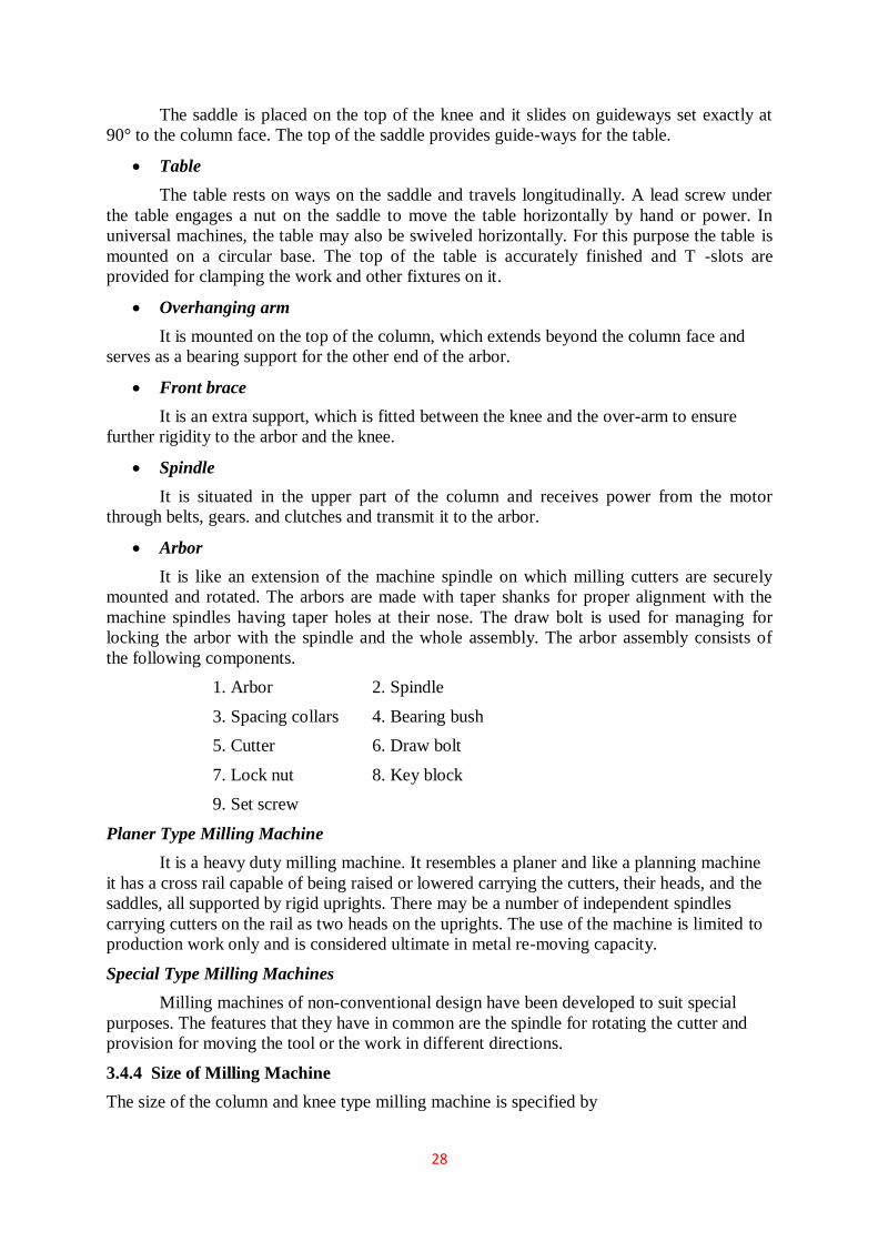
28
The saddle is placed on the top of the knee and it slides on guideways set exactly at
90° to the column face. The top of the saddle provides guide-ways for the table.
Table
The table rests on ways on the saddle and travels longitudinally. A lead screw under
the table engages a nut on the saddle to move the table horizontally by hand or power. In
universal machines, the table may also be swiveled horizontally. For this purpose the table is
mounted on a circular base. The top of the table is accurately finished and T -slots are
provided for clamping the work and other fixtures on it.
Overhanging arm
It is mounted on the top of the column, which extends beyond the column face and
serves as a bearing support for the other end of the arbor.
Front brace
It is an extra support, which is fitted between the knee and the over-arm to ensure
further rigidity to the arbor and the knee.
Spindle
It is situated in the upper part of the column and receives power from the motor
through belts, gears. and clutches and transmit it to the arbor.
Arbor
It is like an extension of the machine spindle on which milling cutters are securely
mounted and rotated. The arbors are made with taper shanks for proper alignment with the
machine spindles having taper holes at their nose. The draw bolt is used for managing for
locking the arbor with the spindle and the whole assembly. The arbor assembly consists of
the following components.
1. Arbor 2. Spindle
3. Spacing collars 4. Bearing bush
5. Cutter 6. Draw bolt
7. Lock nut 8. Key block
9. Set screw
Planer Type Milling Machine
It is a heavy duty milling machine. It resembles a planer and like a planning machine
it has a cross rail capable of being raised or lowered carrying the cutters, their heads, and the
saddles, all supported by rigid uprights. There may be a number of independent spindles
carrying cutters on the rail as two heads on the uprights. The use of the machine is limited to
production work only and is considered ultimate in metal re-moving capacity.
Special Type Milling Machines
Milling machines of non-conventional design have been developed to suit special
purposes. The features that they have in common are the spindle for rotating the cutter and
provision for moving the tool or the work in different directions.
3.4.4 Size of Milling Machine
The size of the column and knee type milling machine is specified by

29
(1) The dimensions of the working surface of the table, and
(2) Its maximum length of longitudinal, cross and vertical travel of the table.
In addition to above, number of spindle speeds, number of feeds, spindle nose taper, power
available, floor space required and net weight of machine will also be required for additional
specification.
3.4.5 Depth of Cut
The depth of cut in milling is defined as the thickness of the material removed in one
pass of the work under the cutter. Thus it is the perpendicular distance measured between the
original and final surface of the workpiece, and is expressed in mm.
3.4.6 Indexing and Dividing Heads
Indexing is the operation of dividing the periphery of a piece of work into any number
of equal parts. In cutting spur gear equal spacing of teeth on the gear blank is performed by
indexing. Indexing is accomplished by using a special attachment known as dividing head or
index head as shown in Fig. 24.8. The dividing heads are of three types:
(1) Plain or simple dividing head,
(2) Universal dividing head and
(3) Optical dividing head.
Figure 3.30 Dividing head
Plain or Simple Dividing Head
The plain dividing head comprises a cylindrical spindle housed on a frame, and a base
bolted to the machine table. The index crank is connected to the tail end of the spindle
directly, and the crank and the spindle rotate as one unit. The index plate is mounted on the
spindle and rotates with it. The spindle may be rotated through the desired angle and then
clamped by inserting the clamping lever pin into anyone of the equally spaced holes or slots
cut on the periphery of the index plate. This type of dividing head is used for handling large
number of workpieces, which require a very small number of divisions on the periphery.
1. Swiveling block 2. Live centre
3. Index crank 4. Index plate.
3.4.7 Operations Performed on Milling Machine

30
Unlike a lathe, a milling cutter does not give a continuous cut, but begins with a
sliding motion between the cutter and the work. Then follows a crushing movement, and then
a cutting operation by which the chip is removed. Many different kinds of operations can be
performed on a milling machine but a few of the more common operations will now be
explained. These are:
Figure 3.31 Types milling
3.5 ABRASIVE MACHINING
Abrasive machining is a material removal process that involves the use of abrasive
cutting tools. There are three principle types of abrasive cutting tools according to the degree
to which abrasive grains are constrained,
Bonded abrasive tools: abrasive grains are closely packed into different shapes, the
most common is the abrasive wheel. Grains are held together by bonding material.

31
Abrasive machining process that use bonded abrasives include grinding, honing,
superfinishing;
Coated abrasive tools: abrasive grains are glued onto a flexible cloth, paper or resin
backing. Coated abrasives are available in sheets, rolls, endless belts. Processes
include abrasive belt grinding, abrasive wire cutting;
Free abrasives: abrasive grains are not bonded or glued. Instead, they are introduced
either in oil-based fluids (lapping, ultrasonic machining), or in water (abrasive water
jet cutting) or air (abrasive jet machining), or contained in a semisoft binder (buffing).
Abrasive machining can be likened to the other machining operations with multipoint
cutting tools. Each abrasive grain acts like a small single cutting tool with undefined
geometry but usually with high negative rake angle. Abrasive machining involves a number
of operations, used to achieve ultimate dimensional precision and surface finish.
3.5.1 Grinding
Grinding is a material removal process in which abrasive particles arc contained in a
bonded grinding wheel that operates at very high surface speeds. The grinding wheel is
usually disk shaped and is precisely balanced for high rotational speeds.
Grinding wheel
A grinding wheel consists of abrasive particles and bonding material. The bonding
material holds the particles in place and establishes the shape and structure of the wheel.
The way the abrasive grains, bonding material, and the air gaps are structured,
determines the parameters of the grinding wheel, which are
abrasive material,
grain size,
bonding material,
wheel grade, and
wheel structure.
To achieve the desired performance in a given application, each parameter must be
carefully selected.
Abrasive materials
The abrasive materials of greatest commercial importance today are listed in the
table:

32
Grain size
The grain size of the abrasive particle is an important parameter in determining
surface finish and material removal rate. Small grit sizes produce better finishes while
larger grain sizes permit larger material removal rates.
The abrasive grains are classified in a screen mesh procedure, as explained in Section
3.2. In this procedure smaller grit sizes have larger numbers and vice versa.
Grain sizes used in grinding wheels typically range between 6 and 600. Grit size 6 is
very coarse and size 600 is very fine. Finer grit sizes up to 1000 are used in some
finishing operations
Bonding Materials
The bonding material holds the abrasive grains and establishes the shape and
structural integrity of the grinding wheel. Desirable properties of the bond material include
strength, toughness, hardness, and temperature resistance.
Bonding materials commonly used in grinding wheels include the following:
vitrified bond: vitrified bonding material consists chiefly of ceramic materials. Most
grinding wheels in common use are vitrified bonded wheels. They are strong and
rigid, resistant to elevated temperatures, and relatively unaffected by cutting fluids;
rubber bond: rubber is the most flexible of the bonding materials. It is used as a
bonding material in cutoff wheels;
resinoid bond: this bond is made of various thermosetting resin materials. They have
very high strength and are used for rough grinding and cutoff operations;
shellac bond: shellac-bonded grinding wheels are relatively strong but not rigid. They
are often used in applications requiring a good finish;
metallic bond: metal bonds, usually bronze, are the common bond material for
diamond and CBN grinding wheels. Diamond and CBN abrasive grains are bond
material to only the outside periphery of the wheel, thus conserving the costly
abrasive materials.
Wheel grade
Wheel grades indicates the wheel bond strength. It is measured on a scale ranging
from soft to hard. Soft wheels loose grains easily and are used for low material removal rates
and grinding of hard materials. Harder grades are preferred for high productivity and grinding
of relatively soft materials.
Structure
The wheel structure indicates spacing of the abrasive grains in the wheel. It is
measured on a scale that ranges from open to dense. Open structure means more pores and
fewer grains per unit wheel volume, and vice versa. Open structure is recommended for work
materials that tend to produce continuous chips, while denser structure is used for better
surface finish and dimensional precision.
Grinding wheel specification
Grinding wheels are marked with a standardized system of letters and numbers, which
specifies the parameters of the grinding wheel. Grinding wheels are available in a variety of
shapes and sizes the most popular shown in the figure:

33
Figure 3.32 Some common types of grinding wheels
Surface grinding
Surface grinding is an abrasive machining process in which the grinding wheel
removes material from the plain flat surfaces of the workpiece.
In surface grinding, the spindle position is either horizontal or vertical, and the
relative motion of the workpiece is achieved either by reciprocating the workpiece past the
wheel or by rotating it. The possible combinations of spindle orientations and workpiece
motions yield four types of surface grinding processes illustrated in the figure:
Figure 3.32 Four types of grinding
3
Cylindrical grinding
In this operation, the external or internal cylindrical surface of a workpiece are
ground. In external cylindrical grinding (also center-type grinding) the workpiece rotates and
reciprocates along its axis, although for large and long workparts the grinding wheel
reciprocates.
In internal cylindrical grinding, a small wheel grinds the inside diameter of the part.
The workpiece is held in a rotating chuck in the headstock and the wheel rotates at very high
rotational speed. In this operation, the workpiece rotates and the grinding wheel reciprocates.

34
Figure 3.33 Two types of grinding
Three types of feed motion are possible according to the direction of feed motion,
traverse feed grinding (also through feed grinding, cross-feeding) in which the relative feed
motion is parallel to the spindle axis of rotation, plunge grinding in which the grinding wheel
is fed radially into the workpiece, and a combination of traverse and plunge grinding in
which the grinding wheel is fed at 45o to grind simultaneously the cylindrical part of the
workpiece and the adjacent face. This methods provides a precise perpendicular mutual
position of both surfaces.
Figure 3.34 Three types of grinding
3.5.2 Grinding Machines
Grinding Machines are also regarded as machine tools. A distinguishing feature of
grinding machines is the rotating abrasive tool. Grinding machine is employed to obtain high
accuracy along with very high class of surface finish on the workpiece. However, advent of
new generation of grinding wheels and grinding machines, characterised by their rigidity,
power and speed enables one to go for high efficiency deep grinding (often called as abrasive
milling) of not only hardened material but also ductile materials.
Conventional grinding machines can be broadly classified as:
a. Surface grinding machine

35
b. Cylindrical grinding machine
c. Internal grinding machine
d. Tool and cutter grinding machine
Surface grinding machine:
This machine may be similar to a milling machine used mainly to grind flat surface.
However, some types of surface grinders are also capable of producing contour surface with
formed grinding wheel.
Basically there are four different types of surface grinding machines characterised by
the movement of their tables and the orientation of grinding wheel spindles as follows:
• Horizontal spindle and reciprocating table
• Vertical spindle and reciprocating table
• Horizontal spindle and rotary table
• Vertical spindle and rotary table
Horizontal spindle reciprocating table grinder
Figure illustrates this machine with various motions required for grinding action. A
disc type grinding wheel performs the grinding action with its peripheral surface. Both
traverse and plunge grinding can be carried out in this machine as shown in Figure.
Figure 3.35 Surface grinder
Vertical spindle reciprocating table grinder
This grinding machine with all working motions is shown in Figure. The grinding
operation is similar to that of face milling on a vertical milling machine. In this machine a
cup shaped wheel grinds the workpiece over its full width using end face of the wheel as
shown in Figure. This brings more grits in action at the same time and consequently a higher
material removal rate may be attained than for grinding with a peripheral wheel.

36
Figure 3.36 Surface grinder
Cylindrical grinding machine
This machine is used to produce external cylindrical surface. The surfaces may be
straight, tapered, steps or profiled. Broadly there are three different types of cylindrical
grinding machine as follows:
1. Plain centre type cylindrical grinder
2. Universal cylindrical surface grinder
3. Centreless cylindrical surface grinder
Figure illustrates schematically this machine and various motions required for
grinding action. The machine is similar to a centre lathe in many respects. The workpiece is
held between head stock and tailstock centres. A disc type grinding wheel performs the
grinding action with its peripheral surface. Both traverse and plunge grinding can be carried
out in this machine as shown in Figure.
Figure 3.37 Plain centre type cylindrical grinder
Universal cylindrical surface grinder

37
Universal cylindrical grinder is similar to a plain cylindrical one except that it is more
versatile. In addition to small worktable swivel, this machine provides large swivel of head
stock, wheel head slide and wheel head mount on the wheel head slide. This allows grinding
of any taper on the workpiece. Universal grinder is also equipped with an additional head for
internal grinding. Schematic illustration of important features of this machine is shown in
Figure.
Figure 3.38 Universal cylindrical grinder
External centreless grinder
This grinding machine is a production machine in which out side diameter of the
workpiece is ground. The workpiece is not held between centres but by a work support blade.
It is rotated by means of a regulating wheel and ground by the grinding wheel.
In through-feed centreless grinding, the regulating wheel revolving at a much lower
surface speed than grinding wheel controls the rotation and longitudinal motion of the
workpiece. The regulating wheel is kept slightly inclined to the axis of the grinding wheel
and the workpiece is fed longitudinally as shown in Figure.
Figure 3.39 Centreless through feed grinder
Internal grinding machine
This machine is used to produce internal cylindrical surface. The surface may be
straight, tapered, grooved or profiled.
Broadly there are three different types of internal grinding machine as follows:
1. Chucking type internal grinder
2. Planetary internal grinder

38
3. Centreless internal grinder
Chucking type internal grinder
Figure illustrates schematically this machine and various motions required for
grinding action. The workpiece is usually mounted in a chuck. A magnetic face plate can also
be used. A small grinding wheel performs the necessary grinding with its peripheral surface.
Both transverse and plunge grinding can be carried out in this machine as shown in Figure.
Figure 3.40 Centreless grinder
Planetary internal grinder
Planetary internal grinder is used where the workpiece is of irregular shape and can
not be rotated conveniently as shown in Figure. In this machine the workpiece does not
rotate. Instead, the grinding wheel orbits the axis of the hole in the workpiece.
Figure 3.41 Planetary grinder
Centreless internal grinder
This machine is used for grinding cylindrical and tapered holes in cylindrical parts
(e.g. cylindrical liners, various bushings etc). The workpiece is rotated between supporting
roll, pressure roll and regulating wheel and is ground by the grinding wheel as illustrated in
Figure.

39
Figure 3.42 centreless grinder
3.6 SHAPER
Shaper is a reciprocating type of machine tool in which the ram moves the cutting tool
backwards and forwards in a straight line. It is intended primarily to produce flat surfaces.
These surfaces may be horizontal, vertical, or inclined. In general, the shaper can produce any
surface composed of straight-line elements
3.6.1 Working Principle of Shaper
A single point cutting tool is held in the tool holder, which is mounted on the ram.
The workpiece is rigidly held in a vice or clamped directly on the table. The table may be
supported at the outer end. The ram reciprocates and thus cutting tool held in tool holder
moves forward and backward over the workpiece. In a standard shaper, cutting of material
takes place during the forward stroke of the ram. The backward stroke remains idle and no
cutting takes place during this stroke. The feed is given to the workpiece and depth of cut is
adjusted by moving the tool downward towards the workpiece. The time taken during the idle
stroke is less as compared to forward cutting stroke and this is obtained by quick return
mechanism.
Figure 3.43 Working principal of shaping machine

40
Figure 3.44 Job surface generated by shaper
Figure 3.45 Cutting action and functioning of clapper box
3.6.2 Types of Shapers
Shapers are classified under the following headings:
(1) According to the type of mechanism used for giving reciprocating motion to the
ram
a) Crank type
b) Geared type
c) Hydraulic type
(2) According to the type of design of the table:
a) Standard shaper
b) Universal shaper
(3) According to the position and travel of ram:
a) Horizontal type
b) Vertical type
c) Traveling head type
(4) According to the type of cutting stroke:
a) Push type
b) Draw type.
Crank Shaper-This is the most common type of shaper. It employs a crank mechanism to
change circular motion of a large gear called “bull gear” incorporated in the machine to
reciprocating motion of the ram. The bull gear receives power either from an individual
motor or from an overhead line shaft if it is a belt-driven shaper.

41
Geared Shaper-Geared shaper uses rack and pinion arrangement to obtain reciprocating
motion of the ram. Presently this type of shaper is not very widely used.
Hydraulic Shaper-In hydraulic shaper, reciprocating motion of the ram is obtained by
hydraulic power. For generation of hydraulic power, oil under high pressure is pumped into
the operating cylinder fitted with piston. The piston end is connected to the ram through
piston rod. The high pressure oil causes the piston to reciprocate and this reciprocating
motion is transferred to the ram of shaper. The important advantage of this type of shaper is
that the cutting speed and force of the ram drive are constant from the very beginning to the
end of the cut.
Standard Shaper-In standard shaper, the table has only two movements, horizontal and
vertical, to give the feed.
Universal Shaper-A universal shaper is mostly used in tool room work. In this type of
shaper, in addition to the horizontal and vertical movements, the table can be swiveled about
an axis parallel to the ram ways, and the upper portion of the table can be tilted about a
second horizontal axis perpendicular to the first axis.
Horizontal Shaper-In this type of shaper, the ram holding the tool reciprocates in a
horizontal axis.
Vertical Shaper-In vertical shaper, the ram reciprocates in a vertical axis. These shapers are
mainly used for machining keyways, slots or grooves, and internal surfaces.
Travelling Head Shaper-In this type of shaper, the ram while it reciprocates, also moves
crosswise to give the required feed.
Push Type Shaper-This is the most general type of shaper used in common practice, in
which the metal is removed when the ram moves away from the column, i.e. pushes the work.
Draw Type Shaper-In this type of shaper, the cutting of metal takes place when the ram
moves towards the column of the machine, i.e. draws the work towards the machine. The tool
is set in a reversed direction to that of a standard shaper.
3.6.3 Principal Parts of Shaper
Figure 3.46 Parts of a standard shaper

42
Base - It is rigid and heavy cast iron body to resist vibration and takes up high compressive
load. It supports all other parts of the machine, which are mounted over it. The base may be
rigidly bolted to the floor of the shop or on the bench according to the size of the machine.
Column - The column is a box shaped casting mounted upon the base. It houses the ram-
driving mechanism. Two accurately machined guide ways are provided on the top of the
column on which the ram reciprocates.
Cross rail - Cross rail of shaper has two parallel guide ways on its top in the vertical plane
that is perpendicular to the rai1 axis. It is mounted on the front vertical guide ways of the
column. It consists mechanism for raising and lowering the table to accommodate different
sizes of jobs by rotating an elevating screw which causes the cross rail to slide up and down
on the vertical face of the column. A horizontal cross feed screw is fitted within the cross rail
and parallel to the top guide ways of the cross rail. This screw actuates the table to move in a
crosswise direction.
Saddle - The saddle is located on the cross rail and holds the table on its top. Crosswise
movement of the saddle by rotation the cross feed screw by hand or power causes the table to
move sideways.
Table -The table is a box like casting having T -slots both on the top and sides for clamping
the work. It is bolted to the saddle and receives crosswise and vertical movements from the
saddle and cross rail.
Ram - It is the reciprocating part of the shaper, which reciprocates on the guideways provided
above the column. Ram is connected to the reciprocating mechanism contained within the
column.
Tool head - The tool head of a shaper performs the following functions-
(1) It holds the tool rigidly,
(2) It provides vertical and angular feed movement of the tool, and
(3) It allows the tool to have an automatic relief during its return stroke.
The various parts of tool head of shaper are apron clamping bolt, clapper box, tool
post, down feed, screw micrometer dial, down feed screw, vertical slide, apron washer, apron
swivel pin, and swivel base. By rotating the down feed screw handle, the vertical slide
carrying the tool gives down feed or angular feed movement while machining vertical or
angular surface. The amount of feed or depth of cut may be adjusted by a micrometer dial on
the top of the down feed screw. Apron consisting of clapper box, clapper block and tool post
is clamped upon the vertical slide by a screw. The two vertical walls on the apron called
clapper box houses the clapper block, which is connected to it by means of a hinge pin. The
tool post is mounted upon the clapper block. On the forward cutting stroke the clapper block
fits securely to the clapper box to make a rigid tool support. On the return stroke a slight
frictional drag of the tool on the work lifts the block out of the clapper box a sufficient
amount preventing the tool cutting edge from dragging and consequent wear. The work
surface is also prevented from any damage due to dragging.
3.6.3 Specification of a Shaper
The size of a shaper is specified by the maximum length of stroke or cut it can make.
Usually the size of shaper ranges from 175 to 900 mm. Besides the length of stroke, other
particulars, such as the type of drive (belt drive or individual motor drive), floor space
required, weight of the machine, cutting to return stroke ratio, number and amount of feed,
power input etc. are also sometimes required for complete specification of a shaper.

43
3.6.4 Shaper Mechanism
In a shaper, rotary motion of the drive is converted into reciprocating motion of the
ram by the mechanism housed within the column or the machine. In a standard shaper metal
is removed in the forward cutting stroke, while the return stroke goes idle and no metal is
removed during this period as shown in Figure. The shaper mechanism is so designed that it
moves the ram holding the tool at a comparatively slower speed during forward cutting
stroke, whereas during the return stroke it allow the ram to move at a faster speed to reduce
the idle return time. This mechanism is known as quick return mechanism. The reciprocating
movement of the ram and the quick return mechanism of the machine are generally obtained
by anyone of the following methods:
(1) Crank and slotted link mechanism
(2) Whitworth quick return mechanism, and
(3) Hydraulic shaper mechanism
Crank and Slotted Link Mechanism
In crank and slotted link mechanism, the pinion receives its motion from an individual
motor or overhead line shaft and transmits the motion or power to the bull gear. Bull gear is a
large gear mounted within the column. Speed of the bull gear may be changed by different
combination of gearing or by simply shifting the belt on the step cone pulley. A radial slide is
bolted to the centre of the bull gear.
Figure 3.47 Crank and slotted link mechanism
This radial slide carries a sliding block into which the crank pin is fitted. Rotation of
the bull gear will cause the bush pin to revolve at a uniform speed. Sliding block, which is
mounted upon the crank pin is fitted within the slotted link. This slotted link is also known as
the rocker arm. It is pivoted at its bottom end attached to the frame of the column.
The upper end of the rocker arm is forked and connected to the ram block by a pin.
With the rotation of bull gear, crank pin will rotate on the crank pin circle, and
simultaneously move up and down the slot in the slotted link giving it a rocking movement,
which is communicated to the ram. Thus the rotary motion of the bull gear is converted to
reciprocating motion of the ram.

44
3.6.5 Shaper Operations
A shaper is a machine tool primarily designed to generate a flat surface by a single
point cutting tool. Besides this, it may also be used to perform many other operations. The
different operations, which a shaper can perform, are as follows:
Figure 3.48 Cutting operation in shaper
3.7 PLANER
Like a shaper, planer is used primarily to produce horizontal, vertical or inclined flat
surfaces by a single point cutting tool. But it is used for machining large and heavy
workpieces that cannot be accommodated on the table of a shaper. In addition to machining
large work, the planer is frequently used to machine multiple small parts held in line on the
platen. Planer is mainly of two kinds namely open housing planer and double housing planer.
The principle parts of the open housing planer are shown in Figure(a).
The principle parts of the double housing planer are shown in Fig ure(b). The bigger
job is fixed with help of the grooves on the base of the planer and is accurately guided as it
travels back and forth. Cutting tools are held in tool heads of double housing planer and the
work piece is clamped onto the worktable as shown in Figure(b).
The worktable rides on the gin tool heads that can travel from side to side i.e., in a
direction at right angle to the direction of motion of the worktable. Tool heads are mounted
on a horizontal cross rail that can be moved up and down. Cutting is achieved by applying the
linear primary motion to the workpiece (motion X) and feeding the tool at right angles to this
motion (motion Y and Z).
The primary motion of the worktable is normally accomplished by a rack and pinion
drive using a variable speed motor. As with the shaper, the tool posts are mounted on clapper

45
boxes to prevent interference between the tools and work-piece on the return stroke and the
feed motion is intermittent.
The size of a standard planer is specified by the size of the largest solid that can
reciprocate under the tool. In addition to this, some other parameters such as table size
(length and width), type of drive, number of speeds and feeds available, power input, weight
of the machine, floor space required etc. may be required to specify a planer completely
Figure 3.49 Principle parts of double housing planer
3.7.1 Working Principal of Planer
Figure depicts the working principle of a planer. In a planer, the work which is
supported on the table reciprocates past the stationary cutting tool and the feed is imparted by
the lateral movement of the tool.
The tool is clamped in the tool holder and work on the table. Like shaper, the planner
is equipped with clapper box to raise the tool in idle stroke. The different mechanisms used to
give reciprocating motion to the table are following-
1. Reversible motor drive
2. Open and cross belt drive
3. Hydraulic drive
Figure 3.50 Working Principle of a planer

46
3.7.2 Difference Between Shaper and Planer
3.7.3 Types of Planers
Planers may be classified in a number of ways, but according to general construction, these
are the following types:
1. Double housing planer
2. Open side planer
3. Pit planer
4. Edge or plate type planer
5. Divided table planer
3.8 SLOTTER
The slotter or slotting machine is also a reciprocating type of machine tool similar to a
shaper or a planer. It may be considered as a vertical shaper. The chief difference between a
shaper and a slotter is the direction of the cutting action. The machine operates in a manner
similar to the shaper, however, the tool moves vertically rather than in a horizontal direction.
The job is held stationary. The slotter has a vertical ram and a hand or power operated rotary
table.
3.8.1 PRINCIPLE PARTS OF A SLOTTER
The main parts of a slotter are discussed as under:
Bed or Base - It is made up of cast iron. It supports column, tables, ram, driving mechanism
etc. The top of the bed carries horizontal ways along which the worktable can traverse.
Table - It holds the work piece and is adjustable in longitudinal and cross-wise directions.
The table can be rotated about its centre.

47
Hand wheels - They are provided for rotating the table and for longitudinal and cross
traverse.
Column is the vertical member - They are made up of cast iron and it houses the driving
mechanism. The vertical front face of the column is accurately finished for providing ways
along which the ram moves up and down.
Ram - It is provided to reciprocate vertically up and down. At its bottom, it carries the
cutting tool. It is similar to the ram of a shaper; but it is more massive and moves vertically,
at right angle to the worktable, instead of having the horizontal motion of a shaper.
Cross-slide - It can be moved parallel to the face of the column. The circular work-table is
mounted on the top of the cross-slide.
Figure 3.51 Slotter and its various parts
3.8.2 Operations Performed on a Slotting Machine
A slotter is a very economical machine tool when used for certain classes of work given as
under.
a. It is used for machining vertical surfaces
b. It is used angular or inclined surfaces
c. It is used It is used to cut slots, splines keyways for both internal and external jobs
such as machining internal and external gears,
d. It is used for works as machining concave, circular, semi-circular and convex surfaces
e. It is used for shaping internal and external forms or profiles
f. It is used for machining of shapes which are difficult to produce on shaper
g. It is used for internal machining of blind holes

48
h. It is used for machining dies and punches, and Since a slotter works slowly. It has less
use in mass production work. It can be substituted by the broaching machine.
3.9 BASIC PRINCIPLES OF BROACHINING
Broaching is a machining process for removal of a layer of material of desired width
and depth usually in one stroke by a slender rod or bar type cutter having a series of cutting
edges with gradually increased protrusion as indicated in Figure. In shaping, attaining full
depth requires a number of strokes to remove the material in thin layers step – by – step by
gradually infeeding the single point tool. Whereas, broaching enables remove the whole
material in one stroke only by the gradually rising teeth of the cutter called broach. The
amount of tooth rise between the successive teeth of the broach is equivalent to the infeed
given in shaping.
Figure 3.52 Basic principle of broaching
Machining by broaching is preferably used for making straight through holes of
various forms and sizes of section, internal and external through straight or helical slots or
grooves, external surfaces of different shapes, teeth of external and internal splines and small
spur gears etc. Figure schematically shows how a through hole is enlarged and finished by
broaching.
3.9.1 Broaches
A broach is a multiple-edge cutting tool that has successively higher cutting edges along
the length of the tool.
Types of Broaches:
Broaches may be classified in various ways, according to:
Type of operation: internal or external.
Method of operation: push or pull.
Type of construction: solid, built-up, inserted tooth, progressive cut, rotor cut, double jump,
or overlapping tooth.’
Function: surface, keyway, round hole, splint, spiral, burnishing, etc.

49
Figure 3.53 Horizontal broaching machine
Figure 3.54 Surface broaching

50
Figure 3.54 Vertical broaching machine
3.9.2 Advantages of Broaching
• Rate of production is very high. With properly applied broaches, fixtures, and
machines, more pieces can be turned per hour by broaching than by any other means,
• Little skill is required to perform a broaching operation. In most cases the operator
merely loads and unloads the workpiece.
• High accuracy and a high class of surface finish is possible. A tolerance of ± 0.0075
mm and a surface finish of about 0.8 microns (1 micron = 0.001mm) can be easily
obtained in broaching.
• Both roughing and finishing cuts are completed in one pass of the tool.
• The process can be used for either internal or external surface finishing.
• Any form that can be reproduced on a broaching can be machined.
• Cutting fluid may be readily applied where it is most effective because a broach tends
to draw the fluid into the cut.
3.9.3 Dis-Advantages of Broaching
• High tool cost. A broach usually does only one job and is expensive to make and
sharpen.
• Very large workpieces cannot be broached.
• The surfaces to be broached cannot have an obstruction.
• Broaching cannot be used for the removal of a large amount of stock.
CONTINUES BROACHING

51
• Parts to be broached must be capable of being rigidly supported and must be able to
withstand the forces that set up during V Cutting.
3.10 BORING
Boring is similar to turning. It uses a single-point tool against a rotating workpart. The
difference is that boring is performed on the inside diameter of an existing hole rather than
the outside diameter of an existing cylinder.
3.10.1 Horizontal Boring
In a horizontal boring operation, the setup can be arranged in either of two ways. The
first setup is one in which the work is fixtured to a rotating spindle, and the tool is
attached to a cantilevered boring bar that feeds into the work shown in figure.
The boring bar in this setup must be very stiff to avoid deflection and vibration during
cutting. To achieve high stiffness.
The second possible setup is one in which the tool is mounted to a boring bar, and the
boring bar is supported and rotated between centers. The work is fastened to a feeding
mechanism that feeds it past the tool. This setup is shown in figure.
Figure 3.54 Horizontal boring machine
3.10.2 Vertical Boring Machine
A vertical boring machine is used for large heavy workparts with large
diameters,usually the workpart diameter is greater than its length. As in Figure the
part is clamped to a worktable that rotates relative to the machine base. Work tables
up to 40 ft in diameter are available.

52
The tools are mounted on tool heads that can be fed horizontally and vertically
relative to theworktable
One or two heads aremounted ona horizontal cross-rail assembled to the machine tool
housing above the worktable
The cutting tools mounted above the work can be used for facing and boring. In
addition to the tools on the cross-rail, one or two additional tool heads can be mounted
on the side columns of the housing to enable turning on the outside diameter of the
work.
Figure 3.55 Vertical boring machine
3.11 AUTOMATION OF MANUFACTURING PROCESS
Automation
Automation generally is defined as the process of enabling machines to follow a
predetermined sequence of operations with little or no human intervention and using
specialized equipment and devices that perform and control manufacturing processes and
operations.

53
Automation is an evolutionary rather than a revolutionary concept. In manufacturing plants,
for example, it has been implemented especially in the following basic areas of activity:
Manufacturing processes: Machining, forging, cold extrusion, casting, powder
metallurgy, and grinding operations.
Material handling and movement: Materials and parts in various stages of completion
(works in progress) are moved throughout a plant by computer controlled equipment,
with little or no human guidance.
Inspection: Parts are inspected automatically for dimensional accuracy, surface finish,
quality, and various specific characteristics during their manufacture (in-process
inspection).
Assembly: Individually manufactured parts and components are assembled
automatically into subassemblies and then assemblies to complete a product.
Packaging: Products are packaged automatically for shipment. Industrial Revolution
in the 1750s (also referred to as the First Industrial Revolution, the Second Industrial
Revolution having begun in the mid 1950s, with advances in many areas) that
automation began to be introduced in the production of goods. Machine tools (such as turret
lathes, automatic screw machines, and automatic glass bottle-making equipment) began to be
developed in the late 1890s. Mass-production techniques and transfer machines were
developed in the 1920s. These machines had fixed automatic mechanisms and were designed
to produce specific products, best represented by the automobile industry, which produced
passenger cars at a high production rate and low cost.
The major breakthrough in automation began with numerical control (NC) of machine
tools in the early 1950s. Since this historic development, rapid progress has been made in
automating almost all aspects of manufacturing, from the introduction of computers into
automation, to computerized numerical control (CNC) and adaptive control (AC), to
industrial robots, to computer-aided design, engineering, and manufacturing
(CAD/CAE/CAM) and computer-integrated manufacturing (CIM) systems.
Manufacturing involves various levels of automation, depending on the processes
used, the products to be made, and production volumes. Manufacturing systems, in order of
increasing automation, include the following classifications ° ]ob shops: These facilities use
general-purpose machines and machining centers with high levels of labor involvement.
Stand-alone NC production: This method uses numerically controlled machines but
with significant operator-machine interaction.
Manufacturing cells: These cells use a cluster of machines with integrated computer
control and flexible material handling, often with industrial robots.
Flexible manufacturing systems: These systems use computer control of all aspects of
manufacturing, the simultaneous incorporation of a number of manufacturing cells,
and automated material-handling systems.
Flexible manufacturing lines: These lines organize computer-controlled machinery in
production lines instead of cells. Part transfer is through hard automation and product
flow is more limited than in flexible manufacturing systems, but the throughput is
larger for higher production quantities.
Flow lines and transfer lines: These lines consist of organized groupings of machinery
with automated material handling between machines. The manufacturing line is
designed with limited or no flexibility, since the goal is to produce a single part.
3.11.1 Numerical Control

54
Numerical control (NC) is a method of controlling the movements of machine
components by directly inserting coded instructions in the form of numbers and letters into
the system. The system automatically interprets these data and converts them to output
signals, which, in turn, control various machine components-for example, turning spindles on
and off, changing tools, moving the workpiece or the tools along specific paths, and turning
cutting fluids on and off.
The importance of numerical control can be illustrated by the following example:
Assume that several holes are to be drilled on a part in the positions shown in Figure. In the
traditional manual method of machining this part, the operator positions the drill bit with
respect to the workpiece, using reference points given by any of the three methods shown in
the figure.
The operator then proceeds to drill the holes. Assume now that 100 parts, all having
exactly the same shape and dimensional accuracy, are to be drilled. Obviously, this operation
is going to be tedious and time consuming, because the operator has to go through the same
motions repeatedly.
Moreover, the probability is high that, for a variety of reasons, some of the parts
machined will be different from others. Now assume further that, during this production run,
the order of processing these parts is changed and, in addition, 10 of the parts now require
holes in different positions. The machinist now has to reposition the worktable, an operation
that is time consuming and subject to error.
Such operations can be performed easily by numerical-control machines, which are
capable of producing parts repeatedly and accurately and of handling different parts simply
by loading different part programs. In numerical-control operations, data concerning all
aspects of the machining operation (such as tool locations, speeds, feeds, and cutting fluids)
are stored on hard disks. On the basis of input information, relays and other devices (known
as hardwired controls) can be actuated to obtain a desired machine setup. Complex
operations, such as turning a part having various contours or die sinking in a milling machine,
are now carried out easily.
NC machines are used extensively in small- and medium-quantity production
(typically 500 or fewer parts) of a wide variety of parts, both in small shops and in large
manufacturing facilities.
Figure 3.56 Numerical Control
3.11.2 Computer Numerical Control

55
In the next step in the development of numerical control, the control hardware
(mounted on the NC machine) was converted to local computer control by software. Two
types of computerized systems were developed-direct numerical control and computer
numerical control:
In direct numerical control (DNC), several machines are controlled directly step by
step-by a central mainframe computer. In this system, the operator has access to the central
computer through a remote terminal. With DNC, the status of all machines in a
manufacturing facility can be monitored and assessed from a central computer.
However, DNC has a crucial disadvantage: If the computer shuts down, all of the
machines be- I (onboard computer). The machine operator can program Qi onboard
computers, modify the programs directly, prepare u? programs for different parts, and store
the programs. CNC systems are used widely today because of the availability of (a) small
computers with large memory, (b) low-cost programmable controllers and microprocessors,
and (c) programediting capabilities.
Figure 3.57 Computer Numerical Control

1
SCHOOL OF MECHANICAL ENGINEERING
DEPARTMENT OF MECHANICAL ENGINEERING
UNIT – IV – Fundamentals of Mechanical Engineering – SMEA1203

2
4. I.C. ENGINES
4. HEAT ENGINES
A heat engine is a machine, which converts heat energy into mechanical energy. The
combustion of fuel such as coal, petrol, diesel generates heat. This heat is supplied to a
working substance at high temperature. By the expansion of this substance in suitable
machines, heat energy is converted into useful work. Heat engines can be further divided into
two types:
(i) External combustion and
(ii) Internal combustion.
4.1 Classification of Heat Engines
4.2 External combustion engine
Here, the working medium, the steam, is generated in a boiler, located outside the
engine and allowed in to the cylinder to operate the piston to do mechanical work.
4.3 Internal combustion engine
In internal combustion engine, the combustion of fuel takes place inside the engine
cylinder and heat is generated within the cylinder. This heat is added to the air inside the
cylinder and thus the pressure of the air is increased tremendously. This high pressure air
moves the piston which rotates the crank shaft and thus mechanical work is done. Most of the
internal combustion engines are reciprocating engines with a piston that reciprocate back
and forth in the cylinder.
4.4 Classification of Internal Combustion Engines
4.4.1 Based on fuel used
1. Diesel engine 2. Petrol engine 3. Gas engine
Diesel engine – Diesel is used as fuel
Petrol engine – Petrol is used as fuel
Gas engines – propane, butane or methane gases are used

3
4.4.2 Based ignition of fuel
1. Spark ignition engine (Carburetor type engines)
2. Compression ignition engine ( injector type engines)
Spark ignition engine – A mixture of air and fuel is drawn in to the engine cylinder. Ignition
of fuel is done by using a spark plug. The spark plug produces a spark and ignites the air- fuel
mixture. Such combustion is called constant volume combustion (C.V.C.).
Compression ignition engine – In compression ignition engines air is compressed in to the
engine cylinder,. Due to this the temperature of the compressed air rises to 700-900C. At this
stage diesel is sprayed in to the cylinder in fine particles. Due to a very high temperature, the
fuel gets ignited. This type of combustion is called constant pressure combustion (CP.C.)
because the pressure inside the cylinder is almost constant when combustion is taking place.
4.4.3 Based on working cycle
1. Four stroke cycle engine - When the cycle is completed in two revolutions of the
crankshaft, it is called four stroke cycle engine.
2. Two stroke cycle engine. - When the cycle is completed in one revolution of the
crankshaft, it is called two stroke cycle engine
4.5 IC ENGINE COMPONENTS
Internal combustion engine consists of a number of parts which are given below :
Figure 4.1 IC Engine components
Cylinder: It is a part of the engine which confines the expanding gases and forms the
combustion space. It is the basic part of the engine. It provides space in which piston operates
to suck the air or air-fuel mixture. The piston compresses the charge and the gas is allowed to
expand in the cylinder, transmitting power for useful work. Cylinders are usually made of
high grade cast iron.
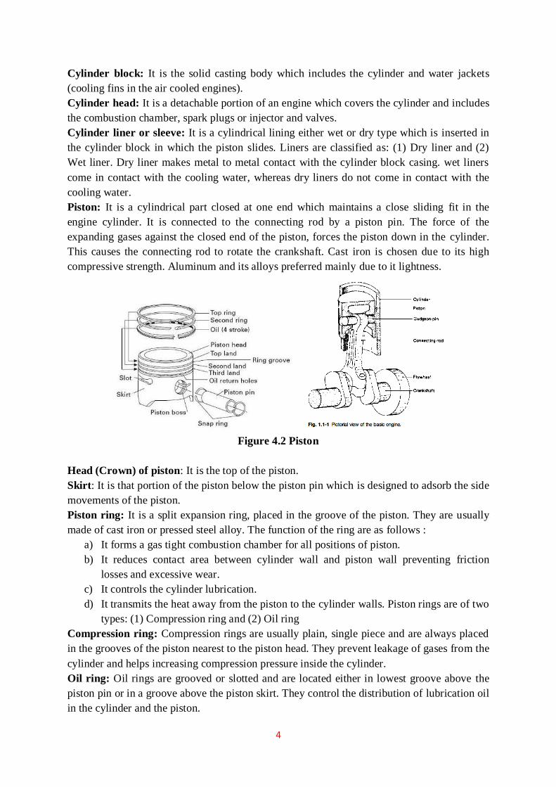
4
Cylinder block: It is the solid casting body which includes the cylinder and water jackets
(cooling fins in the air cooled engines).
Cylinder head: It is a detachable portion of an engine which covers the cylinder and includes
the combustion chamber, spark plugs or injector and valves.
Cylinder liner or sleeve: It is a cylindrical lining either wet or dry type which is inserted in
the cylinder block in which the piston slides. Liners are classified as: (1) Dry liner and (2)
Wet liner. Dry liner makes metal to metal contact with the cylinder block casing. wet liners
come in contact with the cooling water, whereas dry liners do not come in contact with the
cooling water.
Piston: It is a cylindrical part closed at one end which maintains a close sliding fit in the
engine cylinder. It is connected to the connecting rod by a piston pin. The force of the
expanding gases against the closed end of the piston, forces the piston down in the cylinder.
This causes the connecting rod to rotate the crankshaft. Cast iron is chosen due to its high
compressive strength. Aluminum and its alloys preferred mainly due to it lightness.
Figure 4.2 Piston
Head (Crown) of piston: It is the top of the piston.
Skirt: It is that portion of the piston below the piston pin which is designed to adsorb the side
movements of the piston.
Piston ring: It is a split expansion ring, placed in the groove of the piston. They are usually
made of cast iron or pressed steel alloy. The function of the ring are as follows :
a) It forms a gas tight combustion chamber for all positions of piston.
b) It reduces contact area between cylinder wall and piston wall preventing friction
losses and excessive wear.
c) It controls the cylinder lubrication.
d) It transmits the heat away from the piston to the cylinder walls. Piston rings are of two
types: (1) Compression ring and (2) Oil ring
Compression ring: Compression rings are usually plain, single piece and are always placed
in the grooves of the piston nearest to the piston head. They prevent leakage of gases from the
cylinder and helps increasing compression pressure inside the cylinder.
Oil ring: Oil rings are grooved or slotted and are located either in lowest groove above the
piston pin or in a groove above the piston skirt. They control the distribution of lubrication oil
in the cylinder and the piston.

5
Piston Pin: It is also called wrist pin or gudgeon pin. Piston pin is used to join the connecting
rod to the piston.
Connecting rod: It is special type of rod, one end of which is attached to the piston and the
other end to the crankshaft. It transmits the power of combustion to the crankshaft and makes
it rotate continuously. It is usually made of drop forged steel.
Figure 4.3 Connecting Rod
Figure 4.4 Crankshaft
Crankshaft: It is the main shaft of an engine which converts the reciprocating motion of the
piston into rotary motion of the flywheel. Usually the crankshaft is made of drop forged steel
or cast steel. The space that supports the crankshaft in the cylinder block is called main
journal, whereas the part to which connecting rod is attached is known as crank journal.
Crankshaft is provided with counter weights throughout its length to have counter balance of
the unit.
Flywheel: Flywheel is made of cast iron. Its main functions are as follows :
a) It stores energy during power stroke and returns back the energy during the idle
strokes, providing a uniform rotary motion of flywheel.
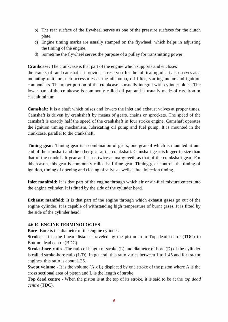
6
b) The rear surface of the flywheel serves as one of the pressure surfaces for the clutch
plate.
c) Engine timing marks are usually stamped on the flywheel, which helps in adjusting
the timing of the engine.
d) Sometime the flywheel serves the purpose of a pulley for transmitting power.
Crankcase: The crankcase is that part of the engine which supports and encloses
the crankshaft and camshaft. It provides a reservoir for the lubricating oil. It also serves as a
mounting unit for such accessories as the oil pump, oil filter, starting motor and ignition
components. The upper portion of the crankcase is usually integral with cylinder block. The
lower part of the crankcase is commonly called oil pan and is usually made of cast iron or
cast aluminum.
Camshaft: It is a shaft which raises and lowers the inlet and exhaust valves at proper times.
Camshaft is driven by crankshaft by means of gears, chains or sprockets. The speed of the
camshaft is exactly half the speed of the crankshaft in four stroke engine. Camshaft operates
the ignition timing mechanism, lubricating oil pump and fuel pump. It is mounted in the
crankcase, parallel to the crankshaft.
Timing gear: Timing gear is a combination of gears, one gear of which is mounted at one
end of the camshaft and the other gear at the crankshaft. Camshaft gear is bigger in size than
that of the crankshaft gear and it has twice as many teeth as that of the crankshaft gear. For
this reason, this gear is commonly called half time gear. Timing gear controls the timing of
ignition, timing of opening and closing of valve as well as fuel injection timing.
Inlet manifold: It is that part of the engine through which air or air-fuel mixture enters into
the engine cylinder. It is fitted by the side of the cylinder head.
Exhaust manifold: It is that part of the engine through which exhaust gases go out of the
engine cylinder. It is capable of withstanding high temperature of burnt gases. It is fitted by
the side of the cylinder head.
4.6 IC ENGINE TERMINOLOGIES
Bore- Bore is the diameter of the engine cylinder.
Stroke - It is the linear distance traveled by the piston from Top dead centre (TDC) to
Bottom dead centre (BDC).
Stroke-bore ratio -The ratio of length of stroke (L) and diameter of bore (D) of the cylinder
is called stroke-bore ratio (L/D). In general, this ratio varies between 1 to 1.45 and for tractor
engines, this ratio is about 1.25.
Swept volume - It is the volume (A x L) displaced by one stroke of the piston where A is the
cross sectional area of piston and L is the length of stroke
Top dead centre - When the piston is at the top of its stroke, it is said to be at the top dead
centre (TDC),

7
Bottom dead centre - when the piston is at the bottom of its stroke, it is said to be at its
bottom dead centre (BDC).
Figure 4.5 Engine terminologies
Compression ratio - It is the ratio of the volume of the cylinder at the beginning of the
compression stroke to that at the end of compression stroke, i.e. ratio of total cylinder volume
to clearance volume. The Compression ratio of diesel engine varies from 14:1 to 22:1 and
that of carburetor type engine (spark ignition engine) varies from 4:1 to 8:1.
Power - It is the rate of doing work. S.I. unit of power is watt.
Watt = Joule/sec. (4.2 Joules = 1 Calorie).
In metric unit the power can be expressed in kg.m/sec.
Horse power (HP) - It is the rate of doing work. Expressed in horse power Conversion
factors from work to power
4500 kg m of work /minute = 1.0 hp
75 kg. m of work /second = 1.0 hp.
Indicated horse power (IHP) - It is the power generated in the engine cylinder and received
by the piston. It is the power developed in a cylinder without accounting frictional losses.
Brake horse power (BHP) - It is the power delivered by the engine at the end of the
crankshaft. It is measured by a dynamometer.
4.7 FOUR STROKE CYCLE ENGINE ( DIESEL/ PETROL ENGINE)
In four stroke cycle engines the four events namely suction, compression, power and
exhaust take place inside the engine cylinder. The four events are completed in four strokes
of the piston (two revolutions of the crank shaft).
This engine has got valves for controlling the inlet of charge and outlet of exhaust
gases. The opening and closing of the valve is controlled by cams, fitted on camshaft. The
camshaft is driven by crankshaft with the help of suitable gears or chains. The camshaft runs
at half the speed of the crankshaft. The events taking place in I.C. engine are as follows:
1. Suction stroke 2. Compression stroke
3. Power stroke 4. Exhaust stroke

8
Figure 4.6 Four stroke cycle engine
Suction stroke
During suction stroke inlet valve opens and the piston moves downward. Only air or a
mixture of air and fuel are drawn inside the cylinder. The exhaust valve remains in closed
position during this stroke. The pressure in the engine cylinder is less than atmospheric
pressure during this stroke.
Compression stroke
During this stroke the piston moves upward. Both valves are in closed position. The
charge taken in the cylinder is compressed by the upward movement of piston. If only air is
compressed, as in case of diesel engine, diesel is injected at the end of the compression stroke
and ignition of fuel takes place due to high pressure and temperature of the compressed air. If
a mixture of air and fuel is compressed in the cylinder, as in case of petrol engine, the mixture
is ignited by a spark plug.
Power stroke
After ignition of fuel, tremendous amount of heat is generated, causing very high
pressure in the cylinder which pushes the piston downward. The downward movement of the
piston at this instant is called power stroke. The connecting rod transmits the power from
piston to the crank shaft and crank shaft rotates. Mechanical work can be taped at the rotating
crank shaft. Both valves remain closed during power stroke.
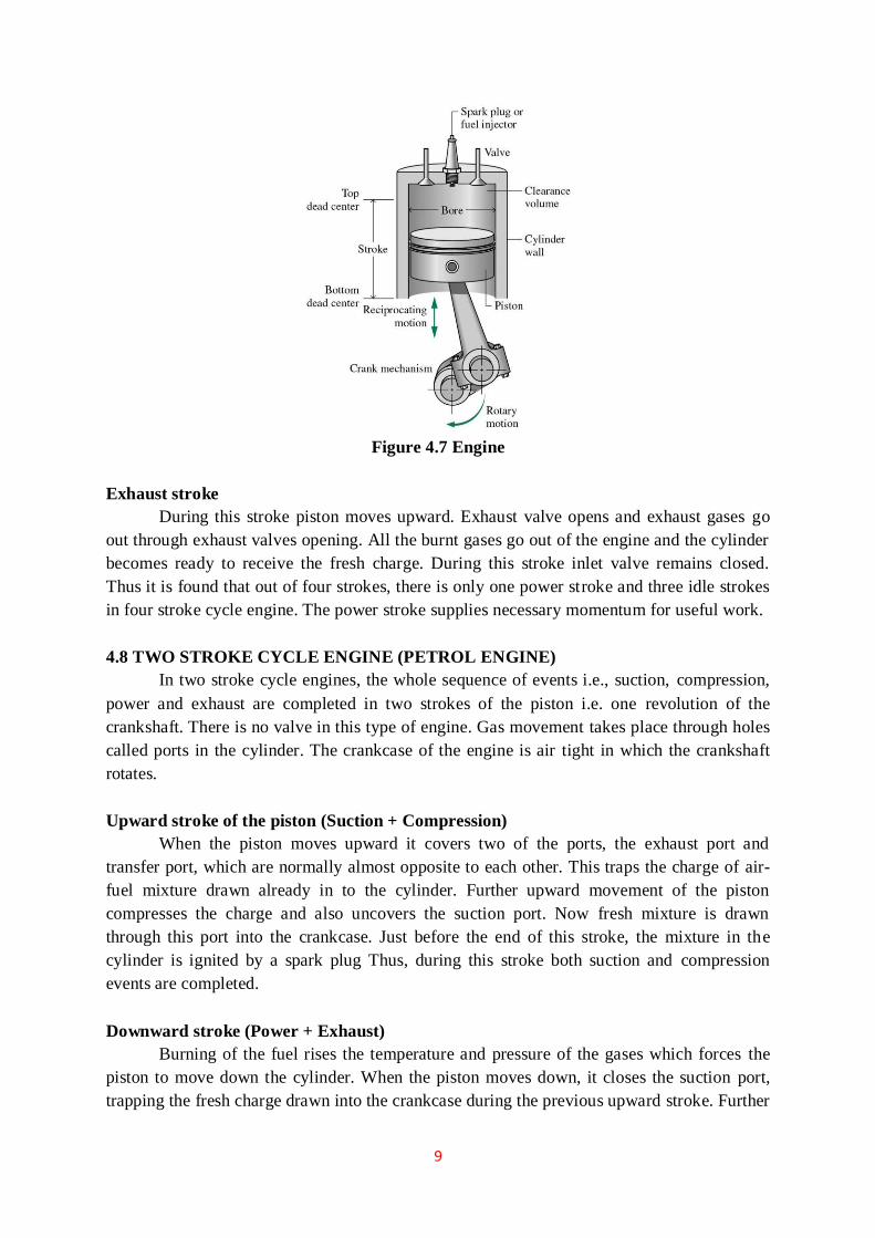
9
Figure 4.7 Engine
Exhaust stroke
During this stroke piston moves upward. Exhaust valve opens and exhaust gases go
out through exhaust valves opening. All the burnt gases go out of the engine and the cylinder
becomes ready to receive the fresh charge. During this stroke inlet valve remains closed.
Thus it is found that out of four strokes, there is only one power stroke and three idle strokes
in four stroke cycle engine. The power stroke supplies necessary momentum for useful work.
4.8 TWO STROKE CYCLE ENGINE (PETROL ENGINE)
In two stroke cycle engines, the whole sequence of events i.e., suction, compression,
power and exhaust are completed in two strokes of the piston i.e. one revolution of the
crankshaft. There is no valve in this type of engine. Gas movement takes place through holes
called ports in the cylinder. The crankcase of the engine is air tight in which the crankshaft
rotates.
Upward stroke of the piston (Suction + Compression)
When the piston moves upward it covers two of the ports, the exhaust port and
transfer port, which are normally almost opposite to each other. This traps the charge of air-
fuel mixture drawn already in to the cylinder. Further upward movement of the piston
compresses the charge and also uncovers the suction port. Now fresh mixture is drawn
through this port into the crankcase. Just before the end of this stroke, the mixture in the
cylinder is ignited by a spark plug Thus, during this stroke both suction and compression
events are completed.
Downward stroke (Power + Exhaust)
Burning of the fuel rises the temperature and pressure of the gases which forces the
piston to move down the cylinder. When the piston moves down, it closes the suction port,
trapping the fresh charge drawn into the crankcase during the previous upward stroke. Further

10
downward movement of the piston uncovers first the exhaust port and then the transfer port.
Now fresh charge in the crankcase moves in to the cylinder through the transfer port driving
out the burnt gases through the exhaust port. Special shaped piston crown deflect the
incoming mixture up around the cylinder so that it can help in driving out the exhaust gases .
During the downward stroke of the piston power and exhaust events are completed.
4.9 COMPARISON OF CI AND SI ENGINES
The CI engine has the following advantages over the SI engine.
1. Reliability of the CI engine is much higher than that of the SI engine. This is because
in case of the failure of the battery, ignition or carburetor system, the SI engine cannot
operate, whereas the CI engine, with a separate fuel injector for each cylinder, has less
risk of failure.
2. The distribution of fuel to each cylinder is uniform as each of them has a separate
injector, whereas in the SI engine the distribution of fuel mixture is not uniform,
owing to the design of the single carburetor and the intake manifold.
3. Since the servicing period of the fuel injection system of CI engine is longer, its
maintenance cost is less than that of the SI engine.
4. The expansion ratio of the CI engine is higher than that of the SI engine; therefore, the
heat loss to the cylinder walls is less in the CI engine than that of the SI engine.
Consequently, the cooling system of the CI engine can be of smaller dimensions.
5. The torque characteristics of the CI engine are more uniform which results in better
top gear performance.
6. The CI engine can be switched over from part load to full load soon after starting
from cold, whereas the SI engine requires warming up.
7. The fuel (diesel) for the CI engine is cheaper than the fuel (petrol) for SI engine.
8. The fire risk in the CI engine is minimized due to the absence of the ignition system.
9. On part load, the specific fuel consumption of the CI engine is low.
4.10 ADVANTAGES AND DISADVANTAGES OF TWO-STROKE CYCLE OVER
FOUR- STROKE CYCLE ENGINES
Advantages:
1) The two-stroke cycle engine gives one working stroke for each revolution of the
crankshaft. Hence theoretically the power developed for the same engine speed and
cylinder volume is twice that of the four-stroke cycle engine, which gives only one
working stroke for every two revolutions of the crankshaft. However, in practice,
because of poor scavenging, only 50-60% extra power is developed.
2) Due to one working stroke for each revolution of the crankshaft, the turning moment
on the crankshaft is more uniform. Therefore, a two-stroke engine requires a lighter
flywheel.
3) The two-stroke engine is simpler in construction. The design of its ports is much
simpler and their maintenance easier than that of the valve mechanism.
4) The power required to overcome frictional resistance of the suction and exhaust
strokes is saved, resulting in some economy of fuel.

11
5) Owing to the absence of the cam, camshaft, rockers, etc. of the valve mechanism, the
mechanical efficiency is higher.
6) The two-stroke engine gives fewer oscillations.
7) For the same power, a two-stroke engine is more compact and requires less space than
a four-stroke cycle engine. This makes it more suitable for use in small machines and
motorcycles.
8) A two-stroke engine is lighter in weight for the same power and speed especially
when the crankcase compression is used.
9) Due to its simpler design, it requires fewer spare parts.
10) A two-stroke cycle engine can be easily reversed if it is of the valve less type.
Disadvantages:
1. The scavenging being not very efficient in a two-stroke engine, the dilution of the
charges takes place which results in poor thermal efficiency.
2. The two-stroke spark ignition engines do not have a separate lubrication system and
normally, lubricating oil is mixed with the fuel. This is not as effective as the
lubrication of a four-stroke engine. Therefore, the parts of the two-stroke engine are
subjected to greater wear and tear.
3. In a spark ignition two-stroke engine, some of the fuel passes directly to the exhaust.
Hence, the fuel consumption per horsepower is comparatively higher.
4. With heavy loads a two-stroke engine gets heated up due to the excessive heat
produced. At the same time the running of the engine is riot very smooth at light
loads.
5. It consumes more lubricating oil because of the greater amount of heat generated.
6. Since the ports remain open during the upward stroke, the actual compression starts
only after both the inlet and exhaust ports have been closed. Hence, the compression
ratio of this engine is lower than that of a four-stroke engine of the same dimensions.
As the efficiency of an engine is directly proportional to its compression ratio, the
efficiency of a two-stroke cycle engine is lower than that of a four-stroke cycle engine
of the same size.
4.11 IGNITION SYSTEM TYPES
Basically Convectional Ignition systems are of 2 types :
a) Battery or Coil Ignition System, and
b) Magneto Ignition System.
Both these conventional, ignition systems work on mutual electromagnetic induction
principle.
Battery ignition system was generally used in 4-wheelers, but now-a-days it is more
commonly used in 2-wheelers also (i.e. Button start, 2-wheelers like Pulsar, Kinetic
Honda; Honda-Activa, Scooty, Fiero, etc.). In this case 6 V or 12 V batteries will
supply necessary current in the primary winding.
Magneto ignition system is mainly used in 2-wheelers, kick start engines. (Example,
Bajaj Scooters, Boxer, Victor, Splendor, Passion, etc.).

12
In this case magneto will produce and supply current to the primary winding. So in
magneto ignition system magneto replaces the battery.
4.11.1 Battery or Coil Ignition System
Figure shows line diagram of battery ignition system for a 4-cylinder petrol engine. It
mainly consists of a 6 or 12 volt battery, ammeter, ignition switch, auto-transformer (step up
transformer), contact breaker, capacitor, distributor rotor, distributor contact points, spark
plugs, etc. Note that the Figure 4.1 shows the ignition system for 4-cylinder petrol engine,
here there are 4-spark plugs and contact breaker cam has 4-corners. (If it is for 6-cylinder
engine it will have 6-spark plugs and contact breaker cam will be a perfect hexagon).
The ignition system is divided into 2-circuits :
(i) Primary Circuit : It consists of 6 or 12 V battery, ammeter, ignition switch,
primary winding it has 200-300 turns of 20 SWG (Sharps Wire Gauge) gauge wire,
contact breaker, capacitor.
(ii) Secondary Circuit : It consists of secondary winding. Secondary winding consists
of about 21000 turns of 40 (S WG) gauge wire. Bottom end of which is connected to
bottom end of primary and top end of secondary winding is connected to centre of
distributor rotor. Distributor rotors rotate and make contacts with contact points and
are connected to spark plugs which are fitted in cylinder heads (engine earth).
(iii) Working : When the ignition switch is closed and engine in cranked, as soon as the
contact breaker closes, a low voltage current will flow through the primary winding.
It is also to be noted that the contact beaker cam opens and closes the circuit 4-times
(for 4 cylinders) in one revolution. When the contact breaker opens the contact, the
magnetic field begins to collapse. Because of this collapsing magnetic field, current
will be induced in the secondary winding. And because of more turns (@ 21000
turns) of secondary, voltage goes unto 28000-30000 volts.
Figure 4.8 Battery ignition system
This high voltage current is brought to centre of the distributor rotor. Distributor rotor
rotates and supplies this high voltage current to proper stark plug depending upon the engine

13
firing order. When the high voltage current jumps the spark plug gap, it produces the spark
and the charge is ignited-combustion starts-products of combustion expand and produce
power.
4.11.2 Magneto Ignition System
In this case magneto will produce and supply the required current to the primary
winding. In this case as shown, we can have rotating magneto with fixed coil or rotating coil
with fixed magneto for producing and supplying current to primary, remaining arrangement
is same as that of a battery ignition system.
Figure 4.9 Magneto ignition system
Comparison Between Battery and Magneto Ignition System

14
Disadvantages of Conventional Ignition Systems
Following are the drawbacks of conventional ignition systems :
(a) Because of arcing, pitting of contact breaker point and which will lead to regular
maintenance problems.
(b) Poor starting : After few thousands of kilometers of running, the timing becomes
inaccurate, which results into poor starting (Starting trouble).
(c) At very high engine speed, performance is poor because of inertia effects of the
moving parts in the system.
(d) Sometimes it is not possible to produce spark properly in fouled spark plugs.
Advantages of Electronic Ignition System
Following are the advantages of electronic ignition system :
(a) Moving parts are absent-so no maintenance.
(b) Contact breaker points are absent-so no arcing.
(c) Spark plug life increases by 50% and they can be used for about 60000 km without
any problem.
(d) Better combustion in combustion chamber, about 90-95% of air fuel mixture is burnt
compared with 70-75% with conventional ignition system.
(e) More power output.
(f) More fuel efficiency.
4.11.3 Types of Electronic Ignition System
Electronic Ignition System is as follow :
(a) Capacitance Discharge Ignition system
(b) Transistorized system
(c) Piezo-electric Ignition system
(d) The Texaco Ignition system
Capacitance Discharge Ignition System
It mainly consists of 6-12 V battery, ignition switch, DC to DC convertor, charging
resistance, tank capacitor, Silicon Controlled Rectifier (SCR), SCR-triggering device, step up
transformer, spark plugs. A 6-12 volt battery is connected to DC to DC converter i.e. power
circuit through the ignition switch, which is designed to give or increase the voltage to 250-
350 volts. This high voltage is used to charge the tank capacitor (or condenser) to this voltage
through the charging resistance. The charging resistance is also so designed that it controls
the required current in the SCR

15
Figure 4.10 Capacitance Discharge ignition system
Depending upon the engine firing order, whenever the SCR triggering device, sends a
pulse, then the current flowing through the primary winding is stopped. And the magnetic
field begins to collapse. This collapsing magnetic field will induce or step up high voltage
current in the secondary, which while jumping the spark plug gap produces the spark, and the
charge of air fuel mixture is ignited.
Transistorized Assisted Contact (TAC) Ignition System
Figure shows the TAC system.
Advantages
(a) The low breaker-current ensures longer life.
(b) The smaller gap and lighter point assembly increase dwell time minimize contact
bouncing and improve repeatability of secondary voltage.
(c) The low primary inductance reduces primary inductance reduces primary current drop-off
at high speeds.
Disadvantages
(a) As in the conventional system, mechanical breaker points are necessary for timing the
spark.
(b) The cost of the ignition system is increased.
(c) The voltage rise-time at the spark plug is about the same as before.
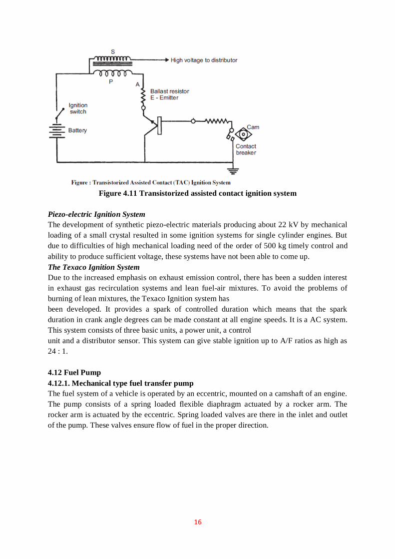
16
Figure 4.11 Transistorized assisted contact ignition system
Piezo-electric Ignition System
The development of synthetic piezo-electric materials producing about 22 kV by mechanical
loading of a small crystal resulted in some ignition systems for single cylinder engines. But
due to difficulties of high mechanical loading need of the order of 500 kg timely control and
ability to produce sufficient voltage, these systems have not been able to come up.
The Texaco Ignition System
Due to the increased emphasis on exhaust emission control, there has been a sudden interest
in exhaust gas recirculation systems and lean fuel-air mixtures. To avoid the problems of
burning of lean mixtures, the Texaco Ignition system has
been developed. It provides a spark of controlled duration which means that the spark
duration in crank angle degrees can be made constant at all engine speeds. It is a AC system.
This system consists of three basic units, a power unit, a control
unit and a distributor sensor. This system can give stable ignition up to A/F ratios as high as
24 : 1.
4.12 Fuel Pump
4.12.1. Mechanical type fuel transfer pump
The fuel system of a vehicle is operated by an eccentric, mounted on a camshaft of an engine.
The pump consists of a spring loaded flexible diaphragm actuated by a rocker arm. The
rocker arm is actuated by the eccentric. Spring loaded valves are there in the inlet and outlet
of the pump. These valves ensure flow of fuel in the proper direction.

17
Figure 4.12 Mechanical type fuel transfer pump
As the rocker arm is moved by the eccentric, the diaphragm is pulled down against the
spring force. This movement causes a partial vacuum in the pump chamber. Now the delivery
valve remains closed and the suction valve opens. This admits fuel into the pump chamber.
At the maximum position of the eccentric, the diaphragm is flexed to the maximum extent.
After this, further rotation of the eccentric will release the rocker arm. Now the rocker arm
will simply follow the eccentric by the action of the return spring. The diaphragm spring will
now push the diaphragm upwards and force the fuel to flow out, opening the delivery valve,
into the delivery tube. Now the suction valve remains closed.
4.12.2. Electromagnetic fuel pump
An electromagnetically operated fuel pump is shown in figure below. The valves
diaphragm and push pull rod are similar to the mechanical pump but a solenoid, an armature,
a toggle switch and electrical contacts are new features. In this arrangement, a diaphragm is
operated by means of a solenoid armature assembly. A contact breaker toggle switch is
connected to the electrical system of the vehicle. A break in the contact causes solenoid to
attract the armature and induces intake stroke. During this stroke the diaphragm is pulled by
the push pull rod, a vacuum is created inside the pump chamber, intake valve opens and the
fuel flows into it from the tank. There after, when the toggle switch makes contact, the
solenoid releases the armature, and fuel is delivered under the influence of diaphragm spring
pressure. The sequence of opening and closing of inlet and outlet valves is similar to that in
the mechanical pump.
Figure 4.13 Electromagnetic fuel pump

18
4.13. CARBURETOR
Functions of a carburetor:
(a) It maintains a small quantity of petrol in the float chamber at constant head (height) to
ensure uninterrupted supply for vaporization.
(b) It vaporizes (atomizes) petrol, i.e. it converts liquid petrol to vapor form for
convenient mixing with the air.
(c) It does carburetion i.e. prepares a homogeneous mixture of air and vapor petrol
(d) It delivers correct air-fuel mixture to the engine through the manifold under varying
conditions of load and speed of the engine.
A simple carburetor consists of a float chamber, float, needle valve, jet nozzle, mixing
chamber, venturi, throttle and a choke. The float is a hollow and light weight part made of
thin metal sheet. The float chamber maintains the fuel at a constant level which is necessary
for normal operation of a carburetor.
The float chamber is vented through a hole to communicate with the atmosphere.
When the fuel level sinks, the float goes down, opens the needle valve and admits fuel into
the chamber. And when the fuel level reaches its normal level, the float goes up, closes the
needle valve and stops inflow of the fuel.
A normal level is reached when the fuel in the chamber is 1-2 mm below the edge of
the nozzle. This level ensures easy suction of fuel from the nozzle and prevents leakage when
the carburetor is inoperative. The jet tube - with a calibrated hole of definite diameter meters
out the amount of fuel to be supplied.
The pulverizer which takes the form of a pin tube communicates with float chamber
through the jet. Mixing chamber is straight or bent tube one of whose ends is connected to the
engine inlet pipe and the other to the air cleaner.
The fuel is mixed with air precisely in this chamber. Venturi mounted in the mixing
chamber at the end of the nozzle increases the velocity of the air stream in the mixing
chamber and there by provides a more intensive atomization of fuel.
Throttle changes the cross section presented to the combustible mixture. The throttle
is controlled by the driver from the cab. The degree to which the throttle is opened
determines the amount of mixture passed and accordingly changes the power of the engine. A
simple carburetor is shown in the figure below.

19
Figure 4.14 Carburetor
The figure above shows the different types of mixing chamber. The most commonly used
mixing chamber is the down draught type mixing chamber.

1
SCHOOL OF MECHANICAL ENGINEERING
DEPARTMENT OF MECHANICAL ENGINEERING
UNIT – V – Fundamentals of Mechanical Engineering – SMEA1203

2
5. POWER GENERATION
Introduction to Power Plant Engineering
The whole world is in the grip of energy crisis and the pollution manifesting itself in
the spiraling cost of energy and uncomforted due to increase in pollution as well as the
depletion of conventional energy resources and increasing curve of pollution elements. It is
commonly accepted that the standard of living increases with increasing energy consumption
per capita.
The government of India has laid down the policy “it is imperative that we carefully
utilize our renewal (i.e., non-decaying) resources of soil water, plant and animal live to
sustain our economic development” our exploration or exploitation of these is reflected in
soil erosion, salutation, floods and rapid destruction of our forest, floral and wild life
resources. The depletion of these resources often tends to be irreversible since bulk of our
population depends on these natural resources. Depletion of these natural resources such as
fuel, fodder, and housing power plant;
A power plant is assembly of systems or subsystems to generate electricity, i.e.,
power with economy and requirements. The power plant itself must be useful economically
and environmental friendly to the society. The present book is oriented to conventional as
well as non-conventional energy generation.
CLASSIFICATION OF POWER PLANTS
A power plant may be defined as a machine or assembly of equipment that generates
and delivers a flow of mechanical or electrical energy. The main equipment for the
generation of electric power is generator. When coupling it to a prime mover runs the
generator, the electricity is generated. The type of prime move determines, the type of power
plants. The major power plants, which are discussed in this book, are,
1. Steam power plant
2. Diesel power plant
Power Plant
Non-conventional
Conventional
Steam/Thermal Power Plants
Diesel Power Plants
Gas Turbine Power Plants
Hydro-Electric Power Plants
Nuclear Power Plants
Solar System
Wind Energy Power System
Geothermal Energy
Ocean Thermal energy conversion (OTEC)
Wave and Tidal Wave
Thermoelectric Generator
Thermo-ionic generator
Biogas, Biomass Energy Power system

3
3. Gas turbine power plant
4. Nuclear power plant
5. Hydro electric power plant
The Steam Power Plant, Diesel Power Plant, Gas Turbine Power Plant and Nuclear Power
Plants are called THERMAL POWER PLANT, because these convert heat into electric
energy.
Sources of Energy
There are mainly two types of sources of energy
1. Conventional Sources of Energy (Non-Renewable Sources of Energy)
2. Non-conventional Sources of Energy (Renewable Sources of Energy).
CONVENTIONAL SOURCES OF ENERGY
These resources are finite and exhaustible. Once consumed, these sources cannot be
replaced by others. Examples include coal, timber, petroleum, lignite, natural gas, fossil fuels,
nuclear fuels etc.
The examples are (i) fossil fuel (ii) nuclear energy (iii) hydro energy
Have you not seen the filling of fuel in automobiles? What are the fuels that are being used in
automobiles? What type of sources of energy are they? Are they non-conventional? Fossil
fuel is an invaluable source of energy produced due to chemical changes taking place in the
absence of oxygen, in plants and animals that have been buried deep in the earth’s crust for
many million years. Fossil fuels like coal, petroleum and natural gas are formed in this
manner. These are conventional sources of energy. For example, energy from, Petroleum,
natural gas, coal, nuclear energy, etc
NON-CONVENTIONAL SOURCES OF ENERGY
These sources are being continuously produced in nature and are not exhaustible.
Examples include wood, geothermal energy, wind energy, tidal energy, nuclear fusion, gobar
gas, biomass, solar energy etc.
The examples are (i) Solar energy (ii) wind energy (iii) geothermal energy (iv) ocean energy
such as tidal energy,
wave energy (v) biomass energy such as gobar gas.
It is evident that all energy resources based on fossil fuels has limitations in availability and
will soon exhaust. Hence the long term option for energy supply lies only with non-
conventional energy sources. These resources are in exhaustible for the next hundreds of
thousands of years. The sources which are perennial and give energy continuously and which
do not deplete with use are the Non conventional sources of energy. For example, energy
from, solar energy, bio-energy, wind energy, geothermal energy, wave, tidal and OTEC.
STEAM TURBINE POWER PLANT
The conversion from coal to electricity takes place in three stages :
Stage 1
The first conversion of energy takes place in the boiler. Coal is burnt in the boiler furnace to
produce heat. Carbon in the coal and Oxygen in the air combine to produce Carbon Dioxide
(CO2) and heat.

4
Figure 5.1 Steam turbine power plant
Stage 2
The second stage is the thermodynamic process :
a) The heat from combustion of the coal boils water in the boiler to produce steam. In
modern power plant, boilers produce steam at a high pressure and temperature.
b) The steam is then piped to a turbine.
c) The high pressure steam impinges and expands across a number of sets of blades in
the turbine.
d) The impulse and the thrust created rotate the turbine.
e) The steam is then condensed and pumped back into the boiler to repeat the cycle.
Stage 3
In the third stage, rotation of the turbine rotates the generator rotor to produce electricity
based of Faraday’s Principle on electromagnetic induction.
Gas Turbine Power Station
The schematic arrangement of a gas turbine power plant is shown in Figure 1.8. The main
components of plants are :
Compressor
Regenerator
Combustion Chamber
Gas Turbine
Alternator
Starting motor

5
Figure 5.2 Gas turbine combined cycle
Compressor
The compressor used in the plant is generally of rotatory type. The air at atmospheric
pressure is drawn by the compressor via the filter which removes the dust from the air. The
rotatory blades of the compressor pushthe air between stationary blades to raise its pressure.
Thus air at high pressure is available at the output of the compressor.
Regenerator
A regenerator is a device which recovers heat from the exhaust gases of the turbine. The
exhaust is passed through the regenerator before wasting to atmosphere. A regenerator
consists of a nest of tubes contained in a shell. The compressed air from the compressor
passes through the tubes on its way to the combustion chamber. In this way compressor is
heated by the hot exhaust gases.
Combustion Chamber
The air at high pressure from the compressor is led to the combustion chamber via the
regenerator. In the combustion chamber, heat is added to the air by burning oil. The oil is
injected through the burner into the chamber at high pressure ensure atomisation of oil and its
thorough mixing with air. The result is that the chamber attains a very high temperature. The
combustion gases are suitably cooled and then delivered to gas turbine.
Gas Turbine
The products of combustion consisting of a mixture of gases at high temperature and pressure
are passed to the gas turbine. These gases in passing over the turbine blades expand and thus
do the mechanical work. The temperature of the exhaust gases from the turbine is about
900oF.
Alternator
The gas turbine is coupled into the alternator. The alternator converts the mechanical energy
of the turbine into electrical energy. The output of the alternator is given to the bus-bars
through transformers, isolators and circuit breakers.
Starting Motor
Before starting the turbine, compressor has to be started. For this purpose, an electric motor is
mounted on the same shaft as that of the turbine. The motor is energised by the batteries.

6
Once the unit starts, a part of the mechanical power of the turbine drives the compressor and
there is no need of the motor now.
Internal Combustion Engines Plant
It is a plant in which the prime mover is an internal combustion engine. An internal
combustion engine has one or more cylinders in which the process of combustion takes place,
converting energy released from the rapid burning of a fuel-air mixture into mechanical
energy. Diesel or gas-fired engines are the principal types used in electric plants. The plant is
usually operated during periods of high demand for electricity.
NUCLEAR ENERGY
In a universe, energy and matter have a common origin.
None the energy nor the matter can be created or destroyed; instead they just change their
state. As well, they are convertible to each other.
Albert Einstein was the first man who explained this relation by the well known formula :
E = mC2
This equation defines :
E (Energy) equals to m (mass) times C2 (C stands for speed of light).
By looking in close, we may find the enormous energy exist in a small piece of material.
The name of atom comes from Greek language, referring to smallest part of nature.
Nowadays we have a better knowledge on atom structure, and we know a nucleus,
surrounded by electrons, form the atoms. This structure is somehow similar to our solar
system.
Nuclear Fission
Any try for splitting a part a nucleus will cause a tremendous energy be released. This
energy would be released in both forms of heat and light. In a harnessed, controlled way of
doing this, a useful energy for producing electricity is possible. Doing this at once would
result to a big explosion, as seen in an automatic bomb.
In a nuclear power plant, uranium is the element used as fuel. Uranium is found in
many parts of the world but in a low quantity. It is loaded in to the reactor in a tiny pallet
form inside long rods.
Fission meaning splitting a part is what happens in a reactor. Here uranium atoms are split in
a paced controlled chain of reactions.
Inside a reactor the intensity of crashes are harnessed by inserting-taking of control
roads.
In an atomic bomb a different process occurs, by using almost pure pieces of
elements-uranium 235 or plutonium, in a precise mass and shape, burning them together in a
great force. As we see there is no requisite like this in a reactor.
Byproducts of such reactions are radioactive materials. If released, they would be
gravely harmful. Knowing this, strong structures must keep the materials in the case of any
accident.
The released heat energy would be used for boiling water in the core of reactor. So instead of
burning fuel, we may use the heat of reactor core.
By sending the hot water around the nuclear to the heat exchanger section, water
filled pipes produce steam needed for steam turbine.
Nuclear Fusion In another form of nuclear reaction, joining of smaller nuclei makes a larger nucleus.
Such a process in sun changes the hydrogen atoms to helium. The result heat and light we
receive in earth.

7
In a more detailed explanation, two different types of atoms, deuterium and tritium, combine
to make a helium plus and extra particle called neutron.
There has been a fierce competition among scientists, but to their frustration, they
have yet trouble in controlling reaction in a closed space. The advantage of fusion is its
abundance of supply (hydrogen) as well as its less radioactive material than fission.
HYDROELECTRIC
Man has utilised the power of water for years. Much of the growth of early colonial
industry can be attributed to hydropower. Because fuel such as coal and wood were not
readily available to inland cities, settlers were forced to turn to other alternatives. Falling
water was ideal for powering sawmills and grist mills. As coal became a better-developed
source of fuel, however, the importance of hydropower decreased.
Theory
Hydroelectric systems make use of the energy in running water to create electricity. In
coal and natural gas systems, a fossil fuel is burned to heat water. The steam pressure from
the boiling water turns propellers called turbines. These turbines spin coils of wire between
magnets to produce electricity. Hydro powered systems also make use of turbines to generate
electrical power; however, they do so by using the energy in moving water to spin the
turbines.
Water has kinetic energy when it flows from higher elevations to lower elevations.
The energy spins turbines like as shown in Figure.
In larger scale hydroelectric plants, large volumes of water are contained by dams
near the generator and turbines. The “forebay” is a storage area for water that must be deep
enough that the penstock is completely submerged. The water is allowed to flow into the
electricity-generating system through a passage called the penstock. The controlled high-
pressure water spins the turbines, allowing the generator to produce an electric current. The
powerhouse contains and protects the equipment for generating electricity. The high-pressure
water exits the system through a draft tube. The fish ladder attempts to minimise the
environmental impact of hydroelectric systems by providing a path for migrating fish to take.
Figure 5.3 Hydroelectric
Types of Hydroelectric Power Plants
Micro-Scale As their name implies, micro-hydroelectric plants are the smallest type of
hydroelectric energy systems. They generate between one kilowatt and one megawatt of
power. The main application for these hydro systems is in small, isolated villages in
developing countries. They are ideal for powering smaller services such as the operation of
processing machines.

8
Small-Scale
Small hydropower systems can supply up to 20 megawatts of energy. These systems
are relatively inexpensive and reliable. They have the potential to provide electricity to rural
areas in developing countries throughout the world. Small systems are especially important to
countries that may not be able to afford the costs of importing fossil fuels such as petroleum
from other countries.
Run-of-the-River In some areas of the world, the flow rate and elevation drops of the water are
consistent enough that hydroelectric plants can be built directly in the river. The water passes
through the plant without greatly changing the flow rate of the river. In many instances a dam
is not required, and therefore the hydroelectric plant causes minimal environmental impact on
its surroundings. However, one problem with run-of-the-river plants is the obstruction of fish
and other aquatic animals. This and other problems are discussed in the next section.
Problems with Hydroelectric Power Although hydroelectric power is admittedly one of the cleanest and most
environmentally-friendly sources of energy, it too has the capability to alter or damage its
surroundings. Among the main problems that have been demonstrated by hydroelectric power
is significant change in water quality. Because of the nature of hydroelectric systems, the
water often takes on a higher temperature, loses oxygen content, experiences siltation, and
gains in phosphorus and nitrogen content.
Another major problem is the obstruction of the river for aquatic life. Salmon, which
migrate upstream to spawn every year, are especially impacted by hydroelectric dams.
Fortunately, this problem has been dealt with by the production of fish ladders. These
structures provide a pathway for fish to navigate past the hydroelectric dam construction.
Advantages and Disadvantages Advantages
Inexhaustible fuel source
Minimal environmental impact
Viable source--relatively useful levels of energy production
Can be used throughout the world
Disadvantages
Smaller models depend on availability of fast flowing streams or rivers.
Run-of-the-River plants can impact the mobility of fish and other river life
SOLAR
The name solar power is actually a little misleading. In fact, most of the energy
known to man is derived in some way from the sun. When we burn wood or other fuels, it
releases the stored energy of the sun. In fact, there would be no life on earth without the sun,
which provides energy needed for the growth of plants, and indirectly, the existence of all
animal life. The solar energy scientists are interested in energy obtained through the use of
solar panels. Although the field of research dealing with this type of solar power is relatively

9
new, one should bear in mind that man has known about the energy of the sun for thousands
of years.
Theory
The energy of the sun can be used in many ways. When plants grow, they store the
energy of the sun. Then, when we burn those plants, the energy is released in the form of
heat. This is an example of indirect use of solar energy. The form we are interested in is
directly converting the sun’s rays into a usable energy source : electricity. This is
accomplished through the use of “solar collectors”, or, as they are more commonly known as,
“solar panels”.
There are two ways in which solar power can be converted to energy. The first,
known as “solar thermal applications”, involve using the energy of the sun to directly heat air
or a liquid. The second, known as “photoelectric applications”, involve the use of
photovoltaic cells to convert solar energy directly to electricity.
There are two types of solar thermal collectors. The first, known as flat plate
collectors, contain absorber plates that use solar radiation to heat a carrier fluid, either a
liquid like oil or water, or air. Because these collectors can heat carrier fluids to around 80oC,
they are suited for residential applications. The second type of solar collectors is known as
concentrating collectors. These panels are intended for larger-scale applications such as air
conditioning, where more heating potential is required. The rays of the sun from a relatively
wide area are focused into a small area by means of reflective mirrors, and thus the heat
energy is concentrated. This method has the potential to heat liquids to a much higher
temperature than flat plate collectors can alone. The heat from the concentrating collectors
can be used to boil water. The steam can then be used to power turbines attached to
generators and produce electricity, as in wind and hydroelectric power systems.
Photovoltaic cells depend on semiconductors such as silicon to directly convert solar
energy to electricity. Because these types of cells are low-maintenance, they are best suited
for remote applications.
Solar power has an exciting future ahead of it. Because solar power utilizes the sun's light, a
ubiquitous resource (a resource that is everywhere), solar panels can be attached to moving
objects, such as automobiles, and can even be used to power those objects. Solar powered
cars are being experimented with more and more frequently now.
Problems with Solar Power
Solar power is actually one of the cleanest methods of energy production known.
Because solar panels simply convert the energy of the sun into energy that mankind can use,
there are no harmful byproducts or threats to the environment.
One major concern is the cost of solar power. Solar panels (accumulators) are not
cheap; and because they are constructed from fragile materials (semiconductors, glass, etc.),
they must constantly be maintained and often replaced.
Further, since each photovoltaic panel has only about 40% efficiency, single solar
panels are not sufficient power producers. However, this problem has been offset by the
gathering together of many large panels acting in accord to produce energy. Although this
setup takes up much more space, it does generate much more power.
Advantages and Disadvantages
Advantages
Inexhaustible fuel source.
No pollution.

10
Often an excellent supplement to other renewable sources.
Versatile is used for powering items as diverse as solar cars and satellites.
Disadvantages
Very diffuse source means low energy production – large numbers of solar panels
(and thus large land areas) are required to produce useful amounts of heat or
electricity.
Only areas of the world with lots of sunlight are suitable for solar power generation.
WIND
Mankind has made use of wind power since ancient times. Wind has powered boats
and other sea craft for years. Further, the use of windmills to provide power for the
accomplishment of agricultural tasks has contributed to the growth of civilization. This
important renewable energy source is starting to be looked at again as a possible source of
clean, cheap energy for years to come.
Theory Differences in atmospheric pressure due to differences in temperature are the main
cause of wind. Because warm air rises, when air fronts of different temperatures come in
contact, the warmer air rises over the colder air, causing the wind to blow.
Wind generators take advantage of the power of wind. Long blades, or rotors, catch
the wind and spin. Like in hydroelectric systems, the spinning movement is transformed into
electrical energy by a generator.
The placement of wind systems is extremely important. In order for a wind-powered
system to be effective, a relatively consistent wind-flow is required. Obstructions such as
trees or hills can interfere with the rotors. Because of this, the rotors are usually placed atop
towers to take advantage of the stronger winds available higher up. Furthermore, wind speed
varies with temperature, season, and time of day. All these factors must be considered when
choosing a site for a wind-powered generator.
Another important part of wind systems is the battery. Since wind does not always
blow consistently, it is important that there be a backup system to provide energy. When the
wind is especially strong, the generator can store extra energy in a battery.
There are certain minimal speeds at which the wind needs to blow. For small turbines
it is 8 miles an hour. Large plants require speeds of 13 miles an hour.
Remote
Remote systems are small, relatively cheap sources of energy. They are best suited for rural
environments because they can be left unattended for long periods of time. Further, they can
operate under harsh conditions, and thus have potential for powering extremely remote
regions
Hybrid
The very nature of wind-powered generators makes them ideal to use in conjunction with
other sources of energy. Wind and solar generators have been extremely successful as
supplements to one another. The presence of the wind generator means that the other energy
source does not have to be producing as much of the time.

11
Grid Connected Grid Connected systems are already in wide use in areas that are already hooked up to a
utility grid. Their main use is as a supplement to other forms of energy. This is important
because average wind turbines only generate electricity about 25% of the time
Utilities
Because individual wind-powered systems by themselves do not produce a great deal of
energy, so-called wind farms have been developed. These collections of many wind
generators gathered in one place provide a source of relatively high energy output.
Advantages and Disadvantages Advantages
Inexhaustible fuel source.
No pollution.
Often an excellent supplement to other renewable sources.
Disadvantages
Very diffuse source means low energy production – large numbers of wind generators
(and thus large land areas) are required to produce useful amounts of heat or
electricity.
Only areas of the world with lots of wind are suitable for wind power generation.
Relatively expensive to maintain.
GEOTHERMAL
The center of the earth can reach 12000 degrees Fahrenheit. Just imagine if we could tap that
heat for our own use. Well, geothermal systems do just that. Convection (heat) currents travel
quite near the surface in some parts of the world.
Theory The earth’s crust is heated by the decay of radioactive elements. The heat is carried by
magma or water beneath the earth's surface. Some of the heat reaches the surface and
manifests itself in geysers and hot springs throughout the world.
Figure 5.4 Geothermal

12
Geothermal power can be used to directly heat buildings. Further, the pressurised
steam from superheated water beneath the earth’s surface can be used to power turbines and
thus generate electricity.
Although geothermal power seems ideal in that it is naturally occurring and does not
require structures to trap or collect the energy (as in solar panels or windmills), it does have
limitations. The greatest drawback is that naturally occurring geothermal vents are not widely
available. Artificial vents have been successfully drilled in the ground to reach the hot rocks
below and then injected with water for the production of steam. However, oftentimes the
source of heat is far too deep for this method to work well. Nor can geothermal power
realistically generate enough electricity for the entire country or any large industrialised
nation. A good-sized hot spring can power at most a moderate sized city of around 50,000
people. And there just isn’t enough viable hot springs to power all the cities in any large
country.
Advantages and Disadvantages Advantages
Theoretically inexhaustible energy source.
No pollution.
Often an excellent supplement to other renewable sources.
Does not require structures such as solar panels or windmills to collect the energy –
can be directly used to heat or produce electricity (thus very cheap).
Disadvantages
Not available in many locations.
Not much power per vent
Tidal Energy
Tides are caused by the gravitational pull of the moon and sun, and the rotation of the
earth. Near shore, water levels can vary up to 40 feet. Only a few locations have good inlets
and a large enough tidal range- about 10 feet- to produce energy economically. The simplest
generation system for tidal plants involves a dam, known as a barrage, across an inlet. Sluice
gates on the barrage allow the tidal basin to fill on the incoming high tides and to empty
through the turbine system on the outgoing tide, also known as the ebb tide. There are two-
way systems that generate electricity on both the incoming and outgoing tides.
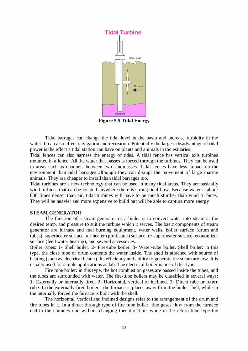
13
Figure 5.5 Tidal Energy
Tidal barrages can change the tidal level in the basin and increase turbidity in the
water. It can also affect navigation and recreation. Potentially the largest disadvantage of tidal
power is the effect a tidal station can have on plants and animals in the estuaries.
Tidal fences can also harness the energy of tides. A tidal fence has vertical axis turbines
mounted in a fence. All the water that passes is forced through the turbines. They can be used
in areas such as channels between two landmasses. Tidal fences have less impact on the
environment than tidal barrages although they can disrupt the movement of large marine
animals. They are cheaper to install than tidal barrages too.
Tidal turbines are a new technology that can be used in many tidal areas. They are basically
wind turbines that can be located anywhere there is strong tidal flow. Because water is about
800 times denser than air, tidal turbines will have to be much sturdier than wind turbines.
They will be heavier and more expensive to build but will be able to capture more energy
STEAM GENERATOR
The function of a steam generator or a boiler is to convert water into steam at the
desired temp. and pressure to suit the turbine which it serves. The basic components of steam
generator are furnace and fuel burning equipment, water walls, boiler surface (drum and
tubes), superheater surface, air heater (pre-heater) surface, re-superheater surface, economizer
surface (feed water heating), and several accessories.
Boiler types: 1- Shell boiler. 2- Fire-tube boiler. 3- Water-tube boiler. Shell boiler: in this
type, the close tube or drum contents the water inside. The shell is attached with source of
heating (such as electrical heater). Its efficiency and ability to generate the steam are low. It is
usually used for simple applications as lab. The electrical boiler is one of this type.
Fire tube boiler: in this type, the hot combustion gases are passed inside the tubes, and
the tubes are surrounded with water. The fire-tube boilers may be classified in several ways:
1- Externally or internally fired. 2- Horizontal, vertical or inclined. 3- Direct tube or return
rube. In the externally fired boilers, the furnace is places away from the boiler shell, while in
the internally forced the furnace is built with the shell.
The horizontal, vertical and inclined designs refer to the arrangement of the drum and
fire tubes in it. In a direct through type of fire tube boiler, flue gases flow from the furnace
end to the chimney end without changing ther direction, while in the return tube type the

14
gases first flow to the rear and then come to the front through the fire tubes to a smoke box at
the front.
Figure 5.6 Steam generator
Down flow type. Figure shows a sectional view of dawn flow condenser. Steam enters at the
top and flows downward. The water flowing through the tubes in one direction lower half
comes out in the opposite direction in the upper half Fig. 1.10 shows a longitudinal section of
a two pass down-flow condenser.
Central flow condenser. Figure shows a central flow condenser. In this condenser the
steam passages are all around the periphery of the shell. Air is pumped away from the centre
of the condenser. The condensate moves radially towards the centre of tube nest. Some of the
exhaust steams while moving towards the centre meets the undercooled condensate and pre-
heats it thus reducing undercooling.
Figure 5.7 Condenser
Evaporation condenser. In this condenser steam to be condensed is passed
through a series of tubes and the cooling waterfalls over these tubes in the form of spray. A
steam of air
flows over the tubes to increase evaporation of cooling water, which further increases the
condensation
of steam.
ADVANTAGES AND DISADVANTAGES OF A SURFACE CONDENSER
The various advantages of a surface condenser are as follows:
1. The condensate can be used as boiler feed water.

15
2. Cooling water of even poor quality can be used because the cooling water does not
come in direct contact with steam.
3. High vacuum (about 73.5 cm of Hg) can be obtained in the surface condenser. This
increases the thermal efficiency of the plant.
The various disadvantages of' the surface condenser are as follows:
1. The capital cost is more.
2. The maintenance cost and running cost of this condenser is high.
3. It is bulky and requires more space.


![mechaNICAL ENGINEERING [CAY 2019-20]](https://static.fdokumen.com/doc/165x107/6315d572c72bc2f2dd04da92/mechanical-engineering-cay-2019-20.jpg)