
Power Distribution Engineering: Fundamentals and Applications
48
-
Upload
khangminh22 -
Category
Documents
-
view
0 -
download
0
Transcript of Power Distribution Engineering: Fundamentals and Applications


PowerDistributionEngineering

ELECTRICAL ENGINEERING AND ELECTRONICSA Series of Reference Books and Textbooks
EXECUTIVE EDITORS
Martin O. ThurstonDepartment of Electrical EngineeringThe Ohio State UniversityColumbus, Ohio
William MiddendorfDepartment of Electricaland Computer EngineeringUniversity of CincinnatiCincinnati, Ohio
EDITORIAL BOARD
Maurice BellangerTélécommunications, Radioélectriques,et Téléphoniques (TRT)Le Plessis-Robinson, France
J. Lewis BlackburnBothell, Washington
Sing-Tze BowDepartment of Electrical EngineeringNorthern Illinois UniversityDe Kalb, Illinois
Norman B. FuquaReliability Analysis CenterGriffiss Air Force Base, New York
Charles A. HarperWestinghouse Electrical Engineeringand Technology Seminars, Inc.Timonium, Maryland
Nairn A. KheirDepartment of Electrical andSystems EngineeringOakland UniversityRochester, Michigan
Lionel M. LevinsonGeneral Electric CompanySchenectady, New York
V. RajagopalanDepartment of EngineeringUniversité du Québecà Trois-RivièresTrois-Rivières, Québec, Canada
Earl E. SwartzlanderTRW Défense Systems GroupRedondo Beach, California
Spyros G. TzafestasDepartment of Electricaland Computer EngineeringNational Technical Universityof AthensAthens, Greece
Sakae YamamuraCentral Research Institute ofthe Electric Power IndustryTokyo, Japan

1. Rational Fault Analysis, edited by Richard Saeks and S. R. Liberty2. Nonparametric Methods in Communications, edited by P. Papantoni-
Kazakos and Dimitri Kazakos3. Interactive Pattern Recognition, Yi-tzuu Chien4. Solid-State Electronics, Lawrence E. Murr5. Electronic, Magnetic, and Thermal Properties of Solid Materials, Klaus
Schroder6. Magnetic-Bubble Memory Technology, Hsu Chang7. Transformer and Inductor Design Handbook, Colonel Wm. T.
McLyman8. Electromagnetics: Classical and Modern Theory and Applications,
Samuel Seely and Alexander D. Poularikas9. One-Dimensional Digital Signal Processing, Chi-Tsong Chen
10. Interconnected Dynamical Systems, Raymond A. DeCarlo and RichardSaeks
11. Modern Digital Control Systems, Raymond G. Jacquot12. Hybrid Circuit Design and Manufacture, Roydn D. Jones13. Magnetic Core Selection for Transformers and Inductors: A User's
Guide to Practice and Specification, Colonel Wm. T. McLyman14. Static and Rotating Electromagnetic Devices, Richard H. Engelmann15. Energy-Efficient Electric Motors: Selection and Application, John C.
Andreas16. Electromagnetic Compossibility, Heinz M. Schlicke17. Electronics: Models, Analysis, and Systems, James G. Gottling18. Digital Filter Design Handbook, Fred J. Taylor19. Multivariable Control: An Introduction, P. K. Sinha20. Flexible Circuits: Design and Applications, Steve Gurley, with con-
tributions by Carl A. Ed s trom, Jr., fía y D, Greenway, and William P.Kelly
21. Circuit Interruption: Theory and Techniques, Thomas E. Browne, Jr.22. Switch Mode Power Conversion: Basic Theory and Design, K. Kit
Sum23. Pattern Recognition: Applications to Large Data-Set Problems, Sing-
Tze Bow24. Custom-Specific Integrated Circuits: Design and Fabrication, Stanley
L. Hurst25. Digital Circuits: Logic and Design, Ronald C. Emery26. Large-Scale Control Systems: Theories and Techniques, Magdi S.
Mahmoud, Mohamed F. Hassan, and Mohamed G. Darwish27. Microprocessor Software Project Management, Eli T. Fathiand Cedric
V. W. Armstrong (Sponsored by Ontario Centre for Microelectronics)28. Low Frequency Electromagnetic Design, Michael P. Perry29. Multidimensional Systems: Techniques and Applications, edited by
Spy ros G. Tzafestas30. AC Motors for High-Performance Applications: Analysis and Control,
Sakae Yamamura

31. Ceramic Motors for Electronics: Processing, Properties, and Applica-tions, edited by Relva C. Buchanan
32. Microcomputer Bus Structures and Bus Interface Design, Arthur L.Dexter
33. End User's Guide to Innovative Flexible Circuit Packaging, Jay J.M in/et
34. Reliability Engineering for Electronic Design, Norman B. Fuqua35. Design Fundamentals for Low-Voltage Distribution and Control, Frank
W. Kussy and Jack L. Warren36. Encapsulation of Electronic Devices and Components, Edward R.
Salmon37. Protective Relaying: Principles and Applications, J. Lewis Blackburn38. Testing Active and Passive Electronic Components, RichardF. Powell39. Adaptive Control Systems: Techniques and Applications, V. V.
Chalam40. Computer-Aided Analysis of Power Electronic Systems, Venkatachari
Rajagopalan41. Integrated Circuit Quality and Reliability, Eugene R. Hnatek42. Systolic Signal Processing Systems, edited by Earl E. Swartzlander,
Jr.43. Adaptive Digital Filters and Signal Analysis, Maurice G. Bellanger44. Electronic Ceramics: Properties, Configuration, and Applications,
edited by Lionel M. Levin son45. Computer Systems Engineering Management, Robert S. A/ford46. Systems Modeling and Computer Simulation, edited by Nairn A. Kheir47. Rigid-Flex Printed Wiring Design for Production Readiness, Walter S.
Rigling48. Analog Methods for Computer-Aided Circuit Analysis and Diagnosis,
edited by Takao Ozawa49. Transformer and Inductor Design Handbook: Second Edition, Revised
and Expanded, Colonel Wm. T. McLyman50. Power System Grounding and Transients: An Introduction, A. P.
Sakis Meliopoulos51. Signal Processing Handbook, edited by C. H. Chen52. Electronic Product Design for Automated Manufacturing, H. Richard
Stillwell53. Dynamic Models and Discrete Event Simulation, William Delaney and
Erminia Vaccart54. FET Technology and Application: An Introduction, Edwin S. Oxner55. Digital Speech Processing, Synthesis, and Recognition, SadaokiFurui56. VLSI RISC Architecture and Organization, Stephen B. Furber57. Surface Mount and Related Technologies, Gerald Ginsberg58. Uninterruptible Power Supplies: Power Conditioners for Critical Equip-
ment, David C. Griffith59. Polyphase Induction Motors: Analysis, Design, and Application, Paul
L. Cochran

60. Battery Technology Handbook, edited by H. A. Kiehne61. Network Modeling, Simulation, and Analysis, edited by Ricardo F.
Garzia and Mario R. Garzia62. Linear Circuits, Systems, and Signal Processing: Advanced Theory
and Applications, edited by Nobuo Nagai63. High-Voltage Engineering: Theory and Practice, edited by M. Khalifa64. Large-Scale Systems Control and Decision Making, edited by Hiroyuki
Ta mura and Tsuneo Yoshikawa65. Industrial Power Distribution and Illuminating Systems, Kao Chen66. Distributed Computer Control for Industrial Automation, Dobrivoje
Popovic and Vijay P. Bhatkar67. Computer-Aided Analysis of Active Circuits, Adrian loinovici68. Designing with Analog Switches, Steve Moore69. Contamination Effects on Electronic Products, Carl J. Tautscher70. Computer-Operated Systems Control, Magdi S. Mahmoud71. Integrated Microwave Circuits, edited by Yoshihiro Konishi72. Ceramic Materials for Electronics: Processing, Properties, and Appli-
cations, Second Edition, Revised and Expanded, edited by Re/va C.Buchanan
73. Electromagnetic Compatibility: Principles and Applications, David A.West on
74. Intelligent Robotic Systems, edited by Spyros G. Tzafestas75. Switching Phenomena in High-Voltage Circuit Breakers, edited by
Kunio Nakanishi76. Advances in Speech Signal Processing, edited by Sadaoki Furui and
M. Mohan Sondhi77. Pattern Recognition and Image Preprocessing, Sing-Tze Bow78. Energy-Efficient Electric Motors: Selection and Application, Second
Edition, John C. Andreas79. Stochastic Large-Scale Engineering Systems, edited by Spyros G.
Tzafestas and Keigo Watanabe80. Two-Dimensional Digital Filters, Wu-Sheng Lu and Andreas Antoniou81. Computer-Aided Analysis and Design of Switch-Mode Power
Supplies, Yim-Shu Lee82. Placement and Routing of Electronic Modules, edited by Michael
Pec ht83. Applied Control: Current Trends and Modern Methodologies, edited
by Spyros G. Tzafestas84. Algorithms for Computer-Aided Design of Multivariable Control
Systems, Stanoje Bingulac and Hugh F. VanLandingham85. Symmetrical Components for Power Systems Engineering, J. Lewis
Blackburn86. Advanced Digital Signal Processing: Theory and Applications, Glenn
Zelniker and Fred J. Taylor87. Neural Networks and Simulation Methods, Jian-Kang Wu88. Power Distribution Engineering: Fundamentals and Applications,
James J. Burke
Additional Volumes in Preparation
Modern Digital Control Systems, Second Edition, Raymond G. Jacquot
Integrated Circuit Quality and Reliability, Second Edition, Revised andExpanded, Eugene R. Hnatek
Handbook of Electric Motors, edited by Richard Engelmann and William H.Middendorf
Adaptive MR Filtering in Signal Processing and Control, Philip Regalia
PowerDistributionEngineeringFundamentals and Applications
James J. BurkePower Technologies, Inc.Schenectady, New York
Tay'or & FrancisTaylor &.Francis Group
Boca Raton London New York
CRC is an imprint of the Taylor & Francis Group,an informa business
CRC PressTaylor & Francis Group6000 Broken Sound Parkway NW, Suite 300Boca Raton, FL 33487-2742
© 1994 by Taylor & Francis Group, LLCCRC Press is an imprint of Taylor & Francis Group
No claim to original U.S. Government worksPrinted in the United States of America on acid-free paper25 24 23 22 21 20 19 18 17 16International Standard Book Number-13: 978-0-8247-9237-4 (Hardcover)Library of Congress catalog number: 94-11103
This book contains information obtained from authentic and highly regarded sources. Reprinted material isquoted with permission, and sources are indicated. A wide variety of references are listed. Reasonable effortshave been made to publish reliable data and information, but the author and the publisher cannot assumeresponsibility for the validity of all materials or for the consequences of their use.
Except as pemitted by U.S. Copyright Law, no part of this book may be reprinted, reproduced, transmitted, orutilized in any form by any electronic, mechanical, or other means, now known or hereafter invented, includingphotocopying, microfilming, and recording, or in any information storage or retrieval system, without writtenpermission from the publishers.
For permission to photocopy or use material electronically from this work, please access www.copyright.com(http://www.copyright.com/) or contact the Copyright Clearance Center, Inc. (CCC) 222 Rosewood Drive,Danvers, MA 01923, 978-750-8400. CCC is a not-for-profit organization that provides licenses and registrationfor a variety of users. For organizations that have been granted a photocopy license by the CCC, a separatesystem of payment has been arranged.
Trademark Notice: Product or corporate names may be trademarks or registered trademarks, and are used onlyfor identification and explanation without intent to infringe.
Library of Congress Cataloging-in-Publication Data
Catalog record is available from the Library of Congress
Visit the Taylor & Francis Web site athttp://www.taylorandfrancis.com
and the CRC Press Web site athttp://www.crcpress.com

To the memory of Aunt Marg & Uncle Rick

PREFACE
The purpose of this book is to give the utility distribution engineer adocument which is truly useful and up-to-date for today's competitiveenvironment. The book is based on over 25 years of experience in bothperforming distribution studies and in teaching courses in distributionengineering. Too often the author has found that books on distributionengineering are either simply very good reference data books or goodacademic textbooks. Neither document usually explains why utilities dothings the way they do. It is hoped that this book will bridge that gap.
Simplicity of concepts is emphasized. Complex mathematicalconcepts are not used since teaching experience has shown thatunderstanding concepts is far more valuable than being able to use a widevariety of mathematical techniques. The book's math is straightforwardand is used only to illustrate the point that many seemingly difficultconcepts and calculations can be greatly simplified using obviousassumptions.
This book is intended to cover a wide and comprehensive list oftopics, from system protection to economic evaluations. Its chaptersreflect current and future thinking in these areas and are based on theauthor's work in IEEE Standards groups as well as many real utilitystudies.
The material varies in depth. For example, Chapter 1 is meant to bea brief overview of a distribution system. This was done because thereare several good documents presently on the market that address thetopic in greater detail. On the other hand, Chapters 4 and 5, onovercurrent and overvoltage protection, are quite comprehensive. Thiswas done for two reasons. First, philosophies in both these areas are ina state of flux. Second, very little material on either of these areas iscurrently available in a comprehensive form.
Chapter 7, on power quality, appears near the end of the book sincethe concept of power quality can mean just about anything and as suchwill be more meaningful if the earlier chapters are read beforehand.Typical topics, such as sags, swells, and harmonics, are covered as areother areas such as electromagnetic fields and stray voltage, consideredby only some distribution engineers to be associated with power quality.
Each chapter has review questions meant to stimulate thought for
V

Preface
those readers who utilize the book as a self-teaching guide. Although thisbook can serve as a good day-to-day reference, gaining the maximumvalue from its contents will be helped by attempting these exercises. Thequestions are meant to be simple and fun.
The author would like to acknowledge help over the years fromHarold Campbell as well as the late Jack Easley, Norm Schultz, and BillMoody. Finally, the author wishes to thank Sherie Roseboom, who hasworked so hard and so long typing and assembling the many drafts andmanuscripts.
JAMES J. BURKE
VI

CONTENTS
PREFACE v
1 UTILITY DISTRIBUTION SYSTEM DESIGN ANDCHARACTERISTICS 1
Introduction 1Design 1Overhead vs. Underground 12Grounding 16Load and Fault Characteristics 20Questions 27
2 TRANSFORMERS AND REGULATORS 29
Transformers 29Distribution Transformer Connections 47Regulators 54Questions 63
3 APPLICATION OF CAPACITORS FORDISTRIBUTION SYSTEMS 64
Fundamentals 64Voltage Rise and Voltage Drop 76Losses 88Questions 99
4 DISTRIBUTION OVERCURRENT PROTECTION 101
Introduction 101Characteristics of Devices 101
VII
Contents
Coordination of Devices 129Questions 165
5 SURGE ARRESTERS 168
Characteristics of Lightning 168System Overvoltage 174Silicon Carbide vs. MOV Arresters 182Classes of Arresters 184Arrester Selection 185Insulation Coordination 194Traveling Waves 208Line Protection 220Induced Strikes 231Reference 232Questions 232
6 DISTRIBUTION RELIABILITY 234
Introduction 234Fundamentals 234Power Quality 246Factors Affecting Reliability 252Reference 268Questions 268
7 POWER QUALITY FUNDAMENTALS 270
Introduction 270Definitions 270Voltage Quality 272Sensitive Loads 292Power Line Conditioning 296Electromagnetic Fields 305Stray Voltage 312Reference 316Questions 316
viii
Contents
8 DISTRIBUTION ECONOMICS 320
Introduction 320Time Value of Money 320Annual Carrying Charge 328Definition of Terms 332Economic Evaluations 335Reference 347Questions 347
INDEX 349
¡x

PowerDistributionEngineering
1UTILITY DISTRIBUTION SYSTEMDESIGN AND CHARACTERISTICS
INTRODUCTION
The distribution engineer sometimes finds it difficult to define a typicaldistribution system. It is the purpose of this chapter to suggest typicalvalues of voltage, line lengths, load and fault levels, as well as types ofsystem design and grounding which can be used as backgroundinformation for the more technical discussions later on in the book.
DESIGN
The Utility System
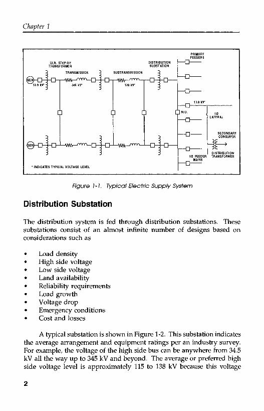
The electric utility system is usually divided into three segments whichare generation, transmission, and distribution. A fourth division, whichcan sometimes be made is subtransmission, which can really beconsidered a subset of transmission since the voltage levels overlap andoperational and protection practices are quite similar. Figure 1-1, shownbelow, illustrates some of the major components in these divisions.
The distribution system, which is our main area of interest, iscommonly broken down into the following three components:
1. Distribution substation2. Distribution primary3. Secondary
Even on this greatly simplified one-line diagram, it can be seen thatthe distribution system consists of a much wider variety of voltage levels,components, loads and interconnections than does the generation ortransmission system.
1
Chapter 1
GEN. STEP-UPTRANSFORMER
DISTRIBUTIONSUBSTATION
D Û Û
* INDICATES TYPICAL VOLTAGE LEVEL
DISTRIBUTION30 FEEDER TRANSFORMER
MAINS
Figure 1-1. Typical Electric Supply System
Distribution Substation
The distribution system is fed through distribution substations. Thesesubstations consist of an almost infinite number of designs based onconsiderations such as
• Load density• High side voltage• Low side voltage• Land availability• Reliability requirements• Load growth• Voltage drop• Emergency conditions• Cost and losses
A typical substation is shown in Figure 1-2. This substation indicatesthe average arrangement and equipment ratings per an industry survey.For example, the voltage of the high side bus can be anywhere from 34.5kV all the way up to 345 kV and beyond. The average or preferred highside voltage level is approximately 115 to 138 kV because this voltage
2

Utility Distribution System Design and Characteristics
level is usually high enough to maintain a "stiff enough source and lowenough to alleviate the costs associated with high side equipments. Asshown, the average substation consists of two transformers rated21/28/35 MVA (OA/FA/FOA) with an impedance of approximately 10percent. Protection of the substation transformer is usually attained viahigh side breakers or circuit switchers and low side breakers used inconjunction with differential relays (overcurrent relaying is also used asbackup and is not shown). The transformer low side breaker, sometimesreferred to as the "substation secondary breaker", is also used to protectagainst low voltage bus faults as well as back up the feeder breakers.
138kVHIGH VOLTAQE
BUS
13.8KVLOW VOLTAGE
BUS
21/28/35 MVAZ%=10
SUBSTATIONTRANSFORMER
PRIMARY FEEDERS
OVERCURRENT RELAYS
óFigure 1-2. Average Distribution Substation Arrangement
The low voltage bus in a multiple transformer substation is usuallysplit (contains a normally open breaker or switch) to alleviate circulatingcurrents as well as reduce the short circuit current seen by the system.Two or more feeders are normally connected to each bus through a feederbreaker. On smaller substations where short circuit levels are lower, arecloser is sometimes used instead of a breaker. Short circuit levels at the
3
Chapter 1
terminals of the low voltage bus are generally kept at 12,000 amperes orless although there are many systems where much higher levels can befound.
Distribution Feeders
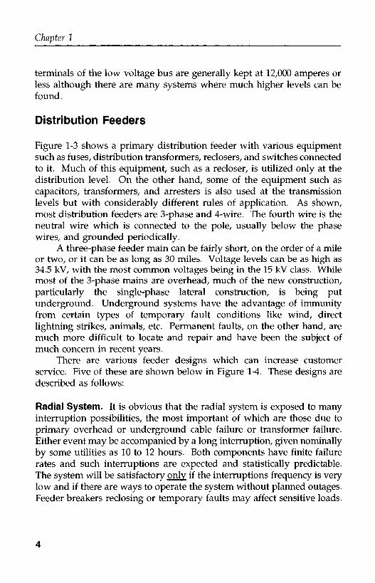
Figure 1-3 shows a primary distribution feeder with various equipmentsuch as fuses, distribution transformers, reclosers, and switches connectedto it. Much of this equipment, such as a recloser, is utilized only at thedistribution level. On the other hand, some of the equipment such ascapacitors, transformers, and arresters is also used at the transmissionlevels but with considerably different rules of application. As shown,most distribution feeders are 3-phase and 4-wire. The fourth wire is theneutral wire which is connected to the pole, usually below the phasewires, and grounded periodically.
A three-phase feeder main can be fairly short, on the order of a mileor two, or it can be as long as 30 miles. Voltage levels can be as high as34.5 kV, with the most common voltages being in the 15 kV class. Whilemost of the 3-phase mains are overhead, much of the new construction,particularly the single-phase lateral construction, is being putunderground. Underground systems have the advantage of immunityfrom certain types of temporary fault conditions like wind, directlightning strikes, animals, etc. Permanent faults, on the other hand, aremuch more difficult to locate and repair and have been the subject ofmuch concern in recent years.
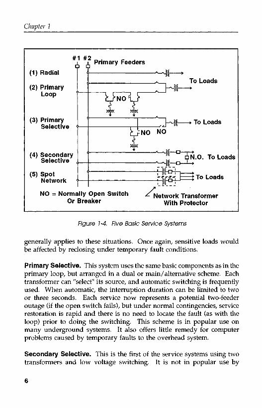
There are various feeder designs which can increase customerservice. Five of these are shown below in Figure 1 -4. These designs aredescribed as follows:
Radial System. It is obvious that the radial system is exposed to manyinterruption possibilities, the most important of which are those due toprimary overhead or underground cable failure or transformer failure.Either event may be accompanied by a long interruption, given nominallyby some utilities as 10 to 12 hours. Both components have finite failurerates and such interruptions are expected and statistically predictable.The system will be satisfactory only if the interruptions frequency is verylow and if there are ways to operate the system without planned outages.Feeder breakers reclosing or temporary faults may affect sensitive loads.
4

Utility Distribution System Design and Characteristics
PRIMARY DISTRIBUTION FEEDER
i 138kV
DISTRIBUTIONX¿C; SUBSTATION
TRANSFORMERIsc 2 10,000 A ¿
Í Î jPEAK LOAD=600 AMPS—
\ . . (T\[ \ W^
¿ ¿ I ,T T1* SECTIONALIZER-J
x
i 1 "IT T
UNDERGROUND LATERAL •-
] à FEEDER BREAKER
^^^ 3$, 4-WIRE, MULTIGROUNDED
^^- FUSE CUTOUT NORMALLY OPEN^"^ TIE SWITCH
/-\ , . . /
^ DIST. 0^4-15 HOMES/
T TRANS. T TRANSFORMERctgo
x<5u. o m
' — It 1 11
M 3 PHASE RECLOSER
C¿ Oía O •**
Í<<5? FAULTED CIRCUIT1/1 Om^ INDICATOR
— NS — 1( — \\* (FCÍ) (FCI)/^ y1^ N.O. TIE
POTHEAD / / SWITCH
-^^ — D> — f r { \ — / ~
\ \ \ \ — ELBOWV NORMALLY uL J^ DISCONNECT
OPEN TIE j |
Figure 1-3, Primary Distribution Feeder
Primary Loop. A great improvement is obtained by arranging a primaryloop, which provides two-way feed at each transformer. In this manner,any section of the primary can be isolated, without interruption, andprimary faults are reduced in duration to the time required to locate afault and do the necessary switching to restore service. This procedurecan be performed either manually or automatically. The cable in each halfof the loop must have capacity enough to carry all the load. Theadditional cable exposure will tend to increase the frequency of faults, butnot necessarily the faults per customer. The addition of a loop tie switchat the open point also introduces the possibility of a single equipmentfault causing an interruption to both halves of the loop. Murphy's Law
5
Chapter 1
(1) Radial
(2) PrimaryLoop
(3) PrimarySelective
(4) SecondarySelective
(5) SpotNetwork
#1 #2 n . . . .i Primary Feeders
To Loads
:~~D ¿N.O. To Loads!—O—L-+
Hh h— To Loads
NO = Normally Open SwitchOr Breaker ^
Network TransformerWith Protector
F/gure 7-4, F/Ve fios/c Service Systems
generally applies to these situations. Once again, sensitive loads wouldbe affected by reclosing under temporary fault conditions.
Primary Selective. This system uses the same basic components as in theprimary loop, but arranged in a dual or main/alternative scheme. Eachtransformer can "select" its source, and automatic switching is frequentlyused. When automatic, the interruption duration can be limited to twoor three seconds. Each service now represents a potential two-feederoutage (if the open switch fails), but under normal contingencies, servicerestoration is rapid and there is no need to locate the fault (as with theloop) prior to doing the switching. This scheme is in popular use onmany underground systems. It also offers little remedy for computerproblems caused by temporary faults to the overhead system.
Secondary Selective. This is the first of the service systems using twotransformers and low voltage switching. It is not in popular use by
6

Utility Distribution System Design and Characteristics
utilities for 480 volt service, but is common in industrial plants and oninstitutional properties. Primary operational switching is eliminated andwith it some causes of difficulty. Duplicate transformers virtuallyeliminate the possibility of a long interruption due to failure. Load isdivided between the two units and automatic transfer is employed on lossof voltage to either load. There must be close coordination of utility andcustomer during planned transfers, and the split responsibility is probablythe principal reason for its limited use as a service system. Temporaryfaults on the primary feeders should have little if any effect on evensensitive computer loads.
Secondary Spot Network. Maximum service reliability and operatingflexibility are obtained by use of the spot network using two or moretransformer/protector units in parallel. The low voltage bus iscontinuously energized by all units, and automatic disconnection of anyunit is obtained by sensitive reverse power relays in the protector.Maintenance switching of primary feeders can be done without customerinterruption or involvement. Spot networks are common in downtown,high density areas and are being applied frequently in outlying areas forlarge commercial services where the supply feeders can be madeavailable. This system also represents the most compact and reliablearrangement of components and is the most reliable for all classes ofloads.
Each of the five systems described can be evaluated in terms ofreliability for traditional loads as shown below. As can be seen (see Table1-1), a radial system, which is used in some residential areas, can expectan outage almost once a year lasting approximately 90 minutes. On theother hand, a spot network, which many utilities use in downtown areas,will see only two outages for every 100 years.
Network Systems
Secondary ac network systems (grid networks) began around the year1915 replacing the older dc networks which had problems with cost ofconverters, copper costs and voltage difficulties. Most cities (over 260) inthe U.S. have an ac network system. These network systems are wellknown for their high reliability (see Table 1-1), although their costdifferential has favored the primary selective design for new constructionin recent years.
7

Chapter 1
Table 1-1. Measured Reliability of Different Distribution Systems
Type of System
Outages/yr
Averageoutage
duration, min
Momentaryinterruptions/yr
Radial
0.3-1.3
90
5-10
PrimaryAuto-Loop
0.4-0.7
65
10-15
URD
0.4-0.7
60
4-8
PrimarySelective
0.1-0.5
180
4-8
SecondarySelective
0.1-0.5
180
2-4
GridNetwork
0.005-0.020
135
0
SpotNetwork
0.02-0.10
180
0-1
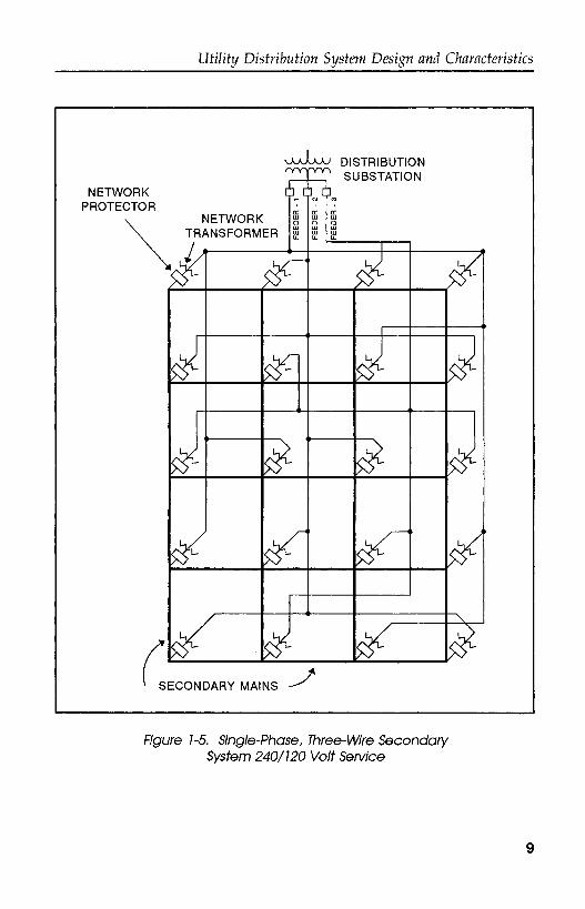
The major segments of a network system, as shown in Figure 1-5,are:
• Primary feeder circuits• Network units (consisting of the network transformer and the
network protector)• Secondary grid
The secondary grid is either 208Y/120 or 480Y/277 with virtually allspot networks favoring the higher voltage (see Figure 1-6). Commonlyused wire sizes range from 4/0 to 500 MCM AWG. The main protectionof the secondary grid comes from the ability of the system to "burn off"the fault. This, of course, meant that no protective device was requiredto operate. While this practice proved to be highly successful on the208Y/120 volt secondary network, there have been many instances of the480Y/277 volt system not being able to successfully burn itself clear,sometimes resulting in fires and considerable damage. A partial solutionto this has been the use of "limiters", which are devices (really justrestricted copper sections which act like a fuse) installed in the secondarymain at each junction point. It should be noted that the "limiter" isusually like an expulsion fuse and does not limit the magnitude of currentlike a true current limiting fuse. In high short circuit areas, true "currentlimiting" fuses are now being used to limit damage due to thesesecondary faults.
The network protector is an electrically operated low-voltage aircircuit breaker with self-contained relays for controlling its operation. Itsmain purpose is to isolate the secondary from problems on the source side
8
Utility Distribution System Design and Characteristics
DISTRIBUTIONSUBSTATION
NETWORKPROTECTOR
NETWORKTRANSFORMER
SECONDARY MAINS
Figure 1-5. Single-Phase, Three-Wire SecondarySystem 240/120 Voit Service
9

Chapter 1
DISTRIBUTIONSUBSTATION
FEEDERBREAKER
I i—i PRIMARY"—« FEEDER
NETWORKTRANSFORMER
i
PROTECTORFUSE
208Y/120OR
480Y/277
Figure 7-ó,
(network transformer, primary feeder, etc.). It is not its function to isolatefaults on the secondary network itself. The network protector performsthe following three basic functions:
1. Provides automatic isolation of faults in the primary feeders ornetwork transformers.
2. Provides ability to trip protector on reverse power.3. Provides ability to close automatically when feeder is energized, and
in-phase or leading.
The network protector is equipped with a set of fuses, one in eachphase, located between the circuit breaker and the terminals forconnection to the system secondary voltage grid. The primary functionof the fuse is to provide backup to the protector, not to clear secondaryfaults. These secondary faults are either supposed to "burn clear" or becleared by the limiters.
Secondaries
The purpose of the distribution transformer is to reduce the primaryvoltage to a level where it can be utilized by the customer. Three-phasecommercial distribution transformers range in size anywhere from about75 kVA to over 2000 kVA. Single-phase transformers range in size from
10
Utility Distribution System Design and Characteristics
about 10 kVA to about 300 kVA with units in the 25 and 37.5 kVA sizebeing the most popular for residential areas.
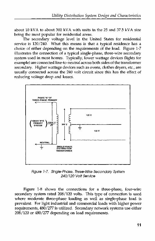
The secondary voltage level in the United States for residentialservice is 120/240. What this means is that a typical residence has achoice of either depending on the requirements of the load. Figure 1-7illustrates the connection of a typical single-phase, three-wire secondarysystem used in most homes. Typically, lower wattage devices (lights forexample) are connected line-to-neutral across both sides of the transformersecondary. Higher wattage devices such as ovens, clothes dryers, etc., areusually connected across the 240 volt circuit since this has the effect ofreducing voltage drop and losses.
PHASE "A" OFTHREE-PHASE PRIMARY
[13800V WYE \PRIMARY 113800VSYSTEM /
SINGLE-PHASEDISTRIBUTION
TRANSFORMER
Figure 1-7. Single-Phase, Three-Wire Secondary System240/120 Voit Service
Figure 1-8 shows the connections for a three-phase, four-wiresecondary system rated 208/120 volts. This type of connection is usedwhere moderate three-phase loading as well as single-phase load isprevalent. For light industrial and commercial loads with higher powerrequirements, 480/277 is utilized. Secondary network systems use either208/120 or 480/277 depending on load requirements.
11

Chapter 1
THREE-PHASEDISTRIBUTION TRANSFORMER
Figure 1-8. Three-Phase, Four-Wire Secondary System208/120 Volt Service
OVERHEAD VS. UNDERGROUND
Reliability
Underground distribution has become commonplace. The major drivefrom overhead distribution to underground distribution was primarily aresponse to environmental pressures. Most utilities today put most oftheir single-phase residential developments (5 homes or more)underground. Many utilities are also very gradually converting existingthree-phase overhead to underground.
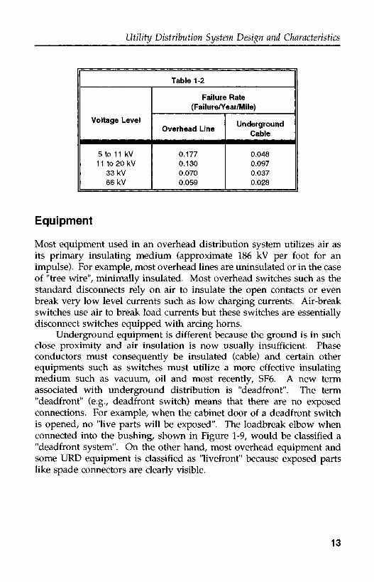
Most engineers agree that underground is more reliable thanoverhead. The argument is many times made that underground systemsfail less often but take much longer to fix. Also, the older URD cable hasbeen failing at considerably higher rates than expected. The bottom lineis that "average customer minutes outage" (CMO), is considerably lowerfor most URD designs. Undergrounding also eliminates almost alltemporary faults which, for some systems, is 80% of their total. In thesedays of "power quality", where momentary outages are a large concern,URD can have a very desirable effect. A comparison of the failure rates(permanent faults) between overhead and underground is shown below.
12
Utility Distribution System Design and Characteristics
Table 1-2
Voltage Level
5 to 11 kV1 1 to 20 kV
33 kV66 kV
Failure Rate(Failure/Year/Mile)
Overhead Line
0.1770.1300.0700.059
UndergroundCable
0.0480.0970.0370.028
Equipment
Most equipment used in an overhead distribution system utilizes air asits primary insulating medium (approximate 186 kV per foot for animpulse). For example, most overhead lines are uninsulated or in the caseof "tree wire", minimally insulated. Most overhead switches such as thestandard disconnects rely on air to insulate the open contacts or evenbreak very low level currents such as low charging currents. Air-breakswitches use air to break load currents but these switches are essentiallydisconnect switches equipped with arcing horns.
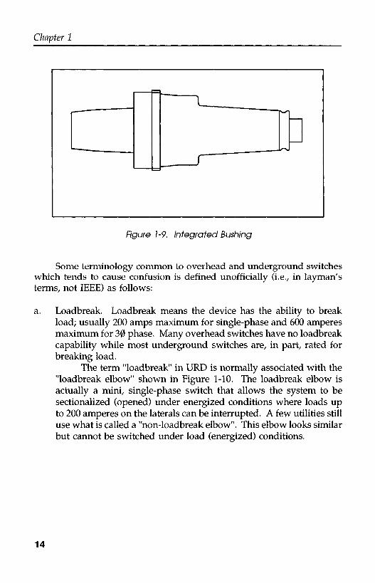
Underground equipment is different because the ground is in suchclose proximity and air insulation is now usually insufficient. Phaseconductors must consequently be insulated (cable) and certain otherequipments such as switches must utilize a more effective insulatingmedium such as vacuum, oil and most recently, SF6. A new termassociated with underground distribution is "deadfront". The term"deadfront" (e.g., deadfront switch) means that there are no exposedconnections. For example, when the cabinet door of a deadfront switchis opened, no "live parts will be exposed". The loadbreak elbow whenconnected into the bushing, shown in Figure 1-9, would be classified a"deadfront system". On the other hand, most overhead equipment andsome URD equipment is classified as "livefront" because exposed partslike spade connectors are clearly visible.
13
Chapter 1
Figure 1-9, Integrated Bushing
Some terminology common to overhead and underground switcheswhich tends to cause confusion is defined unofficially (i.e., in layman'sterms, not IEEE) as follows:
a. Loadbreak. Loadbreak means the device has the ability to breakload; usually 200 amps maximum for single-phase and 600 amperesmaximum for 30 phase. Many overhead switches have no loadbreakcapability while most underground switches are, in part, rated forbreaking load.
The term "loadbreak" in URD is normally associated with the"loadbreak elbow" shown in Figure 1-10. The loadbreak elbow isactually a mini, single-phase switch that allows the system to besectionalized (opened) under energized conditions where loads upto 200 amperes on the laterals can be interrupted. A few utilities stilluse what is called a "non-loadbreak elbow". This elbow looks similarbut cannot be switched under load (energized) conditions.
14

Utility Distribution System Design and Characteristics
Figure 1-10, Motded-shield Elbows
b. Continuous Rating. The maximum ampere rating of the deviceunder continuous operation. If the device is a switch, "continuous"does not mean that the switch can interrupt this load; it just meansit can pass this load, in the closed position, without damage.
c. Momentary Rating. The "momentary rating" of a device is theamount of short circuit current it can pass, in the closed position,without damage (still be operable). It does not mean the device caninterrupt the fault current. For example, a loadbreak elbow has amomentary rating and cannot be used to interrupt anything higherthan load current (generally 200 amperes).
d. Short Circuit Rating. The short circuit rating of a device is themaximum current it is designed to interrupt. Examples of deviceswith this rating are fuses, breakers and reclosers.
e. Close and Latch. The "close and latch" rating of a switch is themaximum ampere rating (fault level) that the switch can close intosuccessfully. It is never normal practice to close into a fault.However, by mistake, it is entirely possible that a switch will beclosed into a fault. The "close and latch" capability of a device ismeant to protect the operator from this error. Even simple switches,like the loadbreak elbow, have close and latch ratings. If an elbowis closed into a fault, within its rating, it will survive but it shouldbe replaced.
f. BIL. BIL (basic impulse level) is a rating which allows the user toassess the voltage impulse capability (ability to withstand impulses
15
Chapter 1
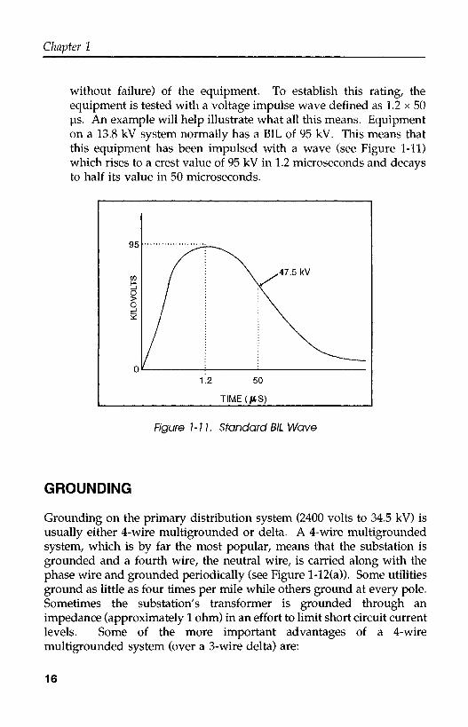
without failure) of the equipment. To establish this rating, theequipment is tested with a voltage impulse wave defined as 1.2 x 50(is. An example will help illustrate what all this means. Equipmenton a 13.8 kV system normally has a BIL of 95 kV. This means thatthis equipment has been impulsed with a wave (see Figure 1-11)which rises to a crest value of 95 kV in 1.2 microseconds and decaysto half its value in 50 microseconds.
95
47.5 kV
1.2 50
TIME (US)
Figure 1-11. Standard BIL Wave
GROUNDING
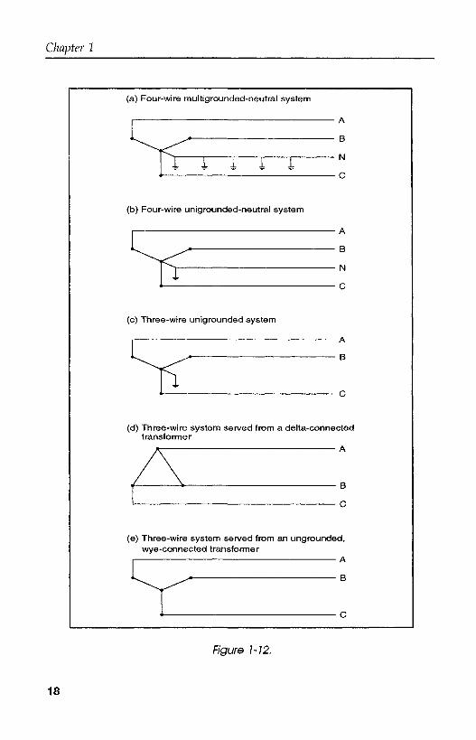
Grounding on the primary distribution system (2400 volts to 34.5 kV) isusually either 4-wire multigrounded or delta. A 4-wire multigroundedsystem, which is by far the most popular, means that the substation isgrounded and a fourth wire, the neutral wire, is carried along with thephase wire and grounded periodically (see Figure l-12(a)). Some utilitiesground as little as four times per mile while others ground at every pole.Sometimes the substation's transformer is grounded through animpedance (approximately 1 ohm) in an effort to limit short circuit currentlevels. Some of the more important advantages of a 4-wiremultigrounded system (over a 3-wire delta) are:
16
Utility Distribution System Design and Characteristics
1. High short circuit currents allowing effective overcurrent relayingpractice.
2. Much cheaper for single-phase service, especially underground, sinceonly one cable, bushing, switch, fuse, etc., needs to be used ascompared to a delta system which needs 2 times as much equipment.
3. Lower rated arresters and lower rated BIL required.
Figure 1-12 shows the types of distribution circuits.
17
Chapter 1
(a)
L
(b)
L
(c)
L
(d)
/
(e)
^
Four-wire multigrounded-neutral system
. r>
^^p\ M1 i 1 i i
Four-wire unigrounded-neutral system
. n\
J\ M
i "
Three-wire unigrounded system
m PI
^i f^
Three-wire system served from a delta-connectedtransformer
» A
/\\ n
Three-wire system served from an ungrounded,wye-connected transformer
. n
Figure 1-12,
18

Utility Distribution System Design and Characteristics
The second most popular type of grounding for a distribution systemis the 3-wire delta system shown in Figure l-12(d). These systems aregenerally older and lower in voltage than the 4-wire multigrounded type.They are also very popular on industrial power systems. Although stillin use, they are not being actively expanded since they lack some of theadvantages shown for the 4-wire multigrounded design. Some of theadvantages of a 3-wire delta are:
1. Better phase balancing2. Lower energy into fault3. Less EMF.
The three other designs shown in Figure 1-12 (12(b), 12(c), 12(e)) areall systems presently in use but only on a very limited basis. Four-wireunigrounded systems (Figure 1-12 (b)) are systems where the primaryneutral conductor is insulated at all points except at the source. Theneutral conductor in these systems is connected to the neutral point of thesource transformer windings and to ground. Distribution transformersusually are connected between phase and neutral conductors with thesurge arrester connected between phase and ground. Some four-wireunigrounded systems use an arrester between the neutral conductor andground. A spark gap may also be used at the distribution transformerbetween its secondary neutral and arrester ground to provide better surgeprotection to the transformer windings. The principal advantage of four-wire unigrounded systems is the greater ground relaying sensitivitywhich can be obtained in comparison to multigrounded systems.
On three-phase three-wire unigrounded primary distribution circuits(see Figure l-12(c)), single-phase distribution transformers are connectedphase-to-phase. The connection of three single-phase distributiontransformers or of three-phase distribution transformers is usually delta-ground wye or delta-delta. The floating wye-delta or T-T connections alsocan be used. The grounded wye-delta connection is generally not usedbecause it acts like a grounding transformer.
19
Chapter 1
LOAD AND FAULT CHARACTERISTICS*
Typical Feeder Load Characteristics
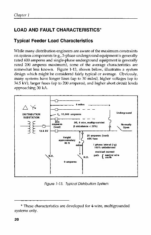
While many distribution engineers are aware of the maximum constraintson system components (e.g., 3-phase underground equipment is generallyrated 600 amperes and single-phase underground equipment is generallyrated 200 amperes maximum), some of the average characteristics aresomewhat less known. Figure 1-13, shown below, illustrates a systemdesign which might be considered fairly typical or average. Obviously,many systems have longer lines (up to 30 miles), higher voltages (up to34.5 kV), larger fuses (up to 200 amperes), and higher short circuit levelsapproaching 30 kA.
DISTRIBUTIONSUBSTATION
\N
1 — i ..... .......LJ1 8 miles ^
ru^ lsc 10,000 amperes I Underground
ri , ,, fU ^*°° 30, 4 wire, multigrounded r>
amperes I Normally(load) C unbalance < 25%) A v Qpen
n I XH[ 25 amperes (load)
approximately ^40 ft -5 r
miles 1 Phase latéral (l-g)I 100% unbalanced
I residual currentn V path f neutral wire•ÜI X N.O. K \ earth
0 amperes
Figure 1-13. Typical Distribution System
* These characteristics are developed for 4-wire, multigroundedsystems only.
20
Utility Distribution System Design and Characteristics
Fault Currents
Fault levels are easily calculated using standard computer programsavailable to almost all distribution engineers. A good calculation of theselevels and a proper understanding of what they mean is very importantbecause fault levels are used to determine protective coordination,switchgear duty, etc. The largest concern when making these calculationsis whether to use bolted fault conditions (Z/ - 0) or a higher faultimpedance to reflect the so-called worst case scenario. Studies haveshown that there are two fairly distinct types of faults: high impedanceand low impedance. If the fault arcs to the neutral, the fault can beclassified as "low impedance" reflecting a fault impedance of less than twoohms and usually somewhat less. If, on the other hand, the phase wirelands on the ground and does not contact the neutral conductor, then thefault impedance is very high (usually 300 ohms or more) and the currentproduced by them is very low, too low to ever be seen by conventionalprotection practices. Based on the studies described below, experiencewould indicate that coordination studies using bolted fault conditions isprobably the best approach.
Low Impedance Faults. Coordination of protective devices on adistribution system is greatly affected by the short circuit levels on thesystem. Fault levels are known to vary with distance as illustrated inFigure 1-14. The available short circuit current at the substation is shownto be about 6500 amps, but could be as high as 30 or 40 kA in largersubstations near metropolitan areas. The average level reported byutilities at the substation was approximately 10,000 amperes. Manyutilities subscribe to the concept that faults have an impedance whichconsequently limits fault current values to levels considerably less thanthe calculated bolted fault magnitudes. To compensate for this duringcoordination studies, some utilities add fault impedance to their shortcircuit calculations on the order of 5 to 50 ohms. This methodology, whileconservative, not only limits the reach of many devices, but as such maycause miscoordination if the actual fault impedance is different from theone used in calculations. There is no question that some faults are "highimpedance" faults and as such limit fault current to levels ofapproximately 50 amperes or less (i.e., hundreds of ohms faultimpedance).
Two studies provide the raw data for this discussion. The first iswork performed on the Virginia Power 34.5 kV system in 1977 and the
21

Chapter 1
second is edited from work completed for EPRI in 1983 which consistedof the instrumentation of 50 feeders in thirteen utilities.
10000
HIOCmQ.
1000LUCECE
Ü
h-
100
THREE-PHASEFAULT PROFILE
MAXIMUM /PHASE-TO-GROUND '
FAULT PROFILE
1002 3 4 5 6 7 8 9 2 3 4 5 6 7 8 9 2 3 4 5 6 7 8 9
1000 10000 100000
DISTANCE IN FEET, ONE WAY FROM SUBSTATION TO POINT OF FAULT
Figure 1-14
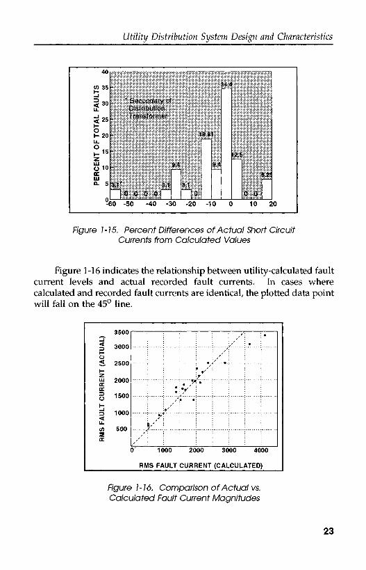
In those cases studied where the location of the fault occurrence wasknown, it was possible for Virginia Power to calculate the magnitude offault current and compare this with the measured values. On the 34.5 kVcircuits, Virginia Power made every effort to include all the resistance andreactances of equipment, but did not put in any fault resistance. Figure1-15 indicates the relative accuracy of the calculated values as comparedwith the actual measured values. As can be seen, almost 50% of thecalculated values were within ± 5% of the actual implying that there waslittle, if any, fault impedance. Most of the error is where the actualcurrents were less than the calculated, as would be expected.
In the late 70's, a large 4 year fault study was performed. Fiftyfeeders at various voltage levels were chosen to be instrumented atthirteen utilities.
22
Utility Distribution System Design and Characteristics
CO 35_J
< 30
<25
H 20LL0
Z
o 10<rLUo. 5
n
-
" 'SSrtffl01
r K*WW«*
A
A
*
Lv.-.vK..v....kv.-..:t.;..-...-3
ffv.
-60 -50 -40 -30
04,4
16. Et
niftl
8áj
Bt?
| . -r:.„..<:*.. I
- 2 0 - 1 0 0 10 20
Figure 1-15. Percent Differences of Actual Short CircuitCurrents from Calculated Values
Figure 1-16 indicates the relationship between utility-calculated faultcurrent levels and actual recorded fault currents. In cases wherecalculated and recorded fault currents are identical, the plotted data pointwill fall on the 45° line.
3500
^ 3000
ÜS 2500HZm o AnnccŒ
Ü 150°
^ innn
LL
(/) 500
Œ
: ' ' : ' >x : ' •
;- ; ; ; *•<' . - -o . ; ; .;• \ • a ' \ \ ; ;
'\ i :\y*}' ! i M: \9' : : : : : :
y' i ; i ; ; i i
3 1000 2000 3000 4000
RMS FAULT CURRENT (CALCULATED)
Figure 1-16. Comparison of Actual vs,Calculated Fault Current Magnitudes
23
Chapter 1
In general, utility calculation of fault currents were extremely closeto recorded values. No fault resistance was assumed in the utilitycalculations, which proved to be a valid assumption, since essentially nofault resistance was seen in the recorded faults. The average utilityoperated its feeders at approximately 7% above nominal voltage rating,with one recorded instance of a 17% steady-state overvoltage noted. Asmall amount of fault resistance, on the order of 2 ohms, would explainthose faults that fall below the 45° line. Points falling above the 45° linereflect the operating voltage increase above normal or simply the slightinaccuracy of sequence component calculations.
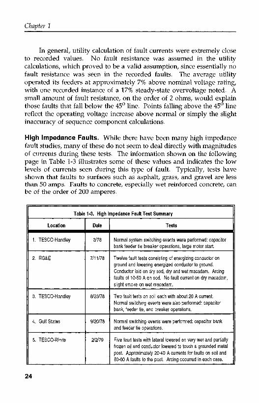
High Impedance Faults. While there have been many high impedancefault studies, many of these do not seem to deal directly with magnitudesof currents during these tests. The information shown on the followingpage in Table 1-3 illustrates some of these values and indicates the lowlevels of currents seen during this type of fault. Typically, tests haveshown that faults to surfaces such as asphalt, grass, and gravel are lessthan 50 amps. Faults to concrete, especially wet reinforced concrete, canbe of the order of 200 amperes.
Table 1-3. High Impedance Fault Test Summary
Location
1. TESCO-Handley
2. RG&E
3. TESCO-Handley
4. Gulf States
5. TESCO-White
Date
3/78
7/11/78
8/23/78
9/20/78
2/2/79
Tests
Normal system switching events were performed: capacitorbank feeder tie breaker operations, large motor start.
Twelve fault tests consisting of energizing conductor onground and lowering energized conductor to ground.Conductor laid on dry sod, dry and wet macadam. Arcingfaults of 10-50 A on sod. No fault current on dry macadam,slight smoke on wet macadam.
Two fault tests on soil each with about 20 A current.Normal switching events were also performed: capacitorbank, feeder tie, and breaker operations.
Normal switching events were performed: capacitor bankand feeder tie operations.
Five fault tests with lateral lowered on very wet and partiallyfrozen oil and conductor lowered to touch a grounded metalpost. Approximately 20-40 A currents for faults on soil and50-60 A faults to the post. Arcing occurred in each case.
24

Utility Distribution System Design and Characteristics
Table 1-3. High Impedance Fault Test Summary - Con't
Location
6. TESCO-White
7. RG&E
8. TESCO-Sand Hills
9. PNM
10. TESCO-Randol Mill
Date
5/15/79
6/1/79
6/21/79
7/2-3/79
2/2/80
Tests
At White: four fault tests on relatively dry ground. Arcing
occurred in each case with about 30 A current. At Handley:normal system data recorded.
Thirteen faults on dry sod, reinforced and non-reinforced
concrete, wet and dry macadam. Several tests with
covered conductor produced small fault current on sod.
Small fault current on non-reinforced concrete, higher
magnitude on reinforced concrete. Little or no fault current
on macadam. Subsequent tests on sod produced 50 A
currents. Normal system was monitored as were switching
events: capacitor bank and load tap changer operations.
Eight faults on dry and wetted sand and on a mesquite
bush. Less than 1 A current on sand, 30-40 A current on
the mesquite bush (due to deep roots).
7/2: Instrumentation located at a regulator bank 6 miles
from substation. Faults at 1/8, 6, 11, 15, 18 miles from
regulator
7/3: Instrumentation at substation, faults at 6, 12, 17 miles.
Fault current 10-30 A, faults staged with capacitor in andout and regulator in and out.
Eleven fault tests on dry cement and very wet soil.Capacitor bank and load tap changer operations. One faultblew the fuse. Faults on cement had little current, on soil
had high magnitude.
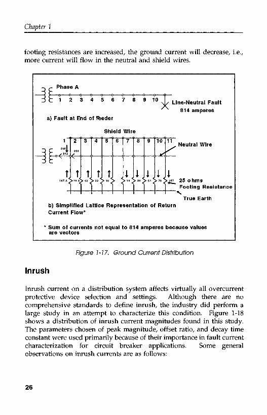
Ground Fault Current Flow. Good grounding has been credited withalleviating a variety of utility ills including line flashover, stray voltageand reduced transformer failure rates. Utilities try to maintain 25 ohmsor less when placing ground rods but in many utilities obtaining such alow value is just about impossible, regardless of the number of groundrods, due to poor soil conditions. Several utilities have major programsto reduce ground rod impedance. Shown below is a lattice diagramillustrating the flow of ground fault currents for a line-to-ground fault atthe end of the feeder. The ground rod impedance used for thiscalculation was 25 ohms at each pole. It is interesting to note that if the
25
Chapter 1
footing resistances are increased, the ground current will decrease, i.e.,more current will flow in the neutral and shield wires.
Phase A
2 3 4 5 6 7 8 9 1 0
a) Fault at End of feeder
Shield Wire
160 1
814
Î
2
366
<-
t
3
Î
4
Î
5
Î.
6 7
1.
8
1
9
1
10
^
1.
11x"
i
Line-Neutral Fault814 amperes
Neutral Wire
107.5>76.3$>525>30 >10 > S 10 > 30 S 51 S 76 > 107 25 O tlITI
i i i i 1 1 1 1 i r>°"-° Resistance
True Earthb) Simplified Lattice Representation of ReturnCurrent Flow*
* Sum of currents not equal to 814 amperes because valuesare vectors
Figure 1-17. Ground Current Distribution
Inrush
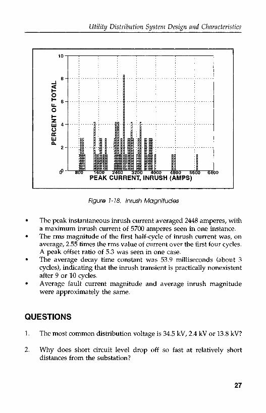
Inrush current on a distribution system affects virtually all overcurrentprotective device selection and settings. Although there are nocomprehensive standards to define inrush, the industry did perform alarge study in an attempt to characterize this condition. Figure 1-18shows a distribution of inrush current magnitudes found in this study.The parameters chosen of peak magnitude, offset ratio, and decay timeconstant were used primarily because of their importance in fault currentcharacterization for circuit breaker applications. Some generalobservations on inrush currents are as follows:
26
Utility Distribution System Design and Characteristics
J f\P
ER
CE
NT
OF
TO
TA
L:>
fo
.u
CT>
CD
c1
1 1
1
R : : : :
iirr rM . 1
1 1QM
1 1
j: .. ( \1 1
0* 800 1600 2400 3200 4000 4800 5600 64PEAK CURRENT, INRUSH (AMPS)
00
Figure 1-18. Inrush Magnitudes
• The peak instantaneous inrush current averaged 2448 amperes, witha maximum inrush current of 5700 amperes seen in one instance.
• The rms magnitude of the first half-cycle of inrush current was, onaverage, 2.55 times the rms value of current over the first four cycles.A peak offset ratio of 5.3 was seen in one case.
• The average decay time constant was 53.9 milliseconds (about 3cycles), indicating that the inrush transient is practically nonexistentafter 9 or 10 cycles.
• Average fault current magnitude and average inrush magnitudewere approximately the same.
QUESTIONS
1. The most common distribution voltage is 34.5 kV, 2.4 kV or 13.8 kV?
2. Why does short circuit level drop off so fast at relatively shortdistances from the substation?
27

Chapter 1
3. Short circuit levels should be calculated from the (OA, FA, FOA)rating of a triple rated substation transformer?
4. What are some of the concerns associated with long feeders?
5. Laterals on a typical distribution system are usually fused (true orfalse)?
6. Name one advantage and one disadvantage of a secondary networksystem?
7. A typical load level for a distribution feeder is amperes anda typical fuse size for that load is about . Why should thelateral fuse size be higher than the load?
8. The most common type of grounding on a distribution system is
9. High impedance faults refer to low current faults at the end of thefeeder (true or false)? Explain!
10. Average inrush current levels are not a problem for relay engineersbecause relay settings are based on fault levels which are muchhigher in magnitude (true or false)?
28
Surge Arresters P.P. Barker , “Voltage Quadrupling on a UD Cable”, IEEE Transactions on Power Delivery,January 1990, Vol. 5 No. 1, Transmission & Distribution Conference, April 1989.
Distribution Reliability G. Wacker , Ε. Wojczynski , and R. Billinton , “Interruption Cost Methodology and Results - ACanadian Residential Survey”, IEEE Trans, on Power Apparatus and Systems, Oct. 1983, pp.3385-3392.
Power Quality Fundamentals L.M. Anderson and K.B. Bowes , “The Effects of Power-Line Disturbances of ConsumerElectronic Equipment”, ′89 TD 423-5 PWRD, Transmission & Distribution Conference, April1989.
Distribution Economics Campbell, H.E. , “Distribution Economics”, Chapter 3, Power Distribution System Course, PTI-1982.