Preferential vaporization impacts on lean blow-out of liquid ...
Upload
independentCategory
view
1download
0
Functional gradation through preferential crystallisation and interfacialactivity in rapidly quenched Fe/Co-based bilayered ribbons for bendsensorsA. K. Panda, R. K. Roy, Sushmita Dey, Satnam Singh, and A. Mitra Citation: J. Appl. Phys. 114, 023909 (2013); doi: 10.1063/1.4813222 View online: http://dx.doi.org/10.1063/1.4813222 View Table of Contents: http://jap.aip.org/resource/1/JAPIAU/v114/i2 Published by the AIP Publishing LLC. Additional information on J. Appl. Phys.Journal Homepage: http://jap.aip.org/ Journal Information: http://jap.aip.org/about/about_the_journal Top downloads: http://jap.aip.org/features/most_downloaded Information for Authors: http://jap.aip.org/authors
Downloaded 12 Jul 2013 to 14.139.221.158. This article is copyrighted as indicated in the abstract. Reuse of AIP content is subject to the terms at: http://jap.aip.org/about/rights_and_permissions

Functional gradation through preferential crystallisation and interfacialactivity in rapidly quenched Fe/Co-based bilayered ribbons for bend sensors
A. K. Panda,a) R. K. Roy, Sushmita Dey, Satnam Singh, and A. MitraNDE & Magnetic Materials Group, Material Science & Technology Division, CSIR-National MetallurgicalLaboratory, Jamshedpur 831007, India
(Received 22 April 2013; accepted 20 June 2013; published online 12 July 2013)
Rapidly quenched bilayered ribbons comprising one layer as Fe73.5Nb3Cu1Si13.5B9 (FM) and the other
layer either as Fe74.5Nb3Si13.5B9 (FNb) or Co72.5Si12.5B15 (CSB) alloy designated as BLFM/FNb and
BLFM/CSB, respectively, have been addressed. Phase transformation, thermomagnetic transitions,
saturation magnetization, and soft magnetic properties of individual layers were revealed in the
functional properties of bilayered ribbons. Properties of bilayer could be endorsed with respect to the
single layered Fe73.5Nb3Cu1Si13.5B9, Fe74.5Nb3Si13.5B9, and Co72.5Si12.5B15 alloy ribbons. Selective
devitrification of the layers in the bilayers could be induced through optimum heat treatment. Enhanced
bend sensitivity was revealed in BLFM/CSB through generation of desirable phases in the bilayers of the
bilayered ribbon. Synergistic diffusivity of Fe and Co with its consequent effect on interfacial zone of
BLFM/CSB bilayer was observed. VC 2013 AIP Publishing LLC. [http://dx.doi.org/10.1063/1.4813222]
I. INTRODUCTION
The synergy between micro-mechanics and sensitivity
of functional materials is of paramount significance for
enhancing sensor efficiency. In recent years, these materials
have occupied important segments of sensors and actuators.
Amongst such materials, rapidly quenched ribbons have
been explored as stress, torque,1 magnetic shape memory,2
and thermal sensors.3 Subsequently, it was found that nano-
crystallisation of soft magnetic glassy precursors is a poten-
tial microstructural evolution methodology for improving
the properties of materials to develop sensors. In these cases,
nanostructured phases in metallic composites change the
magnetostriction (kS) of the system which consequently
modifies the functional properties. In the Fe-based alloy, the
critical balance between positively magnetostrictive (þkS)
glassy matrix and negatively magnetostrictive (�kS) of FeSi-
nanophase led to reduction in “kS” of the material.4 This
resulted into enhancement in the soft magnetic properties
like low coercivity and high permeability. Such enhanced
properties are also observed in þkS and �kS magnetostric-
tive materials when subjected to tensile and compressive
stresses, respectively. During bending, the upper and lower
portions of the materials experience two opposing types of
stresses, wherein the top layer is in tensile while bottom
layer is in compressive state. Thus, in a single layer (SL) rib-
bon, the contribution towards by stress in one surface of rib-
bon is nullified by the other. Such deleterious effects of the
counter surface open the scope of development of bilayered
(BL) materials with different functional properties.5
In the quest to develop functionally graded bilayers
materials, bend sensors have been explored using ribbons
agglutinated to counter non-magnetic metallic base.6
Agglutination of a metallic ribbon to either another metallic
ribbon or a counter polymer ribbon lowers the sensor output
due to thickness of the glue. Welding of layers has a tend-
ency of generating inhomogeneous force distribution
between the two bilayers. Thus, attempts have been made to
develop monolithic bilayers of Fe6.5Si/FeMnCrSiB and Fe-
based amorphous/nanocrystalline ribbons, wherein the inves-
tigation has been limited only to their magnetic response.7,8
In the application arena, rapidly quenched metastable metal-
lic ribbon, layered on a polymer or nonmetallic base, has
been observed for biomedical applications like monitoring
chest wall displacements (cardio-respiratory activity).9 Static
curvatures (airplane wings, optical lenses)10 and dynamic
measurements like airflow detectors11 have also been investi-
gated. The potential property of magnetostriction in biosen-
sor platforms comprising amorphous magnetostrictive
Fe80B20 layer coated with a biomaterial has also been
reported recently.12
Despite exploration of bilayered systems with combina-
tion of a magnetic ribbon with a counter magnetic or non-
magnetic base, proper choice of glassy systems which can
contribute towards selective structural modifications and
effective functional gradation is under investigation. The
present study is focussed on a controlled crystallisation
and its effect on the structural, magnetic, and bend sensitivity
of two sets of bilayered ribbons with one set as
Fe73.5Nb3Cu1Si13.5B9/Fe74.5Nb3Si13.5B9 and another one in
the form of Fe73.5Nb3Cu1Si13.5B9/Co72.5Si12.5B15 bilayer.
II. MATERIAL PREPARATION
Alloys Fe73.5Nb3Cu1Si13.5B9 (FM), Fe74.5Nb3Si13.5B9
(FNb), and Co72.5Si12.5B15 (CSB) were melt spun into single
layered ribbons designated as SLFM, SLFNb, and SLCSB,
respectively. Two different BL ribbons BLFM/FNb and BLFM/
CSB were also prepared by using double nozzle technique
(DNT).13 In this process, two different alloys were taken in
the dual chambers of a quartz crucible, induction melted and
ejected simultaneously through the double nozzles on a rotat-
ing Cu-wheel. The orientation of the crucible nozzles was
a)Electronic addresses: [email protected] and akpanda2_in@rediffmail.
com. Tel.:þ91-657-2345002. Fax: þ91-657-2345213.
0021-8979/2013/114(2)/023909/8/$30.00 VC 2013 AIP Publishing LLC114, 023909-1
JOURNAL OF APPLIED PHYSICS 114, 023909 (2013)
Downloaded 12 Jul 2013 to 14.139.221.158. This article is copyrighted as indicated in the abstract. Reuse of AIP content is subject to the terms at: http://jap.aip.org/about/rights_and_permissions
maintained in such a way so that the FM formed the top layer
while FNb and CSB are the bottom layers of BLFM/FNb and
BLFM/CSB bilayers, respectively.
III. EXPERIMENTAL
Magnetostriction (kS) of the ribbons was measured using a
parallel plate capacitance based device developed in the labo-
ratory. The thermal and structural properties were evaluated by
a Differential scanning calorimeter (Perkin Elmer Diamond
DSC) and an x-ray diffractometer (XRD), respectively. The
diffractometer has a Cu-Ka target. Magnetisation studies at
room and at elevated temperatures were carried out using a
Vibrating sample magnetometer (Lakeshore VSM 7404) with
furnace attachment. The coercivity was measured using a B-H
loop tracer. The elemental distribution across bilayer cross-
section was observed using an electron probe microanalyser
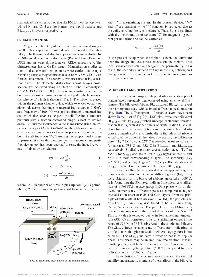
(EPMA: JXA-8230, JEOL). The bending sensitivity of the rib-
bons was determined using a setup developed in the laboratory,
the scheme of which is shown in Fig. 1. The ribbon is placed
within the polymer channel guide, which extended equally on
either side across the hinge. A magnetising voltage of 500 mV
at a frequency of 100 kHz was applied through a magnetising
coil which also serves as the pick-up coil. The free aluminium
platform with a friction controlled hinge is bent to desired
angle “h” and the inductance value is measured using an im-
pedance analyser (Agilent 4294A). As the ribbons are sensitive
to stress, bending induces change in permeability of the rib-
bons via self induction “SL,” resulting into proportional change
in permeability. For this measurement, a non-contact magnetic
flux pick-up coil has been reported5 to sense the inductive volt-
age “v” given by the relation
ðvÞ ¼ �Nsd/dt; (1)
Since;// f ðl; d; iÞ; (2)
ðvÞ ¼ �Nsd/ðl; d; iÞ
dt; (3)
where “NS” is number of turns in pick-up coil, “l” is perme-
ability, “d” is distance of pick-up coil from sensor element,
and “i” is magnetising current. In the present device, “NS”
and “i” are constant while “d” function is neglected due to
the coil encircling the sensor element. Thus, Eq. (1) modifies
with the incorporation of constant “k” for magnetising cur-
rent per unit turns and can be written as
SL ¼ v ¼ �k0d/ðlÞ
dt: (4)
In the present setup when the ribbon is bent, the curvature
near the flange induces stress effects on the ribbon. This
local stress causes relative change in the permeability. As a
result, the secondary induced voltage in the magnetising coil
changes which is measured in terms of inductance using an
impedance analyser.
IV. RESULTS AND DISCUSSION
The structure of as-spun bilayered ribbons at its top and
bottom layers separately was observed using an x-ray diffrac-
tometer. The bilayered ribbons, BLFM/FNb and BLFM/CSB, reveal
their amorphous state with a broad diffraction peak maxima
(Fig. 2(a)). The diffractograms of separate layers have been
shown in the inset of Fig. 2(a). DSC plots reveal that bilayered
BLFM/FNb and BLFM/CSB ribbon undergo exothermic transfor-
mation (Fig. 3) with distinct onsets of crystallisation (Table I).
It is observed that crystallisation onsets of single layered rib-
bons are manifested characteristically in the bilayered ribbons
as indicated by arrows in the table. The primary crystallisation
onset “TX1” for SLFM at 528 �C is revealed as onsets of trans-
formation at 534 �C and 532 �C in BLFM/FNb and BLFM/CSB,
respectively. Similarly, primary crystallisation stage “TX2” at
595 �C for SLFNb and 567 �C for SLCSB appear at 600 �C and
567 �C in their corresponding bilayers. The secondary (TX2
¼ 585 �C) and tertiary (TX3¼ 567 �C) crystallisation stages of
SLCSB emerge at similar onsets in the bilayer BLFM/CSB.
To analyse the phases generated when approaching pri-
mary crystallisation onset, x-ray diffractograms (Fig. 2(b))
were obtained for the bilayered ribbons annealed at 500 �C.
It is found that the FM-layer indicated incipient crystallisa-
tion of a-FeSi/F3Si (space group Im3m) phase with a rela-
tively sharper x-ray diffraction peak as compared to higher
crystallisation onset of FNb- and CSB-layers. From the prin-
ciple of full width at half maxima (FWHM), the particle size
of a-FeSi/F3Si in SLFM was found to be �6–7 nm using
Debye Scherrer equation. The particle size in FM-alloy is
low in comparison with the reported values of 12–15 nm.14
This low value is expected due to its low annealing tempera-
ture (500 �C) as compared to its crystallisation onsets in the
range of 528 �C to 534 �C observed in the single and bilayer.
The SLFNb shows broader x-ray diffractogram indicating its
vitrified state, though nanoscale incipient segregation is not
ruled out. The SLCSB indicates diffraction peaks of hcp-Co
phase. This phase may be in small volume fraction (low in-
tensity primary and higher order reflections)15 in view of its
far lower annealing temperature (500 �C) compared to crys-
tallisation onsets of 567 �C (Fig. 3).
The evolution of the phases also influences the thermal
stability and magnetic moment of these alloys in the bilayers,FIG. 1. Schematic presentation of the bending device.
023909-2 Panda et al. J. Appl. Phys. 114, 023909 (2013)
Downloaded 12 Jul 2013 to 14.139.221.158. This article is copyrighted as indicated in the abstract. Reuse of AIP content is subject to the terms at: http://jap.aip.org/about/rights_and_permissions

which is revealed from their thermomagnetic transition tem-
peratures (Fig. 4) and indicated in Table II. The ferromag-
netic to paramagnetic transitions (inset of Fig. 4) of
amorphous matrix indicates its (TC1) occurring at 190 �C and
342 �C SLFM and for SLCSB, respectively. These transitions
appear as step-drops at 190 �C (TC1) and 332 �C (TC2) in the
magnetisation profile of BLFM/CSB. The first transition is not
complete due to high magnetic moment of FM layer, while
the second transition is counter balanced by formation of
hcp-Co in the CSB layer. In the case of SLCSB, the gradual
rise in magnetisation beyond 250 �C is attributed to incipient
segregation of hcp-Co which is also evidenced by small peak
intensities in x-ray diffractogram (Fig. 2(b)) of SLCSB
annealed at 500 �C. Such segregates occur prior to silicide
formation at 567 �C (TX1). In BLFM/CSB, the drop in magnet-
isation at 435 �C (TC3) indicates the Curie temperature of the
FM layer, which is shifted to such high temperature due to
FIG. 2. X-ray diffractograms of (a) as-spun ribbons and (b) ribbons annealed at 500 �C.
FIG. 3. DSC plots of SL and BL as-quenched ribbons.
TABLE I. DSC crystallisation onsets of single layered and bilayered
ribbons.
FIG. 4. Thermomagnetic plots single layered (SLFM, SLCSB) and bilayered
(BLFM/CSB) as-quenched ribbons.
TABLE II. Ferromagnetic ordering temperatures obtained from thermomag-
netic plots.
023909-3 Panda et al. J. Appl. Phys. 114, 023909 (2013)
Downloaded 12 Jul 2013 to 14.139.221.158. This article is copyrighted as indicated in the abstract. Reuse of AIP content is subject to the terms at: http://jap.aip.org/about/rights_and_permissions

drastic rise in magnetisation of FM and CSB layer. In the
case of BLFM/FNb, thermomagnetic transition TC1 is equal to
that of SLFNb and closer to that of SLFM. At temperatures
closer to 500 �C, the SLFM ribbon showed rise in magnetisa-
tion due to the formation of a-Fe3Si phase (Fig. 2(b)) with
higher magnetic moment.
Thermal response of coercivity (Fig. 5) also throws light
on the contribution of FM layer on the crystallisation and
magnetic transitions of the bilayer. The FM layer (Fig. 5(a))
in BLFM/FNb counteracts the rapid deterioration in soft mag-
netic property (coercivity increase) and compensates for det-
rimental profile beyond 500 �C occurring due to the FNb-
layer. This is attributed to by far a controlled phase transfor-
mation exhibited by a shallow DSC exotherm16 of “FM”
alloy showing nanocrystallisation in this layer. The presence
of Cu in this layer facilitates heterogeneous nanophase for-
mation along with grain growth impeding element Nb which
slows down the kinetics of transformation.17 This gives the
advantage of averaged anisotropy of nanoparticles based on
Herzer’s random anisotropy model (RAM).18 However, the
phenomenon of drastic deterioration contributed by the CSB
layer (Fig. 5(b)) in the span of 400 �C to 500 �C cannot
be compensated by the FM layer and hence the bilayer
BLFM/CSB also follows the deteriorating trend beyond
500 �C. The highly anisotropic nature of clusters of hcp-Co
sets in deterioration of soft magnetic properties prior to pri-
mary crystallisation onset.19 To understand the effect of
functionalisation, thermal variation of coercivity has been
analysed with respect to the initial as-quenched state. In this
analysis, coercivity values of combining single layered rib-
bons are averaged and then the averaged data are normalised
with respect to averaged as-quenched values. Similarly, the
bilayered coercivity data are normalised with the as-
quenched values. The plot profiles of the normalised values
are shown in Fig. 6. Although the bilayer BLFM/FNb showed
a magnetic hardening effect up to 500 �C compared to the
averaged value of its single layers, the influence of nanocrys-
tallisation due to FM layer has a dominating effect in
improving the property of the bilayer. Similarly, the func-
tional effect of magnetic enhancement was also evidenced in
the bilayer BLFM/CSB with its slower kinetics of deterioration
with elevation in temperature. The influence of individual
alloy layers is also observed in the saturation magnetisation
values (MS) of the bilayers (Fig. 7). The MS values of the
bilayer BLFM/CSB lie between those of single layered ribbons
SLFM and SLCSB. However, the BLFM/FNb has values much
closer to those of SLFNb as the difference in saturation mag-
netisation values of SLFM and SLFNB is very small.
FIG. 5. Thermal variation of coercivity in (a) BLFM/FNb and (b) BLFM/CSB along with their single layered ribbons.
FIG. 6. Variation of coercivity with annealing temperature in bilayered rib-
bons and averaged coercivity of single layered ribbons. FIG. 7. Magnetisation plots of single and bilayered as-spun ribbons.
023909-4 Panda et al. J. Appl. Phys. 114, 023909 (2013)
Downloaded 12 Jul 2013 to 14.139.221.158. This article is copyrighted as indicated in the abstract. Reuse of AIP content is subject to the terms at: http://jap.aip.org/about/rights_and_permissions

The bending sensitivity can be explained on the basis of
magnetostriction, stress state, and structural developments.
The pre-stress (bend) values are initially deducted from the
inductance values “SL” obtained in Eq. (4) and then normal-
ised with respect to the zero bend state. The variation of the
inductance with bend angle is shown for BLFM/FNb and
BLFM/CSB bilayered ribbons along with their corresponding
single layer ribbons in Figs. 8(a) and 8(b), respectively. The
inductance data for corresponding single layers are also
shown in the plots. In as-spun state, the bend sensitivity of
SLFNb and BLFM/FNb is comparable (Fig. 8(a)). Sensitivity
towards bend is observed in the case of as-spun SLCSB and
BLFM/CSB (Fig. 8(b)). In both the cases, the single layer rib-
bon SLFM indicates higher sensitivity with increasing bend
angle. The influence of structural developments as a func-
tional gradation of magnetostriction and consequent effect
on bending stress is schematically presented in Fig. 9. To
further explain the bend sensitivity, magnetostriction of
SLFM, SLFNb, and SLCSB was measured. SLFM indicated
higher bend sensitivity due to its higher positive kS (Fig. 10).
In the case of bilayer BLFM/FNb, the bottom FNb layer with
small positive (kS > 0) magnetostriction results in the com-
pressive stress (rCS) which counteracts the rise in inductance
due to tensile stress (rTS) generated at the top FM layer.
Thus, the overall bend sensitivity does not enhance the
bilayer BLFM/FNb with bend angle. Similarly, the as-spun
BLFM/CSB does not indicate any enhancement in bend sensi-
tivity due to the fact that in bottom CSB-layer, the negative
kS (kS < 0) is small enough to enhance the overall induct-
ance of the bilayer subjected to bending. Upon annealing at
500 �C, the incipient generation of negatively magnetostric-
tive (�kS) a-FeSi/F3Si (space group Im3m) dispersed in
FeNbB amorphous matrix (precursor metastable state) with
þve kS reduces the overall magnetostriction in FM layer.20
Thus, the bend sensitivity of BLFM/FNb annealed at 500 �C is
reduced as compared to as-spun state. However, in SLFNb,
FIG. 8. Bend sensitivity of bilayers (a) BLFM/FNb, (b) BLFM/CSB and their respective single layered as-spun ribbons.
FIG. 9. Scheme showing mechanism
of selective structural modifications on
magnetostriction (kS) and permeability
(l) wherein arrows (") and (#) indi-
cated rise or drop, respectively, in the
as-spun and heat treated bilayers (a)
BLFM/FNB and (b) BLFM/CSB ribbons.
aFe, Hcp-Co segregations are
representative.
023909-5 Panda et al. J. Appl. Phys. 114, 023909 (2013)
Downloaded 12 Jul 2013 to 14.139.221.158. This article is copyrighted as indicated in the abstract. Reuse of AIP content is subject to the terms at: http://jap.aip.org/about/rights_and_permissions

the generation of a-Fe (þkS) reduces the inductance in the
“rCS” state and thus lowers the bend sensitivity compared to
its as-spun state. The combined effect of SLFM and SLFNb in
bilayer reduced its bend sensitivity on annealing at 500 �C.
In the case of BLFM/CSB, the generation of hcp-Co in CSB-
layer further enhanced the permeability and thus the induct-
ance in the compressive bottom layer. The generation of
hcp-Co further lowered the kS of CSB-layer which improved
the permeability in the compressive state “rCS” of the bot-
tom layer of BLFM/CSB. Thus, in BLFM/CSB, the bend sensi-
tivity increased with increasing bend angle. The generation
of a-Fe and hcp-Co in the bottom layers “FNb” and “CSB,”
respectively, have indicated their signatures in the EPMA
elemental profile shown in Fig. 11. The BLFM/FNb indicated
the drop in Fe concentration as the profile proceeds from FM
to FNb layers of this bilayer. The phenomenon of diffusion
and generation of interfacial layers in the nano-regime is
schematically presented in Fig. 12. The interdiffusion of Fe
across the interface results in fluctuation in the concentra-
tion. Similar fluctuation in Fe and Co content is also
observed across BLFM/CSB. Elemental line profile analysis
shows the depletion zones of the Fe concentration denoted as
FeFM-DZ and FeFNb-DZ �1.4 lm each and close to the inter-
face diffusing zone (DFZ) layer �1.42 lm. The profile of Fe
indicates diffusion of the Fe atoms leading to a rise in its
concentration which is more or less symmetric across the
zone. This is due to the near equal compositional stoichiome-
try of Fe in “FM” and “FNb” layers on either side of the
bilayer BLFM/FNb. Elemental profiles of Fe and Co indicate
similar depletion zones FeFM-DZ and CoCSB-DZ in the bilayer
BLFM/CSB. Interestingly, the Fe and Co diffusions indicate a
non-symmetric concentration profiles at the interface. The
synergistic variation of Fe (increase/decrease) and Co
(decrease/increase) concentration is clearly evidenced in Fig.
11 and represented in the scheme of Fig. 12. This is sugges-
tive of the fact that these two elements are miscible along a
wide range of their compositions and lowers their interfacial
energy.21 The diffusion zone “DFZ” � 0.6 lm evolving a
synergistic change in Fe-Co concentration indicates a reveal-
ing demarcation zone between the two layers of the bilayer
BLFM/CSB. The EPMA image indicates the visible demarca-
tion interface in BLFM/CSB as compared to a more diffused
FIG. 10. Variation of magnetostriction with applied magnetic field in SLFM,
SLFNb, and SLCSB ribbons.
FIG. 11. EPMA micrographs and elemental distribution of bilayers (a) BLFM/FNb, (b) BLFM/CSB ribbons.
023909-6 Panda et al. J. Appl. Phys. 114, 023909 (2013)
Downloaded 12 Jul 2013 to 14.139.221.158. This article is copyrighted as indicated in the abstract. Reuse of AIP content is subject to the terms at: http://jap.aip.org/about/rights_and_permissions

one in BLFM/FeNb. Such distinct interfacial layer due to inter-
diffusion of Co and Fe in SmCo5/Fe and Sm2Co7/Fe/Sm2Co7
thin films have also been reported.22 In the bilayer BLFM/CSB,
the drop in the concentration of Fe is followed by a drastic
rise in the gradient of Fe in the diffusivity zone “DFZ” and the
corresponding gradient of Co diffusivity profile is alterna-
tively varied in the “DFZ” zone. The diffusivity of either Fe
or Co as tracer element into the Co-based and Fe-based layer,
respectively, has been estimated using intrinsic diffusivity
equation
D ¼ Aeð�Q=RTÞ; (5)
or log D ¼ log A� Q
2:303R
1
T
� �; (6)
where A is the frequency factor, i.e., maximum diffusion
coefficient at infinite temperature, Q is activation energy, R
is gas constant, and T is the temperature of diffusion. T is the
melt ejection temperature and which is also assumed to be
the temperature of diffusion in the case of rapid solidification
processing through melt spinning. The calculated diffusivity
coefficient from the standard diffusivity parameters of the
tracer elements23 are shown in Table III. From Eq. (6), coef-
ficients DFeCo and DCo
Fe have the values of 4.72� 10�14 m2/s
and 1.06� 10�14 m2/s, respectively. The higher values of
DFeCo is attributed to sharper and higher diffusivity gradient as
compared to DCoFe in the bilayer BLFM/CSB. Analysing the
present result, it is suggested that due to such a phenomenon
occurring in SmCo5 thin film, the FeCo layer has been found
to be thicker in the Fe-rich zone of the thin film.23 In the
present investigation, the diffusivity is also supposed to con-
tinue for some time even beyond the melt solidification front
as long as the ribbon has the critical temperature for diffusiv-
ity. The compositional profiles of the rest of the elements
Nb, Cu, Si, and B is consistent either due to their low con-
centrations (Nb, Cu) or due to their near equal content (Si,
B) in the individual layers of the bilayers.
V. CONCLUSIONS
The bilayered rapidly quenched amorphous ribbons
BLFM/FNb and BLFM/CSB exhibited functional gradation in
properties. Crystallisation onsets, saturation magnetisation,
and Curie temperature of the single layered ribbons SLFM,
SLFNb, and SLCSB are revealed in the bilayered ribbons. A
bend sensor based on change in self inductance for ribbon
sample was designed. The bend angle sensitivity of BLFM/
FNb and BLFM/CSB in annealed ribbons depends on the partial
crystallisation of the layers in the bilayered ribbons. The
behaviour has been correlated to the structural modification
in the individual layers of the bilayers. In the annealed state,
the formation of the a-FeSi in “FM” layer and hcp-Co in
“CSB” layer of the BLFM/CSB improved the bending sensitiv-
ity of the bilayer. This opened the scope of the bilayer as a
material for surface profile detectors and bend sensors. In the
bilayered ribbon BLFM/CSB, the fluctuation in the concentra-
tion of iron and cobalt at the interface layer is correlated to
their diffusivity coefficients and concentration gradient.
ACKNOWLEDGMENTS
The authors express their sincere gratitude to Director,
CSIR-National Metallurgical Laboratory (CSIR-N.M.L),
Jamshedpur, India, for his kind permission to carry out and
publish the work. One of the authors (A.K.P.) acknowledges
Dr. Peter Svec and Dr. Dusan Janickovic, Slovak Academy of
Sciences for the experience gained on bilayered ribbons dur-
ing his visit to the Academy under INSA visiting program.
1I. Giouroudi, J. Kosel, H. Pfutzner, and W. Brenner, Sens. Actuators, A
142, 474 (2008).2S. Singh, R. K. Roy, M. Ghosh, A. Mitra, and A. K. Panda, J. Appl. Phys.
112, 103512 (2012).3E. Kaniusas, L. Mehnen, and H. Pfutzner, J. Magn. Magn. Mater.
254–255, 624 (2003).4M. E. McHenry, M. A Willard, and D. E. Laughlin, Prog. Mater. Sci. 44,
291 (1999).
FIG. 12. Schematic presentation of the EPMA elemental line profiles of (a)
BLFM/FNb and (b) BLFM/CSB bilayers showing interface layers and elemental
diffusion (arrows).
TABLE III. Diffusivity coefficients determined for the interface layer using
tracer element data and rapid solidification temperature.
Tracer
element
Host layer
of bilayer A (m2/s) (10�4) Q (kJ/mol) T (K)
Calculated
D (m2/s) (10�14)
Fe CSB 0.11 253.30 1583 4.72 DFeCo
Co FM 1.0 301.90 1583 1.06 DCoFe
023909-7 Panda et al. J. Appl. Phys. 114, 023909 (2013)
Downloaded 12 Jul 2013 to 14.139.221.158. This article is copyrighted as indicated in the abstract. Reuse of AIP content is subject to the terms at: http://jap.aip.org/about/rights_and_permissions

5J. Kosel et al., Sens. Actuators, A 123–124, 349 (2005).6L. Mehnen, H. Pfutzner, and E. Kaniusas, J. Magn. Magn. Mater.
215–216, 779 (2000).7D. Imamura, T. Todaka, and M. Enokizano, IEEE Trans. Mater. 47, 3184
(2011).8Y. Sato, M. Fujikura, Y. Haga, and T. Sato, J. Magn. Soc. Jpn. 20, 505
(1996).9E. Kaniusas, L. Mehnen, C. Krell, and H. Pfutzner, J. Magn. Magn. Mater.
215–216, 776 (2000).10H. Pfutzner et al., J. Mater. Process. Technol. 181, 186 (2007).11G. S. Katranas and T. Meyden, IEEE Trans. Magn. 43, 2382–2384 (2007).12S. Li, S. Horikawa, M.-K. Park, Y. Chai, V. J. Vodyanoy, and A. B. Chin,
Intermetallics 30, 80 (2012).13L. Mehnen, P. Svec, H. Pfutzner, and P. Duhaj, J. Magn. Magn. Mater.
254–255, 627 (2003).14M. E. McHenry, F. Johnson, H. Okumura, T. Ohkubo, V. R. V. Ramanan,
and D. E. Laughlin, Scr. Mater. 48, 881 (2003).
15P. R. Ohodnicki, Jr., D. E. Laughlin, M. E. McHenry, and M. Widom,
Acta Mater. 58, 4804 (2010).16O. Mohanta, A. Basumallick, A. Mitra, and A. K. Panda, J. Magn. Magn.
Mater. 322, 112 (2010).17Y. Yoshizawa, S. Oguma, and K. Yamauchi, J. Appl. Phys. 64, 6044
(1988).18G. Herzer, Acta Mater. 61, 718 (2013).19O. Mohanta, M. Ghosh, A. Mitra, and A. K. Panda, J. Phys. D: Appl. Phys.
42, 065007 (2009).20G. Vlasak, P. Duhaj, and P. Svec, J. Magn. Magn. Mater. 140–144, 443
(1995).21P. R. Ohodnicki, Jr., Y. L. Qin, D. E. Laughlin, H. E. McHenry, M. Kodzuka,
T. Ohkubo, K. Hono, and M. A. Willard, Acta Mater. 57, 87 (2009).22Y. Zhang, M. J. Karamer, D. Banerjee, I. Takeuchi, and J. Pinglu, J. Appl.
Phys. 110, 053914 (2011).23Smithell Metal Reference Book, 7th ed., edited by E. A. Brandes and G. B.
Brook (Butterworth-Heinemann Publications, 1992).
023909-8 Panda et al. J. Appl. Phys. 114, 023909 (2013)
Downloaded 12 Jul 2013 to 14.139.221.158. This article is copyrighted as indicated in the abstract. Reuse of AIP content is subject to the terms at: http://jap.aip.org/about/rights_and_permissions
Copyright © 2022 FDOKUMEN