Fuel Cell Power Systems for Maritime Applications - MDPI
34
sustainability Review Fuel Cell Power Systems for Maritime Applications: Progress and Perspectives Hui Xing 1,2, * , Charles Stuart 3 , Stephen Spence 4 and Hua Chen 2 Citation: Xing, H.; Stuart, C.; Spence, S.; Chen, H. Fuel Cell Power Systems for Maritime Applications: Progress and Perspectives. Sustainability 2021, 13, 1213. https://doi.org/10.3390/ su13031213 Academic Editor: Dino Musmarra Received: 1 January 2021 Accepted: 21 January 2021 Published: 24 January 2021 Publisher’s Note: MDPI stays neutral with regard to jurisdictional claims in published maps and institutional affil- iations. Copyright: © 2021 by the authors. Licensee MDPI, Basel, Switzerland. This article is an open access article distributed under the terms and conditions of the Creative Commons Attribution (CC BY) license (https:// creativecommons.org/licenses/by/ 4.0/). 1 Marine Engineering College, Dalian Maritime University, Dalian 116026, China 2 Institute of Green Energy for Ships and Marine Engineering, Dalian Maritime University, Dalian 116026, China; [email protected] 3 School of Mechanical and Aerospace Engineering, Queen’s University Belfast, Belfast BT7 1NN, UK; [email protected] 4 Department of Mechanical and Manufacturing Engineering, Trinity College Dublin, Dublin 2, Ireland; [email protected] * Correspondence: [email protected] Abstract: Fuel cells as clean power sources are very attractive for the maritime sector, which is committed to sustainability and reducing greenhouse gas and atmospheric pollutant emissions from ships. This paper presents a technological review on fuel cell power systems for maritime applications from the past two decades. The available fuels including hydrogen, ammonia, renewable methane and methanol for fuel cells under the context of sustainable maritime transportation and their pre-processing technologies are analyzed. Proton exchange membrane, molten carbonate and solid oxide fuel cells are found to be the most promising options for maritime applications, once energy efficiency, power capacity and sensitivity to fuel impurities are considered. The types, layouts and characteristics of fuel cell modules are summarized based on the existing applications in particular industrial or residential sectors. The various research and demonstration projects of fuel cell power systems in the maritime industry are reviewed and the challenges with regard to power capacity, safety, reliability, durability, operability and costs are analyzed. Currently, power capacity, costs and lifetime of the fuel cell stack are the primary barriers. Coupling with batteries, modularization, mass production and optimized operating and control strategies are all important pathways to improve the performance of fuel cell power systems. Keywords: maritime transportation; shipping emissions; fuel cells; hydrogen energy; alternative marine fuels; future power and propulsion; sustainability 1. Introduction Marine diesel engines have driven the shipping industry for over a century. Owing to the use of fossil fuels and particularly marine residual oils, greenhouse gases (GHG) and air pollutants from ships, such as carbon dioxide (CO 2 ), nitrogen oxides (NO x ), sulfur oxides (SO x ) and particulate matters (PM), have become the key regulatory targets in the maritime sector [1]. The International Maritime Organization (IMO) has adopted a variety of regulations under Annex VI (titled Regulations for the Prevention of Air Pollution from Ships) of the International Convention for the Prevention of Pollution from Ships (MARPOL) [2–4]. As well as this, the phasing out of GHG emissions from ships as soon as possible in this century has been set as a target [5]. Correspondingly, a series of technological and operational measures have been employed to mitigate shipping emissions and improve ship energy efficiency [6,7]. However, current measures are not sufficient to make the shipping industry consistent with the global response to the threat of climate change [8]. Hence, alternative fuels and energy sources are expected to play a vital role as a synergistic solution for reductions of SO x , NO x , PM and CO 2 emissions. Apart from innovative technologies and systems for traditional engines, fuel cell power systems Sustainability 2021, 13, 1213. https://doi.org/10.3390/su13031213 https://www.mdpi.com/journal/sustainability
-
Upload
khangminh22 -
Category
Documents
-
view
1 -
download
0
Transcript of Fuel Cell Power Systems for Maritime Applications - MDPI
sustainability
Review
Fuel Cell Power Systems for Maritime Applications: Progressand Perspectives
Hui Xing 1,2,* , Charles Stuart 3 , Stephen Spence 4 and Hua Chen 2
�����������������
Citation: Xing, H.; Stuart, C.; Spence,
S.; Chen, H. Fuel Cell Power Systems
for Maritime Applications: Progress
and Perspectives. Sustainability 2021,
13, 1213. https://doi.org/10.3390/
su13031213
Academic Editor: Dino Musmarra
Received: 1 January 2021
Accepted: 21 January 2021
Published: 24 January 2021
Publisher’s Note: MDPI stays neutral
with regard to jurisdictional claims in
published maps and institutional affil-
iations.
Copyright: © 2021 by the authors.
Licensee MDPI, Basel, Switzerland.
This article is an open access article
distributed under the terms and
conditions of the Creative Commons
Attribution (CC BY) license (https://
creativecommons.org/licenses/by/
4.0/).
1 Marine Engineering College, Dalian Maritime University, Dalian 116026, China2 Institute of Green Energy for Ships and Marine Engineering, Dalian Maritime University,
Dalian 116026, China; [email protected] School of Mechanical and Aerospace Engineering, Queen’s University Belfast, Belfast BT7 1NN, UK;
[email protected] Department of Mechanical and Manufacturing Engineering, Trinity College Dublin, Dublin 2, Ireland;
[email protected]* Correspondence: [email protected]
Abstract: Fuel cells as clean power sources are very attractive for the maritime sector, which iscommitted to sustainability and reducing greenhouse gas and atmospheric pollutant emissionsfrom ships. This paper presents a technological review on fuel cell power systems for maritimeapplications from the past two decades. The available fuels including hydrogen, ammonia, renewablemethane and methanol for fuel cells under the context of sustainable maritime transportation andtheir pre-processing technologies are analyzed. Proton exchange membrane, molten carbonateand solid oxide fuel cells are found to be the most promising options for maritime applications,once energy efficiency, power capacity and sensitivity to fuel impurities are considered. The types,layouts and characteristics of fuel cell modules are summarized based on the existing applicationsin particular industrial or residential sectors. The various research and demonstration projects offuel cell power systems in the maritime industry are reviewed and the challenges with regard topower capacity, safety, reliability, durability, operability and costs are analyzed. Currently, powercapacity, costs and lifetime of the fuel cell stack are the primary barriers. Coupling with batteries,modularization, mass production and optimized operating and control strategies are all importantpathways to improve the performance of fuel cell power systems.
Keywords: maritime transportation; shipping emissions; fuel cells; hydrogen energy; alternativemarine fuels; future power and propulsion; sustainability
1. Introduction
Marine diesel engines have driven the shipping industry for over a century. Owingto the use of fossil fuels and particularly marine residual oils, greenhouse gases (GHG)and air pollutants from ships, such as carbon dioxide (CO2), nitrogen oxides (NOx), sulfuroxides (SOx) and particulate matters (PM), have become the key regulatory targets inthe maritime sector [1]. The International Maritime Organization (IMO) has adopteda variety of regulations under Annex VI (titled Regulations for the Prevention of AirPollution from Ships) of the International Convention for the Prevention of Pollution fromShips (MARPOL) [2–4]. As well as this, the phasing out of GHG emissions from shipsas soon as possible in this century has been set as a target [5]. Correspondingly, a seriesof technological and operational measures have been employed to mitigate shippingemissions and improve ship energy efficiency [6,7]. However, current measures are notsufficient to make the shipping industry consistent with the global response to the threat ofclimate change [8]. Hence, alternative fuels and energy sources are expected to play a vitalrole as a synergistic solution for reductions of SOx, NOx, PM and CO2 emissions. Apartfrom innovative technologies and systems for traditional engines, fuel cell power systems
Sustainability 2021, 13, 1213. https://doi.org/10.3390/su13031213 https://www.mdpi.com/journal/sustainability
Sustainability 2021, 13, 1213 2 of 34
are proposed to be an important option to improve the use of alternative marine fuels.High energy efficiencies make fuel cells very attractive compared to marine combustionengines and gas turbines (GTs), though the power capacities of fuel cells cannot cover allmaritime applications. However, the efficiencies and power capacities of fuel cells continueto be a focal point of research and development, leading to constant improvements thatbring the technology closer to widespread adoption with every passing year.
Maritime fuel cells used onboard underwater vehicles can be traced back to the 1960s [9].Possible applications of fuel cells onboard merchant ships include: low power demand mainpropulsion; auxiliary power for hybrid propulsion; electricity generation; and emergencypower supply [10]. Several demonstration projects for fuel cell applications in the merchantmarine sector have been carried out since 2000 [11]. Through a literature review of existingstudies on fuel cells for maritime applications, three key aspects were identified:
(i) Economic and environmental analysis. To determine the feasibility of fuel cells formaritime applications, an exergy analysis was carried out for both a methanol reformingproton exchange membrane fuel cell (PEMFC) system and a direct methanol fuel cell(DMFC) system, where the two systems exhibited similar power capacity and energyefficiency figures [12]. However, weight, volume and unit cost should be considered forfurther thermo-economic analysis. A hybrid solar photovoltaic (PV)-PEMFC-diesel gen-erator power system was modelled and optimized for cruise ship trading in Stockholm,Sweden [13]. The renewable energy system contributed 13.8% of the overall energy re-quirement and achieved 9.8% emissions reduction compared to the conventional dieselengine power system. A life cycle assessment of a molten carbonate fuel cell (MCFC) plantfor marine applications was conducted and compared to a conventional diesel enginepower plant [14]. The results showed that the operational phase is the major contributor toclimate change for both systems when hydrocarbons are used as fuels. The production ofraw materials and the manufacturing of MCFC components were shown to have higherenvironmental impact compared to that of diesel engines. Hence, the recycling and re-useof MCFC components are important to improve the overall environmental performance ofsuch systems. A testbed of a hybrid power source composed of a MCFC, a lead-acid batteryand a diesel generator was developed to simulate the fuel consumption of five types ofships based on respective operating profiles [15]. Average CO2 savings of 70–74% based ondifferent ship types and load scenarios were reported, compared to the standalone opera-tion of the diesel generator. An integrated energy system was developed and evaluated,which was composed of a hydrogen-fueled solid oxide fuel cell gas turbine (SOFC-GT)hybrid system, a solar PV system, wind turbines and an absorption refrigeration plant. Theship consumed renewable energy only and the overall energy efficiency was 41.5% [16].A SOFC power system used for propulsion, electricity and heat generation onboard shipswas investigated and optimized in terms of energy, cost and emission savings [17]. Theabatement of GHG emissions was claimed to be up to 34% and SOFCs fed with liquefiednatural gas (LNG) were deemed to be the most cost-optimal solution for reducing GHGemissions. A four-scheme energy management strategy for a hybrid fuel cell-battery drivenpassenger ship was proposed with the aim of minimizing energy consumption [18]; thesimulation results showed that maximum energy savings of 8% could be achieved.
(ii) Safety and reliability analysis. A PEMFC stack operated under marine environ-mental conditions was experimentally analyzed [19], from which it was concluded that seasalt (sodium chloride) vapor was the major contaminant and caused a significant perfor-mance decrement for the fuel cells. Based on SF-BREEZE projects, safety-related physicaland combustion properties of liquefied hydrogen (LH2) and LNG were evaluated andcompared [20]. The results showed that LH2 and LNG pose similar safety risks, and severalcountermeasures such as avoiding fuel leaks, providing adequate ventilation, monitoringconfined spaces, etc., are required to minimize the risks. A numerical calculation wascarried out to simulate the leakage and diffusion of hydrogen in a fuel cell ship to betterunderstand hydrogen safety issues [21]. The hydrogen concentration distributions andthe effects of different ventilation conditions were determined, providing guidance for the
Sustainability 2021, 13, 1213 3 of 34
optimal positions for hydrogen sensors and ventilation. Risk assessment of a hydrogendriven high speed passenger ferry was performed [22], with the results illustrating thatthe estimated risk related to hydrogen systems is relatively low and within acceptablelimits. Based on a MCFC power system for a LH2 tanker, the safety integrity levels foran electric propulsion system were investigated [23]. Fire and explosion caused by fueloverflows or a control failure in the stack were identified as the most severe potentialincidents. A failure mode and effects analysis (FMEA) approach was proposed to evaluatethe safety and reliability of a hybrid MCFC-GT system for LH2 tankers [24]. A similarapproach was verified by successfully applying it to a hybrid power system composed of aMCFC, a battery system and a diesel engine [25].
(iii) Power system development. A PEMFC-battery hybrid propulsion system wasdeveloped for a tourist boat [26], the reliable operation of which was successfully demon-strated in the coastal waters of South Korea. A hybrid propulsion system coupling anLNG-fueled combustion engine with a hydrogen-fueled PEMFC was proposed for an LNGcarrier [27]. To satisfy the required energy efficiency design index, the energy fractionsfrom hydrogen were determined. This allowed the cost competitiveness of the hydrogensystem to be evaluated against the conventional LNG propulsion system. A MCFC-basedmarine auxiliary power unit (APU) fed with diesel oil was developed and modelled [28],allowing the system efficiency under different reforming strategies and process configura-tions to be assessed. A hybrid propulsion system coupling a MCFC with a bottoming cyclewas developed for a LH2 tanker [29]. System efficiency, economic feasibility and exhaustemissions were evaluated. Currently, the fuel cell systems are less economical than otherpropulsion systems, but their environmental performance is brilliant. It was found thatthe MCFC-GT system was preferable with regard to overall system efficiency. A SOFC-GTtri-generation system was developed for marine applications [30]. An absorption chillercould be employed to drive the heating, ventilation and air conditioning (HVAC), and thusthe overall system efficiency could be significantly improved considering different systemconfigurations. A hybrid diesel electric propulsion system coupled with two methanol-fed250-kW SOFC systems was designed for an offshore platform supply vessel, where notablereductions of pollutant emissions were observed [31]. A propulsion system composed of adual-fuel diesel generator and a SOFC-GT hybrid system was developed and optimized fora 90,000 m3 ethane carrier [32]. The optimal system configuration was determined and theenergy efficiency design index complied with all requirements set by the IMO regulations.
Very few research papers focus on the specific application of fuel cells for the mar-itime sector. While there are a number of parallels to be drawn in terms of transferableknowledge with stationary power, automotive and other land-based applications, theunique challenges posed by the maritime sector (particularly for international deep seashipping) create a number of additional barriers to entry for fuel cell technology. Thesewill be explored in greater detail in the coming sections, but can broadly be attributed to aharsh working environment and limitations relating to onboard energy storage (includingany fuel pre/post processing systems) that would ultimately encroach upon the payload(and hence profitability) of a vessel.
The possibility of using fuel cells onboard ships was analyzed in ref. [33], whichreviewed some existing research and demonstration projects of fuel cells for maritimeapplications. The costs and expected service lifetime of potential fuel cells were highlighted.In addition, marine fuel cell systems were reviewed in terms of fuel cell types, potentialfuels and system characteristics in ref. [34]. The authors presented information on thepotential of fuel cell systems fueled by LH2 and LNG. However, a summary of the specificlayouts and characteristics of different types of fuel cell modules is absent in the publishedliterature. Moreover, the topic of design and development of fuel cell hybrid power systemsfor maritime applications is lacking a comprehensive review. Therefore, this paper aims toaddress these shortcomings in the literature by conducting a comprehensive review on thedevelopment of the fuel cell modules and systems, culminating in a summary of the mostpromising pathways for future maritime applications.
Sustainability 2021, 13, 1213 4 of 34
2. Fuel Cells and Available Fuels for Sustainable Shipping2.1. Types of Fuel Cells
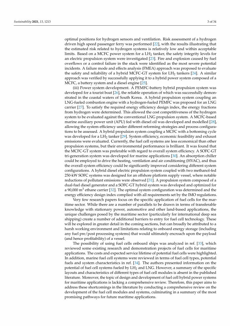
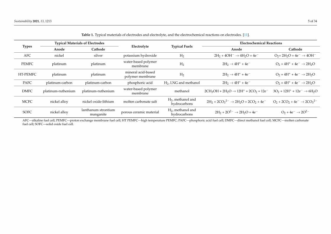
A fuel cell consists of an anode, a cathode and an electrolyte, and converts the chemicalenergy from a fuel into electricity through an electrochemical reaction. A basic schematicdiagram of a hydrogen fuel cell is shown in Figure 1, where the two illustrations depictthe different possible ion transfer characteristics across the electrolyte depending on thetype of fuel cell. Only a very small electric potential, about 0.7 volts (V), is produced byan individual fuel cell. Hence, cells are placed in series to create sufficient voltage to meetthe requirement of an application, resulting in a “fuel cell stack”. Fuel cells are usuallyclassified by the type of electrolyte they use. Typical fuel cells and their electrochemicalreactions are summarized in Table 1.
Sustainability 2021, 13, x FOR PEER REVIEW 4 of 33
layouts and characteristics of different types of fuel cell modules is absent in the published
literature. Moreover, the topic of design and development of fuel cell hybrid power sys-
tems for maritime applications is lacking a comprehensive review. Therefore, this paper
aims to address these shortcomings in the literature by conducting a comprehensive re-
view on the development of the fuel cell modules and systems, culminating in a summary
of the most promising pathways for future maritime applications.
2. Fuel Cells and Available Fuels for Sustainable Shipping
2.1. Types of Fuel Cells
A fuel cell consists of an anode, a cathode and an electrolyte, and converts the chem-
ical energy from a fuel into electricity through an electrochemical reaction. A basic sche-
matic diagram of a hydrogen fuel cell is shown in Figure 1, where the two illustrations
depict the different possible ion transfer characteristics across the electrolyte depending
on the type of fuel cell. Only a very small electric potential, about 0.7 volts (V), is produced
by an individual fuel cell. Hence, cells are placed in series to create sufficient voltage to
meet the requirement of an application, resulting in a “fuel cell stack”. Fuel cells are usu-
ally classified by the type of electrolyte they use. Typical fuel cells and their electrochem-
ical reactions are summarized in Table 1.
Anode
Electrolyte
Cathode
Ions+Ions+
Load
H2
O2 H2O
Anode
Electrolyte
Cathode
Ions-Ions-Load
e-
e-
e-
e-
H2
O2
H2O
or
Figure 1. Basic schematic diagram of a hydrogen fuel cell.
Table 1. Typical materials of electrodes and electrolyte, and the electrochemical reactions on electrodes. [11].
Types Typical Materials of Electrodes
Electrolyte Typical fuels Electrochemical Reactions
Anode Cathode Anode Cathode
AFC nickel silver potassium
hydroxide H2
2H2 + 4OH- → 4H2O +
4e-
O2+ 2H2O + 4e- →
4OH-
PEMFC platinum platinum
water-based
polymer
membrane
H2 2H2 → 4H+ + 4e- O2 + 4H++ 4e- →
2H2O
HT-
PEMFC platinum platinum
mineral acid-
based
polymer
membrane
H2 2H2 → 4H+ + 4e- O2 + 4H++ 4e- →
2H2O
PAFC platinum-
carbon platinum-carbon phosphoric acid H2, LNG and methanol 2H2 → 4H+ + 4e-
O2 + 4H++ 4e- →
2H2O
DMFC platinum-
ruthenium platinum-ruthenium
water-based
polymer
membrane
methanol 2CH3OH + 2H2O
→12H+ + 2CO2 + 12e-
3O2 + 12H+ + 12e-
→ 6H2O
MCFC nickel alloy nickel oxide-lithium molten carbonate
salt
H2, methanol and
hydrocarbons
2H2 + 2CO32- → 2H2O +
2CO2 + 4e-
O2 + 2CO2 + 4e- →
2CO32-
SOFC nickel alloy
lanthanum
strontium
manganite
porous ceramic
material
H2, methanol and
hydrocarbons
2H2 + 2O2- → 2H2O +
4e- O2 + 4e- → 2O2-
Figure 1. Basic schematic diagram of a hydrogen fuel cell.
(i) AFC (alkaline fuel cell). The AFC is relatively low cost. The only product of thereaction is water and there are no other emissions. However, CO2 poisoning is a majorconcern as CO2 could react with the alkaline electrolyte. Hence, pure hydrogen and pureoxygen (O2) are required, meaning that other fuels and air are not recommended owing tothe significant purification measures required [11].
(ii) PEMFC. The low operating temperature of PEMFCs allows flexible and safeoperation, less stringent material requirements and quick start-up. However, low tempera-ture also leads to a lack of waste heat recovery options and a complex system for watermanagement [35]. The complexity of the latter issue is not to be underestimated, withhumidification of the air supply and removal of excess water from the cathode both posingchallenges. In addition, the platinum catalysts add to system cost and can be poisoned bycarbon monoxide (CO) and sulphur (S) with a medium sensitivity. Therefore, a reformingand purification unit is necessary to obtain the required purity of hydrogen if hydrocarbonsrather than pure hydrogen are to be used as fuels.
(iii) HT-PEMFC. Apart from continuous development of PEMFC technology to im-prove operational flexibility, extend lifetime and reduce cost, the development of hightemperature PEMFC systems is also an area of research interest [36]. Compared to PEMFC,HT-PEMFC uses a mineral acid electrolyte instead of a water based one. Thus, it can workat a temperature up to 200 ◦C. Due to this higher temperature, HT-PEMFC is less sensitiveto CO and S poisoning, and there is no need for water management. In addition, a wasteheat recovery (WHR) system could be employed by using a bottoming cycle to enhanceoverall system efficiency.
(iv) PAFC (phosphoric acid fuel cell). The PAFC has a moderate cost and works attemperatures up to 200 ◦C. Due to the higher temperatures, fuels other than pure hydrogen(hydrocarbons such as LNG and methanol) can be used, whilst both a reforming unit and aWHR system (typically a steam turbine) might be included [11]. Consequently, while theproduct of the electrochemical reaction is water, the reforming process generates CO2. Thehigher operating temperature makes the platinum catalyst less sensitive to CO poisoningand other contaminants.
Sustainability 2021, 13, 1213 5 of 34
Table 1. Typical materials of electrodes and electrolyte, and the electrochemical reactions on electrodes. [11].
TypesTypical Materials of Electrodes
Electrolyte Typical FuelsElectrochemical Reactions
Anode Cathode Anode Cathode
AFC nickel silver potassium hydroxide H2 2H2 + 4OH− → 4H2O + 4e− O2+ 2H2O + 4e− → 4OH−
PEMFC platinum platinum water-based polymermembrane H2 2H2 → 4H+ + 4e− O2 + 4H+ + 4e− → 2H2O
HT-PEMFC platinum platinum mineral acid-basedpolymer membrane H2 2H2 → 4H+ + 4e− O2 + 4H+ + 4e− → 2H2O
PAFC platinum-carbon platinum-carbon phosphoric acid H2, LNG and methanol 2H2 → 4H+ + 4e− O2 + 4H+ + 4e− → 2H2O
DMFC platinum-ruthenium platinum-ruthenium water-based polymermembrane methanol 2CH3OH + 2H2O→ 12H+ + 2CO2 + 12e− 3O2 + 12H+ + 12e− → 6H2O
MCFC nickel alloy nickel oxide-lithium molten carbonate salt H2, methanol andhydrocarbons 2H2 + 2CO3
2− → 2H2O + 2CO2 + 4e− O2 + 2CO2 + 4e− → 2CO32−
SOFC nickel alloy lanthanum strontiummanganite porous ceramic material H2, methanol and
hydrocarbons 2H2 + 2O2− → 2H2O + 4e− O2 + 4e− → 2O2−
AFC—alkaline fuel cell; PEMFC—proton exchange membrane fuel cell; HT PEMFC—high temperature PEMFC; PAFC—phosphoric acid fuel cell; DMFC—direct methanol fuel cell; MCFC—molten carbonatefuel cell; SOFC—solid oxide fuel cell.
Sustainability 2021, 13, 1213 6 of 34
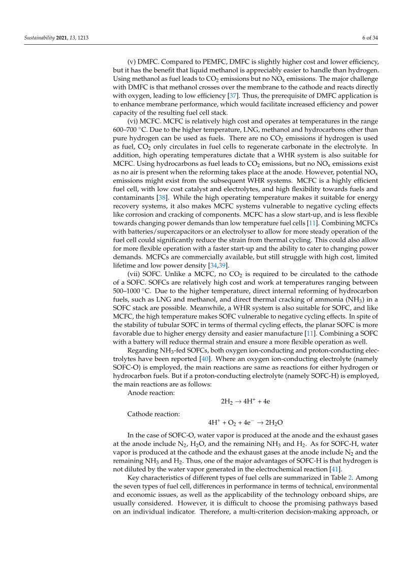
(v) DMFC. Compared to PEMFC, DMFC is slightly higher cost and lower efficiency,but it has the benefit that liquid methanol is appreciably easier to handle than hydrogen.Using methanol as fuel leads to CO2 emissions but no NOx emissions. The major challengewith DMFC is that methanol crosses over the membrane to the cathode and reacts directlywith oxygen, leading to low efficiency [37]. Thus, the prerequisite of DMFC application isto enhance membrane performance, which would facilitate increased efficiency and powercapacity of the resulting fuel cell stack.
(vi) MCFC. MCFC is relatively high cost and operates at temperatures in the range600–700 ◦C. Due to the higher temperature, LNG, methanol and hydrocarbons other thanpure hydrogen can be used as fuels. There are no CO2 emissions if hydrogen is usedas fuel, CO2 only circulates in fuel cells to regenerate carbonate in the electrolyte. Inaddition, high operating temperatures dictate that a WHR system is also suitable forMCFC. Using hydrocarbons as fuel leads to CO2 emissions, but no NOx emissions existas no air is present when the reforming takes place at the anode. However, potential NOxemissions might exist from the subsequent WHR systems. MCFC is a highly efficientfuel cell, with low cost catalyst and electrolytes, and high flexibility towards fuels andcontaminants [38]. While the high operating temperature makes it suitable for energyrecovery systems, it also makes MCFC systems vulnerable to negative cycling effectslike corrosion and cracking of components. MCFC has a slow start-up, and is less flexibletowards changing power demands than low temperature fuel cells [11]. Combining MCFCswith batteries/supercapacitors or an electrolyser to allow for more steady operation of thefuel cell could significantly reduce the strain from thermal cycling. This could also allowfor more flexible operation with a faster start-up and the ability to cater to changing powerdemands. MCFCs are commercially available, but still struggle with high cost, limitedlifetime and low power density [34,39].
(vii) SOFC. Unlike a MCFC, no CO2 is required to be circulated to the cathodeof a SOFC. SOFCs are relatively high cost and work at temperatures ranging between500–1000 ◦C. Due to the higher temperature, direct internal reforming of hydrocarbonfuels, such as LNG and methanol, and direct thermal cracking of ammonia (NH3) in aSOFC stack are possible. Meanwhile, a WHR system is also suitable for SOFC, and likeMCFC, the high temperature makes SOFC vulnerable to negative cycling effects. In spite ofthe stability of tubular SOFC in terms of thermal cycling effects, the planar SOFC is morefavorable due to higher energy density and easier manufacture [11]. Combining a SOFCwith a battery will reduce thermal strain and ensure a more flexible operation as well.
Regarding NH3-fed SOFCs, both oxygen ion-conducting and proton-conducting elec-trolytes have been reported [40]. Where an oxygen ion-conducting electrolyte (namelySOFC-O) is employed, the main reactions are same as reactions for either hydrogen orhydrocarbon fuels. But if a proton-conducting electrolyte (namely SOFC-H) is employed,the main reactions are as follows:
Anode reaction:2H2 → 4H+ + 4e
Cathode reaction:4H+ + O2 + 4e− → 2H2O
In the case of SOFC-O, water vapor is produced at the anode and the exhaust gasesat the anode include N2, H2O, and the remaining NH3 and H2. As for SOFC-H, watervapor is produced at the cathode and the exhaust gases at the anode include N2 and theremaining NH3 and H2. Thus, one of the major advantages of SOFC-H is that hydrogen isnot diluted by the water vapor generated in the electrochemical reaction [41].
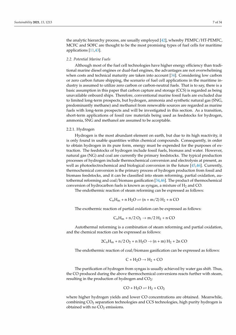
Key characteristics of different types of fuel cells are summarized in Table 2. Amongthe seven types of fuel cell, differences in performance in terms of technical, environmentaland economic issues, as well as the applicability of the technology onboard ships, areusually considered. However, it is difficult to choose the promising pathways basedon an individual indicator. Therefore, a multi-criterion decision-making approach, or
Sustainability 2021, 13, 1213 7 of 34
the analytic hierarchy process, are usually employed [42], whereby PEMFC/HT-PEMFC,MCFC and SOFC are thought to be the most promising types of fuel cells for maritimeapplications [11,43].
2.2. Potential Marine Fuels
Although most of the fuel cell technologies have higher energy efficiency than tradi-tional marine diesel engines or dual-fuel engines, the advantages are not overwhelmingwhen costs and technical maturity are taken into account [34]. Considering low carbonor zero carbon future shipping, the scenario of fuel cell applications in the maritime in-dustry is assumed to utilize zero carbon or carbon-neutral fuels. That is to say, there is abasic assumption in this paper that carbon capture and storage (CCS) is regarded as beingunavailable onboard ships. Therefore, conventional marine fossil fuels are excluded dueto limited long-term prospects, but hydrogen, ammonia and synthetic natural gas (SNG,predominantly methane) and methanol from renewable sources are regarded as marinefuels with long-term prospects and will be investigated in this section. As a transition,short-term applications of fossil raw materials being used as feedstocks for hydrogen,ammonia, SNG and methanol are assumed to be acceptable.
2.2.1. Hydrogen
Hydrogen is the most abundant element on earth, but due to its high reactivity, itis only found in usable quantities within chemical compounds. Consequently, in orderto obtain hydrogen in its pure form, energy must be expended for the purposes of ex-traction. The feedstocks of hydrogen include fossil fuels, biomass and water. However,natural gas (NG) and coal are currently the primary feedstocks. The typical productionprocesses of hydrogen include thermochemical conversion and electrolysis at present, aswell as photoelectrochemical and biological conversion in the future [45,46]. Currently,thermochemical conversion is the primary process of hydrogen production from fossil andbiomass feedstocks, and it can be classified into steam reforming, partial oxidation, au-tothermal reforming and coal/biomass gasification [34,46]. The product of thermochemicalconversion of hydrocarbon fuels is known as syngas, a mixture of H2 and CO.
The endothermic reaction of steam reforming can be expressed as follows:
CnHm + n H2O (n + m/2) H2 + n CO
The exothermic reaction of partial oxidation can be expressed as follows:
CnHm + n/2 O2 →m/2 H2 + n CO
Autothermal reforming is a combination of steam reforming and partial oxidation,and the chemical reaction can be expressed as follows:
2CnHm + n/2 O2 + n H2O→ (n + m) H2 + 2n CO
The endothermic reaction of coal/biomass gasification can be expressed as follows:
C + H2O→ H2 + CO
The purification of hydrogen from syngas is usually achieved by water gas shift. Thus,the CO produced during the above thermochemical conversions reacts further with steam,resulting in the production of hydrogen and CO2:
CO + H2O H2 + CO2
where higher hydrogen yields and lower CO concentrations are obtained. Meanwhile,combining CO2 separation technologies and CCS technologies, high purity hydrogen isobtained with no CO2 emissions.
Sustainability 2021, 13, 1213 8 of 34
Table 2. Key characteristics of fuel cells. [11,17,34–39,44].
Types Operating Temperature, ◦C Power CapacityEfficiency
Drawbacks Waste Heat Recovery Relative Cost Lifetime SizeElectric Overall
AFC 60–200 ≤500 kW 50–60% - CO2 poisoning - Low Medium Small
PEMFC 65–85 ≤120 kW 50–60% - CO + S poisoning - Low Medium Small
HT-PEMFC 160–220 - 50–60% 80% CO + S poisoning HEx/ST Medium Medium Small
PAFC 140–200 100–400 kW 40–55% 80% CO + S poisoning HEx/ST Medium Good Large
DMFC 75–120 ≤5 kW 20–30% - methanol crossover - Medium Medium Small
MCFC 650–700 120 kW–10 MW 50–55% 85% S poisoning, cycling effects,long start-up time HEx/GT/ST High Good Large
SOFC 500–1000 ≤10 MW 50–60% 85%S poisoning, cycling effects,mechanically fragile, long
start-up timeHEx/GT/ST High Medium Medium
HEx–heat exchanger; ST–steam turbine; GT–gas turbine.
Sustainability 2021, 13, 1213 9 of 34
The electrolysis process splits water into hydrogen and oxygen in an electrolyser.Alkaline electrolysers are the most technically mature, but polymer electrolyte membraneelectrolysers and solid oxide electrolysers show potential for future applications dueto offering higher efficiency values [47]. During the electrolysis process, electricity isconsumed and pure hydrogen is obtained, which is particularly ideal for low temperaturefuel cells. With the increasing proportion of renewable electricity in the world energy mix,sustainable hydrogen production is an increasingly viable prospect, and would also bebeneficial as an energy storage medium to deal with the fluctuations and demand mismatchinherent to most renewable technologies. In addition, photoelectrochemical conversion, orthe photolysis/photolytic process, splits water into hydrogen and oxygen by using solarenergy, and biological processes can convert biomass to hydrogen. These two conversionroutes are also regarded as having great potential in the future. In the near to mid-termfuture, the deployment of sustainable hydrogen depends greatly on the costs of CCS andrenewable electricity.
Regarding the transportation and storage of hydrogen, low volumetric energy densityis a big challenge. Even discounting the energy requirement for liquification at −253 ◦Cor compression at either 350 bar or 700 bar, it is notable that a larger storage space is stillrequired compared to conventional marine fuels. Therefore, hydrogen as a marine fuelis not ideal for long distance shipping. However, hydrogen’s excellent environmentalperformance always attracts industrial attention. Accordingly, further development forbetter hydrogen carriers is necessary. Ammonia, SNG and liquid organic hydrogen carriers(LOHCs, e.g., methanol) [48] are potential options.
2.2.2. Ammonia
Ammonia is one of the most abundant synthetic chemicals in the world. The Haber–Bosch process is the most typical method of ammonia production. At 300–500 ◦C and200–350 bar over a Fe-, Ni- or Ru-based catalyst, the chemical reaction could be expressedas follows [49–51]:
N2 + 3H2 2NH3
The air is usually used for nitrogen production by the pressure swing absorption ormembrane filtration method, whilst hydrogen production is as discussed in Section 2.2.1.The ammonia is stored at ambient temperature and 8 bar vapour pressure. Due to thetoxicity of liquid ammonia, ammonia storage in solid form such as metal amine salts,ammonium carbonates or urea has been proposed [49,50]. However, the slightly increasedstorage mass and additional energy consumption for ammonia release would result inextra costs. In spite of this, ammonia is easier and less expensive to transport and storethan hydrogen, and it is feasible to use ammonia as a hydrogen carrier [51]. As a hydrogencarrier, ammonia could be decomposed or cracked to release the products of hydrogenand nitrogen. Since no carbon and sulphur are contained, there is no the risk of CO or Spoisoning [34]. Ammonia could be used as direct fuel for fuel cells, where ammonia-fuelledSOFC arouses significant research interest due to the decomposition of ammonia underhigh operating temperature and over catalysts [40,41,52]. Direct ammonia alkaline/alkalinemembrane fuel cells and direct hydrazine/ammonia borane fuel cells are also possibleoptions [40,50].
2.2.3. Synthetic Natural Gas
NG has already seen use as an alternative marine fuel to reduce SOx and NOx emis-sions. In parallel with this, NG also has the potential to reduce CO2 emissions owing to itsminimum carbon emissions per unit of energy release among hydrocarbon and alcoholicfuels. NG can be synthesised from syngas using the thermochemical conversion of fossilraw materials. The exothermic reactions can be expressed as follows:
3H2 + CO CH4 + H2O
Sustainability 2021, 13, 1213 10 of 34
Apart from fossil-based NG, SNG from renewable sources could have a more favourableclimate impact. Carbon-neutral SNG can be synthesised from biomass or power-to-gassystems [53]. Anaerobic digestion is the predominant process for SNG production frombiomass compared to thermal gasification of organic biomass or the Sabatier reaction [54].Power-to-gas systems produce SNG through a catalytic or biological methanation reac-tion, where hydrogen produced by water electrolysis from renewable energy and CO2captured from industrial processes are combined together [55]. The SNG production frompower-to-gas systems can be expressed as follows [56]:
4H2 + CO2 CH4 + 2H2O
SNG is stored below −163 ◦C in liquefied state or above 200 bar in compressed state.Hence, transportation and storage of SNG in a cryogenic or pressurized state are costlyand relatively inefficient, which are the main challenges for the widespread applicationsof SNG. Currently, NG is an important source of hydrogen and methanol. Although thevolumetric energy density of NG is twice that of hydrogen, the synthesis of SNG on landand then reforming for hydrogen onboard requires more capital for equipment, as well asthe corresponding increased energy consumption. Hence, except for high temperature fuelcell power systems, there are no significant advantages for SNG compared to hydrogen.
2.2.4. Renewable Methanol
Methanol is traditionally produced from NG and coal, but oil, biomass, wastes andeven CO2 can also be taken as feedstocks [57]. The chemical reactions of fossil methanolsynthesis from syngas can be expressed as follows:
2H2 + CO CH3OH
3H2 + CO2 CH3OH+ H2O
Renewable methanol is mainly produced from second generation biomass, such asforest residues, agriculture residues, municipal solid waste and black liquor produced frompulp and the paper industry. The production process is the same as fossil methanol produc-tion, where syngas production, methanol synthesis and processing of crude methanol arecovered. Renewable methanol could be regarded as carbon-neutral if renewable energy isused for the production processes [57]. Methanol can be produced by catalytic synthesis ofCO2 captured from industrial processes and hydrogen electrolysed by renewable electricity,so called power-to-liquid (PtL) [58]. Methanol is liquid at ambient temperatures, making iteasier to transport and store than NG, hydrogen and ammonia. The methanol industry isglobal and fuel methanol could be available in major port terminals globally with minimalinfrastructure changes. Hence, as an important hydrogen carrier, renewable methanol hasseveral advantages with regard to transportation, storage and energy density.
2.3. Onboard Pre-Processing of Marine Fuels
The electrochemical reaction of fuel cells happens between hydrogen and oxidizingagents. Hence, pre-processing is required for marine fuels other than hydrogen. Althoughseveral marine fuels could be converted into hydrogen, a complex pre-processing systeminstalled onboard a ship means complicated operation and probably expensive operationalcosts. Moreover, fossil fuels supplied onboard ships mean that an onboard CCS system isrequired for low carbon or zero carbon shipping. Therefore, only hydrogen, ammonia, SNGand renewable methanol are suggested to be supplied onboard ships directly in this paper.However, large-scale fuel conversions from fossil raw materials, biomass or renewableenergy sources are suggested to be conducted on land. Meanwhile, sulphur would poisonthe catalysts used for steam reforming, water gas shift and the electrochemical reaction offuel cells. Hence, a desulphurization process is suggested to be conducted on land as muchas possible, before the fuels are supplied onboard ships. However, onboard pre-processingfor converting ammonia, SNG and renewable methanol into hydrogen is still required.
Sustainability 2021, 13, 1213 11 of 34
Apart from conversion to a hydrogen-rich mixture, there are requirements for hydrogenpurity, especially for low temperature fuel cells.
2.3.1. Hydrogen Pre-Processing for Low Temperature Fuel Cells
Low temperature fuel cells are very sensitive to CO. High purity hydrogen from landindustry is required to be supplied onboard ships. Otherwise, CO clean-up processesare required. Commonly, if the hydrogen is from the conversions of hydrocarbon fuels,the CO concentrations in hydrogen after the water gas shift reaction probably exceed theallowable limits (e.g., 0.2 ppm) of low temperature fuel cells [59]. At that point, selectiveoxidation, selective methanation, membrane separation or pressure swing adsorption couldbe employed to remove CO or purify H2 [34].
Selective oxidation:2CO + O2 → 2CO2
Selective methanation:CO + 3H2 CH4 + H2O
2.3.2. Ammonia Pre-Processing for SOFC
Ammonia fuel cells include direct ammonia alkaline and alkaline membrane fuel cells,direct hydrazine and ammonia borane fuel cells and direct ammonia SOFC [40]. However,an ammonia-fed SOFC has better performance and direct catalytic thermal decompositionof ammonia over catalysts at the anode is possible. Direct thermal cracking of ammoniaoccurs at 400–1000 ◦C and the equilibrium reaction can be expressed as follows:
2NH3 N2 + 3H2
The rate of NH3 decomposition is influenced by different catalysts and differentoperating conditions. High partial pressure of NH3 and high operating temperatures couldincrease the decomposition of NH3 [41]. However, both the SOFC-H and SOFC-O mightachieve a lower efficiency and change of external voltage as the temperature increases [40].Therefore, there is an optimal operating temperature relating to NH3 decomposition,theoretical efficiency and external voltage of a SOFC.
2.3.3. NG Pre-Processing for High Temperature Fuel Cells
When NG is fed to fuel cells, steam reforming is commonly used to convert it intohydrogen. The reforming reactions of NG are as follows:
Steam reforming:CH4 + H2O CO + 3H2
Water gas shift:CO + H2O CO2 + H2
Total reaction from reforming:
CH4 + 2H2O CO2 + 4H2
Steam reforming usually takes place at 500–1000 ◦C in the presence of a catalyst, e.g.,nickel. Following the reforming reaction, a water gas shift reaction is usually conductedto improve hydrogen yield and lower CO concentration. An external reforming system isviable by using a suitable catalyst, external heat and steam. However, due to the availabilityof waste heat from the electrochemical reaction in a high temperature fuel cell, NG canbe reformed internally by an independent reforming unit, known as indirect internalreforming. By mixing a part of the anode tail gas with the fresh fuel, heat and steam aresupplied to sustain the reforming reaction. However, decreased fuel utilization reducesthe overall system efficiency. To increase the fuel-to-electricity conversion efficiency, NG isreformed directly on the anode, known as direct internal reforming. The high temperaturereleased and water vapor produced in the anode promote the reforming reactions, and
Sustainability 2021, 13, 1213 12 of 34
the overall system efficiency is improved by enhanced system integration [60]. However,a series of problems, such as thermal stress and inhomogeneous current distributions, limitthe extent of direct internal reforming [40].
2.3.4. Methanol Pre-Processing
When methanol is fed to fuel cells, steam reforming is also used to convert it intohydrogen. The reforming reactions of methanol are as follows:
Steam reforming:CH3OH CO + 2H2
Water gas shift:CO + H2O CO2 + H2
Total reaction from reforming:
CH3OH + H2O CO2 + 3H2
As for methanol, steam reforming can take place at temperatures as low as 200 ◦Cin the presence of a catalyst, e.g., nickel. Similarly, external reforming, indirect internalreforming or direct internal reforming could be employed for medium or high temperaturefuel cells.
3. Fuel Cell Modules
A fuel cell power system consists of a hydrogen storage subsystem, a fuel cell modulesubsystem, a control subsystem and an energy management subsystem. Considering theenergy efficiency, power capacity and sensitivity to fuel/oxidant impurities, AFC, PAFCand DMFC are excluded when discussing fuel cell modules in maritime applications below.For low temperature applications, PEMFC/HT-PEMFC is recommended as the powersource and hydrogen is recommended as fuel. For high temperature applications, MCFCor SOFC are recommended as the power source and all kinds of hydrogen carriers orrenewable fuels are recommended as fuels, where a reforming unit and a WHR systemmight be employed simultaneously to enhance system efficiency.
3.1. PEMFC Modules
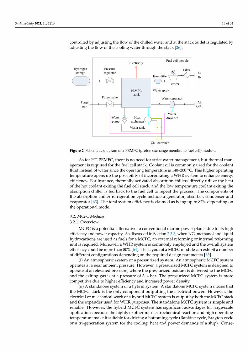
A PEMFC module subsystem consists of a stack, a hydrogen delivery unit, an airdelivery unit and a cooling unit [26,61]. A schematic diagram of a PEMFC module isshown in Figure 2. The hydrogen is stored in the storage tank in a cryogenic liquefiedstate, or in a compressed state with pressure of 350–700 bar. The pressure of hydrogen isregulated by the pressure regulator. After the fuel cell stack, a purge valve at the outletof the anode chamber is periodically opened to prevent the cell voltage from decreasingbelow a certain limit [26]. A humidifier and a water separator may be installed before thepressure regulator and after the purge valve, to humidify the hydrogen and to remove thewater from the purge gas respectively [19,26]. In addition, auxiliary components betweenthe fuel inlet and outlet of the stack might be employed for hydrogen recirculation [61]. Thefiltered air is pressurized by an air blower and then humidified to maintain the performanceof the polymer membrane within the fuel cells. For maritime applications, degradationof the polymer membrane may occur due to the cathode being exposed to the sea-airconditions [19]. Therefore, appropriate pretreatment of the inlet air to remove sodiumchloride vapor might be required. The air blower not only maintains sufficient air flow tothe stack, but also facilitates reduced stack size by increasing the inlet air density and easesthe humidification process by increasing intake air temperature. Water in the residual airis separated by a condenser before being discharged to the outside of the module. Theheat generated by the stack is removed by a cooling module, which comprises a watertank, a water pump and a heat exchanger. The heat exchanger transfers the heat to chilledwater or sea water outboard [62]. The temperature of the cooling water at the stack inlet is
Sustainability 2021, 13, 1213 13 of 34
controlled by adjusting the flow of the chilled water and at the stack outlet is regulated byadjusting the flow of the cooling water through the stack [26].
Sustainability 2021, 13, x FOR PEER REVIEW 12 of 33
residual air is separated by a condenser before being discharged to the outside of the mod-
ule. The heat generated by the stack is removed by a cooling module, which comprises a
water tank, a water pump and a heat exchanger. The heat exchanger transfers the heat to
chilled water or sea water outboard [62]. The temperature of the cooling water at the stack
inlet is controlled by adjusting the flow of the chilled water and at the stack outlet is reg-
ulated by adjusting the flow of the cooling water through the stack [26].
Hydrogen
storage
Pressure
regulator
PEMFC
stack
M
Humidifier
Filter
Blower
Air
IN
Air
OUT
Water separatorPurge valve
Purge
gas
Chilled water
Electricity
Water
draw off
Water spray
Water tank
Water
pump
Heat
exchanger
Fuel cell module
Figure 2. Schematic diagram of a PEMFC (proton exchange membrane fuel cell) module.
As for HT-PEMFC, there is no need for strict water management, but thermal man-
agement is required for the fuel cell stack. Coolant oil is commonly used for the coolant
fluid instead of water since the operating temperature is 140–200 °C. This higher operating
temperature opens up the possibility of incorporating a WHR system to enhance energy
efficiency. For instance, thermally activated absorption chillers directly utilize the heat of
the hot coolant exiting the fuel cell stack, and the low temperature coolant exiting the
absorption chiller is fed back to the fuel cell to repeat the process. The components of the
absorption chiller refrigeration cycle include a generator, absorber, condenser and evap-
orator [63]. The total system efficiency is claimed as being up to 87% depending on the
operational mode.
3.2. MCFC Modules
3.2.1. Overview
MCFC is a potential alternative to conventional marine power plants due to its high
efficiency and power capacity. As discussed in Section 2.3.3, when NG, methanol and liq-
uid hydrocarbons are used as fuels for a MCFC, an external reforming or internal reform-
ing unit is required. Moreover, a WHR system is commonly employed and the overall
system efficiency could be more than 80% [64]. The layout of a MCFC module can exhibit
a number of different configurations depending on the required design parameters [65].
(i) An atmospheric system or a pressurized system. An atmospheric MCFC system
operates at a near ambient pressure. However, a pressurized MCFC system is designed to
operate at an elevated pressure, where the pressurized oxidant is delivered to the MCFC
and the exiting gas is at a pressure of 3–4 bar. The pressurized MCFC system is more
competitive due to higher efficiency and increased power density.
(ii) A standalone system or a hybrid system. A standalone MCFC system means that
the MCFC stack is the only component outputting the electrical power. However, the elec-
trical or mechanical work of a hybrid MCFC system is output by both the MCFC stack
Figure 2. Schematic diagram of a PEMFC (proton exchange membrane fuel cell) module.
As for HT-PEMFC, there is no need for strict water management, but thermal man-agement is required for the fuel cell stack. Coolant oil is commonly used for the coolantfluid instead of water since the operating temperature is 140–200 ◦C. This higher operatingtemperature opens up the possibility of incorporating a WHR system to enhance energyefficiency. For instance, thermally activated absorption chillers directly utilize the heatof the hot coolant exiting the fuel cell stack, and the low temperature coolant exiting theabsorption chiller is fed back to the fuel cell to repeat the process. The components ofthe absorption chiller refrigeration cycle include a generator, absorber, condenser andevaporator [63]. The total system efficiency is claimed as being up to 87% depending onthe operational mode.
3.2. MCFC Modules3.2.1. Overview
MCFC is a potential alternative to conventional marine power plants due to its highefficiency and power capacity. As discussed in Section 2.3.3, when NG, methanol and liquidhydrocarbons are used as fuels for a MCFC, an external reforming or internal reformingunit is required. Moreover, a WHR system is commonly employed and the overall systemefficiency could be more than 80% [64]. The layout of a MCFC module can exhibit a numberof different configurations depending on the required design parameters [65].
(i) An atmospheric system or a pressurized system. An atmospheric MCFC systemoperates at a near ambient pressure. However, a pressurized MCFC system is designed tooperate at an elevated pressure, where the pressurized oxidant is delivered to the MCFCand the exiting gas is at a pressure of 3–4 bar. The pressurized MCFC system is morecompetitive due to higher efficiency and increased power density.
(ii) A standalone system or a hybrid system. A standalone MCFC system means thatthe MCFC stack is the only component outputting the electrical power. However, theelectrical or mechanical work of a hybrid MCFC system is output by both the MCFC stackand the expander used for WHR purposes. The standalone MCFC system is simple andreliable. However, the hybrid MCFC system has significant advantages for large-scaleapplications because the highly exothermic electrochemical reaction and high operatingtemperature make it suitable for driving a bottoming cycle (Rankine cycle, Brayton cycleor a tri-generation system for the cooling, heat and power demands of a ship). Conse-
Sustainability 2021, 13, 1213 14 of 34
quently, higher overall efficiency and larger power outputs can be obtained in the hybridconfiguration.
(iii) An indirect hybrid system or a direct hybrid system. Regarding hybrid MCFCsystems, either a ST or GT can be combined with the MCFC module. Indirect hybridsystems use the fuel cell exhaust gas to heat the working fluid of a bottoming cycle,where the power turbine is driven by the steam or the air heated by the energy from thecombustion of the unreacted anode gas and the cathode gas, probably along with theauxiliary fuel. However, a direct hybrid system uses the energy from the combustion of theexiting gas of the MCFC stack to drive a GT directly. The indirect hybrid system is simpleand reliable, and the operation of the MCFC is independent from the GT, which allowsa safe and robust operation for both the fuel cell and the GT. However, the direct hybridsystem is more attractive for large-scale applications.
3.2.2. Standalone MCFC System
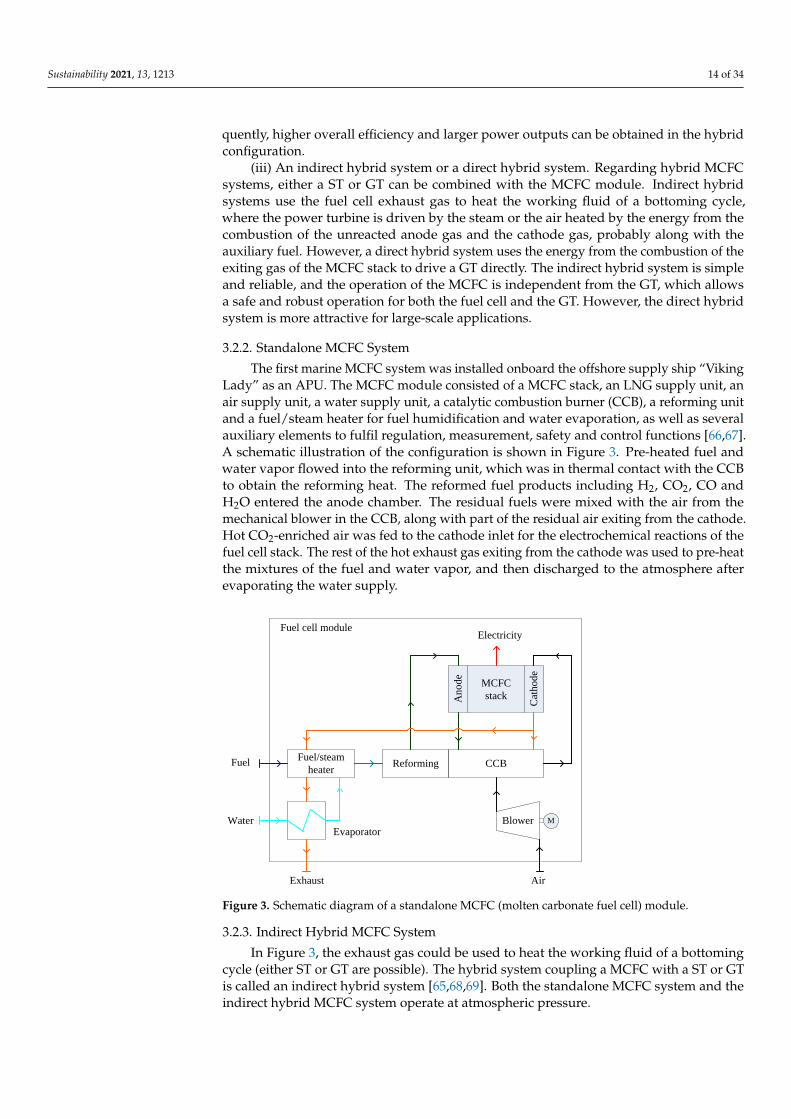
The first marine MCFC system was installed onboard the offshore supply ship “VikingLady” as an APU. The MCFC module consisted of a MCFC stack, an LNG supply unit, anair supply unit, a water supply unit, a catalytic combustion burner (CCB), a reforming unitand a fuel/steam heater for fuel humidification and water evaporation, as well as severalauxiliary elements to fulfil regulation, measurement, safety and control functions [66,67].A schematic illustration of the configuration is shown in Figure 3. Pre-heated fuel andwater vapor flowed into the reforming unit, which was in thermal contact with the CCBto obtain the reforming heat. The reformed fuel products including H2, CO2, CO andH2O entered the anode chamber. The residual fuels were mixed with the air from themechanical blower in the CCB, along with part of the residual air exiting from the cathode.Hot CO2-enriched air was fed to the cathode inlet for the electrochemical reactions of thefuel cell stack. The rest of the hot exhaust gas exiting from the cathode was used to pre-heatthe mixtures of the fuel and water vapor, and then discharged to the atmosphere afterevaporating the water supply.
Sustainability 2021, 13, x FOR PEER REVIEW 13 of 33
and the expander used for WHR purposes. The standalone MCFC system is simple and
reliable. However, the hybrid MCFC system has significant advantages for large-scale ap-
plications because the highly exothermic electrochemical reaction and high operating tem-
perature make it suitable for driving a bottoming cycle (Rankine cycle, Brayton cycle or a
tri-generation system for the cooling, heat and power demands of a ship). Consequently,
higher overall efficiency and larger power outputs can be obtained in the hybrid configu-
ration.
(iii) An indirect hybrid system or a direct hybrid system. Regarding hybrid MCFC
systems, either a ST or GT can be combined with the MCFC module. Indirect hybrid sys-
tems use the fuel cell exhaust gas to heat the working fluid of a bottoming cycle, where
the power turbine is driven by the steam or the air heated by the energy from the com-
bustion of the unreacted anode gas and the cathode gas, probably along with the auxiliary
fuel. However, a direct hybrid system uses the energy from the combustion of the exiting
gas of the MCFC stack to drive a GT directly. The indirect hybrid system is simple and
reliable, and the operation of the MCFC is independent from the GT, which allows a safe
and robust operation for both the fuel cell and the GT. However, the direct hybrid system
is more attractive for large-scale applications.
3.2.2. Standalone MCFC System
The first marine MCFC system was installed onboard the offshore supply ship “Vi-
king Lady” as an APU. The MCFC module consisted of a MCFC stack, an LNG supply
unit, an air supply unit, a water supply unit, a catalytic combustion burner (CCB), a re-
forming unit and a fuel/steam heater for fuel humidification and water evaporation, as
well as several auxiliary elements to fulfil regulation, measurement, safety and control
functions [66,67]. A schematic illustration of the configuration is shown in Figure 3. Pre-
heated fuel and water vapor flowed into the reforming unit, which was in thermal contact
with the CCB to obtain the reforming heat. The reformed fuel products including H2, CO2,
CO and H2O entered the anode chamber. The residual fuels were mixed with the air from
the mechanical blower in the CCB, along with part of the residual air exiting from the
cathode. Hot CO2-enriched air was fed to the cathode inlet for the electrochemical reac-
tions of the fuel cell stack. The rest of the hot exhaust gas exiting from the cathode was
used to pre-heat the mixtures of the fuel and water vapor, and then discharged to the
atmosphere after evaporating the water supply.
Fuel
MCFC
stack
ElectricityFuel cell module
Reforming CCB
An
od
e
Cat
ho
de
Blower
Fuel/steam
heater
Evaporator
Exhaust
Water
Air
M
Figure 3. Schematic diagram of a standalone MCFC (molten carbonate fuel cell) module.
Figure 3. Schematic diagram of a standalone MCFC (molten carbonate fuel cell) module.
3.2.3. Indirect Hybrid MCFC System
In Figure 3, the exhaust gas could be used to heat the working fluid of a bottomingcycle (either ST or GT are possible). The hybrid system coupling a MCFC with a ST or GTis called an indirect hybrid system [65,68,69]. Both the standalone MCFC system and theindirect hybrid MCFC system operate at atmospheric pressure.
Sustainability 2021, 13, 1213 15 of 34
Combined MCFC-ST System
A ST may be used in a bottoming cycle for WHR [29,67]. The water supply is changedinto superheated steam by the exhaust gas from the cathode of the fuel cell stack througha cascade of pre-heater, evaporator and superheater after the fuel/steam heater. Thesuperheated steam operates a ST for power generation. The residual steam along withthe fuel is then pre-heated in the fuel/steam heater. Other components and processes aresimilar to those of the standalone MCFC system.
Combined MCFC-GT System
In some indirect hybrid systems, a power turbine is driven by air heated by energyfrom the combustion of the unreacted anode gas and the cathode gas, possibly along withauxiliary fuel [29]. This kind of indirect system might be preferred for a small-scale system.In some configurations [69], the exiting gas from the combustor heats the inlet air of thepower turbine and then flows into the cathode; the exhaust gas from the cathode heats thepressurized air, the fuel and the water one by one before leaving the module. The fuel andwater are reformed in an internal reformer and then enter into the anode. The residualfuels from the anode react with the exiting air from the power turbine in the combustor.The applications of these configurations are limited due to the relatively low efficienciesand the incompatibility of current commercial GT units.
3.2.4. Direct Hybrid MCFC System
If the exhaust gas of the MCFC stack is used to drive a GT directly, this kind ofWHR system is called a direct hybrid system, where the operating pressure is usually3–4 bar [65,70–72]. In the direct hybrid system, the power turbine is driven by the exhaustgas from the combustion of the unreacted anode gas and the cathode gas, probably alongwith the auxiliary fuel. The significant feature of the direct system is that without theheat exchanger present in the indirect system, it produces turbine inlet gas with highertemperature and pressure. This offers a greater variety of options for system layoutscompared to the indirect system and increases the potential of the system to more efficientlyexploit the heat released from the MCFC [65]. The direct hybrid system is suitable forlarge-scale systems.
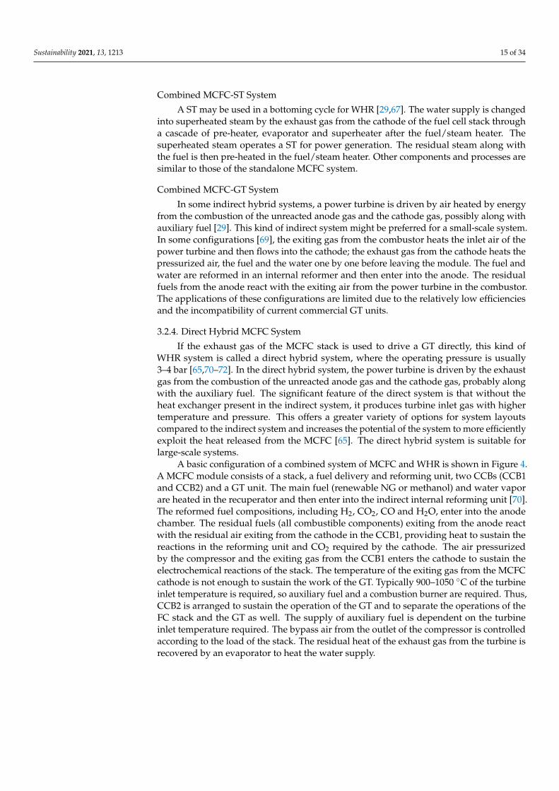
A basic configuration of a combined system of MCFC and WHR is shown in Figure 4.A MCFC module consists of a stack, a fuel delivery and reforming unit, two CCBs (CCB1and CCB2) and a GT unit. The main fuel (renewable NG or methanol) and water vaporare heated in the recuperator and then enter into the indirect internal reforming unit [70].The reformed fuel compositions, including H2, CO2, CO and H2O, enter into the anodechamber. The residual fuels (all combustible components) exiting from the anode reactwith the residual air exiting from the cathode in the CCB1, providing heat to sustain thereactions in the reforming unit and CO2 required by the cathode. The air pressurizedby the compressor and the exiting gas from the CCB1 enters the cathode to sustain theelectrochemical reactions of the stack. The temperature of the exiting gas from the MCFCcathode is not enough to sustain the work of the GT. Typically 900–1050 ◦C of the turbineinlet temperature is required, so auxiliary fuel and a combustion burner are required. Thus,CCB2 is arranged to sustain the operation of the GT and to separate the operations of theFC stack and the GT as well. The supply of auxiliary fuel is dependent on the turbineinlet temperature required. The bypass air from the outlet of the compressor is controlledaccording to the load of the stack. The residual heat of the exhaust gas from the turbine isrecovered by an evaporator to heat the water supply.
Sustainability 2021, 13, 1213 16 of 34
Sustainability 2021, 13, x FOR PEER REVIEW 15 of 33
according to the load of the stack. The residual heat of the exhaust gas from the turbine is
recovered by an evaporator to heat the water supply.
Fuel
MCFC
stack
ElectricityFuel cell module
Reforming CCB1
An
od
e
Cat
ho
de
CCB2
CompressorTurbine
Recuperator
Evaporator
Exhaust
Water Air
Main fuel
Au
xil
iary
fu
el
Bypass valve
G
Figure 4. Schematic diagram of the basic configuration of a MCFC-GT (molten carbonate fuel cell
gas turbine) system.
If no auxiliary fuels are fed into the CCB2, a turbocharger, such as those commonly
used in the application of internal combustion engines, could be employed to pressurize
the air [70]. In such circumstances, the total power output and the efficiency of the MCFC
system is limited. Accordingly, hybrid MCFC systems using GT are relatively common
and several configurations have been investigated. The residual fuels exiting from the an-
ode and the residual air from the cathode were recycled to either CCB1 or CCB2, or both
of them. In addition, auxiliary fuels were fed to either CCB1 or CCB2, and a heat ex-
changer (regenerator) was used to pre-heat the pressurized air from the compressor by
the exhaust gas from the turbine [70]. In some configurations, in addition to generating
mechanical power for the air compressor, the turbine might generate extra electrical
power through a generator [70]. Thus, both electrical power and efficiency increase. CCB2
could be a direct combustor and part of the reformed fuel products might be used for
hydrogen separation in a pressure swing absorption system. The extracted hydrogen
could be stored or mixed with the residual fuels exiting from the anode and the residual
air exiting from the cathode [73]. In addition, the main fuel might be reformed by an ex-
ternal reformer using the waste heat from the system; the pressurized air is heated by the
exhaust gas from the turbine, and reacts with part of the residual fuels from the anode in
the CCB1, then entering into the cathode. Meanwhile, the exiting gas from the cathode
reacts with the auxiliary fuel and the remaining part of the residual fuel from the anode
in the CCB2 to drive the turbine [71]. It is clear therefore that the hybrid MCFC system
efficiency, power output, complexity of the layout, power ratio of the stack to WHR sys-
tem, power ratio of electricity to heat and plant costs are heavily influenced by system
configuration factors such as post-combustion and operating pressure of the stack. [70].
Figure 4. Schematic diagram of the basic configuration of a MCFC-GT (molten carbonate fuel cellgas turbine) system.
If no auxiliary fuels are fed into the CCB2, a turbocharger, such as those commonlyused in the application of internal combustion engines, could be employed to pressurizethe air [70]. In such circumstances, the total power output and the efficiency of the MCFCsystem is limited. Accordingly, hybrid MCFC systems using GT are relatively commonand several configurations have been investigated. The residual fuels exiting from theanode and the residual air from the cathode were recycled to either CCB1 or CCB2, orboth of them. In addition, auxiliary fuels were fed to either CCB1 or CCB2, and a heatexchanger (regenerator) was used to pre-heat the pressurized air from the compressor bythe exhaust gas from the turbine [70]. In some configurations, in addition to generatingmechanical power for the air compressor, the turbine might generate extra electrical powerthrough a generator [70]. Thus, both electrical power and efficiency increase. CCB2 couldbe a direct combustor and part of the reformed fuel products might be used for hydrogenseparation in a pressure swing absorption system. The extracted hydrogen could be storedor mixed with the residual fuels exiting from the anode and the residual air exiting fromthe cathode [73]. In addition, the main fuel might be reformed by an external reformerusing the waste heat from the system; the pressurized air is heated by the exhaust gas fromthe turbine, and reacts with part of the residual fuels from the anode in the CCB1, thenentering into the cathode. Meanwhile, the exiting gas from the cathode reacts with theauxiliary fuel and the remaining part of the residual fuel from the anode in the CCB2 todrive the turbine [71]. It is clear therefore that the hybrid MCFC system efficiency, poweroutput, complexity of the layout, power ratio of the stack to WHR system, power ratio ofelectricity to heat and plant costs are heavily influenced by system configuration factorssuch as post-combustion and operating pressure of the stack. [70].
3.3. SOFC Modules3.3.1. Overview
The basic components of a SOFC module consist of a SOFC stack, a fuel supply unit,an air supply unit, a reforming unit, an after combustor and a WHR unit, as well as severalauxiliary elements serving regulation, measurement, safety and control functions [74,75].
Sustainability 2021, 13, 1213 17 of 34
The operating temperature of the SOFC stack affects the layout of a SOFC module, interms of fuel reforming, fuel preheating, air preheating and WHR system. SOFC modulescan also have a number of distinct layouts, e.g., external reforming or internal reforming,atmospheric system or pressurized system, standalone system or hybrid system, indirecthybrid system or direct hybrid system [75–77]. Internal reforming is more attractivethan external reforming due to higher efficiency and lower capital cost. However, theendothermic reaction of the fuel reforming process may lead to significant temperaturegradients and inhomogeneous current distributions inside the cells [40,74,76,77], so indirectinternal reforming is preferable due to reduced thermal stress. In addition, depending onthe source of steam for fuel reforming, there may be recirculation of water from the anodeor external water supply. Anode recirculation provides the steam for the fuel reformingprocess through recirculating part of the exiting gas from the anode. Anode recirculation isnormally performed by a blower or an ejector. However, if there is no anode recirculationarrangement, an external water supply is heated by a heat recovery steam generatorto provide the steam for the fuel reforming process [75]. Anode recirculation seems tobe more attractive for marine applications since it is typically less expensive and moreefficient. In addition, the limited fresh water storage available onboard a ship is anotherconsideration. However, it is difficult to control the steam-to-carbon ratio inside the stackaccurately [75–77].
3.3.2. Standalone SOFC System
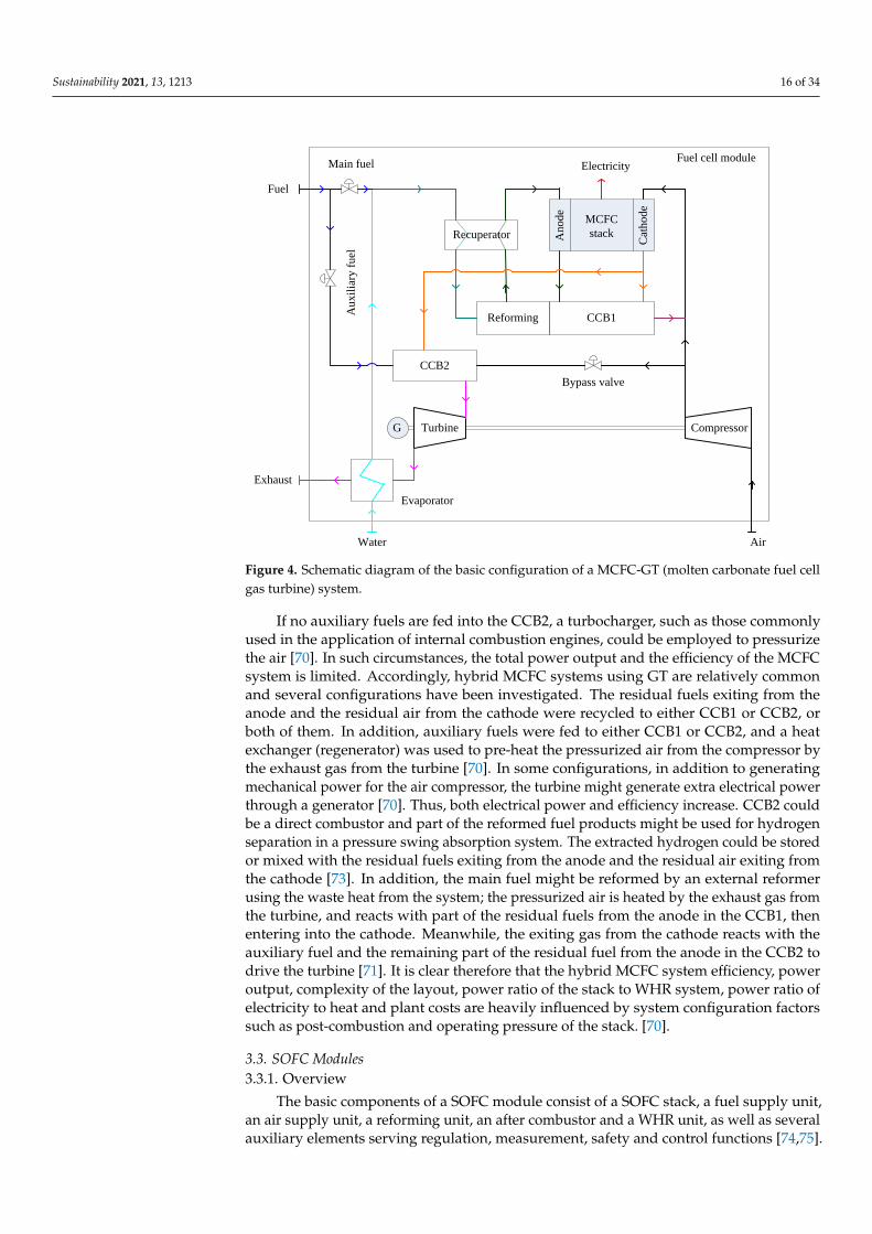
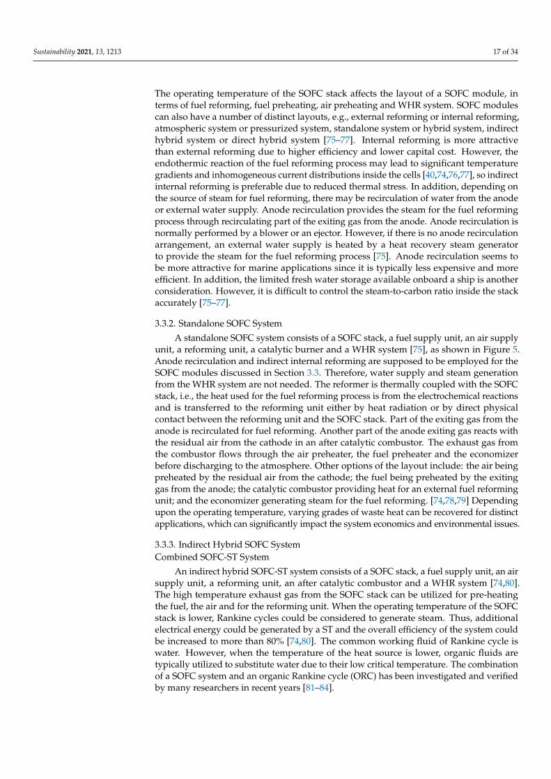
A standalone SOFC system consists of a SOFC stack, a fuel supply unit, an air supplyunit, a reforming unit, a catalytic burner and a WHR system [75], as shown in Figure 5.Anode recirculation and indirect internal reforming are supposed to be employed for theSOFC modules discussed in Section 3.3. Therefore, water supply and steam generationfrom the WHR system are not needed. The reformer is thermally coupled with the SOFCstack, i.e., the heat used for the fuel reforming process is from the electrochemical reactionsand is transferred to the reforming unit either by heat radiation or by direct physicalcontact between the reforming unit and the SOFC stack. Part of the exiting gas from theanode is recirculated for fuel reforming. Another part of the anode exiting gas reacts withthe residual air from the cathode in an after catalytic combustor. The exhaust gas fromthe combustor flows through the air preheater, the fuel preheater and the economizerbefore discharging to the atmosphere. Other options of the layout include: the air beingpreheated by the residual air from the cathode; the fuel being preheated by the exitinggas from the anode; the catalytic combustor providing heat for an external fuel reformingunit; and the economizer generating steam for the fuel reforming. [74,78,79] Dependingupon the operating temperature, varying grades of waste heat can be recovered for distinctapplications, which can significantly impact the system economics and environmental issues.
3.3.3. Indirect Hybrid SOFC SystemCombined SOFC-ST System
An indirect hybrid SOFC-ST system consists of a SOFC stack, a fuel supply unit, an airsupply unit, a reforming unit, an after catalytic combustor and a WHR system [74,80].The high temperature exhaust gas from the SOFC stack can be utilized for pre-heatingthe fuel, the air and for the reforming unit. When the operating temperature of the SOFCstack is lower, Rankine cycles could be considered to generate steam. Thus, additionalelectrical energy could be generated by a ST and the overall efficiency of the system couldbe increased to more than 80% [74,80]. The common working fluid of Rankine cycle iswater. However, when the temperature of the heat source is lower, organic fluids aretypically utilized to substitute water due to their low critical temperature. The combinationof a SOFC system and an organic Rankine cycle (ORC) has been investigated and verifiedby many researchers in recent years [81–84].
Sustainability 2021, 13, 1213 18 of 34Sustainability 2021, 13, x FOR PEER REVIEW 17 of 33
Fuel
SOFC
stack Electricity
Fuel cell module
Air preheater
Anode
Cathode
Exhaust
Air
Economizer
Reforming
CC
B
Fuel preheater
M
Blower
Figure 5. Schematic diagram of an atmospheric SOFC (solid oxide fuel cell) module.
3.3.3. Indirect Hybrid SOFC System
Combined SOFC-ST System
An indirect hybrid SOFC-ST system consists of a SOFC stack, a fuel supply unit, an
air supply unit, a reforming unit, an after catalytic combustor and a WHR system [74,80].
The high temperature exhaust gas from the SOFC stack can be utilized for pre-heating the
fuel, the air and for the reforming unit. When the operating temperature of the SOFC stack
is lower, Rankine cycles could be considered to generate steam. Thus, additional electrical
energy could be generated by a ST and the overall efficiency of the system could be in-
creased to more than 80% [74,80]. The common working fluid of Rankine cycle is water.
However, when the temperature of the heat source is lower, organic fluids are typically
utilized to substitute water due to their low critical temperature. The combination of a
SOFC system and an organic Rankine cycle (ORC) has been investigated and verified by
many researchers in recent years [81–84].
Combined SOFC-GT System
The indirect hybrid SOFC-GT system consists of a SOFC stack, a fuel supply unit, an
air supply unit, a reforming unit, an after catalytic combustor, a heat exchanger, tur-
bomachinery (in the form of a GT) and an economizer [74,75,85], as shown in Figure 6. In
an indirect hybrid SOFC-GT system, the air from the compressor is heated by the exhaust
gas from the combustor through the heat exchanger, which then drives the air turbine
before it flows into the cathode. To improve the turbine inlet temperature for a higher
pressure ratio, an auxiliary combustor may be arranged before the turbine [74,75,85,86].
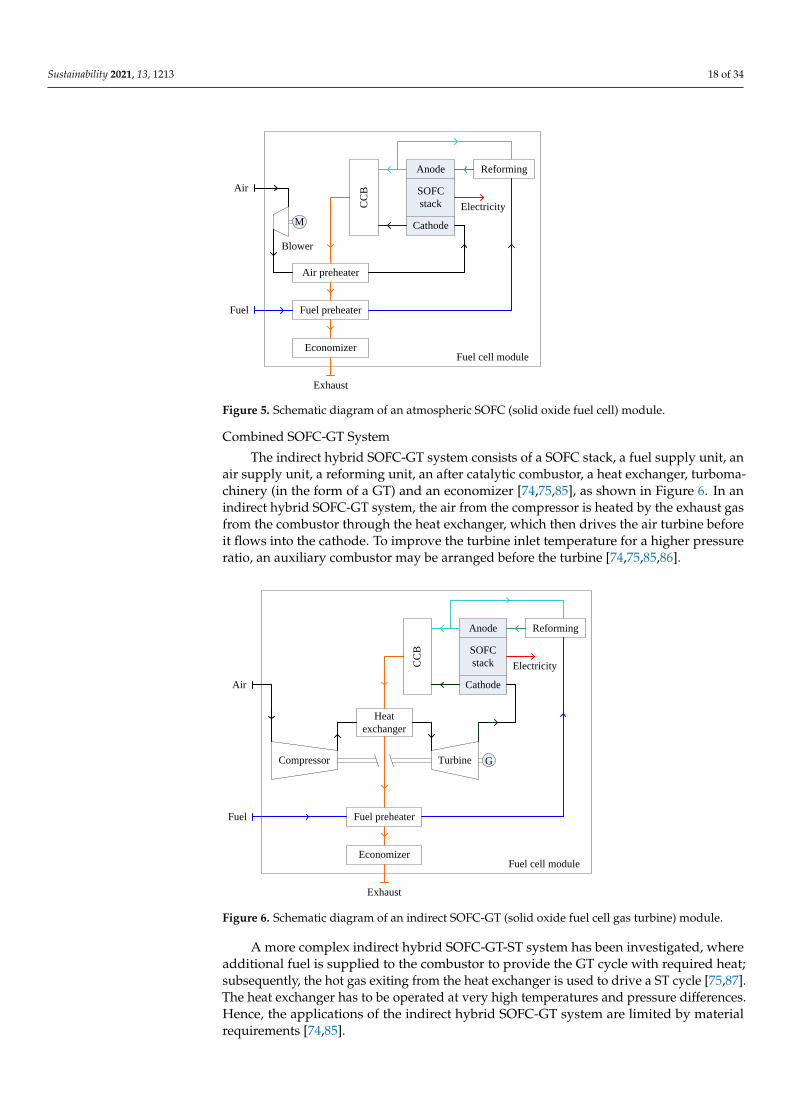
A more complex indirect hybrid SOFC-GT-ST system has been investigated, where
additional fuel is supplied to the combustor to provide the GT cycle with required heat;
subsequently, the hot gas exiting from the heat exchanger is used to drive a ST cycle
[75,87]. The heat exchanger has to be operated at very high temperatures and pressure
differences. Hence, the applications of the indirect hybrid SOFC-GT system are limited by
material requirements [74,85].
Figure 5. Schematic diagram of an atmospheric SOFC (solid oxide fuel cell) module.
Combined SOFC-GT System
The indirect hybrid SOFC-GT system consists of a SOFC stack, a fuel supply unit, anair supply unit, a reforming unit, an after catalytic combustor, a heat exchanger, turboma-chinery (in the form of a GT) and an economizer [74,75,85], as shown in Figure 6. In anindirect hybrid SOFC-GT system, the air from the compressor is heated by the exhaust gasfrom the combustor through the heat exchanger, which then drives the air turbine beforeit flows into the cathode. To improve the turbine inlet temperature for a higher pressureratio, an auxiliary combustor may be arranged before the turbine [74,75,85,86].
Sustainability 2021, 13, x FOR PEER REVIEW 18 of 33
Fuel
SOFC
stack Electricity
Fuel cell module
Heat
exchanger
Anode
Cathode
Compressor Turbine
Exhaust
Air
Economizer
Reforming
CC
B
Fuel preheater
G
Figure 6. Schematic diagram of an indirect SOFC-GT (solid oxide fuel cell gas turbine) module.
3.3.4. Direct Hybrid SOFC System
A direct hybrid system uses the energy from the combustion of the exiting gases of
the SOFC stack to drive a GT directly, as shown in Figure 7. Consequently, the exhaust
gas exiting from the GT is used to preheat the air and the fuel, and then an economizer is
used to recover the residual heat. The operating range of a GT, in terms of pressures and
mass flow rates, is very restricted due to the intrinsic characteristics of the turbomachin-
ery. Thus, auxiliary fuel is supplied to the combustor to maintain the necessary turbine
inlet temperature. Meanwhile, the SOFC and GT work separately through the combustor.
A large number of distinct configurations have been investigated. Examples include using
the GT to drive both the air compressor and a generator, which means both mechanical
and electrical energy are generated from the GT, and also using the GT to drive the air
compressor, which is followed by a power turbine driving a generator to output addi-
tional electrical energy [30,74,75,88,89].
Fuel
SOFC
stack Electricity
Fuel cell module
Air preheater
Anode
Cathode
Compressor Turbine
Exhaust
Air
Main fuel
Au
xil
iary
fu
el
Economizer
Reforming
CC
B
Fuel preheater
G
Figure 6. Schematic diagram of an indirect SOFC-GT (solid oxide fuel cell gas turbine) module.
A more complex indirect hybrid SOFC-GT-ST system has been investigated, whereadditional fuel is supplied to the combustor to provide the GT cycle with required heat;subsequently, the hot gas exiting from the heat exchanger is used to drive a ST cycle [75,87].The heat exchanger has to be operated at very high temperatures and pressure differences.Hence, the applications of the indirect hybrid SOFC-GT system are limited by materialrequirements [74,85].
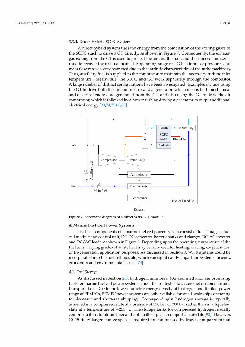
Sustainability 2021, 13, 1213 19 of 34
3.3.4. Direct Hybrid SOFC System
A direct hybrid system uses the energy from the combustion of the exiting gases ofthe SOFC stack to drive a GT directly, as shown in Figure 7. Consequently, the exhaustgas exiting from the GT is used to preheat the air and the fuel, and then an economizer isused to recover the residual heat. The operating range of a GT, in terms of pressures andmass flow rates, is very restricted due to the intrinsic characteristics of the turbomachinery.Thus, auxiliary fuel is supplied to the combustor to maintain the necessary turbine inlettemperature. Meanwhile, the SOFC and GT work separately through the combustor.A large number of distinct configurations have been investigated. Examples include usingthe GT to drive both the air compressor and a generator, which means both mechanicaland electrical energy are generated from the GT, and also using the GT to drive the aircompressor, which is followed by a power turbine driving a generator to output additionalelectrical energy [30,74,75,88,89].
Sustainability 2021, 13, x FOR PEER REVIEW 18 of 33
Fuel
SOFC
stack Electricity
Fuel cell module
Heat
exchanger
Anode
Cathode
Compressor Turbine
Exhaust
Air
Economizer
Reforming
CC
B
Fuel preheater
G
Figure 6. Schematic diagram of an indirect SOFC-GT (solid oxide fuel cell gas turbine) module.
3.3.4. Direct Hybrid SOFC System
A direct hybrid system uses the energy from the combustion of the exiting gases of
the SOFC stack to drive a GT directly, as shown in Figure 7. Consequently, the exhaust
gas exiting from the GT is used to preheat the air and the fuel, and then an economizer is
used to recover the residual heat. The operating range of a GT, in terms of pressures and
mass flow rates, is very restricted due to the intrinsic characteristics of the turbomachin-
ery. Thus, auxiliary fuel is supplied to the combustor to maintain the necessary turbine
inlet temperature. Meanwhile, the SOFC and GT work separately through the combustor.
A large number of distinct configurations have been investigated. Examples include using
the GT to drive both the air compressor and a generator, which means both mechanical
and electrical energy are generated from the GT, and also using the GT to drive the air
compressor, which is followed by a power turbine driving a generator to output addi-
tional electrical energy [30,74,75,88,89].
Fuel
SOFC
stack Electricity
Fuel cell module
Air preheater
Anode
Cathode
Compressor Turbine
Exhaust
Air
Main fuel
Au
xil
iary
fu
el
Economizer
Reforming
CC
B
Fuel preheater
G
Figure 7. Schematic diagram of a direct SOFC-GT module.
4. Marine Fuel Cell Power Systems
The basic components of a marine fuel cell power system consist of fuel storage, a fuelcell module and control unit, DC-DC converter, battery banks and charger, DC-AC inverterand DC/AC loads, as shown in Figure 8. Depending upon the operating temperature of thefuel cells, varying grades of waste heat may be recovered for heating, cooling, co-generationor tri-generation application purposes. As discussed in Section 3, WHR systems could beincorporated into the fuel cell module, which can significantly impact the system efficiency,economics and environmental issues [74].
4.1. Fuel Storage
As discussed in Section 2.3, hydrogen, ammonia, NG and methanol are promisingfuels for marine fuel cell power systems under the context of low/zero net carbon maritimetransportation. Due to the low volumetric energy density of hydrogen and limited powerrange of PEMFCs, PEMFC power systems are only available for small-scale ships operatingfor domestic and short-sea shipping. Correspondingly, hydrogen storage is typicallyachieved in a compressed state at a pressure of 350 bar or 700 bar rather than in a liquefiedstate at a temperature of −253 ◦C. The storage tanks for compressed hydrogen usuallycomprise a thin aluminum liner and carbon fiber–plastic composite materials [90]. However,10–15-times larger storage space is required for compressed hydrogen compared to that
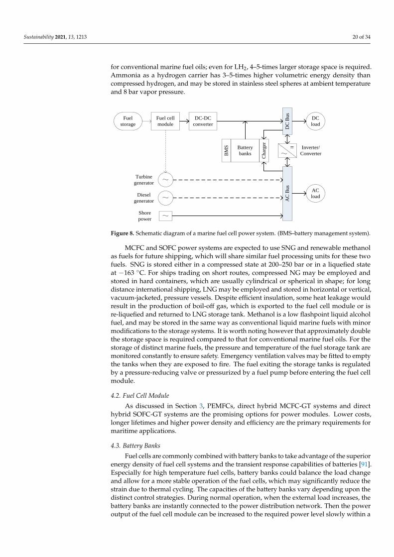
Sustainability 2021, 13, 1213 20 of 34
for conventional marine fuel oils; even for LH2, 4–5-times larger storage space is required.Ammonia as a hydrogen carrier has 3–5-times higher volumetric energy density thancompressed hydrogen, and may be stored in stainless steel spheres at ambient temperatureand 8 bar vapor pressure.
Sustainability 2021, 13, x FOR PEER REVIEW 19 of 33
Figure 7. Schematic diagram of a direct SOFC-GT module.
4. Marine Fuel Cell Power Systems
The basic components of a marine fuel cell power system consist of fuel storage, a
fuel cell module and control unit, DC-DC converter, battery banks and charger, DC-AC
inverter and DC/AC loads, as shown in Figure 8. Depending upon the operating temper-
ature of the fuel cells, varying grades of waste heat may be recovered for heating, cooling,
co-generation or tri-generation application purposes. As discussed in Section 3, WHR sys-
tems could be incorporated into the fuel cell module, which can significantly impact the
system efficiency, economics and environmental issues [74].
Fuel cell
module
DC-DC
converter
Fuel
storage
DC
Bu
s
Battery
banksBM
S
Ch
arg
er
AC
Bu
s
=
~
~
~
DC
load
AC
load
Inverter/
Converter
Turbine
generator
Diesel
generator~
Shore
power
Figure 8. Schematic diagram of a marine fuel cell power system. (BMS–battery management sys-
tem).
4.1. Fuel Storage
As discussed in Section 2.3, hydrogen, ammonia, NG and methanol are promising
fuels for marine fuel cell power systems under the context of low/zero net carbon maritime
transportation. Due to the low volumetric energy density of hydrogen and limited power
range of PEMFCs, PEMFC power systems are only available for small-scale ships operat-
ing for domestic and short-sea shipping. Correspondingly, hydrogen storage is typically
achieved in a compressed state at a pressure of 350 bar or 700 bar rather than in a liquefied
state at a temperature of −253 °C. The storage tanks for compressed hydrogen usually
comprise a thin aluminum liner and carbon fiber–plastic composite materials [90]. How-
ever, 10–15-times larger storage space is required for compressed hydrogen compared to
that for conventional marine fuel oils; even for LH2, 4–5-times larger storage space is re-
quired. Ammonia as a hydrogen carrier has 3–5-times higher volumetric energy density
than compressed hydrogen, and may be stored in stainless steel spheres at ambient tem-
perature and 8 bar vapor pressure.
MCFC and SOFC power systems are expected to use SNG and renewable methanol
as fuels for future shipping, which will share similar fuel processing units for these two
fuels. SNG is stored either in a compressed state at 200–250 bar or in a liquefied state at
−163 °C. For ships trading on short routes, compressed NG may be employed and stored
in hard containers, which are usually cylindrical or spherical in shape; for long distance
international shipping, LNG may be employed and stored in horizontal or vertical, vac-
uum-jacketed, pressure vessels. Despite efficient insulation, some heat leakage would re-
sult in the production of boil-off gas, which is exported to the fuel cell module or is re-
liquefied and returned to LNG storage tank. Methanol is a low flashpoint liquid alcohol
fuel, and may be stored in the same way as conventional liquid marine fuels with minor
modifications to the storage systems. It is worth noting however that approximately dou-
ble the storage space is required compared to that for conventional marine fuel oils. For
Figure 8. Schematic diagram of a marine fuel cell power system. (BMS–battery management system).
MCFC and SOFC power systems are expected to use SNG and renewable methanolas fuels for future shipping, which will share similar fuel processing units for these twofuels. SNG is stored either in a compressed state at 200–250 bar or in a liquefied stateat −163 ◦C. For ships trading on short routes, compressed NG may be employed andstored in hard containers, which are usually cylindrical or spherical in shape; for longdistance international shipping, LNG may be employed and stored in horizontal or vertical,vacuum-jacketed, pressure vessels. Despite efficient insulation, some heat leakage wouldresult in the production of boil-off gas, which is exported to the fuel cell module or isre-liquefied and returned to LNG storage tank. Methanol is a low flashpoint liquid alcoholfuel, and may be stored in the same way as conventional liquid marine fuels with minormodifications to the storage systems. It is worth noting however that approximately doublethe storage space is required compared to that for conventional marine fuel oils. For thestorage of distinct marine fuels, the pressure and temperature of the fuel storage tank aremonitored constantly to ensure safety. Emergency ventilation valves may be fitted to emptythe tanks when they are exposed to fire. The fuel exiting the storage tanks is regulatedby a pressure-reducing valve or pressurized by a fuel pump before entering the fuel cellmodule.
4.2. Fuel Cell Module
As discussed in Section 3, PEMFCs, direct hybrid MCFC-GT systems and directhybrid SOFC-GT systems are the promising options for power modules. Lower costs,longer lifetimes and higher power density and efficiency are the primary requirements formaritime applications.
4.3. Battery Banks
Fuel cells are commonly combined with battery banks to take advantage of the superiorenergy density of fuel cell systems and the transient response capabilities of batteries [91].Especially for high temperature fuel cells, battery banks could balance the load changeand allow for a more stable operation of the fuel cells, which may significantly reduce thestrain due to thermal cycling. The capacities of the battery banks vary depending upon thedistinct control strategies. During normal operation, when the external load increases, thebattery banks are instantly connected to the power distribution network. Then the poweroutput of the fuel cell module can be increased to the required power level slowly within a
Sustainability 2021, 13, 1213 21 of 34
short period of time after load increase, followed by the adjustment of the GT. Conversely,when the external load decreases, the excess power generated by the fuel cell module cancharge the battery banks.
4.4. Power Electronics and Loads
(i) Battery management system. According to the state of charge (the level of charge ofan electric battery relative to its capacity, SoC), the power output of the fuel cell module isadjusted automatically. A battery management system is equipped to monitor the voltage,temperature and state of charge of the battery banks to ensure safe operation. The batterycharger is developed to charge the battery banks using either the fuel cell module or anexternal power source [26].
(ii) DC-DC converter. An individual fuel cell produces a DC voltage of 0.5–1.0 Vat rated load, which decreases as current increases. Hence, only a few or as many ashundreds of individual cells could be placed in series (known as stacking) to yield a highervoltage, the maximum limit of which is usually constrained by the manufacturing process.Meanwhile, to output the desired power, a higher current is achieved by increasing thesurface area of the cells, or by combining the fuel cells in parallel. The DC-DC converter isused to increase the voltage of the fuel cell module to meet the requirements of industrialapplications, e.g., 240–370 V or more [26]. Due to the release of heat from the convertercircuits and the use of cooling fans, the efficiency of the converter is less than 100%. Asinput power increases, the efficiency of the converter also increases because the proportionof the basic power consumed by the cooling fans is decreased. The DC-DC converternormally has an efficiency greater than 90%.
(iii) DC-AC inverter. A DC bus is used to collect power from the DC-DC converter ofthe fuel cell module and distribute the power to the DC loads. An AC bus is used to collectpower from the turbine generators (if fitted) of the fuel cell module, the diesel generators(if fitted) and a shore power supply. A DC-AC inverter is installed to convert the DCpower from the fuel cell module to the desired current types and voltage levels, which aresupplied to power AC loads.
(iv) Loads. The AC bus distributes the power to the AC loads, such as auxiliarypumps and blowers of fuel cell module, and onboard auxiliary equipment includingradiocommunication, navigation, lighting and air conditioners. DC and more often ACelectric motors could be used for propulsion directly through driving a propeller or waterjetpump.
5. Marine Applications of Fuel Cell Power Systems5.1. Fuel Cells for Maritime Demonstrations
Fuel cells have been used for military submarines since the 1960s, but civil applicationsof the technology did not arise until this century. Up to now, a large number of research anddemonstration projects have verified the viability of fuel cells for maritime applications.Some noticeable demonstration projects of marine fuel cells since 2000 are shown in Table 3.Reduced emissions, increased efficiency and quiet operation make fuel cells attractive forfuture low carbon shipping. In particular, PEMFC, including HT-PEMFC, as well as MCFCand SOFC, are the most promising types of marine fuel cells.
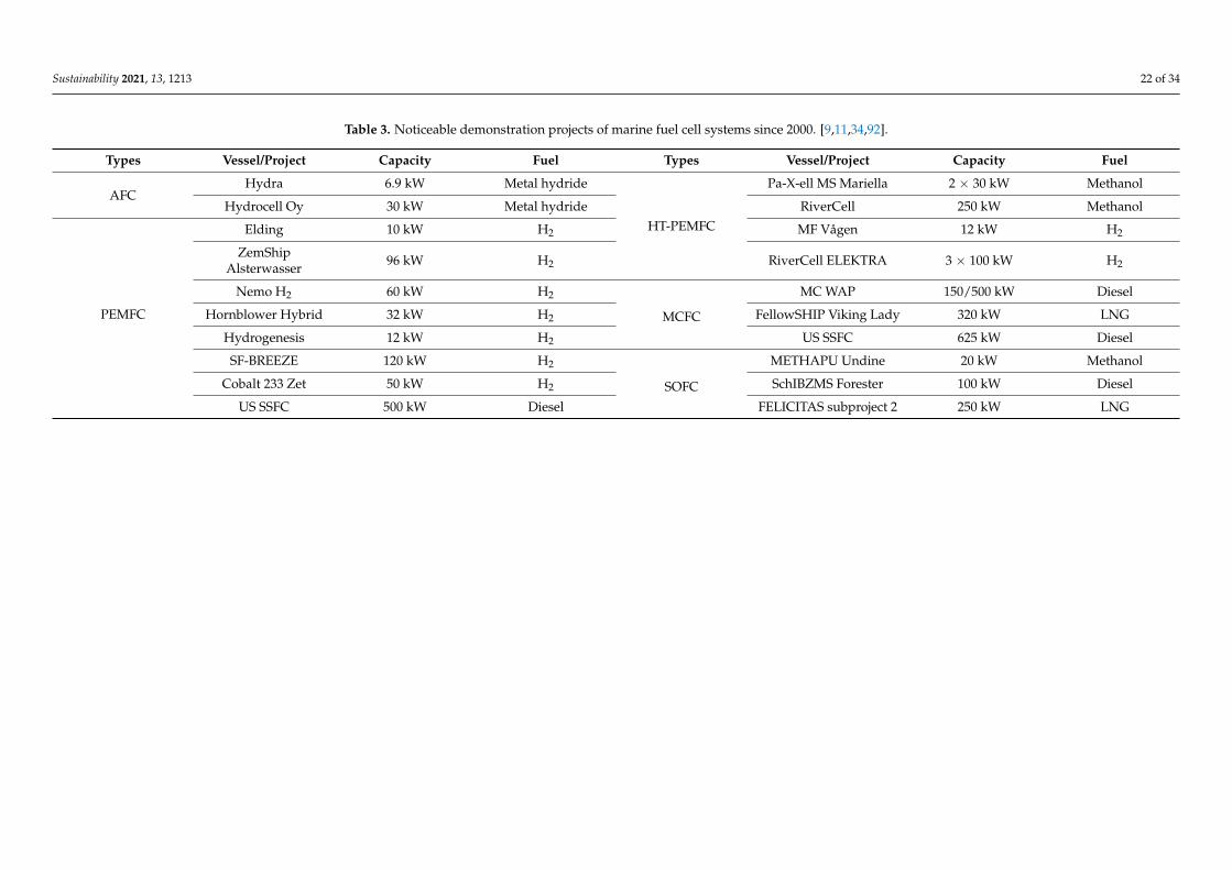
Sustainability 2021, 13, 1213 22 of 34
Table 3. Noticeable demonstration projects of marine fuel cell systems since 2000. [9,11,34,92].
Types Vessel/Project Capacity Fuel Types Vessel/Project Capacity Fuel
AFCHydra 6.9 kW Metal hydride
HT-PEMFC
Pa-X-ell MS Mariella 2 × 30 kW Methanol
Hydrocell Oy 30 kW Metal hydride RiverCell 250 kW Methanol
PEMFC
Elding 10 kW H2 MF Vågen 12 kW H2
ZemShipAlsterwasser 96 kW H2 RiverCell ELEKTRA 3 × 100 kW H2
Nemo H2 60 kW H2
MCFC
MC WAP 150/500 kW Diesel
Hornblower Hybrid 32 kW H2 FellowSHIP Viking Lady 320 kW LNG
Hydrogenesis 12 kW H2 US SSFC 625 kW Diesel
SF-BREEZE 120 kW H2
SOFC
METHAPU Undine 20 kW Methanol
Cobalt 233 Zet 50 kW H2 SchIBZMS Forester 100 kW Diesel
US SSFC 500 kW Diesel FELICITAS subproject 2 250 kW LNG
Sustainability 2021, 13, 1213 23 of 34
5.2. Marine PEMFC Power Systems
The early applications of PEMFC power systems in the maritime sector include: A 12-m-long yacht with a maximum cruising range of 225 km at a speed of 8 knots, whichutilized 6 kg of hydrogen stored in three storage tanks at a pressure of 300 bar, and waspowered by four 1.2 kW PEMFC modules combined with nine lead-gel batteries, generatinga total power output of up to 20 kW [93]; a canal boat using the hydrogen stored in a five-cylinder metal hydride storage system, powered by a 5 kW PEMFC module together witha lead-acid battery [94]; and a small boat with a maximum operating time of 10 h at amaximum speed of 7 knots, which utilized 5 kg of hydrogen onboard and was poweredby an 8 kW PEMFC module [95,96]. However, the installed power of these applications isusually less than 10 kW [9,26].
5.2.1. FCS Alsterwasser
FCS Alsterwasser was the first passenger ship powered by hydrogen fuel cells with amaximum power up to 100 kW. Based on the Zemships project, a PEMFC power system wasdeveloped for FCS Alsterwasser, which was about 25 m long and designed to accommodateup to 100 passengers at a maximum speed of 8 knots [97]. The power system consisted oftwelve storage tanks with 50 kg of hydrogen at a pressure of 350 bar, two 48 kW PEMFCmodules, 7 lead-gel battery packs with total capacities of 234 kWh and total voltage of560 V, a 100 kW propulsion electric motor and a 20 kW bow thruster. The PEMFC powersystem was used to power the propulsion motor directly or charge the lead-gel batterypacks. The battery packs, used as a back-up option if the fuel cells failed, not only deliveredpower to the propulsion motor at peak load but also lightened the load on the fuel cellsduring docking and casting-off procedures, which prolonged the life cycle of the fuel cells.The operation of the battery packs was determined by an energy management system. Thehydrogen stored onboard allowed the ship to operate for 2–3 days without refueling, whileit took only 12 min to fill up the hydrogen storage tanks.
5.2.2. Nemo H2
A PEMFC power system was developed for Nemo H2, which was about 22 m longand designed to accommodate about 88 passengers at a maximum speed of 8.6 knots [98].The power system consisted of six storage tanks with 24 kg of hydrogen at a pressure of350 bar, two 30 kW PEMFC modules, 55 lead-acid battery packs with total capacities of70 kWh, a 75 kW propulsion electric motor and a 11 kW bow thruster. The PEMFC powersystem was used to power the propulsion motor directly or charge the lead-acid batterypacks. The battery packs were used as a back-up option and to improve the performance ofthe fuel cells as well. An energy management system was used to determine the operationof the battery packs. The refueling process happened once a day.
5.2.3. SF-BREEZE
SF-BREEZE was a concept hydrogen-powered passenger ferry, which was developedto accommodate 150 passengers at a maximum speed of 35 knots [99]. The power systemconsisted of a single Type C (pressurized vessel) storage tank on the top deck with 1200 kgof LH2, 41 120 kW PEMFC modules containing four 30 kW PEMFC stacks each, DC-DCconverters, DC-AC inverters and two waterjet propulsion systems driven by AC motorswith a power of 2000 kW each. In addition, 120 kW of power was used for auxiliary systemssuch as HVAC and 400 kW was retained for a working margin. No additional batterypacks were installed and the endurance was up to 100 nautical miles before refueling. Theshoreside refueling facility needed to be able to provide fuel to the vessel twice a day.
5.2.4. A Tourist Boat
A PEMFC power system was developed for a 20-m-long tourist boat, which had alight weight of 20 tons and accommodated a maximum of 50 passengers [26]. Fuel storageconsisted of fourteen storage tanks with 74 L hydrogen each at 350 bar, resulting in a
Sustainability 2021, 13, 1213 24 of 34
total hydrogen capacity of 25 kg onboard. The power system consisted of two 28 kWPEMFC modules, two 25 kW DC-DC converters with input voltages of 82–170 V andoutput voltages of 240–370 V, three 15.7 kWh Li-ion battery packs, a battery charger anda waterjet propulsion system with a maximum power of 86 kW. The total volume of thesystem was 7.41 m3 and the total weight was 2190 kg, where the storage tanks includinghydrogen were 4.25 m3 and 712 kg respectively. The hydrogen stored onboard allowedthe PEMFC modules to operate at the maximum power output of 50 kW for about 8 h.When the boat was propelled by the PEMFC modules only, the speed of the boat was4.5–5.6 knots at power outputs of 38–51 kW. However, when the PEMFC modules and theLi-ion battery packs delivered power to the boat together, the speed reached 6.6–7.8 knotsat a total power output of about 85 kW. For a higher speed, the PEMFC power systemwould need to be several times the volume and weight of installed version. Therefore, therewere some technical and economic limitations for the widespread maritime application ofPEMFC power systems due to the relatively low power densities of PEMFCs and the lowvolumetric energy density of hydrogen storage systems.
5.2.5. Others
Based on the E4Ships Pa-X-ell project, a 60 kW modularized HT-PEMFC power systemfueled by methanol was developed for the auxiliary power supply onboard the passengership MS Mariella [100,101]. The power system included two 30 kW HT-PEMFC units, eachof which comprised six 5 kW modules. The fuel cell stack, the reformer, the afterburner, thein-process heat exchanger, the DC-DC converter and the control units were integrated inone module housing with an exhaust as well as fuel and cooling water piping. In addition,a methanol tank was installed.
Based on the RiverCell project [11], a 250 kW modularized HT-PEMFC power systemfueled by methanol was developed as a part of a hybrid power supply for river cruisevessels. Meanwhile, the feasibility of a 192 kW HT-PEMFC power system fueled byhydrogen combining with 1250 kWh fully charged battery packs was conducted. The shiphad six storage tanks with 740 kg of hydrogen at a pressure of under 500 bar.
Compared to PEMFC power systems, HT-PEMFC power systems improved the fuelflexibility and avoided complex water management. WHR was also possible with theHT-PEMFC system.
In addition, a hybrid power system was developed to provide the main and auxiliarypower of a cruise ship in Stockholm [13]. Solar PV, PEMFC and diesel generators weretaken as power sources, and a DC-bus, an AC-bus and a DC-AC inverter were used tocollect, distribute and convert power. However, the energy production from the PEMFCwas extremely low since the hydrogen production for the PEMFC mainly depended on thesurplus electrical power from the solar PV.
5.3. Marine MCFC Power Systems
The offshore supply vessel Viking Lady, which utilized fully electric propulsionpowered by dual fuel engines, was the first ship using a MCFC power system onboard asan APU [66]. The newly installed MCFC and existing power plant used the same LNGfuel and supply system. The 320 kW MCFC module was newly developed and comprisedof a stack of 500 fuel cells, as well as an internal reforming unit and a WHR system. TheMCFC module delivered a DC voltage varying between 380–520 V depending on its loadcondition and age (expected operational lifetime of 24,000 h). The electrical system hadbeen designed to compensate for the slow response of the fuel cells in order to keep stableconditions to protect against harmful dynamic load changes which could diminish thelifetime of the fuel cells. When the FellowSHIP project entered into the third phase, marinelithium ion battery packs were integrated into the ship power system. When the shipoperated at low loads, such as maneuvering or berthing, the fuel cells and its batteriesoperated alone and relieved the concern of methane slip from the LNG-fueled engines,which would reduce emissions, noise and vibrations significantly.
Sustainability 2021, 13, 1213 25 of 34
Apart from the Viking Lady, a 28 MW MCFC-based propulsion system, which con-sumed both LNG and hydrogen boil-off gas as fuel, was developed for a 140,000 m3 LH2tanker [24,29,102]. In addition, a 625 kW MCFC power system and a 500 kW (conceptdesign)/150 kW (final design) MCFC power system were developed based on the US SSFCproject and the MC-WAP project, respectively [11], both of which were fueled by diesel; noapplication demonstrations were carried out onboard ships.
5.4. Marine SOFC Power Systems
Based on the METAPHU project, the conceptual study of a 250 kW SOFC APU usingmethanol was finished, and practical operation of a 20 kW SOFC unit onboard car carrierMV Undine has been carried out [103]. This 20 kW SOFC unit, which was independent ofthe ship’s propulsion source or main electric system, just aimed at testing the performanceand emissions under real-life conditions onboard a ship and at assessing the maturity ofmethanol-based technology in the shipping sector. The SOFC system comprised a methanoltank, a reformer, the SOFC stack, a catalytic combustion afterburner and in-process heatexchangers [104,105]. The SOFC stack ran on hydrogen and the methanol (or NG in otherSOFC applications) was reformed prior to entering the stack. Part of the anode gas wasrecirculated for methanol reforming and another part was burned with the cathode exitgas in a catalytic burner. The stack operated at the temperature of 600–900 ◦C. The air waspreheated by the cathode exit gas through a heat exchanger. The heat of the exhaust gasfrom the catalytic burner was absorbed by the methanol prior to entering the reformerthrough a heat exchanger and was further absorbed by an economizer.
Based on E4Ships SchIBZ project, a hybrid power system combining a 50 kW con-tainerized SOFC unit with lithium-ion battery packs was developed for the auxiliary powersupply onboard the general cargo ship MS Forester [101]. The hybrid power system com-prised a diesel tank, a water tank, a reformer, the SOFC stack, a catalytic combustionafterburner operating at a temperature of 750 ◦C, a heat exchanger for WHR, lithium-ionbattery packs to compensate the fluctuations of the electrical loads and power electronics.The SOFC module fueled by low-sulphur diesel (maximum 15 ppm sulphur) was expectedto provide 25–50% of the onboard power demand. In addition, the power output of theSOFC stack could be scalable up to 500 kW. The module operated at a temperature ofaround 800 ◦C, and the heat recovery of exhaust gases and the integrated reforming processmade it possible to achieve a higher overall efficiency [11].
6. Challenges and Perspectives
The future prospects of fuel cells can be assessed and analyzed based on a multidi-mensional framework considering technological indexes, economic costs, environmentalperformance and social effects. The excellent performance from climate change and localemissions perspectives are the most outstanding advantages of fuel cells, and there are nosignificant public concerns to speak of. Consequently, environmental and social factors arenot the main considerations limiting the widespread uptake of fuel cell technology in themarine sector. As a marketable marine power system, power capacity, safety, reliability,durability, operability and costs are important factors that need more attention.
6.1. Power Capacity
The power demands for marine power systems range from a few kW to tens of MW.Currently, the maximum power output of fuel cells is only several MW. The potentialuses within merchant marine applications are therefore limited in terms of power output.As a result, the advantages of fuel cells are being realized through use in APUs, as wellas propulsion power plants for inland and short-sea shipping. The maximum powercapacity and total performances could be further improved by combining with batteries,according to the existing operational experience [11]. However, through creating hybridsystems by coupling with turbomachinery, high temperature fuel cells, such as MCFC andSOFC, also exhibit the potential to provide propulsive power for larger maritime vessels

Sustainability 2021, 13, 1213 26 of 34
rather than just contributing auxiliary power. Although a GT itself has no competitivenessfor propulsion in a merchant marine setting due to relatively low efficiency, the overallsystem efficiencies of the co- and tri-generation schemes combining high temperaturefuel cells, GT units and HVAC installations are claimed to be up to 70–85%. Optimizingthe power distribution between fuel cells and the GT, deriving suitable control strategiesand operating condition-dependent power distribution between fuel cell modules andbatteries are the feasible pathways to increase the power output without compromisingtotal efficiency. In addition, modularization is an important pathway to increase the totalpower of the plants, which is similar to battery banks. Several projects have demonstratedthe potential of modularized fuel cells, such as the RiverCell project [11], the E4ShipsPa-X-ell project [100], and the E4Ships SchIBZ project [101].
6.2. Safety
Safe operation of power systems onboard ships is of paramount importance. Thesafety of fuel cell power systems depends primarily on the choice of fuel, key considerationsrelated to which are fuel density, flashpoint, auto-ignition temperature, flammability limitsand toxicity, etc. In addition, different working scenarios including bunkering, onboardstorage, daily service and emergency response should be covered when managing therisks. Focusing on hydrogen, ammonia, methane and methanol discussed in this paper,gas-tight enclosures of pipelines and fuel cell stacks, redundant monitoring for leakage,emergency shutdown for systems and rapid venting of leaking fuels into the atmosphereare indispensable risk-mitigating measures for these gaseous or low flashpoint fuels. Thisis especially the case for ammonia and methanol which can be slightly toxic and dangerousfor humans to some extent. International maritime regulations and classification rulessurrounding fuel cell power systems are currently absent. Although the International Codeof Safety for Ships Using Gases or Other Low-flashpoint Fuels (IGF Code) provides somereference, detailed regulations, classification rules and operational guidelines targeting fuelcell power plants are dependent on the accumulation of lots of testing and demonstrationexperience. Formal safety assessment and risk-based safety management are the importanttools and principles for system designers, rule makers and ship operators.
6.3. Reliability
The reliability of fuel cell power systems depends on trouble-free operation on theone hand; on the other hand, it depends on the availability of fuels. An absence of primarymechanical moving parts makes fuel cells relatively reliable, especially for low temperaturefuel cells coupled with moderate working conditions. For MCFC and SOFC power systemshowever, high operating temperatures and cycling effects due to load changes make thefuel cell stack vulnerable, with the probability of failure further increased when introducingintegrated fuel reforming units and WHR units. Therefore, the design of redundant systemsand components could be employed to avoid a complete loss of power due to single pointfailures. Apart from improving the reliability of systems and components, battery banksare viable options to buffer the load fluctuations of fuel cells to avoid negative cyclingeffects. In addition, adequate control strategies are key to ensure reliability of complexsystems.
The fuel availability depends on infrastructure, which is one of the primary barriers oflow carbon shipping. Purely considering economic interests, there is no market motivationfor infrastructure since there are very few ships fueled by eco-friendly fuels in operation;in turn, there is little motivation for fuel-cell-powered ships since there is very little infras-tructure for fuel bunkering available. Therefore, legal frameworks and policy incentives inthe maritime community, globally, regionally or locally, should be implemented. At thepresent time, this remains a significant barrier to widespread fuel cell adoption; however,increasingly stringent targets being levied by the IMO and the ultimate goal of net-zerocarbon emissions will drive change in the years to come.
Sustainability 2021, 13, 1213 27 of 34
6.4. Durability
Durability primarily means the lifetime of a fuel cell stack. The lifetimes of a PEMFCfor stationary and transportation applications are expected to be 40,000 and 5000 h, re-spectively, by the U.S. Department of Energy [44]. Some MCFC and SOFC plants haveachieved a lifetime of more than 30,000 h [17,33,106]. The lifetime of a fuel cell stack ismainly dependent on the degradation of electrolyte, electrode and bipolar plate [107,108].For instance, the degradation mechanisms of PEMFC include loss of catalyst, reducedconductivity of electrolyte, corrosion, poisoning and flooding. [109,110]; the degradationmechanisms of SOFC include loss of catalyst and electrolyte, cracking or corrosion. [111]Based on the degradation mechanisms of a fuel cell stack, novel materials and technologieshave been employed to improve performance and durability. However, for large-scalecommercialization, the focus also includes maintaining the performance throughout theoperational life or mitigating the degradation rates to an acceptable level [108]. The realisticoperating conditions include load cycling, thermal cycling and impurities in the fuel andair, which will influence the chemical and mechanical stability of the fuel cell systemsand components. Maintaining steady-state operation is important to obtain prolongeddurability, and can only be achieved through appropriate system design and an optimizedcontrol strategy encompassing all elements of the power system. In addition, marine fuelcell power systems operate in a sea water environment. Accordingly, some precautionsneed to be taken to prevent ingression of salt mist in the cathode air since the performanceof the fuel cells is proved to be degraded by the sea mist [19].
6.5. Operability
Operability could be reflected by start-up time and transient dynamic response. Con-sidering the fuel cell stack, the start-up time ranges from a few seconds for a PEMFC totens of minutes for a SOFC since high temperature fuel cells need more time for stack andreformer preheating [106]. However, for maritime applications, a long start-up time is not asignificant flaw and could be accepted to some extent. After all, several hours are normallyrequired for engine standby of large maritime ships powered by diesel engines at present.Dynamic response characteristics reflect the response of fuel cell power systems to externalload changes. The transient response time ranges from less than 10 s for PEMFC to 15 minfor SOFC [106]. Meanwhile, the transient response time of reforming systems is typically afew minutes. Therefore, for standalone fuel cell systems, batteries or supercapacitors arerequired to offset the sudden changes of external loads since the transient response time ofbatteries or supercapacitors is normally less than 10 s [112]. When the working conditionsof the fuel cell stack adapt to the external loads, the batteries or supercapacitors no longercontribute power to the grid.
6.6. Economic Costs
The application of any new technology onboard a ship has a cost associated with it, whichcan of course act to inhibit the transition to novel power and propulsion systems. However,estimating the premium of innovation of a ship by applying the net present value formula is aneffective tool which could assist in the evaluation of the financial performance on acquisition andoperational decisions [113]. The development of fuel cells for maritime applications commencedhalf a century ago, but high costs are commonly regarded as the primary factor restricting theirwidespread use. High costs emanate from the following aspects:
(i) High stack costs. The unit prices of fuel cell stacks are more than 50 $/kW forPEMFC and about 4000–9000 $/kW for MCFC and SOFC at present [34], which are signifi-cantly more expensive than conventional diesel engine power plants. Achieving reducedstack costs depends on the use of cheaper electrode materials rather than precious metalcatalysts. In addition, with increasing annual production volume, the unit prices woulddecrease gradually due to economies of scale. For example, the SOFC stack cost is ex-pected to reduce to a competitive price, 170 $/kW, through mass production and cell
Sustainability 2021, 13, 1213 28 of 34
scale-up [114,115]. In addition, increased system efficiency with cell scale-up will alsodecrease operational cost.
(ii) Shorter plant lifetime. The maximum stack lifetime of MCFC and SOFC is com-monly about 40,000 h [17,106]. In any case, stack lifetimes are significantly shorter than thelifetime of 20–30 years of conventional diesel engine power plants, which further increasesthe plant investment cost. Fuel pretreatment, electrode material technologies and stableoperating conditions are helpful to mitigate stack degradation.
(iii) Higher cost of auxiliary systems and components. Fuel storage units, reformingunits, WHR units, monitoring systems and power electronics are more expensive thanthat for conventional diesel engine power plants. However, mass production would lowerthe component costs and the increased energy efficiencies witnessed with fuel cell hybridsystems would save some operational cost.
(iv) Investment cost for onshore infrastructure. Currently, the infrastructure for pro-duction, transport, storage and bunkering of renewable fuels is insufficient, and withoutregulatory intervention, the huge investment required would manifest itself in increasedfuel prices. The prices of renewable fuels discussed in this paper are commonly higherthan conventional marine fuels. However, with increasingly stringent regulations on localemissions in Emission Control Areas and near port areas, infrastructure for eco-friendlyfuels is gradually becoming indispensable.
(v) Operational cost. During the operating phase, fuel consumption is the main cost.Other operational costs include repair and maintenance, educational and training cost forspecial professional skills and higher wages for crews with higher skill levels. Fuel costdepends on fuel consumption and fuel price. The former is related to energy efficiencyand the latter is linked to infrastructure investment as well as market supply and demand.Fuel cell stacks have higher electrical efficiencies than conventional power plants. If a GTor power turbine are installed to recover waste heat, the overall efficiency of the systemwill be increased [17]. However, auxiliary systems and components such as reforming,cooling, recirculating and controlling are associated with pumps, fans/blowers, sensors andcontrollers (usually referred to as the balance of plant, BoP), which will consume parasiticpower [34]. Thus, the net system efficiency will decrease significantly. Moreover, the netsystem efficiency is further reduced when the plant operates at partial load conditions.Overall, energy efficiency is associated with system design [75], predetermined controlstrategies [75], stack degradation [116] and operating conditions [72,75]. Research anddevelopment on tailored system designs for specific maritime applications, identifyingdegradation mechanisms and optimized operating and control strategies are required for ahigher system efficiency.
7. Conclusions and Implications
Fuel cell power systems for maritime applications were reviewed in terms of theirtypes, characteristics, potential zero carbon or carbon-neutral fuels and notable demonstra-tion projects. The challenges with regard to power capacity, safety, reliability, durability,operability and costs were analyzed. The following conclusions and implications can besummarized and are expected to provide useful reference for research communities andindustrial organizations in the maritime sector.
(1) Existing demonstration projects were originally aimed at reducing NOx and SOxemissions, meaning CO2 emissions were not the main consideration. This led to diesel,LNG and fossil-based methanol being the chosen fuel options for several projects. However,with the goal of achieving low or zero carbon maritime transportation, the prospects forcarbon-containing fossil fuels onboard ships are not particularly optimistic due to the extraspace and energy demands for carbon capture and conditioning and for the temporarystorage of captured CO2. Therefore, the selection of marine fuel cell power systems andmarine fuels should be considered simultaneously. The demonstration projects to dateshow that the refueling interval for power systems with hydrogen storage could not extendbeyond 2–3 days due to the low volumetric energy density of hydrogen, otherwise the

Sustainability 2021, 13, 1213 29 of 34
necessary increase in space utilized for hydrogen storage would significantly decrease thepower density of onboard power systems and the payloads of ships. Consequently, directhydrogen storage is probably only viable for domestic or short-sea shipping. Deep-seashipping, by comparison, requires marine fuels with higher volumetric energy density,such as ammonia, renewable methane and methanol.
(2) Considering energy efficiency, power capacity and sensitivity to fuel/oxidantimpurities, PEMFC/HT-PEMFC, MCFC and SOFC are the most promising options formaritime applications. Due to the existence of reforming units and WHR units, MCFC andSOFC power systems have lower power densities but higher energy efficiencies comparedto a PEMFC power system. Therefore, for the maritime sector, quantifying the powerdensity of different fuel cell power systems (including their storage volume for differentmarine fuels), determining specific fuel consumption and comparing with conventionalmarine power systems are important research issues at present. Moreover, the advantagesof each power system are dependent upon their application scenarios, and the guidelinesfor design and applications need to be addressed.
(3) Due to the possible integration of reforming units and WHR units, MCFC andSOFC power systems can be characterized by a number of layout options. These includethe choice of a standalone or hybrid system, indirect hybrid system or direct hybrid system,atmospheric system or pressurized system, external reforming or internal reforming, etc.A large number of system design and optimization parameters must be considered tomaximize performance depending on the specific applications. In addition, optimizedoperating and control strategies should be employed to improve energy efficiency, reliabilityand durability. Moreover, hybrid systems coupling fuel cells with batteries, solar PV ordiesel generators could effectively improve reliability and durability of fuel cell stacks,and consequently decrease the costs; due to localized cooling, heat and power demandsonboard ships, a co- and tri-generation system coupling fuel cells with GT and HVAC is akey consideration to maximize fuel efficiency. An overall system optimization and energymanagement scheme study, which is clearly ship specific and application dependent, is animportant future research requirement.
(4) The technical feasibility of fuel cell power systems for maritime applications, interms of power capacity, safety, reliability, durability and operability, has been verifiedby significant amounts of research and existing demonstration projects. The significantadvantages are mainly characterized by reduced emissions, increased efficiency and quietoperation, which are all attractive for the sustainability of future shipping. However, thedisadvantages in terms of power capacity, durability and economic costs are noteworthyas well. The maximum power output of the demonstration projects conducted within themaritime industry is only a few hundred kW, which is far from meeting the requirements ofocean shipping. In addition, the durability tests of practical application scenarios onboardships are scarce. More convincing results are dependent on the accumulation of more real-world data. Currently, short plant lifetime, high initial investment and operational costs arethe main obstacles preventing widespread use of fuel cells in the maritime sector. However,large-scale applications in transport sectors in future are expected to significantly reducethe costs to an acceptable level. In addition, strict regulatory requirements, investmentin infrastructure for fuel bunkering and development of design rules and operationalguidelines should simultaneously accompany the development of this technology.
Author Contributions: Conceptualization, H.C.; methodology, H.X.; formal analysis, H.X. and C.S.;investigation, H.X. and C.S.; writing-original draft, H.X. and C.S.; resources, S.S.; Writing-review &editing, S.S.; supervision, S.S.; project administration, H.C.; funding acquisition, H.C. All authorshave read and agreed to the published version of the manuscript.
Funding: This work was financially supported by the China Scholarship Council, grant number2019-44, and the Fundamental Research Funds for the Central Universities, grant number 3132019330.
Institutional Review Board Statement: Not applicable.
Informed Consent Statement: Not applicable.
Sustainability 2021, 13, 1213 30 of 34
Data Availability Statement: Not applicable.
Conflicts of Interest: The authors declare no conflict of interest.
Abbreviations
AFC Alkaline Fuel CellC CarbonCCB Catalytic Combustion BurnerCCS Carbon Capture and StorageCH3OH MethanolCH4 MethaneCnHm HydrocarbonsCO Carbon MonoxideCO2 Carbon DioxideDMFC Direct Methanol Fuel CellGHG Greenhouse GasesGT Gas TurbineH2 HydrogenH2O WaterHex Heat ExchangerHT-PEMFC High Temperature Proton Exchange Membrane Fuel CellHVAC Heating, Ventilation and Air ConditioningIMO International Maritime OrganizationLH2 Liquefied HydrogenAPU Auxiliary Power UnitLNG Liquefied Natural GasMCFC Molten Carbonate Fuel CellN2 NitrogenNG Natural GasNH3 AmmoniaNOx Nitrogen OxidesO2 OxygenORC Organic Rankine CyclePAFC Phosphoric Acid Fuel CellPEMFC Proton Exchange Membrane Fuel CellPM Particulate MattersPV PhotovoltaicS SulphurSNG Synthetic Natural GasSOFC Solid Oxide Fuel CellSOx Sulphur OxidesST Steam TurbineV VoltsWHR Waste Heat Recovery
References1. IMO. Third IMO GHG Study 2014; Technical Report; International Maritime Organization: London, UK, 2015.2. IMO. Amendments to the Annex of the Protocol of 1997 to Amend the International Convention for the Prevention of Pollution from Ships,
1973, as Modified by the Protocol of 1978 Relating Thereto; Resolution MEPC.203(62); IMO: London, UK, 15 July 2011.3. IMO. 2012 Guidelines on the Method of Calculation of the Attained Energy Efficiency Design Index (EEDI) for New Ships; Resolution
MEPC.212(63); IMO: London, UK, 2 March 2012.4. IMO. 2012 Guidelines for the Development of a Ship Energy Efficiency Management Plan (SEEMP); Resolution MEPC.213(63); IMO:
London, UK, 2 March 2012.5. IMO. Initial IMO Strategy on Reduction of GHG Emissions from Ships; Resolution MEPC.304(72); IMO: London, UK, 13 April 2018.6. Bouman, E.A.; Lindstad, E.; Rialland, A.I.; Strømman, A.H. State-of-the-art technologies, measures, and potential for reducing
GHG emissions from shipping—A review. Transport. Res. Part D Transport. Environ. 2017, 52, 408–421. [CrossRef]7. Xing, H.; Spence, S.; Chen, H. A comprehensive review on countermeasures for CO2 emissions from ships. Renew. Sustain.
Energy Rev. 2020, 134, 110222. [CrossRef]

Sustainability 2021, 13, 1213 31 of 34
8. CE Delft; UMAS. Study on Methods and Considerations for the Determination of Greenhouse Gas Emission Reduction for InternationalShipping; Final Report Prepared for the European Commission; European Commission: Brussels, Belgium, 2019.
9. McConnell, V.P. Now, voyager? The increasing marine use of fuel cells. Fuel Cells Bull. 2010, 2010, 12–17. [CrossRef]10. Sattler, G. Fuel cells going on-board. J. Power Sources 2000, 86, 61–67. [CrossRef]11. Tronstad, T.; Åstrand, H.H.; Haugom, G.P.; Langfeldt, L. Study on the Use of Fuel cells in Shipping; Report to European Maritime
Safety Agency by DNV GL; DNV GL: Oslo, Norway, 2017.12. Leo, T.J.; Durango, J.A.; Navarro, E. Exergy analysis of PEM fuel cells for marine applications. Energy 2010, 35, 1164–1171.
[CrossRef]13. Ghenai, C.; Bettayeb, M.; Brdjanin, B.; Hamid, A.K. Hybrid solar PV/PEM fuel cell/diesel generator power system for cruise
ship: A case study in Stockholm, Sweden. Case Stud. Therm. Eng. 2019, 14, 100497. [CrossRef]14. Alkaner, S.; Zhou, P. A comparative study on life cycle analysis of molten carbon fuel cells and diesel engines for marine
application. J. Power Sources 2006, 158, 188–199. [CrossRef]15. Roh, G.; Kim, H.; Jeon, H.; Yoon, K. Fuel Consumption and CO2 emission reductions of ships powered by a fuel-cell-based hybrid
power source. J. Mar. Sci. Eng. 2019, 7, 230. [CrossRef]16. Evrin, R.A.; Dincer, I. Thermodynamic analysis and assessment of an integrated hydrogen fuel cell system for ships. Int. J.
Hydrogen Energy 2019, 44, 6919–6928. [CrossRef]17. Baldi, F.; Moret, S.; Tammi, K.; Maréchal, F. The role of solid oxide fuel cells in future ship energy systems. Energy 2020, 194, 116811.
[CrossRef]18. Bassam, A.M.; Phillips, A.B.; Turnock, S.R.; Wilson, P.A. Development of a multi-scheme energy management strategy for a
hybrid fuel cell driven passenger ship. Int. J. Hydrogen Energy 2017, 42, 623–635. [CrossRef]19. Sasank, B.V.; Rajalakshmi, N.; Dhathathreyan, K.S. Performance analysis of polymer electrolyte membrane (PEM) fuel cell stack
operated under marine environmental conditions. J. Mar. Sci. Technol. 2016, 21, 471–478. [CrossRef]20. Klebanoff, L.E.; Pratt, J.W.; LaFleur, C.B. Comparison of the safety-related physical and combustion properties of liquid hydrogen
and liquid natural gas in the context of the SF-BREEZE high-speed fuel-cell ferry. Int. J. Hydrogen Energy 2017, 42, 757–774.[CrossRef]
21. Li, F.; Yuan, Y.; Yan, X.; Malekian, R.; Li, Z. A study on a numerical simulation of the leakage and diffusion of hydrogen in a fuelcell ship. Renew. Sustain. Energy Rev. 2018, 97, 177–185. [CrossRef]
22. Aarskog, F.G.; Hansen, O.R.; Strømgren, T.; Ulleberg, Ø. Concept risk assessment of a hydrogen driven high speed passengerferry. Int. J. Hydrogen Energy 2020, 45, 1359–1372. [CrossRef]
23. Ahn, J.; Noh, Y.; Joung, T.; Lim, Y.; Kim, J.; Seo, Y.; Chang, D. Safety integrity level (SIL) determination for a maritime fuel cellsystem as electric propulsion in accordance with IEC 61511. Int. J. Hydrogen Energy 2019, 44, 3185–3194. [CrossRef]
24. Ahn, J.; Noh, Y.; Park, S.H.; Choi, B.I.; Chang, D. Fuzzy-based failure mode and effect analysis (FMEA) of a hybrid moltencarbonate fuel cell (MCFC) and gas turbine system for marine propulsion. J. Power Sources 2017, 364, 226–233. [CrossRef]
25. Jeon, H.; Park, K.; Kim, J. Comparison and verification of reliability assessment techniques for fuel cell-based hybrid powersystem for ships. J. Mar. Sci. Eng. 2020, 8, 74. [CrossRef]
26. Choi, C.H.; Yu, S.; Han, I.-S.; Kho, B.-K.; Kang, D.-G.; Lee, H.Y.; Seo, M.-S.; Kong, J.-W.; Kim, G.; Ahn, J.-W.; et al. Development anddemonstration of PEM fuel-cell-battery hybrid system for propulsion of tourist boat. Int. J. Hydrogen Energy 2016, 41, 3591–3599.[CrossRef]
27. Jeong, J.; Seo, S.; You, H.; Chang, D. Comparative analysis of a hybrid propulsion using LNG-LH2 complying with regulations onemissions. Int. J. Hydrogen Energy 2018, 43, 3809–3821. [CrossRef]
28. Bensaid, S.; Specchia, S.; Federici, F.; Saracco, G.; Specchia, V. MCFC-based marine APU: Comparison between conventionalATR and cracking coupled with SR investigated inside the stack pressurized vessel. Int. J. Hydrogen Energy 2009, 34, 2026–2042.[CrossRef]
29. Ahn, J.; Park, S.H.; Lee, S.; Noh, Y.; Chang, D. Molten carbonate fuel cell (MCFC)-based hybrid propulsion systems for a liquefiedhydrogen tanker. Int. J. Hydrogen Energy 2018, 43, 7525–7537. [CrossRef]
30. Tse, L.K.C.; Wilkins, S.; McGlashan, N.; Urban, B.; Martinez-Botas, R. Solid oxide fuel cell/gas turbine trigeneration system formarine applications. J. Power Sources 2011, 196, 3149–3162. [CrossRef]
31. Díaz-de-Baldasano, M.C.; Mateos, F.J.; Núñez-Rivas, L.R.; Leo, T.J. Conceptual design of offshore platform supply vessel basedon hybrid diesel generator-fuel cell power plant. Appl. Energy 2014, 116, 91–100. [CrossRef]
32. Ahn, J.; Park, S.H.; Noh, Y.; Choi, B.I.; Ryu, J.; Chang, D.; Brendstrup, K.L.M. Performance and availability of a marinegenerator-solid oxide fuel cell-gas turbine hybrid system in a very large ethane carrier. J. Power Sources 2018, 399, 199–206.[CrossRef]
33. De-Troya, J.J.; Alvarez, C.; Fernandez-Garrido, C.; Carral, L. Analysing the possibilities of using fuel cells in ships. Int. J.Hydrogen Energy 2016, 41, 2853–2866. [CrossRef]
34. Van Biert, L.; Godjevac, M.; Visser, K.; Aravind, P.V. A review of fuel cell systems for maritime applications. J. Power Sources 2016,327, 345–364. [CrossRef]
35. Dai, W.; Wang, H.; Yuan, X.Z.; Martin, J.J.; Yang, D.; Qiao, J.; Ma, J. A review on water balance in the membrane electrodeassembly of proton exchange membrane fuel cells. Int. J. Hydrogen Energy 2009, 34, 9461–9478. [CrossRef]
Sustainability 2021, 13, 1213 32 of 34
36. Rosli, R.E.; Sulong, A.B.; Daud, W.R.W.; Zulkifley, M.A.; Husaini, T.; Rosli, M.I.; Majlan, E.H.; Haque, M.A. A review ofhigh-temperature proton exchange membrane fuel cell (HT-PEMFC) system. Int. J. Hydrogen Energy 2017, 42, 9293–9314.[CrossRef]
37. Ahmed, M.; Dincer, I. A review on methanol crossover in direct methanol fuel cells: Challenges and achievements. Int. J.Energy Res. 2011, 35, 1213–1228. [CrossRef]
38. McPhail, S.J.; Aarva, A.; Devianto, H.; Bove, R.; Moreno, A. SOFC and MCFC: Commonalities and opportunities for integratedresearch. Int. J. Hydrogen Energy 2011, 36, 10337–10345. [CrossRef]
39. Kulkarni, A.; Giddey, S. Materials issues and recent developments in molten carbonate fuel cells. J. Solid State Electrochem. 2012,16, 3123–3146. [CrossRef]
40. Afif, A.; Radenahmad, N.; Cheok, Q.; Shams, S.; Kim, J.H.; Azad, A.K. Ammonia-fed fuel cells: A comprehensive review.Renew. Sustain. Energy Rev. 2016, 60, 822–835. [CrossRef]
41. Ni, M.; Leung, M.K.H.; Leung, D.Y.C. Ammonia-fed solid oxide fuel cells for power generation—A review. Int. J. Energy Res.2009, 33, 943–959. [CrossRef]
42. Schinas, O.; Stefanakos, C.N. Selecting technologies towards compliance with MARPOL Annex VI: The perspective of operators.Transport. Res. Part D Transport. Environ. 2014, 28, 28–40. [CrossRef]
43. Inal, O.B.; Deniz, C. Assessment of fuel cell types for ships: Based on multi-criteria decision analysis. J. Clean. Prod. 2020,265, 121734. [CrossRef]
44. Office of Energy Efficiency & Renewable Energy. Fuel Cells. Available online: https://www.energy.gov/eere/fuelcells/fuel-cells(accessed on 24 June 2020).
45. Mazloomi, K.; Gomes, C. Hydrogen as an energy carrier: Prospects and challenges. Renew. Sustain. Energy Rev. 2012, 16, 3024–3033.[CrossRef]
46. Chaubey, R.; Sahu, S.; James, O.O.; Maity, S. A review on development of industrial processes and emerging techniques forproduction of hydrogen from renewable and sustainable sources. Renew. Sustain. Energy Rev. 2013, 23, 443–462. [CrossRef]
47. Office of Energy Efficiency & Renewable Energy. Hydrogen Production: Electrolysis. Available online: https://www.energy.gov/eere/fuelcells/hydrogen-production-electrolysis (accessed on 24 June 2020).
48. Niermann, M.; Beckendorff, A.; Kaltschmitt, M.; Bonhoff, K. Liquid Organic Hydrogen Carrier (LOHC)-Assessment based onchemical and economic properties. Int. J. Hydrogen Energy 2019, 44, 6631–6654. [CrossRef]
49. Klerke, A.; Christensen, C.H.; Nørskov, J.K.; Vegge, T. Ammonia for hydrogen storage: Challenges and opportunities.J. Mater. Chem. 2008, 18, 2304–2310. [CrossRef]
50. Lan, R.; Irvine, J.T.S.; Tao, S. Ammonia and related chemicals as potential indirect hydrogen storage materials. Int. J. Hydrogen Energy2012, 37, 1482–1494. [CrossRef]
51. Ibrahim, A.A.; Lan, R.; Christophe, T.G.P.; Tao, S. Solid-state electrochemical synthesis of ammonia: A review. J. Solid State Electrochem.2011, 15, 1845–1860.
52. Cinti, G.; Discepoli, G.; Sisani, E.; Desideri, U. SOFC operating with ammonia: Stack test and system analysis. Int. J. Hydrogen Energy2016, 41, 13583–13590. [CrossRef]
53. Weiland, P. Biogas production: Current state and perspectives. Appl. Microbiol. Biotechnol. 2010, 85, 849–860. [CrossRef] [PubMed]54. Zheng, Y.; Zhao, J.; Xu, F.; Li, Y. Pretreatment of lignocellulosic biomass for enhanced biogas production. Prog. Energy Combust.
2014, 42, 35–53. [CrossRef]55. Götz, M.; Lefebvre, J.; Mörs, F.; Koch, A.M.; Graf, F.; Bajohr, S.; Reimert, R.; Kolb, T. Renewable Power-to-Gas: A technological
and economic review. Renew. Energy 2016, 85, 1371–1390. [CrossRef]56. Bailera, M.; Lisbona, P.; Romeo, L.M.; Espatolero, S. Power to Gas projects review: Lab, pilot and demo plants for storing
renewable energy and CO2. Renew. Sustain. Energy Rev. 2017, 69, 292–312. [CrossRef]57. Svanberg, M.; Ellis, J.; Lundgren, J.; Landälv, I. Renewable methanol as a fuel for the shipping industry. Renew. Sustain. Energy Rev.
2018, 94, 1217–1228. [CrossRef]58. Ganesh, I. Conversion of carbon dioxide into methanol—A potential liquid fuel: Fundamental challenges and opportunities (a
review). Renew. Sustain. Energy Rev. 2014, 31, 221–257. [CrossRef]59. Fuel Cell Technologies Office of U.S. Department of Energy. Hydrogen Fuel Quality Specifications for Polymer Electrolyte Fuel Cells in
Road Vehicles; Report to the Safety, Codes and Standards Program; U.S. Department of Energy: Washington, DC, USA, 2016.60. Peters, R.; Dahl, R.; Klüttgen, U.; Palm, C.; Stolten, D. Internal reforming of methane in solid oxide fuel cell systems. J. Power Sources
2002, 106, 238–244. [CrossRef]61. Li, Q.; Yang, H.; Han, Y.; Li, M.; Chen, W. A state machine strategy based on droop control for an energy management system of
PEMFC-battery-supercapacitor hybrid tramway. Int. J. Hydrogen Energy 2016, 41, 16148–16159. [CrossRef]62. Frangopoulos, C.A.; Nakos, L.G. Development of a model for thermoeconomic design and operation optimization of a PEM fuel
cell system. Energy 2006, 31, 1501–1519. [CrossRef]63. Arsalis, A. Modeling and simulation of a 100 kWe HT-PEMFC subsystem integrated with an absorption chiller subsystem. Int. J.
Hydrogen Energy 2012, 37, 13484–13490. [CrossRef]64. Bischoff, M. Molten carbonate fuel cells: A high temperature fuel cell on the edge to commercialization. J. Power Sources 2006,
160, 842–845. [CrossRef]
Sustainability 2021, 13, 1213 33 of 34
65. Wee, J.-H. Molten carbonate fuel cell and gas turbine hybrid systems as distributed energy resources. Appl. Energy 2011,88, 4252–4263. [CrossRef]
66. Ovrum, E.; Dimopoulos, G. A validated dynamic model of the first marine molten carbonate fuel cell. Appl. Therm. Eng. 2012,35, 15–28. [CrossRef]
67. Dimopoulos, G.G.; Stefanatos, I.C.; Kakalis, N.M.P. Exergy analysis and optimisation of a marine molten carbonate fuel cellsystem in simple and combined cycle configuration. Energy Convers. Manag. 2016, 107, 10–21. [CrossRef]
68. Lunghi, P.; Bove, R.; Desideri, U. Analysis and optimization of hybrid MCFC gas turbines plants. J. Power Sources 2003,118, 108–117. [CrossRef]
69. Oh, K.S.; Kim, T.S. Performance analysis on various system layouts for the combination of an ambient pressure molten carbonatefuel cell and a gas turbine. J. Power Sources 2006, 158, 455–463. [CrossRef]
70. Grillo, O.; Magistri, L.; Massardo, A.F. Hybrid systems for distributed power generation based on pressurisation and heatrecovering of an existing 100 kW molten carbonate fuel cell. J. Power Sources 2003, 115, 252–267. [CrossRef]
71. Liu, A.; Weng, Y. Performance analysis of a pressurized molten carbonate fuel cell/micro-gas turbine hybrid system.J. Power Sources 2010, 195, 204–213. [CrossRef]
72. Yoshiba, F. Kawagoe 300 kW class MCFC/TCG compact system: Thermal efficiency and endurance test results. J. Fuel CellSci. Technol. 2008, 5, 021010. [CrossRef]
73. Sciacovelli, A.; Verda, V. Sensitivity analysis applied to the multi-objective optimization of a MCFC hybrid plant. Energy Convers. Manag.2012, 60, 180–187. [CrossRef]
74. Choudhury, A.; Chandra, H.; Arora, A. Application of solid oxide fuel cell technology for power generation—A review.Renew. Sustain. Energy Rev. 2013, 20, 430–442. [CrossRef]
75. Buonomano, A.; Calise, F.; d’Accadia, M.D.; Palombo, A.; Vicidomini, M. Hybrid solid oxide fuel cells-gas turbine systems forcombined heat and power: A review. Appl. Energy 2015, 156, 32–85. [CrossRef]
76. Zhang, X.; Chan, S.H.; Li, G.; Ho, H.K.; Li, J.; Feng, Z. A review of integration strategies for solid oxide fuel cells. J. Power Sources2010, 195, 685–702. [CrossRef]
77. Arsalis, A. Thermoeconomic modeling and parametric study of hybrid SOFC-gas turbine-steam turbine power plants rangingfrom 1.5 to 10 MWe. J. Power Sources 2008, 181, 313–326. [CrossRef]
78. Lee, Y.D.; Ahn, K.Y.; Morosuk, T.; Tsatsaronis, G. Exergetic and exergoeconomic evaluation of a solid-oxide fuel-cell-basedcombined heat and power generation system. Energy Convers. Manag. 2014, 85, 154–164. [CrossRef]
79. Park, S.H.; Lee, Y.D.; Ahn, K.Y. Performance analysis of an SOFC/HCCI engine hybrid system: System simulation and thermo-economic comparison. Int. J. Hydrogen Energy 2014, 39, 1799–1810. [CrossRef]
80. Masoud, R. Thermodynamic analysis of an integrated solid oxide fuel cell cycle with a Rankine cycle. Energy Convers. Manag.2010, 51, 2724–2732.
81. Pierobon, L.; Rokni, M.; Larsen, U.; Haglind, F. Thermodynamic analysis of an integrated gasification solid oxide fuel cell plantcombined with an organic Rankine cycle. Renew. Energy 2013, 60, 226–234. [CrossRef]
82. Ozcan, H.; Dincer, I. Thermodynamic analysis of an integrated SOFC, solar ORC and absorption chiller for tri-generationapplications. Fuel Cells 2013, 13, 781–793. [CrossRef]
83. Tuo, H. Energy and exergy-based working fluid selection for organic Rankine cycle recovering waste heat from high temperaturesolid oxide fuel cell and gas turbine hybrid systems. Int. J. Energy Res. 2013, 37, 1831–1841. [CrossRef]
84. Al-Sulaiman, F.A.; Dincer, I.; Hamdullahpur, F. Thermoeconomic optimization of three trigeneration systems using organicRankine cycles: Part I—Formulations. Energy Convers. Manag. 2013, 69, 199–208. [CrossRef]
85. Roberts, R.; Brouwer, J.; Jabbari, F.; Junker, T.; Ghezel-Ayagh, H. Control design of an atmospheric solid oxide fuel cell/gasturbine hybrid system: Variable versus fixed speed gas turbine operation. J. Power Sources 2006, 161, 484–491. [CrossRef]
86. Park, S.K.; Kim, T.S. Comparison between pressurized design and ambient pressure design of hybrid solid oxide fuel cell gasturbine systems. J. Power Sources 2006, 163, 490–499. [CrossRef]
87. Obara, S. Dynamic-characteristics analysis of an independent microgrid consisting of a SOFC triple combined cycle powergeneration system and large-scale photovoltaics. Appl. Energy 2015, 141, 19–31. [CrossRef]
88. Meratizaman, M.; Monadizadeh, S.; Amidpour, M. Techno-economic assessment of high efficient energy production (SOFC-GT)for residential application from natural gas. J. Nat. Gas Sci. Eng. 2014, 21, 118–133. [CrossRef]
89. Haseli, Y.; Dincer, I.; Naterer, G.F. Thermodynamic analysis of a combined gas turbine power system with a solid oxide fuel cellthrough exergy. Thermochim. Acta 2008, 480, 1–9. [CrossRef]
90. Durbin, D.J.; Malardier-Jugroot, C. Review of hydrogen storage techniques for on board vehicle applications. Int. J. Hydrogen Energy2013, 38, 14595–14617. [CrossRef]
91. Borgogna, G.; Speranza, E.; Lamberti, T.; Traverso, A.N.; Magistri, L.; Gadducci, E.; Massardo, A.F.; Olivieri, P. Design anddevelopment of a laboratory for the study of PEMFC system for marine applications. E3S Web Conf. 2019, 113, 02020. [CrossRef]
92. Markowski, J.; Pielecha, I. The potential of fuel cells as a drive source of maritime transport. IOP Conf. Ser. Earth Environ. Sci.2019, 214, 012019. [CrossRef]
93. MTU Friedrichshafen GmbH. First yacht with certified fuel cell propulsion. Fuel Cells Bull. 2003, 2003, 4–5. [CrossRef]94. Green Car Congress. Hydrogen Hybrid Canal Boat. 24 September 2007. Available online: https://www.greencarcongress.com/
2007/09/hydrogen-hybrid.html (accessed on 24 June 2020).

Sustainability 2021, 13, 1213 34 of 34
95. Hydrogenics Corporation. Turkish fuel cell boat powered, refuelled by Hydrogenics tech. Fuel Cells Bull. 2012, 2012, 2–3.96. Yazici, M.S.; Hatipoglu, M. Hydrogen and fuel cell demonstration in Turkey. Energy Procedia 2012, 29, 683–689. [CrossRef]97. Zemships. One Hundred Passengers and Zero Emissions: The First Ever Passenger Vessel to Sail Propelled by Fuel Cells.
Available online: https://ec.europa.eu/environment/life/project/Projects/index.cfm?fuseaction=home.showFile&rep=file&fil=Zemships_Brochure_EN.pdf (accessed on 24 June 2020).
98. Chakraborty, S.; Dzielendziak, A.S.; Köroglu, T.; Yang, K. Evaluation of Smart Eco-Friendly Public Transport Options in Coastal Cities:Towards a Green Future for the City of Southampton; LRF Collegium 2013 Series; University of Southampton: Southampton, UK,2013; Volume 2.
99. Pratt, J.W.; Klebanoff, L.E. Feasibility of the SF-BREEZE: A Zero-Emission, Hydrogen Fuel Cell, High-Speed Passenger Ferry; SANDIAReport; SAND2016-9719; Sandia National Laboratories: Livermore, CA, USA, 2016.
100. German e4ships project reports on fuel cell maritime demos. Fuel Cells Bull. 2016, 2016, 5, 11. [CrossRef]101. E4ships. Fuel Cells in Marine Applications (2009–2016). December 2016. Available online: https://www.e4ships.de/english/
news/ (accessed on 24 June 2020).102. Ahn, J.; You, H.; Ryu, J.; Chang, D. Strategy for selecting an optimal propulsion system of a liquefied hydrogen tanker. Int. J.
Hydrogen Energy 2017, 42, 5366–5380. [CrossRef]103. METHAPU prototypes methanol SOFC for ships. Fuel Cells Bull. 2008, 2008, 4–5.104. Green Car Congress. Project to Start Trials on Ship-Board Methanol SOFC APU. 18 March 2008. Available online: https:
//www.greencarcongress.com/2008/03/project-to-star.html (accessed on 24 June 2020).105. Strazza, C.; Borghi, A.D.; Costamagna, P.; Traverso, A.; Santin, M. Comparative LCA of methanol-fuelled SOFCs as auxiliary
power systems on-board ships. Appl. Energy 2010, 87, 1670–1678. [CrossRef]106. Ellamla, H.R.; Staffell, I.; Bujlo, P.; Pollet, B.G.; Pasupathi, S. Current status of fuel cell based combined heat and power systems
for residential sector. J. Power Sources 2015, 293, 312–328. [CrossRef]107. De Bruijn, F.A.; Dam, V.A.T.; Janssen, G.J.M. Review: Durability and degradation issues of PEM fuel cell components. Fuel Cells
2008, 1, 3–22. [CrossRef]108. Hawkes, A.D.; Brett, D.J.L.; Brandon, N.P. Fuel cell micro-CHP techno-economics: Part 2-Model application to consider the
economic and environmental impact of stack degradation. Int. J. Hydrogen Energy 2009, 34, 9558–9569. [CrossRef]109. Shabani, B.; Hafttananian, M.; Khamani, S.; Ramiar, A.; Ranjbar, A.A. Poisoning of proton exchange membrane fuel cells
by contaminants and impurities: Review of mechanisms, effects, and mitigation strategies. J. Power Sources 2019, 427, 21–48.[CrossRef]
110. Khatib, F.N.; Wilberforce, T.; Ijaodola, O.; Ogungbemi, E.; El-Hassan, Z.; Durrant, A.; Thompson, J.; Olabi, A.G. Materialdegradation of components in polymer electrolyte membrane (PEM) electrolytic cell and mitigation mechanisms: A review.Renew. Sustain. Energy Rev. 2019, 111, 1–14. [CrossRef]
111. Yokokawa, H.; Tu, H.; Iwanschitz, B.; Mai, A. Fundamental mechanisms limiting solid oxide fuel cell durability. J. Power Sources2008, 182, 400–412. [CrossRef]
112. Maru, H.; Singhal, S.C.; Stone, C.; Wheeler, D. 1–10 kW Stationary Combined Heat and Power Systems Status and Technical Potential;Independent Review Report for U.S. Department of Energy Hydrogen and Fuel Cells Program; The National Renewable EnergyLaboratory: Washington, DC, USA, 2010.
113. Schinas, O. Financing ships of innovative technology. In Finance and Risk Management for International Logistics and the SupplyChain; Gong, S., Cullinane, K., Eds.; Elsevier: Amsterdam, The Netherlands, 2018; Chapter 8; pp. 167–192. [CrossRef]
114. Scataglini, R.; Mayyas, A.; Wei, M.; Chan, S.H.; Lipman, T.; Gosselin, D.; D’Alessio, A.; Breunig, H.; Colella, W.G.; James, B.D.A Total Cost of Ownership Model for Solid Oxide Fuel Cells in Combined Heat and Power and Power-Only Applications; A Report byLawrence Berkeley National Laboratory under Contract No. DE-AC02-05CH11231; Lawrence Berkeley National Laboratory:Berkeley, CA, USA, 2015.
115. Thijssen, J. The impact of scale-up and production volume on SOFC stack cost. Presented at the 7th Annual SECA Workshop andPeer Review, Philadelphia, PA, USA, 12–14 September 2006.
116. Staffell, I. Fuel Cells for Domestic Heat and Power: Are They Worth It? Ph.D. Thesis, University of Birmingham, Birmingham,UK, 2009.