
Fuel cell technology for domestic built environment applications: State of-the-art review
19
Fuel cell technology for domestic built environment applications: State of-the-art review Theo Elmer n , Mark Worall, Shenyi Wu, Saffa B. Riffat Architecture, Climate and Environment Research Group, The University of Nottingham, Nottingham NG7 2RD, United Kingdom article info Article history: Received 21 December 2013 Received in revised form 22 July 2014 Accepted 21 October 2014 Keywords: Fuel cell Combined heat and power Combined cooling heat and power Tri-generation Domestic abstract Fuel cells produce heat when generating electricity, thus they are of particular interest for combined heat and power (CHP) and combined cooling heat and power (CCHP) applications, also known as tri- generation systems. CHP and tri-generation systems offer high energy conversion efficiency and hence the potential to reduce fuel costs and CO 2 emissions. This article serves to provide a state-of-the-art review of fuel cell technology operating in the domestic built environment in CHP and tri-generation system applications. The review aims to carry out an assessment of the following topics: (1) the operational advantages fuel cells offer in CHP and tri-generation system configurations, specifically, compared to conventional combustion-based technologies such as Stirling engines, (2) how decarboni- sation, running cost and energy security in the domestic built environment may be addressed through the use of fuel cell technology, and (3) what has been done to date and what needs to be done in the future. The article commences with a review of fuel cell technology, then moves on to examine fuel cell CHP systems operating in the domestic built environment, and finally explores fuel cell tri-generation systems in domestic built environment applications. The article concludes with an assessment of the present development of, and future challenges for, domestic fuel cells operating in CHP and tri- generation systems. As fuel cells are an emergent technology the article draws on a breadth of literature, data and experience, mostly from the United Kingdom, Germany, Japan, America and Australia. Fuel cells are a technology of the future here today, providing a change in the way heat and power are supplied to end users. Fuel cells operating in CHP and tri-generation systems in domestic built environment applications could finally provide the means by which energy generation can transfer from centralised to decentralised locales in a sustainable and effective manner. & 2014 Elsevier Ltd. All rights reserved. Contents 1. Introduction ........................................................................................................ 914 1.1. Fuel cells .................................................................................................... 914 1.2. Combined heat and power systems ............................................................................... 915 1.3. Tri-generation systems ......................................................................................... 915 2. Fuel cell technology.................................................................................................. 917 2.1. Fuel cell CHP systems .......................................................................................... 918 3. Fuel cell CHP in the domestic built environment .......................................................................... 919 3.1. Maintenance ................................................................................................. 919 3.2. Durability .................................................................................................... 919 3.3. Cost ........................................................................................................ 920 3.4. Emission savings achievable with fuel cell combined heat and power.................................................... 921 Contents lists available at ScienceDirect journal homepage: www.elsevier.com/locate/rser Renewable and Sustainable Energy Reviews http://dx.doi.org/10.1016/j.rser.2014.10.080 1364-0321/& 2014 Elsevier Ltd. All rights reserved. Abbreviations: CHP, combined heat and power; CCHP, combined cooling heat and power; CCP, combined cooling and power; UK, United Kingdom; EU, European Union; JPN, Japan; US, United States of America; GER, Germany; AUS, Australia; SUI, Switzerland; DEN, Denmark; GHG, greenhouse gases; PEMFC, proton exchange membrane fuel cell; AFC, alkaline fuel cell; DMFC, direct methanol fuel cell; PAFC, phosphoric acid fuel cell; MCFC, molten carbonate fuel Cell; SOFC, solid oxide fuel cell; CoP, coefficient of performance; ICE, internal combustion engine; SE, stirling engine; CI, compression ignition engine; PER, primary energy ratio; NPV, net present value; CFCL, ceramic fuel cells Ltd. n Corresponding author. E-mail address: [email protected] (T. Elmer). Renewable and Sustainable Energy Reviews 42 (2015) 913–931
-
Upload
nottingham -
Category
Documents
-
view
0 -
download
0
Transcript of Fuel cell technology for domestic built environment applications: State of-the-art review
Fuel cell technology for domestic built environment applications:State of-the-art review
Theo Elmer n, Mark Worall, Shenyi Wu, Saffa B. RiffatArchitecture, Climate and Environment Research Group, The University of Nottingham, Nottingham NG7 2RD, United Kingdom
a r t i c l e i n f o
Article history:Received 21 December 2013Received in revised form22 July 2014Accepted 21 October 2014
Keywords:Fuel cellCombined heat and powerCombined cooling heat and powerTri-generationDomestic
a b s t r a c t
Fuel cells produce heat when generating electricity, thus they are of particular interest for combined heatand power (CHP) and combined cooling heat and power (CCHP) applications, also known as tri-generation systems. CHP and tri-generation systems offer high energy conversion efficiency and hencethe potential to reduce fuel costs and CO2 emissions. This article serves to provide a state-of-the-artreview of fuel cell technology operating in the domestic built environment in CHP and tri-generationsystem applications. The review aims to carry out an assessment of the following topics: (1) theoperational advantages fuel cells offer in CHP and tri-generation system configurations, specifically,compared to conventional combustion-based technologies such as Stirling engines, (2) how decarboni-sation, running cost and energy security in the domestic built environment may be addressed throughthe use of fuel cell technology, and (3) what has been done to date and what needs to be done in thefuture. The article commences with a review of fuel cell technology, then moves on to examine fuel cellCHP systems operating in the domestic built environment, and finally explores fuel cell tri-generationsystems in domestic built environment applications. The article concludes with an assessment of thepresent development of, and future challenges for, domestic fuel cells operating in CHP and tri-generation systems. As fuel cells are an emergent technology the article draws on a breadth of literature,data and experience, mostly from the United Kingdom, Germany, Japan, America and Australia.
Fuel cells are a technology of the future here today, providing a change in the way heat and power aresupplied to end users. Fuel cells operating in CHP and tri-generation systems in domestic builtenvironment applications could finally provide the means by which energy generation can transferfrom centralised to decentralised locales in a sustainable and effective manner.
& 2014 Elsevier Ltd. All rights reserved.
Contents
1. Introduction . . . . . . . . . . . . . . . . . . . . . . . . . . . . . . . . . . . . . . . . . . . . . . . . . . . . . . . . . . . . . . . . . . . . . . . . . . . . . . . . . . . . . . . . . . . . . . . . . . . . . . . . 9141.1. Fuel cells . . . . . . . . . . . . . . . . . . . . . . . . . . . . . . . . . . . . . . . . . . . . . . . . . . . . . . . . . . . . . . . . . . . . . . . . . . . . . . . . . . . . . . . . . . . . . . . . . . . . 9141.2. Combined heat and power systems . . . . . . . . . . . . . . . . . . . . . . . . . . . . . . . . . . . . . . . . . . . . . . . . . . . . . . . . . . . . . . . . . . . . . . . . . . . . . . . 9151.3. Tri-generation systems . . . . . . . . . . . . . . . . . . . . . . . . . . . . . . . . . . . . . . . . . . . . . . . . . . . . . . . . . . . . . . . . . . . . . . . . . . . . . . . . . . . . . . . . . 915
2. Fuel cell technology. . . . . . . . . . . . . . . . . . . . . . . . . . . . . . . . . . . . . . . . . . . . . . . . . . . . . . . . . . . . . . . . . . . . . . . . . . . . . . . . . . . . . . . . . . . . . . . . . . 9172.1. Fuel cell CHP systems . . . . . . . . . . . . . . . . . . . . . . . . . . . . . . . . . . . . . . . . . . . . . . . . . . . . . . . . . . . . . . . . . . . . . . . . . . . . . . . . . . . . . . . . . . 918
3. Fuel cell CHP in the domestic built environment . . . . . . . . . . . . . . . . . . . . . . . . . . . . . . . . . . . . . . . . . . . . . . . . . . . . . . . . . . . . . . . . . . . . . . . . . . 9193.1. Maintenance . . . . . . . . . . . . . . . . . . . . . . . . . . . . . . . . . . . . . . . . . . . . . . . . . . . . . . . . . . . . . . . . . . . . . . . . . . . . . . . . . . . . . . . . . . . . . . . . . 9193.2. Durability . . . . . . . . . . . . . . . . . . . . . . . . . . . . . . . . . . . . . . . . . . . . . . . . . . . . . . . . . . . . . . . . . . . . . . . . . . . . . . . . . . . . . . . . . . . . . . . . . . . . 9193.3. Cost . . . . . . . . . . . . . . . . . . . . . . . . . . . . . . . . . . . . . . . . . . . . . . . . . . . . . . . . . . . . . . . . . . . . . . . . . . . . . . . . . . . . . . . . . . . . . . . . . . . . . . . . 9203.4. Emission savings achievable with fuel cell combined heat and power. . . . . . . . . . . . . . . . . . . . . . . . . . . . . . . . . . . . . . . . . . . . . . . . . . . . 921
Contents lists available at ScienceDirect
journal homepage: www.elsevier.com/locate/rser
Renewable and Sustainable Energy Reviews
http://dx.doi.org/10.1016/j.rser.2014.10.0801364-0321/& 2014 Elsevier Ltd. All rights reserved.
Abbreviations: CHP, combined heat and power; CCHP, combined cooling heat and power; CCP, combined cooling and power; UK, United Kingdom; EU, European Union;JPN, Japan; US, United States of America; GER, Germany; AUS, Australia; SUI, Switzerland; DEN, Denmark; GHG, greenhouse gases; PEMFC, proton exchange membrane fuelcell; AFC, alkaline fuel cell; DMFC, direct methanol fuel cell; PAFC, phosphoric acid fuel cell; MCFC, molten carbonate fuel Cell; SOFC, solid oxide fuel cell; CoP, coefficient ofperformance; ICE, internal combustion engine; SE, stirling engine; CI, compression ignition engine; PER, primary energy ratio; NPV, net present value; CFCL, ceramic fuelcells Ltd.
n Corresponding author.E-mail address: [email protected] (T. Elmer).
Renewable and Sustainable Energy Reviews 42 (2015) 913–931

3.5. Current state of the industry: fuel cell combined heat and power in the domestic built environment . . . . . . . . . . . . . . . . . . . . . . . . . . 9223.5.1. Asia. . . . . . . . . . . . . . . . . . . . . . . . . . . . . . . . . . . . . . . . . . . . . . . . . . . . . . . . . . . . . . . . . . . . . . . . . . . . . . . . . . . . . . . . . . . . . . . . . . 9223.5.2. Europe . . . . . . . . . . . . . . . . . . . . . . . . . . . . . . . . . . . . . . . . . . . . . . . . . . . . . . . . . . . . . . . . . . . . . . . . . . . . . . . . . . . . . . . . . . . . . . . 923
3.6. Commercially available fuel cell CHP units for domestic application . . . . . . . . . . . . . . . . . . . . . . . . . . . . . . . . . . . . . . . . . . . . . . . . . . . . . 9233.6.1. Baxi – GAMMA series 1.0 . . . . . . . . . . . . . . . . . . . . . . . . . . . . . . . . . . . . . . . . . . . . . . . . . . . . . . . . . . . . . . . . . . . . . . . . . . . . . . . . 9243.6.2. Ceramic fuel cells Ltd. – BlueGEN . . . . . . . . . . . . . . . . . . . . . . . . . . . . . . . . . . . . . . . . . . . . . . . . . . . . . . . . . . . . . . . . . . . . . . . . . . 924
3.7. Fuel cell system optimisation for domestic housing integration . . . . . . . . . . . . . . . . . . . . . . . . . . . . . . . . . . . . . . . . . . . . . . . . . . . . . . . . . 9254. Fuel cell tri-generation systems . . . . . . . . . . . . . . . . . . . . . . . . . . . . . . . . . . . . . . . . . . . . . . . . . . . . . . . . . . . . . . . . . . . . . . . . . . . . . . . . . . . . . . . . 926
4.1. Large scale fuel cell tri-generation systems . . . . . . . . . . . . . . . . . . . . . . . . . . . . . . . . . . . . . . . . . . . . . . . . . . . . . . . . . . . . . . . . . . . . . . . . . 9264.2. Combustion-based tri-generation systems for domestic built environment applications . . . . . . . . . . . . . . . . . . . . . . . . . . . . . . . . . . . . . 9274.3. Fuel cell tri-generation systems for domestic built environment applications . . . . . . . . . . . . . . . . . . . . . . . . . . . . . . . . . . . . . . . . . . . . . . 928
5. Conclusions . . . . . . . . . . . . . . . . . . . . . . . . . . . . . . . . . . . . . . . . . . . . . . . . . . . . . . . . . . . . . . . . . . . . . . . . . . . . . . . . . . . . . . . . . . . . . . . . . . . . . . . . 9295.1. Fuel cell combined heat and power systems . . . . . . . . . . . . . . . . . . . . . . . . . . . . . . . . . . . . . . . . . . . . . . . . . . . . . . . . . . . . . . . . . . . . . . . . 9295.2. Fuel cell tri-generation . . . . . . . . . . . . . . . . . . . . . . . . . . . . . . . . . . . . . . . . . . . . . . . . . . . . . . . . . . . . . . . . . . . . . . . . . . . . . . . . . . . . . . . . . 929
Acknowledgements . . . . . . . . . . . . . . . . . . . . . . . . . . . . . . . . . . . . . . . . . . . . . . . . . . . . . . . . . . . . . . . . . . . . . . . . . . . . . . . . . . . . . . . . . . . . . . . . . . . . . . 930References . . . . . . . . . . . . . . . . . . . . . . . . . . . . . . . . . . . . . . . . . . . . . . . . . . . . . . . . . . . . . . . . . . . . . . . . . . . . . . . . . . . . . . . . . . . . . . . . . . . . . . . . . . . . . 930
1. Introduction
Humanity is currently facing a future of dwindling reserves offossil fuels, rising energy demand and a greater understanding ofthe environmental impact by the use of fossil fuels. It is now ofglobal importance that greenhouse gas (GHG) emissions asso-ciated with energy production are substantially reduced in orderto limit the effects of climate change and environmental pollution.Agreements such as the 1997 Kyoto Protocol have been establishedin order to try and mitigate the effects of climate change byreducing the quantities of GHGs released into the atmosphere.More recently the United Kingdom (UK) set out in its 2007 EnergyWhite Paper that it would commit to an 80% GHG emissionreduction compared to 1990 levels by 2050 [1]. The EuropeanUnion (EU) has committed to reduce CO2 emissions by 20% by2020 compared to 1990 levels [2]. Both the UK and EU targets areambitious; however there is now a common trend amongst manynations towards aspirations of a low carbon future. In the 4thInter-governmental Panel on Climate Change Assessment the builtenvironment was identified as holding the largest economicpotential for the reduction of CO2 emissions [3]. Currently, inEurope, buildings account for over 40% of energy demand [4] and50% of CO2 emissions [5]. These figures illustrate the criticalimportance of decarbonising the built environment if substantialCO2 emissions reductions are to be realised on a national andinternational scale across all emitting sectors.
Fuel cells have recently been identified as a key technologicaloption on route to a future low carbon built environment. This isbecause of the ability of fuel cells, depending on hydrogenproduction technique, to produce electrical power with little orno emission of harmful pollutants such as CO2 [3,6]. Furthermore,fuel cells produce useful quantities of heat when generatingelectricity, thus they are of particular interest for combined heatand power (CHP) and combined cooling heat and power (CCHP)applications, also known as tri-generation systems [7,8]. In CHPand tri-generation systems, the often wasted heat created in theelectrical generation process is utilised in a useful process such asspace heating or cooling, this offers the potential to bring aboutimproved system efficiency and thus increased energy savings [9].
This article serves to provide a state-of-the-art review of fuelcell technology operating in the domestic built environment inCHP and tri-generation system applications. The review aims tocarry out an assessment of the following topics: (1) the opera-tional advantages fuel cells offer in CHP and tri-generationsystem configurations, specifically, compared to conventionalcombustion-based technologies such as Stirling engines, (2) howdecarbonisation, running cost and energy security in the domestic
built environment may be addressed through the use of fuel celltechnology, (3) what has been done to date and what needs to bedone in the future. The article is split into three sections. Section1 provides a review of fuel cell technology, section two examinesfuel cell CHP systems operating in the domestic built environment,whilst section three explores fuel cell tri-generation systems indomestic built environment applications. Fuel cells are an emer-gent technology, particularly in terms of real world application,thus there is a restricted research base. The review draws on dataand experience from Japan, Europe, America and Australia. Next,an introduction to fuel cell technology, CHP and tri-generationsystems for domestic built environment applications is provided.
1.1. Fuel cells
Fuel cells are electrochemical devices which combine hydrogenand oxygen to produce electricity, heat and water. Fuel cells are anattractive option for stationary building applications because oftheir; high electrical efficiency even at part load, low emissions,near silent operation and flexibility of fuel use. Because fuel cellsproduce heat when generating electricity, they are of specificinterest for CHP and tri-generation systems, particularly in thedomestic built environment. Owing to the variety of types of fuelcells and their modularity, fuel cells have the ability to cover arange of building applications from a single family home to anentire hospital [6]. Fuel cells are now recognised, across a varietyof markets, most significantly the stationary, as a superior tech-nological option compared to conventional combustion-basedgenerators [10]. As a result, the stationary sector is currently thelargest user of fuel cell technology, showing year on year growth,demonstrated in Fig. 1. In 2012 alone, 125 MW of fuel cells forstationary applications were shipped, a 53% increase on 2011figures, representing the rapid expansion of the sector. Further-more, Ceramic Fuel Cells Ltd. (CFCL) reported that the domestichousing solid oxide fuel cell (SOFC) market is around 17,000 kWeinstalled per annum, a large market potential. E.ON believes mostUK homes are technically suitable for fuel cell micro-CHP, equal toa potential total installed capacity of 24 GWe [11].
Extensive literature searches have highlighted that successfulwork has been carried out on the application of fuel cells in thedomestic built environment; most significantly EneFarm's fieldtrials of a 1 kWe Proton exchange membrane fuel cell (PEMFC)CHP system in Japanese households. The project has spear-headedthe wider, global use of fuel cell CHP in the domestic builtenvironment and the systems have confirmed annual CO2 emis-sion reductions in the order of 750–1250 kg per annum arepossible, illustrating the significant potential fuel cells have in
T. Elmer et al. / Renewable and Sustainable Energy Reviews 42 (2015) 913–931914

assisting decarbonisation of the future domestic built environ-ment [3].
1.2. Combined heat and power systems
CHP is defined as the generation of heat and power from asingle fuel source, with the view to using both products. Fig. 2shows a typical domestic CHP system configuration. Fuel issupplied to the prime mover technology, in this case a fuel cell,from the central network, to produce electrical power, and in theprocess creates heat. The electricity is used directly in the home,and if grid interactive; can be imported or exported as required.The heat produced in the electrical generation process is recoveredand used in applications such as space heating or domestic hotwater. By consuming this heat, system efficiency can be elevatedfrom as low as 20% to over 90%, depending on the prime movertechnology and the extent of waste heat utilisation [12].In domestic built environment applications elevated system effi-ciency results in reduced primary energy demand, leading todecreased emissions and running cost for the consumer. However,as Beaussoleil-Morrison [13] states, if the thermal output of theCHP system cannot be fully utilised, then the system cannot expectto deliver a net benefit relative to grid electricity and a highlyefficient condensing boiler. Therefore accurate building energyload assessments and sizing of the CHP unit is essential [14].
1.3. Tri-generation systems
Tri-generation takes the concept of CHP one step further byutilising the recovered waste heat to produce a useful coolingoutput through a heat driven cooling technology. In small scale(o15 kWe) tri-generation systems it has been estimated that over80% of fuel energy is converted to usable energy, thereby increas-ing the cost and emission saving potential of adopting a CHPsystem [15]. In many domestic building applications the demandfor cooling coincides with a reduction in heating demand, enablingtri-generation systems to operate for a greater period of timeover the course of a year compared to conventional CHP systems.
Tri-generation systems therefore have the potential to increaseaccess to the benefits achievable from on-site electrical generation,primarily; reduced emissions and operating costs [15]. The appli-cation of tri-generation systems in the domestic built environmenthas been increasing, particularly in areas where the thermaldemand during the cold season is balanced by an almost equalcooling demand during the hot season [16]. Furthermore, recentchanges in climatic conditions means in many countries thedemand for cooling in buildings is projected to increase. Severalnorthern European cities such as London now report havinghigher summer cooling loads than winter heating loads. Koloko-troni et al. [17] state that as a result of the urban heat island effect,cooling loads in cities is up to 25% higher than that of a rurallocation over the course of one year. Tri-generation systems aretherefore a clear technological option to help address this changein demand, particularly in cities.
Because CHP and tri-generation systems produce electricityat point of use, they are often referred to as decentralisedenergy generators. There are many advantages associated with
Fig. 1. Fuel cell use by application 2009–2013 [10].
Fig. 2. Fuel cell micro CHP in a domestic home [3].
T. Elmer et al. / Renewable and Sustainable Energy Reviews 42 (2015) 913–931 915

decentralised energy generation in the domestic built environ-ment, these are listed below:
� Improved system efficiency, otherwise wasted heat is utilised(heating or cooling), therefore system efficiency can be elevatedfrom as low as 30–50% in central power stations to around70–90% [9].
� Decentralised energy generation with CHP reduces significantlytransmission losses, which account for 6–24% in the Europeantransmission network [18].
� Improved system efficiency and greater fuel utilisation leads toreduced primary energy demands, resulting in cuts to CO2
emissions and operating costs [19].� Electricity is regarded as having an economic value of roughly
three times that of gas. Therefore converting lower cost gas(common fuel in domestic CHP) to electricity allows house-holds to recover cost and reduce energy bills. This is animportant factor in the fight against fuel poverty [20].
� Centralised decarbonisation of electricity generation in manycountries is problematic because of opposition to low carbontechnologies such as renewables and nuclear. CHP in consu-mers' homes offers an option to assist in both decarbonisingelectricity production and providing energy saving benefitsdirectly to the home owner [20].
Fig. 3 illustrates the benefits of generating heat and power atpoint of use with fuel cell technology. Note the efficiencies areillustrative and will vary depending on the systems used andcounties involved. In a tri-generation system the CHP heat outputis simply used to provide cooling in summer.
Currently there are three key technologies used as primemovers in CHP and tri-generation systems in the domestic builtenvironment. All are at varying levels of commercial and techno-logical maturity; internal combustion engine, Stirling engine –
both combustion-based technologies and fuel cells. The perfor-mance and operational characteristics of these three technologiesare summarised in Table 1.
The data presented in Table 1 is indicative and used forcomparative purposes. The data is quoted for micro CHP systems
Fig. 3. Scheme of the advantages of decentralised energy generation with fuel cell micro CHP compared to conventional centralised energy generation.
Table 1Domestic CHP technologies [3,7,20–25].
Internal combustion engine (ICE) Stirling engine (SE) Fuel cell (FC)
Capacity (electrical) 1–5 kW 1–5 kW 0.7–5 kWElectrical efficiency (%) 20–30 Oct-20 PEMFC – 30 to 40 [23,25]
SOFC – 40 to 60 [23,25]Overall efficiency Up to 90 up to 95 up to 85Heat to Power ratio 3 Oct-8 PEMFC – 2
SOFC – 0.5–1Able to vary output No No PEMFC – yes
SOFC – noFuel used Gas, biogas, liquid fuels Gas, Biogas, Butane Hydrocarbon, hydrogenNoise Loud Fair QuietMaturity High Fair LowCompanies Vaillant ecoPower EHE Wispergen Baxi, CFCL
Fig. 4. Rated electrical efficiency as a function of rated electrical power [24].
T. Elmer et al. / Renewable and Sustainable Energy Reviews 42 (2015) 913–931916
in the range up to 5 kWe. It should be noted that CHP perfor-mance, primarily electrical efficiency, is highly dependent uponfuel used, engine type, engine size and running mode. As illu-strated in Fig. 4, larger capacity ICE and SE-based systems willhave higher electrical efficiencies [24], and as seen in Fig. 7, thishas a strong impact on emission saving performance [23,26]. Inreal operating scenarios, overall efficiency (heat and power) ishighly dependent upon the amount of heat utilisation [13].
In Table 1 the SOFC micro CHP system has been quoted with ahigher electrical efficiency than the PEMFC micro CHP system [27].However, the total energy conversion efficiency (heat and power)of the PEMFC is actually higher than that of the SOFC. This isbecause the PEMFC has a better heat output than the SOFC, seen inthe higher heat to power ratio [28]. Further details regarding thePEMFC and SOFC technology is given in Table 2.
It is evident that a fuel cell has some clear operationaladvantages, particularly when operating in the domestic builtenvironment. Advantages include higher electrical efficiencies,low heat to power ratio and near silent operation. However, therelative infancy of fuel cell technology has limited their extensiveapplication and market involvement to date.
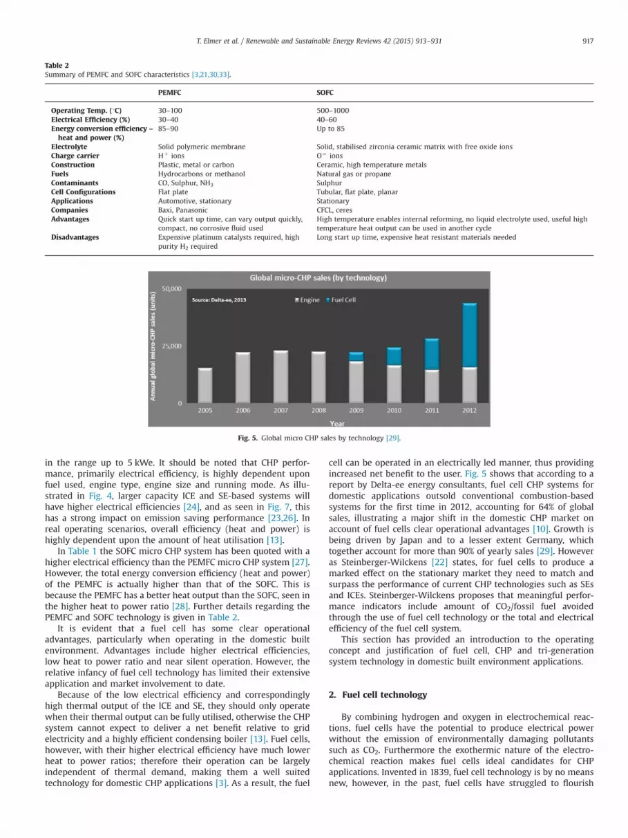
Because of the low electrical efficiency and correspondinglyhigh thermal output of the ICE and SE, they should only operatewhen their thermal output can be fully utilised, otherwise the CHPsystem cannot expect to deliver a net benefit relative to gridelectricity and a highly efficient condensing boiler [13]. Fuel cells,however, with their higher electrical efficiency have much lowerheat to power ratios; therefore their operation can be largelyindependent of thermal demand, making them a well suitedtechnology for domestic CHP applications [3]. As a result, the fuel
cell can be operated in an electrically led manner, thus providingincreased net benefit to the user. Fig. 5 shows that according to areport by Delta-ee energy consultants, fuel cell CHP systems fordomestic applications outsold conventional combustion-basedsystems for the first time in 2012, accounting for 64% of globalsales, illustrating a major shift in the domestic CHP market onaccount of fuel cells clear operational advantages [10]. Growth isbeing driven by Japan and to a lesser extent Germany, whichtogether account for more than 90% of yearly sales [29]. Howeveras Steinberger-Wilckens [22] states, for fuel cells to produce amarked effect on the stationary market they need to match andsurpass the performance of current CHP technologies such as SEsand ICEs. Steinberger-Wilckens proposes that meaningful perfor-mance indicators include amount of CO2/fossil fuel avoidedthrough the use of fuel cell technology or the total and electricalefficiency of the fuel cell system.
This section has provided an introduction to the operatingconcept and justification of fuel cell, CHP and tri-generationsystem technology in domestic built environment applications.
2. Fuel cell technology
By combining hydrogen and oxygen in electrochemical reac-tions, fuel cells have the potential to produce electrical powerwithout the emission of environmentally damaging pollutantssuch as CO2. Furthermore the exothermic nature of the electro-chemical reaction makes fuel cells ideal candidates for CHPapplications. Invented in 1839, fuel cell technology is by no meansnew, however, in the past, fuel cells have struggled to flourish
Table 2Summary of PEMFC and SOFC characteristics [3,21,30,33].
PEMFC SOFC
Operating Temp. (1C) 30–100 500–1000Electrical Efficiency (%) 30–40 40–60Energy conversion efficiency –
heat and power (%)85–90 Up to 85
Electrolyte Solid polymeric membrane Solid, stabilised zirconia ceramic matrix with free oxide ionsCharge carrier Hþ ions O¼ ionsConstruction Plastic, metal or carbon Ceramic, high temperature metalsFuels Hydrocarbons or methanol Natural gas or propaneContaminants CO, Sulphur, NH3 SulphurCell Configurations Flat plate Tubular, flat plate, planarApplications Automotive, stationary StationaryCompanies Baxi, Panasonic CFCL, ceresAdvantages Quick start up time, can vary output quickly,
compact, no corrosive fluid usedHigh temperature enables internal reforming, no liquid electrolyte used, useful hightemperature heat output can be used in another cycle
Disadvantages Expensive platinum catalysts required, highpurity H2 required
Long start up time, expensive heat resistant materials needed
Fig. 5. Global micro CHP sales by technology [29].
T. Elmer et al. / Renewable and Sustainable Energy Reviews 42 (2015) 913–931 917

particularly in terms of commercialisation and market application.This stalled start has occurred for a variety of reasons; technolo-gical reliability, lack of interest, lack of supporting infrastructurebut mainly cost [30].
Fuel cells are often categorised by the type of electrolyte. This isdetermined by the type and purity of the fuel and oxidant usedand the operating temperature. There are currently six types ofestablished fuel cells on the market [31]:
(1) Proton Exchange Membrane Fuel Cell (PEMFC).(2) Alkaline Fuel Cell (AFC).(3) Direct Methanol Fuel Cell (DMFC).(4) Phosphoric Acid Fuel Cell (PAFC).(5) Molten Carbonate Fuel Cell (MCFC).(6) Solid Oxide Fuel Cell (SOFC).
The first three fuel cells are classified as low temperature(80–250 1C), whilst the remaining three are medium to hightemperature (250–1000 1C). The operating temperature is often asignificant factor when determining which type of fuel cell shouldbe used in a particular application. This is due to a number offactors including; heat usability, start-up time and ability to varyoutput. Of the six fuel cell variants listed above, the low tempera-ture PEMFC and the high temperature SOFC demonstrate thegreatest promise for early market application, attracting the mostattention and investment in building application projects[6,30,32]. The discussions in this review will therefore focus onthese two variants. PEMFC and SOFC characteristics are sum-marised in Table 2.
As previously mentioned, SOFC technology is often quoted witha higher electrical efficiency than PEMFC [27,34]; however thePEMFC has higher overall energy conversion efficiency (heat andpower); this is because PEMFC technology has a better heat output[28]. Due to the fact that electricity is seen as a more noble form ofenergy, with a higher economic value than heat, SOFC technologyis well suited for domestic applications. Furthermore, a low heatoutput reduces the issue of thermal demand interfering withmicro CHP system operation.
Recent advances in low temperature SOFC technology usingceria-carbonate two or multi-phase nanocomposite has illustratedthat high electrochemical performance (1.2 W/cm2) can still beachieved at reduced temperatures (500 1C). This is a clear advan-tage for the domestic sector where high temperature operationresults in technical complexity and consequent costs that inhibitcommercialisation. Furthermore these developments mean SOFCstacks can be manufactured for prices below 400 €/kWe compared
to 1000 €/kWe for conventional SOFC systems [35,36]. Currently itis estimated SOFC developments are around five years behindPEMFC, however many commercial developers believe the futureof fuel cell technology in the domestic built environment lies withSOFC systems. This is due to lower capital cost as they do not needto use expensive platinum catalysts such as PEMFCs and can befuelled directly by natural gas, with fuel reformation occurringdirectly on the anode [37,38]. Furthermore SOFCs are often cited asa more attractive fuel cell option for tri-generation system appli-cations because of their high quality exhaust heat [39].
2.1. Fuel cell CHP systems
A fuel cell in principle is very simple, requiring few parts (evenless moving), resulting in near silent operation and little main-tenance required. However, in order to operate a fuel cell system,that is, a load supplied by a fuel cell, many auxiliary devices andinterconnections are needed for both the correct operation of thefuel cell and the delivery of heat and power to the load. Some ofthese auxiliary devices have a power demand, thus they are aparasitic load on the system. The electrical efficiency of the entiresystem can be between a fifth and third less than the quoted stackefficiency due to these parasitic loads [3]. Auxiliary equipment alsocontributes to increased noise, vibrations and maintenance. How-ever, in comparison a fuel cell CHP system can expect to produce0–55 dB, whereas an internal combustion engine is around 95 dB[3]. Fig. 6 shows a schematic of a fuel cell CHP system, with themain auxiliary equipment.
The following provides a list of the components found in adomestic fuel CHP system illustrated in Fig. 6.
Fuel cell system� Fuel cell stack, where hydrogen and oxygen are combined to
produce electricity, heat and water.� Fuel processor, converts a hydrocarbon fuel such as natural gas
into hydrogen and CO2.� Inverter, grid tie and power electronics; converts the DCelectrical output of the fuel cell stack into AC electrical powerto either serve the buildings energy demands or to be fed backto the grid.
� Heat recovery system; used to recover heat from the fuel cellin order to improve; (a) the performance of the fuel cell stackand (b) the environmental performance, that is, makes it a CHPsystem.
� Balance of plant; includes pumps, fans, valves sensors, pipingand control system, used to ensure the whole system functionsin a safe, efficient manner for long term stable operation.Additional items for housing CHP applications
� Boiler, to provide peak thermal loads alongside the fuel cell.� Thermal energy storage, that is, hot water tank, to store the
thermal output of the fuel cell.� Smart metres to measure and record energy production and
consumption.� Internet connection; to facilitate remote monitoring and data
acquisition.
To summarise, this section has provided an introduction to thefundamentals of fuel cell technology, the operational advantagesfuel cells offer compared to conventional domestic scale CHPtechnology such as SEs and the components required in acomplete domestic fuel cell CHP system. Next fuel cell CHPsystems operating in domestic built environment applicationsare discussed.
Fig. 6. A fuel cell micro CHP system [3].
T. Elmer et al. / Renewable and Sustainable Energy Reviews 42 (2015) 913–931918

3. Fuel cell CHP in the domestic built environment
This section examines fuel cell CHP systems operating in thedomestic built environment. Maintenance, durability, cost, emis-sion reductions, global state of the industry, commercially avail-able fuel cell CHP products and optimised domestic housingintegration will all be discussed. Because tri-generation systemscan be deemed a subset of CHP, particularly when the same primemover technology, in this case fuel cell, is used, much of thediscussions pertaining to maintenance, durability and cost dis-cussed here apply also to the tri-generation systems discussed inSection 4.
It is envisaged that the first generation of fuel cells for thedomestic built environment will run on hydrocarbon fuels such asmethane and propane. Following this, the second generation offuel cells will run on pure hydrogen [30]. There are two reasons forthe first and second generational stages of fuel use. One, theinfrastructure to store, transport and deliver natural gas toindividual homes is already present in both the UK and mostdeveloped countries. Two, currently, the production of hydrogen isexpensive and, depending on the production method, needs care-ful consideration to ascertain whether greenhouse gas emissionswould actually be reduced due to the substitution of hydrogen forother energy sources [40]. Braun et al. [41] developed a systemmodel to evaluate the performance of different residential scaleSOFC CHP systems. One of the main findings was that hydrogenfuelled SOFCs did not offer any efficiency advantages over methanefor both internal and external reforming, and in some cases themagnitude of efficiency advantage of methane can be as high as6%. This result demonstrates a positive outlook for the current useof hydrocarbons in fuel cells. However, the transition from the firstgenerational stage of fuel use (hydrocarbon) to the second gen-eration (hydrogen) will offer additional benefits, including; CO2
emission reductions onsite and the ability to operate a range offuel cells without localised reformation. However, if a significantincrease in the use fuel cell technology in domestic homes doesoccur in the next 10 years, an increasing shift in gas demand andwith it an increase in cost can be expected, a potential short-coming to the extensive use of the technology as it is today in thedomestic built environment, and something that will requirefurther consideration.
The development of effective hydrogen production and storagetechniques pose a large challenge in the move towards a futurehydrogen economy [42]. For stationary applications productionand storage of hydrogen are central issues that need to beaddressed, specifically for the development of a zero carbonsociety, as the use of natural gas as a fuel source will only allowpermit a certain level of decarbonisation. Hydrogen has favourableenergy density on mass (MJ/kg), but very poor gravimetric energydensity (wt%). Hydrogen may be stored in a variety of waysincluding compression (2.8–3.7 wt% at 300 bar), liquefied(4.5.5 wt%) and hydride materials [43]. Obviously hydrogen canbe transported as a hydrocarbon fuel such as natural gas; howeverthis necessitates the use of onsite fuel reformation, which addscost and complexity to domestic fuel cell systems, along theproduction of onsite CO2 emissions. The use of renewable carbo-hydrate as a high-density hydrogen carrier and energy source forhydrogen production has been proposed as an effective alternativeto these current storage techniques [43,44]. Gravimetric density ofcarbohydrate is 14.8H2 mass % if water can be recycled from aPEMFC or 8.33% H2 mass based on the water/carbohydrate slurry;volumetric density of the carbohydrate is 4100 kg of H2/m3. Thisapproach has the potential not only to address the low-costsustainable hydrogen production challenge but also address thechallenges associated with storage, safety, distribution, and infra-structure in the future hydrogen economy.
In the next four sections: maintenance, durability, cost andemission savings associated with fuel cell CHP systems arediscussed. It is essential these topics are covered as they willdirectly impact the future, wider viability of the use of thetechnology. Earlier reviews related to the topic have however,failed to effectively cover this, mainly due to a previous lack ofinformation, and the fast moving nature of the field.
3.1. Maintenance
As a result of the lack of moving parts in a fuel cell, regularmaintenance work to the fuel cell stack itself is hoped to be less incomparison to conventional combustion-based CHP technologies.However, due to the size and complexity of the auxiliary equip-ment in a fuel cell system this will be the source of the majority ofmaintenance work. For systems using hydrocarbon fuels, the fuelprocessor will need to be changed periodically [3]. CFCL predictsthe SOFC stack in their 1.5 kWe BlueGEN CHP unit, discussed inSection 3.6, will need to be changed once every five years [45].
3.2. Durability
Lifetime, reliability and durability of fuel cells are currently oneof their largest limiting factors. Fuel cells need to meet bothlifetime and stop–start operating targets in order for them tobecome viable as CHP technologies in the domestic built environ-ment, competing with both current centralised and decentralisedgeneration technologies. It is estimated that both PEMFC and SOFCstacks lose power at a rate of 0–5% per 1000 operating hours [3].Currently the industry holds a target of 40,000 h for stationeryapplications. This gives around 10 years of operation if the unit isoperated at regular intervals instead of continuously, which is amore likely scenario for the lower temperature PEMFC. CFCL statethat their SOFC CHP unit will operate continuously due to the longstart up and shutdown times required of the high temperatureoperation of SOFC systems. The CFCL unit has a target lifetimeof 15 years, although this includes stack replacement every5 years [45]. Laboratory tests of both PEMFC and SOFCs have shownthe 40,000 h target is possible, nonetheless limited data is availableregarding actual field results, and even more so for domestic CHPsystems. In 2008 as part of the EneFarm Project, Panasonic's homeuse PEMFC demonstrated durability of 40,000 h with 4000 start-stop cycles [46]. The latest Panasonic model, launched in April 2011has a quoted system lifetime of 50,000 h [47], showing greatpromise for the stationary market. SOFC systems have notbeen tested on such a large scale as PEMFCs. Limited data beyond10,000 operational hours has been reported in the literaturereviewed.
In comparison, Jradi and Riffat [48] state that ICE and SEtechnologies have reported durability in the range of 20–50,000 h and 10–30,000 h respectively. Operational PEMFC resultsare now approaching these figures; however SOFC is still behind.Furthermore, due to the operational constraints of SOFC technol-ogy needing to be operated constantly, their operational hourtarget figure needs to be higher than that of technologies that canbe cycled, otherwise their total useable lifetime will be very short,and not a viable option for a consumer. It is clear that the aims ofthe fuel cell industry are to compete with those of the current ICEand SE figures, this is essential if fuel cell-based CHP is to make amarked impact on the domestic sector.
In summary, the development of fuel cell technology has nowmatured to a point where stack technology is at a level commen-surate with operational targets. It is the other relatively untriedcomponents of the fuel cell CHP system that are causing reliabilityissues and require developmental work. However, with the intro-duction of more fuel cell CHP units to the market and increased
T. Elmer et al. / Renewable and Sustainable Energy Reviews 42 (2015) 913–931 919

volumes of both field tests and commercial applications, it ishoped these problems will soon be dealt with.
3.3. Cost
All cost figures in this section have been given in Americandollars to assist in comparison. Currently there is a lack of standardindustry prices for fuel cell CHP systems; however, they can beexpected to be higher than those of conventional CHP systems dueto the maturity of the technology. Many cost targets have been set,most significantly those by the US Department of Energy whichaims for $1200/kW by 2015 and $1000/kW by 2020 for a complete2 kW natural gas fuelled PEMFC CHP system [49,50]. However asStaffell and Green [51] state these future targets are currentlyunrealistic even with a large industry effort, and the price of adomestic fuel cell CHP system will generally be 25–50% higher,even though mass production began three years ago. Staffell andGreen [51] therefore propose a long term cost target of $3000–5000 for a 1–2 kW system as being a more feasible figure,attainable by 2020.
For demonstration projects, a quoted price in 2009 ranged from$16,000 to $160,000 for a 1 kWe PEMFC unit [3]. Panasonic'sEneFarm branded 1 kWe PEMFC CHP unit had a retail price of
$42,464 in 2009, then in 2011 with the launch of the new modelthe price dropped to $33,650 [47]. In 2013 the price was reducedto $21,000 before subsidies, which can further reduce the price byup to 25% [10]. By 2015 Panasonic believe they can offer the unit ata price of $5,608 to energy companies [52]. An interestingdevelopment in the EneFarm project is the planned phasing outof its subsidies. During the EneFarm demonstration phase thesubsidy reduced the cost of the unit for the consumer from$73,609 to $26,990. However as of 2010 the subsidy has beencapped at $15,949, with plans to eliminate subsidies all togetheronce production volumes are such that the units are cost effectiveand affordable on their own. Subsidy removal will mark asignificant milestone in the deployment of fuel cell technologyfor domestic built environment applications as it will prove theirworth without external assistance [49].
Data regarding SOFC system cost is limited in comparison toPEMFCs. This is due to SOFCs less substantial commercial devel-opment. Staffell and Green [51] estimate that currently a domesticSOFC CHP system will sell for $25,000 per kW, a figure in reason-able agreement with the SOFCs presented in Table 3, for exampleCFCL are currently charging $31,968 for their 1.5 kWe SOFC CHPunit (�$21,312/kW). However once in mass production CFCLforecast the cost to drop to around $8012 [45]. Many commercial
Table 3Fuel cell micro CHP products. It should be noted that some of the data regarding performance of the fuel cell micro CHP systems is taken from manufacturer's data.
Manufacturer(country oforigina)
Stack type Electricalcapacity(kWe)
Electricalefficiency(%)
Thermaloutput(kWth)
Auxiliaryheaterincluded
Cost Commercialavailability
Partners/projects
Comments Reference
Baxi (UK) PEM 1 32 1.7 20 kWth – 2015 Ballard/Callux
Requires external heater [27]
Toshiba (JPN) PEM 0.7 35 1 – $20,000 Japan 2009 EneFarm 80,000 operationalhours expected
[69,70]EU – 2015
Viessmann(GER)
PEM 0.75 37 1.3 19 kWth € 35,000 Germany -2014 Panasonic Uses Japanese stack [27,69]Europe – 2015
Elcore (GER) PEM 0.3 33 0.6 – € 9,000 Enefield – 2013 Enefield Low electrical/heatoutput means fuel cellruns continuously
[71]
DanthermPower (DEN)
PEM 1.7,2.5 and 5
– – – – Danish field trials Ballard Only short duration teststhus far
[72]
Panasonic(JPN)
PEM 0.7 40 0.9 Yes € 25,000 Japan – 2011 EneFarm European R&D stared in2012
[23,25,70]Europe – 2014
JX Eneos (JPN) PEM 0.7 40 – – – Japan – 2011 EneFarm Now pursuing SOFCtechnology
[70]
Vaillant (GER) PEM 5 25–50 – – – PlugPower Aimed at multi-familyhomes
[27,69]
Plug Power(USA)
HT-PEM 0.3–3 30 1.65 Yes(7–25 kW)
– – – Operates on natural gas [73]
CFCL (AUS) SO 1.5 60 0.6–1 No d20,000 Yes E.On Highest electricalefficiency on market
[23,25,27]
Hexis (SUI) SO 1 30–35 1.8 20 kW – Callux – 2012 Viessmann/Callux
Electrical efficiencysimilar to PEMFC
[23,25,27]
Ceres Power(UK)
SO 1 – – – – 2016 British Gas/KD Navien
External reformer [64,69]
Vaillant (GER) SO 1 30 1.7 – – 2013 Staxera/Callux
Unit focussed onreliability
[27,69]
Kyocera (JPN) SO 0.7 46.5 0.65 – – Japan – 2012 Osaka Gas Uses flat tubular cells [69,74]Aisin Seiki(JPN)
SO 0.7 46.5 – Yes d21,000 Japan – 2012 Osaka Gas/Bosch
Highest Japanese SOFCproduct efficiency
[69]Europe – 2014
JX Eneos (JPN) SO 0.7 45 – 40 kWth $31,000 Japan – 2012 Kyocera Robust unit [75]Topsoe (DEN) SO 1 – – – – Wärtsilä/
DanthermRobust cells [76]
Acumentrics(US)
SO 0.25–1.5 o35 – – – 2013 – Able to respond tothermal cycling
[69]
SOFC power(SUI)
SO 0.5/1 30–32 – – – – – Poor electrical efficiencyfor SOFC
[69,77]
Acumentrics(USA)
SO 1/2.5 peak 30 – Up to24 kW
– Not yet in generalavailability; qualifiedcustomers only
– Operates on natural gas [78]
a UK¼United Kingdom, JPN¼ Japan, GER¼Germany, DEN¼Denmark, AUS¼Australia, SUI¼Switzerland, USA¼United States of America.
T. Elmer et al. / Renewable and Sustainable Energy Reviews 42 (2015) 913–931920
developers believe the future of cheaper fuel cell technology lieswith SOFC systems. This is because they do not need to useexpensive platinum catalysts such as PEMFCs [53].
In their experimental work Conroy et al. [54] state that the costof a 1 kWe WhisperGen SE micro CHP system was around $3382(€2500). Jradi and Riffat [48] presents figures for SE technology at1300–2000 $/kW and ICE-based CHP systems at 340–1600/kW.Conroy et al. figures are for the entire CHP system, whereas Jradiand Riffat are for the prime mover only, and thus the lowerestimate. However what is clearly apparent is that the cost forboth the SE and ICE is considerably less than an equivalent 1 kWefuel cell. Combustion-based technology has been in developmentfor far longer than fuel cell, hence the lower cost. It is envisagedwith time fuel cell cost will fall to rival that of SE and ICEs,particularly with the development of low temperature SOFCs [36].Fuel cell cost reduction has already been apparent in the datapresented above.
To summarise, as time progresses and the volume of fuel cellCHP units produced increases, it is anticipated that their price willdecrease, encouraging their wider uptake. Currently the JapaneseEneFarm project is spearheading this drive for economies of scale.
3.4. Emission savings achievable with fuel cell combined heat andpower
The likely contribution domestic fuel cell CHP systems willprovide regarding CO2 emissions reduction is explored. Currently,natural gas fed fuel cell CHP poses a potential challenge in terms ofa transition to a zero or even low carbon domestic built environ-ment [11]. Currently, it is estimated that the achievable reductionin CO2 emissions for a fuel cell CHP system running on natural gasis around 30% compared to grid electricity and gas boiler [55].However, the aforementioned generational stage of fuel use is anessential component in optimising the resource present today andensuring the arrival at a zero carbon economy in the future whenpure hydrogen becomes more widely available. As previouslydiscussed, there is currently a limited bank of available dataregarding the benefits of fuel cell technologies operating in thedomestic built environment; this is a result of the still prematurelevel of implementation of the technology.
The Annex 42 project [13] has carried out extensive real worldand simulation-based performance assessment studies for bothSOFC and PEMFC technologies operating as CHP units in single andmultifamily homes, comparing them to a reference system.Beaussoleil-Morrison [13] states four key findings from the Annex42 project, supported by similar research found in the literature.(1) Individual buildings employing fuel cell CHP systems couldreduce non-renewable primary energy (NRPE) demand comparedto a reference system using a gas boiler and grid electricity.However the magnitude of reduction is highly dependent uponthe reference systems grid electricity generation mix, that is, thekg/CO2/kWh. A finding backed up by the work of Pade et al. [56],Dorer et al. [57] and Steinberger-Wilckens [22] who all state thatthe impact of fuel cells on primary energy reduction, and thusemission savings, is highly dependent upon the energy systemthey are placed in. For example, Pade et al. [56] demonstrate thatin Denmark, the use of SOFC CHP would reduce NRPE demand andcreate a corresponding cut in CO2 emissions in the Danish energysystem, however in France, fuel cell power generation wouldprimarily replace nuclear, thus creating an increase in naturalgas consumption and CO2 emissions. (2) When the referencesystem utilised centralised electricity generation from a combinedcycle gas turbine and an individual home heat pump, the opera-tional electrical efficiency of the fuel cell had to be greater than40% in order for it to be competitive both on a cost and CO2
emission level basis. (3) In order to obtain maximum system
efficiency and CO2 emission reduction at least 80–90% of thehomes annual heat demands needed to be met by the fuel cell.(4) The way in which the fuel cell CHP unit was operated had alarge impact on the benefits gained. When in heat led mode, thesystem showed the best energy efficiency. However, when inelectrical led mode, it created the greatest cost savings. In general,base load sizing offered better energy savings than peak loadsizing.
Field trials of 1 kWe PEMFC CHP units in Japanese homes hasindicated a reduction of a 750–1250 kg CO2 per household perannum when switching from a gas boiler and grid electricity to afuel cell CHP system. Simulations by Hawkes et al. [3] based uponthe UK illustrate fuel cell CHP has the potential to reduceCO2 emissions by 1.5 t per annum for a high demand home, afigure which is consistent with previous simulations that predictaround 1 t per annum are achievable for an average sized familyhome [58].
E.ON estimates that the 1.5 kWe SOFC CHP unit produced byCFCL can achieve CO2 emission reductions of up to 4.5 t/house/year [11]. Ceres Power, a manufacturer of an intermediate tem-perature 1 kWe SOFC, anticipate savings of up to 2.5 t of CO2 peryear and d250 in energy bills are attainable for a UK residencewhen switching from gas boiler and grid electricity to their fuelcell unit [59]. Clearly these estimates are much larger than thedata presented above. It is clear that emission and energy savingsare highly dependent upon the specific case. There is a danger ofmanufactures overselling the benefits of fuel cell CHP systems toconsumers; this needs to be restricted until a sufficient bank ofreliable, real time operational data can be acquired in order toaccurately verify the possible benefits.
Steinberger-Wilckens [22] states that currently, in the EU, thereare no clear indications for the desired minimum performancestationary fuel cells are to meet in order to satisfy the EU goals ofenergy efficiency and greenhouse gas emission reduction. As aresult Steinberger-Wilckens has been working on a methodologyto accurately assess the environmental advantage delivered by fuelcells operating in current electricity markets across Europe.Currently a benchmarking approach has been adopted, whichconsiders; a reference dwelling, key performance merits – CO2 /fossil fuel avoided and the total and electrical efficiency, differentCHP technologies (PEMFC, SOFC, SE, ICE) and different operatingstrategies (electrical or heat led and economic optimisation).Initial simulations for s single family home show an increasingelectrical efficiency of a domestic CHP system creates greater CO2
emission reductions. For a SOFC using internal steam reformingoperating at an electrical efficiency of 55% emission savings in theorder of 2.4 t per annum are predicted. For a PEMFC system withelectrical efficiency of 35% this figure drops to around 1.5 t perannum, a figure in good agreement with Hawkes et al. [3] and thework at EneFarm. A SE with an electrical efficiency of around 12%shows emission savings in the order of only 0.5 t per annum areachievable – a much lower potential compared to the fuel cellssimulated. It is intended that the methodology will be reportedback to the US and Japan to try and gain global standardisationwith regards to the performance assessment of stationary fuelcells. This represents a significant opportunity for the benefits offuel cell CHP to be verified and disseminated.
Fig. 7 shows the annual CO2 savings of various micro CHPsystems compared to a grid electricity and boiler alternative [23].The emission savings shown for the SOFC and PEMFC systems areof a similar order of magnitude to that previously presented.Variation in reported savings occurs due to different values used inthe assessment, including; central electricity mix, the home'sannual energy demand, electrical and total efficiency of the fuelcell system. The data in Fig. 7 shows the SOFC-based system hasthe best emission performance, with the PEMFC system second,
T. Elmer et al. / Renewable and Sustainable Energy Reviews 42 (2015) 913–931 921

excluding the 5 kW gas engine. The high electrical efficiency seenin SOFC-based CHP systems means they can large emission savingsdue to a greater displacement of carbon intensive centralisedelectrical generation. Although PEMFC-based systems have highelectrical efficiencies in the 1–5 kWe range, as the electricalcapacity of the gas engine increases to 5 kWe, its efficiency willalso increase, therefore improving the emission performance, andin this case surpassing the PEMFC performance.
An experimental assessment of a 1 kWeWhisperGen SEmicro CHPsystem in a domestic dwelling demonstrated emission reductions ofaround 1.2 t (16.1% reduction) of CO2 per annum compared to aconventional boiler and grid electricity system [54]. This assessmentshows the SE system is competitive on a carbon emission basis;however the emission assessment carried out by the authors con-sidered the offset emissions from SE electrical generation, thusboosting the final figure. Field trials by the Carbon Trust in domestichomes show the emission performance of the SE CHP system to bepoor, at around 0.4 t of CO2 reduction per annum [60]. In their trials,The Carbon trust did not consider the offset emissions; this issupported by the data presented in Fig. 7 of around 0.5–0.65 t perannum are achievable with a SE CHP system. The Carbon trust thusrecommended that considerable improvements in SE technology is berequired to make the use of SE technology viable, or it would need tobe used in a region with a high grid emission factor.
In summary, from the literature presented in this section, it isclear that currently there is no conclusive set of figures concerningthe CO2 emission savings achievable from fuel cell CHP operatingin the domestic built environment. Sizeable reductions are achiev-able, but are largely dependent upon a range of factors including;central electricity mix, the home's annual energy demand, elec-trical and total efficiency of the fuel cell system and emissionassessment process. Currently, literature regarding SE and ICE-based systems show fuel cell CHP is competitive on an emissionbasis; this is primarily due to the higher electrical efficiencies ofthese systems on a domestic scale (1–5 kWe). It can be anticipatedthat the CO2 emission savings from fuel cell CHP in the future willonly improve with the introduction of renewable biogas/hydrogenand improved fuel cell efficiencies. In this case fuel cell CHP couldpotentially reach zero carbon status.
3.5. Current state of the industry: fuel cell combined heat and powerin the domestic built environment
In terms of commercialisation, fuel cell CHP in the domesticbuilt environment is still in its infancy. It is predicted SOFC
demonstration projects are around 5 years behind those of PEMFC,with around 80% of projects employing PEMFC technology and20% SOFC [3]. Japan is currently the leader in terms of fuel cell CHPtechnology in the domestic sector. In 2008 there was an estimated3300 PEMFC units under demonstration in residential buildings inJapan (Nishizaki 2008), and as of 2012 that figure is closer to40,000 [10]. Real world applications of fuel cell systems areessential in the development of an efficient, effective and usabletechnology. Currently Asia followed by Europe lead the world interms of fuel cell CHP for domestic applications. The state of theindustry in these two regions is discussed below.
3.5.1. AsiaEneFarm is a fuel cell research, development and demonstra-
tion (RDD) project based in Japan, and is the largest and mostsuccessful of its kind in Asia and the rest of the world to date. Theproject started in the 1990s and involves many companies includ-ing Panasonic, Tokyo Gas Co Ltd. and Kyocera. The research anddevelopment stage began with the production of a 1 kWe PEMFCCHP system that runs on natural gas. Demonstration has beencarried out in three stages. Stage 1; small scale demonstrationwhere 50 units were installed in homes between 2003 and 2005.Stage 2; large scale demonstration of 3000 PEMFC CHP units ranuntil 2009. Stage 3; commercialisation phase ran from 2009onwards and as of 2012 there were more than 20,000 unitsinstalled with the aid of Japanese government grants [61]. Thecurrent EneFarm PEMFC model has an electrical capacity of 700–750 W, with an overall efficiency of 95%. The fuel cell systemdeveloped can be operated both grid connected or disconnected.The PEMFC system is designed, due to its operational character-istics, not to run continuously. It is on during the day whendemand is high and hot water can be stored. The system is thenturned off at night when demand is low. EneFarm users benefitfrom a discounted gas price, further incentifying the use of theunits [62]. Highlights for the EneFarm project include the very firstfuel cell CHP system in the world supplied to the Japanese PrimeMinister's residence in April 2005 and the world's first generallaunch of a household fuel cell CHP system in May 2009. TheEneFarm project has facilitated the continual improvement (cost,size and efficiency) of the initial fuel cell system for housingintegration, seen in Fig. 8.
By the end of 2010, cumulative shipments of the EneFarm unitshad reached 13,500 [49]. The devastating events of the Tohokuearthquake and tsunami that struck Japan in March 2011, leading
Fig. 7. Annual micro CHP CO2 savings compared to grid electricity and boiler alternatives [23,26].
T. Elmer et al. / Renewable and Sustainable Energy Reviews 42 (2015) 913–931922

to the Fukushima nuclear incident had a profound impact on thesales of EneFarm units. More than twice as many fuel cell unitswere sold in 2011 than in 2010 as consumers sought to reduceenergy bills and reliance on the grid. An estimated 20,000EneFarm units were sold in 2012, effectively doubling the numberof fuel CHP units in Japanese homes to around 40,000 [10]. Salestargets of 50,000 by 2015 and 2.5 million by 2030 are currentlybeing proposed [62]. With such large volumes of sales it can beanticipated that the cost of these systems will continue todecrease, hopefully permitting the widespread uptake of fuel celltechnology in the domestic built environment, not only in Japanbut across the world.
Fuel Cell Toady [49] expects the EneFarm demonstrationprogramme to be replicated in other developing markets such asKorea, Europe and America. Analysis has shown that if in additionto the Japanese EneFarm case, if four additional projects world-wide can be implemented at a similar rate, sales of up to 20,000units annually can be expected by 2014 and 100,000 unitscumulatively installed globally by 2015. The EneFarm project hasfacilitated the wider use of fuel cell technology in the domesticbuilt environment with many valuable lessons learnt. EneFarm isforming a suitable platform on which to base future fuel cell RDDprogrammes on across Asia and the rest of the world, such as TheGreen Home Project in South Korea where more than 350 PEMFCunits have been installed [49]. EneFarm has now expanded its RDDbase with a newly introduced SOFC system from Kyocera. TheSOFC will operate continuously to avoid damage due to thermalcycling. The introduction of a SOFC to the programme has beenspearheaded due to its promise of lower capital cost and furtherefficiency gains. Furthermore, due to EneFarm's success, compa-nies such as Honda are now considering SOFC for domestic CHPapplications [10].
3.5.2. EuropeThe European market for domestic fuel cell CHP is growing
rapidly. Currently, under the Callux project, Germany is second toJapan in terms of fuel cell CHP applications in domestic homes.The Callux project is the largest national field test of fuel cellheating appliances for homes. The project has installed over 350systems produced by Baxi, Hexi and Vaillant, between 2008 andthe end of 2012. The products are a mix of PEMFC and SOFC [64].The Callux project is scheduled to run until 2015 [10]. Further tothe Callux project is the launch of the ene.field project in October2012. ene.field aims to bring together 27 project partners with the
aim of installing 1000 fuel cell CHP systems (both PEMFC andSOFC) across 12 member states of the EU [65,66]. It is believed ene.field will create a dramatic increase in the deployment of fuel cellCHP in Europe, and a meaningful step towards commercialisationof the technology. CFCL has also made large in-roads into theEuropean fuel cell market. CFCL and E.ON have now formed apartnership as part of the European Union Fuel Cell and HydrogenJoint Undertaking's Joint Technology Initiative (JTI) fuel celldemonstration programme, with the aim to demonstrate 100domestic fuel cells in Europe. CFCL now have manufacturingcapabilities in Europe to produce up to 1000 units per annum.CFCL have received an order for 60 units from German powercompany EWE, and now with the introduction of new capital-based subsidies from the German government for highly efficientCHP systems for domestic applications, the sales of CFCL's unit areset to increase, with the aim of 600 units to be in operation acrossGermany by 2015 [10]. In the UK, E.ON has placed an order for 45of CFCL's units as part of a demonstration period, after which,subject to a minimum order of 100,000 units, E.ON would becomethe sole UK supplier of CFCL products, an arrangement E.ON hassuccessfully maintained in the past with the commitment topurchase 80,000 Whispergen units from Powergen in 2005 [37].Finally, EneFarm is looking to expand its customer base to theEuropean market, with Panasonic collaborating with Viesssmannto help bring the EneFarm product to Europe.
In summary, it is clear that Asia, particularly Japan, lead theway in terms of the deployment of fuel cell CHP in domesticbuildings. The work carried out by EneFarm has, and will, continueto facilitate the wider use of fuel cell CHP in the domestic builtenvironment, seen in the increasing number of units installed inEurope and Korea. EneFarm has formed the most suitable casestudy for the use of fuel cell technology in the domestic builtenvironment to date, consistently illustrating the operationaladvantages of the adoption of the technology. Future projectssuch as the European ene.field programme should look to EneFarmas a suitable case study.
3.6. Commercially available fuel cell CHP units for domesticapplication
Currently, commercial suppliers of fuel cell CHP units intendthat them to be installed alongside a highly efficient condensingboiler and thermal energy store. Depending on system capacityand application, the fuel cell provides the base load electricalpower and domestic hot water, as this provides greatest energy
Fig. 8. The latest (left) and previous (right) EneFarm PEMFC CHP system for domestic homes [63].
T. Elmer et al. / Renewable and Sustainable Energy Reviews 42 (2015) 913–931 923

savings to the consumer [13]. In this section, fuel cell CHP unitsthat are currently available on the commercial market, or are closeto market application are introduced, summarised in Table 3 anddiscussed.
A number of operational configurations are possible for the fuelcell CHP systems shown in Table 3, and largely depend on thetype/size of fuel cell used, application and the market they arebeing used within. Continuous baseload operation is suited tounits with high electrical efficiencies and a lower heat output, suchas the BlueGEN SOFC. The unit would be operated continuouslyand its thermal output will be used to meet the DHW loadthroughout the year with a supplementary burner used to meetvariable space heat requirements. This operating strategy avoidsthe need for power modulation to prevent heat dumping and thusthermal cycling of the stack is minimised [45,67]. Howeverproducts with lower electrical efficiencies and consequentlyhigher heat to power ratios such as PEMFC systems need tomodulate their output to maintain the heat production belowthe daily hot water demand of the home, and thus they can besized bigger [10].Many manufacturers (Kyocera, JX Eneos) havehowever concluded that the future of fuel cells in domestic built
environment applications lie with SOFC, and have thereforestopped PEMFC development.
Two European marketed PEMFC and SOFC CHP systems (asshown in Table 3) are now discussed.
3.6.1. Baxi – GAMMA series 1.0Extensive demonstrations and field trials of the GAMMA series
1.0, shown in Fig. 9, have been carried out in Germany as part ofthe Callux project. The unit consists of a PEMFC, heat storage andenergy manager. Due to the fuel cells low thermal output, there isa requirement of an auxiliary heater. This adds cost and complex-ity to the system; however it does mean the system can beoperated in an electrical led manner, thus adding greater benefitto the consumer. Baxi state that the fuel cell CHP system willprovide 100% of the heating demand of a single family home usingthe fuel cell and auxiliary heater and produce 5000–6000 kWh ofelectricity per annum, covering roughly 73% of the annual elec-trical load. Baxi have produced a development road map of wherethey believe the GAMMA series technology will progress. By 2013/2014 it is planned the DELTA will be introduced with electricalefficiency of 35%, CHP efficiency of 490% and a durability of60,000 h [68].
3.6.2. Ceramic fuel cells Ltd. – BlueGENThe CFCL BlueGEN unit, shown in Fig. 10, is currently the only
fuel cell product on the UK market to be certified under the Micro-generation Certification Scheme in the UK, making it eligible forthe CHP FiT. Under this tariff, 10.5 p/kWh of electricity produced ispaid to the homeowner, with a further 3.1 p/kWh paid for surpluselectricity exported [49]. CFCL is now collaborating with HOMASoftware BV under the JTI project, and is aiming to develop a“virtual” grid. The proposal aims to conglomerate many homes'fuel cell CHP capacity and remotely manage generation inresponse to utility scale power demands. With enough combinedunits, the generation capacity could be equal to several centralisedpower plants. However, electrical and system efficiencies would bemuch higher [11,66]. Pade et al. [56] state that operating SOFC CHPunits as a virtual power plant in response to spot market pricesseems promising, offering a lower price premium compared toother financial support mechanisms for domestic fuel cell CHP.
Fig. 10. CFCL BlueGEN unit [45].
Fig. 9. Baxi GAMMA series 1.0 [68].
T. Elmer et al. / Renewable and Sustainable Energy Reviews 42 (2015) 913–931924

From Table 3 it is apparent that a large proportion of fuel cellCHP units commercially available are Japanese, this is due to Japanholding such a large segment of the market. Many of the non-Japanese units are currently still in the RDD stage and not offeredon the commercial market, seen in the lack of data for these unitsin Table 3. Many of these Japanese manufactures – Toshiba,Panasonic and JX Eneos – have launched their own branded fuelcell units on the back of the developments made by the EneFarmproject discussed in Section 3.5. This market dominance illustrateswhy initial funding and support for RDD projects such as EneFarmare critical for the development of the fuel cell CHP industry indomestic homes. EneFarm should serve as precedence to theEuropean and American markets looking to match the work donein Japan. The Japanese fuel cells, particularly the SOFC variety,presented in Table 3 have smaller electrical capacities (�0.7 kWe)compared to the European units (�1.5 kWe). This is for tworeasons (1) to minimise electrical export, which is discouraged inthe Japanese market, and (2) to prevent the need to cycle poweroutput to minimise heat dumping. The issue of electrical exportillustrates a clear difference between the Japanese and Europeanmarkets in which fuel cells are being placed. In the Europeanmarket electrical export is actively encouraged with schemes suchas the UK's Feed-in-Tariff (FiT) and could be a reason why there is acontinuing trend of higher electrical capacities seen in the Eur-opean units – Baxi GAMMA and CFCL BlueGEN. This fundamentaldifference in unit capacity and operation could pose a significantchallenge when trying to bring the European and Asian fuel cellmarkets together. For example with the EneFarm product beinglaunched in Germany, issues such as unit capacity will needcareful consideration in order to assure successful product inte-gration into a market where competitors already exist.
To summarise, this section has provided an overview of all thecurrent fuel cell CHP units on, or on their way to, market. Japancurrently dominates, largely as a result of the initial stimulus from theEneFarm project which started over 20 years ago. EneFarm and theJapanese market will be a motivating and fundamental reference pointfor the future European market, particularly for projects such as ene.field which aims to have over 1000 units in operation in the nextcouple of years. The European and rest of the world markets(Australia) are responding to the Japanese developments with theirown commercially available products (CFCL, Baxi etc.), however thevolume of companies manufacturing these units and sales volumesare currently not commensurate with the Japanese. External support,subsidies and stimulus are essential in order to overcome the inertiaexperienced in the deployment of novel technology such as fuel cellCHP in a competitive commercial market. From the products reviewed,it is clear that the type of fuel cell used and the market it is beingintegrated into have a marked impact on fuel cell capacity, operatingstrategy and system design. There is currently a noticeable differencebetween the Japanese (Asian) and European market design. This couldpose a significant challenge, even barrier, when companies wishto expand their fuel cell CHP products to different regions of the world.
3.7. Fuel cell system optimisation for domestic housing integration
Fuel cell system optimisation for domestic built environmentapplications is an essential research topic if the benefits of theiroperation are to be fully realised. This area of optimisation work ismainly focused on thermal energy because the majority of fuelCHP systems in use are grid connected. In many counties, gridinteraction offers the option to sell surplus electrify back to thegrid, therefore optimisation methods to maximise surplus elec-tricity use in individual homes is not such an issue.
The heat led nature of combustion-based CHP technologiesmeans they should only be in use when demand for thermalenergy is present, however, because their operation can be of an
intermittent nature, their output can be modulated in response toa home's energy demands [13]. Due to PEMFCs low temperatureoperation, they also have the ability to quickly respond to varyingenergy demands, and therefore they may be operated in a similarmanner to conventional combustion-based CHP technologies. Thismeans maximising the energy outputs from the system is rela-tively simple. Kato et al. [79] investigated the use of thermalenergy storage (TES) in a residential PEMFC application. It wasfound that a high level of temporal precision was required in orderto match the domestic hot water demand and to correctly size thesystem components. However, for a 2 kWe installation, a 200–350 l TES was required to effectively maximise the use of thePEMFCs thermal output, a similar requirement of combustion-based CHP systems [23].
SOFCs with their promise of lower capital cost, high electricalefficiency and thus greater economic benefit to the consumer, arepredicted to be the fuel cell of choice in the future domestic builtenvironment [10]. However, SOFCs have very different operationalcharacteristics to combustion and even PEMFC technologies, mostsignificantly; the requirement of constant operation, at least on adiurnal basis, to avoid thermal cycling and long start-up and shutdown times. Constant operation does yield benefits in terms of extraelectrical generation, and in the UK case, payment through the FiT.However, the majority of UK and northern European housing stock ischaracterised by peak morning and evening heating demands, shownin Case 1, Fig. 11. How a SOFC with their preference for constantoperation is thermally integrated into domestic buildings in order tomaximise system efficiency is a challenging task.
Hawkes et al. [67] present a SOFC CHP model for use in atechno-economic analysis to determine options in the provision ofresidential heat demand in the UK. Four different UK heatingdemand profiles were considered to see which profile best suitedthat of a SOFC CHP system using a cost minimisation model. Themodel also included the use of a TES. The base case model, shownin Case 1, Fig. 11 was based on a typical UK heat load profile.Results showed that a ‘slow’ space heating demand, seen in Case 4,Fig. 11, running constantly in winter with under floor heating wasmost suitable for the SOFC due to maximum thermal energyutilisation. This profile achieved highest cost and CO2 savingscompared to the reference study of grid electricity and gas firedboiler. The slower heating demand is also a better match for SOFCtechnology due to the avoidance of thermal cycling. TES providedadded benefit to the system. In an operational strategy and systemintegration study of SOFC CHP systems, Pade et al. [56] state that a
Fig. 11. Case 1: conventional UK heating profile, Case 4: slow heating demand [67].
T. Elmer et al. / Renewable and Sustainable Energy Reviews 42 (2015) 913–931 925

relatively small 100–200 l heat storage can limit, but not eliminatethe number of required cold starts required for a SOFC CHP system.
District scale fuel cell operation and interaction has been cited asan effective way to optimise the use of fuel cell technology in thedomestic built environment [39]. Work has been carried out by the EUfunded FC-DISTRICT project to optimise individual building SOFC CHPsystems using district heat storage and distribution networks. Thisconcept is being used on account of district systems potential toincrease thermal energy utilisation due to the dynamic heat exchangepossible with collective thermal energy storage [7,80]. Initial resultsfrom the project show for a 100 house study, a district heat andelectricity network powered by SOFC CHP can reduce annual primaryenergy demand by up to 50%, in the specific case, equal to 2 GWh [7].The encouraging outcomes achieved thus far from the FC-DISTRICTcould pave the way for future integration options for SOFC CHPgenerators in the domestic built environment, where district scaleoptimisation favours that of individual buildings. District scale tri-generation systems have been investigated [81]. The authors state thatit is highly desirable that more examples of district heating andcooling networks are developed due to their potential for builtenvironment decarbonisation. The economic and environmental per-formance of these systems could be further improved with theinclusion of fuel cell technology.
Where appropriate, comparisons and parallels have beendrawn with equivalently sized SE and ICE-based CHP systems.The literature reviewed indicates that currently the durability andcapital cost of fuel cell-based CHP systems in domestic builtenvironment applications lack that of the combustion-basedsystems; however the potential emission savings achievable aregreater, indicating the rationale to pursue the development of thetechnology, as cost and durability can be addressed through futurework, but fundamental performance cannot.
In summary, Section 3 has addressed fuel cells operating asCHP systems in domestic built environment applications. A varietyof topics that have and will continue to influence the viability oftheir use in the domestic built environment have been covered,including; maintenance, durability, cost, emissions saving poten-tial, current state of the industry, commercially available units andhousing integration. Currently there is no conclusive set of figuresconcerning the CO2 emission savings achievable from fuel cell CHPoperating in the domestic built environment; however they areachievable and have the potential to be sizeable depending uponthe situation. From this section of the review it can be concludedthat currently the main barriers for fuel cell CHP systems in thedomestic built environment include [75] the follwing:
1. Cost – future systems will need to use using fewer parts andmore mass produced components.
2. Reliability – future systems will need to look for simpler designsolutions and quality control mechanisms.
3. Current performance – for the more promising SOFC technol-ogy this will be the use of lower temperature catalysts andnovel materials.
4. Fuel cell tri-generation systems
This section will examine tri-generation energy systems fordomestic building applications, with the specific aim of assessingthe potential fuel cell technology has in this area of domesticenergy supply. Fuel cells are well suited to tri-generation builtenvironment applications because they produce heat when gen-erating electricity, have high electrical efficiency and excellent loadfollowing characteristics [82]. Moreover, continued technologicalimprovements to fuel cells have, in recent years increased interestin fuel cell-based tri-generation systems [83]. The discussions
covered in the previous section regarding fuel cell CHP systemsin domestic built environment applications are also applicable tothe tri-generation systems concept because the prime movertechnology and operational aims are very similar, thus they willnot be re-covered here [83].
Tri-generation is a well-known technology for energy conser-vation in commercial and industrial applications. However, verylimited work has been completed for tri-generation systems indomestic building applications [84,85]. Kong et al. [86] states thatthe concept of tri-generation systems for individual domesticbuildings has only be thought reasonable with the more recentdevelopment of heat driven cooling technologies with capacitiesof o10 kW cooling, that can operate on low-grade thermal energy(60–90 1C). Huangfu et al. [84] believe the main obstacles to anytype of domestic scale tri-generation systems is the high initialcost and complexity of optimum matching of different parts of thesystem, that is, prime mover and chiller.
Due to the limited breadth of literature covering fuel cell tri-generation systems, particularly on a domestic scale, this sectionof the review will be split into three parts: (1) fuel cell tri-generation systems of all scales, (2) domestic scale tri-generationsystems employing combustion- based prime mover technology,and (3) domestic scale fuel cell tri-generation systems. Thisapproach has been adopted to achieve a broader context ofresearch. Discussions will cover; what has been done to date, theimportant lessons learnt from the larger studies and how thesemight be applied at a domestic level, the advantages fuel celltechnology can provide over conventional combustion-basedprime mover technologies in tri-generation system applicationsand the future of fuel cell tri-generation systems in the domesticbuilt environment.
4.1. Large scale fuel cell tri-generation systems
Yu et al. [87] have numerically investigated a tri-generationsystem incorporating a SOFC and a double-effect water/lithiumbromide absorption chiller, high total system efficiencies of 84% ormore were reported by the authors, illustrating the benefits of tri-generation systems in applications where heating, cooling andpower are required. Margalef and Samuelsen [88] numericallyexamined a 300 kW MCFC tri-generation system using absorptioncooling, achieving an overall system efficiency of 72%. However,the pairing of two ‘off the shelf’ technologies for tri-generationsystem construction was shown to be problematic. Margalef andSamuelsen [88] state that the fuel cell and absorption chillerchosen for the tri-generation system were close, but not an idealmatch. The fuel cell exhaust gas temperature was higher than theinlet temperature specified for the chiller and the exhaust flowrate was not sufficient to achieve the potential heat recoverywithin the chiller heat exchanger. Therefore two strategies toovercome this were presented (1) blending the fuel cell exhaustgas with ambient air, and (2) mixing the fuel cell exhaust gaseswith a fraction of the chiller exhaust gas. Both options worked,however the second option yielded better performance and wasthus used. Al-Sulaiman et al. [89] presents an energy analysis of atri-generation plant incorporating a 520 kW SOFC, organic Rankincycle, heat exchanger and single effect absorption chiller. Theinvestigation showed that by incorporating the cooling cyclesystem efficiency is improved by 22% compared to just havingthe SOFC and organic Rankin cycle running together. A maximumtri-generation efficiency of 74% has been achieved.
Fong and Lee [8] have studied a SOFC tri-generation energysystem for a high-rise building in a hot-humid climate. The studyfocussed on two sizing options. (1) Full-SOFC, where the systemwas sized to peak loads, therefore requiring no grid import, andthe other (2) partial-SOFC, where the system was sized such that
T. Elmer et al. / Renewable and Sustainable Energy Reviews 42 (2015) 913–931926
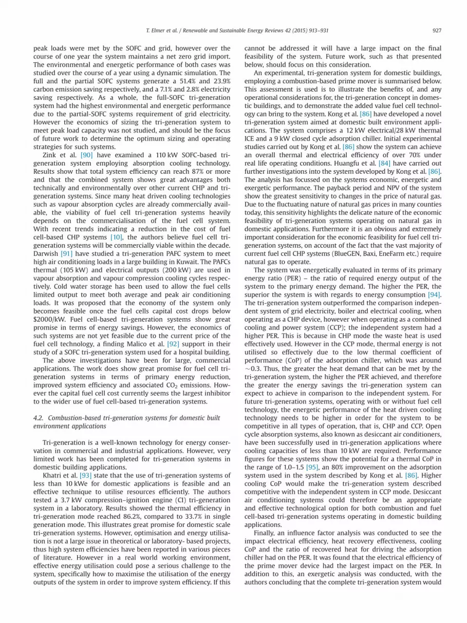
peak loads were met by the SOFC and grid, however over thecourse of one year the system maintains a net zero grid import.The environmental and energetic performance of both cases wasstudied over the course of a year using a dynamic simulation. Thefull and the partial SOFC systems generate a 51.4% and 23.9%carbon emission saving respectively, and a 7.1% and 2.8% electricitysaving respectively. As a whole, the full-SOFC tri-generationsystem had the highest environmental and energetic performancedue to the partial-SOFC systems requirement of grid electricity.However the economics of sizing the tri-generation system tomeet peak load capacity was not studied, and should be the focusof future work to determine the optimum sizing and operatingstrategies for such systems.
Zink et al. [90] have examined a 110 kW SOFC-based tri-generation system employing absorption cooling technology.Results show that total system efficiency can reach 87% or moreand that the combined system shows great advantages bothtechnically and environmentally over other current CHP and tri-generation systems. Since many heat driven cooling technologiessuch as vapour absorption cycles are already commercially avail-able, the viability of fuel cell tri-generation systems heavilydepends on the commercialisation of the fuel cell system.With recent trends indicating a reduction in the cost of fuelcell-based CHP systems [10], the authors believe fuel cell tri-generation systems will be commercially viable within the decade.Darwish [91] have studied a tri-generation PAFC system to meethigh air conditioning loads in a large building in Kuwait. The PAFCsthermal (105 kW) and electrical outputs (200 kW) are used invapour absorption and vapour compression cooling cycles respec-tively. Cold water storage has been used to allow the fuel cellslimited output to meet both average and peak air conditioningloads. It was proposed that the economy of the system onlybecomes feasible once the fuel cells capital cost drops below$2000/kW. Fuel cell-based tri-generation systems show greatpromise in terms of energy savings. However, the economics ofsuch systems are not yet feasible due to the current price of thefuel cell technology, a finding Malico et al. [92] support in theirstudy of a SOFC tri-generation system used for a hospital building.
The above investigations have been for large, commercialapplications. The work does show great promise for fuel cell tri-generation systems in terms of primary energy reduction,improved system efficiency and associated CO2 emissions. How-ever the capital fuel cell cost currently seems the largest inhibitorto the wider use of fuel cell-based tri-generation systems.
4.2. Combustion-based tri-generation systems for domestic builtenvironment applications
Tri-generation is a well-known technology for energy conser-vation in commercial and industrial applications. However, verylimited work has been completed for tri-generation systems indomestic building applications.
Khatri et al. [93] state that the use of tri-generation systems ofless than 10 kWe for domestic applications is feasible and aneffective technique to utilise resources efficiently. The authorstested a 3.7 kW compression–ignition engine (CI) tri-generationsystem in a laboratory. Results showed the thermal efficiency intri-generation mode reached 86.2%, compared to 33.7% in singlegeneration mode. This illustrates great promise for domestic scaletri-generation systems. However, optimisation and energy utilisa-tion is not a large issue in theoretical or laboratory- based projects,thus high system efficiencies have been reported in various piecesof literature. However in a real world working environment,effective energy utilisation could pose a serious challenge to thesystem, specifically how to maximise the utilisation of the energyoutputs of the system in order to improve system efficiency. If this
cannot be addressed it will have a large impact on the finalfeasibility of the system. Future work, such as that presentedbelow, should focus on this consideration.
An experimental, tri-generation system for domestic buildings,employing a combustion-based prime mover is summarised below.This assessment is used is to illustrate the benefits of, and anyoperational considerations for, the tri-generation concept in domes-tic buildings, and to demonstrate the added value fuel cell technol-ogy can bring to the system. Kong et al. [86] have developed a noveltri-generation system aimed at domestic built environment appli-cations. The system comprises a 12 kW electrical/28 kW thermalICE and a 9 kW closed cycle adsorption chiller. Initial experimentalstudies carried out by Kong et al. [86] show the system can achievean overall thermal and electrical efficiency of over 70% underreal life operating conditions. Huangfu et al. [84] have carried outfurther investigations into the system developed by Kong et al. [86].The analysis has focussed on the systems economic, energetic andexergetic performance. The payback period and NPV of the systemshow the greatest sensitivity to changes in the price of natural gas.Due to the fluctuating nature of natural gas prices in many countiestoday, this sensitivity highlights the delicate nature of the economicfeasibility of tri-generation systems operating on natural gas indomestic applications. Furthermore it is an obvious and extremelyimportant consideration for the economic feasibility for fuel cell tri-generation systems, on account of the fact that the vast majority ofcurrent fuel cell CHP systems (BlueGEN, Baxi, EneFarm etc.) requirenatural gas to operate.
The system was energetically evaluated in terms of its primaryenergy ratio (PER) – the ratio of required energy output of thesystem to the primary energy demand. The higher the PER, thesuperior the system is with regards to energy consumption [94].The tri-generation system outperformed the comparison indepen-dent system of grid electricity, boiler and electrical cooling, whenoperating as a CHP device, however when operating as a combinedcooling and power system (CCP); the independent system had ahigher PER. This is because in CHP mode the waste heat is usedeffectively used. However in the CCP mode, thermal energy is notutilised so effectively due to the low thermal coefficient ofperformance (CoP) of the adsorption chiller, which was around�0.3. Thus, the greater the heat demand that can be met by thetri-generation system, the higher the PER achieved, and thereforethe greater the energy savings the tri-generation system canexpect to achieve in comparison to the independent system. Forfuture tri-generation systems, operating with or without fuel celltechnology, the energetic performance of the heat driven coolingtechnology needs to be higher in order for the system to becompetitive in all types of operation, that is, CHP and CCP. Opencycle absorption systems, also known as desiccant air conditioners,have been successfully used in tri-generation applications wherecooling capacities of less than 10 kW are required. Performancefigures for these systems show the potential for a thermal CoP inthe range of 1.0–1.5 [95], an 80% improvement on the adsorptionsystem used in the system described by Kong et al. [86]. Highercooling CoP would make the tri-generation system describedcompetitive with the independent system in CCP mode. Desiccantair conditioning systems could therefore be an appropriateand effective technological option for both combustion and fuelcell-based tri-generation systems operating in domestic buildingapplications.
Finally, an influence factor analysis was conducted to see theimpact electrical efficiency, heat recovery effectiveness, coolingCoP and the ratio of recovered heat for driving the adsorptionchiller had on the PER. It was found that the electrical efficiency ofthe prime mover device had the largest impact on the PER. Inaddition to this, an exergetic analysis was conducted, with theauthors concluding that the complete tri-generation systemwould
T. Elmer et al. / Renewable and Sustainable Energy Reviews 42 (2015) 913–931 927
benefit from operation that maximises electrical efficiency. There-fore the authors concluded that the tri-generation system shouldbe operated at conditions that maximise its electrical efficiency inorder to bring about the best energetic and exergetic performance.As demonstrated in Table 1, fuel cells, particularly SOFCs havemuch higher electrical efficiencies compared to both the ICE andSE. Fuel cells are therefore a key technological option for max-imising the energetic and exergetic and economic performance oftri-generation systems in domestic built environment applications.
Ren and Gao [96] have investigated a gas engine and fuel cellfor domestic CHP applications in Japan. It was found that the fuelcell offered superior economic and environmental performance ina domestic application.
This section has discussed the use of combustion-based tri-generation systems in domestic built environment applications,and how the use of fuel cell technology can potentially enhancethe performance of these systems. With regards to domestic scalefuel cell tri-generation systems, there is a great absence of work.This is mainly due to the current system; size, maturity, cost andcomplexity. The substantial lack of work and highlighted opera-tional benefits of fuel cell technology signifies the large researchpotential this topic holds for the future. The work that has beencompleted to date has mainly focussed on simulation studies andis discussed below.
4.3. Fuel cell tri-generation systems for domestic built environmentapplications
Mıguez [85] and Porteiro [97] state that the introduction of tri-generation systems to the domestic built environment requires thecore of the system, the CHP unit, to be compact, cost efficient andeasily installed. With the market introduction of commerciallyavailable fuel cell CHP units such as BlueGEN and GAMMA, thepossibility of fuel cell tri-generation energy systems for domestichomes is becoming more realistic. Gigliucci et al. [98] haveconducted extensive work on fuel cell CHP systems in domesticbuilt environment applications, in particular their thermal man-agement. Conclusions drawn from their work include the abilitiesof delivering the waste heat to a useful heat sink (tri-generationapplications will increase this), capacity to vary the heat to powerratio and electrical output during operation are all critical for thefull potential of the fuel cell device to be realised. Fuel cells withtheir lower heat to power ratios show great promise in terms oftotal thermal energy utilisation, illustrating why fuel cell technol-ogy has been highlighted as an obvious candidate for tri-generation domestic built environment applications [82].
Bhatti et al. [99] present a patent publication for a SOFCassisted air conditioning system based on solid desiccant andevaporative cooling technology. The aim of the system is toprovide both comfort cooling and heating. The authors state thatthe most common technology to provide heating and cooling is areversible heat pump; however these use electric power to drivethe compressor. Desiccant enhanced systems are a low energyalternative to this. The thermal energy from the SOFC is used toregenerate a solid desiccant wheel which is used to address thelatent load, whilst an evaporative cooler is used to address thesensible load. No performance data is available, however it isexpected the system will provide a high system efficiency andenergy reduction in comparison to a separate vapour compression,boiler and grid electricity system.
Pilatowsky et al. [100] have carried out simulation-basedwork on a 1 kWe PEMFC coupled to an absorption cooling system.The simulations were completed to determine the optimumoperating conditions of the absorption cooler during the co-generation process; primarily the cooling capacity at maximumpower output from the PEMFC. The absorption cycle was operated
with a mono-methylamine water solution, with low vapour gen-eration temperatures of around 80 1C, ideal for PEMFC CHP applica-tions. Results show that the co-generation process increases totalefficiency of the fuel cell system, illustrating the feasibility of usingfuel cells in small scale tri-generation applications. Results from thesimulation include (1) The CoP of the absorption cooler increases asthe generation temperature (from the fuel cell) increases, reaching amaximum value and then dropping off (2) The cooling powerincreases with an increase of the electrical power from the PEMFCand evaporation temperature of the absorption cooler, butdecreases with an increase of generation temperature, and (3) Theco-generation efficiency is almost independent of the electricalpower, but strongly dependant on evaporation and generationtemperatures of the absorption cooler.
A 1.5 kWe low temperature SOFC liquid desiccant tri-generationsystem has been proposed by Riffat [35] as an environmentallyfriendly way of providing heating, cooling and electricity to lowcarbon domestic buildings. It has been predicted that the describedsystem running on hydrogen from the natural gas network will resultin a 70% CO2 emission reduction compared to a traditional energyproduction system comprising of separate condensate power plant,boiler and compressor driven cooling unit. The tri-generation systemwill be constructed at The University of Nottingham as part of the EUfunded TriSOFC project [35].
To summarise, Section 4 has addressed fuel cell tri-generationsystems. With recent advances in fuel cell CHP systems fordomestic applications; the feasibility of fuel cell tri-generationsystems for domestic applications is strong and shows greatpromise. It has been demonstrated that a fuel cell tri-generationsystems can create substantial energy savings, leading to reducedatmospheric pollution and operational costs [12]. However, issuessuch as the accurate pairing of prime mover and cooling technol-ogies needs careful consideration to ensure effective systemoperation. Also, the presentation of laboratory-based results asopposed to real world examples can skew the predicted perfor-mance of such systems. The economic viability of any tri-generation system, particularly fuel cell, lies with the capital costof the fuel cell, not cooling technology, which is already at a levelcommensurate with economic viability. Darwish [91] estimates afuel cell cost of $2000/kW or below is required to permit the wideruse of fuel cell tri-generation systems, a cost target figure Staffelland Green [51] believe is possible by 2020. The reviewed work ontri-generation systems using combustion-based prime movertechnology has shown that high cooling CoP, maximised electricalefficiency and low/stable gas prices are all required in order tomake the tri-generation system concept a viable option fordomestic built environment applications. Conclusions that willbe largely applicable to the application of fuel cell technology inthe domestic built environment. However, there are severalbarriers to be overcome in the development of tri-generationsystems for domestic built environment applications. Currently,the components, particularly the heat driven cooling technology,of tri-generation systems of less than 10 kW are still very much inthe research and development stages. Higher initial (capital) costand less supporting services mean there is less demand for suchsystems. There is a lack of incentives to stimulate the use of tri-generation systems, particularly on a domestic scale. In general,developmental barriers are more pronounced in smaller (micro)scale systems than they are in larger applications [15]. Currently anextensive gap in the literature exists regarding fuel cell tri-generation systems, particularly in domestic built environmentapplications. Literature found regarding fuel cell tri-generationsystems has predominately been either larger commercial applica-tions or simulation, with little or no work on experimental-baseddomestic studies. There is therefore a clear need for experimentalwork in the field of fuel cell tri-generation systems in domestic
T. Elmer et al. / Renewable and Sustainable Energy Reviews 42 (2015) 913–931928

applications. This is due to the large energy saving potentialpossible with both fuel cell technology and the tri-generationsystem concept.
5. Conclusions
This article has served to provide a state-of-the-art review offuel cell technologies operating in the domestic built environmentas CHP and tri-generation systems. The review has been achievedthrough the assessment of fuel cell technology, fuel cell CHPsystems and fuel cell tri-generation systems. Throughout, up todate specific examples have been used to address the three mainaims of the article; (1) the operational advantages fuel cells offer inCHP and tri-generation system configurations, specifically, com-pared to conventional combustion- based technologies such as SEand ICEs, (2) how decarbonisation, running cost and energysecurity in the domestic built environment may be addressedthrough the use of fuel cell technology, and (3) what has beendone to date and what needs to be done in the future. The articleconcludes with an assessment of the present development of, andfuture challenges for, domestic fuel cells operating in CHP and tri-generation systems.
5.1. Fuel cell combined heat and power systems
This article has highlighted the significant operational advan-tages fuel cells offer compared to conventional micro-CHP tech-nologies, such as; higher electrical efficiencies, lower H:P ratios,reduced noise and vibrations during operation and flexibility offuel use. The use of fuel cell technology can lead to significantreductions in CO2 emissions and operating costs for the user. Withregards to the type of fuel cells being used, the low temperaturePEMFC and the intermediate to high temperature SOFC currentlyshow the greatest promise, with most building integrated projectsfocussing on these two technological variants. The PEMFC offersquick start up time, power modulation and useful direct hot wateroutput, whilst the SOFC provides high electrical efficiency, abilityto internally reform hydrocarbon fuels and a high temperatureheat output which can be utilised in another cycle. However,issues with the current PEMFC technology include the require-ment of additional heating devices – the Baxi unit has a poor heatoutput and therefore requires an expensive water heater/store costing an additional d3000. The SOFC devices have a longstart-up time – BlueGEN takes one day to warm up. It has beenreported that in 2012 fuel cell technology outsold conventionalcombustion-based systems for micro-CHP applications for the firsttime. This signifies a significant shift in the market and shows anexciting future for fuel cell technology. Currently there are manydifferent estimates regarding the extent of CO2 emission reduc-tions delivered by fuel cells operating in the built environment.Sizeable reductions are achievable in the range of 1–2.5 t/annum/house, however they are largely dependent upon a range offactors including; central electricity mix, the home's annualenergy demand and electrical / total efficiency of the fuel cellsystem. Future work will aim to address these discrepancieswith a standardised methodology to assess the environmentalperformance of fuel cell CHP systems in domestic homes. Issuesof fuel cell CHP optimisation, particularly thermal, has beenaddressed, with district scale fuel cell operation and interactionbeing cited as an effective way to optimise the use of fuel celltechnology in the domestic built environment. A variety ofdemonstration projects have been introduced, with the longrunning Japanese EneFarm project being by far the largest andmost successful to date. EneFarm has facilitated the global expan-sion of the commercial fuel cell CHP market, seen in the number
of commercialised units in Japan today. EneFarm should serveas a suitable case study for any future demonstration projects tolearn from.
This article concludes that fuel cell technology is a feasibletechnological option for domestic CHP built environment applica-tions. This can be seen in increasing sales figures that nowoutweigh those of conventional combustion-based technologies.However issues with cost, reliability, durability, and fuel supplystill need resolving in order to effectively integrate the technologyand permit it's wider and more effective use in the domestic builtenvironment.
5.2. Fuel cell tri-generation
This article concludes that domestic scale tri-generation hasthe potential to produce higher energy conversion efficiency andhence reduce net fuel cost and CO2 emissions compared to aconventional combustion-based CHP system. Currently there isvery limited literature regarding fuel cell tri-generation systems,however one of the main aims of the review was to highlight thesignificant research potential such systems offer in domestic builtenvironment applications. This has been achieved by looking atthree core topics (1) commercial scale systems, which illustratehigh system efficiency and reduced primary energy demand,(2) combustion-based systems, which would benefit from a primemove technology with a higher electrical efficiency, such as a fuelcell, and (3) fuel cell tri-generation systems, although onlysimulation-based work, they show high energy utilisation andfuture potential. A common conclusion with the fuel cell CHPreview is that the cost of the fuel cell needs to fall in order toeffectively facilitate the uptake of fuel cell tri-generation systems.The district concept also represents a significant possibility. Bysharing the capital cost of the fuel cell in the CHP or tri-generationsystem it would make the current use of fuel cell technology amuch more viable prospect. Most critically, the tri-generationreview has highlighted the current, extensive and valuableresearch potential fuel cell tri-generation systems for domesticbuilt environment applications offer. These systems should there-fore be the focus of future investigations.
To conclude, decentralised energy generation from fuel cells inthe domestic built environment can lead to emission reductions,reduced operational cost for the user and increased energysecurity, all essential objectives for the future built environment.Economic profitability is an essential criterion for any form ofsustainable development [15]. Fuel cell CHP and tri-generationsystems have shown throughout the review to offer the potentialto produce real energy savings and thus economic benefit to theuser. However as with any novel technology, a major challengefacing fuel cell technology is its capital cost. Until significantreductions in the capital cost of the technology can be made, beit through government support or technological innovation, thewider use of fuel cell technology in the domestic built environ-ment cannot be expected.
If the UK and other countries are serious about their aspirationsof a low carbon future, the built environment and the domesticsector in particular will play a critical role. In order to create a realtransformation, both operational and technological changes needto occur. Nations can no longer rely on technologies of the past tohelp arrive at the destination of a low carbon sustainable society.Fuel cells are a technology of the future here today, providing achange in the way heat and power are supplied to end users. Fuelcells operating in CHP and tri-generation systems could finallyprovide the means by which energy generation can transfer fromcentralised to decentralised locales in a sustainable and effectivemanner.
T. Elmer et al. / Renewable and Sustainable Energy Reviews 42 (2015) 913–931 929

Acknowledgements
The authors would like to acknowledge the support fromEuropean Commission under the Fuel Cell and Hydrogen JointUndertaking Initiative (FCH-JU) for the “Durable low temperaturesolid oxide fuel cell Tri-generation system for low carbon build-ings” project, Agreement no. 303454. The authors would also liketo thank the EPSRC and CDT in Hydrogen, Fuel cells and theirApplications for their continued financial and academic support.
References
[1] DECC. Department of Energy and Climate Change (UK): Climate Change Act2008. 2013, Electronic article; 2008.
[2] Böhringer C, Rutherford TF, Tol RSJ. THE EU 20/20/2020 targets: an overviewof the EMF22 assessment. Energy Econ 2009;31(Suppl. 2):S268–73 (0).
[3] Hawkes A, Staffell I, Brett D, Brandon N. Fuel cells for micro-combined heatand power generation. Energy Environ Sci 2009;2:729–44.
[4] Ekins P, Lees E. The impact of EU policies on energy use in and the evolutionof the UK built environment. Energy Policy 2008;36(12):4580–3.
[5] Clarke JA, Johnstone Cameron M, Kelly Nicolas J, Strachan Paul A, Tuohy Paul.The role of built environment energy efficiency in a sustainable UK energyeconomy. Energy Policy 2008;36(12):4605–9.
[6] Kazempoor P, Dorer Viktor, Weber Andreas. Modelling and evaluation ofbuilding integrated SOFC systems. Int J Hydrogen Energy 2011;36(20):13241–9.
[7] Vourliotakis, G, Giannopoulos, D, Founti, M. Potentials of fuel cells as μ-CHPsystems for domestic applications in the framework of energy efficient andsustainable districts. FC-DISTRICT project, 7th FP, CP-IP 260105 FC-DISTRICT; 2010.
[8] Fong KF,, Lee CK. Investigation on zero grid-electricity design strategies ofsolid oxide fuel cell trigeneration system for high-rise building in hot andhumid climate. Appl Energy 2014;114(0):426–33.
[9] Choudhury A, Chandra H, Arora A. Application of solid oxide fuel celltechnology for power generation – a review. Renew Sust Energy Rev2013;20(0):430–42.
[10] FCT. Fuel cell today: the leading authority on fuel cells: the fuel cell todayindustry review, ⟨http://www.fuelcelltoday.com/media/1889744/fct_review_2013.pdf⟩; 2013.
[11] Harrison J. E.ON – smart homes with fuel cell micro CHP. In: Smart hydrogen& fuel cell power conference; 2012. Birmingham.
[12] Choudhury A, Chandra H, Arora A. Application of solid oxide fuel celltechnology for power generation – a review. Renew Sust Energy Rev2013;20(0):430–42.
[13] Beaussoleil-Morrison I. An experimental and simulation-based investigationof the performance of small scale fuel cell and combustion-based cogenera-tion devices serving residential buildings. Annex 42 of the InternationalEnergy Agency's Energy Conservation in Buildings and Community SystemsProgramme 2008.
[14] El-Gohary MM. Economical analysis of combined fuel cell generators andabsorption chillers. Alex Eng J 2013;52(2):151–8.
[15] Sonar D, Soni SL, Sharma D. Micro-trigeneration for energy sustainability:technologies, tools and trends. Appl Therm Eng 2014;71(2):790–6.
[16] Badami M, Portoraro A. Performance analysis of an innovative small-scaletrigeneration plant with liquid desiccant cooling system. Energy Buildings2009;41(11):1195–204.
[17] Kolokotroni M, Zhang Y, Watkins R. The london heat island and buildingcooling design. Sol Energy 2007;81(1):102–10.
[18] Peht M, Cames M, Fischer C, Prateorius B, Schneider L, Schumacher K, et al. Microcogeneration towards dencentralized energy systems. Berlin: Springer; 2006.
[19] Fubara TC, Cecelja Franjo, Yang Aidong. Modelling and selection of micro-CHP systems for domestic energy supply: the dimension of network-wideprimary energy consumption. Appl Energy 2014;114(0):327–34.
[20] Staffell I. Fuel cells for domestic heat and power: are they worth It?, inChemical engineering. The University of Birmingham, Birmingham; 2009.
[21] Wu DW, Wang RZ. Combined cooling, heating and power: A review. ProgEnergyCombust 2006;32(5–6):459–95.
[22] Steinberger-Wilckens R. Fuel cells and hydrogen joint undertaking: evaluat-ing the performance of fuel cells in European energy supply grids (FC-EuroGrid). Fuel Cells and Hydrogen Joint Undertaking 2013.
[23] Maghanki MM, Ghobadian Barat, Najafi Gholamhassan, Galogah Reza Janza-deh. Micro combined heat and power (MCHP) technologies and applications.Renew Sust Energy Rev 2013;28(0):510–24.
[24] Bianchi M, De Pascale A, Spina PR. Guidelines for residential micro-CHPsystems design. Appl Energy 2012;97(0):673–85.
[25] Simader GR, Krawinkler Robert, Trnka Georg. Deliverable 8 (D8) of greenlodges project (EIE/04/252/S07.38608) – micro CHP systems: state-of-the-art. Austrian Energy Agency; 2006.
[26] Kuhn V, Klemeš J, Bulatov I. MicroCHP: overview of selected technologies,products and field test results. Appl Therm Eng 2008;28(16):2039–48.
[27] Blum L, Deja R, Peters R, Stolten D. Comparison of efficiencies of low, meanand high temperature fuel cell systems. Int J Hydrogen Energy 2011;36(17):11056–67.
[28] Chu HS, Tsau F, Yan YY, Hsueh KL, Chen FL. The development of a smallPEMFC combined heat and power system. J Power Sources 2008;176(2):499–514.
[29] Bradley A. Technology shift in micro-CHP: fuel cell outsells engines for thefirst time. news-releases, ⟨http://www.prnewswire.com/news-releases/technology-shift-in-micro-chp-fuel-cell-outsells-engines-for-the-first-time-214928111.html⟩; 2013 [accessed 03.02.13].
[30] Gencoglu MT, Ural Z. Design of a PEM fuel cell system for residentialapplication. Int J Hydrogen Energy 2009;34(12):5242–8.
[31] O'Hayre R, Cha SK, Colella W, Prinz FB. Fuel cell fundamentals. New York:John Wiley & Sons; 2006.
[32] Sammes NM,, Boersma R. Small-scale fuel cells for residential applications.J Power Sources 2000;86(1–2):98–110.
[33] Minh NQ. Solid oxide fuel cell technology – features and applications. SolidState Ionics 2004;174(1–4):271–7.
[34] Dentice d'Accadia M, Sasso M, Sibilio S, Vanoli L. Micro-combined heat andpower in residential and light commercial applications. Appl Therm Eng2003;23(10):1247–59.
[35] Riffat S, EU project proposal: durable solid oxide fuel cell tri-generationsystem for low carbon buildings, FCH-JU, Brussels; 2012.
[36] Fan L, Wang Chengyang, Chen Mingming, Zhu Bin. Recent developmentof ceria-based (nano)composite materials for low temperature ceramicfuel cells and electrolyte-free fuel cells. J Power Sources 2013;234(0):154–174.
[37] Hawkes A, Tiravanti G, Leach MA. Routes to energy efficiency: complemen-tary energy service products in the UK residential sector. Eur Council EnergyEfficient Econ (ECEEE) 2005;2:531–40.
[38] Hawkes A, Leach M. Solid oxide fuel cell systems for residential micro-combined heat and power in the UK: key economic drivers. J Power Sources2005;149(0):72–83.
[39] Brouwer J. On the role of fuel cells and hydrogen in a more sustainable andrenewable energy future. Curr Appl Phys 2010;10(2, Supplement):S9–17.
[40] Kothari R, Buddhi D, Sawhney RL. Comparison of environmental andeconomic aspects of various hydrogen production methods. Renew SustEnergy Rev 2008;12(2):553–63.
[41] Braun RJ, Klein SA, Reindl DT. Evaluation of system configurations for solidoxide fuel cell-based micro-combined heat and power generators in resi-dential applications. J Power Sources 2006;158(2):1290–305.
[42] McAlister R. The solar hydrogen civilization. Mesa, USA: American HydrogenAssociation; 2003.
[43] Percival Zhang YH, Mielenz R. Jonathan. Renewable hydrogen carrier –
carbohydrate: constructing the carbon-neutral carbohydrate economy. Ener-gies 2011;4:254–75.
[44] Percival Zhang YH, Xu JH, Zhong JJ. A new high-energy density hydrogencarrier – carbohydrate – might be better than methanol. Int J Energy Res2013;37(7):769–79.
[45] CFCL. Electronic resource: CFCL blueGEN modular generator – power andheat. Electronic resource, ⟨http://www.bluegen.info/Assets/Files/BlueGen_Brochure_(ENG_GER)_April_2010.pdf⟩; 2009 [accessed 08.12.12].
[46] Panasonic. Panasonic develops new fuel cell cogeneration system for homeuse. [Electronic resource], 2008 ⟨http://panasonic.co.jp/corp/news/official.data/data.dir/en080414-2/en080414-2.html⟩; 2012 [accessed 27.04.12].
[47] Panasonic. Tokyo gas and panasonic to launch new improved “Ene-Farm” homefuel cell with world-highestn1 power generation efficiency at more affordableprice, 2011 Electronic resource]. ⟨http://panasonic.co.jp/corp/news/official.data/data.dir/en110209-2/en110209-2.html⟩; 2012 [accessed 27.04.12].
[48] Jradi M,, Riffat S. Tri-generation systems: energy policies, prime movers,cooling technologies, configurations and operation strategies. Renew SustEnergy Rev 2014;32(0):396–415.
[49] FCT. Fuel cell today; the leading authority on fuel cells: the fuel cell todayindustry review 2011, ⟨http://www.fuelcelltoday.com/media/1351623/the_industry_review_2011.pdf⟩; 2011.
[50] DoE. The US Department of Energy: Hydrogen, Fuel Cells & InfrastructureTechnologies Program. [Electronic article] 2010 21/10/2013; Available from:⟨http://www.nrel.gov/docs/fy05osti/34289.pdf⟩; 2010 [accessed 21.10.13].
[51] Staffell I, Green R. The cost of domestic fuel cell micro-CHP systems. Int JHydrogen Energy 2013;38(2):1088–102.
[52] Boyd J. IEEE Spectrum. Home fuel cells to sell in Japan, ⟨http://spectrum.ieee.org/energy/renewables/home-fuel-cells-to-sell-in-japan⟩; 2008 [accessed 27.04.12].
[53] Steele BCH, Heinzel A. Materials for fuel-cell technologies. Nature 2001;414(6861):345–52.
[54] Conroy G, Duffy A, Ayompe LM. Economic, energy and GHG emissionsperformance evaluation of a WhisperGen Mk IV Stirling engine μ-CHP unitin a domestic dwelling. Energy Convers Manage 2014;81(0):465–74.
[55] FCT. Fuel cell today; the leading authority on fuel cells: the fuel cell todayindustry review 2012. ⟨http://www.fuelcelltoday.com/media/1713685/fct_review_2012.pdf⟩; 2012.
[56] Pade LL, Schröder Sascha Thorsten, Münster Marie, Birkl Christoph, RopenusStephanie, Morthorst Poul Erik, et al. Policy schemes, operational strategiesand system integration of residential co-generation fuel cells. Int J HydrogenEnergy 2013;38(7):3050–63.
[57] Dorer V, Weber R, Weber A. Performance assessment of fuel cell micro-cogeneration systems for residential buildings. Energy Buildings 2005;37(11):1132–46.
[58] Peacock AD, Newborough M. Impact of micro-CHP systems on domesticsector CO2 emissions. Appl Therm Eng 2005;25(17–18):2653–76.
T. Elmer et al. / Renewable and Sustainable Energy Reviews 42 (2015) 913–931930

[59] Flint B. Gas industry micro CHP workshop: fuel cell products for globalenergy markets. Gas Industry Micro CHP Workshop, ⟨http://www.marcogaz.org/index.php/workshops/micro-chp-ws⟩; 2008.
[60] Guy R, Sykes Benjamin. Carbon trust:micro-CHP accelerator. Final Report –2011; 2011.
[61] Carter D. Fuel cell residential micro-CHP developments in Japan, ⟨http://www.fuelcelltoday.com/media/1597029/29-02-12_ene-farm.pdf⟩; 2012[accessed 12.02.13].
[62] TG. ENE FARM residential fuel cells launched. 2009 Electronic resource].⟨http://www.tokyo-gas.co.jp/tgminutes/64.pdf⟩; 2012 [accessed 15.05.12].
[63] Panasonic. Launch of new ‘Ene-Farm’ home fuel cell product more affordableand easier to install. ⟨http://panasonic.co.jp/corp/news/official.data/data.dir/2013/01/en130117-5/en130117-5.html⟩; 2013 [accessed 05.10.13].
[64] Wachsman ED, Marlowe CA, Lee KT. Role of solid oxide fuel cells in abalanced energy strategy. Energy Environ Sci 2012;5(2):5498–509.
[65] Ene.Field. Hannover fair. European union's seventh framework programme(FP7/2007-2013) for the fuel cells and hydrogen joint technology initiativeunder grant agreement no. 303462 [Electronic article], ⟨http://enefield.eu/wp-content/uploads/2013/05/Newsflash-N1.pdf⟩; 2013 [accessed 04.11.13].
[66] Barrett S. German virtual power plant project using 25 BlueGen mCHP units.Fuel Cells Bull 2012(10):4.
[67] Hawkes AD, Aguiar P, Croxford B, Leach MA, Adjiman CS, Brandon NP. Solidoxide fuel cell micro combined heat and power system operating strategy:options for provision of residential space and water heating. J Power Sources2007;164(1):260–71.
[68] Klose P. Baxi innotech – gamma 1.0 large scale demonstration of residentialPEFC systems in Germany, status and outlook. in 4th IPHE Workshop –
Stationary Fuel Cells. Tokyo, Japan; 2011.[69] Harrison J. Micro combined heat & power. 2013 09/11/2013, ⟨http://www.
microchap.info/INDEX.HTM⟩; 2013 [accessed 03.12.13].[70] FCCJ. ENE-FARM dissemination and general specification. Fuel Cell Commer-
cialisation Conference of Japan; 2012.[71] Elcore. Elcore 2400 – the most compact and efficient fuel cell for Your House,
⟨http://www.elcore.com/home.html⟩; 2013 [accessed 03.12.13].[72] Dantherm. ElectraGen™-ME, ⟨http://dantherm-power.com/products/fuel-
cell-systems/ElectraGenME.aspx⟩; 2013 [accessed 03.12.13].[73] Power, P. Plug Power: GenSys Blue, ⟨http://www.plugpower.com/userfiles/
GenSys%20HT%20MK.pdf⟩; 2014.[74] Ishikawa T. SOFC Development by Tokyo Gas, Kyocera, Rinnai and Gastar. In:
Proceedings of the 23rd World Gas Conference. Amsterdam: InternationalGas Union; 2006.
[75] Takami H. Development of fuel cell at JX. DOE Hydrogen and Fuel CellTechnical Advisory Committee 2011. ⟨http://www.hydrogen.energy.gov/pdfs/htac_02_2011_jx_eneos_takami.pdf⟩.
[76] Topsoe. Topsoe powercore for micro CHP units, ⟨http://www.topsoefuelcell.com/products/powercore/next_generation.aspx⟩; 2013 [accessed 09.12.2013].
[77] SOFC P. EnGen 500. ⟨http://www.sofcpower.com/11/engen-500.html⟩; 2013.[78] Acumentrics. Acumentrics AHEAD, ⟨http://www.fuelcellmarkets.com/con
tent/images/articles/AHEAD_page_1%5B1%5D.pdf⟩; 2007.[79] Kato T, Iida Tetsuhisa, Wu Kai, Suzuoki Yasuo. A study of a micro co-
generation system's conformation for residential use considering observedfluctuating characteristics of hot-water demand. Electr Eng Jpn 2003;143(2):30–7.
[80] FC-DISTRICT. New m-CHP network technologies for energy efficient andsustainable districts 7th FP, CP-IP 260105 FC-DISTRICT. 2013, EU fundedproject; 2010.
[81] Rodriguez-Aumente PA, Rodriguez-Hidalgo María del Carmen, Nogueira José I,Lecuona Antonio, Venegas María del Carmen. District heating and cooling forbusiness buildings in Madrid. Appl Therm Eng 2013;50(2):1496–503.
[82] Deng J, Wang RZ, Han GY. A review of thermally activated coolingtechnologies for combined cooling, heating and power systems. Prog EnergyCombust 2011;37(2):172–203.
[83] Yu Z, Han Jitian, Cao Xianqi, Han Jitian, Cao Xianqi, Chen Wei, et al. Analysisof total energy system based on solid oxide fuel cell for combined coolingand power applications. Int J Hydrogen Energy 2010;35(7):2703–7.
[84] Huangfu Y, Wu JY, Wang RZ, Kong XQ, Wei BH. Evaluation and analysis ofnovel micro-scale combined cooling, heating and power (MCCHP) system.Energy Convers Manage 2007;48(5):1703–9.
[85] Mıguez JL, Murillo S, Porteiro J, López LM. Feasibility of a new domestic CHPtrigeneration with heat pump: I. Design and development. Appl Therm Eng2004;24(10):1409–19.
[86] Kong XQ, Wang RZ, Wu JY, Huang XH, Huangfu Y, Wu DW, Xu YX.Experimental investigation of a micro-combined cooling, heating and powersystem driven by a gas engine. Int J Refrig 2005;28(7):977–87.
[87] Yu Z, Han Jitian, Cao Xianqi. Investigation on performance of an integratedsolid oxide fuel cell and absorption chiller tri-generation system. Int JHydrogen Energy 2011;36(19):12561–73.
[88] Margalef P, Samuelsen S. Integration of a molten carbonate fuel cell with adirect exhaust absorption chiller. J Power Sources 2010;195(17):5674–85.
[89] Al-Sulaiman FA, Dincer I, Hamdullahpur F. Energy analysis of a trigenerationplant based on solid oxide fuel cell and organic Rankine cycle. Int J HydrogenEnergy 2010;35(10):5104–13.
[90] Zink F, Lu Yixin, Schaefer Laura. A solid oxide fuel cell system for buildings.Energy Convers Manage 2007;48(3):809–18.
[91] Darwish MA. Building air conditioning system using fuel cell: case study forKuwait. Appl Therm Eng 2007;27(17–18):2869–76.
[92] Malico I, Carvalhinho AP, Tenreiro J. Design of a trigeneration system using ahigh-temperature fuel cell. Int J Energy Res 2009;33(2):144–51.
[93] Khatri KK, Sharma Dilip, Soni SL, Tanwar Deepak. Experimental investigationof CI engine operated micro-trigeneration system. Appl Therm Eng 2010;30(11–12):1505–9.
[94] Havelský V. Energetic efficiency of cogeneration systems for combined heat,cold and power production. Int J Refrig 1999;22(6):479–85.
[95] Liu XH, Geng KC, Lin BR, Jiang Y. Combined cogeneration and liquid-desiccant system applied in a demonstration building. Energy Buildings2004;36(9):945–53.
[96] Ren H,, Gao W. Economic and environmental evaluation of micro CHPsystems with different operating modes for residential buildings in Japan.Energy Buildings 2010;42(6):853–61.
[97] Porteiro J, Mıguez JL, Murillo S, López LM. Feasibility of a new domestic CHPtrigeneration with heat pump: II. Availability analysis. Appl Therm Eng2004;24(10):1421–9.
[98] Gigliucci G, Petruzzi L, Cerelli E, Garzisi A, La Mendola A. Demonstration of aresidential CHP system based on PEM fuel cells. J Power Sources 2004;131(1–2):62–8.
[99] Bhatti MS, O'Brien JF, Reyzin I, Grieve M, Kelly SM. Solid oxide fuel cellassisted air conditioning system. USA; 2010.
[100] Pilatowsky I, Romero RJ, Isaza CA, Gamboa SA, Rivera W, Sebastian PJ, et al.Simulation of an air conditioning absorption refrigeration system in a co-generation process combining a proton exchange membrane fuel cell. Int JHydrogen Energy 2007;32(15):3174–82.
T. Elmer et al. / Renewable and Sustainable Energy Reviews 42 (2015) 913–931 931