
Chitosan based nonstoichiometric polyelectrolyte complexes as specialized flocculants
Upload
khangminh22Category
view
2download
0
Vision Sensor FQ-M-series
Specialized Vision Sensor for Positioning
User’s Manual
Z314-E1-03
FQ-MS12@

Introduction
Thank you for purchasing the FQ-M. This manual provides information regarding functions, performance and operating methods that are required for using the FQ-M. When using the FQ-M, be sure to observe the following:
• The FQ-M must be operated by personnel knowledgeable in electrical engineering. • To ensure correct use, please read this manual thoroughly to deepen your understanding of the
product. • Please keep this manual in a safe place so that it can be referred to whenever necessary.

1
1
2
User's ManualVision Sensor for Positioning
FQ-M
APPLICATION CONSIDERATIONS(Please Read)
Introduction
Installation and Connections
3
Taking Images4
Setting Up Inspections5
Testing and Saving Settings6
Operation7
Convenient Functions8
9
10
11
12
Communications with External Devices
Calibration
Offline Settings
Appendices
Troubleshooting

2
READ AND UNDERSTAND THIS DOCUMENTPlease read and understand this document before using the products. Please consult your OMRONrepresentative if you have any questions or comments.
WARRANTYOMRON’s exclusive warranty is that the products are free from defects in materials and workmanship for aperiod of one year (or other period if specified) from date of sale by OMRON.
OMRON MAKES NO WARRANTY OR REPRESENTATION, EXPRESS OR IMPLIED, REGARDING NON-INFRINGEMENT, MERCHANTABILITY, OR FITNESS FOR PARTICULAR PURPOSE OF THE PRODUCTS.ANY BUYER OR USER ACKNOWLEDGES THAT THE BUYER OR USER ALONE HAS DETERMINED THATTHE PRODUCTS WILL SUITABLY MEET THE REQUIREMENTS OF THEIR INTENDED USE. OMRONDISCLAIMS ALL OTHER WARRANTIES, EXPRESS OR IMPLIED.
LIMITATIONS OF LIABILITYOMRON SHALL NOT BE RESPONSIBLE FOR SPECIAL, INDIRECT, OR CONSEQUENTIAL DAMAGES,LOSS OF PROFITS OR COMMERCIAL LOSS IN ANY WAY CONNECTED WITH THE PRODUCTS,WHETHER SUCH CLAIM IS BASED ON CONTRACT, WARRANTY, NEGLIGENCE, OR STRICT LIABILITY.
In no event shall responsibility of OMRON for any act exceed the individual price of the product on whichliability is asserted.
IN NO EVENT SHALL OMRON BE RESPONSIBLE FOR WARRANTY, REPAIR, OR OTHER CLAIMSREGARDING THE PRODUCTS UNLESS OMRON’S ANALYSIS CONFIRMS THAT THE PRODUCTS WEREPROPERLY HANDLED, STORED, INSTALLED, AND MAINTAINED AND NOT SUBJECT TOCONTAMINATION, ABUSE, MISUSE, OR INAPPROPRIATE MODIFICATION OR REPAIR.
SUITABILITY FOR USETHE PRODUCTS CONTAINED IN THIS DOCUMENT ARE NOT SAFETY RATED. THEY ARE NOT DESIGNED ORRATED FOR ENSURING SAFETY OF PERSONS, AND SHOULD NOT BE RELIED UPON AS A SAFETY COMPO-NENT OR PROTECTIVE DEVICE FOR SUCH PURPOSES. Please refer to separate catalogs for OMRON’s safety rated products.
OMRON shall not be responsible for conformity with any standards, codes, or regulations that apply to thecombination of products in the customer’s application or use of the product.
At the customer’s request, OMRON will provide applicable third party certification documents identifying ratingsand limitations of use that apply to the products. This information by itself is not sufficient for a completedetermination of the suitability of the products in combination with the end product, machine, system, or otherapplication or use.
The following are some examples of applications for which particular attention must be given. This is notintended to be an exhaustive list of all possible uses of the products, nor is it intended to imply that the useslisted may be suitable for the products:
• Outdoor use, uses involving potential chemical contamination or electrical interference, or conditions oruses not described in this document.
FQ-M User’s Manual

• Nuclear energy control systems, combustion systems, railroad systems, aviation systems, medicalequipment, amusement machines, vehicles, safety equipment, and installations subject to separate industryor government regulations.
• Systems, machines, and equipment that could present a risk to life or property.
Please know and observe all prohibitions of use applicable to the products.
NEVER USE THE PRODUCTS FOR AN APPLICATION INVOLVING SERIOUS RISK TO LIFE ORPROPERTY WITHOUT ENSURING THAT THE SYSTEM AS A WHOLE HAS BEEN DESIGNED TOADDRESS THE RISKS, AND THAT THE OMRON PRODUCT IS PROPERLY RATED AND INSTALLED FORTHE INTENDED USE WITHIN THE OVERALL EQUIPMENT OR SYSTEM.
PERFORMANCE DATAPerformance data given in this document is provided as a guide for the user in determining suitability and doesnot constitute a warranty. It may represent the result of OMRON’s test conditions, and the users must correlateit to actual application requirements. Actual performance is subject to the OMRON Warranty and Limitations ofLiability.
CHANGE IN SPECIFICATIONSProduct specifications and accessories may be changed at any time based on improvements and otherreasons.
It is our practice to change model numbers when published ratings or features are changed, or when significantconstruction changes are made. However, some specifications of the product may be changed without anynotice. When in doubt, special model numbers may be assigned to fix or establish key specifications for yourapplication on your request. Please consult with your OMRON representative at any time to confirm actualspecifications of purchased products.
DIMENSIONS AND WEIGHTSDimensions and weights are nominal and are not to be used for manufacturing purposes, even whentolerances are shown.
ERRORS AND OMISSIONSThe information in this document has been carefully checked and is believed to be accurate; however, noresponsibility is assumed for clerical, typographical, or proofreading errors, or omissions.
PROGRAMMABLE PRODUCTSOMRON shall not be responsible for the user’s programming of a programmable product, or any consequencethereof.
COPYRIGHT AND COPY PERMISSIONThis document shall not be copied for sales or promotions without permission.
This document is protected by copyright and is intended solely for use in conjunction with the product. Pleasenotify us before copying or reproducing this document in any manner, for any other purpose. If copying ortransmitting this document to another, please copy or transmit it in its entirety.
FQ-M User’s Manual 3

4
The following signal words are used in this manual.
The following alert symbols are used in this manual
Meanings of Signal Words
Indicates a potentially hazardous situation which, if not avoided, will result in minor or moderate injury, or may result in serious injury or death. Additionally there may be significant property damage.
Meanings of Alert Symbols
Indicates general prohibitions for which there is no specific symbol.
Indicates the possibility of explosion under specific conditions.
Indicates prohibition when there is a risk of minor injury from electrical shock or other source if the product is disassembled.
This product is not designed or rated for ensuring safety of persons.Do not use it for such purposes.
A lithium ion battery is built into the Touch Finder and may occasionally combust, explode, orburn if not treated properly.Dispose of the Touch Finder as industrial waste, and never disassemble, apply pressure thatwould deform, heat to 100 °C or higher, or incinerate the Touch Finder.
High-voltage parts inside; danger of electrical shock. Do not open the product cover.
FQ-M User’s Manual

The following points are important to ensure safety, so make sure that they are strictly observed.
1. Installation Environment• Do not use the product in environments where it can be exposed to inflammable/explosive gas.• To secure the safety of operation and maintenance, do not install the product close to high-voltage devices
and power devices.• Install the product in such a way that its ventilation holes are not blocked.• Tighten mounting screws at the torque specified in this manual.
2. Power Supply and Wiring• The power supply voltage must be within the rated range (24 VDC ±10%), and an AC voltage must not be
used.• Reverse connection of the power supply is not allowed. Do not short the load of the open collector output.• The load must be within the rated range.• High-voltage lines and power lines must be wired separately from this product. Wiring them together or
placing them in the same duct may cause induction, resulting in malfunction or damage. • Use the products within the power supply voltages specified in this manual. • Use the specified size of crimp terminals to wire connections. Do not connect wires that have been simply
twisted together directly to the power supply or terminal block.• Use a DC power supply with safety measures against high voltages (safety extra low-voltage circuit).• Use independent power sources for the products. Do not use a shared power source.• Tighten mounting screws at the torque specified in this manual. • Always turn OFF the power supply to the Camera before performing any of the following. The Sensor may
become faulty if you do any of these while power is being supplied.• Setting the node address setting switches• Connecting or wiring the cable• Connecting or disconnecting the connector
3. Battery• Do not short the positive and negative terminals of the Battery.• Do not use the Touch Finder in an environment that exceeds the operating temperature range of the Battery.
If the Touch Finder is used at temperatures that exceed the operating temperature range, the protectivedevice may activate and prevent charging.
• Do not connect the Battery directly to a power supply or car cigarette lighter socket.• Do not use the Touch Finder with any other type of battery.• Turn OFF the power supply immediately if the Battery leaks or produces an odor. Electrolyte leaked from the
Battery may ignite, possibly causing smoke, rupture, or fire. • If during usage, charging, or storage, the Battery produces an odor, heats, becomes discolored, becomes
misshapen, or exhibits any other unusual conditions, remove it and do not use it. Continuing to use such aBattery may result in the Battery heating, smoking, rupturing, or igniting.
• If the Touch Finder (FQ-MD31) will be installed permanently or semi-permanently, remove the Battery (FQ-BAT1). If the rated temperature is exceeded with the Battery inserted, the protective circuit may activate andstop the Touch Finder.
4. AC Adapter• Use an AC cable that is suitable for the power supply and power voltage you are using.• Do not touch the power plug with a wet hand. Doing so may result in electrical shock.• If you notice an abnormal condition, such as smoke, abnormal heating of the outer surface, or a strange
odor, immediately stop using the AC Adapter, turn OFF the power, and remove the power plug from theoutlet.Consult your dealer, as it is dangerous to attempt to repair the AC Adapter yourself.
Precautions for Safe Use
FQ-M User’s Manual 5

6
• If the AC Adapter is dropped or damaged, turn OFF the power, remove the power plug from the outlet, andcontact your dealer. There is a risk of fire if you continue using the AC Adapter.
5. Other• Do not use this product in safety circuits associated with nuclear power and human life. • Do not disassemble, repair, modify, deform by pressure, or incinerate this product. • Dispose of this product as industrial waste.• Connect the special products (Sensor, Touch Finder, Cables). The product might break down or malfunction
if you use a part not included in the special products.• If you notice an abnormal condition, such as a strange odor, extreme heating of any product, or smoke,
immediately stop using the product, turn OFF the power, and consult your dealer.• The Sensor surfaces become hot during use. Do not touch them.• Do not drop or subject the products to shock.• Use the special Sensor (FQ-M), Touch Finder (FQ-MD), Cables (FQ-WN, FQ-MWNL, FQ-MWD, and FQ-
MWDL), Battery (FQ-BAT1), and AC Adapter (FQ-AC). Using other than the specified products may causefire, burning, malfunction or failure.
• If the product has a lock mechanism, always make sure it is locked before using the product.
6. Laws and Regulations, Standards• This product complies with the following EC Directives and EN Standards:
EC Directive No.2004/104/ECEN Standards EN61326
FQ-M User’s Manual

Observe the following precautions to prevent failure to operate, malfunctions, or undesirable effects on productperformance.
1. Installation SiteDo not install this product in locations subjected to the following conditions:
• Ambient temperature outside the rating• Rapid temperature fluctuations (causing condensation)• Relative humidity outside the range of 35 to 85%• Direct vibration or shock• Strong ambient light (such as other laser beams, light from arc-welding machines, or ultraviolet light)• Direct sunlight or near heaters• Strong magnetic or electric field
Also, do not install this product in locations subjected to the following conditions to ensure its protectiveperformance as described in the specifications:
• Presence of corrosive or flammable gases• Presence of dust, salt, or iron particles• Water, oil, or chemical fumes or spray, or mist atmospheres
2. Power Supply, Connection, and Wiring• When using a commercially available switching regulator, make sure that the FG terminal is grounded. • If surge currents are present in the power lines, connect surge absorbers that suit the operating
environment. • Before turning ON the power after the product is connected, make sure that the power supply voltage is
correct, there are no incorrect connections (e.g. load short-circuit) and the load current is appropriate.Incorrect wiring may result in breakdown of the product.
• For cables, use only the special products specified in this manual.
p.237, p.238
• Use only combinations of the Sensor, Touch Finder, and PC Tool that are specified in this manual. Usingother combinations may cause malfunction or damage.
• Do not turn the power OFF in the following instances. Doing so will damage data that is in the process ofbeing saved. - While data is being saved in internal memory- While data is being saved on the SD card
• The LCD panel has been made using precision technology, and sometimes a few pixels are missing in thepanel. This is due to the structure of the LCD panel, and is not a malfunction.
• Connector coverAlways attach the covers of I/O cable connector and Ethernet cable connector. This prevents extraneousmaterial from making malfunction of the Sensor.
3. Battery• Do not use or charge the Battery with other than the specified products.• Do not charge the Battery with other than the specified AC adapter.• When using the Touch Finder, the battery cover screw must be tightened.
4. AC Adapter• During maintenance and when not using the Touch Finder for an extended time, remove the power plug
from the outlet.• Do not bend the power cable past its natural bending radius.• Do not use the AC Adapter with other than the specified products.• If a voltage higher than 380 V is applied, there is a risk that the capacitor will be damaged, the pressure
valve will open, and vaporized gas will be emitted. If there is a possibility that a voltage higher than 380 Vwill be applied, use a protective device.
Precautions for Correct Use
FQ-M User’s Manual 7

8
5. Maintenance and InspectionDo not use thinner, benzene, acetone or kerosene to clean the Sensor and Touch Finder. If large dust particlesadhere to the Camera, use a blower brush (used to clean camera lenses) to blow them off. Do not use breathfrom your mouth to blow the dust off. To remove dust particles from the Camera, wipe gently with a soft cloth(for cleaning lenses) moistened with a small amount of alcohol. Do not use excessive force to wipe off dustparticles. Scratches to the Camera might cause error.
Editor's Note
■ Meaning of Symbols
Menu items that are displayed on the Touch Finder LCD screen, and windows, dialog boxes and other GUI
elements displayed on the PC are indicated enclosed by brackets "[ ]".
■ Visual Aids
Copyrights and Trademarks
• Sysmac is a trademark or registered trademark of OMRON corporation in Japan and other countries for our FA
equipment products.
• Windows, Windows XP, Windows Vista, Windows 7, and Windows 8 are registered trademarks of Microsoft Corpo-
ration in the USA and other countries.
• EtherCAT is registered trademark and patented technology that is licensed by Beckhoff Automation GmbH, Ger-
many.
• Other system names and product names that appear in this manual are the trademarks or registered trademarks of
the respective companies.
Indicates points that are important to achieve the full product performance,
such as operational precautions.
Indicates application procedures.
Indicates pages where related information can be found.
Important
Note
OMRON, 2011All rights reserved. No part of this publication may be reproduced, stored in a retrieval system, or trans-mitted, in any form, or by any means, mechanical, electronic, photocopying, recording, or otherwise,without the prior written permission of OMRON.
No patent liability is assumed with respect to the use of the information contained herein. Moreover,because OMRON is constantly striving to improve its high-quality products, the information containedin this manual is subject to change without notice. Every precaution has been taken in the preparation ofthis manual. Nevertheless, OMRON assumes no responsibility for errors or omissions. Neither is anyliability assumed for damages resulting from the use of the information contained in this publication.
FQ-M User’s Manual

Related Manuals
The following manual is related to the NJ-series Controllers. Use this manual for reference.
Manual name Cat. No. Model numbers Application DescriptionSysmac Studio Version 1Operation Manual
W504 SYSMAC-SE2@@@ Learning about the operatingprocedures and functions ofthe Sysmac Studio.
Describes the operating proce-dures of the Sysmac Studio.
FQ-M User’s Manual 9

10
FQ-M User’s Manual
Table of Contents
T
able of Contents
Copyrights and Trademarks . . . . . . . . . . . . . . . . . . . . . . . . . . . . . . . . . . . . . . . . 8
Related Manuals . . . . . . . . . . . . . . . . . . . . . . . . . . . . . . . . . . . . . . . . . . . . . . . . . 9
1. Introduction1-1 FQ-M-series Vision Sensors . . . . . . . . . . . . . . . . . . . . . . . . . . . . . . . . . . 20
Sensor Models . . . . . . . . . . . . . . . . . . . . . . . . . . . . . . . . . . . . . . . . . . . . . . . . . 20
Differences between the PC Tool and Touch Finder . . . . . . . . . . . . . . . . . . . . 21
1-2 Measurement Process. . . . . . . . . . . . . . . . . . . . . . . . . . . . . . . . . . . . . . . 22
1-3 Basic Operational Flow . . . . . . . . . . . . . . . . . . . . . . . . . . . . . . . . . . . . . . 23
2. Installation and Connections2-1 System Configuration . . . . . . . . . . . . . . . . . . . . . . . . . . . . . . . . . . . . . . . 26
System Configuration . . . . . . . . . . . . . . . . . . . . . . . . . . . . . . . . . . . . . . . . . . . . 26
Connection Compatibility . . . . . . . . . . . . . . . . . . . . . . . . . . . . . . . . . . . . . . . . . . 27
2-2 Part Names and Functions . . . . . . . . . . . . . . . . . . . . . . . . . . . . . . . . . . . 29
2-3 Installation . . . . . . . . . . . . . . . . . . . . . . . . . . . . . . . . . . . . . . . . . . . . . . . . 32
Installing the Sensor . . . . . . . . . . . . . . . . . . . . . . . . . . . . . . . . . . . . . . . . . . . . . 32
Installing the Touch Finder . . . . . . . . . . . . . . . . . . . . . . . . . . . . . . . . . . . . . . . . 36
2-4 Wiring . . . . . . . . . . . . . . . . . . . . . . . . . . . . . . . . . . . . . . . . . . . . . . . . . . . . 40
Wiring the Sensor . . . . . . . . . . . . . . . . . . . . . . . . . . . . . . . . . . . . . . . . . . . . . . . 40
Wiring the Touch Finder . . . . . . . . . . . . . . . . . . . . . . . . . . . . . . . . . . . . . . . . . . 45
2-5 Installing the Sysmac Studio . . . . . . . . . . . . . . . . . . . . . . . . . . . . . . . . . 48
2-6 Starting a Project . . . . . . . . . . . . . . . . . . . . . . . . . . . . . . . . . . . . . . . . . . . 49
Connecting to the Sensor from the PC Tool . . . . . . . . . . . . . . . . . . . . . . . . . . . 49
Entering Project Information . . . . . . . . . . . . . . . . . . . . . . . . . . . . . . . . . . . . . . . 50
2-7 The User Interface . . . . . . . . . . . . . . . . . . . . . . . . . . . . . . . . . . . . . . . . . . 52
PC Tool . . . . . . . . . . . . . . . . . . . . . . . . . . . . . . . . . . . . . . . . . . . . . . . . . . . . . . . 52
Touch Finder . . . . . . . . . . . . . . . . . . . . . . . . . . . . . . . . . . . . . . . . . . . . . . . . . . . 58
2-8 Saving a Project . . . . . . . . . . . . . . . . . . . . . . . . . . . . . . . . . . . . . . . . . . . . 59
Saving a Project . . . . . . . . . . . . . . . . . . . . . . . . . . . . . . . . . . . . . . . . . . . . . . . . 59
Exporting Projects . . . . . . . . . . . . . . . . . . . . . . . . . . . . . . . . . . . . . . . . . . . . . . . 59
Importing Projects . . . . . . . . . . . . . . . . . . . . . . . . . . . . . . . . . . . . . . . . . . . . . . . 60
Exportable and Importable File Types . . . . . . . . . . . . . . . . . . . . . . . . . . . . . . . . 61
FQ-M User’s Manual11

12
3. Taking Images3-1 Selecting a Sensor for Configuration . . . . . . . . . . . . . . . . . . . . . . . . . . 64
PC Tool . . . . . . . . . . . . . . . . . . . . . . . . . . . . . . . . . . . . . . . . . . . . . . . . . . . . . . . 64
Touch Finder . . . . . . . . . . . . . . . . . . . . . . . . . . . . . . . . . . . . . . . . . . . . . . . . . . . 67
3-2 Adjusting Image Quality . . . . . . . . . . . . . . . . . . . . . . . . . . . . . . . . . . . . . 69
Adjusting the Focus . . . . . . . . . . . . . . . . . . . . . . . . . . . . . . . . . . . . . . . . . . . . . . 69
Adjusting the Sensor Installation . . . . . . . . . . . . . . . . . . . . . . . . . . . . . . . . . . . . 70
Displaying Guide Lines to Assist in Sensor Installation . . . . . . . . . . . . . . . . . . . 72
Adjusting Image Brightness with External Lighting . . . . . . . . . . . . . . . . . . . . . . 73
Taking Clear Images of Moving Objects . . . . . . . . . . . . . . . . . . . . . . . . . . . . . . 75
Improving the Image Quality of Metallic and other Shiny Surfaces . . . . . . . . . . 76
Adjusting the Colors of the Image (White Balance) . . . . . . . . . . . . . . . . . . . . . . 78
3-3 Synchronizing the Measurement Object Image Capture Timing. . . . . 79
Setting the Measurement Trigger . . . . . . . . . . . . . . . . . . . . . . . . . . . . . . . . . . . 79
Delaying the Image Capture Timing from the Trigger Input . . . . . . . . . . . . . . . 80
Adjusting External Lighting Timing . . . . . . . . . . . . . . . . . . . . . . . . . . . . . . . . . . 81
3-4 Preventing Mutual Interference of Multiple Sensors . . . . . . . . . . . . . . 82
4. Setting Up Inspections4-1 Inspection Item Selection Guide . . . . . . . . . . . . . . . . . . . . . . . . . . . . . . 84
4-2 Setup Procedure for Inspection Items . . . . . . . . . . . . . . . . . . . . . . . . . . 85
4-3 Registering Inspection Items . . . . . . . . . . . . . . . . . . . . . . . . . . . . . . . . . 86
Registering New Inspection Items . . . . . . . . . . . . . . . . . . . . . . . . . . . . . . . . . . . 86
Modifying Registered Inspection Items . . . . . . . . . . . . . . . . . . . . . . . . . . . . . . . 86
Copying Registered Inspection Items . . . . . . . . . . . . . . . . . . . . . . . . . . . . . . . . 87
Deleting Registered Inspection Items . . . . . . . . . . . . . . . . . . . . . . . . . . . . . . . . 87
Changing the Name of Registered Inspection Items . . . . . . . . . . . . . . . . . . . . . 87
4-4 Inspecting with the Search Inspection Item . . . . . . . . . . . . . . . . . . . . . 88
Search Inspection Item . . . . . . . . . . . . . . . . . . . . . . . . . . . . . . . . . . . . . . . . . . . 88
Setup Procedure for Search Inspection Item . . . . . . . . . . . . . . . . . . . . . . . . . . 88
Changing Output Coordinate Positions . . . . . . . . . . . . . . . . . . . . . . . . . . . . . . . 91
Increasing Measurement Position Accuracy . . . . . . . . . . . . . . . . . . . . . . . . . . . 92
Obtaining Multiple Results Simultaneously . . . . . . . . . . . . . . . . . . . . . . . . . . . . 93
Select the Results to Output . . . . . . . . . . . . . . . . . . . . . . . . . . . . . . . . . . . . . . . 94
Using the Encoder Input to Exclude Redundant Search Results . . . . . . . . . . . 95
Using the Grip Interference Check Function to Exclude the Search Results of Workpieces That Are Not Able to Grip . . . . . . . . . . . . . . . . . . . . . . . . . . . . . . . 96
Handling the Tilt of a Search Object . . . . . . . . . . . . . . . . . . . . . . . . . . . . . . . . . 98
Stabilizing Search Results . . . . . . . . . . . . . . . . . . . . . . . . . . . . . . . . . . . . . . . . . 98
Increasing the Processing Speed . . . . . . . . . . . . . . . . . . . . . . . . . . . . . . . . . . . 98
Editing the Model Region . . . . . . . . . . . . . . . . . . . . . . . . . . . . . . . . . . . . . . . . . 99
Changing the Measurement Region . . . . . . . . . . . . . . . . . . . . . . . . . . . . . . . . 102
FQ-M User’s Manual

Measurement Data That Can Be Used for External Outputs and Calculations 103
Measurement Data That Can Be Logged . . . . . . . . . . . . . . . . . . . . . . . . . . . . 103
Errors . . . . . . . . . . . . . . . . . . . . . . . . . . . . . . . . . . . . . . . . . . . . . . . . . . . . . . . . 104
4-5 Inspecting with the Edge Position Inspection Item . . . . . . . . . . . . . . 105
Edge Position . . . . . . . . . . . . . . . . . . . . . . . . . . . . . . . . . . . . . . . . . . . . . . . . . 105
Setup Procedure for Edge Position Inspection Item . . . . . . . . . . . . . . . . . . . . 105
Stabilizing Edge Position Results . . . . . . . . . . . . . . . . . . . . . . . . . . . . . . . . . . 108
Specifying the Edge Detection Color (Sensors with Color Cameras Only) . . . 110
Changing Edge Detection Conditions (Sensors with Monochrome Cameras Only) . . . . . . . . . . . . . . . . . . . . . . . . . . . . . . . . . . . . . . . . . . . . . . . . . . . . . . . . . . . . . 111
Increasing Processing Speed for Edge Position . . . . . . . . . . . . . . . . . . . . . . . 111
Measurement Data That Can Be Used for External Outputs and Calculations 111
Measurement Data That Can Be Logged for Edge Position . . . . . . . . . . . . . . 112
Errors . . . . . . . . . . . . . . . . . . . . . . . . . . . . . . . . . . . . . . . . . . . . . . . . . . . . . . . . 112
4-6 Inspecting with the Labeling Inspection Item . . . . . . . . . . . . . . . . . . . 113
Labeling . . . . . . . . . . . . . . . . . . . . . . . . . . . . . . . . . . . . . . . . . . . . . . . . . . . . . . 113
Setup Procedure for Labeling Inspection Item . . . . . . . . . . . . . . . . . . . . . . . . 113
Measuring Multiple Colors . . . . . . . . . . . . . . . . . . . . . . . . . . . . . . . . . . . . . . . . 117
Checking the Extracted Results as an Image . . . . . . . . . . . . . . . . . . . . . . . . . 117
Changing the Label Detection Conditions . . . . . . . . . . . . . . . . . . . . . . . . . . . . 118
Changing the Label Extraction Conditions . . . . . . . . . . . . . . . . . . . . . . . . . . . 119
Sorting Extracted Labels . . . . . . . . . . . . . . . . . . . . . . . . . . . . . . . . . . . . . . . . . 120
Using an Encoder Input to Exclude Redundant Labeling Results . . . . . . . . . . 121
Editing the Measurement Region . . . . . . . . . . . . . . . . . . . . . . . . . . . . . . . . . . 122
Increasing the Processing Speed . . . . . . . . . . . . . . . . . . . . . . . . . . . . . . . . . . 123
Measurement Data That Can Be Used for External Outputs and Calculations 123
Measurement Data That Can Be Logged for Labeling . . . . . . . . . . . . . . . . . . 124
Errors . . . . . . . . . . . . . . . . . . . . . . . . . . . . . . . . . . . . . . . . . . . . . . . . . . . . . . . . 124
4-7 Inspecting with the Shape Search Inspection Item . . . . . . . . . . . . . . 125
Shape Search . . . . . . . . . . . . . . . . . . . . . . . . . . . . . . . . . . . . . . . . . . . . . . . . . 125
Setup Procedure for the Shape Search Inspection Item . . . . . . . . . . . . . . . . . 125
Changing Output Coordinate Positions . . . . . . . . . . . . . . . . . . . . . . . . . . . . . . 128
Obtaining Multiple Results Simultaneously . . . . . . . . . . . . . . . . . . . . . . . . . . . 129
Select the Results to Output . . . . . . . . . . . . . . . . . . . . . . . . . . . . . . . . . . . . . . 130
Using the Encoder Input to Exclude Redundant Search Results . . . . . . . . . . 131
Using the Grip Interference Check Function to Exclude the Search Results of Workpieces That Are Not Able to Grip . . . . . . . . . . . . . . . . . . . . . . . . . . . . . . 132
Handling the Tilt of a Search Object . . . . . . . . . . . . . . . . . . . . . . . . . . . . . . . . 134
Stabilizing Search Results . . . . . . . . . . . . . . . . . . . . . . . . . . . . . . . . . . . . . . . . 134
Increasing the Processing Speed . . . . . . . . . . . . . . . . . . . . . . . . . . . . . . . . . . 134
Editing the Model Region . . . . . . . . . . . . . . . . . . . . . . . . . . . . . . . . . . . . . . . . 135
Changing the Measurement . . . . . . . . . . . . . . . . . . . . . . . . . . . . . . . . . . . . . . 135
Measurement Data That Can Be Used for External Outputs and Calculations 136
Measurement Data That Can Be Logged . . . . . . . . . . . . . . . . . . . . . . . . . . . . 137
FQ-M User’s Manual13

14
Errors . . . . . . . . . . . . . . . . . . . . . . . . . . . . . . . . . . . . . . . . . . . . . . . . . . . . . . . . 137
4-8 Calculations and Judgements Using Inspection Item Data. . . . . . . . 138
Calculation . . . . . . . . . . . . . . . . . . . . . . . . . . . . . . . . . . . . . . . . . . . . . . . . . . . . 138
Setup Procedure for Calculations . . . . . . . . . . . . . . . . . . . . . . . . . . . . . . . . . . 140
Copying Expressions . . . . . . . . . . . . . . . . . . . . . . . . . . . . . . . . . . . . . . . . . . . . 142
Deleting Expressions . . . . . . . . . . . . . . . . . . . . . . . . . . . . . . . . . . . . . . . . . . . . 142
Function List . . . . . . . . . . . . . . . . . . . . . . . . . . . . . . . . . . . . . . . . . . . . . . . . . . 143
Performing Expression Judgement . . . . . . . . . . . . . . . . . . . . . . . . . . . . . . . . . 145
Reflecting the Judgement Results for Expressions to the Overall Judgement Re-sults . . . . . . . . . . . . . . . . . . . . . . . . . . . . . . . . . . . . . . . . . . . . . . . . . . . . . . . . . 146
Inspection Item Data That Can Be Used in Expressions . . . . . . . . . . . . . . . . 146
Measurement Data That Can Be Logged for Calculations . . . . . . . . . . . . . . . 148
5. Testing and Saving Settings5-1 Performing Test Measurements . . . . . . . . . . . . . . . . . . . . . . . . . . . . . . 150
Performing Test Measurements with Samples . . . . . . . . . . . . . . . . . . . . . . . . 150
Performing Test Measurements with Saved Images (Re-measuring) . . . . . . . 151
5-2 Checking the Trend of Measurement Results with Graphs . . . . . . . . 152
Trend Monitor . . . . . . . . . . . . . . . . . . . . . . . . . . . . . . . . . . . . . . . . . . . . . . . . . 152
Arranging the Trend Monitor Display . . . . . . . . . . . . . . . . . . . . . . . . . . . . . . . . 153
Histograms . . . . . . . . . . . . . . . . . . . . . . . . . . . . . . . . . . . . . . . . . . . . . . . . . . . 155
Arranging Histogram Displays . . . . . . . . . . . . . . . . . . . . . . . . . . . . . . . . . . . . . 156
5-3 Decreasing the Measurement Takt Time . . . . . . . . . . . . . . . . . . . . . . . 158
Checking the Measurement Takt Time . . . . . . . . . . . . . . . . . . . . . . . . . . . . . . 158
Increasing Image Input Speed . . . . . . . . . . . . . . . . . . . . . . . . . . . . . . . . . . . . 159
Shortening the Processing Time for Measurement Items . . . . . . . . . . . . . . . . 159
5-4 Checking a List of All Inspection Item Results . . . . . . . . . . . . . . . . . . 160
5-5 Saving Data to the Sensor . . . . . . . . . . . . . . . . . . . . . . . . . . . . . . . . . . 161
6. Operation6-1 Starting Operation . . . . . . . . . . . . . . . . . . . . . . . . . . . . . . . . . . . . . . . . . 164
Run Mode Display . . . . . . . . . . . . . . . . . . . . . . . . . . . . . . . . . . . . . . . . . . . . . . 164
Changing to Run Mode . . . . . . . . . . . . . . . . . . . . . . . . . . . . . . . . . . . . . . . . . . 165
Starting the Monitor . . . . . . . . . . . . . . . . . . . . . . . . . . . . . . . . . . . . . . . . . . . . . 168
6-2 Configuring the Run Mode Display . . . . . . . . . . . . . . . . . . . . . . . . . . . 169
Displayed Information . . . . . . . . . . . . . . . . . . . . . . . . . . . . . . . . . . . . . . . . . . . 169
Specifying the Startup Run Mode Display for the Touch Finder . . . . . . . . . . . 172
6-3 Checking the Trend of Measurement Results with Graphs . . . . . . . . 173
Trend Monitor . . . . . . . . . . . . . . . . . . . . . . . . . . . . . . . . . . . . . . . . . . . . . . . . . 173
Arranging the Trend Monitor Display . . . . . . . . . . . . . . . . . . . . . . . . . . . . . . . . 173
Histograms . . . . . . . . . . . . . . . . . . . . . . . . . . . . . . . . . . . . . . . . . . . . . . . . . . . 174
Arranging Histogram Displays . . . . . . . . . . . . . . . . . . . . . . . . . . . . . . . . . . . . . 175
FQ-M User’s Manual

6-4 Adjusting Judgement Parameters during Operation . . . . . . . . . . . . . 176
Preparations . . . . . . . . . . . . . . . . . . . . . . . . . . . . . . . . . . . . . . . . . . . . . . . . . . 176
Changing the Judgement Parameters in Run Mode . . . . . . . . . . . . . . . . . . . . 176
7. Convenient Functions7-1 Changing the Scene to Change the Line Process . . . . . . . . . . . . . . . 180
What Are Scenes? . . . . . . . . . . . . . . . . . . . . . . . . . . . . . . . . . . . . . . . . . . . . . 180
Creating New Scenes . . . . . . . . . . . . . . . . . . . . . . . . . . . . . . . . . . . . . . . . . . . 181
Changing to a Different Scene . . . . . . . . . . . . . . . . . . . . . . . . . . . . . . . . . . . . 181
Changing Scene Names, Copying Scenes, and Deleting Scenes . . . . . . . . . 182
Switching Scenes from an External Device . . . . . . . . . . . . . . . . . . . . . . . . . . . 182
Setting the Startup Scene . . . . . . . . . . . . . . . . . . . . . . . . . . . . . . . . . . . . . . . . 182
7-2 Display Functions . . . . . . . . . . . . . . . . . . . . . . . . . . . . . . . . . . . . . . . . . 183
Image Zoom . . . . . . . . . . . . . . . . . . . . . . . . . . . . . . . . . . . . . . . . . . . . . . . . . . 183
Displaying a Live Image . . . . . . . . . . . . . . . . . . . . . . . . . . . . . . . . . . . . . . . . . 184
Displaying a Frozen Image . . . . . . . . . . . . . . . . . . . . . . . . . . . . . . . . . . . . . . . 185
Displaying a Saved Image . . . . . . . . . . . . . . . . . . . . . . . . . . . . . . . . . . . . . . . . 186
Updating the Display and Measurement Results Only for NG Measurement Re-sults . . . . . . . . . . . . . . . . . . . . . . . . . . . . . . . . . . . . . . . . . . . . . . . . . . . . . . . . . 187
Displaying Guide Lines . . . . . . . . . . . . . . . . . . . . . . . . . . . . . . . . . . . . . . . . . . 189
Automatically Changing to the Display for Any Sensor with an NG Result (Touch Finder Only) . . . . . . . . . . . . . . . . . . . . . . . . . . . . . . . . . . . . . . . . . . . . . . . . . . . 190
Hiding the Menu (Touch Finder Only) . . . . . . . . . . . . . . . . . . . . . . . . . . . . . . . 190
Turning OFF the LCD Backlight (Touch Finder Only) . . . . . . . . . . . . . . . . . . . 190
Changing the LCD Brightness (Touch Finder Only) . . . . . . . . . . . . . . . . . . . . 190
7-3 Logging Measurement Data and Image Data . . . . . . . . . . . . . . . . . . . 191
Logging All Data (File Logging) . . . . . . . . . . . . . . . . . . . . . . . . . . . . . . . . . . . . 191
Checking Recent Measurement Trends (Recent Results Logging) . . . . . . . . 199
Selecting the Data To Log . . . . . . . . . . . . . . . . . . . . . . . . . . . . . . . . . . . . . . . . 201
Saving Logged Recent Results Data in a File . . . . . . . . . . . . . . . . . . . . . . . . . 201
Deleting Logged Data . . . . . . . . . . . . . . . . . . . . . . . . . . . . . . . . . . . . . . . . . . . 203
7-4 Transferring and Saving Settings . . . . . . . . . . . . . . . . . . . . . . . . . . . . 204
Backing Up Sensor Data to an External File . . . . . . . . . . . . . . . . . . . . . . . . . . 204
Transferring External Files to the Sensor . . . . . . . . . . . . . . . . . . . . . . . . . . . . 205
Printing the Sensor Settings Data . . . . . . . . . . . . . . . . . . . . . . . . . . . . . . . . . . 205
7-5 SD Card Operations. . . . . . . . . . . . . . . . . . . . . . . . . . . . . . . . . . . . . . . . 206
Inserting and Removing SD Cards . . . . . . . . . . . . . . . . . . . . . . . . . . . . . . . . . 206
Checking the Available Space on the SD Card . . . . . . . . . . . . . . . . . . . . . . . . 207
Formatting an SD Card . . . . . . . . . . . . . . . . . . . . . . . . . . . . . . . . . . . . . . . . . . 207
7-6 Convenient Functions for Operation . . . . . . . . . . . . . . . . . . . . . . . . . . 208
Setting a Password to Prevent Unwanted Changes . . . . . . . . . . . . . . . . . . . . 208
Capturing the Currently Visible Display (Touch Finder Only) . . . . . . . . . . . . . 209
7-7 Functions Related to the Sensor System Environment . . . . . . . . . . . 210
FQ-M User’s Manual15
16
Changing the Sensor Name . . . . . . . . . . . . . . . . . . . . . . . . . . . . . . . . . . . . . . 210
Initializing the Sensor . . . . . . . . . . . . . . . . . . . . . . . . . . . . . . . . . . . . . . . . . . . 210
Restarting the Sensor . . . . . . . . . . . . . . . . . . . . . . . . . . . . . . . . . . . . . . . . . . . 210
Checking Versions . . . . . . . . . . . . . . . . . . . . . . . . . . . . . . . . . . . . . . . . . . . . . 210
Displaying Help . . . . . . . . . . . . . . . . . . . . . . . . . . . . . . . . . . . . . . . . . . . . . . . . 211
7-8 Functions Related to the Touch Finder System Environment . . . . . 212
Switching the Display Language . . . . . . . . . . . . . . . . . . . . . . . . . . . . . . . . . . . 212
Setting the Time on the Touch Finder . . . . . . . . . . . . . . . . . . . . . . . . . . . . . . . 212
Initializing the Touch Finder . . . . . . . . . . . . . . . . . . . . . . . . . . . . . . . . . . . . . . 212
Restarting the Touch Finder . . . . . . . . . . . . . . . . . . . . . . . . . . . . . . . . . . . . . . 212
Checking the Touch Finder Battery Level . . . . . . . . . . . . . . . . . . . . . . . . . . . . 212
Correcting the Touch Screen Positions of the Touch Finder . . . . . . . . . . . . . . 212
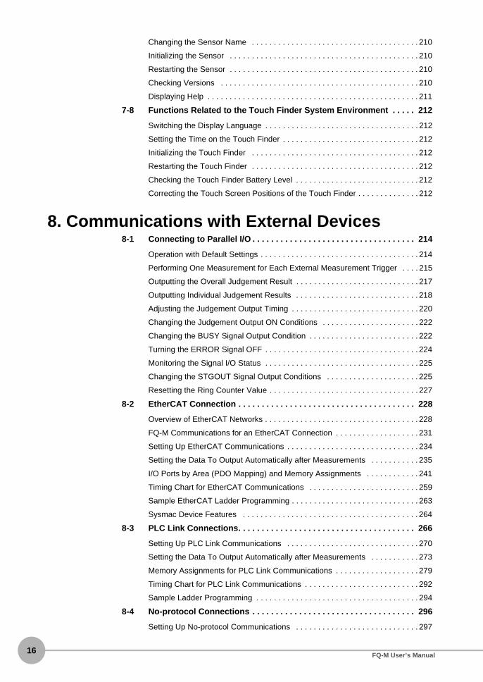
8. Communications with External Devices8-1 Connecting to Parallel I/O . . . . . . . . . . . . . . . . . . . . . . . . . . . . . . . . . . . 214
Operation with Default Settings . . . . . . . . . . . . . . . . . . . . . . . . . . . . . . . . . . . . 214
Performing One Measurement for Each External Measurement Trigger . . . . 215
Outputting the Overall Judgement Result . . . . . . . . . . . . . . . . . . . . . . . . . . . . 217
Outputting Individual Judgement Results . . . . . . . . . . . . . . . . . . . . . . . . . . . . 218
Adjusting the Judgement Output Timing . . . . . . . . . . . . . . . . . . . . . . . . . . . . . 220
Changing the Judgement Output ON Conditions . . . . . . . . . . . . . . . . . . . . . . 222
Changing the BUSY Signal Output Condition . . . . . . . . . . . . . . . . . . . . . . . . . 222
Turning the ERROR Signal OFF . . . . . . . . . . . . . . . . . . . . . . . . . . . . . . . . . . . 224
Monitoring the Signal I/O Status . . . . . . . . . . . . . . . . . . . . . . . . . . . . . . . . . . . 225
Changing the STGOUT Signal Output Conditions . . . . . . . . . . . . . . . . . . . . . 225
Resetting the Ring Counter Value . . . . . . . . . . . . . . . . . . . . . . . . . . . . . . . . . . 227
8-2 EtherCAT Connection . . . . . . . . . . . . . . . . . . . . . . . . . . . . . . . . . . . . . . 228
Overview of EtherCAT Networks . . . . . . . . . . . . . . . . . . . . . . . . . . . . . . . . . . . 228
FQ-M Communications for an EtherCAT Connection . . . . . . . . . . . . . . . . . . . 231
Setting Up EtherCAT Communications . . . . . . . . . . . . . . . . . . . . . . . . . . . . . . 234
Setting the Data To Output Automatically after Measurements . . . . . . . . . . . 235
I/O Ports by Area (PDO Mapping) and Memory Assignments . . . . . . . . . . . . 241
Timing Chart for EtherCAT Communications . . . . . . . . . . . . . . . . . . . . . . . . . 259
Sample EtherCAT Ladder Programming . . . . . . . . . . . . . . . . . . . . . . . . . . . . . 263
Sysmac Device Features . . . . . . . . . . . . . . . . . . . . . . . . . . . . . . . . . . . . . . . . 264
8-3 PLC Link Connections. . . . . . . . . . . . . . . . . . . . . . . . . . . . . . . . . . . . . . 266
Setting Up PLC Link Communications . . . . . . . . . . . . . . . . . . . . . . . . . . . . . . 270
Setting the Data To Output Automatically after Measurements . . . . . . . . . . . 273
Memory Assignments for PLC Link Communications . . . . . . . . . . . . . . . . . . . 279
Timing Chart for PLC Link Communications . . . . . . . . . . . . . . . . . . . . . . . . . . 292
Sample Ladder Programming . . . . . . . . . . . . . . . . . . . . . . . . . . . . . . . . . . . . . 294
8-4 No-protocol Connections . . . . . . . . . . . . . . . . . . . . . . . . . . . . . . . . . . . 296
Setting Up No-protocol Communications . . . . . . . . . . . . . . . . . . . . . . . . . . . . 297
FQ-M User’s Manual

Setting the Data To Output Automatically after Measurements . . . . . . . . . . . 299
Controlling the Sensor from an External Device (Procedure for No-protocol Com-mand/Response Communications) . . . . . . . . . . . . . . . . . . . . . . . . . . . . . . . . . 305
8-5 Connecting with the Programmable No-protocol Communications. 325
Setting Up Programmable No-protocol Communications . . . . . . . . . . . . . . . . 326
Setting the Data To Output Automatically after Measurements . . . . . . . . . . . 329
8-6 Using the Encoder Input . . . . . . . . . . . . . . . . . . . . . . . . . . . . . . . . . . . . 339
Controlling Measurement Timing with an Encoder Input . . . . . . . . . . . . . . . . . 340
Enabling Synchronized Control by Outputting the Encoder Value . . . . . . . . . 343
9. Calibration9-1 Calibration . . . . . . . . . . . . . . . . . . . . . . . . . . . . . . . . . . . . . . . . . . . . . . . 346
9-2 Calibration for Conveyor Tracking. . . . . . . . . . . . . . . . . . . . . . . . . . . . 347
Batch Sampling Calibration . . . . . . . . . . . . . . . . . . . . . . . . . . . . . . . . . . . . . . . 348
Point Specification Calibration . . . . . . . . . . . . . . . . . . . . . . . . . . . . . . . . . . . . . 353
9-3 General-purpose Calibration . . . . . . . . . . . . . . . . . . . . . . . . . . . . . . . . 356
General-purpose Calibration . . . . . . . . . . . . . . . . . . . . . . . . . . . . . . . . . . . . . . 356
9-4 Direct Input . . . . . . . . . . . . . . . . . . . . . . . . . . . . . . . . . . . . . . . . . . . . . . . 368
10. Offline Settings10-1 Offline Setup. . . . . . . . . . . . . . . . . . . . . . . . . . . . . . . . . . . . . . . . . . . . . . 372
10-2 Starting a Project in Offline Mode . . . . . . . . . . . . . . . . . . . . . . . . . . . . 373
10-3 Changing between Online and Offline . . . . . . . . . . . . . . . . . . . . . . . . . 374
10-4 Offline Simulation of Sensor Measurement Operations . . . . . . . . . . 375
10-5 Offline Debugging of the Sensor Control Program and Sensor Operation . . . . . . . . . . . . . . . . . . . . . . . . . . . . . . . . . . . . . . . . . . . . . . . . 376
11. Troubleshooting11-1 Error Histories . . . . . . . . . . . . . . . . . . . . . . . . . . . . . . . . . . . . . . . . . . . . 382
EtherCAT Connection (Sysmac Error Status) . . . . . . . . . . . . . . . . . . . . . . . . . 382
Errors for Ethernet (No-protocol or PLC Link) Connections . . . . . . . . . . . . . . 388
11-2 Error Messages . . . . . . . . . . . . . . . . . . . . . . . . . . . . . . . . . . . . . . . . . . . 390
11-3 Basic Troubleshooting . . . . . . . . . . . . . . . . . . . . . . . . . . . . . . . . . . . . . 391
12. Appendices12-1 Function List . . . . . . . . . . . . . . . . . . . . . . . . . . . . . . . . . . . . . . . . . . . . . 394
12-2 External Reference Parameters . . . . . . . . . . . . . . . . . . . . . . . . . . . . . . 412
Search . . . . . . . . . . . . . . . . . . . . . . . . . . . . . . . . . . . . . . . . . . . . . . . . . . . . . . . 412
Edge Position . . . . . . . . . . . . . . . . . . . . . . . . . . . . . . . . . . . . . . . . . . . . . . . . . 416
Labeling . . . . . . . . . . . . . . . . . . . . . . . . . . . . . . . . . . . . . . . . . . . . . . . . . . . . . . 418
Shape Search . . . . . . . . . . . . . . . . . . . . . . . . . . . . . . . . . . . . . . . . . . . . . . . . . 422
FQ-M User’s Manual17

18
Calculations . . . . . . . . . . . . . . . . . . . . . . . . . . . . . . . . . . . . . . . . . . . . . . . . . . . 426
12-3 Specifications and Dimensions . . . . . . . . . . . . . . . . . . . . . . . . . . . . . . 428
Vision Sensors . . . . . . . . . . . . . . . . . . . . . . . . . . . . . . . . . . . . . . . . . . . . . . . . 428
EtherCAT Communications Specifications . . . . . . . . . . . . . . . . . . . . . . . . . . . 434
Touch Finders . . . . . . . . . . . . . . . . . . . . . . . . . . . . . . . . . . . . . . . . . . . . . . . . . 435
Sysmac Studio . . . . . . . . . . . . . . . . . . . . . . . . . . . . . . . . . . . . . . . . . . . . . . . . 439
Options . . . . . . . . . . . . . . . . . . . . . . . . . . . . . . . . . . . . . . . . . . . . . . . . . . . . . . 440
12-4 Upgrading Sensor and Touch Finder Firmware . . . . . . . . . . . . . . . . . 446
12-5 Object Dictionary . . . . . . . . . . . . . . . . . . . . . . . . . . . . . . . . . . . . . . . . . . 447
Object Dictionary Area . . . . . . . . . . . . . . . . . . . . . . . . . . . . . . . . . . . . . . . . . . 447
Data Types . . . . . . . . . . . . . . . . . . . . . . . . . . . . . . . . . . . . . . . . . . . . . . . . . . . 447
Object Description Format . . . . . . . . . . . . . . . . . . . . . . . . . . . . . . . . . . . . . . . . 448
Communication Objects . . . . . . . . . . . . . . . . . . . . . . . . . . . . . . . . . . . . . . . . . 449
PDO Mapping Object . . . . . . . . . . . . . . . . . . . . . . . . . . . . . . . . . . . . . . . . . . . 451
Sync Manager Communication Object . . . . . . . . . . . . . . . . . . . . . . . . . . . . . . 454
Manufacturer Specific Objects . . . . . . . . . . . . . . . . . . . . . . . . . . . . . . . . . . . . 457
Index . . . . . . . . . . . . . . . . . . . . . . . . . . . . . . . . . . . . . . . . . . . . . . . . . . . . 462
Revision History. . . . . . . . . . . . . . . . . . . . . . . . . . . . . . . . . . . . . . . . . . . 465
FQ-M User’s Manual
1Introduction
Introduction
1-1 FQ-M-series Vision Sensors . . . . . . . . . . . . . . . . . . . . . . . . . . . . . . . . .20
1-2 Measurement Process . . . . . . . . . . . . . . . . . . . . . . . . . . . . . . . . . . . . . .22
1-3 Basic Operational Flow . . . . . . . . . . . . . . . . . . . . . . . . . . . . . . . . . . . . .23

20
1-1 FQ-M-series Vision Sensors
The FQ-M Series is a series of Vision Sensors that are designed to be integrated with high-speed positioningequipment. To set up or monitor a Sensor, you can use either the Touch Finder or the computer-based PC Tool.
Sensor Models
There are four different models of FQ-M-series Vision Sensors. The differences are given in the following table.
Model FQ-MS@@@-M FQ-MS@@@-M-ECT FQ-MS@@@ FQ-MS@@@-ECT
Type Monochrome Color
I/O specifications EtherCAT not supported. EtherCAT supported. EtherCAT not supported. EtherCAT supported.
PC Tool
Touch Finder
Setup, Image Confirmation, and Logging Tools
Vision SensorThe PC Tool is used to perform initial setup of the Sensor and for system design.You can operate FQ-M series Vision Sensors from the integrated Sysmac development environment that is provided by the Sysmac Studio Automation Software.
The Touch Finder is a special user interface that allows you to easily check the operating status of the Sensor and adjust settings after you have constructed the system.
The Sensor includes a camera, measurement processor, and I/O.After the Sensor has been set up, it can be operated alone to perform measurements without the Touch Finder or PC Tool.
The PC Tool and Touch Finder are used to check images and set the judgement parameters.These are also used to save measurement results and check status during operation.
FQ-M-series Vision Sensors FQ-M User’s Manual

1Introduction
Differences between the PC Tool and Touch Finder
The PC Tool (provided in the Sysmac Studio package) and the Touch Finder are different primarily in thefollowing ways.
Item Description Sysmac Stu-dio (Standard Edition)
Sysmac Stu-dio (Vision Edi-tion)
Touch Finder
Offline simulation
Offline Settings p. 371
Simulation is performed with images saved in the PC Tool without a con-nection to the Sensor.
Supported. Supported. Not sup-ported.
Debugging the Sensor control program and Sen-sor operation offline
Offline Debugging of the Sensor Control Program and Sensor Operation p. 376
The linked operation of the sequence control of the NJ-series Controller and the operation of the FQ-M Sensor is checked offline.
Supported. Not sup-ported.
Not sup-ported.
Calibration settings
Calibration p. 345
Calibration settings are made for the Sensor.
Supported. Supported. Not sup-ported.
Customized output settings
Connecting with the Programmable No-protocol Communications p. 329
Customized settings are made for data output.
Supported. Supported. Not sup-ported.
Simultaneous monitoring of multiple Sensors
Selecting a Sensor for Configuration p. 66
You can simultaneously monitor images from more than one Sensor.
Not sup-ported.
Not sup-ported.
Supported.
Monitoring logging
Checking the Results of Recent Loggingp. 200
You can display graphs of the most recent data that was logged in the Sensor.
Not sup-ported.
Not sup-ported.
Supported.
Monitoring trends
Arranging the Trend Monitor Display p. 173
You can simultaneously display up to three types of data on graphs.
Supported. Supported. Not sup-ported.
FQ-M-series Vision SensorsFQ-M User’s Manual21

22
1-2 Measurement Process
This section describes the basic flow of the measurement process.
• The measurements are started for an encoder input or a signal from an exter-
nal device.
• Images are taken according to the trigger.
• The image is measured using inspection items.
• You can also perform calculations based on the measurement results from
inspection items.
• The overall judgement of all inspection items are output using OR logic.
• Detailed measurement results for each inspection item can be output via
Ethernet or EtherCAT.
• Measurement data and image data can be logged in memory in the Sensor,
with the PC Tool, or on an SD card (if using the Touch Finder).
Trigger input
Take image
Measurement
Output
Logging
Measurement Process FQ-M User’s Manual

1-3 Basic Operational Flow
1Introduction
The following flow shows the basic operation of FQ-M-series Vision Sensors.
*1: In Setup Mode, the Sensor can be set up and adjusted, but it does not output signals on the I/O lines.*2: In Run Mode, the Sensor performs measurements and outputs signals on the I/O lines.
With FQ-M-series Vision Sensors, you can change settings offline without connecting to the Vision Sensor.
Section 10 Offline Settings
Calibration Settings ([Calibration])
Image Setup ([Image])
Calculation Settings ([Calculation])
Output Settings ([Output])
Registering inspection items
Teaching
Setting judgement parameters
Starting the Sensor
Connections and Wiring
Adjustments
Test measurements and results verification
Saving the settings
Setup*1
Operation*2 Starting Operation (Run Mode)
Inspection Settings ([Inspect])
Section 2 Installation and Connections
Section 2 Installation and Connections2-6 Starting a Project
Section 3 Taking Images
Section 4 Setting Up Inspections
Section 8 Communications with External Devices
Section 5 Testing and Saving Settings
Section 6 Operation
Section 9 Calibration
Section 4 Setting Up Inspections4-8 Calculations and Judgements Using Inspection Item Data
Note
Basic Operational FlowFQ-M User’s Manual23

24
MEMO
Basic Operational Flow FQ-M User’s Manual

2
Installation and Connections
Installation and Connections
2-1 System Configuration . . . . . . . . . . . . . . . . . . . . . . . . . . . . . . . . . . . . . . 26
2-2 Part Names and Functions . . . . . . . . . . . . . . . . . . . . . . . . . . . . . . . . . . 29
2-3 Installation . . . . . . . . . . . . . . . . . . . . . . . . . . . . . . . . . . . . . . . . . . . . . . . 32
2-4 Wiring . . . . . . . . . . . . . . . . . . . . . . . . . . . . . . . . . . . . . . . . . . . . . . . . . . . 40
2-5 Installing the Sysmac Studio. . . . . . . . . . . . . . . . . . . . . . . . . . . . . . . . . 48
2-6 Starting a Project . . . . . . . . . . . . . . . . . . . . . . . . . . . . . . . . . . . . . . . . . . 49
2-7 The User Interface . . . . . . . . . . . . . . . . . . . . . . . . . . . . . . . . . . . . . . . . . 52
2-8 Saving a Project . . . . . . . . . . . . . . . . . . . . . . . . . . . . . . . . . . . . . . . . . . . 59

26
2-1 System Configuration
System Configuration
No-protocol Ethernet and PLC Link Connections
I/O Cable
Touch Finder *Sysmac Studio *Vision Edition
FQ-MS@@@-ECTFQ-MS@@@-M-ECT
FL-TCC1 Lighting Controller
External Lighting(FL Series)
Programmable Controller with CJ2 CPU Unit
Robot Controller
Control PLC, Robot Controller, or Motion Controller
* The Sysmac Studio and Touch Finder cannot be used at the same time. If both are used at the same time, the Sysmac Studio takes priority.
EtherCAT ConnectionsEtherCAT Master
General-purpose Ethernet Cable
Touch Finder *
Sysmac Studio *Standard Edition Vision Edition
Special Ethernet Cable (M12/M12)
Special EtherCAT Cable (M12/RJ45)
I/O control PLCIncremental rotary encoder
Trigger input sensor
24-V power supply
FL-STCLighting Controller
FL-TCC1 Lighting ControllerExternal Lighting
(FL Series)
Programmable Controller with CJ2 CPU Unit
CJ1W-NC@82 Position Control Unit
+NJ-series Machine Automation Controller
I/O Cable
FQ-MS@@@-ECT or FQ-MS@@@-M-ECT (with built-in EtherCAT slave)
Special Ethernet Cable (M12/RJ45)
Special Ethernet Cable (M12/RJ45)
* The Sysmac Studio and Touch Finder cannot be used at the same time. If both are used at the same time, the Sysmac Studio takes priority.
General-purpose Ethernet Cable
Special Ethernet Cable (RJ45/M12)
General-purpose Ethernet Cable
Special Ethernet Cable (RJ45/M12)
24-V power supply
I/O control PLCIncremental rotary encoder
Trigger input sensor
FL-STCLighting Controller
Other EtherCAT slaves
Industrial EtherNet/IP/Ethernet Switching Hub
Industrial EtherNet/IP/Ethernet Switching Hub
System Configuration FQ-M User’s Manual

2Installation and C
onnections
Connection Compatibility
• EtherCAT and Ethernet (PLC Link) connections cannot be used at the same time.
• When the FQ-M is connected via EtherCAT, you cannot set up or adjust the FQ-M through an NJ-seriesController (route 1 in the figure). To use the Sysmac Studio Standard Edition to set up and adjust the FQ-Mwhile setting up and adjusting an NJ-series Controller, connect the computer to the FQ-M through Ethernet(route 2 in the figure). Up to eight FQ-M Vision Sensors can be connected with EtherCAT.
Connected to FQ-M
Other connection
EtherCAT Ethernet (PLC Link)
Ethernet (no-pro-tocol)
Ethernet (Robot Controller proto-col)
I/O Cable
EtherCAT --- Not compatible Compatible Compatible Compatible
Ethernet (PLC Link)
Not compatible --- Not compatible Not compatible Compatible
Ethernet (no-pro-tocol)
Compatible Not compatible --- --- Compatible
Ethernet (program-mable no-protocol)
Compatible Not compatible --- --- Compatible
Switching Hub
Multiple Sensors Connected
General-purpose Ethernet cable
Touch Finder or PC Tool
Special Ethernet Cable
FQ-M Vision Sensors (2 max.)
Important
FQ-M Vision SensorPC Tool(Sysmac Studio)
USB or Ethernet (1)
Ethernet (2)EtherCAT
NJ-series Controller
System ConfigurationFQ-M User’s Manual27

28
*1: The shape and dimensions of the Ethernet connector plug and jack are specified in ISO/IEC 8877:1992 (JIS X 5110:1996) and RJ-45 of the FCC regulations. To prevent connector connection failures, the structure of the jack of this product does not allow insertion of plugs that do not comply with the standard. If a commercially available plug cannot be inserted, it is likely that the plug is non-compliant.
Do not connect network devices other than PLCs or Robot Controllers on the same network as the Touch Finder orcomputer. If another device is connected, the responsiveness of displays and settings of the Touch Finder or computermay be slow.
Product Model Application
Vision Sensor FQ-MS@@@@@@@@ This Vision Sensor performs measurements.
Touch Finder FQ-MD@@ This is a setup console for setting up the Sensor and checking images.
PC Tool Sysmac Studio Stan-dard Edition• SYSMAC-SE200D
(no licenses included (media only))
• SYSMAC-SE201L (1-license edition)
• SYSMAC-SE203L/210L/230L/250L (multilicense edi-tions (3, 10, 30, or 50 licenses))
Sysmac Studio Vision Edition• SYSMAC-VE001L
(1-license edition)
This is the setup application. It is part of the Sysmac Studio Pack-age and it runs on Windows.The Sysmac Studio comes in two different editions.• Sysmac Studio Standard Edition
The Sysmac Studio provides an integrated development environ-ment for the NJ-series Controllers and other Machine Automation Controllers and EtherCAT Slaves. It supports setup, program-ming, debugging, operation, and maintenance.The Sysmac Studio Standard Edition DVD includes Support Soft-ware for EtherNet/IP, DeviceNet, serial communications, and PT screen design (CX-Designer). Refer to the Sysmac catalog (Cat. No. P072) for details.
• Sysmac Studio Vision EditionThis license provides the functions that are required to set up FQ-M Vision Sensors from the Sysmac Studio. This model number is for the license only. You must also purchase the DVD for the Sys-mac Studio Standard Edition.
Special Ethernet Cable FQ-MWN@@@ This cable connects the Sensor to external devices, such as the Touch Finder, computers, and PLCs.
Special EtherCAT Cable FQ-MWNE@@@ The Special EtherCAT Cable connects the Sensor to another Sen-sor or to another EtherCAT device.
General-purpose Ether-net cable*1
--- This cable connects the Switching Hub to the Touch Finder, comput-ers, and PLCs. Use a connector that complies with the FCC RJ45 standard. (STP (shielded twisted-pair) cable, category 5e or 6, impedance: 100 Ω)
I/O Cable FQ-MWD@@@ The I/O Cable connects the Sensor to external devices such as the power supply, encoder, and trigger input sensor.
Switching Hub W4S1-0@@ The Switching Hub connects multiple Sensors to one Touch Finder or one computer running PC Tool.
Encoder --- The encoder enables you to use an encoder counter to activate trig-gers for the Sensor or to attach an encoder counter to measure-ment results for outputs.
PLC --- The PLC sends control commands to control the Sensor or to store specified data. However, the following restrictions apply for some connection methods.• EtherCAT connection: Compatible with NJ-series Controllers
only.• Ethernet (PLC Link): Not compatible with NJ-series Controllers.
Robot Controller --- The Robot Controller is used to receive measurement results or encoder information from the Sensor. You can change the format of the Robot Controller data output as required.
Important
System Configuration FQ-M User’s Manual

2-2 Part Names and Functions
2Installation and C
onnections
Vision Sensor
*1: Applicable models: FQ-MS@@@-ECT and FQ-MS@@@-M-ECT.
No. Name Description
(1) I/O connector An I/O Cable is used to connect the Sensor to the power supply and external devices.
(2) Ethernet connector An Ethernet cable is used to connect the Sensor to external devices such as PLCs, the Touch Finder, or computers.
(3) Lighting connector This connector is used to connect to external lighting (a Strobe Controller).
(4) EtherCAT input connector*1 This connector is used to connect to EtherCAT-compatible devices.
(5) EtherCAT output connector*1 This connector is used to connect to EtherCAT-compatible devices.
(6) Node address setting switches*1 These switches are used to set the node address as an EtherCAT communications device. The setting range is 00 to 99.
(7) Mounting holes These mounting holes are used to mount the camera.
12-3 Specifications and Dimensions p. 428
(8) C-mount lens fitting The C-mount lens is attached here. Determine the appropriate CCTV lens (C-mount lens) to use based on the field of view required for the size of the measurement object.
Optical Diagrams p. 33
(9) Strobe Controller mounting holes The Strobe Controller is attached here. The Vision Sensor is compatible with the FL-TCC1.
Strobe Controller Installation Method p. 32
(10) Measurement process opera-tion indicators
OR This indicator lights orange when the OR output signal turns ON.
ETN This indicator lights orange when Ethernet communications are performed.
ERROR This indicator lights red when an error occurs.
11-1 Error Histories p. 382
BUSY This indicator lights green when the Sensor is executing a process.
(11) EtherCAT oper-ation indica-tors*1
ECAT RUN This indicator lights green when EtherCAT communications can be performed.
ECAT ERROR This indicator lights red when an EtherCAT communications error has occurred.
L/A IN This indicator lights green when the Sensor is connected to an EtherCAT device. It flashes green during data input communications.
L/A OUT This indicator lights green when the Sensor is connected to an EtherCAT device. It flashes green during data output communications.
(7)
(4)
(8)(9)
(10) (11)
(7)
(1) (3)
(5)
(2)(6)
Part Names and FunctionsFQ-M User’s Manual29
30
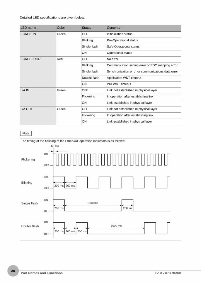
Detailed LED specifications are given below.
LED name Color Status Contents
ECAT RUN Green OFF Initialization status
Blinking Pre-Operational status
Single flash Safe-Operational status
ON Operational status
ECAT ERROR Red OFF No error
Blinking Communication setting error or PDO mapping error
Single flash Synchronization error or communications data error
Double flash Application WDT timeout
ON PDI WDT timeout
L/A IN Green OFF Link not established in physical layer
Flickering In operation after establishing link
ON Link established in physical layer
L/A OUT Green OFF Link not established in physical layer
Flickering In operation after establishing link
ON Link established in physical layer
The timing of the flashing of the EtherCAT operation indicators is as follows:
Note
ON
OFF
ON
OFF
ON
OFF
ON
OFF
Flickering
Blinking
Single flash
Double flash
50 ms
200 ms 200 ms
200 ms 200 ms
1000 ms
200 ms 200 ms 200 ms
1000 ms
Part Names and Functions FQ-M User’s Manual

2Installation and C
onnections
Touch Finder
*1: Applicable to the FQ-MD31 only.
No. Name Description
(1) Operation indicators
POWER Lights green when the Touch Finder is turned ON.
ERROR Lights red when an error occurs. 11-1 Error Histories p. 382
SD ACCESS Lights yellow when an SD card is inserted. Flashes yellow when the SD card is being accessed.
CHARGE*1 Lights orange when the Battery is charging.
(2) LCD/touch panel Displays the setting menu, measurement results, and images input by the camera.
(3) SD card slot An SD card can be inserted.
(4) Battery cover*1 The Battery is inserted behind this cover. Remove the cover when mounting or removing the Battery.
(5) Power supply switch Used to turn the Touch Finder ON and OFF.
(6) Touch pen holder The touch pen can be stored here when it is not being used.
(7) Touch pen Used to operate the touch panel.
(8) DC power supply connector Used to connect a DC power supply. p. 45
(9) Slider Used to mount the Touch Finder to a DIN Track.
(10) Ethernet port Used when connecting the Touch Finder to the Sensor with an Ethernet cable. Insert the connector until it locks in place. The indicator will light green when a link is established and flash orange during packet communi-cations.
(11) Strap holder This is a holder for attaching the strap.
(12) AC power supply connector*1 Used to connect the AC adapter.
(5)
(1)
(12)
(2)
(6) (7)
(4)
(3)
(11)
(8)
(9)
(10)
Part Names and FunctionsFQ-M User’s Manual31

32
2-3 Installation
Installing the Sensor
Installation Procedure
Refer to the dimension drawings in the appendix for the positions of the screw holes.
Strobe Controller Installation Method
FL-TCC1 Strobe Controller
1 Mount the Vision Sensor into with M4 screws. You canmount it from either the front or the back.Tightening torque: 1.2 N·mEffective depth of front mounting holes: 7 mmEffective depth of back mounting holes: 8.5 mm
12-3 Specifications and Dimensions p. 428
1 Mount the FL-TCC1 onto the Sensor with the M2 ×6-mm screws enclosed with the FL-TCC1 (tighten-ing torque: 0.15 N·m max.).
Important
Front Installation Back Installation
FL-TCC1
Installation FQ-M User’s Manual

2Installation and C
onnections
Lens Selection
Use the following optical diagrams to determine the Lens, camera installation distance, and detection range.
Optical Diagrams
The following values are estimates only. Adjustment is required after installing the camera.
Y axis of field of view (mm)
Cam
era
inst
alla
tion
dist
ance
(m
m)
t: Macro ring
Examplest0: Macro ring is not
required.t5: A 5-mm macro
ring is required.
t5
t15 t0
t5
t0
t0
t2
10
100
1,000
10,000
1,000100101
t50
SV-0614V
3Z4S-LE
SV-0813V
SV-1214V
SV-1614V
SV-2514V
SV-3518V
SV-5018V
SV-7527V
SV-10035Vt40 t30
t1
t0.5
t0
t0
t0
t5
t10t10
t15t20
t20t25
t25t30
t30t40
t40t50
t50
t0
t2
t5
t10
t40 t25t30 t20
t15
t0
t0t2 t1
t2
t5t10
t25 t20 t15
t25 t20
t15t10
t5
t2
t1
t1
t1 t0.5
InstallationFQ-M User’s Manual33

34
The X axis in the above optical diagrams represent field of view (mm)*1. The Y axis represents the camerainstallation distance (mm) or WD (mm)*2. These optical diagrams show the relationship between the detectionrange and installation distance for different CCTV Lenses. The values vary for each Lens. Pay close attentionto the Lens that you are using when you refer to these optical diagrams. The macro ring thickness to be used isgiven as, for example “t5.0,” on the graphs. “t0” means that a macro ring is not required. “t5.0” means that youmust use a 5-mm macro ring.
Lens Models and Dimensions
Lens model Focal length Brightness Maximum out-side diameter
Total length Filter size
3Z4S-LE SV-0614V 6.20 mm F1.4 29 mm 30.0 mm M27 P0.5
3Z4S-LE SV-0813V 8.05 mm F1.3 28 mm 34.0 mm M25.5 P0.5
3Z4S-LE SV-1214V 12.43 mm F1.4 29 mm 29.5 mm M27 P0.5
3Z4S-LE SV-1614V 16.34 mm F1.4 29 mm 24.0 mm M27 P0.5
3Z4S-LE SV-2514V 25.17 mm F1.4 29 mm 24.5 mm M27 P0.5
3Z4S-LE SV-3518V 34.75 mm F1.8 29 mm 33.5 mm M27 P0.5
3Z4S-LE SV-5018V 47.97 mm F1.8 32 mm 37.0 mm M30.5 P0.5
3Z4S-LE SV-7527V 76.71 mm F2.7 32 mm 42.0 mm M30.5 P0.5
3Z4S-LE SV-10035V 95.4 mm F3.5 32 mm 43.9 mm M30.5 P0.5
Field of viewY
X
*1: The Y axis in the optical charts represents the height of the field of view.*2: The Y axis of the Compact Camera represents the WD.
WD (mm)
Macro ring t@ (mm)
Camera
Lens
Measurement object
Camera installation distance (mm)
Field of view (mm)
Example: If you use a 3Z4S-LE SV-1614V CCTV Lens for a measurement object that requires field of view of 50 mm, the camera installation distance must be 300 mm and a 1-mm macro ring is required.
Maximum outside diameter
1-32 UNF (C-mount threads)
Filter threads
Total length
Installation FQ-M User’s Manual

2Installation and C
onnections
Macro Rings
Macro rings are inserted between the Lens and the camera to adjust the focus. You can use up to seven macrorings to achieve the required thickness.
• Do not stack 0.5 mm, 1.0 mm, and 2.0 mm macro rings. These sizes fit between the Lens and the threaded portion
of other macro rings. If two or more are stacked together, the screw cannot be tightened securely.
• The macro rings may need to be reinforced depending on the vibration conditions if over 30 mm is used.
Model Maximum out-side diameter
Thickness
3Z4S-LE SV-EXR 31 mm 7-piece set
Macro Ring
40 mm
40m
m
20 mm
20m
m
10 mm
10m
m
5 mm2 mm1 mmThickness: 0.5 mm
Important
InstallationFQ-M User’s Manual35
36
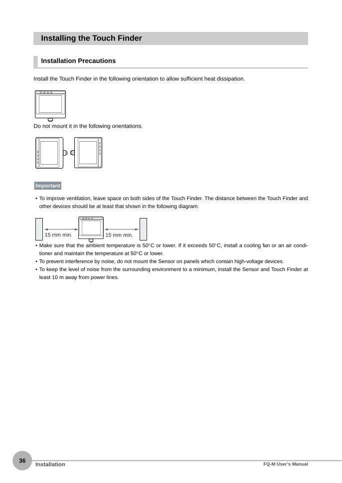
Installing the Touch Finder
Installation Precautions
Install the Touch Finder in the following orientation to allow sufficient heat dissipation.
Do not mount it in the following orientations.
• To improve ventilation, leave space on both sides of the Touch Finder. The distance between the Touch Finder and
other devices should be at least that shown in the following diagram.
• Make sure that the ambient temperature is 50°C or lower. If it exceeds 50°C, install a cooling fan or an air condi-
tioner and maintain the temperature at 50°C or lower.
• To prevent interference by noise, do not mount the Sensor on panels which contain high-voltage devices.
• To keep the level of noise from the surrounding environment to a minimum, install the Sensor and Touch Finder at
least 10 m away from power lines.
Important
15 mm min. 15 mm min.
Installation FQ-M User’s Manual

2Installation and C
onnections
Mounting to DIN Track
Installation Procedure
• Attach End Plates (sold separately) on the sides of the Touch Finder on the DIN Track.
• If other devices will be installed next to the Touch Finder on the same DIN Track, make sure that sufficient space is
kept between the devices as indicated on previous page.
• Always hook the clip at the top of the Touch Finder on the DIN Track first. If the lower clip is hooked on first, the
Touch Finder will not be mounted very securely.
Removal Procedure
Mounting to a Control Panel
The Touch Finder can be mounted on a panel using the FQ-XPM Panel Mounting Adapter.
• Always turn OFF the Touch Finder power before attaching or detaching the Panel Mount Adapter. Attaching or
detaching with the power turned ON may cause a failure.
1 Press the slider on the Touch Finder to the top.
2 Hook the clip at the top of the Touch Finder on to the DINTrack.
3 Press the Touch Finder onto the DIN Track until the bottomclip clicks into place.
1 Pull down on the slider on the Touch Finder.
2 Lift the Touch Finder at the bottom and remove it from theDIN Track.
1 Set the Touch Finder in the Panel Mount Adapter.
1
2
3
3
Important
2 1
Important
InstallationFQ-M User’s Manual37

38
Using the Touch Finder as a Portable Device (with Battery)
The Touch Finder with a Battery can be used as a portable device. Use the strap when carrying it to preventdropping it.
There are two types of straps (FQ-XH, sold separately), a Neck Strap and a Hand Strap.
1 Attach the Mini-strap to the Touch Finder.There are a total of four holes for attaching the Mini-strap on the left and on the right of the Touch Finder.
2 Press the slider up on the Touch Finder.
3 Create holes in the panel for mounting.Refer to the following page for hole dimensions.
p. 438
4 Connect the cable to the Touch Finder.
5 Mount the Touch Finder with the Panel Mount Adapter fromthe front of the panel.
6 Hook the hooks on the Mounting Bracket in the four holesof the Panel Mount Adapter and secure them with screws.(Tightening torque: 1.2 N·m)
7 Check that the Touch Finder is attached properly to thePanel.
Mounting Bracket
Hand StrapNeck Strap
Installation FQ-M User’s Manual

2Installation and C
onnections
2 Connect the Neck Strap or Hand Strap to the Mini-strap.
Mini-strap Neck Strap or Hand Strap
InstallationFQ-M User’s Manual39

40
2-4 Wiring
Wiring the Sensor
Connect and secure the I/O Cable to the I/O Cable connector located at the bottom of the Vision Sensor. Wirethe I/O Cable signals.
Cut off lines that are not required so that they do not come into contact with the other signal lines.
Classifi-cation
Signal Application
Power supply
Power supply (24 V)
These terminals are for the external power supply (24 V).
Wire the power supply separately from other devices. If the wiring for other devices is placed together or in the same duct as the wiring for the Vision Sensor, the influences of electromagnetic induction may cause the Sensor to malfunction or may damage it.
GND
VDD ENCODER These terminals are for the encoder power supply.Connect these terminals to the same power supply as the encoder (5 V, 12 V, or 24 V).GND ENCODER
Inputs TRIG This terminal is the trigger signal input.
ERROR CLR This terminal is the clear error input.
EFC RST This terminal is the encoder ring counter reset input.
COM_I This is the common terminal for the TRIG, ERROR_CLR, and EFC_RST signals.
Encoder inputs
ENCODER (A±, B±, Z±)
These terminals are for the encoder inputs.
Shield wire
SHIELD ENCODER
This is the shield wire for encoder signals. Connect the shield wire to the GND ENCODER ground wire for the encoder power supply.
Brown 24 VBlue GNDBrown/White VDD ENCODERBlue/White GND ENCODERPink TRIGRed/White ERROR CLRGreen/White EFC RSTPurple/White COM_IPurple ENCODER (A−)Gray ENCODER (A+)Green ENCODER (B−)White ENCODER (B+)Red ENCODER (Z−)Yellow ENCODER (Z+)Green/Yellow SHIELD ENCODERBlack OUT0 (OR)Orange OUT1 (BUSY)Light blue OUT2 (ERROR)Yellow-Green OUT3 (SHTOUT)Beige OUT4 (STGOUT)Black/White COM_O
FQ-MWD@@@/FQ-MWDL@@@I/O Cable
Important
Important
Wiring FQ-M User’s Manual

2Installation and C
onnections
*1: This signal is output to an external device when exposure of the imaging elements is completed. If you want to move the Sensor to the next measurement location after a measurement is completed, move the Sensor only after this signal turns ON.
Shutter Output Signal (SHTOUT)
*2: This control signal is used to turn ON external lighting when an image is taken. Connect this signal to external lighting.*3: You can select whether to turn the external lighting ON (Positive) or OFF (Negative) when the signal turns ON. (The setting is called the
strobe output polarity.)
Changing the Output Polarity of the STGOUT Signal p. 225
Outputs OUT0(OR) This is an output terminal. By default, this is the OR output signal (overall judgement).The assignment can be changed to an individual judgement signal between OR0 and OR31.
OUT1(BUSY) This is an output terminal. By default, this is the BUSY output signal.The assignment can be changed to an individual judgement signal between OR0 and OR31.
OUT2(ERROR) This is an output terminal. By default, this is the ERROR output signal.The assignment can be changed to an individual judgement signal between OR0 and OR31.
OUT3(SHTOUT) This is an output terminal. By default, this is the SHTOUT output signal (shutter output).*1
The assignment can be changed to an individual judgement signal between OR0 and OR31.
OUT4(STGOUT) This is an output terminal. By default, this is the STGOUT output signal (strobe trigger output).*2*3
The assignment can be changed to an individual judgement signal between OR0 and OR31.
COM_O This is the common terminal for the OUT0 to OUT4 output signals.
The assignments of I/O signals can be changed. Communications with External Devices p. 213
Classifi-cation
Signal Application
Trigger input (TRIG)
Shutter timeImaging element shutter signal
SHTOUT
10 ms
Trigger delayON
OFF
ON
OFF
ON
OFF
The SHTOUT signal turns ON for approximately 10 ms (fixed) when the shutter time (exposure period) elapses after the trigger is input from an external device.
Note
WiringFQ-M User’s Manual41
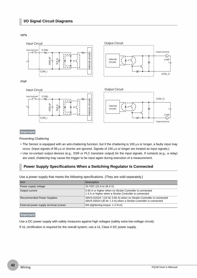
42
I/O Signal Circuit Diagrams
Preventing Chattering
• The Sensor is equipped with an anti-chattering function, but if the chattering is 100 μs or longer, a faulty input may
occur. (Input signals of 99 μs or shorter are ignored. Signals of 100 μs or longer are treated as input signals.)
• Use no-contact output devices (e.g., SSR or PLC transistor output) for the input signals. If contacts (e.g., a relay)
are used, chattering may cause the trigger to be input again during execution of a measurement.
Power Supply Specifications When a Switching Regulator Is Connected
Use a power supply that meets the following specifications. (They are sold separately.)
Use a DC power supply with safety measures against high voltages (safety extra low-voltage circuit).
If UL certification is required for the overall system, use a UL Class II DC power supply.
NPN
PNP
Item Description
Power supply voltage 24 VDC (21.6 to 26.4 V)
Output current 0.65 A or higher when no Strobe Controller is connected1.3 A or higher when a Strobe Controller is connected
Recommended Power Supplies S8VS-01524@ (15 W, 0.65 A) when no Strobe Controller is connectedS8VS-03024 (30 W, 1.3 A) when a Strobe Controller is connected
External power supply terminal screws M4 (tightening torque: 1.2 N·m)
3.3 KΩ
910
Ω
1000
pF
COM_I
Input terminal
+
Input Circuit
Inte
rnal
circ
uits Output terminal
Load
Output Circuit
L
COM_O
+Internal circuits
3.3 KΩ
910
Ω
1000
pF
COM_I
Input terminal
+
Input CircuitIn
tern
al c
ircui
ts
Output terminal
Load
Output Circuit
L
COM_O
+Internal circuits
Important
Important
Wiring FQ-M User’s Manual

2Installation and C
onnections
Encoder Connection Examples
Encoder power supply (5, 12, or 24 VDC)*1
NPN Open-collector Input
120 Ω*2
120 Ω*2
120 Ω*2
5.1 kΩ
5.1 kΩ
5.1 kΩ
FQ-M
+
Inte
rnal
circ
uits
Brown/White VDD ENCODER
Blue/White GND ENCODER
Green/Yellow SHIELD ENCODER
Gray ENCODER(A+)
Green ENCODER(B−)
White ENCODER(B+)
Red ENCODER(Z−)
Yellow ENCODER(Z+)
Purple ENCODER(A−)
Photocoupler
Photocoupler
PhotocouplerPower supplyPhase
A
Phase B
Phase Z
Open-collector encoder (NPN)
Inpu
t circ
uitIn
put c
ircuit
Inpu
t circ
uit
*1: Connect these wires to the same power supply as the encoder (5, 12, or 24 V).*2: The 120-Ω resistors are used when line driver encoders are connected. Make the
software settings to turn OFF the switches that are connected to the 120-Ω resistors when open-collector encoders are connected.
Photocoupler
Photocoupler
Photocoupler
Encoder power supply (5, 12, or 24 VDC)*1
Power supplyPhase A
Phase B
Phase Z
Brown/White VDD ENCODER
Blue/White GND ENCODER
Green/Yellow SHIELD ENCODER
Gray ENCODER(A+)
Green ENCODER(B−)
White ENCODER(B+)
Red ENCODER(Z−)
Yellow ENCODER(Z+)
Purple ENCODER(A−)120 Ω*2
120 Ω*2
120 Ω*2
5.1 kΩ
5.1 kΩ
5.1 kΩ
FQ-M
Open-collector encoder (PNP)
+
PNP Open-collector Input
Inpu
t circ
uitIn
put c
ircuit
Inpu
t circ
uit
Inte
rnal
circ
uits
*1: Connect these wires to the same power supply as the encoder (5, 12, or 24 V).*2: The 120-Ω resistors are used when line driver encoders are connected. Make the
software settings to turn OFF the switches that are connected to the 120-Ω resistors when open-collector encoders are connected.
Phase A −
Phase A +
Phase B −
Phase B +
Phase Z −
Phase Z +
Encoder power supply (5 VDC)
Brown/White VDD ENCODER
Blue/White GND ENCODER
Green/Yellow SHIELD ENCODER
Gray ENCODER(A+)
Green ENCODER(B−)
White ENCODER(B+)
Red ENCODER(Z−)
Yellow ENCODER(Z+)
Purple ENCODER(A−)Power supply
120 Ω*3
120 Ω*3
120 Ω*3
FQ-M
Line-driver encoder
+Line-driver Input
Photocoupler
Photocoupler
Photocoupler
Inpu
t circ
uitIn
put c
ircuit
Inpu
t circ
uit
Inte
rnal
circ
uits
*3: The 120-Ω resistors are used when line driver encoders are connected. The terminating resistance can be turned ON and OFF from the PC Tool. Turn the terminating resistance ON or OFF according to the application conditions.
Controlling Measurement Timing with an Encoder Input p. 339
WiringFQ-M User’s Manual43
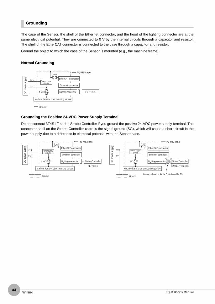
44
Grounding
The case of the Sensor, the shell of the Ethernet connector, and the hood of the lighting connector are at thesame electrical potential. They are connected to 0 V by the internal circuits through a capacitor and resistor.The shell of the EtherCAT connector is connected to the case through a capacitor and resistor.
Ground the object to which the case of the Sensor is mounted (e.g., the machine frame).
Normal Grounding
Grounding the Positive 24-VDC Power Supply Terminal
Do not connect 3Z4S-LT-series Strobe Controller if you ground the positive 24-VDC power supply terminal. Theconnector shell on the Strobe Controller cable is the signal ground (SG), which will cause a short-circuit in thepower supply due to a difference in electrical potential with the Sensor case.
24 V
0 V
1 MΩ
Ground
1 MΩFQ-MS case
EtherCAT connector
Ethernet connector
Machine frame or other mounting surface
FL-TCC1Lighting connectorDC p
ower
sup
ply
Power supply circuits
24 V
0 V
1 MΩ
Ground
1 MΩFQ-MS case
FL-TCC1Machine frame or other mounting surface
3Z4S-LT Series
Connector hood on Strobe Controller cable: SG
24 V
0 V
1 MΩ
Ground
1 MΩFQ-MS case
Machine frame or other mounting surface
EtherCAT connector
Ethernet connector
Strobe ControllerLighting connector
EtherCAT connector
Ethernet connector
Strobe ControllerLighting connectorDC p
ower
sup
ply
DC p
ower
sup
ply
Power supply circuits
Power supply circuits
Wiring FQ-M User’s Manual

2Installation and C
onnections
Wiring the Touch Finder
Power Supply Wiring
Connecting the Power Supply
Turning ON the Touch Finder
Power Supply Specifications
Use a power supply that meets the following specifications. (The power supply is sold separately.)
• Supply power from a DC power supply for which measures have been applied to prevent high voltages (e.g., a
safety extra low voltage circuit).
If UL certification is required for the overall system, use a UL Class II DC power supply.
• When using the FQ-MD31, do not connect a switching regulator and AC Adapter (FQ-AC@) at the same time.
1 Loosen the two terminal screws using a Phillipsscrewdriver.
2 Attach crimp terminals to the power lines.Secure the positive and negative lines as indicatedusing M3 screws.Power supply tightening torque: 0.54 N⋅m
3 In environments where there is excessive noise, at-tach a ferrite core (ZCAT1730-0730 from TDK or the equivalent) to the power supply cable.
1 Remove the cover from the power switch on the left side ofthe Touch Finder.
2 Press the switch toward ON.
Item Description
Power supply voltage 24 VDC (21.6 to 26.4 V)
Output current 0.65 A min.
Recommended Power Supply S8VS-01524@ (24 VDC, 0.65 A)
External power supply terminal screws M4 (tightening torque: 1.2 N⋅m)
Recommended power line wire size AWG16 to AWG22 (length of 5 m max.)
24 VDC
+−
When you attach the ferrite core to the power supply cable, wrap the cable only one time.
1
2
ON
OFF
Important
WiringFQ-M User’s Manual45

46
Charging the Battery
This section describes how to charge and install the FQ-MD31 Battery and provides applicable precautions.
Charge the Battery while it is attached to the Touch Finder.
Use the AC adapter to charge the battery.
Mounting the Battery in the Touch Finder
1 Remove the screw from the battery cover on the top of theTouch Finder, slide the cover in the direction of the arrow,and open the battery cover.
2 Face the rounded side of the battery toward the back of theTouch Finder and insert the battery.
Do not insert the battery in the wrong orientation.
3 Close the battery cover, slide the battery cover in the direc-tion of the arrow, and tighten the screw on the battery cov-er.
4 Attach the AC adapter to the Touch Finder to start changingthe battery.The CHARGE indicator will be lit while the battery is beingcharged. It will go out when charging the battery has been com-pleted.
The Touch Finder will operate even if the AC adapter is connected when no battery is mounted in the Touch Finder.
Important
CHARGE indicator
Note
Wiring FQ-M User’s Manual

2Installation and C
onnections
• If the Touch Finder (FQ-MD31) will be installed permanently or semi-permanently, remove the Battery (FQ-BAT1). If
the rated temperature is exceeded with the Battery inserted, the protective circuit may activate and stop the Touch
Finder.
• The battery complies with the following recycling regulation.
• California regulations concerning perchlorate:
This product is a lithium battery that contains perchlorate, which is regulated by the State of California. Please com-
ply with these regulations. For details see the following URL:
www.dtsc.ca.gov/hazardouswaste/perchlorate/
Important
EU
Li-ion00
Japan Taiwan
WiringFQ-M User’s Manual47

48
2-5 Installing the Sysmac Studio
The PC Tool used to set up FQ-M-series Vision Sensors is installed from the Sysmac Studio Installer. Refer tothe Sysmac Studio Version 1 Operation Manual (Cat. No. W504) for the system requirements and installationprocedure.
Installing the Sysmac Studio FQ-M User’s Manual

2-6 Starting a Project
2Installation and C
onnections
Connecting to the Sensor from the PC Tool
Creating a Project
This section shows how to create a project, add a Vision Sensor to the project, and start communicating withthe Vision Sensor.
1 Start the PC Tool.
2 Create a project.Click [New Project], select [Vision Sensor] for the [Cate-gory] of the [Select Device], and select [FQ-M] for the[Device.]Then enter information for the [Project name], [Author],and [Comment] fields.
Click the [Create] Button. An empty project is created.
3 Use either of the following methods to specify theSensor to connect to.
• Searching for the Sensor to Connect toClick [Search for sensors] and select a Sensor. When youclick the [Execute] Button, a list of all the Sensors foundon the network is displayed. Click the Sensor you want toconnect to, and then click the [OK] Button.
• Directly Enter the IP Address of the Sensor to Connect toSelect the [Specify the IP address] Check Box. Enter theIP address of the Sensor you want to connect to, and thenclick the [OK] Button.
• Not Connecting to a Sensor (Offline Mode)To not connect to an actual Sensor and set up the projectin Offline Mode, click [Enter the type].Select a Sensor model and software version, and thenclick the [OK] Button.
Section 10 Offline Settings p. 371
If you have already created a project, click the [Open Project] But-ton. A list of existing projects is displayed. Select the project youwant to open, and then click the [Open] Button. When you openan existing project, the project will start in Offline Mode. Refer tothe following section for information on Offline Mode.
Section 10 Offline Settings p. 371
Note
Starting a ProjectFQ-M User’s Manual49

50
Adding a Sensor to a Project
After you create a project, you can add Sensors to it.
Multiview Explorer: [Device group] (Right-click) − [Add]
Entering Project Information
You can enter comments related to the project.
Multiview Explorer: [Device group] − Sensor name (Double-click)→ Edit Pane: [General settings] icon
1 Enter comments about the project in the [Comment] field.
4 After connecting to the Sensor, the following pane isdisplayed.If the Sensor Has Not Been Set Up:
• The Edit Scene Pane is displayed for the Edit Pane.The Sensor starts in Setup Mode.
If the Sensor Has Already Been Set Up:
• The Main Pane is displayed for the Edit Pane.The Sensor starts in Run Mode.
When a Sensor is added to the project, a scene (scene 0) is also automatically added.
▲
Note
▲
Starting a Project FQ-M User’s Manual

2Installation and C
onnections
Use the following procedure if you connected to the Sensor from the Touch Finder.
1 The Sensor is automatically detected by the TouchFinder when the power supply to the Sensor andTouch Finder is turned ON.The Auto Connect Display will appear if the Sensor can-not be detected. Check that the cable is connected cor-rectly to the Sensor and Touch Finder, and then press[Auto connect]. If the Sensor is still not detected afteryou press [Auto Connect], refer to the following informa-tion.
The Sensor cannot be detected: p. 391
2 When the Sensor is detected, the following displaywill appear.The Setup Mode will appear if a Sensor that has notbeen set up is connected.
The Run Mode will appear if a Sensor that has alreadybeen set up is connected.
Note
Starting a ProjectFQ-M User’s Manual51

52
2-7 The User Interface
PC Tool
This section describes the names and functions of elements of the Sysmac Studio user interface.
Main Window
No. Name Description
(1) Menu bar This is where the menu for the PC Tool is displayed.
(2) Toolbar This is where the icons for the various tools available in the PC Tool are displayed.
(3) Multiview Explorer The Multiview Explorer displays the data hierarchy of the Sensor in a tree format. You can double-click data items to display the Main Pane, Scene Data Edit Pane, System Data Edit Pane, or Calibration Data Edit Pane for the Edit Pane.
(4) Edit Pane The Edit Pane is used to edit and view the data selected in the Explorer Pane. The Edit Pane primarily consists of images, settings, properties, and guidance.
(5) Toolbox The Toolbox displays a list of all inspection items that you can add to the scene. You can add inspection items to the scene by dragging them with the mouse.
(6) Status bar The status bar displays the status of the setting operation.
(1)(2)
(6)
(3) (5)
(4)
The User Interface FQ-M User’s Manual

2Installation and C
onnections
Explorer Pane
No. Name Description
(1) Sensor model Displays the model of the Vision Sensor. The online/offline status of the Sensor is dis-played after the model number.
(2) Scene group A scene group is a collection of scene data. Up to 32 scene data items can be added to a single scene group.
(3) Scene data Scene data includes image settings, inspection settings, or output settings. The scene data names are also displayed. The number in parenthesis is the scene number.
(4) System data System data is shared by all scenes.
(5) Calibration group A calibration group is a collection of calibration data. Up to four calibration data items can be added to a single calibration group.
(6) Calibration data Calibration data is used to convert the scale of position coordinates that are measured during inspection. Up to four calibration data items can be added.
(1)
(2)
(3)
(4)
(5)
(6)
The User InterfaceFQ-M User’s Manual53

54
Right-click Menus
Tree view item Menu command Description
Device group Add − FQ-M Adds a Sensor to the project
Paste Pastes a copied Sensor into the project.
Rename Renames the device group.
Sensor model Edit Displays the Main Pane for the Edit Pane.
Delete Deletes the Sensor from the project.
Copy Copies the Sensor.
Setup When online, changes the Sensor to Setup Mode.
Run When online, changes the Sensor to Run Mode.
Start monitor Displays the Monitor Pane as a modeless dialog box.
Online Places a Sensor online.
Offline Places a Sensor offline.
Scene group Add − Scene data Adds a new scene to the scene group.
Paste Adds the copied scene to the scene group.
Scene data Edit Displays the Edit Scene Pane for the Edit Pane.
Copy Copies the scene.
Delete Deletes the scene.
Rename Renames the scene.
System data Edit Displays the System Data Edit Pane for the Edit Pane.
Copy Copies the system data.
Paste Overwrites the system data. Before overwriting, a confirmation message (yes/no: default) is displayed.
Calibration group Add − Calibration scene data
Adds new calibration data to the calibration group.
Paste Adds the copied calibration data to the calibration group.
Calibration data Edit Displays the Calibration Data Edit Pane for the Edit Pane.
Copy Copies the calibration data.
Delete Deletes calibration data.
Rename Changes the name of the calibration data.
The User Interface FQ-M User’s Manual

2Installation and C
onnections
Edit Pane
The Edit Pane changes as shown below based on what is selected in the Explorer Pane.
No. Name Description
(1) Menu icons Allows you to change the parameters that are displayed in the Edit Pane.
(2) Image Displays the Sensor image that is being edited. When online, the image from the con-nected Sensor is displayed. When offline, the image from the specified image file is dis-played.
(3) Parameters Allows you to edit the parameters for the selected menu icon. A dialog box is displayed when editing parameters.
(4) Property Displays the details of the parameters.
(5) Guidance Displays a description of the currently selected parameter.
(1) (1)
(1)
(2)
(3) (3)
(3)(3) (2)
(5) (5)
(5)
(4)
(4)(5)
Main Pane Scene Data Edit Pane
System Data Edit Pane Calibration Data Edit Pane
(2)
(4)
The User InterfaceFQ-M User’s Manual55

56
Icons
(1) Menu Icons
Edit Pane Icon Menu command Description
Main Pane General settings Allows you to view Sensor names and project information.
Online Allows you to switch between online and offline and switch run modes. You can also transfer settings data, save settings data, and monitor measurement results.
Error history Allows you to view and clear errors that have occurred in the Sen-sor.
Support software Allows you to initialize or upgrade the Sensor. You can also print the patterns that are used for calibration.You can import, export, and print the project data.
Scene Data Edit Pane Image Allows you to change image conditions, such as the shutter speed, white balance, and external lighting. You can also adjust the timing to take images.
Calibration Allows you to change the scale of position coordinates measured during inspection. You can select from any of the registered calibra-tion patterns.
Inspection Allows you to use the Search, Shape Search, Edge Position, and Labeling inspection items to set up the inspections. Up to 32 inspec-tion items can be registered.
Calculation Allows you to perform calculations using inspection results. You can make up to 32 expressions.
Logging Allows you to set the data to log to the Sensor’s internal memory, the Touch Finder, or external PC memory for each inspection.
Output Allows you to set up the data to output to external devices through Ethernet or EtherCAT, such as PLCs or Robot Controllers.
Run Allows you to save settings data to the Sensor’s internal memory, switch Sensor modes, or monitor measurement results.
System Data Edit Pane Trigger settings Allows you to select the external trigger signal and set the timing.
I/O settings Allows you to set the I/O conditions for parallel I/O.
Encoder settings Allows you to set encoder input conditions, the maximum ring counter value, and offsets. Also allows you to set conditions when using an encoder as a measurement trigger.
Ethernet communica-tion settings
Allows you to change settings related to Ethernet communications. You can set Sensor settings, data output network settings, and out-put conditions.
EtherCAT communica-tion settings
Sets parameters for EtherCAT communications. Allows you to set communications conditions to output data to the EtherCAT master or to control the Sensor from the EtherCAT master.
Log settings Allows you to set execution conditions for statistical data, image data, and measurement data logging.
Sensor settings Allows you to set the scene number when the Sensor starts, change the password, and set up the Adjustment Mode in Run Mode.
The User Interface FQ-M User’s Manual

2Installation and C
onnections
(2) Operation Icons
Icon Name Description
Camera image Displays the image from the Sensor.
Logging image Displays images logged in the Sensor’s internal memory.
Image file Displays the image from the specified file.
Live Starts updating the image on the display.
Freeze Stops updating the image on the display.
Switch to the next image Displays the next image when the image on the display is not being updated and when a logged image or file image is currently displayed.
Switch to the previous image
Displays the previous image when the image on the display is not being updated and when a logged image or file image is currently displayed.
Select the image Selects the image file to display when displaying file images.
Zoom in Enlarges the displayed image.
Zoom out Reduces the displayed image.
Maximum Automatically resizes the displayed image to fit the size of the pane.
Switch the scale display on and off
Displays scale lines on the image.
Set the conditions of the scale display
Allows you to change scale line settings.
Single-view display Changes to a single-view display.
4-view display Changes to a 4-view display (Graphics, Result List, Histogram, and Trend Graph).
Graphics Graphically displays the measurement results of selected inspection items.
Result list Displays a list of all inspection item measurement results.
Trend graph Displays a trend graph.
Histogram Displays a histogram.
Latest result Updates the view after each measurement.
Latest NG Refreshes the display after each NG result.
Start logging Starts logging to a file.
Stop logging Stops logging to a file.
Edit Pane, Dialog Box Monitor Pane
The User InterfaceFQ-M User’s Manual57

58
Touch Finder
Setup Mode
In Setup Mode, you can set the image conditions, judgement parameters, and I/O settings for the Sensor.
Run Mode
In Run Mode, measurements are performed by receiving external signals, such as triggers, and measurementresults are output.
p. 163
The Display Button can be used to switch between the following images.• Live: The live image is displayed.
• Freeze: The image that was taken last is displayed.
• Log: An image saved in internal memory is displayed.
• File: An image saved on an SD card is displayed.
The Touch Finder does not support guide lines or a 4-view display (Graphics, Result List, Histogram, andTrend Graph). These are supported only by the PC Tool.
Tool Button: Used to call functions, such as saving data or select scenes.
Capture Button: Used to capture the current screen to the SD card.
This button menu is always displayed.
[Image]: Used to adjust the image.
[In/Out]: Used to set the I/O.
[Run]: Used to switch to Run Mode. [Test]: Used to test and adjust the set measurements.
[Inspect]: Used to set the inspection items.
The setup flow is shown by these five tabs.
• If the [ ] Button appears, pressing it will display the sub-menu or commands.
• Buttons will appear on the right according to the mode.
The menu changes according to the selected tab page.
The selected scene number is displayed.
The name of the Sensor being set up is displayed.
Only-image Button: Used to select either displaying the camera image and messages, or only the camera image.
Display Button: Used to select the source of the image or to zoom the image.
The name of the mode or the menu hierarchy is displayed.
Capturing the Displayed Image p. 209
7-2 Display Functions p. 183
Note
Note
The User Interface FQ-M User’s Manual

2-8 Saving a Project
2Installation and C
onnections
Saving a Project
You can save the project you are currently editing in the PC Tool.
The following information is stored in a saved project.
You cannot save projects while in Run Mode. Change to Setup Mode, and then save the project.
1 Select [File] − [Save] from the menu bar.
Exporting Projects
You can export the project data to a single file (.smc) or to seven different files that can be read by the TouchFinder (file types: scn, sgp, syd, clb, cgp, bkd, and vsn). You can import the exported data to use it on the PCTool running on a different computer. The different types of data are described below.
Exportable and Importable File Types p. 61
Data Description
Project information Sensor data registered in the project
Sensor all information All of the Sensor data. This data is compatible with the Touch Finder.
PC Tool settings data PC Tool setting parameters for each Sensor registered in the project• Monitoring data• File logging specifications
Changing to Setup Mode p. 165
Exporting Project Data
1 Select [File] − [Export] from the menu bar.
Exporting Data That the Touch Finder Can Read
1 Multiview Explorer: [Device group] − Sensorname (Double-click) Select (Support software) Icon − [Sensordata] − [Save] in the Edit Pane.
Note
Saving a ProjectFQ-M User’s Manual59

60
Importing Projects
You can import data that has been exported from another computer into your projects as project data.
2 When [Scene data] or [Calibration scenedata] is selected as a file type, you canspecify the data to export.
Scene data 0 through 31 and any calibration scene data is displayed for export. You cannot specify any location(number) that has no data.
Importing Project Data
1 Select [File] − [Import] from the menu bar.
Importing Data That the Touch Finder Can Read
1 Multiview Explorer: [Device group] − Sensorname (Double-click)Select (Support software) Icon − [Sensordata] − [Save] in the Edit Pane.
2 When [Scene data] or [Calibration scenedata] is selected as a file type, you canspecify where to import the data.
Scene data 0 through 31 and any calibration scene data is displayed for import. You can specify any location (num-ber), even if no data exists there yet.
Note
Note
Saving a Project FQ-M User’s Manual

2Installation and C
onnections
Exportable and Importable File Types
Select the file type from the drop-down list.
File type File name extension Description
Project data smc All of the project data
Scene data scn Settings data for an FQ-M scene (scene 0 to 31)
Scene group data sgp Settings data for all FQ-M scenes (scenes 0 to 31)
Sensor system data syd FQ-M system data
Calibration scene data clb Individual FQ-M calibration scene data (scene 0 to 31)
Calibration scene group data
cgp All of the calibration scene data in the FQ-M (scenes 0 to 31)
Sensor all data bkd A collection of system data, scene group data, and calibration scene group data
Saving a ProjectFQ-M User’s Manual61

62
MEMO
Saving a Project FQ-M User’s Manual
Taking Images
3 T
aking Images
3-1 Selecting a Sensor for Configuration. . . . . . . . . . . . . . . . . . . . . . . . . . 64
3-2 Adjusting Image Quality . . . . . . . . . . . . . . . . . . . . . . . . . . . . . . . . . . . . 69
3-3 Synchronizing the Measurement Object Image Capture Timing . . . . 79
3-4 Preventing Mutual Interference of Multiple Sensors . . . . . . . . . . . . . 82

64
3-1 Selecting a Sensor for Configuration
If more than one Sensor is connected to the Touch Finder or computer, you can select the Sensor that you wantto set up.
PC Tool
Selecting a Sensor That Is Registered in the Project
You can select a Sensor for setting from the Multiview Explorer. You can select from the Sensors that havealready been added to the project.
1 Click the Sensor you want to set from thelist of registered Sensors in the MultiviewExplorer.
Selecting a Sensor for Configuration FQ-M User’s Manual

3 T
aking Images
Adding a Sensor to the Project
If you want to connect multiple Sensors to a single computer, use the PC Tool to add those Sensors to theproject.
You can register up to eight FQ-M Sensors in one project.
1 Right-click [Device group] in the MultiviewExplorer, then select [Add] − [FQ-M].
2 To make the settings offline, click [Enterthe type].To make the settings online, click [Search forsensor], and then click [Execute]. After that,click the Sensor you want to set from the list.
The selected Sensor is added to the MultiviewExplorer.
Important
Selecting a Sensor for ConfigurationFQ-M User’s Manual65

66
Making an Online Connection to the Sensor to Set
You can transfer Sensor data that was added to the project offline to a network Sensor if you go online with theSensor.
1 Double-click the Sensor model, or right-click the model and select [Edit] from thepop-up menu. The Main Pane is displayedfor the Edit Pane.
2 Click [Online] − [Sensor connection] −[Connect] in the Edit Pane.
3 Click the Sensor you want to connect to.
Selecting a Sensor for Configuration FQ-M User’s Manual

3 T
aking Images
Touch Finder
To specify a Sensor with its IP address, click [Communication settings] and select [Set IP address].
1 Press [Run].This will enable setting the current Sensor into RUNMode before selecting another Sensor.
2 Then press [Switch to Run mode].
3 Press [Yes].
4 Press − [Switch Sensor].
5 Press the image of the Sensor to be set up.
will be displayed for Sensors that are not yet set.
Once the Touch Finder detects and records a Sensor, the display or-der for showing more than one Sensor is fixed. Even if the systemconfiguration is changed to reduce the number of Sensors, the pre-vious display location will remain for Sensors that were removed. To update displays of multiple Sensors to the current connection sta-
tus, press [ ] - [Auto connect] on the right of the display in step 5,above, to automatically reconnect.
Note
Note
Selecting a Sensor for ConfigurationFQ-M User’s Manual67

68
6 Press − [Sensor settings] to return to SetupMode.
7 Press [Yes].
Selecting a Sensor for Configuration FQ-M User’s Manual

3-2 Adjusting Image Quality
3 T
aking Images
Adjusting the Focus
Multiview Explorer: [Scene] − Scene number→ Edit Pane: (Image) Icon − [Setup menu] − [Mounting status monitor]
• Operation on the Touch Finder
Use the following menu command to display the Setup Display on the Touch Finder.
[Image] − [Camera setting]
1 Display the Camera Setup Display.The focus can be seen as a numerical value.The higher the value, the better the focus.
2 Click the (Live) Icon to change the dis-play mode to Live Mode.
3 Adjust the position so that the measurementobject is in the center of the monitor display.
4 Adjust the focus of the Lens.
▲
Focus Level
▲
Adjusting Image QualityFQ-M User’s Manual69

70
Adjusting the Sensor Installation
You can use a special pattern for calibration to quantify the installation condition of the Sensor to use as anadjustment scale.
Printing a Calibration Pattern
Multiview Explorer: [Device group] − Sensor name (Double-click)→ Edit Pane: [Support software] Icon
1 Click [The mark for calibration] under [Print].
▲
Adjusting Image Quality FQ-M User’s Manual
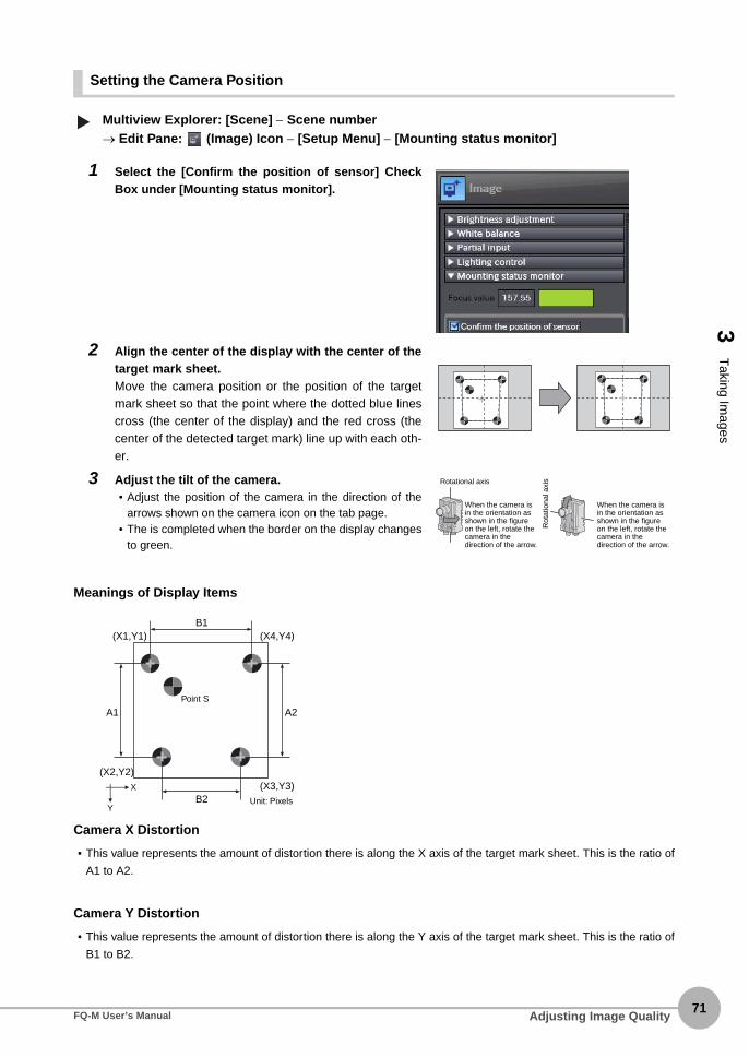
3 T
aking Images
Setting the Camera Position
Multiview Explorer: [Scene] − Scene number→ Edit Pane: (Image) Icon − [Setup Menu] − [Mounting status monitor]
Meanings of Display Items
Camera X Distortion
• This value represents the amount of distortion there is along the X axis of the target mark sheet. This is the ratio of
A1 to A2.
Camera Y Distortion
• This value represents the amount of distortion there is along the Y axis of the target mark sheet. This is the ratio of
B1 to B2.
1 Select the [Confirm the position of sensor] CheckBox under [Mounting status monitor].
2 Align the center of the display with the center of thetarget mark sheet.Move the camera position or the position of the targetmark sheet so that the point where the dotted blue linescross (the center of the display) and the red cross (thecenter of the detected target mark) line up with each oth-er.
3 Adjust the tilt of the camera.• Adjust the position of the camera in the direction of the
arrows shown on the camera icon on the tab page.• The is completed when the border on the display changes
to green.
▲
Rotational axis
When the camera is in the orientation as shown in the figure on the left, rotate the camera in the direction of the arrow.
When the camera is in the orientation as shown in the figure on the left, rotate the camera in the direction of the arrow.
Rot
atio
nal a
xis
(X2,Y2)
(X1,Y1)
(X3,Y3)
B1
B2
A2A1
(X4,Y4)
Y
X
Unit: Pixels
Point S
Adjusting Image QualityFQ-M User’s Manual71

72
Target Marks 1 to 4
• These are represented by four points arranged counterclockwise from the closest point to the inner point (point S).
In the above figure, the target marks are as follows:
Target mark 1 (X1,Y1)
Target mark 2 (X2,Y2)
Target mark 3 (X3,Y3)
Target mark 4 (X4,Y4)
Displacement from the Center of the Display
• This is the Euclidean distance between the intersection of the dotted blue lines (the center of the display) and the
green cross (the center of the detected target mark).
Displaying Guide Lines to Assist in Sensor Installation
You can display guide lines (scale lines) on top of the image.
This operation is not possible on the Touch Finder.
1 Click the (Guide Lines) Icon.
• You can change the drawing conditions for the guide lines.
Displaying Guide Lines p. 189
• This operation is not possible on the Touch Finder.
Note
Note
Adjusting Image Quality FQ-M User’s Manual

3 T
aking Images
Adjusting Image Brightness with External Lighting
You can adjust image brightness with external lighting or by setting the Sensor sensitivity.
Using a Strobe Controller to Control External Lighting
Multiview Explorer: [Scene] − Scene number→ Edit Pane: (Image) Icon − [Setup menu] − [Lighting control]
• Operation on the Touch Finder
Use the following menu command to display the Setup Display on the Touch Finder.
[Image] − [Camera Setup] − − [Lighting control]
Using a Strobe Trigger Signal to Control External Lighting
You can change the output time of the strobe trigger signal to adjust the brightness.
Changing the STGOUT Signal Output Conditions p. 225
1 Connect the Strobe Controller to the Sen-sor.
2 Set the timing to turn ON the external light-ing.Lighting Mode
Off: Do not turn ON the light.Trigger sync: Turn ON the light in sync
with the trigger.Lighting always: Keeps the light turned ON
constantly.
3 Adjust light intensity values to set the imagebrightness.
▲▲
Adjusting Image QualityFQ-M User’s Manual73
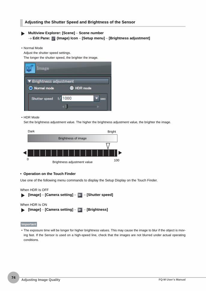
74
Adjusting the Shutter Speed and Brightness of the Sensor
Multiview Explorer: [Scene] − Scene number→ Edit Pane: (Image) Icon − [Setup menu] − [Brightness adjustment]
• Normal Mode
Adjust the shutter speed settings.
The longer the shutter speed, the brighter the image.
• HDR Mode
Set the brightness adjustment value. The higher the brightness adjustment value, the brighter the image.
• Operation on the Touch Finder
Use one of the following menu commands to display the Setup Display on the Touch Finder.
When HDR Is OFF
[Image] − [Camera setting] − − [Shutter speed]
When HDR Is ON
[Image] − [Camera setting] − − [Brightness]
• The exposure time will be longer for higher brightness values. This may cause the image to blur if the object is mov-
ing fast. If the Sensor is used on a high-speed line, check that the images are not blurred under actual operating
conditions.
▲
1000Brightness adjustment value
Dark Bright
Brightness of image
▲▲
Important
Adjusting Image Quality FQ-M User’s Manual

3 T
aking Images
Taking Clear Images of Moving Objects
For quick moving objects, the effect of blurring can be reduced by decreasing the shutter speed.In HDR Mode, set the brightness value to a low setting.
• Relationship between Shutter Speed and the Brightness Adjustment Value in HDR Mode
Multiview Explorer: [Scene] − Scene number→ Edit Pane: (Image) Icon − [Setup menu] − [Brightness adjust]
Adjusting the Shutter Speed and Brightness of the Sensor p. 74
The smaller the value you set for the shutter speed and brightness, the darker the image becomes. If theSensor is used in a dark environment, make sure that the darkness of the image does not cause themeasurements to be unstable.
• Operation on the Touch Finder
Use the following menu command to display the Setup Display on the Touch Finder.
[Image] − [Camera setting] − − [Brightness]
1/30000 1/10
SlowFast Moving speed
1000 Brightness
Shutter speed
▲
Important
▲
Adjusting Image QualityFQ-M User’s Manual75

76
Improving the Image Quality of Metallic and other Shiny Surfaces
When objects with shiny surfaces are being measured, the lighting may be reflected off the surface and affectthe image.To remove reflections, the following function can be used.
HDR Function
The HDR function is used for objects that have a large difference between light and dark areas. For this kind ofobject, clear images cannot be achieved with the standard brightness setting. The HDR function combinesseveral images of different brightnesses (exposure times) so that the resulting image has a lower degree ofcontrast and can be measured stably for the desired characteristic.
Observe the following precautions.• Use the HDR function only for objects that are not moving to avoid image blurring.
Several images are taken with different shutter speeds and combined. If the object moves while the imageis being taken, the image will become blurred.
• Images with different brightnesses are combined, so the resulting image will have a lower degree of con-trast.
Multiview Explorer: [Scene] − Scene number→ Edit Pane: (Image) Icon − [Setup menu] − [Brightness adjust]
Function Description
HDR (High Dynamic Range) If objects have contrasting light and dark areas, the dynamic range can be made wider to improve the quality of the images.
Inputting Images with a Limit Range of Brightness Combining Images to Create an Image with a Wide Dynamic Range
Dark Bright
▲
Adjusting Image Quality FQ-M User’s Manual

3 T
aking Images
• Operation on the Touch Finder
Use the following menu command to display the Setup Display on the Touch Finder.
[Image] − [Camera setup] − − [HDR]
1 Click [HDR].
2 Click [Auto].The best HDR mode will be selected automati-cally. The enabled range will appear in green onthe brightness adjustment bar.
3 If the automatic adjustment does not workwell, adjust to the optimal level manually.
If the measurement object is changed after setting theHDR function, click the [Auto] Button to automatically setthe HDR mode again.
Note
• As shown below, the higher the level, the wider thecombined dynamic range will be.
Note
HDR: 1HDR: 2HDR: 3HDR: 4
Dark Bright
▲
Adjusting Image QualityFQ-M User’s Manual77

78
Adjusting the Colors of the Image (White Balance)
If external lighting is used, the image may appear as having different colors than the actual object. If this is thecase, adjust the white balance.This can be done only when a Sensor with Color Camera is connected.
Multiview Explorer: [Scene] − Scene number→ Edit Pane: (Image) Icon − [Setup menu] − [White balance]
• Operation on the Touch Finder
Use the following menu command to display the Setup Display on the Touch Finder.
[Image] − [Camera setup] − − [White balance]
1 Input a picture of white paper or cloth.
2 Click the [Auto] Button. The Sensor will au-tomatically adjust the colors.
3 Move the bar to the left (light) or right (dark)to finetune the colors.
4 Click the [OK] Button.
▲▲
Adjusting Image Quality FQ-M User’s Manual

3-3 Synchronizing the Measurement Object Image Capture Timing
3 T
aking Images
Setting the Measurement Trigger
Select the type of trigger input to use to capture an image of the measurement object.You can select from three different types of input triggers, based on the configuration of the system connectedto the Sensor.• TRIG: One inspection is performed in sync with an external trigger.
• EtherCAT trigger: One inspection is performed when a command to measure is received via EtherCAT.
• Encoder trigger: One inspection is performed based on the encoder input value.
Multiview Explorer: [System] − [System data]→ Edit Pane: (Trigger settings) Icon − [Trigger type]
1 Select the trigger type.
Item Description
TRIG An external trigger is used to perform measurements.
EtherCAT trigger A measurement command received via EtherCAT is used to perform measure-ments.
Encoder trigger An encoder counter value is used to perform measurements.
▲
Synchronizing the Measurement Object Image Capture TimingFQ-M User’s Manual79

80
Delaying the Image Capture Timing from the Trigger Input
If objects are moving, the position in the image of the characteristic that is to be measured will vary accordingto the timing of the trigger signal. A delay can be applied from when the trigger (the TRIG signal) is input untilwhen the image is input, to synchronize the timing of image input with the speed of the moving objects. If theobject position varies in the image, this function cannot be used to make the object position more stable. Whenyou use a trigger delay, you will also need to adjust the timing to turn ON external lighting.
Multiview Explorer: [System] − [System data]→ Edit Pane: (Trigger settings) Icon
You can also adjust the trigger delay while monitoring the image.
Multiview Explorer: [System] − [System data]→ Edit Pane: (Trigger settings) Icon − [Confirm image]
1 Set a suitable value for the trigger delay time.
1 Input a TRIG signal.Images are input continuously.
2 Display the image with the measurement ob-ject in the center using and Buttons.
3 Select the image.
4 Click the [OK] Button.
The delay time can be set using the adjustment bar or by directly entering a value.
Trigger input sensor
Delay timeDelay from when the trigger is input until when Sensor input is started.
▲▲
Note
Synchronizing the Measurement Object Image Capture Timing FQ-M User’s Manual

3 T
aking Images
• Operation on the Touch Finder
Use the following menu command to display the Setup Display on the Touch Finder.
[Image] − [Trigger setup] − − [Trigger delay]
Adjusting External Lighting Timing
When you use a trigger delay, you must adjust the timing to turn ON external lighting so that it matches thetrigger delay timing.
Using a Strobe Controller to Control External Lighting
If a Strobe Controller is used and the lighting mode is set to [Triggered synchronization], it is not necessary toset any lighting controls to match the lighting to the trigger delay timing.
Using a Strobe Trigger Signal to Control External Lighting
Delay the output time of the strobe trigger signal to adjust the external lighting timing.
Changing the STGOUT Signal Output Conditions p. 225
• Operation on the Touch Finder
Use the following menu command to display the Setup Display on the Touch Finder.
[Image] − [Camera setup] − [Lighting control]
When you use a trigger delay, you will also need to adjust the timing to turn ON external lighting so that it matchesthe trigger delay timing.
Adjusting External Lighting Timing p. 81
▲
Note
▲
Synchronizing the Measurement Object Image Capture TimingFQ-M User’s Manual81

82
3-4 Preventing Mutual Interference of Multiple Sensors
When the same trigger signal is input to multiple Sensors, the lighting from one Sensor may affect themeasurements of the other Sensors. This is called mutual interference. This kind of interference can beprevented offsetting the image input timing of each Sensor from when the trigger signal is received.Example: A trigger (i.e., the TRIG signal) is input to Sensor 0 and Sensor 1 at the same time.
• The delay time for preventing mutual interference must be longer than the shutter time.
• Operation on the Touch Finder
Use the following menu command to display the Setup Display on the Touch Finder.
[Image] − [Trigger setup] − − [Trigger delay]
Sensor 0 immediately begins image input when the trigger is input. Sensor 1 begins image input after the specified time has passed.
1 Change to the setup for to Sensor 1.
p. 64
2 Multiview Explorer: [System] − [System data]→ Edit Pane: (Trigger settings) Icon
3 Set the trigger input delay time for Sensor 1.
p. 80
4 Adjust the external lighting timing to match the trigger delay.
p. 81
Sensor 0
Sensor 1
Trigger Sensor
Timing of taking the image
Timing of taking the image
Sensor 0 No trigger delay
Sensor 1 trigger delay
Sensor 1
TRIG signal
Important▲
Preventing Mutual Interference of Multiple Sensors FQ-M User’s Manual

Setting Up Inspections
4 S
etting Up Inspections
4-1 Inspection Item Selection Guide . . . . . . . . . . . . . . . . . . . . . . . . . . . . . 84
4-2 Setup Procedure for Inspection Items . . . . . . . . . . . . . . . . . . . . . . . . 85
4-3 Registering Inspection Items . . . . . . . . . . . . . . . . . . . . . . . . . . . . . . . . 86
4-4 Inspecting with the Search Inspection Item . . . . . . . . . . . . . . . . . . . . 88
4-5 Inspecting with the Edge Position Inspection Item . . . . . . . . . . . . . 105
4-6 Inspecting with the Labeling Inspection Item . . . . . . . . . . . . . . . . . 113
4-7 Inspecting with the Shape Search Inspection Item . . . . . . . . . . . . . 125
4-8 Calculations and Judgements Using Inspection Item Data . . . . . . 138

84
4-1 Inspection Item Selection Guide
The Vision Sensor uses inspection items to judge measurement objects and perform position detection. Thereare four different inspection items. Select the inspection items to use according to the features of themeasurement object and the required results (OK/NG judgement, position detection, etc.)
Inspection Example Inspection item used Reference
Detecting positions with shapes at high speed
Measurement objects of the same shape can be detected.
Shape Search p. 125
Detecting positions with patterns Measurement objects of the same color and pattern can be detected.
Search p. 88
Detecting positions by edges The positions of the edges of glass surfaces can be detected.
Edge Position p. 105
Detecting positions with groups Groups of the same color can be detected. Labeling p. 113
OMRONOMRON
Inspection Item Selection Guide FQ-M User’s Manual

4-2 Setup Procedure for Inspection Items
4S
etting Up Inspections
The basic steps for setting up inspection items are given below.
If measurements are unstable:
Registering Inspection ItemsStep 1tep 1
TeachingStep tep 2
Setting Judgement ParametersStep tep 3
Setting Detailed ItemsStep tep 4
Re-teachingStep tep 5
Setup Procedure for Inspection ItemsFQ-M User’s Manual85

86
4-3 Registering Inspection Items
Registering New Inspection Items
Multiview Explorer: [Scene] − Scene number (Double-click) or (right-click [Edit])
• Operation on the Touch Finder
Use the following menu command to display the Setup Display on the Touch Finder.
[Inspect] − [Inspection] − Unregistered item number − [Add item]
Modifying Registered Inspection Items
Multiview Explorer: [Scene] − Scene number (Double-click) or (right-click [Edit])
• Operation on the Touch Finder
Use the following menu command to display the Setup Display on the Touch Finder.
[Inspect] − [Inspection] − Registered item number − [Modify]
1 Click the (Inspection) Icon.
2 Drag the inspection item you want to regis-ter from the [Available inspection items]area in the Toolbox to the inspection itemlist.
1 Click the (Inspection) Icon.
2 Right-click the inspection item to set upand select [Edit]. The Edit Pane is dis-played.
▲
Drag
▲▲
▲
Registering Inspection Items FQ-M User’s Manual

4S
etting Up Inspections
Copying Registered Inspection Items
Multiview Explorer: [Scene] − Scene number (Double-click) or (right-click [Edit])
When you make a copy of an inspection item, the copy is inserted at the end of the inspection item list.
Deleting Registered Inspection Items
Multiview Explorer: [Scene] − Scene number (Double-click) or (right-click [Edit])
• Operation on the Touch Finder
Use the following menu command to display the Setup Display on the Touch Finder.
[Inspect] − [Inspection] − Registered item number − [Delete]
Changing the Name of Registered Inspection Items
Multiview Explorer: [Scene] − Scene number (Double-click) or (right-click [Edit])
1 Click the (Inspection) Icon.
2 Click the inspection item to copy.
3 Right-click and select [Copy], or click the (Copy) Icon.
1 Click the (Inspection) Icon.
2 Click the inspection item to delete.
3 Right-click and select [Delete], or click the (Delete) Icon.
1 Click the (Inspection) Icon.
2 Click the inspection item for which tochange the name.
3 Right-click and select [Rename].
4 Enter the new name.
5 Press the [ENTER] key to confirm the newname.
▲▲
▲▲
Registering Inspection ItemsFQ-M User’s Manual87

88
4-4 Inspecting with the Search Inspection Item
Search Inspection ItemThe image pattern to use for measurements is registered in advance and measurements are performed to seeif the pattern is present, to find the position of the pattern, or to see if characteristics, such as the shape orcolor, are different. The image pattern that is registered in advance is called the model. The degree to whichthe image matches the model is called the correlation.
Setup Procedure for Search Inspection Item
Step 1 Selecting the Inspection Item
Multiview Explorer: [Scene] − Scene number → Edit Pane: (Inspection) Icon
1 Drag [Search] from the [Available inspec-tion items] area to the inspection item list.
2 Right-click the [Search] inspection itemyou added to the inspection item list andselect [Edit].
Registering Inspection Items p.86
Sample SettingsModel(Desired image pattern)
OK NGSearch region(The region in which to search for the model)
Sample Measurement
A search is made for sections that are similar to the model.
▲
Drag
Inspecting with the Search Inspection Item FQ-M User’s Manual

4S
etting Up Inspections
• Operation on the Touch Finder
Use the following menu command to display the Setup Display on the Touch Finder.
[Inspect] − [Inspection]
Step 2 Teaching
Teaching means to store the region and image as reference data for the measurement.
Multiview Explorer: [Scene] − Scene number→ Edit Pane: (Inspection) Icon − [Search] (right-click [Edit])→ Search Pane: [Model region] − [Edit]
The following data is stored as the measurement reference.
• Operation on the Touch Finder
Use the following menu command to display the Setup Display on the Touch Finder.
[Inspect] − [Inspection] − [Search] − [Modify] − [Settings] Tab Page − [Teach] − − [Model region]
1 Place the object that is to be used as themeasurement reference in front of theCamera.
2 Move the rectangle to the location to bemeasured.
3 Click [TEACH].The basic settings will be registered whenteaching has been completed.
Item Parameter Description
Reference data Model image This is the image in the model region that is stored as the reference.
Reference position X These are the coordinates of the model image that are stored as the reference.
Reference position Y
• You can edit the region to use for teaching.
Editing the Model Region p. 99
• The Teaching Button will flash if the conditions for model registration change.
When the Teaching Button flashes, click the Teaching Button again to register the model.
▲▲
Drag the rectangle to move it. Drag a corner to size the rectangle.
Note
▲
Inspecting with the Search Inspection ItemFQ-M User’s Manual89

90
Step 3 Adjusting the Judgement Parameters
Multiview Explorer: [Scene] − Scene number→ Edit Pane: (Inspection) Icon − [Search] (right-click [Edit])→ Search Pane: [Judgment parameters]
• Operation on the Touch Finder
Use the following menu command to display the Setup Display on the Touch Finder.
[Inspect] − [Inspection] − [Search] − [Modify] − [Settings] Tab Page − [Judgement]
1 Set the ranges that are to be judged as OKfor the following parameters.Continuous measurements will be performedfor the images that are taken. The measuredvalue is displayed beside the setting name.
2 Click [OK] at the lower right of the EditPane.Click the [OK] Button to apply all edited set-tings. Click the [Cancel] Button to cancel allchanges.
Parameter Setting Description
Correlation Range: 0 to 100Defaults: Lower limit: 0, Upper limit: 100
Adjust the upper and lower limits of the correlation for an OK judgement.
Position X Range: −99,999.9999 to 99,999.9999Defaults: Lower limit: −99,999.9999, Upper limit: 99,999.9999
Adjust the upper and lower limits of measurement posi-tion X for an OK judgement.
Position Y Range: −99,999.9999 to 99,999.9999Defaults: Lower limit: −99,999.9999, Upper limit: 99,999.9999
Adjust the upper and lower limits of measurement posi-tion Y for an OK judgement.
Measure angle Range: −180 to 180Defaults: Lower limit: −180, Upper limit: 180
Adjust the upper and lower limits of measurement angle for an OK judgement.
Count Range: 0 to 32Defaults: Lower limit: 0, Upper limit: 32
Adjust the upper and lower limits of the detection count for an OK judgement.
If you enabled the output of multiple results, you can specify the results to display with their detection number.
▲
Green for OK. Red for NG.
Lower limit
Upper limit
Note
▲
Inspecting with the Search Inspection Item FQ-M User’s Manual

4S
etting Up Inspections
Changing Output Coordinate PositionsYou can specify which part of the model to detect as coordinates during inspections. Normally, the centerposition of the registered model is used as the detection point.
Multiview Explorer: [Scene] − Scene number→ Edit Pane: (Inspection) Icon − [Search] (right-click [Edit])→ Search Pane: [Detection Point]
• Operation on the Touch Finder
Use the following menu command to display the Setup Display on the Touch Finder.
[Inspect] − [Inspection] − [Search] − [Modify] − [Settings] Tab Page − [Teach] − − [Detection point]
1 Move the cross cursor to any position.The position of the cross cursor will be the co-ordinate position that is output. This position isregistered relative to the model region. Youcan also enter a value directly.
The detection coordinates will automatically return to the center coordinates of the model if you change the modelregion.
▲
Drag the cross cursor.
Enter a value.
Note
▲
Inspecting with the Search Inspection ItemFQ-M User’s Manual91

92
Increasing Measurement Position AccuracyYou can increase the accuracy of measurement positioning.You can calculate down to four decimal places.
Multiview Explorer: [Scene] − Scene number→ Edit Pane: (Inspection) Icon − [Search] (right-click [Edit])→ Search Dialog Box: [Measurement conditions]
• Operation on the Touch Finder
Use the following menu command to display the Setup Display on the Touch Finder.
[Inspect] − [Inspection] − [Search] − [Modify] − [Details] Tab Page − [Meas. Parameter]
1 Select the [Sub-pixel] Check Box.
▲▲
Inspecting with the Search Inspection Item FQ-M User’s Manual

4S
etting Up Inspections
Obtaining Multiple Results SimultaneouslyYou can detect all items that satisfy the extraction conditions.Judgement is performed for all detected results.You can also change the output order when you output the results.
Multiview Explorer: [Scene] − Scene number→ Edit Pane: (Inspection) Icon − [Search] (right-click [Edit])→ Search Dialog Box: [Measurement conditions]
• Operation on the Touch Finder
Use the following menu command to display the Setup Display on the Touch Finder.
[Inspect] − [Inspection] − [Search] − [Modify] − [Details] Tab Page − [Meas. Parameter]
1 Select the [Multi-point output] Check Box.
2 Select the conditions by which to sort thedetected results under [Sorting method].You can output the results in the sort order thatyou selected.
3 Set the [Count].This allows you to set the maximum number ofresults to output.
Selection item Setting Description
Sorting method Ascending order of correlation value Sorts the results in order from the smallest correlation to the largest.
Descending order of correlation value Sorts the results in order from the largest correlation to the smallest.
Ascending order of position X Sorts the results in order from the smallest measure-ment X position to the largest.
Descending order of position X Sorts the results in order from the largest measure-ment X position to the smallest.
Ascending order of position Y Sorts the results in order from the smallest measure-ment Y position to the largest.
Descending order of position Y Sorts the results in order from the largest measure-ment Y position to the smallest.
Count 1 to 32 Sets the upper limit for the number of items to detect as a single set of search results.
▲▲
Inspecting with the Search Inspection ItemFQ-M User’s Manual93

94
Select the Results to OutputYou can use multiple conditions to determine which results to output from all the objects detected with acorrelation at the candidate level or higher.Only the results that meet all the specified conditions are output.
Multiview Explorer: [Scene] − Scene number→ Edit Pane: (Inspection) Icon − [Search] (right-click [Edit])→ Search Dialog Box: [Measurement conditions]
• Operation on the Touch Finder
Use the following menu command to display the Setup Display on the Touch Finder.
[Inspect] − [Inspection] − [Search] − [Modify] − [Details] Tab Page − [Meas. Parameter]
1 Adjust the [Candidate level] under [Extrac-tion condition] so that only objects higherthan a certain correlation are detected.
2 Set the measurement range (position X, po-sition Y) and the measure angle.
Extraction condi-tion
Range Description
Candidate level 0 to 100 Outputs only objects with a correlation that is higher than the specified candidate level.
Position X −99999.9999 to 99999.9999 Outputs only objects with an X measurement position that is within this range.
Position Y −99999.9999 to 99999.9999 Outputs only objects with an Y measurement position that is within this range.
Measure angle −180 to 180 Outputs only objects with a measurement angle that is within this range.
The processing time changes if you change the candidate level.
▲▲
Note
Inspecting with the Search Inspection Item FQ-M User’s Manual

4S
etting Up Inspections
Using the Encoder Input to Exclude Redundant Search ResultsWhen you detect workpieces as they travel along a conveyor belt, you can use an encoder input to exclude theresults detected for the previous inspection. To use this function, an encoder input to the Sensor and conveyortracking calibration are required.Refer to Section 9 Calibration for how to perform the conveyor tracking calibration.
9-1 Calibration p. 346
When using this function, continuously input the trigger at a short interval. The intended detection results maynot be achieved if the trigger interval is too long.Input the next trigger before the measurement objects leave the field of view of the camera.• When using an encoder trigger, adjust the trigger counter timing (p. 341).
• When using the TRIG parallel I/O signal (p. 215), an EtherCAT trigger (p. 241), the MEASURE no-protocol com-
mand (p. 283), or a single measurement PLC link command (p. 310), program the external device to create a short
measurement trigger interval.
Multiview Explorer: [Scene] − Scene number→ Edit Pane: (Inspection) Icon − [Search] (right-click [Edit])→ Search Dialog Box: [Measurement conditions]
1 Select the [Remove duplication] Check Box.
2 Adjust the [Judgement distance] based onthe size of the detection object.Set the numerical values after calibration (i.e.,the values in the robot coordinate system). Theunit will be the setting unit that was used for cal-ibration.
You cannot set the judgement distance from the Touch Finder.
The previously detected results are not output.
Workpiece direction of movement
Field of view
Important
▲
Note
Inspecting with the Search Inspection ItemFQ-M User’s Manual95

96
Using the Grip Interference Check Function to Exclude the Search Results of Workpieces That Are Not Able to GripWhen you detect workpiece, you can use the grip interference check function to exclude results fromworkpieces that are not able to grip.
Multiview Explorer: [Scene] − Scene number→ Edit Pane: (Inspection) Icon − [Search] (right-click [Edit])→ Search Dialog Box: [Measurement conditions]
1 Specify the necessary grip region aside fromthe model region, and register the color to bemeasured and area to be determined fromthe workpieces and the background colorswithin the specified region.
2 Complete measurement within the grip re-gion of the detected workpiece using thearea of the color registered in step 1 to deter-mine whether gripping is possible or not byrelative value to reference area value (the %).
3 Only the search results for workpieces thathave been determined as being able to gripwith gripping areas at or above the grip arealevel are output.
1 Select the [Grip interference check] CheckBox. The [Grip region] and [Set color] aredisplayed under [Judgment parameters].
Model region to search
Grip region
Measurement object 1
Measurement object 2
▲
Inspecting with the Search Inspection Item FQ-M User’s Manual
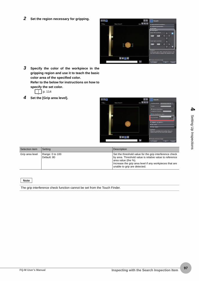
4S
etting Up Inspections
2 Set the region necessary for gripping.
3 Specify the color of the workpiece in thegripping region and use it to teach the basiccolor area of the specified color.Refer to the below for instructions on how tospecify the set color.
p. 114
4 Set the [Grip area level].
Selection item Setting Description
Grip area level Range: 0 to 100Default: 80
Set the threshold value for the grip interference check by area. Threshold value is relative value to reference area value (the %).Increase the grip area level if any workpieces that are unable to grip are detected.
The grip interference check function cannot be set from the Touch Finder.
Note
Inspecting with the Search Inspection ItemFQ-M User’s Manual97

98
Handling the Tilt of a Search ObjectAdjust the [Angle range] parameter to increase the range in which a search is made for the model. The Search inspection item judges whether an image is OK or NG according to the correlation with apreviously registered image pattern. For this reason, if the object is at an angle, the correlation is reduced andthe image may be judged as NG. To achieve an OK judgement for the same image pattern even when theobject is at an angle, the rotation range must be widened.
Multiview Explorer: [Scene] − Scene number→ Edit Pane: (Inspection) Icon − [Search] (right-click [Edit])→ Search Dialog Box: [Model region] − [Rotation]
• Operation on the Touch Finder
Use the following menu command to display the Setup Display on the Touch Finder.
[Inspect] − [Inspection] − [Search] − [Modify] − [Details] Tab Page − [Model parameter]
Stabilizing Search Results
Correlation Is Inconsistent Due to Low Contrast
Adjust the brightness to improve the contrast of the mark.
Adjusting Brightness p. 73
Correlation Is Inconsistent Due to Variations in the Measurement Object
Inconsistent portions can be masked so that they are omitted from matching.
Masking Parts of the Model p.101
Increasing the Processing SpeedThe following two methods can be used to reduce processing time.
• Reduce the range in which a search is performed for the model.
Changing the measurement region p. 102
• Reduce the angle range setting.
Adjust the [Angle range] parameter to reduce the range in which a search for the model is performed.
Setting the angle range p. 98
Parameter Setting Description
Rotation range −180° to 180° A search is performed within the set angle range.The larger the angle range, the longer the processing time.
If you change the angle range, perform teaching again.
p. 89
▲
Important
▲
Inspecting with the Search Inspection Item FQ-M User’s Manual

4S
etting Up Inspections
Editing the Model RegionThis section describes how to edit the model regions.
If the model region is changed, perform teaching again.
p. 89
Model registration region
Inspection region (region that is searched for the model)
Important
Inspecting with the Search Inspection ItemFQ-M User’s Manual99
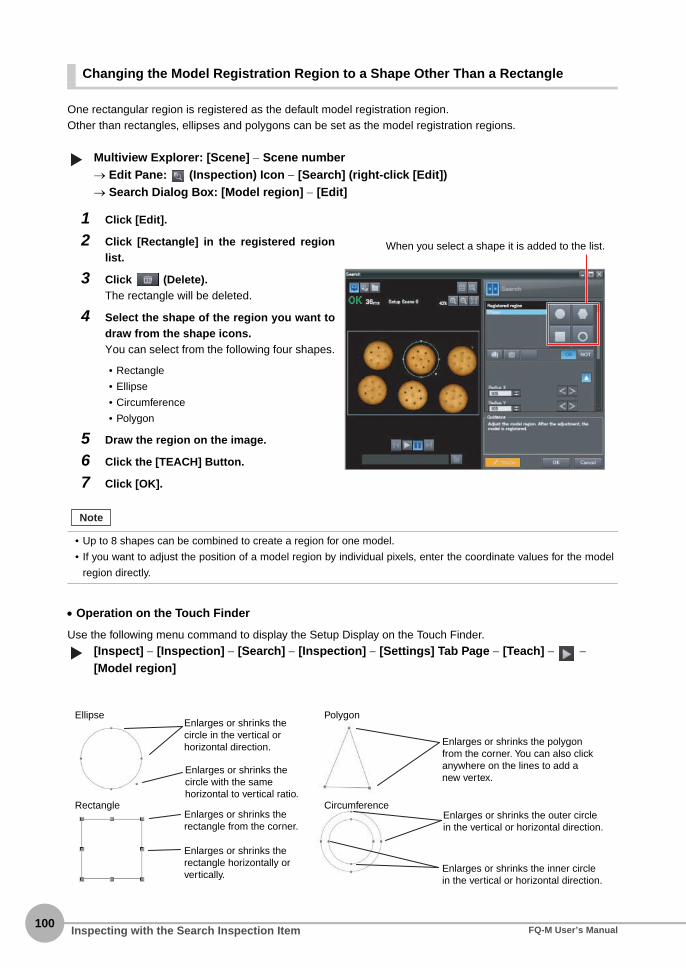
100
Changing the Model Registration Region to a Shape Other Than a Rectangle
One rectangular region is registered as the default model registration region.Other than rectangles, ellipses and polygons can be set as the model registration regions.
Multiview Explorer: [Scene] − Scene number→ Edit Pane: (Inspection) Icon − [Search] (right-click [Edit])→ Search Dialog Box: [Model region] − [Edit]
• Operation on the Touch Finder
Use the following menu command to display the Setup Display on the Touch Finder.
[Inspect] − [Inspection] − [Search] − [Inspection] − [Settings] Tab Page − [Teach] − − [Model region]
1 Click [Edit].
2 Click [Rectangle] in the registered regionlist.
3 Click (Delete).The rectangle will be deleted.
4 Select the shape of the region you want todraw from the shape icons.You can select from the following four shapes.
• Rectangle
• Ellipse
• Circumference
• Polygon
5 Draw the region on the image.
6 Click the [TEACH] Button.
7 Click [OK].
• Up to 8 shapes can be combined to create a region for one model.
• If you want to adjust the position of a model region by individual pixels, enter the coordinate values for the model
region directly.
▲
When you select a shape it is added to the list.
Note
▲
Ellipse
Rectangle
Polygon
Circumference
Enlarges or shrinks the circle in the vertical or horizontal direction.
Enlarges or shrinks the circle with the same horizontal to vertical ratio.
Enlarges or shrinks the rectangle from the corner.
Enlarges or shrinks the rectangle horizontally or vertically.
Enlarges or shrinks the polygon from the corner. You can also click anywhere on the lines to add a new vertex.
Enlarges or shrinks the outer circle in the vertical or horizontal direction.
Enlarges or shrinks the inner circle in the vertical or horizontal direction.
Inspecting with the Search Inspection Item FQ-M User’s Manual

4S
etting Up Inspections
Masking Parts of the Model
The model registration region can be formed freely by combining enabled and disabled regions.
Multiview Explorer: [Scene] − Scene number→ Edit Pane: (Inspection) Icon − [Search] (right-click [Edit])→ Search Dialog Box: [Model region] − [Edit]
• Operation on the Touch Finder
Use the following menu command to display the Setup Display on the Touch Finder.
[Inspect] − [Inspection] − [Search] − [Modify] − [Settings] Tab Page − [Teach] − − [Model region]
1 Draw the figure according to the section thatyou want to mask.
p. 100
2 Select the region to mask, then click [NOT].The selected area will be removed from themodel.
OR: Enabled rangeNOT: Disabled range
Figure 3: Enabled range
The gray section is the model region.
Figure 2: Disabled range
Figure 1: Enabled rangeExample:
▲▲
Inspecting with the Search Inspection ItemFQ-M User’s Manual101
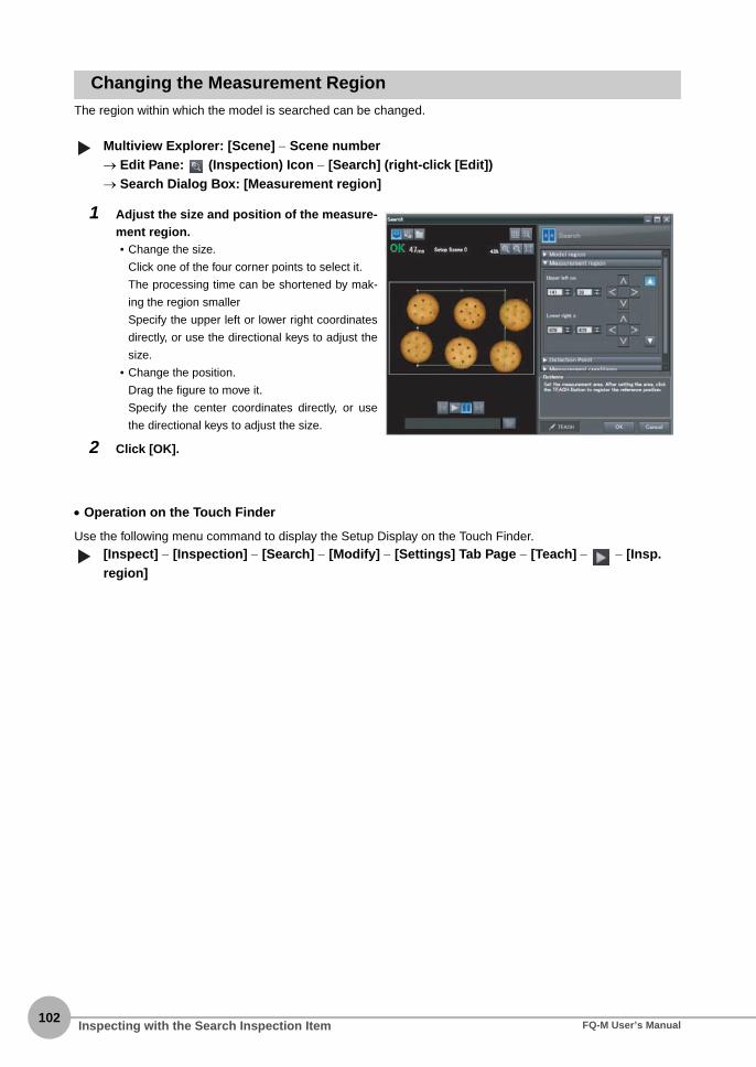
102
Changing the Measurement RegionThe region within which the model is searched can be changed.
Multiview Explorer: [Scene] − Scene number→ Edit Pane: (Inspection) Icon − [Search] (right-click [Edit])→ Search Dialog Box: [Measurement region]
• Operation on the Touch Finder
Use the following menu command to display the Setup Display on the Touch Finder.
[Inspect] − [Inspection] − [Search] − [Modify] − [Settings] Tab Page − [Teach] − − [Insp. region]
1 Adjust the size and position of the measure-ment region.• Change the size.
Click one of the four corner points to select it.
The processing time can be shortened by mak-
ing the region smaller
Specify the upper left or lower right coordinates
directly, or use the directional keys to adjust the
size.
• Change the position.
Drag the figure to move it.
Specify the center coordinates directly, or use
the directional keys to adjust the size.
2 Click [OK].
▲▲
Inspecting with the Search Inspection Item FQ-M User’s Manual

4S
etting Up Inspections
Measurement Data That Can Be Used for External Outputs and CalculationsThe following values can be used as measurement data and output to external devices used in calculations.
4-8 Calculations and Judgements Using Inspection Item Data p. 138
Measurement Data That Can Be LoggedYou can select to log any of the following values.
* When logging data is output, the data is output in the order of the above table.If more than one item is stored, results are output for each model.
7-3 Logging Measurement Data and Image Data p. 191
Expression text string
Data name Description Data range
JG Judgement This is the judgement results of the search. −2: No judgement (not measured), 0: Judgement is OK, −1: Judgement is NG, −13: Teaching not performed error, −14: Figure not registered error, −15: Out of range error
C Count This is the number of models found. 0 to 32
CR[0] to CR[31] Correlation This is the correlation of the Nth model that was found.
0 to 100
X[0] to X[31] Position X This is the X coordinate where the Nth model was found.
−99999.9999 to 99999.9999
Y[0] to Y[31] Position Y This is the Y coordinate where the Nth model was found.
−99999.9999 to 99999.9999
TH[0] to TH[31] Measure angle This is the angle in which the Nth model was found.
−180 to 180
SX Reference X This is the X coordinate of the position where the model was registered. (This is the center of the model region.)
−99999.9999 to 99999.9999
SY Reference Y This is the Y coordinate of the position where the model was registered. (This is the center of the model region.)
−99999.9999 to 99999.9999
ST Reference angle This is the angle when the model was regis-tered.
−180 to 180
RX Detection point coor-dinate X
This is the X coordinate of the detection point when the model was registered.
−99999.9999 to 99999.9999
RY Detection point coor-dinate Y
This is the Y coordinate of the detection point when the model was registered.
−99999.9999 to 99999.9999
Parameter Range Description
Judgement 0: Judgement is OK−1: Judgement is NG−13: Teaching not performed error−14: Figure not registered error−15: Out of range error
This is the measurement judgement results.
Count 0 to 32 This is the number of models found.
Correlation 0 to 100 This is the measured correlation.
Position X −99999.999 to 99999.999 This is the measurement position X.
Position Y −99999.999 to 99999.999 This is the measurement position Y.
Measure angle −180 to 180 This is the measurement angle.
Inspecting with the Search Inspection ItemFQ-M User’s Manual103

104
Errors
Errors in Teaching
A teaching error message will appear if the contrast of the image within the model registration region is too low.Select a region with a larger contrast between light and dark areas compared to the region that was registeredas the model and re-register it as the model.
Inspecting with the Search Inspection Item FQ-M User’s Manual

4-5 Inspecting with the Edge Position Inspection Item
4S
etting Up Inspections
Edge PositionPlaces where the color changes greatly are called edges. The positions of these edges are measured. Forexample, Edge Position can be used to see if a label is attached at the correct position or if a component is setin the correct position.
Setup Procedure for Edge Position Inspection Item
Step 1 Selecting the Inspection Item
Multiview Explorer: [Scene] − Scene number→ Edit Pane: (Inspection) Icon
• Operation on the Touch Finder
Use the following menu command to display the Setup Display on the Touch Finder.
[Inspect] − [Inspection]
1 Drag [Edge Position] from the [Availableinspection items] area to the inspectionitem list.
2 Right-click the [Edge Position] inspectionitem you added to the inspection item listand select [Edit].
Registering Inspection Items p. 86
Sample Settings Sample Measurement
OK NGEdge search direction Color of edge to be found
Measurement regionAn edge is detected within the region according to set direction and color.
▲
Drag
▲
Inspecting with the Edge Position Inspection ItemFQ-M User’s Manual105

106
Step 2 Teaching
Teaching means to store the region and the edge position in the region as reference data for the measurement.
Multiview Explorer: [Scene] − Scene number→ Edit Pane: (Inspection) Icon − [Edge Position] (right-click [Edit])→ Edge Position Pane: [Measurement region]
The following data is stored as basic measurement data.
• Operation on the Touch Finder
Use the following menu command to display the Setup Display on the Touch Finder.
[Inspect] − [Inspection] − [Edge Position] − [Modify] − [Settings] Tab Page − [Teach] − − [Inspect region]
1 Place the object that is to be used as themeasurement reference in front of the Cam-era.
2 Move the rectangle to the location to be mea-sured.
3 Click the [TEACH] Button in the lower-rightcorner.The basic settings will be registered whenteaching has been completed.
Changing the Measurement Region p. 102
Item Parameter Description
Reference data Reference position X The reference coordinates (X, Y) of the position are set automati-cally.Reference position Y
• The Teaching Button will flash if the conditions for reference registration change. When the Teaching Button
flashes, click the Teaching Button again to register the reference.
▲
Drag the rectangle to move it.
Changes the width of the measurement region.
Moves the end point of the measurement region.
Moves the starting point of the measurement region.
The arrow in the middle shows the direction for detecting an edge.
Note
▲
Inspecting with the Edge Position Inspection Item FQ-M User’s Manual

4S
etting Up Inspections
Step 3 Adjusting the Judgement Parameters
Multiview Explorer: [Scene] − Scene number→ Edit Pane: (Inspection) Icon − [Edge Position] (right-click [Edit])→ Edge Position Pane: [Judgment parameters]
• Operation on the Touch Finder
Use the following menu command to display the Setup Display on the Touch Finder.
[Inspect] − [Inspection] − [Edge Position] − [Modify] − [Settings] Tab Page − [Judgement]
1 Set the ranges that are to be judged as OKfor the following parameters.Continuous measurements will be performedfor the images that are taken. The measuredvalue is displayed beside the setting name.
2 Click [OK] at the lower right of the EditPane.Click the [OK] Button to apply all of the chang-es made to the settings. Click the [Cancel] But-ton to cancel all changes.
Parameter Setting Description
Position X Range: −99,999.9999 to 99,999.9999Defaults: Lower limit: −99,999.9999, Upper limit: 99,999.9999
Adjust the upper and lower limits of edge position X for an OK judgement.
Position Y Range: −99,999.9999 to 99,999.9999Defaults: Lower limit: −99,999.9999, Upper limit: 99,999.9999
Adjust the upper and lower limits of edge position Y for an OK judgement.
▲
Lower limit Upper limit
Green for OK. Red for NG.
▲
Inspecting with the Edge Position Inspection ItemFQ-M User’s Manual107

108
Stabilizing Edge Position Results
There Is an Edge But It Cannot Be Detected
Multiview Explorer: [Scene] − Scene number→ Edit Pane: (Inspection) Icon − [Edge Position] (right-click [Edit])→ Edge Position Dialog Box: [Measurement conditions]
• Operation on the Touch Finder
Use the following menu command to display the Setup Display on the Touch Finder.
[Inspect] − [Inspection] − [Edge Position] − [Modify] − [Details] Tab Page − [Meas. Parameter] − [Edge level]
Parameter Setting Description
Edge threshold Range: 0 to 100Default: 50
Set the color change threshold to detect as an edge. The edge point is found based on a threshold that is set for a color change.
If you change the edge threshold, perform teaching again.
Edge Threshold
An edge is detected in the following way.1. The color change distribution of the entire measurement region is determined.2. The minimum color change is 0%. The maximum color change is 100%.3. The location where the color change intersects with the edge threshold is detected as the edge.
▲
Important
Note
100%
50%
0% Minimum color change
Edge thresholdMeasurement region
Maximum color change
▲
Inspecting with the Edge Position Inspection Item FQ-M User’s Manual
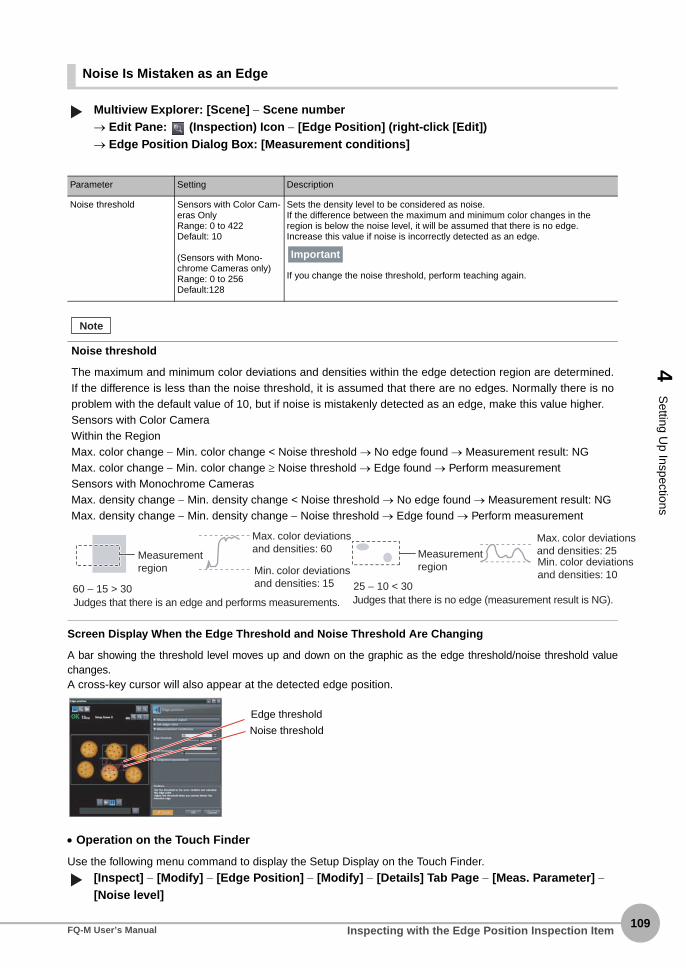
4S
etting Up Inspections
s
Noise Is Mistaken as an Edge
Multiview Explorer: [Scene] − Scene number→ Edit Pane: (Inspection) Icon − [Edge Position] (right-click [Edit])→ Edge Position Dialog Box: [Measurement conditions]
Screen Display When the Edge Threshold and Noise Threshold Are Changing
A bar showing the threshold level moves up and down on the graphic as the edge threshold/noise threshold valuechanges. A cross-key cursor will also appear at the detected edge position.
• Operation on the Touch Finder
Use the following menu command to display the Setup Display on the Touch Finder.
[Inspect] − [Modify] − [Edge Position] − [Modify] − [Details] Tab Page − [Meas. Parameter] − [Noise level]
Parameter Setting Description
Noise threshold Sensors with Color Cam-eras OnlyRange: 0 to 422Default: 10
(Sensors with Mono-chrome Cameras only)Range: 0 to 256Default:128
Sets the density level to be considered as noise.If the difference between the maximum and minimum color changes in the region is below the noise level, it will be assumed that there is no edge. Increase this value if noise is incorrectly detected as an edge.
If you change the noise threshold, perform teaching again.
Noise threshold
The maximum and minimum color deviations and densities within the edge detection region are determined.If the difference is less than the noise threshold, it is assumed that there are no edges. Normally there is noproblem with the default value of 10, but if noise is mistakenly detected as an edge, make this value higher.Sensors with Color CameraWithin the RegionMax. color change − Min. color change < Noise threshold → No edge found → Measurement result: NGMax. color change − Min. color change ≥ Noise threshold → Edge found → Perform measurementSensors with Monochrome CamerasMax. density change − Min. density change < Noise threshold → No edge found → Measurement result: NGMax. density change − Min. density change − Noise threshold → Edge found → Perform measurement
▲
Important
Note
Judges that there is an edge and performs measurements. Judges that there is no edge (measurement result is NG).60 − 15 > 30 25 − 10 < 30
Min. color deviations and densities: 15
Min. color deviationsand densities: 10
Measurement region
Measurement region
Max. color deviationand densities: 25
Max. color deviations and densities: 60
Edge threshold
Noise threshold
▲
Inspecting with the Edge Position Inspection ItemFQ-M User’s Manual109

110
Specifying the Edge Detection Color (Sensors with Color Cameras Only)Manually set the color of the edge that you want to detect.
Multiview Explorer: [Scene] − Scene number→ Edit Pane: (Inspection) Icon − [Edge Position] (right-click [Edit])→ Edge Position Dialog Box: [Set edge color]
• Operation on the Touch Finder
Use the following menu command to display the Setup Display on the Touch Finder.
[Inspect] − [Inspection] − [Edge Position] − [Modify] − [Settings] Tab Page − [Teach] − − [Set color]
1 Select the [Set edge color] Check Box.
2 Select a density change.
3 Select the color to detect in the color palette.You can check the extraction color you selectedin the color palette. You can also check and ad-just the RGB values of the extraction color. Thespecified color will be extracted.
4 Click [TEACH].
Item Parameter Description
Density change Color IN Detects as an edge any position where the color changes from another color to the specified color.
Color OUT Detects as an edge any position where the color changes from the specified color to another color.
▲
(Only a rectangle can be used to specify the region.)
Beginning position
Ending position
Color IN
Beginning position
Ending position
Color OUT▲
Inspecting with the Edge Position Inspection Item FQ-M User’s Manual

4S
etting Up Inspections
Changing Edge Detection Conditions (Sensors with Monochrome Cameras Only)You can change the following measurement conditions for Sensors with Monochrome Cameras.
Multiview Explorer: [Scene] − Scene number→ Edit Pane: (Inspection) Icon − [Edge Position] (right-click [Edit])→ Edge Position Dialog Box: [Measurement conditions]
• Operation on the Touch Finder
Use the following menu command to display the Setup Display on the Touch Finder.
[Inspect] − [Inspection] − [Edge Position] − [Modify] − [Details] Tab Page − [Meas. Parameter]
Increasing Processing Speed for Edge PositionMake the measurement region smaller to reduce the processing time.
Changing the Measurement Region p. 102
Measurement Data That Can Be Used for External Outputs and CalculationsThe following values can be used as measurement data and output to external devices used in calculations.
4-8 Calculations and Judgements Using Inspection Item Data p.138
Item Parameter Description
Density change Light to Dark Detects as an edge any position within the specified region that changes from white to black.
Dark to Light Detects as an edge any position within the specified region that changes from black to white.
Measurement methods Projection method A projection is formed based on the gray level, and any position of intersection between the gray level value and the threshold (edge level) is detected as an edge.This detection method is used when you must process an image with exces-sive noise or when the edges are blurry.
Differentiation method A differentiated waveform is created that represents the amount of change in gray level between neighboring pixels. The maximum value of the differenti-ated waveform that exceeds the threshold (edge level) is detected as an edge. This detection method is used for low-contrast images.
Expression text string
Data name Description Data range
JG Judgement This is the judgement results for the edge posi-tion.
−2: No judgement (not measured), 0: Judgement is OK, −1: Judgement is NG, −13: Teaching not performed error, −14: Figure not registered error, −15: Out of range error
X Edge position X This is the X coordinate of the measured edge position.
−99999.9999 to 99999.9999
Y Edge position Y This is the Y coordinate of the measured edge position.
−99999.9999 to 99999.9999
SX Standard position X This is the X position of the edge position when a region is registered.
−99999.9999 to 99999.9999
SY Standard position Y This is the Y position of the edge position when a region is registered.
−99999.9999 to 99999.9999
▲▲
Inspecting with the Edge Position Inspection ItemFQ-M User’s Manual111

112
Measurement Data That Can Be Logged for Edge PositionYou can select to log any of the following values.
* When logging data is output, the data is output in the order of the above table.If more than one item is stored, results are output for each model.
7-3 Logging Measurement Data and Image Data p. 191
Errors
Errors in Teaching
A teaching error message will appear if the edge position cannot be detected when teaching. Perform thefollowing. • If the color of the measurement object has changed from the specified color, set the color again and try
teaching again. • If there is an edge and it cannot be detected, adjust the [Noise level] on the [Details] Tab Page and try
teaching again.
Edge Not Found
If an edge is not found, the measurement result will be NG. Perform the following. • If a color was specified, make sure the color of the measurement object has not changed from the specified
color. • Set the color again if necessary. • If there is an edge and it cannot be detected, make sure the [Edge level] parameter on the [Details] Tab Page
is correct.
Edge Levels p. 108
Setting Colors p. 110
Measurement item
Range of value Description
Judgement 0: Judgement is OK−1: Judgement is NG−13: Teaching not performed error−14: Figure not registered error−15: Out of range error
This is the measurement judgement results.
Edge position X −99999.9999 to 99999.9999 This is the X coordinate of the measured edge posi-tion.
Edge position Y −99999.9999 to 99999.9999 This is the Y coordinate of the measured edge posi-tion.
Inspecting with the Edge Position Inspection Item FQ-M User’s Manual

4-6 Inspecting with the Labeling Inspection Item
4S
etting Up Inspections
LabelingOne region of the color you want to measure is counted as a Label. You can sort these labels by position orsize, and assign numbers to them. You can then output the total number of labels, and size and position of adesired label.
Setup Procedure for Labeling Inspection Item
Step 1 Selecting the Inspection Item
Multiview Explorer: [Scene] − Scene number→ Edit Pane: (Inspection) Icon
• Operation on the Touch Finder
Use the following menu command to display the Setup Display on the Touch Finder.
[Inspect] − [Inspection]
If a Sensor with Color Camera is connected, you can specify up to four colors to measure. If a Sensor with Mono-chrome Camera is connected, the image is converted to a black and white binary image. Then, white pixels aremeasured.
1 Drag [Labeling] from the [Available inspec-tion items] area to the inspection item list.
2 Right-click the [Labeling] inspection itemyou added to the inspection item list and se-lect [Edit].
Registering Inspection Items p.86
Color information is extracted from the measurement object.
Measurement region
Label numbers when sorted by area
Label 0
Label 1
Label 2
Sample Settings Sample MeasurementRegions of the extracted color are detected as labels.
Total number of detected labels: 3
Note
▲
Drag
▲
Inspecting with the Labeling Inspection ItemFQ-M User’s Manual113
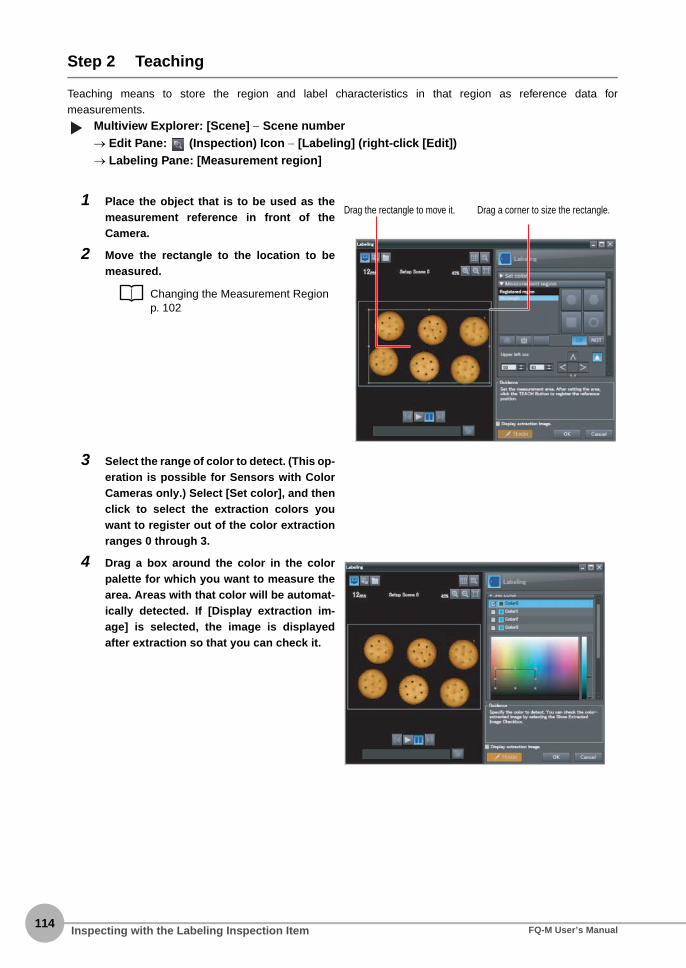
114
Step 2 Teaching
Teaching means to store the region and label characteristics in that region as reference data formeasurements.
Multiview Explorer: [Scene] − Scene number→ Edit Pane: (Inspection) Icon − [Labeling] (right-click [Edit])→ Labeling Pane: [Measurement region]
1 Place the object that is to be used as themeasurement reference in front of theCamera.
2 Move the rectangle to the location to bemeasured.
Changing the Measurement Region p. 102
3 Select the range of color to detect. (This op-eration is possible for Sensors with ColorCameras only.) Select [Set color], and thenclick to select the extraction colors youwant to register out of the color extractionranges 0 through 3.
4 Drag a box around the color in the colorpalette for which you want to measure thearea. Areas with that color will be automat-ically detected. If [Display extraction im-age] is selected, the image is displayedafter extraction so that you can check it.
▲
Drag the rectangle to move it. Drag a corner to size the rectangle.
Inspecting with the Labeling Inspection Item FQ-M User’s Manual

4S
etting Up Inspections
The following data is stored as the measurement reference.
• Operation on the Touch Finder
Use the following menu command to display the Setup Display on the Touch Finder.
Editing the Measurement Region
[Inspect] − [Inspection] − [Labeling] − [Modify] − [Settings] Tab Page − [Teach] − − [Inspect region]
Creating a Binary Image (Sensors with Monochrome Cameras Only)
[Inspect] − [Inspection] − [Labeling] − [Modify] − [Settings] Tab Page − [Teach] − − [Binary level]
5 Select the range of brightness to detect.(Sensors with Monochrome Cameras only)Click [Binary]. Specify the gray level you wantto detect, and then click the [OK] Button. Spec-ify the range of brightness to extract to convertto a binary image. Measurement is performedafter the image taken by the camera in 256-color grayscale is converted to a binary image.In this case, white pixels are measured.
6 Click the [TEACH] Button in the lower-rightcorner.The basic settings will be registered whenteaching has been completed.
If you press the [TEACH] Button without specifying a color, the color with the largest area in the measurement regionwill be extracted and the resulting color information will be registered.
Item Parameter Description
Reference data Reference area The area for label 0 to use as a reference is set automatically.
Reference position X The gravity position X for label 0 to use as a reference is set automatically.
Reference position Y The gravity position Y for label 0 to use as a reference is set automatically.
• The Teaching Button will flash if the conditions for reference registration change. When the Teaching Button
flashes, click the Teaching Button again to register the model.
Note
▲▲
Note
Inspecting with the Labeling Inspection ItemFQ-M User’s Manual115

116
Step 3 Adjusting the Judgement Parameters
Multiview Explorer: [Scene] − Scene number→ Edit Pane: (Inspection) Icon − [Labeling] (right-click [Edit])→ Labeling Pane: [Judgment parameters]
• Operation on the Touch Finder
Use the following menu command to display the Setup Display on the Touch Finder.
[Inspect] − [Inspection] − [Labeling] − [Modify] − [Settings] Tab Page − [Judgement]
1 Set the ranges that are to be judged as OKfor the following parameters.Continuous measurements will be performed forthe images that are taken.
2 Click [OK] at the lower right of the Edit Pane.Click the [OK] Button to apply all edited settings.Click the [Cancel] Button to cancel all changes.
Item Parameter Setting Description
Judgment parameters
Number of labels
Range: 0 to 100Defaults: Upper limit: 100, Lower limit: 0
Set the upper and lower limits of the number of labels for an OK judgement.
Total label area Range: 0 to 999,999,999.9999Defaults: Upper limit: 999,999,999.999, Lower limit: 0
Set the upper and lower limits of the total label area for an OK judgement.
Area Range: 0 to 999,999,999.9999Defaults: Upper limit: 999,999,999.999, Lower limit: 0
Sets the upper and lower limits of the area for an OK judgement.
Gravity center X
Range: −99,999.999 to 99,999.999Defaults: Upper limit: 99,999.999, Lower limit: −99,999.999
Set the upper and lower limits of the gravity X for an OK judgement.
Gravity center Y
Range: −99,999.999 to 99,999.999Defaults: Upper limit: 99,999.999, Lower limit: −99,999.999
Set the upper and lower limits of the gravity Y for an OK judgement.
Elliptic major angle
Range: −180 to 180Defaults: Upper limit: 180, Lower limit: −180
Sets the upper and lower limits of the elliptic major angle for an OK judgement.
▲
Lower limit Upper limitGreen for OK. Red for NG.
▲
Inspecting with the Labeling Inspection Item FQ-M User’s Manual

4S
etting Up Inspections
Measuring Multiple ColorsSet the colors using the color palette. Up to four colors can be specified. (This operation is possible for Sensorswith Color Cameras only.)
Multiview Explorer: [Scene] − Scene number→ Edit Pane: (Inspection) Icon − [Labeling] (right-click [Edit])→ Labeling Dialog Box: [Set color]
If the Reverse Check Box is selected, the color outside the region will become the selected color. The[Reverse] parameter applies to all colors.Select the [Exclude] Check Box to exclude the selected color from extraction.
• Operation on the Touch Finder
Use the following menu command to display the Setup Display on the Touch Finder.
[Inspect] − [Inspection] − [Labeling] − [Modify] − [Settings] Tab Page − [TEACH] − − [Set color] − − [Color Palette]
Checking the Extracted Results as an ImageYou can change how the extraction color and all other colors are displayed. (This operation is for Sensors withColor Cameras only.)
Multiview Explorer: [Scene] − Scene number→ Edit Pane: (Inspection) Icon − [Labeling] (right-click [Edit])→ Labeling Dialog Box: [Display setting]*1
*1 If [Display extraction image] is selected, the [Display setting] menu is displayed.
• Operation on the Touch Finder
Use the following menu command to display the Setup Display on the Touch Finder.
[Inspect] − [Inspection] − [Labeling] − [Inspection] − [Settings] Tab Page − [Teach] − − [Set color] − − [Display setting]/[Background color]
Item Parameter Setting Description
Set color data Extraction image type
All color imageBinary image
Allows you to change how the extraction color is dis-played.
Select the back-ground color
Black, White, Red, Green, or Blue Allows you to change how colors other than the extrac-tion color are displayed.
▲▲
▲▲
Inspecting with the Labeling Inspection ItemFQ-M User’s Manual117

118
Changing the Label Detection ConditionsYou can fill in the labels detected through color extraction or binary conversion to perform a stable extraction ofthe labels and their characteristics or to mark only labels inside the measurement region for inspection.
Multiview Explorer: [Scene] − Scene number→ Edit Pane: (Inspection) Icon − [Labeling] (right-click [Edit])→ Labeling Dialog Box: [Measurement conditions]
• Operation on the Touch Finder
Use the following menu command to display the Setup Display on the Touch Finder.
[Inspect] − [Inspection] − [Labeling] − [Modify] − [Details] Tab Page − [Meas. Parameter]
1 Select the [Filling up holes] Check Box to en-able filling.
2 To cut out the image, select the [Outsidetrimming] Check Box.
Item Parameter Setting Description
Labeling Filling up holes Selected.Not selected.Default: Not selected.
Sets how to process areas surrounded by the specified color.If this check box is selected, those areas are processed as the specified color.
Outside trim-ming
Selected.Not selected.Default: Not selected.
Select this option if there are areas of the specified color inside the measurement region that you do not want to measure.If this check box is selected, all areas outside the measurement region are cut out as the specified color.
▲
Input Image Filled Image
Measurement region
Selected.
You can find the position and area of the center label if you set the sort condition to sort by descending order of area. Areas outside the measure-ment region are set to the color for measurement.
You need to know the position and area of this label.
▲
Inspecting with the Labeling Inspection Item FQ-M User’s Manual

4S
etting Up Inspections
Changing the Label Extraction ConditionsSet the label extraction conditions.You can select to extract only labels that satisfy all three of the following: specified area, gravity X, and gravity Yconditions.
Multiview Explorer: [Scene] − Scene number→ Edit Pane: (Inspection) Icon − [Labeling] (right-click [Edit])→ Labeling Dialog Box: [Measurement conditions]
• Operation on the Touch Finder
Use the following menu command to display the Setup Display on the Touch Finder.
[Inspect] − [Inspection] − [Labeling] − [Modify] − [Settings] Details − [Details] Tab Page − [Meas. Parameter] − [Extraction condition]
1 Set the parameters for the extraction condi-tions.
Item Parameter Setting Description
Extraction condi-tion
Area Range: −999,999,999.9999 to 999,999,999.9999
Defaults: Upper limit: 999,999,999.999, Lower limit: 0
Specify the area range to judge as a label.
Gravity X Range: −999,999,999.9999 to 999,999,999.9999
Defaults: Upper limit: 999,999,999.999, Lower limit: −999,999,999.999
Specify the gravity X position to judge as a label.
Gravity Y Range: −999,999,999.9999 to 999,999,999.9999
Defaults: Upper limit: 999,999,999.999, Lower limit: −999,999,999.999
Specify the gravity Y position to judge as a label.
▲▲
Inspecting with the Labeling Inspection ItemFQ-M User’s Manual119

120
Sorting Extracted LabelsSet the sort condition and count for extracted labels.You can set the sort condition and the maximum number of detections for detection results.
Multiview Explorer: [Scene] − Scene number→ Edit Pane: (Inspection) Icon − [Labeling] (right-click [Edit])→ Labeling Dialog Box: [Measurement conditions]
• Operation on the Touch Finder
Use the following menu command to display the Setup Display on the Touch Finder.
[Inspect] − [Inspection] − [Labeling] − [Modify] − [Details] Tab Page − [Meas. Parameter]
1 Select a sort condition.
2 Set the [Count].
Item Parameter Settings Description
Labeling condi-tion
Sort condition Ascending order of areaDescending order of area (default)Ascending order of X coordinateDescending order of X coordinateAscending order of Y coordinateDescending order of Y coordinate
Sets the condition to use for label number reassign-ment. When sorting by X or Y coordinates, the upper-left corner is the origin.
Count 1 to 100100 (default)
Set the maximum number of labels to detect.
▲▲
Inspecting with the Labeling Inspection Item FQ-M User’s Manual

4S
etting Up Inspections
Using an Encoder Input to Exclude Redundant Labeling ResultsWhen you detect workpieces as they travel along a conveyor belt, you can use an encoder input to exclude theresults detected for the previous inspection. To use this function, an encoder input to the Sensor and conveyortracking calibration are required. Refer to Section 9 Calibration for how to perform the conveyor trackingcalibration.
Calibration p. 345
When using this function, continuously input the trigger at a short interval. The intended detection results maynot be achieved if the trigger interval is too long.Input the next trigger before the measurement objects leave the field of view of the camera.• When using an encoder trigger, adjust the trigger counter timing (p. 341).
• When using the TRIG parallel I/O signal (p. 215), an EtherCAT trigger (p. 241), the MEASURE no-protocol com-mand (p. 283), or a single measurement PLC link command (p. 310), program the external device to create a shortmeasurement trigger interval.
Multiview Explorer: [Scene] − Scene number→ Edit Pane: (Inspection) Icon − [Labeling] (right-click [Edit])→ Labeling Dialog Box: [Measurement conditions]
1 Select the [Remove duplication] Check Box.
2 Adjust the [Judgement distance] based onthe size of the detection object.Set the numerical values after calibration (i.e.,the values in the robot coordinate system). Theunit will be the setting unit that was used for cal-ibration.
You can use the Panorama Display in RunMode to check the adjusted results.
6-2 Configuring the Run Mode Display
p. 169
You cannot set the judgement distance from the Touch Finder.
The previously detected results are not output.
Workpiece direction of movement
Field of view
Important
▲
Note
Inspecting with the Labeling Inspection ItemFQ-M User’s Manual121

122
Editing the Measurement RegionThis section describes how to edit the measurement regions.You can edit the measurement region in the same way as for a search region.
Changing the Model Registration Region to a Shape Other Than a Rectangle p. 100
If the measurement region is changed, perform teaching if required.
p. 89
Measurement region
Important
Inspecting with the Labeling Inspection Item FQ-M User’s Manual

4S
etting Up Inspections
Increasing the Processing SpeedMake the measurement region smaller to reduce the processing time.
Changing the Measurement Region p. 102
Measurement Data That Can Be Used for External Outputs and CalculationsThe following values can be used as measurement data and output to external devices via the Ethernet or usedin calculations.
4-8 Calculations and Judgements Using Inspection Item Data p. 138
Expression text string
Data name Description Data range
JG Judgement This is the Labeling judgement results. −2: No judgement (not measured), 0: Judgement is OK, −1: Judgement is NG, −13: Teaching not performed error, −14: Figure not registered error, −15: Out of range error
L Number of labels This is the number of labels found. 0 to 100
TAR Total label area This is the total area of all labels found. 0 to 999,999,999.9999
AR[0] to AR[99] Area These are the areas of each individual label. 0 to 999,999,999.9999
X[0] to X[99] Gravity coordinate X These are the X coordinates of the center of each label.
−99,999.9999 to 99,999.9999
Y[0] to Y[99] Gravity coordinate Y These are the Y coordinates of the center of each label.
−99,999.9999 to 99,999.9999
ATH[0] to ATH[99] Elliptic major angle These are the elliptic major angles of the center of each label.
−180 to 180
SA Reference area This is the reference area. 0 to 999,999,999.9999
SX Reference position X This is the X coordinate of the reference posi-tion.
−99,999.9999 to 99,999.9999
SY Reference position Y This is the Y coordinate of the reference posi-tion.
−99,999.9999 to 99,999.9999
Inspecting with the Labeling Inspection ItemFQ-M User’s Manual123
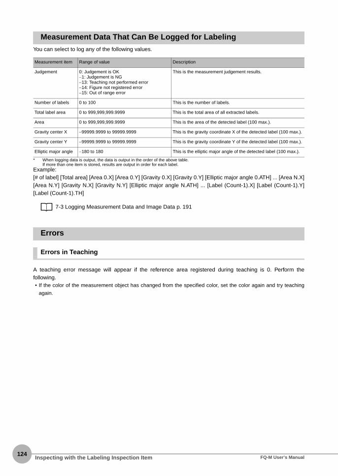
124
Measurement Data That Can Be Logged for LabelingYou can select to log any of the following values.
* When logging data is output, the data is output in the order of the above table.If more than one item is stored, results are output in order for each label.
Example:[# of label] [Total area] [Area 0.X] [Area 0.Y] [Gravity 0.X] [Gravity 0.Y] [Elliptic major angle 0.ATH] ... [Area N.X][Area N.Y] [Gravity N.X] [Gravity N.Y] [Elliptic major angle N.ATH] ... [Label (Count-1).X] [Label (Count-1).Y][Label (Count-1).TH]
7-3 Logging Measurement Data and Image Data p. 191
Errors
Errors in Teaching
A teaching error message will appear if the reference area registered during teaching is 0. Perform thefollowing.• If the color of the measurement object has changed from the specified color, set the color again and try teaching
again.
Measurement item Range of value Description
Judgement 0: Judgement is OK−1: Judgement is NG−13: Teaching not performed error−14: Figure not registered error−15: Out of range error
This is the measurement judgement results.
Number of labels 0 to 100 This is the number of labels.
Total label area 0 to 999,999,999.9999 This is the total area of all extracted labels.
Area 0 to 999,999,999.9999 This is the area of the detected label (100 max.).
Gravity center X −99999.9999 to 99999.9999 This is the gravity coordinate X of the detected label (100 max.).
Gravity center Y −99999.9999 to 99999.9999 This is the gravity coordinate Y of the detected label (100 max.).
Elliptic major angle −180 to 180 This is the elliptic major angle of the detected label (100 max.).
Inspecting with the Labeling Inspection Item FQ-M User’s Manual

4-7 Inspecting with the Shape Search Inspection Item
4S
etting Up Inspections
Shape SearchThe shape data of the image to measure is registered in advance and measurements are performed to seewhere that shape is located. The image pattern that is registered in advance is called the model. The degree towhich the image matches the model is called the correlation.
Setup Procedure for the Shape Search Inspection Item
Step 1 Selecting the Inspection Item
Multiview Explorer: [Scene] − Scene number→ Edit Pane: (Inspection) Icon
• Operation on the Touch Finder
Use the following menu command to display the Setup Display on the Touch Finder.
[Inspect] − [Inspection]
1 Drag [Shape Search] from the [Available in-spection items] area to the inspection itemlist.
2 Right-click the [Shape Search] inspectionitem you added to the inspection item listand select [Edit].
Registering Inspection Items p.86
Sample SettingsModel (Desired image pattern)
OK NGSearch region(The region in which to search for the model)
Sample Measurement
A search is made for sections that are similar to the model.
The entire model is detected (center position by default).
▲
Drag
▲
Inspecting with the Shape Search Inspection ItemFQ-M User’s Manual125

126
Step 2 Teaching
Teaching means to store the region and image as reference data for the measurement.
Multiview Explorer: [Scene] − Scene number→ Edit Pane: (Inspection) Icon − [Shape Search] (right-click [Edit])→ Shape Search Pane: [Model region] − [Edit]
The following data is stored as the measurement reference.
• Operation on the Touch Finder
Use the following menu command to display the Setup Display on the Touch Finder.
[Inspect] − [Inspection] − [Shape Search] − [Modify] − [Settings] Tab Page − [TEACH] − − [Model region]
1 Place the object that is to be used as themeasurement reference in front of theCamera.
2 Move the rectangle to the location to bemeasured.
3 Click [TEACH].The basic settings will be registered whenteaching has been completed.
Item Parameter Description
Reference data Model image This is the image in the model region that is stored as the reference.
Reference position X These are the center coordinates of the model image that are stored as the reference.
Reference position Y
• You can customize the region to use for teaching.
Editing the Model Region p. 99
• The Teaching Button will flash if the conditions for model registration change.
When the Teaching Button flashes, click the Teaching Button again to register the model.
▲
Drag the rectangle to move it. Drag a corner to size the rectangle.
Note
▲
Inspecting with the Shape Search Inspection Item FQ-M User’s Manual

4S
etting Up Inspections
Step 3 Adjusting the Judgement Conditions
Multiview Explorer: [Scene] − Scene number→ Edit Pane: (Inspection) Icon − [Shape Search] (right-click [Edit])→ Shape Search Pane: [Judgment parameters]
• Operation on the Touch Finder
Use the following menu command to display the Setup Display on the Touch Finder.
[Inspect] − [Inspection] − [Shape Search] − [Modify] − [Settings] Tab Page − [TEACH] − [Judgement]
1 Set the ranges that are to be judged as OKfor the following parameters.Continuous measurements will be performed forthe images that are taken. The measured valueis displayed beside the setting name.
2 Click [OK] at the lower right of the Edit Pane.Click the [OK] Button to apply all of the changesmade to the settings. Click the [Cancel] Buttonto cancel all changes.
Parameter Setting Description
Correlation Range: 0 to 100Defaults: Lower limit: 0, Upper limit: 100
Adjust the upper and lower limits of the correlation for an OK judgement.
Position X Range: -99,999.9999 to 99,999.9999Defaults: Lower limit: -99,999.999, Upper limit: 99,999.999
Adjust the upper and lower limits of measurement posi-tion X for an OK judgement.
Position Y Range: -99,999.9999 to 99,999.9999Defaults: Lower limit: -99,999.999, Upper limit: 99,999.999
Adjust the upper and lower limits of measurement posi-tion Y for an OK judgement.
Angle Range: -180 to 180Defaults: Lower limit: -180, Upper limit: 180
Adjust the upper and lower limits of measurement angle for an OK judgement.
Count Range: 0 to 32Defaults: Lower limit: 0, Upper limit: 32
Adjust the upper and lower limits of the detection count for an OK judgement.
If you enabled the output of multiple results, you can specify the results to display with their detection number.
▲
Lower limit Upper limit
Green for OK. Red for NG.
Note
▲
Inspecting with the Shape Search Inspection ItemFQ-M User’s Manual127

128
Changing Output Coordinate PositionsYou can specify which part of the model to detect as coordinates during inspections. Normally, the centerposition of the registered model is used as the detection point.
Multiview Explorer: [Scene] − Scene number→ Edit Pane: (Inspection) Icon − [Shape Search] (right-click [Edit])→ Shape Search Dialog Box: [Detection Point]
• Operation on the Touch Finder
Use the following menu command to display the Setup Display on the Touch Finder.
[Inspect] − [Inspection] − [Shape Search] − [Modify] − [Settings] Tab Page − [Teach] − − [Detection point]
1 Move the cross cursor to any position.The position of the cross cursor will be the co-ordinate position that is output. This position isregistered relative to the model region. Youcan also enter a value directly.
The detection coordinates will automatically return to the center coordinates of the model if you change the modelregion.
▲
Enter a value.Drag the cross cursor.
Note
▲
Inspecting with the Shape Search Inspection Item FQ-M User’s Manual
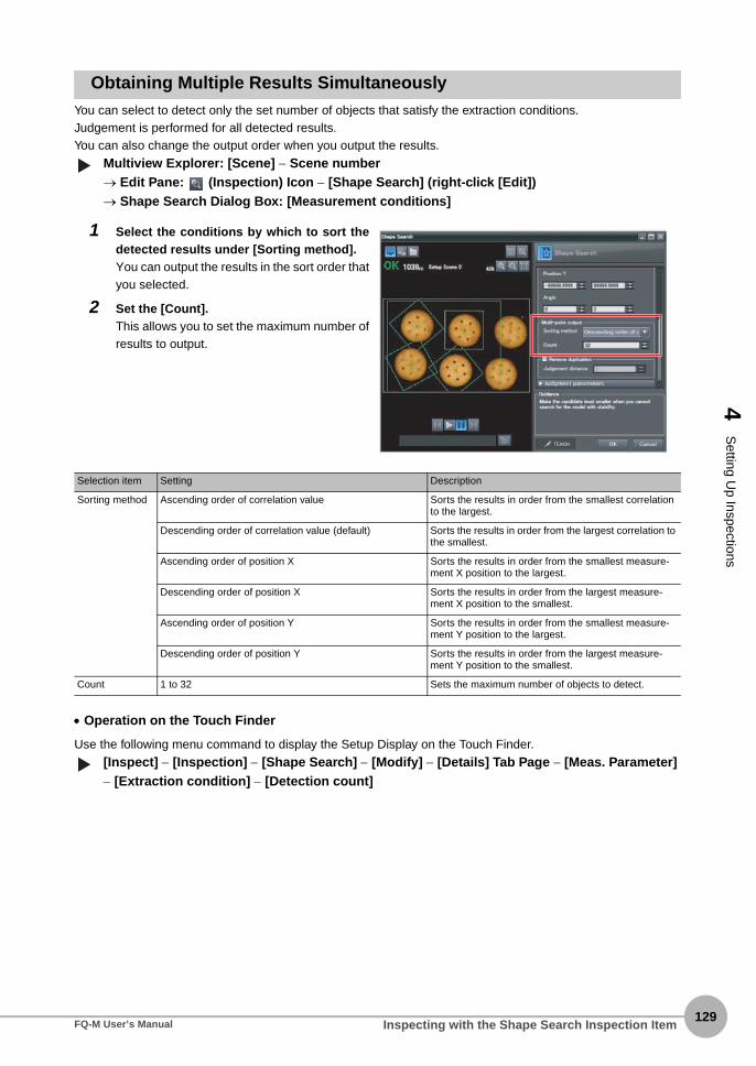
4S
etting Up Inspections
Obtaining Multiple Results SimultaneouslyYou can select to detect only the set number of objects that satisfy the extraction conditions.Judgement is performed for all detected results.You can also change the output order when you output the results.
Multiview Explorer: [Scene] − Scene number→ Edit Pane: (Inspection) Icon − [Shape Search] (right-click [Edit])→ Shape Search Dialog Box: [Measurement conditions]
• Operation on the Touch Finder
Use the following menu command to display the Setup Display on the Touch Finder.
[Inspect] − [Inspection] − [Shape Search] − [Modify] − [Details] Tab Page − [Meas. Parameter] − [Extraction condition] − [Detection count]
1 Select the conditions by which to sort thedetected results under [Sorting method].You can output the results in the sort order thatyou selected.
2 Set the [Count].This allows you to set the maximum number ofresults to output.
Selection item Setting Description
Sorting method Ascending order of correlation value Sorts the results in order from the smallest correlation to the largest.
Descending order of correlation value (default) Sorts the results in order from the largest correlation to the smallest.
Ascending order of position X Sorts the results in order from the smallest measure-ment X position to the largest.
Descending order of position X Sorts the results in order from the largest measure-ment X position to the smallest.
Ascending order of position Y Sorts the results in order from the smallest measure-ment Y position to the largest.
Descending order of position Y Sorts the results in order from the largest measure-ment Y position to the smallest.
Count 1 to 32 Sets the maximum number of objects to detect.▲
▲
Inspecting with the Shape Search Inspection ItemFQ-M User’s Manual129

130
Select the Results to OutputYou can use multiple conditions to determine which results to output from all the objects detected with acorrelation at the candidate level or higher.Only the results that meet all the specified conditions are output.
Multiview Explorer: [Scene] − Scene number→ Edit Pane: (Inspection) Icon − [Shape Search] (right-click [Edit])→ Shape Search Dialog Box: [Measurement conditions]
• Operation on the Touch Finder
Use the following menu command to display the Setup Display on the Touch Finder.
[Inspect] − [Inspection] − [Shape Search] − [Modify] − [Details] Tab Page − [Meas. Parameter] − [Extraction condition]
1 Adjust the [Candidate level] under [Extrac-tion condition] so that only objects higherthan a certain correlation are detected.
2 Set the measurement range (position X, po-sition Y).
Extraction condition Range Description
Candidate level Range: 0 to 100Defaults: Lower limit: 60, Upper limit: 100
Outputs only objects with a correlation that is higher than the specified candidate level.
Position X Range: −99,999.9999 to 99,999.9999Defaults: Lower limit: −99,999.9999, Upper limit: 99,999.9999
Outputs only objects with an X measurement position that is within this range.
Position Y Range: −99,999.9999 to 99,999.9999Defaults: Lower limit: −99,999.9999, Upper limit: 99,999.9999
Outputs only objects with a Y measurement position that is within this range.
The processing time changes if you change the candidate level.
▲▲
Note
Inspecting with the Shape Search Inspection Item FQ-M User’s Manual

4S
etting Up Inspections
Using the Encoder Input to Exclude Redundant Search ResultsWhen you detect workpieces as they travel along a conveyor belt, you can use an encoder input to exclude theresults detected for the previous inspection. To use this function, an encoder input to the Sensor and conveyortracking calibration are required. Refer to Section 9 Calibration for how to perform the conveyor tracking calibration.
9-1 Calibration p. 346
When using this function, continuously input the trigger at a short interval. The intended detection results maynot be achieved if the trigger interval is too long.Input the next trigger before the measurement objects leave the field of view of the camera.• When using an encoder trigger, adjust the trigger counter timing (p. 341).
• When using the TRIG parallel I/O signal (p. 215), an EtherCAT trigger (p. 241), the MEASURE no-protocol com-
mand (p. 283), or a single measurement PLC link command (p. 310), program the external device to create a short
measurement trigger interval.
Multiview Explorer: [Scene] − Scene number→ Edit Pane: (Inspection) Icon − [Shape Search] (right-click [Edit])→ Shape Search Dialog Box: [Measurement conditions]
1 Select the [Remove duplication] Check Box.
2 Adjust the [Judgement distance] based onthe size of the detection object.Set the numerical values after calibration (i.e.,the values in the robot coordinate system). Theunit will be the setting unit that was used for cal-ibration.
You cannot set the judgement distance from the Touch Finder.
Workpiece direction of movement
Field of view
The previously detected results are not output.
Important
▲
Note
Inspecting with the Shape Search Inspection ItemFQ-M User’s Manual131

132
Using the Grip Interference Check Function to Exclude the Search Results of Workpieces That Are Not Able to GripWhen you detect workpiece, you can use the grip interference check function to exclude results fromworkpieces that are not able to grip.
Multiview Explorer: [Scene] − Scene number→ Edit Pane: (Inspection) Icon − [Shape Search] (right-click [Edit])→ Shape Search Dialog Box: [Measurement conditions]
1 Specify the necessary grip region aside fromthe model region, and register the color to bemeasured and area to be determined fromthe workpieces and the background colorswithin the specified region.
2 Complete measurement within the grip re-gion of the detected workpiece using thearea of the color registered in step 1 to deter-mine whether gripping is possible or not byrelative value to reference area value (the %).
3 Only the search results for workpieces thathave been determined as being able to gripwith gripping areas at or above the grip arealevel are output.
1 Select the [Grip interference check] CheckBox. The [Grip region] and [Set color] aredisplayed under [Judgment parameters].
Model region to search
Grip region
Measurement object 1
Measurement object 2
▲
Inspecting with the Shape Search Inspection Item FQ-M User’s Manual

4S
etting Up Inspections
2 Set the region necessary for gripping.
3 Specify the color of the workpiece in thegripping region and use it to teach the basiccolor area of the specified color.Refer to the below for instructions on how tospecify the set color.
p. 114
4 Set the [Grip area level].
Selection item Setting Description
Grip area level Range: 0 to 100Default: 80
Set the threshold value for the grip interference check by area. Threshold value is relative value to reference area value (the %).Increase the grip area level if any workpieces that are unable to grip are detected.
The grip interference check function cannot be set from the Touch Finder.
Note
Inspecting with the Shape Search Inspection ItemFQ-M User’s Manual133

134
Handling the Tilt of a Search ObjectAdjust the [Angle range] parameter to increase the range in which a search is made for the model.The Search inspection item judges whether an image is OK or NG according to the correlation with apreviously registered image pattern. For this reason, if the object is at an angle, the correlation is reduced andthe image may be judged as NG.To achieve an OK judgement for the same image pattern even when the object is at an angle, the rotationrange must be widened.
Multiview Explorer: [Scene] − Scene number→ Edit Pane: (Inspection) Icon − [Shape Search] (right-click [Edit])→ Shape Search Dialog Box: [Model region] − [Rotation]
• Operation on the Touch Finder
Use the following menu command to display the Setup Display on the Touch Finder.
[Inspect] − [Inspection] − [Shape Search] − [Modify] − [Details] Tab Page − [Model parameter] − [Angle range]
Stabilizing Search Results
Correlation Is Inconsistent Due to Low Contrast
Adjust the brightness to improve the contrast of the mark.
Adjusting Brightness p. 73
Correlation Is Inconsistent Due to Variations in the Measurement Object
Inconsistent portions can be masked so that they are omitted from matching.
Masking Parts of the Model p.101
Increasing the Processing SpeedThe following two methods can be used to reduce processing time.
• Reduce the range in which a search is performed for the model.
Changing the Measurement Region p. 102
• Reduce the angle range setting.
Adjust the [Angle range] parameter to reduce the range in which a search for the model is performed.
Setting Angle Ranges p. 98
Parameter Parameter Description
Rotation range −180° to 180° A search is performed within the set angle range.The larger the angle range, the longer the processing time.
If you change the angle range, perform teaching again.
p. 89
▲
Important
▲
Inspecting with the Shape Search Inspection Item FQ-M User’s Manual
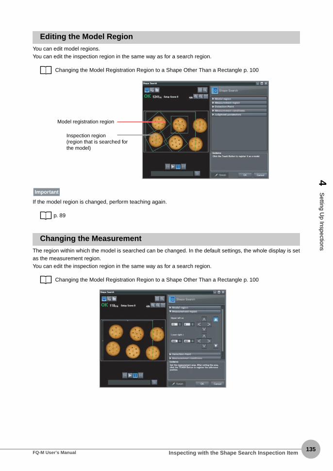
4S
etting Up Inspections
Editing the Model RegionYou can edit model regions.You can edit the inspection region in the same way as for a search region.
Changing the Model Registration Region to a Shape Other Than a Rectangle p. 100
If the model region is changed, perform teaching again.
p. 89
Changing the MeasurementThe region within which the model is searched can be changed. In the default settings, the whole display is setas the measurement region.You can edit the inspection region in the same way as for a search region.
Changing the Model Registration Region to a Shape Other Than a Rectangle p. 100
Model registration region
Inspection region (region that is searched for the model)
Important
Inspecting with the Shape Search Inspection ItemFQ-M User’s Manual135

136
Measurement Data That Can Be Used for External Outputs and CalculationsThe following values can be used as measurement data and output to external devices used in calculations.
4-8 Calculations and Judgements Using Inspection Item Data p. 138
Expression text string
Data name Description Data range
JG Judgement This is the judgement results of the search. −2: No judgement (not measured), 0: Judgement is OK, −1: Judgement is NG, −13: Teaching not performed error, −14: Figure not registered error, −15: Out of range error
C Count This is the number of models found. 0 to 32
CR[0] to CR[31] Correlation This is the correlation of the Nth model that was found.
0 to 100
X[0] to X[31] Position X This is the X coordinate where the Nth model was found.
−99,999.9999 to 99,999.9999
Y[0] to Y[31] Position Y This is the Y coordinate where the Nth model was found.
−99,999.9999 to 99,999.9999
TH[0] to TH[31] Angle This is the angle in which the Nth model was found.
−180 to 180
SX Reference position X This is the X coordinate of the position where the model was registered.
−99,999.9999 to 99,999.9999
SY Reference position Y This is the Y coordinate of the position where the model was registered.
−99,999.9999 to 99,999.9999
ST Reference angle This is the angle when the model was regis-tered.
−180 to 180
RX Detection point coor-dinate X
This is the X coordinate of the detection point when the model was registered.
−99,999.9999 to 99,999.9999
RY Detection point coor-dinate Y
This is the Y coordinate of the detection point when the model was registered.
−99,999.9999 to 99,999.9999
Inspecting with the Shape Search Inspection Item FQ-M User’s Manual

4S
etting Up Inspections
Measurement Data That Can Be LoggedYou can select to log any of the following values.
* When logging data is output, the data is output in the order of the above table. If more than one item is stored, results are output for each model.
7-3 Logging Measurement Data and Image Data p. 191
Errors
Errors in Teaching
A teaching error message will appear if the contrast of the image within the model registration region is too low.Select a region with a larger contrast between light and dark areas compared to the region that was registeredas the model and re-register it as the model.
Parameter Range Description
Judgement 0: Judgement is OK−1: Judgement is NG−13: Teaching not performed error−14: Figure not registered error−15: Out of range error
This is the measurement judgement results.
Correlation 0 to 100 This is the measured correlation.
Position X −99,999.999 to 99,999.999 This is the measurement position X.
Position Y −99,999.999 to 99,999.999 This is the measurement position Y.
Angle −180 to 180 This is the measurement angle.
Inspecting with the Shape Search Inspection ItemFQ-M User’s Manual137

138
4-8 Calculations and Judgements Using Inspection Item Data
You can set inspection item judgement results and measurement data with the Calculation menu command touse them in basic arithmetic operations and functions. You can reflect the judgement results of the calculationsin the overall judgement.
CalculationUse the Calculation menu command to set the calculation expressions and the judgement parameters for thecalculation results.
Expression
You can get up to 32 expressions. You can also combine expressions.You can use the following values in calculations.• Inspection item data (measurement data, reference values, and judgement results)• Constants• Other calculation results
Judgement
Upper and lower limit values are used for the judgement of calculation results (D0 to D31). Each calculationjudgement result (J0 to J31) is turned ON if the result falls within the upper and lower limits. The OR logic ofthese results will be the overall judgement result JG.
Calculations and Judgements Using Inspection Item Data FQ-M User’s Manual
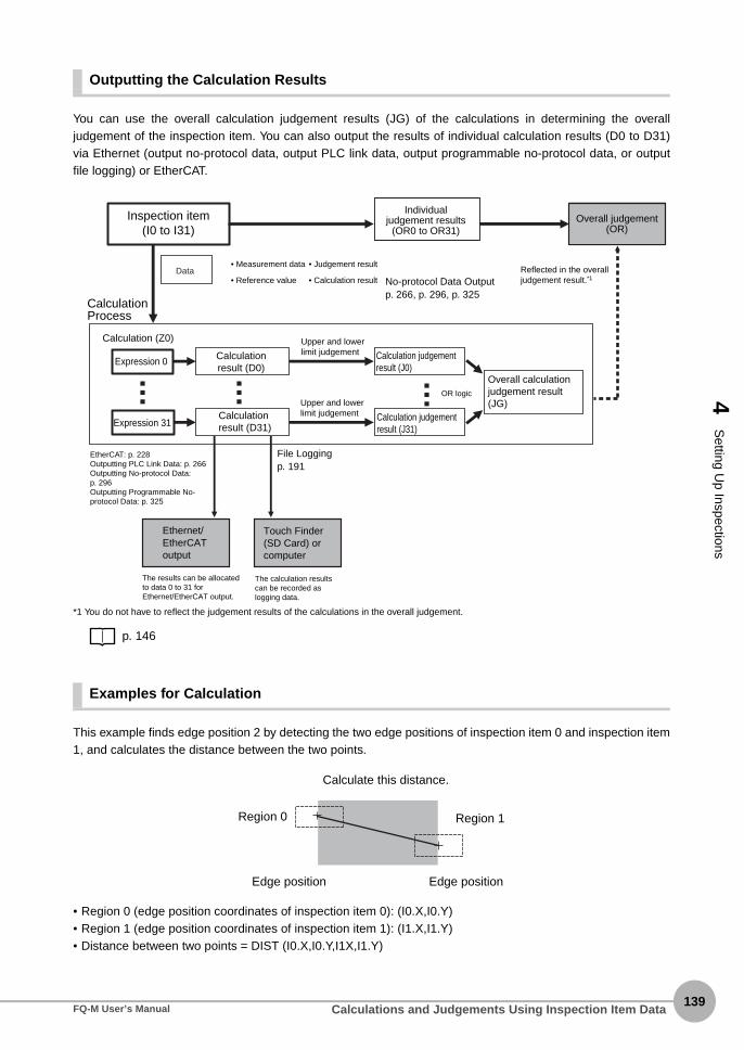
4S
etting Up Inspections
Outputting the Calculation Results
You can use the overall calculation judgement results (JG) of the calculations in determining the overalljudgement of the inspection item. You can also output the results of individual calculation results (D0 to D31)via Ethernet (output no-protocol data, output PLC link data, output programmable no-protocol data, or outputfile logging) or EtherCAT.
*1 You do not have to reflect the judgement results of the calculations in the overall judgement.
p. 146
Examples for Calculation
This example finds edge position 2 by detecting the two edge positions of inspection item 0 and inspection item1, and calculates the distance between the two points.
• Region 0 (edge position coordinates of inspection item 0): (I0.X,I0.Y)• Region 1 (edge position coordinates of inspection item 1): (I1.X,I1.Y)• Distance between two points = DIST (I0.X,I0.Y,I1X,I1.Y)
Calculation (Z0)
Inspection item(I0 to I31)
Upper and lower limit judgement
Calculation result (D31)
Calculation result (D0)
Calculation Process
• Measurement data
• Reference value
Upper and lower limit judgement Calculation judgement
result (J31)
OR logic
Expression 0
Expression 31
Ethernet/EtherCAT output
• Judgement result
• Calculation result
Individual judgement results
(OR0 to OR31)Overall judgement
(OR)
Data
Overall calculation judgement result (JG)
Calculation judgement result (J0)
The results can be allocated to data 0 to 31 for Ethernet/EtherCAT output.
The calculation results can be recorded as logging data.
Reflected in the overall judgement result.*1
Touch Finder (SD Card) or computer
File Loggingp. 191
EtherCAT: p. 228Outputting PLC Link Data: p. 266Outputting No-protocol Data: p. 296Outputting Programmable No-protocol Data: p. 325
No-protocol Data Outputp. 266, p. 296, p. 325
Calculate this distance.
Region 0 Region 1
Edge position Edge position
Calculations and Judgements Using Inspection Item DataFQ-M User’s Manual139

140
Setup Procedure for Calculations
Multiview Explorer: [Scene] − Scene number→ Edit Pane: (Calculation) Icon
• Operation on the Touch Finder
Use the following menu command to display the Setup Display on the Touch Finder.
[Inspect] − [Calculation]
Setting Expressions
• Operation on the Touch Finder
Use the following menu command to display the Setup Display on the Touch Finder.
[Inspect] − [Calculation] − [Expression*] − [Settings] Tab Page − [Expression]
1 Right-click the expression list number youwant to assign and select [Edit].
1 Set the expression under [Expression]. Youcan specify inspection item output data,constants, and variables in expressions.
2 Enter a comment about the expression un-der [Name].
▲▲
You can enter expressions as text.
Note
Select and insert inspection item output data.
Select and insert functions.
Comment inputExpression input
▲
Calculations and Judgements Using Inspection Item Data FQ-M User’s Manual
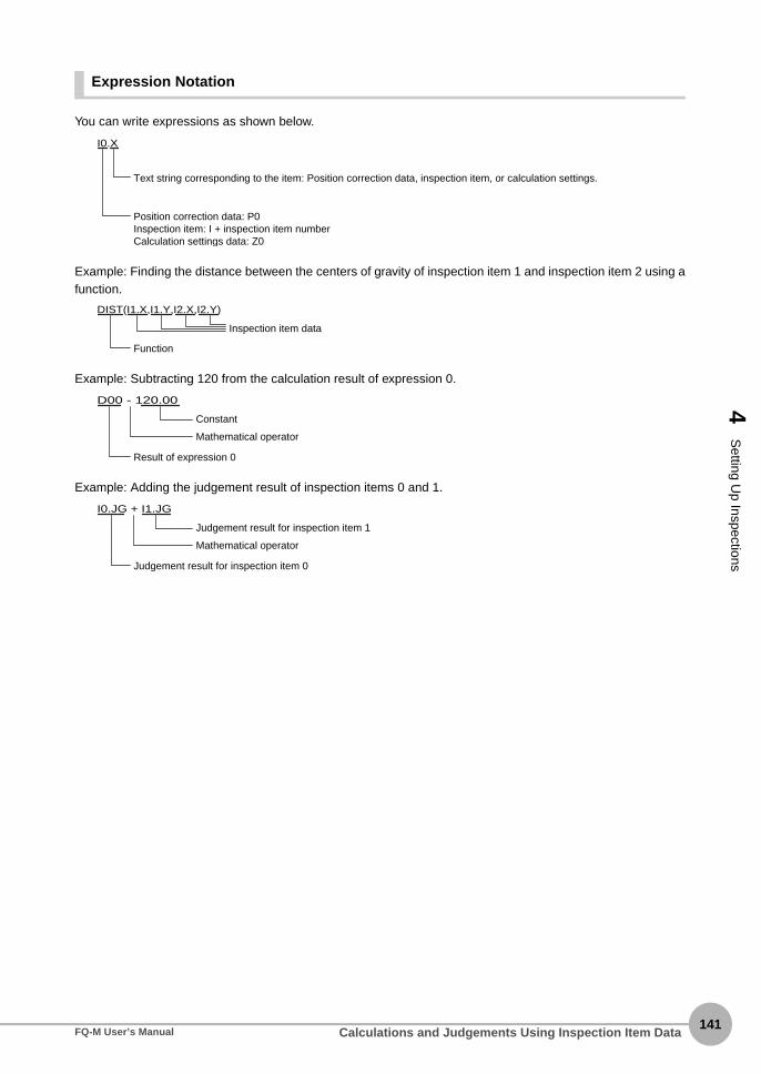
4S
etting Up Inspections
Expression Notation
You can write expressions as shown below.
Example: Finding the distance between the centers of gravity of inspection item 1 and inspection item 2 using afunction.
Example: Subtracting 120 from the calculation result of expression 0.
Example: Adding the judgement result of inspection items 0 and 1.
I0.X
Text string corresponding to the item: Position correction data, inspection item, or calculation settings.
Position correction data: P0Inspection item: I + inspection item numberCalculation settings data: Z0
DIST(I1.X,I1.Y,I2.X,I2.Y)
Inspection item data
Function
D00 - 120.00
Constant
Mathematical operator
Result of expression 0
I0.JG + I1.JG
Judgement result for inspection item 1
Mathematical operator
Judgement result for inspection item 0
Calculations and Judgements Using Inspection Item DataFQ-M User’s Manual141

142
Copying ExpressionsYou can copy an expression if you need to use a similar expression in more than one location.
Deleting ExpressionsYou can delete a previously set expression.
1 Click the expression you want to copy in theExpression List.
2 Click the (Copy) Icon.
3 Select the location where you want to makethe copy in the Expression List.
4 Click the (Paste) Icon.
1 Click the expression you want to delete inthe Expression List.
2 Click the (Delete) Icon.
Calculations and Judgements Using Inspection Item Data FQ-M User’s Manual

4S
etting Up Inspections
Function ListThe following functions can be used in calculations.
Function Description
SIN Finds the sine. The result is a value between −1 and 1.The angle in the expression is in degrees.
SIN(angle)
COS Finds the cosine. The result is a value between −1 and 1.The angle in the expression is in degrees.
COS(angle)
ATAN Finds the arctangent of the value (Y component, X component). The result is a radian value between −π and π.
ANGL(Y_component,X_component)Example: Finding the angle between the straight line joining the centers of region 0 and region 1 and
horizontal.ATAN(R1.Y-R0.Y,R1.X-R0.X)
If the two arguments are both 0, the result is 0 and the judgement is NG.
AND Finds the logical AND.If one of the arguments is 0, the calculation result is 0. Otherwise it is −1.
AND(argument_1,argument_2)
OR Finds the logical OR.If both of the arguments are 0, the calculation result is 0. Otherwise it is −1.
OR(argument_1,argument_2)
NOT Applies a logical NOT operation.If the argument is 0, the calculation result is −1. Otherwise it is 0.
NOT(argument)
ABS Finds the absolute value.ABS(argument)
MAX Returns the larger of the two arguments.MAX(argument_1, argument_2)
MIN Returns the smaller of the two arguments.MIN(argument_1, argument_2)
Calculations and Judgements Using Inspection Item DataFQ-M User’s Manual143

144
Function Description
ANGL Finds the angle of the straight line joining two points (the center of gravity and center of the model). The angle against the horizontal is found. The result is a value between −180 and 180.
ANGL(Y_component,X_component)Example: Finding the angle of the straight line joining the centers of region 0 and region 1
ANGL(R1.Y-R0.Y,R1.X-R0.X)
If the two arguments are both 0, the result is 0 and the judgement is NG.
MOD Finds the remainder after dividing a dividend with a divisor.MOD(dividend, divisor)
If any of the arguments are real numbers, the decimals are rounded off before calculating the remain-der. The remainder is the result of dividing integers.
Example: MOD(13,4) ... Result: 1 (remainder when 13 is divided by 4)MOD(25.68,6.99) ... Result: 5 (remainder when 26 is divided by 7)
SQRT Finds the square root.If the argument is negative, the result is 0. The judgement will be NG.
SQRT(argument)
DIST • Finds the distance between two points (the center of gravity and the center of the model).DIST(first_position_X, first_position_Y, second_poistion_X, second_position_Y)Example: Finding the distance between the centers of gravity of region 0 and region 1
DIST(R0.X,R0.Y,R1.X,R1.Y)The following calculation is performed internally.
• Finds the length of a perpendicular line from point (x,y) to line ax + by + c = 0.DIST (X_coordinate_of_point, Y_coordinate_of_point, coefficient_a_of_line, coefficient_b_of_line, coefficient_c_of_line)
ECNT • You can obtain the value of the encoder. You can set ECNT only from the PC Tool.ECNT(value to obtain)
• The following values can be obtained.0: Get ring counter value at trigger1: Get ring counter value at calculation2: Get trigger counter value
First point
(Horizontal)
Second point
(R1.X−R0.X) 2+ (R1.Y−R0.Y) 2
Calculations and Judgements Using Inspection Item Data FQ-M User’s Manual

4S
etting Up Inspections
Performing Expression Judgement
Multiview Explorer: [Scene] − Scene number→ Edit Pane: (Calculation) Icon − Expression number
• Operation on the Touch Finder
Use the following menu command to display the Setup Display on the Touch Finder.
[Inspect] − [Calculation] − [Settings] Tab Page − [Judgement]
1 Right-click the expression for which to ad-just judgement conditions and select [Ed-it].
2 Click [Judgment parameters].
3 Set the upper and lower limit values for thejudgement conditions.
▲▲
Calculations and Judgements Using Inspection Item DataFQ-M User’s Manual145

146
Reflecting the Judgement Results for Expressions to the Overall Judgement ResultsPerform the following settings to reflect the judgement results of a calculation in the overall judgement.
Multiview Explorer: [Scene] − Scene number→ Edit Pane: (Calculation) Icon
• Operation on the Touch Finder
Use the following menu command to display the Setup Display on the Touch Finder.
[Inspect] − [Calculation] − [Details] Tab Page − [Reflect]
Inspection Item Data That Can Be Used in Expressions
1 Select the [Reflect to overall judgement]Check Box.
Inspection item
Data name Expression text string Data range Default
Search Judgement JG −2: No judgement (not measured), 0: Judgement is OK,−1: Judgement is NG, −13: Teaching not performed error, −14: Figure not registered error, −15: Out of range error
Count C 0 to 32
Correlation CR[0]*1 to CR[31] 0 to 100
Position X X[0]*1 to X[31] −99999.9999 to 99999.9999
Position Y Y[0]*1 to Y[31] −99999.9999 to 99999.9999
Angle TH[0]*1 to TH[31] −180 to 180
Reference position X SX −99999.9999 to 99999.9999
Reference position Y SY −99999.9999 to 99999.9999
Reference angle ST −180 to 180
Detection point coordinate X RX −99999.9999 to 99999.9999
Detection point coordinate Y RY −99999.9999 to 99999.9999
Edge Position Judgement JG −2: No judgement (not measured), 0: Judgement is OK, −1: Judgement is NG, −13: Teaching not performed error, −14: Figure not registered error, −15: Out of range error
Edge position X X −99999.9999 to 99999.9999
Edge position Y Y −99999.9999 to 99999.9999
Standard position X SX −99999.9999 to 99999.9999
Standard position Y SY −99999.9999 to 99999.9999
▲▲
Calculations and Judgements Using Inspection Item Data FQ-M User’s Manual

4S
etting Up Inspections
*1: You can omit [0] if there is only a single value.
The following expression values can be specified as expression data to output them.
Labeling Judgement JG −2: No judgement (not measured), 0: Judgement is OK, −1: Judgement is NG, −13: Teaching not performed error, −14: Figure not registered error, −15: Out of range error
# of label L 0 to 100
Total area TAR 0 to 999999999.9999
Area AR[0]*1 to AR[99] 0 to 999999999.9999
Gravity coordinate X X[0]*1 to X[99] −99999.9999 to 99999.9999
Gravity coordinate Y Y[0]*1 to Y[99] −99999.9999 to 99999.9999
Elliptic major angle ATH[0]*1 to ATH[99] −180 to 180
Reference area SA 0 to 999999999.9999
Reference position X SX −99999.9999 to 99999.9999
Reference position Y SY −99999.9999 to 99999.9999
Shape Search Judgement JG −2: No judgement (not measured), 0: Judgement is OK, −1: Judgement is NG, −13: Teaching not performed error, −14: Figure not registered error, −15: Out of range error
Count C 0 to 32
Correlation CR[0]*1 to CR[31] 0 to 100
Position X X[0]*1 to X[31] −99999.9999 to 99999.9999
Position Y Y[0]*1 to Y[31] −99999.9999 to 99999.9999
Measurement angle TH[0]*1 to TH[31] −180 to 180
Reference position X SX −99999.9999 to 99999.9999
Reference position Y SY −99999.9999 to 99999.9999
Reference angle ST −180 to 180
Detection point coordinate X RX −99999.9999 to 99999.9999
Detection point coordinate Y RY −99999.9999 to 99999.9999
Expression text string
Data name Description Data range
JG Judgement This is the overall judgement results for all expressions.
−2: No judgement (not measured), 0: Judgement is OK, −1: Judgement is NG
JG[0] to JG[31] Individual judge-ment results
This is the individual judgement result for expression N.
−2: No judgement (not measured), 0: Judgement is OK, −1: Judgement is NG
D[0] to D[31] Individual calcula-tion results
This is the calculation result for expres-sion N.
−999,999,999.9999 to 999,999,999.9999
Inspection item
Data name Expression text string Data range Default
Calculations and Judgements Using Inspection Item DataFQ-M User’s Manual147
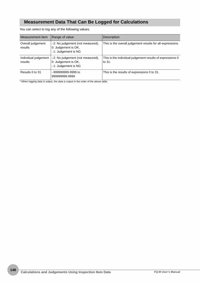
148
Measurement Data That Can Be Logged for CalculationsYou can select to log any of the following values.
* When logging data is output, the data is output in the order of the above table.
Measurement item Range of value Description
Overall judgement results
−2: No judgement (not measured), 0: Judgement is OK, −1: Judgement is NG
This is the overall judgement results for all expressions.
Individual judgement results
−2: No judgement (not measured), 0: Judgement is OK, −1: Judgement is NG
This is the individual judgement results of expressions 0 to 31.
Results 0 to 31 −999999999.9999 to 999999999.9999
This is the results of expressions 0 to 31.
Calculations and Judgements Using Inspection Item Data FQ-M User’s Manual

Testing and Saving Settings
5 T
esting and Saving S
ettings
5-1 Performing Test Measurements...........................................................150
5-2 Checking the Trend of Measurement Results with Graphs ..............152
5-3 Decreasing the Measurement Takt Time.............................................158
5-4 Checking a List of All Inspection Item Results ..................................160
5-5 Saving Data to the Sensor....................................................................161

150
5-1 Performing Test Measurements
After you finish making the [Image], [Calibration], [Inspection], and [Calculation] settings, you can perform atest measurement to check for correct operation. Test measurements is used to verify that the settings thathave been made will produce stable results and, if necessary, to fine-tune the measurements. Testmeasurements are performed on the currently displayed image.
Performing Test Measurements with Samples
Test measurements are performed on the image currently being taken by the Sensor. You can view the overalljudgement of all inspection items for the target of a test measurement.
Multiview Explorer: [Scene] − Scene number→ Edit Pane: [Run] − [Start monitor]
• Operation on the Touch Finder
Use the following menu command to display the Setup Display on the Touch Finder.
[Test] − [Continuous test] − [Graphics + Details]
You can select from four different views: Graphics, Result List, Trend Monitor, and Histogram.
Changing the Run Mode Display p. 169
1 Input an image of a previously prepared object.Check the judgement results.
2 When you finish checking the results, click [Close].
Note
▲▲
Performing Test Measurements FQ-M User’s Manual

5 T
esting and Saving S
ettings
Performing Test Measurements with Saved Images (Re-measuring)
The Sensor can save measured images in the Sensor’s built-in memory or on an SD card through either the PCTool or the Touch Finder. Test measurements can be performed by using these saved images. This function isuseful for adjusting the judgement parameters when objects are not available.
Multiview Explorer: [Scene] − Scene number→ Edit Pane: [Inspection]
• Operation on the Touch Finder
Use the following menu command to display the Setup Display on the Touch Finder.
[Test] − [Continuous test] − [Graphics + Details] − −
1 Select (Logging image) or (Image file).• Logging image: Images logged in the Sensor’s internal
memory
• File image: Images saved in the personal computer
2 Click the (Select the image) Icon and select a file.
3 The display switches to the selected image and mea-surements are taken again.
4 You can use the following control buttons to changethe displayed image and perform measurementsagain.
For file images, this button cycles through all image files in the folder where the selected file is stored. For logged images, all logged images are cycled through.
When the [Pause] Button is pressed, this button changes to the previous image.
When the [Pause] Button is pressed, this button changes to the next image.
With the PC Tool, you can perform test measurements even in Offline Mode. When offline, you can select file imagesand perform test measurements. However, you cannot accurately determine the measurement time with offline mea-surements.
Offline Settings p. 372
▲
Note
▲
Performing Test MeasurementsFQ-M User’s Manual151

152
5-2 Checking the Trend of Measurement Results with Graphs
You can use the trend monitor and histograms to check the test measurement result histories.
Trend Monitor
Changes in the measurement values of the selected inspection item against time can be observed from thegraph. It is possible to predict when malfunctions may occur or to analyze the cause of a malfunction bychecking the trends in the measurement values. The most recent 1,000 measurement values are displayed ona graph.
PC Tool
Multiview Explorer: [Scene] − Scene number→ Edit Pane: (Run) Icon − [Start monitor] − (Trend Monitor) Icon
Touch Finder
(Run Mode) − [Select display] − [Monitor]
▲
Changes in the measured values of the selected inspection item are displayed against time in a graph.
Measurement values
Changes in the measured values of the selected inspection item are displayed against time in a graph.
Measurement values
Switches the display to the previous inspection item number.
Switches the display to the next inspection item number.
Checking the Trend of Measurement Results with Graphs FQ-M User’s Manual
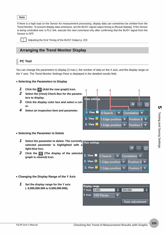
5 T
esting and Saving S
ettings
Arranging the Trend Monitor Display
PC Tool
You can change the parameters to display (3 max.), the number of data on the X axis, and the display range onthe Y axis. The Trend Monitor Settings Pane is displayed in the detailed results field.
• Selecting the Parameters to Display
• Selecting the Parameter to Delete
• Changing the Display Range of the Y Axis
If there is a high load on the Sensor for measurement processing, display data can sometimes be omitted from theTrend Monitor. To prevent display data omissions, set the BUSY signal output timing to [Result display]. If the Sensoris being controlled over a PLC link, execute the next command only after confirming that the BUSY signal from theSensor is OFF.
Adjusting the End Timing of the BUSY Output p. 223
1 Click the (Add the new graph) Icon.
2 Select the [View] Check Box for the parame-ters to display.
3 Click the display color box and select a col-or.
4 Select an inspection item and parameter.
1 Select the parameter to delete. The currentlyselected parameter is highlighted with alight-blue box.
2 Click the (The display of the selectedgraph is cleared) Icon.
1 Set the display range for the Y axis (−9,999,999.999 to 9,999,999.999).
Note
2 3 4 1
Checking the Trend of Measurement Results with GraphsFQ-M User’s Manual153

154
• Automatically Setting the Display Range of the Y Axis
1 Click the [Auto adjustment] Button. The range of the Y axis is set automatically based on the dis-played data.
• Changing the Display Range of the X Axis
1 Select the number of data to display (100 to 1,000).
Touch Finder
You can change the display range for the Y axis and the number of values that are displayed for the X axis.
• Disabling Automatic Selection of the Display Range
1 Press [ ] − [Auto display] on the right of the trend monitor.
2 Press [OFF].
• Changing the Display Range of the Vertical Axis
1 Press [ ] − [Display range] on the right of the trend monitor.
2 Set the minimum and maximum values of the measurement values.
• Changing the Number of Values That Are Displayed
1 Press [ ] − [Number of data] on the right of the trend monitor.
2 Select the number of values from 200, 400, and 1,000.
You can display only one parameter in the Trend Monitor on the Touch Finder. You cannot display multiple parameters at the same time.
• Trend monitor data is held until the power supply is turned OFF.
• You can select whether to display all data on the trend monitor or only data for which the overall judgement is NG.
Logging settings are applied to the trend monitor as well. However, they are not applied to trend monitor when it is
displayed in Setup Mode.
Checking Recent Measurement Trends (Recent Results Logging) p. 199
Note
Note
Checking the Trend of Measurement Results with Graphs FQ-M User’s Manual

5 T
esting and Saving S
ettings
Histograms
You can check the distribution of measurement values on a histogram.
PC Tool
Multiview Explorer: [Scene] − Scene number→ Edit Pane: (Run) Icon - [Start monitor] − (Histogram) Icon
Touch Finder
(Run Mode) − [Select display] − [Histogram]
If there is a high load on the Sensor for measurement processing, display data can sometimes be omitted from theHistogram. To prevent display data omissions, set the BUSY signal output timing to [Result display]. If the Sensor isbeing controlled over a PLC link, execute the next command only after confirming that the BUSY signal from theSensor is OFF.
Adjusting the End Timing of the BUSY Output p. 223
▲
Measurement values
Number of measurement values
The distribution of measurement values that are equivalent to the judgement values is displayed in a histogram for the selected inspection item.
Measurement values
Number of measurement values
Switches the display to the next inspection item number.
Switches the display to the previous inspection item number.
The distribution of measurement values that are equivalent to the judgement values is displayed in a histogram for the selected inspection item.
Note
Checking the Trend of Measurement Results with GraphsFQ-M User’s Manual155

156
Arranging Histogram Displays
PC Tool
The parameters to display, the display range on the X axis, and the number of data on the Y axis of thehistogram can be changed. The Histogram Settings Pane is displayed in the detailed results field.
• Selecting the Parameters to Display
• Changing the Display Range of the X Axis
• Changing the Number of Data on the Y Axis
1 Set the maximum number of data to display (1 to 99,999).
• Automatically Setting the Maximum Number of Data for the Y Axis
1 Click the [Auto adjustment] Button.The maximum number of data for the Y axis is set automatically based on the displayed data.
1 Select the display color.
2 Select the inspection item and the parame-ter.
1 Set the display range for the X axis (−9,999,999.999 to 9,999,999.999).
2 Set the spacing between vertical histogrambars (1 to 9,999,999).
Checking the Trend of Measurement Results with Graphs FQ-M User’s Manual

5 T
esting and Saving S
ettings
Arranging Histogram Display
The display range on the X axis and the number of data on the Y axis of the histogram can be changed.
• Disabling Automatic Adjustment of the Display Range
1 Press [ ] − [Auto display] on the right of the histogram.
2 Press [OFF].
• Changing the Display Range of the X Axis
1 Press [ ] − [Display range] on the right of the histogram.
2 Select the maximum measurement value, the minimum measurement value, and the class.
• Changing the Number of Data on the Y Axis
1 Press [ ] − [Number of data] on the right of the histogram.
2 Select the maximum number of data to display.
• Histogram data is held until the power supply is turned OFF.
• You can select whether to display all data in the histogram or only data for which the overall judgement is NG.
Logging settings are applied to the histogram as well.
However, they are not applied to histograms displayed in Setup Mode.
Checking Recent Measurement Trends (Recent Results Logging) p. 199
Note
Checking the Trend of Measurement Results with GraphsFQ-M User’s Manual157

158
5-3 Decreasing the Measurement Takt Time
Checking the Measurement Takt Time
You can check the measurement time of the Sensor from the Edit Pane. When online, the measurement time isdisplayed as the amount of time that was required for processing by the Sensor. When offline, the amount oftime that was required for processing by the computer is displayed. To estimate the processing time, connectthe Sensor and go online.
The measurement time is the time taken from when a trigger is input until when all measurement processes areexecuted.During the measurement time, this Sensor will not accept the next trigger. This means that the measurementtime is the basic measurement takt time.
Measurement Time Display Example
Measurement time
DisplayMeasurementImage inputFile
logging
Measurement time = Measurement takt time
Inputting a trigger
Decreasing the Measurement Takt Time FQ-M User’s Manual

5 T
esting and Saving S
ettings
Increasing Image Input Speed
With the partial input function, it is possible to input only images that are in the region that is necessary formeasurements. The image measurement region becomes smaller and thus the image input time is shortened.
Multiview Explorer: [Scene] − Scene number→ Edit Pane: (Image) Icon − [Setup menu] − [Partial input]
If you use partial input, perform teaching again.
• Operation on the Touch Finder
Use the following menu command to display the Setup Display on the Touch Finder.
[Image] − [Camera setup] − − [Partial input]
Shortening the Processing Time for Measurement Items
The processing time can be shortened by making the measurement region for each measurement itemsmaller.
Changing the Measurement Region p. 102
1 Change the input size.The minimum vertical width for image input is 8lines.
▲
Important
▲
Decreasing the Measurement Takt TimeFQ-M User’s Manual159

160
5-4 Checking a List of All Inspection Item Results
You can check the individual judgement results for all inspection items in a list. You can select the individualinspection items to change the judgement parameters.
Multiview Explorer: [Scene] − Scene number→ Edit Pane: (Inspection) Icon
The judgement results (OK: green, NG: red) are displayed in the inspection item list in Edit Pane.
The judgement results (OK: Green, NG: Red) are also displayed in the inspection item flow list in theMonitoring Pane.
• Starting the Monitor
p. 150
• Operation on the Touch Finder
Use the following menu command to display the Setup Display on the Touch Finder.
[Test] − [Continuous test] − [All results/region]
▲▲
Checking a List of All Inspection Item Results FQ-M User’s Manual

5-5 Saving Data to the Sensor
5 T
esting and Saving S
ettings
Execute [Save data] after you have finished making your settings.The Vision Sensor will remind you to do so with a message if you switch from Setup Mode to Run Mode. Whena message is displayed, always execute [Save data].
Do not turn OFF the power supply while data is being saved. The data that is being saved may becomecorrupted.
• Operation on the Touch Finder
Use the following menu command to display the Setup Display on the Touch Finder.
[Test] − [Save data]
1 Use either of the following methods to savethe settings to the Sensor.• Multiview Explorer: [Device group] − Sensor
name (Double-click)
→ Edit Pane: (Online) Icon − [Save data]
• Multiview Explorer: [Scene] − Scene number
→ Edit Pane: (Run) Icon − [Save data]
2 Click the [Yes] Button.
• Scene data, system data, and calibration data can be saved with the above procedure.
Scene Data and System Data p. 204
• Measurement data and image data cannot be saved with the above procedure.
Logging Measurement Data and Image Data p. 191
• Settings data can also be backed up to an external memory
Saving Settings p. 204
Important
▲
Note
Saving Data to the SensorFQ-M User’s Manual161

162
MEMO
Saving Data to the Sensor FQ-M User’s Manual

Operation
6 O
peration
6-1 Starting Operation. . . . . . . . . . . . . . . . . . . . . . . . . . . . . . . . . . . . . . . . 164
6-2 Configuring the Run Mode Display . . . . . . . . . . . . . . . . . . . . . . . . . . 169
6-3 Checking the Trend of Measurement Results with Graphs. . . . . . . 173
6-4 Adjusting Judgement Parameters during Operation . . . . . . . . . . . . 176
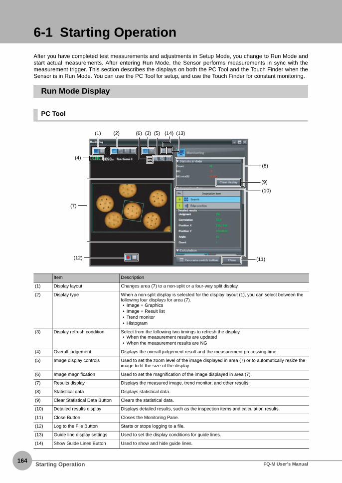
164
6-1 Starting Operation
After you have completed test measurements and adjustments in Setup Mode, you change to Run Mode andstart actual measurements. After entering Run Mode, the Sensor performs measurements in sync with themeasurement trigger. This section describes the displays on both the PC Tool and the Touch Finder when theSensor is in Run Mode. You can use the PC Tool for setup, and use the Touch Finder for constant monitoring.
Run Mode Display
PC Tool
Item Description
(1) Display layout Changes area (7) to a non-split or a four-way split display.
(2) Display type When a non-split display is selected for the display layout (1), you can select between the following four displays for area (7).• Image + Graphics• Image + Result list• Trend monitor• Histogram
(3) Display refresh condition Select from the following two timings to refresh the display.• When the measurement results are updated• When the measurement results are NG
(4) Overall judgement Displays the overall judgement result and the measurement processing time.
(5) Image display controls Used to set the zoom level of the image displayed in area (7) or to automatically resize the image to fit the size of the display.
(6) Image magnification Used to set the magnification of the image displayed in area (7).
(7) Results display Displays the measured image, trend monitor, and other results.
(8) Statistical data Displays statistical data.
(9) Clear Statistical Data Button Clears the statistical data.
(10) Detailed results display Displays detailed results, such as the inspection items and calculation results.
(11) Close Button Closes the Monitoring Pane.
(12) Log to the File Button Starts or stops logging to a file.
(13) Guide line display settings Used to set the display conditions for guide lines.
(14) Show Guide Lines Button Used to show and hide guide lines.
(4)
(7)
(12) (11)
(10)
(1) (2) (6) (5) (14) (13)(3)
(8)
(9)
Starting Operation FQ-M User’s Manual

6 O
peration
Touch Finder
Changing to Run Mode
PC Tool
You can move from Setup Mode to Run Mode from either the Main Pane or an Edit Pane. Use either of thefollowing methods to save the settings to the Sensor.
• Main Pane
Multiview Explorer: [Device group] − Sensor model (right-click [Edit])→ Edit Pane: [Online] − [Switch the sensor mode]
1 Press [Run].
Overall judgement
Measurement processing time
Connected Sensor nameSelected scene number
Sub-menu
Tool Button or OK Button
Indicates the measurement results that are currently displayed.
The present display name.
The time required from when an image is input until all measurements have been completed.
Inspection results can be displayed in six patterns, such as in a list or as a trend graph.
Selected inspection item
These buttons are displayed both in Setup Mode and Run Mode.
p. 169
p. 58
▲
Starting OperationFQ-M User’s Manual165
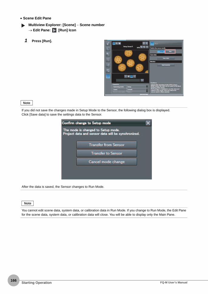
166
• Scene Edit Pane
Multiview Explorer: [Scene] − Scene number→ Edit Pane: [Run] Icon
1 Press [Run].
If you did not save the changes made in Setup Mode to the Sensor, the following dialog box is displayed.Click [Save data] to save the settings data to the Sensor.
After the data is saved, the Sensor changes to Run Mode.
You cannot edit scene data, system data, or calibration data in Run Mode. If you change to Run Mode, the Edit Panefor the scene data, system data, or calibration data will close. You will be able to display only the Main Pane.
▲
Note
Note
Starting Operation FQ-M User’s Manual

6 O
peration
Touch Finder
You can move from Setup Mode to Run Mode by using the following procedure.
1 Press [Run].
2 Press [Switch to Run mode.].
• Returning to Setup Mode
Press and press [Sensor settings].
• Signal Status When Moving to Run Mode
When moving to Run Mode, the signal will change as shown below and data can be input from and output to anexternal device.
Note
ON
OFF
The BUSY signal that was always ON will turn OFF.
BUSY signal
Display Run ModeSetup Mode
Starting OperationFQ-M User’s Manual167

168
Starting the Monitor
In the PC Tool, you can open the Monitor Pane to view measurement results.
• Main Pane
Multiview Explorer: [Device group] − Sensor model (right-click [Edit])→ Edit Pane: [Online]
• Scene Edit Pane
Multiview Explorer: [Scene] − Scene number→ Edit Pane: [Run] Icon
1 Select [Start monitor].
1 Select [Start monitor].
You cannot edit scene data, system data, or calibration data while monitoring measurement results.
▲▲
Note
Starting Operation FQ-M User’s Manual

6-2 Configuring the Run Mode Display
6 O
peration
Displayed Information
You can select what information is displayed in Run Mode. Select the display as desired for the application.
PC Tool
You can click the display type icon to view results in the results display area in two different patterns. Thedetailed results display shows detailed results for the inspection item that is currently selected in the [Inspectflow].
• Statistical data: The history of the overall judgement results (measurement count, NG count, and NG rate) will
appear.
• Inspect flow: Displays a list of registered inspection items sorted by order of inspection.
• Detailed results: Displays detailed measurement results for an inspection item.
• Calculation: Displays the results for each expression registered to an inspection item.
You cannot select the trend monitor or histogram on the PC Tool in Run Mode.
Image + Graphics Image + Result list
Important
Configuring the Run Mode DisplayFQ-M User’s Manual169

170
Click the [Panorama switch button] to view the panorama display.
No. Item Description
(1) Panorama image Combines continuous display images into a panorama image display. The model region and detection points for the inspection item are dis-played. The regions where the images overlap are also displayed. This allows you to easily confirm if any models were not detected.
(2) Conveyor speed Enter the speed of the conveyor. The average imaging interval is calcu-lated based on these values.
(3) Average imaging time Displays the average image trigger interval in milliseconds.
(4) Maximum processing time Displays the maximum time that was required for measurement pro-cessing in milliseconds. This allows you to confirm how much leeway you have in the measurement time compared with the averaging imag-ing interval.
(5) Average processing time Displays the average processing time for measurement processing in milliseconds.
(6) Close Closes the panorama display.
The following conditions must be satisfied to view the panorama display.• The encoder must be connected directly to the Sensor and must be used for the value of the ring counter.
• The calibration for conveyor tracking must be completed.
• The BUSY output condition for the BUSY signal must be set to [Result display completion].
Changing the BUSY Signal Output Condition p. 222
• When offline, an image that was saved by using file logging must be selected.
• The file name assigned for logging must not be changed.
• When offline, the Sensor settings (calibration data and scene data) when the logging was performed must be
imported into the PC Tool.
(2)(3)(4)(5)
(6)
(1)
Note
Configuring the Run Mode Display FQ-M User’s Manual

6 O
peration
Touch Finder
(Run Mode) − [Select display]
Checking the Judgement Results of Inspection Items Checking the Overall Judgement Result History
Graphics
The image and region currently being measured will appear.
Graphics + Details
In addition to [Graphics] display, indi-vidual judgement results and measure-ment values of selected inspection items will appear.
Statistical data
The currently measured image and history of the overall judgement results (measurement count, NG count, and NG rate) will appear.
Checking the Judgements of All Inspection Items in a List Displaying Measurement Result Histories
All results/region (Standard Models Only)
Trend monitor Histogram
The judgement results of all inspection items can be checked in a list.
The statistical data for the currently selected inspection item can be checked against time.
p. 173
The distribution of measurement results of the currently selected inspection item can be checked.
p. 173
▲
Configuring the Run Mode DisplayFQ-M User’s Manual171

172
The following displays are convenient if more than one Sensor is connected.
(Run Mode) − [Sensor monitor]
Displaying the Inspection Item Results
You can scroll though the measurement results of all the configured inspection items by using the followingoperations.
Specifying the Startup Run Mode Display for the Touch Finder
You can set the display that appears when the power supply is turned ON. The default setting is [Graphics].
(Setup Mode or Run Mode) − [TF settings] − [Startup display] − [Display pattern]
Multi sensor NG sensor
Displays the measurement results ofall connected Sensors.Green display: OK, Red display: NG
Automatically changes to the display forany Sensor with an NG result.
The following are also displayed in addition to the measurement results for each inspection item.• Camera input: The image that is being measured is displayed.
• Position comp.: The result of position compensation is displayed.
• All Region: The measurement regions for all inspection items are displayed.
You can set the scene to display when the power supply is turned ON.
Setting the Startup Scene p. 182
Switches to the next inspection item.
Switches to the previous inspection item.
Note
Note
Configuring the Run Mode Display FQ-M User’s Manual

6-3 Checking the Trend of Measurement Results with Graphs
6 O
peration
You can use the trend monitor and histograms to check the measurement result histories.
You cannot display the trend monitor or histogram on the PC Tool in Run Mode.
Trend Monitor
Changes in the measurement values of the selected inspection item against time can be observed from thegraph. It is possible to predict when malfunctions may occur or to analyze the cause of a malfunction bychecking the trends in the measurement values. The most recent 1,000 measurement values are displayed ona graph.
Touch Finder
(Run Mode) − [Select display] − [Monitor]
Arranging the Trend Monitor Display
Touch Finder
You can change the display range for the Y axis and the number of values that are displayed for the X axis.
• Disabling Automatic Selection of the Display Range
1 Press [ ] − [Auto display] on the right of the trend monitor.
2 Press [OFF].
You can display only one parameter in the Trend Monitor on the Touch Finder. You cannot display multiple parameters at the same time.
Important
Changes in the measured values of the selected inspection item are displayed against time in a graph.
Measurement values
Switches the display to the previous inspection item number.
Switches the display to the next inspection item number.
Note
Checking the Trend of Measurement Results with GraphsFQ-M User’s Manual173
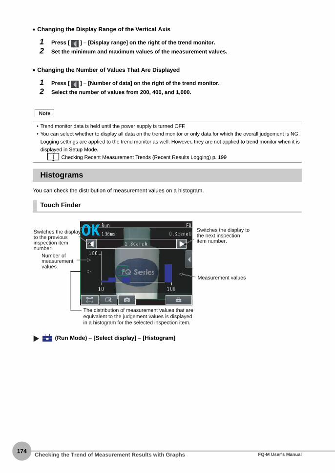
174
• Changing the Display Range of the Vertical Axis
1 Press [ ] − [Display range] on the right of the trend monitor.
2 Set the minimum and maximum values of the measurement values.
• Changing the Number of Values That Are Displayed
1 Press [ ] − [Number of data] on the right of the trend monitor.
2 Select the number of values from 200, 400, and 1,000.
Histograms
You can check the distribution of measurement values on a histogram.
Touch Finder
(Run Mode) − [Select display] − [Histogram]
• Trend monitor data is held until the power supply is turned OFF.
• You can select whether to display all data on the trend monitor or only data for which the overall judgement is NG.
Logging settings are applied to the trend monitor as well. However, they are not applied to trend monitor when it is
displayed in Setup Mode.
Checking Recent Measurement Trends (Recent Results Logging) p. 199
Note
Measurement values
Number of measurement values
Switches the display to the next inspection item number.
Switches the display to the previous inspection item number.
The distribution of measurement values that are equivalent to the judgement values is displayed in a histogram for the selected inspection item.
Checking the Trend of Measurement Results with Graphs FQ-M User’s Manual

6 O
peration
Arranging Histogram Displays
Arranging Histogram Display
The display range on the X axis and the number of data on the Y axis of the histogram can be changed.
• Disabling Automatic Adjustment of the Display Range
1 Press [ ] − [Auto display] on the right of the histogram.
2 Press [OFF].
• Changing the Display Range of the X Axis
1 Press [ ] − [Display range] on the right of the histogram.
2 Select the maximum measurement value, the minimum measurement value, and the class.
• Changing the Number of Data on the Y Axis
1 Press [ ] − [Number of data] on the right of the histogram.
2 Select the maximum number of data to display.
• Histogram data is held until the power supply is turned OFF.
• You can select whether to display all data in the histogram or only data for which the overall judgement is NG.
Logging settings are applied to the histogram as well.
However, they are not applied to histograms displayed in Setup Mode.
Checking Recent Measurement Trends (Recent Results Logging) p. 199
Note
Checking the Trend of Measurement Results with GraphsFQ-M User’s Manual175
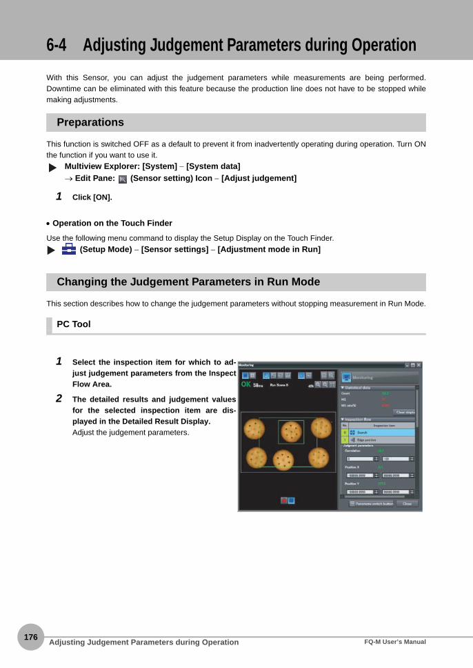
176
6-4 Adjusting Judgement Parameters during Operation
With this Sensor, you can adjust the judgement parameters while measurements are being performed.Downtime can be eliminated with this feature because the production line does not have to be stopped whilemaking adjustments.
Preparations
This function is switched OFF as a default to prevent it from inadvertently operating during operation. Turn ONthe function if you want to use it.
Multiview Explorer: [System] − [System data]→ Edit Pane: (Sensor setting) Icon − [Adjust judgement]
1 Click [ON].
• Operation on the Touch Finder
Use the following menu command to display the Setup Display on the Touch Finder.
(Setup Mode) − [Sensor settings] − [Adjustment mode in Run]
Changing the Judgement Parameters in Run Mode
This section describes how to change the judgement parameters without stopping measurement in Run Mode.
PC Tool
1 Select the inspection item for which to ad-just judgement parameters from the InspectFlow Area.
2 The detailed results and judgement valuesfor the selected inspection item are dis-played in the Detailed Result Display.Adjust the judgement parameters.
▲
Adjusting Judgement Parameters during Operation FQ-M User’s Manual

6 O
peration
Touch Finder
Run Mode
1 Select the inspection item for which you want to ad-just the judgement parameters using the and Buttons.
2 Press [ ] – [Adjust judgement].
3 Change the adjustment parameters with the slider.
4 Press [OK].The judgement results with the changed judgementparameters will appear.
The changed judgement parameters will not be reflected in the measurement result until [OK] is pressed.
Important
Adjusting Judgement Parameters during OperationFQ-M User’s Manual177

178
MEMO
Adjusting Judgement Parameters during Operation FQ-M User’s Manual
Convenient Functions
7 C
onvenient Functions
7-1 Changing the Scene to Change the Line Process .............................180
7-2 Display Functions .................................................................................183
7-3 Logging Measurement Data and Image Data .....................................191
7-4 Transferring and Saving Settings........................................................204
7-5 SD Card Operations ..............................................................................206
7-6 Convenient Functions for Operation...................................................208
7-7 Functions Related to the Sensor System Environment ....................210
7-8 Functions Related to the Touch Finder System Environment ..........212

180
7-1 Changing the Scene to Change the Line Process
What Are Scenes?
With an FQ-M Vision Sensor, the inspection items that can be processed at the same time are registered asscenes. A command input from an external device, a Touch Finder operation, or a PC Tool operation can beused to select a certain scene. If a scene is registered for each type of measurement object or inspection, theline process can be changed simply by changing the scene when the measurement object or inspectionchanges. You can create up to 32 scenes. Example:
• Settings Included with Scenes
Settings, such as the camera image and inspection items, are changed when the scene is changed. Thesettings related to external I/O specifications that are included in the output settings and the system settings forthe overall Sensor are used for all of the scenes. Refer to the following information for the data that is includedin the scene data.
12-1 Function List p. 394
Scene 0 Scene 1 Scene 31
Inspection for product A
Inspection for product B
Inspection for product Z
Line Process Changes:
SODA WATER JUICE
TEA
Model position (Inspection item 0: Search)
Model position (Inspection item 1: Search)
Center point between the two modelsCalculation 0 (X coordinate of the center point between Search 0 and Search 1)Calculation 1 (Y coordinate of the center point between Search 0 and Search 1)
These can be registered as one scene.
Changing the Scene to Change the Line Process FQ-M User’s Manual

7 C
onvenient Functions
Creating New Scenes
The default scene number is 0. To create another scene, use the following procedure to create the scene andthen make the settings.
Multiview Explorer: [Scene] (Right-click) − [Add] − [Scene data]
Changing to a Different Scene
Multiview Explorer: [Scene] − Target scene (right-click [Edit])
1 You can now modify the selected scene. Make the settings for the scene.
• Operation on the Touch Finder
Use the following menu command to display the Setup Display on the Touch Finder.
(Setup Mode) − [Select scene] − Target Scene − [Select]
1 This command creates a new scene. Thenewly added scene is displayed in the Multi-view Explorer as “Scene Name (Scene Num-ber).” You can register up to 32 scenes.
The Touch Finder displays all scenes, including unregistered scenes. Therefore, the Touch Finder does not have amenu command to register new scenes.
▲
Note
▲▲
Changing the Scene to Change the Line ProcessFQ-M User’s Manual181

182
Changing Scene Names, Copying Scenes, and Deleting Scenes
Multiview Explorer: [Scene] − Scene Number (Right-click) − [Copy]/[Delete]/[Rename]
• Operation on the Touch Finder
Use the following menu command to display the Setup Display on the Touch Finder.
(Setup Mode) − [Select scene] − Touch Target Scene − [Rename]/[Copy]/[Clear]
Switching Scenes from an External Device
• Switching Scenes with an EtherCAT Command
p. 255
• Switching Scenes with a PLC Link Command
p. 288
• Controlling with Ethernet Inputs
Command Details p. 308
Setting the Startup Scene
Multiview Explorer: [System] − [System data]→ Edit Pane: (Sensor setting) Icon − [Startup mode]
The following items can be set.
• Operation on the Touch Finder
Use the following menu command to display the Setup Display on the Touch Finder.
(Setup Mode) − [Sensor settings] − [Startup settings]
1 To change the name, enter a new scenename in 15 alphanumeric characters or less.To copy a scene, select the number of thescene to copy.
Item Purpose Setting range
Startup mode Select whether the startup scene number is set manually.
ONOFF (The scene number when the settings were saved will be the startup scene num-ber. The startup mode is set to OFF in the default settings.)
Startup scene Set the scene number to use at startup. 0 to 31
▲▲
▲▲
Changing the Scene to Change the Line Process FQ-M User’s Manual

7-2 Display Functions
7 C
onvenient Functions
The procedures given in this section can be used to make the Sensor easier to use and the display easier tounderstand.
Image Zoom
The display can be zoomed in or out to make the image easier to see.
PC Tool
Multiview Explorer: [Scene] − Scene Number→ Edit Pane: (Run) Icon − [Setup]
Touch Finder
(Setup Mode or Run Mode)
Press [Back] to end setting the display.
▲
Fits the image to the display size.
Enlarges the displayed image.
Reduces the displayed image.
Reduces the display.
Enlarges the display.
Fits the image to the display size.
Display FunctionsFQ-M User’s Manual183

184
Displaying a Live Image
You can display a live image to check the image that is input by the Sensor in realtime.
PC Tool
Edit Pane: (Online) Icon − [Setup]
Touch Finder
(Setup Mode)
1 Click the (Camera image) Icon.
2 Click the (Live) Icon.
You can select [Camera image] only when online.If [Logging image] or [Image file] are selected, all images in the same folder are displayed in order.
1 Press .
2 Press [Camera].
3 Press [Live].
4 Press the [Back] Button to return to the [Display] Dis-play.
▲
Note
Display Functions FQ-M User’s Manual

7 C
onvenient Functions
Displaying a Frozen Image
When you stop the live image, the image is no longer refreshed and the last image that was input is displayed.
PC Tool
Edit Pane: (Online) Icon − [Setup]
Touch Finder
(Setup Mode)4
1 Click the (Freeze) Icon.
1 Press .
2 Press [Camera].
3 Press [Freeze].
4 Press the [Back] Button to return to the [Display] Dis-play.
▲
Display FunctionsFQ-M User’s Manual185
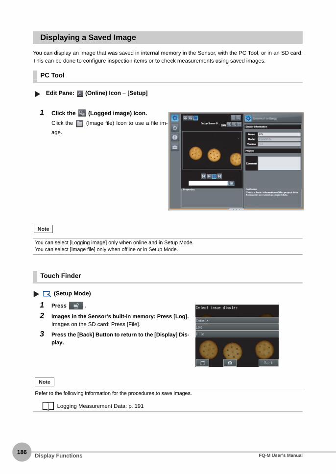
186
Displaying a Saved Image
You can display an image that was saved in internal memory in the Sensor, with the PC Tool, or in an SD card.This can be done to configure inspection items or to check measurements using saved images.
PC Tool
Edit Pane: (Online) Icon − [Setup]
Touch Finder
(Setup Mode)
1 Click the (Logged image) Icon.
Click the (Image file) Icon to use a file im-
age.
You can select [Logging image] only when online and in Setup Mode.You can select [Image file] only when offline or in Setup Mode.
1 Press .
2 Images in the Sensor’s built-in memory: Press [Log].Images on the SD card: Press [File].
3 Press the [Back] Button to return to the [Display] Dis-play.
Refer to the following information for the procedures to save images.
Logging Measurement Data: p. 191
▲
Note
Note
Display Functions FQ-M User’s Manual

7 C
onvenient Functions
Updating the Display and Measurement Results Only for NG Measurement Results
In Run Mode, you can specify updating the display of the image and measurement results only when themeasurement result is NG.
PC Tool
Multiview Explorer: [Device group] − Sensor name (Double-click)→ Edit Pane: (Online) Icon − [Start monitor]
Touch Finder
(Run Mode)
Change the following setting to display the last NG image after restarting.
1 Click the (Latest NG) Icon.
This menu command can be selected only in Run Mode.
1 Press .
2 Press [Last NG image].
3 Press [Back].
▲
Note
Display FunctionsFQ-M User’s Manual187

188
(Setup Mode or Run Mode) - [TF Settings] - [Startup display] - [Display update mode]
1 Press [Last NG image].
If an operation to change the display is performed (e.g., if the display pattern is changed or the inspection item ischanged) when displaying images for NG results is set, the display will change to refreshing the most recent mea-surement results and the most recent NG display will disappear. To ensure that you can check the NG results, log the NG results.
Checking Recent Measurement Trends (Recent Results Logging) p. 199
Note
Display Functions FQ-M User’s Manual

7 C
onvenient Functions
Displaying Guide Lines
• Displaying Guide Lines
Multiview Explorer: [Scene] − Scene number→ Edit Pane: (Run) Icon − [Start monitor]→ Monitor Pane: (Switch the scale display on and off) Icon
• Customizing Guide Lines
Multiview Explorer: [Scene] − Scene number→ Edit Pane: (Run) Icon − [Start monitor]→ Monitor Pane: (Set the conditions of the scale display) Icon
1 A scale is displayed on the measurement im-age.
1 Set the scale type.You can select to display either a scale (marks)or scale lines.
2 Set the color of the scale lines.
3 Set the scale display interval.This value is in pixels when not using calibration.
This operation is only possible on the PC Tool. This operation is not possible on the Touch Finder.
▲▲
Note
Display FunctionsFQ-M User’s Manual189

190
Automatically Changing to the Display for Any Sensor with an NG Result (Touch Finder Only)
You can change the settings to automatically display the Sensor for which the measurement result is NG ifmore than one Sensor is connected.
(Run Mode) − [Sensor monitor] − [NG sensor]
Hiding the Menu (Touch Finder Only)
You can hide the menu and display only the image on the Touch Finder to check the part of the image hiddenbehind the menu. If you press the icon again, the menu will be displayed.
(Setup Mode or Run Mode)
Turning OFF the LCD Backlight (Touch Finder Only)
You can use Eco Mode to turn OFF the LCD backlight and reduce the power consumed by the Touch Finderwhenever there is no operation on the Touch Finder for 30 seconds or longer. The LCD backlight will turn ONwhenever any part of the touch panel is pressed.
(Setup Mode or Run Mode) − [TF settings] − [LCD backlight] − [ECO mode]
Changing the LCD Brightness (Touch Finder Only)
The brightness of the LCD backlight can be changed to any of five levels.
(Setup Mode or Run Mode) − [TF settings] − [LCD backlight] − [Brightness level]
▲▲
▲▲
Display Functions FQ-M User’s Manual

7-3 Logging Measurement Data and Image Data
7 C
onvenient Functions
There are two ways to log data. Data can be temporarily saved in memory inside the Sensor (called recentresults logging) or large amounts of data can be saved in external media, such as a computer or SD card(called file logging). The amounts of data that can be logged are given in the following table.
*1: For recent results logging, the oldest data is overwritten when the maximum number of saved data items is exceeded.*2: If more than one data item is logged at the same time, logging can be performed as long as the total number of data items in all logged
data is 32,000 or less.
Logging All Data (File Logging)
Large amounts of measurement and image data can be saved in files in external memory (SD cards orcomputer).
System Configuration p. 26
To implement stable file logging for an extended period of time (i.e., 1 hour or longer), use the Touch Finder.Observe the following precautions when implementing file logging from the PC Tool.• There may be inconsistencies in the logging processing time.
• Logging processing may be interrupted if the load on the computer is too heavy.
Logged data Recent results logging*1 File logging
Measurement data (measured val-ues and calculation results)
32,000 data items max.*2 Up to the capacity of the external memory
Image data (measured values and calculation results)
20 images max.
Only the data for the Sensor that is currently being displayed on the Touch Finder will be logged if more than oneSensor is connected.If multiple Sensors are displayed or if the most recent NG Sensor is displayed, only the results of the Sensor thatwas displayed before changing to the monitor screen for the other Sensor will continue to be logged.Simultaneous logging of the results of multiple Sensors is not possible.
Vision Sensor
Saved for each measurement. Computer
SD card
Touch Finder
Hard disk drive
Image logging file
Data logging file
Note
Important
Logging Measurement Data and Image DataFQ-M User’s Manual191

192
Setting Logging Conditions
You can select the data to be logged.
Multiview Explorer: [System] − [System data]→ Edit Pane: (Log settings) Icon
• Operation on the Touch Finder
Use the following menu command to display the Setup Display on the Touch Finder.
[In/Out] − [Logging settings]
Setting the Data To Log
With file logging, you can select what measurement data to log. This setting also applies to recent resultslogging.
Selecting the Data To Log p. 201
1 Select the data for which to change the log-ging parameters.
Item Description
Image data • Save all: All images will be logged regardless of the measurement results.• Save only NG items: Only images for which the overall judgement was NG will be logged.• None: No images will be logged. (Default)
Measurement data • Save all: All measurement data (measured values and calculation results) will be logged regardless of the measurement results.
• Save only NG items: Only measurement data (measured values and calculation results) for which the overall judgement was NG will be logged.
• None: No measurement data (measured values and calculation results) will be logged. (Default)
The logging parameter settings are the same for file logging and recent results logging.▲
Note
▲
Logging Measurement Data and Image Data FQ-M User’s Manual

7 C
onvenient Functions
Starting and Stopping Logging
After logging is started (i.e., set to ON), the specified image data and measurement data will be saved in theSD card in the Touch Finder or on the computer hard disk each time measurements are performed.
• PC Tool
Edit Pane: (Online) Icon − [Start monitor]
1 Start the monitor.
2 Click the (Start the logging to the file)Icon.
3 Select the check boxes for the items to logand then specify the location to store thelog files and the name to save under.
4 Select the method to use to create log filesfor measurement data.[Separate the logging file by scene]
Select whether to store the results for allscenes in a single file, or to separate the logfiles by scene or whenever the scene ischanged.
Storage Methods and File Names for
Logged Data p. 195
[Output Format]
The separator to use in the output file can bechanged as shown below according to the ex-
ternal device.
▲
Item Separator
Field sepa-rator
None, comma (default), tab, space, or semicolon
Decimal symbol
None, point (default), or comma
The record separator is always CR + LF.
Note
Logging Measurement Data and Image DataFQ-M User’s Manual193

194
• Touch Finder
(Run Mode)
1 Press [Log to the file].
2 Press [Image data] or [Measurement data].
3 Press [ON] to start logging.Press [OFF] to stop logging.
4 Press [OK].
Use the following menu command to change the output CSV file format.
(Setup Mode or Run Mode) − [TF settings] − [File format]
Format of Saved Data p. 202
5 Select the method to use to store image datain log files.By default, image data is stored in the samefolder. However, to separate the storage loca-tion by total judgement, select the [The storagelocation is distributed by total judgement] CheckBox.
Storage Methods and File Names for Logged Data p. 195
6 Click the [OK] Button.
7 Click the (Stop logging) Icon to stop log-ging.
To save logged data, you must first select either [All data is saved] or [Only NG data is saved] in the logging parame-ters.
Setting Logging Conditions p. 192
Note
▲▲
Logging Measurement Data and Image Data FQ-M User’s Manual

7 C
onvenient Functions
Storage Methods and File Names for Logged Data
PC Tool
• Measurement Data
You can select one of the following three types of storage for measurement data.1) Store the results for all scenes in a single file (default).2) Store the results for each scene in a separate file.3) Store the results for a separate file each time the scene is changed.The setting method is described below.
Starting and Stopping Logging p. 193
The file names depend on the selected storage method, as described in the following table.
In the following cases, logging will not continue in the current file and the data will be saved in a new file.
• When the Sensor is changed
• When the Sensor is changed between Run and Setup Mode
Case File name Examples Note
Storing the results for all scenes in a single file
name.csv log.csv The item name is inserted on the first line of the file. However, if the data out-put is different for each scene, the data name is inserted each time the scene is changed.
Storing the results for each scene in a sep-arate file
name_ScnXXX.csvXXX: Scene number (000 to 031)
log_Scn000.csvlog_Scn001.csv
The data name is inserted on the first line of each file.All results for a scene are stored in the same file.
Storing the results in a separate file each time the scene is changed
name_ScnXXX(YYYY).csvXXX: Scene number (000 to 031)YYYY: Serial number for each scene (0000 to 9999)
log_Scn000(0000).csvlog_Scn001(0000).csvlog_Scn000(0001).csvlog_Scn001(0001).csv
The data name is inserted on the first line of each file.
Important
Logging Measurement Data and Image DataFQ-M User’s Manual195

196
• Image Data
You can select one of the following types of storage for image data.1) Store all image data in the same folder (default).2) Store image data by total judgement.
[OK] and [NG] folders are created in the specified folder. Image data with an overall judgement of OK isstored in the [OK] folder, while NG image data is stored in the [NG] folder. The setting method is describedbelow.
Starting and Stopping Logging p. 193
The file names are as follows:
Example: The following file names would be used for three measurements performed at 10:10:21 PM onOctober 1, 2011 with an encoder value of 100 and a save name of “img.”
img_Scn000_2011_10_01-22_10_21_100_OK.ifzimg_Scn000_2011_10_01-22_10_21_100(2)_NG.ifzimg_Scn000_2011_10_01-22_10_21_100(3)_OK.ifz
Touch Finder
Data is stored in a folder on the SD card with the following file names.
*1 A five-digit number is assigned as a name to the image data storage folder in the order of folder creation as shown below. Up to 100 images are stored in each folder.0000000001..
No. Item Description
1) Name This is the file name string specified in the [Save name] field in the PC Tool.*1
2) XXX Scene number
3) YYYY_MM_DD-HH_MM_SS Year_Month_Day-Hour_Minutes_Seconds
4) ID Measurement ID
5) (Y) The serial number is appended when a measurement is obtained at the same time (to the second) with the same encoder value.
6) JJ Judgement result (OK or NG)
Data Storage location File name
Measurement data \sensor_name\LOGDATA*1 YYYY_MM_DD-HH_MM_SS.CSVExample: The following name would be used for measurements performed at 10:10:21 pm on March 10, 2010.2010_03_10-22_10_21.CSV
Image data \sensor_name\LOGIMAGE\num-ber\*1
YYYY_MM_DD-HH_MM_SS.IFZExample: The following name would be used for measurements performed at 10:10:21 pm on March 10, 2010.2010_03_10-22_10_21.IFZ
Name_ScnXXX_YYYY_MM_DD-HH_MM_SS_ID(Y)_JJ.ifz
2) 3) 4) 5) 6)1)
Logging Measurement Data and Image Data FQ-M User’s Manual
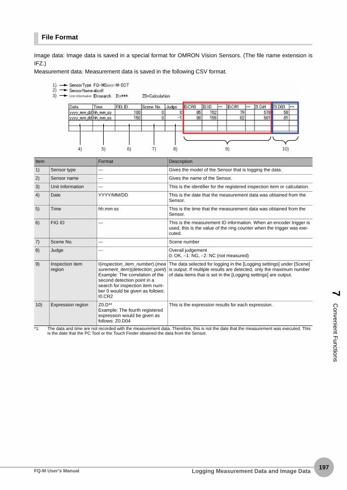
7 C
onvenient Functions
File Format
Image data: Image data is saved in a special format for OMRON Vision Sensors. (The file name extension isIFZ.) Measurement data: Measurement data is saved in the following CSV format.
*1: The data and time are not recorded with the measurement data. Therefore, this is not the date that the measurement was executed. This is the date that the PC Tool or the Touch Finder obtained the data from the Sensor.
Item Format Description
1) Sensor type --- Gives the model of the Sensor that is logging the data.
2) Sensor name --- Gives the name of the Sensor.
3) Unit Information --- This is the identifier for the registered inspection item or calculation.
4) Date YYYY/MM/DD This is the date that the measurement data was obtained from the Sensor.
5) Time hh:mm:ss This is the time that the measurement data was obtained from the Sensor.
6) FIG ID --- This is the measurement ID information. When an encoder trigger is used, this is the value of the ring counter when the trigger was exe-cuted.
7) Scene No. --- Scene number
8) Judge --- Overall judgement0: OK, −1: NG, −2: NC (not measured)
9) Inspection item region
I(inspection_item_number).(measurement_item)(detection_point)Example: The correlation of the second detection point in a search for inspection item num-ber 0 would be given as follows: I0.CR2
The data selected for logging in the [Logging settings] under [Scene] is output. If multiple results are detected, only the maximum number of data items that is set in the [Logging settings] are output.
10) Expression region Z0.D**Example: The fourth registered expression would be given as follows: Z0.D04
This is the expression results for each expression.
1)2)3)
4) 5) 6) 7) 8) 9) 10)
Unit Information
Logging Measurement Data and Image DataFQ-M User’s Manual197

198
Ensuring That All Measurement Results Are Logged in External Memory
To ensure that all measurement results are actually saved, change the settings so that the BUSY signalremains ON until logging has been completed. During operation, do not input the next trigger until the BUSYsignal turns OFF.
Multiview Explorer: [System] − [System data]→ Edit Pane: (I/O) Icon − [BUSY output] − [Output condition]
Change the BUSY output parameter to [End data logging] or [Image logging].
• Operation on the Touch Finder
Use the following menu command to display the Setup Display on the Touch Finder.
[In/Out] − [I/O setting] − [I/O terminals] − [BUSY output]
• File logging cannot be used when performing continuous measurements.
• If you use the PC Tool, the logging time may vary by up to 100 ms depending on the application conditions of your
computer.
• If logging data to an SD card, the write time depends on the amount of the available space on the SD card.
Reference value: For SDHC class 4, the time required to write image data is approx. 200 to 800 ms.
▲
BUSYON
OFF
Trigger signal
Vision Sensor
Image input Measurements
Touch Finder
Data Logging Image logging Display
Note
▲
Logging Measurement Data and Image Data FQ-M User’s Manual
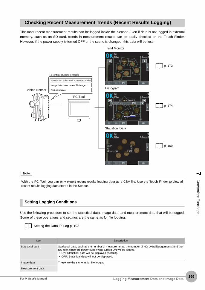
7 C
onvenient Functions
Checking Recent Measurement Trends (Recent Results Logging)
The most recent measurement results can be logged inside the Sensor. Even if data is not logged in externalmemory, such as an SD card, trends in measurement results can be easily checked on the Touch Finder.However, if the power supply is turned OFF or the scene is changed, this data will be lost.
Setting Logging Conditions
Use the following procedure to set the statistical data, image data, and measurement data that will be logged.Some of these operations and settings are the same as for file logging.
Setting the Data To Log p. 192
Trend Monitor
p. 173
Histogram
p. 174
Statistical Data
p. 169
With the PC Tool, you can only export recent results logging data as a CSV file. Use the Touch Finder to view allrecent results logging data stored in the Sensor.
Item Description
Statistical data Statistical data, such as the number of measurements, the number of NG overall judgements, and the NG rate, since the power supply was turned ON will be logged.• ON: Statistical data will be displayed (default).• OFF: Statistical data will not be displayed.
Image data These are the same as for file logging.
Measurement data
Vision Sensor
PC Tool
Inspection data, Calculation result: Most recent 32,000 values
Image data: Most recent 20 images
Statistical data
Recent measurement results
Note
Logging Measurement Data and Image DataFQ-M User’s Manual199
200
Selecting the Data To Log
With recent results logging, you can select what measurement data to log. This setting also applies to filelogging.
Selecting the Data To Log p. 201
Starting Logging
Logging will be started as soon as the data to log has been set. If the settings are saved, logging will startautomatically the next time the power supply is turned ON.
Checking the Results of Logging
You can use trend monitors, histograms, or statistical data on the Touch Finder to check all logged data.
p. 169
Checking Logged Images
Use the following menu command to check the measurement images.
(Setup Mode) − (Logging image) Icon
• Operation on the Touch Finder
Use the following menu command to display the Setup Display on the Touch Finder.
(Setup Mode or Run Mode) − [ ] − [Log]
With the PC Tool, you can also view any other parameters in addition to logged data by using the trend monitors andhistograms.Select the logged data to use as reference data. You can select up to three parameters for trend monitors, or a singleparameter for histograms.
Note
▲▲
Logging Measurement Data and Image Data FQ-M User’s Manual

7 C
onvenient Functions
Selecting the Data To Log
Select the measurement data to log.
Multiview Explorer: [Scene] − Scene number→ Edit Pane: (Logging) Icon
• Operation on the Touch Finder
Use the following menu command to display the Setup Display on the Touch Finder.
[In/Out] − [Log settings] − [Measurement data] − [Select measurement data]
Saving Logged Recent Results Data in a File
Although the logged recent results data will be deleted when the power supply is turned OFF, it can be saved ina file in external memory. The most recent 32,000 measurement values and the most recent 20 images will besaved.
PC Tool
(Setup Mode) Multiview Explorer: [Device group] − Sensor name (Double-click)→ Edit Pane: (Online) Icon − [Transfer or Save Data] − [Transfer from Sensor]
Touch Finder
(Setup Mode) − [Save to file] − [Logging] Tab Page
1 Select the measurement data to log.
1 Select the data to save.
2 The following display will appear if [Imagedata] is selected.Select whether to save the most recently loggedimage or to save all of the data that is logged inthe Sensor.
▲▲
▲▲
Logging Measurement Data and Image DataFQ-M User’s Manual201

202
The file storage locations and file format are given in the following table.
*1: Files are stored in the specified folder with the specified file name when the PC Tool is used.
• File Format
Statistical data: The data is saved in the following CSV format.Number of measurements, number of OKs, number of NGs, OK rate, NG rate (line feedcode)
Image data: Image data is saved in a special format for OMRON Vision Sensors. (The file nameextension is IFZ.)
Measurement data: Measurement data is saved in the following CSV format.
The same format is used to log the most recent results to files for the inspection item region and expressionregion of the file logging function.
File logging format: Items 9 and 10 on p. 197
The recent log data will be cleared if the scene is changed.
Changing the File Format
The output CSV file format can be changed as shown below according to the external device.
Changing the File Format p. 193
Item Storage location File name
Statistical data \sensor_name\LOGDATA*1 YYYY_MM_DD-HH_MM_SS.CSVExample: The following name would be used for data saved at 10:10:21 pm on March 10, 2010.2010_03_10-22_10_21.CSV
Measurement data
Image data \sensor_name\LOGIMAGE*1 YYYY_MM_DD-HH_MM_SS_NNN.IFZExample: The following name would be used for data saved at 10:10:21 pm on March 10, 2010.2010_03_10-22_10_21_000.IFZ* NNN is the serial number that is appended when multiple items are
logged at the same time.
• The saved recent measurement data cannot be loaded back into the Sensor and displayed on a trend monitor or
histogram.
• The date and time are not recorded with the measurement data.
The file name is created from the time when the file is saved. It does not indicate when the measurement was
made.
Note
Important
Logging Measurement Data and Image Data FQ-M User’s Manual

7 C
onvenient Functions
Deleting Logged Data
The logged data will be deleted when the power supply to the Sensor is turned OFF or the scene is changed.You can also delete the logged data without turning OFF the power supply.
Multiview Explorer: [System] − [System data]→ Edit Pane: (Logging) Icon − [Clear logging data]
1 Select [Clear logging data].
• Operation on the Touch Finder
Use the following menu command to display the Setup Display on the Touch Finder.
[In/Out] − [Log settings]
▲▲
Logging Measurement Data and Image DataFQ-M User’s Manual203

204
7-4 Transferring and Saving Settings
The Sensor settings are saved in flash memory inside the Sensor. This section describes how to back up thesettings in and restore them from an SD card or other external memory.
Backing Up Sensor Data to an External File
You can transfer various types of data from an online Sensor to an external file.
Multiview Explorer: [Device group] − Sensor name (Double-click)→ Edit Pane: (Support Software) Icon − [Sensor data] - [Save]
1 Select the data to transfer.
• Operation on the Touch Finder
Use the following menu command to display the Setup Display on the Touch Finder.
(Setup Mode) − [Save to file] − [Settings] Tab Page
Applicable Data
*1: This is the storage location when the Touch Finder is used to save data to an SD card. With the PC Tool, you can save data to any folder.*2: This data can be saved only with the Touch Finder.
Data Storage location*1 Description
Scene data (file name extension: SCN)
\sensor_name\SCN The following data is backed up for each scene.• Settings for all inspection items• Order of inspection items
Scene group data (file name exten-sion: SGP)
\sensor_name\SGP All scene data is backed up.
Sensor system data (file name extension: SYD)
\sensor_name\SYD All system data in the Sensor is backed up.The system data is the same for all scenes.
Sensor all information (file name extension: BKD)
\sensor_name\BKD All settings in the Sensor (all scene data, Sensor system data, and calibration group data) are backed up.
Touch Finder data*2
(The file name extension is MSD.)\sensor_name\MSD All settings in the Touch Finder are backed up.
Calibration data (file name exten-sion: CLB)
--- The calibration settings for each scene are backed up.
Calibration group data (file name extension: CGP)
--- The calibration settings for all scenes are backed up.
▲▲
Transferring and Saving Settings FQ-M User’s Manual
7 C
onvenient Functions
Transferring External Files to the Sensor
You can transfer externally saved settings to any Sensor that is connected online.The procedure for transferring this data is described below.
You can use the following to transfer saved data to the Sensor.
Multiview Explorer: [Device group] − Sensor name (Double-click)→ Edit Pane: (Support Software) Icon − [Sensor data] - [Read]
1 Select the data to transfer.
• Operation on the Touch Finder
Use the following menu command to display the Setup Display on the Touch Finder.
(Setup Mode) − [Load from file]
Printing the Sensor Settings Data
You can print the Sensor scene and system data.
Multiview Explorer: [Device group] − Sensor name (Double-click)→ Edit Pane: (Support software) Icon − [Print]
1 Click [Sensor parameter].
2 Select the data to print.
3 Click [Print].
Changing between Online and Offline p. 374
Note
▲▲
Transferring and Saving SettingsFQ-M User’s Manual205

206
7-5 SD Card Operations
With an FQ Vision Sensor, the following folders are automatically created in the SD card according to the datathat is saved. The specified data is saved in files in these folders.
*1: For the PC Tool, data will be saved in the following folder: \\..\My Documents\OMRON FQ
Inserting and Removing SD Cards
Inserting an SD Card in the Touch Finder
Storage folder*1 Data
\sensor_name\SCN Scene data (The file name extension is SCN.)
\sensor_name\SGP Scene group data (The file name extension is SGP.)
\sensor_name\SYD Sensor system data (The file name extension is SYD.)
\sensor_name\BKD All sensor data (The file name extension is BKD.)
\MSD Touch Finder data (The file name extension is MSD.)
\sensor_name\LOGIMAGE Image data (The file name extension is IFZ.)
\sensor_name\LOGDATA Statistical data and measurement data (The file name extension is CSV.)
\CAPTURE Captured images (The file name extension is BMP.)
The PC Tool does not support SD card operations.
1 Open the cover to the SD card slot on the top of theTouch Finder.
2 Insert the SD card with the back of the SD card facingthe front of the Touch Finder and press it in until itclicks into place.
3 Close the cover to the SD card slot.
Note
SD Card Operations FQ-M User’s Manual
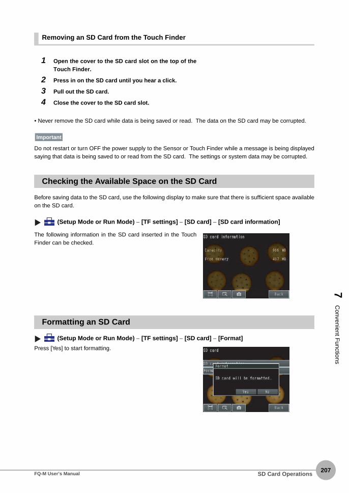
7 C
onvenient Functions
Removing an SD Card from the Touch Finder
• Never remove the SD card while data is being saved or read. The data on the SD card may be corrupted.
Do not restart or turn OFF the power supply to the Sensor or Touch Finder while a message is being displayedsaying that data is being saved to or read from the SD card. The settings or system data may be corrupted.
Checking the Available Space on the SD Card
Before saving data to the SD card, use the following display to make sure that there is sufficient space availableon the SD card.
(Setup Mode or Run Mode) − [TF settings] − [SD card] − [SD card information]
Formatting an SD Card
(Setup Mode or Run Mode) − [TF settings] − [SD card] − [Format]
1 Open the cover to the SD card slot on the top of theTouch Finder.
2 Press in on the SD card until you hear a click.
3 Pull out the SD card.
4 Close the cover to the SD card slot.
The following information in the SD card inserted in the TouchFinder can be checked.
Press [Yes] to start formatting.
Important
SD Card OperationsFQ-M User’s Manual207

208
7-6 Convenient Functions for Operation
This section describes the functions that can be used during Sensor operation.
Setting a Password to Prevent Unwanted Changes
A password can be set to prevent unwanted changes to settings.If a password is set, you cannot change from Run Mode to Setup Mode without entering the password.
Setting a Password
Multiview Explorer: [System] − [System data]→ Edit Pane: (Sensor settings) Icon − [Password settings]
1 Set the password setting to [ON].
2 Enter a password that contains up to 15 characters.
• Operation on the Touch Finder
Use the following menu command to display the Setup Display on the Touch Finder.
(Setup Mode) − [Sensor settings] − [Password]
Clearing the Password
Multiview Explorer: [System] − [System data]→ Edit Pane: (Sensor settings) Icon − [Password settings]
1 Set the password setting to [OFF].
• Operation on the Touch Finder
Use the following menu command to display the Setup Display on the Touch Finder.
(Setup Mode) − [Sensor settings] − [Password settings]
Entering the Password When Switching from Run Mode to Setup Mode
1 If a password is set and you try to changefrom Run Mode to Setup Mode, the follow-ing password entry display will appear.
Edit Pane: (Run) Icon − [Setup]
2 Enter the password that you set.
▲▲
▲▲
▲
Convenient Functions for Operation FQ-M User’s Manual

7 C
onvenient Functions
• This password restricts only the operation to switch from Run Mode to Setup Mode. It does not restrict other operations.
• If you forget the password, contact your OMRON representative for the procedure to clear the password. • The password is deleted when the Sensor is initialized.
• Operation on the Touch Finder
Use the following menu command to display the password entry display on the Touch Finder.
[Run Mode] − [Sensor settings]
Capturing the Currently Visible Display (Touch Finder Only)
The current display on the Touch Finder can be captured and used in text files and other files on the computer.The captured images are saved in external memory as bit maps.
(Setup Mode or Run Mode)
The image that is being displayed when the button is pressed is saved in external memory.
• Storage Location and File Names
Make sure an SD card is inserted in the Touch Finder before capturing display images.
Storage location File name
\CAPTURE YYYY_MM_DD-HH_MM_SS_MS.BMPExample: The following file name would be used for a screen capture executed at 10:10:21.350 PM on March 10, 2010.2010_03_10-22_10_21_350.BMP
Important
▲▲
Important
Convenient Functions for OperationFQ-M User’s Manual209
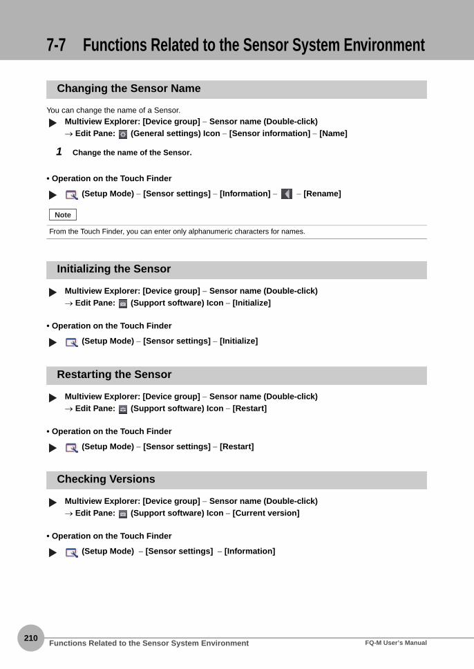
210
7-7 Functions Related to the Sensor System Environment
Changing the Sensor Name
You can change the name of a Sensor.
Multiview Explorer: [Device group] − Sensor name (Double-click)→ Edit Pane: (General settings) Icon − [Sensor information] − [Name]
1 Change the name of the Sensor.
• Operation on the Touch Finder
(Setup Mode) − [Sensor settings] − [Information] − − [Rename]
Initializing the Sensor
Multiview Explorer: [Device group] − Sensor name (Double-click)→ Edit Pane: (Support software) Icon − [Initialize]
• Operation on the Touch Finder
(Setup Mode) − [Sensor settings] − [Initialize]
Restarting the Sensor
Multiview Explorer: [Device group] − Sensor name (Double-click)→ Edit Pane: (Support software) Icon − [Restart]
• Operation on the Touch Finder
(Setup Mode) − [Sensor settings] − [Restart]
Checking Versions
Multiview Explorer: [Device group] − Sensor name (Double-click)→ Edit Pane: (Support software) Icon − [Current version]
• Operation on the Touch Finder
(Setup Mode) − [Sensor settings] − [Information]
From the Touch Finder, you can enter only alphanumeric characters for names.
▲▲
Note
▲▲
▲▲
▲▲
Functions Related to the Sensor System Environment FQ-M User’s Manual

7 C
onvenient Functions
Displaying Help
You can view Help when you use the PC Tool.
Multiview Explorer: [Device group] − Sensor name (Double-click)→ Edit Pane: (Support software) Icon
1 Click [Show help].
▲
Functions Related to the Sensor System EnvironmentFQ-M User’s Manual211

212
7-8 Functions Related to the Touch Finder System Environment
Switching the Display Language
Any of the following languages can be selected for display on the Touch Finder or the PC Tool.Japanese or English
(Setup Mode or Run Mode) − [TF settings] − [Language]Press the language to be displayed.
Setting the Time on the Touch Finder
You can set the date and time.
(Setup Mode or Run Mode) − [TF settings] − [Time settings]
Initializing the Touch Finder
(Setup Mode or Run Mode) − [TF settings] − [Initialize]
Restarting the Touch Finder
(Setup Mode or Run Mode) − [TF settings] − [Reset TF]
Checking the Touch Finder Battery Level
(Setup Mode or Run Mode) − [TF settings] − [Battery remaining]
• The battery level is displayed only for a Touch Finder with a DC/AC/battery power supply (FQ-MD31).
• The settings will be lost if the battery runs out while you are making the settings. If the battery level is low, save the
settings and charge the battery immediately.
Correcting the Touch Screen Positions of the Touch Finder
Use this function to correct the touch screen positions if they are offset from the opposite position.
(Setup Mode) − [TF settings] − [Touch panel calib]
▲▲
▲▲
▲
Important
▲
Functions Related to the Touch Finder System Environment FQ-M User’s Manual
Communications with External Devices
8 C
omm
unications with E
xternal Devices
8-1 Connecting to Parallel I/O . . . . . . . . . . . . . . . . . . . . . . . . . . . . . . . . . . 214
8-2 EtherCAT Connection . . . . . . . . . . . . . . . . . . . . . . . . . . . . . . . . . . . . . 228
8-3 PLC Link Connections. . . . . . . . . . . . . . . . . . . . . . . . . . . . . . . . . . . . . 266
8-4 No-protocol Connections . . . . . . . . . . . . . . . . . . . . . . . . . . . . . . . . . . 296
8-5 Connecting with the Programmable No-protocol Communications 325
8-6 Using the Encoder Input . . . . . . . . . . . . . . . . . . . . . . . . . . . . . . . . . . . 338

214
8-1 Connecting to Parallel I/O
Operation with Default Settings
This section describes the basic connections and signal flow with external devices.With the default settings, the Sensor operates in the following manner.
• Create the ladder program to control the TRIG signal so that it does not turn ON while the BUSY signal is ON. If not,
a TRIG input error will occur and the ERROR signal will turn ON.
• Operation When the Sensor Power Supply Is Turned ON
The BUSY signal will operate as shown below when the Sensor’s power supply is turned ON.
Create the ladder program in the PLC or other external device so that the BUSY signal is ignored while it turns OFF,
ON, and OFF again for up to 5 s after the power supply is turned ON.
* Depends on the scene data.
(2) Measurements performed
(1) Measurement trigger input
(3) Judgement results output
Trigger SensorFQ Vision Sensor
External device
Measurement trigger• TRIG (default)
• Encoder
(3) Judgement results output (overall judgement: OR signal)
Retained until the next judgement results are output.
Turned ON when overall judgement is NG.
(2) Executing measurement processing (BUSY signal)
This signal stays ON until the next measurement trigger can be input.
You can confirm if measurements are in progress.
The trigger to perform measurements once is turned ON.(1) Measurement
trigger input (TRIG signal)
ON
OFF
ON
OFFON while measure-ments are in progress
Important
24 V
BUSYON
OFF
0 V
1.5 s 3.5 s*
Sensor system is initializing
Turns OFF when the Sensor is ready for operation.
Power supply
Connecting to Parallel I/O FQ-M User’s Manual
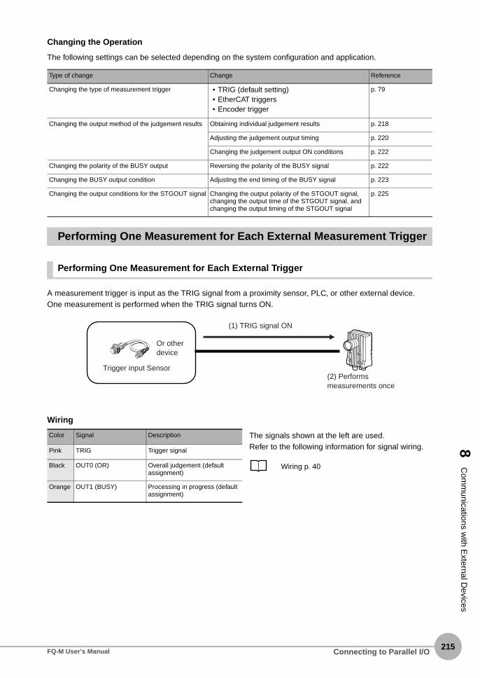
8 C
omm
unications with E
xternal Devices
Changing the Operation
The following settings can be selected depending on the system configuration and application.
Performing One Measurement for Each External Measurement Trigger
Performing One Measurement for Each External Trigger
A measurement trigger is input as the TRIG signal from a proximity sensor, PLC, or other external device.One measurement is performed when the TRIG signal turns ON.
Wiring
Type of change Change Reference
Changing the type of measurement trigger • TRIG (default setting)• EtherCAT triggers• Encoder trigger
p. 79
Changing the output method of the judgement results Obtaining individual judgement results p. 218
Adjusting the judgement output timing p. 220
Changing the judgement output ON conditions p. 222
Changing the polarity of the BUSY output Reversing the polarity of the BUSY signal p. 222
Changing the BUSY output condition Adjusting the end timing of the BUSY signal p. 223
Changing the output conditions for the STGOUT signal Changing the output polarity of the STGOUT signal, changing the output time of the STGOUT signal, and changing the output timing of the STGOUT signal
p. 225
Color Signal Description The signals shown at the left are used. Refer to the following information for signal wiring.
Wiring p. 40
Pink TRIG Trigger signal
Black OUT0 (OR) Overall judgement (default assignment)
Orange OUT1 (BUSY) Processing in progress (default assignment)
(2) Performs measurements once
Trigger input Sensor
Or other device
(1) TRIG signal ON
Connecting to Parallel I/OFQ-M User’s Manual215

216
Timing Chart (For Single Measurement with Parallel TRIG Signal)
1. Turn ON the TRIG signal while the BUSY signal is OFF.2. Measurement begins and the BUSY signal is turned ON during the measurement process.3. When the measurement has been finished, the measurement result is output using an OR signal, and the
BUSY signal is turned OFF. *1
*1: You can also set the signal to be turned OFF after data logging, image logging, or displaying results in the [BUSY output].
Sample Ladder Program
The following sample program is used to input a TRIG signal to perform a single measurement. A singlemeasurement will be performed when W0.00 turns ON.
• I/O Signal Allocations
Signal Address
Output signals OUT0 (OR signal) CIO 0.00
OUT1 (BUSY signal) CIO 0.01
Input signals TRIG CIO 1.00
OFF
ON
OFF
ON
Turned ON when overall judgement is NG. (Output polarity: ON for NG)
OR signal
ON while measurements are being processed (depends on BUSY output conditions)
BUSY signal
TRIG signal ON for 1 ms min.
SET
TRIG
W0.00 OUT1
0000
#2
TRIGTMHH
RSET
TRIG
T0000
RSET
W0.00
++L
1000
++L
1002
OUT0
OUT0
OUT1
Single measure-ment command bit
BUSY signal
When the single measurement command bit (W0.00) turns ON, the TRIG signal is turned ON if the BUSY signal is OFF.
TRIG signal
BUSY signal OR signal
OR signal
The TRIG signal is kept ON for 2 ms and then turned OFF.
When the BUSY signal turns OFF to indicate that the measurement has been finished, the judgement result is added to the total count.OK measurements: CIO 1000NG measurements: CIO 1002
Connecting to Parallel I/O FQ-M User’s Manual

8 C
omm
unications with E
xternal Devices
Performing a Measurement for the Encoder Input Value
A measurement is performed when the ring counter changes to a specified value.
Outputting the Overall Judgement Result
When the results of the inspection items are judged, if even one individual judgement result is NG, the ORoutput signal is turned ON.
Controlling Measurement Timing with an Encoder Input p. 339
You can also turn ON the overall judgement result output signal when all individual judgement results are OK.
Changing the Judgement Output ON Conditions p. 222
You can select whether to use the judgement result of one of the calculations (0 through 31) as the overall judge-ment.
Using Calculation Results without Applying Them to the Overall Judgement p. 146
The timing for updating the OR signal and the ON time after judgement processing can be adjusted.
Adjusting the Judgement Output Timing p. 220
Note
OK
NG
OKInspection item 31
If there is even one NG judgement,the overall judgement will be NG and the output will be turned ON.
NG (OR signal ON)Inspection item 1
Overall judgement result
Inspection item 0
Individual judgement results
OKExpression
Note
Note
Connecting to Parallel I/OFQ-M User’s Manual217

218
Output Using a Parallel I/O CableUse the following wiring for the output.
Timing Chart (For Single Measurement with Parallel TRIG Signal)
The OR signal that is output is held until the next overall judgement is output.
Outputting Individual Judgement Results
You can output the judgement results of individual inspection items (individual judgement signals OR0 toOR31) to an external device.
Output Using a Parallel I/O Cable
As shown below, you can assign up to five outputs to terminals OUT0 to OUT4 to output to external devices.
Color Signal Description The signal shown at the left is used.Refer to the following information for signal wiring.Black OUT0 (OR) Overall judgement (default assignment)
Wiring p. 40
The timing for updating the OR0 to OR31 signals and the ON time after judgement processing can be changed.
Adjusting the Judgement Output Timing p. 220
Output terminal Output signals that can be assigned
OUT0 • OR (overall judgement) ... (default)• OR0 (Item 0 judgement) to OR31 (Item 31 judgement)
OUT1 • BUSY ... (default)• OR0 (Item 0 judgement) to OR31 (Item 31 judgement)
OUT2 • ERROR (error) ... (default)• OR0 (Item 0 judgement) to OR31 (Item 31 judgement)
OUT3 • SHTOUT (shutter output) ... (default)• OR0 (Item 0 judgement) to OR31 (Item 31 judgement)
OUT4 • STGOUT (strobe lighting output) ... (default)• OR0 (Item 0 judgement) to OR31 (Item 31 judgement)
You cannot assign signals to OUT3 or OUT4 from the Touch Finder.
OFF
ON
OFF
ON
Overall judgement
Turned ON when overall judgement is NG. (Output polarity: ON for NG)
OR signal
ON while measurements are being processed (depends on BUSY output conditions)
BUSY signal
TRIG signal ON for 1 ms min.
Note
Note
Connecting to Parallel I/O FQ-M User’s Manual

8 C
omm
unications with E
xternal Devices
Example: Signals are assigned to terminals OUT0 to OUT2 as shown below.• OUT0: Inspection number 2 (OR2)• OUT1: Inspection number 5 (OR5)• OUT2: Inspection number 14 (OR14)
As described above, if terminals OUT0 to OUT2 are all assigned to individual judgement output signals, theBUSY signal and ERROR signal assigned as the default settings will no longer be output. Similarly, if youassign individual judgement output signals to terminals OUT3 and OUT4, the SHTOUT and STGOUT signalswill not be output.
Use the following procedure to make the setting.
Multiview Explorer: [System] − [System data] → Edit Pane: (I/O) Icon − [OUT allocation]
1 Select [OR2 (Item 2 judgement)] for [OUT0].OR2 output signal will be assigned to OUT0.
2 Assign the other signals in the following manner.OUT1: OR5OUT2: OR14
Timing Chart (For Single Measurement with Parallel TRIG Signal)
Output OR0 to OR31 signals are held until the next judgement output.
*1: The timing for updating the OR signal is when the measurement results are finalized, regardless of the output settings of the BUSY signal (BUSY output conditions).
• Operation on the Touch Finder
Use the following menu command to display the Setup Display on the Touch Finder.
[In/Out] − [I/O setting] − [I/O terminals]
Color Signal Description The signals shown at the left are used.Refer to the following information for signal wiring.
Wiring p. 40
Black OUT0 (OR2) Outputs the judgement for OR2.
Orange OUT1 (OR5) Outputs the judgement for OR5.
Light blue
OUT2 (OR14) Outputs the judgement for OR14.
OFF
ON
OFF
ON
OR1 signal Turned ON when individual judgement is NG. (Output polarity: ON for NG)
OR0 signal Turned ON when individual judgement is NG. (Output polarity: ON for NG)
Example:
ON while measurements are being processed (depends on BUSY output conditions)
BUSY signal
TRIG signal ON for 1 ms min.
Individual judgement*1
Connecting to Parallel I/OFQ-M User’s Manual219

220
Adjusting the Judgement Output Timing
The output timing of the OR signal or OR0 to OR31 signals can be selected from two modes depending on theexternal device.
Selecting the OFF Timing
• Level output (default)
The status of the output OR signal is held until the next OR signal is output.
• One-shot output
The status of the output OR signal is turned OFF after a specified time has passed. (Setting range: 1 to 1,000 ms)
Delaying the Output Timing
When using one-shot output, the output timing of the OR signal can be delayed. (Setting range: 0 to 1,000 ms)
OFF
ON
OFF
ON
OFF
ONNG OK
Held until the next judgement result is output
Overall judgement (Output polarity: ON for NG)
OR signal
ON while measure-ments are being processed (depends on BUSY output conditions)
BUSY signal
TRIG signal ON for 1 ms min.
OFF
ON
OFF
ON
OFF
ONNG OK
Turns OFF.
One-shot output time
Overall judgement (Output polarity: ON for NG)
OR signal
ON while measurements are being processed (depends on BUSY output conditions)
BUSY signal
TRIG signal ON for 1 ms min.
OFF
ON
OFF
ON
OFF
ONNG
One-shot output time
Overall judgement (Output polarity: ON for NG)
OR signal
ON while measurements are being processed (depends on BUSY output conditions)
BUSY signal
TRIG signal ON for 1 ms min.
One-shot output delay
Connecting to Parallel I/O FQ-M User’s Manual

8 C
omm
unications with E
xternal Devices
Settings
Multiview Explorer: [System] − [System data] → Edit Pane: (I/O settings) Icon − [OR output settings]
When a one-shot output is selected for the output mode, make the following value smaller than the trigger inputperiod.• One-shot delay time + One-shot output time
• Operation on the Touch Finder
Use the following menu command to display the Setup Display on the Touch Finder.
[In/Out] − [I/O setting] − [I/O terminals]
1 Select [One-shot output] for the [Output mode].
2 Set the [One-shot output delay].
3 Set the [One-shot output time].
Item Description
Output mode One-shot output After the measurement results are finalized, if the judgement output ON condition is met, the OR signal is turned ON for the one-shot output time. It is then turned OFF once the specified time has expired.
Level output (default) The judgement is output after measurement results are finalized and the ON/OFF status of the OR signal is held until it is changed for the next measurement result.
One-shot output delay When one-shot output mode is selected, this parameter sets the delay from when a measurement is completed until when the OR signal turns ON. (Setting range: 0 to 1,000 ms)
One-shot output time When one-shot output mode is selected, this parameter sets the time that the OR signal is ON. (Setting range: 1 to 1,000 ms)
Important
Connecting to Parallel I/OFQ-M User’s Manual221

222
Changing the Judgement Output ON Conditions
The ON conditions for the OR signal and the OR0 to OR31 signals can be set to turn ON the signals when thejudgement results are OK or when they are NG. The default setting is when they are NG.
Settings
Multiview Explorer: [System] − [System data] → Edit Pane: (I/O settings) Icon − [OR output settings] − [Output polarity]
• Operation on the Touch Finder
Use the following menu command to display the Setup Display on the Touch Finder.
[In/Out] − [I/O setting] − [I/O terminals] − [Output Polarity]
Changing the BUSY Signal Output Condition
Changing the Polarity of the BUSY Output
The Sensor turns ON the BUSY output signal during measurements, command execution, and otherprocessing to indicate that a measurement trigger cannot be received. You can change the BUSY signal outputconditions.
Settings
Multiview Explorer: [System] − [System data] → Edit Window: (I/O) Icon − [BUSY output settings] − [Output polarity]
All timing charts in this manual show the operation of the BUSY signal at the default setting. If you change thepolarity of the BUSY signal, take this into consideration when reading the timing charts.
• Operation on the Touch Finder
Use the following menu command to display the Setup Display on the Touch Finder.
[In/Out] − [I/O setting] − [I/O terminals]− [BUSY Polarity]
Item Description
Output polarity OK: ON The output is turned ON if the judgement is OK.For the overall judgement, the output is turned ON if all judgements are OK.
NG: ON (default) The output is turned ON if the judgement is NG.For the overall judgement, the output is turned ON if even one judgements is NG.
Item Description
Output polarity BUSY: ON (default) The BUSY signal is ON while the Sensor is processing data.
READY: ON The BUSY signal is ON while the Sensor can receive a trigger signal.
Important
Connecting to Parallel I/O FQ-M User’s Manual
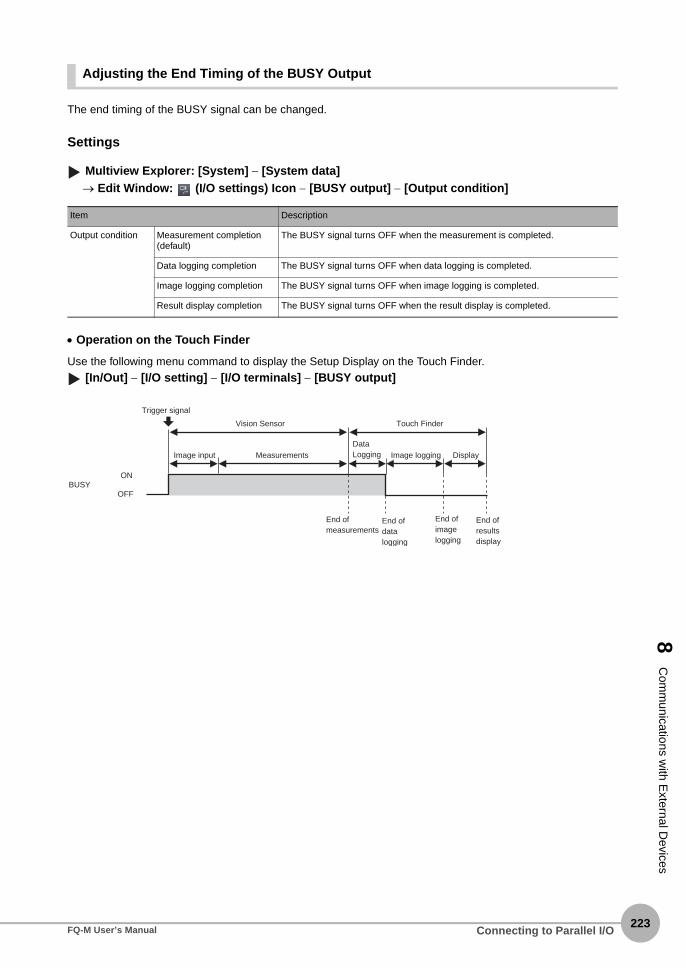
8 C
omm
unications with E
xternal Devices
Adjusting the End Timing of the BUSY Output
The end timing of the BUSY signal can be changed.
Settings
Multiview Explorer: [System] − [System data] → Edit Window: (I/O settings) Icon − [BUSY output] − [Output condition]
• Operation on the Touch Finder
Use the following menu command to display the Setup Display on the Touch Finder.
[In/Out] − [I/O setting] − [I/O terminals] − [BUSY output]
Item Description
Output condition Measurement completion (default)
The BUSY signal turns OFF when the measurement is completed.
Data logging completion The BUSY signal turns OFF when data logging is completed.
Image logging completion The BUSY signal turns OFF when image logging is completed.
Result display completion The BUSY signal turns OFF when the result display is completed.
BUSYON
OFF
Trigger signal
Vision Sensor
Image input Measurements
Touch Finder
Data Logging
End of measurements
End of data logging
End of image logging
End of results display
Image logging Display
Connecting to Parallel I/OFQ-M User’s Manual223

224
Turning the ERROR Signal OFF
The ERROR signal can be turned OFF with command inputs from an external device without connecting theTouch Finder.
Turning OFF the ERROR Signal
The ERROR signal turns ON when an error occurs. After you remove the cause of the error, turn OFF theERROR signal using one of the following methods.Method 1
Turn the error clear signal ON from an external device, such as a PLC.Method 2
Input the measurement trigger again.For example, turn the TRIG signal OFF and then ON.The ERROR signal will turn OFF when measurement is executed correctly.
Clearing Errors Using a Parallel I/O Cable
The timing chart to clear errors through a parallel TRIG signal is given below. Turn ON the IN0 signal while theBUSY signal is OFF to clear the error.
This function can be used in Run Mode only.
Color Signal Description The signals shown at the left are used.Refer to the following information for signal wiring.
I/O Signal Wiring p. 40
Red/White
IN0 Clear error input terminal
Orange OUT1 (BUSY) Processing in progress (default assignment)
Light blue
OUT2 (ERROR) ERROR signal (default assignment)
Note
IN0 signalOFF
ONON for 1 ms min.
BUSY signalOFF
ON
ERROR signalOFF
ON
Connecting to Parallel I/O FQ-M User’s Manual

8 C
omm
unications with E
xternal Devices
d
g u
Monitoring the Signal I/O Status
You can check if the I/O connections are working normally.
Multiview Explorer: [System] − [System data]→ Edit Pane: (I/O settings) − [I/O monitor] − [Monitoring start]
• Operation on the Touch Finder
Use the following menu command to display the Setup Display on the Touch Finder.
[In/Out] − [I/O monitor] − [I/O monitor]
Changing the STGOUT Signal Output Conditions
You can change the output polarity, the output time, and the output timing of the STGOUT signal. The STGOUTsignal controls the external lighting.
Changing the Output Polarity of the STGOUT Signal
Multiview Explorer: [Scene] − Scene number→ Edit Pane: (Image) Icon − [Setup menu] − [Lighting control] − [Strobe output polarity]
1 You can set the control operation for external lighting for the status of the STGOUT signal.
1 The I/O status of the external devices will be dis-played.
2 Press the output signal and change the output sta-tus. Then, check the connection with the externaldevice.
Item Description
Positive (default) The STGOUT signal is turned ON to light the external lighting.
Negative The STGOUT signal is turned OFF to light the external lighting.
Input Signals (TRIG, ERRCLR, and ENCCLR) Signals that are displayed in red are currently being input from the external devices to the Sensor.
Output Signals (OR, BUSY, ERROR, STGOUT, anSHTOUT) Signals that are displayed in red are currently beinoutput from the Sensor to the external devices. Yocan turn the signals ON and OFF by clicking the display to test the outputs.
Connecting to Parallel I/OFQ-M User’s Manual225

226
• Operation on the Touch Finder
Use one of the following menu commands to display the Setup Display on the Touch Finder.
[Image] − [Camera setting] − − [Lighting control]
Changing the Output Time of the Strobe Output Signal
Multiview Explorer: [Scene] − Scene number→ Edit Pane: (Image) Icon − [Setup menu]
• Operation on the Touch Finder
Use the following menu command to display the Setup Display on the Touch Finder.
[Image] − [Camera setting] − − [Lighting control]
1 Connect the Sensor to the external lightingwith the STGOUT signal.
2 Click [Lighting control].
3 Change the strobe output time to adjust thebrightness.Increasing the strobe output time beyond theshutter speed will not increase the brightnessany further.
Connecting to Parallel I/O FQ-M User’s Manual
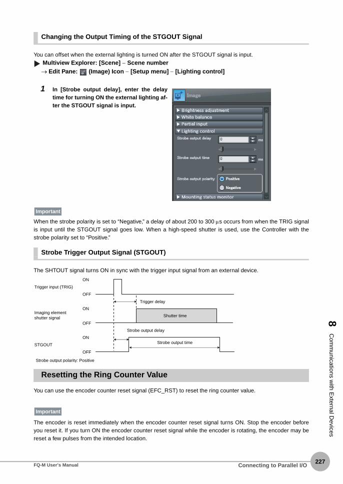
8 C
omm
unications with E
xternal Devices
Changing the Output Timing of the STGOUT Signal
You can offset when the external lighting is turned ON after the STGOUT signal is input.
Multiview Explorer: [Scene] − Scene number→ Edit Pane: (Image) Icon − [Setup menu] − [Lighting control]
When the strobe polarity is set to “Negative,” a delay of about 200 to 300 μs occurs from when the TRIG signalis input until the STGOUT signal goes low. When a high-speed shutter is used, use the Controller with thestrobe polarity set to “Positive.”
Strobe Trigger Output Signal (STGOUT)
The SHTOUT signal turns ON in sync with the trigger input signal from an external device.
Resetting the Ring Counter Value
You can use the encoder counter reset signal (EFC_RST) to reset the ring counter value.
The encoder is reset immediately when the encoder counter reset signal turns ON. Stop the encoder beforeyou reset it. If you turn ON the encoder counter reset signal while the encoder is rotating, the encoder may bereset a few pulses from the intended location.
1 In [Strobe output delay], enter the delaytime for turning ON the external lighting af-ter the STGOUT signal is input.
Important
Trigger input (TRIG)
Shutter timeImaging element shutter signal
STGOUT
Trigger delay
Strobe output delay
Strobe output time
ON
OFF
ON
OFF
ON
OFF
Strobe output polarity: Positive
Important
Connecting to Parallel I/OFQ-M User’s Manual227

228
8-2 EtherCAT Connection
Overview of EtherCAT Networks
EtherCAT (Ethernet Control Automation Technology) is a high-performance industrial network system based onEthernet system and can realize faster and more efficient communications.Each node achieves a short communications cycle time by transmitting Ethernet frames at high speed.Furthermore, even though EtherCAT is a unique protocol, it offers excellent general-purpose applicability. Forexample, you can use Ethernet cables because EtherCAT utilizes standard Ethernet technology for thephysical layer. And the effectiveness of EtherCAT can be fully utilized not only in large control systems thatrequire high processing speeds and system integrity, but also in small and medium control systems.
Features of EtherCAT
EtherCAT has the following features.
● Extremely high-speed communications with speed of 100 Mbps
It dramatically shortens the I/O response time from generation of input signals to transmission of outputsignals. By fully utilizing the optimized Ethernet frame bandwidth to transfer data using a high-speed repeatmethod, it is possible to efficiently transmit a wide variety of data.
● Extremely High Compatibility with Ethernet
EtherCAT is an open network with extremely high compatibility with conventional Ethernet systems.
Structure of EtherCAT
EtherCAT does not send data to individual slave nodes on the network, instead, it passes Ethernet framesthrough all of the slave nodes.When frame passes through a slave node, the slave node reads and writes data in the areas allocatedto it in the frames in a few nanoseconds.Ethernet frames sent from the EtherCAT Master Unit go through all the EtherCAT Slave Units without stoppingon the way. Once they reach the final Slave Unit, they are sent back from the final Slave Unit, pass through allSlave Units again, and return to the EtherCAT Master Unit. With this structure, EtherCAT secures high-speed and real-time data transmission.
EtherCATMaster Unit
Slave Unit Slave Unit Slave Unit
Ethernet frame
INOUT
Data
• Reading output data addressed to the local Slave Units• Writing input data
EtherCAT Connection FQ-M User’s Manual

8 C
omm
unications with E
xternal Devices
It is the "EtherCAT telegram" stored directly in an Ethernet frame that exchanges data regularly between theEtherCAT Master Unit and Slave Units. Each "EtherCAT telegram" is configured with telegram header (data length, including address of one or moreSlave Units, etc.), data, working counter (check bit).When an Ethernet frame is compared to a "train", an EtherCAT telegram can be considered as "railway car."
Communications Types of EtherCAT
EtherCAT provides the following two types of communication functions.PDO communications are always updating data per communication cycle on EtherCAT, while SDOcommunications are processed in between those updates.
● Process data communications functions (PDO communications)
This communication function is used to transfer process data in real time in a fixed-cycle.By mapping logical process data space to each node by the EtherCAT Master Unit, it achieves fixed-cyclecommunications among the EtherCAT Master Unit and Slave Units.
Ethernetheader CRC Ethernet data (Maximum 1498 bytes)
DataTelegramheader WKC
1...n EtherCAT telegramEtherCATheader
1st EtherCATtelegram
2nd EtherCATtelegram
n th EtherCATtelegram
. . . . .
EtherCAT frame
Ethernet frame
WKC : Working counter
EtherCAT ConnectionFQ-M User’s Manual229

230
● Mailbox communications functions (SDO communications)
It refers to message communications.At any timing, the EtherCAT Master Unit transmits commands to Slave Units and the Slave Units returnresponses to the EtherCAT Master Unit.It performs the following data communications:• Read and write process data
EtherCAT Master Unit Slave Unit
Ethernet frame
Slave Unit Slave Unit Slave Unit
Ethernetheader
EtherCATheader
1st EtherCATtelegram
2nd EtherCATtelegram
3rd EtherCATtelegram
CRC. . .
Logic process data
.
.
.
.
.
.
.
.
.
Data a
Data b
Data c
EtherCAT Connection FQ-M User’s Manual

8 C
omm
unications with E
xternal Devices
FQ-M Communications for an EtherCAT Connection
You can use EtherCAT to communicate between the EtherCAT master and the Vision Sensor to controloperation with command/response communications or to output data after measurements. With an NJ-seriesController-series CPU Unit and an EtherCAT connection, you can use the Sysmac Studio Standard Edition toregister the FQ-M in the EtherCAT slave configuration in the Edit Network Configuration Tab Page. Refer to theSysmac Studio Version 1 Operation Manual (Cat. No. W504) for details on registering slaves.
If you enable EtherCAT output for EtherCAT communications, PLC link communications will be disabled. Enabling EtherCAT Outputs p. 234
● Command/Response Communications
EtherCAT communications uses process data objects (PDOs) to perform cyclic PDO communications.Command/response control signals are handled by storing control commands from the master in the VisionSensor and storing responses from the Vision Sensor to the master in the Controller’s I/O ports or I/Omemory.*1 This allows you to control the operation of the Vision Sensor (e.g., perform continuousmeasurements or change the scene) without using communications instructions.*1: NJ-series Controllers use I/O ports. CJ-series PLCs use I/O memory. The following description applies to NJ-series Controllers.
After you write a control command to an I/O port, such as Vision Command, you can turn ON the ControlCommand Execution (EXE) Bit to send the control command to the Vision Sensor via EtherCAT. The VisionSensor executes the control command and sends a response back to the Controller via EtherCAT. TheController stores the response in an I/O port, such as Vision Response.
Important
Controller (master)Vision Sensor (slave)
Command area
Response area
I/O ports
NJ-series CPU Unit
EtherCAT communications
Commands
Response
● Switching the scene number
● Continuous measurement, etc.
OK, etc.
EtherCAT ConnectionFQ-M User’s Manual231

232
● Data Output after MeasurementsImmediately after executing measurements, the Vision Sensor will automatically output the data for themeasurements that are specified for output in advance to the Vision Data Output I/O ports in the output area.This enables you to easily transfer the measurement results data for inspection items to the Controller. Whenhandshaking is enabled, the data can be output from the Vision Sensor only when the condition to receive thatdata are met at the Controller.
You must specify in advance the data to output after measurement is performed (up to 256 bytes and up to 64items). After a single measurement or continuous measurements, the data is automatically stored in the I/Oport in the Data Output Area of the Controller via EtherCAT.Refer to the following page for the data output setting method.
Setting Up EtherCAT Communications p. 234
EtherCAT communications uses I/O ports in the following four areas to perform communications. The I/O portsin the Sysmac Error Status Area are used only when connected to a NJ-series CPU Unit.
Command/response communications
1. Command area I/O port These are the I/O ports to which you write control com-mands for the Vision Sensor to execute.
2. Response area I/O port These are the I/O ports to which the Vision Sensor writes the results of control commands executed from the Com-mand Area.
Data output after mea-surements
3. Output area I/O port These are the I/O ports to which the Vision Sensor writes output data for measurements after an inspection is per-formed.
Error status 4. I/O ports in Sysmac Error Status Area
These are the I/O ports to which the Vision Sensor writes error status.
Output area
After measurements
Data
Automatically output the specified data (up to 256 bytes and up to 64 items).
Controller (master) Vision Sensor (slave)
I/O ports
NJ-series CPU Unit
EtherCAT communications
EtherCAT Connection FQ-M User’s Manual

8 C
omm
unications with E
xternal Devices
Command area I/O port
● Control signals● Command code● Command parameters
Response area I/O port
Controller (master)
Output area I/O port
I/O Ports in Sysmac Error Status Area
Vision Sensor (slave)
Command
Response
● Vision Status Flags● Command code ● Response code● Response data
● Output data 1 to 64
Execution
After measurements
● Sysmac error status
Command/response communi-cations
Data output after measure-ments
Error status
Error status information from the Vision Sensor is written here.
Output data from the Vision Sensor is written here.
The execution results from the Vision Sensor are written here.
The following control commands are written to the Vision Sensor.
The control commands written to the I/O ports in the Command Area are executed.
The results of execution are written to the I/O ports in the Response Area.
Measurement results are written to the I/O ports in the Data Output Area.
Error status information is written to the I/O ports in the Sysmac Error Status Area.
EtherCAT ConnectionFQ-M User’s Manual233

234
Setting Up EtherCAT Communications
Initial Settings for EtherCAT Communications
You must set the data output size, output handshake, and output controls to perform EtherCATcommunications.
Multiview Explorer: [Device group] − Sensor name − [System] − [System data] (Double-click)→ Edit Pane: [EtherCAT] Icon
The following items can be set.
Item Description Setting range
EtherCAT output Specify whether to enable EtherCAT communica-tions. If you enable EtherCAT communications, PLC link communications will be disabled. Select [−] for [Ethernet communication] − [EtherCAT/PLC link data output setting] − [Communication method].
OFF or ON
Data output size Select the size of the output area.Allows you to change the size of data to output at one time.
• 259th sending PDO mapping: 32 bytes• 259th+260th sending PDO mapping:
64 bytes• 259th+261th sending PDO mapping:
128 bytes• 259th+262th sending PDO mapping:
256 bytes
Output handshake Enables or disables handshaking.• ON: Outputs data when the DSA signal after
the Controller turns ON.• OFF: Outputs data regardless of the signal
state from the Controller.
OFF or ONDefault: OFF
Output control
Output cycle (with no handshaking)
Set the output cycle. 2 to 5,000 msDefault: 10 ms
The output time of GATE signal (with no handshak-ing)
Set the output time of the GATE signal. 1 to 1,000 msDefault: 5 ms
Timeout Sets the timeout time. 100 to 12,000 msDefault: 10,000 ms
▲
EtherCAT Connection FQ-M User’s Manual

8 C
omm
unications with E
xternal Devices
Setting the Data To Output Automatically after Measurements
You can set the data to output automatically after measurements. (You can set up to 64 data items.)
Data That Can Be Output
You can set up to 32 items of data (data 0 to data 31) to output.The measurement data from inspection items that can be output and the calculation results from theexpression settings can be output. For the data that can be output, refer to the Measurement Data That Can BeUsed for External Outputs and Calculations for each inspection item.
Checking EtherCAT Communications Settings
You can check the current EtherCAT communications settings.
Multiview Explorer: [Device group] Sensor name [Scene] Scene data number (Double-click) Edit Pane: (Output) Icon [Communication settings]
If you click the [Output] Button while setting up inspection items, the following Output Setting Main Window isdisplayed.
• Changes to settings are not applied until the Vision Sensor is restarted. Therefore, save the settings and then
restart the Vision Sensor.
5-5 Saving Data to the Sensor p. 161
Restarting the Sensor p. 210
• When a CJ1W-NC@8@ CJ-series Position Control Unit is connected via EtherCAT, do not change the setting of
the data output size. Use the default setting (259th sending PDO mapping (32 bytes)).
Important
▲
EtherCAT ConnectionFQ-M User’s Manual235

236
Allocating Output Data
Multiview Explorer: [Device group] − Sensor name − [Scene] − Scene data number (Double-click)→ Edit Pane: (Output) Icon − [No-protocol data output]
1 Right-click the output data number to set in the output data list under [No-protocol data output]and select [Edit].
Item Description
Communication settings The settings of the following parameters in the system data are displayed.1. EtherCAT setting statusEnabled (green): EtherCAT output is enabled.Disabled (red): EtherCAT output is OFF.
2. The following EtherCAT output parameters• Data output size• Output format
Properties The properties of the output data are displayed.
If EtherCAT is not set in the output destination settings, click the [System settings] Button and make the initial set-tings for EtherCAT communications in the EtherCAT Dialog Box.
Note
▲
EtherCAT Connection FQ-M User’s Manual

8 C
omm
unications with E
xternal Devices
The following Output Dialog Box is displayed.
2 Set the data to output in the Output Dialog Box.
Item Description
Output data settings The number of the output data that was selected for setting is dis-played.
Name You can change the name of the output data.Max. number of characters: 15
Expression Registers the output data item or multiple data output function.Examples:I0.XLPR(0, 3, I0.X, I0.Y)LPC(0, I0.C, I0.X, I0.Y)
Unit You can insert parameters selected from Units and parameters into expressions.
Unit Select one of the following.• An inspection item that has the output item to use for the output
data.• Calculation
Parameter Select the output item from the selected unit.Example: If the Search inspection item was selected, you can select either of the following: Judgement results: Judgement JG or Correla-tion: Corre. CR
EtherCAT ConnectionFQ-M User’s Manual237

238
3 Click the [OK] Button.
4 Set the output format.Set the output format in [Output format] under [EtherCAT/PLC link data output setting].
● Expression Setting Example
This example registers an expression to output the following inspection results for data 0.Inspection item: 0 SearchParameters to output: Position X, Position Y, Reference SX, and Reference SYMulti-point output setting: Multi-point output Check Box selected, Count = 4
Function The following functions can be inserted.• In Multiple Data Output Mode, select one of the following types of
multiple data output functions.• Data logging order: LPR function
The measurement data is output in order.Format: LPR (start_number,number_of_data,data_A, data_B,data_C...)Output Example:LPR(0,3,I0.X,I0.Y,I0.Z)X0,Y0,Z0,X1,Y1,Z1,X2,Y2,Z2
• Detection point order: LPC functionOutputs data for each detected measurement point.Format: LPC (start_number,number_of_data,data_A, data_B,data_C...)Output Example:LPC(0,3,I0.X,I0.Y,I0.Z)X0,X1,X2,Y0,Y1,Y2,Z0, Z1, Z2You can specify up to five data items as the above LPR and LPC functions arguments.
• Encoder Value Output Function• Encoder Value Output: ECNT function
The encoder value is output.Format: ECNT(argument)Output Example:
ECNT(0)0: Ring counter value at measurement trigger1: Ring counter value at calculation2: Trigger counter value at calculation
Item Description Setting range
Output format Sets the output format for numerical data.
Floating point or fixed pointDefault: Floating point
Item Description
LPR(0,I0.C,I0.X,I0.Y,I0.SX,I0.SY)
start_number
Number_of_data (Count) data_A, data_B...data_dFunction
EtherCAT Connection FQ-M User’s Manual

8 C
omm
unications with E
xternal Devices
Output ResultsThe expression that is registered for data 0 assigns the data for 16 items (64 bytes) in the output area as shownbelow.
● Output Area Size and the Output Data Size
When more than one inspection result is output, the size of the data that is actually output for the data outputsettings could exceed the size of the output area.If that occurs, increase the set value of the data output size setting or adjust the output data settings so thatspecified data output size is not exceeded.If the size of data that is output does exceed the set value of the data output size setting, the remaining data willbe output separately.ExampleOutput data size: 256 bytes (Data output size setting: 259th+262th sending PDO mapping)Data Output Settings
Output area data Assigned data
Output data 0 (4 bytes) I0.X[0] (Position X 1st point)
Output data 1 (4 bytes) I0.Y[0] (Position Y 1st point)
Output data 2 (4 bytes) I0.SX[0] (Reference SX 1st point)
Output data 3 (4 bytes) I0.SY[0] (Reference SY 1st point)
Output data 4 (4 bytes) I0.X[1] (Position X 2nd point)
Output data 5 (4 bytes) I0.Y[1] (Position Y 2nd point)
Output data 6 (4 bytes) I0.SX[1] (Reference SX 2nd point)
Output data 7 (4 bytes) I0.SY[1] (Reference SY 2nd point)
Output data 8 (4 bytes) I0.X[2] (Position X 3rd point)
Output data 9 (4 bytes) I0.Y[2] (Position Y 3rd point)
Output data 10 (4 bytes) I0.SX[2] (Reference SX 3rd point)
Output data 11 (4 bytes) I0.SY[2] (Reference SY 3rd point)
Output data 12 (4 bytes) I0.X[3] (Position X 4th point)
Output data 13 (4 bytes) I0.Y[3] (Position Y 4th point)
Output data 14 (4 bytes) I0.SX[3] (Reference SX 4th point)
Output data 15 (4 bytes) I0.SY[3] (Reference SY 4th point)
The inspection results will be output according to the sorting method that is set for multi-point output for the inspec-tion item.
Output data Setting
Data 0 I0.X[0] Inspection item 0: Position X for Search
Data 1 I0.Y[0] Inspection item 0: Position Y for Search
Note
EtherCAT ConnectionFQ-M User’s Manual239

240
The specified output data is output to the output area as shown below.The output data that exceeds the set value of the data output size setting (256 bytes) is output separately.
Data 2 LPC (0,30,I1.X,I1.Y) Inspection item 1: Position X 1st point for Shape Search···
Inspection item 1: Position X 30th point for Shape SearchInspection item 1: Position Y 1st point for Shape Search
···
Inspection item 1: Position Y 30th point for Shape Search
Data 3 LPR (0,10,I2.X,I2.Y) Inspection item 2: Position X 1st point for Shape SearchInspection item 2: Position Y 1st point for Shape Search
···
Inspection item 2: Position X 10th point for Shape SearchInspection item 2: Position Y 10th point for Shape Search
Output data Setting
Inspection item 0: Position X for Search
Assigned output data
Inspection item 0: Position Y for Search
Inspection item 1: Position X 1st point for Shape Search
Inspection item 1: Position X 30th point for Shape Search
Inspection item 1: Position Y 1st point for Shape Search
Inspection item 1: Position Y 30th point for Shape Search
Inspection item 2: Position X 1st point for Shape Search
Inspection item 2: Position Y 1st point for Shape Search
Inspection item 2: Position X 2nd point for Shape Search
Inspection item 2: Position X 10th point for Shape Search
Inspection item 2: Position Y 10th point for Shape Search
Data output size setting: 256 bytesFirst Data Output Second Data Output
DATA 1 DATA 1
DATA 18
DATA 64
256 bytes
72 bytes
256 bytes (This data is output.)
72 bytesThis data is output separately.*1
The previous data will be overwritten. Adjust the timing with handshaking to get the data.
*1 If the size of the specified output data exceeds the set value of the data output size setting, the data is output separately as shown below.
Zeros are written to unused bytes.
EtherCAT Connection FQ-M User’s Manual

8 C
omm
unications with E
xternal Devices
I/O Ports by Area (PDO Mapping) and Memory Assignments
When Connected to an NJ-series Controller
This section describes the I/O ports in the Command, Response, Data Output, and Sysmac Error StatusAreas.Refer to the following section for the sizes, data types, default values, and other information on the I/O ports.
Vision Sensor Specific Objects p. 457
● Command Area I/O Ports
Controller (Master) to Vision Sensor (Slave)
I/O port name Signal Signal name Function
Vision Control Flag Control Signals
EXE EXE Control Command Execu-tion Bit
Turn ON this signal from the Controller to send a control command for the Vision Sen-sor to execute.Set the control command code and parame-ters before you turn ON this signal.
Turn OFF the EXE signal from the Controller when the Control Command Completed (FLG) signal from the Vision Sensor turns ON.
TRIG TRIG Execute Measurement Turn ON this signal from the Controller to send a command to execute a measurement.
This signal returns to OFF when the Com-mand Execution Active (BUSY) signal goes ON.
DSA DSA Data Output Request Bit* This signal is used only
when the Output Hand-shake parameter is set to ON.
Turn ON this signal from the Controller to request data output. When this signal turns ON, the Vision Sensor outputs data.
Turn OFF the DSA signal from the Controller when the Data Output Completed (GATE) signal from the Vision Sensor turns ON.
ERCLR ERCLR Clear Error Turn ON this signal to turn OFF the error (ERR) signal from the Vision Sensor.
Turn OFF this signal from the Controller when the error (ERR) signal goes OFF.
Vision Command Command code Command code This I/O port stores the command code.
Vision Command Parameter 1 to 3
Parameters 1 to 3 Command parameters These I/O ports store the command parame-ters.
EtherCAT ConnectionFQ-M User’s Manual241

242
● Response area I/O port
Vision Sensor (Slave) to Controller (Master)
I/O port name Signal Signal name Function
Vision Status Flag Status Signals
FLG FLG Control Command Com-pleted
This signal turns ON when the Vision Sensor completes execution of the control command.This signal turns ON after the control com-mand code, response code, and response data have been stored.
This signal automatically turns OFF when the EXE signal from the Controller turns OFF.
BUSY BUSY Command Execution Active
This signal is ON while the Vision Sensor cannot execute a control command.
This signal is OFF while the Vision Sensor can execute a control command.
READY READY Ready This signal turns OFF when the Vision Sen-sor cannot execute a control command.
This signal turns ON when the Vision Sensor can execute a control command.
OR OR Overall judgement This signal turns ON when the overall judge-ment is NG.
This signal turns OFF when overall judge-ment is OK.
ERR ERR Error This signal turns ON when an error is detected in the Vision Sensor.
This signal is OFF while the Vision Sensor is operating normally.
RUN RUN Run Mode This signal is ON while the Vision Sensor is in Run Mode.
This signal is OFF while the Vision Sensor is not in Run Mode.
GATE GATE Data Output Completed* This signal is used only
when the Output Hand-shake parameter is set to ON.
This signal turns ON when the Vision Sensor finishes outputting data.
If handshaking is enabled, the GATE signal turns OFF automatically when you turn OFF the Data Output Request Bit (DSA) signal from the Controller.
Vision Response Command code Command code This I/O port returns the command code that was executed.
Vision Response Code Response code Response code This I/O port contains the response code of the executed command.
Vision Response Data Response data Response data This I/O port contains the response data of the executed command.
Vision extended data For future expan-sion
For future expansion A value of 0 is always stored.
EtherCAT Connection FQ-M User’s Manual

8 C
omm
unications with E
xternal Devices
● Output Area I/O Ports
Vision Sensor (Slave) to Controller (Master)If output data is registered that exceeds the data output size in the EtherCAT settings, the data is divided upand output across multiple cycles.
● I/O Ports in Sysmac Error Status Area
Vision Sensor (Slave) to Controller (Master)The Sysmac Error Status is mapped only when connected to an NJ-series Controller.
• The following setting is required to enable the TRIG signal.
Changing the Type of Measurement Trigger to an EtherCAT Trigger p. 79
• You can change the output timing of the BUSY signal for measurements.
Adjusting the End Timing of the BUSY Output p. 223
I/O port name Signal Signal name Data output size
Output data size
Vision Data Output 1 to 8
DATA1 to DATA8
Output data 1 to 8 32 bytes These I/O ports output the output data for the output data specified for the data output method.
Vision Data Output 1 to 16
DATA1 to DATA16
Output data 1 to 16 64 bytes
Vision Data Output 1 to 32
DATA1 to DATA32
Output data 1 to 32 128 bytes
Vision Data Output 1 to 64
DATA1 to DATA64
Output data 1 to 64 256 bytes
I/O port name Signal Signal name Function
Sysmac Error Status Sysmac Error Status
Sysmac Error Status Gives the Sysmac error status.
Observation Observation Observation Error This signal turns ON when an observation error occurs in the Vision Sensor.
Minor Fault Minor Fault Minor Fault Level Error This signal turns ON when a minor fault level error occurs in the Vision Sensor.
Note
EtherCAT ConnectionFQ-M User’s Manual243

244
Assigning Device Variables to I/O Ports (PDO Mapping)
When connected to an NJ-series CPU Unit, the data for PDO communications in the Vision Sensor is displayedwith I/O port names on the Sysmac Studio. You can assign device variables to the I/O ports in the SysmacStudio I/O map to perform programming and monitoring.
Multiview Explorer (Connected to NJ-series CPU Unit): [Configurations and Setup] − [I/O Map] (Double-click)
Right-click a slave or I/O port in the I/O map and select [Create Device Variable]. The device variable name isautomatically created as a combination of the device name and the I/O port name. You can also select an I/Oport and enter a variable name in the [Variable] column.
You can also select a registered variable from the variable table to use as a device variable. Refer to theSysmac Studio Version 1 Operation Manual (Cat. No. W504) for details on registering device variables.
EtherCAT Connection FQ-M User’s Manual

8 C
omm
unications with E
xternal Devices
When Connected to a CJ-series PLC
This section describes the I/O memory assignments for the Command, Response, and Data Output Areas.
● Command Area
PLC (Master) to Vision Sensor (Slave)
First word
Bits Contents
15 14 13 12 11 10 9 8 7 6 5 4 3 2 1 0
+0 ERCLR Resv Resv Resv Resv Resv Resv Resv Resv Resv Resv Resv Resv Resv TRIG EXE Control sig-nals (32 bits)+1 Resv Resv Resv Resv Resv Resv Resv Resv Resv Resv Resv Resv Resv Resv Resv DSA
+2 Command code Command code (32 bits)+3
+4 Parameter 1 Parameter 1 (32 bits)
+5
+6 Parameter 2 Parameter 2 (32 bits)
+7
+8 Parameter 3 Parameter 3 (32 bits)
+9
Signal Signal name Function
EXE Control Command Execu-tion Bit
Turn ON this signal from the PLC to send a control command for the Vision Sensor to execute.Set the control command code and parameters before you turn ON this signal.
Turn OFF the EXE signal from the PLC when the Control Command Completed (FLG) signal from the Vision Sensor turns ON.
TRIG Execute Measurement Turn ON this signal from the PLC to send a command to execute a measurement.
This signal returns to OFF when the Command Execution Active (BUSY) signal goes ON.
DSA Data Output Request Bit* This signal is used only
when the Output Hand-shake parameter is set to ON.
Turn ON this signal from the PLC to request data output. When this signal turns ON, the Vision Sensor outputs data.
Turn OFF the DSA signal from the PLC when the Data Output Com-pleted (GATE) signal from the Vision Sensor turns ON.
ERCLR Clear Error Turn ON this signal to turn OFF the error (ERR) signal from the Vision Sensor.
Turn OFF this signal from the PLC when the error (ERR) signal goes OFF.
Command code Command code This I/O port stores the command code.
Parameters 1 to 3 Command parameters These I/O ports store the command parameters.
EtherCAT ConnectionFQ-M User’s Manual245

246
● Response Area
Vision Sensor (Slave) to PLC (Master)
First word
Bits Contents
15 14 13 12 11 10 9 8 7 6 5 4 3 2 1 0
+0 ERR Resv Resv Resv Resv Resv Resv Resv Resv Resv Resv RUN OR READY BUSY FLG Vision Sta-tus Flags (32 bits)+1 Resv Resv Resv Resv Resv Resv Resv Resv Resv Resv Resv Resv Resv Resv Resv GATE
+2 Command code Command code (32 bits)+3
+4 Response code Response code (32 bits)+5
+6 Response data Response data (32 bits)+7
+8 Extended region Vision extended data (32 bits)
+9
Signal Signal name Function
FLG Control Command Com-pleted
This signal turns ON when the Vision Sensor completes execution of the control command.(This signal turns ON after the control command code, response code, and response data have been stored.)
This signal automatically turns OFF when the Control Command Exe-cution Bit (EXE) is turned OFF by the user (PLC).
BUSY Command Execution Active
This signal is ON while the Vision Sensor cannot execute a control command.
This signal is OFF while the Vision Sensor can execute a control com-mand.
READY Ready This signal turns OFF when the Vision Sensor cannot execute a con-trol command.
This signal turns ON when the Vision Sensor can execute a control command.
OR Overall judgement This signal turns ON when the overall judgement is NG.
This signal turns OFF when total judgement is OK.
ERR Error This signal turns ON when an error is detected in the Vision Sensor.
This signal is OFF while the Vision Sensor is operating normally.
RUN Run Mode This signal is ON while the Vision Sensor is in Run Mode.
This signal is OFF while the Vision Sensor is not in Run Mode.
GATE Data Output Completed* This signal is used only
when the Output Hand-shake parameter is set to ON.
This signal turns ON when the Vision Sensor finishes outputting data.
If handshaking is enabled, the GATE signal turns OFF automatically when you turn OFF the Data Output Request (DSA) signal from the PLC.
Command code Command code This I/O port returns the command code that was executed.
Response code Response code This I/O port contains the response code of the executed command.
EtherCAT Connection FQ-M User’s Manual

8 C
omm
unications with E
xternal Devices
● Output Area
The data output area is assigned in the I/O memory area immediately after the response area.Vision Sensor (Slave) to PLC (Master)
Response data Response data This I/O port contains the response data of the executed command.
• The following setting is required to enable the TRIG signal.
Changing the Type of Measurement Trigger to an EtherCAT Trigger p. 79
First word
Bits Contents
15 14 13 12 11 10 9 8 7 6 5 4 3 2 1 0
+10 DATA1 Output data 1 (32 bits)
+11
+12 DATA2 Output data 2 (32 bits)
+13
+14 DATA3 Output data 3 (32 bits)
+15
+16 DATA4 Output data 4 (32 bits)
+17
+18 DATA5 Output data 5 (32 bits)
+19
+20 DATA6 Output data 6 (32 bits)
+21
+22 DATA7 Output data 7 (32 bits)
+23
+24 DATA8 Output data 8 (32 bits)
+25
Signal Signal name Function
DATA1-DATA8 Output data 1 to 8 These I/O ports output the output data for the output data specified for the data output method.
If the size of data that is output exceeds the set value of the data output size setting, the data will be output sepa-rately.
Allocating Output Data p. 236
Signal Signal name Function
Note
Note
EtherCAT ConnectionFQ-M User’s Manual247

248
I/O Memory Assignment Method (PDO Mapping)
If you connect the Vision Sensor to a CJ-series PLC, the OMRON CJ1W-NC@82 Position Control Unit is usedas the EtherCAT master. This section describes the assignments in the I/O memory of the PLC for theCommand, Response, and Data Output Areas for the Vision Sensor.The areas for the Vision Sensor correspond to the areas for the Position Control Unit as shown in the followingtable.
The I/O memory assignment method is described below.
1. Network Settings
Double-click I/O Table and Unit Setup in the CX-Programmer, right-click CJ1W-NC@82, and select Edit SIOUnit Parameters.
2. Setting Common Parameters
The Support Software for Position Control Units will start. Set the areas and the first words for the Remote I/OOutput Memory Area, the Axis Status Memory Area, and the Remote I/O Input Memory Area.
3. Checking the Remote I/O Area
Select [Network] and then click the [Remote I/O Assignment] Tab to check the I/O addresses that are set forremote I/O. (You can manually change the input offset and output offset.) In the following example, CIO 3800 isset as the first word of the remote I/O output area and CIO 3900 is set as the first word of the remote I/O input area.
Vision Sensor area Position Control Unit area Maximum number of words
Command area Remote I/O Output Memory Area 10
Response area Remote I/O Input Memory Area 10
Output area Remote I/O Input Memory Area 16
First address in the response and data output areas of the FQ-M
First address of the command area of the FQ-M
EtherCAT Connection FQ-M User’s Manual

8 C
omm
unications with E
xternal Devices
The memory map for the above example is shown below.
For the Position Control Unit, the areas are set only for node 17 (which has the first area for each of the threememory areas).To access data from another node from a ladder program, add the correct offset from the first word of the firstarea for node 17 and access the resulting address.
Refer to the CJ-series Position Control Units Operation Manual (Cat. No. W487) for details on I/O memoryassignment methods.
If you connect more than one FQ-M Sensor to an OMRON Position Control Unit, the following addresses in thememory map are assigned in order for the I/O areas.Set the node address setting switches on the Sensors to 0 to automatically set up the network. Nodeaddresses 17 and higher will be automatically set for the remote I/O.
Position Control Unit to FQ-M
CIO3800
CIO3809
Node 17FQ-M command area (10 words)
CIO3810
CIO3819
Node 18FQ-M command area (10 words)
FQ-M to Position Control Unit
CIO3900
CIO3910
CIO3925
Node 17FQ-M response area (10 words)
Node 17FQ-M data output area (16 words)
CIO3926
CIO3936
CIO3951
Node 18FQ-M command area (10 words)
Node 18FQ-M data output area (16 words)
EtherCAT ConnectionFQ-M User’s Manual249

250
Commands
This section describes the EtherCAT commands.
● Measurement Control Commands
● Utility Commands
● Scene Control Commands
● Data Acquisition/Setting Commands
Command code in command area (hex)
Command name Function Reference
0010 1020 Start Continuous Measure-ments
Executes continuous measurements. p. 251
0010 1030 End Continuous Measure-ments
Ends continuous measurements. p. 251
Command code in command area (hex)
Command name Function Reference
0010 2010 Clear Measurement Values Clears all measurement result values. p. 252
0010 2020 Clear Data Output Buffer Clears all data in the data output buffer. p. 252
0010 2030 Reset Encoder Counter Resets the encoder counter. p. 253
0010 3010 Save Data in Sensor Saves the current system data and scene groups in the Sensor.
p. 253
0010 4010 Re-register Model Registers the model again. p. 254
0010 F010 Reset Resets the Vision Sensor. p. 254
0020 5000 Get Latest Error Information Acquires the latest error information. p. 254
Command code in command area (hex)
Command name Function Reference
0020 1000 Get Scene Number Acquires the current scene number. p. 255
0030 1000 Select Scene Changes to the specified scene number. p. 255
Command code in command area (hex)
Command name Function Reference
0040 1020 Get Inspection Item Data Acquires the inspection item data. p. 256
0050 1020 Set Inspection Item Data Sets the inspection item data to the specified data.
p. 257
0040 3000 Get Software Version Informa-tion
Acquires the software version. p. 257
0020 6000 Get Encoder Counter Acquires the encoder counter. p. 258
0030 6000 Set Encoder Counter Sets the encoder counter. p. 259
EtherCAT Connection FQ-M User’s Manual

8 C
omm
unications with E
xternal Devices
Command Details
● Start Continuous Measurements (Command Code: 0010 1020 (hex))
Command (Controller to Vision Sensor)
Response (Vision Sensor to Controller)
● End Continuous Measurements (Command Code: 0010 1030 (hex))
Command (Controller to Vision Sensor)
Response (Vision Sensor to Controller)
First word of command area (hex)
Bits Contents
12 to 15 8 to 11 4 to 7 0 to 3
+2 0001 0000 0010 0000 Command code (32 bits)
+3 0000 0000 0001 0000
First word of response area
(hex)
Bits Contents
12 to 15 8 to 11 4 to 7 0 to 3
+2 0001 0000 0010 0000 Command code (32 bits)The command code for which the response applies is stored.
+3 0000 0000 0001 0000
+4 0000 0000 0000 0000 Response code (32 bits)Command execution result0: OK, FFFFFFFF: NG
+5 0000 0000 0000 0000
First word of command area (hex)
Bits Contents
12 to 15 8 to 11 4 to 7 0 to 3
+2 0001 0000 0011 0000 Command code (32 bits)
+3 0000 0000 0001 0000
First word of response area
(hex)
Bits Contents
12 to 15 8 to 11 4 to 7 0 to 3
+2 0001 0000 0011 0000 Command code (32 bits)The command code for which the response applies is stored.
+3 0000 0000 0001 0000
+4 0000 0000 0000 0000 Response code (32 bits)Command execution result0: OK, FFFFFFFF: NG
+5 0000 0000 0000 0000
Set data output to output the measurement results.If data output is not set, only the command response is output.
Setting the Data To Output Automatically after Measurements: p. 235
Note
EtherCAT ConnectionFQ-M User’s Manual251

252
● Clear Measurement Values (Command Code: 0010 2010 (hex))
Command (Controller to Vision Sensor)
Response (Vision Sensor to Controller)
● Clear Data Output Buffer (Command Code: 0010 2020 (hex))
Command (Controller to Vision Sensor)
Response (Vision Sensor to Controller)
First word of command area (hex)
Bits Contents
12 to 15 8 to 11 4 to 7 0 to 3
+2 0010 0000 0001 0000 Command code (32 bits)
+3 0000 0000 0001 0000
First word of response area
(hex)
Bits Contents
12 to 15 8 to 11 4 to 7 0 to 3
+2 0010 0000 0001 0000 Command code (32 bits)The command code for which the response applies is stored.
+3 0000 0000 0001 0000
+4 0000 0000 0000 0000 Response code (32 bits)Command execution result0: OK, FFFFFFFF: NG
+5 0000 0000 0000 0000
First word of command area (hex)
Bits Contents
12 to 15 8 to 11 4 to 7 0 to 3
+2 0010 0000 0010 0000 Command code (32 bits)
+3 0000 0000 0001 0000
First word of response area
(hex)
Bits Contents
12 to 15 8 to 11 4 to 7 0 to 3
+2 0010 0000 0010 0000 Command code (32 bits)The command code for which the response applies is stored.
+3 0000 0000 0001 0000
+4 0000 0000 0000 0000 Response code (32 bits)Command execution result0: OK, FFFFFFFF: NG
+5 0000 0000 0000 0000
EtherCAT Connection FQ-M User’s Manual

8 C
omm
unications with E
xternal Devices
● Reset Encoder Counter (Command Code: 0010 2030 (hex))
Command (Controller to Vision Sensor)
Response (Vision Sensor to Controller)
● Save Data in Sensor (Command Code: 0010 3010 (hex))
Command (Controller to Vision Sensor)
Response (Vision Sensor to Controller)
First word of command area (hex)
Bits Contents
12 to 15 8 to 11 4 to 7 0 to 3
+2 0010 0000 0011 0000 Command code (32 bits)
+3 0000 0000 0001 0000
+4 0000 0000 0000 0000 Parameter 1Reset target (32 bits)
0: Reset the trigger counter and ring counter.
1: Reset the ring counter.2: Reset the trigger counter.
+5 0000 0000 0000 0000
First word of response area
(hex)
Bits Contents
12 to 15 8 to 11 4 to 7 0 to 3
+2 0100 0000 0001 0000 Command code (32 bits)The command code for which the response applies is stored.
+3 0000 0000 0101 0000
+4 0000 0000 0000 0000 Response code (32 bits)Command execution result0: OK, FFFFFFFF: NG
+5 0000 0000 0000 0000
First word of command area (hex)
Bits Contents
12 to 15 8 to 11 4 to 7 0 to 3
+2 0011 0000 0001 0000 Command code (32 bits)
+3 0000 0000 0001 0000
First word of response area
(hex)
Bits Contents
12 to 15 8 to 11 4 to 7 0 to 3
+2 0011 0000 0001 0000 Command code (32 bits)The command code for which the response applies is stored.
+3 0000 0000 0001 0000
+4 0000 0000 0000 0000 Response code (32 bits)Command execution result0: OK, FFFFFFFF: NG
+5 0000 0000 0000 0000
EtherCAT ConnectionFQ-M User’s Manual253
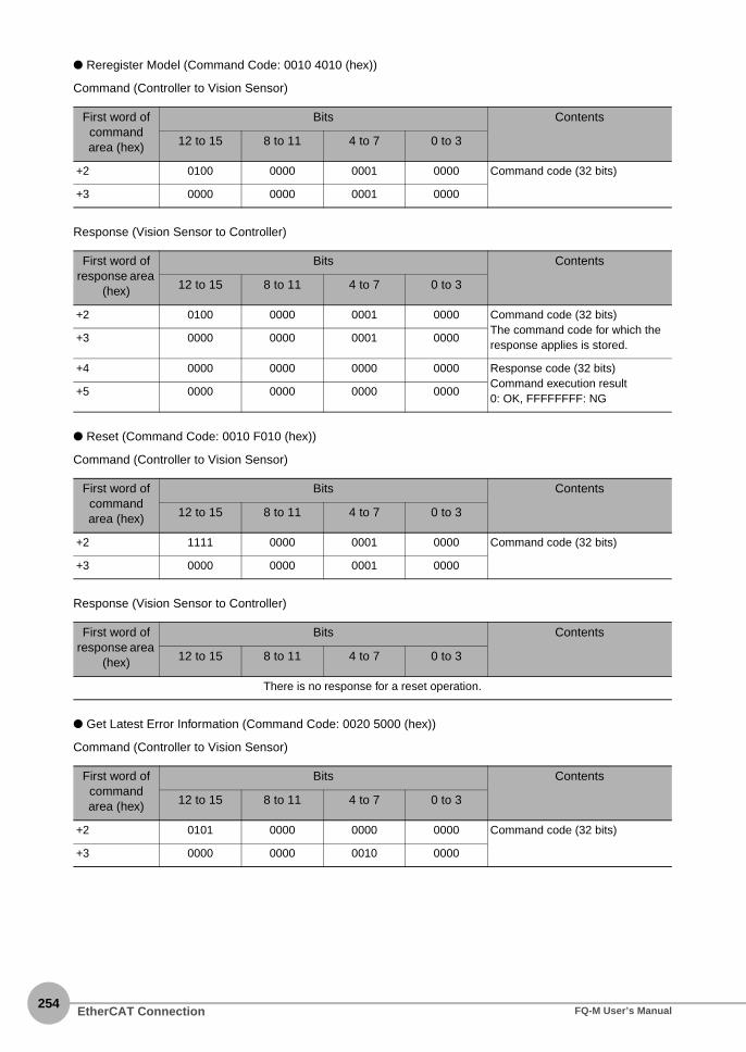
254
● Reregister Model (Command Code: 0010 4010 (hex))
Command (Controller to Vision Sensor)
Response (Vision Sensor to Controller)
● Reset (Command Code: 0010 F010 (hex))
Command (Controller to Vision Sensor)
Response (Vision Sensor to Controller)
● Get Latest Error Information (Command Code: 0020 5000 (hex))
Command (Controller to Vision Sensor)
First word of command area (hex)
Bits Contents
12 to 15 8 to 11 4 to 7 0 to 3
+2 0100 0000 0001 0000 Command code (32 bits)
+3 0000 0000 0001 0000
First word of response area
(hex)
Bits Contents
12 to 15 8 to 11 4 to 7 0 to 3
+2 0100 0000 0001 0000 Command code (32 bits)The command code for which the response applies is stored.
+3 0000 0000 0001 0000
+4 0000 0000 0000 0000 Response code (32 bits)Command execution result0: OK, FFFFFFFF: NG
+5 0000 0000 0000 0000
First word of command area (hex)
Bits Contents
12 to 15 8 to 11 4 to 7 0 to 3
+2 1111 0000 0001 0000 Command code (32 bits)
+3 0000 0000 0001 0000
First word of response area
(hex)
Bits Contents
12 to 15 8 to 11 4 to 7 0 to 3
There is no response for a reset operation.
First word of command area (hex)
Bits Contents
12 to 15 8 to 11 4 to 7 0 to 3
+2 0101 0000 0000 0000 Command code (32 bits)
+3 0000 0000 0010 0000
EtherCAT Connection FQ-M User’s Manual
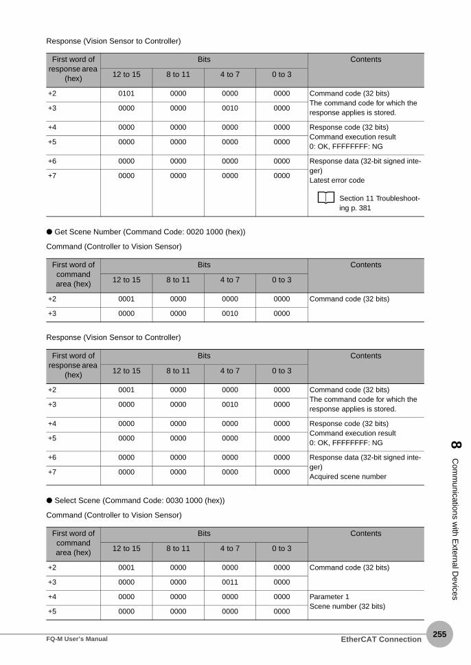
8 C
omm
unications with E
xternal Devices
Response (Vision Sensor to Controller)
● Get Scene Number (Command Code: 0020 1000 (hex))
Command (Controller to Vision Sensor)
Response (Vision Sensor to Controller)
● Select Scene (Command Code: 0030 1000 (hex))
Command (Controller to Vision Sensor)
First word of response area
(hex)
Bits Contents
12 to 15 8 to 11 4 to 7 0 to 3
+2 0101 0000 0000 0000 Command code (32 bits)The command code for which the response applies is stored.
+3 0000 0000 0010 0000
+4 0000 0000 0000 0000 Response code (32 bits)Command execution result0: OK, FFFFFFFF: NG
+5 0000 0000 0000 0000
+6 0000 0000 0000 0000 Response data (32-bit signed inte-ger)Latest error code
Section 11 Troubleshoot-ing p. 381
+7 0000 0000 0000 0000
First word of command area (hex)
Bits Contents
12 to 15 8 to 11 4 to 7 0 to 3
+2 0001 0000 0000 0000 Command code (32 bits)
+3 0000 0000 0010 0000
First word of response area
(hex)
Bits Contents
12 to 15 8 to 11 4 to 7 0 to 3
+2 0001 0000 0000 0000 Command code (32 bits)The command code for which the response applies is stored.
+3 0000 0000 0010 0000
+4 0000 0000 0000 0000 Response code (32 bits)Command execution result0: OK, FFFFFFFF: NG
+5 0000 0000 0000 0000
+6 0000 0000 0000 0000 Response data (32-bit signed inte-ger)Acquired scene number
+7 0000 0000 0000 0000
First word of command area (hex)
Bits Contents
12 to 15 8 to 11 4 to 7 0 to 3
+2 0001 0000 0000 0000 Command code (32 bits)
+3 0000 0000 0011 0000
+4 0000 0000 0000 0000 Parameter 1Scene number (32 bits)
+5 0000 0000 0000 0000
EtherCAT ConnectionFQ-M User’s Manual255

256
Response (Vision Sensor to Controller)
● Get Inspection Item Data (Command Code: 0040 1020 (hex))
Command (Controller to Vision Sensor)
Response (Vision Sensor to Controller)
First word of response area
(hex)
Bits Contents
12 to 15 8 to 11 4 to 7 0 to 3
+2 0001 0000 0000 0000 Command code (32 bits)The command code for which the response applies is stored.
+3 0000 0000 0011 0000
+4 0000 0000 0000 0000 Response code (32 bits)Command execution result0: OK, FFFFFFFF: NG
+5 0000 0000 0000 0000
First word of command area (hex)
Bits Contents
12 to 15 8 to 11 4 to 7 0 to 3
+2 0001 0000 0010 0000 Command code (32 bits)
+3 0000 0000 0100 0000
+4 0000 0000 0000 0000 Parameter 1Inspection item number (32-bit unsigned integer)
+5 0000 0000 0000 0000
+6 0000 0000 0000 0000 Parameter 2External; access number (32-bit unsigned integer)
12-2 External Reference Parameters p. 412
+7 0000 0000 0000 0000
First word of response area
(hex)
Bits Contents
12 to 15 8 to 11 4 to 7 0 to 3
+2 0001 0000 0010 0000 Command code (32 bits)The command code for which the response applies is stored.
+3 0000 0000 0100 0000
+4 0000 0000 0000 0000 Response code (32 bits)Command execution result0: OK, FFFFFFFF: NG
+5 0000 0000 0000 0000
+6 0000 0000 0000 0000 Response data Acquired data (32-bit signed inte-ger: 1,000 times the value)
+7 0000 0000 0000 0000
EtherCAT Connection FQ-M User’s Manual

8 C
omm
unications with E
xternal Devices
● Set Inspection Item Data (Command Code: 0050 1020 (hex))
Command (Controller to Vision Sensor)
Response (Vision Sensor to Controller)
● Get Software Version Information (Command Code: 0040 3000 (hex))
Command (Controller to Vision Sensor)
First word of command area (hex)
Bits Contents
12 to 15 8 to 11 4 to 7 0 to 3
+2 0001 0000 0010 0000 Command code (32 bits)
+3 0000 0000 0101 0000
+4 0000 0000 0000 0000 Parameter 1Inspection item number (32-bit unsigned integer)
+5 0000 0000 0000 0000
+6 0000 0000 0000 0000 Parameter 2External access number (32-bit unsigned integer)
12-2 External Reference Parameters p. 412
+7 0000 0000 0000 0000
+8 0000 0000 0000 0000 Parameter 3Value to set (32-bit signed integer: 1,000 times the value)
+9 0000 0000 0000 0000
First word of response area
(hex)
Bits Contents
12 to 15 8 to 11 4 to 7 0 to 3
+2 0001 0000 0010 0000 Command code (32 bits)The command code for which the response applies is stored.
+3 0000 0000 0101 0000
+4 0000 0000 0000 0000 Response code (32 bits)Command execution result0: OK, FFFFFFFF: NG
+5 0000 0000 0000 0000
First word of command area (hex)
Bits Contents
12 to 15 8 to 11 4 to 7 0 to 3
+2 0011 0000 0000 0000 Command code (32 bits)
+3 0000 0000 0100 0000
EtherCAT ConnectionFQ-M User’s Manual257

258
Response (Vision Sensor to Controller)
● Get Ring Counter (Command Code: 0020 6000 (hex))
Command (Controller to Vision Sensor)
Response (Vision Sensor to Controller)
First word of response area
(hex)
Bits Contents
12 to 15 8 to 11 4 to 7 0 to 3
+2 0011 0000 0000 0000 Command code (32 bits)The command code for which the response applies is stored.
+3 0000 0000 0100 0000
+4 0000 0000 0000 0000 Response code (32 bits)Command execution result0: OK, FFFFFFFF: NG
+5 0000 0000 0000 0000
+6 0000 0000 0000 0000 Response data (32-bit signed inte-ger)Software version (DINT: 1,000 times the value)
+7 0000 0000 0000 0000
First word of command area (hex)
Bits Contents
12 to 15 8 to 11 4 to 7 0 to 3
+2 0110 0000 0000 0000 Command code (32 bits)
+3 0000 0000 0010 0000
+4 0000 0000 0000 0000 Parameter 1Counter timing (32-bit unsigned integer)
0: Current ring counter value at command execution
1: Ring counter value at most recent trigger
+5 0000 0000 0000 0000
First word of response area
(hex)
Bits Contents
12 to 15 8 to 11 4 to 7 0 to 3
+2 0001 0000 0100 0000 Command code (32 bits)The command code for which the response applies is stored.
+3 0000 0000 0100 0000
+4 0000 0000 0000 0000 Response code (32 bits)Command execution result0: OK,FFFFFFFF: NG
+5 0000 0000 0000 0000
+6 0000 0000 0000 0000 Response data (32-bit signed inte-ger)Acquired data
+7 0000 0000 0000 0000
EtherCAT Connection FQ-M User’s Manual

8 C
omm
unications with E
xternal Devices
● Set Ring Counter (Command Code: 0030 6000 (hex))
Command (Controller to Vision Sensor)
Response (Vision Sensor to Controller)
Timing Chart for EtherCAT Communications
● Performing Measurements with the TRIG Signal
First word of command area (hex)
Bits Contents
12 to 15 8 to 11 4 to 7 0 to 3
+2 0110 0000 0000 0000 Command code (32 bits)
+3 0000 0000 0011 0000
+4 0000 0000 0000 0000 Parameter 1Set value for ring counter
+5 0000 0000 0000 0000
First word of response area
(hex)
Bits Contents
12 to 15 8 to 11 4 to 7 0 to 3
+2 0100 0000 0001 0000 Command code (32 bits)The command code for which the response applies is stored.
+3 0000 0000 0101 0000
+4 0000 0000 0000 0000 Response code (32 bits)Command execution result0: OK, FFFFFFFF: NG
+5 0000 0000 0000 0000
READY signal
Overall judgement (OR)
(1) (5)(2)(3) (4)
Execute Measure-ment (TRIG) signal
Command Execution Active (BUSY) signal
(1) Measurement starts when the TRIG signal turns ON while the BUSY signal is OFF.(2) The BUSY signal turns ON when measurement begins.(3) The TRIG signal turns OFF when the BUSY signal turns ON.(4) The OR of the measurement results is output when measurements are completed.(5) The BUSY signal turns OFF when the BUSY output condition is met.
CommandON
OFF
ON
OFF
ON
OFF
ON
OFF
Response Area
EtherCAT ConnectionFQ-M User’s Manual259
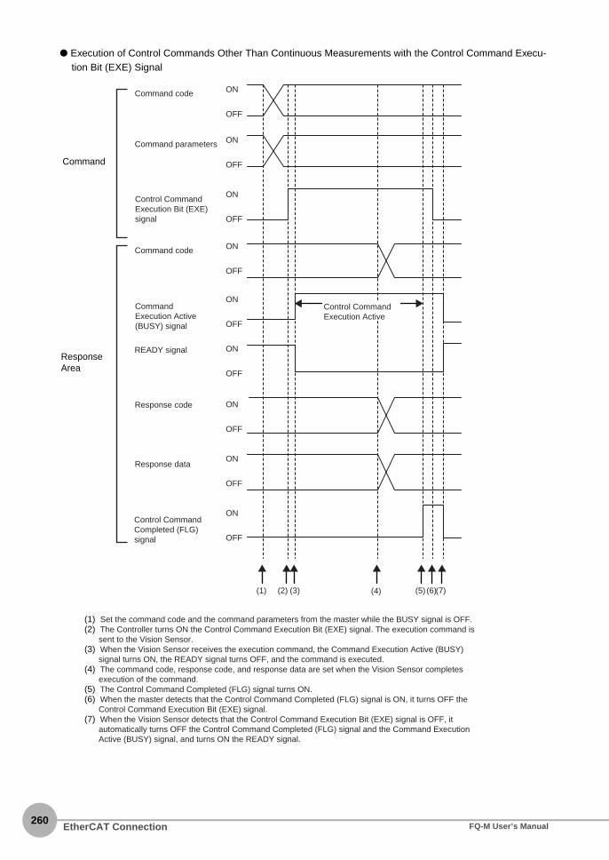
260
● Execution of Control Commands Other Than Continuous Measurements with the Control Command Execu-tion Bit (EXE) Signal
Command code
Command parameters
Command code
Response code
Response data
(1) (2) (4) (5) (6)(3) (7)
Control Command Execution Bit (EXE) signal
Command Execution Active (BUSY) signal
Control Command Completed (FLG) signal
READY signal
ON
OFF
ON
OFF
ON
OFF
ON
OFF
ON
OFF
ON
OFF
ON
OFF
ON
OFF
ON
OFF
Control Command Execution Active
(1) Set the command code and the command parameters from the master while the BUSY signal is OFF.(2) The Controller turns ON the Control Command Execution Bit (EXE) signal. The execution command is
sent to the Vision Sensor.(3) When the Vision Sensor receives the execution command, the Command Execution Active (BUSY)
signal turns ON, the READY signal turns OFF, and the command is executed.(4) The command code, response code, and response data are set when the Vision Sensor completes
execution of the command.(5) The Control Command Completed (FLG) signal turns ON.(6) When the master detects that the Control Command Completed (FLG) signal is ON, it turns OFF the
Control Command Execution Bit (EXE) signal.(7) When the Vision Sensor detects that the Control Command Execution Bit (EXE) signal is OFF, it
automatically turns OFF the Control Command Completed (FLG) signal and the Command Execution Active (BUSY) signal, and turns ON the READY signal.
Command
Response Area
EtherCAT Connection FQ-M User’s Manual

8 C
omm
unications with E
xternal Devices
nt
● Execution of Control Commands for Continuous Measurements with the Control Command Execution Bit (EXE) Signal
Total judgement (OR)
There is no signal to acquire measuremeresults during continuous measurements.
Command code
Command parameters
Command code
Response code
Response data
(1) (2) (4) (5) (6)(3) (7)
Control Command Execution Bit (EXE) signal
Command Execution Active (BUSY) signal
Control Command Completed (FLG) signal
READY signal
ON
OFF
ON
OFF
ON
OFF
ON
OFF
ON
OFF
ON
OFF
ON
OFF
ON
OFF
ON
OFF
Continuous measure-ments executed.
(1) Set the Start Continuous Measurements command code and the command parameters from the master while the BUSY signal is OFF.
(2) The Controller turns ON the Control Command Execution Bit (EXE) signal. The execution command is sent to the Vision Sensor.
(3) When the Vision Sensor receives the execution command, the Command Execution Active (BUSY) signal turns ON, the READY signal turns OFF, and the command is executed. Continuous measurements start at this time.
(4) The command code, response code, and response data are set when the Vision Sensor completes execution of the command.
(5) The Control Command Completed (FLG) signal turns ON.(6) When the master detects that the Control Command Completed (FLG) signal is ON, it turns OFF the Control Command
Execution Bit (EXE) signal.(7) When the Vision Sensor detects that the Control Command Execution Bit (EXE) signal is OFF, it automatically turns OFF the
Control Command Completed (FLG) signal. The BUSY signal remains ON until continuous measurements are completed.(8) During continuous measurements, an OR of the measurement results is output each time a measurement is completed.
Command
Response Area
EtherCAT ConnectionFQ-M User’s Manual261
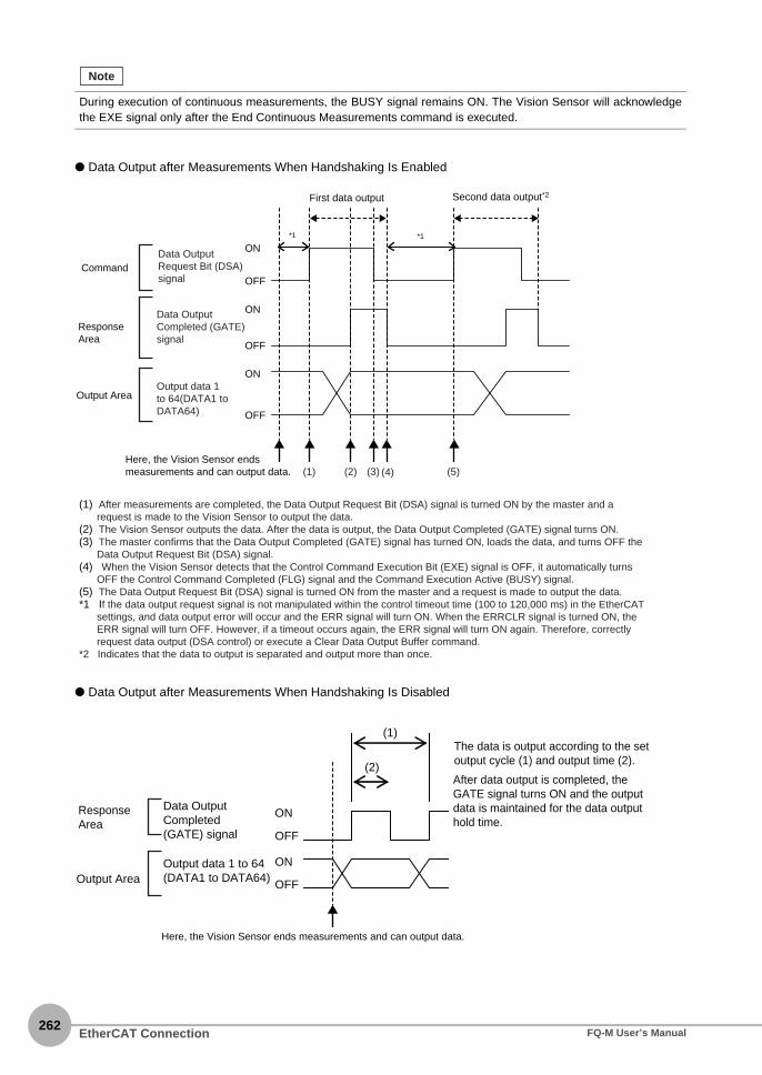
262
● Data Output after Measurements When Handshaking Is Enabled
● Data Output after Measurements When Handshaking Is Disabled
During execution of continuous measurements, the BUSY signal remains ON. The Vision Sensor will acknowledgethe EXE signal only after the End Continuous Measurements command is executed.
Note
Second data output*2First data output
(1) (2) (4) (5)(3)
Data Output Request Bit (DSA) signal
Output data 1 to 64(DATA1 to DATA64)
Data Output Completed (GATE) signal
*1 *1
ON
OFF
ON
OFF
ON
OFF
Output Area
(1) After measurements are completed, the Data Output Request Bit (DSA) signal is turned ON by the master and a request is made to the Vision Sensor to output the data.
(2) The Vision Sensor outputs the data. After the data is output, the Data Output Completed (GATE) signal turns ON.(3) The master confirms that the Data Output Completed (GATE) signal has turned ON, loads the data, and turns OFF the
Data Output Request Bit (DSA) signal.(4) When the Vision Sensor detects that the Control Command Execution Bit (EXE) signal is OFF, it automatically turns
OFF the Control Command Completed (FLG) signal and the Command Execution Active (BUSY) signal.(5) The Data Output Request Bit (DSA) signal is turned ON from the master and a request is made to output the data.*1 If the data output request signal is not manipulated within the control timeout time (100 to 120,000 ms) in the EtherCAT
settings, and data output error will occur and the ERR signal will turn ON. When the ERRCLR signal is turned ON, the ERR signal will turn OFF. However, if a timeout occurs again, the ERR signal will turn ON again. Therefore, correctly request data output (DSA control) or execute a Clear Data Output Buffer command.
*2 Indicates that the data to output is separated and output more than once.
Command
Response Area
Here, the Vision Sensor ends measurements and can output data.
Data Output Completed (GATE) signal
Output data 1 to 64(DATA1 to DATA64)
(2)
(1)The data is output according to the set output cycle (1) and output time (2).
After data output is completed, the GATE signal turns ON and the output data is maintained for the data output hold time.
Output Area
Response Area
ON
OFF
ON
OFF
Here, the Vision Sensor ends measurements and can output data.
EtherCAT Connection FQ-M User’s Manual

8 C
omm
unications with E
xternal Devices
Sample EtherCAT Ladder Programming
● Command/Response Communications
The following sample program is used to perform continuous measurements.The continuous measurements command (lower bytes: #1020, upper bytes: #0010) is sent to the VisionSensor.
Create the ladder program to control the TRIG signal so that it does not turn ON while the BUSY signal is ON.If not, a TRIG input error will occur and the ERROR signal will turn ON.
● Data Output after Measurements When Handshaking Is Enabled
First RUN Period Flag
Control Command Completed
(E001_FLG)
Execution condition
Control Command Completed
(E001_FLG)
Command Execution Active
(E001_BUSY)
Command Execution Bit(E001_EXE)
Turns ON Command Execution Bit.
Command Execution Bit(E001_EXE)
When the control command is completed, the Command Execution Bit is turned OFF.
E001_Vision_Command
Sets the continuous measurement command.
DINT#16#00101020
MOVE
EN
In
S
R
Out
ENO
Important
Data Output Request Bit(E001_DSA)
Data Output Request Bit(E001_DSA)
S
R
Data Output Completed
(E001_GATE)
Data Output Completed
(E001_GATE)Execution condition
EtherCAT ConnectionFQ-M User’s Manual263

264
Sysmac Device Features
The control device product designed according to standardized communications and user interfacespecifications for OMRON control devices are called a Sysmac Device. And the features available with such a Device is called Sysmac Device Features. This section describes the features the FQ-M series Vision Sensor provides when combined with a MachineAutomation Controller such as NJ series and automation software.
Sysmac Error Status
Because, in Sysmac Devices, errors that may occur in slaves are systematized, you can check the causes andremedies for errors with a common procedure.The status of an error can be monitored in the Sysmac Error Status (2002-01 hex). To display the error statusdetected by the FQ-M series Vision Sensor in Sysmac Studio, the Sysmac Error Status (2002-01 hex) must bemapped to the PDO. Sysmac Studio, by default, uses the 512th transmit PDO Mapping assignment to map theSysmac Error Status (2002-01 hex) automatically to the PDO.
Saving the Node Address Setting
When the node address switch setting is “00” (Software Setup mode), the node address value you set inSysmac Studio is enabled. If the node address switches are set to any other value, the value that is set on theswitches is used as the node address.In the Software Setup mode, in Sysmac Studio, execute [Write Slave Node Address] on the [EtherCAT Edit]screen to save the slave node address setting in the nonvolatile memory of the FQ-M series Vision Sensor.
● Software Setting
The set value saved as Slave Information Interface (SII) information in the nonvolatile memory of the slave isthe node address.
• For the Sysmac Error status (2002-01 hex), refer to 12-5 Object Dictionary p. 446.
• For errors displayed in Sysmac Studio, refer to NJ-series Troubleshooting Manual (Cat. No. W503).
Note
SII
(1)
(2)
(3)
(4) (5)
Node AddressSwitch
EtherCAT Slave
Register : 0010h
Register : 0012h
EtherCATSlave Controller
EtherCAT master
Nonvolatilememory
(1) The Node Address Switch is set to “00” at power OFF.
(2) Write a node address set value to Slave SII from the master.
(3) The value of the node address setting is applied to Register: 0012 hex by the software, when the slave power is ON.
(4) EtherCAT master reads the set value of Register: 0012 hex.
(5) EtherCAT master writes the value of 0012 hex address to 0010 hex address as the node address value.
EtherCAT Connection FQ-M User’s Manual

8 C
omm
unications with E
xternal Devices
● Node Address Switch Setting
The value set on the node address switches is the node address.
Serial Number Display
The serial number saved in the nonvolatile memory of the Vision Sensor is displayed in the Serial Number(1018-04 hex). Controllers that support Sysmac Device Features can use this serial number to check thenetwork configuration. To enable this check, in Sysmac Studio, set [Serial No. Check Condition] to [Set Value =Actual Unit] on the [EtherCAT Edit] screen. If the set condition is not met, a Network Configuration Check Errorwill occur.
Compliance with ESI Specification (ETG.2000 S (R) V1.0.1)
The ESI Specification is a set of specifications that define the entries required in an EtherCAT SlaveInformation (ESI) file.
SII Data Check
The Slave Information Interface (SII) is an interface area in the nonvolatile memory of an EtherCAT slave thatstores the configuration information specific to that EtherCAT slave.Sysmac Device EtherCAT slaves check the SII information from the slave side.If one of these slaves finds that SII information with which it cannot operate was written, it generates an SIICheck Error (Error No. 88.3).If this error persists even after turning OFF and then ON the power again, contactyour OMRON sales representative.
Do not use third-party or any other configuration tools to edit the SII information.
This network configuration check detects any slave devices that have been replaced, which prevents you from for-getting to set parameters on those slaves.
(1)
(2)
(3) (4)SII
(1) The Node Address Switch is set at power OFF.(2) The value of Node Address Switch is applied to
Register: 0012 hex, when the slave power is ON.
(3) EtherCAT master reads the set value of Register: 0012 hex.
(4) EtherCAT master writes the value of 0012 hex address to 0010 hex address as the node address value.
Register : 0010h
Register : 0012h
EtherCAT master
Node AddressSwitch
EtherCAT Slave
EtherCATSlave Controller
Nonvolatilememory
Note
Important
EtherCAT ConnectionFQ-M User’s Manual265

266
8-3 PLC Link Connections
You can use a PLC Link to communicate between the PLC and the Vision Sensor to perform control viacommand/response communications or to output data after measurements. You can use thesecommunications methods simultaneously. A PLC Link can be used only when [EtherCAT] for EtherCATcommunications is set to [OFF].
● Command/Response Communications
For PLC Link communications, command/response control signals are handled by storing control commandsfrom the PLC to the Vision Sensor and responses from the Vision Sensor to the PLC in the I/O memory of thePLC. This allows you to control the operation of the Vision Sensor (e.g., perform single inspections or changethe scene) without using communications instructions.
After you write a control command to the specified Command Area in the I/O memory of the PLC, you can turnON the Command Execution (EXE) Bit to send the control command to the Vision Sensor via Ethernet. TheVision Sensor executes the control command and sends a response back to the PLC via Ethernet. The PLCstores the response in the specified Response Area in I/O memory.
● Data Output after Measurements
Immediately after a single measurement or continuous measurements, the Vision Sensor will automaticallyoutput to the specified I/O memory in the PLC the data for measurements that are specified for output inadvance. This enables you to easily transfer the measurement results data for inspection items to the PLC.When handshaking is enabled, the data can be output from the Vision Sensor only when the condition toreceive that data are met at the PLC.
PLC (master) Vision Sensor (slave)
Command area
Response area
I/O memory(Communications areas)
CPU Unit
Ethernet (PLC Link communications)
Command
Response
OK, etc.
● Switching the scene number
● Single measurement, etc.
Output area
After measurements
Data
Up to 256 specified data items can be automatically output.
PLC (master) Vision Sensor (slave)
I/O memory(Communications area)
CPU Unit
Ethernet (PLC Link communications)
PLC Link Connections FQ-M User’s Manual
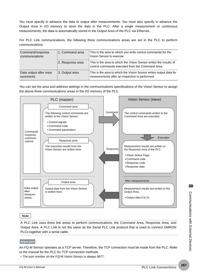
8 C
omm
unications with E
xternal Devices
You must specify in advance the data to output after measurements. You must also specify in advance theOutput Area in I/O memory to store the data in the PLC. After a single measurement or continuousmeasurements, the data is automatically stored in the Output Area of the PLC via Ethernet.
For PLC Link communications, the following three communications areas are set in the PLC to performcommunications.
You can set the area and address settings in the communications specifications of the Vision Sensor to assignthe above three communications areas in the I/O memory of the PLC.
An FQ-M Sensor operates as a TCP server. Therefore, the TCP connection must be made from the PLC. Referto the manual for the PLC for TCP connection methods.• The port number on the FQ-M Vision Sensor is always 9877.
Command/response communications
1. Command area This is the area to which you write control commands for the Vision Sensor to execute.
2. Response area This is the area to which the Vision Sensor writes the results of control commands executed from the Command Area.
Data output after mea-surements
3. Output area This is the area to which the Vision Sensor writes output data for measurements after an inspection is performed.
A PLC Link uses three link areas to perform communications: the Command Area, Response Area, andOutput Area. A PLC Link is not the same as the Serial PLC Link protocol that is used to connect OMRONPLCs together with a serial cable.
Command area
The following control commands are written to the Vision Sensor.
● Control signals● Command code● Command parameters
Response area
The execution results from the Vision Sensor are written here.
PLC (master)
Output area
Output data from the Vision Sensor is written here.
Vision Sensor (slave)
Command
ResponseMeasurement results are written to the Response Area of the PLC.
● Vision Status Flags● Command code● Response code● Response data
● Output data 0 to 31
Execution
After measurements
Measurement results are written to the Output Area.
Command/response communi-cations
The control commands written to the Command Area are executed.
Data output after measure-ments
Note
Important
PLC Link ConnectionsFQ-M User’s Manual267

PLC Link Connections268
FQ-M User’s Manual
PLC Link-compatible Models
● OMRON
● Mitsubishi Electric Corporation
Series CPU Interface
Built-in port in CPU Unit Ethernet Unit
SYSMAC CJ2 CJ2, CJ2M Supported (Built-in port only)
CJ1W-EIP21, CJ1W-ETN21
SYSMAC CJ1 CJ1H, CJ1G --- CJ1W-EIP21, CJ1W-ETN21
CJ1M Supported (Built-in port only)
CJ1W-EIP21, CJ1W-ETN21
SYSMAC CS CS1H, CS1D, CS1G --- CS1W-EIP21, CS1W-ETN21
SYSMAC CP1 CP1L Supported (Built-in port only)
---
CP1H --- CJ1W-EIP21, CJ1W-ETN21
SYSMAC One NSJ --- NSJW-ETN21
Series Model name CPU name CPU Interface
Built-in port in
CPU Unit
Ethernet Unit
MELSEC-QnU Universal model QnUDECPU Q03UDECPU, Q04UDEHCPU, Q06UDEHCPU, Q10UDEHCPU, Q13UDEHCPU, Q20UDEHCPU, Q26UDEHCPU
Supported QJ71E71-100, Q71E71-B2QJ71E71-B5
QnUDCPU Q03UDCPU, Q04UDHCPU, Q06UDHCPU, Q10UDHCPU, Q13UDHCPU, Q20UDHCPU, Q26UDHCPU
---
QnUCPU Q00UJCPU, Q00UCPU, Q01UCPU, Q02UCPU
---
Basic model QnCPU Q00JCPU, Q00CPU, Q01CPU
---
MELSEC-Q High-performance model
QCPU Q02CPU, Q02HCPU, Q06HCPU, Q12HCPU, Q25HCPU
---

8 C
omm
unications with E
xternal Devices
MELSEC-QnAS --- --- Q2ASCPU, Q2ASCPU-S1, Q2ASHCPU, Q2ASHCPU-S1
--- A1SJ71QE71N3-T
Series Model name CPU name CPU Interface
Built-in port in
CPU Unit
Ethernet Unit
PLC Link ConnectionsFQ-M User’s Manual269

270
Setting Up PLC Link Communications
Setting Network Settings in the Sensor
This section describes how to set the network settings in the Vision Sensor.
Multiview Explorer: [Device group] − Sensor name − [System] − [System data] (Double-click)→ Edit Pane: (Ethernet communications settings) Icon − [Ethernet settings]
The following items can be set.
Item Description Setting range
Auto connection Select whether the IP address is assigned automatically.To communicate with a PLC or other exter-nal device, set [Auto connection] to OFF and set the IP address setting described below.
OFF or ONDefault: ON
IP address Set the IP address of the Vision Sensor. a: 1 to 223, b: 0 to 255, c: 0 to 255, d: 1 to 254Default: 10.5.5.100
Subnet mask Set the subnet mask. 0.0.0.0 to 255.255.255.255Default: 255.255.255.0
Default Gateway Sets the default gateway. 0.0.0.0 to 255.255.255.255Default: 0.0.0.0
• Changes to settings are not applied until the Vision Sensor is restarted. Therefore, save the settings and then
restart the Vision Sensor.
5-5 Saving Data to the Sensor p. 161
Restarting the Sensor p. 210
• The port number on the FQ-M Vision Sensor is always 9877.
▲
Important
PLC Link Connections FQ-M User’s Manual
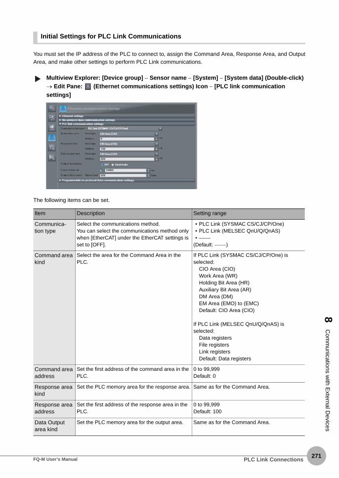
8 C
omm
unications with E
xternal Devices
Initial Settings for PLC Link Communications
You must set the IP address of the PLC to connect to, assign the Command Area, Response Area, and OutputArea, and make other settings to perform PLC Link communications.
Multiview Explorer: [Device group] − Sensor name − [System] − [System data] (Double-click) → Edit Pane: (Ethernet communications settings) Icon − [PLC link communication settings]
The following items can be set.
Item Description Setting range
Communica-tion type
Select the communications method.You can select the communications method only when [EtherCAT] under the EtherCAT settings is set to [OFF].
• PLC Link (SYSMAC CS/CJ/CP/One)• PLC Link (MELSEC QnU/Q/QnAS)• −−−−
(Default: −−−−)
Command area kind
Select the area for the Command Area in the PLC.
If PLC Link (SYSMAC CS/CJ/CP/One) is selected:
CIO Area (CIO)Work Area (WR)Holding Bit Area (HR)Auxiliary Bit Area (AR)DM Area (DM)EM Area (EMO) to (EMC)Default: CIO Area (CIO)
If PLC Link (MELSEC QnU/Q/QnAS) is selected:
Data registersFile registersLink registersDefault: Data registers
Command area address
Set the first address of the command area in the PLC.
0 to 99,999Default: 0
Response area kind
Set the PLC memory area for the response area. Same as for the Command Area.
Response area address
Set the first address of the response area in the PLC.
0 to 99,999Default: 100
Data Output area kind
Set the PLC memory area for the output area. Same as for the Command Area.
▲
PLC Link ConnectionsFQ-M User’s Manual271

272
• Operation on the Touch Finder
Use the following menu command to display the Setup Display on the Touch Finder.
(Setup Mode) − [Sensor settings] − [Network]
Output area address
Set the first address of the output area in the PLC.
0 to 99,999Default: 200
Output control Enables or disables handshaking.• Handshake: Data is output when the DSA sig-
nal from the PLC turns ON.• None: Data is output regardless of the signal
state from the PLC.
None or HandshakeDefault: None
Timeout (only when hand-shaking is enabled)
Sets the time for a timeout error to occur in 1-ms increments when handshaking is used.
100 to 120,000msDefault:10,000 ms
Number of out-put data upper value
Sets the maximum data size that can be output at one time through PLC Link communications. The size is set in bytes. Any data that exceeds the set value is discarded.
32 to 1,024 bytesDefault: 256 bytes
• Changes to settings are not applied until the Vision Sensor is restarted. Therefore, save the settings and then
restart the Vision Sensor.
5-5 Saving Data to the Sensor p. 161
Restarting the Sensor p. 210
Item Description Setting range
If the PLC does not retrieve the data evenafter the timeout time is exceeded, the VisionSensor adds error information to the error log.
Note
▲
Important
PLC Link Connections FQ-M User’s Manual

8 C
omm
unications with E
xternal Devices
Setting the Data To Output Automatically after Measurements
You can set the data to output automatically after measurements. (You can set up to 32 data items.)
Data That Can Be Output
You can output up to 32 data items (data 0 to data 31). The measurement data from inspection items that canbe output and the calculation results from the expression settings can be output. For data that can be output,refer to the Measurement Data That Can Be Used for External Outputs and Calculations for each inspectionitem.
Checking PLC Link Communications Settings
You can check the current PLC Link communications settings.
Multiview Explorer: [Device group] − Sensor name − [Scene] − Scene data number (Double-click)→ Edit Pane: (Output) Icon − [Communication settings]
If you click the [Output] Button while setting up inspection items, the following Output Setting Main Window isdisplay.
▲
PLC Link ConnectionsFQ-M User’s Manual273

274
Item Description
Output destination settings The settings of the following parameters in the system data are displayed.1. Ethernet Setting Status
Enabled (green): Output no-protocol data, output link data, or program-mable no-protocol data is selected as the communica-tions method.
Disabled (red): All settings are disabled.2. The following output no-protocol data, output link data, programmable no-
protocol data parameters:• Communication method• IP address• Port number
Output properties The properties of the output data that is selected in the data output list are displayed.
If outputting link data is not set in the output destination settings, click the [Edit system data] Button and makethe initial settings for PLC Link communications in the Ethernet Communication Dialog Box.
Note
PLC Link Connections FQ-M User’s Manual

8 C
omm
unications with E
xternal Devices
Allocating Output Data
Multiview Explorer: [Device group] − Sensor name − [Scene] − Scene data number (Double-click)→ Edit Pane: (Output) Icon − [No-protocol data output]
1 In the Output Settings Main Pane, right-click the output data number to set in the output data listunder [No-protocol data output] and select [Edit].
The following Output Dialog Box is displayed.
▲
PLC Link ConnectionsFQ-M User’s Manual275

PLC Link Connections276
FQ-M User’s Manual
2 Set the data to output in the Output Dialog Box.
3 Click the [OK] Button.
4 Set the output format. Set the output format in [Output format] under [EtherCAT/PLC link data output setting].
Item Description
Output data settings The number of the output data that was selected for setting is displayed.
Name You can change the name of the output data.Max. number of characters: 15
Expression Registers the output data item or multiple data output function.Examples:I0.XLPR(0, 3, I0.X, I0.Y)LPC(0, I0.C, I0.X, I0.Y)
Data You can insert parameters selected from Units and parameters into expressions.
Unit Select one of the following.An inspection item that has the output item to use for the output data.Calculation
Parameter Select the output item from the selected unit.Example: If the Search inspection item was selected, you can select either of the following: Judgement results: Judgement JG or Correlation: Corre. CR
Function The following functions can be inserted.• In Multiple Data Output Mode, select one of the following types of multiple data output
functions.• Data logging order: LPR function
The measurement data is output in order.Format: LPR (start_number,number_of_data,data_A, data_B,data_C...)Output Example:
LPR(0,3,I0.X,I0.Y,I0.Z)X0,Y0,Z0,X1,Y1,Z1,X2,Y2,Z2
• Detection point order: LPC functionOutputs data for each detected measurement point.Format: LPC (start_number,number_of_data,data_A, data_B,data_C...)Output Example:
LPC(0,3,I0.X,I0.Y,I0.Z)X0,X1,X2,Y0,Y1,Y2,Z0, Z1, Z2,,,
You can specify up to five data items as the above LPR and LPC functions arguments.• Encoder Value Output Function
• Encoder Value Output: ECNT functionThe encoder value is output.Format: ECNT(argument)Output Example:
ECNT(0)0: Ring counter value at measurement trigger1: Ring counter value at calculation2: Trigger counter value at calculation
Item Description Setting range
Output format Sets the output format for numerical data. Floating point or fixed pointDefault: Floating point

8 C
omm
unications with E
xternal Devices
● Expression Setting Example
This example registers an expression to output the following inspection results for data 0.Inspection item: 0 SearchParameters to output: Position X, Position Y, Reference SX, and Reference SYMulti-point output setting: Multi-point output Check Box selected, Count = 4
Output ResultsThe expression that is registered for data 0 assigns the data for 16 items (64 bytes) in the output area as shown below.
● Output Data Size and Number of Output Data Upper Value Setting
When more than one inspection result is output, the size of the data that is output for the data output settingscould exceed the limit that is set in the number of output data upper value setting.If that occurs, increase the set value of the number of output data upper value setting or adjust the output datasettings so that data output size is not exceeded.If the size of data that is output does exceed the set value of the number of output data upper value setting, theremaining data will be discarded.
ExampleOutput data size: 328 bytesNumber of output data upper value setting: 256 bytes
Output area data Assigned data
Output data 0 (4 bytes) I0.X[0] (Position X 1st point)
Output data 1 (4 bytes) I0.Y[0] (Position Y 1st point)
Output data 2 (4 bytes) I0.SX[0] (Reference SX 1st point)
Output data 3 (4 bytes) I0.SY[0] (Reference SY 1st point)
Output data 4 (4 bytes) I0.X[1] (Position X 2nd point)
Output data 5 (4 bytes) I0.Y[1] (Position Y 2nd)
Output data 6 (4 bytes) I0.SX[1] (Reference SX 2nd point)
Output data 7 (4 bytes) I0.SY[1] (Reference SY 2nd point)
Output data 8 (4 bytes) I0.X[2] (Position X 3rd)
Output data 9 (4 bytes) I0.Y[2] (Position Y 3rd)
Output data 10 (4 bytes) I0.SX[2] (Reference SX 3rd point)
Output data 11 (4 bytes) I0.SY[2] (Reference SY 3rd point)
Output data 12 (4 bytes) I0.X[3] (Position X 4th)
Output data 13 (4 bytes) I0.Y[3] (Position Y 4th)
Output data 14 (4 bytes) I0.SX[3] (Reference SX 4th point)
Output data 15 (4 bytes) I0.SY[3] (Reference SY 4th point)
The inspection results will be output according to the sorting method that is set for multi-point output for the inspection item.
LPR(0,I0.C,I0.X,I0.Y,I0.SX,I0.SY)
start_number
Number_of_data (Count) data_A, data_B...data_dFunction
Note
PLC Link ConnectionsFQ-M User’s Manual277

278
Data Output Settings
The output data that is assigned is output to the output area as shown below.Any output data that exceeds the set value of the number of output data upper value setting (256 bytes) isdiscarded.
Data 0
Output data Setting
Data 1Data 2
I0.X[0] Inspection item 0: Position X for Search
I0.Y[0] Inspection item 0: Position Y for SearchLPC(0,30,I1.X,I1.Y)
Inspection item 1: Position X 1st point for Shape Search
Inspection item 1: Position X 30th point for Shape SearchInspection item 1: Position Y 1st point for Shape Search
Inspection item 1: Position Y 30th point for Shape Search
Data 3 LPR(0,10,I2.X,I2.Y)
Inspection item 2: Position X 1st point for Shape SearchInspection item 2: Position Y 1st point for Shape Search
Inspection item 2: Position X 10th point for Shape SearchInspection item 2: Position Y 10th point for Shape Search
328bytes
+0
Output data Assigned output data
+1
Output data 0(4 bytes)
Output data 1(4 bytes)
Output data 2(4 bytes)
Output data 31(4 bytes)
Output data 32(4 bytes)
Output data 61(4 bytes)
Output data 62(4 bytes)
Output data 63(4 bytes)
Output data 64(4 bytes)
Output data 80(4 bytes)
Output data 81(4 bytes)
Inspection item 0: Position X for Search
+2
+3
Inspection item 0: Position Y for Search
+4
+5
Inspection item 1: Position X 1st point for Shape Search
+62
+63
Inspection item 1: Position X 30th point for Shape Search
+64
+65
Inspection item 1: Position Y 1st point for Shape Search
+122
+123
Inspection item 1: Position Y 30th point for Shape Search
+124
+125
Inspection item 2: Position X 1st point for Shape Search
+126
+127
Inspection item 2: Position Y 1st point for Shape Search
+128
+129
Inspection item 2: Position X 2nd point for Shape Search
+160
+161
Inspection item 2: Position X 10th point for Shape Search
+162
+163
Inspection item 2: Position Y 10th point for Shape Search
256 bytes (This data is output.)
Offset from first address in output area
72 bytesThe data that exceeds the set upper limit is discarded.
PLC Link Connections FQ-M User’s Manual

8 C
omm
unications with E
xternal Devices
Memory Assignments for PLC Link Communications
This section describes the assignments for the Command, Response, and Data Output Areas.
● Command Area
PLC (Master) to Vision Sensor (Slave)
First word
Bits Contents
15 14 13 12 11 10 9 8 7 6 5 4 3 2 1 0
+0 ERRCLR Resv Resv Resv Resv Resv Resv Resv Resv Resv Resv Resv Resv Resv Resv EXE Control sig-nals (32 bits)+1 Resv Resv Resv Resv Resv Resv Resv Resv Resv Resv Resv Resv Resv Resv Resv DSA
+2 Command code Command code (32 bits)+3
+4 Parameter 1 Parameter (integer)
+5
+6 Parameter 2 Spare (inte-ger)
+7
+8 Parameter 3 Spare (inte-ger)
+9
Signal Signal name Function Application
EXE Control Command Execution Bit
Turn ON this signal from the PLC to send a control command for the Vision Sensor to execute.
Command/response commu-nications
Turn OFF the EXE signal from the PLC when the Control Command Completed (FLG) signal from the Vision Sensor turns ON. (Set the control command code and parameters before you turn ON this sig-nal.)
DSA Data Output Request Bit
Turn ON this signal from the PLC to request data output. When this signal turns ON, the Vision Sen-sor outputs data.
Data output after measurements
Turn OFF the DSA signal from the PLC when the Data Output Completed (GATE) signal from the Vision Sensor turns ON.
ERRCLR Clear Error Turn ON this signal to turn OFF the error (ERR) sig-nal from the Vision Sensor.
Command/Response Commu-nications
Turn OFF this signal from PLC when the error (ERR) signal goes OFF.
Command code Command code This I/O port stores the command code. Command/Response Commu-nications
Parameters 1 to 3
Command parameters These I/O ports store the command parameters.
PLC Link ConnectionsFQ-M User’s Manual279

280
● Response Area
Vision Sensor (Slave) to PLC (Master)
First word
Bits Contents
15 14 13 12 11 10 9 8 7 6 5 4 3 2 1 0
+0 ERR Resv Resv Resv Resv Resv Resv Resv Resv Resv Resv Resv Resv READY BUSY FLG Control signals (32 bits)+1 Resv Resv Resv Resv Resv Resv Resv Resv Resv Resv Resv Resv Resv Resv Resv GATE
+2 Command code Com-mand code (32 bits)
+3
+4 Response code Response code (32 bits)+5
+6 Response data Response data (32 bits)+7
Signal Signal name Function Application
FLG Control Command Com-pleted
This signal turns ON when the Vision Sensor completes execution of the control command.
Command/response commu-nications
This signal automatically turns OFF when the Control Command Execution Bit (EXE) signal from the PLC turns OFF.This signal turns ON after the control com-mand code, response code, and response data have been stored.
BUSY Command Execution Active
This signal is ON while the Vision Sensor is executing a control command.
It is OFF while the Vision Sensor is not execut-ing a control command.
READY Ready This signal turns ON when the Vision Sensor can execute a command.
Command/response
communications
This signal turns OFF when the Vision Sensor cannot execute a command.
ERR Error This signal turns ON when an error is detected in the Vision Sensor.
Command/response commu-nications
This signal turns OFF when the Clear Error (ERRCLR) signal from the PLC turns ON.
GATE Data Output Completed This signal turns ON when the Vision Sensor finishes outputting data.
Data output after measurements
If handshaking is enabled, the GATE signal turns OFF automatically when you turn OFF the Data Output Request (DSA) signal from the PLC.
Command code Command code This I/O port returns the command code that was executed.
Command/response commu-nications
Response code Response code This I/O port contains the response code of the executed command.
Response data Response data This I/O port contains the response data of the executed command.
PLC Link Connections FQ-M User’s Manual

8 C
omm
unications with E
xternal Devices
● Output Area
Vision Sensor (Slave) to PLC (Master)
First word
Bits Contents
15 14 13 12 11 10 9 8 7 6 5 4 3 2 1 0
+0DATA 0
Output data 0 (32 bits)
+1
···
···
···
+14DATA 7
Output data 7 (32 bits)
+15
···
···
···
+128DATA 63
Output data 63 (32 bits)
+219
···
···
···
+512DATA 255
Output data 255 (32 bits)
+513
Signal Signal name Function Application
DATA0-255 Output data 0 to 255 These I/O ports output the output data that is specified for the data output method.The range of the data that can be output is determined by the set value of the number of output data upper value setting as follows:Minimum setting (32 bytes): Output data 0 to 7Default setting (256 bytes): Output data 0 to 63Maximum setting (1,024 bytes): Output data 0 to 255
Data output after measurements
If the size of data that is output exceeds the set value of the number of output data upper value setting, the remain-ing data will be discarded.
Allocating Output Data p. 236
Note
PLC Link ConnectionsFQ-M User’s Manual281

282
Command Tables for PLC Link Communications
This section describes the commands used in PLC Link communications.
● Measurement Control Commands
● Utility Commands
● Scene Control Commands
First word of com-mand area (hex)
Command name Function Reference
+2 +3
1010 0010 Single Measurement Performs a single measurement. p. 283
1020 0010 Start Continuous Measure-ments
Executes continuous measurements. p. 284
1030 0010 End Continuous Measure-ments
Ends continuous measurements. p. 284
First word of com-mand area (hex)
Command name Function Reference
+2 +3
2010 0010 Clear Measurement Values Clears all measurement result values. p. 285
2030 0010 Reset Encoder Counter Resets the encoder counter. p. 285
3010 0010 Save Data in Sensor Saves the current system data and scene groups in the Sensor.
p. 286
4010 0010 Re-register Model Registers the model again. p. 286
F010 0010 Reset Resets the Vision Sensor. p. 286
5000 0020 Get Latest Error Information Acquires the latest error information. p. 287
First word of com-mand area (hex)
Command name Function Reference
+2 +3
1000 0020 Get Scene Number Acquires the current scene number. p. 287
1000 0030 Select Scene Changes to the specified scene number. p. 288
PLC Link Connections FQ-M User’s Manual

8 C
omm
unications with E
xternal Devices
● Data Acquisition/Setting Commands
Command Details
● Single Measurement (Command Code: 1010 0010)
Command (PLC to Vision Sensor)
Response (Vision Sensor to PLC)
First word of com-mand area (hex)
Command name Function Reference
+2 +3
1020 0040 Get Inspection Item Data Acquires the inspection item data. p. 288
1020 0050 Set Inspection Item Data Sets the inspection item data to the specified data.
p. 289
3000 0040 Get Software Version Informa-tion
Acquires the software version. p. 290
6000 0020 Get Ring Counter Acquires the ring counter value. p. 290
6000 0030 Set Ring Counter Sets the ring counter value. p. 291
First word of command area (hex)
Bits Contents
12 to 15 8 to 11 4 to 7 0 to 3
+2 0001 0000 0001 0000 Command code: 4-byte binary data
+3 0000 0000 0001 0000
First word of response area
(hex)
Bits Contents
12 to 15 8 to 11 4 to 7 0 to 3
+2 0001 0000 0001 0000 Command codeThe command code for which the response applies is stored.
+3 0000 0000 0001 0000
+4 0000 0000 0000 0000 Response codeCommand execution result0: OK, FFFFFFFF: NG
+5 0000 0000 0000 0000
The measurement results are written to the output area if data output is set.The measurement results are not output if data output is not set.
Setting the Data To Output Automatically after Measurements: p. 273
Note
PLC Link ConnectionsFQ-M User’s Manual283
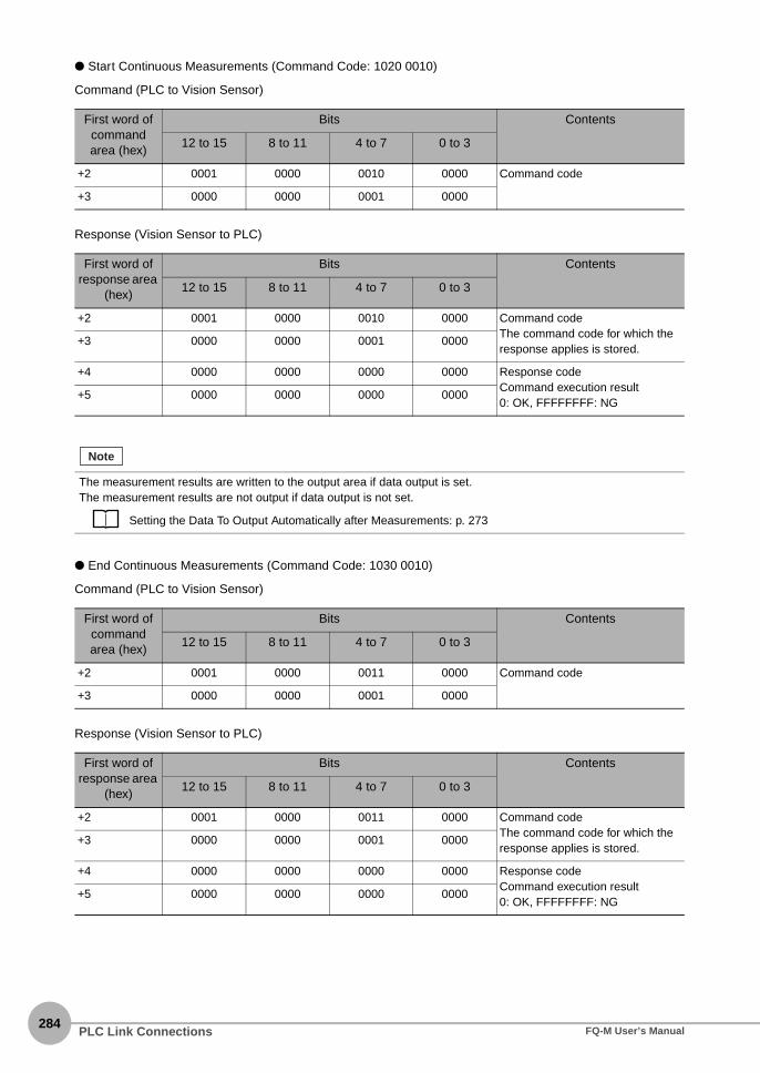
284
● Start Continuous Measurements (Command Code: 1020 0010)
Command (PLC to Vision Sensor)
Response (Vision Sensor to PLC)
● End Continuous Measurements (Command Code: 1030 0010)
Command (PLC to Vision Sensor)
Response (Vision Sensor to PLC)
First word of command area (hex)
Bits Contents
12 to 15 8 to 11 4 to 7 0 to 3
+2 0001 0000 0010 0000 Command code
+3 0000 0000 0001 0000
First word of response area
(hex)
Bits Contents
12 to 15 8 to 11 4 to 7 0 to 3
+2 0001 0000 0010 0000 Command codeThe command code for which the response applies is stored.
+3 0000 0000 0001 0000
+4 0000 0000 0000 0000 Response codeCommand execution result0: OK, FFFFFFFF: NG
+5 0000 0000 0000 0000
The measurement results are written to the output area if data output is set.The measurement results are not output if data output is not set.
Setting the Data To Output Automatically after Measurements: p. 273
First word of command area (hex)
Bits Contents
12 to 15 8 to 11 4 to 7 0 to 3
+2 0001 0000 0011 0000 Command code
+3 0000 0000 0001 0000
First word of response area
(hex)
Bits Contents
12 to 15 8 to 11 4 to 7 0 to 3
+2 0001 0000 0011 0000 Command codeThe command code for which the response applies is stored.
+3 0000 0000 0001 0000
+4 0000 0000 0000 0000 Response codeCommand execution result0: OK, FFFFFFFF: NG
+5 0000 0000 0000 0000
Note
PLC Link Connections FQ-M User’s Manual

8 C
omm
unications with E
xternal Devices
● Clear Measurement Values (Command Code: 2010 0010)
Command (PLC to Vision Sensor)
Response (Vision Sensor to PLC)
● Reset Encoder Counter (Command Code: 2030 0010)
Command (PLC to Vision Sensor)
Response (Vision Sensor to PLC)
First word of command area (hex)
Bits Contents
12 to 15 8 to 11 4 to 7 0 to 3
+2 0010 0000 0001 0000 Command code
+3 0000 0000 0001 0000
First word of response area
(hex)
Bits Contents
12 to 15 8 to 11 4 to 7 0 to 3
+2 0010 0000 0001 0000 Command codeThe command code for which the response applies is stored.
+3 0000 0000 0001 0000
+4 0000 0000 0000 0000 Response codeCommand execution result0: OK, FFFFFFFF: NG
+5 0000 0000 0000 0000
First word of command area (hex)
Bits Contents
12 to 15 8 to 11 4 to 7 0 to 3
+2 0000 0010 0000 0011 Command code
+3 0000 0000 0001 0000
+4 0000 0000 0000 0000 Reset target0: Reset the trigger counter and
ring counter.1: Reset the ring counter.2: Reset the trigger counter.
+5 0000 0000 0000 0000
First word of response area
(hex)
Bits Contents
12 to 15 8 to 11 4 to 7 0 to 3
+2 0001 0000 0000 0000 Command codeThe command code for which the response applies is stored.
+3 0000 0000 0011 0000
+4 0000 0000 0000 0000 Response codeCommand execution result0: OK, FFFFFFFF: NG
+5 0000 0000 0000 0000
PLC Link ConnectionsFQ-M User’s Manual285

286
● Save Data in Sensor (Command Code: 3010 0010)
Command (PLC to Vision Sensor)
Response (Vision Sensor to PLC)
● Reregister Model (Command Code: 4010 0010)
Command (PLC to Vision Sensor)
Response (Vision Sensor to PLC)
● Reset Vision Sensor (Command Code: F010 0010)
Command (PLC to Vision Sensor)
First word of command area (hex)
Bits Contents
12 to 15 8 to 11 4 to 7 0 to 3
+2 0011 0000 0001 0000 Command code
+3 0000 0000 0001 0000
First word of response area
(hex)
Bits Contents
12 to 15 8 to 11 4 to 7 0 to 3
+2 0011 0000 0001 0000 Command codeThe command code for which the response applies is stored.
+3 0000 0000 0001 0000
+4 0000 0000 0000 0000 Response codeCommand execution result0: OK, FFFFFFFF: NG
+5 0000 0000 0000 0000
First word of command area (hex)
Bits Contents
12 to 15 8 to 11 4 to 7 0 to 3
+2 0100 0000 0001 0000 Command code
+3 0000 0000 0001 0000
First word of response area
(hex)
Bits Contents
12 to 15 8 to 11 4 to 7 0 to 3
+2 0100 0000 0001 0000 Command codeThe command code for which the response applies is stored.
+3 0000 0000 0001 0000
+4 0000 0000 0000 0000 Response codeCommand execution result0: OK, FFFFFFFF: NG
+5 0000 0000 0000 0000
First word of command area (hex)
Bits Contents
12 to 15 8 to 11 4 to 7 0 to 3
+2 1111 0000 0001 0000 Command code
+3 0000 0000 0001 0000
PLC Link Connections FQ-M User’s Manual

8 C
omm
unications with E
xternal Devices
Response (Vision Sensor to PLC)
● Get Latest Error Information (Command Code: 5000 0020)
Command (PLC to Vision Sensor)
Response (Vision Sensor to PLC)
● Get Scene Number (Command Code: 1000 0020)
Command (PLC to Vision Sensor)
First word of response area
(hex)
Bits Contents
12 to 15 8 to 11 4 to 7 0 to 3
There is no response for a reset operation.
First word of command area (hex)
Bits Contents
12 to 15 8 to 11 4 to 7 0 to 3
+2 0101 0000 0000 0000 Command code
+3 0000 0000 0010 0000
First word of response area
(hex)
Bits Contents
12 to 15 8 to 11 4 to 7 0 to 3
+2 0101 0000 0000 0000 Command codeThe command code for which the response applies is stored.
+3 0000 0000 0010 0000
+4 0000 0000 0000 0000 Response codeCommand execution result0: OK, −1: NG
+5 0000 0000 0000 0000
+6 0000 0000 0000 0000 Response data Latest error code
Errors Stored in the Error History p. 388
+7 0000 0000 0000 0000
First word of command area (hex)
Bits Contents
12 to 15 8 to 11 4 to 7 0 to 3
+2 0001 0000 0000 0000 Command code
+3 0000 0000 0010 0000
PLC Link ConnectionsFQ-M User’s Manual287

288
Response (Vision Sensor to PLC)
● Select Scene (Command Code: 1000 0030)
Command (PLC to Vision Sensor)
Response (Vision Sensor to PLC)
● Get Inspection Item Data (Command Code: 1020 0040)
Command (PLC to Vision Sensor)
First word of response area
(hex)
Bits Contents
12 to 15 8 to 11 4 to 7 0 to 3
+2 0001 0000 0000 0000 Command codeThe command code for which the response applies is stored.
+3 0000 0000 0010 0000
+4 0000 0000 0000 0000 Response codeCommand execution result0: OK, FFFFFFFF: NG
+5 0000 0000 0000 0000
+6 0000 0000 0000 0000 Response dataAcquired scene number
+7 0000 0000 0000 0000
First word of command area (hex)
Bits Contents
12 to 15 8 to 11 4 to 7 0 to 3
+2 0001 0000 0000 0000 Command code
+3 0000 0000 0011 0000
+4 0000 0000 0000 0000 Scene number
+5 0000 0000 0000 0000
First word of response area
(hex)
Bits Contents
12 to 15 8 to 11 4 to 7 0 to 3
+2 0001 0000 0000 0000 Command codeThe command code for which the response applies is stored.
+3 0000 0000 0011 0000
+4 0000 0000 0000 0000 Response codeCommand execution result0: OK, FFFFFFFF: NG
+5 0000 0000 0000 0000
First word of command area (hex)
Bits Contents
12 to 15 8 to 11 4 to 7 0 to 3
+2 0001 0000 0010 0000 Command code
+3 0000 0000 0100 0000
+4 0000 0000 0000 0000 Unit number
+5 0000 0000 0000 0000
+6 0000 0000 0000 0000 Data number
+7 0000 0000 0000 0000
PLC Link Connections FQ-M User’s Manual
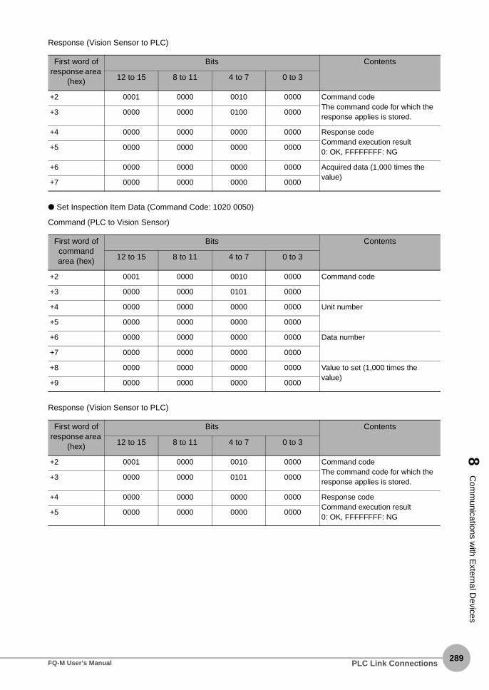
8 C
omm
unications with E
xternal Devices
Response (Vision Sensor to PLC)
● Set Inspection Item Data (Command Code: 1020 0050)
Command (PLC to Vision Sensor)
Response (Vision Sensor to PLC)
First word of response area
(hex)
Bits Contents
12 to 15 8 to 11 4 to 7 0 to 3
+2 0001 0000 0010 0000 Command codeThe command code for which the response applies is stored.
+3 0000 0000 0100 0000
+4 0000 0000 0000 0000 Response codeCommand execution result0: OK, FFFFFFFF: NG
+5 0000 0000 0000 0000
+6 0000 0000 0000 0000 Acquired data (1,000 times the value)
+7 0000 0000 0000 0000
First word of command area (hex)
Bits Contents
12 to 15 8 to 11 4 to 7 0 to 3
+2 0001 0000 0010 0000 Command code
+3 0000 0000 0101 0000
+4 0000 0000 0000 0000 Unit number
+5 0000 0000 0000 0000
+6 0000 0000 0000 0000 Data number
+7 0000 0000 0000 0000
+8 0000 0000 0000 0000 Value to set (1,000 times the value)
+9 0000 0000 0000 0000
First word of response area
(hex)
Bits Contents
12 to 15 8 to 11 4 to 7 0 to 3
+2 0001 0000 0010 0000 Command codeThe command code for which the response applies is stored.
+3 0000 0000 0101 0000
+4 0000 0000 0000 0000 Response codeCommand execution result0: OK, FFFFFFFF: NG
+5 0000 0000 0000 0000
PLC Link ConnectionsFQ-M User’s Manual289

290
● Get Software Version Information (Command Code: 3000 0040)
Command (PLC to Vision Sensor)
Response (Vision Sensor to PLC)
● Get Ring Counter (Command Code: 6000 0020)
Command (PLC to Vision Sensor)
Response (Vision Sensor to PLC)
First word of command area (hex)
Bits Contents
12 to 15 8 to 11 4 to 7 0 to 3
+2 0011 0000 0000 0000 Command code
+3 0000 0000 0100 0000
First word of response area
(hex)
Bits Contents
12 to 15 8 to 11 4 to 7 0 to 3
+2 0011 0000 0000 0000 Command codeThe command code for which the response applies is stored.
+3 0000 0000 0100 0000
+4 0000 0000 0000 0000 Response codeCommand execution result0: OK, FFFFFFFF: NG
+5 0000 0000 0000 0000
+6 0000 0000 0000 0000 Response dataSoftware version (DINT: 1,000 times the value)
+7 0000 0000 0000 0000
First word of command area (hex)
Bits Contents
12 to 15 8 to 11 4 to 7 0 to 3
+2 0110 0000 0000 0000 Command code
+3 0000 0000 0010 0000
+4 0000 0000 0000 0000 Counter timing0: Current ring counter value at
command execution1: Ring counter value at trigger
+5 0000 0000 0000 0000
First word of response area
(hex)
Bits Contents
12 to 15 8 to 11 4 to 7 0 to 3
+2 0110 0000 0000 0000 Command codeThe command code for which the response applies is stored.
+3 0000 0000 0010 0000
+4 0000 0000 0000 0000 Response codeCommand execution result0: OK, FFFFFFFF: NG
+5 0000 0000 0000 0000
+6 0000 0000 0000 0000 Acquired data
+7 0000 0000 0000 0000
PLC Link Connections FQ-M User’s Manual

8 C
omm
unications with E
xternal Devices
● Set Ring Counter (Command Code: 6000 0030)
Command (PLC to Vision Sensor)
Response (Vision Sensor to PLC)
First word of command area (hex)
Bits Contents
12 to 15 8 to 11 4 to 7 0 to 3
+2 0110 0000 0000 0000 Command code
+3 0000 0000 0011 0000
+4 0000 0000 0000 0000 Value to set
+5 0000 0000 0000 0000
First word of response area
(hex)
Bits Contents
12 to 15 8 to 11 4 to 7 0 to 3
+2 0110 0000 0000 0000 Command codeThe command code for which the response applies is stored.
+3 0000 0000 0011 0000
+4 0000 0000 0000 0000 Response codeCommand execution result0: OK, FFFFFFFF: NG
+5 0000 0000 0000 0000
PLC Link ConnectionsFQ-M User’s Manual291

292
Timing Chart for PLC Link Communications
● Command/Response Communications
ON
OFF
ON
OFF
ON
OFF
ON
OFF
ON
OFF
ON
OFF
ON
OFF
ON
OFF
Command code
Command parameters
Command code
Response code
Response data
(1) (2) (4) (5) (6)(3) (7)
Control Command Execution Bit (EXE) signal
Command Execution Active (BUSY) signal
Control Command Completed (FLG) signal
1. The command code and command parameters are set from the PLC.
2.The PLC turns ON the Control Command Execution Bit (EXE) signal. The execution command is sent to the Vision Sensor.
3. When the Vision Sensor receives the execution command, the Command Execution Active (BUSY) signal turns ON and the command is executed.
4. The command code, response code, and response data are set when the Vision Sensor completes execution of the command.
6. When the PLC detects that the Control Command Completed (FLG) signal is ON, it turns OFF the Control Command Execution Bit (EXE) signal.
7. When the Vision Sensor detects that the Control Command Execution Bit (EXE) signal is OFF, it automatically turns OFF the Control Command Completed (FLG) signal and the Command Execution Active (BUSY) signal.
* If the PLC does not turn OFF Control Command Execution Bit (EXE) signal within the control timeout time (100 to 120,000 ms) that is set in the PLC link settings, the Control Command Completed (FLG) signal and Command Execution Active (BUSY) signal will be forced OFF.
5. The Control Command Completed (FLG) signal turns ON.
*
Control Command Execution Active
PLC Link Connections FQ-M User’s Manual

8 C
omm
unications with E
xternal Devices
● Data Output after Measurements When Handshaking Is Enabled
● Data Output after Measurements When Handshaking Is Disabled
First data output
*
(1) (2) (4) (5)(3)
Output data 0 to 255 (DATA0 to DATA255)
1. When the PLC is ready to received output data, the Data Output Request Bit (DSA) is turned ON from the PLC and a request is made to the Vision Sensor to output the data.
2. The Vision Sensor outputs the data. After the data is output, the Data Output Completed (GATE) signal turns ON.
3. The PLC confirms that the Data Output Completed (GATE) signal has turned ON, loads the data, and turns OFF the Data Output Request Bit (DSA) signal.
4. When the Vision Sensor detects that the Control Command Execution Bit (EXE) signal is OFF, it automatically turns OFF the Control Command Completed (FLG) signal and the Command Execution Active (BUSY) signal.
* If the Data Output Request Bit (DSA) signal is not turned OFF within the control timeout time (100 to 120,000 ms) that is set in the PLC Link settings, the Data Output Completed (GATE) signal is forced OFF and data output is completed.
5. The Data Output Request Bit (DSA) signal is turned ON from the PLC and a request is made to output the following data.
Data Output Request Bit (DSA) signal
Data Output Completed (GATE) signal
ON
OFF
ON
OFF
ON
OFF
(1)
ON
OFF
Output data 0 to 255 (DATA0 to DATA255)
1. Data is output automatically when the Vision Sensor completes a measurement.
* The PLC turns ON the Control Command Completed (FLG) signal and then gets the output data.
PLC Link ConnectionsFQ-M User’s Manual293

294
Sample Ladder Programming
● Command/Response Communications
The following sample program is used to perform single measurements. The single measurements command(lower bytes: #1010, upper bytes: #0010) is sent to the Vision Sensor.
Create the ladder program to control the TRIG signal so that it does not turn ON while the BUSY signal is ON.If not, a TRIG input error will occur and the ERROR signal will turn ON.
PLC Link commands cannot be executed while the Command Execution Active (BUSY) parallel communicationssignal is ON during execution for the parallel measurement trigger input (TRIG signal). Execute PLC Link commandswhile the Command Execution Active (BUSY) parallel communications signal is OFF. You can also perform mea-surements with the measurement trigger input (TRIG signal) in parallel I/O and use PLC Link communications tooutput data.
First RUN Period Flag
Control Command Completed (FLG)
Execution condition
Control Command Completed (FLG)
Sets the lower word of the measurement command.
Sets the upper word of the measurement command.
Turns ON Command Execution Bit.
When the control command is completed, the Command Execution Bit is turned OFF.
Command Execution Active (BUSY)
MOV
#1010
+2 word
MOV
#0010
+3 word
SET
Command Execution Bit
RSET
Command Execution Bit
Important
Note
PLC Link Connections FQ-M User’s Manual

8 C
omm
unications with E
xternal Devices
● Data Output after Measurements When Handshaking Is Enabled
Data Output Completed (GATE)
Execution condition
Data Output Completed (GATE)
Data Output Request Bit (DSA)
SET
RSET
Data Output Request Bit (DSA)
PLC Link ConnectionsFQ-M User’s Manual295

296
8-4 No-protocol Connections
You can use no-protocol communications between an external device (such as a PLC) and the Vision Sensorto perform control from the external device via command/response communications or to output data aftermeasurements. You can use these communications methods simultaneously.
● Command/Response Communications
With no-protocol communications, the external device sends a control command to the Vision Sensor andreceives a response back from the Vision Sensor. This allows you to control the operation of the Vision Sensor(e.g., perform single measurements or change the scene).
The external device sends a command as an ASCII string (e.g., “MEASURE” for a single measurement). TheVision Sensor then returns a response such as “OK”, “NG”, or some value.
● Data Output after Measurements
Immediately after a single or continuous measurement, the Vision Sensor will automatically output to anexternal device (e.g., a PLC) the data for measurements that are specified for output in advance. This enablesyou to easily transfer the measurement results data for inspection items to the external device.
You must specify in advance the data to output (up to 32 items) after measurements. That data is sent to theexternal device in either ASCII or binary format through a continuous serial connection. There is nohandshaking from the external device to confirm if it can receive the data.
Response
OK, etc.
Command
External device Vision Sensor
● Changing the scene number
● Executing one measurement, etc.
Data
External device Vision Sensor
Up to 32 specified data items can be automati-cally output.
No-protocol Connections FQ-M User’s Manual

8 C
omm
unications with E
xternal Devices
Setting Up No-protocol Communications
Setting Network Settings in the Sensor
This section describes how to set the network settings in the Vision Sensor.
Multiview Explorer: [Device group] − Sensor name − [System] − [System data] (Double-click)→ Edit Pane: (Ethernet communication settings) Icon − [Ethernet settings]
The following items can be set.
• Operation on the Touch Finder
Use the following menu command to display the Setup Display on the Touch Finder.
(Setup Mode) − [Sensor settings] − [Network]
Item Description Setting range
Auto connection Select whether the IP address is assigned automatically.To communicate with a PLC or other exter-nal device, set [Auto connection] to OFF and set the IP address setting described below.
OFF or ONDefault: ON
IP address Set the IP address of the Vision Sensor. a: 1 to 223, b: 0 to 255, c: 0 to 255, d: 1 to 254Default: 10.5.5.100
Subnet mask Set the subnet mask. 0.0.0.0 to 255.255.255.255Default: 255.255.255.0
Default gateway Sets the default gateway. 0.0.0.0 to 255.255.255.255Default: 0.0.0.0
▲▲
No-protocol ConnectionsFQ-M User’s Manual297

298
Initial Settings for No-protocol Communications
You must set the communications method, destination IP address, and I/O port number of the destinationexternal device to perform no-protocol communications.
Multiview Explorer: [Device group] − Sensor name − [System] − [System data] (Double-click) → Edit Pane: (Ethernet communication settings) Icon − [No-Protocol data communication setting]
The following items can be set.
When no-protocol communications (TCP server) is specified, the port number on the FQ-M Vision Sensor isalways 9876.
Item Description Setting range
Communication type Select the communications method. • No protocol (TCP server)• No protocol (TCP client)• −−−−
(Default: −−−−)
IP address Set the IP address of the external device at the connection destination.Set it in the form a.b.c.d.
a: 1 to 253, b: 0 to 255, c: 0 to 255, d: 0 to 255Default: 10.5.5.1
Port No. Set the I/O port number of the external device at the connection destination.Set the value to between 0 and 65,535.
0 to 65,535Default: 9,600
Click the [Confirmation] Button to confirm establishment of communications in the IP layer between the external device at the connection destination (e.g., a PLC) and the Vision Sensor as given below. The following text is displayed: • If a connection is confirmed: [Connection: OK] (green text)• If a connection is not confirmed: [Connection: NG] (red text)
▲If you connect an external OMRON CS/CJ-series PLC to Ethernet, the following default IPaddress is assigned to the PLC.• IP address: 192.168.250.node_address
Note
Important
No-protocol Connections FQ-M User’s Manual

8 C
omm
unications with E
xternal Devices
Setting the Data To Output Automatically after Measurements
You can set the data to output automatically after measurements. (You can set up to 32 data items.)
Data That Can Be Output
You can output up to 32 data items (data 0 to data 31).The measurement data from inspection items that can be output and the calculation results from theexpression settings can be output. For data that can be output, refer to the Measurement Data That Can BeUsed for External Outputs and Calculations for each inspection item.
Checking No-protocol Communications Settings
You can check the current no-protocol communications settings.
Multiview Explorer: [Device group] − Sensor name − [Scene] − Scene data number (Double-click)→ Edit Pane: (Output) Icon − [Communication settings]
If you click the [Output] Button while setting up inspection items, the following Output Setting Main Window isdisplay.
▲
No-protocol ConnectionsFQ-M User’s Manual299

300
Item Description
Output destination set-tings
The settings of the following parameters in the system data are displayed.1. Ethernet Setting Status
Enabled (green): Output no-protocol data, output link data, or programmable no-proto-col data is selected as the communications method.
Disabled (red): All settings are disabled.2. The following output no-protocol data, output link data, programmable no-protocol
data parameters:• Communication method• IP address• Port number
Output properties The properties of the output data that is selected in the data output list are displayed.
If outputting no-protocol data is not set in the output destination settings, click the [Edit system data] Button andmake the initial settings for no-protocol communications on the Ethernet Communication Dialog Box.
Note
No-protocol Connections FQ-M User’s Manual

8 C
omm
unications with E
xternal Devices
Allocating Output Data
Multiview Explorer: [Device group] − Sensor name − [Scene] − Scene data number (Double-click)→ Edit Pane: [Output] Icon − [No-protocol data output]
1 In the Output Settings Main Window, right-click the output data number to set in the output datalist under [Output no-protocol data] and select [Edit].
The following Output Dialog Box is displayed.
2 Set the data to output in the Output Dialog Box.
▲
No-protocol ConnectionsFQ-M User’s Manual301

No-protocol Connections302
FQ-M User’s Manual
3 Click the [OK] Button.
4 Set the output format.Set the output format for [Output format] under [No-protocol data output].
Item Description
Output data settings The number of the output data that was selected for setting is displayed.
Name You can change the name of the output data.Max. number of characters: 15
Expression Registers the output data item or multiple data output function.Examples:I0.XLPR(0, 3, I0.X, I0.Y)LPC(0, I0.C, I0.X, I0.Y)
Data You can insert parameters selected from Units and parameters into expressions.
Unit Select one of the following.• An inspection item that has the output item to use for the output data.• Calculation
Parameter Select the output item from the selected unit.Example: If the Search inspection item was selected, you can select either of the follow-
ing: Judgement results: Judgement JG or Correlation: Corre. CR
Function The following functions can be inserted.• In Multiple Data Output Mode, select one of the following types of multiple data output
functions.• Data logging order: LPR function
The measurement data is output in order.Format: LPR (start_number,number_of_data,data_A, data_B,data_C...)Output Example:
LPR(0,3,I0.X,I0.Y,I0.Z)X0,Y0,Z0,X1,Y1,Z1,X2,Y2,Z2
• Detection point order: LPC functionOutputs data for each detected measurement point.Format: LPC (start_number,number_of_data,data_A, data_B,data_C...)Output Example:
LPC(0,3,I0.X,I0.Y,I0.Z)X0,X1,X2,Y0,Y1,Y2,Z0, Z1, Z2,,,
You can specify up to five data items as the above LPR and LPC functions argu-ments.
• Encoder Value Output Function• Encoder Value Output: ECNT function
The encoder value is output.Format: ECNT(argument)Output Example:
ECNT(0)0: Ring counter value at measurement trigger1: Ring counter value at calculation2: Trigger counter value at calculation

8 C
omm
unications with E
xternal Devices
ASCII Binary
Item Description Setting range
Data format Sets the data format. ASCII or BinaryDefault: ASCII
For ASCII Digits of integer
Sets the number of digits in the integer part of the number.
1 to 10 digitsDefault: 6 digits
Digits of decimal
Set the number of digits in the integer part. 0 to 4 digitsDefault: 4 digits
Negative Sets the way to express negative numbers. − or 8Default: −
0 Sup-pressed
Sets whether to use zero suppression. OFF or ONDefault: OFF
Field sepa-rator
Sets the field separator. OFF, comma, tab, space, CR, LF, CR+LF, or SemicolonDefault: OFF
Record separator
Sets the record separator. OFF, comma, tab, space, CR, LF, CR+LF, or SemicolonDefault: OFF
For Binary Output for-mat
Sets the output format for numerical data. Floating point or fixed pointDefault: Floating point
No-protocol ConnectionsFQ-M User’s Manual303

304
• When Output Format Is ASCII
Set the parameters for integer digits, decimal digits, negative numbers, 0 suppression, the field separator,and the record separator.
• Output Format
Example: Integer digits: 5, decimal digits: 3, negative number expression:−, zero suppressed: none, fieldseparator: comma, record separator: CR
*1 Because the record separator is set to CR, only one record is output for each measurement. A blank line (CR:delimiter) will therefore be entered after the record separator. If you do not want a blank line, set the record sepa-rator to None.
The following range of values can be output.−999,999,999.9999 ≤ Measured value ≤ 999,999,999.9999
If the measured value is lower than −999,999,999.9999, then −999,999,999.9999 is output.If the measured value is higher than 999,999,999.9999, then 999,999,999.9999 is output.
The following values are output if JG (Judge) is set.OK: 0NG: −1
• When Output Format Is Binary
Set the numerical expression.Select either fixed decimal or floating-point decimal.
• Output Format
The measurement data multiplied by 1,000 is output continuously at 4 bytes per data. Negative numbers areoutput as two’s complements.
Measured value of data 0
,Measured value of
data 1, · · ·
Measured value of data 7
CR
The data output method, digits, and data separators can be changed as needed.
The field separator is not output unless the data continues.
Data that is output after measurement is output until the last data even after the measurement is finished. Data out-put is not interrupted midway.
Note
1
Measured value of data 0
12 2 1 123 34 5 56 7 6 6 6 5 6 5 CR9 9 8 77 78. . . ., , , ,
Measured value of data 1
Measured value of data 7
Measured value of data 2
Field separator Record separator
*1
Delimiter
Field separator
Field separator
Field separator
CR + LF
Note
Note
4 bytes 4 bytes 4 bytes
<Measured value of data 0 × 1,000><Measured value of data 1 × 1,000> <Measured value of data 7 × 1,000>· · · CR
Delimiter
No-protocol Connections FQ-M User’s Manual

8 C
omm
unications with E
xternal Devices
Example: When Data 0 Is 256.324 and Data 1 Is −1.000.
The following range of values can be output.−2,147,483.648 ≤ Measured value ≤ 2,147,483.647
If the measured value is lower than −2,147,483.648, then −2,147,483.648 is output.If the measured value is higher than 2,147,483.648, then 2,147,483.648 is output.
The following values are output if JG (Judge) is set.OK: 0 (0 × 1000)NG: −1000 (−1 × 1000)
Controlling the Sensor from an External Device (Procedure for No-protocol Command/Response Communications)
Command Format
This section describes the command format for no-protocol communications.
Commands defined in the command list can be used.Set commands and parameters in ASCII.If the command has an argument parameter, set the parameter after inserting a space (0×20).If it has multiple parameters, insert a space before each parameter.Place a delimiter at the end of the command. No space is required before the delimiter.The delimiter is always CR.
<Command Format>
<Response Format>If a parameter is attached, the parameter and delimiter are output when the command is processed normally,and the command execution result is OK. A delimiter is inserted at the end of the response.The delimiter is always CR.
Binary output does not use data separators, i.e., field separators or record separators. These separators are usedonly for ASCII output.
Data that is output after measurement is output until the last data even after the measurement is finished. Data out-put is not interrupted midway.
Data 0: 256324(256.324 × 1000)
Data 1: −1000(−1.000 × 1000)
$00 $03 $E9 $44 $FF $FF $FC $18 $0D
A delimiter will be attached to the end.
Note
Note
Parameter 3Parameter 2Parameter 1Command
Space(0x20)
Space(0x20)
Space(0x20)
Delimiter
D A 1 0 1 0 1 0 0 CRT AI T E M
No-protocol ConnectionsFQ-M User’s Manual305

306
Command Execution ResultParameter
If the command is not processed normally, the command execution result is NG.Command Execution Result
An error occurs in the following cases.• A non-existent command was specified.
• The number of parameters is incorrect.
• The parameter range is incorrect.
• The parameter content is incorrect.
• Operation could not be performed normally for the operation command.
Delimiter
1 0 CR
Delimiter
O K CR
Delimiter
N G CR
No-protocol Connections FQ-M User’s Manual

No-protocol ConnectionsFQ-M User’s Manual307
8 C
omm
unications with E
xternal Devices
Command List
The following table lists the no-protocol commands.Commands that can be used in no-protocol Ethernet communications are listed below.
Type of command Command Abbreviation Function Reference
Scene control com-mands
SCENE S Acquires the current scene number.
p. 308
SCENE Scene_number S Scene_number Changes the scene number being used.
p. 309
Measurement control commands
MEASURE M Executes one measurement. p. 310
MEASURE/C M/C Starts continuous measure-ments.
p. 311
MEASURE/E M/E Ends continuous measure-ments.
p. 312
Data acquisition/setting commands
ITEMDATA Inspection_item_number External_reference_data_number
ID Inspection_item_number External_reference_data_number
Acquires the inspection item data.
p. 313
ITEMDATA Inspection_item_number External_reference_data_numberSet_value
ID Inspection_item_number External_reference_data_numberSet_value
Sets the inspection item data. p. 314
Model re-registration command
MODEL None Re-registers the models for registered Search and Shape Search inspection items.
p. 315
Setting acquisition com-mand
VERGET/S None Acquires the version informa-tion of the Sensor software.
p. 316
VERGET/H None Acquires the Sensor model information.
p. 317
ERRGET None Acquires the latest error code of the Sensor.
p. 318
Utility commands CLRMEAS None Clears the measurement val-ues.
p. 319
CLRERR None Clears the error output status (error signal and error indica-tor).
p. 320
RESET None Restarts the Sensor. p. 320
Encoder control com-mands
ENCRESET None Resets the encoder trigger counter and ring counter.
p. 321
ENCFCGET None Acquires the counter value of the encoder’s ring counter.
p. 322
ENCFCSET None Sets the counter value of the encoder’s ring counter.
p. 323

308
Command Details
Scene Control Commands
● SCENE or S
Acquire Scene NumberThis command acquires the scene number currently being used.
<Command Format>
<Response Format>When the Command Is Processed Normally
When the Command Is Not Processed Normally
<Parameter Descriptions>
Example:When Scene 0 Is Being Used
<Command>
<Response>
Scene number The acquired scene number (currently used scene number) is returned.
S C CRE N E
Delimiter
CRS
Delimiter
or
CR
CRO K
Delimiter
Delimiter
Scene number (2 digits max.)
CRE R
Delimiter
S C CRE N E
0 CR
KO CR
No-protocol Connections FQ-M User’s Manual

8 C
omm
unications with E
xternal Devices
Change Scene NumberThis command changes the scene number to use.
<Command Format>
<Response Format>When the Command Is Processed Normally
When the Command Is Not Processed Normally
<Parameter Descriptions>
Scene number Specifies the scene number (0 to 31) to change to.
S C CRE N E or
Scene number (2 digits max.)
Delimiter Delimiter
CRS
Scene number (2 digits max.)
CRO K
Delimiter
CRE R
Delimiter
No-protocol ConnectionsFQ-M User’s Manual309
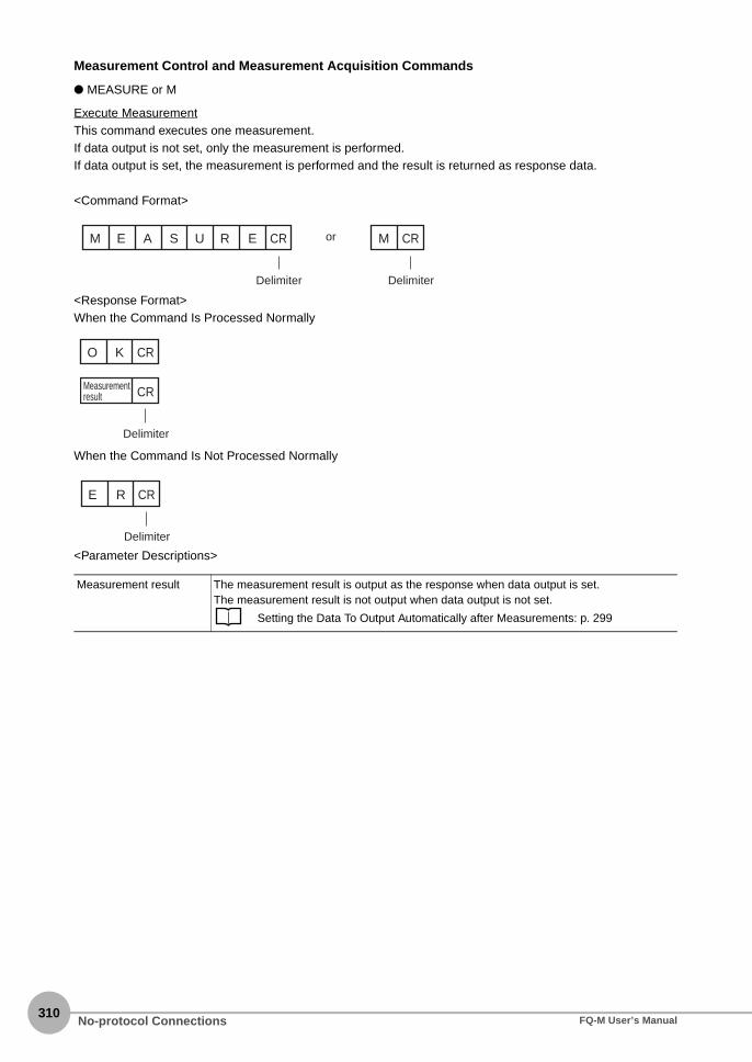
310
Measurement Control and Measurement Acquisition Commands
● MEASURE or M
Execute MeasurementThis command executes one measurement.If data output is not set, only the measurement is performed.If data output is set, the measurement is performed and the result is returned as response data.
<Command Format>
<Response Format>When the Command Is Processed Normally
When the Command Is Not Processed Normally
<Parameter Descriptions>
Measurement result The measurement result is output as the response when data output is set.The measurement result is not output when data output is not set.
Setting the Data To Output Automatically after Measurements: p. 299
A SM E CRU R E
Delimiter
CRM
Delimiter
or
CRMeasurement result
CRO K
Delimiter
CRE R
Delimiter
No-protocol Connections FQ-M User’s Manual

8 C
omm
unications with E
xternal Devices
Start Continuous MeasurementsThis command starts continuous measurements.If data output is not set, only continuous measurement is performed.If data output is set, continuous measurement is performed and the results corresponding to the number ofmeasurements made are returned as response data.
<Command Format>
<Response Format>When the Command Is Processed Normally
When the Command Is Not Processed Normally
<Parameter Descriptions>
Measurement result The measurement results corresponding to the number of measurements made are out-put when data output is set.The measurement result is not output when data output is not set.
Setting the Data To Output Automatically after Measurements: p. 299
A SM E CRU R E / C
Delimiter
CRM / C
Delimiter
or
CR
CR
CRO K
CR
Delimiter
Data returned for the number of continu-ous measurements made.
Measure-ment result
Measure-ment result
Measure-ment result
CRE R
Delimiter
No-protocol ConnectionsFQ-M User’s Manual311

312
End Continuous MeasurementsThe command ends continuous measurements.
<Command Format>
<Response Format>When the Command Is Processed Normally
When the Command Is Not Processed Normally
Set the data output to output measurement results.If data output is not set, only the command response is output.
Setting the Data To Output Automatically after Measurements: p. 299
A SM E CRU R E / E
Delimiter
CRM / E
Delimiter
or
CRO K
Delimiter
CRMeasurement result
CRO K
CR
Delimiter
Measurement result
Data returned for the number of continuous measurements made.
Note
No-protocol Connections FQ-M User’s Manual

8 C
omm
unications with E
xternal Devices
Data Acquisition/Setting Commands
● ITEMDATA or ID
Acquire Inspection Item DataThis command acquires the parameters and measurement values of the specified inspection item.
<Command Format>
<Response Format>When the Command Is Processed Normally
When the Command Is Not Processed Normally
<Parameter Descriptions>
Inspection item number Specifies the inspection item number. (0 to 31)
External reference data number
Specifies the external reference data number. (0 to 999)
p. 412
Acquired value Returns the data for the specified inspection item.
p. 412
I T D A T A CRE M
Inspection item number (2 digits max.)Command
Space (0×20)
Space (0×20)
Delimiter
Command
or
DI CR
Delimiter
Space (0×20)
Space (0×20)
External reference data number
(3 digits max.)
Inspection item number
(2 digits max.)
External reference data number
(3 digits max.)
CRAcquired value
Delimiter
CRO K
CRE R
Delimiter
No-protocol ConnectionsFQ-M User’s Manual313

314
Set Inspection Item DataThis command sets the parameters and measurement values of the specified inspection item.
<Command Format>
<Response Format>When the Command Is Processed Normally
When the Command Is Not Processed Normally
<Parameter Descriptions>
Inspection item number Specifies the inspection item number. (0 to 31)
External reference data number
Specifies the external reference data number. (0 to 999)
p. 412
Acquired value Returns the data for the specified inspection item.
p. 412
I T D A T A Setting CRE M
Inspection item number (2 digits max.)Command
Space (0×20)
Space (0×20)
Space (0×20)
Delimiter
Setting
DelimiterExternal reference data number
(3 digits max.)
External reference data number
(3 digits max.) Set value
Set valueCommand
or
DI CR
Space (0×20)
Space (0×20)
Space (0×20)
Inspection item number
(2 digits max.)
CRO K
Delimiter
CRE R
Delimiter
No-protocol Connections FQ-M User’s Manual

8 C
omm
unications with E
xternal Devices
● MODEL
Re-register ModelsThis command re-registers the models for registered Search inspection items.
<Command Format>
<Response Format>When the Command Is Processed Normally
When the Command Is Not Processed Normally
M O CRD E L
Command
Delimiter
CRO K
Delimiter
CRE R
Delimiter
No-protocol ConnectionsFQ-M User’s Manual315

316
● VERGET
Acquire Software VersionThis command acquires the version information of the Sensor software.
<Command Format>
<Response Format>When the Command Is Processed Normally
When the Command Is Not Processed Normally
<Parameter Descriptions>
Software version Returns the software version.Example: When the software version is 1.20, the response is 1.20.
Date Returns the date.Example: When the date is 13 December 2010, the response is 2010/12/13.
V E / S CRR G TE
ParameterCommand
Space (0×20)
Delimiter
1 . 1 02 0 2 0 2 / 1 3/ 1
DateSoftware version
Space (0×20)
CR
Delimiter
CRO K
Delimiter
CRE R
Delimiter
No-protocol Connections FQ-M User’s Manual

8 C
omm
unications with E
xternal Devices
Acquire Sensor ModelThis command acquires the Sensor model.
<Command Format>
<Response Format>When the Command Is Processed Normally
When the Command Is Not Processed Normally
<Parameter Descriptions>
Model Returns the model.Example: When the model is FQ-S20010F, the response is FQ-S20010F.
V E / H CRR G TE
ParameterCommand
Space (0×20)
Delimiter
F Q 1 0 F CR- S 0 02
Delimiter
Model
CRO K
Delimiter
CRE R
Delimiter
No-protocol ConnectionsFQ-M User’s Manual317

318
● ERRGET
Acquire Error InformationThis command acquires the latest error code from the Sensor.
<Command Format>
<Response Format>When the Command Is Processed Normally
When the Command Is Not Processed Normally
<Parameter Descriptions>
Error code Returns the latest error code. If there is no error history, the response is 00000000.
Error List p. 391
E R CRR G TE
Command
Delimiter
0 0 0 CR0 0 0 00
Delimiter
Model
CRO K
Delimiter
CRE R
Delimiter
No-protocol Connections FQ-M User’s Manual

8 C
omm
unications with E
xternal Devices
● CLRMEAS
Clear Measurement ValuesThis command clears the measurement values.
<Command Format>
<Response Format>When the Command Is Processed Normally
When the Command Is Not Processed Normally
C L CRR M A SE
Command
Delimiter
CRO K
Delimiter
CRE R
Delimiter
No-protocol ConnectionsFQ-M User’s Manual319

320
● CLRERR
Clear ErrorsThis command clears the error output status (error output and error indicator).
<Command Format>
<Response Format>When the Command Is Processed Normally
When the Command Is Not Processed Normally
● RESET
Resets the SensorThis command resets the Sensor.
<Command Format>
<Response Format>When the Command Is Processed NormallyIf process is completed normally, the Sensor is restarted. There is therefore no response.
When the Command Is Not Processed Normally
C L CRR E RR
Command
Delimiter
CRO K
Delimiter
CRE R
Delimiter
R E CRS E T
Command
Delimiter
CRE R
Delimiter
No-protocol Connections FQ-M User’s Manual

8 C
omm
unications with E
xternal Devices
● ENCRESET
Reset Encoder Trigger Counter and Ring CounterThis command resets the encoder trigger counter and ring counter.
<Command Format>
<Response Format>When the Command Is Processed Normally
When the Command Is Not Processed Normally
<Parameter Descriptions>
Reset target Specify the counters to reset.0: Encoder trigger counter and ring counter1: Ring counter2: Trigger counter
E N C R SE
CommandReset target
(1 digit)
E T CR
DelimiterSpace (0x20)
CRO K
Delimiter
CRE R
Delimiter
No-protocol ConnectionsFQ-M User’s Manual321

322
● ENCFCGET
Get Encoder Ring Counter ValueThis command acquires the ring counter value of the encoder.
<Command Format>
<Response Format>When the Command Is Processed Normally
When the Command Is Not Processed Normally
<Parameter Descriptions>
Counter timing Specify when to acquire the ring counter value.0: Current counter value1: Counter value at the trigger
Counter value The counter value is returned.
E N C F GC
CommandCounter timing
(1 digit)
E T CR
DelimiterSpace (0x20)
CR
Delimiter
Counter value
CRO K
Delimiter
CRE R
Delimiter
No-protocol Connections FQ-M User’s Manual

8 C
omm
unications with E
xternal Devices
● ENCFCSET
Set Ring Counter ValueThis command sets the ring counter value of the encoder.
<Command Format>
<Response Format>When the Command Is Processed Normally
When the Command Is Not Processed Normally
<Parameter Descriptions>
Parameter Specify the ring counter value of the encoder.
E N C F SC
Command Set value
E T CR
DelimiterSpace (0x20)
CRO K
Delimiter
CRE R
Delimiter
No-protocol ConnectionsFQ-M User’s Manual323

324
Communications Example
An example of the communications log when a computer is connected and communications is performed witha no-protocol command from a terminal application is shown below.
Example 1: Changing Scenes (Scene number 1 is specified.)
Example 2: Acquiring inspection item data (Acquires the judgement result for a search registered to inspectionitem 10.)
Example 3: Measurement when Data Output Is Not Set
Example 4: Measurement when Data Output Is Set
S 1
OK
ITEMDATA 100
0
OK
M
OK
M
OK
1.0000 0.0000 0.0000 306.0000
M
OK
2.0000 0.0000 0.0000 0.0000
No-protocol Connections FQ-M User’s Manual

8-5 Connecting with the Programmable No-protocol Communications
8 C
omm
unications with E
xternal Devices
You can use programmable no-protocol communications to communicate between an external device and theVision Sensor to output data in the specified format after measurements are completed.
● Data Output after Measurements
Immediately after a single measurement or continuous measurements, the Vision Sensor will automaticallyoutput to an external device (e.g., a Robot Controller) data in the preset format. This enables you to transfer themeasurement results data for inspection items to the Robot Controller.
You can output commands to directly control a robot by combining text strings.
Only ASCII data can be output. Binary data output is not supported.
Robot controller
DataThe data is automatically output in the specified format.
PLCVision Sensor
After measurements
Command
Response
Ethernet (programmable no-protocol communications)
● TRIG signal (parallel)
● Ethernet (no-protocol or PLC Link communications)
● EtherCAT
Note
Connecting with the Programmable No-protocol CommunicationsFQ-M User’s Manual325

326
Setting Up Programmable No-protocol Communications
Setting Network Settings in the Sensor
This section describes how to set the network settings in the Vision Sensor.
Multiview Explorer: [Device group] − Sensor name − [System] − [System data] (Double-click)→ Edit Pane: [Ethernet communications settings] Icon − [Ethernet settings]
The following items can be set.
• Operation on the Touch Finder
Use the following menu command to display the Setup Display on the Touch Finder.
(Setup Mode) − [Sensor settings] − [Network]
Item Description Setting range
Auto connection Select whether the IP address is assigned automatically.To communicate with a PLC or other exter-nal device, set [Auto connection] to OFF and set the IP address setting described below.
OFF or ONDefault: ON
IP address Set the IP address of the Vision Sensor. a: 1 to 223, b: 0 to 255, c: 0 to 255, d: 1 to 254Default: 10.5.5.100
Subnet mask Set the subnet mask. 0.0.0.0 to 255.255.255.255Default: 255.255.255.0
Default Gateway Sets the default gateway. 0.0.0.0 to 255.255.255.255Default: 0.0.0.0
▲▲
Connecting with the Programmable No-protocol Communications FQ-M User’s Manual

8 C
omm
unications with E
xternal Devices
Initial Settings for the Programmable No-protocol
You must set the communications method, IP address, and I/O port number for the destination external device(e.g., Robot Controller) to perform programmable no-protocol communications. You can output results to up tothree external devices.
Multiview Explorer: [Device group] − Sensor name − [System] − [System data] (Double-click) → Edit Pane: [Ethernet communications settings] Icon − [Programmable no-protocol data communication settings]
The following items can be set.
Item Description Setting range
Communication type Select the communications method. • −−−−• TCP client• TCP Server
(Default: −−−−)
▲
When the [communication type] is set to “TCP client”
When the [communication type] is set to “TCP server”
Connecting with the Programmable No-protocol CommunicationsFQ-M User’s Manual327

328
• When the [communication type] is set to “TCP server,” the following port numbers are reserved and cannot be used:
9876, 9877, 12345, 12346, 12347, and 15000
• The port number is initialized when you switch from TCP client to TCP server, or vice versa. Reset the port number
whenever you switch the [communication type].
Output set-tings (when the [com-munication type] is set to “TCP cli-ent”)
IP address Set the IP address of the external device (e.g., Robot Controller) at the connection destination.Set it in the form a.b.c.d.
a: 1 to 253, b: 0 to 255, c: 0 to 255, d: 0 to 255Default: 10.5.5.111
Port No. Set the I/O port number of the external device (e.g., Robot Controller) at the connection destina-tion.Set the value to between 0 and 65,535.
0 to 65,535Default: 9,600
Click the [Confirmation] Button to confirm establishment of communications in the IP layer between the external device at the connection destination (e.g., Robot Controller) and the Vision Sensor as given below. The following text is displayed: • If a connection is confirmed: [Connection: OK] (green text)• If a connection is not confirmed: [Connection: NG] (red text)
Port No. (when the [com-munication type] is set to “TCP server”)
Set the port number of the TCP server. 0 to 65,536Default: 9,878
Item Description Setting range
Important
Connecting with the Programmable No-protocol Communications FQ-M User’s Manual

8 C
omm
unications with E
xternal Devices
Setting the Data To Output Automatically after Measurements
You can set the data to output automatically after measurements. (You can set up to 32 data items.)
Output Data
● Parameters
The following three parameters are output in programmable no-protocol communications.
1. Output format parameter2. Argument parameter3. Array parameter (optional)
Tags are added to these parameter.The format for each parameter is Tag=XXX.XXX is replaced with the specified parameter.
You must set in advance the format of the data to output after measurement is performed.The specified format is entered from the keyboard for the [Expression] in the [Output] area.After the measurements are completed, the data is sent to external device (e.g., Robot Controller) through acontinuous serial connection.
Specification Format
1. Output Format Parameters
Tag: FYou can enable displaying the output results by defining formatted text strings as the output format with theargument parameters for tag D.The format for the formatted text stings is as follows:
%[Flag][Minimum field width][.Precision]Conversion specifier
* Items in square brackets can be omitted.
Signed decimal integer Signed decimal fraction
Conversion specifier d f
Minimum field width Minimum number of characters (limit: 10 characters)
Minimum number of characters (limit: 15 characters)
Precision Minimum number of digits (limit: 10 digits) Minimum number of digits below the decimal (limit: 4)* Four digits is used if this item is omitted.
Flag Meaning
0 (zero) If the number of output characters is less than the minimum field width, 0 is output.
Argument parameter C (tag)
Array parameter
D (tag)Output format parameter
F (tag) = = =, ,
Connecting with the Programmable No-protocol CommunicationsFQ-M User’s Manual329

330
Any text string can be used for tag F.
2. Argument ParametersTag: DSet the output format for the argument.You can specify for arguments the results of inspection items that can be used in calculation expressions andthe results of calculation expressions.
12-2 External Reference Parameters p. 412
Multiple arguments are separated with commas.To specify an array for a parameter that contains more than one result, place square brackets after theparameter. (Example: X[])Specify an array index, place the index inside the brackets. (Example: X[1])The following functions can be used for the arguments.
3. Array parameter
Tag: CTo use the argument parameter for tag D as an array parameter, specify the array information.This tag can be omitted.The parts of the array information are separated with a comma and consist of the following three items.
Output start number, Number of steps, Number of outputs
Item Meaning
ECNT(argument) Argument of 0: Ring counter value at measurement triggerArgument of 1: Ring counter value at calculationArgument of 2: Trigger counter value at calculation
FIDX(argument) Argument of 0: Start from 0 and count up 1 at a time.Argument of 1: Count up according to the contents specified by tag C.
Item Meaning Default when omitted
Output start number The starting index of the array. 0
Number of steps The number of steps in the array (the increment/decrement width of the array argument).* Negative values can be set.
1
Number of outputs The number of output data items. 1
Connecting with the Programmable No-protocol Communications FQ-M User’s Manual

8 C
omm
unications with E
xternal Devices
Checking Programmable No-protocol Communications Settings
You can check the current programmable no-protocol communications settings.
Multiview Explorer: [Device group] − Sensor name − [Scene] − Scene data number (Double-click)→ Edit Pane: (Output) Icon − [Communication settings]
If you click the [Output] Button while setting up inspection items, the following Output Setting Main Window isdisplay.
Item Description
Communication settings
The settings of the following parameters in the system data are displayed.1. Ethernet Setting Status
Enabled (green): Output no-protocol data, output link data, or programmable no-protocol data is selected as the communications method.
Disabled (red): All settings are disabled.2. The following output no-protocol data, output link data, programmable no-protocol data
parameters:• Communication method• IP address• Port number
Output Properties The properties of the data output list are displayed.
If programmable no-protocol data is not set in the output destination settings, click the [Edit system data] Button andmake the initial settings for programmable no-protocol communications in the Ethernet Communication Dialog Box.
▲
Note
Connecting with the Programmable No-protocol CommunicationsFQ-M User’s Manual331

332
Allocating Output Data
Multiview Explorer: [Device group] − Sensor name − [Scene] − Scene data number (Double-click)→ Edit Pane: [Output] Icon − [Programmable no-protocol data]
1 In the Output Settings Main Pane, right-click the output data number to set in the output data listunder [Programmable no-protocol data] and select [Edit].
The following Output Dialog Box is displayed.
2 Set the data to output in the Output Dialog Box.
Item Description
Output data settings The number of the output data that was selected for setting is displayed.
Name You can change the name of the output data.Max. number of characters: 15
▲
Connecting with the Programmable No-protocol Communications FQ-M User’s Manual

8 C
omm
unications with E
xternal Devices
3 Click the [Confirm] Button for the output data text string.The output data entered in the expression is displayed under the [Confirm] Button so that you can checkit.
4 Click the [OK] Button.
5 Set the output format.Set the output format in [Output format] under [Programmable no-protocol data].
Expression Enter the output data for the specified format from the keyboard.Max. number of characters: 255 + NULLDefault: NULL
Data You can insert parameters selected from Units and parameters into expressions.
Unit Select one of the following.• An inspection item that has the output item to use for the output data.• Calculation
Parameter Select the output item from the selected unit.Example: If the Search inspection item was selected, you can select either of the
following: Judgement results: Judgement JG or Correlation: Corre. CR
Function The following functions can be inserted in Tag D.• Encoder Value Output Function
• Encoder Value Output: ECNT functionThe encoder value is output.Format: ECNT(argument)Output Example:
ECNT(0)0: Ring counter value at measurement trigger1: Ring counter value at calculation2: Trigger counter value at calculation
• Function That Outputs the Value Resulting from Counting Up from the Specified Value• Function that outputs the value resulting from counting up from the specified
value: FIDXThe value that results from counting up from the specified value is output.Format: FIDX(argument)Output Example:
0: Start from 0 and count up 1 at a time.1: Count up according to the array parameter that is specified for tag C.
Item Description Setting range
Field separator Sets the field separator. OFF, Comma, Tab, Space, CR, LF, CR+LF, or SemicolonDefault: OFF
Record separator Sets the record separator. OFF, comma, tab, space, CR, LF, CR+LF, or SemicolonDefault: OFF
Item Description
Connecting with the Programmable No-protocol CommunicationsFQ-M User’s Manual333

334
Field separator: The separator between parametersRecord separator: The separator between measurements
The record separator is inserted at the end of output data 2. A field separator is inserted between eachoutput value if you have enabled multiple output within the output data.
Example: Integer digits: 5, decimal digits: 3, field separator: comma, record separator: CR
*1 Because the record separator is set to CR, only one record is output for each measurement, A blank line (CR+LF: delimiter) will therefore be entered after the record separator. If you do not want a blank line, set the record separator to OFF.
If data is output as an array for one output data, a field separator is inserted between consecutive array elements.
1
Measured value of data 0
12 2 1 123 34 5 56 7 6 6 6 5 6 5 CR9 9 8 77 78. . . ., , , ,
Measured value of data 1
Measured value of data 7
Measured value of data 2
Field separator Record separator
*1
Delimiter
Field separator
Field separator
Field separator
CR + LF
Note
Connecting with the Programmable No-protocol Communications FQ-M User’s Manual

8 C
omm
unications with E
xternal Devices
● Examples of Signed Decimal Integers
The following examples are for when inspection item 0 is set to the Search inspection item, the search Xcoordinate is −123.456 and the search Y coordinate is −456.789. The field and record separators are set to“OFF.”
Example When the Minimum Field Width and Precision Are Not UsedF="%d",D="I0.X" ⇒ "−123"<CR+LF>
Examples When the Minimum Field Width (Minimum Number of Characters) Is UsedF="%5d",D="I0.X" ⇒ "*−123"<CR+LF> Note: A space is added to make five
characters.F="%05d",D="I0.X" ⇒ "−0123"<CR+LF> Note: A zero is added instead of a
space.F="%2d",D="I0.X" ⇒ "−123"<CR+LF> Note: If two characters is insufficient, the
required number of characters(three) is output.
Examples When the Precision (Minimum Number of Digits) Is UsedF="%.6d",D="I0.X" ⇒ "−000123"<CR+LF> Note: Six digits are output. Zeros are
added if required to make sixdigits.
F="%.2d",D="I0.X" ⇒ "−123" <CR+LF> Note: If two digits is insufficient, therequired number of digits (three) isoutput.
Example When the Minimum Field Width and Precision Are UsedF="%10.6d",D="I0.X" ⇒ "***−000123"<CR+LF> Note: If ten characters and six digits are
specified, three spaces and threezeros are added.
Example with Specified Text StringsF="X is %d",D="I0.X" ⇒ "X is −123"<CR+LF> Note: The specified text string is output.
Example of Rounding Off the Digits below the Decimal PointF="%d",D="I0.Y" ⇒ "−457"<CR+LF> Note: The decimal portion of −456.789 is
rounded off.
Example of Outputting More Than One ValueF="X is %d, Y is %d",D="I0.X,I0.Y" ⇒ "X is −123, Y is −457"<CR+LF>
● Examples of Signed Decimal Fractions
The following examples are for when inspection item 0 is set to the Search inspection item, the search Xcoordinate is −123.456 and the search Y coordinate is −456.789. The field and record separators are set to“OFF.”
Example When the Minimum Field Width and Precision Are Not UsedF="%d",D="I0.Y" ⇒ "−123.4560"<CR+LF> Note: If the precision (number of digits
below the decimal point) is notspecified, four digits are output.Zeros are added if there are notenough digits.
Examples When the Minimum Field Width (Minimum Number of Characters) Is UsedF="%10f",D="I0.X" ⇒ "*−123.4560"<CR+LF> Note: A space is added to make ten
characters.F="%06f",D="I0.X" ⇒ "−0123.4560"<CR+LF> Note: A zero is added instead of a
space.F="%2f",D="I0.X" ⇒ "−123.4560"<CR+LF> Note: If two characters is insufficient, the
required number of characters(nine) is output.
Connecting with the Programmable No-protocol CommunicationsFQ-M User’s Manual335

336
Examples When the Precision (Number of Digits Below Decimal Point) Is UsedF="%.3f",D="I0.X" ⇒ "−123.456"<CR+LF> Note: Three digits below the decimal
point are output.F="%.2f",D="I0.X" ⇒ "−123.46"<CR+LF> Note: If two digits below the decimal is
specified, the digits below thethousandths digit are rounded off.
Example When the Minimum Field Width and Precision Are UsedF="%10.3f",D="I0.X" ⇒ "**−123.456"<CR+LF> Note: If ten characters and six digits
below the decimal are specified,two spaces are added.
Examples with Specified Text StringsF="X is %f",D="I0.X" ⇒ "X is −123.4560"<CR+LF> Note: The specified text string is
output.F="\\X is %f",D="I0.X" ⇒ "\X is −123.4560"<CR+LF> Note: The specified text string is
output.
Example of Outputting More Than One ValueF="X is %f, Y is %f",D="I0.X,I0.Y" ⇒ "X is −123.4560, Y is −456.7890"<CR+LF>
● Examples of Outputting Array Data and the FIDX() and ECNT() Functions
The following examples are for when inspection item 0 is set to the Search inspection item, and the followingresults are obtained.Three images were detected.Correlation: 90, X coordinate: 111.111, Y coordinate: 222.222Correlation: 80, X coordinate: 333.333, Y coordinate: 444.444Correlation: 70, X coordinate: 555.555, Y coordinate: 666.666* The results are sorted in the descending order of correlations.
Example of Outputting Data without Specifying Array IndicesF="%f %f",D="I0.X,I0.Y" ⇒ "111.1110 222.2220"<CR+LF> Note: If an array index is not
specified, the first data inthe array is output. Thefield and record separatorsare set to “OFF.”
Example of Outputting Data Specifying Array Index 1F="%f %f",D="I0.X[0],I0.Y[0]" ⇒ "111.1110 222.2220"<CR+LF> Note: Same as above.
Example of Outputting Data Specifying Array Index 2F="%f %f",D="I0.X[1],I0.Y[1]" ⇒ "333.3330 444.4440"<CR+LF> Note: Same as above.
Example of Outputting Two Array Elements from the Start of the ArrayF="%f %f",D="I0.X[],I0.Y[]",C="0,1,2" ⇒ Note: Here, CR is used as the field separator. The record separator
is set to “OFF.”"111.1110 222.2220"<CR>"333.3330 444.4440"<CR><CR+LF>
Example of Outputting Two Array Elements from the Second Element of the ArrayF="%f %f",D="I0.X[],I0.Y[]",C="1,1,2" ⇒ Note: Here, CR is used as the field separator. The record separator
is set to “OFF.”"333.3330 444.4440"<CR>"555.5550 666.6660"<CR><CR+LF>
Example of Outputting the First and Third Elements But Not the Second Element of an ArrayF="%f %f",D="I0.X[],I0.Y[]",C="0,2,2" ⇒ Note: Here, CR is used as the field separator. The record separator
is set to “OFF.”"111.1110 222.2220"<CR>"555.5550 666.6660"<CR><CR+LF>
Connecting with the Programmable No-protocol Communications FQ-M User’s Manual

8 C
omm
unications with E
xternal Devices
Example of Outputting the Data for More Than One Detected ImageF="%f %f",D="I0.X[],I0.Y[]",C="0,1,I0.C" ⇒ Note: Here, CR is used as the field separator. The record
separator is set to “OFF.”"111.1110 222.2220"<CR>"333.3330 444.4440"<CR>"555.5550 666.6660"<CR><CR+LF>
Example Using FIDX(0)F="%d %f %f",D="FIDX(0),I0.X[],I0.Y[]",C="0,1,I0.C" ⇒ Note: Here, CR is used as the field separator.
The record separator is set to “OFF.”"0 111.1110 222.2220"<CR>"1 333.3330 444.4440"<CR>"2 555.5550 666.6660"<CR><CR+LF>
Example Using FIDX(1)F="%d %f %f",D="FIDX(1),I0.X[],I0.Y[]",C="1,1,2" ⇒ Note: Here, CR is used as the field separator.
The record separator is set to “OFF.”"1 333.3330 444.4440"<CR>"2 555.5550 666.6660"<CR><CR+LF>
Example Using ECNT(0)F="%d",D="ECNT(0)" ⇒ "1234"<CR+LF> Note: In this example, the ring counter was 1234
at the measurement trigger.
● Output Specification Example
Measurement Results• Inspection item (number): Search (0)
• Number of detections: 4
• Detection results: (X,Y)=(0,0)(1,2)(3,4)(5,6)
Output Format• ASCII output (fixed)
• Field separator: Comma
• Record separator: CR
Output Settings• Data 0: F="COUNT=%03d",D="I0.C"
• Data 1: F="@P%03d=%0.3f,%0.3f",D="FIDX(0),I0.X[],I0.Y[]",C="0,1,I0.C"
* I0.C: Search_count I0.X[]: X_measurement_result I0.Y[]: Y_measurement_result 12-2 External Reference Parameters p. 412
Output Data
● Restrictions
• There is a limit to the number of characters per field.Maximum number of characters per field: 2,048 characters
• If the string that is created for the output format exceeds the maximum number of characters, the portion of the string after2,048 characters is not output.
Data 0 output C O U N T = 0 0 4 ,
Data 1 output @ P 0 0 1 = 0 . 0 0 0 , 0 . 0 0 0 ,
@ P 0 0 2 = 1 . 0 0 0 , 2 . 0 0 0 ,
@ P 0 0 3 = 3 . 0 0 0 , 4 . 0 0 0 ,
@ P 0 0 4 = 5 . 0 0 0 , 6 . 0 0 0 CR
CR+LF
Connecting with the Programmable No-protocol CommunicationsFQ-M User’s Manual337

338
8-6 Using the Encoder Input
The Vision Sensor can accept an encoder input. You can use the encoder input to control the measurementtiming and perform synchronized control with an external robot or other device. There are three primarypatterns for controlling the measurement timing with an encoder.
Pattern 1
Workpieces are placed on a rotating table at specified rotation angles. In this case, the trigger is created after aspecified angle of rotation and the counter is reset after a full rotation (phase Z).
Pattern 2
A timing sensor is placed on a conveyor. This timing sensor takes an image of any workpiece that it detects. Inthis case, a trigger is created when the conveyor moves a certain distance after the timing sensor detects aworkpiece. The counter is reset when the sensor detects a workpiece.
Pattern 3
Many workpieces are placed along a conveyor at different spacings. In this case, a trigger is created every timethe conveyor moves a certain distance (e.g., 1/2 the field of vision). The counter is reset every time a trigger iscreated.
Standard position 0°300°
220° 170°
60°
Workpiece
Pulse count
Workpiece
Conveyor
CameraTiming sensor
Camera
Conveyor
Workpiece
Using the Encoder Input FQ-M User’s Manual

8 C
omm
unications with E
xternal Devices
Controlling Measurement Timing with an Encoder Input
The work flow for controlling measurement timing with the encoder input is described below.
Step 1 Set the trigger type.
Multiview Explorer: [System] − [System data] (Double-click)→ Edit Pane: (Trigger settings) Icon
1 Select [Encoder trigger] from the [Triggertype] list.
Set the trigger type.Step 1tep 1
Set the encoder input.Step tep 2
Set the trigger timing.Step tep 3
▲
Using the Encoder InputFQ-M User’s Manual339

340
Step 2 Set the encoder input.
Multiview Explorer: [System] − [System data] (double-click)→ Edit Pane: (Encoder Settings) Icon − [Common encoder settings]
1 Select [Direction of rotation].
2 Select either OFF or ON for the [Reverse-turn trigger detection].
3 Select the multiplier from the [Multiplica-tion] list. This setting must be the same asthe setting for the Robot Controller.
4 Set the [Hunting width].
5 Set the [Backlash width].
Parameter Range Description
Direction of rotation CW (Clockwise)CCW (Counter-clock-wise)
Specifies the direction to count up.CW: Count up when rotating clockwise. (Count down in the opposite direction.)CCW: Count up when rotating counterclockwise. (Count down in the opposite direction.)
Reverse-turn trigger detection
OFFON
Specifies whether to create the trigger when rotating in the opposite direction.OFF: Do not create the trigger when rotating in the opposite direc-tion.ON: Create the trigger when rotating in the opposite direction.
Multiplication 1x2x4x
Sets the multiplier for the input pulse count. This setting must be the same as the setting for the Robot Controller.1x: Creates a pulse on the rising edge of phase A.2x: Creates a pulse on the rising edge and falling edge of phase A.4x: Creates a pulse on the rising edge and falling edge of phase A
and phase B.
Hunting width 0 to 65,535 Specifies the width of hunting cap in the Servo.0: No hunting processing
Backlash width 0 to 65,535 Specifies the backlash width in the gears.0: No backlash processing
Terminating resistance OFFON
Turns the encoder terminating resistance ON or OFF. For normal 1:1 communications, turn OFF the terminating resistance for an open collector and turn it ON for a line driver. When branching with line drivers, turn OFF the terminating resistance.
Using the Encoder Input FQ-M User’s Manual

8 C
omm
unications with E
xternal Devices
Step 3 Set the trigger timing.
Multiview Explorer: [System] − [System data] (double-click)→ Edit Pane: (Encoder Settings) Icon − [Encoder trigger settings]
1 Select the reset timing for the counter in[Reset timing].
2 Set the offset in [Offset value of triggercounter].
3 Set the counter value at which to create atrigger in [Trigger timing (phases A)].
4 Click the [Counter reset] Button to reset thetrigger counter.
Parameter Range Description
Reset timing Phase Z: Pattern 1 Resets the counter on phase Z.
TRIG signal: Pattern 2 Resets the counter when an external TRIG signal is received.
After trigger input: Pat-tern 3
Resets the counter after the trigger is created.
Offset value of trigger counter
−32,768 to +32,768 Sets the trigger counter value to add as an offset when resetting the counter.
Trigger timing 0 to 1,000,000,000 Sets the points at which to create the trigger. Up to six points can be set. If you select phase Z for the reset timing, a maximum of 6 points can be set. If you select to reset the counter for the TRIG signal or after a trigger occurs, you can set only one point.
Using the Encoder InputFQ-M User’s Manual341
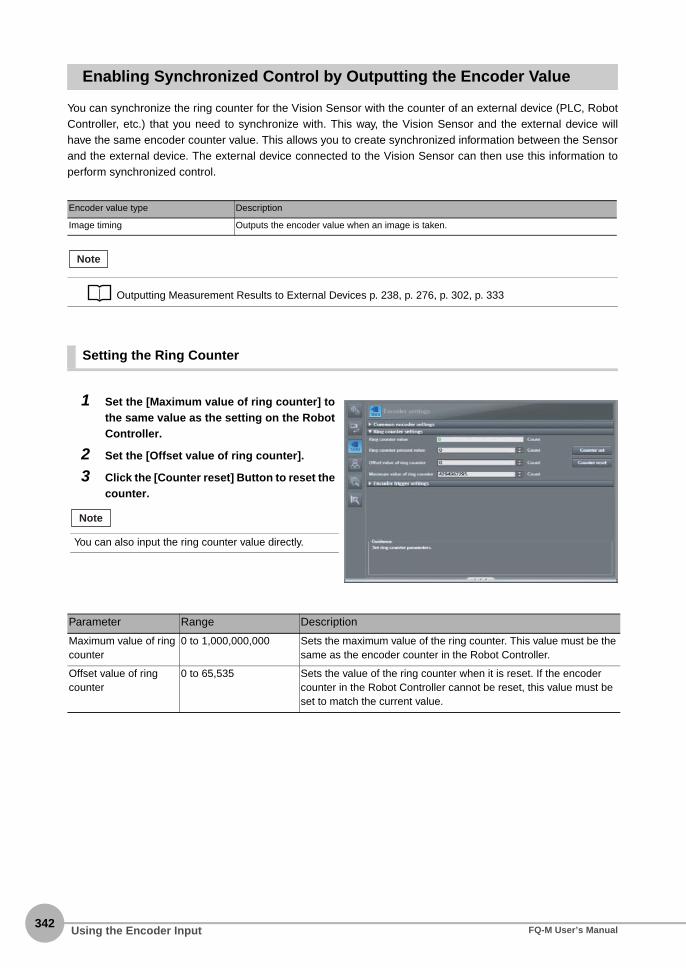
342
Enabling Synchronized Control by Outputting the Encoder Value
You can synchronize the ring counter for the Vision Sensor with the counter of an external device (PLC, RobotController, etc.) that you need to synchronize with. This way, the Vision Sensor and the external device willhave the same encoder counter value. This allows you to create synchronized information between the Sensorand the external device. The external device connected to the Vision Sensor can then use this information toperform synchronized control.
Setting the Ring Counter
Encoder value type Description
Image timing Outputs the encoder value when an image is taken.
Outputting Measurement Results to External Devices p. 238, p. 276, p. 302, p. 333
1 Set the [Maximum value of ring counter] tothe same value as the setting on the RobotController.
2 Set the [Offset value of ring counter].
3 Click the [Counter reset] Button to reset thecounter.
Parameter Range Description
Maximum value of ring counter
0 to 1,000,000,000 Sets the maximum value of the ring counter. This value must be the same as the encoder counter in the Robot Controller.
Offset value of ring counter
0 to 65,535 Sets the value of the ring counter when it is reset. If the encoder counter in the Robot Controller cannot be reset, this value must be set to match the current value.
Note
You can also input the ring counter value directly.
Note
Using the Encoder Input FQ-M User’s Manual

8 C
omm
unications with E
xternal Devices
MEMO
Using the Encoder InputFQ-M User’s Manual343

344
Using the Encoder Input FQ-M User’s Manual
Calibration
Calibration
9
9-1 Calibration .............................................................................................346
9-2 Calibration for Conveyor Tracking ......................................................347
9-3 General-purpose Calibration ...............................................................356
9-4 Direct Input ............................................................................................368
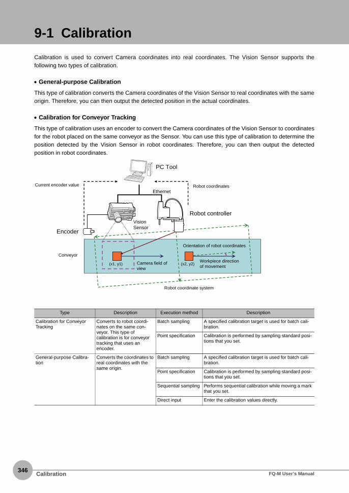
346
9-1 Calibration
Calibration is used to convert Camera coordinates into real coordinates. The Vision Sensor supports thefollowing two types of calibration.
• General-purpose Calibration
This type of calibration converts the Camera coordinates of the Vision Sensor to real coordinates with the sameorigin. Therefore, you can then output the detected position in the actual coordinates.
• Calibration for Conveyor Tracking
This type of calibration uses an encoder to convert the Camera coordinates of the Vision Sensor to coordinatesfor the robot placed on the same conveyor as the Sensor. You can use this type of calibration to determine theposition detected by the Vision Sensor in robot coordinates. Therefore, you can then output the detectedposition in robot coordinates.
Type Description Execution method Description
Calibration for Conveyor Tracking
Converts to robot coordi-nates on the same con-veyor. This type of calibration is for conveyor tracking that uses an encoder.
Batch sampling A specified calibration target is used for batch cali-bration.
Point specification Calibration is performed by sampling standard posi-tions that you set.
General-purpose Calibra-tion
Converts the coordinates to real coordinates with the same origin.
Batch sampling A specified calibration target is used for batch cali-bration.
Point specification Calibration is performed by sampling standard posi-tions that you set.
Sequential sampling Performs sequential calibration while moving a mark that you set.
Direct input Enter the calibration values directly.
Encoder
Current encoder value
Robot controllerVision Sensor
Conveyor
PC Tool
Robot coordinates
(x1, y1) (x2, y2)
Ethernet
Camera field of view
Orientation of robot coordinates
Robot coordinate system
Workpiece direction of movement
Calibration FQ-M User’s Manual
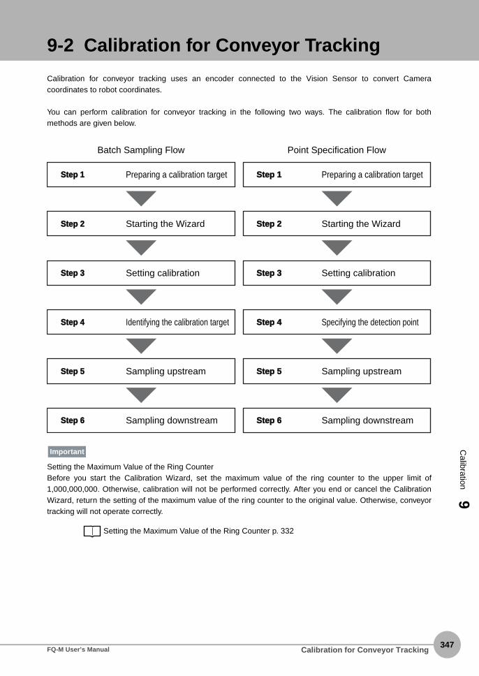
9-2 Calibration for Conveyor Tracking
Calibration
9
Calibration for conveyor tracking uses an encoder connected to the Vision Sensor to convert Cameracoordinates to robot coordinates.
You can perform calibration for conveyor tracking in the following two ways. The calibration flow for bothmethods are given below.
Setting the Maximum Value of the Ring CounterBefore you start the Calibration Wizard, set the maximum value of the ring counter to the upper limit of1,000,000,000. Otherwise, calibration will not be performed correctly. After you end or cancel the CalibrationWizard, return the setting of the maximum value of the ring counter to the original value. Otherwise, conveyortracking will not operate correctly.
Setting the Maximum Value of the Ring Counter p. 332
Preparing a calibration target
Batch Sampling Flow
Step 1tep 1
Starting the WizardStep tep 2
Setting calibrationStep tep 3
Identifying the calibration targetStep tep 4
Sampling upstreamStep tep 5
Sampling downstreamStep tep 6
Preparing a calibration target
Point Specification Flow
Step 1tep 1
Starting the WizardStep tep 2
Setting calibrationStep tep 3
Specifying the detection pointStep tep 4
Sampling upstreamStep tep 5
Sampling downstreamStep tep 6
Important
Calibration for Conveyor TrackingFQ-M User’s Manual347

348
Batch Sampling Calibration
Step 1 Preparing a Calibration Target
Step 2 Starting the Wizard
Step 3 Setting Calibration
1 Print a calibration target that is the size ofthe field of view of the Camera.
2 Place the calibration target into the Cam-era’s field of view.
1 Select [New Calibration] from the [Calibra-tion pattern] list to start the CalibrationWizard.
Before you start the Calibration Wizard, set themaximum value of the ring counter to the upper limitof 1,000,000,000.
1 Enter the name of the calibration in the[Name] field.
2 Click [Batch sampling] for Conveyor Track-ing.
3 Click the [Next] Button.
Important
Calibration for Conveyor Tracking FQ-M User’s Manual

Calibration
9
Step 4 Identifying the Calibration Target
4 Click the number of sampling points to se-lect it.In this example, we use 4 sampling points.
5 Specify the input method for robot coordi-nates.To enter a value with the keyboard, select the[Key input only] Option. Select the [Read thedata via Ethernet] Option when inputting RobotController data via Ethernet. Enter the type, IPaddress, and port number of the Robot Con-troller. After you enter the IP address, click[Communications test] to confirm that commu-nications are working properly.
6 Click the [Next] Button.
Type Description
Address If your Controller is a trajexia, set the IP address of the Controller.
1 Adjust the calibration target position so thatall five target marks are visible.If necessary, adjust the Camera so that the cal-ibration targets are clearly visible.
2 Click the [Next] Button.
3 Make sure that all five marks can be detect-ed.If they cannot be properly detected, adjust theCamera.
4 Click the [Next] Button.
If a YRC Robot Controller is connected, set the [Control-ler] Field to [Programmable no-protocol data output].
Note
You cannot click the [Next] Button in the Wizard if thereare any problems with the settings.
Note
Calibration for Conveyor TrackingFQ-M User’s Manual349

350
Step 5 Sampling Upstream
5 Click the [Read] Button to acquire the encod-er value.
6 Click the [Next] Button.
Parameter Range Description
Encoder value 0 to 1,000,000,000 Sets the current encoder value.
1 Move the conveyor and place the calibrationtarget so that it is at the start of the operatingrange of the robot on the conveyor.
2 Click the [Next] Button.
3 Move the center of the robot hand to the cen-ter of the cross of the first mark on the cali-bration target.
4 Enter the X and Y coordinates of the robot inthe [Robot coordinates] field.Read the coordinates of the robot from the ro-bot’s teaching pendant and enter them from thekeyboard. To obtain the coordinates of the robotover the network, click the [Read] Button.
5 Click the [Next] Button.
Item Parameter Range Description
Robot coor-dinates
X −99,999.9999 to 99,999.9999 Set the X coordinate of the control device.
Y −99,999.9999 to 99,999.9999 Set the Y coordinate of the control device.
Calibration for Conveyor Tracking FQ-M User’s Manual

Calibration
9
Step 6 Sampling Downstream
6 Repeat steps 3 and 4 for the number ofmarks specified in the [Sampling points]field.In this example we will perform these steps formarks 2 through 4.
7 Click the [Read] Button to obtain the encod-er value.
8 Click the [Next] Button.
Parameter Range Description
Encoder value 0 to 1,000,000,000 Sets the current encoder value.
1 Move the conveyor and place the calibrationtarget so that it is at the end of the operatingrange of the robot on the conveyor.
2 Click the [Next] Button.
3 Move the center of the robot hand to the cen-ter of the cross of the first mark on the cali-bration target.
4 Enter the X and Y coordinates of the robot inthe [Robot coordinates] field.Read the coordinates of the robot from the ro-bot’s teaching pendant and enter them from thekeyboard. To obtain the coordinates of the robotover the network, click the [Read] Button.
5 Click the [Next] Button.
Item Parameter Range Description
Robot coor-dinates
X −99,999.9999 to 99,999.9999 Set the X coordinate of the control device.
Y −99,999.9999 to 99,999.9999 Set the Y coordinate of the control device.
If you select [Input the value directly] and enter valuesfor the [X Distance per 1 encoder pulse] and [Y Distanceper 1 encoder pulse], steps 1 through 7 are not neces-sary.
Note
Calibration for Conveyor TrackingFQ-M User’s Manual351

352
6 Click the [Read] Button to obtain the encod-er value.
7 Click the [Next] Button.
Parameter Range Description
Encoder value 0 to 1,000,000,000 Sets the current encoder value.
8 Check the results of the calibration.
9 Click the [Exit] Button to close the Wizard.
• After you end or cancel the Calibration Wizard, return
the setting of the maximum value of the ring counter to
the original value.
• The error that is maintained for calibration is the average
of the distance between the following two points.
• The camera coordinates that were used to calculate
calibration coefficients A to F converted to robot coor-
dinates using calibration coefficients A to F
• The robot coordinates that were used to calculate the
calibration coefficients A to F
Important
Calibration for Conveyor Tracking FQ-M User’s Manual
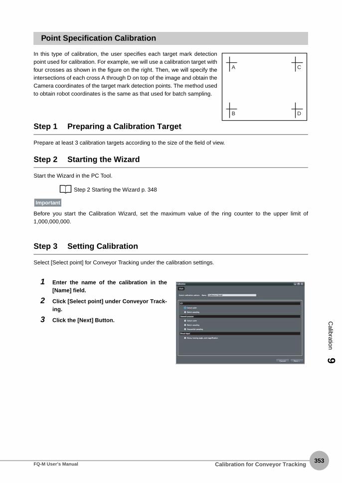
Calibration
9
Point Specification Calibration
In this type of calibration, the user specifies each target mark detectionpoint used for calibration. For example, we will use a calibration target withfour crosses as shown in the figure on the right. Then, we will specify theintersections of each cross A through D on top of the image and obtain theCamera coordinates of the target mark detection points. The method usedto obtain robot coordinates is the same as that used for batch sampling.
Step 1 Preparing a Calibration Target
Prepare at least 3 calibration targets according to the size of the field of view.
Step 2 Starting the Wizard
Start the Wizard in the PC Tool.
Step 2 Starting the Wizard p. 348
Before you start the Calibration Wizard, set the maximum value of the ring counter to the upper limit of1,000,000,000.
Step 3 Setting Calibration
Select [Select point] for Conveyor Tracking under the calibration settings.
1 Enter the name of the calibration in the[Name] field.
2 Click [Select point] under Conveyor Track-ing.
3 Click the [Next] Button.
A
B
C
D
Important
Calibration for Conveyor TrackingFQ-M User’s Manual353

354
Step 4 Specifying the Detection Point
Specify detection points A through D on the display and obtain the Camera coordinates for those detectionpoints.
4 Click the number of sampling points to se-lect it.In this example, we use 4 sampling points.
5 Specify the input method for robot coordi-nates.To enter a value with the keyboard, select the[Key input only] Option. Select the [Read thedata via Ethernet] Option when inputting RobotController data via Ethernet. Enter the type, IPaddress, and port number of the Robot Con-troller. After you enter the IP address, click[Communications test] to confirm that commu-nications are working properly.
6 Click the [Next] Button.
Type Description
Address If your Controller is a trajexia, set the IP address of the Controller.
1 Adjust the calibration target position sothat the target marks are visible..If necessary, adjust the Camera so that thecalibration targets are clearly visible.
2 Click the [Next] Button.
3 Click the position of the first mark on theimage or enter the position in Camera coor-dinates (X, Y) directly.
4 Click the [Next] Button.
If a YRC Robot Controller is connected, set the [Control-ler] Field to [Programmable no-protocol data output].
Note
Calibration for Conveyor Tracking FQ-M User’s Manual

Calibration
9
Step 5 Sampling Upstream
Place the calibration target at the start of the operating range of the robot, specify the detection points of thetarget mark with the robot, and obtain the robot coordinates.
Step 5 Sampling Upstream p. 350
Step 6 Sampling Downstream
Place the calibration target at the end of the operating range of the robot, specify the detection points of thetarget mark with the robot, and obtain the robot coordinates.
Step 6 Sampling Downstream p. 351
After you end or cancel the Calibration Wizard, return the setting of the maximum value of the ring counter tothe original value.
5 Repeat steps 3 and 4 for the number ofmarks specified in the [Sampling points]field.In this example we will perform these steps formarks 2 through 4.
6 Click the [Read] Button to acquire the en-coder value.
7 Click the [Next] Button.
Item Parameter Range Description
Camera coordinates
X 0 to 99,999.9999 Set the X coordinate of the Camera.
Y 0 to 99,999.9999 Set the Y coordinate of the Camera.
Encoder value 0 to 1,000,000,000 Sets the current encoder value.
Important
Calibration for Conveyor TrackingFQ-M User’s Manual355

356
9-3 General-purpose Calibration
General-purpose Calibration
Three calibration methods are supported.The calibration flow for these methods are given below.
Preparing a calibration target
Batch Sampling Flow
Step 1Step 1
Starting the WizardStep Step 2
Setting calibrationStep Step 3
Identifying the calibration targetStep Step 4
SamplingStep Step 5
Preparing a calibration target
Sequential Sampling Flow
Step 1Step 1
Starting the WizardStep Step 2
Setting calibrationStep Step 3
Registering the modelStep Step 4
SamplingStep Step 5
Preparing a calibration target
Point Specification Flow
Step 1Step 1
Starting the WizardStep Step 2
Setting calibrationStep Step 3
Specifying the detection point and samplingStep Step 4
General-purpose Calibration FQ-M User’s Manual
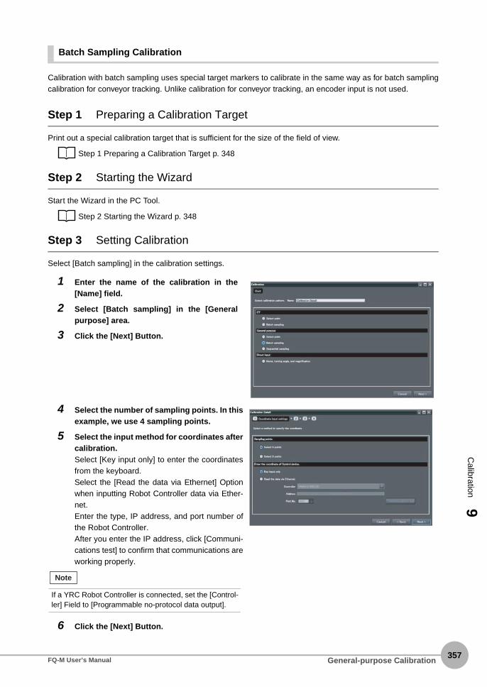
Calibration
9
Batch Sampling Calibration
Calibration with batch sampling uses special target markers to calibrate in the same way as for batch samplingcalibration for conveyor tracking. Unlike calibration for conveyor tracking, an encoder input is not used.
Step 1 Preparing a Calibration Target
Print out a special calibration target that is sufficient for the size of the field of view.
Step 1 Preparing a Calibration Target p. 348
Step 2 Starting the Wizard
Start the Wizard in the PC Tool.
Step 2 Starting the Wizard p. 348
Step 3 Setting Calibration
Select [Batch sampling] in the calibration settings.
1 Enter the name of the calibration in the[Name] field.
2 Select [Batch sampling] in the [Generalpurpose] area.
3 Click the [Next] Button.
4 Select the number of sampling points. In thisexample, we use 4 sampling points.
5 Select the input method for coordinates aftercalibration.Select [Key input only] to enter the coordinatesfrom the keyboard.Select the [Read the data via Ethernet] Optionwhen inputting Robot Controller data via Ether-net.Enter the type, IP address, and port number ofthe Robot Controller.After you enter the IP address, click [Communi-cations test] to confirm that communications areworking properly.
6 Click the [Next] Button.
If a YRC Robot Controller is connected, set the [Control-ler] Field to [Programmable no-protocol data output].
Note
General-purpose CalibrationFQ-M User’s Manual357

358
Step 4 Identifying the Calibration Target
The special calibration target is recognized and the coordinates of the detected points are obtainedautomatically.
Step 5 Sampling
The coordinates of the detected points on the target marks after calibration are obtained.
Item Description
Address If your Controller is a Trajexia, set the IP address of the Controller.
1 Adjust the calibration target position so thatall five target marks are visible.If necessary, adjust the Camera so that the cal-ibration targets are clearly visible.
2 Click the [Next] Button.
3 Make sure that all five marks are detected.If they cannot be properly detected, adjust theCamera.
4 Click the [Next] Button.
1 Enter the X and Y coordinates after calibra-tion in the [Coordinates of control device]fields.To obtain the coordinates after calibration overthe network, click the [Read] Button.
General-purpose Calibration FQ-M User’s Manual

Calibration
9
2 Click the [Next] Button.
Item Parameter Range Description
Coordinates of control device
X −99999.9999 to 99999.9999 Set the X coordinate of the control device.
Y −99999.9999 to 9999.9999 Set the Y coordinate of the control device.
3 Repeat steps 3 and 4 for the number ofmarks specified in the [Sampling points]field.In this example, we perform these steps formarks 2 through 4.
4 Click the [Next] Button.
5 Check the results of the calibration.
6 Click the [Exit] Button to close the Wizard.
• The error that is maintained for calibration is the average
of the distance between the following two points.
• The camera coordinates that were used to calculate
calibration coefficients A to F converted to robot coor-
dinates using calibration coefficients A to F
• The robot coordinates that were used to calculate the
calibration coefficients A to F
Important
General-purpose CalibrationFQ-M User’s Manual359
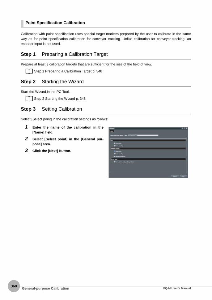
360
Point Specification Calibration
Calibration with point specification uses special target markers prepared by the user to calibrate in the sameway as for point specification calibration for conveyor tracking. Unlike calibration for conveyor tracking, anencoder input is not used.
Step 1 Preparing a Calibration Target
Prepare at least 3 calibration targets that are sufficient for the size of the field of view.
Step 1 Preparing a Calibration Target p. 348
Step 2 Starting the Wizard
Start the Wizard in the PC Tool.
Step 2 Starting the Wizard p. 348
Step 3 Setting Calibration
Select [Select point] in the calibration settings as follows:
1 Enter the name of the calibration in the[Name] field.
2 Select [Select point] in the [General pur-pose] area.
3 Click the [Next] Button.
General-purpose Calibration FQ-M User’s Manual

Calibration
9
Step 4 Specifying the Detection Point and Sampling
1. Specify the detected points on the target marks on the display to obtain the Camera coordinates.2. Specify the detected points on the target marks after calibration.3. Repeat the above two steps for all of the target marks on the calibration target.
4 Change the [Sampling points] with the slid-er.In this example, we use 4 sampling points.
5 Select the input method for coordinates af-ter calibration.Select [Key input only] to enter the coordinatesfrom the keyboard. Select the [Read the data via Ethernet] Optionwhen inputting Robot Controller data via Ether-net. Enter the type, IP address, and port number ofthe Robot Controller.After you enter the IP address, click [Commu-nications test] to confirm that communicationsare working properly.
6 Click the [Next] Button.
Item Description
Address If your Controller is a Trajexia, set the IP address of the Controller.
1 Adjust the calibration target position so thatthe target marks are visible.If necessary, adjust the Camera so that the cal-ibration targets are clearly visible.
2 Click the [Next] Button.
If a YRC Robot Controller is connected, set the [Control-ler] Field to [Programmable no-protocol data output].
Note
General-purpose CalibrationFQ-M User’s Manual361

362
3 Click the position of the first mark on the im-age or enter the position in Camera coordi-nates (X, Y) directly.
4 Click the [Next] Button.
5 Enter the X and Y coordinates after calibra-tion in the [Coordinates of control device]fields.To obtain the coordinates after calibration overthe network, click the [Read] Button.
6 Click the [Next] Button.
Item Parameter Range Description
Camera coordi-nates
X 0 to 99999.9999 Set the X coordinate of the Camera.
Y 0 to 99999.9999 Set the Y coordinate of the Camera.
[Coordinates of control device]
X −99999.9999 to 99999.9999 Set the X coordinate of the control device.
Y −99999.9999 to 9999.9999 Set the Y coordinate of the control device.
7 Repeat steps 3 to 6 for the number of marksspecified in the [Sampling points] field.In this example, we perform these steps formarks 2 through 4.
8 Click the [Next] Button.
9 Check the results of the calibration.
10 Click the [Exit] Button to close the Wizard.
• The error that is maintained for calibration is the average
of the distance between the following two points.
• The camera coordinates that were used to calculate
calibration coefficients A to F converted to robot coor-
dinates using calibration coefficients A to F
• The robot coordinates that were used to calculate the
calibration coefficients A to F
Important
General-purpose Calibration FQ-M User’s Manual

Calibration
9
Sequential Sampling Calibration
With sequential sampling, a sample workpiece prepared by the user, such as an actual workpiece, is used forcalibration. Anything can be used as long as the workpiece image can be registered as a model and searchingis possible. Sampling is performed for one workpiece in various locations in the field of view, and the Cameracoordinate and robot coordinates are obtained to calibrate the system.
Step 1 Preparing a Calibration Target
Prepare one calibration target, such as a workpiece or mark.
Step 1 Preparing a Calibration Target p. 348
Step 2 Starting the Wizard
Start the Wizard in the PC Tool.
Step 2 Starting the Wizard p. 348
Step 3 Setting Calibration
Select [Sequential sampling] in the calibration settings.
Sequential sampling allows you to set any model as a calibration target.
1 Enter the name of the calibration in the[Name] field.
2 Select [Sequential sampling] in the [Generalpurpose] area.
3 Click the [Next] Button.
Note
General-purpose CalibrationFQ-M User’s Manual363

364
4 Change the [Sampling points] with the slid-er.In this example, we use 4 sampling points.
5 Select the input method for coordinates aftercalibration.Select [Key input only] to enter the coordinatesfrom the keyboard.Select the [Read the data via Ethernet] Optionwhen inputting Robot Controller data via Ether-net.Enter the type, IP address, and port number ofthe Robot Controller.After you enter the IP address, click [Communi-cations test] to confirm that communications areworking properly.
6 Click the [Next] Button.
Item Description
Address If your Controller is a Trajexia, set the IP address of the Controller.
If a YRC Robot Controller is connected, set the [Control-ler] Field to [Programmable no-protocol data output].
Note
General-purpose Calibration FQ-M User’s Manual
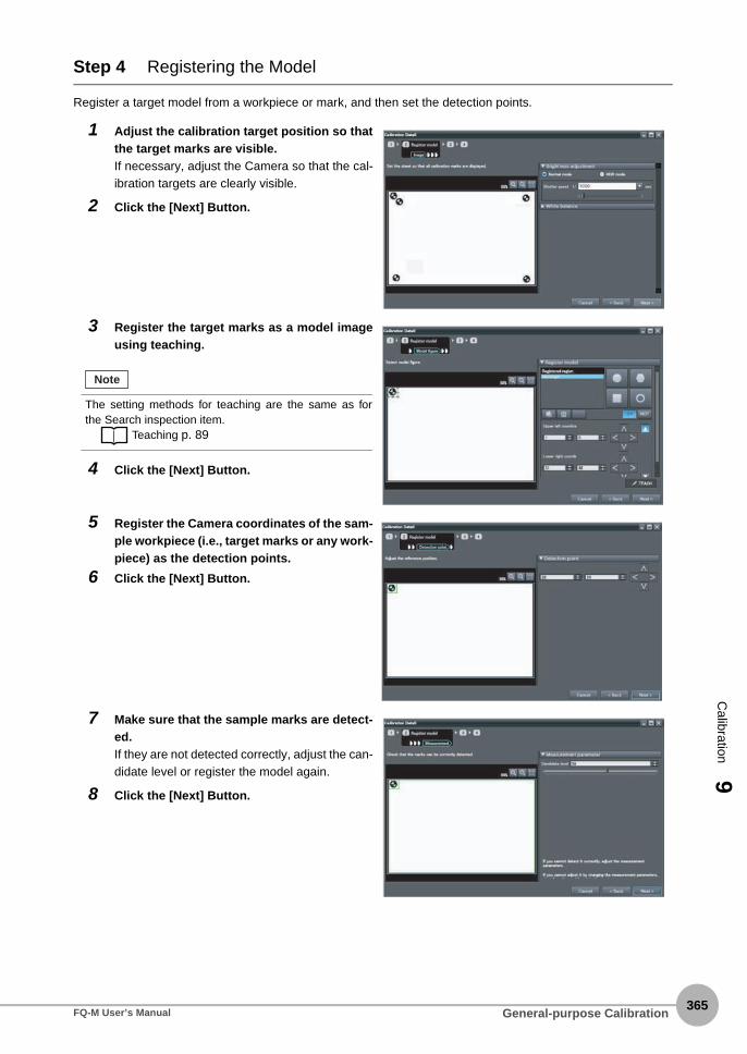
Calibration
9
Step 4 Registering the Model
Register a target model from a workpiece or mark, and then set the detection points.
1 Adjust the calibration target position so thatthe target marks are visible.If necessary, adjust the Camera so that the cal-ibration targets are clearly visible.
2 Click the [Next] Button.
3 Register the target marks as a model imageusing teaching.
4 Click the [Next] Button.
5 Register the Camera coordinates of the sam-ple workpiece (i.e., target marks or any work-piece) as the detection points.
6 Click the [Next] Button.
7 Make sure that the sample marks are detect-ed.If they are not detected correctly, adjust the can-didate level or register the model again.
8 Click the [Next] Button.
The setting methods for teaching are the same as forthe Search inspection item.
Teaching p. 89
Note
General-purpose CalibrationFQ-M User’s Manual365

366
Step 5 Sampling
1. Place the target on one point in the field of view.2. Obtain the Camera coordinates of the target mark (obtained automatically by the Search inspection item).3. Obtain the coordinates of the detected points on the target marks after calibration.4. Perform the above three steps for all of the sampling points in the field of view (four in this example).
1 Register the Camera coordinates (X, Y) forthe first point.To automatically obtain the Camera coordinatesfrom the displayed image, click the [Measure-ment] Button.
2 Click the [Next] Button.
3 Enter the X and Y coordinates after calibra-tion in the [Coordinates of control device]fields.To obtain the coordinates after calibration overthe network, click the [Read] Button.
4 Click the [Next] Button.
Item Parameter Range Description
Camera coordinates
X 0 to 99999.9999 Set the X coordinate of the Camera.
Y 0 to 99999.9999 Set the Y coordinate of the Camera.
Coordinates of control device
X −99999.9999 to 99999.9999
Set the X coordinate of the robot.
Y −99999.9999 to 9999.9999
Set the Y coordinate of the robot.
5 Repeat the above four steps for marks 2 to 4.
6 Click the [Next] Button.
General-purpose Calibration FQ-M User’s Manual

Calibration
9
7 Check the results of the calibration.
8 Click the [Exit] Button to close the Wizard.
• The error that is maintained for calibration is the average
of the distance between the following two points.
• The camera coordinates that were used to calculate
calibration coefficients A to F converted to robot coor-
dinates using calibration coefficients A to F
• The robot coordinates that were used to calculate the
calibration coefficients A to F
Important
General-purpose CalibrationFQ-M User’s Manual367

368
9-4 Direct Input
Specify the calibration coordinates for the robot and the Camera directly from the position of the origin, thecoordinate magnification, and the coordinate rotation angle. The flow for direct input is given below.
Step 1 Starting the Wizard
Step 2 Starting the Wizard p. 348
Step 2 Setting Calibration
Step 3 Enter the Calibration Information
1 Enter the name of the calibration in the[Name] field.
2 Click [Home, turning angle, and magnifica-tion] for direct entry.
3 Click the [Next] Button.
1 Enter the Camera coordinates and the coor-dinates after calibration.
Direct Input FQ-M User’s Manual

Calibration
9
The settings parameters are listed in the following table.
Parameter Range of value Description
Position X of camera coor-dinates
−9,999.9999 to 9,999.9999
Set the X coordinate of standard position in the Camera coordinate system.
Position Y of camera coor-dinates
−9,999.9999 to 9,999.9999
Set the Y coordinate of standard position in the Camera coordinate system.
Position X after calibration processing
−9,999.9999 to 9,999.9999
Set the X coordinate of standard position in the converted coordinate system. This is the value of the X coordinate of the position after calibration (i.e., in robot coordinates) that correspond to position X of Camera coordinates.
Position Y after calibration processing
−9,999.9999 to 9,999.9999
Set the Y coordinate of standard position in the converted coordinate system. This is the value of the Y coordinate of the position after calibration (i.e., in robot coordinates) that correspond to position Y of Camera coordinates.
Magnification 0.0001 to 9,999.9999 Specifies how many pixels to replace individual pixels with for magnification.
Rotation angle −180 to 180 Sets the rotational offset of the robot coordinates in relation to the Camera coordinates.
Coordinate system Right-hand or Left-hand Sets the coordinate system for the position after calibration processing (robot coordinates).
Direct InputFQ-M User’s Manual369

370
MEMO
Direct Input FQ-M User’s Manual

Offline Settings
Offline S
ettings10
10-1 Offline Setup..............
10-2 Starting a Project in O
10-3 Changing between On
10-4 Offline Simulation of S
10-5 Offline Debugging of tion .............................
..........................................................................372
ffline Mode .....................................................373
line and Offline ..............................................374
ensor Measurement Operations..................375
the Sensor Control Program and Sensor Opera-..........................................................................376

372
10-1 Offline Setup
With the PC Tool, you can change settings offline without connecting to the Vision Sensor. Parameters setoffline can be saved as project data, just like online settings, and conditions set offline can be transferred to anyspecified Sensor.
When you change settings offline, you must use image files stored on your computer. You can performbasically any settings that you can when online. However, the following parameters modify the displayed imagewhen you are online, but they will not modify the displayed image when you are offline.
The following functions are disabled during offline setup.
Item Reference
Image settings Brightness setting p. 74
White balance p. 78
Partial input p. 159
Lighting controls p. 226, p. 227
Strobe controller settings p. 73
Item Reference
System Image display for trigger delay settings p. 80
Monitor File logging p. 191
Calibration Wizard settings for calibration other than with direct input p. 346
Offline Setup FQ-M User’s Manual

10-2 Starting a Project in Offline Mode
Offline S
ettings10
To start a project in Offline Mode, select [Enter the type] on the Select Sensor Dialog Box after you create aproject, then select the sensor type and version.
You cannot change the sensor type and version after you select them.
Starting a Project in Offline ModeFQ-M User’s Manual373
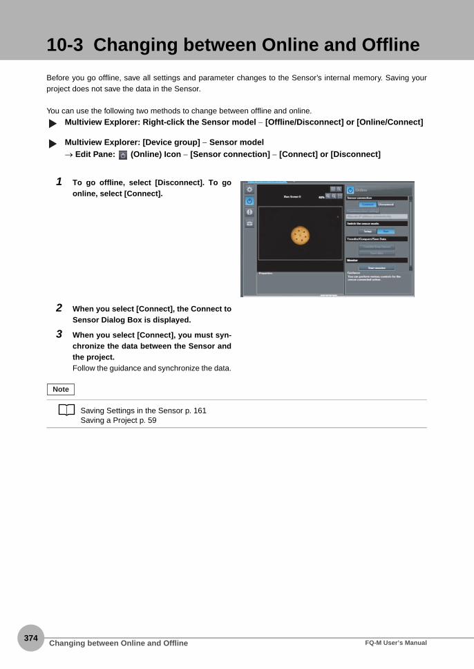
374
10-3 Changing between Online and Offline
Before you go offline, save all settings and parameter changes to the Sensor’s internal memory. Saving yourproject does not save the data in the Sensor.
You can use the following two methods to change between offline and online.
Multiview Explorer: Right-click the Sensor model − [Offline/Disconnect] or [Online/Connect]
Multiview Explorer: [Device group] − Sensor model→ Edit Pane: (Online) Icon − [Sensor connection] − [Connect] or [Disconnect]
1 To go offline, select [Disconnect]. To goonline, select [Connect].
2 When you select [Connect], the Connect toSensor Dialog Box is displayed.
3 When you select [Connect], you must syn-chronize the data between the Sensor andthe project.Follow the guidance and synchronize the data.
Saving Settings in the Sensor p. 161Saving a Project p. 59
▲▲
Note
Changing between Online and Offline FQ-M User’s Manual
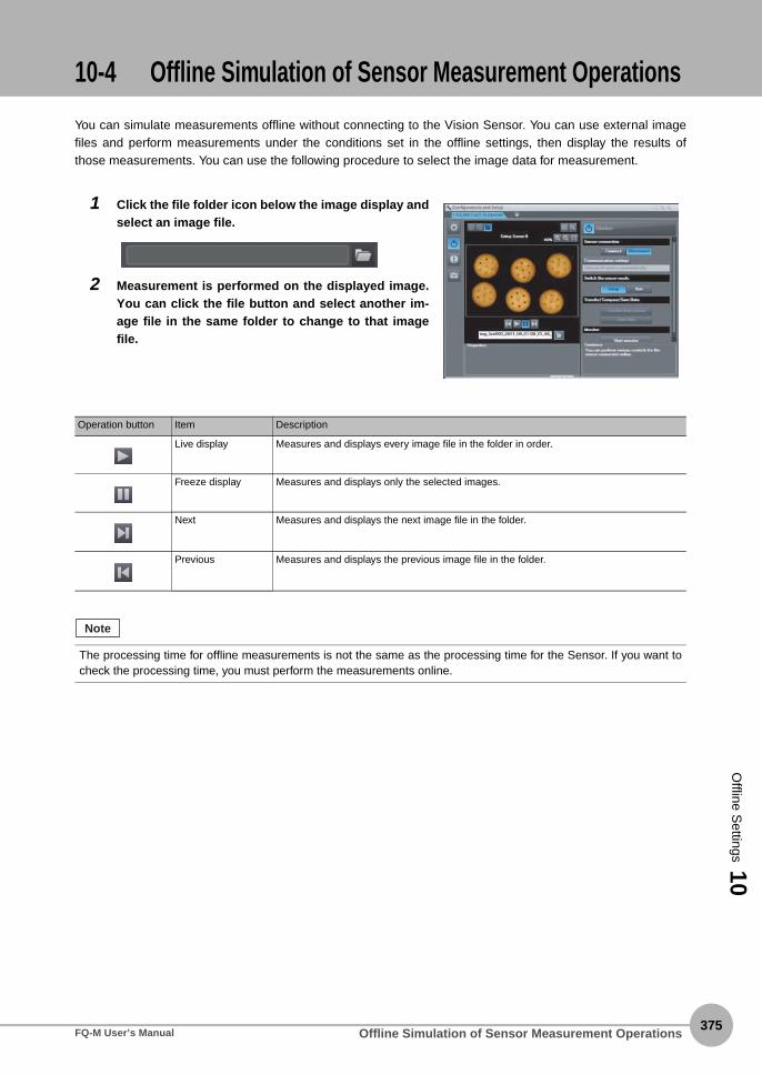
10-4 Offline Simulation of Sensor Measurement Operations
Offline S
ettings10
You can simulate measurements offline without connecting to the Vision Sensor. You can use external imagefiles and perform measurements under the conditions set in the offline settings, then display the results ofthose measurements. You can use the following procedure to select the image data for measurement.
1 Click the file folder icon below the image display andselect an image file.
2 Measurement is performed on the displayed image.You can click the file button and select another im-age file in the same folder to change to that imagefile.
Operation button Item Description
Live display Measures and displays every image file in the folder in order.
Freeze display Measures and displays only the selected images.
Next Measures and displays the next image file in the folder.
Previous Measures and displays the previous image file in the folder.
The processing time for offline measurements is not the same as the processing time for the Sensor. If you want tocheck the processing time, you must perform the measurements online.
Note
Offline Simulation of Sensor Measurement OperationsFQ-M User’s Manual375

376
10-5 Offline Debugging of the Sensor Control Program and Sensor Operation
If an EtherCAT system is configured, you can perform a linked simulation between the sequence control of anNJ-series Controller and the operation of an FQ-M Sensor.This allows you to debug operation offline from when measurements and other processing is performed forcontrol signals, such as measurement triggers, through the output of processing results.
The following table shows the items in the PDO mapping that you can debug offline.
Item Description Support Remarks
Command area Measurement execu-tion
Measurement execution request Supported.
Command execution Continuous measurement start request Supported.
Continuous measurement end request Supported.
Measurement value clear request Supported.
Data output buffer clear request Supported.
Sensor save request Supported.
Model re-registration request Supported.
Reset request Supported.
Scene number acquisition request Supported.
Latest error information acquisition request Supported.
Scene change request Supported.
Inspection item data output request Supported.
EtherCAT data output data acquisition request
Supported.
Realtime encoder value acquisition request Not supported. A value of 0 is always output.
Software version acquisition request Supported.
System data acquisition request Supported.
Encoder information acquisition request Supported.
Inspection item data setting request Supported.
EtherCAT data output data acquisition request
Supported.
System data setting request Supported.
Encoder data setting request Supported.
Data output request Data output request Supported.
Clearing errors Error clear request Supported.
Computer
EtherCAT online connection
FQ-M Sensor Simulator (virtual Vision Sensor)
NJ-series Controller Simulator (virtual Controller)
Image file (images to measure)
Sysmac Studio
Operations That Are Possible with Simulation
SysmacStudio Simulator
connection
User program
(3) Outputting measurement results to the storage area in the NJ-series Controller
(2) Individual measurements and control command processing
(1) Trigger signals and control commands
Offline Debugging of the Sensor Control Program and Sensor Operation FQ-M User’s Manual

Offline S
ettings10
Simulation is possible only on the Standard Edition of the Sysmac Studio.
Registering the FQ-M as an EtherCAT Slave
You use the Sysmac Studio (Standard Edition) to add the FQ-M to the EtherCAT slave configuration.Refer to the Sysmac Studio Version 1 Operation Manual (Cat. No. W504) for details on registering slaves.Only simplified procedures are provided here.
• Opening the Edit EtherCAT Configuration Tab Page
Multiview Explorer: [Configurations and Setup] − [EtherCAT] (Double-click)
• Registering a Slave Offline (Building the Network Configuration)
1 Use either of the following methods to add an FQ-M slave to the master.• Drag [FQ-MS@@@-ECT] or [FQ-MS@@@-M-ECT] from the [Toolbox] to the master in the Edit Network Con-
figuration Tab Page.
• Select the master in the Edit Network Configuration Dialog Box and then double-click [FQ-MS@@@-ECT] or
[FQ-MS@@@-M-ECT] in the [Toolbox].
Response area FLG Command Completed signal Supported.
BUSY Command Execution Active signal Supported.
READY Ready signal Supported.
OR Overall Judgement Supported.
ERR Error signal Supported.
RUN Run Mode signal Supported.
GATE Data Output Completed signal Supported.
Data area 32 bytes Partially supported. A value of 0 is always output for the encoder value.The results of Sen-sor simulation are output for other val-ues.
64 bytes Partially supported.
128 bytes Partially supported.
256 bytes Partially supported.
Logging is not supported offline.
Simulation of Sensor measurement operations and other processing is performed for image files that are preparedin advance.
Selecting the Image File to Measure p.378
Item Description Support Remarks
Note
Note
Important
▲
Offline Debugging of the Sensor Control Program and Sensor OperationFQ-M User’s Manual377

378
2 Select the FQ-M that was added to the Edit Network Configuration Tab Page and change the nodeaddress of the FQ-M to the node address that is set on the FQ-M hardware switches.
Setting Up the FQ-M
Set up the inspections in the FQ-M, e.g., set the inspection items.
Executing the Simulation
1 Double-click the FQ-M that was added to theEdit Network Configuration Tab Page.The FQ-M Setup Pane is displayed for the EditPane. Make all of the required settings.
1 Write and build the user program that will op-erate the machine.Refer to the Sysmac Studio Version 1 OperationManual (Cat. No. W504) for details on program-ming.
2 Change to Run ModeRight-click [FQ-MS12x...] in the Edit NetworkConfiguration Tab Page and change to RunMode.
Offline Debugging of the Sensor Control Program and Sensor Operation FQ-M User’s Manual

Offline S
ettings10
After the Simulator is connected, the NJ-series Controller and FQ-M Simulator will be internally connected online via EtherCAT and the NJ-series Controller will enter RUN mode.Refer to the Sysmac Studio Version 1 Operation Manual (Cat. No. W504) for the operating procedures for the Simulator.
3 Start the monitor.Right-click [FQ-MS12x...] in the Edit NetworkConfiguration Tab Page and select [Start moni-tor].
4 Set the FQ-M and then specify the measure-ment image to use for offline debugging.Click the image file selection icon and select animage.
5 Select [Simulation] − [Execute].The simulation will start.
6 When control bits are manipulated from thesequence controls to execute measure-ments, the measurement results are dis-played in the [Monitoring] area so that youcan check them.
Offline Debugging of the Sensor Control Program and Sensor OperationFQ-M User’s Manual379

380
MEMO
Offline Debugging of the Sensor Control Program and Sensor Operation FQ-M User’s Manual

Troubleshooting
11 T
roubleshooting
11-1 Error Histories . . . . . . . . . . . . . . . . . . . . . . . . . . . . . . . . . . . . . . . . . . 382
11-2 Error Messages . . . . . . . . . . . . . . . . . . . . . . . . . . . . . . . . . . . . . . . . . 390
11-3 Basic Troubleshooting . . . . . . . . . . . . . . . . . . . . . . . . . . . . . . . . . . . 391

382
11-1 Error Histories
Error histories are stored with the PC Tool and in the Sensor and in the Touch Finder.Up to 100 errors will be stored in the error history in the Sensor or Touch Finder.The method for checking the error history in the Sensor depends on how the Sensor is connected.
EtherCAT Connection (Sysmac Error Status)
The Sysmac Studio Standard Version displays errors that occur in the EtherCAT system (including Sensorerrors) as Sysmac error status.
Sysmac Error Status Table
This section provides a table of Sysmac error status that is related to the Sensor and describes the eventcodes. Refer to the NJ-series Troubleshooting Manual (Cat. No. W503) for details on event codes.Levels: Maj: Major fault level, Par: Partial fault level, Min: Minor fault level, Obs: Observation, Info: Information
Note: If an error with this mark occurs, the ERROR operation indicator will light and the ERROR signal will turn ON.*1: Major Fault Level
• These errors prevent control operations for the entire Controller. If a major fault level error is detected, user program execution is stopped
immediately and the loads for all slaves (including remote I/O) are turned OFF. You cannot reset major fault level errors from the user
program, the Sysmac Studio, or an NS-series PT. To recover from a major fault level error, remove the cause of the error, and either cycle
the power supply to the Controller or reset the Controller from the Sysmac Studio.
• Partial Fault Level
These errors prevent control operations in a certain function module in the Controller. The NJ-series CPU Unit continues to execute the
user program even after a partial fault level error occurs. After you remove the cause of the error, execute one of the following to return to
normal status.
• Reset the error from the user program, the Sysmac Studio, or an NS-series PT.
Event code Event name Meaning Assumed cause Level*1 Refer-enceMaj Prt Min Obs Infor
78080000 hex TRIG Input Error
A TRIG signal was input when the BUSY signal for Sensor measure-ment was ON.
• A TRIG signal was input when the BUSY signal for Sensor measurement was ON.
• Chattering occurred for a contact input.
✔ p. 385
780A0000 hex Scene Data Error
The scene data to switch to is cor-rupted.
• The power supply was inter-rupted when the scene data to switch to was saved.
✔ p. 385
780B0000 hex Model Error A model was re-registered with an image with low contrast.
• A model was re-registered with an image with low con-trast.
✔ p. 386
780C0000 hex Logging Error Some data was not saved when log-ging data to files on an SD card.
• Too much data to log in files occurred in a short period of time, and writing to the SD card could not keep up.
✔ p. 386
780D0000 hex Output Time-out
A timeout occurred in data output handshaking con-trol for measure-ment results.
• The data output handshak-ing controls in the program (i.e., the ON/OFF timing of the DSA signal) are not cor-rect.
• The output control timeout time is too short in compari-son with the program pro-cessing time.
✔ p. 387
780E0000 hex Output Size Error
The data output size setting and the PDO mapping setting do not agree.
• The EtherCAT data output size setting in the Sensor and the PDO mapping set-ting in the EtherCAT master do not agree.
✔ p. 387
Error Histories FQ-M User’s Manual

11 T
roubleshooting
• Cycle the power supply to the Controller.
• Reset the Controller from the Sysmac Studio.
• Minor Fault Level
These errors prevent part of the control operations in a certain function module in the Controller. The troubleshooting for minor fault level
errors is the same as the processing for partial fault level errors.
• Observations
These errors do not affect the control operations of the Controller. Observations serve as warnings to the user so that the error does not
develop into an error at a higher level.
• Information
Events that are classified as information do not indicate errors.
Checking Sysmac Error Status
You can use the troubleshooting functions of the Sysmac Studio Standard Version to check the Sysmac errorstatus. Refer to the NJ-series Troubleshooting Manual (Cat. No. W503) for information on troubleshootingfunctions.
1 Select [Troubleshooting] from the Tools Menu while online. You can also click the [Troubleshoot-ing] Button in the toolbar.The following Troubleshooting Dialog Box is displayed.
2 Click the [Controller Errors] Tab.A list of the current Sysmac error status and corresponding event codes will be displayed.
Clearing the Sysmac Error Status
Remove the cause of the error and then click the [Reset All] Button on the [Controller Errors] Tab Page of the[Troubleshooting] Pane.
Even if you reset the Sysmac error status, the errors will remain on the [Controller Event Log] Tab Page.
Note
Error HistoriesFQ-M User’s Manual383

384
Error Descriptions
The items that are used to describe individual errors (events) are described in the following copy of an errortable.
*1 One of the following:Major fault: Major fault levelPartial fault: Partial fault levelMinor fault: Minor fault levelObservationInformation
*2 One of the following:Automatic recovery: Normal status is restored automatically when the cause of the error is removed.Error reset: Normal status is restored when the error is reset after the cause of the error is removed.Cycle the power supply: Normal status is restored when the power supply to the Controller is turned OFF and then back ON after the cause of the error is removed.Controller reset: Normal status is restored when the Controller is reset after the cause of the error is removed.Depends on cause: The recovery method depends on the cause of the error.
*3 One of the following:System: System event logAccess: Access event log
*4 One of the following:Continues: Execution of the user program will continue.Stops: Execution of the user program stops.Starts: Execution of the user program starts.
Event name Gives the name of the error. Event code Gives the code of the error.
Meaning Gives a short description of the error.
Source Gives the source of the error. Source details Gives details on the source of the error.
Detection timing
Tells when the error is detected.
Error attributes Level Tells the level of influence on con-trol.*1
Recovery Gives the recov-ery method.*2
Log category Tells which log the error is saved in.*3
Effects User program Tells what will hap-pen to execution of the user program.*4
Operation Provides special information on the operation that results from the error.
Indicators This is the status of the indicators for the EtherCAT port that is built into the NJ-series Controller. Indicator status is given only for errors in the EtherCAT Master Function Module and the EtherNet/IP Function Module.
System-defined variables
Variable Data type Name
Lists the variable names, data types, and meanings for system-defined variables that provide direct error notifica-tion, that are directly affected by the error, or that contain settings that cause the error.
Cause and correction
Assumed cause Correction Prevention
Lists the possible causes, corrections, and preventive measures for the error.
Attached information
This is the attached information that is displayed by the Sysmac Studio or an NS-series PT.
Precautions/Remarks
Provides precautions, restrictions, and supplemental information.
Error Histories FQ-M User’s Manual

11 T
roubleshooting
Event name TRIG Input Error Event code 78080000 hex
Meaning A TRIG signal was input when the BUSY signal for Sensor measurement was ON.
Source EtherCAT Master Function Module Source details Slave Detection timing
When TRIG signal turns ON
Error attributes Level Minor fault Recovery Error reset (after resetting the error in the slave)
Log category System
Effects User program Continues. Operation The TRIG signal is disabled and measurements do not start.
Indicators EtherCAT NET RUN EtherCAT NET ERR EtherCAT LINK/ACT
--- --- ---
System-defined variables
Variable Data type Name
None --- ---
Cause and correction
Assumed cause Correction Prevention
A TRIG signal was input when the BUSY signal for Sensor measure-ment was ON.
Correct the program so that a TRIG signal is not input while the BUSY signal is ON.
Write the program so that a TRIG signal is not input while the BUSY signal for Sensor measurement is ON.
Chattering occurred for a contact input.
Use a no-contact output device (e.g., SSR or PLC transistor) instead of a contact output device (e.g., relay).
Use no-contact output devices (e.g., SSR or PLC transistors) to prevent chattering.
Attached information
None
Precautions/Remarks
None
Event name Scene Data Error Event code 780A0000 hex
Meaning The scene data to switch to is corrupted.
Source EtherCAT Master Function Module Source details Slave Detection timing
When the scene is changed
Error attributes Level Minor fault Recovery Error reset (after resetting the error in the slave)
Log category System
Effects User program Continues. Operation The data for the destination scene is initialized and then the scene is switched to. The initialized scene data is used for operation until the data for the destination scene is set.
Indicators EtherCAT NET RUN EtherCAT NET ERR EtherCAT LINK/ACT
--- --- ---
System-defined variables
Variable Data type Name
None --- ---
Cause and correction
Assumed cause Correction Prevention
The power supply was interrupted when the scene data to switch to was saved.
Reset the scene to switch to. Do not turn OFF the power supply during save processing for the scene data.
Attached information
None
Precautions/Remarks
None
Error HistoriesFQ-M User’s Manual385

386
Event name Model Error Event code 780B0000 hex
Meaning A model was re-registered with an image with low contrast.
Source EtherCAT Master Function Module Source details Slave Detection timing
When model re-registration com-mand is executed
Error attributes Level Minor fault Recovery Error reset (after resetting the error in the slave)
Log category System
Effects User program Continues Operation There is no longer a registered model and the Search inspection item will continue to fail until a model is regis-tered again.
Indicators EtherCAT NET RUN EtherCAT NET ERR EtherCAT LINK/ACT
--- --- ---
System-defined variables
Variable Data type Name
None --- ---
Cause and correction
Assumed cause Correction Prevention
A model was re-registered with an image with low contrast.
Re-register the model with an image with high contrast.
Re-register models with images with high contrast.
Attached information
None
Precautions/Remarks
None
Event name Logging Error Event code 780C0000 hex
Meaning Some data was not saved when logging data to files on an SD card.
Source EtherCAT Master Function Module Source details Slave Detection timing
When file logging is executed
Error attributes Level Minor fault Recovery Error reset (after resetting the error in the slave)
Log category System
Effects User program Continues. Operation Logging data with the file logging process will continue to fail until the problem is corrected.
Indicators EtherCAT NET RUN EtherCAT NET ERR EtherCAT LINK/ACT
--- --- ---
System-defined variables
Variable Data type Name
None --- ---
Cause and correction
Assumed cause Correction Prevention
Too much data to log in files occurred in a short period of time, and writing to the SD card could not keep up.
Increase the interval between mea-surements or change the BUSY output condition to "End of data log-ging" or "End of image logging."
Set a suitable interval between measurements or set the BUSY output condition to "End of data log-ging" or "End of image logging."
Attached information
None
Precautions/Remarks
If logging fails due to a problem with the SD card (such as insufficient capacity or a lock), a record is stored only in the error history of the Touch Finder.
Error Histories FQ-M User’s Manual

11 T
roubleshooting
Event name Output Timeout Event code 780D0000 hex
Meaning A timeout occurred in data output handshaking control for measurement results.
Source EtherCAT Master Function Mod-ule
Source details Slave Detection timing
At measurement result output
Error attributes Level Minor fault Recovery Error reset (after resetting the error in the slave)
Log category System
Effects User program Continues Operation Data is not output to the EtherCAT master and it is stored in the Sensor. When the DSA signal turns ON, the stored data is output to the Ether-CAT master.
Indicators EtherCAT NET RUN EtherCAT NET ERR EtherCAT LINK/ACT
--- --- ---
System-defined variables
Variable Data type Name
None --- ---
Cause and correction
Assumed cause Correction Prevention
The data output handshaking con-trols in the program (i.e., the ON/OFF timing of the DSA signal) are not correct.
Correct the data output handshak-ing controls in the program (i.e., the ON/OFF timing of the DSA signal).
Create the data output handshak-ing controls in the program (i.e., the ON/OFF timing of the DSA signal).
The output control timeout time is too short in comparison with the pro-gram processing time.
Correct the timeout time so that it is suitable for the program processing time.
Set the timeout time so that it is suitable for the program processing time.
Attached information
None
Precautions/Remarks
None
Event name Output Size Error Event code 780E0000 hex
Meaning The data output size setting and the PDO mapping setting do not agree.
Source EtherCAT Master Function Module Source details Slave Detection timing
At measurement result output
Error attributes Level Minor fault Recovery Error reset (after resetting the error in the slave)
Log category System
Effects User program Continues. Operation The data is not output to the EtherCAT master.
Indicators EtherCAT NET RUN EtherCAT NET ERR EtherCAT LINK/ACT
--- --- ---
System-defined variables
Variable Data type Name
None --- ---
Cause and correction
Assumed cause Correction Prevention
The EtherCAT data output size set-ting in the Sensor and the PDO map-ping setting in the EtherCAT master do not agree.
Correct either the data output size setting or the PDO mapping set-ting.
Set the EtherCAT data output size setting in the Sensor and the PDO mapping setting in the EtherCAT master so that they agree.
Attached information
None
Precautions/Remarks
None
Error HistoriesFQ-M User’s Manual387

388
Errors for Ethernet (No-protocol or PLC Link) Connections
The following table lists the Sensor errors that are saved in the Sensor or Touch Finder.
Errors Stored in the Error History
Note: If an error that is indicated by this icon occurs, the ERROR operation indicator will light and the ERROR signal will turn ON.
Error in error history Cause Points to check Measures to perform
TRIG Input Error(Error code: 01040302)
A TRIG signal was input when the BUSY signal for Sensor measurement was ON.
• Check the program in the PLC or other host to see if an inter-lock or similar measure has been implemented.
• If a relay or other device with contacts is being used as the input device, see if chattering has occurred.
• Program interlocks to control the TRIG so that they do not turn ON while the BUSY signal is ON.
• Switch from a device with con-tacts (e.g., relay) to a device without contacts (e.g., SSR or PLC transistor output).
IN Input Error(Error code: 11020900)
A no-protocol command or PLC link command was input when the BUSY signal was ON.
• Is an interlock or other counter-measure provided, e.g., in a ladder program in the PLC?
• Program interlocks, such as in a ladder program, so that no-protocol commands and PLC link commands are not input while the BUSY signal is ON.
Scene Data Error(Error code: 01030800)
The scene data to switch to is corrupted.
--- The scene data to be switchedto is corrupted.Reset the scene data from thebeginning.
Model Error(Error code: 01050405,01050500)
A model was re-registered with an image with low contrast.
Check the image to see if thecontrast is too low to register themodel.
Increase the image contrast andtry again to register the model.
Logging Error(Error code: 02160702,02160703)
Some data was not saved when logging data to files on an SD card.
Check to see if the BUSY outputparameter is set to Measurement.
Too much data to log in files occurredin a short period of time, and writ-ingto the SD card could not keep up.
Output Timeout(Error code: 11090101)
A timeout occurred in data out-put handshaking control for measurement results.
• The data output handshaking controls in the program (i.e., the ON/OFF timing of the DSA signal) are not correct.
• The output control timeout time is too short in comparison with the program processing time.
• Correct the data output hand-shaking controls in the pro-gram (i.e., the ON/OFF timing of the DSA signal).
• Correct the timeout time so that it is suitable for the pro-gram processing time.
Output Size Error(Error code: 11090803)
The data output size setting and the PDO mapping setting do not agree.
The EtherCAT data output size setting in the Sensor and the PDO mapping setting in the EtherCAT master do notagree.
Correct either the data output size setting or the PDO mapping set-ting.
You cannot check the error codes from the Touch Finder. Use the command to acquire the most recent error infor-mation for the connection method.• EtherCAT
p. 254
• PLC Link
p. 287
• No-protocol Communications
p. 318
Note
Error Histories FQ-M User’s Manual

11 T
roubleshooting
Checking the Error Histories
Using the PC Tool
Multiview Explorer: [Device Group] − Sensor name (Double-click)→ Edit Pane: [Error history]
Using the Touch Finder
On the Touch Finder, you can check the history of errors detected by the Sensor and those detected by theTouch Finder.
• Checking the History of Errors That Have Occurred in the Sensor
(Setup Mode) − [Sensor settings] − [Error history] − [View history]
• Checking the Log of Errors That Have Occurred in the Touch Finder
(Setup Mode or Run Mode) − [TF settings] − [Error history] − [View history]
Clearing the Error Histories
Using the PC Tool
Multiview Explorer: [Device Group] − Sensor name (Double-click)→ Edit Pane: [Error history] − [Clear]
Using the Touch Finder
On the Touch Finder, you can clear the history of errors detected by the Sensor and those detected by theTouch Finder.
• Deleting the History of Errors That Were Detected in the Sensor
(Setup Mode) − [Sensor settings] − [Error history] − [Delete history]
• Deleting the History of Errors That Were Detected in the Touch Finder
(Setup Mode or Run Mode) − [TF settings] − [Error history] − [Delete history]
Errors will be displayed in order with the most recentones on top.
Error HistoriesFQ-M User’s Manual389

390
11-2 Error Messages
If an error occurs while making settings on the Touch Finder, an error message will appear on the display.For these errors, the ERR indicator on the Sensor will not light, the ERROR signal will not be output, and theerror will not be recorded in the error history.Follow the instructions that are given in the error message.
If the following messages appear, the hardware may be faulty.Contact your OMRON representative.• System error.
• Application system error. Please reboot.
• Failed to startup.
Error Messages FQ-M User’s Manual

11-3 Basic Troubleshooting
11 T
roubleshooting
Problem Measures to perform Reference
The Sensor or Touch Finder will not start. Check the power supply capacity to see if it is sufficient. ---
The Sensor cannot be detected. Check the Ethernet cable to see if it is connected correctly. ---
Check the Ethernet settings to see if they are correct between the devices.
p. 270, p. 297, p. 326
Check if there are any Sensors that were not detected by the Sensor connection check.
---
Check the communications cable to see if it is disconnected. ---
Check the switching hubs to see if any of them are faulty. (If switching hubs are used.)
---
The PC Tool and Touch Finder cannot be connected at the same time.If the PC Tool or Touch Finder is already connected to the Sensor, dis-connect it.
---
The results display is not updated. Check to see if the TRIG signal is being correctly input to the Sensor. p. 225
Check to see if the most recent NG result is being displayed. p. 187
Updating the results display is slow. If other devices are connected to the same network as the Sensor, dis-connect the other devices from the network and check the updatespeed.If the update speed returns to normal, check the specifications of the disconnected devices and take suitable measures.
---
If there are power lines running in parallel with the Ethernet cable or if there are inverters or other sources of noise near the communications cable, separate the communications cable from them and check the update speed.Noise may be adversely affecting the communications response.
---
Data is not logged properly. Check to see if the logging setting in the Sensor are correct. p. 191
If logging to an SD card is not possible, check the available space on the SD card and check to see if the SD card is write-protected.
p. 206
The ERROR indicator lights. Check the error history to see what error has occurred and take suitable measures.
p. 382
EtherCAT communications are not possi-ble.
Check to see it the node address setting switches are set correctly.Check to see it the IN and OUT EtherCAT connectors are connected cor-rectly.
---
Encoder pulses cannot be detected. Check to see it the encoder is wired correctly.Check to see it the encoder input parameters are set correctly.
---
The measurement trigger is not input. Check to see it the measurement trigger is set correctly. ---
Basic TroubleshootingFQ-M User’s Manual391

392
MEMO
Basic Troubleshooting FQ-M User’s Manual

Appendices
12 A
ppendices
12-1 Function List .......................................................................................394
12-2 External Reference Parameters .........................................................412
12-3 Specifications and Dimensions.........................................................428
12-4 Upgrading Sensor and Touch Finder Firmware ...............................445
12-5 Object Dictionary ................................................................................446

394
12-1 Function List
Command Description Setting range Data Reference
Project New Project Project name Sets the name of the project data. --- Project p. 49
Author Sets the project author. --- Project
Comment Sets a comment for the project data.
--- Project
Category Sets the category for the Unit to add to the project.
--- Project
Device Sets the model name of the Unit that was selected with the cate-gory setting.
--- Project
Create Creates the project data. --- ---
Open Project Delete Deletes the project data. --- --- ---
Open Opens project data. --- --- p. 49
Import Import Imports project data for manage-ment.
--- --- ---
Export Export Exports project data. --- --- ---
License License Used to input the license number of the Sysmac Studio Standard Edition or Sysmac Studio Vision Edition (SYSMAC-VE001L).
--- --- ---
Add sensors Enter the type.
Inserts the specified Sensor into the project in Offline Mode.
--- --- p. 49, p. 373
Search for sensors
Automatically searches for Sen-sors on the network and inserts them into the project.
--- ---
Specify the IP address.
Used to specify the IP address of a Sensor to connect to that Sensor online and insert it into the project.
a.b.c.da: 1 to 223b: 0 to 255c: 0 to 255d: 1 to 254
Scene
Menu bar
File Save Saves the project. --- --- p. 59
Close Closes the project. --- --- ---
Import Saves the project as an external file.
--- --- p. 60
Export Imports an exported file so that it can be edited on the PC Tool.
--- --- p. 59
Print Prints settings data. --- --- p. 205
Print settings Used to set printer attributes (e.g., margins).
--- --- ---
Exit Closes the PC Tool. --- --- ---
Function List FQ-M User’s Manual

12 A
ppendices
Menu bar
Edit Copy Copies the selected item (scene data, system data, or calibration data).
--- --- p. 54, p. 182
Paste Pastes the copied item. --- --- p. 54
Delete Deletes the selected item (scene data or calibration data).
--- --- p. 54, p. 182
Help Help con-tents
Displays help. --- --- p. 211
Version Displays version information about the PC Tool.
--- --- p. 211
Toolbar Copy Copies the selected item (scene data, system data, or calibration data).
--- --- p. 54, p. 182
Paste Pastes the copied item. --- --- p. 54
Delete Deletes the selected item (scene data or calibration data).
--- --- p. 54, p. 182
Toolbox Search Registers a Search inspection item.
--- p. 86, p. 88
Shape Search
Registers a Shape Search inspec-tion item.
--- p. 86, p. 125
Labeling Registers a Labeling inspection item.
--- p. 86, p. 113
Edge Posi-tion
Registers an Edge Position inspec-tion item.
--- p. 86, p. 105
Explorer Pane
Device group Add | FQ-M Inserts a Sensor into the project. --- p. 54, p. 65
Paste Pastes a copied Sensor into the project.
---
Sensor model Edit Displays the Main Pane for the Edit Pane.
--- --- p. 54, p. 55
Delete Deletes the Sensor from the project.
--- --- p. 54
Copy Copies the Sensor. --- ---
Setup When online, changes the Sensor to Setup Mode.
--- --- p. 23, p. 54
Run When online, changes the Sensor to Run Mode.
--- --- p. 23, p. 54, p. 164
Start monitor Opens the Monitor Pane. --- --- p. 54, p. 150, p. 168, p. 378
Online Makes an online connection to the Sensor.
--- --- p. 54, p. 65, p. 66, p. 374
Offline Disconnects the online Sensor and places the PC Tool offline.
--- --- p. 54, p. 65, p. 374
Command Description Setting range Data Reference
Function ListFQ-M User’s Manual395

396
Explorer Pane
Scene group Add | Scene data
Adds new scene data to the scene group.
--- --- p. 54, p. 203
Paste Adds the copied scene data to the scene group.
--- ---
Scene data Edit Displays the Scene Data Edit Pane for the Edit Pane.
--- Scene p. 54, p. 55, p. 56, p. 203Copy Copies the scene data. --- Scene
Delete Deletes the scene data. --- Scene
Rename Renames the scene. 15 characters max. Scene p. 182
System data Edit Displays the System Data Edit Pane for the Edit Pane.
--- System p. 54, p. 55, p. 56, p. 203Copy Copies the system data. --- System
Paste Overwrites the system data. --- System
Calibration group Add | Cali-bration data
Adds new calibration data to the calibration group.
--- --- p. 54, p. 55, p. 203
Paste Adds the copied calibration data to the calibration group.
--- ---
Calibration data Edit Displays the Calibration Data Edit Pane for the Edit Pane.
--- Calibra-tion
p. 54, p. 55, p. 203
Copy Copies the calibration data. --- Calibra-tion
Delete Deletes calibration data. --- Calibra-tion
Rename Changes the name of the calibra-tion data.
15 characters max. Calibra-tion
p. 182
Main Pane
General settings
Sensor Information Name Renames the Sensor. 15 characters max. Scene p. 210
Model Displays model information on the Sensor.
--- Scene p. 210
Version Displays version information on the Sensor.
--- Scene p. 210
Project Comment Used to enter a comment on the project.
--- Scene ---
Online Sensor connection Connection/ Disconnect
Changes the connection status (online or offline) of the Sensor.
--- --- p. 374
Communica-tion settings
Sets the conditions for communi-cations with the Sensor.
--- --- p. 273
Switch the sensor mode.
Run mode/ Setting mode
Changes the Sensor mode (Run or Setup Mode).
--- p. 66
Data transfer and collation and preser-vation
Transfer [Sensor → PC]
Transfers project data from an online Sensor to the computer.
--- p. 201
Transfer [PC → Sensor]
Transfers the project data to the online Sensor.
--- ---
Save data Saves all Sensor data to the Sen-sor’s flash memory.
--- p. 161
Monitor Start monitor Opens the Monitoring Pane used to monitor measurement results.
--- p. 168
Error history Update Displays the error history of an online Sensor.
--- p. 383
Delete Clears the error history of an online Sensor.
--- p. 383
Command Description Setting range Data Reference
Function List FQ-M User’s Manual

12 A
ppendices
Main Pane
Support software
Sensor setup Restart Restarts an online Sensor. --- p. 211
Initialize Initializes an online Sensor. --- p. 211
Update firm-ware
Updates the firmware of an online Sensor.
--- p. 445
Sensor data Read Imports external file data (scene data, system data, calibration data, or all Sensor data) as data that can be read by the Touch Finder.
--- --- p. 205
Save Exports project data (scene data, system data, calibration data, and all Sensor data) to an external file as data that can be read by the Touch Finder.
--- --- p. 204
Print Sensor parameter
Prints out the Sensor scene and system data.
--- --- p. 205
The mark for calibration
Prints out a calibration pattern that is used to perform conveyor track-ing calibration.
--- p. 70
Help Help display Displays help. --- p. 211
Edit scene
Image Brightness adjust Brightness adjustment
Changes the brightness adjust-ment mode (Normal or HDR Mode).
Normal Mode (default) or HDR Mode
Scene p. 76
Shutter speed
Sets the shutter speed for Normal Mode.
1/10 to 1/30,000 s (default: 1/1,000)
Scene p. 74, p. 75
Brightness Sets the brightness level of the image for HDR Mode.
1 to 100 Scene p. 74, p. 75
HDR Level Sets the HDR level to one of four levels for HDR Mode.
OFF, HDR:1, HDR:2, HDR:3, HDR:4
Scene p. 76
White balance R Corrects the RGB ratio when the coloring of an image is not correct.
0.001 to 7.999 Scene p. 78
G 0.001 to 7.999 Scene
B 0.001 to 7.999 Scene
Partial input Start point, End point
Narrows the image input range. 752 × 8 to 752 × 480 Scene p. 159
Lighting control Strobe output delay
Sets the delay time for the strobe output signal (STGOUT) in response to the trigger signal.
0 to 65,535 ms (default: 0 ms)
Scene p. 227
Strobe output time
Sets the output time of the strobe output signal (STGOUT).
0 to 65,535 ms (default: 1,000 ms)
Scene p. 226
Strobe output polarity
Sets the output polarity of the strobe output signal (STGOUT).
Positive (default) or Negative
Scene p. 225
Strobe controller settings
Used chan-nel
Sets the channel to use when con-nected to a Strobe Controller.
CH0 to CH7 (default), CH0 to CH3, or CH4 to CH7
Scene ---
Light mode Sets the lighting mode to use when connected to a Strobe Controller.
Off, Trigger Sync (default)
Scene p. 73
Adjust light intensity 0 to 7
Sets the light intensity for each channel when connected to a Strobe Controller.
1 to 400 (default: 1) Scene p. 73
Calibration Calibration pattern
Sets a registered calibration pat-tern.
Unregistered (default), New Cali-bration, or Calibra-tion Data 0 to 3
Scene p. 348
Command Description Setting range Data Reference
Function ListFQ-M User’s Manual397
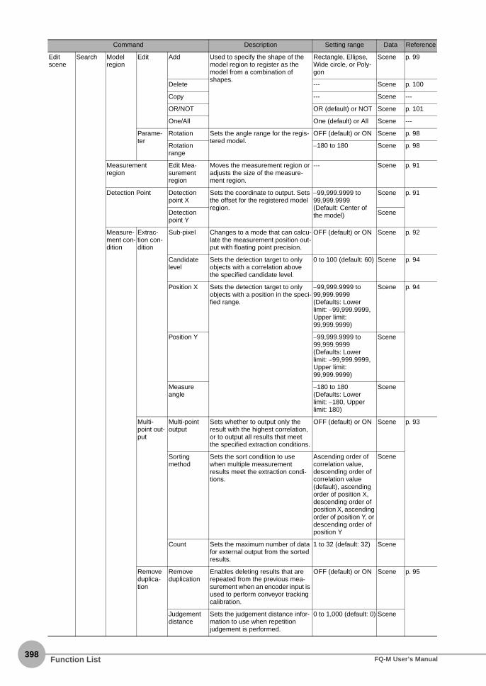
398
Edit scene
Search Model region
Edit Add Used to specify the shape of the model region to register as the model from a combination of shapes.
Rectangle, Ellipse, Wide circle, or Poly-gon
Scene p. 99
Delete --- Scene p. 100
Copy --- Scene ---
OR/NOT OR (default) or NOT Scene p. 101
One/All One (default) or All Scene ---
Parame-ter
Rotation Sets the angle range for the regis-tered model.
OFF (default) or ON Scene p. 98
Rotation range
−180 to 180 Scene p. 98
Measurement region
Edit Mea-surement region
Moves the measurement region or adjusts the size of the measure-ment region.
--- Scene p. 91
Detection Point Detection point X
Sets the coordinate to output. Sets the offset for the registered model region.
−99,999.9999 to 99,999.9999 (Default: Center of the model)
Scene p. 91
Detection point Y
Scene
Measure-ment con-dition
Extrac-tion con-dition
Sub-pixel Changes to a mode that can calcu-late the measurement position out-put with floating point precision.
OFF (default) or ON Scene p. 92
Candidate level
Sets the detection target to only objects with a correlation above the specified candidate level.
0 to 100 (default: 60) Scene p. 94
Position X Sets the detection target to only objects with a position in the speci-fied range.
−99,999.9999 to 99,999.9999 (Defaults: Lower limit: −99,999.9999, Upper limit: 99,999.9999)
Scene p. 94
Position Y −99,999.9999 to 99,999.9999 (Defaults: Lower limit: −99,999.9999, Upper limit: 99,999.9999)
Scene
Measureangle
−180 to 180 (Defaults: Lower limit: −180, Upper limit: 180)
Scene
Multi-point out-put
Multi-pointoutput
Sets whether to output only the result with the highest correlation, or to output all results that meet the specified extraction conditions.
OFF (default) or ON Scene p. 93
Sorting method
Sets the sort condition to use when multiple measurement results meet the extraction condi-tions.
Ascending order of correlation value, descending order of correlation value (default), ascending order of position X, descending order of position X, ascending order of position Y, or descending order of position Y
Scene
Count Sets the maximum number of data for external output from the sorted results.
1 to 32 (default: 32) Scene
Remove duplica-tion
Remove duplication
Enables deleting results that are repeated from the previous mea-surement when an encoder input is used to perform conveyor tracking calibration.
OFF (default) or ON Scene p. 95
Judgement distance
Sets the judgement distance infor-mation to use when repetition judgement is performed.
0 to 1,000 (default: 0) Scene
Command Description Setting range Data Reference
Function List FQ-M User’s Manual

12 A
ppendices
Edit scene
Search Measure-ment con-dition
Grip interfer-ence check
Grip interfer-ence check
Sets whether or not to execute the [Grip interference check].
OFF (default) or ON Scene p. 96
Grip area level
Sets the threshold for executing the grip interference check.
0 to 100 (default: 80) Scene p. 97
Judgment parame-ters
Detection No.
If you enabled the output of multi-ple results, you can specify the results to display.
--- Scene p. 90
Correlation Sets the correlation OK range. 0 to 100 (Defaults: Lower limit: 0, Upper limit: 100)
Scene
Judgement condi-tions
Position X Sets the position OK range. −99,999.9999 to 99,999.9999 (Defaults: Lower limit: −99,999.9999, Upper limit: 99,999.9999)
Scene p. 94
Position Y −99,999.9999 to 99,999.9999 (Defaults: Lower limit: −99,999.9999, Upper limit: 99,999.9999)
Scene
Angle Sets the angle OK range. −180 to 180 (Defaults: Lower limit: −180, Upper limit: 180)
Scene
Count Sets the count OK range. 0 to 32 (default: 0) Scene p. 93
Set color Color extrac-tion range 0 to 3
Specifies the colors to extract with the grip interference check func-tion. You can specify up to four col-ors. These parameters can only be set when there is a color camera connected.
OFF or ON (default) Scene p. 117
Hue 0 to 3 (H)
0 to 359 Scene
Saturation 0 to 3 (S)
0 to 255 Scene
Brightness 0 to 3 (V)
0 to 255 Scene
Exclude 0 to 3
Sets which of the specified colors not to extract.
OFF (default) or ON Scene
Reverse Allows you to inversely specify the color extraction range. This setting applies to all four colors.
OFF (default) or ON Scene
Binary Binary level Specifies the brightness range to extract with the grip interference check function. These parameters can only be set when there is monochrome camera connected.
0 to 255 (Defaults: Lower limit: 128, Upper limit: 255)
Scene p. 114
Reverse OFF (default) or ON Scene p. 117
Grip region Insp. region Moves the grip region or adjusts the size of the grip region.
--- Scene p. 97
Display setting Extraction image type
Allows you to change how the extraction color is displayed.
All color image or binary image
Scene p. 117
Select the background color
Allows you to change how colors other than the extraction color are displayed.
Black, White, Red, Green, or Blue
Scene
Shape Search
Model region
Edit Add Used to specify the shape of the model region to register as the model from a combination of shapes.
Rectangle, Ellipse, Wide circle, or Poly-gon
Scene ---
Delete --- Scene
Copy --- Scene
OR/NOT OR (default) or NOT Scene
One/All One (default) or All Scene
Parame-ter
Rotation Sets the angle range for the regis-tered model.
OFF (default) or ON Scene
Rotation range
−180 to 180 Scene p. 134
Command Description Setting range Data Reference
Function ListFQ-M User’s Manual399

400
Edit scene
Shape Search
Measurement region
Insp. region Moves the measurement region or adjusts the size of the measure-ment region.
--- Scene p. 135
Detection point Detection coordinate X
Sets the coordinate to output. Sets the offset for the registered model region.
−99,999.9999 to 99,999.9999Center of the model (default)
Scene p. 128
Detection coordinate Y
−99,999.9999 to 99,999.9999Center of the model (default)
Scene
Measure-ment con-dition
Extrac-tion con-dition
Candidate level
Sets the detection target to only objects with a correlation above the specified candidate level.
0 to 100 (default: 60) Scene p. 130
Position X Sets the detection target to only objects with a position in the speci-fied range.
−99,999.9999 to 99,999.9999 (Defaults: Lower limit: −99,999.9999, Upper limit: 99,999.9999)
Scene
Position Y −99,999.9999 to 99,999.9999 (Defaults: Lower limit: −99,999.9999, Upper limit: 99,999.9999)
Scene
Multi-point out-put
Sorting method
Sets the sort condition to use when multiple measurement results meet the extraction condi-tions.
Ascending order of correlation value, descending order of correlation value (default), ascending order of position X, descending order of position X, ascending order of position Y, or descending order of position Y
Scene p. 129
Count Sets the maximum number of data for external output from the sorted results.
1 to 32 (default: 32) Scene
Remove duplica-tion
Remove duplication
Enables deleting results that are repeated from the previous mea-surement when an encoder input is used to perform conveyor tracking calibration.
OFF (default) or ON Scene p. 131
Judgement distance
Sets the judgement distance infor-mation to use when repetition judgement is performed.
0 to 1,000 (default: 0) Scene
Grip interfer-ence check
Grip interfer-ence check
Sets whether or not to execute the [Grip interference check].
OFF (default) or ON Scene p. 132
Grip area level
Sets the threshold for executing the grip interference check.
0 to 100 (default: 80) Scene p. 133
Judgment parame-ters
Detection No.
If you enabled the output of multi-ple results, you can specify the results to display.
--- Scene p. 127
Correlation Sets the correlation OK range. 0 to 100 (Defaults: Lower limit: 0, Upper limit: 100)
Scene
Position X Sets the position OK range. (Defaults: Lower limit: −99,999.9999, Upper limit: 99,999.9999)
Scene
Position Y (Defaults: Lower limit: −99,999.9999, Upper limit: 99,999.9999)
Scene
Command Description Setting range Data Reference
Function List FQ-M User’s Manual

12 A
ppendices
Edit scene
Shape Search
Judgment parame-ters
Angle Sets the angle OK range. −180 to 180 (Defaults: Lower limit: −180, Upper limit: 180)
Scene p. 127
Count Sets the count OK range. 0 to 32 (default: 0) Scene p. 129
Set color Color extrac-tion range 0 to 3
Specifies the colors to extract with the grip interference check func-tion. You can specify up to four col-ors. These parameters can only be set when there is a color camera connected.
OFF or ON (default) Scene p. 117
Hue 0 to 3 (H)
0 to 359 Scene
Saturation 0 to 3 (S)
0 to 255 Scene
Brightness 0 to 3 (V)
0 to 255 Scene
Exclude 0 to 3
Sets which of the specified colors not to extract.
OFF (default) or ON Scene
Reverse Allows you to inversely specify the color extraction range. This setting applies to all four colors.
OFF (default) or ON Scene
Binary Binary level Specifies the brightness range to extract with the grip interference check function. These parameters can only be set when there is monochrome camera connected.
0 to 255 (Defaults: Lower limit: 128, Upper limit: 255)
Scene p. 114
Reverse OFF (default) or ON Scene p. 117
Grip region Insp. region Moves the grip region or adjusts the size of the grip region.
--- Scene p. 133
Display setting Extraction image type
Allows you to change how the extraction color is displayed.
All color image or binary image
Scene p. 117
Select the background color
Allows you to change how colors other than the extraction color are displayed.
Black, White, Red, Green, or Blue
Scene
Edge position
Measurement region
Measure-ment region
Moves the measurement region or adjusts the size of the measure-ment region.
--- Scene p. 111
Set edge color Set edge color
Specifies the detection color to use to find the edge position. These parameters can be set only when a color camera is connected.
OFF (default) or ON Scene p. 110
R 0 to 255 Scene
G 0 to 255 Scene
B 0 to 255 Scene
Density change
Sets the detection direction (Color IN or Color OUT) for the edge to detect.
Color IN (default) or Color OUT
Scene
Judgment parame-ters
Edge thresh-old
Sets the color density change level of the edge.
0 to 100 (default: 50) Scene p. 107
Noise thresh-old
Sets the color density change level to treat as noise.
0 to 422 (default: 10) Scene p. 108
Density change
Sets the detection direction (Dark -> Light or Light -> Dark) for the edge to detect. These parameters can be set only when a mono-chrome camera is connected.
Light -> Dark (default) or Dark -> Light
Scene p. 111
Measure-ment meth-ods
Sets the edge measurement method. Displayed only when a monochrome camera is con-nected.
0: Projection method or 1: Differentiation method
Scene
Command Description Setting range Data Reference
Function ListFQ-M User’s Manual401

402
Edit scene
Edge position
Judgement condi-tions
Position X Sets the position OK range. −99,999.9999 to 99,999.9999 (Defaults: Lower limit: −99,999.9999, Upper limit: 99,999.9999)
Scene p. 107
Position Y −99,999.9999 to 99,999.9999 (Defaults: Lower limit: −99,999.9999, Upper limit: 99,999.9999)
Scene
Labeling Set color Color extrac-tion range 0 to 3
Sets the colors to extract as labels. You can specify up to four colors. These parameters can be set only when a color camera is connected.
OFF or ON (default) Scene p. 117
Hue 0 to 3 (H)
0 to 359 Scene
Saturation 0 to 3 (S)
0 to 255 Scene
Brightness 0 to 3 (V)
0 to 255 Scene
Exclude 0 to 3
Sets which of the specified colors not to extract.
OFF (default) or ON Scene
Reverse Allows you to inversely specify the color extraction range. This setting applies to all four colors.
OFF (default) or ON Scene
Binary Binary level Specifies the brightness range to extract as labels. These parame-ters can be set only when a mono-chrome camera is connected.
0 to 255 (Defaults: Lower limit: 128, Upper limit: 255)
Scene p. 114
Reverse OFF (default) or ON Scene p. 117
Measure-ment region
Edit Add Used to specify the measurement region as a combination of shapes.
Rectangle, Ellipse, Wide circle, or Poly-gon
Scene p. 122
Delete --- Scene
Copy --- Scene
OR/NOT OR (default) or NOT Scene
One/All One (default) or All Scene
Measure-ment con-ditions
Labeling condition
Filling up holes
Enables filling holes. OFF (default) or ON Scene p. 118
Outside trim-ming
Enables cutting out images. OFF (default) or ON Scene
Sorting method
Sets the sort condition to use for extracted labels.
Ascending order of area, descending order of area (default), ascending order of gravity X, descending order of gravity X, ascending order of gravity Y, or descending order of gravity Y
Scene p. 120
Count Sets the maximum number of labels to detect.
1 to 100 Scene
Command Description Setting range Data Reference
Function List FQ-M User’s Manual
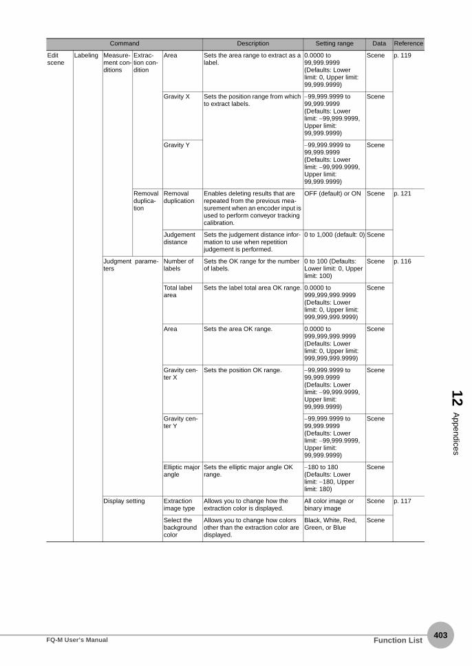
12 A
ppendices
Edit scene
Labeling Measure-ment con-ditions
Extrac-tion con-dition
Area Sets the area range to extract as a label.
0.0000 to 99,999.9999 (Defaults: Lower limit: 0, Upper limit: 99,999.9999)
Scene p. 119
Gravity X Sets the position range from which to extract labels.
−99,999.9999 to 99,999.9999 (Defaults: Lower limit: −99,999.9999, Upper limit: 99,999.9999)
Scene
Gravity Y −99,999.9999 to 99,999.9999 (Defaults: Lower limit: −99,999.9999, Upper limit: 99,999.9999)
Scene
Removal duplica-tion
Removal duplication
Enables deleting results that are repeated from the previous mea-surement when an encoder input is used to perform conveyor tracking calibration.
OFF (default) or ON Scene p. 121
Judgement distance
Sets the judgement distance infor-mation to use when repetition judgement is performed.
0 to 1,000 (default: 0) Scene
Judgment parame-ters
Number of labels
Sets the OK range for the number of labels.
0 to 100 (Defaults: Lower limit: 0, Upper limit: 100)
Scene p. 116
Total label area
Sets the label total area OK range. 0.0000 to 999,999,999.9999 (Defaults: Lower limit: 0, Upper limit: 999,999,999.9999)
Scene
Area Sets the area OK range. 0.0000 to 999,999,999.9999 (Defaults: Lower limit: 0, Upper limit: 999,999,999.9999)
Scene
Gravity cen-ter X
Sets the position OK range. −99,999.9999 to 99,999.9999 (Defaults: Lower limit: −99,999.9999, Upper limit: 99,999.9999)
Scene
Gravity cen-ter Y
−99,999.9999 to 99,999.9999 (Defaults: Lower limit: −99,999.9999, Upper limit: 99,999.9999)
Scene
Elliptic major angle
Sets the elliptic major angle OK range.
−180 to 180 (Defaults: Lower limit: −180, Upper limit: 180)
Scene
Display setting Extraction image type
Allows you to change how the extraction color is displayed.
All color image or binary image
Scene p. 117
Select the background color
Allows you to change how colors other than the extraction color are displayed.
Black, White, Red, Green, or Blue
Scene
Command Description Setting range Data Reference
Function ListFQ-M User’s Manual403

404
Edit scene
Calcula-tion
Calculations 0 to 31 Name Sets the name of the expression. 15 characters max. Scene p. 140
Expression Used to set the expression.Expression symbols: ( ) / * − , + TJGFunctions: SIN, COS, ATAN, AND, OR, NOT, ABS, MAX, MIN, MOD, SQRT, ANGL, DIST, and ECNT
--- Scene
Judgment parameters
Sets the judgement conditions for calculation results.
−999,999,999.9999 to 999,999,999.9999 (Defaults: Lower limit: −999,999,999.9999, Upper limit: 999,999,999.999)
Scene p. 145
Output No-protocol data output
Data type Sets the data format to ASCII or binary.
ASCII (default) or Binary
Scene p. 303
Output format for ASCII
Digits of inte-ger
Sets the number of digits in the integer part of the number, includ-ing the sign. For integers, the plus sign is not output.Example: When four digits is set, “−5963” is output as “−999”.
1 to 10 (default: 6) Scene
Digits of dec-imal
Sets the number of digits to output after the decimal. If the number of digits is set to 0, the decimal part is rounded off before the value is out-put.
0 to 4 (default: 4) Scene
Negative Sets what to output for the sign when a number is negative.
− (default) or 8 Scene
0Suppressed
Sets how to format numbers in the output data when the left digits are blank.Yes: Inserts zeros for any blank digits.No: Inserts spaces for any blank digits.Example:Digits of integer setting: 5 digitsDigits of decimal setting: 3 digitsIf the data is 100.000:ON: 00100.000OFF: __100.000 (“_” represents a space.)
ON or OFF (default) Scene p. 303
Field separa-tor
Sets the delimiter between individ-ual output data.
OFF (default), comma, tab, space, CR, LF, CR+LF, or Semicolon
Scene
Record sepa-rator
Sets the delimiter between sets of output data.
OFF (default), comma, tab, space, CR, LF, CR+LF, Semicolon
Scene
Output format for binary
Output for-mat
Sets the decimal output form when the output format is set to binary. For fixed point data, the data is output as its original value multi-plied by 1,000.
Floating point or Fixed point (default)
Scene
Command Description Setting range Data Reference
Function List FQ-M User’s Manual

12 A
ppendices
Edit scene
Output No-proto-col data output
Outputs 0 to 31
Name Sets the name of the output data. 15 characters max. Scene p. 302
Expression Used to set the output data.You can output multiple pieces of data as a group with the LPR and LPC functions.Example:The following example outputs the measurement results as two groups of data:Correlation of Item 0: I0.CR[0], I0.CR[1]Position X of Item 0: I0.X[0], I0.X[1]Position Y of Item 0: I0.Y[0], I0.Y[1]The data is output as follows for LPR(0, 3, I0.CR, I0.X, I0.Y):IO.CR[0], IO.X[0], IO.Y[0], IO.CR[1], IO.X[1], IO.Y[1]The data is output as follows for LPC(0, 3, I0.CR, I0.X, I0.Y):IO.CR[0], IO.CR[1], IO.X[0], IO.X[1], IO.Y[0], IO.Y[1]
--- Scene
Program-mable no-protocol data out-put
Output format
Field separa-tor
Sets the delimiter between individ-ual output data.
None (default), comma, tab, space, CR, LF, CR+LF, or Semicolon
Scene p. 333
Record sepa-rator
Sets the delimiter between sets of output data.
None (default), comma, tab, space, CR, LF, CR+LF, or Semicolon
Scene
Outputs 0 to 31
Name Sets the name of the output data. 15 characters max. Scene p. 333
Expression Used to set the output data.You can use F, D, and C tags to flexibly output results, including text.
--- Scene
Ether-CAT/PLC link data output
Output format
Output for-mat
Sets the decimal output form. For fixed point data, the data is output as its original value multiplied by 1,000.
Floating point or Fixed point (default)
Scene p. 276
Outputs 0 to 31
Name Sets the name of the output data. 15 characters max. Scene p. 276
Expression Used to set the output data.In the same way as for outputting no-protocol data, you can output multiple pieces of data as a group with the LPR and LPC functions.
--- Scene
Edit scene
Logging Logging item
Search Logging Sets whether to log the Search inspection item.
OFF or ON (default) Scene p. 201
Judgement Sets whether to log parameters. OFF or ON (default) Scene
Count OFF or ON (default) Scene
Correlation OFF or ON (default) Scene
Position X OFF or ON (default) Scene
Position Y OFF or ON (default) Scene
Angle OFF or ON (default) Scene
Upper limit of logging count
OFF or ON (default) Scene
Command Description Setting range Data Reference
Function ListFQ-M User’s Manual405

406
Edit scene
Logging Logging item
Labeling Logging Sets whether to the Labeling inspection item.
OFF or ON (default) Scene p. 201
Judgement Sets whether to log parameters. OFF or ON (default) Scene
Number of labels
OFF or ON (default) Scene
Total label area
OFF or ON (default) Scene
Area OFF or ON (default) Scene
Gravity cen-ter X
OFF or ON (default) Scene
Gravity cen-ter Y
OFF or ON (default) Scene
Elliptic major angle
OFF or ON (default) Scene
Upper limit of logging count
OFF or ON (default) Scene
Shape Search
Logging Sets whether to log the Shape Search inspection item.
OFF or ON (default) Scene
Judgement Sets whether to log parameters. OFF or ON (default) Scene p. 201
Count OFF or ON (default) Scene
Correlation OFF or ON (default) Scene
Position X OFF or ON (default) Scene
Position Y OFF or ON (default) Scene
Angle OFF or ON (default) Scene
Upper limit of logging count
OFF or ON (default) Scene
Edge position
Logging Sets whether to log the Edge Posi-tion inspection item.
OFF or ON (default) Scene
Judgment Sets whether to log parameters. OFF or ON (default) Scene
Position X OFF or ON (default) Scene
Position Y OFF or ON (default) Scene
Calcula-tion
Logging Sets whether to log calculations. OFF or ON (default) Scene
Log overall judgement
Sets whether to reflect the calcula-tion results in the overall judge-ment.
OFF or ON (default) Scene
Log judge-ment
Sets whether to log judgement results.
OFF or ON (default) Scene
Judgments 0 to 31
Sets whether to log individual judgement results 0 through 31.
OFF or ON (default) Scene
Log calcula-tion
Sets whether to log calculation results.
OFF or ON (default) Scene
Results 0 to 31
Sets whether to log individual cal-culation results 0 through 31.
OFF or ON (default) Scene
System Trigger settings
Select trigger Trigger type Sets the trigger type to use for measurements.
TRIG (default), EtherCat trigger, or Encoder trigger
System p. 79
Trigger delay time
Sets the trigger delay time. 0 to 163 ms (default: 0)
System p. 80
Command Description Setting range Data Reference
Function List FQ-M User’s Manual
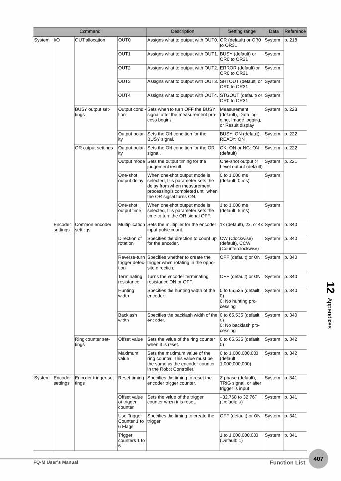
12 A
ppendices
System I/O OUT allocation OUT0 Assigns what to output with OUT0. OR (default) or OR0 to OR31
System p. 218
OUT1 Assigns what to output with OUT1. BUSY (default) or OR0 to OR31
System
OUT2 Assigns what to output with OUT2. ERROR (default) or OR0 to OR31
System
OUT3 Assigns what to output with OUT3. SHTOUT (default) or OR0 to OR31
System
OUT4 Assigns what to output with OUT4. STGOUT (default) or OR0 to OR31
System
BUSY output set-tings
Output condi-tion
Sets when to turn OFF the BUSY signal after the measurement pro-cess begins.
Measurement (default), Data log-ging, Image logging, or Result display
System p. 223
Output polar-ity
Sets the ON condition for the BUSY signal.
BUSY: ON (default), READY: ON
System p. 222
OR output settings Output polar-ity
Sets the ON condition for the OR signal.
OK: ON or NG: ON (default)
System p. 222
Output mode Sets the output timing for the judgement result.
One-shot output or Level output (default)
System p. 221
One-shot output delay
When one-shot output mode is selected, this parameter sets the delay from when measurement processing is completed until when the OR signal turns ON.
0 to 1,000 ms (default: 0 ms)
System
One-shot output time
When one-shot output mode is selected, this parameter sets the time to turn the OR signal OFF.
1 to 1,000 ms (default: 5 ms)
System
Encoder settings
Common encoder settings
Multiplication Sets the multiplier for the encoder input pulse count.
1x (default), 2x, or 4x System p. 340
Direction of rotation
Specifies the direction to count up for the encoder.
CW (Clockwise) (default), CCW (Counterclockwise)
System p. 340
Reverse-turn trigger detec-tion
Specifies whether to create the trigger when rotating in the oppo-site direction.
OFF (default) or ON System p. 340
Terminating resistance
Turns the encoder terminating resistance ON or OFF.
OFF (default) or ON System p. 340
Hunting width
Specifies the hunting width of the encoder.
0 to 65,535 (default: 0)0: No hunting pro-cessing
System p. 340
Backlash width
Specifies the backlash width of the encoder.
0 to 65,535 (default: 0)0: No backlash pro-cessing
System p. 340
Ring counter set-tings
Offset value Sets the value of the ring counter when it is reset.
0 to 65,535 (default: 0)
System p. 342
Maximum value
Sets the maximum value of the ring counter. This value must be the same as the encoder counter in the Robot Controller.
0 to 1,000,000,000 (default: 1,000,000,000)
System p. 342
System Encoder settings
Encoder trigger set-tings
Reset timing Specifies the timing to reset the encoder trigger counter.
Z phase (default), TRIG signal, or after trigger is input
System p. 341
Offset value of trigger counter
Sets the value of the trigger counter when it is reset.
−32,768 to 32,767 (Default: 0)
System p. 341
Use Trigger Counter 1 to 6 Flags
Specifies the timing to create the trigger.
OFF (default) or ON System p. 341
Trigger counters 1 to 6
1 to 1,000,000,000 (Default: 1)
System p. 341
Command Description Setting range Data Reference
Function ListFQ-M User’s Manual407

408
System Ethernet commu-nication settings
Ethernet settings Auto connec-tion
Sets whether an IP address is assigned to the Sensor automati-cally.
OFF (default) or ON System p. 297
IP address Enter the IP address of the Sensor.(This setting is enabled only when auto connection is set to OFF.)
a.b.c.da: 1 to 223b: 0 to 255c: 0 to 255d: 1 to 254(Default: 10.5.5.100)
System p. 297
Subnet mask Specifies the subnet mask address. (This setting is enabled only when auto connection is set to OFF.)
0.0.0.0 to 255.255.255.255 (Default: 255.255.255.0)
System p. 297
Default Gate-way
Specifies the default gateway address. (This setting is enabled only when auto connection is set to OFF.)
0.0.0.0 to 255.255.255.255 (Default: 0.0.0.0)
System p. 297
No-protocol data communication set-tings
Communica-tion type
Specifies the communications method to use to output no-proto-col data.
None (default), Nor-mal (TCP Server), or Normal (TCP Client)
System p. 298
IP Address Specifies the IP address to which to output no-protocol data. * Setting is not possible if the com-
munications method is set to “TCP server.”
a.b.c.da: 1 to 223b: 0 to 255c: 0 to 255d: 1 to 254(Default: 10.5.5.111)
System p. 298
Port No. Specifies the output port number.* Setting is not possible if the com-
munications method is set to “Normal (TCP server).”
0 to 65,535 (Default: 9,600)
System p. 298
PLC link communi-cation settings
Communica-tion type
Specifies the communications method to use for PLC Link out-puts. This can be selected only when the EtherCAT output is set to OFF.
None (default), PLC link (SYSMAC CS/CJ/CP/ONE), PLC link (MELSEC QnU/Q/QnAS)
System p. 271
Instruction area type
Specifies the area to write com-mand data to the Sensor. Control inputs, command codes, and com-mand parameters are written to this area.
PLC Link (SYSMAC CS/CJ/CP/One)
CIO Area (CIO) (default), Work Area (WR), Holding Bit Area (HR), Aux-iliary Bit Area (AR), DM Area (DM), or EM Area (EM0 to EMC)
PLC Link (MELSEC QnU/Q/QnAS)
Data registersFile registersLink registers
System p. 272
Instruction area address
Specifies the address of the first word in the command area.
0 to 99,999 (Default: 0)
System p. 272
Response area type
Specifies the area to write execu-tion results from the Sensor. (Con-trol outputs, command codes, response codes, and response data)
CIO Area (CIO) (default), Work Area (WR), Holding Bit Area (HR), Auxiliary Bit Area (AR), DM Area (DM), or EM Area (EM0 to EMC)
System p. 272
Response area address
Specifies the address of the first word in the response area.
0 to 99,999 (Default: 100)
System p. 272
Command Description Setting range Data Reference
Function List FQ-M User’s Manual

12 A
ppendices
System Ethernet commu-nication settings
PLC link communi-cation settings
Output area type
Specifies the area to write output data from measurements.Output data 0 to 255
CIO Area (CIO) (default)Work Area (WR)Holding Bit Area (HR)Auxiliary Bit Area (AR)DM Area (DM)EM Area (EM0)EM Area (EM1) :EM Area (EMC)
System p. 272
Output area address
Specifies the address of the first word in the output area.
0 to 99,999 (Default: 200)
System p. 272
Output con-trol
Sets whether to establish an inter-lock with the PLC when data is out-put. None: Data is output regardless of the signal status from the PLC.Handshake: Data is output only after confirming the DSA signal from the PLC.
None (default) or Handshake
System p. 272
Control time-out
Specifies the timeout time when handshaking is enabled.
100 to 120,000 ms (Default: 10,000 ms)
System p. 272
Upper limit of output data count
Specifies the maximum number of output data.
32 to 1,024 bytes (Default: 256)
System p. 272
Programmable no-protocol data com-munication settings
Communica-tion type
Specifies the communications method to use for programmable no-protocol I/O.
None (default), TCP client, or TCP server
System p. 327
Output setting (when the [commu-nication type] is set to “TCP cli-ent”)
Output set-tings
Specifies whether to output Output Setting.
OFF or ON (default) System p. 328
IP address Specifies the IP address of the out-put destination for Robot Controller data.
a.b.c.da: 1 to 223b: 0 to 255c: 0 to 255d: 1 to 254(Default: 10.5.5.111)
System p. 328
Port No. Specifies the output port number. 0 to 65,535 (Default: 9,600)
System p. 328
Port No. (when the [commu-nication type] is set to “TCP server”)
Port No. Used to specify the port number 0 to 65,536 (Default: 9,878)
System p. 328
EtherCAT communication set-tings
EtherCAT communica-tion
Sets whether to perform data out-put via EtherCAT. You can output EtherCAT data if outputting no-pro-tocol link data is disabled.
OFF (default) or ON System p. 234
Data output size
Specifies the size of the data out-put region. Allows you to change the size of data to output at one time. Set this value according to the size of the data output region of the EtherCAT master PDO.
259th PDO mapping (default)259th+260th PDO mapping259th+261th PDO mapping259th+262th PDO mapping
System p. 234
Output hand-shake
Sets whether to establish an inter-lock with the EtherCAT master when data is output.OFF: Data is output regardless of the signal status from the Ether-CAT master.ON: Data is output only after con-firming the DSA signal from the EtherCAT master.
OFF or Handshake (default)
System p. 234
Command Description Setting range Data Reference
Function ListFQ-M User’s Manual409

410
System EtherCAT communi-cation settings
For when the output control setting is set to “None.”
Output cycle Specifies the cycle to output Ether-CAT data when handshaking is disabled.
2 to 5,000 ms (Default: 10 ms)
System p. 234
Output time of GATE sig-nal
Specifies the output time of the GATE signal when handshaking is disabled.
1 to 1,000 ms (Default: 5 ms)
System p. 234
For when the output control setting is set to “Hand-shake.”
Control time-out time
Specifies the timeout time when handshaking is enabled.
100 to 120,000 ms (Default: 10,000 ms)
System p. 234
Log settings Statistical data
Sets whether to record the number of measurements and the number of NG overall judgements.
Do not show (default) or Show
System p. 199
Image data Sets the condition to log measure-ment image data.
Save all, Save only NG items, or None (default)
System p. 192
Measure-ment data
Resets the log data without turning OFF the power supply.
All, Only NG, or None (default)
System p. 192
Sensor settings
Startup mode Startup mode
Select whether the startup scene number is set manually. When startup scene control is set to OFF, the Sensor starts with the same scene number as when the data was saved.
OFF (default) or ON System p. 182
Startup scene
Sets the scene number to use at startup.
0 to 31 (Default: 0) System p. 182
Password settings Password settings
Specifies whether to enable (ON) or disable (OFF) the password.
OFF (default) or ON System p. 208
Password Sets the password. 15 characters max. System p. 208
Adjustment judge-ment
Adjustment judgement
Sets whether to adjust judgement parameters in Run Mode.
OFF (default) or ON System p. 176
Calibra-tion scene data
Wizard settings CT batch sampling
Performs conveyor tracking cali-bration with an encoder input. Spe-cial calibration marks are used to automatically detect target marks and calculate the calibration parameters.
--- --- p. 348
CT select point
Performs conveyor tracking cali-bration with an encoder input. The specified calibration marks are used and position information is entered directly to calculate the calibration parameters.
--- --- p. 353
General pur-pose batch sampling
Special calibration marks are used to automatically detect target marks and calculate the calibration parameters.
--- --- p. 357
General pur-pose sequential sampling
The specified calibration marks are registered as a model, and the result of the position detection per-formed on those marks is used to calculate the calibration parame-ters.
--- --- p. 363
Command Description Setting range Data Reference
Function List FQ-M User’s Manual

12 A
ppendices
Calibra-tion scene data
Wizard settings General pur-pose select point
The specified calibration marks are used and position information is entered directly to calculate the calibration parameters.
--- --- p. 360
Direct input The calibration parameters are cal-culated by specifying the standard position, magnification, rotation angle, and coordinates.
--- --- p. 368
Parameter settings Coefficient A Allows you to view and edit calibra-tion parameters.
−99,999,999.999999 to 99,999,999.999999 (Defaults: 1)
Calibra-tion
---
Coefficient B −99,999,999.999999 to 99,999,999.999999 (Defaults: 0)
Calibra-tion
---
Coefficient C −99,999,999.999999 to 99,999,999.999999 (Defaults: 0)
Calibra-tion
---
Coefficient D −99,999,999.999999 to 99,999,999.999999 (Defaults: 0)
Calibra-tion
---
Coefficient E −99,999,999.999999 to 99,999,999.999999 (Defaults: 1)
Calibra-tion
---
Coefficient F −99,999,999.999999 to 99,999,999.999999 (Defaults: 0)
Calibra-tion
---
X Distance per encoder pulse
Allows you to view and edit the dis-tance moved per encoder input pulse.
−99,999.9999 to 99,999.9999
Calibra-tion
p. 351, p. 355
Y Distance per encoder pulse
−99,999.9999 to 99,999.9999
Calibra-tion
Command Description Setting range Data Reference
Function ListFQ-M User’s Manual411
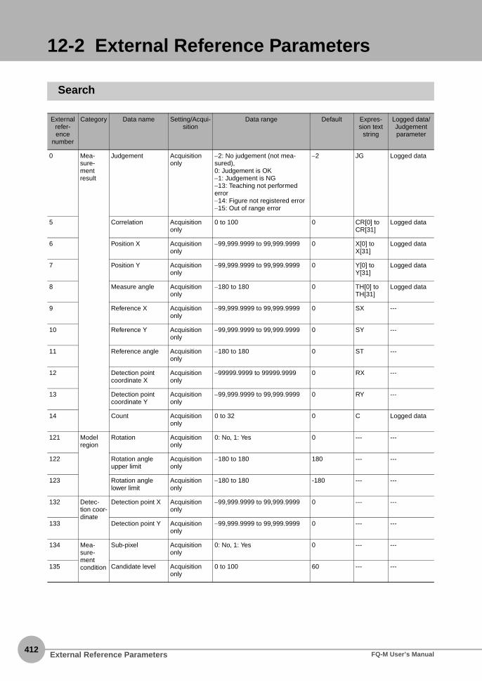
412
12-2 External Reference Parameters
Search
External refer-ence
number
Category Data name Setting/Acqui-sition
Data range Default Expres-sion text
string
Logged data/ Judgement parameter
0 Mea-sure-ment result
Judgement Acquisition only
−2: No judgement (not mea-sured),0: Judgement is OK−1: Judgement is NG−13: Teaching not performed error−14: Figure not registered error−15: Out of range error
−2 JG Logged data
5 Correlation Acquisition only
0 to 100 0 CR[0] to CR[31]
Logged data
6 Position X Acquisition only
−99,999.9999 to 99,999.9999 0 X[0] to X[31]
Logged data
7 Position Y Acquisition only
−99,999.9999 to 99,999.9999 0 Y[0] to Y[31]
Logged data
8 Measure angle Acquisition only
−180 to 180 0 TH[0] to TH[31]
Logged data
9 Reference X Acquisition only
−99,999.9999 to 99,999.9999 0 SX ---
10 Reference Y Acquisition only
−99,999.9999 to 99,999.9999 0 SY ---
11 Reference angle Acquisition only
−180 to 180 0 ST ---
12 Detection point coordinate X
Acquisition only
−99999.9999 to 99999.9999 0 RX ---
13 Detection point coordinate Y
Acquisition only
−99,999.9999 to 99,999.9999 0 RY ---
14 Count Acquisition only
0 to 32 0 C Logged data
121 Model region
Rotation Acquisition only
0: No, 1: Yes 0 --- ---
122 Rotation angle upper limit
Acquisition only
−180 to 180 180 --- ---
123 Rotation angle lower limit
Acquisition only
−180 to 180 -180 --- ---
132 Detec-tion coor-dinate
Detection point X Acquisition only
−99,999.9999 to 99,999.9999 0 --- ---
133 Detection point Y Acquisition only
−99,999.9999 to 99,999.9999 0 --- ---
134 Mea-sure-ment condition
Sub-pixel Acquisition only
0: No, 1: Yes 0 --- ---
135 Candidate level Acquisition only
0 to 100 60 --- ---
External Reference Parameters FQ-M User’s Manual

12 A
ppendices
136 Judge-ment condi-tions
Judgement upper limit for search coordinate X
Setting/Acqui-sition
−99,999.9999 to 99,999.9999 99999.9999 --- Adjust judge-ment
137 Judgement lower limit for search coordinate X
Setting/Acqui-sition
−99,999.9999 to 99,999.9999 −99999.9999 --- Adjust judge-ment
138 Judgement upper limit for search coordinate Y
Setting/Acqui-sition
−99,999.9999 to 99,999.9999 99999.9999 --- Adjust judge-ment
139 Judgement lower limit for search coordinate Y
Setting/Acqui-sition
−99,999.9999 to 99,999.9999 −99999.9999 --- Adjust judge-ment
140 Judgement upper limit for search angle
Setting/Acqui-sition
−180 to 180 180 --- Adjust judge-ment
141 Judgement lower limit for search angle
Setting/Acqui-sition
−180 to 180 −180 --- Adjust judge-ment
142 Judgement upper limit for correlation
Setting/Acqui-sition
0 to 100 100 --- Adjust judge-ment
143 Judgement lower limit for correlation
Setting/Acqui-sition
0 to 100 0 --- Adjust judge-ment
146 Sort condition Setting/Acqui-sition
For Multiple Searches0: Ascending order of correla-tion value, 1: Descending order of correla-tion value, 2: Ascending order of position X, 3: Descending order of position X, 4: Ascending order of position Y, 5: Descending order of position Y
1 --- ---
148 Judgement upper limit for detection count
Setting/Acqui-sition
0 to 32 32 --- Adjust judge-ment
149 Judgement lower limit for detection count
Setting/Acqui-sition
0 to 32 0 --- Adjust judge-ment
150 Mea-sure-ment condition
Multiple output Setting/Acqui-sition
0: No, 1: Yes 0 --- ---
152 Extraction condi-tion, X upper limit
Setting/Acqui-sition
−99,999.9999 to 99,999.9999 99999.9999 --- ---
153 Extraction condi-tion, X lower limit
Setting/Acqui-sition
−99,999.9999 to 99,999.9999 −99999.9999 --- ---
154 Extraction condi-tion, Y upper limit
Setting/Acqui-sition
−99,999.9999 to 99,999.9999 99999.9999 --- ---
155 Extraction condi-tion, Y lower limit
Setting/Acqui-sition
−99,999.9999 to 99,999.9999 −99999.9999 --- ---
156 Extraction condi-tion, angle upper limit
Setting/Acqui-sition
−180 to 180 180 --- ---
157 Extraction condi-tion, angle lower limit
Setting/Acqui-sition
−180 to 180 −180 --- ---
158 Repetition removal Setting/Acqui-sition
0: Repetition removal OFF,1: Repetition removal ON
0 --- ---
External refer-ence
number
Category Data name Setting/Acqui-sition
Data range Default Expres-sion text
string
Logged data/ Judgement parameter
External Reference ParametersFQ-M User’s Manual413
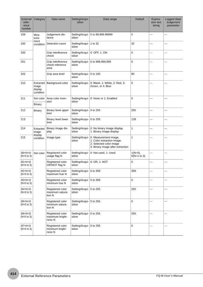
414
159 Mea-sure-ment condition
Judgement dis-tance
Setting/Acqui-sition
0 to 99,999.99999 0 --- ---
160 Detection count Setting/Acqui-sition
1 to 32 32 --- ---
200 Grip interference check
Setting/Acqui-sition
0: OFF, 1: ON 0 --- ---
201 Grip interference check reference area
Setting/Acqui-sition
0 to 999,999,999 0 --- ---
202 Grip area level Setting/Acqui-sition
0 to 100 80 --- ---
210 Extracted image display condition
Background color Setting/Acqui-sition
0: Black, 1: White, 2: Red, 3: Green, or 4: Blue
0 --- ---
211 Set color Area color inver-sion
Setting/Acqui-sition
0: None or 1: Enabled 0 --- ---
Binary
212 Binary Binary level upper limit
Setting/Acqui-sition
0 to 255 255 --- ---
213 Binary level lower limit
Setting/Acqui-sition
0 to 255 128 --- ---
214 Extracted image display condition
Binary image dis-play
Setting/Acqui-sition
0: No binary image display,1: Binary image display
1 --- ---
215 Image type Setting/Acqui-sition
0: Measurement image,1: Color extraction image,2: Selected color image3: Binary image after extraction
1 --- ---
260+N×10(N=0 to 3)
Set color Registered color usage flag N
Setting/Acqui-sition
0: Not used, 1: Used 1(N=0), 0(N=1 to 3)
--- ---
261+N×10(N=0 to 3)
Registered color OR/NOT flag N
Setting/Acqui-sition
0: OR, 1: NOT 0 --- ---
262+N×10(N=0 to 3)
Registered color maximum hue N
Setting/Acqui-sition
0 to 359 359 --- ---
263+N×10(N=0 to 3)
Registered color minimum hue N
Setting/Acqui-sition
0 to 359 0 --- ---
264+N×10(N=0 to 3)
Registered color maximum satura-tion N
Setting/Acqui-sition
0 to 255 255 --- ---
265+N×10(N=0 to 3)
Registered color minimum satura-tion N
Setting/Acqui-sition
0 to 255 0 --- ---
266+N×10(N=0 to 3)
Registered color maximum bright-ness N
Setting/Acqui-sition
0 to 255 255 --- ---
267+N×10(N=0 to 3)
Registered color minimum bright-ness N
Setting/Acqui-sition
0 to 255 0 --- ---
External refer-ence
number
Category Data name Setting/Acqui-sition
Data range Default Expres-sion text
string
Logged data/ Judgement parameter
External Reference Parameters FQ-M User’s Manual

12 A
ppendices
300 Logging condi-tions
Number of data log records
Setting/Acqui-sition
0 to 32 32 --- ---
310 Data logging switch for entire unit
Setting/Acqui-sition
0: Data logging OFF,1: Data logging ON
1 --- ---
311 Data logging switch for judge-ment
Setting/Acqui-sition
0: Data logging OFF,1: Data logging ON
1 --- ---
312 Data logging switch for correla-tion
Setting/Acqui-sition
0: Data logging OFF,1: Data logging ON
1 --- ---
313 Data logging switch for position X
Setting/Acqui-sition
0: Data logging OFF,1: Data logging ON
1 --- ---
314 Logging condi-tions
Data logging switch for position Y
Setting/Acqui-sition
0: Data logging OFF,1: Data logging ON
1 --- ---
315 Data logging switch for mea-surement angle
Setting/Acqui-sition
0: Data logging OFF,1: Data logging ON
1 --- ---
321 Data logging switch for detection count
Setting/Acqui-sition
0: Data logging OFF,1: Data logging ON
1 --- ---
External refer-ence
number
Category Data name Setting/Acqui-sition
Data range Default Expres-sion text
string
Logged data/ Judgement parameter
External Reference ParametersFQ-M User’s Manual415

416
Edge Position
External reference number
Category Data name Setting/Acquisition
Data range Default Expres-sion text
string
Logged data/Judgement parameter
0 Measure-ment result
Judgement Acquisition only
−2: No judgement (not mea-sured),0: Judgement is OK−1: Judgement is NG−13: Teaching not performed error−14: Figure not registered error−15: Out of range error
−2 JG Logged data
5 Edge position X Acquisition only
−99,999.9999 to 99,999.9999 0 X Logged data
6 Edge position Y Acquisition only
−99,999.9999 to 99,999.9999 0 Y Logged data
7 Standard position X
Acquisition only
−99,999.9999 to 99,999.9999 0 SX ---
8 Standard position Y
Acquisition only
−99,999.9999 to 99,999.9999 0 SY ---
120 Set color Set color Setting/Acquisition
0: No edge color specification,1: Edge color specification
0 --- ---
121 Edge color red Setting/Acquisition
0 to 255 255 --- ---
122 Edge color green Setting/Acquisition
0 to 255 255 --- ---
123 Edge color blue Setting/Acquisition
0 to 255 255 --- ---
127 Detection mode Setting/Acquisition
Edge Detection Mode Parame-ter0: Color IN, 1:Color OUT
0 --- ---
132 Measure-ment con-dition
Edge level Setting/Acquisition
0 to 100 50 --- ---
133 Noise level Setting/Acquisition
0 to 442 5 --- ---
136 Judge-ment con-ditions
Edge position X upper limit
Setting/Acquisition
−99,999.9999 to 99,999.9999 99999.9999 --- Adjust judge-ment
137 Edge position X lower limit
Setting/Acquisition
−99,999.9999 to 99,999.9999 −99999.9999 --- Adjust judge-ment
138 Edge position Y upper limit
Setting/Acquisition
−99,999.9999 to 99,999.9999 99999.9999 --- Adjust judge-ment
139 Edge position Y lower limit
Setting/Acquisition
−99,999.9999 to 99,999.9999 −99999.9999 --- Adjust judge-ment
140 Measure-ment con-dition
Detection mode for Monochrome Sensor
Setting/Acquisition
0: Light → Dark, 1: Dark → Light 0 --- ---
144 Measurement method for Mono-chrome Sensor
Setting/Acquisition
0: Projection method, 1: Differ-entiation method
0 --- ---
External Reference Parameters FQ-M User’s Manual

12 A
ppendices
310 Logging conditions
Data logging switch for entire unit
Setting/Acquisition
0: Data logging OFF,1: Data logging ON
1 --- ---
311 Data logging switch for judge-ment
Setting/Acquisition
0: Data logging OFF,1: Data logging ON
1 --- ---
312 Data logging switch for detected edge position X
Setting/Acquisition
0: Data logging OFF,1: Data logging ON
1 --- ---
313 Data logging switch for detected edge position Y
Setting/Acquisition
0: Data logging OFF,1: Data logging ON
1 --- ---
External reference number
Category Data name Setting/Acquisition
Data range Default Expres-sion text
string
Logged data/Judgement parameter
External Reference ParametersFQ-M User’s Manual417

418
Labeling
External reference number
Category Data name Setting/Acquisition
Data range Default Expres-sion text
string
Logged data/ Judgement parameters
0 Measure-ment result
Judgement Acquisition only
−2: No judgement (not mea-sured),0: Judgement is OK−1: Judgement is NG−13: Teaching not performed error−14: Figure not registered error−15: Out of range error
−2 JG Logged data
5 # of label Acquisition only
0 to 100 0 L Logged data
6 Area Acquisition only
0 to 999,999,999.9999 0 AR[0] to AR[99]
Logged data
7 Gravity coordinate X
Acquisition only
−99,999.9999 to 99,999.9999 0 X[0] to X[99]
Logged data
8 Gravity coordinate Y
Acquisition only
−99,999.9999 to 99,999.9999 0 Y[0] to Y[99]
Logged data
9 Reference area Acquisition only
0 to 999,999,999.9999 0 SA ---
10 Reference posi-tion X
Acquisition only
−99,999.9999 to 99,999.9999 0 SX ---
11 Reference posi-tion Y
Acquisition only
−99,999.9999 to 99,999.9999 0 SY ---
15 Total area Acquisition only
0 to 999,999,999.9999 0 TAR Logged data
55 Elliptic major angle Acquisition only
−180 to 180 0 ATH[0] to ATH[99]
Logged data
127 Extracted image dis-play con-dition
Background color Setting/Acquisition
0: Black, 1: White, 2: Red, 3: Green, or 4: Blue
0 --- ---
131 Set color Inversion Flag Setting/Acquisition
0: Do not invert, 1: Invert 0 --- ---
Binary --- ---
132 Measure-ment con-ditions
Filling up holes Setting/Acquisition
0: No, 1: Yes 0 --- ---
133 Outside trimming Setting/Acquisition
0: No, 1: Yes 0 --- ---
136 Sort condition Setting/Acquisition
0: Ascending order of area, 1: Descending order of area,2: Ascending order of gravity X,3: Descending order of gravity X,4: Ascending order of gravity Y,5: Descending order of gravity Y
1 --- ---
146 Binary level
Binary level upper limit
Setting/Acquisition
0 to 255 255 --- ---
147 Binary level lower limit
Setting/Acquisition
0 to 255 128 --- ---
148 Extracted image dis-play con-dition
Binary image dis-play
Setting/Acquisition
0: No binary image display,1: Binary image display
1 --- ---
149 Image type Setting/Acquisition
0: Measurement image,1: Color extraction image,2: Selected color image3: Binary image after extraction
1 --- ---
External Reference Parameters FQ-M User’s Manual

12 A
ppendices
154 Measure-ment con-ditions
Repetition removal Setting/Acquisition
0: Repetition removal OFF,1: Repetition removal ON
0 --- ---
155 Judgement dis-tance
Setting/Acquisition
0 to 99,999.9999 0 --- ---
156 Extraction condi-tion, detection count
Setting/Acquisition
0 to 100 100 --- ---
160 Set color Registered color usage flag 0
Setting/Acquisition
0: Not used, 1: Used 1 --- ---
161 Registered color exclusion flag 0
Setting/Acquisition
0: OR, 1: NOT 0 --- ---
162 Registered color maximum hue 0
Setting/Acquisition
0 to 359 359 --- ---
163 Registered color minimum hue 0
Setting/Acquisition
0 to 359 0 --- ---
164 Registered color maximum satura-tion 0
Setting/Acquisition
0 to 255 255 --- ---
165 Registered color minimum satura-tion 0
Setting/Acquisition
0 to 255 0 --- ---
166 Registered color maximum bright-ness 0
Setting/Acquisition
0 to 255 255 --- ---
167 Registered color minimum bright-ness 0
Setting/Acquisition
0 to 255 0 --- ---
170 Registered color usage flag 1
Setting/Acquisition
0: Not used, 1: Used 0 --- ---
171 Registered color exclusion flag 1
Setting/Acquisition
0: OR, 1: NOT 0 --- ---
172 Registered color maximum hue 1
Setting/Acquisition
0 to 359 359 --- ---
173 Registered color minimum hue 1
Setting/Acquisition
0 to 359 0 --- ---
174 Registered color maximum satura-tion 1
Setting/Acquisition
0 to 255 255 --- ---
175 Registered color minimum satura-tion 1
Setting/Acquisition
0 to 255 0 --- ---
176 Registered color maximum bright-ness 1
Setting/Acquisition
0 to 255 255 --- ---
177 Registered color minimum bright-ness 1
Setting/Acquisition
0 to 255 0 --- ---
180 Registered color usage flag 2
Setting/Acquisition
0: Not used, 1: Used 0 --- ---
181 Registered color exclusion flag 2
Setting/Acquisition
0: OR, 1: NOT 0 --- ---
182 Registered color maximum hue 2
Setting/Acquisition
0 to 359 359 --- ---
183 Registered color minimum hue 2
Setting/Acquisition
0 to 359 0 --- ---
External reference number
Category Data name Setting/Acquisition
Data range Default Expres-sion text
string
Logged data/ Judgement parameters
External Reference ParametersFQ-M User’s Manual419

420
184 Set color Registered color maximum satura-tion 2
Setting/Acquisition
0 to 255 255 --- ---
185 Registered color minimum satura-tion 2
Setting/Acquisition
0 to 255 0 --- ---
186 Registered color maximum bright-ness 2
Setting/Acquisition
0 to 255 255 --- ---
187 Registered color minimum bright-ness 2
Setting/Acquisition
0 to 255 0 --- ---
190 Registered color usage flag 3
Setting/Acquisition
0: Not used, 1: Used 0 --- ---
191 Registered color exclusion flag 3
Setting/Acquisition
0: OR, 1: NOT 0 --- ---
192 Registered color maximum hue 3
Setting/Acquisition
0 to 359 359 --- ---
193 Registered color minimum hue 3
Setting/Acquisition
0 to 359 0 --- ---
194 Registered color maximum satura-tion 3
Setting/Acquisition
0 to 255 255 --- ---
195 Registered color minimum satura-tion 3
Setting/Acquisition
0 to 255 0 --- ---
196 Registered color maximum bright-ness 3
Setting/Acquisition
0 to 255 255 --- ---
300 Logging conditions
Number of data log records
Setting/Acquisition
1 to 100 100 --- ---
310 Data logging switch for entire unit
Setting/Acquisition
0: Data logging OFF,1: Data logging ON
1 --- ---
311 Data logging switch for judge-ment
Setting/Acquisition
0: Data logging OFF,1: Data logging ON
1 --- ---
312 Data logging switch for number of labels
Setting/Acquisition
0: Data logging OFF,1: Data logging ON
1 --- ---
313 Data logging switch for area
Setting/Acquisition
0: Data logging OFF,1: Data logging ON
1 --- ---
314 Data logging switch for gravity X
Setting/Acquisition
0: Data logging OFF,1: Data logging ON
1 --- ---
315 Data logging switch for gravity Y
Setting/Acquisition
0: Data logging OFF,1: Data logging ON
1 --- ---
319 Data logging switch for total label area
Setting/Acquisition
0: Data logging OFF,1: Data logging ON
1 --- ---
326 Data logging switch for elliptic major angle
Setting/Acquisition
0: Data logging OFF,1: Data logging ON
1 --- ---
External reference number
Category Data name Setting/Acquisition
Data range Default Expres-sion text
string
Logged data/ Judgement parameters
External Reference Parameters FQ-M User’s Manual

12 A
ppendices
503 Measure-ment con-ditions
Extraction condi-tion, area upper limit
Setting/Acquisition
0 to 999,999,999.9999 999999999.9999
--- ---
504 Extraction condi-tion, area lower limit
Setting/Acquisition
0 to 999,999,999.9999 0 --- ---
513 Extraction condi-tion, gravity X upper limit
Setting/Acquisition
−99,999.9999 to 99,999.9999 99999.9999 --- ---
514 Extraction condi-tion, gravity X lower limit
Setting/Acquisition
−99,999.9999 to 99,999.9999 −99999.9999 --- ---
523 Extraction condi-tion, gravity Y upper limit
Setting/Acquisition
−99,999.9999 to 99,999.9999 99999.9999 --- ---
524 Extraction condi-tion, gravity Y lower limit
Setting/Acquisition
−99,999.9999 to 99,999.9999 −99999.9999 --- ---
602 Judge-ment parame-ters
Judgement condi-tion, number of labels upper limit
Setting/Acquisition
0 to 100 100 --- Adjust judge-ment
603 Judgement condi-tion, number of labels lower limit
Setting/Acquisition
0 to 100 0 --- Adjust judge-ment
612 Judgement condi-tion, total label area upper limit
Setting/Acquisition
0 to 999,999,999.9999 999999999.9999
--- Adjust judge-ment
613 Judgement condi-tion, total label area lower limit
Setting/Acquisition
0 to 999,999,999.9999 0 --- Adjust judge-ment
622 Judgement condi-tion, area upper limit
Setting/Acquisition
0 to 999,999,999.9999 999999999.9999
--- Adjust judge-ment
623 Judgement condi-tion, area lower limit
Setting/Acquisition
0 to 999,999,999.9999 0 --- Adjust judge-ment
632 Judgement condi-tion, gravity X upper limit
Setting/Acquisition
−99,999.9999 to 99,999.9999 99999.9999 --- Adjust judge-ment
633 Judgement condi-tion, gravity X lower limit
Setting/Acquisition
−99,999.9999 to 99,999.9999 −99999.9999 --- Adjust judge-ment
642 Judgement condi-tion, gravity Y upper limit
Setting/Acquisition
−99,999.9999 to 99,999.9999 99999.9999 --- Adjust judge-ment
643 Judgement condi-tion, gravity Y lower limit
Setting/Acquisition
−99,999.9999 to 99,999.9999 −99999.9999 --- Adjust judge-ment
652 Judgement condi-tion, elliptic major angle upper limit
Setting/Acquisition
−180 to 180 180 --- Adjust judge-ment
653 Judgement condi-tion, elliptic major angle lower limit
Setting/Acquisition
−180 to 180 −180 --- Adjust judge-ment
External reference number
Category Data name Setting/Acquisition
Data range Default Expres-sion text
string
Logged data/ Judgement parameters
External Reference ParametersFQ-M User’s Manual421

422
Shape Search
External reference number
Category Data name Setting/Acquisition
Data range Default Expres-sion text
string
Logged data/ Judgement parameter
0 Measure-ment result
Judgement Acquisition only
−2: No judgement (not mea-sured),0: Judgement is OK−1: Judgement is NG−13: Teaching not performed error−14: Figure not registered error−15: Out of range error
−2 JG Logged data
5 Correlation Acquisition only
0 to 100 0 CR[0] to CR[31]
Logged data
6 Position X Acquisition only
−99,999.9999 to 99,999.9999 0 X[0] to X[31]
Logged data
7 Position Y Acquisition only
−99,999.9999 to 99,999.9999 0 Y[0] to Y[31]
Logged data
8 Measurement angle TH
Acquisition only
−180 to 180 0 TH[0] to TH[31]
Logged data
9 Reference posi-tion X
Acquisition only
−99,999.9999 to 99,999.9999 0 SX ---
10 Reference posi-tion Y
Acquisition only
−99,999.9999 to 99,999.9999 0 SY ---
11 Reference angle Acquisition only
−180 to 180 0 ST ---
12 Detection point coordinate X
Acquisition only
−99,999.9999 to 99,999.9999 0 RX ---
13 Detection point coordinate Y
Acquisition only
−99,999.9999 to 99,999.9999 0 RY ---
14 Count Acquisition only
0 to 32 0 C Logged data
120 Model region
Rotation Setting/Acquisition
0: No, 1: Yes 0 --- ---
121 Rotation angle upper limit
Setting/Acquisition
−180 to 180 180 --- ---
122 Rotation angle lower limit
Setting/Acquisition
−180 to 180 −180 --- ---
133 Measure-ment con-dition
Candidate level Setting/Acquisition
0 to 100 60 --- ---
134 Detection point coor-dinate
Detection point X Setting/Acquisition
−99,999.9999 to 99,999.9999 0 --- ---
135 Detection point Y Setting/Acquisition
−999,99.9999 to 99,999.9999 0 --- ---
136 Measure-ment con-dition
Sort condition Setting/Acquisition
0: Ascending order of correla-tion value, 1: Descending order of correla-tion value, 2: Ascending order of position X, 3: Descending order of position X, 4: Ascending order of position Y, 5: Descending order of position Y
1 --- ---
External Reference Parameters FQ-M User’s Manual

12 A
ppendices
138 Judge-ment parame-ters
Judgement upper limit for correlation
Setting/Acquisition
0 to 100 100 --- Judgement parameter
139 Judgement lower limit for correlation
Setting/Acquisition
0 to 100 60 --- Judgement parameter
140 Judgement upper limit for detection count
Setting/Acquisition
0 to 32 32 --- Judgement parameter
141 Judgement lower limit for detection count
Setting/Acquisition
0 to 32 0 --- Judgement parameter
142 Judgement upper limit for search coordinate X
Setting/Acquisition
−99,999.9999 to 99,999.9999 99999.9999 --- Judgement parameter
143 Judgement lower limit for search coordinate X
Setting/Acquisition
−99,999.9999 to 99,999.9999 −99999.9999 --- Judgement parameter
144 Judgement upper limit for search coordinate Y
Setting/Acquisition
−99,999.9999 to 99,999.9999 99999.9999 --- Judgement parameter
145 Judgement lower limit for search coordinate Y
Setting/Acquisition
−99,999.9999 to 99,999.9999 −99999.9999 --- Judgement parameter
146 Judgement upper limit for search angle
Setting/Acquisition
−180 to 180 180 --- Judgement parameter
147 Judgement lower limit for search angle
Setting/Acquisition
−180 to 180 −180 --- Judgement parameter
152 Measure-ment con-ditions
Extraction condi-tion, X upper limit
Setting/Acquisition
−99,999.9999 to 99,999.9999 99999.9999 --- Judgement parameter
153 Extraction condi-tion, X lower limit
Setting/Acquisition
−99,999.9999 to 99,999.9999 −99999.9999 --- Judgement parameter
154 Extraction condi-tion, Y upper limit
Setting/Acquisition
−99,999.9999 to 99,999.9999 99999.9999 --- Judgement parameter
155 Extraction condi-tion, Y lower limit
Setting/Acquisition
−99,999.9999 to 99,999.9999 −99999.9999 --- Judgement parameter
156 Extraction condi-tion, angle upper limit
Setting/Acquisition
−180 to 180 180 --- Judgement parameter
157 Extraction condi-tion, angle lower limit
Setting/Acquisition
−180 to 180 −180 --- Judgement parameter
158 Repetition removal Setting/Acquisition
0: Repetition removal OFF,1: Repetition removal ON
0 --- ---
159 Repetition judge-ment distance
Setting/Acquisition
0 to 99,999.9999 0 --- ---
160 Image type Setting/Acquisition
0: Measurement image,1: Color extraction image,2: Selected color image,3: Binary image after extraction
0 --- ---
161 Extraction condi-tion, detection count
Setting/Acquisition
1 to 32 32 --- ---
200 Grip interference check
Setting/Acquisition
0: OFF, 1: ON 0 --- ---
External reference number
Category Data name Setting/Acquisition
Data range Default Expres-sion text
string
Logged data/ Judgement parameter
External Reference ParametersFQ-M User’s Manual423

424
201 Measure-ment con-ditions
Grip interference check reference area
Setting/Acquisition
0 to 999,999,999 0 --- ---
202 Grip area level Setting/Acquisition
0 to 100 80 --- ---
210 Extracted image dis-play condi-tion
Background color Setting/Acquisition
0: Black, 1: White, 2: Red, 3: Green, or 4: Blue
0 --- ---
211 Set color Area color inver-sion
Setting/Acquisition
0: None or 1: Enabled 0 --- ---
Binary
212 Binary Binary level upper limit
Setting/Acquisition
0 to 255 255 --- ---
213 Binary level lower limit
Setting/Acquisition
0 to 255 128 --- ---
214 Extracted image dis-play condi-tion
Binary image dis-play
Setting/Acquisition
0: No binary image display,1: Binary image display
1 --- ---
260+N×10(N=0 to 3)
Set color Registered color usage flag N
Setting/Acquisition
0: Not used, 1: Used 1(N=0), 0(N=1 to 3)
--- ---
261+N×10(N=0 to 3)
Registered color OR/NOT flag N
Setting/Acquisition
0: OR, 1: NOT 0 --- ---
262+N×10(N=0 to 3)
Registered color maximum hue N
Setting/Acquisition
0 to 359 359 --- ---
263+N×10(N=0 to 3)
Registered color minimum hue N
Setting/Acquisition
0 to 359 0 --- ---
264+N×10(N=0 to 3)
Registered color maximum satura-tion N
Setting/Acquisition
0 to 255 255 --- ---
265+N×10(N=0 to 3)
Registered color minimum satura-tion N
Setting/Acquisition
0 to 255 0 --- ---
266+N×10(N=0 to 3)
Registered color maximum bright-ness N
Setting/Acquisition
0 to 255 255 --- ---
267+N×10(N=0 to 3)
Registered color minimum bright-ness N
Setting/Acquisition
0 to 255 0 --- ---
External reference number
Category Data name Setting/Acquisition
Data range Default Expres-sion text
string
Logged data/ Judgement parameter
External Reference Parameters FQ-M User’s Manual

12 A
ppendices
300 Logging conditions
Number of data log records upper limit
Setting/Acquisition
1 to 32 32 --- ---
310 Data logging switch for entire unit
Setting/Acquisition
0: Data logging OFF,1: Data logging ON
1 --- ---
311 Data logging switch for judge-ment
Setting/Acquisition
0: Data logging OFF,1: Data logging ON
1 --- ---
312 Data logging switch for correla-tion
Setting/Acquisition
0: Data logging OFF,1: Data logging ON
1 --- ---
313 Data logging switch for position X
Setting/Acquisition
0: Data logging OFF,1: Data logging ON
1 --- ---
314 Data logging switch for position Y
Setting/Acquisition
0: Data logging OFF,1: Data logging ON
1 --- ---
315 Data logging switch for mea-surement angle
Setting/Acquisition
0: Data logging OFF,1: Data logging ON
1 --- ---
321 Data logging switch for detection count
Setting/Acquisition
0: Data logging OFF,1: Data logging ON
1 --- ---
External reference number
Category Data name Setting/Acquisition
Data range Default Expres-sion text
string
Logged data/ Judgement parameter
External Reference ParametersFQ-M User’s Manual425

426
Calculations
External refer-ence
number
Category Data name Setting/Acquisition
Data range Default Expres-sion text
string
Logged data/Judgement parameter
0 Mea-sure-mentresult
Judgement result Acquisition only
−2: No judgement (not measured), 0: Judgement is OK, −1: Judgement is NG
−2 JG Logged data
5 Calculation result 0 Acquisition only
−999,999,999.9999 to 999,999,999.9999
0 D[0] Logged data
6 Calculation result 1 Acquisition only
−999,999,999.9999 to 999,999,999.9999
0 D[1] Logged data
7 Calculation result 2 Acquisition only
−999,999,999.9999 to 999,999,999.9999
0 D[2] Logged data
··· ··· ··· ··· ··· ··· ···
36 Calculation result 31 Acquisition only
-999,999,999.9999 to 999,999,999.9999
0 D[31] Logged data
55 Individual judge-ment result 0
Acquisition only
−2: No judgement (not measured), 0: Judgement is OK, −1: Judgement is NG
−2 JG[0] Logged data
56 Individual judge-ment result 1
Acquisition only
−2: No judgement (not measured), 0: Judgement is OK, −1: Judgement is NG
−2 JG[1] Logged data
57 Individual judge-ment result 2
Acquisition only
−2: No judgement (not measured), 0: Judgement is OK, −1: Judgement is NG
−2 JG[2] Logged data
··· ··· ··· ··· ··· ··· ···
86 Individual judge-ment result 31
Acquisition only
−2: No judgement (not measured), 0: Judgement is OK, −1: Judgement is NG
−2 JG[31] Logged data
103 Set con-ditions
Reflect to total judgement
Setting/Acquisition
0: Yes, 1: No 0 --- ---
150 Expression 0 Setting/Acquisition
--- --- --- ---
151 Expression 1 Setting/Acquisition
--- --- --- ---
152 Expression 2 Setting/Acquisition
--- --- --- ---
··· ··· ··· ··· ··· ··· ···
181 Expression 31 Setting/Acquisition
--- --- --- ---
250 Comment 0 Setting/Acquisition
--- --- --- ---
251 Comment 1 Setting/Acquisition
--- --- --- ---
252 Comment 2 Setting/Acquisition
--- --- --- ---
··· ··· ··· ··· ··· ··· ···
281 Comment 31 Setting/Acquisition
--- --- --- ---
External Reference Parameters FQ-M User’s Manual

12 A
ppendices
300 Judge-ment parame-ters
Judgement condi-tion 0 upper limit
Setting/Acquisition
−999,999,999.9999 to 999,999,999.9999
999,999,999.9999 --- Adjust judge-ment
301 Judgement condi-tion 1 upper limit
Setting/Acquisition
−999,999,999.9999 to 999,999,999.9999
999,999,999.9999 --- Adjust judge-ment
302 Judgement condi-tion 2 upper limit
Setting/Acquisition
−999999999.9999 to 999999999.9999
999,999,999.9999 --- Adjust judge-ment
··· ··· ··· ··· ··· ··· ···
331 Judgement condi-tion 31 upper limit
Setting/Acquisition
−999,999,999.9999 to 999,999,999.9999
999,999,999.9999 --- Adjust judge-ment
350 Judgement condi-tion 0 lower limit
Setting/Acquisition
−999,999,999.9999 to 999,999,999.9999
−999,999,999.9999 --- Adjust judge-ment
351 Judgement condi-tion 1 lower limit
Setting/Acquisition
−999,999,999.9999 to 999,999,999.9999
−999,999,999.9999 --- Adjust judge-ment
352 Judgement condi-tion 2 lower limit
Setting/Acquisition
−999,999,999.9999 to 999,999,999.9999
−999,999,999.9999 --- Adjust judge-ment
··· ··· ··· ··· ··· ··· ···
381 Judgement condi-tion 31 lower limit
Setting/Acquisition
-999,999,999.9999 to 999,999,999.9999
−999,999,999.9999 --- Adjust judge-ment
410 Logging condi-tions
Data logging switch for all calculations
Setting/Acquisition
0: Log,1: Do not log
1 --- ---
411 Data logging switch for overall judge-ment results
Setting/Acquisition
0: Log,1: Do not log
1 --- ---
412 Data logging switch for all calculation results
Setting/Acquisition
0: Log,1: Do not log
1 --- ---
500 Data logging switch for individual judge-ment 0
Setting/Acquisition
0: Log,1: Do not log
1 --- ---
501 Data logging switch for individual judge-ment 1
Setting/Acquisition
0: Log,1: Do not log
1 --- ---
502 Data logging switch for individual judge-ment 2
Setting/Acquisition
0: Log,1: Do not log
1 --- ---
··· ··· ··· ··· ··· ··· ···
531 Data logging switch for individual judge-ment 31
Setting/Acquisition
0: Log,1: Do not log
1 --- ---
550 Data logging switch for calculation result 0
Setting/Acquisition
0: Log,1: Do not log
--- --- ---
551 Data logging switch for calculation result 1
Setting/Acquisition
0: Log,1: Do not log
--- --- ---
552 Data logging switch for calculation result 2
Setting/Acquisition
0: Log,1: Do not log
--- --- ---
··· ··· ··· ··· ··· ··· ···
581 Data logging switch for calculation result 31
Setting/Acquisition
0: Log,1: Do not log
--- --- ---
External refer-ence
number
Category Data name Setting/Acquisition
Data range Default Expres-sion text
string
Logged data/Judgement parameter
External Reference ParametersFQ-M User’s Manual427
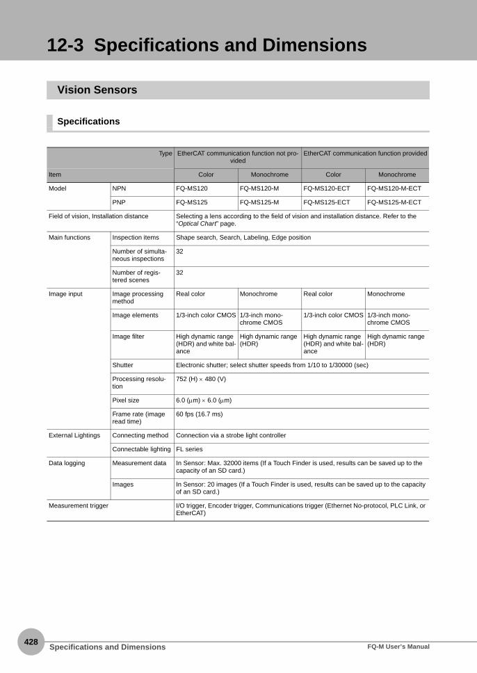
428
12-3 Specifications and Dimensions
Vision Sensors
Specifications
Type EtherCAT communication function not pro-vided
EtherCAT communication function provided
Item Color Monochrome Color Monochrome
Model NPN FQ-MS120 FQ-MS120-M FQ-MS120-ECT FQ-MS120-M-ECT
PNP FQ-MS125 FQ-MS125-M FQ-MS125-ECT FQ-MS125-M-ECT
Field of vision, Installation distance Selecting a lens according to the field of vision and installation distance. Refer to the “Optical Chart” page.
Main functions Inspection items Shape search, Search, Labeling, Edge position
Number of simulta-neous inspections
32
Number of regis-tered scenes
32
Image input Image processingmethod
Real color Monochrome Real color Monochrome
Image elements 1/3-inch color CMOS 1/3-inch mono-chrome CMOS
1/3-inch color CMOS 1/3-inch mono-chrome CMOS
Image filter High dynamic range (HDR) and white bal-ance
High dynamic range (HDR)
High dynamic range (HDR) and white bal-ance
High dynamic range (HDR)
Shutter Electronic shutter; select shutter speeds from 1/10 to 1/30000 (sec)
Processing resolu-tion
752 (H) × 480 (V)
Pixel size 6.0 (μm) × 6.0 (μm)
Frame rate (image read time)
60 fps (16.7 ms)
External Lightings Connecting method Connection via a strobe light controller
Connectable lighting FL series
Data logging Measurement data In Sensor: Max. 32000 items (If a Touch Finder is used, results can be saved up to the capacity of an SD card.)
Images In Sensor: 20 images (If a Touch Finder is used, results can be saved up to the capacity of an SD card.)
Measurement trigger I/O trigger, Encoder trigger, Communications trigger (Ethernet No-protocol, PLC Link, or EtherCAT)
Specifications and Dimensions FQ-M User’s Manual

12 A
ppendices
I/O specifications Input signals 9 signals• Single measurement input (TRIG)• Error clear input (IN0)• Encoder counter reset input (IN1)• Encoder input (A±, B±, Z±)
Refer to Table 1 for the input specifications. Refer to Table 2 for the encoder pulse input specifications.
Output signals 5 signals• OUT0 Overall judgement output (OR)• OUT1 Control output (BUSY)• OUT2 Error output (ERROR)• OUT3 (Shutter output: SHTOUT)• OUT4 (Strobe trigger output: STGOUT)
The five output signals can be allocated for the judgements of individual inspection items. Refer to Table 3 for the output specifications.
Ethernet specifica-tions
100BASE-TX/10BASE-TX
EtherCAT specifica-tions
--- Dedicated protocol for EtherCAT 100BASE-TX
Connection method Special connector cables• Power supply and I/O: 1 special connector I/O cable• Touch Finder, Computer and Ethernet: 1 Ethernet cable• EtherCAT: 2 EtherCAT cable
LED display • OR: Judgment result indicator (color: orange)• ERR: Error indicator (color: red)• BUSY: BUSY indicator (color: green)• ETN: Ethernet communications indicator (color: orange)
EtherCAT display --- • L/A IN (Link/Activity IN) × 1 (color: green)
• L/A OUT (Link/Activity OUT) × 1 (color: green)
• RUN × 1 (color: green)• ERR × 1 (color: red)
Ratings Power supply volt-age
21.6 to 26.4 VDC (including ripple)
Insulation resistance Between all lead wires and case: 0.5 MΩ (at 250 V)
Current consumption 450mA max. (When the FL-series Strobe controller and lighting are used.)250mA max. (When external lighting is not used.)
Environmentalimmunity
Ambient tempera-turerange
Operating: 0 to +50°C, Storage: −20 to +65°C (with no icing or condensation)
Ambient humidity range
Operating and storage: 35% to 85% (with no icing or condensation)
Ambient atmosphere No corrosive gas
Vibration resistance(destruction)
10 to 150 Hz, single amplitude: 0.35 mm, X/Y/Z directions, 8 min each, 10 times
Shock resistance(destruction)
150 m/s2 3 times each in 6 direction (up, down, right, left, forward, and backward)
Degree of protection IEC 60529 IP40
Materials Case: aluminium die casting, Rear cover: aluminium plate
Weight Approx. 390 g (Sensor only) Approx. 480 g (Sensor only)
Accessories Instruction Manual
Type EtherCAT communication function not pro-vided
EtherCAT communication function provided
Item Color Monochrome Color Monochrome
Specifications and DimensionsFQ-M User’s Manual429

430
Table 1: I/O Specifications
Input Specifications
TRIG, ERROR CLR, and EFC RST Signals
*1 ON Current/ON VoltageThe voltage or current at which the signal changes from OFF to ON.The ON voltage applies to the electrical potential between COM_I and each input terminal.
*2 OFF Current/OFF VoltageThe voltage or current at which the signal changes from ON to OFF.The OFF voltage applies to the electrical potential between COM_I and each input terminal.
Table 2: Encoder Input Specifications
Encoder with Open-collector Output
Pulse Input Specifications
*1: ON voltage: The voltage at which the signal changes from OFF to ON. The ON voltage applies to the electrical potential between the power supply ground terminal of the encoder and each input terminal.
*2: OFF voltage: The voltage at which the signal changes from ON to OFF. The ON voltage applies to the electrical potential between the power supply ground terminal of the encoder and each input terminal.
*3: The measurement conditions are shown in the following figure.
Mode NPN PNP
Input voltage 24 VDC ±10% 24 VDC ±10%
Input current 7 mA typical (at 24 VDC) 7 mA typical (at 24 VDC)
ON voltage/OFF current 19 V min./3 mA min. 19 V min./3 mA min.
OFF voltage/OFF current 5 V max./1 mA max. 5 V max./1 mA max.
ON delay 0.1 ms max. 0.1 ms max.
OFF delay 0.1 ms max. 0.1 ms max.
Internal circuit diagram
Item Specifications
Input voltage 24 VDC ±10% 12 VDC ±10% 5 VDC ±5%
Input current 4.8 mA typical (at 24 VDC) 2.4 mA typical (at 12 VDC) 1.0 mA typical (at 5 VDC)
NPN ON voltage*1 4.8 V max. 2.4 V max. 1.0 V max.
OFF voltage*2 19.2 V min. 9.6 V min. 4.0 V min.
PNP ON voltage*1 19.2 V min. 9.6 V min. 4.0 V min.
OFF voltage*2 4.8 V max. 2.4 V max. 1.0 V max.
Maximum response frequency*3 50 kHz (with the FQ-MWD005 or FQ-MWDL005 I/O Cable)
20 kHz (with the FQ-MWD010 or FQ-MWDL010 I/O Cable)
Input impedance 5.1 kΩ
Input terminal
COM_I
3.3 kΩ
+
1000
pF
910
Ω
Inte
rnal
circ
uits
Input terminal
COM_I
3.3 kΩ
+
1000
pF
910
Ω
Inte
rnal
circ
uits
I/O Cable length5 m (FQ-MWD@005)10 m (FQ-MWD@010)
FQ-M
Encoder cable length: 1.5 m
Terminal blockIncremental rotary encoder with open-collector output
Specifications and Dimensions FQ-M User’s Manual

12 A
ppendices
Pulse Input Timing Specifications
Encoder with Line-driver Output
Pulse Input Specifications
*1: When terminating resistance is used.*2: The measurement conditions are shown below.
Encoder Phases A, B, and ZInput Pulse Duty: 50%
Encoder Phases A and BInput Phase Difference
* The graph shows the input waveform for a PNP encoder.* The V1 voltage is VDD_ENCODER × 0.9.* The V2 voltage is VDD_ENCODER × 0.1.* A is the signal rise/fall time.* B is the input ON/OFF time.* C is the input pulse cycle time. * The graph shows the input waveform for a PNP encoder.
* D is the input ON/OFF time.* E is the input pulse cycle time.* F is the phase lag time.
Timing conditions
I/O Cable length A B C D E F
5 m <25 μs >10 μs >20 μs >10 μs >20 μs >3 μs
10 m <9 μs >25 μs >50 μs >25 μs >50 μs >6 μs
Item Specification
Input voltage EIA RS-422-A line-driver level
Input impedance*1 120 Ω±5%
Differential input voltage 0.2 V min.
Hysteresis voltage 50 mV
Maximum response fre-quency *2
200 kHz (with 5-m (FQ-MWD@005) or 10-m (FQ-MWD@010) I/O Cable)
Encoder (A, B, and Z) inputs
GND_ENCODER voltage
VDD_ENCODER voltage
V1
V2
ON voltage
OFF voltage
A A
B B
C
F
Phase A input
Phase B input
ON voltage
OFF voltage
ON voltage
OFF voltage
F F F
E
ED D
DD
FQ-M
Encoder cable length: 1.5 m
Terminal block I/O Cable length5 m (FQ-MWD@005)10 m (FQ-MWD@010)
Incremental rotary encoder with line-driver output
Specifications and DimensionsFQ-M User’s Manual431

432
Pulse Input Timing Specifications
Table 3: Output Specifications
OR, BUSY, ERROR, SHTOUT, and STGOUT Signals
Connect loads that match the output specifications. The Sensor will fail if the output terminals are short-circuited.
Encoder Phases A, B, and ZInput Pulse Duty: 50%
Encoder Phases A and BInput Phase Difference
* The V3 voltage is encoder differential input voltage × 0.6.* The V4 voltage is hysteresis voltage (50 mV).* A is the signal rise/fall time.* B is the input ON/OFF time.* C is the input pulse cycle time.
* The V4 voltage is hysteresis voltage (50 mV).* D is the input ON/OFF time.* E is the input pulse cycle time.* F is the phase lag time.
Timing conditions
I/O Cable length A B C D E F
5 or 10 m <25 μs >2.5 μs >5.0 μs >2.5 μs >5.0 μs >0.625 μs
Mode NPN PNP
Output voltage 21.6 to 30 VDC 21.6 to 30 VDC
Load current 50 mA max. 50 mA max.
ON residual voltage 1.2 V max. 1.2 V max.
OFF leakage current 0.1 mA max. 0.1 mA max.
Internal circuit dia-gram
V3V4
A A
B B
C
Encoder A, B, and Z negative inputs
Encoder A, B, and Z positive inputs
Encoder differential input voltage
D D
D D
E
E
F F F F
V4
V4
Encoder A negative input
Encoder A positive input
Encoder B negative input
Encoder B positive input
L
Output terminal
Load +Internal circuits
COM_O
+
COM_O
L
Output terminal
Load
Internal circuits
Important
Specifications and Dimensions FQ-M User’s Manual

12 A
ppendices
Dimensions
FQ-MS120/-MS120-MFQ-MS125/-MS125-M (Unit: mm)
FQ-MS120-ECT/-MS120-M-ECTFQ-MS125-ECT/-MS125-M-ECT (Unit: mm)
550
.5
15.0
5
4-φ4.5
50±
0.1
98
(5)
23.45
10.35
28
12.5
4-φ4.5
36±
0.1
30±0.1
75
(30)
110
4-M4 DEPTH 7 max.
6-M2 DEPTH 4.5 max.
36
18
63 3033
22.08
98±0.1
50
25
25.4
4.6
10.7
8.7
4-M4 DEPTH 8.5 max.
MOUNTING SCREW HOLES (1)
MOUNTING SCREW HOLES (2)
OPTICAL AXIS
OPTICAL AXIS
25.4 OPTICAL AXIS
6-M2 DEPTH 4.5 max.
550
.5
15.0
5
MOUNTING SCREW HOLES (1)
4-φ4.5
50±
0.1
98
(5)
23.45
25.254.55
10.35
28
12.5
4-φ4.5
36±
0.1
30±0.1
MOUNTING SCREW HOLES (2)
75
30
110
4-M4 DEPTH 7 max.
36
18
63 30
22.08
98±0.1
50
25
4.6
10.7
8.7
4-M4 DEPTH 8.5 max.
33
OPTICAL AXIS
Specifications and DimensionsFQ-M User’s Manual433

434
EtherCAT Communications Specifications
Item Specifications
Communications standard IEC 61158 Type12
Physical layer 100BASE-TX (IEEE802.3)
Connector M12 × 2E-CAT IN : EtherCAT (IN)E-CAT OUT : EtherCAT (OUT)
Communications media Use the cables for FQ-MWN@@, or FQ-WN@@ series.
Communications distance Use the communication cable within the length of FQ-MWN@@ or FQ-WN@@ series cables.
Process data Variable PDO Mapping
Mailbox (CoE) Emergency messages, SDO requests, SDO responses, and SDO information
Distributed clock Synchronization with DC mode 1
LED display L/A IN (Link/Activity IN) × 1L/A OUT (Link/Activity OUT) × 1RUN × 1ERR × 1
Specifications and Dimensions FQ-M User’s Manual

12 A
ppendices
Touch Finders
Specifications
The FQ-MD30 are FQ-MD31 are used exclusively for FQ-M-series Sensors.You cannot connect them to FQ-S-series Sensors.
Item Model with DC power supply Model with AC/DC/battery power supply
FQ-MD30 FQ-MD31
Number of connectable Sensors 2 max.
Main func-tions
Types of measurement dis-plays
Last result display, Last NG display, trend monitor, histograms
Types of display images Through, frozen, zoom-in, and zoom-out images
Data logging Measurement results, measured images
Menu language English or Japanese
Indications LCD Display device 3.5-inch TFT color LCD
Pixels 320 × 240
Display colors 16,777,216
Backlight Life expect-ancy *1
50,000 hours at 25°C
Brightness adjustment
Provided
Screen saver Provided
Indicators Power indicator (color: green): POWERError indicator (color: red): ERRORSD card access indicator (color: yellow): SD ACCESS
Power indicator (color: green): POWERError indicator (color: red): ERRORSD card access indicator (color: yellow): SD ACCESSCharge indicator (color: orange): CHARGE
Operation interface
Touch screen Method Resistance film
Life expect-ancy *2
1,000,000 operations
External interface
Ethernet 100 BASE-TX/10 BASE-T
SD card OMRON HMC-SD291 SD Card or SDHC-compliant, Class 4 or higher card recom-mended.
Ratings Power supply voltage DC power connection: 20.4 to 26.4 VDC (including ripple)
DC power connection: 20.4 to 26.4 VDC (including ripple)AC adapter connection: 100 to 240 VAC, 50/60 HzBattery connection: FQ-BAT1 Battery (1 cell, 3.7 V)
Continuous operation on Bat-tery *3
--- 1.5 h
Current consumption DC power connection: 0.2 A
Insulation resistance Between all lead wires and case: 0.5 MΩ (at 250 V)
Important
Specifications and DimensionsFQ-M User’s Manual435

436
*1 This is a guideline for the time required for the brightness to diminish to half the initial brightness at room temperature and humidity. No guarantee is implied. The life of the backlight is greatly affected by the ambient temperature and humidity. It will be shorter at lower or higher temperatures.
*2 This value is only a guideline. No guarantee is implied. The value will be affected by operating conditions.*3 This value is only a guideline. No guarantee is implied. The value will be affected by the operating environment and operating conditions.
• Battery Specifications
*1 This value is only a guideline. No guarantee is implied. The value will be affected by operating conditions.*2 This is a guideline for the time required for the capacity of the Battery to be reduced to 60% of the initial capacity. No guarantee is
implied.The value will be affected by the operating environment and operating conditions.
Item Model with DC power supply Model with AC/DC/battery power supply
FQ-MD30 FQ-MD31
Environmen-tal immunity
Ambient temperature range Operating: 0 to +50°CStorage: −25 to +65°C(with no icing or condensation)
Operating: 0 to +50°C when mounted to DIN Track or panel 0 to +40°C when oper-ated on a BatteryStorage: −25 to +65°C(with no icing or condensation)
Ambient humidity range Operating and storage: 35% to 85% (with no condensation)
Ambient atmosphere No corrosive gas
Vibration resistance (destruc-tion)
10 to 150 Hz, single amplitude: 0.35 mm, X/Y/Z directions 8 min each, 10 times
Shock resistance (destruction) 150 m/s2 3 times each in 6 direction (up, down, right, left, forward, and backward)
Degree of protection IEC 60529 IP20
Dimensions 95 × 85 × 33 mm
Materials Case: ABS
Weight Approx. 270 g (without Battery and hand strap)
Accessories Touch Pen (FQ-XT), Instruction Manual
Item FQ-BAT1
Battery type Secondary lithium ion battery
Nominal capacity 1800 mAh
Rated voltage 3.7 V
Dimensions 35.3 × 53.1 × 11.4 mm
Ambient temperature range Operating: 0 to +40°CStorage: -25 to +65°C(with no icing or condensation)
Ambient humidity range Operating and storage: 35% to 85%(with no condensation)
Charging method Charged in Touch Finder (FQ-MD31).AC adapter (FQ-AC@) is required.
Charging time *1 2.0 h
Battery backup life *2 300 charging cycles
Weight 50 g max.
Specifications and Dimensions FQ-M User’s Manual
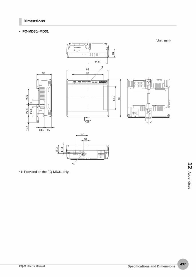
12 A
ppendices
Dimensions
• FQ-MD30/-MD31
*1: Provided on the FQ-MD31 only.
44.5
20
339570
85
*1
*1
52.9
23.8
14
27.9
12.1
35.5
17.3
27
10
19.2
1513.5
(Unit: mm)
Specifications and DimensionsFQ-M User’s Manual437

438
• Panel Mounting Adapter (FQ-XPM)
• Panel cutout dimensions
(133
.4)
(8.1)
(2)3.5
116
95
85116
31.6
(36.9)(Unit: mm)
111±1
111±
1
Specifications and Dimensions FQ-M User’s Manual

Specifications and DimensionsFQ-M User’s Manual439
12 A
ppendices
Sysmac Studio
*1 Sysmac Studio Operating System Precaution: System requirements and hard disk space may vary with the system environment.*2 To use the file logging function, additional memory area to save the logging data is necessary.
Item Requirement
Operating system (OS) *1
Japanese or English systemWindows XP (Service Pack 3 or higher, 32-bit version)/Vista (32-bit version)/7 (32-bit/64-bit version)/8 (32-bit/64-bit version)
CPU Windows computers with Celeron 540 (1.8 GHz) or faster CPU. Core i5 M520 (2.4 GHz) or equivalent or faster recommended
Main memory 2GB min.
Hard disk At least 1.6 GB of available space *2
Display XGA 1024 . 768, 1600 million colors.WXGA 1280 . 800 min. recommended
Disk drive DVD-ROM drive
Communications ports USB 2.0 port or Ethernet port
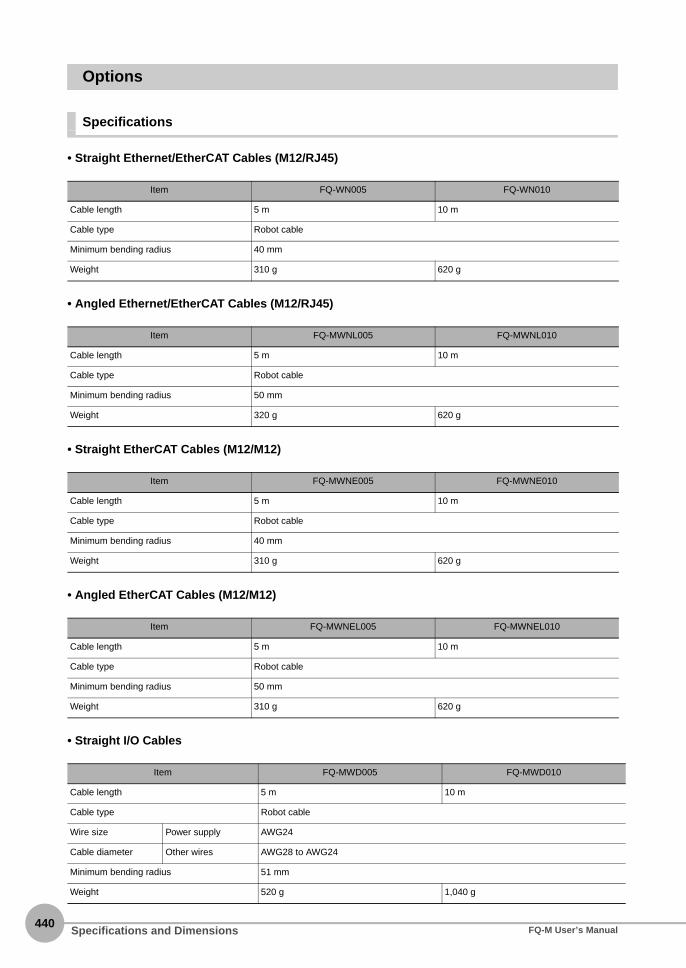
440
Options
Specifications
• Straight Ethernet/EtherCAT Cables (M12/RJ45)
• Angled Ethernet/EtherCAT Cables (M12/RJ45)
• Straight EtherCAT Cables (M12/M12)
• Angled EtherCAT Cables (M12/M12)
• Straight I/O Cables
Item FQ-WN005 FQ-WN010
Cable length 5 m 10 m
Cable type Robot cable
Minimum bending radius 40 mm
Weight 310 g 620 g
Item FQ-MWNL005 FQ-MWNL010
Cable length 5 m 10 m
Cable type Robot cable
Minimum bending radius 50 mm
Weight 320 g 620 g
Item FQ-MWNE005 FQ-MWNE010
Cable length 5 m 10 m
Cable type Robot cable
Minimum bending radius 40 mm
Weight 310 g 620 g
Item FQ-MWNEL005 FQ-MWNEL010
Cable length 5 m 10 m
Cable type Robot cable
Minimum bending radius 50 mm
Weight 310 g 620 g
Item FQ-MWD005 FQ-MWD010
Cable length 5 m 10 m
Cable type Robot cable
Wire size Power supply AWG24
Cable diameter Other wires AWG28 to AWG24
Minimum bending radius 51 mm
Weight 520 g 1,040 g
Specifications and Dimensions FQ-M User’s Manual

12 A
ppendices
• Angled I/O Cables
Item FQ-MWDL005 FQ-MWDL010
Cable length 5 m 10 m
Cable type Robot cable
Wire size Power supply AWG24
Cable diameter Other wires AWG28 to AWG24
Minimum bending radius 51 mm
Weight 540 g 1,080 g
Specifications and DimensionsFQ-M User’s Manual441

442
• AC Adapter
Dimensions
• For EtherCAT and Ethernet Cable
Straight type (M12/RJ45)
FQ-WN005/010
Item Model FQ-AC1
Input voltage 100 to 240 VAC (90 to 264 VAC), 50/60 Hz
Input current 0.3 mA max.
Output voltage 15 VDC±20%
Output current 1 A max.
Ambient temperature range Operating: 0 to 40°CStorage: −20 to 65°C (with no icing or condensation)
Ambient humidity range Operating and storage: 35% to 80% (with no condensation)
Material Case: PPE
Cable length 1.5 m
Dimensions 78 × 50 × 30 mm (without power cable)
Weight Approx. 270 g
Contents of label on AC Adapter
(54.7)L*1
(100)
(44.7)(1
9.9)
φ6.5
(φ14
.9)
(5) 35
φ19.
5
(5)35
φ19.
5
CIRCULAR CONNECTOR M12 ETHERNET CONNECTOR RJ45
*1: The cable length is given in the following table.
Model L
FQ-WN005 5 m
FQ-WN010 10 m
(Unit: mm)
Specifications and Dimensions FQ-M User’s Manual

12 A
ppendices
Angle: M12/Straight: RJ45FQ-MWNL005/010
• For EtherCAT Cable
Straight type (M12/M12)FQ-MWNE005/010
Angle type (M12/M12)FQ-MWNEL005/010
(56.5)
(5) (5)35
φ19.5
φ6.5
φ19.5
35
φ12
30.9
φ14.8
(14.6)
(14)
(100)
36.3
ANGLED CONNECTOR M12
ETHERNET CONNECTOR RJ45
L*1 (Unit: mm)
*1: The cable length is given in the following table.
Model L
FQ-MWNL005 5 m
FQ-MWNL010 10 m
(φ14.9)
(5)
(φ19.5)
(φ19.5)
(5)
(44.7)
(φ14.9)
(44.7)
35 35
(100)
CIRCULAR CONNECTOR M12CIRCULAR CONNECTOR M12
L*1
*1: The cable length is given in the following table.
Model L
FQ-MWNE005 5 m
FQ-MWNE010 10 m
(Unit: mm)
(5)φ6.5
φ19.5
35(5)
35
φ19.5
φ12
30.9
φ14.8 36.3 36.3
(100)
ANGLED CONNECTOR M12
ANGLED CONNECTOR M12
L*1
*1: The cable length is given in the following table.
Model L
FQ-MWNEL005 5 m
FQ-MWNEL010 10 m
(Unit: mm)
Specifications and DimensionsFQ-M User’s Manual443

444
• I/O Cables
Straight typeFQ-MWD005/010
Angle type (M12/M12)FQ-MWDL005/010
• AC Adapter
FQ-AC1
(φ21)φ8.5
(5)
φ19.5
(53.5)
35
CIRCULAR CONNECTOR M15
(100)
L*1
1: The cable length is given in the following table.
Model L
FQ-MWD005 5 m
FQ-MWD010 10 m
(Unit: mm)
φ21
41.7
(5)35
φ19.5
φ8.5
29.95
(100)
ANGLED CONNECTOR M15
L*1
*1: The cable length is given in the following table.
Model L
FQ-MWDL005 5 m
FQ-MWDL010 10 m
(Unit: mm)
30
50
781,800 to 2,000 1,500(Unit: mm)
Specifications and Dimensions FQ-M User’s Manual

12-4 Upgrading Sensor and Touch Finder Firmware
12 A
ppendices
Ask your OMRON representative for information on obtaining the most recent firmware versions.After you obtain the more recent firmware, use the following procedure to update the firmware you are using.
• Updating from the Sysmac Studio
Multiview Explorer: Double-click the Sensor model.→ Edit Pane: [Tool] − [Update firmware]
1 Select the folder that contains the firmware data.
• Updating from the Touch Finder
1 Place the update file that you obtained directly in the root folder of the SD card.
2 Insert an SD card into the Touch Finder.
3 To update the software in the Sensor, press (Setup Mode) - [Sensor settings] - [Update].
4 To update the software in the Touch Finder, press (Setup Mode) - [TF settings] - [Update].
The software will be updated automatically.
Do not turn OFF the power supply until updating the software has been completed.The Sensor or Touch Finder may not start normally if power is turned OFF during the update.
Important
Upgrading Sensor and Touch Finder FirmwareFQ-M User’s Manual445

446
12-5 Object Dictionary
Object Dictionary Area
The CAN application protocol over EtherCAT (CoE) protocol uses the object dictionary of CAN applicationprotocol as its base. Each object is assigned with an index of four-digit hexadecimal value. The indexes areconfigured in the areas below.
Data TypesThis profile uses the following data types.
Indexes Area Contents
0000 hex-0FFF hex Data Type area Definitions of data types
1000 hex-1FFF hex CoE Communications area Definitions of variables that can be used by all servers for des-ignated communications
2000 hex-2FFF hex Manufacturer Specific area 1 Variables defined for all OMRON products
3000 hex-5FFF hex Manufacturer Specific area 2 Variables defined for FQ-M series EtherCAT Slave Units
6000 hex-9FFF hex Device Profile area Not supported
A000 hex-FFFF hex Reserved area Area reserved for future use
Data Types Code Size Range
Boolean BOOL 1 bit true(1), false(0)
Unsigned8 U8 1 byte 0 to 255
Unsigned16 U16 2 bytes 0 to 65535
Unsigned32 U32 4 bytes 0 to 4294967295
Integer8 INT8 1 byte −128 to 127
Integer16 INT16 2 bytes −32768 to 32767
Integer32 INT32 4 bytes −2147483648 to 2147483647
Visible string VS - -
Object Dictionary FQ-M User’s Manual

12 A
ppendices
Object Description FormatIn this manual, objects are described in the following format.
Object description format
Object description format with sub-indexes
The following values are indicated within the pointed brackets <>.
<Index> <Object name>
Range: <Setting range> Unit: <Unit> Default: <Default setting> Attribute: <Data attribute>
Size: <Size> Access: <Access> PDO map: <Possible/Not possible>
<Index> <Object name>
Sub-index 0
Range: <Setting range> Unit: <Unit> Default: <Default setting> Attribute: <Data attribute>
Size: <Size> Access: <Access> PDO map: <Possible/Not possible>
• • •
Sub-index N
Range: <Setting range> Unit: <Unit> Default: <Default setting> Attribute: <Data attribute>
Size: <Size> Access: <Access> PDO map: <Possible/Not possible>
Indexes An object index given by a four-digit hexadecimal number
Object name The object name
Range The possible range of settings
Unit Physical unit
Default Default value set before product shipment
Attribute The timing when a change is updated in a writable objectA: Always enabledB: Timing of count stop → operation (Encoder Input Slave Unit only)C: Timing of pre-operational state → safe-operational stateD: Timing of pre-operational state → init stateR: Updated after the power supply is reset-: Read only
Size The object size is given in bytes
Access Indicates whether the object is read only, or read and writeRO: Read onlyRW: Read and write
PDO map Indicates the PDO mapping possibility
Object DictionaryFQ-M User’s Manual447

448
Communication Objects
• The FQ-M Sensors do not have a device profile.
• Indicates the error type that occurs in a Slave Unit.
• The error kind is allocated in each bit as follows.
It becomes "0:There is no error" and "1:The error is occurring".
• Indicates the Slave Unit model number.
• Indicates the version of the Slave Unit hardware.
• Indicates the version of the Slave Unit software.
* The default settings of device type, device name, hardware version, and software version vary by the Slave UnitTypes.
1000 hex Device Type
Range: − Unit: − Default: 00000000 hex Attribute: −
Size: 4 bytes (U32) Access: RO PDO map: Not possible
1001 hex Error Register
Range: − Unit: − Default: 00 hex Attribute: −
Size: 1 byte (U8) Access: RO PDO map: Not possible
Bits Name Bits Name
0 Generic error 4 Communications error
1 Current error 5 Device profile specific error
2 Voltage error 6 (Reserved)
3 Temperature error 7 Manufacturer specific error
1008 hex Manufacturer Device Name
Range: − Unit: − Default: Differ by Slave Unit types* Attribute: −
Size: 20 bytes (VS) Access: RO PDO map: Not possible
1009 hex Manufacturer Hardware Version
Range: − Unit: − Default: Differ by Slave Unit types* Attribute: −
Size: 20 bytes (VS) Access: RO PDO map: Not possible
100A hex Manufacturer Software Version
Range: − Unit: − Default: Differ by Slave Unit types* Attribute: −
Size: 20 bytes (VS) Access: RO PDO map: Not possible
Model Manufacturedevice name
Manufacture hardware version
Manufacture software version
FQ-MS120-ECT FQ-MS12x-ECT Space (20 hex) of 20 characters
"V1.00 "(Space (20 hex) of 15 characters)
FQ-MS125-ECT
FQ-MS120-M-ECT FQ-MS12x-M-ECT
FQ-MS125-M-ECT
Object Dictionary FQ-M User’s Manual

12 A
ppendices
• Resets the parameters to their default values.
• The parameter is reset only when a specific value is written to sub-index 1. This prevents parameter values from
being accidentally overwritten.
• The specific value is "load".
• The ABORT code is displayed if a value other than the specific is written.
• A value 0000 0001 hex (command valid) is indicated when reading.
• The FQ-M Sensors do not support this parameter.
• Indicates the device information.
• Sub-index 1(Vendor ID) gives the manufacturer identifier.
• Sub-index 2 (Product Code) gives the value assigned to each Slave Unit type.
• Sub-index 3 (Revision Number) gives the Unit revision number.
Bits 0 to 15: Minor revision number of the device
Bits 16 to 31: Major revision number of the device
• Sub-index 4 (Serial Number) gives a serial number for each product.
• For unit version 1.0, the serial number is always shown as 00000000 hex.
* The table below shows the identity object values by Slave Unit types.
1011 hex Restore Default Parameters
Sub-index 0: Number of entries
Range: − Unit: − Default: 01 hex Attribute: −
Size: 1 byte (U8) Access: RO PDO map: Not possible
Sub-index 1: Restore Default Parameters
Range: − Unit: − Default: 00000001 hex Attribute: A
Size: 4 bytes (U32) Access: RW PDO map: Not possible
MSB LSB
d a o l
64 hex 61 hex 6F hex 6C hex
1018 hex Identity Object
Sub-index 0: Number of entries
Range: − Unit: − Default: 04 hex Attribute: −
Size: 1 byte (U8) Access: RO PDO map: Not possible
Sub-index 1: Vendor ID
Range: − Unit: − Default: 00000083 hex Attribute: −
Size: 4 bytes (U32) Access: RO PDO map: Not possible
Sub-index 2: Product Code
Range: − Unit: − Default: Differ by Slave Unit types* Attribute: −
Size: 4 bytes (U32) Access: RO PDO map: Not possible
Sub-index 3: Revision Number
Range: − Unit: − Default: Differ by Slave Unit types* Attribute: −
Size: 4 bytes (U32) Access: RO PDO map: Not possible
Sub-index 4: Serial Number
Range: − Unit: − Default: Each Unit Attribute: −
Size: 4 bytes (U32) Access: RO PDO map: Not possible
Model Product Code(hex) Revision Number(hex)
FQ-MS120-ECT 00000062 00010000
FQ-MS125-ECT
FQ-MS120-M-ECT 00000063 00010000
FQ-MS125-M-ECT
Object DictionaryFQ-M User’s Manual449

450
• This object indicates up to 8 diagnosis histories. It also sets whether to notify emergency messages or not.
• Sub-index 1 (Maximum Messages) gives the number of error messages.
• Sub-index 2 (Newest Messages) gives the sub-index number the latest message in the diagnosis history.
• Sub-index 5 (Flags) is the control flag of diagnosis history. It specifies whether or not to notify error messages via
emergency messages. Setting 0001 hex means to notify. It is set to 0001 hex (Emergency notify) when power is
turned ON. At startup, the setting is 0000 hex (no emergency notification).
• Sub-indexes 6 to 13 (Diagnosis messages 1 to 8) indicate the diagnosis history.
From sub-index 6 (Diagnosis message 1) to sub-index 13 (Diagnosis message 8) are stored 8 errors. The 9th error
and onward are stored from the sub-index 6 (Diagnosis message 1) again.
• The FQ-M Sensors support only the flags.
PDO Mapping Object
Indexes 1600 hex to 17FF hex are used for Receive PDO mapping, and indexes 1A00 hex to 1BFF hex areused for Transmit PDO mapping. Sub-indexes after sub-index 1 provide information about the applicationobject being mapped.
• This object gives the mapping for an application that uses vision sensor functions.
• 3000h (Vision Control Flag) is mapped in 4 bytes.
• This object is excluded by 1700h (257th receive PDO Mapping)
10F3 hex Diagnosis History
Sub-index 0: Number of entries
Range: − Unit: − Default: 0D hex Attribute: −
Size: 1 byte (U8) Access: RO PDO map: Not possible
Sub-index 1: Maximum Messages
Range: − Unit: − Default: 00 hex Attribute: −
Size: 1 byte (U8) Access: RO PDO map: Not possible
Sub-index 2: Newest Message
Range: − Unit: − Default: − Attribute: −
Size: 1 byte (U8) Access: RO PDO map: Not possible
Sub-index 5: Flags
Range: 0000 hex- 0001 hex Unit: − Default: 0000 hex Attribute: −
Size: 2 bytes (U16) Access: RW PDO map: Not possible
Sub-index 6 to 13: Diagnosis Message 1-8
Range: − Unit: − Default: − Attribute: −
Size: 23 bytes (VS) Access: RO PDO map: Not possible
31 16 15 8 7 0
Indexes SubIndexes
Bit length
MSB LSB
Bits 0 to 7 : Bit length of the mapped object.(For example, for 32 bits, 20 hex is given.)
Bits 8 to 15 : Sub-index of the mapped object.
Bits 16 to 31 : Index of the mapped object.
16FF hex 256th receive PDO Mapping
Sub-index 0: Number of objects
Range: − Unit: − Default: 01 hex
Size: 1 byte (U8) Access: RO PDO map: Not possible
Sub-index 1: 1st Output Object to be mapped
Range: − Unit: − Default: 30000120 hex
Size: 4 bytes (U32) Access: RO PDO map: Not possible
Object Dictionary FQ-M User’s Manual

12 A
ppendices
• This object gives the mapping for an application that uses vision sensor functions.
• 3000h (Vision Control Flag) is mapped in 1 bit.
• This object is excluded by 16FFh (257th receive PDO Mapping)
• This object gives the mapping for an application that uses vision sensor functions.
• 3002h (Vision Command)
• 3010h (Vision Command Parameter1-3)
• This object gives the mapping for an application that uses vision sensor functions.
• 3001h (Vision Status Flag) is mapped in 4 bytes.
• This object is excluded by 1B700h (257th transmit PDO Mapping)
• This object gives the mapping for an application that uses vision sensor functions.
• 3001h (Vision Status Flag) is mapped in 1 bit.
• This object is excluded by 1AFFh (256th transmit PDO Mapping)
1700 hex 257th receive PDO Mapping
Sub-index 0: Number of objects
Range: − Unit: − Default: 20 hex
Size: 1 byte (U8) Access: RO PDO map: Not possible
Sub-index 1-32: 1st-32th Output Object to be mapped
Range: − Unit: − Default: 30000201-30002101 hex
Size: 4 bytes (U32) Access: RO PDO map: Not possible
1701 hex 258th receive PDO Mapping
Sub-index 0: Number of objects
Range: − Unit: − Default: 04 hex
Size: 1 byte (U8) Access: RO PDO map: Not possible
Sub-index 1: 1st Output Object to be mapped
Range: − Unit: − Default: 30020020 hex
Size: 4 byte (U32) Access: RO PDO map: Not possible
Sub-index 2: 2nd Output Object to be mapped
Range: − Unit: − Default: 30100120 hex
Size: 4 byte (U32) Access: RO PDO map: Not possible
Sub-index 3: 3rd Output Object to be mapped
Range: − Unit: − Default: 30100220 hex
Size: 4 byte (U32) Access: RO PDO map: Not possible
Sub-index 4: 4th Output Object to be mapped
Range: − Unit: − Default: 30100320 hex
Size: 4 bytes (U32) Access: RO PDO map: Not possible
1AFF hex 256th transmit PDO Mapping
Sub-index 0: Number of objects
Range: − Unit: − Default: 01 hex
Size: 1 byte (U8) Access: RO PDO map: Not possible
Sub-index 1: 1st Input Object to be mapped
Range: − Unit: − Default: 30010120 hex
Size: 4 bytes (U32) Access: RO PDO map: Not possible
1B00 hex 257th transmit PDO Mapping
Sub-index 0: Number of objects
Range: − Unit: − Default: 20 hex
Size: 1 byte (U8) Access: RO PDO map: Not possible
Sub-index 1-32: 1st-32th Output Object to be mapped
Range: − Unit: − Default: 30010201-30012101 hex
Size: 4 bytes (U32) Access: RO PDO map: Not possible
Object DictionaryFQ-M User’s Manual451

452
• This object gives the mapping for an application that uses vision sensor functions.
• 3003h (Vision Response)
• 3004h (Vision Response Code)
• 3005h (Vision Response Data1)
• 3006h(Vision Extended Data)
• This object gives the mapping for an application that uses vision sensor functions.
• 3020h (Vision Data Output1-8)
• This object gives the mapping for an application that uses vision sensor functions.
• 3020h (Vision Data Output9-16)
• This object is excluded by 1B04h (261th transmit PDO Mapping) and 1B05h (262th transmit PDO Mapping)
• This object gives the mapping for an application that uses vision sensor functions.
• 3020h (Vision Data Output9-32)
• This object is excluded by 1B03h (260th transmit PDO Mapping) and 1B05h (262th transmit PDO Mapping)
1B01 hex 258th transmit PDO Mapping
Sub-index 0: Number of objects
Range: − Unit: − Default: 04 hex
Size: 1 byte (U8) Access: RO PDO map: Not possible
Sub-index 1: 1st Output Object to be mapped
Range: − Unit: − Default: 30030020 hex
Size: 4 byte (U32 Access: RO PDO map: Not possible
Sub-index 2: 2nd Output Object to be mapped
Range: − Unit: − Default: 30040020 hex
Size: 4 byte (U32) Access: RO PDO map: Not possible
Sub-index 3: 3rd Output Object to be mapped
Range: − Unit: − Default: 30050120 hex
Size: 4 byte (U32) Access: RO PDO map: Not possible
Sub-index 4: 4th Output Object to be mapped
Range: − Unit: − Default: 30060020 hex
Size: 4 bytes (U32) Access: RO PDO map: Not possible
1B02 hex 259th transmit PDO Mapping
Sub-index 0: Number of objects
Range: − Unit: − Default: 08 hex
Size: 1 byte (U8) Access: RO PDO map: Not possible
Sub-index 1-8: 1st-8th Input Object to be mapped
Range: − Unit: − Default: 30200120-30200820 hex
Size: 4 bytes (U32) Access: RO PDO map: Not possible
1B03 hex 260th transmit PDO Mapping
Sub-index 0: Number of objects
Range: − Unit: − Default: 08 hex
Size: 1 byte (U8) Access: RO PDO map: Not possible
Sub-index 1-8: 1st-8th Input Object to be mapped
Range: − Unit: − Default: 30200920-30201020 hex
Size: 4 bytes (U32) Access: RO PDO map: Not possible
1B04 hex 261th transmit PDO Mapping
Sub-index 0: Number of objects
Range: − Unit: − Default: 18 hex
Size: 1 byte (U8) Access: RO PDO map: Not possible
Sub-index 1-24: 1st-24th Input Object to be mapped
Range: − Unit: − Default: 30200920-30202020 hex
Size: 4 bytes (U32) Access: RO PDO map: Not possible
Object Dictionary FQ-M User’s Manual

12 A
ppendices
• This object gives the mapping for an application that uses vision sensor functions.
• 3020h (Vision Data Output9-64)
• This object is excluded by 1B03h (260th transmit PDO Mapping) and 1B04h (261th transmit PDO Mapping)
• This object gives the mapping for notification of errors that are detected in the Slave Unit.
• The mapping includes 2002 hex-01 hex (Sysmac Error Status).
• When connected to an NJ-series Machine Automation Controller, 1C13 hex (Sync manager 3 PDO assignment) is
assigned to this object.
This object is automatically assigned in the default settings of the Sysmac Studio.
Sync Manager Communication Object
The communication memory of EtherCAT is set by the objects from 1C00 hex to 1C13 hex.
• The sync manager has the following settings.
• SM0: Mailbox receive (EtherCAT Master Unit to Slave Unit)
• SM1: Mailbox transmit (EtherCAT Slave Unit to Master Unit)
• SM2: Process data output (EtherCAT Master Unit to Slave Unit)
• SM3: Process data input (EtherCAT Slave Unit to Master Unit)
1B05 hex 262th transmit PDO Mapping
Sub-index 0: Number of objects
Range: − Unit: − Default: 38 hex
Size: 1 byte (U8) Access: RO PDO map: Not possible
Sub-index 1-56: 1st-56th Input Object to be mapped
Range: − Unit: − Default: 30200920-30204020 hex
Size: 4 bytes (U32) Access: RO PDO map: Not possible
1BFF hex 512th transmit PDO Mapping
Sub-index 0: Number of objects in this PDO
Range: − Unit: − Default: 01 hex Attribute: −
Size: 1 byte (U8) Access: RO PDO map: Not possible
Sub-index 1: 1st Input Object to be mapped
Range:− Unit: − Default: 20020108 hex Attribute: −
Size: 4 bytes (U32) Access: RO PDO map: Not possible
1C00 hex Sync Manager Communication Type
Sub-index 0: Number of used SM channels
Range: − Unit: − Default: 04 hex Attribute: −
Size: 1 byte (U8) Access: RO PDO map: Not possible
Sub-index 1: Communication Type Sync Manager 0
Range: − Unit: − Default: 01 hex Attribute: −
Size: 4 bytes (U8) Access: RO PDO map: Not possible
Sub-index 2: Communication Type Sync Manager 1
Range: − Unit: − Default: 02 hex Attribute: −
Size: 4 bytes (U8) Access: RO PDO map: Not possible
Sub-index 3: Communication Type Sync Manager 2
Range: - Unit: - Default: 03 hex Attribute: -
Size: 4 bytes (U8) Access: RO PDO map: Not possible
Sub-index 4: Communication Type Sync Manager 3
Range: - Unit: - Default: 04 hex Attribute: -
Size: 4 bytes (U8) Access: RO PDO map: Not possible
Object DictionaryFQ-M User’s Manual453

454
• It indicates the number of PDO mappings used by this sync manager.
• Mailbox reception sync manager does not have PDOs.
• It indicates the number of PDO mappings used by this sync manager.
• Mailbox transmit sync manager does not have PDOs.
• If a receive PDO is not provided, R0 is used.
• It indicates the RxPDOs used by this sync manager.
* "RO" is set if there is no TxPDO.
• It indicates the TxPDOs used by this sync manager.
* The default settings for Sync Manager 2 PDO Assignment and Sync Manager 3 PDO Assignment are different for
OMRON software and software from other companies. The default settings are given in the following table.
• Default Settings for Sysmac Studio (NJ Series)
There is normally no reason to change the default settings.To transfer more than 32 bytes of data (4 bytes × 8 data items) at the same time from the FQ-M Sensor to anNJ-series Controller, change the following PDO mapping settings.(The default setting can be used to separate the data and transfer it in more than one transfer operation fromthe FQ-M to the NJ-series Controller using handshaking.)
1C10 hex Sync Manager 0 PDO Assignment
Sub-index 0: Number of assigned PDOs
Range: 00 hex Unit: − Default: 00 hex Attribute: −
Size: 1 byte (U8) Access: RO PDO map: Not possible
1C11 hex Sync Manager 1 PDO Assignment
Sub-index 0: Number of assigned PDOs
Range: 00 hex Unit: − Default: 00 hex Attribute: −
Size: 1 byte (U8) Access: RO PDO map: Not possible
1C12 hex Sync Manager 2 PDO Assignment
Sub-index 0: Number of assigned PDOs
Range: − Unit: − Default: 02 hex Attribute: −
Size: 1 byte (U8) Access: RW* PDO map: Not possible
Sub-index 1-2: 1st-2nd PDO Mapping Object Index of assigned 2nd PDO
Range: − Unit: − Default: Differ by Slave Unit types* Attribute: −
Size: 2 bytes (U16) Access: RW* PDO map: Not possible
1C13 hex Sync Manager 3 PDO Assignment
Sub-index 0: Number of assigned PDOs
Range: − Unit: − Default: 05 hex Attribute: −
Size: 1 byte (U8) Access: RW* PDO map: Not possible
Sub-index 1-5: 1st-5th PDO Mapping Object Index of assigned PDO
Range: − Unit: − Default: Differ by Slave Unit types* Attribute: −
Size: 2 bytes (U16) Access: RW* PDO map: Not possible
Model FQ-MSxxx-x-ECT (all of models)
Sync manager 2 PDO assignment (hex)
Number of assignment RxPDO 02 hex
Assigned PDO1 16FF hex (256th receive PDO Mapping)
2 1701 hex (258th receive PDO Mapping)
Sync manager 3 PDO assignment (hex)
Number of assignment RxPDO 04 hex
Assigned PDO
1 1AFF hex (256th transmit PDO Mapping)
2 1B01 hex (258th transmit PDO Mapping)
3 1B02 hex (259th transmit PDO Mapping)
4 ---
5 1BFF hex (512th transmit PDO Mapping)
Object Dictionary FQ-M User’s Manual

12 A
ppendices
• Default Settings for CX-Programmer (CJ Series with Position Control Unit (NC8@@)
The default settings cannot be changed with the CX-Programmer.To transfer more than 32 bytes of data (4 bytes × 8 data items) from the FQ-M Sensor to an CJ-seriesController, separate the data and transfer it in more than one transfer operation by using handshaking.
• Software from Other Companies
To transfer more than 32 bytes of data (4 bytes × 8 data items) from the FQ-M Sensor to an EtherCAT master,separate the data and transfer it in more than one transfer operation by using handshaking.
assigned PDO Size of output data from FQ-M
--- 32bytes(4bytes * 8data)
1B03 hex (260th transmit PDO Mapping)
64bytes(4bytes * 16data)
1B04 hex (261st transmit PDO Mapping)
128bytes(4bytes * 32data)
1B05 hex (262nd transmit PDO Mapping)
256bytes(4bytes * 64data)
Model FQ-MSxxx-x-ECT (all of models)
Sync manager 2 PDO assignment (hex)
Number of assignment RxPDO 02 hex
Assigned PDO1 16FF hex (256th receive PDO Mapping)
2 1701 hex (258th receive PDO Mapping)
Sync manager 3 PDO assignment (hex)
Number of assignment RxPDO 03 hex
Assigned PDO
1 1AFF hex (256th transmit PDO Mapping)
2 1B01 hex (258th transmit PDO Mapping)
3 1B02 hex (259th transmit PDO Mapping)
4 ---
5 ---
Model FQ-MSxxx-x-ECT (all of models)
Sync manager 2 PDO assignment (hex)
Number of assignment RxPDO 02 hex
Assigned PDO1 1700 hex (257th receive PDO Mapping)
2 1701 hex (258th receive PDO Mapping)
Sync manager 3 PDO assignment (hex)
Number of assignment RxPDO 03 hex
Assigned PDO
1 1B00 hex (257th transmit PDO Mapping)
2 1B01 hex (258th transmit PDO Mapping)
3 1B02 hex (259th transmit PDO Mapping)
4 ---
5 ---
assigned PDO Size of output data from FQ-M
--- 32bytes(4bytes * 8data)
1B03 hex (260th transmit PDO Mapping) 64bytes(4bytes * 16data)
1B04 hex (261st transmit PDO Mapping) 128bytes(4bytes * 32data)
1B05 hex (262nd transmit PDO Mapping) 256bytes(4bytes * 64data)
Model
Sync manager 2PDO assignment(Hex)
Number of assignment RxPDO
Number of assignment RxPDO
Assigned RxPDO
Assigned RxPDO 3
4
5
1
2
1
2
Sync manager 3PDO assignment(Hex)
FQ-MSxxx-x-ECT (all of models)
02Hex
16FFHex (256th receive PDO Mapping)
1701Hex (258th receive PDO Mapping)
1AFFHex (256th transmit PDO Mapping)
1B01Hex (258th transmit PDO Mapping)
1B02Hex (259th transmit PDO Mapping)
-
1BFFHex (512th transmit PDO Mapping)
04Hex
Model
Sync manager 2PDO assignment(Hex)
Number of assignment RxPDO
Number of assignment RxPDO
Assigned PDO
Assigned PDO 3
4
5
1
2
1
2
Sync manager 3PDO assignment(Hex)
FQ-MSxxx-x-ECT (all of models)
02Hex
1700Hex (257th receive PDO Mapping)
1701Hex (258th receive PDO Mapping)
1B00Hex (257th transmit PDO Mapping)
1B01Hex (258th transmit PDO Mapping)
1B02Hex (259th transmit PDO Mapping)
-
-
03Hex
Object DictionaryFQ-M User’s Manual455

456
Manufacturer Specific Objects
This section explains the CiA401 generic I/O module device profile implemented in FQ-M-series EtherCATSlave Units and the objects specially mounted in FQ-M-series EtherCAT Slave Units.
Common Objects for Sysmac Devices
• Manufacturer Specific area 1
• This object clears diagnosis history of 10F3 hex (Diagnosis History).
• It clears the history only when specific values are written. The specific value is "elcl".
Writing values other than this is invalid.
• The mapping is used for Sysmac error status notification and to clear Sysmac error status.
• Sub-index 1: Sysmac Error Status
• This object is for notification of errors that are detected in the Slave Unit.
• When connected to an NJ-series Machine Automation Controller, map this object to a PDO.
• Sub-index 2: Sysmac Error Status Clear
• This object is used by the Controller (a Sysmac device) to reset errors that occur in Slave Units.
• Object mounted only on Slave Units operating in the DC mode.
• The number of sequences for detecting communications errors is set with this object.
• The setting range is from 00 to 0F hex and the number of detections is "the set number of times + 1."
• Rewriting value is possible at operation in the DC mode, but the operation is performed with the value set when
shifting from the pre-operational state to safe-operational state. Note that at this point, the rewritten value is read.
2100 hex Error History Clear
Range: − Unit: − Default: 00000000 hex Attribute: A
Size: 4 bytes (U32) Access: RW PDO map: Not possible
MSB LSBl c l e6C hex 63 hex 6C hex 65 hex
2002 hex Sysmac Error
Sub-index 0: Number of entries
Range: − Unit: − Default: 02 hex Attribute: −
Size: 1 byte (U8) Access: RO PDO map: Not possible
Sub-index 1: Sysmac Error Status
Range: − Unit: − Default: 00 hex Attribute: −
Size: 1 byte (U8) Access: RO PDO map: Possible
Sub-index 2: Sysmac Error Status Clear
Range: − Unit: − Default: 00 hex Attribute: A
Size: 1 byte (U8) Access: RW PDO map: Not possible
In the default Sysmac Studio settings, sub-index 1 (Sysmac Error Status) is automatically mapped to a PDObecause 1BFF hex (512th transmit PDO Mapping) is assigned.
2200 hex Communication Error Setting
Range: 00 hex to 0F hex Unit: number of sequences
Default: 01 hex Attribute: C
Size: 1 byte (U8) Access: RW PDO map: Not possible
Note
Object Dictionary FQ-M User’s Manual

12 A
ppendices
• Object mounted only on Slave Units operating in the DC mode.
• This object is used to set the standby time until the first synchronization interrupt signal (SYNC0) is input after shift-
ing to the safe-operational state (state where a DC mode is confirmed).
• If the first interrupt signal (SYNC0) is not input at all within this setting time, a synchronization error occurs.
• The setting range is from 0000 hex to 0258 hex (600s) and operation is performed at 120s when 0000 hex is set.
• Rewriting value is possible at operation in the DC mode, but the operation is performed with the value set when
shifting from the pre-operational state to safe-operational state. Note that at this point, the rewritten value is read.
Vision Sensor Specific Objects
• Manufacturer Specific area 2
• This object gives the control for vision sensor functions.
• EXE bit: Turn this on to execute the commands.
• TRIG bit: Turn this on to execute the measurement.
• ERCLR bit: Turn this on to clear the ERR bit (3001h Sub-index17).
• DSA bit: Turn this on to request the output data.
• If the Sysmac Studio or CX-Programmer is used, a subindex of 1 is mapped, including all bits of EXE, TRIG,
ERCLR, and DSA.
With the default setting of 01 hex, an error is detected if communications errors occur twice in a row.
2201 hex Sync Not Received Timeout Setting
Range: 0000 hex to 0258 hex Unit: s Default: 0000 hex Attribute: C
Size: 2 bytes (U16) Access: RW PDO map: Not possible
3000 hex Vision Control Flag
Sub-index 0: Number of entries
Range: − Unit: − Default: 21 hex
Size: 1 byte (U8) Access: RO PDO map: Not possible
Sub-index 1: Vision Control Flag
Range: − Unit: − Default: 00000000 hex
Size: 4 byte (U32) Access: RW PDO map: Possible
Sub-index 2: EXE Bit
Range: True(1) or False(0) Unit: − Default: False(0)
Size: 1 bit (BOOL) Access: RW PDO map: Possible
Sub-index 3: TRIG Bit
Range: True(1) or False(0) Unit: − Default: False(0)
Size: 1 bit (BOOL) Access: RW PDO map: Possible
Sub-index 4-16: Control Reserve Bit02-14
Range: True(1) or False(0) Unit: − Default: False(0)
Size: 1 bit (BOOL Access: RW PDO map: Possible
Sub-index 17: ERCLR Bit
Range: True(1) or False(0) Unit: − Default: False(0)
Size: 1 bit (BOOL Access: RW PDO map: Possible
Sub-index 18: DSA Bit
Range: True(1) or False(0) Unit: − Default: False(0)
Size: 1 bit (BOOL Access: RW PDO map: Possible
Sub-index 19-33: Control Reserve Bit17-31
Range: True(1) or False(0) Unit: − Default: False(0)
Size: 1 bit (BOOL) Access: RW PDO map: Possible
Note
Object DictionaryFQ-M User’s Manual457
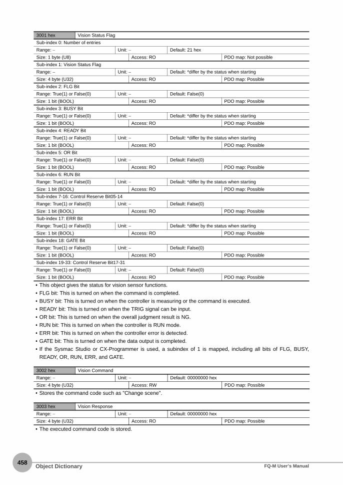
458
• This object gives the status for vision sensor functions.
• FLG bit: This is turned on when the command is completed.
• BUSY bit: This is turned on when the controller is measuring or the command is executed.
• READY bit: This is turned on when the TRIG signal can be input.
• OR bit: This is turned on when the overall judgment result is NG.
• RUN bit: This is turned on when the controller is RUN mode.
• ERR bit: This is turned on when the controller error is detected.
• GATE bit: This is turned on when the data output is completed.
• If the Sysmac Studio or CX-Programmer is used, a subindex of 1 is mapped, including all bits of FLG, BUSY,
READY, OR, RUN, ERR, and GATE.
• Stores the command code such as "Change scene".
• The executed command code is stored.
3001 hex Vision Status Flag
Sub-index 0: Number of entries
Range: − Unit: − Default: 21 hex
Size: 1 byte (U8) Access: RO PDO map: Not possible
Sub-index 1: Vision Status Flag
Range: − Unit: − Default: *differ by the status when starting
Size: 4 byte (U32) Access: RO PDO map: Possible
Sub-index 2: FLG Bit
Range: True(1) or False(0) Unit: − Default: False(0)
Size: 1 bit (BOOL) Access: RO PDO map: Possible
Sub-index 3: BUSY Bit
Range: True(1) or False(0) Unit: − Default: *differ by the status when starting
Size: 1 bit (BOOL) Access: RO PDO map: Possible
Sub-index 4: READY Bit
Range: True(1) or False(0) Unit: − Default: *differ by the status when starting
Size: 1 bit (BOOL) Access: RO PDO map: Possible
Sub-index 5: OR Bit
Range: True(1) or False(0) Unit: − Default: False(0)
Size: 1 bit (BOOL) Access: RO PDO map: Possible
Sub-index 6: RUN Bit
Range: True(1) or False(0) Unit: − Default: *differ by the status when starting
Size: 1 bit (BOOL) Access: RO PDO map: Possible
Sub-index 7-16: Control Reserve Bit05-14
Range: True(1) or False(0) Unit: − Default: False(0)
Size: 1 bit (BOOL) Access: RO PDO map: Possible
Sub-index 17: ERR Bit
Range: True(1) or False(0) Unit: − Default: *differ by the status when starting
Size: 1 bit (BOOL) Access: RO PDO map: Possible
Sub-index 18: GATE Bit
Range: True(1) or False(0) Unit: − Default: False(0)
Size: 1 bit (BOOL) Access: RO PDO map: Possible
Sub-index 19-33: Control Reserve Bit17-31
Range: True(1) or False(0) Unit: − Default: False(0)
Size: 1 bit (BOOL) Access: RO PDO map: Possible
3002 hex Vision Command
Range: − Unit: − Default: 00000000 hex
Size: 4 byte (U32) Access: RW PDO map: Possible
3003 hex Vision Response
Range: − Unit: − Default: 00000000 hex
Size: 4 byte (U32) Access: RO PDO map: Possible
Object Dictionary FQ-M User’s Manual

12 A
ppendices
• The response code is stored when the command is completed. (OK: 00000000 hex, NG: FFFFFFFF hex)
• The response data is stored the command is completed. (e.g. the scene number is stored when the command "Get
scene number".)
• This object is not supported.
• Store the parameter of the command. (e.g. the scene number is stored when the command "Switch scene".)
• The output data are stored.
3004 hex Vision Response Code
Range: − Unit: − Default: 00000000 hex
Size: 4 byte (U32) Access: RO PDO map: Possible
3005 hex Vision Response Data
Sub-index 0: Number of entries
Range: − Unit: − Default: 01 hex
Size: 1 byte (U8) Access: RO PDO map: Not possible
Sub-index 1: Vision Response Data1
Range: − Unit: − Default: 00000000 hex
Size: 4 byte (INT32) Access: RO PDO map: Possible
3006 hex Vision Extended Data
Range: − Unit: − Default: 00000000 hex
Size: 4 byte (INT32) Access: RO PDO map: Possible
3010 hex Vision Command Parameter
Sub-index 0: Number of entries
Range: − Unit: − Default: 01 hex
Size: 1 byte (U8) Access: RO PDO map: Not possible
Sub-index 1: Vision Command Parameter1
Range: − Unit: − Default: 00000000 hex
Size: 4 byte (U32) Access: RW PDO map: Possible
Sub-index 2: Vision Command Parameter2
Range: − Unit: − Default: 00000000 hex
Size: 4 byte (U32) Access: RW PDO map: Possible
Sub-index 3: Vision Command Parameter3
Range: − Unit: − Default: 00000000 hex
Size: 4 byte (INT32) Access: RW PDO map: Possible
3020 hex Vision Data Output
Sub-index 0: Number of entries
Range: − Unit: − Default: 40 hex
Size: 1 byte (U8) Access: RO PDO map: Not possible
Sub-index 1-64: Vision Data Output1-64
Range: − Unit: − Default: 00000000 hex
Size: 4 byte (INT32) Access: RO PDO map: Possible
Object DictionaryFQ-M User’s Manual459

460
Index
AAC Adapter 442AC power supply connector
Touch Finder 31adjusting judgement parameters during operation 176all region 172all results/region 171all sensor data 206auto connect 51auto display 154, 157, 173, 175
Bbacking up Sensor data to an external file
204basic troubleshooting 391battery 46battery remaining 212BKD 61, 204, 206BMP 206Brightness adjust 74brightness level 190BUSY 41BUSY polarity
BUSY: ON 222READY: ON 222
BUSY signal 214
Ccalculation 138calibration 346calibration data 204calibration for conveyor tracking 347calibration group data 204calibration scene data 61calibration scene group data 61camera input 172candidate level 130captured images 206capturing the currently visible display 209CGP 61, 204change the line process 180changing scene names 182changing the BUSY signal output condition
222changing the file format 202checking a list of all inspection item results
160checking Sysmac error status 383checking the error histories 389checking versions 210CLB 61, 204clearing the error histories 389clearing the Sysmac error status 383C-mount lens fitting 29color palette 114color pallette 117COM_I 40
common terminal 41COM_O 41copying scenes 182correcting the touch screen positions of the Touch Finder 212correlation 88, 90, 125, 127count 129CSV 206
DDC power supply connector
Touch Finder 31decimal symbol 193deleting logged data 203deleting scenes 182dimensions 428direct input 368display language 212display pattern 172display range 154, 157, 174, 175
EECAT ERROR 29ECAT RUN 29ECO mode 190edge threshold 108Edit Pane 55EFC RST 40ENCODER 40encoder input 339ERROR 29, 41ERROR CLR 40error descriptions 384error history 388error messages 390ERROR Signal 224errors in teaching
edge position 112labeling 124search 104shape search 137
errors stored in the error history 388ESI specification 265EtherCAT 228EtherCAT input connector 29EtherCAT operation indicators 29EtherCAT output connector 29EtherCAT telegram 229Ethernet connector 29Ethernet port
Touch Finder 31ETN 29Explorer Pane 53exportable and importable file types 61exporting projects 59external lighting 73, 81external reference parameters 412external trigger 215
Index FQ-M User’s Manual

Index12
Ffield separator 193file format 197, 202file logging 191focus 69formatting SD cards 207frozen image 185function list 394
Ggeneral-purpose calibration 356general-purpose Ethernet cable 28GND 40GND ENCODER 40graphics 171graphics + details 171grip area level 97, 133grip interference check 96, 132guide lines 72, 189
HHDR function 76help 211hiding the menu 190high dynamic range 76histogram 155, 171, 174
II/O Cable 40I/O connector 29icons 56IFZ 206image data 191, 206image input speed 159image zoom 183images
displaying last NG image 187importing projects 60individual judgement 218initializing 210inspection items 84
deletion 87edge position 105labeling 113registration 86search 88shape search 125
installing the Sensor 32installing the Sysmac Studio 48
LL/A IN 29L/A OUT 29labeling condition 120language 212LCD backlight 190lens models 34lens selection 33level output 221lighting connector 29lighting control 225live image 184
logging 191
Mmacro rings 35Main Window 52masking 101measurement data 191measurement process operation indicators 29measurement region 102, 135measurement takt time 158measurement trigger 79menu bar 52model 88, 125mounting
control panel 37DIN Track 37
mounting holes 29MSD 204, 206multi-point output 93
Nnode address setting switches 29No-protocol 296no-protocol command 305NPN 42number of data 154, 157, 174, 175
Oobject dictionary 447offline debugging 376offline setup 372offline simulation 375one-shot output 221One-shot output delay 221operation 163operation indicators
CHARGE 31ERROR 31POWER 31SD ACCESS 31Touch Finder 31
OR 29, 41OR signal 214OUT0 41OUT1 41OUT2 41OUT3 41OUT4 41output mode 221output polarity 222
NG: ON 222OK: ON 222
output time 221overall judgement 217
PPanel Mounting Adapter 438
mounting 37panorama display 170parallel I/O 214password 208PC Tool 28
IndexFQ-M User’s Manual461

462
PLC Link 266PNP 42position compensation 172power supply switch
Touch Finder 31preventing mutual interference of multiple Sensors 82printing a calibration pattern 70programmable no-protocol communications 325project data 61
Rrecent results logging 199re-measuring 151remove duplication 95, 121, 131resetting the ring counter value 227restarting 210Robot Controller 28rotation range 98, 134Run Mode 58Run Mode display 164
Ssaved image 186saving a project 59saving data 161saving the node address setting 264scene data 61, 204, 206scene group data 61, 204, 206scenes 180
changing scene names 182copying scenes 182deleting scenes 182
SCN 61, 204, 206SD card
available space 207formatting 207information 207slot 31
selecting a Sensor for configuration 64selecting the data to log 201Sensor all data 61Sensor all information 204Sensor monitor 172Sensor name 210Sensor system data 61, 204, 206serial number display 265setting the data to log 192setting the data to output automatically after measurements 235, 273, 299, 329setting the time on the Touch Finder 212setting up EtherCAT communications 234setting up no-protocol communications 297setting up PLC Link communications 270setting up programmable no-protocol communications 326Setup Mode 58
returning to Setup Mode 167SGP 61, 204, 206SHIELD ENCODER 40SHTOUT 41
shutter output 41shutter speed and brightness of the Sensor 74SMC 61Special EtherCAT Cable 28specifications 428starting a project 49starting and stopping logging 193startup display 172startup mode 182startup scene 182statistical data 171, 202statistical data and measurement data 206STGOUT 41STGOUT signal 225straps 38Strobe Controller mounting holes 29strobe trigger output 41Switching Hub 28SYD 61, 204, 206Sysmac device 264Sysmac error status 264, 382Sysmac Studio Standard Edition 28Sysmac Studio Vision Edition 28system configuration 26
Ttest measurements
performing 150toolbar 52toolbox 52Touch Finder data 204, 206trend monitor 152, 171, 173TRIG 40TRIG signal 214
Uupdating 446updating the display and measurement results for NG measurement results 187user interface 52
VVDD ENCODER 40
Wwhite balance 78wiring 40
Touch Finder 45
Index FQ-M User’s Manual

FQ-M User’s Manual463
Revision HistoryA manual revision code appears as a suffix to the catalog number at the bottom of the front and back covers of
this manual.
Revision code Date Revised contents
01 October 2011 Original production
01A March 2012 Minor corrections
02 August 2012 Added a grip interference check and other functions compatible with Ver. 1.50
03 December 2013 Minor corrections for compatibility with Windows 8
Cat. No. Z314-E1-03
Revision code

464FQ-M User’s Manual
MEMO


Authorized Distributor:
In the interest of product improvement, specifications are subject to change without notice.
Cat. No. Z314-E1-03 1213
© OMRON Corporation 2011 All Rights Reserved.
OMRON Corporation Industrial Automation Company
OMRON ELECTRONICS LLC One Commerce Drive Schaumburg, IL 60173-5302 U.S.A. Tel: (1) 847-843-7900/Fax: (1) 847-843-7787
Regional Headquarters
OMRON EUROPE B.V. Wegalaan 67-69-2132 JD Hoofddorp The Netherlands Tel: (31)2356-81-300/Fax: (31)2356-81-388
Contact: www.ia.omron.com Tokyo, JAPAN
OMRON ASIA PACIFIC PTE. LTD. No. 438A Alexandra Road # 05-05/08 (Lobby 2), Alexandra Technopark, Singapore 119967 Tel: (65) 6835-3011/Fax: (65) 6835-2711
OMRON (CHINA) CO., LTD. Room 2211, Bank of China Tower, 200 Yin Cheng Zhong Road, PuDong New Area, Shanghai, 200120, China Tel: (86) 21-5037-2222/Fax: (86) 21-5037-2200
Copyright © 2022 FDOKUMEN