FPGA Implementation of the Wavelet Packet Transform for High Speed Communications
10
FPGA implementation of the wavelet packet transform for high speed communications Antony Jamin, Petri M¨ ah¨ onen {antony.jamin,petri.mahonen}@ee.oulu.fi Center for Wireless Communications University of Oulu, Finland Abstract. Recent work has shown interest in wavelet-packet based mod- ulation (WPM). This scheme is implemented with an architecture similar to orthogonal frequency division multiplex (OFDM), except for using the wavelet packet transform (WPT) in place of the Fourier transform. In this article, we study the implementation complexity of a WPT suit- able for such a modulation scheme. A speed optimized implementation of the Mallat algorithm based on a generic reconfigurable filter struc- ture is proposed. Measured complexity results of the designed transform implemented in FPGA using VHDL are reported and commented. 1 Introduction With the success of OFDM in providing high data rates over wireless [1], the interest in multicarrier systems has grown rapidly in the past decade. OFDM has reached the consumer market for some time now, and research on compet- itive multicarrier schemes is being carried out. Wavelet packet modulation is among the most promising schemes, its main advantages being flexibility and the potential of lower implementation complexity. We focus in this article on issues related to the design of a wavelet packet transform suited for use in transceivers for this new modulation scheme. Since the aim is to support future wireless local area networks, the sustainable data rate of our system must range from 10 to 100 Msymbols/sec. This obviously implies that speed is the largest constraint on the design of the transform core. This is not however the only one, since the need for flexibility of wireless communication at the link layer required a certain degree of reconfigurability in the transform. In the case of the core transform, the reconfigurability is actually three fold. First, the length of the wavelet filters and their coefficients must be programmable. Second, the transform size must be configurable. And last, any wavelet packet tree structure must be realisable. This paper is divided as follows. First, the iterative algorithm implementing the WPT is recalled. The corresponding generic architecture is derived, and its theoretical complexity is given. The scheme proposed in order to take advan- tage of the fastest speed supported by the implementation technology is then described. We pursue in studying the modifications required to allow for our ar- chitecture to support transforms with a non fully pruned tree structure. Finally,
-
Upload
independent -
Category
Documents
-
view
1 -
download
0
Transcript of FPGA Implementation of the Wavelet Packet Transform for High Speed Communications
FPGA implementation of the wavelet packettransform for high speed communications
Antony Jamin, Petri Mahonen{antony.jamin,petri.mahonen}@ee.oulu.fi
Center for Wireless CommunicationsUniversity of Oulu, Finland
Abstract. Recent work has shown interest in wavelet-packet based mod-ulation (WPM). This scheme is implemented with an architecture similarto orthogonal frequency division multiplex (OFDM), except for using thewavelet packet transform (WPT) in place of the Fourier transform.In this article, we study the implementation complexity of a WPT suit-able for such a modulation scheme. A speed optimized implementationof the Mallat algorithm based on a generic reconfigurable filter struc-ture is proposed. Measured complexity results of the designed transformimplemented in FPGA using VHDL are reported and commented.
1 Introduction
With the success of OFDM in providing high data rates over wireless [1], theinterest in multicarrier systems has grown rapidly in the past decade. OFDMhas reached the consumer market for some time now, and research on compet-itive multicarrier schemes is being carried out. Wavelet packet modulation isamong the most promising schemes, its main advantages being flexibility andthe potential of lower implementation complexity.
We focus in this article on issues related to the design of a wavelet packettransform suited for use in transceivers for this new modulation scheme. Since theaim is to support future wireless local area networks, the sustainable data rateof our system must range from 10 to 100 Msymbols/sec. This obviously impliesthat speed is the largest constraint on the design of the transform core. This isnot however the only one, since the need for flexibility of wireless communicationat the link layer required a certain degree of reconfigurability in the transform. Inthe case of the core transform, the reconfigurability is actually three fold. First,the length of the wavelet filters and their coefficients must be programmable.Second, the transform size must be configurable. And last, any wavelet packettree structure must be realisable.
This paper is divided as follows. First, the iterative algorithm implementingthe WPT is recalled. The corresponding generic architecture is derived, and itstheoretical complexity is given. The scheme proposed in order to take advan-tage of the fastest speed supported by the implementation technology is thendescribed. We pursue in studying the modifications required to allow for our ar-chitecture to support transforms with a non fully pruned tree structure. Finally,
implementation complexity results obtained after the synthesis of our VHDLdesign are reported and commented.
2 Wavelet packet transform algorithm
In this article, we limit our analysis to discrete WPT that can be defined througha pair of length L FIR filters denoted (h, g). The wavelet packet transform canbe efficiently implemented through the Mallat recursive algorithm. Denotingωj,i the wavelet coefficient of branch i at decomposition level j = 1 . . . J , we cancalculate the wavelet coefficients recursively through the relations
ωj+1,2i[k] =L−1∑l=0
ωj,i[2k − l]h[l] (1)
ωj+1,2i+1[k] =L−1∑l=0
ωj,i[2k − l] g[l] (2)
with i = 0 . . . (2j − 1). The recursion starts with ω0,0 which is the signal tobe decomposed. The inverse wavelet packet transform (IWPT) can similarlyreconstruct the signal from its coefficients by iteration, i.e.
ωj,i[k] =L−1∑l=0
ωj−1,2i[(k − l)/2] h[l] +L−1∑l=0
ωj−1,2i+1[(k − l)/2] g[l] (3)
with i = 0 . . . (2j−1) and where ωj,i[k] denotes the upsampled-by-two version ofωj,i[k], i.e. ωj,i[k] = ωj,i[k] if k ∈ N, and 0 otherwise. The recursion ends with ω0,0
which is the reconstructed signal. Eq. (2) and (3) correspond to upsampling andfiltering operations as depicted on the left and right side of Figure 1 respectively.The reconstruction makes use of another filter pair (g, h), and we refer the readerto [2, 3] for further characteristics on their inter-relations.
A rough estimate of the fast discrete wavelet packet transform gives a com-plexity of order Mlog(M), thus of similar order to what is required for DFT.This complexity analysis can be further refined by calculating the number ofoperations required by the elementary blocks composing a complete transform.For the decomposition block (WPT), the amount of operations per input sampleis
CWPT ={
2 (L− 1) ADD2L MULT (4)
Note that the reconstruction block is using one extra addition to combine the twofilters output samples. Considering now the full transform, there are J stages,each composed of N(j) = 2j−1 elementary blocks running at the rate R(j) =21−j . We thus obtain the total number of operation for each M-point transform

with M = 2J as
NWPT (J) = CWPT
J∑j=1
N(j)R(j) (5)
={
(2J+1 − 1) (L− 1) ADD(2J+1 − 1)L MULT
The total number of memory word P required by the transform can be similarlyderived, i.e.
PIWPT (J) = L
J∑j=1
N(j) = (2J+1 − 1)L (6)
3 Proposed WPT architecture
The iterative structure of the WPT is in fact very well suited to hardware im-plementation. For each stage of the transform, the product of the number ofelementary blocks by their processing rate is constant and equal to 1. Thus, foreach transform period, the number of output samples to produce is constant andequal to the transform size. Both forward and reverse transforms can thereforebe built by successive stages, each operating synchronously and at an identicalrate. This is illustrated in Figure 3 for the forward transform. The reverse trans-form is identical except for the stage indexes which are in reverse order. Thissimple structure has the advantage that Jmax stages can be instantiated in aprogrammable logic device, leading to a transform of size Mmax = 2Jmax maxi-mum. If a lower size transform is needed, the corresponding higher order stagescan be bypassed, and eventually put in standby mode if low power consumptionis of interest.
Our design work is thus reduced to the implementation of the J stages.An interesting architecture has been proposed in [4]. In this scheme, the inputsamples of stage j are written in cyclic buffers of size 2j . They are then readby generating successively the addresses corresponding to the 2 × L/2 samplesrequired to calculate the output sample of each elementary block. Each sampleread from memory is multiplied by the corresponding filter coefficient, and the
2
2 h ~
g ~
2
2
h
g
i j W 2 ,
1 2 , + i j W
i j W , 1 - i j W , 1 -
Fig. 1. Wavelet packet elementary block decomposition and reconstruction

2 h
g
0 , 0 W
0 , 2 W
0 , 1 W
1 , 1 W
1 , 2 W
2 , 2 W
3 , 2 W
2
2 h
2 h
g 2
g 2
Fig. 2. Forward wavelet packet transform (decomposition operation)
results feed an accumulator. After L clock cycles, the accumulator contains theelementary block output to be transmitted to the next stage input. This methodbenefits from a rather simple architecture since only one memory block, onemultiplier, one accumulator, and two address generators are needed for eachstage. The major limitation is obviously its speed, since L clock periods arerequired per output sample. With current technology, such a method is thus notcapable of reaching the bit rate our application is targeting, and thus a slightlydifferent architecture must be derived.
In the given example, the speed limitation is obviously bound to the filter im-plementation. We must therefore parallelize the filter implementation in order toreach a rate of one cycle per output sample. This can be achieved by making useof L multipliers fed at each clock cycle with its data samples and correspondingfilter coefficients. The L resulting products are then added in a pipelined adderwith L inputs. This last block can be built from log2(L) adders and thus have adelay of log2(L) clock cycles as well. We choose an intermediate approach, usingonly L/2 multipliers. With current technology, a data rate of half of the clockfrequency is sufficient for our application, and the 50% complexity reductionallows a doubling of the maximum transform size.
We study in the following the sequencing of an overall period for both theforward and reverse transforms. In particular, we must review the combinationdata-filter coefficients that must be provided at each clock cycle to every multi-plier.
3.1 IWPT architecture
Since we assumed a data rate equal to half the clock frequency, each stage receivesa new data sample every two clock cycles. For the IWPT, the upsampler imposesa division of the transform period in two. In the first half-period, we calculatethe even output samples ωj,i[2k], and in the second, the odd ones ωj,i[2k + 1].On the other hand, every other input sample of the h and g filters is null, thanks

Sta
ge
1
Sta
ge
2
Sta
ge
3
Sta
ge
J
Transform input signal
Clock
Wavelet packet transform
coefficients
Fig. 3. Forward wavelet packet transform implementation through J synchronousstages
to the preceding upsampler. Thus only the even coefficients of the filters areused to calculate ωj,i[2k], and the odd ones are used for ωj,i[2k + 1]. Processingsuccessively every wj,i[k] in increasing order of i, we calculate alternatively theoutput of filter h or g depending on if i is even or odd. The output of filter h isstored for one clock cycle, and added to the output of filter g during the nextclock cycle to form the stage output. The usage of the processing elements is of100%, and the output data rate of the stage is half the clock rate.
One problem arising in this architecture is the need of providing L/2 inputsamples at every clock cycle. This can not easily be achieved with one singlememory block. However, using one memory block of size 2j per multiplier leadsto a very simple address generation architecture, and this is the approach wechoose to take here. During the first half-period, 2j samples coming from theprevious memory block are simultaneously feeding the multiplier and written inmemory. The multiplier coefficients are then the even coefficients of the filtersh and g, alternatively. During the second half-period, the 2j data samples areread from the memory and sent again to the multipliers, whose coefficients arenow the odd coefficients of the filters h and g alternatively.
Overall, this results in the architecture shown in Figure 4. In addition to thestructure we described, a FIFO is inserted between the first memory block andthe stage input. This is required due to the fact that the 2j input samples areinput in 2j+1 clock cycles, but must be available from memory after the first halfof that period. The introduction of the FIFO of depth 2j−1 in thus necessary,though it leads to an increase in overall processing delay.
3.2 WPT architecture
We deduce from Eq. (2) that only every other filter output is needed. We cantherefore calculate the output filter in two cycles, each calculating half of theproducts needed for the whole filter. Processing again the wavelet coefficientsωj,i[k] in increasing order of the index value i, we use the filters h and g alter-natively. For each filter output, we first calculate the even terms of the filtersummation. In the next cycle, we calculate the odd terms and add the result tothe partial result previously obtained. Thus, one output sample is again calcu-lated every two clock cycles.

FIFO
Dual port RAM
block 0
ADDER
Mux
h(0) h(1) g(0) g(1)
Dual port RAM
block 1
Dual port RAM
block 2
Dual port RAM
block 3
Mux
h(2) h(3) g(2) g(3)
Mux
h(4) h(5) g(4) g(5)
Mux
h(6) h(7) g(6) g(7)
1 cycle ACC.
Stage output
Sequencing block
Coef. select
Filter select
Stage input
Addresses
Write enable
Fig. 4. Architecture of one IWPT stage with filter of length L = 8
In this operational sequencing, the elementary cycle is four clock cycles long.In the first (resp. second), each multiplier has to be feed by an even (resp. odd)sample of each elementary block input stream, together with the correspondingeven (resp. odd) coefficient of filter h. In the two remaining clock cycles, thesame input samples are multiplied by the even and odd coefficients of filter gconsecutively.
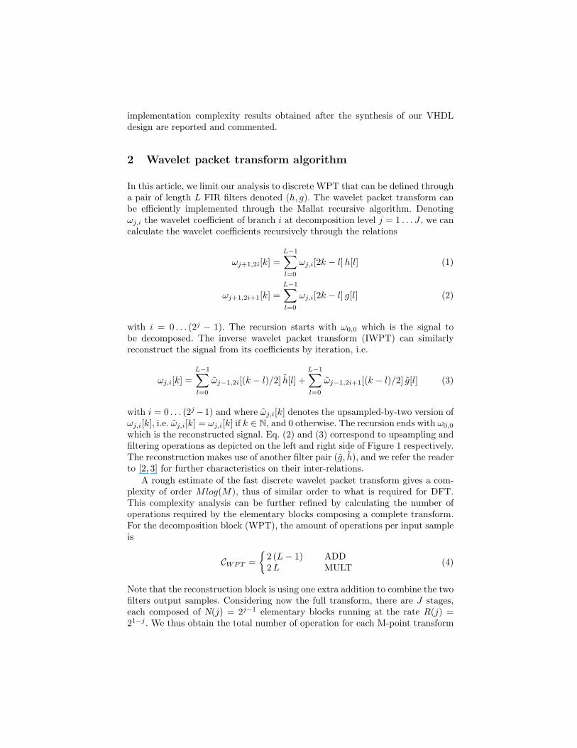
3.3 Configurable forward/reverse transform
It can be easily noticed that the structures described for forward and reversetransforms are almost identical. The only differences are essentially in filter coeffi-cient selection and in the memory reading/writing address generators. It is there-fore interesting to study the possibility to build a configurable forward/reverseWPT. For a given stage, the differences mentioned can be easily overcome byselecting one out of the two address generators for either direction of the trans-form. Similarly, doubling the size of the multiplexers selecting the suitable filtercoefficients allow access to the coefficient of the four filters h, g, h, and g. Theremaining issue is the inter-stage connections, since the transform requires themin increasing or decreasing order of their index j. Moreover for any stage j, bothtransforms require memory block sizes of 2j words and thus stages are not inter-changeable. It is nevertheless possible to build a configurable forward/reversetransform by using bidirectional links between blocks. This solution is illustratedin Figure 5.
Stage 1
Stage 2
Stage J
Wavelet packet transform output
Forward/Reverse
Wavelet packet transform input
Fig. 5. Architecture of a configurable bi-directional wavelet packet transform
3.4 Non-regular transform
We considered until now only a fully pruned transform. We show here thatsome rather simple modifications allow our architecture to support non-fullypruned transforms as well. From an implementation point of view, we start withan architecture with a depth equal to the maximal depth of the non-regulartransform. Focusing only on the inverse transform fo the moment, we assumewithout loss of generality that the elementary block i0 of the higher index stageJ is not implemented. Thus, the transform input coefficients ωJ,2i0 and ωJ,2i0+1
of the bypassed elementary block are no longer required. On the other hand, weneed to provide the coefficients ωJ−1,i0 [k] and ωJ−1,i0 [k + 1] to the next stage.An simple way to achieved this without modifying the input and output formatof the transform is to substitute the second pair of coefficients for the first one. Ina such situation, the input coefficients are passing through the stage unmodifiedand are provided to the input of the next stage. Similar reasoning can be appliedto any stage.
From an implementation point of view, this can be done easily using a binaryflag for each input coefficient of every stage. If the flag is not set, then normalprocessing is performed, and otherwise the elementary block is bypassed. Theactual bypassing operation can be done by providing an alternative path frominput to output with the required number of clock cycle delays1. Another possi-bility is to switch to an alternate pair of specific filters. It can be easily verifiedthat a filter pair h[k] = δ[k] and g[k] = δ[k − 1] leads to the expected result.This latter solution has the advantage of not requiring the implementation of analternative data path.
4 Performance and complexity of the implementedtransform
The architecture proposed has been developed using VHDL. At the time wherethis article is written, complete results are only available for the inverse transform1 The total delay is equal to log2(L) + 3 and thus dependent of the filter length L.

3 4 5 6 7 8 9 100
2000
4000
6000
8000
10000
Number of stages J
Num
ber o
f Xili
nx F
PG
A s
lices
Slices count
3 4 5 6 7 8 9 100
200
400
600
800
1000
Complexity of the implemented reverse WPT(Filter length L
0 = 8)
Num
ber o
f equ
ival
ent g
ates
[ ×
1000
]
Gates count
Fig. 6. Complexity of our synthesized IWPT for different transform sizes (in numberof stages) for a filter length L0 of 8
without support for fully pruned reconstruction tree. The functionality of theconfigurable bi-directional and arbitrary tree transforms has been completed,but the corresponding VHDL implementations are still under developments.
We intend to implement the developed core in a transceiver testbed basedon FPGA devices from Xilinx Virtex-E family. Consequently, most of the ele-mentary blocks have been taken from the manufacturer provided VHDL library.Those blocks are in particular the input FIFO, dual-port memory, multipliersand adders.
For modularity reason, the read and write address generators have been in-stantiated separately for each memory block. This differs slightly from our ref-erence architecture where only one pair of address generators was used for eachstage. This has only a minor impact on overall system complexity and further-more, later versions of our model could remove this non optimal design. Similarduplications appear in the registers holding the filter coefficients: there is onepair of registers per stage, while one per transform would actually be sufficient.
Our design has been synthesized with an inter-stage data path and filtercoefficients resolution of 16 bits. Subsequently, the multiplier operates at thesame resolution, which provides a 32 bit wide result. This value is truncatedthe first time to 16 bits before reaching the adder input, and a second timebefore the stage output. Those data path widths have been chosen arbitrary for

4 6 8 10 12 14 160
1000
2000
3000
4000
5000
6000
Filter length L0
Num
ber o
f Xili
nx F
PG
A s
lices
Slices count
4 6 8 10 12 14 16100
200
300
400
500
600
700
Num
ber o
f equ
ival
ent g
ates
[ ×
1000
]
Complexity of the implemented reverse WPT(Number of stages J = 4)
Gates count
Fig. 7. Complexity of the synthesized IWPT as a function of the filter length for atransform size J of 4.
testing purposes only and other values would most probably better suit a givenapplication in terms of overall complexity versus overall round-off error.
Our design has been synthesized with Xilinx development tools with theassumptions mentioned above. Figure 6 plots the complexity of the implementedinverse transform as a function of its size. The filter length L0 is equal to 8 in thiscase. Both the number of slices and equivalent number of gates are displayed fortransform sizes between 8 (J = 3) and 1024 (J = 10). The influence of the filterlength on the overall complexity is illustrated in Figure 7 for a 4-stage transformsize. The XCV1000-E device used has 12288 slices in total. Thus, a 512-point,8-tap filter based IWPT requires only about 43% of the whole device. For thisparticular configuration and a device speed grade of “-6”, the post-synthesistiming analysis indicates a maximum clock frequency of 125 MHz when defaultconstraints are used. Well setup additional constraints should permit to keep thisvalue higher than 100 MHz, thus allowing to fulfill the highest initial requirement.
5 Conclusion
This article has proposed an architecture to implement very fast, largely config-urable forward and inverse wavelet packet transforms. Though high speed hasbeen preferred to a reduced silicon area, it has been underlined that the proposedarchitecture permits to trade complexity for speed. A complete implementation
has been done in order to validate the expected performance and obtain exactcomplexity measurements. The results are matching the initial speed requirementand our design can therefore be used as the core of an multicarrier transceiverrunning at up to 100 Msymbols/sec. Further work nevertheless remains to becarried out to complete the design a workable WPM transceiver.
Acknowledgments
This work has been supported in part by the Academy of Finland (Grants forproject 50624 and 50618).
References
1. van Nee, R., Prasad, R.: OFDM wireless multimedia communications. Artech house(2000)
2. Mallat, S.: A wavelet tour of signal processing. Academic Press (1997)3. Chui, C.K.: An introduction to wavelets. Volume 1. Academic Press (1992)4. Trenas, M.A., Lopez, J., Zapata, E.L.: FPGA implementation of wavelet packet
transform with reconfigurable tree structure. In: EUROMICRO conference pro-ceedings. (2000) 916–919