Formation of a Carbon Interphase Layer on SiC Fibers Using ...
6
Journal of the Korean Ceramic Society Vol. 52, No. 4, pp. 284~289, 2015. - 284 - http://dx.doi.org/10.4191/kcers.2015.52.4.284 † Corresponding author : Dang-Hyok Yoon E-mail : [email protected] Tel : +82-53-810-2561 Fax : +82-53-810-4628 Formation of a Carbon Interphase Layer on SiC Fibers Using Electrophoretic Deposition and Infiltration Methods Pipit Fitriani, Amit Siddharth Sharma, Sungho Lee, and Dang-Hyok Yoon † School of Materials Science and Engineering, Yeungnam University, Gyeongsan 712-749, Korea (Received June 29, 2015; Revised July 14, 2015; Accepted July 14, 2015) ABSTRACT This study examined carbon layer coating on silicon carbide (SiC) fibers by utilizing solid-state and wet chemistry routes to confer toughness to the fiber-reinforced ceramic matrix composites, as an alternative to the conventional pyrolytic carbon (PyC) interphase layer. Electrophoretic deposition (EPD) of carbon black nanoparticles using both AC and DC current sources, and the vacuum infiltration of phenolic resin followed by pyrolysis were tested. Because of the use of a liquid phase, the vacuum infiltra- tion resulted in more uniform and denser carbon coating than the EPD routes with solid carbon black particles. Thereafter, vac- uum infiltration with controlled variation in phenolic resin concentration, as well as the iterations of infiltration steps, was improvised to produce a homogeneous carbon coating having a thickness of several hundred nanometers on the SiC fiber. Con- clusively, it was demonstrated that the carbon coating on the SiC fiber could be achieved using a simpler method than the con- ventional chemical vapor deposition technique. Key words : Carbon, Silicon carbide, Composites, Electrophoretic deposition 1. Introduction iC-based ceramics are considered one of the most attractive materials for high temperature applications, being used in areas such as structural components for gas turbines, heat exchangers, and nuclear reactors, owing to their excellent thermal and mechanical properties. 1-4) Because monolithic SiC shows brittle fracture behavior, SiC fiber-reinforced SiC matrix composites (SiC f /SiC) have been proposed to mitigate this problem. 5) Among the several com- mercially available SiC fibers, Tyranno Fiber SA grade (Ube Industries, Ltd, Japan) is considered to be best for reinforce- ment because of its high strength and excellent heat resis- tance up to 2200 o C in an inert atmosphere. 6) Moreover, Tyranno Fiber SA exhibited better static fatigue and longer rupture time than Hi-Nicalon Type S fiber (NGS Advanced Fibers Co., Ltd, Japan) because of its lower amount of free carbon (~ 2 at.%) and coarser grains (~ 50 - 100 nm). 6) To confer damage tolerance to SiC f /SiC, the presence of weak interphase between the fiber and matrix is essential. This is normally obtained by the deposition of a pyrolytic carbon (PyC). When a crack is propagating through a com- posite, the weak interphase enhances toughness by a vari- ety of mechanisms, such as interfacial de-bonding, fiber pullout, and crack deflection. Thus far, chemical vapor depo- sition (CVD) is mainly used for the formation of a PyC layer, which normally gives a homogeneous and uniform coating. On the other hand, CVD is an expensive and time-consum- ing process using toxic reactant gases. 7,8) Therefore, the development of an alternative method for PyC coating that is simpler and more cost-effective than CVD is desirable. For this, both the electrophoretic deposition (EPD) of car- bon black particles and coating of phenolic resin on the SiC fiber followed by pyrolysis were considered. 4,9) EPD is a col- loidal process which involves the migration of charged parti- cles to the counter-electrode in a suspension under an electric field. EPD using a direct current (DC-EPD) in organic solvents instead of water has been used convention- ally due to water electrolysis under a DC electric field. On the other hand, the recently introduced EPD using an asymmetric alternating current (AC-EPD) has been used to deposit many kinds of ceramic particles in aqueous systems, while minimizing the decomposition of water. 10-12) Because the velocity of a particle shows a non-linear dependence on the AC electric field, the net particle movement for deposi- tion occurs under an asymmetric AC electric field, suppress- ing water decomposition. 13) Although some studies used DC- EPD to deposit a carbon layer from a carbon black suspen- sion, 14,15) to the best of the authors’ knowledge, there are no reports of the application of AC-EPD. Therefore, in this study, both DC- and AC-EPD were tested and compared for the formation of a carbon layer from a carbon black suspen- sion containing both a binder and dispersant. Periodic ultra- sonic pulses were applied during EPD to infiltrate the carbon black particles deep inside the SiC preform. Another alternative technique used in this study was the infiltration of phenolic resin into an SiC fabric followed by S
-
Upload
khangminh22 -
Category
Documents
-
view
3 -
download
0
Transcript of Formation of a Carbon Interphase Layer on SiC Fibers Using ...

Journal of the Korean Ceramic Society
Vol. 52, No. 4, pp. 284~289, 2015.
− 284 −
http://dx.doi.org/10.4191/kcers.2015.52.4.284
†Corresponding author : Dang-Hyok Yoon
E-mail : [email protected]
Tel : +82-53-810-2561 Fax : +82-53-810-4628
Formation of a Carbon Interphase Layer on SiC Fibers Using Electrophoretic Deposition and Infiltration Methods
Pipit Fitriani, Amit Siddharth Sharma, Sungho Lee, and Dang-Hyok Yoon†
School of Materials Science and Engineering, Yeungnam University, Gyeongsan 712-749, Korea
(Received June 29, 2015; Revised July 14, 2015; Accepted July 14, 2015)
ABSTRACT
This study examined carbon layer coating on silicon carbide (SiC) fibers by utilizing solid-state and wet chemistry routes to
confer toughness to the fiber-reinforced ceramic matrix composites, as an alternative to the conventional pyrolytic carbon (PyC)
interphase layer. Electrophoretic deposition (EPD) of carbon black nanoparticles using both AC and DC current sources, and the
vacuum infiltration of phenolic resin followed by pyrolysis were tested. Because of the use of a liquid phase, the vacuum infiltra-
tion resulted in more uniform and denser carbon coating than the EPD routes with solid carbon black particles. Thereafter, vac-
uum infiltration with controlled variation in phenolic resin concentration, as well as the iterations of infiltration steps, was
improvised to produce a homogeneous carbon coating having a thickness of several hundred nanometers on the SiC fiber. Con-
clusively, it was demonstrated that the carbon coating on the SiC fiber could be achieved using a simpler method than the con-
ventional chemical vapor deposition technique.
Key words : Carbon, Silicon carbide, Composites, Electrophoretic deposition
1. Introduction
iC-based ceramics are considered one of the most
attractive materials for high temperature applications,
being used in areas such as structural components for gas
turbines, heat exchangers, and nuclear reactors, owing to
their excellent thermal and mechanical properties.1-4)
Because monolithic SiC shows brittle fracture behavior, SiC
fiber-reinforced SiC matrix composites (SiCf/SiC) have been
proposed to mitigate this problem.5) Among the several com-
mercially available SiC fibers, Tyranno Fiber SA grade (Ube
Industries, Ltd, Japan) is considered to be best for reinforce-
ment because of its high strength and excellent heat resis-
tance up to 2200oC in an inert atmosphere.6) Moreover,
Tyranno Fiber SA exhibited better static fatigue and longer
rupture time than Hi-Nicalon Type S fiber (NGS Advanced
Fibers Co., Ltd, Japan) because of its lower amount of free
carbon (~ 2 at.%) and coarser grains (~ 50 - 100 nm).6)
To confer damage tolerance to SiCf/SiC, the presence of
weak interphase between the fiber and matrix is essential.
This is normally obtained by the deposition of a pyrolytic
carbon (PyC). When a crack is propagating through a com-
posite, the weak interphase enhances toughness by a vari-
ety of mechanisms, such as interfacial de-bonding, fiber
pullout, and crack deflection. Thus far, chemical vapor depo-
sition (CVD) is mainly used for the formation of a PyC layer,
which normally gives a homogeneous and uniform coating.
On the other hand, CVD is an expensive and time-consum-
ing process using toxic reactant gases.7,8) Therefore, the
development of an alternative method for PyC coating that
is simpler and more cost-effective than CVD is desirable.
For this, both the electrophoretic deposition (EPD) of car-
bon black particles and coating of phenolic resin on the SiC
fiber followed by pyrolysis were considered.4,9) EPD is a col-
loidal process which involves the migration of charged parti-
cles to the counter-electrode in a suspension under an
electric field. EPD using a direct current (DC-EPD) in
organic solvents instead of water has been used convention-
ally due to water electrolysis under a DC electric field. On
the other hand, the recently introduced EPD using an
asymmetric alternating current (AC-EPD) has been used to
deposit many kinds of ceramic particles in aqueous systems,
while minimizing the decomposition of water.10-12) Because
the velocity of a particle shows a non-linear dependence on
the AC electric field, the net particle movement for deposi-
tion occurs under an asymmetric AC electric field, suppress-
ing water decomposition.13) Although some studies used DC-
EPD to deposit a carbon layer from a carbon black suspen-
sion,14,15) to the best of the authors’ knowledge, there are no
reports of the application of AC-EPD. Therefore, in this
study, both DC- and AC-EPD were tested and compared for
the formation of a carbon layer from a carbon black suspen-
sion containing both a binder and dispersant. Periodic ultra-
sonic pulses were applied during EPD to infiltrate the
carbon black particles deep inside the SiC preform.
Another alternative technique used in this study was the
infiltration of phenolic resin into an SiC fabric followed by
S
Communication

July 2015 Formation of a Carbon Interphase Layer on SiC Fibers Using Electrophoretic Deposition and Infiltration Methods 285
pyrolysis. Phenolic resin is a heat-cured plastic formed from
a reaction between carbon-based alcohol and an aldehyde,
and it is being used for a wide range of applications.16,17) The
vacuum infiltration technique, which uses a pressure gradi-
ent, was adopted for the efficient infiltration of phenolic
resin into the woven SiC fabric.18,19) This study examined
the above three different techniques for the formation of a
carbon layer on the SiC fibers, as an alternative method to
the conventional pyrolytic carbon (PyC) interphase layer.
2. Experimental Procedure
2.1. DC- and AC-EPD
Two-dimensionally woven Tyranno-SA3 SiC fabric, with a
fiber diameter of 7.5 µm and 1600 fibers per yarn, was used
as a preform. Prior to use, the polyethylene oxide sizing
agent was removed by immersing the fabric in boiling water
for 10 minutes. For DC-EPD, a well-dispersed suspension,
containing 2 wt% carbon black particles (Hiblack, Orion
Engineered Carbons, Korea) with a mean particle size of 35
nm, was prepared in ethanol by adding 5 wt% polyester/
polyamine co-polymeric dispersant (Hypermer KD1, ICI,
UK) and 5 wt% PVB binder resin (Butvar B-98, MW =
55,000 g/mol, Solutia, USA). The suspension was ball-milled
for 24 hours using 6 mm SiC balls to ensure dispersion. The
zeta potential of the suspension was measured using an
electroacoustic-type zeta potential analyzer (Zeta Probe,
Colloidal Dynamics, USA) by varying the operational pH of
the suspension.
A disc-shaped SiC fabric with a 5 cm diameter was placed
between the dual stainless steel electrodes dipped in a car-
bon black suspension, as shown in Fig. 1. DC-EPD was then
performed under an electric field of 500 V/m for 60 minutes
with the application of 10 W ultrasonic pulses (HD 2070,
Bandelin, Germany). The distance between each electrode
and the SiC fabric was 2 cm. By considering the positive
zeta potential of the carbon black particles in the suspen-
sion, the SiC fabric was connected to the negative power
source, and the dual stainless steel electrodes were con-
nected to the positive source. After drying the infiltrated
fabrics at 80oC, the samples were heat-treated to 600oC for 2
h in an N2 atmosphere. The experimental conditions for DC-
EPD were chosen based on the previous report4) and further
preliminary tests.
For AC-EPD, an aqueous carbon black suspension was
prepared by adding 0.5 wt% each of ammonium polycarbox-
ylate (Cerasperse 5468CF, San Nopco, Korea) dispersant
and water-soluble acrylic binder (WB4101, Polymer Innova-
tions, USA). Ball milling and zeta potential measurement
were then performed, as described above. AC-EPD was then
conducted using the apparatus shown in Fig. 1 after switch-
ing the polarity from that of a DC-EPD because of the nega-
tive zeta potential of the carbon black particles for AC-EPD.
Instead of a DC-power supply, however, a programmable
function generator (3322A, Agilent, USA), power amplifier
(PZD 700A M/S, Trek, USA), and digital oscilloscope (DSO-
X 2002A, Agilent, USA) were used for AC signal generation
and EPD for a disc-shaped SiC fabric using a dual electrode
system. A square-shaped asymmetric 100 Hz AC signal
with an asymmetry factor of 4 and a peak-to-peak voltage of
20 V was applied for 60 minutes for AC-EPD to the aqueous
suspension at pH=3, based on a preliminary test,20) while
applying 10 W ultrasonic pulses with a frequency of 1 Hz to
enhance the degree of phenolic resin infiltration into the
SiC preform. The inset in Fig. 1 shows the waveforms of the
voltage signals for DC- and AC-EPD.
2.2. Vacuum infiltration
After diluting a phenolic resin (HiRENOL, Kolon Indus-
tries, Korea) to 5 wt% in six different kinds of solvents
(methanol, ethanol, propanol, butanol, pentanol, and eth-
ylene glycol), the phenolic resin solution was infiltrated into
five layers of SiC fabrics by pressure gradient using the vac-
uum infiltration apparatus shown in Fig. 2. The experimen-
tal setup was composed of an outer chamber, vacuum pump,
and inner vessel, which was divided by a spacer to place five
layers of round-shaped SiC fabrics. After placing the fabrics
Fig. 1. Schematic diagram of the experimental setup for car-bon black infiltration using DC- and AC-EPD. Modi-fied from a previous report.21)
Fig. 2. Schematic diagram of the experimental setup forvacuum infiltration during vacuum (a) increase and(b) release. Modified from a previous report.19)
286 Journal of the Korean Ceramic Society - Pipit Fitriani et al. Vol. 52, No. 4
in the middle of the inner vessel with the phenolic resin
solution on top, the vacuum was released slowly to atmo-
spheric pressure when the pressure reached 0.1 Pa. Owing
to the pressure difference between the top and bottom of the
inner vessel during this release, the solution was passed
through the fabrics, infiltrating the gaps of the fibers. The
infiltrated fabrics were then centrifuged at 200 rpm to
remove the extra phenolic resin filling the voids of the fab-
rics. Vacuum infiltration was performed at various concen-
trations of phenolic resin solution in methanol and
infiltration repetitions because methanol was the optimal
solvent for the coating. To convert the phenolic resin to car-
bon, pyrolysis was performed in a tube furnace at 600oC for
1 hour at a heating rate of 5oC/min in an N2 atmosphere.
The thermal decomposition behavior of the phenolic resin
was also examined by thermo-gravimetric analysis (TGA:
SDT Q600, TA Instruments, USA). The viscosity of each
phenolic resin solution at 20oC was measured using a com-
puter-controlled viscometer (DV-II+ Pro, Brookfield, MA,
USA) equipped with a small sample adapter with a SC4-18
spindle at various shear rates. The microstructure of the
infiltrated fabrics was observed by scanning electron
microscopy (SEM; Hitachi S-4200).
3. Results and Discussion
3.1. DC- and AC-EPD of the carbon black particles
Figure 1 presents the experimental setup used for carbon
black particle infiltration into the SiC fabric by DC- and AC-
EPD combined with ultrasonication. The apparatus was
composed of dual stainless steel positive electrodes to
enhance the degree of deposition from both sides and a neg-
ative electrode connected to the SiC fabric placed in the
middle of the vessel. An ultrasonic tip was placed into the
suspension, which released 10 W ultrasonic pulses with a 1
second cycle to accelerate the carbon black infiltration into
the deep voids of the preform. The only difference in the DC-
and AC-EPD apparatus was the power supply, where a sole
DC power supply was used for DC-EPD, whereas the combi-
nations of function generator, amplifier, and oscilloscope
were used for AC-EPD.
As mentioned previously, a solvent-based system is used
preferentially for DC-EPD because of the decomposition of
water under a DC electric field, whereas AC-EPD can use
an aqueous system owing to the minimized water electroly-
sis under asymmetric AC electric field. Fig. 3 (a) and (b)
shows the zeta potential behavior of a carbon black suspen-
sion in ethanol (for DC-EPD) and water (for AC-EPD),
respectively, as a function of the operational pH with/with-
out a binder and dispersant. Both measurements were per-
formed using an electroacoustic technique, which is
adequate for measuring the zeta potential for small parti-
cles because the carbon black particles were very fine with a
mean particle size of 35 nm. The higher zeta potential con-
fers larger repulsion between the particles in terms of the
electrostatic mechanism, whereas the sign of the zeta poten-
tial determines the direction of particles moving during
EPD. For the ethanol-based suspension shown in Fig. 3 (a),
the zeta potential decreased with increasing operational pH
due to the increased concentration of hydroxyl ions (OH–),
regardless of the presence of a binder or dispersant.
Because higher zeta potential leads to higher mobility of
particles, the suspension containing both the binder and dis-
persant with the operational pH=3 was chosen for DC-EPD,
which had a positive zeta potential of 25 mV. Five wt% of a
polymeric dispersant was added to maximize the dispersion
stability via steric stabilization, whereas the binder was
added to enhance the adhesion of carbon black powder to
the surface of the SiC fabric preform. The effects of the dis-
persant and binder addition on the zeta potential were
found to be insignificant in this ethanol-based system, as
shown in Fig. 3(a). On the other hand, the zeta potential of
the carbon black particles in an aqueous system was
affected by the co-presence of a binder and dispersant, as
shown in Fig. 3(b). Therefore, pH=8 was chosen for AC-
EPD, where a zeta potential of -28 mV could be achieved.
Fig. 3. Zeta potential of the carbon black suspensions with/without binder and dispersant in (a) ethanol and (b)water as a function of the operational pH.

July 2015 Formation of a Carbon Interphase Layer on SiC Fibers Using Electrophoretic Deposition and Infiltration Methods 287
Although the AC power source oscillates its polarity, the
SiC fabric was connected to the positive electrode because of
the asymmetric AC signal to maximize the degree of infil-
tration. The iso-electric points, where the zeta potential = 0,
were a pH of approximately 6 for both systems.
Figure 4 shows SEM images of the SiC fibers before and
after EPD. Because the as-received SiC fabrics have small
gaps between the fibers within a yarn, as shown in Fig. 4(a),
the efficient infiltration of carbon black particles into the
deep inter-fiber voids is essential for coating each SiC fiber
uniformly, as shown in Fig. 4(b). Fig. 4(c) and (d) show SEM
images of the carbon coating layers formed by DC- and AC-
EPD after pyrolysis at 600 oC, respectively. Although the
vigorous migration of carbon black particles was observed
during EPD, the resulting carbon coating layers on the SiC
fiber surface were inhomogeneous in both methods. The
coating layer revealed the rough agglomeration of carbon
black particles instead of a smooth surface, which might be
inevitable because of the use of a solid phase as a starting
material. A simple comparison of the coating layer morphol-
ogy showed that AC-EPD resulted in a more uniform coat-
ing than DC-EPD, indicating the potential feasibility of the
eco-friendly AC-EPD using an aqueous system.
3.2. Vacuum infiltration of the phenolic resin fol-
lowed by pyrolysis
To identify a more suitable method for the formation of a
carbon layer than the EPD of carbon black particles, infil-
tration using a phenolic resin solution followed by pyrolysis
was examined as an alternative. The utilization of a liquid
phase instead of solid particles would be more desirable for
forming a smooth carbon coating layer. Because the viscos-
ity of pure phenolic resin was too high to infiltrate, i.e., 600
cPs at a shear rate of 132 s−1, dilution into a 5 wt% solution
was performed using six different kinds of solvents. All sol-
vents contained a hydroxyl ion (OH–) functional group, i.e.,
one OH– group for five kinds of alcohols and two OH– groups
for ethylene glycol, because the presence of OH– in the sol-
vents is effective in reducing the viscosity of the pure pheno-
lic resin. Based on the viscosity data shown in Fig. 5, all
suspensions exhibited pseudo-plastic behavior. The phenolic
resin in methanol exhibited the lowest viscosity, whereas
that in ethylene glycol revealed the highest viscosity. There-
fore, the viscosity of the phenolic resin solution is affected by
the molecular weight of the solvent as well as the number of
OH– groups, even though the difference in viscosity of phe-
nolic resins dissolved in six types of solvents was not signifi-
cant, as shown in Fig. 5.
A vacuum infiltration apparatus, which uses a forced
pressure difference, was designed for effective infiltration of
phenolic resin into the small inter-fiber voids, as shown in
Fig. 2. After placing five layers of fabrics in the middle of the
inner vessel with the phenolic resin on top, a vacuum was
applied for infiltration, as shown in Fig. 2(a). When the vac-
uum level reached 0.1 Pa, the air was released slowly. The
slurry passed through the fabrics infiltrating between the
gaps of the fibers due to the difference in force during
release, as shown in Fig. 2(b).
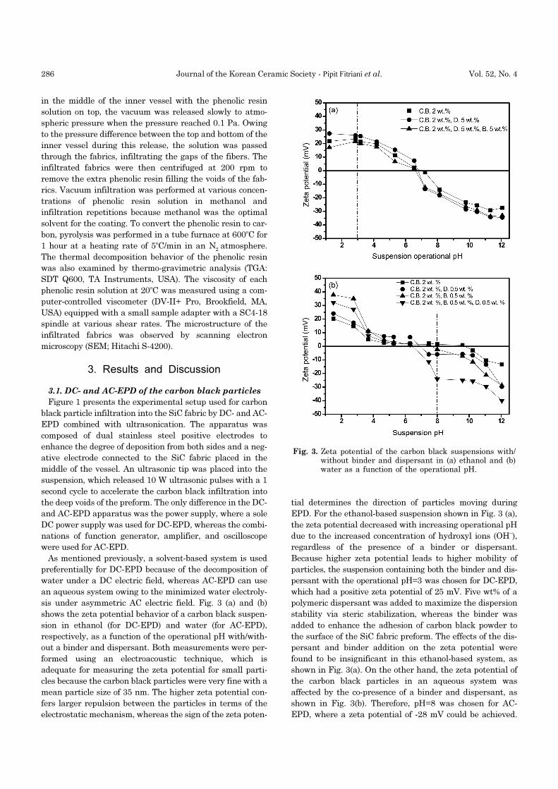
TGA was performed to determine the optimal tempera-
ture for the conversion of phenolic resin to carbon, and the
result is shown in Fig. 6. The weight loss up to 200oC was
attributed to the loss of moisture, while the further weight
loss at 400 - 650°C was due to degradation of the hydroxyl
group and the decomposition of phenolic resin to carbon.22,23)
The last weight loss above 650°C was attributed to the
thermo-oxidative reaction and the evaporation of the phenolic
resin. Because most of the weight loss occurred up to 600oC,
the pyrolysis conditions were 600oC for 1 hour in an N2
atmosphere.
Figure 7 (a) and (b) shows SEM images of the carbon coat-
ing layer formed using a phenolic resin diluted to 5 wt% in
methanol and butanol, respectively. The phenolic resin dis-
solved in methanol resulted in a uniform carbon coating
layer on the SiC fiber, whereas that in butanol or other sol-
vents did not produce a homogeneous coating. Therefore,
Fig. 4. SEM images of the (a) as-received SiC woven fabric,(b) bare SiC fibers, and the carbon black powder-coated SiC fibers using (c) DC- and (d) AC-EPD.
Fig. 5. Viscosity of the 5 wt% phenolic resin solution dis-solved in various solvents.
288 Journal of the Korean Ceramic Society - Pipit Fitriani et al. Vol. 52, No. 4
the property of the solvent appears to be very important for
obtaining a uniform carbon coating layer, including the dis-
solvability of the phenolic resin. Among the six types of sol-
vents, methanol tends to form the strongest hydrogen bond
with the phenolic resin molecule because each hydroxyl
group can provide a proton to form a hydrogen bond. More-
over, the hydrogen bond strength between the solvent and
hydroxymethyl groups (R-OH) in the phenolic resin decreased
with increasing molecular weight because the polarity of
solvent decreased with increasing hydrocarbon chain
length. Consequently, the interaction force between the
phenolic resin and methanol would be highest in terms of
the hydrogen bonding strength and polarity. The other fac-
tor that might affect the formation of a uniform carbon layer
is the degree of curing upon heat treatment, where fast and
complete crosslinking is desirable. As suggested by Yan et
al., the curing rate of the phenolic resin in methanol is the
fastest compared to the other solvents containing a hydroxyl
group.24) Therefore, it appears that the phenolic resin solu-
tion in methanol produced the most homogeneous carbon
coating layer on the SiC fiber, as shown in Fig. 7(a).
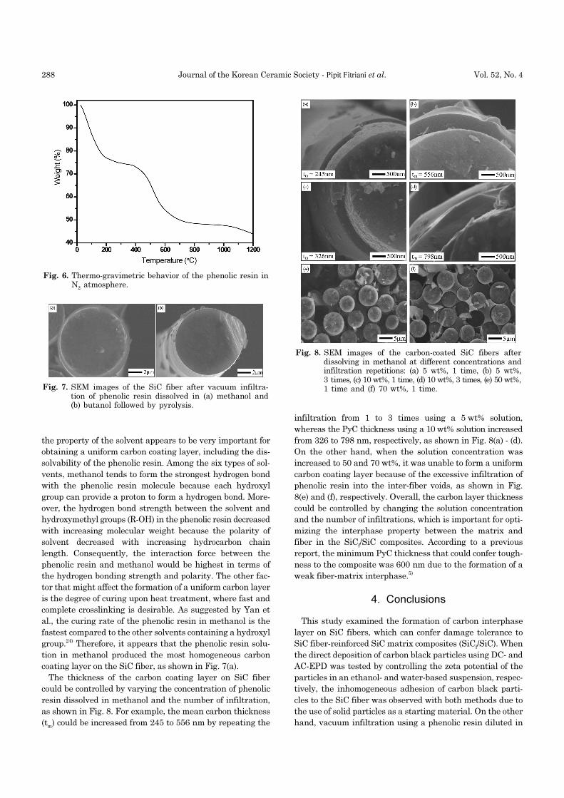
The thickness of the carbon coating layer on SiC fiber
could be controlled by varying the concentration of phenolic
resin dissolved in methanol and the number of infiltration,
as shown in Fig. 8. For example, the mean carbon thickness
(tm) could be increased from 245 to 556 nm by repeating the
infiltration from 1 to 3 times using a 5 wt% solution,
whereas the PyC thickness using a 10 wt% solution increased
from 326 to 798 nm, respectively, as shown in Fig. 8(a) - (d).
On the other hand, when the solution concentration was
increased to 50 and 70 wt%, it was unable to form a uniform
carbon coating layer because of the excessive infiltration of
phenolic resin into the inter-fiber voids, as shown in Fig.
8(e) and (f), respectively. Overall, the carbon layer thickness
could be controlled by changing the solution concentration
and the number of infiltrations, which is important for opti-
mizing the interphase property between the matrix and
fiber in the SiCf/SiC composites. According to a previous
report, the minimum PyC thickness that could confer tough-
ness to the composite was 600 nm due to the formation of a
weak fiber-matrix interphase.5)
4. Conclusions
This study examined the formation of carbon interphase
layer on SiC fibers, which can confer damage tolerance to
SiC fiber-reinforced SiC matrix composites (SiCf/SiC). When
the direct deposition of carbon black particles using DC- and
AC-EPD was tested by controlling the zeta potential of the
particles in an ethanol- and water-based suspension, respec-
tively, the inhomogeneous adhesion of carbon black parti-
cles to the SiC fiber was observed with both methods due to
the use of solid particles as a starting material. On the other
hand, vacuum infiltration using a phenolic resin diluted in
Fig. 6. Thermo-gravimetric behavior of the phenolic resin inN2 atmosphere.
Fig. 7. SEM images of the SiC fiber after vacuum infiltra-tion of phenolic resin dissolved in (a) methanol and(b) butanol followed by pyrolysis.
Fig. 8. SEM images of the carbon-coated SiC fibers afterdissolving in methanol at different concentrations andinfiltration repetitions: (a) 5 wt%, 1 time, (b) 5 wt%,3 times, (c) 10 wt%, 1 time, (d) 10 wt%, 3 times, (e) 50 wt%,1 time and (f) 70 wt%, 1 time.
July 2015 Formation of a Carbon Interphase Layer on SiC Fibers Using Electrophoretic Deposition and Infiltration Methods 289
various kinds of solvents followed by pyrolysis at 600 oC
resulted in a uniform carbon coating layer over the SiC fiber
only when methanol was used as a solvent. This was
explained by the highest hydrogen bonding strength and
the polarity of methanol among the six kinds of solvents
used, which gives a strong interaction force between the sol-
vent and phenolic resin, along with the fastest crosslinking
upon pyrolysis. Moreover, the thickness of the carbon coat-
ing layer on the SiC fiber could be controlled within a thick-
ness of 200 - 800 nm by changing the solution concentration
and the number of infiltration steps. The fabrication of SiCf/
SiC using a carbon-coated SiC fabric by vacuum infiltration
of phenolic resin is currently underway.
Acknowledgments
This study was supported by the National R&D Program
funded by the Ministry of Science, ICT & Future Planning,
Republic of Korea (Grant no. 2014M1A7A1A02029408).
REFERENCES
1. S. J. Dapkunas, “Ceramic Heat Exchangers,” Am. Ceram.
Soc. Bull., 67 388-91 (1988).
2. Y. Takeda, “Development of High-Thermal-Conductive SiC
Ceramics,” Am. Ceram. Soc. Bull., 67 1961-63 (1988).
3. B. Riccardi, L. Giancarli, A. Hasegawa, Y. Katoh, A.
Kohyama, R. H. Jones, and L. L. Snead, “Issues and Advances
in SiCf/SiC Composites Development for Fusion Reactors,”
J. Nucl. Mater., 329-333 56-65 (2004).
4. J. H. Lee, G. Y. Gil, and D. H. Yoon, “Fabrication of SiCf/
SiC Composites Using an Electrophoretic Deposition,” J.
Korean Ceram. Soc., 46 447-51 (2009).
5. A. Noviyanto and D. H. Yoon, “The Effects of Pyrolytic Car-
bon Interphase Thickness on the Properties of Hot-Pressed
SiCf/SiC Composites,” J. Ceram. Process. Res., 13 392–97
(2012).
6. T. Ishikawa, Y. Kohtoku, K. Kumagawa, T. Yamamura,
and T. Nagasawa, “High-Strength Alkali-Resistant Sin-
tered SiC Fibre Stable to 2,200oC,” Nature, 391 773-75
(1998).
7. K. Yoshida, Y. Aoyagi, H. Akimoto, T. Yano, M. Kotani, and
T. Ogasawara, “Interfacial Control of Uni-Directional SiCf/
SiC Composites Based on Electrophoretic Deposition and
Their Mechanical Properties,” Compos. Sci. Technol., 72
1665-70 (2012).
8. J. J. Brennan, “Interfacial Studies of Chemical-Vapor-Infil-
trated Ceramic Matrix Composites,” Mater. Sci. Eng. A,
216 203-23 (1990).
9. K. Raju and D. H. Yoon, “Electrophoretic Deposition of
BaTiO3 in Aqueous Suspension Using Asymmetric Alter-
nating Current,” Mater. Lett., 110 188-90 (2013).
10. V.O. Kollath, Q. Chen, R. Closset, J. Luyten, K. Traina, S.
Mullens, A. R. Boccaccini, and R. Cloots, “AC vs. DC Elec-
trophoretic Deposition of Hydroxyapatite on Titanium Sub-
strate,” J. Eur. Ceram. Soc., 33 2715-21 (2013).
11. A. Chavez-Valdez, M. Herrmann, and A.R. Boccaccini,
“Alternating Current Electrophoretic Deposition (EPD) of
TiO2 Nanoparticles in Aqueous Suspensions,” J. Colloid
Interphase Sci., 375 102-05 (2012).
12. A. Nold and R. Clasen, “Bubble-Free Electrophoretic Shap-
ing from Aqueous Suspension with Micro Point-Electrode,”
J. Eur. Ceram. Soc., 30 2971-75 (2010).
13. B. Neirinck, J. Fransaer, O. Van der Biest, and J. Vleugels,
“Aqueous Electrophoretic Deposition in Asymmetric AC
Electric Fields (AC-EPD),” Electrochem. Commun., 11 57-
60 (2009).
14. K. Yoshida, K. Matsukawa, M. Imai, and T. Yano, “Forma-
tion of Carbon Coating on SiC Fiber for Two-Dimensional
SiCf/SiC Composites by Electrophoretic Deposition,” Mater.
Sci. Eng. B, 161 188-92 (2009).
15. K. Yoshida, “Development of Silicon Carbide Fiber-Rein-
forced Silicon Carbide Matrix Composites with High Per-
formance Based on Interfacial and Microstructure Control,”
J. Ceram. Soc. Jpn., 118 82-90 (2010).
16. Y. Chen, M. Yue, Z. H. Huang, and F. Kang, “Electrospun
Carbon Nanofiber Networks from Phenolic Resin for
Capacitive Deionization,” J. Chem. Eng., 252 30-37 (2014).
17. F. T. Behrooz, B. M. Maher, and M. M. Shokrieh, “Mechan-
ical Properties Modification of a Thin Film Phenolic Resin
Filled with Nano Silica Particles,” Comp. Mater. Sci., 96
411-15 (2015).
18. P. Yonathan, J. H. Lee, H. T. Kim, and D. H. Yoon, “Prop-
erties of SiCf/SiC Composites Fabricated by Slurry Infiltra-
tion and Hot Pressing,” Mater. Sci. Tech-Lond., 27 257-63
(2011).
19. P. Yonathan, J. H. Lee, H. T. Kim, D. H. Yoon, W. J. Kim,
and J.Y. Park, “Improvement of SiCf/SiC Density by Slurry
Infiltration and Tape Stacking,” Mater. Res. Bul., 44 2116-
22 (2009).
20. K. Raju, H. W. Yu, and D. H. Yoon, “Aqueous Electropho-
retic Deposition of SiC Using Asymmetric AC Electric
Fields,” Ceram. Int., 40 12609-12 (2014).
21. G. Y. Gi and D. H. Yoon, “Densification of SiCf/SiC Com-
posites by Electrophoretic Infiltration Combined with
Ultrasonication,” J. Ceram. Process. Res., 12 371-75 (2011).
22. M. Su, Z. Wang, H. Guo, X. Li, S. Huang, and L. Gan, “Sili-
con, Flake Graphite and Phenolic Resin-Pyrolyzed Carbon
Based Si/C Composites as Anode Material for Lithium-Ion
Batteries,” Adv. Powder. Technol., 24 921-25 (2013).
23. S. Chow and P. R. Steiner, “Comparison of the Cure of Phe-
nolic-Formaldehyde Novolac and Resol Systems by Differ-
ential Scanning Calorimetry,” J. Appl. Polym. Sci., 23
1973-85 (1979).
24. Z. Yan, L. Yujian, H. Qi, and H. Zhewen, “Effect of Solvent
on the Chain Conformation and Cure Behavior of Phenolic
Resin,” J. Appl. Polym. Sci., 108 3009-15 (2008).


![Grammatical notes and vocabulary of Nagnuma primier [sic]](https://static.fdokumen.com/doc/165x107/6324da70e491bcb36c0a0414/grammatical-notes-and-vocabulary-of-nagnuma-primier-sic.jpg)