For use with R32 OUTDOOR UNIT - Mitsubishi-les
64
For use with R32 en de fr es it nl pt el ru tr 中<简> cs sk hu pl sl sv hr bg ro no da INSTALLATION MANUAL For safe and correct use, please read this installation manual thoroughly before installing the air-conditioner unit. INSTALLATIONSHANDBUCH Zum sicheren und ordnungsgemäßen Gebrauch der Klimageräte das Installationshandbuch gründlich durchlesen. MANUEL D’INSTALLATION Veuillez lire le manuel d’installation en entier avant d’installer ce climatiseur pour éviter tout accident et vous assurer d’une utilisation correcte. MANUAL DE INSTALACIÓN Para un uso seguro y correcto, lea detalladamente este manual de instalación antes de montar la unidad de aire acondicionado. MANUALE DI INSTALLAZIONE Per un uso sicuro e corretto, leggere attentamente questo manuale di installazione prima di installare il condizionatore d’aria. INSTALLATIEHANDLEIDING Voor een veilig en juist gebruik moet u deze installatiehandleiding grondig doorlezen voordat u de airconditioner installeert. MANUAL DE INSTALAÇÃO Para segurança e utilização correctas, leia atentamente este manual de instalação antes de instalar a unidade de ar condicionado. ΕΓΧΕΙΡΙΔΙΟ ΟΔΗΓΙΩΝ ΕΓΚΑΤΑΣΤΑΣΗΣ Για ασφάλεια και σωστή χρήση, παρακαλείστε διαβάσετε προσεχτικά αυτό το εγχειρίδιο εγκατάστασης πριν αρχίσετε την εγκατάσταση της μονάδας κλιματισμού. РУКОВОДСТВО ПО УСТАНОВКЕ Для осторожного и правильного использования прибора необходимо тщательно ознакомиться с данным руководством по установке до выполнения установки кондиционера. MONTAJ ELKİTABI Emniyetli ve doğru biçimde nasıl kullanılacağını öğrenmek için lütfen klima cihazını monte etmeden önce bu elkitabını dikkatle okuyunuz. 安装手册 为了安全和正确地使用本空调器,请在安装前仔细阅读本安装手册。 PŘÍRUČKA K INSTALACI V zájmu bezpečného a správného používání si před instalací klimatizační jednotky důkladně pročtěte tuto příručku k instalaci. NÁVOD NA INŠTALÁCIU Pre bezpečné a správne použitie si pred inštalovaním klimatizačnej jednotky, prosím, starostlivo prečítajte tento návod na inštaláciu. TELEPÍTÉSI KÉZIKÖNYV A biztonságos és helyes használathoz, kérjük, olvassa el alaposan ezt a telepítési kézikönyvet, mielőtt telepítené a légkondicionáló egységet. PODRĘCZNIK INSTALACJI W celu bezpiecznego i poprawnego korzystania należy przed zainstalowaniem klimatyzatora dokładnie zapoznać się z niniejszym podręcznikiem instalacji. PRIROČNIK ZA NAMESTITEV Za varno in pravilno uporabo pred namestitvijo klimatske naprave skrbno preberite priročnik za namestitev. INSTALLATIONSHANDBOK Läs den här installationshandboken noga innan luftkonditioneringsenheten installeras, för säker och korrekt användning. PRIRUČNIK ZA UGRADNJU Radi sigurne i ispravne uporabe, temeljito pročitajte ovaj priručnik prije ugradnje klimatizacijskog uređaja. РЪКОВОДСТВО ЗА МОНТАЖ За безопасна и правилна употреба, моля, прочетете внимателно това ръководство преди монтажа на климатизатора. MANUAL CU INSTRUCŢIUNI DE INSTALARE Pentru o utilizare corectă şi sigură, vă rugăm să citiţi cu atenţie acest manual înainte de a instala unitatea de aer condiţionat. INSTALLATIONSMANUAL Læs venligst denne installationsmanual grundigt, før De installerer airconditionanlægget, af hensyn til sikker og korrekt anvendelse. INSTALLASJONSHÅNDBOK For sikker og riktig bruk, skal du lese denne installasjonshåndboken nøye før du installerer klimaanlegget. Air-Conditioners For Building Application OUTDOOR UNIT PURY-M-YNW-A1(-BS) PURY-EM-YNW-A1(-BS) <ORIGINAL>
-
Upload
khangminh22 -
Category
Documents
-
view
2 -
download
0
Transcript of For use with R32 OUTDOOR UNIT - Mitsubishi-les
For use with R32
ende
fres
itnl
ptel
rutr
中<简>
cssk
hupl
slsv
hrbg
rono
da
INSTALLATION MANUALFor safe and correct use, please read this installation manual thoroughly before installing the air-conditioner unit.
INSTALLATIONSHANDBUCHZum sicheren und ordnungsgemäßen Gebrauch der Klimageräte das Installationshandbuch gründlich durchlesen.
MANUEL D’INSTALLATIONVeuillez lire le manuel d’installation en entier avant d’installer ce climatiseur pour éviter tout accident et vous assurer d’une utilisation correcte.
MANUAL DE INSTALACIÓNPara un uso seguro y correcto, lea detalladamente este manual de instalación antes de montar la unidad de aire acondicionado.
MANUALE DI INSTALLAZIONEPer un uso sicuro e corretto, leggere attentamente questo manuale di installazione prima di installare il condizionatore d’aria.
INSTALLATIEHANDLEIDINGVoor een veilig en juist gebruik moet u deze installatiehandleiding grondig doorlezen voordat u de airconditioner installeert.
MANUAL DE INSTALAÇÃOPara segurança e utilização correctas, leia atentamente este manual de instalação antes de instalar a unidade de ar condicionado.
ΕΓΧΕΙΡΙΔΙΟ ΟΔΗΓΙΩΝ ΕΓΚΑΤΑΣΤΑΣΗΣΓια ασφάλεια και σωστή χρήση, παρακαλείστε διαβάσετε προσεχτικά αυτό το εγχειρίδιο εγκατάστασης πριν αρχίσετε την εγκατάσταση της μονάδας κλιματισμού.
РУКОВОДСТВО ПО УСТАНОВКЕДля осторожного и правильного использования прибора необходимо тщательно ознакомиться с данным руководством по установке до выполнения установки кондиционера.
MONTAJ ELKİTABIEmniyetli ve doğru biçimde nasıl kullanılacağını öğrenmek için lütfen klima cihazını monte etmeden önce bu elkitabını dikkatle okuyunuz.
安装手册 为了安全和正确地使用本空调器,请在安装前仔细阅读本安装手册。
PŘÍRUČKA K INSTALACIV zájmu bezpečného a správného používání si před instalací klimatizační jednotky důkladně pročtěte tuto příručku k instalaci.
NÁVOD NA INŠTALÁCIUPre bezpečné a správne použitie si pred inštalovaním klimatizačnej jednotky, prosím, starostlivo prečítajte tento návod na inštaláciu.
TELEPÍTÉSI KÉZIKÖNYVA biztonságos és helyes használathoz, kérjük, olvassa el alaposan ezt a telepítési kézikönyvet, mielőtt telepítené a légkondicionáló egységet.
PODRĘCZNIK INSTALACJIW celu bezpiecznego i poprawnego korzystania należy przed zainstalowaniem klimatyzatora dokładnie zapoznać się z niniejszym podręcznikiem instalacji.
PRIROČNIK ZA NAMESTITEVZa varno in pravilno uporabo pred namestitvijo klimatske naprave skrbno preberite priročnik za namestitev.
INSTALLATIONSHANDBOKLäs den här installationshandboken noga innan luftkonditioneringsenheten installeras, för säker och korrekt användning.
PRIRUČNIK ZA UGRADNJURadi sigurne i ispravne uporabe, temeljito pročitajte ovaj priručnik prije ugradnje klimatizacijskog uređaja.
РЪКОВОДСТВО ЗА МОНТАЖЗа безопасна и правилна употреба, моля, прочетете внимателно това ръководство преди монтажа на климатизатора.
MANUAL CU INSTRUCŢIUNI DE INSTALAREPentru o utilizare corectă şi sigură, vă rugăm să citiţi cu atenţie acest manual înainte de a instala unitatea de aer condiţionat.
INSTALLATIONSMANUALLæs venligst denne installationsmanual grundigt, før De installerer airconditionanlægget, af hensyn til sikker og korrekt anvendelse.
INSTALLASJONSHÅNDBOKFor sikker og riktig bruk, skal du lese denne installasjonshåndboken nøye før du installerer klimaanlegget.
Air-Conditioners For Building ApplicationOUTDOOR UNITPURY-M-YNW-A1(-BS)PURY-EM-YNW-A1(-BS)
<ORIGINAL>

CONTENTS1. Safety precautions ················································································ 2
1-1. General precautions...............................................................................................................21-2. Precautions for transporting the unit ......................................................................................41-3. Precautions for unit installation ..............................................................................................41-4. Precautions for piping work....................................................................................................51-5. Precautions for electrical wiring .............................................................................................61-6. Precautions for relocating or repairing the unit ......................................................................71-7. Additional precautions ............................................................................................................7
2. About the product ················································································103. Combination of outdoor units ································································ 114. Specifications ······················································································125. Package contents ·················································································136. Transporting the unit ············································································147. Installation location ··············································································15
7-1. Single unit installation ..........................................................................................................177-2. Multiple unit installation ........................................................................................................18
8. Foundation work ··················································································209. Refrigerant piping work ········································································22
9-1. Restrictions ..........................................................................................................................229-2. Pipe selection.......................................................................................................................239-3. Twinning kit selection ...........................................................................................................239-4. Pipe connection example .....................................................................................................249-5. Piping connections and valve operations ............................................................................299-6. Air-tightness test ..................................................................................................................329-7. Thermal insulation for pipes .................................................................................................339-8. Evacuation of the system .....................................................................................................359-9. Additional refrigerant charge ................................................................................................36
10. Electrical work ···················································································4110-1. Before electrical work.........................................................................................................4110-2. Power cables and device capacity .....................................................................................4110-3. Control cable specifications ...............................................................................................4410-4. System configuration .........................................................................................................4410-5. Wiring connections in the control box ................................................................................4810-6. Address setting ..................................................................................................................53
11. Test run ·····························································································5411-1. Before a test run .................................................................................................................5411-2. Function setting ..................................................................................................................5511-3. Operation characteristics in relation to the refrigerant charge ...........................................5611-4. Operation check .................................................................................................................56
12. Inspection and maintenance ································································5713. Rating plate information ······································································58
1WT09050X01
en
1. Safety precautions ►Read and observe the safety precautions below and the instructions provided on the labels affixed to the unit. ►Retain this manual for future reference. Make sure that this manual is passed on to the end users. ►All refrigerant piping work, electrical work, air-tightness test, and brazing work must be performed by qualified personnel. ►Incorrect use may result in serious injury.
: indicates a hazardous situation which, if not avoided, could result in death or serious injury.
: indicates a hazardous situation which, if not avoided, could result in minor or moderate injury.
: addresses practices not related to personal injury, such as product and/or property damage.
1-1. General precautions
Do not use any refrigerant other than the type indicated in the manuals for the unit and on the nameplate. - Doing so will cause the unit or pipes to burst, or result in an explosion or fire during use, during repairs, or at the time of disposal of the unit. - It may also be in violation of applicable laws. - MITSUBISHI ELECTRIC CORPORATION cannot be held responsible for malfunctions or accidents resulting from the use of the wrong type of refrigerant.
Do not use the unit in an unusual environment. - If the unit is used in areas exposed to large amounts of oil, steam, organic solvents, or corrosive gases (such as ammonia, sulfuric compounds, or acids), or areas where acidic/alkaline solutions or special chemical sprays are used frequently, it may significantly reduce the performance and corrode the internal parts, resulting in refrigerant leakage, water leakage, injury, electric shock, malfunction, smoke, or fire.
Do not change the settings of the safety or protection devices. - Forcing the unit to operate by disabling the safety devices, such as the pressure switch or the thermal switch, may result in bursting, fire, or explosion. - Operating the unit with a safety device whose settings have been changed may result in bursting, fire, or explosion. - Using safety devices other than those specified by Mitsubishi Electric may result in bursting, fire, or explosion.
Do not alter or modify the unit. - Doing so will result in refrigerant leakage, water leakage, serious injury, electric shock, or fire.
Do not wet the electrical parts. - Doing so may result in current leakage, electric shock, malfunction, or fire.
Do not touch the electrical parts, switches, or buttons with wet fingers. - Doing so may result in electric shock, malfunction, or fire.
2WT09050X01
Do not touch the refrigerant pipes and refrigerant line components with bare hands during and immediately after operation. - The refrigerant in the pipes will be very hot or very cold, resulting in frostbite or burns.
Do not touch the electrical parts with bare hands during and immediately after operation. - Doing so may result in burns.
Ventilate the room while servicing the unit. - If the refrigerant leaks, oxygen deficiency may result. If the leaked refrigerant comes in contact with a heat source, toxic gas will be generated.
If you notice any abnormality (e.g., a burning smell), stop the operation, turn off the power switch, and consult your dealer. - Continuing the operation may result in electric shock, malfunction, or fire.
Properly install all required covers and panels on the terminal box and the control box. - If dust or water enters the unit, this may result in electric shock or fire.
Periodically check the unit base for damage. - If the damage is left uncorrected, the unit will fall and cause serious injury.
Consult your dealer for the proper disposal of the unit. - The refrigerant oil and the refrigerant in the unit will pose a risk of environmental pollution, fire, or explosion.
Do not use means to accelerate the defrosting process or to clean, other than those recommended by the manufacturer.
The unit shall be stored in a room without continuously operating ignition sources (for example: open flames, an operating gas appliance or an operating electric heater.)
Do not pierce or burn.
Be aware that refrigerants may not contain an odour.
The unit shall be stored in a space where any possible leakage of refrigerant will not accumulate.
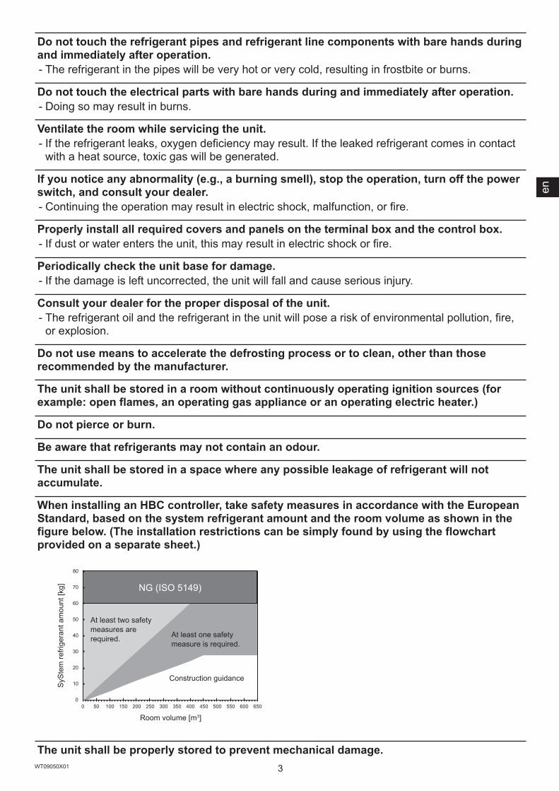
When installing an HBC controller, take safety measures in accordance with the European Standard, based on the system refrigerant amount and the room volume as shown in the figure below. (The installation restrictions can be simply found by using the flowchart provided on a separate sheet.)
0
10
20
30
40
50
60
70
80
0 50 100 150 200 250 300 350 400 450 500 550 600 650
The unit shall be properly stored to prevent mechanical damage.
At least two safety measures are required.
Room volume [m3]
SySt
em re
frige
rant
am
ount
[kg] NG (ISO 5149)
At least one safety measure is required.
Construction guidance
3WT09050X01
en
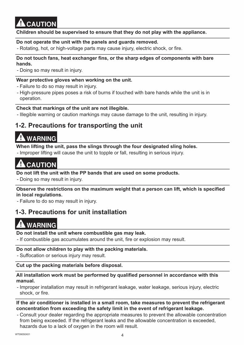
Children should be supervised to ensure that they do not play with the appliance.
Do not operate the unit with the panels and guards removed. - Rotating, hot, or high-voltage parts may cause injury, electric shock, or fire.
Do not touch fans, heat exchanger fins, or the sharp edges of components with bare hands. - Doing so may result in injury.
Wear protective gloves when working on the unit. - Failure to do so may result in injury. - High-pressure pipes poses a risk of burns if touched with bare hands while the unit is in operation.
Check that markings of the unit are not illegible. - Illegible warning or caution markings may cause damage to the unit, resulting in injury.
1-2. Precautions for transporting the unit
When lifting the unit, pass the slings through the four designated sling holes. - Improper lifting will cause the unit to topple or fall, resulting in serious injury.
Do not lift the unit with the PP bands that are used on some products. - Doing so may result in injury.
Observe the restrictions on the maximum weight that a person can lift, which is specified in local regulations. - Failure to do so may result in injury.
1-3. Precautions for unit installation
Do not install the unit where combustible gas may leak. - If combustible gas accumulates around the unit, fire or explosion may result.
Do not allow children to play with the packing materials. - Suffocation or serious injury may result.
Cut up the packing materials before disposal.
All installation work must be performed by qualified personnel in accordance with this manual. - Improper installation may result in refrigerant leakage, water leakage, serious injury, electric shock, or fire.
If the air conditioner is installed in a small room, take measures to prevent the refrigerant concentration from exceeding the safety limit in the event of refrigerant leakage. - Consult your dealer regarding the appropriate measures to prevent the allowable concentration from being exceeded. If the refrigerant leaks and the allowable concentration is exceeded, hazards due to a lack of oxygen in the room will result.
4WT09050X01

Install the unit in accordance with the instructions to minimize the risk of damage from earthquakes and strong winds. - Improper installation will cause the unit to topple, resulting in serious injury.
The unit must be securely installed on a structure that can sustain its weight. - Failure to do so will cause the unit to fall, resulting in serious injury.
Do not open the control box cover when charging refrigerant. - Doing so may cause sparks, resulting in fire.
Seal all openings around pipes and wires to keep out small animals, rainwater, or snow. - Failure to do so may result in current leakage, electric shock, or damage to the unit.
Do not install the unit where corrosive gas may be generated. - Doing so can corrode the pipes, resulting in refrigerant leakage and fire.
Outdoor unit with salt-resistant specification is recommended to use in a place where it is subject to salt air.
Even when the unit with salt-resistant specification is used, it is not completely protected against corrosion.
Salt-resistant unit is resistant to salt corrosion, but not salt-proof.
Install the salt-resistant unit out of direct exposure to sea breeze, and minimize the exposure to salt water mist.
Periodically wash salt deposits off the unit, especially when the unit is installed in a coastal area.
Periodically check the unit, and apply anti-rust agent and replace corroded parts as necessary.
1-4. Precautions for piping work
Piping work shall be kept to a minimum.
The pipes shall be protected from physical damage.
Before heating the brazed sections, remove the gas and oil that are trapped in the pipes. - Failure to do so may generate fire, resulting in serious injury.
Do not purge the air using refrigerant. Use a vacuum pump to evacuate the system. - Residual gas in the refrigerant lines will cause bursting of the pipes or an explosion.
Do not use oxygen, flammable gas, or a refrigerant containing chlorine for air-tightness testing. - Doing so may result in an explosion. Chlorine will deteriorate the refrigerant oil.
When installing or relocating the unit, do not allow air or any substance other than the specified refrigerant to enter the refrigerant lines. - Any substance other than the specified refrigerant may cause abnormally high pressure in the refrigerant lines, resulting in bursting of the pipes or an explosion.
5WT09050X01
en

After the installation has been completed, check for refrigerant leaks. - If the refrigerant leaks, oxygen starvation may result. If the leaked refrigerant comes in contact with a heat source, toxic gas will be generated.
Have a fire extinguisher nearby before brazing work. - If the refrigerant leaks while brazing work is being performed, fire may result.
Provide no-smoking signs at the brazing workplace. - If the refrigerant leaks when an ignition source is present, fire may result.
1-5. Precautions for electrical wiring
Include some slack in the power cables. - Failure to do so may break or overheat the cables, resulting in smoke or fire.
Connections must be made securely and without tension on the terminals. - Improperly connected cables may break, overheat, or cause smoke or fire.
Tighten all terminal screws to the specified torque. - Loose screws and contact failure may result in smoke or fire.
Electrical work must be performed by qualified personnel in accordance with local regulations and the instructions provided in this manual. Only use the specified cables and dedicated circuits. - Inadequate power source capacity or improper electrical work will result in electric shock, malfunction, or fire.
Install an inverter circuit breaker on the power supply of each unit. - Failure to do so may result in electric shock or fire.
Only use properly rated breakers (an earth leakage breaker, local switch <a switch + fuse that meets local electrical codes>, or overcurrent breaker). - Failure to do so may result in electric shock, malfunction, smoke, or fire.
Only use standard power cables of sufficient capacity. - Failure to do so may result in current leakage, overheating, smoke, or fire.
Proper grounding must be provided by qualified personnel. - Improper grounding may result in electric shock, fire, explosion, or malfunction due to electrical noise. Do not connect the ground wire to gas or water pipes, lightning rods, or telephone ground wires.
When air flow decrease is detected of a circulation fan beside the HBC controller installed at the height of less than 1.8 m from the ground, the system must be powered off within 10 seconds from the detection. Before powering off the system, connect the contactor to the power cable of the outdoor unit and open the contactor.
After the wiring work has been completed, measure the insulation resistance, and make sure that it reads at least 1 MΩ. - Failure to do so may result in electric leakage, malfunction, or fire.
6WT09050X01

1-6. Precautions for relocating or repairing the unit
Only qualified personnel must relocate or repair the unit. Do not attempt to disassemble or alter the unit. - Failure to do so will result in refrigerant leakage, water leakage, serious injury, electric shock, or fire.
Do not service the unit in the rain. - Doing so may result in electric leakage, electric shock, wire shorting, malfunction, smoke, or fire.
Check for refrigerant leaks before service. - If the refrigerant leaks, fire may result.
Do not open the control box cover when recovering, charging, or purging refrigerant. - Doing so may cause sparks, resulting in fire.
1-7. Additional precautions
Do not turn off the power immediately after stopping operation. - Wait for at least five minutes after the unit has stopped before turning off the power. Failure to do so may result in drain water leakage or the mechanical failure of sensitive parts.
The unit must be periodically inspected by a dealer or qualified personnel. - If dust or dirt accumulates inside the unit, the drain pipes may become clogged, and water leakage from the pipes may wet the surroundings and generate odours.
Turn on the power at least 12 hours before starting operation. Keep the power turned on throughout the operating season. - Insufficient energizing will result in malfunction.
Do not use the air conditioner for special purposes (e.g. keeping food, animals, plants, precision devices, or art objects in a room). - Such items could be damaged or deteriorated.
Collect the refrigerant and properly dispose of it in accordance with local regulations.
Do not install the unit on or over items that are subject to water damage. - When the room humidity exceeds 80% or if the drain pipe is clogged, condensation may collect and drip from the indoor unit onto the ceiling or floor.
Drain piping must be installed by a dealer or qualified personnel to ensure proper drainage. - Improper drain piping may cause water leakage, resulting in damage to furniture and other surroundings.
Take appropriate measures against electrical noise interference when installing the unit in hospitals or radio communication facilities. - Inverter, high-frequency medical, or wireless communication equipment as well as power generators may cause the air conditioning system to malfunction. The air conditioning system may also adversely affect the operation of these types of equipment by creating electrical noise.
Insulate pipes to prevent condensation. - Condensation may collect and drip from the unit onto the ceiling or floor.
7WT09050X01
en
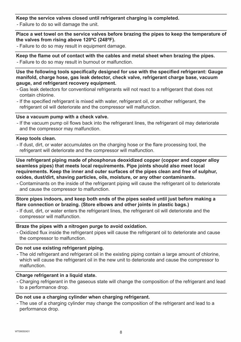
Keep the service valves closed until refrigerant charging is completed. - Failure to do so will damage the unit.
Place a wet towel on the service valves before brazing the pipes to keep the temperature of the valves from rising above 120ºC (248ºF). - Failure to do so may result in equipment damage.
Keep the flame out of contact with the cables and metal sheet when brazing the pipes. - Failure to do so may result in burnout or malfunction.
Use the following tools specifically designed for use with the specified refrigerant: Gauge manifold, charge hose, gas leak detector, check valve, refrigerant charge base, vacuum gauge, and refrigerant recovery equipment. - Gas leak detectors for conventional refrigerants will not react to a refrigerant that does not contain chlorine. - If the specified refrigerant is mixed with water, refrigerant oil, or another refrigerant, the refrigerant oil will deteriorate and the compressor will malfunction.
Use a vacuum pump with a check valve. - If the vacuum pump oil flows back into the refrigerant lines, the refrigerant oil may deteriorate and the compressor may malfunction.
Keep tools clean. - If dust, dirt, or water accumulates on the charging hose or the flare processing tool, the refrigerant will deteriorate and the compressor will malfunction.
Use refrigerant piping made of phosphorus deoxidized copper (copper and copper alloy seamless pipes) that meets local requirements. Pipe joints should also meet local requirements. Keep the inner and outer surfaces of the pipes clean and free of sulphur, oxides, dust/dirt, shaving particles, oils, moisture, or any other contaminants. - Contaminants on the inside of the refrigerant piping will cause the refrigerant oil to deteriorate and cause the compressor to malfunction.
Store pipes indoors, and keep both ends of the pipes sealed until just before making a flare connection or brazing. (Store elbows and other joints in plastic bags.) - If dust, dirt, or water enters the refrigerant lines, the refrigerant oil will deteriorate and the compressor will malfunction.
Braze the pipes with a nitrogen purge to avoid oxidation. - Oxidized flux inside the refrigerant pipes will cause the refrigerant oil to deteriorate and cause the compressor to malfunction.
Do not use existing refrigerant piping. - The old refrigerant and refrigerant oil in the existing piping contain a large amount of chlorine, which will cause the refrigerant oil in the new unit to deteriorate and cause the compressor to malfunction.
Charge refrigerant in a liquid state. - Charging refrigerant in the gaseous state will change the composition of the refrigerant and lead to a performance drop.
Do not use a charging cylinder when charging refrigerant. - The use of a charging cylinder may change the composition of the refrigerant and lead to a performance drop.
8WT09050X01
If a large electric current flows due to a malfunction or faulty wiring, earth-leakage breakers on the unit side and on the upstream side of the power supply system could both operate. Depending on the importance of the system, separate the power supply system or take protective coordination of breakers.
This appliance is intended to be used by expert or trained users in shops, in light industry and on farms, or for commercial use by lay persons.
This appliance is not intended for use by persons (including children) with reduced physical, sensory or mental capabilities, or lack of experience and knowledge, unless they have been given supervision or instruction concerning use of the appliance by a person responsible for their safety.
Store the unit in a room large enough to allow clearance in the event of refrigerant leakage.
Refrigerant R32 is flammable. Do not use a naked-flame type detector.
Carry a refrigerant leak detection sensor when installing or removing the unit.
Only qualified personnel may touch the USB port in the control box.
9WT09050X01
en

10WT09050X01
2. About the product・The outdoor unit described in this manual is air-conditioning equipment that is designed only for human comfort.・The numeric values in the unit model name (e.g., PURY-M***YNW-A1, PURY-EM***YNW-A1) indicate the capacity
index of the unit.・This unit uses R32 refrigerant.・In this manual, the following terms are used.
Hybrid City Multi systemControllers that are connected to indoor units HBC controllerHeating medium on the indoor unit side Water or antifreeze liquid
・CMB-WP108V-G can be connected to PURY-WP200YJM-A and PURY-WP250YJM-A, but not to PURY-M-YNW-A1/PURY-EM-YNW-A1 models of units.・PURY-M200YNW-A1 through PURY-M500YNW-A1, and PURY-EM200YNW-A1 through PURY-EM500YNW-A1 can
be used in a Hybrid City Multi system and can be connected to CMB-WM***V-AA/AB.

en
11WT09050X01
3. Combination of outdoor units(1) M models
Outdoor unit model Combination of outdoor unitsPURY-M200YNW-A1(-BS) - -PURY-M250YNW-A1(-BS) - -PURY-M300YNW-A1(-BS) - -PURY-M350YNW-A1(-BS) - -PURY-M400YNW-A1(-BS) - -PURY-M450YNW-A1(-BS) - -PURY-M500YNW-A1(-BS) - -
(2) EM models
Outdoor unit model Combination of outdoor unitsPURY-EM200YNW-A1(-BS) - -PURY-EM250YNW-A1(-BS) - -PURY-EM300YNW-A1(-BS) - -PURY-EM350YNW-A1(-BS) - -PURY-EM400YNW-A1(-BS) - -PURY-EM450YNW-A1(-BS) - -PURY-EM500YNW-A1(-BS) - -

12WT09050X01
4. Specifications(1) M models
Model PURY-M200YNW-A1*3 PURY-M250YNW-A1*3 PURY-M300YNW-A1*3 PURY-M350YNW-A1*3
Sound pressure level*4 (50/60 Hz) 59 dB <A> 60.5 dB <A> 61 dB <A> 62.5 dB <A>External static pressure 0 Pa*2
Indoor unit Total capacity 50% to 150%*1
Model 10 to 125Quantity 1 to 30 1 to 37 2 to 45 2 to 50
Operation temperature (Cooling)
Indoor W.B. +15.0°C to +24.0°C (+59.0°F to +75.0°F)
Outdoor D.B. -5.0°C to +52.0°C (+23.0°F to +125.6°F)Operation temperature (Heating)
Indoor D.B. +15.0°C to +27.0°C (+59.0°F to +81.0°F)
Outdoor W.B. -20.0°C to +15.5°C (-4.0°F to +60.0°F)
Model PURY-M400YNW-A1*3 PURY-M450YNW-A1*3 PURY-M500YNW-A1*3
Sound pressure level*4 (50/60 Hz) 65 dB <A> 65.5 dB <A> 63.5 dB <A>External static pressure 0 Pa*2
Indoor unit Total capacity 50% to 150%*1
Model 10 to 125Quantity 2 to 50 2 to 50 2 to 50
Operation temperature (Cooling)
Indoor W.B. +15.0°C to +24.0°C (+59.0°F to +75.0°F)
Outdoor D.B. -5.0°C to +52.0°C (+23.0°F to +125.6°F)Operation temperature (Heating)
Indoor D.B. +15.0°C to +27.0°C (+59.0°F to +81.0°F)
Outdoor W.B. -20.0°C to +15.5°C (-4.0°F to +60.0°F)
*1 The maximum total capacity of indoor units operating simultaneously is 150%.*2 To enable the high static pressure setting, set the dipswitch on the main board as follows.
SW6-5: ON SW6-5: OFFSW6-4: ON 80 Pa 60 PaSW6-4: OFF 30 Pa 0 Pa
*3 These models can be used for a Hybrid City Multi system.*4 Cooling mode
(2) EM models
Model PURY-EM200YNW-A1*3 PURY-EM250YNW-A1*3 PURY-EM300YNW-A1*3 PURY-EM350YNW-A1*3
Sound pressure level*4 (50/60 Hz) 59 dB <A> 60.5 dB <A> 61 dB <A> 62.5 dB <A>External static pressure 0 Pa*2
Indoor unit Total capacity 50% to 150%*1
Model 10 to 125Quantity 1 to 30 1 to 37 2 to 45 2 to 50
Operation temperature (Cooling)
Indoor W.B. +15.0°C to +24.0°C (+59.0°F to +75.0°F)
Outdoor D.B. -5.0°C to +52.0°C (+23.0°F to +125.6°F)Operation temperature (Heating)
Indoor D.B. +15.0°C to +27.0°C (+59.0°F to +81.0°F)
Outdoor W.B. -20.0°C to +15.5°C (-4.0°F to +60.0°F)
Model PURY-EM400YNW-A1*3 PURY-EM450YNW-A1*3 PURY-EM500YNW-A1*3
Sound pressure level*4 (50/60 Hz) 65 dB <A> 65.5 dB <A> 63.5 dB <A>External static pressure 0 Pa*2
Indoor unit Total capacity 50% to 150%*1
Model 10 to 125Quantity 2 to 50 2 to 50 2 to 50
Operation temperature (Cooling)
Indoor W.B. +15.0°C to +24.0°C (+59.0°F to +75.0°F)
Outdoor D.B. -5.0°C to +52.0°C (+23.0°F to +125.6°F)Operation temperature (Heating)
Indoor D.B. +15.0°C to +27.0°C (+59.0°F to +81.0°F)
Outdoor W.B. -20.0°C to +15.5°C (-4.0°F to +60.0°F)
*1 The maximum total capacity of indoor units operating simultaneously is 150%.*2 To enable the high static pressure setting, set the dipswitch on the main board as follows.
SW6-5: ON SW6-5: OFFSW6-4: ON 80 Pa 60 PaSW6-4: OFF 30 Pa 0 Pa
*3 These models can be used for a Hybrid City Multi system.*4 Cooling mode
en
13WT09050X01
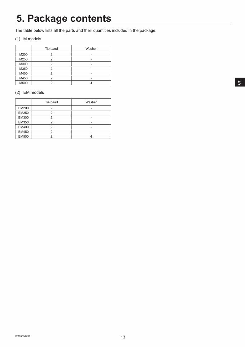
5. Package contentsThe table below lists all the parts and their quantities included in the package.
(1) M models
Tie band Washer
M200 2 -M250 2 -M300 2 -M350 2 -M400 2 -M450 2 -M500 2 4
(2) EM models
Tie band Washer
EM200 2 -EM250 2 -EM300 2 -EM350 2 -EM400 2 -EM450 2 -EM500 2 4

14WT09050X01
6. Transporting the unit
When lifting the unit, pass the slings through the four designated sling holes. - Improper lifting will cause the unit to topple or fall, resulting in serious injury.
・Always use two slings to lift up the unit. Each sling must be at least 8 m (26 ft) long and must be able to support the weight of the unit.・Put protective pads between slings and the unit where the slings touch the unit at the base to protect the unit from
being scratched.・Put 50 mm (2 in) or thicker protective pads between slings and the unit where the slings touch the unit at the top of
the unit to protect the unit from being scratched and to avoid contact with the slings and the fan guard.・Make sure that the angles between slings at the top are less than 40 degrees.
M200, M250, M300, EM200, EM250, EM300 M350, M400, M450, EM350, EM400, EM450
Ⓐ
Ⓔ
Ⓑ
Ⓒ
Ⓓ
Ⓐ
Ⓑ
Ⓒ
Ⓔ
Ⓓ
M500, EM500
Ⓐ
Ⓑ
Ⓒ
Ⓔ
Ⓓ
Ⓐ Slings (Min. 8 m (26 ft) x 2)Ⓑ Protective pads (Minimum thickness: 50 mm (2 in))
(two each in the front and back)Ⓒ Protective pads
(two each in the front and back)Ⓓ Sling holes
(two each in the front and back)Ⓔ Fan guard
≤ 40°
≤ 40°
≤ 40°

en
15WT09050X01
7. Installation location
Do not install the unit where combustible gas may leak. - If combustible gas accumulates around the unit, fire or explosion may result.
・Provide sufficient space around the unit for effective operation, efficient air movement, and ease of access for maintenance.・Note that refrigerant gas is heavier than air and will therefore tend to collect in low spots such as basements.・When an indoor unit that draws in outside air exits near the outdoor unit, be careful not to affect the normal
operation of the indoor unit.・When the amount of drain water is excessive, drain water comes out of the outdoor unit along the panel during
heating operation. Provide sufficient space around the unit according to the instructions in section 7-1 and 7-2.・R32 is heavier than air—as well as other refrigerants—so tends to accumulate at the base (in the vicinity of the
floor). If R32 accumulates around the base, it may reach a flammable concentration in case the room is small. To avoid ignition, maintain a safe work environment by ensuring appropriate ventilation. If the refrigerant leaks in a room or an area that has insufficient ventilation, refrain from using flames until the work environment is improved by ensuring appropriate ventilation.・Do not install the outdoor unit in a basement or machinery room, where the refrigerant stagnates.・Install the outdoor unit in a place where at least one of the four sides is open.
・If the unit needs to be installed in a space where all four sides are blocked, confirm that one of these situations (A, B, or C) is satisfied.
A: Secure sufficient installation space (minimum installation area: Amin).Install the unit in a space with an installation area of Amin or more, corresponding to the refrigerant amount (M). (M = factory-charged refrigerant + refrigerant to be added on site)
M (kg) Amin (m2)
Amin
10 11220 22330 33440 44550 55660 667
B: Install the unit in a space with a wall height of ≤ 0.125 m.
Good Good Good NG
Wall height ≤ 0.125 m(No restrictions apply to the refrigerant amount)
Wall height ≤ 0.125 m

16WT09050X01
C: Create an appropriate ventilation open area.
NG
Good
Longitudinal direction
Width of an opening ≥ 0.9 m
Height from the ground to an opening ≥ 0.125 m
Height of an opening ≥ 0.15 m
Opening:• Must occupy 80% of the
longitudinal side of a space.• Must have an opening ratio of
75% or higher.
(Example: space with a louver)
(Example: basement)
en
17WT09050X01
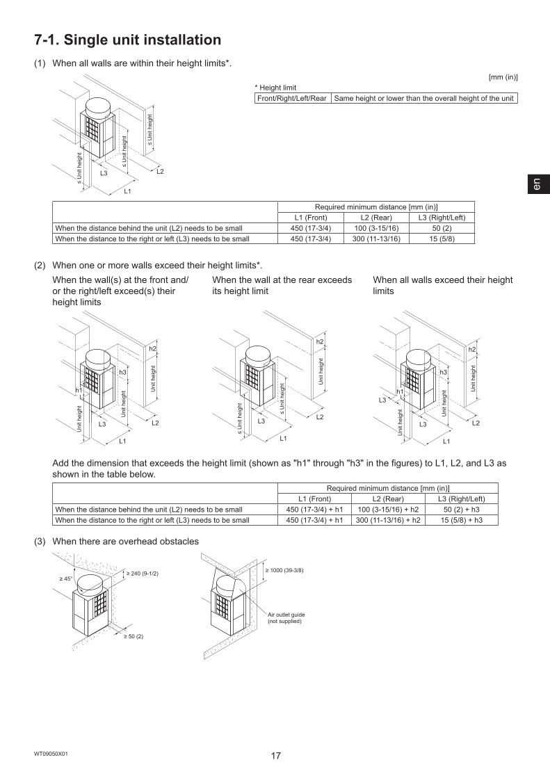
7-1. Single unit installation(1) When all walls are within their height limits*.
L1
L2L3
[mm (in)]* Height limitFront/Right/Left/Rear Same height or lower than the overall height of the unit
Required minimum distance [mm (in)]L1 (Front) L2 (Rear) L3 (Right/Left)
When the distance behind the unit (L2) needs to be small 450 (17-3/4) 100 (3-15/16) 50 (2)When the distance to the right or left (L3) needs to be small 450 (17-3/4) 300 (11-13/16) 15 (5/8)
(2) When one or more walls exceed their height limits*.When the wall(s) at the front and/or the right/left exceed(s) their height limits
When the wall at the rear exceeds its height limit
When all walls exceed their height limits
h3
L1
L2L3
h1
h2
L1
L2L3
h2
L1
h3
h2
L2
L3
L3
h1
Add the dimension that exceeds the height limit (shown as "h1" through "h3" in the figures) to L1, L2, and L3 as shown in the table below.
Required minimum distance [mm (in)]L1 (Front) L2 (Rear) L3 (Right/Left)
When the distance behind the unit (L2) needs to be small 450 (17-3/4) + h1 100 (3-15/16) + h2 50 (2) + h3When the distance to the right or left (L3) needs to be small 450 (17-3/4) + h1 300 (11-13/16) + h2 15 (5/8) + h3
(3) When there are overhead obstacles
≤ U
nit h
eigh
t
≤ U
nit h
eigh
t
≤ U
nit h
eigh
tU
nit h
eigh
t
Uni
t hei
ght U
nit h
eigh
t
≤ U
nit h
eigh
t
≤ U
nit h
eigh
t Uni
t hei
ght
Uni
t hei
ght
Uni
t hei
ght U
nit h
eigh
t
≥ 1000 (39-3/8)≥ 240 (9-1/2)≥ 45°
≥ 50 (2)
Air outlet guide (not supplied)
18WT09050X01
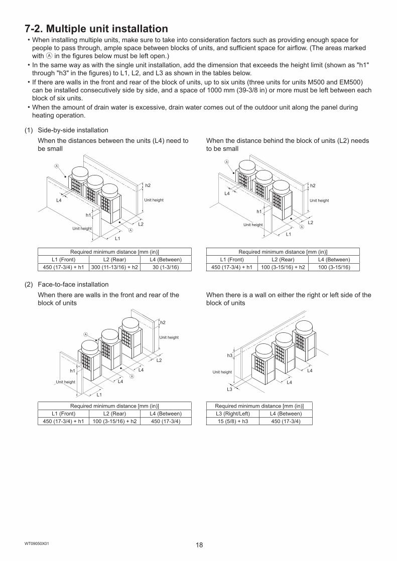
7-2. Multiple unit installation・When installing multiple units, make sure to take into consideration factors such as providing enough space for
people to pass through, ample space between blocks of units, and sufficient space for airflow. (The areas marked with Ⓐ in the figures below must be left open.)・In the same way as with the single unit installation, add the dimension that exceeds the height limit (shown as "h1"
through "h3" in the figures) to L1, L2, and L3 as shown in the tables below.・If there are walls in the front and rear of the block of units, up to six units (three units for units M500 and EM500)
can be installed consecutively side by side, and a space of 1000 mm (39-3/8 in) or more must be left between each block of six units.・When the amount of drain water is excessive, drain water comes out of the outdoor unit along the panel during
heating operation.
(1) Side-by-side installationWhen the distances between the units (L4) need to be small
When the distance behind the block of units (L2) needs to be small
h2
L2
L1
h1
L4
Ⓐ
Ⓐ
h2
h1
L1
L2
L4
Ⓐ
Ⓐ
Required minimum distance [mm (in)]L1 (Front) L2 (Rear) L4 (Between)
450 (17-3/4) + h1 300 (11-13/16) + h2 30 (1-3/16)
Required minimum distance [mm (in)]L1 (Front) L2 (Rear) L4 (Between)
450 (17-3/4) + h1 100 (3-15/16) + h2 100 (3-15/16)
(2) Face-to-face installationWhen there are walls in the front and rear of the block of units
When there is a wall on either the right or left side of the block of units
h1
h2
L1
L4
L4
L2
Ⓐ
Ⓐ
h3
L4L3
L4
Required minimum distance [mm (in)]L1 (Front) L2 (Rear) L4 (Between)
450 (17-3/4) + h1 100 (3-15/16) + h2 450 (17-3/4)
Required minimum distance [mm (in)]L3 (Right/Left) L4 (Between)15 (5/8) + h3 450 (17-3/4)
Unit height
Unit height
Unit height
Unit height
Unit height
Unit height
Unit height

en
19WT09050X01
(3) Combination of face-to-face and side-by-side installationsWhen there are walls in the front and rear of the block of units
h2
h2’
L2’
L4
L2
Ⓐ
Ⓐ
Required minimum distance [mm (in)]L2 (Rear) L2' (Rear) L4 (Between)
300 (11-13/16) + h2 300 (11-13/16) + h2' 900 (35-7/16)
When there are two walls in an L-shape
h2
L2
L4
L3
Ⓐ
Ⓐ
h3
Required minimum distance [mm (in)]L2 (Rear) L3 (Right/Left) L4 (Between)
300 (11-13/16) + h2 1000 (39-3/8) + h3 900 (35-7/16)
Ⓐ Leave open in two directions.
Unit height
Unit height
Unit heightUnit height

20WT09050X01
8. Foundation work
Install the unit in accordance with the instructions to minimize the risk of damage from earthquakes and strong winds. - Improper installation will cause the unit to topple, resulting in serious injury.
The unit must be securely installed on a structure that can sustain its weight. - Failure to do so will cause the unit to fall, resulting in serious injury.
・When performing the foundation work, make sure that the floor surface has sufficient strength and carefully route pipes and wires in consideration of the water drainage that will be required when the unit is operated.・If considering routing the pipes and wires across the bottom of the unit, make sure that the base is at least 100 mm
(3-15/16 in) high so that the through-holes will not be blocked.・Provide a strong base of concrete or angle iron. If a stainless steel base is used, insulate the area between the
base and the outdoor unit by putting a rubber cushion or by applying an electrically insulated coating to prevent the base from rusting.・Install the unit on a level surface.・With some types of installation, unit vibration and sound will be transmitted to the floors and walls. In such locations,
take measures to prevent vibration (such as using anti-vibration rubber pads).[mm (in)]
(1) Without a detachable leg
Ⓐ
Ⓑ
Ⓒ
Ⓓ
(2) With a detachable leg
ⒶⒺ Ⓔ
Ⓒ Ⓒ
Ⓐ M10 anchor bolt (not supplied)Ⓑ (Incorrect installation) The corner section is not securely received.Ⓒ Fixing bracket for post-installed anchor bolts (not supplied) (To be fixed with three screws)Ⓓ Anti-vibration rubber pad
(The pad needs to be large enough to cover the entire width of each unit leg.)Ⓔ Detachable leg
・Make sure that the corner section is securely received. If not, the unit legs could bend.・The length of the projecting part of the anchor bolt should be 30 mm (1-3/16 in) or less.・This unit is not designed to be anchored with post-installed anchor bolts unless fixing brackets are installed at
the bottom four locations (six locations for units M500 and EM500).
≤ 30
(1-3
/16)
≤ 30
(1-3
/16)

en
21WT09050X01
・To remove the detachable legs on site, unscrew the screws shown in the figure below. If the unit leg coating is damaged when the detachable leg is removed, repair the coating on site.
Ⓐ Ⓐ
Ⓐ Screws
・In abnormally harsh environments such as cold and/or windy areas, sufficient countermeasures to guard against excessive wind and snow should be taken to ensure the unit’s correct operation. When the unit is expected to operate in cooling mode in conditions under 10°C (50°F), in snowy areas, in environments subject to strong winds or rain, install snow hoods of the following specifications (not supplied) as shown in the figure below.
Material: Galvanized steel plate 1.2T Painting: Overall painting with polyester powder Color: Munsell 5Y8/1 (same as the unit color)Size: Refer to the Data Book.
Ⓓ Ⓓ
Ⓐ
Ⓑ Ⓑ ⒷⒷ
Ⓒ ⒸⒸ
ⒸⒸ
Ⓒ
Ⓐ OutletⒷ InletⒸ Snow hoodⒹ Raised base
・Install the unit so that the wind will not blow directly against the inlet and outlet.・If necessary, install the unit on a raised base of the following specifications (not supplied) to prevent damage
from snow.
Material: Angle iron (Build a structure that snow and wind can pass through.) Height: Expected maximum snowfall plus 200 mm (7-7/8 in) Width: Within the unit width (If the raised base is too wide, snow will accumulate on the raised base.)
・When the unit is used in a cold region and the heating operation is continuously performed for a long time when the outside air temperature is below freezing, install a heater on the raised base or take other appropriate measures to prevent water from freezing on the raised base.・When installing a panel heater, provide sufficient space for maintenance accordingly. For details, refer to the
Data Book or installation manual for the panel heater.

22WT09050X01
9. Refrigerant piping work
Do not use any refrigerant other than the type indicated in the manuals for the unit and on the nameplate. - Doing so will cause the unit or pipes to burst, or result in an explosion or fire during use, during repairs, or at the time of disposal of the unit. - It may also be in violation of applicable laws. - MITSUBISHI ELECTRIC CORPORATION cannot be held responsible for malfunctions or accidents resulting from the use of the wrong type of refrigerant.
After the installation has been completed, check for refrigerant leaks. - If the refrigerant leaks, oxygen starvation may result. If the leaked refrigerant comes in contact with a heat source, toxic gas will be generated.
Wear protective gloves when working on the unit. - Failure to do so may result in injury. - High-pressure pipes poses a risk of burns if touched with bare hands while the unit is in operation.
Use the following tools specifically designed for use with the specified refrigerant: Gauge manifold, charge hose, gas leak detector, check valve, refrigerant charge base, vacuum gauge, and refrigerant recovery equipment. - Gas leak detectors for conventional refrigerants will not react to a refrigerant that does not contain chlorine. - If the specified refrigerant is mixed with water, refrigerant oil, or another refrigerant, the refrigerant oil will deteriorate and the compressor will malfunction.
Do not use existing refrigerant piping. - The old refrigerant and refrigerant oil in the existing piping contain a large amount of chlorine, which will cause the refrigerant oil in the new unit to deteriorate and cause the compressor to malfunction.
9-1. Restrictions・Existing refrigerant piping must not be used because the design pressure for systems using R32 is higher than that
for systems using other types of refrigerants.・Do not install outdoor unit piping when it is raining.・Do not use special detergents for washing piping.・Always observe the restrictions on refrigerant piping (such as pipe size, pipe length, and vertical separation
distance) to prevent equipment failure or a decline in heating/cooling performance.・Do not install solenoid valves to prevent oil backflow and compressor start-up failure. ・Do not install a sight glass because it may show improper refrigerant flow. If a sight glass is installed, inexperienced
technicians that use the glass may overcharge the refrigerant.

en
23WT09050X01
9-2. Pipe selection
Use refrigerant piping made of phosphorus deoxidized copper (copper and copper alloy seamless pipes) that meets local requirements. Pipe joints should also meet local requirements. Keep the inner and outer surfaces of the pipes clean and free of sulphur, oxides, dust/dirt, shaving particles, oils, moisture, or any other contaminants. - Contaminants on the inside of the refrigerant piping will cause the refrigerant oil to deteriorate and cause the compressor to malfunction.
Use refrigerant pipes for use with R32 refrigerant system. Piping for systems for use with other types of refrigerants may not be able to be used.Use refrigerant pipes with the thicknesses specified in the table below.
Size [mm (in)] Minimum wall thickness [mm (mil)] Typeø6.35 (ø1/4) 0.8 (32) Type-Oø9.52 (ø3/8) 0.8 (32) Type-Oø12.7 (ø1/2) 0.8 (32) Type-Oø15.88 (ø5/8) 1.0 (40) Type-O
ø19.05 (ø3/4)1.2 (48) Type-O1.0 (40) Type-1/2H or H
ø22.2 (ø7/8) 1.0 (40) Type-1/2H or Hø25.4 (ø1) 1.0 (40) Type-1/2H or H
ø28.58 (ø1-1/8) 1.0 (40) Type-1/2H or Hø31.75 (ø1-1/4) 1.1 (44) Type-1/2H or Hø34.93 (ø1-3/8) 1.2 (48) Type-1/2H or Hø41.28 (ø1-5/8) 1.4 (56) Type-1/2H or H
9-3. Twinning kit selection9-3-1. 2-Branch Joint PipeA 2-Branch Joint Pipe is used to connect multiple indoor units to a port.
Hybrid City Multi system・Connect the pipes on site, referring to the HBC controller Installation Manual.・CMY-Y102SS-G2 is used in an R2 system, and cannot be used in a Hybrid City Multi system.
9-3-2. Joint Pipe KitA Joint Pipe Kit is used to connect an indoor unit of P100 model or above.
Hybrid City Multi system・Connect the pipes on site, referring to the HBC controller Installation Manual.・CMY-R160-J1 is used in an R2 system, and cannot be used in a Hybrid City Multi system.

24WT09050X01
9-4. Pipe connection example9-4-1. Example of pipe connection between an outdoor unit and HBC controller, and
between an HBC controller and indoor unit
h1
h2
g
f
H H'
h1
A
edc
b'a b
Ⓐ
Ⓒ Ⓓ
Ⓑ Ⓑ Ⓑ Ⓑ Ⓑ
Ⓔ
Ⓖ
Ⓕ
Ⓑ
Ⓐ Outdoor unitⒷ Indoor unitⒸ Main HBC controllerⒹ Sub HBC controllerⒺ 2-Branch Joint Pipe (not supplied)Ⓕ Joint Pipe Kit (not supplied)Ⓖ Max. 3 sets for 1 port (Total capacity ≤ WP80)
Ⓐ Ⓒ
Ⓑ
Ⓐ HBC controllerⒷ Joint Pipe Kit (not supplied)Ⓒ Increaser (20A-to-32A) (not supplied)
Item Piping portion Allowable value
Pipe lengthBetween outdoor unit and HBC controller (refrigerant pipework) A 110 m (360 ft) or belowWater pipework between indoor units and HBC controller f + g 60 m (196 ft) or below
Difference of elevation
Between HBC controller and outdoor units
Outdoor unit above HBC controller H 50 m (164 ft) or below
Outdoor unit below HBC controller H' 40 m (131 ft) or below
Between indoor units and HBC controller h115 m (10 m*1)
(49 ft (32 ft*1)) or below
Between indoor units h215 m (10 m*1)
(49 ft (32 ft*1)) or below
*1 The values marked with *1 indicate the values when the total indoor unit capacity exceeds 130% of outdoor unit capacity.
(~(E)M300)
(WP100-WP125)(WP10-WP80)
CMB-WM108V-AA + CMB-WM108V-AB(CMB-WM1016V-AA) (CMB-WM1016V-AB)
(WP100 and WP125 models)
Fig. 9-4-1

en
25WT09050X01
h1h3
h2
g
f
H H'
h1
A1
A2
A3
<A>
<B>
<C>
edc
b'a b
B
Ⓐ
Ⓑ
Ⓑ Ⓑ Ⓑ Ⓑ Ⓑ
Ⓒ
Ⓒ Ⓓ
Ⓔ
Ⓖ
Ⓕ
Ⓑ
<A>, <B> Main HBC controller (Total capacity of indoor units: WP375 or below)<C> Sub HBC controller (Total capacity of indoor units <B> + <C>: WP375 or below)
Ⓐ Outdoor unitⒷ Indoor unitⒸ Main HBC controllerⒹ Sub HBC controllerⒺ 2-Branch Joint Pipe (not supplied)Ⓕ Joint Pipe Kit (not supplied)Ⓖ Max. 3 sets for 1 port (Total capacity ≤ WP80)
Item Piping portion Allowable value
Pipe lengthBetween outdoor unit and HBC controller (refrigerant pipework) A 1 + A 2 + A 3 110 m (360 ft) or belowWater pipework between indoor units and HBC controller f + g 60 m (196 ft) or belowBetween HBC controllers B 40 m (131 ft) or below
Difference of elevation
Between HBC controller and outdoor units
Outdoor unit above HBC controller H 50 m (164 ft) or below
Outdoor unit below HBC controller H' 40 m (131 ft) or below
Between indoor units and HBC controller h115 m (10 m*1)
(49 ft (32 ft*1)) or below
Between indoor units h215 m (10 m*1)
(49 ft (32 ft*1)) or below
Between HBC controllers h315 m (10 m*1)
(49 ft (32 ft*1)) or below
*1 The values marked with *1 indicate the values when the total indoor unit capacity exceeds 130% of outdoor unit capacity.
((E)M300)
(WP100, WP125)(WP10-WP80)
CMB-WM108V-AA + CMB-WM108V-AB(CMB-WM1016V-AA) (CMB-WM1016V-AB)
26WT09050X01
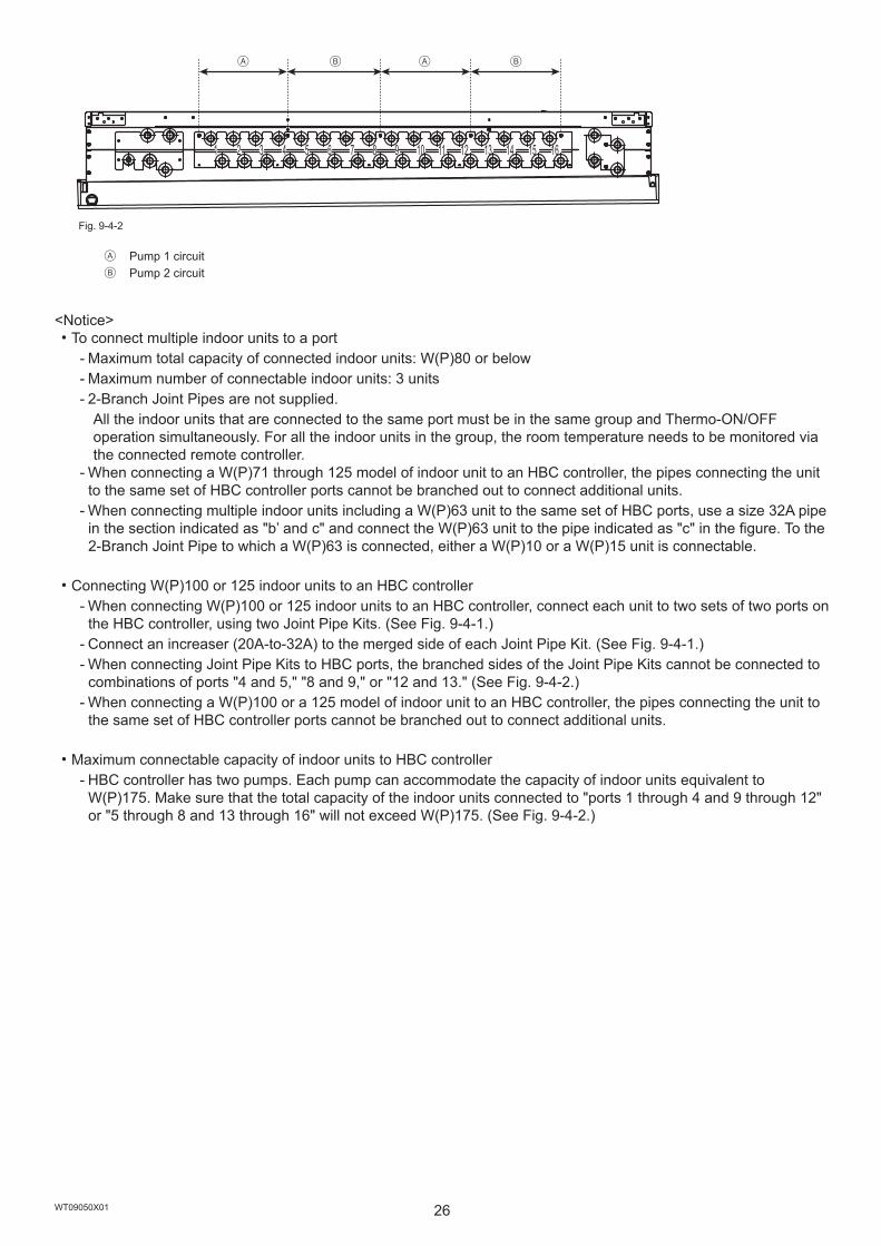
1 2 3 4 5 6 7 8 9 10 11 12 13 14 15 16
Ⓐ ⒶⒷ Ⓑ
Ⓐ Pump 1 circuitⒷ Pump 2 circuit
<Notice>・To connect multiple indoor units to a port-- Maximum total capacity of connected indoor units: W(P)80 or below-- Maximum number of connectable indoor units: 3 units-- 2-Branch Joint Pipes are not supplied.
All the indoor units that are connected to the same port must be in the same group and Thermo-ON/OFF operation simultaneously. For all the indoor units in the group, the room temperature needs to be monitored via the connected remote controller.-- When connecting a W(P)71 through 125 model of indoor unit to an HBC controller, the pipes connecting the unit to the same set of HBC controller ports cannot be branched out to connect additional units.-- When connecting multiple indoor units including a W(P)63 unit to the same set of HBC ports, use a size 32A pipe in the section indicated as "b’ and c" and connect the W(P)63 unit to the pipe indicated as "c" in the figure. To the 2-Branch Joint Pipe to which a W(P)63 is connected, either a W(P)10 or a W(P)15 unit is connectable.
・Connecting W(P)100 or 125 indoor units to an HBC controller-- When connecting W(P)100 or 125 indoor units to an HBC controller, connect each unit to two sets of two ports on the HBC controller, using two Joint Pipe Kits. (See Fig. 9-4-1.)-- Connect an increaser (20A-to-32A) to the merged side of each Joint Pipe Kit. (See Fig. 9-4-1.)-- When connecting Joint Pipe Kits to HBC ports, the branched sides of the Joint Pipe Kits cannot be connected to combinations of ports "4 and 5," "8 and 9," or "12 and 13." (See Fig. 9-4-2.)-- When connecting a W(P)100 or a 125 model of indoor unit to an HBC controller, the pipes connecting the unit to the same set of HBC controller ports cannot be branched out to connect additional units.
・Maximum connectable capacity of indoor units to HBC controller-- HBC controller has two pumps. Each pump can accommodate the capacity of indoor units equivalent to W(P)175. Make sure that the total capacity of the indoor units connected to "ports 1 through 4 and 9 through 12" or "5 through 8 and 13 through 16" will not exceed W(P)175. (See Fig. 9-4-2.)
Fig. 9-4-2
en
27WT09050X01
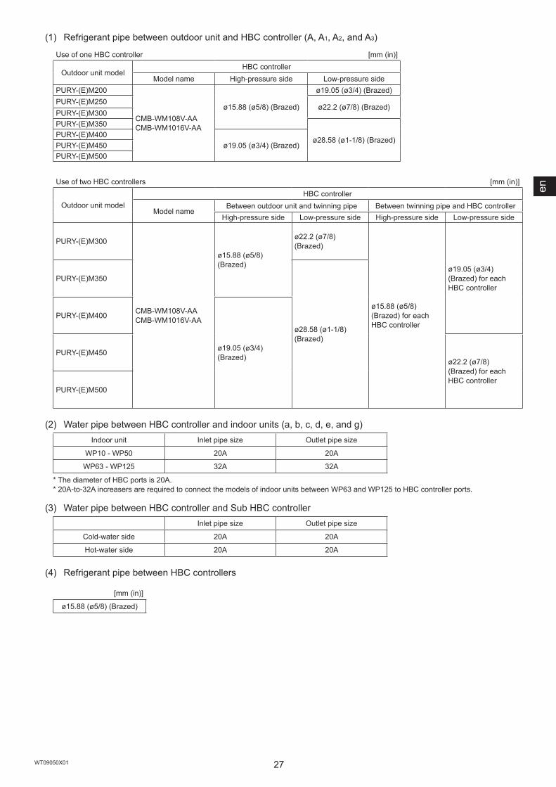
(1) Refrigerant pipe between outdoor unit and HBC controller (A, A1, A2, and A3)
Use of one HBC controller [mm (in)]
Outdoor unit modelHBC controller
Model name High-pressure side Low-pressure sidePURY-(E)M200
CMB-WM108V-AA CMB-WM1016V-AA
ø15.88 (ø5/8) (Brazed)
ø19.05 (ø3/4) (Brazed)PURY-(E)M250
ø22.2 (ø7/8) (Brazed)PURY-(E)M300PURY-(E)M350
ø28.58 (ø1-1/8) (Brazed)PURY-(E)M400
ø19.05 (ø3/4) (Brazed)PURY-(E)M450PURY-(E)M500
Use of two HBC controllers [mm (in)]
Outdoor unit modelHBC controller
Model nameBetween outdoor unit and twinning pipe Between twinning pipe and HBC controller
High-pressure side Low-pressure side High-pressure side Low-pressure side
PURY-(E)M300
CMB-WM108V-AA CMB-WM1016V-AA
ø15.88 (ø5/8) (Brazed)
ø22.2 (ø7/8) (Brazed)
ø15.88 (ø5/8) (Brazed) for each HBC controller
ø19.05 (ø3/4) (Brazed) for each HBC controller
PURY-(E)M350
ø28.58 (ø1-1/8) (Brazed)
PURY-(E)M400
ø19.05 (ø3/4) (Brazed)PURY-(E)M450
ø22.2 (ø7/8) (Brazed) for each HBC controller
PURY-(E)M500
(2) Water pipe between HBC controller and indoor units (a, b, c, d, e, and g)Indoor unit Inlet pipe size Outlet pipe size
WP10 - WP50 20A 20A
WP63 - WP125 32A 32A
* The diameter of HBC ports is 20A.* 20A-to-32A increasers are required to connect the models of indoor units between WP63 and WP125 to HBC controller ports.
(3) Water pipe between HBC controller and Sub HBC controllerInlet pipe size Outlet pipe size
Cold-water side 20A 20A
Hot-water side 20A 20A
(4) Refrigerant pipe between HBC controllers
[mm (in)]
ø15.88 (ø5/8) (Brazed)

28WT09050X01
9-4-2. Connecting the HBC controller
(1) Size of the pipe that fits the standard HBC controller ports
Ⓐ
Ⓒ ⒹⒷ
Ⓔ Ⓔ Ⓔ Ⓔ Ⓔ Ⓔ Ⓔ ⒺⒼ
Ⓕ
Ⓐ To outdoor unitⒷ End connection (Brazed)Ⓒ Main HBC controllerⒹ Sub HBC controllerⒺ Indoor unitⒻ Twinning pipe (not supplied)Ⓖ Up to three units for 1 branch hole; total capacity: below 80 (but same in cooling/heating mode)
<Notice>・To connect multiple indoor units to a port-- Maximum total capacity of connected indoor units: W(P)80 or below-- Maximum number of connectable indoor units: 3 units-- 2-Branch Joint Pipes are not supplied.
All the indoor units that are connected to the same port must be in the same group and Thermo-ON/OFF operation simultaneously. For all the indoor units in the group, the room temperature needs to be monitored via the connected remote controller.-- When connecting a W(P)71 through 125 model of indoor unit to an HBC controller, the pipes connecting the unit to the same set of HBC controller ports cannot be branched out to connect additional units.-- When connecting multiple indoor units including a W(P)63 unit to the same set of HBC ports, use a size 32A pipe in the section indicated as "b’ and c" and connect the W(P)63 unit to the pipe indicated as "c" in the figure. Refer to section 9-4-1.
・Connecting W(P)100 or 125 indoor units to an HBC controller-- When connecting W(P)100 or 125 indoor units to an HBC controller, connect each unit to two sets of two ports on the HBC controller, using two Joint Pipe Kits. (See Fig. 9-4-1.)-- Connect an increaser (20A-to-32A) to the merged side of each Joint Pipe Kit. (See Fig. 9-4-1.)-- When connecting Joint Pipe Kits to HBC ports, the branched sides of the Joint Pipe Kits cannot be connected to combinations of ports "4 and 5," "8 and 9," or "12 and 13." (See Fig. 9-4-2.)-- When connecting a W(P)100 or a 125 model of indoor unit to an HBC controller, the pipes connecting the unit to the same set of HBC controller ports cannot be branched out to connect additional units.
・Maximum connectable capacity of indoor units to HBC controller-- HBC controller has two pumps. Each pump can accommodate the capacity of indoor units equivalent to W(P)175. Make sure that the total capacity of the indoor units connected to "ports 1 through 4 and 9 through 12" or "5 through 8 and 13 through 16" will not exceed W(P)175. (See Fig. 9-4-2.)

en
29WT09050X01
9-5. Piping connections and valve operations
Before heating the brazed sections, remove the gas and oil that are trapped in the pipes. - Failure to do so may generate fire, resulting in serious injury.
Ventilate the room while servicing the unit. - If the refrigerant leaks, oxygen deficiency may result. If the leaked refrigerant comes in contact with a heat source, toxic gas will be generated.
Store pipes indoors, and keep both ends of the pipes sealed until just before making a flare connection or brazing. (Store elbows and other joints in plastic bags.) - If dust, dirt, or water enters the refrigerant lines, the refrigerant oil will deteriorate and the compressor will malfunction.
Keep the service valves closed until refrigerant charging is completed. - Failure to do so will damage the unit.
Place a wet towel on the service valves before brazing the pipes to keep the temperature of the valves from rising above 120ºC (248ºF). - Failure to do so may result in equipment damage.
Keep the flame out of contact with the cables and metal sheet when brazing the pipes. - Failure to do so may result in burnout or malfunction.
Braze the pipes with a nitrogen purge to avoid oxidation. - Oxidized flux inside the refrigerant pipes will cause the refrigerant oil to deteriorate and cause the compressor to malfunction.
9-5-1. Removing the pinched connecting pipesThe unit is shipped with the pinched connecting pipes attached to the high- and low-pressure side service valves to prevent gas leakage.Take the following steps ① through ③ to remove the pinched connecting pipes before connecting refrigerant pipes to the outdoor unit.
① Check that the service valves are fully closed (turned clockwise all the way).② Remove the gas in the pinched connecting pipes, and drain out all the refrigerant oil. (See Ⓔ below.)③ Remove the pinched connecting pipes. (See Ⓕ below.)
<A> <B>
Ⓐ
Ⓒ
Ⓑ
Ⓓ
Ⓔ
Ⓕ
<A> Refrigerant service valve (high-pressure/brazed)<B> Refrigerant service valve (low-pressure/brazed)
Ⓐ Valve shaft The unit is shipped with the valve closed. Keep the valve closed while connecting pipes or evacuating the system. Open the valve upon completion of this work. Turn the shaft counterclockwise as far as it will go (90˚) to open the valve, and clockwise to close it.
Ⓑ Stopper pin Prevents the shaft from turning 90˚ or more.
Ⓒ Service port Through the service ports, you can charge refrigerant, remove the gas in the pinched connecting pipes, or evacuate the system.
Ⓓ Cap Remove the cap before turning the shaft. Put the cap back on upon completion of all work.
Ⓔ Severed section of the pinched connecting pipeⒻ Brazed section of the pinched connecting pipe

30WT09050X01
9-5-2. Connecting pipes・The refrigerant pipe from the outdoor unit is branched at the pipe end, and each branch is then connected to an
indoor unit.
Connecting methodIndoor unit Brazed or flared
Outdoor unitHigh-pressure pipe BrazedLow-pressure pipe Brazed
Branched section Brazed
・When connecting pipes, make sure the service valves are completely closed.・Commercially available pipes often contain dust or debris. Always blow them clean with a dry inert gas.・Take care to prevent dust, water or other contaminants from entering the pipes during installation.・Reduce the number of bending portions as much as possible, and make the bending radius as big as possible.・Do not use any commercially available anti-oxidizing agents since they may cause pipe corrosion and degrading of
the refrigerant oil. Please contact Mitsubishi Electric for more details.・Make sure that the pipes are not in contact with each other, unit panels, or base plates.
<Refrigerant piping connection examples>・Obtain joints and elbows on site as necessary according to the pipe diameter, and connect the pipes as shown in
the figures below.(1) When routing the pipes through the front of the unit
ⒶⒷⒹ
<A><B>
(2) When routing the pipes through the bottom of the unit
Ⓐ
Ⓑ
ⒸⒹ
<A><B>
<A> High-pressure side<B> Low-pressure side
Ⓐ Refrigerant service valve pipingⒷ Reducer etc.Ⓒ ElbowⒹ On-site piping

en
31WT09050X01
<Reference> Size of refrigerant pipesOn-site piping [mm (in)] Service valve piping [mm (in)]
High-pressure side Low-pressure side High-pressure side Low-pressure sideM200
ø15.88 (ø5/8)
ø19.05 (ø3/4)ø22.2 (ø7/8)
ø28.58 (ø1-1/8)
M250ø22.2 (ø7/8)
M300M350
ø28.58 (ø1-1/8) ø28.58 (ø1-1/8)M400
ø19.05 (ø3/4)M450M500
On-site piping [mm (in)] Service valve piping [mm (in)]High-pressure side Low-pressure side High-pressure side Low-pressure side
EM200
ø15.88 (ø5/8)
ø19.05 (ø3/4)ø22.2 (ø7/8)
ø28.58 (ø1-1/8)
EM250ø22.2 (ø7/8)
EM300EM350
ø28.58 (ø1-1/8) ø28.58 (ø1-1/8)EM400
ø19.05 (ø3/4)EM450EM500
・When expanding the on-site piping, satisfy the minimum insertion depth requirement as follows.
Pipe size [mm (in)] Minimum insertion depth [mm (in)]ø5 (ø1/4) or more, less than ø8 (ø3/8) 6 (1/4)
ø8 (ø3/8) or more, less than ø12 (ø1/2) 7 (5/16)ø12 (ø1/2) or more, less than ø16 (ø11/16) 8 (3/8)ø16 (ø11/16) or more, less than ø25 (ø1) 10 (7/16)ø25 (ø1) or more, less than ø35 (ø1-7/16) 12 (1/2)
ø35 (ø1-7/16) or more, less than ø45 (ø1-13/16) 14 (9/16)
9-5-3. Sealing the openings around the pipes
Seal all openings around pipes and wires to keep out small animals, rainwater, or snow. - Failure to do so may result in current leakage, electric shock, or damage to the unit.
Ⓐ Ⓑ
Ⓐ Example of closure materials (not supplied)Ⓑ Fill the openings

32WT09050X01
9-6. Air-tightness test
Do not use oxygen, flammable gas, or a refrigerant containing chlorine for air-tightness testing. - Doing so may result in an explosion. Chlorine will deteriorate the refrigerant oil.
After refrigerant pipe installation is completed, check the system for leaks by conducting an air-tightness test. If there is a leak, the composition of the refrigerant will change and the performance will drop.
<Air-tightness test procedures>① Make sure the service valves are closed.② Add pressure to the refrigerant pipes through the service ports of the high- and low-pressure pipes.
* Pressurize to the design pressure (4.15 MPa) using nitrogen gas.③ If the pressure holds for one day and does not decrease, the pipes have passed the test and there are no leaks.
If the pressure decreases, there is a leak. Look for the source of the leak by spraying a bubbling agent (e.g., Gupoflex) on the flared or brazed sections.
④ Wipe off the bubbling agent.
LO HI
Ⓐ Ⓓ Ⓔ
Ⓒ
Ⓑ
Ⓑ
Ⓗ
Ⓘ
Ⓙ
Ⓖ
Ⓕ Ⓐ Nitrogen gasⒷ To indoor unitⒸ Gauge manifoldⒹ Low pressure knobⒺ High pressure knobⒻ Service valveⒼ Low-pressure pipeⒽ High-pressure pipeⒾ Outdoor unitⒿ Service port
en
33WT09050X01
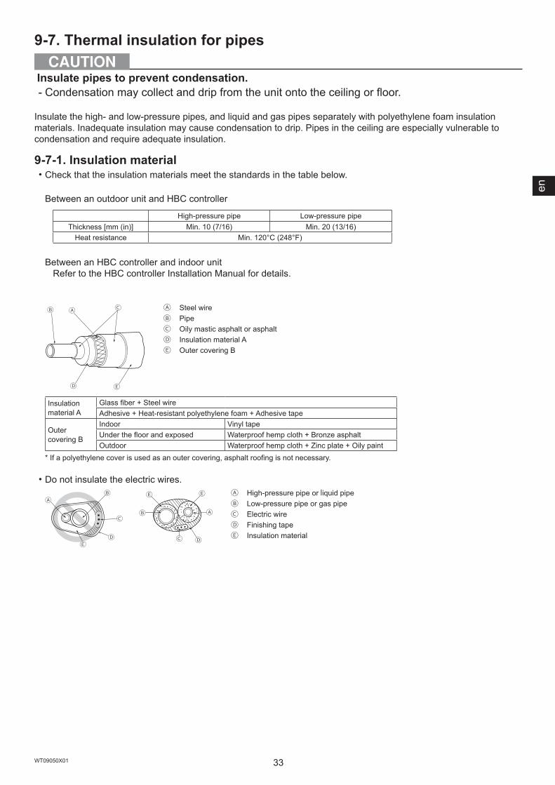
9-7. Thermal insulation for pipes
Insulate pipes to prevent condensation. - Condensation may collect and drip from the unit onto the ceiling or floor.
Insulate the high- and low-pressure pipes, and liquid and gas pipes separately with polyethylene foam insulation materials. Inadequate insulation may cause condensation to drip. Pipes in the ceiling are especially vulnerable to condensation and require adequate insulation.
9-7-1. Insulation material・Check that the insulation materials meet the standards in the table below.
Between an outdoor unit and HBC controller
High-pressure pipe Low-pressure pipeThickness [mm (in)] Min. 10 (7/16) Min. 20 (13/16)
Heat resistance Min. 120°C (248°F)
Between an HBC controller and indoor unitRefer to the HBC controller Installation Manual for details.
Ⓐ ⒸⒷ
Ⓓ Ⓔ
Ⓐ Steel wireⒷ PipeⒸ Oily mastic asphalt or asphaltⒹ Insulation material AⒺ Outer covering B
Insulation material A
Glass fiber + Steel wireAdhesive + Heat-resistant polyethylene foam + Adhesive tape
Outer covering B
Indoor Vinyl tapeUnder the floor and exposed Waterproof hemp cloth + Bronze asphaltOutdoor Waterproof hemp cloth + Zinc plate + Oily paint
* If a polyethylene cover is used as an outer covering, asphalt roofing is not necessary.
・Do not insulate the electric wires.
ⒶⒷ
Ⓒ
ⒹⒺ
ⒶⒷ
Ⓔ
Ⓓ
Ⓔ
Ⓒ
Ⓐ High-pressure pipe or liquid pipeⒷ Low-pressure pipe or gas pipeⒸ Electric wireⒹ Finishing tapeⒺ Insulation material

34WT09050X01
・Make sure that the pipe connections all the way from the indoor unit are properly insulated.
9-7-2. Insulation for the section of the pipe that goes through a wall(1) Inner wall (concealed) (2) Outer wall (3) Outer wall (exposed)
Ⓐ ⒷⒶ Ⓑ
ⒸⒹ Ⓔ
Ⓑ
Ⓗ
(4) Floor (waterproof) (5) Rooftop pipe shaft (6) Protecting the penetrating parts in a fire limit zone or through a parting wall
Ⓓ
Ⓕ
Ⓖ
Ⓑ
Ⓓ Ⓑ
ⒸⒻ
1000(39-3/8)
1000(39-3/8)
Ⓐ
ⒽⒾ
Ⓐ SleeveⒷ Insulation materialⒸ LaggingⒹ Caulking materialⒺ BandⒻ Waterproof layerⒼ Sleeve with a flangeⒽ Caulk with a nonflammable material such as mortar.Ⓘ Nonflammable insulation material
・When caulking the gaps with mortar, cover the section of the pipe that goes through the wall with a metal sheet to prevent the insulation material from sagging. For this section, use nonflammable insulation and covering materials. (Vinyl tape should not be used.)
[mm (in)]

en
35WT09050X01
9-8. Evacuation of the system
Do not purge the air using refrigerant. Use a vacuum pump to evacuate the system. - Residual gas in the refrigerant lines will cause bursting of the pipes or an explosion.
Use a vacuum pump with a check valve. - If the vacuum pump oil flows back into the refrigerant lines, the refrigerant oil may deteriorate and the compressor may malfunction.
<Evacuation procedures>① Evacuate the system from both service ports, using a vacuum pump with the service valves closed.② After the vacuum reaches 650 Pa, continue evacuation for at least one hour.③ Stop the vacuum pump and leave it for an hour.④ Verify that the vacuum has not increased by more than 130 Pa.⑤ If the vacuum has increased by more than 130 Pa, water infiltration is suspected. Pressurize the system with dry
nitrogen gas up to 0.05 MPa. Repeat ① though ⑤ until the vacuum is increased by 130 Pa or below. If the results persist, then perform the "Triple Evacuation" below.
<Triple Evacuation>① Evacuate the system to 533 Pa from both service ports, using a vacuum pump.② Pressurize the system with dry nitrogen gas up to 0 Pa from the discharge service port.③ Evacuate the system to 200 Pa from the suction service port, using a vacuum pump.④ Pressurize the system with dry nitrogen gas up to 0 Pa from the discharge service port.⑤ Evacuate the system from both service ports, using a vacuum pump.⑥ After the vacuum reaches 66.7 Pa, stop the vacuum pump and leave it for an hour. A vacuum of 66.7 Pa must
be maintained for at least one hour.⑦ Verify that the vacuum has not increased for at least 30 minutes.
LO HIⒶ
Ⓑ Ⓒ
Ⓝ
Ⓝ
Ⓔ
Ⓓ
Ⓕ
Ⓞ
Ⓖ
Ⓗ Ⓘ
Ⓚ
Ⓙ
Ⓛ
Ⓜ
Ⓐ Gauge manifoldⒷ Low pressure knobⒸ High pressure knobⒹ Service valveⒺ Low-pressure pipeⒻ High-pressure pipeⒼ Service portⒽ Three-way jointⒾ Valve (vacuum pump)Ⓙ Valve (for charging refrigerant)Ⓚ Refrigerant tankⓁ ScaleⓂ Vacuum pumpⓃ To indoor unitⓄ Outdoor unit
・Use a scale that can measure down to 0.1 kg (0.1 oz).・Recommended vacuum gauge: ROBINAIR 14830A Thermistor Vacuum Gauge or Micron Gauge・Do not use a gauge manifold to measure the vacuum pressure.・Use a vacuum pump capable of attaining a vacuum of 65 Pa (abs) within five minutes of operation.
36WT09050X01
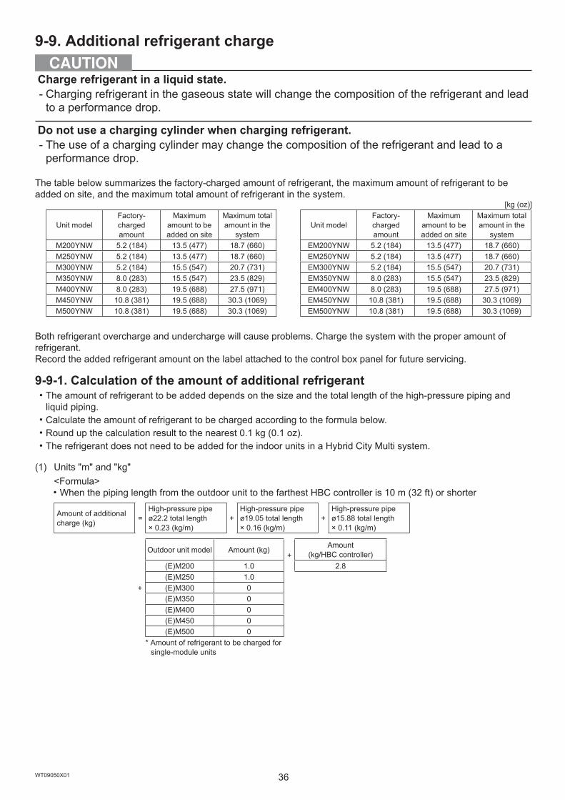
9-9. Additional refrigerant charge
Charge refrigerant in a liquid state. - Charging refrigerant in the gaseous state will change the composition of the refrigerant and lead to a performance drop.
Do not use a charging cylinder when charging refrigerant. - The use of a charging cylinder may change the composition of the refrigerant and lead to a performance drop.
The table below summarizes the factory-charged amount of refrigerant, the maximum amount of refrigerant to be added on site, and the maximum total amount of refrigerant in the system.
[kg (oz)]
Unit modelFactory-charged amount
Maximum amount to be added on site
Maximum total amount in the
systemUnit model
Factory-charged amount
Maximum amount to be added on site
Maximum total amount in the
systemM200YNW 5.2 (184) 13.5 (477) 18.7 (660) EM200YNW 5.2 (184) 13.5 (477) 18.7 (660)M250YNW 5.2 (184) 13.5 (477) 18.7 (660) EM250YNW 5.2 (184) 13.5 (477) 18.7 (660)M300YNW 5.2 (184) 15.5 (547) 20.7 (731) EM300YNW 5.2 (184) 15.5 (547) 20.7 (731)M350YNW 8.0 (283) 15.5 (547) 23.5 (829) EM350YNW 8.0 (283) 15.5 (547) 23.5 (829)M400YNW 8.0 (283) 19.5 (688) 27.5 (971) EM400YNW 8.0 (283) 19.5 (688) 27.5 (971)M450YNW 10.8 (381) 19.5 (688) 30.3 (1069) EM450YNW 10.8 (381) 19.5 (688) 30.3 (1069)M500YNW 10.8 (381) 19.5 (688) 30.3 (1069) EM500YNW 10.8 (381) 19.5 (688) 30.3 (1069)
Both refrigerant overcharge and undercharge will cause problems. Charge the system with the proper amount of refrigerant.Record the added refrigerant amount on the label attached to the control box panel for future servicing.
9-9-1. Calculation of the amount of additional refrigerant・The amount of refrigerant to be added depends on the size and the total length of the high-pressure piping and
liquid piping.・Calculate the amount of refrigerant to be charged according to the formula below.・Round up the calculation result to the nearest 0.1 kg (0.1 oz).・The refrigerant does not need to be added for the indoor units in a Hybrid City Multi system.
(1) Units "m" and "kg"<Formula>・When the piping length from the outdoor unit to the farthest HBC controller is 10 m (32 ft) or shorter
Amount of additional charge (kg) =
High-pressure pipe ø22.2 total length × 0.23 (kg/m)
+High-pressure pipe ø19.05 total length × 0.16 (kg/m)
+High-pressure pipe ø15.88 total length × 0.11 (kg/m)
+
Outdoor unit model Amount (kg)+
Amount (kg/HBC controller)
(E)M200 1.0 2.8(E)M250 1.0(E)M300 0(E)M350 0(E)M400 0(E)M450 0(E)M500 0
* Amount of refrigerant to be charged for single-module units
en
37WT09050X01
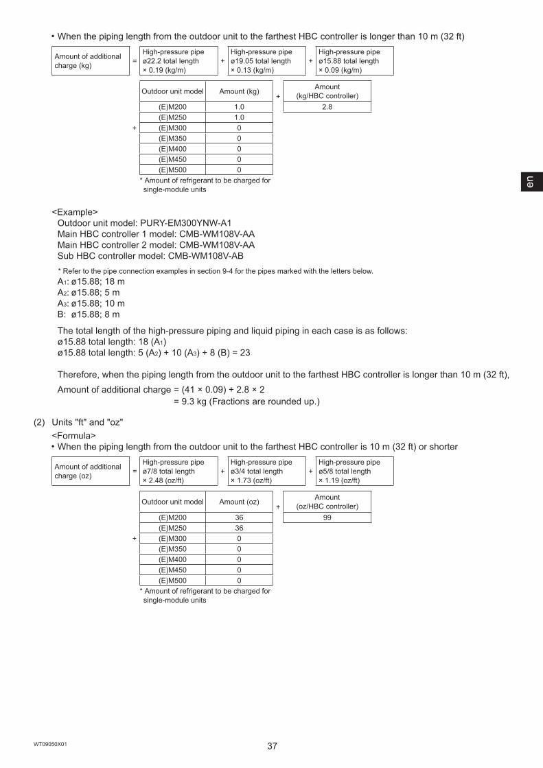
・When the piping length from the outdoor unit to the farthest HBC controller is longer than 10 m (32 ft)
Amount of additional charge (kg) =
High-pressure pipe ø22.2 total length × 0.19 (kg/m)
+High-pressure pipe ø19.05 total length × 0.13 (kg/m)
+High-pressure pipe ø15.88 total length × 0.09 (kg/m)
+
Outdoor unit model Amount (kg)+
Amount (kg/HBC controller)
(E)M200 1.0 2.8(E)M250 1.0(E)M300 0(E)M350 0(E)M400 0(E)M450 0(E)M500 0
* Amount of refrigerant to be charged for single-module units
<Example>Outdoor unit model: PURY-EM300YNW-A1Main HBC controller 1 model: CMB-WM108V-AAMain HBC controller 2 model: CMB-WM108V-AASub HBC controller model: CMB-WM108V-AB* Refer to the pipe connection examples in section 9-4 for the pipes marked with the letters below.A1: ø15.88; 18 mA2: ø15.88; 5 mA3: ø15.88; 10 mB: ø15.88; 8 m
The total length of the high-pressure piping and liquid piping in each case is as follows:ø15.88 total length: 18 (A1)ø15.88 total length: 5 (A2) + 10 (A3) + 8 (B) = 23
Therefore, when the piping length from the outdoor unit to the farthest HBC controller is longer than 10 m (32 ft),Amount of additional charge = (41 × 0.09) + 2.8 × 2
= 9.3 kg (Fractions are rounded up.)
(2) Units "ft" and "oz"<Formula>・When the piping length from the outdoor unit to the farthest HBC controller is 10 m (32 ft) or shorter
Amount of additional charge (oz) =
High-pressure pipe ø7/8 total length × 2.48 (oz/ft)
+High-pressure pipe ø3/4 total length × 1.73 (oz/ft)
+High-pressure pipe ø5/8 total length × 1.19 (oz/ft)
+
Outdoor unit model Amount (oz)+
Amount (oz/HBC controller)
(E)M200 36 99(E)M250 36(E)M300 0(E)M350 0(E)M400 0(E)M450 0(E)M500 0
* Amount of refrigerant to be charged for single-module units
38WT09050X01
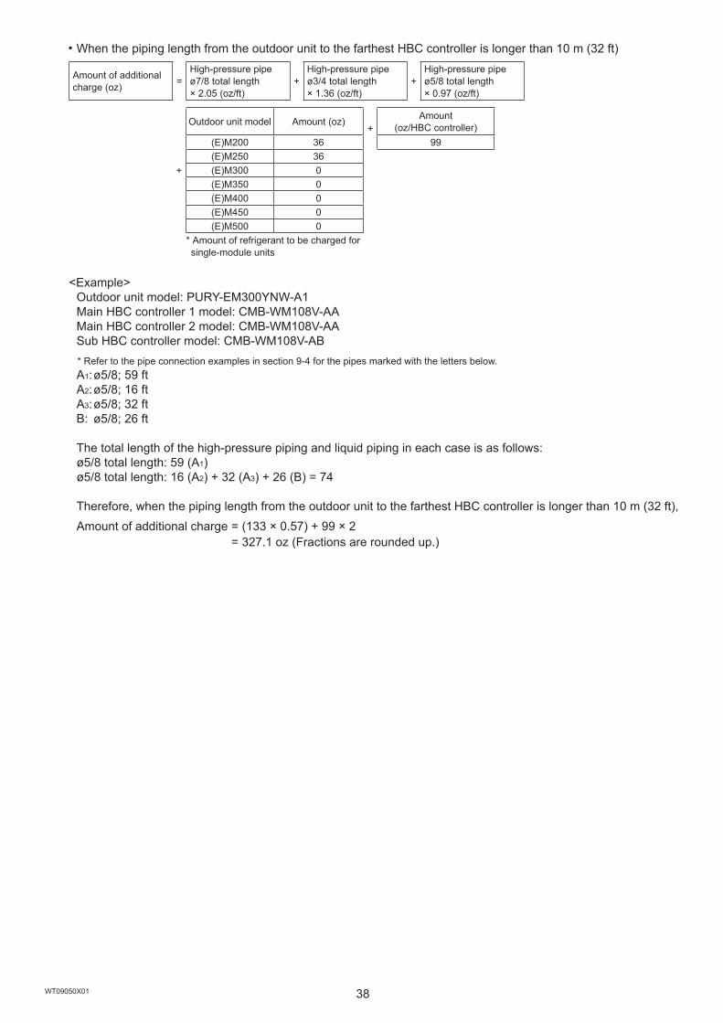
・When the piping length from the outdoor unit to the farthest HBC controller is longer than 10 m (32 ft)
Amount of additional charge (oz) =
High-pressure pipe ø7/8 total length × 2.05 (oz/ft)
+High-pressure pipe ø3/4 total length × 1.36 (oz/ft)
+High-pressure pipe ø5/8 total length × 0.97 (oz/ft)
+
Outdoor unit model Amount (oz)+
Amount (oz/HBC controller)
(E)M200 36 99(E)M250 36(E)M300 0(E)M350 0(E)M400 0(E)M450 0(E)M500 0
* Amount of refrigerant to be charged for single-module units
<Example>Outdoor unit model: PURY-EM300YNW-A1Main HBC controller 1 model: CMB-WM108V-AAMain HBC controller 2 model: CMB-WM108V-AASub HBC controller model: CMB-WM108V-AB* Refer to the pipe connection examples in section 9-4 for the pipes marked with the letters below.A1: ø5/8; 59 ftA2: ø5/8; 16 ftA3: ø5/8; 32 ftB: ø5/8; 26 ft
The total length of the high-pressure piping and liquid piping in each case is as follows:ø5/8 total length: 59 (A1)ø5/8 total length: 16 (A2) + 32 (A3) + 26 (B) = 74
Therefore, when the piping length from the outdoor unit to the farthest HBC controller is longer than 10 m (32 ft),Amount of additional charge = (133 × 0.57) + 99 × 2
= 327.1 oz (Fractions are rounded up.)

en
39WT09050X01
Do not use means to accelerate the defrosting process or to clean, other than those recommended by the manufacturer.
The unit shall be stored in a room without continuously operating ignition sources (for example: open flames, an operating gas appliance or an operating electric heater.)
Do not pierce or burn.
Be aware that refrigerants may not contain an odour.
The unit shall be stored in a space where any possible leakage of refrigerant will not accumulate.
When installing an HBC controller, take safety measures in accordance with the European Standard, based on the system refrigerant amount and the room volume as shown in the figure below. (The installation restrictions can be simply found by using the flowchart provided on a separate sheet.)
0
10
20
30
40
50
60
70
80
0 50 100 150 200 250 300 350 400 450 500 550 600 650
The unit shall be properly stored to prevent mechanical damage.
At least two safety measures are required.
Room volume [m3]
SySt
em re
frige
rant
am
ount
[kg] NG (ISO 5149)
At least one safety measure is required.
Construction guidance

40WT09050X01
9-9-2. Charging additional refrigerantCharge the calculated amount of refrigerant in the liquid state to the unit through the service port after the completion of piping work. Upon completion of all work, securely tighten all service port caps and shaft caps to prevent refrigerant leakage.
<Notice>・Do not vent the refrigerant into the atmosphere.・Refer to the table below for the appropriate tightening torque.
Pipe size [mm (in)] Shaft cap (N·m) Shaft (N·m) Size of hexagonal wrench [mm (in)] Service port cap (N·m)ø22.2 (ø7/8) 22 - - 16
ø28.58 (ø1-1/8) 22 - - 16
・If the refrigerant tank does not have a siphon pipe, charge the liquid refrigerant with the tank upside-down as shown in the figure below.
Ⓐ
Ⓐ Siphon pipe
・After evacuation and refrigerant charging, ensure that the service valves are fully open. Do not operate the unit with the service valves closed.・Ensure that contamination of different refrigerants does not occur when using charging equipment. Hoses and
pipes shall be as short as possible to minimize the amount of refrigerant contained in them.・The refrigerant tank shall be kept upright.・Ensure that the refrigerant system is earthed prior to charging the system with refrigerant.・Record the added refrigerant amount on the label attached to the control box panel for future servicing.・Extreme care shall be taken not to overfill the refrigerant system.

en
41WT09050X01
10. Electrical work
Electrical work must be performed by qualified personnel in accordance with local regulations and the instructions provided in this manual. Only use the specified cables and dedicated circuits. - Inadequate power source capacity or improper electrical work will result in electric shock, malfunction, or fire.
Proper grounding must be provided by qualified personnel. - Improper grounding may result in electric shock, fire, explosion, or malfunction due to electrical noise. Do not connect the ground wire to gas or water pipes, lightning rods, or telephone ground wires.
10-1. Before electrical work・When performing electrical work, refer to the indoor unit or controller installation manuals as well.・Bear in mind ambient conditions (ambient temperature, direct sunlight, rain water, etc.) when proceeding with the
wiring and connections.・When opening or closing the front panel of the control box, do not let it come into contact with any of the internal
components.・Specific wiring requirements should adhere to the wiring regulations of the region.・Include some slack in the wiring for the control box on the indoor and outdoor units, because these boxes are
sometimes removed at the time of service work.
10-2. Power cables and device capacity
Include some slack in the power cables. - Failure to do so may break or overheat the cables, resulting in smoke or fire.
Install an inverter circuit breaker on the power supply of each unit. - Failure to do so may result in electric shock or fire.
Only use properly rated breakers (an earth leakage breaker, local switch <a switch + fuse that meets local electrical codes>, or overcurrent breaker). - Failure to do so may result in electric shock, malfunction, smoke, or fire.
Only use standard power cables of sufficient capacity. - Failure to do so may result in current leakage, overheating, smoke, or fire.
Tighten all terminal screws to the specified torque. - Loose screws and contact failure may result in smoke or fire.
If a large electric current flows due to a malfunction or faulty wiring, earth-leakage breakers on the unit side and on the upstream side of the power supply system could both operate. Depending on the importance of the system, separate the power supply system or take protective coordination of breakers.
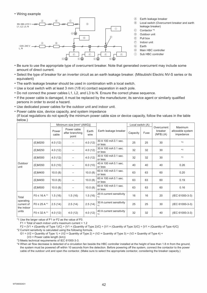
42WT09050X01
・Wiring example
Ⓑ ⒸⒶⒹ
ⒷⒶ
Ⓕ Ⓕ
Ⓔ
Ⓕ Ⓕ
ⓛ
Ⓗ
Ⓖ
Ⓖ Ⓖ Ⓖ Ⓖ
Ⓐ Earth leakage breakerⒷ Local switch (Overcurrent breaker and earth
leakage breaker)Ⓒ Contactor *4
Ⓓ Outdoor unitⒺ Pull boxⒻ Indoor unitⒼ EarthⒽ Main HBC controllerⒾ Sub HBC controller
・Be sure to use the appropriate type of overcurrent breaker. Note that generated overcurrent may include some amount of direct current.・Select the type of breaker for an inverter circuit as an earth leakage breaker. (Mitsubishi Electric NV-S series or its
equivalent)・The earth leakage breaker should be used in combination with a local switch.・Use a local switch with at least 3 mm (1/8 in) contact separation in each pole.・Do not connect the power cables L1, L2, and L3 to N. Ensure the correct phase sequence.・If the power cable is damaged, it must be replaced by the manufacturer, its service agent or similarly qualified
persons in order to avoid a hazard.・Use dedicated power cables for the outdoor unit and indoor unit.・Power cable size, device capacity, and system impedance
(If local regulations do not specify the minimum power cable size or device capacity, follow the values in the table below.)
Minimum size [mm2 (AWG)]
Earth leakage breaker
Local switch (A)Overcurrent
breaker (NFB) (A)
Maximum allowable system
impedancePower cable
Power cable after branching
point
Earth wire Capacity Fuse
Outdoor unit
(E)M200 4.0 (12) – 4.0 (12) 30 A 100 mA 0.1 sec. or less 25 25 30 *3
(E)M250 4.0 (12) – 4.0 (12) 30 A 100 mA 0.1 sec. or less 32 32 30 *3
(E)M300 4.0 (12) – 4.0 (12) 30 A 100 mA 0.1 sec. or less 32 32 30 *3
(E)M350 6.0 (10) – 6.0 (10) 40 A 100 mA 0.1 sec. or less 40 40 40 0.26
(E)M400 10.0 (8) – 10.0 (8) 60 A 100 mA 0.1 sec. or less 63 63 60 0.20
(E)M450 10.0 (8) – 10.0 (8) 60 A 100 mA 0.1 sec. or less 63 63 60 0.19
(E)M500 10.0 (8) – 10.0 (8) 60 A 100 mA 0.1 sec. or less 63 63 60 0.16
Total operating current of the indoor units
F0 ≤ 16 A *1 1.5 (16) 1.5 (16) 1.5 (16) 20 A current sensitivity *2 16 16 20 (IEC 61000-3-3)
F0 ≤ 25 A *1 2.5 (14) 2.5 (14) 2.5 (14) 30 A current sensitivity *2 25 25 30 (IEC 61000-3-3)
F0 ≤ 32 A *1 4.0 (12) 4.0 (12) 4.0 (12) 40 A current sensitivity *2 32 32 40 (IEC 61000-3-3)
*1 Use the larger value of F1 or F2 as the value of F0. F1 = Total of each indoor unit's maximum current × 1.2 F2 = {V1 × (Quantity of Type 1)/C} + {V1 × (Quantity of Type 2)/C} + {V1 × (Quantity of Type 3)/C} + {V1 × (Quantity of Type 4)/C}
*2 Current sensitivity is calculated using the following formula. G1 = (V2 × Quantity of Type 1) + (V2 × Quantity of Type 2) + (V2 × Quantity of Type 3) + (V2 × Quantity of Type 4) +
(V3 × Power cable length (km))*3 Meets technical requirements of IEC 61000-3-3.*4 When air flow decrease is detected of a circulation fan beside the HBC controller installed at the height of less than 1.8 m from the ground,
the system must be powered off within 10 seconds from the detection. Before powering off the system, connect the contactor to the power cable of the outdoor unit and open the contactor. (Make sure to select the appropriate contactor, considering the breaker capacity.)
~220–240 VL, N
3N~380–415 VL1, L2, L3, N

en
43WT09050X01
Indoor unit V1 V2
20
C
108643210.01
0.1
1
10
60
600
6000Type 1 PLFY-(WP)VBM, PMFY-VBM, PEFY-VMS, PCFY-VKM, PKFY-VHM, PKFY-VKM, PFFY-VKM, PFFY-(WP)VLRMM 18.6 2.4
Type 2 PEFY-(WP)VMA 38 1.6Type 3 PEFY-VMHS 13.8 4.8Type 4 Indoor unit other than the above 0 0
"C" is multiples of the tripping current at 0.01 s. Obtain the value of "C" from the tripping characteristic of the breaker that is used on site.
<Example of "F2" calculation>Conditions: PEFY-VMS × 4 units, PEFY-VMA × 1 unit, "C" = 8 (See the sample chart.)
F2 = 18.6 × 4/8 + 38 × 1/8 = 14.05 → Use a 16 A type breaker. (Tripping current = 8 × 16 A at 0.01 s)
Power cable size [mm2 (AWG)] V31.5 (16) 482.5 (14) 564.0 (12) 66
G1 Current sensitivity30 mA or less 30 mA 0.1 sec or less100 mA or less 100 mA 0.1 sec or less
・The wire size is the minimum value for metal conduit wiring. If the voltage drops, use a wire that is one size thicker in diameter. Make sure the power-supply voltage does not drop more than 10%. Make sure that the voltage imbalance between the phases is 2% or less.・Power supply cords of parts of appliances for outdoor use shall not be lighter than polychloroprene sheathed
flexible cord (design 60245 IEC57). For example, use wiring such as YZW.・This unit is intended for the connection to a power supply system with a maximum permissible system
impedance shown in the above table at the interface point (power service box) of the user’s supply.・The user must ensure that this unit is connected only to a power supply system which fulfils the requirement
above. If necessary, the user can ask the public power supply company for the system impedance at the interface point.・This unit complies with IEC 61000-3-12 provided that the short-circuit power Ssc is greater than or equal to
Ssc*1 at the interface point between the user’s supply and the public system. It is the responsibility of the installer or user of the equipment to ensure, by consultation with the distribution network operator if necessary, that the equipment is connected only to a supply with a short-circuit power Ssc greater than or equal to Ssc*1.*1 Ssc
Model Ssc (MVA) Model Ssc (MVA)M200 1.25 EM200 1.25M250 1.58 EM250 1.54M300 1.95 EM300 1.82M350 2.14 EM350 1.89M400 2.72 EM400 2.38M450 2.88 EM450 2.69M500 3.35 EM500 3.13
Trip
ping
Tim
e [s
]
SAMPLE
Multiples of rated tripping current
Sample chart

44WT09050X01
10-3. Control cable specifications・Transmission cable
Type 2-core shielded cable CVVS, CPEVS, or MVVSSize 1.25 mm2 (AWG 16)Length Max. 200 m (656 ft)
Remarks
The maximum allowable length of transmission cables via outdoor units (both centralized control transmission cables and indoor-outdoor transmission cables) is 500 m (1640 ft)*1.The maximum allowable length of transmission cables from the power supply unit to each outdoor unit or to the system controller is 200 m (656 ft).
* Do not use a single multiple-core cable to connect indoor units that belong to different refrigerant systems. The use of a multiple-core cable may result in signal transmission errors and malfunctions.
* Ensure shield continuity when extending the transmission cable.*1 When extending the length of the transmission cables to 1000 m (3280 ft), consult your dealer.
・Remote controller cableME remote controller cable MA remote controller cable
Type 2-core sheathed cable (unshielded) CVVSize 0.3–1.25 mm2 (AWG 22–16) (0.75–1.25 mm2 (AWG 18–16) if a simple remote controller is connected)
LengthMax. 10 m (32 ft)* If the length exceeds 10 m (32 ft), use a 1.25 mm2
(AWG 16) shielded cable.Max. 200 m (656 ft)
10-4. System configuration・Unit code and the maximum number of connectable units
Unit type Code Number of connectable unitsOutdoor unit Main unit OC –Indoor unit IC 1 to 50 units per OC (depends on the unit model)
HBC controllerMain HB 1 to 2 units per OCSub HS 0 to 2 units per OC
Remote controller RC 0 to 2 units per groupTransmission booster unit RP 0 to 2 units per OC
* A transmission booster unit may be required depending on the number of connected indoor units. The outdoor unit does not support PAC-SF46EPA but PAC-SF46EPA-G only.
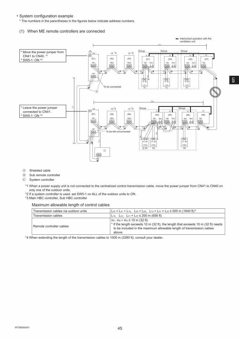
en
45WT09050X01
・System configuration example* The numbers in the parentheses in the figures below indicate address numbers.
(1) When ME remote controllers are connected
Ⓐ
ⒸⒷ
IC
TB5S
TB151 2
(01)
IC
TB5S
TB151 2
(02)
LC
TB5S
(07)
IC
TB5S 1 2
TB15
IC
TB5S
TB151 2
(05)(04)
LC
TB5S
(08)
IC
TB5S
TB151 2
(03)
IC
TB5S
TB151 2
(06)
A1 B2
RC(101)
A1 B2
RC(102)
A1 B2
RC(103)
M1M2 M1M2M1M2
M1M2 M1M2 M1M2 M1M2
L31
A B S
L32
OC
m1
TB3
TB7M1 M2S
(51)
M1M2
OC
TB3
TB7S
(57)
M1M2
M1M2
M1M2
(104)
A1 B2
RC(154)
A1 B2
RC
m3
(106)
A1 B2
RC
m2
S
HS
TB02
(53)
S
HS
TB02
(56)
L12
L22
M1M2
M1M2S
HB
TB02
(52)
S
HB
TB02
(54)
M1M2
M1M2
Ⓐ Shielded cableⒷ Sub remote controllerⒸ System controller
*1 When a power supply unit is not connected to the centralized control transmission cable, move the power jumper from CN41 to CN40 on only one of the outdoor units.
*2 If a system controller is used, set SW5-1 on ALL of the outdoor units to ON.*3 Main HBC controller, Sub HBC controller
Maximum allowable length of control cablesTransmission cables via outdoor units L32 + L31 + L12, L32 + L22, L12 + L31 + L22 ≤ 500 m (1640 ft)*4
Transmission cables L12, L22, L31 + L32 ≤ 200 m (656 ft)
Remote controller cables
m1, m2 + m3 ≤ 10 m (32 ft)* If the length exceeds 10 m (32 ft), the length that exceeds 10 m (32 ft) needs
to be included in the maximum allowable length of transmission cables above.
*4 When extending the length of the transmission cables to 1000 m (3280 ft), consult your dealer.
*3
Interlocked operation with the ventilation unit
To be left unconnected
To be connected
GroupGroup*3
*3
*3* Leave the power jumper connected to CN41.
* SW5-1: ON *2
* Move the power jumper from CN41 to CN40. *1
* SW5-1: ON *2
Group Group Group
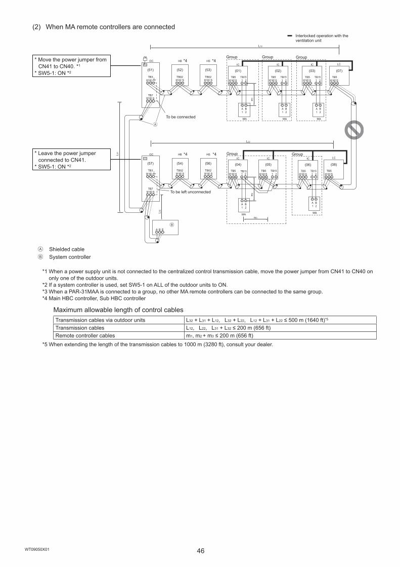
46WT09050X01
(2) When MA remote controllers are connected
Ⓐ
Ⓑ
IC
TB5S
TB151 2
(01)
IC
TB5S
TB151 2
(02)
A1
B2
MA
A1
B2
MA
LC
TB5S
(07)
IC
TB5S 1 2
TB15
IC
TB5S
TB151 2
(05)(04)
LC
TB5S
(08)
IC
TB5S
TB151 2
(03)
A1
B2
MA
IC
TB5S
TB151 2
(06)
A1
B2
MA
A1
B2
MAm3
L31
A B S
L32
OC
m2
m1
TB3
TB7S
(51)
M1 M2
M1 M2
M1 M2 M1 M2 M1 M2 M1 M2 M1 M2
M1 M2M1 M2M1 M2M1 M2M1 M2M1 M2
M1 M2
OC
TB3
TB7S
(57)
M1 M2
M1 M2
S
HS
TB02
(53)
S
HS
TB02
(56)
S
HB
TB02
(52)
S
HB
TB02
(54)
L22
L12
Ⓐ Shielded cableⒷ System controller
*1 When a power supply unit is not connected to the centralized control transmission cable, move the power jumper from CN41 to CN40 on only one of the outdoor units.
*2 If a system controller is used, set SW5-1 on ALL of the outdoor units to ON.*3 When a PAR-31MAA is connected to a group, no other MA remote controllers can be connected to the same group.*4 Main HBC controller, Sub HBC controller
Maximum allowable length of control cablesTransmission cables via outdoor units L32 + L31 + L12, L32 + L22, L12 + L31 + L22 ≤ 500 m (1640 ft)*5
Transmission cables L12, L22, L31 + L32 ≤ 200 m (656 ft)Remote controller cables m1, m2 + m3 ≤ 200 m (656 ft)
*5 When extending the length of the transmission cables to 1000 m (3280 ft), consult your dealer.
Interlocked operation with the ventilation unit
To be left unconnected
To be connected
GroupGroup*4
GroupGroup*4*4
*4
* Move the power jumper from CN41 to CN40. *1
* SW5-1: ON *2
* Leave the power jumper connected to CN41.
* SW5-1: ON *2
Group
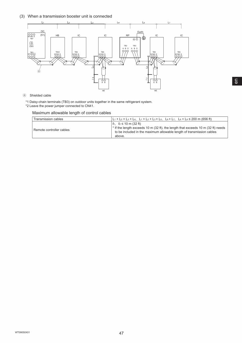
en
47WT09050X01
(3) When a transmission booster unit is connected
ME
ICHB
M1M2 STB5
IC
M1M2 STB5
RP
A B
A BA B
STB2
A B STB3
L8
ME
IC
M1M2 STB5
IC
M1M2 STB5
M1M2 SM1M2TB3
M1M2 STB7
OC(51)
Ⓐ
CN41
TB02
111
Ⓐ Shielded cable
*1 Daisy-chain terminals (TB3) on outdoor units together in the same refrigerant system.*2 Leave the power jumper connected to CN41.
Maximum allowable length of control cablesTransmission cables L1 + L2 + L3 + L4, L1 + L2 + L3 + L5, L6 + L7, L6 + L8 ≤ 200 m (656 ft)
Remote controller cables
ℓ1, ℓ2 ≤ 10 m (32 ft)* If the length exceeds 10 m (32 ft), the length that exceeds 10 m (32 ft) needs
to be included in the maximum allowable length of transmission cables above.
Earth
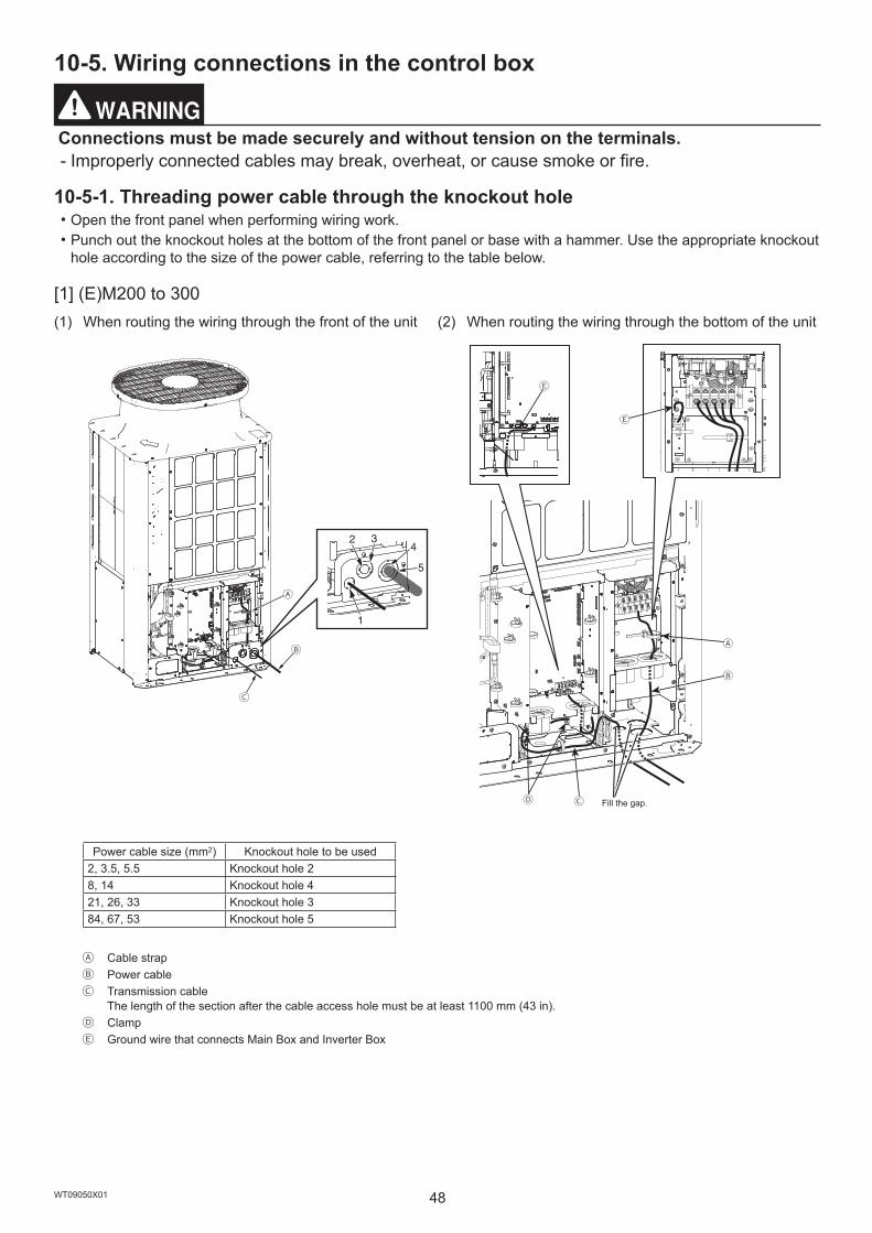
48WT09050X01
10-5. Wiring connections in the control box
Connections must be made securely and without tension on the terminals. - Improperly connected cables may break, overheat, or cause smoke or fire.
10-5-1. Threading power cable through the knockout hole・Open the front panel when performing wiring work.・Punch out the knockout holes at the bottom of the front panel or base with a hammer. Use the appropriate knockout
hole according to the size of the power cable, referring to the table below.
[1] (E)M200 to 300(1) When routing the wiring through the front of the unit (2) When routing the wiring through the bottom of the unit
Ⓑ
Ⓒ
Ⓐ
Ⓒ
Ⓐ
Ⓑ
Ⓓ
Ⓔ
Ⓔ
Power cable size (mm2) Knockout hole to be used2, 3.5, 5.5 Knockout hole 28, 14 Knockout hole 421, 26, 33 Knockout hole 384, 67, 53 Knockout hole 5
Ⓐ Cable strapⒷ Power cableⒸ Transmission cable
The length of the section after the cable access hole must be at least 1100 mm (43 in).Ⓓ ClampⒺ Ground wire that connects Main Box and Inverter Box
Fill the gap.

en
49WT09050X01
[2] (E)M350 to 500(1) When routing the wiring through the front of the unit (2) When routing the wiring through the bottom of the unit
Ⓑ
Ⓒ
Ⓐ
Ⓒ
Ⓐ
Ⓑ
Power cable size (mm2) Knockout hole to be used2, 3.5, 5.5 Knockout hole 28, 14 Knockout hole 421, 26, 33 Knockout hole 384, 67, 53 Knockout hole 5
Ⓐ Cable strapⒷ Power cableⒸ Transmission cable
The length of the section after the cable access hole must be at least 1100 mm (43 in).
<Notice>・Do not remove the ground wire that connects Main Box and Inverter Box.・Install the transmission cable as shown in the figure above so that the cable is long enough for the Main Box to be
moved for servicing.・If there are any gaps around the power cable and transmission cable, please be sure to fill these in with a suitable
material to prevent snow from entering, which may cause damage to the electrical parts, and to protect your hands from direct contact with cables.・When putting the power cable through the knockout hole without using a conduit tube, deburr the hole and protect
the power cable with protective tape.・Use a conduit tube to narrow down the opening if there is a possibility of small animals entering the unit.・When taking the conduit tube out from the bottom part of the unit, caulk around the tube opening to prevent water
infiltration.
Fill the gap.

50WT09050X01
10-5-2. Fixing the cables in placeRoute the cables as shown in the figures below.・(E)M200 to 300
・(E)M350 to 500
Fill the gap.
Rubber bushing (for main inverter connection wiring (200 V) and unit wiring
(solenoid coil wiring))
Inverter BoxMain Box
Cable strap
Tie band(Supplied)
Rubber bushing 1
Transmission terminal block
Main inverter connection wiring (low voltage)
Transmission cable (not supplied)The length of the section after the cable access hole must be at least 1100 mm (43 in).
Power supply terminal block
Power cable (not supplied)
Rubber bushing 2
Tie band(Supplied)
Unit wiring (sensor wiring)
Rubber bushing(for FAN cable)
Power cable (not supplied)
Transmission terminal block
Rubber bushing (for Fan cable and unit wiring
(solenoid coil wiring))
Cable strap
Tie band(Supplied)
Rubber bushing 1
Transmission cable (not supplied)
Power supply terminal block
Rubber bushing 2
Tie band(Supplied)
Unit wiring (sensor wiring)
Fill the gap.

en
51WT09050X01
Take the procedure below.
① Thread the power cable through the rubber bushing 1. (See *1 and *2 below.)② Thread the unit wiring (sensor wiring) and the transmission cable through the rubber bushing 2. (See *1 and *2
below.)③ Hold the power cable and the transmission cable in place respectively with the cable straps.④ Secure each rubber bushing with the supplied tie band. (See *3 below.)
*1 Make sure the cables are not coming out of the rubber bushing cut.
*2 When threading the wiring through the rubber bushing, make sure the rubber bushing will not come off the sheet metal on the control box.
*3 When tying the supplied tie band around the rubber bushing, make sure to leave no gap between the ends.
Cables are coming out of the rubber bushing.
Wiring
Cross-sectional view
Rubber bushing (oval part)
Rubber bushing (oval part)
Cut
Top view
WiringWiring
Top view
Rubber bushing
Sheet metal on the control box
Rubber bushing
Sheet metal on the control box
Rubber bushing
<<Important>> When putting the tie band on the rubber bushing, make sure the ends of the rubber bushing overlap each other as shown in the figure at left.* If there is a gap, water from snow or rain may enter, resulting in
equipment damage. Cut on the rubber bushing
There is a gap in the rubber bushing.
Approx. 20 mm (13/16 in)
<Back of the rubber bushing>
Cut on the rubber bushing
Tie band
Overlapped rubber bushing

52WT09050X01
10-5-3. Connecting the cablesPURY-(E)M200 to 300YNW-A1
L1 L2 L3 NⒷⒶ-1 Ⓐ-2 Ⓒ Ⓓ
PURY-(E)M350 to 500YNW-A1
L1 L2 L3 NⒷⒶ Ⓒ Ⓓ Ⓐ Control box
Ⓑ Power supply terminal block (TB1)Ⓒ Terminal block for indoor-outdoor transmission
cable (TB3)Ⓓ Terminal block for centralized control
transmission cable (TB7)
Ⓐ Ⓑ
Ⓒ Ⓐ Terminal block with loose screwsⒷ Properly installed terminal blockⒸ Spring washers must be parallel to the terminal block.
Ⓐ
Ⓑ
ⒸⒺ
Ⓓ Ⓐ Power cables, transmission cablesⒷ Daisy-chain (transmission cables only)Ⓒ Terminal blocks (TB1, TB3, TB7)Ⓓ Make an alignment mark.Ⓔ Install the ring terminals back to back.
<Notice>・Connect the cables respectively to the power supply terminal block and the transmission terminal block.
Erroneous connection does not allow the system to operate.・Never connect the power cable to the transmission terminal block. If connected, electrical parts will be damaged.・Transmission cables should be (5 cm (2 in) or more) apart from the power cable so that it is not influenced by
electric noise from the power cable. (Do not put the transmission cables and the power cable in the same conduit.)・Follow the tightening torque for each screw type as shown below. Be careful not to use excessive torque as this
could damage the screw. Terminal block (TB1 (M6 screw)): 2.5–2.9 [N·m] Terminal block (TB3, TB7 (M3.5 screw)): 0.82–1.0 [N·m]・When tightening the screws, do not push the driver strongly to avoid damaging the screw.・Make an alignment mark with a permanent marker across the screw head, washer, and terminal after tightening
the screws.
Take the procedure below to connect the cables.① Connect the indoor-outdoor transmission cable to TB3.
If multiple outdoor units are connected to the same refrigerant system, daisy-chain TB3 (M1, M2, earth) on the outdoor units. The indoor-outdoor transmission cable to the indoor unit should be connected to TB3 (M1, M2, earth) of only one of the outdoor units. Connect the shield to the earth terminal.
② Connect the centralized control transmission cables (between the centralized control system and the outdoor units of different refrigerant systems) to TB7. If multiple outdoor units are connected to the same refrigerant system, daisy-chain TB7 (M1, M2, S) on all outdoor units. Connect the shield to the S terminal.
③ When a power supply unit is not connected to the centralized control transmission cable, move the power jumper from CN41 to CN40 on only one of the outdoor units.
④ On the outdoor unit whose power jumper was moved from CN41 to CN40, short circuit the S terminal and the earth terminal.
⑤ Connect terminals M1 and M2 of the transmission terminal block on the indoor unit that has the lowest address in the group to the terminal block on the remote controller.
⑥ When a system controller is connected, set SW5-1 on all outdoor units to ON.⑦ Fix the cables securely in place with the cable strap below the terminal block.

53WT09050X01
10-6. Address setting・Set the address setting switch as follows.
Address setting method Address
Indoor unit (Main, Sub)
Assign the lowest address to the main indoor unit in the group, and assign sequential addresses to the rest of the indoor units in the same group.* In a system with a sub HBC controller, make the settings for the indoor units in the
following order. (Set the addresses so that the addresses of ① are smaller than those of ②.)
① Indoor units that are connected to the main HBC controller② Indoor units that are connected to the sub HBC controller
01 to 50
Outdoor unit (OC) Assign sequential addresses to the outdoor units in the same refrigerant system.* To set the address to 100, the address setting switch must be set to 50. 51 to 100
HBC controller
Main
Assign an address that equals the address of the outdoor unit plus 1. If the address that is assigned to the main HBC controller overlaps any of the addresses that are assigned to the outdoor units or to the sub HBC controller, use a different, unused address within the setting range.* To set the address to 100, the address setting switch must be set to 50.
51 to 100
SubAssign an address that equals the lowest address of the indoor units that are connected to the sub HBC controller plus 50.* To set the address to 100, the address setting switch must be set to 50.
51 to 100
ME remote controller Main Assign an address that equals the address of the main indoor unit in the group plus 100. 101 to 150Sub Assign an address that equals the address of the main indoor unit in the group plus 150. 151 to 200
MA remote controller Address setting is not required. (The Main/Sub setting is required.) –* Make indoor unit group settings from remote controllers after turning on the power to all units.
Address setting switch (Outdoor units)
54WT09050X01
11. Test run11-1. Before a test run
After the wiring work has been completed, measure the insulation resistance, and make sure that it reads at least 1 MΩ. - Failure to do so may result in electric leakage, malfunction, or fire.
Turn on the power at least 12 hours before starting operation. Keep the power turned on throughout the operating season. - Insufficient energizing will result in malfunction.
・Before performing a test run, turn off the power to the outdoor unit, and disconnect the power cable from the power supply terminal block to measure the insulation resistance.・Measure the insulation resistance between the power supply terminal block and the earth with a 500 V ohmmeter,
and make sure it is at least 1 MΩ.・If the insulation resistance is 1 MΩ or above, connect the power cable to the power supply terminal, and turn on the
power at least 12 hours before starting operation. If the insulation resistance is below 1 MΩ, do not operate the unit, and check the compressor for a earth fault.・While the unit is turned on, the compressor will remain energized even when it is stopped.・The insulation resistance between the power supply terminal block and the earth may drop to near 1 MΩ
immediately after installation or when the main power to the unit has been turned off for a long time because of the stagnation of refrigerant in the compressor.・By turning on the main power and energizing the unit for 12 hours or longer, the refrigerant in the compressor will
evaporate and the insulation resistance will rise.・Do not apply an ohmmeter voltage to the terminal block for transmission cables. Doing so will damage the control
board.・Do not measure the insulation resistance of the transmission terminal block of the unit remote controller.・Check for refrigerant leakage and for loose power cables and transmission cables.・Check that the high-pressure side and low-pressure side service valves are fully open. Tighten the valve caps.・Check the phase order of the power supply and the interphase voltage. If the voltage is out of the ±10% range, or if
the voltage imbalance is more than 2%, discuss the countermeasure with the customer.・When a transmission booster unit is connected, turn on the transmission booster unit before turning on the outdoor
unit. If the outdoor unit is turned on first, the refrigerant circuit connection information will not be properly verified. If the outdoor unit is turned on first, turn on the transmission booster unit and then power reset the outdoor unit.・When a power supply unit is connected to the centralized control transmission cable, or when power is supplied
from a system controller with a power-supply function, perform a test run with the power supply unit being energized. Leave the power jumper connected to CN41.・When power is turned on or after power recovery, performance may degrade for approximately 30 minutes.

en
55WT09050X01
11-2. Function settingMake function settings by setting the dipswitches SW4, SW6, and SWP3 on the main board.Write down the switch settings on the electrical wiring diagram label on the control box front panel for future reference when the control box needs to be replaced.・Take the following steps to make temperature unit (ºC or ºF) settings.
① Set the 10th bit of SW6 to ON.② Set SW4 as shown in the table below to select the setting item No.921. (The setting item No. will be displayed
on LED301.)③ Press SWP3 for two seconds or longer to change the settings. (The settings can be checked on LED3.)
Setting item No.
SW4 0: OFF, 1: ON *1 Setting (LED3 display) *2
1 2 3 4 5 6 7 8 9 10 Unlit LitTemperature unit setting 921 1 0 0 1 1 0 0 1 1 1 ºC ºF
*1 Make the SW4 setting after the unit is energized.*2 This will blink while the system is starting up.
・Make various function settings by setting SW5 and SW6, referring to the table below.
Setting contentSetting
Switch setting timingOFF ON
SW5-1 Centralized control switch Without connection to the centralized controller
With connection to the centralized controller Before being energized
SW5-2 Deletion of connection information Normal control Deletion Before being energizedSW5-3 –
Preset before shipment
–SW5-4 – –SW5-5 – –SW5-6 – –SW5-7 – –SW5-8 – –
Setting contentSetting
Switch setting timingOFF ON
SW6-1 – – – –SW6-2 – – – –SW6-3 – – – –SW6-4
High static pressure setting Refer to *1. Refer to *1. Before being energizedSW6-5SW6-6 – – – –SW6-7 Low-noise mode selection Performance priority Low-noise priority Any time after being energizedSW6-8 Selection of Low-noise or Demand Low-noise (Night) Demand Before being energizedSW6-9 Selection of Diagnostic display or
Function detail setting Refer to *2. Refer to *2. Any time after being energizedSW6-10
* Do not change the factory settings of SW5-3 through SW5-8.* Unless otherwise specified, leave the switch to OFF where indicated by "–," which may be set to OFF for a reason.*1
SW6-5: ON SW6-5: OFFSW6-4: ON 80 Pa 60 PaSW6-4: OFF 30 Pa 0 Pa
*2
SW6-10: ON SW6-10: OFFSW6-9: ON LED (round type) No. 0 to 1023 LED (7seg) No. 1024 to 2047SW6-9: OFF Function setting No. 0 to 1023 LED (7seg) No. 0 to 1023

56WT09050X01
11-3. Operation characteristics in relation to the refrigerant chargeIt is important to have a clear understanding of the characteristics of refrigerant and the operation characteristics of air conditioners before attempting to adjust the refrigerant charge in a given system.・During cooling operation, the amount of refrigerant in the accumulator is the smallest when all indoor units are in
operation.・During heating operation, the amount of refrigerant in the accumulator is the largest when all indoor units are in
operation.・Refrigerant undercharge creates a tendency for the discharge temperature to rise.・Changing the amount of refrigerant in the system while there is refrigerant in the accumulator has little effect on the
discharge temperature.・The higher the high pressure level, the more likely it is for the discharge temperature to rise.・The lower the low pressure level, the more likely it is for the discharge temperature to rise.・When the amount of refrigerant in the system is adequate, the compressor shell temperature is 10 to 60ºC (50 to
140ºF) higher than the low-pressure saturation temperature. If the temperature difference between the compressor shell temperature and low-pressure saturation temperature is 5ºC (41ºF) or less, refrigerant overcharge is suspected.
11-4. Operation checkThe following symptoms are normal and do not indicate a problem.Events Display on
remote controller
Cause
The auto vane automatically switches air flow direction.
Normal display The auto vane may switch over to horizontal air flow operation from vertical air flow operation in cooling mode if the vertical air flow operation has been running for one hour. At defrost in heating mode or immediately after heating start-up/shutdown, the auto vane automatically switches to horizontal air flow for a short time.
The fan speed automatically changes during heating operation.
Normal display The fan operates at Very Low speed when the thermostat is turned off, and automatically changes over to the preset speed according to the timer setting or refrigerant temperature when the thermostat is turned on.
The fan stops during heating operation. "Defrost" The fan remains stopped during the defrost cycle.The fan keeps running after the unit has stopped.
No display After the unit has stopped during heating operation, the fan operates for one minute to exhaust heat.
At the beginning of heating operation, the fan cannot be manually set.
"Stand By" The fan operates at Very Low speed for five minutes after heating operation starts or until the refrigerant temperature reaches 35°C (95°F), then the fan operates at Low speed for two minutes, and finally the fan operates at the preset speed.
When the main power is turned on, the display as shown right appears on the remote controller for about five minutes.
"HO" or "PLEASE WAIT" blinks.
The system is starting up. Wait until "HO" or "PLEASE WAIT" stops blinking and goes off then try again.
The drain pump keeps running after the unit has stopped.
No display The drain pump remains in operation for three minutes after the unit in cooling mode has stopped.The drain pump goes into operation when drain water is detected, even when the unit is stopped.
The indoor unit emits noise when switching from heating to cooling and vice versa.
Normal display Some air may be left in the water circuit. Referring to the Service Handbook provided with the HBC controller, take the appropriate measures.
Immediately after startup, the indoor unit emits the sound of liquid flowing.
Normal display Unstable flow of the heating medium produces a sound. This is temporary and does not imply a problem.
In a short while after the outdoor unit stops, the unit makes a clicking sound.
No display After the unit stops and before the unit performs pressure equalization, the pressure difference temporarily becomes small and the check valve may vibrate and make a sound. This is temporary and does not imply a problem.
Drain water comes out of the outdoor unit from the bottom part of the heat exchanger.
No display This ensures proper drainage of drain water in case the drain water freezes and remains in the outdoor unit during the heating operation at low ambient temperature.
en
57WT09050X01
12. Inspection and maintenance
Only qualified personnel must relocate or repair the unit. Do not attempt to disassemble or alter the unit. - Failure to do so will result in refrigerant leakage, water leakage, serious injury, electric shock, or fire.
・While the unit is turned on, the compressor will remain energized even when it is stopped. Before inspecting the inside of the control box, turn off the power, keep the unit off for at least 10 minutes, and confirm that the capacitor voltage at the connector (RYPN) has dropped to 20 VDC or less. (It takes about 10 minutes to discharge electricity after the power supply is turned off.)・Control boxes house high-voltage and high-temperature electrical parts. They may still remain energized or hot
after the power is turned off.・Perform the service after disconnecting the connectors (RYFAN1 and RYFAN2).
(To plug or unplug connectors, check that the outdoor unit fan is not rotating and that the voltage is 20 VDC or below. The capacitor may collect a charge and cause an electric shock when the outdoor unit fan rotates in windy conditions. Refer to the wiring nameplate for details.) Reconnect the connectors (RYFAN1 and RYFAN2) after servicing.・Unit components may be damaged after long use of the unit, resulting in a performance drop or the unit becoming a
safety hazard. To use the unit safely and maximize its life, it is recommended that a maintenance contract with a dealer or qualified personnel be signed. If the contract is signed, service technicians will periodically inspect the unit to identify any damage at an early stage, and take appropriate measures.・Please contact local MITSUBISHI ELECTRIC sales office for maintenance frequency and tasking
recommendations.・When the outdoor unit is installed on the waterproof sheet, the sheet may become dirty due to the copper
component seeped out from the unit. In this case, installing a drain pan for centralized drainage is recommended.

58WT09050X01
13. Rating plate information(1) M models
Model PURY-M200YNW-A1(-BS) PURY-M250YNW-A1(-BS) PURY-M300YNW-A1(-BS) PURY-M350YNW-A1(-BS)Unit combination – – – –Refrigerant (R32) 5.2 kg 5.2 kg 5.2 kg 8.0 kgAllowable pressure (Ps) HP: 4.15 MPa, LP: 2.26 MPaNet weight 227 kg 227 kg 227 kg 270 kg
Model PURY-M400YNW-A1(-BS) PURY-M450YNW-A1(-BS) PURY-M500YNW-A1(-BS)Unit combination – – –Refrigerant (R32) 8.0 kg 10.8 kg 10.8 kgAllowable pressure (Ps) HP: 4.15 MPa, LP: 2.26 MPaNet weight 273 kg 293 kg 337 kg
(2) EM models
Model PURY-EM200YNW-A1(-BS) PURY-EM250YNW-A1(-BS) PURY-EM300YNW-A1(-BS) PURY-EM350YNW-A1(-BS)Unit combination – – – –Refrigerant (R32) 5.2 kg 5.2 kg 5.2 kg 8.0 kgAllowable pressure (Ps) HP: 4.15 MPa, LP: 2.26 MPaNet weight 231 kg 231 kg 231 kg 276 kg
Model PURY-EM400YNW-A1(-BS) PURY-EM450YNW-A1(-BS) PURY-EM500YNW-A1(-BS)Unit combination – – –Refrigerant (R32) 8.0 kg 10.8 kg 10.8 kgAllowable pressure (Ps) HP: 4.15 MPa, LP: 2.26 MPaNet weight 280 kg 305 kg 348 kg

59WT09050X01
0035
R32 kgHP 4.15MPa (41.5bar)LP 2.26MPa (22.6bar)
REFRIGERANTALLOWABLE PRESSURE(Ps)WEIGHT
YEAR OF MANUFACTURE
SERIAL No.
kgIP CODE IP24
AIR CONDITIONER OUTDOOR UNITMODEL
Contains fluorinated greenhouse gases.
OPERATION COOLING HEATINGRATED VOLTAGE 3N~FREQUENCY 50 / 60Hz
400 415380
kW
kW
CAPACITYkcal/hBtu/h
RATED INPUTRATED CURRENT
50 / 60400 415380
A
V
RATED CONDITION INDOOR 27 / 19OUTDOOR 35 / 24
INDOOR 20 / -OUTDOOR 7 / 6DB / WB
A
°C
MAX CURRENT
MANUFACTURER: MITSUBISHI ELECTRIC CORPORATION AIR-CONDITIONING & REFRIGERATION SYSTEMS WORKS 5-66, TEBIRA, 6-CHOME, WAKAYAMA CITY, JAPAN MADE IN JAPAN


This product is designed and intended for use in the residential, commercial and light-industrial environment.
The product at hand is based on the following EU regulations:• Low Voltage Directive 2014/35/EU• Electromagnetic Compatibility Directive 2014/30/EU• Pressure Equipment Directive 2014/68/EU• Machinery Directive 2006/42/EC
Please be sure to put the contact address/telephone number on this manual before handing it to the customer.
HEAD OFFICE: TOKYO BLDG., 2-7-3, MARUNOUCHI, CHIYODA-KU, TOKYO 100-8310, JAPAN
WT09050X01_en