For all two-way rzi - World Radio History
76
September 1983 90p 1 For all two-way rzi GS reilegistp IFS ó11 432MHz antennas compared and tested All about Top Band We investigate used radio prices How to fit a Mutek board 'o enthusiasts ii ., 1 í; ¡ ii 111. ®r -0111:1 00) -0,;(* r -2 t3889 7wséV rT-l7 O Q -ICI I_J l ',v \ - r, r 7 Classic receiver FT 9Bp L6 _ aw. - the Drake IB - ir cs, rlbl b iYr 1. e ~ i
-
Upload
khangminh22 -
Category
Documents
-
view
1 -
download
0
Transcript of For all two-way rzi - World Radio History

September 1983 90p
1
For all two-way rzi
GS reilegistp IFS
ó11 432MHz antennas compared and tested
All about Top Band
We investigate used radio prices
How to fit a Mutek board
'o enthusiasts ii
., 1 í; ¡ ii
111. ®r -0111:1 00) -0,;(* r -2 t3889
7wséV rT-l7
O Q -ICI I_J l ',v \ -
r, r 7
Classic receiver FT 9Bp L6 _
aw.
- the Drake IB - ir
cs,
rlbl b iYr
1. e ~
i

CIIICIOLUAVE r1JDULES LTD
WELCOME.... TO THE WORLD OF AMATEUR RADIO
Q. WHO ARE WE7 A. WE ARE MICROWAVE MODULES LTD, FORMED IN 1969, A WHOLLY INDEPENDENT
BRITISH COMPANY, LOCATED IN LIVERPOOL, MANUFACTURING QUALITY PRODUCTS TO PROFESSIONAL STANDARDS SOLELY FOR THE AMATEUR MARKET.
Q. WHAT DO WE MANUFACTURE? A. - HF, VHF AND UHF LINEAR POWER AMPLIFIERS UP TO 200 WATTS - FREQUENCY CONVERTERS AND TRANSVERTERS UP TO 13cm - AMATEUR TELEVISION TX AND RX EQUIPMENT FOR 435 MHz - RECEIVE PREAMPLIFIERS FOR HF, VHF and UHF - RTTY RECEIVE and TRANSCEIVE CONVERTERS - MORSE TUTORS WITH SYNTHESISED SPEECH RESPONSE - MORSE KEYBOARD - FREQUENCY COUNTER, PRESCALER and PROBE ACCESSORIES Q. HOW CAN I FIND OUT MORE ABOUT THESE PRODUCTS A. SEND 40p IN STAMPS TO THE ADDRESS BELOW AND WE WILL DESPATCH A COPY OF
OUR LATEST 24 PAGE CATALOGUE BY RETURN OF POST ALSO, WE EXHIBIT AT MOST OF THE MOBILE RALLIES HELD THROUGHOUT THE UK, SO WHY NOT COME ALONG AND TAKE A CLOSER LOOK AT OUR RANGE OF PRODUCTS
IT WOULD BE IMPOSSIBLE TO DETAIL EACH OF OUR TOP DUALITY PRODUCTS HERE. BUT WE HAVE TAXER IRIS OPPORTUNITY OF OUTLINING SEVERAL ITEMS FROM OUR RANGE. THIS WILL ILLUSTRATE THE VAST EXTENT OF OUR TECHNICAL RESOURCES AND MANUFACTURING CAPABILITY TO THE MANY NEWCOMERS INTERESTED IN THEFASCINATING WORLD OF AMATEUR RADIO.
MMS1
Price: £115 Inc VAT (0+11 £2.50)
THE MORSETALKER Speech synthesised Morse Tutor. 2-20 wpm, variable group lengths, ideal for
amateur, Post Office and Maritime Exams.
MMC435/600
4:-
Price: £27.90 Inc VAT I1)+0 £1)
435MHz ATV RECEIVE CONVERTER
Suitable for UHF TV receivers - CH35 Gain: 25dB Noise figure: 1.9dB
Fully compatible with our MTV435TX.
MVIML1441100-S
b I WIWI
Price: £139.95 Inc VAT (p+p £3)
144MHz 100 WATT LINEAR AMP & RECEIVE PREAMP Suitable for 10 Watt transceivers, RF
Vox, switchable PA and preamp
MTV435
Price: £149 Inc VAT 111+9 £2.50)
435MHz 20 WATT ATV TRANSMITTER
Two channel, two video inputs, internal aerial changeover switching internal
waveform test generator
MML144130-LS
V 41t `I I Lt Jr
Price: £69.95 Inc VAT (p+p £2.50)
144MHz 30 WATT LINEAR AMP & RECEIVE PREAMP
Switchable input, 1 or 3 Watts, suitable for use with rigs such as C58, FT290-R,
TR2300 etc
MMD050I500
893E©o +
Price: £75 Inc VAT (p+p £1)
500MHz DIGITAL FREQUENCY METER
Two ranges: 0.45-50MHz, 50-500MHz 6 digit resolution, highly compact, 12v DC
operation
Price: £129.95 Inc VAT (11+0 £9)
28MHz 100 WATT LINEAR AMP & RECEIVE PREAMP Suitable for 10 Watt transceivers, RF
Vox, switchable PA and preamp
MM2001 -
NM re TV i0/1VtA131
--t-, r - Price: £189 lac VAT (p+p £2.50)
RTTY TO TV CONVERTER Suitable for 45.5, 50, 75, 100 baud RTTY 110, 300, 600, 1200 baud
ASC with printer output facility.
MMT144128
$ r,,
. .ffér Price: £109.95 Inc VAT (p+p £2.50)
2 METRE LINEAR TRANSVERTER
For use with 10 metre transceiver 10 Watts RF output, low -noise receive
converter, 12v DC operation
MMC144/28
xi - Price: £29.90 Inc VAT (p+p £1)
2 METRE CONVERTER For use with 28-30MHz receivers to allow
reception of the ever popular 2 metre band
MMA144V
Price: £94.90 Inc VAT (0+9 £11
144MHz RF SWITCHED LOW NOISE PREAMPLIFIER
Noise figure: 1.3dB max 100 Watts through power capability
Utilises 3SK88 MOSFET
MML1441100-LS
7
EO
Price: £159.95 Inc VAT (p+p £3)
a.
144MHz 100 WATT LINEAR AMP & RECEIVE PREAMP
Switchable input, 1 or 3 Watts, suitable for use with rigs such as C58, FT290-R,
TR2300 etc
ALL MICROWAVE MODULES PRODUCTS ARE FULLY GUARANTEED RR 12 MONTHS (INCLUDING PA TRANSISTORS) a
MICROWAVE MODULES BROOKFIELD DRIVE, AINTREE, LIVERPOOL L97AN, ENGLAND
Telephone:. 051-5234011 Telex: 628608 MICRO G CALLERS ARE WELCOME, PLEASE TELEPHONE FIRST WELCOME
HOURS: MONDAY -FRIDAY
9-12.30, 1-5.00

4 Current comment A quick explanation of what's going on
this month and the latest escapades
undertaken by our editorial department.
6 Your letters And they still keep flooding in! The address is elsewhere on this page, so
don't be shy.
10 Straight and level
Mainly news and views gathered from
the amateur radio grapevine by the
investigative types at this office.
13 SWL A round up of what you're likely to
hear on the airwaves, and a few
indications of some interference hassles you may have still to come.
14 Top band Newcomers to the ranks of Class A Licence holders may not yet have realised the delights the 160m band can offer. Cost of equipment is
generally very reasonable and returns
are surprisingly high.
19 Sound analysis: Yaesu FT980 and FT77
Two of Yaesu's most popular
transceivers are dragged before the
gaze of Angus McKenzie, G3OSS.
Although they represent two
completely different sectors of the
market, both carne in for praise.
28 Antenna review Testing equipment problems dogged
the early stages of Nigel Gresley's look
at the Jaybeam Parabeam, Jaybeam LW24 and the 21 -ele Tonna, but here,
at long, long last are the gory details.
34 Wire aerials a different slant
Yet more ideas from the imaginative and enterprising John D. Heys, G3BDQ, on the subject of home -built wire aerials. Read on to find out how much use you can make of your back garden.
JADIO 38 Mutek board
fitting Following our test of last month of the
Icom IC251E with Mutek front end
board, we thought it would be best if
we also showed you how to fit the little
devil.
42 Classis receivers: Drake 2B
Although it first appeared as far back as the fifties, the Drake 2B can still
turn in some impressive performance figures. Does it rate as a classic receiver, though? Yes, we think so.
48 Starting from scratch: Procedures
Nigel Gresley waxes lyrically on the
subject of radio communication procedures and how they should
influence the beginner. This month he
turns his attentions to Morse.
51 Pass the RAE:6 Nigel Gresley strikes again, this time
with chalk and stiff cane in hand.
Before you sneak out, boy, there's yet
more on resistance and resistors to
come!
56 In the lab and the shack
How do complex electronic measuring
methods and principles apply when
taken in an amateur context? According to Angus McKenzie, they're virtually invaluable.
60 Is secondhand safe?
Well, it depends very much upon the
price. If a certain article is dirt cheap
then one should expect one or two
gremlins, but how many? And where
can they be found? All will be
revealed.
62 On the beam Glen Ross, G8MWR, gives us the first of his monthly (with any luck) chats on news and topics concerning the bands above 50MHz.
64 Dealer profile: Bi-Pak
The' intrepid Peter Dodson visits one of
the leaders of the component trade -
Bi-Pak.
66 Ham byte John Morris, G4ANB, attempts to enlighten us on the subject of computers and amateur radio.
68 What radio? Still not too sure which transceiver to
lash out your hard-earned pennies on?
If it's prices you're after, they're here.
70 Club news Of interest this month ís a list of those clubs or organisations who intend to run RAE courses this winter.
Editor: Christopher F. Drake Technical Editor: Nigel Gresley Art Editor: Frank Brzeski Graphic Design: Gina Satch Contributors: Angus McKenzie G3OSS, John D. Heys G3BDQ, John Morris G4ANB, Glen Ross G8MWR, Ken Williams, Hugh Allison G3XSE, Peter Dodson. Advertisement Manager: Linda Beviere
Ad Executive: Rose Kirtland Production Co-ordinator: Alison Pezarro Managing Director: Eric Rowe Published by Goodhead Publications, 27 Murdock Road, Bicester, Oxon OX6 7RG. Telephone Bicester (08692) 44517. Printing by Wiltshires (Bristol) Ltd., Bristol. Typesetting by Cathedral Graphics, New Buildings, Trinity Street,
Coventry CV 1 5QR. Tel: 27792.
Distributed by COMAG Ltd., West Drayton, Middlesex.
Goodhead Publications, a division of
Goodhead Publishing Ltd. Our front cover shot for this month shows the two latest rigs on test by Angus McKenzie, G3OSS, - the Yaesu FT980 and FT77. Photography by lay Moss -Powell. Whilst every effort is made to ensure the correct reproduction of advertisements, neither the Publishers nor their advertisement contractors accept any responsibility for errors in. or non-
appearance of the final reproduction of
advertisements. Advertisements are accepted and reproduced on
the understanding that the Publishers' 'Conditions of Acceptance" apply in all cases. Copies of these
conditions are also available from the Advertisement Offices.
All material printed in this magazine is the
copyright of the Publishers and must not be
reproduced in any form or affixed to as any part of
any publication or advertising whatsoever without the written permission of the Publishers.
3

CURRENT -COMMENT Here we are again with another bumper bundle. Many thanks to one and all for lots of letters appreciating the HF prefixes and things in the last issue - it seems to have gone down well, that, and we'll probably do the same again with more info of various sorts in a subsequent issue.
Do keep the letters coming, and don't forget that we're pleased to sort out your technical problems as well if
you like for the "Technical Q and A" spot. Technical queries are funny things; they tend to come in fits and starts, and you get no letters whatsoever for a week and then about three on the same day! Definitely a quantum effect.
Other than that, we and the antenna test range finally got our collective act together to review three well-known 432MHz antennas. A newish company by the name of Metalfayre have also offered
Introducing you to this month's issue
us some antennas which we'll be reviewing in a subsequent issue, so watch this space! G3055 Angus McKenzie also does his thing with a couple of Yaesu HF wirelesses this month. Oh yes, and in response to your requests as a result of our review of the Mutek-modded 1C251E a couple of months back, we've included a sequence of pictures showing you exactly how to go about fitting the board should you buy one for the 251 you already own.
Actually, we omitted to say that the Mutek board can also be fitted to the older IC211 E -
you know, the ancestor of the 251E - and although we haven't tried one ourselves, we understand that it transforms the performance of the 211E.
We feel we should stress once again that this magazine is completely and utterly independent and owes no
i
ADIO M A GA.Z-I.NE
g3 o n\v @T1 New, strong with leather -style covering, each Amateur Radio
binder can contain 12 copies. Embossed in silver to give your collection of Amateur Radio magazines a sophisticated quality,
while keeping them clean, and forever on file for future reference.
ITo: Amateur Radio, I 27 Murdock Road, Bicester, Oxon. I Name
1 Address 1
1
1
1
1
1
1
1
1
1
Tel: Postal order, or cheque made out to Goodhead Publications
NB NM Ma Ca MI WO al ea MI Oa Ea all al 1
allegiance to one manufactur- er as against another - one or two people have said that our 251E review was too good to be true and we must have been getting a rake-off or something. Emphatically not true, you cynical lot - the IC251E with the Mutek board happens to be far and away the best thing we've ever seen for serious 144MHz work,
Finally, a thought for the month that might produce for you some MONEY - yes, folks, that's what we said. CASH. Maybe you are an established author or maybe you haven't set pen to paper since you last wrote to your bank manager imploring him to let you have an overdraft so that you could buy an FT1 and a 100ft tower. Either way, we're always looking for good articles about more or less
Fancy yourself as a writer, or are you simply dying to tell the world of something new or interesting?
Let us know
and that's a matter of testing and measurement to high laboratory standards, not just what we happen to feel about it.
If Trio or Yaesu or anyone else come up with anything as good or better we'll be delighted to tell the world all about it. We gather that the Mutek preamp does a good job on the Yaesu FT290 actually - but we say just what we find and what we believe, not what seems a good way of getting more advertising or backhanders or something. So what we said stands, folks, and we're glad to have had the chance to see the machine in action.
So, lots there to keep you going and out of the shack and into the armchair. Don't forget that here at Bicester we're always delighted to get letters from our readers - yes, that's right, YOU, yes YOU! So if
you want to praise us
Equipment reviews are a matter of testing and measurement to the highest laboratory
standards.
(preferably), kick us (if you really must) or generally sound off about whatever takes your fancy, or doesn't let's hear it from you.
anything to do with amateur radio.
You read this mag so you've probably got a good idea of the kind of things we like to publish; anything which will help readers (and us come to that) to make things, build better things, use things or make more contacts. We can more or less knock anything into shape, so don't worry about spelling, grammar or anything like that - if there's the germ of anything interesting there, we can make something of it.
If your club has a project, or you're the club Brainiac on some topic or other, or you've sussed a way of doing something that you've never seen in print, don't keep it to yourself. Give us a chance to look at it at least, and hopefully make an article out of it. It isn't that we couldn't write the entire mag ourselves -
we certainly could - but it's your magazine really and we'd like to give you an outlet for your creativity if at all possible. Payment, as they say in the trade, is very generous!
So having appealed to your creative instincts and your more - er - basic instincts at the same time (heh heh) here's a magazine for you! See you soon.
4

F.
- see us at A.R.R.A. Doncaster Oct. 6, 7, 8 i
- T N r rid AUTO WOODPECKER
= ON 1OHi
II -E1- OFF 16Hz
MODEL SRB2
IN
OUT
Is the definitive and long awaited answer to the Russian Woodpecker. Others
claim to solve the problem of the distinctive RAT A - TAT TAT of the
Russian radar system. DATONG are the first to succeed with a
fully automatic blanker. With the introduction of model SRB2 the Woodpecker is dead. Completely
automatic in operation, SRB2 locks onto the Woodpecker within a second or
so of its appearance and blanks it out completely. SRB2 adjusts automatically
and continuously to changing pulse widths and phase changes that defeat the
manual blankers. SRB2 can even deal with more than one Woodpecker at a
BLANKER
BLANKER ACTIVE
MODEL SRB2
6..4 , I y 104 "Ai, il1T:IU(
111IN,
C)ATONf+ w - `i? 440 tr111 111,Tul
time. User selectable between I0 and I6hz repetition rates, SRB2 connects in .
series with loudspeaker and antenna leads, and is equally effective on SSB. AM
and CW. A power supply of 10 to 16 volts Ia 150 ma is required.
Price: £75.00 + VAT (£86.25 Total) MODEL ANF The value for money, stand alone automatic notch filter that doubles as a C W
filter. Model ANF is small in size but neat in looks and big in performance.
Simply connect model ANF in series with the loudspeaker lead of your receiver
and from then on heterodynes, whistles and other steady tones that often
make listening on the crowded amateur and short wave bands hard work will
vanish automatically, as model ANF notches them out.
A bargraph LED display shows you the frequency of the offending interference.
At the push of a button model ANF becomes a good CW filter eliminating all
but the signal you want to hear. Manual or automtaic operation in notch and
peak modes, plus automatic frequency control, makes model ANF extremely
. versatile and easy to use.
A power supply of 10 to I6 volts DC I/ 100 ma is required. Model ANF is
supplied with connecting leads, and is identical in size to model SRB 2
DATONG ELECTRONICS LIMITED Price: f 59.00 + VAT (£67.85 Total)
ORDER FORM Your Name Call Sign
Address Tel
Town
City Pcist Code
Please send me the following I enclose CHEQUE/POSTAL ORDER No.
Model SRB2
Model ANF
Qty. Unit Price Unit Total
C86.25
L67.85 Total it
Prices Include Post, Packing and VAT(U.K.)
for C
Please debit my VISA/ACCESS account.
Card No *1
All orders sent by return, I st class parcel post.
Any delay will be notified to you immediately.
SENDTO- Dept A.R., Spence Mills, Mill Lane, Bramley, Leeds LS13 3HE, England. Tel: (0532) 552461
5

The test! I have for a long time been interested in Amateur Radio and with the advent of CB I
decided to try my hand. The first attempt was a CB Nato 2000 legal/illegal from which I gained a good deal of experience and also a great deal of help from fellow "breakers" (many of whom are far better operators than some older amateurs). This soon however became too restrictive if one wished to remain on the right side of the law.
The RAE exam is not a trial, only a test of basic skills (many of which are never used). I studied hard and after a while found that I was actually enjoying myself and my newfound confidence in maths has amazed me. The date of the exam drew nearer and my studies became intense. All the usual books were read some were found to be better than others. One stood head and shoulders above the others - `Passport to the RAE" by Practical Wireless: On the day of the exam a brief revision was carried out, only on the more technical sections. The exam itself was a revelation, I actually answered some of the questions with confidence. After a short wait the results arrived: -
Pass and credit. I applied for my licence the same day and was allocated my call sign G6UFV. This,however, is where my trouble started. My main idea was to operate in all the amateur bands not just 2 metre.
The morse code is a fiendish device designed to carry the student to the depths of despair. I have studied to no avail, I have listened for hours. A collection of tapes has been amassed, my practice oscillator runs hot and at this stage I can say with certainty that I know at least 18
LETT-ERS letters of the alphabet. The next step is to purchase a
practical aid such as a morse talker of some description. My honest belief is that no matter what method is used the end product of the code can only be achieved by hard work and repetition of same. To any inspiring amateurs, I would say this. The RAE is a difficult enough obstacle but at least it is varied and you have the option of going to another subject if you get stuck, but morse gives you no such option, you just work, work, work. 1 wonder if there is
such a thing as morseitosis a new variety of addictive disease. I am at a stage now where any mode of learning would be considered. Maybe a crash course by the army? Or use of a computer. So all you aspiring radio amateurs learn to enjoy working. You will need it if you want a full A ticket! D.G. Clifford G6UFV.
Hints on CW procedure Communication on the amateur bands (or any other band, for that matter) will never be successfully acheived unless both parties READ and UNDERSTAND what is being sent. More importantly, action should be taken on any instructions given, or advice offered.
Reports should mean exactly what they say, they should not be misleading. What is said, and the manner in which it is said, should be tailored to the report, or question, or prevailing conditions.
Increasingly over the past few months, I have been plagued by operators who give misleading reports, appear to be unable to use their equipment to its best advantage, and do NOT
read what is being said. If they were unable to read for whatever reason, no indication was given.
It seems to me that articles on procedure are not reaching those that appear to need them; perhaps the way in which the subject is approached needs revising. The RST code is arguably more abused than used, with reports of 599 bandied about like so much confetti. The 599 report which has become as much a part of contest working as the exchange of serial numbers is now becoming a standard part of a normal QSO. The table for Strength is far too unwieldy: QSA1-5 would cover all that is required.
A strong signal would not necessarily indicate perfect copy, nor a weak signal, poor copy. The Readability table should cover all requirements but apparently fails to do so. If the following were adopted as a
guide line, and strictly adhered to, more meaningful reports would result:
R5 =100% copy R4= 80% copy R4 = 80% copy R3 = 60% copy
R2 = Less than 60% copy R1 = Less than 30% copy
A report of R5 would (should) indicate that NO repititions are necessary, except for perhaps unusual words, or to emphasise a point. R3 that one understands the gist of what is being sent. R2/R1 should indicate tht all is NOT well, and that steps should be taken to improve matters.
On receipt of say R3 -R1 one should not go to great lengths on conditions, one's equipment etc, but ask for advice or the intentions of one's correspondent. Having given 125 there is NO point in repeating back what has just been sent, ie: "OK ON UR QTH IN TIMBUCTOO, AND OK
ON UR RIG A CO/PA WITH AN 807 IN THE FINAL..." Don't laugh, it happens all the time!
Another failing of many operators is the inability to use their equipment to its and their own advantage. The RIT control should be used with discretion, and NEVER when netting. Having decided that one wished to reply to a CQ, the RIT should be switched OUT of circuit; the RF and IF gains backed off and the signal tuned so that resultant beat note matches to side tone frequency.
On most modern transceivers, this is
approximately 800 Hertz. If the resultant beat note is not that which you prefer, use the RIT to obtain it, NOT the main tuning knob. Switch to the narrowest selectivity available, and adjust gains as required. Then one can commence replying to CQ calls. A narrow band width will not only help to eliminate problems caused by other band users (QRM), but will also lessen the effects of QRN etc.
I venture to suggest that many of the difficulties encountered in copying are the result of too wide a bandwidth and/or far too much gain. AGC should never be used on CW, and the use of AGC to obtain an '5' meter reading is a total waste of time. Readings from `S' meters are meaningless, and should be used for comparision purposes only.
In conclusion, I would emphasis that reports should be given wisely, and NOT on one or two callsigns. Listen to what has been transmitted and act accordingly. Repeat back only in confirmation, and do not QSZ unless requested to do so. E. H. Ross GM3LWS (C.W. Mann), Glenrothes, Fife.
6

Nasty surprise I wonder if other readers experienced similar problems with the recent radio amateurs examination. My wife is not of a scientific bent and put in a great deal of hard work before the examination on 16 May at the Camden Centre. I also put in a lot of hard work teaching her! Like most people we based our work on the RSGB examination manual containing the two sample papers. When l' took the exam in December 1979 the questions covered very similar subjects to those in the sample papers.
It was with a dawning sense of horror that my wife realised that in the recent exam, Part 2 of the paper in particular bore very little relation to the types of questions and subjects covered in the sample papers. Because you cannot bring out the paper she had to rely on memory but we
believe that there were no questions at all on the following important subjects which had been covered in
the sample papers; Q codes, RST codes, quotation of formula or calculations on reactances and resonant frequency, transformer calculations, recognition and basic functions of solid state devices, receiver block diagrams, advantages of superhets, types and impedences of the common antennae systems and polar diagrams. Where some of the
subjects with which one was familiar were covered the questions seemed to be phrased in a rather contorted fashion to confuse rather than examine fairly.
I wonder whether other examinees felt unfairly treated in this way and might I be allowed to ask for their views through the columns of your magazine. R. M. Fumbelow, G8UYL, The Spinney, The Chase, Knott Park, Oxshott, Surrey.
LETTERS., Anyone who can help? Having seen your excellent publication I was more than interested to read the comments on the article by Pat Hawker. I have for some years been compiling whatever information was possible for the eventual publication of a book entitled "Radio at War". However although the subject is
fascinating and could well be
very commercial, as a
investigative journalist it is
extremely difficult to obtain original and positive information. Although it is
only a few years since one could purchase quite openly the sets as outlined by R. D. Becks letter, such sets were "going for a song" yet many specifications will still come under the Official Secrets act, a rather ludicrous situation, if put into publication.
I would however certainly appreciate any information from your readers on "experiences" and equipment used, which hopefully, if eventually published, would be given full credits. Jan Foster, "Brecon", Rettendon Common, Essex.
Inside info on wartime radio A friend has given me the May issue of Amateur Radio in which I read Mr. Hawker's article on 'The Secrets of Wartime Radio' with great interest.
It has occurred to me that you might like to ask Miss Jennie Davies at Michael Joseph Ltd (44 Bedford Square, London WC 1) for a
review copy of my recent book The Black Game: British Subversive Operations Against Germany 1939-45. This contains a detailed account of the clandestine black broadcasting operations
which were organised by the
Political Warfare Executive, which originated in much the
same egg which hatched SOE.
I was PWE's printed fakes and forgeries specialist and worked in close harness with the late Sefton Delmer, who was by far the Department's most brilliant black specialist. At that time I met some of
the members of his black German broadcasting team but did not know very much about the radio side at the
time. Conversely they knew even less about my activities. Harold Robin, until recently Chief Engineer of the Diplomatic Wireless Service, game me a list of hitherto missing information about the historical development of
black broadcasting, as he
was on the spot and installed
all the transmitting equipment.
Finally, I have a new
Grundig Satellit 3400 but don't know how to work it!! Ellic Howe, London SW5 OLE.
Possible confusion In his "Procedures" article in your May 1983 edition Nigel Gresley is in danger of perpetuating a bad habit in suggesting that his friend G6ZZZ might insert the word "figure" when giving his call phonetically. On hearing G6ZZZ's CQ call at low signal strength a DX station will think it most likely that "Golf" will be followed by a number and if
he does not hear one he is
more likely to expect "Whiskey" or "India" etc, than a totally redundant word like "figure". It should also be realised that his
English may be somewhat limited and that a majority of foreign callsigns have two letters in the prefix which would reinforce his confusion!
It should be mentioned that G6ZZZ would be unwise to call CQ DX on 144.30MHz as even in the unlikely event that a DX station might be listening on that frequency during an opening (rather than tuning around), the QRM from locals might prevent contact being established or a
suitable change of frequency being arranged. John Stow, G4MCU, 14 Headley Road, Billericay, Essex. We see your point, good sir - Nigel has sort of repented, although people do use "figure" a good deal on VHF and UHF. Regarding 144.300 MHz, the example is an everday contact -
during an opening or a contest and, 144.300 MHz certainly isn't used in the way we've mentioned. In everyday work, DX is relative and people do monitor the calling frequency when doing other things - we've had many a good QSO that way - Ed.
Imaginative but wrong Your article on procedures in the May issue, ingeniously suggested that CQ is a morse version of "Seek You". OK, but hold on a minute....
We all know the Q code consists of three letters, the first being Q. But did you know there was an earlier Q code of two letters, ending with Q?
Remnants of this code are still used in commercial telegraphy, for example:-
BQ = Repetition as requested. CQ = All Stations. DQ = Break sign. (This one baffles me, since it is
transmitted BT) RQ = Request for repetition. WQ = Un -numbered note between stations.
So GA OM, if CQ =
"Seek You", what do the rest mean? J. A. Marsdon - G4SNY
7

Valve location Could you please tell me where I can purchase the following trasmitting valves? QQV02-6, QQV03.20A. H. I. Humphreys, Bagillt, Clwyd. Your best bet would be some of the chaps who advertise in Wireless World - Colomor, Z & 1
Aero Services, Wilson Valves, Langrex, and the like - Ed.
Who speaks our language? Congratulations on an excellent magazine, as a
complete newcomer to the hobby I appreciate reading a magazine 1 can understand. Winter studies for the RAE lie ahead and in the meantime I shall concentrate on SWL.
Will you please consider publishing lists of stations that send out English Language broadcasting, such lists might be rather long but a start could be made with European stations such as Hilversum, Berw, Prague, Copenhagen etc, including the respective frequencies and times of broadcasts. F. H. Strutt, Herne Bay. Glad you like the mag, sire. Trouble is, there are an enormous amount of stations transmitting English broadcasts and we could only get them from the World Radio and TV Handbook ourselves - which you probably have. Anyone else like some? We'll see what we can do if there's a demand - Ed.
Keep it simple Having just read your first monthly issue I'm glad to report that the standard has remained very high. One point which seems to be
missed by a lot of the amateur radio mags is in my mind practical mods,i.e. frequency alignment, a bug in otherwise good rigs, transverter alignment (my bug), the fitting of on board pre -amps, deviation settings,
LETTERS mic gain for SSB, squelch settings, power output, listen on input, the list goes on....
If you could run a series of DIY without expensive measuring gear, I'm sure it would prove very interesting, especially if you covered the more popular rigs, FT290R, 480, 130, IC2E, FT101, plus all the others. As regards "Buyers' Rights" -
nice article, shame about the emporiums! I'm behind Angus all the way! I hope your stand won't affect your commercial interests too much, but it really was surprising to get that kind of spiteful reaction from some companies! The missing emporiums have been noted, and are very noticeable by their absence! A big mistake on their part.
Keep up the good work. Rino Bragoli, Totteridge, N20 G6RBY Well, we do try and many thanks for taking the trouble to write. We'll keep the reviews coming - Ed.
More listings, please The publication of your first magazine coincided with my purchase of an FRG 7700, my first tentative step into the world of SW radio. My knowledge of this very absorbing hobby was at that time less than zero. Your magazine has been very helpful in that I find it fairly easy to understand and interesting.
Could we perhaps have details of foreign broadcasts etc, and where they can be
found, and I would like to know the difference between FM and VHF and how best to contact (as an SWL) DX stations, and many other things, which I hope will eventually "turn up" in your excellent mag. Best wishes, keep up the good work and who knows I might even have a go at building the ATV in the April issue. V. Wainwright, Dartford, Kent.
Thing is, details of foreign broadcasts can be found in about a million publications already and we'd reacher try and cater for things others don't. We'll keep churning out the goodies and hope you like 'em. Kick us if you don't! - Ed.
1934 magazine I have been reading your magazine from the first issue and I must say how much enjoy the many subjects in it.
I am an old age pensioner and have been interested in wireless from the old catwhisker days, but have only now been able to indulge in the hobby with an FRG7700 as a SWL. The article on "Antique or Rubbish-" reminded me of an old magazine from 1934 about early developments in TV. I am sending it to you as I think it could be of some interest to your staff, A TV kit for 75/- (shillings)!
Wishing you all success with your magazine. F. Perkins, Callington, Cornwall.
Many thanks for the magazine, we loved it and it's now in pride of place on the Editor's bookshelf. Good luck with the 7700, and do let us know what you've been hearing - Ed.
Ideas aplenty I am writing to you with some suggestions for future issues of your excellent magazine. Simple items such as aerial tuner units and notch filters which can fairly easily be put together at home, at a fraction of the cost of the commercial item, e.g. the Rev Dodds ATV and the £42 Yaesu FRT7700, comparative performance tests would be
interesting. Are we paying for the name and a pretty box?
In your SWL column it might be an idea to take small areas of the world and give a good technique for
getting some good DX from them - one little area each month. Such items as times, stations, identifications, signal strength likely, possibly aerial needed as well.
Could we also have more reasonably simple aerial information for the SWL and any way of improving that very weak signal. I have a friend who swears by the Datong FL3 added to his Yaesu FT7700. Another uses a tuneable pre -amp.
It could also be worthwhile taking a popular receiver such as the Yaesu and giving an account of trying the various possible add ons to improve it. Richard Calved, Robin Hoods Bay, Yorkshire.
Antennae dabbler How about Ground Plain as a suggestion for re -naming the "Straight and Level" column!
Thanks to Angus McKenzie for his tests on the four linear amps for 2 metres. Is there any chance of him now testing those from SOTA, SEM and BNOS?
I am looking forward with interest to the article on antenna gain as I dabble in antennae myself. A tip for anyone who decides to build a G2BCX 16 Element is
that the most difficult part, and the most critical, is the driven elements.
I am currently "playing" with a scaled down and extended version for 70 cms and if it proves successful, may report on my results at a later date.
Keep up the good work with the magazine. Long may you flourish. Peter Buck G8AUL, Brighouse. We look forward to seeing it - yes, there's more to VHF beams than meets the eye -
Ed.
8

Why bother with the RAE? After I bought your journal for the first time, in June, I
was pleased to realise that your magazine caters for the AMATEUR!
Your article about gaining the coveted licence brings to mind many dormant thoughts which have been heretically nurtured for years. Why should I have to pass a technical exam at all? And why the RAE anyway? And why is the RAE aimed so high? I don't need it. I can go up the road to the sales stores, plonk down about £500 and come out of the shop with a crystal controlled transceiver, a SW meter, and all the other bits. I can go home, erect the gear, hook up the power supply and switch on. I can transmit, receive and trust the machine. If it goes wrong I stand down the machine and put in my standby. If there is any obvious fault, the other hams will soon tell me. If
the machine goes wrong the sales and service department will tell me and repair it. So what do I need the exam for?
I was working in Africa for some years and I had on the job 42 Motorola and Harris transceivers. The base stations were 150 watts in the desert and 100 watts in Algiers. I put up the beam aerials. These were difficult because we had to transmit NW, and SE, North and South, and NE and SW from the same array, and back and front too. One station was at an altitude of
3,000 metres and in a bowl surrounded by mountains. The stations were on the coast at Oran, Arzew, Algiers, and Skikda and the desert stations as far south as Annaminas about 1,000 miles from Oran. Seven cars had 100 watt mobiles. The frequencies were from 5.85 Mc to 7.2Mc. We had a fully -equipped repair shack
LEITTERS with all gear possibly needed. We had stock of valves, crystals, sets, inductors, capacitors, resistors, wire, etc and could do a complete overhaul. We had no licensed operators.
So, what do we need exams for?
In your articles on antennas may I suggest that you let your readers know that, with a dipole, horizontal, the field modes can be directionally changed by changing the tapping points from the antenna to the feeders. If tapped into the exact centre .the madimum modes will be at right anlges to the line of the wire; if the taps are moved so that the ratios of the length of wire are say three to one, the modes will be shifted to the positions radiating at about 30° from the horizontal line of the wire; if the tap is further moved to a ratio of six to one the antenna will show twelve nodes. This can cause back interference, but it will also get signals from other directions.
I would like to see a series of articles on RF inductors, so that we can construct our own inductors for RF and especially for receiving; and inductors, (coils) which have sharp shoulders with a narrow cutoff; and not too complicated methods of designing inductors. Then we can start getting some of the unwanted interference out of our circuits. Probably you would also have to include some data on loading too, su that the coil with a good "Q" is not ruined by a bad circuit. Many thanks and keep it up. John D. Berridge, Whitchurch, Cardiff, Glamorgan.
Mold and Syledis explained I enjoyed your May issue very much. Can you please explain the terms `Mold' and
`Syledis' both of which are mentioned in your interview with G30UF.
John D. Hays G3BDQ review of the inverted vee was also very interesting. Is
it possible to print a polar diagram of this type of
antenna to see how it
compares with the standard dipole. Clive Edwards, Swansea. Well, MOULD is actually a Ministry of Defence communication system. It's exact purpose in life is
classified but we'd guess it's for local fixed and mobile communications for local Army commanders and such. Basically, it's a glorified repeater system with outputs in the 432 MHz band and inputs all over the place - we gather 11 MHz below 432 and also in the low PRM-ish bands, with links just below our 144MHz band. SYLEDIS is a marine radio position -fixing system much beloved of the oil industry -
it's very accurate but damned expensive in bandwidth and very vulnerable to stray RF. Our feeling is that the 432 MHi band is a positively stupid place to put it and award the Home Office 0 out of 10 for brains. Trouble is, we're secondary users to the wretched thing. We've asked G3BDQ to produce a natty polar diagram. Watch this space! - Ed.
A return to SWL I fortunately had occasion to read your March issue, in
which I found much of interest to an old timer like myself. I made up my first crystal set in 1919, when found the only reliable transmission I could receive were the Eiffel Tower time signals. A little while later voices began to be heard.
I wonder how many of
your readers remember the experimental transmissions from Writtel, which were the forerunners to the BBC? In
those days there was no regular schedule - the BBC (Marconis?) requested interested listeners to send them a packet of stamped addressed post cards, and they would let us know in
advance when the next transmission would take place. The new Wireless World magazine began to advertise a new thing called a thermionic valve, which at first we rather scoffed at. However, it began to appear to have its uses, and how simple it all was in
those days - one general purpose tube which was frequently used twice over in reflex circuits.
In 1924/25 (?) I was lucky enough to take part in
the original transatlantic short wave tests, when the amateurs first demonstrated to the professionals that short waves did have their uses. My amateur SWL days petered out at the end of the War. During the War I had an interesting part time post office hours job with the RSS organisation in India.
Now, in my retirement, I
am getting interested again in taking up SWL again, particularly in being able to
listen in to the two way traffic which I understand takes place between single- handed sailors and the like crossing the Atlantic, and some amateur organisations in the UK. Can you tell me please what frequencies are used for such transmissions, and what is the least expensive modern communication receiver that you can recommend capable of picking up transmissions from a small sailing boat in
mid Atlantic? It is evident from the advertisements in
your magazine that none of the leading manufacturers during the War days -
Hammarlund, National, Hallicrafter, Eddystone, etc, are still functioning. E. J. Martin, Ipswich.
9

STRAIGHT AND LEVEL Our comments about Raynet a couple of months back brought only one letter and a very sensible one too - it's reproduced herewith. We would be the last people to deny that Raynet does serve a very useful purpose and, like so many things in life, it's a
shame that a few members of any organisation who do daft things can affect the whole image of it. Anyone out there care to do us a full-length article on Raynet and all its works?
Big bother of the month was the thing we referred to briefly in last month's magazine, which is the Belgian episode.
Belgian attitudes
We'll confine ourselves here to saying that this isn't just a
matter of interest to the VHF chaps; the attitude of the Belgian PTT is the important thing and even though it happens to mean the loss of some of the UHF and VHF spectrum, it could just as easily have been the HF bands.
Anyway, let's turn to happier things. It's been quite a busy month here at Swinging Bicester, and almost too hot to stagger into the shack, tune up the rig and call CQ or go back to one. However we managed somehow!
News and views from the world of the radio amateur, compiled by the staff of
Amateur Radio.
Two new ones also cropped up on 432MHz, F and ON. So a good time was had by all, although we didn't manage to get our claws into any of the sporadic E stuff which was floating about. We heard G4BWG/P working into RI square, of all places - that must be in excess of 2,500 kilometres and is one hell of a
long way.
We couldn't hear the Russian, and if we had we'd probably have thought it was breakthrough from the 10 metre IF!! However, we did manage to work 9H1 before the contest for a new one and poor old Niggle Greasy was really peeved at that. He hasn't ever worked 9H1 on 144MHz, you see, and' he must be about the only avid 144MHz DX merchant who hasn't.
He's always been some- where else when the band's been open that way. We suspect he once went there on holiday and became smitten with one of the local maidens (WHACK! WALLOP!) Sorry Nigel, didn't mean it, honest. Actually, he did work some YU and YO chaps the other afternoon so that does
2,500 kilometres is a long way when working 432MHz
We seem to have spent a
fair amount of time one way and another on VHF of late; VHF Field Day was a lot of fun apart from the inevitable grimy signals (urgh, not again). We managed four new countries this year on 144MHz. Messrs. GI, EI, GD and HB9 kindly obliged, thank you very much chaps and hope you'll all QSL like you said you will - more on this
in a minute.
even things up a bit. It's been a
bit of a weird sporadic E season this year - Grease Nipple says that it's been the oddest he can remember, with no really sustained openings and pretty thin ionisation resulting in some very long distance being worked. But oh boy! is it selective.
Some people this year have worked stuff at S9 which we couldn't hear at all, and they
were only in the proverbial next village - certainly in the same QTH square. Equally, though, we worked two Yugoslavians one evening and they were very strong with us -
one, in KE square, was really knocking the S -meter for six. About an hour later, a friend of ours over Reading way called us and asked us to do some tests with him because he'd heard us working the YUs and hadn't heard a dicky -bird from them. Crazy.
The approach of a
few contestants seemed most peculiar to us!
Coming back to Field Day, most of the signal we heard on 144MHz weren't too bad but there were some stinkers on 432. Were some of them bad? We got the feeling that some chaps just borrowed a genny from A, a transceiver from B, and a transverter from C, a
microphone from D, a processor from E and the contest started.
Heaps of people we heard spent the first hour of the contest trying to get the station to behave itself enough for some contacts to be had -
which seems barmy to us if you're really trying to make something of the contest. If you care enough to go out portable for 24 hours in a
contest, with all the possible consequences to your comfort, sanity and eardrums, why on earth waste the first hour or two messing about trying to get the station to work instead of wading in there and piling
up the points? Seems most peculiar to us.
Ah well, maybe you have to be crazy to be a radio amateur in the first place! It certainly seems that at least one amateur likes his hobby so
much that he's taking a rig with him when he flies in the Space Shuttle at the end of September. According to a
contact we had with three USA chaps the other day, W5LFL, Owen Garriott, is
taking some gear with him for 144MHz on the next Shuttle flight which is supposed to go off on 30 September or 1
October. We understand that the gear is FM and running five watts, but as to channels and frequencies and times, no one seems to know as we went to press.
If we get any firm details at the very last minute we'll drive our typesetters barmy again and see if we can get them in. Otherwise, we'd imagine that GB2RS will carry it if the RSGB are on the ball. It'd be fun to work the Shuttle, though, and it shouldn't be any problem - if we remember rightly the Shuttle's orbit is
about 250.300 kilometres above the Earth and it'll certainly be a line -of -sight path!
Some sort of antenna with a
fair amount of upwards radiation in its pattern strikes us as a Good Idea (no you can't turn your 16 -ele Tonna upwards, Brian; well, you could but it wouldn't work too well unless you actually track the Shuttle and we don't know its orbital parameters yet). Greasy Features informed us yesterday that he'd construct something known as a turnstile antenna for the job when he got a moment!
Talking about orbital parameters reminds us that OSCAR 10 is (sort of) in orbit after more than its fair share of misadventures so far. Apparently the ARIA NE rocket and the satellite had a
bit of an argument as they parted company, and the satellite came off worst there
10

was some doubt as to whether a fuel line had been damaged.
Then something went wrong with the preliminary burn to put the thing into a proper orbit - it lasted something like 190 seconds instead of the prescribed 107.7985297 or whatever it was. We love the satellite fraternity quote times to four decimal places - can they really shut off a fuel flow to
that order of precision? There was also a story
doing the rounds that AMSAT, doing the all -action live commentary on the burn,
were more or less making it up as they went along - they certainly sounded amazingly in control of the situation on the net, but ít later emerged (after the burn went wrong) that it was all a big con and that they'd been reading off the
computer simulation instead of the real thing! Hmmm - good
old human frailty again.
Did anyone out there see a great big movie called Capricorn One? Or did it only ever appear in the Bicester Odeous? Maybe Goodhead ought to diversify into films
and make a movie called
5.
AMSAT One - The Sequel to Capricorn.
Back here on earth we've been getting some more reviews together. The astonishingly clever Doctor Tong up in Leeds has been at it again and Messrs. Datong have sent us an automatic notch filter and also a little device called the Woodpecker Blanker. They .really are superb, typical Datong, and there'll be a full review in next month's issue.
Isn't it a pity, though, that you have to make things to
But when a country which is
supposed to be civilised starts
monopolising the HF bands ín
a manner which is completely oblivious to the needs and
rights of anyone else, we really do see red. Gresley swears that
Sir, or Chris, In case you really don't know, though I'm sure you do,
Raynet is the national radio amateurs' organisation,
sponsored by the RSGB, whose members choose as part of
their hobby, to pledge their radio services to the "user
services" listed in their licence in times of disaster.
Organising an efficient, operational Raynet Group is a
difficult, often thankless and frequently slow process relying
heavily on the dedication of its members, both for their
precious time and their precious cash!
Why has Raynet been allocated frequencies in the middle
of the beacon band? It hasn't!! Beacons (and repeaters)
just seem to keep creeping up on Raynet frequencies
because they are so often free, and because Raynet appears
to be an easy touch when it comes to squeezing more
features into the band plans.
The RSGB are making noble efforts to renew their
regulating and promoting role toward Raynet, but the
business of protecting its frequencies is another of their
unhappier sagas. This is instanced by the need in May's
Radcom to publish art amendment (due to oversight?) to the
Raynet part of the VHF plan.
It is not surprising that established Raynet Groups defend
their call -in and working frequencies so vigorously.
Raynet is only one aspect of our hobby and it is regrettable
that there are members who abuse the privilege of having air
space reserved for their activities. The band plans are, after
all, voluntary and it would be preferable that Ruynet
observes ash the usual courtesies of amateurs when
commencing a net.
Having said that, have you ever tried to organise a
regular sked with 80 amateurs? The first thing you do is
choose a "safe" frequency and where better than within the
area of the band indicated as being the preferred area in the
UK for you to do your particular thing. In Raynet's
situation the hobbyists tend to be a bit serious about their
thing and a large porportion of its membership own rigs and
antennas on a band almost entirely because of their desire to
be of service in an emergency. Some of these members, as
your article states, are crystalled for only limited
frequencies. What, therefore, does a Controller do or say to two
amateurs rightfully in QSO who after all the niceties still
prefer not to budge? What do you do when you've asked
members to re -crystal already in the wider interests of the
hobby, only to find the pressure is on to move yet again?
Nobody asks actual Raynet members if they would mind
other countries putting a beacon near their allocated
frequency, nor whether they mind other countries having
repeaters outside the UK repeater plan. The installers of
these beacons, no doubt, consider Raynet's presence not to
be a major drawback to their choice of frequency. I assume
the RSGB believe Raynet is best positioned next to becaons
rather than some other parts of the plan.
One has to leave matters to the RSGB to arrange the best
band plans for the UK amateur scene, to get the best deal at
the time for all would-be users. When it comes to fighting
for survival however, Raynet considers itself to be a worthy
cause that ought to survive and be accepted even if it does
sometimes prevent some other hobbyists from hearing a
remote beacon during that special lilt, or dose of sporadic.
For those who believe Raynet is selfish, please check the
track record of each amateur interest group and see which
group has been "moved" the most!
The user services value Raynet's assistance very highly and
the assitance, and potential assistance of the organisation is
very real. Even the Thursday night Group 1
guess you were referring to has taken part in recent
exercises and real -emergency situations, and is very active in
developing its effectiveness in serving the County Emergency
Planning Officer.
Thursday call -ins are an essential part of this Group's
development and training. 1 hope future events, more
diplomacy amongst Raynet members, and perhaps some
features in your magazines will enable you and your readers
to understand Raynet's problems and hopefully recruit more
interest in what can be a very rewarding aspect of amateur
radio.
My apologies to all serious amateurs whose hobby is
occasionally inconvenienced by a Monday night call -in.
And my curses on a machine called Ocean Nancy, or
something!
Richard Martin, G4PPX,
Wivenhoe, Essex.
keep muck and rubbish out of our bands where they've no right to be? The Russian Woodpecker is one of those few things that really make us
genuinely angry; here in the sticks we bumble along enjoying life and having a lot of innocent fun and it takes a lot to make us that mad.
11
11

STRAIGHT AND LEVEL one of these days when he's got the time and the bits he'll make a Woodpecker jammer that renders the damn thing so useless that it'll be forced to shut up shop. Here's an idea for AMSAT's next bird - how about incorporating a secret wonder weapon that does the Woodpecker a real nasty every time it passes over Poltava or wherever it is?
Oh well, what else this month? QSL cards. We've had a couple of letters which, amongst other things, mentioned the apparent reluctance of some stations to produce them as promised, even after being sent an SAE or an IRC or whatever it is.
This is something that's been a problem in amateur radio since the year dot and we're not convinced it's ever going to change. We suffer from it ourselves, actually -
we've worked a lot of French QTRH squares in contests and openings but the vast
majority of French VHF stations seem distinctly disinclined to produce QSL cards, at least via the bureau. But UK stations aren't all that brilliant either.
For rare ones we tend to QSL direct, with an SAE or an IRC or whatever seems best -
remembering that UK mainland stamps aren't valid in the Channel Islands, the Isle of Man or Eire - but our QSL return rate is only about 50% even doing it like this.
For goodness sake, why can't stations either say "No QSL" if they're not going to or haven't got any cards or simply send your SAE back with a note saying "sorry I
don't have any cards but here are the details on a bit of paper for you" or something? And as for HF DX stations, the same applies. The bureau usually does work in our experience, but it's very slow, and there's an increasing tendency for stations to require one dollar
US for a QSL card.
We heard a VS6 on 21 MHz claiming to be 200 dollars in profit, which really struck us as disgusting. He was referring to common countries like the UK and the USA as "rubbish" whilst advising one of his mates how to obtain DXCC in a weekend. Dear oh dear - aren't some people strange? It's enough to shatter your idealism beyond any hope of repair.
But some nice things do happen despite it all. We worked a G station in Merseyside the other day and we happened to mention that we'd never had that county confirmed. Lo and behold, next morning there was a beautifully done QSL card with all the details Letrasetted in and a really nice letter with it. And it wasn't because we work on the magazine either -
we never, ever tell people on the air that because we'd much rather just behave like
ordinary amateurs and see what happens.
You know who you are, Sir, up there on Merseyside, so well done - you're the guy who went on CW halfway through when conditions went a bit down, and back on SSB later, remember?
Great stuff, this CW -
Greasley's been writing all about it in `Starting From Scratch' this month. It occurs to us that those who are rude about CW and yet who use pip -tones on SSB are contradicting themselves abit -
a pip -tone does just what CW does, in effect, and using one is implicitly admitting that CW is better than SSB when conditions are so so.
Actually, we all use the buzzword "digital" and think that digital systems are better than analogue ones some of the time - well, isn't Morse a sort of digital system???
And with that hornet's nest stirred up - CU next time!
LOSING DX? ANTENNA FAULT?POOr reports? Check FAST with an Antenna Noise Bridge, MEASURE resonance 1-160MHz and radiation resistance 2-1000 ohms, GET answers - MORE DX, £19.60. RARE DX UNDER QRM? DIG it OUT with a Tunable Audio Notch Filter, between your receiver and speaker, BOOST your DX/QRM ratio, 40dB notch, hear WEAK DX, £16.40. LINEAR OKAY? Check with a Two Tone Oscillator, £14.90. MISSING DX? Make them HEAR YOU with a Speech Compressor, be- tween your microphone and transmitter, BOOST your POWER up to four times, 60dB agc, SOUND BIG, £16.80.
Each fun -to -build kit includes all parts, printed circuit, case, instructions, by -return postage etc, money back assurance, so GET yours NOW.
CAMBRIDGE KITS 45 (BW) Old School Lane, Milton, Cambridge.
,-BECOME A RADIO AMATEUR Train now for the Radio Amateur Licence examination. No previous knowledge needed, only a few hours per week of home study for 3 to 6 months. Post coupon now for details or tel. 0734 51515 (24 hr service)'
V L'. . -'f : `t'ill:(---- ....:
16R British National Radio S. Electronics School Reading, Berks. RG1
FREE brochure without obligation from:- Í CACO British National Radio&Electronics School I
READING, BERKS. RG1 1BR
Name
Address
L AR/9/846 BLOCK CAPS PLEASE j 12
UR RADIO AMATE UAW _ SUCCESS
Study at home - pass first time with RRC's Complete Home Tuition Service
Self-contained courses, regularly updated for The City & Guilds Radio Amateurs Exam Fully inclusive fees No costly, time consuming text books to buy
Everything you need in booklet lecture form Regular tests ensure you are fully prepared Enrol
at any time Timetable to suit you Continued tuition at no extra cost if you don't pass first time
FREE PROSPECTUS & ADVISORY SERVICE Write or 'phone today for full details, and a FREE copy of our prospectus, without obligation to:
THE RAPID RESULTS COLLEGE 7 Dept. JS1, Tuition House, London SW 19 4DS n Tel: 01-947 7272 (9am-5pm) - or use v our 24 -hour Recordacall Service:
01-946 1102 quoting Dept. JS1
Name )BLOCK CAPITALS PLEASE)
Address
Postcode
My interest is
THE RAPID RESULTS COLLEGE

O
It's been an interesting time on
the wireless, and conditions seem to have been quite
pleasantly stable. 28MHz, of
course, has been chock-a- block with short -skip sporadic E, and for the county -hunters and Europe -hunters it's been
an excellent band.
There have been times when seven or eight beacons
within single -hop range have been audible on 28MHz, and indeed LASTEN was almost overloading the front-end of
our receiver last week. We're now up to 44 counties heard on 28MHz, by the way, and
it's interesting how common tropospheric effects of one sort -
or another are on this band. In
the early evening, when the
sun is going down a bit and the
earth ís starting to cool, it's interesting how often we've been noting counties at 100- 150 miles coming in with good
stable signals.
There was one occasion a
few weeks ago when conditions on 144MHz were good and there seemed to be
something of the same effects
on 28MHz - some stations in
Scotland were coming into our neck of the woods with very stable and strong signals. Indeed, we seriously thought about collecting QTH squares on 28MHz in the same way as
the 144MHz fraternity do, and of course it's a good band for messing about with antennas.
But DX on 28MHz meaning worldwide -type stuff, has been somewhat lacking. There have been times when beacons were quite audible but practically no activity, and we almost longed for someone to
put out a CQ call - but no,
nothing happened.
21MHz has been reason-
able and our propagation fellas reckon it'll stay that way for some time. A couple of times recently have seen that band staying open until rather later than you'd expect - it was producing signals from Central and South America at
2030 some evenings ago. During the day, despite
For the short wave listener
summer conditions, the band is still doing its thing quite well.
14MHz, of course, continues to produce the
goods. It's still the home of all the funny noises, tuning -up, splattery and wide signals from all over everywhere and
some nice DX in there somewhere. We've recently been looking at the Datong auto -notch filter for review, and it's been in extensive use
on the SWL side as well as the
transmitting department. It's one of the best things ever invented for the 14MHz band, and nitwits who will insist on
turning up 1KHz away from the choice DX you're after are given about 35dB worth of attenuated short shrift in no time flat.
A thousand curses to the Kremlin yobs
responsible for Woodpecker!
Take a look at the review next month and you'll see what we mean. Oh, and while we're
at it, a thousand curses to the yobs in the Kremlin who deploy their wretched Woodpecker - who the hell do they think they are?
7MHz hasn't yielded much to us just .lately, although it's jolly nice to see that Peking have moved off some of the
frequencies they used to use in
that Band. Tirana please copy.
Coming down to the other end of the spectrum (or up to it as you wish), we've been enjoying some VHF FM broadcast DXing just lately as
the barometer stayed high and ducts did their thing. Is
anyone out there interested,in this form of SWLing.
We did have a letter which was principally about something completely different; the reader did 'ask, however, what the legal
position was with listening to
aircraft in the 118.136MHz band. Well, theoretically it is
against the law to listen to any service of this type since a
licence can't be issued to members of the general public and they're not "broadcasts" in any sense of the word.
Thou shalt not transmit without the appropriate
licence...
However, (and not for one
moment wishing to condone anything illegal) it would seem
that no one is all that bothered about it! We have never heard of anyone being prosecuted for listening to the aeronautical bands, and we rather tend to
assume that the authorities have more important things to
do.
Maybe this would be a good time to mention the old chestnut of whether an SWL can legally own a transceiver for the amateur bands or whether he can't. The answer, once again, is that anyone may purchase more or less
what they like. An SWL can go and buy an IC720 or whatever; indeed so could a
Class B licencee if he so
desired. In other words, it is
NOT an offence to buy or install or stash away in the airing cupboard any form of transceiver or transmitter or what -have -you. It isn't an offence to "own" it.
The ONLY offence would be if you USED the transmitter in contravention of the usual bit in the Wireless Telegraphy Act which says thou -shalt -not - transmit -without -the approp- riate -licence -for -that -particul- ar -transmitter.
In other words, if you buy an IC720 you can do whatever you wish to with it provided you don't transmit with it unless you have a
licence appropriate to an IC720 - to wit, a Class A
amateur ticket, since the thing is an HF machine. G6ZZZ can also buy one and use it with a transverter to come out
on 144 or 432 or any other band for which he is licenced. However, he may not transmit on the HF bands with it because he lacks the appropriate licence to do so.
NO-ONE could use it on CB frequencies because it doesn't conform to the UK spec for CB machines. It's all so simple we sometimes wonder why people get so
confused! If you hear reports of so-and-so getting busted for owning or installing or whatever, you can bet your last quid that there's more to it than meets the eye. Either he's been using it for transmitting or the RI man has had a
brainstorm or there's some other reason which simply hasn't emerged - there is
always more to this type of case than first seems to be:
So, if you're an SWL and you're thinking of buying a
transceiver for listening in prior to taking the RAE (and we know that. that makes a
great deal of economic sense) our advice would be to feel free to do so.
To listen -in is quite lawful, but do not be
tempted
By all means erect whatever antennas you wish and listen as much as you want. No one can prosecute you for anything - you're not committing an offence and anyone who says you are is a
clot. However, if you do start radiating RF out of it - well, that's a clear breach of the law and if the BT vans start screeching into handbrake turns and crash stops outside your abode you have only yourself to blame.
Well, that's it for another month. Now how about some more letters?
13

' _ ` r t
.
%.-
\ 41
t _
., ,'-; c
n , .
.r -
ti *0
,
.
. --"7,aV.':-"-h-i.41-z,n
'Top band". otherwise known as the 160
metre band, is the lowest frequency band available to Class A amateurs in the UK Whilst at one time it was the training ground for newly licensed amateurs, as
well as the home for a small but dedicated band of experienced operators, it has to some extent given way in popularity in
favour of VHF and UHF operating.
This may be due to the availability and comparative cheapness of black boxes. or the sheer weight of numbers of Class B
operators who have appeared over the
past few years. Even ' so, for the newly licensed Class A operator it can provide CW and phone contacts both local and DX
with simple gear. and a scope for experi- menting with aerials. For the SWL or Class
B operator it can provide a source of interesting listening and experimentation.
How nice it is to hear a good AM signal!
Most of the budget priced communication receivers and ex -government receivers cover top band and for general listening will prove satisfactory. though for more serious listening. particularly on CW. a
narrow IF filter or audio filter will be
necessary.
,
\ Fi ta
' ,,0
.
t .
r
by Howard Aspinall G3RXH
Working the 160 metre band ís,
above all, cheap and cheerful. In
these days of numerous knobs,
dials, bells and whistles, however,
it has largely been forgotten.
Many of the commercial transceivers have top band fitted. but for those with no
such facility. simple transverter designs have been published over the years in
magazines and handbooks. Likewise simple practical designs are available for both valve and solid state transmitters. One can
still regularly hear good signals from people using simple CW and AM rigs. some having
been made from junk box components. How nice it is to hear a well modulated AM
signal!
One problem which arises in this age of
postage stamp gardens and flats is the
aerial length required. A quarter wave
aerial on top band is approximately 124 feet
long, and although good results can be
obtained with aerials much physically shorter
than this. in general terms the longer the aerial. the better it will work.
A common top band aerial is the inverted L (fig 1). This type of aerial is one quarter wave long. and with a reasonable earth system will give good all round working both ground wave and sky wave, and for correct matching could be used with a
series tuned ATU (fig 2).
For those with plenty of space, the half wave end fed aerial is worth experimenting with. This will be about 250 feet long, but it need not be in a straight line, and would be
matched with a parallel tuned ATU (fig 3).
The advantage of this aerial is that having a
high impedance at the feed point. it does
not depend on a good earth for efficient operation. Its main radiating(and receiving) characteristic is that it is best for high angle
sky wave. and so is good for getting round the UK at night and also round Europe. It is
not good for ground wave and local working.
Vertical aerials have always been popular and are best for local ground wave working (up to say 25 miles) and for low angle sky
wave (DX) but are often noisy receiving aerials. As it is usually impossible in practice to have a full quarter wave vertical on top band. the physical length is shortened by including a loading coil say half way up its
length. Again many practical designs for such aerials have been published. but the general principal is shown in fig 4. The
major problem with this type of aerial is
that it requires a good earth system.
14

Table A 1.8 MHz BAND ALLOCATIONS
Argentina 1,800 - 1,850 Malta 1,800 -2,000 Australia 1,800 - 1,860 Mexico 1,800 -1,850 Austria 1,823 - 1,838 Montserrat 1,810-2,000
1,854 - 1,873 Netherlands 1,800 -2,000 1,879-1,900 New Zealand 1,803 -1,813
Bermuda 1,800 - 1,825 1,875 -1,900
Brazil 1,600 -1,800 Nicaragua 1,800 -2,000
Canada 1,800 -2,000 Nigeria 1,800 -2,000
Cyprus 1,800 -2,000 Norway 1,810-1,840 Czechoslovakia 1,750 - 1,950 Oman 1,800 -2,000 Denmark 1,720 - 1,740 Pakistan 1,800 -2,000
1,830 - 1,850 Papua New Guinea 1,800 -1,860
Finland 1,820 - 1,825 1,915 - 1,995 Poland 1,750 - 1,950
France 1,926 Sierra Leone 1,800 - 2,000
W. Germany 1,815 1,835 South Africa 1,800 - 2,000
Gibralter 1,800 2,000 Singapore 1,800 - 2,000
Honduras 1,800 2,000 Switzerland 1,800 - 2,000
Hong Kong 1,800 2,000 Thailand 1,800 - 2,000
Indonesia 1,800 2,000 UK 1,810 - 2,000
Irish Republic 1,800 2,000 Uraguay 1,800 - 1,850
Israel Band available but USA 1,800-1,900 details not known USSR 1,850 - 1,950
Japan 1,9075 - 1,9125 Yugoslavia 1,825 - 1,835
Kenya 1,800 - 2,000 Zambia 1,800 - 1,850
Malaysia 1,800 - 2,000
Although believed to be correct, this list may not be absolutely complete at the time of going to press.
TABLE "B" List of UK coastal stations within the British top band allocation. These stations do not transmit continuously, but the frequencies should be avoided by amateurs. In addition to these, there are other ship to shore stations on the continent, and in Scandinavia, which operate within the top band allocation, and various navigation systems.
1-827MHz Wick 1.834MHz Niton
1.838MHz Cullercoats 1.841 MHz Lands End
1.848MHz North Foreland, Oban
1.855MHz Ilfracombe, Stonehaven 1.869MHs Humber
1.883MHs Portpatrlck 1.925MHz Anglesey
NOTE: The coastal stations now transmit upper sideband, and so con generally be
distinguished from amateur signals.
Other aerials include the inverted V, and gamma matched towers. The writer uses an inverted V which ís two of the guy wires for his tower (but insulated from it). Provided one uses a matching unit (ATU) the length is not critical. Those who have towers with VHF or HF aerials on top might like to gamma match the tower which then is a
vertical aerial. but it does need much trial and error to get the correct impedance (fig 5). Again a good earth is essential and all co -axial feeders, rotator cables etc must be brought down to ground level before going off to the shack.
Static noise can be troublesome on top
band
tor most aerials a good earth system is a
must. An earth connection to the nearest heating radiator or water pipe will work, but probably not very well. The"goodness" or conductivity of the earth varies from area to area, and unless one uses an
"artífical earth" the overall efficiency of the radiating system will vary depending on that conductivity, but really this is an area for experimentation. Any non-ferrous metal tube can be driven into the ground, the deeper the better, or for example a copper water cylinder can be buried. Make sure however that whatever you put in the ground is well connected electrically with as heavy cable as possible. to the earth connection or chassis of the rig or ATU.
As an alternative, a counterpoise will work well. This is a length of wire one quarter wave long, insulated from every- thing, but one end connected to the rig.
Preferably it should run above the ground and under the aerial. The more of these lengths of wire that can be got out the better, and if they are laid out like the spokes of a wheel, the overall efficiency will rise dramatically. Shorter lengths than a quarter wave will work and can be worth trying.
One of the best ways of getting com- parative measurements of increases or decreases in efficiency is with an RF ammeter. These are still to be found at rallies and exhibitions as government surplus and one having an fsd of .5amp or lamp will suffice. The meter should be placed in
series with the end of the aerial and the rig (or ATU if used). It will give indication of the RF current actually going into the aerial, something that an SWR bridge will not do, however an SWR bridge will still be
useful if connected between the ATU (if one is used) and the rig.
Electrical interference, television time - base noise, and static noise can all be most troublesome when receiving on top band. Unsuppressed motors, switches, thermo- stats, and light dimmers all produce annoying clicks and buzzes, and there is not much one can do except move the aerial as far as
possible from buildings or known sources or noise. Half wave aerials seem less prone to these noises than quarter waves and verticals. Suppressors are commercially available and might help in some cases.
15

X0U7 La o3OMú o3LQCkr]15)
Colour televisions are a very bad source of noise. One has to disccver whether the noise is being radiated directly from the set, radiated down the mains wiring, or from the television feeder or aerial. A check with a medium wave portable receiver will give a good indication of this. Re- member that a TV coaxial feeder can radiate noise. Try a proper earth connection. ie, copper pipe in the ground and as short a lead as possible connecting it to the television aerial plug body. If noise is being radiated by the mains wiring, a commercial in -line mains filter placed as near as possible to the television set might help. If the noise comes directly from the set there is not much one can do (rental sets in particular) though some people have been successful lining the case of the TV with metal foil. Be careful if you try to suppress a thermostat. particularly the type in gas boilers. The writer heard of one instance where after a suppressor was added, the thermostat contacts failed to open, and the boiler overheated.
Thermostat suppression - caution
required...
Top band can suffer badly from the effects of natural radio noises and static build-up. These can produce various forms of noise in the receiver from the crashes produced by lightning to the scream produced by electrically charged rain or snow. There is nothing you can really do to combat these things although various circuits for crash limiters have been published. It does seem however, that vertical aerials are worse for picking up noise from these natural sources than horizontal ones.
High voltage build up can occur
Perhaps incidental but maybe more important is the possible damage to life or equipment due to possible high voltage build up on aerial systems, particularly verticals, during the summer months or during electrical storms. The writer has received a nasty electric shock through touching the end of a large top band aerial. which had no DC connection to earth. Commercial lightning arresters are available which might help, except in cases of a
direct strike by lightning. The writer has found that an ordinary car engine spark plug is an effective spark gap for this purpose with its body connected with heavy wire to earth, and the high voltage connector to the aerial.
A.
100'
2
A method of turning a quarter wave inverted L aerial against a counterpoise. The counterpoise is a quarter wave length of insulated wire running about one foot above ground level. One end is connected directly to the rig on ATV and the other end disconnected. Improved performance can be obtained by using several similar radials all connected together at one end and laid out like spokes of a wheel. (If radials are used the equipment should also be earthed for safety purposes).
A method of fabricating an inverted vee aerial (quarter wave) over a house. This does work and can be fitted into small gardens. /t is, however, much inferior to the half wave. /f open to an upstairs shack the length of conductor to earth affects performance and increases noise pick up (live should be insulated from all anchor points). (The aerial can be bent round to suit individual site). NOTE: As with any end fed aerial, this can be made to operate effectively on any frequency with the use of an ATV. The lengths of each section are not critical except that the total length should, if possible, be 125' or greater.
C.
TX/RX 1
SWR. METER
I ATti
RF CURRENT METER
A method of connecting rig to end fed, current fed or other low impedance fed aerial. The SWR meter ensures a good match between rig and ATV. With such aerials (e.g. 132' wire) the object is to get as much RF current as possible indicated in the RF ammeter. The reading on the ammeter will depend upon aerial length and earth efficiency. Add radiaes or earth spikes until a greater reading cannot be obtained.
16

--t
D.
TO TREE
E.
F.
CATE 'Nil POST
The writer's top band aerial. End fed half wave inverted vee. The 100' and 90' lengths form also 2 of the guy ropes for the structure. With this type of aerial the point of greatest radiation is in its centre, which here is at its highest point also. The angle at the top of the vee is not critical but should not be too acute. The wire is of course insulated from the top of the support. The vertical section above the top of the vee is an 18' 10m vertical aerial
which also acts as a lightning conductor!
I TOP BAND MOBILE WHIP
An old or redundant mobile whip can be used by connecting its base to an insulated (non metalic) pole attached to chimney etc. The base is connected to wire down lead and taken via a stand off insulator to the shack. The whip and the downhead will act as the aerial, but the conductor below the loading coil does the work. Such a system can be turned by using a series tuned ATV or a series inductor.
SERIES INDUCTOR FOR USE WITH SMALL VERTICAL AERIALS
- - - - TO RIG (VIA SWR METER)
If a series inductor is used, the mobile whip should be adjusted to resonate on the highest frequency required. By increasing the number of turns in the series inductor (which can be in the shack) the frequency of the aerial system is lowered. Series Inductor can be ex government roller coaster type or made up of 16 SUG wire space wound 25 turns 1" to 2" diameter. Adjust for maximum aerial current and minimum SWR.
G.
COIL
COAX TO RX/TX L1 A
S
CENTRE: Front loaded vertical aerial from A to loading coil is 20' dural tube (length not critical). Coil should be wound on as greater diameter fonus as practical with as thick wire as possible. From coil to B is 9' to 12' dural tube or tank whip. LI variable induction (roller coil). S Earth spike in ground as far as possible. Note: base of tube at A is insulated from earth.
H.
TO TX/RX
S
Gamma match feed of earthed tower. Correct impedance obtained by moving point A up and down tower, and by making A to B longer or shorter. S earth spike connected to base of tower. Use of quarter wove radials parallel to ground will improve radiation efficiency.
1. Cl 1
TO ANT
'. TO TX/RX
1 35 turns 16 SUG 2" long tapped 5 turrms up CI 500pí broadcast type variable ( body & shaft must be insulated).
TO ANT
TO TX/RX
LI 35 turns 16 SUG 2" former 4" long tapped 5 turns up CI 500pf broadcast type variable. NOTE: In both Fig 2 and Fig 3 correct matching will be attained by altering tap on coil and also the setting of Cl.
17

X©`v L[ o3(631-D`J
&Y-15) The band is good at any time for local
working, though the noise level is greater at night. Most local traffic is above 1.9MHz for both AM and SSB. At night, sky wave operating is possible with distances of up to hundreds of miles being attainable. For this the phone seems to extend down to 1.870MHz. Most CW working takes place between 1.84MHz and 1.87MHz, but the CW DX is generally below that. Much transatlantic working and longer distance DX is done using split frequencies. DX stations transmit below 1.815 and people in Europe call them between 1.825MHz and 1.840MHz. Operators in the UK should not cal: DX below 1.815, as this will only cause annoyance to other operators in Europe.
Contacts with VK and ZL are possible usually only in spring and autumn, and the time when communication is possible is short, ie, a few minutes each day. Trans- atlantic contacts are best during the winter months, and in practice there seem to be two peaks in signal level, one around midnight and the other some four to six hours later, though this depends entirely on the conditions at the time. Although much of the DX is worked on CW, it is usually sent slowly and one does not need much expertise to receive it, though there is often a lot of noise to contend with, but if conditions are good North American stations are to be heard on SSB.
A refreshing alternative to local 2 metre
The best way to get to know the charac- teristics and procedure on any amateur band is to listen. A week's listening is probably better than any information which an article like this one would give, and the writer recommends that any newcomer to the band should spend a few hours listening before touching the mike or the key.
Most of the mobile operating was, up to a few years ago, done on top band with AM as the preferred mode, and whilst aerials and interference from vehicle electrics present problems, it is probably fair to say that ranges as good as, if not often better than. 2 metres can be achieved particularly at night. Commercial 160 metre mobile aerials are avialable, and designs for home made ones have been described in the handbooks. Most regular mobile operators on the band agree that a whip with a loading coil in its centre works better than those with the coil at its base.
Some amateurs enjoy participating in
contests, whilst others do not like them at all. There are various CW and phone contests on top band from time to time, some organised by the Radio Society of Great Britain, some by radio clubs, and some by organisations outside the UK Fór the newcomer who wishes to gain experience
.,/ ,r
i
1 +l"} rr
in contest working these can be ideal, for although operating is quick and efficient, standards are good and for those who do not have an electronic key, don't worry; most operators will slow down for you. After all, they want the contact for the points.
Some of the international contests bring out the DX stations, and often present a good opportunity to get new countries. All contests require participants to exchange a group of numbers, and sometimes letters as well. The numbers start with the usual RST signal report followed by either a group of three numbers usually starting with 001 and progressing upward with each contact, but some require the giving of a number which represents the zone number of the country of the participating station. If letters are required as in RSGB contests, these are the county codes. and information about these can be obtained from the RSGB, though some local amateur will probably know what your code is.
Again, for the newcomer the best advice is to listen for a while and find out what information is being exchanged. After all, one can use a contest to gain experience rather than to send .an entry in. To sum -
The rod "sticking out at right angles from the bottom of this photograph is
the fixing point for a gamma match to load the tower as a vertical antenna.
manse then, 160 metres offers the radio amateur and the listener the basis for good local communication with DX potential. Equipment can be the simplest or the most sophisticated. For those who want to build their own it provides a haven now lost on many of the other bands where technology has overtaken most of our constructional abilities or our pockets.
Aerials can be simple and there is much scope for experimentation, rather than just buying one off the shelf. It can give a. refreshing alternative to 2 metres for local natters, and a more restful way of working DX than 20 or 15 metres. A list of international top band allocations is shown in table A.
Any amateur or SWL intending to use the band should remember that it is a shared band, on a secondary basis for amateurs. This means that amateurs must do all they can to avoid interference to other services. A number of coastal stations which provide a radio telephone service for shipping come within the band and are listed in table B. and these frequencies should be avoided. It is however hoped that part of the band will become exclusive to amateurs in thenot too distant future.
18

I
r
1=17."...--...4 TRg1'l9CEryFR pT-yBO- -
ow iii . CI 7 , --._ III aer. -71,7-'
..-
,, yi . ' yt t,,,,-h, . ! (r
r
Pa tilp Y
' 1) 14 bt M
H l_ 1
.. .;
' ' --
`
Ire r 4,
1 r t I
- _ MT .- - .yy _`~b
_r. r 'ir 4 ._ _ :_ ®
Two of the best from Yaesu
I had been looking forward to reviewing the Yaesu FT980 for some time, and
have now had the opportunity to use and measure it for around six weeks. It follows on from the "top end of the range" Yaesu FT1, which was introduced about a year before the 980, and which did have a few bugs in its design because of the new use of fairly advanced circuitry.
A particular bug which has been
spotted with the FT1 is that of reciprocal mixing, and it would seem that in this area at least the FT980 benefits in its
advanced design from the earlier experiences.
The 980 is a very heavy transceiver and is designed for mains -only operation, input transformer taps being available for 100, 110, 117, 200, 220, and 234AC. The rig has most of its functions operted by a very complex microprocessor control system, and has two basic overall modes: general coverage receiver from 10k Hz to 30MHz, and amateur bands only 'n 500kHz chunks, including all the new bands.
It is not possible to transmit when in the
general coverage mode, which
Latest to receive the careful attentions of Angus McKenzie are the Yaesu FT980 and FT77. Do
they stand up to close scrutiny? Firstly the FT980....
FT980 incidentally tunes continuously from one 500kHz segment to the next. A mode switch selects LSB, CW wide; CW narrow, AM wide, AM narrow, FSK and FM. This covers almost any use imaginable on the HF bands! So now let's have a look at all the main functions on the main panel and how we found them in general operation.
A frequency can be tuned to in several different ways, the most straightforward being tuning into it with the main VFO, at 10kHz per rev. (in 10Hz steps). You can also QSY up and down slowly at 300Hz per second, or rapidly at 30kHz per second, using three buttons under the VFO knob for down, up and fast appropriately.
On the microprocessor pad are two buttons which allow you to shift in 5kHz steps up or down. Band switching uses the same technique for up and down 500 kHz at a time, a repeat button allowing you to shift band much more quickly and continuously. Two separate buttons control the selection of general coverage for listening only, or amateur radio bands for transceiving. You can also put in your required frequency by direct entry with the key pad, this allowing you to VFO from that frequency in the normal way.
Finally, you can enter a frequency and mode into any of 12 memories and select these at will either as fixed channels of with the facility of using the VFO to vary up and down from the memory frequency. It is in this area that I
discovered one very serious snag in the design of the FT980 which I hope will be put right, for it's very irritating. When you memorise a chosen frequency, most unfortunately, the microprocessor also memorises the position of the mode switch. This is reasonable enough if you've selected FM on 29.6MHz, or CW on 14.05MHz, but what about your regular vox frequency of, say,
19

21.,425MHz that you use every Saturday afternoon to talk to some guy in
Wyoming?
You select SSB in the memory, and you make your contact in that mode and your friend asks you to go to CW to get your message over. You cannot change the mode if it has been established with frequency via memory, so the result is a panic pressing of buttons, followed by twiddling of VFO and mode switch to find your friend again, who by then has stopped re -calling you, and is waiting for you - very frustrating!
The micro processor/key pad also allows very comprehensive RIT facilities in various forms, allowing you to transmit and receive on completely different bands, or up and down with a constant split.
`Woodpecker' proved too much for it on one
occasion
The front panel is festooned with buttons and knobs of almost every conceivable kind, and it might be useful to detail what they all do to show how amazingly comprehensive the FT980 is. On the left a row of buttons selects several functions. MOX puts the rig into TX mode. AMGC selects quite a clever automatic mic gain control. This establishes a relative normal thresh -hold level, below which modulation is muted, but above which audio follows through. A processor can be switched in, which is very effective, and variable. An ALC hold meter button provides the useful facility of holding temporarily a peak ALC button, thus making it much easier for you to see if you are using too much -
this was most useful.
CW cal, is also helpful, and is used in conjunction with the monitor button. When you receive CW it is usual to transmit on the same frequency, and this provides you with an internal zero beat, after which you are transceiving perfectly with the incoming CW. A noise blanker button is complemented by a variable control below it, which copes with quite a lot of interference problems, although it
did not do very well with the 'Russian Woodpecker' on one particular occasion.
The next button controls an audio peak filter, which with its accessory knob puts in a sharp peak within the pass band, of particular use in CW reception, but also usable for SSB. A button bearing the legend "notch" failed to provide its claimed facility, its associated knob just altering HF response slightly, and quite obviously faulty (a notch could be produced, but only at extremely low frequencies, so the circuit was clearly out of adjustment internally).
w sk o . . . .. ....,. M. . ...r. '. .
- soh
.: ...o.
'V oi WI
...la ./ an AN w/
MVP. la lust
145 .
. . a w
..mil O O O$ . #""
k jaal
Two buttons select AGC on/off and fast/slow, but I would have preferred the AGC characteristic to have been continuously variable, as on the 1C740. Two more buttons operate light dimming (even at their brightest we felt that the displays were not bright enough for a well lit snack on a very sunny day), and frequency lock button which stops you losing a frequency inadvertently.
Under these buttons are seven concentric split rotaries, with the following facilities: vox delay and vox sensitivity (vox delay has off position for instantaneious break-in keying), mic gain and compression control, drive control and noise blanker degree, TX monitor and auto keyer speed (when installed), AF and RF gains, tone control and FM only squelch, and finally audio peak filter and notch controls (NB latter didn't work).
To the right of the VFO, and under the key pad are the IF shift and width controls. The shift control has 31 fine click steps approximately in 100Hz increments, whereas the width control in
centre indented. The width control either brings the lower filter skirt towards the centre of the pass band, or when turned the other way, brings down the higher edge, thus reducing band width, as opposed to the shift control shifting the whole pass band sideways. A four position rotary attenuator is most useful, having steps of 0, -10, -20, and -30dB, these attenuating between 1 t/2dB too much. The memory switch has 12 positions and is complemented by four push buttons.
The shift button allows you to use the VFO up and down from the memorised frequency. A check button will at any time indicate to you, even when you are not in memory mode, the frequency stored in any of the channels. When in shift mode you can store a new frequency in the appropriate channel, even if you have shifted it with the VFO. Memories 1
- 8 require the pressing of only one button, but 9 12 require you to press both store one and two. We could not discover any logical reason for this requirement.
The back panel of the Yaesu FT980, described by even Mr McKenzie as being "amazingly complicated"!
The main meter can be switched to several modes on transmit, PA voltage applied from the power supply (around 24v). PA total current (typically 9), compression in dBs, power output in watts (this read surprisingly accurate), and SWR. For reading SWR, you have to switch to FSK mode and turn a forward set rotary control flat out, and then slowly advance the drive control from minimum until the forward set mark is reached on to the power output meter (meter I), and then read the reverse SWR on meter II. This facility worked extremely well.
The indicated power output was surprisingly
accurate
There are two separate frequency indications on the front panel, a digital one giving 10Hz resolution (ie 7 digit) and an electronic equivalent to an analogue display underneath it in the form of a scale moving sideways with a cursor which can also move. The display scrolls to the left or right for each 20kHz shift, but within this the cursor scrolls for every 1 kHz shift, this being best described perhaps as a pseudo analogue display.
In certain circumstances the purely digital display can be reading one frequency, eg, a memory whilst the pseudo analogue one is giving its approximate indication of VFO frequency (only kHz).
The front panel also houses, of course, a multi -pin Yaesu standard mic socket and a1/4in mono headphone jack. The back panel is amazingly complicated, for in addition to housing the usual S0239 antenna feed socket, IEC mains input socket, a massive fuse holder, an earth
20

terminal wing nut assembly and a
massive power supply with enormous heat sink and fan for the PA, there are
very many sockets and switches
providing some amazing functions.
Looking at the back from the rear, and
going from left to right, there are two 1/4in
jacks for manual and auto CW keys, a
switch for linear amplifier special break-in
operation, key pad beep tone on/off,
marker generator switch (every 25kHz) on/off, receive antenna to receiver input
break point switch, separate receiver
input socket, external receiver feed from RX output of main antenna relay, FSK keying line (5v open circuit, and 5mA through short circuit for mark/space), low power RF output for feeding transverters, etc (approximately 100mV into 500hms), external PTT input (shorting this socket puts rig to TX), low
level audio output at around 200mV into
not less than 50kohms, IF output at 455kHz after filters, phone patch audio input (mic gain affects this unless
compressor is ín use), external speaker
jack (3.5mm), accessory two multipin socket (5 -pin DIN, for external ALC input, TX/RX short circuit relay, and
PTT line for external linear), accessory one socket with 28 pins (mainly for digital data in/out, eg, could allow frequency of
external transverter to be indicated on rig, or various remote data control functions).
Finally, on the extreme right hand side
there is a three -position FSK switch (170, 425 or 850Hz shift), and CW pitch (500, 600, or 700Hz). A potentiometer is also
provided for the adjustmewnt of anti vox.
We feel that the rig is generally very substantially built, and whilst an initial glance inside inferred that the wiring was
rather untidy, further investigation revealed that the manner in which the
wiring is made allows much more easy
servicing and access to various parts of
the circuitry. If everything jis beautifully harnessed on a very neat mother board, it is a devil of a job to find, for example, a
small crack in an interconnection.
Underneath the rig, incidentally, is a
small bug hutch with press stud lid in
which are housed back-up batteries for memories. Perhaps Yaesu have not yet discovered the Matsushita 1 Farad capacitor yet, which would be rather neater.
Laboratory measurements
We decided to test the receiver section
in virtually the same way as we have
previously tested many rigs, so let's have
a look at how the FT980 fared from the
input circuits onwards. We checked the
RF sensitivity on SSB from 160 metres
up to 10 metres on the six main bands. It
was worst on the 21MHz band, and the
28MHz performance was acceptable but
4dB inferior to the IC740.
To put it into perspective, the lower
bands were in fact, better, somewhat
unnecessarily. In practice, the RF
performance should be found good, but
the IC740 would have the edge on 10
metres and 15 metres as the bands were
dying out, or on ground wave, particularly for 10FM.
The FM sensitivity at 29.6MHz was
disappointing, although adequate, for whilst a massive great aerial array might bring in quite a lot of band noise which
would mask the receiver noise, a modest
vertical, eg, silver rod, would not
overcome receiver noise. Radio frequency intermod. performance was
checked for products being developed at
three different equivalent input levels.
The performance is very good to
excellent by the standards of many other amateur rigs, although a much better performance should be possible. A very rough approximation of intercept point would be at around -8dBm, but this
should be taken with a pinch of salt (see
my comments in the "Lab and Shack" series).
We had a quick look at reciprocal mixing, and for a 3dB degradation of 15dB sinad signal being received at 28.6MHz, we required a signal at 28.62MHz of 0.7mV, and at 28.7MHz a signal of 15mV. This infers that whilst the local oscillator might be fairly noisy close in, it's very much quieter at 100kHz off channel. This may well have been the
reason why we found the selectivity measurements very difficult to make, for whilst selectivity was good down to around -40dB, the skirts effectively opened well out below this, this giving an
apparant shape factor which is rather poor. In fact, the true selectivity is
probably much better.
Selectivity measurements were checked on SSB in various positions of
the selectivity controls, and we just could not get any improvements at -60dB over the figures quoted. FM slectivity on 10
was very good indeed, 10kHz selectivity even being quite acceptable, and 25/50kHz selectivities being as good as
we have seen for FM.
We checked the `S' meter on both SSB
add FM. The S9 point is ridiculously insensitive, requiring 20.0uV, and I have
heard of some Scottish 'S' meters, but this
is going too far. However, the actual law
from SI to S9 is superb at very roughly
4dB per S point. Note that S9 + 20 is
moderately accurate as well, and that the
`S' meter on FM is just 2dB more
sensitive.
Putting this into perspective, it means
that a signal on 10 which would be at
least 20dB signal to noise ratio on SSB
would only read Si, and that S9 is almost 60dB above receiver noise! The `S'
meter is, of course, following the AGC, and note the pen chart of RF input versus
audio out which is almost linear up to as
high as 2uV or so, transferring to a
maximum audio output level very shortly above this at the onset of AGC action, this level being much too high. Also note
the AGC recovery chart, showing it to be
too fast.
The maximum audio output level
available into eight ohms is only 1.8, which is little more than a battery tranny radio, and 1 do not consider this adequate for a mains rig. Some of us like to use a
reasonable quality speaker, particularly for short wave listening, and whilst the
poorer quality "coloured" speakers are
more efficient, and 1.8 at 10% distortion might just be enough, a good loudspeaker will want much more power. Incidentally, the distortion at lower levels seems to be a
little high.
We checked the power output of the
transmitter on the six popular bands from 1.9 to 29MHz, and also checked that the
rig was normal on the three new bands.
CW and SSB power on all bands can be
seen to be around 100, varying over only a very small range. Indeed, with the drive control, we checked FM, which could be
reduced to a very low level indeed, but when brought up, it could give the same
level as the other modes could.
Spreading tests were all subjective on
SSB, and listeners much liked the quality of transmission, which seemed fairly narrow, and more dependent for quality on the microphone than usual, which infers good audio circuits, the compressor
11111111111
1 NUIU
innll IlUlli i:!
Removing the bottom cover from the Yaesu
FT980 can be a little frightening at first, revealing a jumbled mass of wiring. Closer inspection does, however, show that home maintainence has been taken into consideration.
21

Measurements Yaesu F'P980 RX measurements Sensitivity, SSB for 12dB SINAD 1KHz beat at 28.60 / 21.30 / 14.25MHz (uV pd) at 7.05 / 3.65 / 1.90MHz (uV pd)
0.22 / 0.28 / 0.16 0.20 / 0.18 / 0.18
Sensitivity, FM for 12dB SINAD, 4Hz deviation. ¡kHz mod 29.6MHz (uV pd) 0.25
Display accuracy
S.meter reading, SSB RF level for SI / S5 / S9 / S9+20dB (uV pd)
Reciprocal mixing. RF level at 28.7 MHz required to degrade 15dB SINAD signal at 28.6MHz by 3dB (mV) 15
Level required at 28.62MHz (mV) 0.7
'Setter than 10Hz on all bands Actual attenuation of '10' / '20' / '30dB' steps of attenuator control (dB)
4.5/35/200/ 1600
S -meter reading, FM RF level for SI / S5 / S9 / S9+20dB (uV pd) 3.5 / 28 / 160 / 1300
SSB selectivity width control nominal 3d8 / 60dB bandwidths (kHz) 2.1/7.7
Shape factor (60dB bw/3dB bw) 3.7
SSB selectivity - width control fully anti -clockwise. 3dB / 60dB bandwidths (kHz) 0.5 / 4.4
Shape !actor 8.8
SSB selectivity - width control fully clockwise. 3dB / 60dB bandwidths (kHz) 1.4 / 4.9
Shape factor 3.5
CW selectivity - width control centre 3dB / 60dB bandwidths (kHz) 0.7 / 4.0
Shape factor 5.7
FM selectivity. Ratio off channel to on channel to degrade from 15dB to 12dB SINAD. Off channel signal high/low of on channel signal. 10kHz offset (dB) 36/ 19
25kHz offset (dB) 73 / 68
50kHz offset (dB) 84 / 83
RF intermodulation distortion. Listening at 28.599 MHz DSO Sending 28.62 and 28.64MHz. Level From each for 12dB SINAD / S5 / S9 product (mV pd) 9.6/27/48
11.5 / 21.5 / 32.5
Audio output into 8 ohms for 10% THD (W) 1.8
Audio distortion at 125mW into 8 ohms output (%)
TX measurements Max CW output power into 50 ohms at 28.6 / 21.3 / 14.25MHz (w) at 7.05 / 3.65 / 1.90MHz (w)
2.3
100 / 108 / 96 96 / 98 / 106
Max SSB output power into 50 ohms at 28.6 / 21.3 / 14.25MHz (wPEP) at 7.05 / 3.65 / 1.90MHz (wPEP)
105 / 110 / 100 100 / 100 / 110
FM output power into 50 ohms at 29.6MHz min / max (w) 0.056 / 102
Carrier suppression SSB 'dative to 100wCW mic. gain min, processor off (dB) -70
Harmonic output on CW - full power. 2nd / 3rd harmonic (dBc). Fundamental at 28.6MHz -64 / -67 Fundamental at 21.4MHz -60 / -66 Fundamental at 14.25MHz -61 / -60 Fundamental at 7.05MHz -61 / -61 Fundamental at 3.65MHz -62 / -71 Fundamental at 1.90MHz -54 / -61
Carrier frequency error on CW at 28.6 / 14.25 / 1.90MHz (Hz) -60 / -30 / <Z-10
General Weight (kg) Dimensions (width x height x depth) (mm)
17 approx.
380 x 165 x 465
also being liked and very effective.
Carrier suppression was fantastically good, and amongst the best we have measured. Transmitted frequency accuracy measured extremely well, and drift was amazingly low after a few minutes arm up. Harmonic output was checked on the main six bands. We looked for second and third harmonics and also for any bad spurii. With the sole exception of the second harmonic of 1.9MHz being -54dB, all other harmonics right up to 10 were at or better than -60dB.
This result is really excellent, making this rig one of the cleanest HF rigs I have ever checked.
On air trials - transmitter section
The microphone supplied was a Yaesu MH-IB8. This microphone has on it three buttons at the top which work in parallel with the down, up and fast sweeping buttons beneath the VFO knob on the main rig. I found this very useful
when relaxing back with the hand mic," the facility allowed me to put my feet on the table and QSY up and down!
A switch on the microphone changes the bass end to give either a natural voice reproduction or a punchy and toppy one. There was no clear preference for either position by stations receiving me, opinions being equally divided. The automatic mic gain facility was very useful and worked well, and the compressor certainly increased intelligibility without reducing quality too much.
One of the cleanest HF rigs I have ever checked
Although I normally use "press to talk", the vox sensitivity and delay facilities worked well, the anti trip setting being fairly easy to set, making vox operation more effective than usual. Superb break-in CW keying was possible; the RX/TX main change over relay being incredibly fast. At no time did anyone ever accuse me of drifting,
although I did use RIT occasionally with stations who knew they drifted themselves.
The 10kHz per rev VFO was pleasant to use, although I personally prefer the heavier Trio 830 option one. SWR and output power measurements were easy to use. Alternate side band rejection seemed quite good, and comments were made on the excellence of the carrier rejection, particularly when compression was not used. The rig was easy to
interconnect with the linear, and ALC seemed to present no problems. I found the drive control particularly useful on FM to reduce power output around 29.6 MHz, although the variation in power all took place with a control very near minimum, making it slightly difficult to set
accurately a required output power level.
Receive section
The input RF attenuator was found extremely useful on the lower frequency bands, and when using the rig for receiving medium wave from a long wire
22

9 THe POI' ¡JckeNt
ReP°
aerial. If you are using rig with an
average Microwave Modules transverter, then the 'S' meter readings, despite the gain of the transverter, should be about right. I found that I liked to use
around 20dB attenuation on 40 and 80 meters at night time to give less pumping of receive signals, even with AGC on long, this inferring that the recovery time was too short.
I did not notice any RF1M problems on any band from a resonant aerial. I tried resonating an antenna on 7.2MHz which brought in incredibly strong signals from commercial stations, and then tuned to
the 20 band. 1 was not able to detect any noises or carriers that I could attribute to second harmonic distortion products of
the 40 band on to 20, which confirms my good impression of the front end and mixer performance.
I did get some trouble, though, when trying to receive long wave radio stations on a very long, low frequency aerial because of very strong medium wave signals coming in from BBC Brookmans Park, and various ILR local stations. The little Yaesu ATU should put this
problem right, though (type FRT 7700).
The receiver was easily sensitive enough on all bands for all normal QSOs to be received with a signal-to-noise ratio dependent upon band noise, with the exception of 10 and 15 meters after the band had completely closed down. Selectivity sounded reasonably good, but the skirt on SSB and CW didn't have the knife -like edge that I have been used to on rigs such as IC740, Drake TR7, Collins 75A4 and 75S;3, all rigs that I have had in the past. I very much liked using the click step shift control and whilst the audio speaking filter was splendid for CW, the notch filter only seemed to be partly working at very low tone frequencies, and was thus almost useless.
The audio sound quality was quite reasonable, but just the occasional peaky voice caused audio clipping to be noted when the volume was turned up enough to allow several people to hear the QSO, this showing that more power really is needed. Receive quality on FM was superb, if one ignores the CB area, and the tone control was most useful here, the
squelch also allowing a very wide range of sensitivity adjustment.
I liked the key pad for entering frequencies, but only because the receiver allowed you to VFO from them, but I only used the memories for 10 FM, and general coverage receiving frequencies, because of the bad ergonomics previously described. No particularly serious receive spurii were noted on amateur bands, although there were a few very quiet ones of no consequence.
Conclusion
One must not forget all the amazing facilities available on the back panel which allow this rig so easily to tie in with
external transverters, linears, RTTY terminals and computers. It is a rig that I
can most warmly recommend, and which you will have to get to know, but you
should take note of just the three areas of
main criticism, the inability to switch mode from a memorised frequency, the apparently rather high noise level that seems to be close in to the local oscillator carrier, and the lack of punch in the audio output amplifier. This is clearly a rig
which is going to give a lot of pleasure to
its owner, and which 1 much prefer to the FT102, although this too, is a good rig.
The instruction book was superb, containing ample instruction and details.
-. - - -- ---- ------ -=-- - - -- --._ - .
input: -- - ----- - - - -- ---------- ---- - - Kt.. input: --- - --- -- _ " ...-. ..- - - -70dBm10d6 --- - - - - __....
------ ------_ - ---- 100dBm - - - - - -- --- ---- -- -- - - - _ _ _ .. Left: YAESU FT980
- -------- --- ---- - - - AGC ------ - - - ----- ----- -- -- -_-- - -... - - - - - - -- CHARACTER- ___ . _ _ _.._._ -
Audio - ---."------- -- -- -- - -- - -- -
- - ISTIC output- - - --- -- - -- -- - - - - -- -.. . . . -- - - - ---
-- -- - - - - - - - - -
-- -------- -- - --- --- ----- ---_------ -- - Below: YAESU
- - -- - -- - - - - -- -- --- FT980 A GC `SLOW' --- - - - - -- - ------------ - ' MODER.F..- ---- ---. --R.F. input: - ----------- -- - ------ -- -- - - - - LEVEL RED-
._ --127dBm --_:.--- - - - - UCED IN r - -- ------ - - _-- -
.. . - --- - 10dB STEPS
~T - ..
- - - .47dBm - S7dlim _ ..---- -- .
IOdB --- r--
67d&n 77dtim 87d&n - --- -- - - - - - -
. -
. - - -- - - --- - --
- - - -- -- 97dBm -- - - - - - - ..
. .
G -- - - . : -:_ -_ -
_:. - -- - - -- -- - - - -- - -- ---- - - -- - - ^ --- - - - Audio ------ ----- Output - - --
- - -- ----- -
- - --- - - -- -- - - - '-- --- -- ... -- - - - . _.. .... -
- - - - - - - - 107dBm --- - --- - - - --- - .. _ . . -- -
-- ---- -- - -.- - - - -- - - - - - - - - - -
- - --'--' ------ - - - - - - .... -- -- --- --- -- - --. C - -- - ---- -- - - -- - - - -.._.-_ -
- - -- I17dBm - - -----^- --
-..---_ - - ' -- - I
-- time lOmms -
23

Yaesu FT77 covers all the amateur bands from 80 to 10, but it's unfortunate that 160 is omitted. Various designs for miniature transverters for this have been published for the FT7, which might possibly be adapted to the 77.
The little FT77 was supplied with an accessory aerial tuning unit type FC 700, a 13.5V power supply with built-in speaker type FP 700, and a microphone type MH-1 B8. The rig (designed to take over from the popular FT -7B) is
nominally rated at 100 PEP output, the FT77S also being available for just IOW PEP. A car mounting bracket is available, but was not supplied with the review sample. The 13 lead (2.9 long) includes an in -line 20 fuse in the positive lead, and you actually get a spare fuse for your money!
A mode switch on the front panel selects LSB, USB, CW wide, CW narrow (optional special filter required for this), and FM (optional module available, which was supplied).
Other controls on the front panel are, first, a row of push buttons for 13.5 DC on/off, 20dB RF receiver input attenuator, noise blanker (an additional switch for this to select narrow and wide under bug hutch cover), AGC fast/slow, crystal -controlled operation (crystal holder and its trimmer inside bug hutch again), marker on/off (25kHz optional marker board), and clarifier (actually RIT rotary control for this, having a good range of +/-2.5kHz, but without centre indent, unfortunately). Other potentiometers include microphone gain (for SSB, but this acts as a power level
. _ `
~law
The smell of burning rubber - and fingers!
control on CW and FM), AF again and FM only squelch (mounted concentrically) and, finally, a band change switch with 11 positions.
The VFO knob is, unusually, covered in some form of pseudo rubber finish which feels reasonable enough around the knob, but is dreadful on the front, for the finger hole almost brings ones finger up to furnace temperature, accompanied by the smell of burning rubber, after a very rapid QSY!
I may be taking the mickey, but it is at least 90 degrees fahrenheit whilst I am dictating this! I very much liked the six - digit blue fluorescent digital display which indicates output frequency to the nearest 100Hz. This display also indicates the frquency source, internal VFO, internal fixed crystal control, or external digital VFO input.
Under the bug hutch cover Ion the top of the rig are a miniature pot for adjusting CW side tone level, the noise blanker switch which has its narrow position recommended for removing ignition noise, and the wide position for attempting to remove the Russian Woody Woodpecker, a three -position switch for meter function during TX (ALX, forward power and reference power for SWR measurement), the crystal socket etc, forward set for VSWR measurement, and TX/RX delay for CW break-in keying.
Alt
o 0
R +
I
Underneath the rig are four small feet, the front ones having a tilt provision which can bring up the front around 1cm from horizontal (extension feet also supplied). On the back of the rig is a very substantial heat sink for the PA, with a thermostatically -controlled fan, and several sockets. The main antenna socket is an SO239, but there is also a transverter TX low level feed phono socket which delivers just below ImW max.
Three multi -pin DIN sockets are fitted for feeding accessories. ACC1 provides switching interconnections for phone patch, linear operation and ALC return, the socket being a six -pin one. The next socket has eight pins and interfaces with the external VFO type FV 700DM, or FV 707DM. The third socket, accessory 2, has seven pins and provides facilities for up/down scann controlling, TX audio input, external PTT to enable TX, and a 13.5 line which is enabled when the rig is
on TX.
This socket is also used in conjunction with an external VFO. Additional sockets are provided for 13.5 input, 3.5mm external speaker jack, 1/4in CW jack, and 8 DC jack for interfacing with the antenna tuning unit type FC700. A heavy duty terminal with wing nut is fitted for earth connection.
The power output on all the bands up to 15 averaged at 100 CW and SSB/PEP. On 10 the power output was slightly down at 80, whilst on FM although it could give this power, I would recommend turning the drive down to around 50. The quality of the
24

transmissions was always rated at (at least) very good by listeners, FM being
well liked. There did not seem to be any
SSB spreading problems. The
transmitter seemed stable over a long
period.
One or two ergonomic points may well
be of importance to you, the first being
that the loudspeaker faces upwards, being in the top of the rig. This is quite
reasonable for home station use, but if
you buy the normal power supply this has
a built-in speaker anway.
For in -car mounting, most people like
the speaker facing downwards, but with the FT77 you might be forced to use an
external speaker if you clamp the rig
under the dashboard. I prefer the SSB
switching to change automatically for 40 and 80 to LSB, and this is done in a close
competitor to this rig, the TS130 from Trio.
Let' s look at a few more valid comparisons. TheFT77 does not have a
compressor built in with an in/out switch, nor does it have an RF gain control. The TS130 has both of these, but also has
narrow and wide filters switchable both for SSB and CW, admittedly as options. However, the TS130 completely omits the FM mode, which is available with the
FT77, albeit as an option. The Yaesu noise blanker is probably better, although I have not made a direct comparison. 1
slightly preferred the FT77 tuning rate, and I have found the Trio rig, at 25kHz per rev, a little too rapid under mobile conditions.
The receiver sensitivity of the FT77 seems to be similar to that of the FT980, which 1 regard as quite good throughout. The RF attenuator was very useful on 80 and 40. I did not come across any RFIM nasties, and the reciprocal mixing performance was satisfactory, although this was not measured, as the Editor agreed that this should be just a brief review. Selectivity was also good, and the audio quality was at least as good as
average, although I found the AGC speed much too fast (but this always seems to be one of my fads). I found that strong signals tended to pump the noise if the operators kept on stopping and starting, but use of the RF attenuator did help in these cases. The loudspeaker output volume was just about sufficient
..
T - - T - i. + :
F.
.1 t,1{U ',1
s;
ma.miavetae.sN b_ . - ----
::: `- , i
. . l {' .¡i 1 f Ii Y
, :. , .i l:1 ,_ . Iu ..s 1 . ..2.. : . r 1, ,' A i fl;.' I . -e /UN, II ?4+' tl C 51.'
; + , /.{ . 'f tir
' L. ,r'4 , M`
i; , e
i'.rI 7 ,
i
. . . ..
f : .. .
View of F777 with bottom cover missing.
Speaker is mounted on top, which could prove a problem to mobile operators.
for mobile applications, but there was not
that much to spare if you were driving through heavy traffic.
Most rigs made by reasonable -sized
companies in Japan incorporate circuit boards which are very much mass- produced, the whole design being computer -aided for improved productivity. I have been round Japanese production lines, and I can assure readers that in the UK we hardly know the meaning of productivity, and I
can just imagine the rate at which FT77s will be belting off the production line, for
there is quite clearly going to be a big demand for them.
It did not seem to have any performance problems that I could spot in
a reasonably lengthy field trial, or with
brief technical tests. The associated
aerial tuning unit is simple but very effective, and can take up to around 150 maximum through it, which is of course more than enough.
This ATU, type FC700, has SO239 sockets for input and output, and a heavy duty terminal with wing nut for earth. Intended for coaxial fed antennas or balun driven ones, it should cope with up to around 5:1 SWR, although the bottom end of 80 might be alittle tricky. An 8 dC input socket, also on the back, should be
interconnected with an equivalent socket on the FT77, which delivers the voltage to light up the LEDs and meter etc (leads supplied). Three large knobs control the
two variable capacitors and the band change switch (again this omits 160, although it has a straight -through position). The ATU includes a built-in switchable 50ohm dummy load, which
will take full power for quite a number of seconds. A meter -is incorporated for reading power output and SWR, having two ranges, for FSD.
The FP700 power supply delivers 13.5 DC from normal AC. It has a built- in loudspeaker and an attached heavy duty lead 0.66 long, with an appropriate DC plug on it for pushing home onto the
FT77, as well as a 3.5mm jack plug lead for feeding the loudspeaker. The unit incorporates an 1EC mains standard
socket, and a heavy duty fuse. Most usefully on the rear the PSU also has to
banana socket terminals allowing 13.5 to
be taken off for any other required purpose at quite a high current. The PSU
is rated as giving up to 204 at 50% duty cycle.
A compact little rig with superb literature
I enjoyed using this little rig, and
summing up, the most important points to
think about are the absence of top band, RF gain controil and a compressor, but the provision of FM on 10 and the ability for it too be interconnected with much external equipment, may well outweight the disadvantages. If you can't stand the
tuning knob, then I suppose you can
always replace it with a less rubbery one which won't wear your finger out. High marks, then, for a compact little rig,
supplied with the usual superb Yaesu
instruction book full of helpful information, which should be a lesson to Trio.
Amateur Radio would like to thank South Midlands Communications Ltd for the loan of the Yaesu FT77, and FT980 reviewed and tested in
this issue.
25

_- - _\\ \\\ 1 'l South Midlands
FREE FINANCE on regular priced YAESU and many other major lines. (Invoice Balances over £120)
SMC'S SUMMER SALE OF YAESU vr4YYAESU-
FANTASTIC PRICE REDUCTIONS ON OVERSTOCKED ITEMS AND DISCONTINUED LINES: LIMITED STOCKS AVAILABLE
FTV 107 grey c/w 2m MODULE
FTV 901R
TRANSVERTER c/w 2m Module Fitted
£89.00
£139.00
FV M01
Keyboard VFO
FV 901 DM DIGITAL VFO
--£119.00
ta !' o.t^
FT 1021830
now only £685
119.00 FT 707 £99.00
- IYesaa
\ - It o - Mel ..
41 9- ik.
Special low price due to Bulk Purchase
I : ...',.. r - `u
TRANSCEIVER c/w 2mtre
ALL PRICES INCLUDE VAT AND DELIVERY
SMC HAS ACQUIRED FROM YAESU THE LAST FT225RD NOW'S YOUR CHANCE TO BUY ONE OF THE MOST SOUGHT AFTER 2m MULTIMODE TRANSCEIVERS EVER!!
THIS TRANSCEIVER IS UP FOR DUTCH AUCTION SO MNCE US AN OFFER AND YOU TOO COULD BE USING A RADIO LIKE THE DX KINGS OR THE MANY CONTEST WINNERS.
NOW AVAILABLE FOR HIRE 60ft TRAILER MOUNT TOWER
module
/969.400t3 e
w 'clot
I CLOSING DATE FOR OFFERS
WEDNESDAY OCT 12th *NORMAL SMC GUARANTEE*
Q: -
AVAILABLE MOST WEEKDAYS AND WEEKENDS EXCEPT VHF NFD!!
-
REMEMBER Only authorised Yaesu dealers have direct contact with the factory in Japan, and only if you buy your radio from an authorised dealer can you be assured of spares and service back up. So BEWARE of grey importers who offer sets a few pounds cheaper, they may not be around if your set goes wrong!!
SMC SERVICE Free Securicot delivery on mejor equipment Access end Bercleycard over the phone. Biggest branch agent end Sealer network. Securicor'8 Service contract at £4.49. Biggest etockiet of ameteur equipment
FREE FINANCE On teeny reguler priced items SMC offers Free Finente Ion invoice Silences over £1201. 20% down and the balance over 6 months or 50% down and the balance over a year. You pay no mare than the cash pnce'l
GUARANTEE Importer warranty on Yaesu Musen products. Ably stetted end equipped Service Department Deily contact with the Yaesu Musen fectoef. Tens of thousands of spares end teat equipment Twenty-five year* of professional experience.
Neath John
SMC STOCK CARRYING AGENTS WITH DEMONSTRATION FACILITIES
GW4F01 (0639) 52374Day Bangor John G13KDR (0247)55162 Stourbridge Andrew (0639) 2942 Eve. Tandragee Mervyn G13WWY (0762) 840656 G4EJY (03843) 72632
a

AUTHORISED
Communications Ltd MAIN DISTRIBUTOR FACTORY BACKED
ANTENNAS VHF
JAYBEAM 4Y/4M Yagi 4 element P61112/4M Phasing harness 2 -way HO/2M Halo head Only HM/2M - Halo with 24" mast C5/2M Colinear omnlven LW5/2M Yagi 5 element LW8/2M Yagl 8 element LW10/2M Yagi 10 element LW16/2M Vagi 16 element 14Y/2M Yagi 14 element PBM10/2M 10 ele parabeam PBM14/2M 14 ele parabeam 04/2M Ouad 4 element 06/2M Quad 6 element 08/2M Ouel 8 element 05/2M Yagi 5 over 5 slot 081241 Yagi 8 over 8 slot 5XY/2M Yagi 5 ele crossed 8XY/2M Yagi 8 ele crossed 10XY/2M Yagl 10 ele crossed PMH2/C Harness cir polarisation PMH2/2M Harness 2 -way 144MHz PMH4/2M Harness 4 -way 144MHZ C8/70 Colinear Omni Vertical D8/70 Vagi 8 over 8 slot PBM18/70 18 ele Parabeam PBM24/70 24 ele Parabeam LW24/70 Yagi 24 element MBM28/70 28 ele Multlbeam MBM48/70 48 ele Multlbeam MBM88J70 88 ele Multlbeam 8XY/70 Yagi 8 ele crossed 12XY/70 Yagi 12 ele crossed P14142/70 Harness 2 -way PMH4/70 Harness 4 -way CR2/23CM Corner reflector PMH2.23CM Harness 2 -way
SMC-HS SMCGDx1 SMCG0X2 GDXA SMCVHFL SMCGP23 SMCGP14aW SMCGP2M SMCSG144 SMCGP432X SMC703v SMC2HB6 SMCHS770 SMC2OW
SMC2NE SMC2VF SMC78F SMC788 SMC88F SMC258 SMC358 SMC7ON2M SMCHS770 SMCGCCA SMCSOMM
708 £29.90 £16.10
OdBd [5.98 OdBd £6.55
4.80Bd £54.62 7 8o8a £14.37 9.5080 £17.82
10.5413d £24.15 13.dd0d £35.07 12 8013d £36.23 11 7080 £44.85 13.7480 £55.77
9 40B0 £29.32 10 9d0d £39.10 11 9d13d £44.85
10d130 £25.30 11.1dBd £34.50
7 8dBd £28.17 9 5080 £35.65
£46.00 £9.77
£12.65 £28.75
6 1dBd £62.10 12.3080 £25.87 13 50630 £32.20 151á8a £42.55 14.130Bd £27.02 11 50136 £21.27 14 CdBd £35.65 16.3dBd £48.87
10080 £42.55 12ded [52.90
£10.35 £22.42
13 5d80 £40.25 £31.05
D'scone 80.480MI17 3dB', 33 £40.25 O.lcone 50.480MH3 306', 6 2 £49.45 Oescone 100-44OMela 300', £33.75 Descone 65-520MH2 Re Only 50 £15.70 Col,near 2M 3 . A. wave 7 808', 14 6' £39.85 Cohnear 2M Multi 1, wave 6 508', 10 2' £27.60 L, wave Ow ground plane 3 448', 3 6 £16.00 2m Swiss Quad for vertical mounting £57.60 Colinear 70cm 3 a A. wave 6 831B', 5 6' [29.90 Colinear 2 8081 2M. 5 70131. 70cm 3 6' £29.90 641 I9139CV 2 Orlean elements £19.96 1441412 Oupleeer SOW 300E1 150111.0n £15.35 Element 144M11a 114 wave OaB', £2.30 Element 144MH3 18 wave 3 oá8', Element 146M117 1.2 wave 30de', Element 14aMH7 7,8 wave 508, Element 144MHe 7.8 wave 4 SOB', Element 144MHa 8.8 wave S 2da', Element 432MH7 2. 5 8 5 508', Element 332MH7 3 e 1. 6 3ÚB'. 2M 2 708', 70cm 5 1 dB
£6.90 £11.50 £13.80 £13.80 £18.80 £12.65 £16.65 £16.85
144/432 duple.er SOW 30d8 isolation C15.35
^' 4 entes Cabe £9.95 máí'ó.1 C' base rJw ON Cable £9.95
241 ASCOT ANTENNAS MOBILE (The keenest prices) Complete with bases and cable 34000M 'G X Standard 31000M / X Swrval 344COM X Sprung 44000M ', a Standard 33000M 341COM 092 350 351 091
'e x Swival % X Sprung Magnetic Mount '6 X Standard 1y x Sprung I
Magnetic Mt 12 X
N.B. PRICES INCLUDE VAT AT 15'. Carnage e.lra mainland rate shown
SEND US A LARGE S.A.E.
£6.10 £8.10
£10.38 £7.71
£10.00 £12.31 £10.75 £14.26 £15.01 £10.75
FOR
.D' HY GAIN £2.20 £1.50 £1 20
£1.20 f250 £2 50 E2 50 £2 50 £320 £3 20 f3 20 £320 £2.50 £2 50 f2 50 £2 50 £2.50 f2 50 £2 50 £2.50 £150 £1 50 £1.50 £2 50
12 000 1a4V0 we BO:T W8
'431410
'6V f0380
1 '0580 15380
I 155BA
203BA 20484 20560 4028A
10810 15A H3 JNP yH2t0K1 T 31.163
TH50XX T116DXX 1117DXX
HYOUAD IBTD
JAYBEAM £2 50 ' 083 Verl.aal 10.IS-20M DC Snort 6 10
£2 50 13 5 H L46.00 £2.50 TB 3 ele 9191 10.15-20M 14 6 TR 14 1 B £189.75 £230 MINI BEAM £2.50 C4 OertiCal M,n,ature 10-15-2041 8 10 £2 50
11 5 11 £59.00 £2'50 H01 Min, Quad beam, 10-15.2041 £250 HOLE 45B £250. £1.50 G4MH MINI BEAM
£1 .80 Mm. Beam 10.15-20M £82.50
£2.50 SMC TRAPPED DIPOLE 10-130N 119 Potted Traps £1 50 SM H CTO,P 14SWG H D c, :raps 100097 PEP £43.41
S,ACTO P Portable C l tery,ene -S coo. £59.60
SMCHPT Hign Puwer 7W-iratOW en, pa.r £15 52
ANTENNAS HF
Vertical lO 15 20 14011
Ve,ICal 10 11 Y. al, 160 H
Vebcal 10 15 20 40 80M 250 H
Real mounting Net 124V0 14ÁV0 ano IBAVT
Verl.C3i 10. 15 20 00 8041 19011 3971- Vag, 'O amps 170 LE 808 5 ele Vag 10mtrs 185 LE2400 3 ele Yagi 'S mfrs 230 LE 12013 5 e.e Vag. 15 mfrs 24 5 LE 260 0
3 ele nag. 20 mfrs 35 OLE 16 0 0
ele Vag 20 mfrs 36 5 LE 260 B
5 ele Sag. 20 mfrs 360 LE 3408 2 ele Vag. 40 retro 43 0 LE 16 0 8
3 1e sage 10-15M 23 0 LE 130 B
3 ele Tag. 10-15.20M 24 21.E 1208 2 ele Vag. 10.15.2041 27 3 LE 6 0 8
3 ele Yag1 10-15.20M 2- 0 LE 14 0 8 Thunderbird 5 ele 31 0 LE 18 0
Thunderbird 6 ele 31 1 LE 24 0 B
Tnunaerb'rd 7 ele 31 0 LE20 TR
2 ele Quad 10.15 2041 13 5 TR 8.0 Opole Tape 10 15 20 40 BOM 132
P&P £50.60 L2'5 £64.40 £2 75
£113.65 0275
£38.52 02 75
£36.22 £2 75
£67.85 £350 £155.25 £3 95
£90.65 £3 50
L236.90 05 90
£178.25 £490 £286.35 £7 30
£396.75 £9 40
[247.25 £6 50
£198.95 £a 80
£202.40 £3 50 £169.05 £3 50 £274.85 £53U £419.75 £6 70
L396.75 £8 50
£511.75 [8 TS
£354.20 £600 £121.90 £260
£2 50
£250 £2 50
L2 SO
£250 £2 50
L2 SO
£250 L250 [250
SMC-HS ANTENNA SMC-'e59 e.rnr.a 10 's 22 41 R^' -- - £54.60
Sk1CH3511 Rac.alnlnddnO65 '3 £34.90
SMCHF3vlB vertu.. t0-18-vaM lwuv eEl-'ouH LS ..15
NB. PRICES INCLUOE VAT AT 15% Carnage eltra rannihnO 'ate shown
£250 £5 40
f2 50
£139.00 C400
C400
(2 50
C250 C' 80
L2 SC
02 50 i2 50
ANTENNA ROTATORS
£2 So RLDJ tl 50 5C15 LI So AR30 C1 M KP250 £180 95028
00 AR22 , t200 9508 £2 05 AR40 LI Bp BT1
E' M KR400 (160
KR500 (' AR50 El M KR400RC C160 CD45
KR600RC i HAM IV
KR20URC T2X H300
Type bell Bell Offset Bell Offset Bell Olfset Bell Bell Bell Thro Bell Bell Bell Bell Bell Bell Bell Bell
£1 50 Control Cable £1 SO RC4W 4 -way £1 SD RCSW 5 -way £1 SO RC6W 6 -way Li 50 RC8W 8 -way £15C 9523 £1 50
£150 it 50 f1 50
O Cure 0.gni Duty £40.25 Core L gSI Duty £40.25 Core Light Out, £56.35
Core Lighter Duty £54.91 Coro Lighter Duty £56.92
Core Medium Duty £67.85 Core Medium Duty £80.21 Core Medium Duty £90.65 Core 4 Preset Medium £91.43 Core Medium matches K850C£97.75 Core Elevation £112.12 POSIIIOn Medium £113.85 Core Medium Duty £114.94 Core Heavy Duty 0136.85
Core Heavy Duty £163.30 Core Heavier Duty £258.75
Core Heavier Duly £314.52 Core Very Heavy Duty £327.75 Core Digital Readout £493.35
iMICROWAVE MODULES - RTTY EQUIPMENT 13132001 RTTY 10 Demod /Convertor £189.00 Mí44001 RTTY Transceiver £219.00 41Á6040001K8 RTTY Transce,ver 0197 keybd £299.00
£2.50 MMS1 "Morse Talker" £115.00 KC038 MMS2 Advanced "Morse Talker" £155.00
KR400'600 £12.07 MM1000 ASCII to Morse Convertor £69.95 Carriage £250 MM1000K6 ASCII to Morse cony Owkeybd £89.00
Pr.ceS .nC.ud'ng VAT and Carnage but abeeSSO,e5 e -e PRICES INCLUDE VAT AT 15% entra unless sent with rotatOrs Ma.nlana carnage where applcable
YAESU
STATION ACCESSORIES
HANSEN FS710H FS710V FS5OHP FS50VP FS500H FSOOV FS300H FGS300V FS200 FS001M FS601 MH FSB00M FS600M FS210
FS301M FS301M11 F5302M FS711H FS711V FS711U 11131
VB1 UB1 FSSE FSSS FS7 SWR3E SWR3S SWR508 FS20D FS800
JD .10110
MIRAGE MP2
SMC S3 -30L T3 -170L
1 8-60MHz 15'150/1500W Pep 50-150MHz 15'150W Pep 1 8-60MHz 20.20012000W Pep 50-150MHz 20,300W Pep 1 8-80A1Hz 20,200 2000W Pep 50-150MHz 20,200W Pep
1 8-80MHz 20 200'1000 50-150MHz 20 200 1 8 150MHz 20 200 Pep 1 8-3061hz 20'200W Pep 1 8-30MHz 20012000W Pep 50-150MHz 20/200W Pep 430-440 MHz 5/20W Pep
1 8-150041-íz 20 200W Auto SWR 2-30MHz 20 200W 2-30MHz 20012000W 50-150MHz 20 200W 2-30MHz 20'200W Head 50-150MHZ 20,200W Head 430-711H 5.20V/ Head FS711H Coupler FS711V Coupler
F5711U Coupler 3 5-150MHz 20/200/1000W I IF 18-150MHz 20/200,1000W HF
145 8 1432MHz 15/20/ 200 144 3 5-150MHz 20/200/1000W HF 3 5.150MHz F,S 1leter an:. 35 150MHz Twln Meter 3-150MHz 5/20W 1 8-150MHz 6/30'150W
1 5 150MHz 1U 100W
.0
£89.70 £68.70 £88.70 £88.70 £69.75 £69.75 £46.40 £46.40 £50.60 L51.35 £51.35 £51.35 £51.35
£55.20 £36.65 £36.85 £35.65 £36.80 [36.80 £36.80 £23.75 £23.75 £23.75 £37.20 £37.95
£41.00 £25.00 £28.46 £26.45 £37.95
£115.00
P&P FOC FOC FOC FOC FOC FOC FOC FOC FOC FOC FOC FOC FOC -
FOCi. FOC FOC v
FOC FOC FOCI FOC' FOC FOC
.
FOC -
FOC FOC,
FOC '
FOC FOC FOC FOC FOC
E13.80 FOC
50-150MHz 50/500/1500W Pep £100.00 FOC
Mine CB 3 5-170MHz Relative
MORSE KEYS BKUI HK703 HK704 HK706 HK707 HK710 HKR09 HK711 BK100 MK701 MK702 MK703 tAK705 IAK706 IKP60 SR1
Squeeze Key Straight Key Straight Key Straight Key Straight Key Straight Key Straight Key Key Mounting Mechanical Bug Single Lever Paddle Single Lever Paddle Squeeze Key Squeeze Key Squeeze Key Iambic Straight Key
MORSE EQUIPMENT KP100 Squeeze CMOS 230,13.8V KP200 Memory 4096 Multi Ch Mem
Back-up 230 13 8V
Morse Tutor
£8.80 FOC ,
£14.95 FOC
£30.30 £1 20 £25.70 £1.20 £17.65 £1.20 £14.60' £1.00 £13.75 £1 00 £36.40 £1.75 £45.60 £1.75 £29.50 £1.50 C22.25 £1 75 £25.25 £1.60 £26.45 £1 60 £25.96 £1.75 £22.60 £1.75 £19.50 £1.75
£9.95 FOC £12.65 FOC
£69.00 £2.00
£155:25 £2.50
£56.35 FOC
280 mtr Carnage £1.80 33p mtr Carriage £1 80 519/mtr Carriage £1 80 55prndr Carnage £' 40 Support 8eanng 9502 £15.81 Carnage Lower Mast Clamp
IDatong 070
26 page Catalogue and Price List Information on Yaesu Radio Equipment Data on Towers, Antennas, Masts etc.
4343 m,aa
FOC FOC FOC FOC FOC FOC '
FOC
LEEDS SMC 111140 257 Orin Road Leeds 16 Yorkshire Lee. 105321 787326 9.5 l01 Mun. sari
CHESTERFIELD SMC 12.1. lwende, Ira 102 ego Sneer Nor. memento. Cnelien.e.d £'held 102461 453340 9 5 1íí.5.1
9uCKL£Y STORE DRIMs6Y JERSEY or SMC ITMP1 u., 2? en.WdLane
SMC Istolel 76 High Street
SMC lO.enabyl 2474 f,eem.n Sueer
SMC !Jersey? 1 Brannan Garden M
A
A auC31 Covet tepe Fla Stoke Gr.nsq l.nu Srnei.1. Jersey M 9uc1-1102441 549563 m.gioee 1078161 72644 Gnm.oe'04721 59368 10534) 77067 9 30.5 30 tues.5a. 9.5 30 1ue.S.1 9 30.5 30 Mon, St 1J.7 Mw.Ser # N
E DIMS U ROM SMC Semeomm 23 Manen Suet Eanou.pn 1815 209 11 031 657 2430 104rn5Pm 1unfn 9.4,arn Sat
HEAD OFFICE S.M. HOUSE, RUMBRIDGE STREET, TOTTON, SOUTHAMPTON, SO4 4DP, ENGLAND. Et MAIL ORDER Tel: Totton (0703) 867333. Telex: 477351 SMCOMM G. Telegram: "Aerial" Southampton.
27

A
Here, at long last, it is - a comparative, no -holds -barred, back-to-back review of three 432MHz antennas. Both the Jaybeam LW24, the PBM 18 and the 21 -ele Tonna figured well, but there's far more to a proper test than mere general conclusions. Read on.
We all know that you can have the best, most sensitive, most powerful and, all in
all, the most superb wireless in the world. But without some sort of antenna it's going to be about as much use to you for speaking to your friends and the DX as a
rollmop herring. So we thought it was about time we got together some antenna reviews - after all, it's all very well reviewing wirelesses in great and gory detail but it's a fact that the antenna is
going to be the single most important variable affecting how your station will or won't perform.
We thought we'd begin with some
reviews of commonly -used antennas for the 432MHz band, fondly thinking that this would be easy - har har as you probably saw from our note last month, it proved to be anything but!
Having said that the antenna is far and away the most important part of any
amateur station (shall we say that again because it's so important? THE ANTENNA IS FAR AND AWAY THE MOST IMPORTANT PART OF ANY AMATEUR STATION) it's a fact that it's exquisitely difficult to come up
with valid ways and means of reviewing them.
á
.
i' -1 pp > ,.;..
. a - -i :.1 J}
.~11 ..,
;
; Lis a14°`}
--d _ _. - - _
t
.
. , , .t..
t 1% . e n u.
0
- a , e
g 't- 7
E SIS
e f ^' I
F ,d., Si,'
Fr 4
a _' ?',Ipt
Me. 7 ' E ; t.
.
I r
,. Is . -' . . ,, i j . .
'5
-
ti;di
,
Ar- 1,.,..r, 7.4 á
'. 'Cr: ffir WV.
' q 1.L'
t il ,: ,, o- Z
. rM ' 0 , . ti
The three antennas in question: (from left to right)laybeam LW24, PBM, and 21 -ele Tonna.
A 100 watt HF transceiver is a 100 watt HF transceiver and there are only so many ways of making one. But the variety of antenna systems is enormous, especailly for HF band use, so deciding which tack to approach the topic for review purposes isn't exactly as easy as falling off a tower. Theoretically, life is easier at VHF and UHF, where the only real different between Yagi-type antennas are in the details. They're essentially the same type of antenna and it ought to be easier to get comparative figures which mean something.
, f . µ
Except for one tiny problem. There are so many pitfalls and problems which you can run into in testing VHF and UHF antennas that unless you know a very great deal about what you're doing, you can end up with results which are about as valid as predicting who you'll be able to work on 14MHz by means of a tide table for Walton -on -Thames and a wet finger held up to the wind.
Our first thoughts as we've said, were to get hold of three well-known 432MHz antennas, namely the 21 -element Tonna (from Randam) the 18 -element
28

i
9;é^ :.41-
' ,
ce, 41111~i
L.
Parabeam and the 24 -element LW -24, both from Jaybeam. We then needed to, er, ahem, acquire some time on an antenna test range belonging to a very well-known electronics concern not a million miles from Reading, at times when they could find a little slot for us.
"Antenna test range? Wot's one of them?" Well, Brian, you can't exactly test antennas in your back garden, not if you want to come up with any valid results that is. You need what amounts to
a nice open space (actually, the sea would be the best place to do antenna
IAbove: 21 -ele Tonna i brackets and fixings. ;Left: Tonna driven
Ielements. Below: Tonna, the overall winner.
1 6
' 1
N . -
.-.-, ,
measurements, but there are certain - wel - practical problems in messing about with antennas and the instrumentation to test them in the middle of the briny) so
that you don't get problems with reflections mucking up the results, and you also need some nice measuring facilities.
What you're basically trying to establish when you test this sort of .antenna is something like this: 1. the forward gain - is it more or less what the maker says it is? 2. the front -to -back ratio, which is basically a measure of how
much better the antenna is in its forward direction than in the other one. Thís can matter a lot under interference conditions, or in contests when getting rid of a signal "off the back of the beam" can be as
important as getting some signal from the
front of it. 3. the sidelobe pattern, which indicates more or less how much power is being wasted in directions other than the main forward direction of the
beam. 4. What sort of match the
antenna is to the transmitter, bearing in
mind that ATUs aren't common on VHF and UHF and it's better to avoid them if
you can.
As a side isue, you're interested in S -d
the effective width of the main lobe of the
signal - this is what causes some antennas to be "sharper" than others. This property works both ways; it can be very helpful if the band's full of signals but it can also be counterproductive if you're beaming in one direction with a sharp antenna and, unbeknown to you, there's some choice DX listening on the
frequency at the time but not quite in the
main line of fire of the beam. You may never get to work him, which is sad.
All these things are fairly basic, but they're difficult to measure with any certainty because inevitably the "patterns" of an antenna - any antenna -
is modified by things like the ground, surrounding buildings, whether the aerial has been assembled properly and, in
some antennas, the precise frequency you're using. You can discount that on
432MHz, however, which is one less
thing to bother about.
The most senior antenna in the three
reviewed here is the 18 -element Parabeam, manufactured by Jaybeam in
Northampton; the Parabeam principle is
well known in that oldie-but-goldie, the
14 -element Parabeam for 144MHz which used to be state -of -the art several
years ago and which several VHF DX types still swear by.
The Parabeam principle employs more
or less conventional long-Yagi techniques but the radiating element isn't just a
dipole; it's a sort of skelton slot, which gives better coupling of the driven element into the director chain and also
has the benefit of a wider bandwidth. The reflector in the 18 -element Parabeam for 432MHz is also in skelton-slot form.
29

ANTENNAE ANALYSIS
Mechanically the Parabeam is typical Jaybeam of the old school - it's sturdy and substantial, with the elements mounted on the boom with die-cast saddle clamps and through -bolts and wing nuts. The elements themselves are tubular, and the whole affair is rugged and reliable. It weighs 3.2 kilogrammes in fighting trim, to which you need to add the weight of the feeder down the back of the boom.
In common with every amateur antenna we've met, in this condition it's quite noticeably tail -heavy, which can't be good for the rotator. Quite why antenna makes can't allow for the weight of the feeder remains a complete mystery to us - the majority of people will be using UR67 for it, with a known weight, and the thing would balance rather better if they did.
For this antenna, Jaybeam specify a
forward gain of 13.15dBd, and this is a
good moment to look at how you specify this parameter. The expression "dBd" means gain with reference to a dipole, whereas the expression "dBi" means gain with reference to an isotropic source. Before you ask, an isotropic source means one which radiates equally in all directions and it doesn't really exist except as a concept, which must be useful to someone but not to users of amateur - type Yagi antennas!
A dipole has a gain over an isotropic source of 2.15dB, so that if you come across an antenna whose gain is
expressed in dBi (such as all of Monsieur Tonna's creations) you can convert that to the rather more meaningful dBd by substracting 2.15 from the figure of dBi given. We do wish that everyone would standardise on one or the other - Jaybeam use dBd but Tonna use dBi and it's nothing less than a severe pain to have to keep subtracting the same old figure every time. We wouldn't mind if there was any point in it...
i, w _ . _ _ _ . , _ `.A
Anyway, the other relevent figures for the 18 -element Parabeam suggest a
front -to -back ratio of 18dB and a 3dB beamwidth (which tells you who sharp the thing is, in effect) of 25 degrees. The boom length of the beast is 2.8 metres.
Put to the test, we found a forward gain of a bit more than Jaybeam claimed, of just under 1.5dB. The front-to.back ratio was a bit less, however, at only 15dB. The Parabeam had two sidelobes at 40 degrees away from the main lobe, which were some 15dB down on the main lobe pattern, and two less marked ones at about 70 degrees away at 22dB down.
It was interesting to note that the polarisation in the two "main sidelobes" was getting towards the vertical. There were two very tiny sidelobes off the back of the beam at 25dB down. The Parabeam also had quite marked up - and down - lobes off the front in the vertical direction - these were at about 40 degrees to the main lobe and about 18dB down.
Above: Jaybeam Parabeam brackets and fixings. Below: Jaybeam LW24 brackets.
Opposite: Jaybeam PBM (Parabeam)
> .
. ,, ; + V , .
. * 'o
e
. T
,' 1 «*1
We had a look at how these things varied with frequency, and the short answer was - not a lot. The thing produced its best SWR at about 434.5MHz, and at that it measured 1.12:1. At the band edges, this rose to 1.35:1 at the LF end and 1.55:1 at the HF end; or, in other words, you wouldn't have to worry in the slightest about matching.
French and fragile?
So, next for the torture, this way please. The next one was the 21 -element Tonna, kindly supplied for us by the
importers Randam Electronics of Abingdon. Tonna antennas started to make inroads into the VHF and UHF antenna market in the UK in about 1978 - designed by F9FT in La Belle France. They couldn't be more different, in
mechanical concept at least, from Mr. Jaybeam's offspring. When you first see
a Tonna antenna you're struck by how well fragile it looks. No big tubular booms and elements here, oh non non -
very light square section aluminium and elements which look like thin sections of welding red or about 14swg wire, just pushed into the boom and held by spring dips.
A ratio not to be sniffed at
What with the general lack of castings and tubular thingies, your average Tonna antenna weighs about as much as three feathers and your first thought is "how the hell can that thing hope to survive the winter?" It does, of course - it's just that the design approach is distinctly weird to those brought up on the home-grown Jaybeam device. Gallic, of course, and none the worse for that once you get used to the idea.
30

For his 21 -element masterpiece, Monsieur Tonna specifies a forward gain of 18dBi (argh, curses) - subtracting 2.15 suggests 15.85dBd. A front -to -back ratio of 23dB is indicated in the spec, along with a 3dB beamwidth of 24 degrees - it weighs 2.6 kilogrammes avec all attachments and is 4.6 metres long. Note the Tonna specialité de la maison -
a long Yagi weighing really very little.
Hooked up to the measuring implements, we couldn't see 15.85dB in the forward direction - a gnat's under 15dB was the final result after lots of fiddling about and re -checking. If you perform the calculations for this sort of antenna (which is a long subject and we'll do an article on it some time if enough people are interested, but it gets a bit mathematical) you find that a gain of somewhere around 15dB is about right assuming that everything is in your favour, and this particular Tonna managed 14.8ish dBd.
The front -to -back ratio quoted in the spec didn't quite pan out either; we saw a
shade under 20dB on our one, which is
still very good going and not to be sniffed at. The two main sidelobes were at precisely 30 degrees off the main lobe at 12dB down, and there were a couple of very small ones at 40 degrees at 26dB down. Off the back, all we could find were two lobes about 25 degrees off at a
V.
=. --_ _----B-
1
' y-- J
.
r 1 .
;,
.tiS.,:
bit over 20dB down and a couple of very tiny ones almost at right angles to the boom - these were almost at the limit of what we could measure, being about 30dB down.
Vertically speaking, there were only two up-and-down lobes at about 40 degrees off the main lobe - same as the Parabeam - but about 22dB down. Funnily enough, these were most marked at the band edges, and they all but disappeared at 432.5MHz, where the SWR was at its lowest.
Length of boom is a whopping 5.1 metres
It was so low we couldn't measure it with any certainty. This antenna is very much for the DX end of the band - above about 434MHz its SWR started to shoot up and the gain fell away as though forward gain was going out of fashion. Indeed, at 439.7MHz the front -to -back ratio was only 6dB, which was novel to say the least! If you're an amateur TV addict, Tonna do make a variant of this antenna just for you under the type number 20422 - the DX model is 20421. At 431 MHz, by the way, the SWR was about 1.15:1.
- A Sr" .
,..r,..
. . ,
..., .
-
Alors - not as good an antenna as Monsieur Tonna would have you believe but still a fine performer. So to the last one on the list; this is another Jaybeam device, quite different from the Parabeam, called the LW24. In concept, this is pretty obviously Jaybeam's answer to the success of the Tonna antennas. It shares some of its design concepts insofar as it's very much lighter than anything to emerge from Northampton for years and years. It's a delightfully lightweight 24 - element long-Yagi with a claimed 14.8dBd of forward gain in a 22 degree beamwidth - the length of its boom is a
whopping 5.1 metres but for all that it only weighs 2.72 kilogrammes fully assembled.
Mechanically it's a bit more British than the Tonna and it strikes us as a whiff more solid when up in the air. The Tonna, as we found when we came to try it out for a while on the roof at Bicester, does tend to nod about a bit in a stiff-ish breeze whereas the LW24 seemed a bit more rigid. Not that this would be likely to influence the performance, you understand, but it's just a physical impression.
Anyway, how did the LW24, Northampton's answer tó Tonna's haute cuisine, shape up? Its forward gain was entirely what the maker said it was, to wit 14.8dBd to within a hair - for some weird
I
YAGIS to NBS ANTENNAS Made in U.K.
* Gain Optimised * P.T.F.E. Insulated Gamma * N Socket Termination * Easy Assembly
* User Adjustable Matching
CODE MODEL LENGTH GAIN COST (Inc. VAT)
70 ems 432119T 19 Ele 2.2 m 14.2 dBd £33.90 432117X 17 Ele crossed 2.2 m 13.4 dBd £46.83 432117T 17 Ele long 2.9 m 15 dBd £37.33
2 M 144(7T 7 Ele 1.6 m 10 dBd £19.99 144/8T 8 Ele long 2.45 m 11 dBd £31.26 144/14T 14 Ele 4.5 m 13 dBd £44.49 144119T 19 Ele 6.57 m 14.2 dBd £53.22 144I6X 6 Ele crossed 2.5 m 10.2 dBd £37.86 144I12X /2 Ele crossed 4.57 m 12.2 dBd £54.95
4 M 7013 3 Ele 1.7 m 7.1 dBd £28.69 7015 5 Ele 3.45 m 9.2 dBd £43.56
U.K. P&P on all abovels £2.95 144/GP 2 m Base Station Ground Plane £14.41 + P&P 01.30.
RG213 Coax and Andrew Heliax Cable at Competitive Prices. Please telephone for details.
METALFAYRE 12 Kingsdown Road,
are,. St. Margarets-at-Cliffe, DOVER, CT15 6AZ II
11
AM Tel: 0304 853021 VISA Enquiries from Overseas dealers welcome
. dr 31

ANTENNAE ANALYSIS
reason, or perhaps they just forgot, Jaybeam don't give a front -to -back ratio but we found that it was a whopping 23dB. This rather suggests that the design sacrifices a bit of forward gain for
the sake of the front -to -back ratio to us, and there are certainly times when that can be no bad thing.
However, the sidelobe performance seemed a bit peculiar to us insofar as it
was decidedly asymmetrical. The right- hand side of the beam showed one major lobe about 40 degrees away from the main lobe and about 20dB down, whereas the left-hand side was more like
50 degrees away and about 15dB down. Most odd; we checked that several times in different ways but the computer told us
the same thing every time. The back lobes were more or less symmetrical and quite broad - moreso than the Tonna's -
about 45 degrees off and exactly 20dB down, which ties up with the way this antenna is set up.
We couldn't measure anything in the way of separate up -and -down -lobes off
the front at any frequency. All we could see was one quite broad lobe in the vertical plane instead of the narrow -main - plus -up-and-down of the others, so that was nice. There wouldn't be much difference in day-to-day operation, though.
Anyway, that completed the formal tests on the range. The next step was to
put up each antenna in turn for a fortnight and see how they performed in the
environment at Bicester. Each antenna in turn went on top of a tower about 45ft off the deck, with a reasonably clear take off in most directions, and the idea was just to get some impressions of each in.
service.
The first thing to say here, by the way, is that what we found at our site won't
necessarily tie up with what you find at your residence. Given that, like hi-fi,
there's something called a "new antenna syndrome" when you become quite convinced that the antenna you've just
,.- "I
n.r.+ar.a...-174?...~..m.:k.._.._ ::.
FA _ ti' r
Jaybeam LW24 with -
driven element in foreground.
put up to replace the old one is far, far better (it's as though you have to justify the expense and effort somehow).
What was surprising were the similarities between the antennas rather than the differences. After all, two of
them, the Torina and the LW24, had exactly the same forward gain and virtually the same f/b ratio (there's only 3dB in it, or half an S point), and the Parabeam wasn't all that different. Certainly there's no way in the world in
which the differences between these three were immediately obvious. As with hi-fi,
the actual differences were very slight and subtle and only showed up when you'd used all three for a while.
Overall, we rather got the feeling that the LW24 was slightly less .sharp in the forward direction than the Tonna, despite the fact that on the range the Tonna's main lobe was slightly broader. It was as though there were small sidelobes only a few degrees off the main beam of the LW24 which weren't there on the Tonna. You could quite easily see the effect if you beamed up on one or other of the beacons. The Tonna really is sharp, and you feel as though you're using a really precise scalpel -like antenna to winkle out
the DX - you have to drive it as opposed to sitting there and letting it all happen, and your rotator will need to be well
calibrated too if you're going to skeds at
long range in precise directions. The LW24 was a bit more. user-friendly in
day-to-day work, giving an impression of
a wider main lobe with no loss of forward gain.
- Jaybeam PBM18.
. 2
- .
-~i w
You could feel the effect of the
sidelobes on both these antennas as you swung the beam through them, but this is
normal for any Yagi. You can't really get
rid of sidelobes unless you sacrifice the other things and it's futile to try. All three antennas had a nice clean polar diagram, with the Parabeam feeling subjectively the best in this area. The Parabeam felt
quite broad after the other two, but not all
that much down on gain (as indeed you'd except if you were being realistic) and a nice easy antenna to use.
Mechanically there isn't a straight choice since both the Tonna and the
LW24 are lightweight and none the less rugged for all that. If we were mounting a 434MHz antenna on a stub mast over, say, a 144MHz array, we'd want the lightest antenna possible and one which had least wind -loading. The Tonna was a clear winner in this respect but we must admit that we still wonder what happens if a large crow or whatever decides to sit on
the end of an element! Alas, we couldn't test that.
From the point of view of sturdiness and ruggedness the Parabeam is
excellent and we'd guess that it would last for years and years if properly put together in the first place: Spray -varnish, incidentally, of the polyurethane or
"yacht" is a good idea on antenna arrays and, if our experience over the years is
anything to go by, it doesn't affect the performance of the antennas one iota.
Well, there it is. If we really had to
choose we'd probably go for the Tonna -
keeping an eye on it from time to time to make sure that it was surviving!
We'd put the LW24 in second place, and we'd have put it first if we weren't keen DX and contest types and after sharpness before practically anything else.
The Parabeam comes third from the
gain point of view, but it's got a nice clean pattern and it's as rugged and reliable as you could wish. We could live with any of
them, and we hope it doesn't sound like a
cop-out when we say "yer pays yer
money and yer takes yer choice."
32

G4JDT HARVEY `EAST LONDON HAM STORE
H. LEXTON LIMITED DRESSLER AMPLIFIERS
These are high power 240V linears using 4C x 150 or 4C x 250 or 4C x 350 Eimac Tubes NOT using the grounded Grid system .
Fully protected, no thermal damage to PA finals possible.
1__-4
.37
DRESSLER AMPLIFIERS D70 70cm 200wfm 400 PEP £700.00 0200 2mtr 300 wfm 600w PEP £595.00 D200S 2mtr 400 wfm 1KW PEP £695.00
0200 2mtr 100w Few left at £275.00
191 FRANCIS ROAD LEYTON E.10 TEL 01-558 0854 TELEX 8953609 LEXTON G
01-556 1415 -
GASFET DRESSLER PRE-AM_PS
VV2 VV2GAAS 150W £44.00, VV2GAAS 750W £75.00 VV2000GAAS 1KW £85.00 VV2RPS S0259 non switching £22.00 VV2RPS N Type £24.00 VV7RPS S0259 £22.00 VV7RPS N Type £24.00
New VV200 VOX £84.00 250w per vox
Powered by the linear or with separate interface. 0.7 - 0.9dB signal to noise 0.2dB insertion loss GASFET MASTHEAD PREAMPS
3SK97 GASFET Available separately £5.00
l COMPUTERISED ROTATOR CONTROL
We are expecting delivery in early March of a revolutionary new rotator. When under automatic control it has several unique features including Control is handled by an 8 bá CPU scanning between directions stored it can rotate to a specified angle in the rrlenwry it can scan between two specified changing the origin of rotation
angles adjustable scanning speed it will scan 360 gegrees,continuously adjustable step angle and pause single step rotation available duration continuous steps over a certain range data can be stored and cleared from 360 continuous steps the memory rotation to a direction stored in a Manual operation is also possible
memory
£350.00
( ma Visas' 1C740 HF 100W £769.00 1C720RHF 100W G.C. £845.00 1C730 HF 100W £595.00 1C2KL Linear £915.00 1C2KLPS P.S.U. £256.00 PS15 P.S.U. £119.00 PS20 P.S.U. £155.00 AT500 A.T U £339.00 RX70 Receiver ..... .... £475.00
FT1 Gen coverage TX/RX FT9B0 -X- cat system FT757 -X- FT102 FC102 IV102DM SP102 FT77 F P700 FV700DM FRG7700 ... FRG7700M .. ..
£1,200.00 £1,050.00
POA £685.00 £200.00 £225.00 £45.00
£450.00 £95.00
..£185.00 £295.00 £370.00
MORSE READERS AEA MBA RO CW/RTTV reader (I e.d ) £190.00 Tasco CWR 600 CWrRTTY reader £165.00 (uhI) Tasco CWR 610 CWrRTTY reader (uhf) Tasco CWR 685 CW RTTY reader £745.00 monitor TX RX keyboard inc
5300CWR670 live £280.00 300CWR675 fader monitor 6" £450.00 Above inc printer P0Á1
ALINCO ELH 230 1-3W in 15-30W out (2m) £39.00 ELH 730 2-5W in 30W out (70cm) . . £79.00 EMR 430 Rotator for HF beams...... .£99.000
IC2E 2mtr Im portable £160.00 IC4E 70cm fm portable £190.00 IC25G 2mtr 25w Im .. . .. £235.00 IC290 2mtr 10w fm ssb . £366.00 IC251 2mtr 10w Imk w ssb base . £425.00 IC451 70cm tow fink w ssb base. £620.00 IC490 70cm fm ssb mobile . £445.00
IC271 NEW POA ICSP3 Speaker ... .... ...........£39.00
Mic .......... .. .. ...£29.00
£180.00
Accessories .
CLC/1/2/3 case ..............£4.25 CWM9 SP/Mic ................£13.00 CBP2 6V pack £33.00 CBP3 9V pack ........ £23.00 CBP4 empty pack .£6.95 CPBS 12V pack ....... £43.00 CCP1 charging lead... £4.48 CDC1 12V car park.. £11.99
LC8 leather case ... . .£18.98 BC30' Base Charger £49.00
FT790 FM SSB í 299.00 FT29OR with mods FM SSB .
£245.00 FT208 2mtr portable FM........ .£195.00 FT708 70cm portable FM ... £205.00 FT230 2mtr FM mobile . £220.00 FT730 70cm FM mobile . . £240.00 FT726 .. ... .... [635.00 FRV7700A 118 150 ..£60.00 FRV7700B 50 60 118 150. .. .....í7S.00
V-W ELTZ SP200 1.6-160MHz 20-200-11KW £69.00 SP300 1.8-150MHz 20-200-1 KW £97.00 SP400 130-500MHz 5.20-150W £89.00 SP15M 1.8 160MHz 5.20-200W £35.00 SP10X small £24.00 SP45 130-470MHZ £50 SP250 1.8-60MHz £49.00 SP350 1.8 500MHZ £59.00 AC38 ATU 3.5-30MHz £65.00 GT150 150W Dummy £35.00 CT300 300W Dummy £49.00 CH20A 2 -way coax switch £17.50 CH2ON 2 -way -X- N type £31.00
FRV7700C 140 170. .... .... .[65.00 FRV7700D 70 80 118 150.... . . £72.00 FRT7700 Aerie! Tuner . .. . . £42.00 FRA7700 Active Antenna ...[40.00 FF5 Filter . .... ..£9.95 MMB11 FT290 Car Mount ... . £24.00 NC11C Charger ... £9.50 NCB Base Charger FT208/708 £45.00
DATONG D70 Morse Tutor .... PC1 Gen cov converter.. FL1 Agile filter .. ...... ...... FL2 Active filter FL3 Agile filter & notch ASP Auto clipper ......
.156.35 D75 Manual clipper ....................[56.35 £137.00 RFC Speech clipper ....£29.90 £79.35 AD270 Indoor active ant. £47.15 ..£89.70 AD370 Outdoor active ant £64.40 £129.37 RFA Wide band AMP....... . £33.92 ..E82.80 ANF Auto notch filter ....... ..........£67.89
DUE TO F LUCTUATIONS IN THE EXCHANGE RATE. PRIC [mamma
Morse keys Swed,sn brass her H,Mound ieK707 Hi Mound MK705 H,Moune HK702 KenDro s4ueeie key KP100 ieciromd key
KenDrb KR200 Memory Keyer Daiwa DK210 Eiecrron,c Keyer
ES ARE SUBJECT TO ALTERATION
£46.00 [12.95 C11s0 £12.95
C61.00
C149.00
£47.00
POWER SUPPLIES
AinCo EP 2500 25amp IC Regulated with SIC protection £89.00 also EP3000 15amp Metred version voltage adjustable 6-15 volts .........£89.00 Diawa PS300 £130.00
[aAsl[T4IeLelai TS930 General coverage RX TX £1,150.00 TS830 100W HF £675.00 TS530 100W HF £575.00
R2000 '£380.00 TS430 5395.00 TR9130 £415.00 TR2500 2mtr Portable £'215.0o T W 4000 P.O.A. AT230 £135.00 SP230 £41.00 DM801 GDO [70.00 R600 Receiver AM SSB £230.00
`JTR3500 70cm portable £230.00
DIAWA RM940 Mic (Infrared) £45.00 CN620A (1KW SWR)... .... ...157.00 CN1001 (Auto A.T.U.) .. £158.00 CN2002 (2KW Auto A T U.) £228.00 CN518 (2.5KW A T U.. £175.00 CNW 419 500W PEP General coverage A.T.U........... £130.00 AF40S Active Filter AF606 P.L.L. Active Filter £63.00
DR7500X [113.00 DR7500R ...[125.00 DR7800X £183.00
1-57R760OR £178.00
TONO 2M SOW Linear amp 1.3Win £59.00 2M 70W Linear amp 1OWin £90.00 2M 100W Linear amp 10Win .£129.00
500 CW/RTTY Terminal .. £299.00 7H 60W ATV . £869.00
CANNING RECEIVER
Scanning Receiver SX200N... L295.00 CD600 AIR ..........................£110.00 `
MK4000 [95.00
ROTATORS
Kenpro KR 250.... .... Hirshmann HR 250.. ...
Kenpro KR400RC..... .
Kenpro elevation rotator
£47.00 . £55.00 £110.00
110.00
r ,1a,2.í 50 5 ele .. .. £34.00 144 4 ele . .. . . £14.00 144 7 ele .. .... ...£17.00 144 9 ele cross ..£32.00 144 9 ele tele -portable. £20.00 t44 13 ele portable .. .£31.00 144 17 ele . . . £37.00
432 21 ele. . £29.00 r
435 21 ele ATV £29.00 FriaTrei7
432 19 ele .. £20.00 T83 3 ele Tnbend..... ..... £189.95 432 19 ele cross £34.00 VR3 Triband vertical .......£46.00 1296 23 ele £25.00 DC1/WB wide band 144/432 9 19 cross £34.00 discone £41.40 Power splitters and portable LW5/2M 5 ele 2m Yagl £14.37 masts in stock. / LW8/2M 8 ele 2m Yadi £17.82
H835C HB33T . . .. . £189.00 - S022144.
H834T í222.00 S02200144X4 14835T . . . £389.00 S0007 70cm
£P.O.A. £55.00 [90.00
£P.O.A.
EMI=CE C58 2mtr FM/SSB/CW C78 70cm Portable C7900 70cm mobile.. C8900 2mtr -X- ......
L339.00 £219.00
C5800 2mtr FM/SSB 25W £359.00 C1100 2mtr portable plus all accessories £139.00
5XY/2M 5 ele cross £29.11 04/2M 4 ele Quad £29.32
06/2M 6 ele Quad £39.10 08/2M 8 ele Quad £44.65 D5/2M Dble slot fed.. £25.33 D8/70cm Dble slot led [25.87 8XY/70cm 8 ele cross C42.55 Chimney mounting kits, poles, brackets in stock Full range of Jaybeam stocked
=MI GP5 2mtr colinear 6.4DB
DX1 dlscone TX -TX E34.00 H F5DX-80-40-20-15-10mtr
£33.00 Vertical £84.00
Ji Swedish Brass Morse keys in stock M9.00
J ALL ACCESSORIES AVAILABLE - PLUGS SKTS CO -AX 2MTR COLINEAR £33.00 70CM COLINEAR £33.00
PRICES INCLUDE VAT AT THE PRESENT RATE OF 15%
OPEN.MON-FRIDAY 9:00-5.30. SATURDAY 10:00-3:00. INSTANT HP FACILITY AVAILABLE
EASY ACCESS M2 -M11 -M1 NORTH CIRCULAR ROAD -EASY PARKING
EASY ACCESS M2 -M1 -M11 -M25. EASY PARKING
VISA
33
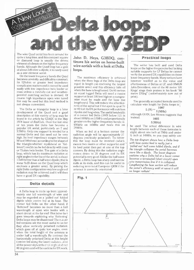
The wire Quad aerial has been around for quite a long time, and this compact square or diamond loop is usually the driven element of a beam on the higher frequency bands. Although the Quad loop has a gain of about 2dB over a dipole, it is rarely used as a one element aerial.
On the lower frequency bands the Quad becomes unwieldy and difficult to construct Its 120ohm or greater feed impedance complicates matters and it cannot be used easily with low impedance twin feeder or coax unless a carefully cut and weather- proofed matching section is devised. Of course high impedance open wire tuned line may be used but this feed method is not always convenient.
The Delta or triangular loop is a later development of the Quad and a good description of this variety of loop may be found in the article by G3AQC in the May 1974 issue of RadCom. Over the last nine or ten years the Delta has become a popular DX aerial, particularly on 7 and 3.5MHz. 'Only one support is needed for a normal Delta and this need not be very high. Its feed impedance ranges between 50 and 100ohms (according to the shape of the triangle -whether equilateral or 'flat- tened') and it can be fed directly with coax or 75ohm twin feeder. The gain of a Delta loop, which has its maximum radiation at right angles to the line of the aerial, is about 1.5dB better than a half wave dipole (that is some' dB down on the Quad loop which encloses a greater area). By picking the right Delta configuration very low angles of radiation may be achieved and it will then have a good DX capability.
Delta details
A Delta loop is made up from approxi- mately one full wavelength of wire and may be regarded as a 'pulled out' folded dipole when centre fed at its base. The corner fed Delta on the other hand, if 'flattened' becomes no more than a half wavelength of open wire feeder with a short circuit at the far end! This latter fact goes towards explaining why 'flattening' Delta loops may be disastrous! The corner fed versions are the most useful to us for they allow vertically polarised radiation which goes off at quite low angles, even when the total height of the antenna is under half a wavelength. By contrast the horizontally polarised Delta at this height (centre fed along the base) radiates .nost of the power skywards at an angle of about 80 degrees and will be useless for DX work.
John D. Heys, G3BDQ, con- tinues his series on home -built wire aerials with a look at Delta loops.
The maximum efficiency is achieved when the three legs of the Delta loop are equal in length (so enclosing the largest possible area) and this efficiency falls off when the base is lengthened. On 80 metres an equal legged Delta will need a centre support at least 100 feet high so a compro- mise must be made and the base line lengthened. This will reduce the effective- ness of the aerial but if the apex is up at 70 or 80 feet its DX performance will outclass dipoles and long wires. The useful bandwidth of a corner fed Delta (SWR below 1:2) is about 100kHz on 3.5MHz and proportionally greater on the higher frequency bands; ie. 400kHz on 14MHz and twice this on 28MHz.
When so fed at a bottom corner the radiation angle will be approximately 27 degrees (vertically polarised). To better this the loop must be inverted (which means two masts or other supports) and its feed point then put at one of the top corners. By doing this the radiation angle comes down to 20 degrees and its DX potential is very good. Unlike the half wave dipole, a Delta loop has sharp and narrow nulls at its ends, and this can be useful in reducing semi -local European QRM if the antenna is correctly orientated.
Practical loops
The writer has built and used Delta loops on the higher frequencies but lacking suitable supports for LF Deltas he cannot verify the avowed DX capabilities on those lower frequency bands. Many writers have however testified as to the value and' effectiveness of Deltas at LF, and ON4UN John Devoldeve, one of the 80, metre 'DX Kings' sings their praises in his book "80 metre DXing" (unfortunately now out of print). I
The generally accepted formula used to calculate wire length for Delta loops is:1
1007
f (MHz) although G6XN, Les Moxon suggests that instead. 1005
f (MHz) be used. The actual difference in wire length between each of these formulas is slight; about one inch at 7MHz and under '/s inch at 14MHz, so you may safely use
The top diagram shows how a Delta loop with base centre feed is really just a 'pulled out' half wave folded dipole, and if the triangle collapses the aerial becomes more like a dipole. The lower diagram explains why a Delta fed at a lower comer becomes a terminated (short circuit) open
`wire transmission line if it is collapsed. Lengthening the base section will reduce the aerial's efficiency until at worst it will no longer radiate!
F .d
34

9ruund
A = 800 D = 280 B = 800 E = 200 C= 450 to 500 (broken lines indicate supports)
'i l
Delta Loops - Horizontal Polarisation Main Radiation Angle
ground
either! The type of wire used (single, stranded, bare or plastic covered) the insulation at the support points and the proximity of trees and ther objects will have a greater impac upon resonant length and the differenc between the two calculations.
DELTA LOOP WIRE LENGTHS
3.6MHz-280 feet 7.05MHz-142ft loin 10.1MHz-99ft 8in 14.2MHz-70ft 111n 21.2MHz-47ft 6in 28.5MHz-35ft 4in
The 14111Hz Delta used in G3BDQ's QTH was cut to the length shown in the above table and did not require pruning. It is not often that an aerial 'works first time' but this one did. Its SWR over the band ranged from 1:1.4 to 1:1.5 without any ATU and it was a bottom corner fed job with about 60ft of 75ohm twin feeder. The height of the centre support (a gim-crack wooden mast) was about 26 feet which allowed the horizontal leg of the aerial to run about 6ft above the ground. A higher pole would have L"en advantageous and might then have liftt-1 this lower section above the heads of our tallest visitors! Some thin nylon cord was cut to antenna length and thin plastic covered wire was taped all along its length at about two -foot intervals.
Vertical Polarisation The only Delta configurations suitable for DX working
The top of the antenna is not at a point of very high impedance (being roughly mid- way between a high and a low impedance point) so no special insulation precautions need to be taken. The writer's wire at the top was just tied to the pole with nylon cord. The lower corners are similarly not at high impedance points and insulators are unnecessary; the nylon end support lines being tied to the wire at these points. If coax feeder is used the inner conductor connects to the sloping wire.
Results
Although running through a 20 foot gap between the writer's abode and the house next door, the 14MHz Delta has given a good account of itself. Its deep end nulls fall in the directions which are best on the Long-wire and the maximum radiation from the loop comes just where it is most needed - at right angles to the Long-wire! Using three different aerials on 14MHz with instant switching capability between a long- wire, a trapped vertical and the Delta, it has been possible to verify the directional properties of the Delta loop. In its preferred directions the Delta is 10dBs better' than the long-wire and about 5dB up on the vertical. The vertical is three S -points better than the Delta in the direction of the Delta's nulls. A recent SSB contact with a
Gambian station showed that the Delta was about two S -points up on the long- wire when working down to the south at the writer's QTH. With less wire up in the air than the long-wire the Delta is a 'quiet' aerial and signals seem to pop up from a much less noisy background. Some signals can be copied on the Delta which are barely audible on the LW and which are little better on the vertical.
Although tried on 28MHz, the 14MHz Delta could not be properly evaluated for that band because of poor conditions. With no ATU in circuit the Delta gave SWR readings of 1:1.6 at 28MHz, 1:1.2 at 28.4MHz and 1:1.5 at 28.6MHz. The reading fór 28.4MHz was the lowest obtainable. On 28MHz the Delta shows little directivity and does not seem to have any advantage over the long-wire in any direction. It was better than the vertical in all directions, which is hardly surprising for on 28MHz the vertical is a poor performer being so close to the ground.
Loop antennas do not have the very high voltage points along their lengths such as are found at the ends of wires and they seem to be more tolerant of nearby objects. Some amateurs sling their Delta loops up into trees where they are sur- rounded by foliage yet still seem to work surprisingly well. A Delta up in a tree can become yet another type of 'invisible'
35

Fig. 3
I e
Delta loops and the W3EDP
aerial when aesthetic and other consider- ations prevent a more usual approach to antenna construction. If the SWR is found to be unacceptable some pruning is needed. This will not be difficult for it can be done at the lower corners where the feeder connects and may not even involve any lowering of the aerial.
The W3 EDP aerial
Try as you may, I doubt if you will find reference to this aerial in modern antenna handbooks or articles. The writer never knew the name of the holder of the call W3EDP, but it seems that this gentleman's aerial was developed and described during the 1930s. It fell out of favour soon after WW2 (when Band 1 TVI problems raised their ugly heads) and the new generation of HF band operators know nothing about it. I propose to describe this simple multi - band antenna in some detail for I have a
personal affection for it! It was the aerial type used (successfully) when the writer was first licenced in 1946 and even today it will prove most useful to many readers should they 'give it a whirl'.
The W3EDP is basically an 85 foot length of wire. This may run out horizontally from an upstairs shack window or go up first vertically and become the classic inverted V. It is not too long to be accommodated in most gardens or over urban roof tops between chimneys. This 85 foot length of wire must be used in conjunction with one of several counterpoises, which may be outdoor or indoor wires. My new up -dated version of the W3EDP allows for its use on the 21 and 10MHz bands; these bands did not exist when the original concept was born nor indeed when the writer was first experimenting just after the War.
How it works - band by band
It is perhaps best to begin with the
operation of the W3EDP on 3.6MHz for then it does not need any counterpoise at
all. On this frequency the 85 foot wire is an
end fed job which is about I 1 feet longer than a quarter wavelength. This allows a
medium impedance match to the ATU and
also more importantly places the high
current section of the wire out and away
from the house where it can do most good.
85ít
high current point
Tap for 14x match
17/t
-o
ATU
3.5MHz
17It
7MHz opened out
'Zepp'feeder
1 7R
-o
IT
V";
17ft 14MHz
i/2 dipole '
asymmetric feed to 11/2 T wire
17/tom E- 17h_ g¢.¢] 21 MHz
21/2 A -
opened out 'Zepp' feeder
8ft 3in
1 28MHz - > 'artificial earth'
1/iN
t/a
10MHz
The Six -Band 'W3EDP'
'artificial earth' 1/4x
36

On 7MHz a 17 foot counterpoise is
needed. This does not behave as an 'artificial' earth (being only '/s wavelength long) but acts as half (one leg) of a 17 foot 'Zepp' feed -line to the end of a half wave top! The other half of the feed -line being the first 17
feet of the 85 foot aerial wire We end up with a 'Zepp' with a 68ft top. Although the feed wires are well separated they still behave as an open wire line of high impedance
but of course will radiate to some degree.
This same 17 foot counterpoise becomes a quarter wave extension to a wire already PA wavelengths long when on 14MHz, so
making the system into a complete 11/2
wave long-wire using asymmetrical feed.
Now the 17 foot section will radiate so it would be advantageous to have it outside in the clear!
Yet another counterpoise is used on
10MHz
On the 21 MHz band this ubiquitous 17
foot wire again reverts to its function as
beig a part of a 'Zepp' tuned feed line; this time to feed a 11/2 wavelength top! Additional counterpoises are needed for operation on 28 or 10MHz. On 28MHz the 17 footer is
disconnected and replaced by an 8ft Sin
wire which behaves as a normal 'artifical earth' against which the 85 foot wire is
tuned as a 21/2 wave end fed long-wire. A
similar situation exists on 10MHz where yet another counterpoise is used, this time 23 feet long and the main wire then behaves as a 11 wave end fed wire.
Some practical points
The weakness of the W3EDP aerial system lies in its connection to the transceiver, for simple direct feed using low impedance coax or twin feeder cannot be used. Part of the aerial actually comes right into the shack and can give rise to 'stray RF and
'hot chassis' problems, particularly when the counterpoise in use is not a quarter wavelength at the frequency being operated This applies on 7 and 21 MHz. Additional quarter wave counterpoises for these bands
may be used but they MUST NOT BE
CONNECTED TO THE ATU. Instead they must connect to the earth terminal of the
equipment to hold it at earth potential.
The 85 feet of the W3EDP need not run in
a straight line but can snake about to fit whatever space is available. This makes it a
useful antenna for temporary use in awkward locations. The various counterpoises are best slung out of a window but they may instead run along the.shack skirting boards or picture rails. Keep these wires away from small inquisitive fingers for they may carry quite high RF voltages when trans- mitting. The 85 foot wire and the counter- poise wires connect at opposite ends of a
simple parallel tuned circuit ATU. Plug in coils for each band are best but a tapped system with a ceramic switch may be used instead A one or two turn link winding couples the ATU to the transceiver via an
SWR meter.
Using just 7 watts of CW on 80, 40 and 20 ' metres the W3EDP antenna used by the writer from his sea -front 'eyrie' many years ago enabled hundreds of contacts world- wide and it did not cost many of the pennies which were so hard to acquire then! Adventurous souls may like to work out and then test versions of the W3EDP which will work on the two other new bands of 18 and 24MHz; although at present our licence limitations prevent the use of transmitting antennas longer than a half wave on these frequencies.
Fig. 4
COAX TO TX
e -
.. Link (2T)
Link
PLUG-IN COILS TO SUIT BAND
s
/ 100pF
To 85k wire
(on 3.5 and 10MHz the 85ít wire may be best tapped down the coil).
To Counterpoise or Earth (see text)
Simple ATU for 'W3EDP' Aerial
To 85k wire
4
100pF
o To Counterpoise or Earth
Switch with high quality insulation
Alternative ATU with Switched Coil
37

r
ft'' The results of our test of the Icom IC -251E with the added delight of a Mutek front end board were spectacular to say the least. Now we take it a step further and show you how
the Mutek should be fitted.
.
,-, ,-. k.5
4J r i
1. Top and bottom covers have been removed from the
transceiver. Mutek board (left) is poised for action with tools for the job.
III"III''llllll"!fl 11011111111111111111111
s =v ,°
.i
a a ' ri . a a
1- ; , ,1, r
eo. r1
1.
`
3. Remove synthesiser assembly. Do NOT forget fixing screw located through main pcb. Note positions of connectors and remove. Lift assembly clear.
t+
. +... . . . .. .. ... ?...
l,
r
.' á é.a.-r;:. : ((S.
ea-,='-%: _. r
2. Remove power supply assembly by removing fixing screws. Disconnect mutlipole connector and put assembly to one side.
+
!,.t ,t , E. ,..r 3 k . a4t7 --
)a .(Y ú . 1 ' I, +i-..
c L\' a 11131-
Lam___ I. r _~± _ r 1. 4. Remove carefully the wire soldered between antenna
socket and main pcb. Solder (as shown) red -coded coaxial cable to antenna socket, braid to associated solder tag.
4.
t-+
= . , t 1, _ -. . ¡ 7]. ü 1 -
7 -JO.'" i.. 12.,L--
.- t ,-;
38

UUUUU,:
Jill
,a .
' r rc
ri ...V wY {_y . ,y /o.
r'
e ;13 If"I r, . i. 1:
041 á, !` Ltl.a!,
L 1 . S
.:.
a:rY^st t ,: i. e -
ley
7. Solder white -coded and black -coded coaxial cables to back of main pcb.
8. Remove C187 and replace with 47p provided in installation kit.
.
+i - n - . }' 1.. :% .` --; '151
-{. `,. . < +i , yy- ^,
C %..» -
5. Solder blue -coded coaxial cable to
pad on rear of main pcb.
6. Carefully remove filter FL2 and inductor L55 from main pcb.
i
- I 1
V .' 4.
8.
39

Mutek board fitting
9. Solder in place red and green wires as
detailed in fixing instructions
.. , 1: . .j. _. \ --,._. -
k + AaI....' { 4 '` `
11111111 11111111
jIIIIIIIIk vi IUlli; = ; ,d ' + r - r . 1
. .. , 1RI724'l! ...,w t.i ̀' .,, -- r _
II..) / `,
^ ' _ 4 _ _.. ¡
- 1
. +f' ) t
. .. - - -:.4:::- .; A.
. tzr.`-o o - - - , \ . } ` j F[1,, lib t ,r . ..
~ r ... f rJa T . x+ r .` 'SG
'rír.`+}1r 1C' /t , +, } 1 v ,_- jr."-Ign±,_._'
10. Solder in place brown wire as detailed in instructions.
, .11. I : . Y
1' , -i *üls . -; iÍ a.i ` , :r i `4 1
.: s r i r ii .%' . . 1111115:" ' "
;Oft gi ,1 t :- 4.
c-4:1 T' / M .': Ii.;
.4
__ r
t . b
I
- .1=1.
112.
I
IA ti' {
1
L
n.
e>
_.J A
°i? I kT: i.I
11.
,,.,_.. 11. Replace both psu and synthesiser
assemblies arranging RPCB251ub cables leading from slots on either side of synthesiser assembly.
1 2. Fix Mutek board with two screws provided to existing (unused) diecast lugs, and as per detailed, fixing solder colour coded cables to the appropriate pins. Replace both covers and get out amongst the dx!
40

DEWSBURY ELECTRONICS
UHF ALL -MODE TR J500 corrFtia TRANSCEIVER
The TR 9500 is a lightweight compact 70cm FM/USB/LSB/CW transceiver with advanced and convenient functons and many accessories at an affordable price The transceiver is designed for FM, SSB, and CW modes, utilizing a microcomputer which permits frequency selection in 100Hz, 1kHz, and 5kHz, 25k Hz steps by means of two digital VFOs. The microcomputer also permits memory, scanning, searching, and other features.
The TR9130 is the new all mode VHF mobile or base station rig from Trio giving 25 watts output on 2 metres FM, USB. LSB and CW and now having a
green LED display to make for easier mobile operation.
25 watts output on FM, SSB and CW. FM/USB/LSB/CW all mode operation. For added convenience in all modes of operation, the mode switch, in combination with the digital step (DS) switch, determines the size of the tuning step, and the number of digits displayed.
TR "ma 9130
,p 3°" i. eEei «r
r w u n IIII Siff
NO°t ro.+r/va 42
lY
o.
- .- - 0 1
, .s c é. . - I ~0 u I
W, 1,11 +n
r,;ti :pfi1 SP 120 TR-9500 BO -9
£395 + carriage £5.00 PS -20
Six memories. On FM, memories 1
through 5 for simplex or +600kHz offset, with the OFFSET switch. Memory 6 for non-standard offset. All six memories may be operated simplex, any mode. Memory scan. Scans memories in which data is stored. Stops on busy channels. Internal battery memory back-up. With Ni -Cad installed (not Trio supplied), memories will be retained approximately 24 hours, adequate for the typical move from base to mobile. A terminal is provided on the rear panel for connecting an external back-up supply.
Automatic band scan. Scans within whole 1 MHz segments (ie 144.0-144.999MHz), for improved scanning efficiency. Dual digital VFOs. Incorporates two built-in digital VFOs, selected through use of the NB switch and individually tuned.
®Im ALE MODE rM.1.114 LQR .iSt These antennas simply put iL ,tJ rte£,/ your signal where you want it - on the horizon. Most
i .c.. áo.° ither VHF verticals radiate at 10-15° above the
°
hori- zontal but the
w.Q unique (aesthetically pleas - II /_ , z ing) decoupling cones stop f / " ,..1 any feeder radiation and
ensure a proper 0° radiation i pattern. All users report do dramatic improvement over
o previous, similar sized. anten- nas they have used. One of the hottest selling antennas o- in the U.S.A.
Squelch circuit on all modes (FM/SSB/CW).
Repeater reverse switch. For checking signals on the repeater input, on FM.
Cw semi break-in circuit with sidetone. Built-in, for convenience in CW operations. Digital display with green LEDs. Transmit offset switch for repeater shift High performance noise blanker. RIT (Receiver Incremental Tuning) circuit. Useful during SSB/CW operations. HI/LOW power switch. Select 25 or5 watts RF output on FM or CW. A four -pin accessory terminal is provided for use with a linear amplifier or other accessory Includes quick release mobile mounting bracket and up/down microphone.
J
TR9130 ALL MODE TRANSCEIVER £433 + car: £5.00
Access/Barclaycard accepted. Licenced credit broker
Jito ISOPOLE 144
A.E.A ISOPOLE TM
2M AND 70cm VERTICAL
ANTENNAS
Isopole 144 £35.00 (£2.50 P&P & Insurance) Isopole 440 £59.00 (£2.50 P&P & Insurance)
Dewsbury Electronics offer a full range of Trio Equipment always in stock. We are also stockists of DAIWA - WELTZ - DAVTREND - TASCO TELEREADERS - MICROWAVE MODULES -
ICS AMTOR - AEA PRODUCTS - DRAE
Dewsbury Electronics, 176 Lower High Street, Stourbridge, West Midlands. Telephone: Stourbridge (0384) 390063. After Hours: Kidderminster (0562) 851255
Closed Thursday
41

0 oc
"One of the smallest of the classic receivers, the 2B was designed specifically for the
amateur. Don't be put off by the fact that it was made in the fifties - nor by the fact that it uses valves. The Drake has a reputation for
reliability and ease of maintenance," says Ken Williams
if
g.r 1-_ - -'-, f 29 1 79.2
Z8 5 28 6 280 28l , . 35 36
70 3 u 29 / 29 5 -----N ill 29 6 ..,.,-' 28 7 28 8 28 9 290
1 282 26.3 264 "85 ab 37 3.8 39 /º I 1 it, L111' 1 PRESELECTOR i s 7 7* i 1 , 7 o
9
2
145 U/ 143 40 20 215 21/ 213
5 A 500 400 300
7 15
9 10'
10
14.2 141 140 9 21.2 211 210 ^r9
I 200 100 0 i
POWER CAL STBY S.AVC NL PROD,
OFF OFF RCv F.AVC . OFF
BAND RP- GAIN PASSBAND ZO :is 10
.s
C
40
`r
to
I RI' .1 á - j E A
0\, JJ
3.6 J S 0
R.I. DRAKE CO-MIAMISRURG OHIO MODEL 2-8 COMMUNICATION RECEIVER
BFO
OIOOE OfF
AF GAIN

When RL. Drake and Company of Miamis- burg, Ohio, introduced their 2B receiver in the late 1950s, they gave the amateur radio fraternity some equipment specifically designed for amateur operation at a price which they could afford.
Today, over 20 years later, many old timers will declare that of all the receivers produced in the intervening years, few have equalled it. and even fewer are better.
By the standards of the day, the 2B was quite small, measuring only 12 inches wide by 7 inches high by 9 inches deep and weighing only 14 pounds. To the present generation of operators weaned on tran- sistors, chips and other solid state black magic, this may seem quite hefty, but to a generation of amateurs used to suffering a hernia every time that they moved the AR88 on ór off the bench, it was a revelation!
Extra crystal provision The 2B is a triple conversion superhet-
rodyne receiver employing a crystal - controlled high frequency converter feed- ing to a tuneable intermediate frequency of 3.5 to 4.1 MHz. The signal is then conver- ted to 455kHz and then to 50kHz at which frequency the signal passes through a highly selective tuneable LC filter which gives a choice of bandwidth of 3.5, 2.1 or 0.5kHz. Product and diode detectors simultaniously demodulate the signal, with the two stage audio amplifier being switched to the required output The AGC circuit provides an amplified control voltage during all modes of reception and a switchable time constant allows selec- tion of optimum characteristics for mode and band conditions. In the event of an even longer time constant being required, additional capacity may be added via a tag strip on the rear panel.
As sold, the receiver covered 80in (3.5- 4.1 MHz), 40m (6.9-7.5MHz), 20in (13.9- 14.5MHz), 15m (20.9-21.5MHz) bands and one segment of the 10m band (28.5- 29.1 MHz). Switch provision is made for two additional crystals to cover the re- mainder of the 28.0-29.7 MHz band and five further bands within the coverage of the receiver. This feature has proved useful for, with the incorporation of one minor modification, the author has extended the range' of the receiver to cover all current amateur bands from 1.7MHz to 30MHz.
The frequency display is a seven inch ' slide rule dial marked in 10kHz divisions
which are sufficiently even to allow the use of a calibrated skirt on the main tuning knob. To compensate for slight inac- curacies of conversion crystal frequen- cies, the main tuning dial may be moved to the right or left to a distance correspond- ing to 10kHz, the final position being deter- mined by comparison with a calibration signal. Provision is made for the use of a matching Q -multiplier and a 100kHz crys- tal calibrator. If these are not used, their power sockets may be used to power and attach a variety of home made accessories
r
S Q. ., --^
.-.- -- - k--
.
ka `
fi v,. "b1 d.
1 . kYJ+,' x @
a
Top view of the Drake 2B. The discolouration of the chassis is due to the ravages of too many years in leaky garden shed shacks. The performance was not affected, however.
such as VHF converters, outboard FM dis- criminators etc.
Beneath the tuning dial, a row of slide 'switches control: power on/off, crystal, calibrator (if fitted), BFO, noise limiter and selection of product detector or diode detection and AGC time constant.
Lower still are controls for: band selec- tion, RF gain, IF passband and tuning, AF gain and main tuning. The remaining con- trol is the preselector tuning which is located on the left hand side of the receiver above the bandswitch.
The RF amplifier. The circuit of the Drake 2B has several unusual features, the first of which is the input tuned circuit. Whilst most receivers have separate aerial input and tuned circuits for each wave band, the 2B uses only one circuit corres- ponding to the 40m or B ranges. When the Aor80m ranges are selected, an additional 180pF of capacity is switched ir. parallel with the preselector tuning capacitor whilst for the higher ranges, inductive shunts are switched in parallel with the B band coil. A similar method is useu in the anode circuit of the RF stage. By this means a set of switch contacts for the aerial input circuit can be eliminated with consequent economic advantage and im- proved reliability.
The valve used in the RF amplifier is a 6BZ6. This is a semi -remote cutoff pentode which gives high gain with low inter - modulation and good control character- istics. Sufficient gain is available to ensure that the amplified front end noise will swamp that generated in the succeeding mixer stages and in consequence controls the sensitivity of the receiver.
This is quoted by the manufacturers as 10dB signal to signal plus noise at an input level of 0.5 microvolts. Measurements on the author's receiver using a Marconi TF144G signal generator indicate that this specification can be met even after 20 years service! The Ekco noise bridge indi- cates a noise factor of a little better than
10dB. Whilst this may seem excessive when compared with VHF equipment it must be remembered that conditions on HF are vastly different Noise coming down the aerial feeder is frequently 5-10 mic- rovolts and on 80 may sometimes reach five or ten times this figure. Only on the ten metre band will any disadvantage be noticed compared with the best modern receivers.
Electron Coupled Oscillator circuit is used
First mixer. This stage uses a 6U8 triode - pentode in a circuit which has two unusual features. The triode portion of the 6U8 operates as a Pierce untuned oscillator on all bands requiring a crystal frequency of 20MHz or less (A, B, C, D and 40m). When a crystal frequency higher than 20MHz is necessary, the appropriate coils are inserted by the bandswitch and the cir- cuit is converted to an overtone oscillator. Exceptionally, on the 80m position, the oscillator is disabled and the first mixer acts as an additional RF Stage. The oscillator output is taken from a low impedence point on the tuned circuit and fed to the 6U8 pentode section grid via the inter -valve RF transformer secondary. The grid,. cathode and screengrid circuits of this section are conventional, the AGC being applied to the control grid through a 1 Megohm resistor R9. The anode circuit, however, requires a little explanation for, what at first sight appears to be a more -or - less standard valve coupling is in fact a low pass filter, tuned by C14a, which assists in the attenuation of spurious responces common to many multiconversion re- ceivers. The very low noise characteristics of the 6U8 allows this stage to operate at low gain without degrading the excellent signal to noise ratio achieved in the RF stage.
Second mixer. The second mixer stage uses a 6BE6 valve to convert the incoming 3.5-4.1 MHz to 455kHz. Particular care has been taken in the design of the VFO section
43

103
r S 9A Front
S9A Rear
S99 Front
10_1,0
599 Rcar
S9D S9C Rear
10 A
4
25.0 (=18.01 Mc. Mc.
Crystals A,B,C,D,E, S9C Front 181 and 102 are available as accessories (For frequency see text)
Band switch viewed from front In 80 meter position
AV -2 B/2
1
RS
560
89 I
MEG
C2 L C72 ? .005
.01 1-C3a = 0-234 r-
1
PRESEISCTOR- - - C7
I.005
C 34 .005
C 75
140
Ce
R4
2.2 MEG
I
VI 6BZ6
/i M P
1,W R3 150K
C9 .001
AVC 2 /2
858 15
1 C 7WKNV
.001
C 74
47
R20
10K
R57
220
H/2
R61
33K
V2 1/2
6U8 X'RLOSC:
R59 -150K
C79 .001 I
T.R
B/2 AVC-2 9/2
t10 R10 2¿R11
01 1.5 C17 C18 <68 K > .01
-TI
1301
2 o-C14a
6U8 Io5
1117 100
C6
C16I.001
R12 22K
6/2
ANT GND
1st M.00ERg 500 /'_ 2',
r
7
OFF 11 CAL
OFF POWER Bk
X Bk/Yel
C. 3
bk/Grn AMP 240V
CIIb CDt
0- 37.5T
- - -FREQUENCY
AVC MUTE GND OYER
V 10 C70d
6X4 10 MFD
70a 100 MFD
POWER RECT.
C70b 100 MFD
C70c 10
MFD
12 Q-MULT
R :9 C 29y 1.5K .1
-T'
865 -
1500 I WAi'
b/1
R55 470 1 WATT
2200
I-41 9/3
V7 V8 V9 VIO PLI PL2
1
L _ _ r. i.
il__
r- 18
68 R22-1
I ,C40-.1
853 100
r
e BIM
854 12K
1 NOTE: Capacitor value and those from .
noted.
Resistors are 1/
All Jacks shown
. Value selects
'Highest Cepacl'
Far 240 vo.t opt marked -- X - An extra termina connection C.
of this stage. This is tuned above signal fre- quency and uses an Electron Coupled Oscillator circuit in which a space wóund oscillator coil wound on a ceramic former and a double spaced tuning capacitor con- tribute much towards the frequency stability and consequently that of the receiver. The output from the first mixer is fed to G3 of the 6BE6, combines with the VFO frequency within the valve and gives an output at 455kHz in the anode circuit which is coupled to the succeeding stage by IF transformer T2.
Third mixer: Another 6BE6 is used to convert the 455kHz output from the Second mixer to 50kHz at which frequency the selectivity of the 2B is achieved. This circuit is conventional, the only unusual feature being the extremely high value of capacitor in parallel with the oscillator cbil.
One of the accessories available for the 2B was the 2BQ Q -multiplier which is con- nected via a socket to the signal grid of this stage. Unfortunately the author never
possessed one of these desirable items, however, this socket has proved extremely useful, for at various times it has been used to connect to an oscilloscope to examine incoming waveforms, to feed a dis- criminator for receiving FM and to feed an 8kHz bandwidth IF strip for AM short wave broadcast reception.
Passband tuner/selector: Almost alone among communications receivers manufactured since WW2, the 2B uses neither crystals nor mechanical filters to
44

T5
PASSBANI
TUNING
PASSBAND SELECTOR _(.5) (2.1) (3.6)
i V4
_ \6BE6 3rd MIXER }J}r Y}
í6 IC39 2P26 .01 82K
100
T4 _ _ 623 33K
C331
1.00i 8/2 -
AVC 2
/8 /3
RE GAIN R50-15 MEG
8/I
I S
METER ZERO 8245K
Ir
B/2
METER
S -4 R67 METER
CAL.
470 C42 -f )
,11
C 4157 R29 r, 3.3
s Z K
1 \68A6 - -'- VF AMP'
l..r____,6 7
1.5K
C43
1
R25
I2K
('2
1128 - 7
8/3
r
R33 4K
B/3
T6
1- C46 C47 - R34 0025 0025
, 47K
-r I C48 b b jL-
.0068
V7 _ 6BE6
PROD. DET. R35 _ _ _. ti
220 1
R730-68 C50 V1- 001 T7
231 r 22K
C51 I
.002 R32 I
220 I 41
M C52-.1 OFF
)
/3
R46 I V6 IBK 1 68F6 C63 AVC AMP. 6
.001 A. M. DETECTOR
1 R49
15K S.A1C C68
RECT. C80 I WASQ ADJ.
> 2 ME jR51 1,
I 1.S I MEG
R52 > C69 6800
.1 -
¡* 1 MFD 1
T,AVC
680K _ R68
C67 .001
.- /VV`! R47
C66
from I to 1000 are in moil. I` 01 to 100 are In mid unless s' ' " f7 71 j inlln
watt 10% except where noted.
ottom view
In production
C130 Highest Resister R71
non, disconnect wires and connect
3n strip as provided for
STBY
RCV
a
PROD
DIODE
? R61 ? 330 ??
C53 ,005
O
8 t
=137-6b MEG
R38 001 9
6 K R29 15 /1
V8 1/3
8BN8 ' AUDIO AMP7
C55 220
-7 52 R69 40
1 MEG
Z--1 6
2 lR43 5330K
1144
3301:
C60 .01
R45 <s1.5
R36 3 r.
15 -
C59 (
C561
.02T
NL RECT.
4,
R70 1 MEG 'SAO,
1% 3
1 13
C49 - .01
if
OFF
NL
C58
.0015 R64 5000
6/2 B/1
AUDIO GAIN
)I
R40 150
R42 680
T C7I .01
)4
C57 001
V 9 6AQ6 AUDIO
2 OUTPUT R41
276 C78 T18
MFD
SCHEMATIC DIAGRAM MODEL 2-B COMMUNICATIONS RECEIVER 531626290
achieve the necessary selectivity.
The heart of the passband tuner is four very high Q circuits which are variable from 47 to 53kHz by permiability tuning, this being achieved without varying the shape of the passband. A switch co - centred on the passband tuning control gives a selection of three different band- widths (0.5, 2.1 and 3.6kHz) by varying the coupling between'the four tuned circuits.
This technique does not give such a steep sided bandwidth characteristic as
alternative (crystal or mechanical) filters but the ability to move the passband just a little away from interfering signals gives, in the authors opinion, an advantage over the fixed filter which more than makes up for the slightly broader skirt selectivity.
IF amplifier. The output of the 50kHz passband tuner is coupled to a conven- tional IF amplifier using a 6BA6. The AGC fed to this amplifier has a very fast attack and release time thus serving a function similar to a noise limiter. The anode load
comprises a single tuned circuit, the signal output being taken by a capacitative coupling to the product, diode and AGC detectors. Product detector. A 6BE6 valve is used in a conventional product detector circuit. The BFO section of this stage is switched seperately in order that it may be used with either the product detec- tor or the diode detector for CW reception. The output of this stage is then fed via a low pass filter and the detector selection
*switch to the audio amplifier. The lowpass filter has an upper frequency cutoff of
45

3kHz and has the dual purpose of remov- ing any 50kHz component which may be present and also improving the selectivity of the receiver by restricting the higher audio frequencies.
Diode detector and noise limiter. In addition to feeding the product detector, the signal from the IF amplifier also goes to the triode section of V6, a 6BF6 double diode triode, which amplifies the 50kHz signal prior to both signal and AGC diode detectors. It may cause some surprise to find a triode as an IF amplifier but there is insufficient anode -grid capacity to cause Miller Effect feedback at this frequency. Furthermore, using an amplifier at this point causes less damping of the IF amplifier tuned circuit with consequent improvement in selectivity. The two diodes of the 6BF6 are fed from the anode circuit and operate as signal and AGC detectors. The audio output from the signal diode then passes via the noise limiter (using one of the diodes of the 6BN8 audio amplifier) to the detector selector switch.
AGC circuits: The second diode of the 6BF6 provides two AGC voltages for the receiver. The first of these is taken from the output of the filter L13 -C64 across C65 and feeds only the 50kHz IF amplifier. This voltage has a very fast (less than 100 mic- roseconds) rise time and in consequence, when applied to the amplifier, has much the same action as a noise limiter, con- siderably reducing impulse noise in the audio output of the receiver. The voltage across C65 also charges either C67 or C67 +
C68 through R47, the voltage so developed being used to control the RF and tuneable RF valves. The discharge path for all the AGC system is through R68 and R48 (the no -signal bias adjustment potentiometer) which gives a release time of 0.75 seconds in the slow AGC switch position and 0.025 seconds on the fast Should an even longer time constant be required, an AGC con- nection on the rear terminal strip of the receiver can be used to add further "out- board" capacity. Alternatively this connec- tion may be used to feed AGC voltage to converters etc.
In addition to the signal derived voltage, the RF gain control voltage is also fed via the AGC line, the minimum level for this being adjusted by R48. Should this be set at too low a level, the apparent gain of the receiver will be increased but overloading can occur. During transmission periods, muting is achieved by inserting a cut-off voltage in series with the AGC capacitor C67. In this way it is not necessary to charge or discharge the capacitor during muting or recovery.
Power pack: Unconventionally for the time of manufacture, no smoothing choke is used in the filter éircuit of the 6x4 rec- tifier, adequate smoothing being achieved by using two 1O0mfd capacitors and a
resistive element Under load, the power supply provides HT outputs of 130v and 150v. Additionally, a bias supply, rectified by a diode section of the 6BN8 provides 18 volts negative to the RF gain and muting systems.
Accessory bands: In addition to the amateur bands, the 2B has provision for five other bands to the users choice. In the years since this receiver was introduced, three new amateur bands have been introduced and, for the licenced amateur operator or SWL, these obviously have priority.
The general formulae for calculating the crystal frequency required for a particular waveband are either:
f = lowest desired frequency + 4MHz or, f= high desired frequency- 4MHz
For each crystal inserted, therefore, two additional bands are gained. These general formulae, however, do not allow that the upper frequency limit of the tuneable IF is actually 4.1 MHz, and at times it is possible to take advantage of this. Thus, by insert- ing a crystal of 14.1 MHz in position C, both the 10 and 18MHz bands will be covered. A 21 MHz crystal in position E will give coverage of the 24MHz band.
Operation: As with many receivers, some experience is necessary before the full potential of the equipment can be realised. At first the receiver may seem to be lacking in selectivity compared with those using mechanical or lattice crystal filters. However, under heavy QRM condi- tions it will be found that altering the bandpass tuning even a few Hertz will often eliminate troublesome hetrodynes at the upper or lower end of the audio scale, whilst in CW operation, using the 0.5kHz bandwidth, the ability to select the pitch of the received signal can assist both in separating adjacent signals and in picking a pleasant CW note to listen to.
Tuning the receiver is a pleasure, for the tuning. rate is sufficiently high to allow rapid QSY yet sufficiently slow to permit easy tuning even on the narrowest selec- tivity position. The 10kHz frequency divi- sions on the tuning scale are spaced 3-4 mm, and when used in conjunction with the calibrated skirt on the tuning knob, it is quite possible to measure a frequency to an accuracy of 1 kHz.
The stability of the receiver is excellent, the manufacturers quoting a figure of better than 100Hz after warm up. The author has no way of checking this figure but can say that he has never noticed any drift. The specification of the receiver calls for a sensitivity of 0.5 microvolts for 10dB signal to signal plus noise ratio. This is more than adequate on all bands except, perhaps, 10m where modern, more sensi- tive receivers have a slight advantage. Against this, however, it would be difficult to better the cross -modulation and second channel rejection characteristics.
Many newcomers to amateur radio are influenced against purchasing valve equip- ment by the thought that it may not prove reliable. In the case of the 2B this fear is unfounded, for in over 20 years' operation the author has only replaced four valves, the dial lights and the tuning capacitor drive cord, áI1 of which can be donequite easily on the kitchen table.
For the SWL or radio amateur seeking a reliable and sensitive yet relatively inexpensive receiver, the Drake2B, despite its age, is well worthy of serious consideration.
.I I! IPA,. _III a.
rol
. `
` ` / .
i .a_ ,'
`r
l , i V. Q
..._ , ' -y - -
-t. - r.",1.
46

Address
Name
Dept 1282 ICS School of Electronics 160 Srewarts Road London SW8 4UJ eassml
GBUUS
R.A.S. (NOTTINGHAM Radio Amateur Supplies
Tel: 0602 280267 r
Visit your Local Emporium v Large Selection of New/Used Equipment
on Show. ACCESSORIES: Welz Range
Microwave Modules. Adonis Mics. Mutek Pre -Amps. DRAE PSU and Wave Metre
AERIALS: Tonna, Ha/bar, New Diamond Range of Mobile Whips.
AGENTS FOR: F.D.K.
AIDEN ICOM
TABU SOMMERKAMP FORTOP ATV
Get your RADIO AMATEURS City £t Guilds Qualifications with ICS
In your own time-at your own pace ICS, the world's leading home study specialists, offer a
superb course for those wishing to obtain their City & Guilds Radio Amateurs qualifications. Prepared by experts, the course fully covers the syllabus of the examination, and you study step by step at your pace, in your own home, via the post.
Personal Tuition Throughout your course you have the expert and personal guidance of a fully qualified tutor, plus the ICS guarantee of tuition until successful.
Other courses available The ICS School of Electronics offer a comprehensive range of courses for most areas including: TV & Audio Servicing £t Engineering, Radio Frequency, Electronic Engineering, Electrical Engineering, ... and many more.
¡¡ ICKet ICS Approved by CACC
Un N,, mar E,' tor, Cal, n
INrr owl
Member of ABCC
POST OR PHONE TODAY FOR FREE BOOKLET Please send me your FREE School of Electronics Prospectus.
Subject of Interest
ICS 12? 01 622 9911' rAa Hoursf
PLUS OWN "Special" Q.R.P. GW5 HF5 Band Beams.
JUST GIVE USA RING
3 Farndon Green, Wollaton Park, Off Ring Road between A52 (Derby Rd) &
A609 (Ilkeston Rd).
1 -
1
1
1
1
1
1
1
1
1
1
1
tl WOOD & DOUGLASI ' - RADIO KITS?
Have you ever thought of building your own amateur transmitter?
Wouldn't you like to know what is under the lid of your transceiver?
Why not build your next pre -amp for a change?
Wood 8, Douglas have had eleven years of professional r.f. experience which has led in the past six years to the largest range of original design products for the radio amateur market in the UK. Our
professional standards have led to only the best quality components being used on our compact miniature assemblies. Our range otters kits or made-up modules for VHF and UHF
transceivers, tonebursts, pre -amps, synthesisers etc. Each kit comes
with a comprehensive set of notes that include circuit diagram, testing
procedure, parts list and generally a twice full size layout. We do not
offer the simple items external to the pcb such as a box or volume
control which you probably already have. We give you the electronic heart of the equipment to an exacting well designed standard. Full details of our complete range are available on receipt of an A4 size
SAE. Professional users should ask for our advanced design modules for OEM applications. If you can solder you can built our products. If it doesn't work apart from being surprised we can offer a complete back-up/servicing
facility for all the range.
TRY A KIT AND WE KNOW YOU WILL ENJOY IT
Unit 13, Young Industrial Estate, Oldermaston, Reading RG7 4P0,tel: (07356) 5324.telex: 848702
GAREX (G3ZV1)
SX200-N THE SUPERIOR
SCANNER
COMPARE THESE FEATURES
*SPECIALLY DESIGNED FOR EUROPEAN MARKET MICROPROCESSOR CONTROLLED 32.000 CHANNELS
*AM AND FM ALL BANDS *WIDER COVERAGE: 26-58. 58-88, 108-180, 380-514MHz; includes 10m. 6m
4m, 2m and 70cm Amateur Bands *5kHz and 12}kHz FREQUENCY INCREMENTS tr 16 MEMORY CHANNELS WITH DIRECT ACCESS *2 -SPEED SCAN/SCAN DELAY CONTROL * 2 -SPEED SEARCH UP AND DOWN * SEARCH BETWEEN PRESET LIMITS UP AND DOWN *3 SQUELCH MODES inc CARRIER AND AUDIO * RELAY OUTPUT FOR Aux CONTROL *INTERNAL SPEAKER *EXTERNAL SPEAKER AND TAPE OUTPUTS * LARGE GREEN DIGITRON DISPLAY BRIGHT/DIM *AM -PM CLOCK DISPLAY * 12V DC. 230V AC OPERATION *12 MONTH WARRANTY FACTORY -BACKED SPARES AND 'KNOW-HOW'
AND THE ALL-IMPORTANT PRE -DELIVERY CHECK BY GAREX. THE MAIN SERVICE AND SALES AGENTS. £299.00 inc VAT Delivered
REVCONE* A superb quality 16 -element. all British made, VHF/UHF broadband fixed station aerial from Revco. Ideally suited to SX200 and other VHF/UHF
receivers. Covers 50 to 500 MHz. PRICE (24.95 inc
MAIN DISTRIBUTORS OF REVCO AERIALS & SPECIAL PRODUCTS Send SAE for details
PRICES INCLUDE UK P&P and 15% VAT
GAREX ELECTRONICS 7 NORVIC ROAD, MARSWORTH, TRING, HERTS HP23 4LS
Phone 0296 668684 (Callers by appointment only) ,11-9111
47

We've now had a look at a basic SSB- type contact such as you might hear on 144MHz, and it's time now to expand our horizons a bit and look at CW or Morse or whatever you wish to call it.
"Morse?" I hear you say "cor blimey, that's for the birds, isn't it?" What do we want Morse for in this high-tech age of ours? I thought SSB was the way to work the DX, not go messing about with keys and things."
Well, we all have our little misconceptions(one of yours, brother, is that you're going to get paid for rabbiting on like this; get on with it for goodness' sake - MD) Let's begin at the beginning and see why Morse is still the greatest thing since sliced bread if you're really chasing the DX - especially on Class B type bands such as 144 and 432MHz.
Basically, what happens is that instead of your voice being converted to radio waves which reflect the pattern of the original sound pressure waves coming out of your larynx or whatever, you turn the transmitter's carrier wave on and off. You do this in a particular way which is recognised all over the world and which you'll know from old war movies even if
you never saw a Morse key in your life -
you know, the ones where the wireless operator site in the ship's radio room sending out SOS and for -Bawd's -sake - help -us messages as the water pours in up to his earholes. The system used is called Morse code, and it's no different from the one used by the ship's operator in the movies or the one you might have learned in the scouts or at school.
If you want to use Morse on the amateur bands, the first job is to learn it
up to a speed of 12 words per minute so that you can take the official Morse Test. The Morse Test is handled by British Telecom, and you can take it either at the main test centre in London and some other major cities or at coastal radio stations up and down the country. All the details are contained in the application form for the test, which you can get from the Radio Regulatory Division at Waterloo Bridge House,London SE1 8UA or else from the RSGB.
The dots, dashes, dits, and dahs collectively known as Morse, when heard, can completely destroy the
newfound confidence of the beginner. Even when noted and decoded, a message is unlikely to resemble
conversational English! Nigel Gresley attempts to calm your nerves.
You can make enquiries and provisional test bookings on the phone but you need to make sure that the place you're going to take the test at has the application in their possession prior to the time you turn up for it. The fee for the test is £15, and the other thing to remember is that you'll need to show some positive form of identification (such as a passport) to the examiner.
Your first Morse OSO
Actually, you may find that your club can arrange for a visit by an examiner, and it's worth asking at the nearest test centre to you. There needs to be a minimum of 12 candidates poised to take the test if you want to play it this way.
Anyway, let's assume that you've taken the test and passed it and that you're now the proud possessor of a Class A ticket. You'll be able to send and receive Morse at 12 words per minute -
actually you'll probably have found that you can cope with about 15 most of the time and either way that's plenty for your first steps in using the stuff. Let's assume for a start that you're still on 144MHz and haven't gone to an HF rig just yet, or let's assume that you're one of the growing band of fold who've twigged that Morse is a good way to work the real weak and watery ones on that band. Let's have a look, before we launch into how to have your first Morse QSO, at why the mode should be quite so good_
Speech has a wide dynamic range
Human speech is funny stuff. An awful lot of it is what is called "redundant", which means that not all your dulcet tones are necessary to convey information. You may have noticed already on the wireless that even when someone's about 3 and 1 you can still more or less get the gist of what he's saying to you even though it's hard work.
IS
It's also very "peaky", or if you want to be posh about it, speech has quite a wide dynamic range; this means that if you set up your transmitter so that your speech peaks don't overdo it and make you 30k Hz wide every time you make certain sounds, the average power coming out of it (which is what conveys information to the bod at the other end) is quite low. In other words, and compressing whole text books into a sentence or two, even single sideband doesn't make all that effective use of the potential power of your transmitter.
Even if you use a technique called compression, or processing, which has the effect of making the average transmitter power somewhat higher, you're still on balance not using the transmitter as effectively as it could be used. All of this is bound up with some jolly clever stuff called information theory, by the way, but we won't go into it now otherwise we'll have weird and wonderful formulae all over the shop and MD will beat me up again.
Weak signal With Morse, as we've seen what
happens is that you're either transmitting full power or nothing, in a pattern which corresponds to Mr Morse's Code. There are several advantages in doing this. One is that you can use a narower "bandwidth" in the receiver, which means that the amount of signal you can use in
order to extract the information compared with the internal noise and what -have -you in the receiver is rather more - if you're familiar with the term, the signal-to-noise ratio is better.
A skilled Morse operator can read the stuff when there's only as much signal as there is noise - in other words, an incredibly weak signal - and an SSB signal that weak, in comparison, would be pretty useless. You might be able to tell that there was someone there but there's no way you could get a report or a QTH locator or something from him; you'd be doing well to recognise your own callsign, and it's odds on you wouldn't be able to read his.
48

Here's an example for you; we were having a little go in VHF Field Day a month or two ago, and at some ungodly hour in the morning we heard BH9CIU/P in a square we hadn't worked before. He was really weak on SSB; occasionally he'd come up out of the QSB and you'd get the odd word or two but most of the time it was a write off, and it took about five minutes of listening with the cans on and the wick up to suss out where he was. So we called him on SSB - nothing happened. We called him a couple of times more and eventually got a "QRZ?" out of him. And that was it. However, we weren't going to give up knocking DH square off the list that easily, so it was out with the keyer, switch to CW and give him a blast in Morse. Bless him, he came straight back, no sweat, and we exchanged 519 reports! Great stuff....
Want to be a real DX merchant?
You will also find that Morse comes into its own during auroral openings. SSB is, well, workable but it's heavy going, whereas Morse just sails straight through. If you want to work exotica like UC2AAB in NN square (we did, two years ago - hooray) Morse is really the only way to go.
So having convinved you that if you're going to be a real DX merchant you need to brace yourself and learn the stuff, let's see how you might have that first contact. You've probably listened round the CW parts of the HF bands, and you may also have taken a look at the bottom end of 144MHz; a good time to do this is Monday evenings, which from time immemorial have been designated as CW Activity Night. You'll probably have heard all types of Morse, from super -smooth to super -awful, and you'll probably have got the basic idea.
It all lodges in your noddle after a bit
First of all, the Q -codes come into their own on CW - it's. what they were meant. for after all - and you will find that you can convey a lot of basic information with them.
Secondly, there's no need to spell out each word solemnly - there are well - established abbreviations for most common words and you can say 'a lot in no time if you're reasonbly fluent in what you can send. Anyway, let's assume we're listening on the calling frequency which is 144.05MHz; suddenly we hear Mórse starting to come through.
In this article, by the way, we'll do what books and things usually do and spell out the Morse characters in capital letters; so let's assume that you grab your pencil and start writing down what comes. You'll find yourself dispensing with the pencil quite quickly, by the way, so don't think you need to write down everything you hear. It sort of lodges in your noddle after a bit. Here goes:
CQ CQ CQ DE GM2ZZZ GM2ZZZ GM2ZZZ YP55D AR K
Hmmmm - what's áll that about? we don't hear anything, so we keep listening - ah, here he is again;
CQ CQ CQ DE GM2ZZZ GM2ZZZ GM2ZZZ CQ CQ CQ DE GM2ZZZ GM2ZZZ GM2ZZZ CQ CQ CQ DE GM2ZXZZ GM2ZZZ GM2ZZZ YP55D YP55D AR K
ar
?4. .. -
.:
.
49

This is a classic CW CQ call - it's known as a "three by thr.;e" call because he repeats the basic call three times and it's made up of three repetitions of CQ and the caisign. He also gives his QTH locator as YP55D and then sends AR and K.
AR and K - hmmm, what's this? Well, AR, which is always sent run together. (.-.. in Morse) is the procedure signal which means "end of message" and the letter K is an invitation to any station who may wish to go ahead and reply. You'll sometimes find that American stations send only the "AR" without the K, but usually both are sent at the end of a CQ call.
So, let's keep listening and see what happens yes, here's someone going back to him:
GM2AAA GM2ZZZ GM2ZZZ DE G2YYY G2YYY G2YYY AR K
So it's one old-timer to another G2 callsigns go back a long way and we might well be in for the treat of hearing a couple of good operators of the old school showing us how to send Morse. G2YYY sent both his and the other station's call three times; it's a reasonable bet that this is because maybe signals from Scotland aren't all that strong and are fading up and down into the noise somewhat so G2YYY gave the other guy a sporting chance of sussing out who was calling him. Had it been a local, who knew perfectly well what he was going to put S9 into GM2ZZZ's receiver, he might only have sent something like:
GM2ZZZ DE G2YYY G2YYY AR K
Anyhow, let's see what happens next:
G2YYY DE GM2ZZZ GE OM ES TNX CL US RST 529 529 529 IN QTH YP55D YP55D MOFFAT MOFFAT NAME GEORGE GEOR- GE HW? G2YYY DE GM2ZZZ KN
The Datong Morse Keyboard pictured below, which virtually does the job for you, is regarded with some contempt by purists (and there are many...). They prefer the traditional type of key, a number of examples of which are shown on the previous page.
tu 0yt 91E0 >a. KEY -t1[
t -
("IN 2s
. .30 3 -
C t:tt,Ul .
C
UV *YE 1/a
1- t !
30 » 1.16 .
SPEED(WPM' Wy1ONT(Orl , , OELAYts)
DATONG
GM2ZZZ DE G2YYY R R FB GEORGE UR RST 549 549 549 IN QTH CAMBRIDGE CAMBRIDGE QRA AM61 B AM61 B ES HR NAME BILL BILL OK? GM2ZZZ DE G2YYY KN
if you've just copied something like this in Morse for the first time you're quite likely to wonder what on earth is going on. It's all quite simple, though. George has used some common Morse -type abbreviat- ions; GE is simply Good Evening and OM is that half -affectionate or (as in the sense of "you're 30KHz wide here, old man") somewhat exasperated expression Old Man. On CW it's invariably the friendly version, whereas on SSB it usually means that the other man thinks you're the candidate for Lid of the Year....
ES is the usual abbreviation for "and" in Morse, and TNX as you might guess, is "thanks" - you'll sometimes hear it as TKS instead. CL is shortened version of "call". So you could translate GE OM ES TNX CL as "good evening, brother amateur whose name I don't yet have the pleasure of knowing, and thank you for the call".
We'll continue to analyse this contact next time. In the meantime, you might want to have a look at our little list of CW abbreviations and so on and maybe listen around and copy what's being sent. You'll be surprised at how much fun Morse can be ....73 ES CUL.
s
Jüi O. - , I
C3 "Leti)
Kt#' - C w MC
50 J

120 y\<</
THEORY 49 .elzLI
PRACTICE Right then. First of all, the answers to last month's nasty and beastly questions. In the first one, we mentioned that your linear had decided to sulk in the comer instead of melting the troposphere between you and the Kingdom of Malta; a 1K wirewound had departed for a less strenuous world. There had been about half an amp flowing in it and about 50 volts across it when in use, and you had rummaged furiously in the junk box and produced two 500 ohm resistors with a power rating of five watts. The question was, were they going to be man enough for the job?
The point of the question was to remind you that sometimes you need to think about the power rating of a resistor as well as its resistance, and you'll remember 'that power could be stated as V timesl, or I2R or even V2 divided by R - all the initials meaning what they usually do, ie, volts, amps and ohms. So, what do we have in this case? 50 volts across the resistor and half an amp flowing in it. Hmmm, that sounds like an ideal candidate for the old V times 1 formula.
Let's see - 50 times 1/2 must be 25, or in other words the power rating of the resistor needs to be 25 watts. Sounds like quite a chunky component, the sort of thing you might well find in a big power supply, and it's likely to be a big wire - wound job.
Later this month we'll have a close look at different types of resistors and what they can be used for an then we'll be leaving resistors for a while (cries of "thank the Lord for that". Shut up, you mob at the back, otherwise you'll be condemned to fixing synthesisers with a pair of pliers and a gas blowtorch)
So basically, your proposed substitution of a couple of 500 ohm five watt jobs isn't going to be good enough. The power rating of resistors in series is additive, just like their resistance, and so the 1K you've made would have a power rating of 10 watts. You might get away with it for long anough to work into Malta on sporadic E - it shouldn't take you more than about ten seconds, but as a long- term proposal I'd suggest you pay a visit
PART 6 Thought you'd heard the last of resistors, eh? Well, think again. After all, we haven't yet told you about variable resistors, preset resistors, carbon -film resistors, metal film resistors, metal oxide resistors... Pay attention class! Teacher Nigel Gresley, Sir, has just arrived.
to your local resistor shop and get something a bit more beefy.
By the way, this example is a bit over- simplified to make the point. If you're thinking that Ohm's Law wouldn't allow a resistor of 1K to have 50 volts across it and pass half an amp you're dead right -
we were talking about a worse case and we weren't suggesting that the thing would simultaneously have 50v and 0.5a across it, or in it, at the same time!
Sighs of relief all round!
But you do need to think about what voltage is going to appear across a resistor, and what current is going to flow in it before you start sticking any old replacement in. Nine times out of 10 it won't matter, but it certainly will in power supplies where there are a lot of volts and amps flying about.
Anyhow, Question 2 asked about the power dissipation needed in a resistor whose value was 10K and in which was flowing 100 mA. This sounds like a case for using the I2R formula, since we know I
and R, so let's see. We need to watch the units here; 100m.A is 0.1a and 10K is 10,000 ohms. But you all knew that, didn't you? Oh well. 0.1 squared is 0.01 according to us; 0.01 times 10,000 is, er, 100. So this resistor needs a power rating of 100 watts. Gosh.
10K 100w resistor isn't all that common, and it must be one hell of a clever power supply. Just for the hell of it, let's see how we can use Ohm's Law to find out what voltage is across it and see if the V times I bit gives the same answer. V = 1 times R, so that's going to be 10,000 times 0.1, which is 1,000. Oho, must be an EHT supply for something if there's 1000 volts across it.Maybe it's a feedback resistor for a really clever supply like an SMPS or thereabouts. Anyway, let's try multiplying the voltage by the current. 1000 times 0.1 equals 100. Jolly good, sighs or relief all round.
Just for the general hell of it, let's prove to ourselves that V2/R is true as well. We know the voltage is 1000, so let's square that; must be 1,000,000 being 1000 times 1000. Divide 1,000,000 by 10,000 (10K - remember?) and we get 100. Crazy. So whatever we do we get the same answer.
Note that a sum like this by the way, could well be done in index notation to save all those noughts slithering about. 1000 is the same as 103, and if you want to multiply 103 by 103 you simply add the indices. 3 plus 3 is 6, and so the answer is 106. 10K could just as easily be
e
Y
41' r -
-..1;11,:
51

called 104 (10 x 10 x 10 x 10 - yes of course you remember it!) and you remember that all you do to divide in index notation is to subtract the indices. So 106 divided by 104 is really 106 4 or 102, and 1°2 is 10 times 10 or 100.
Anyway, at the end of the day the thing needs a power rating of 100 watts because that's what it's going to dissipate at full chat - any lesser resistor will undoubtedly overheat and smell awful....
A maths dunce? Don't' worry...
The last question said that you had a
200 watt linear (ie.one which produces 200 watts of transmitted urge) which uses a 12 volt supply. We said that it was about 50% more efficient, or in other words took twice as much power from the power supply as it delivered in output power, and we wondered what sort of fuse to use to give said power supply some protection.
Well, now, if it's 50% efficient that means that it'll want no less than 400 watts of input power from the 12 volt supply; how much current is that? If V times I is W, than you can re -arrange that formula into I = W divided by V in the same way that you can re -arrange the Ohm's Law formula; if you're a dunce at maths, don't worry, just commit it to memory. So the current will be 400/12 amps hmmm, 33.3 recurring. That's the current it would take at full power, and the fuse for it would need to be a bit bigger. We'd suggest a 35a fuse for starters and see what happened - if it blew occasionally for no very good reason, we'd probably up it a bit to 40 amps.
Forty amps is a lot, and as we'll see
later when we get on to the practical side of amateur life, you need to be a bit careful with power supplies that'll supply 40 amps without turning a hair....
Right, that's dealt with those. Let's now have a look at the different sorts of resistors you're likely to meet in everyday use. For many years, the bog -standard electronic resistor was made from carbon in one form or another, and you'll still come across the carbon composition resistor in oldish equipment.
1 --11111» 1°
POTENTIONMETER PRE-SET VARIABLE RESISTOR
1°
VARIABLE RESISTOR
io I RESISTOR
They come in 0.125, 0.5 and 1w ratings most of the time, although you'll occasionally see really ancient ones of higher power rating. You can tell those because they use a system of colour coding of their value quite different from the multi -coloured stripes on modem ones - these had a so-called "body, tip, spot" system. We have to confess that we couldn't find one anywhere to take a pic of to show you, so that shows how rare they are in these days. Anyway, the carbon composition resistor used to be the most commonly found sort.
They have some snags, though. Their tolerance or in other words how much their actual resistance can vary from what they're supposed to be, was 20% for the ordinary ones you'd buy in a resistor shop even ten years ago, and you had to pay more for better tolerance ones; 20% 'is a lot really, and although it didn't matter too much for many circuits, especially in the days when valves ruled (sigh) and high -value resistors 'were common, this type of resistor isn't what you'd choose today. They also tend to produce rather a lot of electrical noise when current flows through them, which isn't so good if you're trying to make low - noise amplifiers of one sort of another.
0.5w sizes and their tolerance is usually 1%. They're very quiet electrically and practically everything about them makes them the usual choice these days.
The other main family are the metal oxide types, which you only usually see in 0.5w size. These are also very quiet and very stable, usually of 2% tolerance; they're a bit cheaper on the whole than metal -film jobs, although that rather depends on where you buy them!
So for the usual run of electronic projects, we'd suggest that either metal oxide resistors are perfectly acceptable. If you need a bit more dissipation capability, the 1 or 2w carbon film jobs are fine. However, if you really need to handle lots of power you need to go to what are known as wire -wound resistors. As you might guess, these consist of resistance wire of one sort or another wound on some form of ceramic supporting material - it needs to be ceramic because any wirewound resistor run up to its rating gets hot.
Wire wound resistors are available in
all sorts of power ratings; the smallest are 2.5 or 3w and they're very handy when you need a bit more dissipation than usual. However, they have a couple of snags. They aren't all that common in values much above 1K, and you'll find
Metal film resistors are the most usual choice
these days
A rather better version of the carbon composition type is the carbon -film resistor. These are sometimes known as "hi -stab" types because of their higher stability than the ordinary composition types; their value tends to change less with time and their tolerance is usually 5%. You still use them for higher power resistors than can be found in more modern types; they're made in 0.25, 0.5, 1 and 2w versions, and the 1 and 2 watt types still find good homes in gear where you need that bit more dissipation.
However, they aren't as good as the
two main families of modern resistors. These are the metal film and the metal oxide types, and both of them are excellent for modern applications. The metal film, type usually come in 0.4 or
this with all wire wound resistors. The fact that they get decidedly hot can be a
nuisance, and the other nuisance is that they are what is known as "inductive".
Now if you haven't the foggiest idea what that means don't worry because we'll be delving into inductance in great and gory detail a bit later on; all it means is that in circuits carrying high frequency voltages or currents, the resistor doesn't behave quite like a pure resistance a la
Ohms Law but does some other things as
well which can either be a blessing or a
thundering nuisance depending on your point of view.
However, in things like power supplies they're very useful. You can get ordinary wire wounds in ratings of up to 50 or
100w quite easily, although the higher -
52

value ones can be a pain to get hold of. They tend to be very reliable, although there's one funny thing about them which we might as well mention in passing; it's
to do with the whole idea of how reliable any piece of electronic gear is.
Generally speaking, reliability can always be improved by using things well
within their ratings; if you use a resistor whose power dissipation is lw and run it
at about 0.1w, it'll live a long, happy and stable life. However, if you do this with wire wounds, ie if you say to yourself "I want my nice power supply to be jolly reliable so I'll use 25 watt wire wounds even though there's only about six watts
at worst in them" you're likely to degrade reliability instead!
What happens is that if they just get warm in use, funny things can happen and moisture can get in between the wire
itself and the former, corrosion or whatever can set in and the resistor will give up. It's much less of a problem with modern components but it used to drive us barmy not all that many years ago when we were trying to make some telephone exchange power supplies super
reliable - they weren't.... They soon
became a lot better when we sussed out what was happening!
Variable resistors will not dissipate much
power
There's a very fancy type of wire
wound available these days, which sits in
an aluminium casting and can be bolted down to the chassis so that it acts as a
heatsink. These are jolly nice, but they're also jolly expensive new and it pays to
keep your eyes open at rallies and such to
see if you can get them very cheaply. One dealer at Longleat this year was
selling them for a song and we picked up a
whole load of them for various projects -
terrific!
The other type of resistor we need to
mention is the variable one. These are
usually available as carbon or wire wound types, and the idea is that a slider inside the body moves over a curved section of the resistive material as you turn the knob or make with the
screwdriver or whatever. You'll find them used for everything from setting up specific voltages inside a unit (when they're small adjustable devices usually known as "presets") to bog -standard volume controls or whatever. The main thing to remember about them is that most won't dissipate a lot of power so
don't get ideas of using them to control the output of a power supply directly, for instance!
Another type of preset is the so-called "ten -turn" type. These are used when you need lots of precision in the value you're after and it's sometimes useful to replace an ordinary variable resistor with one if you're after better performance. By the way, you'll inevitably find variable resistors referred to as "pots" . This is a
shortening of the word "potentiometer", which is a posh (and incorrect) word for a
variable resistor.
A few questions to test your knowledge
Well, gents, that concludes our look at resistors and Ohm's Law and such. Next time we'll take a look at strange and wonderful devices known as capacitors -
but, as usual, to leave you with something to think about, here are some little questions to see how you've done so far!
1. You have built some strange and interesting circuit in which 10 volts has to be supplied to part of it to make it work. You know that this part needs to be able
to draw up to about half an amp of current and the power supply feeding the main circuitry is a 24 volt rail. This rail is
stabilised, by the way, so it'll sit at 24 volts whatever you do to it, and the value
of 10 volts isn't all that critical - you're just designing for that voltage and seeing
what happens. How would you do it with resistors, and what value and power rating will they need to be?
2. You see at a rally a wire -wound resistor marked 1K 10w. Will this be
adequate to carry a current of 50mA in a
circuit you have in mind?
3. Your mate gives you a power supply which has ceased to work; you open it
up and note that a 10 ohm resistor
connected to one of the transistors has
burnt up to a smelly mess. Your mate has
changed the transistor which originally caused the resistor to burn up but he
couldn't find another resistor; you peruse
the circuit and discover that there's about 1 amp supposed to flow in the resistor. So
what power rating should its replacement be, and what voltage would you expect to
find across it when the circuit is working properly?
4. If you connect three 10K resistors in
parallel and connect them across a 30 volt supply, how much current would flow in each resistor and what wattage ought each one to be?
5. Finally, how would you know a 2.2K 10% tolerance resistor if you saw one? (Hint - look at the resistor code list in the
last issue but one).
53

W' Y
t: is the brand that gives ° you the best service in every aspect of Amateur Radio, and ilk name is-ItON from Thanet Electronics.
I(ONiL 1c5t: The Kant NF iranueiver
?
«""
mvs...,
:¡- 1 i 1
( ""r b 4, .1:
.
.Think about the IC -740, One of the most popular amateur bands transceivers,make a few improvements such as adding 36 memory channels, doing away with mechanical,bandswitching and then add full HF receive capabillity (0.1-30 MHz) which is even an improvement on the famous R70 and you get a pretty good idea of what the IC -751 is like. It is fully compatible with Icom Auto units such as the AT -500 and IC-2KL and a further option for computer control can be added. There is also a
digital'speech synthesizer option which will be ideal for blind operators For power supplies you havé the,option of the IC-PS740 (which fits inside) or the PS-15/PS20 range for external use.
As you would expect mere is a out in speecn processor. a switchable choice,of a J-FET pre -amp, straight through or a 20dB pin diode attenuator and two VFOs allowing split frequency operation.
Other standard features include;- 36 memory channels with scan facility and starUstop timers, a marker, 4 variable tuning rates, Pass Band Tuning, notch, variable noise blanker, monitor switch, DFM (direct feed mixer) in the front end; full break-in on CW and AMTOR compatibility. The first IF is 70.045 MHz. Any XIT and RIT adjustment is shown on the.display. The transmitter features high reliability 2SC2904 transistors in a low IMD (-32dBG, 100W) full 100% duty cycle. Power is restricted to 40W on AM and adjustable from IOW on all modes. FM and the IC-FL44A crystal SSB filter are both fitted as standards As you can see from this brief description the IC -751 is certainly a transceiver worth considering - Why not call us for details?
.......... 11
A r.
NEW' ICZ7f, .
VHF Multimode Base station
: _, '._ r T:YY.'7tt1->>>f ...* 1!...
... -. .. .., c -' . .. ,. . ':'= i
. Icom. have made improvements to the popular IC -251 and
brought it up to date. - Power can be adjusted up to 25W on all modes SSB, CW and
FM. Squelch works on all modes and a listen -input facility has been added for Repeater work. There is a switchable front end pre -amp._ RIT shift is shown on the display. Why Pot call us for further details? Options include: Speech synthesizer announcing displayed frequency. ,
22 Channel memory extension - with scan facilities. '
10 Hz tuning facility. SM5 desk mic. Internal chopper PSU (IC -740S)
IC1170,;,HF Receiver
V_^ :U359403i3i?;
parrf: ...ronr.mir.......c-w7o r-= .
a..xti.,. .. .... ..
/Ma,
......,.
.The R-70 covers all modes (when the FM option is -included), and uses 2 CPU -driven VFO's for split frequency working, and has 3 IF frequencies: 70MHz, 9MHz and 455KHz, and a dynamic range of 100dB. It has a built-in mains supply. "
Other R-70 features include: input switchability through a pre- amplifier, direct or via an attenuator, selectable tuning steps of 1 KHz, 10GHz or 10Hz, adjustable IF bandwidth in 3 steps (455KHz). Noise limiter, switchable AGC, tunable notch filter, squelch on all modes, RIT, tone control. -Tuning LED for FM (discriminator centre indicator). Recorder output, dimmer control. " .
The R-70 also has separate antenna sockets for LW -MW with automatic -switching, and a large, front mounted loudspeaker with 5.8W output. The frequency stability for the 1st, hour is ± 50Hz, sensitivity- SSB/CW/RTTY better than 0.32µv for 12dB (S+N)=N,. Am-0.51..vFM better than 0.32,for 12dB Sinad. DC is optional n
bk. A A A11/4.
*9'
<91 ¡ ¡ ¡ -
54

NEVI 1(x110,1196 MHz FM
- -- 11..,.. ` ' N : rr
4
Thinking of 12961 When the ICOM I(;110 could be the answer
Now you can have the sophistication of today's technology on this up and coming band -all built into a unit the same size as the IC -25E. very compact... Features include: Frequency coverage 1260-13OÓ Adjustable Repeater Shift 2 VFO's °
6 Memories - with scanning facility Deviation + 5 KHz Spurious Emissions - 40dB or better R I T 8 W and 16W (Puma) Linear Amps available shortly.
Output Power, 1 W or more Mode::FM '
I(x190H,rHr Multimode Mobile
- oirn,`bur.........,''-'''''"-e ."}..
-u .. Illi in c
#0°i[ w.. 4
,.o.. -n
:4:::4.1.',_1.-,-..1I.. i ' i .-r;' ,+ I~ 1 a , °r. +
r/ ` .. ....., ftii+,++1¢G trt;.
The recently introduced IC -290H has proved so popular that we have decided to concentrate on this (25W) model 2m multimode. With -its bright green display. 5 memories, scan facilities on either memories or the whole band. tone -call button on the microphone and instant listen input for repeaters, this little box really is a beauty. The 70cm version, the IC -490E has similar features (although the output is only 10W In this case).
r,
A I(ZE,rHF/FM 1(xatE vHr Portables
r. . ,,. ! i -- w .
e '
r»r _ e `--e.,r+y r:;17 t
Nearly everybody has an IC2E - the most popular amateur transceiver in the world - there is also the 70 cm version which
is every bit as good and takes the same accessories.
n
/1IIY,"Morse As(1l Shortwave listeners and amateurs are'able to take more interest
in other modes of transmission than speech with the latest range of décóders and senders available. As well as amateur transmissions, there is an abundance of news and otherinteresting broadcasts which can be read using these space-age devices.
Some models in our range are the Tono 550, 9000E and the Telereader CWR-670, CWR-685E and CWR-610E. There is now available a professional version of the Tono 9000E, the PRO -1, which has a built-in scrambler. The Teléreader CWR-670'is also
. available with a built-in VDU which can include a 40 column printer.
v '
TONO 9000E ' Sender/Decoder
.
Coda
, ,
it Mit
"Trri, it `` % lrt1
11 (r -rr
- --
.
Master cw,Rm . ,.
FONO SsO, . Decoder r
14
CWR6f0E, Decoder ,
a,.
I
As U.K. importers of the renowned TONO and TELEREADER products, we'can offer you á wide range, from a simple morse and RTTY reader which can be plugged into your TV.. to a complete send and receive system with memories añd built-in displays, or dutputs for high -definition VDU.
As well as stocking the complete ICOM range of'equipment suitable for European use, we also sell Yaesu, Jaybeam, Datong, Welz. G -Whip, Western, TAL, Bearcat, Versatower and RSGB publications from our shop and showroom at the address below. Come in for a demonstration or just a chat, our qualified sales staff and technicians wil( be glad to assist you, o Do you .Know what time it id
When the globe of this digital clock is revolved, a red lamp indicating a major city in the world will blink, and the current time of that city will be displayed in place of the' date.'At a glance'know the current times of 24 different time zones throughout the world.
This'mini-globe clock stands 195mm. high, .
and also has an'alarm fitted. This useful device should stop you getting your -Amateur friends, on the other side of the world, out of bed in the middle of'the night.
Agents .
Please telephone first. all evenings and weekends only (except Scotland).
North West - Gordon G3LE0 Knutsford (0565) 4040. Ansaphone. Scotland - Jack GM8 GEC (03)) 665 2420 ' "
Secfuricor or post despatch free; same day if possible.
55

- .
I -r ;sr,
_ @ .....
t - .
.I,
-
1 VcDE2 'DBIDI :177D
iW)) Ifn 2113,yh Sometime before your rig gets to you, it has to go through a series of checks and tests to make sure it at least reached the specifications in the manual! Here, Angus McKenzie, G3OSS, continues his di scussion into laboratory measurements, with comments on AGC characteristics, demodulation, audio distortion, sinad measurements, audio output level,loudspeaker quality and some problems encountered with noise blankers and S -meters.
I have always been rather surprised that so many radio amateurs (and even professional communications engineers) take automatic gain control (AGC) characteristics completely for granted. There is an awful lot of difference between running a receiver with manual gain, fast AGC or slow AGC, and just as much difference between different types of AGC itself.
The ideal AGC circuit should be designed to give a fixed peak audio output level from the detector to the output audio amplifier, at the same time as reproducing the major part of the dynamic range of the human voice accurately.
Designer's headache
RF signal strengths may vary from way below 1 uV up to lOs or even 100s of mV if you tune from one station to another. Even in one QSO with the same station, the input signal can vary over a range of at least 40dB, and you don't want to be for ever reaching for the audio gain control to correct levels.
Automatic gain control is rather like audio feed back round an amplifier, except that whilst the feed back amplifier has to have the same input/output gain over a very wide frequency range, the AGC controlled amplifier has to give the same output level from the detector for almost any RF input level. Earlier stages in the receiver must be capable of having their gain varied over a very wide range on the application of an increasing DC voltage to them. If the level coming through to the detector is too high, then more DC voltage resulting from the rectified RF is "fed back" to the earlier stages in order to reduce gain, so that the detector and its immediately preceeding stages are never run above a designed maximum level.
There are so many snags, though, in the design and workings of AGC circuits that it would be as well to comment on some of the problems so that you can see that designers have quite a headache trying to get things right.
Whenever there are filters in an RF circuit, there is a longer time delay between the input and the output, and so by the time that a signal is getting louder
56

at the detector, the "instruction" to cut down again with DC changes in the AGC, back to the earlier stages is already getting a bit late.
The most difficult AGC problem in human speech is the transient of a consonant or sibilant with SSB received signals. There must be many dBs of leeway between the normal maximum operating point of each stage within the AGC loop, and the peak capability of each stage, so that when a fast transient comes along, the entire loop can cope with it before the AGC has time to start its initial action.
Some receivers make a nasty spitting clank on the first loud transient received after a few seconds of silence, and this is always a sign of insufficient overload margin. Other receivers seem to sound as sweet as they come on a good transmission. If AGC is too fast, and the receiver has insufficient dynamic range within its AGC loop, then it will clank away furiously - many early transistorised receivers had this problem. A receiver with long AGC will have its gain reduced considerably on the first loud transient, and then allow the next period of a few seconds to come through with reasonable dynamic range.
the Racal RA 17 for example. The actual manner in which gain is restored, ie. the characteristics of recovery, can make an amazing difference to the subjective sound quality of the receiver.
I like an exponential recovery in which after two seconds or so, the gain starts coming up faster and faster until it begins to round off to full gain. Some sets though, such as the old Plessey PR155, have what is called an AGC "hand" circuit in which the reduced gain is held for a pre -determined time after which it suddenly belts to to that required at the time that it changes. I must be frank and say that some engineers like this type of AGC, but I can't stand it!
There are some more problems with AGC. Most circuits can only look at the level of the signal that has passed through the filters, and been rectified by the detector. If there is an extremely strong signal just outside the passband of the filters, this is going to be pushing many RF and IF stages before the narrowest filters, possibly over the limit.
This is the reason why many receivers have various sets of filters with wider band widths early one, and narrow band widths near the detector. You may be listening to a luV signal, and so the AGC
Manner in which gain is restored can make an amazing difference
I always like to listen to SSB with very long AGC if it is a relaxed QSO on which there are no QRM problems. Listening fatigue is dramatically reduced, but there is one bad snag; someone who is not at all strong who tries to break in at the end of a
sentence may not be audible, and his information could be important. On the other hand, a receiver just having short AGC reproduces all voices like shouting radio commercials, which is incredibly tiring and boring, every crackle or spit coming up to full level.
The attack of the AGC circuit should be as fast as is reasonably possible, so that gain can be closed down quickly to avoid overloading intermediate stages. It is no earthly use having a receiver that has AGC with two positions, fast attack and decay, or fairly slow attack and very slow decay, this problem being noticed in
may not be acting very hard on the input RF stages. But what happens with a 10mV signal only 25KHz off channel? It will get through the RF stage and mixer, but maybe it will not get past the first IF filter, in which case it may not be troublesome, provided that the mixer has enough dynamic range capability. It may get through the first roofing filter, though, at the beginning of the IFs, and so in some receivers there can be a secondary AGC loop to bring the gain of the early stages down, this avoiding severe overloading of the stage immediately prior to.the later IF filters.
The narrower the band width of the RF stages, the less troublesome will very strong signals be that are a reasonable spacing away from the received frequency. Many modem receivers
though, have extremely broad band tuned RF stages, some just having a series of a few high pass filters switched in and out by switching diodes, or FETs.
A length of wire in the garden
In order for the AGC to do its job without problems developing, it is necessary for these receivers to have a phenomenally good dynamic range, and I am sorry that many cheaper communication receivers costing between say £100 and £350, just do not perform very well when connected to a first class aerial system.
Some of these little sets are just not designed to work with efficient transmitting quality antennas, and they will work much better with little more than a length of wire down the garden, with a crude aerial tuning unit and an attenuator.
In order to measure the AGC characteristics of a receiver, there are two particular parameters to be measured; both, I think, of equal importance. Taking as an example a receiver set on SSB mode, which is giving a 1 kHz audio beat note from a weak RF carrier, then, with RF again at maximum, and AGC switched on as required, the audio output level should be plotted against the RF input level as the latter is slowly increased from noise level to the full capability of the receiver.
Much too sensitive
You should find that after you have increased the input level by 10 or 20dBs, the audio output level is barely changing at all, until distortion becomes apparent when you are over driving everything beyond the receiver's capability. Some receivers do not reach this constant output level portion of the AGC curve until you are well above a 30dB signal to noise ratio point, whilst others have their AGC characteristic much too sensitive, so that only a few dBs above noise the input carrier will reach maximum audio output.
57

(O In the latter case, you will probably find
the hiss pumping up and down very annoying, but when AGC does not commence until a medium strength signal is received, you may then find that weak
audio level, signals require you to boost which again is a nuisance.
There is always a happy medium, and there is no doubt at all that this whole área is highly subjective, and different from person to person.
The second AGC measurement is of the attract and decay characteristic. This requires ideally a pen chart recorder incorporating a logarithmic potentiometer, so that an audio input level change in dBs is represented by linear millimeters deflection vertically as the chart is moving along horizontally.
r--
N
We use Bruel and Kjaer pen chart recorders with 50dB range potentiometers, and quite wide paper for the tests. An attenuator which can be rapidly switched to any required attenuation is needed, and fortunately this is built in to the Marconi 2019, so that by presssing a button the output level can vary by at least 100dB if I want it.
Check the recovery time
The attact time can be checked by setting the chart recorder going, then sending a level which is just on the threshold of almost a constant audio output level, and then upping the level by say 60dBs and noticing how long the kick is on the paper, with the paper speed known. You may have to use as fast scope if the attack time is very fast, or if
your chart recorder pen speed is very slow.
I
I'
tt
To check the recovery time, you simply cut the level down by required amounts until the gain settles, allowing you to see the recovery very neatly. Using this technique you will often be able to find a dynamic range problem with a receiver that you had not previously suspected. When you are jumping the gain, you should also have a good listen to the distortion to see if it sounds rather nasty -until gain is normalised.
You 'II need to be careful to set the maximum audio level output to quite a few dBs below nominal peak output level from the loudspeaker driving stage to avoid any possibilities of the audio stage clipping the measurement.
"Lemons and tomatoes"
Most receivers have a signal strength indication, or meter, of some kind, the crudest being a row of "lemons and tomatoes", whereas the normal `S' meter
T
ti
1
/al
,e
58

a`.
is a conventional moving coil meter with indications from 0 - 9, and usually marks for 9 + 10d B, + 20d B, and perhaps + 40d etc. If you remember that the decibel is one tenth of a bel, you can of course in future tell people that they are 21/2 bels over 9! This means 25dB over the level that would correspond to an S9 indication.
It seems pretty silly to give someone
readability 5 and strength O, but I have
heard this"
There is an unfortunate problem about 'S' meters which I don't think is fully appreciated by many recently licenced amateurs. Not only is the signal strength required at the receiver's aerial input for an S9 indication, anything from 1 uV to a 100uV between various models, but the scaling of the S points is ridiculously different between models, and often between two samples of the same model.
To understand what is wrong with S meters, let's have a look at how they actually work. Almost all S meters are, in fact, indicating the state of the AGC line. The higher the AGC feedback voltage, then the higher the S meter reading. I
have previously explained that receivers vary as to the RF level at hich AGC commences to operate. This also affects the level required to obtain an indication above SO. It seems pretty silly to give somebody readability 5 and strength 0, but I have heard this.
N
sh '1
i.
tr9k414* l. . ' r: ,,,.
S points were originally given over the air as an indication of subjective signal strength, S1 meaning that the received station is extremely weak and barely detectable, whereas S9 referred to an extremely strong signal. Over the years conventions have been introduced which make S9 somewhere between 25 and 100uV on the LF and HF bands, and 20dB more snesitive on VHF and UHF bands.
Many VHF SSB rigs are around 3uV for S9. But the law of the scaling is sometimes crazy, and it is quite typical for one meter to be only 1.5dB per S point from SI to S5 and then increasing to a few dBs per S unit above this. This is almost useless, for many signals will be at either end of the meter and not in the middle!
Relatively few meters are designed to have a decent logarithmic law of, say, 4dB per S point from S1 to S9. Even fewer meters are anywhere near correct in their indications above S9.
Constant again
It is, of course, easy enough to check the S meter indications with a good signal generator, but in doing so you may find the gain of the receiver different between bands, and unfortunately, although you would normally need less gain at LF and more gain at HF, matters often work out with the converse. Fortunately, many modern designs have a fairly constant gain over all the shortwave bands, which is helpful.
L'
. *r
Quite frequently I will aks for a comparative report with two -metre linear on an off. The difference should be approximately 25dB, but so often I have been given reports of, "you go from S7 to about 40 over 9". It all goes to show how useless an uncalibrated S meter is.
Take readings with a pinch of salt
Sometimes I may give a report of S3 to a station running 400 PEP, and be given back a report of S7. This would either infer that I am running around 7.5kW, or that his meter is strange! 1 then ask where the noise indicates on the S meter, and I am often told; "Oh, around S5!".
In such a case it is obvious that the transverter gain is so high that its noise, plus the receiver input noise, is pushing the AGC line quite considerably. Perhaps a pre -amp is also being used which exaggerates the problem.
Many trans,rerters, e.g. a Microwave Modules 2 one, have around 32dB gain, and this may be the problem. I think it's much better to try to estimate the signal to noise ratio on VHF and UHF etc, and give this as a report for signal strength.
All this goes to show that you should take S meter readings (given to you) with a pinch of salt, unless you know the precise equipment being used the other end, and whether it has been calibrated or not.
Next month I shall be dealing with notch filters and audio stages.
59

Do you remember a few months ago the `contents' page of this learned journal carried exciting details about a new series on second-hand equipment and prices? Do you remember that it was supposed to be on page 33, and wasn't? It appears that the priceless prose was lost at the printers, so to make up for the lost time, here is a bumper bundle of all you need to know about second-hand prices. The aim of the series is to prevent you either buying a Nagombi multi -mode all band ABC 123 GT for £25 and finding them everywhere else for £10, or selling your ABC 123 GT for £25 in a year or two to find they are now worth £50.
RALLIES Apart from small ads, most amateurs
obtain and dispose of their equipment at radio rallies, either new from dealers, or second-hand again from dealers, or the Bring -and -Buy stall. The rallies themselves are organised by radio clubs throughout the UK, and a list of the venues are published monthly in Radio Communcations. Normally the Bring - and -Buy keeps a 10% commission from each sale for club funds. If you are technically competent the world is your oyster with regard to bargains, especially with the non -working gear often sold. But even if you couldn't bang a nail in with an avo the advice given in these columns will hopefully prevent you paying over the odds for a given article.
Due to the seasonal nature of the rallies, traditionally from the Leeds rally the week before Easter, to the Harlow rally the last Sunday in September, this column will make somewhat of a semi - regular appearance in the magazine, and losses at the printers will make it even more irregular!
THE BARGAIN OF 1983 Without doubt the most freely
available bargain at most rallies this year must be the Pye Pocketphone. You remember them, about ten years ago the police started carrying two long thin blue devices, one a transmitter, the other a receiver. They have been available for about five years at the rallies at about £25 a pair. In January of this year the Home Office disposed of thousands of units at incredible prices. Your scribe bought 250 assorted transmitters and receivers for £250. A good percentage of these units we're in good condition, and, surprise, had their crystals in. Previously the limited disposals made by the HO had. no crystals in - presumably to prevent the final purchaser listening in to the Fuzz -
and the extreme `sharpness' of the RF filters made them difficult to align on 70cms. I know that the crystal doesn't help you align them on 70, but it gives you great confidence to bung a signal generator up the unit you have just
O titled owner...
... 30,000 miles and full service history from new? No, perhaps not, but there are
some bargains to be picked up in the world of secondhand radio equipment. It's knowing when, where and what to
buy that matters, says Hugh Allison, G3XSE
bought (whilst still on the original frequency) and see it work. You can then put in your 70cros crystal and tweak until you get similar performance.
As I said above, the RF filters are quite sharp, so turn those trimmers slowly! As regards to price, £2 to £3 is fair for a receiver in good condition, preferably one that you have heard tick. The transmitters started off the year at about the same price but seem to be slightly scarce, and hence go for roughly £5. You'll love the way the aerial shoots up when you hit the press -to -talk! Batteries (rechargeable) go for £ 1.50 each, and 70cms crystals are about £3 each. The Pye chargers are normally £5, so, if you find a complete set for sale on the frequency you want, then £20 is a good price. Last year you would have paid £25 for an uncrystalled pair without batteries and no charger. The receiver alone gives you a good 'chance to listen to the local 70cms repeater, £3 for the RX, £3 for the crystal and 50p for a PP3 battery gives you a slice of the action, especially if you have a synthesized 2m FM rig and a varactor tripler.
Incidentally, your scribe has a complete set of pocketphones, with charger, on RBO, all marked Strangeways'!
THE RALLIES SO FAR Leeds was superb, with the Bring -and -
Buy near the door - handy if you buy a big teleprinter or similar. One guy put ten closed-circuit TV cameras on the Bring - and -Buy at £25 each. They were nice too, about the size of a house brick, mains in, video out, with lens. What a scrum they caused. Much better than old ladies at a jumble sale!
Need it be said that your scribe is very pleased with his?
Another bargain was an HRO, that grand old lady of the receiver world, with 10 coils, a mains power pack and a battery power pack for 12v operation. The speed at which a 12volt powered HRO can flatten a car battery is
amazing, would you believe 15 to 20 minutes? Forgetting this `mobile' PSU, the whole lot was still a good buy for £25.
The Drayton Manor rally caused a few moans. The organisers of the rally had agreed a reduced price for admission with the site owners - a shame this information wasn't given to the guys taking the money! People in the queue complained to the talk -in, who joined in, which was handy - your scribe was lost on the M6!
As an aside from this potted history of the 1983 rally season, have you ever thought of having your own stall at a rally? Here are a few prices, all for the six foot stall. Leeds £9, Drayton £ 10, Spalding £6, Suffolk (Ipswich Wireless Revival) £3.50. The prices for the RSGB NEC etc, but one quote was £ 120 for 18ft for the two days.
The Maidstone rally is the only bi- annual rally I know of, but a good one none the less. A really excellent Bring - and -Buy produced some good bargains, particularly a Hallicrafters SX28 for a fiver. This superb receiver now occupies pride of place on the floor of the shack. It's on the floor since it was built with total disregard to weight and I can't get it onto the bench! In return for advising an up- grading CB'er that a Heathkit RA1 at £25 was a good buy, he helped me stagger the SX28 out to the van.
The British Amateur Television Club (BATC) Convention at Leicester is not to be overlooked by the serious bargain hunter. How about a working Sony video tape recorder, plus one for spares, plus a good rechargeable battery, plus a six new
60

sealed -in -the -bag tapes, plus one used
tape, plus a kinky carry -case for £30? How about a FREE Philips video? The going rate for a one hour tape for these is
about £4. One guy had two tapes on his stall, but when asked how much they were, said they went with the recorder. When asked how much the recorder was he said £8 with the two tapes!
Incidentally, there are a large number of these early Philips VTR's now appearing. There is little between the N1500 and N1502 except a somewhat dubious freeze frame on the latter, and the going rate seems to be £25 for a
worker with a tape. The 1700 series go for about £45, and will run the tape at half the speed of the 1500, thus giving more time per tape.
A word of wisdom to the wise though - head for thse machines cost about £80 and are as rare these days as TV AM viewers, so make sure it does work. Conversely, if you have one that does work, don't buy old crinkled tapes, it really isn't worth it.
Other good buys were a box of non- working TV cameras at a fiver a time. The one I bought had a loose connection to the target of videcon, and now produces excellent pictures.
The Suffolk Wireless Revival was heaven, not only a Bring -and -Buy tent, but also a car boot sale as well, which is
an excellent idea. There were several moans about the cost of the latter, (a fiver per car boot, but it was great fun and should be copied by other rallies. Points in favour of the car boot sale to your overworked, abused rally organizer are that the whole fair can be run by one man, and secondly no liability can be directed at the club for stolen items, always a
problem at Bring -and -Buys.
Longleat was good, superb weather, lots of bargains and a nice idea on the Bring -and -Buy. One end 'junk' under £ 10, the other end 'goodies' over £ 10.
MASTER .PRICE LIST We have now come to the most useful part of this article. Printed here you will find a list of prices that the given equipment actually SOLD for, in good condition and stated working. The price given is the average price of three or more items, rounded to the nearest £5. The sale of the equipment has been witnessed by the author at either a rally or club junk sale. If an item has been offered for sale through an advert and has been sold, the
price 'sold at' does count. Remember, three items must have been witnessed
selling, so the list is incomplete.
If the equipment you are interested in
buying or selling is not listed, it does not mean we have never heard of it, we just
haven't seen the magic three change hands.
Please note that we are unable to value any second hand equipment, and this list is obviously not compulsory, you are free to buy (or sell) your equipment at any price you choose. Crystal controlled rigs normally have three to five channels, if more add roughly a pound a channel. Portable rigs supplied new without nicads are worth an extra £5 on the price indicated if sold second-hand with nicads.
Seriously modified or physically abused examples do not count. It is intended to update individual prices in the semi- monthly column if a price fluctuation is
noticed on any given item, and publish the whole list once a year. The price list started 1st January, 1981. The prices shown for Trio do not include Trio- Kenwood 'equivalents'. These generally go for less, and watch it, some accessories really aren't interchangeable!
211-'
J
A guide to YAESU
£ TRIO
what you FL2100 FL2100B
200 275 9R59DS 35
should expect FL2100Z 300 AT200 70
to pay: FL2500 FR50B
200 70
QR666 RX5999
60 150
FRG7 135 R820 395 FRG7700 275 R10000 155
VARIOUS FT7 215 TS120V 265 FT7B 250 TS130S 405
AR240 95 FT75 75 TS180S 415 EA12 135 FT101 190 TV502 40 EC10 45 FT202B 295 TS520 300 FSI 007P 65 FT101EE 320 TS520S 325 GR84 25 FT101Z 405 TX5999 165 HA700 30 FTIO7M 500 TS7000 225 HE30 30 FT(DX)150 135 TS700G 255 HF5 (Ant) 25 FT200+ TS770 415 HRO (5 coils) 25 FT200 200 TS830S 510 KF430 80 FT201 245 TR2200 50 KP202 45 FT207B 135 TR2200G 60 LINER 2 45 FT220 165 TR2200GX 65 LINER 10 70 FT225RD 370 TR2300 100 LINER 430 85 FT227R 115 TR2500 135 PHILLIPS FT290R 185 TR7010 75 N1500 25 FT255 170 TR7200 70 N1502 25 FT480R 270 TR7600 125 N1700 45 FTDX560 175 TR7800 145 PYE PFI Rx FT707 370 TR7850 225
2.50 FT72OR 150 TR9000 235 PYE PF1 Tx 5 FT901 465 TR9130 335 Charger 5 FT902DM 635 TR9500 330
ICOM
IC2E 145 IC22A 75 IC202E 75 IC202S 85 IC211E 270 IC225 95 IC245E 145 IC251 375 IC701+701PS
400
MICROWAVE MODULES
N.B. These are listed by function, not by part number - the part numbers confuse me!
2 in 70 out 2 in 10 out 10 in 2 out 10 in 70 out T.V. convert (Rx only) 2m converter (All IF's)
£85 £45 £60 £70 £15 £10
61

VHF
-a
By W!en ss, GSMWR Hews and topics of interest for the
bands above 50MHz Going around in circles. Well ellipticals actually. As you probably know, the new Oscar 10 satellite has now gone into orbit and by the time you read this it should be
providing all sorts of thrills for the keen VHF operator. Until now all the Oscar machines have been in a fairly low orbit, which has meant they have not been
available for more than 30 minutes or so
on each pass and that a considerable amount of beam swinging has been required to keep up with them.
It has also meant that due to the low height above the Earth, the range
available has been restricted to not more
than a maximum of 3000ms or so. There has also been the problem of keeping track of them! The AMSAT calenders have been a great help and the satellites have provided a lot of fun; however, they were hardly a practical means of long term communication.
All this has now changed and Oscar 10 is with us. So what is special about this one? Mainly the orbit. The ideal would be to put your satellite into a
geostationary orbit. To do this requires putting the device up to a height of around 22,000 miles; it can then see about one
third of the Earth's surface and provide 24 hour a day availability.
It also means that only one third of the
Earth's surface can make use of it! Now we come to the cunning part. If you put your bird up into an orbit which is nearly geostationary it will gradually drift and allow everyone to have a crack at it over a period of time. Now we have a system which will be available for several hours
on each pass, and by a suitable choice of time will allow contacts to most parts of the world.
Two transponders will be carried, as well as a host of special facilities such as dedicated news channels; let's have a look at those transponders and see just what will be required to use the facilities.
Firstly the "U" system. The uplink on this one is between 435.025 and 435.175MHz, with a downlink between 145.975 and 145.825MHz. Using the average aerial with a gain of around 13bB a power of 10 watts at the aerial should give a signal to noise ratio in the receiver of 20 dB.
MICROWAVE
In this new regular feature we shall be taking a look at all those things which are of interest to the operator on the bands above 50MHz. Perhaps your interest is 145MHz, mobile, maybe SSB on 24GHz, or even moonbounce on 1296. We intend to keep you up to date with the latest ideas and news in this exciting end of the radio spectrum.
The Russian RS satellites continue to orbit with great precision (you could set your watch by them) and are providing excellent signals into the States. Oscar 8 is in a recharge mode and should not be
used until AMSAT gives the go ahead. If you have not operated on the satellites before, now is the time to give it a try.
We look forward to hearing of your experiences
This assumes a receiver of about 5bB noise figure and an aerial gain of 10dB. In other words, a fairly average station capability. There is an engineering beacon on 145.987MHz and a general beacon on 145.810MHz which provides informative to users.
Now the "L" transponder. This has a
bandwidth of 800kHz, the uplink frequencies being between 1269.05 and 1269.85MHz. The associated downlink is 436.95 to 436.15MHz. Five watts to a 20dB gain aerial should be more than enough to provide a 20dB signal to noise ratio in a receiver with 3dB noise figure and 15dB gain aerial. Again, a fairly normal sort of system.
The only real problem may be generating the uplink frequencies. All the above data assumes SSB and a receiver with 2.5kHz bandwidth. Oscar 10 is
going to be a milestone in amateur radio history. We look forward to getting reports on your experiences using it, and will keep you up to date with the extra facilities as they become available.
Light my fire. The GB3LES beacon is
now operational on 2,320.955 MHz from ZM24j which is somewhere north of Leicester. It is providing excellent signals around the Midlands area and is proving useful to people who are trying to get gear going on this band, (we can't all afford Angus type test gear!). The other unit operating from the same site is GB3LEX on 10,400MHz. I have spent many happy hours using this one to optimise 3cm receivers. Thanks are due to the Leicester Group for providing these facilities.
Into battle. You love 'em or you hate 'em. Now for the contest news. The 144MHz contest runs On the 3rd and 4th of September. This event is on the same weekend as the IARU contest, so if
conditions are at all reasonable then contacts well into Europe could be
expected.
The 18th óf September sees a
hillclimbing contest. This is the day that the microwave men get out the
10,000MHz gear for the last of this
62

year's cumulative contests. Imagine working paths over 100kms long using about 10mW of FM!
If you want to find out where they are operating from, try listening on the talkback links around 144.170MHz; then pay them a visit and get a new amateur radio experience. (You could easily get hooked on this side of the hobby).
Axemen
The ambition of all 10GHz operators is to obtain the RSGB's award for working distances over 150kms and, as you can imagine, there are not too many sites from which this can be done. One of them is the patch from the Black Mountains to Axe Edge. This requires someone to carry the gear 2600 feet up the mountain and the man who undertook
A limited amount of operating may soon be heard from Sweden on 9cms
On the weekend of the 1st and 2nd of September there is the IARU VHF and Microwave Contest. This one covers all bands up to 24GHz and provides plenty of chances to add some of those missing squares to your score.
Pardon! Repeater news this month concerns GB3YJ, the box at Royal Leamington Spa. This has been having a rather rough time of recent months, due to problems with co -sited equipment, which caused the repeater to be taken off the air for some time. Various battled with the problem and the box is now operational again on R7, running reduced power until a new site is
approved.
The new site will be an improvement on the one previously used and should result in extended range. So far this repeater has managed to stay clear of the attentions of the lunatic fringe which cause so many problems on some repeaters.
Topband
By which we mean the segment from 144.8 to 146.0MHz. Please remember that this is allocated internationally to space sytems. Now that Oscar 10 is with us it is more than ever essential to keep clear of this area. FM operators using these frequencies are going to be rather unpopular over a large part of the world's surface so please remember this and stick to the bandplan.
Norwegians wood
And now they can. We hear that the authorities have given permission for operation on 2320MHz. The band will
be only 100kHz wide and we have no information yet as to the power that will
be allowed. At least this is a step in the right diréction and follows the information that a limited amount of operating may soon be heard from Sweden on 9cms; this band has not been available to the SMs before. It looks as if the SHF fraternity will be having a great time trying to get into Scandinavia. These higher bands really are worth some consideration.
this task was GW3PPF. (He is slowly recovering from the ordeal). Only 24 hours notice could be given of the attempt due to weather considerations. Even so, even operators turned up during the course of the day and all those who made the attempt got the desired result. The day also proved to be a social affair and the Microwave Society, who made the arrangements, is planning similar future events.
What is going on?
Secondly, that the 432MHz band would be cut to 435.440MHz; this would effectively mean that it would not be possible for them to contact the rest of the continent on this band, and that fast scan TV would not be possible due to the reduced bandwidth available. The normal offset used by continental repeaters would not be useable, meaning the loss of the repeater network.
The 1.3, 2.3 and 5.6GHz bands were to be completely lost, which would be a major blow to all those who operate on the SHFs, significantly reducing the changes of obtaining continental contacts.
The power limit on all bands from 10GHz up would be reduced to 100mW output. This is, perhaps, not the blow it would seem to be as most operators will be using less than this at present. Its long term effect on the development of high power SSB systems is to be regretted.
The latest news seems to be that the date for implementing the new rules has been set back, which at least gives time for second thoughts. We quote the RSGB: "The society has no reason to believe that anything of this nature is at all imminent in the UK."
The date for the Belgian changes appears to have been put back
t seems that we are back into the same .
sort of speculation that occurred at the time of the Great Regulations Debate of a couple of years ago. This time the subject is not quite so close to home and hopefully will not get any closer. It appears that the Belgians are going to lose vast amounts of radio space and power, and that various other authorities may well follow the Belgian government's example.
Getting at the truth has not been easy, but the following facts emerge. As from the 15th July various changes were to be made to the Belgian licences. First the power that could be used on 144 and 432MHz would be cut.
So there you have it, the first edition of news for those interested in the bands above 50MHz. No lists of who worked what three months ago, no ladders to provide an ego trip for those at the top, and no competitions.
To make this feature reflect your interests we need a lot of feedback from you. If you don't write in we can't print out. When shall we hear from you?
Goods inward
All information please to: Glen, G8MUR, 81 Ringwood Highway, Conventry. Telephone (0203) 616941.
reports of
beclude news of things to come and there will also There will be no set format for this feature. It will
of interest. In
recent events,sithere wilook
subject which might of very much on
factbe
the occasional ide open
and the content will depend worku 4X4
the door is wide ou Mind you,; the news and views receive
Any from
will be welcomed, of course. 1'
get excited!! Any on 1296 we will
Ross, G8MWR, first got involved it interest iln the 1940 when
above Glen Ro ,
MHz can be traced back to membership of the VHF Listeners Club be built an ST 300 kit, (and it worked).
50 1296 MHz, and 10 GHz
in 1948. He is currently active and
144,s well known for his talks on
from his QTH in Coventry, ,, microwave
equipment. ..:;..'.:';E: :.;;'R<;; .;;:::::.,..
63

DODSON ON THE ROAD.The fourth of al
series of profiles of
distributors who serve
the amateur radio
fraternity. = Í U9 ILE EALER
Bi-Pak. Friends of that endangered species, the radio amateur who builds his own equipment, this London -based company
have spent the last 18 years at the forefront of the components business. They have survived the Far Eastern invasion, but
not without some quick and original thinking.
r
t
Not a lot of people know this, but Ware was one of the places where they buried the dead from the plague of London! This single macabre fact has nothing whatever to do with amateur radio except by the loosest association with an ex -gravestone salesman who brought electronics to that part of the world.
In 1965 David Ward (who presumably did not sell his product on a door-to-door basis!) met with a traveller for Heinz foods called Bill Baines, and together they founded what was then the biggest semiconductor mail order business in the country. And, indeed, to
this day, Bi-Pak remains as one of the prime suppliers of transistors to the trade, educational organisations and the general public.
Both David and Bill freely admit to a minimal understanding of radio and electronic theory, and apart from CB rigs have never sold a radio transmitter or receiver; they are concerned solely with components. They both come from Southend and met when applying for the same job, on release from the services.
1965 was the time of big opportunity - particularly in electronics -
when the right man with the right attitude and determination could make his mark. David, who at the time was working part time in a TV shop, hit on the idea of buying surplus semiconductors from people like Mullard (remember valves?) and Texas Instruments in bulk, for resale. The components they bought were excess -
to -order lots and items that had been rejected, not necessarily for technical reasons.
The intention was to make a few pounds to supplement the meagre wages of that era, and the initial operation was handled from home. The idea was to sell semiconductors in multi - packs at a cheap rate to amateur radio buffs on the principle that if they got two out of four that worked, they were winning! Everybody was happy; the manufacturers had got an outlet for their excess components, the amateurs were getting cheap `bits' and the duo of Ward and Baines were making a few extra bob.
Very soon (in fact,within three months) David and Bill realised that
64

they had a tiger by the tail; although they didn't know it at the time, they had cornered 75% of the market. Already the volume of trade was such that they had to take over a small lock -up shop in
Southend to accommodate the business. And still it grew until, in 1966, Bill had to devote all his time to it. He left Heinz to their own devices.
David Ward, meanwhile, had moved up to the busy Hertfordshire town of Ware. Down a picturesque alleyway off the High Street, was an old maltings some three to four hundred years old. Here, Bi-Pak, as the company had become known, rented a floor of 900 square feet of the ancient building, a
tenancy which was to increase to 4000 as trading increased.
To this day, access to the Bi-Pak offices is by a fire -escape -type staircase on the outside of the premises, and is not one of the more photogenic aspects of the company! The one and only Bi-Pak shop, which is located further up the
High Street is a mere youngster by comparison - just two to three hundred years old. Nevertheless, its ultra- modern till rings up around £ 100,000 in takings every year.
A change in policy But if the buildings were old
fashioned, the business acumen of the directors wasn't. Under contract to Bi- Pak, a company in Aylesbury started to manufacture audio modules - amplifiers and pre -amplifiers, under the Bi-Pak name. But by 1978, the British semiconductor source had dried up. Far Eastern manufacturers had cornered the market.
The switch to importing transistorised components from Taiwan and Japan meant a change in policy. No longer did customers receive reject parts on a hit and miss basis, but guaranteed first class products. David and Bill put two travellers on the road, injecting their components into 350 radio shops throughout the length and breadth of Britain. They expanded their range, making sound generators for Sinclair computers - devices that sold in
ten countries including the United States which is some achievement! Agents were appointed all over the world including Australia.
4,000 square feet
CB was not taken too seriously by Bi- Pak, although they made their contribution by manufacturing power supplies, TV filters and power reducers; over -investment did not feature in this aspect of radio. They did, however, have a flutter with computers, but finding themselves undercut by vast companies like Boots, discarded the venture but retained the software element of the business.
One of the advantages of being a
component distributor is that there is no hassle with a major importer, as in the radio trade. As a result, the clientele of Bi-Pak is divided 40% mail order trade, 40% wholesale trade and 20% export. Customers are drawn from the ranks of manufacturers of all electronic equipment, education authorities, the Open University, and that endangered species, the radio amateur who builds his own equipment.
To help Bill Baines and David Ward is a staff of 22 which includes three fulltime technicians, one of whom works on design projects; Chief Engineer is
Derek Bastin, who has held an amateur radio licence for about 15 years. And there is no doubt that, even with 4000 square feet, space at Bi-Pak is at a
premium, with a lot of it used for storage. At one time the company employed 36, so it must have been even worse then. However, plans to move to new and larger premises are well advanced, and Bi-Pak should be re- housed before the end of the year and ready to cope with the extra work that should flow from the addition of two travellers to the road team.
In terms of expansion, Bi-Pak have exceeded even Bill Baines' expectations. Turnover doubled every year between 1966 and 1973 to reach over half a million pounds; growth -rate, on the other hand, has not moved in the last two years. Strangely enough, the
tl f
Bill Baines at his
. desk (left) and in front of Bi-Pak's High Street shop.
high volume mailorder side of the business that put Bi-Pak on the map have moved out of favour with the public over the past two years.
Now they want to see the goods before they buy 'em...Another good reason for engaging two more reps! Export -wise, Bi-Pak has done well; the biggest order to date being for 30,000,000 diodes to a transistor adio manufacturer in Hong Kong. And with 4000 different component lines in stock, 5i-t'ak are certainly the people to talk to when it comes to bits to build with.
But even though the company had it virtually all their own way in 1965, they do have competition now from firms such as Maplin and half a dozen others; as Bill says "nobody has it all for long!" Nevertheless, there is room for all in the expanding market of components. The penetration of electronics into so many aspects of home, business and leisure life has made it so. If anything, the cost of electronic devices is actually coming down - which makes for a pleasant change in this day and age.
The answer is bulk
The morals of the Far Easterm production system might be
debateable; the facts aren't. The answer is bulk, and where we in the UK talk of thousands, the Japanese talk in millions. Resistórs, bought in at 15p per hundred, resale at considerably more. On the other hand, Bi-Pak must find the space to store a couple of million of them, and split the bulk delivery into sale -packs and mail them.
The first Texas Instrument LED cost 34p; the same thing is available from the Far East at 2p! In the Far East, girls will work in a 15 x 15ft room testing 20,000 semiconductors a day each for £8 a week. In the UK, you couldn't expect half that output for ten times the pay. But this is what you get when you have a population problem, no severance pay, no DHSS and no unemployment benefit, like it or not!
So how has nearly 20 years in the component industry treated two completely inexperienced salesmen who were enterprising enough to sieze the opportunity when it presented itself? Unfortunately, David Ward wasn't on the premises to give his answer; suffice to say that he likes a little golf and a lot of foreign travel. As far as Bill Baines is
concerned, if you think of success in
terms of worldly goods, then a baby mansion in Hertfordshire, a villa in Spain, not to mention a 33ft ocean- going yacht, a Rolls Royce and a BMW have got to count for something!
65

HAM BYTE.'. Third in our series about computing and the amateur. Use it as a
forum - tell us about your ideas and programs. This month we delve into the question of writing "on -off" programs - or CW. by John Morris, G4ANB
I've been to see the man in the white coat, and he tells me that I am not paranoid. I
can only conclude that they really are out to get me. It all started with the unmistakable thunk of May's issue of Amateur Radio hitting the news stands.
I bought a copy on the way to work, mostly to see if I had won the sweepstake we run on how many misprints there will be each month (that'll never get past the Ed's blue pencil), but also to see how the first Hambyte looked in print. Scanning through, it all looked good, except for the cunning omission of a "not" here and there...
Right at the end was a jolly little program description. What a shame there was no jolly little program to go with it. Oh well. you can't win them all; although it would be nice to win one occasionally. In case you didn't spot it, the 6522 signal generator program was printed in the July issue.
Computer Morse
Last time I gave some hints about writing RTTY programs. This month we will take a
look at the other popular "on -off' mode of communication, Morse code, or CW as it is
often called. In one way CW is ideally suited to computers. The signal is either on or off, just like the digital bits in a computer. On the other hand Morse code was designed for people, not machines, and so getting the computer to handle it raises some interesting problems.
The most obvious difference. between CW and codes specifically designed for machines, such as RTTY, is that instead of letters being coded into ons and offs (space and mark) they are turned into long and short ones (dashes and dots). Although this seems like a big difference it turns out not to be very important at all. It would be quite possible to devise some weird form of RTTY that used dashes and dots instead of space and mark signals. Rather than sending "space mark space mark mark" for the letter G, you could send "dot dash dot dash dash".
The resulting communication would not be very efficient, but it could be sent and received by a computer with little more difficulty that RTTY.
The next difference is that the speed of CW is not controlled. An RTTY signal has a
constant speed: usually 45.5 or 50 baud in amateur circles. CW can come at anything from ten to fifty words per minute (or even hundreds of words per minute in meteor scatter working). The speed can change within a contact. or even with a word. This can give problems when trying to receive CW by computer, but this month I am going to stick with sending, where it does not arise.
The standard definition of Morse runs something like this: The basic unit of time is the length of a dot. A dash is three dots long. The gap between dots and dashes in a character is one dot length. The gap between characters is three dot lengths. A gap between words is five to seven dot lengths. Figure la shows this for the word "in".
Three basic routines
For computer Morse it is useful to redefine our terms, as shown in fig 1 b. Some of the gaps have been included in the previous dots or dashes. Thus a dot becomes two periods long, with the key down during the first and up during the second. A dash is four periods long, three keys down and one key up. After each character must come a two period gap. The word gap has gone .completely, to be replaced by the space character. This is a completely normal character, except that it consists of no dots and no dashes, but still has the two period gap that follows all characters!
The advantage of this way of looking at CW is that it simplifies programs. Instead of having five different things to worry about (dot, dash, dot -dash gap, character gap, letter gap) there are just three (dot, dash and gap). With only these three components we will need three basic routines; one to send a dot, one for a dash, and one for a
gap. By calling them in the right order any CW message can be sent.
How does the computer know when to send a dot, when a dash, and when a gap? This raises one of the most difficult parts about generating Morse by computer; the characters are not all the sane length.
We have to find some way of representing the sequence of dots and dashes that make up each character. The most obvious way, computers being what they are, is to use a bit set to"1" to indicate a dash, and a
bit set to "0" for a dot. In addition the total number of dots and dashes must be known. This could be done by holding a table in memory of the lengths of all possible characters. A useful alternative, especially for machine code programs, is to code the character using "1" and "0" for dash and dot, but add an extra 1' bit as a flag to mark the end of the character. For example, the Morse for "U" (di di dah) might be repre- sented in a single byte something like this:
00001100 Working from right to left the two "0"
bits mean two dots. Then comes a "1" for the dash. The leftmost "1" indicates that the end of the character has been reached. Using this method "G" is coded as 00001011, "9" as 00101111, space as 00000001, and so on.
Fig 2 is an outline flowchart showing how coded characters can be turned into CW. You will have to add a delay routine and a look -up table to find the code for each character, but I'll leave such fine details for you to experiment with.
Fig I
r I' / 3 3 5
> :x
Letter Gap Letter
x
Word gap
la) The conventional representation of Morse.
r- r-
dot dot gap dash
lb) A more useful /for computers) way of looking at Morse.
dot gap
The lust gap follows an "invisible" space here
gap
66

Fig 2
BEGIN
Put the key up
Copy the CW code into a register.
Divide the register by two. sailing the remainder. In machine code this will be
a right shift into carry.
Is the register zero?
Yes
Put the key down
Yes
Call the delay routine twice
Call the delay routine once
Put the key up
Call the delay routine once
Call the delay routine twice
CES)
Figure 2: Outline flowchart of a simple CW character sending routine
When you get your Morse sending prog- ram going you will probably want to cali- brate it. The easiest figure to remember is
that when the basic time period (the "key - down" time for a dot) is a tenth of a second the speed is exactly 12 words per minute. For higher speeds the dot length is pro- portionately shorter, and vice -versa.
Ideas
I'm not giving you a program listing this month, mostly because I still haven't found my printer after a house -move from one end of the country to the other. Instead I
will give a couple of ideas for simple programs that can be written on most new computers, but whose details will vary greatly from one model to the next.
The first is to use the graphics to simulate a cross -hatch generator. A cross -hatch generator is normally a small piece of electronic wizardry that produces a TV picture consisting of vertical and horizontal white bars. By gazing intently at the edges of the bars (this has nothing to do with the Editor's habitual pose just before closing time) it is possible to set up a colour television so that all three electron guns are working together properly. Any halfway reasonable book on colour TV will explain the details. Try your local library.
Once you have your cross- hatch simulator going, why not get ambitious and get it to produce a test card, or even a fancy caption for an ATV set up? Be slightly wary about poking video from a computer straight into an ATV transmitter, as it may not be as
clean as it ought to be.
The second is to use the sound facilities to make a CW practice generator. BASIC by itself is usually too slow to produce good Morse code at any reasonable speed. However, many new computers have a
built-in PLAY command, or something similar, which takes a "musical string" and converts it into sound. As the conversion is
done by machine code routines within the BASIC interpreter it is usually fast. Thus by putting together a string made up of single and triple length notes and rests in the right order any desired cw character can be produced. Set up a string array with the "music" equivalents of all CW characters; pick out an element at random; and PLAY it. Hey presto, a practice CW generator.
Convert to sound
With a little effort you can add all the usual features, such as numbers, letters or mixed; a checklist at the end of each session; long delays between quickly sent characters; and so on.
As with video, don't feed the audio from a computer straight into a transmitter. In theory the rig's audio filters should tidy up all the harmonics. but in practice it is likely to have trouble with the fast rise and fall square waves that come out of the computer.
That's it for this month. Happy bit - twiddling!
67

The idea of this feature is to provide an easy -to -understand guide to all the currently available wirelesses of interest to the amateur and SWL, we list HF transceivers, VHF transceivers, VHF and UHF hand-helds, '
mobiles and HF receivers. Where
HF transceivers Icom IC720A £690
Icom IC730 £580
Icom IC740 £720
Trio TS530S £520
Trio TS830S £645
TS930S £1000 approx
Trio TS430S £736
Yaesu FT102 £785
Yaesu FT980 £1115
Yaesu FT1 £1349
Yaesu FT902DM £885
FTIOIZ £559
FT707 £509
Drake TR7A £1199
Drake IRS £657
Good performer; includes general coverage Rx
Good, aimed at mobile use, but nice Lovely rig - see review in Issue 3.
Very good rig for
the newcomer, reliable We love this one - see our review in
Issue 2.
We don't know
anyone who has one Very new Nice - see review
in Issue 3.
New, and we
haven't yet seen one
It's a lot of radio,
but a lot of bread
Rugged, reliable,
nice machine
Has got whiskers
now, but a good old rig
Didn't like this one much, but it's adequate. A lovely machine, great signal handling We'd love to review one :.
r
Collins KWM380 £2195 It ought to be
good for the price!
KW/Ten-Tec Argosy £? A good name, but we don't know
the rig.
Yaesu FT77 £? Replaces FI7B.
VHF transceivers Trio TS780 £799 Covers 2m and
70cm; god reputation; bit
deaf!
Yaesu F1290R £265 Base -cum -portable 2m rig; see review in May 1983 issue.
Yaesu FT79OR £325 Ditto for 432MHz
see review ,in May
1983 issue.
Trio T1í9130 £395 Very nice 144MHz
multimode - '
reliable and solid Icom IC251E £559 Good 144MHz
múltimóde, see review in,next issue.
Icom IC451E £689 Ditto for 432MHz
Yaesu FT726 £649 Brand new
VHF and UHF portables Icom IC2E . £169 Super '144MHz FM
handheld; cousin .
of the IC4E. '
Review in April
1983 issue.
Icom IC4E £199 We loved this - Review in April
1983 issue.
FDK Palm II £109 144MHz 6 -channel FM hand-held
FDK Palm IV £109 Ditto for 432MHz
Azden PCS300 £179 144MHz
68

we know something about the radio we've appended a comment or two if the column's blank it doesn't mean that we'd be sued if we said what we though4 but that we haven't come across one or heard anything either way about it.
handheld; good Rx
synthesised Trio TR2300 £144 Big portable FM
144MHz box Trio TR2500 £220 Keypad -
synthesised 144MHz handheld; review in April 1983 issue.
Trio TR3500 £250 As above; review "in May 1983 issue.
Icom'IC202 £209 SSB 144MHz
"portable", still
going strong Icom IC402 £245 ditto for 432MHz
Yaesu FT208R £209 2.5w FM 144MHz
hand-held - review in April 1983 issue.
Yaesu FT708R £230 1w FM 432MHz
handheld - review
in April 1983 issue.
VHF and UHF mobiles There are many and they change almost every month, also allow for changes and new introductuions. FDK M700AX £180 144MHz 25watt FM
- nice audio and good Rx
FDK M750AX £269 ' 144MHz
multimode, 10 watts Trio TR7730 £268 25watt 144MHz
mobile, nice to use Trio TR7800 £257 Much as above
only bigger!
Trio TR8400 £299 A mobile 432MHz
FM machine, good Rx, apparently
Trio TR9500 £428. Multimode mobile 10watt 432MHz
Yaesu FT230R £239 25watts on
144MHz mobile/base station (FM)
Yaesu FT73OR £285 Ditto on 432MHz - 10watts. Rx a bit
deaf Yaesu 480R £369 Multimode
144MHz rig; some have had problems
Yaesú FT78OR £399 Ditto for 432MHz
Yaesu FT720 £199/229 You can get a 144
or 432MHz head for these
(coin IC25E £269 Nice 144MHz FM
mobile rig - tiny,
two VFOs
Icom IC290E £375 144MHz
multimode with a 25watt brother (IC290H)
Standard C5800E £359 Lovely 25watt 144 MHz
multimode KDK FM2030 £ 199 Compact
mobile/base 144MHz 25watt FM; good
HF receivers Trio R1000 £297 Synthesised, good
performer Trio R2000 £399 Lots of facilities,
Icom IC -R70 £499 See our review .
in March 1983
issue. Yaesu FRG7 £ 199 The old "Frog"
Yaesu FRG7700 £330 Reputedly rather good.
NRD515 £985 Very nice,
although not without its faults
69

RAE Courses A 20 -week RAE course commencing Thursday 29th September 1983 (from 7.30 for two hours) is being organised at Hilderstone Adult Education Centre in Thanet. Write for further information to Hilderstone House, St Peters, Broadstairs, Kent. Lecturer will be Dr Ken Smith G3JIX.
CHESTHUNT and District Amateur Radio Society have arranged RAE courses at the East Herts College at Turnford starting in September 1983 for three terms. Details are available from Jim G30JI'(QTHR) on Ware 4316, or the East Herts College, Turnford, Herts. Telephone Hoddesdon 66451 asking for Mr J. France.
HENDON College of Technology are running RAE courses on Tuesdays from 27th Setpember 1983 at 7.30 for two hours. Enrolment day is 13th or 14th September 1983. Details can be obtained from Mr A. M. McDonagh on 01-202-3811 extension 7.
SANDIACRE Adult Education Centre, Friesland School, Nursery Avenue, Sandiacre, near Nottingham are running RAE courses on Tuesdays from 20th Setpember at 7.15. Enrolment day is 13th September at 7.15. The course tutor will be G2VGW and further details can be obtained from H. G. Crowther, the Principal, at the centre.
DERBY College of Further Education are running RAE courses on Wednesdays from 28th September. Enrolment days are 12th and 13th September. Further details can be obtained from F. Whitehead G4M11, the course tutor at the College, Telephone Derby 73012.
A 25 -week RAE course is
being organised at Tretherras School Newquay on Monday evenings between 7.00 and 9.00. Enrolment day is
Wednesday 21st September
Tell others about what's happening in your club - give us the information and we will try and print it here.
between 6.30 and 8.30 or by post to the Adult Education principal, MCCFE, Palace Road, St Austell, Cornwall. The course will commence on 26th September. Further details are available from Bob Lawrence G4LDA, course tutor, on Wadebridge 3649.
HECKMONDWYKE Grammar School are running RAE courses on Mondays between 7.00 and 9.00 and Morse courses on Wednesdays; enrolment days are 6th and 7th Setpember and the courses start on September 12th 1983. Further details can be obtained from G3TEE Mr F. Storm at 75 Waterloo Lane, Bramley, Leeds LS 13 2JE.
DACORUM College, Hemel Hempstead will be running RAE courses on Wednesdays between 6.30 and 9.00, and Mondays between 6.30 and 9.00, if
there are sufficient numbers, starting September 21st. Enrolment for this course is
September 5th. Further details can be obtained from the College by telephoning 0442 63771. The course tutor will be C. B. Burke G3VOZ.
Courses Courses in Logic. A short evening course in logic theory and practical design is on offer.
It is intended for those who have a basic knowledge of electronics (to RAE standard) but who have no previous knowledge of logic. The course is intended for a very small group (about three people at a time) at
any convenient venue. Contact should be made with Godfrey Manning G4GLM on 01.958.5113 who is
offering the course.
An Amateur Radio Morse class will be held at St Hugh's CE Comprehensive School, The Avenue, Dysart Road, Grantham, Lincs on Monday evenings between 6.30pm and 8.00pm commencing on 12th September. Enrolment takes place at the class. Full details can be obtained from the school or from the College of Further Education, Stonebridge Road, Grantham.
The London Borough of Enfield, Theobalds park College, Bulls Cross Ride, Waltham Cross, Herts, are holding a course on broadcasting, from Marconi to Channel 4, on 11th - 13th November 1983. The course director is Ralph Barrett. Fees for the weekend course are £28 (sharing) or £50 single. Why not make up a party? Further details can be obtained by telephoning Waltham Cross 37255.
Maltby AR Society Meetings are held every Friday at 7.00pm by the Maltby Amateur Radio Society at the Methodist Church Hall, Blythe Road, Maltby. Further information is available from Peter Goben G4BVV, Ian Abel G3HZI or Simon Hindle G8NVS. The club also holds Morse classes and have a computer enthusiast's corner.
Bury radio society Meetings are held every Tuesday at 8.00pm at the Bury Radio Society at Mosses Community Centre, Cecil Street, Bury. (The centre will be closed on Tuesday September 20th). A talk by Norman Kendrick G3CSG describing his experience during World War II is planned for Tuesday September 13th. Further information can be obtained by contacting Brian Tyldsley G4TBT at 4 Colne Road, Burnley. Telephone 24254.
Devon Radio Rally The Third Devon Radio Rally is to be held in Bradworthy Memorial Hall (near Holsworthy) on Saturday November 5th between 10.30am and 5.00pm. There will be a bring and buy stand etc, and a talk -in on 2 metres (S22) G8MXI. Information from K. Nicholls, G8MXI, of Flexbury, Bradworthy, Holsworthy, Devon.
Bath DAR Society The Bath and District Amateur Radio Club hold their meetings on alternate Wednesdays at the Englishcombe Inn, Englishcombe Lane, Bath at 7.45pm. Further information can be obtained from either Trevor Whitehead on Bath 319150 or Mike Mason on Bath 3112046.
Kidderminster DAR Society The Kidderminster and District Amateur Radio Society, who hold fortnightly meeteings on Tuesday evenings from 8.00pm at the Aggborough Community Centre, Hoo Road, are holding the following special meetings during the month of
September: Sunday 11th the Wyre Forest Mini Marathon Station, on Tuesday 13th their Annual General Meeting and on Tuesday 27th an RSGB lecture by Leo Craven, G3EQI. Morse courses are run on
70

Wednesday evenings. Further information available from A. F. Hartland G8WOX on Kidderminster 751584.
Theobalds Park College There will be a house party at Theobalds Park College (GLC Enfield) on 11th November where all aspects of radio and television will be discussed with practical demonstrations. Contact Ralph Barrett on 01-845- 6807 for further information.
WARCL The World Association of Christian Radio Amateurs & Listeners are holding a Conference Weekend, September 9th - 11th at the London Bible College, Green Lane, Northwood, Middx, costing £22 per person. Further information can be obtained via the secretary of the association Len Colley, G3AGX, at Micasa, 13 Ferry Road, Wawne, Nr. Hull, HU7 5XU.
North Yorkshire AR Society The North Yorkshire Amateur Radio Society hold their meetings on Wednesdays at 8 pm at the Bradshaw Tavern. Further information on how to join or forthcoming events can be obtained from Brian Aspinall G6CJL on Bradford 834442. The NHARS also have a splinter group at Keighley meeting on the last Tuesday in every month at the Globe Inn, Parkwood Street.
Edgware DRS The Edgware and District Radio Society have the following items planned for the next month or so, 3/4th September SSB Field Day at Copthall Playing Fields, 8th September, an Information meeting, 22nd September a
talk on Basic Programming by John Bluff G3SJE, 2nd October Sunday Afternoon HF Hunt, (160/2m) and on 27th October a talk on propagation by Reg Flavell G3LTP. The society hold meetings on the 2nd and 4th Thursday of each month at
8.00pm: Further details can be obtained from Howard Drury G4MHD on Northwood 22776.
Stourbridge DAR Society The Stourbridge and District Amateur Radio Society have the following on their calendar of events: 3/4th September HF SSB Field Day, 5th September an informal meeting to finalise arrangements for the Stourbridge Carnival, 10th September the Stourbridge Carnival which features the Stars Demonstration Station and 19th September a talk by Dave Yates G3PGQ about matching circuits and SWRs. Further information can be obtained by calling Malcolm Davies G8JTL on Lye 4019.
Greater Peterborough ARC The Greater Peterborough Amateur Radio Club are holding' a video evening on 22nd September and a talk by G4LOC on homebrew transceivers on October 20th. Further information can be obtained from Frank Brisley G4NRJ at 27 lady Lodge Drive, Orton Longueville, Peterborough PE2 OES.
Midlands VHF Convention The Midlands VHF Convention is being held this year at the British Telecom Training School at Stone in Staffordshire on Saturday October 15th. Doors open at 11.00. The convention will feature lectures by G3RKL on the GB3SF experimental pilot SSB repeaters G3RZP on solid- state power amplifiers and G3USF experimental pilot
SSB repeaters G3RZP on solid-state power amplifiers and G3USF on the first six months of UK 50MHz operation. Further details can be obtained from J. P.
H. Burden G3UBX at 28 Coalway Road, Wolverhampton WV3 7LX
Audiojumble An Audiojumble is being held on Saturday 8th October at St James' Hall, Gloucester Terrace, London, W2: proceeds are being donated to the St John's Ambulance Brigade. The sale beings at 1.00pm and finishes at 5.00pm; this is an excellent oppportunity to sell off your unwated audio equipment. Admission to the sale is 90p.
Swale AR Club The Swale Amateur Radio Club have two more events planned in the near future, on 3rd October a talk by G3VTT on 2RP operating and G-2RP Club and on the 17th October a talk by G4AXD on HF amplifiers. Both meetings will be at Nino's Restuarant, 43 High Street, Sittingbourne. More details about the club can be
obtained from B. Hancock G4NPM on Minster 873147.
Inverness AR Club The Inverness Amateur Radio Club meets every Thursday at the Cameron Youth Club, Planefield Road, Inverness at 7.30. Their present projects include building a power supply unit, and a 2m transceiver. Morse tuition classes are also held each week. Further information can be obtained from Bob Irwin, 40 Lawers Way, Inverness, tel Inverness 221056.
Welsh AR Convention The Welsh Amateur Radio Convention celebrates its tenth anniversary this year. The venue will be Oakdale Community College, Blackwood: the date is 25th September. Admission will be £1.00. There will be all the usual trade stands and lectures. Further details can be obtained from R. B. Davies GW3KYA on Blackwood 225825.
Stockton DAR Group The Stockton & District Amateur Radio Group meet on Mondays at 8.00pm in the Oxbridge Hotel, Stockton-on-Tees. Membership is 50p and entry to the meeting is 20p. They will shortly be starting classes on the RAE examination. Anyone interested in amateur radio is welcome. Further details can be obtained from J. A. Walker G6NRY at 7
Widdrington Court, Stockton on Tees TS19 8UF
Glenrothes DAR Club The annual general meeting of the Glenrothes & District Amateur Radio Club takes place on September 18th 1983. Anyone wanting information about the club should contact CM4GRC at Provosts Land, Leslie, Fife.
Radio Club of Thanet The Radio Club of Thanet hold meetings on the second and fourth Tuesdays of each month at the Grosvenor Club, Grosvenor Place, Margate at 8.00pm. Morse classes also take place 'on these days at 7.30pm. On September 13th a talk has been planned by a member Committee. Further information can be obtained from I.H. Gane G4NEF at 17 Penshurst Road, Ramsgate, Kent. CT11 8ES.
71

IL S *TRIO JR 500S receiver pro selector for ham bands. Good working order £35. Also Belcom AMR 217B scanning monitor UHF -FM model with crystals for marine bands will take crystals for 2 metres £5C. Ring 0425 6120070.
* WANTED: Reception set R208 also Pye PCR3: For sale Hammarlund HQ170 receiver with manual £230. Also valves 400 of them.
FOR SALE: Heath kit model SB310 9 band short wave receiver £60. Daiwa 2mt FM RX £25. Electronica special % wave antenna new £25. Bremi BRL200 Linear £60. Tel. Horley 0293 2910.
TRIO TS700S 2m USB/LSB/CW/FM/AM digital readout transceiver 10w 0/P many features. A real rig £275 sem 10 watt 2m amp and RXpre- amp £40. Stolle Rotator used in attic £40. 10m to 2m converter £15. Gosby Tel. 0920 2971.
DX 300 Quartz synthesized communications receiver. General coverage 0-30 Mhz with digital frequency readout. All usual features LSB USB ANL etc. Very good condition. £115 ono. Tel. 04575 4395
WANTED:Loan of instruction book for Heathkit June 1979 model I0 -1590E wind speed/direction unit. Tel: March (0354 740 255).
*WANTED: FDC copy of Amateur Radio for 1983 to complete set. Please quote price. Mr. F.C. Maitland, Flat3,2 Griffiths Road, Wimbledon, London. SW19 1SP.
YAESU FT790R 70cros multimode complete with Nicads and carry case. Virtually unused. £230. Contact Jim G6FPC. 01 556 1415 day, 0455 209224 night.
TRIO 8400 UHF 10w FM transceiver plus matching PS10 PSU. 4 weeks old. Never used. Sale due to bereavement £259 ono. Tel. 061 973 7882.
WANTED:Circuit diagrams for the AR88. Photocopies perfectly OK. Please send to The Editor, Amateur Radio magazine for re- directing, or directly to me, Colin MacKinnon, VK2DYM, 16
Mills Road, Glenhaven, New South Wales 2154, Australia.
COLLECTORS ITEMS: 1918 Wavemeter, "Forward Spark B", 1936 G5N1 manual, 1936 Gernsbeck radiocrat magazine - offers. Wanted: 62 set, 2-10 Mhz. Circuits/manuals - W/S 62, Mullard CT8/1/3 valve tester, (CTA20), Eddystone 770r/1. MCR1., Taylor RC bridge 110C., Heathkit Mohican. Sell/Exch. 1935-1960 radio service sheets, some ex. gov't RX info etc. write: 8 Honey Suckle Close, Gurnos, Merthyr Tydfil, Mid Glam.
FOR SALE: FR101 DD exc cond. rarely used no mods £275. Plus carridge. Wanted: Xtal for HRO ring Tony 05643 2190 G30MF QTHR.
RAE CLASSES will be held again in Durham for details contact Mr. J. F. Greenwood G3ZJY QTHR or 0385 66773. Classes commence 25.9.83.
ELECTRON ORIC BBC programmes Morse Tutor £4. Locator gives distance, bearing, points, handles Lat/long, QRA, QTHL £4. BBC RTTY £4. (Requires TU). Texas T199 locator £5. G8KMV QTHR Tel. 0438 354689.
EXCHANGE: Beirette 35mm camera complete with accessories for base station microphone. Tel. 01 455 5021.
*FOR SALE: or exchange ICDM 251E, mint boxed, manual, wanted TR2400 or FT290 in part exchange or HF transceiver no rubbish. T. Waters, 42 Tregundy Rd., Perranporth, Cornwall.
FOR SALE: Realistic DX300, 10KHZ - 30 MHZ Quartz synthesised communication receiver as new £150. Mr. J. D.
Barnett, 19 Julia Ave., Erdington, Birmingham.
*COMPLETE range of CB equipment, two CB rigs one requiring repair. Sirtel CBE 2006 power base echo mike power pack Realistic 1001 40 channel hand-held with rubber duck, rechargeables charger (wire loose) 18ft 1/2 wave Diafol exchange for Lowe SRX 30D or any good general coverage receiver of similar type. D. Burton, 100 Carden Hil, Hillingbury, Brighton, Sussex.
FOR SALE: DX200 HF communications receiver as
new, original packaging £85.
S.A.E. Cooper, 351 London Road, Hemel Hempstead, Herts. HP39AL Tel: 56375.
WANTED: Copy of Amateur Radio for March 1983. GM8 BFG. Phone 0856 2531.
*NATO: 2000 Multimode CB radio K40 speech processor plus Zetigi B150, 150 watt linear amplifier. No reasonable offer refused, all letters answered. Enquiries to Mr. Evans P.O Box 710, Birmingham, B33 ONS.
NASCOM: Dot Matrix Printer with full documentation. RS232 input 80 columns, 80 CPS, tractor or pinch drive. Exchange for general coverage receiver. John Clark, 66 Princess Avenue, Tolworth, Surrey. 01 399 4177.
EXCHANGE: Sony 2001 Gen/Cov. P.L.L. RX. plus mains P.S.U. Superstar Multimode Transceiver 26.965 28.940 plus 60/120 watts linear amplifier for a 2 meter multimode or W.H.Y. all letters answered. Details available, Mr. J. Bicknell, 7
Chestnut Close, Lower Meadow, Quedgeley, Glos.
EXCHANGE: Grundig Satellit 1400SL. month old also Webley Vulcun 1.77 airifle. For good receiver 0.5 - 30MHZ Grundlg. Cost £165 Vulcun cost £75. 35 The Oval, Didcot, Oxon.
BREMI: BRL500 Linear amplifier £225ono. Datong FL3 audio filter £110ono. both brand new and boxed. Ken Lingard, 46 Saville Street, Dalton, Rotherham, S.Yorks.
24GHZ: slotted line SWR meter by Rank, with dial gauge, spare detector,transit case, new cost £800, snip at £190. Also rotary vane attenuator, bends, twists, couplers, detectors, transitions, Cambridge 860150.
FT202R: 2M handheld. S.20.21.22, R.3.5.7, complete with NC1 charger, nicads, wrist strap, helical whip, soft case, speaker/mic.,'and manual. £90. G8UJP QTHR. Tel: 07373 52391 (Banstead).
*WANTED: 2 metre receiver. Any ,make considered, will collect or pay carriage. Write: Bill Ward, 10 Dukeries Court, Clowne, Chesterfield, S43 4DT.
*WANTED: FR50B or AR88D receivers, in excellent condition. Niall Reilly, GI6MHN, 6 Windsor
Avenue, Portadown, Graigavon. Tel: Portadown 333412.
*WANTED: World radio TV handbook 1981 edition. John Clevedon 871039.
YAESU FRG 7700: Receiver unused, purchased in March. 0.5 to 30 MHZ Mint condition for quick sale no offers £200. Tel: Kevin Crawley on Harpenden 66077.
YAESU FR101E: Transceiver - recently overhauled by main Yaesu Agent in the North West £250. Tel: Braye 061 864 1665.
*WANTED: A desk mike for Cobra 14GTLOX also an antenna for 11M. Please tel: Tony on 642 7169 between 4pm and 9pm.
YAESU FT -7B: Mobile or base matching freq. display matching FP 12 power supply desk power mic. exc. condition £400ono. Tel: G4PYY 08894 6474 (Staffs).
HEATHKIT: Mohican comm- unications receiver 580 KC - 30 MC 24/ VAC or 12v DC 500 KC and 50KC calibrator £35. Vintage Telsen 1930 receiver £10. Several old HT eliminators. Buyer collectors. Tel: Clacton - on -Sea 812170 G6CAJ.
* JUMBO: AM/FM SSB/LSS £100 Atron base FM £80. Grundig Satellite 205A transistor 5000 10.15.20.40.80. 160 M/C. 62-10 meter LW145- 350KC 510-1620 KC. FM 87-108 MC. Offers £80. J. Tarleton, 499
Burton Road, Midway, Nr. Burton -on -Trent. Tel: Burton - on -Trent 221870.
*FOR SALE: Service instruc- tions Book for Hallicrafter SX28 and RCA Victor AR88D also valve replacement handbooks. A quantity of valves applicable SX28/AR88D also other American Octals. R/F/IF trimmers, resisters, capacitors, electrolytics. Some valves/ items new. Offers as one lot. Tel: Guildford (0483) 60535.
*WANTED: Inexpensive reliable frequency counter. Tel: /1 623 4779 Daytime. ASDEN: 10M FM transceiver model No. PCS2800 with 27FM conversion. Immaculate condition £100 mobile power amp 100w AM FM 250 watt SSB £50 brand new rotator complete with wire ready to use £40. Roy Eliott, 49 Cromwell Road, Newbury, RG13 2HP Berks. Tel: Newbury (0635) 43139.
JAYBEAM: Antenna 163-174 MHZ Exchange for 2M or 70CM antenna or WHY Racal frequency counter 0-300KHZ swap for WHY. Tel: Tamworth 51591.
72

WANTED: Mint FT221/225 or IC 211/251 with or without Mutek front end, reasonable price paid, sale: Microwave Modules MMC144/28 LO Converter £12.50. 18AVT coil wire 20p metre. G6ZH QTHR (S.Oxon) Tel: 01 430 5739 (day) 0491 651259 (evenings).
DRAKE: SPR4 programmable receiver. Extra crystals fitted for amateur and broadcast bands AM/SSB/CW 0-30MHZ at £150ono. at give away Tel: Milton Keynes (0908) 568166 (evenings). Also offers for YAESU FRG7700 in mint condition.
WANTED: Trio TS120v or TS130v in v.g.c. with PSU and mike, hand book etc. Please write: L/cpl. C. Booker, 54 Lodge Hill Lane, Charrenden, Nr. Rochester, Kent. ME38NRT.
WANTED: Ex post office morse key or any good up and down key. For sale RA11 TRAP Dipole 3.5MHZ - 28MHZ £15. or WHY to swap. Mr. J. McDonnell, 25 Croft Parc, The Lizard, Helston, Cornwall. Tel:The Lizard 2900711.
WANTED: Two CTVR's 29.860MHZ hand sets, new or good second hand ones. C. Dann, P.O. Box 3, Cinderford, Glos. GL14 2EN. SALE: G. Whips 10 to 80 mobile £20 Band 1 VHF DX TV converter (Teleng) £15 Tel: 0453 83 3411 Glos.
WANTED: Eddystone 770U VHF/UHF receiver. Receive converters for ATV and 136 MHZ satellite band. Prefer to collect within North-East England. Tel: Middlesborough (0642) 318451.
WANTED: Trio AT130 Aerial tuner. Sony 2001 receiver. Mr. J.G. Barner, G3AOS 5 Prospect Drive, Hale Barns, Cheshire WA15 8TQ. Tel: 061 980 2415.
FOR SALE: Standard C58 2m Multimode plus Nicads mobile mount and charger £220ono. 16 Spinney Close, Arley, Coventry, Tel: 0676 42036. Dave.
FOR SALE: Liner 2 2MSSB TXRX plus PSU, Ext. speaker, handbook, £70ono. Has slight fault. 718 whip, gutter mount £15. or swap above for 70cm FH rig. EG TR3200 or equiv. Tel: Graham Weybridge 51918.
G2DYM AERIALS TRAP UNI-POLES OR TRAP DIPOLES
DATA SHEETS LARGE SAE. AERIAL GUIDE 75p
G2DYM, UPLOWMAN, TIVERTON, DEVON Callers Welcome by appointment Tel: 03986 215
MARCONI: Atalanta maring dual vanversion receiver recalibrated 50KHZ to 30KHZ £85 ono. Tel: 0272 35586 (evenings) also Tecktronics 515. scope £70. Pitts, 4 Hall Rise, Sudbury, Suffolk. Tel: 0787 75586.
PERSONAL A NEW BEGINNING:
the vital monthly newsletter for widowed, divorced,
separated men and women. FREE Introductory offer:
S.A.E.
A NEW BEGINNING, Dept. 1N Alston, Cumbria CA9 3RP
Ant Products, All Saints Industrial Estate,
Baghill Lane, Pontefract, West Yorkshire.
Telephone 0977 700949 AMATEUR ANTENNA
Silver 70-70cms 16 dbd Gain Beam £31.95 Tiger LY6 9 dbd 2 Meter Beam £12.95 Tiger LY8 11 dbd 2 Meter Beam £19.50 Tiger LY10 14 dbd 2 Meter Beam £32.95
TWO YEAR GUARANTEE ON ABOVE
ZL 12 Mk 2 13 dbd Gain Beam Antenna £32.95 ZL8 Mk 2 9 dbd Gain 5'7" Long Boom £19.95
ALL ABOVE HAVE STAINLESS STEEL PARASITIC ELEMENTS
Norcone 512 Wide Band Discone Antenna £25.95 Superior Amateur Radio Station Log
Book post paid: £3.00 Securicor Delivery Extra £4.50 Send cheque or money order today, made payable to Ant Products or write enclosing S.A.E. for full details.
HAM HOLIDAY SRI LANKA WRITE TO SPANGLES TRAVELS,
84 TEMPLERS ROAD, MOUNT LAVINIA. SRI LANKA. TELEPHONE 010 941 713437.
LIST -A -RIG The daily advertiser for all amateur radio enthusiasts. For your free copy simply send two first class postage stamps to List -A -Rig (AR), 65 Cecil Avenue, Hornchurch, Essex.
G3 RCQ ELECTRONICS Amateur radio equipment bought, sold, exchanged. Tel: Hornchurch 55733, evenings 6/9pm and weekends. ~ ~ EMI ~ ~-~ MIR 1~ 1~ ~ ~ ~ ~ ~ 1~ NM
FREE ADS: Sell your radio equipment and spares for profit!
AMATEUR RADIO Classified Order Form
The Advertisement Manager reserves the right to alter, reject or suspend an advertisement without assigning any reason. Advertisements are accepted subject to approval of copy and to the right of the Advertisement Manager to alter, reject or cancel any order or part of order without explanation. The Proprietors are not liable for any loss from any cause whatever, nor do they accept liability for printers errors. The Advertisement shall indemnify the Publishers in respect of any claim, costs and expenses arising out of any libellous or malicious matter or untrue statement in any advertisement published for the advertisers, or any infringement of copyright. patentor design therein. The placing of any order will be deemed to be an acceptance of these conditions.
Name
Address
Tel:
To: Amateur Radio, Classified Dept, 27 Murdock Road, Bicester, Oxon.
Don't forget - October issue of Amateur Radio appears on September 26th, 1983
73

RACAL RA17: £150. Racal RAMW £195. Eddystone 840L £100. Layfayette ham band RX £50. R107 £25. AR88 £65. Murphy B40 £65. Trio ham band £60. Avo from £18. Meggers from £15. Valve voltmeters from £40. Avo 8 £45. Some good old scopes signal generators etc. Tel: for a chat Ashley James, The Mount, High Street, Chalford, Strwd, Glos. 045388 2164.
YAESU: FT301S 20W PEP HF transc. 160 - 10M FP301 D PSU 20amp. matching FV301 VFO mic. £360ono.YAESU FT221R 2m Multimode Mutek front end matching speaker £360ono. Tel: Weymouth 786930. G4 owy.
*FOR SALE: Vega Selna radio model 210/2 8 bands AM FM 2
months old. Plus Cossor Melody Maker valve radio 30 years old needs slight attention £45 lot Buyer collect. Mr. W. Flatt, Gt. Wratting, Haverhill, Suffolk. Tel: Thurlow 544.
HALLICRAFTERS: HT37 Transmitter 10.15.20.40 and 80 100w AM SSB 110 vac with 110/240 transformer £125. Tel: Milton Keynes 79630.
FOR SALE: Jaybeam C5/2M Colinear 7/8 wave, 13.1 ft long cost £54. 1 month old accept £30. complete with co -ax RG8 or exchange for M/Modules 70cm converter. K. White, 147 Burstall Hill, Bridlington.
THREE element bram £25. Bremi 200 watt valve linear amplifier £60. Ham international Multimode AM/FM SSB expanded to 160 channels plus variable K/C shift £110. All excellent condition. Tel: 0327 857755.
EXCHANGE: DX100L General coverage receiver and Mustang CB3000 FM transceiver with SWR meter and power supply for scanning receiver such as Bearcat, SX200 or ICF 2001. Tel: 0533 778747 after 7pm.
TWO HANDHELD Pye Pocketfone 70 walkie talkies 49 MHZ 3 channels with flexible extension mikes plus two spare batteries and charger. All offers considered. Tel: Peter 061 998 1511.
FOR SALE: or exchange, Ferguson portable video recorder and tuner/charger. 30 min. and 3 hour batteries. And charger aluminium cases etc. 4
months old £500 or exchange for HF equipment with cash adjustment either way. P. Deighton 3 Prickett Road, Bridlington, Tel: (0262) 78270.
*WANTED: 4 or 5 element 10
metre beam antenna, and price considéred, With or without rotator also for sale FRT 7700 antenna tuner £25ono. Tel: 01
421 1506 (Watford).
AEA MBA -RO: CW/RTTY reader flourescent display £130 as new. HWS QRP transceiver 80m - 15m PSU £70ono. Wanted Argonaut transceiver. G.W. Geieveson, 91 Friday Street, West Tow, Mildenhall, Bury St. Edmunds. Tel: Mildenhall 713350.
HAMMBERLUND: Rec. model 170 mint with transformer £230ono. D.Hardy, 12 Fyfield Road, London, E17.
*WANTED: Handbook manual for Trio 9R-59 valve communic- ations receiver, willing to buy or hire to copy all expenses paid. D. Parry, 3 Vine Place, Newport, Gwent.
EDDYSTONE: EC10 MK1 Good -order £70. will exchange 2
metre 70cm transceiver with cash adjustment. R.K. Bassford, 59 Watline street, Dordon, Nr. Tamworth, B78 ISY. Tel: Tam. 892818.
YAESU: FRG7000 General coverage receiver 250 KHZ 30MHZ digital readout AM SSB (USBOR LSB) CW Preset automatic recording and 24 hour clock. Mint condition with stevens-james ATU £200ono. Reason for sale - severe hearing loss. Write or call. E. Pearce, 70
Duncroft, Plumstead, London SE18 2JA.
ROBOT SSTV: Monitor like new boxed radiomobile 40 CH CB top model. Obiter 22 ft
antenna SWR matcher etc. All like new boxed sell or exchange either or both for Scanner SX200N or Monochrome portable video gear or what have you. Tel: 051 638 5554.
*TRIO 2400: Handheld £100 Icom 255E 25W £125. Labgear LG300. HRO receiver. Katsumi Keyer. Offers invited G3RCO QTHR. Tel: Seaton 21016.
FOR SALE: TS520 £360; YAESU FC-902 ATU £95: and FRG 7000 General coverage receiver £180 - Mr. G. Hayes, 3
Manor Ave. Higher Marston, Nr. Northwich, Cheshire. CW9 6DS
FOR SALE: Grundig Satellit 1400 receiver £140 ono; also Pye PCR2 REVR + spare P.S.U, ex Naval HF receiver; AVO signal generator; Hartley and Cossor double beam oscilloscopes, consider swap for discone, 70cm YAGI, rotator or W.H.Y. -
phone John Wilson 031-449- 5043 (evenings).
HOKUSHIN 5 band vertical trap antenna 80.40.20.15.10. metre bands with ground plane kit, new £50 would exchange for 50 watt 2 metre linear ring - 0903 66329.
YAESU FRG 7 eighteen months old E100, Microwave modules 70cm ATV converter E20 4M & 2M Pre -amps unswitched 18db Gain - phone Southampton 782545.
Advertisers Index
A New Beginning P.73
Ant Products P.73
British National Radio & Electronics School P.12
Cambridge Kits P.12
Datong Electronics P.5
Dewsbury Electronics P.41
Garex Electronics P.47
G3RCO Electroics/List-a-Rig P.73
G2D YM P.73
International Correspondence School P.47
H. Lexton Limited P.33
Meta lfa yre P.31
Microwave Modules P.2
OCT International P.75
021 -Radio & Electrical P.76
Rapid Results College P.12
RAS Nottingham P.47
South Midlands Communications P.26/27
Spangels Travels P.73
Thanet Electronics P.54/55
Wood & Douglas P.47
Now turn to page 73 for your opportunity to include a free
private classified ad in the next issue of Amateur Radio!
It pays to advertise in AMATEUR RADIO
74

¡ I -N
1i
TRADE ENOUIRIES WELCOME
OCT
ProTel
Now available from all leading Amateur and CB Radio Stores
00111. -- Ur-,
......."7.4:7;*''' r,r,.r
...........
r - _______........-
.......-- r
CENTRAL DISTRIBUTION DEPOT
Unit 1, Earlstleld Lane, Grantham
Dealer Hotline Tel: (0476) 76928
Retailers who are not receiving our regular dealer support package in- cluding point of sale advertising material - simply complete this
coupon, and send to: 1 OCT, UNIT 1, EARLSFIELD LANE,
GRANTHAM Details of how to become a dealer will
also be included Name
Address
.Tel.

A n ra e of antennas for those w. o must have
ythebest.
ANTF-1NAS
.QG; S Q,
L
i Ask for them at your locall amateur radio shop