New Way To Select Replacement Transistors - World Radio ...
84
Radio-Electronics FOR MEN WITH IDEAS IN ELECTRONICS New Way To Select Replacement Transistors Microwave Ovens A Look Inside M N ir o :DP Qì --7 if% 6ERNSBACK PUBLICATION BUILD: Low -Cost IC Audio Generator arkroom Temperature Monitor Pocket Pipper www.americanradiohistory.com
-
Upload
khangminh22 -
Category
Documents
-
view
1 -
download
0
Transcript of New Way To Select Replacement Transistors - World Radio ...

Radio-Electronics FOR MEN WITH IDEAS IN ELECTRONICS
New Way To Select Replacement Transistors
Microwave Ovens A Look Inside
M N ir o :DP Qì --7 if%
6ERNSBACK PUBLICATION
BUILD: Low -Cost IC Audio Generator arkroom Temperature Monitor Pocket Pipper
www.americanradiohistory.com

5 new RCA VOM's* Priced from $9.95 * *to $48.00 **
nc
.loa o 110 o Wl. 1714 zeCMA
WV-516A V 0.0J
O o o o ó°°Mb0000 - tev VW WV
Complete with test leads, batteries ani full RCA warranty (12 months parts and labor).
Input resistances from 2000 -o 100,000 ohms per volt.
Optional Distributor Resale Price
RC,'
RC/1
2K co -
1K c,0
30 2) WV- 520A io
500 I 1>
AC VI ADC RANGE DE O
f1
50 10.5 150 100 500 305
15 ?s
100K ':./V DC
10K CiV AC
0C.3IMW 6000
1500V OC a:
0 A11 M00 Rcli ROOK
.IC A; MI \ 1 i -oc "MI r- \
150 O C
50 y 1 5 --
5
I 1 . 5 9 5
0
_cob
soo ``-500 150
15 y
5J i 1.5 15 50 150 500
I15pA
l DC MA r `
5A
RCAIEIectronic Components I Harrison, New Jersey 07029
www.americanradiohistory.com

If You Plan To STAY IN and MOVE AHEAD IN Electronics
UPGRADE YOUR KNOWLEDGE and your paycheck
Yes, upgrading is the name of the game. More knowledge to supplement your experience brings more pay and greater job security. And to hold an accredited degree from Grantham School of Engineering is another important plus, which you can "chalk up" for your side while you are upgrading your electronics knowledge at the college level.
Are You Ready For an Employment Cutback? Don't let an employment cutback get your job.
Those who have real knowledge and ability are the ones who STAY IN their jobs when the unemploy- ment axe begins to fall. And the stronger your knowledge and ability, the more likely you are to stay in and also to MOVE AHEAD to higher and more profitable levels of employment.
Grantham School of Engineering knows what it takes for an electronics technician to advance. Our entire program is devoted to preparing technicians to upgrade, step -by -step, to better positions. You can advance from technician to engineering technician, and then to electronics engineer. Upon completion of our educational program you are awarded the Degree of Associate in Science in Electronics Engi- neering = the ASEE Degree.
This accredited ASEE Degree program includes a review of basic electronic circuits and systems, a thorough coverage of applied engineering mathe- matics (including algebra, trigonometry, and calcu- lus)., classical and modern physics, technical writ- ing, computer science, electrical networks, and semiconductor circuit analysis and design.
Not For Beginners
The Grantham educational program in electronics engineering is not for beginners. Every point is ex- plained just as carefully as if you were a beginner, but this program is designed, written, and taught for and to experienced technicians; beginners are not accepted for enrollment. As a technician, you already know the "hardware" side of electronics, and you can upgrade from technician to engineering technician, and then to engineer, while you continue your employment in electronics.
Grantham School of Engineering %TED s Established in 1
951 y
r NHSC ` 1505 N. Western Ave. Hollywood, Calif. 90027
Zip 0
z o Telephone: City State zi
(213) 469 -7878 I have been in electronics for years.
Circle 19 on reader service card Circle 1 on reader service card
Study By Correspondence, At Home
The Grantham ASEE Degree program is offered entirely by correspondence except for the final two weeks. After completing 390 correspondence les- sons, you then go to School for a two -week gradua- tion seminar, at which time you are awarded your degree.
Orantfjam ecryool of engineering M reeeM
John Woe
tá hiree el
Rosa te in Wane in etrrtnnin dn/ineering
...._.....*mew _....._..._.... . ..u..ame Y.W..00 mom Ilmom.. .mi....-... .../1/4--.... . ir_ yck- - --
Accreditation and G.I. Bill Approval Grantham School of Engineering is accredited by the Accrediting Commission of the National Home Study, is approved under the G.I. Bill, and is authorized under the laws of the State of California to grant academic degrees.
Find out how you can advance in electronics
Mail the coupon below for our free Bulletin
Grantham School of Engineering RE-2-71
1505 N. Western Ave., Hollywood, Calif. 90027
Gentlemen: Please send nie your free Bulletin which gives corn - plete details on the Grantham educational program leading to the Associate Degree in Electronics Engi- neering. I understand no salesman will call.
Name
Address
{ HOME s39
www.americanradiohistory.com

NEW &TIMELY Volume 42 Number 2 RADIO- ELECTRONICS . . . FOR MEN WITH IDEAS IN ELECTRONICS February 19/I
TALKING COMPUTER IN
MURRAY HILL, N.J.- "The party you have just called has been assigned a new number. The number is . . . Sound familiar? These and other helpful words may one day be spoken to Bell System customers by a "talk- ing" computer.
Recent work by three Bell Laboratories scientists makes it practical to store large vo- cabularies of synthetic speech in talking computers.
L. R. Rabiner, R. W. Schafer and J. L. Flanagan have devised a method of pro- ducing computer- spoken syn- thetic speech using about one - fiftieth the amount of digital information normally required. The method includes the tech- niques of speech analysis, con- catenation (linking words to- gether), and synthesis and is
a research step toward pro- viding computers with a prac- tical means for supplying an- swers by voice.
According to J. L. Flana- gan, head of Bell's Acoustic Research Department, "Indi- vidual words spoken by a hu- man are analysed, converted into numerical information. and stored in a computer. Pre -programmed instructions tell the machine to link the stored data into the numer- ical equivalent of sentences,
2
and then convert this digital information into synthetic speech."
When computers are able to talk as easily as they can now print or display informa- tion, they may provide a whole new range of commu- nications services. A user, de- siring information from a computer library, might call the computer from home and have the machine speak the information over his tele- phone. Numerical data, en- tered from a telephone, could be processed by stored pro- grams and the result reported verbally. Similarly, talking computers might supply spo- ken weather reports. provide inventory accounting, give ver- bal status reports from air- craft and space vehicles, or provide information to help people complete telephone calls that reach disconnected or changed numbers through the Bell System's automatic intercept service.
To provide computers with a store of words they can use for talking, human speech must be broken down into basic elements and con- verted into digital informa- tion a machine can under- stand. These basic elements describe the natural reso- nances produced by the vocal
THE LAB tract when people talk. De- termining these elements and converting them into com- puter language is accom- plished through an analysis of real speech. The resulting information describes speech sounds that require only about one fiftieth of the di- gital storage capacity that is
presently used to record natu- ral speech.
To produce a sentence, the stored elements for indi- vidual words and phrases are consolidated or linked to- gether by the computer. The final step in the process, di-
gital synthesis, converts the data into intelligible sound waves that can be fed to an ordinary loudspeaker or transmitted over a con-
ventional telephone system. Different sounding speech
can be produced by telling the computer to lengthen or shorten words; insert pauses; and superimpose pitch vari- ations for the sentence.
One such system has just been put into use in Long Is- land, N. Y. It handles inquiries about disconnected or changed numbers.
MICROWAVE OVENS
They're new, they're electron- ic. and they're on page 68 of this issue of RADIO -ELEC- TRONICS.
See how they work, how to keep them working, and a brief on microwave safety problems.
SHOOT THE SUN
BY X -RAYS PITTSBURGH, PA. -A TV
camera, with a SEC (Secon- dary Electron Conduction) tube similar to the one our astronauts used to send moon pictures back to earth, is
being used to test an x -ray telescope that will fly on the Skylab orbiting satellite to be launched in 1972.
The imaging x -ray tele- scope, to be used to obtain high -resolution photographs of the sun in x -rays, is being designed, built, and tested by the American Science and Engineering Corporation of Cambridge, Mass. When in actual use in space, the tele- scope will image soft x -rays from the sun onto photo- graphic film.
In the laboratory long ex- posures are required because of the weakness of laboratory x -ray sources. To conduct tests with the telescope, ex- .. posure times have been short- ened by substituting the SEC camera for the film. Images are portrayed on a TV moni- tor and then photographed with Polaroid film.
Since soft x -rays don't travel very far in our atmos- phere without being ab- sorbed, space conditions are simulated using a vacuum
chamber. In the chamber the Westinghouse SEC camera is
coupled by the laboratory's own optical relay with an x- ray image intensifier.
The test setup enables the lab to better evaluate the properties of the x -ray tele- scope and further perfect it prior to the 1972 launch of Skylab. (continued on page 6)
RADIO -ELECTRONICS
www.americanradiohistory.com

Radio -Electronics. F O R M E N WITH I D E A S I N ELECTRONICS
February 1971 Over 60 Years of Electronics Publishing
SPECIAL FEATURES Replacement Transistors 33 Jack Darr
New way to select the right one fast
What's A Frequency Synthesizer SO Larry Allen Hon' to make an accurate radio transmitter
Microwave Ovens 68 ... Larry Steckler A brand new way to cook with electronics
TELEVISION In The Shop 26 Jack Darr Checking the chip
Kwik -Fix Troubleshooting Charts 59 Forest Belt Transistor video amplifiers
Service Clinic 82 Jack Darr Reader questions answered by the Service Editor
BUILD ONE OF THESE One -IC Audio Generator 37 .. R. D. Crawford Low-cost hit'lrquality unit is easy to build
Darkroom Temperature Monitor 40 James A. Gupton, Jr. Use a thermistor and get it right
Pocket -Pipper 46 Tom Annes Portable pulse generator fits the palm of your hand
STEREO -HI -FI -AUDIO Solid -State Amplifier Design 64 .. Mannie Horowitz Part ill: Transistors in audio circuits
GENERAL ELECTRONICS Looking Ahead 4 . David Lachenbruch Current happenings with future overtones
Engineers & Doctors 39 Dr. P. Reichert, M. D.
A new kind of partnership centered around electronics
The Laser 43 Bureau of Part II: Operation and applications today Radiological Health
Resistor Polygons 48 .... J. T. Heydt
Microwave ovens are here now perhaps in your kitchen tomorrow. Do you know how they work, their hazards, mainte- nance techniques? . . . see page 68
Low -Cost audio generator is built around one IC, yet offers extremely low- distor- tion output. You'll want one for your bench. Get complete details.
. . . see page 37
ORIGINAL
New n'en' to build a substitution box SPAGHETTI
Using Operator 1" 49 .. John R. Collins A ver\' important letter of the alphabet
Patent Talk 53 . Arthur S. Cookfair Some words about getting a patent
Logic Laboratory 87 l'art III: Complete parts list and source of suppliers
DEPARTMENTS Coming Next Month 83 New & Timely
Correspondence 22 New literature
New Products
REPLACEMENT Replacement transistors are always a
problem. Here's a new method for find- ing the "right" replacement with a min - imum of fuss. . . . see page 33
2 Noteworthy Circuits 36 77 Try This One 85 72
RADIO-ELECTRONICS. Feb. 1071. Vol. 42. No. Published monthly by Gernsback Publication-. Ice.. at 201) Park Avenue South. New York. New York 10003.
Editorial, Advertising. and Executive offices: 200 Park .tse. S.. New York. S.Y. 10003. Subscription Service: Boulder. Colo. 80302. Second -class postage paid et New York l'ity and additional mailing u0tce. Printed in F.S.A. One -year subscription rate: C.S.
and possessions. Canada. $7. Pan - American countries, $8. Other countries, $ %.50. Single copies 00e. e1971 by Gernsback Publications, Inc. All rights reserved.
POSTMASTER: Notices or uuderlivered copies (Form 3370) to Boulder. Culo. 80302.
Ires Radio-Electronics is indexed in Applied Science & Technology
a Index (formerly Industrial cda&%`a Arts Index)
www.americanradiohistory.com

LOOKING AHEAD Volume 42 Number 2 RADIO- ELECTRONICS . . . FOR MEN WITH IDEAS IN ELECTRONICS February 1971
by DAVID LACHENBRUCH CONTRIBUTING EDITOR
Great leap forward The electronics- communications story of the year may
well be a loosely -knit organization which goes under the initials "BCN" and is shrouded in self- imposed secrecy. BCN stands for Broadband Communications Networks, and to the best of our knowledge, at our presstime, it had received no mention in any general- circulation publication.
BCN was mentioned briefly in Looking Ahead last month, and the more information that comes to light the more intriguing the whole idea seems. BCN basically is an effort to speed up the timetable of the future of electronic communication into and out of the home, businesses and educational institutions. Its members quite casually admit that nothing at all may come of it. But, on the other hand, BCN could give birth to a new giant in the field of com- munications of the future.
BCN's basic premise is that the communications and electronics wonders of the future can be turned into reality much sooner if major corporations pool money and know - how and work together, than if everybody goes off in a different direction. The list of member companies in BCN is still -officially -a closely guarded secret, but there are un- derstood to be at least 20 of them, including many of America's top firms in technology and information.
It is known that the members include IBM and Hon- eywell in the data -processing field; Magnavox, Motorola and Sylvania in the electronic hardware area; such finan- cial firms as Dow -Jones ( Wall Street Journal) and Merrill, Lynch, Pierce, Fenner & Smith: CATV operators TV- Communications and American TV & Communications; CATV equipment manufacturer Vikoa; publisher- broad- casters New York Times and Times -Mirror Co. (Los An- geles Times), and miscellaneous giants including American Express, Canadian Pacific and Eastman Kodak.
Many of these firms have little in common except an interest in orienting their own businesses to future tech- nology. Their participation is currently exploratory. Some may back out later, while others may subsequently join up. The establishment of BCN has been informally cleared, from the legal standpoint, by the Justice Department and the FCC.
BCN's goals The prime mover in BCN is Arthur D. Little Inc., a
management consultant and research firm which has been in the forefront in assessing the potential and impact of advancing technologies. The eventual goal of BCN is a working pilot communications system linking 10,000 to 15,000 homes in one or two locations in the U.S. to pro- vide major new services.
"We have no idea what we'll come up with," we were told by someone close to the operation of BCN. Just about every type of service ever mentioned in the commu- nications of the future will be examined. Among them: computerized information banks to provide consumers with such data as stock quotations, recipes, magazines, books electronically; electronic banking; television shop- ping; individual programmed learning in the home; airline and theater ticket sales direct to the home; prerecorded video program selection on demand; facsimile newspapers and magazines; fire and intrusion surveillance of homes; mail or telegram delivery; public opinion surveys; two -way video telephone.
4
The firms currently in BCN are committed only to the
early phases of the program, principally involving research as to what is technically feasible and what types of services are likely to be wanted by the public. After this initial research stage, plans will be drawn up to put the results into an actual working system. After this planning stage will come the go /no -go point. If it's decided to go ahead with the actual project, a new company -BCN Inc. -will be formed, jointly owned by all participating firms. It will
also offer stock to the public, with the goal of raising possi- bly $15 to $20 million for construction.
The pilot system would be in operation by 1975, ac-
cording to the tentative plans of the BCN consortium, and would be designed to test the feasibility and desirability of the various services. After the initial system is operating, many options are open to BCN and its members: To set
up and operate more systems, linking them into a nation- wide network and becoming, in effect, a competitor of AT &T; to license other firms to establish further systems using principles and techniques proven in the pilot project; to permit various members of BCN to go their own indi- vidual ways and manufacture and sell hardware and soft- ware used in the test.
BCN is a bold concept, reminiscent in some ways of Comsat, the multi- corporation firm formed with the U.S. government to get communications satellite technology into operation. The prestigious list of companies which have been attracted into the BCN fold -and already put up pre- liminary seed money for the initial phases -gives some in- dication of how American business views its potential. -
First Teleplayer deliveries The CBS -developed EVR player and film cartridges
are now in production and being delivered. Receiving the first 200 Teleplayers, made by Motorola, was Equitable Life, which will use them to help improve the training of its agents. The consumer version of the EVR is still more than a year away.
Those firms planning to produce video tape recorders for the home have criticized CBS's EVR approach because it doesn't permit consumers to make their own home TV recordings. However, a patent recently issued to CBS Lab- oratories President Peter C. Goldmark may well reverse this situation. This patent covers a lightweight, low -cost camera which can make EVR recordings -on 8.3 -mm black- and -white cartridge film which will play back in color through EVR Teleplayers. The color information is
coded on separate frames adjacent to the optical picture frames. Unlike video tape, however, processing would be required before the EVR cartridges could be played through a color TV set. CBS Laboratories spokesmen said there are no immediate plans to produce the camera.
Color TV prices rising Even though the color television set market can still
be described as soft and there are bargains to be had in last year's unsold models, the vast majority of manufacturers have increased the prices of their 1971 models -generally by $10 to $20 at retail. The story is the familiar problem which has been plaguing most industries in 1970 and 1971 -rising costs of labor and materials. The popular new 25 -inch super -rectangular screen -size sets have been hit with the steepest increases. However, most manufac- turers are preparing lower -priced 25- inchers to fill in the gap left by raising prices on the existing models. R -E
RADIO -ELECTRONICS
www.americanradiohistory.com
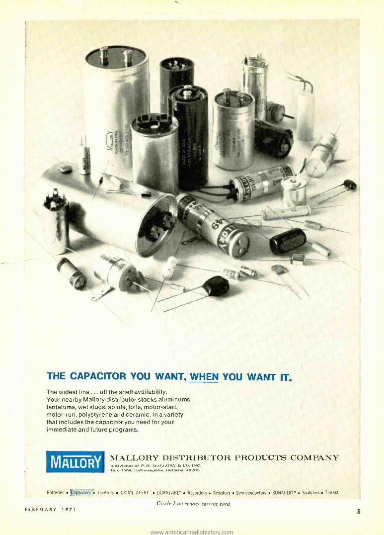
THE CAPACITOR YOU WANT, WHEN YOU WANT IT. The widest line ... off the shelf availability. Your nearby Mallory distributor stocks alum nums, tantalums, wet slugs, solids, foils, motor -start, motor -run, polystyrene and ceramic. In a variety that includes the capacitor you need for your immediate and future programs.
MALLORY MALLORY DISTRIBUTOR PRODUCTS COMPANY a divl'.1<ln .r I. 11. N1A1.1.01t1' lk. CO. INC. ßux 1558. Indlanaixolla. Indiana 1(3206
Batteries lapacitors. Controls CRIME ALERT" DURATAPE Recorder:; Resistors Semiconductors SONALERT' Switches Timers
Circle 2 on reader service card FEBRUARY 1971 5
www.americanradiohistory.com

New &Timely (continued from page 2)
A similar solar telescope has been sent aloft five times on rockets and returned with x -ray photographs. Between flights, work has continued in the laboratory to further per- fect and understand its imag- ing properties. Throughout the testing the SEC camera has been an invaluable tool.
When the Skylab is
launched in 1972, it will be the first orbiting space lab. Three teams of astronauts will go up at different inter- vals. The first will fly 28 days and bring down a load of film with images obtained by the solar telescope. After a two-month interval, the sec- ond team will go up to spend 56 days and will return with two loads of film. After an- other month interval, the third team will go up for an- other 56 -day visit and bring down a load of film from the telescope to complete the mission. *
CALLING ALL PHOTOGRAPHERS
There's an electronic ther- mometer construction article that starts on page 40. You'll find it to be an easily- built, yet extremely handy addition to your darkroom. It's writ- ten by our new photographic electronics editor; James A. Gupton, Jr.
Safer; Sharper X -Ray Pictures STAMFORD, CONN. -An
automatic device that reduces patients' x -ray exposure, pro- duces sharper x -ray pictures. and virtually eliminates the need for "retakes ", has been introduced by The Machlett Laboratories, Inc., a subsidi- ary of the Raytheon Com- pany.
Called "Dynadex ", the new device acts like a vari- able choke or iris attached to the output window of an x- ray tube. It limits the beam of x -rays to the area of the film being used. X -rays fall- ing beyond the dimensions of the film unnecessarily expose the patient's body while con-
-RATS -,
-1
INCROFOCDS X-RAY N SOURCE OR
PLASMA LOCUS X-RAY SOURCE
ONTON COUNTER
::CET
VACUUM CRAMMER
,S -RAT MIRRORS
ORATING
OPTICAL RENCA
FILTER MOSEL
SET -uP FOR TESTING X-RAY TELESCOPE
DOUBLE REELECTING BRAZING INCIDENCE B -RAT TELESCOPE
E -RT IMAGE INTENSIFIER
F RAY IMAGING SYSTEM
OPTICAL
SEC TV SYSTEM
TRANSLATION STARE
SEC CAMERA
tributing nothing to the diag- nosis.
A recent survey by the U.S. Public Health Service in- dicated that as much as two- thirds of the x -rays from a typical diagnostic procedure fall beyond the limits of the film and hence should be eliminated.
The new Machlett device senses the size of the x -ray film being used and automat- ically shutters a series of lead leaves to make the beam con- form. In addition to reacting to the size of the film being used, the "Dynadex" also gen- erates a distance signal. Logic circuits do the calculating and the result is a sharp, accurately sized x -ray.
4- CHANNEL STEREO
Next month R -E looks into the latest happenings in 4- channel stereo. There's tape now, talk of records, and de- tails of new FM compatible systems. Whatever your in- terest in 4- channel stereo don't miss RADIO- ELECTRON- ICS, March 1971 issue.
(continued on page 12)
Radio -Electronics HUGO GERNSBACK (1884 -1967)
founder
M. HARVEY GERNSBACK, editor -in -chief and publisher
LARRY STECKLER, editor
Robert F. Scott, W2PWG senior technical editor
lack Darr, service editor
I. Queen, editorial associate
Matthew Mandl, contributing editor
David Lachenbruch, contributing editor
lames A. Gupton, Jr.,
photographic electronics editor
Vincent P. Cicenia, production manager
Barbara Rosefelt, production assistant
H. Matysko, circulation
Cover design by Marius Trinque
Cover photo by Phil Koenig
RADIO- ELECTRONICS is published by Gernsback Publications, Inc. 200 Park Ave. South New York, N.Y. 10003 (212) 777-6400 President: M. Harvey Gernsback Secretary: Bertina Baer
ADVERTISING SALES EAST Stanley Levitan, Eastern Sales Mgr. N.Y.C. (212) 777 -6400
MIDWEST/Texas/Arkansas/Okla. Ralph Bergen, 6319 N. Central Ave. Chicago, Ill. 60646 (312) 792 -3646
PACIFIC COAST /Mountain States
J. E. Publishers Representative Co., 8560 Sunset Blvd., Suite 601 Los Angeles, Calif. 90069 (213) 659 -3810 420 Market St. San Francisco, Calif. 94111, (415) 981 -4527 SOUTHEAST E. Lucian Neff Associates 25 Castle Harbor Isle Fort Lauderdale, Florida 33308 (305) 566 -5656
SUBSCRIPTION SERVICE: Send all subscription orders and correspondence to RADIO -ELECTRONICS, Subscrip- tion Department, Boulder, Colo. 80302. MOVING? For change of address, allow six weeks, fur- nishing both the old and new addresses and if possible attaching label from a recent issue below. Otherwise please print clearly your name and address exactly as it appears on your label.
ATTACH LABEL HERE
name (please print)
address
city state zip code
Mail to: RADIO -ELECTRONICS SUBSCRIPTION DEPT., BOULDER. COLO. 80302
6 RADIO- ELECTRONICS
www.americanradiohistory.com

THE SANSUI QS -1
QUADPHONIC SYNTHESIZER®
4- CHANNEL SOUND FROM ANY 2- CHANNEL SOURCE Senses and recovers the ambient information
hidden in your stereo discs, tapes and broadcasts After having discovered that the ambient components of the original total sound field are already contained in hidden form, in conventional stereo records, tapes and broadcasts, Sansui engineers developed a method for sensing and
2ch i Put recovering them. These subtle shifts and modulations, if re- introduced, Sansui L quadOhonic breathtakingly recreate the total of the original sound as it existed in the R matna recording or broadcast studio.
The heart of the Sansui Quadphonic Synthesizer" is a combination of a unique reproducing matrix and a phase modulator. The matrix analyzes the 2- channel information to obtain separate direct and indirect components, then redistributes Phasamodulatad signals these signals into a sound field consisting of four distinct sources.
This type of phase modulation of the indirect components, applied to the additional speakers, adds another important element. It sets up a complex phase interference fringe in the listening room that duplicates the multiple indirect -wave effects of the original field. The result is parallel to what would be obtaind by using an infinite number of microphones in the studio (Ml through Mn in the accompanying illustration) and reproducing them through a corresponding number of channels and speakers.
1
FEBRUARY 1971
1F. L F
The startling, multidimensional effect goes beyond the four discrete sources used in conventional 4- channel stereo, actually enhancing the sense of spatial distribution and dramatically expanding the
dynamic range. Also, the effect is evident anywhere in the listening room, not just in a limited area at the center. And that is exactly the effect obtained with live music! This phenomenon is one
of the true tests of the Quadphonic system. The Sansui Quadphonic Synthesizer QS -1 has been the talk of the recent high -fidelity shows at which it has been demonstrated throughout the country. You have to hear it yourself to believe it. And you
can do that now at your Sansui dealer. Discover that you can hear four channels plus, today, with your present records and present stereo broadcasts. $199.95.
*Patents Pending
SANSUI ELECTRONICS CORP. Woodside, New York Gardena, California
SANSUI ELECTRIC CO., LTD., Tokyo, Japan Frankfurt a M., West Germany Electronic Distributors (Canada), British Columbia
Circle 3 on reader service card
7
www.americanradiohistory.com

NRI "hands -on" training in TV- Radio, Electronics can give you as much as 2 years of on- the -job experience.
EARN YOUR FCC LICENSE - OR YOUR MONEY BACK NRI Communications training programs will qualify you for a First Class Commercial Radiotelephone License issued by the FCC. If you fail to pass the FCC examinations for this license after successfully completing an NRI Communications course we will, on request, refund in full the tuition you have paid. This agreement is valid for the period of your active student membership and for six months after completion of your training. No school offers a more liberal FCC License agreement.
RAD 0-ELECTRONICS
www.americanradiohistory.com

Experience is still your best teacher
NRI Achievement Kit is educator -ac- claimed and the original "starter" kit in home study train- ing. Imitated but never duplicated, this kit is designed and personalized for you and your training objective. It has one purpose - to get you started quickly and easily.
"Bite-Size" Texts average an easily -digested 40 pages of well -illustrated, scientifically prepared subject matter in the course of your choice. Questions in each book are carefully hand -graded and returned to you with helpful instructional notes. You get unlimited personal help from the day you enroll.
...here's how you get it with unique NRI training at home Ask any teacher, job counselor, engineer, technician or prospective employer about the need for practical application of theory in Electronics. He'll tell you Electronics is as much a "hands -on" profession as dentistry or chemistry. That's how you learn at home with NRI. You prove the theory you read in "bite - size" texts, by actual experimentation with the type of solid- state, transistor and tube circuits you'll find on the job today - not hardware or hobby kits. You introduce circuit defects, analyze results, discover quickly the kind of trouble- shooting and design tech- niques that will make you employable in Electronics.
Train with the leader -NRI NRI lab equipment is designed from chassis up for effective, fascinating training - not for entertain- ment. The fact that end results are usable, quality products is a bonus. In Communications, for example, you build and analyze, stage by stage, your own 25- watt phone /cw transmitter. It's suitable for use on the 80 -meter amateur band, if you have an interest in ham radio. In TV -Radio Servicing your practical training gives you your choice of monochrome or color TV sets. All training equipment is included in the low tuition - you pay nothing extra. Discover for your- self the ease, excitement and value of NRI training. Mail postage -free card today for new NRI Catalog . . . or use the coupon below. No obligation. No salesman will call on you. NATIONAL RADIO INSTITUTE, Washington, D.C. 20016.
APPROVED UNDER NEW GI BILL If you have served since January 31, 1955, or are in service now, check GI line on postage -free card or in coupon.
Designed- For -Learning Equipment Like this phone -cw transmitter (Kit #7 in the Communi- cations course) is engineered from chassis up to demonstrate principles you must know. NRI does not use modified hobby kits for training, but the finest parts money can buy, pro- fessionally and educationally applied. FEBRUARY 1971
MAIL THIS COUPON IF CARD IS GONE
NATIONAL RADIO INSTITUTE Washington, D.C. 20016 3 -021
Please send me your new NRI Catalog. I understand no salesman will call and there is no obligation.
Name Age
Address
City State - Zip
Check for facts on new GI Bill ACCREDITED MEMBER NATIONAL HOME STUDY COUNCIL
11
www.americanradiohistory.com
(Continued from page 6) New &Timely
AUDIOVISUAL TV SERVICE AIDS FOR TECHNICIANS HARRISON, N. J. -Three
new audiovisual informa- tional programs designed to furnish practical guidelines and solutions to technicians in everyday servicing of tele- vision receivers and other electronic equipment are available from RCA dis- tributors.
The new technical ser- vice aids cover critical areas in specific detail to save ser- vice technicians time and trouble. Each program con- sists of a series of color slide presentations containing pro- fessional graphics and illus- trations, an audibly- synchro- nized cassette tape recording and a brochure recapping the salient points necessary to achieve maximum effective- ness. 35mm projector and a standard cassette tape recorder are required for group or individual presenta- tion.
The first tape -cas- sette /slide -film presentation is
entitled "Color TV Picture Tube Installation and Associ- ated Receiver Adjustments ". It offers specifics on color picture tube replacement; outlines safety precautions; indicates short cuts on tube removal and replacement; and provides a step -by -step guideline covering con- vergence, purity. and track- ing- intermixed with elec- tronic theory for greater understanding of TV elec- tronics.
The second aid covers "Basic Techniques For Tran- sistor Checking" (1L1337). It explores the use of basic test equipment; provides simple techniques for transistor checking; reveals quick ways to identify unknown transis- tor leads and types, and of- fers cost -saving information on good servicing practices, techniques and short cuts.
The third service aid deals directly with a no- raster problem and is entitled "Tele-
'NEW
vision Servicing; No Raster Condition ". This presentation provides a preliminary check list and a diagrammatic procedure recommended by RCA television specialists. Both "no raster -no sound" and "no raster -sound present" conditions are dis- cussed in detail. Servicing techniques are% presented that will save --the technician's most important commodity - his time.
CASSETTE ELECTRONICS
If you aren't really famil- iar with the electronics used in today's cassette tape re- corders you won't want to miss the programmed ar- ticle in the March 1971
issue. It covers cassette elec- tronics from A to Z. In April, the mechanical side of cassette machines is de- tailed in the same step -by- step fashion.
from the originators
xx O of N OISE"
N
You've tried others, now try the best!
ahead ! NO NOISE has been an innovative
force in the development and production of cleaners and lubricants for 25 years. Our technical peo- ple. who made us No. 1. were turned loose to create a new line that would out -per form anything on the market. Three years of experimentation and testing developed these 2 new products. Approved by leading service
s organizations .
tf t
..NOOISE',
SUPER - LUBE
A miracle concentrated for- mulation for heavy duty jobs. Its
clinging action foams away corrosion, dirt and oxidation -and polishes all tuners con-
tinuously without drift or detuning. SUPER- LUBE's
built -in lubricating quality makes channel selecting smooth and easy. For color and black A. white. Pftftft- tltf--- - -- ---
Itttt'otltrt lilts BUY 4 CANS OF SUPER -CUBE AND GET 2 EXTRA
- CANS FREE FROM YOUR JOBBERS! MONEY BACK
Offer GUARANTEE!
in
lettuce UIC &A411 p' ...:..,..,.,
SUPER SPRAY BATH dissolves and flushes
t' away grease, dirt, oil and oxidation. Simply spray
tuners, its penetrative action cleans and
restores tuners inside and out.
Itt> tttmi
2a o, 5325
Nóisr
ecc All NO NOISE products
are non -toxic - non -flam- mable - no carbon tat -
safe for all plastics.
Olten imitated but never duplicated
813 Communipaw Avenue Jersey City, N. J. 07304
Nlirms ELECTRONIC CHEMICAL CORP.
12
ïi Circle 4 on reader service card
STEREO TAPE CASSETTE
COMPATIBILITY NEW YORK, N.Y.-A so-
lution to the problem of quad- stereo -mono compatibil- ity in cassettes has been pro- posed by Norelco. It calls for 3 -way 4 -2 -1 compatibility -the capacity to play four -channel, stereo or mono cassettes inter- changeably without loss of quality on any cassette ma- chine.
Edward R. Hanson, tech- nical manager states, "The basic mono -stereo com- patibility that has prevailed so far in the cassette industry can and should be extended to the suggested four -track medium. Although it's far from clear whether the public will eventually accept four - channel as a standard mode, we must be prepared for the eventuality."
Hanson adds that the sys-
tem is being offered as a basis (continued on page 14)
BRIGHTENERS For Those
Problem Picture Tubes
BLACK & WHITE
UNIVERSAL
for all voltages and currents
TYPE MODEL
DOUDECAL CR -69
RCA 110° CR -154
SYLVANIA
110° CR -159
MINIATURE BASE CR -12
COLOR
70 CR -200
90' CR 250
2 IN ONE
ISOLATION COLOR
Test for and cure
Cathode -Heater shorts
and low emission.
70° -CR -300
90° -CR -350
Ask Your Distributor TELEMATIC, BKLYN, N.Y. 11207
Circle 5 on reader service card Circle 6 on reader service card 41.
www.americanradiohistory.com
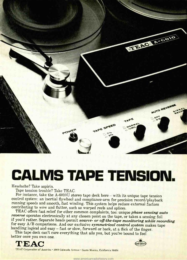
CALMS TAPE TENSION. Headache? Take aspirin.
Tape tension trouble? Take TEAC. For instance, take the A -6010U stereo tape deck here - with its unique tape tension
control system: an inertial flywheel and compliance arm for precision record /playback running speeds and smooth, fast winding. This system helps reduce external factors contributing to wow and flutter, such as warped reels and splices.
TEAC offers fast relief for other common complaints, too: unique phase sensing auto reverse operates electronically at any chosen point on the tape, or takes a sensing foil if you'd rather. Separate heads permit source- or off-the-tape monitoring while recording for easy A/B comparisons. And our exclusive symmetrical control system makes tape handling logical and easy - fast or slow, forward or back, at a flick of the finger.
This tape deck can't cure everything that ails you, but you're bound to feel better once you own one.
TEAC TEAC Corporation of America 2000 Colorado Avenue Santa Monica, California 90404
NMI RINE=
www.americanradiohistory.com

(continued from page 12) New &Timely
for industry standardization in much the same manner as the original Norelco /Philips cassette was offered a number of years ago.
MONOPHONIC
STEREOPHONIC
QUADROPHONIC
In the Norelco approach, four discrete channels are placed in the space occupied by the two stereo tracks on a standard cassette tape. Since cassettes record and play back in two directions, the process results in a dual four-
PROPOSED TAPE STAND- ARDS for cassettes. Left: po- sitions of tracks for compatible mono, stereo and 4- channel stereo. Below: 4- channel speci- fications.
channel configuration, with four tracks for recording and playback in one direction and fouls tracks in the other.
The new format places two distinct sound sources in the space now occupied by one source in a stereo cas- sette. The width of individual tracks is reduced from 0.0264 inches to 0.0110 inches.
The smaller channels pro- duce a reduction in signal-to- noise ratio, but in practice dispersion is said to reduce the disturbance level.
TRACK CHANNEL
I- 8 LEFT FRONT
7 LEFT REAR
SIDE II (8)
L_ 6 RIGHT REAR
5 RIGHT FRONT
SIDE (A)
3.66
0.144
4 RIGHT FRONT
3 RIGHT REAR
2 LEFT REAR
LEFT FRONT r
OIO MM 0 000
00001N.
CODE -COM READY COLUMBUS, Onto -This
new instrument, now available to telephone users permits deaf, or deaf -blind, persons to communicate via the tele- phone.
The set contains a light, sending key and vibrating disc. A deaf person watches the flashes of light; a deaf - blind person feels the vibra- tions. The key is used to trans- mit messages using a pre- arranged code for simple mes- sages or Morse code. R -E
NO COMPETITORS Nobody else but EMC designs in so much value
Full -view meter gives direct. clear -rut quai. ity indications.
Three heavy -duty controls for quick set -up of all tests. Check a fistful of tubes in the time it often takes to test one.
12 slide switches for ....individual selection of
tube pins provides versatility in testing, prevents obsolescence.
Compact, light. weight portabil- ity. Use it on the bench or in the field.
Full Comple- ment of sturdy sockets accepta compactron (12- pin). nuvistor. nover. 10 -pin. 9 -pin. octal. loetal. and miniature tubes.
Precise pro- gramming. Only one socket per tube -base configuration prevents aeei- dental plug -in,
THE MODEL 213 saves you Lane. energy. money Checks for shorts. leakage. intermittents. and quality Tests
all tube types including magic eye. regulator. and hi -fi tubes Checks each section of multipurpose tubes sep,
arately Gives long. trouble, free life through heavy-duty components. including permanently etched panel Your
best dollar value in a tube tester. Available in high-impact bake:ite case with strap: $33.40 wired: $21.90 in kit
form. Wood carrying case (illustrated) slightly higher.
11.9-177M r-
E MC, 625 Broadway, New York 12, N.Y. Rush me FREE catalog describing all EMC
value -loaded test instruments and name of local distributor.
NAME
W c J
ELECTRONIC MEASUREMENTS CORPORATION 625 Broadway, New York 12, New York
Eeport:Pan-Polar Corp.,1270 B'way, N. Y. 1, N. Y.
ADDRESS
CITY 70NE -STATF
14
. [j RUSH CATALOG . Name
Ot.\1 ca
UO Modúlén. ` \ Speakers. Stereo. HI -Fl,
Va Photo Cells and thousands of
other Electronic
Parts. Send for
FREE CataIng
irr
1274
0 tfl7
o , rat
161 ELECTRONIC DISTRIBUTORS Dept. TA -2, 4900 Elston Chicago. III. 60630
INC.
Address . City State Zip Code
Circle 7 uri reader service card RADIO- ELECTRONICS
www.americanradiohistory.com

LOTS
NEW A broad new line of exciting, laboratory grade test instruments from Leader, for servicing all electronic equipment - priced to give you the best dollar- for -dollar value - and built to the highest standards in the industry!
Leader's got it in New, Portable Triggered Scopes; Battery Operated Color Bar Generators; Post Injection Sweep Marker Generators; and lots more. Accessories too. Seeing is believing. Send for your new catalog. See your distributor.
LOTS OF SCOPE... Here's the only 3" Portable Triggered Scope with vertical and horizontal calibration! All solid state, it features highest sensi-
LBO.301 tivity, wide bandwidth and an easy-to-use, horizontal panel design for testing under all conditions. Great for servicing color TV and computer circuitry. It's compact, it's portable, it's remarkably low- priced. $334.50
LOTS OF STABILITY... Our fabulous, new, Mini -Portable Color Bar Generator that's battery operated, yet offers test patterns of the highest stability. Features
LCG -384 Leader's digital clock and binary system that acts as a miniature computer. Has two switch selectable frequencies, four basic pat- terns including gated rainbow for testing NTSC color sets. With carry case, extra battery compartment and all accessories. $109.50
LOTS OF SENSITIVITY... 0 This 5" Wideband Scope features calibrated vertical input, 10MVp-
p /cm sensitivity and unstinting operational stability. Bandwidth LBO -548 is DC to 10MHz and the high linearity sweep range has automatic
synch. DC coupling and push-pull amplifiers help deliver distortion- ' free displays. $249.50
-+ I i?'
From left to right here's our LBO -501 -5" Triggered Scope/
Vectorscope $339.50 LSW- 330 -Solid State Post
Injection Swemar Generator _ _ . $399.50
LBO -328-3" Wideband Oscilliscope $189.50
LDM -810 -Grid Dip Meter $44.50
FEBRUARY 1971
AND LOTS MORE ...
-
J sas. w 11
Cire le S,vrre tide r iur,l
. 1114.
Seeing is believing.
TEST INSTRUMENTS 37-27 27th Street. Long Island City
New York 11101. Telephone: (212) 729-7410
15
www.americanradiohistory.com

FREE! YOUR FIRST
CAN OF ' i1oIoI1 IS
ON US!
PPROFESSFOR IONAL1 . TV TECHNICIANS
HEAVY DUTY TUNIS; SPRAY WITH BUILT IN
POLISHING ACTION!
SHA"1 W ELL
We say TUN -O -BRITE is head and shoulders above any other tuner spray you've ever tried. You say you've heard that song before.
It's time for us to put our money where our claims are. Tell you what we're gonna do. Buy a can of TUN -O -BRITE from your fav- orite distributor - at the regular price.
When you've used the TUN -O -BRITE up, send the empty can to us. We'll send you a new can OF YOUR FAVORITE TUNER SPRAY FREE! There are no strings attached to this offer. If you ask for TUN -O- BRITE, we'll be de- lighted to send you another can absolutely free. If you ask for a competitive brand, we'll be disappointed, but we'll send it to you any- how. Either way, you can't lose. You get to try TUN -O -BRITE at our expense because you can swap the empty can for a free can of your favorite tuner spray.
Of course, we're betting that once you try TUN -O- BRITE, you simply won't settle for any other product, no matter how cheap you can buy it. After all, you can tell a profes- sional TV technician by the tools he uses.
ONLY ONE FREE CAN TO A TECHNICIAN.
CHEMTPONUCS This offer expires March 1, 1971
16 Circle 9 on reader service card
1260 RALPH AVE. BKLYN., N.Y. 11236
RADIO-ELECTRONICS
www.americanradiohistory.com

WH u stands to benefit most from Color TV?
Everyone, including the service technician, has a lot to gain.
That's why Sprague wants to help you get your fair share of this increasing business.
EE i of the service technician are of
great importance to Sprague. That's why we supply capacitors
with the exact ratings required to meet the exacting require- ments of Color TV.
CC L has been both boon and bane of the service trade. While it has added to service volume, it has also caused some headaches. That's why Sprague is con-
stantly striving to simplify Color TV capacitor selection.
Yes, TV repair represents a big portion of your business. And color is boosting it even higher. You do faster, surer work with Sprague replacement capacitors for Color TV.
THE BROAD -LINE PRODUCER OF ELECTRONIC PARTS
Circle IO on reader service card FEBRUARY 1971
SPRAGUE® THE MARK OF RELIABILITY
Sprague' and 'Ú' are t{i,ta,C Irademuka Ql tht $Drsµ' Clodot Cp.
17
www.americanradiohistory.com

NTS outs a whale new world at your tiuoertìvs. NTS home training can put a whole new way of life in the palm of your hand. A new, exciting job, a much bigger income is now easily within your reach. NTS training is something spe- cial. We provide all the kits you need for the most effective train- -rig. National Technical Schools sends kits with every course, and teaches you to build and test a
18
wide range of professional equip- ment - the same kind of equip- ment you'll actually use on the job. That's the NTS "Project Method" - training that's practical and in- depth. You learn everything from fundamentals to the latest innovations. From beginning to end, NTS makes it fas- cinating and fun to learn this way. And all you need is a little
spare time and an interest in electronics. Each year, men are moving into important new jobs, or their own businesses, straight out of NTS electronics training. NTS is what's happening to men every- where. Check the coupon. Take hold of the career you want most. Do it now. No obligation. No salesman will call.
RADIO- ELECTRONICS
www.americanradiohistory.com

We aacN your electronics course with Nits to make
your trainino fast. You'll eoioy every minute of it.
NTS COLOR TV SERVICING
COLOR TV 295 SO. IN. PICTURE
NTS training provides an easy way to become a professional home - entertainment service technician. You receive a big screen Color TV with many unique features. The unit even includes self servicing equip- ment that permits you to make all normal test operations. No addition- al test equipment is needed for ad- justing your set. In addition you get an AM -SW radio, Solid -State radio, Field- Effect Transistor Volt -Ohm- meter, and Electronic Tube Tester. You learn about Electronic princi- ples and trouble shooting, hi -fi, multiplex systems, stereo, and color TV servicing.
NTS COMPUTER ELECTRONICS This is the future. And it's happen- ing now. The number of computers will increase many times in the next few years.
NTS offers a solid grounding in com- puter operation, wiring, data pro- cessing and programming. One of the 10 important kits included is our exclusive Compu-Trainer. It's a fully operational computer logic trainer - loaded with integrated circuits - the first ever offered in home study. It introduces you quickly to how, what, when and why of computers ... from theory to practical servicing techniques. This unit is capable of performing 50,000 operations per second.
NTS ELECTRONICS COMMUNICATIONS Choose from two exciting courses to get into the big -paying fields of transmitting and receiving equip- ment: (1) The FCC License Course. (2) The Master Course in Electronic Communications (more comprehen- sive, with Citizens' Band Two -Way- Radio). Either Communications program qualifies you for your FCC First Class Commercial Radio -Tele- phone License - NTS assures you will pass this FCC exam within six months after successfully com- pleting your course or your tuition is refunded. Kits include an Amateur - Phone 6 Meter VHF Transceiver - NTS exclusive, 6 transistor Solid - State Radio, Volt- Ohmmeter (fully transistorized).
Exclusive new Compu- Trainer r
If card is missing check coupon and mail for free color catalog and sample lesson. Now.
National Technical Schools 4000 S. Figueroa St., Los Angeles, Calif. 90037 Please rush Free Color Catalog and Sample Lesson, plus information on course checked below. No obligation. No salesman will call.
FEBRUARY 1971
5 Watt AM Transmitter/ Receiver
Master Course in Color TV Servicing Color TV Servicing Master Course in TV & Radio Servicing Practical TV & Radio Servicing Master Course in Electronic Comm.
El FCC License Course L; Master Course in Electronics Tech.
Industrial and Automation Electronics Computer Electronics Basic Electronics
NTS AUTOMATION/ INDUSTRIAL ELECTRONICS Let NTS put you into the age of elec- tronic controls. Systems Automation is rapidly becoming the emphasis of modern industry. Your NTS training in automation electronics includes equipment like a 5" wide band Oscil- loscope. You also get the new NTS Electronics Lab. It's an exclusive NTS experimental laboratory -a complete workshop that simplifies learning about solid- state, miniature and integrated circuits.
I
1 5" Oscilloscope
CLASSROOM TRAINING AT LOS ANGELES You can take classroom training at Los Angeles in sunny Southern California. NTS occupies a city block with over a million dollars in facilities devoted ex- clusively to technical training. Check box in coupon.
NATIONAL SCHOOLS WORLD -WIDE TRAINING SINCE '905
4000 South Figueroa Street Los Angeles, Calif. 90037, U.S.A.
APPROVED FOR VETERANS Accredited Member: National Associ- ation of Trade and Technical Schools; National Home Study Council.
Name Age
Address
City _ __ _State_ __ _.Zip
ID Check if interested in Veteran Training under new G.I. Bill
p Check if interested only in Classroom Train- ing at Los Angeles Dept 206 -021
J
21
www.americanradiohistory.com

C responden
seemed to be exactly what I was look- ing for so I decided to try it. I have been extremely satisfied with the final
THANKS FOR THE MIXER
I had been looking for a good straight- forward mixer circuit when I
saw the cover article in the October 1970 issue Of RADIO -ELECTRONICS. It
results. My final project does not look anything like yours (see photos), but it does exactly what I want it to and more.
PUT IT TO THE TES
Leave it to B &K to come up with a new model 179 FET /VOM with fea- tures that almost make it unbelievable a* its price. Complete DC voltage ranges from .3V to 1000V; DC current ranges .03 to 300 mA; AC voltage ranges .3 to 1000V and AC current ranges .03 to 300 mA. Resistance 0 to 500 Meg and stable operation 0° to 40'C. Fastest and easiest to use.
The 179 uses Field Effect Transistors for drift -free accuracy. High in- put impedance minimizes circuit loading. And the 179's super -wide variety of ranges makes this an ideal FET /VOM for shop, lab, produc- tion line, or school. Includes mirror scale, and stay -put handle.
Now is the time to update your shop with a stable, protected FET/ VOM. And the economical, yet professional B &K 179 is the instrument
that will give the most usefulness and satisfaction for your money.
Ask your distributor or write us for catalog.
There is a
difference in
test equipment ... ours works!
A Product of OYNASCAN CORPORA ?/ON 1801 W. Belle Plaine Chicago, Illinois 60613
B &K Model 179 FET /VOM $74.95 The new standard of stability I%
Circle 11 on reader service card 22
I incorporated a number of fea- tures not found in your original de- sign and eliminated a few you had put in, only because my needs are differ- ent.
A small cue amplifier is in- corporated in the console as well as monitor muting. This was all easily accomplished because of your no-pop
no -click circuit. All switching is done with non -shorting switches with no problems.
I have made frequency response, distortion and noise tests for both channels and they are not too bad. The only thing I would like to see a bit better would be the noise figure. The overall noise increases consid- erably when either the master or pre - amp gains are increased from the test levels. I'm sorry to say that I couldn't use the same transistors you did be- cause they are not as readily available as others in this area. I used 2N3393's for low level, GE -20 and GE-18 for line amplifier and mixer boards.
I did have one problem, but it was probably due to the different tran- sistors. The output transistor in the power supply kept opening. I inserted a 10 -ohm, 1/2 -watt resistor in series with the transformer secondary and had no further problem.
I did find the gain from the mike preamps is tremendous, even with low output cardioid mikes. This probably helps to account for some of the noise.
Thanks for your time and a good circuit when it was needed most. JULIAN E. JETZER .Sheboygan, Wisc.
Julian, when you start substitut- ing transistors you never know exactly what will happen. It you stuck to the units specified you might have gotten the better results you were looking for. Your unit looks great and we're pleased to see that you were able to make good use of the article.
We'd like to see pictures of other construction projects assembled by readers, especially when they've made modifications and changes. Other readers would like to hear about them too. Just drop us a short note and in- clude a snapshot or two of your gear. Maybe you'll get to see yours in this column too. R -E
RADIO -ELECTRONICS
www.americanradiohistory.com

Winter can't drag the new ruggedized Color Crossfire down!
Now the world's most popular color TV antenna has even greater strength to keep it standing firm through the Winter storms!
The new ruggedized Color Crossfire fea- tures30% stronger rear elements that take heavy snow and ice loading and still de- liver their message.
Other body building improvements include a rugged, one -piece all aluminum harness
that won't rust or wrench out of shape, and will keep all elements working in perfect harmony. And preassembled hardware that makes the Color Crossfire the world's easiest, as well as strongest a n t e n n a installation.
So now, with Winter wind, snow and ice dragging lesser antennas down to earth, the Color Crossfire is keeping its new blue boom up, and its elements on target!
The new ruggedized Color Crossfires
CHANNEL MASTER DIV. OF AVNET, INC., ELLENVILLE, N.Y. 12428
Circle 12 on reader service card
www.americanradiohistory.com

v jobs so
\der\n9
Most cr \t`ca\ e gun
the n \cs' d the d \e ctro grounded packed to tack ted a \e _W a \ s nse \y p Apr
e better gun soPh\stfia\ ;splat\On
.G .s and as a \so sate and
Wes
better
the by today's e \ectcc
sens\a\ve currents.
\t both you
Now Ungar demand Ypu ..so y° and stray that protects de
pu
e k\nd °\ jobs
fit's and cord
. e \den gun for y
the s why MP P saat`c , a s`mP so
\der\ts cV \try Here's
3 w \re Ne sate
\roR`punded `p ent\re \y new advanced dvance accurate \y
w \th
components
a tG ned an re \\ab u can cpmP l the
re W nsiorrner you get Npw y e d
gOp° F
you cu\try the s {Or punt d a <9 00° an d °n your c\e n t stop heavy
abet -\\ght w,NthOUt hat ranges { thread-on
d\d
But o\
the u gun a {e to -spots bean o \ect the
\nsmáK s th \s ee n hard-to-get-to-spots ard
g; y You
get you have a c t ;::
can east
\t so \d vets gun. P d \n constant \nt added same g
or ben s \b\ \ \ty,
p Next we a\\ w\th the same
greater acre our 1 °b ar s new
Plev4
rox1 tips that best. For 9 eded for your
w\th un9 case
, t) L' a
needs ang \e needed on \y
ro0\ cas
gun ,
rthat \ts your the exact uses y° atter'p every 9
e a \p to standard bon vfirtua \\y sh each and
just take our
lock the other std a o e don't as oneun
- tr t`
separately
eab \e prks. t who
\\stedsepagate \y one or ask
another of so \ \d
and "' rn \nd the ace \ghts ti
word e uP
your own that stheheaJyw
Make {or
state Ungar really r.. f
:,
www.americanradiohistory.com

Solve 7 problemi...in reconcJf.
4 Circle 13 on reader service card FEBRUARY 1971
Something totally new to add to your bag of tricks! We call them Plug -in Problem Solvers. They're designed to provide seven common modifications in microphone and sound system setups without soldering or rewiring -just plug them in! The Model Al 5A Microphone Attenuator that prevents input overload; Model A15PR balanced line Phase Reverser; and A15HP High Pass and A15LP Low Pass Filters to modify low and high frequency response; A15PR Presence Adapter to add brilliance; A15RS Response Shaper to filter sibilance and flatten response; and the A15LA Line Adapter that con- verts low impedance microphone inputs to line level inputs. Carry them on every job. It's a lot easier than carrying a studio console with you! Shure Brothers Inc., 222 Hartrey Ave., Evanston, III. 60204. 11/A
Circle 14 on reader service card
S H V R E 25
www.americanradiohistory.com

Build this excitin Schober Consolette Organ _Of
1040!'
Includes finished walnut console. (Only $793 it you build
your own console.) Amplifier, speaker system, optional
accessories extra.
You couldn't touch an organ like this in a store for less than $1800 -and there never has been
an organ of the Consolette II's graceful small size with 22 such pipelike, versatile voices, five- octave big -organ keyboards, and 17 pedals! It sings and schmaltzes for standards, pops, old-
time favorites, speaks with authority for hymns
and the lighter classics, all with a range of vari- ety and satisfying authenticity you've never found before in an instrument under church or theatre size. If you've dreamed of an organ of your own, to make your own beautiful music, even if your home or budget is limited, you'll get more joy from a Schober Consolette II than any other "home size" organ -kit or no kit.
You can learn to play it. And you can build it, from Schober Kits, world famous for ease of as-
sembly without the slightest knowledge of elec- tronics or music, for design and parts quality from the ground up, and - above all - for the highest praise from musicians everywhere.
Send right now for the full -color Schober catalog, containing specifications of all five Schober Or-
gan models, beginning at $499.50. No charge, no obligation. If you like music, you owe yourself a Schober Organ!
Thetrek.detOrgan Corp., Dept. RE 87
43 West 61st Street, New York, N.Y. 10023
Please send me Schober Organ Catalog and free 7 -inch "sample" record.
CI Enclosed please find S1.00 for 12 -inch L.P. record of Schober Organ music.
NAMF
ADDRESS
CITY STATE 711' - L
Circle 15 on reader service card
26
In the Shop ... With Jack By JACK DARR
SERVICE EDITOR
CHECKING THE CHIP
ONE OF MY ALLEGED FRIENDS ONCE (.\'. me one of those signs saying " An Ex- pert is one who knows more and more about less and less!" In some fields this is true, but the American electronics technician is just the opposite. He knows more and more about more and more! He has to. They keep throwing new things at us- color, transistors, and now integrated circuits. You name it, we fix it!
We are finding IC's in several things now and we'll find more of them as time rocks along. So let's take a look at some of the test methods and in- struments needed to find the trouble and fix it. One of the first in common use is Zenith's IC color demodulator, which they call "The Chip ". It has been in use for a couple of years and is doing very well.
Chip- checking The chip used here is a "dual
double -balanced synchronous detector" if you want the description. It contains 21 transistors and a lot of resistors. etc. However, we do not need to know this! All we need to know is the normal input and output signal amplitudes and wave - shapes, and the dc voltages at various terminals, plus the normal dc current drawn. (We can't get inside the chip to do anything; all we can do is check it to find out if it is working.)
This is the basic problem we face - is the chip working or is the trouble in the external circuitry? So we must have tests that will give us this data in the least possible time. Of course, when these first came out, the regular number of perfectly good chips were replaced. However. it is not difficult to pin down the trouble with the rieht test equipment and methods.
The only reliable way of checking is probably the oldest in the business. It's simply "Signal input /signal output" and dc voltages. We read the input sig- nals, then the output signals. If they are normal, go on -the chip is ok. If these aren't normal, then we read the dc volt- ages at the IC terminals. If the dc sup- ply voltage is normal. but the dc volt- ages at other points on the chip are not, then there is a definite chance that the IC is bad. All of the dc voltages found on other terminals (from the input sup- ply) come "from within" the chip, and indicate trouble if they're off -value.
The diagram is the circuitry of the chip in the 14Z8C50 series Zenith chassis. All of the normal dc voltages are shown. The color signals are fed into
terminals 2 and 3, at a very low amplitude. You'll see a color -bar signal here, with a low- capacitance or crystal - detector probe on the scope. at about 0.75 volts p -p. The chip demodulates these signals. and comes out with the three color signals, red, blue and green, at a good deal greater level.
The output signals will be the fa- miliar "rocker" waveforms. just like those you see on the tube demodulators and color- difference amplifiers. They're fed to the control grids of a triple triode 6MN8 color- difference amplifier tube, at about 10 volts p -p. The green signal, as usual, will be somewhat lower than the
TO
6MN8 COLOR RIFF AMPL
FROM 2 ND
COLOR AMPL
24V
2.7 K
CI30 .05
C131 .05 .05
3.3K 3.3K 3.3K
15.2V 9
3.2V 3
15.2V
8 152V
5.8V I .01
4 5
5.8V 24V 22mA
39pF v 05
T T .05
AFC 3.58 MHz
INPUT red or blue. The color outputs from the chip are pins 7. 8 and 9. They can be easily identified by the external load re- sistors, 3300 ohms each, and the .05 µF coupling capacitors.
So there's the first test. Feed a
color -bar signal to the antenna of the set and check for these signals with a scope and low- capacitance or crystal demo- dulator probe. Actually, you can use a
low- capacitance probe on the output. If you get the right signals here, there's no need to check the input.
Second -stage testing Now -suppose that we do not get a
normal output. Then, we check the in- put. If we see the normal, very low level
(continued on page 82)
RADIO -ELECTRONICS
www.americanradiohistory.com

Thirteen cures for 78 headaches. Integrated circuits are replacing transistor circuits
in many stereos, radios, B & W and color TVs. That means more parts to stock and more money tied
up in inventory. Now, Sylvania ECG can take some of the pain out of these
stocking headaches. Our 13 ICs will replace 78 part numbers,
including RF, IF and audio amplifiers, sound detectors, oscillator /mixers, chroma demodulators, and auto- matic fine -tuning systems.
That's 65 fewer items to stock. And our 13 ICs are just part
of our ECG replacement line. That's the line that lets you replace 35,000 semi-
conductor types with just 87 Sylvania ECG types.
It's the line that lets you put a complete stockroom on one
shelf. Maybe the same shelf where you
used to keep the.aspirin. k SYLVANIA GENERAL TELEPHONE & ELECTRONICS
www.americanradiohistory.com

A Government FCC License can help you bring home up to $10,000, $12,000, and more a year. Read how you can prepare for the license exam at home in your spare time -with a passing grade assured or your money back.
IF YOU'RE OUT TO BAG A BET I ER JOB in Electronics, you'd better have a Government FCC License.
For you'll need it to track down the choicest, best - paying jobs that this booming field has to offer.
Right now there are 80,000 new openings every year for electronics specialists -jobs paying up to $5, $6, even $7 an hour... $200, $225, $250, a week ... $10,000, $12,000, and up a year! You don't need a college education to make this kind of money in Electronics, or even a high school diploma.
But you do need knowledge, knowledge of elec- tronics fundamentals. And there is only one na- tionally accepted method of measuring this knowl- edge ... the licensing program of the FCC (Federal Communications Commission). Why a license is important An FCC License is a legal requirement if you want to become a Broadcast Engineer, or get into serv- icing any other kind of transmitting equipment - two -way mobile radios, microwave relay links, radar, etc. And even when it's not legally required, a li- cense proves to the world that you understand the principles involved in any electronic device. Thus, an FCC "ticket" can open the doors to thousands of exciting, high -paying jobs in communications, radio and broadcasting, the aerospace program, industrial automation, and many other areas.
So why doesn't everyone who wants a good job in Electronics get an FCC License and start cleaning up?
The answer: it's not that simple. The govern- ment's licensing exam is tough. In fact, an average of two out of every three men who take the FCC exam fail.
There is one way, however, of being pretty certain that you will pass the FCC exam. And that is to take one of the FCC home study courses offered by Cleveland Institute of Electronics.
CIE courses are so effective that better than 9 out of 10 CIE graduates who take the exam pass it. That's why we can back our courses with this iron- clad Warranty: Upon completing one of our FCC courses, you must be able to pass the FCC exam and get your license -or you'll get your money back!
They got their licenses and went on to better jobs The value of CIE training has been demonstrated time and again by the achievements of our thous- ands of successful students and graduates.
2 NEW CIE CAREER COURSES 1. BROADCAST (Radio and TV) ENGINEERING... now includes Video Systems, Monitors, FM Stereo Multiplex. Color Transmitter Operation. 2. ELECTRONICS ENGINEERING. .. covers steady - state and transient network theory, solid state physics and circuitry, pulse techniques, computer logic and mathematics through calculus. A college -level course for men already working in Electronics.
FEBRUARY 1971
Ed Dulaney, Scottsbluff, Nebraska, for example, passed his 1st Class FCC License exam soon after completing his CIE training ... and today is the proud owner of his own mobile radio sales and serv- ice business. "Now I manufacture my own two -way equipment," he writes, "with dealers who sell it in seven different states, and have seven full -time em- ployees on my payroll."
Daniel J. Smithwick started his CIE training while in the service, and passed his 2nd Class exam soon after his discharge. Four months later, he reports, "I was promoted to manager of Bell Telephone at La Moure, N.D. This was a very fast promotion and a great deal of the credit goes to CIE."
Eugene Frost, Columbus, Ohio, was stuck in low - paying TV repair work before enrolling with CIE and earning his FCC License. Today, he's an inspec- tor of major electronics systems for North American Aviation. "I'm working 8 hours a week less," says Mr. Frost, "and earning $228 a month more." Send for FREE book If you'd like to succeed like these men, send for our FREE 24 -page book "How To Get A Commercial FCC License." It tells you all about the FCC License ... requirements for getting one ... types of licenses available ... how the exams are organized and what kinds of questions are asked ...where and when the exams are held, and more.
With it you will also receive a second FREE book, "How To Succeed In Electronics," To get both books without cost or obligation, just mail the attached postpaid card. Or, if the card is missing, just mail the coupon below.
ENROLL UNDER NEW G.I. BILL. All CIE courses are available under the new G.I. Bill. If you served on active duty since Jan. 31, 1955, or are in service now, check box on reply card for complete details.
C' E Cleveland Institute of Electronics
1776 E.17th St., Cleveland, Ohio 44114 Accredited Member National Home Study Council A Leader in Electronics Training ... Since 1934 .
Cleveland Institute of Electronics 1776 East 17th Street, Cleveland, Ohio 44114 Please send me without cost or obligation:
Your 44 page book "How to Succeed In Elec- tronics" describing job opportunities in Electronics today, and how your courses can prepare me for them.
Your book on "How To Get A Commercial FCC License." I am especially interested in:
Electronics Technology Electronic Communications Broadcast Engineering Industrial Electronics First Class FCC License ] Electronics Engineering
Name
Address
City
I.LE.SE PRINTS
State__ Zi p Age RE-e7 Check here for G.I. Bill information
Circle 17 on reader service card J
31
www.americanradiohistory.com

SONY achieves true integration
In all too many transistor integrated amplifiers, the preamp stage does not quite live up to the per- formance of the amplifier section.
Not in Sony's new TA -1130. Thanks to an FET front end, this integrated package has a preamp stage that really does full justice to its output section.
Why FET's For the same reason that we use them in our tuners and receivers, and in our studio professional con- denser microphones; because FET's have a far wider dynamic range than ordinary transistor types.
And the preamplifier needs that range. Because it
has to be sensitive enough to handle the lowest - output, moving -coil car- tridges, yet still accept the highest output cartridges F
without overloading. (The power amp has it easier: you keep its input level fairly constant with your volume control.)
Power to Spare But if the power amplifier doesn't need that range, it does need power. The output section of TA -1130 has it: 230 IHF watts (into 4 ohms),with continuous power rated at 65 +65 watts into 8 ohms. (With all that power, we made sure that both transistor and speaker protection circuits were included.)
Nothing Stands Between You and the Sound Both sections are powered by balanced positive and negative supply voltages (not just positive and ground), so there need be no coupling capacitors or interstage transformers between you and the sound.
Without them, the TA -1130 can extend its power band width down to 7 Hertz, and actually exceed its
rated damping factor of 100 all the way down to 5 Hz.
An Abundance of Audiophile Conveniences Of course, the TA -1130 has all the control facilities that you could ask for: low and high filters, tape monitor, a speaker selector, and even an Auxiliary input jack on the front panel. The selector switch is
Sony's instant -access knob - and -lever system.
There's even provision to use the TA- 1130's power amp and preamp sections separately, to add equal- izers, electronic cross- overs, or 4- channel adapt- ers to your system.
I n fact, you can even get the power output section separately, as the model TA -3130 basic amp. It makes a great match for our TA -2000 preamp, too. SONY FM' Amplifier
32
Your Sony dealer has both models available, and at prices - $359.50 for the TA -1130; $239.50 for the TA -3130. Sony Corporation of America, 47 -47 Van Dam Street, Long Island City, New York 11101.
Circle /6 on reader service curd RADIO -ELECTRONICS
www.americanradiohistory.com

THOSE REPLA TRANSISTORS:
do the really work?
by JACK DARR SERVICE EDITOR
Finding a suitable transistor substitute is often quite a job. Here is a sure -fire way to find the transistor you need to get the set working again.
FEBRUARY 1971
, ..,. .,
;t,;
¡''i:;\ I ; ,.., I t. . t i..r.ti,. hrtt nt:tn tul><', art un thi ìntrr- t:tlnnlìrt-¡uodutt, li,t,. :trt ntttri. hu, I,tt. .t ¡, ., a ttll: , of ..
...,;ì. fll; rll:tl It) ,ho,t "ì: I1;1U
2r.tll,;,hol, ( I ihiltti It I I il í: It' Nì al; i,no\4 Ci: \
to tip a ni\t ,r;, trtl tind .t nttt b..t:h of lr::n,:,tttr,. Ori .t tìrl fiv, conl¡`.ullt,. all of ti;irn firnt, cttr tl,ì the ,.tillt: tr.tn,I,IU,, II', d;ll et- en t nntdil,. ttt tinti ir. ul:rt t
1tt, ;I crì ou !t t`:ttl.:rnt', lliL{: ll:..:h:ì t¡` ..:ilni', tr..:1,r, tor, tthin onr of tfl LRi: !ì eìd
rut. And rl:I Ihit .tu 1,4,1
( ontra;t to ,orllt of tllì L...1 I, tl.::rn, about Oh: ;nitnort,tirt of tr.:r,,;stol,, tlle} prohahlt rot idt th: t:rc:rtis; amount of :tttu.:f trouhiì,, just as
. an,hl s. What' to do?
Fortunately 1.0 us, we a of help from
a slstor manufac emendous t
.A.';',r...t i, °rrrt-7, tt:ls
r ., o t IZ( 1
n:;11;;I1t,,.. '.!;..Vt.' ITS
t*tng , morse a,
Nì It I,t! ii :t rtlitlth! ,_r.:dt;ai;t dt- tiaU'}iii_ Uir<l 1ilaLttr6 tli'
Ri¡:..,ì;nìnt 1r.tn,;,tttr c1111tir1)004,, ',eh::: and III,Lt.Ì .. rt'r.r:ìrllii:t
t me tn o IdC;lt:f`.I nlrmhìr on Ilti tr.lrl,.,tUr. : rd lind it litid in thì I r::n,i,tor
33
www.americanradiohistory.com

Guide. If you have a schematic of the set, especially from a Sams Photofact folder, you'll find the replacement transistors in the parts lists.
With only a schematic, you can get a great deal of data; type, use, and so on. If voltages are given, this is
very helpful. However, the start -from- scratch method we'll outline in a min- ute will help, even if you have abso- lutely nothing to start with.
"Worst- case" method Engineers, when they're design-
ing something, talk about "worst- case" possibilities. What would happen to the circuit under the worst possible conditions. Let's start out with our versions of the worst possible condi- tions: We have a little import radio, and there are no names, markings or labels that will give us anything to go on. By main strength and awkward- ness, and shotgun tests with our tran- sistor- tester, we find that one of the transisors is bad. It has numbers on it, but they're meaningless: not in the replacement list. If that's not a worst - case, I hope I never see one!
So. What do we need? Informa- tion. Make up a little scratch -paper list as follows:
1. Maximum voltage? 2. Type (npn or pnp)9 3. How used (rf, af, i.f., etc.) ?. 4. Power rating (see text)" 4a. Case type (applies only to
high -power audio and televi- sion sweeps)?
5. Germanium or silicon? The first question is important;
not as important as it used to be, but important. We must know the max- imum voltage which will be applied to this transistor, so that we can pick a
replacement that will stand up. The second question is obvious;
we have to have one of the same type, or it's not going to work too well! The third question is important mainly in
tuned circuits: rf, i.f. and tuners. Audio transistors all have high -fre- quency cutoffs far above any we'll need. The power rating, in the 4th question, applies only to power tran- sistors, such as audio outputs, and TV sweep transistors, vertical and hori- zontal. These do handle a good deal of power, and our replacement must have a safety factor big enough to take care of any future requirements.
The germanium or silicon ques- tion is important because of the differ-
ence in the cutoff bias; 0.2 volt for germanium, and 0.6 volt for silicons. Odd distortions, etc. can be due to the use of the wrong type transistor. (Oddly enough, they will interchange fairly well in some circuits! However, for best results, be sure you've got the
right type.)
34
The answers: How to get them There are the questions; now,
how do we get the answers? Easily: we test. 1. Voltage. If the thing is battery powered, fine. Look at the battery. This will give you the maximum volt- age right away. Write that down.
If it is ac- powered, take the old transistor out, (See precautions on this. later on), turn the set on and read the dc voltage on the three empty holes. Or, read the maximum voltage delivered by the dc power supply. This can usually be easily identified by finding the power transformer, or the rectifiers, or, probably the best, the big filter capacitors. (You can get a rough idea by looking at the maximum volt- age of the filter capacitors, if it's in English!) Write that down, too. CAUTION: In some TV circuits, you may find transistors fed through very large resistors, or voltage divider cir- cuits. If the transistor is completely open, or out of the circuit, voltages here may be high, because of the no- load condition: no transistor currents. In any case, if you use the higher volt- age figure, you'll certainly be safer!
What type is it, pnp or npn? If your luck is running pretty
good, you may be able to find another transistor with the same numbers, and check it. Your transistor -tester will give you the answer, in- circuit. If it's running about as usual, take the old transistor out. First, make a rough sketch of the PC board, and the tran- sistor base. Figure 1 shows an ex- ample of this.
Since you don't know, as yet, which connection is which, sketch the transistor base upside down, and num- ber the leads I, 2, 3. If there is one junction of the transistor left working, you can find out the type.
If you can identify one lead of the transistor, this will be a big help. By turning the power on, with the transistor out of the board, you will
o 2
o o
SKETCH OF PC BOARD SECTION
TRANSISTOR TERMINALS
Fig. 1- SKETCH OF PC BOARD and tran- sistor base. The numbers show correspond- ing leads and terminals.
normally find the highest voltage on the collector terminal. Most of the amplifier circuits will be common emitter; the collector will have the highest voltage, and the emitter will return to ground or common through a small resistor, a couple of hundred ohms. Identifying these two does the trick, since only the base is left.
In this circuit, the collector is al- ways reverse -biased. So, the collector of a pnp would have a high negative voltage, an npn a high positive volt- age. The emitter terminal will be zero, if the transistor is out. The base may have a voltage -divider network to set bias, but if so, this will be much lower than the collector voltage.
The preceding applies mostly to small- signal transistors, such as rf, i.f. and audio preamplifier transistors. In power stages, such as audio output, and driver stages, you may find the collector going to ground through a transformer winding, with the highest voltage applied (in reverse polarity) to the emitter. This kind of circuit will usually be pretty obvious: you will be able to see the terminals going to the audio transformer. Figure 2 shows ex- amples of these two circuits.
As you can see in the i.f. stage circuit (Fig. 2 -a), if this transistor was out, you'd read a - I 1 to -12 volts on the collector terminal, still read -1.4 volts on the base, and zero on the emitter. In the audio driver cir- cuit (Fig. 2 -b), you'd read zero on the collector, since this goes to ground through the low- resistance primary of
2ND IF TRANS IST I.F.
FROM TRANS
MIXER 1
I
l
12K 1.2K -12V J
BIAS DIVIDER
PNP -IIV
c
NPN
AUDIO +10.3V IN
+10.5V
560
E - 87V
a
0.7V
100µF
T
I
1
r
4700 4700.
680a
+12V
-12V
DRIVER TRANS
TO OUTPUT TRANSISTOR
b
Fig. 2- a -I.F. AMPLIFIER using pnp tran- sistor in common -emitter circuit. b- Audio driver using npn transistor in a
common- emitter arrangement. Although the collector is grounded through the transformer primary winding. the circuit is still a common -emitter type.
RADIO-ELECTRONICS
www.americanradiohistory.com

the transformer, the full +12 volts on the emitter terminal, and probably read the full supply voltage on the base.
In the case of the i.f. transistor, the negative polarity on the collector would tell you that this is a pnp. In the audio driver circuit, the element going to ground through the trans- former winding is almost certain to be the collector, since this circuit is used quite frequently. (The signal is taken off the emitter only in emitter follow- ers, and usually through a capacitor.) The positive polarity on the emitter and base tells you that this is an npn. The collector is biased "more nega- tive" than the emitter.
Playing the percentages Like all other methods, this isn't
100 %, or "universal." However, it will work in most cases. All it takes is a careful testing of the circuit, and then applying logic to the results.
This is easier than it sounds; you can do things like finding a transistor sitting between two i.f. transformer cans, and saying that it is an i.f. am- plifier! Trace other components; for example, if you can see a good sized capacitor, connected from the slider of the volume control straight to one of the elements of a transistor, you can pretty well figure that this is an audio transistor, and the capacitor goes to its base!
Use any other simple tests that you can think of. There are a lot of them. For example, turn the set on, and check on all three elements with a scope. See what kind of signals you get. With the transistor out of the cir- cuit, if you find signals on only one element, the chances are very high that this is the base. Even older nar- row -band scopes will tell you the dif- ference between audio, rf, and /or sync signals, or video signals. Once you can identify that base connection, the ohmmeter tests will usually give you the others, together with the volt- age readings. (In other words, if you have the base, there are only two left; the one on the board with the highest voltage will probably be the collec- tor.)
Next question; is this stage a common -emitter, with the highest voltage on the collector, or a grounded -collector common- emitter, with the highest voltage on the emit- ter? To identify these, check for the signal- transfer device; the transformer winding, or coupling capacitor. If the collector goes to ground through a transformer winding, or through a re- sistor with a coupling capacitor con- nected directly to the collector, then it is a grounded -collector type. The highest voltage will then be on the
FEBRUARY 1971
emitter. Confirm; there will be an emitter bypass capacitor, a fairly large one, directly from the emitter to ground. Alternate, in a very few cir- cuits; there will be a smaller resistor on the emitter, unbypassed for degen- erative feedback, but there will be no signal- transfer device.
Common Basings There will he two major types of
cases or packages for small- signal transistors: one is the TO -5 (round metal) case, with three leads, as at a in Figure 3. Looking at the bottom of
TAB u E C B
TO-5 0
TO-92 b
Fig. 3- SMALL- SIGNAL TRANSISTORS often use the TO -5 (a) or TO -92 (b) base or terminal configurations.
these, start with the first lead to the left of the little locator tab. The ma- jority of these now seem to use the "E -B -C" basing, going clockwise around from the tab. A few will use the "E -C -B" basing, as at the right.
The very small epoxy -case tran- sistors, with one flat side, in the TO- 92 case, mostly use the "E -B -C" bas- ing as shown at left. A good many of these will have the letters stamped into the case, as shown at the right, but they'll be small. You may have to use a magnifying glass to find 'em, but try it! It might be well worthwhile. These, and all other transistor base diagrams, can be found in the transistor Re- placement Guides, either in the front or back of the book.
The finished list If you've written this data down
as you got it, by now you should have a pretty good list of the characteristics you need for the replacement transis- tor. Let's plug in some figures to see what it might look like. Say the tran- sistor has 25 volts applied to the col- lector, it's an npn, and was in the sec- ond i.f. stage of a 40-MHz i.f. TV set. Fig. 4 shows what the list might look
V oLíag ee -t- V
40 -MHz ' 0 M)'tz
Basing T0 -q2 German um on .641-Lem
Fig. 4 -MAKE CHARACTERISTICS LIST and lilt in pertinent information.
like as you add known information. NOW we start looking through
the characteristics listings in our tran- sistor replacement guide books. All of these give this information, either in the front or the back of the book. First we look for silicon npn's. These are usually separated into classes, like this. We find a Motorola HEP -736; 50 volts collector- emitter breakdown, so that's fine. 600 mA dc maximum collector current, 310 milliwatts dis- sipation, and the frequency cutoff is 150 MHz. That'll do nicely. RCA's book shows an SK- 3018. Silicon npn, collector- emitter voltage breakdown rating of 45 volts, 180 mW dis- sipation. Upper- frequency cutoff which isn't given. However, this tran- sistor is rated for "rf, mixer and os- cillator stages, i.f. stages and for vhf TV," so that's fine.
So, there you are. That's the whole ball of wax. Notice that we did NOT mention the basing of the re- placement transistor? This is the least important of all. As long as we know the basing of the new transistor, we can get it hooked up! Even if the orig- inal base is E -C -B, and the new one is E -B -C, we can put a tiny piece of spa- ghetti on the base lead, and put it in "cross- legged" to get the leads into the right holes. Figure 5.
REPLACEMENT
Fig. SHOW TO MOUNT TRANSISTORS when original and replacement units have different terminal lead arrange- ments. Spaghetti prevents shorts.
There are quite a few other re-. placement transistors that will fit the specs here. We chose these two to ex- plain the basic method, and because they are so widely available.
Medium power transistors You'll find stacked and corn-
plementary-symmetry output circuits used in a great many mono and stereo amplifiers. The "output-tram- formerless" circuit (OTL) used with these saves a lot of bulk (and parts!) The use of the complementary-sym - metry circuit, with one pnp and one npn transistor, saves having to use a phase- inverter.
Transistors in the smaller units up to 5 watts will often be the small types in TO -5 cases. There are a lot of
35
www.americanradiohistory.com

these. In ac- powered equipment, volt- ages will be higher, so now you have to watch out for that, too. A typical replacement pair would be something like Motorola's HEP -242, a silicon pnp, and HEP -243, silicon npn: rated at 60 volts at 3.0 amperes. RCA's SK- 3024 is a silicon npn, and its com- plement is an SK -3925, pnp. These are rated at 5 watts, with a 120 -volt collector breakdown and a 1.0 ampere current.
For the "quasi- complementary pair," using two identical transistors, you can get matched -pairs. RCA's SK -3037 is a matched pair of SK- 3036 transistors, silicon npn with 90 volt breakdown, and a total rating of 150 watts each. There are several oth- ers. You can match these pretty well with your transistor tester, if you can't find one in stock, which is unlikely. To get a definite check, read the col- lector currents, after installation. These should be very close.
A lot of these small transistors will have slip -on aluminum heat -sinks. Be sure to replace these. Others will have flat -plate type clamp -on heat sinks. Another type will clamp all of the output transistors to the chassis. In most cases, the cases (collectors) of the transistors must be insulated from chassis. If you have any doubt about the insulation, replace it!
Some of the later stereos, and a lot of auto -radios, will use the newer flat -case (case -77), power transis- tors, with a flat epoxy case and long extended leads. Typical examples of this type are RCA's SK -3041, silicon npn, and Motorola HEP -245, silicon npn. There is a complement for this, in the HEP -246, silicon pnp, for matched pairs in comp -symm outputs. The collector of these transistors is
connected to the case; actually, to a bare metal area around the mounting - bolt hole. If this must be insulated, shoulder -washers and flat mica wash- ers are needed. These will generally be packed with the new transistor. In auto -radios, the heat -sink itself is of- ten insulated, with the transistors bolted directly to it.
High power transistors Now we come to a little different
class; the really high powered jobs. Easier in some ways, harder in others. As far as classification is concerned, audio output, TV horizontal and ver- tical sweep output transistors will all fall into the same class.
Beside the voltage rating, now you will have to watch the maximum current rating very closely. In auto - radio and b/w TV sweeps, this will be somewhere around 1.0 ampere actual drain. Power dissipation will be around 5 watts, as a ball -park figure.
36
In auto -radios and small mono or stereo amplifiers, your maximum volt- age will be about 14 ( the voltage found in a car with the engine run- ning). In medium -power stereo ampli- fiers, it can be higher, up to 40-50 volts; check the dc power supply.
So, if you need one of these, check your replacement lists for a transistor in the same case, with plenty of voltage -breakdown rating; 25 volts for auto -radios, and about 20% over maximum voltage for the ac- powered circuits. From this point on up, you'll find most of the power transistors in the TO -3 cases, or the TO -41, which is the same. The popu- lar auto -tape players use a lot of the TO -66 case types; these are the same shape as the TO -3, but smaller. Here, too, you'll have a wide range of choices in the different lines.
Power transistor mountings One very important thing about
these transistors is mounting and heat - sinking. Now, we're dissipating a much greater amount of power, which must be carried away by the heat -sink. You may have heard the fable about "Transistors running cool." Have you ever touched a hard -working output transistor under full load? If you don't have thick callouses on your fingertip, I wouldn't recommend it! You can fry eggs on some of them. (Small eggs, of course!) So, the heat -sink is a very im- portant part.
Most of them will have an in- tegral heat -sink, either as a part of the radio case, or the chassis, in ampli- fiers. In practically all of these transis- tors, the collector is electrically con- nected to the case, for better "thermal connection" to dissipate the heat. They'll also have to be insulated, since the two collectors are seldom at the same voltage.
Be SURE to check, before you take the old transistor out, so that you'll know how it was mounted, and whether it was insulated or not, and how. It's always a good idea to coat
VOLUME
5 MEG
k22 OK
XTAL PICKUP
both the underside of the transistor, and the new mica washer, with silicon grease, to improve the thermal cou- pling to the heat -sink. If a new mica washer is included in the mounting kit, use it; practically all replacement transistors provide new washers. After the transistor is mounted, check from case to ground with an ohmmeter, to make SURE that you do not have an accidental short. Leave the base and emitter leads off until this is done. If the case is grounded, and you turn it on, you may have two bad transistors; the old one, and the new one you just installed. (Don't ask me how I know.)
Darlington pair transistors A special circuit has gotten very
popular in the last year or so. This is one that can cause you a lot of trouble if you don't know about it! It looks like a standard transistor, in a small flat -sided epoxy case or a TO -5 can. However, it isn't! It's a two -stage, direct coupled amplifier circuit, called a Darlington pair. Figure 6 shows the
AF AMPL 5564I
78V 1V
470pF
1MEG
TONE
Fig. 6- INSIDE THE DARLINGTON PAIR composite transistors.
internal connections. Only three con- nections are brought out, and it does look exactly like a stock preamplifier transistor.
The circuit itself isn't new. It's been used for quite a while. Here's how it works. Transistor Q1 is con- nected as an emitter follower. Its char- acteristics are high current gain, low voltage gain and high input imped- ance. It is directly coupled, emitter -to- base, to transistor Q2.
(to he continued)
39 2711 MEG
78V 02
OUTPUT 2N4I05
Q3 OUTPUT
2N4I06 8V
IMEG
12K
79V C2 200µF
15V
SPI 4" 8fl
Fig. 7- DARLINGTON -PAIR is shown as a single transistor in some schematics as in service data for Truetone 4DC6963.
RADIO -ELECTRONICS
www.americanradiohistory.com

by R. D. CRAWFORD LINFAR IN I LGRA i LI) CIRCUITS ARE
coming into style in a big way, and tor good reasons. The present gener- ation of operational amplifiers. for in- stance. has features that lend them- selves to the design of audio equipment. These features include:
1. Well controlled gain and phase characteristics.
2. Short -circuit proof. 3. High gain. 4. High input impedance, 5. Reasonable price. An excellent application for these
lC's is the audio oscillator described here. It covers the audio range from 20 Hz to 20 kHz with less than I% distortion and is very simple.
The circuit (see Fig. 1) is derived
PARTS LIST R1, R4 -2400 ohms, 2 %, % watt R2, R3- ganged pot. 25.000 ohms each sec-
tion, linear taper R5, R6, R7 -oot, 200 ohms, '4 watt R8 -pot, 10,000 ohms, audio taper R10, R11- 10.000 ohms. 10 %, % watt C1 -.0012 pF, 200 V, Mylar, 10% C2 -.012 pF, 200 V, Mylar, 10% C3 -0.12 1F. 200 V. Mylar, 10% C4 -1.0 pF, 35 V, tantalum, 20% C5 -0.1 pF. 200 V, Mylar. 10% C6-.01 pF, 200 V, Mylar, 10% C7 -5 1F, 50 V, electrolytic C8, C9 -200 ELF, 25 V, electrolytic C10. C11 -.01 pF, 100 V DI. D2, D3. D4- 1N3253 (500 mA, 200 prv,
silicon) D5, D6- 1N5246 (16 V Zener) 10% ICI- pA741C or equivalent (Fairchild) Q1- 2N3053 Q2- 2N4037 F1 -1 /.A slow blow S1 -3 -pole 3-position shorting (Centralab 1008
or equiv) S2 -spst, 3A T1 -117V pri; 32V et sec. (Triad F -90x or
equal) LM1 -10V, 14 mA (344, 1869, 914) or 10V,
10mA (913.367) LM2 -Neon panel lamp and resistor assembly
FIG. 1- HERE'S THE CIRCUIT of the generator (a) and its power supply lb).
FEBRUARY 1971
CI .0012
óI2
6-1( ` (( C3 ,12
RI R2 R3 R4 2.4K 25K 25K 2.4K 2% 2%
b SI-4 o«-o--
9
C4 IµF
35V
c _ - - " FREQUENCY
^ C5 .1
C6
-o o . o- SI-b `
SLOW BLOW 1/4 A FI
LM2
.01
1
Build
One -IC
Audio
Generator High-quality low-cost generator
corers 20 1h to 20 kllz in three
bands. Its easy to build and rery handy to hare around the shop.
2
3
B +15 VOLTS
ICI µA 74IC
B -15 VOLTS
LMI*
R5 R6 R7 2000 2000 2000
Si-c
17 5µF/50V
OUTPUT
JI 1.7171
10K LEVEL
RANGE
WON PILOT AMRESISTOR
S2
O
D2 1N3253
QI
2N3904
T
117 VAC
* SEE PARTS LIST
DI
1N3253
C9+ 200µF
25V
D4 1N3253
b
02 2N3906
J2
B+15V
B 15V
37
www.americanradiohistory.com

from the bridged -T R-C oscillator used in so many vacuum tube audio oscillators. This circuit has a greater Q than a Wien bridge circuit. To adapt it for integrated circuits, a ganged potentiometer is used as the tuning element instead of a ganged variable capacitor. This gives a tuning dial with almost 360 degrees rotation. Another advantage of the potentiome- ter tuning is that the oscillator is in- sensitive to 60 -Hz hum, a common problem with R -C oscillators. My unit
displays no visible beating effects when tuned near 60 Hz, and it won't lock to 60 Hz.
The integrated circuit used is a 741C. About the only way to damage it, is to plug it in backwards. Fairchild introduced this microcircuit, but sev- eral companies are now producing it.
Lamps for the feedback circuit are sometimes a problem with R -C os- cillators, but there are several that can be used with this design (see parts list). The curves for frequency re-
C2 C3 Cl
R8
4111 .."- .-(LM2
2,R3
TI
RI
R4
C5
C6
-L C4
AMPLIFIER AND POFIWER
f SUPPLY BOARC
R7
ICI
R6
R5
3
N ó
+2
+I
t.0 .6
.2
.06
.04
.02
.01
.006
.006
38
C8 R O 02 QI (BOTTOM) (TOP)
4V RMS-- [ [
20H2 100 IkH: FREQUENCY
HARMONIC DISTORTION AT 2V RMS ..
ii
. 2nd harmonic I -x-x-s-x- 3r0 harmonic ,I ........... 1t1 iIIIIIaI
11I111111111!íI11I ar.tar' iIK11wl1P11111I111I 111M11Y.04051111I11 s.:.itaïiGI aI 1111wee=wweeweet
20Hí 40 100 400 1Má 4 10 201MZ
FREQUENCY
IO 20kHt
LO
.08
.06
.04
.02
.01 .008 .006
+2db
+I O
Idb
+2db
o
Idb
INTERNAL VIEW of the completed unit. Part locations are identified to simplify construc- tion.
FIG. 2- FREQUEN- CY response curves are good thanks to close potentiometer tracking for R2 and R3.
FIG. 3-DISTOR- TION curves show that it never climbs above 1% and is below 0.1 °,, for most points.
sponse and distortion were taken us- ing a 10 -volt 14 -mA lamp, but a 10- volt 10 -mA lamp can be used. The latter lamp will give slightly lower dis- tortion above 100 Hz and slightly higher distortion below that. Treat these lamps carefully; the filaments are fragile.
The frequency response curves (Fig. 2) show great similarity from band to band. Actually this shows the tracking of the two sections of the tuning potentiometer. The output on mine was within 2 dB of 1000 Hz. I suggest using a high -quality poten- tiometer, as this will result in good tracking and thus a flatter frequency response. The frequency response is the same for all outputs between 2 and 4 volts.
The distortion curves are shown in Fig. 3. In general, distortion at 2 volts output will be less than at 4 volts output. but not by much. The dis- tortion rise at low frequencies is due to the lamp changing resistance dur- ing each cycle. This gives rise to odd order (mostly third) harmonic dis- tortion. At the higher frequencies, the distortion starts increasing because of the decreasing loop gain of the IC at these frequencies. The third -harmonic distortion starts rising above 5 kHz because of slew rate limitations of the IC. However, the distortion never ex- ceeds 1%, and over most of the audio range it is 0.1% or less. Thus at 1
kHz this generator is a useful unit for harmonic distortion testing of audio amplifiers.
The power supply is straight- forward. The current drain of the 741C is less than 5 mA unless a low impedance load is placed across the output. Then the output current (and power supply current) is limited to 20 mA, so a smaller transformer can be used if desired.
Adjusting the finished unit is easy. Turn on the generator and check power supply voltages. Set the frequency dial around midscale, set the range switch to X 1, and adjust R5 for the desired output amplitude. Repeat with R6 and R7 for the other two ranges. The dial can be calibrated
on the X 1 range using Lissa- jous patterns, or with a fre- quency counter if you're fortunate enough to have ac- cess to one.
There you have it, a good quality low -cost audio oscillator that will introduce you to working with linear integrated circuits. R -E
HARMONIC DISTORTION AT 4V RMS
2nd harmonic r 3rd harmonl i ...hR%.
tlim.l..,com..mi 111.211=111I _,1K1 -1_
2Wá ` 40`60 100 200 400 16á 2
FREQUENCY
4 6 610 20411:
RADIO- ELECTRONICS
www.americanradiohistory.com

ENGINEERS a DOCTORS
A NEW PARTNERSHIP by PHILIP REICHERT, M.D.'
THERE'S A NEW TEAM IN MEDICINE and public health, a new department in medical schools, a new word in the language. The doctors and the elec- tronics experts have joined forces in Bio- Medical Engineering, and the things they are doing are rapidly turn- ing science fiction into fact. Each month, each week, contributes reports of body functions helped or even taken over by transistors, implants .... the list grows even as I write about it. The integrated circuits get smaller until they almost disappear; the minia- tures get into the heart and blood ves- sels, even into the brain.
You must keep up with it or fall far behind. The blind man's radar cane is already old hat; the new report from Mexico is the amauroscope. Goggles pick up luminous images in photo -electric cells and transmit the electric impulses to electrodes placed on the nerve just above each eye, and the stimulation goes to visual receptor centers in the brain. Blind people walk around obstacles and they no longer need a cane, not even a radar cane. But don't rush out to get an amauroscope, yet. Next month there may be something better. The engi- neers are working on it with the doc- tors' help.
There are any number of re- search and development units trying to "conquer the dark ". Many are commercial and some are non -profit, but all are hot on the trail of devices that use the latest electronic equip- ment and the boldest invasion of the body's nerve receptors. The Braille raised code is read by scanners, and work is in progress to make scanners that will read ordinary type. This, of course, right now is far from easy, but far from impossible.
The blend are in the arts and in science. There is a whole library of text books recorded on tape. Anatomical diagrams are carefully de- scribed by volunteer specialists and the blind are in medical schools, in chem- istry, in engineering. The need to be self supporting has important psy- chological overtones, and there is job training in the use of business and technical equipment.
Hearing aids have progressed from the cumbersome boxes to the tiny aid that is completely concealed inside the ear canal -the microphone, the amplifier, the receiver and the bat-
Sometime fellow of the Rockefeller Institute for Medical Research and executive director emeritus of the American College of Cardiology.
FEBRUARY 1971
tery -the whole works the size of a pencil eraser, hidden. The amplifying stethoscope for the hard -of- hearing doctor had the unexpected advantage of bringing out heart sounds that had previously been missed by doctors who thought their hearing perfect.
Graphic methods have been the goal of medical investigators for years; the first electrocardiographs were the size of a bath tub and ex- pensive beyond the reach of most phy- sicians. The thermionic tube sets made them smaller and cheaper, and the solid state came next, again smaller and less costly. During the last ten years there have been two great con- tributions of the engineers to medi- cine- telemetry and monitoring.
Telemetry has made possible the transmission of physiological data not only across land and sea, but also across thousands of miles in space. The space shots and moon shots were made possible. Monitoring a contin- uous record of heart rate, respiration, and blood pressure has been adapted to another important and life saving set -up, hospital intensive care units.
The heart specialists have made particular demands on their engineer- ing associates. The patient with co- ronary closure, in imminent danger of sudden death through heart stoppage. is kept under continuous electrical surveillance. Any change in rate or rhythm that spells danger sounds an alarm and brings instant help. This help again is sometimes electronic. It may be an electrical shock to restore regularity of beat, or to restore a beat that has stopped entirely.
Where the normal mechanism for heart beat has failed, it is possible to implant a pace -maker connected into the heart muscle. This battery -pow- ered unit will keep up a continuous series of electrical impulses to stimu- late the heart beat. The whole unit is smaller than a book of matches, com- pletely self- contained, sealed into the chest wall surgically.
The veterinarians have used a sexual stimulator to cause ejaculation of semen in a bull. Frozen and ship- ped by air, a prize bull has been used to impregnate hundreds of cows many miles away. This method may not be popular with humans, but it may be on the way, especially where paralysis makes normal intercourse impossible and where children are desired.
Paralysis of limbs may now be helped. A contact button in the heel may shoot a stimulus to a weakened leg, or even to an artificial leg. A
whole project is under way to make artificial arms and legs obey corn - mands of action from the brain. Amputees are working with the bio- engineering team of a great university rehabilitation center. They have built an arm that is operated by the thought processes of the human brain. Electrodes implanted in residual mus- cles transmit commands that the arti- ficial arm obeys. After a retraining pe- riod the operation of the prosthetic limb will be as smooth and rhyth- mical. almost, as the original limb.
The most dramatic development, so far, has been the control of emo- tion and of resultant behavior. The mapping of the brain has been a con- tinuous process for years and the spe- cific areas that control specific func- tions are fairly well known. That the brain in action gives off electrical waves has been the basis of the elec- troencephalographic studies that have been extensively reported. More recently, implanted electrodes in the brains of monkeys have been experi- mented with, and the results have shown control methods that could be applied to human problems.
One report concerns a lad of eleven who had uncontrollable epilep- tic seizures and destructive behavior. In an attempt to use a surgical approach, electrodes were implanted in the boy's brain for the purpose of pin -pointing the areas affected by the seizures. During the several days of observation, it was noted that the elec- trical stimulation of one certain area markedly increased the boy's friendly attitude, reduced the destructive pat- tern of his behavior, increased his conversational capacity and pin- pointed the exact area of his brain from which the seizures came. The new team has actually begun to find a way electrically to influence the physi- ological basis of the human mind.
The horizon expands with no limit in sight. This is only a partial listing of what is already in the works. The new team of bio- medical engi- neers has the goal of applying the en- tire spectrum of the physical sciences to the service of the medical profes- sion. The very word "rehabilitation" takes on a new impressive dimension: for the blind, the deaf, the paralyzed, the amputees. the cardiac facing sud- den death, the epileptic, the childless. and now even the aggressive and com- pulsive criminal. We have come a far way from the ancient Physician -priest who cast out devils by incantation and by chants. We have come full circle to the bio- medical engineer with the new magic of electronics, a weird com- plexity of wires, transistors, tiny im- plants -all to bring new hope and help to the disabled and the sick. R -E
39
www.americanradiohistory.com

CIRCULAR CUTOUT for the meter is easy if you first drill holes for metal cuter.
BOIL
rRONT PANEL of the darkroom thcr- ometer is plain and simple. Dial is cali- rated in degrees for easy reading.
INSIDE VIEW of the author's monitor.
PROBE WIRE is enclosed in plastic (ty4oii. to protect the wires and the thermistc-
www.americanradiohistory.com

an electronic darkroom temperature monitor
by JAMES A. GUPTON, JR.
WHEN WAS THE LAST TIME YOU MEA- sured a temperature? That bout with the flu? Troubleshooting an over- heating electronic component? Pro- cessing a roll of film? In any case, you probably used a mercury -bulb ther- mometer.
Unfortunately, the mercury -bulb thermometer has drawbacks. It re- quires as long as 5 minutes for the mercury to stabilize. Next, the scale is difficult to read, even in normal room light. In the dimness of a photo- graphic darkroom the scale can be- come impossible to read. Fractions of a degree must be estimated. Finally,
FIG. 1. -BASIC THERMISTOR CIRCUIT indicates temperature changes on meter.
FIG. 2- TEMPERATURE MONITOR cir- cuit used in prototype. R3 is set to the lowest temperature resistance of the thermistor.
FEBRUARY 1971
the thermometer is made of glass, which can break and scatter glass fragments and mercury droplets ev- erywhere.
Thermistor circuit advantages Of the many mechanical or elec-
tronic devices used for measuring tem- perature, the thermistor is most widely used. For temperatures under 300 °F, the thermistor circuit can be ±-0.001° accurate, yet contain no more than six components.
The basic thermistor circuit is in Fig. 1. It requires only a voltage source, a meter and the thermistor. As temperature varies, the thermistor re- sistance changes and the current
A handful of electronic components
go together to make this really -
accurate fast -reading thermometer
change through the meter is calibrated in temperature units.
This means versatility in measur- ing temperatures, since the thermistor can be placed any distance from the meter circuit. The thermistor's high re- sistance makes ambient temperature changes in the connecting copper wires to the probe negligible.
Before assembling a thermistor temperature monitor, two points must be determined: the temperature range to be measured and the accuracy re- quired. For general photographic tem- peratures used in black and white pro- cessing, we need an accuracy of ±-2 °F ( ±1 °C). For color processing or printing, accuracy must be -±0.5°F
5 - 8
I I "
16
II" 16
5 - 8
2-5/8"
1/41 DIA. (2)
3/8" DIA. (1)
FIG. 3- PRINTED CIR- CUIT pattern may sim- plify assembly if you have materials for etch- ing. Otherwise. perf board construction for the thermistor circuit will be suitable.
41
www.americanradiohistory.com

68
( ±0.25 °C). Thus temperature requirements
vary from 68 °F (20 °C) to 78 °F (26 °C) for slide or negative film pro- cessing and 75 °F (25 °C) to 100 °F (38 °C) for color print processing, ac- cording to the process used. Although thermistors can easily cover both tern - perature ranges accurately, the values of RI and R2 must be changed from film- temperature values to printing val- ues for accurate readings.
The resistance of RI and R2 should equal the thermistor value at the mid -point of the temperature to be measured. Resistor R3 should equal the lowest- temperature resistance thermis- tor at the bridge null- current point. Since the meter scale determines ac- curacy, a microampere meter is the most suitable for extreme accuracy. Only 2 °F will take one division on a 20 -µA meter scale; this can easily be scaled to tenths of a degree.
A small printed -circuit board sim- plifies mounting the resistors directly to the meter terminals. Fig. 3 provides both physical measurements and cir- cuit layout for the meter specified. Adjust the dimensions slightly so me- ter terminal holes fit the meter you use. The idea is to make the PC board diameter the same as the meter body. If it's oversize, you'll have a problem getting the assembly into the cabinet meter hole.
Drill wire or resistor holes with a No. 55 drill bit or 0.052 -inch diameter bit. For the potentiometer lugs simply drill three No. 55 holes very close to- gether and angle the drill to work out the interconnecting material. You might try mounting the battery box on the chassis wall with double -sided adhesive tape. I use Kleen -Stick pres- sure- sensitive transfer adhesive (No. 202 -1 DP) .
42
FIG. 4 -METER FACE for use with specified meter indicates film -pro- cessing temperatures.
Since the thermistor is to be used at a remote position, the R4 terminals are wired to a phono socket. In the prototype model, the thermistor is connected to a pair of thermocouple connector wires and enclosed in a sec- tion of 1/4-inch plastic tubing. The tubing keeps chemicals from the con- necting wires and protects the thermis- tor from breakage. A switch is wired in the battery supply line for on -off operation.
How to calibrate When assembly is completed, turn
on the battery switch and hold the thermistor between your fingers. If the meter begins to deflect counter- clockwise, reverse the battery polarity. I set the prototype for 68° F at mid - scale on a 0 -20-SA meter. With a laboratory-grade mercury -bulb ther- mometer, I began calibration at 58 °F and progressed upward to full scale in I °C sets. On my meter. the null point
is 14.4 °C or 58 °F; mid -point is 20 °C or 68 °F; full scale is 25.6 °C or 78 °F. Fig. 4 shows a meter face that pro- vides 2 °F increment steps from 58° to 78° -the range of film processing temperatures for both color and black and white.
PARTS LIST R1, R2 -6.100 -ohm, 1 /2W. 5% resistor R3- 10.000 -ohm linear potentiometer R4- thermistor (Fenwal GB35P8 or equiv) M1- 0 -20.aA meter (GE DO.91 or equiv) Sl-spst switch B1 -1.5 -volt Penlight battery (2 in parallel) MISC-4 x 5 x 3 -inch utility box, plastic tubing,
phono plug and jack, battery holder
For additional information on thermistors and thermistor circuits, I recommend Thermistor Manual EMC -5, available from Fenwal Elec- tronics Inc., Framingham, Mass. 01701. They will furnish thermistor data on request. R -E
STEREO
SPEAKER HEADPHONE SWITCHING
The usual headphone- loudspeak- er switching circuit switches the -'hot" lead from the headphone to the loudspeaker depending on which is de- sired. This type of switching circuit is difficult to implement if the loud- speaker and headphone are of different impedances and must be rewired if the loudspeaker impedance is changed.
This circuit switches the ground lead and has some very useful advan- tages. It is only suitable for amplifiers whose two channels have a common ground. The particular values shown work well with a Dyna Stereo 70 and Koss Pro 4 -A headphones. With this
75n" IOW
510.a 1w
JACK FOR STEREO PHONES
SPKRS PHONES
75a* IOW 510t1
IW
*FUSED RESISTOR (RADIO SHACK NO. 271-147 OR EQUAL)
circuit, the headphones are always on whenever they are plugged in. For this reason, the 510 -ohm resistors must be adjusted so that the headphone vol- ume is the same as the loudspeaker volume to prevent the headphones from being over -driven when the loudspeakers are driven at high vol- ume. These resistors also keep the headphones from loading down the loudspeakers when the latter are turned on.
This circuit is also independent of the loudspeaker impedance. Al- though the drawing shows 8 -ohm loudspeakers hooked up, any imped- ance speaker can be accommodated by changing the tap to which the speaker is connected. The whole circuit fits easily inside a Stereo 70.- lames A. Rome R -E
RADIO- ELECTRONICS
www.americanradiohistory.com

Bell Labs Photo
by U.S. BUREAU OF RADIOLOGICAL HEALTH
This is the second part of a continuing series on lasers. It will cover every aspect of lasers from basic theory of operation to actual experiments that can be performed with low -power lasers.
Optical cavities Once the lasing medium has been pumped and a pop-
ulation inversion obtained, lasing action may begin. If, however, no control were placed over the direction of beam propagation, photon beams would be produced in all directions. This is called superradiant lasing.
The direction of beam propagation can be controlled by placing the lasing medium in an optical cavity formed by two reflectors facing each other along a central axis (Fig. 6).
Photon beams which are produced along the cavity axis are reflected I8O° at each reflection and travel once more through the lasing medium causing more stimulated emission. Thus, the beam grows in magnitude with each traverse of the lasing medium.
Since the reflectors are not I00% reflective some photons are lost by transmission through the mirrors with each passage. If the pumping is continuous. a state of equilibrium is soon reached between the number of pho- tons produced by atoms raised to the excited state and the number of photons emitted and lost. This results in a con- tinuous laser output and is usually used only with low power -input levels. Higher power inputs usually are achieved in the form of a pulse, and the output is also in pulse form. One of the mirrors in the system is usually made more transparent than the other and the output, pulsed or continuous. is obtained through this reflector.
Q- switching (or Q- spoiling) is used to produce an ex- ceptionally high -power output pulse. The term "Q" as ap- plied to lasers is derived from the more familiar Q of electrical circuits. Lasers are resonant cavities and in a similar way, many electrical devices are resonant. The Q is a numerical index of the ability of the resonant cavity to store energy at the output frequency. The higher the Q, the more effective the power concentration at the resonant frequency. Q- switching in lasers refers to the method of laser operation in which the power of the laser is concen- trated into a short burst of coherent radiation. A Q- switch is a device which interrupts the optical cavity for a short period of time during pumping. A schematic of a Q- switched solid state laser is shown in Fig. 7.
Lasing action normally begins as soon as a population inversion is achieved and continues as long as pumping action maintains the inversion. The Q- switch interrupts the optical cavity and reduces the losses due to lasing until pumping can achieve a greater population inversion, say 70 to 80 %. the Q switch then suddenly restores the cavity
FEBRUARY 1971
sew nr- LASER THEORY AND EXPERIMENTS. This time we see how the laser works and some of the ways it is being used in industry today.
and the resulting pulse is much shorter and more powerful than would normally be achieved.
One example of a Q switch is the Pockel's cell. made of a crystal of ammonium or potassium dihydrogen phos- phate (ADP or KDP) sandwiched between two crossed po- larizers. In its de- energized state the crystal does not affect polarized light. When an electric field is applied across the crystal, however, the plane of polarization of the incident light is rotated by 90 °, allowing it to pass the second crossed polarizer. This completes the optical cavity and results in a "giant pulse."
Reflectors may consist of plane mirrors, curved mir- rors, or prisms, as shown in Figs. 6 and 7. The mirror
A. PULSEO RUBY
B. 0- SWITCHED RUBY
FIG. 6 -(top) OPTICAL CAVITIES as they are used and how they work. They can be plane mirrors, curved, or prisms. FIG. 7- labove) Q SWITCH and pulse output diagram. Note the sharper pulse delivered by the Qswitch approach.
43
www.americanradiohistory.com

coating may be silver, if laser output power is low, but higher powers may require dichroic material. A dichroic material is a crystalline substance in which two preferred states of polarization of light may be propagated with dif- ferent velocities and, more important, with different ab- sorption. By appropriate choice of material and thickness, the light impinging upon the dichroic coating may be ei- ther totally absorbed or totally reflected. The first ruby lasers were constructed with the crystal ends polished opti- cally flat and silvered. Semiconductor lasers use a similar technique. Gas lasers may use mirrors as seals for the ends of the gas tube or may utilize exterior mirrors. In the latter case, the tubes use end windows of glass or quartz set at Brewster's angle and the output is polarized light.
The ruby laser The first laser successfully operated was a ruby laser.
It was constructed and operated by Dr. T. H. Maiman in 1960. Ruby is a crystal form of aluminum oxide with about 0.05 %, by weight, chromium as an impurity. The chromium gives the ruby its red color and is responsible for the lasing. Chromium has the 3 -level energy system, shown in Fig. 8.
In a ruby laser, the electrons of chromium atoms are pumped to an excited energy level by a xenon flashlamp placed beside or around the ruby rod. The chromium elec- trons absorb photons in a band centered around 545.1 nm and are raised from their ground level to excited level E2.
E2 Phonon Transition
E3
Photon Transition
694.3 nm
545.1 nm
FIG 8- ENERGY LEVELS OF CHROMIUM. Note that this is a
3 -level energy system. The chromium is an impurity in the ruby.
From here they drop almost immediately to level E3 by means of a phonon (radiationless) transition. The small amount of energy lost here is through heat and vibration. The electrons will reside in level E3 for a considerable length of time -much less than a second -but for an electron that is a relatively long time. Thus, since the flash -
lamp operates in a period of microseconds, a population inversion can be obtained.
The excited atoms begin to de- excite spontaneously, dropping from level E3 to E1, and since a population in-
version is in effect, stimulated emission may begin. In any lasing medium, stimulated emission may occur in all direc- tions and no particular direction of propagation is favored. As stated earlier, to control the emission direction and in-
crease the amount of energy within the pulse, the lasing medium is placed in an optical cavity. Photons not emitted along the axis of the cavity pass out of the system and are lost. lf, however, a photon cascade is aligned with the cavity axis, it encounters one of the mirrors and is re- flected back upon itself, passing once more through the lasing medium and triggering more excited atoms to un- dergo stimulated emissions. The pulse thus grows in size
and on each encounter with the less reflective mirror, part of it emerges from the laser as high intensity coherent light.
The pulse from a typical ruby laser lasts only a few
44
microseconds, since the pumping is not continuous. The flashlamp is run by a charge stored in capacitor banks, and once the lamp has flashed, the capacitors must be re- charged. Pumping occurs over a few hundred microseconds and continues as long as the flashlamp is discharging.
The He -Ne laser The most common laser used today in both industry
and education is the He -Ne laser. It was first operated in 1961 by Ali Javan and has proved to be the forerunner of a whole family of gas lasers. Since gas lasers are all quite similar in construction and behavior, we shall discuss the He -Ne as representative of the group.
The lasing medium in the He -Ne laser is a mixture of about 90% helium and 10% neon, with neon providing the lasing action. An energy level diagram for neon is
shown in Fig. 9.
E2 Photon Transition
E3
Phonon Transition
E4
Phonon Transition
FIG. 9- ENERGY LEVELS OF NEON. The gas laser has a 4 -level energy system. It uses 90% helium and 10% neon.
The 4 -level system of a gas laser differs from the 3-
level system of chromium in that the emission of a photon does not return the atom to a ground level. Transitions from level E3 to E4 and E4 to El are accomplished through a phonon transition in which energy is transferred mainly through heat.
Pumping neon to an excited state is not done directly by the energy source. Instead, indirect pumping is pro- vided by exciting atoms of helium which then transfer energy to the new atoms by way of electron collision. These two gases are used because they have electron ex- citation levels which are almost identical, thus facilitating the necessary energy transfer. Additionally, in the mixture of gases used, one does not need to affect a population inversion in helium to obtain a population inversion in
neon. A more complete energy level scheme for He -Ne is
in Fig. 10.
FIG. 10- DETAILED ENERGY LEVEL diagram of a gas laser. Here a mixture of helium and neon is used.
The He -Ne gas mixture is in a sealed tube. Exciting the helium is accomplished by a discharge of electricity through the tube, similar to a neon sign. The mirrors can be enclosed in the tube or may form the end caps of the
RADIO -ELECTRONICS
www.americanradiohistory.com
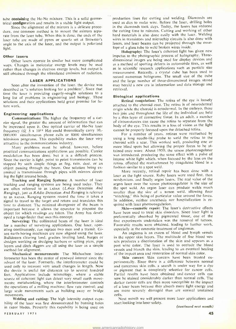
tube containing the He -Ne mixture. This is a solid geome- trical configuration and results in a stable light output.
Since the alignment of the mirrors is a delicate proce- dure, one common method is to mount the mirrors sepa- rate from the laser tube. When this is done, the ends of the laser tube are made of pyrex or quartz set at Brewster's angle to the axis of the laser, and the output is polarized light.
Other lasers Other lasers operate in similar but more complicated
ways. Changes in molecular energy levels may be used rather than changes in electron energy levels, but output is
still obtained through the stimulated emission of radiation.
LASER APPLICATIONS Soon after the invvention of the laser, the device was
described as "a solution looking for a problem ". Since that time the laser is providing eagerly- sought solutions to a long list of problems in engineering and biology. These solutions and their applications hold great promise for fu- ture work.
Engineering applications Communications: The higher the frequency of a car-
rier signal, the greater the amount of information that can be impressed upon it. One optical carrier of He -Ne laser frequency (@ 5 x 10'4 Hz) could theoretically carry 10; 000,000 simultaneous phone calls or 8000 simultaneous television programs. This capability makes the laser very attractive to the communications industry.
Many problems must be solved, however, before practical communications applications are possible. Carrier modulation has been done. but it is a difficult process. Since the carrier is light, point to point transmission can be stopped by such simple things as fog, rain. dust. or an object passing through the beam. One solution being ex- amined is transmission through pipes with mirrors direct- ing the light around bends.
Tracking and Ranging Systems: A number of laser tracking and ranging systems are being used today. They are often referred to as LADAR (LAser Detection And Ranging), just as RAdio Detection And Ranging is referred to as RADAR. Ranging systems record the time it takes a signal to travel to the target and return and translates this time to distance. The minimal divergence of the beam is
important because it allows the operator to pinpoint the object for which readings are taken. The Army has devel- oped a range -finder that uses this concept.
Surveying: The collimated beam of the laser is ideal for a number of surveying applications. One laser, oper- ating continuously, can replace two men and a transit. Gi- ant earth -boring machines are now aligned using the laser. Bulldozers clearing land, graders leveling land. barges or dredges working on dredging harbors or setting piers, pipe layers and ditch diggers are all using the laser as a simple method for alignment.
Mechanical measurements: The Michaelson inter- ferometer has been the center of renewed interest since the advant of the laser. Formerly. the interferometer could he used only to measure very small changes in length. Now the device is useful for distances up to several hundred feet. Applications include seismology, where a stable source of coherent light can detect very small earth move- ments; metalworking, where the interferometer controls the operations of a milling machine; flow rate control; and large scale movements such as building sway or bridge movements.
Welding and cutting: The high intensity output capa- bility of the laser was first demonstrated by burning holes in razor blades. Presently this capability is being used on
FEBRUARY 1971
production lines for cutting and welding. Diamonds are used as dies to make wire. Before the laser, drilling holes in the diamonds took days. Today, the lasers has reduced the cutting time to minutes. Cutting and working of other hard materials is also done easily with the laser. Welding wires in transistors and microchip circuits is also done with lasers, and laser beams can be projected through the enve- lope of a glass tube to weld broken wires inside.
Holography: The laser's coherent light has given new impetus to the photographic process of holography. Three - dimensional images are being used for display devices and as a method of spotting defects in automobile tires, as well
as in scientific research applications such as particle size measurement. Recently, a crystal cube has been used to record numerous holograms. The small size of the cube and the large number of three -dimensional images stored may herald a new era in information and data storage and retrieval.
Biological applications Retinal coagulation: I he retina of the eye is loosely
attached to the choroid coat. The retina is of neurodermal origin while the choroid is ectodermal. In the embryo, these two join and throughout the life of the individual are held by a thin layer of connective tissue. In an adult, a number of circumstances can cause the retina to separate from the body of the eye. This results in a loss of vision as the light cannot be properly focused upon the detached retina.
For a number of years, retinas were reattached by using a long needle -like probe to weld the retina to the choroid with a scar. This worked well, producing one or more blind spots but allowing the proper focus to be at- tained once more. About 1950, the xenon photocoagulator was introduced. producing the same effect with a pulse of intense white light which, when focused by the lens on the retina. effected the reattachment by coagulated blood in a
fashion similar to a spot weld. More recently, retinal repair has been done with a
laser as the light source. Ruby lasers were used first, then neodymium. and finally argon lasers. The real value of the argon laser over the xenon photocoagulator is the size of the spot weld. An argon laser can produce welds much smaller than the size of a xenon weld, allowing finer "stitching," this being of particular value around the fovea. In addition, neither anesthesia nor hospitalization is re- quired with laser photocoagulation.
Skin -cosmetic repair: The laser's destructive effects have been used to treat skin disorders. Since laser light is
preferentially absorbed by pigmented tissue, one of the first experiments undertaken was the removal of tattoos. Favorable results were obtained, leading to further work, especially in the cosmetic treatment of angiomas.
An angioma is an excess of blood and lymph vessels in the upper skin layers. The multitude of fine blood ves- sels produces a discoloration of the skin and appears as a port wine color. The laser is used to occlude the blood vessels and blanch the skin. leading to an eventual healing of the impact arca and restoration of normal skin color.
Skin cancer: Skin cancers have been treated ex- perimentally. Since there is a difference between normal and cancerous skin cells, a search is under way for a dye or pigment that is completely selective for cancer cells. Partial results have been obtained and cancer cells can now he stained considerably darker than normal cells. The darker cancer cells are then more susceptible to the impact of a laser beam because they absorb more light energy and are more severely damaged than are normal unstained cells.
Next month we will present more laser applications and start looking into laser safety.
(continued next month)
45
www.americanradiohistory.com

R4
CG
R3
C3
02
03
Fig. S -PARTS LAYOUT FOR PC BOARD. A 3 -in. length of No. 20
copper wire goes in hole A. Use 2-in. lengths in the other holes marked by circled letters.
BATTERY MOLDER
Fig. 6- UNDERSIDE OF FRONT PANEL with R7, 52 and battery holder in place. Tinned leads are run between corresponding points on panel and PC board.
A POCKET PIPPER by TOM ANNES
Fast risetime pulse generator you can build for about $12
Fig. 2- FULL -SIZE PATTERN for the PC board. Drill all holes with a No. 60 drill then drill or ream the center one to 3/s in.
46
RI
.1K R2 .47K C6-
5 pF
+ o
BATT 4.5V
It
2N3903 C2 C3 33pF 33pF
03 2N3903
.0027
SLOW
S2
FAST
02
2N3903 R6 220II
J1
OUTPUT
0027 TD-718
R5 46.752 1%
Fig. 1 -THE POCKET PIPPER is a handy source of 3 -nsec fast -rise square waves.
RADIO -ELECTRONICS
www.americanradiohistory.com

ULTRA -FAST -RISE SQUAREWAVE GENER- ators have many uses in conjunction with an oscilloscope. The first is ad- justing peaking coils and the delay line in the scope. This little Pocket Pipper, as shown in Fig. 1, with its risetime of less than 3 nsec, makes an ideal signal source for standardizing the transient response of oscilloscopes with up to 50 MHz bandwidth.
Checking video amplifiers and measuring their risetimes and band- widths is duck soup with this unit. Fault location in coaxial systems such as TV master antenna systems is an- other use for this little generator. This is done by using the Pipper as a pulse source and viewing the echos on an oscilloscope -a technique called Time Domain Reflectometry (TDR). This technique is also very practical for lo- cating faults in artificial delay lines. Since the Pipper has a known internal impedance, it can be used to measure the surge impedance of coaxial cable, delay lines and L -C filters.
The unit (Fig. 1) can be built for around $12.00. The battery is good for about 60 hours of operation. At 90 cents per battery, operating cost is about 11/2 cents per hour.
Construction is started by mak- ing a PC board per Fig. 2 out of G- 10 epoxy glass. Glue the clamping ferrule, fibre washer and R5 together as in Fig. 3. Punch or drill the case as in Fig. 4.
Start assembly by mounting the panel bearing on the PC board. Next, temporarily assemble the coax con- nector and R5 to the panel bearing. Mount and solder all parts to the board as per Fig. 5. Also solder into the board one 3" length (A) and seven 2" lengths (B -H) of tinned No. 20 wire. Make sure that all soldering is done with a minimum of solder and that all component leads are cut very close to the board. This is very impor- tant because clearance between the case and the PC board is only the
FEBRUARY 1971
thickness of the panel bearing mount- ing nut.
After the PC board is fully wired, remove the coax connector. Mount the PC board by using a sec- ond 3 /a "X 32 nut on the panel bush- ing on the outside of the case, then reinstall the coax connector. Next, mount C4 and CS on the speed change switch and mount it in the case using No. 2 screws, nuts and lock washers. Next, mount the battery holder with :y16" long No. 2 screws. nuts and lock washers. Bias control R7 is mounted by using a nut as a spacer inside of the case and a nut and flat washer outside the case. The knob is then mounted.
Final hookup is done hooking the eight (8) wires from the PC board to the controls and battery holder. Use Figs. 5 and 6 (on the first page of this article) as guides con- necting the leads between points marked by circled letters. The lead dress of the leads from R7 should be as shown in Fig. 7. One extra lead (X -X) has to be installed from the plus side of the battery holder to switch SI on R7. Install the battery and check the Pipper for proper oper- ation.
Hook the Pipper directly to an oscilloscope with the Pipper speed switch on FAST. Turn it on and slowly advance the bias control. At first the scope pattern should look like Fig. 8- C. As the bias control is advanced, this amplitude should increase to about 65 mV before the tunnel diode switches to the high amplitude state as shown in Fig. 8 -B. The fast positive transition is the portion that has an amplitude of about 400 mV. This is the proper bias. A further increase in bias will only cause a rounding of the
Fig. 3 -THIS RESISTOR (RS) sets the in- ternal impedance. Note how it is glued to the clamping ferrule and the fiber washer.
9/16"
13/16
5/8"
3/8" DRILL, 2 HOLES
NO.42 DRILL 4 HOLES
5/16"
5/8" 1.5/8"
2 -I/8"
13/16"
23/32"
13/16"
'4, 2-3/4"
7/16"
Fig. 4 -THE MINIATURE CASE is drilled or punched to the dimensions shown.
leading edge as shown in Fig. 8 -A. The frequency should be about 400 kHz.
Repeat this check with the speed changed to SLOW. The frequency of the square wave should be about 4 kHz. The optimum bias control set- ting should be practically the same for both speeds.
Next step is to repeat these tests with the output terminated in 50 ohms. The results should be about the same as earlier except for two things. First, the bias control should be more advanced for optimum, and second, the output amplitude should be half of what it was without a load.
The Pipper is designed to work into a 50-ohm load for optimum rise - time. The Pipper may be used without a load to double the available output voltage. This will increase the risetime somewhat and increase the falltime to about 20 nsec from the normal 5 nsec. The bias control has enough range to permit operation into a short circuit. This type of operation is also safe for the Pipper.
The output voltage is best ad- justed by using fixed attenuators or pads. However, it is practical to con- nect the Pipper across a 50 -ohm or 100 -ohm carbon potentiometer (don't use wire wound) and take the variable level out between the wiper arm and ground.
Parts substitution The frequency determining ca-
pacitors C2 through C5 may be changed to suit individual needs.
The BNC connector is a UG88 /U. A UG260/U will also work. However, make sure that the threads in the rear of the connector you select are 3/8" X 32, so as to mate with the panel bushing.
The bias control R7 must be a noninductive potentiometer. The one listed in the parts list is the only low - cost unit located that had a switch on
47
www.americanradiohistory.com

it and was small enough. An earlier model of the Pocket Pipper used a second slide switch as a power switch. This proved unsatisfactory because it always seemed to get turned on by ac- cident with a resultant dead battery.
Capacitor C6 bypasses any high - frequency noise that may pretrigger the tunnel diode. The listed value may
Fig. 7- UNDERSIDE OF POCKET PIPPER with all parts in place. Note how unused lug has been clipped off the potentiometer.
have to be changed if the parts layout is changed.
How it works Transistors Ql and Q2 form a
free -running multivibrator. Timing re- sistors R2 and R3 along with the tim- ing capacitors C2 and C3 give a fre- quency of operation of about 400 kHz. When the speed change switch puts C4 and C5 in parallel with C2
and C3, this reduces the frequency to about 4 kHz. The square wave in the collector of Q2 drives emitter follower Q3. Q3 drives the 10 mA tunnel diode TD -718 through R6 and R7. Pot R7 is on the front panel and is adjusted to set the peak current through the tun- nel diode just high enough to switch to the forward peak voltage.
This switching from the peak to the forward peak voltage is very rapid. The switching time (10 -90% ) is less than 3 nsec with a TD -718 in use. This switching time can be reduced to about 800 psec by using the more costly TD -253.
The use of a TD -253 tunnel diode will cause some ringing on the top portion of the square wave. The frequency of this ringing is about 3
GHz. This is too high to be seen on anything but the fastest of sampling oscilloscopes.
(a)
(b)
(c)
ilamr
=WM PnM t MIIMMEMMEM m:rrll pilorm
MUM= MMI MEMM
Fig. 8- OUTPUT WAVEFORMS. Rounded positive corners la) indicate bias control is advanced too far. Pattern b indicates that bias is correct. Bias control is set too low when output drops lc) to about 35 mV when output is terminated in 50 ohms.
The only problem that has shown up is the battery holder contacts. Make sure the battery terminals are clean and the battery is making good contact in the holder. Bend the ends of the battery holder inward if needed.
When the unit is first turned on and the bias control is adjusted for optimum setting, the unit runs for about 30 seconds and requires a read- justment of the bias control. This may be interpreted as a trouble. This it is not. It is caused by the battery voltage falling because of the load on it. R -E
PARTS LIST Resistors 1/2W, 10% Rl, R4 -1000 ohms R2, R3- 47,000 ohms R5 -48.7 ohms metal film, 1 %, Electra MF6C
or equal R6-220 ohms R7 -300 ohms, linear taper pot with spst
switch Centralab, F1 -300, Cl Taper, with SRS -010 shaft and KR -1 switch
Capacitors C1 -.05 µF, 20V C2, C3 -33 pF C4, C5 -.0027 µF C6-5 pF S1 -see R7 S2 -Slide switch, dpdt Continental -Wirt No.
G126 Ql, Q2. Q3- 2N3903 Dl -TD -718, tunnel diode (G -E) J1- UG -88/U BNC Connector Hardware Panel bearing. Johnson 115 -255 Case, 23/4 "x21/4"x15 /e" Bud CU -2100A or equal Knob, Raytheon 70 -3.2 Battery holder, Keystone No. 139 or equal Battery, Burgess AL -133 or Eveready 523 or
Mallory MN -1306 PC board 2 ea. 3/8 " -32 nut 1 ea. 3 /e" flat washer 4 ea. 3/16"x2-56 screw 4 ea. No. 2 washers 4 ea. No. 2 nuts 1 ea. No. 6 fibre washer
NOTE: The following parts are available from:
Tools For Electronics PO Box 2232 Denver, Colorado 80201
(1) Printed Circuit Board etched and drilled. -$1.50 postpaid
(2) R5 glued into the clamping ferrule, with BNC Connector and panel bearing.
-$2.25 postpaid (3) A full set of parts with a punched base,
PC board, and R5 glued into ferrule, less battery. -$11.95 postpaid
RESISTOR POLYGONS
Resistor substitution boxes are usually in a decade arrangement. However, a more economical, space - saving substitutor can be constructed by connecting resistors in the form of a polygon. A very simple resistor polygon is a triangle. This configura- tion is not too efficient because there are only three different resistances. More useful configurations are the hexagon and octagon shown. It can readily be seen that the total number of resistances possible is equal to the sum of the number of sides of the polygon and its diagonals. Thus the total number of resistances is N2-N
2 where N is the number of sides of the polygon or the number of resistors used. With only 30 resistors it is pos-
48
RESISTOR OCTAGON delivers 28 different resistances for substitution, yet requires only eight resistors. Expand this arrange- ment to 30 resistors, and you can get 435 different resistances.
RESISTANCE IN K CORRECT TO THE NEAREST HUNDREDTH
A B C D E F GH A - 2 00 21 52 54 66 91 12 160 0 227.5 245.1
8 2 00 - 19 6 52.66 95 55 159.6 226.9 2454
C 2152 19.6 - 34 7 6043 146.32 220.4 247.7
D 54 66 52 66 34 7 - 46 39 121.84 206 74 249.66
E 97.12 95 55 e0 43 48 39 - 62.72 162.9 24641
F 16.00 1596 14632 12146 6272 - 1275 2331
G 227.5 226 9 220 4 206 74 162.9 127.5 - 245.1
H 245.1 2454 2477 24916 24646 233.1 245.1 -
sible to have 435 different resistances! Connect a miniature test jack at each vertex of the polygon to accept a
pair of test prods. Make a table show- ing the resistance between any two vertices of the polygon. -l. T. Heydt
RADIO -ELECTRONICS
www.americanradiohistory.com

How To Use Operator by JOHN COLLINS
IN ALMOST ANN ARTICLE ABOUT impedance, reactance, resonant cir- cuits or phase angles -in fact, any feature of ac networks -you run into the letter "j ". Expressions like "Z = R + jX,.." or "E = 12 j16" keep turning up. You may learn that j is an operator (meaning that it in- dicates an operation), that the oper- ation is a multiplication by 1 and that the result is an imaginary num- ber.
This information may have been interesting, but did little to explain how or why j is used to describe elec- trical quantities in ac circuits, or why we should bother about imaginary numbers at all. An example may help to clear up the mystery. Suppose we have a 120 -volt ac generator con- nected in series with a resistor and ca- pacitor, as in Fig. 1. A voltmeter shows a drop of 96 volts across the resistor.
96V
X I t
Fig.I
Y
25
50 25 25
25 Ec(72V)
50
75
100 Y FEBRUARY 1971
EQ (96V)
áL ,, 1
"j" is an imaginary number used in
many electronic calculations. Here's
how you can use it effectively
What is the voltage drop across the capacitor?
A beginner might guess 24 volts (120 -96). But the voltmeter shows that the actual drop is 72 volts. The sum of the drops across the two com- ponents is much greater than the in- put voltage!
How is this possible? Look at the vector diagram, Fig. 2. Voltage E across the resistor is in phase with the current in the circuit (rises and falls in step with it) and is plotted on the horizontal axis. Voltage E,. across the capacitor does not keep in step, how- ever. Because the capacitor has to be fully charged before the voltage comes up to full, voltage lags behind current in a capacitive circuit.
In an ordinary ac circuit, this lag is a quarter of a cycle. The current is
at maximum just as the capacitor starts to charge, and voltage is at its lowest. As the capacitor charges, the voltage across it rises and current drops, till at full charge voltage is
maximum and current zero. Then, as
is the habit of alternating current, the voltage starts to go down, and the ca- pacitor to discharge, till it is dis- charging at maximum when the source voltage is zero.
This quarter -cycle lag (or current lead) is put down mathematically as a
90° lag, and is plotted on the Y axis at
FIG. 1 -SUM IS GREATER THAN THE WHOLE when ac is applied across a series R -C network. FIG. 2- VECTOR DIAGRAM of series R -C voltages.
50 7-5
100 'ors X
(120V) (Ec)
Fig.2
90° from the X axis. Mathematicians have a convention by which capacitive reactance is plotted below the origin (the point of intersection of the two axes) and called negative, while in- ductive reactance is called positive and plotted above the origin.
The resultant voltage ET can be represented by the diagonal of the rec- tangle in which E and E. are adjacent sides.
If the figure is drawn to scale, the diagonal will be approximately equal to 120 when the sides of the rectangle are 96 and 72. The relationship be- tween the voltages would be indicated this way: ET - 96 j72. The j sim- ply indicates that the line (or vector) representing the reactive part of the voltage must be rotated 90° to the vec- tor for the simple resistive part, to show its true relationship.
If we replace the capacitor with an inductor of equal reactance, the voltage drops will be the same, but the voltage across the inductor will lead the circuit current by 90 °. because the magnetic field building up around the inductor opposes the rising current. It is represented by a line on the Y axis above the origin. The equation then becomes ET - 96 + j72.
In ac circuits it is almost always necessary to deal with vectors, which are quantities having both magnitude and direction. A typical example of a vector is the diagonal in Fig. 2, which has a magnitude of 120 and a direc- tion at an angle below the X axis. Ev- ery vector can be described by a com- plex number consisting of a real term, plotted on the X axis, and an imagi- nary term, plotted on the Y axis: 96 j72, for example, is a complex number.
It may sometimes be necessary to add, subtract, multiply or divide num- bers containing j operators. Addition and subtraction are most common, and the easiest. Simply add the real and imaginary parts separately. Thus 6 j8 added to 5 j3 comes to I 1 j5. Multiplication and division are almost as easy, and the method may be learned without trouble from math books for electronic technicians, such as Nelson Cooke's Basic Math- ematics for Electronics (McGraw -Hill, $9.95) or Crowhurst's Basic Math- ematics, 3 volumes (Rider, $12.75).
R -1:
49
www.americanradiohistory.com

by LARRY ALLEN
Radio Shack TRC -24
Courier "Citation"
what's a frequency
Johnson Messenger 123
YOU'VE PROBABLY HEARD OF IT. CITI-
zens -band operators talk about it, and hams use it. If you fly a plane much, you've used it -maybe without know- ing..
Synthesis of frequency. "Putting a frequency together," a dictionary would explain. A design engineer would tell you its a way of generating a whole batch of frequencies with few crystals. A sensible (and maybe simple) explanation must lie some- where between these two vague de- scriptions.
The old two -by -four trick Suppose you want to generate an
X6 X1 X8r'X91 XIO XII 0 0 o c.7 o 0 I I I
I I MHz
11.050 10.95 10.85 MHz MHz MHz
11.0 MHz 10.9 MHz 11.10 MHz
8.6 MHz
synthesizer? Today's method of generating precise
transmitter frequencies
rf signal. You use an oscillator. If you want the frequency carefully fixed, you include a crystal as the tuning ele- ment.
Suppose you want to generate two different rf signals. Two os- cillators -and two crystals. For an ex- ample, just say one of them is 200 kHz and the other 300.
Now put them together in any kind of mixer. The output, if you re- member heterodyne theory, is four signals at four different frequencies. They are: the two original signals, plus one at the difference between the two and another at the sum of the two.
So, two new frequencies have
TTTT
7.5- MHz ose
1
Tó XI I
7.500 MHz
TO POWER AMPLS
8655 86358625 8615 kHz kHz kHz kHz
FIG. 1 -A HANDFUL OF CRYSTALS in a synthesizer replaces 23 crystals in typical CB rig.
50
been put together, or synthesized. They are 100 and 500 kHz. If you happen to need them, you have all four from only two crystals. What you've accomplished is simple fre- quency synthesis.
Of course, the numbers in useful frequency synthesis are seldom that simple. But the process is that simple mathematically, no matter how many decimal places are involved. Synthesis is merely creating new frequencies by signals from oscillators at appropriate frequencies.
Spanning the CB spectrum Frequency synthesis is old -hat in
communications. But only when it came to CB did it attract attention. For Citizens band, it's largely a nov- elty. After all, there are only 23 chan- nels in the first place.
And yet, done straight, that would require 46 crystals for transmit and receive. That's why most CB units have only a few channels. But syn- thesis does the same job with only 12 crystals. Look at how in Fig. 1.
This is the transmitter part of a modern CB unit. Channel 9 makes a good example; it's the road emergency channel. Frequency is 27.065 MHz.
Setting the selector switch to "9" connects crystals X5 and X8 to their oscillators. Frequencies are 8.615 and 10.95 MHz. These two oscillator sig- nals are mixed. Besides the original frequencies. the synthesis converter puts out sum and difference fre- quencies: 2.335 and 19.565 MHz.
The synthesis converter could be made to favor just one output fre- quency, but in this model it isn't. All four are fed to the second transmitter converter. There, they mix with a sig- nal from a crystal -controlled 7.5 -MHz oscillator.
RADIO -ELECTRONICS
www.americanradiohistory.com

Now you've got eight new fre- quencies, plus the first four, plus the 7.5 -MHz frequency. If you calculate them all, the list is: 1.115, 2.335, 3.450, 5.165, 7.500, 8.615, 9.835, 10.950, 12.065, 16.115, 18.450, 19.565 and 27.065 MHz. The only one you want is that last one, which should look familiar -it's CB channel 9.
The second converter is fre- quency- selective. A tuned tank picks out signals around 27 MHz and re- jects all the others. The 27.065 -MHz product of this synthesis is thus sent on alone to the transmitter amplifiers.
Various combinations of the 11- MHz and 8 -MHz crystals can synthe- size the frequency of any other CB channel. For example, channel I : The 8.615 and 10.85 crystals produce 19.465: mixed with the 7.5, that synthesizes 26.965 MHz.
Or channel 11: The 8.635 and 10.95 crystals make 19.585; add the 7.5 and you have 27.085 MHz. Or channel 23: The 8.655 and 11.1 crys- tals add up to 19.755: the 7.5 brings it to 27.255 MHz. Thus, 23 channels of CB transmitter frequencies are synthe- sized from only 11 crystals.
The same synthesizer can be used for receiving. This is done with the setup in Fig. 2.
Remember from the transmitter calculations that the channel fre- quency is always 7.5 MHz above the synthesis frequency? Beat the in- coming CB signal (after am- plification) with that channel's syn- thesis signal and you get 7.5 MHz. That is taken from the mixer by a 7.5 -MHz tank.
From there it's easy to convert the signal to any i.f. In the example, an oscillator with a 7.975 -MHz crystal feeds another converter. It beats the 7.5 -MHz i.f. down to 475 kHz. A low i.f. is handier to amplify; selectivity can be sharpened easily.
If you've kept count, you know that 46 separate frequency functions are now being handled by 12 crystals. It's done by frequency synthesis.
The all- country ham Frequency synthesis can simplify
a receiver that must tune signals within a certain spectrum or band. This is what happens in amateur (ham) radio.
A ham receiver covers little bands of frequencies at widely sepa- rated spots in the spectrum. For ex- ample, the 80 -meter band covers from 3.5 to 4.0 MHz; the 40 -meter band from 7.0 to 7.3 MHz; the 20 -meter band from 14.0 to 14.35; the 15 -me- ter band from 21.0 to 21.45; the 10- meter band from 28.5 to 29.7 MHz. As you can easily imagine, to produce
FEBRUARY 1971
such diversity of frequencies directly with crystals would demand a fantas- tic number. A variable -frequency os- cillator (vfo) to cover them all would mean having a lot of tuned circuits and switching. You can easily imagine double the trouble in a transceiver.
Frequency synthesis is a solution. Here's an example (Fig. 3) . This single -sideband transceiver, in transmit mode, generates first a 9 -MHz carrier. Then the single -sideband modulation is added. The 9 MHz has to be hetero- dyned up or down to the various out- put frequencies of the transmitter.
For 80 and 20 meters, it is done rather simply. A vfo that tunes 5.0 -5.5 MHz heterodynes with the 9- MHz sideband signal in a frequency converter (called translator, some-
11 MHz
8.6MHz
RF AMPL
27 MHz
ISYNTHESIS CONVERTER
FROM OSC AND
times). The difference tuning range is
3.5 -4.0 MHz; the sum range is 14.0 -14.5 MHz. Band -selector tanks in the output of the converter pick out which band is fed on to the output amplifiers.
For the other bands, a synthesis converter is switched in. Output from the vfo is combined with output from a crystal oscillator. Here's what hap- pens.
Take the 40 -meter band. The switch connects the outputs of the 21.5 -MHz crystal and vfo to the syn- thesis converter. Another switch sec- tion feeds the output of the synthesis converter to the main frequency con- verter.
The 21.5 MHz and the 5.0 -5.5 MHz synthesize a 16.0 -16.5 -MHz
75 MHz
475 TO kHz 475 -kHz
FIRST RCVR
CONVERTER
SECOND R VR
CONVERTER I. F.AMPLS ETC.
19.5 MHz RCVR OSC
9- MHz AMPL
5.0-5.5 MHz VFO
FIG. 2 Itopl- RECEIV- ER CIRCUIT of CB rig at left. FIG. 3 I right) - FREQUENCY SYN- THESIZER of ham - band set that covers the bands in 500 -kHz segments.
r,
L
J FREQUENCY 11 CONVERTER
80 40
X12
T 7.975 MHz
BAND - SELECTOR
TANKS
TO OUTPUT AMPL
20
SYNTHESIS CONVERTER
8 0 of0 40v
20
80
CRYSTAL OSC
40q
o
20
10 (H11
10(LO)
015
0 0 0 0 T T -V- 21.5 35.5 42.5 43.0 MHz MHz MHz MHz
51
www.americanradiohistory.com

(difference) range of signals. Beat with the 9 -MHz sideband signal, that makes a 7.0 -7.5 range of sideband signals. All other differences and sums are blocked by a band -selector tank tuned to center on 7.2 MHz.
At 15 meters, the synthesizer produces 30.0 -30.5 MHz. That con- verts to 21.0 -21.5 MHz.
It takes two crystals to cover the 10 -meter band. The lower half uses a 42.5 -MHz signal in the synthesizer; output is 37.0 -37.5 MHz. That con- verts to 28.0 -28.5 MHz. For the up- per half, a 43.0 -MHz crystal produces
OSC WITH 7th OVERTONE CRYSTALS
118 119 120 121 122 123 124 125 126
146.095 147.095 14 8.0 95 149.095 150.095 1 51 .095 152.095 153.095 154.095
127 128 129 130 131 132 133 134 135
radio in a plane today must transmit and receive on every talk channel from 118.0 to 135.95 MHz. Channels are only 0.05 MHz apart. That's 360 channels. A navigation receiver covers 108.0 to 117.9 MHz; with 0.1 -MHz channel spacing, that's 100 channels. The clincher is that all these must -by law -have crystal accuracy and stabil- ity. Naturally, a synthesis system is the only practical way.
The diagram of Fig. 4 gives you an inkling how one modern aircraft transceiver covers 360 channels. The solid arrows show receiver signal
OSC WITH 3rd
RTONE XTLS
.0 .I .2 .3 .4 .5 .6 .7
8 .9
23.595 23.495 23.395 23.295 23.195 22.095 2 2.995 22.895 2 2.795 22.695
TO XMTR POWER --- AMPL$
MIXER FOR
I - MHz STEPS
/
/ i
27.5 -MHz -AMPL
- J
XMTR OSC
118 - 126.95
127- 135.95
^MHz 'KNOB
RCVR OSC
DIAL XTAL DIAL XTAL
.00
.05 4.500 4.450
.00 .05
4.045 3.995
.00 .05
4.500 4.550
.00 .05
4.045 4.095
MHz KNOB
__
MIXER FOR
0.1 -MHz STEPS
4.5-MHz AMPL
MIXER FOR
0.05 - MH z STEPS
TO 455 -kHz AMPLS
ETC.
(127 -135 MHz) FIG. 4- SYNTHESIS PERMITS DIGITAL FREQUENCY SELECTION in aircraft commu- nications transceiver. Set represented here covers 360 channels with only 23 crystals.
a synthesizer output of 37.5 -38.0 MHz, which converts to 28.5 -29.0 MHz.
The receiver can use the same converters, crystals and vfo with care- ful planning. The advantage is ob- vious. This vfo can be extremely stable and simple, since it has to cover only a narrow range of frequencies. And they can be spread out over a wide dial, making accuracy high. Crystal bandswitching improves ac- curacy even more.
Fly along with decimal synthesis Where frequency synthesis really
shines is in fixed- frequency com- mercial communications. Aircraft nay -corn receivers and transmitters are the best example.
A complete pilot- communications
52
paths. Nine crystals, oscillating l MHz apart at vhf (on their seventh over- tone), create i.f.'s around 27.5 MHz or 18.5 MHz, depending on the fre- quency of the received signal. A dig- ital dial on the switch shaft shows which MHz frequency has been se- lected. One deck of the MHz -step switch picks the right i.f.
The 27.5 or 18.5 i.f. goes to a mixer for 0.1 -MHz steps. Ten third - overtone crystals give a selection of frequencies to beat with whatever i.f. comes to the mixer. The result is around 4.5 MHz.
Finally, one of three low -fre- quency crystals puts a signal into a mixer for 0.05 -MHz steps, beating the signal down to a 455 -kHz i.f. Three stages of synthesis thus provide crystal control of all 360 receiving channels,
using only 25 crystals. The digital dials on the three switches read in decimals, and the frequencies received are in steps of 0.05 MHz.
A quick example makes it clearer. Suppose you want to receive 119.50 MHz. You set the MHz dial to 119, the 0.1 -MHz dial to 5, and the 0.05 -MHz dial to 0. Here's the syn- thesis.
The MHz switch picks the 147.095 -MHz crystal. Its signal mixes with 119.50 to make a 27.595 -MHz i.f. The MHz switch has also picked the 27.5 -MHz i.f. amplifiers.
The 0.1 -MHz switch has picked the 23.095 -MHz crystal in the next oscillator. That mixes with 27.595 MHz and forms a 4.5 -MHz i.f., which is also amplified.
The 0.05 -MHz switch, set for 0, puts a 4.045 -MHz crystal into its os- cillator. That mixes with 4.5 MHz to create a 455 -kHz i.f. That's amplified and sent on to the detector.
Another quick example: receiv- ing 131.65 MHz. The crystals picked by the switches are the 150.095, 22.995 and 4.095 (they're in the charts) .
The 150.095 -MHz crystal makes an 18.445 -MHz i.f. from the 131.65 - MHz received signal. The 22.995 - MHz crystal beats that down to 4.550 MHz. And the 4.095 -MHz signal mixes with that to make 455 kHz.
Transmitter synthesis works in just the opposite direction. The dashed arrows in Fig. 4 show transmitter sig- nal flow. When you set the knobs and dials for a receive frequency, another switch deck on the 0.05 -MHz dial sets up transmitter crystal synthesis at the same time. The only change is in this low- frequency oscillator crystal.
Example: transmitting 119.50 MHz. The crystal the 0.05 -MHz switch selects is 4.500 MHz. The sig- nal is amplified by the same amplifiers used for receiver i.f. In the 0.1 -MHz mixer a 23.095 crystal (same as for receive) translates the signal up to 27.595 MHz. And the MHz -step mixer, heterodyning that with the 147.095 vhf crystal forms an output of 119.50 MHz. Tuned tanks keep any other sums or differences from reaching the output amps of the trans- mitter.
Example: transmitting 131.65 MHz. The low- frequency crystal is 4.550 MHz. The 22.995 crystal heter- odynes that -actually producing both 27.545 (sum) and 18.445 (difference). But the MHz switch se- lects the 18.5 -MHz amplifier when it is for 127 MHz or above. So only 18.445 MHz reaches the last trans- mitter mixer. The 150.095 crystal het- erodynes the 18.445 MHz to 131.65 MHz. R -E
RADIO -ELECTRONICS
www.americanradiohistory.com

t office atn 2 lncorPn'
atric prodltals
Un3_tecl FIc l_fint edition. _Sylvania f b and 1 har c¡r
Circuits ---Sylvania paLa. usef tll as Il: `
sidur rieht been quite 1, described rated-coP)'
ha.e ent lmlbs t cells. this tYl ' cn
3.37S.;1ç .'X(11.tllt'sCHNT (-ilauis of
with the use of ¡na:ur"cledrulurrti,,_.. or .. i'.h of t- l(i K-. l
1 cuit:, both publication that the lamp the higher
f volt 1.1. . 10021 the above Pt
¡n the art u to provide u
( 1ü('t't l (.1:,1.1 ti orl:, ` 1. 5 in f;lro.. n
w o
hl.:ti111'.R tit., es g35 It is well replaced
with a transformer ,cent aa the P'tte:;t
to
('u{r<:arr xlt('- ,a0) , can he
required b} c1a`la:u!IVr¡nlo..nour
c. this .ultiu.,í , k.. 9 tier. No. 5
ltohcrt 1 0.1.2.3, : (Cl. ;5-- voltage , 1111. Of a Ji,a:l,.iun l u;r("rtttcrt.\ 3.u_b. further i ¡lc Claims. ( suah d, Patcnt ;:: 1)C l0 ..'ell
dli:CC
ane inohcri' ( flasher frequency aonni,tur'
Alitií a¡tau¡t fl-,t, ui
ua:r. ,,,cr r' -lhc flasher the PnrP base irau¡t 1.d. tn lha ra,lllh. f, T
circuit to pst circuit -t,a¡rtc t,..at ira baak a ,_ood Il }li,_h P
in thc fcad' itrovida and
n,.fu¡:a a}alati for l:i thiti eirau t `Iti.c 1` !' r
du(' u,
circuit `,\'hilc are a`p t:1:ui`a ra` ' l. ,h;r 11-
ot t1lnrlmrPl'r Iasli';au,tll 1
,lile ,;lts r
i±:ì11 that nr::', ban .,!,1.' Ila ,ir:
It ha, thcrafutt not 11--
oil in j:1(,l:,ftl`- I
. ,¡un ate 1'. ,}.. ,
3,313,315
patented Mar. 12 1968
h cùi:¡,n. P` f.,l d,r.1.1- A h¡; A(' .,,Ita:-
voltat'.e to all
otl,ar 1o:1,1s.
to :, t .t a Iv,
relates ,anet.,11. rt¡ Miar )' t 1lar.lt i,.vrnt¡on la`'`ll :au1. mote P, u;tai e
I `'i ` r.,b1c and P a r. ait 1
.trt,!un,inc>- 1,:,1 ,rin± c.t t lu`.-P,r..arc.l. .a¡ç.tt,
il;c. ataa,n,lu. f:l,,,l'c
:tnt1 ' PATENT TALK
It was just two minutes before game time when Jim settled down in front of the TV. The sound of the door chimes brought a warning that his plans were about to be interrupted. The caller was his next door neighbor.
"Hi Fred. Come in, you're just in time for the game." "No thanks. I haven't got time. I just want to get some
information. You know I fool around with radio and I was working with my rig the other day when I got a great idea for a new type of antenna. So I figured that since you're a patent attorney, maybe you could tell me . . ."
After a typical week of working out arguments to con- vince patent examiners that this or that client's invention was the greatest thing since DeForest added a grid to the vacuum diode, Jim was in no mood to hear about another "great idea" -and the game had just started. He countered quickly, "Why don't we go in and watch the game and you tell me all about your idea afterward ?"
Fred wasn't going to be sidetracked that easily. "Let me tell you about this first, Jim. It will only take a
few minutes." He had that all too familiar look of the inventor with
just one thing on his mind -his "great idea." Jim knew there was no sense trying to dissuade him.
"Go ahead." he said weakly. Fred glowed. "Well, you see I've got this idea for a new
type of variable length mercury -column antenna that can be tuned to a hair's breadth and I figured I might as well get a patent on it. I thought that you could tell me where I
can get the necessary application forms so that I can get a patent right away."
"Wait a minute, Fred. It's not quite that simple. You don't just fill out an application and get a patent automatically."
By this time they had settled down on the front steps
FEBRUARY 1971
by ARTHUR S. COOKFAIR
"Hey Jim, how do I get a patent?" "W ell Fred, that's what titis article is all about."
and Jim could feel his chances of seeing that game getting more and more remote.
"Fill me in, Jim. What's the procedure ?" "First of all," Jim said, "it's best to have a patent search
made to find out if your idea is new." Like many inventors, Fred was so convinced of the nov-
elty of his invention that he couldn't conceive of anyone having thought of it before him.
"I keep up on the latest hardware in this field" he ex- plained, "and I'd know if anyone had an antenna like mine on the market."
"No doubt," said Jim, "But remember that in the last 175 years the U.S. Patent Office has granted more than three million patents. Many of them are good ideas that for one reason or another were never marketed. Sometimes an inventor will get a terrific idea but find that he can't get anyone interested in it. For instance, when Richard Carl- son received his patent on xerography, he took it to twenty companies over a period of five years before he got anyone interested in developing the idea. A less persistent inventor might have given up, but the patent would still be in the records. Sometimes an inventor is just too far ahead of his time. Supposing someone patented an antenna like yours back in the early I 900's. when radio was just getting started. The idea might have been ignored and then forgot- ten because the world of electronics wasn't ready for it."
Fred looked surprised. "Would that stop me from get- ting a patent on it ?"
"I'm afraid so. You see, if the same idea was available to the public or appeared in a printed publication (such as a patent) before your invention of it, you are not entitled to a patent."
"What if I disclose the invention myself ?" Fred asked. "I've been thinking of making a few of these antennas and
53
www.americanradiohistory.com

Your paycheck
lot about you
It tells you more than how much you make. It tells you how far you've come. And if your paycheck looks very much the same as it did last year, or the year before, it simply means that you look very much the same as you did last year and the year before.
But times change, and you should be changing with them. Old dull jobs are disappearing. New ex- citing ones are being created. There are challen- ging new fields that need electronics technicians ...new careers such as computers, automation, television, space electronics where the work is interesting and the earnings are greater.
RCA Institutes has one of the nation's largest and most respected home study schools devoted to electronics. They can get you started even if you've had no previous training or experience. RCA Insti- tutes has developed a faster, easier way for you to gain the skills and the knowledge you need for a fascinating, rewarding electronics career. And you don't have to quit work and go back to school. With RCA Institutes Home Study Plan you can do
FEBRUARY 1971
both. You set your own pace depending on your schedule. Check over these RCA benefits:
You get Hands -On Training -over 300 experi- ments and as many as 25 kits with some pro- grams. You get RCA's unique "Autotext" method of learning - individual programmed instruction, the easy, faster, simplified way to learn! You get the widest choice of electronics courses and programs- everything from Elec- tronics Fundamentals right up to Solid State Technology and Communications Electronics. You get a selection of low -cost tuition plans!
Sounds great, and it is! For complete information, without obligation, send in the attached postage paid card...or return the coupon below. That will say a lot about you.
Veterans: Train under new GI Bill. Accredited Mem- ber National Home Study Council. Licensed by N.Y. State -courses of study and instructional facilities approved by the State Education Department.
RC1 Institutes Home Study Dept. 758 -002 -1 320 West 31st Street, New York, N. Y. 10001
Please rush me FREE illustrated catalog. I understand that I am under no obligation.
Name Age
Address
City State Zip
(please print)
L Veterans: Check here
If reply card is detached - send this coupon today
57
www.americanradiohistory.com

selling them. Do I have to apply for a patent first ?"
"No, but you must apply for a patent within 12 months after your first public use, disclosure or sale. After that you
are barred from getting a patent." "Can I make some models and mark them Patent
Pending' since I'll probably file a patent application within a year ?"
Jim responded with an emphatic "No." and went on to
explain that terms such as "patent pending" and "patent applied for" can only be used to inform the public that a
patent application is already on file in the United States Patent Office. Misuse of such terms can result in a heavy fine.
"What if someone else tries to patent the same in-
vention?" Fred asked. "Who gets the patent ?" "When two inventors file separate applications on the
same invention," Jim answered, "the Patent Office starts a
procedure called an `interference'. This is an investigation to find out which applicant made the invention first and is
legally entitled to a patent. Each party may be called on to prove his date of invention."
"I've heard that I can establish proof of my date of invention by describing it in a letter, sending it to myself by registered mail and then keeping the letter unopened until it's needed for proof. Is that a good idea ?"
"It's not a good idea." Jim replied. "It is a common misconception that you can protect your invention that way. But you should keep good written records of your ideas and experiments and have a trustworthy friend follow your progress and read and witness your records. If you should have to prove your date of invention later on, that person can corroborate your statements. It's also a good idea to keep records of purchases and other correspond- ence relating to your invention."
"Do I have to send a model of the antenna to the Patent Office ?"
"It's not likely." Jim replied. "The Commissioner of Patents has the authority to require a model, but it is seldom asked for -except in cases where the Patent Examiner has reason to doubt that an invention will work, for example, where the invention is supposed to be a perpetual motion machine."
"What information do I have to reveal in a patent appli- cation?" Fred asked.
"The patent laws require that you provide a written de-
scription of your invention in sufficient detail so that a
person of reasonable technical skill (electronics technology in this case) could make and use the invention from your description. You're also required to point out what you think is the best way of carrying out your invention."
"Why is it necessary for me to give away so much infor- mation about my invention ?"
"It isn't exactly a give- away." Jim explained. "It's more like an exchange between you and the public. You see, the idea behind our patent laws is that you, as the inventor, disclose your invention in return for the grant of a patent. The patent gives you a monopoly on your invention for 17
years. In return, you have supplied the necessary informa- tion so that after your patent has expired others will be
able to practice your invention." "It sounds as if a patent application might be difficult to
write." Fred remarked. "Do I need legal help or can I do it
myself ?" "An inventor is legally entitled to handle his own patent
application. However very few do." Jim explained. "It takes a good deal of know -how in patent law to do an
effective job. A famous judge once said that a patent appli- cation is one of the most difficult of all legal documents to prepare. The Patent Office, while permitting an inventor to handle his own case, recommends that he seek the aid of a
registered patent agent or patent attorney."
58
"How long does it take before a patent is granted ?" "The average time is about two and one half years." "Why so long ?" "The Patent Office receives more than 1600 patent ap-
plications each week. At present there is a back -log of about 200,000 applications and it takes about a year before an application comes up for action by a Patent Examiner. The examiner must study the application from both a tech- nical and legal standpoint and make a search of the patent and technical literature to determine patentability. Then there is an exchange of opinions and arguments between the Patent Examiner and the applicant (or his attorney or agent) as to the patentability and the exact definition of the invention. The outcome is either a rejection (which may be appealed) or the granting of a patent. The Patent Office issues more than 1000 patents each week (somewhat more than half of the applications filed.) Incidentally, a patent search before filing is a great help in determining the chances of getting a patent.
"A patent application on your invention," Jim went on, "would probably be assigned to a Patent Examiner who is
an expert on antennas. You see each examiner is a special- ist in some area of technology as well as in patent law."
"Supposing I get a patent on my antenna," Fred ques- tioned, "and someone infringes on my patent. Will the Pat- ent Office help me prosecute the infringer ?"
"No." explained Jim. "The Patent Office doesn't have jurisdiction over infringement matters. It would be up to you to sue the infringer in a U.S. Court."
"Would the patent give me protection in other countries ?"
"I'm afraid not. Each nation has its own patent laws. A United States patent can protect your invention only in this country. To obtain protection in other countries you would have to get a patent in each country -and that can be pretty expensive."
After a thoughtful pause, Fred responded, "It looks as if there's a lot more to patenting than I had imagined. It would probably be a good idea for me to learn a little more about patents before I go ahead with my invention. Where can I get more information ?"
"I have some material in my desk that would be help- ful." said Jim, as he disappeared through the door. He returned a minute later and handed Fred some pamphlets.
"These are government pamphlets relating to patents. I-hey are written for inventors like yourself and they offer a great deal of basic information and advice on the sub- ject."
A quick glance at his watch told Jim that the game must be nearly over. With a barely audible sigh of dis- appointment, he said: "I hope the pamphlets will be of some help."
"Thanks. Maybe this information will help me decide whether to try to patent my antenna.
"By the way Jim, I've been recording the game on my new video tape recorder. How about coming over to my place -I'll fix a couple of cold drinks and we can watch the play- back." R -E The following patent pamphlets may be purchased from the Superintendent of Documents, Washington, D.C. or through any field office of the U.S. Department of Corn - merce: General Information Concerning Patents $ 30 Patents and Inventions, An Information Aid For Inventors
$15 How To Obtain Information From U.S. Patents .... $.20 A single copy of the pamphlet: "Answers to Questions Frequently Asked About Patents" can be obtained free of charge by writing to The U.S. Patent Office, Dept. of In- formation, U.S. Department of Commerce, Washington, D.C. 20230. R -E
RADIO-ELECTRONICS
www.americanradiohistory.com

Transistor video amplifier with video peaking and brightness controls
Kwik- .Fix'" Icture_and waveform charts .iii&o,dimilift.c.aingsaigisik SCREEN SYMPTOMS AS GUIDES
SYMPTOM PIC DESCRIPTION
Pic goes out of focus and then dark as brightness is turned up
Q1 collector
not much help
PART
R2. R3, RS, R6, R8, R10. R11, C3
atti washed out
Picture dark; not enough brightness
WHERE TO CHECK FIRST VOLTAGE I WAVEFORM I
much
Q1 base Q1 emitter
P`.c too bright and Q1 base out of focus: Q 1 emitter brightness control has little effect
.111111u...
r Screen black
Q1 collector mconclusiae
AWBEIMPOINIIIMF.
R4. R6. R7. R11, á212., C%.,
L1.. Q1
1
Contrast too high: brightness control can make picture out-of-focus
Picture too bright; focus okay: brightness control has little or no effect
Pix Peak control has no effect
not much help
Q1 emitter
inconclusit,e
inconclusive
no no
help help
U I I:.S:
Use this ,guide to help you find which key toltage or wave- form to check first.
.Study the screen and the action of the three controls. The most helpful clues for the symptom are found at the
key test points listed.
RS. R7. á28g
R9. R10. CS
C6 R12
an Easy Read' '' feature by FOREST H. BELT & Associates 1971
Make voltage or waveform checks as. suggested. Use the Voltage (;aide and Waveform Guide to analyze
the results of those tests. For a quick check, test or snhstitute the parts listed as the
most likely cause of the symptom.
www.americanradiohistory.com

DC VOLTAGES AS GUIDES
to zero very low low slightly low slightly high high change -4 Ql base Normal 7 V
''5.5 at max brightness
R7 shorted R5 open R7 low
R3 open' R7 low R8 open R9 open C5 shorted Q1 faulty
R2 open, high R6 open R8 high
R7 open
Ql emitter Normal 6.5 V
`'5 V at max brightness
R7 shorted R7 low R3 open' R7 low R8 open R9 open C5 shorted Q1 faulty
R2 open, high R5 open R6 open R8 high
LI open R7 open R8 low RII open R12 open
Q1 collector Normal 15 V
"18 V at max brightness
Q1 faulty R4 open, high R11 high R2 open, high R3 open R5 open R6 open R7 open R8 low R11 open R12 open LI open Q1 faulty
'Volts low because of Brightness setting
NOTES: Use this guide to help you pinpoint the faulty part. Measure each of the three key voltages with a vrntt. For each, more across to the column that describes what- ever change you find in that voltage.
.01.052.01
WFI
FROM FIRST VIDEO
60
)1( Cl 25rF N.P.
RI R3 I5K IK
27K
Notice which parts might cause that change. Finally, notice which parts are repeated in the .- omhination of changes you find. Test those parts individually for the fault described.
Mh R6 I0011
COLOR COMMANDER
(CONTRAST SECTION)
24V R4 8211
C3 RS 50pF
3.3K
PIX PEAK
WF2
7V
wlltillw'
6.5V
WF4/
I5 V
01 SECOND VIDEO AMPL
_L C4
RII 2211 C5
39OpF
I
R12 30011
_L C6 T.0022
R7 27011
RI3 10011
.0039
TO DELAY LINE AND THIRD VIDEO AMPL
RIO 1.3K
24V
WF5
WF6
R8 47011 BRIGHTNESS
R9 50011
24V
I I ,
,.....,...rte..
111111111114
RADIO -ELECTRONICS
www.americanradiohistory.com

THE STAGES This video amplifier is used in transistor and hybrid
color TV sets as well as in some monochrome set. The stage used for this example is in a Zenith 4B25C19 color chassis. One distinction is the contrast potentiometer ganged with a chroma -level pot; together they're called COLOR COMMANDER. But that part of the dual pot works the same as an ordinary contrast control in any stage like this.
There are connections to this stage which arc not shown. They will be covered in the next two Kwik -FixTM features. This one involves only the Y- signal (video) por- tion of this section.
SIGNAL OPERATION A 2.5 -volt p -p video signal is coupled into the stage
from the first video amplifier (an emitter follower) by Cl. The input load is R3, the contrast section of the COLOR
COMMANDER control, and R4. Capacitor C3 decouples them from R5 (which is an input load for signals from certain other stages, see the two following issues). Small -value C2 is for frequency compensation. The position of the R3 slider sets how much video signal is applied through R6 to the base of Ql.
The transistor is wired as a common -emitter amplifier. It gives a healthy boost to the video -signal amplitude, as you can see by comparing WF2 with the video portion of WF3. R 10 is the output load for the collector of Q I.
In the emitter circuit, LI and C4 resonate (LI is ad- justable) to trap out any beat signal that may develop be- tween the chroma and sound carriers when they mix together 41 the video detector.
A network of resistors and capacitors constitutes a peak- ing circuit in the emitter circuit of Ql. They are R11, C5, R13, R12 (the PIX PEAK control), and C6. Adjusting the slider of R12 lets C6 have more effect or less; turning the slider toward the bottom of the control sharpens video peaks.
DC DISTRIBUTION For all practical purposes, the input of this stage is ac-
coupled. The output, however, is dc- coupled. Base voltage for Q1 is developed from the 24 -volt dc
supply, with R2- R3 -R4 -R5 forming the divider. Moving the slider of R3 has almost no effect on the voltage measured at the base. because the value of R3 is only a small portion
of the whole divider. The collector supply comes through R10, from the
24 -volt dc line. There's also a dc source not visible in this schematic, through the delay line. That's why an open R I 0 doesn't remove collector voltage.
The emitter dc circuit has several branches. You can see two paths to ground in this schematic -through R11 -R12 and through R7. Voltage for the emitter comes mainly from the 24 -volt line, through R9 (the BRIGHTNESS control) and R8. R9 can control brightness on the picture -tube screen because of dc coupling from this stage to the third video amp and from that stage to the picture tube.
An unseen stage, the automatic brightness limiter, also affects dc voltage at the emitter of QI; the interrelationship will be explained in the next Kwik -Fix".
SIGNAL AND CONTROL EFFECTS Station signal does affect the amplitudes of video
waveforms WFI and WF2. But the effect on WF3, WF4, WF5, and WF6 appears slight. That's because those wave- forms are dominated by blanking pulses. The video portion is only a small bit along the bottom. Station signal has almost no effect on dc voltages.
Control R3 affects the amount of video passed on to Q1. For testing, a setting about two -thirds of full clockwise is standard. It affects amplitude of WF2 directly, but only affects the video portions of WF3 through WF6.
The effect of the peaking control is noticeable only on the screen. You can't see its effect in waveforms nor in dc voltages.
R9 does affect dc voltages. It alters emitter and base voltages about a half -volt, and shifts the collector voltage as much as 3 volts. For testing, again the best setting is about two -thirds up.
QUICK TROUBLESHOOTING You have two things to consider in this kind of video
stage: how it handles signals, and its dc operation. If the symptom is in the video level -the contrast of the pic- ture- chances are the scope will be the most help to you. If raster brightness is the problem, you'll get to the root quicker with your vtvm.
Also study the action of the three controls. You can pin down many borderline faults by testing the circuit in which a control doesn't work right. R -E
(1Varefarms continue on pages 62 and 63)
WAVEFORMS AS GUIDES
at' 0511
WF1 Normal 2.5 V p -p
This is the input waveform, coming from the emitter of t'ie first video amplifier stage. Polarity is the same as the signal right out of the video detector, with sync pulses pointing negative. This waveform is displayed at the horizontal rate, because the vertical -rate wave- form doesn't show much information of value.
V p-p Inw V p -p high V p -p zero
1l" 0.4 V p -p Cl open
www.americanradiohistory.com

WAVEFORMS AS GUIDES
WF2 Normal 0.7 V p -p
Taken at the base of Q1, this waveform is the signal from the slider of R3, the contrast con- trol. The amplitude listed here is about normal to produce a picture with good gray scale, if all the stages from here to the picture tube are working properly. Control R3 is set about two- thirds clockwise. The scope locks this wavform best in the negative sync mode.
V p -p low V p -p high V p -p zero R3 open
.irf M4`,
0.2 V p -p Cl open
`r 8 V p -p C3 open
1 . I
-...{rr+L ' 1
5 V p -p R6 high
WF3 Normal 13 V p -p
Taken at the collector of Q1, with the scope set to show horizontal pulses. The horizontal r r
blanking pulse dominates the waveform, leaving only a small part-about 3 volts p -p -of the overall amplitude taken up by video. The scope locks this waveform best in the positive sync mode.
OM
V p -p low R2 open R7 open R10 low
V p -p high V p -p zero R5 low R11 open R12 open C3 leaky L1 open Q1 faulty
-`-"- 13 V p -p Cl open
-..^..." .... -' ,..., -, 13 V p -p
.....1-in,.. ,rte
4 V p R3 open
'. - - 13 V p -p R4 open p en
. .
13 V p -p R7 low
' R2 open
¡ li r
10 V p -p
R6 open
15 V p -p C3 open
20 V p -p R6 high
WF4 Normal 13 V p -p -Y - This waveform also is taken at the collector of Q1, but with the scope set for vertical frames. Again, the dominant feature is the blanking pulse -vertical blanking 'n this case. If you look closely, you can see vertical sync pulses between each frame of video. The scope locks this waveform best on positive sync.
V p -p low R2 open R6 open R7 open R10 low
V p -p high V p -p zero R6 open R11 open R12 open L1 open Q1 faulty
' V. X f . I.
20 V p -p R7 low
--'r+fç..t 13 V p-p C3 open
13 V p -p
Cl open
WF5 Normal 2.5 V p -p
Taken in the emitter circuit of Q1, with the scope set to show horizontal pulses. Video is almost not noticeable, being overshadowed by the horizontal blanking pulses. Blanking is
I I positive -going here, the same as in the collector circuit; being applied at the emitter, the blanking signal isn't inverted by the amplifier (the video is inverted, being applied at the
01.1111.4 01110111111411.041.1 base).
V p -p low R7 low C5 shorted
V p -p high R11 high
V p -p zero R2 low
'
2 V p p
Cl open
,
4 V pp R2 open
4 V p -p R3 open 1.5 V p p
R4 high
www.americanradiohistory.com

WAVEFORMS AS GUIDES
ft I A1 ,
4 V p-p C3 open
4.2 V p -p C3 leaky R5 low
6 V pp R6 open
4 V p -p L1 open
Ile 6 V p -p R7 open
3 V pp R8 low
6 V p -p R11 open R12 open
3.5 V p -p Q1 faulty
WF6 Normal 5 V p -p
Also taken in the emitter circuit of Q1, but with the scope set for vertical frames. The blank- ing pulses dominate. You can see the vertical sync, and notice that it's the same polarity as the sync in WF1 and WF2- negative -going. There's no inversion from base to emitter in this amplifier. The display locks best with scope sync positive.
V p -p low R2 low R7 low C5 shorted
V p -p high R2 open
V p -p zero
5 V p -p Cl open
4 V p-p R3 open
5 V pp R4 high
7 V p -p C3 open
6 V p -p C3 leaky R5 low
6 V p -p R6 open
6 V p -p R7 open
4Vp -p R8 low
7 V p -p R11 open R12 open
6 V p -p L1 open
NOTES: and WF6, use about 20 Hz. Use this guide and the Voltage Guide to help you pin down Check the six waveforms at the four key test points.
fault possibilities. Note amplitude. If it's low or high, check the parts listed Use the direct probe of the scope. Set scope frequency to under those columns.
show three cycles of the waveform. For WF1, WF2, Note waveshape. If there's a change that matches one WF3, and WF5, set scope for about 5 kHz; for IVF4 shown, check the parts indicated.
FEBRUARY 1971 63
www.americanradiohistory.com

Design for
STEREO by MANNIE HOROWITZ`
how to desicn
your own solid -state
audio amplifier
Part Ill: I nt roducing tran.si.slor hypes and characteris- tics -facts you'll need tellen designing your amplifier.
TAKE A SLAB OF P -TYPE SEMICONDUC- tor. Place one n -type slab in intimate contact with the p -type material. The resulting device is the junction diode discussed in the first two articles (De- cember 1970, January 1971). Now add a second n -type slab in close contact with the other side of the p -type mate- rial. The new configuration is the npn bipolar transistor.
The npn bipolar transistor "l he illustration in Fig. 1 is a
N
P
N
COLLECTOR
BASE
EMITTER
FIG. 1- PHYSICAL AND SCHEMATIC representations of an npn transistor.
physical representation and schematic drawing of the transistor. The three semiconductor slabs are assigned names -emitter, base and collector.
Note that the base and emitter form one diode; the base and collector form a second. In audio applications, the base -emitter junction is forward biased and the base -collector is reverse biased. In the case of the npn transis- tor, the base is made positive with re- spect to the emitter and negative with respect to the collector. As was the case when discussing the diode, the
Chief Project Engineer, EICO Electronic Instrument Co. Inc.
64
arrow in the schematic of the transis- tor drawings also indicate the direc- tion of conventional current flow through the device. In the npn transis- tor shown, it flows from the base (and collector) to the emitter.
The emitter current, IF:, consists of the sum of two currents -the col- lector current. I,, and the base current IR. Stated mathematically, IE,- Ie +IK.
One important relationship be- tween the currents is the ratio of steady -state (dc) collector current to the steady -state emitter current. This ratio is assigned the Greek letter alpha a. The direct -current gain (a,,,) of the transistor is
ad. -Ic /Ix Eq. 1
As le is less than IF, ad, is always less than one. In most transistors, it is
so close to this limiting value that it is indistinguishable from 1.
To establish a second relationship between ad, and the various currents, assume for the moment that the emit- ter current is 1 ampere. The collector current is ad, while the current flow- ing through the base is
IR = 1 - ad, amperes. Another important ratio to be re-
membered is that of the collector di- rect current to the base direct current. The Greek beta ß, is the letter repre- senting this ratio. The direct -current gain from the base to the collector is
ßde ßd = Ie /IR Eq. 2
Io is usually much greater than IR.
pdo normally ranges from 1 to 1000. A bit of arithmetic manipulation
can be used to establish the relation- ship between a and ß.
a = ß/ (ß + 1) Eq. 3 ß = a /(1 - a) Eq.4
From the foregoing, we see that alpha and beta are simply ratios of output current divided by input cur- rent: or measures of current gain. When the transistor is operated with the hase at ground potential so it is common to both input and output cir- cuits, the arrangement is called a
grounded -hase or common -hase circuit and current gain is alpha. When the transistor emitter is at ground poten- tial, we have a grounded -or common - emitter circuit and current gain is beta. Dc alpha and beta are often rep- resented by h, and h,,:, in tran- sistor manuals and data sheets.
A bipolar circuit If a current 1,, is fed into the
base, the collector current should be, from equation 2. about ßdrlR. (The "about" in this statement stems from leakage factors to be discussed in the future.)
Let's hook up the transistor circuit
2N3393
FIG. 2 -NOW TRANSISTOR IS BIASED in an experimental circuit arrangement.
RADIO-ELECTRONICS
www.americanradiohistory.com

in Fig. 2. The 2N3393 is specified as
having a beta range of 100 to 300. We will assume a nominal beta of 200. We will also assume zero dc resistance in the base -emitter diode. Set up the cir- cuit and see if the results you find through measurements are as pre- dicted in the calculations below.
The base current is (3 volts /300,- 000 ohms) = 10 amperes. The collector current should be about ß X 10-5 = 200 X 10-5 = 2 X 10 -3
amperes. If this is true, then the volt- age across the 2200 -ohm resistor is
(2200 ohms) (2 X 10⁻³ amperes) = 4.4 volts. This voltage can be checked accurately with an ordinary vom if the resistance of the meter range used is
much higher than 2200 ohms. Other- wise, use a tvm or vtvm.
Variations will occur. The beta of the 2N3393 can be anywhere be- tween 100 and 300. Assume that the beta is at one extreme -100. Then L.
is 10-5 X 100 = 10-3 amperes and the voltage across the 2200 -ohm resistor is 2200 x 10-3 = 2.2 volts. Should beta be at the upper extreme of the range at 300. the collector current is
10-' X 300 = 3 X 10.3 amperes and the voltage across the collector resistor is 2200 x 3 x 10-3 = 6.6 volts. The voltage across the resistor can vary, at least, from 2.2 volts to 6.6 volts, de- pending upon the particular 2N3393 transistor used in the circuit. Methods have been devised to reduce the size of this variation.
Pnp transistors Only one form of transistor is
shown in Fig. 1. Should n -type mate- rial be sandwiched between two slabs of p -type material, as shown in Fig. 3,
P
N
P
_1
COLLECTOR
BASE
EMITTER
FIG. 3- SCHEMATIC AND PHYSICAL representations of a pnp transistor.
a second form of the bipolar transis- tor has been formed. This is the pnp transistor.
Everything that has been written here about the npn device applies equally to the pnp transistor. Only the polarities of the power supplies must be reversed. For the base -emitter junc- tion to be forward biased, the base must be negative with respect to the emitter. Following this logic, the base must be positive with respect to the collector if there is to be no con- duction through this junction.
Although pnp and npn devices
FEBRUARY 1971
are made from both germanium and silicon semiconductor materials, sili- con transistors are primarily npn and germanium are mostly pnp. As silicon transistors currently dominate the field, the discussion will generally con- sider npn devices. However, all facts are applicable to pnp transistors as
well. Only the polarity of the power supplies must be reversed to accom- modate these devices.
Ac alpha and beta Dc alpha and beta define the cur-
rent gain for the transistor at one point of operation. In the example, when 10-5 amp flows to the base, a
current of 2 X 10⁻³ amp flows through the collector circuit, assuming
ßdr =200. Now feed current the base with a
current of 5 X 10 -6 amp. peak -to -peak.
Assume this current is riding on top of the 10-5 dc amp. The situation is
shown in Fig. 4.
10-5A (.01mA )
DC
O AMP DC
1.25x10⁻⁵A (.0125mA) DC
5x10⁻⁶A (.005mA)AC
075 10-5A (.0075mA)DC
FIG. 4 -THE AC INPUT SIGNAL is super- imposed on a dc base bias current.
As the peak ac is 0.25 X 10⁻⁵
amperes, the current fed to the base at this instant is 10-5A + 0.25 X 10`5A = 1.25 X 10⁻⁵A. At the crest of the signal, the current fed to the base is 10 -5A - 0.25 X 10⁻⁵A = 0.75 X 10⁻⁵A. When ßd. equals 200, the col- lector current at the instant of peak base current is 200(1.25 X 10- 5) _ 2.5 x 10⁻³A. At the moment the cur- rent fed to the base is at a minimum, the collector current is 200(0.75 X 10⁻⁵) = 1.5 x l 0-3A. The peak -to- peak output current is 2.5 X 10⁻³ - 1.5 X 10-I = 10-3A. Thus with an ac input to the base of 5 x 10⁻⁶A, the output at the collector is 10-3A, and the ac current gain in this example is 103/5 x 10-1= 200.
In this very approximate ex- ample, the ac current gain is identical in value to the dc beta. Ac beta or current gain, f3, is usually very close in value to ß,,,.. And /3 is defined as
the ratio of the difference of two d -c current levels. - ICa - ICI ,7IC
ßac =
IBI - In, 1B Eq. 5
Similarly, Ica - IC, AIe
1E2 - 1,:, AIN Eq. 6
where Ica is the collector current flowing when I,,., or Ira is fed to the base or emitter, respectively. IC, is the collector current flowing when IB, or IB, is fed to the base or emitter, re- spectively. Delta (A) is a symbol in- dicating a change of value, such as
Al, is a change of collector current, All, is a change in base current, etc.
Inside the FET The input impedance of the bipo-
lar transistor is relatively low due to the forward bias requirement of the input base -emitter diode. An impor- tant comparative characteristic of the field -effect transistor (FET) is the higher input impedance. Its input cir- cuit is reversed biased.
FET's can be divided into two basic groups. One type is abbreviated JFET for junction field effect tran- sistor and the other is known by the letters IGFET for insulated gate field effect transistor, or MOS and MOST for metal oxide semiconductor field effect transistor. The IGFET .is identical to the MOS and MOST. The structure of the JFET differs from that of the IGFET. The former is cur- rently more applicable to audio cir- cuits due to its inherent lower noise characteristic.
The physical representation of the n- channel JFET and its schematic, are shown in Fig. 5. An n -type semi-
FIG. 5- PHYSICAL AND SCHEMATIC representations of an n- channel JFET.
conductor channel connects two ter- minals known as the drain and the source. Current flows through this channel. A third terminal, the gate, is connected to the p- slabs. These p -slabs form a junction with the channel. The relative voltage on the gate with re- spect to the source determines the amount of current flowing through the channel. In the usual bias arrangement, the drain is made posi- tive with respect to the source while the gate is made negative.
The resistance from the source to the drain is merely the resistance of the n -slab. It is usually only several hundred ohms. Current flows through
(continued on page 74)
67
www.americanradiohistory.com

MICROWAVE OVENS
MC -24 OVEN from International Crystal fits on a countertop, cooks in minutes.
COVER OFF reveals the oven cavity, and electronic circuits that make the oven work.
by LARRY STECKLER EDITOR
MICROWAVE OVENS ARE THE LASTEST ITEM IN HOME ELEC- tronics. They are becoming more and more popular, so don't be too surprised to find yourself running into them from time to time. Fortunately, they are also a relatively uncomplicated device. In this article you will discover how they work, some cautions in working with and on them, and some tips on how to keep them working.
How microwaves cook Foods are heated in the microwave oven by the
absorption of microwave power. All food is constructed of many millions of molecules per cubic inch. These mole- cules react to the microwave field in much the same man- ner as a compass needle reacts to a magnet. If you place a magnet to one side of the compass, the needle will then point to the magnet. If you then move the magnet to the other side of the compass, the needle will turn and again point to the magnet. When this process is repeated quickly and many times, eventually the friction in the bearing that supports the needle will heat the bearing.
The molecules in food react in a very similar manner to the changing microwave field; that is, the molecules tend to align themselves with the field. The molecules that make up the food which is cooked in the microwave oven are
68
a brand new Concentrated microwave energy
Here's why, and
rotated from their starting position to 180° from their starting position and back to their starting position 2,450 million times a second. (This rate depends upon the oper- ating frequency of the oven and can vary from oven -to- oven. This constant and rapid rotation causes the food to get hot. As the microwaves penetrate the food, power is lost to each successive layer of molecules. The center mole- cules. therefore are not rotated a full 180° and less heat is generated towards the center of the food than at the out- side of the food.
Contrary to popular belief, food prepared in a micro- wave oven is not cooked from the inside out, but is cooked all the way through at the same time with more cooking being performed on the exterior of the food. It is, therefore, possible to prepare a rare, medium, or well done roast in a
microwave oven. The fact that food is heated throughout makes it pos-
sible for the microwave oven to cook food fast. Time re- quired to cook an item in the microwave oven is solely dependent upon how much heat is required, and in turn the amount of heat required of the food and the weight of the food. In conventional cooking, only the surface of the food is heated directly by the oven or grille. The heat re- quired to cook the inside portion has to be conducted from the surface.
Three factors govern the time required to cook an item in the more conventional way. A minor one of these is how much heat is required. The major ones are, how well does the food conduct heat, and how much can the surface be overheated without causing serious defects. For example, let's take water. Water is a good conductor of heat and the surface can be overheated without deteriora- tion, therefore. water can boil fairly quickly on a range. On the other hand, let's take milk. Milk is also a good conductor, but the surface cannot take overheating. If you try to boil milk quickly, the milk will burn, therefore, milk has to be cooked slowly. Cake is an example of a food that conducts heat poorly. Although a small amount of heat is required to bake a cake, it must be cooked rather slowly because the conduction to the center is poor.
Oven circuits used today A typical circuit for a microwave oven can be seen on
RADIO -ELECTRONICS
www.americanradiohistory.com

way to cook can cook foods fast.
how it works
page 70. You will note that the magnetron is the heart of the oven. It is the device that converts dc power into rf cooking energy. Magnetrons operate from a high voltage source (about 4000 volts dc) and a low ac voltage (3 -volt heater supply) and in a magnetic field. The tube itself consists of a plate, cathode and heater.
For the tube to operate, electrons must flow through the tube from the cathode to the plate. To get the elec- trons to flow, high voltage must be applied between the cathode and plate and the cathode must be heated by a heater.
So far what we have described could fit a diode. To convert this diode into a magnetron, a magnetic field is applied parallel to the cathode. This field causes the elec- trons to spin around the cathode instead of merely trav- eling from the cathode to the plate.
The spinning action of the electrons and the physical shape of the plate causes rf currents to flow on the surface of the plate. An antenna connected to the plate directs the rf power to flow from the plate down the waveguide into the oven cavity.
Safe microwave cooking All microwave ovens have several built -in safety de-
vices. The idea is to prevent the oven from being operated whenever the door is open and to prevent excessive micro- wave radiation from reaching the oven exterior.
To start, all microwave ovens include interlock switches that turn off the magnetron when the oven door is opened. Some ovens have a physical lock that does not permit the user to open the door at all while the oven is on.
A second type of precaution protects the magnetron against damage. It is a time -delay circuit that delays the application of high- voltage for at least 15 seconds. This gives the magnetron heater time to warm up before high - voltage is applied. Also, there is usually a thermal cutout that turns the oven off if the magnetron overheats.
Once generated, the microwaves must be contained so that only the food is cooked. A combination of several techniques is used to insure this. The oven cavity is usually made of stainless steel which reflects microwave energy and does not absorb any power. Aluminum will do the same job and is sometimes used.
FEBRUARY 1971,
TAPPAN 56 -1139 mi- crowave oven with some of the many foods it can cook.
AMAN A RADA- RANCE is another countertop micro- wave oven being made today.
The door seal must also prevent the passage of micro- wave energy. Three basic types are used. The first is a metal -metal pressure seal. This type depends upon a metal - to -metal contact and its effectiveness depends upon main- taining a good contact between the pressure plate and the cavity -door interface. Aging, denting. or grease accum- ulations on the metal seal can deteriorate the contact and cause leakage to increase.
A capacitive pressure door seal is also used. It differs from the metal -metal seal in that it has a thin layer of dielectric material covering the contact plate. At microwave frequencies this capacitive plate acts in the same manner as the metal -metal seal. The dielectric coating however, in- creases the cavity -door interface breakdown potential and therefore reduces the possibility of arcing between the door and the cavity.
A choke door seal in the third type. It works on the waveguide principle that a short circuit termination must have zero voltage and maximum current, while 1/4
wavelength away the current will be zero with the voltage at a maximum. With the current at zero at the door edge, the radiation is also zero, so no leakage is possible. Usually the quarterwave slot formed around the door is filled with some dielectric material so that food cannot get into the choke seal.
69
www.americanradiohistory.com

115
VAC
F-I
744 -108
F-2
PWR- 0N -OFF SWITCH 202 -106
D-I 7
BASIC CIRCUIT of the International Crys- tal microwave oven. Aside from a power supply and magnetron, the rest of the electronics is concerned with interlocks and timing oven operation. It is certainly much less complex than the average radio.
STIR 741 -102
(MOTOR) ONLY N
LIGHT 745-III (LAMP) 745 -211
(SOCKET)
C I SOO
511-14-320-sa TI
MAGNATRON DX-206, 801-016
DELAY RELAY 743 -108
N
BLOWER 741 -105 C2
500 N 1320-SOI
40 VAC 30AMPS
TIMER 207 -I01
745 -210 T2 COOK SII n7
READY LIGHT 745 -210
Everyday repair guide It you are called upon to service an oven here are
some guide lines to follow. They cover most common faults.
Trouble
Blower, light, and stirrer do not start when power switch is pushed.
READY light OK but COOKING light does not come on when Timer started. COOKING light comes on and oven operates, but quits after a few minutes.
Arcing in top of oven around stirrer. Oven seems to be cooking slow.
READY and COOKING lights work OK but oven does not seem to be cooking.
Remedy
Check house circuit breaker and for power at the wall outlet be- ing used. Check fuses inside the oven. Interlock not closed. Check to see that door is closed com pletely. Insufficient air through magn tron causing temperature to actuate protective cutout. Check blower for dirt, and ventilation around oven. Oven operating with insufficient load in the chamber. Check line voltage at outlet while oven is operating. Check magnetron current.
Microwave radiation hazards When inspecting a microwave oven prior to repair there
is always the danger of improper operation causing potential exposure to excessive radiation. This can most easily occur if the interlocks are not operating properly. To protect against this hazard. never open the oven door of a micro- wave oven unless the high -voltage supply is off. You can de- termine if it is off by checking the cooking tinier. if this timer is at zero, the magnetron is not operating. Don't rely on the interlock to cut off the oven, it may not he working.
Some ovens use a perforated metal screen over the door panel to permit viewing the interior. It is important that you do not poke any metal objects through these openings. A metallic object could act as a receiving antenna in the cavity of an operating oven while the other end could act as a transmitting antenna.
70
DOOR INTER -LOCK
SWITCH 204 -106
H RECTIFIER
- 738 -201
RY-2 74}107
TUBE THERMAL 205 -102
ISMFD 5000 VAC
09-901 -00
N
N N
D-2 738-106
RED
00
114)3-100
BLK
Above all, be careful Two final cautions. Never operate the oven with the
oven door open and the interlocks disabled. Microwave energy from an oven can be extremely dangerous. It only takes a short exposure to cause an injury. Don't expose yourself or anyone else to it.
Last, the magnetron has strong permanent magnets in its frame. Sharp blows can cause the magnetic field to change, affecting tube operation. If the air chambers are removed, be extremely careful to protect the magnets against damage.
4110.
OVEN TOP
CHOKE SLCTION
INNER DOOR
CHOKE -TYPE DOOR SEAL action is illustrated in this diagram. This is an effective method used in microwave ovens.
Microwave ovens are still new and are likely to be- come commonplace. In the interim we will keep you in- formed on all the latest developments in this expanding new field. R -E
RADIO -ELECTRONICS
www.americanradiohistory.com

Important New
SAMS Books
Color -TV Field- Service Guides These invaluable guides have been com- piled to enable the technician to service color -TV more efficiently in the cus- tomer's home. Charts provide chassis layouts showing type, function, and location of all tubes and /or transistors used in a particular chassis, ratings and locations of fuses and circuit breakers, location of service controls and adjust - menta, etc. Specific field -adjustment procedures are shown on page opposite chassis layout. Index provides instant reference to the proper chart for any particular TV chassis. Each volume contains 80 diagrams covering over 3,000 chassis. Volume 1. Order 20796, only $4.95 Volume 2. Order 20807, only $4.95 Questions and Answers
About Medical Electronics by EDWARD J. BUKSTEIN Anyone fa- miliar with basic electronic circuits will find this a fascinating and readily understandable book emphasizing the applications of electronic equipment in clinical and research medicine, general principles of equipment operation, special features of the equipment, and the related medical terminology Order 20816, only $2.95
ABC's of Integrated Circuits by RUFUS P. TURNER. This basic in- troduction to the integrated circuit (IC) will be welcomed by hobbyists, experi- menters, and students who have some familiarity with semiconductors. De- scribes the fundamentals of the IC, and its applications in amplifiers, oscillators, control circuits, communications, test equipment, and computers. Order 20823, only $2.95
Transistor Specifications Manual 4th Ed. by THE HOWARD W. SAMS ENGINEERING STAFF. Lists the electrical and physical parameters (along with the manufac- turers) of virtually all of the transistor types now in use. Also includes fre- quency, gain, and leakage parameters, as well as a special section on rf power transistors. Comb -bound Order 20788, only $4.50
ABC's of FET's by RUFUS P. TURNER. Clearly explains the theory and describes the operating principles of FET's (field -effect tran- sistors), special semiconductor devices with unique qualities. Describes FET circuit design and typical applications in a number of practical circuits Order 20789, only $2.95
FEBRUARY 1971
Computer Data Handling Circuits by ALFRED CORBIN. This book offers the beginner a valuable introductory course in practical digital data circuit analysis. Makes understandable the semiconductors and circuitry used in digital equipment. Explains digital data logic and the associated mathematics. Analyzes the basic logic circuits and their functional blocks, as well as digital display devices. Invaluable for anyone desiring to be conversant in the opera- tional theory of data handling circuits. Order 20808, only $4.50
Color -TV Case Histories by JACK DARR. Case histories not only provide the TV technician with solu- tions to troubles he is likely to encounter, but enable him to compare his trouble- shooting methods with those of others. Each of these case histories of troubles actually happened. The symptoms are given for each trouble, along with the method used to locate it. Order 20809, only $3.50
Radio Spectrum Handbook by JAMES M. MOORE. This book fills the "information gap" about the many types of radiocommunication which ex- ist apart from radio and TV. Each chapter covers a given frequency -allo- cation range; a table provides an over- all summary of the uses of all frequencies in that range, followed by text describ- ing the individual radio services avail- able. Includes information on receivers available for the various frequency bands described. Hardbound. Order 20772, only $7.95
First -Class Radiotelepone
License Handbook. Third Edition by EDWARD M. NOLL. Completely up- dated to cover all the new material included in the recently revised FCC Study Guide. Book sections include: Theory and discussion of all phases of broadcasting; all the questions (and the answers) included in the FCC Study Guide; three simulated FCC examina- tions; appendices containing the most relevant FCC Rules and Regulations. This book will not only help you ac- quire your license, but will also serve as a textbook for broadcast engineering training. Order 20804, only $6.50
Short -Wave Listener's Guide. 4th Ed. by H. CHARLES WOODRUFF. Completely revised and enlarged to include the most recent changes in SW broadcasting schedules. Lists world -wide short -wave stations by country, city, call letters, frequency, power, and transmission time. Includes Voice of America and Radio Free Europe stations, and sta- tions operating behind the Iron Curtain. With conversion chart and handy log. Order 20798, only $2.95
ABC's of Tape Recording. 3rd Ed by NORMAN CROWHURST. Newly revised and updated edition of this popular handbook. Explains how tape recorders work (transport mechanisms, heads, controls, etc. ), how to choose the best recorder for your needs, and how to use it most effectively for both entertain- ment and practical purposes. Includes tips on recording quality and recorder care. Order 20805, only $2.95
r - - - - -- - HOWARD W. SAMS & CO., INC.-- -- - - -, Order from your Electronic Parts Distributor, or mail to Howard W. Sams & Co., Inc., Dept. RE -021 4300 W. 62nd St., Indianapolis, Ind. 46268 Send books checked at right. $ enclosed (please in- clude sales tax where applicable).
Send FREE 1971 Sams Book Catalog
Name
L
Address
City State Zip
Circle 18 on reader service card
20796
20807
20772
20816
20823
20788
20808
20809
20789
20804
20798
20805
71
www.americanradiohistory.com

NEW PRODUCTS More information on new products is available from the manufacturers
of items identified by a Reader Service number. Use the Reader Service
Card on page 93 and circle the numbers of the new products on which
you would like further information. Detach and mail the postage -paid card.
STYLUS FORCE GAUGE, model SFG- 2, is based upon a counterweight balance principle, no springs are used. It mea- sures stylus pressure with the pickup ansi in playing position and is accurate within '/o of a gram in the optimum tracking range of ii to Di grams. If
plastic globes, are motor driven and available in hanging models. The smaller sizes have glass globes and are heat
tuning and volume control. FM tuner has a two -stage rf circuit and uses a FET's, 5 IC's, 2 crystal filters, and a 4- gang variable capacitor. Sensitivity is 1.6 AV /meter. Capture ratio is 1 dB at 98 MHz. Antenna input is 300 ohms bal- anced and 75 ohms unbalanced. There are two phono inputs. $549.95- Pioneer Electronics, 140 Smith St, Farmingdale, L.I. New York. 11735.
Circle 35 on reader service card
TYMETER NUMERAL CLOCK, model Essex #171, is a 110 -120 V, 60 cycle, ac clock. Measures 4" x 7" x 33d" and weighs 3 pounds. Housed in a plastic case- walnut or white-it has a 3 -1) re-
stylus force exceeds lii grams, the stylus L placed in a second channel which makes it possible to get an extended force measurement of up to 3 grams. $4.95. -Shure Bros, Inc. 222 Hartrey Ave. Evanston, IiI. 60204.
Circle 31 on reader service card
DIGITAL READOUT FREQUENCY COUNTER KIT, model IB -101, uses computer -type integrated circuitry to provide accurate counting from 1 Hz to over 15 MHz and eliminate divider chain adjustment. Readings to the near- est kHz are made with the range switch in the kHz position. Switching to the Hz position allows reading figures down to
the last Hz. Five -digit readout plus over - range indicator. The input circuit uses a dual -gate, diode -protected MOSFET to provide proper triggering from less than 100 mV to greater than 200 volts, with- out input level adjustment. Input imped- ance is 1 megohm shunted by less than 20 pF to minimize circuit loading and er- ror. Kit $199.95. -Heath Co. Benton Harbor, Michigan 49022.
Circle 32 on reader service card
KINETIC ART FORM LAMPS, Atmo- Spheres, creates the illusion that the lamp itself is moving. The pattern spins around an assembly of transparent, color light bulbs that blink on and off. The globe -type AtmoSpheres are available as table lamps in 8 -, 12 -, 16 -, and 24 -inch diameters. The two largest ones have
72
driven. Other models include the "Color Column," the "Pagoda Light," and oth- ers. Replacement masks that change the effects of the images are available. -Ed- mund Scientific Co., 380 Edscorp Bldg., Barrington, N.J. 08007.
Circle 33 on reader service card
UHF CONVERTERS, models 6715, 6714, have transistor inputs with low noise figures for maximum signal -to -noise ratio, and snow free pictures. Vernier slide rule tuning for channel selection. The 671.5 includes a uhf preamplifier and an illuminated Glial. It is recom-
mended for fringe areas. The 6714 is similar, but has no amplifier, and is rec- ommended for metropolitan and subur- ban areas. $25.95 and $19.95 respec- tively.- Channel Master, Ellenvill, N.Y. 12428.
Circle 34 on reader service card
340 -WATT STEREO RECEIVER, model SX-2.500, features automatic search tuning. While station hunting, a muting switch cuts out interstation noise. There is also an adjustable muting level control for presetting the amount of mut- ing between FM stations. Another fea-
ture is the FM stereo selector switch, which when on, causes the tuning fea- ture to stop only on stations broadcasting stereo. Remote control unit for automatic
cessed white face and gold trimmed es- cutcheon. $16- Tymeter Electronics, Div. of Pennwood Numechron, 7249 Frankstown Ave., Pittsburgh, Pa. 15208.
Circle 36 on reader service card
TUNER LUBRICANT AND CLEANER, Super Lube, and Super Spray Bath, are approved for both color and black and white TV sets. Super Lube foam cleans, lubricates and restores while polishing tuner contacts. Will not cause drift or detuning. Super Spray Bath dissolves ac- cumulated grease, dirt, oil and oxidation
and
c=11111r
kihe * .ns:rms
restores tuners. Can be used on all types of electronic equipment. Both prod- ucts are non -flammable and non -toxic. Super Lube comes in an 8 oz. spray can, Super Spray Bath in a 24 oz. spray can. $2.35 and $3.25, respectively.- Electronic Chemical Corp. Jersey City, N.J. 07304.
Circle 37 on reader service card
PLASTIC KNOBS. Model PKS- 90B -10, has a .937" knob diameter with a dial skirt size of 1.437 ". A brass insert ac- cepts 'S" shaft and includes a 6/32 set screw. The dial skirt is natural finished
RADIO -ELECTRONICS
www.americanradiohistory.com

N Eiexciting home training to be a
COMPUTE TECHNICIA
You build your own digital computer step -by -step, circuit -by-circuit. You really get involved as you learn corn - puter organization, operation and programming with this remarkable new training aid. It performs the same functions as bigger commer- cial computers -and its yours to keep and use.
What better way to learn all about computers than to ac- tually build and use one? That's exactly what you do in NRI's new Complete Computer Electronics home training program.
What you see illustrated may very well be the most unique educational aid ever developed for home training. This is not simply a "logic trainer." It is literally a complete, general purpose, programmable digital computer that contains a memory and is fully automatic. It's a small -scale model of larger, expensive commercial computers. Once you build it and it is operational, you can define and flow -chart a problem, code your program, store your program and data in the mem- ory bank. Press the "start" button and, before you can remove your finger, the computer solves your problem and displays the results.
NRI is offering this new course because this is only the be- ginning of the "Computer Age." The computer industry con- tinues to leap ahead. Qualified men are urgently needed, not only as digital technicians and field service representatives, but also to work on data acquisition systems in such fascinat- ing fields as telemetry, meteorology and pollution control. Office equipment and test instruments also demand the skills of the digital technician. This exciting NRI program can give you the priceless confidence you seek to walk into a techni- cian's job and know just what to do and how to do it.
You learn with your hands as well as your head Planned from the beginning to include training equipment in the pioneering NRI tradition, this exceptional new course combines kits with educator -ac- claimed NRI "bite- size" texts in an easy -to- understand pack- age. But, unlike other home training, this is not a general electronics course. Lessons have been specifically written to stress computer repair. You perform a hundred experiments,
FEBRUARY 1971
N NRI program includes a complete, operating computer, with memory, to make you thoroughly familiar with
computer organization, design, operation, construction, programming, trouble shooting and maintenance.
build hundreds of circuits, use professional test equipment. You build and use your own solid -state, transistorized volt - ohmmeter and your own oscilloscope in addition to your digi- tal computer. Because you work with your hands as well as your head, your training is as much fun as it is education.
Train at home with the leader There is so much to tell you about this latest NRI "first" in home training, you must fill out and mail the coupon today. Get the full story of Complete Computer Electronics and the amazing digital computer you build and use as you learn. The free NRI Catalog you receive also tells you about other NRI training plans in Color TV Servicing, Communications, Elec- tronics Technology. There is no obligation. No salesman will call on you. NATIONAL RADIO INSTITUTE, Washington, D.C. 20016.
MN NM INN ti I= ti NOW FOR FREE CATALOG
Name_
NATIONAL RADIO INSTITUTE Washington, D.C. 20016 94 -021
Please send me your FREE CATALOG with de- tails about new Complete Computer Electronics training. (No salesman will call)
Address
City ACCREDITED
_Age_
State Zip MEMBER NATIONAL HOME STUDY COUNCIL
1=MMMsM -M
1
1
1
1
1
1
1
1
1
73
www.americanradiohistory.com

DESIGN FOR STEREO
(continued from page 67)
this slab from the positive biased drain to the relatively negative source.
The gate and source are normally the input terminals of the FET. Thus the gate- source junction is forward biased so the gate is made at least 0.6 volt positive with respect to the chan- nel. (Remember, from a previous ar- ticle, that we need at least 0.6V for a forward- biased diode to conduct.) There is conduction between the gate and the channel. The input impedance would be that of a forward -biased diode. But this junction is normally reverse biased. The negative voltage controls the quantity of current flow- ing from the source to the drain. An increase in negative voltage reduces the source -drain current.
Should the channel be made of a p -type semiconductor and the gate of n- slabs, the resulting configuration is the p- channel transistor. The sche- matic change is but a reversal of the arrow representing the gate. The oper- ation is exactly as described above for the n- channel device. However. here the bias must be reversed to make the drain negative and the gate positive with respect to the source.
As the input impedance is high the FET is a voltage- activated device. Whereas ß,, is the ratio of currents, ..Ie /AIR, the ac gain here is the ra- tio of the change of drain current, -SIn, to the change of gate voltage, AV.. This ratio is known as trans - conductance. Using the symbol gm for this factor
,In gm = AV.
Eq. 7
Assume for the moment. that you have a transistor with a trans - conductance of 5000 micromhos (equal to 0.005 mhos). If you apply 0.2 volt ac between the gate and source, the output drain current is 0.2 X 0.005 = 0.001 amp ac = 1
mA ac. The ac voltage developed across a load resistor is the drain cur- rent flowing through that resistor mul- tiplied by the 1 mA.
Relative even to the JFET, the input impedance of the IGFET is ex- tremely high. The magnitude of this impedance can he realized when it is noted that a static charge is frequently induced at the various elements of the device. (Large amounts of static charge can be generated only across extremely high impedances.) This static voltage is so high that it requires special precautions to be taken when handling an IGFET. To avoid damage to the IGFET due to the static charge, all leads must be shorted together un- til after the IGFET has been soldered into its circuit.
The physical structures of the n
and p channel depletion type of IG- FET, along with the schematic repre- sentation of each, are shown in Fig. 6. The discussion will center around the n- channel device. Once again, every- thing will refer to the p- channel tran- sistor as well. Only the types of mate- rial and the polarities of the applied voltages are reversed.
SUBSTRATE D DRAIN
OXIDE INSU L ATOR
G G GATE o-
METAL PLATE
SS
CONDUCTING SOURCE CHANNEL
SUBSTRATE
SS
SUBSTRATE
N- CHANNEL DEVICE
G
DRAIN
OXIDE INSULATOR
SS GATE
METAL PL ATE
CONDUCTING SOURCE CHANNEL
SUBSTRATE
P- CHANNEL DEVICE
SS
FIG. 6- PHYSICAL MAKEUP AND SYM- BOLS of depletion -mode insulated -gate field -effect transistors.
Two n -slabs of the n- channel IG- FET are diffused into or put in in- timate contact with a highly resistive p- semiconductor foundation, known as a substrate. A medium- resistance n- type material connects the two n- slabs. One of the two n -slabs serves as the source and the other n -slab is the drain. The gate is made out of metal- lic material and is insulated from the semiconductors by an oxide. If the drain is made positive with respect to the source. current flows between the two semiconductors. A negative volt- age on the gate will affect the amount of source to drain current flow. The current will be reduced as the gate is made more negative with respect to the source. This is referred to as the depletion mode of operation.
An additional feature of the IG- FET over the junction type of transis- tor is that more source to drain cur- rent flows as the gate is made more positive. The IGFET gate can actually be made positive with respect to the source. This positive bias will not re- duce the input impedance since the gate material does not form a junction
SUBSTRATE
NO CHANNEL
SS
DRAIN D
OXIDE /INSULATOR
G GATE
SUBSTRATE
SS
G SS
METAL PLATE
SOURCE'
SUBSTRATE
P- CHANNEL DEVICE
D. DRAIN
OXIDE INSULATOR
G G
GATE
METAL PLATE
NO SOURCE CHANNEL
SUBSTRATE
N- CHANNEL DEVICE
FIG. 7- SYMBOLS AND PHYSICAL MAKEUP of enhancement -type FET's. There is no channel between the drain and the source.
with the channel, but is physically in- sulated from it by the oxide. When biased positively, the transistor is said to be operating in the enhancement mode.
Some IGFET's are strictly en- hancement types. A drawing of this type is shown in Fig. 7. The drawing is similar to the drawing of the types just discussed with the exception that there is no n- channel connecting the source to the drain. Current flows be- tween the source and drain only when the positively biased gate induces negative charges into the p- substrate. This reduces the resistance between the two n -slabs allowing conduction.
As for gain, the definition of gm
discussed for the JFET applies here as well. The example discussed above does not change for this type of tran- sistor -only the voltages involved at the gate have the additional flexibility of being either positive or negative. The substrate lead is normally tied to the source.
In all types of FET's, there is also a dc transconductance character- istic, written g,5. This defines the ra- tio of dc drain current flow to the dc gate -to- source voltage.
Biasing Many transistor circuits can be
understood and the explanations infer- red from the above discussion. Proper bias is an important factor when de- signing any circuit using these devices. Bias methods will be discussed in the next installment of this series. R -E
www.americanradiohistory.com

Fill in coupon for a FREE Cne Year Sub -1 scrIption to OLSON ELECTRCNICS Fantas- tic Value Packed Catalog - Unheard of LOW, LOW PRICES on Brand Nome Speak- ers, Changers, Tubes, Tools, Stereo Amps. Tuners, CB, HI -Fi's, and thousands of other Electronic Values. Credit plan avallabl,. NAME
ADDRESS
CITY STATE
GIVE ZIP CODE
If you have a friend Interested in electronic, send his name and address for a FREE sub scription also.
OLSON ELECTRONICS Dept. LN 260 S. Forge Street
Akron, Ohio 44308 4
anodized machined aluminum with counter -clockwise 0 -10 markings having 30° spacing. The dial is available with-
out the 0 -10 markings and has an arrow- head indicator. 550 each. -Alco Elec- tronic Products, P. O. Box 1348, Law- rence, Mass. 01842.
Circle 38 on reader service card
AUTOMATIC TURNTABLE LINE, in- cludes the Professional Series, featuring the 610 -the top of the line -and the MP60, a manual turntable with automatic toncarm set -down and shut- off. The Promotional Series offers models 310 ( illustrated ) and 5.500; budget priced. The Minichanger Series consists
of miniature sized units to fit tight spaces. All models in the three series
consist of a pre -installed caLLridge, molded ebony vinyl walnut base, and a tinted dust cover. -BSR McDonald, Div. of BSR, USA, Ltd., Route 303, Blauvelt, N.Y.
Circle 39 on reader service card
SWEEP /MARKER GENERATOR, Speed Aligner SM158. Intended to sim- plify aligning i.f. and chroma amplifiers in any color TV, and to check the tuner. Hook up four leads labeled TO Ty and To SCOPE. Only two major controls. All markers are crystal controlled and
automatic. It is no longer necessary to look up carrier frequencies or channel frequencies. \Vhen crystal marker buttons are pushed the rf, i.f. or chroma markers will pop on the curve at correct frequency. $275. -Sencore Inc., 426 S. NVestgate Dr., Addison, Ill. 60101.
Circle 40 on reader service card
4- CHANNEL RECEIVER, model 701. Uses integrated circuits throughout AM and FM sections (a total of 14 IC stages ). Pushlhntton electronic tuning
without moving parts is provided by an Autoscan circuit with four dual varactor diodes. Featuring overload capacity of 2,000,000 microvolts and 105 dB spurious response rejection. The unit is a
four -channel amplifier which also func- tions as a flexible two- channel unit. Four -channel listening in a second room, through a remote set of four speakers, is available at the throw of a switch. Sepa- rate four -channel controls for bass, treble, balance, high filter, loudness con- tour and tape monitor. Maximum output from the four amplifiers is 250 watts mu- sic power, Rms power is 40 watts per channel.- Fisher Radio, Long Island City, New York 11101.
Circle 41 on reader service card
CB BASE STATION, Citation. Features a digital clock with a turn-on timer that can be programmed to operate at a pre-
OUR STORE AT YOUR DOOR
ELECTRONICS
FREE Catalog
( ire!e 62 on reader service card FEBRUARY 1971
Need high temperatures in tiny places? The amazing Little Torch is so tiny it can throw a flame of 6300 °F. through the eye of a needle. It sol- ders, brazes, welds and heats with exacting precision in the smallest places; uses oxygen and acetylene,
474_7c Told
hydrogen, propane, natural gas or Mapp. It's available with five tips ranging in size from one large enough to weld 16 ga. steel to one small enough to weld .002" copper wire. For free brochure write to:
Instrument
Ap141'
Dept. 2SS -1, 2633 S.E. 4th St., Minneapolis, Minnesota 55414 Circle 6I Ouf reader service tard
75
www.americanradiohistory.com

Nothing replaces
the reality of personal
in- class" instruction. It builds your confidence through thorough preparation.
Professional success depends upon the quality of your training. You
owe yourself the best. Anything less will be costly, takes much longer and requires more effort from you.
Take the shortest distance between you and your career. You'll be
ahead in every day.
FREE
eJ,1
LIFETIME PLACEMENT VETERAN APPROVED
HEALD Engineering College
1215 Van Ness Ave.
San Francisco, California 94109
Oldest and Largest Institution of its kind in the United States. (Since 183)
Please send information on: HEALD ENGINEERING COLLEGE Bachelor of Science Degree Courses (36 months)
['Electronic Engineering DElectrical Engineering Mechanical Engineering DCivil Engineering [Architecture (42
months) HEALD INSTITUTE OF TECHNOLOGY A division of Heald Engineering College
Technology Diploma Courses DElectronic Engineering Technician (FCC)
(15 months) Radio- Television Technician (FCC) (15
months) DI Mechanical Drafting (12 months) [)Electrical Drafting (12 months) Structural Drafting (12 months)
Name Age
Address
City State
c Zip Phone
76 Circle 64 on reader service card
i
selected time. Colored indicator lights indicate modulation, transmission and re- ception. Crystals for all 23 channels are supplied. An automatic noise limiter re- duces ignition noise during reception of weak signals. Provides 100% modulation for full talk power. Equipped with aux- iliary speaker /phone jack and a built -in PA system with volume control. $229.95.- Courier Communications, 100 Hoffman Place, Hillside, N.J. 07205
Circle 42 on reader service card
DESOLDERING TOOL, Soldapullt eases component rework through rapid removal of unwanted solder from joints. Recently improved by adding a plastic sleeve to
shield exhaust ports hulls user. Larger and lighter loading knob for easier loading. $5.95, including illustrated 12 page in- struction manual. -Edsyn Inc. 15954 Anninta St. Van Nuys, Calif. 91406.
Circle 43 on reader service card
BURGLAR ALARM SYSTEM, model 7100 is a solid- state, radar system oper- ating in the 400 -MHz range. Provides total protection for up to 3500 square feet. Sustained human movement for 4 seconds or snore energizes alarm relay contacts. The ON /OFF switch circuit is impedance controlled and shorting or cutting the cable will result in alarm. May be power- ed either from 110 Vac or 12 Vdc, is
MISSILE BATTERY
The Only Lifetime Battery
Surplus -Ni -Cad plastic sinter- ed -plate battery cells at ap-
prox. 10 °0 of government cost
Connect ti u-t I V. Cell, in ..cue. 10 wake bar.. of any sulfa.. ITautple: la cell. = 12 C. is
or size to ni,i,. storage batteries an autos. cycle, bows. radio. etc. All the good rhanu-teristi.- not nos,1's ed by bad acid and other itikaline tat- ter[°, such :c: Lifetime service. lighter seat.. con slant collage. high di.chargr rate tanprnx, 10 I.
All .ap.i. rut' at low; 1a0. in !chop. 1. -t1-,° to i Ili-, °F'.. tiol lul clued by storage rhan:e. ..verrhargt. or freezing. NI ay be chars. I Thousand, of Woe, with the ally maintenance of adding distilled eater and keeping clean. Select loll sizes to tit your implication below. F.ssai ASi I' Dimensions Inches t\'gl. Type Ilr High Width Deep On. Cos' AH4 4 6 2 1/2 1.49
1/2 2.95 AH6S 6 4 2.1/8 15/16 1.79 AH6 6 4-5/8 2 -5/8 3/4 1.79 AH6R 6 4.1/2 2 -5/8 11,16 2.95 AH10 10 4.3!4 2 -3/4 1-3/16 1 2.29 AHIO 10 4.9/4 2-3/4 1-3/16 1 4.95 AHI2 12 5.3/4 2-5/16 I-1/16 1 2.79 AH34 34 9 -1/4 3-1/8 1 -3/8 5 4.9;, AH60 60 11.1/4 5 1.3 /8 104 5.95 Sete SPECIAL CLOSE OUT! Melts eased Nil'ad crie. ideal for motor starting. 90AHM- 311.tll. s- 7 /vx:1xl1 /1. tt'gt. 3 -1/2 lbs. $2.00 52AHM- 7._.a11. :ix :ix1-5/9. 11'gí. 4 -1/2 Ilia. ...$3.50 Send for °mildew Ici Including made -up batterie,. All cells guaranteed for satisfaction or money hack. All cells out marked new are used 1101 serviceable Diriude pn.tage uu porrol host 'liipuu'nts.
ESSE RADIO COMPANY Dept. RE -2
368 S. Meridian St. Indianapolis. Ind. 46225
Circle 65 on reader service card
easily camouflaged, and can stand alone or be used as part of larger system. Artronix Surveillance, 716 Hanley In- dustrial Court, St. Louis, Mo. 63144.
Circle 44 on reader service card
STEREO AMPLIFIER, Dual 50A ampli- fier features 5 -year warranty. Patented circuitry provides high music definition into complex speaker loads. $440. Also SP -2 preamplifier, an extremely low dis- tortion stereo control unit ( $395.00) and
SP -1A preamplifier with electronic voltage regulation and additional variable equal- ization ( $75(1.0(1). -Audio Research Cor- poration, 2843 26th Avenue South, Minneapolis. Minn. 55406.
C'irc'le 45 on reader service card Write direct to the manufacturers for in-
formation On the following item.
PEGBOARD TOOL HANGERS, snap into 1V' pegboards providing space for tools, parts and supplies at easy reach. Two 9" long tool holders can accom-
t
ri ,. li. ,. , _ .
0
- + _- mutate ',crew drivers, pliers, Ns cenelles, ete. A 9" shelf holds boxed, bottled or canned items. Part bins come in 7 ", 5" and 31s" sizes. All pieces are made of high -impact plastic. 200 to $1.00 per item. Sample kit with ß pieces, $3.50.- Wickliffe Industries, Inc. P.O. Box 286, \\ ickliffe. Ohio 44092 R -E
CASSETTES GOT YOU PUZZLED? Next month Larry Allen presents a
programmed article on the elec- tronics in cassette tape recorders. Step -by -step he details how these new tape machines operate; and how you can keep them operating. Be sure you get the March 1971 issue of RADIO -ELECTRONICS.
RADIO -ELECTRONICS
www.americanradiohistory.com

NEW LITERATURE All booklets catalogs, charts, data sheets and other literature listed here with a Reader's Service number are free for the asking. Turn to the Reader Service Card on page 93 and circle the numbers of the items you want. Then detach and mail the card. No postage required!
STEREO COMPONENTS CATALOG, is a convenient reference source. Lists receivers, AM /FM stereo tuners, amplifiers, preamplifiers, reverberation amplifiers, equalizer preamps, speaker systems. turntables. tape decks. and headphones. Gives complete electronic and me- chanical specifications of each listed component. Each item listed is illustrated. Price. weight, and space occupied is also presented.- Pioneer Elec- tronics, 140 Smith St., Farmingdale, N.Y.
Circle 47 on reader service card CROSS REFERENCE COLOR TV CON- TROLS. No. X67, is a 32 page. vest- pocketsize cross reference. lists replacement color TV con- trols for convergence. audio. color, age delay, focus, brightness, sensitivity, horizontal frequency and centering, vertical linearity and centering. Book lists replacement for original manufac- turer's part. Organized by set maker and original part number.- Workman Electronics, P. O. Box 3828, Sarasota. Fla. 33578.
Circle 48 on reader service card ELECTRON TUBES AND SEMI- CONDUCTOR CATALOG, 1970. 94 pages in- cludes semiconductor diodes, transistors, silicon controlled rectifiers, foreign diodes and transis- tors, transmitting, industrial and special purpose tubes, radio and TV receiving tubes, and many others.- Starnetics, 10639 Riverside Drive, N. Hollywood, Calif. 91602.
TUBE TESTER OWNERS
WE HAVE THE
LATEST TUBE
DATA AND ADAPTERS FOR --o-
Don't let your tube tester become obsolete
CLIP AND MAIL COUPON TODAY
COLETRONICS SERVICE INC. 1744 Rockaway Ave., TD -71 Hewlett, N.Y. 11557 IA Enclosed find $3.50 for latest data.
D Enclosed find $5.00 for 1 -yr. subscription (Latest Data Plus 2 Supplements.)
Specify Model No Make
Name Address City State Zone
Circle 66 on reader .service card FEBRUARY 1971
TOOL CATALOG, NC. Flasher, Fan /Winter, offers an assortment of precision tools, in- struments, and specialty items. In addition to hundreds of special- purpose and hard -to -find tools, there is a listing of tools and test equip- ment for photographic equipment technicians. Gadgets for home workshops and hobbyists are also featured. Included are a pocketsize measur- ing microscope, a variety of calipers for inside or outside measurements, and the "Caliputer ", a combination slide rule. depth gage and cali- per.- National Camera, 2000 W. Union Ave., Englewood. Colorado 80010.
Circle 50 on reader .service card SEMICONDUCTOR CROSS- REFERENCE GUIDE & CATALOG, Fall, 1970. Offers ger- manium transistors, silicon transistors, unijunc- tion, drift field and field effect transistors, sili- con rectifiers, dual diodes. zoner diodes, triaca, digital IC's, and hardware. Over 25,000 devices listed in 61 pages. Also features important tips on using semiconductors. - Motorola (NEP) Semiconductors. Box 20924. Phoenix, Arizona.
Circle 51 on reader service card
TV AND RADIO TUBE CATALOG, Lists a large number of replacement vacuum tubes, stereo headphones, cooling spray, electronic cleaner, microphones, speaker wire, phono arms, grounding adapters. recording tapes multime- ters, transistors and many more items. -Cornell Electronics, 4217 University Ave., San Diego, Calif. 92105.
Circle 52 on reader service card
Write direct to the manufacturers for in- formation on the following items. COMMERCIAL SOUND PRODUCTS CATA- LOG, lists complete specifications for Power Line amplifiers and amplifier accessories, booster and mobile amps, weather proof hi -fi speakers, paging /talkback speakers, reflex trumpets and trumpet accessories, microphones and accesso- ries, and explosion proof drivers. Also includes a sound pressure level chart, sound system de- sign chart, and technical data for public address system designers and installers. -University Sound, 9500 W. Reno. P. O. Box 26105, Okla- homa City, Okla. 71126. R -E
If you can't come to the world's newest, largest and most exciting
electronics department store, well mail the store to you!
XclusiVe night-Kit and
Science -Fair Kits. Bu yout-
own stereo, CB, automotive,
barn radio, science, hobby, test,
photography and mote'
Exclusive! time Tubes. Life- time
Wes- The end of tube last as long guarantee ours will replace it FREE! set-or
we
1971 Allied Radio Shack Caíalog Thousands of electronic values!
Exclusive! Big Choice of Audio Items... Factory- Direct Savings! ®`e
Fitt¡ Allied TD-1099. 3-Head Stereo Tape Deck. One - piece head makes tape threading a snap. Walnut - grain case. $179.95
Realistic STA -120. Wideband AM, FET -FM Stereo Receiver. 140 Watts. With case. $269.95
World's finest selection of famous brands - in one book!
..,: _ \1 W _S,sn..00e, O FISHER
FU" ,® , r KOSs T °° r .p1.Ih-
1I ® MOTOROLA _Ä QrlcdQh.NASONIC' 7.= .: -- , 7fp KOBERTS efl/rlr.orN 1`ctl IQfm GJ
Allied Radio and Radio Shack have joined forces to form the largest electronics dis- tributing company in the world! This new 460 -page catalog offers you famous -name brands, exclusive new products you'll find nowhere else and prices that only our combined buying power makes possible!
World's Largest! Over 800 stores in 48 states. See your phone book.
RADIO 51141K D1V1510N C. TANDY CORP.
Mail Coupon To Address Below... or bring to
Allied Radio Shack store for new 1971 catalog!
ALLIED RADIO SHACK, 100 N. Western Avenue Chicago, Illinois 60680 Yes! I want your big new 1971 catalog. I enctosè $1 for mailing and handling (refundable with my first purchase of $1 or more).
NAME rust Middle Last
ADDRESS
CITY 1 enclose check money order cash
L_
Sheet or Route and Ho, No
STATE 7IP111 J
77
www.americanradiohistory.com

0 New Heathkit solid -state 25" ultra - rectangular Color TV with exclusive MTX -5 Matrix picture tube
This is the world's finest color TV ... and you can prove it to yourself. Compare the standard features of the new "371" to any color TV at any price ... and you'll agree. MTX -5 picture tube ... standard. Developed by Heath engineers in conjunction with leading domestic picture tube manufacturers to provide optimum picture quality. Specially formulated etched glass face plate cuts out unwanted glare ... gives increased con- trast without sacrificing brightness ... delivers the sharpest, purest, most natural 315 sq. in. of color you'll ever see. Unique solid -state design ... under development for over 5 years: 45 transistors, 55 diodes, 2 SCR's; 4 advanced Integrated Circuits containing another 46 transistors and 21 diodes; and just two tubes (picture & high voltage rectifier) combine to deliver performance and reliability unmatched in the industry. Modular plug -in circuit boards permit easier assembly & service. 3 -stage solid -state IF ... standard ... delivers higher gain for better overall picture quality. Factory assembled & aligned. Exclusive design solid -state VHF tuner ... MOSFET design for greater sensitivity, lower noise & lower cross -modulation. Delivers visibly superior color reception. Assembled & aligned. Automatic Fine Tuning ... standard. Just push a button and the
assembled & aligned AFT module tunes in perfect picture & sound automatically, instantly ... eliminates manual fine tuning. VHF power tuning ... standard ... scan thru all VHF channels and one preselected UHF channel at the push of the button. "Instant- On "... standard. A push of the power switch brings in- stant sound, picture in seconds. Preheated picture tube filaments extend picture tube life. Automatic noise limiting and gated AGC ... standard. Keep pulse -type interference to a minimum, maintain signal strength at a constant level. High resolution circuitry ... standard. Improves picture clarity. Adjustable video peaking lets you select the degree of sharpness. Adjustable tone control ... standard. Lets you vary the tone from the built -in dual cone 6x9" speaker from deep, rich bass to clean, crisp highs. Hi -fi sound output ... standard. Permits playing the audio from the "371" thru your hi -fi or stereo for better reproduction. Exclusive Heath owner -service capability built -in. Heath color TV's are the only sets on the market that can be serviced by you ... without special equipment or knowledge. The exclusive Heath manual, combined with the built -in dot generator and volt -ohm meter make service and adjustment easy ... and save money. The GR -371 is the world's finest color TV. Order yours now. Kit GR -371, 125 lbs.... $579.95 *. Other solid -state color TV's in 227 & 295 sq. in. sizes from $489.95`.
New Heathkit solid -state "Legato" 25 -pedal Theatre Organ
The most versatile musical instrument ever created ... here to- day in easy -to- assemble kit form, saving you hundreds of dollars over comparable organs. A truly professional instrument, designed exclusively for Heath by the famous Thomas Organ company. Exclusive Thomas Color -Glo key lights show you correct notes & chords. Match the colors with your left hand, letters with your right. The unique Color -Glo keys and comprehensive Thomas organ course supplied will have you playing complete professional sounding songs in minutes, without musical knowledge. 15 manual voices, 4 pedal voices ... any or all at the flip of a tab. SOLO: Diapason 16', Bass Clarinet 16', Trumpet 16', English Horn 8', Oboe 8', Violin 8', Tibia 16', Tibia 8', Tibia 4', Tibia 2'. ACCOM- PANIMENT: Diapason 8', Saxophone 8', French Horn 8', Oboe Horn 8', Cello 8'. PEDAL: Diapason 16', Major Flute 8', Bass Clarinet 8', String Bass 8'.
200 watts peak power from two separate solid -state amplifiers ... one for the Leslie system, one for the main system. "Stereo" sound. 2 -speed rotating Leslie to create the liquid trem- olo beauty of the theatre organ ... 2 -12" speakers in the main system. Play some voices thru the Leslie, others thru the main sys- tem to create a lifelike "stereo" effect. Two 44 -note keyboards ... both manuals tilt & overhang for easier playing. Accompaniment manual range 8' ... F1 to C5; solo man- ual 16', 8', 4', 2' ... F1 to C7. 25 -note heel & toe pedalboard ... exclusive Thomas Radial -Arc de- sign, permits easy, tireless pedal playing. Range 16' & 8', CO to C3. Other features include selective repeat percussion for "strum- ming" effects; selective attack percussion for crisp piano or guitar sounds; Reverb for concert hall realism; variable vibrato and easy assembly with the famous Heathkit manual. Put a universe of sound in your home today ... order your new TO -101 now. Kit TO -101, 299 lbs ... $1495'. Playmate & Band Box accessories also available.
New Heathkit solid -state 14" portable Color TV
Console performance with portable convenience ... that's the new GR -169. Heath engineers took the highly sophisticated cir- cuitry of the new GR -371 above, modified it slightly to accommo- date the smaller picture tube, eliminated the AFT feature, and put it in a handsome, compact cabinet. The result is a portable that performs better than any portable at any price ... and better than most consoles as well. Features the unique Heath solid -state chassis for unexcelled performance and long -term reliability.
0
Other features include modular plug -in circuit boards for easier assembly, faster service. Solid -state 3 -stage IF provides increased gain for improved picture quality. Factory assembled & aligned VHF tuner uses MOSFET design for greater sensitivity... delivers supe- rior color pictures. Front panel secondary controls permit periodic minor adjustments without removing chassis from cabinet. Exclusive Heath self- service features built -in provide complete owner service capability... and you can do it without special knowledge or equip- ment. It all adds up ... to the new Heathkit GR -169 ... the world's finest portable (and one of the world's best consoles too!). Order yours today. Kit GR -169, 69 lbs... $349.95*
New Heathkit solid -state 80 -10 Meter Amateur Receiver
The world's best ham receiver. Tunes USB, LSB, AM, CW & RTTY, 80 -10 M. 15 MHz WWV coverage. 100 & 25 kHz calibration. Dual gate MOSFET front end for greater dynamic range. Solid -state fac- tory assembled & aligned Linear Master Oscillator for rock -solid tuning with 1 kHz readout. 1/4 uV sensitivity for 10 dB S +N /N. 2.1
kHz selectivity with built -in SSB crystal filter ... optional AM & CW crystal filters available. Fast, easy assembly. Order your SB -303 now. Kit SB -303, 21 lbs. $319.95*
New Heathkit solid -state 15 MHz frequency counter
Now ... frequency measurement at a price you can afford. De- livers stable, accurate counting from 1 Hz to over 15 MHz. All inte- grated circuitry for top performance, high reliability. Automatic trigger level for wide range input without adjustment. Five digit cold- cathode readout with Hz /kHz ranges and overrange indica- tors give 8 -digit capability. Input Z 1 megohm shunted by less than 20 pF for low circuit loading. Order your new IB -101 today. Kit IB -101, 7 lbs. $199.95
See these and 300 other Heathkit suggestions at one of the following Heathkit Electronic Centers:
COLORADO MASSACHUSETTS Denver, 80212 Wellesley, 02181 5940 W. 38th Ave.
CALIFORNIA Anaheim, 92805 330 E. Ball Road
El Cerrito, 94530 6000 Potrero Avenue La Mesa, 92041 8363 Center Drive Los Angeles, 90007 2309 S. Flower St.
Redwood City, 94063 2001 Middlefield Rd.
Woodland Hills, 91364 22504 Ventura Blvd.
78
GEORGIA Atlanta, 30305 5285 Roswell Road
ILLINOIS Chicago, 60645 3462 -66 W. Devon Ave. Downers Grove, 60515 224 Ogden Ave.
MARYLAND Rockville, 20852 5542 Nicholson Lane
165 Worcester St. MICHIGAN
Detroit, 48219 18645 W. Eight Mile Rd.
MINNESOTA Hopkins, 55343 101 Shady Oak Rd.
MISSOURI St. Louis, 63123 9296 Gravois Ave.
NEW JERSEY Fair Lawn, 07410 35 -07 Broadway (Rte. 4)
NEW YORK Jericho, L.I., 11753 15 Jericho Turnpike New York, 10036 35 W. 45th Street
OHIO Cleveland, 44129 5444 Pearl Rd. Woodlawn, 45215 10133 Springfield Pike
PENNSYLVANIA Philadelphia, 19149 6318 Roosevelt Blvd.
Pittsburgh, 15235 3482 William Penn Hwy.
TEXAS Dallas, 75201 2715 Ross Avenue Houston, 77027 3705 Westheimer
WASHINGTON Seattle, 98121 2221 Third Ave.
WISCONSIN Milwaukee, 53216 5215 W. Fond du Lac
Retail Heathkit Electronic Center prices slightly higher to cover shipping, local stock, consultation and demonstration facilities. Local service also available whether you purchase locally or by factory mail order.
RADIO -ELECTRONICS
www.americanradiohistory.com

Five New Heathkit® Solid -State Ideas
a 25" ultra -rectangular Color TV
25 -pedal theatre organ
4
FEBRUARY 197
Amateur radio receiver
11.1111111ft
11111111111.11.11P-
15 MHz frequency counter
Another great idea:
Send for your FREE 1971 Heathkit catalog today!
rHEATH COMPANY, Dept. 20.2
L
14" portable Color TV
Benton Harbor, Michigan 49022 a Schlumberger Company
Enclosed is $ _ , plus shipping. Please send model (s) Please send FREE Heathkit Catalog. D Please send Credit Application.
Name
Address
City _ _ State Zip Mail order prices; F.O.B. factory.
Prices & specifications subject to change without notice.
Circle 67 on reader service card
CL400,
81
www.americanradiohistory.com

Melted solder disappears up hollow tip into tube
The ENDECO Desoldering Iron Removes Soldered Components in seconds...without damage! Endeco melts solder; removes last trace by vacuum. Leaves terminals and mounting holes clean. Resolders PC boards better than regular iron. One- hand operation. Temperature controlled for continuous use. Standard tip furn- ished, 5 other tip sizes. Pays for itself. $20.65 net. Smaller size available. See your distributor or write:
ENTERPRISE /ENS °ECO" DEVELOPMENT
CORPORATION 5127 E. 65th Indianapolis, Ind. 46220
Circle 6R on reader service card
NOW A ONE STOP SHOPPING CENTER FOR YOUR AUTO RADIO AND 8 TRACK STEREO PARTS. AT FACTORY DISCOUNTS
WE ARE AUTHORIZED PARTS DISTRIBUTORS FOR:
DELCO BENDIX MOTOROLA LEAR JET TENNA RANGER METRA AUTOMATIC ON GUARD CRAIG PANASONIC PHILIPS BELLE WOOD WARD QUICKMOUNT DEWEKO AC SPEEDO
STERO LOCK MOUNTS SPARKOMATIC
SEND YOUR ORDERS WITH PART NUMBERS TO
Laran Electronics, Inc. 3768 Boston Road
Dept. 200 Bronx, N.Y. 10469 OR SEND MODEL, MAKE AND
DESCRIPTION OF PART WANTED
Circle 69 on reader service card
IN THE SHOP (continued from page 26) signal here, but get no output, we read the dc voltages around the chip- socket. To repeat, all of the dc voltages found here are developed inside the chip, ex- cept for the 24 -volt supply. The three color output terminals. 7, 8 and 9, should read +15.2 volts. Terminals 2 and 3 should read +3.2 volts, 4 and 5 should read +5.8 volts. Pin 1 is ground.
If any of these voltages are off lim- its. for example. 7 and 8 normal, 9 low or high; check all external components connected to the faulty terminal. An open load resistor. leaky coupling ca- pacitor. etc could be the cause of this type of trouble. One good quick -check for possible external troubles is simply pulling the chip, which is mounted on a standard 9 -pin tube base. If the rest of the things are ok, there should be zero dc voltage on all pins except the 24 -volt supply, which should rise to about 26 volts or so.
Another good check for possible chip trouble is to read the dc current drawn. In this one, normal current is 22 mA ± about 1.0 mA. Current a good deal greater than this would indicate a short, quite a bit less than this some kind of open circuit inside the chip.
Leaky coupling capacitors can be checked by lifting one end and recheck- ing the dc voltage on the chip- socket. For example, the two .05 AF's which feed in the I/Q CW signal from the transmission line to the oscillator. If ei- ther of these were shorted or leaking, the dc voltage would drop because of the low resistance to ground of the transmission line chokes, etc. Resistors can be checked with an ohmmeter.
You might think that these things run cool. They don't. The chip case will warm up in operation, to a temperature somewhere around 100 °F, or slightly warm to a fingertip. If there is an inter- nal short, it will probably get hot enough to make you withdraw the fin- gertip pretty fast. If the chip is "stone - cold" after the set has been running for say 5 minutes, it is quite apt to be open tor the 24 -volt supply missing; check that first. This can be done "from the top ". by taking a reading on pin 6. All leads of the 221 -37 or 221 -39 IC's are exposed. since it is mounted on a wafer hase. Voltage readings and replacement can be made without pulling the chassis.
All in all, though these things are a novelty to most of us, I don't think they're going to cause us any more trouble than any other type of com- ponent. With a few logical tests and diagnoses. we can spot and clear up any kind of trouble originating in the IC's or in the external circuitry. R -E
DID YOU MISS? Learn how to replace unknown transistors in electronic equipment. Service Editor Jack Darr tells how it can be done on page 33. Next month he concludes this article with a series of case histories demon- strating his technique.
82
Service linic
By JACK DARR SERVICE EDITOR
This column is for your service problems -TV, radio, audio or gen- eral and industrial electronics. We answer all questions individually by mail, free of charge, and the more in- teresting ones will he printed here.
If you're really stuck. write us. We'll do our best to help you. Don't forget to enclose a stamped, self -ad- dressed envelope. Write: Service Edi- tor, Radio -Electronics, 200 Park Ave. South, New York 10003.
SCREWBALL REACTIONS
RCA KCS -136 I've an RCA KCS -136 chassis that's
got some of the screwiest reactions I've ever seen! It's got a pale picture, lousy sync, and the age voltage is much too high, negative. This is not bad. But, when I pulled the 6GX6 audio detector tube (I forget why, but I did.), the pic- ture GOT BETTER! Cleared up a lot! Riddle me that one! -R. F., Boston, Mass.
Well the Crystal Ball nearly popped its circuit- breaker on this one, but I found it in the file! It happened to me some time ago, with almost all the same reactions.
Your major trouble is agc, as you thought. So far, so good. The "picture gets better when the sound
6GX6 AUDIO DET.
tube is pulled" symptom is due to the simple (after you find it!) fact that the agc tube is supplied from a little voltage -divider between the +200 V and +270 V lines. So is the 6GX6 audio detector! Taking the screen -grid load off the voltage- divider changed the voltage. You'll find that the 12; 000 -ohm resistor in the divider is open, I believe.
(continued on page 84)
RADIO -ELECTRONICS
www.americanradiohistory.com

COMING
NEXT
MONTH MARCH 1971
STEREO SPECTACULAR MONTH
Quad Stereo - What's Happening Up -to- the -minute report on the latest developments in 4- channel stereo. Find out what's going on with 4 -chan- nel tape, records, and broadcasting.
6 Ways To Improve Your Stereo Sys- tem
Contributing Editor Matt Mandl details six simple improvements you can make to insure getting the best out of your music system.
Transformerless Stereo Adapter
Turn any FM radio into a stereo -FM re- ceiver by adding on this solid -state cir- cuit. Novel design lets you build it without using any inductors. Printed circuit simplifies construction.
is Cassette Recorder Circuits
Step -by -step programmed article pre- sents and explains the electronic cir- cuits used in today's cassette recorder.
Fluorescent Light Strobe
Simple project shows how to turn a single -tube fluorescent light fixture in- to a pulsating, rhythmic light that really jumps.
PLUS... Designing Solid -State Amplifiers All About the Laser Technical Topics Jack Darr's Service Clinic Home Appliance Electronics
FEBRUARY 1971
CB Troubleshooter's Casebook
Compiled by
Andrew J. Mueller*
Case: Transmit is weak. Receive is normal. Common to: Johnson 242 -102
FROM osc
COLL
LI
82pF
LEAKY! OINAL AMPL
.01 TO
ANT
L2
-10.5V
01
-11.IV * VALUES DEPEND ON OPERATING FREQUENCY
Remedy: Replace Q1. Reasoning: Q1 is the transmitter final power amplifier. It
is very leaky from the base to the collector. Replacing Q1 and realigning L1 and L2 will restore transmitting to normal. R -E
Service Manager, Tel -Air Communications, Inc., Pewaukee, Wis.
11 LISTEN TO: /NSTAN7 POLICE, FIRE,
& WEATHER REPORTS! Perfect for
Industrial, Commercial, Utility and Government Use
SONAR SENTRY
VHF MONITOR RECEIVERS ADJUSTABLE SQUELCH
VHF SENTRY i toa-sw
BC SeUTt
r CN:N!
Designed and engineered for sim- plicity of operation, compact enough to fit a shirt Docket yet powerful enough to deliver a clear clean sig- nal -its dependable Operates on three crystal controlled VHF chan- nels and tuneable broadcast band Adjustable squelch Completely solid state for long life use Visable battery indicator to show battery condition at all times Built in an- tenna 5v /e" H x 21/2 " W x 1K6" D. Wt. 11 oz.
With Battery 8 Earphone less Crystals
Crystals 65.00 ea.
MODELS FR- 103-SA 150-175 MHz
FR-1 06 -SA (IN 4 FREQUENCIES)
A -30 -33 MHz- B- 33.38MHz C -38-44 M H z -D -44.50 M H z
SONAR RADIO CORPORATION I
73 Wortman Ave.. Brooklyn, N.Y. 112071 Please send me information on VHF Monitor Receivers I.
Dept. 246
Name I
Address I
City.. State Zip,
Circle 70 on reader servire c ard 83
www.americanradiohistory.com

Who Needs a Tuner Wash?
Use
O U/E TROLE Mark II Spray Pack The product that cleans and
lubricates better than any product you can buy and has been used for more years than
any product of its kind. The Choice of "Better
Servicemen" Everywhere
s
manufactured by
QUIETROLE COMPANY Spartanburg, South Carolina
Circle 71 on reader service card
SERVICE CLINIC (continued from page 82)
This changes the agc tube cath- ode voltage, and of course, upsets the dc voltages around that whole stage. Isn't it remarkable how simple these are. afterward?
'VERTICAL BARS' IN COLOR,
RCA CTC 28 In an RCA CTC 28, there are about
seven vertical bars on the screen, about 3/4 inch wide. At the left side of the screen, the red seems to be missing. On a weak signal, this is worse. I've checked out the antenna, all of the horizontal sec- tion tubes, etc. with no luck. Swapped the 6GU7 tubes; no help. Can't see any- thing that could cause a 60 -Hz pickup. - K. W., Fullerton, Calif.
This isn't a 60 -Hz problem; that makes horizontal bars. The basis of this trouble is some sort of stray pickup of the original horizontal -blanking waveform. In this, the spike does the blanking, and the ringing along the baseline must be completely clipped off! I believe that these ringing -waves are the cause of this trouble.
Check the waveforms on the horizontal blanker, the "1 -2 -3" triode of the 6GU7 (other part is the G -Y amplifier). Also, check the keying pulse on the burst amplifier grid, which also goes to the 6KE8 color
bandpass amplifier grid. If the ringing is too great on this waveform, it can override the clamp action of bypass capacitors, etc., and get into the color and /or burst amplifiers. There are sev-
NORMAL
TOO MUCH RINGING
eral bypass capacitors which could open, and allow this to happen. Try shunting each of these with another capacitor. Since they will all cause the same trouble, we can't pinpoint it with- out making actual tests. R -E
NEXT MONTH Want to build an FM multiplex adapter that doesn't use any induc- tors? See the article by Len D'Airo in the March, 1971 Stereo issue.
UNBEATABLE BARGAIN BUYS FREE $1 BUY WITH EVERY 10 YOU ORDER , °, "i,B s
L TRANSISTOR l.RADIO
,' f1 goal, bad, bn,. s, potluck
' 51.50 LJ KNOB SPECIAL
100 - ASSORTED RADIO KNOBS "i tyres ... S1 $20 50 - TV KNOBS - POPULAR S1 TYPES F " " " 25 - VERTICAL LINEARITY KNOBS ' ".k Front 51
u mount ..: a assortment NE.
30 - VERTICAL LINEARITY KNOBS soar mount .. 5
1 Standard sizes 25- KNURLED RADIO KNOBS 51
e Hari t. et . Best selection is 25 ASSORTED CLOCK -RADIO KNOBS ' -' s'rtment. Most 5 1 Popular
Aue /. KITE rno ec
STEREO HEADPHONES Iii -Fi quality . ...lnplete 5595 with Stereo plug 50 - TUBE CARTONS (colored) 51 .sorted .sizes l'or Popular Tubes .
4 - 36" Hi -Fi CABLES "CA Molded Phone plug ut one end stripped and tinned leads on other 51 end 3' JUMPER CABLES male RCA 5119 Type Plug on Both Ends, 2 For 50 - ASST. TERMINAL STRIPS S1 all types. 1-lug to 6 -lug
á 2 -G.E. PIECES OF EQUIPMENT $1 Slackest with over 2110 useful parts 520 - SHURE M7D DIAMOND S3 NEEDLE tepla.ment SHURE M44 SERIES DIAMOND $A49 NEEDLE e.n.t Replueetmcnt
PICKERING V -15 DIAMOND 54.69 NEEDLE Exact replacement ..
TAPE RECORDER - '-sorted types 54 gosst, had, hruk. is, Pollock
CI 300 - ASST. 17 W RESISTORS Top Brand. Shutt Leads, Excellent 51 Selection a 100 -ASST 1/4 WATT RESISTORS S1 stand, choice ohmage... some In 5, 4.
100 -ASST t/2 WATT RESISTORS S1 stand. choice oli ,. 5? some in c
70 - ASST 1 WATT RESISTORS S1 ,. stand, choice oh ,e In 5',',
35 - ASST 2 WATT RESISTORS S1 stand, choice ohm:,;.. -. me In 5
ea 5O - PRECISION RESISTORS S1 asst. list -price $50 Les,. 1,4,ío
20 - ASSORTED WIREWOUND $1 RESISTORS. 5. io, 0 watt 4 - TOGGLE SWITCHES $1 srx.r, d'o'll. UI'4'r. Ui'UT
10- ASSORTED SLIDE SWITCHES S1 sIsT. SPOT. ll11/T. etc.
COLOR POWER TRANSFORMER God for most Sets 268150 56.95
List Price --- $36.75
6 - TRANSISTOR RADIO EAR- $1 PIECES "ices complete with plug
100 - FINEST NYLON DIAL S1 CORD heat sise. .028 gauge .. 10 - SETS PHONO PLUGS A $1 PIN JACKS RCA type
3- PRINTED CIRCUIT IF TRANS- 51 FORMERS all'ug 456 KC
25 - 3900-OHM-7w RESISTOR 51, 10o/a Corning glass
20 - .47 -600V CONDENSERS 51 White Ceramic C.U. -American
FREE GIFT WITH EVERY ORDER 12- MINIATURE ELECTROLYTIC CONDENSERS For Translator A $1 miniature work
10 - MINIATURE 456KC IF TRANSFORMERS Exceptional value y8 -PC-ut x %. i HEAVY DUTY COLOR FOCUS S1 RECTIFIER I t. ""n rit- /,r, 1 ma .
50 - OIL IMPREGNATED TUBULAR CAPACITORS Par. celain. Axial Leads -Most S/.25 Popular values 3 COLOR -TV RECTIFIER - Used in mo-t i. r sets -6500 5 95 kv 3 for 1 15 - ASST. ROTARY SWITCHES $1 all popular t,; sá20 value 15 - G.E. #NE -2 TUBES
Lamp Neon Glow Lamp fur 101 uses 150' - BUSS WIRE #2o tinned $1 for hookups, special circuits, etc.
50 - .0033 DISC CERAMIC S1 CAPACITORS Citi. 3- ELECTROLYTIC CONDENSERS
S1 El most popular number 5(1/30 -1511v 7 - TV ELECTROLYTIC CON- S
DENSERS arairable types 1 5 - 6' LINE CORDS S 1 #18 vtr:tn.lcal Copper Wire MOTOROLA PWR TRANSFORM S11 110v, CT 150/150v. 6.3v 25 - #130 WESTINGHOUSE PI- LOT BULBS 560° Ilours Same as $ -17
SARKES TARZIAN TUNER . 41mc
Op Latest Compact Model good for all 41 me TV's.
BRAND NEW-
Best TUNER " SARKES TAR - Z1AN" ever made -last word for stability. definition & smoothness of operation. An opportunity -t° improve and bring your TV Re- ceiver up -to -date. 5795
COMPLETE with Tubes
TV TUNER - asst. all new 51 standani makes. Ins tubes
WESTINGHOUSE STANDARD 54 TUNER Serbs Type.
MATCHED PAIRS TRANSISTORS NPN _A PNP 2x4252.3N2904) 51 , - -2 \200') Each set
UHF TUNER - TRANSISTOR $3.95
50 - ASSORTED PRINTED CIR- j 25- WESTINGHOUSE PILOT CUIT SOCKETS Lest types 1 BULBS Your choice of #241, #154. $ #PR -^ -3 1, 3- ELECTROLYTIC CONDENSERS S1 C.U. 500 mfd -200 volts
IMMEDIATE DELIVERY . . . Scientific light packing for safe delivery at minimum cost. HANDY WAY TO ORDER: Pencil mark or write amounts wanted in each box, place letter F in box for Free $1 BUY. Enclose with check or money order, add extra for shipping. Tearsheets will be returned as packing slips in your order, plus lists of new offers. Minimum Order $3.00
Xatne
ASTATIC #13T STEREO CAR- $2.78 TRIDGE plug in. imoer point.. kit
RONETTE STEREO CARTRIDGE S2 latest dual sapphire alpover type ..
Address
Cost of da
Shipping estimated TOTAL
Please specify refund on shipping overpayment desired: CHECK POSTAGE STAMPS r; MERCHANDISE (our choice) with advantage to customer
BROOKS RADIO & TV CORP., 487 Columbus Ave., New York, Na Y. 10024 212.874 5600 TELEPHONE
84 RADIO- ELECTRONICS
www.americanradiohistory.com

TRY THIS ONE SIMPLE AUDIBLE ALARM
An excellent alarm, producing a
tone similar to that from a Sonalert, can be made from a discarded transis- tor radio if its audio system is still op- erable. Many inexpensive radios have been discarded because of troubles in the rf or i.f. circuits. These can be
pressed into service as signalling de-
vices since only the audio components and speaker are used.
Merely solder one end of a .002- µF to the center terminal of the vol-
(SEE TEXT) .002 VOLUME
-
urne control and the other to the col- lector of one of the output transistors. If you have trouble locating an output collector, just try various points on the PC hoard until von find one that
makes the circuit sound off. No dam- age will result from trying various take -off points. Any tone from a low growl up to several kHz can be ob- tained by using different capacitor val- ues.
To use the alarm, arrange to have one side of the battery circuit open until it is desired to have a sig- nal. For example, a burglar alarm can be made by using a fine thread to hold two spring contacts apart: then if the string is broken the contacts are closed to start the alarm. The alarm is
battery operated and cannot be de-
feated by cutting off the ac supply to the house. The device uses very little current when operating and none at all when idle. Insert a telegraph key in series with the battery and you will have a neat little code practice os- cillator.- George Garvin
RENEWING RELAY CONTACTS
When silver contacts on a relay wear and require immediate renewal, you can either renew them or make new ones by using a propane torch to melt silver solder on them or atop suitable screws, then file them down to the required size.- H..loceph.Y R -F.
NEW MONITOR
RECEIVER
goes anywhere!
MOBILE with built -in DC supply
BASE with AC supply in conven- ient desk -top stand PORTABLE with rechargeable power pack complete with handle and antenna
VHF FM models cover 148 -174 MHz with 5 channels. Profes- sional features Include crystal filter and true noise- operated squelch.
You're going to hear more from...
JOHNSON Jo Waseca, Minnesota 56093
C'irr!e 72 on render verra ice card - SHANNON MYLAR RECORDING TAPE- 21/2" - 225' ..S .17 7" - 2400' $1.79
3' - 225 .. .19 7" - 3600' 2.95
300' .. .27 CASSETTE 00 minutes ,89
CASSETTE 00 minute. 1.54 314" - 600' .. .58 12o minute.
S" 600' .. .62 CASSETTE 1.97
5 , _ 900' 80 21/2" TAPE REEL .... .04 5" - 120.) 97 3" TAPE REEL .... .05 5" - 1800' 1.49 31/4" TAPE REEL .... .06 7" - I200 77 5" TAPE REEL .... .12 7" -1800'.. 1.12 7" TAPE REEL .... .14
L 4 - TV ALIGNMENT TOOLS S1 "'" -i ''.,.fol :i -..,i n.ent #1
4 - TV ALIGNMENT TOOLS 51.49 For Color TV #2 6 - TV COLOR ALIGNMENT $2.79 TOOLS I' i.r tape .
5 - PNP TRANSISTOR $1 general p,'''. '-e III 5 -a 5 - NPN TRANSISTORS $1 general purpose. TO.S case
TV TWIN LEAD -IN 300 ohm $ 1 500' - $7 100' - $1.50 50 -
1_1 CO-AX CABLE HG59U grey or $111
black 250' -S9 1011' -$3.69 5('- So - ASSORTED TRANSISTORS 51 big f.a tor) scoop-sold as -Is
0 TO 200 MICRO AMP MINIA- TURE METER m, s 1 tr, wt. $1 3 Oz. E.cellent S meter
10 - STANDARD TRANSISTORS S1 NPN L. PNP 2N.104. 2N4í4. etc.
10- ASSORTED DIODE CRYSTALS S1 1N34 N . IN48. INGO. I6.l. etc. .
3 - TOP BRAND SILICON REC- Si TIFIERS 1 amp. 1)1oo ply 20 - ASST. PILOT LIGHTS S1 #44../6. 47..'.1. etc.
50 - ASSORTED #3AG FUSES 51 P, l ui r mnperc rmings
4 -50' HANKS HOOK -UP WIRE 51 assorted colors
100' -SPOOL SPEAKER WIRE $1.50 2 cond, mini zip. clear. 101 uses
5 - I.F. COIL TRANSFORMERS $1 456 -kc for Transistor Radios
5 - AUDIO OUTPUT TRANS - 51 FORM Sub-min for Trans Rados
FEBRUARY 1971
CANADIANS: Ordering is easy
ry ° IBM R SECTIONS .- - . 8 assorted Units we
__.. nrnsi sell for $1 are "2"°` - t1f3> t loaded with over
150 valuable parts.
Incl. - Translator. Condensers, Rests - I,rs. Heat Sinks, li:ales, Etc.
8 for `1 tuo In' S10
- we do the paperwork - try a small order
WESTINGHOUSE ALL TRAN- SISTOR HOME OFFICE
MESSAGE CENTER Leaves messages for other for replay . . . Built in speaker /microphone for talk -into convenience ... Re- cords up to 3 minutes of messages . . . Illuminated signal shows when a message is waiting. Control adjusts playback volume without affecting recording volume Capstan Drive: S7.95 BRAND NEW SOLD AS IS
WESTINGHOUSE FM TUNER $2.99 MARKET SCOOP COLUMN (I2DTS Tube)
WESTINGHOUSE FM TUNER STANDARD TUNER - TRANSIS- #476- V.015D01 . . . Trannia $ 3,99 TOR (GUIDED GRID) $1 for 1 channel Mosel circuit
300 - ASSORTED HEX NUTS 2/50. 4/40. 5/40. 6/32. 8/32 ..
250 - ASST. SOLDERING LUGS best types and sizes
250 -ASST. WOOD SCREWS ónest Popular selection
250 - ASST. SELF TAPPING SCREWS #6. #8. etc.
150 - ASST. 6/32 SCREWS and 150 6/32 HEX NUTS
150 - ASST. 8/32 SCREWS and 150 -8/32 HEX NUTS
150 - ASST. 2/56 SCREWS and 150 -2/56 HEX NUTS
150 - ASST. 4/40 SCREWS and 150 -4/40 HEX NUTS
150 - ASST. 5/40 SCREWS and 150 -5/40 HEX NUTS - -
500 - ASSORTED RIVETS most useful selected sizes
500 - ASSORTED WASHERS most useful selcctel sizes
AF POWER AMPLIFIER $1 TRANSISTOR
Gy: -12. ItCASK3021. lige -240 $1.95 lieplarement
$1 1_1
GE -2. RCA- SK300D. HEP -230 1.39 Replacement Si 5 ASSORTED GLOSAR VARI-
SISTOR Popular replacements for $1 ntost C01.011 TV
12" UNIVERSAL SPEAKER. Top $4 Quality . . . I. arge Magnet 10" PHILCO SPEAKER 52.69 Top Quality . . . Large Magnet 8" UNIVERSAL SPEAKER - Large Magnet Special Buy .. UTAH 8" -HEAVY DUTY 10 OZ. SSPEEAKER Ceramic Type- $3.69
Si 6 "- ECONOMY SPEAKER Toi» $2.94
sin 5" UNIVERSAL TWEETER $1.29 1 ii, Ala; ̂.net
$1
51 $1
100 - ASST. RUBBER BUMPERS 51 for cabinet bottoms L other uses .
100- ASSORTED RUBBER GROM- 51 METS best sizes
UNIVERSAL 4" PM SPEAKER S1 With 501.6 Output Transformer .. 21/2" x 4" SPEAKER 69' Special Roy.
31/2" - ROUND SPEAKER 59! speck,) duly
4" X 6" "GUAM" 16 OHM SPEAKER large magnet special HUY
51.79
RCA 110 FLYBACK TRANSFORMER
We .scooped the Market Latest type - standard for all 110° TVs RCA design of large Coll produces ISKV- assuring adequate width Intl Schematic Diagram application for any TV
List price $13.00
$3 Your price ..
logo off in lots of s
75 -3.3 Meg 1/2 WATT RESIS- S1 TORS 110° TV DEFLECTION YOKE rot' 52 all types TV's Inc! schematic ..
"COMBINATION SPECIAL" RCA 110' FLYBACK plus 110° DEFLECTION YOKE
$5
90° FLYBACK TRANSFORMER $2 for all type TV's mcl schematic .
90° TV DEFLECTION YOKE S2 for all type TV's Mel schematic .
70° FLYBACK TRANSFORMER S2 for all type TV's incl schematic .
70° TV DEFLECTION YOKE 52 for all type TV's loci schematic .. 2 - TV CIRCUIT BREAKERS 51.19 Rated 4.2 TO 5.0 AMPS. etc.
70° COLOR YOKE S12.95 75 -68K 1/2 WATT RESTS- Si For au round color COT'. TORS 90° COLOR YOKE For all 75 -10 Mag 1/2 WATT RESTS- $1 Rectangular 19 to 25" CoL" 510,97 TORS CRT's
Circle 73 on reader service card 85
www.americanradiohistory.com

NOTEWORTHY CIRCUIT
SCR TOOL -SPEED CONTROL This SCR control unit (see dia-
gram) effectively slows down the speed of an electric drill, sander or other item around the home work- shop, that has a universal, commu- tator -brush -type ac /dc motor. It's also handy for cutting down the input voltage to a transformer; for dimming incandescent lamps, etc.
The SCR should be rated to
carry the maximum current you want to control. You can use the G -E C15B or up to 3 amps and the C37B for up to 8 amps. Be sure to use an adequate heat sink for the SCR. It dis- sipates quite a bit of heat when the circuit is adjusted for dim lights or slow -speed operation.
The value of R l may be altered if the minimum speed of the tool is too slow. Try values from 22 to 68
FRE ! .
RAF AF DIO ELECTRON:
Lafayette's 1971
Golden Jubilee Catalog
!rvOitli
anniversary
468 PAGES
Your 1st Guide To Everything in Electronics
Stereo /Hi -Fi Components Musical Instruments and Amplifiers Photography Equipment Ham and CB Gear Public Address Sys- tems Tools and Test Equipment Educational and Optical Equipment Black and White /Color Televisions Police and Fire Monitor Re- ceivers Books and Parts
Plus Thousands of Additional Items
Send For Your Free 1971 Lafayette Catalog Today! LAFAYETTE Radio ELECTRONICS Dept. 11021
P. 0. Box 10, Syosset, L. I., N. Y. 11791
Mail This
Coupon Today
For Your
1971 Catalog No. 710
86
r ' Send Me the Free Lafayette Golden Jubilee 1971 Catalog 710
I Name 17021
Address
City ._
State Zip (Please include your zip code)
CirCIC 74 im n uc/c r urd
FUSE* SI
SCR SEE TEXT
*TO MATCH SCR AND CIRCUIT LOAD CURRENT
ohms. A small 75 -ohm pot could also be used for this resistor. Switch Si by- passes control unit. -Bob Lange R -E
WHAT DO YOU DO WITH A LASER? If you don't know, turn back to page 43 and find out. In this con- tinuing series of articles on lasers you'll find a complete section on today's applications for lasers.
LIGHT ACTIVATED SCRs STOCK PRV PRICE
B4116 60 1.00
B4117 100 1.95
B4118 200 2.50
B4119 300 3.50
HONEYWELL COMPUTER BOARDS
Honeywell Computer boards, 41/2" x 12 ". Tran- sistors, diodes, zeners, capacitors, precision resistors. heat sinks, trimmers etc. 2 Different boards $1.00. Stock No. B9082.
Stock No. B9040 Honeywell Boards 5'/2" x 6 ". Loaded with late no. transistors, diodes, resistors and capacitors. 2 different boards $1.25.
COMPUTER GRADE CAPACITORS B2040 Sangamo or Pyramid 4'/," x 1 3/4"
4000 MFD 50V .65 5/3.00 $1.00 FREE WITH $10.00 ORDER
MINIMUM ORDER 3.00 Lots of other items -send for free flier; all mer- chandise fully guaranteed. Please include post- age; excess will he refunded.
DELTA ELECTRONICS CO. BOX 1, LYNN, MASSACHUSETTS 01903
Circle 79 on reader service card RADIO -ELECTRONICS
www.americanradiohistory.com

R-E's Logic Laboratory HERE IS :1 COMPLETE 1.1ST OF ALL PARTS required to assemble R-Es Logic Laboratory (December 1970 and Jan- uary 19711. As well as individual parts lists, you will find a separate list of suppliers for some of the more exotic elements. At the end of this section you will find a listing of various groups of parts and printed- circuit hoards that can he used to assemble the lab.
In the months to come we will present an assortment of experiments that can he performed with the com- pleted unit. If there are any particular arrangements you would like to see,
let us know and we'll pass them on to the author.
SUPPLIERS ADDRESSES SPECTRA -STRIP CORPORATION P.O. Box 415 Garden Grove, California 92642 Part Number SS- 3026 -7B (30 conduc- tors, #26 AWG. 7 strands, type B insu- lation, Spectra -Strip flat ribbon cable).
MURA CORPORATION 355 Great Neck Road Great Neck, N.Y. 11021 Model L -6/50 lamps with round lens caps
CALECTRO, GC Electronics Division of Hydrometals, Inc. 400 South Wyman Street Rockford, Illinois 61101 Part #E2-118 miniature DPDT toggle switches
MARK EYELET & STAMPING INC. Wakelee Road, Route 69 Wolcott, Connecticut 06716 Mark Part Number M -843F eyelets, tin plated
SCHRY -WAY CASES 2211 E. Walnut Street Pasadena, California 91107 Case Model L1P- 12- 9 -4 -3/1 with split hinges on left side, narrow dimension horizontal, catch on right side looking at front, handle centered top (12 ") four rubber feet on bottom of large section. Include four corner mounting blocks.
CASE PARTS LIST 1 12.75 x 9.75 x 4.5 inch hardwood case. 1 Type 7486 3-wire male base for power. 1 Type 7484 3 -wire female connector and a
3 -wire tine cord. Assembled, these will make the 120 -volt ac power cord. Glue, paint, sandpaper and similar material to finish as desired.
1 Calectro Catalog #N4.057 power supply (a 9 -volt battery could be used here)
1 6 -3 -volt, 1 -2A transformer (Allied #54D2030 or equivalent)
1 12.6.volt. 1 -2A transformer (Allied #54D4136 or equivalent)
1 Fuse holder. Littelfuse #357001 (Allied #5703009 or equivalent)
2 Terminal strips. H.H. Smith Type 879
LOGIC PANEL PARTS LIST 1 Printed circuit card'
338 Eyelets (Mark Eyelet and Stamping #M.843F)
2 TI SN7400N or equivalent 2 TI SN741ON or equivalent 2 TI SN7420N or equivalent 2 TI SN7450N or equivalent 4 TI SN7473N or equivalent 5 15µF, 20 -volt tantalum capacitors
FEBRUARY 1971
8 "L" brackets (Calectro Catalog #J4-642) Wire and 4-40 hardware as required
see price list
DISPLAY PANEL PARTS LIST 1 Panel assembly' I Potentiometer, 500,000 ohms Mallory
type MLO N55L, with % inch bushing. Allied Part #46D1143
1 Knob for the potentiometer. Mallory Type 1910K, Allied Part #46D1146
8 Type L-6/50 Muralite lamps with lens caps -3 red, 3 green and 2 yellow
10 Dpdt switches, Calectro Catalog #E2 -118 2 Pushbutton switches with Form C con-
tacts (single pole, double throw), and bushing
'see price list
CLOCK -LAMP DRIVER PARTS LIST 1 Circuit card 1 220 -ohm resistor, t/4 watt (R2) 1 47,000 -ohm resistor,
'/4 watt (R3) 1 100 -ohm resistor, '/ watt (R4) 8 3,300 -ohm resistors,
'/4 watt (R01 thru 1 .25 -pF, Mylar capacitor (C1) 1 .001 -µF ceramic capacitor (C2) 1 15 -pF, 20 -volt tantalum
capacitor (C3) 16 1N914 diodes (001 thru D71)
(002 thru D72) (QO thru Q7)
RECTIFIER- REGULATOR PARTS LIST I Circuit card 2 Motorola MDA 942A -1 Bridge rectifier
assemblies 3 500 -pF, 25 -volt electrolytic capacitors
Sprague Type 390507G025HE4 1 1N5337B Zener diode, 4.7 -volt, 5 -watt. 5%
(D9) 1 1N5338B Zener diode. 5.1 -volt, 5 -watt. 5%
(D10) 1 2N4231 2A 35-watt, npn power transistor 1 Thermalloy Model 6166B transistor cooler
assembly 1 0.75 -ohm resistor, 2 -watt. 10 %, BWH Type
(RI) 1 3.5 -ohm resistor. 2 -watt. 10 %. BWH Type
(R2) 2 20 -ohm resistor, 2 -watt, 10 %,
(R5 and R6) 2 220 -ohm resistor, 2 -watt. 10 %.
(R3 and R4)
BWH Type
BWH Type
LOGIC LAB PARTS Parts for the logic laboratory are
available from Southwest Technical Products Corp., 219 Rhapsody. San Antonio, Texas. 78216. The following
R07) `. items are ivailahle: \Rectifier -Regulator Board 52.20
Kit of parts plus hoard S17.50 \ Lamp -clock Driver Board S2.IO \O Kit of parts plus hoard 520.75
Lamp and Switch Panel with \ associated parts S2()I I
V Main Logic Panel Board SS.51) Kit of parts plus hoard i3(ß.30
It -1:
8 2N3705 transistors 1 2N4870 Unijunction
transistor 2 SP380A Signetics IC's 1 SP322B Signetics IC
'see price list
(Q8)
IMPOSSIBLE ?... BARGAINS IN SURPLUS ELECTRONICS (AND OPTICS) LJ GOVERNMENT SUR-
PLUS GEIGER COUNT- ER "USAF" radiation detec-
tors are in like new condition, with instructions. Shirt pock- et size, in gray plastic case. Requires one each 1.35 V and 5.4 volt mercury batteries, cost about $3.00. Will oper- ate fine from less expensive pentue batteries. Quantity limited ASAFGC . . . $7.50 ppd.
SPECIAL, INTEGRATED CIRCUIT VOLTAGE REGULATOR Latest type, Motorola MC1460G, RCA 3055 or
equivalent. Range 3 to 30 volts at 200 MA, 4 amperes with external transistor. Foldback current limiting makes it short circuit proof. Complete with circuit diagrams and data sheets. MFGS price over $6.00. Our price S2.00 each
I POWER SUPPLY KIT We have taken a
select group of sur- plus components, and put together this bargain kit. The kit includes all compo- nents required to make a power sup- ply as shown capable of supplying 24 volts at 2 amps, 12 volts at 4 amps or 6 volts
at 8 amps. You couldn't build or buy this same supply at 4 times our low price of $13.50. For an additional $8.00, we supply the P. C. board and components to build an integrated circuit regulator for this supply, using a silicon power transistor and the I. C. regulator described elsewhere in this ad.
Power Supply Kit, Unregulated S13.50 Power Supply Kit, Regulated $21.50
PUSH BUTTON SWITCHES These high grade moulded
bakelite push button switches were made to be used as a
computer entry device. Uses are limited only by your imagina- tion. Consists of seven sections, six double pole double throw and one four pole double throw. May be cut apart to make seven independent switches. Alternate action, similar to switches on professional audio equipment. PBS -1 $1.25 each
Charges Welcome $10.00 min Bank Americard- Master Charge
TI T1S43 Unijunction Xsistor 2/$1.00 TI 2N3819 FET Xsistor 2/$1.00 IN3821A (3.3 volts) 1 watt, 1N3822A (3.6 volts) 1 watt, 1N429 reference or 12 volt 3 watt zener. Your choice 3/51.00 Socket for 14 pin DIP integrated circuit 3/$1.00 Integrated Circuits, TTL flat pak, new origi- nal packages ... 5400 quad 4 input, 5410 triple 3 input, 5420 dual 4 input, 5440 power nand. Your choice 3/51.00 Hi -Fi Headphone Speakers, MFG G.E. Make your own Hi -Fi headset, to z. Price 2/$1.50 GIANT 80 PAGE ILLUSTRATED CATA- LOG jammed with BARGAINS in I.C:s, Electronics, Optics, G.l: Watches, etc. Free with any order or send $25. Price $..25
ALL ITEMS POSTAGE PAID IN THE U.S.A.
B. & F. ENTERPRISES
PHONE: 617 532 -2323 P.O. Box 44, Hathorne, Massachusetts 01937
Circle 75 on reader service card 87
www.americanradiohistory.com

MARKET CENTER
r-
ELECT BONICS_
PRINTED Circuit Boards, solder plated, for magazine projects. Send magazine page or drawing of circuit pattern. 20¢ square inch. Min. $1.75 per board. Send remittance: GENERAL PRINTED CIRCUITS, Box 4013, Downey, Calif. 90241
INTRUSION alarm. Protect your home with solid state modular system. Plans $2.50. BOB KINP.RD, Box 11, Walterville, Oregon 97489.
RADIO and TV Tubes 360 each. One year guaranteed. Plus many unusual electronic bar- gains. Free Catalog. CORNELL 4217 -E Univer- sity, San Diego, California 92105
B & K, Sencor test equipment, discount prices, Free catalog and price sheet. FORDHAM RA- DIO, 265 East 149th Street, Bronx, NY 10451
CONVERT any television to sensitive big -screen oscilloscope. Only minor changes required. No electronic experience necessary. Illustrated plans $2.00. RELCO -A25, Box 10563, Houston, Texas 77018
DISCHARGE Ignition, Photoflash. Free catalog parts, kits. TRANSPARK, Carlisle, Mass. 01741
TUBES -Lowest prices. Foreign -American. Ob- solete, receiving, special purpose, transmitting tubes. Send for tube, parts catalog. UNITED RADIO COMPANY, 56 -R Ferry St., Newark, N.J. 07105
"HOW TO INCREASE TRANSISTOR RADIO RE- PAIR PROFIT" Write: X T R, Box 1556, Las Vegas, Nev. 89101.
RECEIVING & Industrial Tubes, Transistors, All Brands -Biggest Discounts. Technicians, Hob- byists, Experimenters- Request FREE Giant Catalog and SAVE! ZALYTRON, 469 Jericho Turnpike. Mineola, N.Y. 11501
DIFFERENT? You bet. Industrial and Govern- ment Electronic Surplus. Monthly catalogs: all different. Get yours now! STARTRONICS, Box 17127, Portland, Oregon 97217
FREE ELECTRONICS CATALOG. Tremendous bargains. EDU -KITS, Department C -259G, Hewlett. New York 11557
CONVERT your scope for dual trace sweep. described in July '70 R.E. Also high speed triggersweep. Semiconductor and PC board kits. HAMLIN TECHNICAL PRODUCTS, P.O. Box 901, Cupertino, Calif. 95014
TELEVISION- Instant starting! Convert receivers for pleasure -profit! Schematics, complete in- structions. Guaranteed $3.95. DLW COMPANY, 1304 Magnolia Drive, Richardson, Texas 75080.
COLOR CONVERTER FOR B &W TELEVISION. Electronic Patented system. Write for free Brochure. BELE ELECTRONICS CORP. 111 North- east Second Avenue. Miami. Florida. 33132
RENT 4 -track open reel tapes -all major labels -3,000 different -free brochure. STEREO - PARTI, 55 St. James Drive, Santa Rosa, Calif. 95401
PSYCHEDELIC LIGHTING MANUAL. Make strobes, kaleidoscopes, organs. etc. Send $2.95. LIGHTRAYS, 1315 -C Weaver. Philadelphia. Pa. 19150
Independent News Company, Inc. is pleased to announce a Retail Display Plan which In- cludes Radio- Electronic as part of a group of magazines available for the earning of a Display Allowance.
To obtain details and a copy of the formal contract please write to Marketing Depart- ment, Independent News Co., Inc., 909 Third Avenue, New York 10022 (Attention Mr. Paul Hendershott). Under the Retail Display Plan in consideration of your acceptance and fulfillment of the terms of formal contract to be sent to you upon request you will receive a Display Allowance of 10% of the cover price per copy of each magazine in the group sold by you. This plan will become effective with all issues of the magazine group delivered to you subsequent to the date your written acceptance is received and accepted by our Company.
CLASSIFIED ADVERTISING ORDER FORM
1
6
11
16
21
26
31
2
7
12
17
22
27
32
3
8
13
18
23
28
J @ .30 Non -Commercial Rates( No. of Words l @ .70 Commercial Rate J=*
No. of Words in bold caps @ .10 =$-
Total Enclosed Payment must ac
Insert-time(s) company order un less placed through accred -
Starting with Issue ited advertising MAIL TO: RADIO -ELECTRONICS, CLASSIFIED AD DEPT., agency 28 200 PARK AVE. SOUTH, NEW YORK, N.Y. 10003
33
4
9
14
19
24
29
34
5
10
15
20
25
30
35
RAW
ADDRESS
CITY STATE ZIP
SIGNATURF
88
ADVERTISING INDEX
RADIO -ELECTRONICS does not assume responsibility for any errors which may appear in the index below.
READER SERVICE CARD NO. PAGE
Allied Radio Shack 77
75 B.F. Enterpiscs 87 11 B & K (Division of Dynascan Corp. . 22 73 Brooks Radio & TV Corp. 84-85
12 Channel Master 23 9 Chemtronics 16 17 Cleveland Institute of Electronics ... 28 -31 66 Coletronics 77
CREI. Home Study Division of McGraw -Hill Book Co. 65 -66
79 Delta Electronics 86
4 Electronic Chemical Corp. 12 7 Electronic Distributors Inc. 14
Electronic Measurement Corp. 14 68 Enterprise Development Corp. 82 65 Esse Radio Co. 76
1 Grantham School of Electronics 1
64 Heald Engineering College 67 Heath Co.
76 International Crystal Mfg. Co. 92
72 E.F. Johnson Co. 85
74 Lafayette Radio Electronics 86 69 Laran Electronics Corp. 82 8 Leader Instrument Corp. 15
2 Mallory Distributor Products Co. 5
76 78 -81
National Radio Institute 8 -11 National Radio Institute
Computer Training 73 National Technical Schools 18 -21
62 Olson Electronics Inc. 75
71 Quictrole Co. 84
19 RCA Electronic Components, Test Equipment Cover If
RCA Institutes 54-57
I8 Sams & Co.. Howard W. 71 s Sansui Electronics Corp. 7 15 Schober Organ Co. 26 77 Sencore, Inc. Cover III 14 Shure Brothers, Inc. 25 711 Sonar Radio Corp. 83 16 Sony Corp. of America 32 10 Sprague 17
Sylvania 27
6 TEAC Corp. of America 13 5 Telematic Division U.X.L. Corp. 12 61 Tescom, Inc. 75
13 Ungar, Division of Eldon Ind., Inc. 24
78 Winegard Co. Cover IV
)IARKET CENTER 88 -91
Alco Electronics 82 Edmund Scientific Co.
Fair Radio Sales Lakeside Industries Midwest Knife Co, Music Associated Park Electronic Products Polypaks Solid State Sales Surplus Center
81 83
SCHOOL. DIREC'T'ORY 91
North American School of Drafting Valparaiso Technical Institute
RADIO -ELECTRONICS
www.americanradiohistory.com

AMPLIFIER 500 WATTS RMS stereo. 250 RMS per board, built in protection circuit, newest semiconductor design. For musicians or stereo. Circuit guaranteed. Schematic and complete assembly plans. $9.95 Check or money order. AMPLIFIER DESIGN CORP. P.O. Box 4, Rossford, Ohio 43460.
SAVE over 331/3 on a pair of one of the World's Best Speaker Systems. Shipped Direct to you from factory. Try them in your home for thirty days. KGLL, INC. Water Street, Lew- iston. Maine 04240
BACKGROUND MUSIC. continuous, commercial -
free. Solid -state MUSICON SCA ADAPTER plugs into any FM Tuner, Receiver. Line pow- ered. 5 year guarantee! Only $39 postpaid. K- LAB, Box 572R, South Norwalk, Conn. 06856
STEREO TAPE TRANSPORT -7" reel -2 speeds -pause control -made for famous manufac- turer-50 to 15.000 Hz -with rec /play and erase heads, without case. Send M.O. or check for $19.50 to STEREO CENTER, 218 Columbia St., Utica, N.Y. 13502. $2.50 for prepaid ship. ping and insurance.
TAPEMATES makes available to you ALL 4 -TRACK STEREO TAPES. ALL labels -Postpaid to your door -a tremendous szvings. For free brochure write: TAPEMATES CLUB, 5280 RE West Pico Blvd., Los Angeles, Calif. 90019
OLD RADIO PROGRAMS ON TAPE. YOUR FA VORITES LIVE AGAIN. $8.00 FOR 6 HOURS 50C FOR CATALOG. THOUSANDS OFCERED.REMEM BER RADIO INC., 1926 CHEROKEE. NORMAN. OKLA 73069
fr 1
E
EDUCATION/ INSTRUCTION
TV TUNER REPAIRS -Complete Course De- tails, 12 Repair Tricks. Many Flans. Two Les- sons. all for $1. Refundable. FRANK BOCEK, Box 3236 (Enterprise), Redding, Calif. 96001
MEMORIZE, Study: "1970 Test Answers" for FCC First and Second Class License. -plus- "Self Study Ability Test." Proven. $5.00. COM- MAND, Box 26348 -E. San F- ancisco, Calif. 94126
PEP'$ Dollar Sale $1 Money Back guarantee $1 1 Amp Silicon Rectifier
choice of package Bullet- Miniature Glass -
Metal 5.800V units $1.00 n 4 -1000V units $1.00
17 3 -1200V units $1.00 3 AMP Epoxy Package
10.100V units $1.00 5.400V units $1.00 2.1000V units $1.00 Gen Purpose PNP
Germ Transistor Similar to 2N404
n 8 For $100
2 AMP BULLET RECTIFIERS
10 -200V -$1.00 8 -:00V -$1.00 6.500V -$1.00
GERM GLASS DIODES DO7 GEN PURPOSE
20 Units $1.00 Replaces 1N -34 IN-60 IN -64 1N295
SILICON STUD MOUNT 20 AMP
ri 3.10cv units $1.00 71 -1000V unit $1.50
SILICON CONTROL RECTIFIERS PP.V , 1 Amp
I 3 Amp 7 Amp
50 .20 .25 .30 100 .25 .30 .35
200 .40 .45 .50 300 .60 .70 -80 400 .75 .85 .95 500 .00 600 .30
TRIACS PRV I lAmp I 3Amp 6Amp I 10Amp 15Amp 100
1 .40 1 .50 1
.75 ! 1.00 I 1.20 200 1-.65
1 .75 1 1.00 I
1.40 I 1.80 300
I 1.00 I 1.10 I 1.25 I
1.90 I 2.20 400 I 1.30 I 1.40 I 1.80
I 2.30 I 2.60
500 I
1.60 I 1.80 1
2.10 I 2.75 I 3.10
FULL WAVE BRIDG.=S PRV I 2Amp_I 3Amp 5Amp I lOAmp 50V I 1.25 I_
__I_ 1.35 I 1.50 i 1.70
100V I 1.50 I 1.601 .1.75 I 1.95
200V 1 1.75 I 1.85 _ 2.00 I 2.20 400V I 2.00
1 2.10 2.25 I 2.45
600V I 2.50 I
_I 2.60 I 2.75 I 2.95
800V I 3.00 I 3 10 I 3.75 I 3.45
I
PARK ELECTRONIC PRODUCTS
P. O. Box 78 N. Salem, N. H. 03073 Tel. (603) 893-0276
NO SALES TAX WE PAY POSTAGE
Circle 80 on reader se, vice cort! FEBRUARY 1971
4,000 BIT MEMORY S8.50
From 11M Computers, Guaranteed' W 'Spec Sheets
1971 SPECIAL! FREE! SUBTRACT
$1 WITH EVERY
$10 PURCHASE
GIANT SALE ON NEW TTL TEXAS & NATIONAL ICs
Guaranteed! W /Spec Sheets
Any 3 - 10% Discount! Type° Description SALE SN7400N Quad 2 input NAND gate $0.88 SN7401N Quad 2 input NAND gate° .88 SN7402N Quad 2 input NOR gate .88 SN7404N Hex inverter .99 SN7410N Triple 3 input NAND gate .88 SN7420N Dual 4 input NAND gate .88 SN7430N 8 input NAND gate .88 SN7440N Dual 4 input NAND gate .88 SN7441N BCD -to-decimal decoder -driver 4.95 SN7442N BCDtodecimal decoder 4.50 SN7447N BCDto7 seg decoder- driver 4.95 SN7460N Dual 4 input expander .88 SN7473N Dual J -K master slave flip flop 1.19 SN7474N Dual D -type edge triggered flip flop 1.19 SN7475N Quad bistable latch 2.95 SN7476N Dual J K master slave flip flop 1.19 SN7483N 4 bit binary full adder 4.95 SN7490N Decade counter 3.95 SN7492N Divide -by-twelve counter 3.95 SN7493N 4 bit binary counter 3.95 SN7495N 4 bit right-shift left-shift register 4.95
10C Catalog on Fiber Optics, 'ICs', Semis, Parts Terms: add postage. Rated: net 30, cod's 25%. Phone Orders: Wakefield. Mass. 16171 245.38291 Retail: 211 Albion. St., Wakefield. Mass.
POLY PAKS P O. BOX 942 R IVNNPIELD, MASS
01940
SPRAGUE- IC's
Your Choice
3 tor $1 T. 908 Full Adder
(J 909 Buffer 912 Half Addr ÿ
t. iJ 913 Shift Register
[I 915Uual 3 In. Gate ó c 921 Dual 2 In. Gate á h 940 JK Flip Flop rb 960 Dual Buffer
POPULAR "LINE LITERS" 10 - 1 watt zeners to 12 v.,lt. . ..
-1 741C Freq. Comp, 70:1 Op. amplifier .. `-3 10 - lAmp 800 pin silicon rectifiers n 8 - lAmp 1000 pie silicon rectifiers n 1 - 2N3055 NPN 100V 15A TO:1 trans
1 - 1N2929 Tunnel diode, Centralab 4 - ER -900 Trigger diodes, tracs . .. .
2 - 2N2419 Cnijunction transistors .. I 25 GE lAmp soicon reefs, to 10f1OV
5 - 3Amp 000V top harts silicon ri 4 - 3Amp 00V lop hats silicon I I
8 Transistor stereo preamplifier
FAIRCHILD IC SALE
$1.19 each
LINEAR 703 RF -IF Amp 709 Operational Amp 710 Ili -Speed Dif 711 Dual Comparator
l.oII 1.80 1.00 1.00 I.19
SI 19 .99
1.11. 1.00
.99
.99 1.9s
AMP
r 1 -Watt Audio "IC amplifier" WC:t :t.t 1.49 r 1 Voltage Regulator, 0 to 40 VDC Positive 1.111 r 4 - 2N4409 Nixie tube drivers transis) 1.011
i - 15Amp 200 PRV Trlac stud . .. 1.49 2 Uniiunction '2NIS91 1.19 2 N- Channel pLi_i f,i- :A I , T,. v,. 1.19
COUNTING SYSTEM 3 1.1 hl f
ivvlY/' $11
Includes SN7 1911 decade counter. SN7441 BCD decoder- driver, SN7475 quad latch with hookup* instructions
(0 -0), wide angle 1=11011$5.95. i,»ilar to Burroogh.
( (rule SI on read( r " ri ü r and
Protect and Preserve Your Copies of Radio -Electronics
An elegant, durable Li- brary Case will protect an entire year's copies from dust and wear. At the same
time, it will enable you to
conserve valuable space and reduce book- case clutter.
With Maroon simulated leather back, and black sides, the attractive case should be a handsome addition to your library. (16 -k
gold lettering is used to give maximum legibility.) Each Library Case also includes gold transfer so you can print the year on it. To order, send your check with the order form, below:
L
Clip 8 Mail with your check to: JESSE JONES BOX CORP. Box 5120, Philadeiphia, Pa. 19141
name
address
city
state zip
Please send me RADIO -ELECTRONICS Library Cases at $3.50 per Case. (Payment must accompany order.)
Orders outside U.S.A. not accepted
FREE Catalog Ff14ESTlOOV T SURPLUS ELECTRONIC BARGAINS
Now B I G G E R a n d BETTER Than Ever!
--MAIL THIS COUPON NOW - -1
ZIP: __ I
J For your FREE copy, fill out coupon and mail. Dept. RE
NAME, -
ADDRESS,
CITY: STATE:
FAIR RADIO SALES 1016 E. EUREKA Box 1105 LIMA, OHIO 45802
ENJOY THE "MUSIC ONLY" FM PROGRAMS
M. A. D. MUSIC ASSOCIATED'S DETECTOR for continuous, commercial -free music
with ANY FM tuner or receiver
i
Kit 549.50 Wired $7500 Cover 54.95 List of FM stations with SCA authorization 51.00. Excellent F.M. Monaural Tuner with M.P.X. Jack 550.00
MUSIC ASSOCIATED 65 Glenwood Rd.,
Upper Montclair, N.J. 07043 phone 201. 744 -3387
www.americanradiohistory.com

KEEP PACE WITH SPACE AGE! SEE MOON SHOTS-LANDINGS, SPACE FLIGHTS, CLOSE-UP!
FREE GIAN
T
CATALOG! AMAZING SCIENCE BUYS for FUN, STUDY or PROFIT
NEW $99.50 HELIUM-NEON LAcsf Rf ..sctobled, in-
, m/three times powir °moot of comparable models. Steady. ripple-free light of moderate (safe) poser. Excellent collima- tion. Particularly useful for studies, experiments in lailography. interferomelry. .1131...lion. opt teal align- ment. Simple and sate tO
uae-just itiog in. switch on. The Vit lb. unit reaches 75% power III 2 ; loll power. typh ally 11.5 milliwatt 10.3 tilW minimum) in 3 ruins. Beam divergence only 2 milli- radians far ahead of competition. beam only 2 ems al In ft Stock No. 79.004EH $99.50 Ppd. SINGLE MODE MODEL Stock No. 79,008Eli 5129.50 Ppd.
PSYCHEDELIC LIGHTING HANDBOOK 11111 inlornlation packed pages! Fully explains latest Iti psychedelic lighting equipment. techniques. de- welopments. Covers all facets of psychedelic light-show production including strobes. black lights. projectors,
. crystals. organic slides. stir- .ays4ggikil rum color organs. polarized
color. light hones. 'Music- V blot. etc. x 11" looseleaf paper for 3 ring hinder.
Stock No. 9100EH 53.00 Ppd. LONG-WAVE BLACK LIGHT FIXTURE
Extremely versatile. com- pactly designed, long wave 1321111-10110 angstrom.) black
11 ght (ultraviolet 1 fixture- eliminates harmful shorter vase ultraviolet rays. Use to identify minerals. Dalai, bacteria check for surface flaws. oil and gas leakage- perfect for displays with flu- orescent paper. paints. chalk,
crayons. it... A` powder. Incl. adjustable aluminum reflector. push-pull sw j lc connect I nit plug. Mount cert.. Aorta.. or on corner. le L.. 1Y. W i ll. Steak No. 70.364EH $12.50 Ppd. No. 60.124EH .. REPLACEMENT BULB 54.75 Ppd.
MIRRORED BALLS BOUNCE LIGHT Yesteryear's ballrooms echo in mirrored lights that riehocitet to the beat of to- .1:ay's discotheque. Up to Limo bistro., clear. hand- made glass mirrors on each ball Ireate fall tut' lighting etrects. Nlotorlzed-thelr re- flections blow the mind! ideal for light shows. die- 'doss. restaurants. hotels, romiern stores.
Stock No. 71.066EH (12" Diem.) $30.00 Ppd. Stock No. 85.180EH (16" Diam.) $75.00 FOB Stock No. 71.065EH ( 8" Diam.) $17.50 Ppd. Stock No. C0.744EH .... CEILING MOTOR _512.50 BLACK-LIGHT MIGHTY MITES
Relatively small fIrl fix- tures give surprisingly bright blue:Might. Mirror- finished reflector makes In- stant shirting g-watt, high- intensity bulb look like 10-watter. l'p to 5.000 hours of Mire. long - wove (311110.% t black-light to really turn-on parties. light Pe
theatrical shows. psychedelic decors. holiday decorations.
Shockproof end- caps remove for safe. easy replacement of 1,1111, and starer. Stands 1.pright tie Stock No. 71.274EH $14.95 Ppd. DELUXE OUTDOOR/INDOOR MODEL Stock Pin. 71,299EH $19.95 Ppd.
2SX to 900X LABORATORY MICROSCOPE SIIITI13. mono. ..11m 1Y1,e. t '1101 141 Achromatic parf oca I
obit...them-5X 111.10 NA) 111X 10.25 N.%). OlIN 411.:45 NA 1 : triple revolving nose- piece. Automat le foeting .11111 prevents damage to oit. lectives and slides. Fixed 1611tnnt tube. Rack h pinion roar, focusing at fire micrometer type slide ad- hicinients. 3 1111vgenlan eYe-
pieces. 5X. PIN. 15X. Bakelite stage 4-l/2 x 4-5/16, 2 stag, arcept Edmund graduated mech. stage N.-. 30.060-Sulistage equipment: Fixedcondenser len,. iri diaphragm. 1-7 -'0 " plano-coorave mirror. Stock No. 85.049EH..(1114H., II lbs.W)..$99.75 F.O.B.
MAIL COUPON FOR GIANT FREE CATALOG 148 PAGES-1000's OF BARGAINS Completely Ilt.W 1371 edition. New items, categories. Illustrations. Dozen:: (if electri- cal and t.I....1,Itial211).lir Parts. 1111.......ri Enormous sole( lion Id Astronomical Tele- scope,. Coigne 11 1.1.11 ing Item, Mitroscopes. Binoculars. :Magnifiers. Magnets. Lenses. Prisms. Many war surplus Items. Mall (4,1111..11 for catalog "Ell" EDMUND SCIENTIFIC CO. 300 EDSCORP BUILDING BARRINGTON. N.J. 08007 NA ME ADDRESS CITY STATE ZIP
SPECIAL VISUAL EFFECTS PROJECTOR SET
heauf ul ,t I I. eNlrlorlitur. fiery color like "Sympt Spheres", "Chrolo.c. bursts". "t ts - host". Feat.,
o proiltiers big 111,1, $11 w. fan cooli ; p .f, ;
distance. Accepts tmo Main. wheels (Dry lialcido- " scope & Ilexitirmcopel. 2 cyliminca I accessories ored Cloud h 5 ilexidoseope w/six internal niirr, rr I
walls). Complete instructions. Stock No. 71,212EN 579.50 Port.
I
3 ASTRONOMICAL TELESCOPE See Moon shots, orbits-stars phases of Venus. planet- close up. MI to 140 power '
and overcooled I. diameter f '10 primary mirror. ventilated cell Equatorial 111011Ilt 55 {III locks on both axe,. Equiplie(1 With 60X eyepiece and mounted Barlow lens. 3X finder tele. :cope. hardwood tripod. FREE: "STAR CHART": 272-page "HANDBOOK OF HEAVENS": "HOW TO USE YOUR TELESCOPE" Stock No. 85.050EH $29.95 Ppd. Stook No. 85.105ESI $94.50 FOB Stock No. 85.086EH 6 $239.50 FOB
{".
ROTATING MULTI-COLORED LIGHT Dazzling colors stream end- lessly from constantly rota- ting light. Facetted. trans- parent globe has louvered drum inside mith rot. grecn. Moe & yellow stars. Bulb heat rotate- drum which pro- jects flickering star points on walls, ceilings. etc. while individual globe facelc pre- sent constantly changing ar- ray of brilliant colors. Pi' star-approx. 12 high on bell-shaped base. Surprisingly light. Envily placed on table. TV. fireplace, or X11131s tree top, Stock No. 71.000E H 57.00 Ppd.
le
1st LOW-COST XENON STROBE! Price breakthrough in hric,!.. reliable electronic tarot-, 30WiScorild 5(.11011 III.- Variable flash rafes-Cti 500 per minute. Long lit, . more than L1100.01111 tta-C. Printed circuit board tltrsigi Safe. durable Bakelite co
Externally nmumed 1111111 it ITT:ix3o, 2
II oz. Perfect for psyl lc stop-act ion Ugh, f'
effects for home light . :da.) Stock No. 71.342EH $24.45 Pod. BUILD-1T-YOURSELF STROBE K IT Stock No. 71.543EH so 47, Pod
1st QUALITY OPAQUE UNDER 5200 Terrific Buy! Trip Quality! Plujects brilliant. sharp ft. sq. image $ ' using urr yu 55'I color. tr&W il- lustrations. Retain.: all ori- ginal colors. proport i 011, 1.:11Lage. draw i 115 5. coins. P110115. etc. Revolut ioIIarY peanut-size quartz Ilalogen lamp 1211 hr. anastigmatic If3.1. F. L.1 unique ire rotal re- doling syspaff Si u maximu, bri,Jt lnc..s. entice field Toms. Can lie 111`.I upside domn. Turbo-cooled. 51 ft. cord. Stock No. 7I.272EH (Wt lbs.) $89.75 Ppd.
ASTRONOMICAL TELESCOPE (Rind your roll mirror for powerful telescope.. Kits contain tine annealed pyrex mirror blank. tool. alma- she.. diagonal mirror. and eyepiece lenses. Instrunielus you build range in value rom $72 to hundreds of
dollars. D1A 511.2fEll-Oi" Thick
Stock No. 70.003EH $10.75 Pod. 6" DIAMETER-I" Thick Stock No. 70.004EH $13.95 Ppd. 8" DIAMETER-155 - Thick Stock No. 70.005EH $21.50 Ppd. 10" DIAMETER-15," Thick Stock No. 70.006EH $52.50 FOB
KITS
for,
1st LOW-COST VACUUM PUMP! Nothing like hi Top-(Ma111)" nund-held pump produces & maintains 25" of vacuum. ilas instant release tab. l'it" dam. stainless gauge 10- 39"). 1011's of usec-siphon noxious fluids. evacuate bell jars and re- trieve, lift sict Ile objects. demonstrate Alagdebtirg hemispheres. bleed fuel lines. check leaks. etc. Lifts 40 lbs. with Included "I"' Lifter (21-$' 1111101 more tiu larger cup. Stock Na. 71.30IEH No. 71.300EH (without gauge/lifterl
diem. cup)- $12.00 Ppd.
5.50 Ppd.
EDMUND 300 EDSCORP BLDG. SCIENTIFIC CO.
ORDER BY STOCK NUMBER SEND CHECK OR MONEY ORDER MONEY-BACK GUARANTEE
BARRINGTON, NEW JERSEY 08007
Circle 82 on reader service card 90
U.S. GOV'T ELECTRONIC SURPLUS Nationally I( Frown - World Famous SU R P L US CENTER otters
finest. most expensive. Government Surplus electronic units an( components at a fraction ot their or.A.nal acquismoo cost.
IBM COMPUTER POWER SUPPLY
( ITEM .22-934 I - I.,. ,,,,,,, ..,..- '
Uteri mil. I inr lot inlIrti/ IA, 110.0.111 la
cune ..miir shim, eti. 1.100 IN n
0 ,.1
imile rag of "dram,. lir rug. m ia. F. I:, . 40. rtr. Si. ranee nI 1/1/ mina,. mail.Oilr.
. I
1..1 Iranlornier, lille, Int.,. loa.1 reculainin ...Ir. Initrprudrni ol line wham/ Ilurtualinn. o mu., Ime mIr nu Islirr 10,1111, I nil i lurnishell nuMini nimill -ii/a i . : C
Isla.. [aril" whien tan . P.1.11 maiI. or 1.0. I. lirtm1. 11.0 .4.1 i im nil diagrams list. nialipd. JO" 1 1' Ill-. I I:: Ilm. /
P. $ ,n z., 24.95
:.4
ONCE-IN-ALIFETISIE SPECIAL
BURGLAR-FIRE ALARM SYSTEM
( ITEM N I 136-11 I - - Nu.. mu.. _1,, .,....--,
.
0. .../,,,, mtrat Kim , %anima ii, Iiii. i Mr/Orm ,,,z-,EINN - ...- Otirrir sin I 154 4'. 1 mlinil u.. Z.
' admit '
. kola/ 11.,0 lar 2-niescup man.. t inclum ..111/1101 atanit hell 10.1 II. ,... a.6 u-ima,wr $2 9.95 um/ remain. Urn, .,. % :.," I 1.. 17 Ihh.)
STANDARD DIAL TELEPHONE ..,------. ---,', ( ITEM 11115 I - Lindurs. Ippintems.1
W.: ./,'., tel mar. a um/d ihrmartioui 1..5.1. \WW- ----. 1.. mar.. Alm l. likr nr cuois1111. 1. a. twitnal ealtothom Omni/ 10 p.s...1. ...111.111% 01 1101.11011 ..... .10,11 appov rpcpthrr lor Ir. al Intetruon lem. I nil ...inn. arr lumished. /11t. 10, 5/01.L. $7.49
STEP-BY-STEP TELEPHONE SWITCH II; I ITEM .1-1106 I - - 5.,...,,,,, 1011101010 .10.01 - A'
.prIch. 1...1 rsgm,...o.....1 Orin. Mhen u....A soli 1..- um. trImMuer Mai will ...Um. am num.. limn 0 in t00. r: Mahr inn/mom tor pinIr irm. I /iv lo inn, nu 1,15/1/ Irckp.. ..1.6.1 1111110, 10 . Complete rule mmo 4/ i bank 13- v Ii" 5". i lh II, i rem. 11 Na IMI
41iie
...4:7 $6.2 9 it
lop 1.1.,... deal ha ustto al.,. ,holoo
$1.97
MAGNETIC DIGITAL COUNTER(12 to 18-VDC) ( ITEM oil-ISO ) - - i ..- p. inuni fli MIMI,
1 ..0 01 11N1111 11111111/01 10 111nr, door ...nett aII. Whine.. s 8 lo....1 I. ....., o hafting goo, ION..
..
f I 0. 11., 00 . .11 101011 1 101 0.111 poi... and mat 0 1 tranhle IIMII room 10 no,. moo I. I h" PI-.
I ''' ". .In'}'1:;.;:u 51111 $1.99 ',.' $4.99
TYPICAL BUYS FROM OUR 1970 CATALOGS
s 16.10 I l5-Vlt OPOT Relays $1.69 s101.00 Regalaiird 7(2113101dt, rose Range $14.91 s 15.011 20-Relay Telephone Panel $4.39 S250.00 Gyroscope, Twin Rotor any $9.89
AC PROGRAM TIMING CLOCK
(ITEM P1511 ) 6) -
.
an lime in :4 too.. wo.o1 Ms. t... stot...... want,. t.... to. noologolo. lootranon.A. I) ao... .. whs. al,- s wl: s 4. . X 11.. P
$15.75 .
û SNAP AROUND VOLT-OHM-AMMETER ,
I. ( ITEM 021444 / Sle......., Sr . tor, iii %Motu. omo.nonn Int. Poe hooplt po- haredl. And ohoo Ow pooh.
. :Inland Ow ...oho log. Wad. 8 uno.nts Pool .27 to 12M-
' a.,... 11....1.. o.n.o... to mu rewro. Wre, .1. 1. ,.... 1.... m.o., applaand .... vie . III,. lion.n. lan....... Po. olt aa. mina. nth o.... Irhl Ivad. 1;" :I" s l's"
$36.90 Rec. Prue I 2 14, )
SPECIAL SALE
Correspondence Course In
ELECTRICAL -
ENGINEERING $10.76 ours,. a .A. I ITEM .A MO I - - 111.4.1, 1... Ims. 4 I ......51 at hot 11151' Imo uln
111,100 111, .0 11..1 ha ...good... oh oophooehlenar co ,,,,, two uh. ad woo. s .....,.. 5 hooted nurnhoa A I 1. oo. al I 000nvetina row., re ...Ptah, tad ....so Ow ranonaloao 1a1.111, ......... 15.. row.. run- him. A 17 1. hone I.e.,. rat h noto.h..........1 0,1110. Ind hhootant n- flew I. lunta.41...1 1 no 8 oh.
RUNNING TIME METER ........_
I ......,.. .......,... ... on- ,.--i3O 114110, ho.. .1 ..loo tr. loa1oh and rIvo lo. al
,
Ito. on.l. hdat Is..u, lanth. awl lonolohlth, loo Ma
. o, I. '. shIlnuoMm... 2 " $4.39 ,-...., 11wer 3:111.00
COMPUTER TRANSISTORS ON HEAT SINKS IBM Computer Quality Units
( On-12S) - t nir ipp , pi pm. iso-
11 Amon". hrat hull. Slam ...perm...Pal v....h. 11 It.
I 023 III I - rm- .., agur Ili.. 1101,1in, Ill . 1111 111,1%
pAhrol 411110111W. 110.11 inlis. kleI . um/ mot., hy....1 noold. 1 x Ihh. t
.... 1....1 01.1 $15.00 $4.91
.,,,, ...- 1 pil., All items shipped f.o.b. Lincoln. Nebr.
rJ qt.iw....4 Order Orrect from Ad. Money Back Guarantat.
-,... ' -111 !.. SURPLUS CENTER 77-i. ,rzrz. j DEPT. RE-021 LINCOLN, NEBR. 8E501 .:-- -
RADIO-ELECTRONICS
www.americanradiohistory.com

MARKET CENTER
NEW! COMPUTER -TUTOR slide rule will teach YOU how computers get their answers. Send $2.95 to: COMPUTER -TUTOR, Dept. R2, Box 242, Orchard Park, N.Y. 14127.
COLOR TELEVISION, IT'S ANTENNA How they work, facts you should know, 2 booklets $1.00. BOOKLETS, Box 90218x, Los Angeles, Calif. 90009.
GOVERNMENT SURPLUS
JEEPS Typically from $53.90 . . . Trucks from $78.40 Airplanes, Typewriters. Boats, Clothing, Camping, Sporting, Photographic, Electronics Equipment. Wide Variety, Condition. 100,000 Bid Bargains Direct from Government Nationwide. Complete Sales Directory and Sur. plus Categories Catalog. $1.00 (Deductible First
5-RANGE DC MICROAMP 29.95 Meter
R 50-100-2f0-S00 ^r 111111IuA. Extra-wide meter
lrlth mirn)red seale. With text lead.s. Itakelite ease 71 .tx
\. ISSx,.l..,r For .eho.,ls, shops, labs. S\I:1111
RLCOOrder: Bor 13480E SHIPPED POSTPAID
Lawrence, MA 01842 Other Functions Too!
Rebuild Your Own Picture Tubes?
With l.akerlde Imlustries preelsinn equipment. you 11111 rebuild any Picture tube!
For complete Jetalls, zend name, address, zip code w: LAKESIDE INDUSTRIES 5234 N. Clark St. (Tlrngo. IIL Glib ln l'hure: 319 -271 -3399
ryr SCHOOL
DIRECTORY GET INTO
ELECTRONICS V. -1.1. training leads to
e technic/1.S, new engineer.. apecliallnlo In communication.. Nfded missiles. computers. radar and summation. Dame
advanced course/ In theory labora- tory. Electronic Engineering 1'echnhl- err Electronic Technology run ieula oath aoallahle. Associate degree in 20 mod B.S. oleo obtainable. (.1.1. ap- proved. Graduate. in all branches of eleetronire with minor companies. Stan Sept.. Feb. forme, earnpue. AIRn school Readmit. nr equivalent. Cataloe.
VALPARAISO TECHNICAL INSTITUTE
Dept. C. Valparaiso. Indiana 48383
tt
nll, 1%11,
O. S. Lab., Dept. says "42"., more Draftsmen needed next 10 years." Send for FREE -DRAFT- ING CAREER KIT." No salesman well call.
NAME AGE
ADDRESS
CITY STATE ZIP NORTH AMERICAN SCHOOL OF DRAFTING, Dept. 13082
1 um,nef Nlans erne sum, t «ml 4500 Campus Dr., New,ort, Calif. 92660 -a
FEBRUARY 1971
$10.00 Order From Our Separate Included Cat., log.) SURPLUS SERVICE, Box 820 -REL, Holland, Mich. 49423
INVENTIONS & PATENTS
INVENTORS: Protect your ideas! Free "Recom- mended Procedure ". WASHINGTON IN- VENTORS SERVICE. 422X Washington Build- ing, Washington, D.C. 20005
FREE "Directory of 500 Corporations Seeking New Products ". For information regarding de- velopment, sale, licensing of your pat -
ented/unpatented invention. Write: RAYMOND LEE ORGANIZATION, 230 -U Park Avenue, New York City 10017
INVENTIONS Wanted. Patented; Unpatented. GLOBAL MARKETING, 2420 -AE 77th Ave., Oak- land, Calif. 94605
GENERAL
JAPANESE NEW PRODUCTS MONTHLY! $1.00 Refundable. DEERE. 10639 Riverside, North Hollywood, Calif. 91602
BOOKS, more than 20 current listings on audio, electronics, mathematics. Descriptive list free from author. NORMAN CROWHURST, Rte. 3, Box 324 -RE, Dallas, Oregon 97338
QUICK CASH . . . for Electronic EQUIPMENT, COMPONENTS, unused TUBES. Send list now! BARRY, 512 Broadway, New York, N.Y. 10012, 212 WALKER 5-7000
1* SALE GUARANTEED'.: 10 YEARS
Tee knife for hunting. ;a! ill :1 o around
use. Mirror pRlhlhed, Im- poned stainless
steel blade honed to a rasor' edge.
Rug`ed. Opmn 11h oleo of anger. I JI. into ) position. Brade will not .line
when in use. Pre.s button in handle to close. j S afned. nagael r
Ned fodgeSrc r-gwp R. naF
ROREN NO CHARGE! Use 30 days. om Money b.k not
Send ` d ì le
a I lie A receive Sale.
2knlvrn. Add 9e 111.08 po Re, handling. Remit TOTAL 52.4. for a only... ORDER NOW' Midwest Knife Co.. 11043 S. Western Ave., Dept. DC.Z 1, ('hleagu, III. 00020. ais. 1936.
CLASSIFIED COMMERCIAL RATE (for firms or individuals offering commercial products or services). 70C per word . . . minimum 10 words. NON- COMMERCIAL RATE (for individuals who want to buy or sell personal items) 30¢ per word . . . no minimum. FIRST WORD and NAME set in bold caps at no extra charge. Additional bold face at 10C per word. Payment must accompany all ads except those placed by accredited advertising agencies. 10% discount on 12 consecutive insertions, if paid in advance. Misleading or objectionable ads not accepted. Copy for April issue must reach us before Feb. 5.
INTEGRATED CIRCUITS f RECTIFIERS SEMICONDUCTORS f TRIACS
TRIACS PRV I 1A I 5A 115A 100 ! .50 I .70 1 1.00 200 .80 ' 1.25 1.40 300
1 1.10 1.60 ' 1.80 400 1.40 1.90 2.20 500. 1.75
1 2.20 3.00
ER900 TRIGGER DIODES. These biodirectional trigger diodes are one of the best and cheapest methods to trigger SCR's and triacs 3/$1.00
UNIJUNCTIONS! Similar to 2N2419. RBB of 5.7 stand off ratio of .6 and Ip of 12 with data sheet $.80
N-CHANNEL FET'S TO -18 plastic units, low noise. low
leakage, 25 volts source to gate. 50 ma gate current Gain to 9000 ,,mho's. $ .60
2N4303. P channel FET with a
Q ms of 2000 ohms $.95 MM 2260. An NPN T0-5 silicon unit used for video output circuits in transistorized TV's, with a gain of 35 and Vcb of 175 $ .75
MOUNTING HARDWARE KITS.
These kits are used to mount our SCR's Zeners and Rectifiers etc.
6x32 stud (3, 12 amp rectifiers,
7A SCR's) 6 sets /$1.00 14 x28 stud (30 amp. rectifiers, 20 amps SCR's) 4 sets /$1.00
MRTL IC's 908 FULL ADDER .75 912 HALF ADDER .50 913 REGISTER .50 940 11( FLIP FLOP .50
TTL IC SERIES 7441 BCD DECIMAL
DECODER $2.50 7474 DUAL FLIP FLOP $1.25 7475 QUAD BISTABLE
LATCH $2.00 7476 DUAL 1K MASTER -
SLAVE 11( FLIP FLOP $1.50 7490 DECADE COUNTER . $2.50 7492 DIVIDE BY TWELVE $2.50 7493 4 BIT BINARY
COUNTER $2.50 Silicon Power Rectifiers
PRV
100
200 400 600 800
3A I 12A 30A
.09 I .24 I .50
.16 I .35 .80
.20 ! .45 ' 1.20
.30 I .70 1 1.50
.40 I .85 I 1.80 1000 .50 I 1.10
I 2.20 Terms: FOB Cambridge, Mass.
Send check or Money Order. Include Postage. Average Wt. per package 1/2 lb. No. C.O.D.'s. Minimum Order $3.00
Send for our latest catalog featuring Transistors and Rectifiers;
FIBRE OPTICS 1/32" 2.5 mil. fibers in PVC packet. $ .33 /ft.
COMPLETE LIGHT GUIDE BUNDLE
consisting of an 11" length of 1/10" dia. fiber optics with bound ends. $4.00 ea.
Controlled Avalanche or Epoxy Rectifiers 1 AMP.
PRY PRY
100 I .07 600 I .16 200 I .09 800 I .20 400
I .11 1000 I .30
LINEAR CIRCUITS 709C operational Amp . $1.30 SE 501 Video Amp ....$1.00 SE 518 Voltage
Comparator $1.00 Silicon Control Rectifiers
PRV ; 3A I
7A 120A 50 .30
1 .35 I .70 100 .40
I .55
I 1.00 200 ' .60
1 .80 ! 1.30
300 .80 I 1.00 1
1.70 400 1.00 1.30 2.10 500 I 1.25 11.60 I 2.50 600 1.50 11.90 I 3.00
70A
4.00 8.00
12.00
16.00
BIGGER AND BETTER BARGAINS.
325 Elm St., Cambridge, Mass.
Circle 83 on reader service card
ALES Tel. (617) 547 -4005
91
www.americanradiohistory.com

92
three in one... INTERNATIONAL'S
6024 FREQUENCY METER
SECONDARY FREQUENCY STANDARD
SIGNAL GENERATOR
POWER METER
The 6024 packs three test instruments into one
small package for fast, professional servicing on all
makes of Citizens Radio transceivers. You have at
the flick of a switch, a SECONDARY FREQUENCY
STANDARD, range 26.965 to 27.255 MHz with
Counter Circuit, zero to 2500 Hz; SIGNAL GEN-
ERATOR, 26.965 to 27.555 MHz and DUMMY LOAD/
POWER METER, up to 5 watts.
Order your International 6024 today!
Complete with connecting cable, dummy $34500 load, rechargeable battery and charger.
PRACTICAL
CB RADIO SERVICING A reference manual for CB'rs, servicemen and students
This book covers virtualy every servicing problem faced by CB radio enthusiasts, technicians, servicemen, and students. It pro- vides all the theory and detailed procedures needed to repair and maintain equipment in a profes- sional manner. Ideal tool for spot - testing and trouble shooting. Complete with tables and charts. $4.75 postpaid
WRITE FOR CATALOG
Agf INTERNATIONAL
CRYSTAL MFG. CO., INC. 10 NO. LEE OKLA CITY. OKLA 73102
Circle 76 on render service card RADIO -ELECTRONICS
www.americanradiohistory.com

NOW you can measure resistors accurately
CIRCUIT! in solid state devices
imilikxxx=xxximworliallaV\i, A IV
FE21 HI -LO with 41/2-inch meter $99.50
FE20 HI -LO
with hi- voltage probe and large six -inch meter $129.50
WITH THE NEW HI -LO FIELD EFFECT MULTI VIETERS USES ONLY .08 VOLTS TO POWER OHMMETER TO PREVENT TRANSISTORS FROM
CONDUCTING AND UPSETTING READINGS
Look at these extra features to see why the Hi -Lo
Unbelievable specifications of 15 megohm input impedance on DC and 12 megohms on AC
Laboratory accuracy of 1.5 percent on DC and 3 percent on AC
9 DC voltage ranges from as low as .1 volts full scale to 1000 volts 3 hi- voltage ranges of 3 KV, 10 KV and 30 KV
9 DC zero center ranges from .05 volts to 500 volts . . . a must for delicate transistor bias measurements 7 resistance ranges from 1000 ohms full scale to 1000 megohms
Low voltage of .08 volts prevents tran- sistors from conduct- ing and misreading circuit. Resistor will
$ now read 10K as it should. Also prevents any damage to tran- sistor.
meter belongs on your want list: 9 DC current ranges from 100 microamps to 1
amp Automatic built -in battery test . . . never a worry about rundown batteries, just push the switches under the meter and read. Standard .6 amp fuse to protect the ohms and milliamps scales if voltage or overload is ac- cidentally applied. No more need to return the meter to factory for repair . . . just replace the fuse. Special probe with 100K isolation resistor in probe to prevent AC pickup or tc prevent loading oscillator circuits. Leave in normal position for most tests.
Here is why you should have both Hi and Lo battery volt- ages for correct in- circuit resistance measurements in solid state circuits:
T Higher voltage of 1.5 volts causes semi- conductors to con- duct to read proper front -:o -back ratio or conductivity of tran- sistors. Meter would not be complete with- out tri -ohms reading.
CD FR INC. 3200 Sencore Drive Sioux Falls, South Dakota 57107
Circle 77 on reader service card
www.americanradiohistory.com
the first miniature outdoor TV antenna designed for color. Sensar is the first miniature an- tenna that's going to become a big antenna. The miniature part, obviously, is the size -only 46" x 6" x 31/4 ". What's not so obvi- ous, until you see it for yourself, is the big, big performance.
As a matter of fact, Sensar will perform as well as a much larger antenna on all VHF and UHF channels (2 to 83), in color and black & white, and, depending on the reception problems unique to any area, from as far as 40 miles and more from tv transmitters.
Of course, to do all those things, Sensar must have something no other antenna has. And it does. Space -age solid -state circuitry,
coupled with Winegard engineer- ing capabilities. Together, they make Sensar sensitive and pow- erful enough to match the big an- tennas, yet small enough to fit under an eaves, outside an apart- ment window, even in the attic.
Naturally, because of its size, the weatherproof, windproof Sen- sar is the easiest and quickest antenna to install. We've even de- veloped special mounts to make installation easier -a 30 -inch high tripod roof mount, a combination wall, window and chimney mount, and a mount for travel trailers, mobile homes and boats. And be- cause Sensar uses 75 -ohm coax- ial cable, we offer 15, 25, 50, 75
and 100 -foot cable kits with con- nectors already attached.
You see, we figure everybody's going to want a Winegard Sensar. To make sure everybody knows about Sensar, we're advertising it in Life Magazine and Sunday Newspaper Magazines. We have plenty of in -store sales aids, too, including sell -on -sight packaging,,. banners and floor displays.
About the only thing we haven't told you about Sensar is the price. Only $49.88 (Fair Trade List) for the SR -20 Solid -State model with VU Band Separator. A small price for a small wonder. More informa- tion? Call your Winegard distrib- utor.
Win egaru' ANTENNA SYSTEMS Copyright. 1971
U S. patents pending
WINEGARD COMPANY 3000 KIRKWOOD STREET BURLINGTON, IOWA 52601 ('irn le 78 MI rnnlnr trrrir r card
www.americanradiohistory.com