Interfacial charge transfer in nanoscale polymer transistors
Upload
khangminh22Category
view
2download
0
G. Rizzoni, Principles and Applications of Electrical Engineering, 5th Edition Problem solutions, Chapter 10
PROPRIETARY MATERIAL. © The McGraw-Hill Companies, Inc. Limited distribution permitted only to teachers and educators for course preparation. If you are a student using this Manual, you are using it without permission.
Chapter 10 introduces bipolar junction transistors. The material on transistors is divided into two independent chapters, one on bipolar devices, and one on field-effect devices. The two chapters are functionally independent, except for the fact that Section 10.1, introducing the concept of transistors as amplifiers and
switches, can be covered prior to starting Chapter 11 if the instructor decides to only teach field-effect
devices, or to cover them before bipolar devices. Section 10.2 introduces the fundamental ideas behind the operation of bipolar transistors, and illustrates the
calculation of the state and operating point of basic transistor circuits. The discussion of the properties of the BJT in Section 10.2 is centered around a description of the base and collector characteristics, and purposely avoids a detailed description of the physics of the device, with the intent of providing an intuitive understanding of the transistor as an amplifier and electronic switch.
The second part of the chapter has been reorganized for clarity. Section 10.3 introduces large-signal models of the BJT, and also includes the box Focus on Methodology: Using device data sheets (pp. 559-561). Example 10.4 (LED Driver) and the box Focus on Measurements: Large Signal Amplifier for Diode Thermometer (pp. 566-568) provide two application examples. New to the 5th Edition are examples 10.5 and 10.6, that present simple but practically useful battery charger and DC motor drive BJT circuits. These examples are accompanied by related homework problems (10.25-10.27). Section 10.4 defines the concept of operating point and illustrates the selection of a bias point, introducing the idea of a small-signal amplifier in the most basic way. Finally, Section 10.5 introduces the analysis of BJT switches and presents TTL gates. The end-of-chapter problems are straightforward applications of the concepts illustrated in the chapter. The 5th Edition of this book includes 17 new problems; some of the 4th Edition problems were removed, increasing the end-of-chapter problem count from 40 to 51.
1. Understand the basic principles of amplification and switching. Section 10.1. 2. Understand the physical operation of bipolar transistors, and identify their state. Section
10.2 3. Understand the large-signal model of the bipolar transistor, and apply it to simple
amplifier circuits. Section 10.3. 4. Determine and select the operating point of a bipolar transistor circuit; understand the
principle of small signal amplifiers. Section 10.4. 5. Understand the operation of bipolar transistor as a switch and analyze basic analog and
digital gate circuits. Section 10.5.
G. Rizzoni, Principles and Applications of Electrical Engineering, 5th Edition Problem solutions, Chapter 10
PROPRIETARY MATERIAL. © The McGraw-Hill Companies, Inc. Limited distribution permitted only to teachers and educators for course preparation. If you are a student using this Manual, you are using it without permission.
!
"#$
%&'
! "
#
(
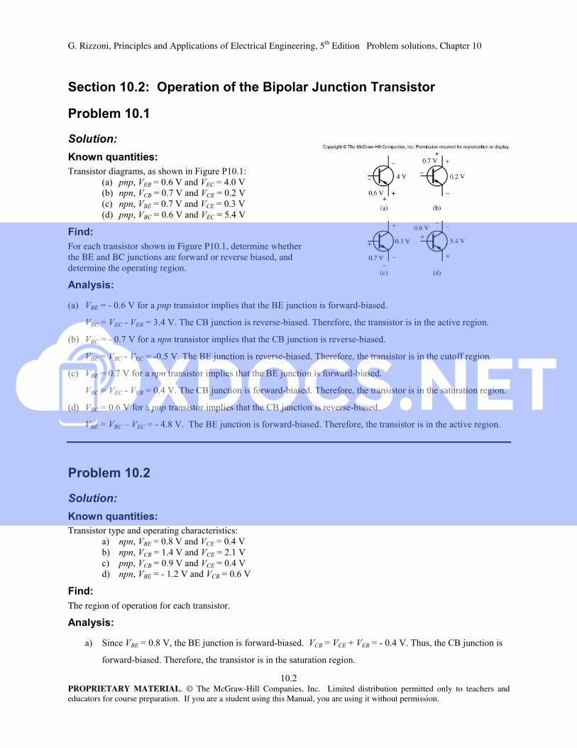
For each transistor shown in Figure P10.1, determine whether the BE and BC junctions are forward or reverse biased, and determine the operating region.
)
$% &'()*! % $
$"+(*! ,$% !,
$ % &'+(*! ,$
$$#()*! ,$% ! %%
! % &'()*! % $
$+(*! % $%
% &'+(*! ,$
-$.()*! % $% !,
"#$
%&'
/& &!!!
.
! 0
$
(
The region of operation for each transistor.
)
1!.()*! % $2$+(*!
% $%

G. Rizzoni, Principles and Applications of Electrical Engineering, 5th Edition Problem solutions, Chapter 10
"PROPRIETARY MATERIAL. © The McGraw-Hill Companies, Inc. Limited distribution permitted only to teachers and educators for course preparation. If you are a student using this Manual, you are using it without permission.
2 ()*! % $
+(*! ,$% !,
! 0% &'+(*! % $
-$"()*! % $%
3$()*! ,$
$+(*! ,$% ! %%
"#$*
%&'
The circuit of Figure P10.3:
.
(
The operating point and the state of the transistor.
)
()*! %
40".
4"0
356 $ %!!
VCE VCC IC RC IC IB RE 12 (1.39)(2.2) (1.39 0.0139)(0.910) 7.664 V
VBC VBE VCE 0.6 _ 7.664 8.264 V
!,
G. Rizzoni, Principles and Applications of Electrical Engineering, 5th Edition Problem solutions, Chapter 10
PROPRIETARY MATERIAL. © The McGraw-Hill Companies, Inc. Limited distribution permitted only to teachers and educators for course preparation. If you are a student using this Manual, you are using it without permission.
"#$+
%&'
% 7! %, '! $
! ''! $*!
4
4
#
"
(
! '& & %
)
"$##
$#04
! '& & !% 3"00## "
"#$,
%&'
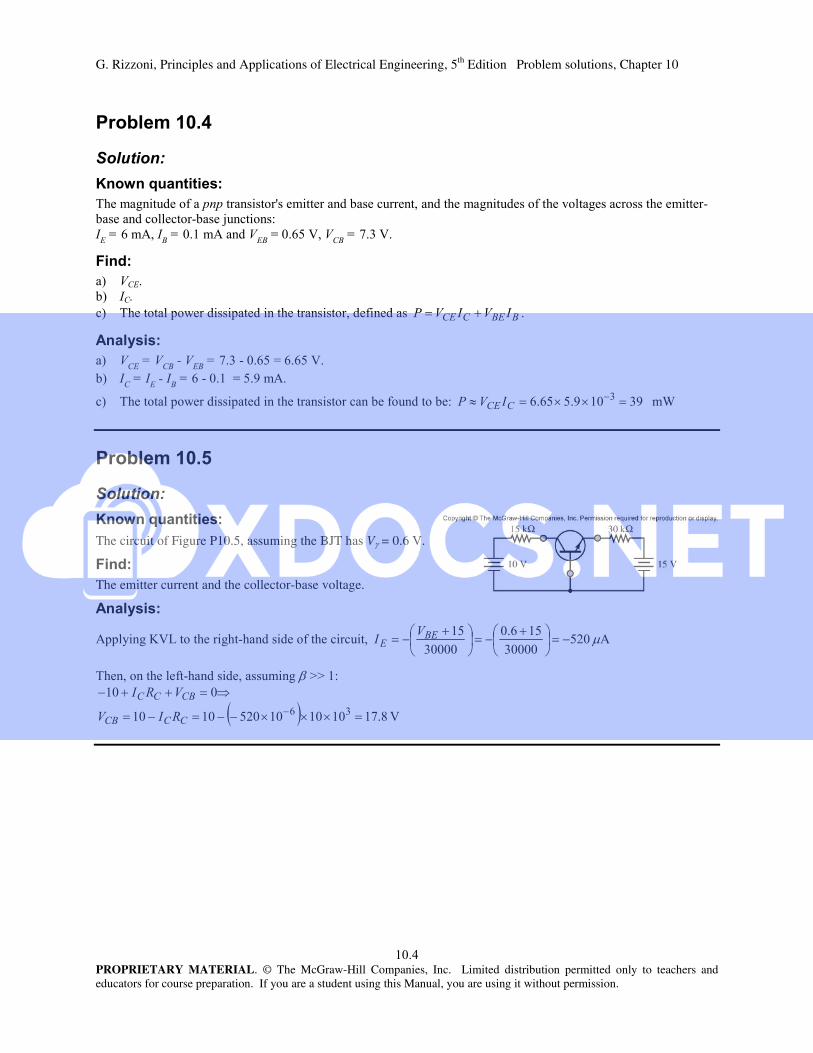
The circuit of Figure P10.5, assuming the BJT has V = 0.6 V.
(
The emitter current and the collector-base voltage.
)
4&&'/56 $ %!! 4#"
#
"
#
'%$88
. #
"
G. Rizzoni, Principles and Applications of Electrical Engineering, 5th Edition Problem solutions, Chapter 10
#PROPRIETARY MATERIAL. © The McGraw-Hill Companies, Inc. Limited distribution permitted only to teachers and educators for course preparation. If you are a student using this Manual, you are using it without permission.
"#$-
%&'
!! %(9
#
(
&& !
&
)
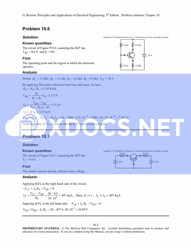
:% RC 3.3 k, RE 1.2 k, R1 62 k, R2 15 k, VCC 18 V
(/&&'/,; % ,
.# ###"".
4#
<4#
#"
=> .??
"
,' %!'(9!,
"#$.
%&'
!! % (9
(
!! ''! $, '
)
Applying KVL to the right-hand side of the circuit,
<40 "0
"
. Since , <40
Applying KVL to the left-hand side:
VCB VDD IC RC 20 497.4 20 103 10.05V
G. Rizzoni, Principles and Applications of Electrical Engineering, 5th Edition Problem solutions, Chapter 10
PROPRIETARY MATERIAL. © The McGraw-Hill Companies, Inc. Limited distribution permitted only to teachers and educators for course preparation. If you are a student using this Manual, you are using it without permission.
"#$/
%&'
!! % ! = (9
(
The operating point of the transistor.
)
4<...
"
, <4...
""...
"#$0
%&'
! ''! !!!% !
0
(
%
444
@ '' ' ! ''! &
& #3% 4#
)
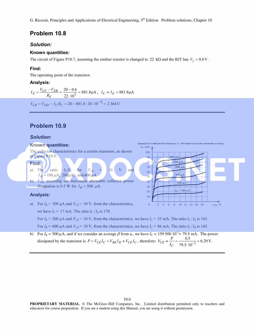
A4% !!!
, 4
A4% !!!,""4 #
A4% !!!,.4 "
b) For IB = 500 A, and if we consider an average from a., we have IC = 159·500 10-3= 79.5 mA. The power
dissipated by the transistor is , therefore: VCE P
IC
0.5
79.5 103 6.29 V.

G. Rizzoni, Principles and Applications of Electrical Engineering, 5th Edition Problem solutions, Chapter 10
PROPRIETARY MATERIAL. © The McGraw-Hill Companies, Inc. Limited distribution permitted only to teachers and educators for course preparation. If you are a student using this Manual, you are using it without permission.
"#$
%&'
Figure P10.10, assuming both transistors are silicon-based with .
(
a) IC1, VC1, VCE1. b) IC2, VC2, VCE2.
)
56 "
<4 "0 #
""
40 "
0#0 """
0# .
b) Again, from KVL: 0# 4.
0#"
and 4
.
.
Also, " # " " .
Finally, ". ""
.
"#$
%&'
+ ''! !!! %B"0
&#
(
The operating point of the transistor in Figure P10.11, and the value of at this point.
)
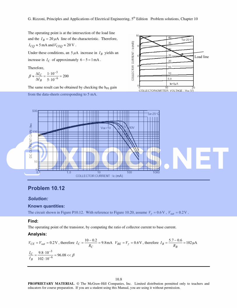
Construct a load line. Writing KVL, we have: ## .
Then, if , # ; and if , 4 . The load line is shown superimposed on the collector
characteristic below:
G. Rizzoni, Principles and Applications of Electrical Engineering, 5th Edition Problem solutions, Chapter 10
.PROPRIETARY MATERIAL. © The McGraw-Hill Companies, Inc. Limited distribution permitted only to teachers and educators for course preparation. If you are a student using this Manual, you are using it without permission.
The operating point is at the intersection of the load line
and the 4 line of the characteristic. Therefore,
4# and .
Under these conditions, an 4# increase in yields an
increase in of approximately 4# .
Therefore,
#
"
The same result can be obtained by checking the hFE gain
from the data-sheets corresponding to 5 mA.
"#$
%&'
The circuit shown in Figure P10.12. With reference to Figure 10.20, assume , .
(
The operating point of the transistor, by computing the ratio of collector current to base current.
)
% 4.0
% <4
#
.0
.0
"
6 '
G. Rizzoni, Principles and Applications of Electrical Engineering, 5th Edition Problem solutions, Chapter 10
0PROPRIETARY MATERIAL. © The McGraw-Hill Companies, Inc. Limited distribution permitted only to teachers and educators for course preparation. If you are a student using this Manual, you are using it without permission.
"#$*
%&'
The circuit in Figure 10.28 in the text. VCC=20 V, RC=5kΩ, RE=1kΩ.
(
The region of operation of the transistor.
)
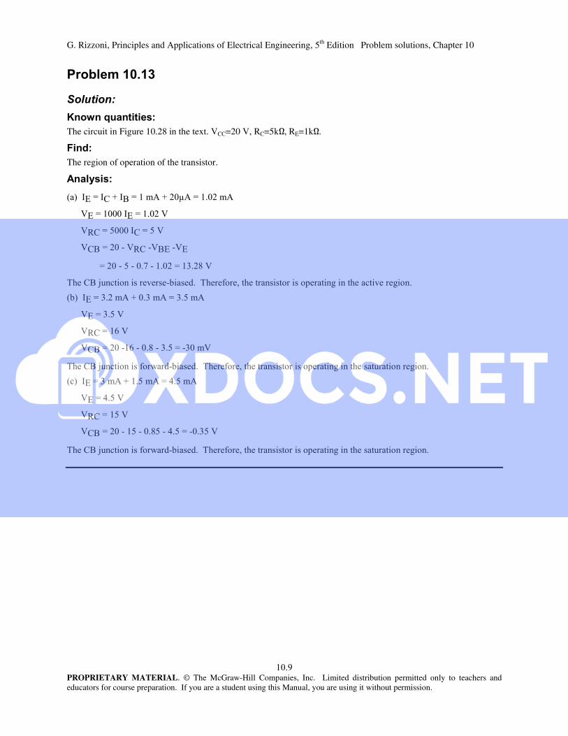
C)C+2C(42A44
)C)
D+#C+#
+($D+$()$)
$#$ $".
+(*! ,$% &!,
C)"42"4"#4
)"#
D+
+($$.$"#$"
+(*! % $% &
!C)"42#4#4
)#
D+#
+($#$.#$#$"#
+(*! % $% &
G. Rizzoni, Principles and Applications of Electrical Engineering, 5th Edition Problem solutions, Chapter 10
PROPRIETARY MATERIAL. © The McGraw-Hill Companies, Inc. Limited distribution permitted only to teachers and educators for course preparation. If you are a student using this Manual, you are using it without permission.
"#$+
%&'
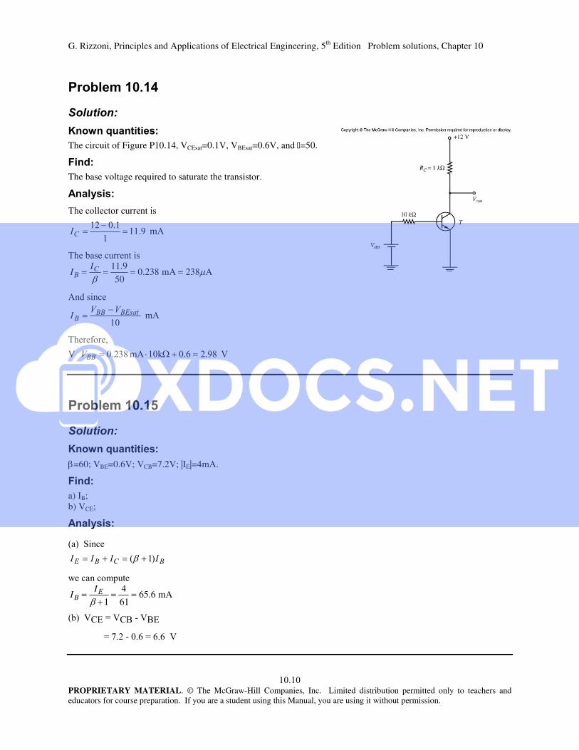
The circuit of Figure P10.14, VCEsat=0.1V, VBEsat=0.6V, and β=50.
(
The base voltage required to saturate the transistor.
)
! ''! !
40
!
IB IC
11.9
50 0.238 mA 238A
4!
4
%
0.=4".
"#$,
%&'
=60; VBE=0.6V; VCB=7.2V; |IE|=4mA.
(
a) IB; b) VCE;
)
1!
!! &
IB IE
1
4
61 65.6 mA
+)+($()
$
Copyright © 2022 FDOKUMEN