FOI 055-1617 document 5 - Therapeutic Goods Administration ...
40
Re: DIR 28523 - 41JA letter [SEC=UNCLASSIFIED] to: iris 22/10/2012 03:44 PM Dear Sir or Madam, As request, please find enclosed the completed DIR form and the relevant documents. Should you have any further querie s, please do not hesitate to contact us. Thanks. Best regards, ESKA Australia Pty Ltd Address: 72 South St. Rydalmere NSW 2116 I Tel: I Fa x: Email : I Web site: www.eskaaustralia.com.au TlllS em 311 messc ge and cJny accompanying attachment!> may cont am I nformat,on that 1s conf1dent1al and subJect to legal privilege. If you are not the intended recipient. do not read. use, disseminate distribute 01 copy this message and ,ts attachments. If you have received th,~ message in error, please notify the stnder immediately and delete this n'essage. Any views expressed 111 this messa 6 e are tfiose of the individual sender, except where the sender express, and with author 1ty, states them to be the views of the wr it(r. This email c<1nnot be shared with any outside third pc1rty other than those that this email has been wntte to, unless perrrnss,on has been given by the writer, 1•1 accordance with privacy laws. From:- Sent: Tuesday, Octob er 16, 2012 2:21 PM To : Subject: FW: DIR 28523 - 41JA letter [SEC=UNCL ASSI FIED] FYI Regards, r- ESKA ~ AUSTRALIA 72 South Street Rydalmere New South Wales 2116 Australia I Mob: - T I Fa x: I E-mail: I Web site: www.eskaaustralia.com.au
-
Upload
khangminh22 -
Category
Documents
-
view
1 -
download
0
Transcript of FOI 055-1617 document 5 - Therapeutic Goods Administration ...

Re: DIR 28523 - 41JA letter [SEC=UNCLASSIFIED] to: iris 22/10/2012 03:44 PM
Dear Sir or Madam,
As request, please find enclosed the completed DIR form and the relevant documents.
Should you have any further queries, please do not hesitate to contact us.
Thanks.
Best regards,
ESKA Australia Pty Ltd Address: 72 South St. Rydalmere NSW 2116 I Tel: I Fax: Email : I Web site: www.eskaaustra lia.com.au
TlllS em 311 messc ge and cJny accompanying attachment!> may cont am I nformat,on that 1s conf1dent1al and subJect to legal privilege. If you are not the intended recipient. do not read. use, disseminate distribute 01 copy this message and ,ts attachments. If you have received th,~ message in error, please notify the stnder
immediately and delete this n'essage. Any views expressed 111 this messa6e are tfiose of the individual sender, except where the sender express, and with author 1ty, states them to be the views of the wr it(r. This email c<1nnot be shared with any outside third pc1rty other than those that this email has been wntte to, unless perrrnss,on has been given by the writer, 1•1 accordance with privacy laws.
From:-Sent: Tuesday, October 16, 2012 2:21 PM To: Subject: FW: DIR 28523 - 41JA letter [SEC=UNCLASSI FIED]
FYI
Regards,
r- ESKA ~ AUSTRALIA
72 South Street Rydalmere New South Wales 2116 Australia I Mob: -T I Fax: I E-mail : I Web site: www.eskaaustralia .com.au
davihe
Typewritten Text
DOCUMENT 5

I E-mail:
This email message and any accompanying attachments may contain information that is confidential and subject to legal privilege. If you are not the intended recipient, do not read, use, disseminate, distribute or copy this message and its attachments. If you have received this message in error, please notify the sender immediately and delete this message. Any views expressed in this message are those of the individual sender, except where the sender express, and with authority, states them to be the views of the writer. This email cannot be shared with any outside third party other than those that this email has been written ta,
unless permission has been given by the writer, in accordance with privacy laws.
------ Forwarded Message From: <wlmailhtml:[email protected]> Date: Tue, 16 Oct 2012 09:38:01 +1100
To: Subject: DIR 28523 - 41JA letter [SEC=UNCLASSIFIED]
Medical Device Incident Report Investigation Scheme (IRIS) Office of Product Review Therapeutic Goods Administration (TGA) Email: wlmailhtml:[email protected] <mailto:[email protected]> Fax: 02 6232 1713 Post: PO Box 100, Woden, ACT 2606 Courier: 136 Narrabundah Lane, Symonston, ACT 2609
*To ensure you are receiving all your correspondence, please update your contact details with the IRIS team. Please note: Only employees in your company who are listed on the ebs can be contacted about incident reports.
Online reporting -Sponsors/ Manufacturers: http://www.tga.gov.au/safety/problem-device-report-lndustry.htm < http://www.tga.gov.au/safety/problem-device-report-industry.htm> (Initial reports only) Medical Device Users: http://www.tga.gov .au/safety/problem-device-report-user.htm <

http://www.tga.gov .au/safety/problem-device-report-user. htm>
"Important: This transmission is intended only for the use of the addressee and may contain confidential or legally privileged
information and has been sent in accordance with the TGA security policy.
If you are not the intended recipient, you are notified that any use or dissemination of this communication is strictly prohibited. If you
receive this transmission in error please notify the author Immediately and delete all copies of this transmission."
------ End of Forwarded Message
Best regards,
ESKA Australia Pty Ltd Address: 72 South St. Rydalmere NSW 2116 I Tel: I Fax: Email: I Web site: www.eskaaustralia.com.au
This en"'li:'!d n10s~;0ge zn1d anv ncco1YqJ~Jny!ng z-1tt(1chP12nts 1Y1ay contain inforn1at1on thi:it i~i confrdentia! cind
s.ubject to iEt\:'d privdegf\ If you Gre not thE.1 int.ended H~cipient, do not read, u~.e, ch:,~·,.erninJte. chstdbute ot
copy this i-r1e~ .. ~.ag0 {Ind its ~-:-!ttE1c.hrr1er)t:..,. ff you havr::: reci~ived thb nte~.s.::lJi~e in error, ph::\:.l~:,C· notify· thi.:: senc.k:r
tn-nn~~1di.::it1;:_;ly ,:lnd delete thi::.. r-r1es::.oge. tsr/ VH2VJ~. e>::pre::sed tn thb rnessage a!"C tho~.(> of thr.:1 iridividu~:~i
:::.cnderf E·xc.ept voJh~!re the :}ender e2(pr0~,~;~ and '/Jith autl1oritv~ s.tates thi::-n1 to be the vie\tJs ()f the 1;.vrrter Thi~
ei·Had ca1·1not be shared \Mith tn-1v outside third party other thta1 tho·A:· thttt this einJd has. been vvritten to.
un!e~s perrni~,sion htis been gfven by the vvrit.GI', fn accord/~nce \.,\,·ith privacv !ti\:v:;.
hp_scan_2210201214250700 .pdf Ceramic options for Total Hip & Resurfacing.pdf
Clinical_assessment_Bionik System.pdfSummary of wear tests pairing CeraMetal_ESKA-Ceram.pdf
~ Surgical Technique-BS Resuriacing.pdf

- MEDICAL DEVICE INCIDENT REPORT INVESTIGATION SCHEME -INITIAL REQUEST OF INFORMATION FROM LISTED SPONSOR
INITIAL REQUEST FOR INFORMATION FROM LISTED SPONSOR Date: 26/09/2012
DIR: 28523 Manufacturer Name: Eska Implants GmbH and Co [45325]
:. <•.qi,esJi~n/R(,quiri,nient
1) Please confirm the device's Australian Register of Therapeutic Goods (ARTG) number
2) Do you currently supply or have you previously supplied this product, with the indicated Model/Serial/Batch/Lot numbers:
a) To the Australian Market b) For Export
3) How many of this model have been supplied In Australia:
4) How many of this batch (if applicable] have been supplied:
5) Are you aware of this problem, as reported?
Worldwide:
In Australia:
Worldwide:
6) If deemed necessary, is a sample of the mentioned device available for review and/or testing?
7) Have you had any other reports of similar problems with this product?
If YES, how many:
If YES, please give details:
Page 2 of5
IARTG: !} 1; ·~ .
. ll(J'"r>s50
0 D 12
;V//~
N'/A
1V;A
D D
D
D 0
0 5J
0

8) If you are not the manufacturer, has the manufacturer been contacted for any other reports of similar problems with this product?
If YES, how many:
lfYES, please give details:
D
9) Please provide details of any action you have taken, or intend to take, regarding this problem
' ,,
10) Please provide details of the manufacturer's investigation to date, including expected Manufacturer's investigation completion elate
1v1 A
11) When returning this response to the office of the Therapeutic Goods Administration, you arc requested to attach the following (if ticked):
D Sample of the product/device
D Product Specifications
I vi Operator's manual
D Technical Service Manual
I vi Descriptive product promotional documentation D Clinical training manual in printed or video form
D Instructions for use, as supplied with the device
D Device Packaging with printed instructions
D In-house training documentation
D Evidence of compli,mce with the Essential Principles
I v'J A summary ofrisk assessment activities performed by the manufacturer for the device, cg Risk Management Report required by Clause 8 of ISO 14971 :200
Page 3 of 5

12) Additional Information required:
13) If your device is an implantable pacemaker/defibrillator you are asked to provide the following additional information:
1. Both published and unpublished clinical trial data where events of this type are analysed. 2. The number of reported events of ALL types (including unconfirmed events), the number of devices sold and the cumulative implant months for each device in this product family.
'1B Attach your completed form to an email and send to: iris@tga,gov.au
~ Fax your completed form to: (02) 6203 1713 Supponing documenlat1on fo//01ving by normiJ/ mail
Please do not send more than one copy of your response lo /lie TGA
Postal Address: Medical Device Incident ReporL I nvesligalion Scheme, Office of Product Review. Devices, ~] Therapeutic Goods /\dtninistration, PO Box 100, WODEN /\CT 2606, /\ustrnlia
Courier Address: Medical Device Incident Report Investigation Scheme, Office or Product Review· Devices, ~ Thcrapculic Goods /\dminislralion, 136 Narrabunclah kmc, SYMONSTON /\CT 2606, /\ustralia
Sponsors of products listed or registered on the /\ustralian Register ofTherapeutic Goods (ARTG) arc reminded of their responsibilities under Section 31 and/or '11 )A (as appropriate) of tlw Therapeutic Goods Act of 1989, to provide information relating to their product's formulation, composition, design specification, quality, method and place of manufacture, presentation, safety and efncricy, conformity to advertising regulations under the /let, regulatory history in another country, or any other matter prescribed
Page 4. of 5

DIR 28523 - ARTG # 1184-30 - Prosthesis, internal, joint, hip, resurfacing
Reporter Reference ff:
Date of Adverse Event: Date of Final Report: 13/09/2012
ARTG #: 118430
Brand Name: Eska resurfacing ceramic hip replacement
Device Class: Model#: Serial 1-1: Class lib
Software Version: Batch#:
Manufacturer: Eska Implants GmbH and Co [,J.5325]
Sponsor: Eska Australia [45270] 72 South Street RYDALMERE NSW 2116
Email:
Reporter:
Patient Outcome/Consequences: Revision hip replacement.
Device Analysis Results:
Corrective/Preventative Actions:
Details of Similar Events:
Number of Similar Events:
Countries Similc1r Events Also Occurred:
Clinical Event Information:
Lot#:
Contact N,11ne: -Phone:
Fax:
Confidential: Yes
Rate of Similar Events:
Debmination of the ceramic coating causing early failure requiring revision procedure.
Page 5 of 5

Resurfacing endoprosthe~is
2006 iF Material Award fo~ th~ Spongiosa surface structure . .
ESKA IMPLANTS

Historical Review Polyethylene has been used in the field of endo-prosthetics for more than 40 years. It is considered as the weakest component within existing bearing options. Mostly wear and destruction of the polyethylene bearing options due to pitting are the reason for aseptic loosening and therefore for failure of joint endoprosthesis. 1, 2, 3
Based on numerable ring-on-disc and simulator tests a composite material has been developed for which the patent DD 272 603 Al has been awarded and which was launched into the market as ENDOCERAM. 1
ESKA AUSTRALIA
ESKA Implants GmbH & Co. KG has been awarded the if material award at the "Hannover Exhibition 2006". 3
In 1989 ESKA Implants GmbH & Co. KG reserved all rights for the production and sales of this composite material. It was modified then as a result of more scientific examinations and was named ESKA-CERAM®.3
After further biomechanical examinations the clinical approval for a new ESKACERAM® inse1i was achieved in 1998 by ESKA Implants GmbH & Co. KG.3 In 2007, the ESKA-CERAM® product has been extended to a full range of Ceramic Large Femoral Heads (available for both THR and Resurfacing) and ESKA-CERAM® Inse1is (available for both THR and Resurfacing).
ESKA-CE RAM® -- a new material in hip endoprosthesis
The composite material ENDOCERAM consists of a polyurethane matrix and of a mixed-in glass ceramic powder. By starting manufacturing at ESKA Implants GmbH & Co. KG ESKA-CERAM® for THR and Resurfacing has been modified to comprise two-thirds polyurethane and one-third A'203-Ceramic substituting the glass ceramic.4
The new material ESKA-CERAM® is a little lighter in appearance than the original material and has a porcelain-like loolc.5 Its wear rates are of a similar low order of magnitude as those reported for metal-metal and ceramic-ceramic combinations. A great advantage of the material is that it permits the production of asymmetrical inserts for acetabular cups.4
Fig.I ESKA Cera-Metal® Large Femoral Head (38, 44 & 48mm)
Coe by !Z~~~rs
Fig.2 ESKA Cera-Metal® Resurfacing Head
Fig.3 ESKA-CERAM® Inse,t (available for both THR and Resurfacing)
2

ESKA AUSTRALIA
Laboratory Results of 10 Mio Simulator Tests The performance of the new material was shown in numerable tests using a load and movement simulator.6
Inlay ESKA-Ceram "BS" 1D=46 mm
Running in wear: y = Sx + 27,233 ~
ESKAU\l8 IMPLANTS
60
50
40 ----- . ,;_=~=--Fig. 5 Simulator Testing Pairing (D - 46 mm) Cera-Metal/ESKA-Ceram® "'"
i30 ··--~ - -,- --- ...., .
Average Wear 2-10 Mio: y -1,0305x + 34,649
~
<l 20
10
0
0 2 4 6
Load Cycle [N 1 O']
Regression analysis line
-;,- Linear inlay wear
Run-In Inlay ESKA-Ceram: 5 µm Femoral Head Cera-Metal : 5 µm
"'"
8
60.0
50.0
40.0
i3o.o ~ <l
20.0
10.0
0.0
Linear Wear Rate:AZ = 1.2 µm/106
Source: ESKA Lab. 23556 Ltibcck, Germany
10
Femoral Head Cera-Metal "BS" AD=46 mm
Regression analysis line -1- Linear fem. bend wear
Running in wear: y = 5x + 24,96~
./ ....-""'•rage Wear 2-10 Mio: y = 0, 1186x + 30,771 .
. /
0 2 4 6 8
Load Cycle [N 106]
10
fochmsche Univt!rSitat Hamburg-Ha.rhuri high significance
100
90
80
E: 70 ~
60 w 0,
" 50 "' C) 40 " I 30
20
10
0
Al203 CoCr Cast CoCr Forged CoO Pow der - Cera flt.eta!
rv1etalurgy Femoral Head
Source:
TI-Oxinttrate CrNiMo-316L S
s
Fig. 4 Comparison of wetting angles with bovine serum (TU Hamburg)
TUHH, Technicnl Univ. Hamburg, Biomcchanics Dept., 21079 Hamburg, Germany
Coe by tit ~~TS 3

ESKA AUSTRALIA
Laboratory Results of 10 Mio Simulator Tests Fig. 6 Simulator Testing-Results
Component Inlay Cap Inlay Cap
Run in Wear 5 run 5 run 26µm
Linear Wear Rate < I run/106 I run/106 o, 9 r,m/1 o' I, 8 µm/I0 6
Wear Rate Bearing I, 2 µm/I0 6
Wear Rate Total < 5 µm/106
Linear Wear Rate of the Pairing Cera-Metal®/ESKA-Ceram®
Fig. 7a Inlay 46 after 1 Mio LC (Load cycles)
Fig. Sa Cap 46 after 1 Mio LC
Source: ESKA Lab. 23556 Lilbeck, Germany
Fig. 7b Inlay 46 after 10 Mio LC (Load cycles)
Fig. Sb Cap 46 after 10 Mio LC
2, 7 run/I 06
ESKALAB IMPLANTS
ESKA-Bionik® System - Ceramic on Ceramic
"ESKA Cera-Metal®" Resurfacing Head (Fig 9l
+ Sizes from 38 mm to 58 mm, 2 mm increments + 3 mm guiding nails in 30, 40, 50 mm length
''.ESKA Cera-Metal®" Large Femoral Head Wig 1oi
+ 3 bead sizes in following diameters : 38, 44, and 48 mm, with Short, Medium & Long options
+ Asymmetrical insert available (10° taper)
Coe by PIJ~~b.NTS
Fig. 9
Fig. 10
4

ESKA AUSTRALIA
ESKA-Bionik® System-BS Acetabular Cup with Spongiosa Metal® surface structure
Positive results for the metal Spongiosa cups with ESKA-CERAM® inserts can be reported.7 For an optimal outcome, ESKA Implants GmbH & Co. KG proudly provides three types of Metal Shell.
+ Cementless anchorage : using surface structure Spongiosa Metal® II.
+ Extensive range of sizes: Standard Shell, Screw Fixation Shell & Dysplasia.
+ Various insert options : Metal-on-metal, ceramic-on-ceramic, metal-on-
polyethylene as well as ceramic-on-polyethylene bearing options.
+ Extensive range of sizes : available in 11 sizes (0D=46 to 66 mm, 2 mm
increments).
+ Material : CoCrMo TiNb-Coat.
Metal Shell, Cem.Iess F;g. 11
TiNb-COA TING Size: 00=46 to 66 mm (HA-Coating available upon request)
Ring shaped fixation assures primary stability by initial press fit.
Metal Shell, Cem.less F;g. 12
TiNb-COA TING, Screw Fixation Size: 0 0=46 to 66 mm (I-IA-Coating available upon request) (Various sizes of screws are available)
Additional screw supports primary press-fit anchorage.
Metal Shell, Cem.Iess s;g. 13
TiNb-COA TING, Dysplasia Size: 00=46 to 66 mm (I-IA-Coating available upon request)
A combination of threaded posts and fixation provides primary stability.
Coe by r,J~~~TS
Fig. II
Fig. 12
Fig. 13
5

ESKA AUSTRALIA
Spongiosa Metal® Porous Structure Implanted since 1981
The surface of the cementless ESKA endoprosthesis is a three-dimensional grid net structure, which is adapted to the natural spongiosa. The first clinical introduction was in 1981 of Spongiosa Metal® then Spongiosa Metal® I in 1989 followed by the current Spongiosa Metal® II in 1990.
The Spongiosa Metal® II (fig.! 4) structural height is adjusted between .65mm to 3mm and its porosity is between 70 - 80% .
Fig. 14 Spongiosa Metal® II Fig. 15 Bony in growth into Spongiosa Metal®
At the "Hannover Exhibition 2006", ESKA Implants GmbH & Co. KG has been awarded the iF material award for its surface structure Spongiosa Metalav(since its introduction in the year 1953 this award is a well-known established label wherever outstanding design is involved). 8
The surface structure and the implant body are cast as one piece. Therefore a homogeneous casting is accomplished. Primary stability is realized by an immediate press-fit with long term stability achieved by bony in growth (fig.15) rather than bony on-growth to a roughened surface. The three-dimensional porous structure has been in successful clinical use since 1982 5, s, 9, 1 o, 11
References: I. M.Bliithncr, University Leipzig, Department ofOrthopcdics(Dircctor. Univ.-Prof.Dr.mcd.G. von Salis-Soglio). "ENDOCERAM- A Possible
Alternative to Polyethylene in Hip Arthrop\asty" 2. Quack G ct al. "Design considerations for improving the acctabular cup of the ESKA hip endoprosthcsis by using the ceramic/ceramic wear
couple." Biomcd Tech (Berl). 1996 Sep; 41 (9): 253-9. 3. ESKA Implants Gmbl-1 & Co. KG website, http://\w/\v.cska-implants.de/cms/front_content.php?idart=l 33 4 Scholz, Jet al "ESKA-Ccram- a new material in hip endoprosthetics" Biomed Tech (Berl). 2000 Dec; 45(12); 377-9. 5. Scholz,] et al."Twenty year follow up of the uncemented spongiosa metal surface SMS total hip artroplasty" Oral presentation German ortho
pedics 6. Test reports 2004 to 2007 from external and intemal Biomceh. Labs. ENDO LAB, 83101 Rosenheim, Germany; ESKA Lab. 23556 Lubeck,
Germany; TUI-II-I, Technical Univ. Hamburg, Biomecimnics Dept., 21079 Hamburg, Germany. 7. Von Sa!is-Soglio G., et al. "Cementless acetabular cup with Spongiosa Metal Kand surface Ceramic-Polyethylene insert (ESKA-CERAM')"
Effenberger I-1., Ziclmer L., Richolt J.A., MCU Verlag 2004, P. 147-150 8. Japan Design Net. "iF Material Award". http://global.japandesign.ne.jp/COMPE/report/ima2006/. April 2006. 9. Sielcwicz,M ct al. "Five year follow-up of 605 cases of the MCCL (metal canccl!ous cement Jess Lubeck) Total hip prosthesis" Orthopaedic
Clinic of the Neukolin Hospital, West Berlin pg:433-443 10. Matsui, M et al. "The Metal-Cance!lous Cement less Lubeck total hip arthrop\asty" Journal of Bone& Joint surgery-British 1998:404-410 11. Kinner, B ct al. "Hydroxyapitite-coated open Macroporous, Anatomical Hip prosthesis" Z. Orthopad. 1999; 137: 114-121
6

ESKA AUSTRALIA
ESKA-CERAM® BS Bionik®-System
Hip Surface Replacement
Metal Shell
ESKA-CERAM® Insert for HSR
ESKA-CERAM® Resurfacing Head
Total Hip Replacement
Metal Shell
ESKA-CERAM® Inse11 for THR
ESKA-CERAM® Large Femoral Head
Coe by ra~~~TS
46 / 48 / 50 / 52 / 54 / 56 / 58 / 60 / 62 / 64 / 66
38 / 40 / 42 / 44 / 46 / 48 / 50 I 52 I 54156 I 58
3 8 / 40 / 42 / 44 / 46 / 48 / 50 / 52 / 54 / 56 / 58
46 / 48 / 50 / 52 / 54 / 56 / 58 / 60 / 62 / 64 / 66
46 / 48 / 50 I 52154 I 56 I 58 / 60 / 62 / 64 / 66
38 / 44 / 48 mm
7
~ J>m ccn ~~ :JJ )> .... ;:;
--; ~
g. g. 0 0
'" ~ '° :... ~ °' 2 g 0 " - } ;, Cl :-: ~s !" ~ r .... ., '"' ::; 0 0
~ ')
§ ~ z
') ~ ::; < ~ 1-.>
g g ~ c-.
w , ;;· ~ 0
fr i~ i~
Ii "
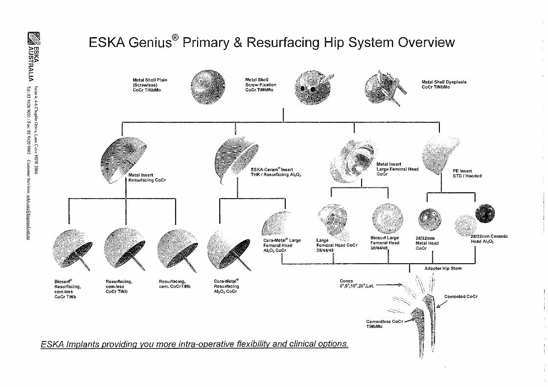
Biosurf' Resurfacing, cem.less CoCrTiNb
ESKA Genius® Primary & Resurfacing Hip System Overview
Resurfacing, cem.less CoCr TiNb
Metal Shell Plain (Screwless) CoCrTiNbMo
Resurfacing, cem. CoCrTiNb
Cera-Metal® Resurfacing Al20 3 CoCr
Metal Shell Screw Fixation CoCr TiNbMo
ESKA-Ceram© Insert THR / Resurfacing Al20 3
Cera-Metal® Large Femoral Head Al 20 3 CoCr
Large Femoral Head CoCr 38/44148
Cones
Metal Insert
Metal Shell Dysplasia CoCr TiNbMo
Large Femoral Head CoCr
Biosurf Large Femoral Head 38/44148,
28132mm Metal Head cocr
Adapter Hip Stem
· / '·'28/32mm Ceramic Head Ah03
0",5°,10°,20°,Lat. ----+,
·~<;;,;,
Cementless CoCr TINbMo
Cemented CoCr
/
ESKA Implants providing you more intra-operative flexibility and clinical options.

Pages 16-30 exempt in full under section 47(1)(b) of the FOI Act

ESKA IMPLANTS
securely better

ESKA Genius® Hip-System
Hip Resurfacing
Today's material standards, the medical and technical know-how as well as the modern manuf
acturing facilities are promising high grade of quality for a reliable system of hip resurfacing. The
modular concept os ESKA Implants made the Hip Resurfacing "BS" Bionik®-System inimitable.

ESKA Genius" Hip-System Hip Resurfacing ESKA Bionik'-System Surgical Technique "Nail"
DD DDDDDDLJ The following surgical technique describes the use of the ESKA Bionik® System hip surface replacement with reference to the instruments available for this procedure.
Contents
1. Preoperative planning .................................................................................................... 4
2. Surgical Technique ...... ................................................................................. 5 2. 1 Approach ....... ........... ........... ........... ........... ........... ........... ........... .......... ............ .... ....... 5 2. 2 Determining the size of the resurfacing .......................................................................... 5 2. 3 Preparation of the femoral head ..................................................................................... 5
2.3.1 Determining the point of entry ............................................................................ 5 2.3.2 Preliminary preparation of the femoral head ........................................................ 8
2. 4 Preparation of the acetabulum ......... ........... ........... ........... ........... ........... ........... .... ........ 8 2.4.1 Reaming the acetabulum ................................................................................... 9 2.4.2 Implantation of metal shell cementless ............................................................... 1 O
2. 5 Final preparation of the femoral head........... ........... ........... ........... ........... ........... ...... ..... 11 2. 6 Implantation of the insert .............................................................................................. 13 2. 7 Implantation of the femoral resurfacing Nail0
.................................................................. 14 2.7.1 Design .............................................................................................................. 14 2.7.2 Assembly of the modular resurfacing ................................................................. 14 2.7.3 Seating the implant manually ............................................................................. 15
2. 8 Repositioning ............................................................................................................... 16 2. 9 Wound closure ............................................................................................................. 16 2.10 Preparation Type Cornwall ............................................................................................ 16
3. Cleaning and resterilisation of the instrument set.. ... ............................................ 17
4. Precautions ............................................................................ ............................................ 17
Annex ......................................................................................................................... ..................... 18 Size classification .. .. .. .. . .. .. .. .. .. .. .. .. .. . .. . .. .. .... .. .. .... .. . .. .. .. .. .. . .. .. .. .. .. . . .. ... . .. .. .. . .. .. .. .. . .. .. .. .. .. . .. .. .. .. .. .. . .. .. .. .. 19 System concept......... ........... ....... .... ....... .... ... ........ ........... ........... ........... ....... ............. ... ....... ... .... ....... 20 Metal-on-Metal bearing option - size com bi mix ................................................................................... 21 Ceramic-on-Ceramic bearing option - size com bi mix ........ ........... ........... ............ .... ....... ....... ... .... .. .. ... 22
- 3 -

ESKA Geniusa Hip-System
DDDDDDDDLJ 1. Preoperative planning
Hip Resurfacing ESKA Bionik'-System Surgical Technique "Nail"
With the help of preoperative planning the following aspects should be specified before the surgery starts:
- Size of implants - Varus / valgus -Anteversion, retroversion - Pathological situation of femoral head
Appropriate planning templates are available for this purpose (Fig. 1). When using x-ray templates note that the image scale of the femur changes depending on the distance between the x-ray source and film and patient and film. A default magnification factor of 15% is used with the templates for the hip surface replacement. Corresponding to the average magnification factor in most clinical x-ray images. Where taller or obese patients are involved a higher magnification factor can be used, because the distance of bone to film is longer.A mark can be set at the height oftl1e femur for measurement on the x-ray image to define the magnification of the x-ray image.
& Note: X-tray templates with a different magnification scale are available on request.
It is important for the final result to determine the exact position of the resurfacing. The pathological situation of the femoral head can be identified and the natural position of the centre of rotation can be reconstructed with reference to the femoral neck from the x-ray images. A frontal view (A/P) and a side view (M/L) are required both. The x-ray template is positioned to size the implant. The system can also be supported by electronic planning systems. For more information please contact ESKA Implants.
l~"L,,,_~ :g;!ll~'f>~I ~ ' TI •-rn I ....,,.,,.,---,, """7,:anl
' ~-~-~·-· "', ' \ -·- 1· '"'-~ -::
l ,·" l'<Wi ~·D U-/l'"~ ¢.la
1~»
~ ~ . . '"""'"
i1 :!: "
! 1,11t.w:d:i.l~-.O Tcl111ur a.~1 :): t:,
~ -·~"" .,.~.,- 1: ~
.- """'.!l:-\~ -"'., ..,,, ; , : ..
1 ~-~-, . . •
i ; ~·1-··- f. - ~ . s:o(: < : ~~;
, '-~':$'!F""
0~) ~-ll a."~~o R 09 [=)w,,,,, ~
Resurfacing, modular with CL Nail metal shell, cementless
Fig. 1 X-tray template
. 4.

ESKA Geniusa Hip-System Hip Resurfacing ESKA Bionik'-System Surgical Technique "Nail"
DD DD DD D LIU 2. Surgical technique
2.1 Approach
The surgeon is responsible for selecting the approach for this type of implant. Following standard criteria are significant: complete uncovery of the acetabulum and proximal femur is required to allow accurate preparation of these areas without affecting the positioning of the components.
2.2 Determining the size of the resurfacing
The size of resurfacing selected during preoperative preparation is verified during the procedure. The size of the femoral neck is measured with the gauge (Fig. 2). The size of the femoral neck measured in alp-direction (longitudinal oval) determines a minimum resurfacing size, and a smaller size must not be used.
/,\ A too small selected implant could damage important blood L..!....",. vessels and cause premature loosening of the resurfacing.
2.3 Preparation of the femoral head
2.3.1 Determining the point of entry (centre of femoral neck)
Fig. 2
The entry point on the femoral head can be marked by positioning two gauges with rods placed with 90° in between (crosshairs) (Fig. 3a, b).
// Crosshairs
Fig. 3b
- 5 -

ESKA Geniusa Hip-System Hip Resurfacing ESKA Bionik'-System Surgical Technique "Nail"
DDDDDDDDD The hole for the central guiding pin is drilled into the femoral neck using the drill guide.The twist drill (0=2.5 mm) is inserted through the feed hole of the drill guide (Fig. 4). The drill must aim towards the head center.
Following the drill is aligned to the head and the drill guide is pressed onto the femoral head, taking into account the varus, valgus and ante-version and retroversion situation of the femoral neck. Two pins on the bottom of the drill guide secure the position. Then the pilot hole is positioned (Fig. 5).
Now the central position of the direction of the drill hole is checked with an image intensifier. A short position tack is placed as an indicator. The position is checked with the image intensifier(Fig. Sa, b).
' {
'
Fig. Ga Fig. 6b
. 6.
. Fig. 4

ESKA Geniusa Hip-System Hip Resurfacing ESKA Bionik'-System Surgical Technique "Nail"
DDDDDDDDDD If the positioning tack is not central to the head, the offset can be corrected with the head paralleler(Fig. Gf).
The positioining tack must be removed and the guide pin of the head paralleler is positioned in the pilot hole (Fig. Ge, 6d). A new hole is drilled in the femoral head to take the required offset into account with the twist drill 0=2.5 mm (Fig. 6e).
I
Fig. Ge Fig. Gd Fig. Ge
Correction hole
Fig. 61 Head paralleler view from above
The position can be checked again with the positioning tack and the image intensifier. The correction procedure can be repeated until the correct position is achieved. A pin is inserted tightly into tl1e correct hole.
fil A second parallel er with a 5' inclination is available for angular correction (Fig. 7).
Fig. 7
Standard 0° angular correction 5°
The guide pin is inserted to the stop into the femoral neck at the definitive hole position. The guide pin is inserted with the handle attached (Fig. 8, 9). Afterwards the handle is removed.
Guide pin Handle -,.
Guide pin -,. ~
Fig. B Fig. 9
. 7.

ESKA Genius" Hip-System Hip Resurfacing ESKA Bionik'-System Surgical Technique "Nail"
LJ 2.3.2 Preliminary preparation of the femoral head
Stepwise preparation is carried out, starting with the largest resurfacing reamer. Preparation is continued with smaller sizes until a size is reached that is two sizes larger than the planned implant size. The resurfacing reamers are positioned through the guide wire inserted in the femoral head (Fig.1 Oa - c). The guide pin must be removed after preliminary preparation.
Fig. 10a Fig. 10b Fig.10c
2.4 Preparing the acetabulum
Mainly the preparation of the acetabulu111 is to be done as usual. The only important thing to beware of is that the ESKA Metal Shell Bionik® -System is different to standard systems with the SpongiosaMetal0 Structure II surface. This allows highly primary stability caused by press- and friction fit and a good long-term stability caused by osseous integration. Therefore a fixation in the cancellous bone is necessary. The first step is to remove the osteophytes and the soft tissue of the acetabular rim.
Note: The size of the resurfacing has been determined during preoperative planning and as a result the size of the metal shell has been defined with reference to the insert. The primary stability of the metal shell cementless is achieved by press-fit anchorage, which requires the final implant to be 2 111111 larger than the reamer used last.
The largest possible metal shell should be selected (see table p. 19)
1. Femoral Hip Resurfacing Nail" Implant+ 6 mm =Acetabulum Reamer 2. Acetabulum Reamer+ 2 mm= Size of Metal Shell "BS"
Example:
• Hip Resurfacing Nail" Implant = 50 mm
• Acetabulum Reamer= 56 mm
• Acetabulum Implant Metal Shell "BS"= 58 mm
. 8.

ESKA Genius" Hip-System Hip Resurfacing ESKA Bionik'-System Surgical Technique "Nail"
onn [JDDDD 2.4.1 Reaming the acetabulum
In the first step the cranial region of the lunate surface of the acetabulum is hollowed out with the curved gouge chisel (Fig.11).
The compatibility to the available power tools are to be considered. ESKA Implants offers a wide range of power tool connectors upon request.
The Acetabulum is incrementaly prepared up to the required size and until the subchondrale bleeding becomes visible (Fig. 12). This way the bony integration of the metal shell is guaranteed. During reaming it is to beware of reaming into cranial direction.
Fig. 11 Preparing the cranial region of the lunate surface
& The reamer must be prevented from migrating in a caudal direction (Fig. 12).
The desired positioning (inclination 35° - 45° and anteversion 10° -15°) 11 must be taken into account. The reaming depth is defined with the edge of the blade at least 3 mm below the margin of the acetabulum. This guarantees an optimum press-fit seating of the implant in the acetabulum(Fig.12a).
Reaming the cancel!ous structures of the acetabulum
Region of the acetabulum preparation
Ream min. 3 mm below margin
Subchondral haemorrhages
Abb. 12 Reaming the acetabulum Abb. 12a Reaming depth
- 9 -

ESKA Genius" Hip-System Hip Resurfacing ESKA Bionik'-System Surgical Technique "Nail"
D 1 DD- r--ion LJ I ! LJ I L~.--.J
2.4.2 Implantation of metal shell cementless "BS"
The metal shell is been assembled with the inserter. Size of metal shell is respective to the Resurfacing Nail® implant+ 8 mm (Fig. 13a).Then the metal shell can be positioned with reference to an inclination angle of35° -45° and an anteversion of 15° (Fig. 13b).
Metal shell cementless "BS"
Pusher
Fig. 13a Fig. 13b Mounting metal shell with pusher
Note: The closure screw must be unscrewed from the metal shell before assembly. When using ESKABionik0 -System inserts without a centering guide the opening in the base of the shell can be closed again (Fig. 14).
Important: When using ESKA Bionik' System inserts with a centering guide (Fig. 15) the closure screw is not required .
.ffi Note: • Exentric beating can lead to deformation of the metal shell
and is to avoid strictly. Deformation increases the abrasive wear caused by incorrect fit of the components. The metal shell is to be placed correctly into the anatomical acetabular rim.
. 10.
Fig. 14 Allen key with closure screw for insert without centering guide
centering guide
Fig.15 Metal insert SILVER with centering guide

ESKA Genius~ Hip-System Hip Resurfacing ESKA Bionik'-System Surgical Technique "Nail"
r·1oooonoo 2.5 Final preparation of the femoral head
This completes the preliminary preparation:
• The guide pin is replaced again (Fig. 16a).
• The last selected resurfacing reamer is positioned.
• The femoral head is reamed incrementally to the definitive size (Fig. 1 Gb).
Fig. 16a Fig. 16b
The position level is marked to set the insertion position of the resurfacing (Fig.17a, b). The reamer is removed and the marking gauge is inserted. In most cases the centre slot is selected. A higher or lower level (±4 mm) can optionally be selected.
& Note: Use original ESKA saw blades with pins for marking only. The pins are used as stops.
The resection is conducted after removal of the marker gauge (Fig. 17c).
Pins~1
Fig. 17a Fig. 17b Fig.17c
- 11 -

ESKA Geniusa Hip-System Hip Resurfacing ESKA Bionik'-System Surgical Technique "Nail"
D[1 0 11 ·ooon-· _J . ~J I _ _J I I ~ LJ Option: As an alternative to the resection the femoral head can be prepared with the flat reamer. A mark can be made with the cutting gauge for safety. Then the femoral head is reamed flat (Fig. 18a). Observe the marks with reference to the leg length through the view window in theshaft(+4, 0, -4)(Fig.18b).
Then the surrounding bone margin is chamfered with the chamfer reamer of the relevant size (Fig. 19a, b).
Important: work to the stop of the reamer so the implant will reach the maximum seating depth.
Note: Preparation for type Cornwall see page 18.
Remove the guide pin and widen the guide hole with the counter sink (Fig. 20a, b) to ensure a secure and flat base for the resurfacing.
Inspection resurfacing
Fig. 18a
Markings
Guide pin
After preparation of the femur the test inspection resurfacing is positioned (Fig. 21). The hole in the inspection resurfacing is used to check that the resurfacing is in contact with the flat surface. When the seating is exact the final resurfacing position is marked (Fig. 22).
Fig. 19a, b
This marking is used to check the resurfacing during implantation (seating depth).
Note: The inspection resurfacing must be used for/he trial reposition only in combination with a corresponding provisional insert not with the original implant.
Fig. 21 Nail 3 mm
Hole for inspection resurfacing
• 12 •
Fig. 22 Marking the seating depth of tl1e resurfacing
Fig. 20a Fig. 20b

ESKA Genius" Hip-System Hip Resurfacing ESKA Bionik'-System Surgical Technique "Nail"
DDDDDDDDnD 2.6 Implantation of the Insert
Manually placement of the insert
If the metal shell is fixed position the insert manually avoiding wedging. Final conical fixation by hitting with the disposable PE-impactor(Fig. 23a).
Caution: Only with a conical fixation without deformation of the metal shell or insert allows an easier revision with changing the insert.
The position is to be verified by palpating and visual check.
Alternative:
Instrumental placement of the insert
Instrument for positioning the insert (Fig. 23b).
/,\ Note: LL;. The ESKA inlay positioner is available on request.
The ESKA inlay positioneris a special seating instrument for positioning inserts in the metal shell.
It consists of: • Handle • Outer sleeve • Piston • Suction cup
The air is pressed out by pressing the piston down (Fig. 23c). Then the suction cup of the positioner is pressed onto the insert and the piston is released.
The insert is clamp slightly by the vacuum (Fig. 23g). Then the insert is inserted into the metal shell.
Lt, Caution: Do no/tap in.
The piston is pulled out to the stop to vent the instrument and to release the insert (Fig. 23d). The positioner can be removed (Fig. 23e).
Then the attachment that matches the internal diameter of the insert, which was supplied with the metal insert in sten"/e condition, is attached to the handle and the insert is tapped in (Fig. 23a). After seating check visually and by feel that the seat is flush.
- 13 -
Fig. 23a Using the inserter
Suction cup
Outer sleeve
Handle
Fig. 23b Inlay positioner
Fixing the inlay by vacuum
Removing the inlay positioner
Fig. 23a Using the inserter

ESKA Geniusa Hip-System Hip Resurfacing ESKA Bionik'-System Surgical Technique "Nail"
DDnDDDDDD 2.7 Implantation of the Femoral Resurfacing Nail"
2.7.1 Design
The femoral resurfacing is available in different designs. It is available in single components as well as pre-assembled.
The single component variant must be assembled first.
Pre-assembled design for directly implantation:
!!
ESKA Geniusa Hip-System Hip Resurfacing ESKA Bionik'-System Surgical Technique "Nail"
DD 11 D CJ [JD [l LJLJ The "Nail" or "Profi" is manually screwed into the thread at the base of the femoral resurfacing. Tighten it with the "Nail" or "Profi" screwdriver. This crushes a plastic pin in the thread for a selflocking effect to fix the guide aid securely and reliably.
Screwdriver "Naff'"
Fig. 27
2.7.3 Seating the implant manually
Assemble the protector which is supplied with the resurfacing implant in sterile condition with the pusher to cap it in position. Have the previously placed marking in mind during placing the implant {Fig. 28a, b).
Fig. 28a Fig. 28b
- 15 -

ESKA Genius" Hip-System Hip Resurfacing ESKA Bionik'-System Surgical Technique "Nail"
2. 8 Repositioning
Immediately after the implantation of the Hip Resurfacing Nail® the hip joint can be set. Finally the range of motion is checked to exclude an anterior or posterior impingement. In case of an impingement the bony parts have to be removed.
2. 9 Wound closure
Fig. 29
After the final inspection rinse out the complete wound area several times, place the drainage and close the wound in layers with a pressure dressing.
2.10 Preparation Type Cornwall
The model type Cornwall has a special internal geometry for offset correction. The cutting template is positioned according to the required offset correction (Fig. a).
A slot (Fig. b) is milled into the straight face of the saw gauge to allow a colour marking to be placed on the femoral head, which can be used later to check the implant position.
• 16 ·

ESKA Geniusa Hip-System Hip Resurfacing ESKA Bionik'-System Surgical Technique "Nail"
3. Cleaning and resterilisation ofthe instrument set
For preparation of the ESKA instrument set please read our guide of cleaning, disinfection and preparation of surgical instruments and orthopaedic implants, which is available on request free of charge.
4. Precautions
The surgeon must be completely familiar with the warnings, precautions for use, indications, contraindications and adverse effects included in the package inserts. The package inserts are also available from ESKA lmplantsAG.

ESKA Genius" Hip-System
ooonn Hip Resurfacing ESKA Bionik'-System Surgical Technique "Nail"
Annex
- 18 -

ESKA Genius" Hip-System Hip Resurfacing ESKA Bionik'-System Surgical Technique "Nail"
,.., D' D 01 o- 01 r-1 Dl o, D' L_I _J - I L. -_J _J
Size classification
Femoral neck Diameter of Diameter of Outside diameter of diameter 0 femoral acetabulum metal shell
resurfacing reamer - Metal-insert - ESKA-CERAM-insert - PE-insert
[a] [bl [c,] [c,J
• 19 •

ESKA Geniusa Hip-System
System concept
Metall-lnsert
. R lrf . Hip esu acing
Cementless Cement!ess Cement!ess Cemented Biosurf Cornwall
Hip Resurfacing ESKA Bionik'-System Surgical Technique "Nail"
Metal shell cementless
Screw fixation
Insert
Cementless Cera-Metal"
- 20 -
Metall-lnsert (Large Femoral Head)
PE-Insert
Metal H~~~ i Ceramic Head I I
Adapter Hip Stem

ESKA Genius" Hip-System
DDDDD[JDD
Hip Resurfacing ESKA Bionik'-System Surgical Technique "Nail"
Metal-on-Metal bearing option - size combi mix
Metal shell BS cementless CoCrMo, TiNb-coated
Metal-Insert CoCrMo (silver)
Hip Resurfacing cementless Hip Resurfacing cemented CoCrMo (silver)
Femoral Head Metal CoCrMo (silver)
• 21 •
46/48/50/52/54/56/58/60/62/64/66
38/40/42/44/46/48/50/52/54/56/58
1•' '°'~','I' s
1
o' "Ii"' I' "i 38 / 44 / 4!3
s/m/1
+8

ESKA Genius" Hip-System Hip Resurfacing ESKA Bionik'-System Surgical Technique "Nail"
Ceramic-on-Ceramic bearing option - size com bi mix
Metal shel! BS cementless CoCrMo, TiNb-coated
ESKA-Ceram "'-Insert
Hip Resurfacing Cera-Metal1
Femoral Head large Cera-Metalt
46 / 48 / 50 / 52 / 54 I 56 / 58 I 60 f 62 / 64 / 66
38 / 40 / 42 / 44 / 46 / 48 / 50 / 52 / 54 / 56 / 58
,",.,"CT~,"//" r .. 38 / 44 / 48
s / m /!
+8


Surgical Technique ,,Nail" ESKA Genius® Hip-System - Hip Resurfacing ESKA Bionik®-System Type "Standard" and "Cornwall"