Elimination of cavitation induced vibrations in orifice plates
Upload
khangminh22Category
view
1download
0
energies
Review
Flow-Induced Vibrations of Single and Multiple HeatedCircular Cylinders: A Review
Ussama Ali 1,2, Md. Islam 1,*, Isam Janajreh 1 , Yap Fatt 1 and Md. Mahbub Alam 3
�����������������
Citation: Ali, U.; Islam, M.; Janajreh,
I.; Fatt, Y.; Alam, M.M. Flow-Induced
Vibrations of Single and Multiple
Heated Circular Cylinders: A Review.
Energies 2021, 14, 8496. https://
doi.org/10.3390/en14248496
Academic Editor: Dmitri Eskin
Received: 11 November 2021
Accepted: 13 December 2021
Published: 16 December 2021
Publisher’s Note: MDPI stays neutral
with regard to jurisdictional claims in
published maps and institutional affil-
iations.
Copyright: © 2021 by the authors.
Licensee MDPI, Basel, Switzerland.
This article is an open access article
distributed under the terms and
conditions of the Creative Commons
Attribution (CC BY) license (https://
creativecommons.org/licenses/by/
4.0/).
1 Department of Mechanical Engineering, Khalifa University of Science and Technology,Abu Dhabi 127788, United Arab Emirates; [email protected] (U.A.); [email protected] (I.J.);[email protected] (Y.F.)
2 Department of Mechanical Engineering, University of Engineering and Technology, Lahore 54890, Pakistan3 Center for Turbulence Control, Harbin Institute of Technology (Shenzhen), Shenzhen 518055, China;
[email protected]* Correspondence: [email protected]
Abstract: This study is an effort to encapsulate the fundamentals and major findings in the areaof fluid-solid interaction, particularly the flow-induced vibrations (FIV). Periodic flow separationand vortex shedding stretching downstream induce dynamic fluid forces on the bluff body andresults in oscillatory motion of the body. The motion is generally referred to as flow-inducedvibrations. FIV is a dynamic phenomenon as the motion, or the vibration of the body is subjectedto the continuously changing fluid forces. Sometimes FIV is modeled as forced vibrations to mimicthe vibration response due to the fluid forces. FIV is a deep concern of engineers for the design ofmodern heat exchangers, particularly the shell-and-tube type, as it is the major cause for the tubefailures. Effect of important parameters such as Reynolds number, spacing ratio, damping coefficient,mass ratio and reduced velocity on the vibration characteristics (such as Strouhal number, vortexshedding, vibration frequency and amplitude, etc.) is summarized. Flow over a bluff body withwakes developed has been studied widely in the past decades. Several review articles are availablein the literature on the area of vortex shedding and FIV. None of them, however, discusses thecases of FIV with heat transfer. In particular systems, FIV is often coupled to heat transfer, e.g., innuclear power plants, FIV causes wear and tear to heat exchangers, which can eventually lead tocatastrophic failure. As the circular shape is the most common shape for tubes and pipes encounteredin practice, this review will only focus on the FIV of circular cylinders. In this attempt, FIV of singleand multiple cylinders in staggered arrangement, including tandem and side-by-side arrangementis summarized for heated and unheated cylinder(s) in the one- and two-degree of freedom. Thereview also synthesizes the effect of fouling on heat transfer and flow characteristics. Finally, researchprospects for heated circular cylinders are also stated.
Keywords: flow-induced vibrations; vortex-induced vibration; wake-induced vibration; heatedcylinders; tandem; side-by-side; staggered; fouling; surface roughness
1. Introduction
Any bluff body subjected to fluid flow experiences flow-induced vibrations due to theinduced aerodynamic forces which can have catastrophic results. Flow-induced vibrations(FIV) can be very harmful especially if the vibration frequency synchronizes with one ofthe natural frequencies of the structure. This is of great engineering significance, as thevortex-induced forces may develop in the structures exposed to fluid flow, such as, tallstacks, bridge towers and cables, offshore structures, and pipelines. Airplanes and jets mayexperience unwanted noise and vibrations due to FIV which may result due to poor airfoilor rotor design. These and many other examples explain the importance of understandingFIV and its control [1]. Flow over bluff bodies and the developed wakes have been widelystudied especially in the past decades. Based on the nature of excitation, FIV is classified
Energies 2021, 14, 8496. https://doi.org/10.3390/en14248496 https://www.mdpi.com/journal/energies
Energies 2021, 14, 8496 2 of 48
into two main types: vortex-induced vibrations (VIV), and wake-induced vibrations (WIV).FIV of a single cylinder is mainly due to the vortices generated from the structure. Thisvortex shedding induces periodic forcing on the cylinder and causes the cylinder vibration,hence it is referred to as vortex-induced vibration (VIV). For the case of multiple cylinders,FIV comprises of both, VIV and WIV. In addition to VIV, which is comparable to thesingle cylinder case, the wake interactions between the cylinders give rise to WIV resultingin more severe vibrations. Sarpkaya [2] defined VIV as “an inherently nonlinear, self-governed or self-regulated, multi-degree-of-freedom phenomenon. It presents unsteadyflow characteristics manifested by the existence of two unsteady shear layers”.
The two types of flow-induced vibrations encountered in practice, with respect to thedirection of motion, are streamwise (parallel or in-line to the flow direction) and transverse(normal to the flow direction). External flow over a circular cylinder result in periodicvortex shedding for Reynolds number (Re) greater than 47, and the natural vortex sheddingfrequency depends on Re [3–5]. The repeating array of vortices is identified as Karmanvortex street. The flow remains 2D until Reynolds number of 190 [4,6,7].
When the cylinder vibration occurs at a frequency that is near to its natural vortexshedding frequency, the shedding of vortices harmonizes with the cylinder oscillation,and this condition is known as the lock-in phenomenon [8]. FIV studies have been doneexperimentally using wind tunnel or water channel with digital particle image velocimetry(PIV), and computationally using numerical techniques such as direct numerical simula-tions (DNS), Reynolds-averaged Navier–Stokes equations (RANS), large eddy simulations(LES), detached eddy simulations (DES), and several blends of these methods. In the DNSapproach, the Navier–Stokes equations are directly solved without the use of any modelingassumption. It solves the extensive range of spatial and temporal scales, as fine as theKolmogorov length scales. Therefore, the mesh resolution and the time step size need to bevery fine. This is the reason DNS technique is computationally very expensive. RANS isthe most computationally friendly technique in which only the large scales are resolvedand the rest of the flow with small scale flow structures is modeled using the ensembleaverage technique. If the flow is unsteady, then this technique is called unsteady-RANS orsimply URANS. For the LES approach the mesh is more refine than RANS and only thesmallest scales are filtered out through the mesh and modeled while the rest are resolved.LES is more accurate than RANS but also more computationally expensive. Mesh needsto be very fine near the surface of the body in LES, however if this criterion is relaxedand RANS is used near the wall while LES away from the wall, then this technique iscalled DES. It is a good compromise between solution accuracy and computational time.DNS and LES provide good information about the wake-boundary layer interaction ascompared to RANS.
A particular complicated issue with FIV in tube bundles is that a small change in flowrate or mechanical design can lead to a catastrophic failure of the unit. FIVs are of key inter-est in the design of shell-and-tube heat exchangers and of immense practical importance.Cylindrical structures are commonly found in industrial and engineering applications suchas the tubes in heat exchangers of nuclear power plants, transmission lines, drilling andproduction risers in petroleum production, chimney stacks, cable-stayed bridges, mooringcables, thermowells, towed cables, marine cables, and in other applications [2].
FIV is of grave significance in nuclear power plants, particularly because of its frequentoccurrence and large amplitude which can be of catastrophic nature. The vibration of fueltubes stimulated by the coolant flow in the crossflow direction was initially detected ina high flux nuclear reactor in 1948, USA. Similar event has been noted in other countriesas well, including Germany, Japan, Belgium, China, Denmark, UK, Australia, and France.The world’s first nuclear reactor to generate electricity, the American reactor at EBR-I(Experimental Breeder Reactor I), suffered a partial meltdown in 1955 during a coolantflow test. FIV in heat exchangers is a serious issue as discussed above and is also reportedin several studies. It has resulted in tube bundle fracture in a nuclear power plant’s heatexchanger, leaks in nuclear power plant’s steam generator, and caused abrasive wear in
Energies 2021, 14, 8496 3 of 48
recuperator [9,10]. These and other examples resulted in either shutdown of the facilities orpermanent damage of the equipment. Given its importance, both designers and operatorsare required to have a good understanding of the engineering issues associated with FIV.
Coupling between the flow and other parameters such as heat transfer, fluid forces, andstructure elasticity and reactions can be of great importance to understand FIV mechanismand mitigate consequent damages. Heat transfer is the most common natural phenomenon.Similarly to the fact that human beings transfer heat to the surroundings in order to regulatethe body temperature, most of the industrial systems and devices also need to transferheat to the environment for their efficient performance. Heat can be transferred passivelyor actively. Heat exchangers are incorporated where active heat transfer is needed orwhere a high heat transfer rate is required. The most common examples of the use of heatexchangers are the radiator of a car, boiler of a power plant, condenser, evaporator of anair-conditioning unit, etc. FIV is commonly experienced in heated cylinders. Generally, asingle heat exchanger tube can be modeled as a heated cylinder subjected to freestreamfluid flow. Pin fins in electronic devices, nuclear reactor control rods, and heat exchangertubes can all be viewed in a simplified way as a system with fluid flow over a heatedcylinder, i.e., non-isothermal flow. Heat exchangers are of many types, including but notlimited to, shell-and-tube type heat exchangers, plate heat exchangers, double-pipe heatexchangers, pin fin heat exchangers, etc. These types are further subdivided into severalcategories depending upon the type of flow, i.e., counter flow, parallel flow, or cross flow.This study will mainly focus on the shell-and-tube type heat exchangers with cross flowarrangement, as a single tube of shell-and-tube type heat exchanger can be modeled ascircular cylinder subjected to crossflow. The most common type of heat exchangers arethe shell-and-tube type heat exchangers, and these are widely used in industries, suchas manufacturing industries, gas and steam turbine power plants, nuclear power plants,etc. Efficient working of the heat exchanger is necessary for the optimal operation of thesystem. Any fault in the heat exchanger is harmful not only for the system, but also forthe personnel working in the vicinity of the plant. In severe cases it becomes hazardousnot only for the human life but also for the environment and the neighborhood especiallyin the case of a nuclear power plant disaster, as observed in the incidents of Chernobyl in1986 and Fukushima in 2011.
Due to the no slip condition at the surface of the cylinder, the first layer of fluid sticksto the surface and its velocity goes to zero and boundary layer develops. At Re > 47 vorticesstart to shed past the cylinder and as the shear layers get detached from the surface of thecylinder, they pull the cylinder towards them, and this results in vibrations of the cylinder.For the heated cylinder, thermal boundary also develops along with viscous boundarylayer. The key to enhance heat transfer is to disrupt the thermal boundary layer. At thestagnation point of the cylinder the thermal boundary layer is the thinnest and it increasesaway from the stagnation point. FIV causes the position of the stagnation point to changeand the point of separation of shear layers also changes on the surface of the cylinder. Boththese factors disturb the thermal boundary layer and so does the thermal resistance andtherefore FIV results in increase in the heat transfer. Yang et al. [11] pointed out that at theseparation point thermal resistance is maximum and the local Nusselt number is minimum.Some of the studies discussing the boundary layer are [12–15]. The reader can view thework of Schlichting and Gersten [16] which is marvel in this field.
Due to the immense importance in the engineering applications FIV cannot be ignoredand has been thoroughly studied especially in the past few years. A considerable volumeof the literature has been made on FIV and its mitigation. In comparison to the previousreviews, this work attempts to summarize various studies and presents the importantparameters affecting the FIV, focusing on the recent developments in the field. AlthoughFIV is mostly considered hazardous, in a more recent trend, FIV can be utilized to harnessenergy. The ultimate objective of studying FIV is to understand, predict, and preventFIV. Research, on the other hand, has been done to harvest energy from FIV where FIVis not suppressed but energy is harvested from it. The reader may refer to the works of
Energies 2021, 14, 8496 4 of 48
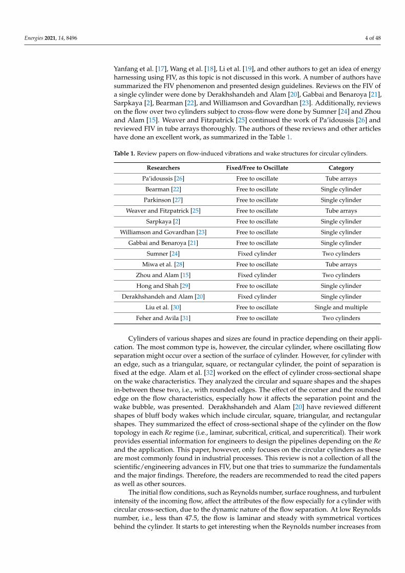
Yanfang et al. [17], Wang et al. [18], Li et al. [19], and other authors to get an idea of energyharnessing using FIV, as this topic is not discussed in this work. A number of authors havesummarized the FIV phenomenon and presented design guidelines. Reviews on the FIV ofa single cylinder were done by Derakhshandeh and Alam [20], Gabbai and Benaroya [21],Sarpkaya [2], Bearman [22], and Williamson and Govardhan [23]. Additionally, reviewson the flow over two cylinders subject to cross-flow were done by Sumner [24] and Zhouand Alam [15]. Weaver and Fitzpatrick [25] continued the work of Pa’idoussis [26] andreviewed FIV in tube arrays thoroughly. The authors of these reviews and other articleshave done an excellent work, as summarized in the Table 1.
Table 1. Review papers on flow-induced vibrations and wake structures for circular cylinders.
Researchers Fixed/Free to Oscillate Category
Pa’idoussis [26] Free to oscillate Tube arrays
Bearman [22] Free to oscillate Single cylinder
Parkinson [27] Free to oscillate Single cylinder
Weaver and Fitzpatrick [25] Free to oscillate Tube arrays
Sarpkaya [2] Free to oscillate Single cylinder
Williamson and Govardhan [23] Free to oscillate Single cylinder
Gabbai and Benaroya [21] Free to oscillate Single cylinder
Sumner [24] Fixed cylinder Two cylinders
Miwa et al. [28] Free to oscillate Tube arrays
Zhou and Alam [15] Fixed cylinder Two cylinders
Hong and Shah [29] Free to oscillate Single cylinder
Derakhshandeh and Alam [20] Fixed cylinder Single cylinder
Liu et al. [30] Free to oscillate Single and multiple
Feher and Avila [31] Free to oscillate Two cylinders
Cylinders of various shapes and sizes are found in practice depending on their appli-cation. The most common type is, however, the circular cylinder, where oscillating flowseparation might occur over a section of the surface of cylinder. However, for cylinder withan edge, such as a triangular, square, or rectangular cylinder, the point of separation isfixed at the edge. Alam et al. [32] worked on the effect of cylinder cross-sectional shapeon the wake characteristics. They analyzed the circular and square shapes and the shapesin-between these two, i.e., with rounded edges. The effect of the corner and the roundededge on the flow characteristics, especially how it affects the separation point and thewake bubble, was presented. Derakhshandeh and Alam [20] have reviewed differentshapes of bluff body wakes which include circular, square, triangular, and rectangularshapes. They summarized the effect of cross-sectional shape of the cylinder on the flowtopology in each Re regime (i.e., laminar, subcritical, critical, and supercritical). Their workprovides essential information for engineers to design the pipelines depending on the Reand the application. This paper, however, only focuses on the circular cylinders as theseare most commonly found in industrial processes. This review is not a collection of all thescientific/engineering advances in FIV, but one that tries to summarize the fundamentalsand the major findings. Therefore, the readers are recommended to read the cited papersas well as other sources.
The initial flow conditions, such as Reynolds number, surface roughness, and turbulentintensity of the incoming flow, affect the attributes of the flow especially for a cylinder withcircular cross-section, due to the dynamic nature of the flow separation. At low Reynoldsnumber, i.e., less than 47.5, the flow is laminar and steady with symmetrical vorticesbehind the cylinder. It starts to get interesting when the Reynolds number increases from
Energies 2021, 14, 8496 5 of 48
47–190 (still laminar) where vortices of opposite rotations start to shed from the bottomand top side of the cylinder alternately and Karman vortex street emerges. In this rangeof Re, the Strouhal number increases with increasing Re. The cylinder wake evolves tothree-dimensional (3D) from two-dimensional (2D) in the range of Reynolds number from190–260 [7,33].
Although there is a lot of work done in this area and many review papers are available,new techniques have emerged which have not been discussed in detail in the previousreview articles, such as two degrees of freedom (2DOF) motion of cylinder(s), effect ofsurface roughness on FIV and wake structures, FIV of heated cylinder(s), etc. This papersummarizes the recent trends in the FIV field of study. Considering the impact of FIVon vast number of applications, there is a dire need to understand the mechanism fullyin order to avoid its occurrence and the related tube failure. Research must be done toidentify the specific flow conditions where the FIV is most hazardous and to providegeneral engineering guidelines that can be applied to each application. Therefore, thereneeds to be more experimental and numerical research conducted in a more realistic wayin order to mimic the actual flow conditions. Such as, considering single and multiplecylinders with heating to simulate the heat exchanger tubes and allowing the tubes tovibrate in 2DOF and taking into account their surface roughness.
Before we jump into the technical aspect of FIV, some technical terms are defined here:
n Excitation frequency (fex): vibration frequency of a (self-excited or forced) bluff body� Strouhal frequency (fst): the frequency of vortex shedding for a body at rest� Vortex shedding frequency (fvs): frequency of vortex shedding for a body in motion
(self-excited or forced)� Natural frequency (fn): cylinder natural frequency in vacuum
The frequency value at which the vortices are shed is called vortex shedding frequency.It is nondimensionalized with the diameter of the cylinder and free steam velocity and isreferred to as Strouhal number (St):
St = fstD/U (1)
The Reynolds number (Re) is defined as:
Re = ρUD/µ, (2)
The reduced velocity (Ur) is defined as:
Ur = U/fnD (3)
where D (m) is the cylinder diameter, U (m/s) is the freestream velocity, and µ (N s/m2)and ρ (kg/m3) represent the dynamic viscosity and density of the fluid, respectively.
The remainder of the manuscript is organized as follows. The following sectiondiscusses the wake structures behind the cylinder and how they vary depending uponthe Reynolds number. The St-Re relation is also presented in this section, along with thedependence of oblique shedding angle on the Re. The wall effect for the 3D cylinder andparallel and oblique shedding is discussed in the next section. Governing equations forcylinder undergoing 1DOF and 2DOF motion are presented, followed by the parametersaffecting FIV, added mass, mass and structural damping, forced vibrations, the lock-inphenomenon, and the vortex shedding modes. The later sections present the variousstudied covering flow over unheated and heated single and multiple cylinders in tandem,side-by-side, and staggered arrangement. The sections at the end of the manuscript presentthe effect of 2DOF motion and surface roughness on the wake characteristics. Lastly,conclusions and future prospects for the research in the area of flow over circular cylindersand the related FIV is presented.
Energies 2021, 14, 8496 6 of 48
2. Wake Structures
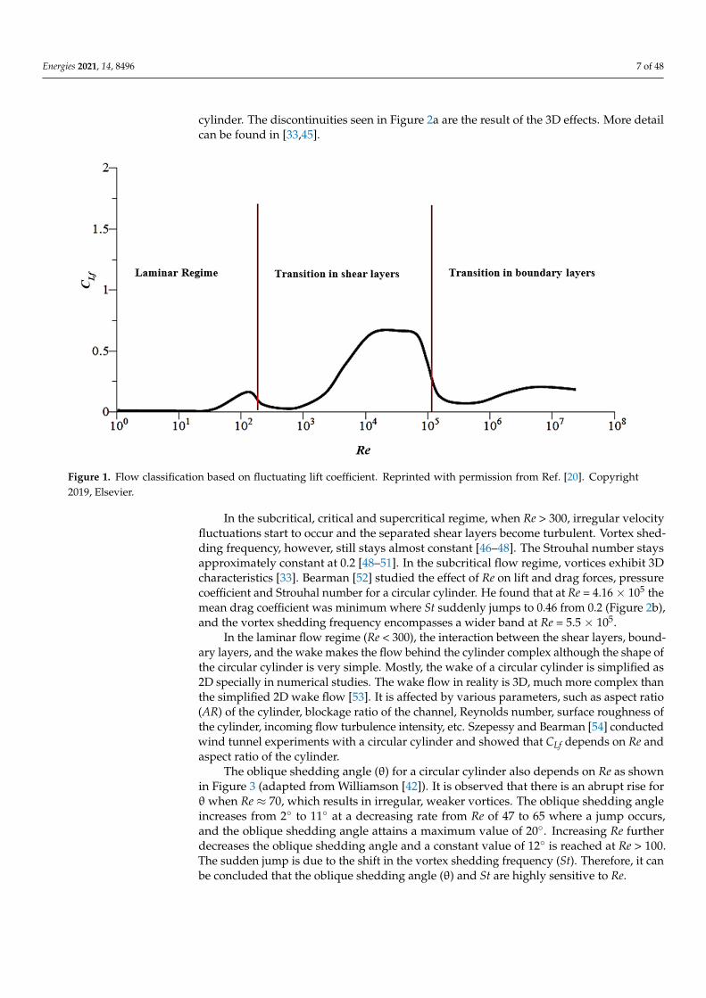
In order to understand FIV, it is vital to understand the wake structure behind thecylinder which gives rise to the vibrations. The behavior of the flow around a cylinderstrongly depends on the Re and a number of authors have classified various flow regimesbased on Re. Roshko [34] defined four flow regimes: subcritical (1 × 10³ < Re < 2 × 10⁵),critical (2 × 10⁵ < Re < 5 × 10⁵), supercritical (5 × 10⁵ < Re < 2 × 10⁶), and hypercritical(Re > 2 × 10⁶). In subcritical regime, the vortex shedding frequency remains constantand transition to turbulence occurs in the separated shear layers. In critical regime, adecrease in the drag coefficient is experienced due to transition to turbulence with anunstable boundary layer. In supercritical regime, fluctuating vortex shedding is experiencedwith loss in periodicity. In hypercritical regime, fully turbulent separation of the shearlayers is experienced which results in wider wake and the drag coefficient also increases.Coutanceau and Defaye [35] classified the flow over a single cylinder into ten regimesdepending on the flow structures based on their visual observation (Table 2). The transitionfrom one regime to another affects the vorticity, vortex size, separation point, and liftand drag forces [36–38]. The Re is the predominant factor, affecting the flow structures.More recently, Derakhshandeh and Alam [20] classified the flow over a circular cylinderinto three major regimes based on the results of Zdravkovich [39] depending upon Re,i.e., Re < 300 (laminar); 300 ≤ Re < 1.4 × 10⁵ (subcritical); and Re ≥ 1.4 × 10⁵ (criticaland supercritical). One of the reasons behind this classification is that the fluctuating liftcoefficient (CLf) acts differently in these three regions, as shown in Figure 1. So does thetransition in the shear and boundary layers [39,40].
Table 2. Flow classification based on the work of [35].
Regime Reynolds Number Range Characteristics of Regime
1: Fore-aft symmetrical flow Re < 0.1 Flow surrounds the cylinder perfectly
2: Fore-aft asymmetrical flow 0.1 ≤ Re ≤ 4.5 Speed of downstream fluid is reduced
Regime 3 4.5 ≤ Re ≤ 35 Presence of symmetrical eddies
Regime 4 35 ≤ Re ≤ 60 Slight bubble asymmetry
Regime 5 60 ≤Re ≤ 100 Shedding of alternate vortices (Karman vortex street)
Regime 6 100 ≤ Re ≤ 2000 Quasi-laminar vortices transform into turbulent vortices
Regime 7 2000 ≤ Re ≤ (1.5−2) × 105 Karman vortex street emerges at steady Strouhalnumber of 0.2
8: Critical Regime (1.5−2) × 105 ≤ Re ≤ (4−5) × 105 Unstable boundary layer, decrease in wake width, andincrease in Strouhal number
9: Supercritical Regime (4−5) × 105 ≤ Re ≤ 3.5 × 10⁶ Unstable regime and loss of wake periodicity
10: Trans-critical Regime Re ≥ 3.5 × 10⁶ Reappearance of the wake periodicity withgreater stability
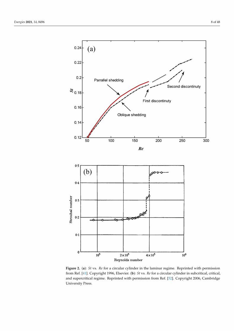
Figure 2a,b represents the effect of increasing Re on St for flow over a cylinder. Itis observed that vortex shedding starts at Re of about 47. As Re increases, St increaseswith a decreasing rate, until it reaches a constant value of 0.2 at Re of 300 (laminar regime)and stays constant in the sub-critical range from Re = 300 to 1.4 × 10⁵. The vortices arethree-dimensional in subcritical flow. A discontinuity is seen at Re of 180 [41–44]. In thecritical regime St jumps abruptly from 0.2 to around 0.5 at Re of 1.5 × 10⁵, after which itdecreases slightly and has random values at Re > 6 × 10⁵.
Many numerical studies are simplified as 2D studies, however in the 3D studies andin the experimental work, the effect of spanwise length of the cylinder is captured. Thethird dimension affects the wake of the cylinder. Williamson [6] in his work reviewedthe shift to three-dimensionality of the flow characteristics in the near wake of a circular
Energies 2021, 14, 8496 7 of 48
cylinder. The discontinuities seen in Figure 2a are the result of the 3D effects. More detailcan be found in [33,45].
Energies 2021, 14, x FOR PEER REVIEW 7 of 50
Figure 1. Flow classification based on fluctuating lift coefficient. Reprinted with permission from Ref. [20]. Copyright 2019, Elsevier.
Figure 2a,b represents the effect of increasing Re on St for flow over a cylinder. It is observed that vortex shedding starts at Re of about 47. As Re increases, St increases with a decreasing rate, until it reaches a constant value of 0.2 at Re of 300 (laminar regime) and stays constant in the sub-critical range from Re = 300 to 1.4 × 10⁵. The vortices are three-dimensional in subcritical flow. A discontinuity is seen at Re of 180 [41–44]. In the critical regime St jumps abruptly from 0.2 to around 0.5 at Re of 1.5 × 10⁵, after which it decreases slightly and has random values at Re > 6 × 10⁵.
Many numerical studies are simplified as 2D studies, however in the 3D studies and in the experimental work, the effect of spanwise length of the cylinder is captured. The third dimension affects the wake of the cylinder. Williamson [6] in his work reviewed the shift to three-dimensionality of the flow characteristics in the near wake of a circular cyl-inder. The discontinuities seen in Figure 2a are the result of the 3D effects. More detail can be found in [33,45].
In the subcritical, critical and supercritical regime, when Re > 300, irregular velocity fluctuations start to occur and the separated shear layers become turbulent. Vortex shed-ding frequency, however, still stays almost constant [46–48]. The Strouhal number stays approximately constant at 0.2 [48–51]. In the subcritical flow regime, vortices exhibit 3D characteristics [33]. Bearman [52] studied the effect of Re on lift and drag forces, pressure coefficient and Strouhal number for a circular cylinder. He found that at Re = 4.16 × 10⁵ the mean drag coefficient was minimum where St suddenly jumps to 0.46 from 0.2 (Figure 2b), and the vortex shedding frequency encompasses a wider band at Re = 5.5 × 10⁵.
Figure 1. Flow classification based on fluctuating lift coefficient. Reprinted with permission from Ref. [20]. Copyright2019, Elsevier.
In the subcritical, critical and supercritical regime, when Re > 300, irregular velocityfluctuations start to occur and the separated shear layers become turbulent. Vortex shed-ding frequency, however, still stays almost constant [46–48]. The Strouhal number staysapproximately constant at 0.2 [48–51]. In the subcritical flow regime, vortices exhibit 3Dcharacteristics [33]. Bearman [52] studied the effect of Re on lift and drag forces, pressurecoefficient and Strouhal number for a circular cylinder. He found that at Re = 4.16 × 10⁵ themean drag coefficient was minimum where St suddenly jumps to 0.46 from 0.2 (Figure 2b),and the vortex shedding frequency encompasses a wider band at Re = 5.5 × 10⁵.
In the laminar flow regime (Re < 300), the interaction between the shear layers, bound-ary layers, and the wake makes the flow behind the cylinder complex although the shape ofthe circular cylinder is very simple. Mostly, the wake of a circular cylinder is simplified as2D specially in numerical studies. The wake flow in reality is 3D, much more complex thanthe simplified 2D wake flow [53]. It is affected by various parameters, such as aspect ratio(AR) of the cylinder, blockage ratio of the channel, Reynolds number, surface roughness ofthe cylinder, incoming flow turbulence intensity, etc. Szepessy and Bearman [54] conductedwind tunnel experiments with a circular cylinder and showed that CLf depends on Re andaspect ratio of the cylinder.
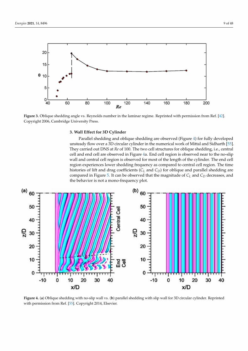
The oblique shedding angle (θ) for a circular cylinder also depends on Re as shownin Figure 3 (adapted from Williamson [42]). It is observed that there is an abrupt rise forθwhen Re ≈ 70, which results in irregular, weaker vortices. The oblique shedding angleincreases from 2◦ to 11◦ at a decreasing rate from Re of 47 to 65 where a jump occurs,and the oblique shedding angle attains a maximum value of 20◦. Increasing Re furtherdecreases the oblique shedding angle and a constant value of 12◦ is reached at Re > 100.The sudden jump is due to the shift in the vortex shedding frequency (St). Therefore, it canbe concluded that the oblique shedding angle (θ) and St are highly sensitive to Re.
Energies 2021, 14, 8496 8 of 48Energies 2021, 14, x FOR PEER REVIEW 8 of 50
Figure 2. (a): St vs. Re for a circular cylinder in the laminar regime. Reprinted with permission from Ref. [41]. Copyright 1996, Elsevier. (b): St vs. Re for a circular cylinder in subcritical, critical, and supercritical regime. Reprinted with permission from Ref. [52]. Copyright 2006, Cambridge University Press.
In the laminar flow regime (Re < 300), the interaction between the shear layers, boundary layers, and the wake makes the flow behind the cylinder complex although the shape of the circular cylinder is very simple. Mostly, the wake of a circular cylinder is simplified as 2D specially in numerical studies. The wake flow in reality is 3D, much more
Figure 2. (a): St vs. Re for a circular cylinder in the laminar regime. Reprinted with permissionfrom Ref. [41]. Copyright 1996, Elsevier. (b): St vs. Re for a circular cylinder in subcritical, critical,and supercritical regime. Reprinted with permission from Ref. [52]. Copyright 2006, CambridgeUniversity Press.
Energies 2021, 14, 8496 9 of 48
Energies 2021, 14, x FOR PEER REVIEW 9 of 50
complex than the simplified 2D wake flow [53]. It is affected by various parameters, such as aspect ratio (AR) of the cylinder, blockage ratio of the channel, Reynolds number, sur-face roughness of the cylinder, incoming flow turbulence intensity, etc. Szepessy and Bearman [54] conducted wind tunnel experiments with a circular cylinder and showed that CLf depends on Re and aspect ratio of the cylinder.
The oblique shedding angle (θ) for a circular cylinder also depends on Re as shown in Figure 3 (adapted from Williamson [42]). It is observed that there is an abrupt rise for θ when Re ≈ 70, which results in irregular, weaker vortices. The oblique shedding angle increases from 2° to 11° at a decreasing rate from Re of 47 to 65 where a jump occurs, and the oblique shedding angle attains a maximum value of 20°. Increasing Re further de-creases the oblique shedding angle and a constant value of 12° is reached at Re > 100. The sudden jump is due to the shift in the vortex shedding frequency (St). Therefore, it can be concluded that the oblique shedding angle (θ) and St are highly sensitive to Re.
Figure 3. Oblique shedding angle vs. Reynolds number in the laminar regime. Reprinted with permission from Ref. [42]. Copyright 2006, Cambridge University Press.
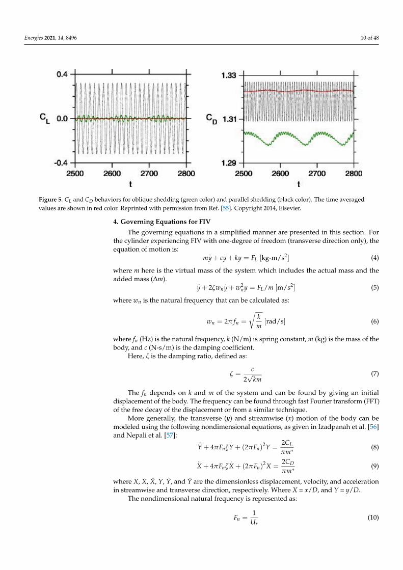
3. Wall Effect for 3D Cylinder Parallel shedding and oblique shedding are observed (Figure 4) for fully developed
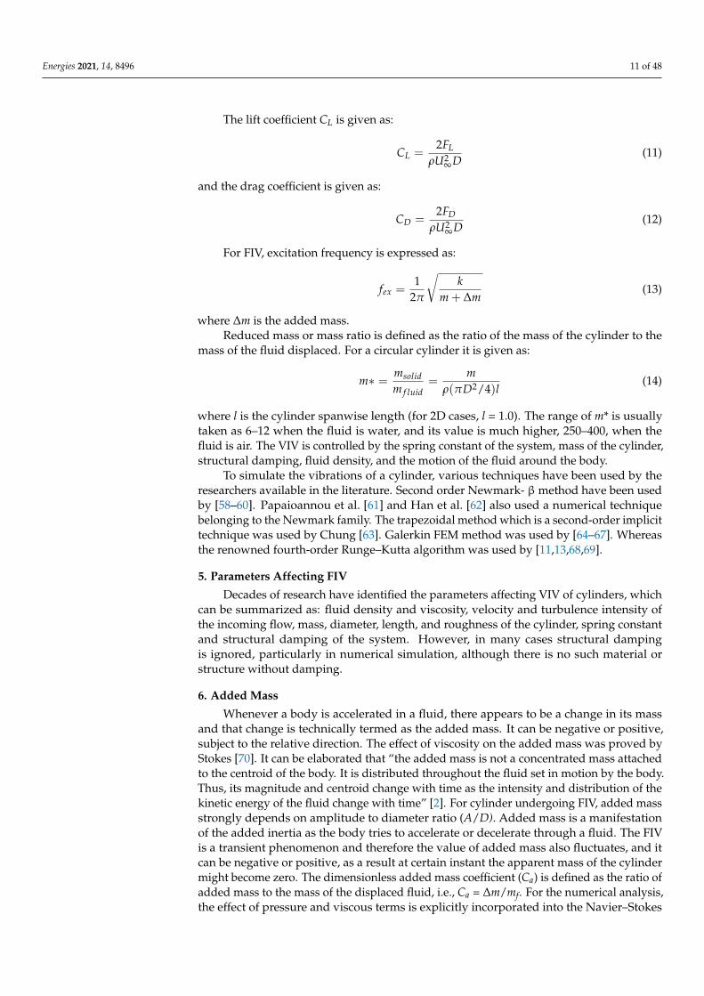
unsteady flow over a 3D circular cylinder in the numerical work of Mittal and Sidharth [55]. They carried out DNS at Re of 100. The two cell structures for oblique shedding, i.e., central cell and end cell are observed in Figure 4a. End cell region is observed near to the no-slip wall and central cell region is observed for most of the length of the cylinder. The end cell region experiences lower shedding frequency as compared to central cell region. The time histories of lift and drag coefficients (CL and CD) for oblique and parallel shed-ding are compared in Figure 5. It can be observed that the magnitude of CL and CD de-creases, and the behavior is not a mono-frequency plot.
Figure 3. Oblique shedding angle vs. Reynolds number in the laminar regime. Reprinted with permission from Ref. [42].Copyright 2006, Cambridge University Press.
3. Wall Effect for 3D Cylinder
Parallel shedding and oblique shedding are observed (Figure 4) for fully developedunsteady flow over a 3D circular cylinder in the numerical work of Mittal and Sidharth [55].They carried out DNS at Re of 100. The two cell structures for oblique shedding, i.e., centralcell and end cell are observed in Figure 4a. End cell region is observed near to the no-slipwall and central cell region is observed for most of the length of the cylinder. The end cellregion experiences lower shedding frequency as compared to central cell region. The timehistories of lift and drag coefficients (CL and CD) for oblique and parallel shedding arecompared in Figure 5. It can be observed that the magnitude of CL and CD decreases, andthe behavior is not a mono-frequency plot.
Energies 2021, 14, x FOR PEER REVIEW 10 of 50
Figure 4. (a) Oblique shedding with no-slip wall vs. (b) parallel shedding with slip wall for 3D circular cylinder. Reprinted with permission from Ref. [55]. Copyright 2014, Elsevier.
Figure 5. CL and CD behaviors for oblique shedding (green color) and parallel shedding (black color). The time averaged values are shown in red color. Reprinted with permission from Ref. [55]. Copyright 2014, Elsevier.
4. Governing Equations for FIV The governing equations in a simplified manner are presented in this section. For the
cylinder experiencing FIV with one-degree of freedom (transverse direction only), the equation of motion is: 𝑚𝑦 + 𝑐𝑦 + 𝑘𝑦 = 𝐹 [kg-m/s2] (4)
where m here is the virtual mass of the system which includes the actual mass and the added mass (Δm). 𝑦 + 2𝜁𝑤 𝑦 + 𝑤 𝑦 = 𝐹 /𝑚 [m/s2] (5)
where wn is the natural frequency that can be calculated as: 𝑤 = 2𝜋𝑓 = [rad/s] (6)
where fn (Hz) is the natural frequency, k (N/m) is spring constant, m (kg) is the mass of the body, and c (N-s/m) is the damping coefficient.
Here, ζ is the damping ratio, defined as:
Figure 4. (a) Oblique shedding with no-slip wall vs. (b) parallel shedding with slip wall for 3D circular cylinder. Reprintedwith permission from Ref. [55]. Copyright 2014, Elsevier.
Energies 2021, 14, 8496 10 of 48
Energies 2021, 14, x FOR PEER REVIEW 10 of 50
Figure 4. (a) Oblique shedding with no-slip wall vs. (b) parallel shedding with slip wall for 3D circular cylinder. Reprinted with permission from Ref. [55]. Copyright 2014, Elsevier.
Figure 5. CL and CD behaviors for oblique shedding (green color) and parallel shedding (black color). The time averaged values are shown in red color. Reprinted with permission from Ref. [55]. Copyright 2014, Elsevier.
4. Governing Equations for FIV The governing equations in a simplified manner are presented in this section. For the
cylinder experiencing FIV with one-degree of freedom (transverse direction only), the equation of motion is: 𝑚𝑦 + 𝑐𝑦 + 𝑘𝑦 = 𝐹 [kg-m/s2] (4)
where m here is the virtual mass of the system which includes the actual mass and the added mass (Δm). 𝑦 + 2𝜁𝑤 𝑦 + 𝑤 𝑦 = 𝐹 /𝑚 [m/s2] (5)
where wn is the natural frequency that can be calculated as: 𝑤 = 2𝜋𝑓 = [rad/s] (6)
where fn (Hz) is the natural frequency, k (N/m) is spring constant, m (kg) is the mass of the body, and c (N-s/m) is the damping coefficient.
Here, ζ is the damping ratio, defined as:
Figure 5. CL and CD behaviors for oblique shedding (green color) and parallel shedding (black color). The time averagedvalues are shown in red color. Reprinted with permission from Ref. [55]. Copyright 2014, Elsevier.
4. Governing Equations for FIV
The governing equations in a simplified manner are presented in this section. Forthe cylinder experiencing FIV with one-degree of freedom (transverse direction only), theequation of motion is:
m..y + c
.y + ky = FL [kg-m/s2] (4)
where m here is the virtual mass of the system which includes the actual mass and theadded mass (∆m).
..y + 2ζwn
.y + w2
ny = FL/m [m/s2] (5)
where wn is the natural frequency that can be calculated as:
wn = 2π fn =
√km
[rad/s] (6)
where fn (Hz) is the natural frequency, k (N/m) is spring constant, m (kg) is the mass of thebody, and c (N-s/m) is the damping coefficient.
Here, ζ is the damping ratio, defined as:
ζ =c
2√
km(7)
The fn depends on k and m of the system and can be found by giving an initialdisplacement of the body. The frequency can be found through fast Fourier transform (FFT)of the free decay of the displacement or from a similar technique.
More generally, the transverse (y) and streamwise (x) motion of the body can bemodeled using the following nondimensional equations, as given in Izadpanah et al. [56]and Nepali et al. [57]:
..Y + 4πFnζ
.Y + (2πFn)
2Y =2CLπm∗
(8)
..X + 4πFnζ
.X + (2πFn)
2X =2CDπm∗
(9)
where X, X, X, Y, Y, and Ÿ are the dimensionless displacement, velocity, and accelerationin streamwise and transverse direction, respectively. Where X = x/D, and Y = y/D.
The nondimensional natural frequency is represented as:
Fn =1
Ur(10)
Energies 2021, 14, 8496 11 of 48
The lift coefficient CL is given as:
CL =2FL
ρU2∞D
(11)
and the drag coefficient is given as:
CD =2FD
ρU2∞D
(12)
For FIV, excitation frequency is expressed as:
fex =1
2π
√k
m + ∆m(13)
where ∆m is the added mass.Reduced mass or mass ratio is defined as the ratio of the mass of the cylinder to the
mass of the fluid displaced. For a circular cylinder it is given as:
m∗ = msolidm f luid
=m
ρ(πD2/4)l(14)
where l is the cylinder spanwise length (for 2D cases, l = 1.0). The range of m* is usuallytaken as 6–12 when the fluid is water, and its value is much higher, 250–400, when thefluid is air. The VIV is controlled by the spring constant of the system, mass of the cylinder,structural damping, fluid density, and the motion of the fluid around the body.
To simulate the vibrations of a cylinder, various techniques have been used by theresearchers available in the literature. Second order Newmark- βmethod have been usedby [58–60]. Papaioannou et al. [61] and Han et al. [62] also used a numerical techniquebelonging to the Newmark family. The trapezoidal method which is a second-order implicittechnique was used by Chung [63]. Galerkin FEM method was used by [64–67]. Whereasthe renowned fourth-order Runge–Kutta algorithm was used by [11,13,68,69].
5. Parameters Affecting FIV
Decades of research have identified the parameters affecting VIV of cylinders, whichcan be summarized as: fluid density and viscosity, velocity and turbulence intensity ofthe incoming flow, mass, diameter, length, and roughness of the cylinder, spring constantand structural damping of the system. However, in many cases structural dampingis ignored, particularly in numerical simulation, although there is no such material orstructure without damping.
6. Added Mass
Whenever a body is accelerated in a fluid, there appears to be a change in its massand that change is technically termed as the added mass. It can be negative or positive,subject to the relative direction. The effect of viscosity on the added mass was proved byStokes [70]. It can be elaborated that “the added mass is not a concentrated mass attachedto the centroid of the body. It is distributed throughout the fluid set in motion by the body.Thus, its magnitude and centroid change with time as the intensity and distribution of thekinetic energy of the fluid change with time” [2]. For cylinder undergoing FIV, added massstrongly depends on amplitude to diameter ratio (A/D). Added mass is a manifestationof the added inertia as the body tries to accelerate or decelerate through a fluid. The FIVis a transient phenomenon and therefore the value of added mass also fluctuates, and itcan be negative or positive, as a result at certain instant the apparent mass of the cylindermight become zero. The dimensionless added mass coefficient (Ca) is defined as the ratio ofadded mass to the mass of the displaced fluid, i.e., Ca = ∆m/mf. For the numerical analysis,the effect of pressure and viscous terms is explicitly incorporated into the Navier–Stokes
Energies 2021, 14, 8496 12 of 48
equations solutions, therefore one does not need to be concerned about the value of theadded mass. Vikestad et al. [71] described complete experimental procedure and the relatedequations to find the value of added mass coefficient for a circular cylinder. The addedmass and the related added mass coefficient can be found by the following equations:
∆m = m
[(fn
fex
)2− 1
](15)
Ca = m∗[(
fn
fex
)2− 1
](16)
where fn is the cylinder natural frequency in vacuum, and fex is the vibration frequency.Cylinders with high mass ratios are less affected by the added mass and its variations,
as the lighter fluids provide less resistance to the motion of the cylinder. Heating thecylinder results in lowered values of added mass as it decreases the fluid density in thevicinity of the cylinder and hence the apparent mass ratio increases. It becomes easier forthe cylinder to accelerate in lower density fluid as compared to high density fluid.
7. Mass and Structural Damping
One must be clear about the difference between the structural damping and fluiddamping. The former results from the structure’s support whereas the latter result fromthe fluid viscosity. Structural damping is constant regardless of the fluid medium, whereasthe fluid damping strongly depends on the type of fluid. For example, the fluid dampingfor a cylinder in water will be much higher than the one present in the air. Heatingindirectly affects the effective (total) damping as the temperature change alters the fluiddamping. Heating results in lowered fluid damping if the fluid is a liquid as it decreasesits viscosity, however for gases the viscosity increases with the increase in temperature andso does the fluid damping. For FIV it must be noted that equivalent damping should beconsidered for the analysis which represents both, the structural damping as well as thefluid damping. Koopmann [72] performed experiments on elastically supported cylinderto find the damping in vacuum and in still air. His results showed that structural dampingwas only 15% of the damping in the still air. Sarpkaya [2] suggested that for VIV in water,the structural damping term is negligible as comparted to the fluid damping, and for evendense fluids, it can be completely neglected in numerical simulations. Sarpkaya [2] andAlam [73] suggested that m*ζ should not be merged to form a single parameter, althoughit has almost become a common practice to blend these parameters into a single ‘mass-damping’ parameter (m*ζ). They argued very important roles are played by each m* andζ in VIV. According to Khalak and Williamson [74], synchronization range is controlledmainly by m* (when m*ζ is constant), however the maximum amplitude of vibration isregulated mostly by the product of m*ζ in Re = 3.5 × 10³ − 1 × 10⁴.
8. Forced Vibrations
For forced vibrations, the vibrations are imposed externally at given values of A andfex. For transverse forced oscillations:
Y(t) = A*sin(2πfext) (17)
and for forced streamwise oscillations:
X(t) = A*sin(2πfext) (18)
where Y(t) and X(t) are the time-dependent displacements in the transverse and streamwisedirections, respectively.
Energies 2021, 14, 8496 13 of 48
9. Lock-In Phenomenon
One of the most important terms in FIV is the lock-in or synchronization where “large-amplitude vibrations occur on an elastically mounted cylinder. This phenomenon occursat a range of Ur when the vortex shedding frequency synchronizes with the structure’snatural frequency” [6]. The term lock-on is also synonymously used in the literature. Gaoet al. [75] defined the lock-in region as: “the VIV amplitudes within the lock-in regionmust be larger than half of the maximum amplitude experienced within the whole reducedvelocity range”. This approach of determining the lock-in zone was also used in a priorstudy [76].
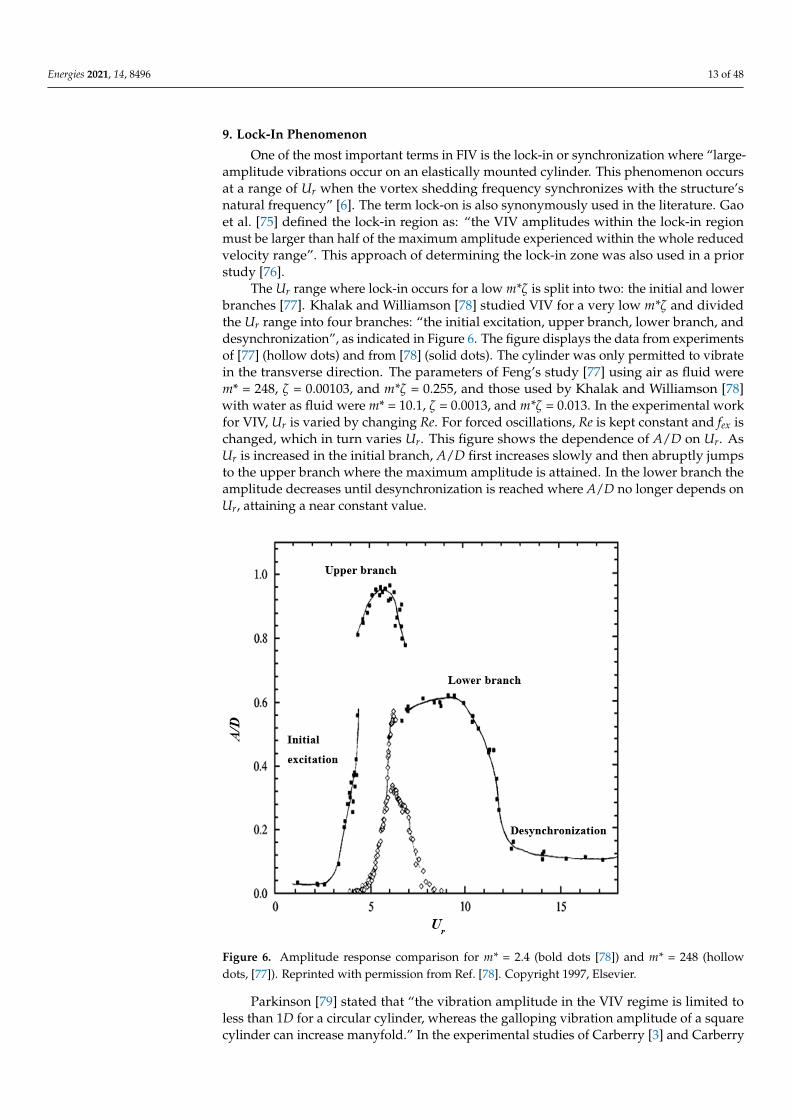
The Ur range where lock-in occurs for a low m*ζ is split into two: the initial and lowerbranches [77]. Khalak and Williamson [78] studied VIV for a very low m*ζ and dividedthe Ur range into four branches: “the initial excitation, upper branch, lower branch, anddesynchronization”, as indicated in Figure 6. The figure displays the data from experimentsof [77] (hollow dots) and from [78] (solid dots). The cylinder was only permitted to vibratein the transverse direction. The parameters of Feng’s study [77] using air as fluid werem* = 248, ζ = 0.00103, and m*ζ = 0.255, and those used by Khalak and Williamson [78]with water as fluid were m* = 10.1, ζ = 0.0013, and m*ζ = 0.013. In the experimental workfor VIV, Ur is varied by changing Re. For forced oscillations, Re is kept constant and fex ischanged, which in turn varies Ur. This figure shows the dependence of A/D on Ur. AsUr is increased in the initial branch, A/D first increases slowly and then abruptly jumpsto the upper branch where the maximum amplitude is attained. In the lower branch theamplitude decreases until desynchronization is reached where A/D no longer depends onUr, attaining a near constant value.
Energies 2021, 14, x FOR PEER REVIEW 14 of 50
et al. [80] on vibrating cylinders, the maximum lift coefficient increased by two-folds in Re = 2300−9100.
Figure 6. Amplitude response comparison for m* = 2.4 (bold dots [78]) and m* = 248 (hollow dots, [77]). Reprinted with permission from Ref. [78]. Copyright 1997, Elsevier.
In the lock-in region, even if the vortices are weak, cylinder can oscillate at large am-plitudes because of lock-in. The self-excited and self-sustaining resonant response of the cylinder occurs at specific amplitudes and frequencies, and it is a complete dynamic phe-nomenon governed by the interacting shear layers, vortex shedding and the induced forces on the body. It does not strictly happen at a fixed value of amplitude and frequency due to the continuous variations in the added-mass and in the response amplitude and frequency.
Figure 7 shows the plot between fvs vs. fex normalized by fst. When fvs is close to fst, i.e., on the horizontal line at fvs/fst = 1, vortex shedding is not affected by the excitation fre-quency. However, when fvs is equal to fex, given by the line of the slope of 1, the vortex shedding becomes synchronized with the excitation frequency and deviates from the Strouhal frequency. This trend is observed in the range of 0.5 ≤ fex/fst ≤ 1.6.
Figure 6. Amplitude response comparison for m* = 2.4 (bold dots [78]) and m* = 248 (hollowdots, [77]). Reprinted with permission from Ref. [78]. Copyright 1997, Elsevier.
Parkinson [79] stated that “the vibration amplitude in the VIV regime is limited toless than 1D for a circular cylinder, whereas the galloping vibration amplitude of a squarecylinder can increase manyfold.” In the experimental studies of Carberry [3] and Carberry
Energies 2021, 14, 8496 14 of 48
et al. [80] on vibrating cylinders, the maximum lift coefficient increased by two-folds inRe = 2300−9100.
In the lock-in region, even if the vortices are weak, cylinder can oscillate at largeamplitudes because of lock-in. The self-excited and self-sustaining resonant response of thecylinder occurs at specific amplitudes and frequencies, and it is a complete dynamic phe-nomenon governed by the interacting shear layers, vortex shedding and the induced forceson the body. It does not strictly happen at a fixed value of amplitude and frequency due tothe continuous variations in the added-mass and in the response amplitude and frequency.
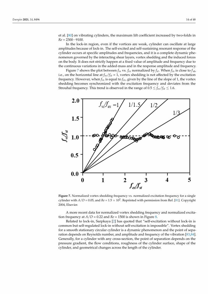
Figure 7 shows the plot between fvs vs. fex normalized by fst. When fvs is close to f st,i.e., on the horizontal line at fvs/fst = 1, vortex shedding is not affected by the excitationfrequency. However, when fvs is equal to fex, given by the line of the slope of 1, the vortexshedding becomes synchronized with the excitation frequency and deviates from theStrouhal frequency. This trend is observed in the range of 0.5 ≤ fex/fst ≤ 1.6.
Energies 2021, 14, x FOR PEER REVIEW 15 of 50
Figure 7. Normalized vortex shedding frequency vs. normalized excitation frequency for a single cylinder with A/D = 0.05, and Re = 1.5 × 10². Reprinted with permission from Ref. [81]. Copyright 2004, Elsevier.
A more recent data for normalized vortex shedding frequency and normalized exci-tation frequency at A/D = 0.22 and Re = 1500 is shown in Figure 8.
Figure 8. Normalized vortex shedding frequency vs. normalized excitation frequency for A/D = 0.22 and Re = 1.5 × 10². Reprinted with permission from Ref. [82]. Copyright 2001, Elsevier.
Related to lock-in, Sarpkaya [2] has quoted that “self-excitation without lock-in is common but self-regulated lock-in without self-excitation is impossible”. Vortex shedding for a smooth stationary circular cylinder is a dynamic phenomenon and the point of sep-aration depends on Reynolds number, and amplitude and frequency of the vibration [83,84]. Generally, for a cylinder with any cross-section, the point of separation depends on the pressure gradient, the flow conditions, roughness of the cylinder surface, shape of the cylinder, and geometrical changes across the length of the cylinder.
From Figures 7 and 8 it can be observed that the lock-in can also happen at oscilla-tions that are super-harmonics of the vortex shedding frequency. Moreover, the lock-in zones for the odd-number super-harmonics seem to be different from those for the even-
Figure 7. Normalized vortex shedding frequency vs. normalized excitation frequency for a singlecylinder with A/D = 0.05, and Re = 1.5 × 10². Reprinted with permission from Ref. [81]. Copyright2004, Elsevier.
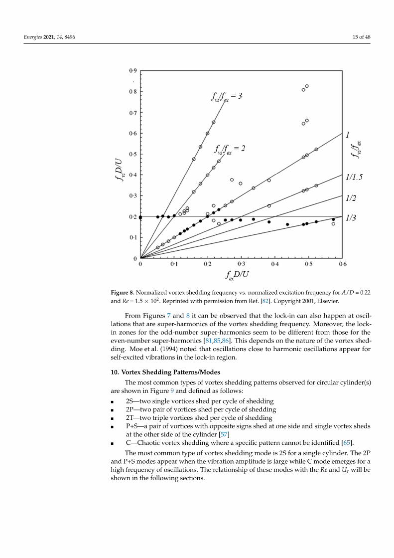
A more recent data for normalized vortex shedding frequency and normalized excita-tion frequency at A/D = 0.22 and Re = 1500 is shown in Figure 8.
Related to lock-in, Sarpkaya [2] has quoted that “self-excitation without lock-in iscommon but self-regulated lock-in without self-excitation is impossible”. Vortex sheddingfor a smooth stationary circular cylinder is a dynamic phenomenon and the point of sepa-ration depends on Reynolds number, and amplitude and frequency of the vibration [83,84].Generally, for a cylinder with any cross-section, the point of separation depends on thepressure gradient, the flow conditions, roughness of the cylinder surface, shape of thecylinder, and geometrical changes across the length of the cylinder.
Energies 2021, 14, 8496 15 of 48
Energies 2021, 14, x FOR PEER REVIEW 15 of 50
Figure 7. Normalized vortex shedding frequency vs. normalized excitation frequency for a single cylinder with A/D = 0.05, and Re = 1.5 × 10². Reprinted with permission from Ref. [81]. Copyright 2004, Elsevier.
A more recent data for normalized vortex shedding frequency and normalized exci-tation frequency at A/D = 0.22 and Re = 1500 is shown in Figure 8.
Figure 8. Normalized vortex shedding frequency vs. normalized excitation frequency for A/D = 0.22 and Re = 1.5 × 10². Reprinted with permission from Ref. [82]. Copyright 2001, Elsevier.
Related to lock-in, Sarpkaya [2] has quoted that “self-excitation without lock-in is common but self-regulated lock-in without self-excitation is impossible”. Vortex shedding for a smooth stationary circular cylinder is a dynamic phenomenon and the point of sep-aration depends on Reynolds number, and amplitude and frequency of the vibration [83,84]. Generally, for a cylinder with any cross-section, the point of separation depends on the pressure gradient, the flow conditions, roughness of the cylinder surface, shape of the cylinder, and geometrical changes across the length of the cylinder.
From Figures 7 and 8 it can be observed that the lock-in can also happen at oscilla-tions that are super-harmonics of the vortex shedding frequency. Moreover, the lock-in zones for the odd-number super-harmonics seem to be different from those for the even-
Figure 8. Normalized vortex shedding frequency vs. normalized excitation frequency for A/D = 0.22and Re = 1.5 × 10². Reprinted with permission from Ref. [82]. Copyright 2001, Elsevier.
From Figures 7 and 8 it can be observed that the lock-in can also happen at oscil-lations that are super-harmonics of the vortex shedding frequency. Moreover, the lock-in zones for the odd-number super-harmonics seem to be different from those for theeven-number super-harmonics [81,85,86]. This depends on the nature of the vortex shed-ding. Moe et al. (1994) noted that oscillations close to harmonic oscillations appear forself-excited vibrations in the lock-in region.
10. Vortex Shedding Patterns/Modes
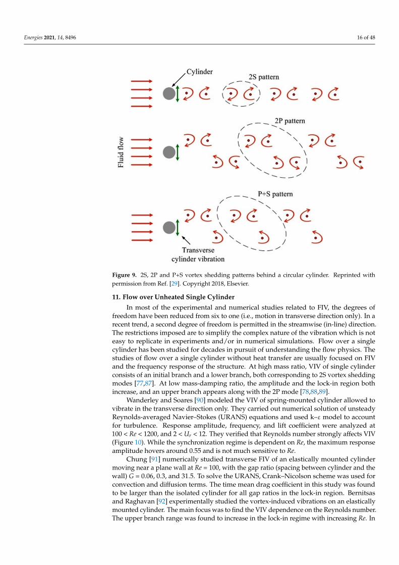
The most common types of vortex shedding patterns observed for circular cylinder(s)are shown in Figure 9 and defined as follows:
� 2S—two single vortices shed per cycle of shedding� 2P—two pair of vortices shed per cycle of shedding� 2T—two triple vortices shed per cycle of shedding� P+S—a pair of vortices with opposite signs shed at one side and single vortex sheds
at the other side of the cylinder [57]� C—Chaotic vortex shedding where a specific pattern cannot be identified [65].
The most common type of vortex shedding mode is 2S for a single cylinder. The 2Pand P+S modes appear when the vibration amplitude is large while C mode emerges for ahigh frequency of oscillations. The relationship of these modes with the Re and Ur will beshown in the following sections.
Energies 2021, 14, 8496 16 of 48
Energies 2021, 14, x FOR PEER REVIEW 16 of 50
number super-harmonics [81,85,86]. This depends on the nature of the vortex shedding. Moe et al. (1994) noted that oscillations close to harmonic oscillations appear for self-ex-cited vibrations in the lock-in region.
10. Vortex Shedding Patterns/Modes The most common types of vortex shedding patterns observed for circular cylinder(s)
are shown in Figure 9 and defined as follows: 2S—two single vortices shed per cycle of shedding 2P—two pair of vortices shed per cycle of shedding 2T—two triple vortices shed per cycle of shedding P+S—a pair of vortices with opposite signs shed at one side and single vortex sheds
at the other side of the cylinder [57] C—Chaotic vortex shedding where a specific pattern cannot be identified [65].
Figure 9. 2S, 2P and P+S vortex shedding patterns behind a circular cylinder. Reprinted with per-mission from Ref. [29]. Copyright 2018, Elsevier.
The most common type of vortex shedding mode is 2S for a single cylinder. The 2P and P+S modes appear when the vibration amplitude is large while C mode emerges for a high frequency of oscillations. The relationship of these modes with the Re and Ur will be shown in the following sections.
11. Flow over Unheated Single Cylinder In most of the experimental and numerical studies related to FIV, the degrees of free-
dom have been reduced from six to one (i.e., motion in transverse direction only). In a recent trend, a second degree of freedom is permitted in the streamwise (in-line) direction. The restrictions imposed are to simplify the complex nature of the vibration which is not easy to replicate in experiments and/or in numerical simulations. Flow over a single cyl-inder has been studied for decades in pursuit of understanding the flow physics. The studies of flow over a single cylinder without heat transfer are usually focused on FIV and the frequency response of the structure. At high mass ratio, VIV of single cylinder consists of an initial branch and a lower branch, both corresponding to 2S vortex shedding modes [77,87]. At low mass-damping ratio, the amplitude and the lock-in region both increase, and an upper branch appears along with the 2P mode [78,88,89].
Figure 9. 2S, 2P and P+S vortex shedding patterns behind a circular cylinder. Reprinted withpermission from Ref. [29]. Copyright 2018, Elsevier.
11. Flow over Unheated Single Cylinder
In most of the experimental and numerical studies related to FIV, the degrees offreedom have been reduced from six to one (i.e., motion in transverse direction only). In arecent trend, a second degree of freedom is permitted in the streamwise (in-line) direction.The restrictions imposed are to simplify the complex nature of the vibration which is noteasy to replicate in experiments and/or in numerical simulations. Flow over a singlecylinder has been studied for decades in pursuit of understanding the flow physics. Thestudies of flow over a single cylinder without heat transfer are usually focused on FIVand the frequency response of the structure. At high mass ratio, VIV of single cylinderconsists of an initial branch and a lower branch, both corresponding to 2S vortex sheddingmodes [77,87]. At low mass-damping ratio, the amplitude and the lock-in region bothincrease, and an upper branch appears along with the 2P mode [78,88,89].
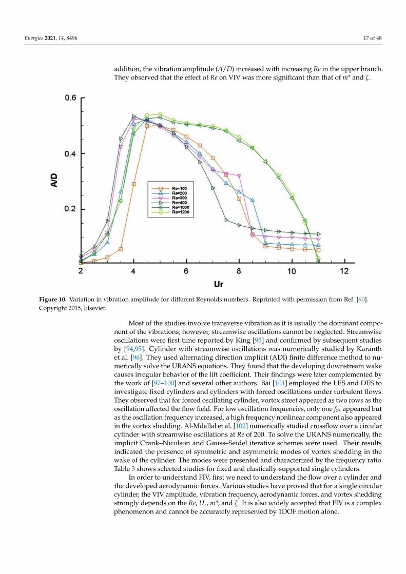
Wanderley and Soares [90] modeled the VIV of spring-mounted cylinder allowed tovibrate in the transverse direction only. They carried out numerical solution of unsteadyReynolds-averaged Navier–Stokes (URANS) equations and used k–ε model to accountfor turbulence. Response amplitude, frequency, and lift coefficient were analyzed at100 < Re < 1200, and 2 < Ur < 12. They verified that Reynolds number strongly affects VIV(Figure 10). While the synchronization regime is dependent on Re, the maximum responseamplitude hovers around 0.55 and is not much sensitive to Re.
Chung [91] numerically studied transverse FIV of an elastically mounted cylindermoving near a plane wall at Re = 100, with the gap ratio (spacing between cylinder and thewall) G = 0.06, 0.3, and 31.5. To solve the URANS, Crank–Nicolson scheme was used forconvection and diffusion terms. The time mean drag coefficient in this study was foundto be larger than the isolated cylinder for all gap ratios in the lock-in region. Bernitsasand Raghavan [92] experimentally studied the vortex-induced vibrations on an elasticallymounted cylinder. The main focus was to find the VIV dependence on the Reynolds number.The upper branch range was found to increase in the lock-in regime with increasing Re. In
Energies 2021, 14, 8496 17 of 48
addition, the vibration amplitude (A/D) increased with increasing Re in the upper branch.They observed that the effect of Re on VIV was more significant than that of m* and ζ.
Energies 2021, 14, x FOR PEER REVIEW 17 of 50
Wanderley and Soares [90] modeled the VIV of spring-mounted cylinder allowed to vibrate in the transverse direction only. They carried out numerical solution of unsteady Reynolds-averaged Navier–Stokes (URANS) equations and used k–ε model to account for turbulence. Response amplitude, frequency, and lift coefficient were analyzed at 100 < Re < 1200, and 2 < Ur < 12. They verified that Reynolds number strongly affects VIV (Figure 10). While the synchronization regime is dependent on Re, the maximum response ampli-tude hovers around 0.55 and is not much sensitive to Re.
Figure 10. Variation in vibration amplitude for different Reynolds numbers. Reprinted with permission from Ref. [90]. Copyright 2015, Elsevier.
Chung [91] numerically studied transverse FIV of an elastically mounted cylinder moving near a plane wall at 𝑅𝑒 = 100, with the gap ratio (spacing between cylinder and the wall) 𝐺 = 0.06, 0.3, and 31.5. To solve the URANS, Crank–Nicolson scheme was used for convection and diffusion terms. The time mean drag coefficient in this study was found to be larger than the isolated cylinder for all gap ratios in the lock-in region. Ber-nitsas and Raghavan [92] experimentally studied the vortex-induced vibrations on an elastically mounted cylinder. The main focus was to find the VIV dependence on the Reynolds number. The upper branch range was found to increase in the lock-in regime with increasing Re. In addition, the vibration amplitude (A/D) increased with increasing Re in the upper branch. They observed that the effect of Re on VIV was more significant than that of m* and ζ.
Most of the studies involve transverse vibration as it is usually the dominant compo-nent of the vibrations; however, streamwise oscillations cannot be neglected. Streamwise oscillations were first time reported by King [93] and confirmed by subsequent studies by [94,95]. Cylinder with streamwise oscillations was numerically studied by Karanth et al. [96]. They used alternating direction implicit (ADI) finite difference method to numeri-cally solve the URANS equations. They found that the developing downstream wake causes irregular behavior of the lift coefficient. Their findings were later complemented by the work of [97–100] and several other authors. Bai [101] employed the LES and DES to investigate fixed cylinders and cylinders with forced oscillations under turbulent flows. They observed that for forced oscillating cylinder, vortex street appeared as two rows as
Figure 10. Variation in vibration amplitude for different Reynolds numbers. Reprinted with permission from Ref. [90].Copyright 2015, Elsevier.
Most of the studies involve transverse vibration as it is usually the dominant compo-nent of the vibrations; however, streamwise oscillations cannot be neglected. Streamwiseoscillations were first time reported by King [93] and confirmed by subsequent studiesby [94,95]. Cylinder with streamwise oscillations was numerically studied by Karanthet al. [96]. They used alternating direction implicit (ADI) finite difference method to nu-merically solve the URANS equations. They found that the developing downstream wakecauses irregular behavior of the lift coefficient. Their findings were later complemented bythe work of [97–100] and several other authors. Bai [101] employed the LES and DES toinvestigate fixed cylinders and cylinders with forced oscillations under turbulent flows.They observed that for forced oscillating cylinder, vortex street appeared as two rows as theoscillation affected the flow field. For low oscillation frequencies, only one fvs appeared butas the oscillation frequency increased, a high frequency nonlinear component also appearedin the vortex shedding. Al-Mdallal et al. [102] numerically studied crossflow over a circularcylinder with streamwise oscillations at Re of 200. To solve the URANS numerically, theimplicit Crank–Nicolson and Gauss–Seidel iterative schemes were used. Their resultsindicated the presence of symmetric and asymmetric modes of vortex shedding in thewake of the cylinder. The modes were presented and characterized by the frequency ratio.Table 3 shows selected studies for fixed and elastically-supported single cylinders.
In order to understand FIV, first we need to understand the flow over a cylinder andthe developed aerodynamic forces. Various studies have proved that for a single circularcylinder, the VIV amplitude, vibration frequency, aerodynamic forces, and vortex sheddingstrongly depends on the Re, Ur, m*, and ζ. It is also widely accepted that FIV is a complexphenomenon and cannot be accurately represented by 1DOF motion alone.
Energies 2021, 14, 8496 18 of 48
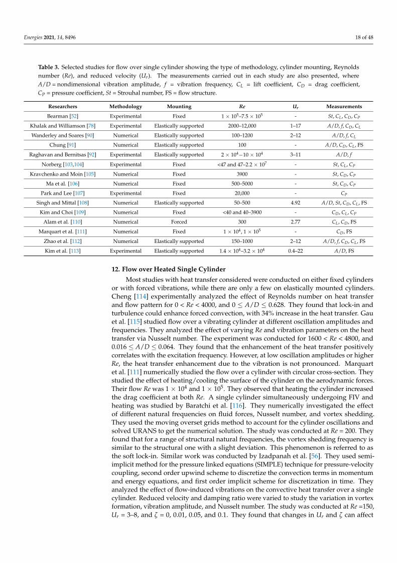
Table 3. Selected studies for flow over single cylinder showing the type of methodology, cylinder mounting, Reynoldsnumber (Re), and reduced velocity (Ur). The measurements carried out in each study are also presented, whereA/D = nondimensional vibration amplitude, f = vibration frequency, CL = lift coefficient, CD = drag coefficient,CP = pressure coefficient, St = Strouhal number, FS = flow structure.
Researchers Methodology Mounting Re Ur Measurements
Bearman [52] Experimental Fixed 1 × 10⁵–7.5 × 10⁵ - St, CL, CD, CP
Khalak and Williamson [78] Experimental Elastically supported 2000–12,000 1–17 A/D, f, CD, CL
Wanderley and Soares [90] Numerical Elastically supported 100–1200 2–12 A/D, f, CL
Chung [91] Numerical Elastically supported 100 - A/D, CD, CL, FS
Raghavan and Bernitsas [92] Experimental Elastically supported 2 × 10⁴−10 × 104 3–11 A/D, f
Norberg [103,104] Experimental Fixed <47 and 47–2.2 × 10⁷ - St, CL, CP
Kravchenko and Moin [105] Numerical Fixed 3900 - St, CD, CP
Ma et al. [106] Numerical Fixed 500–5000 - St, CD, CP
Park and Lee [107] Experimental Fixed 20,000 - CP
Singh and Mittal [108] Numerical Elastically supported 50–500 4.92 A/D, St, CD, CL, FS
Kim and Choi [109] Numerical Fixed <40 and 40–3900 - CD, CL, CP
Alam et al. [110] Numerical Forced 300 2.77 CL, CD, FS
Marquart et al. [111] Numerical Fixed 1 × 10⁴, 1 × 10⁵ - CD, FS
Zhao et al. [112] Numerical Elastically supported 150–1000 2–12 A/D, f, CD, CL, FS
Kim et al. [113] Experimental Elastically supported 1.4 × 10⁴–3.2 × 10⁴ 0.4–22 A/D, FS
12. Flow over Heated Single Cylinder
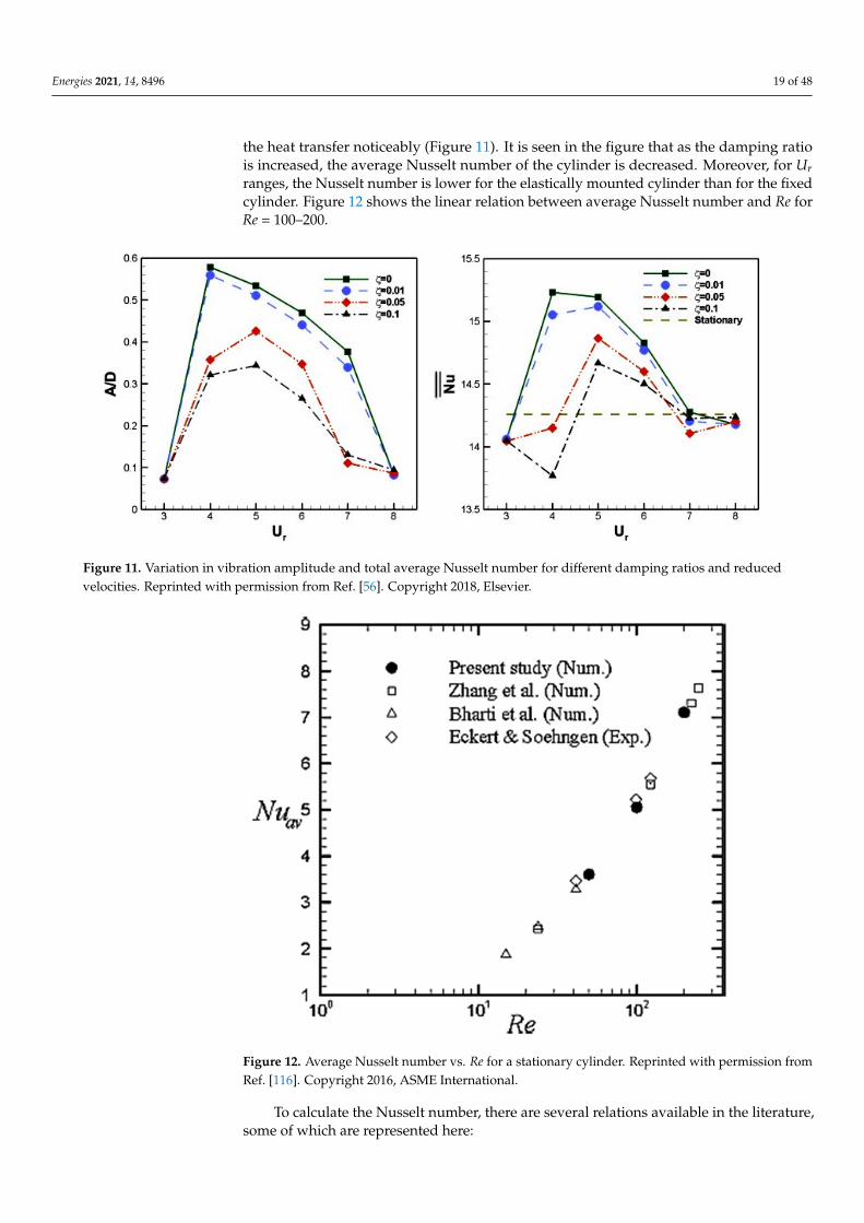
Most studies with heat transfer considered were conducted on either fixed cylindersor with forced vibrations, while there are only a few on elastically mounted cylinders.Cheng [114] experimentally analyzed the effect of Reynolds number on heat transferand flow pattern for 0 < Re < 4000, and 0 ≤ A/D ≤ 0.628. They found that lock-in andturbulence could enhance forced convection, with 34% increase in the heat transfer. Gauet al. [115] studied flow over a vibrating cylinder at different oscillation amplitudes andfrequencies. They analyzed the effect of varying Re and vibration parameters on the heattransfer via Nusselt number. The experiment was conducted for 1600 < Re < 4800, and0.016 ≤ A/D ≤ 0.064. They found that the enhancement of the heat transfer positivelycorrelates with the excitation frequency. However, at low oscillation amplitudes or higherRe, the heat transfer enhancement due to the vibration is not pronounced. Marquartet al. [111] numerically studied the flow over a cylinder with circular cross-section. Theystudied the effect of heating/cooling the surface of the cylinder on the aerodynamic forces.Their flow Re was 1 × 10⁴ and 1 × 10⁵. They observed that heating the cylinder increasedthe drag coefficient at both Re. A single cylinder simultaneously undergoing FIV andheating was studied by Baratchi et al. [116]. They numerically investigated the effectof different natural frequencies on fluid forces, Nusselt number, and vortex shedding.They used the moving overset grids method to account for the cylinder oscillations andsolved URANS to get the numerical solution. The study was conducted at Re = 200. Theyfound that for a range of structural natural frequencies, the vortex shedding frequency issimilar to the structural one with a slight deviation. This phenomenon is referred to asthe soft lock-in. Similar work was conducted by Izadpanah et al. [56]. They used semi-implicit method for the pressure linked equations (SIMPLE) technique for pressure-velocitycoupling, second order upwind scheme to discretize the convection terms in momentumand energy equations, and first order implicit scheme for discretization in time. Theyanalyzed the effect of flow-induced vibrations on the convective heat transfer over a singlecylinder. Reduced velocity and damping ratio were varied to study the variation in vortexformation, vibration amplitude, and Nusselt number. The study was conducted at Re =150,Ur = 3–8, and ζ = 0, 0.01, 0.05, and 0.1. They found that changes in Ur and ζ can affect
Energies 2021, 14, 8496 19 of 48
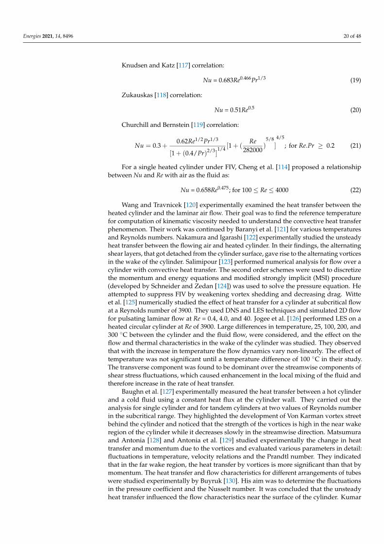
the heat transfer noticeably (Figure 11). It is seen in the figure that as the damping ratiois increased, the average Nusselt number of the cylinder is decreased. Moreover, for Urranges, the Nusselt number is lower for the elastically mounted cylinder than for the fixedcylinder. Figure 12 shows the linear relation between average Nusselt number and Re forRe = 100–200.
Energies 2021, 14, x FOR PEER REVIEW 20 of 50
Figure 11. Variation in vibration amplitude and total average Nusselt number for different damping ratios and reduced velocities. Reprinted with permission from Ref. [56]. Copyright 2018, Elsevier.
Figure 12. Average Nusselt number vs. Re for a stationary cylinder. Reprinted with permission from Ref. [116]. Copyright 2016, ASME International.
Wang and Travnicek [120] experimentally examined the heat transfer between the heated cylinder and the laminar air flow. Their goal was to find the reference temperature for computation of kinematic viscosity needed to understand the convective heat transfer phenomenon. Their work was continued by Baranyi et al. [121] for various temperatures and Reynolds numbers. Nakamura and Igarashi [122] experimentally studied the un-steady heat transfer between the flowing air and heated cylinder. In their findings, the alternating shear layers, that got detached from the cylinder surface, gave rise to the al-ternating vortices in the wake of the cylinder. Salimipour [123] performed numerical anal-ysis for flow over a cylinder with convective heat transfer. The second order schemes were used to discretize the momentum and energy equations and modified strongly implicit (MSI) procedure (developed by Schneider and Zedan [124]) was used to solve the pressure equation. He attempted to suppress FIV by weakening vortex shedding and decreasing drag. Witte et al. [125] numerically studied the effect of heat transfer for a cylinder at sub-
Figure 11. Variation in vibration amplitude and total average Nusselt number for different damping ratios and reducedvelocities. Reprinted with permission from Ref. [56]. Copyright 2018, Elsevier.
Energies 2021, 14, x FOR PEER REVIEW 20 of 50
Figure 11. Variation in vibration amplitude and total average Nusselt number for different damping ratios and reduced velocities. Reprinted with permission from Ref. [56]. Copyright 2018, Elsevier.
Figure 12. Average Nusselt number vs. Re for a stationary cylinder. Reprinted with permission from Ref. [116]. Copyright 2016, ASME International.
Wang and Travnicek [120] experimentally examined the heat transfer between the heated cylinder and the laminar air flow. Their goal was to find the reference temperature for computation of kinematic viscosity needed to understand the convective heat transfer phenomenon. Their work was continued by Baranyi et al. [121] for various temperatures and Reynolds numbers. Nakamura and Igarashi [122] experimentally studied the un-steady heat transfer between the flowing air and heated cylinder. In their findings, the alternating shear layers, that got detached from the cylinder surface, gave rise to the al-ternating vortices in the wake of the cylinder. Salimipour [123] performed numerical anal-ysis for flow over a cylinder with convective heat transfer. The second order schemes were used to discretize the momentum and energy equations and modified strongly implicit (MSI) procedure (developed by Schneider and Zedan [124]) was used to solve the pressure equation. He attempted to suppress FIV by weakening vortex shedding and decreasing drag. Witte et al. [125] numerically studied the effect of heat transfer for a cylinder at sub-
Figure 12. Average Nusselt number vs. Re for a stationary cylinder. Reprinted with permission fromRef. [116]. Copyright 2016, ASME International.
To calculate the Nusselt number, there are several relations available in the literature,some of which are represented here:
Energies 2021, 14, 8496 20 of 48
Knudsen and Katz [117] correlation:
Nu = 0.683Re0.466Pr1/3 (19)
Zukauskas [118] correlation:
Nu = 0.51Re0.5 (20)
Churchill and Bernstein [119] correlation:
Nu = 0.3 +0.62Re1/2Pr1/3
[1 + (0.4/Pr)2/3]1/4 [1 + (
Re282000
)5/8
]
4/5
; for Re.Pr ≥ 0.2 (21)
For a single heated cylinder under FIV, Cheng et al. [114] proposed a relationshipbetween Nu and Re with air as the fluid as:
Nu = 0.658Re0.475; for 100 ≤ Re ≤ 4000 (22)
Wang and Travnicek [120] experimentally examined the heat transfer between theheated cylinder and the laminar air flow. Their goal was to find the reference temperaturefor computation of kinematic viscosity needed to understand the convective heat transferphenomenon. Their work was continued by Baranyi et al. [121] for various temperaturesand Reynolds numbers. Nakamura and Igarashi [122] experimentally studied the unsteadyheat transfer between the flowing air and heated cylinder. In their findings, the alternatingshear layers, that got detached from the cylinder surface, gave rise to the alternating vorticesin the wake of the cylinder. Salimipour [123] performed numerical analysis for flow over acylinder with convective heat transfer. The second order schemes were used to discretizethe momentum and energy equations and modified strongly implicit (MSI) procedure(developed by Schneider and Zedan [124]) was used to solve the pressure equation. Heattempted to suppress FIV by weakening vortex shedding and decreasing drag. Witteet al. [125] numerically studied the effect of heat transfer for a cylinder at subcritical flowat a Reynolds number of 3900. They used DNS and LES techniques and simulated 2D flowfor pulsating laminar flow at Re = 0.4, 4.0, and 40. Jogee et al. [126] performed LES on aheated circular cylinder at Re of 3900. Large differences in temperature, 25, 100, 200, and300 ◦C between the cylinder and the fluid flow, were considered, and the effect on theflow and thermal characteristics in the wake of the cylinder was studied. They observedthat with the increase in temperature the flow dynamics vary non-linearly. The effect oftemperature was not significant until a temperature difference of 100 ◦C in their study.The transverse component was found to be dominant over the streamwise components ofshear stress fluctuations, which caused enhancement in the local mixing of the fluid andtherefore increase in the rate of heat transfer.
Baughn et al. [127] experimentally measured the heat transfer between a hot cylinderand a cold fluid using a constant heat flux at the cylinder wall. They carried out theanalysis for single cylinder and for tandem cylinders at two values of Reynolds numberin the subcritical range. They highlighted the development of Von Karman vortex streetbehind the cylinder and noticed that the strength of the vortices is high in the near wakeregion of the cylinder while it decreases slowly in the streamwise direction. Matsumuraand Antonia [128] and Antonia et al. [129] studied experimentally the change in heattransfer and momentum due to the vortices and evaluated various parameters in detail:fluctuations in temperature, velocity relations and the Prandtl number. They indicatedthat in the far wake region, the heat transfer by vortices is more significant than that bymomentum. The heat transfer and flow characteristics for different arrangements of tubeswere studied experimentally by Buyruk [130]. His aim was to determine the fluctuationsin the pressure coefficient and the Nusselt number. It was concluded that the unsteadyheat transfer influenced the flow characteristics near the surface of the cylinder. Kumar
Energies 2021, 14, 8496 21 of 48
and Jayavel [131] examined the flow over a tube bundle and isolated a single cylinder fromthe tube bundle for analysis. Their study was carried out at Re of 50–100 with varyingtransverse pitch (H/D) in the range of 1.54–5. They considered varying blockage ratios forheat exchanger with cylindrical tubes and concluded that the heat transfer enhancementonly depends on the frequency of vortex shedding when blockage ratio is over 3.
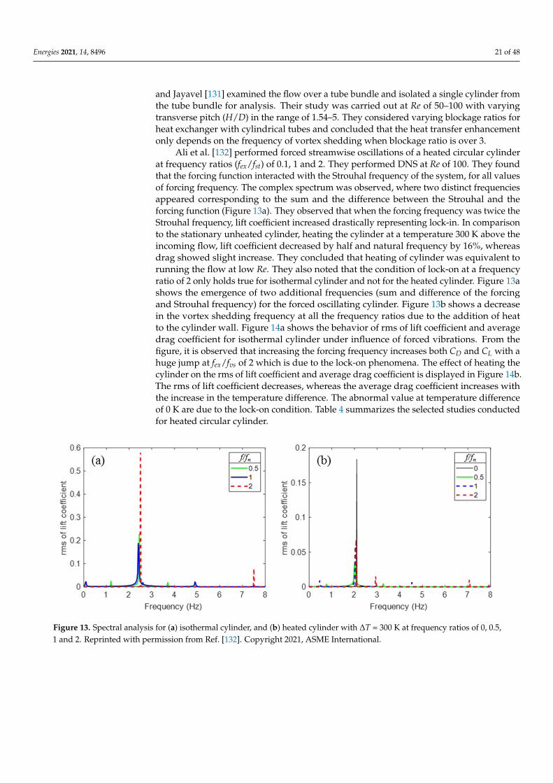
Ali et al. [132] performed forced streamwise oscillations of a heated circular cylinderat frequency ratios (fex/fst) of 0.1, 1 and 2. They performed DNS at Re of 100. They foundthat the forcing function interacted with the Strouhal frequency of the system, for all valuesof forcing frequency. The complex spectrum was observed, where two distinct frequenciesappeared corresponding to the sum and the difference between the Strouhal and theforcing function (Figure 13a). They observed that when the forcing frequency was twice theStrouhal frequency, lift coefficient increased drastically representing lock-in. In comparisonto the stationary unheated cylinder, heating the cylinder at a temperature 300 K above theincoming flow, lift coefficient decreased by half and natural frequency by 16%, whereasdrag showed slight increase. They concluded that heating of cylinder was equivalent torunning the flow at low Re. They also noted that the condition of lock-on at a frequencyratio of 2 only holds true for isothermal cylinder and not for the heated cylinder. Figure 13ashows the emergence of two additional frequencies (sum and difference of the forcingand Strouhal frequency) for the forced oscillating cylinder. Figure 13b shows a decreasein the vortex shedding frequency at all the frequency ratios due to the addition of heatto the cylinder wall. Figure 14a shows the behavior of rms of lift coefficient and averagedrag coefficient for isothermal cylinder under influence of forced vibrations. From thefigure, it is observed that increasing the forcing frequency increases both CD and CL with ahuge jump at fex/fvs of 2 which is due to the lock-on phenomena. The effect of heating thecylinder on the rms of lift coefficient and average drag coefficient is displayed in Figure 14b.The rms of lift coefficient decreases, whereas the average drag coefficient increases withthe increase in the temperature difference. The abnormal value at temperature differenceof 0 K are due to the lock-on condition. Table 4 summarizes the selected studies conductedfor heated circular cylinder.
Energies 2021, 14, x FOR PEER REVIEW 22 of 50
Figure 13. Spectral analysis for (a) isothermal cylinder, and (b) heated cylinder with ΔT = 300 K at frequency ratios of 0, 0.5, 1 and 2. Reprinted with permission from Ref. [132]. Copyright 2021, ASME International.
Figure 14. Behavior of rms of lift coefficient and average drag coefficient along (a) frequency ratios for isothermal cylinder and (b) temperature difference between the cylinder wall and the incoming fluid. Reprinted with permission from Ref. [132]. Copyright 2021, ASME International.
Table 4. Selected studies for flow over heated single circular cylinder showing the type of methodology, cylinder mount-ing, and Reynolds number (Re). The measurements carried out in each study are also presented, where A/D = nondimen-sional vibration amplitude, CL = lift coefficient, CD = drag coefficient, St = Strouhal number, Nu = Nusselt number, h = convective heat transfer coefficient, FS = flow structure.
Researchers Methodology Mounting Re Measurements Abdelhamid et al. [5] Numerical Fixed 40–180 Nu, CD, CL, flow field
Alam et al. [32] Numerical Fixed 150 Nu, CD, CL, FS, flow field
Izadpanah et al. [56] Numerical Elastically supported 150 Nu, A/D, FS
Cheng et al. [114] Experimental Forced transverse vi-
bration 0–4000 Nu, FS
Gau et al. [115] Experimental Forced transverse vi-
bration 1600–4800 Nu, FS
Baratchi et al. [116] Numerical Elastically supported 200 Nu, CD, St, FS Nakamura and Iga-
rashi [122] Experimental Fixed 3000–15,000 Nu, FS
Kumar and Jayavel [131] Numerical Fixed 50–1000 Nu, CD, St, FS
Figure 13. Spectral analysis for (a) isothermal cylinder, and (b) heated cylinder with ∆T = 300 K at frequency ratios of 0, 0.5,1 and 2. Reprinted with permission from Ref. [132]. Copyright 2021, ASME International.
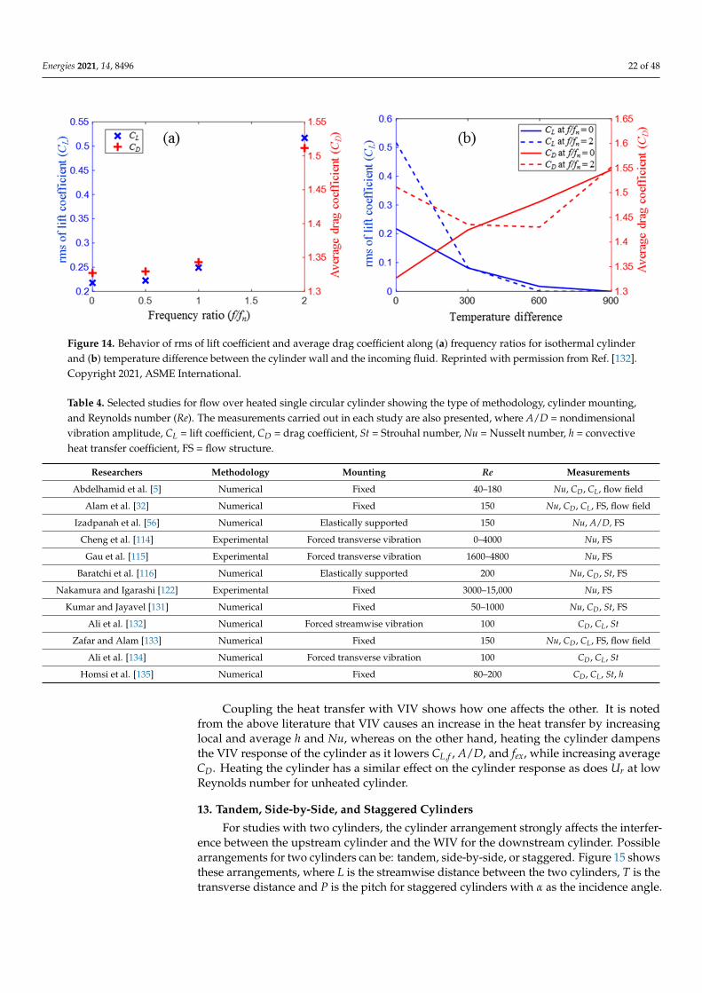
Energies 2021, 14, 8496 22 of 48
Energies 2021, 14, x FOR PEER REVIEW 22 of 50
Figure 13. Spectral analysis for (a) isothermal cylinder, and (b) heated cylinder with ΔT = 300 K at frequency ratios of 0, 0.5, 1 and 2. Reprinted with permission from Ref. [132]. Copyright 2021, ASME International.
Figure 14. Behavior of rms of lift coefficient and average drag coefficient along (a) frequency ratios for isothermal cylinder and (b) temperature difference between the cylinder wall and the incoming fluid. Reprinted with permission from Ref. [132]. Copyright 2021, ASME International.
Table 4. Selected studies for flow over heated single circular cylinder showing the type of methodology, cylinder mount-ing, and Reynolds number (Re). The measurements carried out in each study are also presented, where A/D = nondimen-sional vibration amplitude, CL = lift coefficient, CD = drag coefficient, St = Strouhal number, Nu = Nusselt number, h = convective heat transfer coefficient, FS = flow structure.
Researchers Methodology Mounting Re Measurements Abdelhamid et al. [5] Numerical Fixed 40–180 Nu, CD, CL, flow field
Alam et al. [32] Numerical Fixed 150 Nu, CD, CL, FS, flow field
Izadpanah et al. [56] Numerical Elastically supported 150 Nu, A/D, FS
Cheng et al. [114] Experimental Forced transverse vi-
bration 0–4000 Nu, FS
Gau et al. [115] Experimental Forced transverse vi-
bration 1600–4800 Nu, FS
Baratchi et al. [116] Numerical Elastically supported 200 Nu, CD, St, FS Nakamura and Iga-
rashi [122] Experimental Fixed 3000–15,000 Nu, FS
Kumar and Jayavel [131] Numerical Fixed 50–1000 Nu, CD, St, FS
Figure 14. Behavior of rms of lift coefficient and average drag coefficient along (a) frequency ratios for isothermal cylinderand (b) temperature difference between the cylinder wall and the incoming fluid. Reprinted with permission from Ref. [132].Copyright 2021, ASME International.
Table 4. Selected studies for flow over heated single circular cylinder showing the type of methodology, cylinder mounting,and Reynolds number (Re). The measurements carried out in each study are also presented, where A/D = nondimensionalvibration amplitude, CL = lift coefficient, CD = drag coefficient, St = Strouhal number, Nu = Nusselt number, h = convectiveheat transfer coefficient, FS = flow structure.
Researchers Methodology Mounting Re Measurements
Abdelhamid et al. [5] Numerical Fixed 40–180 Nu, CD, CL, flow field
Alam et al. [32] Numerical Fixed 150 Nu, CD, CL, FS, flow field
Izadpanah et al. [56] Numerical Elastically supported 150 Nu, A/D, FS
Cheng et al. [114] Experimental Forced transverse vibration 0–4000 Nu, FS
Gau et al. [115] Experimental Forced transverse vibration 1600–4800 Nu, FS
Baratchi et al. [116] Numerical Elastically supported 200 Nu, CD, St, FS
Nakamura and Igarashi [122] Experimental Fixed 3000–15,000 Nu, FS
Kumar and Jayavel [131] Numerical Fixed 50–1000 Nu, CD, St, FS
Ali et al. [132] Numerical Forced streamwise vibration 100 CD, CL, St
Zafar and Alam [133] Numerical Fixed 150 Nu, CD, CL, FS, flow field
Ali et al. [134] Numerical Forced transverse vibration 100 CD, CL, St
Homsi et al. [135] Numerical Fixed 80–200 CD, CL, St, h
Coupling the heat transfer with VIV shows how one affects the other. It is notedfrom the above literature that VIV causes an increase in the heat transfer by increasinglocal and average h and Nu, whereas on the other hand, heating the cylinder dampensthe VIV response of the cylinder as it lowers CL,f , A/D, and fex, while increasing averageCD. Heating the cylinder has a similar effect on the cylinder response as does Ur at lowReynolds number for unheated cylinder.
13. Tandem, Side-by-Side, and Staggered Cylinders
For studies with two cylinders, the cylinder arrangement strongly affects the interfer-ence between the upstream cylinder and the WIV for the downstream cylinder. Possiblearrangements for two cylinders can be: tandem, side-by-side, or staggered. Figure 15 showsthese arrangements, where L is the streamwise distance between the two cylinders, T is thetransverse distance and P is the pitch for staggered cylinders with α as the incidence angle.
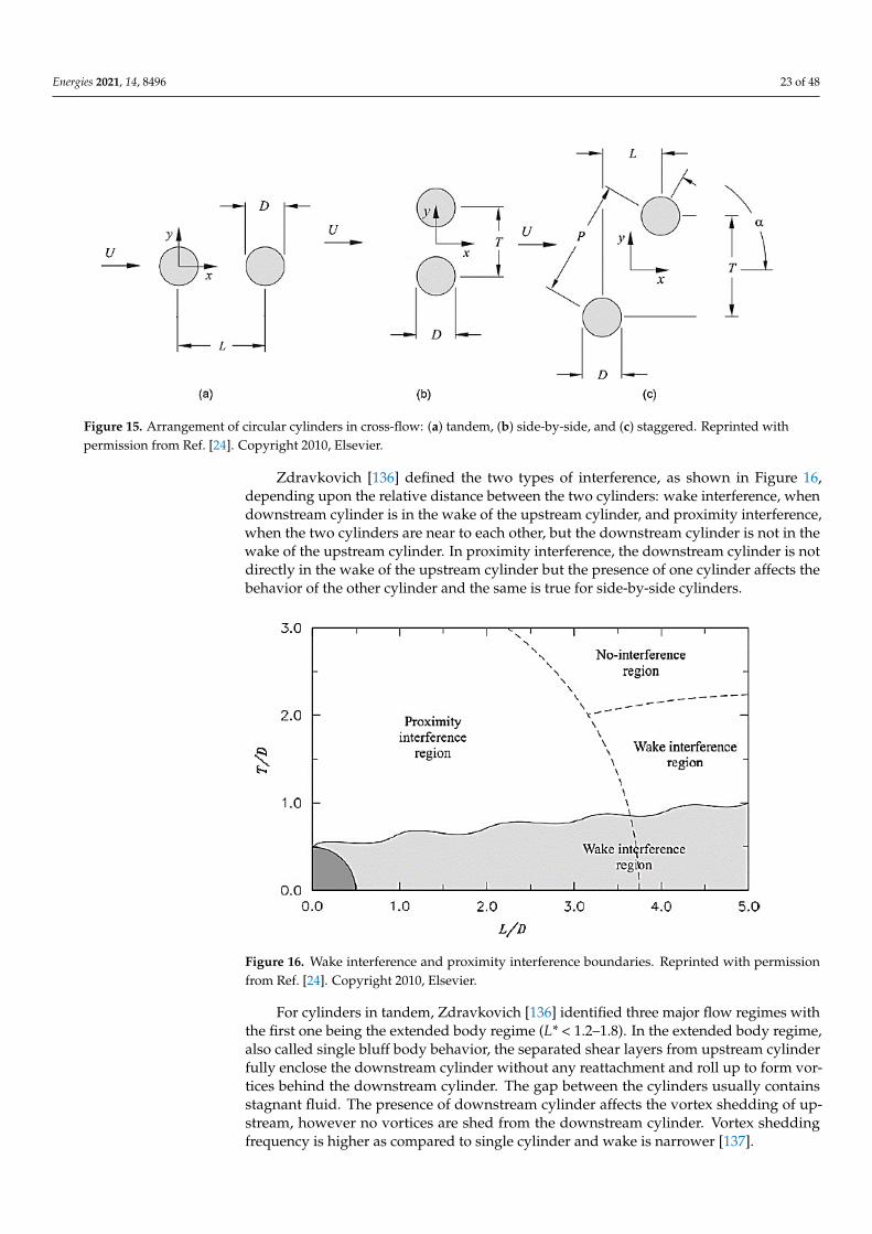
Energies 2021, 14, 8496 23 of 48
Energies 2021, 14, x FOR PEER REVIEW 23 of 50
Ali et al. [132] Numerical Forced streamwise vi-bration
100 CD, CL, St
Zafar and Alam [133] Numerical Fixed 150 Nu, CD, CL, FS, flow field
Ali et al. [134] Numerical Forced transverse vi-bration
100 CD, CL, St
Homsi et al. [135] Numerical Fixed 80–200 CD, CL, St, h
Coupling the heat transfer with VIV shows how one affects the other. It is noted from the above literature that VIV causes an increase in the heat transfer by increasing local and average h and Nu, whereas on the other hand, heating the cylinder dampens the VIV re-sponse of the cylinder as it lowers CL,f, A/D, and fex, while increasing average CD. Heating the cylinder has a similar effect on the cylinder response as does Ur at low Reynolds num-ber for unheated cylinder.
13. Tandem, Side-by-Side, and Staggered Cylinders For studies with two cylinders, the cylinder arrangement strongly affects the inter-
ference between the upstream cylinder and the WIV for the downstream cylinder. Possi-ble arrangements for two cylinders can be: tandem, side-by-side, or staggered. Figure 15 shows these arrangements, where L is the streamwise distance between the two cylinders, T is the transverse distance and P is the pitch for staggered cylinders with α as the inci-dence angle.
Figure 15. Arrangement of circular cylinders in cross-flow: (a) tandem, (b) side-by-side, and (c) staggered. Reprinted with permission from Ref. [24]. Copyright 2010, Elsevier.
Zdravkovich [136] defined the two types of interference, as shown in Figure 16, de-pending upon the relative distance between the two cylinders: wake interference, when downstream cylinder is in the wake of the upstream cylinder, and proximity interference, when the two cylinders are near to each other, but the downstream cylinder is not in the wake of the upstream cylinder. In proximity interference, the downstream cylinder is not directly in the wake of the upstream cylinder but the presence of one cylinder affects the behavior of the other cylinder and the same is true for side-by-side cylinders.
Figure 15. Arrangement of circular cylinders in cross-flow: (a) tandem, (b) side-by-side, and (c) staggered. Reprinted withpermission from Ref. [24]. Copyright 2010, Elsevier.
Zdravkovich [136] defined the two types of interference, as shown in Figure 16,depending upon the relative distance between the two cylinders: wake interference, whendownstream cylinder is in the wake of the upstream cylinder, and proximity interference,when the two cylinders are near to each other, but the downstream cylinder is not in thewake of the upstream cylinder. In proximity interference, the downstream cylinder is notdirectly in the wake of the upstream cylinder but the presence of one cylinder affects thebehavior of the other cylinder and the same is true for side-by-side cylinders.
Energies 2021, 14, x FOR PEER REVIEW 24 of 50
Figure 16. Wake interference and proximity interference boundaries. Reprinted with permission from Ref. [24]. Copyright 2010, Elsevier.
For cylinders in tandem, Zdravkovich [136] identified three major flow regimes with the first one being the extended body regime (L* < 1.2–1.8). In the extended body regime, also called single bluff body behavior, the separated shear layers from upstream cylinder fully enclose the downstream cylinder without any reattachment and roll up to form vor-tices behind the downstream cylinder. The gap between the cylinders usually contains stagnant fluid. The presence of downstream cylinder affects the vortex shedding of up-stream, however no vortices are shed from the downstream cylinder. Vortex shedding frequency is higher as compared to single cylinder and wake is narrower [137].
The second regime is the reattachment regime (1.2–1.8 < L* < 3.4–3.8), also called shear layer reattachment behavior, the separating shear layers from the upstream cylinder reat-tach onto the surface of the downstream cylinder and vortices are shed from the down-stream cylinder. The presence of upstream cylinder affects the behavior of downstream cylinder as compared to single cylinder. This regime can be sub-divided into two regimes, one where the reattachment occurs on the back side of the downstream cylinder and the other where it occurs on the front face of the downstream cylinder, this depends on the L* as shown in Figure 17.
The third regime is the co-shedding regime (L* > 4), where vortices are shed from both the cylinders and the vortices shed from upstream cylinder impinge on the surface of downstream cylinder and affects the behavior of the downstream cylinder. More detail on these regimes can be found in Sumner [24].
Figure 16. Wake interference and proximity interference boundaries. Reprinted with permissionfrom Ref. [24]. Copyright 2010, Elsevier.
For cylinders in tandem, Zdravkovich [136] identified three major flow regimes withthe first one being the extended body regime (L* < 1.2–1.8). In the extended body regime,also called single bluff body behavior, the separated shear layers from upstream cylinderfully enclose the downstream cylinder without any reattachment and roll up to form vor-tices behind the downstream cylinder. The gap between the cylinders usually containsstagnant fluid. The presence of downstream cylinder affects the vortex shedding of up-stream, however no vortices are shed from the downstream cylinder. Vortex sheddingfrequency is higher as compared to single cylinder and wake is narrower [137].
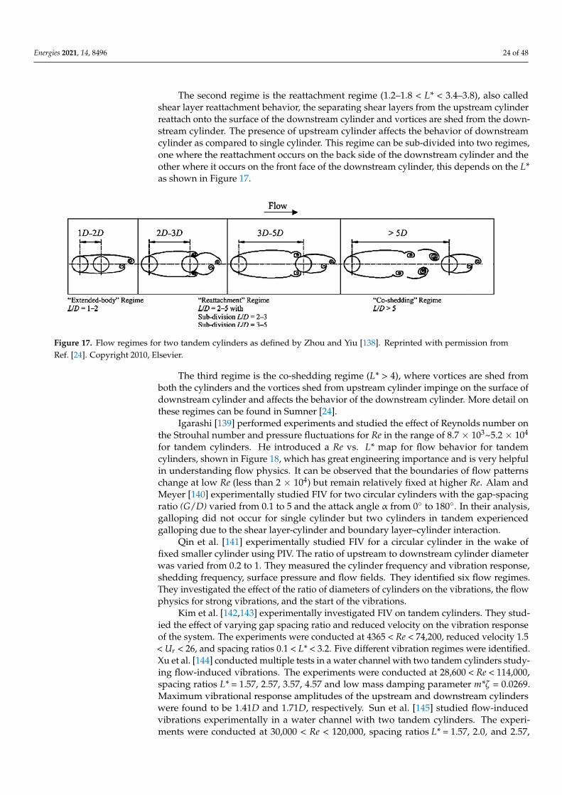
Energies 2021, 14, 8496 24 of 48
The second regime is the reattachment regime (1.2–1.8 < L* < 3.4–3.8), also calledshear layer reattachment behavior, the separating shear layers from the upstream cylinderreattach onto the surface of the downstream cylinder and vortices are shed from the down-stream cylinder. The presence of upstream cylinder affects the behavior of downstreamcylinder as compared to single cylinder. This regime can be sub-divided into two regimes,one where the reattachment occurs on the back side of the downstream cylinder and theother where it occurs on the front face of the downstream cylinder, this depends on the L*as shown in Figure 17.
Energies 2021, 14, x FOR PEER REVIEW 24 of 50
Figure 16. Wake interference and proximity interference boundaries. Reprinted with permission from Ref. [24]. Copyright 2010, Elsevier.
For cylinders in tandem, Zdravkovich [136] identified three major flow regimes with the first one being the extended body regime (L* < 1.2–1.8). In the extended body regime, also called single bluff body behavior, the separated shear layers from upstream cylinder fully enclose the downstream cylinder without any reattachment and roll up to form vor-tices behind the downstream cylinder. The gap between the cylinders usually contains stagnant fluid. The presence of downstream cylinder affects the vortex shedding of up-stream, however no vortices are shed from the downstream cylinder. Vortex shedding frequency is higher as compared to single cylinder and wake is narrower [137].
The second regime is the reattachment regime (1.2–1.8 < L* < 3.4–3.8), also called shear layer reattachment behavior, the separating shear layers from the upstream cylinder reat-tach onto the surface of the downstream cylinder and vortices are shed from the down-stream cylinder. The presence of upstream cylinder affects the behavior of downstream cylinder as compared to single cylinder. This regime can be sub-divided into two regimes, one where the reattachment occurs on the back side of the downstream cylinder and the other where it occurs on the front face of the downstream cylinder, this depends on the L* as shown in Figure 17.
The third regime is the co-shedding regime (L* > 4), where vortices are shed from both the cylinders and the vortices shed from upstream cylinder impinge on the surface of downstream cylinder and affects the behavior of the downstream cylinder. More detail on these regimes can be found in Sumner [24].
Figure 17. Flow regimes for two tandem cylinders as defined by Zhou and Yiu [138]. Reprinted with permission fromRef. [24]. Copyright 2010, Elsevier.
The third regime is the co-shedding regime (L* > 4), where vortices are shed fromboth the cylinders and the vortices shed from upstream cylinder impinge on the surface ofdownstream cylinder and affects the behavior of the downstream cylinder. More detail onthese regimes can be found in Sumner [24].
Igarashi [139] performed experiments and studied the effect of Reynolds number onthe Strouhal number and pressure fluctuations for Re in the range of 8.7 × 10³~5.2 × 10⁴
for tandem cylinders. He introduced a Re vs. L* map for flow behavior for tandemcylinders, shown in Figure 18, which has great engineering importance and is very helpfulin understanding flow physics. It can be observed that the boundaries of flow patternschange at low Re (less than 2 × 10⁴) but remain relatively fixed at higher Re. Alam andMeyer [140] experimentally studied FIV for two circular cylinders with the gap-spacingratio (G/D) varied from 0.1 to 5 and the attack angle α from 0◦ to 180◦. In their analysis,galloping did not occur for single cylinder but two cylinders in tandem experiencedgalloping due to the shear layer-cylinder and boundary layer–cylinder interaction.
Qin et al. [141] experimentally studied FIV for a circular cylinder in the wake offixed smaller cylinder using PIV. The ratio of upstream to downstream cylinder diameterwas varied from 0.2 to 1. They measured the cylinder frequency and vibration response,shedding frequency, surface pressure and flow fields. They identified six flow regimes.They investigated the effect of the ratio of diameters of cylinders on the vibrations, the flowphysics for strong vibrations, and the start of the vibrations.
Kim et al. [142,143] experimentally investigated FIV on tandem cylinders. They stud-ied the effect of varying gap spacing ratio and reduced velocity on the vibration responseof the system. The experiments were conducted at 4365 < Re < 74,200, reduced velocity 1.5< Ur < 26, and spacing ratios 0.1 < L* < 3.2. Five different vibration regimes were identified.Xu et al. [144] conducted multiple tests in a water channel with two tandem cylinders study-ing flow-induced vibrations. The experiments were conducted at 28,600 < Re < 114,000,spacing ratios L* = 1.57, 2.57, 3.57, 4.57 and low mass damping parameter m*ζ = 0.0269.Maximum vibrational response amplitudes of the upstream and downstream cylinderswere found to be 1.41D and 1.71D, respectively. Sun et al. [145] studied flow-inducedvibrations experimentally in a water channel with two tandem cylinders. The experi-ments were conducted at 30,000 < Re < 120,000, spacing ratios L* = 1.57, 2.0, and 2.57,
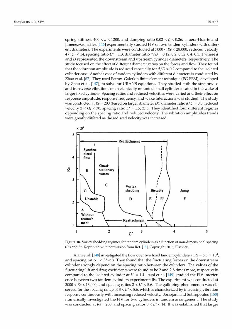
Energies 2021, 14, 8496 25 of 48
spring stiffness 400 < k < 1200, and damping ratio 0.02 < ζ < 0.26. Huera-Huarte andJiménez-González [146] experimentally studied FIV on two tandem cylinders with differ-ent diameters. The experiments were conducted at 7000 < Re < 28,000, reduced velocity4 < Ur < 14, spacing ratio L* = 1.3, diameter ratio d/D = 0.12, 0.2, 0.32, 0.4, 0.5, 1 where dand D represented the downstream and upstream cylinder diameters, respectively. Thestudy focused on the effect of different diameter ratios on the forces and flow. They foundthat the vibration amplitude is reduced especially for d/D > 0.2 compared to the isolatedcylinder case. Another case of tandem cylinders with different diameters is conducted byZhao et al. [67]. They used Petrov–Galerkin finite element technique (PG-FEM), developedby Zhao et al. [147], to solve for URANS equations. They studied both the streamwiseand transverse vibrations of an elastically mounted small cylinder located in the wake oflarger fixed cylinder. Spacing ratios and reduced velocities were varied and their effect onresponse amplitude, response frequency, and wake interactions was studied. The studywas conducted at Re = 200 (based on larger diameter D), diameter ratio d/D = 0.5, reducedvelocity 2 < Ur < 30, spacing ratio L* = 1.5, 2, 3. They identified four different regimesdepending on the spacing ratio and reduced velocity. The vibration amplitudes trendswere greatly differed as the reduced velocity was increased.
Energies 2021, 14, x FOR PEER REVIEW 25 of 50
Figure 17. Flow regimes for two tandem cylinders as defined by Zhou and Yiu [138]. Reprinted with permission from Ref. [24]. Copyright 2010, Elsevier.
Igarashi [139] performed experiments and studied the effect of Reynolds number on the Strouhal number and pressure fluctuations for Re in the range of 8.7 × 10³~5.2 × 10⁴ for tandem cylinders. He introduced a Re vs. L* map for flow behavior for tandem cylinders, shown in Figure 18, which has great engineering importance and is very helpful in under-standing flow physics. It can be observed that the boundaries of flow patterns change at low Re (less than 2 × 10⁴) but remain relatively fixed at higher Re. Alam and Meyer [140] experimentally studied FIV for two circular cylinders with the gap-spacing ratio (G/D) varied from 0.1 to 5 and the attack angle α from 0° to 180°. In their analysis, galloping did not occur for single cylinder but two cylinders in tandem experienced galloping due to the shear layer-cylinder and boundary layer–cylinder interaction.
Figure 18. Vortex shedding regimes for tandem cylinders as a function of non-dimensional spacing (L*) and Re. Reprinted with permission from Ref. [15]. Copyright 2016, Elsevier.
Qin et al. [141] experimentally studied FIV for a circular cylinder in the wake of fixed smaller cylinder using PIV. The ratio of upstream to downstream cylinder diameter was varied from 0.2 to 1. They measured the cylinder frequency and vibration response, shed-ding frequency, surface pressure and flow fields. They identified six flow regimes. They investigated the effect of the ratio of diameters of cylinders on the vibrations, the flow physics for strong vibrations, and the start of the vibrations.
Kim et al. [142,143] experimentally investigated FIV on tandem cylinders. They stud-ied the effect of varying gap spacing ratio and reduced velocity on the vibration response of the system. The experiments were conducted at 4365 < Re < 74200, reduced velocity 1.5 < Ur < 26, and spacing ratios 0.1 < L* < 3.2. Five different vibration regimes were identified. Xu et al. [144] conducted multiple tests in a water channel with two tandem cylinders studying flow-induced vibrations. The experiments were conducted at 28,600 < Re < 114,000, spacing ratios L* = 1.57, 2.57, 3.57, 4.57 and low mass damping parameter m*ζ = 0.0269. Maximum vibrational response amplitudes of the upstream and downstream cyl-inders were found to be 1.41D and 1.71D, respectively. Sun et al. [145] studied flow-in-duced vibrations experimentally in a water channel with two tandem cylinders. The ex-periments were conducted at 30,000 < Re < 120,000, spacing ratios L* = 1.57, 2.0, and 2.57,
Figure 18. Vortex shedding regimes for tandem cylinders as a function of non-dimensional spacing(L*) and Re. Reprinted with permission from Ref. [15]. Copyright 2016, Elsevier.
Alam et al. [148] investigated the flow over two fixed tandem cylinders at Re = 6.5 × 10⁴,and spacing ratio 1 < L* < 8. They found that the fluctuating forces on the downstreamcylinder strongly depend on the spacing ratio between the cylinders. The values of thefluctuating lift and drag coefficients were found to be 2 and 2.8 times more, respectively,compared to the isolated cylinder at L* = 1.4. Assi et al. [149] studied the FIV interfer-ence between two tandem cylinders experimentally. The experiment was conducted at3000 < Re < 13,000, and spacing ratios 2 < L* < 5.6. The galloping phenomenon was ob-served for the spacing range of 3 < L* < 5.6, which is characterized by increasing vibrationresponse continuously with increasing reduced velocity. Borazjani and Sotiropoulos [150]numerically investigated the FIV for two cylinders in tandem arrangement. The studywas conducted at Re = 200, and spacing ratios 3 < L* < 14. It was established that larger
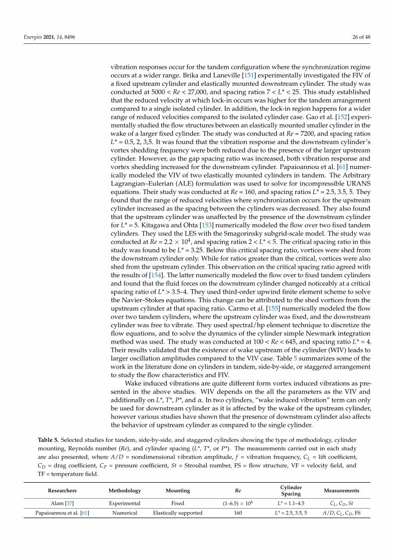
Energies 2021, 14, 8496 26 of 48
vibration responses occur for the tandem configuration where the synchronization regimeoccurs at a wider range. Brika and Laneville [151] experimentally investigated the FIV ofa fixed upstream cylinder and elastically mounted downstream cylinder. The study wasconducted at 5000 < Re < 27,000, and spacing ratios 7 < L* < 25. This study establishedthat the reduced velocity at which lock-in occurs was higher for the tandem arrangementcompared to a single isolated cylinder. In addition, the lock-in region happens for a widerrange of reduced velocities compared to the isolated cylinder case. Gao et al. [152] experi-mentally studied the flow structures between an elastically mounted smaller cylinder in thewake of a larger fixed cylinder. The study was conducted at Re = 7200, and spacing ratiosL* = 0.5, 2, 3,5. It was found that the vibration response and the downstream cylinder’svortex shedding frequency were both reduced due to the presence of the larger upstreamcylinder. However, as the gap spacing ratio was increased, both vibration response andvortex shedding increased for the downstream cylinder. Papaioannou et al. [61] numer-ically modeled the VIV of two elastically mounted cylinders in tandem. The ArbitraryLagrangian–Eulerian (ALE) formulation was used to solve for incompressible URANSequations. Their study was conducted at Re = 160, and spacing ratios L* = 2.5, 3.5, 5. Theyfound that the range of reduced velocities where synchronization occurs for the upstreamcylinder increased as the spacing between the cylinders was decreased. They also foundthat the upstream cylinder was unaffected by the presence of the downstream cylinderfor L* = 5. Kitagawa and Ohta [153] numerically modeled the flow over two fixed tandemcylinders. They used the LES with the Smagorinsky subgrid-scale model. The study wasconducted at Re = 2.2 × 10⁴, and spacing ratios 2 < L* < 5. The critical spacing ratio in thisstudy was found to be L* = 3.25. Below this critical spacing ratio, vortices were shed fromthe downstream cylinder only. While for ratios greater than the critical, vortices were alsoshed from the upstream cylinder. This observation on the critical spacing ratio agreed withthe results of [154]. The latter numerically modeled the flow over to fixed tandem cylindersand found that the fluid forces on the downstream cylinder changed noticeably at a criticalspacing ratio of L* > 3.5–4. They used third-order upwind finite element scheme to solvethe Navier–Stokes equations. This change can be attributed to the shed vortices from theupstream cylinder at that spacing ratio. Carmo et al. [155] numerically modeled the flowover two tandem cylinders, where the upstream cylinder was fixed, and the downstreamcylinder was free to vibrate. They used spectral/hp element technique to discretize theflow equations, and to solve the dynamics of the cylinder simple Newmark integrationmethod was used. The study was conducted at 100 < Re < 645, and spacing ratio L* = 4.Their results validated that the existence of wake upstream of the cylinder (WIV) leads tolarger oscillation amplitudes compared to the VIV case. Table 5 summarizes some of thework in the literature done on cylinders in tandem, side-by-side, or staggered arrangementto study the flow characteristics and FIV.
Wake induced vibrations are quite different form vortex induced vibrations as pre-sented in the above studies. WIV depends on the all the parameters as the VIV andadditionally on L*, T*, P*, and α. In two cylinders, “wake induced vibration” term can onlybe used for downstream cylinder as it is affected by the wake of the upstream cylinder,however various studies have shown that the presence of downstream cylinder also affectsthe behavior of upstream cylinder as compared to the single cylinder.
Table 5. Selected studies for tandem, side-by-side, and staggered cylinders showing the type of methodology, cylindermounting, Reynolds number (Re), and cylinder spacing (L*, T*, or P*). The measurements carried out in each studyare also presented, where A/D = nondimensional vibration amplitude, f = vibration frequency, CL = lift coefficient,CD = drag coefficient, CP = pressure coefficient, St = Strouhal number, FS = flow structure, VF = velocity field, andTF = temperature field.
Researchers Methodology Mounting Re CylinderSpacing Measurements
Alam [37] Experimental Fixed (1–6.5) × 104 L* = 1.1–4.5 CL, CD, St
Papaioannou et al. [61] Numerical Elastically supported 160 L* = 2.5, 3.5, 5 A/D, CL, CD, FS
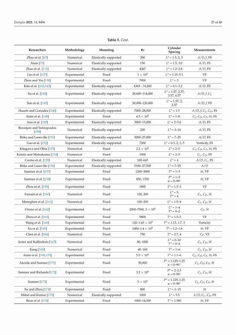
Energies 2021, 14, 8496 27 of 48
Table 5. Cont.
Researchers Methodology Mounting Re CylinderSpacing Measurements
Zhao et al. [67] Numerical Elastically supported 200 L* = 1.5, 2, 3 A/D, f, FS
Alam [73] Numerical Elastically supported 150 L* = 1.5, 3.0 A/D, FS
Zhao et al. [112] Numerical Elastically supported 4267 L* = 1.2–2.8 A/D, FS
Lin et al. [137] Experimental Fixed 1 × 10⁴ L* = 1.15–5.1 VF
Zhou and Yiu [138] Experimental Fixed 7000 L* = 2 VF
Kim et al. [142,143] Experimental Elastically supported 4365−74,200 L* = 0.1–3.2 A/D, FS
Xu et al. [144] Experimental Elastically supported 28,600–114,000 L* = 1.57, 2.57,3.57, 4.57 A/D, f, CL
Sun et al. [145] Experimental Elastically supported 30,000–120,000 L* = 1.57, 2,2.57 A/D, f, FS
Huarte and Gonzalez [146] Experimental Elastically supported 7000–28,000 L* = 1.3 A/D, f, CL, CD, FS
Alam et al. [148] Experimental Fixed 6.5 × 10⁴ L* = 1–8 CL, CD, CP, St, FS
Assi et al. [149] Experimental Elastically supported 3000–13,000 L* = 2–5.6 A/D, FS
Borazjani and Sotiropoulos[150] Numerical Elastically supported 200 L* = 3–14 A/D, FS
Brika and Laneville [151] Experimental Elastically supported 5000–27,000 L* = 7–25 A/D, FS
Gao et al. [152] Experimental Elastically supported 7200 L* = 0.5, 2, 3, 5 Vorticity, FS
Kitagawa and Ohta [153] Numerical Fixed 2.2 × 10⁴ L* = 2–5 CL, CD, CP, St, FS
Kondo and Matsukuma [154] Numerical Fixed 1000 L* = 2–5 CL, CD, FS
Carmo et al. [155] Numerical Elastically supported 100–645 L* = 4 A/D, CL, FS
Brika and Laneville [156] Experimental Elastically supported 5100–27,500 L* = 7–25 A/D
Sumner et al. [157] Experimental Fixed 1200–3000 T* = 1–3 St, VF
Sumner et al. [158] Experimental Fixed 850, 1350 P* = 1–5α = 0–90◦ St, VF
Zhou et al. [159] Experimental Fixed 1800 T* = 1.5–3 VF
Farrant et al. [160] Numerical Fixed 100, 200 L* = 5,T* = 4 CL, CD, St
Meneghini et al. [161] Numerical Fixed 100–200 L* = 1.5–4 CL, CD, St
Ozono et al. [162] Experimental Fixed 2500–7500, 3 × 10⁴ L* = 1–4T* = 0–2 CP, St
Zhou et al. [163] Experimental Fixed 5800 T* = 1.5–3 VF
Wang et al. [164] Experimental Fixed 120–1.65 × 10³ T* = 1.13, 1.7, 3 Vorticity
Xu et al. [165] Experimental Fixed 1000–1.4 × 10⁴ T* = 1.2–1.6 St, VF
Chen et al. [166] Numerical Fixed 750 T* = 2.7, 4 CP, VF
Jester and Kallinderis [167] Numerical Fixed 80, 1000 L* = 0–10T* = 0–4 CL, CD, St
Kang [168] Numerical Fixed 40–160 T* = 1–6 CL, CD, St
Alam et al. [169,170] Experimental Fixed 5.5 × 10⁴ T* = 1.1–6 CL, CD, CP, St, FS
Akosile and Sumner [171] Experimental Fixed 50,000 P* = 1.125–1.25α = 0–90◦ CL, CD, CP, St
Sumner and Richards [172] Experimental Fixed 3.2 × 10⁴ P* = 2–2.5α = 0–90◦ CL, CD, St
Sumner [173] Experimental Fixed 5 × 10⁴ P* = 1.125–1.25α = 0–90◦ CL, CD, CP, St
Xu and Zhou [174] Experimental Fixed 800 L* = 1–15 St
Mittal and Kumar [175] Numerical Elastically supported 1000 L* = 5.5 A/D, CL, CD, FS
Brun et al. [176] Experimental Fixed 1000–14,300 T* = 1.583 St, VF
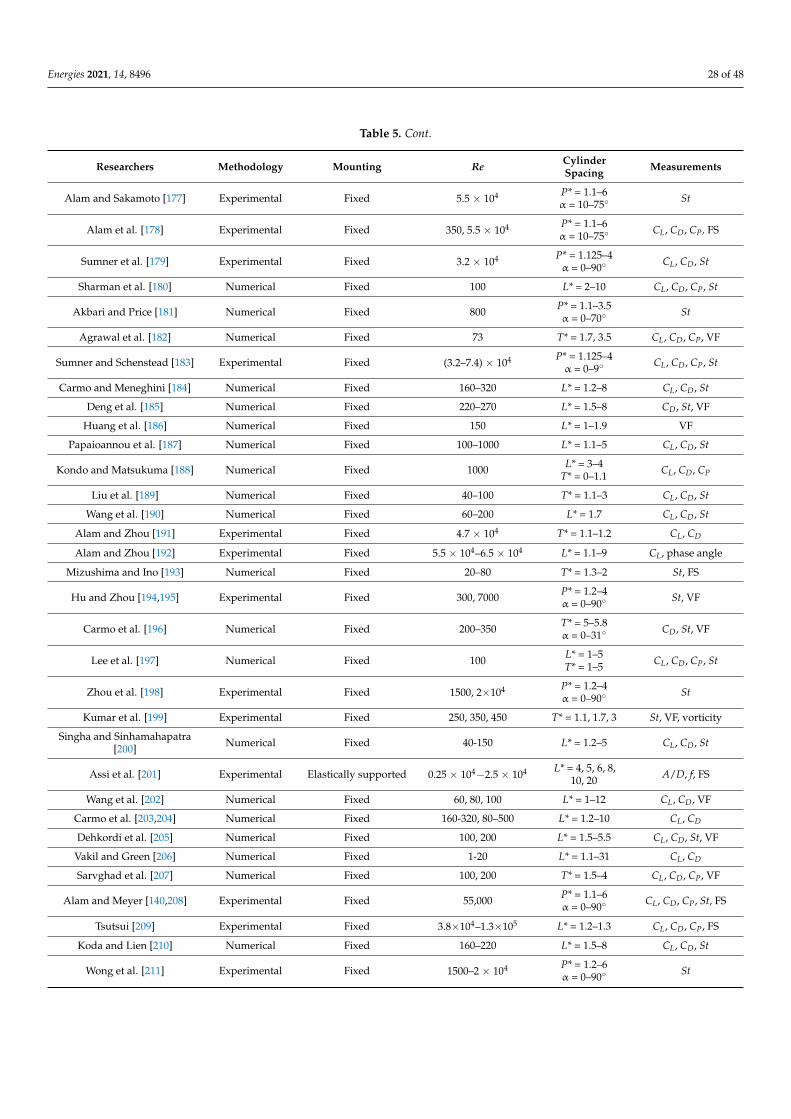
Energies 2021, 14, 8496 28 of 48
Table 5. Cont.
Researchers Methodology Mounting Re CylinderSpacing Measurements
Alam and Sakamoto [177] Experimental Fixed 5.5 × 10⁴ P* = 1.1–6α = 10–75◦ St
Alam et al. [178] Experimental Fixed 350, 5.5 × 10⁴ P* = 1.1–6α = 10–75◦ CL, CD, CP, FS
Sumner et al. [179] Experimental Fixed 3.2 × 10⁴ P* = 1.125–4α = 0–90◦ CL, CD, St
Sharman et al. [180] Numerical Fixed 100 L* = 2–10 CL, CD, CP, St
Akbari and Price [181] Numerical Fixed 800 P* = 1.1–3.5α = 0–70◦ St
Agrawal et al. [182] Numerical Fixed 73 T* = 1.7, 3.5 CL, CD, CP, VF
Sumner and Schenstead [183] Experimental Fixed (3.2–7.4) × 104 P* = 1.125–4α = 0–9◦ CL, CD, CP, St
Carmo and Meneghini [184] Numerical Fixed 160–320 L* = 1.2–8 CL, CD, St
Deng et al. [185] Numerical Fixed 220–270 L* = 1.5–8 CD, St, VF
Huang et al. [186] Numerical Fixed 150 L* = 1–1.9 VF
Papaioannou et al. [187] Numerical Fixed 100–1000 L* = 1.1–5 CL, CD, St
Kondo and Matsukuma [188] Numerical Fixed 1000 L* = 3–4T* = 0–1.1 CL, CD, CP
Liu et al. [189] Numerical Fixed 40–100 T* = 1.1–3 CL, CD, St
Wang et al. [190] Numerical Fixed 60–200 L* = 1.7 CL, CD, St
Alam and Zhou [191] Experimental Fixed 4.7 × 10⁴ T* = 1.1–1.2 CL, CD
Alam and Zhou [192] Experimental Fixed 5.5 × 10⁴–6.5 × 10⁴ L* = 1.1–9 CL, phase angle
Mizushima and Ino [193] Numerical Fixed 20–80 T* = 1.3–2 St, FS
Hu and Zhou [194,195] Experimental Fixed 300, 7000 P* = 1.2–4α = 0–90◦ St, VF
Carmo et al. [196] Numerical Fixed 200–350 T* = 5–5.8α = 0–31◦ CD, St, VF
Lee et al. [197] Numerical Fixed 100 L* = 1–5T* = 1–5 CL, CD, CP, St
Zhou et al. [198] Experimental Fixed 1500, 2×10⁴ P* = 1.2–4α = 0–90◦ St
Kumar et al. [199] Experimental Fixed 250, 350, 450 T* = 1.1, 1.7, 3 St, VF, vorticity
Singha and Sinhamahapatra[200] Numerical Fixed 40-150 L* = 1.2–5 CL, CD, St
Assi et al. [201] Experimental Elastically supported 0.25 × 10⁴−2.5 × 10⁴ L* = 4, 5, 6, 8,10, 20 A/D, f, FS
Wang et al. [202] Numerical Fixed 60, 80, 100 L* = 1–12 CL, CD, VF
Carmo et al. [203,204] Numerical Fixed 160-320, 80–500 L* = 1.2–10 CL, CD
Dehkordi et al. [205] Numerical Fixed 100, 200 L* = 1.5–5.5 CL, CD, St, VF
Vakil and Green [206] Numerical Fixed 1-20 L* = 1.1–31 CL, CD
Sarvghad et al. [207] Numerical Fixed 100, 200 T* = 1.5–4 CL, CD, CP, VF
Alam and Meyer [140,208] Experimental Fixed 55,000 P* = 1.1–6α = 0–90◦ CL, CD, CP, St, FS
Tsutsui [209] Experimental Fixed 3.8×10⁴–1.3×10⁵ L* = 1.2–1.3 CL, CD, CP, FS
Koda and Lien [210] Numerical Fixed 160–220 L* = 1.5–8 CL, CD, St
Wong et al. [211] Experimental Fixed 1500–2 × 10⁴ P* = 1.2–6α = 0–90◦ St
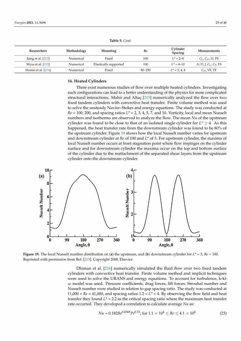
Energies 2021, 14, 8496 29 of 48
Table 5. Cont.
Researchers Methodology Mounting Re CylinderSpacing Measurements
Jiang et al. [212] Numerical Fixed 100 L* = 2–8 CL, CD, St, FS
Mysa et al. [213] Numerical Elastically supported 100 L* = 4–10 A/D, f, CL, CP, FS
Homsi et al. [214] Numerical Fixed 80–250 L* = 2, 4, 8 CD, VF, TF
14. Heated Cylinders
There exist numerous studies of flow over multiple heated cylinders. Investigatingsuch configurations can lead to a better understanding of the physics for more complicatedstructural interactions. Mahír and Altaç [215] numerically analyzed the flow over twofixed tandem cylinders with convective heat transfer. Finite volume method was usedto solve the unsteady Navier–Stokes and energy equations. The study was conducted atRe = 100, 200, and spacing ratios L* = 2, 3, 4, 5, 7, and 10. Vorticity, local and mean Nusseltnumbers and isotherms are observed to analyze the flow. The mean Nu of the upstreamcylinder was found to be close to that of an isolated single cylinder for L* ≥ 4. As thishappened, the heat transfer rate from the downstream cylinder was found to be 80% ofthe upstream cylinder. Figure 19 shows how the local Nusselt number varies for upstreamand downstream cylinder at Re of 100 and L* of 3. For upstream cylinder, the maxima oflocal Nusselt number occurs at front stagnation point where flow impinges on the cylindersurface and for downstream cylinder the maxima occur on the top and bottom surfaceof the cylinder due to the reattachment of the separated shear layers from the upstreamcylinder onto the downstream cylinder.
Energies 2021, 14, x FOR PEER REVIEW 30 of 50
used for downstream cylinder as it is affected by the wake of the upstream cylinder, how-ever various studies have shown that the presence of downstream cylinder also affects the behavior of upstream cylinder as compared to the single cylinder.
14. Heated Cylinders There exist numerous studies of flow over multiple heated cylinders. Investigating
such configurations can lead to a better understanding of the physics for more compli-cated structural interactions. Mahír and Altaç [215] numerically analyzed the flow over two fixed tandem cylinders with convective heat transfer. Finite volume method was used to solve the unsteady Navier–Stokes and energy equations. The study was conducted at Re = 100, 200, and spacing ratios L* = 2, 3, 4, 5, 7, and 10. Vorticity, local and mean Nusselt numbers and isotherms are observed to analyze the flow. The mean Nu of the upstream cylinder was found to be close to that of an isolated single cylinder for L* ≥ 4. As this happened, the heat transfer rate from the downstream cylinder was found to be 80% of the upstream cylinder. Figure 19 shows how the local Nusselt number varies for upstream and downstream cylinder at Re of 100 and L* of 3. For upstream cylinder, the maxima of local Nusselt number occurs at front stagnation point where flow impinges on the cylinder surface and for downstream cylinder the maxima occur on the top and bottom surface of the cylinder due to the reattachment of the separated shear layers from the upstream cyl-inder onto the downstream cylinder.
Figure 19. The local Nusselt number distribution on (a) the upstream, and (b) downstream cylinder for L* = 3, Re = 100. Reprinted with permission from Ref. [215]. Copyright 2008, Elsevier.
Dhiman et al. [216] numerically simulated the fluid flow over two fixed tandem cyl-inders with convective heat transfer. Finite volume method and implicit techniques were used to solve the URANS and energy equations. To account for turbulence, k-kl-ω model was used. Pressure coefficients, drag forces, lift forces, Strouhal number and Nusselt num-ber were studied in relation to gap spacing ratio. The study was conducted at 11,000 < Re < 41,000, and spacing ratios 1.2 < L* < 4. By observing the flow field and heat transfer they found L* = 2.2 as the critical spacing ratio where the maximum heat transfer rate occurred. They developed a correlation to calculate average Nu as:
Nu = 0.182Re0.6568Pr0.33; for 1.1 × 10⁴ ≤ Re ≤ 4.1 × 10⁴ (23)
Harimi and Saghafian [217] numerically simulated the flow over tandem cylinders with convective heat transfer. The numerical simulations were performed using finite vol-ume scheme and the overset grid method. The study was conducted at Re = 100 and 200,
Figure 19. The local Nusselt number distribution on (a) the upstream, and (b) downstream cylinder for L* = 3, Re = 100.Reprinted with permission from Ref. [215]. Copyright 2008, Elsevier.
Dhiman et al. [216] numerically simulated the fluid flow over two fixed tandemcylinders with convective heat transfer. Finite volume method and implicit techniqueswere used to solve the URANS and energy equations. To account for turbulence, k-kl-ω model was used. Pressure coefficients, drag forces, lift forces, Strouhal number andNusselt number were studied in relation to gap spacing ratio. The study was conducted at11,000 < Re < 41,000, and spacing ratios 1.2 < L* < 4. By observing the flow field and heattransfer they found L* = 2.2 as the critical spacing ratio where the maximum heat transferrate occurred. They developed a correlation to calculate average Nu as:
Nu = 0.182Re0.6568Pr0.33; for 1.1 × 10⁴ ≤ Re ≤ 4.1 × 10⁴ (23)
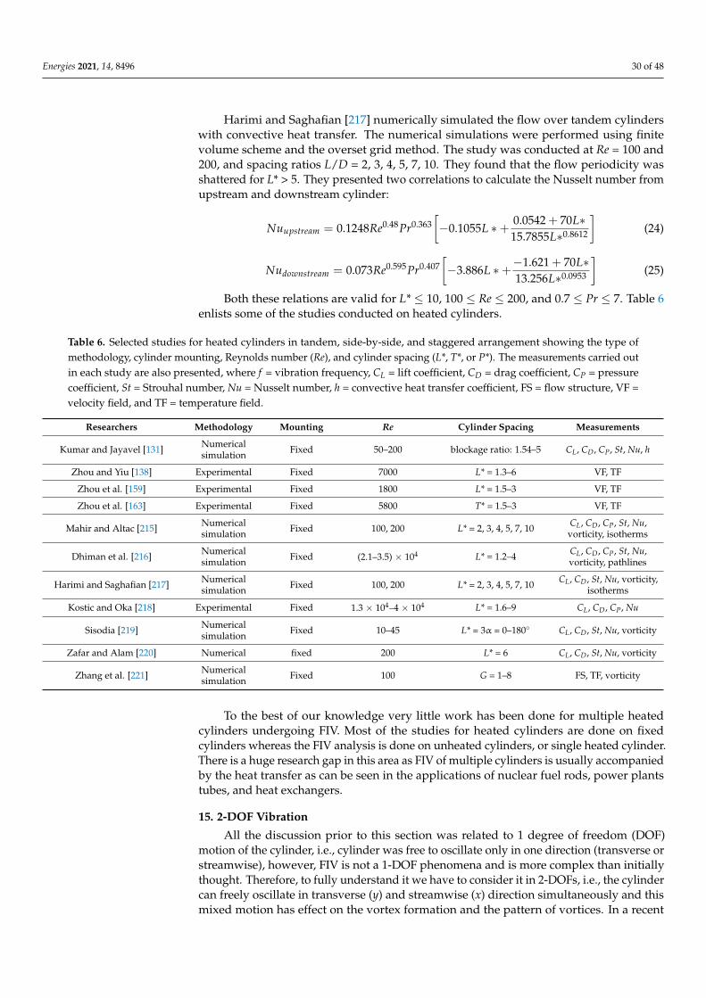
Energies 2021, 14, 8496 30 of 48
Harimi and Saghafian [217] numerically simulated the flow over tandem cylinderswith convective heat transfer. The numerical simulations were performed using finitevolume scheme and the overset grid method. The study was conducted at Re = 100 and200, and spacing ratios L/D = 2, 3, 4, 5, 7, 10. They found that the flow periodicity wasshattered for L* > 5. They presented two correlations to calculate the Nusselt number fromupstream and downstream cylinder:
Nuupstream = 0.1248Re0.48Pr0.363[−0.1055L ∗+ 0.0542 + 70L∗
15.7855L∗0.8612
](24)
Nudownstream = 0.073Re0.595Pr0.407[−3.886L ∗+−1.621 + 70L∗
13.256L∗0.0953
](25)
Both these relations are valid for L* ≤ 10, 100 ≤ Re ≤ 200, and 0.7 ≤ Pr ≤ 7. Table 6enlists some of the studies conducted on heated cylinders.
Table 6. Selected studies for heated cylinders in tandem, side-by-side, and staggered arrangement showing the type ofmethodology, cylinder mounting, Reynolds number (Re), and cylinder spacing (L*, T*, or P*). The measurements carried outin each study are also presented, where f = vibration frequency, CL = lift coefficient, CD = drag coefficient, CP = pressurecoefficient, St = Strouhal number, Nu = Nusselt number, h = convective heat transfer coefficient, FS = flow structure, VF =velocity field, and TF = temperature field.
Researchers Methodology Mounting Re Cylinder Spacing Measurements
Kumar and Jayavel [131] Numericalsimulation Fixed 50–200 blockage ratio: 1.54–5 CL, CD, CP, St, Nu, h
Zhou and Yiu [138] Experimental Fixed 7000 L* = 1.3–6 VF, TF
Zhou et al. [159] Experimental Fixed 1800 L* = 1.5–3 VF, TF
Zhou et al. [163] Experimental Fixed 5800 T* = 1.5–3 VF, TF
Mahir and Altac [215] Numericalsimulation Fixed 100, 200 L* = 2, 3, 4, 5, 7, 10 CL, CD, CP, St, Nu,
vorticity, isotherms
Dhiman et al. [216] Numericalsimulation Fixed (2.1–3.5) × 104 L* = 1.2–4 CL, CD, CP, St, Nu,
vorticity, pathlines
Harimi and Saghafian [217] Numericalsimulation Fixed 100, 200 L* = 2, 3, 4, 5, 7, 10 CL, CD, St, Nu, vorticity,
isotherms
Kostic and Oka [218] Experimental Fixed 1.3 × 10⁴–4 × 10⁴ L* = 1.6–9 CL, CD, CP, Nu
Sisodia [219] Numericalsimulation Fixed 10–45 L* = 3α = 0–180◦ CL, CD, St, Nu, vorticity
Zafar and Alam [220] Numerical fixed 200 L* = 6 CL, CD, St, Nu, vorticity
Zhang et al. [221] Numericalsimulation Fixed 100 G = 1–8 FS, TF, vorticity
To the best of our knowledge very little work has been done for multiple heatedcylinders undergoing FIV. Most of the studies for heated cylinders are done on fixedcylinders whereas the FIV analysis is done on unheated cylinders, or single heated cylinder.There is a huge research gap in this area as FIV of multiple cylinders is usually accompaniedby the heat transfer as can be seen in the applications of nuclear fuel rods, power plantstubes, and heat exchangers.
15. 2-DOF Vibration
All the discussion prior to this section was related to 1 degree of freedom (DOF)motion of the cylinder, i.e., cylinder was free to oscillate only in one direction (transverse orstreamwise), however, FIV is not a 1-DOF phenomena and is more complex than initiallythought. Therefore, to fully understand it we have to consider it in 2-DOFs, i.e., the cylindercan freely oscillate in transverse (y) and streamwise (x) direction simultaneously and thismixed motion has effect on the vortex formation and the pattern of vortices. In a recent
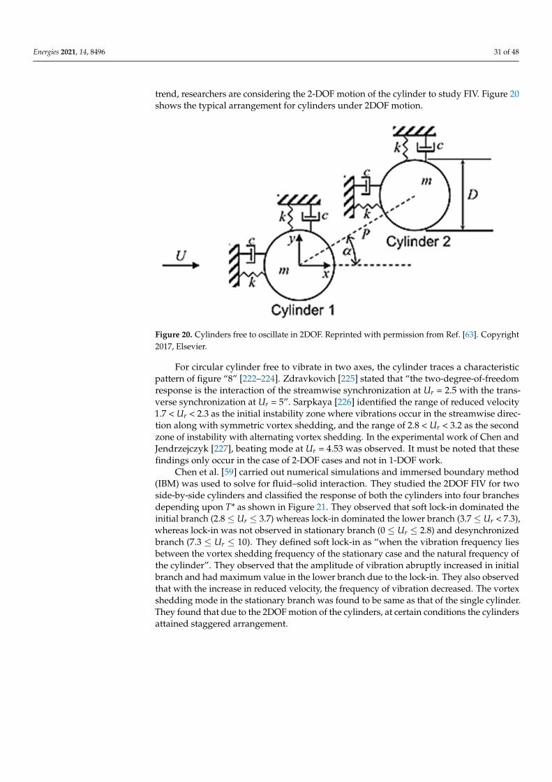
Energies 2021, 14, 8496 31 of 48
trend, researchers are considering the 2-DOF motion of the cylinder to study FIV. Figure 20shows the typical arrangement for cylinders under 2DOF motion.
Energies 2021, 14, x FOR PEER REVIEW 32 of 50
this mixed motion has effect on the vortex formation and the pattern of vortices. In a recent trend, researchers are considering the 2-DOF motion of the cylinder to study FIV. Figure 20 shows the typical arrangement for cylinders under 2DOF motion.
For circular cylinder free to vibrate in two axes, the cylinder traces a characteristic pattern of figure “8” [222–224]. Zdravkovich [225] stated that “the two-degree-of-freedom response is the interaction of the streamwise synchronization at Ur = 2.5 with the trans-verse synchronization at Ur = 5”. Sarpkaya [226] identified the range of reduced velocity 1.7 < Ur < 2.3 as the initial instability zone where vibrations occur in the streamwise direc-tion along with symmetric vortex shedding, and the range of 2.8 < Ur < 3.2 as the second zone of instability with alternating vortex shedding. In the experimental work of Chen and Jendrzejczyk [227], beating mode at Ur = 4.53 was observed. It must be noted that these findings only occur in the case of 2-DOF cases and not in 1-DOF work.
Figure 20. Cylinders free to oscillate in 2DOF. Reprinted with permission from Ref. [63]. Copy-right 2017, Elsevier.
Chen et al. [59] carried out numerical simulations and immersed boundary method (IBM) was used to solve for fluid–solid interaction. They studied the 2DOF FIV for two side-by-side cylinders and classified the response of both the cylinders into four branches depending upon T* as shown in Figure 21. They observed that soft lock-in dominated the initial branch (2.8 ≤ Ur ≤ 3.7) whereas lock-in dominated the lower branch (3.7 ≤ Ur < 7.3), whereas lock-in was not observed in stationary branch (0 ≤ Ur ≤ 2.8) and desynchronized branch (7.3 ≤ Ur ≤ 10). They defined soft lock-in as “when the vibration frequency lies between the vortex shedding frequency of the stationary case and the natural frequency of the cylinder”. They observed that the amplitude of vibration abruptly increased in ini-tial branch and had maximum value in the lower branch due to the lock-in. They also observed that with the increase in reduced velocity, the frequency of vibration decreased. The vortex shedding mode in the stationary branch was found to be same as that of the single cylinder. They found that due to the 2DOF motion of the cylinders, at certain con-ditions the cylinders attained staggered arrangement.
Figure 20. Cylinders free to oscillate in 2DOF. Reprinted with permission from Ref. [63]. Copyright2017, Elsevier.
For circular cylinder free to vibrate in two axes, the cylinder traces a characteristicpattern of figure “8” [222–224]. Zdravkovich [225] stated that “the two-degree-of-freedomresponse is the interaction of the streamwise synchronization at Ur = 2.5 with the trans-verse synchronization at Ur = 5”. Sarpkaya [226] identified the range of reduced velocity1.7 < Ur < 2.3 as the initial instability zone where vibrations occur in the streamwise direc-tion along with symmetric vortex shedding, and the range of 2.8 < Ur < 3.2 as the secondzone of instability with alternating vortex shedding. In the experimental work of Chen andJendrzejczyk [227], beating mode at Ur = 4.53 was observed. It must be noted that thesefindings only occur in the case of 2-DOF cases and not in 1-DOF work.
Chen et al. [59] carried out numerical simulations and immersed boundary method(IBM) was used to solve for fluid–solid interaction. They studied the 2DOF FIV for twoside-by-side cylinders and classified the response of both the cylinders into four branchesdepending upon T* as shown in Figure 21. They observed that soft lock-in dominated theinitial branch (2.8 ≤ Ur ≤ 3.7) whereas lock-in dominated the lower branch (3.7 ≤ Ur < 7.3),whereas lock-in was not observed in stationary branch (0 ≤ Ur ≤ 2.8) and desynchronizedbranch (7.3 ≤ Ur ≤ 10). They defined soft lock-in as “when the vibration frequency liesbetween the vortex shedding frequency of the stationary case and the natural frequency ofthe cylinder”. They observed that the amplitude of vibration abruptly increased in initialbranch and had maximum value in the lower branch due to the lock-in. They also observedthat with the increase in reduced velocity, the frequency of vibration decreased. The vortexshedding mode in the stationary branch was found to be same as that of the single cylinder.They found that due to the 2DOF motion of the cylinders, at certain conditions the cylindersattained staggered arrangement.
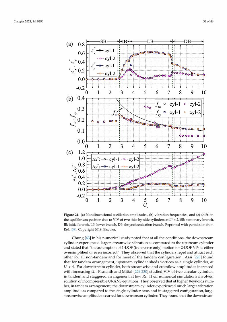
Energies 2021, 14, 8496 32 of 48Energies 2021, 14, x FOR PEER REVIEW 33 of 50
Figure 21. (a) Nondimensional oscillation amplitudes, (b) vibration frequencies, and (c) shifts in the equilibrium position due to VIV of two side-by-side cylinders at L* = 2. SB: stationary branch, IB: initial branch, LB: lower branch, DB: desynchronization branch. Reprinted with permission from Ref. [59]. Copyright 2019, Elsevier.
Chung [63] in his numerical study noted that at all the conditions, the downstream cylinder experienced larger streamwise vibration as compared to the upstream cylinder and stated that “the assumption of 1-DOF (transverse only) motion for 2-DOF VIV is either oversimplified or even incorrect”. They observed that the cylinders repel and attract each other for all non-tandem and for most of the tandem configuration. Assi [228] found that for tandem arrangement, upstream cylinder sheds vortices as a single cylinder, at L* > 4. For downstream cylinder, both streamwise and crossflow amplitudes increased with in-creasing Ur. Prasanth and Mittal [229,230] studied VIV of two circular cylinders in tandem and staggered arrangement at low Re. Their numerical simulations involved solution of incompressible URANS equations. They observed that at higher Reynolds number, in tan-dem arrangement, the downstream cylinder experienced much larger vibration ampli-tude as compared to the single cylinder case, and in staggered configuration, large stream-wise amplitude occurred for downstream cylinder. They found that the downstream cyl-inder experienced an orbital motion for most Ur and a figure-eight motion at some Ur, in staggered configuration, whereas for tandem arrangement only figure-eight motion was observed. Gao et al. [75] numerically simulated the flow over three tandem cylinders at Re of 150, with varying spacing ratio L* from 2–5 and reduced velocity Ur from 3–14. The solution of URANS equations was numerically sought using fourth order Runge–Kutta method, and k−ω turbulence model was used. In their study of FIV, they observed that the middle cylinder and downstream cylinder both had large response amplitudes at all
Figure 21. (a) Nondimensional oscillation amplitudes, (b) vibration frequencies, and (c) shifts inthe equilibrium position due to VIV of two side-by-side cylinders at L* = 2. SB: stationary branch,IB: initial branch, LB: lower branch, DB: desynchronization branch. Reprinted with permission fromRef. [59]. Copyright 2019, Elsevier.
Chung [63] in his numerical study noted that at all the conditions, the downstreamcylinder experienced larger streamwise vibration as compared to the upstream cylinderand stated that “the assumption of 1-DOF (transverse only) motion for 2-DOF VIV is eitheroversimplified or even incorrect”. They observed that the cylinders repel and attract eachother for all non-tandem and for most of the tandem configuration. Assi [228] foundthat for tandem arrangement, upstream cylinder sheds vortices as a single cylinder, atL* > 4. For downstream cylinder, both streamwise and crossflow amplitudes increasedwith increasing Ur. Prasanth and Mittal [229,230] studied VIV of two circular cylindersin tandem and staggered arrangement at low Re. Their numerical simulations involvedsolution of incompressible URANS equations. They observed that at higher Reynolds num-ber, in tandem arrangement, the downstream cylinder experienced much larger vibrationamplitude as compared to the single cylinder case, and in staggered configuration, largestreamwise amplitude occurred for downstream cylinder. They found that the downstream
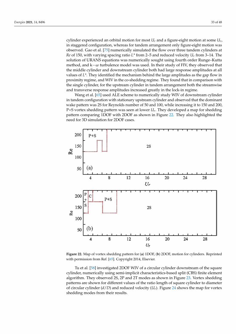
Energies 2021, 14, 8496 33 of 48
cylinder experienced an orbital motion for most Ur and a figure-eight motion at some Ur,in staggered configuration, whereas for tandem arrangement only figure-eight motion wasobserved. Gao et al. [75] numerically simulated the flow over three tandem cylinders atRe of 150, with varying spacing ratio L* from 2–5 and reduced velocity Ur from 3–14. Thesolution of URANS equations was numerically sought using fourth order Runge–Kuttamethod, and k−ω turbulence model was used. In their study of FIV, they observed thatthe middle cylinder and downstream cylinder both had large response amplitudes at allvalues of L*. They identified the mechanism behind the large amplitudes as the gap flow inproximity regime, and WIV in the co-shedding regime. They found that in comparison withthe single cylinder, for the upstream cylinder in tandem arrangement both the streamwiseand transverse response amplitudes increased greatly in the lock-in regime.
Wang et al. [65] used ALE scheme to numerically study WIV of downstream cylinderin tandem configuration with stationary upstream cylinder and observed that the dominantwake pattern was 2S for Reynolds number of 50 and 100, while increasing it to 150 and 200,P+S vortex shedding pattern was seen at lower Ur. They developed a map for sheddingpattern comparing 1DOF with 2DOF as shown in Figure 22. They also highlighted theneed for 3D simulation for 2DOF cases.
Energies 2021, 14, x FOR PEER REVIEW 34 of 50
values of L*. They identified the mechanism behind the large amplitudes as the gap flow in proximity regime, and WIV in the co-shedding regime. They found that in comparison with the single cylinder, for the upstream cylinder in tandem arrangement both the streamwise and transverse response amplitudes increased greatly in the lock-in regime.
Wang et al. [65] used ALE scheme to numerically study WIV of downstream cylinder in tandem configuration with stationary upstream cylinder and observed that the domi-nant wake pattern was 2S for Reynolds number of 50 and 100, while increasing it to 150 and 200, P+S vortex shedding pattern was seen at lower Ur. They developed a map for shedding pattern comparing 1DOF with 2DOF as shown in Figure 22. They also high-lighted the need for 3D simulation for 2DOF cases.
Figure 22. Map of vortex shedding pattern for (a) 1DOF, (b) 2DOF, motion for cylinders. Reprinted with permission from Ref. [65]. Copyright 2014, Elsevier.
Tu et al. [58] investigated 2DOF WIV of a circular cylinder downstream of the square cylinder, numerically using semi-implicit characteristics-based split (CBS) finite element algorithm. They observed 2S, 2P and 2T modes as shown in Figure 23. Vortex shedding patterns are shown for different values of the ratio length of square cylinder to diameter of circular cylinder (d/D) and reduced velocity (Ur). Figure 24 shows the map for vortex shedding modes from their results.
Figure 22. Map of vortex shedding pattern for (a) 1DOF, (b) 2DOF, motion for cylinders. Reprintedwith permission from Ref. [65]. Copyright 2014, Elsevier.
Tu et al. [58] investigated 2DOF WIV of a circular cylinder downstream of the squarecylinder, numerically using semi-implicit characteristics-based split (CBS) finite elementalgorithm. They observed 2S, 2P and 2T modes as shown in Figure 23. Vortex sheddingpatterns are shown for different values of the ratio length of square cylinder to diameterof circular cylinder (d/D) and reduced velocity (Ur). Figure 24 shows the map for vortexshedding modes from their results.
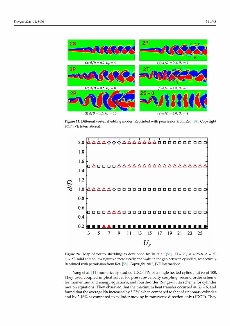
Energies 2021, 14, 8496 34 of 48Energies 2021, 14, x FOR PEER REVIEW 35 of 50
Figure 23. Different vortex shedding modes. Reprinted with permission from Ref. [58]. Copyright 2017, JVE International.
Figure 24. Map of vortex shedding as developed by Tu et al. [58]. □ = 2S, ◇ = 2S-8, Δ = 2P, ○ = 2T, solid and hollow figures denote steady and wake in the gap between cylinders, respectively. Re-printed with permission from Ref. [58]. Copyright 2017, JVE International.
Yang et al. [11] numerically studied 2DOF FIV of a single heated cylinder at Re of 100. They used coupled implicit solver for pressure-velocity coupling, second order scheme for momentum and energy equations, and fourth-order Runge–Kutta scheme for cylinder motion equations. They observed that the maximum heat transfer occurred at Ur = 6, and found that the average Nu increased by 5.73% when compared to that of stationary cylin-der, and by 2.46% as compared to cylinder moving in transverse direction only (1DOF). They highlighted the importance of studying FIV in 2DOF. Table 7 shows some of the work done on FIV of cylinder(s) considering 2DOF.
Figure 23. Different vortex shedding modes. Reprinted with permission from Ref. [58]. Copyright2017, JVE International.
Energies 2021, 14, x FOR PEER REVIEW 35 of 50
Figure 23. Different vortex shedding modes. Reprinted with permission from Ref. [58]. Copyright 2017, JVE International.
Figure 24. Map of vortex shedding as developed by Tu et al. [58]. □ = 2S, ◇ = 2S-8, Δ = 2P, ○ = 2T, solid and hollow figures denote steady and wake in the gap between cylinders, respectively. Re-printed with permission from Ref. [58]. Copyright 2017, JVE International.
Yang et al. [11] numerically studied 2DOF FIV of a single heated cylinder at Re of 100. They used coupled implicit solver for pressure-velocity coupling, second order scheme for momentum and energy equations, and fourth-order Runge–Kutta scheme for cylinder motion equations. They observed that the maximum heat transfer occurred at Ur = 6, and found that the average Nu increased by 5.73% when compared to that of stationary cylin-der, and by 2.46% as compared to cylinder moving in transverse direction only (1DOF). They highlighted the importance of studying FIV in 2DOF. Table 7 shows some of the work done on FIV of cylinder(s) considering 2DOF.
Figure 24. Map of vortex shedding as developed by Tu et al. [58]. � = 2S, 3 = 2S-8, ∆ = 2P,# = 2T, solid and hollow figures denote steady and wake in the gap between cylinders, respectively.Reprinted with permission from Ref. [58]. Copyright 2017, JVE International.
Yang et al. [11] numerically studied 2DOF FIV of a single heated cylinder at Re of 100.They used coupled implicit solver for pressure-velocity coupling, second order schemefor momentum and energy equations, and fourth-order Runge–Kutta scheme for cylindermotion equations. They observed that the maximum heat transfer occurred at Ur = 6, andfound that the average Nu increased by 5.73% when compared to that of stationary cylinder,and by 2.46% as compared to cylinder moving in transverse direction only (1DOF). They
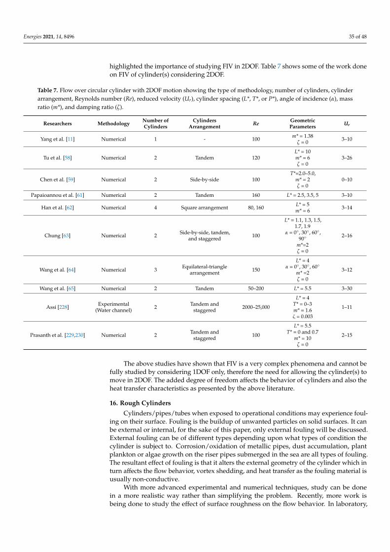
Energies 2021, 14, 8496 35 of 48
highlighted the importance of studying FIV in 2DOF. Table 7 shows some of the work doneon FIV of cylinder(s) considering 2DOF.
Table 7. Flow over circular cylinder with 2DOF motion showing the type of methodology, number of cylinders, cylinderarrangement, Reynolds number (Re), reduced velocity (Ur), cylinder spacing (L*, T*, or P*), angle of incidence (α), massratio (m*), and damping ratio (ζ).
Researchers Methodology Number ofCylinders
CylindersArrangement Re Geometric
Parameters Ur
Yang et al. [11] Numerical 1 - 100 m* = 1.38ζ = 0 3–10
Tu et al. [58] Numerical 2 Tandem 120L* = 10m* = 6ζ = 0
3–26
Chen et al. [59] Numerical 2 Side-by-side 100T*=2.0–5.0,
m* = 2ζ = 0
0–10
Papaioannou et al. [61] Numerical 2 Tandem 160 L* = 2.5, 3.5, 5 3–10
Han et al. [62] Numerical 4 Square arrangement 80, 160 L* = 5m* = 6 3–14
Chung [63] Numerical 2 Side-by-side, tandem,and staggered 100
L* = 1.1, 1.3, 1.5,1.7, 1.9
α = 0◦, 30◦, 60◦,90◦
m*=2ζ = 0
2–16
Wang et al. [64] Numerical 3 Equilateral-trianglearrangement 150
L* = 4α = 0◦, 30◦, 60◦
m* =2ζ = 0
3–12
Wang et al. [65] Numerical 2 Tandem 50–200 L* = 5.5 3–30
Assi [228] Experimental(Water channel) 2 Tandem and
staggered 2000–25,000
L* = 4T* = 0–3m* = 1.6ζ = 0.003
1–11
Prasanth et al. [229,230] Numerical 2 Tandem andstaggered 100
L* = 5.5T* = 0 and 0.7
m* = 10ζ = 0
2–15
The above studies have shown that FIV is a very complex phenomena and cannot befully studied by considering 1DOF only, therefore the need for allowing the cylinder(s) tomove in 2DOF. The added degree of freedom affects the behavior of cylinders and also theheat transfer characteristics as presented by the above literature.
16. Rough Cylinders
Cylinders/pipes/tubes when exposed to operational conditions may experience foul-ing on their surface. Fouling is the buildup of unwanted particles on solid surfaces. It canbe external or internal, for the sake of this paper, only external fouling will be discussed.External fouling can be of different types depending upon what types of condition thecylinder is subject to. Corrosion/oxidation of metallic pipes, dust accumulation, plantplankton or algae growth on the riser pipes submerged in the sea are all types of fouling.The resultant effect of fouling is that it alters the external geometry of the cylinder which inturn affects the flow behavior, vortex shedding, and heat transfer as the fouling material isusually non-conductive.
With more advanced experimental and numerical techniques, study can be donein a more realistic way rather than simplifying the problem. Recently, more work isbeing done to study the effect of surface roughness on the flow behavior. In laboratory,
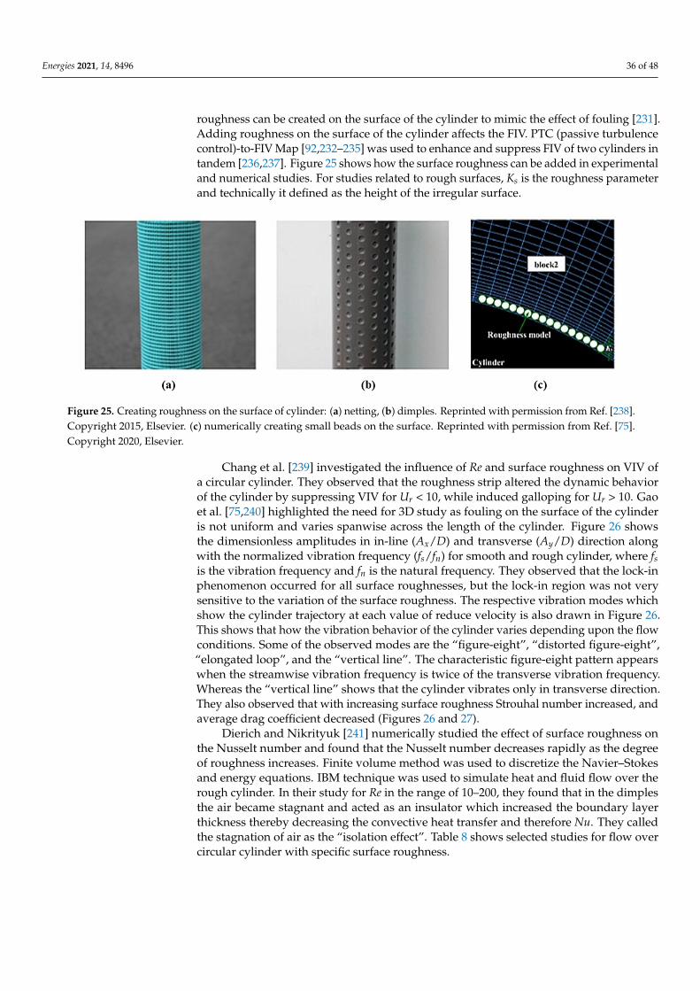
Energies 2021, 14, 8496 36 of 48
roughness can be created on the surface of the cylinder to mimic the effect of fouling [231].Adding roughness on the surface of the cylinder affects the FIV. PTC (passive turbulencecontrol)-to-FIV Map [92,232–235] was used to enhance and suppress FIV of two cylinders intandem [236,237]. Figure 25 shows how the surface roughness can be added in experimentaland numerical studies. For studies related to rough surfaces, Ks is the roughness parameterand technically it defined as the height of the irregular surface.
Energies 2021, 14, x FOR PEER REVIEW 37 of 50
With more advanced experimental and numerical techniques, study can be done in a more realistic way rather than simplifying the problem. Recently, more work is being done to study the effect of surface roughness on the flow behavior. In laboratory, rough-ness can be created on the surface of the cylinder to mimic the effect of fouling [231]. Add-ing roughness on the surface of the cylinder affects the FIV. PTC (passive turbulence con-trol)-to-FIV Map [92,232–235] was used to enhance and suppress FIV of two cylinders in tandem [236,237]. Figure 25 shows how the surface roughness can be added in experi-mental and numerical studies. For studies related to rough surfaces, Ks is the roughness parameter and technically it defined as the height of the irregular surface.
Figure 25. Creating roughness on the surface of cylinder: (a) netting, (b) dimples. Reprinted with permission from Ref. [238]. Copyright 2015, Elsevier. (c) numerically creating small beads on the surface. Reprinted with permission from Ref. [75]. Copyright 2020, Elsevier.
Chang et al. [239] investigated the influence of Re and surface roughness on VIV of a circular cylinder. They observed that the roughness strip altered the dynamic behavior of the cylinder by suppressing VIV for Ur < 10, while induced galloping for Ur > 10. Gao et al. [75,240] highlighted the need for 3D study as fouling on the surface of the cylinder is not uniform and varies spanwise across the length of the cylinder. Figure 26 shows the dimensionless amplitudes in in-line (Ax/D) and transverse (Ay/D) direction along with the normalized vibration frequency (fs/fn) for smooth and rough cylinder, where fs is the vi-bration frequency and fn is the natural frequency. They observed that the lock-in phenom-enon occurred for all surface roughnesses, but the lock-in region was not very sensitive to the variation of the surface roughness. The respective vibration modes which show the cylinder trajectory at each value of reduce velocity is also drawn in Figure 26. This shows that how the vibration behavior of the cylinder varies depending upon the flow condi-tions. Some of the observed modes are the “figure-eight”, “distorted figure-eight”, “elon-gated loop”, and the “vertical line”. The characteristic figure-eight pattern appears when the streamwise vibration frequency is twice of the transverse vibration frequency. Whereas the “vertical line” shows that the cylinder vibrates only in transverse direction. They also observed that with increasing surface roughness Strouhal number increased, and average drag coefficient decreased (Figures 26 and 27).
Figure 25. Creating roughness on the surface of cylinder: (a) netting, (b) dimples. Reprinted with permission from Ref. [238].Copyright 2015, Elsevier. (c) numerically creating small beads on the surface. Reprinted with permission from Ref. [75].Copyright 2020, Elsevier.
Chang et al. [239] investigated the influence of Re and surface roughness on VIV ofa circular cylinder. They observed that the roughness strip altered the dynamic behaviorof the cylinder by suppressing VIV for Ur < 10, while induced galloping for Ur > 10. Gaoet al. [75,240] highlighted the need for 3D study as fouling on the surface of the cylinderis not uniform and varies spanwise across the length of the cylinder. Figure 26 showsthe dimensionless amplitudes in in-line (Ax/D) and transverse (Ay/D) direction alongwith the normalized vibration frequency (fs/fn) for smooth and rough cylinder, where fsis the vibration frequency and fn is the natural frequency. They observed that the lock-inphenomenon occurred for all surface roughnesses, but the lock-in region was not verysensitive to the variation of the surface roughness. The respective vibration modes whichshow the cylinder trajectory at each value of reduce velocity is also drawn in Figure 26.This shows that how the vibration behavior of the cylinder varies depending upon the flowconditions. Some of the observed modes are the “figure-eight”, “distorted figure-eight”,“elongated loop”, and the “vertical line”. The characteristic figure-eight pattern appearswhen the streamwise vibration frequency is twice of the transverse vibration frequency.Whereas the “vertical line” shows that the cylinder vibrates only in transverse direction.They also observed that with increasing surface roughness Strouhal number increased, andaverage drag coefficient decreased (Figures 26 and 27).
Dierich and Nikrityuk [241] numerically studied the effect of surface roughness onthe Nusselt number and found that the Nusselt number decreases rapidly as the degreeof roughness increases. Finite volume method was used to discretize the Navier–Stokesand energy equations. IBM technique was used to simulate heat and fluid flow over therough cylinder. In their study for Re in the range of 10–200, they found that in the dimplesthe air became stagnant and acted as an insulator which increased the boundary layerthickness thereby decreasing the convective heat transfer and therefore Nu. They calledthe stagnation of air as the “isolation effect”. Table 8 shows selected studies for flow overcircular cylinder with specific surface roughness.
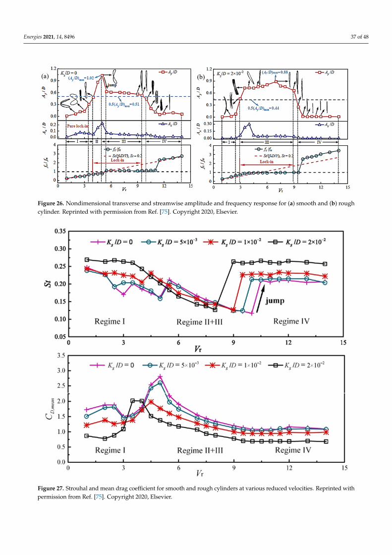
Energies 2021, 14, 8496 37 of 48Energies 2021, 14, x FOR PEER REVIEW 38 of 50
Figure 26. Nondimensional transverse and streamwise amplitude and frequency response for (a) smooth and (b) rough cylinder. Reprinted with permission from Ref. [75]. Copyright 2020, Elsevier.
Figure 27. Strouhal and mean drag coefficient for smooth and rough cylinders at various reduced velocities. Reprinted with permission from Ref. [75]. Copyright 2020, Elsevier.
Dierich and Nikrityuk [241] numerically studied the effect of surface roughness on the Nusselt number and found that the Nusselt number decreases rapidly as the degree of roughness increases. Finite volume method was used to discretize the Navier–Stokes and energy equations. IBM technique was used to simulate heat and fluid flow over the rough cylinder. In their study for Re in the range of 10–200, they found that in the dimples
Figure 26. Nondimensional transverse and streamwise amplitude and frequency response for (a) smooth and (b) roughcylinder. Reprinted with permission from Ref. [75]. Copyright 2020, Elsevier.
Energies 2021, 14, x FOR PEER REVIEW 38 of 50
Figure 26. Nondimensional transverse and streamwise amplitude and frequency response for (a) smooth and (b) rough cylinder. Reprinted with permission from Ref. [75]. Copyright 2020, Elsevier.
Figure 27. Strouhal and mean drag coefficient for smooth and rough cylinders at various reduced velocities. Reprinted with permission from Ref. [75]. Copyright 2020, Elsevier.
Dierich and Nikrityuk [241] numerically studied the effect of surface roughness on the Nusselt number and found that the Nusselt number decreases rapidly as the degree of roughness increases. Finite volume method was used to discretize the Navier–Stokes and energy equations. IBM technique was used to simulate heat and fluid flow over the rough cylinder. In their study for Re in the range of 10–200, they found that in the dimples
Figure 27. Strouhal and mean drag coefficient for smooth and rough cylinders at various reduced velocities. Reprinted withpermission from Ref. [75]. Copyright 2020, Elsevier.
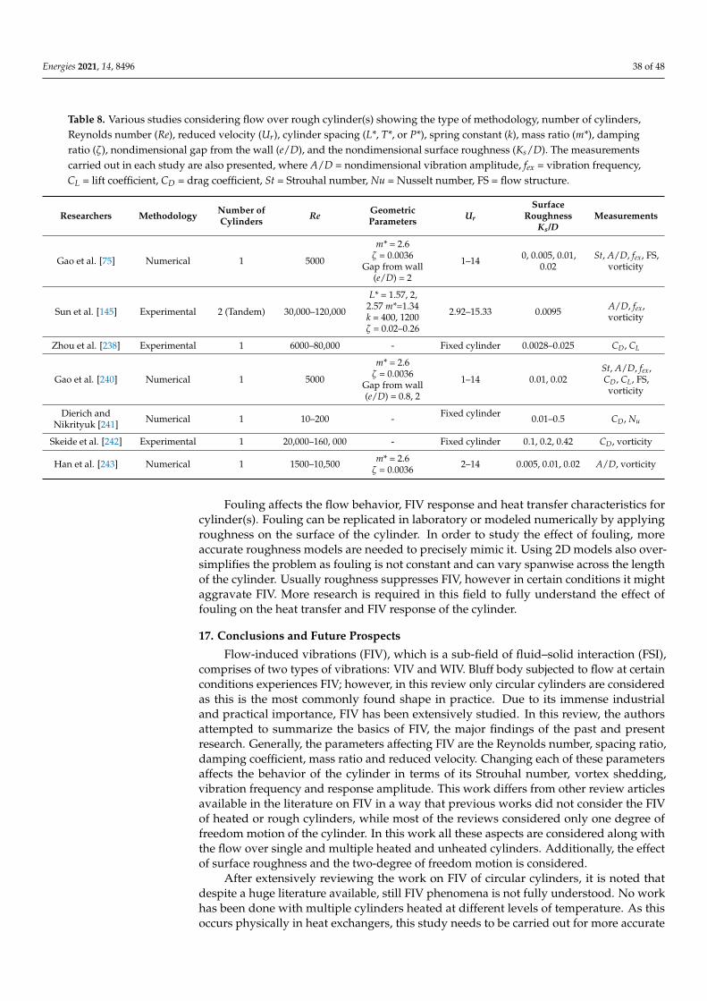
Energies 2021, 14, 8496 38 of 48
Table 8. Various studies considering flow over rough cylinder(s) showing the type of methodology, number of cylinders,Reynolds number (Re), reduced velocity (Ur), cylinder spacing (L*, T*, or P*), spring constant (k), mass ratio (m*), dampingratio (ζ), nondimensional gap from the wall (e/D), and the nondimensional surface roughness (Ks/D). The measurementscarried out in each study are also presented, where A/D = nondimensional vibration amplitude, fex = vibration frequency,CL = lift coefficient, CD = drag coefficient, St = Strouhal number, Nu = Nusselt number, FS = flow structure.
Researchers Methodology Number ofCylinders Re Geometric
Parameters Ur
SurfaceRoughness
Ks/DMeasurements
Gao et al. [75] Numerical 1 5000
m* = 2.6ζ = 0.0036
Gap from wall(e/D) = 2
1–14 0, 0.005, 0.01,0.02
St, A/D, fex, FS,vorticity
Sun et al. [145] Experimental 2 (Tandem) 30,000–120,000
L* = 1.57, 2,2.57 m*=1.34k = 400, 1200ζ = 0.02–0.26
2.92–15.33 0.0095 A/D, fex,vorticity
Zhou et al. [238] Experimental 1 6000–80,000 - Fixed cylinder 0.0028–0.025 CD, CL
Gao et al. [240] Numerical 1 5000
m* = 2.6ζ = 0.0036
Gap from wall(e/D) = 0.8, 2
1–14 0.01, 0.02St, A/D, fex,CD, CL, FS,vorticity
Dierich andNikrityuk [241] Numerical 1 10–200 - Fixed cylinder 0.01–0.5 CD, Nu
Skeide et al. [242] Experimental 1 20,000–160, 000 - Fixed cylinder 0.1, 0.2, 0.42 CD, vorticity
Han et al. [243] Numerical 1 1500–10,500 m* = 2.6ζ = 0.0036 2–14 0.005, 0.01, 0.02 A/D, vorticity
Fouling affects the flow behavior, FIV response and heat transfer characteristics forcylinder(s). Fouling can be replicated in laboratory or modeled numerically by applyingroughness on the surface of the cylinder. In order to study the effect of fouling, moreaccurate roughness models are needed to precisely mimic it. Using 2D models also over-simplifies the problem as fouling is not constant and can vary spanwise across the lengthof the cylinder. Usually roughness suppresses FIV, however in certain conditions it mightaggravate FIV. More research is required in this field to fully understand the effect offouling on the heat transfer and FIV response of the cylinder.
17. Conclusions and Future Prospects
Flow-induced vibrations (FIV), which is a sub-field of fluid–solid interaction (FSI),comprises of two types of vibrations: VIV and WIV. Bluff body subjected to flow at certainconditions experiences FIV; however, in this review only circular cylinders are consideredas this is the most commonly found shape in practice. Due to its immense industrialand practical importance, FIV has been extensively studied. In this review, the authorsattempted to summarize the basics of FIV, the major findings of the past and presentresearch. Generally, the parameters affecting FIV are the Reynolds number, spacing ratio,damping coefficient, mass ratio and reduced velocity. Changing each of these parametersaffects the behavior of the cylinder in terms of its Strouhal number, vortex shedding,vibration frequency and response amplitude. This work differs from other review articlesavailable in the literature on FIV in a way that previous works did not consider the FIVof heated or rough cylinders, while most of the reviews considered only one degree offreedom motion of the cylinder. In this work all these aspects are considered along withthe flow over single and multiple heated and unheated cylinders. Additionally, the effectof surface roughness and the two-degree of freedom motion is considered.
After extensively reviewing the work on FIV of circular cylinders, it is noted thatdespite a huge literature available, still FIV phenomena is not fully understood. No workhas been done with multiple cylinders heated at different levels of temperature. As thisoccurs physically in heat exchangers, this study needs to be carried out for more accurate
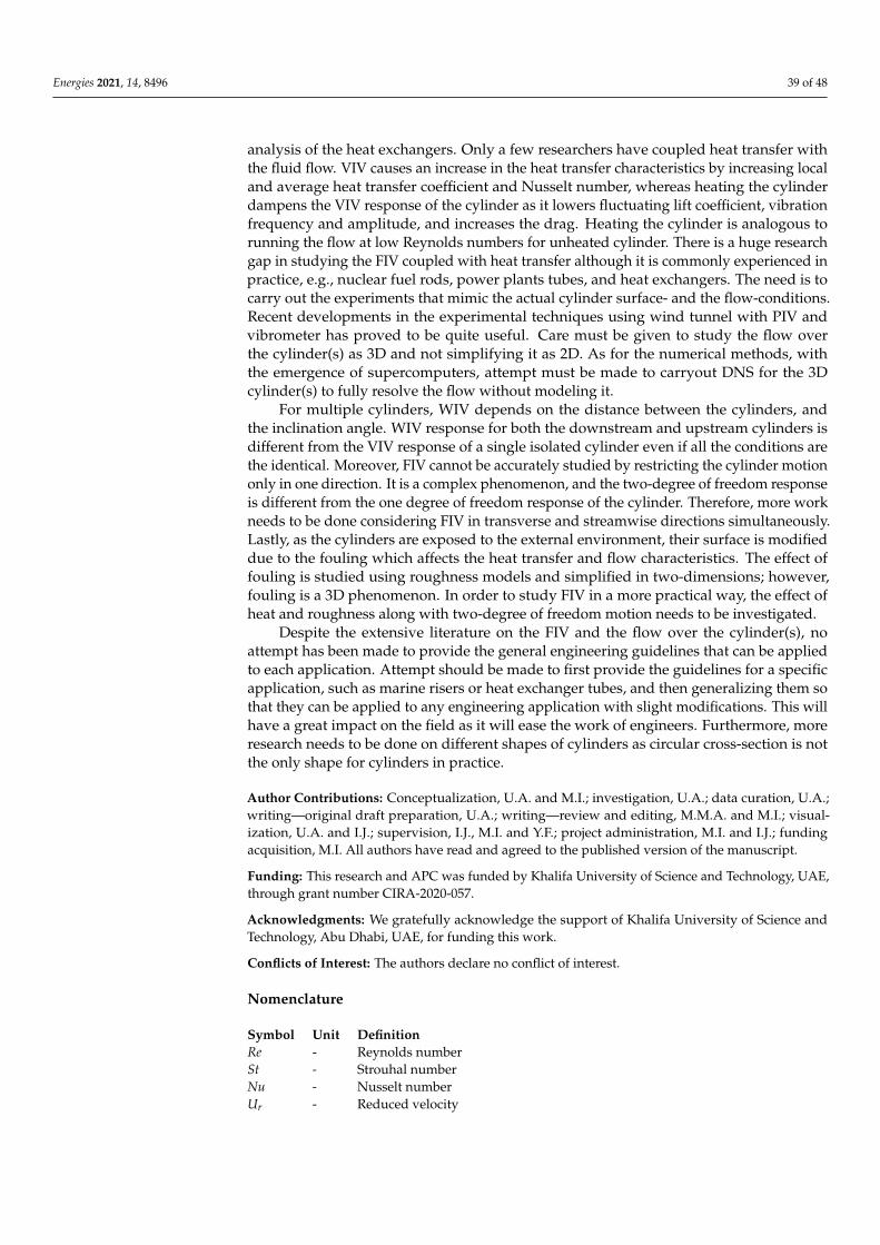
Energies 2021, 14, 8496 39 of 48
analysis of the heat exchangers. Only a few researchers have coupled heat transfer withthe fluid flow. VIV causes an increase in the heat transfer characteristics by increasing localand average heat transfer coefficient and Nusselt number, whereas heating the cylinderdampens the VIV response of the cylinder as it lowers fluctuating lift coefficient, vibrationfrequency and amplitude, and increases the drag. Heating the cylinder is analogous torunning the flow at low Reynolds numbers for unheated cylinder. There is a huge researchgap in studying the FIV coupled with heat transfer although it is commonly experienced inpractice, e.g., nuclear fuel rods, power plants tubes, and heat exchangers. The need is tocarry out the experiments that mimic the actual cylinder surface- and the flow-conditions.Recent developments in the experimental techniques using wind tunnel with PIV andvibrometer has proved to be quite useful. Care must be given to study the flow overthe cylinder(s) as 3D and not simplifying it as 2D. As for the numerical methods, withthe emergence of supercomputers, attempt must be made to carryout DNS for the 3Dcylinder(s) to fully resolve the flow without modeling it.
For multiple cylinders, WIV depends on the distance between the cylinders, andthe inclination angle. WIV response for both the downstream and upstream cylinders isdifferent from the VIV response of a single isolated cylinder even if all the conditions arethe identical. Moreover, FIV cannot be accurately studied by restricting the cylinder motiononly in one direction. It is a complex phenomenon, and the two-degree of freedom responseis different from the one degree of freedom response of the cylinder. Therefore, more workneeds to be done considering FIV in transverse and streamwise directions simultaneously.Lastly, as the cylinders are exposed to the external environment, their surface is modifieddue to the fouling which affects the heat transfer and flow characteristics. The effect offouling is studied using roughness models and simplified in two-dimensions; however,fouling is a 3D phenomenon. In order to study FIV in a more practical way, the effect ofheat and roughness along with two-degree of freedom motion needs to be investigated.
Despite the extensive literature on the FIV and the flow over the cylinder(s), noattempt has been made to provide the general engineering guidelines that can be appliedto each application. Attempt should be made to first provide the guidelines for a specificapplication, such as marine risers or heat exchanger tubes, and then generalizing them sothat they can be applied to any engineering application with slight modifications. This willhave a great impact on the field as it will ease the work of engineers. Furthermore, moreresearch needs to be done on different shapes of cylinders as circular cross-section is notthe only shape for cylinders in practice.
Author Contributions: Conceptualization, U.A. and M.I.; investigation, U.A.; data curation, U.A.;writing—original draft preparation, U.A.; writing—review and editing, M.M.A. and M.I.; visual-ization, U.A. and I.J.; supervision, I.J., M.I. and Y.F.; project administration, M.I. and I.J.; fundingacquisition, M.I. All authors have read and agreed to the published version of the manuscript.
Funding: This research and APC was funded by Khalifa University of Science and Technology, UAE,through grant number CIRA-2020-057.
Acknowledgments: We gratefully acknowledge the support of Khalifa University of Science andTechnology, Abu Dhabi, UAE, for funding this work.
Conflicts of Interest: The authors declare no conflict of interest.
Nomenclature
Symbol Unit DefinitionRe - Reynolds numberSt - Strouhal numberNu - Nusselt numberUr - Reduced velocity
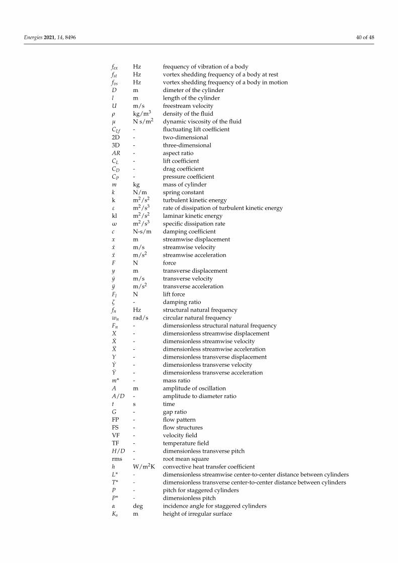
Energies 2021, 14, 8496 40 of 48
fex Hz frequency of vibration of a bodyfst Hz vortex shedding frequency of a body at restfvs Hz vortex shedding frequency of a body in motionD m dimeter of the cylinderl m length of the cylinderU m/s freestream velocityρ kg/m3 density of the fluidµ N s/m2 dynamic viscosity of the fluidCLf - fluctuating lift coefficient2D - two-dimensional3D - three-dimensionalAR - aspect ratioCL - lift coefficientCD - drag coefficientCP - pressure coefficientm kg mass of cylinderk N/m spring constantk m2/s2 turbulent kinetic energyε m2/s3 rate of dissipation of turbulent kinetic energykl m2/s2 laminar kinetic energyω m2/s3 specific dissipation ratec N-s/m damping coefficientx m streamwise displacementx m/s streamwise velocityx m/s2 streamwise accelerationF N forcey m transverse displacementy m/s transverse velocityÿ m/s2 transverse accelerationFl N lift forceζ - damping ratiofn Hz structural natural frequencywn rad/s circular natural frequencyFn - dimensionless structural natural frequencyX - dimensionless streamwise displacementX - dimensionless streamwise velocityX - dimensionless streamwise accelerationY - dimensionless transverse displacementY - dimensionless transverse velocityŸ - dimensionless transverse accelerationm* - mass ratioA m amplitude of oscillationA/D - amplitude to diameter ratiot s timeG - gap ratioFP - flow patternFS - flow structuresVF - velocity fieldTF - temperature fieldH/D - dimensionless transverse pitchrms - root mean squareh W/m2K convective heat transfer coefficientL* - dimensionless streamwise center-to-center distance between cylindersT* - dimensionless transverse center-to-center distance between cylindersP - pitch for staggered cylindersP* - dimensionless pitchα deg incidence angle for staggered cylindersKs m height of irregular surface
Energies 2021, 14, 8496 41 of 48
References1. Lee, A.H.; Campbell, R.L.; Craven, B.A.; Hambric, S.A. Fluid–Structure Interaction Simulation of Vortex-Induced Vibration of a
Flexible Hydrofoil. J. Vib. Acoust. 2017, 139, 041001. [CrossRef]2. Sarpkaya, T. A critical review of the intrinsic nature of vortex-induced vibrations. J. Fluids Struct. 2004, 19, 389–447. [CrossRef]3. Carberry, J.; Sheridan, J.; Rockwell, D. Forces and wake modes of an oscillating cylinder. J. Fluids Struct. 2001, 15, 523–532.
[CrossRef]4. Williamson, C.; Brown, G. A series in 1/
√re to represent the strouhal–reynolds number relationship of the cylinder wake. J.
Fluids Struct. 1998, 12, 1073–1085. [CrossRef]5. Abdelhamid, T.; Alam, M.; Islam, M. Heat transfer and flow around cylinder: Effect of corner radius and Reynolds number. Int. J.
Heat Mass Transf. 2021, 171, 121105. [CrossRef]6. Williamson, C.; Roshko, A. Vortex formation in the wake of an oscillating cylinder. J. Fluids Struct. 1988, 2, 355–381. [CrossRef]7. Rastan, M.R.; Alam, M. Transition of wake flows past two circular or square cylinders in tandem. Phys. Fluids 2021, 33, 081705.
[CrossRef]8. Celik, B.; Raisee, M.; Beskok, A. Heat transfer enhancement in a slot channel via a transversely oscillating adiabatic circular
cylinder. Int. J. Heat Mass Transf. 2010, 53, 626–634. [CrossRef]9. Blevins, R.D.; Gibert, R.J.; Villard, B. Experiments on vibration of heat, exchanger tube arrays in cross flow. In Proceedings of
the Transactions of 6th International Conference on Structural Mechanics in Reactor Technology (SMIRT), Paris, France, 17–21August 1981; p. B6/9.
10. Klein, U.; Zunkel, A.; Eberle, A. Breakdown of heat exchangers due to erosion corrosion and fretting caused by inappropriateoperating conditions. Eng. Fail. Anal. 2014, 43, 271–280. [CrossRef]
11. Yang, Z.; Ding, L.; Zhang, L.; Yang, L.; He, H. Two degrees of freedom flow-induced vibration and heat transfer of an isothermalcylinder. Int. J. Heat Mass Transf. 2020, 154, 119766. [CrossRef]
12. Sun, X.; Ye, Z.; Li, J.; Wen, K.; Tian, H. Forced convection heat transfer from a circular cylinder with a flexible fin. Int. J. Heat MassTransf. 2018, 128, 319–334. [CrossRef]
13. Zhu, H.; Li, G.; Wang, J. Flow-induced vibration of a circular cylinder with splitter plates placed upstream and downstreamindividually and simultaneously. Appl. Ocean Res. 2020, 97, 102084. [CrossRef]
14. Sun, X.; Li, S.; Lin, G.-G.; Zhang, J.-Z. Effects of flow-induced vibration on forced convection heat transfer from two tandemcircular cylinders in laminar flow. Int. J. Mech. Sci. 2020, 195, 106238. [CrossRef]
15. Zhou, Y.; Alam, M. Wake of two interacting circular cylinders: A review. Int. J. Heat Fluid Flow 2016, 62, 510–537. [CrossRef]16. Schlichting, H.; Gersten, K. Boundary-Layer Theory; Springer Science & Business Media: Berlin/Heidelberg, Germany, 2003.17. Lv, Y.; Sun, L.; Bernitsas, M.M.; Sun, H. A comprehensive review of nonlinear oscillators in hydrokinetic energy harnessing using
flow-induced vibrations. Renew. Sustain. Energy Rev. 2021, 150, 111388. [CrossRef]18. Wang, J.; Geng, L.; Ding, L.; Zhu, H.; Yurchenko, D. The state-of-the-art review on energy harvesting from flow-induced vibrations.
Appl. Energy 2020, 267, 114902. [CrossRef]19. Li, D.; Wu, Y.; Da Ronch, A.; Xiang, J. Energy harvesting by means of flow-induced vibrations on aerospace vehicles. Prog. Aerosp.
Sci. 2016, 86, 28–62. [CrossRef]20. Derakhshandeh, J.; Alam, M. A review of bluff body wakes. Ocean Eng. 2019, 182, 475–488. [CrossRef]21. Gabbai, R.; Benaroya, H. An overview of modeling and experiments of vortex-induced vibration of circular cylinders. J. Sound
Vib. 2005, 282, 575–616. [CrossRef]22. Bearman, P.W. Vortex Shedding from Oscillating Bluff Bodies. Annu. Rev. Fluid Mech. 1984, 16, 195–222. [CrossRef]23. Williamson, C.; Govardhan, R. Vortex-induced vibrations. Annu. Rev. Fluid Mech. 2004, 36, 413–455. [CrossRef]24. Sumner, D. Two circular cylinders in cross-flow: A review. J. Fluids Struct. 2010, 26, 849–899. [CrossRef]25. Weaver, D.; Fitzpatrick, J. A review of cross-flow induced vibrations in heat exchanger tube arrays. J. Fluids Struct. 1988, 2, 73–93.
[CrossRef]26. Païdoussis, M. A review of flow-induced vibrations in reactors and reactor components. Nucl. Eng. Des. 1983, 74, 31–60.
[CrossRef]27. Parkinson, G. Phenomena and modelling of flow-induced vibrations of bluff bodies. Prog. Aerosp. Sci. 1989, 26, 169–224.
[CrossRef]28. Miwa, S.; Mori, M.; Hibiki, T. Two-phase flow induced vibration in piping systems. Prog. Nucl. Energy 2015, 78, 270–284.
[CrossRef]29. Hong, K.-S.; Shah, U.H. Vortex-induced vibrations and control of marine risers: A review. Ocean Eng. 2018, 152, 300–315.
[CrossRef]30. Liu, G.; Li, H.; Qiu, Z.; Leng, D.; Li, Z.; Li, W. A mini review of recent progress on vortex-induced vibrations of marine risers.
Ocean Eng. 2019, 195, 106704. [CrossRef]31. Fehér, R.; Avila, J.J. Vortex-induced vibrations model with 2 degrees of freedom of rigid cylinders near a plane boundary based
on wake oscillator. Ocean Eng. 2021, 234, 108938. [CrossRef]32. Alam, M.; Abdelhamid, T.; Sohankar, A. Effect of cylinder corner radius and attack angle on heat transfer and flow topology. Int.
J. Mech. Sci. 2020, 175, 105566. [CrossRef]33. Williamson, C. Three-dimensional vortex dynamics in bluff body wakes. Exp. Therm. Fluid Sci. 1996, 12, 150–168. [CrossRef]
Energies 2021, 14, 8496 42 of 48
34. Roshko, A. Experiments on the flow past a circular cylinder at very high Reynolds number. J. Fluid Mech. 1961, 10, 345–356.[CrossRef]
35. Coutanceau, M.; Defaye, J.-R. Circular Cylinder Wake Configurations: A Flow Visualization Survey. Appl. Mech. Rev. 1991, 44,255–305. [CrossRef]
36. ALAM, M.; Zhou, Y.; Wang, X.W. The wake of two side-by-side square cylinders. J. Fluid Mech. 2011, 669, 432–471. [CrossRef]37. Alam, M. The aerodynamics of a cylinder submerged in the wake of another. J. Fluids Struct. 2014, 51, 393–400. [CrossRef]38. Bai, H.; Alam, M. Dependence of square cylinder wake on Reynolds number. Phys. Fluids 2018, 30, 015102. [CrossRef]39. Zdravkovich, M.M. Flow Around Circular Cylinders Volume 1: Fundamentals; Oxford University Press: Oxford, UK, 1997.40. Norberg, C. Fluctuating lift on a circular cylinder: Review and new measurements. J. Fluids Struct. 2003, 17, 57–96. [CrossRef]41. Zdravkovich, M. Different modes of vortex shedding: An overview. J. Fluids Struct. 1996, 10, 427–437. [CrossRef]42. Williamson, C.H.K. Oblique and parallel modes of vortex shedding in the wake of a circular cylinder at low Reynolds numbers. J.
Fluid Mech. 1989, 206, 579–627. [CrossRef]43. Gerich, D.; Eckelmann, H. Influence of end plates and free ends on the shedding frequency of circular cylinders. J. Fluid Mech.
1982, 122, 109–121. [CrossRef]44. Tritton, D.J. Experiments on the flow past a circular cylinder at low Reynolds numbers. J. Fluid Mech. 1959, 6, 547–567. [CrossRef]45. Williamson, C. Advances in our understanding of vortex dynamics in bluff body wakes. J. Wind Eng. Ind. Aerodyn. 1997, 69–71,
3–32. [CrossRef]46. Ozgoren, M.; Pinar, E.; Sahin, B.; Akilli, H. Comparison of flow structures in the downstream region of a cylinder and sphere. Int.
J. Heat Fluid Flow 2011, 32, 1138–1146. [CrossRef]47. Ong, L.; Wallace, J. The velocity field of the turbulent very near wake of a circular cylinder. Exp. Fluids 1996, 20, 441–453.
[CrossRef]48. Kiya, M.; Tamura, H.; Arie, M. Vortex shedding from a circular cylinder in moderate-Reynolds-number shear flow. J. Fluid Mech.
1980, 101, 721–735. Available online: https://www.cambridge.org/core/journals/journal-of-fluid-mechanics/article/abs/vortex-shedding-from-a-circular-cylinder-in-moderatereynoldsnumber-shear-flow/8C809D0CA910AC165F346250D19E610C(accessed on 10 November 2021). [CrossRef]
49. Alam, M.; Zhou, Y. Alternative drag coefficient in the wake of an isolated bluff body. Phys. Rev. E 2008, 78, 036320. [CrossRef]50. Liang, C.; Papadakis, G. Large eddy simulation of pulsating flow over a circular cylinder at subcritical Reynolds number. Comput.
Fluids 2007, 36, 299–312. [CrossRef]51. Blevins, R.D. Flow-Induced Vibration. 1990. Available online: https://www.osti.gov/biblio/6168070-flow-induced-vibration
(accessed on 10 November 2021).52. Bearman, P.W. On vortex shedding from a circular cylinder in the critical Reynolds number régime. J. Fluid Mech. 1969, 37,
577–585. [CrossRef]53. Williamson, C.H.K. The existence of two stages in the transition to three-dimensionality of a cylinder wake. Phys. Fluids 1988,
31, 3165. [CrossRef]54. Szepessy, S.; Bearman, P.W. Aspect ratio and end plate effects on vortex shedding from a circular cylinder. J. Fluid Mech. 1992, 234,
191–217. [CrossRef]55. Mittal, S.; Sidharth, G. Steady forces on a cylinder with oblique vortex shedding. J. Fluids Struct. 2014, 44, 310–315. [CrossRef]56. Izadpanah, E.; Amini, Y.; Ashouri, A. A comprehensive investigation of vortex induced vibration effects on the heat transfer from
a circular cylinder. Int. J. Therm. Sci. 2018, 125, 405–418. [CrossRef]57. Nepali, R.; Ping, H.; Han, Z.; Zhou, D.; Yang, H.; Tu, J.; Zhao, Y.; Bao, Y. Two-degree-of-freedom vortex-induced vibrations of two
square cylinders in tandem arrangement at low Reynolds numbers. J. Fluids Struct. 2020, 97, 102991. [CrossRef]58. Zhou, D.; Han, Z.; Tu, J.; Sun, W. Flow characteristics and dynamic responses of a rear circular cylinder behind the square cylinder
with different side lengths. J. Vibroeng. 2017, 19, 2956–2975. [CrossRef]59. Chen, W.; Ji, C.; Xu, D. Vortex-induced vibrations of two side-by-side circular cylinders with two degrees of freedom in laminar
cross-flow. Comput. Fluids 2019, 193, 104288. [CrossRef]60. Chen, W.; Ji, C.; Xu, D.; Zhang, Z.; Wei, Y. Flow-induced vibrations of an equilateral triangular prism at various angles of attack. J.
Fluids Struct. 2020, 97, 103099. [CrossRef]61. Papaioannou, G.; Yue, D.; Triantafyllou, M.; Karniadakis, G. On the effect of spacing on the vortex-induced vibrations of two
tandem cylinders. J. Fluids Struct. 2008, 24, 833–854. [CrossRef]62. Han, Z.; Zhou, D.; He, T.; Tu, J.; Li, C.; Kwok, K.C.; Fang, C. Flow-induced vibrations of four circular cylinders with square
arrangement at low Reynolds numbers. Ocean Eng. 2015, 96, 21–33. [CrossRef]63. Chung, M.-H. On characteristics of two-degree-of-freedom vortex induced vibration of two low-mass circular cylinders in
proximity at low Reynolds number. Int. J. Heat Fluid Flow 2017, 65, 220–245. [CrossRef]64. Wang, H.; Yu, G.; Yang, W. Numerical Study of Vortex-Induced Vibrations of Three Circular Cylinders in Equilateral-Triangle
Arrangement. Adv. Mech. Eng. 2013, 5, 287923. [CrossRef]65. Wang, H.; Yang, W.; Nguyen, K.D.; Yu, G. Wake-induced vibrations of an elastically mounted cylinder located downstream of a
stationary larger cylinder at low Reynolds numbers. J. Fluids Struct. 2014, 50, 479–496. [CrossRef]66. Yu, K.R.; Étienne, S.; Scolan, Y.-M.; Hay, A.; Fontaine, E.; Pelletier, D. Flow-induced vibrations of in-line cylinder arrangements at
low Reynolds numbers. J. Fluids Struct. 2016, 60, 37–61. [CrossRef]
Energies 2021, 14, 8496 43 of 48
67. Zhao, M.; Cui, Z.; Kwok, K.; Zhang, Y. Wake-induced vibration of a small cylinder in the wake of a large cylinder. Ocean Eng.2016, 113, 75–89. [CrossRef]
68. Ashouri, A.; Izadpanah, E.; Hekmat, M.H.; Amini, Y. Numerical investigation on two-degree-of-freedom vortex-induced vibrationof a circular cylinder in power-law fluids. J. Non-Newton. Fluid Mech. 2021, 292, 104535. [CrossRef]
69. Zou, Q.; Ding, L.; Zou, R.; Kong, H.; Wang, H.; Zhang, L. Two-degree-of-freedom flow-induced vibration of two circular cylinderswith constraint for different arrangements. Ocean Eng. 2021, 225, 108806. [CrossRef]
70. Stokes, G.G. On the Effect of the Internal Friction of Fluids on the Motion of Pendulums. In Transactions of the CambridgePhilosophical Society; Cambridge University Press: Cambridge, UK, 1851; Volume 9, p. 8.
71. Vikestad, K.; Vandiver, J.; Larsen, C. Added mass and oscillation frequency for a circular cylinder subjected to vortex-inducedvibrations and external disturbance. J. Fluids Struct. 2000, 14, 1071–1088. [CrossRef]
72. Koopmann, G.H. On the Wind-Induced Vibrations of Circular Cylinders. Master’s Thesis, Catholic University of America,Washington, DC, USA, 1967.
73. Alam, M. Effects of Mass and Damping on Flow-Induced Vibration of a Cylinder Interacting with the Wake of Another Cylinderat High Reduced Velocities. Energies 2021, 14, 5148. [CrossRef]
74. Khalak, A.; Williamson, C. Motions, forces and mode transitions in vortex-induced vibrations at low mass-damping. J. FluidsStruct. 1999, 13, 813–851. [CrossRef]
75. Gao, Y.; Liu, L.; Zou, L.; Zhang, Z.; Yang, B. Effect of surface roughness on vortex-induced vibrations of a freely vibrating cylindernear a stationary plane wall. Ocean Eng. 2020, 198, 106837. [CrossRef]
76. Facchinetti, M.; de Langre, E.; Biolley, F. Coupling of structure and wake oscillators in vortex-induced vibrations. J. Fluids Struct.2004, 19, 123–140. [CrossRef]
77. Feng, C.C. The Measurement of Vortex Induced Effects in Flow Past Stationary and Oscillating Circular and D-Section Cylinders.Master’s Thesis, University of British Columbia, Vancouver, BC, Canada, 1968. [CrossRef]
78. Khalak, A.; Williamson, C. Fluid forces and dynamics of a hydroelastic structure with very low mass and damping. J. FluidsStruct. 1997, 11, 973–982. [CrossRef]
79. Parkinson, G.V. Wind-induced instability of structures. Philos. Trans. R. Soc. Lond. Ser. A Math. Phys. Sci. 1971, 269, 395–413.[CrossRef]
80. Carberry, J.; Sheridan, J.; Rockwell, D. Controlled oscillations of a cylinder: Forces and wake modes. J. Fluid Mech. 2005, 538,31–69. [CrossRef]
81. Cheng, M.; Moretti, P.M. Lock-in phenomena on a single cylinder with forced transverse vibration. In Proceedings of the ASMEPVP-206, Flow-Induced Vibration and Wear, San Diego, CA, USA, 23–27 June 1991; pp. 129–133.
82. Krishnamoorthy, S.; Price, S.; Païdoussis, M. Cross-flow past an oscillating circular cylinder: Synchronization phenomena in thenear wake. J. Fluids Struct. 2001, 15, 955–980. [CrossRef]
83. Sarpkaya, T. Taylor–Gortler instability and separation on a cylinder in sinusoidally oscillating flow. In Proceedings of the IUTAMSymposium on Unsteady Flows, Toulouse, France, 8–12 April 2002.
84. Sarpkaya, T.; Butterworth, W. Separation Points on a Cylinder in Oscillating Flow. J. Offshore Mech. Arct. Eng. 1992, 114, 28–35.[CrossRef]
85. Rodriguez, O.; Pruvost, J. Wakes of an oscillating cylinder. In Proceedings of the IUTAM Symposium, Marseille, France, 13–16June 2000.
86. Olinger, D.J.; Sreenivasan, K.R. Nonlinear dynamics of the wake of an oscillating cylinder. Phys. Rev. Lett. 1988, 60, 797–800.[CrossRef]
87. Brika, D.; Laneville, A. Vortex-induced vibrations of a long flexible circular cylinder. J. Fluid Mech. 1993, 250, 481–508. [CrossRef]88. Govardhan, R.; Williamson, C.H.K. Modes of vortex formation and frequency response of a freely vibrating cylinder. J. Fluid
Mech. 2000, 420, 85–130. [CrossRef]89. Blackburn, H.; Govardhan, R.; Williamson, C. A complementary numerical and physical investigation of vortex-induced vibration.
J. Fluids Struct. 2001, 15, 481–488. [CrossRef]90. Wanderley, J.B.; Soares, L.F.N. Vortex-induced vibration on a two-dimensional circular cylinder with low Reynolds number and
low mass-damping parameter. Ocean Eng. 2015, 97, 156–164. [CrossRef]91. Chung, M.-H. Transverse vortex-induced vibration of spring-supported circular cylinder translating near a plane wall. Eur. J.
Mech.-B/Fluids 2016, 55, 88–103. [CrossRef]92. Raghavan, K.; Bernitsas, M. Experimental investigation of Reynolds number effect on vortex induced vibration of rigid circular
cylinder on elastic supports. Ocean Eng. 2011, 38, 719–731. [CrossRef]93. King, R.; Prosser, M.; Johns, D. On vortex excitation of model piles in water. J. Sound Vib. 1973, 29, 169–188. [CrossRef]94. King, R. Vortex Excited Structural Oscillations of a Circular Cylinder in Steady Currents. (OTC #1948 Paper). 1, Article OTC
#1948 Paper. 1974. Available online: https://trid.trb.org/view/25013 (accessed on 10 November 2021).95. Wootton, L.R.; Warner, M.H.; Cooper, D.H. Some Aspects of Oscillations of Full Scale Piles, in Flow Induced Structural Vibrations;
Naudascher, E., Ed.; Springer: Berlin/Heidelberg, Germany, 1974; pp. 587–601.96. Karanth, D.; Rankin, G.W.; Sridhar, K. Computational study of flow past a cylinder with combined in-line and transverse
oscillation. Comput. Mech. 1995, 16, 1–10. [CrossRef]
Energies 2021, 14, 8496 44 of 48
97. Okajima, A.; Kosugi, T.; Nakamura, A. Flow-Induced Vibration of Bluff Bodies. Experiments on Flow-Induced In-Line Oscillationof a Circular Cylinder in a Water Tunnel. 1st-Report, The Difference of the Response Characteristics When a Cylinder is ElasticallySupported at Both Ends and Cantilevered. JSME Int. J. Ser. B 2001, 44, 695–704. [CrossRef]
98. Okajima, A.; Kosugi, T.; Nakamura, A. Flow-Induced In-Line Oscillation of a Circular Cylinder in a Water Tunnel. J. Press. Vessel.Technol. 2001, 124, 89–96. [CrossRef]
99. Nakamura, A.; Okajima, A.; Kosugi, T. Flow-Induced Vibration of Bluff Bodies. Experiments on Flow-Induced In-Line Oscillationof a Circular Cylinder in a Water Tunnel. 2nd Report, Influence of the Aspect Ratio of a Cantilevered Circular Cylinder. JSME Int.J. Ser. B 2001, 44, 705–711. [CrossRef]
100. Sakai, T.; Iwata, K.; Morishita, M.; Kitamura, S. Flow-Induced Vibration of Bluff Bodies. Vortex-Induced Vibration of a CantileverCircular Cylinder in Super-Critical Reynolds Number Flow and Its Suppression by Structure Damping. JSME Int. J. Ser. B 2001,44, 712–720. [CrossRef]
101. Bai, W. Numerical simulation of turbulent flow around a forced moving circular cylinder on cut cells. J. Hydrodyn. 2013, 25,829–838. [CrossRef]
102. Al-Mdallal, Q.; Lawrence, K.; Kocabiyik, S. Forced streamwise oscillations of a circular cylinder: Locked-on modes and resultingfluid forces. J. Fluids Struct. 2007, 23, 681–701. [CrossRef]
103. Norberg, C. An experimental investigation of the flow around a circular cylinder: Influence of aspect ratio. J. Fluid Mech. 1994,258, 287–316. [CrossRef]
104. Norberg, C. Flow around a circular cylinder: Aspects of fluctuating lift. J. Fluids Struct. 2001, 15, 459–469. [CrossRef]105. Kravchenko, A.G.; Moin, P. Numerical studies of flow over a circular cylinder at ReD=3900. Phys. Fluids 2000, 12, 403–417.
[CrossRef]106. Ma, X.; Karamanos, G.-S.; Karniadakis, G.E. Dynamics and low-dimensionality of a turbulent near wake. J. Fluid Mech. 2000, 410,
29–65. [CrossRef]107. Park, C.-W.; Lee, S.-J. Free end effects on the near wake flow structure behind a finite circular cylinder. J. Wind Eng. Ind. Aerodyn.
2000, 88, 231–246. [CrossRef]108. Singh, S.; Mittal, S. Vortex-induced oscillations at low Reynolds numbers: Hysteresis and vortex-shedding modes. J. Fluids Struct.
2005, 20, 1085–1104. [CrossRef]109. Kim, J.; Choi, H. Distributed forcing of flow over a circular cylinder. Phys. Fluids 2005, 17, 033103. [CrossRef]110. Alam, M.; Fu, S.; Zhou, Y. Generation of vortices by a streamwise oscillating cylinder. J. Vis. 2007, 10, 65–73. [CrossRef]111. Marquart, J.; Endicott, D.; Dear, C. CFD Investigation of the Drag Effects of Heating and Cooling Cylinders in Crossflow. In
Proceedings of the 6th AIAA Flow Control Conference, New Orleans, LA, USA, 25–28 June 2012. [CrossRef]112. Zhao, M.; Cheng, L.; An, H.; Lu, L. Three-dimensional numerical simulation of vortex-induced vibration of an elastically mounted
rigid circular cylinder in steady current. J. Fluids Struct. 2014, 50, 292–311. [CrossRef]113. Kim, S.; Alam, M.; Maiti, D.K. Wake and suppression of flow-induced vibration of a circular cylinder. Ocean Eng. 2018, 151,
298–307. [CrossRef]114. Cheng, C.-H.; Chen, H.-N.; Aung, W. Experimental Study of the Effect of Transverse Oscillation on Convection Heat Transfer
From a Circular Cylinder. J. Heat Transf. 1997, 119, 474–482. [CrossRef]115. Gau, C.; Wu, J.M.; Liang, C.Y. Heat Transfer Enhancement and Vortex Flow Structure Over a Heated Cylinder Oscillating in the
Crossflow Direction. J. Heat Transf. 1999, 121, 789–795. [CrossRef]116. Baratchi, F.; Saghafian, M.; Baratchi, B. Numerical Investigation on Lock-In Condition and Convective Heat Transfer From an
Elastically Supported Cylinder in a Cross Flow. J. Fluids Eng. 2013, 135, 031103. [CrossRef]117. Knudsen, J.D.; Katz, D.L. Fluid Dynamics and Heat Transfer; McGraw Hill: New York, NY, USA, 1958.118. Žukauskas, A. Heat Transfer from Tubes in Crossflow. In Advances in Heat Transfer; Elsevier: Amsterdam, The Netherlands, 1972;
Volume 8, pp. 93–160. [CrossRef]119. Churchill, S.W.; Bernstein, M. A Correlating Equation for Forced Convection From Gases and Liquids to a Circular Cylinder in
Crossflow. J. Heat Transf. 1977, 99, 300–306. [CrossRef]120. Wang, A.-B.; Trávnícek, Z. On the linear heat transfer correlation of a heated circular cylinder in laminar crossflow using a new
representative temperature concept. Int. J. Heat Mass Transf. 2001, 44, 4635–4647. [CrossRef]121. Baranyi, L.; Szabó, S.; Bolló, B.; Bordás, R. Analysis of low Reynolds number flow around a heated circular cylinder. J. Mech. Sci.
Technol. 2009, 23, 1829–1834. [CrossRef]122. Nakamura, H.; Igarashi, T. Unsteady heat transfer from a circular cylinder for Reynolds numbers from 3000 to 15,000. Int. J. Heat
Fluid Flow 2004, 25, 741–748. [CrossRef]123. Salimipour, E. A numerical study on the fluid flow and heat transfer from a horizontal circular cylinder under mixed convection.
Int. J. Heat Mass Transf. 2018, 131, 365–374. [CrossRef]124. Schneider, G.E.; Zedan, M. A modified strongly implicit procedure for the numerical solution of field problems. Numer. Heat
Transf. 1981, 4, 1–19. [CrossRef]125. Witte, A.; Cabrera, A.; Polifke, W. Identification of the heat transfer frequency response in pulsating laminar and subcritical flow
across a cylinder. J. Phys. Conf. Ser. 2016, 745, 032055. [CrossRef]126. Jogee, S.; Prasad, B.; Anupindi, K. Large-eddy simulation of non-isothermal flow over a circular cylinder. Int. J. Heat Mass Transf.
2020, 151, 119426. [CrossRef]
Energies 2021, 14, 8496 45 of 48
127. Baughn, J.W.; Elderkin, M.J.; McKillop, A.A. Heat Transfer From a Single Cylinder, Cylinders in Tandem, and Cylinders in theEntrance Region of a Tube Bank With a Uniform Heat Flux. J. Heat Transf. 1986, 108, 386–391. [CrossRef]
128. Matsumura, M.; Antonia, R.A. Momentum and heat transport in the turbulent intermediate wake of a circular cylinder. J. FluidMech. 1993, 250, 651–668. [CrossRef]
129. Antonia, R.; Zhou, Y.; Matsumura, M. Spectral characteristics of momentum and heat transfer in the turbulent wake of a circularcylinder. Exp. Therm. Fluid Sci. 1993, 6, 371–375. [CrossRef]
130. Buyruk, E. Heat Transfer and Flow Structures Around Circular Cylinders in Cross-Flow. J. Eng. Environ. Sci. 1999, 23, 299–315.131. Kumar, R.S.; Jayavel, S. Influence of flow shedding frequency on convection heat transfer from bank of circular tubes in heat
exchangers under cross flow. Int. J. Heat Mass Transf. 2016, 105, 376–393. [CrossRef]132. Ali, U.; Islam, M.; Janajreh, I. Dynamic Behavior of a Streamwise Oscillating Heated Cylinder. In Proceedings of the ASME 2021
Heat Transfer Summer Conference, Online, 16–18 June 2021; p. V001T01A009. [CrossRef]133. Zafar, F.; Alam, M. Flow structure around and heat transfer from cylinders modified from square to circular. Phys. Fluids 2019,
31, 083604. [CrossRef]134. Ali, U.; Islam, M.; Janajreh, I. Heated Circular Cylinder Subjected to Forced Spanwise Oscillations. In Proceedings of the ASME
2021 International Mechanical Engineering Congress and Exposition, Virtual Online, 1–5 November 2021.135. Homsi, R.; Islam, D.; Fatt, Y.Y.; Janajreh, I. Flow dynamics over a heated cylinder subjected to high temperature ratios. Case Stud.
Therm. Eng. 2021, 27, 101357. [CrossRef]136. Zdravkovich, M. The effects of interference between circular cylinders in cross flow. J. Fluids Struct. 1987, 1, 239–261. [CrossRef]137. Lin, J.-C.; Yang, Y.; Rockwell, D. Flow past two cylinders in tandem: Instantaneous and averaged flow structure. J. Fluids Struct.
2002, 16, 1059–1071. [CrossRef]138. Zhou, Y.; Yiu, M.W. Flow structure, momentum and heat transport in a two-tandem-cylinder wake. J. Fluid Mech. 2006, 548, 17–48.
[CrossRef]139. Igarashi, T. Characteristics of the Flow around Two Circular Cylinders Arranged in Tandem: 1st Report. Bull. JSME 1981, 24,
323–331. [CrossRef]140. Alam, M.; Meyer, J. Global aerodynamic instability of twin cylinders in cross flow. J. Fluids Struct. 2013, 41, 135–145. [CrossRef]141. Qin, B.; Alam, M.; Zhou, Y. Two tandem cylinders of different diameters in cross-flow: Flow-induced vibration. J. Fluid Mech.
2017, 829, 621–658. [CrossRef]142. Kim, S.; Alam, M.; Sakamoto, H.; Zhou, Y. Flow-induced vibrations of two circular cylinders in tandem arrangement. Part 1:
Characteristics of vibration. J. Wind Eng. Ind. Aerodyn. 2009, 97, 304–311. [CrossRef]143. Kim, S.; Alam, M.; Sakamoto, H.; Zhou, Y. Flow-induced vibration of two circular cylinders in tandem arrangement. Part 2:
Suppression of vibrations. J. Wind Eng. Ind. Aerodyn. 2009, 97, 312–319. [CrossRef]144. Xu, W.; Ji, C.; Sun, H.; Ding, W.; Bernitsas, M.M. Flow-induced vibration of two elastically mounted tandem cylinders in cross-flow
at subcritical Reynolds numbers. Ocean Eng. 2019, 173, 375–387. [CrossRef]145. Sun, H.; Ma, C.; Kim, E.S.; Nowakowski, G.; Mauer, E.; Bernitsas, M.M. Flow-induced vibration of tandem circular cylinders with
selective roughness: Effect of spacing, damping and stiffness. Eur. J. Mech.-B/Fluids 2018, 74, 219–241. [CrossRef]146. Huera-Huarte, F.; Jiménez-González, J. Effect of diameter ratio on the flow-induced vibrations of two rigidly coupled circular
cylinders in tandem. J. Fluids Struct. 2019, 89, 96–107. [CrossRef]147. Zhao, M.; Cheng, L.; Teng, B.; Dong, G. Hydrodynamic forces on dual cylinders of different diameters in steady currents. J. Fluids
Struct. 2006, 23, 59–83. [CrossRef]148. Alam, M.; Moriya, M.; Takai, K.; Sakamoto, H. Fluctuating fluid forces acting on two circular cylinders in a tandem arrangement
at a subcritical Reynolds number. J. Wind Eng. Ind. Aerodyn. 2003, 91, 139–154. [CrossRef]149. Assi, G.R.S.; Meneghini, J.R.; Aranha, J.; Bearman, P.; Casaprima, E. Experimental investigation of flow-induced vibration
interference between two circular cylinders. J. Fluids Struct. 2006, 22, 819–827. [CrossRef]150. Borazjani, I.; Sotiropoulos, F. Vortex-induced vibrations of two cylinders in tandem arrangement in the proximity–wake
interference region. J. Fluid Mech. 2009, 621, 321–364. [CrossRef]151. Brika, D.; Laneville, A. The flow interaction between a stationary cylinder and a downstream flexible cylinder. J. Fluids Struct.
1999, 13, 579–606. [CrossRef]152. Gao, Y.; Sun, Z.; Tan, D.; Yu, D.; Tan, S.K. Wake flow behaviour behind a smaller cylinder oscillating in the wake of an upstream
stationary cylinder. Fluid Dyn. Res. 2014, 46, 025505. [CrossRef]153. Kitagawa, T.; Ohta, H. Numerical investigation on flow around circular cylinders in tandem arrangement at a subcritical Reynolds
number. J. Fluids Struct. 2008, 24, 680–699. [CrossRef]154. Kondo, N.; Matsukuma, D. Numerical simulation for flow around two circular cylinders in tandem. Int. J. Comput. Fluid Dyn.
2005, 19, 277–288. [CrossRef]155. Carmo, B.S.; Assi, G.R.; Meneghini, J.R. Computational simulation of the flow-induced vibration of a circular cylinder subjected
to wake interference. J. Fluids Struct. 2013, 41, 99–108. [CrossRef]156. Brika, D.; Laneville, A. Wake interference between two circular cylinders. J. Wind Eng. Ind. Aerodyn. 1997, 72, 61–70. [CrossRef]157. Sumner, D.; Wong, S.; Price, S.; Païdoussis, M. Fluid behaviour of side-by-side circular cylinders in steady cross-flow. J. Fluids
Struct. 1999, 13, 309–338. [CrossRef]
Energies 2021, 14, 8496 46 of 48
158. Sumner, D.; Price, S.J.; Païdoussis, M.P. Flow-pattern identification for two staggered circular cylinders in cross-flow. J. FluidMech. 2000, 411, 263–303. [CrossRef]
159. Zhou, Y.; So, R.; Liu, M.; Zhang, H. Complex turbulent wakes generated by two and three side-by-side cylinders. Int. J. Heat FluidFlow 2000, 21, 125–133. [CrossRef]
160. Farrant, T.; Tan, M.; Price, W. A cell boundary element method applied to laminar vortex-shedding from arrays of cylinders invarious arrangements. J. Fluids Struct. 2000, 14, 375–402. [CrossRef]
161. Meneghini, J.R.; Saltara, F.; Siqueira, C.L.R.; Ferrari, J. Numerical simulation of flow interference between two circular cylindersin tandem and side-by-side arrangements. J. Fluids Struct. 2001, 15, 327–350. [CrossRef]
162. Ozono, S.; Oda, J.; Yoshida, Y.; Wakasugi, Y. Critical nature of the base pressure of the upstream circular cylinder in two staggeredones in cross-flow. Theor. Appl. Mech. Jpn. 2001, 50, 335–340.
163. Zhou, Y.; Zhang, H.J.; Yiu, M.W. The turbulent wake of two side-by-side circular cylinders. J. Fluid Mech. 2002, 458, 303–332.[CrossRef]
164. Wang, Z.; Zhou, Y.; Li, H. Flow-visualization of a two side-by-side cylinder wake. J. Flow Vis. Image Process. 2002, 9, 16. [CrossRef]165. Xu, S.J.; Zhou, Y.; So, R.M.C. Reynolds number effects on the flow structure behind two side-by-side cylinders. Phys. Fluids 2003,
15, 1214–1219. [CrossRef]166. Chen, L.; Tu, J.; Yeoh, G. Numerical simulation of turbulent wake flows behind two side-by-side cylinders. J. Fluids Struct. 2003,
18, 387–403. [CrossRef]167. Jester, W.; Kallinderis, Y. Numerical study of incompressible flow about fixed cylinder pairs. J. Fluids Struct. 2003, 17, 561–577.
[CrossRef]168. Kang, S. Characteristics of flow over two circular cylinders in a side-by-side arrangement at low Reynolds numbers. Phys. Fluids
2003, 15, 2486–2498. [CrossRef]169. Alam, M.; Moriya, M.; Sakamoto, H. Aerodynamic characteristics of two side-by-side circular cylinders and application of
wavelet analysis on the switching phenomenon. J. Fluids Struct. 2003, 18, 325–346. [CrossRef]170. Alam, M.; Sakamoto, H.; Moriya, M. Reduction of fluid forces acting on a single circular cylinder and two circular cylinders by
using tripping rods. J. Fluids Struct. 2003, 18, 347–366. [CrossRef]171. Akosile, O.; Sumner, D. Staggered circular cylinders immersed in a uniform planar shear flow. J. Fluids Struct. 2003, 18, 613–633.
[CrossRef]172. Sumner, D.; Richards, M. Some vortex-shedding characteristics of the staggered configuration of circular cylinders. J. Fluids
Struct. 2003, 17, 345–350. [CrossRef]173. Sumner, D. Closely Spaced Circular Cylinders in Cross-Flow and a Universal Wake Number. J. Fluids Eng. 2004, 126, 245–249.
[CrossRef]174. Xu, G.; Zhou, Y. Strouhal numbers in the wake of two inline cylinders. Exp. Fluids 2004, 37, 248–256. [CrossRef]175. Mittal, S.; Kumar, V. Vortex Induced Vibrations of a Pair of Cylinders at Reynolds Number 1000. Int. J. Comput. Fluid Dyn. 2004,
18, 601–614. [CrossRef]176. Brun, C.; Tenchine, D.; Hopfinger, E.J. Role of the shear layer instability in the near wake behavior of two side-by-side circular
cylinders. Exp. Fluids 2004, 36, 334–343. [CrossRef]177. Alam, M.; Sakamoto, H. Investigation of Strouhal frequencies of two staggered bluff bodies and detection of multistable flow by
wavelets. J. Fluids Struct. 2005, 20, 425–449. [CrossRef]178. Alam, M.; Sakamoto, H.; Zhou, Y. Determination of flow configurations and fluid forces acting on two staggered circular cylinders
of equal diameter in cross-flow. J. Fluids Struct. 2005, 21, 363–394. [CrossRef]179. Sumner, D.; Richards, M.; Akosile, O. Two staggered circular cylinders of equal diameter in cross-flow. J. Fluids Struct. 2005, 20,
255–276. [CrossRef]180. Sharman, B.; Lien, F.S.; Davidson, L.; Norberg, C. Numerical predictions of low Reynolds number flows over two tandem circular
cylinders. Int. J. Numer. Methods Fluids 2004, 47, 423–447. [CrossRef]181. Akbari, M.; Price, S. Numerical investigation of flow patterns for staggered cylinder pairs in cross-flow. J. Fluids Struct. 2005, 20,
533–554. [CrossRef]182. Agrawal, A.; Djenidi, L.; Antonia, R. Investigation of flow around a pair of side-by-side square cylinders using the lattice
Boltzmann method. Comput. Fluids 2006, 35, 1093–1107. [CrossRef]183. Sumner, D.; Schenstead, A.J. Moderately and Widely Spaced Circular Cylinders in Crossflow and a Universal Wake Number. J.
Fluids Eng. 2006, 128, 1122–1125. [CrossRef]184. Carmo, B.; Meneghini, J.R. Numerical investigation of the flow around two circular cylinders in tandem. J. Fluids Struct. 2006, 22,
979–988. [CrossRef]185. Deng, J.; Ren, A.-L.; Zou, J.-F.; Shao, X.-M. Three-dimensional flow around two circular cylinders in tandem arrangement. Fluid
Dyn. Res. 2006, 38, 386–404. [CrossRef]186. Huang, Z.; Olson, J.; Kerekes, R.; Green, S. Numerical simulation of the flow around rows of cylinders. Comput. Fluids 2006, 35,
485–491. [CrossRef]187. Papaioannou, G.V.; Yue, D.K.P.; Triantafyllou, M.S.; Karniadakis, G.E. Three-dimensionality effects in flow around two tandem
cylinders. J. Fluid Mech. 2006, 558, 387–413. [CrossRef]
Energies 2021, 14, 8496 47 of 48
188. Kondo, N.; Matsukuma, D. Numerical simulation for aerodynamic characteristics of two circular cylinders in staggered arrange-ment by a third-order upwind finite element method. Int. J. Comput. Fluid Dyn. 2006, 20, 579–591. [CrossRef]
189. Liu, K.; Ma, D.-J.; Sun, D.-J.; Yin, X.-Y. Wake Patterns of Flow Past a Pair of Circular Cylinders in Side-by-Side Arrangements atLow Reynolds Numbers. J. Hydrodyn. 2007, 19, 690–697. [CrossRef]
190. Wang, X.; So, R.; Xie, W.-C. Features of flow-induced forces deduced from wavelet analysis. J. Fluids Struct. 2007, 23, 249–268.[CrossRef]
191. Alam, M.; Zhou, Y. Flow around two side-by-side closely spaced circular cylinders. J. Fluids Struct. 2007, 23, 799–805. [CrossRef]192. Alam, M.; Zhou, Y. Phase lag between vortex shedding from two tandem bluff bodies. J. Fluids Struct. 2007, 23, 339–347.
[CrossRef]193. Mizushima, J.; Ino, Y. Stability of flows past a pair of circular cylinders in a side-by-side arrangement. J. Fluid Mech. 2008, 595,
491–507. [CrossRef]194. Hu, J.C.; Zhou, Y. Flow structure behind two staggered circular cylinders. Part 1. Downstream evolution and classification. J.
Fluid Mech. 2008, 607, 51–80. [CrossRef]195. Hu, J.C.; Zhou, Y. Flow structure behind two staggered circular cylinders. Part 2. Heat and momentum transport. J. Fluid Mech.
2008, 607, 81–107. [CrossRef]196. Carmo, B.S.; Sherwin, S.J.; Bearman, P.W.; Willden, R.H.J. Wake transition in the flow around two circular cylinders in staggered
arrangements. J. Fluid Mech. 2008, 597, 1–29. [CrossRef]197. Lee, K.; Yang, K.-S.; Yoon, D.-H. Flow-induced forces on two circular cylinders in proximity. Comput. Fluids 2008, 38, 111–120.
[CrossRef]198. Zhou, Y.; Feng, S.X.; Alam, M.; Bai, H.L. Reynolds number effect on the wake of two staggered cylinders. Phys. Fluids 2009,
21, 125105. [CrossRef]199. Kumar, S.; Laughlin, G.; Cantu, C. Near-wake structure behind two circular cylinders in a side-by-side configuration with heat
release. Phys. Rev. E 2009, 80, 066307. [CrossRef] [PubMed]200. Singha, S.; Sinhamahapatra, K.P. High-Resolution Numerical Simulation of Low Reynolds Number Incompressible Flow About
Two Cylinders in Tandem. J. Fluids Eng. 2009, 132, 011101. [CrossRef]201. Assi, G.R.S.; Bearman, P.W.; Meneghini, J.R. On the wake-induced vibration of tandem circular cylinders: The vortex interaction
excitation mechanism. J. Fluid Mech. 2010, 661, 365–401. [CrossRef]202. Wang, S.-Y.; Tian, F.-B.; Jia, L.-B.; Lu, X.-Y.; Yin, X.-Z. Secondary vortex street in the wake of two tandem circular cylinders at low
Reynolds number. Phys. Rev. E 2010, 81, 96–111. [CrossRef]203. Carmo, B.S.; Meneghini, J.R.; Sherwin, S.J. Possible states in the flow around two circular cylinders in tandem with separations in
the vicinity of the drag inversion spacing. Phys. Fluids 2010, 22, 054101. [CrossRef]204. Carmo, B.S.; Meneghini, J.R.; Sherwin, S.J. Secondary instabilities in the flow around two circular cylinders in tandem. J. Fluid
Mech. 2010, 644, 395–431. [CrossRef]205. Dehkordi, B.G.; Moghaddam, H.S.; Jafari, H.H. Numerical Simulation of Flow Over Two Circular Cylinders in Tandem Arrange-
ment. J. Hydrodyn. 2011, 23, 114–126. [CrossRef]206. Vakil, A.; Green, S.I. Two-dimensional side-by-side circular cylinders at moderate Reynolds numbers. Comput. Fluids 2011, 51,
136–144. [CrossRef]207. Sarvghad-Moghaddam, H.; Nooredin, N.; Ghadiri-Dehkordi, B. Numerical Simulation of Flow Over Two Side-By-Side Circular
Cylinders. J. Hydrodyn. 2011, 23, 792–805. [CrossRef]208. Alam, M.; Meyer, J. Two interacting cylinders in cross flow. Phys. Rev. E 2011, 84, 056304. [CrossRef]209. Tsutsui, T. Experimental study on the instantaneous fluid force acting on two circular cylinders closely arranged in tandem. J.
Wind Eng. Ind. Aerodyn. 2012, 109, 46–54. [CrossRef]210. Koda, Y.; Lien, F.-S. Aerodynamic effects of the early three-dimensional instabilities in the flow over one and two circular cylinders
in tandem predicted by the lattice Boltzmann method. Comput. Fluids 2013, 74, 32–43. [CrossRef]211. Wong, C.; Zhou, Y.; Alam, M.; Zhou, T. Dependence of flow classification on the Reynolds number for a two-cylinder wake. J.
Fluids Struct. 2014, 49, 485–497. [CrossRef]212. Jiang, R.; Lin, J.; Ku, X. Numerical predictions of flows past two tandem cylinders of different diameters under unconfined and
confined flows. Fluid Dyn. Res. 2014, 46, 025506. [CrossRef]213. Mysa, R.C.; Kaboudian, A.; Jaiman, R.K. On the origin of wake-induced vibration in two tandem circular cylinders at low
Reynolds number. J. Fluids Struct. 2016, 61, 76–98. [CrossRef]214. Homsi, R.; Islam, M.; Fatt, Y.Y.; Janajreh, I. Flow Dynamics Over Two Cylinders in Tandem Subjected to Different Heating Cases.
In Proceedings of the ASME 2021 Heat Transfer Summer Conference, Online, 16–18 June 2021; p. V001T01A008. [CrossRef]215. Mahir, N.; Altaç, Z. Numerical investigation of convective heat transfer in unsteady flow past two cylinders in tandem arrange-
ments. Int. J. Heat Fluid Flow 2008, 29, 1309–1318. [CrossRef]216. Dhiman, S.K.; Kumar, A.; Prasad, J.K. Unsteady computation of flow field and convective heat transfer over tandem cylinders at
subcritical Reynolds numbers. J. Mech. Sci. Technol. 2017, 31, 1241–1257. [CrossRef]217. Harimi, I.; Saghafian, M. Numerical simulation of fluid flow and forced convection heat transfer from tandem circular cylinders
using overset grid method. J. Fluids Struct. 2012, 28, 309–327. [CrossRef]
Energies 2021, 14, 8496 48 of 48
218. Kostic, G.; Oka, S. Fluid flow and heat transfer with two cylinders in cross flow. Int. J. Heat Mass Transf. 1972, 15, 279–299.[CrossRef]
219. Sisodia, S.S.; Sarkar, S.; Saha, S.K. Fluid flow and mixed convective heat transfer around a semi-circular cylinder at incidencewith a tandem downstream square cylinder in cross flow. Int. J. Therm. Sci. 2017, 121, 13–29. [CrossRef]
220. Zafar, F.; Alam, M. A low Reynolds number flow and heat transfer topology of a cylinder in a wake. Phys. Fluids 2018, 30, 083603.[CrossRef]
221. Zhang, W.; Chen, X.; Yang, H.; Liang, H.; Wei, Y. Forced convection for flow across two tandem cylinders with rounded corners ina channel. Int. J. Heat Mass Transf. 2018, 130, 1053–1069. [CrossRef]
222. Moe, G.; Wu, Z.-J. The Lift Force on a Cylinder Vibrating in a Current. J. Offshore Mech. Arct. Eng. 1990, 112, 297–303. [CrossRef]223. Moe, G.; Holden, K.; Yttervoll, P.O. Motion of Spring Supported Cylinders in Subcritical and Critical Water Flows. In Proceedings
of the Fourth International Offshore and Polar Engineering Conference, Osaka, Japan, 10–15 April 1994; Available online: https://onepetro.org/ISOPEIOPEC/proceedings/ISOPE94/All-ISOPE94/ISOPE-I-94-248/26396 (accessed on 10 November 2021).
224. Sarpkaya, T. Hydrodynamic Damping, Flow-Induced Oscillations, and Biharmonic Response. J. Offshore Mech. Arct. Eng. 1995,117, 232–238. [CrossRef]
225. Zdravkovich, M.M. On origins of hysteretic responses of a circular cylinder induced by vortex shedding. Z. FlugwissenchaftWeltraumforsch. 1990, 14, 47–58.
226. Sarpkaya, T. Vortex-Induced Oscillations: A Selective Review. J. Appl. Mech. 1979, 46, 241–258. [CrossRef]227. Chen, S.S.; Jendrzejczyk, J.A. Dynamic Response of a Circular Cylinder Subjected to Liquid Cross Flow. J. Press. Vessel. Technol.
1979, 101, 106–112. [CrossRef]228. Assi, G.R. Wake-induced vibration of tandem and staggered cylinders with two degrees of freedom. J. Fluids Struct. 2014, 50,
340–357. [CrossRef]229. Prasanth, T.; Mittal, S. Vortex-induced vibration of two circular cylinders at low Reynolds number. J. Fluids Struct. 2009, 25,
731–741. [CrossRef]230. Prasanth, T.; Mittal, S. Flow-induced oscillation of two circular cylinders in tandem arrangement at low Re. J. Fluids Struct. 2009,
25, 1029–1048. [CrossRef]231. Kiu, K.; Stappenbelt, B.; Thiagarajan, K. Effects of uniform surface roughness on vortex-induced vibration of towed vertical
cylinders. J. Sound Vib. 2011, 330, 4753–4763. [CrossRef]232. Chen, S.S. A Review of Flow-Induced Vibration of Two Circular Cylinders in Crossflow. J. Press. Vessel. Technol. 1986, 108, 382–393.
[CrossRef]233. Bernitsas, M.M.; Raghavan, K. Enhancement of Vortex Induced Forces and Motion through Surface Roughness Control. U.S.
Patent No. US20090114001A1, 30 April 2009. Available online: https://patents.google.com/patent/US20090114001A1/en(accessed on 10 November 2021).
234. Park, H.; Bernitsas, M.M.; Kumar, R.A. Selective Roughness in the Boundary Layer to Suppress Flow-Induced Motions of CircularCylinder at 30,000 < Re < 120,000. J. Offshore Mech. Arct. Eng. 2012, 134, 041801. [CrossRef]
235. Park, H.; Kim, E.S.; Bernitsas, M.M. Sensitivity to Zone Covering of the Map of Passive Turbulence Control to Flow-InducedMotions for a Circular Cylinder at 30,000 ≤ Re ≤ 120,000. J. Offshore Mech. Arct. Eng. 2017, 139, 021802. [CrossRef]
236. King, R. Flow-Induced Vibrations of Mixing Vessel Internals. J. Vib. Acoust. 1985, 107, 253–258. [CrossRef]237. Bernitsas, M.M. Harvesting Energy by Flow Included Motions. In Springer Handbook of Ocean Engineering; Dhanak, M.R., Xiros,
N.I., Eds.; Springer International Publishing: Berlin/Heidelberg, Germany, 2016; pp. 1163–1244. [CrossRef]238. Zhou, B.; Wang, X.; Gho, W.M.; Tan, S.K. Force and flow characteristics of a circular cylinder with uniform surface roughness at
subcritical Reynolds numbers. Appl. Ocean Res. 2015, 49, 20–26. [CrossRef]239. Chang, C.-C.; Kumar, R.A.; Bernitsas, M.M. VIV and galloping of single circular cylinder with surface roughness at
3.0×10⁴≤Re≤1.2×10⁵. Ocean Eng. 2011, 38, 1713–1732. [CrossRef]240. Gao, Y.; Zhang, Z.; Zou, L.; Liu, L.; Yang, B. Effect of surface roughness and initial gap on the vortex-induced vibrations of a
freely vibrating cylinder in the vicinity of a plane wall. Mar. Struct. 2019, 69, 102663. [CrossRef]241. Dierich, F.; Nikrityuk, P. A numerical study of the impact of surface roughness on heat and fluid flow past a cylindrical particle.
Int. J. Therm. Sci. 2012, 65, 92–103. [CrossRef]242. Skeide, A.K.; Bardal, L.M.; Oggiano, L.; Hearst, R.J. The significant impact of ribs and small-scale roughness on cylinder drag
crisis. J. Wind Eng. Ind. Aerodyn. 2020, 202, 104192. [CrossRef]243. Han, X.; Tang, Y.; Meng, Z.; Fu, F.; Qiu, A.; Gu, J.; Wu, J. Surface roughness effect on cylinder vortex-induced vibration at
moderate Re regimes. Ocean Eng. 2021, 224, 108690. [CrossRef]
Copyright © 2022 FDOKUMEN